to 1-1a-9 navair 01-1a-9 - everyspec
TRANSCRIPT
TO 1-1A-9NAVAIR 01-1A-9
TECHNICAL MANUAL
ENGINEERING SERIESFOR AIRCRAFT REPAIR
AEROSPACE METALS - GENERAL DATA
AND USAGE FACTORS
DISTRIBUTION STATEMENT A - Approved for public release; distribution is unlimited. PA Case Number 11-03010. Submit recommended changesor problems with this Technical Order to 406 SCMS/GUEE. Questions concerning technical content shall be referred to 404 SCMS/GUEEA.
Published Under Authority of the Secretary of the Air Force and by Direction of the Chief of the Naval Air Systems Command.
26 FEBRUARY 1999 CHANGE 9 - 21 AUGUST 2013
BASIC AND ALL CHANGES HAVE BEEN MERGED TO MAKE THIS A COMPLETE PUBLICATION.
Downloaded from http://www.everyspec.com
TO 1-1A-9
NOTE: The portion of the text affected by the changes is indicated by a vertical line in the outer margins ofthe page. Changes to illustrations are indicated by shaded or screened areas, or by miniaturepointing hands.
INSERT LATEST CHANGED PAGES. DESTROY SUPERSEDED PAGES.
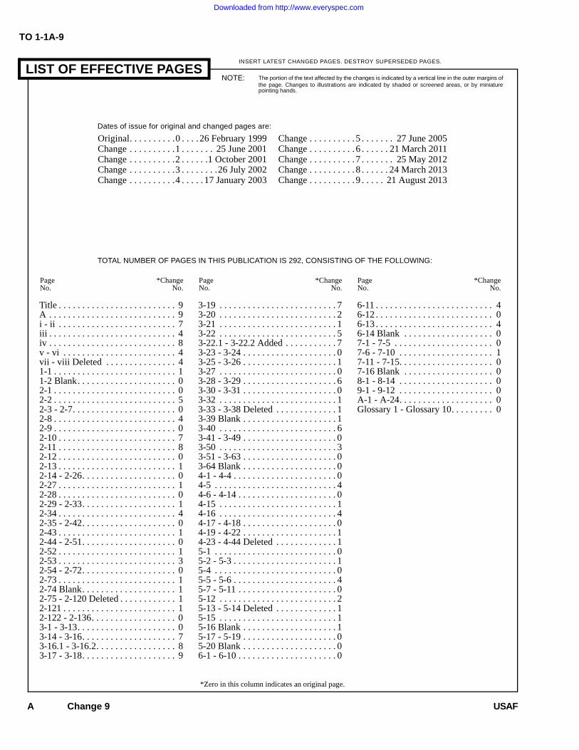
LIST OF EFFECTIVE PAGES
*Zero in this column indicates an original page.
USAF
Page *ChangeNo. No.
Page *ChangeNo. No.
Page *ChangeNo. No.
Dates of issue for original and changed pages are:
Title . . . . . . . . . . . . . . . . . . . . . . . . . 9A . . . . . . . . . . . . . . . . . . . . . . . . . . . 9i - ii . . . . . . . . . . . . . . . . . . . . . . . . . 7iii . . . . . . . . . . . . . . . . . . . . . . . . . . . 4iv . . . . . . . . . . . . . . . . . . . . . . . . . . . 8v - vi . . . . . . . . . . . . . . . . . . . . . . . . 4vii - viii Deleted . . . . . . . . . . . . . . . 41-1 . . . . . . . . . . . . . . . . . . . . . . . . . . 11-2 Blank. . . . . . . . . . . . . . . . . . . . . 02-1 . . . . . . . . . . . . . . . . . . . . . . . . . . 02-2 . . . . . . . . . . . . . . . . . . . . . . . . . . 52-3 - 2-7. . . . . . . . . . . . . . . . . . . . . . 02-8 . . . . . . . . . . . . . . . . . . . . . . . . . . 42-9 . . . . . . . . . . . . . . . . . . . . . . . . . . 02-10 . . . . . . . . . . . . . . . . . . . . . . . . . 72-11 . . . . . . . . . . . . . . . . . . . . . . . . . 82-12 . . . . . . . . . . . . . . . . . . . . . . . . . 02-13 . . . . . . . . . . . . . . . . . . . . . . . . . 12-14 - 2-26. . . . . . . . . . . . . . . . . . . . 02-27 . . . . . . . . . . . . . . . . . . . . . . . . . 12-28 . . . . . . . . . . . . . . . . . . . . . . . . . 02-29 - 2-33. . . . . . . . . . . . . . . . . . . . 12-34 . . . . . . . . . . . . . . . . . . . . . . . . . 42-35 - 2-42. . . . . . . . . . . . . . . . . . . . 02-43 . . . . . . . . . . . . . . . . . . . . . . . . . 12-44 - 2-51. . . . . . . . . . . . . . . . . . . . 02-52 . . . . . . . . . . . . . . . . . . . . . . . . . 12-53 . . . . . . . . . . . . . . . . . . . . . . . . . 32-54 - 2-72. . . . . . . . . . . . . . . . . . . . 02-73 . . . . . . . . . . . . . . . . . . . . . . . . . 12-74 Blank. . . . . . . . . . . . . . . . . . . . 12-75 - 2-120 Deleted . . . . . . . . . . . . 12-121 . . . . . . . . . . . . . . . . . . . . . . . . 12-122 - 2-136. . . . . . . . . . . . . . . . . . 03-1 - 3-13. . . . . . . . . . . . . . . . . . . . . 03-14 - 3-16. . . . . . . . . . . . . . . . . . . . 73-16.1 - 3-16.2. . . . . . . . . . . . . . . . . 83-17 - 3-18. . . . . . . . . . . . . . . . . . . . 9
3-19 . . . . . . . . . . . . . . . . . . . . . . . . . 73-20 . . . . . . . . . . . . . . . . . . . . . . . . . 23-21 . . . . . . . . . . . . . . . . . . . . . . . . . 13-22 . . . . . . . . . . . . . . . . . . . . . . . . . 53-22.1 - 3-22.2 Added . . . . . . . . . . . 73-23 - 3-24 . . . . . . . . . . . . . . . . . . . . 03-25 - 3-26 . . . . . . . . . . . . . . . . . . . . 13-27 . . . . . . . . . . . . . . . . . . . . . . . . . 03-28 - 3-29 . . . . . . . . . . . . . . . . . . . . 63-30 - 3-31 . . . . . . . . . . . . . . . . . . . . 03-32 . . . . . . . . . . . . . . . . . . . . . . . . . 13-33 - 3-38 Deleted . . . . . . . . . . . . . 13-39 Blank . . . . . . . . . . . . . . . . . . . . 13-40 . . . . . . . . . . . . . . . . . . . . . . . . . 63-41 - 3-49 . . . . . . . . . . . . . . . . . . . . 03-50 . . . . . . . . . . . . . . . . . . . . . . . . . 33-51 - 3-63 . . . . . . . . . . . . . . . . . . . . 03-64 Blank . . . . . . . . . . . . . . . . . . . . 04-1 - 4-4 . . . . . . . . . . . . . . . . . . . . . . 04-5 . . . . . . . . . . . . . . . . . . . . . . . . . . 44-6 - 4-14 . . . . . . . . . . . . . . . . . . . . . 04-15 . . . . . . . . . . . . . . . . . . . . . . . . . 14-16 . . . . . . . . . . . . . . . . . . . . . . . . . 44-17 - 4-18 . . . . . . . . . . . . . . . . . . . . 04-19 - 4-22 . . . . . . . . . . . . . . . . . . . . 14-23 - 4-44 Deleted . . . . . . . . . . . . . 15-1 . . . . . . . . . . . . . . . . . . . . . . . . . . 05-2 - 5-3 . . . . . . . . . . . . . . . . . . . . . . 15-4 . . . . . . . . . . . . . . . . . . . . . . . . . . 05-5 - 5-6 . . . . . . . . . . . . . . . . . . . . . . 45-7 - 5-11 . . . . . . . . . . . . . . . . . . . . . 05-12 . . . . . . . . . . . . . . . . . . . . . . . . . 25-13 - 5-14 Deleted . . . . . . . . . . . . . 15-15 . . . . . . . . . . . . . . . . . . . . . . . . . 15-16 Blank . . . . . . . . . . . . . . . . . . . . 15-17 - 5-19 . . . . . . . . . . . . . . . . . . . . 05-20 Blank . . . . . . . . . . . . . . . . . . . . 06-1 - 6-10 . . . . . . . . . . . . . . . . . . . . . 0
6-11 . . . . . . . . . . . . . . . . . . . . . . . . . 46-12 . . . . . . . . . . . . . . . . . . . . . . . . . 06-13 . . . . . . . . . . . . . . . . . . . . . . . . . 46-14 Blank . . . . . . . . . . . . . . . . . . . 07-1 - 7-5 . . . . . . . . . . . . . . . . . . . . . 07-6 - 7-10 . . . . . . . . . . . . . . . . . . . . 17-11 - 7-15. . . . . . . . . . . . . . . . . . . . 07-16 Blank . . . . . . . . . . . . . . . . . . . 08-1 - 8-14 . . . . . . . . . . . . . . . . . . . . 09-1 - 9-12 . . . . . . . . . . . . . . . . . . . . 0A-1 - A-24. . . . . . . . . . . . . . . . . . . . 0Glossary 1 - Glossary 10. . . . . . . . . 0
Original. . . . . . . . . .0 . . . . 26 February 1999Change . . . . . . . . . .1 . . . . . . . 25 June 2001Change . . . . . . . . . .2 . . . . . .1 October 2001Change . . . . . . . . . .3 . . . . . . . .26 July 2002Change . . . . . . . . . .4 . . . . . 17 January 2003
Change . . . . . . . . . . 5 . . . . . . . 27 June 2005Change . . . . . . . . . . 6 . . . . . . 21 March 2011Change . . . . . . . . . . 7 . . . . . . . 25 May 2012Change . . . . . . . . . . 8 . . . . . . 24 March 2013Change . . . . . . . . . . 9 . . . . . 21 August 2013
TOTAL NUMBER OF PAGES IN THIS PUBLICATION IS 292, CONSISTING OF THE FOLLOWING:
A Change 9
Downloaded from http://www.everyspec.com
TO 1-1A-9
Change 7 i
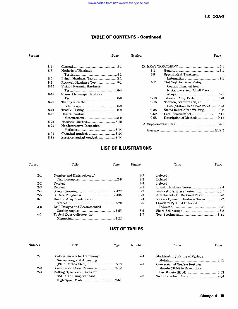
TABLE OF CONTENTS
Section Page Section Page
I INTRODUCTION. . . . . . . . . . . . . . . . . . . . . . . . . . 1-11-1 PURPOSE . . . . . . . . . . . . . . . . . . . . . . . . 1-1
II FERROUS (STEEL) ALLOYS . . . . . . . . . . . . . . . 2-12-1 Classification. . . . . . . . . . . . . . . . . . . . . . 2-12-2 SAE Numbering System . . . . . . . . . . . . . 2-12-4 Carbon Steels . . . . . . . . . . . . . . . . . . . . . 2-12-7 Nickel Steels . . . . . . . . . . . . . . . . . . . . . . 2-22-8 Chromium Steels. . . . . . . . . . . . . . . . . . . 2-22-9 Chromium-Nickel Steels. . . . . . . . . . . . . 2-22-11 Chrome-Vanadium Steels . . . . . . . . . . . . 2-32-12 Chrome Molybdenum Steels. . . . . . . . . . 2-32-13 Principles of Heat Treatment of
Steels . . . . . . . . . . . . . . . . . . . . . . . . . . 2-32-14 Hardening . . . . . . . . . . . . . . . . . . . . . . . . 2-32-19 Quenching Procedure . . . . . . . . . . . . . . . 2-42-26 Tempering (Drawing) . . . . . . . . . . . . . . . 2-42-29 Normalizing . . . . . . . . . . . . . . . . . . . . . . 2-52-30 Case Hardening . . . . . . . . . . . . . . . . . . . . 2-52-35 Carburizing . . . . . . . . . . . . . . . . . . . . . . . 2-62-41 Cyaniding . . . . . . . . . . . . . . . . . . . . . . . . 2-72-42 Nitriding . . . . . . . . . . . . . . . . . . . . . . . . . 2-72-43 Heat Treating Equipment . . . . . . . . . . . . 2-72-48 Heat Control, Furnace Temperatures
Survey and Temperature MeasuringEquipment . . . . . . . . . . . . . . . . . . . . . . 2-8
2-53 Furnace Control InstrumentsAccuracy . . . . . . . . . . . . . . . . . . . . . . . 2-8
2-55 Salt Bath Control. . . . . . . . . . . . . . . . . . 2-102-58 Quenching Tanks and Liquids . . . . . . . 2-102-60 Heat Treating Procedures . . . . . . . . . . . 2-102-68 Hardness Testing. . . . . . . . . . . . . . . . . . 2-112-73 Specification Cross Reference . . . . . . . 2-112-74 General Heat Treating Temperatures,
Composition (Chemical) andCharacteristics of Various Steel andSteel Alloys . . . . . . . . . . . . . . . . . . . . 2-35
2-75 Machining of Steels (General) . . . . . . . 2-602-81 Machining Corrosion Resisting
Steel. . . . . . . . . . . . . . . . . . . . . . . . . . 2-652-117 Deleted2-128 Deleted2-131 Deleted2-135 Deleted2-147 Deleted2-152 Deleted2-168 Deleted2-184 Deleted2-186 Deleted2-195 Deleted2-199 Deleted
2-200 Deleted2-201 Deleted2-202 Deleted2-203 Deleted2-216 Deleted2-234 Fabrication of Ferrous Alloys . . . . . . . 2-1212-292 Steel Surface Finishes . . . . . . . . . . . . . 2-130
III ALUMINUM ALLOYS . . . . . . . . . . . . . . . . . . . . . 3-13-1 Classification. . . . . . . . . . . . . . . . . . . . . . 3-13-4 Commercial and Military
Designations . . . . . . . . . . . . . . . . . . . . 3-13-8 Mechanical Properties. . . . . . . . . . . . . . . 3-23-16 Physical Properties . . . . . . . . . . . . . . . . 3-173-17 Heat Treatment of Aluminum
Alloys . . . . . . . . . . . . . . . . . . . . . . . . 3-173-51 Heat Treatment . . . . . . . . . . . . . . . . . . . 3-243-56 Heat Treating Equipment . . . . . . . . . . . 3-243-70 Fabrication . . . . . . . . . . . . . . . . . . . . . . 3-283-73 Forming Sheet Metal. . . . . . . . . . . . . . . 3-283-96 Deleted3-97 Deleted3-118 Deleted3-123 Deleted3-131 Deleted3-145 Deleted3-154 Deleted3-175 Machining . . . . . . . . . . . . . . . . . . . . . . . 3-453-179 Cutting Tools for Machining
Aluminum . . . . . . . . . . . . . . . . . . . . . 3-453-180 Turning . . . . . . . . . . . . . . . . . . . . . . . . . 3-463-183 Milling-Aluminum . . . . . . . . . . . . . . . . 3-463-189 Shaping and Planing . . . . . . . . . . . . . . . 3-493-195 Tapping . . . . . . . . . . . . . . . . . . . . . . . . . 3-563-198 Filing . . . . . . . . . . . . . . . . . . . . . . . . . . . 3-563-202 Reaming . . . . . . . . . . . . . . . . . . . . . . . . 3-573-204 Sawing. . . . . . . . . . . . . . . . . . . . . . . . . . 3-573-210 Grinding . . . . . . . . . . . . . . . . . . . . . . . . 3-583-216 Polishing . . . . . . . . . . . . . . . . . . . . . . . . 3-583-218 Roughing. . . . . . . . . . . . . . . . . . . . . . . . 3-583-219 Greasing or Oiling. . . . . . . . . . . . . . . . . 3-583-221 Buffing . . . . . . . . . . . . . . . . . . . . . . . . . 3-593-223 Hardness Testing. . . . . . . . . . . . . . . . . . 3-593-226 Non-Destructive Testing/Inspection . . . 3-593-228 Anodizing Process for Inspection of
Aluminum Alloy Parts . . . . . . . . . . . 3-593-231 Aluminum Alloy Effects on Scratches
on Clad Aluminum Alloy . . . . . . . . . 3-593-233 Allowable Defects. . . . . . . . . . . . . . . . . 3-593-234 Harmful Scratches. . . . . . . . . . . . . . . . . 3-60
Downloaded from http://www.everyspec.com
TO 1-1A-9
TABLE OF CONTENTS - Continued
Section Page Section Page
3-241 Disposition of ScratchedSheets/Parts . . . . . . . . . . . . . . . . . . . . 3-60
3-242 Cleaning of Aluminum Alloy Sheet(Stock). . . . . . . . . . . . . . . . . . . . . . . . 3-60
IV MAGNESIUM ALLOYS . . . . . . . . . . . . . . . . . . . . 4-14-1 Classification. . . . . . . . . . . . . . . . . . . . . . 4-14-4 Definitions. . . . . . . . . . . . . . . . . . . . . . . . 4-14-13 Safety Requirements for Handling and
Fabrication of Magnesium Alloys . . . 4-24-19 Safety Precautions for All Alloys
(Including Fire Hazards) . . . . . . . . . . . 4-34-22 Grinding and Polishing Safety
Practices . . . . . . . . . . . . . . . . . . . . . . 4-144-24 Deleted4-25 Heat Treating Safety Practices . . . . . . . 4-154-27 Identification of Alloy. . . . . . . . . . . . . . 4-164-29 Heat Treating Magnesium Alloys-
General . . . . . . . . . . . . . . . . . . . . . . . 4-164-45 Alloy General Characteristic
Information . . . . . . . . . . . . . . . . . . . . 4-194-47 Deleted4-77 Deleted4-78 Deleted4-79 Deleted4-82 Deleted4-93 Deleted
V TITANIUM AND TITANIUM ALLOYS . . . . . . . 5-15-1 Classification. . . . . . . . . . . . . . . . . . . . . . 5-15-4 General . . . . . . . . . . . . . . . . . . . . . . . . . . 5-15-5 Military and Commercial
Designations . . . . . . . . . . . . . . . . . . . . 5-15-6 Physical Properties . . . . . . . . . . . . . . . . . 5-15-7 Mechanical Properties. . . . . . . . . . . . . . . 5-15-10 Methods of Identification . . . . . . . . . . . . 5-15-11 Hardness Testing. . . . . . . . . . . . . . . . . . . 5-15-12 Tensile Testing . . . . . . . . . . . . . . . . . . . . 5-15-13 Non-Destructive Testing. . . . . . . . . . . . . 5-15-14 Fire Damage . . . . . . . . . . . . . . . . . . . . . . 5-65-15 Heat Treatment-General . . . . . . . . . . . . . 5-65-22 Hydrogen Embrittlement . . . . . . . . . . . . 5-85-25 Fabrication . . . . . . . . . . . . . . . . . . . . . . 5-115-26 Forming Sheet Metal-General. . . . . . . . 5-115-28 Draw Forming. . . . . . . . . . . . . . . . . . . . 5-115-29 Hydraulic Press Forming . . . . . . . . . . . 5-115-32 Stretch Forming . . . . . . . . . . . . . . . . . . 5-115-33 Drop-Hammer Forming . . . . . . . . . . . . 5-115-34 Joggling. . . . . . . . . . . . . . . . . . . . . . . . . 5-125-35 Blanking and Shearing . . . . . . . . . . . . . 5-12
5-37 Deleted5-38 Deleted5-39 Deleted5-40 Deleted5-42 Deleted5-43 Deleted5-45 Deleted5-47 Soldering . . . . . . . . . . . . . . . . . . . . . . . . 5-155-48 Riveting. . . . . . . . . . . . . . . . . . . . . . . . . 5-155-51 Machining and Grinding. . . . . . . . . . . . 5-175-52 Machining . . . . . . . . . . . . . . . . . . . . . . . 5-175-54 Turning . . . . . . . . . . . . . . . . . . . . . . . . . 5-175-57 Milling . . . . . . . . . . . . . . . . . . . . . . . . . 5-175-63 Drilling . . . . . . . . . . . . . . . . . . . . . . . . . 5-175-66 Tapping . . . . . . . . . . . . . . . . . . . . . . . . . 5-195-69 Reaming . . . . . . . . . . . . . . . . . . . . . . . . 5-195-70 Grinding . . . . . . . . . . . . . . . . . . . . . . . . 5-19
VI COPPER AND COPPER BASE ALLOYS . . . . . . 6-16-1 Copper and Copper Base Alloys. . . . . . . 6-16-3 Copper Alloying Elements . . . . . . . . . . . 6-16-5 Heat Treatment and Not Working
Temperature of Copper Alloys . . . . . . 6-16-7 Stress Relief of Copper Alloys . . . . . . . . 6-16-9 Machining Copper and Copper
Alloys . . . . . . . . . . . . . . . . . . . . . . . . . 6-16-10 Wrought-Copper-Beryllium Alloys . . . . 6-16-12 Heat Treating Procedures and
Equipment Requirements . . . . . . . . . 6-106-15 Solution Heat Treatment Copper-
Beryllium . . . . . . . . . . . . . . . . . . . . . 6-116-17 Precipitation or Age Hardening . . . . . . 6-11
VII TOOL STEELS. . . . . . . . . . . . . . . . . . . . . . . . . . . . 7-17-1 General . . . . . . . . . . . . . . . . . . . . . . . . . . 7-17-4 Alloying Elements in Tool Steels . . . . . . 7-17-5 Specifications . . . . . . . . . . . . . . . . . . . . . 7-17-6 Class Designations . . . . . . . . . . . . . . . . . 7-57-7 Applications of Tool Steels. . . . . . . . . . . 7-57-9 Selection of Material for a Cutting
Tool. . . . . . . . . . . . . . . . . . . . . . . . . . . 7-57-16 Heat Treat Data . . . . . . . . . . . . . . . . . . . . 7-67-18 Distortion in Tool Steels . . . . . . . . . . . . . 7-67-19 Deleted7-21 Deleted7-22 Deleted7-23 Deleted
VIII TESTING AND INSPECTION, HARDNESSTESTING . . . . . . . . . . . . . . . . . . . . . . . . . . . . . . 8-1
ii Change 7
Downloaded from http://www.everyspec.com
T.O. 1-IA-9
TABLE OF CONTENTS Continued
Section Page
8-1 General 8-18-3 Methods of Hardness
Testing 8-18-5 Brinell Hardness Test 8-18-8 Rockwell Hardness Test 8-18-15 Vickers Pyramid Hardness
Test 8-48-18 Shore Scleroscope Hardness
Test 8-88-20 Testing with the
Scleroscope 8-98-21 Tensile Testing 8-98-22 Decarburization
Measurement 8-98-24 Hardness Method 8-108-27 Nondestructive Inspection
Methods 8-148-33 Chemical Analysis 8-148-34 Spectrochemical Analysis 8-14
Section Page
IX HEAT TREATMENT 9-19-1 General 9-19-9 Special Heat Treatment
Information 9-19-11 Tint Test for Determining
Coating Removal fromNickel Base and Cobalt BaseAlloys 9-1
9-13 Titanium Alloy Parts 9-39-16 Solution, Stabilization, or
Precipitation Heat Treatment 9-39-38 Stress-Relief After Welding 9-89-59 Local Stress-Relief 9-119-68 Description of Methods 9-11
A Supplemental Data ..................................................A-1
Glossary GLS 1
LIST OF ILLUSTRATIONS
Figure
2-1
2-22-32-42-53-1
3-2
4-1
Title Page Figure
Number and Distribution ofThermocouples 2-9
DeletedDeletedStretch Forming 2-127Surface Roughness 2-135Head to Alloy IdentificationMethod ......................................................3-20
Drill Designs and RecommendedCutting Angles 3-55
Typical Dust Collectors forMagnesium 4-22
Title Page
4-2 Deleted4-3 Deleted4-4 Deleted8-1 Brinell Hardness Tester 8-48-2 Rockwell Hardness Tester 8-58-3 Attachments for Rockwell Tester 8-68-4 Vickers Pyramid Hardness Tester 8-78-5 Standard Pyramid Diamond
Indentor 8-88-6 Shore Scleroscope 8-88-7 Test Specimens 8-11
LIST OF TABLES
Number
2-1
2-22-3
Title Page
Soaking Periods for HardeningNormalizing and Annealing(Plain Carbon Steel) 2-10
Specification Cross Reference 2-12Cutting Speeds and Feeds forSAE 1112 Using StandardHigh Speed Tools 2-61
Number Title Page
2-4 Machinability Rating of VariousMetals 2-61
2-5 Conversion of Surface Feet PerMinute (SFM) to RevolutionsPer Minute (RPM) 2-63
2-6 Tool Correction Chart 2-64
Change 4 iii
Downloaded from http://www.everyspec.com
TO 1-1A-9
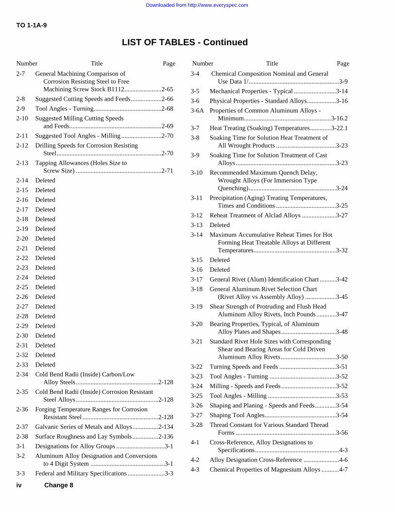
LIST OF TABLES - Continued
Number Title Page Number Title Page
2-7 General Machining Comparison ofCorrosion Resisting Steel to FreeMachining Screw Stock B1112.......................2-65
2-8 Suggested Cutting Speeds and Feeds...................2-66
2-9 Tool Angles - Turning..........................................2-68
2-10 Suggested Milling Cutting Speedsand Feeds.........................................................2-69
2-11 Suggested Tool Angles - Milling .........................2-70
2-12 Drilling Speeds for Corrosion ResistingSteel.................................................................2-70
2-13 Tapping Allowances (Holes Size toScrew Size) .....................................................2-71
2-14 Deleted
2-15 Deleted
2-16 Deleted
2-17 Deleted
2-18 Deleted
2-19 Deleted
2-20 Deleted
2-21 Deleted
2-22 Deleted
2-23 Deleted
2-24 Deleted
2-25 Deleted
2-26 Deleted
2-27 Deleted
2-28 Deleted
2-29 Deleted
2-30 Deleted
2-31 Deleted
2-32 Deleted
2-33 Deleted
2-34 Cold Bend Radii (Inside) Carbon/LowAlloy Steels ...................................................2-128
2-35 Cold Bend Radii (Inside) Corrosion ResistantSteel Alloys ...................................................2-128
2-36 Forging Temperature Ranges for CorrosionResistant Steel ...............................................2-128
2-37 Galvanic Series of Metals and Alloys................2-134
2-38 Surface Roughness and Lay Symbols................2-136
3-1 Designations for Alloy Groups ..............................3-1
3-2 Aluminum Alloy Designation and Conversionsto 4 Digit System ..............................................3-1
3-3 Federal and Military Specifications .......................3-3
3-4 Chemical Composition Nominal and GeneralUse Data 1/........................................................3-9
3-5 Mechanical Properties - Typical ..........................3-14
3-6 Physical Properties - Standard Alloys..................3-16
3-6A Properties of Common Aluminum Alloys -Minimum......................................................3-16.2
3-7 Heat Treating (Soaking) Temperatures.............3-22.1
3-8 Soaking Time for Solution Heat Treatment ofAll Wrought Products .....................................3-23
3-9 Soaking Time for Solution Treatment of CastAlloys ..............................................................3-23
3-10 Recommended Maximum Quench Delay,Wrought Alloys (For Immersion TypeQuenching)......................................................3-24
3-11 Precipitation (Aging) Treating Temperatures,Times and Conditions .....................................3-25
3-12 Reheat Treatment of Alclad Alloys .....................3-27
3-13 Deleted
3-14 Maximum Accumulative Reheat Times for HotForming Heat Treatable Alloys at DifferentTemperatures...................................................3-32
3-15 Deleted
3-16 Deleted
3-17 General Rivet (Alum) Identification Chart ..........3-42
3-18 General Aluminum Rivet Selection Chart(Rivet Alloy vs Assembly Alloy) ...................3-45
3-19 Shear Strength of Protruding and Flush HeadAluminum Alloy Rivets, Inch Pounds ............3-47
3-20 Bearing Properties, Typical, of AluminumAlloy Plates and Shapes..................................3-48
3-21 Standard Rivet Hole Sizes with CorrespondingShear and Bearing Areas for Cold DrivenAluminum Alloy Rivets..................................3-50
3-22 Turning Speeds and Feeds ...................................3-51
3-23 Tool Angles - Turning .........................................3-52
3-24 Milling - Speeds and Feeds..................................3-52
3-25 Tool Angles - Milling ..........................................3-53
3-26 Shaping and Planing - Speeds and Feeds.............3-54
3-27 Shaping Tool Angles............................................3-54
3-28 Thread Constant for Various Standard ThreadForms ..............................................................3-56
4-1 Cross-Reference, Alloy Designations toSpecifications ....................................................4-3
4-2 Alloy Designation Cross-Reference ......................4-6
4-3 Chemical Properties of Magnesium Alloys ...........4-7
iv Change 8
Downloaded from http://www.everyspec.com
T.O. 1-1A-9
LIST OF TABLES Continued
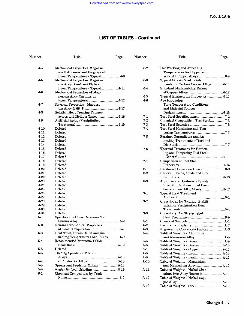
Number Title Page Number
4-4
4-5
Mechanical Properties Magnesi- 6-2
um Extrusions and Forgings atRoom Temperature Typical .....................4-9
Mechanical Properties Magnesi- 6-3
um Alloy Sheet and Plate atRoom Temperature Typical 4-11 6-4
4-6 Mechanical Properties of Mag-nesium Alloy Castings at 6-5Room Temperatures .................................4-12 6-6
4-7 Physical Properties Magnesi-um Alloy @68F......................................4-13
4-8 Solution Heat Treating Temper-atures and Holding Times 4-18 7-1
4-9 Artificial Aging (Precipitation 7-2Treatment) 4-19 7-3
4-10 Deleted 7-44-11 Deleted4-12 Deleted4-13 Deleted4-14 Deleted4-15 Deleted4-16 Deleted4-17 Deleted4-18 Deleted4-19 Deleted
7-5
7-6
7-7
4-20 Deleted 8-14-21 Deleted 8-24-22 Deleted4-23 Deleted4-24 Deleted4-25 Deleted4-26 Deleted4-27 Deleted4-28 Deleted4-29 Deleted4-30 Deleted4-31 Deleted5-1 Specification Cross Reference Ti-
8-3
9-1
9-2
9-3
Title Page
Hot Working and AnnealingTemperatures for Copper andWrought Copper Alloys 6-9
Typical Stress-Relief Treat-ments for Certain Copper Alloys ............6-11
Standard Machinability Ratingof Copper Alloys 6-12
Typical Engineering Properties 6-13Age HardeningTime-Temperature Conditionsand Material TemperDesignations 6-13
Tool Steel Specifications 7-2Chemical Composition, Tool Steel 7-3Tool Steel Selection 7-5Tool Steel Hardening and Tem-pering Temperatures .................................7-5
Forging, Normalizing and An-nealing Treatments of Tool andDie Steels 7-7
Thermal Treatment for Harden-ing and Tempering Tool SteelGeneral 7-11
Comparison of Tool SteelProperties 7-14
Hardness Conversion Chart 8-3Rockwell Scales, Loads and Pre-
fix Letters 8-10Approximate Hardness Tensile
Strength Relationship of Car-bon and Low Alloy Steels 8-12
Typical Heat TreatmentApplication 9-1
Cross-Index for Solution, Stabili-zation or Precipitation HeatTreatments .................................................9-4
Cross-Index for Stress-ReliefHeat Treatments 9-9
Chemical Symbols .........................................A-1Decimal Equivalents .....................................A-2Engineering Conversion Factors ..................A-6Table of Weights Aluminumand Aluminum Alloy A-8
Table of Weights Brass...............................A-9Table of Weights Bronze ..........................A-10Table of Weights Copper ..........................A-11Table of Weights Iron ...............................A-12Table of Weights Lead ..............................A-12Table of Weights Magnesiumand Magnesium Alloy A-12
Table of Weights Nickel Chro-mium Iron Alloy (Inconel) A-13
Table of Weights Nickel Cop-per Alloy A-13
tanium Alloy 5-2 A-15-2 Nominal Mechanical Properties A-2
at Room Temperature 5-7 A-35-3 Heat Treat, Stress Relief and An- A-4
nealing Temperatures and Times .............5-95-4 Recommended Minimum CCLD A-5
Bend Radii 5-12 A-65-5 Deleted A-75-6 Turning Speeds for Titanium A-8
Alloys 5-18 A-95-7 Tool Angles for Alloys 5-18 A-105-8 Speeds and Feeds for Milling 5-185-9 Angles for Tool Grinding 5-19 A-116-1 Chemical Composition by Trade
Name 6-2 A-12
A-13 Table of Weights Steel ..............................A-13
Change 4 v
Downloaded from http://www.everyspec.com
T.O. 1-1A-9
LIST OF TABLES Continued
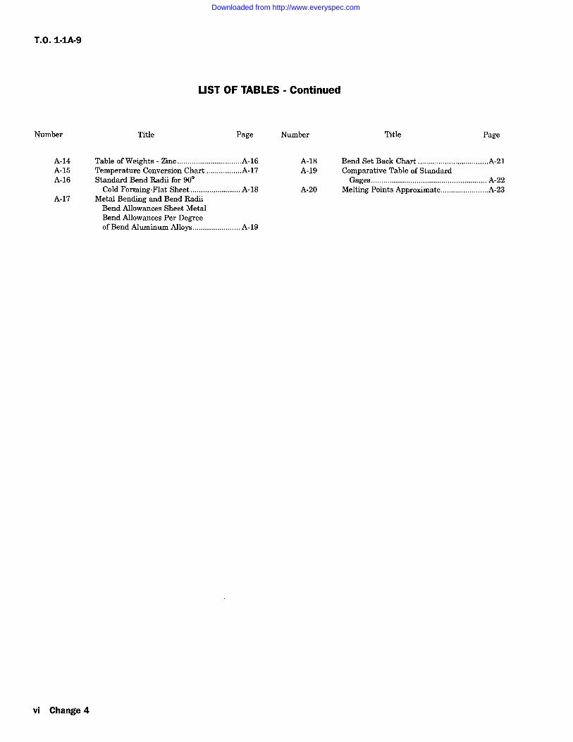
Number Title Page Number Title Page
A-14 Table of Weights Zinc ...............................A-16 A-18 Bend Set Back Chart ..................................A-21A-15 Temperature Conversion Chart .................A-17 A-19 Comparative Table of StandardA-16 Standard Bend Radii for 90 Gages A-22
Cold Forming-Flat Sheet... A-18 A-20 Melting Points Approximate.......................A-23A-17 Metal Bending and Bend Radii
Bend Allowances Sheet MetalBend Allowances Per Degreeof Bend Aluminum Alloys A-19
vi Change 4
Downloaded from http://www.everyspec.com
T.O. 1-1A-9
SECTION
INTRODUCTION
1-1. PURPOSE.
1-2. This is one of a series of technical or engi-neering technical manuals prepared to assist per-sonnel engaged in the maintenance and repair ofAerospace Weapon Systems and Supporting Equip-ment (AGE). Army Personnel: Wherever the textof this manual refers to other technical orders(T.O.'s) for supporting information, refer to compa-rable Army documents.
1-3. This technical manual provides precise dataon specific metals to assist in selection, usage andprocessing for fabrication and repair. It includessuch data as specification cross reference;approved designation system for alloys and tem-
pers; temperatures and other controls for heattreatments; mechanical and physical propertiesprocessing instructions for basic corrosion preven-tion; forming characteristics; and other informa-tion required for general aerospace weapon systemrepair. Procedures for general foundry practice,sand control, gating and risering of both ferrousand non-ferrous castings may be obtained fromavailable commercial handbooks and/or publica-tions. Due to the many types, grades, deversifieduses and new developments of metal products, it
may not include all data required in someinstances and further study and citation of thisdata will be required. If a requirement exists forinformation not included, a request for assistanceshould be made to WR-ALC, LEM.
1-4. The information/instruction containedherein are for general use. If a conflict existsbetween this technical manual and the specifictechnical manual(s) or other approved data for a
particular weapon, end item, equipment, etc., thedata applicable to the specific item(s) will governin all cases.
1-5. The use of "shall", "will", "should" and"may" in this technical manual is as follows:
a. Whenever the word "shall" appears, it shallbe interpreted to mean that the requirements arebinding.
b. The words "will", "should" and "may", shallbe interpreted as nonmandatory provisions.
c. The word "will" is used to express declara-tion of purpose.
d. The word "should" is used to express non-mandatory desired or preferred method ofaccomplishment.
e. The word "may" is used to express anacceptable or suggested means of accomplishment.1-6. Deleted
1-7. WELDING. Information on welding aero-
space metals is contained in NAVAIR 01-1A-34,T.O. 00-25-252, T.C. 9-238.
I
Change 1 1-1/(1-2 blank)
Downloaded from http://www.everyspec.com

Downloaded from http://www.everyspec.com
T.O. 1-IA-9
SECTION II
FERROUS (STEEL) ALLOYS
2-1. CLASSIFICATION.
2-2. SAE NUMBERING SYSTEM. A numeralindex system is used to identify the compositionsof the SAE steels, which makes it possible to usenumerals that are partially descriptive of the com-
position of material covered by such numbers. Thefirst digit indicates the type to which the steelbelongs; for example "1" indicates a carbon steel;"2" a nickel steel; and "3" a nickel chromium steel.In the case of the simple alloy steels, the seconddigit generally indicates the approximate percent-age of the predominant alloying element. Usuallythe last two or three digits indicate the approxi-mate average carbon content in "points" or hun-dredths of percent. Thus "2340" indicates anickel steel of approximately 3 percent nickel (3.25to 3.75) and 0.40 percent carbon (0.38 to 0.43). Insome instances, in order to avoid oonfusion, it hasbeen found necessary to depart from this system ofidentifying the approximate alloy composition of asteel by varying the second and third digits of thenumber. An instance of such departure is thesteel numbers selected for several of the corrosion--and heat resisting alloys.2-3. The basic numerals for the various types ofSAE steel are:
TYPE OF STEEL NUMERALS(AND DIGITS)
Carbon SteelsPlain CarbonFree Cutting (Screw Stock)
Manganese Steels
Nickel Chromium Steels1.25 Percent Nickel; 0.65percent ChromiumCorrosion and Heat Resisting
Molybdenum Steels0.25 Percent Molybdenum
TYPE OF STEEL NUMERALS(AND DIGITS)
Nickel-Chromium-MolybdenumSteels
1.80% nickel; 0.50 and 0.80%Chromium; 0.25% Molybdenum 43xx0.55% Nickel; 0.50 and 0.65%Chromium; 0.20% Molybdenum 86xx0.55% Nickel; 0.50 Chromium0.25% Molybdenum3.25% Nickel; 1.20 Chromium0.12% Molybdenum
Nickel-Molybdenum Steels1.75 Percent Nickel; 0.25percent Molybdenum3.50 Percent Nickel; 0.25percent Molybdenum
87xx
93xx
46xx
48xx
Chromium Steels 5xxxLow Chromium 50xxMedium Chromium 51xxxHigh Chromium 52xxxCorrosion and HeatResisting 514xx and
515xx
Chromium-Vanadium Steel0.80-1.00 percent Chromium,0.10-0.15 Vanadium
6xxx
61xx
Silicon Manganese Steels 9xxxA Percent Silicon 92xxLow Alloy, High Tensile 950Boron Intensified xxBxxLeaded Steels xxLxx
lxxxOxxllxx
13xx
3xxx
2-4. CARBON STEELS. Steel containing car-bon in percentages ranging from 0.10 to 0.30 per-cent is classed as low carbon steel. The equivalentSAE numbers range from 1010 to 1030. Steels ofthis grade are used for the manufacture of articlessuch as safety wire, certain nuts, cable bushing,etc. This steel in sheet form is used for secondarystructural parts and clamps and in tubular formfor moderately stressed structural parts.2-5. Steel containing carbon in percentages rang-ing from 0.30 to 0.50 percent is classed as mediumcarbon steel. This steel is especially adaptable formachining, forging, and where surface hardness is
31xx303xx
4xxx40xx
2-1
Downloaded from http://www.everyspec.com
TO 1-1 A-9
important. Certain rod ends, light forgings, and parts such as
Woodruff keys, are made from SAE 1035 steel.
2-6. Steel containing carbon in percentage ranging from 0.50to 1.05 percent is classed as high carbon steel. The addition ofother elements in varying quantities adds to the hardness ofthis steel. In the fully heat-treated condition it is very hard andwill withstand high shear and wear, but little deformation. Ithas limited use in aircraft construction. SAE 1095 in sheetform is used for making flat springs and in wire form formaking coil springs.
2-7. NICKEL STEELS. The various nickel steels are pro-duced by combinining nickel with carbon steel. Some benefitsderived from the use of nickel as an alloy in steel are as
follows:
a. Lowers the percentage of carbon that is necessary forhardening. The lowering ofthe carbon content makes the steel
more ductile and less susceptible to uneven stress.
b. Lowers the critical temperature ranges (heating andcooling) and permits the use of lower heating temperatures forhardening.
c. Hardening of nickel alloy steels at moderate rates ofcooling has the advantage of lowering the temperature gradi-ents, reducing internal stress/warpage and permits deeper/more uniform hardening.
d. The low heat treating temperatures required, reduces thedanger of overheating, excessive grain growth and the conse-
quent development of brittleness.
e. The characteristics depth hardening from the addition ofnickel to steel as an alloy results in good mechanical proper-ties after quenching and tempering. At a given strength(except for very thin sections/parts) the nickel steels providegreatly improve elastic properties, impact resistance andtoughness.
2-8. CHROMIUM STEELS. Chromium steel is high inhardness, strength, and corrosion resistant properties. SAE51335 steel is particularly adaptable for heat-treated forgingswhich require greater toughness and strength than may beobtained in plain carbon steel. It may be used for such articles
as the balls and rollers of anti-friction bearings.
2-9. CHROMIUM-NICKEL STEELS. Chromium and nickelin various proportions mixed with steel form the chrome-nickel steels. The general proportion is about two and one-halftimes as much nickel as chromium. For all ordinary steels inthis group the chromium content ranges from 0.45 to 1.25percent, while the nickel content ranges from to 2 percent.
Both nickel and chromium influence the properties of steel;nickel toughens it, while chromium hardens it. Chrome-nickelsteel is used for machined and forged parts requiring strength,ductility, toughness and shock resistance. Parts such as crank-shafts and connecting rods are made of SAE 3140 steel.
2-10. Chrome-nickel steel containing approximately 18 per-cent chromium and 8 percent nickel is known as corrosion-resistant steel. It is usually identified as aisi types 301, 302303, 304, 304L, 309, 316, 316L, 321, 347, 347F or Se, etc.,however; the basic 18-8 chrome-nickel steel is type 302. Theother grades/types have been modified by changing or addingalloying elements to that contained in the basic alloy. Thealloys are varied to obtain the required mechanical propertiesfor some specific purpose such as improving corrosion resis-tance or forming machining, welding characteristics, etc. Thefollowing are examples of variations:
a. 301-Chromium and Nickel (approximate 0.5 Nickel) islowered to increase response to cold working.
b. 302-Basic Type 18 Chromium 8 Nickel.
c. 303-Sulfur(s) or Selenium (se) added for improvedmachining characteristics.
d. 304-Carbon (c) lowered to reduce susceptibility to car-
bide precipitation. This alloy is still subject to carbide pre-ceipitation from exposure to temperatures 800-1500F rangeand this shall be considered when it is selected for a specificapplication.
e. 304L-Carbon (c) lowered for welding applications.
f. 309-Cr and Ni higher for additional corrosion and scaleresistance.
g. 316-Molybdenum (Mo) added to improve corrosionresistance and strength.
h. 316L-C- lowered for welding applications.
i. 321-Titanium (Ti) added to reduce/avoid carbide precip-itation (stabilized grade).
j. 347-Columbium (Cb), Tantalum (Ta)- Added to reduce/avoid carbide precipitation (stabilized grade).
k. 347F or Se Sulfur (s) or Selenium (Se) added toimprove machinability.
The chrome-nickel steels are used for a variety of applicationson aircraft and missiles. In plate and sheet form it is used forfirewalls, surface skin,
2-2 Change 5
Downloaded from http://www.everyspec.com
exhaust stacks, heater ducts, gun wells, ammuni-tion chutes, clamps, heat shields/def lectors, fair-ing, stiffeners, brackets, shims, etc. In bar androd it is used to fabricate various fittings, bolts,studs, screws, nuts, couplings, flanges, valvestems/seats, turn-buckles, etc. In wire form it isused for safety wire, cable, rivets, hinge pins,screens/screening and other miscellaneous items.
2-11. CHROME-VANADIUM STEELS. Thevanadium content of this steel is approximately0.18 percent and the chromium content approxi-mately 1.00 percent. Chrome-vanadium steelswhen heat-treated have excellent properties suchas strength, toughness, and resistance to wear andfatigue. A special grade of this steel in sheet formcan be cold-formed into intricate shapes. It can befolded and flattened without signs of breaking orfailure. Chrome-vanadium steel with mediumhigh carbon content (SAE 6150) is used to makesprings. Chrome-vanadium steel with high carboncontent (SAE 6195) is used for ball and rollerbearings.
2-12. CHROME MOLYBDENUM STEELS.Molybdenum in small percentage is used in combi-nation with chromium to form chrome-molybde-num steel; this steel has important applications inaircraft. Molybdenum is a strong alloying element,only 0.15 to 0.25percent being used in the chrome-molybdenum steels; the chromium content variesfrom 0.80 to 1.10 percent. Molybdenum is verysimiliar to tungsten in its effect on steel. In some
instances it is used to replace tungsten in cuttingtools, however; the heat treat characteristic varies.The addition of up to 1% molybdenum gives steel ahigher tensile strength and elastic limit with onlya slight reduction in ductility. They are especiallyadaptable for welding and for this reason are usedprincipally for welded structural parts and assem-blies. Parts fabricated from 4130, are used exten-sively in the construction of aircraft, missiles, andmiscellaneous GSE equipment. The 4130 alloy isused for parts such as engine mounts (recipro-cating), nuts, bolts, gear structures, support brack-ets for accessories, etc.
2-13. PRINCIPLES OF HEAT TREATMENT OFSTEELS.
2-14. HARDENING. At ordinary temperatures,the carbon content of steel exists in the form ofparticles of iron carbide scattered throughout theiron matrix; the nature of these carbide particles,i.e., their number, size, and distribution, deter-mines the hardness and strength of the steel. Atelevated temperatures, the carbon is dissolved inthe iron matrix and the carbide-particles appearonly after the steel has cooled through its "criticaltemperature" (see paragraph 2-15). If the rate of
T.O. 1-IA-9
cooling is slow, the carbide particles are relativelycoarse and few; in this condition the steel is soft.If the cooling is rapid, as be quenching in oil or
water, the carbon precipitates as a cloud of veryfine carbide particles, which condition is associ-ated with high hardness of the steel.
2-15. At elevated temperatures, the iron matrixexists in a form called "austenite" which is capableof dissolving carbon in solid solution. At ordinarytemperatures the iron exists as "ferrite", in whichcarbon is relatively insoluble and precipitates; asdescribed in the preceding paragraph, in the formof carbide particles. The temperature at whichthis change from austenite to ferrite begins to
occur on cooling is called the "upper critical tem-perature" of the steel, and varies with the carboncontent; up to approximately 0.85 percent carbon,the upper critical temperature is lowered withincreasing carbon content; from 0.85 to 1.70 per-cent carbon the upper critical temperature israised with increasing carbon content. Steel thathas been heated to its upper critical point willharden completely if rapidly quenched; however, inpractice it is necessary to exceed this temperatureby/from approximately 28 to 56C (50 to 100F)to insure thorough heating of the inside of thepiece. If the upper critical temperature isexceeded too much, an unsatisfactory coarse grainsize will be developed in the hardened steel.
2-16. Successful hardening of steel will largelydepend upon the following factors after steel hasbeen selected which has harden ability desires:
a. Control over the rate of heating, specifi-cally to prevent cracking of thick and irregularsections.
b. Thorough and uniform heating through sec-tions to the correct hardening temperatures.
c. Control of furnace atmosphere, in the caseof certain steel parts, to prevent scaling anddecarburization.
d. Correct heat capacity, viscosity, and tem-perature of quenching medium to harden ade-quately and to avoid cracks.
e. In addition to the preceding factors, thethickness of the section controls the depth of hard-ness for a given steel composition. Very thick sec-tions may not harden through because of the lowrate of cooling at the center.
2-17. When heating steel, the temperatureshould be determined by the use of accurateinstruments. At times, however, such instrumentsare not available, and in such cases, the tempera-ture of the steel may be judged approximately byits color. The accuracy with which temperatures
2-3
Downloaded from http://www.everyspec.com
T.O. 1-IA-9
may be judged by color depends on the experienceof the workman, the light in which the work isbeing done, the character of the scale on the steel,the amount of radiated light within the furnace,and the emissivity or tendency of steel to radiateor emit light.2-18. A number of liquids may be used forquenching steel. Both the medium and the form ofthe bath depend largely on the nature of the workto be cooled. It is important that a sufficientquantity of the medium be provided to allow themetal to be quenched without causing an apprecia-ble change in the temperature of the bath. This isparticularly important where many articles are tobe quenched in succession.
NOTE
Aerators may be used in the QuenchTanks to help dissipate the vaporbarrier.
2-19. QUENCHING PROCEDURE. The ten-dency of steel to warp and crack during thequenching process is difficult to overcome, and isdue to the fact that certain parts of the article coolmore rapidly than others. Whenever the rate ofcooling is not uniform, internal stresses are set upon the metal which may result in warpage orcracking, depending on the severity of the stresses.Irregularly shaped parts are particularly suscepti-ble to these conditions although parts of uniformsection size are often affected in a similar manner.Operations such as forging and machining may set
up internal stresses in steel parts and it is there-fore advisable to normalize articles before attempt-ing the hardening process. The following recom-mendations will greatly reduce the warpingtendency and should be carefully observed:
a. An article should never be thrown intoquenching media/bath. By permitting it to lie onthe bottom of the bath it is apt to cool faster onthe top side than on the bottom side, thus causingit to warp or crack.
b. The article should be slightly agitated inthe bath to destroy the coating of vapor whichmight prevent it from cooling rapidly. This allowsthe bath to remove the heat of the article rapidlyby conduction and convection.
c. An article should be quenched in such a
manner that all parts will be cooled uniformly andwith the least possible distortion. For example, a
gear wheel or shaft should be quenched in a ver-ticle position.
d. Irregularly shaped sections should beimmersed in such a manner that the parts of thegreatest section thickness enters the bath first.
2-20. QUENCHING MEDIUM.
2-21. Oil is much slower in action than water,and the tendency of heated steel to warp or crackwhen quenched may be greatly reduced by its use.Unfortunately, parts made from high carbon steelwill not develop maximum hardness whenquenched in oil unless they are quite thin in cross
section. In aircraft, however, it is generally usedand is recommended in all cases where it will pro-duce the desired degree of hardness.
NOTE
Alloy steels should never be quenchedin water.
2-22. In certain cases water is used in thequenching of steel for the hardening process. Thewater bath should be approximately 18C (65F)as extremely cold water is apt to warp or crack thesteel and water above this temperature will notproduce the required hardness.
2-23. A 10%, salt brine (sodium chloride) solutionis used when higher cooling rates are desired. A10% salt brine solution is made by dissolving 0.89pound of salt per gallon of water.
2-24. For many articles such as milling cuttersand similar tools, a bath of water covered by afilm of oil is occasionally used. When the steel isplunged through this oil film a thin coating willadhere to it, retarding the cooling effect of thewater slightly, thus reducing the tendency to crackdue to contraction.
2-25. STRAIGHTENING OF PARTS WARPEDIN QUENCHING. Warped parts must bestraightened by first heating to below the temper-ing temperature of the article, and then applyingpressure. This pressure should be continued untilthe piece is cooled. It is desirable to retemper thepart after straightening at the straightening tem-perature. No attempt should be made tostraighten hardened steel without heating, regard-less of the number of times it has been previouslyheated, as steel in its hardened condition cannotbe bent or sprung cold with any degree of safety.2-26. TEMPERING (DRAWING). Steel thathas been hardened by rapid cooling from a pointslightly above its critical range is often harderthan necessary and generally too brittle for most
purposes. In addition, it is under severe internalstress. In order to relieve the stresses and reducethe brittleness or restore ductility the metal isalways "tempered". Tempering consists in reheat-ing the steel to a temperature below the criticalrange (usually in the neighborhood of 6001200F). This reheating causes a coalescence andenlargement of the fine carbide particles produced
2-4
Downloaded from http://www.everyspec.com
T.O. 1-1A-9
by drastic quenching, and thus tends to soften thesteel. The desired strength wanted will determinethe tempering temperature. This is accomplishedin the same types of furnaces as are used for hard-ening and annealing. Less refined methods are
sometimes used for tempering small tools.
2-27. As in the case of hardening, temperingtemperatures may be approximately determinedby color. These colors appear only on the surfaceand are due to a thin film of oxide which forms onthe metal after the temperature reaches 232C(450F). In order to see the tempering colors, thesurface must be brightened. A buff stick consistingof a piece of wood with emery cloth attached isordinarily used for this purpose. When temperingby the color method, an open flame of heated ironplate is ordinarily used as the heating medium.Although the color method is convenient, it shouldnot be used unless adequate facilities for determin-ing temperature are not obtainable. Temperingtemperatures can also be determined by the use ofcrayons of known melting point. Such crayons are
commercially available for a wide range of temper-atures under the trade name of "Tempilstiks". Theabove method may be used where exact propertiesafter tempering is not too important such as forblacksmith work. The most desireable method forgeneral aeronautical use, is to determine tempera-tures by hardness checks, and subsequent adjust-ments made as necessary to obtain the propertiesrequired. For recommended tempering tempera-tures see heat treat data for material/compositioninvolved.
2-28. Steel is usually subjected to the annealingprocess for the following purposes:
a. To increase its ductility by reducing hard-ness and brittleness.
b. To refine the crystalline structure and
remove stresses. Steel which has been cold-worked is usually annealed so as to increase itsductility. However, a large amount of cold-drawnwire is used in its cold-worked state when veryhigh yield point and tensile strength are desiredand relatively low ductility is permissible, as inspring wire, piano wire, and wires for rope andcable. Heating to low temperatures, as in solder-ing, will destroy these properties. However, rapidheating will narrow the affected area.
bending, and welding. Normalizing may be accom-plished in furnaces used for annealing. The arti-cles are put in the furnace and heated to a pointapproximately 150 to 225F above the criticaltemperature of the steel. After the parts havebeen held at this temperature for a sufficient timefor the parts to be heated uniformly throughout,they must be removed from the furnace and cooledin still air. Prolonged soaking of the metal at hightemperatures must be avoided, as this practice willcause the grain structure to enlarge. The lengthof time required for the soaking temperature willdepend upon the mass of metal being treated. Theoptimum soaking time is roughly one-quarter hourper inch of diameter or thickness.
2-30. CASE HARDENING. In many instancesit is desirable to produce a hard, wear-resistantsurface or "case" over a strong, tough core. Treat-ment of this kind is known as "case hardening".This treatment may be accomplished in severalways, the principal ways being carburizing, cya-niding, and nitriding.2-31. Flame Hardening/Softening. Surface hard-ening/softening by applying intense heat (such as
that produced by an Oxy-Acetylene flame) can beaccomplished on almost any of the medium carbonor alloys steel, i.e. 1040, 1045, 1137, 1140 etc.The parts are surface hardened, by applying areducing flame (An Oxidizing flame should never
be used) at such a rate, that the surface is rapidlyheated to the proper quenching temperature forthe steel being treated. Following the applicationof the heat, the part is quenched by a spraying ofwater/oil rapidly. The fast quench hardens thesteel to the depth that the hardening temperaturehas penetrated below the surface. The actual hard-ness resulting will depend on the rate of coolingfrom the quenching temperature. In hardening bythis method the shape and size/mass of the partmust be considered. Most operations will requirespecial adapted spray nozzles to apply the quench-ing media, which is usually water. Normally,flame hardening will produce surface hardnesshigher than can be obtained by routine furnaceheating and quenching, because surface can becooled at a faster rate. If a combination of highstrength core and surface is required some of themedium carbon alloy steels can be heat treatedand subsequently surface hardened by the flamemethod.
c. To soften the material so that machining,forming, etc., can be performed.
2-29. NORMALIZING. Although involving aslightly different heat treatment, normalizing maybe classed as a form of annealing. This processalso removes stresses due to machining, forging,
NOTE
This method is not adapted for sur-face hardening of parts for use in crit-ical applications.
2-32. Surface softening is accomplished by heat-ing the surface to just below the temperature
2-5
Downloaded from http://www.everyspec.com
T.O. 1-IA-9
required for hardening and allowing the materialto cool (in air) naturally. This method is some-
times used to soften material that has been hard-ened by frame cutting. Often it is necessary toapply the heat in short intervals to preventexceeding the hardening temperature.
2-33. Induction. Hardening/Heating. The induc-tion method of heating can be used to surfaceharden steels, in a manner similar to that used forflame hardening. The exception is that the heatfor hardening is produced by placing the part in a
magnetic field (electrical) specifically designed forthe purpose. Parts hardened (surface) by thismethod will be limited to capability and size ofloop/coil used to produce the magnetic field.
2-34. In some instances the induction methodcan be used to deep harden; the extent will dependon exposure/dwell time, intensity of the magneticfield, and the size of the part to be treated.
2-35. CARBURIZING. At elevated tempera-tures iron can react with gaseous carbon com-
pounds to form iron carbide. By heating steel,while in contact with a carbon-aceous substance,carbonic gases given off by this material will pene-trate the steel to an amount proportional to thetime and temperature. For example, if mild or
soft steel is heated to 732C (1,350F) in anatmosphere of carbonic gases, it will absorb carbonfrom the gas until a carbon content of approxi-mately 0.80 percent has been attained at the sur-face, this being the saturation point of the steel forthe particular temperature. By increasing theheat to 899C/(1,650F) the same steel will absorbcarbon from the gas until a carbon content ofapproximately 1.1 percent has been attained,which is the saturation point for the increasedtemperature.
2-36. The carburizing process may be applied toboth plain carbon and alloy steels provided theyare within the low carbon range. Specifically, thecarburizing steels are those containing not morethan 0.20 percent carbon. The lower the carboncontent in the steel, the more readily it willabsorb, carbon during the carburizing process.
2-37. The amount of carbon absorbed and thethickness of the case obtained increases with time;however, the carburization progresses more slowlyas the carbon content increases during the process.The length of time required to produce the desireddegree of carburization material used and the tem-perature to which the metal is subjected. It isapparent that, in carburizing, carbon travelsslowly from the outside toward the inside center,and therefore, the proportion of carbon absorbedmust decrease from the outside to the inside.
2-38. Solid, liquid, and gas carburizing methodsare employed.
a. The simplest method of carburizing con-
sists of soaking the parts at an elevated tempera-ture while in contact with solid carbonaceousmaterial such as wood charcoal, bone charcoal andcharred leather.
b. Liquid carburizing consists of immersingthe parts in a liquid salt bath, heated to theproper temperature. The carbon penetrates thesteel as in the solid method producing the desiredcase.
c. Gas carburizing consists of heating theparts in a retort and subjecting them to a carbona-ceous gas such as carbon monoxide or the commonfuel gases. This process is particularly adaptableto certain engine parts.
2-39. When pack carburizing, the parts are
packed with the carburizing material in a ventedsteel container to prevent the solid carburizingcompound from burning and to retain the carbonmonoxide and dioxide gases. Nichrome boxes,capped pipes of mild steel, or welded mild steelboxes may be used. Nichrome boxes are most eco-
nomical for production because they withstand oxi-dation. Capped pipes of mild steel or welded mildsteel boxes are useful only as substitutes. Thecontainer should be so placed as to allow the heatto circulate entirely around it. The furnace mustbe brought to the carburizing temperature as
quickly as possible and held at this heat from to16 hours, depending upon the depth of case
desired and the size of the work. After carbu-rizing, the container should be removed andallowed to cool in air or the parts removed fromthe carburizing compound and quenched in oil or
water. The air cooling, although slow, reduceswarpage and is advisable in many cases.
2-40. Carburized steel parts are rarely usedwithout subsequent heat treatment, which consistsof several steps to obtain optimum hardness in thecase, and optimum strength and ductility in thecore. Grain size of the core and case is refined.
a. Refining the core is accomplished byreheating the parts to a point just above the criti-cal temperature of the steel. After soaking for asufficient time to insure uniform heating, theparts are quenched in oil.
b. The hardening temperature for the highcarbon case is well below that of the core. It is,therefore, necessary to heat the parts again to thecritical temperature of the case and quench themin oil to produce the required hardness. A soakingperiod of 10 minutes is generally sufficient.
2-6
Downloaded from http://www.everyspec.com
T.O. 1-1A-9
c. A final stress relieving operation is neces-
sary to minimize the hardening stresses producedby the previous treatment. The stress relievingtemperature is generally around 350F. This isaccomplished by heating, soaking until uniformlyheated, and cooling in still air. When extremehardness is desired, the temperature should becarefully held to the lower limit of the range.
2-41. CYANIDING. Steel parts may be surface-hardened by heating while in contact with a
cyanid salt, followed by quenching. Only a thincase is obtained by this method and it is, there-fore, seldom used in connection with aircraft con-
struction or repair. Cyaniding is, however, a rapidand economical method of case hardening, andmay be used in some instances for relatively unim-portant parts. The work to be hardened isimmersed in a bath of molten sodium or potassiumcyanide from 30 to 60 minutes. The cyanide bathshould be maintained at a temperature to 760C to899C (1,400F to 1,650F). Immediately afterremoval from the bath, the parts are quenched inwater. The case obtained in this manner is dueprincipally to the formation of carbides andnitrides on the surface of the steel. The use of a
closed pot and ventilating hood are required forcyaniding, as cyanide vapors are extremelypoisonous.2-42. NITRIDING. This method of case hard-ening is advantageous due to the fact that aharder case is obtained than by carburizing. Manyengine parts such as cylinder barrels and gearsmay be treated in this way. Nitriding is generallyapplied to certain special steel alloys, one of theessential constituents of which is aluminum. Theprocess involves the exposing of the parts toammonia gas or other nitrogenous materials for 20to 100 hours at 950F. The container in which thework and ammonia gas are brought in contactmust be airtight and capable of maintaining goodcirculation and even temperature throughout. Thedepth of case obtained by nitriding is about 0.015inch if heated for 50 hours. The nitriding processdoes not affect the physical state of the core if thepreceding tempering temperature was 950F or
over. When a part is to be only partially treated,tinning of any surface will prevent it from beingnitrided. Nitrided surfaces can be reheated to950F with out losing any of their hardness, how-ever, if heated above that temperature, the hard-ness is rapidly lost and cannot be regained byretreatment. Prior to any nitriding treatment, alldecarburized metal must be removed to prevent
flaking of the nitrided case. When no distortion ispermissible in the nitrided part, it is necessary tonormalize the steel prior to nitriding to remove allstrains resulting from the forging, quenching, or
machining.
2-43. HEAT TREATING EQUIPMENT. Equip-ment necessary for heat treating consists of a suit-able means for bringing the metal to the requiredtemperature measuring and controlling device andquenching medium. Heat may, in some instances,be supplied by means of a forge or welding torch;however, for the treatment required in aircraftwork, a furnace is necessary. Various jigs and fix-tures are sometimes needed for controlling quench-ing and preventing warping.
2-44. FURNACES. Heat treating furnaces areof many designs and no one size or type perfectlyfills every heat treating requirement. The sizeand quantity of metal to be treated and the vari-
ous treatments required determine the size andtype of furnace most suitable for each individualcase. The furnace should be of a suitable type anddesign for the purpose intended and should becapable of maintaining within the working zone a
temperature varying not more than + or 14C(25F) for the desired value.
2-45. HEAT TREATING FURNACES/BATHS.
2-46. The acceptable heating media for heattreating of steels are air, combusted gases, protec-tive atmosphere, inert atmosphere or vacuum fur-naces, molten-fused salt baths, and molten-leadbaths. The heat treating furnaces/baths are ofmany designs and no one size or type will perfectlyfill every heat treating requirement. Furnacesand baths shall be of suitable design, type andconstruction for purpose intended. Protective andinert atmospheres shall be utilized and circulatedas necessary to protect all surfaces of parts com-
prising the furnace load.
2-47. The design and construction of the heatingequipment shall be such that the furnace/bath iscapable of maintaining within the working zone, at
any point, a temperature varying not more than+/-25F (+/-14C) from the required heat treating tem-perature, with any charge. After the charge hasbeen brought up to treating/soaking temperatureall areas of the working zone shall be within thepermissible temperature range specified for thesteel/alloy being heat treated (See Table 2-3, MIL-H-6875 or engineering data for material involved).
2-7
Downloaded from http://www.everyspec.com
T.O. 1-1A-9
NOTE
Specification SAE-AMS-H-6875, HeatTreatment of Steel, will be the controldocument for heat treating steelmaterial to be used on aerospaceequipment. Where new alloys areinvolved, it will be necessary toreview the involved specification ormanufacturer's engineering or designdata for the appropriate heat informa-tion (temperature, control, atmos-phere, times, etc). In case of conflictthe Military/Federal Specification willbe governing factor or the conflict willbe negotiated with the responsibletechnical/engineering activities forresolution.
2-48. HEAT CONTROL, FURNACE TEMPERA-TURES SURVEY AND TEMPERATURE MEA-SURING EQUIPMENT.2-49. Furnaces/baths shall be equipped withsuitable automatic temperature control devices,properly calibrated and arranged, preferably of thepotentiometer type to assure adequate control oftemperature in all heat-treating zones. Theresulting temperature readings shall be within+/-1.0 percent of the temperature indications of thecalibrating equipment. Thermocouples shall beproperly located in the working zones and ade-quately protected from contamination by furnaceatmospheres by means of suitable protectingtubes.
2-50. A survey shall be made before placing anynew furnace in operation, after any change ismade that may affect operational characteristics,and semi-annually thereafter to assure conform-ance with temperature and control requirementpreviously cited. Where furnaces are used only forannealing or stress relieving, an annual surveywill be acceptable. The survey may be waived atthe discretion of the authorized inspector or repre-sentative provided that the results from previoustests, with the same furnace or bath and sametype of load, show that the temperature and con-trol uniformity is within specified limits. As a
part of the inspection thermocouples should beclosely inspected for condition and those severelydeteriorated and of doubtful condition should bereplaced.2-51. The initial and succeeding (semi-annualand annual) surveys shall be performed with astandard production type atmosphere, controlled ifrequired. A minimum of 9 test thermocouples or 1per 15 cubic feet, whichever is greater, shall beused for air furnaces except circulating air fur-naces used for tempering only. In the tempering
furnaces, a minimum of 9 test thermocouples or 1
per 25 cubic feet, whichever is greater, shall beused. Bath furnaces shall be tested by use of aminimum of 5 test locations or 1 per each 15 cubicfeet. The locations may be surveys, using suitableprotected multiple or single brake test thermocou-ples. For distribution of test thermocouples, seeFigure 2-1. Temperature measuring and recordinginstruments used for controlling the furnace shallnot be used to read the temperature of the testtemperature sensing elements.
2-52. For all surveys, the furnace or bath tem-perature shall be allowed to stabilize at the poten-tial test temperature. The initial survey shall bemade at the highest and lowest temperatures ofthe furnace specified operating range. Periodicsurveys may be made at a convenient temperaturewithin the operating range. The temperature ofall test locations/thermocouples shall be recordedat 5 minute intervals, starting immediately afterinsertion of the test thermocouples in the furnace
or bath. Reading shall be continued for 1/2-houror more after furnace control thermocouple readswithin 25F of original setting. After all the testthermocouples have reached the minimum of theheat treating range, their maximum variationshall not exceed +/-25F (14C) and shall be withinthe specified heat treating temperature range inaccordance with Specification SAE-AMS-H-6875 or
1Table 2-3. If the test indicates that conditions are
not satisfactory, the required changes shall bemade in the furnace and arrangements of thecharge. The furnace control couples shall be cor-rected for any deviation from the standard electro-mative force (EMF) temperature chart as deter-mined in calibration of the couples.2-53. FURNACE CONTROL INSTRUMENTSACCURACY.
2-54. The accuracy of temperature measuring,recording and controlling instruments shall bechecked at regular intervals, not exceeding 3months or upon request of personnel in charge orauthorized (Government) inspector or representa-tives. The accuracy of the instrument shall bemade by comparison tests with a standardized pre-cision potentiometer type instrument of known(tested) accuracy used with a calibrated thermo-couple. The test thermocouple shall be locatedapproximately 3 inches from the installed furnacethermocouple(s). The temperature for check shallbe at working temperature with a production load.If instruments are replaced or not used for 3months they shall be checked before use.
2-8 Change 4
Downloaded from http://www.everyspec.com
T.O. 1-IA-9
RETANGULAR FURNACE CYLINDRICAL BATH
(WORKING ZONE) (WORKING ZONE)
08 200
607 104TOP VIEW
06 1O20
08 04
SIDE VIEW
0T
TOP VIEW
CODE;B=BOTTOMT=TOPC=CENTER
CYLINDRICAL AIR FURNACE(WORKING ZONE)
3 1,4 2
5
9 6,7 8TOP VIEW
SIDE VIEW
ONLY CIRCLED TEST LOCATIONS ARE REQUIRED FOR BATH-TYPE FURNACES LESS THAN75 CUBIC FEET.
WHEN VOLUME REQUIRES ADDITIONAL TEST LOCATIONS, THEY SHALL BE SYMMETRICALLYDISTRIBUTED WITHIN THE WORKING ZONE.
L9805646
Figure 2-1. Number and Distribution of Thermocouples
2-9
Downloaded from http://www.everyspec.com
TO 1-1A-9
2-55. SALT BATH CONTROL.
2-56. The bath composition shall be adjusted as frequently asnecessary to prevent objectionable attachment of the steel oralloy to be treated and to permit attainment of the desiredmechanical properties of the finished product. The bath will bechecked at least once a month.
2-57. Temperature recording should be of the automatic con-trolling and recording type, preferably the potentiometer type.Thermocouples should be placed in a suitable protecting tube,unless the furnace atmosphere is such that undue deteriorationof the thermocouples will not result.
2-58. QUENCHING TANKS AND LIQUIDS. Suitable tanksmust be provided for quenching baths. The size of tanksshould be sufficiently large to allow the liquids to remainapproximately at room temperature. Circulating pumps andcoolers may be used for maintaining approximately constanttemperatures where a large amount of quenching is done. Thelocation of these tanks is very important due to the fact thatinsufficiently rapid transfer from the furnace to the quenchingmedium may destroy the effects of the heat treatment in manyinstances.
2-59. The quenching liquids commonly used are as follows:Water at 18°C (65°F), Commercial Quenching Oil, and FishOil.
2-60. HEAT TREATING PROCEDURES.
NOTE
Additional Heat Treatment information is discussedin Section IX.
2-60A. NEWLY FABRICATED PARTS. Newly fabricatedparts that require heat treatment shall be accompanied by acoupon, whenever possible. A coupon is a piece of metal thatis taken from the same stock as the fabricated part. Its thick-ness should match that of the part with an overall size thatprovides adequate room for hardness testing. Coupons must beheat treated along with the fabricated part to ensure both itemsundergo the same metallurgical changes. After completion ofheat treatment, perform required hardness testing on the cou-pon to prevent damage to the fabricated part. See Section VIIIof this technical order for proper hardness testing procedures.
2-61. INITIAL FURNACE TEMPERATURES. In normaliz-ing, annealing and hardening where parts are not preheated,the temperature in that zone of the furnace where works isintroduced should be at least 149°C (300°F) below the work-ing temperature at the time of insertion of parts of simpledesign. For parts of complicated design involving abruptchange of section or sharp corners, the temperature should beat least 260°C (500°F) below the working temperature. Thefurnace must be brought to the proper temperature gradually.
2-62. SOAKING PERIODS. The period of soaking is gov-erned by both the size of the section and the nature of thesteel. Table 2-1 indicates in a general way the effect of size onthe time for soaking. This table is intended to be used as aguide only and should not be construed as being a mandatoryrequirement. It applies only to plain carbon and low alloysteels.
2-63. HARDENING. Temperatures required for hardeningsteel are governed by the chemical composition of the steel,previous treatment, handling equipment, size and shape ofpiece to be treated. Generally, parts of heavy cross sectionshould be hardened from the high side of the given tempera-ture range.
2-64. TEMPERING (DRAWING.). Tempering consists ofheating the hardened steel to the applicable temperature hold-ing at this temperature for approximately 1 hour per inch ofthe thickness of the largest section, and cooling in air orquenching in oil at approximately 27° to 66°C (80° to 150°F).The temperature to be used for tempering of steel dependsupon the exact chemical composition, hardness, and grainstructure obtained by hardening and the method of tempering.The tempering temperatures given are only approximate, andthe exact temperature should be determined by hardness ortension test for individual pieces. The final tempering temper-atures should not be more than 111°C (200°F) below the tem-pering, temperature given. If the center of the section is morethat 1/2-inch from the surface, the tensile strength at the centerwill in general be reduced; therefore, a lower tempering tem-perature should be used for sections thicker than 1 inch inorder to obtain the required tensile strength.
Table 2-1. Soaking Periods for Hardening Normalizing andAnnealing (Plain Carbon Steel)
DIAMETEROR
THICKNESS
TIME OFHEATING TOREQUIRED
TEMPERATURE(APPROX)
TIME OFHOLDING(APPROX)
INCHES HOURS HOURS
1 and less 3/4 1/2
Over 1through 2
1 1/4 1/2
Over 2through 3
1 3/4 3/4
Over 3through 4
2 1/4 1
Over 4through 5
2 3/4 1
Over 5through 8
3 1/2 1 1/2
2-10 Change 7
Downloaded from http://www.everyspec.com
TO 1-1A-9
2-65. ANNEALING. Annealing consists of heating to theapplicable temperature, holding at this temperature for approx-imately the period of time given, and cooling in the furnace toa temperature not higher than 482°C (900°F). The steel maythen be removed from the furnace and cooled in still air.
2-66. NORMALIZING. Normalizing consists of heating thesteel to the applicable temperature, holding at this temperaturefor period of time, removing from furnace and cooling in stillair.
2-67. CARBURIZING. Carburizing consists of heating thesteel packed in a carburizing medium, in a closed container, tothe applicable temperature and holding at this temperature forthe necessary period of time to obtain the desired depth ofcase. 1020 steel will require 1 to 3 hours at a carburizingtemperature of 899°C (1650°F) for each 1/64 inch of casedepth, required. Parts may be cooled in the box or furnace to atemperature of approximately 482°C (900°F) then air cool.This treatment leaves the alloy in a relatively soft conditionand it is then necessary to condition by heating and quenching,first for core refinement, followed by heating and quenchingfor case hardness. Alloy may be quenched directly from thecarburizing furnace, thus producing a hard case and a corehardness of Rockwell B67. This treatment produces a coarsegrain in some types of steel and may cause excessive distor-tion. Usually there is less distortion in fine grain steels. Thecore treatment outlined above refines the grain as well as hard-ens.
2-67A. RECORDS. Air Force personnel shall document heattreatment procedures performed on aircraft and missileweapon systems and support equipment by utilizing AFTOForm 8, Heat Treatment Procedure Record. On-site AF con-tractors shall also use the AFTO Form 8 unless their contractspecifies a different method of heat treatment documentation.Personnel performing hardness testing shall document resultson AFTO Form 8, Blocks 21 - 25. A paper or digital copy ofthe completed record shall be retained by the facility perform-ing the heat treatment in accordance with applicable Air ForceRecords Disposition Schedule guidelines.
2-68. HARDNESS TESTING.
2-69. GENERAL. Hardness testing is an important factor inthe determination of the results of the heat treatment as well asthe condition of the metal before heat treatment and must,therefore, be carefully considered in connection with thiswork. The methods of hardness testing in general use are: theBrinell, Rockwell, Vickers, and Shore Scleroscope. Each ofthese methods is discussed in section VIII.
2-70. TENSILE STRENGTH. Tempering temperatures listedwith the individual steels in Table 2-3 are offered as a guidefor obtaining desired tensile and yield strength of the entirecross section. When the physical properties are specified interms of tensile strength, but tension tests are impractical,hardness tests may be employed using the equivalent hardnessvalues specified in Table 8-3.
2-71. HARDNESS-TENSILE STRENGTH RELATION-SHIP. The approximate relationship between the tensilestrength and hardness is indicated in Table 8-3. This table is tobe used as a guide. It applied only to the plain carbon and lowalloy steels not to corrosion-resistant, magnet, valve, or toolsteels. When a narrow range of hardness is required, the teststo determine the relationship between hardness and strengthshould be made on the actual part. Hardness values should bewithin a range of two points Rockwell or 20 points Brinell orVickers. The tensile strength-hardness relationship is quiteuniform for parts which are sufficiently large and rigid to per-mit obtaining a full depression on a flat surface withoutdeflection of the piece. For cylindrical parts of less than inchin diameter, the Rockwell reading will be lower than indicatedin the table for the corresponding tensile strength. Any processwhich affects the surface, such as buffing and plating, or thepresence of decarburized or porous areas and hard spots, willaffect the corresponding relation between hardness and tensilestrength. Therefore, these surfaces must be adequatelyremoved by grinding before measurements are made.
2-72. In making hardness measurements on tubular sections,correction factors must be determined and applied to theobserved readings in order to compensate for the roundnessand deflection of the tubing under the pressure of the penetra-tor. This may be impractical because every tube size end wallthickness would have a different factor. As an alternate, thefollowing procedure may be used: Short lengths may be cutfrom the tube. A mandrel long enough to extend out both endsof the tube and slightly smaller in diameter than the innerdiameter of the tube is then passed through the section and theends supported in "V" supports on the hardness tester. Hard-ness readings may then be taken on the tubing.
2-73. SPECIFICATION CROSS REFERENCE. Table 2-2 is across reference index listing the steel and alloy types and thecorresponding Federal, Military, and aeronautical materialspecifications for the different configurations. Where two ormore specifications cover the same material, stock materialmeeting the requirements of a military specification shall beused for all aeronautical structural items. Some of the specifi-cations listed in Table 2-2 are for reference only, and are notapproved for Air Force use.
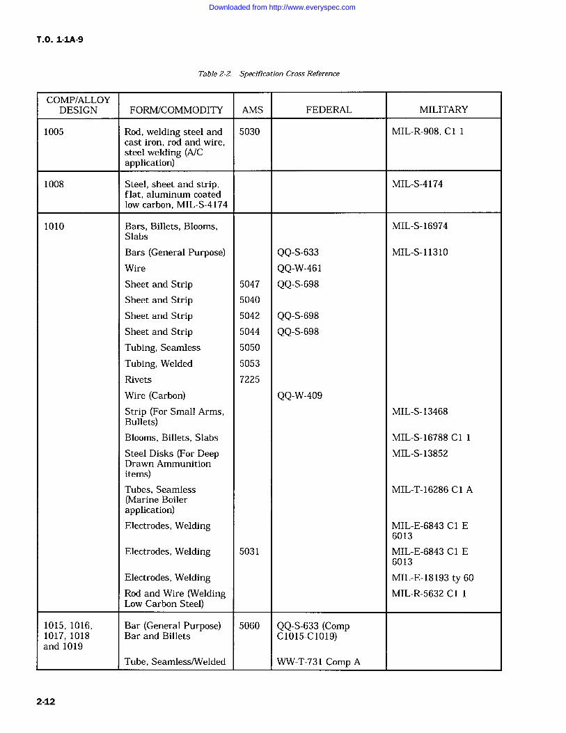
Change 8 2-11
Downloaded from http://www.everyspec.com
T.O. 1-1A-9
Table 2-2. Specification Cross Reference
COMP/ALLOYDESIGN FORMICOMMODITY AMS FEDERAL MILITARY
1005 Rod, welding steel and 5030 MIL-R-908, C1 1cast iron, rod and wire,steel welding (A/Capplication)
1008 Steel, sheet and strip, MIL-S-4174flat, aluminum coatedlow carbon, MIL-S-4174
1010 Bars, Billets, Blooms, MIL-S-16974Slabs
Bars (General Purpose) QQ-S-633 MIL-S-11310
Wire QQ-W-461Sheet and Strip 5047 QQ-S-698Sheet and Strip 5040
Sheet and Strip 5042 QQ-S-698Sheet and Strip 5044 QQ-S-698Tubing, Seamless 5050
Tubing, Welded 5053
Rivets 7225
Wire (Carbon) QQ-W-409Strip (For Small Arms, MIL-S-13468Bullets)Blooms, Billets, Slabs MIL-S-16788 C1
Steel Disks (For Deep MIL-S-13852Drawn Ammunitionitems)Tubes, Seamless MIL-T-16286 Cl A(Marine Boilerapplication)Electrodes, Welding MIL-E-6843 Cl E
6013
Electrodes, Welding 5031 MIL-E-6843 C1 E6013
Electrodes, Welding MIL-E-18193 ty 60
Rod and Wire (Welding MIL-R-5632 Cl 1Low Carbon Steel)
1015, 1016, Bar (General Purpose) 5060 QQ-S-633 (Comp1017, 1018 Bar and Billets C1015-C1019)and 1019
Tube, Seamless/Welded WW-T-731 Comp A
2-12
Downloaded from http://www.everyspec.com
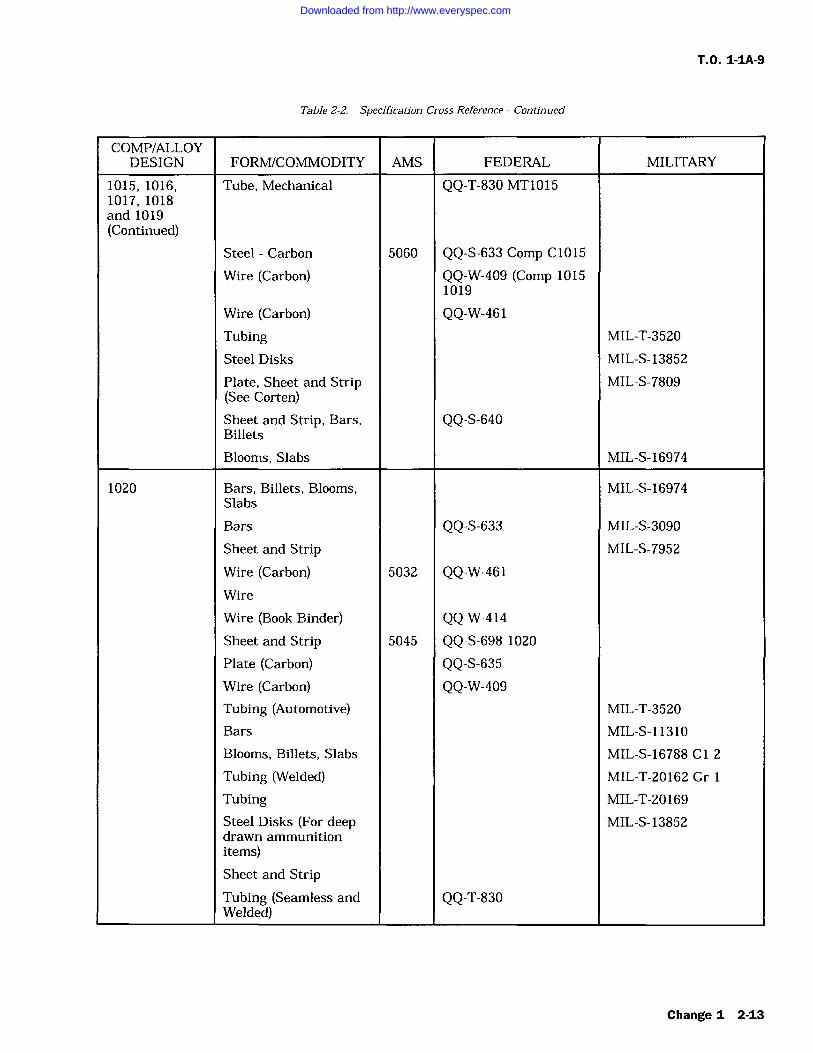
T.O. 1-IA-9
Table 2-2. Specification Cross Reference Continued
COMP/ALLOYDESIGN FORM/COMMODITY AMS FEDERAL MILITARY
1015, 1016, Tube, Mechanical QQ-T-830 MT10151017, 1018and 1019(Continued)
Steel Carbon 5060 QQ-S-633 Comp C1015
Wire (Carbon) QQ-W-409 (Comp 10151019
Wire (Carbon) QQ-W-461Tubing MIL-T-3520
Steel Disks MIL-S-13852
Plate, Sheet and Strip MIL-S-7809(See Corten)Sheet and Strip, Bars, QQ-S-640Billets
Blooms, Slabs MIL-S-16974
1020 Bars, Billets, Blooms, MIL-S-16974Slabs
Bars QQ-S-633 MIL-S-3090
Sheet and Strip MIL-S-7952
Wire (Carbon) 5032 QQ-W-461Wire
Wire (Book Binder) QQ-W-414Sheet and Strip 5045 QQ-S-698 1020
Plate (Carbon) QQ-S-635Wire (Carbon) QQ-W-409Tubing (Automotive) MIL-T-3520
Bars MIL-S-11310
Blooms, Billets, Slabs MIL-S-16788 Cl 2
Tubing (Welded) MIL-T-20162 Gr 1
Tubing MIL-T-20169
Steel Disks (For deep MIL-S-13852drawn ammunitionitems)Sheet and StripTubing (Seamless and QQ-T-830Welded)
Change 1 2-13
Downloaded from http://www.everyspec.com
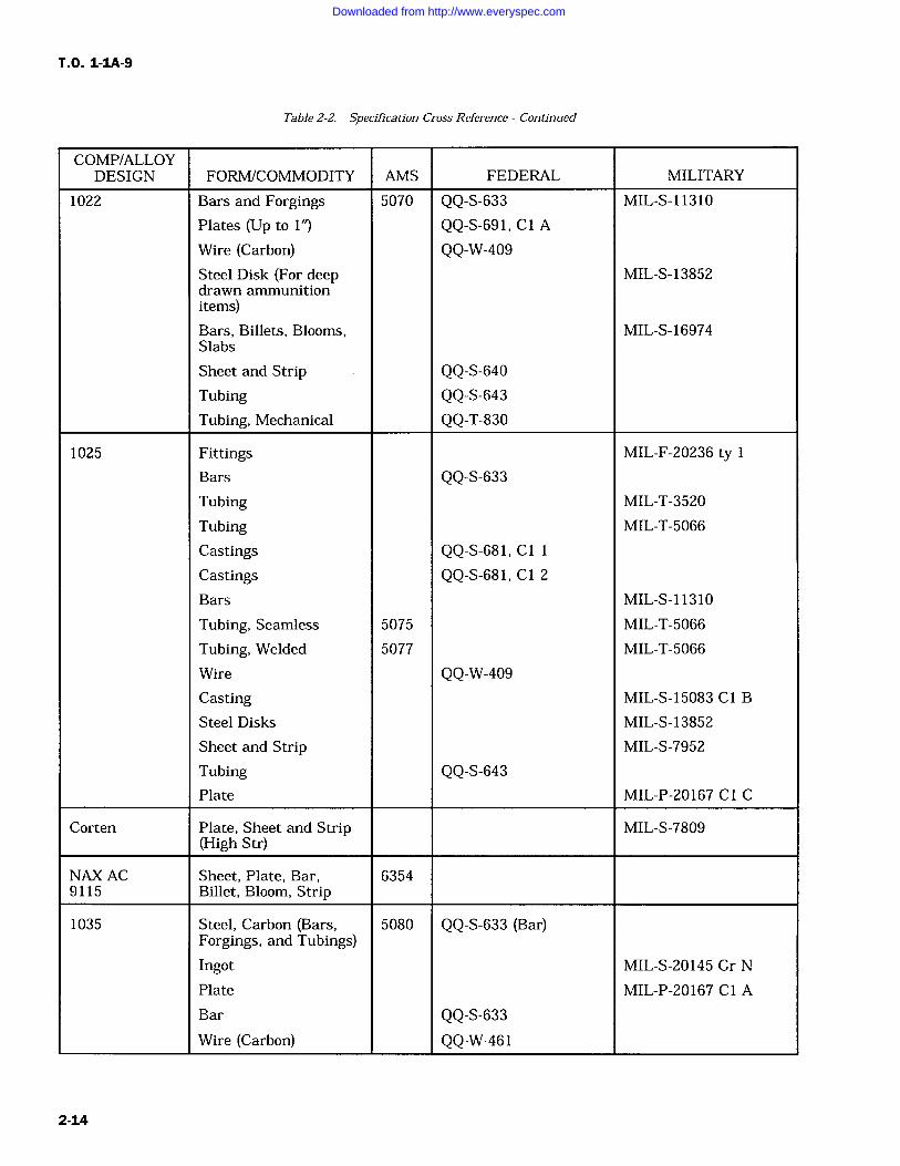
T.O. 1-IA-9
Table 2-2. Specification Cross Reference Continued
COMP/ALLOYDESIGN FORM/COMMODITY AMS FEDERAL MILITARY
1022 Bars and Forgings 5070 QQ-S-633 MIL-S-11310
Plates (Up to 1") QQ-S-691, C1 A
Wire (Carbon) QQ-W-409Steel Disk (For deep MIL-S-13852drawn ammunitionitems)Bars, Billets, Blooms, MIL-S-16974Slabs
Sheet and Strip QQ-S-640Tubing QQ-S-643Tubing, Mechanical QQ-T-830
1025 Fittings MIL-F-20236 tyBars QQ-S-633Tubing MIL-T-3520
Tubing MIL-T-5066
Castings QQ-S-681, C1 1
Castings QQ-S-681, C1 2
Bars MIL-S-11310
Tubing, Seamless 5075 MIL-T-5066
Tubing, Welded 5077 MIL-T-5066
Wire QQ-W-409Casting MIL-S-15083 Cl B
Steel Disks MIL-S-13852
Sheet and Strip MIL-S-7952
Tubing QQ-S-643Plate MIL-P-20167 C1 C
Corten Plate, Sheet and Strip MIL-S-7809(High Str)
NAX AC Sheet, Plate, Bar, 63549115 Billet, Bloom, Strip
1035 Steel, Carbon (Bars, 5080 QQ-S-633 (Bar)Forgings, and Tubings)Ingot MIL-S-20145 Gr N
Plate MIL-P-20167 C1 A
Bar QQ-S-633Wire (Carbon) QQ-W-461
2-14
Downloaded from http://www.everyspec.com
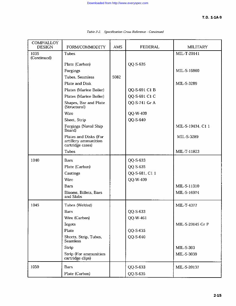
T.O. 1-IA-9
Table 2-2. Specification Cross Reference Continued
COMP/ALLOYDESIGN FORM/COMMODITY AMS FEDERAL MILITARY
1035 Tubes MIL-T-20141(Continued)
Plate (Carbon) QQ-S-635Forgings MIL-S-16900
Tubes, Seamless 5082
Plate and Disk MIL-S-3289
Plates (Marine Boiler) QQ-S-691 C1 B
Plates (Marine Boiler) QQ-S-691 C l C
Shapes, Bar and Plate QQ-S-741 Gr A(Structural)Wire QQ-W-409Sheet, Strip QQ-S-640Forgings (Naval Ship MIL-S-19434, Cl 1Board)Plates and Disks (For MIL-S-3289artillery ammunitioncartridge cases)Tubes MIL-T-11823
1040 Bars QQ-S-633Plate (Carbon) QQ-S-635Castings QQ-S-681, C 1
Wire QQ-W-409Bars MIL-S-11310
Blooms, Billets, Bars MIL-S-16974and Slabs
1045 Tubes (Welded) MIL-T-4377
Bars QQ-S-633Wire (Carbon) QQ-W-461Ingots MIL-S-20145 Gr P
Plate QQ-S-635Sheets, Strip, Tubes, QQ-S-640Seamless
Strip MIL-S-303
Strip (For ammunition MIL-S-3039cartridge clips)
1050 Bars QQ-S-633 MIL-S-20137
Plate (Carbon) QQ-S-635
2-15
Downloaded from http://www.everyspec.com
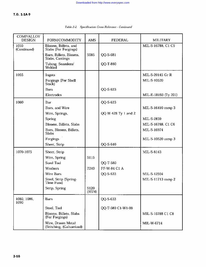
T.O. 1-IA-9
Table 2-2. Specification Cross Reference Continued
COMP/ALLOYDESIGN FORM/COMMODITY AMS FEDERAL MILITARY
1050 Blooms, Billets, and MIL-S-16788, Cl C5(Continued) Slabs (For Forgings)
Bars, Billets, Blooms, 5085 QQ-S-681Slabs, CastingsTubing, Seamless/ QQ-T-880Welded
1055 Ingots MIL-S-20145 Gr R
Forgings (For Shell MIL-S-10520Stock)Bars QQ-S-633Electrodes MIL-E-18193 (Ty 201)
1060 Bar QQ-S-633Bars, and Wire MIL-S-16410 comp 3
Wire, Springs, QQ-W-428 Ty 1 and 2
Spring MIL-S-2839
Blooms, Billets, Slabs MIL-S-16788, Cl C6
Bars, Blooms, Billets, MIL-S-16974Slabs
Forgings MIL-S-10520 comp 3
Sheet, Strip QQ-S-640
1070-1075 Sheet, Strip MIL-S-8143
Wire, Spring 5115
Steel Tool QQ-T-580Washers 7240 FF-W-84 C1 A
Wire Bars QQ-S-633 MIL-S-12504
Steel, Strip (Spring- MIL-S-11713 comp 2Time Fuse)Strip, Spring 5120
(1074)
1080, 1086, Bars QQ-S-6331090
Steel, Tool QQ-T-580 C1-W1-09
Blooms, Billets, Slabs MIL-S-16788 C l C8(For Forgings)Wire, Drawn Metal MIL-W-6714(Stitching, (Galvanized)
2-16
Downloaded from http://www.everyspec.com
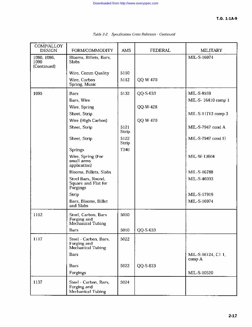
T.O. 1-1A-9
Table 2-2. Specification Cross Reference Continued
COMP/ALLOYDESIGN FORM/COMMODITY AMS FEDERAL MILITARY
1080, 1086, Blooms, Billets, Bars, MIL-S-169741090 Slabs(Continued)
Wire, Comm Quality 5110
Wire, Carbon 5112 QQ-W-470Spring, Music
1095 Bars 5132 QQ-S-633 MIL-S-8559
Bars, Wire MIL-S- 16410 comp
Wire, Spring QQ-W-428Sheet, Strip MIL-S-11713 comp 3
Wire (High Carbon) QQ-W-470Sheet, Strip 5121 MIL-S-7947 cond A
StripSheet, Strip 5122 MIL-S-7947 cond H
StripSprings 7340
Wire, Spring (For MIL-W-13604small armsapplication)Blooms, Billets, Slabs MIL-S-16788
Steel Bars, Round, MIL-S-46033Square and Flat forForgingsStrip MIL-S-17919
Bars, Blooms, Billet MIL-S-16974and Slabs
1112 Steel, Carbon, Bars 5010Forging andMechanical TubingBars 5010 QQ-S-633
1117 Steel Carbon, Bars, 5022Forging andMechanical TubingBars MIL-S-16124, C1 1,
comp A
Bars 5022 QQ-S-633Forgings MIL-S-10520
1137 Steel Carbon, Bars, 5024Forging andMechanical Tubing
2-17
Downloaded from http://www.everyspec.com
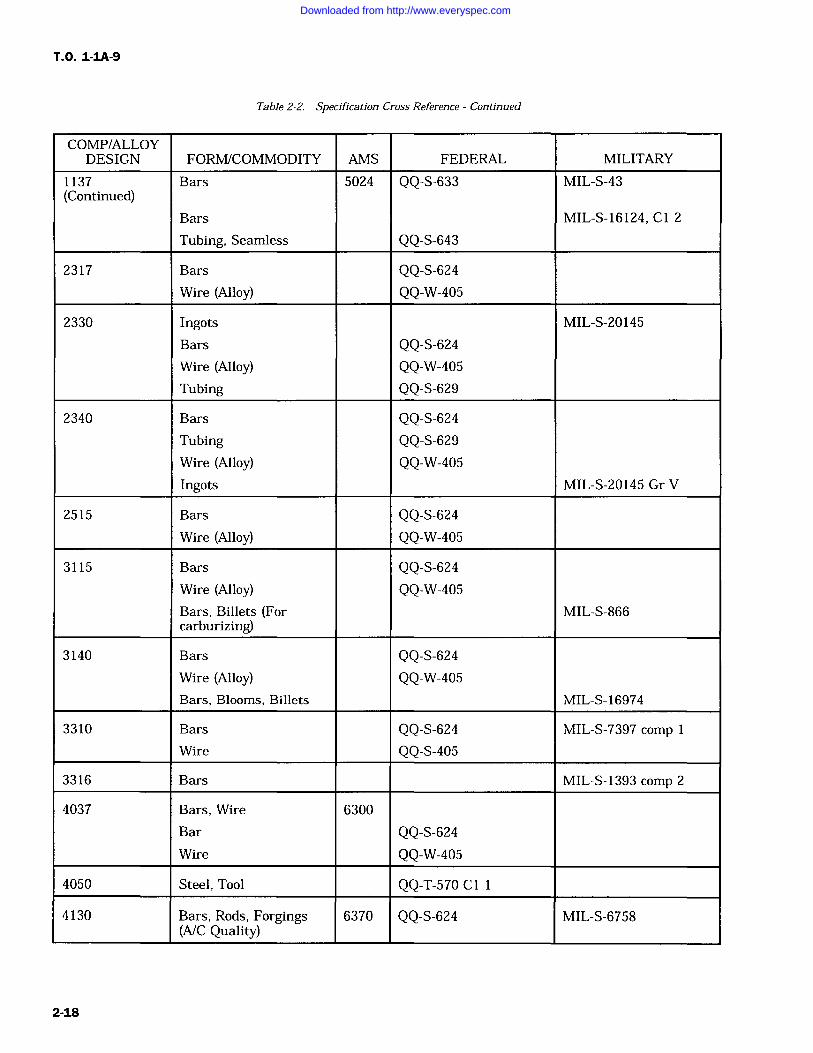
T.O. 1-1A-9
Table 2-2. Specification Cross Reference Continued
COMP/ALLOYDESIGN FORM/COMMODITY AMS FEDERAL MILITARY
1137 Bars 5024 QQ-S-633 MIL-S-43(Continued)
Bars MIL-S-16124, Cl 2
Tubing, Seamless QQ-S-643
2317 Bars QQ-S-6'24Wire (Alloy) QQ-W-405
2330 Ingots MIL-S-20145
Bars QQ-S-624Wire (Alloy) QQ-W-405Tubing QQ-S-629
2340 Bars QQ-S-624Tubing QQ-S-629Wire (Alloy) QQ-W-405Ingots MIL-S-20145 Gr V
2515 Bars QQ-S-624Wire (Alloy) QQ-W-405
3115 Bars QQ-S-624Wire (Alloy) QQ-W-405Bars, Billets (For MIL-S-866carburizing)
3140 Bars QQ-S-624Wire (Alloy) QQ-W-405Bars, Blooms, Billets MIL-S-16974
3310 Bars QQ-S-624 MIL-S-7397 comp
Wire QQ-S-405
3316 Bars MIL-S-1393 comp 2
4037 Bars, Wire 6300
Bar QQ-S-624Wire QQ-W-405
4050 Steel, Tool QQ-T-570 Cl
4130 Bars, Rods, Forgings 6370 QQ-S-624 MIL-S-6758(A/C Quality)
2-18
Downloaded from http://www.everyspec.com
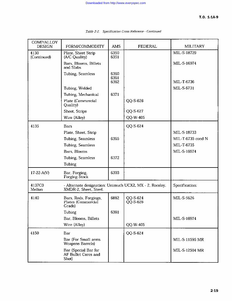
T.O. 1-1A-9
Table 2-2. Specification Cross Reference Continued
COMP/ALLOYDESIGN FORMICOMMODITY AMS FEDERAL MILITARY
4130 Plate, Sheet Strip 6350 MIL-S-18729(Continued) (A/C Quality) 6351
Bars, Blooms, Billets MIL-S-16974and Slabs
Tubing, Seamless 636063616362 MIL-T-6736
Tubing, Welded MIL-S-6731
Tubing, Mechanical 6371
Plate (Commercial QQ-S-626Quality)Sheet, Strips QQ-S-627Wire (Alloy) QQ-W-405
4135 Bars QQ-S-624Plate, Sheet, Strip MIL-S-18733
Tubing, Seamless 6365 MIL-T-6735 cond N
Tubing, Seamless MIL-T-6735
Bars, Blooms MIL-S-16974
Tubing, Seamless 6372
Tubing
17-22-A(V) Bar, Forging, 6303Forging Stock
4137C0 Alternate designation: Unimuch UCX2, MX 2, Rocoloy. Specification:Mellon XMDR-2, Sheet, Steel.
4140 Bars, Rods, Forgings, 6882 QQ-S-624 MIL-S-5626Plates (Commercial QQ-S-626Grade)Tubing 6381
Bar, Blooms, Billets MIL-S-16974
Wire (Alloy) QQ-W-405
4150 Bar QQ-S-624Bar (For Small arms MIL-S-11595 MRWeapons Barrels)Bar (Special Bar for MIL-S-12504 MRAF Bullet Cores andShot)
2-19
Downloaded from http://www.everyspec.com
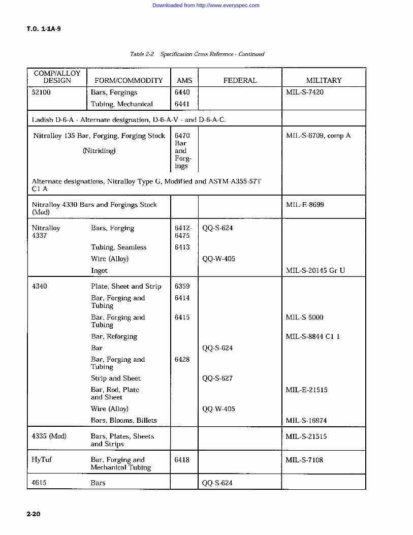
T.O. 1-1A-9
Table 2-2. Specification Cross Reference Continued
COMP/ALLOYDESIGN FORM/COMMODITY AMS FEDERAL MILITARY
52100 Bars, Forgings 6440 MIL-S-7420
Tubing, Mechanical 6441
Ladish D-6-A Alternate designation, D-6-A-V and D-6-A-C.
Nitralloy 135 Bar, Forging, Forging Stock 6470 MIL-S-6709, comp ABar
(Nitriding) andForg-ings
Alternate designations, Nitralloy Type G, Modified and ASTM-A355-57TCl A
Nitralloy 4330 Bars and Forgings Stock MIL-E-8699(Mod)
Nitralloy Bars, Forging 6412- QQ-S-6244337 6475
Tubing, Seamless 6413
Wire (Alloy) QQ-W-405Ingot MIL-S-20145 Gr U
4340 Plate, Sheet and Strip 6359
Bar, Forging and 6414TubingBar, Forging and 6415 MIL-S-5000TubingBar, Reforging MIL-S-8844 C l
Bar QQ-S-624Bar, Forging and 6428TubingStrip and Sheet QQ-S-627Bar, Rod, Plate MIL-E-21515and Sheet
Wire (Alloy) QQ-W-405Bars, Blooms, Billets MIL-S-16974
4335 (Mod) Bars, Plates, Sheets MIL-S-21515and Strips
HyTuf Bar, Forging and 6418 MIL-S-7108Mechanical Tubing
4615 Bars QQ-S-624
2-20
Downloaded from http://www.everyspec.com
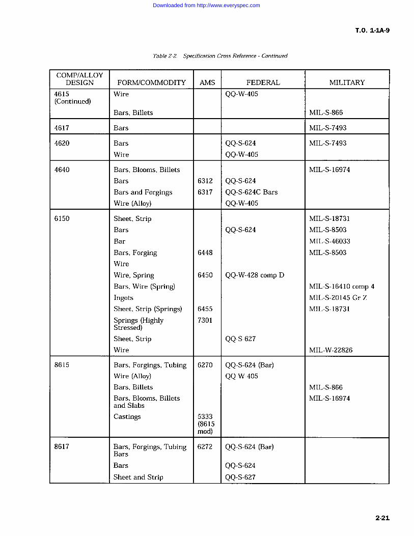
T.O. 1-1A-9
Table 2-2. Specification Cross Reference Continued
COMP/ALLOYDESIGN FORM/COMMODITY AMS FEDERAL MILITARY
4615 Wire QQ-W-405(Continued)
Bars, Billets MIL-S-866
4617 Bars MIL-S-7493
4620 Bars QQ-S-624 MIL-S-7493
Wire QQ-W-405
4640 Bars, Blooms, Billets MIL-S-16974
Bars 6312 QQ-S-624Bars and Forgings 6317 QQ-S-624C Bars
Wire (Alloy) QQ-W-405
6150 Sheet, Strip MIL-S-18731
Bars QQ-S-624 MIL-S-8503
Bar MIL-S-46033
Bars, Forging 6448 MIL-S-8503
Wire
Wire, Spring 6450 QQ-W-428 comp D
Bars, Wire (Spring) MIL-S-16410 comp 4
Ingots MIL-S-20145 Gr Z
Sheet, Strip (Springs) 6455 MIL-S-18731
Springs (Highly 7301Stressed)Sheet, Strip QQ-S-627Wire MIL-W-22826
8615 Bars, Forgings, Tubing 6270 QQ-S-624 (Bar)Wire (Alloy) QQ-W-405Bars, Billets MIL-S-866
Bars, Blooms, Billets MIL-S-16974and Slabs
Castings 5333(8615mod)
8617 Bars, Forgings, Tubing 6272 QQ-S-624 (Bar)Bars
Bars QQ-S-624Sheet and Strip QQ-S-627
2-21
Downloaded from http://www.everyspec.com
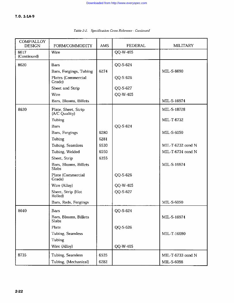
T.O. 1-1A-9
Table 2-2. Specification Cross Reference Continued
COMP/ALLOYDESIGN FORMICOMMODITY AMS FEDERAL MILITARY
8617 Wire QQ-W-405(Continued)
8620 Bars QQ-S-624Bars, Forgings, Tubing 6274 MIL-S-8690
Plates (Commercial QQ-S-626Grade)Sheet and Strip QQ-S-627Wire QQ-W-405Bars, Blooms, Billets MIL-S-16974
8630 Plate, Sheet, Strip MIL-S-18728(A/C Quality)Tubing MIL-T-6732
Bars QQ-S-624Bars, Forgings 6280 MIL-S-6050
Tubing 6281
Tubing, Seamless 6530 MIL-T-6732 cond N
Tubing, Welded 6550 MIL-T-6734 cond N
Sheet, Strip 6355
Bars, Blooms, Billets MIL-S-16974Slabs
Plate (Commercial QQ-S-626Grade)Wire (Alloy) QQ-W-405Sheet, Strip (Hot QQ-S-627Rolled)Bars, Rods, Forgings MIL-S-6050
8640 Bars QQ-S-624Bars, Blooms, Billets MIL-S-16974Slabs
Plate QQ-S-626Tubing, Seamless MIL-T-16690
TubingWire (Alloy) QQ-W-405
8735 Tubing, Seamless 6535 MIL-T-6733 cond N
Tubing, (Mechanical) 6282 MIL-S-6098
2-22
Downloaded from http://www.everyspec.com
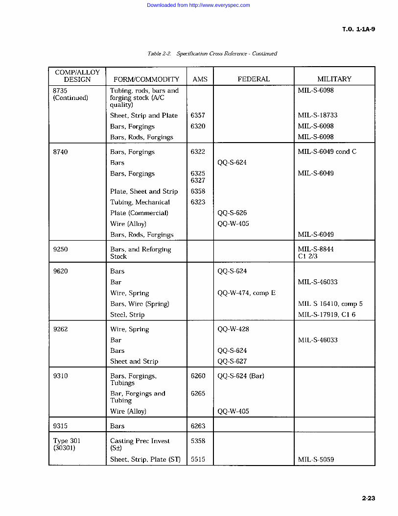
T.O. 1-1A-9
Table 2-2. Specification Cross Reference Continued
COMP/ALLOYDESIGN FORM/COMMODITY AMS FEDERAL MILITARY
8735 Tubing, rods, bars and MIL-S-6098(Continued) forging stock (A/C
quality)Sheet, Strip and Plate 6357 MIL-S-18733
Bars, Forgings 6320 MIL-S-6098
Bars, Rods, Forgings MIL-S-6098
8740 Bars, Forgings 6322 MIL-S-6049 cond C
Bars QQ-S-624Bars, Forgings 6325 MIL-S-6049
6327
Plate, Sheet and Strip 6358
Tubing, Mechanical 6323
Plate (Commercial) QQ-S-626Wire (Alloy) QQ-W-405Bars, Rods, Forgings MIL-S-6049
9250 Bars, and Reforging MIL-S-8844Stock C1 2/3
9620 Bars QQ-S-624Bar MIL-S-46033
Wire, Spring QQ-W-474, comp E
Bars, Wire (Spring) MIL-S-16410, comp 5
Steel, Strip MIL-S-17919, Cl 6
9262 Wire, Spring QQ-W-428Bar MIL-S-46033
Bars QQ-S-624Sheet and Strip QQ-S-627
9310 Bars, Forgings, 6260 QQ-S-624 (Bar)TubingsBar, Forgings and 6265TubingWire (Alloy) QQ-W-405
9315 Bars 6263
Type 301 Casting Prec Invest 5358(30301) (S+/-)
Sheet, Strip, Plate (ST) 5515 MIL-S-5059
2-23
Downloaded from http://www.everyspec.com
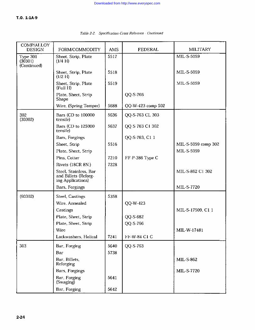
TO. 1-1A-9
Table 2-2. Specification Cross Reference Continued
COMP/ALLOYDESIGN FORMICOMMODITY AMS FEDERAL MILITARY
Type 301 Sheet, Strip, Plate 5517 MIL-S-5059(30301) (1/4 H)(Continued)
Sheet, Strip, Plate 5518 MIL-S-5059(1/2 H)Sheet, Strip, Plate 5519 MIL-S-5059(Full H)Plate, Sheet, Strip QQ-S-766ShapeWire, (Spring Temper) 5688 QQ-W-423 comp 502
302 Bars (CD to 100000 5636 QQ-S-763 CL 303(30302) tensile)
Bars (CD to 125000 5637 QQ-S-763 C1 302tensile)Bars, Forgings QQ-S-763, Cl 1
Sheet, Strip 5516 MIL-S-5059 comp 302
Plate, Sheet, Strip MIL-S-5059
Pins, Cotter 7210 FF-P-386 Type CRivets (18CR 8N:) 7228
Steel, Stainless, Bar MIL-S-862 Cl 302and Billets (Reforg-ing Applications)Bars, Forgings MIL-S-7720
(60302) Steel, Castings 5358
Wire, Annealed QQ-W-423Castings MIL-S-17509, Cl 1
Plate, Sheet, Strip QQ-S-682Plate, Sheet, Strip QQ-S-766Wire MIL-W-17481
Lockwashers, Helical 7241 FF-W-84 Cl C
303 Bar, Forging 5640 QQ-S-763Bar 5738
Bar, Billets, MIL-S-862ReforgingBars, Forgings MIL-S-7720
Bar, Forging 5641(Swaging)Bar, Forging 5642
2-24
Downloaded from http://www.everyspec.com
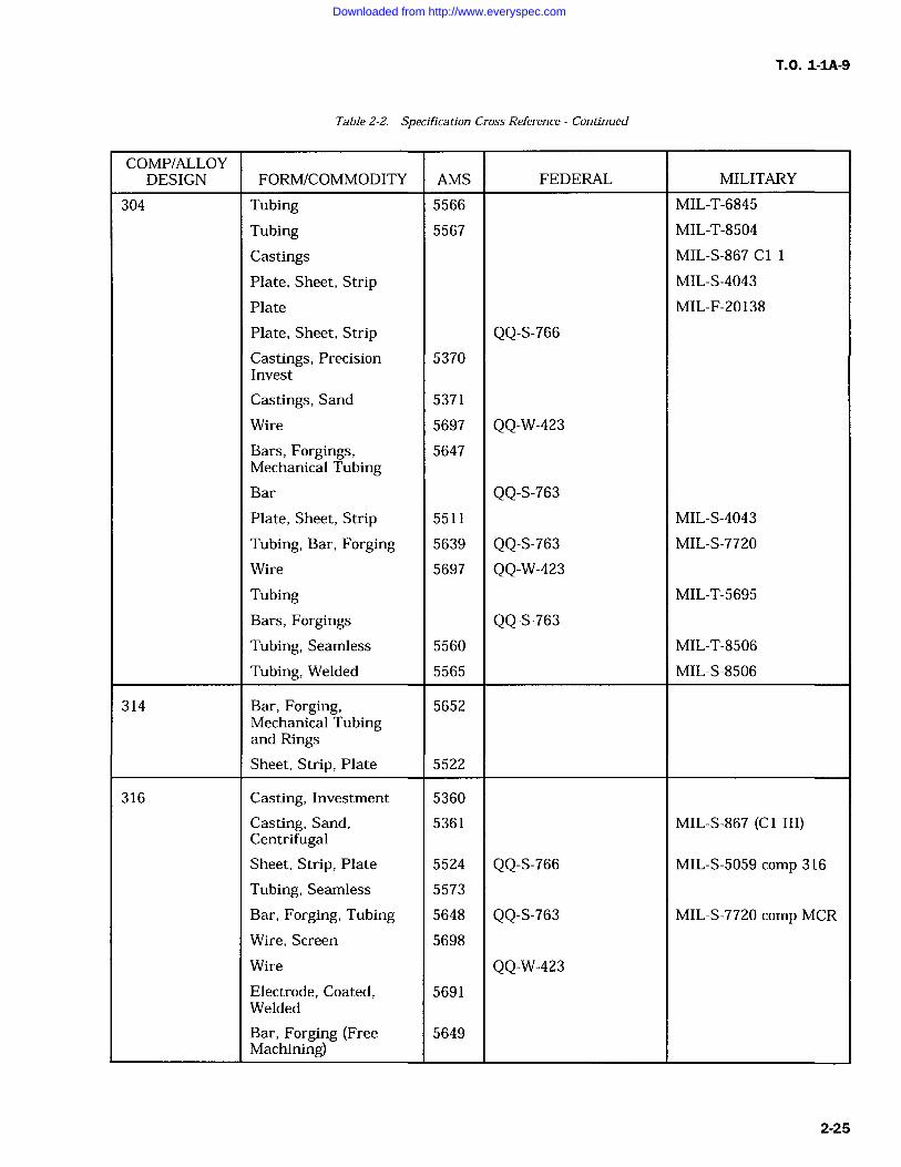
T.O. 1-1A-9
Table 2-2. Specification Cross Reference Continued
COMP/ALLOYDESIGN FORM/COMMODITY AMS FEDERAL MILITARY
304 Tubing 5566 MIL-T-6845
Tubing 5567 MIL-T-8504
Castings MIL-S-867 C l
Plate, Sheet, Strip MIL-S-4043
Plate MIL-F-20138
Plate, Sheet, Strip QQ-S-766Castings, Precision 5370Invest
Castings, Sand 5371
Wire 5697 QQ-W-423Bars, Forgings, 5647Mechanical TubingBar QQ-S-763Plate, Sheet, Strip 5511 MIL-S-4043
Tubing, Bar, Forging 5639 QQ-S-763 MIL-S-7720
Wire 5697 QQ-W-423Tubing MIL-T-5695
Bars, Forgings QQ-S-763Tubing, Seamless 5560 MIL-T-8506
Tubing, Welded 5565 MIL-S-8506
314 Bar, Forging, 5652Mechanical Tubingand RingsSheet, Strip, Plate 5522
316 Casting, Investment 5360
Casting, Sand, 5361 MIL-S-867 (C l III)CentrifugalSheet, Strip, Plate 5524 QQ-S-766 MIL-S-5059 comp 316
Tubing, Seamless 5573
Bar, Forging, Tubing 5648 QQ-S-763 MIL-S-7720 comp MCR
Wire, Screen 5698
Wire QQ-W-423Electrode, Coated, 5691Welded
Bar, Forging (Free 5649Machining)
2-25
Downloaded from http://www.everyspec.com
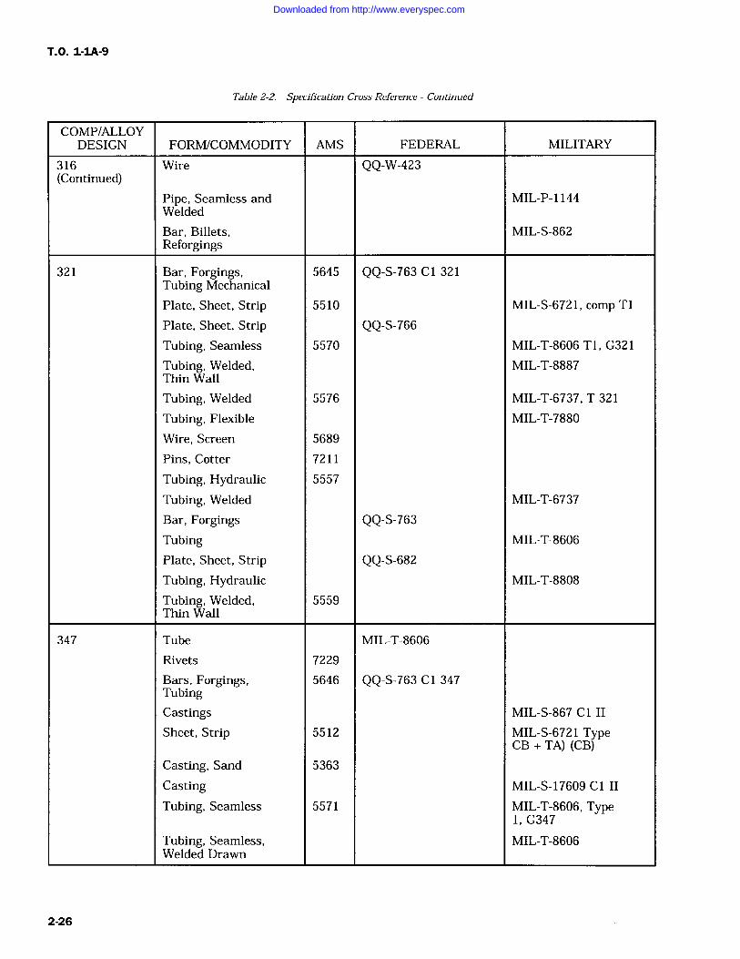
T.O. 1-1A-9
Table 2-2. Specification Cross Reference Continued
COMP/ALLOYDESIGN FORM/COMMODITY AMS FEDERAL MILITARY
316 Wire QQ-W-423(Continued)
Pipe, Seamless and MIL-P-1144Welded
Bar, Billets, MIL-S-862Reforgings
321 Bar, Forgings, 5645 QQ-S-763 C1 321Tubing Mechanical
Plate, Sheet, Strip 5510 MIL-S-6721, comp T1
Plate, Sheet, Strip QQ-S-766Tubing, Seamless 5570 MIL-T-8606 Ti, G321
Tubing, Welded, MIL-T-8887Thin Wall
Tubing, Welded 5576 MIL-T-6737, T 321
Tubing, Flexible MIL-T-7880
Wire, Screen 5689
Pins, Cotter 7211
Tubing, Hydraulic 5557
Tubing, Welded MIL-T-6737
Bar, Forgings QQ-S-763Tubing MIL-T-8606
Plate, Sheet, Strip QQ-S-682Tubing, Hydraulic MIL-T-8808
Tubing, Welded, 5559Thin Wall
347 Tube MIL-T-8606
Rivets 7229
Bars, Forgings, 5646 QQ-S-763 Cl 347TubingCastings MIL-S-867 C1 II
Sheet, Strip 5512 MIL-S-6721 TypeCB + TA) (CB)
Casting, Sand 5363
Casting MIL-S-17609 Cl II
Tubing, Seamless 5571 MIL-T-8606, Type1, G347
Tubing, Seamless, MIL-T-8606Welded Drawn
2-26
Downloaded from http://www.everyspec.com
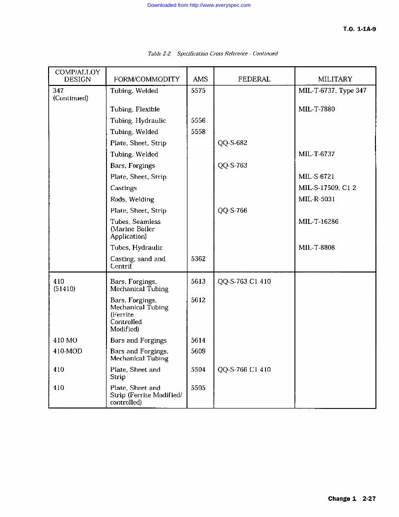
T.O. 1-1A-9
Table 2-2. Specification Cross Reference Continued
COMP/ALLOYDESIGN FORM/COMMODITY AMS FEDERAL MILITARY
347 Tubing, Welded 5575 MIL-T-6737, Type 347(Continued)
Tubing, Flexible MIL-T-7880
Tubing, Hydraulic 5556
Tubing, Welded 5558
Plate, Sheet, Strip QQ-S-682Tubing, Welded MIL-T-6737
Bars, Forgings QQ-S-763Plate, Sheet, Strip MIL-S-6721
Castings MIL-S-17509, Cl 2
Rods, Welding MIL-R-5031
Plate, Sheet, Strip QQ-S-766Tubes, Seamless MIL-T-16286(Marine BoilerApplication)Tubes, Hydraulic MIL-T-8808
Casting, sand and 5362Centrif
410 Bars, Forgings, 5613 QQ-S-763 C1 410(51410) Mechanical Tubing
Bars, Forgings, 5612Mechanical Tubing(FerriteControlledModified)
410-MO Bars and Forgings 5614
410-MOD Bars and Forgings, 5609Mechanical Tubing
410 Plate, Sheet and 5504 QQ-S-766 Cl 410Strip
410 Plate, Sheet and 5505Strip (Ferrite Modified/controlled)
Change 1 2-27
Downloaded from http://www.everyspec.com
T.O. 1-1A-9
Table 2-2. Specification Cross Reference Continued
COMP/ALLOYDESIGN FORMICOMMODITY AMS FEDERAL MILITARY
410 Casting Investment 5350(60410)
Casting, Sand 5351 MIL-S-16933 Cl I
Wire QQ-W-423 comp 410
Bars MIL-S-861
Bars, and Billets MIL-S-862(For Reforging)
(51410) Tubing, Seamless 5591
Tubing, Flexible MIL-T-7880
414 Bars, Forgings 5615 QQ-S-763 C1 414
Bars MIL-S-862
416 Bars 5610 QQ-S-763 C1 416 Se(51416F) (Bar)
Bars and Forgings 5610
Bars and Billets(Reforging) MIL-S-862 C1 6
420 Bars and Billets (For MIL-S-862 C1 5Reforging)Bars and Forgings 5620(Free Mach)
(51420) Bars and Forgings 5621
Bars 5621 QQ-S-763 C1 420
Plate, Sheet and 5506 QQ-S-766 C1 420StripWire QQ-W-423
431 Bars and Billets (For MIL-S-862Reforging)Bars, Billets, MIL-S-18732Forgings, TubingCastings, Sand 5372
Bars, Forgings 5682 QQ-S-763, Cl 431
431 MOD Castings, Precision 5353Investment
440 C Bars and Forgings 5630 QQ-S-763, Cl 440C
440 A Bars and Forgings 5631 QQ-S-763, Cl 440A
2-28
Downloaded from http://www.everyspec.com
T.O. 1-IA-9
Table 2-2. Specification Cross Reference
COMP/ALLOYDESIGN FORMICOMMODITY AMS FEDERAL MILITARY
440 F Bars and Forgings 5632 QQ-S-763, Cl 440F
14-4PH Castings, Investment 5340
15-7 MO Bar and Forging 5657
Plate, Sheet and 5520Strip
17-4 PH Bar 5643
Castings Investment 5342(Heat Treated 130,000PSI)Castings Investment 5343(Heat Treated 150,000PSI)Castings Investment 5344(Heat Treated)Electrode Welding 5827
Castings Investment 5355
17-7 PH Plate, Sheet and Strip 5528 MIL-S-25043
Sheet and Strip (Pre- 5530cipitation Hardening)Bar and Forgings 5644
Tubing, Welded 5568
19-9DL Casting Sand (Solution 5369Treated)Plate, Sheet and Strip 5526
Plate, Sheet and Strip 5527(125000TS, Hot rolled,Stress Relieved)Bars (Up to 1.5 inch) 5720
Bars (Up to 1 inch) 5721
Bars and Forgings 5722
19-9DX Bars, Forgings and 5723RingsBars (Up to inch) 5724
Bars (Up to 1.5 inch) 5729
Plate, Sheet and Strip 5538
Change 1 2-29
Downloaded from http://www.everyspec.com
T.O. 1-1A-9
Table 2-2. Specification Cross Reference Continued
COMP/ALLOYDESIGN FORM/COMMODITY AMS FEDERAL MILITARY
19-9DX Plate, Sheet and Strip, 5539(Continued) (Hot rolled and Stress
Relieved 125,000TS)Bars, Forgings and 5723RingsBars (Up to 1 inch) 5724
Bars (Up to 1.5 inch) 5729
19-9 MOD Electrode, Welding, MIL-E-13080Covered (Armorapplications)
AM350 Bar 5745
Sheet and Strip 5540(Cold rolled)Sheet and Strip 5548 MIL-S-8840(High TempAnnealed)Bar and Forgings 5745
Tubing, Seamless 5554
Wire, Welding 5774
Electrode, Coated 5775Wire
AM355 Bar 5743
Castings, Investment 5368
Sheet and Strip 5547 MIL-S-8840
Plate (Solution 5549Heat Treated)Plate (Equalized and 5594Over-Tempered)Electrode, Coated 5781Welding
A286 Bars, Forgings, 5734Mechanical TubingBars, Forgings, 5735Mechanical Tubing andRings
2-30 Change I
Downloaded from http://www.everyspec.com
T.O. 1-1A-9
Table 2-2. Specification Cross Reference Continued
COMP/ALLOYDESIGN FORM/COMMODITY AMS FEDERAL MILITARY
A286 Bars, Forgings, 5736(Continued) Mechanical Tubing and
Rings (Sol Treated)Bars and Forgings and 5737Mechanical Tubing(Annealedand Precip Treated)Rivets, Steel (Annealed 72351650F and partiallyprecip treated)
Rene 41 Bars and Forgings 5712(Solution Treated
Bars and Forgings 5713(Solution andPrecip Treated)Plate Sheet and Strip 5545(Solution HeatTreated)
Greek Castings, Investment 5354Ascoloy
Plate, Sheet and Strip 5508
Bars, Forgings, 5616Mechanical Tubingand Rings
Inconel 600 Wire, Annealed 5687 QQ-W-390Plate, Sheet and Strip 5540 MIL-N-6840
Bars, Forgings and 5665 MIL-N-6710RingsTubing, Seamless 5580 MIL-T-7840
42 Inconel Sheet and Strip 5542 MIL-N-7786Alloy X750
Change 1 2-31
Downloaded from http://www.everyspec.com
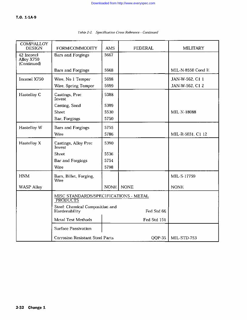
T.O. 1-1A-9
Table 2-2. Specification Cross Reference Continued
COMP/ALLOYDESIGN FORM/COMMODITY AMS FEDERAL MILITARY
42 Inconel Bars and Forgings 5667Alloy X750(Continued)
Bars and Forgings 5668 MIL-N-8550 Cond E
Inconel X750 Wire, No 1 Temper 5698 JAN-W-562, C1
Wire, Spring Temper 5699 JAN-W-562, C 2
Hastelloy C Castings, Prec 5388Invest
Casting, Sand 5389
Sheet 5530 MIL-N-18088
Bar, Forgings 5750
Hastelloy W Bars and Forgings 5755
Wire 5786 MIL-R-5031, C1 12
Hastelloy X Castings, Alloy Prec 5390Invest
Sheet 5536
Bar and Forgings 5754
Wire 5798
HNM Bars, Billet, Forging, MIL-S-17759Wire
WASP Alloy NONE NONE NONE
MISC STANDARDS/SPECIFICATIONS METALPRODUCTS
Steel: Chemical Composition andHardenability Fed Std 66
Metal Test Methods Fed Std 151
Surface Passivation
Corrosion Resistant Steel Parts QQP-35 MIL-STD-753
2-32 Change I
Downloaded from http://www.everyspec.com
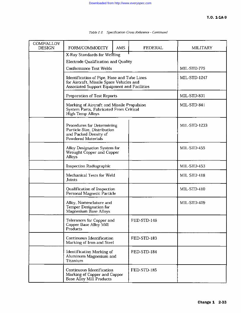
T.O. 1-1A-9
Table 2-2. Specification Cross Reference Continued
COMP/ALLOYDESIGN FORM/COMMODITY AMS FEDERAL MILITARY
X-Ray Standards for WellingElectrode Qualification and QualityConformance Test Welds MIL-STD-775
Identification of Pipe, Hose and Tube Lines MIL-STD-1247for Aircraft, Missile Space Vehicles andAssociated Support Equipment and Facilities
Preparation of Test Reports MIL-STD-831
Marking of Aircraft and Missile Propulsion MIL-STD-841System Parts, Fabricated From CriticalHigh Temp Alloys
Procedures for Determining MIL-STD-1233Particle Size, Distributionand Packed Density ofPowdered Materials
Alloy Designation System for MIL-STD-455Wrought Copper and CopperAlloys
Inspection Radiographic MIL-STD-453
Mechanical Tests for Weld MIL-STD-418Joints
Qualification of Inspection MIL-STD-4 10Personal Magnetic Particle
Alloy, Nomenclature and MIL-STD-409Temper Designation forMagnesium Base Alloys
Tolerances for Copper and FED-STD-146Copper Base Alloy MillProducts
Continuous Identification FED-STD-183Marking of Iron and Steel
Identification Marking of FED-STD-184Aluminum Magnesium andTitanium
Continuous Identification FED-STD-185Marking of Copper and CopperBase Alloy Mill Products
Change 1 2-33
Downloaded from http://www.everyspec.com
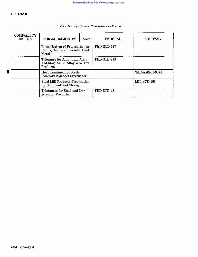
T.O. 1-IA-9
Table 2-2. Specification Cross Reference Continued
COMP/ALLOYDESIGN FORM/COMMODITY AMS FEDERAL MILITARY
Identification of Pressed Bonds, FED-STD-187Forms, Seams and Joints SheetMetal
Tolerance for Aluminum Alloy FED-STD-245and Magnesium Alloy WroughtProducts
Heat Treatment of Steels SAE-AMS-H-6875(Aircraft Practice) Process for
Steel Mill Products Preparation MIL-STD-163for Shipment and StorageTolerances for Steel and Iron FED-STD-48Wrought Products
I
2-34 Change 4
Downloaded from http://www.everyspec.com
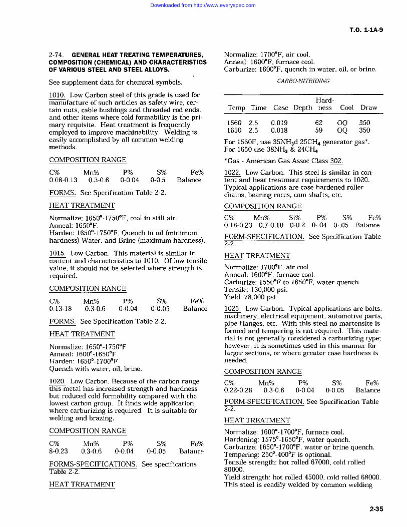
T.O. 1-1A-9
2-74. GENERAL HEAT TREATING TEMPERATURES,COMPOSITION (CHEMICAL) AND CHARACTERISTICSOF VARIOUS STEEL AND STEEL ALLOYS.
Normalize: 1700F, air cool.Anneal: 1600F, furnace cool.Carburize: 1600F, quench in water, oil, or brine.
See supplement data for chemical symbols.
1010. Low Carbon steel of this grade is used formanufacture of such articles as safety wire, cer-
tain nuts, cable bushings and threaded rod ends,and other items where cold formability is the pri-mary requisite. Heat treatment is frequentlyemployed to improve machinability. Welding iseasily accomplished by all common weldingmethods.
COMPOSITION RANGE
C% Mn% P% S% Fe%0.08-0.13 0.3-0.6 0-0.04 0-0.5 Balance
FORMS. See Specification Table 2-2.
HEAT TREATMENT
Normalize: 1650-1750F, cool in still air.Anneal: 1650F.Harden: 1650-1750F, Quench in oil (minimumhardness) Water, and Brine (maximum hardness).
1015. Low Carbon. This material is similar incontent and characteristics to 1010. Of low tensilevalue, it should not be selected where strength isrequired.COMPOSITION RANGE
C% Mn% P% S% Fe%0.13-18 0.3-0.6 0-0.04 0-0.05 Balance
FORMS. See Specification Table 2-2.
HEAT TREATMENT
Normalize: 1650-1750FAnneal: 1600-1650FHarden: 1650-1700FQuench with water, oil, brine.
1020. Low Carbon. Because of the carbon rangethis metal has increased strength and hardnessbut reduced cold formability compared with thelowest carbon group. It finds wide applicationwhere carburizing is required. It is suitable forwelding and brazing.
COMPOSITION RANGE
C% Mn% P% S% Fe%8-0.23 0.3-0.6 0-0.04 0-0.05 Balance
FORMS-SPECIFICATIONS. See specificationsTable 2-2.
HEAT TREATMENT
CARBO-NITRIDING
Hard-Temp Time Case Depth ness Cool Draw
1560 2.5 0.019 62 OQ 3501650 2.5 0.018 59 OQ 350
For 1560F, use 35NH3d 25CH4 generator gas*.For 1650 use 38NH3 & 24CH4*Gas American Gas Assoc Class 302.
1022. Low Carbon. This steel is similar in con-
tent and heat treatment requirements to 1020.Typical applications are case hardened rollerchains, bearing races, cam shafts, etc.
COMPOSITION RANGE
C% Mn% Si% P% S% Fe%0.18-0.23 0.7-0.10 0-0.2 0-.04 0-.05 Balance
FORM-SPECIFICATION. See Specification Table2-2.
HEAT TREATMENT
Normalize: 1700F, air cool.Anneal: 1600F, furnace cool.Carburize: 1550F to 1650F, water quench.Tensile: 130,000 psi.Yield: 78,000 psi.1025. Low Carbon. Typical applications are bolts,machinery, electrical equipment, automotive parts,pipe flanges, etc. With this steel no martensite isformed and tempering is not required. This mate-rial is not generally considered a carburizing type;however, it is sometimes used in this manner forlarger sections, or where greater case hardness isneeded.
COMPOSITION RANGE
C% Mn% P% S% Fe%0.22-0.28 0.3-0.6 0-0.04 0-0.05 Balance
FORM-SPECIFICATION. See Specification Table2-2.
HEAT TREATMENT
Normalize: 1600-1700F, furnace cool.Hardening: 1575-1650F, water quench.Carburize: 1650-1700F, water or brine quench.Tempering: 250-400F is optional.Tensile strength: hot rolled 67000, cold rolled80000.Yield strength: hot rolled 45000, cold rolled 68000.This steel is readily welded by common welding
2-35
Downloaded from http://www.everyspec.com
T.O. 1-1A-9
methods.Temper: 1150F for 70,000 psi.CORTEN Low Carbon, Low Alloy. This steel isnot heat treatable, but in the annealed or normal-ized condition it is stronger than plain carbonsteel, is easily formed, welded and machined. Inaddition, this alloy is 4-6 times more resistant toatmospheric corrosion than plain carbon steel.
COMPOSITION RANGE
C% Cr% Cu% Mn% Ni%0-0.12 0.30-1.25 0.25-0.055 0.2-0.5 0-0.65
Si% P% S% Fe%0.25-0.75 0.07-0.15 0-0.05 Balance
HEAT TREATMENT
Normalize: 1650F, air cool.Anneal: 1550F, furnace cool.
Stress relief 1150F, 1 hour per inch of maximumsection thickness. This alloy cannot be hardened.Tensile strength, annealed or normalized 67,000psi. Yield strength, annealed or normalized 47,000psi. This alloy is readily welded by the usual gasand arc methods with complete freedom from airhardening. ASTM A233 or E60 electrodes are rec-ommended for shielded arc welding. For gas weld-ing, high strength welding rods such as ASTMA251, CA-25, are recommended. This steel may beresistance welded to itself or other resistanceweldable ferrous alloys, using the same methodsapplied to plain carbon steel.
NAXAC9115 Low Carbon, Low Alloy. This mate-rial is usually in the stress relieved condition.Moderate strength is maintained with high tough-ness up to approximately 800F. Weldability isexcellent and it machines better than carbon steelsof the same tensile strengths.COMPOSITION RANGE
C% Cr% Cu% Mn%0.1-0.17 0.5-0.75 0-0.35 0.5-0.8
Mo% Ni% Si% Zn%0.15-0.25 0-0.25 0.6-0.9 0.05-0.15
P% S% Fe%0-0.04 0-0.04 Balance
SPECIFICATIONS
AMS FORM
6354 Sheet, strip, plate.6440 Wire.
HEAT TREATMENT
Anneal: 1625-1650F, furnace cool.Normalize: 1650-1675F, air cool.
Stress relief anneal 900-1150F, air cool, 30 min-utes to 6 hours. Typical room temperatures: tensile76,500, yield 53,000. For arc welding, use lowhydrogen electrodes E6015 (thin gauges) andE7015. For heliarc welding use drawn filler wireof MIL-R-5032. Perform spot welding by pulsationmethod for heavier gauges; use post heat cycle forlighter gauges.
1035. Medium Carbon. This steel is selectedwhere higher mechanical properties are neededsince it may be further hardened and strenghtenedby heat treatment or by cold work. Typical appli-cations are gears, clutch pedals, flywheel rings,crank shafts, tools and springs.
COMPOSITION RANGE
C% Q Mn% P% S% Fe%0.32-0.38 0.6-0.9 0-0.04 0-0.05 Balance
FORM-SPECIFICATION. See Specification Table2-2.
HEAT TREATMENT
Normalize: 1575-1650F, cool in still air.Anneal: 1575-1650F, 1 hour per 1" of section,(Preheat) Temper at 900F for 100,000 psi.Spheroidize: 1250-1375F.Harden: 1525-1600F, quench in water or oil.(Brine or caustic may also be used for quenching.)Weldability is very good by all common weldingmethods. Cold formability is poor, but hotformability is excellent. Tensile strength, hotrolled 85,000 psi, cold rolled 92,000 psi, yieldstrength, hot rolled 54,000 psi, cold rolled 79,000psi, Brinill 183-201, respectively.1040. Medium Carbon is selected where interme-diate mechanical properties are needed and maybe further hardened and strengthened by heattreatment or cold work.
COMPOSITION RANGE
C% Mn% Si% P% S% Fe%0.37-0.44 0.6-0.9 0-0.2 0-0.04 0-0.05 Balance
FORM-SPECIFICATION. See Specification Table-2-2.
HEAT TREATMENT
Normalize: 1575-1650F, air cool.Anneal: 1550-1625F, furnace cool. (Tensile79,000 psi, yield 48,000 psi annealed).Harden: 1500-1575F, water or oil quench.Temper: 1100-1150F, to obtain tensile 100,000psi, yield 80,000 psi. For tensile 125,000 and yield85,000 psi temper at 700F. Suitable heat treat-ment is required to permit machining.
2-36
Downloaded from http://www.everyspec.com
T.O. 1-1A-9
1045. Medium Carbon. Forgings such as connect-ing rods, steering arms, axles, axle shafts andtractor wheels are fabricated from this steel. Notrecommended for welding.
COMPOSITION RANGE
C% Mn% P% S% Fe%0.43-0.5 0.6-0.9 0-0.04 0-0.04 Balance
FORMS-SPECIFICATIONS. See SpecificationTable 2-2.
HEAT TREATMENT
Normalize: 1550-1650F, air cool.Anneal: 1550-1575F.Harden: 1450-1550F, water or oil quench.Temper: 1250F for 100,000 psi tensile, 1050F for125,000 tensile, 600F for 150,000 tensile.
FORMS-SPECIFICATION. See SpecificationTable 2-2.
HEAT TREATMENT
Normalize: 1575-1675F, air cool.Anneal: 1550-1600F, furnace cool for maximumsoftness.Harden: 1475-1550F, quench, water or oil.Temper: 1100F for tensile 100,000 psi, yield65,000 psi.Temper: 1000F for tensile 125,000 psi, yield95,000 psi.
1050. Medium Carbon. This is a medium carbontype steel with high mechanical properties whichmay be further hardened and strengthened byheat treatment or by cold work. Application issimilar to 1045. Not recommended for welding.COMPOSITION RANGE
C% Mn% P% S% Fe%0.46-0.55 0.6-0.9 0-0.04 0-0.05 Balance
FORMS-SPECIFICATION. See SpecificationTable 2-2.
HEAT TREATMENT
Normalize: 1550-1650F, air cool.Anneal: 1450-1525F, furnace cool (Tensile 90,000yield 50,000 annealed.)Harden: 1475-1550F, oil or water quench.Temper: 1250F for 100,000 psi tensile, 75,000 foryield.Temper: 1025F for 125,000 psi tensile, 90,000 foryield.Temper: 700F for 150,000 psi tensile, 114,000 foryield.
1055. High Carbon. Steels of this type (1060,1070, 1080 are in same category) have similiarcharacteristics and are primarily used wherehigher carbon is needed to improve wear charac-teristics for cutting edges, as well as for manufac-ture of springs, etc. Not recommended forwelding.COMPOSITION RANGE
C% Mn% P% S% Fe%0.50-0.60 0.6-0.9 0-0.04 0-0.05 Balance
1060. High Carbon. See 1055 for application andcharacteristics
COMPOSITION RANGE
C% Mn% P% S% Fe%0.55-0.65 0.6-0.09 0-0.04 0-0.05 Balance
FORM-SPECIFICATION. See Specification Table2-2.
HEAT TREATMENT
Normalize: 1525-1625F, air cool.Anneal: 1500-1575F (Tensile 104,000 psi, yield54,000 psi annealed).Harden: 1450-1550F, water or oil quench.Temper: 1125F for 130,000 tensile, 80,000 yield.Temper: 1025F for 139,000 tensile, 96,000 yield.Temper: 925F for 149,000 tensile, 99,000 yield.1070. High Carbon. See 1055 for application andcharacteristics. In addition this alloy is used forflat springs and wire form as coil springs.COMPOSITION RANGE
C% Mn% P% S% Fe%0.65-0.75 0.6-0.9 0-0.04 0-0.05 Balance
FORM-SPECIFICATION. See Specification Table2-2.
HEAT TREATMENT
Normalize: 1525-1625F, air cool, retard coolingrate to prevent hardness.Anneal: 1500-1575F, furnace cool.Harden: 1450-1550F, water or oil quench(Preheat).Hot Working Temperature: 1550-1650F.Temper: 1250F for 100,000 psi tensile.Temper: 1100F for 125,000 psi tensile.Temper: 1000F for 150,000 psi tensile.
The high carbon content of this steel causes diffi-culties in arc or gas welding processes. Weldingby the thermit process is satisfactory. Hot formal-ity is very good at 1550-1650F.
1080. High Carbon. See 1055 for applications andcharacteristics.
COMPOSITION RANGE
2-37
Downloaded from http://www.everyspec.com
T.O. 1-IA-9
C% Mn% P% S% Fe%0.75-0.88 0.6-0.9 0-0.04 0-0.05 Balance
FORM-SPECIFICATION. See Specification Table2-2.
HEAT TREATMENT
Normalize: 1550-1650F, air cool.Anneal: 1475-1525F (Tensile 120,000, yield66,000 psi annealed).Harden: 1450-1550F, quench oil.Temper: 1200F for 129,000 tensile, 87,000 yield.Temper: 1100F for 145,000 tensile, 103,000 yield.Temper: 900F for 178,000 tensile, 129,000 yield.1095. High Carbon. See 1055 for applications. Inaddition these steels are used for flat spring appli-cations and in wire form as coil springs.COMPOSITION RANGE
C% Mn% P% S% Fe%0.9-1.03 0.3-0.5 0-0.04 0-0.05 Balance
FORM-SPECIFICATION. See Specification Table2-2.
HEAT TREATMENT
OIL QUENCH
Normalize: 1550-1650F, air cool.Anneal: 1425-1475F (Tensile 98,000 psi, yield52,000 psi annealed) furnace cool. To reduceannealing time, furnace cool to 900F and air cool.Speroidize for maximum softness when required.Harden: 1425-1550F (oil quench).Temper: 1100F for 146,000 psi tensile, 88,000yield.Temper: 800F for 176,000 psi tensile, 113,000yield.Temper: 600F for 184,000 psi tensile, 113,000yield.
WATER QUENCH
Normalize: 1550-1650F, air cool.Anneal: 1425-1475F.Harden: 1425-1500F, quench with water.Temper: 1100F for 143,000 psi tensile, 96,000yield.Temper: 800F for 200,000 psi tensile, 138,000yield.Temper: 600F for 213,000 psi tensile, 150,000yield.1112. Free Cutting. This steel is used as thestandard for rating the machinability of othersteels. It is easy to machine and resulting surfacefinish is excellent. It has good brazing character-istics but is difficult to weld except with the lowhydrogen electrode E6015 (AWS). This and simi-lar grades are widely used for parts for bolts, nuts,
screws, but not for parts subjected to severe
stresses and shock.
COMPOSITION RANGE
C% Mn% P% S% Fe%0-0.13 max 0.7-0.9 0.07-0.12 0.16-0.23 Balance
FORM-SPECIFICATION. See Specification Table2-2.
HEAT TREATMENT
May be surface hardened by heating in cyanide at1500-1650F, followed by single or double quenchand draw. Preheat and soak at 1500F to 1650Fand quench in oil or water; tempering is optional.Tensile strength hot rolled bars 65,000.
Tensile strength cold drawn 83,000.
1117. Carbon (Free Cutting Steel). This materialis used where a combination of good machinabilityand uniform response to heat treatment is needed.It is suited for fabrication of small parts which are
to be cyanided or carbonitrided and may be oilquenched after case hardening heat treating.COMPOSITION RANGE
C% Mn% P% S% Fe%0.41-0.2 1.0-1.3 0-0.04 0.08-0.13 Balance
FORM-SPECIFICATION. See Specification Table2-2.
HEAT TREATMENT
Normalize: 1650F, air cool.Anneal: 1575F, furnace cool (Tensile 68,000 psiannealed)Harden: 1450F, quench in water
SINGLE QUENCH AND TEMPER
Carburized 1700F for 8 hours.Pot CoolReheat to 1450F.Quench in water.Temper at 350FCase depth 0.045.Case hardness 65 RC.
1137. Carbon, Free Cutting. This steel isintended for those uses where easy machining isthe primary requirement. It is characterized by a
higher sulphur content than comparable carbonsteels, which result in some sacrifice of cold form-ing properties, weldability and forgingcharacteristics.
COMPOSITION RANGE
C% Mn% P% S% Fe%0.32-0.39 1.35-1.65 0-0.04 0.08-0.13 Balance
2-38
Downloaded from http://www.everyspec.com
T.O. 1-1A-9
FORM-SPECIFICATION. See Specification Table2-2.
HEAT TREATMENT
Normalize: 1600-1700F, air cool.Anneal: 1400-1500F, furnace cool.Harden 1525-1575, oil or water quench.TYPICAL STRENGTH OF OIL QUENCHEDTemper: I100F for tensile 100,000 psi, yield80,000 psi.Temper: 825F for tensile 125,000 psi, yield100,000 psi.TYPICAL STRENGTH OF WATER QUENCHED
Temper: 1100F for tensile 105,000 psi, yield90,000 psi.Temper: 975F for tensile 125,000 psi, yield100,000 psi.Tensile strength: 85,000 psi, yield 50,000 psi inannealed condition.
2317. Nickel Alloy. These specifications coversteel castings for valves, flanges, fittings andother pressure containing parts intended princi-pally for low temperature parts.COMPOSITION RANGE
C% Mn% P% S% Si% Ni% Fe%15-0.2 0.4-0.6 0.04 0.04 0.2-0.35 3.25 Balance
FORM-SPECIFICATION. See Specification Table2-2.
2330. Nickel Alloy. This is a heat treatable steelwhich develops high strength and toughness inmoderate sections. It is used in highly stressedbolts, nuts, studs, turnbuckles, etc.
COMPOSITION RANGE
C% Mn% P% S% Si%0.28-0.33 0.6-0.8 0-0.04 0-0.04 0.2-0.35
Ni% Fe%3.25-0.75 Balance
FORM-SPECIFICATION. See Specification Table2-2.
HEAT TREATMENT
Normalize: 1600F, preheat, cool in air.Anneal: 1425-1600F, furnace cool.Harden: 1400-1500F.Quench with oil.Temper: 120017-1250F for tensile 100,000 psi,yield 90,000 psi.Temper: 900F for tensile 140,000 psi.Temper: 700F for 178,000 psi.
WATER QUENCH700F 190,000 psi900F 150,000 psi1100F 124,000 psi
2340. Nickel Alloy. This metal is similar to 2330,but has greater strength. It is an oil hardeningsteel.
HEAT TREATMENT
Normalize: 1600-1700F, air coolAnneal: 1500-1550FHarden: 1375-1525FCarburize: 1650-1700F, reheat to 1450F to1550F, temper at 250-300F.
WATER QUENCH
Temper: 1100F for tensile 100,000 psi, yield psi83,000.Temper: 875F for tensile 125,000 psi, yield psi100,000.Temper: 750F for tensile 150,000 psi, yield psi124,000.
OIL QUENCHTemper: 1025F for tensile 100,000 psi, yield psi83,000.Temper: 850F for tensile 125,000 psi, yield psi88,000.Temper: 650F for tensile 150,000 psi, yield psi108,000.
This steel may be welded by common weldingprocedures.
COMPOSITION RANGE
C% Mn% P% S% Si%0.38-0.43 0.7-0.9 0-0.04 0-0.04 0.2-0.35
Ni%3.25-3.75
FORM-SPECIFICATION. See Specification Table2-2.
HEAT TREATMENT
Normalize: 1600-1700F.Anneal: 1450-1600F.Harden: 1400-1550F, quench in oil.Temper: 1100F for 125,000 psi tensile, 105,000psi yield.Temper: 900F for 150,000 psi tensile, 132,000 psiyield.Temper: 800F for 182,000 psi tensile, 164,000 psiyield.2515. Nickel Alloy. This steel is quite similar toSAE 2512 and 2517, both in composition andresponse to heat treatment.
COMPOSITION RANGE
2-39
Downloaded from http://www.everyspec.com
T.O. 1-1A-9
C% Mn% P% S% Si%0.12-0.17 0.4-0.6 0-0.04 0-0.04 0.2-0.35
Ni% Fe%4.75-5.25 Balance
3140. Nickel Chrome Alloy. This is a mediumdeep hardening steel capable of developing goodstrength and toughness when oil quenched.COMPOSITION RANGE
FORM-SPECIFICATION. See Specification Table2-2.
HEAT TREATMENT
C% Mn% P% S% Si%0.37-0.45 0.6-0.95 0-0.04 0-0.04 0.2-0.35
Ni% Cr% Fe%1 0-1 5 0 5-0 8 Balance
Normalize: 1650-1750F FORM-SPECIFICATION. See Specification TableAnneal: 1500 FQuench: 1425-1525F, oil quench.Temper: 1200F for tensile 104,000, yield 80,000
2-2.
HEAT TREATMENTpsi.Temper: 900F for tensile 125,000, yield 106,000psi.Temper: 700F for tensile 152,000, yield 125,000psi.
WATER QUENCH
Temper: 1100F for 116,000 psi.Temper: 900F for 138,000 psi.Temper: 700F for 165,000 psi.
3115. Steel Nickel Chromium Alloy.
Normalize: 1550-1700FAnneal: 1475-1550F (Tensile 94,000 psi, yield66,000 psi annealed).Harden: 1475-1550F, oil quench.Temper: 1200F for tensile 125,000 psi, yield105,000 psi.Temper: 1000 for Tensile 14,000 psi, yield 125,000psi.Temper: 800F for Tensile 184,000 psi, yield178,000 psi.Temper: 700F for Tensile 200,000 psi.3310. Nickel Chromium Alloy. This steel has
COMPOSITION RANGE
C% Mn% P% S%
execeptionally high hardenability and is wellsuited for heavy parts which must have high, sur-face hardness combined with high and uniform
0.11-0.2 0.37-0.63 0-0.048 0-0.058 properties when heat treated. It is commonly used
Si% Ni% Cr% Fe% in case hardened gears, pinions, etc. It is similarK Ni k Ch0.18-0.37 1.05-1.45 0.52-0.78 Balance rupp romto c e um except t conta ns
more nickel.FORM-SPECIFICATION. See Specification Table COMPOSITION RANGE2-2.
C% Mn% Si% Ni%HEAT TREATMENT 0.08-0.13 0.45-0.6 0.2-0.35 3.25-3.75
Normalize: 1625-1725F Cr% P% S% Fe%Anneal: 1550-1600F 1.4-1.75 0-0.025 0-0.25 BalanceHarden: 1425-1525F, with oil.T 300F f t il 125 000 ld
FORM-SPECIFICATION. See Specification Tableemper: or ens e, ps y e 2-286,000 psi.
HEAT TREATMENTCORE DRAW TENSILE YIELD
PROPERTIES TEMP KSI KSI Normalize: 1600-1700F, air cool.
3115 300F 125 88Anneal: 1475-1575F, furnace cool to 700F, aircool.
Box cooled Quench: 1500F-1550F Oil Cool Slowly1425F Carburize: 1700F for 8 hours reheat to 1500F3120 300F 155 115 oil quench, temper 300F, for tensile 170 000 psi3115 300F 125 86 yield 142 000 typical for 1/2" diameter rod.
Reheated1475F PSI. Effective case depth 0.05".
3120 300F 155 1153115 300F 125 86
4037. Molydenum Alloy. This steel is used for
Oil Quen-ched 1525F
3120 300F 155 110
such parts as gears, shafts, leaf and coil springsand hand tools.
COMPOSITION RANGE
2-40
Downloaded from http://www.everyspec.com
T.O. 1-1A-9
C% Mn% P% S% Si%0.35-0.4 0.7-0.9 0-0.04 0-0.04 0.2-0.35
Mo% Fe%0.2-0.3 Balance
FORM-SPECIFICATION. See Specification Table2-2.
HEAT TREATMENT
Anneal: 1500-1600F, furnace cool.Normalize: 1600F, cool in air.Harden: 1550F, quench in oil.Temper: 1225F for 100,000 psi.Temper: 1100F for 125,000 psi.Temper: 975F for 150,000 psi.4130. Chromium Molydenum Alloy. Typicalusages for this material is in the manufacture ofgear shafts axles, machine tool parts, etc.
COMPOSITION RANGE
C% Mn% P% S% Si%0.26-0.35 0.3-0.75 0-0.04 0-0.05 0.15-0.35
Cr% Mo% Ni% Fe%0.75-1.2 0.08-0.25 0-0.25 Balance
FORM-SPECIFICATION. See Specification Table2-2.
HEAT TREATMENT
Harden (austenitize): 1550-1600F, water quench,for oil quench 1575-1625F.Austenitize Castings: 1600-1650F,1 hour, oilquench.Spherodize: 1400-1425F, 6-12 hours, furnace cool.Temper: 1150F for tensile 132,000, yield 122,000.Temper: 1025F for tensile 151,000, yield 141,000.Temper: 950F for tensile 163,000, yield 159,000.SAE Steels: 8630 and 8730 have similar character-istics.Annealed: 1525-1585F (tensile 80,000 psi, yield57,000 psi annealed), furnace cool.Normalize: (cast) 1900F, hour, A.C. Hardening:1550-1650F, quench in oil.Normalize: (wrought) 1600-1700F, air cool.
4135. Chromium Molydenum Alloy.COMPOSITION RANGE
C% Mn% Si% Cr%0.32-0.39 0.6-0.95 0.2-0.35 0.8-1.15
Mo% P% S% Fe%0.15-0.25 0-0.04 0-0.04 Balance
HEAT TREATMENT
Normalize: 1600-1700F, air cool.Anneal: 1525-1575F, furnace cool.Harden: 1550-1625F, quench in oil.
Temper: 1100F for 125,000 tensile psi.Temper: 1050F for 150,000 tensile psi.Temper: 850F for 180,000 tensile psi.17-22A(V). Structural (Ultra High Strength) LowAlloy. This is a high strength, heat resistant steelwith a 1000 hour rupture strength of 1100F(30,000 psi tensile strength). It is used in turbinerotors, and for components of guided missiles, inwhich high temperatures are encountered for shortperiods.COMPOSITION RANGE
C% Cr% Ce% Mn% Mo%0.25-0.3 1.0-1.5 0-0.5 0.6-0.9 0.4-0.6
Ni% Si% V% P% S%0-0.5 0.55-0.75 0.75-0.95 0-0.04 0-0.04Fe%Balance
FORM-SPECIFICATION. AMS6303 Bar, forging,forging stock.
HEAT TREATMENT
Normalize: 1700-1850F, hold for 1 hour per inchof thickness, air cool. Larger sections may be fan-cooled in order to accelerate cooling. All sectionsshould be so placed as to provide access of air toall surfaces.
Anneal: 1450F, hold at this temperature hourfor each inch of section thickness. Cool down 20Fper hour to 1100F, then air cool.
Oil Quenching requires prior heating to 1750F,for each inch of thickness. Annealed bars, 1 inchdiameter have tensile strength 87,000 yieldstrength, 67,800. Pancake forgings normalized at1800F + tempering at 1225F, 6 hours have ten-sile strength 142,000, yield strength 126,500,hardness BHN 311-321. This alloy may be weldedby any of the commercial methods in use. A weld-ing rod corresponding to 17-22A(S) is available.When pre-heating is required depending upon sizeof section and type of welding procedure, a temper-ature of 600F is generally used. Post heating or
stress relief is recommended.
4137CO. This ultra-high strength steel has yieldstrength in the 230,000-240,000 psi range. Itforms and welds readily. It was developed for usein high performances solid rocket motor cases.Alternate designations are Unimach VC X 2, MX-2, and Rocoloy. Machining characteristics are sim-ilar to 4140.
COMPOSITION RANGE
C% Cr% Co% Mn%0.39-0.4 0.95-1.2 0.98-1.23 0.6-0.79
2-41
Downloaded from http://www.everyspec.com
T.O. 1-IA-9
Mo% Si% V% P%0.22-0.35 0.97-1.19 0.14-0.16 0-0.015
S% Fe%0-0.012 Balance
SPECIFICATIONS: None
FORMS: Sheet, strip, plate, bar, forging, wire.
HEAT TREATMENT
Normalize: 1750F, 30 minutes, air cool.Spheroidize: Anneal: 1420-1460F, 2 hours, fastcool to 1235-1265F, hold 14 to 24 hours, air cool.Resulting hardness RB95 maximum.
Intermediate stress relieve to restore ductility offormed parts, 1250F for 10 minutes, air cool.Stress relieve after welding 1250F, 30 minutesminimum.
Austenitize: 1700F for sections less than 1/2 inch1725F for sections larger than 1/2 inch, 20 min-utes minimum to I hour maximum per inch thick-ness, oil or salt quench at 400F. Maximum timein salt 12 minutes.
Double temper 540-560F for two consecutive 2hour periods with intermediate cooling to roomtemperature. Weldability characteristics are goodusing the Tungsten-arc-inert-gas process.
4140. Medium Carbon Chromium MolybdenunNi rriding Grade). This steel is widely used wherethe higher strength and higher hardenability of4340 is not required. It can be nitrided.
C% Mn% P% S% Cr%0.38-0.43 0.75-1.0 0-0.040 mx 0-0.040 mx 0.80-1.1
Mo% Si% Fe%0.15-0.25 0.2-0.35 Balance
SPECIFICATIONS
TYPE 4140
AMS FORM MILITARY
5336 Precision InvestmentCastings
5338 Precision InvestmentCastings
6378 Bars6379 Bars6381 Heavy Wall Tubing6382 Bars, Forgings, MIL-S-
Forgings, Stock 5626
HEAT TREATMENT
Normalize: 1600-1650F (air cool) minimum 1hour.
Anneal: 1550-1600F furnace cool.Harden: 1550-1600F 30 minutes, oil quench.Spheroidize: 1400-1425F furnace cool.Temper 4 hours to obtain desired strength. Seetable below.
DRAW TEMPERATURES
1300F 100,000 psi1175F 120,000 to 140,000 psi1075F 140,000 to 160,000 psi950F 160,000 to 180,000 psi850F 180,000 to 200,000 psi725F 200,000 to 220,000 psiSAE 4330 V Mod. This steel is 4330 improved bythe addition of vanadium, and is primarily usedheat treated to a tensile strength between 220 and240 KSI. It is highly shock resistant and has bet-ter welding characteristics than higher carbonsteels.
CHEMICAL COMPOSITION
C% Mn% Si% P% Si% Cr%0.28-0.33 0.75-1.00 0.20-0.35 0.040 0.040 0.75-1.00
Ni% Mo% V% Fe%1.65-2.00 0.35-0.50 0.05-0.10 Balance
HEAT TREATMENT
Normalize: 1600 to 1700F, air cool.Temper: normalized condition for machinability1250F maximum.Full anneal at 1525F to 1575F furnace cool or
cool in ash or lime.Austenitize: 1550 to 1600F 15 minutes per inchthickness, oil quench 75 to 140F.Temper: 180 to 200 KSI, 950 to 110F, 4 hours.Temper: 200 to 220 KSI, 750 to 950F, 4 hours.Temper: 220 to 240 KSI, 600 to 750F, 4 hours.
4150. Chromium-Molybdenun. This metal is usedfor such items as gears, shafts, pistons, springs,axles, pins, connecting rods.
COMPOSITION RANGE
C% Mn% P% S% Si% Cr%0.48-0.53 0.75-1.0 0-0.040 0-0.04 0.2-0.35 0.8-0.12
Mo% Fe%0.18-0.25 Balance
FORMS-SPECIFICATIONS. See SpecificationTable 2-2.
HEAT TREATMENT
Normalize: 1550-1650FAnneal: 1450-1525FHarden: 1475-1525F, oil quenchTemper: 1200F for tensile 128,000 yield 116,000Temper: 1100F for tensile 150,000 yield 135,000
2-42
Downloaded from http://www.everyspec.com
Temper: 950F for tensile 180,000 yield 163,000Temper: 800F for tensile 200,000 yield 186,000
1 521000. High Carbon, High Chromium Alloy.This steel is used for anti-friction bearings andother parts requiring high heat treated hardnessof approximately Rockwell C60, toughness andgood wear resistance qualities. It is best machinedin the spheroidized annealed condition.
COMPOSITION RANGE
C% Cr% Mn% Si% S% P%0.95-1.1 1.3-1.6 0.25-0.45 0.2-0.35 0-0.025 0-0.025
Fe%Balance
FORMS-SPECIFICATIONS. See SpecificationTable 2-2.
HEAT TREATMENT
Normalize: 1650-1700F air coolAnneal: 1250-1340F hold 5 hours. Heat to1430-1460F, at 10F per hour, hold 8 hours.Cool to 1320F at 10F per hour. Cool to 1250Fat furnace rate and air cool.Spheroidize: Slow cool (about 5F per hour) follow-ing austenitizing by extended heating at a temper-ature near the ACM point or by isothermal trans-formation at 1275F following austenitizing.Harden: Quench in water from 1425F-1475F or
quench in oil from 1550-1600F, then temper todesired hardness. The Rockwell hardness at vari-
ous temperatures is listed below:
Temper: 400F, RC60Temper: 600F, RC55Temper: 800F, RC48Temper: 100F, RC40Temper: 1200F, RC28
LADISH D-6-A. Low Alloy High Strength. Thisalloy is suitable for hot work die applications andstructural material in aircraft and missiles. Itmay be heat treated to strength levels up to300,000 psi, and at 240,000 has excellent tough-ness. At strength levels below 220,000 psi it issuitable for elevated temperature applicationsbelow 900F. It may readily be welded and coldformed in the annealed or spheroidized condition.It also can be temper straightened.COMPOSITION RANGE
C% Cr% Mn% Mo% Ni% Si% V% Fe%0.46 1.0 0.75 1.0 0.55 0.22 0.05 Balance
SPECIFICATION. None.
FORMS. Available in most wrought forms andforgings.HEAT TREATMENT
T.O. 1-IA-9
Anneal: 1500-1550F, cool down at 50F per hourto 1000F.Normalize: 1600-1650F, 30 minutes, air cool.Austenitize: 1550-1575F, 30 minutes, oil quench.Sections 1 inch or less in cross sections may be aircooled.Temper: 300-1275F, time and temperaturedepend on hardness desired.Stress relieve: 1000-1250F one to two hours, aircool.
TYPE LADISH D-6-A
FORM UP TO 1" THICK BAR
Condition Vacuum remelt by consuma-ble electrode process.
Normalize 1650AC 1550F,air cool +
600F temper.
Tensile 282,000 psiYield 255,000 psi
Nitralloy 135 Mod. Steel ultra high strength(Nitriding Grade). This alloy is well suited forcase hardening by nitriding. This process pro-duces a case of extreme hardness without appreci-ably changing core tensile strength or yieldstrength. It is also readily machined. Afternitriding it may be used where high resistance toabrasion and mild corrosion resistance are
required.COMPOSITION RANGE
A1% C5 Cr% Mn% Mo% Si%0.95-1.3 0.38-0.43 1.4-1.8 0.5-0.7 0.3-0.4 0.2-0.4
P% S% Fe%0-0.04 0-0.04 Balance
SPECIFICATIONS
TYPE NITRALLOY 135 MOD
AMS FORMS MILITARY
5470 Plates, Tubing, Rods, Bar,forgings stock.
MIL-S-6701
HEAT TREATMENT
Anneal: 1450F, 6 hours, furnace cool.Normalize by slowly heating to 1790-1810F, aircool.Austenitize: 1700-I 750F.Oil quench sections less than 2 inches thick.Temper: 1000-1300F 1 hour minimum per inch ofthickness.
Change 1 2-43
Downloaded from http://www.everyspec.com
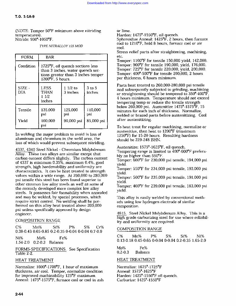
T.O. 1-IA-9
(NOTE: Temper 50F minimum above nitridingtemperatures).Nitride: 930-1050F.
TYPE NITRALLOY 135 MOD
FORM BAR
Condition 1725F, oil quench sections lessthan 3 inches, water quench sec-
tions greater than 3 inches temper1200F, 5 hours.
SIZE LESS 1 1/2 to 3 to 5DIA THAN 3 inches inches
1/2inches
Tensile 135,000 125,000 110,000psi psi psi
Yield 100,000 90,000 psi 85,000 psipsi
In welding the major problem to avoid is loss ofaluminum and chromium in the weld area, theloss of which would prevent subsequent nitriding.4337, 4340 Steel Nickel Chromium MolybdenumAlloy. These two alloys are similar except thatcarbon content differs slightly. The carbon contentof 4337 is minimum 0.35%, maximum 0.4%, goodstrength, high hardenability and uniformity arecharacteristics. It can be heat treated to strengthvalues within a wide range. At 260,000 to 280,000psi tensile this steel has been found superior toother common low alloy steels as well as some ofthe recently developed more complex low alloysteels. It possesses fair formability when annealedand may be welded, by special processes, whichrequire strict control. No welding shall be per-formed on this alloy heat treated above 200,000psi unless specifically approved by designengineer.COMPOSITION RANGE
C% Mn% Si% P% S% Cr%0.38-0.43 0.65-0.85 0.2-0.35 0-0.04 0-0.04 0.7-0.9
Ni% Mo% Fe%1.54-2.0 0.2-0.3 Balance
FORMS-SPECIFICATIONS. See SpecificationTable 2-2.
HEAT TREATMENT
Normalize: 1600-1700F, hour of maximumthickness, air cool. Temper, normalize conditionfor improved machinability 125F maximum.Anneal: 1475-1575F, furnace cool or cool in ash
or lime.Harden: 1475-1550F, oil quench.Spheroidize Anneal: 1425F, 2 hours, then furnacecool to 1210F, hold 8 hours, furnace cool or aircool.Stress relief parts after straightening, machining,etc.Temper: 1100F for tensile 150,000 yield, 142,000.Temper: 900F for tensile 190,000, yield, 176,000.Temper: 725F for tensile 220,000, yield, 200,000.Temper: 400-500F for tensile 260,000, 2 hoursper thickness, 6 hours minimum.
Parts heat treated to 260,000-280,000 psi tensileand subsequently subjected to grinding, machiningor straightening should be tempered to 350-400F,4 hours minimum. Temperature should not exceedtempering temp or reduce the tensile strengthbelow 260,000 psi. Austenitize 1475-1575F, 15minutes for each inch of thickness. Normalize,welded or brazed parts before austenitizing. Coolafter austenitizing.
To heat treat for regular machining, normalize or
austenitize, then heat to 1200F (maximum1250F) for 15-20 hours. Resulting hardnessshould be 229-248 BHN.
Austenitize: 1575-1625F, oil quench.Tempering range is limited to 400-600F prefera-bly no higher than 550F.Temper: 600F for 230,000 psi tensile, 194,000 psiyield.Temper: 550F for 234,000 psi tensile, 193,000 psiyield.Temper: 500F for 235,000 psi tensile, 191,000 psiyield.Temper: 400F for 239,000 psi tensile, 183,000 psiyield.This alloy is easily welded by conventional meth-ods using low hydrogen electrode of similarcomposition.
4615. Steel Nickel Molybdenum Alloy. This is ahigh grade carburizing steel for use where reliabil-ity and uniformity are required.COMPOSITION RANGE
C% Mn% P% S% Si% Ni%0.13-0.18 0.45-0.65 0-0.04 0-0.04 0.2-0.35 1.65-2.0
Mo% Fe%0.2-0.3 Balance
HEAT TREATMENT
Normalize: 1675-1725FAnneal: 1575-1625FHarden: 1425-1550F oil quench.Carburize: 1425-1550F
2-44
Downloaded from http://www.everyspec.com
Where case hardening is paramount, reheat to1425-1475F quench in oil. Tempering 250-350Fis optional. It is generally employed for partialstress relief and improved resistance to crackingfrom grinding operation.4620. Steel Nickel Molybdenum Alloy. This is amedium hardenability case steel. Its hardenabilitycharacteristics lie between that of plain carbonsteel and the high alloy carburized steel. It maybe used for average size case hardened automotiveparts such as gears, piston pins, crackshafts, etc.
COMPOSITION RANGE
C% Mn% P% S% Si% Ni%0.17-0.24 0.45-0.65 0-0.04 0-0.04 0.2-0.35 1.65-2.0
Mo% Fe%0.2-3.0 Balance
HEAT TREATMENT
Normalize: 1650-1750FAnneal: 1550-1600FQuench: (High temperature) 1550FQuench: (Low temperature) 1425FCarburize: 1650-1700F.
Recommend practice for maximum case hardness:Direct quench from pot.(1) Carburize: at 1700F for 8 hours.(2) Quench: in agitated oil.(3) Temper: at 300FCase depth: 0.075.Case hardness: RC62Single Quench and Temper:(1) Carburize: 1700F for 8 hours.(2) Pot cool.(3) Reheat: 1500F.(4) Quench: in agitated oil.(5) Temper: 300F.Case depth: 0.075.Case hardness: RC62Recommended practices for maximum core tough-ness: Direct quench from pot.(1) Carburize: 1700F for 8 hours.(2) Quench: in agitated oil.(3) Temper: 450F.Case depth: 0.06Case hardness: RC58Single Quench and Temper:(1) Carburize: 1700F for 8 hours.(2) Pot Cool.(3) Reheat: to 1500F(4) Quench: in agitated oil.(5) Temper: 450F.Case depth: .065Case hardness: RC59
4640. Steel Nickel Molybdenum. This steel hasexcellent machinability at high hardness levels,
T.O. 1-1A-9
and small distortion in heat treatment. Its applica-tion is primarily gears, spline shafts, hand tools,and machine parts.
COMPOSITION RANGE
C% Mn% P% S% Si% Ni%0.38-0.43 0.6-0.8 0-0.04 0-0.04 0.2-0.35 1.65-2.0
Mo% Fe%0.2-0.3 Balance
FORMS-SPECIFICATIONS. See SpecificationTable 2-2.
HEAT TREATMENT
Normalize: 1600-1750FAnneal: 1450-1550FQuench: 1450-1550F, oil quench, agitated oil.Temper: 1200F for 100,000 psi.Temper: 1100F for 120 to 140,000 psi.Temper: 1000F for 140 to 160,000 psi.Temper: 900F for 160 to 180,000 psi.Temper: 800F for 180 to 200,000 psi.Temper: 700F for 200 to 220,000 psi.
6150, 6152. Chromium Vanadium Alloy. Thesetwo steels are essentially the same, differing onlyin the amount of Vanadium. Alloy 6152 contains aminimum of 0.1% Vanadium. Typical usages arefor flat springs under 1/8 inch thick, cold formed,and 1/8 inch and over hot formed; oil quenched,and drawn at 725-900F to 44-48 or 48-52 RC,and for coil springs over 1/2 inch diameter withsame heat treatment. It is also used for valvesprings, piston rods, pump parts, spline shafts,etc.
COMPOSITION RANGE
C% Mn% P% S% Si% Cr%0.48-0.53 0.7-0.9 0-0.04 0-0.04 0.2-0.35 0.8-1.1
V% Fe%0.15 min Balance
FORM-SPECIFICATIONS. See Specification Table2-2.
HEAT TREATMENT
Normalize: 1625-1750F, furnace cool.Anneal: 1500-1600F. (Tensile psi 90,000 yield58,000 psi annealed.)Harden: 1550-1600F, oil quench.Temper: 1100F for tensile psi 150,000 yield psi137,000 psi.Temper: 800F for tensile psi 210,000 yield psi194,000 psi.Spheroidized annealed to 183-241 BHN 45%
8615. Steel-Ni-Cr-Mo Alloy. This is a triple alloycase-hardening steel with medium hardenability.
2-45
Downloaded from http://www.everyspec.com
T.O. 1-1A-9
It is primarily used for differential pinions, enginepins, gears etc.
COMPOSITION RANGE
C% Mn% P% S% Si% Ni% Cr%0.13-0.18 0.7-0.9 0-.04 0-0.04 0.2-0.3 0.4-0.6 0.4-0.6
Mo% Fe%0.15-0.25 Balance
FORMS-SPECIFICATIONS. See SpecificationTable 2-2.
HEAT TREATMENT
Psuedo-Carburize 1650-1700F, box cool, reheat1550F, oil quench.Temper: 300F for tensile 100,000 psi yield 72,500psi.Normalize: 1650-1725F.Anneal: 1575-1650F.Harden: 1475-1575F.
8617. Steel Ni-Cr-Mo Alloy. This steel is verysimilar to 8615, but develops somewhat greaterstrength.COMPOSITION RANGE
C% Mn% P% S% Si% Ni%0.15-0.2 0.7-0.9 0-0.04 0-0.04 0.2-0.35 0.4-0.7Cr%0.4-0.6
Mo% Fe%0.15-0.25 Balance
FORM-SPECIFICATIONS. See Specification Table2-2.
HEAT TREATMENT
Normalize: 1650-1725FAnneal: 1575-1650F.Harden: 1474-1575FCarburize: 1700F for 8 hours, oil quench.Draw at 300FTensile: 128,000 psi yield 94,000 psi.8620. Ni-Cr-Mo-Alloy. This steel is similar to8615 and 8617 though stronger. It is used for ringgears, transmission gears, cam shafts and for goodcore properties with high surface hardness aftercase hardening. It is also used in the heat treatedcondition as chain, at about 100,000 psi yieldstrength. It is classed as medium hardenable.
COMPOSITION RANGE
C% Mn% P% S% Si% Ni%0.18-0.23 0.7-0.9 0-0.04 0-0.04 0.2-0.35 0.4-0.7
Cr% Mo% Fe%0.4-0.6 0.15-0.25 Balance
FORMS-SPECIFICATIONS. See SpecificationTable 2-2.
HEAT TREATMENT
Normalize: 1600-1750F.Anneal: 1575-1625F.
CARBURIZING:
For maximum case hardness: Direct quench frompot.(1) Carburize: 1700F for 8 hours.(2) Quench: in agitated oil.(3) Temper: 300F.Case depth: 0.075.Case hardness: RC64.Single Quench and temper:(1) Carburize: 1700F for 8 hours.(2) Pot cooled.(3) Reheat: to 1550F.(4) Quench: in agitated oil.(5) Temper: 300F.Case depth: 0.075Case hardness: RC64Recommended practices for maximum core tough-ness.
Direct quench from pot.(1) Carburize: 1700F for 8 hours.(2) Quench: in agitated oil.(3) Temper: 450F.Case depth: 0.050Case hardness: RC58Single Quench and Temper.(1) Carburize: 1700F for 8 hours.(2) Pot cool.(3) Reheat: to 1500F.(4) Quench: in agitated oil.(5) Temper: 450F.Case depth: 0.076.Case hardness: RC61.
8630. Steel Ni-Cr-Mo Alloy This steel has charac-teristics very similar to 4130. It is used for air-craft engine mounts, and other aircraft parts dueto good properties when normalized in light sec-
tions, and its air hardening after welding.COMPOSITION RANGE
C% Mn% P% S% Si% Ni%0.28-0.33 0.7-0.9 0-0.04 0-0.04 0.2-0.35 0.4-0.7
Cr% Mo% Fe%0.4-0.6 0.15-0.25 Balance
FORMS-SPECIFICATIONS. See SpecificationTable 2-2.
HEAT TREATMENT
Normalize: 1550-1650F.Anneal: 1500-1550F (Tensile 90,000 psi, tensile
2-46
Downloaded from http://www.everyspec.com
T.O. 1-1A-9
60,000 annealed), furnace cool.Harden: 1500-1575F, oil or water quench.Temper: 1000F for 150,000 psi tensile, 140,000psi yield strength.Temper: 700F for 200,000 psi tensile, 180,000 psiyield strength.8640. Steel Ni-Cr-Mo. Typical uses, propellershafts, transmission gears, spline shafts, heavyduty bolts, etc. 4140 has higher strength and duc-tility and slightly better machinability.COMPOSITION RANGE
C% Mn% P% S% Si% Ni%0.38-0.43 0.75-1.0 0-0.04 0-0.04 0.2-0.35 0.4-0.7
Cr% Mo% Fe%0.4-0.6 0.15-0.25 Balance
FORMS-SPECIFICATIONS. See SpecificationTable 2-2.
HEAT TREATMENT
Normalize: 1550-1650F.Anneal: 1475-1575F.Harden: 1475-1575F, oil quench.Temper: 1100F for 145,000 psi tensile, 130,000psi yield.Temper: 800F for 200,000 psi tensile, 184,000 psiyield.Temper: 700F for 220,000 psi tensile, 205,000 psiyield.8735. Steel Ni-Cr-Mo. This metal is used forshapes, tubing, aircraft engine studs, knuckles,etc. It is similar in characteristics to 8630 and8640
FORMS-SPECIFICATIONS. See SpecificationTable 2-2.
COMPOSITION RANGE
C% Mn% P% S% Si% Ni%0.33-0.38 0.75-1.0 0-0.04 0-0.04 0.2-0.35 0.4-0.7
Cr% Mo% Fe%0.4-0.6 0.2-0.3 Balance
HEAT TREATMENT
Normalize: 1575-1625FAnneal: 1525-1525F.Harden: 1525-1600F Oil quench.Temper: 1200F for tensile 119,000 psi, yield93,000 psi.Temper: 1100F for tensile 131,000 psi, yield107,000 psi.Temper: 900F for tensile 149,000 psi, yield127,000 psiTemper: 800F for tensile 170,000 psiTemper: 775F for tensile 200,000 psi
8740. Steel Ni-Cr-Mo. This steel is similar to4140. It may be satisfactorily used for axles, tooljoints, bits, core drills, reamer bodies, drill collars,piston rods, aircraft engine bolts, shapes, tubingetc.
COMPOSITION RANGE
C% Mn% P% S% Si% Ni%0.38-0.43 0.75-1.0 0-0.04 0-0.04 0.2-0.35 0.4-0.7
Cr% Mo% Fe%0.4-0.6 0.2-0.3 Balance
FORMS-SPECIFICATIONS. See SpecificationTable 2-2
HEAT TREATMENT
Normalize: 1575-1625F.Anneal: 1500-1575F (Tensile 103,000 psi, yield66,000 psi annealed)Harden: 1500-1575F (Quench in agitated oil)Temper: 1100F for tensile 160,000 psi, yield152,000 psi.Temper: 900F for tensile 190,000 psi, yield183,000 psi.Temper: 800F for tensile 210,000 psi, yield198,000 psi.Temper: 725F for tensile 220,000.
9260, 9261, 9262. Steel Silicon. These are similaralloy spring steels, oil hardening type. The quan-tities of chromium in each, constitutes the onlychemical variations in these alloys. Typical appli-cations are coil and flat springs, axles, chisels,bolts. etc.
COMPOSITION RANGE
C% Mn% P% S% Si%9260 0.55-0.65 -0.7-1.0 0-0.04 0-0.04 1.8-2.2
Cr% Fe%Balance
C% Mn% P% S% Si%9261 0.55-0.65 0.75-1.0 0-0.04 0-0.04 1.8-2.2
Cr% Fe%0.1-0.25 Balance
C% Mn% P% S% Si%9262 0.55-0.65 0.75-1.0 0-0.04 0-0.04 1.8-2.2
Cr% Fe%0.25-0.4 Balance
FORMS-SPECIFICATION. See SpecificationTable 2-2.
HEAT TREATMENT
Normalize: 1600-1650F.Anneal: 1525-1575FHarden: 1575-1625F quench in agitated oil.
2-47
Downloaded from http://www.everyspec.com
T.O. 1-1A-9
Temper: 1100F for tensile 165,000 psi, yield144,000 psi.Temper: 900F for tensile 214,000 psi, yield192,000 psi.Temper: 600F for tensile 325,000 psi, yield280,000 psi.
9310. Steel Ni Cr-Mo (Electric Furnace Steel).This is a high hardenability case steel, since it is ahigh alloy, both the case and core have highhardenability. This type of steel is used particu-larly for carburized parts having thick sectionssuch as bearing races, heavy duty gears etc.
COMPOSITION RANGE
C% Mn% P% S% Si% Ni%0.7-0.13 0.4-0.7 0-0.025 0-0.025 0.2-0.35 2.95-3.55
Cr% Mo% Fe%1.0-1.45 0.08-0.15 Balance
FORMS-SPECIFICATIONS. See SpecificationTable 2-2.
HEAT TREATMENT
Normalize: 1625-1725F, air cool.Anneal: 1475-1575F, furnace cool.Recommended practice for maximum case hard-ness:Direct quench from pot.(1) Carburize: at 1700F for 8 hours.(2) Quench: in agitated oil.(3) Temper: 300F.Case depth: 0.047 inchCase hardness: RC62Single Quench and Temper:(1) Carburize: 1700F for 8 hours.(2) Pot cool.(3) Reheat: to 1450F.(4) Quench: in agitated oil.(5) Temper: 300F.Case depth: 0.047 inchCase hardness: RC62.To obtain maximum core toughness: Directquench from pot.(1) Carburize: 1700F for 8 hours.(2) Quench in agitated oil.(3) Temper: 450F.Case depth: 0.039 inch.Case hardness: RC54.Single quench and temper:(1) Carburize: 1700F for 8 hours.(2) Pot cool.(3) Reheat to 1450F.(4) Quench: in agitated oil.(5) Temper: 450F.Case depth: 0.047 inch.Case hardness: RC59.
Type 301. Steel Austenitic Stainless. This steelbelongs to the sub-family of 18-8 steels, which varyonly slightly in chromium and nickel and containno other metallic alloying element. This alloy maybe strengthened to an exceptional degree by coldwork. For best results, cold work should be fol-lowed by stress relieving at 400-800F.
COMPOSITION RANGE
C% Mn% Si% P% Cr% Ni% S%0.08-0.15 0-2.0 0-1.0 0-0.04 17.0-19.0 6.0-8.0 0-0.03
Cu% Fe%0-0.05 Balance
FORM-SPECIFICATION. See Specification Table2-2.
HEAT TREATMENT
Anneal: 1950-2050F,1 hour per inch thickness,water quench.Cool to 800F within 3 minutes maximum.To relieve the elastic characteristics and increasethe compressive yield strength of cold worked con-ditions, 400-800F, 36 to 8 hours maximumrespectively. After forming in order to preventstress cracking, full anneal, or alternately 600F,1/2 to 2 hours. This alloy can be hardened only bycold work. Maximum tensile strength, 1/4 hard125,000, 1/2 hard 150,000, full hard 185,000 psi.Full anneal is mandatory when, exposed to corro-sive media, such as hot chlorides, etc. which maylead to stress corrosion cracking.Type 302. Steel Austenitic Stainless. This alloy issimilar to Type 301 in composition and character-istics. It is inferior in strength to 301, however,possesses superior corrosive resistance. It is gen-erally used in the annealed conditions
COMPOSITION RANGE
C% Mn% Si% P% S% Cr%0.08-0.25 0-2.0 0-1.0 0-0.045 0-0.03 17.0-19.0
Ni% Fe%8.0-10.0 Balance
FORMS-SPECIFICATIONS. See SpecificationTable, 2-2.
HEAT TREATMENT
The heat treatment and resulting strength is simi-lar to that recommended for type 301, except thatthe temperature range for annealing type 302ranges between 1925-2075F.
Type 303, Type 303Se, Steel Austenitic Stainless.These varieties of the 18-8 austenitic stainlessfamily contain additions of sulphur and seleniumfor the purpose of improving machining character-istics. However the presence of these elements
2-48
Downloaded from http://www.everyspec.com
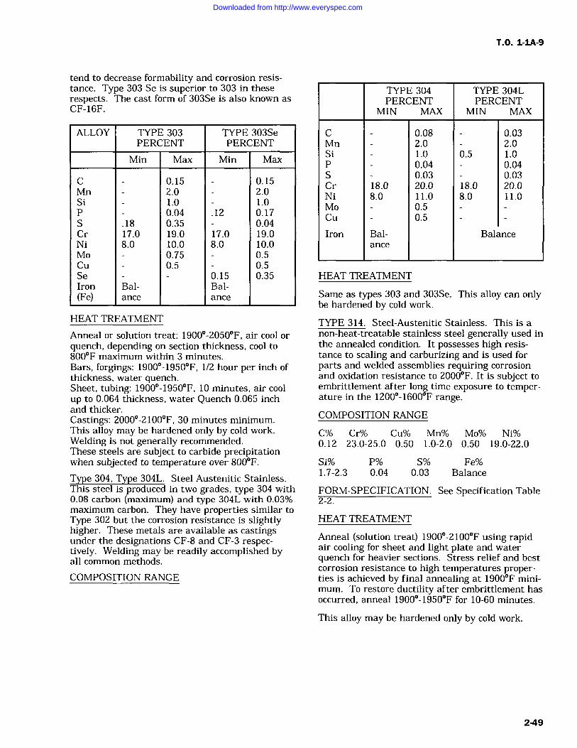
TO. 1-1A-9
tend to decrease formability and corrosion resis-tance. Type 303 Se is superior to 303 in theserespects. The cast form of 303Se is also known asCF-16F.
ALLOY TYPE 303PERCENT
TYPE 303SePERCENT
Min Max Min Max
C 0.15 0.15Mn 2.0 2.0Si 1.0 1.0P 0.04 .12 0.17S .18 0.35 0.04Cr 17.0 19.0 17.0 19.0Ni 8.0 10.0 8.0 10.0Mo 0.75 0.5Cu 0.5 0.5Se 0.15 0.35Iron Bal- Bal-(Fe) ance ance
HEAT TREATMENT
Anneal or solution treat: 1900-2050F, air cool or
quench, depending on section thickness, cool to800F maximum within 3 minutes.Bars, forgings: 1900-1950F, 1/2 hour per inch ofthickness, water quench.Sheet, tubing: 1900-1950F, 10 minutes, air coolup to 0.064 thickness, water Quench 0.065 inchand thicker.Castings: 2000-2100F, 30 minutes minimum.This alloy may be hardened only by cold work.Welding is not generally recommended.These steels are subject to carbide precipitationwhen subjected to temperature over 800F.
Type 304, Type 304L. Steel Austenitic Stainless.This steel is produced in two grades, type 304 with0.08 carbon (maximum) and type 304L with 0.03%maximum carbon. They have properties similar toType 302 but the corrosion resistance is slightlyhigher. These metals are available as castingsunder the designations CF-8 and CF-3 respec-tively. Welding may be readily accomplished byall common methods.
COMPOSITION RANGE
TYPE 304PERCENT
MIN MAX
TYPE 304LPERCENT
MIN MAX
C 0.08 0.03Mn 2.0 2.0Si 1.0 0.5 1.0P 0.04 0.04S 0.03 0.03Cr 18.0 20.0 18.0 20.0Ni 8.0 11.0 8.0 11.0Mo 0.5Cu 0.5
Iron Bal- Balanceance
HEAT TREATMENT
Same as types 303 and 303Se. This alloy can onlybe hardened by cold work.
TYPE 314. Steel-Austenitic Stainless. This is anon-heat-treatable stainless steel generally used inthe annealed condition. It possesses high resis-tance to scaling and carburizing and is used forparts and welded assemblies requiring corrosionand oxidation resistance to 2000F. It is subject toembrittlement after long time exposure to temper-ature in the 1200-1600F range.
COMPOSITION RANGE
C% Cr% Cu% Mn% Mo% Ni%0.12 23.0-25.0 0.50 1.0-2.0 0.50 19.0-22.0
Si% P% S% Fe%1.7-2.3 0.04 0.03 Balance
FORM-SPECIFICATION. See Specification Table2-2.
HEAT TREATMENT
Anneal (solution treat) 1900-2100F using rapidair cooling for sheet and light plate and waterquench for heavier sections. Stress relief and bestcorrosion resistance to high temperatures proper-ties is achieved by final annealing at 1900F mini-
mum. To restore ductility after embrittlement hasoccurred, anneal 1900-1950F for 10-60 minutes.
This alloy may be hardened only by cold work.
2-49
Downloaded from http://www.everyspec.com
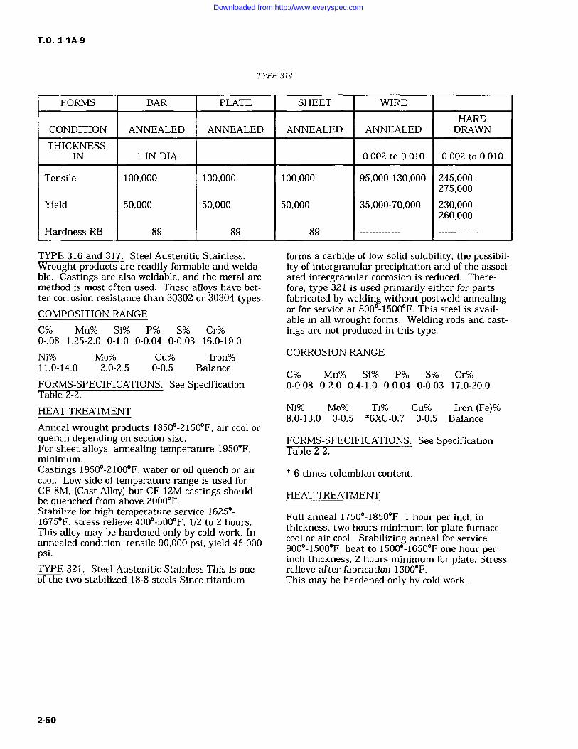
T.O. 1-1A-9
TYPE 314
FORMS BAR PLATE SHEET WIRE
HARDCONDITION ANNEALED ANNEALED ANNEALED ANNEALED DRAWN
THICKNESS-IN IN DIA 0.002 to 0.010 0.002 to 0.010
Tensile 100,000 100,000 100,000 95,000-130,000 245,000-275,000
Yield 50,000 50,000 50,000 35,000-70,000 230,000-260,000
Hardness RB 89 89 89
TYPE 316 and 317. Steel Austenitic Stainless.Wrought products are readily formable and welda-ble. Castings are also weldable, and the metal arcmethod is most often used. These alloys have bet-ter corrosion resistance than 30302 or 30304 types.COMPOSITION RANGE
C% Mn% Si% P% S% Cr%0-.08 1.25-2.0 0-1.0 0-0.04 0-0.03 16.0-19.0
Ni% Mo% Cu% Iron%11.0-14.0 2.0-2.5 0-0.5 Balance
FORMS-SPECIFICATIONS. See SpecificationTable 2-2.
forms a carbide of low solid solubility, the possibil-ity of intergranular precipitation and of the associ-ated intergranular corrosion is reduced. There-fore, type 321 is used primarily either for partsfabricated by welding without postweld annealingor for service at 800-1500F. This steel is avail-able in all wrought forms. Welding rods and cast-ings are not produced in this type.
CORROSION RANGE
C% Mn% Si% P% S% Cr%0-0.08 0-2.0 0.4-1.0 0-0.04 0-0.03 17.0-20.0
HEAT TREATMENT
Anneal wrought products 1850-2150F, air cool orquench depending on section size.For sheet alloys, annealing temperature 1950F,minimum.Castings 1950-2100F, water or oil quench or aircool. Low side of temperature range is used forCF 8M, (Cast Alloy) but CF 12M castings shouldbe quenched from above 2000F.Stabilize for high temperature service 1625-1675F, stress relieve 400-500F, 1/2 to 2 hours.This alloy may be hardened only by cold work. Inannealed condition, tensile 90,000 psi, yield 45,000psi.TYPE 321. Steel Austenitic Stainless.This is oneof the two stabilized 18-8 steels Since titanium
Ni% Mo% Ti% Cu% Iron (Fe)%8.0-13.0 0-0.5 *6XC-0.7 0-0.5 Balance
FORMS-SPECIFICATIONS. See SpecificationTable 2-2.
6 times columbian content.
HEAT TREATMENT
Full anneal 1750-1850F, 1 hour per inch inthickness, two hours minimum for plate furnacecool or air cool. Stabilizing anneal for service900-1500F, heat to 1500-1650F one hour perinch thickness, 2 hours minimum for plate. Stressrelieve after fabrication 1300F.This may be hardened only by cold work.
2-50
Downloaded from http://www.everyspec.com
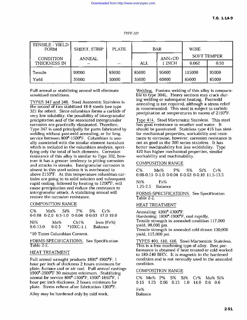
T.O. 1-IA-9
TYPE 321
TENSILE YIELDFORM SHEET, STRIP PLATE BAR WIRE
CONDITION ANNEAL ANN+CDSOFT TEMPER
THICKNESS IN ALL 1 INCH 0.062 0.50
Tensile 90000 85000 85000 95000 115000 95000
Yield 35000 30000 35000 60000 85000 65000
Full anneal or stabilizing anneal will eliminatesensitized conditions.
TYPES 347 and 348. Steel Austenitic Stainless isthe second of two stabilized 18-8 steels (see type321 for other). Since columbian forms a carbide ofvery low solubility, the possibility of intergranularprecipitation and of the associated intergranularcorrosion are practically eliminated. Therefore,Type 347 is used principally for parts fabricated bywelding without postweld annealing, or for longservice between 800-1500F. Columbian is usu-
ally associated with the similar element tantalumwhich is included in the columbian analysis, speci-fying only the total of both elements. Corrosionresistance of this alloy is similar to Type 302, how-ever it has a greater tendency to pitting corrosionand attacks in streaks. Intergranular corrosion isabsent in this steel unless it is overheated toabove 2150F. At this temperature columbian car-bides are going in to solid solution and subsequentrapid cooling, followed by heating to 1200F, willcause precipitation and reduce the resistance tointergranular attack. A stabilizing anneal willrestore the corrosion resistance.
Welding. Fusions welding of this alloy is compara-ble to type 304L. Heavy sections may crack dur-ing welding or subsequent heating. Postweldannealing is not required, although a stress reliefis recommended. This steel is subject to carbideprecipitation at temperatures in excess of 2150F.
Type 414. Steel Martensitic Stainless. This steelhas good resistance to weather and water. Itshould be passivated. Stainless type 416 has simi-lar mechanical properties, workability and resis-tance to corrosion, however, corrosion resistance isnot as good as the 300 series stainless. It hasbetter machinability but less weldability. Type420 has higher mechanical properties, similarworkability and machinability.COMPOSITION RANGE
C% Mn% P% S% Si% Cr%0.08-0.15 0-1.0 0-0.04 0-0.03 0-0.10 11.5-13.5
Ni% Fe%1.25-2.5 Balance
FORMS-SPECIFICATIONS. See SpecificationTable 2-2.
COMPOSITION RANGE
C% Mn% Si% P% S% Cr%0-0.08 0-2.0 0.5-1.0 0-0.04 0-0.03 17.0-19.0
Ni% Mo% Cbl% Iron (Fe%)9.0-13.0 0-0.5 * 10XC-1.1 Balance
* 10 Times Columbian Content.
FORMS-SPECIFICATIONS. See SpecificationTable 2-2.
HEAT TREATMENT
Full anneal wrought products 1800-1900F,hour per inch of thickness 2 hours minimum forplate, furnace cool or air cool. Full anneal castings1900-2000F 30 minutes minimum. Stabilizinganneal for service 800-1500F, 1500-1650F,hour per inch thickness, 2 hours minimum forplate. Stress relieve after fabrication 1300F.
Alloy may be hardened only by cold work.
HEAT TREATMENT
Annealing: 1200-1300F.Hardening: 1800-1900F, cool rapidly.Tensile strength in annealed condition 117,000yield, 98,000 psi.Tensile strength in annealed cold drawn 130,000yield, 115,000 psi.TYPES 403, 410, 416. Steel-Martensitic Stainless.This is a free machining type of alloy. Best per-formance is obtained if heat treated or cold workedto 180-240 BHN. It is magnetic in the hardenedcondition and is not normally used in the annealedcondition.
COMPOSITION RANGE
C% Mn% P% S% Si% Cr% Mo% Si%0.15 1.25 0.06 0.15 1.0 14.0 0.6 0.6
Fe%Balance
2-51
Downloaded from http://www.everyspec.com
T.O. 1-1A-9
FORMS-SPECIFICATION. See SpecificationTable 2-2.
HEAT TREATMENT
Anneal: 1500-1650F, furnace cool 50F per hourto 1100F.Harden: 1700-1850F, cool rapidly, oil andquench.Tensile Yield strength is as follows:
(1) Annealed Tensile 75,000 psi, yield 40,000 psi.(2) Heat Treated Tensile 110,000 psi, yield85,000 psi.(3) Tempered and Drawn Tensile 100,000 psi,yield 85,000 psi. Weldability is poor except by useof low-hydrogen electrodes.
Temper: 400-1300F. Avoid 700-1075F temperrange.Temper: 1300F for 100,000 psi.Temper: 1075F for 120,000 psi.Temper: 575-600F for 180,000 psi.TYPE 420. Steel Martensitic Stainless. This is amedium carbon grade of martensitic stainlesswhich in the past has been intensively used in thecutlery industry. It has recently proved satisfac-tory for air weapon application where its highstrength permits heat treatment for tensilestrength up to 240,000 psi. In the fully annealedcondition formability of this alloy almost equalsthe 1/4 hard austenitic stainless steels. Shearingtype operations such as blanking and punching are
not recommended. It machines best in conditionshaving approximately 225 BHN.
COMPOSITION RANGE
C% Mn% Si% P% S% Cr%0.3-0.4 0-1.0 0-1.0 0-0.04 0-0.03 12.0-14.0
Ni% Mo% Fe%0-0.5 0-0.5 Balance
FORMS-SPECIFICATIONS. See SpecificationTable 2-2.
HEAT TREATMENT
Full anneal 1550-1650F one hour per inch ofthickness, furnace cool (50F per hour) to 1100F.Subcritical anneal 1300-1350F, 3 hours mini-
mum, air cool. Austenitize 1800-1850F oilquench, depending on section size. Heavy sectionsshould be preheated at 1250F. Temper 400-1500F, 3 hours minimum. Tempering between600-1000F is not generally recommended due toreduced ductility and corrosion resistance.
TYPE 431. Steel Martensitic Stainless. This alloyis suitable for highly stressed parts in corrosiveenvironment.
COMPOSITION RANGE
C% Mn% Si% P% S% Cr%0.2 1.0 1.0 0.04 0.03 15.0-17.0Ni%1.25-2.5
Fe%Balance
FORMS-SPECIFICATIONS. See SpecificationTable 2-2.
HEAT TREATMENT
Type 431 steel must be protected from contamina-tion at furnace temperature by dry inert atmos-phere (organ, helium) or vacuum in the furnaceworking zones, except that air or salt bath fur-naces may be employed for tempering operations.Parts shall be transferred from furnace workingzones to the oil bath within a 30-second intervalprior to quenching. Materials in the solution-treated condition (not more than 2 percent segre-gated ferrite or austenite in the microstructure)may be hardened by the following treat treatment.
HT-200 CONDITION
Austenitize at 1850+/-25F for 30 minutes, quicklytransfer from furnace to oil quenching bath at not
over 100F followed by refrigeration at100F+/-10F for 2 hours, tempering at 550F+/-25Ffor 2 hours, air cool, and final temper at550+/-25F for 2 hours; or austenitize 1850+/-25Ffor 30 minutes, marquench into salt bath at 400F,air cool to room temperature, refrigerate at100+/-10F for 2 hours, temper 550+/-25F for 2hours, air cool, temper 550F for 2 hours.
HT-125 (125,000 tensile)Austenitize at 1850+/-25F for 30 minutes, quicklytransfer from furnace to oil quench to bath at not
over 100F, temper 1200+/-25F for 2 hours, aircool, temper 1200+/-25F for 2 hours.
CAUTION
Avoid tempering or holding withinrange from 700 to 1100F.
HT-1 15 (115,000 Tensile and Yield 90,000 PSI)Heat Cond A material to 1800-1900F for 30 min-utes, oil quench from furnace, temper at a temper-ature not lower than 1100F.
HT-175 (175,000 Tensile and 135,000 Yield PSI)Heat Cond A material to 1850-1950F, quench inoil from furnace temper at a temperature nothigher than 700F.
2-52 Change I
Downloaded from http://www.everyspec.com
T.O. 1-1A-9
17-4PH. Steel, Martensitic Stainless, PrecipitationHardening. This stainless steel possesses highstrength and good corrosion and oxidation resis-tance up to 600F.
COMPOSITION RANGE
C% Cb% Cr% Cu% Mn%0.07 max 0.15-0.45 15.5-17.5 3.0-5.0 1.0 max
Ni% P% S% Si% Fe%3.0-5.0 0.04 max .03 max 1.0 max Balance
SPECIFICATION: MIL-S-81506
HEAT TREATMENT
To condition A-1900+/-25F 30 minutes, air cool oroil quench below 90F.
From condition A toCondition H900(RH-C 40/47) 900 +/- 10F,1 hour, air cool.Condition H925(RH-C 38/45) 925 +/- 10F,4 hours, air cool.Condition H950(RH-C 37/44) 950 +/- 10F,4 hours, air cool.Condition H975 (RH-C 36/43) 975 +/- 10F,4 hours, air cool.Condition H1000(RH-C 35/42) 1000 +/- 10F,4 hours, air cool.Condition H 1025 (RH-C 35/42) 1025 +/- 10F,4 hours, air cool.Condition H1050(RH-C 33/40) 1050+/- 10F,4 hours, air cool.Condition H1075(RH-C 31/39) 1075 +/- 10F,4 hours, air cool.Condition H1100(RH-C 32/38) 1100 +/- 10F,4 hours, air cool.Condition H1125(RH-C 30/37) 1125 +/- 10F,4 hours, air cool.1 Condition H1150(RH-C 28/37) 1150 +/- 10F,4 hours, air cool.
17-7PH. Steel Martensitic Stainless (PrecipitationHardening). This stainless steel possesses goodcorrosion resistance, may be machined and formedin its annealed condition, and is used up to tem-peratures of 800F.
COMPOSITION RANGE
A% C% Cr% Mn% Ni%0.50-1.0 0.10-0.12 16.0-18.0 1.00 6.0-8.0
Si% P% S% Iron1.0-5.0 0.045 0.030 Balance
SPECIFICATION: See MIL-S-25043.
HEAT TREATMENT
Condition A. Solution anneal 1925-1975F, 30minutes per inch of thickness, air cool. Age condi-tion A to condition TH1050, 1375 to 1425F, 1-1/2
hour, air cool to 50 to 60F within 1 hour, hold at50 to 60F 1/2 hour (condition TO) + 1040 to1060F, 1-1/2 hour. Age condition A to conditionRH 950, 1735 to 1765F, 10 minutes, refrigerate(condition A 1750) to -90 to -110F 8 hours (con-dition R100), + 940 to 960F, 1 hour. Age condi-tion C of cold rolled sheet or cold drawn wire tocondition CH 900, 890 to 910F for hour.Condition A 130 to 150 KSI ultimate, 55 KSIyield.Condition T 125 to 145 KSI ultimate 75 to 100KSI yield.Condition RH950 200 to 215 KSI ultimate 180 to190 KSI yield.Condition RH1050 180 to 200 KSI ultimate 150to 185 KSI yield.Condition C 200 to 215 KSI ultimate 175 to 185KSI yield.Condition CH900 240 to 250 KSI ultimate, 230 to240 KSI yield.TYPE 440A, 440B, 550C, 440C. Steel MartensiticStainless. These steels are similar except for car-bon range, therefore they are grouped since heattreatment requirements are the same. Thesesteels are used for cutlery, valves, etc.
COMPOSITION RANGE
C% Mn% Si% P% S%440A0.6-0.75 max 1.0 max 1.0 max 0.04 max 0.03 max
Cr% Mo% Fe%16.0-18.0 max 0.75 max Balance
C% Mn% Si% P% S% Cr% Mo%440B0.75-0.95 1.0 1.0 0.04 0.03 16.0-18.0 0.75
Fe%Balance
C% Mn% Si% P% S% Cr% Mo%440C0.95-1.2 1.0 1.0 0.04 0.03 16.0-18.0 0.75
Fe%Balance
FORMS-SPECIFICATIONS. See SpecificationTable 2-2.
HEAT TREATMENT
Anneal: 1550 to 1650F.Temper: 300-800F.Harden: 1850-1950F, cool rapidly.440A, tensile 270,000 psi, yield 260,000 psi.
Change 3 2-53
Downloaded from http://www.everyspec.com
T.O. 1-IA-9
440B, tensile 280,000 psi, yield 270,000 psi.440C, tensile 285,000 psi, yield 275,000 psi.
Welding is not recommended.
15-7-MO. Steel Martensitic Stainless. This alloyis a further development of 17-7PH alloy and dueto molybdenum content it can be heat treated tohigh strength at room and elevated temperature(up to 1000F). The heat treatment is identical to17-7PH and other properties are identical or simi-lar to 17-7PH.
FORMS sheet, strip, plate, bars and forgings.SPECIFICATION AMS 5520, AMS 5657.
COMPOSITION RANGE
C% Mn% Si% P% S% Cr%0.09 1.0 1.0 0.4 0.03 14.0-16.0Ni%6.50-7.75
Mo% A1% Fe%2.0-3.0 0.75-1.50 Balance
HEAT TREATMENT
Condition A. Solution anneal sheet and strip,1925-1975F, 3 minutes per 0.1 inch thickness, aircool. Bar and forgings solution anneal 1925-1975F, 30 minutes per inch thickness, waterquench. Age condition A to condition TH1050,1375 to 1425F, 1-1/2 hour (austenite condition-ing), air cool to 50 60F within hour, hold at50 60F, 1/2 hour (condition T) +
1040 1060F,1-1/2 hour, air cool. Age condition A to conditionRH 950, 1735 1765F, 10 minutes (austeniteconditioning), air cool (condition A 1750) +/-90 to110F, 8 hours (condition R100) + 940 to 960F, 1hour, air cool. Age condition C, sheet cold rolledor wire cold drawn to condition CH 900, by heat-ing 890 -910F for 1 hour, air cool. TH and RHconditions are also used with difference final agehardening temperatures, such as TH1150,RH1050, etc.
TYPICAL PROPERTIES FOR VARIOUSCONDITIONS:
Condition A 130 to 150 KSI ultimate, 55-65 KSIyield, hardness 90-100.Condition T 125 to 145 KSI ultimate, 75-90 KSIyield, hardness 28-30.Condition TH1050 190 to 210 KSI ultimate, 170-200 KSI yield, hardness RC40-45.Condition RH950 225 to 240 KSI ultimate, 200-225 KSI yield, hardness RC46-48.Condition R100 180 KSI ultimate, 125 KSI yield,hardness RC40.Condition C 220 KSI ultimate, 190 yield, hard-ness RC45.
Condition CH900 265 KSI ultimate, 260 yield,hardness RC50.
PH 14-8 MO. This alloy (sheet) is similar to PH15-7 MO except it has slightly lower tensile andyield strength but considerable higher toughnessand superior welding characteristics. In generalthis alloy is unstable during exposure to tempera-tures exceeding 500F, which is a common charac-teristic of precipitation hardening stainless steels.
FORMS AND CONDITIONS available sheetand strip.Condition A annealed C cold worker.
CHEMICAL CONDITION
C% Mn% Si% Ph% S% Cr%0.02-0-05 1.0 1.0 0.015 1.0 13.50-15.50Ni%7.50-9.50
Me% Al% Fe%2.0-3.0 0.75-1.50 Rem
HEAT TREATMENT
Anneal to Condition A, 1800-1850F, 30 minutesair cool. Age condition A to SRH conditions, 16851715F, 1 hour, air cool and within hour cool to100F, 8 hours + age hour, air cool. Aging at940-960F or 1040-1060F is generally used withthe higher temperature giving somewhat lowerstrength but after better toughness. Age coldworked alloy, condition C, 890-910F or 1040-1060F, hour, air cool.
MECHANICAL PROPERTIES TYPICAL
Condition A 150 KSI ultimate, 65 KSI yield,hardness, RB100 max.Condition SRH 950 220 KSI ultimate, 190 KSIyield hardness RC40.
Condition SRH1050 200 KSI ultimate, 180 KSIyield, hardness RC38.
This alloy is subject to salt stress corrosion, how-ever, early test indicate it is superior in thisrespect to 17-7PH and PH 15-7 MO.
This general welding characteristics is similar to17-7 PH. Higher toughness may be obtained byannealing after welding and then heat treating.19-9 DL 19-9 DX. These stainless steels are notheat treatable, but can be hardened to a limitedextent by cold working or hot cold working. Inchemical composition 19-9DL contains columbiumwhich was replaced by a higher molybdenum andtitanium conten in 19-9DX.
CHEMICAL COMPOSITION OF 19-9DL:
2-54
Downloaded from http://www.everyspec.com
T.O. 1-1A-9
C% Mn% Si% Ph% Si% Cr%0.28-0.35 0.75-1.50 0.30-0.80 0.040 0.030 18.0-21.0
Ni% Mo% W% Cb+Ta Ti% Cu%8.0-11.0 1.0-1.75 1.0-1.75 0.10-0.35 0.10-0.35 0.50
Fe%Balance
CHEMICAL COMPOSITION 19-9DX:
C% Mn% Si% Ph% S% Cr%0.28-0.35 0.75-1.50 0.30-0.80 0.040 0.030 18.0-21.0
Ni% Mo% W% Ti% Cu% Fe%8.0-11.0 1.25-2.00 1.0-1.75 0.40-0.75 0.50 Balance
HEAT TREATMENT
Bar and forgings, 1800 to 2150F (1/2 to hour)rapid air cool, oil water quench. Sheet/strip, 1650to 1800F (1/2 to hour) rapid air cool. Avoidhigher temperatures to prevent resolution and pre-cipitation of carbides.Castings, 1950 to 2050, 1/2 to 1 hour minimum,air cool.Solution Treat: Same as anneal.Stress relief: 1175 to 1225F (4 hours) air cool.This treatment is applied to hot worked or hot coldworked material for service up to 1300F. It isalso applied to cold worked materials immediatelyafter working to prevent stress cracking.Age: Bar and forgings, 1200 to 1400F, casting1575 to 1625F, 8 hours minimum, air cool.
NOTE
Intergranular corrosion may occur incertain environments unless annealedat 1800F, followed by rapid cooling.
AM-350. Steel Age Hardening Stainless. Thisalloy is one of a series of age hardening steelswhich combines high strength at temperatures upto 800F and higher with the corrosion resistanceof stainless steels.
COMPOSITION RANGE
C% Mn% Si% P% S% Cr%0.08-0.12 0.5-1.25 0-0.5 0-0.04 0-0.03 16.0-17.0
Ni% Mo% N% Fe%4.0-5.0 2.5-3.25 0.07-0.13 Balance
FORM-SPECIFICATION TABLE 2-2.
HEAT TREATMENT
Anneal to condition H 1900 to 1950F, 3/4 hourminimum per inch of thickness, rapid air cool to80F. Anneal to condition L 1685 to 1735F, 3/4hour minimum, per inch of thickness, rapid aircool to 80F. Subzero cool and age condition L tocondition SCT, cool to 100F, hold 3 hours mini-mum +
850 to 1050F, 3 hours minimum Age to
condition SCT 850, 825 875F. Age to conditionSCT 1000 975 to 1025F. Double age either con-dition H or condition-L to condition DA, 13501400F, 2 hours, air cool to 80F and heat to 825875F, 3 hours. Thoroughly degreased and cleanedprior to annealing to avoid harmful surface reac-
tions and to facilitate subsequent pickling. Allow-ance must also be made for growth which willresult from heat treating. The expansion on agingfrom condition H to set amounts to 0.002 0.004inch per inch.
AM-355. Steel Age Hardening stainless Thisalloy combines high strength at temperatures upto 850F with the corrosive resistance of stainlesssteel. This alloy differs from AM-350 by a lowerchromium and a higher carbon content. It pos-sesses good formability in the high temperatureannealed condition. Corrosion resistance of thisalloy is slightly lower than that of AM-350.
FORM-SPECIFICATIONS. See Specification Table2-2.
HEAT TREATMENT
Anneal to condition H for maximum formabilityand stability.Anneal to condition H: Plate and forgings at1925-1975F, hour minimum per inch, waterquench: sheet and welded tubing, 1850 to 1900F,3/4 hour minimum per inch, rapid air cool. Barshould not be annealed to condition H unless sub-sequently subjected to forgings. Anneal to Condi-tion L: 1685-1735F ---Sheet and strip, 3/4 hourper inch, air cool; plate 3/4 hour inch, oil or waterquench. Condition H plate, if not subsequentlyseverely cold formed, should be equalized beforeannealing to condition L and aging to conditionSCT. Bar forgings and tubing, hour minimumper inch thickness, oil or water quench. Equalizeand age bar for best machineability, 1350-1400F,3 hours, air cool to 80F maximum + 1000 to1050F, 3 hours. Resulting should be approxi-mately RC38 Subzero cool and age condition L tocondition SCT, cool to -100F, hold 3 hour mini-mum, 850 to 1050F for 3 hours minimum. Agecondition SCT 850, 825 to 875F. Age to condi-tion SCT 1000, 975 to 1025F. Double age condi-tion L to condition DA, 1300 to 1450F 1 to 2hours, air cool to 80F, 825 to 875F, 3 hours min-imum. Homogenize sand and shell mold castings,2000F, 2-4 hours, air cool up to 1 inch thick, oil or
water quench, section above 1 inch.
HNM. Steel Age Hardening Stainless. This is aprecipitation hardening austenitic steel, with highrupture and creep properties in the 1000-1400and not prone to overage at these tempera-tures. In the solution annealed condition it has aBrinell hardness of 201 maximum. It has a low
2-55
Downloaded from http://www.everyspec.com
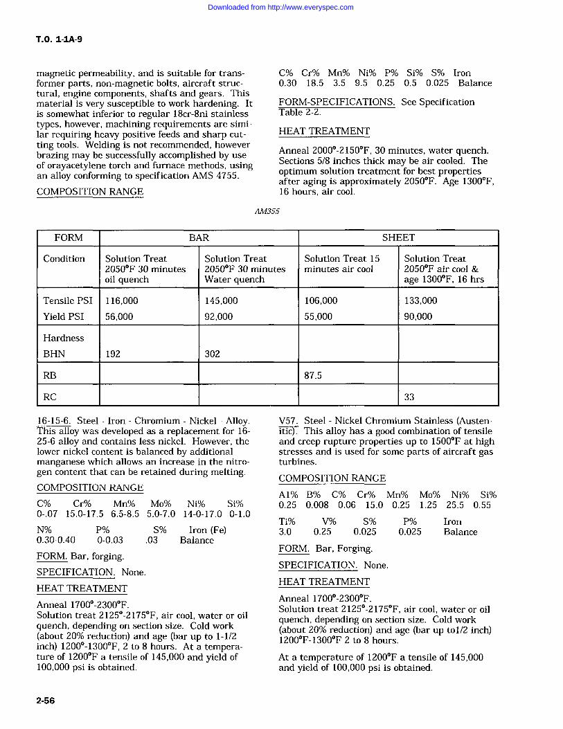
T.O. 1-1A-9
magnetic permeability, and is suitable for trans-former parts, non-magnetic bolts, aircraft struc-tural, engine components, shafts and gears. Thismaterial is very susceptible to work hardening. Itis somewhat inferior to regular 18cr-8ni stainlesstypes, however, machining requirements are simi-lar requiring heavy positive feeds and sharp cut-ting tools. Welding is not recommended, howeverbrazing may be successfully accomplished by useof orayacetylene torch and furnace methods, usingan alloy conforming to specification AMS 4755.
COMPOSITION RANGE
C% Cr% Mn% Ni% P% Si% S% Iron0.30 18.5 3.5 9.5 0.25 0.5 0.025 Balance
FORM-SPECIFICATIONS. See SpecificationTable 2-2.
HEAT TREATMENT
Anneal 2000-2150F, 30 minutes, water quench.Sections 5/8 inches thick may be air cooled. Theoptimum solution treatment for best propertiesafter aging is approximately 2050F. Age 1300F,16 hours, air cool.
AM355
FORM BAR SHEET
Condition Solution Treat Solution Treat Solution Treat 15 Solution Treat2050F 30 minutes 2050F 30 minutes minutes air cool 2050F air cool &oil quench Water quench age 1300F, 16 hrs
Tensile PSI 116,000 145,000 106,000 133,000
Yield PSI 56,000 92,000 55,000 90,000
Hardness
BHN 192 302
RB 87.5
RC 33
16-15-6. Steel Iron Chromium Nickel Alloy.This alloy was developed as a replacement for 16-25-6 alloy and contains less nickel. However, thelower nickel content is balanced by additionalmanganese which allows an increase in the nitro-gen content that can be retained during melting.COMPOSITION RANGE
C% Cr% Mn% Mo% Ni% Si%0-.07 15.0-17.5 6.5-8.5 5.0-7.0 14-0-17.0 0-1.0
N% P% S% Iron (Fe)0.30-0.40 0-0.03 .03 Balance
FORM. Bar, forging.SPECIFICATION. None.
HEAT TREATMENT
Anneal 1700-2300F.Solution treat 2125-2175F, air cool, water or oilquench, depending on section size. Cold work(about 20% reduction) and age (bar up to 1-1/2inch) 1200-1300F, 2 to 8 hours. At a tempera-ture of 1200F a tensile of 145,000 and yield of100,000 psi is obtained.
V57. Steel Nickel Chromium Stainless (Austen-itic This alloy has a good combination of tensileand creep rupture properties up to 1500F at highstresses and is used for some parts of aircraft gasturbines.
COMPOSITION RANGE
A1% B% C% Cr% Mn% Mo% Ni% Si%0.25 0.008 0.06 15.0 0.25 1.25 25.5 0.55
Ti% V% S% P% Iron3.0 0.25 0.025 0.025 Balance
FORM. Bar, Forging.SPECIFICATION. None.
HEAT TREATMENT
Anneal 1700-2300F.Solution treat 2125-2175F, air cool, water or oilquench, depending on section size. Cold work(about 20% reduction) and age (bar up tol/2 inch)1200F-1300F 2 to 8 hours.
At a temperature of 1200F a tensile of 145,000and yield of 100,000 psi is obtained.
2-56
Downloaded from http://www.everyspec.com
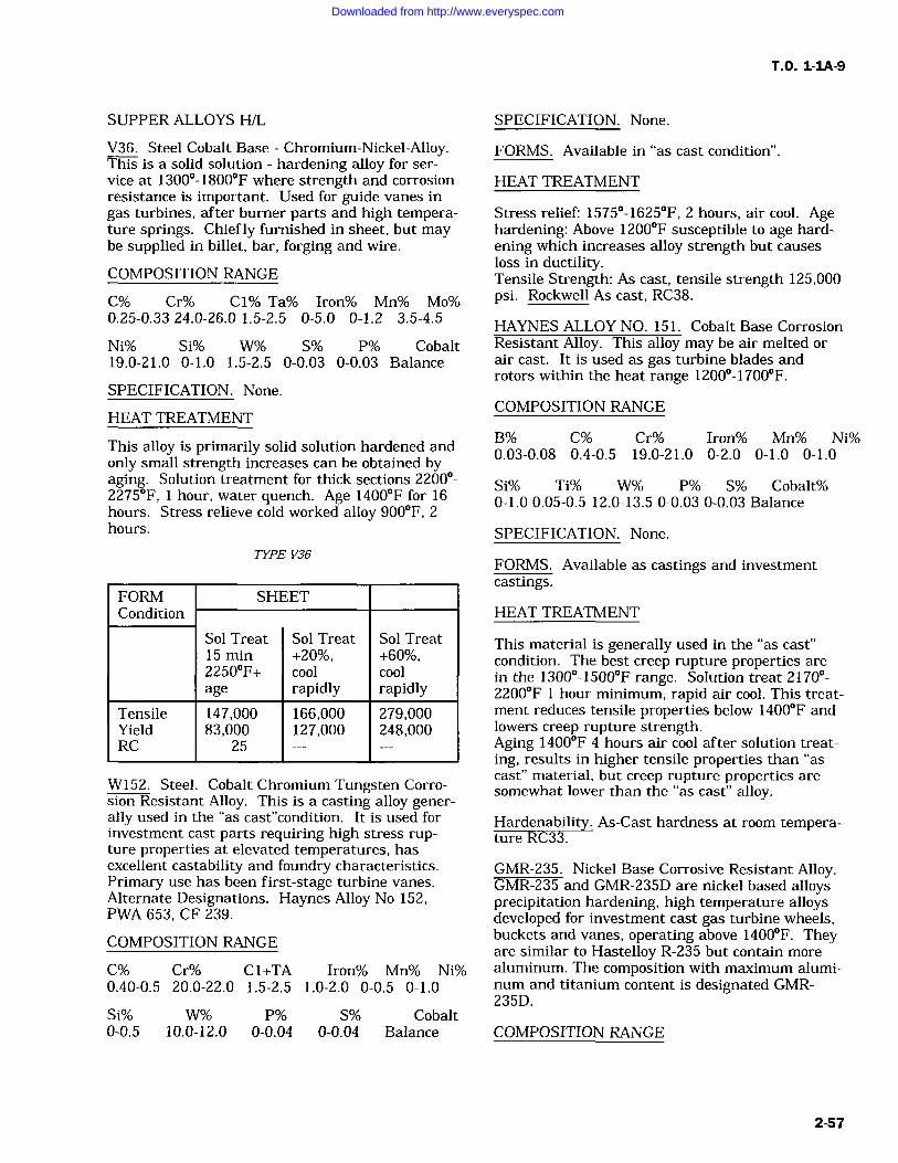
T.O. 1-1A-9
SUPPER ALLOYS H/L
V36. Steel Cobalt Base Chromium-Nickel-Alloy.This is a solid solution hardening alloy for ser-
vice at 1300-1800F where strength and corrosionresistance is important. Used for guide vanes in
gas turbines, after burner parts and high tempera-ture springs. Chiefly furnished in sheet, but maybe supplied in billet, bar, forging and wire.
COMPOSITION RANGE
C% Cr% C1% Ta% Iron% Mn% Mo%0.25-0.33 24.0-26.0 1.5-2.5 0-5.0 0-1.2 3.5-4.5
Ni% Si% W% S% P% Cobalt19.0-21.0 0-1.0 1.5-2.5 0-0.03 0-0.03 Balance
SPECIFICATION. None.
HEAT TREATMENT
SPECIFICATION. None.
FORMS. Available in "as cast condition".
HEAT TREATMENT
Stress relief: 1575-1625F, 2 hours, air cool. Agehardening: Above 1200F susceptible to age hard-ening which increases alloy strength but causesloss in ductility.Tensile Strength: As cast, tensile strength 125,000psi. Rockwell As cast, RC38.
HAYNES ALLOY NO. 151. Cobalt Base CorrosionResistant Alloy. This alloy may be air melted or
air cast. It is used as gas turbine blades androtors within the heat range 1200-1700F.
COMPOSITION RANGE
This alloy is primarily solid solution hardened andonly small strength increases can be obtained byaging. Solution treatment for thick sections 2200-2275F, hour, water quench. Age 1400F for 16hours. Stress relieve cold worked alloy 900F, 2hours.
TYPE V36
FORM SHEETCondition
Sol Treat Sol Treat Sol Treat15 min +20%, +60%,2250F+ cool coolage rapidly rapidly
Tensile 147,000 166,000 279,000Yield 83,000 127,000 248,000RC 25
W152. Steel. Cobalt Chromium Tungsten Corro-sion Resistant Alloy. This is a casting alloy gener-ally used in the "as-cast"condition. It is used forinvestment cast parts requiring high stress rup-ture properties at elevated temperatures, hasexcellent castability and foundry characteristics.Primary use has been first-stage turbine vanes.Alternate Designations. Haynes Alloy No 152,PWA 653, CF 239.
COMPOSITION RANGE
C% Cr% C 1+TA Iron% Mn% Ni%0.40-0.5 20.0-22.0 1.5-2.5 1.0-2.0 0-0.5 0-1.0
Si% W% P% S% Cobalt0-0.5 10.0-12.0 0-0.04 0-0.04 Balance
B% C% Cr% Iron% Mn% Ni%0.03-0.08 0.4-0.5 19.0-21.0 0-2.0 0-1.0 0-1.0
Si% Ti% W% P% S% Cobalt%0-1.0 0.05-0.5 12.0-13.5 0-0.03 0-0.03 Balance
SPECIFICATION. None.
FORMS. Available as castings and investmentcastings.
HEAT TREATMENT
This material is generally used in the "as cast"condition. The best creep rupture properties are
in the 1300-1500F range. Solution treat 2170-2200F hour minimum, rapid air cool. This treat-ment reduces tensile properties below 1400F andlowers creep rupture strength.Aging 1400F 4 hours air cool after solution treat-ing, results in higher tensile properties than "ascast" material, but creep rupture properties are
somewhat lower than the "as cast" alloy.
Hardenability. As-Cast hardness at room tempera-ture RC33.
GMR-235. Nickel Base Corrosive Resistant Alloy.GMR-235 and GMR-235D are nickel based alloysprecipitation hardening, high temperature alloysdeveloped for investment cast gas turbine wheels,buckets and vanes, operating above 1400F. Theyare similar to Hastelloy R-235 but contain morealuminum. The composition with maximum alumi-num and titanium content is designated GMR-235D.
COMPOSITION RANGE
2-57
Downloaded from http://www.everyspec.com
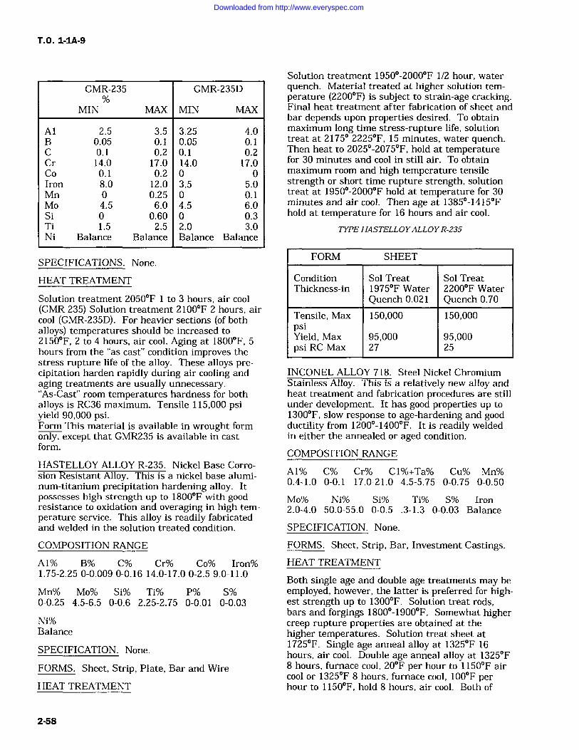
T.O. 1-1A-9
GMR-235
MIN MAX
GMR-235D
MIN MAX
Al 2.5 3.5 3.25 4.0B 0.05 0.1 0.05 0.1C 0.1 0.2 0.1 0.2Cr 14.0 17.0 14.0 17.0Co 0.1 0.2 0 0Iron 8.0 12.0 3.5 5.0Mn 0 0.25 0 0.1Mo 4.5 6.0 4.5 6.0Si 0 0.60 0 0.3Ti 1.5 2.5 2.0 3.0Ni Balance Balance Balance Balance
SPECIFICATIONS. None.
HEAT TREATMENT
Solution treatment 2050F 1 to 3 hours, air cool(GMR 235) Solution treatment 2100F 2 hours, aircool (GMR-235D). For heavier sections (of bothalloys) temperatures should be increased to2150F, 2 to 4 hours, air cool. Aging at 1800F, 5hours from the "as cast" condition improves thestress rupture life of the alloy. These alloys pre-cipitation harden rapidly during air cooling andaging treatments are usually unnecessary."As-Cast" room temperatures hardness for bothalloys is RC36 maximum. Tensile 115,000 psiyield 90,000 psi.Form This material is available in wrought formonly, except that GMR235 is available in castform.
HASTELLOY ALLOY R-235. Nickel Base Corro-sion Resistant Alloy. This is a nickel base alumi-num-titanium precipitation hardening alloy. Itpossesses high strength up to 1800F with goodresistance to oxidation and overaging in high tem-perature service. This alloy is readily fabricatedand welded in the solution treated condition.
COMPOSITION RANGE
Al% B% C% Cr% Co% Iron%1.75-2.25 0-0.009 0-0.16 14.0-17.0 0-2.5 9.0-11.0
Mn% Mo% Si% Ti% P% S%0-0.25 4.5-6.5 0-0.6 2.25-2.75 0-0.01 0-0.03
Ni%Balance
SPECIFICATION. None.
FORMS. Sheet, Strip, Plate, Bar and Wire
HEAT TREATMENT
Solution treatment 1950-2000F 1/2 hour, waterquench. Material treated at higher solution tem-perature (2200F) is subject to strain-age cracking.Final heat treatment after fabrication of sheet andbar depends upon properties desired. To obtainmaximum long time stress-rupture life, solutiontreat at 2175 2225F, 15 minutes, water quench.Then heat to 2025-2075F, hold at temperaturefor 30 minutes and cool in still air. To obtainmaximum room and high temperature tensilestrength or short time rupture strength, solutiontreat at 1950-2000F hold at temperature for 30minutes and air cool. Then age at 1385-1415Fhold at temperature for 16 hours and air cool.
TYPE HASTELLOYALLOYR-235
FORM SHEET
Condition Sol Treat Sol TreatThickness-in 1975F Water 2200F Water
Quench 0.021 Quench 0.70
Tensile, Max 150,000 150,000psiYield, Max 95,000 95,000psi RC-Max 27 25
INCONEL ALLOY 718. Steel Nickel ChromiumStainless Alloy. This is a relatively new alloy andheat treatment and fabrication procedures are stillunder development. It has good properties up to1300F, slow response to age-hardening and goodductility from 1200-1400F. It is readily weldedin either the annealed or aged condition.
COMPOSITION RANGE
A1% C% Cr% C1%+Ta% Cu% Mn%0.4-1.0 0-0.1 17.0-21.0 4.5-5.75 0-0.75 0-0.50
Mo% Ni% Si% Ti% S% Iron2.0-4.0 50.0-55.0 0-0.5 .3-1.3 0-0.03 Balance
SPECIFICATION. None.
FORMS. Sheet, Strip, Bar, Investment Castings.HEAT TREATMENT
Both single age and double age treatments may beemployed, however, the latter is preferred for high-est strength up to 1300F. Solution treat rods,bars and forgings 1800-1900F. Somewhat highercreep rupture properties are obtained at thehigher temperatures. Solution treat sheet at1725F. Single age anneal alloy at 1325F 16hours, air cool. Double age anneal alloy at 1325F8 hours, furnace cool, 20F per hour to 1150F aircool or 1325F 8 hours, furnace cool, 100F perhour to 1150F, hold 8 hours, air cool. Both of
2-58
Downloaded from http://www.everyspec.com
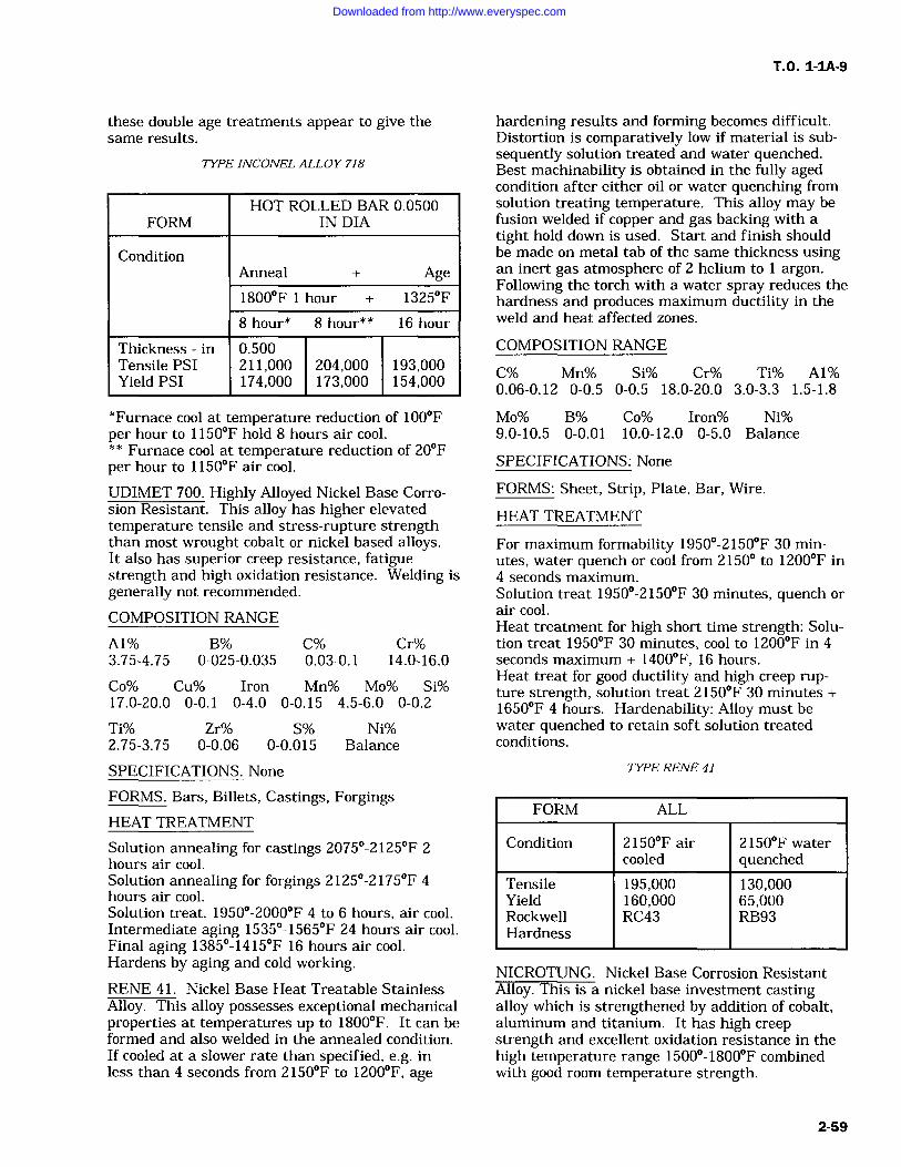
these double age treatments appear to give thesame results.
TYPE INCONEL ALLOY 718
HOT ROLLED BAR 0.0500FORM IN DIA
ConditionAnneal + Age1800F 1 hour + 1325F
8 hour* 8 hour** 16 hour
Thickness in 0.500Tensile PSI 211,000 204,000 193,000Yield PSI 174,000 173,000 154,000
*Furnace cool at temperature reduction of 100Fper hour to 1150F hold 8 hours air cool.* * Furnace cool at temperature reduction of 20Fper hour to 1150F air cool.
UDIMET 700. Highly Alloyed Nickel Base Corro-sion Resistant. This alloy has higher elevatedtemperature tensile and stress-rupture strengththan most wrought cobalt or nickel based alloys.It also has superior creep resistance, fatiguestrength and high oxidation resistance. Welding isgenerally not recommended.
COMPOSITION RANGE
A1% B% C% Cr%3.75-4.75 0-025-0.035 0.03-0.1 14.0-16.0
Cc% Cu% Iron Mn% Mo% Si%17.0-20.0 0-0.1 0-4.0 0-0.15 4.5-6.0 0-0.2
Ti% Zr% S% Ni%2.75-3.75 0-0.06 0-0.015 Balance
SPECIFICATIONS. None
FORMS. Bars, Billets, Castings, ForgingsHEAT TREATMENT
Solution annealing for castings 2075-2125F 2hours air cool.Solution annealing for forgings 2125-2175F 4hours air cool.Solution treat. 1950-2000F 4 to 6 hours, air cool.Intermediate aging 1535-1565F 24 hours air cool.Final aging 1385-1415F 16 hours air cool.Hardens by aging and cold working.RENE 41. Nickel Base Heat Treatable StainlessAlloy. This alloy possesses exceptional mechanicalproperties at temperatures up to 1800F. It can beformed and also welded in the annealed condition.If cooled at a slower rate than specified, e.g. inless than 4 seconds from 2150F to 1200F, age
T.O. 1-1A-9
hardening results and forming becomes difficult.Distortion is comparatively low if material is sub-sequently solution treated and water quenched.Best machinability is obtained in the fully agedcondition after either oil or water quenching fromsolution treating temperature. This alloy may befusion welded if copper and gas backing with a
tight hold down is used. Start and finish shouldbe made on metal tab of the same thickness usingan inert gas atmosphere of 2 helium to 1 argon.Following the torch with a water spray reduces thehardness and produces maximum ductility in theweld and heat affected zones.
COMPOSITION RANGE
C% Mn% Si% Cr% Ti% A1%0.06-0.12 0-0.5 0-0.5 18.0-20.0 3.0-3.3 1.5-1.8
Mo% B% Co% Iron% Ni%9.0-10.5 0-0.01 10.0-12.0 0-5.0 Balance
SPECIFICATIONS: None
FORMS: Sheet, Strip, Plate, Bar, Wire.
HEAT TREATMENT
For maximum formability 1950-2150F 30 min-utes, water quench or cool from 2150 to 1200F in4 seconds maximum.Solution treat 1950-2150F 30 minutes, quench or
air cool.Heat treatment for high short time strength: Solu-tion treat 1950F 30 minutes, cool to 1200F in 4seconds maximum + 1400F, 16 hours.Heat treat for good ductility and high creep rup-ture strength, solution treat 2150F 30 minutes +1650F 4 hours. Hardenability: Alloy must bewater quenched to retain soft solution treatedconditions.
TYPE RENE 41
FORM ALL
Condition 2150F air 2150F watercooled quenched
Tensile 195,000 130,000Yield 160,000 65,000Rockwell RC43 RB93Hardness
NICROTUNG. Nickel Base Corrosion ResistantAlloy. This is a nickel base investment castingalloy which is strengthened by addition of cobalt,aluminum and titanium. It has high creepstrength and excellent oxidation resistance in thehigh temperature range 1500-1800F combinedwith good room temperature strength.
2-59
Downloaded from http://www.everyspec.com
T.O. 1-1A-9
COMPOSITION RANGE
A1% B% C% Cr% Co%3.75-4.75 0.02-0.08 0.08-0.13 11.0-13.0 9.0-11.0
Ti% W% Zr% Ni%3.75-4.75 7.0-8.5 0.02-0.08 Balance
SPECIFICATIONS. None
FORMS. Investment castings.HEAT TREATMENT
Heat treatment is not recommended for this alloy.This material has "as-cast" hardness of RC38-40.
NIMONIC 105. Nickel-Cobalt-Chromium Corro-sion Resistant Alloy. This alloy has excellentresistance to creep at very high temperatures. Itis designed for use as turbine blades and rotorsused in gas turbines. Corrosion resistance is goodand resistance to oxidation under repeated heatingand cooling is very good.COMPOSITION RANGE
A1% C% Cr% Co% Cu% Iron%4.2-4.8 0-0.2 13.5-16.0 18.0-22.0 0-0.5 0-1.0
Mn% Mo% S1% Ti% Ni%0-1.0 4.5-5.5 0-1.0 0.9-1.5 Balance
SPECIFICATION. None
FORMS. Sheet, Strip, Bar.
HEAT TREATMENT
For maximum stress-rupture life in range 1560-1740F, fully heat treat solution treat, and doubleage as follows: Solution treat 2102F 4 hours, aircool. Double age 1922F, 16 hours, air cool and1526F, 8 hours, air cool. Where stress rupturestrength above 1562F is not the important prop-erty, but tensile strength, elongation and impactstrength up to 1292F is desired, the followingheat treatment is recommended.
Solution treat 2104F, 4 hours, air cool.Age 1562F, 16 hours, air cool.
2-75. MACHINING OF STEELS (GENERAL).
2-76. There are five basic factors affectingmachinability as related to steel:
a. The capacity and rigidity of the machinetool.
b. Cutting fluids.
c. Design composition and hardness of thecutting tool.
d. Cutting condition with respect to feeds andspeeds,
e. The structure of the steel to be machined.
2-77. The cutting tool angles (back rake, sideclearance, front clearance, and side rake) are
highly important in the machining of metals. Therange of values based on general practice for themachining of steel and steel alloys, are as follows:
a. Back rake angle, 8-16 degrees.
b. Side rake angle, 12-22 degrees.
c. Front clearance angle, 8-13 degrees.
d. Side clearance angle, 10-15 degrees.
2-78. Regardless of the material of which thecutting tool is made, the cutting action is thesame. The main difference is the cutting speed.The carbon-steel tool cuts at low speed. The high-speed tool cuts at twice the speed of carbon-steel,the cast alloys at twice the speed of high-speedsteel, and the sintered carbides at twice that ofthe cast alloys. The cutting speeds listed in Table2-4 are approximate speeds using high-speed steeltools, and are to be used only as a basis fromwhich proper speeds for a particular part may becalculated. These speeds are based on SAE 1112steel, which is assigned a machinability rating of100%. In order to obtain an approximate startingspeed for different steels, select the type of opera-tion, the width, depth or diameter of cut andobtain the recommended cutting speed for SAE1112 from Table 2-3 then refer to Table 2-4 for thepercent rating of the metal to be machined, andmultiply the SFM value from Table 2-5 by the rat-ing in Table 2-4. The result is the recommendedsurface feet per minute (SFM) for the cutting oper-ation. For a known diameter and surface feet perminute (SFM) be used for an operation, the corre-sponding revolution per minute (RPM) can beobtained from Table 2-5.
2-79. The term cutting feed is used to expressthe axial distance the tool moves in each revolu-tion. A course feed is usually used for roughingoperations, and a fine feed for finishing opera-tions. In general, the feed remains the same fordifferent cutting tool steels, and only the speed ischanged. Approximate cutting feeds are listed inTable 2-3. For tool corrections when impropermachining on an operation is encountered, refer toTable 2-6 for recommended checks.
2-80. The use of a proper coolant (cutting fluid)often results in an increase of cutting speed forthe same tool life, and also acts as a lubricant giv-ing better cutting action and surface finish. Rec-ommended cutting fluids for steels are lard oil,mineral oils, sulphurized oils, and soluble or emul-sifiable oils.
2-60
Downloaded from http://www.everyspec.com
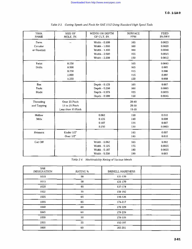
T.O. 1-1A-9
Table 2-3. Cutting Speeds and Feeds for SAE 1112 Using Standard High Speed Tools
TOOL SIZE OF WIDTH OR DEPTH SURFACE FEEDNAME HOLE, IN. OF CUT, IN. FPM IN./REV
Form Width 0.500 165 0.0025
Circular Width 1.000 160 0.0020
or Dovetail Width 1.500 160 0.0018
Width 2.000 155 0.0015
Width 2.500 150 0.0012
Twist 0.250 105 0.0045
Drills 0.500 105 0.005
0.750 115 0.006
1.000 115 0.007
1.250 120 0.008
Box Depth 0.125 165 0.007
Tools Depth 0.250 160 0.0065
Blade Depth 0.375 155 0.0055
Depth 0.500 150 0.0045
Threading Over 25 Pitch 30-40
and Tapping 15 to 25 Pitch 20-30
Less than 15 Pitch 15-20
Hollow 0.062 150 0.010
Mills 0.125 140 0.008
0.187 135 0.007
0.250 130 0.0065
Reamers Under 1/2" 145 0.007
Over 1/2" 145 0.010
Cut Off Width 0.062 165 0.002
Width 0.125 175 0.0025
Width 0.187 180 0.0025
Width 0.250 190 0.003
Table 2-4. Machinability Rating of Various Metals
SAEDESIGNATION RATING % BRINELL HARDNESS
1010 50 131-170
1015 50 131-170
1020 65 137-174
1022 70 159-192
1025 65 116-126
1035 65 174-217
1040 60 179-229
1045 60 179-229
1050 50 179-229
1055 55 192-197
1060 60 183-201
2-61
Downloaded from http://www.everyspec.com
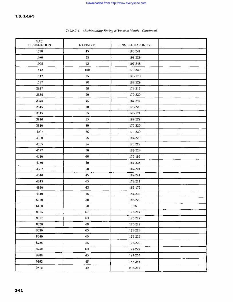
T.O. 1-1A-9
Table 2-4. Machinability Rating of Various Metals Continued
SAEDESIGNATION RATING % BRINELL HARDNESS
1070 45 183-241
1080 45 192-229
1095 42 197-248
1112 100 179-229
1117 85 143-179
1137 70 187-229
2317 55 174-217
2330 50 179-229
2340 45 187-241
2515 30 179-229
3115 65 143-174
3140 55 187-229
3310 40 170-229
4037 65 170-229
4130 65 187-229
4135 64 170-229
4137 60 187-229
4140 66 179-197
4150 50 187-235
4337 50 187-241
4340 45 187-241
4615 65 174-217
4620 62 152-179
4640 55 187-235
5210 30 183-229
6150 50 197
8615 67 170-217
8617 63 170-217
8620 60 170-217
8630 65 179-229
8640 60 179-229
8735 55 179-229
8740 60 179-229
9260 45 187-255
9262 45 187-255
9310 40 207-217
2-62
Downloaded from http://www.everyspec.com
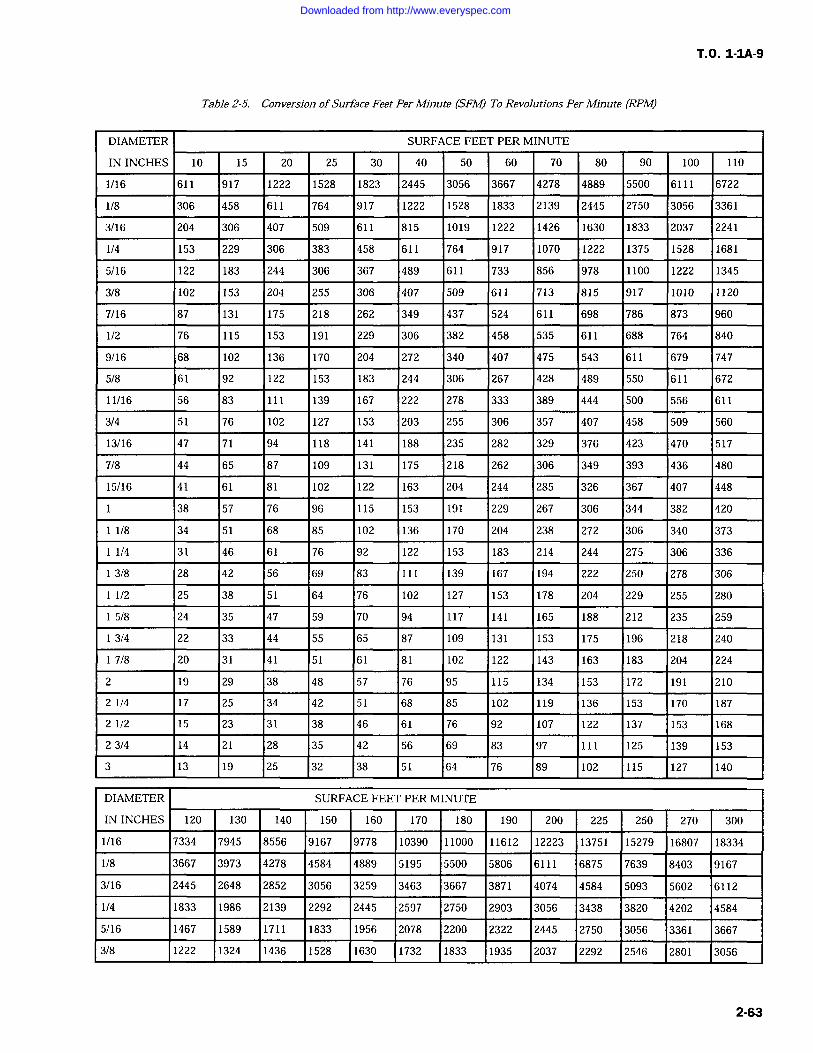
T.O. 1-IA-9
Table 2-5. Conversion ofSurface Feet Per Minute (SFM) To Revolutions Per Minute (RPM)
DIAMETER SURFACE FEET PER MINUTE
IN INCHES 10 15 20 25 30 40 50 60 70 80 90 100 110
1/16 611 917 1222 1528 1823 2445 3056 3667 4278 4889 5500 6111 6722
1/8 306 458 611 764 917 1222 1528 1833 2139 2445 2750 3056 3361
3/16 204 306 407 509 611 815 1019 1222 1426 1630 1833 2037 2241
1/4 153 229 306 383 458 611 764 917 1070 1222 1375 1528 1681
5/16 122 183 244 306 367 489 611 733 856 978 1100 1222 1345
3/8 102 153 204 255 306 407 509 611 713 815 917 1010 1120
7/16 87 131 175 218 262 349 437 524 611 698 786 873 960
1/2 76 115 153 191 229 306 382 458 535 611 688 764 840
9/16 68 102 136 170 204 272 340 407 475 543 611 679 747
5/8 61 92 122 153 183 244 306 267 428 489 550 611 672
11/16 56 83 111 139 167 222 278 333 389 444 500 556 611
3/4 51 76 102 127 153 203 255 306 357 407 458 509 560
13/16 47 71 94 118 141 188 235 282 329 376 423 470 517
7/8 44 65 87 109 131 175 218 262 306 349 393 436 480
15/16 41 61 81 102 122 163 204 244 285 326 367 407 448
38 57 76 96 115 153 191 229 267 306 344 382 420
1/8 34 51 68 85 102 136 170 204 238 272 306 340 373
1/4 31 46 61 76 92 122 153 183 214 244 275 306 336
3/8 28 42 56 69 83 111 139 167 194 222 250 278 306
1/2 25 38 51 64 76 102 127 153 178 204 229 255 280
5/8 24 35 47 59 70 94 117 141 165 188 212 235 259
3/4 22 33 44 55 65 87 109 131 153 175 196 218 240
7/8 20 31 41 51 61 81 102 122 143 163 183 204 224
2 19 29 38 48 57 76 95 115 134 153 172 191 210
2 1/4 17 25 34 42 51 68 85 102 119 136 153 170 187
2 1/2 15 23 31 38 46 61 76 92 107 122 137 153 168
23/4 14 21 28 35 42 56 69 83 97 111 125 139 153
3 13 19 25 32 38 51 64 76 89 102 115 127 140
DIAMETER SURFACE FEET PER MINUTE
IN INCHES 120 130 140 150 160 170 180 190 200 225 250 270 300
1/16 7334 7945 8556 9167 9778 10390 11000 11612 12223 13751 15279 16807 18334
1/8 3667 3973 4278 4584 4889 5195 5500 5806 6111 6875 7639 8403 9167
3/16 2445 2648 2852 3056 3259 3463 3667 3871 4074 4584 5093 5602 6112
1/4 1833 1986 2139 2292 2445 2597 2750 2903 3056 3438 3820 4202 4584
5/16 1467 1589 1711 1833 1956 2078 2200 2322 2445 2750 3056 3361 3667
3/8 1222 1324 1436 1528 1630 1732 1833 1935 2037 2292 2546 2801 3056
2-63
Downloaded from http://www.everyspec.com
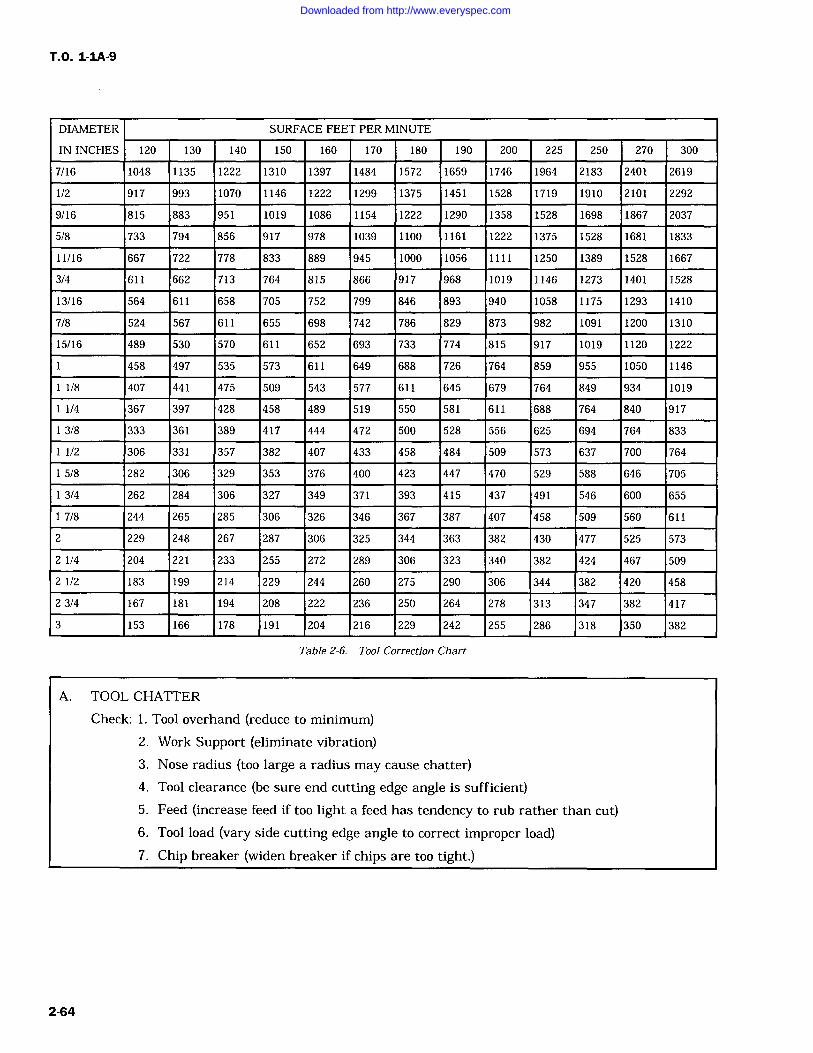
T.O. 1-IA-9
DIAMETER SURFACE FEET PER MINUTE
IN INCHES 120 130 140 150 160 170 180 190 200 225 250 270 300
7/16 1048 1135 1222 1310 1397 1484 1572 1659 1746 1964 2183 2401 2619
1/2 917 993 1070 1146 1222 1299 1375 1451 1528 1719 1910 2101 2292
9/16 815 883 951 1019 1086 1154 1222 1290 1358 1528 1698 1867 2037
5/8 733 794 856 917 978 1039 1100 1161 1222 1375 1528 1681 1833
11/16 667 722 778 833 889 945 1000 1056 1111 1250 1389 1528 1667
3/4 611 662 713 764 815 866 917 968 1019 1146 1273 1401 1528
13/16 564 611 658 705 752 799 846 893 940 1058 1175 1293 1410
7/8 524 567 611 655 698 742 786 829 873 982 1091 1200 1310
15/16 489 530 570 611 652 693 733 774 815 917 1019 1120 1222
458 497 535 573 611 649 688 726 764 859 955 1050 1146
1/8 407 441 475 509 543 577 611 645 679 764 849 934 1019
1/4 367 397 428 458 489 519 550 581 611 688 764 840 917
3/8 333 361 389 417 444 472 500 528 556 625 694 764 833
1/2 306 331 357 382 407 433 458 484 509 573 637 700 764
5/8 282 306 329 353 376 400 423 447 470 529 588 646 705
3/4 262 284 306 327 349 371 393 415 437 491 546 600 655
7/8 244 265 285 306 326 346 367 387 407 458 509 560 611
2 229 248 267 287 306 325 344 363 382 430 477 525 573
2 1/4 204 221 233 255 272 289 306 323 340 382 424 467 509
2 1/2 183 199 214 229 244 260 275 290 306 344 382 420 458
2 3/4 167 181 194 208 222 236 250 264 278 313 347 382 417
3 153 166 178 191 204 216 229 242 255 286 318 350 382
Table 2-6. Tool Correction Chart
A. TOOL CHATTER
Check: 1. Tool overhand (reduce to minimum)2. Work Support (eliminate vibration)3. Nose radius (too large a radius may cause chatter)4. Tool clearance (be sure end cutting edge angle is sufficient)5. Feed (increase feed if too light a feed has tendency to rub rather than cut)6. Tool load (vary side cutting edge angle to correct improper load)7. Chip breaker (widen breaker if chips are too tight.)
2-64
Downloaded from http://www.everyspec.com
T.O. 1-IA-9
Table 2-6. Too] Correction Chart Continued
B. CHIPPING OF CUTTING EDGE
Check: 1. Edge sharpness (Hone or chamber slightly)2. Chip Breaker (widen breaker if tight chip causes chipping)3. Speed (Increase)4. Coolant (Heating and cooling of tip may cause chipping)
C. RAPID TOOL WEAR
Check: 1. Feed (Increase)2. Speed (Low and excessive speeds cause tool wear)3. Relief angles (clearance may not be sufficient)4. Nose radius (decrease size)
D. UNSATISFACTORY FINISH
Check: 1. Speed (rough finishes can be eliminated by increasing speed)2. Nose radius (too large a nose radius mats finish)
2-81. MACHINING CORROSION RESISTINGSTEEL.
2-82. The corrosion resisting steels, especiallythe 18-8 grades, are more difficult to machinethan the carbon steels and most other metals.Even though they are more difficult to machine,the same general methods are used with modifica-tion/compensation for the individual characteris-tics of each type or grade. To improve machiningcharacteristics of some types, their chemical con-
tent is modified by adding selenium (Se) and sul-fur (S). The modified alloys which are usually
designated by a suffix to type number such as 430F or Se. Exceptions are types 416 and 303.
2-83. For comparison and as a general guide tothe machining characteristics of free machiningscrew stock grade B 1112 as an 100% machinable"norm." This table is only intended as a startingpoint and is not intended to replace any informa-tion accumulated through experience or otheravailable data.
Table 2-7. General Machining Comparison ofCorrosion Resisting Steel To Free Machining Screw Stock B1112
MACHINABILITY MACHINABILITYGRADE/TYPE RATING GRADE/TYPE RATING
Group I 430F 80% Group 111 420 45%
416 75% 431 45%
420F 70% 440 45%
303 65% 442 45%
446 45%
347 40-45%
Group 11 403 55% Group IV 302 40%
410 50% 304 40%
430 50% 309 40%
440F 50% 316 40%
2-65
Downloaded from http://www.everyspec.com
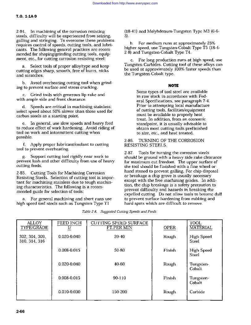
T.O. 1-1A-9
2-84. In machining of the corrosion resistingsteels, difficulty will be experienced from seizing,galling and stringing. To overcome these problemsrequires control of speeds, cutting tools, and lubri-cants. The following general practices are recom-mended for shaping/grinding cutting tools, equip-ment, etc., for cutting corrosion resisting steel:
a. Select tools of proper alloy/type and keepcutting edges sharp, smooth, free of burrs, nicksand scratches.
(18-41) and Molybdenum-Tungsten Type M3 (6-6-3).
b. For medium runs at approximately 25%higher speed, use Tungsten-Cobalt Type T5 (18-4-2-8) and Tungsten-Cobalt Type T4.
c. For long production runs at high speed, use
Tungsten Carbides. Cutting tool of these alloys can
be used at approximately 100% faster speeds thanthe Tungsten-Cobalt type.
b. Avoid overheating cutting tool when grind-ing to prevent surface and stress cracking.
c. Grind tools with generous lip rake andwith ample side and front clearance.
d. Speeds are critical in machining stainless;select speed about 50% slower than those used forcarbon steels as a starting point.
e. In general, use slow speeds and heavy feedto reduce effect of work hardening. Avoid riding oftool on work and intermittent cutting whenpossible.
f. Apply proper lubricant/coolant to cuttingtool to prevent overheating.
g. Support cutting tool rigidly near work to
prevent lash and other difficulty from use of heavycutting feeds.
2-85. Cutting Tools for Machining CorrosionResisting Steels. Selection of cutting tool is impor-tant for machining stainless due to tough machin-ing characteristics. The following is a recom-mended guide for selection of tools:
a. For general machining and short runs usehigh speed tool steels such as Tungsten Type Ti
NOTE
Some types of tool steel are availablein raw stock in accordance with Fed-eral Specifications, see paragraph 7-4.Prior to attempting local manufactureof cutting tools, facilities/equipmentmust be available to properly heattreat. In addition, from an economicstandpoint, it is usually advisable toobtain most cutting tools prefinishedto size, etc., and heat treated.
2-86. TURNING OF THE CORROSIONRESISTING STEELS.
2-87. Tools for turning the corrosion steelsshould be ground with a heavy side rake clearancefor maximum cut freedom. The upper surface ofthe tool should be finished with a fine wheel orhand stoned to prevent galling. For chip disposalor breakage a chip grove is usually necessaryexcept with the free machining grades. In addi-tion, the chip breakage is a safety precaution toprevent difficulty and hazards in breaking theexpelled cutting. Do not allow tools to become dullto prevent surface hardening from rubbing andhard spots which are difficult to remove.
Table 2-8. Suggested Cutting Speeds and Feeds
ALLOY FEED INCH CUTTING SPEED SURFACE TOOLTYPE/GRADE 1/ FT.PER MIN OPER MATERIAL
302, 304, 309, 0.020-0.040 20-40 Rough High Speed310, 314, 316 Steel
0.008-0.015 50-80 Finish High SpeedSteel
0.020-0.040 40-60 Rough Tungsten-Cobalt
0.008-0.015 90-110 Finish Tungsten-Cobalt
0.010-0.030 150-200 Rough Carbide
2-66
Downloaded from http://www.everyspec.com
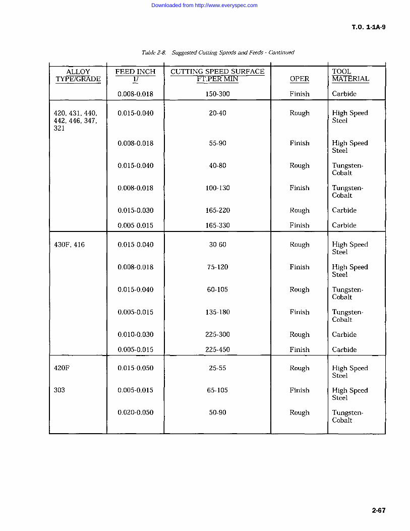
T.O. 1-1A-9
Table 2-8. Suggested Cutting Speeds and Feeds Continued
ALLOY FEED INCH CUTTING SPEED SURFACE TOOLTYPE/GRADE 1/ FT.PER MIN OPER MATERIAL
0.008-0.018 150-300 Finish Carbide
420, 431, 440, 0.015-0.040 20-40 Rough High Speed442, 446, 347, Steel321
0.008-0.018 55-90 Finish High SpeedSteel
0.015-0.040 40-80 Rough Tungsten-Cobalt
0.008-0.018 100-130 Finish Tungsten-Cobalt
0.015-0.030 165-220 Rough Carbide
0.005-0.015 165-330 Finish Carbide
430F, 416 0.015-0.040 30-60 Rough High SpeedSteel
0.008-0.018 75-120 Finish High SpeedSteel
0.015-0.040 60-105 Rough Tungsten-Cobalt
0.005-0.015 135-180 Finish Tungsten-Cobalt
0.010-0.030 225-300 Rough Carbide
0.005-0.015 225-450 Finish Carbide
420F 0.015-0.050 25-55 Rough High SpeedSteel
303 0.005-0.015 65-105 Finish High SpeedSteel
0.020-0.050 50-90 Rough Tungsten-Cobalt
2-67
Downloaded from http://www.everyspec.com
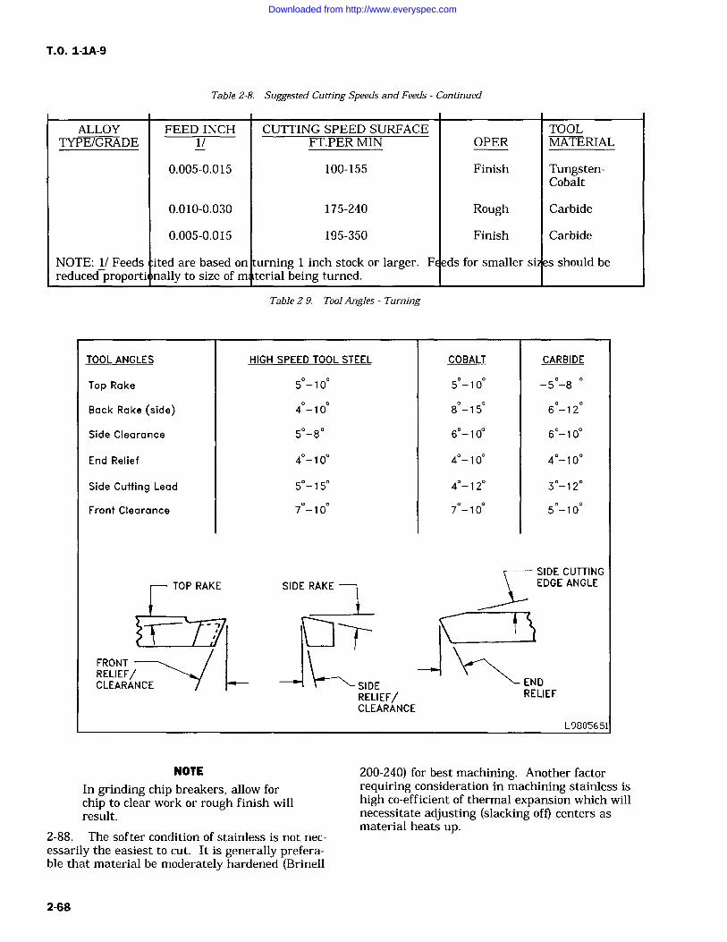
T.O. 1-IA-9
Table 2-8. Suggested Cutting Speeds and Feeds Continued
ALLOY FEED INCH CUTTING SPEED SURFACE TOOLTYPE/GRADE 1/ FT.PER MIN OPER MATERIAL
0.005-0.015 100-155 Finish Tungsten-Cobalt
0.010-0.030 175-240 Rough Carbide
0.005-0.015 195-350 Finish Carbide
NOTE: 1/ Feeds ited are based on turning 1 inch stock or larger. F eds for smaller si s should bereduced proporti nally to size of m terial being turned.
Table 2-9. Tool Angles Turning
TOOL ANGLES HIGH SPEED TOOL STEEL COBALT CARBIDE
Top Rake 5 -10 5 -10 -5 -8
Back Rake (side) 4-10 8 -15 6-12
Side Clearance 5-8 6-10 6-10
End Relief 4-10 4-10 4-10
Side Cutting Lead 5-15 4-12 3-12
Front Clearance 7 -10 7 -10 5-10
SIDE RAKE
SIDERELIEF/CLEARANCE
SIDE CUTTINGEDGE ANGLE
L9805651
NOTE
In grinding chip breakers, allow forchip to clear work or rough finish willresult.
2-88. The softer condition of stainless is not nec-essarily the easiest to cut. It is generally prefera-ble that material be moderately hardened (Brinell
200-240) for best machining. Another factorrequiring consideration in machining stainless ishigh co-efficient of thermal expansion which willnecessitate adjusting (slacking off) centers asmaterial heats up.
2-68
Downloaded from http://www.everyspec.com
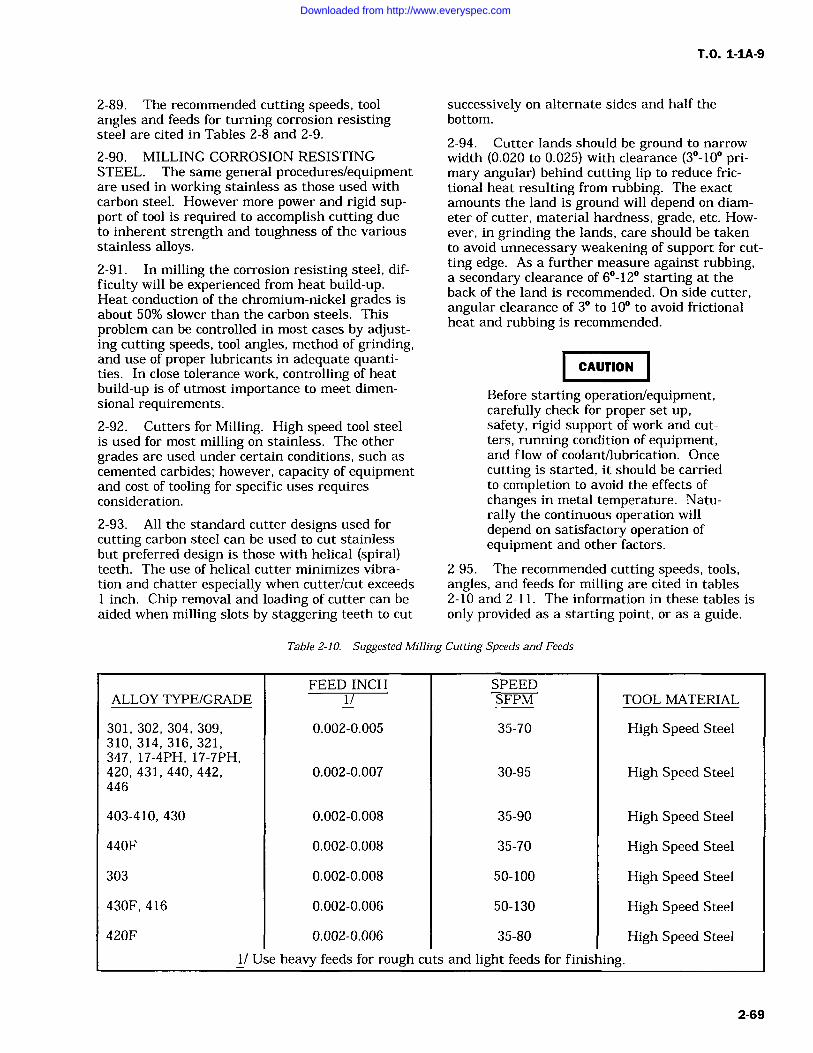
TO. 1-1A-9
2-89. The recommended cutting speeds, toolangles and feeds for turning corrosion resistingsteel are cited in Tables 2-8 and 2-9.
2-90. MILLING CORROSION RESISTINGSTEEL. The same general procedures/equipmentare used in working stainless as those used withcarbon steel. However more power and rigid sup-port of tool is required to accomplish cutting dueto inherent strength and toughness of the variousstainless alloys.2-91. In milling the corrosion resisting steel, dif-ficulty will be experienced from heat build-up.Heat conduction of the chromium-nickel grades isabout 50% slower than the carbon steels. Thisproblem can be controlled in most cases by adjust-ing cutting speeds, tool angles, method of grinding,and use of proper lubricants in adequate quanti-ties. In close tolerance work, controlling of heatbuild-up is of utmost importance to meet dimen-sional requirements.2-92. Cutters for Milling. High speed tool steelis used for most milling on stainless. The othergrades are used under certain conditions, such ascemented carbides; however, capacity of equipmentand cost of tooling for specific uses requiresconsideration.
2-93. All the standard cutter designs used forcutting carbon steel can be used to cut stainlessbut preferred design is those with helical (spiral)teeth. The use of helical cutter minimizes vibra-tion and chatter especially when cutter/cut exceeds1 inch. Chip removal and loading of cutter can beaided when milling slots by staggering teeth to cut
successively on alternate sides and half thebottom.
2-94. Cutter lands should be ground to narrow
width (0.020 to 0.025) with clearance (3-10 pri-mary angular) behind cutting lip to reduce fric-tional heat resulting from rubbing. The exactamounts the land is ground will depend on diam-eter of cutter, material hardness, grade, etc. How-ever, in grinding the lands, care should be takento avoid unnecessary weakening of support for cut-ting edge. As a further measure against rubbing,a secondary clearance of 6-12 starting at theback of the land is recommended. On side cutter,angular clearance of 3 to 10 to avoid frictionalheat and rubbing is recommended.
_1CAUTION
Before starting operation/equipment,carefully check for proper set up,safety, rigid support of work and cut-ters, running condition of equipment,and flow of coolant/lubrication. Oncecutting is started, it should be carriedto completion to avoid the effects ofchanges in metal temperature. Natu-rally the continuous operation willdepend on satisfactory operation ofequipment and other factors.
2-95. The recommended cutting speeds, tools,angles, and feeds for milling are cited in tables2-10 and 2-11. The information in these tables isonly provided as a starting point, or as a guide.
Table 2-10. Suggested Milling Cutting Speeds and Feeds
FEED INCH SPEEDALLOY TYPE/GRADE 1/ SFPM TOOL MATERIAL
301, 302, 304, 309, 0.002-0.005 35-70 High Speed Steel310, 314, 316, 321,347, 17-4PH, 17-7PH,420, 431, 440, 442, 0.002-0.007 30-95 High Speed Steel446
403-410, 430 0.002-0.008 35-90 High Speed Steel
440F 0.002-0.008 35-70 High Speed Steel
303 0.002-0.008 50-100 High Speed Steel
430F, 416 0.002-0.006 50-130 High Speed Steel
420F 0.002-0.006 35-80 High Speed Steel
1/ Use heavy feeds for rough cuis and light feeds for finishing.
2-69
Downloaded from http://www.everyspec.com
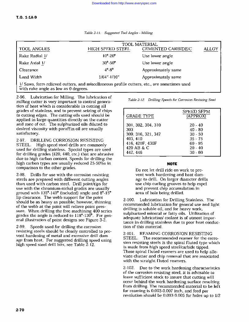
TO. 1-1A-9
Table 2-11. Suggested Tool Angles -Milling
TOOL MATERIALTOOL ANGLES HIGH SPEED STEEL CEMENTED CARBIDE/C ALLOY
Rake Radial 1/ 10-20 Use lower angleRake Axial 1/ 30-50 Use lower angleClearance 4-8 Approximately sameLand Width 1/64"-1/16" Approximately same1/ Saws, form relieved cutters, and miscellaneous profile cutters, etc., are sometimes usedwith rake angle as low as 0 degrees.
2-96. Lubrication for Milling. The lubrication ofmilling cutter is very important to control genera-tion of heat which is considerable in cutting allgrades of stainless, and to prevent seizing of chipsto cutting edges. The cutting oils used should beapplied in large quantities directly on the cutterand zone of cut. The sulphurized oils diluted todesired viscosity with paraffin oil are usuallysatisfactory.2-97. DRILLING CORROSION RESISTINGSTEEL. High speed steel drills are commonlyused for drilling stainless. Special types are usedfor drilling grades (420, 440, etc.) that are abrasivedue to high carbon content. Speeds for drilling thehigh carbon types are usually reduced 25-50%o incomparison to the other grades.2-98. Drills for use with the corrosion resistingsteels are prepared with different cutting anglesthan used with carbon steel. Drill point/tips foruse with the chromium-nickel grades are usuallyground with 135-140 (included) angle and 8-15lip clearance. The webb support for the pointshould be as heavy as possible; however, thinningof the webb at the point will relieve point pres-sure. When drilling the free machining 400 seriesgrades the angle is reduced to 118-130. For gen-eral illustration of point designs see Figure 3-2.
2-99. Speeds used for drilling the corrosionresisting steels should be closely controlled to pre-vent hardening of metal and excessive drill dam-age from heat. For suggested drilling speed usinghigh speed steel drill bits, see Table 2-12.
Table 2-12. Drilling Speeds for Corrosion Resisting Steel
GRADE TYPESPEED SFPM(APPROX)
301, 302, 304, 310 20 40303 40 80309, 316, 321, 347 30 50403,410 35 75416, 420F, 430F 60 95420 AB&C 20-40442, 446 30 60
NOTE
Do not let drill ride on work to pre-vent work hardening and heat dam-age to drill. On larger diameter drillsuse chip curling grooves to help expeland prevent chip accumulation inarea of hole being drilled.
2-100. Lubrication for Drilling Stainless. Therecommended lubrication for general use and lightdrilling is soluble oil, and for heavy work,sulphurized mineral or fatty oils. Utilization ofadequate lubrication/ coolant is of utmost impor-tance in drilling stainless due to poor heat conduc-tion of this material.
2-101. REAMING CORROSION RESISTINGSTEEL. The recommended reamer for the corro-sion resisting steels iS the spiral fluted type whichis made from high speed steel/carbide tipped.These spiral fluted reamers are used to help alle-viate chatter and chip removal that are associatedwith the straight fluted reamers.
2-102. Due to the work hardening characteristicsof the corrosion resisting steel, it is advisable toleave sufficient stock to insure that cutting willoccur behind the work hardening surface resultingfrom drilling. The recommended material to be leftfor reaming is 0.003-0.007 inch, and feed perrevolution should be 0.003-0.005 for holes up to 1/2
2-70
Downloaded from http://www.everyspec.com
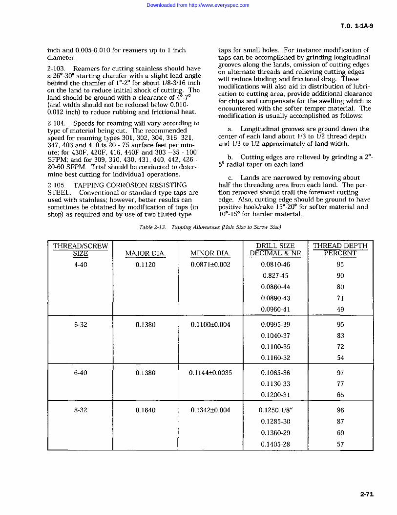
T.O. 1-1A-9
inch and 0.005-0.010 for reamers up to inchdiameter.
2-103. Reamers for cutting stainless should have
a 26-30 starting chamfer with a slight lead anglebehind the chamfer of 1-2 for about 1/8-3/16 inch
on the land to reduce initial shock of cutting. Theland should be ground with a clearance of 4-7(and width should not be reduced below 0.010-0.012 inch) to reduce rubbing and frictional heat.
2-104. Speeds for reaming will vary according to
type of material being cut. The recommendedspeed for reaming types 301, 302, 304, 316, 321,347, 403 and 410 is 20 75 surface feet per min-ute; for 430F, 420F, 416, 440F and 303 --35 100SFPM; and for 309, 310, 430, 431, 440, 442, 42620-60 SFPM. Trial should be conducted to deter-mine best cutting for individual operations.2-105. TAPPING CORROSION RESISTINGSTEEL. Conventional or standard type taps are
used with stainless; however, better results can
sometimes be obtained by modification of taps (inshop) as required and by use of two fluted type
taps for small holes. For instance modification oftaps can be accomplished by grinding longitudinalgrooves along the lands, omission of cutting edgeson alternate threads and relieving cutting edgeswill reduce binding and frictional drag. Thesemodifications will also aid in distribution of lubri-cation to cutting area, provide additional clearancefor chips and compensate for the swelling which isencountered with the softer temper material. Themodification is usually accomplished as follows:
a. Longitudinal grooves are ground down thecenter of each land about 1/3 to 1/2 thread depthand 1/3 to 1/2 approximately of land width.
b. Cutting edges are relieved by grinding a 2-5 radial taper on each land.
c. Lands are narrowed by removing abouthalf the threading area from each land. The por-tion removed should trail the foremost cuttingedge. Also, cutting edge should be ground to havepositive hook/rake 15-20 for softer material and10-15 for harder material.
Table 2-13. Tapping Allowances (Hole Size to Screw Size)
THREAD/SCREW DRILL SIZE THREAD DEPTHSIZE MAJOR DIA. MINOR DIA. DECIMAL & NR PERCENT
4-40 0.1120 0.0871+/-0.002 0.0810-46 95
0.827-45 90
0.0860-44 80
0.0890-43 71
0.0960-41 49
6-32 0.1380 0.1100+/-0.004 0.0995-39 95
0.1040-37 83
0.1100-35 72
0.1160-32 54
6-40 0.1380 0.1144+/-0.0035 0.1065-36 97
0.1130-33 77
0.1200-31 65
8-32 0.1640 0.1342+/-0.004 0.1250-1/8" 96
0.1285-30 87
0.1360-29 69
0.1405-28 57
2-71
Downloaded from http://www.everyspec.com
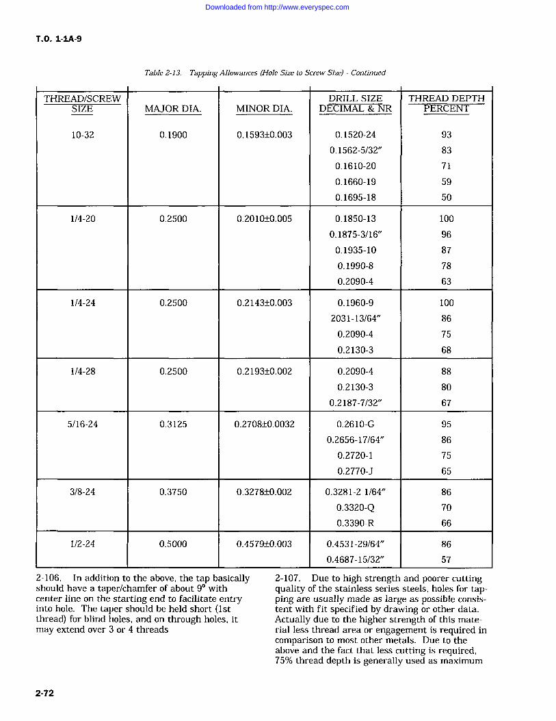
T.O. 1-1A-9
Table 2-13. Tapping Allowances (Hole Size to Screw Size) Continued
THREAD/SCREW DRILL SIZE THREAD DEPTHSIZE MAJOR DIA. MINOR DIA. DECIMAL & NR PERCENT
10-32 0.1900 0.1593+/-0.003 0.1520-24 93
0.1562-5/32" 83
0.1610-20 71
0.1660-19 59
0.1695-18 50
1/4-20 0.2500 0.2010+/-0.005 0.1850-13 100
0.1875-3/16" 96
0.1935-10 87
0.1990-8 78
0.2090-4 63
1/4-24 0.2500 0.2143+/-0.003 0.1960-9 100
2031-13/64" 86
0.2090-4 75
0.2130-3 68
1/4-28 0.2500 0.2193+/-0.002 0.2090-4 88
0.2130-3 80
0.2187-7/32" 67
5/16-24 0.3125 0.2708+/-0.0032 0.2610-G 95
0.2656-17/64" 86
0.2720-1 75
0.2770-J 65
3/8-24 0.3750 0.3278+/-0.002 0.3281-2 1/64" 86
0.3320-Q 70
0.3390-R 66
1/2-24 0.5000 0.4579+/-0.003 0.4531-29/64" 86
0.4687-15/32" 57
2-106. In addition to the above, the tap basicallyshould have a taper/chamfer of about 9 withcenter line on the starting end to facilitate entryinto hole. The taper should be held short (1stthread) for blind holes, and on through holes, itmay extend over 3 or 4 threads
2-107. Due to high strength and poorer cuttingquality of the stainless series steels, holes for tap-ping are usually made as large as possible consis-tent with fit specified by drawing or other data.Actually due to the higher strength of this mate-rial less thread area or engagement is required incomparison to most other metals. Due to theabove and the fact that less cutting is required,75% thread depth is generally used as maximum
2-72
Downloaded from http://www.everyspec.com
T.O. 1-1A-9
unless otherwise specified. Higher percentages ofthread depth are necessary in material when stockis not thick enough to permit the required numberof thread. For tapping allowances of some sizescrews/bolts see Table 2-13.
2-108. The decreased thread depth also reducestendency to gall and seize, power required to drivetap, tap wear, and effect of swelling in softmaterial.
2-109. Tapping Speeds Corrosion Resisting Steel.Tapping speeds used for stainless should be slowerthan those used for carbon steel. The 18-8 (300series) are usually tapped at 10-25 SFPM exceptfor the free machining types which are tapped at15-30 SFPM. The straight-chromium 400 seriesgenerally is tapped at 15-25 SFPM, except the freemachining grades, which are tapped at 15-35SFPM.
2-110. Lubrication for Tapping. The lubricationsrecommended for tapping are sulphurized mineraloils with paraffin and lard oil. The lubricantserves to prevent overheating as well as lubrica-tion, and if applied under pressure, aids in chipremoval. Oil flow/application should be appliedbefore tapping commences to prevent initial con-
gestion of cuttings.2-111. SAWING.
2-112. Hack saws (hand) for cutting corrosionresisting steel should be of high speed steel withapproximately 32 teeth per inch for light work andapproximately 24 teeth per inch for heavy work.The teeth area should be of wavy construction toincrease width of cut area to prevent binding. Aswith cutting other metal, the blade should not beallowed to drag/ride on the return stroke, espe-cially with the 300 series types to prevent workhardening. The hack saw blade should be lightlylubricated with lard oil/other cutting oil for bestresults.
2-113. Hack saws (mechanical drive). Powerhack saws are used for heavy cross-cutting section
bars, tubing, etc. With the power hack saw,deeper cuts are made at relatively low speed. Thedeeper cuts are used to get under work hardenedsurface resulting from previous cut (stroke). Theteeth per inch for saw blades average 8-12 andspeed of saw travel usually ranges from 50-100feet per minute depending on type and temper ofmaterial being cut. Coolant/lubrication is essen-tial to prevent excess blade damage from heat.Lubrication recommended is soluble oil/watermixed about 1 part oil to 4 parts water for heavywork, and for light work, a light grade cutting oil.
2-114. Band Sawing. Band saws are well suitedfor low speed (straight line/contour) sawing ofstainless/corrosion resisting steel within prescribedlimitation. The saw manufacturer's recommenda-tions should be followed for cutting speed, sawselection, etc. However, speeds usually vary withthe physical properties, temper, etc., of type/gradebeing cut. As general guide, speeds range from100-125 feet per minute for material under 0.062and 60-100 FPM for thickness over 0.062 inch.Saw blades must be kept in sharp condition foreffective low speed sawing.2-115. For faster cutting with the band saw, thefriction cutting method may be employed. Inutilizing the friction method, the band saw velocityranges from 5000 FPM for cutting flat 1/32 inchmaterial to about 10,000 FPM for 1/2 inch and14,000 for inch material; tubing material is runat slightly higher speed. Feed for this method canbe considerably higher than is used for slow speedcutting, rates range from about 100 FPM for lightgauge to 15-18 FPM for 1/2 inch material. Sawteeth per inch varies from 18 for material below1/ 8 inch thick to 10 per inch for thicknesses over1/2 inch.
2-116. Heavy pressure to maintain cut is notusually necessary. Pressure should be just suffi-cient to create proper heating and softening at cutpoint without forcing the saw. Lubricants shouldnot be used.
IParagraph 2-117 through 2-227 deleted.Tables 2-14 through 2-33 deleted.Figures 2-2 and 2-3 deleted.Pages 2-75 through 2-120 deleted.
Change 1 2-73/(2-74 blank)
Downloaded from http://www.everyspec.com

Downloaded from http://www.everyspec.com
T.O. 1-1A-9
2-228. (Deleted)2-229. (Deleted)2-230. (Deleted)2-231. (Deleted)2-232. (Deleted)2-233. (Deleted)2-234. FABRICATION OF FERROUS ALLOYS. Theinformation furnished in this section is provided as
a guide to aid personnel engaged in the use andapplication of the ferrous alloys. Due to variedusage of steel products, details and rules relatedwill not fit every application. In many instances,experimentation trial and further study will berequired.2-235. Personnel assigned to accomplish designs,application and fabrication must be well trained infundamentals of metal forming practices, analysis,properties, corrosion control, machining, plating,welding, beat treat, riveting, painting, blue print
reading, assembly, etc., in accordance with scope ofrelation to fabrication process. Also, these person-nel must keep constantly abreast of advancingprocesses for maximum efficiency/proficiency.2-236. The section of steel for design or applica-tion to equipment and component is usually basedon the following:
a. Strength and weight requirement of part/equipment to be fabricated.
b. Method to be used for fabrication, i.e.,welding, forming, machining, heat treat, etc.
c. Corrosion resistance to certain chemicals/environments.
d. Temperatures to which part will besubjected.
e. Fatigue properties under cyclic loads, etc.
2-237. The following general rules should beemployed in handling and forming:
Change 1 2-121
Downloaded from http://www.everyspec.com
T.O. 1-1A-9
a. Sheet, sheared/sawed strips and blankshall be handled with care to prevent cutting andother parts of the body.
b. Sheared or cut edges shall be sanded, filed,or polished prior to forming. The removal of roughand sharp edges is also recommended prior toaccomplishing other machining operations toreduce hazards in handling.
c. Form material across the grain when possi-ble using correct or specified bend radii. Also pro-vide bend relief in corner when required.
d. Observe load capacity of equipment such asbrakes, presses, rolls, drills, lathes, shears, mills,etc.
CAUTION
Machines rated for carbon steel shallnot be used over 60% of rated capac-ity when cutting, forming or machin-ing stainless steel unless approved byresponsible engineering activity.When in doubt inquire.
e. Tool and equipment shall be maintainedsmooth, free of nicks, rust, burrs and foreign mate-rial. In addition to above, dies, ways, etc., shall bechecked for alignment tolerances, etc., periodically/each set-up.
f. Surfaces of material, especially finishedsheet, shall be protected from scratching, foreignparticles, etc. These surfaces can be protectedusing non-corrosive paper, tape, other approvedmaterial and good cleaning procedures. Polishedsheet material should be protected when formingto prevent die tool marking.
g. After forming/machining is completed,remove all cutting lubrication, etc., by cleaning,degreasing, pickling, prior to any heat treat, plat-ing or painting process.
CAUTION
Avoid handling parts, especially corro-sion resistant steel, with bare handsafter cleaning and subsequent to heattreating/ passivation because fingerprints will cause carburization andpitting of surface, when heated.
2-238. BENDING (SINGLE CURVATURE).The bending of most steel sheet and thin bar stockcan be readily accomplished provided that equip-ment with adequate bending and cutting capacityis available and if the materials are formed in the
soft condition/lower temper range. The heat treat-able alloys are usually formed in the annealed ornormalized condition and heat treated if required/specified after forming. Some difficulty will beencountered from warping due to treat treatingand precautions must be taken when forming thematerial to prevent sporadic or uneven stress inthe work piece. Also, parts will require jigs orclose control during the heating and cooling phaseof heat treatment. The use of heat treated formedsheet metal parts on aerospace craft are usuallyan exception in part due to above and most mater-ials are used in the normalized or annealedcondition.
2-239. Springback allowance will vary accordingto the type and temper of material being formed.The use of sharp bend radii on parts for aeronauti-cal application shall be avoided and other applica-tion where the parts will be subjected to flexing(cycle) or concentrated stresses, due to possiblefatigue or stress corrosion failure. For recom-mended General Bend Radii for use on Aerospaceweapon/equipment (see Table 2-34 for Low Car-bon/low alloy steel and Table 2-35 for CorrosionResistant Steel.)2-240. In utilizing Table 2-34 and Table 2-35 it isrecommended that in practice bend area bechecked for strain, grain, or bend cracking. Ifparts show presence of above, increase radius byone thickness or more until difficulty does notexist. Other details, inspection requirements, etc.,shall be used when specified.2-241. DRAW FORMING. Control of diedesign, and material from which dies are made,are essential to successfully draw form steel. Forlong production runs, high carbon, high chromiumsteel is recommended to manufacture drawing diesbecause of wear resistance and hardness. Formedium and short production runs, Kirksite/casezinc alloy can be used with drop hammer hydrau-lic press if the draw is not severe. Hardwood andphenolic can be used in some cases for piece pro-duction where draws are shallow.
2-242. Successful drawing of steel will dependon:
a. Radii used for forming or bending. Usemoderate radii, usually equal to 3-6 times thick-ness of material depending on specific require-ments, and the severity of draw.
b. Finish of die-all scratches and surfaceroughness should be removed.
c. Blank hold down pressure and drawingrings. Hold down pressure should be sufficient toprevent wrinkling of material, but not to theextent that would prevent flow of the metal into
2-122
Downloaded from http://www.everyspec.com
T.O. 1-IA-9
the female portion of the die. Drawing rings radiishould be 4-8 times metal thickness and smoothlypolished.
d. Clearance between punch and die Gener-ally punch clearance should be about 1 1/4 to 1 1/2times thickness for the initial draws, and about1 1/8 to 1 1/4 times for the following draws. Ifparts show signs of galling, clearance (drawing)should be increased when clearance is increased,size requirement must be considered.
e. Temper-drawing should be started withannealed/normalized material and intermediateannealing accomplished as required. The require-ment for annealing (intermediate) usually isneeded after reduction exceeds 30-35% for stain-less/20-25% carbon steel on the initial draw, andwhen reduction exceeds 8-15% on each followingdraw. Parts should be cleaned removing all lubri-cation and other contaminate prior to annealingand desealed after annealing. In instances wheredraws exceed 22-25% annealing is recommendedafter completion of the drawing operation followedby descaling and passivation (stainless). Restrikingon final stage die to remove distortion after finalanneal is permissible without further heattreatment.
f. Drawing Speed Generally a speed of 20-55 feed per minute is satisfactory. Drawing usinga hydraulic powered press in lieu of a cam oper-ated or toggle type press is usually the mostsatisfactory,
g. Lubricant Compounds used should be ofheavy consistency capable of withstanding hightemperature and restating pressure necessary toform material. One heavy bodied lubricant used islard oil, sulfur (one pound of sulfur to gallon ofoil) to which lithopone is added in equal partsuntil consistency equals 600W engine grease, or asdesired. Other compounds such as tallow, mixtureof mineral oil and soft soap, powdered graphitemixed to thin paste with lightweight oil can beused.
h. Blank size and preparation A good prac-tice is to use minimum size required to meetdimensional size of parts and for hold down.When trimming, consideration must be given tothe fact that on rectangular parts, the majority ofdrawings will occur on wider portions of the rec-tangle away from the corners. To overcome thisproblem, the radius of the vertical corner shouldbe approximately 10% of the width. Trial, using a
very ductile material to determine blank size andstress areas prior to starting the forming operationis recommended. After size is determined by trial,etc., the blank should be filed/polished to preventcracking in wrinkle/stress areas, handling hazard
and surface friction which hinders flow of metalinto die.
2-243. The surface condition of the blank alsohas an effect on drawing. A slightly roughenedsurface, such as obtained by pickling (dull surface)improves control of metal under hold down padsand the holding lubricants. On the other hand,the roughened surface may be less desirablebecause of greater friction, especially where freeflowing drawing methods are used (without holddown).
2-244. Where facilities are available, cold form-ing of some steels (primarily straight chromiumstainless such as 410, 416,430, 442, 446) can beimproved by preheating dies and blanks. Thepreheating tends to reduce work hardening andthe requirement for intermediate annealing duringthe drawing operation.
2-245. When forming involves more than onedraw, the first operation should be a moderatedraw with punch diameter equal to 60% of blanksdiameter and reduction of 15-25%. The secondand subsequent draws should be made withpunches about 20%. It is recommended that partbe cleaned and annealed following each draw.Excessive distortion may result from finalannealing after last draw. This problem can beovercome in most instances, by reducing the sever-
ity of the last draw or restriking after finalannealing on last stage die for the purpose ofremoving distortion.
CAUTION
Parts shall be cleaned of all contami-nates, lubrication, filing, other foreignmaterial, etc., before heating orannealing and upon completion offorming or drawing operation. Fail-ure to clean the parts will result inpitting and carburization, which willdamage the surface.
2-246. STRETCH FORMING. Stretch formingis a process where material, sheet or strip, isstretched beyond the elastic limit until permanentset will take with a minimum amount ofspringback.
2-247. The stretch forming is usually accom-plished by gripping ends of material (blank) andapplying force by a separate ram carrying theforming die. The ram pressure sufficient to causethe material to stretch and wrap to contour of thedie form blank is applied perpendicular to theblank (see Figure 2-4). This method of forming is
2-123
Downloaded from http://www.everyspec.com
T.O. 1-1A-9
usually limited to parts with large radii of curva-
ture and shallow depth, such as shallow dishing,reverse curves, and curved pan shaped parts con-
taining flat areas.
2-248. The trimming of edges and removal ofnicks and scratches is important to prevent start-ing points for concentrated stress, which, undertension loads, would tear. The direction of majortension (stretch) and direction of grain is alsoimportant. It is recommended in forming that themajor tension be transverse to the direction ofgrain. Lubrication aids in uniform distribution ofstress and the lubricant shall be applied uniformlyto work piece to avoid distortion which could resultfrom unequal friction when material is slidingacross the forming die during stretching.
2-249. Forming dics/blocks for general productionare made from kirksite/zinc, alloy; for piece pro-duction from phenolic and hardwood. Some typesand kinds of plastic with good hardness and highimpact strengths are also used. The rubber padhydraulic press is used to form relatively flatparts having flanges, beads, lightening holes, andfor very light drawing of pan shaped parts havinglarge radii.
2-250. Form blocks are usually manufacturedfrom steel, phenolic (mechanical grades), kirksite/zinc cast alloy, and some types of hard moldingplastic with high impact strength. The work isaccomplished by setting the form block on thelower press plate or bed, and the blank is placedon the block. The blank is held in place on theblock by locating pins (holes are drilled throughthe blank and into the form block for the insertionof the locating pins). These holes are referred to
as "tooling holes," which prevent slippage of blankwhen pressure is applied. If tooling holes are notallowed, another method of alignment and holdingof blank must be utilized. The sheet metal blankshould be cut to size (allow sufficient material toform flange), deburred, and filed prior to pressing.After the block is prepared and placed on theplate, the rubber pad filled press head is loweredor closed over the block, and as the hydraulic pres-sure (applied by a ram to the head) increases, therubber envelopes the form block forcing the blankto conform to the form block contour or shape. Itis recommended that additional rubber be supple-mented in the form of sheets (usuually 1/2 inch,hardness of 70-80 durometers) over the form blockand blank to prevent damaging the rubber presspad. The design of form blocks for hydropressforming requires compensation for springback.The form for forming flanges on ribs, stiffners,etc., should be undercut approximately 2-8 degreesdepending on the alloy, hardness, and radius. In
some cases, it will be necessary to use a combina-tion of hand forming shrinking/stretching usingsupplemental machinery and pressing to completeforming by this method.
2-251. DROP HAMMER FORMING. Dies fordrop hammer forming are usually made by castingmetals such as kirksite. These dies can be rapidlyproduced; are more economical than permanentdies; can be melted and recast; and can be rein-forced at selected points of wear by facing withharder material, such as tool steel for long produc-tion runs.
2-252. Normally, drop hammer forming is accom-plished without benefit of hold down. The metal isslowly forced in shape by controlling the impact ofblows. In many instances, it is necessary to use
drawings, rings, 2 or 3 stage dies, supplementalequipment, and hard forming such as bumpinghammer, wooden mallet to remove wrinkles, etc.To successfully complete forming operations,another aid that may be necessary is to annealmaterial between die stages and intermediately forsingle stage die forming.
CAUTION
Parts should be cleaned prior toannealing to protect finish. Careshould be taken to remove all tracesof zinc that may be picked up fromkirksite forming dies, as failure to
remove the zinc will result in penetra-tion of the steel (stainless) whentreated and will cause cracking.
2-253. SPINNING. Those steels that have lowyield strengths in the soft/annealed condition, andlow rates of work hardening are the best gradesfor spinning. To overcome work hardeningproblems, intermediate annealing and 2-3 or more
stage spinning blocks are used. Annealing of thepart at intervals also aids the operator when man-ual spinning, because less pressure is required toform metal and springback is lower.
2-254. Form blocks for spinning are usuallymade of phenolic, hard wood, or carbon steel.Manual spinning is usually accomplished on alathe specifically adapted and fitted for that pur-pose. The main requirements are that requiredspeed be maintained without vibration; clampingpressure is sufficient to hold part; facilities areprovided to apply pressure at a uniform rate; andtools are of proper design. Normally, spinningtools are the roller or round nose type designed insuch a manner that high pressure can be appliedwithout bending. Where local design of tools are
2-124
Downloaded from http://www.everyspec.com
T.O. 1-IA-9
required, raw material for manufacture is obtaina-ble under QQ-T-570, Type D2, hardened toRockwell C40-50.
2-255. SHEARING AND BLANKING. To pre-vent damage to shear, and to assure clean, accu-
rate cuts, clearance between shear blades shouldbe approximately one-twentieth (5%) thickness ofmaterial to be cut. Also, blades or knives must bemaintained in sharp condition, clean, and free ofnicks. Where only one shear is available, a clear-ance of 0.005 to 0.006 could be used for generalshearing of sheet stock up to 0.125 inches thick.Excessive blade clearance should be avoided to
prevent work hardening of cut area whichincreases susceptibility to stress corrosion and bur-ring. Lubrication such as lightweight engine oil or
soap should be applied at regular intervals to pre-vent galling and to clean blades for prolongedshear blade life.
2-256. BLANKING AND PUNCHING. Blank-ing and punching requires close control of dieclearance, shearing action of punch/blanking die.Clearance for blanking and punching should be 5%of thickness and closely controlled for all gauges.In designing dies and punches, it is important thatshear action be incorporated to equalize andreduce load. Double shear should be used whenpossible to minimize off balance condition andload. Punches and dies should be maintained inclean sharp condition and lubricated by swabbingor spraying material to be punched with light-weight lube oil to prevent galling and to aid inkeeping punch/die clean.
2-257. GENERAL FABRICATINGCHARACTERISTICS.
used for wire and rod for cold upsetting applica-tions, such as bolts. The higher carbon groups,such as 1040 are often cold drawn to requiredphysical properties for use without heat treatment.
2-262. Alloy Steels 1055 through 1095. Thisalloy group is used where wear resistance result-ing from high carbon content is needed, and isheat treated before use in partically everyapplication.2-263. 1100 Series Steel. Steels in this groupare generally used where easy machining is theprimary requirement. The main use of thesesteels is for screw stock.
2-264. 1300 Series Alloy Steel. The basic advan-tages of this group is high strength coupled withfair ductility and abrasion resistance. The majoruse is in the manufacture of forgings.2-265. 2300 Series Nickel Alloy Steels. The addi-tion of nickel has very little effect on machinabil-ity and greatly increases elasticity and strength.This material is normally machined in the forged,annealed, and normalized condition, and heattreated after fabrication.
NOTE
These grades not currently being pro-duced. Listed for reference only.
2-266. 2500 Series Nickel Steel. This seriesalmost without exception, is a carburizing gradewith extremely high strength core. However, thecase is not as hard as obtained with other carbu-rizing steels. This steel is used for parts requiringa high strength core and good wear resistance.
2-258. PLAIN CARBON AND ALLOY STEELS.
2-259. Plain Carbon Steel 1006 through 1015.This group of steels is used where cold formabilityis the main requirement, and have good drawingqualities. This series is not used where greatstrength is required. The strength and hardnessof these grades will vary according to carbon con-
tent and amount of cold work.
2-260. Plain Carbon Steels SAE 1016 through1030. This group of steels is commonly known asthe carburizing or case hardening grades. Theaddition of manganese improves machining quali-ties but reduces the cold formability characteris-tics. This group is widely used for forged stock.
2-261. Plain Carbon Steels 1030 through 1050.This group (medium carbon types) is used wherehigher mechanical properties are required. Thelower carbon and manganese types are used formost cold formed parts. Alloys 1030 1035 are
NOTE
These grades not currently beingproduced.
2-267. 3100, 3200, and 3300 Series Nickel Chro-mium steels. This series of steels is characterizedby good wear resistance and tough core and sur-face. The 3300 series is used primarily in theform of forgings and bars which are required tomeet rigid mechanical properties. This steel ismore difficult to handle in fabrication and heattreatment than lower nickel chromium alloys.2-268. 4000 Series Molybdenum Steels. Thisgroup of steels have good impact strength andrequire close control of heat treatment practices toobtain the required strength and ductility.2-269. 4100 Series Chromium MolybdenumSteels. This series has good working properties,response to heat treatment, and high wear resis-tance. This group is easily fabricated by forging
2-125
Downloaded from http://www.everyspec.com
T.O. 1-1A-9
and rolling. After welding and cold forming, inter-nal stresses produced should be relieved and lossin strength regained by normalizing.
2-270. 4130 Grade Steel. This grade is usedextensively in aircraft construction in the form ofsheet, bar, rod and tubing. This grade has verygood cold forming characteristics. Forming andwelding operations are accomplished utilizingannealed material, and heat treated or normalizedafter these operations are completed. 4130 sheet(MIL-S-18729 can be cold bent in the annealedcondition to an angle of 180 with a radius equalto the thickness of the sheet. In the normalizedcondition, a radius equal to 3 times the thicknessis recommended.
2-271. 4140 Series Steel. This steel is used forstructural, machined and forged parts over 1/2inch thick. It is usually obtained in the normal-ized condition. Forgings are always normalized or
heat treated after fabrication.
2-272. 4300 Series Nickel Chromium Molybde-num Steels. These steels are used to meet condi-tions in which other alloy steels have insufficientstrength. Preparation for machining or formingmust be by a suitable annealing cycle.
2-273. 8000 Series Molybdemum Steels. Thesesteels are characterized by their high impactstrength and resistance to fatigue. They are easyto forge and machine, and are stable at hightemperatures.
2-274. 8600, 8700, 9300, 9700, 9800, and 9900Series Steels. These steels have approximately thesame characteristics as the 4300 series steele.
2-275. CORROSION RESISTANT (STAINLESS)AND HEAT RESISTANT STEELS.
2-276. The fabrication of stainless steel requiresthe use of modified procedures in comparison tothose used for carbon steels.
2-277. Forming Sheet Stock. The corrosionresisting series, i.e., types 301, 302, 304, 305, 316,321, 347, 410, 430, 431, etc., generally have goodforming and drawing qualities. Some types (302,304 and 305) have forming characteristics superiorto plain carbon steel because of the wide spreadbetween tensile and yield strength, and higherelongation. However, more power is required toform these types than is required for carbon steelbecause of higher tensile strengths and the factthat yield strength increases rapidly during form-ing or bending.
2-278. The straight chromium grades such as
410, 416, 430, 442, and 446 react similar to carbonsteel and are somewhat less ductile than the 300series stainless. The tensile strength are higherthan carbon steel and consequently will standhigher loads before rupture. Yield strengths are
also higher which means that more power isrequired for bending and forming. Because of theductility factor of this series drawing and formingshould be limited to 20 -25% reduction.
2-279. The 301, 302, 304, 305 and 316 types canbe drawn based on a reduction of 35 to 50%, i.e., ashape 8 inches in diameter and 4 inches in depthcould be drawn in one operation, based on a 50%reduction.
2-280. The strains set up by severe reductions(above 45% with chromium-nickel types and 20%with straight chromium types) should be relievedby annealing immediately after the operation iscompleted, especially if using type 301. If thismaterial is not relieved in 2 4 hours, it maycrack.
2-281. Springback allowance should be about 2to 3 times the amount allowed for carbon steel,and naturally will vary according to the type ofmaterial being formed. The use of sharp radiishall be avoided where parts are subjected to flex-ing or concentrated stresses due to possible fatigueor stress corrosion failure.
2-282. Recommended bend radii for use withstainless is shown in Table 2-35.
2-283. Draw Forming. Stainless steels should beannealed for draw forming, and hardness shouldnot exceed Rockwell B90. The beat drawinggrades are of the 18-8 series. In selecting the typefor drawing, welding of the finished parts, ifrequired, shall be considered.
2-284. Drop Hammer Forming. The most com-
mon types of corrosion resistant steel used for drophammer forming are 301, 302, 304, 305, and stab-lized grades 321 and 347. 301 work hardens morerapidly and is subject to strain cracking. The con-dition of material for best forming should beannealed. It is possible to form some type (301and 302) in 1/4 and 1/2 hard condition. However,the severity of the forming operation must bereduced to compensate for the prehardenedmaterial.
2-126
Downloaded from http://www.everyspec.com
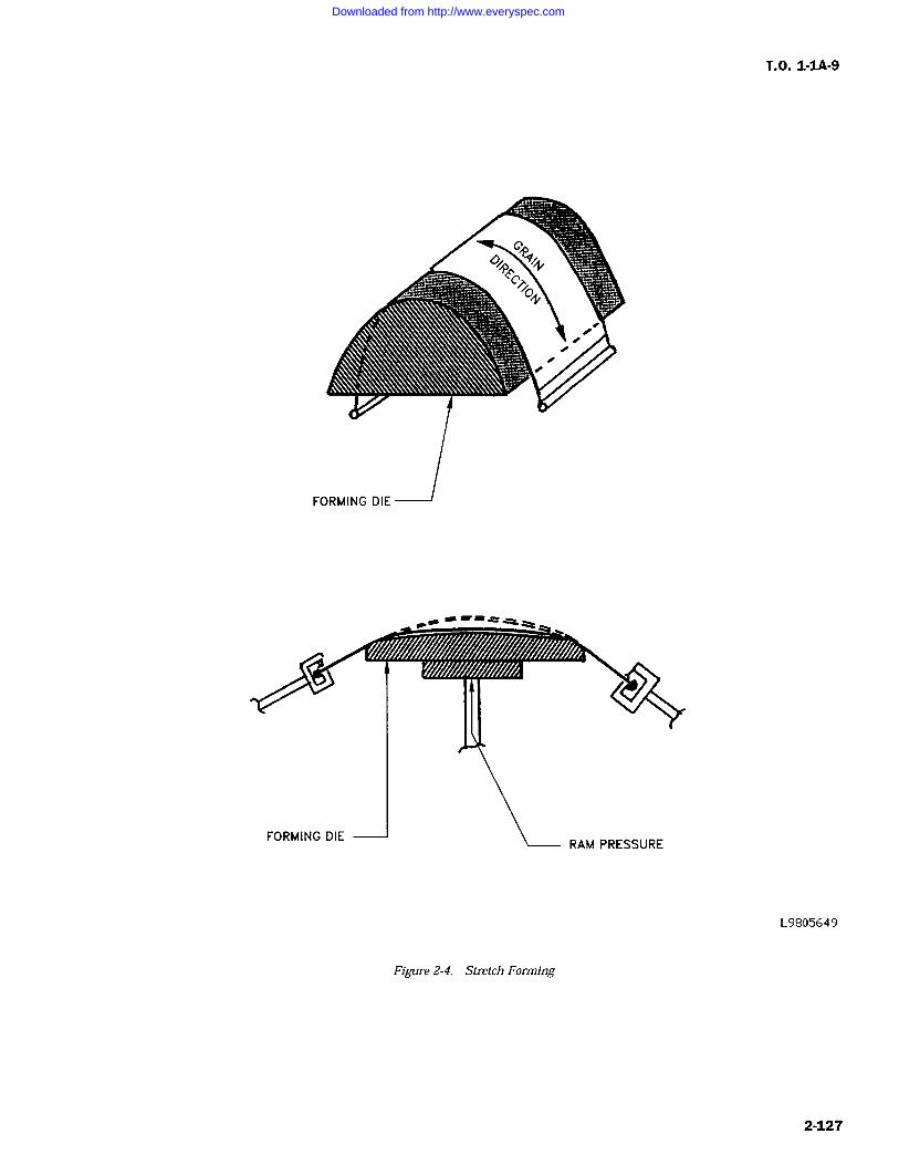
s!s=3Q;
FORMING DIE
Downloaded from http://www.everyspec.com
T.O. 1-1A-9
Table 2-34. Cold Bend Radii (Inside) Carbon/Low Alloy Steels
Temper, Sheet Thickness T (Inches)
Alloy Temper 0.016 0.020 0.025 0.032 0.040 0.050 0.063 0.125 0.187
1020/1025 2T 2T 2T 2T 2T 2T 2T 2T 2T
4130 Annealed 2T 3T 2 1/2T 2T 2 1/2T 2T 2T 2T 2T
4130 Normalized 2T 3T 2 1/2T 3T 3T 3T 3T 3T 3T
8630 Annealed 3T 3T 2 1/2T 3T 2 1/2T 2T 2T 2T 2T
8630 Normalized 3T 3T 2 1/2T 3T 3T 3T 3T 3T 3T
Table 2-35. Cold Bend Radii (Inside) Corrosion Resistant Steel Alloys
Sheet Thickness T (Inches)
Alloy Temper 0.012 0.051 0.051 0.090 0.190 0.250
201, 202 Annealed 1-2T IT 1/2T
301, 302 1/4 Hard 1-2T 1/2T 2T
305, 304 1/2 Hard 2T 2T 2T
309, 310 3/4 Hard 2T 3T
316, 321, 347 Hard 3-4T 4-5T
405, 410, 430 Annealed IT IT 1/2T
17-7PH Annealed IT 1/2T 2T
Table 2-36. Forging Temperature Ranges For Corrosion Resistant Steel
TYPE/GRADE PREHEAT FHEAT TREATED
STARTING FINISHING
301 1500-1600 2050-2200 1600-1700 SEE HEAT TREATDATA FOR ANNEAL-
302 1500-1600 2050-2200 1600-1700 ING AND STRESSRELIEF, SEE TABLE
303 1500-1600 2050-2200 1700-1800 2-3.
304 1500-1600 2050-2200 1600-1700
305 1500-1600 2100-2200 1600-1700
308 1500-1600 2100-2200 1600-1700
316 1500-1600 2150-2250 1600-1700
321 1500-1600 2100-2200 1600-1700
374 1500-1600 2100-2200 1650-1750
2-128
Downloaded from http://www.everyspec.com
T.O. 1-IA-9
Table 2-36. Forging Temperature Ranges For Corrosion Resistant Steel Continued
TYPE/GRADE PREHEAT FHEAT TREATED
STARTING FINISHING
AIR HARDENING
403 1400-1500 1900-2100 1600-1700 These grades shall bepromptly annealed af-
410 1400-1500 1900-2100 1600-1700 ter forging becausethey air harden in-
414 1400-1500 2050-2200 1600-1700 tently if allowed to
cool from forging416 1400-1500 2100-2250 1600-1700 temperatures. See
Heat Treat Data Table420 1400-1500 2000-2100 1600-1700 2-3 for temperatures.
431 1400-1500 2050-2150 1600-1700
440 1400-1500 1950-2100 1950-2100
NON-HARDENING
405 1400-1500 1900-2100 1750-1850 Post annealing re-
quired. See Heat Treat430 1400-1500 1900-2100 1350-1450 Data Table 2-3 for
temperatures.442 1400-1500 1900-2000 1300-1400
446 1400-1500 1800-2000 1300-1500
2-285. Spinning. Spinning procedures for stain- either case, this is accomplished by fullyless are similar to those used for other metals. annealing.Difficulty and variations depend on individualcharacteristics of grade to be worked, i.e., yieldstrength, ultimate strength, ductility, hardnessand reaction to cold working. The best grades forspinning are those that have low yield strength insoft/annealed condition and low rate of work hard-ening such as 304, 305, 403, 410 and 416. Thestraight chromium grades respond to spinningsimilar to carbon steel, however, more power isrequired. Mild warming above 200F improvesperformance of the straight chromium grades.2-286. Shearing and Blanking. Shearing andblanking of corrosion resisting steels as with otherfabrication processes requires more power in com-
parison to shearing carbon steel and most othermetals. Shears and other equipment rated for car-bon steel should not be used above 50 70% ofrated capacity when cutting stainless.
2-287. Hot Forming. Hot forming is used to formshapes in stainless that cannot be accomplished bycold forming and for forging parts economically. Inusing heat for forming, it is important that tem-perature be closely controlled. Also, finished partsshould be relieved of residual stress and carbideprecipitation which affects corrosion resistance. In
CAUTION
Difference in temper of raw materialwill result in variation of preheating,especially with the air hardeninggrades. The air hardening grades intempers other than annealed maycrack from thermal shock upon load-ing into a hot furnace.
2-288. Hot forming by methods other than forg-ing is accomplished at somewhat lower tempera-tures. The unstabilized chromium-nickel gradesmay be formed at temperatures up to 800F andthe extra low carbon grades up to 1000F. The use
of temperatures higher than those cited aboveshould be avoided to prevent subjection of materialto the carbide precipitation heat zone.
2-289. The straight chromium (type 400 series)are more responsive to hot forming than the chro-mium-nickel grades. The reaction of these metalsto hot forming in similar to carbon steels. Uponheating to 800-900F, their tensile strength is
2-129
Downloaded from http://www.everyspec.com
T.O. 1-1A-9
lowered considerably and at the same time ductil-ity begins to increase.
2-290. Forming of the air hardening grades type403, 410 is accomplished in two temperatureranges as follows:
a. Low temperature forming up to 1400F.The advantage of forming at this temperature isthat parts can be stress relieved at 1350 1450Fto restore strength uniformity, and scaling is heldat a minimum.
b. High temperature forming at 1525 1575F. Forming at this temperature is somewhat easierbecause strength is low and ductility is higher.Upon completion of forming at this temperature,parts shall be fully annealed under controlled con-ditions by heating to 1550F and holding, slowlycooling to 1100F (at approximately 50F per hour)and then cooling in air.
Grades 403, and 410 are not subject to loss ofcorrosion resistance due to the forming ofintergranular carbides at grain boundaries.
2-291. When it is required that the non-harden-ing grades 430, 442, and 446 be hot formed, therecommended temperature for forming is 14001500F. This temperature is recommended in viewof the following:
a. Heating these grades above 1600F pro-motes grain growth which can only be corrected bycold working.
b. For types 442 and 446, the 1400-1500Ftemperature is below the scaling limit and veryclose to being below the scaling limit for type 430.
2-292. STEEL SURFACE FINISHES.
2-293. Metal plating is a process where an itemis coated with one or more thin layers of someother metal. This is the type of finishes generallyused on ferrous parts, other than organic finishes.It is usually specified when there is a need forsurface characteristics that the basic metal doesnot possess. The most commonly used types ofplating are: Cadmium plate; zinc plate; nickelplate; chromium plate; copper plate; tin plate; andphosphate coatings. The thickness of the platedcoating is important since its protective value isprimarily dependent on its thickness. The type ofplated coatings is generally dependent on the char-acteristics desired. For protection against corro-sion when appearance is unimportant, either cad-mium or zinc coatings is usually used. Forappearance, nickel, chromium, and silver platingare the most commonly used. For hardness, wear
resistance, and buildup of worn parts, nickel andchromium plating are used. Effectiveness of mostother metallic coatings depends on their ability to
provide envelope or anodic protection. Porouscoatings of the more noble metals such as silver,copper, platinum and gold, tend to accelerate thecorrosion of steel. For processing instructions,refer to T.O. 42C2-1-7. The following galvanicseries table and dissimiliar metal definition inaccordance with MS33586 are for use as a guide inthe selection of the most suitable plating for partssubject to uses where galvanic corrosion would bea prime factor.
2-294. DEFINITION OF DISSIMILIAR MET-ALS. Dissimiliar metals and alloys, for the pur-pose of aircraft and aircraft parts construction areseparated into four groups in accordance withMS33586. Metals classified in the same group areconsidered similar to one another and materialsclassified in different groups are considered dis-similar to one another. The metal materialreferred to in the groups is the metal on the sur-face of the part; e.g., zinc includes all zinc partssuch as castings as well as zinc coated parts,whether the zinc is electro deposited, applied byhot dipping, or by metal spraying over similar ordissimiliar metal parts. The four groups are asfollows:
a. GROUP I Magnesium and its alloys. Alu-minum alloys 5052, 5056, 5356, 6061 and 6063.
b. GROUP II Cadmium, zinc, and aluminumand their alloys (Including the aluminum alloys inGroup I).
c. GROUP III Iron, lead, and tin and theiralloys (except stainless steels).
d. GROUP IV Copper, chromium, nickel, sil-ver, gold, platinum, titaniam, cobalt, rhodium andrhodium alloys; stainless steels; and graphite.
NOTE
The above groups do not apply tostandard attaching parts such as riv-ets, bolts, nuts and washers which are
component parts of assemblies, whichwill be painted prior to being placedin service unless other wise specifiedby specifications MIL-F-7179, or otherapproved data.
2-295. TYPES OF PLATING.
2-296. CADMIUM PLATING (QQ-P-416). Theprimary purpose of cadmium plating is to retard or
prevent surface corrosion of parts. Unless other-wise specified, the plating shall be applied afterall machining, brazing, welding, forming and per-forating of the item has been completed. Propersafety precautions should be observed in the event
any welding or soldering operations are required
2-130
Downloaded from http://www.everyspec.com
on cadmium plated parts because of danger fromtoxic vapors during such operations. Cadmiumcoatings should not be used on parts subjected to
temperatures of 450F or higher. All steel partshaving a hardness of Rockwell C40 (180,000 PSI)and higher shall be baked at 375+/- 25F for 3hours minimum after plating for hydrogen embrit-tlement relief. All steel parts having an ultimatetensile strength of 220,000 PSI or above shall notbe plated, unless otherwise specified. When per-mission is granted, a low embrittlement cadmiumplating bath shall be used. Federal SpecificationsQQ-P-416 should be used for cadmium platerequirements. Critical parts should bemagnafluxed after plating.
2-297. Zinc Plating (QQ-Z-325). The primarypurpose of zinc coatings is to retard or prevent theformation of corrosion products on exposed sur-faces. Unless otherwise specified, the platingshall be applied after all machining, brazing, weld-ing, forming and perforating have been completed.All parts having a hardness greater than RockwellC40 and higher shall be baked at 375 +/- 25F for 3hours after plating for hydrogen embrittlementrelief. Zinc shall be deposited directly on the basicmetal without a preliminary plating of othermetal, except in the case of parts made from corro-sion resisting steels on which a preliminary plat-ing of nickel is permissible. Zinc plating (Type 1)should not be used in the following applications:
a. Parts which in service are subjected to a
temperature of 700F or higher.
b. Parts in contact with structural fabricstructure.
c. Parts in functional contact where gougingor binding may be a factor or where corrosionmight interfere with normal functions.
d. Grounding contacts where the increasedelectrical resistance of zinc plated surfaces wouldbe objectional.
e. Surfaces where free circulation of air doesnot exist and condensation of moisture is likely to
occur. For additional information, refer to QQ-Z-325.
CAUTION
Chromium and nickel electro depositsseverely reduce the fatigue strengthof high strength steels. All steelparts having a tensile strength of180,000 PSI or above should be shot-peened prior to electro plating. In
T.O. 1-1A-9
addition high strength steels are sus-ceptible to detrimental hydrogenembrittlement when electro plated.All steel having an ultimate strengthof 220,000 PSI or above shall not beelectro plated without specificapproval of the procuring service or
responsible engineering activity.2-298. Nickel Plating (QQ-N-290). This coatingis divided into two classes. Class I, plating isintended for decorative plating, and Class II, plat-ing is intended for wear and abrasion resistance.Unless otherwise specified, the plating shall beapplied after all base metal heat treatments andmechanical operations such as machining, brazing,welding, forming and perforating on the articlehave been completed, all steel parts shall be givena stress relief at 375 +/-25F(191 +/- 14C) for 3 hoursor more prior to cleaning and plating, as required,to relieve residual tensile caused by machining,grinding or cold forming. Steel parts having ahardness of Rockwell C40 and higher shall bebaked at 375 +/- 25F for 3 hours or more andwithin eight (8) hours after plating to provideembrittlement relief. Parts shall not be reworkedflexed or subjected to any form of stress loadsafter placing and prior to the hydrogen embrittle-ment relief treatment. The general requirementsfor nickel plating are specified in QQ-N-290.Nickel shall be used for the following applicationonly in accordance with MIL-S-5002:
a. Where temperatures do not exceed 1,000Fand other coating would not be adequate orsuitable.
b. To minimize the effect of dissimilar metalcontacts, such as mild steel with unplated corro-sion resisting steel.
c. As an undercoat for other functionalcoatings.
d. To restore dimensions.
2-299. Chromium Plating (QQ-C-320). This coat-ing is of two classes; Class 1, intended for use as adecorative coating; and Class II, for wear resis-tance and corrosion protection. Heavy chromiumelectro deposits (0-1-10 MILS) are often used tosalvage under machine parts. Unless otherwisespecified, the plating shall be applied after allbasic metal heat treatments and mechanical oper-ations such as machining, brazing, welding, form-ing and perforating have been completed. Hydro-gen embrittlement relief shall be in accordancewith blue prints and /or applicable speciefications.All plated parts which are designed for unlimitedlife under dynamic loads shall be shot peened inaccordance with military Specification MIL-S-
2-131
Downloaded from http://www.everyspec.com
T.O. 1-1A-9
13165 prior to plating. All parts with a hardness ofRockwell C40 (180,000 PSI), after shot peeningand plating, shall be baked at 375 +/-25F for 3hours for hydrogen embrittlement relief. It isextensively used as an undercoating for nickel andchromium plating.
2-300. Tin Plating (QQ-T-425). Tin plating isused where a neat appearance, protective coatingand easy solderability are of prime importance.The base metal for tinplate shall be low carboncold steel.
2-301. Phosphate Coating (MIL-P-16232). Thedescription of phosphate coatings herein is speci-fied as "heavy"coatings. Light phosphate coatingsused as a paint base are covered by specificationTT-C-490. Type "M" (Manganese) coatings are
resistant to alkaline environments and should notbe exposed to temperatures in excess of 250F.Except for special purpose applications, phosphatecoatings should be used with a suitable supple-mentary treatment. Type "Z" (Zinc) coatingsshould not be used in contact with alkaline materi-als or temperature in excess of 200F. For thedifferent classes of coatings and required supple-mental treatments, refer to MIL-P-16232. Thiscoating should be applied after all machining,forming, welding and heat treatment have beencompleted. Parts having a hardness of RockwellC40 or higher shall be given a suitable heat treat
stress relief prior to plating and shall be bakedsubsequent to coating as follows:
a. Type "M" shall be baked at 210 225F forhour.
b. Type "Z" shall be baked at 200 210F for15 minutes (embrittlement relief).
2-302. Silver Plating (QQ-S-635). Silver plating(electro deposits) has high chemical and oxidationresistance, high electrical conductivity and goodbearing properties. Silver is often used as an anti-sieze and for preventing fretting corrosion at ele-vated temperatures. Silver plating shall be of thefollowing types and grades:
a. Type I, Matte. Deposits without luster,normally obtained from silver-cyanide plating solu-tions operated without the use of brighteners.
b. Type II, Semi-Bright. Semi-lustrous depos-its normally obtained from silver-cyanide platingsolutions operated with brightener.
c. Type m, Bright. Sometimes obtained bypolishing or by use of "brighteners".
d. Grade A. With supplementary tarnishresistant treatment (chromate treated).
e. Grade B. Without supplementarytarnishresistant treatment.
2-303. Intended Use. The following applicationsof thicknesses are for information purposes only:
a. 0.0005 for corrosion protection of nonfer-
rous base metal.
b. 0.0003 for articles such as terminalswhich are to be soldered.
c. 0.0005 to 0.010 for electrical contacts,depending on pressure, friction and electrical load.
d. 0.0005 for increasing the electrical con-ductivity of base metals.
e. On ferrous surfaces, the total plated thick-ness shall not be less than 0.001inch. After allbase-metal heat treatments and mechanical opera-tions such as machining, brazing, welding, formingand perforating of the article have been com-
pleted,if the type is not specified, any type isacceptable. All steel parts subject to constant flex-ure or impact having a Rockwell hardness of RC40or greater shall be heated at 375 +/-25F for 3hours for stress relief prior to cleaning andplating.2-304. Hardened parts which have been heattreated at less than 375F shall not be heated as
noted above, but shall be treated by any methodapproved by the contracting agency.
2-305. For complete information pertaining tosilver plating, refer to Federal Specification QQ-S-365.
2-306. SURFACE TREATMENTS FOR CORRO-SION AND HEAT-RESISTING STEELS ANDALLOYS. Normally the corrosion-resisting andheat resisting alloys are unplated unless a coatingis necessary to minimize the effect of dissimiliarmetal contacts. When a plating is required it shallbe in accordance with specification MIL-S-5002Aor other approved technical engineering data.Where a plating is required, steel parts platedwith hard coating, such as nickel and chromium orcombinations thereof, shall be processed as followsin accordance with MIL-S-5002A:
a. Plated parts below Rockwell C40 hardnessand subject to static loads or designed for limitedlife under dynamic loads, or combinations thereof,need not be shot peened prior to plating or bakedafter plating.
b. Plated parts below Rockwell C40 hardnesswhich are designed for unlimited life underdynamic loads shall be shot peened in accordancewith specification MIL-S-13165 prior to plating.Unless otherwise specified, the shot peening shall
2-132
Downloaded from http://www.everyspec.com
T.O. 1-IA-9
be accomplished on all surfaces for which the coat-ing is required and on all immediately adjacentsurfaces when they contain notches, fillets or otherabrupt changes of section size where stresses willbe concentrated.
c. Plated parts which have a hardness ofRockwell C40, or above, and are subject to staticloads or designed for limited life under dynamicloads or combination thereof, shall be baked at375 +/-25F for not less than three (3) hours afterplating.
d. Plated parts which have a hardness ofRockwell C40, or above, and are designed forunlimited life under dynamic loads, shall be shotpeened in accordance with specification MIL-S-13165 prior to plating. Unless otherwise specified,the shot peening shall be accomplished on all sur-faces for which the coating is required and allimmediately adjacent surfaces when they containnotches, fillets, or other abrupt changes of sectionsize where stresses will be concentrated. Afterplating, the parts shall be baked at 375+/- 25F fornot less than three (3) hours.
2-307. PASSIVATION OF STAINLESS STEELS.The stainless steels are usually passivated afterfabricating into parts to remove surface contami-nates, which may cause discoloration or corrosiveattack after the parts are placed in use. The pro-cess is primarily a cleaning operation whichremoves the contamination and speeds up the for-mation of the protective (invisible) oxide filmwhich would occur naturally but slower in thepresence of oxygen in a normal atmosphere. Theprotective film formation is inherent with thestainless steels in normal air when they are clean.
2-308. The foreign materials are removed fromstainless to provide for uniform surface contactwith oxidizing agents (Air or Acid) which formsthe protective film or passive surface. In this caseafter the film has formed the material is placed in
a condition approaching that of maximum corro-
sion resistance. Any areas to which oxygen con-
tact is prevented by contaminants or other meanstends to remain activated and subject to corrosionattack.
2-309. Prior to accomplishing the passivationtreatments the parts shall be cleaned, all grease,oil, wax, which might contaminate the passivationsolution and be a detriment to the passivationtreatment shall be removed. Surfaces will be con-sidered sufficiently clean when a wetted surface isfree of water breaks. After cleaning the parts willbe passivated by immersing in a solution of 20-25% (Volume) nitric acid (Sp.gr 1.42) plus 1.52.5% (Weight) sodium dichromate with processtimes and temperatures as follows:
CAUTION
Excessive time shall not be used, asdamage to parts may occur. In addi-tion the times and temperatures shallbe selected according to the alloyinvolved.
TYPES OF TEMPERATURE TIMEPROCESS (Minutes
Minimum)70-90 30
II 120-130 20III 145-155 10
For parts made of ferritic or austenitic stainlessuse process Type I, II or III. For parts made ofmartensitic stainless steel, use process Type II orIII. Within 15 minutes after above treatment,thoroughly rinse in hot water (140F 160F).Within 1 hour after hot water rinse, immerse in
an agueous solution containing 4 6% sodiumdichromate (by weight) at 140 160F for 30 min-utes, and rinse thoroughly with water and dry.
NOTE
After the parts are passivated theyshall be handled the minimum neces-
sary consistant with packaging,assembly/installation. Parts forinstallations in high temperatureareas shall not be handled with barehands because finger prints willcause carburization and pitting of sur-face when heated.
2-310. VAPOR DEPOSITED COATING. Vapordeposited coating's are applied by exposing thebase metal to a heated vaporized metallic coatingsuch as cadmium and aluminum in a high vac-
uum. The metal coating forms by condensation ofthe vaporized coating metal on all exposed sur-faces of the base metal. Vapor-deposited coatingscan be obtained by processes in which a volatilecompound of the coating is reduced or thermallydecomposed upon the heated surface of the basemetal. Vapor deposited coatings are used to pro-vide good corrosion resistance for steel and elimi-nate sources of hydrogen embrittlement. Specificrequirements for coating, aluminum vacuumdeposited, are cited in specification MIL-C-23217A; and for coating, cadmium vacuum depos-ited, in specification MIL-C-8837.
2-311. MECHANICAL-SURFACE FINISH. Thefollowing paragraphs are concerned with mechani-cal surface finish of the geometrical irregularitiesof surfaces of solid materials and established clas-sification for various degrees of roughness and
2-133
Downloaded from http://www.everyspec.com
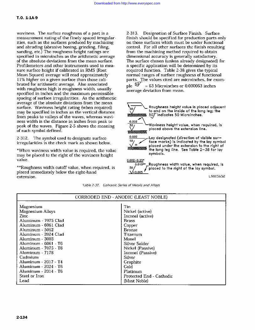
T.O. 1-1A-9
waviness. The surface roughness of a part is a
measurement rating of the finely spaced irregular-ities, such as the surfaces produced by machiningand abrading (abrasive honing, grinding, filing,sanding, etc.) The roughness height ratings arespecified in microinches as the arithmetic averageof the absolute deviations from the mean surface.Profilometers and other instruments used to mea-
sure surface height if calibrated in RMS (RootMean Square) average will read approximately11% higher on a given surface than those cali-brated for arithmetic average. Also associatedwith roughness high is roughness width, usuallyspecified in inches and the maximum permissiblespacing of surface irregularities. As the arithmeticaverage of the absolute diviations from the meansurface. Waviness height rating (when required)may be specified in inches as the vertical distancefrom peaks to valleys of the waves, whereas wavi-ness width is the distance in inches from peak topeak of the waves. Figure 2-5 shows the meaningof each symbol defined.
2-312. The symbol used to designate surfaceirregularities is the check mark as shown below.
*When waviness width value is required, the valuemay be placed to the right of the waviness heightvalue.
2-313. Designation of Surface Finish. Surfacefinish should be specified for production parts onlyon those surfaces which must be under functionalcontrol. For all other surfaces the finish resultingfrom the machining method required to obtaindimensional accuracy is generally satisfactory.The surface chosen (unless already designated) fora specific application will be determined by itsrequired function. Table 2-38 gives the typicalnormal ranges of surface roughness of functionalparts. The values cited are microinches, for exam-ple 63 Microinches or 0.000063 inchesaverage deviation from mean.
50Roughness height value is placed adjacentto and on the inside of the long leg; the5Findicates 50 Microinches.
0.002so -Waviness height value, when required, is
placed above the extension line.
0.002 Lay designated (direction of visible sur-501 face marks) is indicated by the lay symbol
50
o.oos
0.002-0.25"
o.olo"" Roughness width value, when required, is**Roughness width cutoff value, when required, isplaced immediately below the right-handextension.
placed under the extension to the right ofthe long leg line. See Table 2-38 for laysymbols.
placed to the right of the lay symbol.
L9805652
Table 2-37. Galvanic Series ofMetals and Alloys
CORRODED END ANODIC (LEAST NOBLE)
Magnesium TinMagnesium Alloys Nickel (active)Zinc Inconel (active)Aluminum 7075 Clad BrassAluminum 6061 Clad CopperAluminum 5052 BronzeAluminum 2024 Clad TitaniumAluminum 3003 MonelAluminum 6061 T6 Silver SolderAluminum 7075 T6 Nickel (Passive)Aluminum 7178 Inconel (Passive)Cadmium SilverAluminum 2017 T4 GraphiteAluminum 2024 T6 GoldAluminum 2014 T6 PlatinumSteel or Iron Protected End CathodicLead (Most Noble)
2-134
Downloaded from http://www.everyspec.com
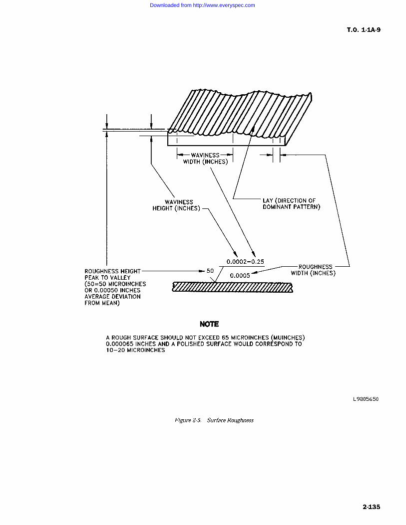
ROUGHNESS HEIGHT-PEAK TO VALLEY(50=50 MICROINCHESOR 0.00050 INCHESAVERAGE DEVIATIONFROM MEAN)
Figure 2-5. Surface Roughness
Y- WAVINESS-HWIDTH (INCHES)
WAVINESSHEIGHT (INCHES)
50
NOTE
LAY (DIRECTION OFDOMINANT PATTERN)
0.0002-0.25
0.0005
-ROUGHNESSWIDTH (INCHES)
A ROUGH SURFACE SHOULD NOT EXCEED 65 MICROINCHES (MUINCHES)0.000065 INCHES AND A POLISHED SURFACE WOULD CORRESPOND TO10-20 MICROINCHES
T.O. 1-1A-9
L9805650
2-135
Downloaded from http://www.everyspec.com
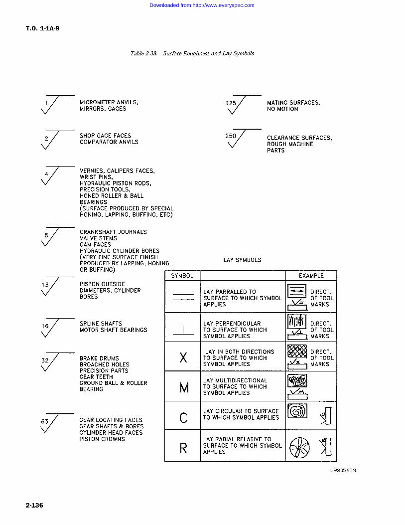
T.O. 1-1A-9
Table 2-38. Surface Roughness and Lay Symbols
MICROMETER ANVILS,MIRRORS, GAGES
SHOP GAGE FACESCOMPARATOR ANVILS
VERNIES, CALIPERS FACES,WRIST PINS,HYDRAULIC PISTON RODS,PRECISION TOOLS,HONED ROLLER & BALLBEARINGS(SURFACE PRODUCED BY SPECIALHONING, LAPPING, BUFFING, ETC)
CRANKSHAFT JOURNALSVALVE STEMSCAM FACESHYDRAULIC CYLINDER BORES(VERY FINE SURFACE FINISHPRODUCED BY LAPPING, HONINGOR BUFFING)
PISTON OUTSIDEDIAMETERS, CYLINDERBORES
SPLINE SHAFTSMOTOR SHAFT BEARINGS
BRAKE DRUMSBROACHED HOLESPRECISION PARTSGEAR TEETHGROUND BALL & ROLLERBEARING
GEAR LOCATING FACESGEAR SHAFTS & BORESCYLINDER HEAD FACESPISTON CROWNS
125
LAY SYMBOLS
MATING SURFACES,NO MOTION
CLEARANCE SURFACES,ROUGH MACHINEPARTS
SYMBOL EXAMPLE
LAY PARRALLED TOa
DIRECT.SURFACE TO WHICH SYMBOL OF TOOLAPPLIES MARKS
LAY PERPENDICULARIY
DIRECT.TO SURFACE TO WHICH OF TOOLSYMBOL APPLIES MARKS
X LAY IN BOTH DIRECTIONSTO SURFACE TO WHICH
DIRECT.OF TOOL
XSYMBOL APPLIESY
MARKS
LAY MULTIDIRECTIONALM TO SURFACE TO WHICHSYMBOL APPLIES
LAY CIRCULAR TO SURFACEC TO WHICH SYMBOL APPLIES
R LAY RADIAL RELATIVE TOSURFACE TO WHICH SYMBOLAPPLIES
L9805653
2-136
Downloaded from http://www.everyspec.com
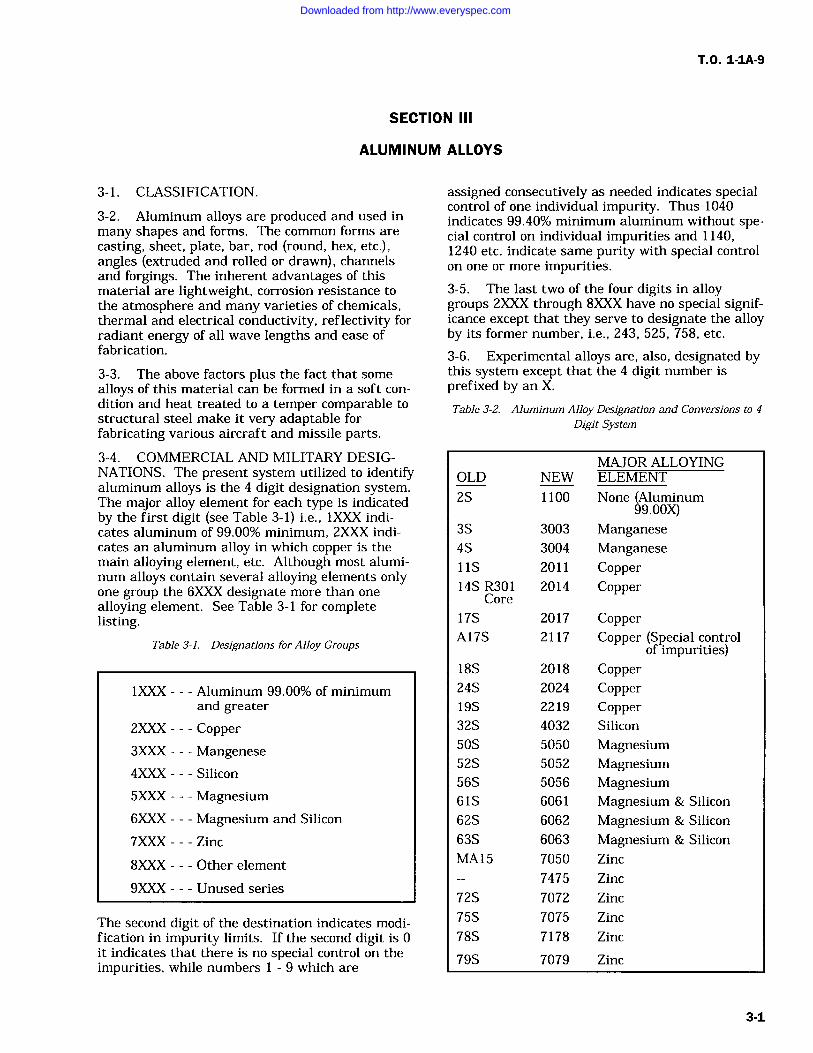
T.O. 1-1A-9
SECTION III
ALUMINUM ALLOYS
3-1. CLASSIFICATION.
3-2. Aluminum alloys are produced and used in
many shapes and forms. The common forms are
casting, sheet, plate, bar, rod (round, hex, etc.),angles (extruded and rolled or drawn), channelsand forgings. The inherent advantages of thismaterial are lightweight, corrosion resistance tothe atmosphere and many varieties of chemicals,thermal and electrical conductivity, reflectivity forradiant energy of all wave lengths and ease offabrication.
3-3. The above factors plus the fact that somealloys of this material can be formed in a soft con-
dition and heat treated to a temper comparable tostructural steel make it very adaptable forfabricating various aircraft and missile parts.
3-4. COMMERCIAL AND MILITARY DESIG-NATIONS. The present system utilized to identifyaluminum alloys is the 4 digit designation system.The major alloy element for each type is indicatedby the first digit (see Table 3-1) i.e., 1XXX indi-cates aluminum of 99.00% minimum, 2XXX indi-cates an aluminum alloy in which copper is themain alloying element, etc. Although most alumi-num alloys contain several alloying elements onlyone group the 6XXX designate more than one
alloying element. See Table 3-1 for completelisting.
Table 3-1. Designations for Alloy Groups
1XXX Aluminum 99.00% of minimumand greater
2XXX Copper3XXX Mangenese4XXX Silicon
5XXX Magnesium6XXX Magnesium and Silicon
7XXX---Zinc
8XXX Other element
9XXX Unused series
The second digit of the destination indicates modi-fication in impurity limits. If the second digit is 0it indicates that there is no special control on theimpurities, while numbers 1 9 which are
assigned consecutively as needed indicates specialcontrol of one individual impurity. Thus 1040indicates 99.40% minimum aluminum without spe-cial control on individual impurities and 1140,1240 etc. indicate same purity with special control
on one or more impurities.3-5. The last two of the four digits in alloygroups 2XXX through 8XXX have no special signif-icance except that they serve to designate the alloyby its former number, i.e., 243, 525, 758, etc.
3-6. Experimental alloys are, also, designated bythis system except that the 4 digit number isprefixed by an X.
Table 3-2. Aluminum Alloy Designation and Conversions to 4
Digit System
MAJOR ALLOYINGOLD NEW ELEMENT
2S 1100 None (Aluminum99.00X)
3S 3003 Manganese4S 3004 Manganese11S 2011 Copper14S R301 2014 Copper
Core
17S 2017 CopperA17S 2117 Copper (Special control
18S 2018
of impurities)Copper
24S 2024 Copper19S 2219 Copper32S 4032 Silicon
50S 5050 Magnesium52S 5052 Magnesium56S 5056 Magnesium61S 6061 Magnesium & Silicon
62S 6062 Magnesium & Silicon
63S 6063 Magnesium & Silicon
MA15 7050 Zinc
7475 Zinc
72S 7072 Zinc
75S 7075 Zinc
78S 7178 Zinc
79S 7079 Zinc
3-1
Downloaded from http://www.everyspec.com
T.O. 1-1A-9
NOTE
Cladding which is a sacrificial alumi-num coating applied to an aluminumalloy core for the purpose of increas-ing corrosion resistance is designatedas alclad 2024, alclad 2014, alclad7075, etc.
3-7. Aluminum alloys for military use are identi-fied by military and federal specifications whichare comparable to commercial specifications anddesignations. The following table is a general listof the commonly used military and federal specifi-cations according to the commercial designationand forms of material.
3-8. MECHANICAL PROPERTIES. Prior topresenting factual data on mechanical propertiesthe tempers (hardness) and methods of designationshould be explained. For nominal mechanicalproperties see Table 3-4.
3-9. The tempers of aluminum alloys are pro-duced essentially by three methods. These meth-ods are cold working (strain hardening), heattreatment and a combination of the two. The vari-ous alloys of aluminum are either classed as heat-treatable or non-heat-treatable. Alloys 1100, 3003,alclad 3003, 3004, alclad 3004, 5050 and 5052 areclassed as nonheat-treatable. The tempers ofthese alloys are designated by symbols Hl, H2,H3, H4, F & O.
3-10. A second number added to the above indi-cates the degree of strain hardening-actualtemper.Example: 2=1/4 hard (2/8) H12, H22, H32
4=1/2 hard (4/8) H14, H24, H346=3/4 hard (6/8) H16, H26, H368=Full Hard (8/8) H18, H28, H38
As previously pointed out the above tempers desig-nation symbols are hyphen (-dash) suffixed to the4 digit alloy designation. Example: 1000-H12,5052-H24, 3004-H34 etc. The general symbolsused for the nonheat-treatable alloys are asfollows:
-F As fabricated-O Annealed-H21 Strain hardened only-H2 Strain hardened then partial annealed-H3 Strain hardened then stabilized
NOTE
Attempt should not be made to alterthe temper characteristics of the "H"series of aluminum alloys other thanin emergencies. This shall be limitedto annealing operation only.
3-11. Alloys alclad 2014, 2024, alclad 2024, 6061,7075, alclad 7075 and 7178 are classed as heattreatable. The mechanical properties of thesealloys is improved by heat treatment or by a com-
bination of heat treatment and strain hardening.The tempers for these alloys is designated by sym-bols, W, T, T2, T3, T4, T5, T6, T7, T8, T9, T10, Fand O. Following is a summary of these symbols.
-F As fabricated-O Annealed-W Solution heat treated unstable temper-T Treated to produce stable tempers other than -F
or -O-T2 Annealed (cast products only)-T3 Solution heat treated and then cold worked-T4 Solution heat treated-T5 Artificially aged only-T6 Solution heat treated and then artificially
aged-T7 Solution heat treated and stabilized-T8 Solution heat treated, cold worked and then
artificially aged-T9 Solution heat treated, artificially aged, and
then cold worked-T10 Artificially aged and then cold worked
Added numbers to the above denotes a modifica-tion of standard tempers. Example: The numeral"6" following "T3" indicates a different amount ofcold work then used in "T3" such as 2024-T36.The numbers added to indicate modification or sig-nificant alternation of the standard temper arearbitrarily assigned and specification for the alloyshould be utilized to determine specific data.
3-12. The following standard modification digitshave been assigned for wrought products in allalloys: TX-51 Stress-Relieved by Stretching:Applies to products which are stress-relieved bystretching the following amounts after solutionheat treatment:
Plate 1 1/2 to 3% permanent set
Rod, Bar and Shapes to 3% permanent set
Applies directly to plate and rolled or cold finishesrod and bar. These products receive no furtherstraightening after stretching. Applies toextruded rod, bar and shapes which receive minorstraightening after stretching to comply with stan-dard tolerances.
-TX510 Applies to extruded rod, bar and shapeswhich receive no further straighteningafter stretching.
-TX511 Applies to extruded rod, bar and shapeswhich receive minor straightening afterstretching to comply with standardtolerances.
3-2
Downloaded from http://www.everyspec.com
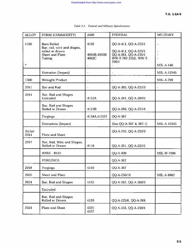
T.O. 1-1A-9
Table 3-3. Federal and Military Specifications
ALLOY FORM (COMMODITY) AMS FEDERAL MILITARY
1100
*
Bars RolledBar, rod, wire and shapes,rolled or drawnSheet and PlateTubing
4102
4001B,4003B4062C
QQ-A-411, QQ-A-225/1
QQ-A-411, QQ-A-225/1QQ-A-561, QQ-A-250/1WW-T-783 (Old), WW-T-700/1
MIL-A-148
Extrusion (Impact) MIL-A-12545
1360 Wrought Product MIL-A-799
2011 Bar and Rod QQ-A-365, QQ-A-225/3
2014 Bar, Rod and ShapesExtruded 4153A QQ-A-261, QQ-A-200/2
Bar, Rod and ShapesRolled or Drawn 4121B QQ-A-266, QQ-A-225/4
Forgings 4134A,4135H QQ-A-367
Extrusions (Impact) (See QQ-A-367 & 367-1) MIL-A-12545
Alclad2014 Plate and Sheet
QQ-A-255, QQ-A-250/3
2017 Bar, Rod, Wire and Shapes,Rolled or Drawn 4118 QQ-A-351, QQ-A-225/5
WIRE ROD QQ-A-430 MIL-W-7986
FORGINGS QQ-A-367
2018 Forgings 4140 QQ-A-367
2020 Sheet and Plate QQ-A-250/16 MIL-A-8882
2024 Bar, Rod and Shapes 4152 QQ-A-267, QQ-A-200/3
Extruded
Bar, Rod and ShapesRolled or Drawn 4120 QQ-A-225/6, QQ-A-268
2024 Plate and Sheet 40354037
QQ-A-355, QQ-A-250/4
3-3
Downloaded from http://www.everyspec.com
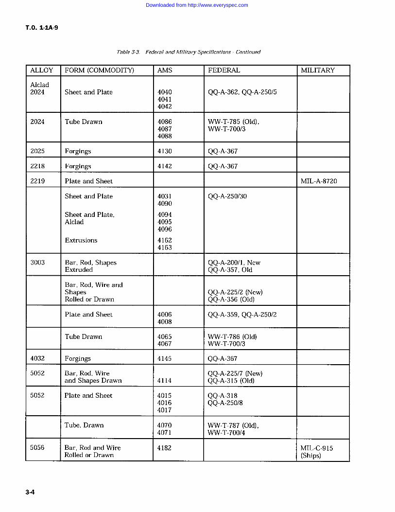
T.O. 1-IA-9
Table 3-3. Federal and Military Specifications Continued
ALLOY FORM (COMMODITY) AMS FEDERAL MILITARY
Alclad2024 Sheet and Plate 4040 QQ-A-362, QQ-A-250/5
40414042
2024 Tube Drawn 4086 WW-T-785 (Old),4087 WW-T-700/34088
2025 Forgings 4130 QQ-A-367
2218 Forgings 4142 QQ-A-367
2219 Plate and Sheet MIL-A-8720
Sheet and Plate 4031 QQ-A-250/304090
Sheet and Plate, 4094Alclad 4095
4096
Extrusions 41624163
3003 Bar, Rod, Shapes QQ-A-200/1, NewExtruded QQ-A-357, Old
Bar, Rod, Wire andShapes QQ-A-225/2 (New)Rolled or Drawn QQ-A-356 (Old)
Plate and Sheet 4006 QQ-A-359, QQ-A-250/24008
Tube Drawn 4065 WW-T-786 (Old)4067 WW-T-700/3
4032 Forgings 4145 QQ-A-367
5052 Bar, Rod, Wire QQ-A-225/7 (New)and Shapes Drawn 4114 QQ-A-315 (Old)
5052 Plate and Sheet 4015 QQ-A-3184016 QQ-A-250/84017
Tube, Drawn 4070 WW-T-787 (Old),4071 WW-T-700/4
5056 Bar, Rod and Wire 4182 MIL-C-915Rolled or Drawn (Ships)
3-4
Downloaded from http://www.everyspec.com
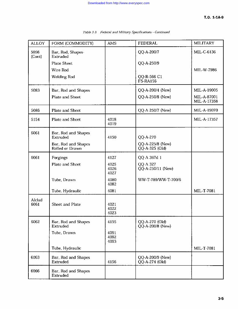
T.O. 1-IA-9
Table 3-3. Federal and Military Specifications Continued
ALLOY FORM (COMMODITY) AMS FEDERAL MILITARY
5056 Bar, Rod, Shapes- QQ-A-200/7 MIL-C-6136(Cont) Extruded
Plate Sheet QQ-A-250/9Wire Rod MIL-W-7986
Welding Rod QQ-R-566 C1FS-RA156
5083 Bar, Rod and Shapes QQ-A-200/4 (New) MIL-A-19005
Plate and Sheet QQ-A-250/8 (New) MIL-A-87001MIL-A-17358
5086 Plate and Sheet QQ-A-250/7 (New) MIL-A-19070
5154 Plate and Sheet 4018 MIL-A-173574019
6061 Bar, Rod and ShapesExtruded 4150 QQ-A-270Bar, Rod and Shapes QQ-A-225/8 (New)Rolled or Drawn QQ-A-325 (Old)
6061 Forgings 4127 QQ-A-367d-1Plate and Sheet 4025 QQ-A-327
4026 QQ-A-250/11 (New)4027
Tube, Drawn 4080 WW-T-789/WW-T-700/64082
Tube, Hydraulic 4081 MIL-T-7081
Alclad6061 Sheet and Plate 4021
40224023
6062 Bar, Rod and Shapes 4155 QQ-A-270 (Old)Extruded QQ-A-200/8 (New)Tube, Drawn 4091
40924093
Tube, Hydraulic MIL-T-7081
6063 Bar, Rod and Shapes QQ-A-200/9 (New)Extruded 4156 QQ-A-274 (Old)
6066 Bar, Rod and ShapesExtruded
3-5
Downloaded from http://www.everyspec.com
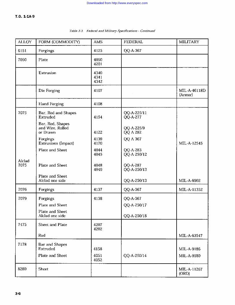
T.O. 1-IA-9
Table 3-3. Federal and Military Specifications Continued
ALLOY FORM (COMMODITY) AMS FEDERAL MILITARY
6151 Forgings 4125 QQ-A-367
7050 Plate 40504201
Extrusion 434043414342
Die Forging 4107 MIL-A-46118D(Armor)
Hand Forging 4108
7075 Bar, Rod and Shapes QQ-A-225/11Extruded 4154 QQ-A-277Bar, Rod, Shapesand Wire, Rolled QQ-A-225/9or Drawn 4122 QQ-A-282Forgings 4139 QQ-A-367Extrusions (Impact) 4170 MIL-A-12545
Plate and Sheet 4044 QQ-A-2834045 QQ-A-250/12
Alclad7075 Plate and Sheet 4048 QQ-A-287
4049 QQ-A-250/13Plate and SheetAlclad one side QQ-A-250/13 MIL-A-8902
7076 Forgings 4137 QQ-A-367 MIL-A-11352
7079 Forgings 4138 QQ-A-367Plate and Sheet QQ-A-250/17Plate and SheetAlclad one side QQ-A-250/18
7475 Sheet and Plate 42074202
Rod MIL-A-63547
7178 Bar and ShapesExtruded 4158 MIL-A-9186
Plate and Sheet 4051 QQ-A-250/14 MIL-A-91804052
8280 Sheet MIL-A-11267(ORD)
3-6
Downloaded from http://www.everyspec.com
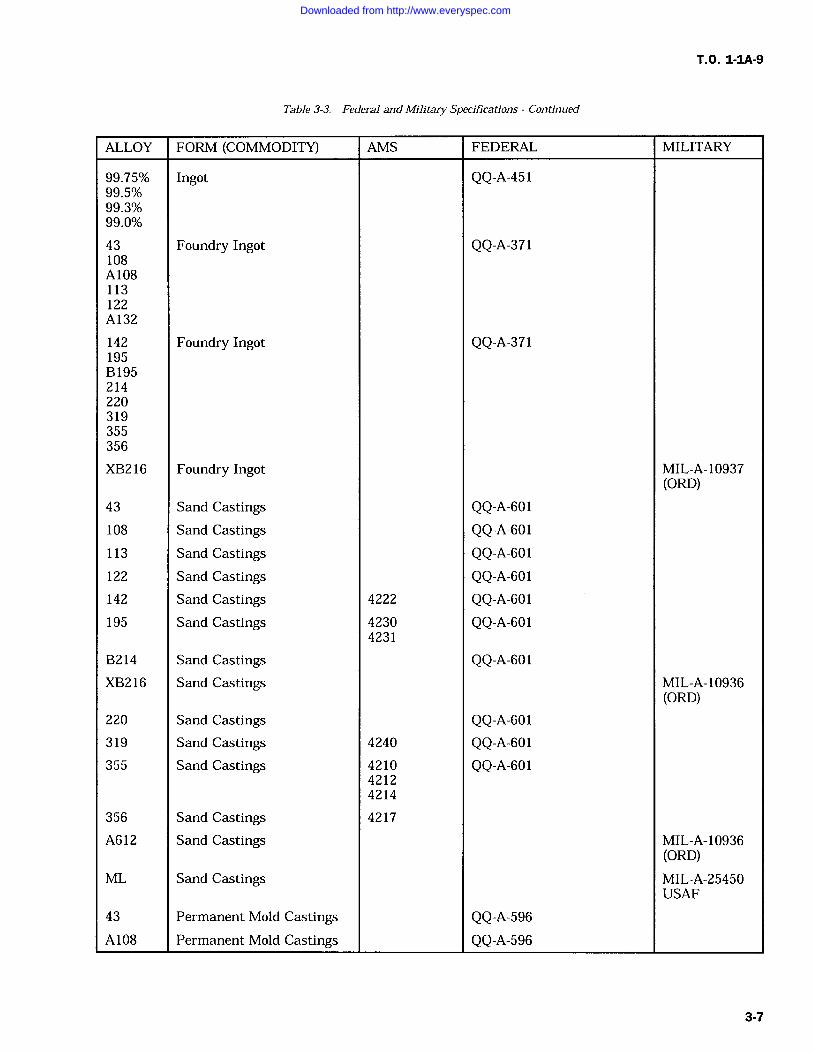
T.O. 1-IA-9
Table 3-3. Federal and Military Specifications Continued
ALLOY FORM (COMMODITY) AMS FEDERAL MILITARY
99.75% Ingot QQ-A-45199.5%99.3%99.0%
43 Foundry Ingot QQ-A-371108A108113122A132
142 Foundry Ingot QQ-A-371195B 195214220319355356
XB216 Foundry Ingot MIL-A- 10937(ORD)
43 Sand Castings QQ-A-601108 Sand Castings QQ-A-601113 Sand Castings QQ-A-601122 Sand Castings QQ-A-601142 Sand Castings 4222 QQ-A-601195 Sand Castings 4230 QQ-A-601
4231
B214 Sand Castings QQ-A-601XB216 Sand Castings MIL-A-10936
(ORD)220 Sand Castings QQ-A-601319 Sand Castings 4240 QQ-A-601355 Sand Castings 4210 QQ-A-601
42124214
356 Sand Castings 4217
A612 Sand Castings MIL-A-10936(ORD)
ML Sand Castings MIL-A-25450USAF
43 Permanent Mold Castings QQ-A-596A108 Permanent Mold Castings QQ-A-596
3-7
Downloaded from http://www.everyspec.com
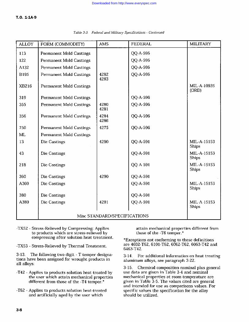
T.O. 1-IA-9
Table 3-3. Federal and Military Specifications Continued
ALLOY FORM (COMMODITY) AMS FEDERAL MILITARY
113 Permanent Mold Castings QQ-A-596
122 Permanent Mold Castings QQ-A-596A132 Permanent Mold Castings QQ-A-596B 195 Permanent Mold Castings 4282 QQ-A-596
4283
XB216 Permanent Mold Castings MIL-A-10935(ORD)
319 Permanent Mold Castings QQ-A-596
355 Permanent Mold Castings 4280 QQ-A-5964281
356 Permanent Mold Castings 4284 QQ-A-5964286
750 Permanent Mold Castings 4275 QQ-A-596ML Permanent Mold Castings13 Die Castings 4290 QQ-A-591 MIL-A-15153
Ships43 Die Castings QQ-A-591 MIL-A-15153
Ships218 Die Castings QQ-A-591 MIL-A-15153
Ships360 Die Castings 4290 QQ-A-591A360 Die Castings QQ-A-591 MIL-A-15153
Ships380 Die Castings QQ-A-591A380 Die Castings 4291 QQ-A-591 MIL-A-15153
Ships
Misc STANDARD/SPECIFICATIONS
-TX52 Stress-Relieved by Compressing: Appliesto products which are stress-relieved bycompressing after solution heat treatment.
-TX53 Stress-Relieved by Thermal Treatment.
3-13. The following two digit T temper designa-tions have been assigned for wrought products inall alloys:
-T42 Applies to products solution heat treated bythe user which attain mechanical propertiesdifferent from those of the -T4 temper.*
-T62 Applies to products solution heat-treatedand artificially aged by the user which
attain mechanical properties different fromthose of the -T6 temper.*
*Exceptions not conforming to these definitionsare 4032-T62, 6101-T62, 6062-T62, 6063-T42 and6463-T42.
3-14. For additional information on heat treatingaluminum alloys, see paragraph 3-22.
3-15. Chemical composition nominal plus generaluse data are given in Table 3-4 and nominalmechanical properties at room temperature are
given in Table 3-5. The values cited are generaland intended for use as comparisons values. Forspecific values the specification for the alloyshould be utilized.
3-8
Downloaded from http://www.everyspec.com
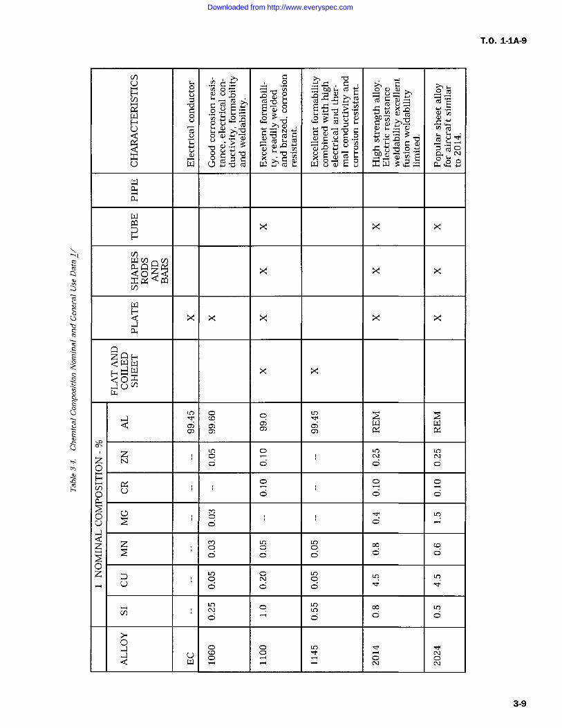
o r. >,[~-Y U Ln U cn ( o U Q O fC
ct CO 7-1 cz
w 3 'O w v ueLn CO
> bV)
cop
CUco
oaY
0)N "a a
a)a)
Yy cR ou
'ncuU hh
> omW
0 oW Q4 -WM a E x W 3 a
a
GD X X XE-
V) V)
Qxx rY
X X X X X
QwX
0aV)
LO C)
of W W
0LOO
C) Lf')N
Lf)NZ
ON
O O O O
O O O
O o 0 0
O L7 MLO
U o 0
z z o 0 0 Co 00 0 0
0z o o
LO Lf)U
o 0 0
N O Y 00
C) O O
0
UC)CO
C)C)
LON
Q w O C)N
O
T.O. 1-1A-9
3-9
Downloaded from http://www.everyspec.com
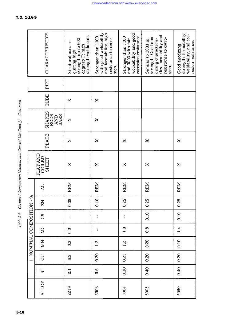
T.O.1-1A-9
UH
vi0
po o po ai
O a sca
oaY o
CZ co
0
Ln ct o
En
3 am
0007
Y7 w V)[_U
bA sti 3co
flYYro..oYo cz$ CO
0)
YLn
cam"YYY bA N bA GO o
0)bAY cd cn d bA qpw" a
co
CU CU o V)
U V)4-d n 0YY(' ciYY3v .(2cn nTSY 7 n3
Ey
WV) V)aoZ<Q
X Xx m
V)
waX X X X
a
z QwW X X X X X0Ya
OR
ZLOo
LON
LON
LON
O O O O O O
O O
p U o 0
00u C7 0 0 00
o o
z z M NO
o o0
NO N O O
U C 0 0 0 0
V)0
O
0M
0c}
0Yf
O O O
Oce)O
OO
C)N O CD O O
3-10
Downloaded from http://www.everyspec.com
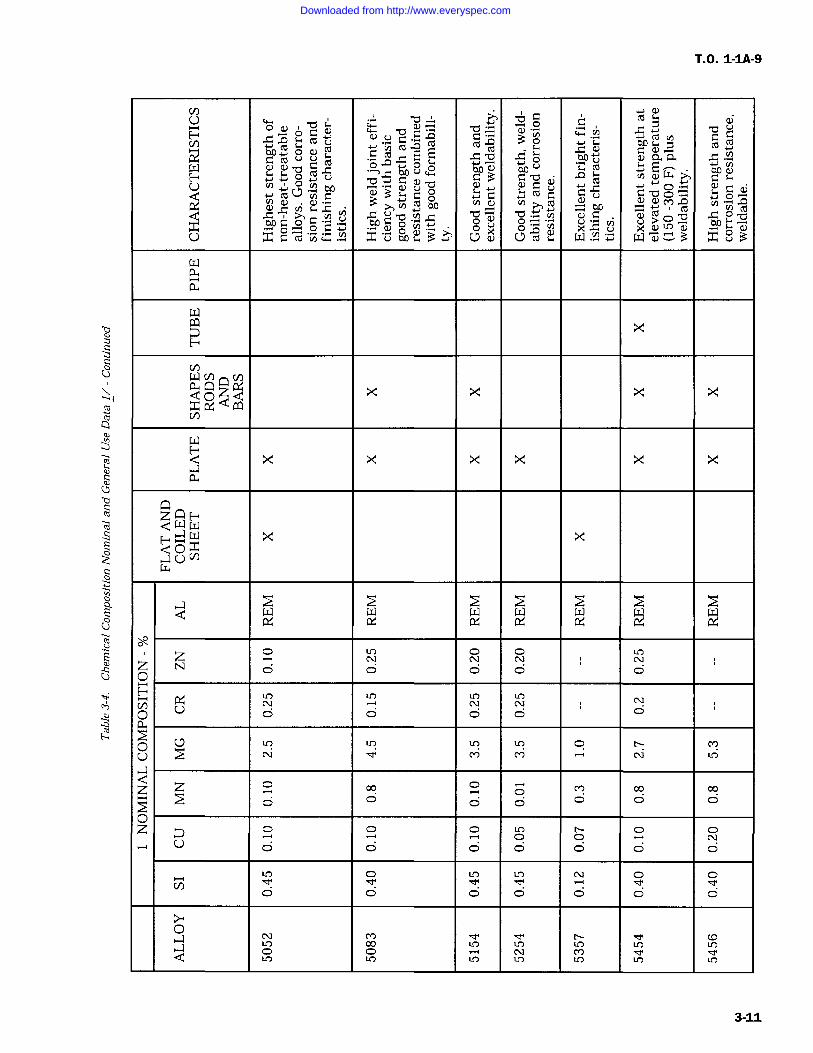
T.O. 1-1A-9
cz0
:8 cz 0 CO
cz E E E ,Y-o o aAY'C w ao, YH `bow
to Y`" czY Y'Y4-1`ZYY
Wo3Yc0O
w
ocu
cZ o q o0-00... o?vi O.
V7
$bQ V W
-00 Y CO'0
CLO cha) fC
yO
0 r.O C i
0 .4 aW r-
No a, O
0 a)O p v
O O OU csi0Z:Y x'YaAc.3+Y 0 0 CZ
X av3 v
0x x x x
xx m
Qx X X x x x
QQ W
X X
V)
w w w w w w w
z N N O O NO
0 0 0 0 0
LON
Ln LON
LCDN N
O U o 0 0 0aY-+GO (J LO Ln LC) LO 0 ti M
U N M M N LC)
Z Z 00 2 M 00 00
O O O O O O
0z O O O LO
OtiO
O ONU o 0 0 0 0 0
LO O Ln Ln N O O
O O O O O O O
ONLO
M00
dLO LO
lYLO Ln
COLO
Q OLO LO
OLO LO
LLf)IC)
3-11
Downloaded from http://www.everyspec.com
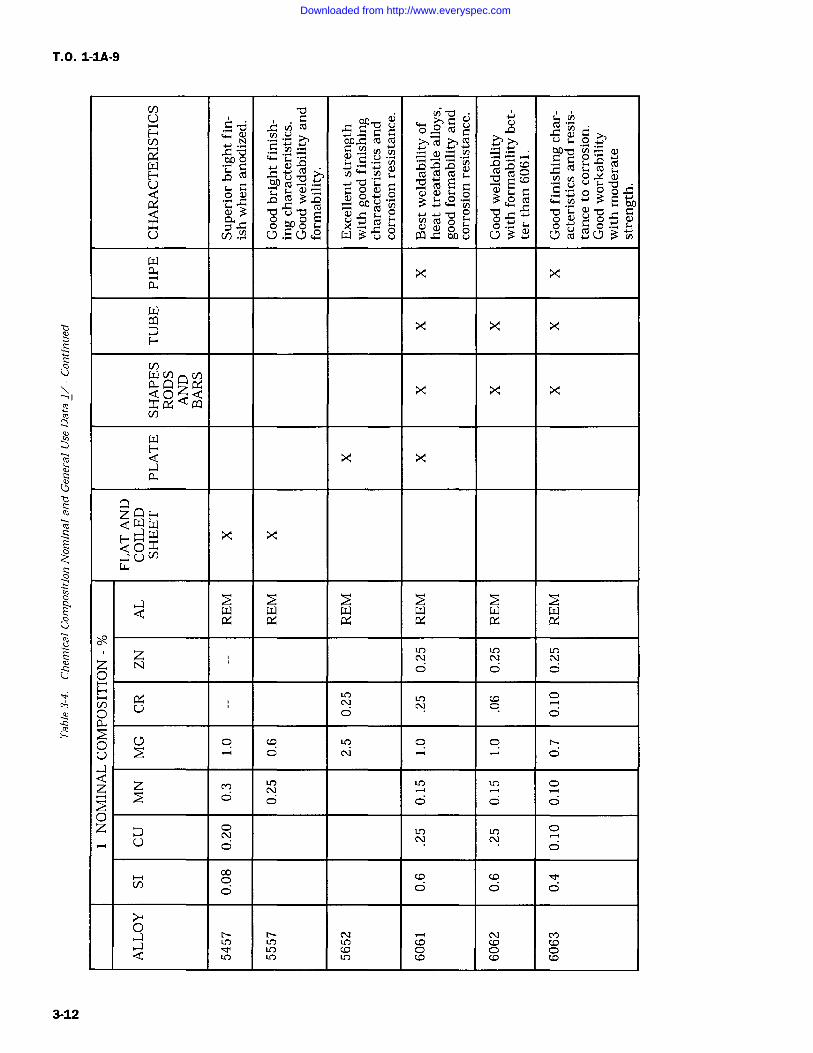
T.O. 1-1A-9
U aA ovi -O(,YYo a
ct
Ytnr tip. = rr 0
H cC b h s cd cd s,CO 0ti cYE co
r. x a)
fx i .0 Cocu
to V)3+
a)3 CO 16 to0.3 cd0 o fo oc CO
Yx
v X00 v0o
U C4() Y Q L) 2 W 3 Y v pCQ Y w8 .Yoo 10C7 M V)
X X
W X X X
<ooza X X Xwxx
Xa
Q wX XSON
aW W W W W W
60,
Z N
Lf')N
LON
LON
p O O O
C/) UO
p o 0
O C7 o CC LC) O ti
N O
1
z z m LC) In ir') O
o 0 0 0 6pz O N N
u0
0Oco Co cM
O O O O
OtiLC)
tiLC)
NLO (
N(
MCD
Q LC)LOLC)
LIC) 0(fl
C)(p (p
3-12
Downloaded from http://www.everyspec.com
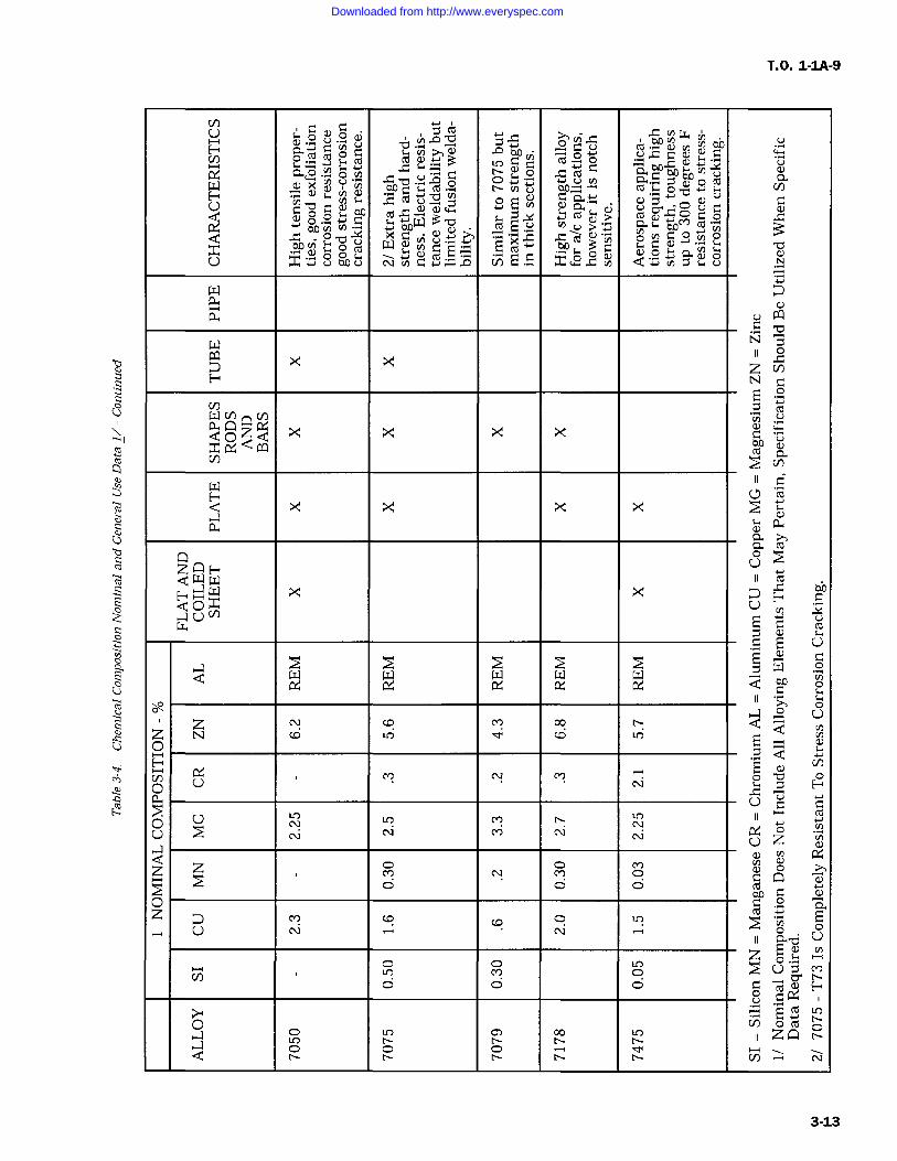
T.O. 1-1A-9
C: CY
0 CZLO CZ o U" x
cu (nu -oYno CUo4J 4Uv) to to (n
0
a(/)
U ti
to cd-0 Ena
r- In oQ aY cC c. 0u YY
to0
a)CO 3 z
aicon ohoaY= cotoc; 0"0u
Yb OxY EX-
Y,>Q).Co
a nO0OoAv oo Y E o0
o a 0 NU x+ obco cm n cn 0xw Q
cu
W N
X X0No
CZ<oz<Q
x x x x jtoxx aa cu
Cl) Cn
x x x xM
a a>1co
0UzQH
W coQ wH ' X >C HUU
W C U
011 U
z N CO Cl? oo ti Qz N co CO in mo 41
oV)O U M N
NZ7 O
Ha
0U
O Cry NN
M
M
t`
N
NoN z Y
N
Q) V)cn CUa) 0 >1
N clY O C Q aO O -1
o az Cl? CO CO O C
EU N N 0 U
a-dV)z o^
o M 0 U Q0 0 o s~ 0 H
o
-Cp o 00
cn 0CozQa O O O
Cl) N
3-13
Downloaded from http://www.everyspec.com
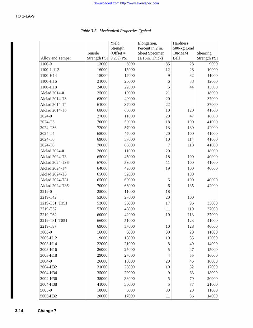
TO 1-1A-9
Table 3-5. Mechanical Properties-Typical
Alloy and TemperTensile Strength PSI
YieldStrength(Offset =0.2%) PSI
Elongation, Percent in 2 in. Sheet Specimen(1/16in. Thick)
Hardness 500-kg Load 10MMMBall
Shearing Strength PSI
1100-0 13000 5000 35 23 9000
1100-1-112 16000 15000 12 28 10000
1100-H14 18000 17000 9 32 11000
1100-H16 21000 20000 6 38 12000
1100-H18 24000 22000 5 44 13000
Alclad 2014-0 25000 10000 21 18000
Alclad 2014-T3 63000 40000 20 37000
Alclad 2014-T4 61000 37000 22 37000
Alclad 2014-T6 68000 60000 10 120 41000
2024-0 27000 11000 20 47 18000
2024-T3 70000 50000 18 100 41000
2024-T36 72000 57000 13 130 42000
2024-T4 68000 47000 20 100 41000
2024-T6 69000 57000 10 114 41000
2024-T8 70000 65000 7 118 41000
Alclad 2024-0 26000 11000 20 18000
Alclad 2024-T3 65000 45000 18 100 40000
Alclad 2024-T36 67000 53000 11 100 41000
Alclad 2024-T4 64000 42000 19 100 40000
Alclad 2024-T6 65000 52000 100
Alclad 2024-T81 65000 60000 6 100 40000
Alclad 2024-T86 70000 66000 6 135 42000
2219-0 25000 11000 18
2219-T42 52000 27000 20 100
2219-T31, T351 52000 36000 17 96 33000
2219-T37 57000 46000 11 110 37000
2219-T62 60000 42000 10 113 37000
2219-T81, T851 66000 51000 123 41000
2219-T87 69000 57000 10 128 40000
3003-0 16000 6000 30 28 11000
3003-H12 19000 18000 10 35 12000
3003-H14 22000 21000 8 40 14000
3003-H16 26000 25000 5 47 15000
3003-H18 29000 27000 4 55 16000
3004-0 26000 10000 20 45 16000
3004-H32 31000 25000 10 52 17000
3004-H34 35000 29000 9 63 18000
3004-H36 38000 33000 5 70 20000
3004-H38 41000 36000 5 77 21000
5005-0 18000 6000 30 28 11000
5005-H32 20000 17000 11 36 14000
3-14 Change 7
Downloaded from http://www.everyspec.com
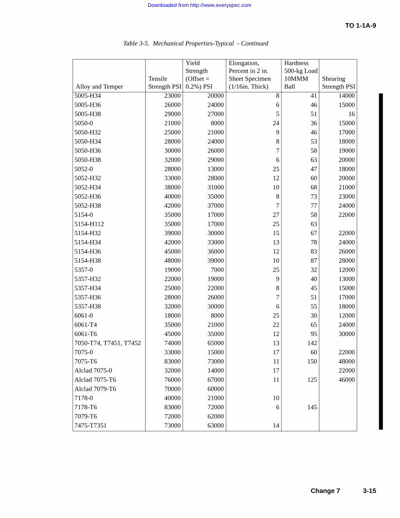
TO 1-1A-9
5005-H34 23000 20000 8 41 14000
5005-H36 26000 24000 6 46 15000
5005-H38 29000 27000 5 51 16
5050-0 21000 8000 24 36 15000
5050-H32 25000 21000 9 46 17000
5050-H34 28000 24000 8 53 18000
5050-H36 30000 26000 7 58 19000
5050-H38 32000 29000 6 63 20000
5052-0 28000 13000 25 47 18000
5052-H32 33000 28000 12 60 20000
5052-H34 38000 31000 10 68 21000
5052-H36 40000 35000 8 73 23000
5052-H38 42000 37000 7 77 24000
5154-0 35000 17000 27 58 22000
5154-H112 35000 17000 25 63
5154-H32 39000 30000 15 67 22000
5154-H34 42000 33000 13 78 24000
5154-H36 45000 36000 12 83 26000
5154-H38 48000 39000 10 87 28000
5357-0 19000 7000 25 32 12000
5357-H32 22000 19000 9 40 13000
5357-H34 25000 22000 8 45 15000
5357-H36 28000 26000 7 51 17000
5357-H38 32000 30000 6 55 18000
6061-0 18000 8000 25 30 12000
6061-T4 35000 21000 22 65 24000
6061-T6 45000 35000 12 95 30000
7050-T74, T7451, T7452 74000 65000 13 142
7075-0 33000 15000 17 60 22000
7075-T6 83000 73000 11 150 48000
Alclad 7075-0 32000 14000 17 22000
Alclad 7075-T6 76000 67000 11 125 46000
Alclad 7079-T6 70000 60000
7178-0 40000 21000 10
7178-T6 83000 72000 6 145
7079-T6 72000 62000
7475-T7351 73000 63000 14
Table 3-5. Mechanical Properties-Typical - Continued
Alloy and TemperTensile Strength PSI
YieldStrength(Offset =0.2%) PSI
Elongation, Percent in 2 in. Sheet Specimen(1/16in. Thick)
Hardness 500-kg Load 10MMMBall
Shearing Strength PSI
Change 7 3-15
Downloaded from http://www.everyspec.com
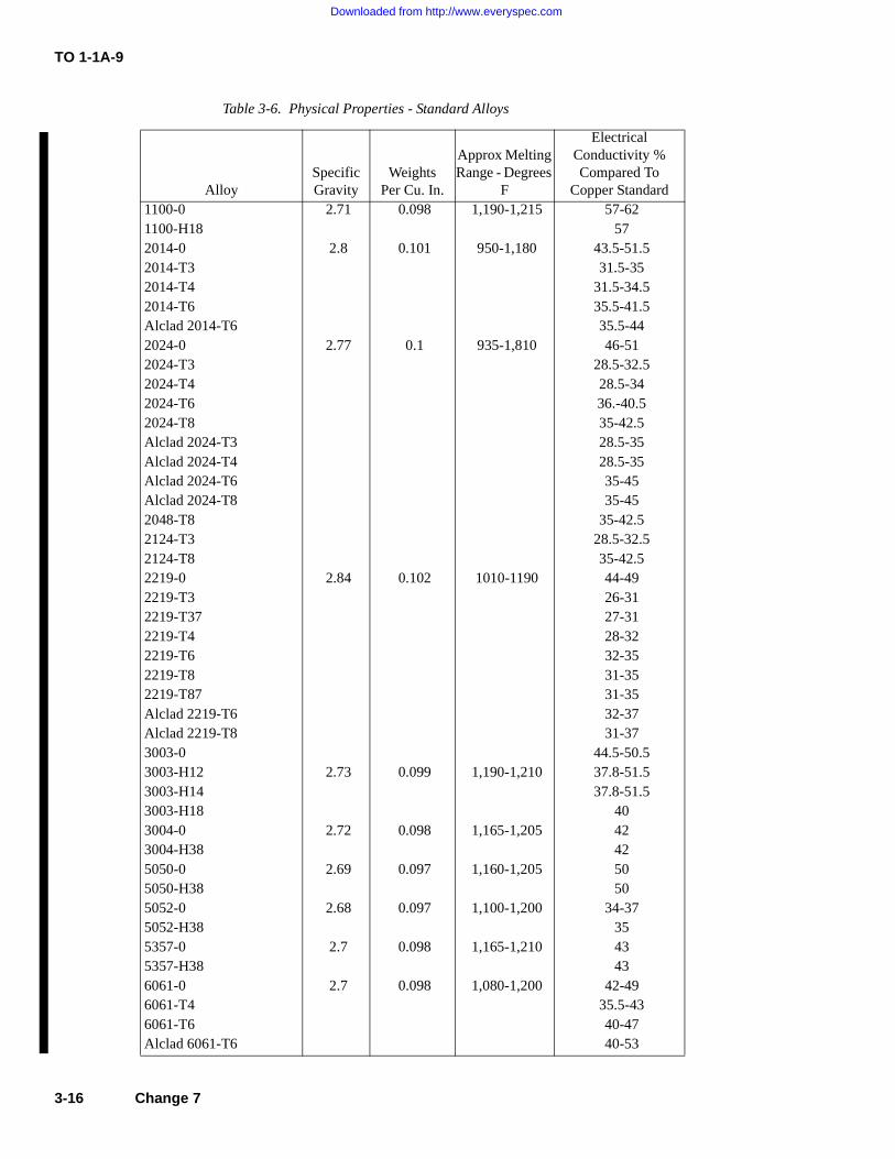
TO 1-1A-9
Table 3-6. Physical Properties - Standard Alloys
AlloySpecificGravity
WeightsPer Cu. In.
Approx Melting Range - Degrees
F
ElectricalConductivity %Compared To
Copper Standard1100-0 2.71 0.098 1,190-1,215 57-621100-H18 572014-0 2.8 0.101 950-1,180 43.5-51.52014-T3 31.5-352014-T4 31.5-34.52014-T6 35.5-41.5Alclad 2014-T6 35.5-442024-0 2.77 0.1 935-1,810 46-512024-T3 28.5-32.52024-T4 28.5-342024-T6 36.-40.52024-T8 35-42.5Alclad 2024-T3 28.5-35Alclad 2024-T4 28.5-35Alclad 2024-T6 35-45Alclad 2024-T8 35-452048-T8 35-42.52124-T3 28.5-32.52124-T8 35-42.52219-0 2.84 0.102 1010-1190 44-492219-T3 26-312219-T37 27-312219-T4 28-322219-T6 32-352219-T8 31-352219-T87 31-35Alclad 2219-T6 32-37Alclad 2219-T8 31-373003-0 44.5-50.53003-H12 2.73 0.099 1,190-1,210 37.8-51.53003-H14 37.8-51.53003-H18 403004-0 2.72 0.098 1,165-1,205 423004-H38 425050-0 2.69 0.097 1,160-1,205 505050-H38 505052-0 2.68 0.097 1,100-1,200 34-375052-H38 355357-0 2.7 0.098 1,165-1,210 435357-H38 436061-0 2.7 0.098 1,080-1,200 42-496061-T4 35.5-436061-T6 40-47Alclad 6061-T6 40-53
3-16 Change 7
Downloaded from http://www.everyspec.com
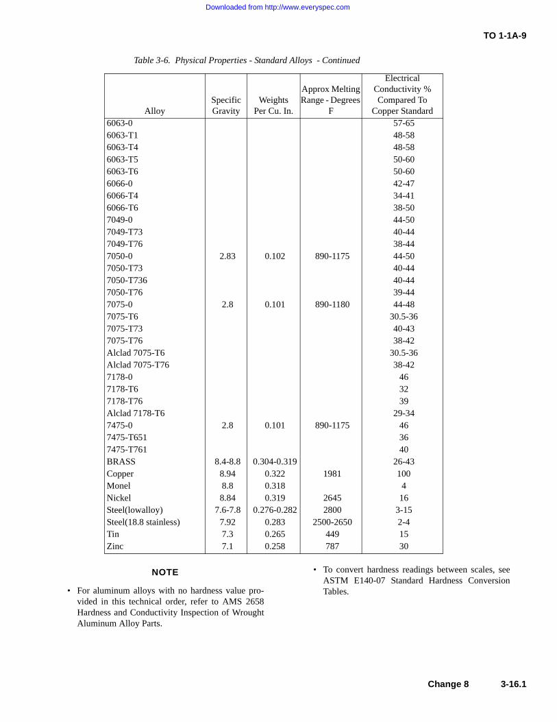
TO 1-1A-9
NOTE
• For aluminum alloys with no hardness value pro-vided in this technical order, refer to AMS 2658Hardness and Conductivity Inspection of WroughtAluminum Alloy Parts.
• To convert hardness readings between scales, seeASTM E140-07 Standard Hardness ConversionTables.
6063-0 57-656063-T1 48-586063-T4 48-586063-T5 50-606063-T6 50-606066-0 42-476066-T4 34-416066-T6 38-507049-0 44-507049-T73 40-447049-T76 38-447050-0 2.83 0.102 890-1175 44-507050-T73 40-447050-T736 40-447050-T76 39-447075-0 2.8 0.101 890-1180 44-487075-T6 30.5-367075-T73 40-437075-T76 38-42Alclad 7075-T6 30.5-36Alclad 7075-T76 38-427178-0 467178-T6 327178-T76 39Alclad 7178-T6 29-347475-0 2.8 0.101 890-1175 467475-T651 367475-T761 40BRASS 8.4-8.8 0.304-0.319 26-43Copper 8.94 0.322 1981 100Monel 8.8 0.318 4Nickel 8.84 0.319 2645 16Steel(lowalloy) 7.6-7.8 0.276-0.282 2800 3-15Steel(18.8 stainless) 7.92 0.283 2500-2650 2-4Tin 7.3 0.265 449 15Zinc 7.1 0.258 787 30
Table 3-6. Physical Properties - Standard Alloys - Continued
AlloySpecificGravity
WeightsPer Cu. In.
Approx Melting Range - Degrees
F
ElectricalConductivity %Compared To
Copper Standard
Change 8 3-16.1
Downloaded from http://www.everyspec.com
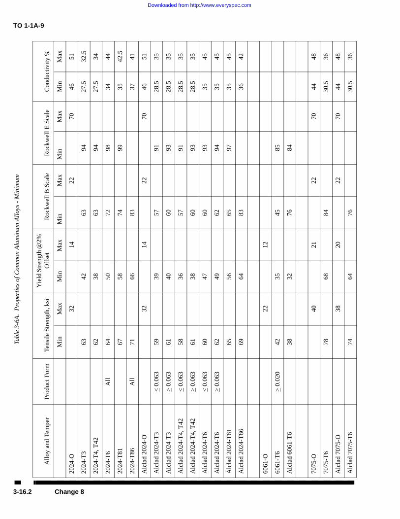
TO 1-1A-9Ta
ble
3-6A
. P
rope
rtie
s of
Com
mon
Alu
min
um A
lloy
s -
Min
imum
All
oy a
nd T
empe
rP
rodu
ct F
orm
Tens
ile
Stre
ngth
, ksi
Yie
ld S
tren
gth
@2%
O
ffse
tR
ockw
ell B
Sca
leR
ockw
ell E
Sca
leC
ondu
ctiv
ity
%
Min
Max
Min
Max
Min
Max
Min
Max
Min
Max
2024
-O32
1422
7046
51
2024
-T3
6342
6394
27.5
32.5
2024
-T4,
T42
6238
6394
27.5
34
2024
-T6
All
6450
7298
3444
2024
-T81
6758
7499
3542
.5
2024
-T86
All
7166
8337
41
Alc
lad
2024
-O32
1422
7046
51
Alc
lad
2024
-T3
< 0
.063
5939
5791
28.5
35
Alc
lad
2024
-T3
> 0
.063
6140
6093
28.5
35
Alc
lad
2024
-T4,
T42
< 0
.063
5836
5791
28.5
35
Alc
lad
2024
-T4,
T42
> 0
.063
6138
6093
28.5
35
Alc
lad
2024
-T6
< 0
.063
6047
6093
3545
Alc
lad
2024
-T6
> 0
.063
6249
6294
3545
Alc
lad
2024
-T81
6556
6597
3545
Alc
lad
2024
-T86
6964
8336
42
6061
-O22
12
6061
-T6
> 0
.020
4235
4585
Alc
lad
6061
-T6
3832
7684
7075
-O40
2122
7044
48
7075
-T6
7868
8430
.536
Alc
lad
7075
-O38
2022
7044
48
Alc
lad
7075
-T6
7464
7630
.536
3-16.2 Change 8
Downloaded from http://www.everyspec.com
TO 1-1A-9
3-16. PHYSICAL PROPERTIES. Commercially pure alumi-num weights 0.098 pounds per cubic inch, corresponding to aspecific gravity of 271. Data for standard alloys are shown inTable 3-6. The approximate weight for aluminum, includingits alloys, is one-tenth of a pound per cubic inch (see Table 3-6).
3-17. HEAT TREATMENT OF ALUMINUM ALLOYS.
NOTE
SAE-AMS-2770, Heat Treatment of wrought alumi-num alloy parts, & SAE-AMS-2771, Heat Treatmentof aluminum alloy castings, will be the control docu-ments for heat treatment of Aluminum Alloys usedon aerospace equipment. For complete description ofaluminum alloy heat treat requirements, refer to latestissues of SAE-AMS-2770 & SAE-AMS-2771.
3-18. GENERAL. There are two types of heat treatmentapplicable to aluminum alloys. They are known as solutionand precipitation heat treatment. Some alloys such as 2017and 2024 develop their full mechanical properties as a resultof solution heat treatment followed by 96 hours (natural pre-cipitation) aging at room temperature. Other alloys, such as2014, 7075, and 7178 require solution heat treatment andaging (precipitation heat treatment) for specific length of timeat a definite temperature (see Table 3-11).
NOTE
Additional Heat Treatment information is discussedin Section IX.
3-18A. NEWLY FABRICATED PARTS. Newly fabricatedparts that require heat treatment shall be accompanied by acoupon, whenever possible. A coupon is a piece of metal thatis taken from the same stock as the fabricated part. Its thick-ness should match that of the part with an overall size thatprovides adequate room for hardness and conductivity testing.Coupons must be heat treated along with the manufacturedpart to ensure both pieces undergo the same metallurgicalchanges. After completion of heat treatment, perform requiredhardness testing on the coupon to prevent damage to the fabri-cated part. See Section VIII of this technical order for properhardness testing procedures. All heat treated aluminum alloyparts and coupons shall be conductivity tested. When numer-ous parts are being heat treated simultaneously, the parts withthe lowest and highest conductivity readings shall also behardness tested to validate metallurgical changes. Parts thatfail to meet hardness or conductivity standards shall berejected and reworked as appropriate.
NOTE
Conductivity testing should not be performed on6061, 6063, 6066, and 6951 aluminum alloy partsand the results of any conductivity testing on thesematerials should not be used as a basis for rejection.
3-18B. RECORDS. Air Force and government personnelshall document heat treatment procedures performed on alumi-num alloy aircraft and missile weapon systems and supportequipment by utilizing AFTO Form 8, Heat Treatment Proce-dure Record. On-site AF contractors shall also use the AFTOForm 8 unless their contract specifies a different method ofheat treatment documentation. The results of heat treatmentperformed on aluminum alloys shall be verified through hard-ness and conductivity testing. Minimum hardness conductivityreadings for commonly used aluminum alloys are specified inTable 3-6A. Additional conductivity data can be found inTable 3-6. Personnel performing hardness testing shall docu-ment results on AFTO Form 8, Blocks 21 - 25. Conductivityshall be tested by qualified NDI personnel using TO 33B-1-2,WP 407 00, or qualified heat treat personnel, using directreading instruments in accordance with MIL-STD-1537,“Electrical Conductivity Test for Verification of Heat Treat-ment of Aluminum Alloys, Eddy Current Method.” Resultsshall be documented on AFTO Form 8, Blocks 27 - 32 andsigned by performing personnel.
3-19. Solution heat treatment is a process where the alloyingelements enter into solid solution in the aluminum at criticaltemperatures. It has been found that those alloying elementswhich increase the strength and hardness are more soluble insolid aluminum at high temperature than at low. To completethe solution often the metal is held at high temperatures forsufficient time; it is then quenched rapidly in cold water toretain this condition. Immediately after quenching, the alloy isin an unstable condition, because it consists of a supersatu-rated solid solution of the hardening agent. Upon standing atroom temperature the hardening constituent in excess of thatwhich is soluble at room temperature precipitates. The precipi-tate is in the form of extremely fine particles which due totheir “keying” action, greatly increase their strength. This is ineffect a method where the molecules of the aluminum andalloying elements are realigned to increase the strength andhardness of some aluminum alloys.
3-20. PRECIPITATION (AGE) HARDENING. This phaseof heat treatment consists of aging material previously sub-jected to solution heat treatments by natural (occurs at roomtemperature) or artificial aging. Artificial aging consists ofheating aluminum alloy to a specific temperature and holdingfor a specified length of time. During this hardening andstrengthening operation the alloying constituents in solid solu-tion precipitate out. As precipitation progresses, the strengthof the material increases until the maximum is reached. Fur-ther aging (overaging) causes the strength to decline until a
Change 9 3-17
Downloaded from http://www.everyspec.com

TO 1-1A-9
stable condition is obtained. The strengthening of the materialis due to the uniform alignment or formation of the moleculestructure of the aluminum and alloying element.
3-21. Artificial aged alloys are usually slightly “overages” toincrease their resistance to corrosion, especially the high cop-per content alloys. This is done to reduce their susceptibility tointergranular corrosion caused by under-aging.
3-22. Natural aging alloys can be artificially aged, however,it increases the susceptibility of the material to intergranularcorrosion. If utilized it should be limited to clad sheet, extru-sions and similar items. For aging treatment, temperature andtimes, see Table 3-11.
3-18 Change 9
Downloaded from http://www.everyspec.com
TO 1-1A-9
3-23. SOLUTION HEAT TREATMENT. As previouslypointed out it is necessary that solution heat treatment of alu-minum alloys be accomplished within close limits in referenceto temperature control and quenching. The temperature forheat treating is usually chosen as high as possible withoutdanger of exceeding the melting point of any element of thealloy. This is necessary to obtain the maximum improvementin mechanical properties.
3-24. If the maximum specified temperature is exceededeutectic melting will occur. The consequence will be inferiorphysical properties, and usually a severely blistered surface. Ifthe temperature of heat treatment is low, maximum strengthwill not be obtained.
3-25. HEATING TIME. The heating time commonly calledthe "soaking time" required to bring about solution increaseswith the thickness of the section or part to be heat treated.Solution heat treatment should be held to the minimum timerequired to obtain the desired physical properties. In manyinstances the above will require sample testing to determinethe exact solution time. For the recommended approximatesoaking time for various alloys see Table 3-8.
3-26. The time at temperature (soaking time) is measuredfrom the time the metal reaches the minimum limit of thetemperature range. In the case of thick material the controllingfactor would be when the center (core) reached the minimumtemperature. The soaking period will vary from 10 minutes forthin sheet to approximately 12 hours for the thicker materials,such as heavy forgings. A general guide to use is approxi-mately one hour for each inch of cross-sectional thickness. Itis recommended that thermocouple be placed in the coldestpart of the load to determine the period required to bring theload to the correct temperature (soaking temperature).
3-27. The soaking temperature required is selected to put allof the soluble elements into solid solution. The recommendedsoaking temperatures for various alloys can be found in Table3-7.
NOTE
With clad materials, prolonged heating may defeatthe purpose of the cladding by allowing the copperand other soluble elements to diffuse into the clad-ding.
3-28. RE-SOLUTION HEAT TREATMENT. The bare heat-treatable alloys can be solution heat treated repeatedly withoutharmful effects other than high temperature oxidation. Theoxidation can be retarded by using either sodium or potassiumfluoborate during the heating cycle.
3-29. For clad sheet the number of solution heat-treatment islimited due to the increased diffusion of the core and cladding.See Table 3-12 for the recommended reheat-treatment times.
3-30. QUENCHING. The basic purpose of quenching is toprevent the immediate re-precipitation of the soluble constitu-ents after heating to solid solution.
3-31. To obtain optimum physical properties of aluminumalloys, rapid quenching is required. The recommended timeinterval between removal from the heat and immersion is 10seconds or less. Allowing the metal to cool before quenchingpromotes intergranular corrosion and slightly affects the hard-ness. This is caused by re-precipitation along grain boundariesand in certain slip planes. For specific quench delay see Table3-10.
3-32. There are three methods employed for quenching. Theone used depends upon the item, alloy and properties desired.
3-33. Cold Water Quenching. Small articles made from sheet,extrusions, tubing and small fairing are normally quenched incold water. The temperature before quenching should be 85°For less. Sufficient cold water should be circulated within thequenching tanks to keep the temperature rise under 20°F. Thistype of quench will insure good resistance to corrosion andparticularly important when heat-treating 2017 and 2024.
3-34. Hot Water Quenching. Large forgings and heavy sec-tions can be quenched in (150° - 180°F) or boiling water. Thistype of quench is used to minimize distortion and crackingwhich are produced by the unequal temperatures obtained dur-ing produced by the unequal temperatures obtained during thequenching operation. The hot water quench will also reduceresidual stresses which improves resistance to stress corrosioncracking.
3-35. Spraying Quenching. Water sprays are used to quenchparts formed from alclad sheet and large sections of mostalloys. Principal reasons for using this method is to minimizedistortion and to alleviate quench cracking. This system is notusually used to quench bare 2017 and 2024 due to the effecton their corrosion resistance. The parts quenched by thismedia should pass the test for corrosion required for the iteminvolved; (see specifications SAE-AMS-2770 & SAE-AMS-2771).
3-36. STRAIGHTENING OF PARTS AFTER SOLUTIONHEAT TREATMENTS. It will be necessary to straighten someparts after heat treating due to warping produced by the pro-cess. These
Change 7 3-19
Downloaded from http://www.everyspec.com
T.O. 1-1A-9
parts are usually straightened by restriking or
forming. It is desirable to place these parts inrefrigeration immediately after quenching toretard natural aging until such time straightening
AD 02117-(AD) DIMPLE
is accomplished. A temperature of 32F or belowwill delay or retard natural aging for approxi-mately 24 hours, lower temperatures will delaythe aging longer.
D
2017-(D) RAISED DOT
B
1100-(A) PLAIN
2024 (DD) RAISED DASHES
5056-(B) RAISED CROSS 7050 (E) INDENTED RING
L9805654
Figure 3-1. Head to Alloy Identification Method
3-37. HEAT TREATMENT OF RIVETS. Theheat-treatable alloys commonly used for rivets are2117, 2017, and 2024.
a. 2117 Rivets. If supplied in T-4 temper nofurther treatment is required. The rivet is identi-fied by a dimple in the center of the head (seeFigure 3-1, item AD for head identification).
b. 2017 or 2017-T4 (D) Rivets. Heat treatprior to installation by heating to 940F +/- 10F for30 minutes in a circulating air furnace, 1 hour instill air furnace, or 30 minutes in a molten saltbath and quench in water. These rivets must bedriven within 20 minutes after quenching orrefrigerate at 32F or lower which will delay theaging time 24 hours. If either time is exceededreheat treatment is required. See Figure 3-1, itemD for head identification. It is noted the D rivetsmay also be used in the age hardened condition.
c. 2024-0 or 2024-T4 (DD) Rivets. The sameconditions apply for these rivets as for the 2017(D) except heat treat at 920F +/- 10F. See Figure3-1, item DD for head identification.
d. 1100 and 5056 Rivets. These do not requireheat treatment, install as received. See Figure 3-1,item A and 3-1, item B for identification.
CAUTION
Rivets which have been anodicallyoxide coated should not be reheat-treated in direct contact with moltensalts more than 5 times.
e. 7050 (E) Rivets. These do not require heattreatment, install as received. See Figure 3-1,item E for head identification.
f. D/DD Rivets. These may be stored inrefrigerators which ensure that the rivet tempera-ture does not rise above minus 10F. Rivets heldat minus 10F or below can be retained for useindefinitely. When the rivets are transported,their temperature will be maintained at minus10F or below by being carried in refrigeratedboxes.
DD
3-20 Change 2
Downloaded from http://www.everyspec.com
T.O. 1-IA-9
(1) Quality control shall be responsible forperiodically checking the temperature of eachrefrigerator and for prohibiting the use of rivets in
any box when the temperature becomes excessive.
(2) Each refrigerator shall have the rivetsremoved and be thoroughly cleaned at least once
every six months. A tag or placard that denotesthe next cleaning date shall be attached to eachrefrigerator.
(3) Rivets which remain out of refrigera-tion for 30 minutes or more shall be reheattreated. These rivets can be reheat treated a maxi-
mum of three times.
3-38. ANNEALING. Aluminum alloys areannealed to remove the effects of solution heattreatment and strain hardening. Annealing is uti-lized to help facilitate cold working. Parts workhardened during fabrication are annealed at vari-ous stages of the forming operation so that compli-cated shapes can be formed. During prolongedforming or stamping operations the metal becomesstrain hardened (commonly called "work hard-ened" and upon the performance of additionalwork it will split or crack.) When the above isencountered it is usually necessary to anneal thepart one or more times at progressive stages of theforming operation, if the part is to be successfullycompleted.
CAUTION
Annealed aluminum parts shall notbe used for parts or fittings on air-craft or missiles unless specified bydrawings or other approved engineer-ing data.
3-39. Time at temperature. This factor will varydepending upon the type of anneal (partial or full),metal, thickness, method of furnace charging andsimilar factors. Avoid excessive time at tempera-ture to prevent growth, diffusion and discoloration,especially when annealing clad alloys.
3-40. When fully annealing, no attempt shouldbe made to shorten the annealing cycle becausethe soluble constituents go into solution as thetemperature is increased. If the material is thencooled rapidly the soluble constituents remain insolution and the material does not attain fullyannealed mechanical properties.
3-41. Annealing and subsequent forming ofmaterial previously heat treated should be avoidedif conditions and time permit. The recommendedmethod is to repeat the solution heat treatment
and immediately perform the forming or drawingoperation.3-42. Recommended times and temperatures forannealing various alloys are as follows:
a. Annealing of Work-Hardened Alloys. All ofthese alloys except 3003 are annealed by heatingto 650F and no higher than 775F, holding attemperature until uniform temperature has beenestablished throughout the furnace load, and cool-ing in air or in the furnace. Annealing tempera-ture shall not exceed 775F to prevent excess oxi-dation and grain growth. The 3003 alloy isannealed by heating to 775F at a relatively rapidrate and holding at the minimum soaking periodnecessary to attain temperature uniformity andthen cool as cited above.
b. Annealing of heat-treated alloys (wrought).These alloys (except 7075) are annealed by heatingto 775F for not less than hour and mostinstances 2-3 hours. Material is then cooled at a
rate of no greater than 50F per hour until the ,temperature is 500F or below. Rate of coolingbelow 500F is not restricted; cool as desired.Alloy 7075 is fully annealed by heating to 775F850F (higher temperature utilized for materialhaving smaller amount of cold work), soaking for 2hours at temperature, cooling in air, reheating to450F, holding at this temperature for 6 hours andthen cooling to room temperature. Alternate 7075annealing methods:
(1) If forming is to be accomplished imme-diately after annealing, heat to 775F, 2-3 hours;air cool.
(2) If alloy is to be stored for an extendedperiod before forming, heat to 670F 775F, 2hours; cool in air; reheat to 450F; hold at thistemperature for 4 hours and then cool in air.
(3) Intermediate anneal during cold work-ing of "0" condition material; heat to 670 700F,1/2 hour maximum, or heat to 910 930F untiluniform temperature is attained; cool in air. Apart shall not be annealed using the 910 930Ftemperature more than 3 times.
c. Annealing of cast alloys. Castings areannealed by heating to 650 750F holding forapproximately 2 hours, and cooling to room tem-perature. The purpose of such annealing are forthe relief of stresses and attainment of dimen-sional stability.
d. Partial annealing of heat-treated material.When heat-treated materials are annealed as spec-ified for annealing of the work-hardened alloys,the effect of heat-treatment is reduced considera-bly, but not completely. The partially annealed
Change 1 3-21
Downloaded from http://www.everyspec.com
TO 1-I A-9
material is only to be utilized when moderate but not secure
operations are to be performed. If difficulty is experiencedwith forming partially annealed material, recommend that "0"fully annealed material be utilized.
3-43. Heat treating temperatures and times. Aluminum alloyshould be heat treated at the temperature given in Table 3-7.The load should be held within the heat-treatment range (afterthe coldest part has reached the minimum of the range) for a
sufficient time to insure that specified properties will be devel-oped. In some cases sample testing will be required to ascer-
tain that specified properties are developed. Suggested soakingperiods are given in Tables 3-8 and 3-9 for the common alloys.In instances where new alloys are involved it will be necessaryto consult the specification for the alloys, Specifications SAE-AMS-2770 & SAE-AMS-2771 or the manufacturer for theappropriate heat treat data. In case of conflict the correct Mili-tary/Federal specification will be the governing factor.
3-44. QUENCHING. To effectively obtain the desired quali-ties in aluminum alloys it is necessary that the intervalbetween removing the charge from the furnace and immersionin the quenching water be maintained at the absolute minimum(See Table 3-10).
3-45. Wrought alloy products must be quenched by totalimmersion in water or by a drastic spray quench. Forgings of2014, 2017, 2117, and 7075 are quenched in water at tempera-tures in excess; of 100F. 7079 forgings are generallyquenched in water at temperatures less than 100F to obtainoptimum mechanical properties, however a hot water quench(180F) should be used whenever possible providing the lowerstrength associated with the quench is satisfactory. The hotwater quench lowers the residual stresses considerably. This isdesirable from the point of view of reducing stress corrosionsusceptibility.
3-46. Charging of furnace and baths. Individual pieces ofmaterials or parts should be racked or supported to preventdistorting if possible and permit free access to the heating and
quenching medium. The above is necessary to maintain theform of the material involved and to facilitate heating to thespecified temperature and quenching rapidly. To prevent dis-tortion it is necessary in some cases to provide jig and fixturesupport for complex contoured (formed) parts. However, thejig used shall be so constructed that it will not restrict thecontact required with the heating medium of the part beingtreated.
NOTE
Parts formed that are unavoidably distorted should bereformed immediately after quenching.
3-47. When heat treating clad sheet material, the size andspacing of the load will be arranged to permit raising to theheat treatment temperature range in the minimum time. Themixing of different thicknesses of clad material when chargingheat-treatment furnaces will be avoided, in order to help pre-vent diffusion of the cladding, especially in the case where
very thin to thick materials are involved.
Heat-treating operations will be performed on thecomplete individual part or piece of material never on
a portion only. This should be accomplished in such a
manner that will produce the utmost uniformity.Maximum quench delay for immersion quenching isshown by Table 3-10.
3-48. Wrought alloy products may be quenched using highvelocity, high volume jets of cold water where the parts are
effectively flushed in a specially constructed chamber pro-vided that the parts will pass the test for corrosion set forth inSpecifications SAE-AMS-2770 & SAE-AMS-2771, MetalSpecification and the mechanical property requirements of theapplicable material specification.
3-22 Change 5
Downloaded from http://www.everyspec.com
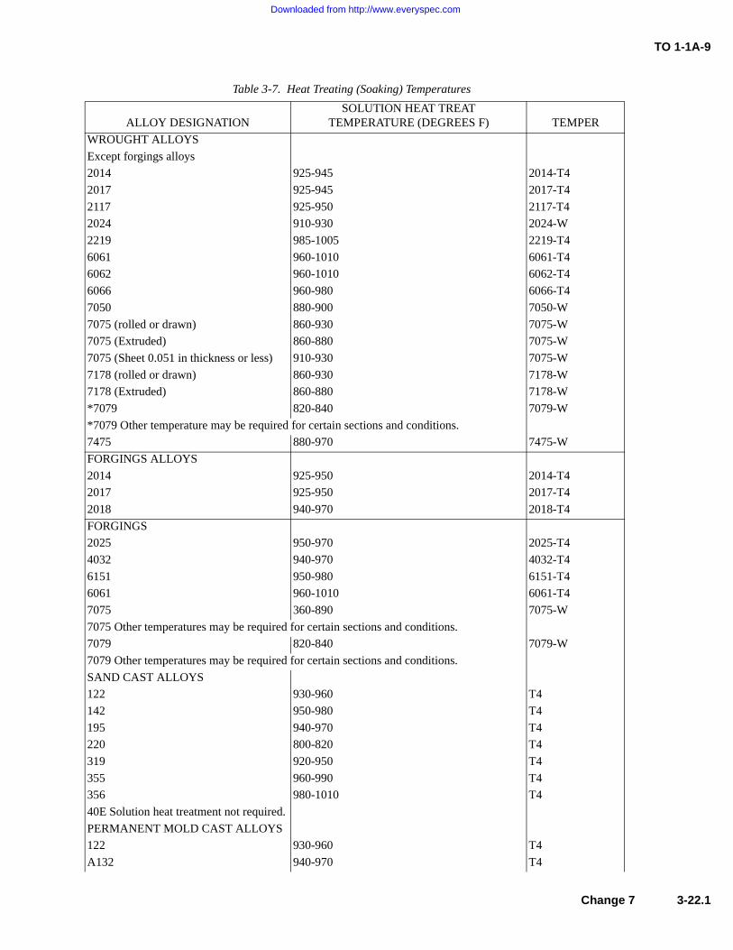
TO 1-1A-9
Table 3-7. Heat Treating (Soaking) Temperatures
ALLOY DESIGNATIONSOLUTION HEAT TREAT
TEMPERATURE (DEGREES F) TEMPER
WROUGHT ALLOYS
Except forgings alloys
2014 925-945 2014-T4
2017 925-945 2017-T4
2117 925-950 2117-T4
2024 910-930 2024-W
2219 985-1005 2219-T4
6061 960-1010 6061-T4
6062 960-1010 6062-T4
6066 960-980 6066-T4
7050 880-900 7050-W
7075 (rolled or drawn) 860-930 7075-W
7075 (Extruded) 860-880 7075-W
7075 (Sheet 0.051 in thickness or less) 910-930 7075-W
7178 (rolled or drawn) 860-930 7178-W
7178 (Extruded) 860-880 7178-W
*7079 820-840 7079-W
*7079 Other temperature may be required for certain sections and conditions.
7475 880-970 7475-W
FORGINGS ALLOYS
2014 925-950 2014-T4
2017 925-950 2017-T4
2018 940-970 2018-T4
FORGINGS
2025 950-970 2025-T4
4032 940-970 4032-T4
6151 950-980 6151-T4
6061 960-1010 6061-T4
7075 360-890 7075-W
7075 Other temperatures may be required for certain sections and conditions.
7079 820-840 7079-W
7079 Other temperatures may be required for certain sections and conditions.
SAND CAST ALLOYS
122 930-960 T4
142 950-980 T4
195 940-970 T4
220 800-820 T4
319 920-950 T4
355 960-990 T4
356 980-1010 T4
40E Solution heat treatment not required.
PERMANENT MOLD CAST ALLOYS
122 930-960 T4
A132 940-970 T4
Change 7 3-22.1
Downloaded from http://www.everyspec.com

TO 1-1A-9
142 950-980 T4
B195 935-965 T4
355 960-990 T4
356 980-1010 T4
Table 3-7. Heat Treating (Soaking) Temperatures - Continued
ALLOY DESIGNATIONSOLUTION HEAT TREAT
TEMPERATURE (DEGREES F) TEMPER
3-22.2 Change 7
Downloaded from http://www.everyspec.com
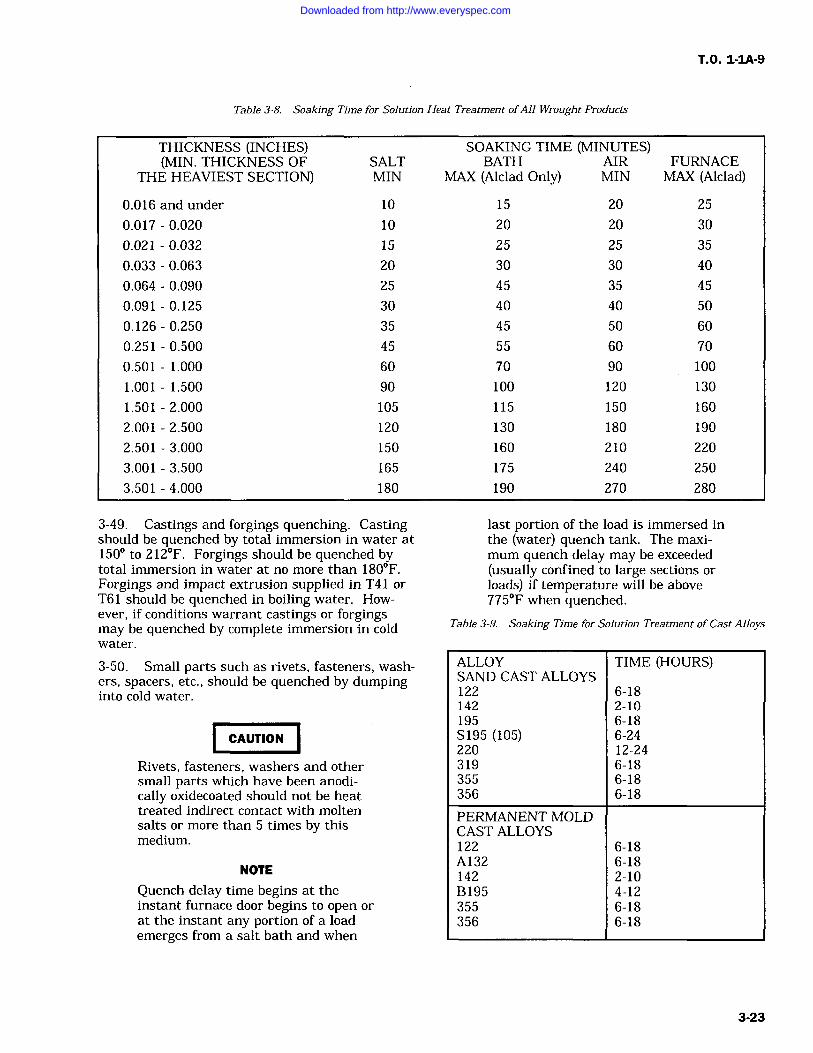
T.O. 1-IA-9
Table 3-8. Soaking Time for Solution Heat Treatment ofAll Wrought Products
THICKNESS (INCHES) SOAKING TIME (MINUTES)(MIN. THICKNESS OF SALT BATH AIR FURNACE
THE HEAVIEST SECTION) MIN MAX (Alclad Only) MIN MAX (Alclad)
0.016 and under 10 15 20 25
0.017 0.020 10 20 20 30
0.021 0.032 15 25 25 35
0.033 0.063 20 30 30 40
0.064 0.090 25 45 35 45
0.091 0.125 30 40 40 50
0.126 0.250 35 45 50 60
0.251 0.500 45 55 60 70
0.501 1.000 60 70 90 100
1.001 1.500 90 100 120 130
1.501 2.000 105 115 150 160
2.001 2.500 120 130 180 190
2.501 3.000 150 160 210 220
3.001 3.500 165 175 240 250
3.501 4.000 180 190 270 280
3-49. Castings and forgings quenching. Castingshould be quenched by total immersion in water at150 to 212F. Forgings should be quenched bytotal immersion in water at no more than 180F.Forgings and impact extrusion supplied in T41 orT61 should be quenched in boiling water. How-ever, if conditions warrant castings or forgingsmay be quenched by complete immersion in coldwater.
3-50. Small parts such as rivets, fasteners, wash-ers, spacers, etc., should be quenched by dumpinginto cold water.
CAUTION
Rivets, fasteners, washers and othersmall parts which have been anodi-cally oxidecoated should not be heattreated indirect contact with moltensalts or more than 5 times by thismedium.
NOTE
Quench delay time begins at theinstant furnace door begins to open or
at the instant any portion of a loademerges from a salt bath and when
last portion of the load is immersed inthe (water) quench tank. The maxi-
mum quench delay may be exceeded(usually confined to large sections orloads) if temperature will be above775F when quenched.
Table 3-9. Soaking Time for Solution Treatment of Cast Alloys
ALLOY TIME (HOURS)SAND CAST ALLOYS122 6-18142 2-10195 6-18S195 (105) 6-24220 12-24319 6-18355 6-18356 6-18
PERMANENT MOLDCAST ALLOYS122 6-18A132 6-18142 2-10B195 4-12355 6-18356 6-18
3-23
Downloaded from http://www.everyspec.com
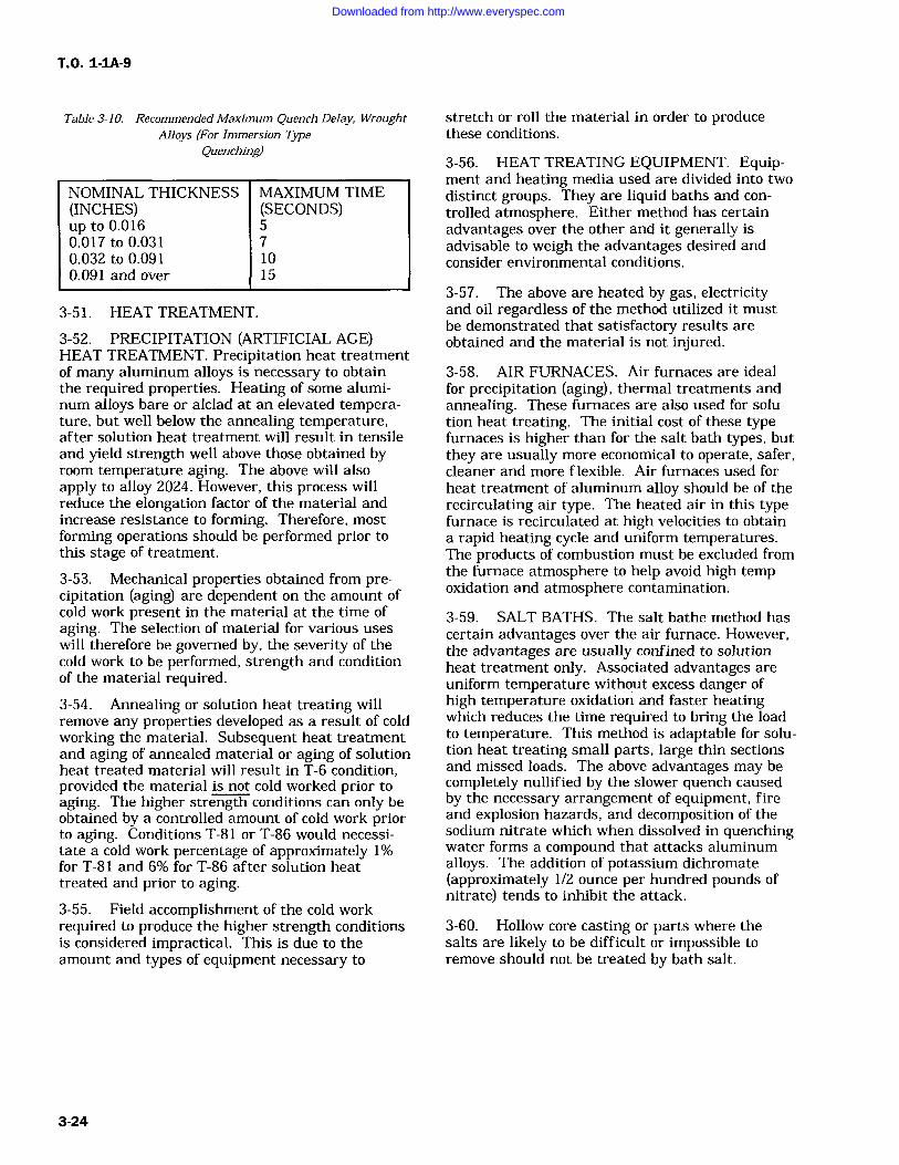
T.O. 1-1A-9
Table 3-10. Recommended Maximum Quench Delay, WroughtAlloys (For Immersion Type
Quenching)
NOMINAL THICKNESS(INCHES)up to 0.0160.017 to 0.0310.032 to 0.0910.091 and over
MAXIMUM TIME(SECONDS)571015
3-51. HEAT TREATMENT.
3-52. PRECIPITATION (ARTIFICIAL AGE)HEAT TREATMENT. Precipitation heat treatmentof many aluminum alloys is necessary to obtainthe required properties. Heating of some alumi-num alloys bare or alclad at an elevated tempera-ture, but well below the annealing temperature,after solution heat treatment will result in tensileand yield strength well above those obtained byroom temperature aging. The above will alsoapply to alloy 2024. However, this process willreduce the elongation factor of the material andincrease resistance to forming. Therefore, mostforming operations should be performed prior tothis stage of treatment.
3-53. Mechanical properties obtained from pre-cipitation (aging) are dependent on the amount ofcold work present in the material at the time ofaging. The selection of material for various useswill therefore be governed by, the severity of thecold work to be performed, strength and conditionof the material required.3-54. Annealing or solution heat treating willremove any properties developed as a result of coldworking the material. Subsequent heat treatmentand aging of annealed material or aging of solutionheat treated material will result in T-6 condition,provided the material is not cold worked prior toaging. The higher strength conditions can only beobtained by a controlled amount of cold work priorto aging. Conditions T-81 or T-86 would necessi-tate a cold work percentage of approximately 1%for T-81 and 6% for T-86 after solution heattreated and prior to aging.3-55. Field accomplishment of the cold workrequired to produce the higher strength conditionsis considered impractical. This is due to theamount and types of equipment necessary to
stretch or roll the material in order to producethese conditions.
3-56. HEAT TREATING EQUIPMENT. Equip-ment and heating media used are divided into twodistinct groups. They are liquid baths and con-
trolled atmosphere. Either method has certainadvantages over the other and it generally isadvisable to weigh the advantages desired andconsider environmental conditions.
3-57. The above are heated by gas, electricityand oil regardless of the method utilized it mustbe demonstrated that satisfactory results areobtained and the material is not injured.
3-58. AIR FURNACES. Air furnaces are idealfor precipitation (aging), thermal treatments andannealing. These furnaces are also used for solu-tion heat treating. The initial cost of these typefurnaces is higher than for the salt bath types, butthey are usually more economical to operate, safer,cleaner and more flexible. Air furnaces used forheat treatment of aluminum alloy should be of therecirculating air type. The heated air in this typefurnace is recirculated at high velocities to obtaina rapid heating cycle and uniform temperatures.The products of combustion must be excluded fromthe furnace atmosphere to help avoid high tempoxidation and atmosphere contamination.
3-59. SALT BATHS. The salt bathe method hascertain advantages over the air furnace. However,the advantages are usually confined to solutionheat treatment only. Associated advantages areuniform temperature without excess danger ofhigh temperature oxidation and faster heatingwhich reduces the time required to bring the loadto temperature. This method is adaptable for solu-tion heat treating small parts, large thin sectionsand missed loads. The above advantages may becompletely nullified by the slower quench causedby the necessary arrangement of equipment, fireand explosion hazards, and decomposition of thesodium nitrate which when dissolved in quenchingwater forms a compound that attacks aluminumalloys. The addition of potassium dichromate(approximately 1/2 ounce per hundred pounds ofnitrate) tends to inhibit the attack.
3-60. Hollow core casting or parts where thesalts are likely to be difficult or impossible to
remove should not be treated by bath salt.
3-24
Downloaded from http://www.everyspec.com
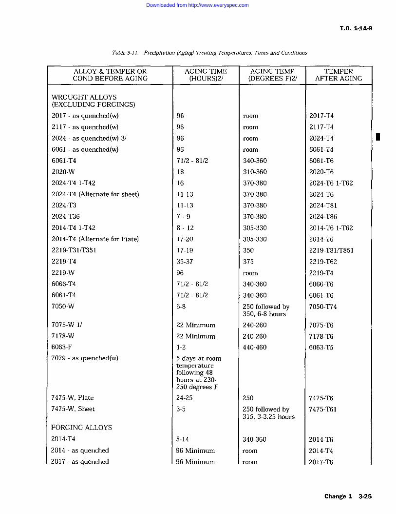
T.O. 1-IA-9
Table 3-11. Precipitation (Aging) Treating Temperatures, Times and Conditions
ALLOY & TEMPER ORCOND BEFORE AGING
AGING TIME(HOURS)2/
AGING TEMP(DEGREES F) 2/
TEMPERAFTER AGING
WROUGHT ALLOYS(EXCLUDING FORGINGS)2017 as quenched(w) 96 room 2017-T4
2117 as quenched(w) 96 room 2117-T4
2024 as quenched(w) 3/ 96 room 2024-T4 I6061 as quenched(w) 96 room 6061-T4
6061-T4 71/2 81/2 340-360 6061-T6
2020-W 18 310-360 2020-T6
2024-T4 1-T42 16 370-380 2024-T6 1-T62
2024-T4 (Alternate for sheet) 11-13 370-380 2024-T6
2024-T3 11-13 370-380 2024-T81
2024-T36 7-9 370-380 2024-T86
2014-T4 1-T42 8-12 305-330 2014-T6 1-T62
2014-T4 (Alternate for Plate) 17-20 305-330 2014-T6
2219-T31/T351 17-19 350 2219-T81/T851
2219-T4 35-37 375 2219-T62
2219-W 96 room 2219-T4
6066-T4 71/2-81/2 340-360 6066-T6
6061-T4 71/2 81/2 340-360 6061-T6
7050-W 6-8 250 followed by 7050-T74350, 6-8 hours
7075-W 1/ 22 Minimum 240-260 7075-T6
7178-W 22 Minimum 240-260 7178-T6
6063-F 1-2 440-460 6063-T5
7079 as quenched(w)
7475-W, Plate
5 days at room
temperaturefollowing 48hours at 230-250 degrees F24-25 250 7475-T6
7475-W, Sheet 3-5 250 followed by 7475-T61315, 3-3.25 hours
FORGING ALLOYS
2014-T4 5-14 340-360 2014-T6
2014 as quenched 96 Minimum room 2014-T4
2017 as quenched 96 Minimum room 2017-T6
Change 1 3-25
Downloaded from http://www.everyspec.com
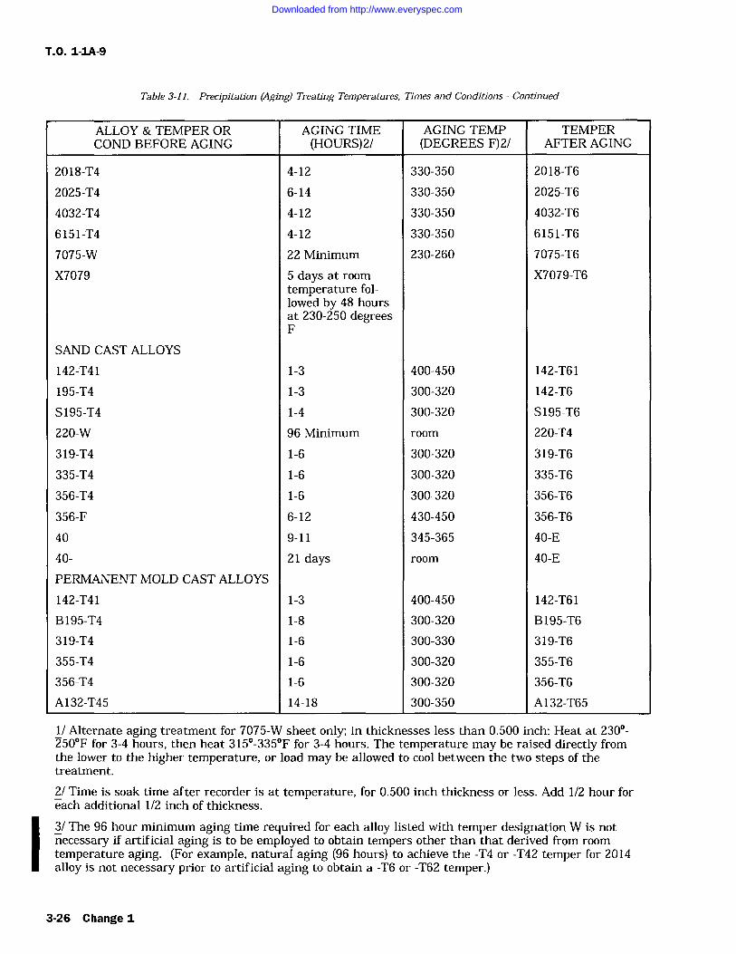
T.O. 1-1A-9
Table 3-11. Precipitation (Aging) Treating Temperatures, Times and Conditions Continued
ALLOY & TEMPER ORCOND BEFORE AGING
AGING TIME(HOURS)2/
AGING TEMP(DEGREES F)2/
TEMPERAFTER AGING
2018-T4 4-12 330-350 2018-T6
2025-T4 6-14 330-350 2025-T6
4032-T4 4-12 330-350 4032-T6
6151-T4 4-12 330-350 6151-T6
7075-W 22 Minimum 230-260 7075-T6
X7079 5 days at room X7079-T6temperature fol-lowed by 48 hoursat 230-250 degreesF
SAND CAST ALLOYS
142-T41 1-3 400-450 142-T61
195-T4 1-3 300-320 142-T6
S195-T4 1-4 300-320 S195-T6
220-W 96 Minimum room 220-T4
319-T4 1-6 300-320 319-T6
335-T4 1-6 300-320 335-T6
356-T4 1-6 300-320 356-T6
356-F 6-12 430-450 356-T6
40 9-11 345-365 40-E
40- 21 days room 40-E
PERMANENT MOLD CAST ALLOYS
142-T41 1-3 400-450 142-T61
B195-T4 1-8 300-320 B195-T6
319-T4 1-6 300-330 319-T6
355-T4 1-6 300-320 355-T6
356-T4 1-6 300-320 356-T6
A132-T45 14-18 300-350 A132-T65
1/ Alternate aging treatment for 7075-W sheet only; in thicknesses less than 0.500 inch: Heat at 230-250F for 3-4 hours, then heat 315-335F for 3-4 hours. The temperature may be raised directly fromthe lower to the higher temperature, or load may be allowed to cool between the two steps of thetreatment.
2/ Time is soak time after recorder is at temperature, for 0.500 inch thickness or less. Add 1/2 hour foreach additional 1/2 inch of thickness.
3/ The 96 hour minimum aging time required for each alloy listed with temper designation W is not
necessary if artificial aging is to be employed to obtain tempers other than that derived from room
temperature aging. (For example, natural aging (96 hours) to achieve the -T4 or -T42 temper for 2014alloy is not necessary prior to artificial aging to obtain a -T6 or -T62 temper.)
3-26 Change I
Downloaded from http://www.everyspec.com
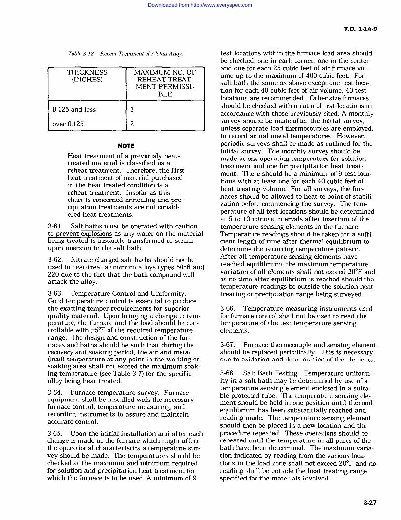
T.O. 1-1A-9
Table 3-12. Reheat Treatment ofAlclad Alloys
THICKNESS MAXIMUM NO. OF(INCHES) REHEAT TREAT-
MENT PERMISSI-BLE
0.125 and less
over 0.125 2
NOTE
Heat treatment of a previously heat-treated material is classified as areheat treatment. Therefore, the firstheat treatment of material purchasedin the heat treated condition is areheat treatment. Insofar as thischart is concerned annealing and pre-cipitation treatments are not consid-ered heat treatments.
3-61. Salt baths must be operated with cautionto prevent explosions as any water on the materialbeing treated is instantly transformed to steam
upon imersion in the salt bath.
3-62. Nitrate charged salt baths should not beused to heat-treat aluminum alloys types 5056 and220 due to the fact that the bath compound willattack the alloy.3-63. Temperature Control and Uniformity.Good temperature control is essential to producethe exacting temper requirements for superiorquality material. Upon bringing a change to tem-perature, the furnace and the load should be con-trollable with +/-5F of the required temperaturerange. The design and construction of the fur-naces and baths should be such that during therecovery and soaking period, the air and metal(load) temperature at any point in the working orsoaking area shall not exceed the maximum soak-ing temperature (see Table 3-7) for the specificalloy being heat treated.
3-64. Furnace temperature survey. Furnaceequipment shall be installed with the necessaryfurnace control, temperature measuring, andrecording instruments to assure and maintainaccurate control.
3-65. Upon the initial installation and after eachchange is made in the furnace which might affectthe operational characteristics a temperature sur-
vey should be made. The temperatures should bechecked at the maximum and minimum requiredfor solution and precipitation heat treatment forwhich the furnace is to be used. A minimum of 9
test locations within the furnace load area shouldbe checked, one in each corner, one in the centerand one for each 25 cubic feet of air furnace vol-ume up to the maximum of 400 cubic feet. Forsalt bath the same as above except one test loca-tion for each 40 cubic feet of air volume, 40 testlocations are recommended. Other size furnacesshould be checked with a ratio of test locations inaccordance with those previously cited. A monthlysurvey should be made after the initial survey,unless separate load thermocouples are employed,to record actual metal temperatures. However,periodic surveys shall be made as outlined for theinitial survey. The monthly survey should bemade at one operating temperature for solutiontreatment and one for precipitation heat treat-
ment. There should be a minimum of 9 test loca-tions with at least one for each 40 cubic feet ofheat treating volume. For all surveys, the fur-naces should be allowed to heat to point of stabili-zation before commencing the survey. The tem-perature of all test locations should be determinedat 5 to 10 minute intervals after insertion of thetemperature sensing elements in the furnace.Temperature readings should be taken for a suffi-cient length of time after thermal equilibrium todetermine the recurring temperature pattern.After all temperature sensing elements havereached equilibrium, the maximum temperaturevariation of all elements shall not exceed 20F andat no time after equilibrium is reached should thetemperature readings be outside the solution heattreating or precipitation range being surveyed.
3-66. Temperature measuring instruments usedfor furnace control shall not be used to read thetemperature of the test temperature sensingelements.
3-67. Furnace thermocouple and sensing elementshould be replaced periodically. This is necessarydue to oxidation and deterioration of the elements.
3-68. Salt Bath Testing Temperature uniform-ity in a salt bath may be determined by use of a
temperature sensing element enclosed in a suita-ble protected tube. The temperature sensing ele-ment should be held in one position until thermalequilibrium has been substantially reached andreading made. The temperature sensing elementshould then be placed in a new location and theprocedure repeated. These operations should berepeated until the temperature in all parts of thebath have been determined. The maximum varia-tion indicated by reading from the various loca-tions in the load zone shall not exceed 20F and noreading shall be outside the heat treating rangespecified for the materials involved.
3-27
Downloaded from http://www.everyspec.com
TO 1-1A-9
3-69. At this point it should be explained that a substantial amount of the difficulties encountered in heating aluminum alloys is due to improper or inadequate temperature control and circulation of heating medium. When difficulties arise the function of these units should be checked prior to performing other system test.
3-70. FABRICATION.
3-71. This portion is intended to provide some of the informa-tion required to fabricate the various aluminum products into parts and assemblies. Aluminum is one of the most workable of all the common metals. It can be fabricated into a variety of shapes by conventional methods.
3-72. The formability varies considerably with alloy and tem-per. Specific application usually depends on the shape, strength and temper of the alloy. The preceeding will necessi-tate that the mechanic be well trained to cope with the vari-ables associated with this material especially when the end use of the item is an aircraft or a missile.
3-73. FORMING SHEET METAL.
3-74. GENERAL. The forming of aluminum (1100) is rela-tively easy, using approximately the same procedures as those used for common steel except that care must be taken to pre-vent scratching. Do not mark on any metal surface to be used as a structural component with a graphite pencil or any type of sharp pointed instrument. Use pencil, Aircraft Marking, Speci-fication MIL-P-83953, NSN 7510-00-537-6928 (Black), 7510-00-537-6930 (Yellow), and 7510-00-537-6935 (Red). All shop equipment, tools and work area should be kept smooth, clean and free of rust and other foreign matter.
3-75. Alloyed aluminum (2024, 7075, 7178, etc.) are more difficult to form, and extensive control is required to prevent scratching and radii cracking. Scratching will make forming more difficult plus it provides an easy path for corrosion attack, especially on clad materials. The clad coating refer-enced is usually a sacrificial corrosion resisting aluminum alloy coating sandwiched metalurgically to an alloyed core material. The thickness of the coating will depend on the thickness of the sheet or plate. The nominal cladding thickness is 4% of composite thickness for material under 0.063 inch; 2.5% for material in the range of 0.063 - 0.187 inch and 1.5% for material 0.188 inch and thicker.
3-76. The following general rules should be employed in the handling and forming operation:
a. Provide clean area; free of chips, grit and dirt and other foreign material.
b. Provide clean smooth (rust free) and adaptable forming equipment.
c. Sheared or cut edges shall be sanded and filed or pol-ished, prior to bending or forming.
d. Use only straight and smooth forming dies or brake leafs of the correct radius which are free of nicks, burrs and sharp edges.
e. Form material across the direction of grain flow when possible.
f. Material should be of the correct temper, thickness and alloy in the range of “formable” material.
3-77. For intricate forming operations it is necessary to use annealed (Con"O") material and final strength developed by heat treating after the forming has been accomplished. Heat-treated alloys can also be formed at room temperature immedi-ately after quenching ("W"temper), which is much more form-able than the fully heat-treated temper. The part is then aged to develop full strength. The forming operation should be per-formed as soon after quenching as possible, in view of the natural aging that occurs at room temperature on all the heat treatable alloys. The natural aging can be delayed to a certain extent by placing the part in a cold storage area of 32° or lower. The lower the temperature the longer the delay to a point where maximum delay is obtained.
3-78. BENDING. Bending is classified as single curvature forming. Upon bending sheet metal, bar or rod, the material at the bends flows or deforms i.e., the material adjacent to the other surface of the bend is under tension and the length is increased due to stretching and the material adjacent to and on the inner surface is under compression and the length is decreased.
3-79. The most common problems encountered in practice are springback and cracking within the bend area. Problems asso-ciated with bend cracking are usually a result of improper bend radii, rough edges of material being formed or forming equipment and bending parallel to direction of grain flow. Actual practice may reveal that a larger or a smaller radius may be used in some instances. Consult TO 1-1A-1 for mini-mum bend radii.
3-80. Difficulties encountered with springback are most com-monly associated with bending of the stronger alloys, espe-cially those having high yield strength. Springback problem associated with this material can be overcome to a certain degree by overforming. The amount of overforming utilized will depend on the temper and the alloy; the softer the material
3-28 Change 6
Downloaded from http://www.everyspec.com

TO 1-1A-9
the less springback compensation required. Other means of reducing springback is to bend the material in the soft condi-tion (Condition "O") or immediately after quenching and
reducing the thickness or the radius if allowed. Avoid reducing radii to the point that grain separation or bend cracking results.
Table 3-13. Deleted
Change 6 3-29
Downloaded from http://www.everyspec.com
T.O. 1-1A-9
3-81. DRAW FORMING. Draw forming isdefined as a method where a male die (punch) anda female die is used to form a sheet blank into a
hollow shell. Draw forming is accomplished byforcing the male die and the metal blank into thefemale die. Generally mechanical press eithersingle or double action and hydraulic presses areused to perform the drawing operation. Resultswill depend on die design, radii of die forming sur-faces, finish of die, surface clearance betweenpunch and female die, blank hold down pressure,shape of blank, material allowance on blank, elon-gation factor of material, temper, shape of partbeing formed, drawing speed, and lubricant.Optium results usually requires experimentationand adjustment of one or more of these factors.Drawing of very deep shells require more experi-mentation and the utilization of a succession oflimit draws. Because of the work hardeningresulting from each draw, reduction in successivedraws must be less. In severe conditions an inter-mediate anneal is sometimes used. Condition "0"material of the heat treatable alloys can be heattreated after drawing to obtain higher strengthand to relieve the effect of work hardening. How-ever, the non-heat treatable alloys can only beannealed to relieve the effect of work hardening.This material should not be annealed if highstrength is the major requirement.
3-82. The recommended material to manufacturedrawing dies is hardened tool steel for large scaleproduction; kirksite and plastic for medium orshort run production; and phenolic and hardwoodfor piece production.
3-83. STRETCH FORMING. This processinvolves stretching a sheet or strip to just beyondthe elastic limit where permanent set will takeplace with a minimum amount of springback.Stretch forming is usually accomplished by grip-ping two opposite edges fixed vises and stretchingby moving a ram carrying the form block againstthe sheet. The ram pressure being sufficient to
cause the material to stretch and wrap to the con-
tour of the form block.
3-84. Stretch forming is normally restricted torelatively large parts with large radii of curvatureand shallow depth, such as contoured skin. Theadvantage is uniform contoured parts at fasterspeed than can be obtained by hand forming witha yoder hammer or other means. Also, the condi-tion of the material is more uniform than thatobtained by hand forming. The disadvantage ishigh cost of initial equipment, which is limited toAMA level repair facilities.
3-85. Material used for stretch forming should belimited to alloys with fairly high elongation and
good spread between yield and tensile strength.Most of the common alloys are formed in theannealed condition. It is possible to stretch formthe heat treatable alloys in tempers T4 or T6,where the shape is not too deep or where narrowwidth material is used. For the deeper curvedshapes, the material is formed in the annealed"O"temper, heat treated and reformed, to elimi-nate distortion resulting from heat treatment. Aspreviously stated the material should be reformedas fast as possible after heat treatment. In some
instances the material is formed immediately afterheat treating and quenching. Selection of a sys-tem or condition of material to be utilized willrequire experimentation and the subsequent utili-zation of the system that gives the best results.
3-86. HYDRAULIC PRESS FORMING. The rub-ber pad hydropress can be utilized to form manyvarieties of parts from aluminum and its alloyswith relative ease. Phenolic, masonite, kirksiteand some types of hard setting molding plastichave been used successfully as form blocks to
press sheet metal parts such as ribs, spars, fans,etc. The press forming operations are usuallyaccomplished by setting the form block (normallymale) on the lower press platen and placing a pre-pared sheet metal blank on the block. The blankis located on the block with locating pins, to pre-vent shifting of blank when the pressure is applied(the sheet metal blank should be cut to size andedges deburred prior to pressing). The rubber padfilled press head is then lowered or closed over theform block and the rubber envelope, the form blockforcing the blank to conform to the form blockscontour. This type forming is usually limited torelatively flat parts having flanges, beads andlightening holes. However, some types of largeradii contoured parts can be formed with a combi-nation of hand forming and pressing operations.It is recommended that additional rubber be sup-plemented in the form of sheets when performingthe above to prevent damage to the rubber presspad. The rubber sheet used should have a shorehardness of 50-80 durometers. The design of foamblock for hydropress forming require compensationfor springback even through the material normallyused is Condition "0" or annealed. Normal prac-tice is to under cut the form block 2-7 dependingon the alloy and radii of the form block.
3-87. DROP HAMMER FORMING. The drophammer can be used to form deep pan shaped andbeaded type parts. Kirksite with a plastic surfaceinsert is satisfactory for male and female dies.The surface of kirksite dies used without plasticinsert should be smooth to prevent galling andscratching of the aluminum surface. When form-ing deep pans and complicated shaped parts it is
3-30
Downloaded from http://www.everyspec.com
T.O. 1-1A-9
often necessary to use drawings rings, pads or 2-3stage dies. An intermediate anneal is sometimesused to relieve the hardened condition (cold work)resulting from the forming operation.3-88. JOGGLING. A joggle is an offset formed toprovide for an overlap of a sheet or angle which isprojecting in the same plain. The inside joggleradii should be approximately the same as usedfor straight bending. Joggle run out or length as a
normal rule should be three times the depth of thejoggle for the medium strength alloys (2024, 2014,etc.) and approximately four times the depth forthe higher strength alloys (7075, 7178, 7079 etc).Where deep and tight joggles are required,annealed material should be used with heat treat-ment to follow.
3-89. HOT-FORMING. Hot forming is not gen-erally recommended, however, it is sometimesused where it is not possible to form an article byother methods. Accomplishment shall not beattempted unless adequate facilities are availableto control temperature requirements. Actualformability will depend on the temperature thatvarious alloys are heated. The higher the temper-ature the easier formed. Excessively high temper-ature shall not be used, as considerable loss instrength and corrosion resistance will occur. Fre-quent checks should be made using an accuratecontact pyrometer. Table 3-14 cites the recom-mended times and temperature (accumulative) forthe various alloys. The losses in strength as a
result of re-heating at the temperature cited bythis table will not exceed 5%. Equal formabilitywill be obtained with shorter periods of heating inmost cases and the minimum times should beused. It should be understood that this table citedthe maximum accumulative times at citedtemperature.3-90. SPINNING. Spinning is an art and makesexacting demands upon the skill and experience ofthe mechanic performing the operation. For thisreason mass production of parts is impractical.However, it can be used to advantages where onlya few parts are required and to assist in the
removal of buckles and wrinkles in drawn shellshaped objects.3-91. Forming by spinning is a fairly simple pro-cess, an aluminum disc (circle) is placed in a lathein conjunction with a form block usually made ofhardwood; as the disc and form block are revolved,the disc is molded to the form block by applyingpressure with a spinning stick or tool. Aluminumsoap, tallow or ordinary soap can be used as alubricant.
3-92. The best adapted materials for spinningare the softer alloys i.e., 1100, 3003, 5052, 6061,etc. Other alloys can be used where the shape tobe spun is not excessively deep or where the spin-ning is done in stages and intermediate annealingis utilized to remove the effect of strain hardening(work hardening) resulting from the spinning oper-ation. Hot forming is used in some instanceswhen spinning the heavier gauge materials andharder alloys.3-93. BLANKING AND SHEARING. Accurateshearing will be affected by the thickness of mate-rial, type of shear or knife blades, condition ofmaterial, adjustment and sharpness of blades, sizeof cut and the relationship of the width of the cutto sheet thickness.
3-94. Normally most aluminum alloys can besheared 1/2 inch and less in thickness except forthe harder alloys i.e., 7075-T6 and 7178-T6. Thesealloys have a tendency to crack in the vicinity ofthe cut especially if the sheer blades are dull ornicked. The above will naturally require that tool-ing used be designed to handle the thickness ofmaterial to be cut. Correct clearance betweenshear blades is important for good shearing. Toolittle clearance will quickly dull or otherwise dam-age the blades or knives; too much will cause thematerial to be burred, or even to fold betweenblades. Normal clearance is from one-tenth to one-eighth the sheet thickness. Blade life will be pro-longed by occasionally lubricating. When thecapacity of shear is doubtful the shear manufac-turer should be consulted.
3-31
Downloaded from http://www.everyspec.com
T.O. 1-1A-9
Table 3-14. Maximum Accumulative Reheat Times for Hot Forming Heat Treatable Alloys at Different Temperatures
ALLOY 450F 425F 400F 375F 350F 325F 300F
2014-T6 To Temp To Temp 5-15 Min 30-60 Min 2-4 Hrs 8-10 Hrs 20-50 H
2024-T81 5 Min 15 Min 30 Min Hr 2-4 Hrs 20-40 H
2024-T86 5 Min 15 Min 30 Min Hr 2-4 Hrs 10-20 H
6061-T6 5 Min 15 Min 30 Min 1-2 Hrs 8-10 Hrs 5-100 Hrs 100-200 H
7075-T6 No No Temp 5-10 Min 30-60 Min 1-2 Hrs 2-4 Hrs 10-12 H
*2014-T4, 2014-T3 No No No No No No No
*2024-T4, 2024-T3 No No No No No No No
* These materials should not be hot formed unless subsequently artificially aged.
required and in such manner that will reduce loadon equipment. Commonly two or more high pointsare ground on die to keep side thrust on the punchat a minimum. Lubrication is essential in blank-ing operations. Suitable lubricants are engine oil,kerosene and lard oil which are normally used inmixed form.
3-95. BLANKING. Blanking is usually accom-plished utilizing a blanking die in almost any typeof punch press equipment. The essential factorsrequiring control are die clearance, shearing edgelead, and stripping action. The shearing principleis primarily the same as that encountered with thesquaring shear. However, the method of grindingpunch dies will vary according to the results
Paragraphs 3-96 through 3-155 deleted.Tables 3-15 through 3-16 deleted.Pages 3-33 through 3-38 deleted.
3-32 Change I
Downloaded from http://www.everyspec.com

Downloaded from http://www.everyspec.com

TO 1-1A-9
3-162. RIVETING. Riveting is the most common method of assembling components fabricated from aluminum. Typical advantages of this method of mechanical fastening are sim-plicity of application, consistent joint uniformity, easily inspected (X Ray and other type equipment no required.), low cost, and in many cases lighter weight.
3-163. The rivets used in USAF Weapon System structures require that the alloys and shapes be closely controlled by specifications/standards, to assure structural integrity and uni-formity. These rivets are presently classified as solid shank, hi-shear, blind (structural-non-structural) explosive/chemical expanded. They are available in a variety of shapes, alloys, sizes, lengths and types. The most common utilized are alumi-num because the structure alloys are normally aluminum. In addition some of the aluminum rivet characteristics can be changed by heat treating which facilitates application (see paragraph 3-37.)
3-164. All of the aluminum alloys could be used to manufac-ture rivets; however, due to some alloys having superior prop-erties they have been selected as standard. See Table 3-17 for alloys head, identification, MS/AN standard cross references, etc., for general rivets used on AF weapons systems.
3-165. Rivets in aluminum alloys 1100(A), 5056(B), 2117(AD) are used in the condition received Alloys 2017 (D) and 2024(DD) often referred to as “Ice Box Rivets” require heat treatment prior to use (see paragraph 3-43). Rivets in alloy 2017 and 2024 should be driven immediately after quenching with a maximum delay of 20 minutes or refriger-ated to delay aging. The customary procedure (unless only a few rivets are involved) is to place the rivets under refrigera-tion immediately after heat treatment The time the rivets may be used will depend on refrigeration equipment available. Cooling to 32°F will retard natural aging to the extent that the rivets may be driven up to 24 hours. Cooling rivets +0-10°F and below will retard natural aging to the extent that the rivets may be retained for use indefinitely.
3-166. Rivets utilized with extended driving time should be closely inspected after upsetting for cracks. If inspection reveals that rivets are cracked, discontinue use, remove defec-tive rivets and obtain reheat treated rivets prior to continuing the assembly operation.
3-167. If for some reason it is necessary to determine if a rivet has been heat treated this may be done by Rockwell Hardness testing. Test by supporting rivets in a vee block and harness reading taken with a 1/16 inch ball 60 kilogram load. A harness of over 75 will indicate a heat treated rivet.
3-156. Deleted.
3-157. Deleted.
3-158. Deleted.
3-159. Deleted.
3-160. Deleted.
3-161. Deleted.
(3-39 blank)/3-40 Change 6
Downloaded from http://www.everyspec.com
T.O. 1-1A-9
HEAD SHAPE IDENTIFICATION
u
ROUND UNIVERSAL BRAZIER COUNTERSUNK
NOTE: RIVETS MARKED X SUPERSEDEDBY UNIVERSAL HEAD.
NOTE: HEAD SHAPES APPLY TO SOLIDSHANK ALUM RIVETS ONLY.
IT ffO 0
RAISED DOT 2017 (D) RAISED DASHES2024 (DD)
L9805656
CAUTION
Heat treatment and most other opera-tions requiring use of heat will beaccomplished prior to installing riv-ets, since heating after rivets areinstalled will cause warping and pos-sible corrosion if salt bath is used.The salt from the bath will contami-nate cracks and crevices of the assem-bly and complete removal can not beassured.
3-168. Shear strength (ultimate) of a driven rivetcan be determined by the formula Ps=SsAN.Ps=ultimate shear strength (pounds), Ss=specifiedshear strength of the driven rivet (psi), A=crosssectional (area of the driven rivet, normally equalto hole cross section (square inch) and N=numberof shear planes. For shear strength of protrudingand flush head rivets see Table 3-19.
3-169. The load required to cause tensile failureof a plate in a rivet joint can be determined by theformula Ts=P+ (D-A) Tp. Ts=ultimate tensilestrength (pounds), PT specified ultimate tensilestrength of the plate (psi), D=pitch of the rivets(inch) pitch is the distance between the center oftwo adjacent rivets on the same gauge line,A=diameter of hole (inch) and Tp=thickness ofplate.3-170. Rivet Selection. Unless otherwise speci-fied rivets should be selected that have compara-ble strength and alloy as material being assem-bled. This is an important factor in preventing
RIVET MARKING TO ALLOY IDENTIFICATION
8 8 8o (R) o
PLAIN HEAD RAISED CROSS DIMPLE1100(A) 5056B 2117(AD)
corrosion from dissimilar metal contact and to
assure structurely sound assemblies. The follow-ing tables are provided as a general guide forselection of rivet alloy vs assembly alloy.3-171. The formula Ps Sb AC can be used todetermine failure in bearing strength. Ps ulti-mate bearing strength of the joints (lbs), Sbspecified ultimate bearing strength of the plate(psi) and AC projected crushing area (bearingarea) of rivet, or diameter (sq in) see table 3-20 fortypical bearing properties of aluminum alloy platesand shapes.3-172. Rivet hole preparation is one of the keyfactors in controlling successful upsetting of rivethead, material separation and buckling whichweakens the structural strength of the rivet joint,and corrosion attack of rivets and material afterequipment is placed in service/use. The rivet holeshould be drilled, punched/reamed to size thatallows the minimum clearance (apprximately 0.003for thin sheet and up to about 0.020 for 0.7501.000 inch thick material) required to insert rivetwithout forcing. Theoretical rivets holes should becompleted i.e., drilled, reamed to size, deburred,chips removed that may lodge or be trapped inbetween surface of metal and treated (anodizedetc.) before starting to rivet assembly. The abovecannot always be accomplished especially wherethe assembly is large and requires the applicationof a large amount of rivets due to hole toleranceand variations in holding clamping/pressures. Toovercome these problems requires that holes bepilot drilled end reamed to size at time rivet is tobe installed. This method has a twofold purpose:(1) allows easy insertion of rivets, (2) prevents
3-41
Downloaded from http://www.everyspec.com
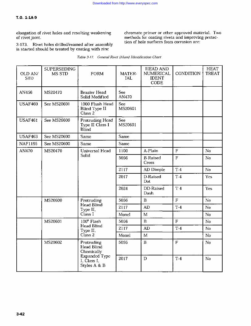
T.O. 1-IA-9
elongation of rivet holes and resulting weakening chromate primer or other approved material. Twoof rivet joint. methods for coating rivets and improving protec-
3-173. Rivet holes drilled/reamed after assembly tion of hole surfaces from corrosion are:
is started should be treated by coating with zinc
Table 3-17. General Rivet (Alum) Identification Chart
SUPERSEDING HEAD AND HEATOLD AN/ MS STD FORM MATER- NUMERICAL CONDITION TREATSTD IAL IDENT
CODE
AN456 MS20470 Brazier Head SeeSolid Modified AN470
USAF460 See MS20601 1000 Flush Head SeeBlind Type II MS20601Class 2
USAF461 See MS20600 Protruding Head SeeType II Class I MS20601Blind
USAF463 See MS20600 Same Same
NAF1195 See MS20600 Same Same
AN470 MS20470 Universal Head 1100 A-Plain F NoSolid
5056 B-Raised F NoCross
2117 AD-Dimple T-4 No
2017 D-Raised T-4 YesDot
2024 DD-Raised T-4 YesDash
MS20600 Protruding 5056 B F NoHead-Blind
2117 AD T-4 NoType II,Class I Monel M No
MS20601 100 Flash 5056 B F NoHead Blind
2117 AD T-4 NoType II,Class 2 Monel M No
MS20602 Protruding 5056 B F NoHead BlindChemicallyExpanded TypeI, Class I, 2017 D T-4 No
Styles A & B
3-42
Downloaded from http://www.everyspec.com
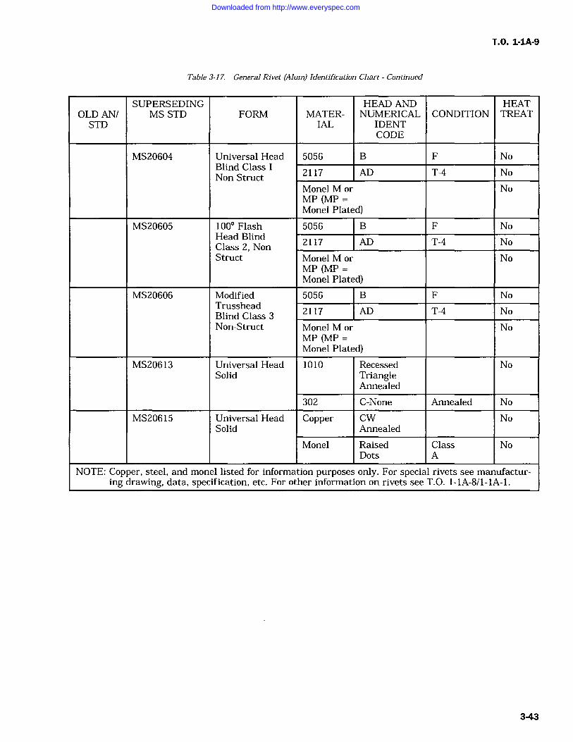
T.O. 1-IA-9
Table 3-17. General Rivet (Alum) Identification Chart Continued
SUPERSEDING HEAD AND HEATOLD AN/ MS STD FORM MATER- NUMERICAL CONDITION TREATSTD IAL IDENT
CODE
MS20604 Universal Head 5056 B F NoBlind Class 1
2117 AD T-4 NoNon StructMonel M or NoMP (MPMonel Plated)
MS20605 100 Flash 5056 B F NoHead Blind
2117 AD T-4 NoClass 2, NonStruct Monel M or No
MP (MPMonel Plated)
MS20606 Modified 5056 B F NoTrusshead
2117 AD T-4 NoBlind Class 3Non-Struct Monel M or No
MP (MPMonel Plated)
MS20613 Universal Head 1010 Recessed NoSolid Triangle
Annealed
302 C-None Annealed No
MS20615 Universal Head Copper CW NoSolid Annealed
Monel Raised Class NoDots A
NOTE: Copper, steel, and monel listed for information purposes only. For special rivets see manufactur-ing drawing, data, specification, etc. For other information on rivets see T.O. 1-1A-8/1-1A-1.
3-43
Downloaded from http://www.everyspec.com
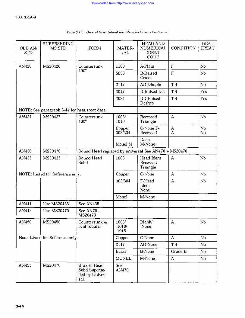
T.O. 1-IA-9
Table 3-17. General Rivet (Alum) Identification Chart Continued
SUPERSEDING HEAD AND HEATOLD AN/ MS STD FORM MATER- NUMERICAL CONDITION TREATSTD IAL IDENT
CODE
AN426 MS20426 Countersunk 1100 A-Plain F No100
5056 B-Raised F NoCross
2117 AD-Dimple T-4 No
2017 D-Raised Dot T-4 Yes
2024 DD-Raised T-4 YesDashes
NOTE: See paragraph 3-44 for heat treat data.
AN427 MS20427 Countersunk 1006/ Recessed A No1000 1010 Triangle
Copper C-None F- A No302/304 Recessed A No
DashMonel M M-None
AN430 MS20470 Round Head replaced by universal See AN470 + M520470
AN435 MS20435 Round Head 1006 Head Ident A NoSolid Recessed
TriangleNOTE: Listed for Reference only. Copper C-None A No
302/304 F-Head A NoIdentNone
Monel M-None
AN441 Use MS20435 See AN435
AN442 Use MS20470 See AN70+MS20470
AN450 MS20450 Countersunk & 1006/ Blank/ A Nooval tubular 1010/ None
1015
Note: Listed for Reference only Copper C-None A No
2117 AD-None T-4 No
Brass B-None Grade B No
MONEL M-None A No
AN455 MS20470 Brazier Head SeeSolid Superse- AN470ded by Univer-sal.
3-44
Downloaded from http://www.everyspec.com
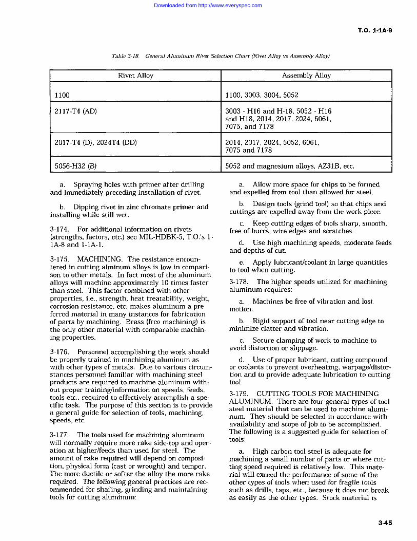
T.O. 1-IA-9
Table 3-18. General Aluminum Rivet Selection Chart (Rivet Alloy vs Assembly Alloy)
Rivet Alloy Assembly Alloy
1100 1100, 3003, 3004, 5052
2117-T4 (AD) 3003 H16 and H-18, 5052 H16and H18, 2014, 2017, 2024, 6061,7075, and 7178
2017-T4 (D), 2024T4 (DD) 2014, 2017, 2024, 5052, 6061,7075 and 7178
5056-H32 (B) 5052 and magnesium alloys, AZ31B, etc.
a. Spraying holes with primer after drillingand immediately preceding installation of rivet.
b. Dipping rivet in zinc chromate primer andinstalling while still wet.
3-174. For additional information on rivets(strengths, factors, etc.) see MIL-HDBK-5, T.O.'s 1-IA-8 and 1-lA-1.
3-175. MACHINING. The resistance encoun-
tered in cutting alminum alloys is low in compari-son to other metals. In fact most of the aluminumalloys will machine approximately 10 times fasterthan steel. This factor combined with otherproperties, i.e., strength, heat treatability, weight,corrosion resistance, etc. makes aluminum a pre-ferred material in many instances for fabricationof parts by machining. Brass (free machining) isthe only other material with comparable machin-ing properties.
3-176. Personnel accomplishing the work shouldbe properly trained in machining aluminum aswith other types of metals. Due to various circum-stances personnel familiar with machining steelproducts are required to machine aluminum with-out proper training/information on speeds, feeds,tools etc., required to effectively accomplish a spe-cific task. The purpose of this section is to providea general guide for selection of tools, machining,speeds, etc.
3-177. The tools used for machining aluminumwill normally require more rake side-top and oper-ation at higher/feeds than used for steel. Theamount of rake required will depend on composi-tion, physical form (cast or wrought) and temper.The more ductile or softer the alloy the more rakerequired. The following general practices are rec-ommended for shafing, grinding and maintainingtools for cutting aluminum:
a. Allow more space for chips to be formedand expelled from tool than allowed for steel.
b. Design tools (grind tool) so that chips andcuttings are expelled away from the work piece.
c. Keep cutting edges of tools sharp, smooth,free of burrs, wire edges and scratches.
d. Use high machining speeds, moderate feedsand depths of cut.
e. Apply lubricant/coolant in large quantitiesto tool when cutting-3-178. The higher speeds utilized for machiningaluminum requires:
a. Machines be free of vibration and lostmotion.
b. Rigid support of tool near cutting edge tominimize clatter and vibration.
c. Secure clamping of work to machine toavoid distortion or slippage.
d. Use of proper lubricant, cutting compoundor coolants to prevent overheating, warpage/distor-tion and to provide adequate lubrication to cuttingtool.
3-179. CUTTING TOOLS FOR MACHININGALUMINUM. There are four general types of toolsteel material that can be used to machine alumi-num. They should be selected in accordance withavailability and scope ofjob to be accomplished.The following is a suggested guide for selection oftools:
a. High carbon tool steel is adequate formachining a small number of parts or where cut-ting speed required is relatively low. This mate-rial will exceed the performance of some of theother types of tools when used for fragile toolssuch as drills, taps, etc., because it does not breakas easily as the other types. Stock material is
3-45
Downloaded from http://www.everyspec.com
T.O. 1-IA-9
obtainable in accordance with Federal Specifica-tion QQ-T-580 where required for local fabricationof high carbon tools etc.
b. High speed tool steel is the most commontype used for machining except on the highersilicon alloys.
(1) Availability, reasonable cost.
(2) Heat resistance (will retain cuttingedge up to about 950F dull red).
(3) Permits use of large rake anglerequired. Federal Specification QQ-T-590 appliesto stock material. All the various classes (Ti, T2,T3, etc.) may be used for machining aluminum.Class Ti (18-4-1) general purpose type is the mostwidely used.
c. Where long production runs are involvedcemented carbide (solid or tipped) tools give betterservice. The carbide tools have been known to lastthirty times longer than high speed tool steel. Thecarbide tools are also recommended for cuttinghigh silicon content alloys. Because of the brittle-ness of the cemented carbide tool the cutting angleshould be greater than those recommended forhigh carbon/high speed steels.
d. Diamond tipped tools should only be usedfor light finishing cute or special finishing opera-tions. Normal cutting of 75 90 are used withtop rake angles of 6 10. Tool projection (or set)should be slightly above center line (CL) of thework.
3-180. TURNING. To properly perform the turn-ing operation firmly attach the work to themachine (lathe) chuck, collet or faceplate. Thework should be held in the best manner to mini-mize distortion from chuck or centrifugal forceaction during the turning operation. Long rods/stock should be supported by ball or roller bearingtailstock centers which are more satisfactory thansolid or fixed centers in resisting thrusts fromcentrifugal force and thermal expansion. Soft lin-ers may be used between work and machine jawfaces to prevent jaw teeth from damaging/marringwork piece. When it is necessary that work beheld by clamping from inside diameter outwardthe tightness ofjaws should be checked frequentlyto be sure that work is not being released as aresult of thermal expansion.
3-181. The recommended cutting fluids are thesoluble oil emulsion which combine the functionsof cooling and lubricating for general purpose use.For heavy cutting especially when speeds are low,
lard oil such as Specification C-O-376 or mineraloil, Specification VV-O-241 is recommended. Inpractice it will be found that some machining oper-ations can be performed dry.
3-182. Tables 3-22 and 3-23 cite suggested turn-ing speeds, tool angles and feeds. Tool projectionin relation to work should be set at or slightlyabove work piece center line. Sturdy constructionof tools and holders is essential to minimize vibra-tion/chatter at the high speeds aluminum alloysare machined.
NOTE
Parting tools should have less toprake than turning tools. Recommendtop rake angles of 12 20 and frontclearances of 4 8 grind face con-
cave (slightly) and so that corneradjacent to work will lead oppositecorner by 4 12 or as required forbest results.
3-183. MILLING ALUMINUM. Milling of alu-minum alloys should be accomplished at high cut-
ter speeds. The limitations will usually depend on
the machine and type cutters used. The reason forthe higher cutter speeds is that at low speeds thecutters will have a tendency to load and gum. Thiswill normally clear as the speed is increased.
3-184. The tooling for milling should be selectedaccording to the operation and duration/size of jobto be performed. The cutters should have fewerteeth and should be ground with more top and siderake than those used for milling steels. Most oper-ations can be accomplished with spiral cutters.Nick tooth cutters are used when reduction in sizeof chips is required. Solid-tooth cutters with largehelix angles are used where free-cutting tools arerequired. When cutters with large helix angles are
used it is often necessary that two interlockingcutters of opposite helixes be employed to alleviateaxial thrust.
3-185. Tool alloys should be selected for millingaluminum as follows:
a. For short runs high carbon steel is nor-mally satisfactory.
b. For production runs of extended durationhigh speed steel is recommended.
c. Where climb milling/high speeds are uti-lized, carbide tipped tools are recommended forextended runs.
3-46
Downloaded from http://www.everyspec.com
T.O. 1-1A-9
Table 3-19. Shear Strength ofProtruding and Flush Head Aluminum Alloy Rivets, Inch Pounds
Size of Rivet(In Dia)
Alloy + driven temper5056 FSU 28 KSI
2117-T321, FSU 30 KSI2017-T31, FSU 34 KSI2017-T3, FSU 38 KSI2024-T31, FSU 41 KSI
1/16
99
106120135145
3/32
203
217297275296
1/8
363
388442494531
5/32
556
596675755815
3/16
802
8629771,0901,180
1/4
1,450
1,5501,7601,9702,120
5/16
2,290
2,4602,9703,1103,360
3/8
3,280
3,5103,9704,4504,800
FSU Average Shear Strength of alloy in specified temper.
KSI 1000 lbs square inch example: 34 KSI 34,000 lbs per square inch.
Single shear rivet strength correction factor (resulting from use in thin plates and shapes).
Sheet thickness (in)0.016 0.0964
0.018 0.0984
0.020 0.0996
0.025 1.000 0.972
0.032 1.000 0.964
0.036 0.980
0.040 0.996 0.964
0.045 1.000 0.980
0.050 0.996 0.972
0.063 1.000 1.000 0.964
0.071 0.980 0.964
0.080 0.996 0.974
0.090 1.000 0.984
0.100 0.996 0.972
0.125 1.000 1.000
0.160
0.190
0.250
Double shear rivet strength correction factor (resulting from use in thin plates and shapes)SIZE OF RIVETS
Sheet Thick Inch 1/16 3/32 1/8 5/32 3/16 1/4 5/16 3/8
0.016 0.688
0.018 0.753
0.020 0.792
3-47
Downloaded from http://www.everyspec.com
T.O. 1-IA-9
Table 3-19. Shear Strength ofProtruding and Flush Head Aluminum Alloy Rivets, Inch Pounds Continued
0.025 0.870 0.714
0.032 0.935 0.818 0.688
0.036 0.974 0.857 0.740
0.040 0.987 0.896 0.792 0.688
0.045 1.000 0.922 0.831 0.740
0.050 0.961 0.870 0.792 0.714
0.063 1.000 0.935 0.883 0.818 0.688
0.071 0.974 0.919 0.857 0.740
0.080 1.000 0.948 0.896 0.792 0.688
0.090 0.974 0.922 0.831 0.753
0.100 1.000 0.961 0.870 0.792 0.714
0.125 1.000 0.935 0.883 0.818
0.160 0.987 0.835 0.883
0.190 1.000 0.974 0.935
0.250 1.000 1.000
Note: Values (lbs) of shear strength should be multiplied by the correction factor whenever the D/Trivet diameter/plates sheet or shape thickness ratio is large enough to require correction. Example:Rivet diameter 1/8 (alloy 2117 T3) installed in 0.040 sheet, shear factor is 388 lbs correction factor0.996
3880.996
23283492
3492386.448 corrected shear pounds
Table 3-20. Bearing Properties, Typical, ofAluminum Alloy Plates and Shapes
Edge Distance 1.5X Rivet Diameter
Edge Distance 2.OXX Rivet Diameter
Alloy Yield Strength Ultimate Strength Yield Strength Ultimate Strength1100 0 10,000 21,000 12,000 27,000
1100 H12 18,000 23,000 21,000 29,000
1100 H14 22,000 24,000 23,000 31,000
1100 H16 23,000 16,000 26,000 34,000
1100 H18 27,000 19,000 32,000 38,000
3003 0 12,000 22,000 15,000 34,000
3003 H12 21,000 27,000 24,000 36,000
3003 H16 28,000 34,000 33,000 42,000
3003 H18 32,000 38,000 38,000 46,000
3-48
Downloaded from http://www.everyspec.com
T.O. 1-IA-9
Table 3-20. Bearing Properties, Typical, ofAluminum Alloy Plates and Shapes Continued
Edge Distance 1.5X Rivet Diameter
Edge Distance 2.OXX Rivet Diameter
Alloy Yield Strength Ultimate Strength Yield Strength Ultimate Strength2014 T4 56,000 93,000 64,000 118,000
2014 T6 84,000 105,000 96,000 133,000
2024 T3 64,000 102,000 74,000 129,000
Alclad 2024-T-3 60,000 96,000 69,000 122,000
2024- T36 80,000 110,000 91,000 139,000
Alclad 2024-T36 74,000 100,000 85,000 127,000
5052 0 25,000 46,000 30,000 61,000
5052 H32 37,000 54,000 42,000 71,000
5052 H34 41,000 59,000 47,000 78,000
5052 H36 47,000 62,000 54,000 82,000
5052 H38 50,000 66,000 58,000 86,000
6061 T4 29,000 56,000 34,000 73,000
6061 T6 56,000 72,000 64,000 94,000
7075 T6 101,000 123,000 115,000 156,000
Alclad 7075-T6 94,000 114,000 107,000 144,000
3-186. Milling cutters should be inclined to workand beveled on leading corner (least bevel for fin-ish cuts) to minimize clatter.
3-187. The cutting fluids for milling aluminumshould combine cooling and lubrication properties.Coolant lubrication should be applied under pres-sure (atomized spray if available) in large quanti-ties to tool and work. The recommended cuttingfluids are water base cutting fluids such as solu-ble oils and emulsions, mixed part to 15 for highspeeds and part to 30 for low speed cutting.
3-188. Tables 3-24 and 3-25 cite suggestedspeeds, contour and tool angles, for milling alumi-num. The best combination of cutting speeds, feedand cut for a given job will depend on design oftool/cutter, kind of tool material, condition ofmachine, machine power, size, clamping methodand type material being worked.
3-189. SHAPING AND PLANING. The speed atwhich aluminum alloys can be cut by planing andshaping is somewhat slower in comparison to othermachining methods, due to equipment design andlimitations.
The slower cutting speeds can be overcome to
some extent by securely anchoring the work to themachine and using heavy rough cutting feeds.The tools used for rough cut should be (roundnose) of heavy construction and properly ground tooperate efficiently. Rough cut tools should beground with moderate amount of rake to providemaximum cutting edge support. Finish tool shouldhave more top rake and an extra large amount ofside rake. Finishing tool shall be used with finefeeds only due to the additional side and top rake(finish cut should not exceed 0.018 inch).3-190. Most cutting operations by shaping andplanning can be accomplished without cuttingfluids, however fine finishing can be improved bylubrication. Recommended cutting compounds arekerosene, mixture of 50-50 lard-oil and soluble oil.
3-191. Tables 3-26 and 3-27 cite suggested turn-ing speeds, tool angles and feeds. Secure clampingof work is re-emphasized especially when heavycutting feeds are to be used.
3-49
Downloaded from http://www.everyspec.com
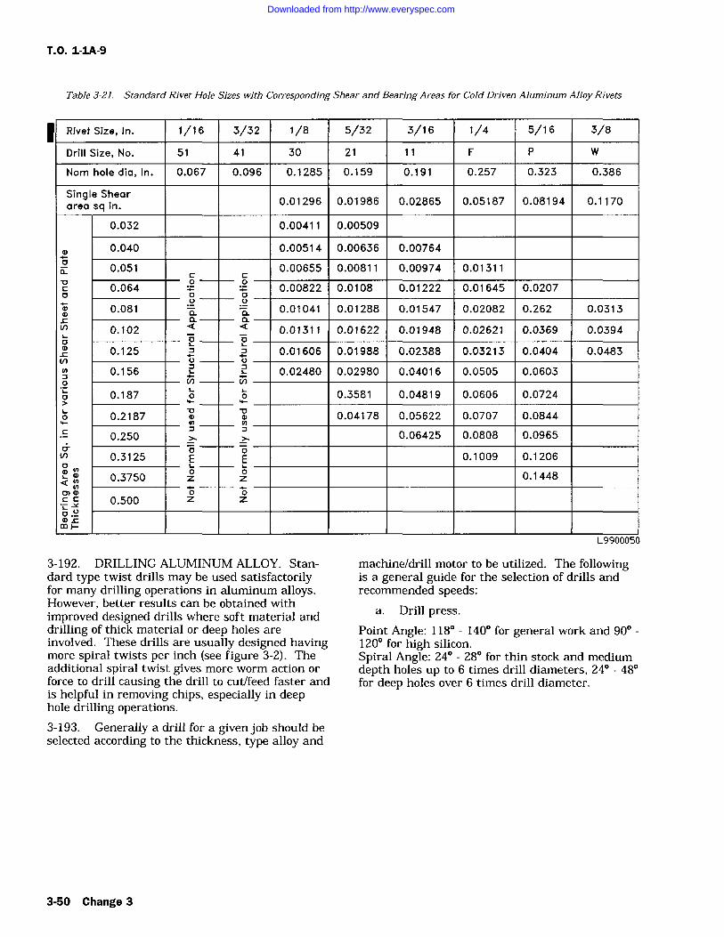
T.O. 1-1A-9
Table 3-21. Standard Rivet Hole Sizes with Corresponding Shear and Bearing Areas for Cold Driven Aluminum Alloy Rivets
Rivet Size, In. 1/16 3/32 1/8 5/32 3/16 1/4 5/16 3/8
Drill Size, No. 51 41 30 21 11 F P W
Nom hole dia, In. 0.067 0.096 0.1285 0.159 0.191 0.257 0.323 0.386
Single Shear0.01296 0.01986 0.02865 0.05187 0.08194 0.1170
area sq inin.
0.032 0.00411 0.00509
0.040 0.00514 0.00636 0.00764m
0 0.051 0.00655 0.00811 0.00974 0.01311
C 0.064 0 0.00822 0.0108 0.01222 0.01645 0.0207v
o 0m 0.081 a a 0.01041 0.01288 0.01547 0.02082 0.262 0.0313
a arV) 0.102 a a 0.01311 0.01622 0.01948 0.02621 0.0369 0.0394
o 0
V)
0.125U U
0.01606 0.01988 0.02388 0.03213 0.0404 0.0483
0.156 0.02480 0.02980 0.04016 0.0505 0.0603V) Np
00.187 0 0 0.3581 0.04819 0.0606 0.0724
0.2187 0.04178 0.05622 0.0707 0.0844
0.250>.
0.06425 0.0808 0.0965vin 0.3125 E E 0.1009 0.1206
a 0.3750 zo zo 0.1448
0) mC C 0.500 Z
0z
o.Uam tmp-
1
L9900050
3-192. DRILLING ALUMINUM ALLOY. Stan-dard type twist drills may be used satisfactorilyfor many drilling operations in aluminum alloys.However, better results can be obtained withimproved designed drills where soft material anddrilling of thick material or deep holes areinvolved. These drills are usually designed havingmore spiral twists per inch (see figure 3-2). Theadditional spiral twist gives more worm action orforce to drill causing the drill to cut/feed faster andis helpful in removing chips, especially in deephole drilling operations.3-193. Generally a drill for a given job should beselected according to the thickness, type alloy and
machine/drill motor to be utilized. The followingis a general guide for the selection of drills andrecommended speeds:
a. Drill press.
Point Angle: 118 140 for general work and 90120 for high silicon.Spiral Angle: 24 28 for thin stock and mediumdepth holes up to 6 times drill diameters, 24 48for deep holes over 6 times drill diameter.
3-50 Change 3
Downloaded from http://www.everyspec.com
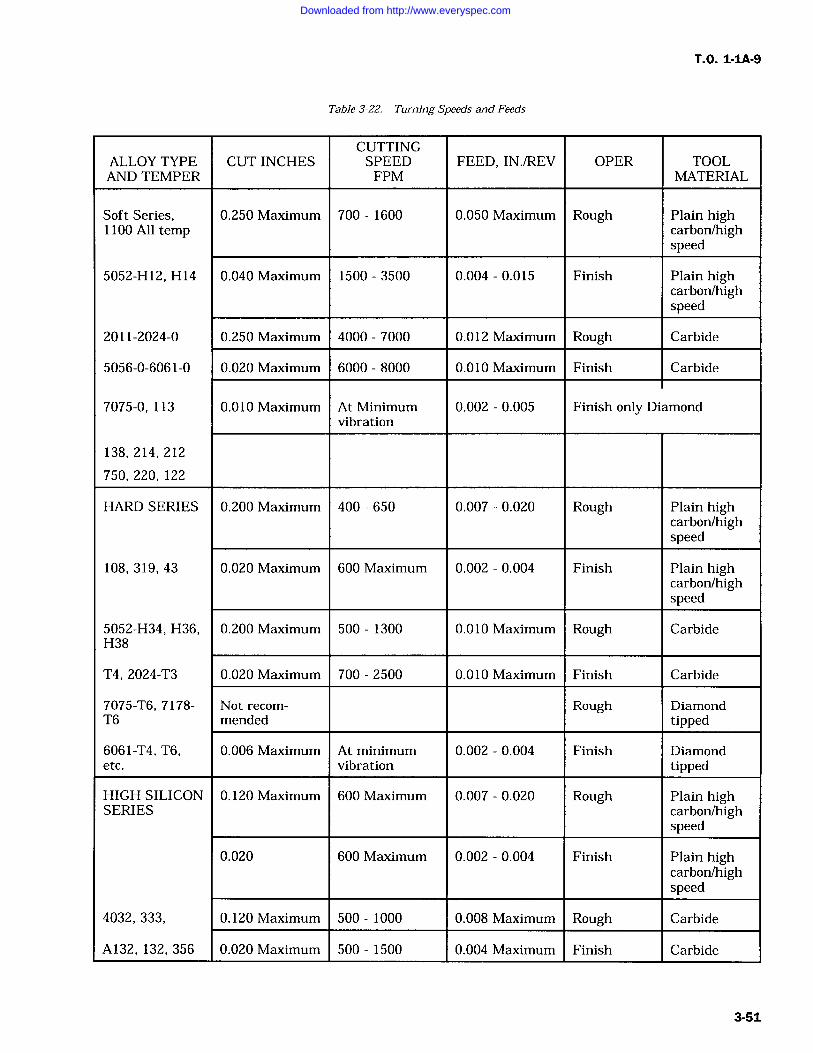
T.O. 1-IA-9
Table 3-22. Turning Speeds and Feeds
CUTTINGALLOY TYPE CUT INCHES SPEED FEED, INJREV OPER TOOLAND TEMPER FPM MATERIAL
Soft Series, 0.250 Maximum 700 1600 0.050 Maximum Rough Plain high1100 All temp carbon/high
speed
5052-1112, H14 0.040 Maximum 1500 3500 0.004 0.015 Finish Plain highcarbon/highspeed
2011-2024-0 0.250 Maximum 4000 7000 0.012 Maximum Rough Carbide
5056-0-6061-0 0.020 Maximum 6000 8000 0.010 Maximum Finish Carbide
7075-0, 113 0.010 Maximum At Minimum 0.002 0.005 Finish only Diamondvibration
138, 214, 212
750, 220, 122
HARD SERIES 0.200 Maximum 400 650 0.007 0.020 Rough Plain highcarbon/highspeed
108, 319, 43 0.020 Maximum 600 Maximum 0.002 0.004 Finish Plain highcarbon/highspeed
5052-H34, H36, 0.200 Maximum 500 1300 0.010 Maximum Rough CarbideH38
T4, 2024-T3 0.020 Maximum 700 2500 0.010 Maximum Finish Carbide
7075-T6, 7178- Not recom- Rough DiamondT6 mended tipped
6061-T4, T6, 0.006 Maximum At minimum 0.002 0.004 Finish Diamondetc. vibration tipped
HIGH SILICON 0.120 Maximum 600 Maximum 0.007 0.020 Rough Plain highSERIES carbon/high
speed
0.020 600 Maximum 0.002 0.004 Finish Plain highcarbon/highspeed
4032, 333, 0.120 Maximum 500 1000 0.008 Maximum Rough Carbide
A132, 132, 356 0.020 Maximum 500 1500 0.004 Maximum Finish Carbide
3-51
Downloaded from http://www.everyspec.com
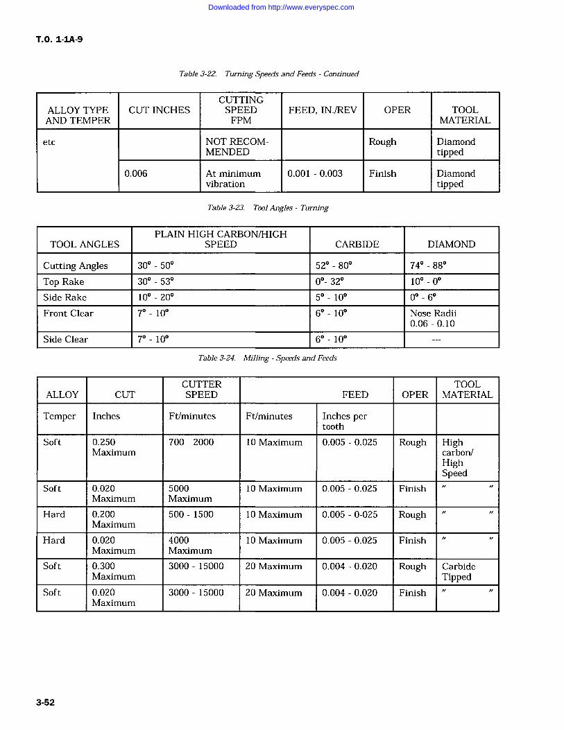
T.O. 1-1A-9
Table 3-22. Turning Speeds and Feeds Continued
CUTTINGALLOY TYPE CUT INCHES SPEED FEED, IN./REV OPER TOOLAND TEMPER FPM MATERIAL
etc NOT RECOM- Rough DiamondMENDED tipped
0.006 At minimum 0.001 0.003 Finish Diamondvibration tipped
Table 3-23. Tool Angles Turning
TOOL ANGLESPLAIN HIGH CARBON/HIGH
SPEED CARBIDE DIAMOND
Cutting Angles 30 50 52- 80 74 88
Top Rake 30 53 0- 32 10 0
Side Rake 10 20 50 10 0- 6
Front Clear 7- 10 6 100 Nose Radii0.06-0.10
Side Clear 7 100 6 10
Table 3-24. Milling Speeds and Feeds
CUTTER TOOLALLOY CUT SPEED FEED OPER MATERIAL
Temper Inches Ft/minutes Ft/minutes Inches pertooth
Soft 0.250 700 2000 10 Maximum 0.005 0.025 Rough HighMaximum carbon/
HighSpeed
Soft 0.020 5000 10 Maximum 0.005 0.025 FinishMaximum Maximum
Hard 0.200 500 1500 10 Maximum 0.005 0-025 RoughMaximum
Hard 0.020 4000 10 Maximum 0.005 0.025 FinishMaximum Maximum
Soft 0.300 3000 15000 20 Maximum 0.004 0.020 Rough CarbideMaximum Tipped
Soft 0.020 3000 15000 20 Maximum 0.004 0.020 FinishMaximum
3-52
Downloaded from http://www.everyspec.com
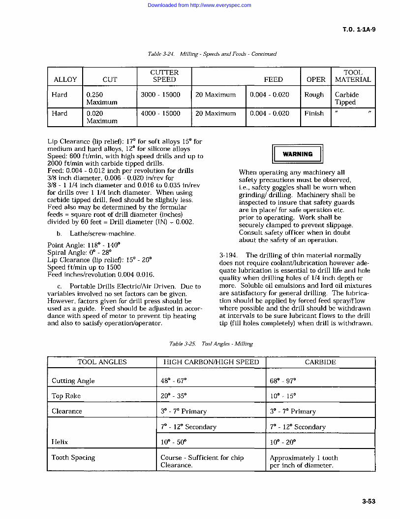
T.O. 1-IA-9
Table 3-24. Milling Speeds and Feeds Continued
ALLOY CUTCUTTERSPEED FEED OPER
TOOLMATERIAL
Hard 0.250 3000 15000 20 Maximum 0.004 0.020 Rough CarbideMaximum Tipped
Hard 0.020 4000 15000 20 Maximum 0.004 0.020 FinishMaximum
Lip Clearance (lip relief): 17 for soft alloys 15 formedium and hard alloys, 12 for silicone alloysSpeed: 600 ft/min, with high speed drills and up to2000 ft/min with carbide tipped drills.Feed: 0.004 0.012 inch per revolution for drills3/8 inch diameter, 0.006 0.020 in/rev for3/8 1 1/4 inch diameter and 0.016 to 0.035 in/revfor drills over 1/4 inch diameter. When usingcarbide tipped drill, feed should be slightly less.Feed also may be determined by the formularfeeds square root of drill diameter (inches)divided by 60 feet Drill diameter (IN) + 0.002.
b. Lathe/screw-machine.
Point Angle: 118 140Spiral Angle: 0 28Lip Clearance (lip relief): 15 20Speed ft/min up to 1500Feed inches/revolution 0.004-0.016.
c. Portable Drills Electric/Air Driven. Due tovariables involved no set factors can be given.However, factors given for drill press should beused as a guide. Feed should be adjusted in accor-dance with speed of motor to prevent tip heatingand also to satisfy operation/operator.
WARNING
When operating any machinery allsafety precautions must be observed,i.e., safety goggles shall be worn whengrinding/ drilling. Machinery shall beinspected to insure that safety guardsare in place/ for safe operation etc.prior to operating. Work shall besecurely clamped to prevent slippage.Consult safety officer when in doubtabout the safety of an operation.
3-194. The drilling of thin material normallydoes not require coolant/lubrication however ade-quate lubrication is essential to drill life and holequality when drilling holes of 1/4 inch depth or
more. Soluble oil emulsions and lard oil mixtures
are satisfactory for general drilling. The lubrica-tion should be applied by forced feed spray/flowwhere possible and the drill should be withdrawnat intervals to be sure lubricant flows to the drilltip (fill holes completely) when drill is withdrawn.
Table 3-25. Tool Angles Milling
TOOL ANGLES HIGH CARBON/HIGH SPEED CARBIDE
Cutting Angle 48 67 68- 97
Top Rake 20 35 10 15
Clearance 3 7 Primary 3 7 Primary
7 12 Secondary 7 12 Secondary
Helix 10- 50 10 20
Tooth Spacing Course Sufficient for chipClearance.
Approximately 1 toothper inch of diameter.
Downloaded from http://www.everyspec.com
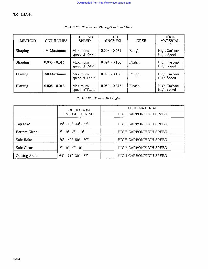
TO. 1-1A-9
Table 3-26. Shaping and Planing-Speeds and Feeds
CUTTING FEED TOOLMETHOD CUT INCHES SPEED (INCHES) OPER MATERIAL
Shaping 1/4 Maximum Maximum 0.008 0.031 Rough High Carbon/speed of RAM High Speed
Shaping 0.005 0.014 Maximum 0.094 0.156 Finish High Carbon/speed of RAM High Speed
Planing 3/8 Maximum Maximum 0.020 0.100 Rough High Carbon/speed of Table High Speed
Planing 0.005 0.018 Maximum 0.050 0.375 Finish High Carbon/speed of Table High Speed
Table 3-27. Shaping Tool Angles
OPERATIONTOOL MATERIAL
ROUGH FINISH HIGH CARBON/HIGH SPEED
Top rake 19 10 43 52 HIGH CARBON/HIGH SPEED
Bottom Clear 7 9 8 10 HIGH CARBON/HIGH SPEED
Side Rake 30 40 50 60 HIGH CARBON/HIGH SPEED
Side Clear 7- 9 0 0 HIGH CARBON/HIGH SPEED
Cutting Angle 64 71 30 37 HIGH CARBON/HIGH SPEED
3-54
Downloaded from http://www.everyspec.com
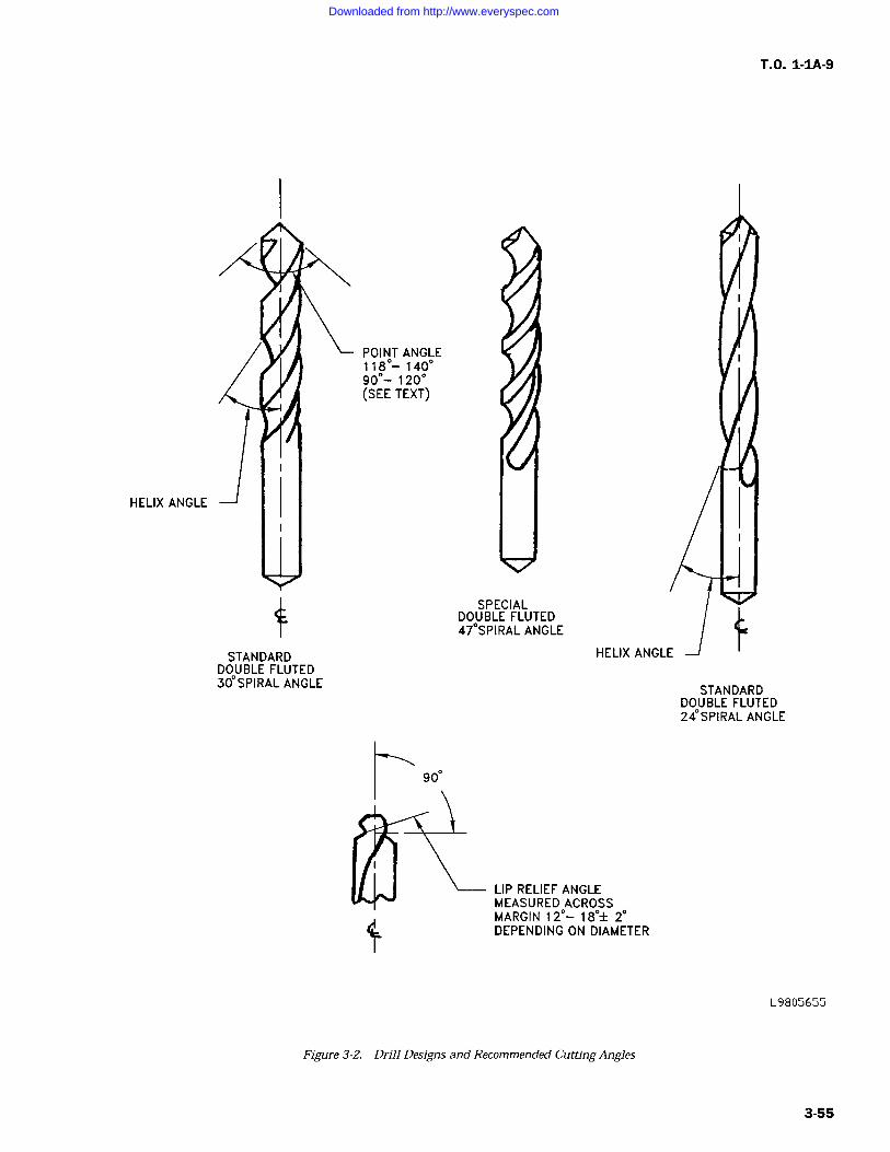
T.O. 1-IA-9
HELIX ANGLE
POINT ANGLE118- 14090- 120(SEE TEXT)
SPECIALDOUBLE FLUTED47SPIRAL ANGLE
STANDARDDOUBLE FLUTED30SPIRAL ANGLE
LIP RELIEF ANGLEMEASURED ACROSSMARGIN 12- 18+/- 2DEPENDING ON DIAMETER
STANDARDDOUBLE FLUTED24SPIRAL ANGLE
L9805655
Figure 3-2. Drill Designs and Recommended Cutting Angles
3-55
Downloaded from http://www.everyspec.com
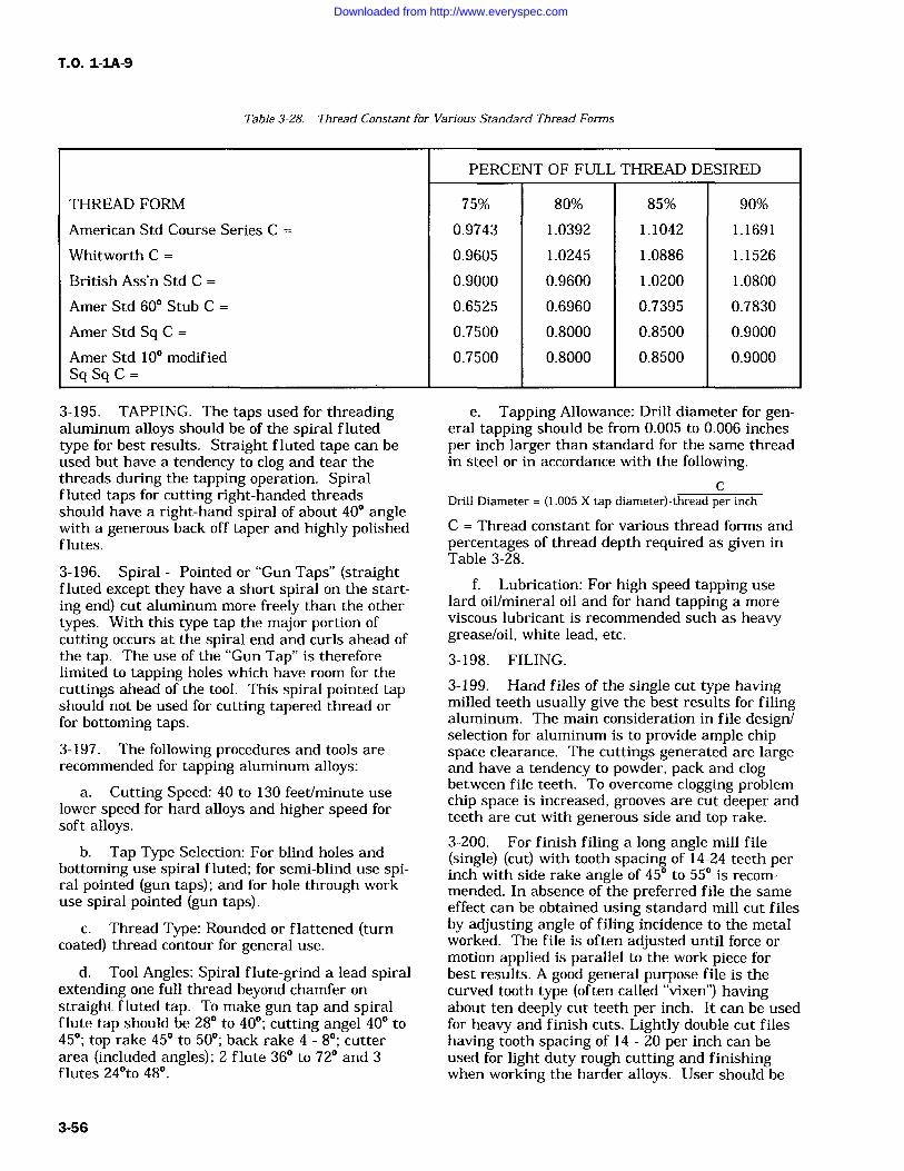
T.O. 1-IA-9
Table 3-28. Thread Constant for Various Standard Thread Forms
PERCENT OF FULL THREAD DESIRED
THREAD FORM 75% 80% 85% 90%
American Std Course Series C 0.9743 1.0392 1.1042 1.1691
Whitworth C 0.9605 1.0245 1.0886 1.1526
British Ass'n Std C 0.9000 0.9600 1.0200 1.0800
Amer Std 60 Stub C 0.6525 0.6960 0.7395 0.7830
Amer Std Sq C 0.7500 0.8000 0.8500 0.9000
Amer Std 10 modified 0.7500 0.8000 0.8500 0.9000SgSgC=
3-195. TAPPING. The taps used for threadingaluminum alloys should be of the spiral flutedtype for best results. Straight fluted tape can beused but have a tendency to clog and tear thethreads during the tapping operation. Spiralfluted taps for cutting right-handed threadsshould have a right-hand spiral of about 40 anglewith a generous back off taper and highly polishedflutes.
e. Tapping Allowance: Drill diameter for gen-eral tapping should be from 0.005 to 0.006 inchesper inch larger than standard for the same threadin steel or in accordance with the following.
CDrill Diameter (1.005 X tap diameter) -thread per inch
C Thread constant for various thread forms andpercentages of thread depth required as given inTable 3-28.
3-196. Spiral Pointed or "Gun Taps" (straightfluted except they have a short spiral on the start-ing end) cut aluminum more freely than the othertypes. With this type tap the major portion ofcutting occurs at the spiral end and curls ahead ofthe tap. The use of the "Gun Tap" is thereforelimited to tapping holes which have room for thecuttings ahead of the tool. This spiral pointed tapshould not be used for cutting tapered thread orfor bottoming taps.
3-197. The following procedures and tools arerecommended for tapping aluminum alloys:
a. Cutting Speed: 40 to 130 feet/minute uselower speed for hard alloys and higher speed forsoft alloys.
b. Tap Type Selection: For blind holes andbottoming use spiral fluted; for semi-blind use spi-ral pointed (gun taps) and for hole through workuse spiral pointed (gun taps).
c. Thread Type: Rounded or flattened (turncoated) thread contour for general use.
d. Tool Angles: Spiral flute-grind a lead spiralextending one full thread beyond chamfer onstraight fluted tap. To make gun tap and spiralflute tap should be 28 to 40; cutting angel 40 to45; top rake 45 to 50; back rake 4 8; cutter
area (included angles); 2 flute 36 to 72 and 3flutes 24to 48.
f. Lubrication: For high speed tapping uselard oil/mineral oil and for hand tapping a moreviscous lubricant is recommended such as heavygrease/oil, white lead, etc.
3-198. FILING.
3-199. Hand files of the single cut type havingmilled teeth usually give the best results for filingaluminum. The main consideration in file design/selection for aluminum is to provide ample chipspace clearance. The cuttings generated are largeand have a tendency to powder, pack and clogbetween file teeth. To overcome clogging problemchip space is increased, grooves are cut deeper andteeth are cut with generous side and top rake.
3-200. For finish filing a long angle mill file(single) (cut) with tooth spacing of 14-24 teeth perinch with side rake angle of 45 to 55 is recom-mended. In absence of the preferred file the sameeffect can be obtained using standard mill cut filesby adjusting angle of filing incidence to the metalworked. The file is often adjusted until force or
motion applied is parallel to the work piece forbest results. A good general purpose file is thecurved tooth type (often called "vixen") havingabout ten deeply cut teeth per inch. It can be usedfor heavy and finish cuts. Lightly double cut fileshaving tooth spacing of 14 20 per inch can beused for light duty rough cutting and finishingwhen working the harder alloys. User should be
3-56
Downloaded from http://www.everyspec.com
T.O. 1-1A-9
careful not to drag file across work on back strokeas with any filling operation. Files shall be keptclean and free of rust. Clogged files can becleaned by wire brushing. The use of chalk or talc
on file will help prevent clogging.3-201. Machine filing using rotary files (minia-ture milling cutters having spiralled sharp teethwith smooth deeply cut flutes) are operated athigh speed. The rotary files are operated up to10,000 RPM for small diameter and to 2,000 maxi-
mum peripheral feet/min for the larger diameter.The teeth should be coarse (about 14 teeth perinch) with deep polished flute and spiral notcheddesign.
CAUTION
Wear goggles or face shield when fil-ing with rotary files to protect eyes.
3-202. REAMING. Generally most of the differ-ent type reamers may be used for aluminum, butfor best results the spiral fluted reamers are rec-ommended solid, expansion or adjustable. Thespiral should be opposite to the rotation to preventreamer from feeding and hogging into the hole.Holes to be finished by reaming should be drilledsufficiently under-size to assure positive cuttingrather than scraping and swedging (indication ofoversize drilled holes and improper feed is the pro-jection of a lip around hole diameter after thereaming operation is accomplished). Finish ream-
ers should be maintained with exceptionally keencutting edges and highly polished flutes forsmooth work.
3-203. The following procedures and tools are
recommended for reaming aluminum alloys:
a. Tool material: High carbon steel for generaluse; high speed steel/or carbide tipped for durabil-ity and continued production jobs.
b. Tool type: Straight/spiral with 10 spiralflute and solid teeth.
c. Clearance and rake angles: Top rake 5 to8; clearance angle primary 4 to 7, secondaryangle 15 to 20; cutting angle 84 to 90.
d. Machine speed and hole reaming allow-ance: Cutting speeds up to 400 ft/min for straightholes, tapered hole should be somewhat slowerabout 300 350. The desired feed in inches/revolu-tion is 0.003 to 0.010. Hole to be reamed shouldbe undersize 0.005 0.015 inch diameter (reamingallowance).
e. Cutting fluids: Soluble oil/mixture of ker-osene and lard oil, light weight machine oil.
3-204. SAWING. It should be emphasized thatthe same principles which govern the shape of cut-ting tools for aluminum should be applied, as faras practicable to saws for aluminum.
3-205. Band Saws. Band saw blades of springtemper steel having a tooth spacing from 4 to 11teeth per inch and with amply radiused gullets arerecommended for aluminum alloys. Curved or cop-ying cuts are made with band saws. In any typeof work, high blade speed are desirable with aspeed range from 1,500 to 5,000 feet per minute.For heavy sections the saw teeth should be fairlycoarse with a slight set and a slight amount offront rake, the restricted chip space requires the
use of coarser tooth spacing of about four teeth perinch to avoid clogging and binding. Also the flexi-ble back type of saw with teeth hardened to thebottom of the gullet is used for heavy work.Blades having as many as 14 teeth per inch aresatisfactory for thin materials. A good and simplegeneral rule to follow when sawing aluminum isthat the spacing of the teeth on band saws foraluminum should be as coarse as is consistentwith the thickness of the material being sawed.The softer alloys require appreciably more bladeset than do the harder, heat treated alloys. Usu-ally an alternate side rake of about 15 and a toprake or "hook" of 10 to 20 proves quite satisfac-tory. This amount of hook, however, requires a
power feed and securely clamped work. For handfeeds the top rake must be reduced considerably toavoid overfeeding.3-206. The band saw blades must be well sup-ported by side rollers and back support both imme-diately below the saw table and about 2 or 3inches above the work. The top blade supports areplaced slightly in advance of those below thetables and the blade should be allowed to vibratefreely to eliminate excessive saw breakage. As ageneral rule, a noisy band saw is cutting more
efficiently than the saw that cuts quietly. Quietsmooth cutting band saws usually produce smoothburnished surfaces accompanied by excessive heatand consequently decreased blade life.
3-207. Hack Saws. Hack saw blades of thewavyset type are well suited for cutting aluminumby hand. The wavy set type of blade having 5 to15 teeth per inch has sufficient chip space to avoidclogging and binding on aluminum alloys. Forextremely fine work a jewelers blade may be used.
3-208. Special routing machines are availablewhich cut varied profiles from aluminum sheet orplate rapidly and efficiently.3-209. Lubricants and coolants. Power hacksawsand hand saws require a cutting lubricant for mostoperations involving thick sections. Soluble oil
3-57
Downloaded from http://www.everyspec.com
T.O. 1-1A-9
cutting compounds and neutral mineral-base lubri-cating oils applied to the sides of the blade aid inminimizing friction and gullet clogging. Lightapplications of heavy grease or paraffin wax willprovide ample lubrication for some work. A wideselection of lubricants exists, ranging from tallowor grease stick to kerosene-thinned mineral baselubricating oil. Stick type lubricants should beapplied very frequently. Experience has revealedin most cases it is more convenient and adaptableto use the fluid type lubricant applied freelythrough a recycling system directly to the bladeand work stock.
3-210. GRINDING. The grinding characteristicsof the various aluminum alloys vary in manyinstances. The harder free-cutting aluminumalloys may be ground satisfactorily with free cut-ting commercial silicon carbide grinding wheels,such as crystalon, carborundum and natalon.Rough grinding operations are usually performedby use of resin bonded wheels of medium harden-ers and grit sizes of 24 to 30. Also the aluminumabrasives from No. 14 to No. 36 have been foundto be satisfactory for rough grindings.3-211. Common alloys, particularly in theirsofter tempers have a tendency to clog the wheelsand do not finish to as bright and smooth a sur-
face as the harder materials.
3-212. Caution should be taken in selecting theproper grade of each commercial make of wheel.Once the grinding wheel has been selected thereare three variables that affect the quality of a fin-ish; these are the wheel speed, work speed andgrinding compound. Experienced operators haveproven that their own good judgement is a deter-mining factor as to the correct wheel and workspeeds, however, wheel speeds of about 6,000 feetper minute have given good results.
3-213. For finish work, a soft silicon carbidewheel of 30 to 40 grit in a vitrified bond haveproven to be very satisfactory. A grinding com-pound of soluble cutting oil and water works well.However, the fine grindings of aluminum must bestrained from the compound before reusing inorder to prevent deep scratches on the finishedsurface.
3-214. Special care should be exercised whengrinding castings and wrought alloy products thathave been heat treated, since their greater resis-tance to cutting or grinding generates a considera-ble amount of heat which may cause warping anddamage to the material.
3-215. Lubricants and Coolants. Generous appli-cations of stick grease are recommended to preventclogging of the grinding wheels during rough
grinding, while copious quantities of a low viscos-ity coolant type grinding compound are essentialand recommended for finish grinding. Soluble oilemulsions of the proportions of 30 or 40 to are
most suitable.
3-216. POLISHING. Polishing or finishing alu-minum and most of its alloys, by the application ofproper machining procedures, gives it a smoothlustrous finish. Aluminum and its alloys are pol-ished in the same manner as other metals, but a
lower wheel-to-metal pressure is used foraluminum.
3-217. Polishing is the act of removing marks,scratches or abrasion on the metal resulting fromprevious handling and operations; it must beunderstood that a more gentle cutting action or
finer abrasives are used for polishing aluminumthan used for steel. The various operations cov-
ered under the polishing category include rough-ing, greasing or oiling, buffing and coloring.These operations are briefly described in the fol-lowing paragraph.
3-218. ROUGHING. This is a term used todescribe the preliminary finishing operation or
process, used to prepare aluminum surfaces hav-ing deep scratches gouges or unusually rough sur-
faces, for subsequent polishing procedures. Rough-ing is not required on smooth undented or
unscratched surfaces. The preliminary finishingor roughing process usually employs a flexible alu-minum oxide paper disc, a semi flexible bondedmuslin or canvas wheel, faced with suitable abra-sives. Usually 50 100 grit abrasives are for thisprocess and are set in an adhesive in accordancewith standard practice. The peripheral speed ofthese discs runs around 6,000 feet per minute;faster wheel speeds would cause heating or ridgingof the soft metal surface. Heating is also reducedby small applications of tallow or a tallow oilmixture.
3-219. GREASING OR OILING. This is arefined or gentle roughing procedure for finishingaluminum surfaces. Application is visuallyemployed by a soft wheel faced with 100 to 200grit aluminum oxide emery, plus a light coat oftallow or beeswax lubricant to prevent excessiveheating. Here again, peripheral speeds of about6,000 FPM are used.
3-220. Greasing or oiling is a necessary operationin finishing coatings and other fabricated workwhich has been marred by previous operations.Excess aluminum pick-up on the wheels as resultsfrom overheating will cause deep scratches in themetal.
3-58
Downloaded from http://www.everyspec.com
T.O. 1-1A-9
3-221. BUFFING. This is a term used todescribe a finishing procedure employed to obtaina smooth high luster on an aluminum surface.This high luster finish is obtained by use of a fineabrasive, such as tripole powder mixed with a
grease binder, which is applied to the face of thewheel. These wheels usually consist of muslindiscs sewed together, turned at a peripheral speedof 7,000 FPM.
3-222. Many factors, such as, the thread count ofthe buff, the pressure applied to the buff againstthe work, the buffing compound used, the speed ofthe buff or wheel and the skill and experience ofthe operator must be considered in obtaining a sat-isfactory and quality type finish.
3-223. HARDNESS TESTING.
method of inspection is not acceptable for inspec-tion of parts subject to internal defects, i.e. inclu-sion in castings and forging or any part subject tointernal stress, etc.
3-230. Defects are indicated by darkening ofcracked or void areas after the anodic treatment.Insufficient rinsing in cold water after anodizingproduces stains which may be confused withdefects. In case of doubt strip film from part andreanodize. If the indications do not reappear thedefects shall be considered absent and part shouldnot be rejected for that reason.
NOTE
For additional general information on
inspection and testing see SectionVIII of this technical order.
3-224. Hardness is the resistance of a metal todeformation by scratching penetration or indenta-tion, and is usually a good indication of strength.Metal hardness can be measured accurately by theBrinell, Rockwell or Vickers Process.
3-225. BRINELL HARDNESS. The Brinell tech-nique is usually used to obtain the hardness ofaluminum and aluminum alloys. This hardnessvalue is obtained by applying a load through a ballindenter and measuring the permanent impressionin the material. To obtain the hardness value of a
material, divide the applied load in kilograms bythe spherical area of the impression in square mil-limeters. Hardness value of aluminum alloy istested by applying a load of 500 kilograms to a
ball ten millimeters in diameter for 30 seconds.
3-226. NON-DESTRUCTIVE TESTING/INSPECTION.
3-227. Aluminum and aluminum alloys are sus-ceptible to stress risers resulting from notching,nicking or scratching. A very close visual inspec-tion is required of all raw material prior to anyforming or machining operations. Before anyfabrication commences it is necessary that allscratches, nicks and notches be removed by sand-ing, polishing and filing.
3-228. ANODIZING PROCESS FOR INSPEC-TION OF ALUMINUM ALLOY PARTS. Parts forwhich anodic coating is applicable in accordancewith MIL-A-8625 Type I, can be anodized for theinspection of defects as cited in Specification MIL-1-8474.
3-229. The parts are examined visually for indi-cations of cracks, forging laps or other defects.Parts inspected by this method shall be limited tosheet stock and surface defect of forgings. This
3-231. ALUMINUM ALLOY EFFECTS ONSCRATCHES ON CLAD ALUMINUM ALLOY.The purpose of the following information on theeffects of scratches on aluminum alloys is to assistin eliminating controversy in depots and fieldinspection, regarding serviceability of aluminumalloy, sheet, skin and aircraft structural partswhich have been scratched, abraded or discoloredfrom the stand point of corrosion resistance andfatigue strength.3-232. In some instances, serviceable aluminumalloy parts and sheets, have been disposed of dueto lack of knowledge by inspection personnel as tothe effect of various depth scratches on thestrength and corrosion resistance of the clad alloy.Also, attempts have been made to removescratches from aircraft skin by sanding, buffing,or polishing resulting in removal of much of thecladding material and causing decrease in strengthand corrosion resistance.
3-233. ALLOWABLE DEFECTS.
a. The following surface defects are thosewhich do not affect the strength or corrosionresistance.
(1) Scratches which penetrate the surfacelayer of clad aluminum alloy sheets or parts but donot extend beneath the cladding are not serious ordetrimental.
(2) The presence of small corroded areaswill not materially affect the strength of cladunless the corroded pitted area extends throughthe cladding down to or into the bare metal Cleancorroded areas thoroughly by authorized methods(See Paragraph 3-242).
(3) Stains are not grounds for rejectionsince they affect neither the strength nor the cor-rosion resistance.
3-59
Downloaded from http://www.everyspec.com
T.O. 1-1A-9
CAUTION
No attempt will be made to removescratches or other surface defects bysanding or buffing since the protec-tive layer of cladding will be removedby such operations.
3-234. HARMFUL SCRATCHES. Scratcheswhich extend through the cladding and penetratethe core material act as notches and create stressconcentrations which will cause fatigue failure ifthe part is highly stressed or subjected to repeatedsmall stress reversals. However, sheets so
scratched may utilized for non-stressedapplications.
3-235. INSPECTION. Assemblies fabricatedfrom clad aluminum-alloy sheets will not berejected by inspection personnel, unless the defectis of sufficient depth to adversely affect themechanical properties or cover sufficient area toimpair the corrosion resistance of the assembly.Scratches or abrasions which penetrate the clad-ding will not affect corrosion resistance. Scratchesresulting from the normal handling and processingof clad aluminum-alloy sheet rarely extendthrough the cladding and penetrate the core.
3-236. TEST FOR DEPTH OF SCRATCHES.Since it is very difficult to measure the depth of ascratch on a sheet without cross sectioning thesheet, it has been found convenient (on clad mate-rial) to use a "spot" test to determine whether or
not a scratch extends through the cladding.
3-237. On alloys except 7075 and 7178 the "spot"test is made by placing a drop of caustic solution(10% by weight of sodium hydroxide, NaOH, inwater) on a portion of the scratch, and allowing itto react for 5 minutes. The caustic solution willthen be rinsed off the sheet with water, and thespot allowed to dry. If a black residue remains inthe base of the scratch at the spot tested, it indi-cates that the scratch extends to the core. If noblack color is visible and only a white residueremains in the base of the scratch, it indicatesthat the scratch does not penetrate through thecladding. For alloys 7075 and 7178 a drop of 10%cadmium chloride solution will produce a dark dis-colorationm within two minutes if the scratch pen-etrates the clad. The cadmium chloride applied asabove will not cause 2024 to discolor within twominutes.
3-238. When making the "spot" test to determinewhether a scratch extends to the core, it is advisa-ble for comparison purposes to spot test an adja-cent area in which there are no scratches. It is
then easier to determine whether the residuewhich remains is black or white.
3-239. Before making the "spot" test, the sheetarea will be cleaned and degreased with solventFederal Specification P-D-680, Type II, or othersuitable solvent, so that the caustic solution willreact properly.
3-240. Caution will be exercised to make surethat all of the caustic solution is removed from thesheet by thorough rinsing, since the caustic solu-tion is very corrosive to aluminum and aluminumalloys. Care wi 11 be taken not to use excessiveamounts of the caustic solution for the same rea-
son and it is preferable that only one drop be usedfor each test. The caustic solution will be pre-pared fresh for each series of tests to be made.
3-241. DISPOSITION OF SCRATCHEDSHEETS/PARTS.
a. All scratched clad aluminum-alloy sheetswi 11 be utilized to the fullest extent. Serviceableportions of damaged sheets will be used in themanufacture of smaller parts and assemblies.Only that portion of sheet that is scratched andotherwise damaged beyond serviceability will beadministratively condemned.
b. Parts (air weapon) shall be closelyinspected as cited and they do not meet specifiedrequirement shall be condemned and replaced asdirected.
3-242. CLEANING OF ALUMINUM ALLOYSHEET (STOCK).
3-243. Solvent Cleaning. Stubborn or exception-ally oily sheets may be cleaned by using solvent,Federal Specification P-D-680, Type II, beforecleaning with alkali solution. The cleaning will beaccomplished by brushing, soaking, scrubbing andwiping. Material or equipment that would scratchor abrade the surface shall not be used. Alsomaterial shall not be stored after solvent cleaningand prior to alkaline cleaning, unless solvent iscompletely removed from the surfaces of the metal.
3-244. Alkali Cleaning Solution. Composition ofsolution is 4 to 6 oz of cleaner specification MIL-C-5543 to one gallon of water. The material iscleaned by immersing in the solution (as preparedby instructions cited in paragraph 3-245) for 4-6minutes, thoroughly rinsing in water (fresh tap)and then completely drying. Never pile/storematerial while damp, wet or moist. Refer to T.O.00-85A23-1 for packaging and storage.
3-60
Downloaded from http://www.everyspec.com
T.O. 1-IA-9
CAUTION
Do not use strong alkali solutionbecause it will etch the aluminum.
3-245. Preparation. Use water heated to a tem-perature of 170F (77C). Add not more than onepound of cleaner at a time. Prepare the solutionin the following manner:
a. Fill the task 1/2 to 2/3 full of water.
b. Carefully dissolve the alkaline cleaner.
c. Add water to operating level and stir thor-oughly with a wooden paddle or other means.
3-246. Maintain solution in the followingmanner:
a. Add tap water to balance-up solution loss.
b. Make addition as required to maintain theactive alkali concentration between 4 and 6 ozalkaline cleaner for each gallon of water addedand stir thoroughly.
c. Prepare a new solution when contamina-tion impares the cleaning ability of the solution.
d. Clean the tank thoroughly before preparinga new solution.
3-247. Corrosion Removal from Aluminum AlloySheets. Corrosion is removed by immersing thesheet in the following acid cleaning solution:
ICAUTION
When using acid solution wearapproved clothing, acid resistinggloves, aprons/ coveralls, face shieldsor respirator. If solution is splashedinto eyes, flush thoroughly withwater immediately, and then report todispensary. For special instructions,contact local safety officer
a. Nitric-Hydrofluoric Acid Cleaning. Thesolution shall consist of 1 gallon technical nitricacid (58-62% HNO3) (39.5 Be).
1/2 pint technical hydrofluoric acid (48HF) (1.15SP).
9 gallons of water.
b. Parts shall be immersed for 3 to 5 minutesin cold acid (50 105F).
3-248. After removing from the acid, the partsshall be washed in fresh hot or cold running waterfor a sufficient length of time to thoroughlyremove the acid. Diluted solution of sodiumdichromate (Na2Cr2 07) 12 to 14 ounces per gallonof water, shall be added to the rinse water as a
corrosion inhibitor. The rinsing time dependsupon the freshness of the solution, size of the partand the amount of solution circulated. One halfhour or less should be sufficient. Parts shall thenbe completely dried by blasting with compressedair or other approved method.
NOTE
The sheet will stain when rinsed withsodium dichromate. The stronger thesolution the darker the stain. A lightdetectable stain is desired on corrodedareas. If the stain is dark reduce theamount of sodium dichromate addedto rinse water.
3-249. Corrosion Removal and Treatment of Alu-minum Sheets When Immersion Is Not Practical.
3-250. The surface shall be cleaned with waterbase cleaner, Specification MIL-C-25769, Type II.
a. Heavily soiled areas. Dissolve the contentsof two 5-pound packages in 10 gallons of water.Stir with a wooden paddle until fully dissolved.
b. Lightly soiled areas. Dissolve four 5-poundpackages in 50 gallons of water (a 55 gallon drumis suitable for this purpose). Agitate thoroughlywith wooden paddle to insure proper mixture.
c. Application. Apply the solution by spray-ing, or with a mop, sponge, or brush. Allow toremain on the surface for several minutes whileagitating with a brush. Rinse thoroughly with a
spray or stream of water. Do not allow solution todry before rinsing as less effective cleaning willresult.
3-251. Corrosion Removal. To remove corrosionproducts use a metal conditioner and brightener,Specification MIL-C-38334.
3-61
Downloaded from http://www.everyspec.com
T.O. 1-1A-9
WARNING
When using acid solution wearapproved clothing, acid resistantgloves, aprons/coveralls, face shieldsor respirator. If solution is splashedinto eyes, flush thoroughly withwater immediately, and then report todispensary. For special instructionscontact local safety officer.
CAUTION
Metal conditioner and brightener isfor use only on aluminum alloys, andit shall not be used just for the sakeof improving the appearance of mate-rial. Material in storage shall not betreated with this material more thanone time.
a. Prepare the brightening solution by mixingSpecification MIL-C-38334 compound with an
equal amount of water, in a rubber pail.b. Apply enough diluted brightener to com-
pletely cover the area being treated with a non-
metallic bristle brush.
c. Agitate the brightener by scrubbing with a
non-metallic bristle brush. Depending on the ambi-ent temperature and amount of corrosion depositspresent, allow approximately 5 to 10 minutes fromapplication of brightener before rinsing. Whenusing brightener at high ambient temperature(above 80F) leave brightener on for shorter peri-ods of time. Do not leave brightener on the sur-face longer than necessary to dissolve thecorrosion.
d. Rinse the brightener from the surface(using approximately 50 gallons of water per min-ute. Insure that all traces of brightener have beenremoved (shown by no foaming or bubbles whilerinsing).3-252. Chromate Conversion Coating Specifica-tion MIL-C-5541, for aluminum alloys. Aluminumalloys which are treated with Specification MIL-C-
38334 shall be treated with Specification MIL-C-5541. Most solutions conforming to SpecificationMIL-C-5541 leave a stain. A clear SpecificationMIL-C-5541 coating is available (reference QPL5541) and should be used when a bright metal fin-ish is desired.
WARNING
Conversion coating is a toxic chemicaland requires use of rubber gloves bypersonnel during its application. Ifacid, accidentally contacts the skin or
eyes, f lush immediately with plentyof clear water. Consult a physician ifeyes are affected or if skin is burned.
Do not permit Specification MIL-C-5541 material to contact paint thin-ner, acetone or other combustiblematerials. Fire may result.
a. Mix the solution in a stainless steel, rubberor plastic container; not in lead, copper alloy orglass.
b. Mix in accordance with manufacturersinstructions.
c. Apply the conversion coating (light) byusing a fiber bristle brush or a clean, soft cloth.Keep the surface wet with the solution until a
coating is formed which may take from 1 to 5 min-utes depending on the surface condition of themetal.
NOTE
Do not permit excess conversion coat-ing to dry on the metal surfacebecause the residue is difficult toflush off with water.
d. Rinse with clear water, or sponge the areawith a clean, moist cloth, frequently rinsing thecloth in clear water. Thorough rinsing is required.
e. Allow the surface to air dry. To speed dry-ing the surface may be blown dry with warm cleanair (140F maximum).
3-62
Downloaded from http://www.everyspec.com
T.O. 1-1A-9
WARNING
Any absorbent material used inapplying or wiping up MIL-C-5541material shall be rinsed in waterbefore discarding. They are extremefire hazards if allowed to dryotherwise.
CAUTIONJ
Avoid brushing or rubbing the newlyapplied chemical conversion coating,since it is soft and can be easilyrubbed off the surface before com-
pletely drying.
NOTE
A light (just visible to the naked eye)evenly dispersed conversion coating isall that is required. It is recom-mended that a test panel be preparedand subjected to complete cleaning/treating procedure before applyingmaterial to a sheet. The test panelshall be used to determine the dwelltime of MIL-C-5541 material. Whenclear material is being used, no con-trol of discoloration is necessary.
After the procedures cited inparagraphs 3-252 through 3-263 havebeen complied with, an AF Form 50Awill be attached to each sheet with a
statement that, "This material has
been cleaned and treated for corrosionin accordance with T.O. 1-1A-9 Sec-tion III, date ........ If originalmarkings are removed as a result ofthe cleaning and treatment process,the material shall be remarked (stag-gered) at each end and in the middlewith the Specification, size/thickness,temper and type or grade. The mark-ing may be applied with Black paintSpecification TT-L-50, MIL-E-7729 or"Magic Marker" manufactured bySpeeddry Products Inc., RichmondHill, N.Y. or "Equal". A felt tip penmay also be used.
3-253. For Packaging, Packing,. and Storage ofAluminum Alloy Sheets and Plates Refer to T.O.00-85A-23-1.
3-254. ANODIC COATINGS FOR ALUMINUM.Anodizing is the anodic process of treating alumi-num alloys; a thin film of artificially producedoxide is formed on the surface of the metal by elec-trochemical reaction. Military Specification MIL-A-8625 lists the requirements of aluminum anodiz-ing, and TO 42C2-1-7 gives the anodizing process.
3-255. Military Specification MIL-C-5541 liststhe requirements for corrosion protection andpaint base of aluminum by the use of chemicalfilm. These chemical films are substitutes thatmay be used in lieu of anodic films, and may beapplied by spray, brush, or immersion as specifiedby QPL-5541. The anodizing method is prefer-rable to chemical films on aluminum parts wherefacilities are available. For process proceduresapplying to chemical films, refer to TechnicalOrders 1-1-8 and 1-1-2.
3-63/(3-64 blank)
Downloaded from http://www.everyspec.com

Downloaded from http://www.everyspec.com
T.O. 1-1A-9
SECTION IV
MAGNESIUM ALLOYS
4-1. CLASSIFICATION.
4-2. Magnesium alloys are produced and used in
many shapes and forms, i.e., castings, extrudedbars, rods, tubing, sheets and plate and forgings.They are suitable for varied stress and non-stress
aerospace applications. Their inherent strength,lightweight, shock and vibration resistance arefactors which make their use advantageous. Theweight for an equal volume of magnesium isapproximately two-thirds of that for aluminumand one-fifth of that for steel.
4-3. The current system used to identify magne-sium alloys, is a two letter, two or three digitnumber designation in that order. The letters des-ignate the major alloying elements, (arranged indecreasing percentage order, or in alphabeticalorder if the elements are of equal amounts), fol-lowed by the respective digital percentages ofthese elements. The percentage is rounded off tothe nearest whole number or if a tolerance rangeof the alloy is specified, the mean of the range(rounded off to nearest whole number) is used. Asuffix letter following the percentage digits,denotes the latest qualified revision of the alloy.For example: Alloy Designation AZ92A would con-
sist of 9% (mean value) aluminum and 2% (meanvalue) zinc as the major alloying elements. Thesuffix "A" indicates this is the first qualified alloyof this type. One exception to the use of the suffixletter is that an "X" denotes that impurity contentis controlled to a low limit. Some of the lettersused to designate various alloying elements are:
A Aluminum, E Rare Earth,H Thorium, K Zirconium,M Manganese, Z Zinc.
4-4. DEFINITIONS.
4-5. HARDNESS. Hardness is the resistance ofa metal to plastic deformation from penetration,indentation, or scratching. The degree of hardnessis usually a good indication of the metals strength.The hardness of a metal can be accurately mea-sured using the Brinell on Rockwell process oftesting. Tables 4-4, 4-5 and 4-6 list the nominalhardness of various magnesium alloys. Brinellhardness testing is explained in Section VIII ofthis manual.
4-6. TENSILE STRENGTH. The useful tensilestrength of a metal is the maximum stress it cansustain in tension or compression without perma-nent deformation. The yield strength is that point
of stress, measured in pounds per square inch, atwhich permanent deformation results from mate-rial failure. The data in Tables 4-4, 4-5 and 4-6lists the nominal yield strengths of various alloys.The yield point in magnesium is not reachedabruptly, but rather a gradual yielding when themetal is stressed above the proportional limit.Tensile and yield strengths decrease at elevatedtemperatures.
4-7. TEMPER is the condition produced in thealloy by mechanically or thermally treating it toalter its mechanical properties. Mechanicalincludes cold rolling, cold working, etc.; thermalincludes annealing, solution and precipitation heattreat and stabilization treating. See paragraph 4-12 for temper designations.4-8. SHEAR STRENGTH is the maximumamount (in pounds per square inch) in cross sec-tional stress that a material will sustain beforepermanent deformation or rupture occurs.
4-9. ELONGATION is the linear stretch of amaterial during tensile loading measured beforeand after rupture. In magnesium it is theincrease in distance which occurs when stretch isapplied between two gage marks placed 2 inchesapart on the test specimen. After rupture the twopieces are fitted together and remeasured. Theelongation is the percentile difference of theamount of stretch in ratio to the original 2 inches.
4-10. PHYSICAL PROPERTIES. Magnesium, inits pure state, has a specific gravity of 1.74, weigh-ing .063 pounds per cubic inch. Similar data formagnesium alloys are included in Table 4-6 aswell as other physical property information.
4-11. CHEMICAL PROPERTIES. Chemicallybare magnesium is resistant to attack by alkalis,chromic and hydrofluoric acids and many organicchemicals including hydrocarbons, aldehydes, alco-hols, phenols, amines, esters and most oils. It issusceptible to attack by salts and by galvanic cor-
rosion from contact with dissimilar metals andother materials. Adequate protection of the metalagainst unfavorable conditions can be maintainedgenerally, by using proper surface finish (See par-agraph 4-93) and assembly protection. The chemi-cal property constituents of the various alloys arelisted in Table 4-3.
4-12. TEMPER DESIGNATION SYSTEM. Thehyphenated suffix symbol which follows an alloydesignation denotes the condition of temper, (heat
4-1
Downloaded from http://www.everyspec.com
T.O. 1-1A-9
treat or strain hardening), to which the alloy hasbeen processed. These symbols and their mean-ings are listed below: (Heat treating itself is dis-cussed in subsequent paragraphs of this section ofthe manual).
-AC As-Cast-F As-fabricated-O Annealed-W Solution heat treated unstable temper-T Treated to produce stable tempers other
than for -O-T2 Annealed (cast products only)-T3 Solution heat treated and then cold
worked-T4 Solution heat treated-T5 Artificially aged only-T6 Solution heat treated and then artifi-
cially aged-T7 Solution heat treated and stabilized-T8 Solution heat treated, cold worked and
then artificially aged-T9 Solution heat treated, artificially aged
and then cold worked-T10 Artificially aged and then cold worked-H1 Strain hardened only-H2 Strain hardened and partially annealed-H3 Strain hardened and stabilized
Added suffix digits 2, 4, 6, 8, to the H1, H2, H3symbols indicate the degree of strain hardening,i.e., 2=1/4 hard, 4=1/2 hard, 6=3/4 hard, and 8=fullhard.
4-13. SAFETY REQUIREMENTS FOR HANDLINGAND FABRICATION OF MAGNESIUM ALLOYS.
4-14. There are two special major areas of safetyprecautions to observe in proceeding of magnesiumalloys other than general shop safety practices.One is the fact some alloys contain thorium, a
radioactive element (e.g., HK31A, HM21A,HM31A) and the other is the low melting point/rapid oxidation (fire hazard) characteristics of themetal. Where the application of heat is to bemade to a thorium alloy, both of these areas mustbe considered.
WARNING
Magnesium thorium alloys shall behandled, stored and disposed of inaccordance with T.O. 00-11ON-4.
4-15. MAGNESIUM-THORIUM ALLOYS (HK31,HM21, HM31, HZ32, ZH42, ZH62) are mildly radi-oactive but are within the safe limits set by theAtomic Energy Commission (AEC) and representno hazard to personnel under normal conditions. A
standard of 0.1 milligram per cubic meter (mg/m3)of thorium in air is a safe limit for continuousatmospheric exposure and is readily met inprocessing magnesium alloys containing up to 10%thorium, For example: Stirring alloy melt of 5%thorium content resulted in 0.002 mg/m3 atmos-pheric contamination and grinding air alloy of 3%thorium content gave thorium contamination inthe breathing zone ranging from 0.008 to 0.035mg/m3. Only long exposure to fine dust or fumesneed cause concern as to radioactive toxicity ofmagnesium-thorium. Normal dust control precau-tions, followed to avoid fire hazards, can beexpected to control any health hazards that mightresult from fine dust in grinding the low thoriumcontent alloys. In welding these alloys withoutlocal exhaust, concentrations of thorium above thetentative limit of 0.1 mg/m3 of air were found inthe breathing zone. Use of local exhaust reducedthorium concentrations to well within acceptablelimits If ventilation is such that the visiblefumes flow away from the welder, it is adequate,providing such fumes are not permitted to accumu-
late in the immediate vicinity. An alternate prac-tice involves use of ventilated welder's hood, ifthere is not sufficient room ventilation to controlcontamination of the general atmosphere. Tho-rium containing scrap and wet grinding sludgemay be disposed of by burning providing an AECammendment is secured for the basic AEC license.If burned, the ashes which will then contain thethorium, must be disposed of in accordance withAEC Standards for Protection Against Radiation10 CFR Part 20. As an alternative the ashes or
scrap may be turned over to an AEC licensedscrap dealer, through applicable disposal proce-dures, See T.O.00-11ON-4
4-16. For indoor storage of thorium alloy sheetsand plates, the size of stacks should be limited to1000 cubic feet with an aisle width not less thanone-half the stack's height. Such storage is withinthe normal recommendations for fire safety.4-17. Radiation surveys have shown that expo-sure of workers handling the referenced thoriumalloys is well within the safe limits set by theAEC. Assuming hand contact, the body one footaway from the alloy for an entire 40 hour workweek, the exposure would be 168 millirems (mr) tothe hands and 72 mr to the whole body. These are
maximum values which probably would not beapproached in actual practice. The correspondingAEC permissible safe limits are 1500 mr/week forthe hands and 300 mr/week for the whole body.4-18. Despite the relative safety present in thehandling, to rage and processing of thorium con-
taining alloys, it is mandatory that all suchactions be made according to the requirements and
4-2
Downloaded from http://www.everyspec.com
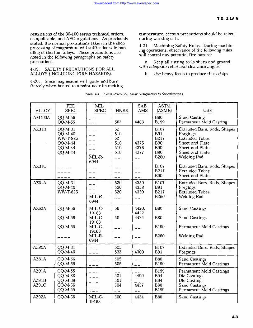
T.O. 1-IA-9
restrictions of the 00-100 series technical orders,as applicable, and AEC regulations. As previouslystated, the normal precautions taken in the shopprocessing of magnesium will suffice for safe han-dling of thorium alloys. These precautions are
noted in the following paragraphs on safetyprecautions.4-19. SAFETY PRECAUTIONS FOR ALLALLOYS (INCLUDING FIRE HAZARDS).
4-20. Since magnesium will ignite and burnfiercely when heated to a point near its melting
temperature, certain precautions should be takenduring working of it.
4-21. Machining Safety Rules. During machin-ing operations, observance of the following ruleswill control any potential fire hazard:
a. Keep all cutting tools sharp and groundwith adequate relief and clearance angles
b. Use heavy feeds to produce thick chips.
Table 4-1. Cross-Reference, Alloy Designation to Specifications
FED MIL SAE ASTMALLOY SPEC SPEC HNBK AMS (ASME) USE
AM100A QQ-M-56 B80 Sand CastingQQ-M-55 502 4483 B 199 Permanent Mold Casting
AZ31B QQ-M-31 52 B107 Extruded Bars, Rods, ShapesQQ-M-40 510 B91 ForgingsWW-T-825 52 B217 Extruded TubesQQ-M-44 510 4375 B90 Sheet and PlateQQ-M-44 510 4376 B90 Sheet and PlateQQ-M-44 510 4377 B90 Sheet and Plate
MIL-R- B260 Welding Rod6944
AZ31C B107 Extruded Bars, Rods, ShapesB217 Extruded TubesB90 Sheet and Plate
AZ61A QQ-M-31 520 4350 B107 Extruded Bars, Rods, ShapesQQ-M-40 530 4358 B91 ForgingsWW-T-825 520 4350 B217 Extruded Tubes
MIL-R- B260 Welding Rod6944
AZ63A QQ-M-56 MIL-C- 50 4420, B80 Sand Castings19163 4422
QQ-M-56 MIL-C- 50 4424 B80 Sand Castings19163
QQ-M-55 MIL-C- B199 Permanent Mold Castings19163MIL-R- B260 Welding Rod6944
AZ80A QQ-M-31 523 B107 Extruded Bars, Rods, ShapesQQ-M-40 532 4360 B91 Forgings
AZ81A QQ-M-56 505 B80 Sand CastingsQQ-M-55 505 B199 Permanent Mold Castings
AZ91A QQ-M-55 B199 Permanent Mold CastingsQQ-M-38 501 4490 B94 Die Castings
AZ91B QQ-M-38 501 B94 Die CastingsAZ91C QQ-M-56 504 4437 B80 Sand Castings
QQ-M-55 B199 Permanent Mold CastingsAZ92A QQ-M-56 MIL-C- 500 4434 B80 Sand Castings
19163
4-3
Downloaded from http://www.everyspec.com
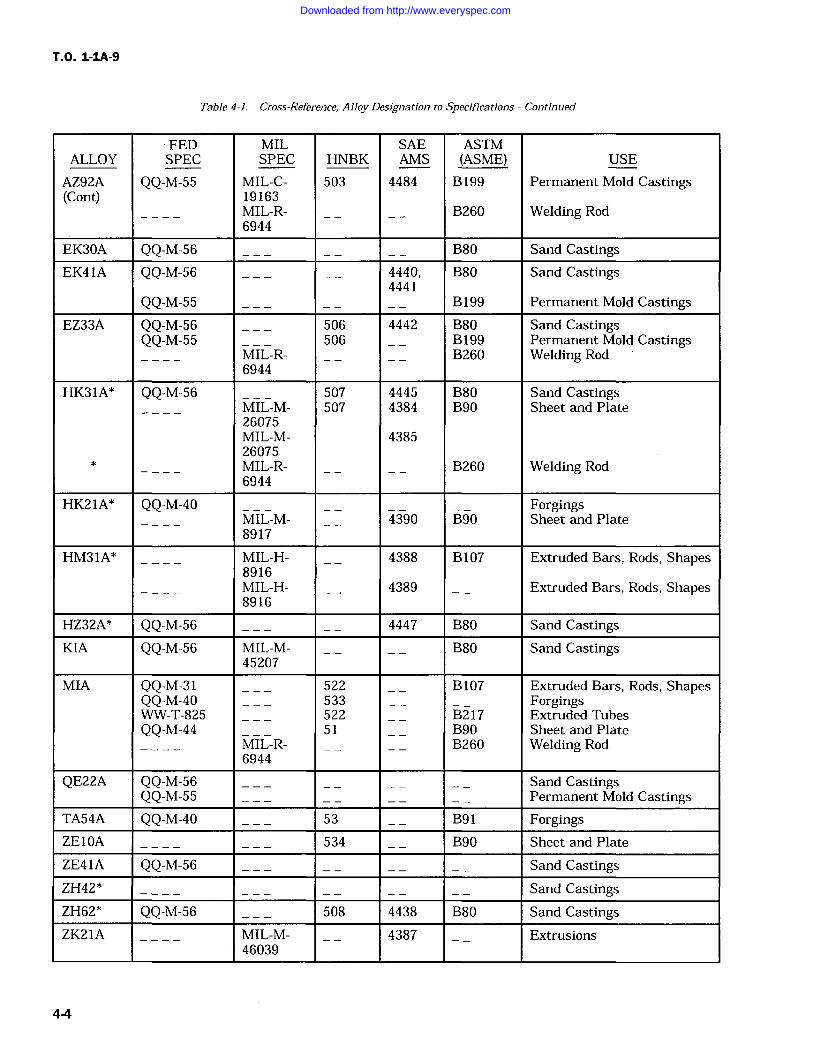
T.O. 1-IA-9
Table 4-1. Cross-Reference, Alloy Designation to Specifications Continued
FED MIL SAE ASTMALLOY SPEC SPEC HNBK AMS (ASME) USE
AZ92A QQ-M-55 MIL-C- 503 4484 B199 Permanent Mold Castings(Cont) 19163
MIL-R- B260 Welding Rod6944
EK30A QQ-M-56 B80 Sand CastingsEK41A QQ-M-56 4440, B80 Sand Castings
4441QQ-M-55 B199 Permanent Mold Castings
EZ33A QQ-M-56 506 4442 B80 Sand CastingsQQ-M-55 506 B199 Permanent Mold Castings
MIL-R- B260 Welding Rod6944
HK31A* QQ-M-56 507 4445 B80 Sand CastingsMIL-M- 507 4384 B90 Sheet and Plate26075MIL-M- 438526075MIL-R- B260 Welding Rod6944
HK21A* QQ-M-40 ForgingsMIL-M- 4390 B90 Sheet and Plate8917
HM31A* MIL-H- 4388 B107 Extruded Bars, Rods, Shapes8916MIL-H- 4389 Extruded Bars, Rods, Shapes8916
HZ32A* QQ-M-56 4447 B80 Sand CastingsKIA QQ-M-56 MIL-M- B80 Sand Castings
45207
MIA QQ-M-31 522 B107 Extruded Bars, Rods, ShapesQQ-M-40 533 ForgingsWW-T-825 522 B217 Extruded TubesQQ-M-44 51 B90 Sheet and Plate
MIL-R- B260 Welding Rod6944
QE22A QQ-M-56 Sand CastingsQQ-M-55 Permanent Mold Castings
TA54A QQ-M-40 53 B91 ForgingsZE10A 534 B90 Sheet and Plate
ZE41A QQ-M-56 Sand CastingsZH42* Sand CastingsZH62* QQ-M-56 508 4438 B80 Sand CastingsZK21A MIL-M- 4387 Extrusions
46039
4-4
Downloaded from http://www.everyspec.com
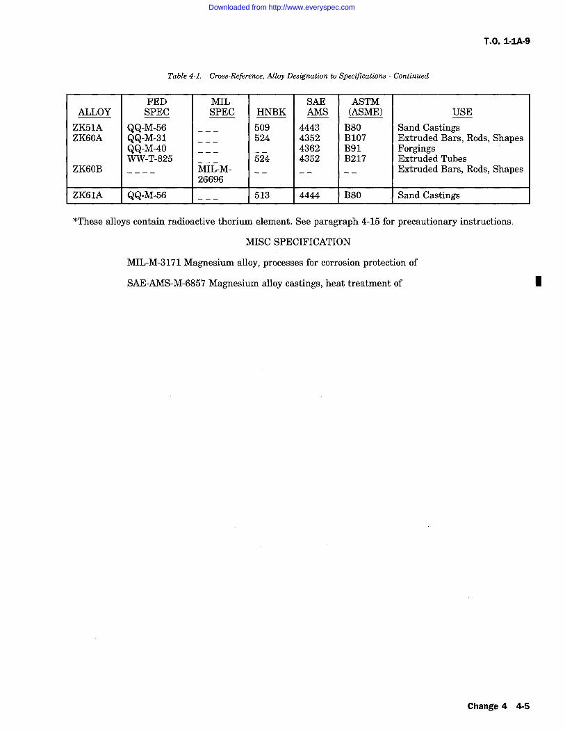
T.O. 1-IA-9
Table 4-1. Cross-Reference, Alloy Designation to Specifications Continued
ALLOYFEDSPEC
MILSPEC HNBK
SAEAMS
ASTM(ASME) USE
ZK51A QQ-M-56 509 4443 B80 Sand CastingsZK60A QQ-M-31 524 4352 B107 Extruded Bars, Rods, Shapes
QQ-M-40 4362 B91 ForgingsWW-T-825 524 4352 B217 Extruded Tubes
ZK60B MIL-M- Extruded Bars, Rods, Shapes26696
ZKG1A QQ-M-56 513 4444 B80 Sand Castings
*These alloys contain radioactive thorium element. See paragraph 4-15 for precautionary instructions.
MISC SPECIFICATION
MIL-M-3171 Magnesium alloy, processes for corrosion protection of
SAE-AMS-M-6857 Magnesium alloy castings, heat treatment of 1
Change 4 4-5
Downloaded from http://www.everyspec.com
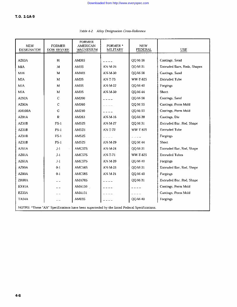
T.O. 1-IA-9
Table 4-2. Alloy Designation Cross-Reference
NEWDESIGNATOR
FORMERDOW REVERE
FORMERAMERICANMAGNESIUM
FORMERMILITARY
NEWFEDERAL USE
AZ63A H AM265 QQ-M-56 Castings, Sand
MIA M AM3S AN-M-26 QQ-M-31 Extruded Bars, Rods, Shapes
MIB M AM403 AN-M-30 QQ-M-56 Castings, Sand
MIA M AM3S AN-T-73 WW-T-825 Extruded Tube
MIA M AM3S AN-M-22 QQ-M-40 Forgings
MIA M AM3S AN-M-30 QQ-M-44 Sheet
A292A C AM260 QQ-M-56 Castings, Sand
AZ92A C AM260 QQ-M-55 Castings, Perm Mold
AM100A G AM240 QQ-M-55 Castings, Perm Mold
AZ91A R AM263 AN-M-16 QQ-M-38 Castings, Die
AZ31B FS-1 AM52S AN-M-27 QQ-M-31 Extruded Bar, Rod, Shape
AZ31B FS-1 AM52S AN-T-72 WW-T-825 Extruded Tube
AZ31B FS-1 AM52S Forgings
AZ31B FS-1 AM52S AN-M-29 QQ-M-44 Sheet
AZ61A J-1 AMC57S AN-M-24 QQ-M-31 Extruded Bar, Rod, Shape
AZ61A J-1 AMC57S AN-T-71 WW-T-825 Extruded Tubes
AZ61A J-1 AMC57S AN-M-20 QQ-M-40 Forgings
AZ80A 0-1 AMC58S AN-M-25 QQ-M-31 Extruded Bar, Rod, Shape
AZ80A 0-1 AMC58S AN-M-21 QQ-M-40 Forgings
ZK60A AMA76S QQ-M-31 Extruded Bar, Rod, Shape
EX41A AMA130 Castings, Perm Mold
EZ33A AMA131 Castings, Perm Mold
TA54A AM65S QQ-M-40 Forgings
NOTES: *These AN" Specifications have been superseded by the listed Federal Specifications.
4-6
Downloaded from http://www.everyspec.com
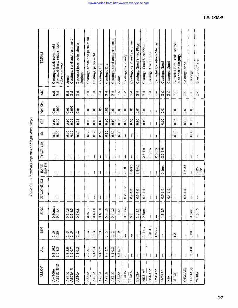
T.O. 1-1A-9
oa
o ca E E E E m m
aa
-o p a) ' yo N tiC o hoo0.5
a
G o EC C C
Co m m cn cn Y dow d N o E b b y v mC C co ro m w Ch L I G V oti P] Q (Y V) V) W V) 0 CO
'b b 'CJ 'O y4 on on on on on on on on on to 00
r C 7C
C C C E C C C C C C C C C Ci:.Y ;:+E on
j:.Y i=Y i, E i:+ i=i y.Y iY on Y+ N +' on
m x A m m x m m cd Co m m m k m m x mu W cn U W U U U U U V) U U U U L74 W U U W U w rn
mm coca m m m m m m m m m m m m m m m0.1 PY G>a 0. Ca CO 0.1 0Y 0.1 W W W 00 0.1 p] W W fY W 0.1 W GO 0.1
U
z O d O O O O O
a O O N M N O OO O
O O O OCl? LI?
O 0 0 0 0
Lqo
H
Wxes-, a E
Q'W O
o E g q o Q Q Q
U x
Ex
xN E E Eco
zO cf) E
O O O
-) c0Q 00 6) m C) C)
MLrY 00 M
0) 00
0.1 U Q d d Q d co U d Q Q d d Q d = d d dQ
O
O 0) dQ [Y d Wd d d d d Q Q d d d d W W W x x x x x O H N
4-7
Downloaded from http://www.everyspec.com
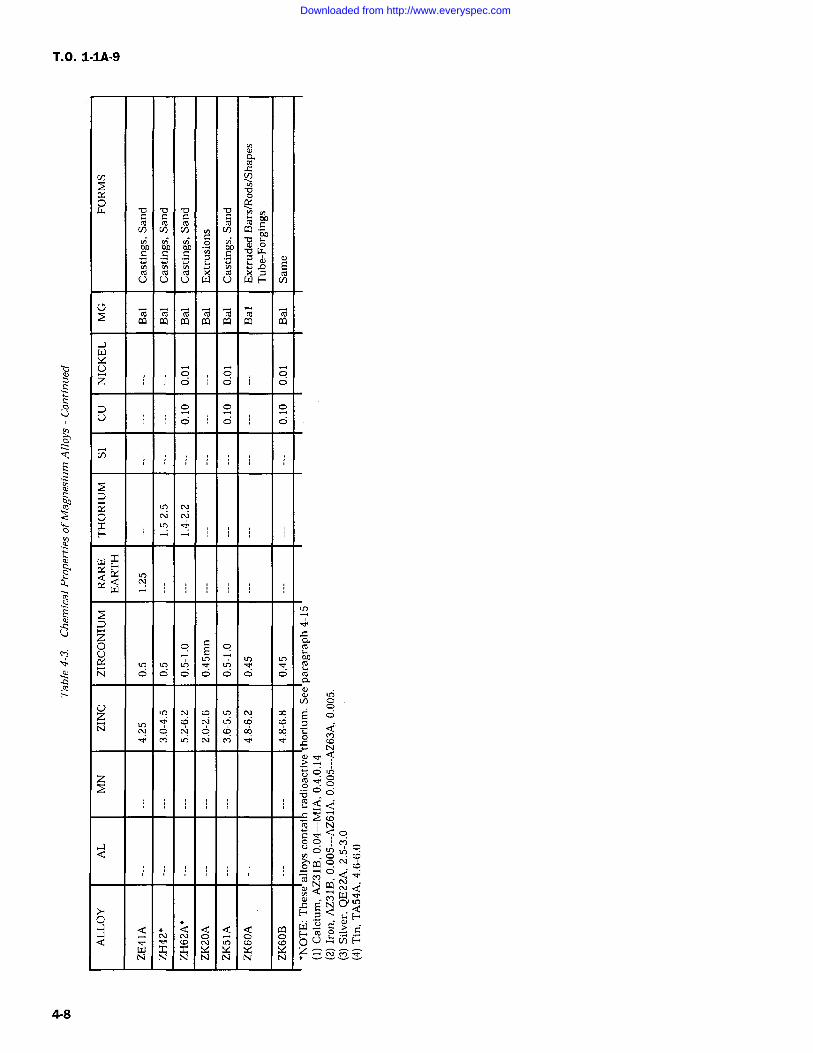
T.O. 1-1A-9
M
ti
ro
f3' o
eoN &DCl)
moAC
aoC
aoC E
onC W
a cU
mU
mU
kW
mU
xW H c/)
c; Oq ;0 0.1W
W 0.1
zo
O O
U o 0 0
ao
H
WxQ Q
cn C!N O O O O O O O
NL? O
Op 06
z
Q
O
YlQ
N QO Q OW x x x x x xN N N N N N N
4-8
Downloaded from http://www.everyspec.com
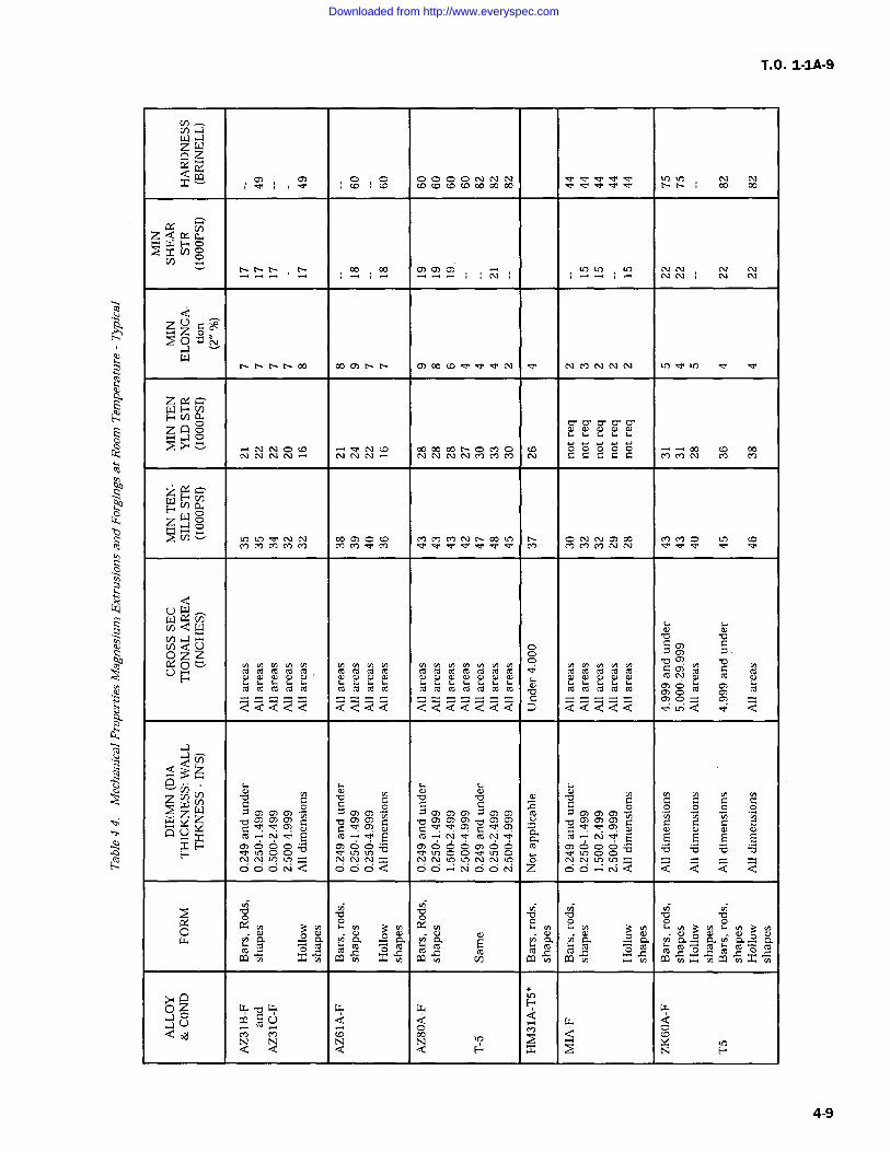
T.O. 1-IA-9
U)nawzZc
rQrrO O 0 0
0.' QL4
00 (7)
z0 N
W
zxY
V) 0Y
>"C C C C C
zooN
W < toQ W
NQ U C C)
C
Q u bC CUV roro ro t ro ro ro m w ro m ro m (t m roro ro roro
ro ro C ro ro C ro ro C ro C ro b ro ro ro ro ro ro rnQ Q Q Q Q Q Q Q d Q Q Q Q Q Q Q Q Q d
aYQQz
Qb
Cn -O b 'C 'bz W 7 7 C C C)) C inW xZ brnrnrn CYd rn o CYrn.arnrna) arnrn
Yr<rrn -o Cwa C C C C CCa 'U+ x Y
roY C
f ro a E CCIt
TH tTOOO C7)OO OO OOCT O)OOO Y^ b 0 bO
=NQ
=OOOQ Z Q Q Q Q Q
p b o -O b 'O
OcxY 3Y 3Y xY N Y v)3v)v)3v)y a 0. a (). Cl. Q.
W x 0. x pLl 0.1 G1 0.1 W
0Zwbw w w
H wYU
to ca ow
oY N
Q Q QNQ x
NH H
4-9
Downloaded from http://www.everyspec.com
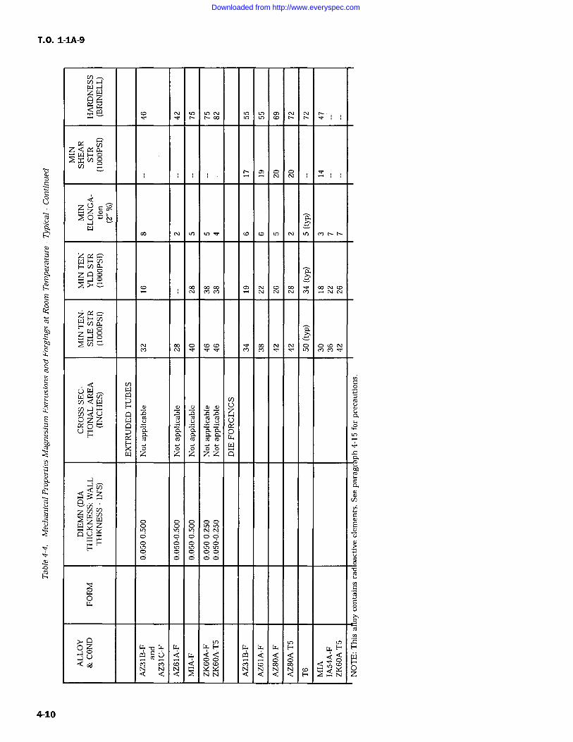
T.O. 1-IA-9
V)zWZz
.Y.
zz aoN
z
F&DzQgM
i aw ozz(/)
WLncndW (n
ON UD n D n Aq
o z w Y U VO F x m m m w
0 0w z
0z z
0 0zz o
zQ3cc-.
z NU o 0 0 00xY- o C) C)
o qC7 O
0w
0 o w Yw w wF w w w HYU CY roU d fi 0 - 0 0 d0d 0Y CO d 00
O 00
dN N - N
d d d d d d H
4-10
Downloaded from http://www.everyspec.com
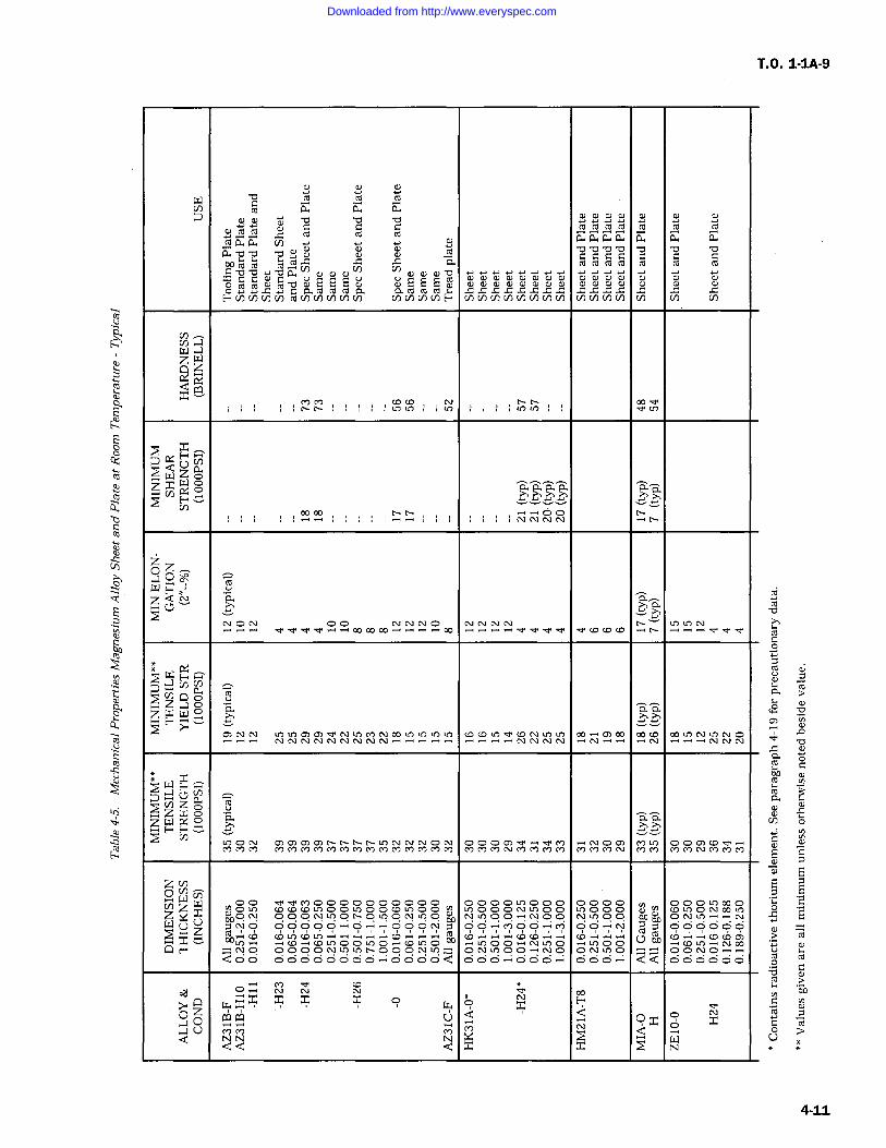
T.O. 1-1A-9
-o ,o a ma a a
w o 0 0 4; m m m rororomaaaa COa coro (Tiacaa cn a w a
m v ov o o v o
c nYc`cro mCavoY"OaV) wCUm0 V) OOOV
mmmm m m mC C marorombw SEE
0Y-.c-cammro0.Fcncncncn rocnv)v)cncn cna)v)cnF cncnv)cncn(n V) V) v)v)uo v) cn Cl)
ccnz W
a7 YcnWZo.
Cl)Y 00
zz0 0o;zoo
NNNO lam"
Z vR"
C)N Q) U,NO
roZWasF F aY Y YY
C/) 0000000000 0000 000 0000 000 000=z 000700wqN 000 NU.70 t.OCO U70
000NOO
00000
ON
W (Y Uz O O Ocz Y
O O- D=0 o- 0 0 0 0
0 CD CD to (' t>QQ F CDU)000OO--Y
NO OOOONin 000C\l LOCo00YNCfi0
ONU700-'NOCo00
0NU)0 00c')0QOO 00000000 -+000OQ 6 O6 --Y000.-; QQ 000000
Q> (7 x.Y". x x x O H
Oa z Cl oa Yj xQ o
Q U N N N x d
QQ x x (z]N
4-11
Downloaded from http://www.everyspec.com
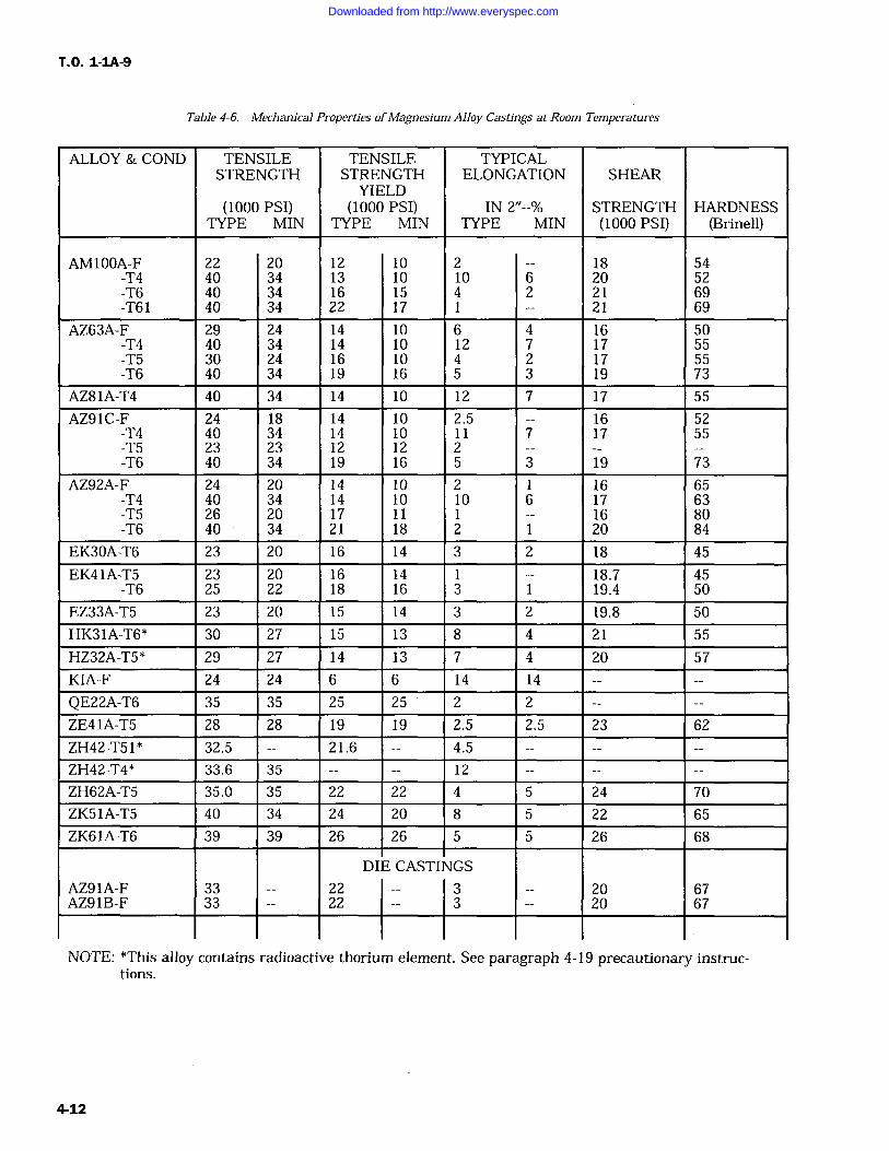
T.O. 1-IA-9
Table 4-6. Mechanical Properties ofMagnesium Alloy Castings at Room Temperatures
ALLOY & COND TENSILE TENSILE TYPICALSTRENGTH STRENGTH ELONGATION SHEAR
YIELD(1000 PSI) (1000 PSI) IN 2"--% STRENGTH HARDNESS
TYPE MIN TYPE MIN TYPE MIN (1000 PSI) (Brinell)
AM100A-F 22 20 12 10 2 18 54-T4 40 34 13 10 10 6 20 52-T6 40 34 16 15 4 2 21 69-T61 40 34 22 17 21 69
AZ63A-F 29 24 14 10 6 4 16 50-T4 40 34 14 10 12 7 17 55-T5 30 24 16 10 4 2 17 55-T6 40 34 19 16 5 3 19 73
AZ81A-T4 40 34 14 10 12 7 17 55
AZ91C-F 24 18 14 10 2.5 16 52-T4 40 34 14 10 11 7 17 55-T5 23 23 12 12 2-T6 40 34 19 16 5 3 19 73
AZ92A-F 24 20 14 10 2 1 16 65-T4 40 34 14 10 10 6 17 63-T5 26 20 17 11 16 80-T6 40 34 21 18 2 20 84
EK30A-T6 23 20 16 14 3 2 18 45
EK41A-T5 23 20 16 14 18.7 45-T6 25 22 18 16 3 19.4 50
EZ33A-T5 23 20 15 14 3 2 19.8 50
HK31A-T6* 30 27 15 13 8 4 21 55
HZ32A-T5* 29 27 14 13 7 4 20 57
KIA-F 24 24 6 6 14 14
QE22A-T6 35 35 25 25 2 2
ZE41A-T5 28 28 19 19 2.5 2.5 23 62
ZH42-T51 * 32.5 21.6 4.5
ZH42-T4* 33.6 35 12
ZH62A-T5 35.0 35 22 22 4 5 24 70
ZK51A-T5 40 34 24 20 8 5 22 65
ZK61A-T6 39 39 26 26 5 5 26 68
DIE CASTINGS
AZ91A-F 33 22 3 20 67AZ91B-F 33 22 3 20 67
NOTE: *This alloy contains radioactive thorium element. See paragraph 4-19 precautionary instruc-tions.
4-12
Downloaded from http://www.everyspec.com
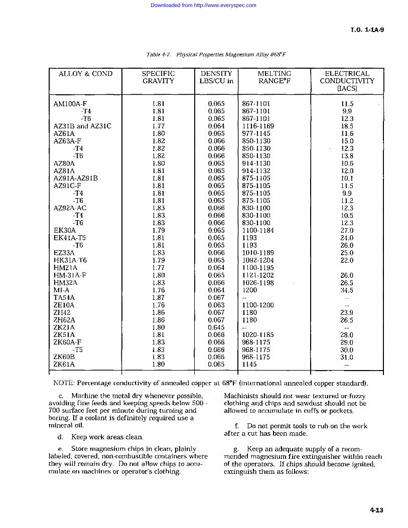
T.O. 1-1A-9
Table 4-7. Physical Properties Magnesium Alloy 4'68F
ALLOY & COND SPECIFICGRAVITY
DENSITYLBS/CU in
MELTINGRANGEF
ELECTRICALCONDUCTIVITY
(IACS)
AM100A-F 1.81 0.065 867-1101 11.5-T4 1.81 0.065 867-1101 9.9-T6 1.81 0.065 867-1101 12.3
AZ31B and AZ31C 1.77 0.064 1116-1169 18.5AZ61A 1.80 0.065 977-1145 11.6AZ63A-F 1.82 0.066 850-1130 15.0
-T4 1.82 0.066 850-1130 12.3-T6 1.82 0.066 850-1130 13.8
AZ80A 1.80 0.065 914-1130 10.6AZ81A 1.81 0.065 914-1132 12.0AZ91A-AZ91B 1.81 0.065 875-1105 10.1AZ91C-F 1.81 0.065 875-1105 11.5
-T4 1.81 0.065 875-1105 9.9-T6 1.81 0.065 875-1105 11.2
AZ92A-AC 1.83 0.066 830-1100 12.3-T4 1.83 0.066 830-1100 10.5-T6 1.83 0.066 830-1100 12.3
EK30A 1.79 0.065 1100-1184 27.0EK41A-T5 1.81 0.065 1193 24.0
-T6 1.81 0.065 1193 26.0EZ33A 1.83 0.066 1010-1189 25.0HK31A-T6 1.79 0.065 1092-1204 22.0HM21A 1.77 0.064 1100-1195HM-31A-F 1.80 0.065 1121-1202 26.0HM32A 1.83 0.066 1026-1198 26.5MI-A 1.76 0.064 1200 34.5TA54A 1.87 0.067ZE10A 1.76 0.063 1100-1200ZH42 1.86 0.067 1180 23.9ZH62A 1.86 0.067 1180 26.5ZK21A 1.80 0.645ZK51A 1.81 0.066 1020-1185 28.0ZK60A-F 1.83 0.066 968-1175 29.0
-T5 1.83 0.066 968-1175 30.0ZK60B 1.83 0.066 968-1175 31.0ZK61A 1.80 0.065 1145
NOTE: Percentage conductivity of annealed copper at 68F (international annealed copper standard).
c. Machine the metal dry whenever possible,avoiding fine feeds and keeping speeds below 500700 surface feet per minute during turning andboring. If a coolant is definitely required use amineral oil.
d. Keep work areas clean.
e. Store magnesium chips in clean, plainlylabeled, covered, non-combustible containers wherethey will remain dry. Do not allow chips to accu-mulate on machines or operator's clothing.
Machinists should not wear textured or fuzzyclothing and chips and sawdust should not beallowed to accumulate in cuffs or pockets.
f. Do not permit tools to rub on the workafter a cut has been made.
g. Keep an adequate supply of a recom-mended magnesium fire extinguisher within reachof the operators. If chips should become ignited,extinguish them as follows:
4-13
Downloaded from http://www.everyspec.com
T, 0. 1-IA-9
WARNING
Water or any of the common liquid orfoam type extinguishers will intensifya magnesium chip fire and may cause
an explosion and shall not be used.
(1) Cover with a layer of G-1 or Met-L-Xpowder. Clean, dry unrusted cast iron chips,graphite powder, clean dry sand, talc and pitchmay also be used.
(2) Actively burning fires on combustiblesurfaces should be covered with a 1/2 inch layer or
more of extinguishing powder; then the entire
mass shoveled into an iron container or onto a
piece of iron plate. Alternately, a one or two inchlayer of powder can be spread on the floor or sur-
face nearby and the burning metal transferred toit, then add more powder as required.
(3) High cutting speeds, extremely finefeeds, dull, chipped or improperly designed tools,tool dwell on work after feed is stopped, tool rub,or tool hitting a steel or iron insert increase thechances of chip ignition. Keeping the cutting speedbelow 700 feet per minute will greatly reduce thefire possibilities even with a dull or poorlydesigned tool and fine feeds.
4-22. GRINDING AND POLISHING SAFETYPRACTICES. During grinding and polishing oper-ations a proper dust collection system must beused. Figure 4-1 illustrates acceptable type collec-tors. The dust produced during grinding and pol-ishing of magnesium must be removed immedi-ately from the working area with a properlydesigned wet type dust collection system. Propersystems precipitate the magnesium dust by aheavy spray of water and must be so designed thatdust or sludge cannot accumulate and dry out to aflammable state. Small collectors as shown inFigure 4-1, detail A serving one or two grindersare the best. The grinder-to-collector ducts shouldbe short and straight. The self opening ventsillustrated prevent hydrogen collection during shutdown. The grinder's power supply, air exhaustblower and liquid level controller should be electri-cally water connected so cessation or failure of thedust collector operation will shut the grinder off.In addition a suitable devise should be installed inthe system that will insure the collector system isin full operation and has changed the air in theducts, etc., several times before the grinder beginsrunning. Dry type filter collectors or central col-lector systems which carry the dust through longdry ducts should not be used for magnesium. Thecollector portrayed in Figure 4-1, detail B is used
with booth type portable grinding and polishingwhere the dust passes through the grate with theair being circulated into a liquid spray whichremoves the dust. Design the booth to catch allthe dust possible. On individual grinders for smallscale work, as shown in Figure 4-1, detail C, thehood design and the oil pan combine to afford asatisfactory dust collection. Any dust escaping thehood should be kept swept up and properly dis-posed of.
4-23. The following specific safety rules pertainto the grinding and polishing of magnesium:
a. Magnesium grinding should be done onequipment set aside and labeled for that purpose.Do not grind sparking material on these grindersunless the magnesium dust has been completelyremoved from the equipment system. In addition,the grinding wheel or belt must be replaced priorto grinding of any other metal.
b. If chrome pickled magnesium is to beground, sparks may result. Therefore, dust andair-dust mixtures must not be allowed to accumu-late within spark range.
c. Maintain adequate supplies of plainlylabeled approved fire extinguishing powder andsuitable dispensing tools readily available to oper-ators. Fire control is the same as detailed in para-graph 4-21 for machine chips.
d. Keep dust from accumulating on surround-ing floors, benches, windows, etc. If such accumu-lation is evident the collector system is not operat-ing properly and must be checked and repaired.Periodically and no less than once a month, com-pletely clean the entire collector systems. Inspectand clean the grinder to collector ducts daily or
move frequently if the volume of collection is high.
e. Dispose of grinding sludge as soon as it isremoved from the equipment. Do not store orallow to even partially dry since it is extremelyflammable. This may be done by spreading it on alayer of fire brick or hard burned paving brick to a
maximum depth of 3" to 4", then placing a com-bustible material on top of it and burning theentire lot. The sludge will burn with intense heat,therefore, a safe location must be used. A methodof rendering magnesium sludge chemically inactiveand non-combustible by reacting it with a 5% solu-tion of ferrous chloride (Fe C122H20) is detailed inthe National Fire Protection Association's BulletinNo. 48, Standards for Magnesium.
f. The clothing of operators should be smoothand fire retardant without pockets and cuffs. Capsshould be worn. All clothing should be easy to
remove and kept free of dust accumulations.
4-14
Downloaded from http://www.everyspec.com
1 4-24. Deleted.
4-25. HEAT TREATING SAFETY PRACTICES.Heat treating of magnesium alloys requires theexercising of certain definite rules, if safe and goodquality workmanship is to result. The followingrules should be closely followed:
a. Use furnace equipment having two sets oftemperature controls, operating independently ofeach other.
b. Standardize checking procedures andadjustments of all equipment and of operatingcycles.
c. Load the furnace with castings of one iden-tical alloy only. Insure the castings are clean.
d. Use SO2 (Sulfur Dioxide) atmosphere tocontrol oxidation.
e. Use the recommended time and tempera-ture operating ranges at all times.
f. Provide approved fire extinguishingequipment.
WARNING
Water and other extinguishers forClass A, B, and C fires shall not beused.
4-26. If a fire should occur for any reason, asevidenced by excessive furnace temperature andomission of a light colored smoke, proceed asfollows:
a. Shut off all power, fuel and SO2 feed linesto the furnace.
b. Notify fire marshal control crew at once.
c. Begin fire extinguishing procedures usingone of the following methods:
(1) G-1 Powder Method.
Where it can be safely done, a small fire should beremoved from the furnace, dumped into an ironcontainer and then extinguished by covering withG-1 powder which is a graphite base powder of thePyrene CO2 Company. Metal Fyr Powder of theFyr Fyter Company is the same material. In largefurnaces or with fires of high intensity, the powdercan be applied to the burning parts with a shovel(assuming the furnace door can be opened safely).Paper bags filled with the powder can be used ifthe fire is so located that such bags can be thrownin effectively. Remove parts not burning with longhandled hooks. After all burning parts have been
T.O. 1-1A-9
covered with the powder, the furnace load shouldbe allowed to cool with the door open. For thehandling of large quantities of G-1 powder, pumpshave been constructed which can throw 75-100 lbs/minute onto the fire through a 30 foot hose andnozzle.
(2) Boron Trifluoride (BF3) Gas Method.
WARNING
Boron trifluoride vapor or gas is toxicin the proportion of more than 1 partper million by volume of air whenexposures are prolonged or frequentlyrepeated. Five parts per million byvolume of air or more are usually pre-sent in visible clouds of materialresulting from the release of the gasto atmosphere. Therefore, personnelmust not enter such clouds or anyarea where there is reason to believethe safe level is exceeded unless wear-ing a gas mask with an acid gas can-
ister containing a dust filler. Analy-sis of atmosphere in the worker'sbreathing zone will be accomplishedto assure personnel safety.
This is an effective gaseous means of extinguish-ing magnesium fires in heat treating furnaces.The gas is introduced into the furnace from a stor-
age cylinder through an entry port preferablylocated near floor level. Connect the gas feed lineto this port, open the feed line valve to provideabout 2 lbs/minute (depending on furnace size andnumber of gas cylinders) and maintain gas flowuntil furnace temperature drops to 700F indicat-ing the fire is out. The furnace door should bekept closed during this action and until a definitetemperature drop below 700F is evident. Run-ning the furnace circulating fans for about min-ute after the gas is first introduced will assist ingas dispersal, then shut the fan off. The gas cylin-der used should be fitted with a Monel needlevalve and a "tee" for attaching a 0-160 psi pres-sure gauge. A suitable gas transfer system uses a5/16" flexible bronze hose to carry the gas to thefurnace where it enters through a 1/4" steel pipeentry port. Using 10 feet of hose and feed of pipe,a gauge pressure of 15-30 psi will deliver 1-2 lbs ofBF3 per minute. The cylinders may be perma-nently connected or brought to the furnace, whenneeded, on a suitable dolly. This gas does notrequire heating in order to flow. The cylindersshould be weight checked for contents every 6months.
Change 1 4-15
Downloaded from http://www.everyspec.com
T.O. 1-1A-9
(3) Boron Trichloride (BCL3) GaseousMethod. This material has been successfully usedto extinguish magnesium heat treat furnace fires.However, there are several factors involved withits use which makes it less preferred than borontrifluoride, these include: ten times more concen-tration than the 0.04% of boron trifluoride, the gasmust be heated to flow freely; it is more expensivethan trifluoride; the liquid is corrosive and thefumes irritating with a health hazard similar tohydrochloric acid fumes. Workmen should notoccupy areas where noticeable vapors are presentunless wearing a gas mask with an acid gas canis-ter containing a dust filter. If this agent must beused, the liquid containing cylinders should beheated with infrared lights to provide the heatnecessary to insure adequate gas flow. The cylin-der outlet should be fitted with a special valve andgauge to control gas flow. Flexible 5/8" ID neo-
prene hose may be used to connect the cylinder toa steel pipe for insertion into the furnace port.Otherwise its use in extinguishing a furnace fire issimilar to the procedures for boron trifluoride.
4-27. IDENTIFICATION OF ALLOY.
4-28. Positive identification of an alloy, from aconstituency standpoint, can only be determinedby laboratory analysis. However, whether a lightmetal is magnesium or not can be generally deter-mined by a simple test consisting of placing thetest metal in contact with an 0.5% solution of sil-ver nitrate, and observing the reaction for 1 min-ute. The solution is made by dissolving 0.5g. ofsilver nitrate in 100 ml. of water. Formation of ablack deposit of metallic silver on the metal indi-cates magnesium or high-magnesium alloy. Thenimmerse the metal in a chrome pickle chemicalsolution, Type I Specification MIL-M-3171 (Com-mercially known as DOW No. 1). The solutionshould be freshly prepared and the test operatorfamiliar with the colors of chemical treatment. Ifthe metal assumes a very bright brassy coating, itindicates it is aluminum free alloy. If a greyish
iridescent coating forms the alloy contains alumi-num. The solution is made in the proportions of24 ounces sodium dichromate and 24 fluid ouncesconcentrated nitric acid to enough water to makeone gallon. Prior to the test the metal should bethoroughly cleaned down to the base metal, if nec-essary, by grinding or filing a clean area on thesurface.
4-29. HEAT TREATING MAGNESIUM ALLOYSGENERAL.
NOTE
SAE-AMS-M-6857, Heat Treatment ofMagnesium Alloy Castings, will bethe control for heat treatment of mag-nesium alloy castings used on aero-
space equipment. For completedescription of magnesium alloy cast-ings heat treat requirements, refer tolatest issue of SAE-AMS-M-6857.
Additional Heat Treatment informa-tion is discussed in Section IX.
4-30. PRECAUTIONS DURING HEATING. Offirst importance in the heat processing of thesealloys is a clear understanding of the characteris-tics of the metal relative to heat. Pure magnesiumwill melt at approximately 1202F. The alloysmelting points range from 830F to 1204F,approximately, according to their element constitu-ency. Therefore, during any heating of alloy items,specified temperature maximums must be closelyadhered to, particularly during solution heat treat-ing. The metal is easily burned and overheatingwill also cause formation of molten pools within it,either condition resulting in ruining of the metal.Certain alloys such as AZ63A Type 1, or AZ92AType 1, are subject to eutectic melting of some ofits elements if heated too rapidly. They must bebrought up to heat treating temperature slowlyenough to prevent this. In the case of these two
I
I
4-16 Change 4
Downloaded from http://www.everyspec.com
examples, no less than two hours should be con-sumed in bringing them from 640F to treatingtemperature.
4-31. An additional and no less important char-acteristic of the metal relative to heat treatment,is that it is subject to excessive surface oxidationat 750F and higher temperatures. In an oxidizingatmosphere, this characteristic can result in igni-tion and fierce burning. To prevent such occur-
rences, a protective atmosphere containing suffi-cient sulphur dioxide, carbon dioxide or othersatisfactory oxidation inhibitor shall be used whenheating to 750F and over. When oxidation inhibi-tors are used, their concentration percentage inthe furnace atmosphere should be periodicallychecked for correct amounts. The particularrequirements for various alloys are detailed in par-agraph 4-46 in this section. These requirementsand those of other pertinent specifications andinstructions should be consulted and strictlyadhered to in processing the metal. The safetymeasures defined in paragraph 4-1 must be rigidlypracticed.
4-32. HEAT TREATING EQUIPMENT.
4-33. Furnaces used for solution heat treatmentshall be of the air chamber type with forced aircirculation. Heating provisions can be gas, electri-city or oil. Their design must be such as to makeimpossible, direct heating element radiation or
flame impingement on the articles being treated.The furnaces shall be installed with the necessarycontrol, temperature measuring and recordinginstrument equipment to assure complete andaccurate control. The temperature control shall becapable of maintaining a given temperature towithin +/- 10 F at any point in the working zone,after the charge has been brought up to this tem-
perature. Each furnace used shall be equippedwith a separate manual reset safety cut-out whichwill turn off the heat source in the event of anymalfunction or failure of the regular automaticcontrols. The safety cut-outs shall be set as closeas practicable above the maximum solution heattreating temperature for the alloy being treated.This will be above the variation expected but shallnot be more than 10F above the maximum heattreat temperature of the alloy being processed.There shall also be protective devices to shut offthe heat source in case of circulation air stoppage.These devices shall be interconnected with a man-ual reset control.
4-34. Upon initial furnace installation and afterany maintenance on the furnace or its equipmentwhich might affect its operational characteristics,a temperature survey shall be made to test its
T.0. 1-1A-9
capability of maintaining the minimum and maxi-
mum temperatures required for the various treat-ments it will be used for. A minimum of 9 testlocations within the furnace load area should bechecked. One in each corner, one in the centerand one for each 25 cubic feet of furnace volumeup to the maximum of 400 cubic feet. A monthlysurvey should be made after the initial survey,unless separate load thermocouples are employed,to record actual metal temperatures. The monthlysurvey should consist of one test for a solutionheat treat temperature and one test for a precipi-tation heat treat temperature, one for each 40cubic feet of heat treating volume with a mini-
mum, of 9 test locations required regardless of thevolume. In addition, a periodic survey should bemade, using the test criteria of the initial survey.For all surveys, the furnaces should be allowed toheat to a point stabilization before taking anyreadings. The temperature of all test locationsshould be determined at 5 to 10 minute intervalsafter insertion of the temperature sensing ele-ments in the furnace. The maximum temperaturevariation of all elements shall not exceed 20F andshall not exceed the solution or precipitation heattreating range at any time after equilibrium isreached.
4-35. Furnace control temperature measuringinstruments shall not be used as test instrumentsduring any survey. The thermocouple and sensingelements should be replaced periodically becauseof the in-service incurred effects of oxidation anddeterioration.
4-36. Pyrometers used with the automatic con-trol system to indicate, maintain and record thefurnace temperatures, should preferably be of thepotentiometer type.
4-37. Suitable jigs, fixtures, trays, hangers,racks, ventilators and other equipment shall beused in processing the articles.
4-38. HEAT TREATMENT SOLUTION. Solu-tion for heat treating of magnesium alloyed arti-cles is accomplished by heating at an elevatedtemperature in an air furnace for a specific lengthof time (holding period); during which certainalloying elements enter into uniform solid solution,since the alloys tend to become plastic at high heattreat temperatures, it is mandatory that suitablesupport be provided for articles being processed toprevent warping. Table 4-8 below lists the recom-mended soaking and holding time for solution heattreating alloys. The holding periods given are forcastings up to 2 inches thick. Items thicker than 2inches will require longer periods.4-39. AZ92A (Type 2), AZ91C and QE22A sandcastings and AM100A permanent mold castings
4-17
Downloaded from http://www.everyspec.com
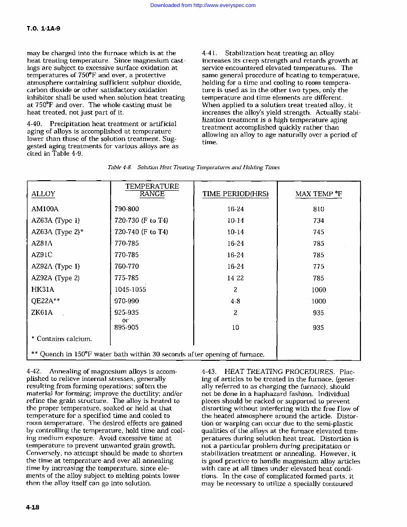
T.O. 1-1A-9
may be charged into the furnace which is at theheat treating temperature. Since magnesium cast-ings are subject to excessive surface oxidation attemperatures of 750F and over, a protectiveatmosphere containing sufficient sulphur dioxide,carbon dioxide or other satisfactory oxidationinhibitor shall be used when solution heat treatingat 750F and over. The whole casting must beheat treated, not just part of it.
4-40. Precipitation heat treatment or artificialaging of alloys is accomplished at temperaturelower than those of the solution treatment. Sug-gested aging treatments for various alloys are ascited in Table 4-9.
4-41. Stabilization heat treating an alloyincreases its creep strength and retards growth atservice encountered elevated temperatures. Thesame general procedure of heating to temperature,holding for a time and cooling to room tempera-ture is used as in the other two types, only thetemperature and time elements are different.When applied to a solution treat treated alloy, itincreases the alloy's yield strength. Actually stabi-lization treatment is a high temperature agingtreatment accomplished quickly rather thanallowing an alloy to age naturally over a period oftime.
Table 4-8. Solution Heat Treating Temperatures and Holding Times
TEMPERATUREALLOY RANGE TIME PERIOD(HRS) MAX TEMP OF
AM100A 790-800 16-24 810
AZ63A (Type 1) 720-730 (F to T4) 10-14 734
AZ63A (Type 2)* 720-740 (F to T4) 10-14 745
AZ81A 770-785 16-24 785
AZ91C 770-785 16-24 785
AZ92A (Type 1) 760-770 16-24 775
AZ92A (Type 2) 775-785 14-22 785
HK31A 1045-1055 2 1060
QE22A** 970-990 4-8 1000
ZK61A 925-935 2 935or
895-905 10 935
Contains calcium.
** Quench in 150F water bath within 30 seconds of
4-42. Annealing of magnesium alloys is accom-plished to relieve internal stresses, generallyresulting from forming operations; soften thematerial for forming; improve the ductility; and/orrefine the grain structure. The alloy is heated tothe proper temperature, soaked or held at thattemperature for a specified time and cooled to
room temperature. The desired effects are gainedby controlling the temperature, hold time and cool-ing medium exposure. Avoid excessive time attemperature to prevent unwanted grain growth.Conversely, no attempt should be made to shortenthe time at temperature and over all annealingtime by increasing the temperature, since ele-ments of the alloy subject to melting points lowerthen the alloy itself can go into solution.
ter opening of furnace.
4-43. HEAT TREATING PROCEDURES. Plac-ing of articles to be treated in the furnace, (gener-ally referred to as charging the furnace), shouldnot be done in a haphazard fashion. Individualpieces should be racked or supported to preventdistorting without interfering with the free flow ofthe heated atmosphere around the article. Distor-tion or warping can occur due to the semi-plasticqualities of the alloys at the furnace elevated tem-peratures during solution heat treat. Distortion isnot a particular problem during precipitation orstabilization treatment or annealing. However, itis good practice to handle magnesium alloy articleswith care at all times under elevated heat condi-tions. In the case of complicated formed parts, itmay be necessary to utilize a specially contoured
4-18
Downloaded from http://www.everyspec.com
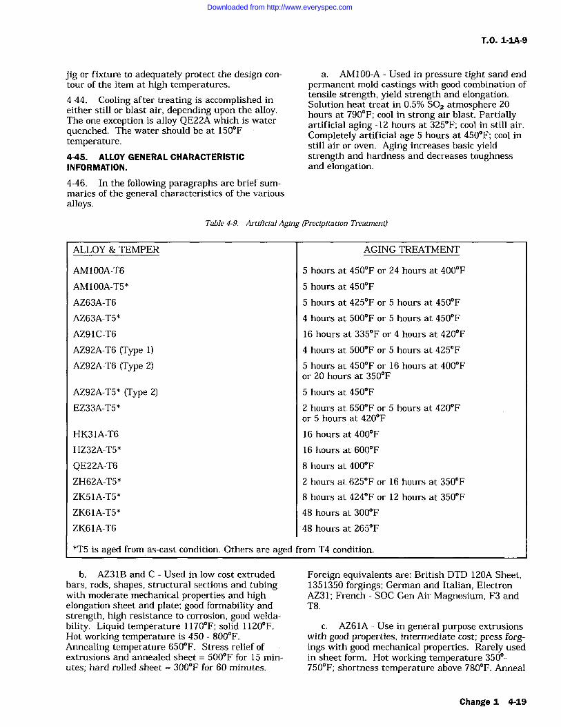
T.O. 1-1A-9
jig or fixture to adequately protect the design con-
tour of the item at high temperatures.
4-44. Cooling after treating is accomplished ineither still or blast air, depending upon the alloy.The one exception is alloy QE22A which is waterquenched. The water should be at 150Ftemperature.4-45. ALLOY GENERAL CHARACTERISTICINFORMATION.
a. AM100-A Used in pressure tight sand endpermanent mold castings with good combination oftensile strength, yield strength and elongation.Solution heat treat in 0.5% SO2 atmosphere 20hours at 790F; cool in strong air blast. Partiallyartificial aging -12 hours at 325F; cool in still air.Completely artificial age 5 hours at 450F; cool instill air or oven. Aging increases basic yieldstrength and hardness and decreases toughnessand elongation.
4-46. In the following paragraphs are brief sum-maries of the general characteristics of the variousalloys.
Table 4-9. Artificial Aging (Precipitation Treatment)
ALLOY & TEMPER
AM100A-T6
AM100A-T5*
AZ63A-T6
AZ63A-T5*
AZ91C-T6
AZ92A-T6 (Type 1)AZ92A-T6 (Type 2)
AZ92A-T5* (Type 2)EZ33A-T5*
HK31A-T6
HZ32A-T5*
QE22A-T6ZH62A-T5*
ZK51A-T5*
ZK61A-T5*
ZK61A-T6
AGING TREATMENT
5 hours at 450F or 24 hours at 400F
5 hours at 450F
5 hours at 425F or 5 hours at 450F
4 hours at 500F or 5 hours at 450F
16 hours at 335F or 4 hours at 420F
4 hours at 500F or 5 hours at 425F
5 hours at 450F or 16 hours at 400For 20 hours at 350F
5 hours at 450F
2 hours at 650F or 5 hours at 420For 5 hours at 420F
16 hours at 400F
16 hours at 600F
8 hours at 400F
2 hours at 625F or 16 hours at 350F
8 hours at 424F or 12 hours at 350F
48 hours at 300F
48 hours at 265F
*T5 is aged from as-cast condition. Others are aged
b. AZ31B and C Used in low cost extrudedbars, rods, shapes, structural sections and tubingwith moderate mechanical properties and highelongation sheet and plate; good formability andstrength, high resistance to corrosion, good welda-bility. Liquid temperature 1170F; solid 1120F.Hot working temperature is 450 800F.Annealing temperature 650F. Stress relief ofextrusions and annealed sheet 500F for 15 min-utes; hard rolled sheet 300F for 60 minutes.
from T4 condition.
Foreign equivalents are: British DTD 120A Sheet,1351350 forgings; German and Italian, ElectronAZ31; French SOC Gen Air Magnesium, F3 andT8.
c. AZ61A Use in general purpose extrusionswith good properties, intermediate cost; press forg-ings with good mechanical properties. Rarely usedin sheet form. Hot working temperature 350-750F; shortness temperature above 780F. Anneal
Change 1 4-19
Downloaded from http://www.everyspec.com
T.O. 1-IA-9
650F. Heat treat annealed sheet extrusions andforgings 15 minutes at 500F rolled sheet 400Ffor 15 minutes. Foreign equivalents are BritishBS 1351 (forgings) BS 1354 (extrusions); GermanAZM.
d. AZ63A Used in sand castings for goodstrength properties with best ductility and tough-ness. Solution heat treat at 740F in a 0.5%-SO2atmosphere for 10 hours then cool in air.Aging is done at 450F for 5 hours and cooled inair or furnace. Stabilize at 300F at 4 hours andcool in air. Foreign equivalents are Elektron AZG,British DTD59A(as cast)and DTD-289 (heattreated). Good salt water anti-corrosion properties.
e. AZ80A Used for extruded and pressforged products. Heat treatable. Hot working tem-
perature 600-750F. Shortness temperature above775F, annealing temperature 725F. Stress relief:as extruded, 500F for 15 minutes, extruded andartificially aged 400F for 60 minutes; forgings500 F for 15 minutes. Foreign equivalents areBritish 1351 (forgings); German AZ855 Helium orArgon-arc weldable using AZ92A welding rod or
may be resistance welded. Stress relieve afterwelding.
Table 4-10. Deleted.
Table 4-11. Deleted.
f. AZ81A Used in sand or permanent moldcastings for good strength, excellent ductility, pres-sure tightness and toughness. Readily castablewith low micro-shrinkage tendency. Solution heattreat 775F for 18 hours, cool in air or by fan.Stabilizing treatment 500F, 4 hours and air cool.To prevent germination (grain growth) an alter-nate heat treat of 775F for 6 hours, 2 hours at665F and 10 hours at 775F may be used.
g. AZ91A, AZ91B AZ91A used for die cast-ings generally.
h. AZ91C AZ91B is also die cast alloy buthas higher impurity content. AZ91C is used forpressure tight sand and permanent mold castingshaving high tensile and weld strength. Shortnesstemperatures are above 750F. Heat treat: T-4 con-dition, 16 hours at 780F, cool in air blast andthen age at 400F for 4 hours; T-7 condition, 5hours at 450F. Foreign equivalents are ElektronAZ91 and British DTD136A. Good impact resis-tance in T-4 temper. T-6 has good yield strengthand, ductility.
i. AZ92A Used in pressure tight sand andpermanent mold castings. Has high tensile andyield strengths. Solution heat treat 20 hours at760F in an atmosphere of 0.5% SO2. Cool instrong air blast. Artificial aging is done at 420Ffor 14 hours. Cool in air or oven. Stabilize for 4hours at 500F, then cool in air. Equal to AX63Ain salt water corrosion resistance.
j. EK30A Used in sand casting for elevatedtemperature applications. Has good strengthproperties in temperature range 300- 500F. Solu-tion heat treat at 1060F maximum 16 hours thencool in air by fan. Age at 400F then air cool.
k. EK41A Used as pressure tight sand cast-ing alloy. Good strength at 300 500F. Solutionheat treat at 1060F maximum 16 hours then coolin air or with fan. Age at 400F 16 hours, air cool.
1. EZ33A Used for pressure tight, goodstrength sand and permanent mold castings wheretemperatures may reach 500F in use. Age at420F for 5 hours. Forgeign equivalent BritishZRE 1.
in. HK31A Used in sand castings for elevatedtemperature use up to 650F and sheet and plateapplications. Has excellent weld and formingcharacteristics in sheet/plate form and retainsgood strength up to 650F. Hot working tempera-ture is 800 to 1050F. Anneal at 750F. Solutionheat treat sand castings by loading into a 1050Ffurnace and holding for 2 hours, then fan or aircool. Age for 16 hours at 400F. H23 sheet may bestress relieved after welding at 650F for 1 hour or675F for 20 minutes. Sheet may be resistancewelded.
n. HM21A Used sheet, plate and forgings,usable at 650F and above. Hot work at 850F1100F Anneal at 850F. Heat treat forgings(T5)450F for 16 hours. Resistance welding is alsosatisfactory.
o. HM31A Used in extruded bars, rods,shapes and tubing for elevated temperature ser-vice. Exposure to temperatures through 600F forperiods of 1000 hours caused practically no changein short time room and elevated temperatureproperties. Superior modulus of elasticity particu-larly at elevated temperatures. Hot work at 700F1000F.
4-20 Change I
Downloaded from http://www.everyspec.com
p. HZ32A Used for sand castings. It is ofproperties for medium and long range exposure attemperatures above 500F and is pressure tight.
q. KIQA Casting alloy with comparativelylow strength has excellent dampingcharacteristics.
r. MIA Used for wrought products and pro-vides for moderate mechanical properties withexcellent weldability, corrosion resistance and hotformability. Hot work at 560 1000F. Anneal at700F. Stress relieve annealed sheet at 500F, in15 minutes; hard rolled sheet at 400F in 60 min-utes; and extrusions at 500F in 15 minutes. For-eign equivalents are British BS1352 (forgings) andGerman AM503.
s. QE22A Castings have high yield strengthat elevated temperatures. Solution heat treat at970-990F 4 to 8 hours. Quench in 150F waterbath.
t. TA54A Best hammer forging alloy.
u. ZE10A Used for low cost, moderatestrength sheet and plate. No stress relief requiredafter welding. Hot work at 500 900F. Anneal400F. AZ61A or EX33A rod is preferred forwelding.
v. ZE41A A good strength, pressure tight,weldable alloy, where temperatures are below200F. Age 2 hours at 625F, air cool; 16 hours at350F air cool. Foreign equivalent British RZ5.
w. ZH42A Used in sand castings for aircraftengines and airframe structures where high
T.O. 1-1A-9
strength at room temperatures and moderate long-time creep resistance at temperatures up to 480Fare required. The alloy is a precipitation harden-ing one from the as-cast condition and requires nosolution heat treatment. Maximum hardness isdeveloped at 480F in 24 hours. More ductilityand better shock resistance may be obtained byoveraging at temperatures such as 750F. For T51condition treat at 480F for 24 hours; T4 condition750F for 24 hours.
x. ZH62A Used as a high strength good duc-tility structural alloy at normal, temperatures andhas the highest yield strength of any alloy exceptZK61A-T6. Heat treat at 480F for 12 hours. For-eign equivalent is British T26.
y. ZK2 1A An alloy of moderate strength forextrusion fabrication. Good weldability usingshielded arc and AZ61A or AZ92A, rod. Resistancewelding also satisfactory. ZK51A Used for highyield strength, good ductility, sand castings. Heattreat for 12 hours at 350F. Foreign equivalent isBritish Z52.
z. ZK60A Used as a wrought alloy forextruded shapes and press forgings. Has highstrength and good ductility characteristics. Hotwork at 600-750F. Shortness temperature is950F. Age at 300F for 24 hours, air cool. For-eign equivalent is German ZW6.
aa. ZK61A Casting Alloy. Solution heat treatat 925 935F for 2 hours or 895 905 F for 10hours.
Paragraphs 4-47 through 4-51 deleted.
Change 1 4-21
Downloaded from http://www.everyspec.com
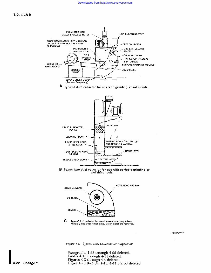
T.O. 1-1A-9
EXHAUSTER WITHTOTALLY ENCLOSED MOTOR
SLOPE DOWNWARD SLIGHTLY TOWARDCOLLECTOR MAKE DUCT AS SHORTAS POSSIBLE
INSPECTION & /LIQUID ELIMINATOR/ PLATESCLEAN OUT DOOR c'I
SELF CLEAN OUT DOORopFNINGVENT 'll..' V _J_ LIQUID LLVLL CON ROL
SLUDGE UNDER LIQUID(Remove Frequently)
& INTERLOCK
DUST PRECIPITATING ELEMENT
A Type of dust collector for use with grinding wheel stands.
BURRING BENCH GRILLED TOPNON SPARKING MATERIAL
B Bench type dust collector for use with portable grinding orpolishing tools.
METAL HOOD AND PAN
C Type of dust collector for small wheels used only inter-mittently and when small amounts of metal removed.
L9805657
Figure 4-1. Typical Dust Collectors for Magnesium
Paragraphs 4-52 through 4-95 deleted.Tables 4-12 through 4-31 deleted.Figures 4-2 through 4-4 deleted.
4-22 Change t Pages 4-23 through 4-43/(4-44 blank) deleted.
Downloaded from http://www.everyspec.com
T.O. 1-1A-9
SECTION V
TITANIUM AND TITANIUM ALLOYS
5-1. CLASSIFICATION.
5-2. Titanium is produced in pure form as well
as in various alloys. Pure titanium is commonlyknown as unalloyed. It can be cast, formed,joined, and machined with relative ease as com-
pared to the various alloy grades. Unalloyed tita-nium cannot be heat treated. Therefore, its uses
are limited to end items not requiring the higherstrengths obtained from the heat treatable alloys.5-3. Titanium is a very active metal, and readilydissolves carbon, oxygen, and nitrogen. The mostpronounced effects are obtained from oxygen andnitrogen. For this reason, any heating processmust be performed in a closely controlled atmos-phere to prevent the absorption of oxygen andnitrogen to a point of brittleness.
5-4. GENERAL.
5-5. MILITARY AND COMMERCIAL DESIG-NATIONS. There are presently two military spec-ifications in existence (See Table 5-1) coveringalloyed and unalloyed titanium in classes estab-lished to designate various chemical compositions.For the selection of the proper class and form ofstock required for a particular purpose, referencewill be made to Table 5-1.
5-6. PHYSICAL PROPERTIES. Limited physi-cal properties are available on the titanium compo-sitions covered by existing military specifications.Compared to other materials, the melting point oftitanium is higher than that of any of the otherconstruction materials currently in use. The den-sity of titanium is intermediate to aluminum andsteel. Electrical resistivities of titanium are simi-lar to those of corrosion-resistant steel. The modu-lus of elasticity is somewhat more than half that ofthe alloy steels and the coefficient of expansion isless than half that of austenitic stainless steels.
5-7. MECHANICAL PROPERTIES. As previ-ously pointed out, titanium is a very active metaland readily dissolves carbon, oxygen and nitrogen.All three elements tend to harden the metal; oxy-gen and nitrogen having the most pronouncedeffect.
5-8. The control of these elements causes consid-erable difficulty in obtaining correct mechanicalproperties during the fabrication of titanium. Thisvariation in mechanical properties is the cause of
difficulties encountered in the fabrication of parts,since the absorption of small amounts of oxygen or
nitrogen makes vast changes in the characteristicsof this metal during welding, heat treatment, or
any application of heat in excess of 800F.
5-9. Operations involving titanium requiring theapplication of heat in excess of 800F must be per-formed in a closely controlled atmosphere by meth-ods explained in future paragraphs. The nominalmechanical properties are listed in Table 5-2.
5-10. METHODS OF IDENTIFICATION. Meth-ods of distinguishing titanium alloys from othermetals are simple and definite. One quick methodis to contact the titanium with a grinding wheel.This results in a pure white trace ending in a bril-liant white burst. Also, identification can beaccomplished by moistening the titanium andmarking the surface with a piece of glass. Thisleaves a dark line similar in appearance to a pen-cil mark. Titanium is non-magnetic. To positivelyidentify the various alloys, a chemical orspectographic analysis is necessary.
5-11. HARDNESS TESTING. Hardness is theresistance of a metal to plastic deformation bypenetration, indentation, or scratching, and is usu-ally a good indication of strength. This propertycan be measured accurately by the Brinell,Rockwell or Vickers Technique. The hardness tobe expected from the various alloys and unalloyedtitanium is listed in Table 5-2.
5-12. TENSILE TESTING. The useful strengthof a metal is the maximum load which can beapplied without permanent deformation. This fac-tor is commonly called yield strength. The tensilestrength of a metal is that load, in pounds persquare inch, at which complete failure occurs. Inthe case of titanium the yield strength is the mostimportant factor and is therefore used by industryto designate the various types of unalloyedtitanium.
5-13. NON-DESTRUCTIVE TESTING. Tita-nium and titanium alloys are highly susceptible tostress risers resulting from scratching, nicking,and notching. For this reason, close visual inspec-tion is required of all raw stock prior to any form-ing or machining operations. All scratches, nicksand notches must be removed, before fabrication,by sanding and polishing.
5-1
Downloaded from http://www.everyspec.com
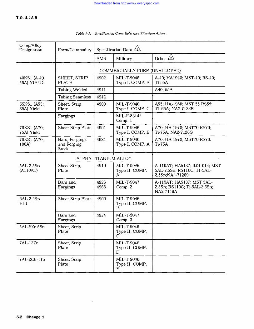
T.O. 1-1A-9
Table 5-1. Specification Cross Reference Titanium Alloys
Comp/AlloyDesignation Form/Commodity ^Specification Data A
AMS Military Other02
COMMERCIALLY PURE (UNALLOYED)40KS1 (A-40 SHEET, STRIP 4902 MIL-T-9046 A-40; HA1940; MST-40; RS-40;55A) YIELD PLATE Type I, COMP. A Ti-55A
Tubing Welded 4941 A40; 55A
Tubing Seamless 4942
55KS1 (A55; Sheet, Strip 4900 MIL-T-9046 A55; HA-1950; MST 55 RS55;65A) Yield Plate Type 1, COMP. C TI-65A; NA2-7123B
Forgings MIL-F-83142Comp. 1
70KS1 (A70; Sheet Strip Plate 4901 MIL-T-9046 A70; HA-1970; MST70 RS70;75A) Yield Type I, COMP. B Ti-75A, NA2-7126G
70KS1 (A70; Bars, Forgings 4921 MIL-T-9046 A70; HA-1970; MST70 RS70;100A) and Forging Type I, COMP. A Ti-75A
Stock
ALPHA TITANIUM ALLOY
5AL-2.5Sn Sheet Strip, 4910 MIL-T-9046 A-11OAT; HA5137; 0.01 014; MST(A11OAT) Plate Type II, COMP. 5AL-2.5Sn; RS11OC; T1-5AL-
A 2.5Sn;NA2-71269
Bars and 4926 MIL-T-9047 A-11OAT; HA5137; MST 5AL-Forgings 4966 Comp. 2 2.5Sn; RS 11OC; Ti-5AL-2.5Sn;
NA2-7149A
5AL-2.5Sn Sheet Strip Plate 4909 MIL-T-9046EL1 Type II, COMP.
B
Bars and 4924 MIL-T-9047Forgings Comp. 3
5AL-SZr-5Sn Sheet, Strip MIL-T-9046Plate Type II, COMP.
C
7AL-12Zr Sheet, Strip MIL-T-9046Plate Type II, COMP.
D
7AL-2Cb-lTa Sheet, Strip MIL-T-9046Plate Type II, COMP.
E
5-2 Change 1
Downloaded from http://www.everyspec.com
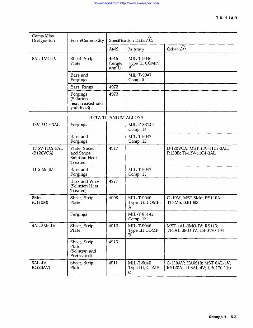
T.O. 1-1A-9
Comp/AlloyD ditF /C
0ifi DSes gnat on orm ommo y pec cat on ata
AMS Military Other
8AL-IMO-IV Sheet, Strip, 4915 MIL-T-9046Plate (Single Type II, COMP.
ann'l) F
Bars and MIL-T-9047Forgings Comp. 5
Bars, Rings 4972
Forgings 4973(Solutionheat treated andstabilized)
BETA TITANIUM ALLOYS
13V-IICr-3AL Forgings MIL-F-83142Comp. 14
Bars and MIL-T-9047Forgings Comp. 12
13.5V-llCr-3AL Plate, Sheet 4917 B-120VCA; MST 13V-llCr-3AL;(B120VCA) and Strips R120B; Ti-13V-11C4-3AL
Solution HeatTreated
11.5 Mo-6Zr- Bars and MIL-T-9047Forgings Comp. 13
Bars and Wire 4977(Solution HeatTreated)
8Mn Sheet, Strip 4908 MIL-T-9046 C110M, MST 8Mn; RS 110A;(C OM) Plate Type III, COMP. Ti-8Mn; 0.01002
A
Forgings MIL-T-83142Comp. 12
4AL-3Mo-IV Sheet, Strip, 4912 MIL-T-9046 MST 4AL-3MO-IV; RS 115;Plate Type III COMP. Ti-3AL 3MO-IV; LB-0170-104
B
Sheet, Strip, 4913Plate(Solution andPretreated)
6AL-4V Sheet, Strip, 4911 MIL-T-9046 C-120AV; HA6510; MST 6AL-4V;(C120AV) Plate Type III, COMP. RS120A; TI-6AL-4V; LBO170-110
C
Change 1 5-3
Downloaded from http://www.everyspec.com
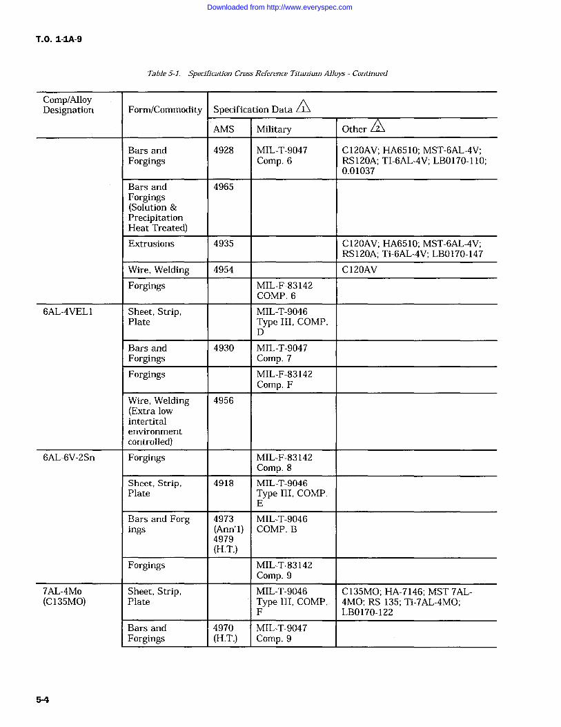
T.O. 1-IA-9
Table 5-1. Specification Cross Reference Titanium Alloys Continued
Comp/AlloyDesignation Form/Commodity Specification Data
0
AMS Military OtherA2
Bars and 4928 MIL-T-9047 C120AV; HA6510; MST-6AL-4V;Forgings Comp. 6 RS120A; TI-6AL-4V; LB0170-110;
0.01037
Bars and 4965Forgings(Solution &PrecipitationHeat Treated)Extrusions 4935 C120AV; HA6510; MST-6AL-4V;
RS120A; Ti-6AL-4V; LB0170-147
Wire, Welding 4954 C 120AV
Forgings MIL-F-83142COMP. 6
6AL-4VEL Sheet, Strip, MIL-T-9046Plate Type III, COMP.
D
Bars and 4930 MIL-T-9047Forgings Comp. 7
Forgings MIL-F-83142Comp. F
Wire, Welding 4956(Extra lowintertitalenvironmentcontrolled)
6AL-6V-2Sn Forgings MIL-F-83142Comp. 8
Sheet, Strip, 4918 MIL-T-9046Plate Type III, COMP.
E
Bars and Forg- 4973 MIL-T-9046ings (Ann' 1)
4979COMP. B
(H.T.)Forgings MIL-T-83142
Comp. 9
7AL-4Mo Sheet, Strip, MIL-T-9046 C135MO; HA-7146; MST 7AL-(C 135MO) Plate Type III, COMP. 4MO; RS 135; Ti-7AL-4MO;
F LB0170-122
Bars and 4970 MIL-T-9047Forgings (H.T.) Comp. 9
5-4
Downloaded from http://www.everyspec.com
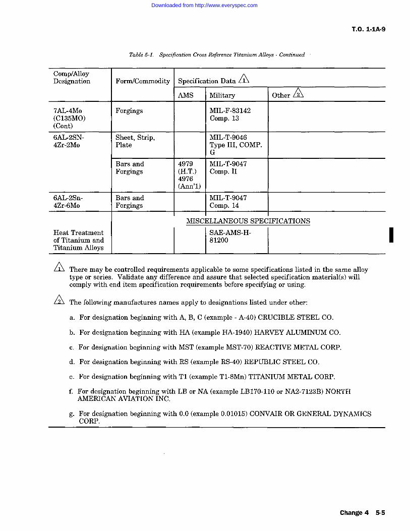
T.O. 1-IA-9
Table 5-1. Specification Cross Reference Titanium Alloys Continued
Comp/AlloyD ti ditF /C ifi D tS ties gna on yorm ommo on apec ca a
AMS Military Other
7AL-4Mo Forgings MIL-F-83142(C135MO) Comp. 13(Cont)
6AL-2SN- Sheet, Strip, MIL-T-90464Zr-2Mo Plate Type III, COMP.
G
Bars and 4979 MIL-T-9047Forgings (H.T.) Comp. II
4976(Ann'l)
6AL-2Sn- Bars and MIL-T-90474Zr-6Mo Forgings Comp. 14
MISCELLANEOUS SPECIFICATIONS
Heat Treatment SAE-AMS-H-of Titanium and 81200Titanium Alloys
ZLThere may be controlled requirements applicable to some specifications listed in the same alloytype or series. Validate any difference and assure that selected specification material(s) willcomply with end item specification requirements before specifying or using.
0The following manufactures names apply to designations listed under other:
a. For designation beginning with A, B, C (example A-40) CRUCIBLE STEEL CO.
b. For designation beginning with HA (example HA-1940) HARVEY ALUMINUM CO.
c. For designation beginning with MST (example MST-70) REACTIVE METAL CORP.
d. For designation beginning with RS (example RS-40) REPUBLIC STEEL CO.
e. For designation beginning with T1 (example T1-8Mn) TITANIUM METAL CORP.
f. For designation beginning with LB or NA (example LB170-110 or NA2-7123B) NORTHAMERICAN AVIATION INC.
g. For designation beginning with 0.0 (example 0.01015) CONVAIR OR GENERAL DYNAMICSCORP.
I
Change 4 5-5
Downloaded from http://www.everyspec.com
T.O. 1-1A-9
5-14. FIRE DAMAGE. Fire damage to titaniumand titanium alloys becomes critical above 1000Fdue to the absorption of oxygen and nitrogen fromthe air which causes surface hardening to a pointof brittleness. However, an overtemperatured con-dition is indicated by the formation of an oxidecoating and can be easily detected by a light greento white color. If this indication is apparent fol-lowing fire damage to titanium aircraft parts, theaffected parts will be removed and replaced withserviceable parts.5-15. HEAT TREATMENT GENERAL.
INOTE
SAE-AMS-H-81200, Heat Treatmentof Titanium and Titanium Alloys, willbe the control document for heattreatment of titanium and titanium
alloys used on aerospace equipment.For complete description of titaniumheat treat requirements, refer to lat-est issue of SAE-AMS-H-81200.
Additional Heat Treatment informa-tion is discussed in Section IX.
5-16. A majority of the titanium alloys can beeffectively heat treated to strengthen, anneal andstress relieve. The heating media for accomplish-ing the heat treatment can be air, combustedgases, protective atmosphere, inert atmosphere, or
vacuum furnace. However, protective, inert atmo-spheres or vacuum shall be used as necessary toprotect all parts (titanium or titanium alloy), etc.,which comprise the furnace load to prevent reac-tion with the elements hydrogen, carbon, nitrogenand oxygen.
0
5-6 Change 4
Downloaded from http://www.everyspec.com
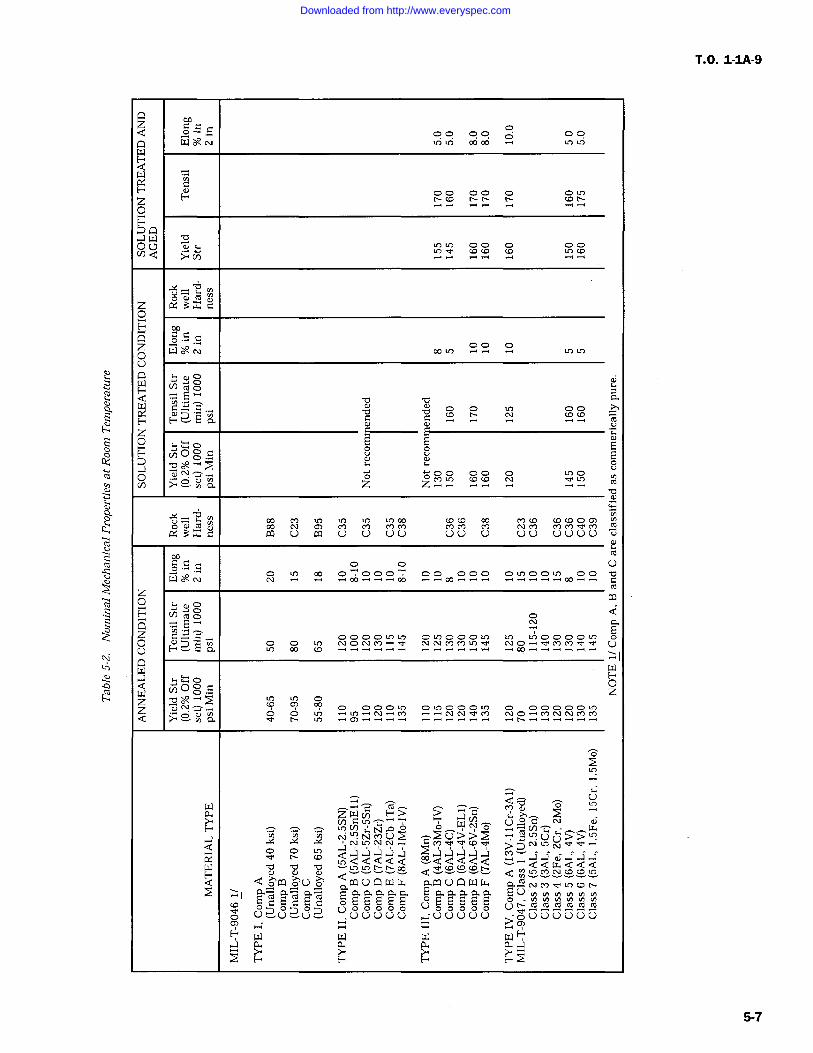
T.O. 1-IA-9
.aUUN '
.C,
b
Vd y
x3xs;
oW o
0
O
C C
EE
L LzYY Yo
O)w u Cl u U UU UL) U 00 UUUU
00"000" 00000
N_
NONM^-Y 000
0?
O
zWv) s > ^C `Y>
C t^,--WN L)
NN YCn(,)U Y'L?>NCOCC--N-
vQdQdd --dddQd -"QQtY 000bC) YYYYo da ccvcpv d oLCY)(.co
d oW o0 0 coUC:)Z. 00LV.
;Y a aY any aaaaaEaaaaa (--u0
0 Uo UY
m mro mU UU _00000 .-;00000 Y;oUUUU00
E" W W W W E"..a a a a a .a
UYI
F0z
5-7
Downloaded from http://www.everyspec.com
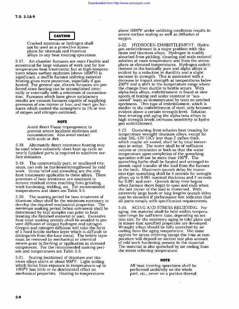
T.O. 1-1A-9
CAUTION
Cracked ammonia or hydrogen shallnot be used as a protective atmos-phere for titanium and titaniumalloys in any heat treating operations.
5-17. Air-chamber furnaces are more flexible andeconomical for large volumes of work and for lowtemperature heat treatments; but at high tempera-tures where surface oxidation (above 1000F) issignificant, a muffle furnace utilizing externalheating gives more protection, especially if gasheated. For general use, electric furnaces are pre-ferred since heating can be accomplished inter-nally or externally with a minimum of contamina-tion. Furnaces which have given satisiactoryresults are vacuum furnaces capable of supplyingpressures of one micron or less; and inert gas fur-naces which control the atmosphere to 1% or lessof oxygen and nitrogen combined.
NOTEAvoid direct flame impengement toprevent severe localized oxidation andcontamination. Also avoid contactwith scale or dirt.
5-18. Alternately direct resistance heating maybe used where extremely short heat up cycle onnearly finished parts is required to minimize sur-face oxidation.
5-19. The commercially pure, or unalloyed tita-nium, can only be hardened/strengthened by coldwork. Stress relief and annealing are the onlyheat treatments applicable to these alloys. Theseprocesses of heat treatment are employed toremove residual stress resulting from grinding,work hardening, welding, etc. For recommendedtemperatures and times see Table 5-3.
5-20. The soaking period for heat treatment oftitanium alloys shall be the minimum necesaary todevelop the required mechanical properties. Theminimum soaking period (when unknown) shall bedetermined by teat samples run prior to heattreating the finiahed material or part. Excessiveheat treat soaking periods ahall be avoided to pre-vent diffusion of oxygen hydrogen and nitrogen.Oxygen and nitrogen diffusion will take the formof a hard brittle surface layer which is difficult todistinguish from the base metal. The brittle layermust be removed by mechanical or chemicalmeans prior to forming or application in stressedcomponents. For the recommended soaking peri-ods and temperatures see Table 5-3.
5-21. Scaling (oxidation) of titanium and tita-nium alloys starts at about 900F. Light scalingwhich forms from exposure to temperatures up to1000F has little or no detrimental effect onmechanical properties. Heating to temperatures
above 1000F under oxidizing conditions results insevere surface scaling as well as diffusion ofoxygen.
5-22. HYDROGEN EMBRITTLEMENT. Hydro-gen embrittlement is a major problem with tita-nium and titanium alloys. Hydrogen is readilyabsorbed from pickling, cleaning and scale removalsolution at room temperature and from the atmos-phere at elevated temperatures. Hydrogen embrit-tlement in the basically pure and alpha alloys isevident by a reduction in ductility and a slightincrease in strength. This is associated with adecrease in impact strength at temperatures below200F and a shift in the temperature range wherethe change from ductile to brittle occurs. Withalpha-beta alloys, embrittlement is found at slowspeeds of testing and under constant or "sus-tained" loads as demonstrated by tests on notchedspecimens. This type of embrittlement, which issimilar to the embrittlement of steel, only becomesevident above a certain strength level. Solutionheat treating and aging the alpha-beta alloys tohigh strength levels increases sensitivity to hydro-gen embrittlement.
5-23. Quenching from solution heat treating fortemperature wrought titanium alloys, except foralloy 3AL-13V-11Cr less than 2 inches thick,which maybe air cooled, shall be by total immer-sion in water. The water shall be of sufficientvolume or circulation or both so that the watertemperature upon completion of the quenchingoperation will not be more than 100F. Thequenching baths shall be located and arranged topermit rapid transfer of the load from the furnaceto the bath. Maximum quench delay for immer-sion-type quenching shall be 4 seconds for wroughtalloys up to 0.091 nominal thickness and 7 secondsfor 0.091 and over. Quench delay time beginswhen furnace doors begin to open and ends whenthe last corner of the load is immersed. Withextremely large loads or long lengths quench delaymay be exceeded if performance test indicates thatall parts comply with specification requirements.5-24. AGING AND STRESS RELIEVING. Foraging, the material shall be held within tempera-ture range for sufficient time, depending on sec-tion size, for the necessary aging to take place andto insure that specified properties are developed.Wrought alloys should be fully quenched by aircooling from the aging temperature. The sameapplies for stress relieving except the time at tem-perature will depend on section size plus amountof cold work hardening present in the material.The material is also quenched by air cooling fromthe stress relieving temperature.
NOTE
All heat treating operations shall beperformed uniformly on the wholepart, etc., never on a portion thereof.
Downloaded from http://www.everyspec.com
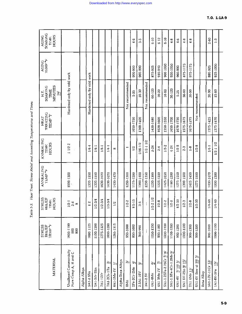
T.O. 1-1A-9
U
.Y.z 9 9C, Q OOV)
C0 oz LL 0 N- N-Q W C rn C) o_ C
v o o 0 0 Cj 0 Cn
C7)3 3b Y
b bo oUr (l) b bz W
W A NO OF": E N
x Q z C C Ln 0 0 0 0 o O wp F"
b v u0) 0) o
co Cfl O z z
zw x xE- 0 zW Qx W
Q! O
zz
to.a rW CL CV
VZH O "Yx
z
0zw
0
WCO N_ v' M_ N_ N_ _MZ
O
W W W Y"
O: .YM
N N N
V) W o(14
CU ti .Mi Y
W00) 000 u") O' 0' 0 0' o O O' O 0' O' O' O
[Y WY
TY U 001 01
YnIa N NI > MI YI t`I;I YI LO
Q ro Q U of OH U
a>
i7 CU N- G YI o
Q p C > [x NV)
Np W
'rp
UCd Q1? 00
a Q U) Q Q Q 0. 00 CU Q d Q Q Q Q Q Q Q Q Q.Y P. Q Q CQ
5-9
Downloaded from http://www.everyspec.com
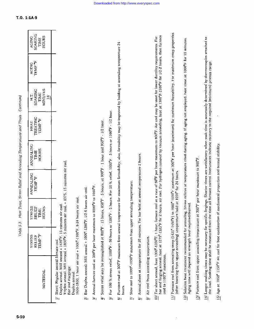
T.O. 1-1A-9
a)C
U
C C o=' o dq"u X 00
roCro OE
ro'C
0 0 ", C
O
p
7 tY 42aiE
440 o mx
w E C.M-i p ro
C p .0+ CE
o ER
= E O4".i
ro ro ^ oC
cC o'o
a)ro by O
C
o Od vmczdo0 m E ro
C C C O C w CW. C7
a nC F a Q Co
0.a N 0u
cn 4.
NI MI Ynl cfll 0I
44o
ov
a cA+C 0.
of -I
Ca
ECC
ro '0E C
oE EX
C'CE 0.
>a
^y sC
h NMroW, 44 Sr V
o d00 w E E
bDm
s; Cy0, 0. EC 0
ro GE
Y
UCE y
C wy C
o Cro
r
E hYE ro9
a C E o0 E bro.3
O o Ocn
pU
bq CM 1A
roC Ccn w a'I YI
5-10
Downloaded from http://www.everyspec.com
T.O. 1-1A-9
5-25. FABRICATION.
5-26. FORMING SHEET METAL-GENERAL.The forming of the unalloyed titantum can beaccomplished at room temperature using approxi-mately the same procedures as those extablishedfor 18-8 stainless steel. The basic difficultiesencountered are sheet thickness, property varia-tions, direction of grain flow and flatness. Theabove factors combined with high yield strength,high tensile strength and low uniform elongationof commercial titanium alloys makes forming diffi-cult. The current equipment available wasdesigned for material of uniform quality and con-siderable work is required for adaptation to formtitanium.
hinge-type dies are used. When cold forming isemployed, it is usually desirable to partially formthe parts, stress-relieve at 1000F for 20 minutes,then finish form. Hot forming for severely con-
toured parts or when only low-forming pressuresare available is accomplished between 600F and800F. For this procedure, the form block isheated to the required temperature, the blankpositioned and covered with powdered or shreddedasbestos; then a rubber pad 70 to 80 Durometerhardness is placed on top. This extra pad of rub-ber serves two purposes: First, it provides addi-tional rigidity for forming; and second, it protectsthe press-contained rubber from the hot formblock.
5-27. BENDING. Straight-Edge Bending of tita-nium using power brake on hand forming equip-ment can be accomplished to a limited degreeusing the methods developed for stainless steel.The factors which require control are the compen-sation for springback and the bend radii. Spr-ingback is comparable to that of hard stainlesssteel when formed at room temperature. The bendradii will depend on the type of material or alloyand whether forming is accomplished hot or cold.The forming of material requiring tight bends orsmall radii necessitates the application of heat inthe range of 500F. The heat should be applied foronly short periods of time to avoid excessive oxy-gen and nitrogen contamination which causes
embrittlement. For approximate cold bend radii ofsheet titanium see Table 5-4. Actual practice mayreveal that smaller bend radii can be used.
5-28. DRAW FORMING. Deep draw formingshould not be attempted unless adequate equip-ment and facilities are available. This will requirethat facilities be maintained for heating and con-trolling temperatures of the blanks to be formedand the dies used in the forming operation.
5-29. HYDRAULIC PRESS FORMING. Rubberpad hydropress forming can be accomplishedeither hot or cold depending on the type toolingemployed and the press pressures used. This typeof forming is used on parts that are predominatelyflat and have flanges, beads, and lightening holes.A male form block is set on the lower press platenand the blank held in place on the block by locat-ing pins. A press-contained rubber pad (45 to 55Shore Durometer hardness and about 8 inchesthick) is located over the form block and blank.The press is then closed. As the ram is lowered,the rubber pad envelops the form block forcing thesheet metal blank to conform to its contour.
5-30. Many parts can be formed at room temper-ature on the hydropress if flange clips, wedges and
5-31. Tooling for hydropress form blocks, if ele-vated temperature forming is to be used, requiresthat pressure plates and dies be made somewhatthicker than in normal practice. If long runs are
anticipated, it is recommended that form blocks bemade from a good grade of hot-work tool steel dueto the galling action of titanium at elevatedtemperatures.
5-32. STRETCH FORMING. Stretch forminghas been used on titanium primarily to bendangles, hat sections, Z-sections and channels andto stretch form skins so that they will fit the con-
tour of the airplane fuselage. This type of formingis accomplished by gripping the section to beformed in knurled jaws, loading until plastic defor-mation begins, then wrapping the part around afemale die. This operation is performed at roomtemperature and should be done at a very slowrate. Spring back is equivalent to that of 1/4 hard18-8 stainless steel. All blanks for stretch-formingshould have the edges polished to remove anynotch effects. Approximately 0.025 inch of shearededges should be removed.
5-33. DROP-HAMMER FORMING. Drop-ham-mer forming of titanium has been very successfuland has been accomplished both at room and atelevated temperatures. Kirksite is satisfactory formale and female dies where only a few parts arerequired. If long runs are to be made, ductile iron
or laminated steel dies are usually necessary. Indrop-hammer forming, the best results have beenobtained by warning the female die to a tempera-ture of 200 to 300F to remove the chill and heat-ing the blank to a temperature of 800 1000F for10 to 15 minutes. The part is then struck and setin the die. Usually a stress relief operation at1000F for 20 minutes is necessary, then a re-strike operation. In most instances, a finishedpart requiring no hand work is obtained.
5-11
Downloaded from http://www.everyspec.com
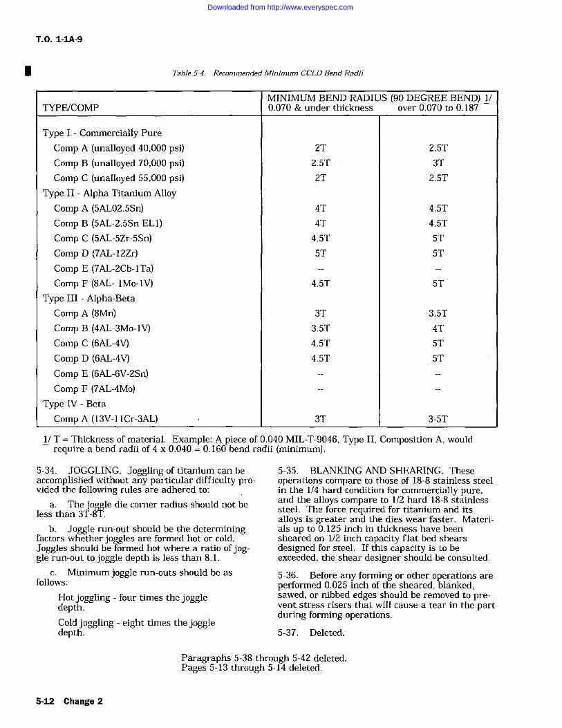
T.O. 1-1A-9
ITable 5-4. Recommended Minimum CCLD Bend Radii
TYPE/COMPMINIMUM BEND RADIUS (90 DEGREE BEND) 1/0.070 & under thickness over 0.070 to 0.187
Type I Commercially Pure
Comp A (unalloyed 40,000 psi) 2T 2.5T
Comp B (unalloyed 70,000 psi) 2.5T 3T
Comp C (unalloyed 55,000 psi) 2T 2.5T
Type II Alpha Titanium AlloyComp A (5AL02.5Sn) 4T 4.5T
Comp B (5AL-2.5Sn EL1) 4T 4.5T
Comp C (5AL-5Zr-5Sn) 4.5T 5T
Comp D (7AL-12Zr) 5T 5T
Comp E (7AL-2Cb-lTa)Comp F (8AL- lMo-1V) 4.5T 5T
Type III Alpha-BetaComp A (8Mn) 3T 3.5T
Comp B (4AL-3Mo-1V) 3.5T 4T
Comp C (6AL-4V) 4.5T 5T
Comp D (6AL-4V) 4.5T 5T
Comp E (6AL-6V-2Sn)Comp F (7AL-4Mo)
Type IV Beta
Comp A (13V-i lCr-3AL) 3T 3-5T
1/ T Thickness of material. Example: A piece of 0.040 MIL-T-9046, Type II, Composition A, wouldrequire a bend radii of 4 x 0.040 0.160 bend radii (minimum).
5-34. JOGGLING. Joggling of titanium can beaccomplished without any particular difficulty pro-vided the following rules are adhered to:
a. The joggle die corner radius should not beless than 3T-8T.
b. Joggle run-out should be the determiningfactors whether joggles are formed hot or cold.Joggles should be formed hot where a ratio of jog-gle run-out to joggle depth is less than 8.1.
c. Minimum joggle run-outs should be asfollows:
Hot joggling four times the joggledepth.Cold joggling eight times the joggledepth.
5-35. BLANKING AND SHEARING. Theseoperations compare to those of 18-8 stainless steelin the 1/4 hard condition for commercially pure,and the alloys compare to 1/2 hard 18-8 stainlesssteel. The force required for titanium and itsalloys is greater and the dies wear faster. Materi-als up to 0.125 inch in thickness have beensheared on 1/2 inch capacity flat bed shearsdesigned for steel. If this capacity is to beexceeded, the shear designer should be consulted.
5-36. Before any forming or other operations areperformed 0.025 inch of the sheared, blanked,sawed, or nibbed edges should be removed to pre-vent stress risers that will cause a tear in the partduring forming operations.
5-37. Deleted.
Paragraphs 5-38 through 5-42 deleted.Pages 5-13 through 5-14 deleted.
5-12 Change 2
Downloaded from http://www.everyspec.com
T.O. 1-1A-9
5-43. Deleted.
5-44. Deleted.
5-45. Deleted.
5-46. Deleted.
5-47. SOLDERING. Limited information isavailable on soldering. It is possible to success-fully solder titanium where little strength isrequired, by precoating with a thin film of silver,copper or tin from their chloride salts. This can beaccomplished by heating the chloride salts-coatedtitanium in an atmosphere controlled furnace aspreviously mentioned in paragraph 5-18. Theresultant film should be made wet with either a60% tin-40% lead or a 50%-50% tin and lead sol-der. Since the deposited film may dissolve in theliquid solder and dewet the surface, it is importantthat the time and temperature be held to a
minimum.
5-48. RIVETING. Riveting of titanium can beaccomplished using conventional equipment withrivets manufactured from commercially pure mate-rial; however, the rivet holes require close toler-ances to insure good gripping. The driving time is
increased about 65% over that required for highstrength aluminum rivets. Better results can beobtained by using the squeeze method rather thanthe rivet gun and bucking bar. When it is neces-
sary to have flush-head rivets, dimpling can beaccomplished at temperatures of 500F to 700F.Other types of rivets such as high strength alumi-num, stainless steel and monel are also used tojoin titanium.
5-49. Due to difficulties involved, the above men-tioned method will probably be replaced in most
cases with rivets of the high shear series, i.e., pinrivets such as NAS1806 through NAS1816, tensionrivet NAS-2006 through NAS-2010, and shearrivet NAS-2406 through NAS-2412.
5-50. As with other metals, it is necessary totake precautions to avoid galvanic corrosion whentitanium is riveted to other metals. This can beaccomplished by coating the titanium with zincchromate primer Specification MIL-P-8585.
ITable 5-5 deleted.
Change 1 5-15/(5-16 blank)
Downloaded from http://www.everyspec.com

Downloaded from http://www.everyspec.com
T.O. 1-IA-9
5-51. MACHINING AND GRINDING.
5-52. MACHINING. Commercially pure, unal-loyed titanium machines similarly to 18-8 stainlesssteel, but the alloy grades are somewhat harder.Variations in actual practice will depend on thetype of work, equipment, and finish, so the follow-ing information is only intended as a guide.
5-53. The basic requirements are: rigid machinesetups, use of a good cutting fluid that emphasizescooling rather than lubrication, sharp and propertools, slow speeds and heavy feeds. Since titaniumhas a tendency to gall and seize on other metals,the use of sharp tools is very important. Slidingcontact, and riding of the tool on the work must beavoided.
5-54. TURNING. Commercially pure and alloytitanium is not difficult to turn. Carbide toolssuch as metal carbides C91 and Carboloy 44A andother similar types give the best results for turn-ing titanium. Cobalt-type high speed steels givethe best results of the many types available. Castalloy tools such as Stellite, Lantung, Rexalloy, etc.,may be used when carbide is not available, or
when the high speed steels, are not satisfactory.
5-55. The recommended cutting fluids arewaterbase cutting fluids such as soluble oils orchemical type fluids.
5-56. Tables 5-6 and 5-7 show suggested turningspeeds, tool angles and feeds. All work should beaccomplished with live centers since galling or
seizing will occur on dead centers. Tool sharpnessis again emphasized because a nick or a seizedchip on a tool increases temperature and willcause rapid tool failures.
5-57. MILLING. Considering the type of toolwhich is required in milling operations, it can bereadily seen that this type of machining is moredifficult than turning. The difficulty encounteredis that chips remain tightly welded to the cutter'sedge at the end of cut or during the portion of therevolution that it does not cut. As the cutterstarts the next machining portion the chips areknocked off. This damages the cutting edge andthe tool fails rapidly.
5-58. One method that can be utilized to relievethis difficulty to a great extent is climb milling.The cutter machines the thinnest portion of thechip as it leaves the cut. Thus, the area of contactbetween chip and tool is at a minimum when thechip is removed at the start of the next cuttingportion of the revolution. This will reduce thedanger of chipping the tool. The machine used forclimb milling should be in good condition because
if there is any lost motion in the feed mechanismof the table, the piece being cut will be pulled intothe cutter. This may damage the cutter or thework piece.
5-59. For effective milling, the work feed shouldmove in the same direction as the cutting teeth,and for face milling the teeth should emerge fromthe cut in the same direction that the work is fed.
5-60. To select the appropriate tool material it isadvisable to try both cast alloy and carbide tools todetermine the better of the two for large millingjobs. This should be done since the cutter usuallyfails because of chipping, and the results are not
as satisfactory with carbide as they are with cast-alloy tools. The increase in cutting speeds (20 to30%) possible by using carbide rather than cast(all alloy tools) does not always compensate for theadditional tool grinding cost.
5-61. The same water-base cutting fluids usedfor turning are recommended for milling; however,carbide tools may give better results when dry.
5-62. See Table 5-8 for recommended speed andfeeds. For tool grinding information see Table 5-9.
5-63. DRILLING. Drilling of titanium can beaccomplished successfully with ordinary highspeed steel drills. Low speeds and heavy positivefeeds are required. The unsupported portion ofthe drill should be as short as possible to providemaximum rigidity and to prevent drill running.All holes should be drilled without pilot holes ifpossible. As with other materials, chip removal is
one of the principal problems and the appearanceof the chip is an indication of the sharpness andcorrect grinding of the drill. In drilling deep holes,intermittent drilling is recommended. That is, thedrill is removed from the hole at intervals to
remove the chips.
5-64. The cutting fluids recommended are sulfu-rized and chlorinated coolants for drills with diam-eters of less than 1/4 inch and mixtures of mineraloil or soluble oil with water for hole sizes largerthan 1/4 inch diameter.
5-65. The cutting speed should be 50 to 60 FPMfor the pure grade of titanium and 30 to 50 FPMfor alloy grades. Feeds should be 0.005 to 0.009inch for 1/4 to 1/2 inch diameter drills; 0.002 to0.005 inch for smaller drills. Point angle, 90 fordrills 1/4 inch diameter and larger and 140 fordrills 1/8 inch diameter or less; but 90, 118 and140 should be tried on large jobs to determine theangle that will give the best result. Helix angle28 to 35 and lip relief 10. Additional informationon drills may be obtained from NAS907.
5-17
Downloaded from http://www.everyspec.com
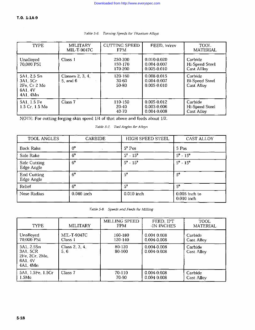
T.O. 1-1A-9
Table 5-6. Turning Speeds for Titanium Alloys
TYPE MILITARY CUTTING SPEED FEED, in/rev TOOLMIL-T-9047C FPM MATERIAL
Unalloyed Class 1 250-300 0.010-0.020 Carbide70,000 PSI 150-170 0.004-0.007 Hi-Speed Steel
170-200 0.005-0.010 Cast Allloy5A1, 2.5 Sn Classes 2, 3, 4, 120-160 0.008-0.015 Carbide3A1, 5Cr 5, and 6 30-60 0.004-0.007 Bi-Speed Steel2Fe, Cr 2 Mo 50-80 0.005-0.010 Cast Alloy6A1, 4V4A1, 4Mn
5A1, 1.5 Fe Class 7 110-150 0.005-0.012 Carbide1.5 Cr, 1.5 Mo 20-40 0.003-0.006 Hi-Speed Steel
40-70 0.004-0.008 Cast AlloyNOTE: For cutting forging skin speed 1/4 of that above and feeds about 1/2.
Table 5-7. Tool Angles for Alloys
TOOL ANGLES CARBIDE HIGH SPEED STEEL CAST ALLOY
Back Rake 0 5 Pos 5 Pos
Side Rake 6 5 15 5 15
Side CuttingEdge Angle
6 50 15 5 15
End CuttingEdge Angle
6 5 5
Relief 6 5 5
Nose Radius 0.040 inch 0.010 inch 0.005 inch to0.010 inch
Table 5-8. Speeds and Feeds for Milling
MILLING SPEED FEED, IPT TOOLTYPE MILITARY FPM -IN INCHES MATERIAL
Unalloyed MIL-T-9047C 160-180 0.004-0.008 Carbide70,000 PSI Class 120-140 0.004-0.008 Cast Alloy5A1, 2.5Sn Class 2, 3, 4, 80-120 0.004-0.008 Carbide3A1, 5CR 5, 6 80-100 0.004-0.008 Cast Alloy2Fe, 2Cr, 2Mo,6A1, 4V4A1, 4Mn
5A1, 1.5Fe, 1.5Cr Class 7 70-110 0.004-0.008 Carbide1.5Mo 70-90 0.004 0.008 Cast Alloy
Downloaded from http://www.everyspec.com
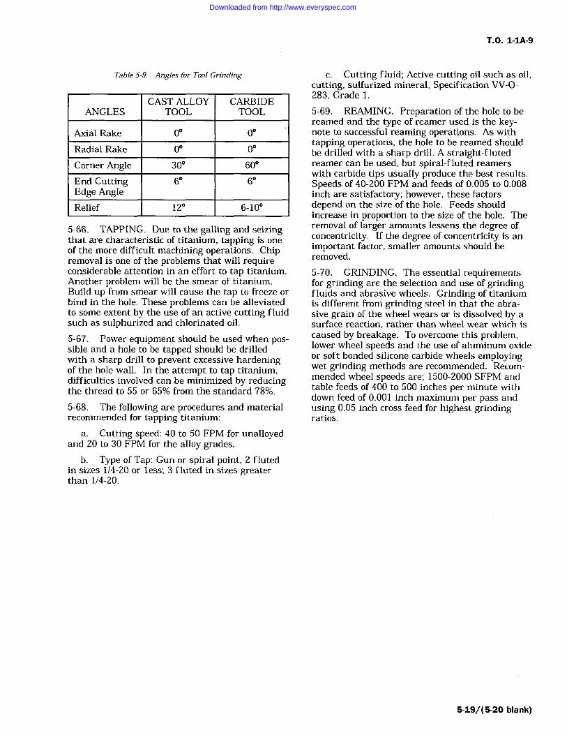
T.O. 1-1A-9
Table 5-9. Angles for Tool Grinding
ANGLESCAST ALLOY
TOOLCARBIDETOOL
Axial Rake 00 00
Radial Rake 0 0
Corner Angle 30 60
End CuttingEdge Angle
6 6
Relief 12 6-10
5-66. TAPPING. Due to the galling and seizingthat are characteristic of titanium, tapping is oneof the more difficult machining operations. Chipremoval is one of the problems that will requireconsiderable attention in an effort to tap titanium.Another problem will be the smear of titanium.Build up from smear will cause the tap to freeze or
bind in the hole. These problems can be alleviatedto some extent by the use of an active cutting fluidsuch as sulphurized and chlorinated oil.
5-67. Power equipment should be used when pos-sible and a hole to be tapped should be drilledwith a sharp drill to prevent excessive hardeningof the hole wall. In the attempt to tap titanium,difficulties involved can be minimized by reducingthe thread to 55 or 65% from the standard 78%.
5-68. The following are procedures and materialrecommended for tapping titanium:
a. Cutting speed: 40 to 50 FPM for unalloyedand 20 to 30 FPM for the alloy grades,
b. Type of Tap: Gun or spiral point, 2 flutedin sizes 1/4-20 or less; 3 fluted in sizes greaterthan 1/4-20.
c. Cutting fluid; Active cutting oil such as oil,cutting, sulfurized mineral, Specification VV-O-283, Grade I.
5-69. REAMING. Preparation of the hole to bereamed and the type of reamer used is the key-note to successful reaming operations. As withtapping operations, the hole to be reamed shouldbe drilled with a sharp drill. A straight-flutedreamer can be used, but spiral-fluted reamerswith carbide tips usually produce the best results.Speeds of 40-200 FPM and feeds of 0.005 to 0.008inch are satisfactory; however, these factorsdepend on the size of the hole. Feeds shouldincrease in proportion to the size of the hole. Theremoval of larger amounts lessens the degree ofconcentricity. If the degree of concentricity is animportant factor, smaller amounts should beremoved.
5-70. GRINDING. The essential requirementsfor grinding are the selection and use of grindingfluids and abrasive wheels. Grinding of titaniumis different from grinding steel in that the abra-sive grain of the wheel wears or is dissolved by asurface reaction, rather than wheel wear which iscaused by breakage. To overcome this problem,lower wheel speeds and the use of aluminum oxideor soft bonded silicone carbide wheels employingwet grinding methods are recommended. Recom-mended wheel speeds are; 1500-2000 SFPM andtable feeds of 400 to 500 inches per minute withdown feed of 0.001 inch maximum per pass andusing 0.05 inch cross feed for highest grindingratios.
5-19/(5-20 blank)
Downloaded from http://www.everyspec.com

Downloaded from http://www.everyspec.com
T.O. 1-1A-9
SECTION VI
COPPER AND COPPER BASE ALLOYS
6-1. COPPER AND COPPER BASE ALLOYS.
6-2. Most of the commercial coppers are refinedto a purity of 99.90%, minimum copper plus silver.The two principal copper base alloys are brass andbronze, containing zinc and tin respectively, as themajor alloying element. Alloy designations forwrought copper and copper alloys are listed intable 6-1, with the corresponding specification andcommon trade names.
6-3. COPPER ALLOYING ELEMENTS.
ZINC Added to copper to form a series of alloysknown as brasses. They are ductile, malleable,corrosion resistant and have colors ranging frompink to yellow.TIN Added to copper to form a series of alloysknown as bronzes. Bronzes are a quality springmaterial, and are strong, ductile and corrosionresistant.
LEAD Added to copper in amounts up to 1% toform a machinable, high-conductivity copper rod.It is added to brasses or bronzes in amounts of 0.5to 4% to improve machinability and in the range of2 -4% to improve bearing properties.ALUMINUM Added to copper as a predominat-ing alloy element to form a series known as alumi-num bronzes. These alloys are of high strengthand corrosion resistance.
IRON Added to copper along with aluminum in
some aluminum bronzes and with manganese in
some manganese bronzes.
PHOSPHOROUS Added to copper principally as
a deoxidizer and in some bronzes to improvespring properties.NICKEL Added to copper for higher strengthwithout loss of ductility. They have excellent cor-
rosion resistance.
SILICON Added to copper to form the coppersilicon series having high corrosion resistance com-bined with strength and superior welding quali-ties. Small amounts are used as deoxidizers.
BERYLLIUM Added to copper to form a series ofage hardenable alloys. In the fully treated condi-tion, it is the strongest of the copper base alloys
and has an electrical conductivity of 20%. Berryl-lium-coppers are widely used for tools where non-sparking qualities are desired.
MANGANESE Added primarily as a desulfuriz-ing and de-gassifying element for alloys containingnickel.
6-4. CHEMICAL COMPOSITION. The chemi-cal composition of the copper alloys (listed by com-mercial trade name) is listed in table 6-1.
6-5. HEAT TREATMENT AND NOT WORKINGTEMPERATURE OF COPPER ALLOYS.
NOTE
Additional Heat Treatment informa-tion is discussed in Section IX.
6-6. During production and fabrication, copperalloys may be heated for homogenizing, hot work-ing, stress relief for solution treatment, and pre-cipitation hardening. The temperatures commonlyused for heating, hot working and annealing aftercold working are given in table 6-2.
6-7. STRESS RELIEF OF COPPER ALLOYS.
6-8. Table 6-3 below gives a list of typical stressrelief treatments commonly used in industry. Thistable is listed in terms of chemical compositionpercents, and should be used as representing aver-
age stress relieving temperatures.6-9. MACHINING COPPER AND COPPERALLOYS. Free cutting brass is one of the mosteasily machined metals and serves as a standardfor machinability ratings of copper alloys. The fol-lowing table gives the machinability ratings andrecommended speeds and feeds for use with highspeed steel tools.
6-10. WROUGHT-COPPER-BERYLLIUMALLOYS. The beryllium copper alloys are fre-quently used due to their ability to respond to pre-cipitation or age hardening treatments and otherbeneficial characteristics. Some of the characteris-tics are; good electrical and thermal conductivity,high strength hardness, corrosion resistance, goodwear resistance, non-magnetic qualities and verygood fatigue strength.
6-1
Downloaded from http://www.everyspec.com
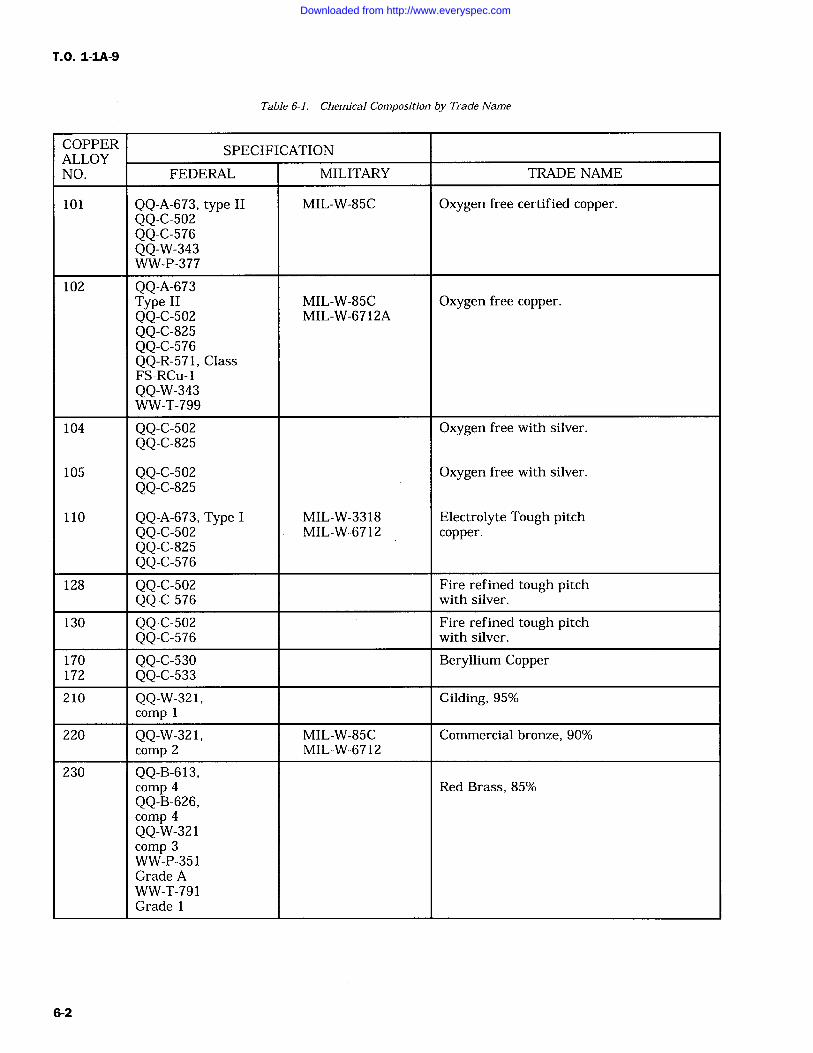
T.O. 1-IA-9
Table 6-1. Chemical Composition by Trade Name
COPPER SPECIFICATIONALLOYNO. FEDERAL MILITARY TRADE NAME
101 QQ-A-673, type II MIL-W-85C Oxygen free certified copper.QQ-C-502QQ-C-576QQ-W-343WW-P-377
102 QQ-A-673Type II MIL-W-85C Oxygen free copper.QQ-C-502 MIL-W-6712AQQ-C-825QQ-C-576QQ-R-571, ClassFS-RCu-1QQ-W-343WW-T-799
104 QQ-C-502 Oxygen free with silver.QQ-C-825
105 QQ-C-502 Oxygen free with silver.QQ-C-825
110 QQ-A-673, Type I MIL-W-3318 Electrolyte Tough pitchQQ-C-502 MIL-W-6712 copper.QQ-C-825QQ-C-576
128 QQ-C-502 Fire refined tough pitchQQ-C-576 with silver.
130 QQ-C-502 Fire refined tough pitchQQ-C-576 with silver.
170 QQ-C-530 Beryllium Copper172 QQ-C-533210 QQ-W-321, Gilding, 95%
comp
220 QQ-W-321, MIL-W-85C Commercial bronze, 90%comp 2 MIL-W-6712
230 QQ-B-613,comp 4 Red Brass, 85%QQ-B-626,comp 4QQ-W-321comp 3WW-P-351Grade AWW-T-791Grade 1
6-2
Downloaded from http://www.everyspec.com
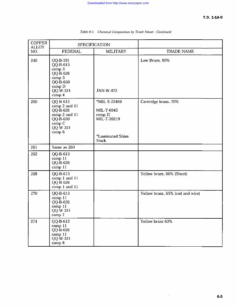
T.O. 1-1A-9
Table 6-1. Chemical Composition by Trade Name Continued
COPPER SPECIFICATIONALLOYNO. FEDERAL MILITARY TRADE NAME
240 QQ-B-591 Low Brass, 80%QQ-B-613.comp 3QQ-B-626comp 3QQ-B-650comp DQQ-W-321 JAN-W-472comp 4
260 QQ-B-613 *MIL-S-22499 Cartridge brass, 70%comp 2 and 11QQ-B-626 MIL-T-6945comp 2 and 11 comp IIQQ-B-650 MIL-T-20219comp CQQ-W-321comp 6
*Laminated ShimStock
261 Same as 260
262 QQ-B-613comp 11QQ-B-626comp 11
268 QQ-B-613 Yellow brass, 66% (Sheet)comp and I1QQ-B-626comp and I1
270 QQ-B-613 Yellow brass, 65% (rod and wire)comp 11QQ-B-626comp 11QQ-W-321comp 7
274 QQ-B-613 Yellow brass 63%comp 11QQ-B-626comp 11QQ-W-321comp 8
6-3
Downloaded from http://www.everyspec.com
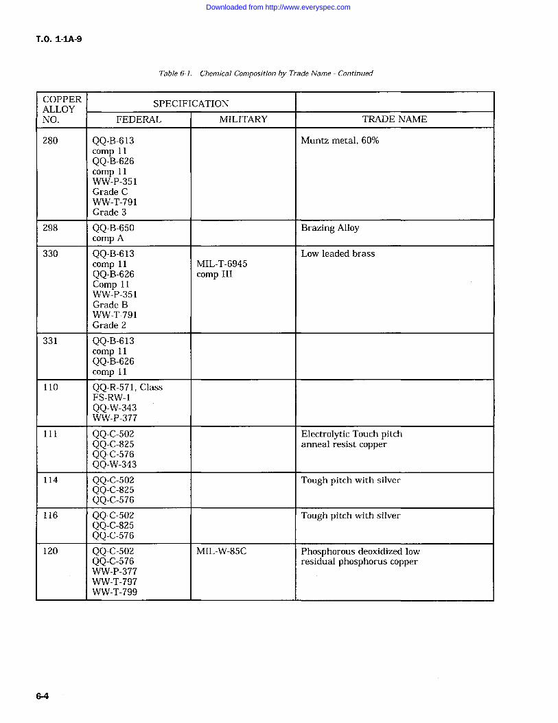
T.O. 1-1A-9
Table 6-1. Chemical Composition by Trade Name Continued
COPPER SPECIFICATIONALLOYNO. FEDERAL MILITARY TRADE NAME
280 QQ-B-613 Muntz metal, 60%comp 11QQ-B-626comp 11WW-P-351Grade CWW-T-791Grade 3
298 QQ-B-650 Brazing Alloycomp A
330 QQ-B-613 Low leaded brasscomp 11 MIL-T-6945QQ-B-626 comp IIIComp 11WW-P-351Grade BWW-T-791Grade 2
331 QQ-B-613comp 11QQ-B-626comp 11
110 QQ-R-571, ClassFS-RW-1QQ-W-343WW-P-377
111 QQ-C-502 Electrolytic Touch pitchQQ-C-825 anneal resist copperQQ-C-576QQ-W-343
114 QQ-C-502 Tough pitch with silverQQ-C-825QQ-C-576
116 QQ-C-502 Tough pitch with silverQQ-C-825QQ-C-576
120 QQ-C-502 MIL-W-85C Phosphorous deoxidized lowQQ-C-576 residual phosphorus copperWW-P-377WW-T-797WW-T-799
6-4
Downloaded from http://www.everyspec.com
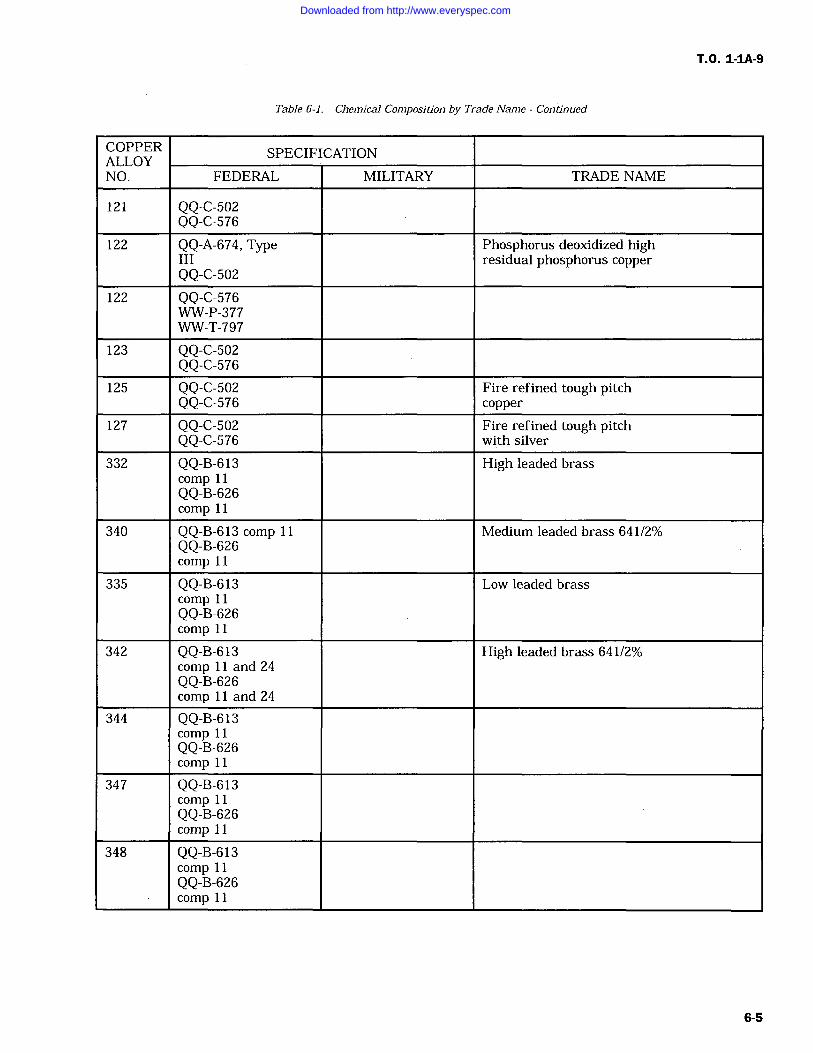
T.O. 1-IA-9
Table 6-1. Chemical Composition by Trade Name Continued
COPPER SPECIFICATIONALLOYNO. FEDERAL MILITARY TRADE NAME
121 QQ-C-502QQ-C-576
122 QQ-A-674, Type Phosphorus deoxidized highIII residual phosphorus copperQQ-C-502
122 QQ-C-576WW-P-377WW-T-797
123 QQ-C-502QQ-C-576
125 QQ-C-502 Fire refined tough pitchQQ-C-576 copper
127 QQ-C-502 Fire refined tough pitchQQ-C-576 with silver
332 QQ-B-613 High leaded brasscomp 11QQ-B-626comp 11
340 QQ-B-613 comp 11 Medium leaded brass 641/2%QQ-B-626comp 11
335 QQ-B-613 Low leaded brasscomp 11QQ-B-626comp 11
342 QQ-B-613 High leaded brass 641/2%comp 11 and 24QQ-B-626comp 11 and 24
344 QQ-B-613comp 11QQ-B-626comp 11
347 QQ-B-613comp 11QQ-B-626comp 11
348 QQ-B-613comp 11QQ-B-626comp 11
6-5
Downloaded from http://www.everyspec.com
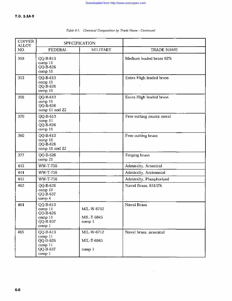
T.O. 1-IA-9
Table 6-1. Chemical Composition by Trade Name Continued
COPPER SPECIFICATIONALLOYNO. FEDERAL MILITARY TRADE NAME
350 QQ-B-613 Medium leaded brass 62%comp 11QQ-B-626comp 11
353 QQ-B-613 Extra High leaded brasscomp 11QQ-B-626comp 11
356 QQ-B-613 Extra High leaded brasscomp 11QQ-B-626comp 11 and 22
370 QQ-B-613 Free cutting muntz metalcomp 11QQ-B-626comp 11
360 QQ-B-613 Free cutting brasscomp 11QQ-B-626comp 11 and 22
377 QQ-B-626 Forging brasscomp 21
443 WW-T-756 Admiralty, Arsenical
444 WW-T-756 Admiralty, Antimonial
445 WW-T-756 Admiralty, Phosphorized462 QQ-B-626 Naval Brass, 631/2%
comp 11QQ-B-637comp 4
464 QQ-B-613 Naval Brasscomp 11 MIL-W-6712QQ-B-626comp 11 MIL-T-6945QQ-B-637 comp 1
comp
465 QQ-B-613 MIL-W-6712 Naval brass, arsenicalcomp 11QQ-B-626 MIL-T-6945comp 11QQ-B-637 comp 1comp
6-6
Downloaded from http://www.everyspec.com
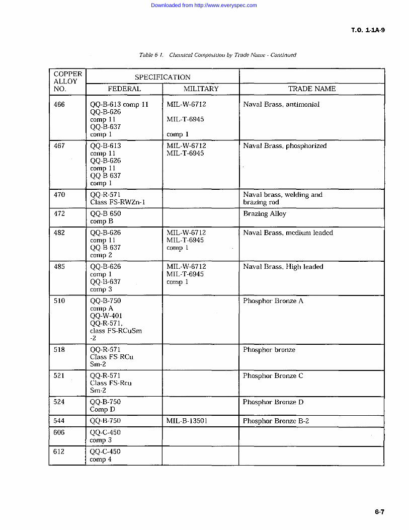
T.O. 1-1A-9
Table 6-1. Chemical Composition by Trade Name Continued
COPPER SPECIFICATIONALLOYNO. FEDERAL MILITARY TRADE NAME
466 QQ-B-613 comp 11 MIL-W-6712 Naval Brass, antimonialQQ-B-626comp 11 MIL-T-6945QQ-B-637comp comp 1
467 QQ-B-613 MIL-W-6712 Naval Brass, phosphorizedcomp 11 MIL-T-6945QQ-B-626comp 11QQ-B-637comp
470 QQ-R-571 Naval brass, welding andClass FS-RWZn-1 brazing rod
472 QQ-B 650 Brazing Alloycomp B
482 QQ-B-626 MIL-W-6712 Naval Brass, medium leadedcomp 11 MIL-T-6945QQ-B-637 comp 1
comp 2
485 QQ-B-626 MIL-W-6712 Naval Brass, High leadedcomp MIL-T-6945QQ-B-637 comp 1comp 3
510 QQ-B-750 Phosphor Bronze Acomp AQQ-W-401QQ-R-571,class FS-RCuSm-2
518 QQ-R-571 Phosphor bronzeClass FS-RCuSm-2
521 QQ-R-571 Phosphor Bronze CClass FS-RcuSm-2
524 QQ-B-750 Phosphor Bronze DComp D
544 QQ-B-750 MIL-B-13501 Phosphor Bronze B-2
606 QQ-C-450comp 3
612 QQ-C-450comp 4
Downloaded from http://www.everyspec.com
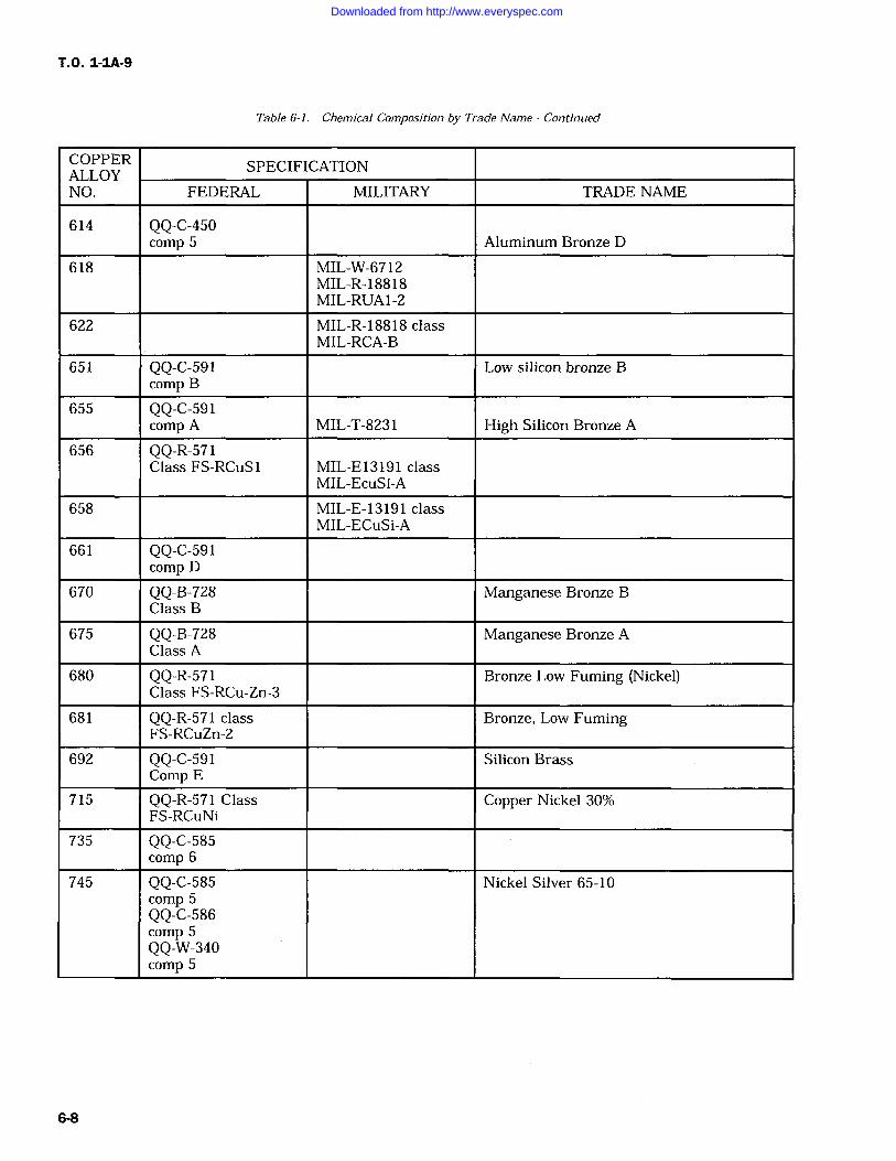
T.O. 1-IA-9
Table 6-1. Chemical Composition by Trade Name Continued
COPPER SPECIFICATIONALLOYNO. FEDERAL MILITARY TRADE NAME
614 QQ-C-450comp 5 Aluminum Bronze D
618 MIL-W-6712MIL-R-18818MIL-RUA1-2
622 MIL-R-18818 classMIL-RCA-B
651 QQ-C-591 Low silicon bronze Bcomp B
655 QQ-C-591comp A MIL-T-8231 High Silicon Bronze A
656 QQ-R-571Class FS-RCuS MIL-E13191 class
MIL-EcuSi-A
658 MIL-E-13191 classMIL-ECuSi-A
661 QQ-C-591comp D
670 QQ-B-728 Manganese Bronze BClass B
675 QQ-B-728 Manganese Bronze AClass A
680 QQ-R-571 Bronze Low Fuming (Nickel)Class FS-RCu-Zn-3
681 QQ-R-571 class Bronze, Low FumingFS-RCuZn-2
692 QQ-C-591 Silicon BrassComp E
715 QQ-R-571 Class Copper Nickel 30%FS-RCuNi
735 QQ-C-585comp 6
745 QQ-C-585 Nickel Silver 65-10comp 5QQ-C-586comp 5QQ-W-340comp 5
6-8
Downloaded from http://www.everyspec.com
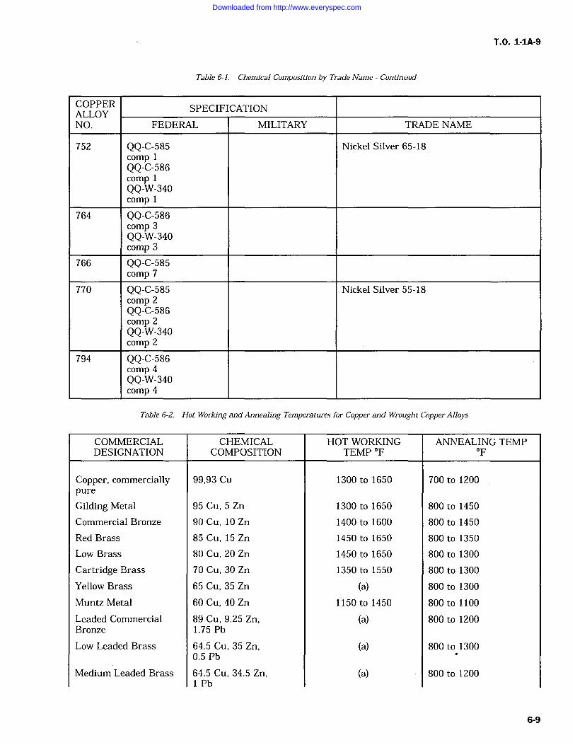
T.O. 1-IA-9
Table 6-1. Chemical Composition by Trade Name Continued
COPPER SPECIFICATIONALLOYNO. FEDERAL MILITARY TRADE NAME
752 QQ-C-585 Nickel Silver 65-18compQQ-C-586compQQ-W-340comp 1
764 QQ-C-586comp 3QQ-W-340comp 3
766 QQ-C-585comp 7
770 QQ-C-585 Nickel Silver 55-18comp 2QQ-C-586comp 2QQ-W-340comp 2
794 QQ-C-586comp 4QQ-W-340comp 4
Table 6-2. Hot Working and Annealing Temperatures for Copper and Wrought Copper Alloys
COMMERCIALDESIGNATION
CHEMICALCOMPOSITION
HOT WORKINGTEMP OF
ANNEALING TEMPOF
Copper, commercially 99,93 Cu 1300 to 1650 700 to 1200pure
Gilding Metal 95 Cu, 5 Zn 1300 to 1650 800 to 1450
Commercial Bronze 90 Cu, 10 Zn 1400 to 1600 800 to 1450
Red Brass 85 Cu, 15 Zn 1450 to 1650 800 to 1350
Low Brass 80 Cu, 20 Zn 1450 to 1650 800 to 1300
Cartridge Brass 70 Cu, 30 Zn 1350 to 1550 800 to 1300
Yellow Brass 65 Cu, 35 Zn (a) 800 to 1300
Muntz Metal 60 Cu, 40 Zn 1150 to 1450 800 to 1100
Leaded Commercial 89 Cu, 9.25 Zn, (a) 800 to 1200Bronze 1.75 Pb
Low Leaded Brass 64.5 Cu, 35 Zn, (a) 800 to 13000.5Pb
Medium Leaded Brass 64.5 Cu, 34.5 Zn, (a) 800 to 12001 Pb
6-9
Downloaded from http://www.everyspec.com
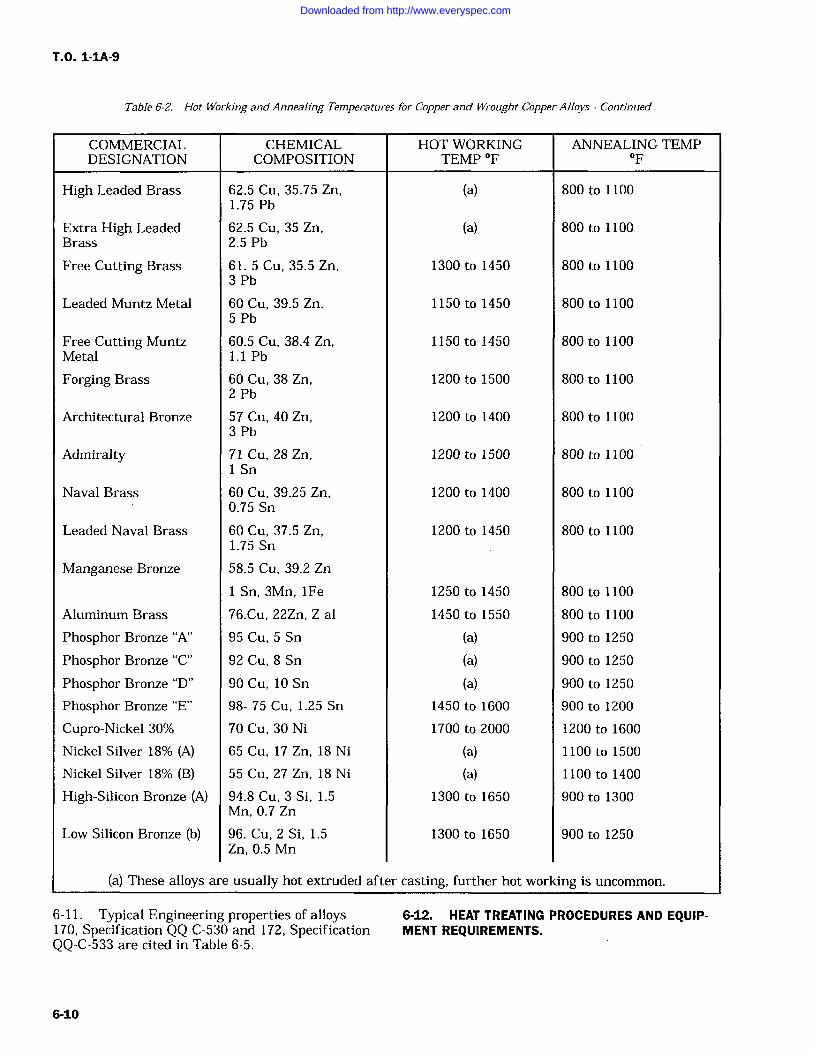
T.O. 1-1A-9
Table 6-Z. Hot Working and Annealing Temperatures for Copper and Wrought Copper Alloys Continued
COMMERCIAL CHEMICAL HOT WORKING ANNEALING TEMPDESIGNATION COMPOSITION TEMP OF OF
High Leaded Brass 62.5 Cu, 35.75 Zn, (a) 800 to 11001.75 Pb
Extra High Leaded 62.5 Cu, 35 Zn, (a) 800 to 1100Brass 2.5 Pb
Free Cutting Brass 61. 5 Cu, 35.5 Zn,3 Pb
1300 to 1450 800 to 1100
Leaded Muntz Metal 60 Cu, 39.5 Zn,5 Pb
1150 to 1450 800 to 1100
Free Cutting Muntz 60.5 Cu, 38.4 Zn, 1150 to 1450 800 to 1100Metal 1.1 Pb
Forging Brass 60 Cu, 38 Zn,2 Pb
1200 to 1500 800 to 1100
Architectural Bronze 57 Cu, 40 Zn,3 Pb
1200 to 1400 800 to 1100
Admiralty 71 Cu, 28 Zn,1 Sn
1200 to 1500 800 to 1100
Naval Brass 60 Cu, 39.25 Zn, 1200 to 1400 800 to 11000.75 Sn
Leaded Naval Brass 60 Cu, 37.5 Zn, 1200 to 1450 800 to 11001.75 Sn
Manganese Bronze 58.5 Cu, 39.2 Zn
1 Sn, 3Mn, iFe 1250 to 1450 800 to 1100
Aluminum Brass 76.Cu, 22Zn, Z al 1450 to 1550 800 to 1100
Phosphor Bronze "A" 95 Cu, 5 Sn (a) 900 to 1250
Phosphor Bronze "C" 92 Cu, 8 Sn (a) 900 to 1250
Phosphor Bronze "D" 90 Cu, 10 Sn (a) 900 to 1250
Phosphor Bronze "E" 98- 75 Cu, 1.25 Sn 1450 to 1600 900 to 1200
Cupro-Nickel 30% 70 Cu, 30 Ni 1700 to 2000 1200 to 1600
Nickel Silver 18% (A) 65 Cu, 17 Zn, 18 Ni (a) 1100 to 1500
Nickel Silver 18% (B) 55 Cu, 27 Zn, 18 Ni (a) 1100 to 1400
High-Silicon Bronze (A) 94.8 Cu, 3 Si, 1.5Mn, 0.7 Zn
1300 to 1650 900 to 1300
Low Silicon Bronze (b) 96. Cu, 2 Si, 1.5Zn, 0.5 Mn
1300 to 1650 900 to 1250
(a) These alloys are usually hot extruded after casting, further hot work
6-11. Typical Engineering properties of alloys
ing is uncommon.
6-12. HEAT TREATING PROCEDURES AND EQUIP-170, Specification QQ-C-530 and 172, Specification MENT REQUIREMENTS.QQ-C-533 are cited in Table 6-5.
6-10
Downloaded from http://www.everyspec.com
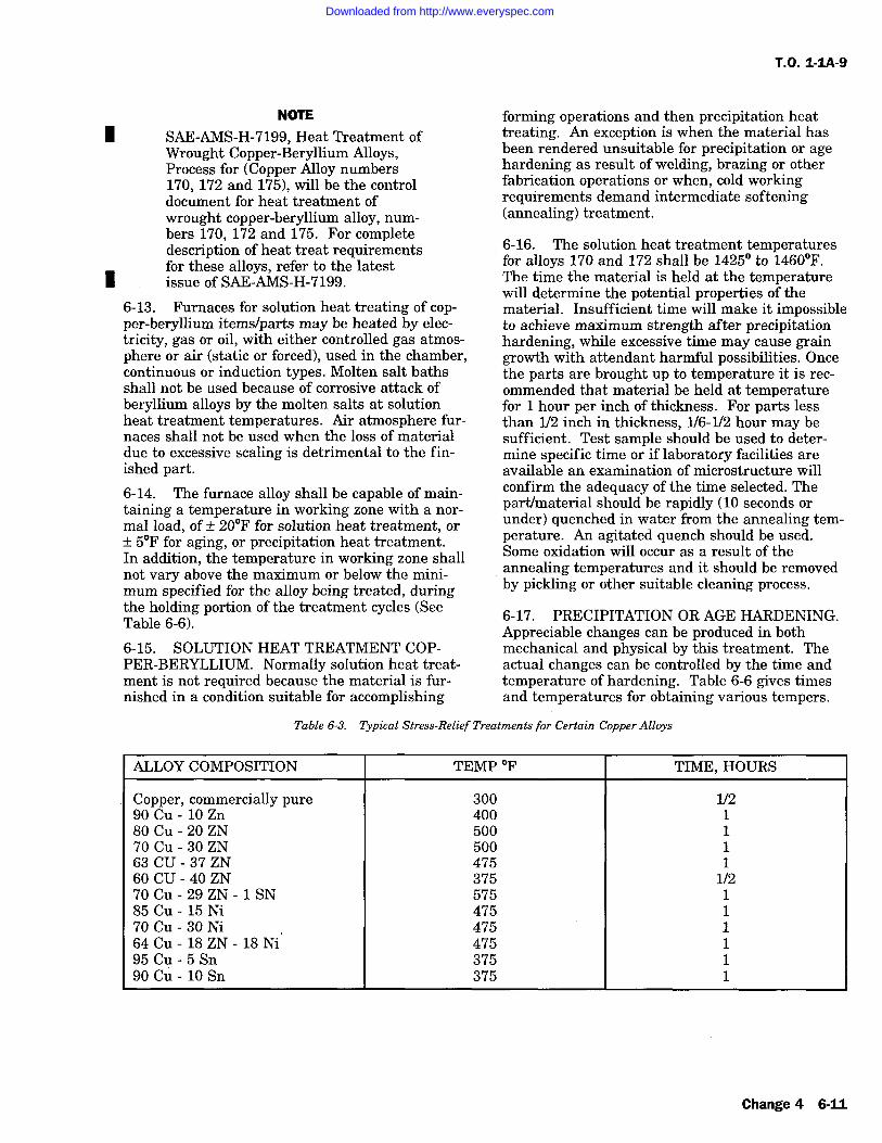
T.O. 1-1A-9
NOTE
SAE-AMS-H-7199, Heat Treatment ofWrought Copper-Beryllium Alloys,Process for (Copper Alloy numbers170, 172 and 175), will be the controldocument for heat treatment ofwrought copper-beryllium alloy, num-bers 170, 172 and 175. For completedescription of heat treat requirementsfor these alloys, refer to the latestissue of SAE-AMS-H-7199.
6-13. Furnaces for solution heat treating of cop-per-beryllium items/parts may be heated by elec-tricity, gas or oil, with either controlled gas atmos-phere or air (static or forced), used in the chamber,continuous or induction types. Molten salt bathsshall not be used because of corrosive attack ofberyllium alloys by the molten salts at solutionheat treatment temperatures. Air atmosphere fur-naces shall not be used when the loss of materialdue to excessive scaling is detrimental to the fin-ished part.6-14. The furnace alloy shall be capable of main-taining a temperature in working zone with a nor-
mal load, of +/- 20F for solution heat treatment, or
+/- 5F for aging, or precipitation heat treatment.In addition, the temperature in working zone shallnot vary above the maximum or below the mini-mum specified for the alloy being treated, duringthe holding portion of the treatment cycles (SeeTable 6-6).
6-15. SOLUTION HEAT TREATMENT COP-PER-BERYLLIUM. Normally solution heat treat-ment is not required because the material is fur-nished in a condition suitable for accomplishing
forming operations and then precipitation heattreating. An exception is when the material hasbeen rendered unsuitable for precipitation or agehardening as result of welding, brazing or otherfabrication operations or when, cold workingrequirements demand intermediate softening(annealing) treatment.
6-16. The solution heat treatment temperaturesfor alloys 170 and 172 shall be 1425 to 1460F.The time the material is held at the temperaturewill determine the potential properties of thematerial. Insufficient time will make it impossibleto achieve maximum strength after precipitationhardening, while excessive time may cause graingrowth with attendant harmful possibilities. Oncethe parts are brought up to temperature it is rec-ommended that material be held at temperaturefor 1 hour per inch of thickness. For parts lessthan 1/2 inch in thickness, 1/6-1/2 hour may besufficient. Test sample should be used to deter-mine specific time or if laboratory facilities areavailable an examination of microstructure willconfirm the adequacy of the time selected. Thepart/material should be rapidly (10 seconds orunder) quenched in water from the annealing tem-perature. An agitated quench should be used.Some oxidation will occur as a result of theannealing temperatures and it should be removedby pickling or other suitable cleaning process.
6-17. PRECIPITATION OR AGE HARDENING.Appreciable changes can be produced in bothmechanical and physical by this treatment. Theactual changes can be controlled by the time andtemperature of hardening. Table 6-6 gives timesand temperatures for obtaining various tempers.
Table 6-3. Typical Stress-Relief Treatments for Certain Copper Alloys
ALLOY COMPOSITION TEMP OF TIME, HOURS
Copper, commercially pure 300 1/290 Cu lO Zn 400 180 Cu 20 ZN 500 170 Cu 30 ZN 500 163 CU 37 ZN 475 160 CU 40 ZN 375 1/270 Cu 29 ZN 1 SN 575 185 Cu 15 Ni 475 170Cu-30Ni 475 164 Cu 18 ZN 18 Ni 475 195 Cu 5 Sn 375 190 Cu lO Sn 375 1
Change 4 6-11
Downloaded from http://www.everyspec.com
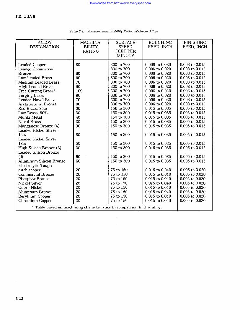
T.O. 1-IA-9
Table 6-4. Standard Machinability Rating of Copper Alloys
ALLOYDESIGNATION
MACHINA-BILITYRATING
SURFACESPEED
FEET PERMINUTE
ROUGHINGFEED, INCH
FINISHINGFEED, INCH
Leaded Copper 80 300 to 700 0.006 to 0.020 0.003 to 0.015Leaded Commercial 300 to 700 0.006 to 0.020 0.003 to 0.015Bronze 80 300 to 700 0.006 to 0.020 0.003 to 0.015Low Leaded Brass 60 300 to 700 0.006 to 0.020 0.003 to 0.015Medium Leaded Brass 70 300 to 700 0.006 to 0.020 0.003 to 0.015High Leaded Brass 90 300 to 700 0.006 to 0.020 0.003 to 0.015Free Cutting Brass* 100 300 to 700 0.006 to 0.020 0.003 to 0.015Forging Brass 80 300 to 700 0.006 to 0.020 0.003 to 0.015Leaded Naval Brass 70 300 to 700 0.006 to 0.020 0.003 to 0.015Architectural Bronze 90 300 to 700 0.006 to 0.020 0.003 to 0.015Red Brass, 85% 30 150 to 300 0.015 to 0.035 0.005 to 0.015Low Brass, 80% 30 150 to 300 0.015 to 0.035 0.005 to 0.015Muntz Metal 40 150 to 300 0.015 to 0.035 0.005 to 0.015Naval Brass 30 150 to 300 0.015 to 0.035 0.005 to 0.015Manganese Bronze (A) 30 150 to 300 0.015 to 0.035 0.005 to 0.015Leaded Nickel Silver,12% 50 150 to 300 0.015 to 0.035 0.005 to 0.015Leaded Nickel Silver18% 50 150 to 300 0.015 to 0.035 0.005 to 0.015High Silicon Bronze (A) 30 150 to 300 0.015 to 0.035 0.005 to 0.015Leaded Silicon Bronze(d) 60 150 to 300 0.015 to 0.035 0.005 to 0.015Aluminum Silicon Bronze 60 150 to 300 0.015 to 0.035 0.005 to 0.015Electrolytic Toughpitch copper 20 75 to 150 0.015 to 0.040 0.005 to 0.020Commercial Bronze 20 75 to 150 0.015 to 0.040 0.005 to 0.020Phosphor Bronze 20 75 to 150 0.015 to 0.040 0.005 to 0.020Nickel Silver 20 75 to 150 0.015 to 0.040 0.005 to 0.020Cupro-Nickel 20 75 to 150 0.015 to 0.040 0.005 to 0.020Aluminum Bronze 20 75 to 150 0.015 to 0.040 0.005 to 0.020Beryllium Copper 20 75 to 150 0.015 to 0.040 0.005 to 0.020Chromium Copper 20 75 to 150 0.015 to 0.040 0.005 to 0.020
Table based on machining characteristics in comparison to this alloy.
6-12
Downloaded from http://www.everyspec.com
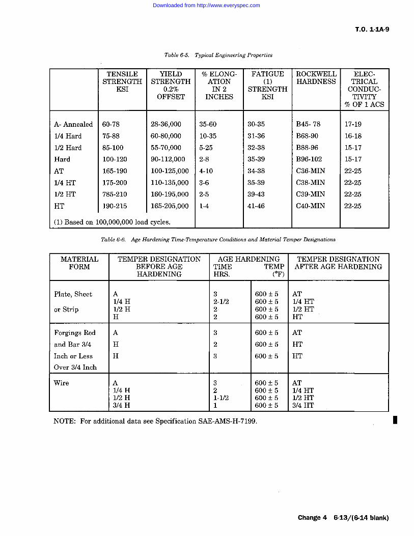
T.O. 1-IA-9
Table 6-5. Typical Engineering Properties
TENSILESTRENGTH
KSI
YIELDSTRENGTH
0.2%OFFSET
% ELONG-ATIONIN 2
INCHES
FATIGUE(1)
STRENGTHKSI
ROCKWELLHARDNESS
ELEC-TRICALCONDUC-TIVITY
% OF 1 ACS
A- Annealed 60-78 28-36,000 35-60 30-35 B45- 78 17-19
1/4 Hard 75-88 60-80,000 10-35 31-36 B68-90 16-18
1/2 Hard 85-100 55-70,000 5-25 32-38 B88-96 15-17
Hard 100-120 90-112,000 2-8 35-39 B96-102 15-17
AT 165-190 100-125,000 4-10 34-38 C36-MIN 22-25
1/4 HT 175-200 110-135,000 3-6 35-39 C38-MIN 22-25
1/2 HT 785-210 160-195,000 2-5 39-43 C39-MIN 22-25
HT 190-215 165-205,000 1-4 41-46 C40-MIN 22-25
(1) Based on 100,000,000 load cycles.
Table 6-6. Age Hardening Time-Temperature Conditions and Material Temper Designations
MATERIAL TEMPER DESIGNATION AGE HARDENING TEMPER DESIGNATIONFORM BEFORE AGE TIME TEMP AFTER AGE HARDENING
HARDENING HRS. (F)
Plate, Sheet A 3 600 +/- 5 AT1/4 H 2-1/2 600 +/- 5 1/4 HT
or Strip 1/2 H 2 600 +/- 5 1/2 HTH 2 600+/-5 HT
Forgings Rod A 3 600 +/- 5 AT
and Bar 3/4 H 2 600 +/- 5 HT
Inch or Less H 3 600 +/- 5 HT
Over 3/4 Inch
Wire A 3 600 +/- 5 AT1/4 H 2 600 +/- 5 1/4 HT1/2 H 1-1/2 600 +/- 5 1/2 HT3/4 H 1 600 +/- 5 3/4 HT
NOTE: For additional data see Specification SAE-AMS-H-7199. I
Change 4 6-13/(6-14 blank)
Downloaded from http://www.everyspec.com

Downloaded from http://www.everyspec.com
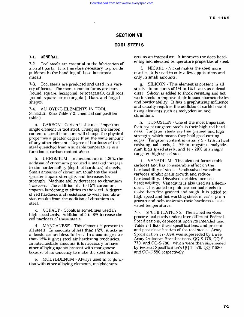
T.O. 1-1A-9
SECTION VII
TOOL STEELS
7-1. GENERAL.
7-2. Tool steels are essential to the fabrication ofaircraft parts. It is therefore necessary to provideguidance in the handling of these importantmetals.
7-3. Tool steels are produced and used in a vari-ety of forms. The more common forms are bars,(round, square, hexagonal, or octaganal), drill rods,(round, square, or rectangular), flats, and forgedshapes.7-4. ALLOYING ELEMENTS IN TOOLSTEELS. (See Table 7-2, chemical compositiontable.)
a. CARBON Carbon is the most importantsingle element in tool steel. Changing the carboncontent a specific amount will change the physicalproperties a greater degree than the same amountof any other element. Degree of hardness of toolsteel quenched from a suitable temperature is afunction of carbon content alone.
b. CHROMIUM In amounts up to 1.80% theaddition of chromium produced a marked increasein the hardenability (depth of hardness) of steels.Small amounts of chromium toughens the steel(greater impact strength), and increases itsstrength. Machine ability decreases as chromiumincreases. The addition of 5 to 15% chromiumimparts hardening qualities to the steel. A degreeof red hardness and resistance to wear and abra-sion results from the addition of chromium tosteel.
c. COBALT Cobalt is sometimes used inhigh speed tools. Addition of 5 to 8% increase thered hardness of these steels.
d. MANGANESE This element is present inall steels. In amounts of less than 1/2%, it acts as
a deoxidizer and desulfurizer. In amounts greaterthan 15% it gives steel air hardening tendencies.In intermediate amounts it is necessary to haveother alloying agents present with manganesebecause of its tendency to make the steel brittle.
e. MOLYBDENUM Always used in conjunc-tion with other alloying elements, molybdenum
acts as an intensifier. It improves the deep hard-ening and elevated temperature properties of steel.
f. NICKEL Nickel makes the steel moreductile. It is used in only a few applications andonly in small amounts.
g. SILICON This element is present in allsteels. In amounts of 1/4 to 1% it acts as a deoxi-dizes. Silicon is added to shock resisting and hotwork steels to improve their impact characteristicsand hardenability. It has a graphitizing influenceand usually requires the addition of carbide stabi-lizing elements such as molybdenum andchromium.
h. TUNGSTEN One of the most importantfeatures of tungsten steels is their high red hard-ness. Tungsten steels are fine grained and highstrength, which means they hold good cuttingedges. Tungsten content is usually 5 12% in heatresisting tool steels, 4 9% in tungsten molybde-num high speed steels, and 14 20% in straighttungsten high speed steel.
i. VANADIUM This element forms stablecarbides and has considerable effect on thehardenability of steels. Undissolved vanadiumcarbides inhibit grain growth and reducehardenability. Dissolved carbides increasehardenability. Vanadium is also used as a deoxi-dizer. It is added to plain carbon tool steels tomake them fine grained and tough. It is added tohigh speed and hot working steels to resist graingrowth and help maintain their hardness at ele-vated temperatures.
7-5. SPECIFICATIONS. The armed services
procure tool steels under three different FederalSpecifications, dependent upon its intended use.Table 7-1 lists these specifications, and presentand past classification of the tool steels. ArmySpecification 57-108A was superseded by threeArmy Ordnance Specifications, QQ-S-778, QQ-S-779, and QQ-S-780. which were then supersededby Federal Specification's QQ-T-570, QQ-T-580and QQ-T-590 respectively.
7-1
Downloaded from http://www.everyspec.com
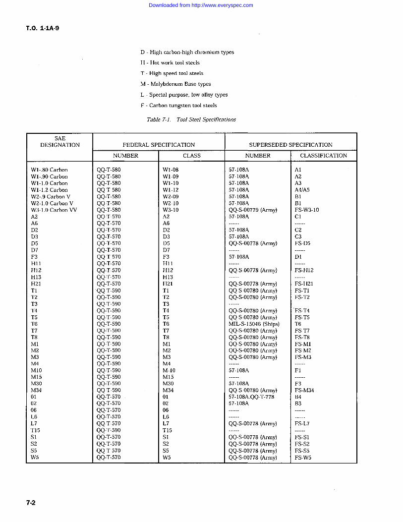
T.O. 1-IA-9
D High carbon-high chromium types
H Hot work tool steels
T High speed tool steels
M Molybdenum Base types
L Special purpose, low alloy types
F Carbon tungsten tool steels
Table 7-1. Tool Steel Specifications
SAEDESIGNATION FEDERAL SPECIFICATION SUPERSEDED SPECIFICATION
NUMBER CLASS NUMBER CLASSIFICATION
W1-.80 Carbon QQ-T-580 W1-08 57-108A AlWl-.90 Carbon QQ-T-580 W1-09 57-108A A2W1-1.0 Carbon QQ-T-580 W1-10 57-108A A3W1-1.2 Carbon QQ-T-580 Wl-12 57-108A A4/A5W2-.9 Carbon V QQ-T-580 W2-09 57-108A BlW2-1.0 Carbon V QQ-T-580 W2-10 57-108A B1W3-1.0 Carbon VV QQ-T-580 W3-10 QQ-S-00779 (Army) FS-W3-10A2 QQ-T-570 A2 57-108A CA6 QQ-T-570 A6D2 QQ-T-570 D2 57-108A C2D3 QQ-T-570 D3 57-108A C3D5 QQ-T-570 D5 QQ-S-00778 (Army) FS-D5D7 QQ-T-570 D7F3 QQ-T-570 F3 57-108A D1H11 QQ-T-570 H11H12 QQ-T-570 H12 QQ-S-00778 (Army) FS-H12H13 QQ-T-570 H13H21 QQ-T-570 H21 QQ-S-00778 (Army) FS-H21T1 QQ-T-590 T1 QQ-S-00780 (Army) FS-T1T2 QQ-T-590 T2 QQ-S-00780 (Army) FS-T2T3 QQ-T-590 T3T4 QQ-T-590 T4 QQ-S-00780 (Army) FS-T4T5 QQ-T-590 T5 QQ-S-00780 (Army) FS-T5T6 QQ-T-590 T6 MIL-S-15046 (Ships) T6T7 QQ-T-590 T7 QQ-S-00780 (Army) FS-T7T8 QQ-T-590 T8 QQ-S-00780 (Army) FS-T8M1 QQ-T-590 M1 QQ-S-00780 (Army) FS-M1M2 QQ-T-590 M2 QQ-S-00780 (Army) FS-M2M3 QQ-T-590 M3 QQ-S-00780 (Army) FS-M3M4 QQ-T-590 M4M10 QQ-T-590 M-10 57-108A FlM15 QQ-T-590 M15M30 QQ-T-590 M30 57-108A F3M34 QQ-T-590 M34 QQ-S-00780 (Army) FS-M3401 QQ-T-570 01 57-108A.QQ-T-778 B402 QQ-T-570 02 57-108A B306 QQ-T-570 06L6 QQ-T-570 L6L7 QQ-T-570 L7 QQ-S-00778 (Army) FS-L7T15 QQ-T-590 T15S1 QQ-T-570 Si QQ-S-00778 (Army) FS-S1S2 QQ-T-570 S2 QQ-S-00778 (Army) FS-S2S5 QQ-T-570 S5 QQ-S-00778 (Army) FS-S5W5 QQ-T-570 W5 QQ-S-00778 (Army) FS-W5
7-2
Downloaded from http://www.everyspec.com
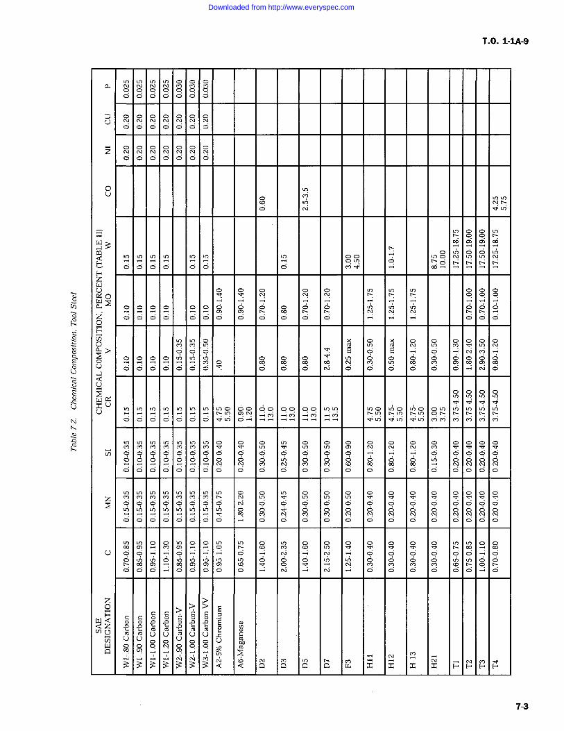
T.O. 1-1A-9
0 0 00 0 0 00 0 0 0
O NUO O O
O Oz6 O O
0
(Y
QOO
O 4Fz
0YO
Y+ O O O
z O O
HV) X O O OO CO CO> E O E
O 'T O O00U
0 0 O O
U
u il IT IT ITU
C] o O v) I InO M M _;
O O 4
V) O O O OO 0 0
O CI
zOY u7 c1') IC) VY O O 0
O
O O
U O
O O O O O O
O O
o > >C C
>C C 7
W Q O o o p A EQ Z A 'n N a
ro M U U U UU U U U
W O O OQ ?
Q Q Q w x x x x H H H H
7-3
Downloaded from http://www.everyspec.com
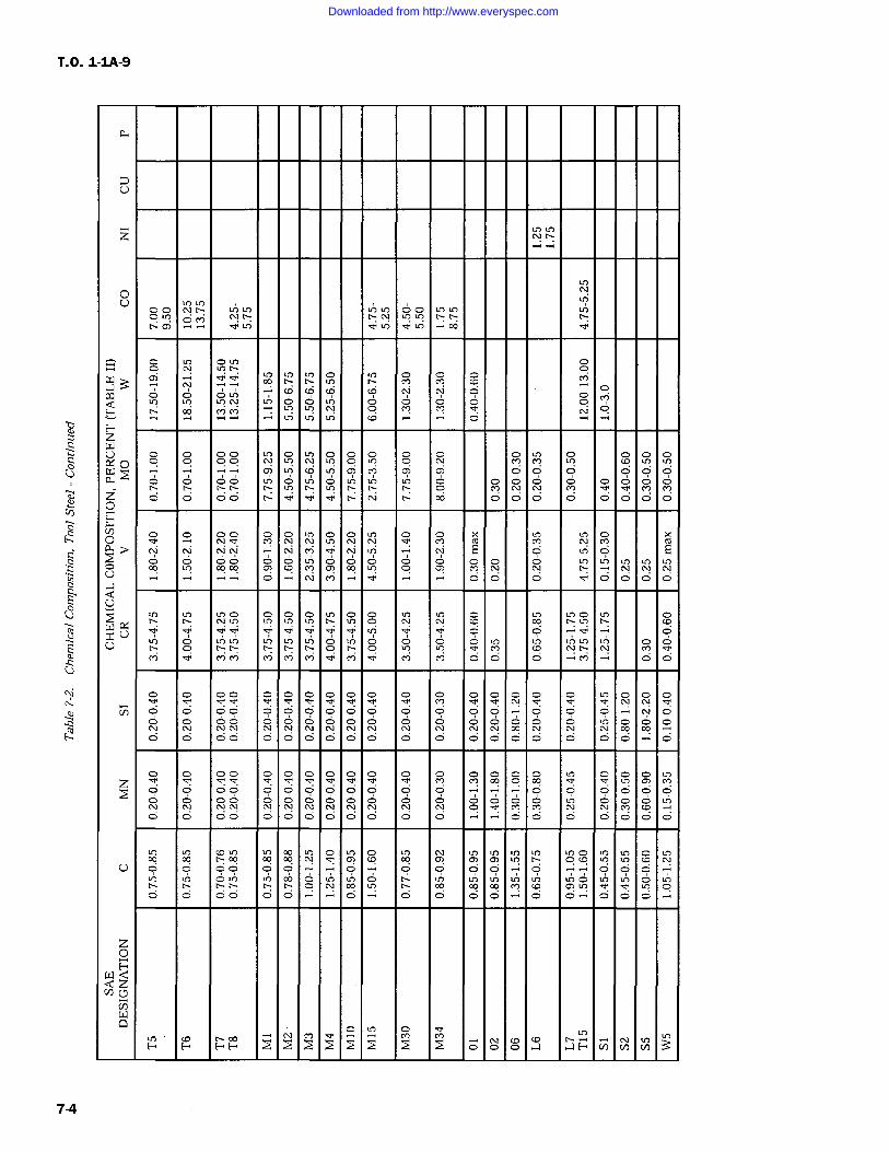
T.O. 1-1A-9
0
OU
O0m
U)w N CO-7(Y
lfY O OE" N
Fz
C.)R! O U? 0 Cl?w O) L? O) O OPr O IO O O O
t'-:z O O O0
X kO C16 E
O O OCl?U
O O O
U0
Lq
oOO O
M
O 0 O
O O 0O O O O
O O
Oz IT I! Cl?
0 O 0O 0
0
U 0 71 71U) U) U) 00 0 u7 O )n in )n in IC) C1') U) U)0 0
O
z0H
0 oF F
FF. 0 0 0 pc)
v) Cn
7-4
Downloaded from http://www.everyspec.com
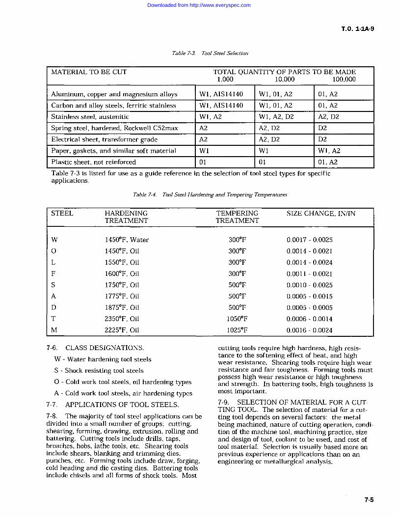
T.O. 1-1A-9
Table 7-3. Tool Steel Selection
MATERIAL TO BE CUT TOTAL QUANTITY OF PARTS TO BE MADE1,000 10,000 100,000
Aluminum, copper and magnesium alloys Wl, AIS 14140 Wl, 01, A2 01, A2
Carbon and alloy steels, ferritic stainless Wl, AIS 14140 Wl, 01, A2 01, A2
Stainless steel, austenitic W1, A2 W1, A2, D2 A2, D2
Spring steel, hardened, Rockwell C52max A2 A2, D2 D2
Electrical sheet, transformer grade A2 A2, D2 D2
Paper, gaskets, and similar soft material W1 W1 Wl, A2
Plastic sheet, not reinforced 01 01 01, A2
Table 7-3 is listed for use as a guide reference in the selection of tool steel types for specificapplications.
Table 7-4. Tool Steel Hardening and Tempering Temperatures
STEEL HARDENINGTREATMENT
TEMPERINGTREATMENT
SIZE CHANGE, IN/IN
W 1450F, Water 300F 0.0017 0.0025
0 1450F, Oil 300F 0.0014 0.0021
L 1550F, Oil 300F 0.0014 0.0024
F 1600F, Oil 300F 0.0011 0.0021
S 1750F, Oil 500F 0.0010 0.0025
A 1775F, Oil 500F 0.0005 0.0015
D 1875F, Oil 500F 0.0005 0.0005
T 2350F, Oil 1050F 0.0006 0.0014
M 2225F, Oil 1025F 0.0016 0.0024
7-6. CLASS DESIGNATIONS.
W Water hardening tool steels
S Shock resisting tool steels
O Cold work tool steels, oil hardening typesA Cold work tool steels, air hardening types
7-7. APPLICATIONS OF TOOL STEELS.
7-8. The majority of tool steel applications can bedivided into a small number of groups: cutting,shearing, forming, drawing, extrusion, rolling andbattering. Cutting tools include drills, taps,broaches, hobs, lathe tools, etc. Shearing toolsinclude shears, blanking and trimming dies,punches, etc. Forming tools include draw, forging,cold heading and die casting dies. Battering toolsinclude chisels and all forms of shock tools. Most
cutting tools require high hardness, high resis-tance to the softening effect of heat, and highwear resistance. Shearing tools require high wear
resistance and fair toughness. Forming tools mustpossess high wear resistance or high toughnessand strength. In battering tools, high toughness ismost important.7-9. SELECTION OF MATERIAL FOR A CUT-TING TOOL. The selection of material for a cut-ting tool depends on several factors: the metalbeing machined, nature of cutting operation, condi-tion of the machine tool, machining practice, sizeand design of tool, coolant to be used, and cost oftool material. Selection is usually based more onprevious experience or applications than on anengineering or metallurgical analysis.
7-5
Downloaded from http://www.everyspec.com
T.O. 1-IA-9
7-10. High speed cutting tools are usually manu-factured from the class "T" or class "M" alloys.Four classes, Ti, Ml, M2 and M10 make up nearly90% of the general purpose high speed steels. Cer-tain special purpose steels in each class, such asT6, T7, T8 and T15 are advantageous for opera-tions like milling cutters and prehardened forgingdie blocks.
7-11. High speed drills should possess highstrength and toughness, notably Ml, M2, M10 andTi. Classes Ti and Ml are used for tools subjectto shock, while M2 and M10 are generally usedwhere tools require less toughness and more abra-sion resistance.
7-12. Material for reamers should be of highhardness and abrasion resistance, such as Ml, M2,M10 and T1. The M3 and M15 and T15 classespossess greater abrasion resistance than the lower-vanadium grades.7-13. Material for taps is generally of the M1M2 or M10 types. In tapping heat-resisting alloysor steels harder than Rockwell C35, M15 or T15may be justified.7-14. Milling cutters are usually made from thehigh speed steels. As the hardness of theworkpiece increases beyond Rockwell C35, thecobalt high speed steels should be used.
7-15. Recommended punch and die material forblanking parts from 0.050 inch sheet materials areshown in following table. This table does not coverall operations, and is a sample table intended foruse as a guide only.7-16. HEAT TREAT DATA.
NOTE
Additional Heat Treatment informa-tion is discussed in Section IX.
7-17. The thermal treatments listed in table 7-5cover the generally used treatments for the forg-ings, normalizing, and annealing of tool and diesteels. The thermal treatments listed in table 7-7cover the usual ranges of temperatures for harden-ing and tempering tool and die steels. Thesetables are listed for use as a guide only, and testsamples should be checked prior to use.
7-18. DISTORTION IN TOOL STEELS. Distor-tion is a general term encompassing all dimen-sional changes; the two main types being volumechange or change in geometrical form. Volumechange is defined as expansion or contraction andgeometric change is defined as changes in curva-
ture or angular relations. Table 7-4 shows an
approximate range of size changes depending uponthe type of tool steel, and also dependent on spe-cific tempering and heat treatments. If a veryclose tolerance is required for a finished tool, spe-cific data covering this item should be obtainedfrom a detailed source.
7-19. Deleted
7-20. Deleted
7-21. Deleted
7-22. Deleted
7-23. Deleted
7-6 Change I
Downloaded from http://www.everyspec.com
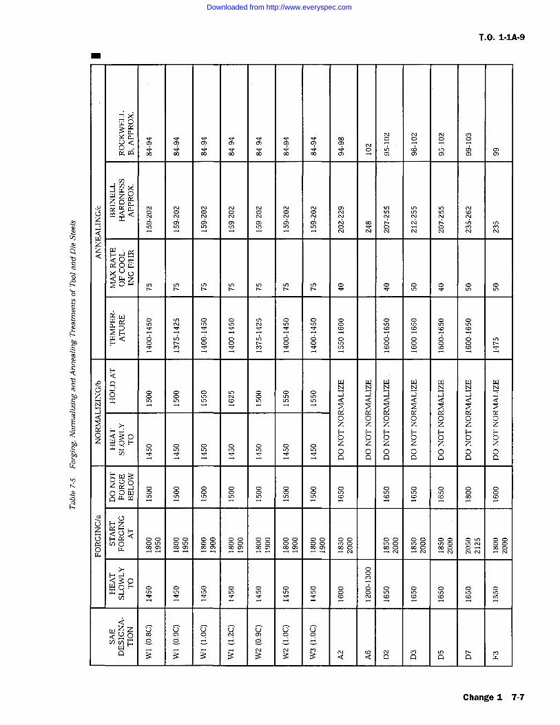
T.O. 1-1A-9
OwaYY. a0 Q rnO04 6)
V)
(Y. aQ O Oz
c'2 2 2 9 2 2 2 O
Q OxO
Q wzQ- O O
0:W
w x
W Q O OO O O9
N N N N N N NN
0 0 0 0 0 0 0<z z z z z z zYa
z z z z z z z zx az z z z z z z
n 0 00 n 0 0 00
0UOOca w Y Y
0z YYFC7 F"xQ
00 00(y! (n 0 O O0 rn 09 2
F ra
W O E'-' O O OY, O
0Q 0 C) O
Change 1 7-7
Downloaded from http://www.everyspec.com
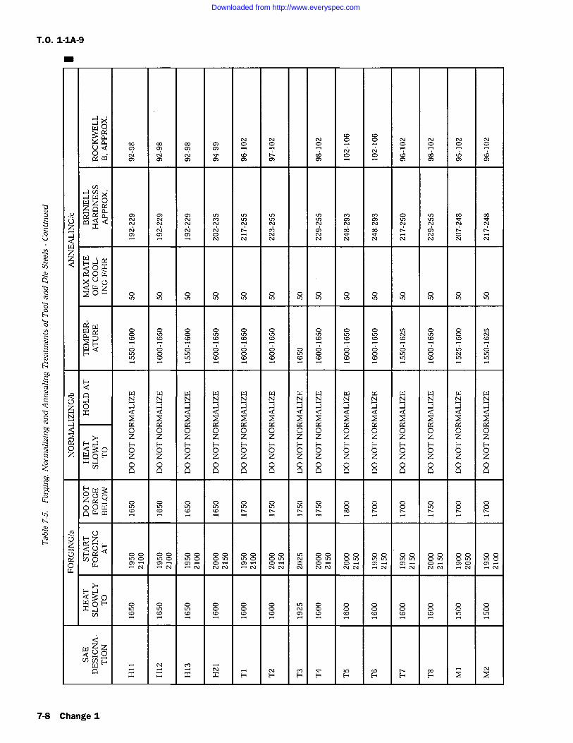
T.O. 1-IA-9
m
0YaY. R
U Q 00 O O
OO: W
06 OO
Cn
W OW zYR: a OQ
zzC)
aQ
Wa a
QOu
z0 O
R;W
W Q O OH LU
H
La W W W W W W W W W W W W W WN N N N N N N N N N N N N N
z 0 a a a a a a a a a a a a a ax Q Q Q Q Q Q Q Q Q Q Q Q Q Q
N
a R: R: R' a' Y R: a' 0.' R: CG fL' Lx R: R;Q O O O 0 0 0 0 0 0 0 0 0 0 0
z z z z z z z z z z z z z zHaH H H H H H H H H H H H H H0 Q 0 0 0 0 0 0 0 0 0 0 0 0 0 0 0z SOH z z z z z z z z z z z z z z0 0 0 0 0 0 Q Q 0 0 0 0 0 0
z C4p 0 W
pC) H zz HQLa
0 O O
QUOO H O
V) CO CO LU LU
zzNNoF
WQ x x x x H H H H H H H H
7-8 Change I
Downloaded from http://www.everyspec.com
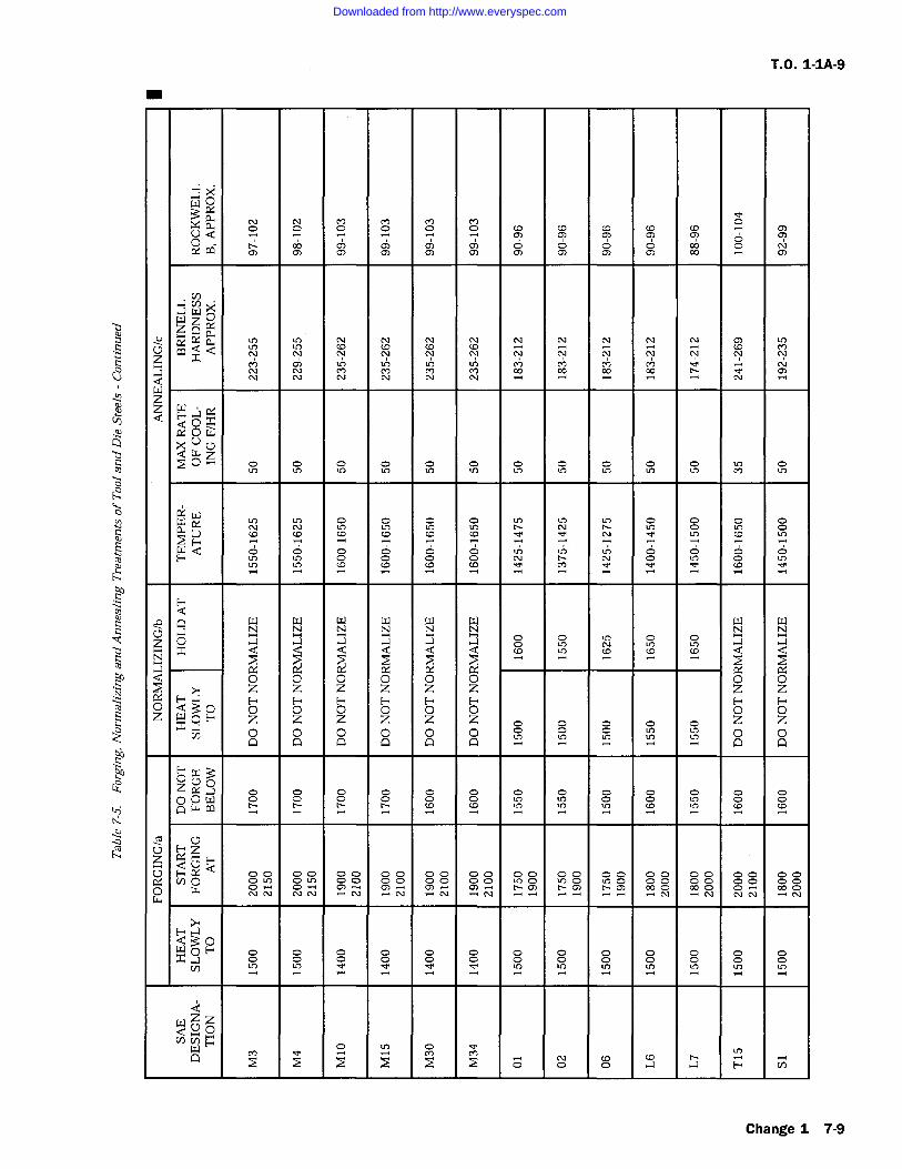
T.O. 1-1A-9
0wawx a
U Q O o rn w0R CQ O O
00
Ow z C,Qaa ) - - -<W Qz
.aQ
C.Ou
z0 o o
fZW(Y O O O OY CD CD
71N_
W Q O OOCO
QN YNi rN-i N rNr rNr N
z O a .a .a .a 00 N o
x -N
0 0 0 0 0 0 0 0z z z z z z z zFa
z 0 0 0xoz z z
z zzU)
0 0 0 0 0U) U) U
0 0n
Zo 0
00 Hzz u
Q a00 00 00
0.! (nom 00 000 w N N N N N N N N N
Q30W 0 F-' 0
..) O O O OV) U)
zzNN0W - OMQ
.a H ()
Change 1 7-9
Downloaded from http://www.everyspec.com
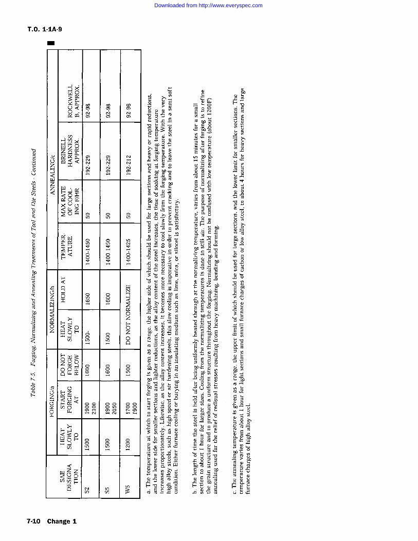
T.O. 1-1A-9
m
0
xaUQ C) C)64 CL1 C)
C) C)
WWz 0Q
im.' QY. az CQxQJ
owUw z0..
fZ Wa o N
F Q o O
d.a N
z x cc oc1 a
wh 0z o
zx[n
o oQ
000z x0 0 w
ro
Z Y.Q0
W, (/J O O0 W NLL4
QUO00 O
W zi OYV) PWQ
V) cn
C
.E aoo w Co S
vEbLp
roE
C
CUo Y > w
co). E C aCiA
Iz
00 0
Cx.C o
7 ro
-c
10 07m m
CO
oco
O. b0
C
is a wc V -0t0, ybc m -,
bA
bD ro h 0 i.ro
C
Cro
0
to
rod COa0-+ W
7-10 Change 1
Downloaded from http://www.everyspec.com
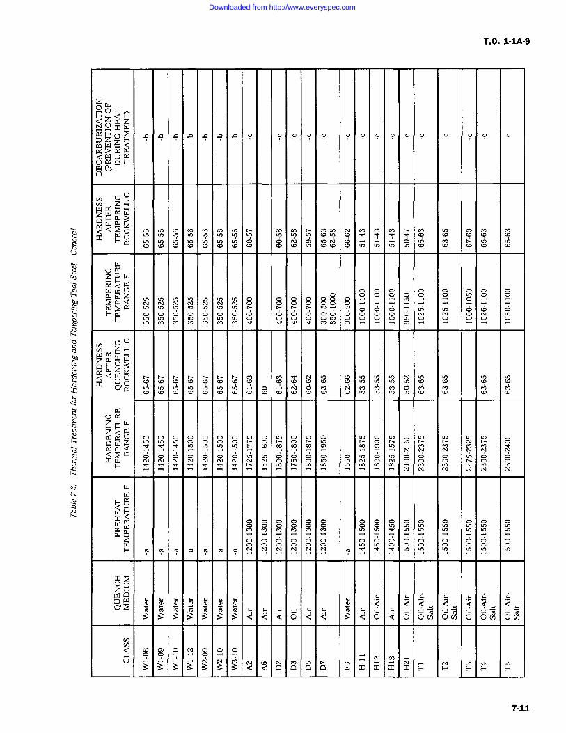
T.O. 1-1A-9
0Owz
a z (YY Z .n .a p A .a p p v cv cv v cv vW Q
Un;q
F"aQ
YvaazWaY
Q OQQ (C
F-' CC)(C to
Oco (D
Yzw
z O O O O O O Oa -, 0 0
W l7 7H (S] O O O 0
O
U UYbPQ W
Q UY (D CO COY 0O M
C.7 R'zawzY"W
C'Z
QOW
Y. Q.n_m _m N
Q'"T (7Y
WF"'
W WR Q
WE"' ro ro ro ro
Q Qro ro al ro ro ro ro
Q.aU
O 'r _N _MLL
7-11
Downloaded from http://www.everyspec.com
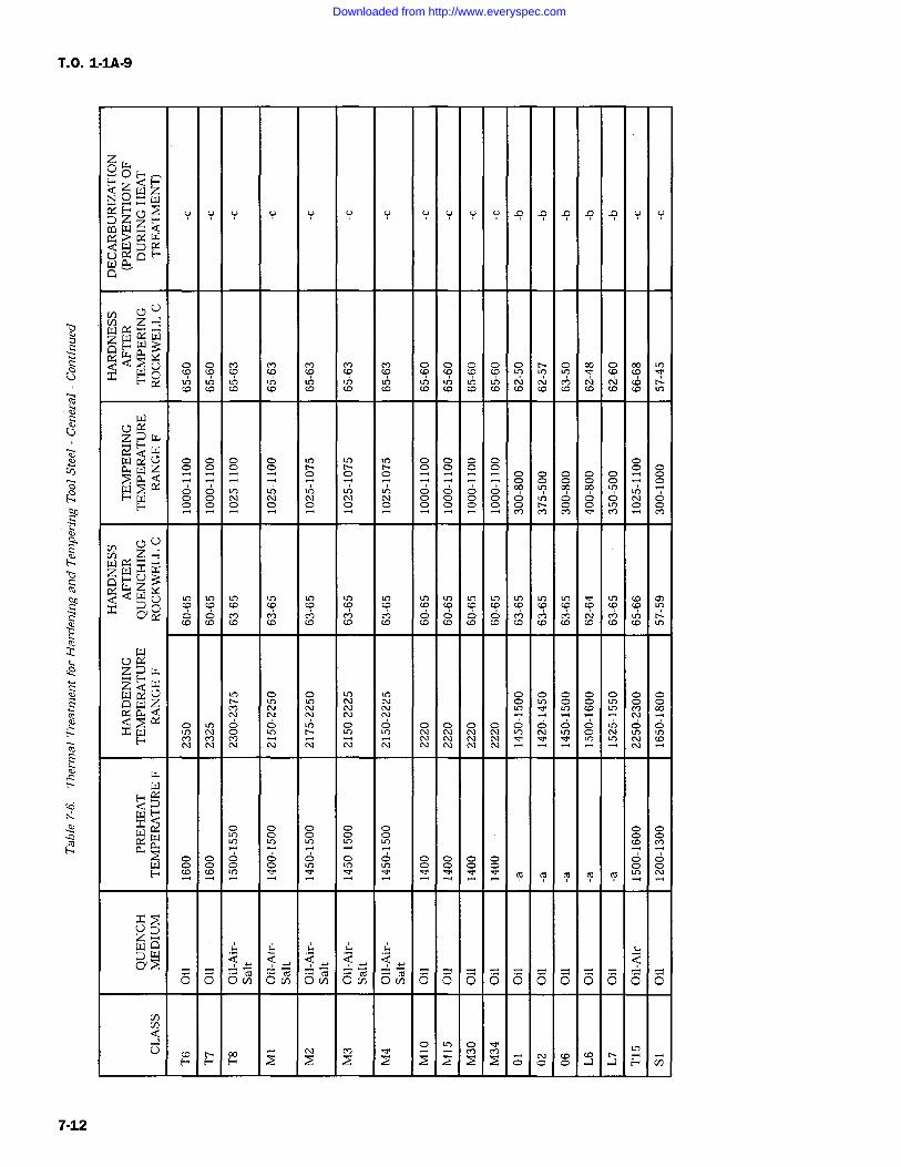
T.O. 1-IA-9
zw
H-0xzzQ y y y y y y y y y y y .9 p a .9 A y y
> rxwYQ
U Uwxaazww
0Ux W
F In 'T I?N I?D
zYwY" wwa 0z
00
00 0
0000 00 .~i 00
wF W
C7 CY In If) In In In C7 00
o 6 I? C9 C9 InO
O O O O 0 0 0
UUV) zazwxWw xY z
uCD
CD
O 0co CD
In lY
zYwwW0
Q W z0 0 0
O O0 0
Q: P0 0 Ox W
F
wH
w woO
Q 0 0 0 0 0 0 0W o
00
F v m ro T T cd
0 0 ova o(Y 0V) ova ova 0 01 01 01 00 0 0 0 0 0
-t
jo" CIO)
7-12
Downloaded from http://www.everyspec.com
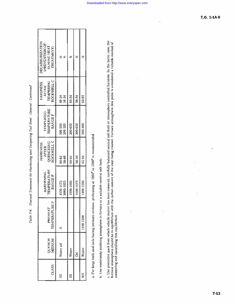
zO <Hza wz
ZY,W'wLYa QA
UZ WzWY
QwaYx F o 00 0 00
]zw- F W
WY
C7aWz I o C CF wF
NUC7
zwxwwzY xw (Y
x xo O
c0D Lo CD co
cYazzQ
z0
wxa BCD CO
CODF
wF
a a0
d
Yz
Ca.a
W C) C) C)a3 3 0
UC
V
Downloaded from http://www.everyspec.com
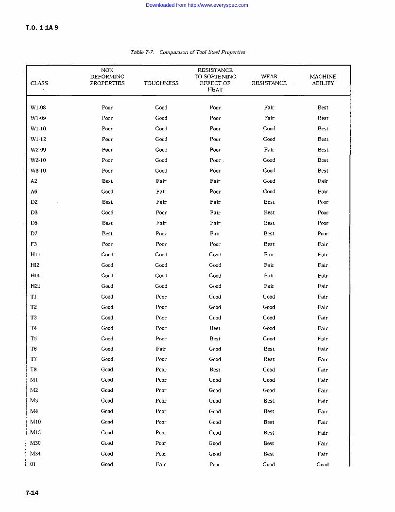
T.O. 1-1A-9
Table 7-7. Comparison of Tool Steel Properties
NON RESISTANCEDEFORMING TO SOFTENING WEAR MACHINE
CLASS PROPERTIES TOUGHNESS EFFECT OF RESISTANCE ABILITYHEAT
WI-08 Poor Good Poor Fair Best
Wi-09 Poor Good Poor Fair Best
W1-10 Poor Good Poor Good Best
W1-12 Poor Good Poor Good Best
W2-09 Poor Good Poor Fair Best
W2-10 Poor Good Poor Good Best
W3-10 Poor Good Poor Good Best
A2 Best Fair Fair Good Fair
A6 Good Fair Poor Good Fair
D2 Best Fair Fair Best Poor
D3 Good Poor Fair Best Poor
D5 Best Fair Fair Best Poor
D7 Best Poor Fair Best Poor
F3 Poor Poor Poor Best Fair
H11 Good Good Good Fair Fair
H12 Good Good Good Fair Fair
H13 Good Good Good Fair Fair
H21 Good Good Good Fair Fair
Ti Good Poor Good Good Fair
T2 Good Poor Good Good Fair
T3 Good Poor Good Good Fair
T4 Good Poor Best Good Fair
T5 Good Poor Best Good Fair
T6 Good Fair Good Best Fair
T7 Good Poor Good Best Fair
T8 Good Poor Best Good Fair
Mi Good Poor Good Good Fair
M2 Good Poor Good Good Fair
M3 Good Poor Good Best Fair
M4 Good Poor Good Best Fair
M10 Good Poor Good Best Fair
M15 Good Poor Good Best Fair
M30 Good Poor Good Best Fair
M34 Good Poor Good Best Fair
01 Good Fair Poor Good Good
7-14
Downloaded from http://www.everyspec.com
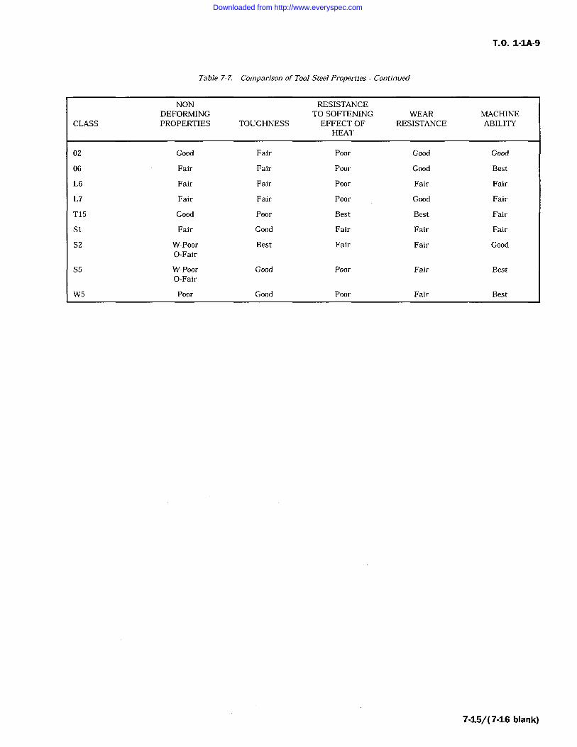
T.O. 1-IA-9
Table 7-7. Comparison of Tool Steel Properties Continued
NON RESISTANCEDEFORMING TO SOFTENING WEAR MACHINE
CLASS PROPERTIES TOUGHNESS EFFECT OF RESISTANCE ABILITYHEAT
02 Good Fair Poor Good Good
06 Fair Fair Poor Good Best
L6 Fair Fair Poor Fair Fair
L7 Fair Fair Poor Good Fair
T15 Good Poor Best Best Fair
S1 Fair Good Fair Fair Fair
S2 W-Poor Best Fair Fair GoodO-Fair
S5 W-Poor Good Poor Fair BestO-Fair
W5 Poor Good Poor Fair Best
7-15/(7-16 blank)
Downloaded from http://www.everyspec.com

Downloaded from http://www.everyspec.com
T.O. 1-1A-9
SECTION VIII
TESTING AND INSPECTION
HARDNESS TESTING
8-1. GENERAL.
8-2. Hardness testing is used to determine theresults of heat treatment as well as the state ofthe metal prior to heat treatment. Its applicationin determining the approximate tensile strength ofthe material by use of a hardness-tensile strengthtable is very limited and should only be used inthe case of ferrous (steel) alloys. Table 8-1 shouldbe used only as a conversion table for convertingthe various hardness values from one type of testto another, and should not be used as an indica-tion of tensile strength for alloys other than fer-rous. In addition, it should be realized that valuesgiven in Table 8-1 are only approximate. When-ever a specific type of hardness test is given in adrawing, specification, etc., necessary hardnessreadings should be made by that test wheneverpossible, rather than by other means, and a con-version made. In obtaining hardness values, pre-caution must be taken to assure removal of clad-ding and decarburized surface layers from area tobe tested.
8-3. METHODS OF HARDNESS TESTING.
8-4. The methods of hardness testing in generaluse are: Brinell, Rockwell, Vickers (British), Tukonand Shore scleroscope.8-5. BRINELL HARDNESS TEST. This testconsists of pressing a hardened steel ball into aflat surface of the metal being tested by the appli-cation of a known pressure. The impression madeby the ball is measured by means of a microscopewith a micrometer eyepiece. The Brinell "number"is obtained by dividing the load in kilograms bythe area of the spherical impression made by theball, measured in square millimeters. The thick-ness of all samples used for testing must be suffi-cient to prevent bulging on the under side.
8-6. Brinell Tester. The Brinell tester (Figure 8-1) consists of the following major parts:
a. An elevating screw and anvil for bringingthe sample into contact with the ball.
b. A manually operated hydraulic pump forapplying the pressure to the hardened steel ball,which is mounted on its actuating member.
c. A pressure gage for determining theapplied pressure.
d. A release mechanism with micrometer eye-piece for calculating the area of the impression.
8-7. Making The Brinell Test. The test ispreformed as follows:
a. Prepare the sample by filing, grinding, andpolishing to remove all scratches and variationsthat may affect the reading.
b. Place the sample on the anvil of themachine and elevate until the hardened ball con-
tacts the surface to be tested.
c. Apply the load by pumping handle.
NOTE
A load of 3,000 kilograms is requiredfor steel, while 500 kilograms is usedwhen testing the softer metals, suchas aluminum alloy, brass, and bronze.Normally, the load should be appliedfor 30 seconds. Although this periodmay be increased to minute forextremely hard steels, in order to pro-duce equilibrium.
d. Release the pressure and measure the areaof impression with the calibrated microscope.
e. Calculate the Brinell number, completingthe test.
8-8. ROCKWELL HARDNESS TEST. TheRockwell hardness test is based on the degree ofpenetration of a specifically designed indentor into
a material under a given static load. Theindentor/penetrator used may be either a diamondor hardened steel ball. The diamond indentorcalled a "brale" is precision ground and polishedand the shape is spheroconica. The steel ball fornormal use is 1/16 inch diameter, however, otherlarger diameter steel balls such as 1/8, 1/4 or 1/2inch may be used for testing soft metals. Theselection of the ball is based on the hardness rangeof the type of material to be tested.
8-9. The Rockwell machine/tester for accomplish-ing the hardness test applies two loads to obtainthe controlled penetration and indicates results on
a graduated dial (see Figure 8-2). A minor load of10 kilograms is first applied to seat the penetratorin the surface of the test specimen. The actualpenetration is then produced by applying a major
8-1
Downloaded from http://www.everyspec.com
T.O. 1-1A-9
load, subsequently, releasing and then readinghardness number from the dial. The dial readingis related to the depth of penetration, load and thepenetrator used. The shallower the penetration,the higher the hardness value number for givenindentor and load. The normal major load is 150kilograms ("C" Scale) when using the diamondpenetrator and 100 kilograms ("B"Scale) whenusing a 1/16 inch steel ball. A hardness value indi-cated by a number alone is incomplete. The num-
ber must be prefixed with a letter to indicate theload and indentor used to obtain the number.There is a variety of combinations of indentors andloads used to obtain a hardness value in accor-
dance with hardness range of various material.The combinations are listed in Table 8-2 which isbased on Specification ASTM E-18.
8-10. Review of Table 8-2 will reveal that theRed Dial Numerals "B" scale are used for steel ballindentors regardless of size of ball or load andBlack Figure "C" scales are used for the diamondpenetrator. When the readings fall below thehardness value, C20 (B98) the material is consid-ered too soft for the diamond cone and 1/16 inch orlarger hardened ball should be used. The diamondcone must be used for all hard materials (thoseabove 100 on the "B"scale) as the steel ball may bedeformed by the test. If in doubt about the hard-ness of a material start with the diamond pene-trator and switch to the steel ball if the material isbelow C20-C22.
8-11. Rockwell Test Procedure: The procedure formaking the Rockwell test is outlined as follows:(See Figure 8-2 for machine illustrations.)
a. Prepare the sample by removing (file, grindand polish) scale, oxide films, pits, variations andforeign material that may affect the reading. Thesurface should be flat, of one thickness and nobludge should be opposite the indentation.
NOTE
Do not perform test closer than 1/8"from edge of specimen to assure accu-
rate reading.b. Select the proper anvil and penetrator and
place proper weight on the weight pan.
c. Check trip lever for proper location. Levershould be located in the OFF LOAD position.
d. Place the test specimen on the anvil and byturning the hand wheel, raise it slowly (do notcrash) until contact is made with the penetrator.On the older model continue turning until pointerof the indicator has made three revolutions and iswithin five divisions (plus or minus) of the uprightposition. On the newer model after contact, con-
tinue turning hand wheel until the small pointeris nearly vertical and slightly to right of the dot.Then watching the long pointer, raise specimenuntil long pointer is approximately upright withinthree degrees (plus or minus) of C-0. K the C=+3degrees position is overshot, lower the specimenand start over. When the pointer is within threedivisions of C-0, set dial to zero. After this step iscomplete, the minor load has been applied.
e. Apply the major load by tripping the triplever. Trip the lever, do not push.
f. When the trip lever comes to rest and thereis no further movement of pointer, return lever tothe original position and read the hardness num-ber indicated by the dial. When dial pointer indi-cates a fraction, use next lower whole number forthe reading.
8-12. All hardness tests should be made on a
single thickness to obtain accurate results. Intesting curved specimens, the concave side shouldface the indentor; if reversed, an inaccurate read-ing will result due to flatening of the piece on theanvil. Specimens that do not balance on the anvilbecause of overhang should be properly supportedto obtain accurate readings and to prevent damag-ing the penetrator. Also to obtain a true indica-tion of hardness of a given part, several readings(3-6 is usually sufficient) at different points shouldbe taken and averaged. If it is necessary to deter-mine the condition of the interior, parts should becut by some method that does not appreciablychange the temper/ condition, such as using awater-cooled saw-off wheel. When testing cladmaterial; the clad coat shall be removed. Speci-men samples of clad and other materials should beprovided when possible. It is not desirable toaccomplish the test on the finished part.
8-2
Downloaded from http://www.everyspec.com
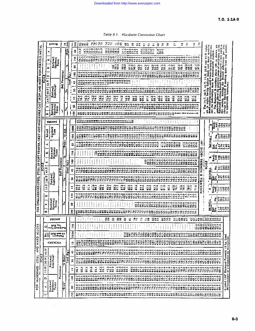
T.O. 1-IA-9
Table 8-1. Hardness Conversion Chart
E
7 YY..O x ctYYi o wH
x Y=
OZ Z
YIO r
Y"
Z _"u ^Y.owwoo.;oowoo.;wowwo.:^o.;.;oo.;oowwow.;oo.:oowco.";wcwwoowoo "!EE meF. rMMni -COP/w+-.Yn..i-OPqln...owv:.'wiw,H-OOPOYrYi"O.rY I-".YYO m. w-Yw<
y Y A.Y w iMO -lo" ;ow :o^. ;o ;Ow ;.no wcc
i$> OXd :...' :_W Y. :.n..: :..i- '00 O.O. "O :fir: V cbcwb ,iyCbnF. r.Yw Y.... fYi Ate..
O.YO.YOwwO^O^Oww0.Y0r0+X00^O"YO.r00^O^CwOYY00wOwOY"OOwO tZ< lct .Op 0w+"+. n.O00++.na.NrOOPP'On'Ob^w+Ynw,N-rOOPP/nn
t-yI-YY, .,loW -i V9cY YY
t..Y.bcI..EO_=wpw(r IOgmn.DO+wN-OPCn.Ow+"nN-OgmnYO+w--OP-------- wOG-Y-Y mltiS Nrvnnrvn---..-OP---
1-< 3NOH5
O nf-^n Anww-qn.O+NOCwp;Y00yY0
"r.n-rOOPPmYnnbb.OwOww+++nnn-r-r--+r.-O
Z< c t. E)' "C. t"' OI O'- YPMwm
N NPCm^Yn.o.o.oYYw++++w.nr.wN-NN------O .ZhNNN
wOOwOO.nOwOwOOwOwOOwOwO+Y00w0^O.YOYOYO Cwo.n?Z_W
;++n.o.O.n0+r1w,.Yn-004YPMlr.0.0..0++.nwN --------- .YI~r"^Ow
Vij mG.ww.nw....
Oi C.Y. :O^7F' Y n.1V: r 0 n0PO Y0 Y +w.NQPmi.G/ .W
Y' O_F' <1 .Y-Y
IN.. v IiO <1F'H I_ 1w-1 F-
O, YJ.di Z1
z 0.:OO? ni1r PPPPO+.PPP000OOYaYalmixe ZIIOPmnbw+.gnrOPmn.Ow+w.N .O.r-r.nrOPmnbw+.nN-OPI ID(]..Y.n.n.n.nOgPPgPPPPPPCCCmmmmbCCnnnnrrnrnrbbV.O.D
3aOHs
ayp.1-31oy
....Y (ICBMCI ua241Iu"
.saax:)IA
Yyy
< Vocx~
i`
JZ
Imo .o.o .P, .19 :zzIw AwO-r YrHrnrv hrr ...rv.,
r w y A+.n..Y-rOPIr-YD +Y+YIwn.+ .^,000OwwwO000w.+wO000ww +YCtYYoer.Ow+wrv--oPO.Y.o.Yw+wN-COYPmrYi. ir. E o -Y..Y. c '-.^o^O
;wo
:owory^o"v ce o a ` `+
:bw w.i .t ..YwY --OOP .Poo Zoo YY--cP :Pp Y"- YYyy.Y.Ow.000.00.X0 rboYno.wv.F:N--oaaoc. dv.w+ Y..;n_ooaoo. noYYrY cac'a
2o:."iB:Cc"sYYr Y-e
.www
.. rpD Vim.rI.nN-Pm
n.Ow+.nNYOPmn.Ow+w.Nr I-n.: ELVi
Q. Y'.--------------CPO.--jwloooooooww.Yw.Ywwwoooooooooo.Y.:^wwwwwwwwwwwwwooooc?oopo j
-1, ,'Zc...Y' nnCPCn.O.:Y.nni-00.a 0-+wN-OLYmn.oo. OPYDn.ow.'w--Op-'Io y
1141;n.p.p.O.p.p.O.p.O.p.p00w0000.0ww+YY.Y++++f+w0.nwww.r..n.fl0NN--NNN
^O.;OOYC.YO+:OOYOOwoO..:'10wC0v'Y"
N--OOPm. 0.0'-.wwfN--oPPOn -0"ot.GO..P....mr..nr..i.e...wi..+i.o..wrrw ..-. W YYIwhow :ow-o 000 Cm on :r"V .p.: :.n :' ::.A- oc :^m o..:PP 'oo Y
700 00Y00Cn
-=m.O^ ."If++wwwwwr:www
r 000Ob70wYr'-odon.o"iwN-
2 VC-wwnON+.OnO'.P^NmVw-Onww-PCVTN-Pmrw+w.N-005Fbw"f.nN-OOPmnn.Oww+Y.n
.Iow.^ww.;www^wwwooooow..0000..w^ooo...woooww^poowv_ooo.w.000wwoo0.w...pw+wN-OPC..00+r.N-OPn.7.n.'wNYPCr.ow.fn.. ,'or.*gymn.00.n..Q3a,3.-' nna3.
M 1000--Gdc.a5 lD'-o.nn-000.- ..:0Ywrv-oaon.oYi O.'wN-OC r"b.pO+wN-00.on.n.OO+wni-
"d .o `": `r.. :0nin: --ooa ccmon:.:.3.0o..--.:. ..Y--odc:c:mor o o.. YY n.vn:--ooa
00000pw0p000000w0000000o00000...r.Op..00000000^OO^^Op..-000000b.n"iYi wON--oPOYO Y"G .0`f"f r1n1--O 000 n, .p.n. +ON-ooc:.or +w.rv-Cr04 sp.n.O.: r.r.n--o
V'tt'0'"OV*0,0*0O"0.0.00000000000.0.-'.
.Op "CYOr"0"0^^+.'w.nN--OOPPCaDnr.O"CO.Y+wwNN-- 06PPCann..p.Oo0++wwiNN--OPPPPPOOOCCCCCmCOeemomCCrnnrnrn
OPOnb.+a.rv-oO.C r.00+wn-0Pmn.o.Y0n-0PCn.O0r.nn-acmn.p^+wN-0Pmn.O^+0
8-3
Downloaded from http://www.everyspec.com
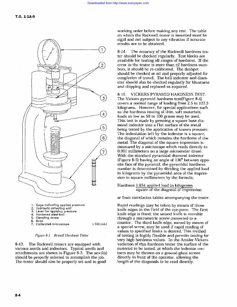
T.O. 1-1A-9
1. Gage indicating applied pressure2. Hydraulic actuating unit3. Lever for applying pressure4. Hardened steel ball5. Elevating screw6. Base7. Calibrated microscope
Figure 8-1. Brinell Hardness Tester
M
L9805661
8-13. The Rockwell testers are equipped withvarious anvils and indentors. Typical anvils andattachments are shown in Figure 8-3. The anvil(s)should be properly selected to accomplish the job.The tester should also be properly set and in good
working order before making any test. The tableon which the Rockwell tester is mounted must berigid and not subject to any vibration if accurateresults are to be obtained.
8-14. The accuracy of the Rockwell hardness tes-ter should be checked regularly. Test blocks areavailable for testing all ranges of hardness. If theerror in the tester is more than +/-2 hardness num-
bers, it should be re-calibrated. The dashpotshould be checked or oil and properly adjusted forcompletion of travel. The ball indentor and diam-eter should also be checked regularly for bluntnessand chipping and replaced as required.
8-15. VICKERS PYRAMID HARDNESS TEST.The Vickers pyramid hardness test(Figure 8-4)covers a normal range of loading from 2.5 to 127.5kilograms. However, for special applications suchas the hardness testing of thin, soft materials,loads as low as 50 to 100 grams may be used.This test is made by pressing a square base dia-mond indentor into a flat surface of the metalbeing tested by the application of known pressure.The indentation left by the indentor is a square,the diagonal of which remains the hardness of themetal. The diagonal of the square impression ismeasured by a microscope which reads directly to0.001 millimeters on a large micrometer drum.With the standard pyramidal diamond indentor(Figure 8-5) having an angle of 136 between oppo-site face of the pyramid, the pyramidal hardnessnumber is determined by dividing the applied loadin kilograms by the pyramidal area of the impres-sion in square millimeters by the formula,
Hardness 1.854 applied load in kilogramssquare of the diagonal of impression
or from correlation tables accompanying the tester.
Rapid readings may be taken by means of threeknife edges in the field of the eye-piece. The firstknife edge is fixed; the second knife is movablethrough a micrometric screw connected to a
counter. The third knife edge, moved by means ofa special screw, may be used if rapid reading ofvalues to specified limits is desired. This methodof testing is highly flexible and permits testing forvery high hardness values. In the Amsler-Vickersvariation of this hardness tester the surface of thematerial to be tested, at which the indentor con-
tacts may be thrown on a ground-glass screendirectly in front of the operator, allowing thelength of the diagonals to be read directly.
8-4
Downloaded from http://www.everyspec.com
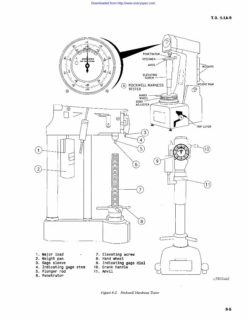
T.O. 1-IA-9
1. Major load 7.2. Weight pan 8.3. Gage sleeve 9.4. Indicating gage stem 10.5. Plunger rod 11.6. Penetrator
Elevating screwHand wheelIndicating gage dialCrank handleAnvil
L9905662
Figure 8-2. Rockwell Hardness Tester
8-5
Downloaded from http://www.everyspec.com
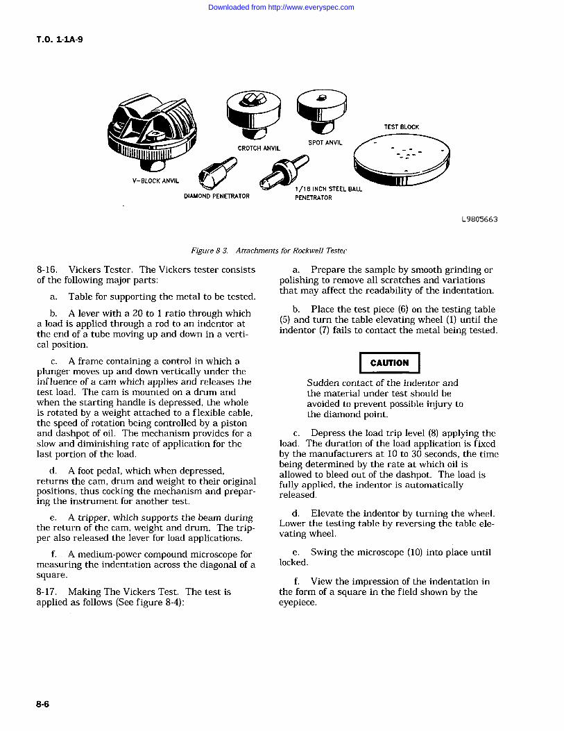
TEST BLOCK
V-BLOCK ANVIL
DIAMOND PENETRATOR1/16 INCH STEEL BALL
PENETRATOR
L9805663
Figure 8-3. Attachments for Rockwell Tester
8-16. Vickers Tester. The Vickers tester consistsof the following major parts:
a. Table for supporting the metal to be tested.
b. A lever with a 20 to ratio through whicha load is applied through a rod to an indentor atthe end of a tube moving up and down in a verti-cal position.
c. A frame containing a control in which aplunger moves up and down vertically under theinfluence of a cam which applies and releases thetest load. The cam is mounted on a drum andwhen the starting handle is depressed, the wholeis rotated by a weight attached to a flexible cable,the speed of rotation being controlled by a pistonand dashpot of oil. The mechanism provides for aslow and diminishing rate of application for thelast portion of the load.
d. A foot pedal, which when depressed,returns the cam, drum and weight to their originalpositions, thus cocking the mechanism and prepar-ing the instrument for another test.
e. A tripper, which supports the beam duringthe return of the cam, weight and drum. The trip-per also released the lever for load applications.
f. A medium-power compound microscope formeasuring the indentation across the diagonal of asquare.
8-17. Making The Vickers Test. The test isapplied as follows (See figure 8-4):
a. Prepare the sample by smooth grinding orpolishing to remove all scratches and variationsthat may affect the readability of the indentation.
b. Place the test piece (6) on the testing table(5) and turn the table elevating wheel (1) until theindentor (7) fails to contact the metal being tested.
CAUTION
Sudden contact of the indentor andthe material under test should beavoided to prevent possible injury tothe diamond point.
c. Depress the load trip level (8) applying theload. The duration of the load application is fixedby the manufacturers at 10 to 30 seconds, the timebeing determined by the rate at which oil isallowed to bleed out of the dashpot. The load isfully applied, the indentor is automaticallyreleased.
d. Elevate the indentor by turning the wheel.Lower the testing table by reversing the table ele-vating wheel.
e. Swing the microscope (10) into place untillocked.
f. View the impression of the indentation inthe form of a square in the field shown by theeyepiece.
8-6
Downloaded from http://www.everyspec.com
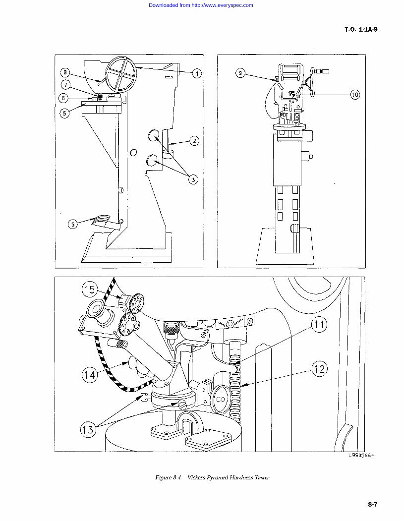
T.O. 1-IA-9
CQ
U
L9905664
Figure 8-4. Vickers Pyramid Hardness Tester
8-7
Downloaded from http://www.everyspec.com
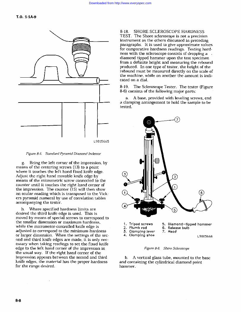
T.O. 1-IA-9
L9805665
Figure 8-5. Standard Pyramid Diamond Indentor
g. Bring the left corner of the impression, bymeans of the centering screws (13) to a pointwhere it touches the left hand fixed knife edge.Adjust the right hand movable knife edge bymeans of the micrometric screw connected to thecounter until it touches the right hand corner ofthe impression. The counter (15) will then showan ocular reading which is transposed to the Vick-ers pyramid numeral by use of correlation tablesaccompanying the tester.
h. Where specified hardness limits aredesired the third knife edge is used. This ismoved by means of special screws to correspond tothe smaller dimension or maximum hardness,while the micrometer-controlled knife edge isadjusted to correspond to the minimum hardnessor larger dimension. When the settings of the sec-ond and third knife edges are made, it is only nec-
essary when taking readings to set the fixed knifeedge to the left hand corner of the impression inthe usual way. If the right hand corner of theimpression appears between the second and thirdknife edges, the material has the proper hardnessfor the range desired.
8-18. SHORE SCLEROSCOPE HARDNESSTEST. The Shore scleroscope is not a precisioninstrument as the others discussed in precedingparagraphs. It is used to give approximate valuesfor comparative hardness readings. Testing hard-ness with the scleroscope consists of dropping adiamond tipped hammer upon the test specimenfrom a definite height and measuring the reboundproduced. In one type of tester, the height of therebound must be measured directly on the scale ofthe machine, while on another the amount is indi-cated on a dial.
8-19. The Scleroscope Tester. The tester (Figure8-6) consists of the following major parts:
a. A base, provided with leveling screws, enda clamping arrangement to hold the sample to betested.
1. Tripod screws 5. Diamond-tipped hammer2. Plumb rod 6. Release bulb3. Clamping lever 7. Head4. Clamping shoe L9805666
Figure 8-6. Shore Scleroscope
b. A vertical glass tube, mounted to the baseand containing the cylindrical diamond pointhammer.
8-8
Downloaded from http://www.everyspec.com
c. A suction heat and bulb for lifting andreleasing the hammer.
d. A scale, visible through the glass tube, fordetermining the height of the rebound.
e. A magnifier hammer with a larger contact
area is supplied for use with extremely softmetals.
8-20. TESTING WITH THE SCLEROSCOPE.The test is made as follows:
a. Level the instrument by means of theadjusting screws (1). (See figure 8-6). The levelposition is determined by means of the plumb rod(2).
b. Prepare the test specimen as described forthe Brinell and Rockwell tests in precedingparagraphs and clamp it on the base. This is doneby raising the lever (3) inserting the sample andexerting the pressure on the clamping shoe (4).
c. Raise the hammer (5) by squeezing andreleasing the bulb (6)
d. Release the hammer by again squeezingthe bulb and observing its rebound.
e. Several tests should be made at differentpoints of a specimen, and an average readingtaken to reduce visual error.
8-21. TENSILE TESTING. The terms tensiontest and compression test are usually taken torefer to tests in which a prepared specimen is sub-jected to a gradually increasing load applied axi-ally until failure occurs For the purpose of ten-sile testing implied by this technical order thistype of setting would apply to determining themechanical properties desired in a material. Forthis test, the following test specimens are listed.(See Figure 8-7.) This does not exclude the use ofother test specimens for special materials or formsof material. The tensile strength shall be deter-mined by dividing the maximum load on the speci-men during a tension test by the original cross-sectional area of the specimen.
a. Diameter of the reduced section may besmaller at center than at ends. Difference shallnot exceed 1% of diameter at ends.
T.O. 1-1A-9
b. When an extensometer is required to deter-mine elastic properties, dimensions C and L maybe modified. In all cases the percentage of elonga-tion shall be based on dimension G.
c. The type R1 test specimen is circular in
cross section and is used for bars, rods, forgings,plates, shapes, heavy-walled tubing, and castings.Types R2, R3, R.4, and R5 are circular in cross-sec-tion and are used for material of dimensions insuf-ficient for type R1.
(1) The ends of the reduced section shallnot differ in width by more than 0.004 inch.
(2) The ends of the specimen shall be sym-metrical with the center line of the reduced sectionwithin 0.10 inch.
(3) When material is over 2 inches thick,machine to 3/4 inch or use type R1 test specimen.For more detailed information, refer to FederalTest Method Standard No. 151.
8-22. DECARBURIZATION MEASUREMENT.
8-23. Decarburization is the loss of carbon at thesurface of ferrous materials which have beenheated for fabricating, welding, etc., or whenheated to modify mechanical properties. Effectivedecarburization is any measurable loss of carboncontent which results in mechanical propertiesbelow the minimum acceptable specifications forhardened materials. The most common methodsused to measure decarburization are microscopic,hardness and chemical. The microscopic method issufficiently accurate for most annealed and hotrolled material for small amounts of decarburiza-tion in high carbon (over 0.60%), high hardnesssteels. The hardness method is insensitive in thiscase, and recourse must be taken to chemical anal-ysis. In this technical order, only the hardnessmethod is covered. When precise measurements
are required, publications giving detailed measure-
ments must be consulted.
8-9
Downloaded from http://www.everyspec.com
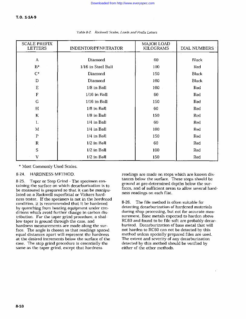
T.O. 1-IA-9
Table 8-2. Rockwell Scales, Loads and Prefix Letters
SCALE PREFIXLETTERS INDENTOR/PENETRATOR
MAJOR LOADKILOGRAMS DIAL NUMBERS
A Diamond 60 Black
B* 1/16 in Steel Ball 100 Red
C* Diamond 150 Black
D Diamond 100 Black
E 1/8 in Ball 100 Red
F 1/16 in Ball 60 Red
G 1/16 in Ball 150 Red
H 1/8 in Ball 60 Red
K 1/8 in Ball 150 Red
L 1/4 in Ball 60 Red
M 1/4 in Ball 100 Red
P 1/4 in Ball 150 Red
R 1/2 in Ball 60 Red
S 1/2 in Ball 100 Red
V 1/2 in Ball 150 Red
* Most Commonly Used Scales.
8-24. HARDNESS METHOD.
8-25. Taper or Step Grind The specimen con-
taining the surface on which decarburization is tobe measured is prepared so that it can be manipu-lated on a Rockwell superficial or Vickers hard-ness tester. If the specimen is not in the hardenedcondition, it is recommended that it be hardenedby quenching from heating equipment under con-ditions which avoid further change in carbon dis-tribution. For the taper grind procedure, a shal-low taper is ground through the case, andhardness measurements are made along the sur-face. The angle is chosen so that readings spacedequal distances apart will represent the hardnessat the desired increments below the surface of thecase. The step grind procedure is essentially thesame as the taper grind, except that hardness
readings are made on steps which are known dis-tances below the surface. These steps should beground at pre-determined depths below the sur-faces, and of sufficient areas to allow several hard-ness readings on each flat.
8-26. The file method is often suitable fordetecting decarburization of hardened materialsduring shop processing, but not for accurate mea-
surement. Base metals expected to harden aboveRC60 and found to be file soft are probably decar-burized. Decarburization of base metal that willnot harden to RC60 can not be detected by thismethod unless specially prepared files are used.The extent and severity of any decarburizationdetected by this method should be verified byeither of the other methods.
8-10
Downloaded from http://www.everyspec.com
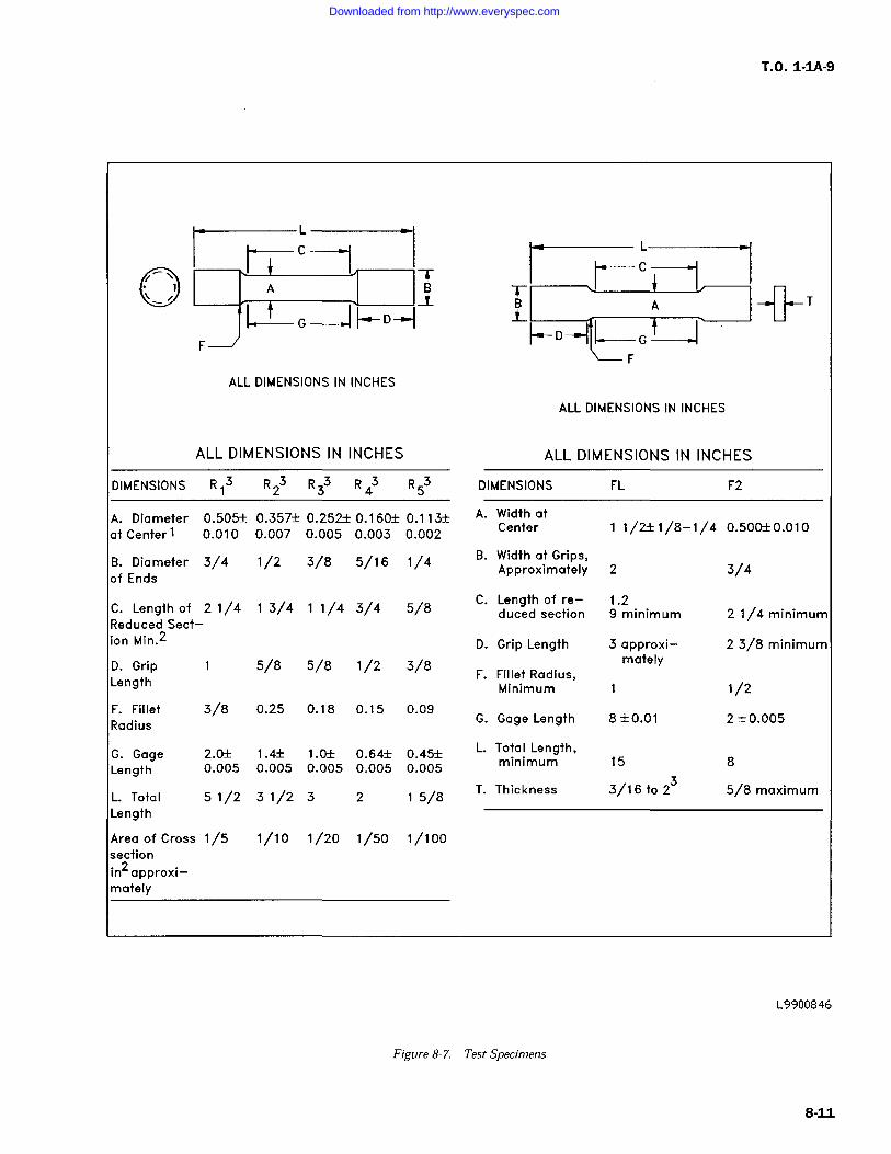
T.O. 1-1A-9
I*- T
ALL DIMENSIONS IN INCHES
ALL DIMENSIONS IN INCHES
ALL DIMENSIONS IN INCHES
DIMENSIONS R13 R23 R33 R4 R53A. Diameter 0.505+/- 0.357+/- 0.252+/- 0.160+/- 0.113+/-at Center 0.010 0.007 0.005 0.003 0.002
B. Diameter 3/4of Ends
1/2 3/8 5/16 1/4
C. Length of 2 /4Reduced Sect-ion Min.2
3/4 /4 3/4 5/8
D. GripLength
5/8 5/8 /2 3/8
F. Fillet 3/8Radius
0.25 0.18 0.15 0.09
G. Gage 2.0+/- 1.4+/- 1.0+/- 0.64+/- 0.45+/-Length 0.005 0.005 0.005 0.005 0.005
L. Total 5 /2Length
3 /2 3 2 5/8
Area of Cross /5sectionin2approxi-mately
1/10 1/20 1/50 1/100
ALL DIMENSIONS IN INCHES
DIMENSIONS
A. Width atCenter
B. Width at Grips,Approximately
C. Length of re-duced section
D. Grip Length
FL F2
1/2+/-1/8-1/4 0.500+/-0.010
2 3/4
1.29 minimum 2 1/4 minimum
3 approxi-mately
2 3/8 minimum
F. Fillet Radius,Minimum 1/2
G. Gage Length 8+/-0.01 2 +/-0.005
L. Total Length,minimum 15 8
T. Thickness 3/16 to23 5/8 maximum
L9900846
Figure 8-7. Test Specimens
8-11
Downloaded from http://www.everyspec.com
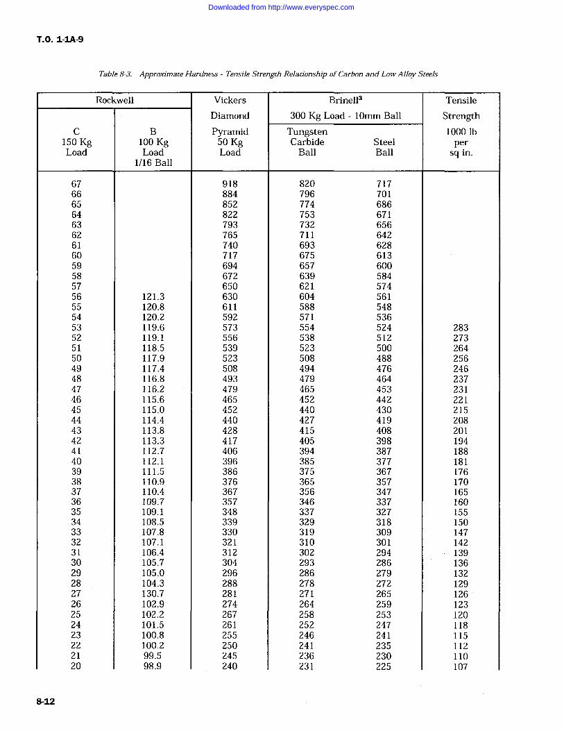
T.O. 1-IA-9
Table 8-3. Approximate Hardness -Tensile Strength Relationship of Carbon and Low Alloy Steels
Rockwell Vickers Brinell3 Tensile
Diamond 300 Kg Load 10mm Ball StrengthC B Pyramid Tungsten 1000 lb
150 Kg 100 Kg 50 Kg Carbide Steel perLoad Load Load Ball Ball sq in.
1/16 Ball
67 918 820 71766 884 796 70165 852 774 68664 822 753 67163 793 732 65662 765 711 64261 740 693 62860 717 675 61359 694 657 60058 672 639 58457 650 621 57456 121.3 630 604 .56155 120.8 611 588 54854 120.2 592 571 53653 119.6 573 554 524 28352 119.1 556 538 512 27351 118.5 539 523 500 26450 117.9 523 508 488 25649 117.4 508 494 476 24648 116.8 493 479 464 23747 116.2 479 465 453 23146 115.6 465 452 442 22145 115.0 452 440 430 21544 114.4 440 427 419 20843 113.8 428 415 408 20142 113.3 417 405 398 19441 112.7 406 394 387 18840 112.1 396 385 377 18139 111.5 386 375 367 17638 110.9 376 365 357 17037 110.4 367 356 347 16536 109.7 357 346 337 16035 109.1 348 337 327 15534 108.5 339 329 318 15033 107.8 330 319 309 14732 107.1 321 310 301 14231 106.4 312 302 294 13930 105.7 304 293 286 13629 105.0 296 286 279 13228 104.3 288 278 272 12927 130.7 281 271 265 12626 102.9 274 264 259 12325 102.2 267 258 253 12024 101.5 261 252 247 11823 100.8 255 246 241 11522 100.2 250 241 235 11221 99.5 245 236 230 11020 98.9 240 231 225 107
8-12
Downloaded from http://www.everyspec.com
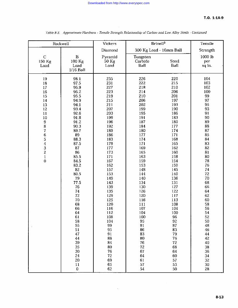
T.O. 1-IA-9
Table 8-3. Approximate Hardness -Tensile Strength Relationship of Carbon and Low Alloy Steels -Continued
Rockwell Vickers Brinell' Tensile
Diamond 300 Kg Load 10mm Ball StrengthC B Pyramid Tungsten 1000 lb
150 Kg 100 Kg 50 Kg Carbide Steel perLoad Load Load Ball Ball sq in.
1/16 Ball
19 98.1 235 226 220 10418 97.5 231 222 215 10317 96.9 227 218 210 10216 96.2 223 214 206 10015 95.5 219 210 201 9914 94.9 215 206 197 9713 94.1 211 202 193 9512 93.4 207 199 190 9311 92.6 203 195 186 9110 91.8 199 191 183 909 91.2 196 187 180 898 90.3 192 184 177 887 89.7 189 180 174 876 89 186 177 171 855 88.3 183 174 168 844 87.5 179 171 165 833 87 177 169 162 822 86 173 165 160 81
85.5 171 163 158 800 84.5 167 159 154 78
83.2 162 153 150 7682 157 148 145 7480.5 153 144 140 7279 149 140 136 7077.5 143 134 131 6876 139 130 127 6674 135 126 122 6472 129 120 117 6270 125 116 113 6068 120 111 108 5866 116 107 104 5664 112 104 100 5461 108 100 96 5258 104 95 92 5055 99 91 87 4851 95 86 83 4647 91 83 79 4444 88 80 76 4239 84 76 72 4035 80 72 68 3830 76 67 64 3624 72 64 60 3420 69 61 57 3211 65 57 53 300 62 54 50 28
8-13
Downloaded from http://www.everyspec.com
T.O. 1-1A-9
8-27. NONDESTRUCTIVE INSPECTIONMETHODS.
8-28. Radiographic inspection will show internaland external structural details of all types of partsand materials. It is accomplished by passing pene-trating radiation (usually X or gamma rays)through the part or assembly being inspected to
expose a film. After developing, interpretation ofthe radiograph will indicate defects or damage.All radiographic inspections shall be accomplishedin accordance with T.O. 33B-1-1, MIL-STD-453,and MIL-STD-410.
8-29. Penetrant inspection is a nondestructiveinspection method that is used to detect disconti-nuities open to the surface of nonporous material.It is accomplished by treating the inspection areawith a fluid (penetrant) that penetrates the sur-face discontinuity. Surplus penetrant remainingon the surface is removed and an absorbent mate-rial (developer) is applied to the surface. Thedeveloper acts as a blotter and draws some of thepenetrant from the discontinuity to the surface.Discontinuities are visible due to color contrastbetween the penetrant drawn out and the back-ground surface. Only fluorescent penetrants areapproved for Air Force use. All penetrant inspec-tion materials shall conform to MIL-I-25135. Allpenetrant inspections shall be accomplished inaccordance with T.O. 33B-1-1 and MIL-STD-410.
8-30. Ultrasonic inspection uses a high frequencysound wave to detect discontinuities in materials.The pulser in the ultrasonic instrument sends an
electrical impulse to a piezoelectric material in thesearch unit (transducer). The transducer changesthe electrical impulse into mechanical vibrations(sound) and transmits them into the materialbeing inspected. Any marked change in acousticproperties, such as a flaw or interface in the mate-rial, reflects the sound back to the transducer.Examination of the reflections on a cathode raytube will reveal discontinuities in the material.All ultrasonic inspections shall be accomplished inaccordance with T.O. 33B-1-1, MIL-I-8950, andMIL-STD-410.
8-31. Magnetic particle inspection is used todetect discontinuities in ferromagnetic materials,principally iron and steel. Magnetic particleinspection is accomplished by inducing a magneticfield into the material being inspected. A disconti-nuity will interrupt this field, creating north and
south poles which will attract magnetic particlesapplied to the material. Discontinuities are visibledue to color contrast between the magnetic parti-cles and the background surface. All magneticparticle inspections shall be accomplished in accor-dance with T.O. 33B-1-1 and MIL-STD-410.
8-32. Eddy current inspection is used to detectdiscontinuities in materials that are conductors ofelectricity. An eddy current is the circulating elec-trical current induced in a conductor by an alter-nating magnetic field, which is produced by asmall test coil in contact with or close to the mate-rial being inspected. Discontinuities in the mate-rial being tested cause variations in the inducededdy current. The test coil measures the varia-tions which reveal discontinuities in the material.All eddy current inspections shall be in accordancewith T.O. 33B-1-1 and MIL-STD-410.
8-33. CHEMICAL ANALYSIS. Chemical analy-sis methods are those in which the elements pre-sent in metals are determined by the use ofreagents in solution, by combustion methods, or byother none-mission methods. Sample metal fromany piece shall be such that it represents as nearlyas possible the metal of the entire piece. Drilling,milling and other machining operations for samplemetal shall be performed without the use of water,oil, or other lubricants, and cutting speeds shall besuch that no burning takes place to cause alterna-tion of the chemical composition of the test metal.Method 111. 1 of Federal Method Standard 151A isthe controlling document for chemical analysis.8-34. SPECTROCHEMICAL ANALYSIS. Spec-trochemical analysis includes all methods in whichmeasurements of electromagnetic radiations pro-duced by a sample metal are employed to deter-mine the chemical composition. Samples shall beso selected as to be representative of the entirequantity of metal under inspection. Cuttingspeeds in all machining operations shall be suchthat no burning takes place to cause alteration ofthe chemical composition of the test metal.Method 112.1 of Federal Test Method Standard151A governs this type of analysis. The result ofspectrochemical analysis shall be determined tothe number of decimal places shown in the chemi-cal requirements for the material.
Downloaded from http://www.everyspec.com
T.O. 1-IA-9
SECTION IX
HEAT TREATMENT
9-1. GENERAL.
9-2. Controlled atmosphere ovens are notrequired for heat treatment operations unlessspecified for a particular part.
9-3. A cold oven is defined as any oven wherethe temperature is not over 500F (260C). Load-ing and unloading a cold oven is possible withoutfurther lowering the temperature.
9-4. Parts that are prone to distortion duringheat treatment shall be properly supported andtemperature raised gradually by steps. Coat fix-turing at part contact points and threaded detailswith PMC 2264 boron nitride coating prior toinstalling part and before heat treatment. Coolingof these parts shall also be done gradually. Cycleswith A suffix are recommended for this purpose.
9-5. Parts that are not prone to distortion duringheat treatment may be loaded into and withdrawnfrom a hot oven.
9-6. Temperature and time are the most criticalfactors in heat treatment. Time required at eachspecified temperature begins only after all sec-
tions of parts have reached that temperature.Furnace operator shall make allowance for size ofpart, number of parts, and furnace inputcapacities.
9-7. Optimum temperatures are given for eachcycle, with tolerances included for practical use.However, it is best to hold to basic temperatureslisted.
9-8. Some typical material applications are listedin Table 9-1 for general guidance only. Cycle forwhich an alloy type is listed may not necessarilybe specified for that material.
9-9. SPECIAL HEAT TREATMENTINFORMATION.
9-10. CADMIUM PLATED PARTS. All cad-mium plate shall be stripped from parts (SPOP 21)and cadmium plated detail parts shall be removedfrom assemblies prior to subjecting the part orassemblies to any furnace temperature in excess of500F (260C). At temperatures above 500F(260C), stress alloying of molten cadmium willoccur with potentially harmful results on the basematerials.
9-11. TINT TEST FOR DETERMINING COAT-ING REMOVAL FROM NICKEL BASE ANDCOBALT BASE ALLOYS.
9-12. Perform test as follows:
a. Remove coating from parts using applicablestripping procedure.
b. Heat parts and an uncoated, vapor blastedtest panel of the same material as the parts at1075 +/-25F (579 +/-14C) for 45 to 75 minutes inair.
c. A uniform color match between the partand the test piece will indicate complete removalof the coating.
Table 9-1. Typical Heat Treatment Application
Cycle No. Type* SPOP No. Possible Alloy Application
1, 1A STR 455-1, 455-2 Low alloy steel, as AMS 6322 and AMS 6415; martensiticstainless steel, as Type 410 (AMS 5504 and AMS 5613) andGreek Ascoloy (AMS 5508 and AMS 5616)
2 STR 456 Aluminum
3 STR 457
4, 4A STR 458-1, 458-2 Inconel X5, 5A STR 459-1, 459-2 Nickel alloys: B-1900 (PWA 663 and PWA 1455); Inconel
713 (PWA 655) Cobalt alloys: Stellite 31 (AMS 5382); WI-52(PWA 653); MAR-M509 (PWA 647)
6, 6A STR 460-1, 460-2 Greek Ascoloy (AMS 5508 and AMS 5616) (martensiticstainless steel)
9-1
Downloaded from http://www.everyspec.com
T.O. 1-IA-9
Table 9-1. Typical Heat Treatment Application Continued
Cycle No. Type* SPOP No. Possible Alloy Application
7 STR 461 Waspaloy, Udimet 700
8 STR 455-3
9 STR 459-3 Inconel 600 (nickel alloy); Nimonic 75 (PWA 673) (nickelalloy); stainless steel, as Types 310, 316, 321, and 347
11 STR 464 Titanium
12, 12A PRE 471, 465 Inconel 718 (nickel alloy), as AMS 5596, AMS 5662, andAMS 5663
13 STR 466 17-7PH (stainless steel austenite conditioning); Type 430(ferritic stainless steel), welded with Type 430 filler metal
14 STR 467 Type 430 (ferritic stainless steel), welded with AMS 5680(Type 347 stainless steel)
15 PRE 468 A-286 (modified Tinidur) stainless steel, as AMS 5525, AMS5731, AMS 5732, and AMS 5737
17 PRE 470 Incoloy 901 (nickel alloy), as AMS 5660 and AMS 5661
20 SOL 480 HASTELLOY X (nickel alloy)21 SOL 481 Nickel alloy: HASTELLOY X (AMS 5536 and AMS 5754)
Cobalt alloys: STELLITE 31 (AMS5382); Haynes 188 (AMS5608, AMS 5772, and PWA 1042); L-605 (AMS 5537 andAMS 5759)
22 STR 482 Nickel alloys: Inconel 600 (AMS 5540 and AMS 5665); In-conel 625 (AMS 5599 and AMS 5666); HASTELLOY N;HASTELLOY X (AMS 5536, AMS 5754, and PWA 1038);HASTELLOY W Cobalt alloys: STELLITE 31 (AMS 5382);Haynes 188 (AMS 5608, AMS 5772, and PWA 1042); L-605(AMS 5537 and AMS 5759); MAR-M509 (PWA 647)
101 SOL 761 Waspaloy (nickel alloy), as AMS 5544, AMS 5706, and AMS5707
102 SOL 762 Waspaloy (nickel alloy), as AMS 5544, AMS 5706, and AMS5707
103 STA 763 Waspaloy (nickel alloy), as AMS 5544, AMS 5706, AMS5707, AMS 5708, and AMS 5709
104 PRE 764 Waspaloy (nickel alloy), as AMS 5596, AMS 5706, AMS5707, AMS 5708, and AMS 5709
105 SOL 765 Inconel 718 (nickel alloy), as AMS 5596, AMS 5662, andAMS 5663
106 SOL 766 Inconel 718 (nickel alloy, as AMS 5596, AMS 5662, andAMS 5663
9-2
Downloaded from http://www.everyspec.com
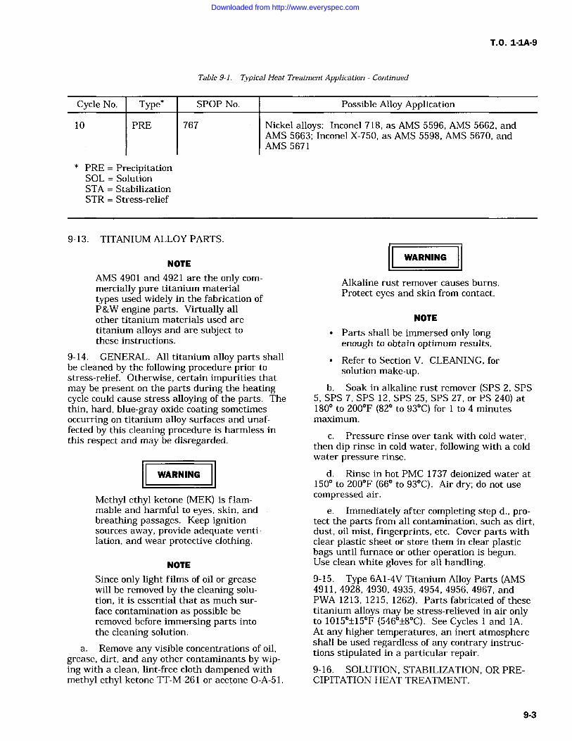
T.O. 1-1A-9
Cycle No.
10
Type*
PRE
Table 9-1. Typical Heat Treatment Application Continued
SPOP No.
767 Nickel alloys: Inconel 718, as AMS 5596, AMS 5662, andAMS 5663; Inconel X-750, as AMS 5598, AMS 5670, andAMS 5671
Possible Alloy Application
* PRE PrecipitationSOL SolutionSTA StabilizationSTR Stress-relief
9-13. TITANIUM ALLOY PARTS.
NOTE
AMS 4901 and 4921 are the only com-
mercially pure titanium materialtypes used widely in the fabrication ofP&W engine parts. Virtually allother titanium materials used are
titanium alloys and are subject tothese instructions.
9-14. GENERAL. All titanium alloy parts shallbe cleaned by the following procedure prior tostress-relief. Otherwise, certain impurities thatmay be present on the parts during the heatingcycle could cause stress alloying of the parts. Thethin, hard, blue-gray oxide coating sometimesoccurring on titanium alloy surfaces and unaf-fected by this cleaning procedure is harmless inthis respect and may be disregarded.
WARNING
Methyl ethyl ketone (MEK) is flam-mable and harmful to eyes, skin, andbreathing passages. Keep ignitionsources
away, provide adequate venti-lation, and wear protective clothing.
NOTE
Since only light films of oil or greasewill be removed by the cleaning solu-tion, it is essential that as much sur-face contamination as possible beremoved before immersing parts intothe cleaning solution.
a. Remove any visible concentrations of oil,grease, dirt, and any other contaminants by wip-ing with a clean, lint-free cloth dampened withmethyl ethyl ketone TT-M-261 or acetone O-A-51.
Alkaline rust remover causes burns.Protect eyes and skin from contact.
WARNING
NOTE
Parts shall be immersed only longenough to obtain optimum results.
Refer to Section V. CLEANING, forsolution make-up.
b. Soak in alkaline rust remover (SPS 2, SPS5, SPS 7, SPS 12, SPS 25, SPS 27, or PS 240) at180 to 200F (82 to 93C) for to 4 minutesmaximum.
c. Pressure rinse over tank with cold water,then dip rinse in cold water, following with a coldwater pressure rinse.
d. Rinse in hot PMC 1737 deionized water at150 to 200F (66 to 93C). Air dry; do not usecompressed air.
e. Immediately after completing step d., pro-tect the parts from all contamination, such as dirt,dust, oil mist, fingerprints, etc. Cover parts withclear plastic sheet or store them in clear plasticbags until furnace or other operation is begun.Use clean white gloves for all handling.9-15. Type 6A1-4V Titanium Alloy Parts (AMS4911, 4928, 4930, 4935, 4954, 4956, 4967, andPWA 1213, 1215, 1262). Parts fabricated of thesetitanium alloys may be stress-relieved in air onlyto 1015+/-15F (546+/-8C). See Cycles and IA.At any higher temperatures, an inert atmosphereshall be used regardless of any contrary instruc-tions stipulated in a particular repair.9-16. SOLUTION, STABILIZATION, OR PRE-CIPITATION HEAT TREATMENT.
9-3
Downloaded from http://www.everyspec.com
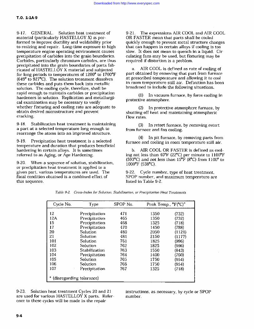
T.O. 1-1A-9
9-17. GENERAL. Solution heat treatment ofmaterial (particularly HASTELLOY X) is per-formed to improve ductility and weldability priorto resizing and repair. Long-time exposure to hightemperature engine operating environment causes
precipitation of carbides into the grain boundaries.Carbides, particularly chromium carbides, are thusprecipitated into the grain boundaries of parts fab-ricated of HASTELLOY X material and subjectedfor long periods to temperatures of 12000 to 1700F(649 to 927C). The solution treatment dissolvesthese carbides and puts them back into metallicsolution. The cooling cycle, therefore, shall berapid enough to maintain carbides or precipitationhardeners in solution. Replication and metallurgi-cal examination may be necessary to verifywhether fixturing and cooling rate are adequate toobtain desired microstructure and preventcracking.9-18. Stabilization heat treatment is maintaininga part at a selected temperature long enough to
rearrange the atoms into an improved structure.
9-19. Precipitation heat treatment is a selectedtemperature and duration that produces beneficialhardening in certain alloys. It is sometimesreferred to as Aging, or Age Hardening.9-20. When a sequence of solution, stabilization,or precipitation heat treatment is applied to a
given part, various temperatures are used. Thefinal condition obtained is a combined effect ofthis sequence.
9-21. The expressions AIR COOL and AIR COOLOR FASTER mean that parts shall be cooledquickly enough to prevent metal structure changesthat can happen in certain alloys if cooling is tooslow. It does not mean to quench in a liquid. Cir-culating fans may be used, but fixturing may berequired if distortion is a problem.
a. AIR COOL is defined as rate of cooling ofpart obtained by removing that part from furnaceat prescribed temperature and allowing it to coolin room temperature still air. Definition has beenbroadened to include the following situations.
(1) In vacuum furnace, by force cooling inprotective atmosphere.
(2) In protective atmosphere furnace, byshutting off heat and maintaining atmosphericflow rates.
(3) In retort furnace, by removing retortfrom furnace and fan cooling.
(4) In pit furnace, by removing parts fromfurnace and cooling in room temperature still air.
b. AIR COOL OR FASTER is defined as cool-ing not less than 40F (22C) per minute to 1100F(593C) and not less than 15F (8C) from 1100 to1000F (538C).
9-22. Cycle number, type of heat treatment,SPOP number, and maximum temperature arelisted in Table 9-2.
Table 9-2. Cross-Index for Solution, Stabilization, or Precipitation Heat Treatments
Cycle No. Type SPOP No. Peak Temp., F(C)`
12 Precipitation 471 1350 (732)12A Precipitation 465 1350 (732)15 Precipitation 468 1325 (718)17 Precipitation 470 1450 (788)20 Solution 480 2050 (1121)21 Solution 481 2150 (1177)101 Solution 761 1825 (996)102 Solution 762 1825 (996)103 Stabilization 763 1550 (843)104 Precipitation 764 1400 (760)105 Solution 765 1750 (954)106 Solution 766 1750 (954)107 Precipitation 767 1325 (718)
* (disregarding tolerance)
9-23. Solution heat treatment Cycles 20 and 21are used for various HASTELLOY X parts. Refer-ence to these cycles will be made in the repair
instructions, as necessary, by cycle or SPOPnumber.
9-4
Downloaded from http://www.everyspec.com
NOTE
These cycles apply only to the repairof HASTELLOY X parts that requireusing one of the following solutionheat treatments. The specific cyclerequired will be included in the repairprocedure.
9-24. CYCLE 20 (SPOP 480). Perform as
follows:
CAUTION
Do not use this cycle for solution heattreating PWA 1038 HASTELLOY Xmaterial. This material was solutiontreated at 1950F (1066C) at itsmanufacture. The beneficial proper-ties derived from this lower tempera-ture treatment could be lost perma-nently if subjected to a temperaturehigher than 1800F (982C). Forother HASTELLOY alloys, solutionheat treat shall be performed per thiscycle unless otherwise directed by aspecific repair procedure.
a. Heat part to 2050 +/-25F (1121 +/-14C) andhold for 7 to 10 minutes.
NOTE
Hydrogen, argon, or air are acceptableatmospheres; however, when solutiontreating is to be followed by weldrepair that requires complete priorremoval of oxides, hydrogen is pre-ferred because of its characteristicand beneficial cleaning action over
the entire part. Hydrogen cleaningremoves oxides from all surfaces,including those difficult to cleanmechanically, and to some extent,from the inside of cracks to be welded.
b. Air cool or faster.
9-25. CYCLE 21 (SPOP 481). Perform asfollows:
CAUTION
Do not use this cycle for solution heattreating PWA 1038 HASTELLOY Xmaterial. This material was solutiontreated at 1950F (1066C) at its
T. 0. 1-1A-9
manufacture. The beneficial proper-ties derived from this lower tempera-ture treatment could be lost perma-nently if subjected to a temperaturehigher than 1800F (982C). For reg-ular Hastelloy material, solution heattreat shall be performed in accordancewith Cycle 20 (SPOP 480), unless oth-erwise directed by a specific repairprocedure.
a. Heat part to 2150 +/-25F (1177 +/-14C) andhold for 7 to 10 minutes.
NOTE
Hydrogen, argon, or air are acceptableatmospheres. However, when solu-tion treating is to be followed by weldrepair that requires complete priorremoval of oxides, hydrogen is pre-ferred because of its characteristicand beneficial cleaning action overthe entire part. Hydrogen cleaningremoves oxides from all surfacesincluding those difficult to cleanmechanically, and to some extent,from the inside of cracks to be welded.
b. Air cool or faster.
9-26. The following solution, stabilization, or pre-cipitation heat treatment cycles apply primarily tocertain age-hardenable alloys such as WASPALOYand INCONEL materials, for stress-relief, and todissolve precipitated carbides and intermetallics(hardeners).
NOTE
These cycles apply only when specifi-cally invoked in repair procedures inengine publications. Parts that are
susceptible to distortion during heattreatment shall be adequately sup-ported, and temperature raised andlowered stepwise. The Suffix A fol-lowing a cycle number indicates a
stepwise cycle. Step cycles shall notbe used for solution heat treatments.Refer to cautions in solution heattreat cycles.
9-27. CYCLE 12 (SPOP 471). Perform asfollows:
NOTE
This is a short-term precipitation(aging) heat treatment for INCONEL718 or other part material specifiedin engine publication.
9-5
Downloaded from http://www.everyspec.com
T.O. 1-IA-9
a. Place part in oven and heat to 1350+/-15F(732+/-8C).
b. Hold at 1350F (732C) for 4 hours.
c. Cool to 1200 +/-15F (649 +/-8C) at approxi-mately 100F (56C) per hour. Hold at tempera-ture for a total of 3 hours, including cool-downtime from 1350F (732C).
d. Air cool to room temperature.9-28. CYCLE 12A (SPOP 465). Perform asfollows:
NOTE
This is a short-term precipitation(aging) heat treatment for INCONEL718 or other part material specifiedin engine publication.
a. Place part in cold oven.
b. Heat to 600F (316C) and hold for 30minutes.
c. Increase to 800F (427C) and hold for 30minutes.
d. Increase to 1000F (538C) and hold for 30minutes.
e. Increase to 1200F (649C) and hold for 30minutes.
f. Increase to 1350 +/-15F (732 +/-8C) andhold for 4 hours.
g. Cool to 1200 +/-15F (649 +/-8C) at approxi-mately 100F (56C) per hour. Hold at tempera-ture for a total of 3 hours, including cool-downtime from 1350F (732C).
h. Air cool to room temperature.9-29. CYCLE 15 (SPOP 468). Perform asfollows:
NOTE
Heating and cooling rates areoptional. Air is an acceptableatmosphere.
a. Heat part to 1325 +/-25F (718 +/-14C) andhold for 4 hours.
b. Air cool.
9-30. CYCLE 17 (SPOP 470). Perform asfollows:
NOTE
Hydrogen, argon, or a blend of hydro-gen and argon, or vacuum, are accept-able atmospheres.
a. Heat part to 1450 +/-15F (788 +/-8C) andhold for 4 hours.
b. Cool to 500F (260C) at a rate equivalentto air cool.
c. Heat part to 1325 +/-15F (718 +/-8C) andhold for 14 hours.
d. Cool at a rate equivalent to air cool.
9-31. CYCLE 101 (SPOP 761). Perform asfollows:
CAUTION
Heating or cooling rate between1000F (538C) and 1850F (1010C)shall be at least 40F (22C) per min-ute to prevent cracking and to controlaging characteristics.
NOTE
This is a solution heat treatmentusing an argon atmosphere.
a. Place part with thermocouples in retort,and seal retort.
b. Purge retort at approximately 150 CFHargon until dew point reaches -40F (-40C) orlower at retort exhaust.
c. Insert retort into furnace.
NOTE
Furnace may initially be set higherthan 1850F (1010C).
d. Heat to 1825 +/-25F (996 +/-14C) usinglower thermocouple for controlling. Do not exceed1850F (1010C) on higher thermocouple. Hold attemperature for 2 hours unless otherwisespecified.
e. Remove retort from furnace and cool withforced argon to 1000F (538C) in no longer than18 minutes; then complete cooling with argon or
air.
9-32. CYCLE 102 (SPOP 762). Perform asfollows:
9-6
Downloaded from http://www.everyspec.com
T.O. 1-1A-9
CAUTION
Heating or cooling rate between1000F (538C) and 1850F (1010C)shall be at least 40F (22C) per min-ute to prevent cracking and to controlaging characteristics.
NOTE
This is a solution heat treatmentusing vacuum. Heat cycle shall becompleted in the 0.010 torr range or
lower.
NOTE
This is a precipitation heat treatmentusing air, argon, or vacuum.
a. Place part in cold furnace.
b. Heat to 1400 +/-15F (760 +/-8.3C) for 16hours.
c. Air cool.
9-35. CYCLE 105 (SPOP 765). Perform asfollows:
CAUTION
Furnace system shall provide forargon forced cooling, in order to sat-isfy cooling rate requirement.
a. Place part, with thermocouples, in furnace.
b. Evacuate to 0.009 torr or lower. Staticleak rate shall not exceed 50 microns per hour.
NOTE
Furnace may initially be set higherthan 1850F (1010C).
c. Heat to 1825 +/-25F (996 +/-14C) usinglower thermocouple for controlling. Do not exceed1850F (1010C) on higher thermocouple. Hold attemperature for 2 hours unless otherwisespecified.
d. Cool at required rate using forced argon.
9-33. CYCLE 103 (SPOP 763). Perform asfollows:
NOTE
This is a stabilization heat treatmentusing air, argon, or vacuum.
a. Place part in cold furnace.
b. Heat to 1550 +/-15F (843 +/-8.3C) for 4hours.
c. Air cool.
9-34. CYCLE 104 (SPOP 764). Perform asfollows:
Heating or cooling rate between1000F (538C) and 1775F (968C)shall be at least 40F (22C) per min-ute to prevent cracking and to controlaging characteristics.
NOTE
This is a solution heat treatmentusing an argon atmosphere.
a. Place part with thermocouples in retort,and seal retort.
b. Purge retort at approximately 150 CFHargon until dew point reaches -40F (-40C) orlower, at retort exhaust.
c. Insert retort into furnace.
NOTE
Furnace may initially be set higherthan 1775F (968C).
d. Heat to 1750 +/-25F (954 +/- 14C), usinglower thermocouple for controlling. Do not exceed1775F (968C) on higher thermocouple. Hold attemperature for hour unless otherwise specified.
e. Remove retort from furnace and cool withforced argon to 1000F (538C) in no longer than16 minutes; then complete cooling with argon orair.
9-36. CYCLE 106 (SPOP 766). Perform asfollows:
9-7
Downloaded from http://www.everyspec.com
T.O. 1-IA-9
CAUTION
Heating or cooling rate between1000F (538C) and 1775F (968C)shall be at least 40F (22C) per min-ute to prevent cracking and to controlaging characteristics.
NOTE
This is a solution heat treatmentusing vacuum. Heat cycle shall becompleted in the 0.010 torr range orlower.
Furnace system shall provide forargon forced cooling, in order to sat-isfy cooling rate requirement.
a. Place part, with thermocouples, in furnace.
b. Evacuate to 0.009 torr or lower. Staticleak rate shall not exceed 0.05 torr per hour.
NOTE
Furnace may initially be set higherthan 1775F (968C).
c. Heat to 1750 +/-25F (954 +/-14C), usinglower thermocouple for controlling. Do not exceed1775F (968C) on higher thermocouple. Hold attemperature for hour unless otherwise specified.
d. Cool at required rate using forced argon.9-37. CYCLE 107 (SPOP 767). Perform asfollows:
NOTE
This is a precipitation heat treatmentusing air or argon.
a. Place part in cold furnace.
b. Heat to 1325 +/-15F (718 +/-8.3C) for 8hours.
c. Furnace cool at a rate not to exceed 100F(56C) per hour to 1150 +/-15F (621 +/-8.3C); holdfor 8 hours.
d. Air cool.
9-38. STRESS-RELIEF AFTER WELDING.
NOTE
Local stress-relief of engine parts fol-lowing minor repairs is authorizedonly if procedure has been developedto be compatible with applicableparts, material, size, and operatingenvironment, and is approved by thecognizant engineering authority.
9-39. GENERAL. Parts that have been repairedby fusion welding shall ordinarily be stress-relieved.
CAUTION
The required stress-relief (Cycle 1 or1A) after welding or brazing Type 410or Greek Ascoloy materials eliminatesthe brittleness in the joint areas. Toavoid cracking, parts shall be handledcarefully until stress-relief isaccomplished.
NOTE
On certain parts, experience has indi-cated that stress-relief is notrequired. This permissible omissionwill be included in appropriate man-ual repair section for such parts.
9-40. The following stress-relief cycles are usedthroughout manual for various parts. Reference tothese cycles will be made, as necessary, by cycle orSPOP number.
NOTE
Parts may require a cycle differentfrom one of the following. This willresult in cycle being included in spe-cific repair procedure.Parts that are susceptible to distor-tion during heat treatment shall beadequately supported, and tempera-ture raised and lowered stepwise.The Suffix A following a cycle numberindicates a stepwise cycle.
9-41. Cycle number, SPOP number, and maxi-mum temperature are listed in Table 16-3.
9-8
Downloaded from http://www.everyspec.com
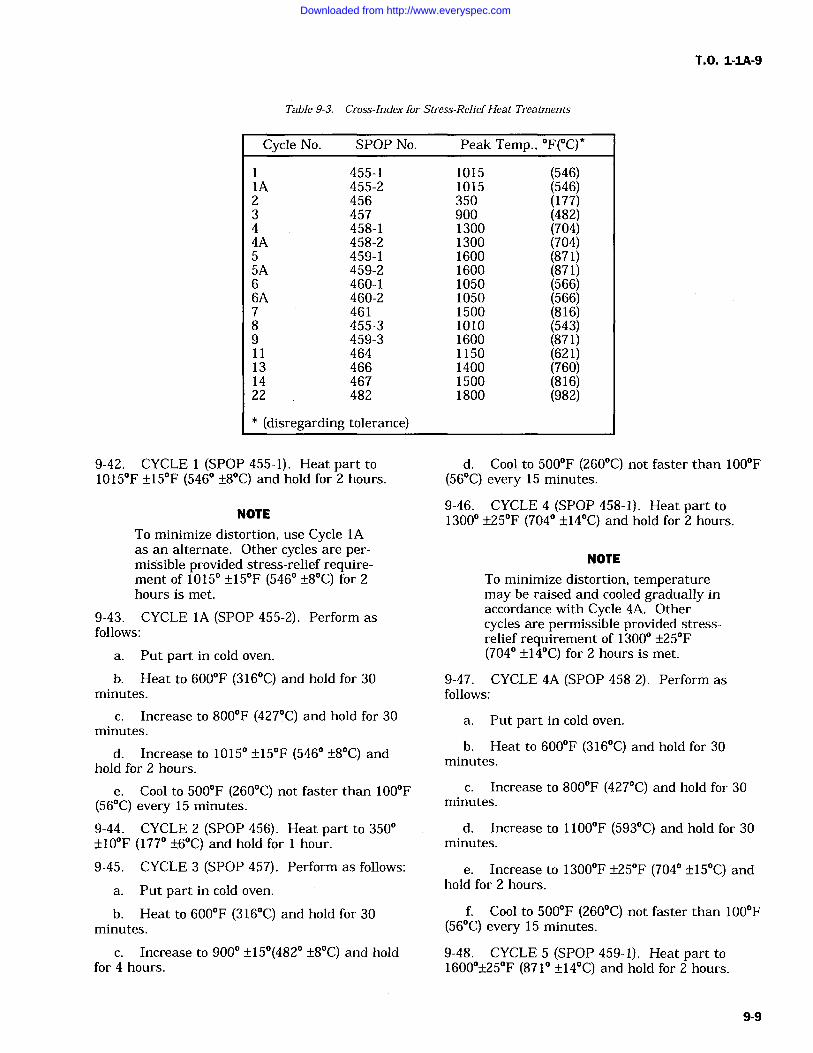
T.O. 1-1A-9
Table 9-3. Cross-Index for Stress-ReliefHeat Treatments
Cycle No. SPOP No.
1 455-11A 455-22 4563 4574 458-14A 458-25 459-15A 459-26 460-16A 460-27 4618 455-39 459-311 46413 46614 46722 482
Peak Temp., F(C)"
1015 (546)1015 (546)350 (177)900 (482)1300 (704)1300 (704)1600 (871)1600 (871)1050 (566)1050 (566)1500 (816)1010 (543)1600 (871)1150 (621)1400 (760)1500 (816)1800 (982)
* (disregarding tolerance)
9-42. CYCLE (SPOP 455-1). Heat part to1015F +/-15F (546 +/-8C) and hold for 2 hours.
NOTE
To minimize distortion, use Cycle 1Aas an alternate. Other cycles are per-missible provided stress-relief require-ment of 1015 +/-15F (546 +/-8C) for 2hours is met.
9-43. CYCLE 1A (SPOP 455-2). Perform as
follows:
a. Put part in cold oven.
b. Heat to 600F (316C) and hold for 30minutes.
c. Increase to 800F (427C) and hold for 30minutes.
d. Increase to 1015 +/-15F (546 +/-8C) andhold for 2 hours.
e. Cool to 500F (260C) not faster than 100F(56C) every 15 minutes.
9-44. CYCLE 2 (SPOP 456). Heat part to 350+/-10F (177 +/-6C) and hold for hour.
9-45. CYCLE 3 (SPOP 457). Perform as follows:
a. Put part in cold oven.
b. Heat to 600F (316C) and hold for 30minutes.
c. Increase to 900 +/-15(482 +/-8C) and holdfor 4 hours.
d. Cool to 500F (260C) not faster than 100F(56C) every 15 minutes.
9-46. CYCLE 4 (SPOP 458-1). Heat part to1300 +/-25F (704 +/-14C) and hold for 2 hours.
NOTE
To minimize distortion, temperaturemay be raised and cooled gradually inaccordance with Cycle 4A. Othercycles are permissible provided stress-relief requirement of 1300 +/-25F(704 +/-14C) for 2 hours is met.
9-47. CYCLE 4A (SPOP 458-2). Perform asfollows:
a. Put part in cold oven.
b. Heat to 600F (316C) and hold for 30minutes.
c. Increase to 800F (427C) and hold for 30minutes.
d. Increase to 1100F (593C) and hold for 30minutes.
e. Increase to 1300F +/-25F (704 +/-15C) andhold for 2 hours.
f. Cool to 500F (260C) not faster than 100F(56C) every 15 minutes.
9-48. CYCLE 5 (SPOP 459-1). Heat part to1600+/-25F (871 +/-14C) and hold for 2 hours.
9-9
Downloaded from http://www.everyspec.com
T.O. 1-IA-9
NOTE
To minimize distortion, temperaturemay be raised and lowered graduallyin accordance with Cycle 5A. Othercycles are permissable providedstress-relief requirement of 1600+/-25F (871 +/-14C) for 2 hours is met.
9-49. CYCLE 5A (SPOP 459-2). Perform asfollows:
a. Put part in cold oven.
b. Heat to 700F (371C) and hold for 30minutes.
c. Increase to 1000F (538C) and hold for 30minutes.
d. Increase to 1300F (704C) and hold for 30minutes.
e. Increase to 1600 +/-25F (871 +/-14C) andhold for 2 hours.
f. Cool to 500F (260C) not faster than 100F(56C) every 15 minutes.
9-50. CYCLE 6 (SPOP 460-1). Heat part to10500 +/-15F (566 +/-8C) for 2 hours.
NOTE
To minimize distortion, temperaturemay be raised and lowered graduallyin accordance with Cycle 6A. Othercycles are permissible provided stress-relief requirement of 1050 +/-15F(566 +/-8C) for 2 hours is met.
9-51. CYCLE 6A (SPOP 460-2). Perform asfollows:
a. Put part in cold oven.
b. Heat to 600F (316C) and hold for 30minutes.
c. Increase to 800F (427C) and hold for 30minutes.
d. Increase to 1050 +/-15F (566 +/-8C) andhold for 2 hours.
e. Cool to 500F (260C) not faster than 100F(56C) every 15 minutes.
9-52. CYCLE 7 (SPOP 461). Heat part to 1500F+/-25F (815+/-14C) and hold for 4 hours.
9-53. CYCLE 8 (SPOP 455-3). Perform asfollows:
a. Put part in cold oven.
b. Heat to 600F (316C) and hold for 30minutes.
c. Increase to 800F (427C) and hold for 30minutes.
d. Increase to 1010F (543+/-8C) and hold for30 minutes.
e. Cool to 500F (260C) not faster than 100F(56C) every 15 minutes.
9-54. CYCLE 9 (SPOP 459-3). Heat part to1600 +/-25F (871 +/-14C) and hold for hour.
9-55. CYCLE 11 (SPOP 464). Perform asfollows:
CAUTION
For titanium parts, a vacuum of 0.5microns mercury, maximum, or argonor helium with a dew point no higherthan -60F (-51C) shall be used.
Longer heat treatment at specifiedtemperature, or shorter heat treat-ment at higher,temperature may berequired by engine publication for cer-
tain parts.
a. Heat part to 1150 +/-15F (621 +/-8C) andhold for 1 hour.
NOTE
For materials other than titanium, air
or argon may be used.
b. Air cool.
9-56. CYCLE 13 (SPOP 466). Perform asfollows:
a. Heat part to 1400 +/-25F (760 +/-14C) inair and hold for 2 hours.
b. Air cool, or faster.
9-57. CYCLE 14 (SPOP 467). Perform asfollows:
a. Heat part to 1500 +/-25F (816 +/-14C) andhold for 30 minutes.
NOTE
A protective atmosphere is suggested.
b. Furnace cool at a rate of 50F (28C) perhour to 1100 (593C), then air cool or faster.
9-58. CYCLE 22 (SPOP 482). Previously desig-nated Cycle 10.
9-10
Downloaded from http://www.everyspec.com
T.O. 1-IA-9
CAUTION
Parts shall be thoroughly cleanedbefore entering oven.
9-65. Choice of method depends upon size andshape of joint, part configuration, and accessibil-ity. Resistance blankets and quartz lamps can beused to 1350F (732C); induction heaters andradiant gas burners can be used to 1825F (996C).
NOTE
Hydrogen, argon, vacuum, or air areacceptable atmospheres; however,when heat treatment is to be followedby weld repair, hydrogen is preferablebecause of its cleaning action onoxides and impurities difficult toclean mechanically, as within cracksor cavities.
a. Place part in cold oven; however, this stepmay be omitted for thin sheet metal parts.
b. Heat part to 1800 +/-25F (982 +/-14C) andhold for hour.
c. Air cool.
9-59. LOCAL STRESS-RELIEF.
9-60. GENERAL. Local stress-relief is the appli-cation of a heat treatment cycle, using a portableheating system, to a part that has been weldrepaired, usually without disassembly. Elaboratefixturing is avoided when stress-relieving minorareas of large components.
9-61. Approval for local stress-relief is governedin part by accessibility, temperature requirement,and configuration and material of part.
9-62. Local stress-relief is especially useful whenapplied to parts on a mounted or partly disassem-bled engine.
9-63. Besides avoiding disassembly, local stress-relief provides significant cost and time savings.
9-64. Typical local stress-relief methods includethe following:
a. Resistance
b. Induction
c. Quartz lamp
CAUTIONJ
Gas burner shall not be used tostress-relieve titanium parts.Exhaust gases can produce harmfulsurface reaction.
d. Gas burner radiant heater.
CAUTION
Thermocouples shall not be tackwelded to titanium parts.
9-66. Temperature profile shall be monitoredwith tack welded thermocouples to provide accu-
rate readout for manual or automatic control dur-ing heat treat cycle. Thermocouples shall belocated every 2 inches of area that is to be stress-relieved. Following the cycle, thermocouples arebroken or ground off, and part blended to originalcontour.
9-67. Stress-relief duration and temperatureshall be the same as for a corresponding furnaceheat treat, unless otherwise specified in applicableengine technical orders.
9-68. DESCRIPTION OF METHODS. Localstress-relief methods are defined in the followingparagraphs.
9-69. Resistance. Heaters consist of nichromewire elements insulated with ceramic fiber andcontained within a flexible wire jacket. Thesecomponents are woven into a thermal blanket,which shall be held in close contact with surface tobe stress-relieved. Supplementary flexible heatersmay be added to ensure that adjacent parts do notconduct heat away in such a manner as to makeheat distribution non-uniform.
9-70. Induction. Requirements include a highfrequency generator, with a water-cooled copperinduction coil of sufficient number of turns to bepositioned over entire area to be heat treated, suchas a welded patch. Coils shall be insulated frommetal contact, which will produce electrical arcing.Typical applications include small weld repair ofholes or bosses, or replacement of small detailparts.
9-71. Quartz Lamp. Radiant lamp providesintense infrared heat, which can be easily directedtoward part being stress-relieved. Temperaturecan be controlled by pulsing lamp on and off. Typ-ical applications include inlet guide vanes, exhauststruts, intermediate cases, door assemblies, acces-sory housing, and thrust reversers.
9-11
Downloaded from http://www.everyspec.com

TO. 1-1A-9
CAUTION
Gas burner shall not be used tostress-relieve titanium parts.Exhaust gases can produce harmfulsurface reaction.
9-72. Radiant Gas Burner. Good heating pat-terns and temperature control are permitted byusing as burners. Heat treat of several areas canbe accomplished simultaneously. Radiant gasburners are fueled with a mixture of air and natu-ral gas.
9-12
Downloaded from http://www.everyspec.com
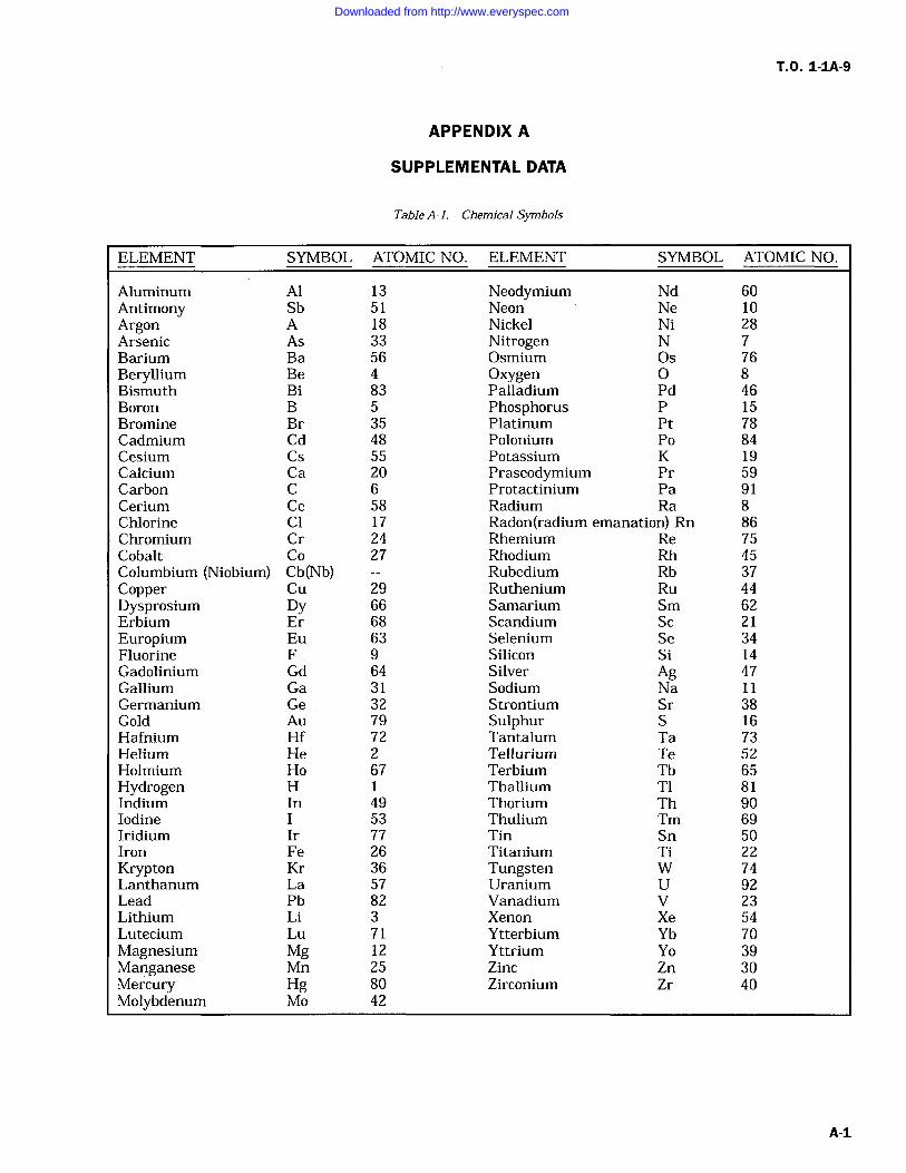
T.O. 1-1A-9
APPENDIX A
SUPPLEMENTAL DATA
Table A-l. Chemical Symbols
ELEMENT SYMBOL ATOMIC NO. ELEMENT SYMBOL ATOMIC NO.
Aluminum Al 13 Neodymium Nd 60Antimony Sb 51 Neon Ne 10Argon A 18 Nickel Ni 28Arsenic As 33 Nitrogen N 7Barium Ba 56 Osmium Os 76Beryllium Be 4 Oxygen 0 8Bismuth Bi 83 Palladium Pd 46Boron B 5 Phosphorus P 15Bromine Br 35 Platinum Pt 78Cadmium Cd 48 Polonium Po 84Cesium Cs 55 Potassium K 19Calcium Ca 20 Praseodymium Pr 59Carbon C 6 Protactinium Pa 91Cerium Ce 58 Radium Ra 8Chlorine Cl 17 Radon(radium emanation) Rn 86Chromium Cr 24 Rhemium Re 75Cobalt Co 27 Rhodium Rh 45Columbium (Niobium) Cb(Nb) Rubedium Rb 37Copper Cu 29 Ruthenium Ru 44Dysprosium Dy 66 Samarium Sm 62Erbium Er 68 Scandium Sc 21Europium Eu 63 Selenium Se 34Fluorine F 9 Silicon Si 14Gadolinium Gd 64 Silver Ag 47Gallium Ga 31 Sodium Na 11Germanium Ge 32 Strontium Sr 38Gold Au 79 Sulphur S 16Hafnium Hf 72 Tantalum Ta 73Helium He 2 Tellurium Te 52Holmium Ho 67 Terbium Tb 65Hydrogen H 1 Thallium T1 81Indium In 49 Thorium Th 90Iodine I 53 Thulium Tm 69Iridium Ir 77 Tin Sn 50Iron Fe 26 Titanium Ti 22Krypton Kr 36 Tungsten W 74Lanthanum La 57 Uranium U 92Lead Pb 82 Vanadium V 23Lithium Li 3 Xenon Xe 54Lutecium Lu 71 Ytterbium Yb 70Magnesium Mg 12 Yttrium Yo 39Manganese Mn 25 Zinc Zn 30Mercury Hg 80 Zirconium Zr 40Molybdenum Mo 42
Downloaded from http://www.everyspec.com
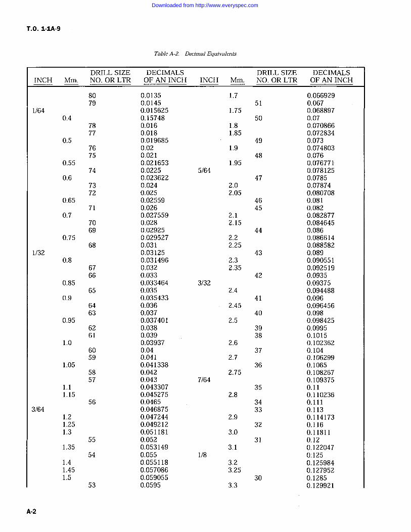
T.O. 1-1A-9
Table A-2. Decimal Equivalents
DRILL SIZE DECIMALS DRILL SIZE DECIMALSINCH Mm. NO. OR LTR OF AN INCH INCH Mm. NO. OR LTR OF AN INCH
80 0.0135 1.7 0.06692979 0.0145 51 0.067
1/64 0.015625 1.75 0.0688970.4 0.15748 50 0.07
78 0.016 1.8 0.07086677 0.018 1.85 0.072834
0.5 0.019685 49 0.07376 0.02 1.9 0.07480375 0.021 48 0.076
0.55 0.021653 1.95 0.07677174 0.0225 5/64 0.078125
0.6 0.023622 47 0.078573 0.024 2.0 0.0787472 0.025 2.05 0.080708
0.65 0.02559 46 0.08171 0.026 45 0.082
0.7 0.027559 2.1 0.08287770 0.028 2.15 0.08464569 0.02925 44 0.086
0.75 0.029527 2.2 0.08661468 0.031 2.25 0.088582
1/32 0.03125 43 0.0890.8 0.031496 2.3 0.090551
67 0.032 2.35 0.09251966 0.033 42 0.0935
0.85 0.033464 3/32 0.0937565 0.035 2.4 0.094488
0.9 0.035433 41 0.09664 0.036 2.45 0.09645663 0.037 40 0.098
0.95 0.037401 2.5 0.09842562 0.038 39 0.099561 0.039 38 0.1015
1.0 0.03937 2.6 0.10236260 0.04 37 0.10459 0.041 2.7 0.106299
1.05 0.041338 36 0.106558 0.042 2.75 0.10826757 0.043 7/64 0.109375
1.1 0.043307 35 0.111.15 0.045275 2.8 0.110236
56 0.0465 34 0.1113/64 0.046875 33 0.113
1.2 0.047244 2.9 0.1141731.25 0.049212 32 0.1161.3 0.051181 3.0 0.11811
55 0.052 31 0.121.35 0.053149 3.1 0.122047
54 0.055 1/8 0:1251.4 0.055118 3.2 0.1259841.45 0.057086 3.25 0.1279521.5 0.059055 30 0.1285
53 0.0595 3.3 0.129921
A-2
Downloaded from http://www.everyspec.com
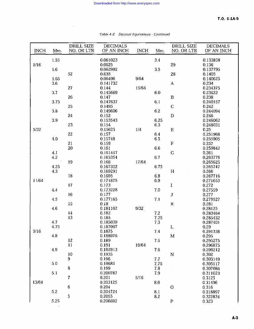
T.O. 1-1A-9
Table A-2. Decimal Equivalents -Continued
DRILL SIZE DECIMALS DRILL SIZE DECIMALSINCH Mm. NO. OR LTR OF AN INCH INCH Mm. NO. OR LTR OF AN INCH
1.55 0.061023 3.4 0.1338581/16 0.0625 29 0.136
1.6 0.062992 3.5 0.13779552 0.635 28 0.1405
1.65 0.06496 9/64 0.1406253.6 0.141732 A 0.234
27 0.144 15/64 0.2343753.7 0.145669 6.0 0.23622
26 0.147 B 0.2383.75 0.147637 6.1 0.240157
25 0.1495 C 0.2423.8 0.149606 6.2 0.244094
24 0.152 D 0.2463.9 0.153543 6.25 0.246062
23 0.154 6.3 0.2480315/32 0.15625 1/4 E 0.25
22 0.157 6.4 0.2519684.0 0.15748 6.5 0.255905
21 0.159 F 0.25720 0.161 6.6 0.259842
4.1 0.161417 G 0.2614.2 0.165354 6.7 0.263779
19 0.166 17/64 0.2656254.25 0.167322 6.75 0.2657474.3 0.169291 H 0.266
18 0.1695 6.8 0.26771611/64 0.171875 6.9 0.271653
17 0.173 I 0.2724.4 0.173228 7.0 0.27559
16 0.177 J 0.2774.5 0.177165 7.1 0.279527
15 0.18 K 0.2814.6 0.181102 9/32 0.28125
14 0.182 7.2 0.28346413 0.185 7.25 0.285432
4.7 0.185039 7.3 0.2874014.75 0.187007 L 0.29
3/16 0.1875 7.4 0.2913384.8 0.188976 M 0.295
12 0.189 7.5 0.29527511 0.191 19/64 0.296875
4.9 0.192913 7.6 0.29921210 0.1935 N 0.3029 0.196 7.7 0.303149
5.0 0.19685 7.75 0.3051178 0.199 7.8 0.307086
5.1 0.200787 7.9 0.3110237 0.201 5/16 0.3125
13/64 0.203125 8.0 0.314966 0.204 0 0.316
5.2 0.204724 8.1 0.3188975 0.2055 8.2 0.322834
5.25 0.206692 P 0.323
A-3
Downloaded from http://www.everyspec.com
T.O. 1-IA-9
Table A-2. Decimal Equivalents Continued
DRILL SIZE DECIMALS DRILL SIZE DECIMALSINCH Mm. NO. OR LTR OF AN INCH INCH Mm. NO. OR LTR OF AN INCH
5.3 0.208661 8.25 0.3248024 0.209 8.3 0.326771
5.4 0.212598 21/64 0.3281253 0.213 8.4 0.330708
5.5 0.216535 Q 0.3327/32 0.21875 8.5 0.334645
5.6 0.220472 8.6 0.3385822 0.221 R 0.339
5.7 0.224409 8.7 0.3425195.75 0.226377 11/32 0.34375
1 0.228 8.75 0.3444875.8 0.228346 8.8 0.3464565.9 0.232283 S 0.3488.9 0.350393 23/32 0.718759.0 0.35433 18.5 0.728345
T 0.358 47/64 0.7343759.1 0.358267 19.0 0.74803
23/64 0.359375 3/4 0.759.2 0.362204 49/64 0.7656259.25 0.364172 19.5 0.7677159.3 0.366141 25/32 0.78125
U 0.368 20.0 0.78749.4 0.370078 51/64 0.7968759.5 0.374015 20.5 0.807085
3/8 0.375 13/16 0.8125V 0.377 21.0 0.82677
9.6 0.377952 53/64 0.8281259.7 0.381889 27/32 0.843759.75 0.383857 21.5 0.8464559.8 0.385826 55/64 0.859375
W 0.386 22.0 0.866149.9 0.389763 7/8 0.875
25/64 0.390625 22.5 0.88582510.0 0.3937 57/64 0.890625
X 0.397 23.0 0.90551Y 0.404 29/32 0.90625
13/32 0.40625 59/64 0.921875Z 0.413 23.5 0.925195
10.5 0.413385 15/16 0.937527/64 0.421875 24.0 0.94488
11.0 0.43307 61/64 0.9531257/16 0.4375 24.5 0.964565
11.5 0.452755 31/32 0.9687529/64 0.453125 25.0 0.9842515/32 0.46875 63/64 0.984375
12.0 0.47244 1 1.031/64 0.484375
12.5 0.4921251/2 0.5
13.0 0.5118133/64 0.51562517/32 0.53125
13.5 0.531495
A-4
Downloaded from http://www.everyspec.com
T.O. 1-1A-9
Table A-2. Decimal Equivalents Continued
INCHDRILL SIZE
Mm. NO. OR LTRDECIMALS DRILL SIZE DECIMALSOF AN INCH INCH Mm. NO. OR LTR OF AN INCH
35/64 0.54687514.0 0.55118
9/16 0.562514.5 0.570865
37/64 0.57812515.0 0.59055
19/32 0.5937539/64 0.609375
15.5 0.6102355/8 0.625
16.0 0.6299241/64 0.640625
16.5 0.64960521/32 0.65625
17.0 0.6692943/64 0.67187511/16 0.6875
17.5 0.68897545/64 0.703125
18.0 0.70866
A-5
Downloaded from http://www.everyspec.com
T.O. 1-IA-9
Table A-3. Engineering Conversion Factors
LENGTH
1 inch 2.54 Centimeters 0.0833 Foot 0.0278 Yard1 foot 0.305 Meter 0.333 Yard1 yard 0.914 Meter 3 FeetRod 16 1/2 Feet 5 1/2 YardsMile 1.609 Kilometers 5280 Feet 1760 Yards
1 Centimeter 0.3937 Inch 0.0328 Foot1 Meter 39.37 Inches 3.281 Feet 1.094 Yards1 Kilometer 1000 Meters 3280.83 Feet 1093.61 Yards 0.62137 Mile
AREA
1 Sq. Inch 6.452 Sq. Centimeters1 Sq. Foot 144 Sq. Inches 929.032 Sq. Centimeters1 Sq. Yard 1296 Sq. Inches 9 Sq. Feet 0.836 Sq. MeterSq. Rod 272 1/4 Sq Feet 30 1/4 Sq. YardsAcre 43,560 Sq. Feet 160 Sq. RodsSq. Mile 640 Acres
1 Sq. Centimeter 0.155 Sq. InchSq. Meter 1550 Sq. Inches 10.764 Sq. Feet 1.196 Sq. YardsSq. Kilometer 0.3861 Sq. Miles 247.104 Acres
VOLUME
Cu. Inch 16.39 Cu. Centimeters 0.00433 Gallons*Cu. Foot 1728 Cu. Inches 7.48 Gallons* 28.317 Liters 0.037 Cu. YardsCu. Yard 27 Cu. Feet 0.7646 Cu. Meter 202 Gallons*Cu. Centimeter 0.001 Liter 0.061 Cu. InchCu. Meter 35.31 Cu. Feet 1.308 Cu. Yards 264.2 Gallons*Quart* 0.25 Gallons* 57.75 Cu. Inches 0.946 Liter 2 Pints*Gallon* 0.832702 Imperial Gallon 231 Cu. Inches 0.1377 Cu. Feet 3.785 Liters3785 Cu. Centimeters
1 Gallon, Imperial 1.20091 U.S. GallonsBarrel (Std.) 31 1/2 Gallons
1 Barrel (Oil) 42 Gallons*U.S. Measure
WEIGHT
Ounce 16 Drams 437.5 Grains 0.0625 Pound 28.35 Grams 0.9155 Ounce (Troy)Pound 16 Ounces 453.593 Grams 0.453593 KilogramTon (Short) 2000 Pounds 907.185 Kilograms 0.892857 Long Ton 0.907185 Metric TonTon (Metric) 2204.62 Pounds 0.98421 Long Ton 1.10231 Short TonsTon (Long) 2240 Pounds 1016.05 Kilograms 1.120 Short Tons 1.01605 Metric Tons
1 Gram 15.43235 Grains 0.001 Kilogram1 Kilogram 2.20462 Pounds
COMPOUND UNITS
gram per square millimeter 1.422 pounds per square inchkilogram per square millimeter 1.422.32 pounds per square inchkilogram per square centimeter 14.2232 pounds per square inchkilogram per square meter 0.2048 pound per square foot
1.8433 pounds per square yard
A-6
Downloaded from http://www.everyspec.com
T.O. 1-1A-9
Table A-3. Engineering Conversion Factors Continued
COMPOUND UNITS (Cont)
kilogram meterkilogram per meter
1 pound per square inch1 pound per square foot1 pound per square foot1 pound per cubic inch1 pound per cubic foot1 kilogram per cubic meter1 foot per second1 meter per second1 meter per second
MULTIPLES
Circumference of CircleArea of Circle
Area of TriangleSurface of Sphere
Volume of Sphere
Area of HexagonArea of Octagon
ENGINEERING UNITS
1 Horsepower33,000 foot pounds per minute550 foot pounds per second746 watts0.746 kilowatts
1 Horsepower Hour0.746 Kilowatt hours1,980,000 foot pounds2,545 heat units (B.T.U)
1 Kilowatt1,000 watts1.34 horsepower737.3 foot pounds per second44.240 foot pounds per minute56.9 heat units (B.T.U) per minute
7.2330 foot pounds0.6720 pound per foot0.07031 kilogram per square centimeter0.0004882 kilogram per square centimeter0.006944 pound per square inch27679.7 kilograms per cubic meter16.0184 kilograms per cubic meter0.06243 pound per cubic foot0.30480 meter per second3.28083 feet per second2.23693 miles per hour
Diameter X 3.1416Square of Diameter X 0.7854, orSquare of Radius X 3.1416, orSquare of Circumference X 0.07958Base X one-half altitudeCircumference X diameter, orSquare of diameter X 3.1416Surface X one-sixth diameter, orCube of diameter X 0.5236Square of Diameter of Inscribed Circle X 0.866Square of Diameter of Inscribed Circle X 0.828
kilowatt Hour1,000 watt hours1.34 horsepower hours2,655,220 foot pounds3,412 heat units (B.T.U)
British Thermal Unit1,055 watt seconds778 foot pounds0.000293 kilowatt hour0.000393 horsepower hour
Wattjoule per second
0.00134 horsepower3.3412 heat units (B.T.U.) per hour0.7373 foot pounds per second44.24 foot pounds per minute
Downloaded from http://www.everyspec.com
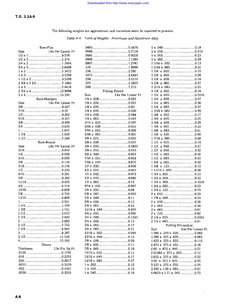
T.O. 1-1A-9
The following weights are approximate and variations must be expected in practice.
Table A-4. Table of Weights Aluminum and Aluminum Alloy
Bars-FlatSize Lbs Per Linear Ft1/2 .......................................0.5781/2 x 2 .......................................1.1743/4 x 2 .......................................1.76043/4 3 .......................................2.6408
2 ..........................................2.3472
x 3 ..........................................3.52081/2 x 2 ....................................3.52083/4 3 1/2 7.1883
2 x 3 ..........................................7.04162 3/4 4 12.90963 x 4 ........................................14.350
SizeBars-Hexagon
Lbs Per Linear Ft3/8 .............................................0.1477/16 ...........................................0.201/2 .............................................0.2629/16 ...........................................0.3315/8 .............................................0.4093/4 .............................................0.639
................................................1.0471/4 ..........................................1.6201/2 ..........................................2.340
Rods-RoundSize Lbs Per Linear Ft3/16 ...........................................0.0321/4 .............................................0.0585/16 ...........................................0.0903/8 .............................................0.1297/16 ...........................................0.1761/2 .............................................0.2309/16 ...........................................0.2915/8 .............................................0.36011/14 .........................................0.4353/4 .............................................0.51813/16 .........................................0.6087/8 .............................................0.70515/16 .........................................0.809
................................................0.9211/4 ..........................................1.4393/8 ..........................................1.7411/2 ..........................................2.0723/4 ..........................................2.820
2 ................................................3.6832 1/2 ..........................................5.7552 3/4 ..........................................6.9643 ................................................8.2873 1/2 ........................................11.5504 ..............................................15.200
SheetsThickness Lbs Per Sq Ft.0126 .........................................0.1797.016 ...........................................0.2253.020 ...........................................0.2817.0253 .........................................0.3570.032 ...........................................0.4501.0359 .........................................0.5055
.0403 .........................................0.5676
.0508 .........................................0.7158
.0641 .........................................0.9026
.0808 .........................................1.1382
.0907 1.2781
.128 ...........................................1.8099
.156 ...........................................2.202
.1875 .........................................2.6481
.250 ...........................................3.5215
.375 ...........................................5.2822
.500 ...........................................7.212Tubing-Round
Size Lbs Per Linear Ft1/4 x .028 ..................................0.0251/4 x .032 ..................................0.0271/4 x .035 ..................................0.031/4 x .049 ..................................0.0361/4 x .058 ..................................0.0441/4 x .065 ..................................0.0475/16 x.025 ................................0.0275/16 x.028 ................................0.0325/16 x .035 ................................0.0395/16 .065 ................................0.0613/8 x .025 ..................................0.0333/8 x .028 ..................................0.0373/8 x .035 ..................................0.04353/8 x .042 ..................................0.0533/8 x .049 ..................................0.0637/16 x .035 ................................0.0547/16 .049 ................................0.0751/2 x .032 ..................................0.0561/2 x .035 ..................................0.0631/2 x .042 ..................................0.073/2 x .049 ..................................0.086
1/2 x .065 ..................................0.119/16 .032 ................................0.0675/8 x .035 ..................................0.085/8 x .042 ..................................0.0935/8 x .049 ..................................0.115/8 x .058 ..................................0.135/8 x .065 ..................................0.1411/16 x .049 ..............................0.1053/4 x .035 ..................................0.0963/4 x .049 ..................................0.12453/4 x .058 ..................................0.153/4 x .065 ..................................0.173/4 x .083 ..................................0.2113/16 .032 ..............................0.09513/16 .049 ..............................0.137/8 x .028 ..................................0.097/8 x .035 ..................................0.117/8 x .049 ..................................0.1615/16 x .032 ..............................0.1115/16 .049 ..............................0.1715/16 x .083 ..............................0.27
x .032 .....................................0.12
x .035 .....................................0.13x.042 .....................................0.16
x .049 .....................................0.18
x .058 .....................................0.210
x .065 .....................................0.23
x .083 .....................................0.291/16x.032 .............................0.131/16 x .083 .............................0.311/8 x .035 ..............................0.15/8 x .049 ..............................0.20
1/8 .058 ..............................0.241/8 x .065 ..............................0.273/16 x .083 .............................0.35/4 x .035 ..............................0.16
1/4 x .049 ..............................0.21341/4 .058 ..............................0.271/4 x .065 ..............................0.30/4 .083 ..............................0.37
5/16 x .083 .............................0.393/8 x .032 ..............................0.173/8 x .049 ..............................0.253/8 x .058 ..............................0.293/8 .065 ..............................0.333/8 .083 ..............................0.413/8 x .120 ..............................0.587/16 .095 .............................0.481/2 .035 ..............................0.191/2 x .049 ..............................0.271/2 x .058 ..............................0.321/2 .065 ..............................0.361/2 x .083 ..............................0.455/8 x .065 ..............................0.395/8 .125 ..............................0.7211/14 .095 ...........................0.583/4 x .035 ...............................0.233/4 .049 ...............................0.323/4 x .065 ...............................0.39343/4 .083 0.533/4 .125 ...............................0.79
2 .042 .....................................0.297/8 x .049 ...............................0.34
2 .049 .:...................................0.362 .065 .....................................0.482 x .083 .....................................0.612 .125 .....................................0.922 1/4 x .025 ...............................0.20522 1/2 x .065 ...............................0.61
Tubing-StreamlineSize Lbs Per Linear Ft1.500 .250 .020 ...................0.0821.500 x .375 x .020 ...................0.0851.625 x .375 x .025 ...................0.1151.875 x .375 x .035 ...................0.162.00 x .875 x .049 ....................0.272.01563 .375 x .025 ...............0.122.625 x .375 x .035 ...................0.223.00 .375 .035 ....................0.253.125 x .375 x .032 ...................0.253.350 x 1.50 x .065 ...................0.614.0625 x 1.71 x .065 .................0.73
A-8
Downloaded from http://www.everyspec.com
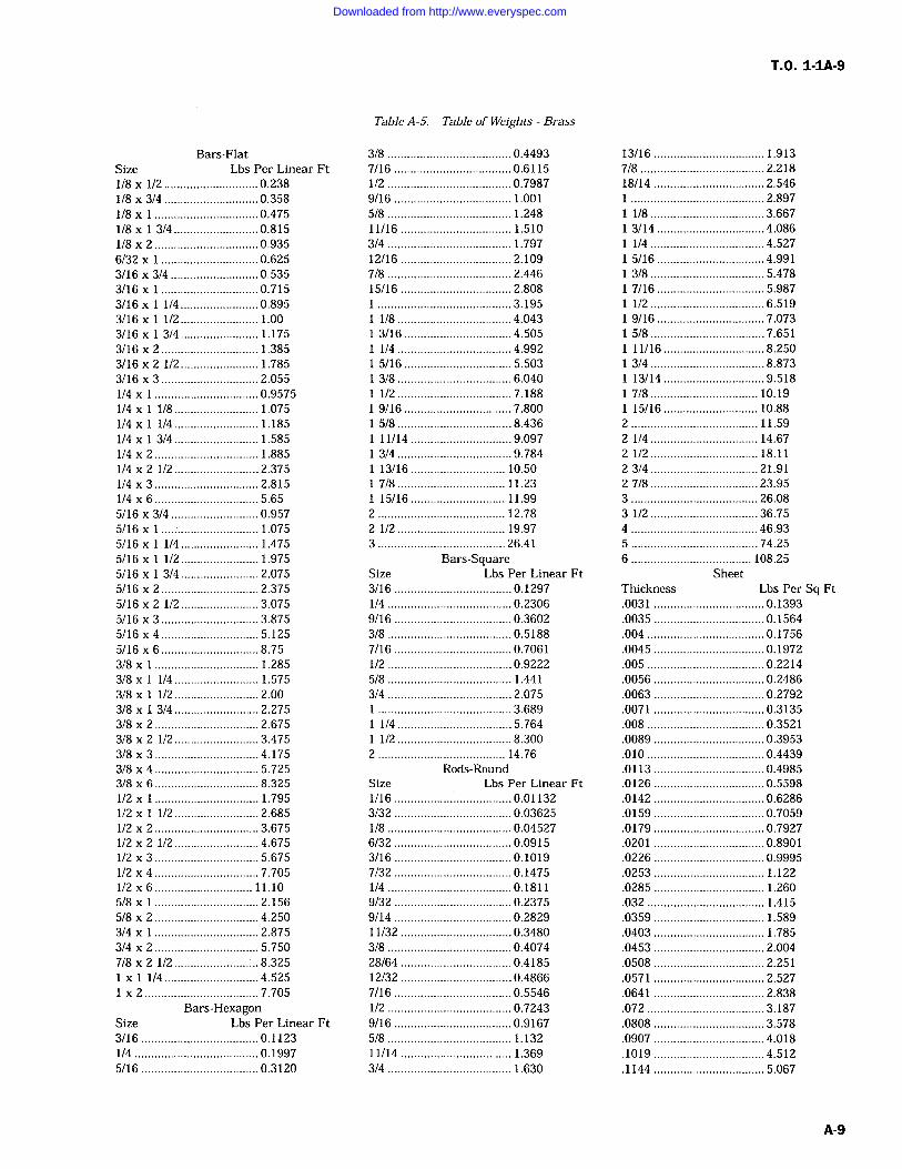
T.O. 1-1A-9
Bars-FlatSize Lbs Per Linear Ft/8 x 1/2 0.2381/8 x 3/4 0.3581/8 x 0.4751/8 3/4 0.8151/8 x 2 0.9356/32 x 0.6253/16 x 3/4 0.5353/16 x 0.7153/16 1/4 0.8953/16 1/2 1.003/16 x 3/4 1.1753/16 x 2 1.3853/16 x 2 1/2 1.7853/16 x 3 2.0551/4 0.95751/4 1/8 1.0751/4 x 1/4 1.1851/4 x 3/4 1.5851/4 x 2 1.8851/4 2 1/2 2.3751/4 3 2.8151/4 6 5.655/16 x 3/4 0.9575/16 1.0755/16 x 1/4 1.4755/16 x 1/2 1.9755/16 x 3/4 2.0755/16 2 2.3755/16 x 2 1/2 3.0755/16 x 3 3.8755/16 x 4 5.1255/16 6 8.753/8 x 1.2853/8 x 1/4 1.5753/8 1/2 2.003/8 3/4 2.2753/8 2 2.6753/8 2 1/2 3.4753/8 x 3 4.1753/8 x 4 5.7253/8 6 8.3251/2 1.7951/2 1/2 2.6851/2 2 3.6751/2 x 2 1/2 4.6751/2 3 5.6751/2 x 4 7.7051/2 x 6 11.105/8 2.1565/8 x 2 4.2503/4 x 2.8753/4 x 2 5.7507/8 x 2 1/2 8.325
1/4 4.525
x 2 7.705Bars-Hexagon
Size Lbs Per Linear Ft3/16 0.11231/4 0.19975/16 0.3120
Table A-5. Table of Weights Brass
3/8 0.44937/16 0.61151/2 0.79879/16 1.0015/8 1.24811/16 1.5103/4 1.79712/16 2.1097/8 2.44615/16 2.808
3.1951/8 4.0433/16 4.5051/4 4.9925/16 5.5033/8 6.0401/2 7.1889/16 7.8005/8 8.43611/14 9.0973/4 9.78413/16 10.507/8 11.2315/16 11.99
2 12.782 1/2 19.973 26.41
Bars-SquareSize Lbs Per Linear Ft3/16 0.12971/4 0.23069/16 0.36023/8 0.51887/16 0.70611/2 0.92225/8 1.4413/4 2.075
3.6891/4 5.7641/2 8.300
2 14.76Rods-Round
Size Lbs Per Linear Ft1/16 0.011323/32 0.036251/8 0.045276/32 0.09153/16 0.10197/32 0.14751/4 0.18119/32 0.23759/14 0.282911/32 0.34803/8 0.407428/64 0.418512/32 0.48667/16 0.55461/2 0.72439/16 0.91675/8 1.13211/14 1.3693/4 1.630
13/16 1.9137/8 2.21818/14 2.546
2.8971/8 3.6673/14 4.0861/4 4.5275/16 4.9913/8 5.4787/16 5.9871/2 6.5199/16 7.0735/8 7.65111/16 8.2503/4 8.87313/14 9.5187/8 10.1915/16 10.88
2 11.592 1/4 14.672 1/2 18.1123/4 21.9127/8 23.953 26.083 1/2 36.754 46.935 74.256 108.25
SheetThickness Lbs Per Sq Ft.0031 0.1393.0035 0.1564.004 0.1756
.0045 0.1972
.005 0.2214
.0056 0.2486
.0063 0.2792
.0071 0.3135
.008 0.3521
.0089 0.3953
.010 0.4439
.0113 0.4985
.0126 0.5598
.0142 0.6286
.0159 0.7059
.0179 0.7927
.0201 0.8901
.0226 0.9995
.0253 1.122
.0285 1.260
.032 1.415
.0359 1.589
.0403 1.785
.0453 2.004
.0508 2.251
.0571 2.527
.0641 2.838
.072 3.187
.0808 3.578
.0907 4.018
.1019 4.512
.1144 5.067
A-9
Downloaded from http://www.everyspec.com
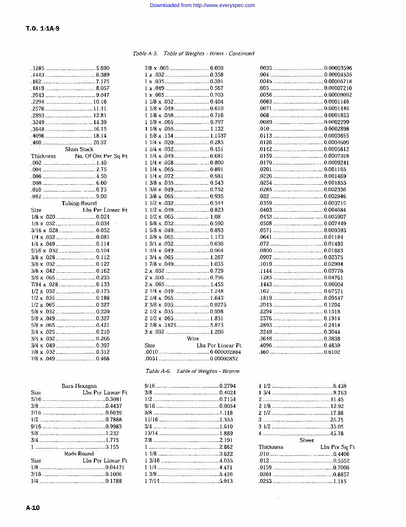
T.O. 1-IA-9
.1285 5.690
.1443 6.389
.162 7.175
.1819 8.057
.2043 9.047
.2294 ................................ 10.16
.2576 11.41
.2893 12.81
.3249 14.39
.3648 16.15
.4096 18.14
.460 20.37Shim Stock
Thickness No. Of Ozs Per Sq Ft.002 1.40.004 2.75.006 4.50.008 6.00.010 6.75.012 9.00
Tubing-RoundSize Lbs Per Linear Ft1/8 x .020 0.024/8 .032 0.034
3/16 x .028 0.0521/4 .032 0.0811/4 .049 0.1145/16 x .032 0.1043/8 x .028 0.1123/8 .032 0.1273/8 x .042 0.1623/8 x .065 0.2337/14 .028 0.1331/2 x .032 0.1731/2 .035 0.1881/2 x .065 0.3275/8 x .032 0.2205/8 x .049 0.3275/8 .065 0.4213/4 .025 0.2103/4 x .032 0.2663/4 x .049 0.3977/8 .032 0.3127/8 .049 0.468
Bars-HexagonSize Lbs Per Linear Ft5/16 ...........................................0.30813/8 .............................................0.44377/16 ...........................................0.60391/2 .............................................0.78889/16 ...........................................0.99835/8 .............................................1.2323/4 .............................................1.775
................................................3.155Rods-Round
Size Lbs Per Linear Ft1/8 .............................................0.044713/16 ...........................................0.10061/4 .............................................0.1788
Table A-5. Table of Weights Brass Continued
7/8 .065 0.609.032 0.358.035 0.391
x .049 0.567x.065 0.7031/8 x .032 0.4041/8x.049 0.6101/8x.058 0.7161/8 x .065 0.7971/8 x .095 1.1321/8 x .134 1.15371/4 .020 0.2851/4 x .032 0.4511/4 .049 0.681/4 .058 0.8001/4x.065 0.8911/4 x .072 0.9813/8 x .035 0.5433/8 x .049 0.7523/8 x .065 0.935/2 x .032 0.544
1/2 .049 0.8231/2 x .065 1.085/8 .032 0.5905/8 x .049 0.8935/8 x .065 1.1733/4 x .032 0.6363/4 x .049 0.9643/4 x .065 1.2677/8 .049 1.035
2 x .032 0.7292 .035 0.7962 .065 1.4552 1/4 x .049 1.2482 /4 .065 1.6432 3/8 x .035 0.92752 1/2 x .035 0.9982 1/2 x .065 1.8312 7/8 .1875 5.8753 x .032 1.200
WireSize Lbs Per Linear Ft.0010 0.000002884.0031 0.00002852
.0035 0.00003596
.004 0.00004535
.0045 0.00005718
.005 0.00007210
.0056 0.00009092
.0063 0.0001146
.0071 0.0001446
.008 0.0001823
.0089 0.0002299
.010 0.0002898
.0113 0.0003655
.0126 0.0004609
.0142 0.0005812
.0159 0.0007328
.0179 0.0009241
.0201 0.001165
.0226 0.001469
.0254 0.001853
.0285 0.002336
.032 0.002946
.0359 0.003715
.0403 0.004684
.0453 0.005907
.0508 0.007449
.0571 0.009393
.0641 0.01184
.072 0.01493
.0800 0.01883
.0907 0.02375
.1019 0.02994
.1144 0.03776
.1285 0.04761
.1443 0.06004
.162 0.07571
.1819 0.09547
.2043 0.1204
.2294 0.1518
.2576 0.1914
.2893 0.2414
.3249 0.3044
.3648 0.3838
.4096 0.4839
.460 0.6102
Table A-6. Table of Weights Bronze
9/16 ...........................................0.27943/8 .............................................0.40241/2 .............................................0.71549/16 ...........................................0.90545/8 .............................................1.11811/16 .........................................1.3533/4 1.61013/14 .........................................1.8897/8 .............................................2.191
................................................2.8621/8 ..........................................3.6223/16 ........................................4.0351/4 ..........................................4.4713/8 ..........................................5.4107/14 ........................................5.913
1/2 ..........................................6.4383/4 ..........................................8.763
2 ..............................................11.452 1/8 ........................................12.922 1/2 ........................................17.883 ..............................................25.753 1/2 ........................................35.054 ..............................................45.78
SheetThickness Lbs Per Sq Ft.010 ...........................................0.4406.012 ...........................................0.5552.0159 .........................................0.7006.0201 .........................................0.8857.0253 .........................................1.115
A-10
Downloaded from http://www.everyspec.com
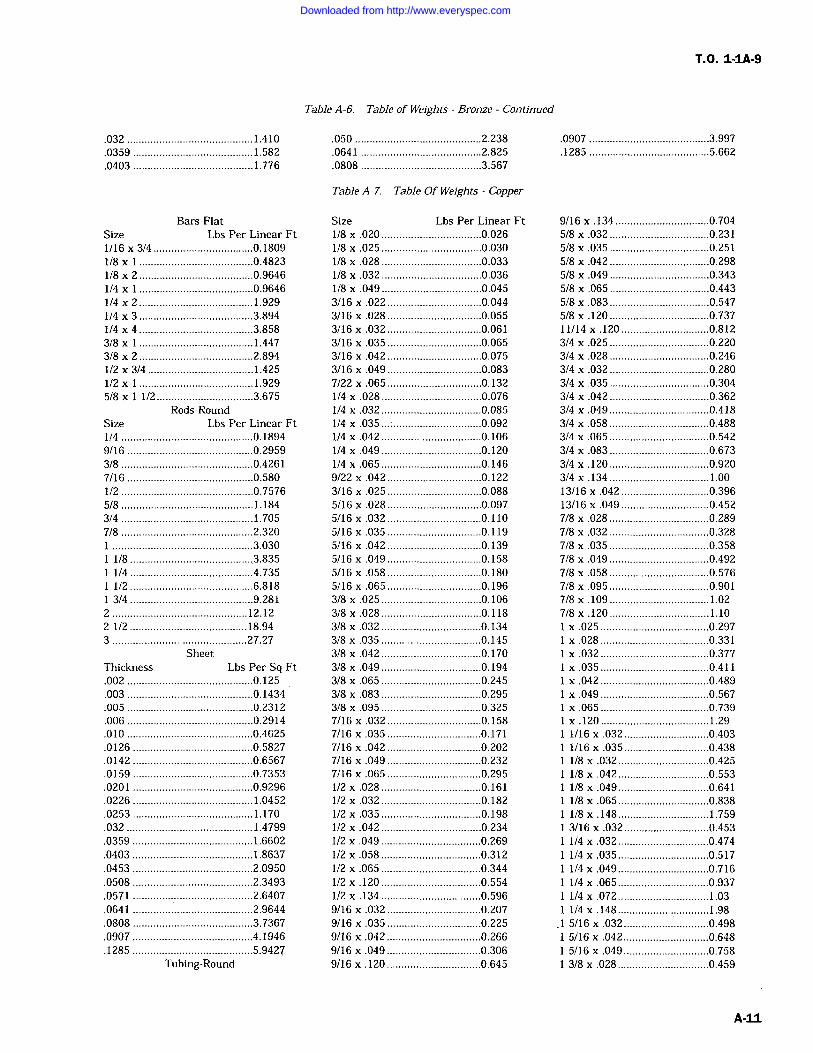
T.O. 1-1A-9
.032 ...........................................1.410
.0359 .........................................1.582
.0403 .........................................1.776
Bars-FlatSize Lbs Per Linear Ft1/16 3/4 ..................................0.18091/8 x .......................................0.48231/8 x 2 .......................................0.9646/4 x .......................................0.9646
1/4 x 2 1.9291/4 x 3 .......................................3.8941/4 4 .......................................3.8583/8 .......................................1.4473/8 2 .......................................2.8941/2 3/4 ....................................1.4251/2 x .......................................1.9295/8 x 1/2 .................................3.675
Rods-RoundSize Lbs Per Linear Ft1/4 .............................................0.18949/16 ...........................................0.29593/8 .............................................0.42617/16 ...........................................0.5801/2 .............................................0.75765/8 .............................................1.1843/4 .............................................1.7057/8 .............................................2.320
................................................3.0301/8 ..........................................3.8351/4 ..........................................4.7351/2 ..........................................6.8183/4 ..........................................9.281
2 12.122 1/2 ........................................18.943 ..............................................27.27
SheetThickness Lbs Per Sq Ft.002 ...........................................0.125.003 ...........................................0.1434.005 ...........................................0.2312.006 ...........................................0.2914.010 ...........................................0.4625.0126 .........................................0.5827.0142 .........................................0.6567.0159 .........................................0.7353.0201 .........................................0.9296.0226 1.0452.0253 1.170.032 ...........................................1.4799.0359 1.6602.0403 1.8637.0453 .........................................2.0950.0508 .........................................2.3493.0571 .........................................2.6407.0641 .........................................2.9644.0808 .........................................3.7367.0907 .........................................4.1946.1285 .........................................5.9427
Tubing-Round
Table A-6. Table of Weights Bronze Continued
.050 ...........................................2.238
.0641 .........................................2.825
.0808 .........................................3.567
.0907 .........................................3.997
.1285 .........................................5.662
Table A-7. Table Of Weights -Copper
Size Lbs Per Linear Ft1/8 .020 ..................................0.0261/8x.025 ..................................0.030/8 x .028 ..................................0.033
1/8 x .032 ..................................0.0361/8 .049 ..................................0.0453/16 x .022 ................................0.0443/16 .028 ................................0.0553/16 x .032 ................................0.0613/16 x .035 ................................0.0653/16 x .042 ................................0.0753/16 x .049 ................................0.0837/22 .065 ................................0.132/4 .028 ..................................0.076
1/4 x .032 ..................................0.0851/4 x .035 ..................................0.0921/4 .042 ..................................0.1061/4 .049 ..................................0.1201/4 x .065 ..................................0.1469/22 .042 ................................0.1223/16 .025 ................................0.0885/16 x .028 ................................0.0975/16 x .032 ................................0.1105/16 x.035 ................................0.1195/16 x .042 ................................0.1395/16 .049 ................................0.1585/16 .058 ................................0.1805/16 .065 ................................0.1963/8 .025 ..................................0.1063/8 x .028 ..................................0.1183/8 .032 ..................................0.1343/8 .035 ..................................0.1453/8 x .042 ..................................0.1703/8 .049 ..................................0.1943/8 .065 ..................................0.2453/8 x .083 ..................................0.2953/8 .095 ..................................0.3257/16 x .032 ................................0.1587/16 .035 ................................0.1717/16 .042 ................................0.2027/16 .049 ................................0.2327/16 .065 ................................0.2951/2 .028 ..................................0.1611/2 x .032 ..................................0.1821/2 .035 ..................................0.1981/2 .042 ..................................0.2341/2 x .049 ..................................0.2691/2 x .058 ..................................0.312/2 x .065 ..................................0.344
1/2 x .120 ..................................0.5541/2 x .134 ..................................0.5969/16 x .032 ................................0.2079/16 x .035 ................................0.2259/16 x .042 ................................0.2669/16 x .049 ................................0.3069/16 x .120 ................................0.645
9/16 x .134 ................................0.7045/8 x .032 ..................................0.2315/8 .035 ..................................0.2515/8 .042 ..................................0.2985/8 x .049 ..................................0.3435/8 x .065 ..................................0.4435/8 x .083 ..................................0.5475/8 x .120 ..................................0.73711/14 .120 ..............................0.8123/4 .025 ..................................0.2203/4 .028 ..................................0.2463/4 .032 ..................................0.2803/4 x .035 ..................................0.3043/4 x .042 ..................................0.3623/4 .049 ..................................0.4183/4 .058 ..................................0.4883/4 .065 ..................................0.5423/4 .083 ..................................0.6733/4 x .120 ..................................0.9203/4 .134 ..................................1.0013/16 x .042 ..............................0.39613/16 .049 ..............................0.4527/8 x .028 ..................................0.2897/8 x .032 ..................................0.3287/8 .035 ..................................0.3587/8 .049 ..................................0.4927/8 .058 ..................................0.5767/8 .095 ..................................0.9017/8 .109 ..................................1.027/8x.120 ..................................1.10
.025 .....................................0.297
.028 .....................................0.331
x .032 .....................................0.377
x .035 .....................................0.411
x .042 .....................................0.489
x .049 .....................................0.567.065 .....................................0.739.120 .....................................1.29
1/16 .032 .............................0.4031/16 x .035 .............................0.4381/8 .032 ...............................0.4251/8 .042 ...............................0.5531/8 x .049 ...............................0.6411/8 .065 ...............................0.8381/8 x .148 1.7593/16 x .032 .............................0.4531/4 .032 ...............................0.4741/4 x .035 ...............................0.517/4 x .049 ...............................0.716
1/4 x .065 ...............................0.9371/4 .072 1.031/4x.148 1.98
.1 5/16 x .032 .............................0.4985/16 x .042 .............................0.6485/16 .049 .............................0.7583/8 x .028 ...............................0.459
A-11
Downloaded from http://www.everyspec.com
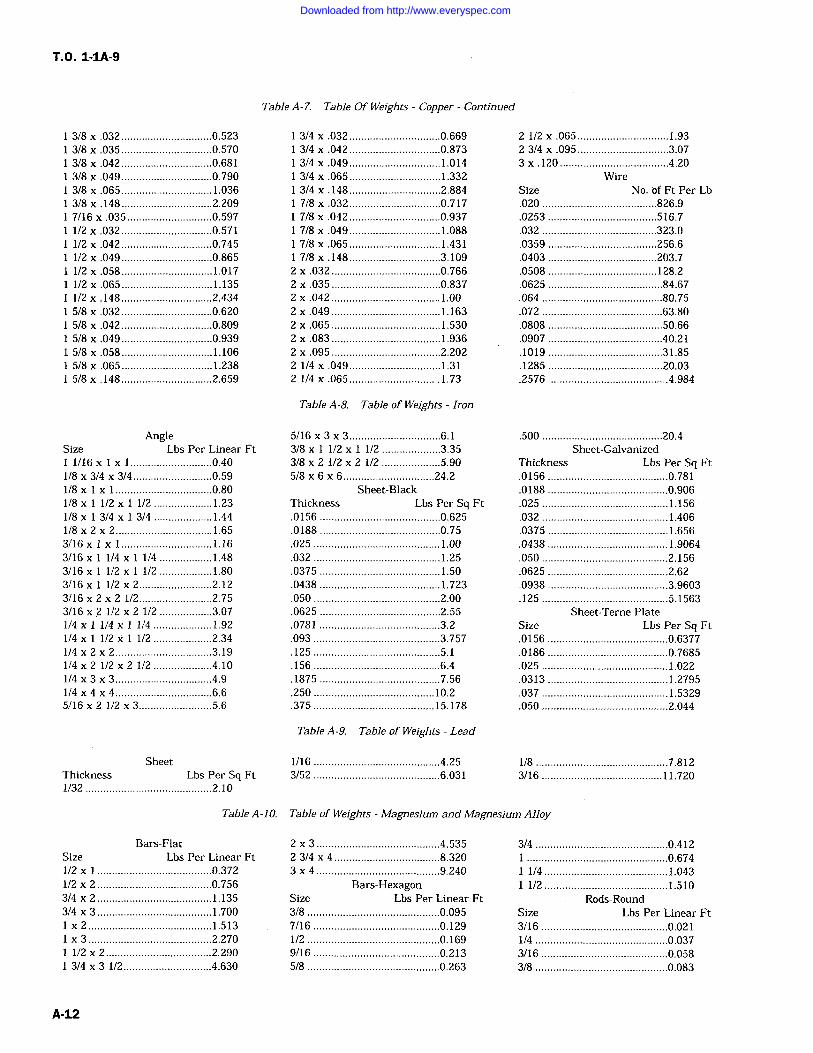
T.O. 1-1A-9
3/8 x .032 ...............................0.5233/8 x .035 ...............................0.5703/8 .042 ...............................0.6813/8 x .049 ...............................0.7903/8 .065 1.0363/8 x .148 2.2097/16 x .035 .............................0.5971/2 x .032 ...............................0.5711/2 .042 ...............................0.7451/2 .049 ...............................0.8651/2x.058 ...............................1.0171/2 .065 ...............................1.1351/2 .148 ...............................2.4345/8 .032 ...............................0.6205/8 x .042 ...............................0.8095/8 x .049 ...............................0.9395/8 x .058 1.1065/8 x .065 ...............................1.2385/8 x .148 ...............................2.659
AngleSize Lbs Per Linear Ft11/16 x ............................0.401/8 x 3/4 x 3/4 ...........................0.591/8x1x1 .................................0.801/8 x 1/2 1/2 1.231/8 x 3/4 3/4 1.441/8x2x2 1.653/16xIx1 ...............................1.163/16 x 1/4 x 1/4 ..................1.483/16 x 1/2 x 1/2 ..................1.803/16x 1/2x2 .........................2.123/16 2 2 1/2 .........................2.753/16 2 1/2 x 2 1/2 ..................3.071/4 1/4 x 1/4 1.921/4 1/2 x 1/2 ....................2.341/4x2x2 .................................3.191/4 x 2 1/2 2 1/2 ....................4.101/4x3x3 .................................4.91/4x4x4 .................................6.65/16x 2 1/2 x3.........................5.6
SheetThickness Lbs Per Sq Ft1/32 ...........................................2.10
Table A-7. Table Of Weights Copper- Continued
3/4 .032 ...............................0.6693/4 .042 ...............................0.8733/4 .049 1.0143/4 x .065 ...............................1.3323/4 .148 2.8847/8 .032 ...............................0.7177/8 x .042 ...............................0.9377/8 x .049 1.0887/8 x .065 1.4317/8 .148 ...............................3.109
2 .032 .....................................0.7662 x .035 .....................................0.8372 x .042 1.002 x .049 1.1632 x .065 1.5302 x.083 .....................................1.9362 x .095 .....................................2.2022 /4 .049 ...............................1.3121/4x.065 1.73
Table A-8. Table of Weights Iron
5/16x3x3 ...............................6.13/8 x 1/2 x 1/2 ....................3.353/8 x 2 1/2 2 1/2 ....................5.905/8x6x6 ...............................24.2
Sheet-BlackThickness Lbs Per Sq Ft.0156 .........................................0.625.0188 .........................................0.75.025 1.00.032 1.25.0375 1.50.0438 1.723.050 ...........................................2.00.0625 .........................................2.55.0781 .........................................3.2.093 ...........................................3.757.125 ...........................................5.1.156 ...........................................6.4.1875 .........................................7.56.250 .........................................10.2.375 .........................................15.178
Table A-9. Table of Weights Lead
1/16 ...........................................4.253/52 ...........................................6.031
2 1/2 .065 ...............................1.932 3/4 .095 ...............................3.073 x .120 .....................................4.20
WireSize No. of Ft Per Lb.020 .......................................826.9.0253 .....................................516.7.032 .......................................323.0.0359 .....................................256.6.0403 .....................................203.7.0508 .....................................128.2.0625 .......................................84.67.064 .........................................80.75.072 .........................................63.80.0808 .......................................50.66.0907 .......................................40.21.1019 .......................................31.85.1285 .......................................20.03.2576 .........................................4.984
.500 .........................................20.4Sheet-Galvanized
Thickness Lbs Per Sq Ft.0156 .........................................0.781.0188 .........................................0.906.025 1.156.032 1.406.0375 .........................................1.656.0438 1.9064.050 ...........................................2.156.0625 .........................................2.62.0938 .........................................3.9603.125 ...........................................5.1563
Sheet-Terne PlateSize Lbs Per Sq Ft.0156 .........................................0.6377.0186 .........................................0.7685.025 ...........................................1.022.0313 .........................................1.2795.037 1.5329.050 ...........................................2.044
1/8 .............................................7.8123/16 11.720
Table A-10. Table of Weights -Magnesium and Magnesium Alloy
Bars-FlatSize Lbs Per Linear Ft1/2 .......................................0.3721/2 x 2 .......................................0.7563/4 x 2 .......................................1.1353/4 x 3 .......................................1.700
x 2 ..........................................1.5133 ..........................................2.270
1/2 2 ....................................2.2903/4 x 3 1/2 ..............................4.630
2 3 ..........................................4.5352 3/4 x 4 8.3203 x 4 ..........................................9.240
Bars-HexagonSize Lbs Per Linear Ft3/8 .............................................0.0957/16 ...........................................0.1291/2 .............................................0.1699/16 ...........................................0.2135/8 .............................................0.263
3/4 .............................................0.412................................................0.6741/4 ..........................................1.0431/2 1.510
Rods-RoundSize Lbs Per Linear Ft3/16 ...........................................0.0211/4 .............................................0.0373/16 ...........................................0.0583/8 .............................................0.083
A-12
Downloaded from http://www.everyspec.com
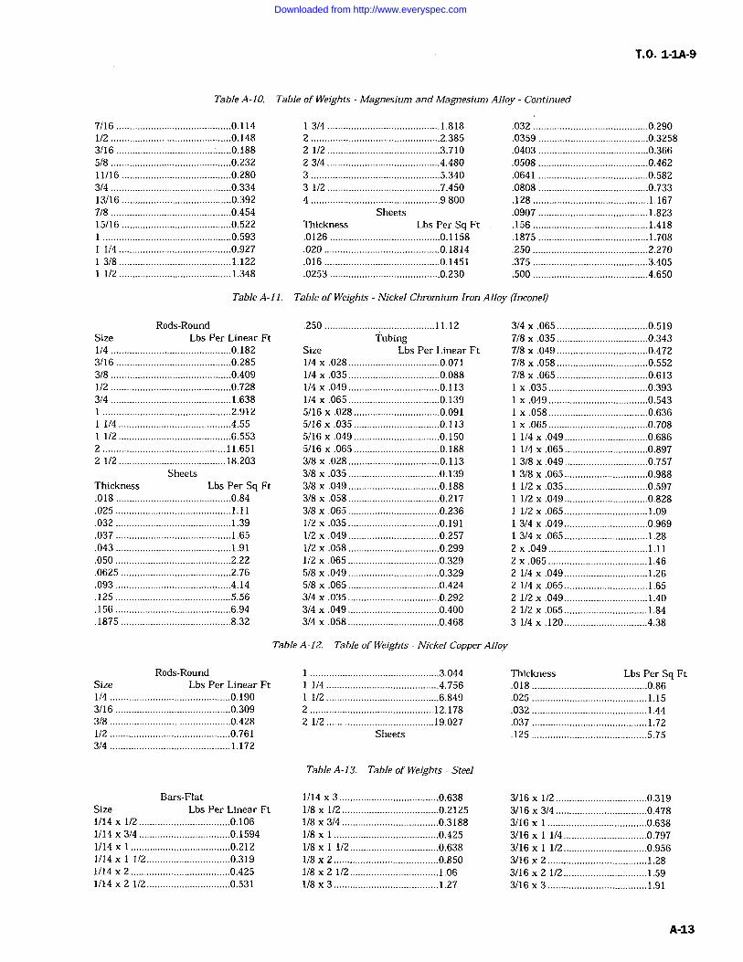
T.O. 1-1A-9
Table A-10. Table of Weights -Magnesium and Magnesium Alloy Continued
7/16 ...........................................0.1141/2 .............................................0.1483/16 ...........................................0.1885/8 .............................................0.23211/16 .........................................0.2803/4 ............................................0.33413/16 .........................................0.3927/8 .............................................0.45415/16 .........................................0.522
................................................0.5931/4 ..........................................0.927
13/8 1.1221/2 ..........................................1.348
13/4 ..........................................1.8182 ................................................2.3852 1/2 ..........................................3.7102314 ..........................................4.4803 ................................................5.3403 1/2 ..........................................7.4504 ................................................9.800
SheetsThickness Lbs Per Sq Ft.0126 .........................................0.1158.020 ...........................................0.1814.016 ...........................................0.1451.0253 .........................................0.230
.032 ...........................................0.290
.0359 .........................................0.3258
.0403 .........................................0.366
.0508 .........................................0.462
.0641 .........................................0.582
.0808 .........................................0.733
.128 ...........................................1.167
.0907 .........................................1.823
.156 ...........................................1.418
.1875 .........................................1.708
.250 ...........................................2.270
.375 ...........................................3.405
.500 ...........................................4.650
Table A-11. Table of Weights -Nickel Chromium Iron Alloy (Inconel)
Rods-RoundSize Lbs Per Linear Ft1/4 .............................................0.1823/16 ...........................................0.2853/8 .............................................0.4091/2 .............................................0.7283/4 .............................................1.638
................................................2.9121/4 ..........................................4.551/2 ..........................................6.553
2 ..............................................11.6512 1/2 ........................................18.203
SheetsThickness Lbs Per Sq Ft.018 ...........................................0.84.025 1.11.032 1.39.037 1.65.043 1.91.050 ...........................................2.22.0625 .........................................2.76.093 ...........................................4.14.125 ...........................................5.56.156 ...........................................6.94.1875 .........................................8.32
.250 .........................................11.12Tubing
Size Lbs Per Linear Ft1/4 x .028 ..................................0.0711/4 .035 ..................................0.0881/4 x .049 ..................................0.1131/4 x .065 ..................................0.1395/16 x .028 ................................0.0915/16 .035 ................................0.1135/16 .049 ................................0.1505/16 x .065 ................................0.1883/8 .028 ..................................0.1133/8 x .035 ..................................0.1393/8 .049 ..................................0.1883/8 x .058 ..................................0.2173/8 x .065 ..................................0.2361/2 x .035 ..................................0.1911/2 .049 ..................................0.2571/2 .058 ..................................0.2991/2 x .065 ..................................0.3295/8 .049 ..................................0.3295/8 .065 ..................................0.4243/4 .035 ..................................0.2923/4 .049 ..................................0.4003/4 .058 ..................................0.468
3/4 x .065 ..................................0.5197/8 .035 ..................................0.3437/8 .049 ..................................0.4727/8 .058 ..................................0.5527/8 x .065 ..................................0.613
.035 .....................................0.393
x .049 .....................................0.543.058 .....................................0.636.065 .....................................0.708
1/4 .049 ...............................0.6861/4 x .065 ...............................0.8973/8 x .049 ...............................0.7573/8 x .065 ...............................0.9881/2 x .035 ...............................0.5971/2 .049 ...............................0.828/2 .065 1.09
3/4 .049 ...............................0.9693/4 x .065 1.28
2 .049 .....................................1.112 x .065 1.462 1/4 x .049 1.262 1/4 x .065 1.652 1/2 .049... _1.402 1/2 .065 1.843 1/4 .120 ...............................4.38
Rods-RoundSize Lbs Per Linear Ft1/4 .............................................0.1903/16 ...........................................0.3093/8 .............................................0.4281/2 .............................................0.7613/4 1.172
Table A-12. Table of Weights -Nickel Copper Alloy
................................................3.0441/4 ..........................................4.7561/2 ..........................................6.849
2 ..............................................12.1782 1/2 ........................................19.027
Sheets
Thickness Lbs Per Sq Ft.018 ...........................................0.86.025 1.15.032 1.44.037 1.72.125 ...........................................5.75
Table A-13. Table of Weights Steel
Bars-FlatSize Lbs Per Linear Ft1/14 x 1/2 ..................................0.1061/14 x 3/4 ..................................0.15941/14 x .....................................0.2121/14 x 112 ...............................0.3191/14 2 .....................................0.4251/14 x 2 1/2 ...............................0.531
1/14 x 3 .....................................0.6381/8 x 1/2 ....................................0.21251/8 3/4 ....................................0.31881/8 x .......................................0.4251/8 x 1/2 .................................0.6381/8 x 2 .......................................0.8501/8 2 1/2 1.061/8 x 3 1.27
3/16 1/2 ..................................0.3193/16x3/4 ..................................0.4783/16 x .....................................0.6383/16 x 1/4 ...............................0.7973/16 x 1/2 ...............................0.9563/16x 2 .....................................1.283/16 2 1/2 ...............................1.593/16 3 1.91
A-13
Downloaded from http://www.everyspec.com
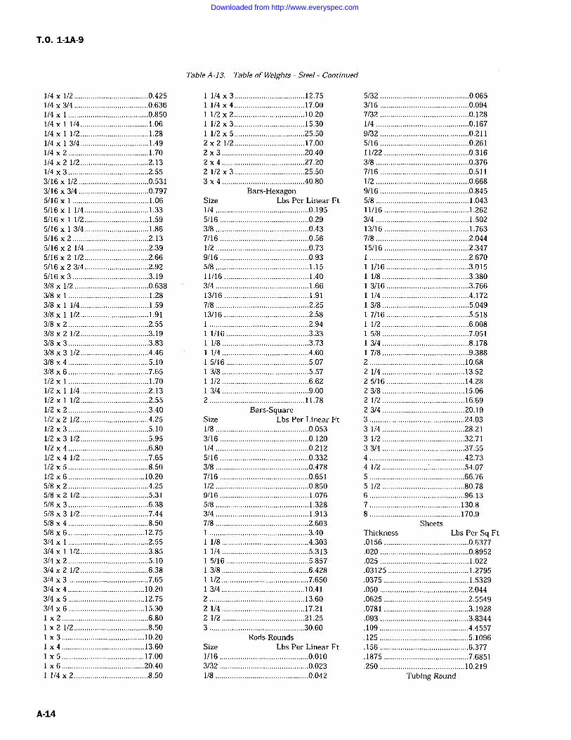
T.O. 1-1A-9
1/4 112 ...................................0.4251/4 3/4 ....................................0.6361/4 x .......................................0.8501/4 1/4 1.061/4 x 1/2 .................................1.281/4 x 3/4 .................................1.491/4 2 1.701/4x21/2 .................................2.131/4 x 3 .......................................2.553/16 x 1/2 ..................................0.5313/16 3/4 ..................................0.7975/16 x .....................................1.065/16 1/4 ...............................1.335/16 1/2 ...............................1.595/16 3/4 ...............................1.865/16 2 .....................................2.135/16x2 1/4 ...............................2.395/16 x 2 1/2 ...............................2.665/16 2 3/4 ...............................2.925/16 x 3 .....................................3.193/8 x 1/2 ....................................0.6383/8 x 1.283/8 1/4 .................................1.593/8 1/2 .................................1.913/8 x 2 .......................................2.553/8 x 2 /2 .................................3.193/8 x 3 .......................................3.833/8 3 1/2 .................................4.463/8 x 4 .......................................5.103/8 6 .......................................7.651/2 x .......................................1.701/2 x 1/4 .................................2.131/2 1/2 .................................2.551/2 2 .......................................3.401/2 x 2 1/2 .................................4.251/2 x 3 .......................................5.101/2 x 3 1/2 .................................5.951/2 x 4 .......................................6.801/2 4 1/2 .................................7.651/2x5 8.501/2 x 6 .....................................10.205/8 2 .......................................4.255/8 2 1/2 5.315/8 3 .......................................6.385/8 3 /2 7.445/8 4 .......................................8.505/8 x 6 .....................................12.753/4 x .......................................2.553/4 /2 3.853/4 x 2 .......................................5.103/4 2 /2 .................................6.383/4 x 3 .......................................7.653/4 x 4 .....................................10.203/4 x 5 .....................................12.753/4 x 6 .....................................15.30
x 2 ..........................................6.80
x 2 1/2 ....................................8.50
x 3 ........................................10.204 ........................................13.60
x 5 ........................................17.00
x 6 ........................................20.401/4 x 2 ....................................8.50
Table A-13. Table of Weights Steel Continued
1/4 x 3 12.751/4 4 ..................................17.001/2 x 2 ..................................10.201/2 3 ..................................15.301/2 5 ..................................25.50
2 x 2 1/2 17.002 x 3 ........................................20.402 x 4 ........................................27.202 1/2 x 3 ..................................25.503 x 4 ........................................40.80
Bars-HexagonSize Lbs Per Linear Ft1/4 .............................................0.1955/16 ...........................................0.293/8 .............................................0.437/16 ...........................................0.561/2 .............................................0.739/16 ...........................................0.935/8 .............................................1.1511/16 .........................................1.403/4 1.6613/16 1.917/8 .............................................2.2513/16 .........................................2.58
................................................2.941/16 ........................................3.331/8 ..........................................3.731/4 ..........................................4.605/16 ........................................5.073/8 ..........................................5.571/2 ..........................................6.623/4 ..........................................9.00
2_ 11.78Bars-Square
Size Lbs Per Linear Ft1/8 .............................................0.0533/16 ...........................................0.1201/4 .............................................0.2125/16 ...........................................0.3323/8 .............................................0.4787/16 ...........................................0.6511/2 .............................................0.8509/16 1.0765/8 1.3283/4 1.9137/8 .............................................2.603
................................................3.401/8 ..........................................4.3031/4 ..........................................5.3135/16 ........................................5.8573/8 ..........................................6.4281/2 ..........................................7.6503/4 10.41
2 13.602 1/4 ........................................17.212 1/2 ........................................21.253 ..............................................30.60
Rods-RoundsSize Lbs Per Linear Ft1/16 ...........................................0.0103/32 ...........................................0.0231/8 .............................................0.042
5/32 ...........................................0.0653/16 ...........................................0.0947/32 ...........................................0.1281/4 0.1679/32 ...........................................0.2115/16 ...........................................0.26111/22 .........................................0.3163/8 .............................................0.3767/16 ...........................................0.5111/2 .............................................0.6689/16 ...........................................0.8455/8 .............................................1.04311/16 .........................................1.2623/4 .............................................1.50213/16 .........................................1.7637/8 .............................................2.04415/16 .........................................2.347
................................................2.6701/16 ........................................3.0151/8 ..........................................3.3803/16 ........................................3.7661/4 ..........................................4.172
13/8 ..........................................5.0497/16 ........................................5.5181/2 ..........................................6.0085/8 ..........................................7.0513/4 ..........................................8.1787/8 ..........................................9.388
2 ..............................................10.682 1/4 ........................................13.522 5/16 ......................................14.2823/8 ........................................15.062 1/2 ........................................16.6923/4 ........................................20.193 ..............................................24.033 1/4 ........................................28.213 1/2 ........................................32.713 3/4 ........................................37.554 ..............................................42.734 1/2 ........................................54.075 ..............................................66.765 1/2 ........................................80.786 ..............................................96.137 ............................................130.88 ............................................170.9
SheetsThickness Lbs Per Sq Ft.0156 .........................................0.6377.020 ...........................................0.8952.025 ...........................................1.022.03125 .......................................1.2795.0375 .........................................1.5329.050 ...........................................2.044.0625 .........................................2.5549.0781 .........................................3.1928.093 ...........................................3.8344.109 ...........................................4.4557.125 ...........................................5.1096.156 ...........................................6.377.1875 .........................................7.6851.250 .........................................10.219
Tubing-Round
A-14
Downloaded from http://www.everyspec.com
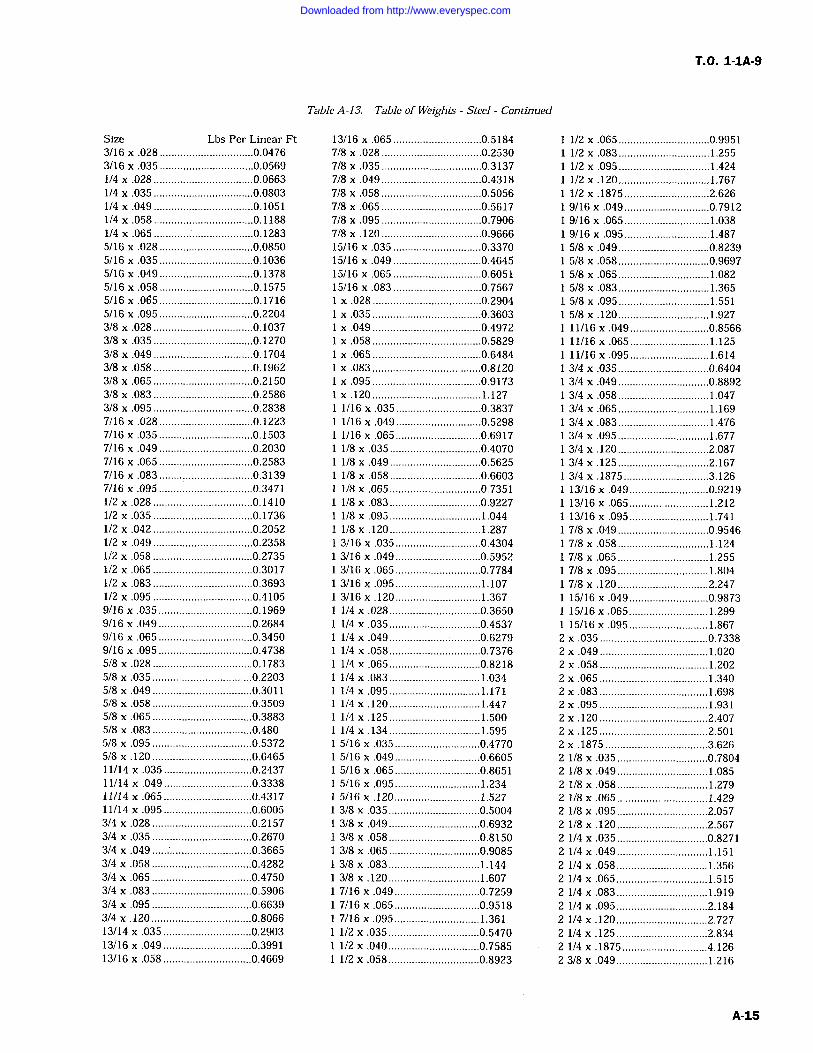
T.O. 1-1A-9
Size Lbs Per Linear Ft3/16 x .028 ................................0.04763/16 x .035 ................................0.05691/4 x .028 ..................................0.06631/4 x .035 ..................................0.08031/4 .049 ..................................0.10511/4 .058 ..................................0.11881/4 x .065 ..................................0.12835/16 .028 ................................0.08505/16 x .035 ................................0.10365/16 x .049 ................................0.13785/16 x .058 ................................0.15755/16 x
.065 ................................0.17165/16 x .095 ................................0.22043/8 .028 ..................................0.10373/8 .035 ..................................0.12703/8 x .049 ..................................0.17043/8 x .058 ..................................0.19623/8 x .065 ..................................0.21503/8 .083 ..................................0.25863/8 .095 ..................................0.28387/16 x .028 ................................0.12237/16 .035 ................................0.15037/16 .049 ................................0.20307/16 x .065 ................................0.25837/16 x .083 ................................0.31397/16 x.095 ................................0.34711/2 .028 ..................................0.14101/2 .035 ..................................0.17361/2 x .042 ..................................0.20521/2 .049 ..................................0.23581/2 .058 ..................................0.27351/2 x .065 ..................................0.30171/2 .083 0.36931/2 x .095 ..................................0.41059/16 x.035 ................................0.19699/16 .049 ................................0.26849/16 x .065 ................................0.34509/16 x .095 ................................0.47385/8 .028 ..................................0.17835/8 .035 ..................................0.22035/8 x .049 ..................................0.30115/8 .058 ..................................0.35095/8 .065 ..................................0.38835/8 .083 ..................................0.4805/8 .095 ..................................0.53725/8 x .120 ..................................0.646511/14 x .035 ..............................0.243711/14 x .049 ..............................0.333811/14 .065 ..............................0.431711/14 x .095 ..............................0.60053/4 x .028 ..................................0.21573/4 x .035 ..................................0.26703/4 x .049 ..................................0.36653/4 x .058 ..................................0.42823/4 x .065 ..................................0.47503/4 x .083 ..................................0.59063/4 x .095 ..................................0.66393/4 x .120 ..................................0.806613/14 x .035 ..............................0.290313/16 .049 ..............................0.399113/16 x .058 ..............................0.4669
Table A-13. Table of Weights Steel Continued
13/16 .065 ..............................0.51847/8 .028 ..................................0.25307/8 x .035 ..................................0.31377/8 x .049 ..................................0.43187/8 x .058 ..................................0.50567/8 x .065 ..................................0.56177/8 x .095 ..................................0.79067/8 .120 ..................................0.966615/16 .035 ..............................0.337015/16 x .049 ..............................0.464515/16 x .065 ..............................0.605115/16 x.083 ..............................0.7567
.028 .....................................0.2904
.035 .....................................0.3603
x .049 .....................................0.4972
x .058 .....................................0.5829.065 .....................................0.6484.083 .....................................0.8120
x .095 .....................................0.9173.120 1.127
1/16 x .035 .............................0.38371/16 x .049 .............................0.52981/16 x .065 .............................0.69171/8 x .035 ...............................0.40701/8 .049 ...............................0.56251/8 .058 ...............................0.66031/8 .065 ...............................0.73511/8 .083 ...............................0.92271/8 .095 ...............................1.0441/8 x .120 ...............................1.2873/16 x .035 .............................0.43043/16 x .049 .............................0.59523/16 x .065 .............................0.77843/16 x .095 .............................1.1073/16x.120 .............................1.3671/4 .028 ...............................0.36501/4 .035 ...............................0.45371/4 .049 ....................:..........0.6279/4 x .058 ...............................0.7376
1/4 x .065 ...............................0.8218/4 .083 ...............................1.034
1/4 x .095 ...............................1.1711/4 .120 ...............................1.4471/4 .125 ...............................1.5001/4 .134 ...............................1.5955/16 x .035 .............................0.47705/16 x .049 .............................0.66055/16 x .065 .............................0.86515/16 x .095 1.2345/16 x.120 1.5273/8 .035 ...............................0.50043/8 x .049 ...............................0.69323/8 x .058 ...............................0.81503/8 .065 ...............................0.90853/8 .083 1.1443/8 x .120 1.6077/16 x .049 .............................0.72597/16 x .065 .............................0.95187/16 x .095 .............................1.3611/2 x .035 ...............................0.5470/2 .040 ...............................0.7585
1/2 x .058 ...............................0.8923
1/2 .065 ...............................0.99511/2 .083 1.2551/2 x .095 ...............................1.4241/2 .120 ...............................1.7671/2 x .1875 .............................2.6269/ 16 x .049 .............................0.7912
19/16x.065.............................1.0389/16 .095 .............................1.4875/8 .049 ...............................0.82395/8 x .058 ...............................0.96975/8 .065 ...............................1.0825/8 .083 ...............................1.3655/8 .095 ...............................1.5515/8 .120 ...............................1.92711/16 .049 ...........................0.856611/16 .065 ...........................1.12511/16 x .095 ...........................1.6143/4 x .035 ...............................0.64043/4 x .049 ...............................0.88923/4 .058 1.0473/4 .065 1.1693/4 x .083 1.4763/4 x .095 1.6773/4 x .120 ...............................2.0873/4 .125 ...............................2.1673/4 .1875 .............................3.12613/16 .049 ...........................0.921913/16 x .065 ...........................1.21213/16 x .095 ...........................1.7417/8 x .049 ...............................0.95467/8 x .058 1.1247/8 .065 1.2557/8 .095 1.8047/8 x .120 2.24715/16 .049 ...........................0.987315/16 .065 ...........................1.29915/16 x .095 ...........................1.867
2 x.035 .....................................0.73382 x .049 .....................................1.0202 .058 .....................................1.2022 x.065 .....................................1.3402 .083 .....................................1.6982 .095 .....................................1.9312 .120 .....................................2.4072 .125 .....................................2.5012 .1875 ...................................3.6262 1/8 x .035 ...............................0.78042 1/8 .049 ...............................1.0852 1/8 .058 ...............................1.2792 1/8 x.065 ...............................1.4292 1/8 x .095 ...............................2.0572 /8 x .120 2.5672 1/4 x .035 ...............................0.82712 1/4 x .049 ...............................1.1512 1/4 x .058 ...............................1.3562 1/4 x .065 ...............................1.5152 /4 x .083 ...............................1.9192 1/4 .095 2.1842 1/4 x.120 ...............................2.7272 1/4 x .125 ...............................2.8342 1/4 x .1875 .............................4.1262 3/8 x .049 ...............................1.216
Downloaded from http://www.everyspec.com
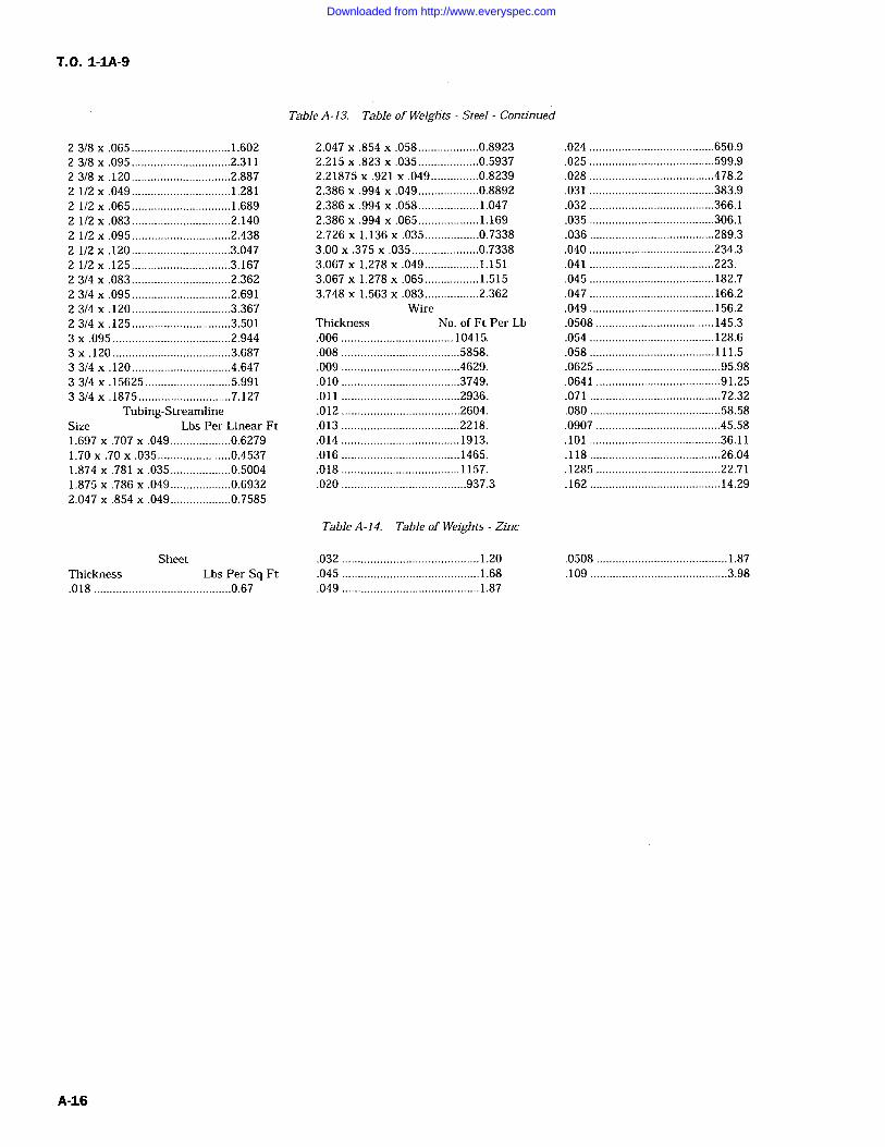
T.Q. 1-1A-9
2 3/8 .065 ...............................1.6022 3/8 .095 ...............................2.3112 3/8 .120 ...............................2.8872 1/2 x .049 ...............................1.2812 1/2 x .065 ...............................1.6892 1/2 x .083 2.1402 1/2 x .095 ...............................2.4382 1/2 x .120 ...............................3.0472 1/2 x .125 ...............................3.1672 3/4 .083 ...............................2.3622 3/4 x .095 ...............................2.6912 3/4 .120 ...............................3.3672 3/4 .125 ...............................3.5013 x .095 .....................................2.9443 x .120 .....................................3.6873 3/4 .120 ...............................4.6473 3/4 .15625 ...........................5.9913 3/4 .1875 .............................7.127
Tubing-StreamlineSize Lbs Per Linear Ft1.697 .707 x.049 ...................0.62791.70 .70 .035 .......................0.45371.874 .781 x .035 ...................0.50041.875 .786 x .049 ...................0.69322.047 x .854 x .049 ...................0.7585
Table A-13. Table of Weights Steel Continued
2.047 x .854 .058...................0.89232.215 .823 .035 ...................0.59372.21875 x .921 x .049 ...............0.82392.386 .994 .049 ...................0.88922.386 x .994 x .058 1.0472.386 .994 x .065 1.1692.726 x 1.136 .035 .................0.73383.00 .375 x .035 .....................0.73383.067 x 1.278 .049 .................1.1513.067 x 1.278 .065 .................1.5153.748 1.563 x .083 .................2.362
WireThickness No. of Ft Per Lb.006 10415..008 .....................................5858..009 .....................................4629..010 .....................................3749..011 .....................................2936..012 .....................................2604..013 .....................................2218..014 1913..016 .....................................1465..018 .....................................1157..020 .......................................937.3
.024 .......................................650.9
.025 .......................................599.9
.028 .......................................478.2
.031 .......................................383.9
.032 .......................................366.1
.035 .......................................306.1
.036 .......................................289.3
.040 .......................................234.3
.041 .......................................223.
.045 182.7
.047 166.2
.049 156.2
.0508 .....................................145.3
.054 .......................................128.6
.058 .......................................111.5
.0625 .......................................95.98
.0641 .......................................91.25
.071 .........................................72.32
.080 .........................................58.58
.0907 .......................................45.58
.101 .........................................36.11
.118 .........................................26.04
.1285 .......................................22.71
.162 .........................................14.29
Table A-14. Table of Weights Zinc
SheetThickness Lbs Per Sq Ft.018 ...........................................0.67
.032 1.20
.045 1.68
.049 1.87
.0508 1.87
.109 ...........................................3.98
A-16
Downloaded from http://www.everyspec.com
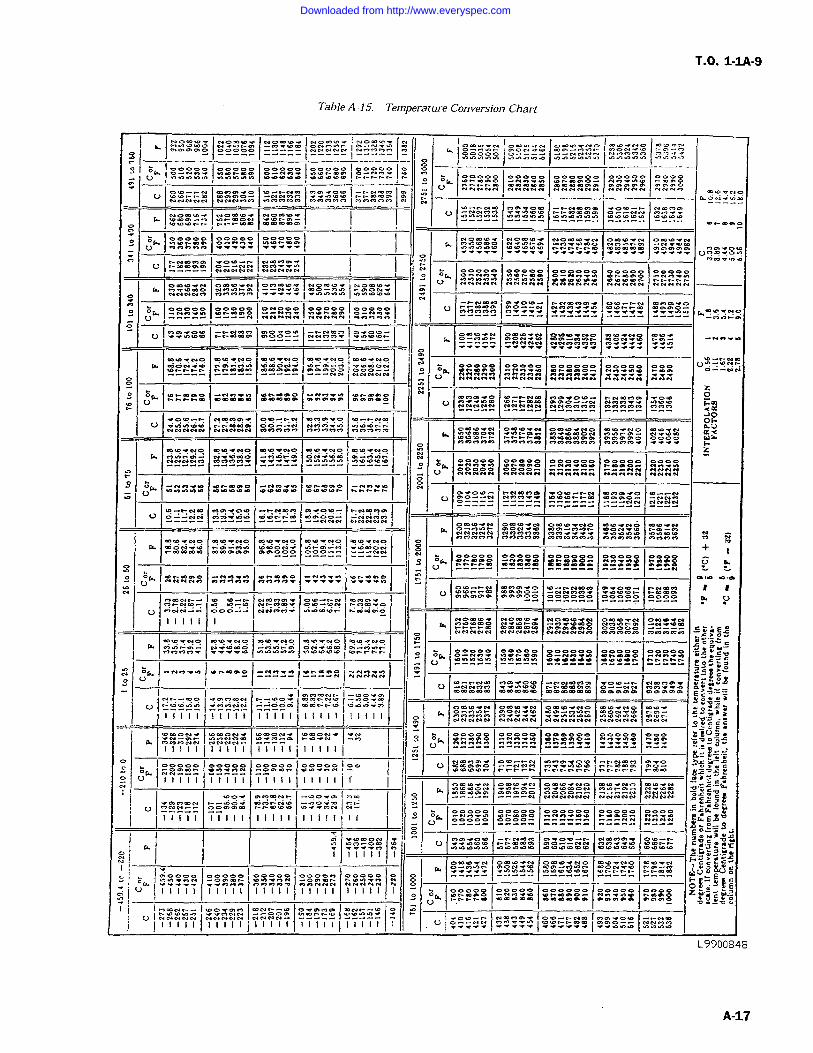
T.O. 1-1A-9
Table A-15. Temperature Conversion Chart
M.nb ably 100000 1uON Slo`
I=JYYY (NNNNN v^ igH"Y.-
Im.OYNYY = == = NYG O.n Y.YiaoorYo NoopY
oO
InFmw$ o -Y
108
YYNYN --N
bbrt-Y0 YmNPOYN YNCN'f YYeb"Y N NY
GY?v-._
b m10Ym 0mo... Y.Y- -.Ot0 1-^-y-FmjY _---
-ba FY
OW 1n_rvDP =YrY =FOPH 1Nil a1'fYYY yafmYo+ON 000+00()
:: :: _ _ _ = __ _ OYYvY n
yOmPPY wY O N
SAN N yYYHHHH /fNrfHn N N N NeabiNNF N
N i? HY O g a___ _ _ YY++YI_ ra_F m o N n
U YYYay vy OYObNn r fNtNJ YPhl^
i1OYYrY 0N0j Wa0
O_vY HtOm NmYPOOVY NNYY Y=H mbmYNO f+O= Y Nty a`9 iY+Y
Y j000000 O N mq Ua -YY^NN
OyJ^ NN W n HNaO qqNNNN N NN
;:; :::;V nrlm+"FO 00000
HFOOwOYwwPY IN1-.YO0
HNNNy^ NNNN YaFps
sNJiHb uomwNNNNNY00
Y-JN tNy may CY"f H)bl`Y
0 qYYYO V :5ti
O- ---a ----9 Yi yYvZ
NYaGmO vOFw h hh NNNYYty tyYayYY~ Y .-.^-.b OW FmwO0 ONE+nO OOOOyY NO Y Nr N
W NONYbb
b b F M1na011OOb - bO -y-^ ^-NN N=NN
-YJyNN Y^YHN ^t eOwNNN NNNNNmmmYNO mmYYeDNNYb
YYYYY YY+meaYYi s+i i!v'
O b oOmN Fm^ayH 000YY 0ANN Ns
OW ------9999. rYY Z OYO1pp Opa PM P
N N nhnYYYY YrY
vn
U Y0 0 0NiO
N
V
ayHb00Y.NNNNN ocy NY cy wE"Y
Y O,Ytf Y>FnnMCYY s<rda YbbbO bFrt-r ^Nn00 -Yi
OW - H1IF
N.rrrv H----= wY. ni-:E-=!: ?OsnYO
UW Y. ..YY IYYmYY NNNNN
U m =000H !-N001OSYYme9PY
0
yYO`"dry 4
mYYNV Ybesm000W 000000
E C"OYYS
F1U Om_NN _x_000 mY-t"aG Y/ivYyYtHE NNNN V ;
P YemY p<w n Y Y 88HHM ntiO h^nn.Y ry IY=O. yvoYY11 11 11
'I ^rrr_ YYYY"O ^FYmYIP Vg
rN=^F = _PIN 0+0NYOmF 000 *IFll+Y Y FI 0m^r FIF Va=YYsIIIII 11111I m ItIIl1If
C"_Wi--h0<
YmYCrNaOmYapWP 0=0 OOYNNNNNN jY NNN
yY Y YayN^^r =mN INS C.G11111 Ilill IIIII IIIIf Ii
YIooo
YOl moo ^O nYp003V
Y .r-rr.^n^ Y YN Y 2=o_$VI A a[fmbYb NmO( YO^^NN+ IYmFF
D OB09 YYCr" A-cv
11111HdmHH 11 r Y`Y"r0Y H CY VfY mONYY Y--10 Y OxG
CW Y=Y1yN 00000 OO+OOby YN nNNN 0000NNNNN N $ r1- +-a^-+-+d y O! sniV ItIII II{11M11Y11111
11111 0000$ "00 1+000NeooyE
ZV41Y rFnraOY
mmanO CYDm bOaFOYY?wI
PwTNO PnTOIbYb tTnb yNNNN^
I--Ob""'N mme'f0Y FWmIIIIIY
IIIII IIII111111II11111 M oY+Y+YI +<Y`.YI fV"vYYI P.YonH`YYYY
L9900848
A-17
Downloaded from http://www.everyspec.com
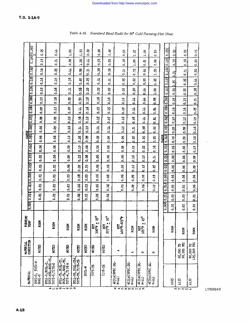
T.O. 1-1A-9
Table A-16. Standard Bend Radii for 90' Cold Forming-Flat Sheet
N
8 8 8O
O O d
O O
8O
O O O .4
O
O .i -Y!O O O
liO
o O O O O O
O O ON O N N 10lY
O
O O O
O O OO O
O .YYO O O O O
O O O O O O OO O d
O O O O OO O
O O O O O O O O OO O O O
OO O O O O OO O O
O
0Ol'.x S 7C b
8 x YH 8YP 8 S O oi8
8 z z g x
H N pHq Nam Y^ g g 8 8$ R$ ?` F. " ci
9SO HFYe4-CF
O`pO8YU 0InNN5$5 aNNfO-- RY -I IY'7yJ 1NN"YJx
t(N-4-4Y
aoX"==nX x.4
0
N
O
O
O
O O
O
OO
O
O
OO
OO
OO
O
O O O
L9900849
A-18
Downloaded from http://www.everyspec.com
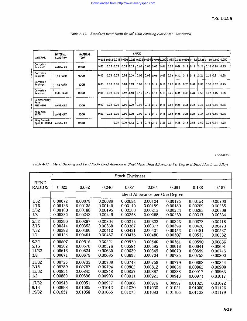
T.O. 1-1A-9
Table A-16. Standard Bend Radii for 90' Cold Forming-Flat Sheet Continued
MATERIAL MATERIAL GAUGE
MATERIAL CONDITION TEMP0.008 .01 0.016 0.020 0.025 0.032 0.036 0.040 .050 0.063 0.080 .090 0.112 0.125 0.160 0.190 0.250
CorrosionResistant ANNEALED ROOM 0.03 0.03 0.03 0.03 0.03 0.03 0.03 0.03 0.06 0.06 0.09 0.12 0.12 0.16 0.16 0.19 0.25
CorrosionResistant 1/4 HARD ROOM 0.03 0.03 0.03 0.03 0.06 0.06 0.06 0.06 0.09 0.09 0.12 0.16 0.19 0.22 0.25 0.31 0.38
CorrosionResistant 1/2 HARD ROOM 0.03 0.03 0.06 0.06 0.09 0.09 0.12 0.12 0.16 0.16 0.19 0.25 0.31 0.38 0.50 0.62 0.75
CorrosionResistant FULL HARD ROOM 0.06 0.09 0.09 0.12 0.16 0.16 0.16 0.19 0.19 0.25 0.31 0.38 0.44 0.50 0.62 0.75 1.00
CommerciallyPureAMS 4901 ANNEALED ROOM 0.03 0.03 0.06 0.06 0.09 0.09 0.12 0.12 0.16 0.19 0.25 0.31 0.38 0.38 0.44 0.56 0.75
Alloy AMS4908 ANNEALED ROOM 0.03 0.03 0.06 0.06 0.09 0.09 0.12 0.12 0.16 0.19 0.25 0.31 0.38 0.38 0.44 0.56 0.75
Alloy ConvairSpec 0-01014 ANNEALED ROOM 0.09 0.09 0.12 0.16 0.19 0.19 0.25 0.31 0.38 0.44 0.56 0.62 0.78 0.94 1.25
L9900850
Table A-17. Metal Bending and Bend Radii Bend Allowances Sheet Metal Bend Allowances Per Degree ofBend Aluminum Alloys
Stock Thickness
BENDRADIUS 0.022 0.032 0.040 0.051 0.064 0.091 0.128 0.187
Bend Allowance per One Degree1/32 0.00072 0.00079 0.00086 0.00094 0.00104 0.00125 0.00154 0.002001/16 0.00126 0.00135 0.00140 0.00149 0.00159 0.00180 0.00209 0.002553/32 0.00180 0.00188 0.00195 0.00203 0.00213 0.00234 0.00263 0.003091/8 0.00235 0.00243 0.00249 0.00258 0.00268 0.00289 0.00317 0.00364
5/32 0.00290 0.00297 0.00304 0.00312 0.00322 0.00343 0.00372 0.004183/16 0.00344 0.00352 0.00358 0.00367 0.00377 0.00398 0.00426 0.004737/32 0.00398 0.00406 0.00412 0.00421 0.00431 0.00452 0.00481 0.005271/4 0.00454 0.00461 0.00467 0.00476 0.00486 0.00507 0.00535 0.00582
9/32 0.00507 0.00515 0.00521 0.00530 0.00540 0.00561 0.00590 0.006365/16 0.00562 0.00570 0.00576 0.00584 0.00595 0.00616 0.00644 0.0069111/32 0.00616 0.00624 0.00630 0.00639 0.00649 0.00670 0.00699 0.007453/8 0.00671 0.00679 0.00685 0.00693 0.00704 0.00725 0.00753 0.00800
13/32 0.00725 0.00733 0.00739 0.00748 0.00758 0.00779 0.00808 0.008547/16 0.00780 0.00787 0.00794 0.00802 0.00812 0.00834 0.00862 0.0090815/32 0.00834 0.00842 0.00848 0.00857 0.00867 0.00888 0.00917 0.009631/2 0.00889 0.00896 0.00903 0.00911 0.00921 0.00943 0.00971 0.01017
17/32 0.00943 0.00951 0.00957 0.00966 0.00976 0.00997 0.01025 0.010729/16 0.00998 0.01005 0.01012 0.01020 0.01030 0.01051 0.01080 0.0112619/32 0.01051 0.01058 0.01065 0.01073 0.01083 0.01105 0.01133 0.01179
A-19
Downloaded from http://www.everyspec.com
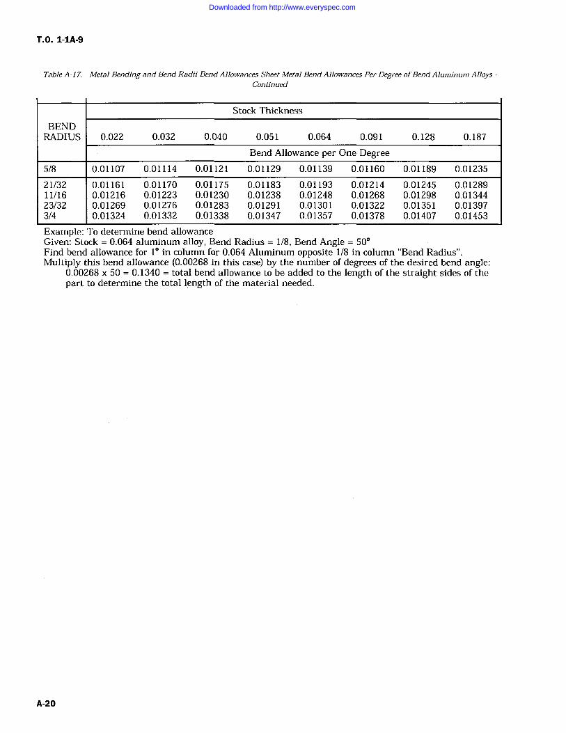
TO. 1-1A-9
Table A-17. Metal Bending and Bend Radii Bend Allowances Sheet Metal Bend Allowances Per Degree ofBend Aluminum AlloysContinued
Stock Thickness
BENDRADIUS 0.022 0.032 0.040 0.051 0.064 0.091 0.128 0.187
Bend Allowance per One Degree5/8 0.01107 0.01114 0.01121 0.01129 0.01139 0.01160 0.01189 0.01235
21/32 0.01161 0.01170 0.01175 0.01183 0.01193 0.01214 0.01245 0.0128911/16 0.01216 0.01223 0.01230 0.01238 0.01248 0.01268 0.01298 0.0134423/32 0.01269 0.01276 0.01283 0.01291 0.01301 0.01322 0.01351 0.013973/4 0.01324 0.01332 0.01338 0.01347 0.01357 0.01378 0.01407 0.01453
Example: To determine bend allowanceGiven: Stock 0.064 aluminum alloy, Bend Radius 1/8, Bend Angle 50Find bend allowance for 1 in column for 0.064 Aluminum opposite 1/8 in column "Bend Radius".Multiply this bend allowance (0.00268 in this case) by the number of degrees of the desired bend angle:
0.00268 x 50 0.1340 total bend allowance to be added to the length of the straight sides of thepart to determine the total length of the material needed.
A-20
Downloaded from http://www.everyspec.com
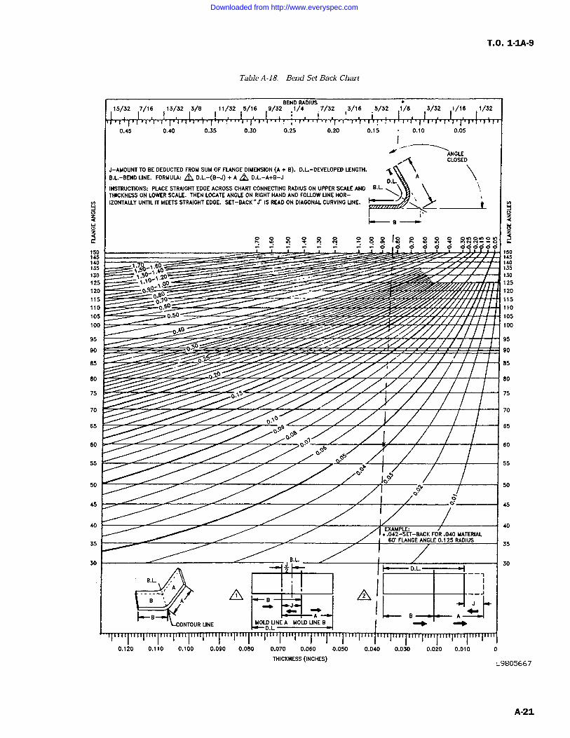
T.O. 1-1A-9
Table A-18. Bend Set Back Chart
BEND RADIUS15/32 7/16 13/32 3/8 111/32 5/16 9/32 1/4 7/32 )3/16 5/32 1/8 3/32 1/16 1/32
0.45 0.40 0.35 0.30 0.25 0.20 0.15 0.10 0.05
ANGLECLOSED
J-AMOUNT TO BE DEDUCTED FROM SUM OF FLANGE DIMENSION (A B). D.L-DEVELOPED LENGTH. .` \AB.L-BEND LINE. FORMULA: L D.L.-(B-J) + A L D.L-A+B-J
INSTRUCTIONS: PLACE STRAIGHT EDGE ACROSS CHART CONNECTING RADIUS ON UPPER SCALE ANDTHICKNESS ON LOWER SCALE. THEN LOCATE ANGLE ON RIGHT HAND AND FOLLOW LINE HOR-
D.LB.L.
IZONTALLY UNTIL IT MEETS STRAIGHT EDGE. SET-BACK ',I IS READ ON DIAGONAL CURVING UNE.
OOM O'
C G C G C O GC OC G C
1.7 _1601.5 40 Yr
to,1
DOI/ If
g080
---Y,Y0.6Y
0.50
030 /Y 'i
O1Y
0q0
O.N5
0Yoo9
08O" 1Y
06Y
O h
Off`to
o`ff'0
EXAMPLE:".042-SET-BACK FOR .040 MATERIAL
60' FLANGE ANGLE 0.125 RADIUS
B.L.
B.L.2D.L
LA B A
UNE MOD LINE A MOLD UNE B Yf YY
a
5
150145140135
130
125
120
115
110
105
100
95
90
85
80
75
70
65
60
55
50
45
40
35
30
0.120 0.110 0.100 0.090 0.080 0.070 0.060 0.050 0.040 0.030 0.020 0.010 0
THICKNESS (INCHES)
5
150145140135
130
125
120
115
110
105
100
95
90
85
fm
75
70
65
60
55
50
45
40
35
30
L9805667
A-21
Downloaded from http://www.everyspec.com
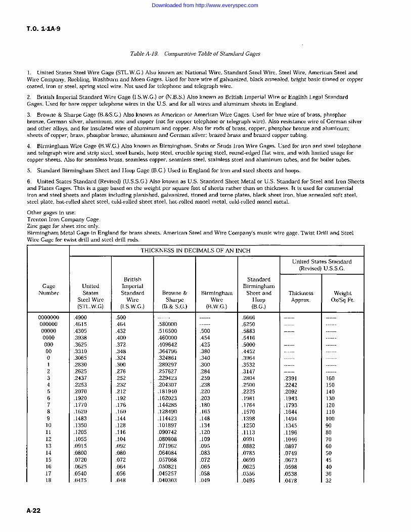
T.O. 1-1A-9
Table A-19. Comparative Table ofStandard Gages
1. United States Steel Wire Gage (STL.W.G.) Also known as: National Wire, Standard Steel Wire, Steel Wire, American Steel andWire Company, Roebling, Washburn and Moen Gages. Used for bare wire of galvanized, black annealed, bright basic tinned or coppercoated, iron or steel, spring steel wire. Not used for telephone and telegraph wire.
2. British Imperial Standard Wire Gage (I.S.W.G.) or (N.B.S.) Also known as British Imperial Wire or English Legal StandardGages. Used for bare copper telephone wires in the U.S. and for all wires and aluminum sheets in England.
3. Browne & Sharpe Gage (B.&S.G.) Also known as American or American Wire Gages. Used for bare wire of brass, phosphorbronze, German silver, aluminum, zinc and copper (not for copper telephone or telegraph wire). Also resistance wire of German silverand other alloys, and for insulated wire of aluminum and copper. Also for rods of brass, copper, phosphor bronze and aluminum;sheets of copper, brass, phosphor bronze, aluminum and German silver; brazed brass and brazed copper tubing.
4. Birmingham Wire Gage (B.W.G.) Also known as Birmingham, Stubs or Studs Iron Wire Gages. Used for iron and steel telephoneand telegraph wire and strip steel, steel bands, hoop steel, crucible spring steel, round-edged flat wire, and with limited usage for
copper sheets. Also for seamless brass, seamless copper, seamless steel, stainless steel and aluminum tubes, and for boiler tubes.
5. Standard Birmingham Sheet and Hoop Gage (B.G.) Used in England for iron and steel sheets and hoops.
6. United States Standard (Revised) (U.S.S.G.) Also known as U.S. Standard Sheet Metal or U.S. Standard for Steel and Iron Sheetsand Plates Gages. This is a gage based on the weight per square foot of sheets rather than on thickness. It is used for commercialiron and steel sheets and plates including planished, galvanized, tinned and terne plates, black sheet iron, blue annealed soft steel,steel plate, hot-rolled sheet steel, cold-rolled sheet steel, hot-rolled monel metal, cold-rolled monel metal.
Other gages in use:
Trenton Iron Company Gage.Zinc gage for sheet zinc only.Birmingham Metal Gage-in England for brass sheets. American Steel and Wire Company's music wire gage. Twist Drill and SteelWire Gage for twist drill and steel drill rods.
THICKNESS IN DECIMALS OF AN INCH
United States Standard(Revised) U.S.S.G.
British StandardGage United Imperial Birmingham
Number States Standard Browne & Birmingham Sheet and Thickness WeightSteel Wire Wire Sharpe Wire Hoop Approx. Oz/Sq Ft.(STL.W.G) (I.S.W.G.) (B.& S.G.) (B.W.G.) (B.G.)
0000000 .4900 .500 .6666000000 .4615 .464 .580000 .625000000 .4305 .432 .516500 .500 .58830000 .3938 .400 .460000 .454 .5416000 .3625 .372 .409642 .425 .500000 .3310 .348 .364796 .380 .44520 .3065 .324 .324861 .340 .3964
.2830 .300 .289297 .300 .35322 .2625 .276 .257627 .284 .31473 .2437 .252 .229423 .259 .2804 .2391 1604 .2253 .232 .204307 .238 .2500 .2242 1505 .2070 .212 .181940 .220 .2225 .2092 1406 .1920 .192 .162023 .203 .1981 .1943 1307 .1770 .176 .144285 .180 .1764 .1793 1208 .1620 .160 .128490 .165 .1570 .1644 1109 .1483 .144 .114423 .148 .1398 .1494 10010 .1350 .128 .101897 .134 .1250 .1345 9011 .1205 .116 .090742 .120 .1113 .1196 8012 .1055 .104 .080808 .109 .0991 .1046 7013 .0915 .092 .071962 .095 .0882 .0897 6014 .0800 .080 .064084 .083 .0785 .0749 5015 .0720 .072 .057068 .072 .0699 .0673 4516 .0625 .064 .050821 .065 .0625 .0598 4017 .0540 .056 .045257 .058 .0556 .0538 3618 .0475 .048 .040303 .049 .0495 .0478 32
A-22
Downloaded from http://www.everyspec.com
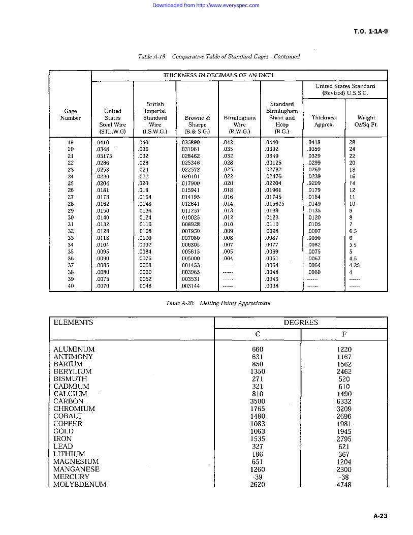
T.O. 1-IA-9
Table A-19. Comparative Table of Standard Gages Continued
THICKNESS IN DECIMALS OF AN INCH
United States Standard(Revised) U.S.S.G.
British StandardGage United Imperial Birmingham
Number States Standard Browne & Birmingham Sheet and Thickness WeightSteel Wire Wire Sharpe Wire Hoop Approx. Oz/Sq Ft.(STL.W.G) (I.S.W.G.) (B.& S.G.) (B.W.G.) (B.G.)
19 .0410 .040 .035890 .042 .0440 .0418 2820 .0348 .036 .031961 .035 .0392 .0359 2421 .03175 .032 .028462 .032 .0349 .0329 2222 .0286 .028 .025346 .028 .03125 .0299 2023 .0258 .024 .022572 .025 .02782 .0269 1824 .0230 .022 .020101 .022 .02476 .0239 1625 .0204 .020 .017900 .020 .02204 .0209 1426 .0181 .018 .015941 .018 .01961 .0179 12
27 .0173 .0164 .014195 .016 .01745 .0164 1128 .0162 .0148 .012641 .014 .015625 .0149 1029 .0150 .0136 .011257 .013 .0139 .0135 930 .0140 .0124 .010025 .012 .0123 .0120 831 .0132 .0116 .008928 .010 .0110 .0105 732 .0128 .0108 .007950 .009 .0098 .0097 6.533 .0118 .0100 .007080 .008 .0087 .0090 634 .0104 .0092 .006305 .007 .0077 .0082 5.535 .0095 .0084 .005615 .005 .0069 .0075 536 .0090 .0076 .005000 .004 .0061 .0067 4.537 .0085 .0068 .004453 .0054 .0064 4.2538 .0080 .0060 .003965 .0048 .0060 439 .0075 .0052 .003531 .004340 .0070 .0048 .003144 .0038
Table A-20. Melting Points Approximate
ELEMENTS DEGREES
C F
ALUMINUM 660 1220ANTIMONY 631 1167BARIUM 850 1562BERYLIUM 1350 2462BISMUTH 271 520CADMIUM 321 610CALCIUM 810 1490CARBON 3500 6332CHROMIUM 1765 3209COBALT 1480 2696COPPER 1083 1981GOLD 1063 1945IRON 1535 2795LEAD 327 621LITHIUM 186 367MAGNESIUM 651 1204MANGANESE 1260 2300MERCURY -39 -38MOLYBDENUM 2620 4748
Downloaded from http://www.everyspec.com
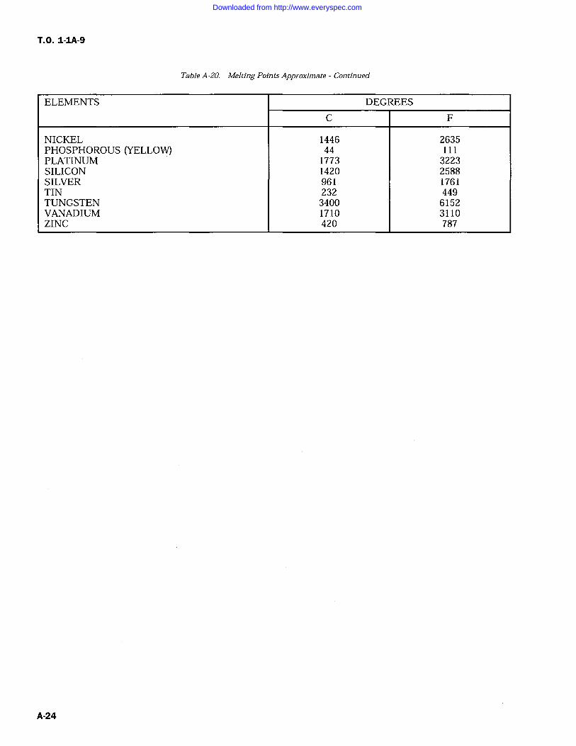
T.O. 1-IA-9
Table A-20. Melting Points Approximate Continued
ELEMENTS DEGREES
C F
NICKEL 1446 2635PHOSPHOROUS (YELLOW) 44 111PLATINUM 1773 3223SILICON 1420 2588SILVER 961 1761TIN 232 449TUNGSTEN 3400 6152VANADIUM 1710 3110ZINC 420 787
Downloaded from http://www.everyspec.com
T.O. 1-IA-9
GLOSSARY
A
ACID BRITTLENESS--Brittleness of steel resulting from use of acid solutions to remove scale, clean andelectroplate. Brittleness is caused by the absorption of hydrogen into the metal from the acid solu-tions (also called hydrogen embrittlement).
AGING--(a) Generally any change in properties with time which occurs at relatively low temperature(room or elevated) after a final heat treatment of a cold marking operation. Aging is a process inwhich the trend is toward restoration of real equilibrium and away from an unstable conditioninduced by a prior operation. (b) Specifically the formation of a new phase by cooling a solid solutionto super saturated state and allowing the super saturated solution to partially return to equilibriumby the formation of a less concentrated solid solution and a new phase.
AIR HARDENING--An alloy which does not require quenching from a high temperature to harden. Hard-ening of the material occurs simply by cooling in air from above critical temperature. The term refersonly to the ability of the material to harden in air and does not imply any definite analysis or
composition.AIR COOLING/QUENCHING--Cooling from an elevated temperature in air, still or forced.
ALLOY--A mixture with metallic properties composed of two or more elements of which at least one is a
metal. However, a metal is not designated an "alloy" based on elements incidental to its manufac-ture. For example; iron, carbon, manganese, silicon, phosphorus, sulphur, oxygen, nitrogen and hydro-gen are incidental to the manufacture of plain carbon steel. It does not become an "alloy steel" untilthe elements are increased beyond regular composition or until other elements (metal) are added insignificant amounts for a specific purpose.
ALLOY ELEMENTS--Chemical elements comprising an alloy, usually limited to the metallic elementsadded to modify the basic metal properties.
AMORPHOUS--Non-crystalline.ANNEALING--Generally it is a controlled heating procedure which leads to maximum softness, ductility
and formability. The annealing procedure is utilized for the following: (a) Remove stresses. (b) Inducesoftness. (c) After ductility, toughness, electrical, magnetic, or physical properties. (d) Refine crystal-line structure. (e) Remove gases. (1) Produce a definite micro-structure.
ANNEALING FULL--A controlled heating procedure which leads to maximum softness, ductility andformability.
ANNEALING, ISOTHERMAL--Heating of a ferritic steel to a austenitic structure (fully or partial) followedby cooling to and holding at a temperature that causes transformation of the austenite to a relativelysoft ferrite and carbide structure.
ANODIC OXIDE COATING--A thin film of aluminum oxide formed on the surface of aluminum andaluminum alloy parts by electro-chemical means.
AS CAST--Condition of a casting as it leaves the mold with no heat treatment.
AUSTENITE--A solid solution of iron carbide in gamma iron. It forms when the metal solidifies andremains a solution until it cools to about 732C (1350F). Theoretically the solution would remain ifthe iron or steel were cooled instantaneously from a bright red heat to atmospheric temperature, butin practice, this degree of rapidity is impracticable, and only a portion of the austenite is preserved byrapid cooling. Addition of certain alloying elements such as nickel and manganese perserves austenitebelow 17C (0F).
Glossary 1
Downloaded from http://www.everyspec.com
T.O. 1-IA-9
GLOSSARY Continued
B
BARK--The decarburized skin or layer just beneath the scale found after heating steel in an oxidizingatmosphere.
BASE METAL--The metal to which other elements are added to form an alloy possessing specificproperties.
BESSEMER PROCESS--A process for making steel by blowing air through molten pig iron contained in a
suitable vessel. The process is one of rapid oxidation primarily of silicon and carbon.
BILLET--An ingot or bloom that has been reduced through rolling or hammering to an approximate squareranging from 1 1/2 inches square to 6 inches square, or to an approximate rectangular cross-section ofequivalent area. Billets are classified as semi-finished products for re-rolling or forging.
BINARY ALLOY--An alloy containing two elements, apart from minor impurities.BLACK ANNEALING--A process of box annealing of sheets prior to tinning whereby a black color is
imparted to the surface of the product.BLUE ANNEALING--A process of annealing sheets after rolling. The sheets, if fairly heavy, are allowed
to cool slowly after the hot rolling; if of lighter gage, as is usually the case, they are passed singlythrough an open furnace for heating to the proper annealing temperature. The sheets have a bluish-black appearance.
BLUE BRITTLENESS--Brittleness occurring in steel when in the temperature range of 149 to 371C(300 to 700F), or when cold after being worked within this temperature range.
BOX ANNEALING--Softening steel by heating it, usually at a sub-critical temperature, in a suitable closedmetal box or pot to protect it from oxidation, employing a slow heating and cooling cycle; also calledclosed annealing or pot annealing.
BRIGHT ANNEALING--A process of annealing, usually with reducing gases, such that surface oxidation isreduced to a minimum, thereby yielding a relatively bright surface.
BRITTLENESS--Brittleness is the property of a material which permits little bending or deformationwithout fracture. Brittleness and hardness are closely associated.
BURNING--The heating of a metal to temperatures sufficiently close to the melting point to cause perma-nent injury. Such injury may be caused by the melting of the more fusible constituents, by thepenetration of gases such as oxygen into the metal with consequent reactions, or perhaps by thesegregation of elements already present in the metal.
BUTT-WELD--The welding of two abutting edges.
C
CARBON FREE--Metals and alloys which are practically free from carbon.
CARBURIZING (CEMENTATION)--Adding carbon to the surface of iron-base alloys by heating the metalbelow its melting point in contact with carbonaceous solids, liquids, or gases.
CASE--The surface layer of an iron-base alloy which has been made substantially harder than the interiorby the process of case hardening.
CASE HARDENING--A heat treatment of a combination of heat treatments in which the surface layer ofan iron-base alloy is made substantially harder than the interior by altering its composition bycarburizing, cyaniding, or nitriding.
Glossary 2
Downloaded from http://www.everyspec.com
T.O. 1-IA-9
GLOSSARY Continued
C (Cont)
CHAPMANIZING--A process for hardening steel by bubbling ammonia through a cyaniding salt bath andholding the finished part in the gas stream. This method produces a case almost as hard as nitridingat a time factor of slightly longer than required for cyaniding.
CHARPY IMPACT--An impact test made by measuring in a Charpy machine the energy required tofracture a standard notched specimen in bending. The values so obtained are merely comparativebetween different materials tested by the same method.
COLD DRAWING--The permanent deformation of metal below its recrystallization temperature, by draw-ing the bay through one or more dies.
COLD ROLLING--The permanent deformation of metal below its recrystallization temperature by rolling.This process is frequently applied in finishing rounds, sheets, strip, and tin plate.
COLD TREATING--Cooling to sub-zero temperature for various purposes, but primarily to promote trans-formation of austenite.
COLD WORKING--Plastic deformation of a metal at a temperature low enough to insure strain hardening.CORE--The interior portion of an iron-base alloy which is substantially softer than the surface layer as the
result of case hardening. Also, that portion of a forging removed by trepanning; the inner part of a
rolled section of rimmed steel as distinct from the rimmed portion or rim; a body of sand or othermaterial placed in a mold to produce a cavity in a casting.
CONVERSION COATING (CHEMICAL)--A film intentionally produced on a metal by subjection to aselected chemical solution for the purpose of providing improved corrosion resistance or to improvethe adhesion of subsequently applied organic coating.
CYANIDING--Surface hardening by carbon and nitrogen absorption of an iron-base alloy article or portionof it by heating at a suitable temperature in contact with a cyanide salt, followed by quenching.
COOLING--Any decrease in temperature; however, specific term usually applies to reducing metal temper-ature in a gaseous environment rather than quenching in a liquid.
D
DECALESCENCE--When a piece of steel is heated, the temperature rises uniformly until it reaches a
point between 718C and 732C (1,325F and 1,350F). At this point the rise in temperature suddenlyhalts due to the fact that the metal absorbs the heat necessary for the change of state. After thishalt the temperature will continue its normal rate of increase. It is the halting in the temperaturerange that is termed decalescence. At the point of decalesence, the carbon and iron are forming asolid solution and the steel is passing from its annealed condition into its hardened condition.
DECARBURIZATION--The removal of carbon (usually refers to the surface of solid steel) by the (normallyoxidizing) action of media which reacts with carbon. The decarburized area is sometimes referred to
as the bark.
Glossary 3
Downloaded from http://www.everyspec.com
T.O. 1-IA-9
GLOSSARY Continued
D (Cont)
DEFECTS IN METALS--Damage occurring to metal during manufacture/fabrication process. Some typicaldefects are as follows: (a) Blister a defect in metal produced by gas bubbles either on the surface orformed beneath the surface. Very fine blisters are called pinhead or pepper blisters. (b) Blow hole a
hole produced during the solidification of metal by evolved gas which in falling to escape, is held inpockets. (c) Bursts -ruptures made in forging or rolling. (d) Fin (Flash) a thin fin of metal formed atthe side of a forging or weld where a small portion of the metal is forced out between the edges of theforging or welding case. (e) Flake -Internal fissures (cracks or clefts) in large steel forgings or large(MASS) rolled shapes. In a factured surface or test piece, they appear as sizable areas of silverybrightness and coarser grain size than their surroundings. Sometimes known as "chrome checks" and"hairline cracks." (f) Ghost (Ferrite ghost) a faint band of ferrite. (g) Lap a surface defect appearingas a seam caused from folding over hot metal, fins, or sharp corners and then rolling or forging, butnot welding, them into the surface. (h) Pipe a cavity formed in metal (especially ingots) duringsolidification of the last portion of liquid metal causes the cavity or pipe. (i) Scab a rough projectionon a casting caused by the mold breaking or being washed by the molten metal; or occuring where theskin from a blowhole has partly burned away and is not welded. (j) Seam a crack on the surface ofmetal which has been closed but not welded; usually produced by blowholes which have becomeoxidized. If very fine, a seam may be called a hair crack or hair seam. (k) Segregation a mixture ofcompounds and elements, which, when cooled from the molten state, solidify at different tempera-tures. (1) Ductility the ability of a metal to withstand plastic deformation without rupture. Ductilityis usually determined by tension test using a standard test (2" gauge length) specimen. The testspecimen is loaded in tension to rupture. The specimen is then assembled and measured for lengthand diameter at the fracture. The increase in length is expressed as per cent elongation and thedecrease in diameter as per cent reduction of area. The above terms measure ductility and since theyare comparative, considerable experience is required for proper evaluation of material for the purposeintended.
DUCTILITY--The property that permits permanent deformation before fracture by stress in tension.
E
ELASTIC LIMIT--The elastic limit of a material is the greatest load per unit area which will not produce ameasurable permanent deformation after complete release of load.
ELONGATION--The amount of permanent extension at any stage in any process which continuouslyelongates a body.
EMBRITTLEMENT--Loss of ductility of a metal, which may result in premature failure. (see acidbrittleness).
ENDURANCE LIMIT--The highest unit stress at which a material can be subjected to a very large numberof repetitions of loading and still show no evidence of failure. Above this limit failure occurs by thegeneration and growth of cracks until fracture results in the remaining section.
ENDURANCE RATIO--The ratio of the endurance limit for cycles of reversed flexural stress to the tensilestrength.
EQUALIZING--Intermediate heat treatment (special) which assists in developing desired properties, pri-mary use is for equalizing/relieving stresses resulting from cold working.
EUTECTIC ALLOY--An alloy which has a lower melting point than neighboring compositions. More thenone eutectic composition may occur in a given alloy system.
EXFOLIATION--The cracking or flaking off of the outer layer of an object.EXPOSURE--Heating to or subjecting to an elevating temperature or environment for a certain period of
time.
Glossary 4
Downloaded from http://www.everyspec.com
T.O. 1-1A-9
GLOSSARY Continued
E (Cont)
ETCHING--Attack of metals structure by reagents. In metallography, the process of revealing structualdetails by the preferential attack of reagents on a metal surface. (a) Micro etching is for theexamination of the sample under a microscope and for this purpose the sample must be very carefullypolished (by an experienced person) prior to etching. (b) Macro-etching is for the examination of thesample under a low power magnifying glass or by unaided eye. High polishing for this purpose is notabsolutely essential; however, a good polish is necessary. (c) Deep-etching is a form of macro-etchingin which the sample with regular cut surface may be immersed in hot hydrocloric acid (50% acqueoussolution) and then examined for major defects such as inclusions, segregations, cracks; etc.
F
FATIGUE--The phenomenon of the progressive fracture of a metal by means of a crack which spreadsunder repeated cycles of stress.
FATIGUE LIMIT--Usually used as synonymous with endurance limit.
FERRITE--A solution in which alpha iron is the solvent, and which is characterized by a body centeredcubic crystal structure.
FILLET--A concave junction of two surfaces usually perpendicular.FLAME HARDENING--A process of hardening a ferrous alloy by heating it above the transformation
range by means of a high-temperature flame and then cooling as required.FORGING STRAINS--Elastic strains resulting from forging or from cooling from the temperature.FORMING--To shape or fashion with hand/tools or by a shape or mold.
FRACTURE TESTING--A test used to determine type of structure, carbon content and the presence ofinternal defects. The test specimen is broken by any method that will produce a clean sharp fracture.The fracture is then examined by eye or with the aid of a low former magnifying glass. A trained/experienced observer will determine grain size; approximate depth of carburized or decarburizedsurface area; the presence of inclusions of dirty steel; and defects such as seams, cracks, pipes burstsand flakes.
FULLY HARDENED--Applies generally to the maximum hardness obtainable. (In particular, applies tomaterials that are hardened by a strain and/or age hardening process).
FUSIBLE ALLOYS--A group of nonferrous alloys which melt at relatively low temperatures. They usuallyconsist of bismuth, lead, tin, etc., in various proportions, and iron only as an impurity.
G
GALVANIC SERIES--A list of metals and alloys arranged in order of their relative potentials in a givenenvironment. The galvanic series indicates the tendency of the serval metals and alloys to set upgalvanic corrosion. The relative position within a group sometimes changes with external conditions,but it is only rarely that changes occur from group to group.
GRAINS--Individual crystals in metal. When metal is in molten state, the atoms have no uniform group-ing. However, upon solidification they arrange themselves in a geometric pattern.
GRAIN GROWTH--An increase in the grain size of metal.
Glossary 5
Downloaded from http://www.everyspec.com
T.O. 1-IA-9
GLOSSARY Continued
H
HARDENABILITY--The ability of an alloy to harden fully throughout the entire section thickness either bycold working or heat treatment. The maximum thickness at which this may be accomplished can beused as a measure of hardenability.
HARDENING--Hardening accomplished by heating the metal to a specified temperature, then rapidlycooling by quenching in oil, water, or brine. This treatment produces a fine grain structure, extremehardness, maximum tensile strength, and minimum ductility.
HARDNESS--Hardness refers to the ability of a material to resist abrasion, penetration, indentation, or
cutting action. The wearing qualities of a material are in part dependent upon its hardness. Hard-ness and strength are properties which are closely related for wrought alloys.
HARDNESS TESTING--Test used to determine the ability of a metal to resist penetration. The testresults are usually directly related to tensile and yield strength of the metal involved. An exceptionwould be case hardness. See Section VIII for typical testing methods.
HEAT TINTING--Heating a specimen with a suitable surface in air for the purpose of developing thestructure by oxidizing or otherwise affecting the different constituents.
HEAT TREATMENT--An operation, or combination of operations, involving the heating and cooling of a
metal or alloy in the solid state for the purpose of obtaining certain desirable conditions or properties.Heating and cooling for the sole purpose of mechanical working are excluded from the meaning of thisdefinition.
HOMOGENIZING--Annealing or soaking at very high temperatures in order to reduce alloy segregation bydiffusion.
HOT SHORTNESS--Brittleness in metal when hot. In iron when sulphur is in excess of the manganesenecessary.to combine with it to form manganese sulphide the excess sulphur combines with the ironto form iron sulphide. This constituent has a lower melting point than the iron and the result can bethat steel may crack during hot working.
HYDROGEN EMBRITTLEMENT--See Acid Brittleness.
IMPACT TEST--A test in which one or more blows are suddenly applied to a specimen. The results areusually expressed in terms of energy absorbed or number of blows (of a given intensity) required tobreak the specimen. See Charpy Impact and Izod Impact.
INCLUSION--Particles of impurities, usually oxides, sulphides, silicates, and such which are mechanicallyheld during solidification or which are formed by subsequent reaction of the solid metal.
INDUCTION HARDENING--A process of hardening a ferrous alloy by heating above the transformationrange by means of electrical induction and then cooling as required.
M
MACHINABILITY--The cutting characteristic of metal and resulting surface finish using standard cuttingtools and coolant/lubricants. There are various factors that effect the machinability of a metal suchas hardness, grain size, alloy constituents, structure, inclusions; shape, type, condition of tool andcoolant. The standard machinability ratings are usually based on comparison to SAE 1112/Aisi B1112 Bessemer screw stock which is rated at 100% machinability.
Glossary 6
Downloaded from http://www.everyspec.com
T.O. 1-1A-9
GLOSSARY Continued
M (Cont)
MAGNA FLUX TESTING--A method of inspection used to detect/locate defects such as cavities, cracks or
seams in steel parts at or very close to the surface. The test is accomplished by magnetizing the partwith equipment specially designed for the purpose and applying magnetic powder, wet or dry, Flawsare then indicated by the powder clinging to them (see Section VIII for additional data).
MALLEABILITY--Malleability is the property of a material which enables it to be hammered, rolled, or tobe pressed into various shapes without fracture. Malleability refers to compression deformation as
contrasted with ductility where the deformation is tensile.
MARTEMPERING--This is a method of hardening steel by quenching from the austenitizing temperatureinto a medium at a temperature in the upper part of or slightly above the martensite range andholding it in the medium until temperature is substantially uniform throughout the alloy is thenallowed to cool in air through the martensite range.
MARTENSITE--It is the decomposition product which results from very rapid cooling of austenite. Thelower the carbon content of the steel, the faster it must be cooled to obtain martensite.
MECHANICAL HARDNESS--See Hardness.
MECHANICAL PROPERTIES--Those properties that reveal the reaction, elastic and inelastic, of a mate-rial to an applied force, or that involve the relationship between stress and strain; for example,tensile strength, yield strength, and fatigue limit.
MECHANICAL TESTING--Testing methods by which mechanical properties are determined.
MECHANICAL WORKING--Subjecting metal to pressure exerted by rolls, presses, or hammers, to changeits form, or to affect the structure and therefore the mechanical and physical properties.
MODULUS OF ELASTICITY--The ratio, within the limit of elasticity, of the stress in the correspondingstrain. The stress in pounds per square inch is divided by the elongation in fractions of an inch foreach inch of the original gage length of the specimen.
N
NITRIDING--Adding nitrogen to iron-base alloys by heating the metal in contact with ammonia gas orother suitable nitrogenous material. Nitriding is conducted at a temperature usually in the range502-538C (935-1000F) and produces surface hardening of the metal without quenching.
NORMALIZING--Heating iron-base alloys to approximately 55C (100F) above the critical temperaturerange, followed by cooling to below that range in still air at ordinary temperatures. This process isused to remove stresses caused by machining, forging, bending, and welding.
0
OVERHEATING--Heating to such high temperatures that the grains have become coarse, thus impairingthe properties of the metal.
P
PATENTING--Heating iron-base alloys above the critical temperature range followed by cooling below thatrange in air, or in molten lead, or a molten mixture of nitrate or nitrites maintained at a temperatureusually between 427-566C (800-1050F),depending on the carbon content of the steel and theproperties required of the finished product. This treatment is applied to wire and to medium or highcarbon steel as a treatment to precede further wire drawing.
Glossary 7
Downloaded from http://www.everyspec.com
T.O. 1-1A-9
GLOSSARY Continued
P (Cont)
PHYSICAL PROPERTIES--Those properties exclusive of those described under mechanical properties; forexample, density, electrical conductivity, coefficient of thermal expansion. This term has often beenused to describe mechanical properties, but this usage is not recommended.
PHYSICAL TESTING--Testing methods by which physical properties are determined. This term is alsoinadvisedly used to mean the determination of the mechanical properties.
PICKLING--Removing scale from steel by immersion in a diluted acid bath.
PLASTIC DEFORMATION--The permanent change in size or shape of a material under stress.
POTENTIOMETER--Potentiometer is an instrument used to measure thermocouple voltage by balancing a
known battery voltage against it.
PROCESS ANNEALING--Heating iron-base alloys to a temperature below or close to the lower limit of thecritical temperature range, followed by coolings desired. This treatment is commonly applied to sheetand wire and the temperatures generally used are from 549 to 649C (10200 to 1200F).
PROOF STRESS--The proof stress of a material is that load per unit area which a material is capable ofwithstanding without resulting in a permanent deformation of more than a specified amount per unitof gage length after complete release of load.
PROPORTIONAL LIMIT--The proportional limit of a material is the load per unit area beyond which theincreases in strain cease to be directly proportional to the increases in atress.
PYROMETER--An instrument for measuring temperature.
Q
QUENCHING--Rapid cooling by immersion in liquids or gases.
QUENCHING MEDIA--Quenching media are liquids or gases in which metals are cooled by immersion.Some of the more common are brine (10 percent sodium chloride solution), water 18C (65F), fish oil,paraffin base petroleum oil, machine oil, air, engine oil, and commercial quenching oil.
R
RECALESCENCE--When steel is slowly cooled from a point above the critical temperature, the coolingproceeds at a uniform rate until the piece reaches a point between 677 and 704C (1,250 and1,300F). At this time, the cooling is noticeably arrested and the metal actually rises in temperatureas the change of state again takes place. This change is the opposite of decalescence and is termedrecalescence.
REDUCTION OF AREA--The difference between the original cross-sectional area and that of the smallestarea at the point of rupture. It is usually stated as a percentage of the original area; also called"contraction of area."
REFINING TEMPERATURE OR HEAT--A temperature employed in case hardening to refine the case andcore. The first quench is from a high temperature to refine the core and the second quench is from alower temperature to further refine and harden the case.
S
SCALE--A coating of metallic oxide that forms on heated metal.
SENSITIZING--Developing a condition in stainless steels, which is susceptible to intergranular corrosion.The condition is usually formed by heating the steel above 800F and cooling slowly, e.g., welding.
Glossary 8
Downloaded from http://www.everyspec.com
T.O. 1-1A-9
GLOSSARY Continued
S (Cont)
SHEETS COLD ROLLED--The flat products resulting from cold rolling of sheets previously produced byhot rolling.
SHEETS HOT ROLLED--The flat-rolled products resulting from reducing sheet bars on a sheet mill, orslabs, blooms, and billets on a continuous strip-sheet mill.
SOAKING--Holding steel at an elevated temperature for the attainment of uniform temperature through-out the piece.
SOLIDIFICATION RANGE--The temperature range through which metal freezes or solidifies.
SPALLING--The cracking and flaking of small particles of metal from the surface.
SPHEROIDAL OR SPHEROIDIZED CEMETITE--The globular condition of iron carbide resulting from a
spheroidizing treatment. The initial structure may be either pearlitic or martensitic.
SPHEROIDIZING--Any process of heating and cooling steel that produces a rounded or globular form ofcarbide. The spheroidizing methods generally used are: (a) Prolonged heating at a temperature justbelow the lower critical temperature, usually followed by relatively slow cooling. (b) In the case ofsmall objects of high carbon steels, the spheroidizing result is achieved more rapidly by prolongedheating to temperatures alternately within and slightly below the critical temperature range. (c) Toolsteel is generally spheroidized by heating to a temperature of 749-804C (1380-1480F) for carbonsteels and higher for many alloy tool steels, holding at heat from 1 to 4 hours, and cooling slowly inthe furnace.
STRAIN--The elongation per unit length.STRESS--The internal load per unit area.
STRESS-RELIEF--This is annealing process which removes or reduces residual stresses retained afterforming, heat treating, welding or machining. The anneal is accomplished at rather low temperaturesfor the primary purposes of reducing residual stresses, without material affecting other properties.
T
TEMPERING (ALSO TERMED DRAWING)--Reheating hardened steel to some temperature below thelower critical temperature, followed by any desired rate of cooling. Although the terms "tempering"and "drawing" are practically synonymous as used in commercial practice, the term "tempering" ispreferred.
TENSILE STRENGTH--The tensile strength is the maximum load per unit area which a material iscapable of withstanding before failure. It is computed from the maximum load carried during atension test and the original cross-sectional area of the specimen.
TENSION--That force tending to increase the dimension of a body in the direction of the force.
THERMOCOUPLE--Thermocouple consists of a pair of wires of dissimilar metals connected at both ends.When the two junctions are subjected to different temperatures an electric potential is set upbetween them. This voltage is almost in direct proportion to the temperature difference, and hence, avoltage measuring instrument inserted in the circuit will measure temperature. The voltage measur-ing instrument is usually calibrated in C or F.
TOLERANCES--Slight deviations in dimensions or weight or both, allowable in the various products.
V
VISCOSITY--Viscosity is the resistance offered by a fluid to relative motion of its parts.
Glossary 9
Downloaded from http://www.everyspec.com
T.O. 1-IA-9
GLOSSARY Continued
w
WIRE--The product obtained by drawing rods through a series of dies.
WORK HARDNESS--Hardness developed in metal resulting from mechanical working, particularly coldworking.
Y
YIELD POINT--The load per unit of original cross section at which a marked increase in deformationoccurs without increase in load.
YIELD STRENGTH--Stress arbitrarily defined as the stress at which the material has a specified perma-nent set (the value of 0.2% is widely accepted).
YOUNG'S MODULUS--See Modulus of Elasticity.
Glossary 10
Downloaded from http://www.everyspec.com