ezeizl - everyspec
TRANSCRIPT
I
EzEIzlDUL-J-891OO (rMA)
SOPEASEDINGPs/lAE/2olPS/3BB/201
November 1976
f MILITAAY SPECIHCATIONS
JOINT OPERATIONS GSAPEICS S-ES 1501A AND 1501 (JOG XIX/GROUND)
TMs specification ia ●pproved for uae by ●ll Departments andAgeaciee of the Department of Defense.
1. SCOPE “’
1.1 -. This specification defines requirements for theDefense Mapping Agency’s (DMA) 1:250,000 Scale Joint OperationsGraphics Series 1501A (Air) and 1501 (Ground).
1.2 EluQQse. The purpose of this specification is to assureuniformity of treatment among all mapping and charting elements,primarily DMA and its contractors, engaged in a coordinatedproduction and maintenance program for this product. Featurerequirements are stated in terms of DMA’s Feature Attribute CodingStandard (FACS), to maintain consistency between variousproduction methods. The use of FACS in this specification is notintended to imply any external digital data coding standard usedby DMA’s Digital Production System (DPS). DPS is the primaryintended, but not exclusive, method for production of this productat this time. The Digital Geographic Information ExchangeStandard (DIGEST) Feature Attribute Coding Catalog (FACC), notFACS, is the approved coding standard for the exchange of digitalgeographic data, as wellas the standard for DMA’s Vector ProductFormat product line. FACC may be included in, or replace FACS ina future edition of this specification.
Beneficial comments (recommendetiona, add.itiona, deletione) end~Y Pe*in=t data which may be of uae in improving this documentehould be addresaed to: Director, Defense Mapping Agency, ATTN.:PR, MAIL STOP A-13, 8613 Lee kiighway, Fairfax, VA 22031-2137 byusing the Standardization Document Improvement Proposal (DD Form1426) appearing at the end of this document or by letter.
AMSC lJ/A AAEli !4CGT
~. Approved for public release;distribution unlimited.
Downloaded from http://www.everyspec.com
ML-J-891OO
1.3 S=MLiLY.
~CL~i~;;ED~. ThisThe securitv classification
specification isof the nroducta
generated by the use of this specification will be-the lowestcategory practicable. When it is necessary to aasign a securityclassification to the product, it shall be in accordance withestablished national security procedures.
I2. APPLICABLE DOCUMENTS
~
2.1.1 . Thefollowing specifications, standards, and handbooks form a part ofthis document to the extent specified herein. Unless otherwiseSDeCified, the issues of these documents are those listed in thec;rrent Department of Defense Index of Specifications and
IStandards (DODISS) and the supplement thereto, cited in thesolicitation (see 6.2).
I STANDARDS
1 MILITARY
MIL-HDBK-129 -Military Levels of ProtectionMIL-STD-2402 -MChG SymbologyMIL-sTD-2403 -MC6G Product Generation RulesMIL-STD-2408 -MC6G Glossary of Feature/Attribute
DefinitionsMIL-STD-2409 -MChG AccuracyMIL-STD-241O -MC6G Reproduction and PrintingMIL-STD-2414 -Defense Mapping Agency Bar Coding
(Unless otherwise indicated, copies of federal and militaryspecifications, standards, and handbooks are available from theStandardization Documents Order Desk, Bldg. 4D, 700 Robins Avenue,Philadelphia, PA 19111-5094.)
2.1.2 Qtbsr GOv~tq. as. and~. The following other governmentand publications form a part of this documentspecified herein. Unless otherwise specifiedthose cited in the solicitation.
I 2
documents, drawings,to the extent, tbe issues are
Downloaded from http://www.everyspec.com
mL-J-89100
DMA TM 8358.1 - “Datums, Ellipsoids, Grids, and GridReference Systems”
fromD.C.
DMA T148358.2 - “The universal Grids; UPS and UTM Grids”
(Copies of DMA TM 8358.1 and DMA TM 8358.2 are availablethe Defense Mapping Agency Combat Support Center, Washington,20816-0010).
DoD Standard Printing Color (SPC) Catalog
(Copies of the DoD Standard Printing Color Catalog is availablefrom Defense Mapping Agency Graphic Arts, Bethesda, Maryland20816-0010.
2.2 &n-Gov~. This section is notapplicable to this specification.
2.3 ~. In the event of a conflict betweenthe text of this”’documentand the references cited herein (exceptfor related associated detail specifications, specificationsheets, or 14sstandards) the text of this document takesprecedence. Nothing in this document, however, supersedesapplicable laws and regulations nnless a specific exemption hasbeen obtained.
3. REQUIREMENTS
3.1 When specified (see 6.2), a sample shallbe subjected to first artical inspection (see 6.3) in accordancewith 4.3.
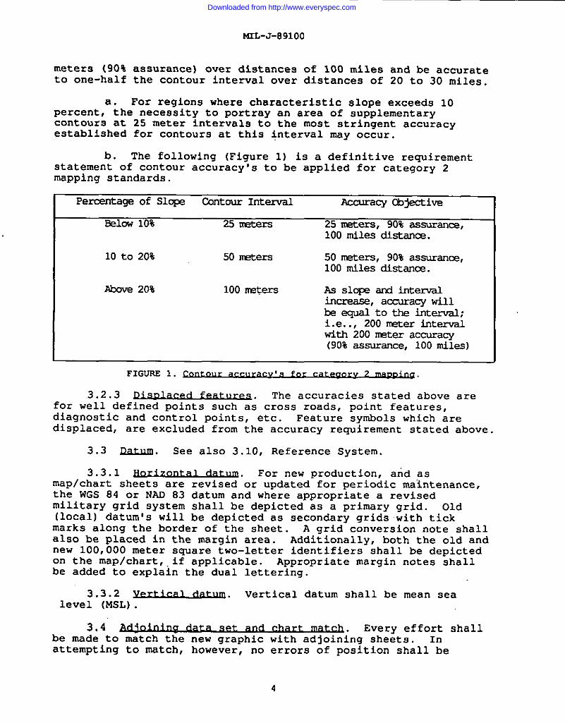
3.z ~. Series 1501A (AIR) and 1501 (GROUND) arerequired to meet the accuracyts prescribed below.
3.2.1 ~. The horizontal accuracy is tomeet category 2 mapping standards. This requires 90 percent (90%)of all planimetric features, except those unavoidable displaced byexaggerated size of symbols, be located within 0.50 mm (125 metersor 41O feet) of their geographical position as referred to mapprojection. Features are required to be carefully and accuratelyshown by positioning, orienting, and aligning those featuresselected to be shown to the maximum degree practicable. Anydisplacement of portrayal due to adjustment between sourcematerials and symbolization shall be held to the absolute minimum.
3.2.2 ~. Vertical accuracy shall vary inaccordance with the percentage of slope characteristic for theterrain being mapped. Generally, the contour accuracy to meetcategory 2 mapping standards will be equal to the contour interval(90% assurance) prescribed for that percent of slope. However,for areas of flat or rolling ground (slopes O to 10%), there is acritical requirement that contours be portrayed at a 25 meterinterval. These 25 meter contours must meet an accuracy of 25
3
Downloaded from http://www.everyspec.com
t4rL-J-89100
meters (90% assurance) over distances of 100 miles and be accurate
~to one-half the contour interval over distances of 20 to 30 miles.
a. For regions where characteristic slope exceeds 10percent, the necessity to portray an area of supplementarycontours at 25 meter intervals to the most stringent accuracyestablished for contours at this Interval may occur.
b. The following (Figure 1) is a definitive requirementstatement of contour accuracy’s to be applied for category 2mapping standards.
Percentageof S1* ContourInterval AccuracyCqective
Eelow10% 251m3ters 25 meters,90% assurance,100milesdistance.
10 to 20% 50 nEtere 50 meters,90% assurance?,100 milesdistance.
AtOve20% 100nr?ters As slopeand intervalincrease,accuracywillbeequaltotheintenzll;i.e..,200 Imter intervalwith 200 interaccuracy(90%assurance,100miles)
FIGURS1.
3.2.3 ~. The accuracies stated above arefor well defined points such as cross roads, uoint features.diagnostic and co~trol points, etc. Feature ~ymbols which-iredisplaced, are excluded from the accuracy requirement stated above.
3.3 [email protected] also 3.10, Reference System.
3.3.1 ~. For new production, and asmap/chart sheets are revised or updated for periodic maintenance,the WGS 84 or NAD 83 datum and where appropriate a revisedmilitary grid system shall be depicted as a primary grid. Old(local) datum’s will be depicted as secondary grids with tickmarks along the border of the sheet. A grid conversion note shallalso be placed in the margin area. Additionally, both the old andnew 100,000 meter square two-letter identifiers shall be depictedon the maplchart, ,if applicable. Appropriate margin notes shallbe added to explain the dual lettering.
3.3.2 ~. Vertical datum shall be mean sealevel (MSL).
3.4 ~. Every effort shallbe made to match the new graphic with adjoining sheets. Inattempting to match, however, no errors of position shall be
4
Downloaded from http://www.everyspec.com
mLI’-.03i””””
introduced into the new graphic, nor shall any factual errors bemade in an attempt to tie to adjoining sheets. Position anddetail of whichever of the sheets is being evaluated as being morereliable shall be retained.
3.4.1 ~. If a 9raphic adjoinsanother which is being prepared by another agency, by agreementone of the agencies shall supply the other with a match strip ofthe common edge.
I 3.5 Sex.ka. Refer to: APPENDIX B-Joint Operations Graphic1501A-AIR Style Sheet, and APPENDIX C-Joint Operations Graphic
1
1501-GROUND Style Sheet.
3.6 f2udJ&z. Final DrOduCt oualitv shall reflect theI quality elements expressed-by each ”appro~riate section within
MIL-STD-2402, MIL-STD-2403, MIL-STD-2408, MIL-STD-2409,MIL-STD-241O and MIL-STD-2414. A production history shall bewritten concurrently with the development of the graphicmanuscript and shall include precise descriptions of sourcematerial utilization and of all pertinent cartographic and controlproblems with the solutions that were applied.
3.7 S&d&. The Joint Operat(G) shall be produced at 1:250,000
3.8 Map/~.
Ons Graphics AIR (A) and GROUNDscale.
3.8.1 ~. Geographical area of coveragefor each individual JOG sheet shall be based on subdivisions ofthe ‘International Map of the World (IMW)” 1:1,000,000 scale sheetnumbering system. The number of 1:250,000 scale graphicscontained within each IMw sheet will vary from 12 to 16, dependingon the latitude. Shifting of the.geographic limits of a graphicfrom its standard.IMW position is permissible to avoid unnecessaryproduction of graphics. However, the elimination of a graphic isnot the sole criterion. Other considerations are the effect onthe sheet lines of surrounding graphics, the coverage on theaffected graphics, and the continuity of information.
3.8.2 ~ ,he~* ~ ,, and Where the
I elimination of a graphic would require the shifting of the sheetlines of several graphics, the graphic would not normally be..eliminated unless the new sheet lines of the other graphics are animprovement in the coverage; i.e., the major related features areshown on one graphic. The coverage should always be considered toavoid separating related features which, if possible, should bepresented as a whole. The continuity of information should not bedisrupted by the elimination of a water area where therelationship between land masses is important for planning orflying purposes.
3.8.3 ~. Each sheet shall provide an overlaparea (bleed edge) of the adjacent sheets to the north and east.
5
Downloaded from http://www.everyspec.com
KtL-J-89100
This overlap area (bleed edge) ehall be aquared off at thenortheast corner. The narrowest width shall be a minimum of 15.25mm PIUS 2.55 mm allowance to assure that the detail contained onthe graphic will extend to the edges of the sheet after it istrimmed. The overlap areas (bleed edge) may be reduced wherenecessary to accommodate placement of margin data. In no case,however, will the overlap (bleed edge) be less than 2.55 mm at itsnarrowest point, after the graphic has been trimmed.
a. Breaking of the south andlor west geographic limits ofa graphic is also permissible to avoid unnecessary production.However, the extended planimetric detail shall not exceed the trimsize from the projection.
b. For graphics shifted from the standard IMW position,the sheet number is that which, in the standard system, relates tothe greater part of the graphic.
c. Insets shall not be shown.
d. Refer to the Appendices B and C, JOG Style Sheets.
3.8.4 ~. In neither of the instances sited3.8.3 and 3.8.3.ar shall the maximum trim size 55.880 cm bycm be exceeded.
3.8.5 ~. Trim line measurements are from thetip of north, and south tip of east projection lines.
a. Measurement is 15.2 mm.
;;.660
west
b. Imaginary lines are constructed from their points eastand north to form a 90° angle northeast.
c. No type is placed closer than 2.5 mm to this line.
d. Refer to Appendices B or C, JOG Style Sheets.
a. Between 84° North and 80° South, the TransverseMercator Projection shall be used. Beyond the 84° North paralleland the 80° South parallel, the Polar Stereographic Projectionshall be used.
b. The basic projection layout must be accurate within &0.50 mm diagonal measurement.
c. Full lines of latitude shall be shown at 15-minuteintervals with l-minute ticks shown thereon.
d. Between latitudes 0° and 76°, full lines of longitudeshall be shown at 15-minute intervals with l-minute ticks shownthereon. Between latitudes 76° to 84° North, and between 76°1to 80°
L. .’
Downloaded from http://www.everyspec.com
MIL-J-891OO
South, full lines of longitude shall be shown at 30-minuteintervals with l-minute ticks shown thereon.
e. The l-minute ticks shall be directed away fromGreenwich and away from the Equator. Ticks shall cross full linesat 0° and 180° longitude and at the Equator.
3.10 The military grids, horizontaldatum’s, and ellipsoids to be used for particular areas shall beas directed in DMA TM 8358.1 and DMA TM 8358.2.
3.10.1 ~.
a. Between latitude 84° North and latitude 80° South theTransverse Mercator (TM) Grid shall be used.
b. North of 84° North and south of 80° South parallels,the Polar Stereographic (PS) Grid shall be used.
It is noted that existing British grids eventually willbe super~~ded by the UTM Grid. Due to the tremendous taskinvolved in converting the grid data, for both control and maps,the transitions must necessarily.be progressive rather thaninstantaneous.
d. The margin shall contain notes and a sample referencebox identifying the grids contained within the graphic, excludingthe north and east overlaps (bleed edge) .
3.10.2 Mj.JAtarvarj& . The following are minimumrequirements for military grids. See APPENDIX B or C, JOG StyleSheets.
a. The first grid line in each direction from each cornerof the manuscript shall be labeled with full grid values.
b. If more than one military grid falls within the area ofthe manuscript, the divisions between grids shall be indicated bygrid junction lines with labeling identifying the grids addedalong the junction lines. Full grid lines shall be shown for thefirst casting and northing grid lines in each direction at sheetcorners and at intersections of grid junction lines and neatlines.
The design of the grids specified to be shown in3.10.2.acis described in DMA TM 8358.1.
d. Necessary tables for constructing VTM and UPS Grids arecontained in the following Defense Mapping Agency TechnicalManuals:
DMA TM 8358.1 Datums, Ellipsoids, Grids, and Grid ReferenceSystem.
7
Downloaded from http://www.everyspec.com
mL-J-89100
DNA TM 8358.2 The Universal Grids; Universal TransverseMercator (UTM), and Universal Polar Stereographic (UPS).
e. “When it is specified that a secondary grid be shownand when the secondary grid differs uniformly from the major grid,a coordinate conversion note may be used in lieu of showing thesecondary grid.” Reference DNA TN 8358.1, Datum.a,Ellipsoids,Grids and Grid Reference Systems and DNA TM 8358, SeriesTransition Phase Standard Operating Procedures, dated 21 September1989. When a coordinate conversion note is necessary for asecondary grid the note will be patterned after the followingexample:
COORDINATE CONVERSION WGSS4 TOEDGrid:Add30melersE.,Sublraot9me!ersN.Gsograph!cArM1.l-Long.,SubtraclO.l-LsL
This note will be in Swiss 742, ? point condensed,uPPer and lower case, the box line weight will be .52 m. Thenote will be positioned in the map margin area according to one ofthe following style sheet arrangements:
(1) 1501 Arrangement No. 1 - Directly above the GridReference BOX and centered, top to bottom, between that and the“Depths in Meters” note with the center being at 9 nun.andcentered left to right at 54 mm. across the top of the GridReference Box.
(2) 1501 Arrangement No. 2 - In the lower left margindirectly below the translated ‘eDepthsin Meters” note and centeredtop to bottom between that and the Grid Reference Box with thecenter being at 14 mm. and centered left to right to thetranslated ‘!Depthsin Meters” note with the center being at 17 mm.
(3) 1501-AIR Arrangement No. 1 - Directly above theGrid Reference BOX and centered top to bottom between that and the“Depths in Feet“ note with the center being at 10 req.,andcentered left to right at 54 mm. across the top of the GridReference Box.
(4) 1501-AIR Arrangement No. 2 - In the lower leftmargin directly below the translated ‘Depths in Feet” note andc’enteredtop to bottom between that and the Grid Reference Boxwith the center being at 14 mm..and centered left to right to thetranslated “Depths in Feet” note with the center being at 17 mm.
3.11 MUdJUMd.
3.11.1
The JOG style sheets (Appendix B or C) graphicallyillustra~is the deeign, composition and location of margin data.All margin data contained on the graphic shall be within the trimlimits of 56 cm by 74 cm.
L. . ..8
Downloaded from http://www.everyspec.com
MIL-J-891OO
~
b. The JOG style sheets portray a standard arrangement of
Imargin information. Modifications (additions, deletions,relocation, etc.) to this arrangement is permitted to reflectconditions or requirements unique to a particular geographicregion.
c. Pertinent information which has bearing on theoperational soundness of the graphic, and which cannot be
I accommodated in the symbol legend, is shown in the form of a note.Some standard notes are illustrated on the style sheets; other
I notes are added as necessary.
d. Margin data shall not reflect bleeding edge informationexcept In those cases where the highest elevation and tint bandwould otherwise be omitted.
~
3.11.2 Geo~t em (W!-.
a. The GEOREF shall be shown by a diagram in the marginonly.
I b. The diagram shall contain a reference to the basic 15°and 1° quadrangles in which the graphics occur, excluding the northand east overlaps (bleed edge) . See DUA TM 8358.1.
c. The GEOREF Diagram appears in Swiss 742, ? and,8 pointcondensed and.8 point bold condensed, upper case type, and isprinted in black.
3.11.3 ~.
I a. Generally, the graphic is named after its outstandingcultural or natural feature. The name of a cultural feature iscustomarily chosen, however, if a natural feature which iscontained completely on the graphic is better known ,that thecultural feature, the name of the natural feature is designated.The selection is made on an individual sheet basis with no attemptbeing made to name graphics after one particular type of feature.The country or island group in which the sheet name feature islocated shall be shown in conjunction with the sheet name. Whenthe sheet covers more than one country,.all country names shall beshown.
b. The use of alternate names is discouraged and is used
Ionly when the alternate name is well known. When used, it isenclosed in parentheses after the sheet name.
Ic. Abbreviations are normally avoided In the sheet name.
IHowever, established and well-known abbreviations such as St. forSaint, Mt. for Mountain, etc., may be used.
9
Downloaded from http://www.everyspec.com
MIL-J-891OO
I
d. Diacritics, hyphens, and apostrophes are shown if theyare parts of official alphabets, or if they are distinguishingcharacteristics of an acceptable transliteration system.
e. Duplication of sheet names shall be avoided.
f. The sheet name appears in Swiss 742,.14 pointcondensed, upper case type, and is printed in black.
3.11.4 ~.
The initial publication of each JOG sheet shall beidentifi~~ as EDITION 1.
b. Numbering of subsequent editions of either versionshall be sequentially numbered.
c. The edition number of either version shall be advancedto the next higher number upon total remake or revision of thefactual data which affects the operational soundness. Thefollowing are examples of cases where the edition number will notbe advanced.
(1) Changes to the ma’rgininformation which do notaffect the operational soundness.
(2) Correction of minor defects on reprinting toimprove legibility or appearance.
d. The aeronautical overprint information which is uniqueto the air version may be revised without revision of thecompanion ground version. In this instance, the air edition willbe advanced if the criteria in paragraph c. above are met. Therevision of the basic information which is common to both versionsof the JOG shall be the basis for advancing the edition number ofboth versions.
The 1501 AIR graphic shall include a reference to thecompanio~’1501 graphic should one exist.. This reference shallread as follows:
SERIES 1501 COMPANION SHEETISEDITION_tlnsert .wmprl.t. .dltlo. nuubr)
f. Edition number shall be shown in accordance withAppendices B or C to these specifications and MIL-STD-2414 for,DNAstock number and bar coding.
9. The edition number appears in Swiss 742,-10 pointcondensed, upper case type, and is printed in black.
L 10
Downloaded from http://www.everyspec.com
MIL-J-891OO
I
“3.11.5 ~
a. The sheet number is based on the worldwide numberingsystem established for the International Map of the World (IMW) at1:1,000,000 scale. Sheet numbers for Joint Operations Graphicsare developed from established subdivisions of the 1:1,000,000 .scale maps. The amount of 1:250,000 scale graphics within eachIMW sheet varies from 12 to 16, depending on the geographiclatitudes. The JOG number is the number of the basic IMW sheetwithin which it lies, together with the number of the numericallydesignated position it occupies within the IMW sheet.
b. The sheet number appears in Swiss 742, .10 pointcondensed upper case type, and is printed in black.
3.11.6 ~.
a. The Joint Operations Graphics are a world wide serieswhose designations are:
I (1) Series 1501 for the ground version.
~
(2) Series 1501 AIR for the air version.
b. The appropriate series designation shall be shown oneach JOG sheet. ‘T-he‘series number appe~rs in Swiss 742,.10 pointcondensed, uPPer case type, and is printed in black.
3.11.7 ~.
a. The symbol legend defines and illustrates featuresrepresented in the area or region of coverage. A typical legendincludes: populated places, roads, railroads, boundaries,vegetation, features peculiar to the area, and notes which havebearing on the operational usefulness of the graphic.
b. The extent feasible, a standard legend iS applied to acountry or region, even though all symbols in the legend may notoccur on all component graphics.
c. Space permitting, populated place classificationsshould be included in the legends in both margins arrangements.
d. The symbol legend appears in Swiss 742 condensed andlight condensed, uPPer andlor upper and lower case type, normallyin.8 and.7 point sizes. The basic symbol legend appears in black,but additional colors are used as necessary to illustrate symbols.
a. Bar scales provide means for making measurements on thegraphics. The zero points of each bar scale (statute miles,kilometers, and nautical miles) are vertically aligned.
11
Downloaded from http://www.everyspec.com
NrL-J-89100
b. The bar scales appear in Swiss 742, ,7 point condensed,uPPer and lower case tYPe, and are printed in black.
3.11.9 ~.
a. The contour interval note provides immediaterecognition of the unit of vertical measure and the intervalbetween contours. It further indicates, when appropriate, the useof supplementary contours, form lines and combinations thereof.
b. When the relief is represented by contours, the notes’are patterned after the following examples:
CONTOUR INTERVAL 100 METERSCONTOUR INTERVAL APPROXIMATELY 330FEET
c. When supplementary contours are shown on the 1501version, the note is patterned after the following example:
CONTOUR INTERVAL 100 METERS WITH SUPPLEMENTARYCONTOUR INTERVAL 50METERS
d. Circumstances may dictate the representation of reliefby form lines. In such cases, the note indicates the method used.Examples:
RELIEF SHOWN BY FORM LINES
CONTOUR INTERVAL 100 METERS WITHRELIEF PARTIALLY SHOWN BY FORM LINES
CONTOUR INTERVAL APPROXIMATELY 320FEETWITH RELIEF PARTIALLY SHOWN BYFORM LINES
e. If there are no contours on a graphic but there arespot elevations, the note indicates the maximum elevation.Example:
MAXIMUM ELEVATION 18METERS
f. The contour interval note appears in Swiss 742,-8 pointcondensed, uPPer case type, and is printed in black.
3.11.10 ~.
a. Between 84” North and 80° South, the projection notereads:
TRANSVERSE MERCATOR PROJECTION
b. For polar regions (north of 84° NorthSouth), the projection note reads:
POLAR STEREOGRAPHIC PROJECTION”
and south of 80”
12
Downloaded from http://www.everyspec.com
i
MIL-J-891OO
c. The projection note appears at the bottom of theAccuracy/Reliability Diagram, in Swiss 742, 7 point condensed,uPPer and lower case type, and is printed in black.
3.11.11 ~. A Copyright note is placed on thebottom work limit line directly under the Users note for thepreferred positioning. The note is Swiss 742, 6 and 7 pointcondensed, upper caae type, and ia printed in black.
3.11.12 siddDQ&. The Grid note identifies the grid, zone,and ellipsoid pertinent to the sheet. It is centered in the lowermargin, below the Contour Interval Note and above the User’s Note.It appears in Swiss 742, 6 point light condensed, upper case type,and is printed in blue.
3.11.13 Gb3SaXY. A glossary of pertinent non-Englishgeneric terms is shown o: most maps. As used herein, a genericterm refers to a name or portion of a name which identifies thetype of feature .pamedon the graphic. In the name KobbermineBugt, for example, the generic term is Bugt (meaning bay) .
a. Examples of generic terms to be included in a glossaryare: bay, cape, cove, factory, hill, island, lake, marketplace,mountain, river, rock, town, village, and similar terms.
b. Adjective terms such as: inner, outer, upper, lower,large, and small, are not shown in the glossary.
c. Generic terms for political and administrativedivisions are included only when they are not explained in thesymbol legend.
d. Generic terms in the glossary are translated intoEnglish, plus other languages specified for the mapping project(see Appendix H).
e. Unless language translations are specified for themapping project, a glossary is not shown on graphics”containingEnglish generic terms.
f. The generic terms on the map, regardless of thelanguage, are listed alphabetically, according to English rules.The initial letter of a term is shown as a upper or lower caseletter, in accordance with national policy. All variants of aterm which appear on the graphic are listed and all possibleEnglish meanings of a term, as used on the graphic, are shown.
9. When translation to English only is required, andavailable space in the map margin is a critical factor, termswhich recur least are translated in,the interior of the graphic.This is done until the remaining terms can be accommodated in theglossary.alongside
Such translations are positioned immediately below orthe native term, enclosed in parentheses and are shown
13
Downloaded from http://www.everyspec.com
MIL-J-891OO
in lower case type. Terms which are translated in the interior ofthe graphic are omitted from the glossary.
h. When translations in addition to English are required,all terms, regardless of the frequency with which they occur, arelisted in the glossary.
i. The generic terms are always shown as the first columnof the glossary.
~. Glossaries are prepared on an individual graphic basis.When warranted, an identical glossary may be applied to a group ofgraphics.
k. When margin space becomes limited, generic terms whichrelate to natural features may be omitted (such as rivers,mountain peaks, etc.) .
1. The glossary title appears in Swiss 742,.8 pointcondensed, uPPer case type, and is printed in black. The rest ofthe glossary appears in Swiss 742, 7 point light condensed, upperand lower case type, and is printed in black.
3.11.14 JOG’s shall contain a locationdiagram to illustrate the adjoining sheets, boundary information,and the incidence of the sheet lines of Operational NavigationCharts (ONC) and the World Area Code (WAC).
a. The diagram shows as many rectangles (representingadjoining sheets) as are necessary to surround the subject sheetrepresentation with two sheet areas in each direction. Usually,the diagram consists of 25 rectangles, but the number may varywith arrangement of the adjoining sheets. The entire limits ofany adjoining sheets are represented so that no part of anodd-size sheet is cut off. Sheets which do not contain a landarea are not represented in open water areas. The diagram neednot be symmetrical. The sheet under consideration i’sshown as thecenter rectangle which is accentuated by a heavy line; all othersheet representations are shown by uniformly lighter lines.
b. Circumstances will arise where the normal 25rectangular areas are not practical to adequately depict therelationship of the subject sheet to the other sheets. Thecondition may occur when the sheet: is entirely surrounded bywater areas and the nearest sheets are too far away; is all orpart of a member of a group of islands, and it is desirable toreflect the relative positions of all islands in the group; or ispart of a group of sheets which cover a region which is peninsularin shape. Under these and similar circumstances, the diagram isshown at a reduced scale, and includes the representation of asmany sheets as are necessary to reflect the relative position ofthe sheet under consideration to the other sheets. A commondiagram may be shown on all sheets concerned, with the sheet underconsideration accentuated by a heavy line.
14
Downloaded from http://www.everyspec.com
NIL-J-891OO
c. Coastlines and shorelines of principal rivers and lakesare represented in the diagram. The prime consideration forincluding these features is the value they afford throughdepiction of the relative geographic locations of the sheets.Because of the small scale of the diagram, delineations of thesefeatures may be generalized.
(1) Large and important rivers which plot in thediagram as single lines may be exaggerated to show an open waterarea whose minimum width is 0.50 mM.
(2) The size of small islands may be exaggerated todelineate their lines.
(3) Coastlines and shorelines are shown in blue. Ablue tint is shown in open water areas.
(4) Names of open water areas, shown in Swiss 742, 5 to7 point light condensed, italic type, printed in blue, are addedwhen practicable.
d. All sheets, whether published or not, are presented.The sheet number of each represented sheet is shown. A DisclaimerNote is placed directly under the location diagram to caveat theuse of the sheet numbers. The note is Swiss 742, 6 pointcondensed type and printed in black. This note reads as follows:
FOR INKX PURPGES CWLY - NOT NECESSARILY AN U401CATKIN OF PuSUSWED MAPS
e. Normally, only international boundaries are shown inthe diagram. The country names are centered in their respectiveareas or as space permits.
f. In certain areas, information concerning de factoboundaries, limits of administration; armistice lines, etc., areincluded. These data are shown as an overprint to the diagram andare shown in the color of the road fills. The appropriateboundaries, their labels, and related notes are shown inaccordance with national policy.
9. The diagram is labeled with geographic coordinates.For a symmetrical diagram, values shall be shown at the corners .ofthe north and the west edges of the diagram. For a non-SYmmetrical diagram, sufficient values are added at all edges ofthe diagram to provide a geographic orientation of all.representedsheets.
h. The location diagram appears in Swiss 742, condensedand light condensed type, usually in 6 to 8 point sizes. Thebasic diagram appears in black, but additional colors are used asnecessary.
I
15
Downloaded from http://www.everyspec.com
MIL-J-891OO
3.11.15 ~.
3.11.15.1 ~. men reqired bYnational policy, boundary disclaimers should be shown.
a. The following note shall appear on graphics which showlines separating areas of national sovereignty (e.g., armisticelines, cease-fire lines) or which show both internationalboundaries and lines separating areas of sovereignty either on thegraphic or in a diagram in the margin:
BOUNDARY REPRESENTATION IS NOT NECESSARILY AUTHORITATIVE
b. When the producing nation does not recognize acountry’s administrative control of areas formerly havingindependent status, the following note, in addition to thestandard boundary disclaimer, shall be stated:
THE (Name of government)HAS NOT RECOGNIZED THE INCORPORATIONOF (Name of country or countries INTO (Nameof controllingcountry).
The Boundary Disclaimer Note appears in Swiss 742, 7point co~densedr upper case type, and is printed in black,
3.11.15.2 ~. When required by nationalpolicy, names disclaimers should be shown. (Names disclaimerswill most probably be applied in cases where the producing countrydoes not recognize the political status of an entity, but usesnames having local sanction.)
a. For graphics that completely cover an area requiring adisclaimer, the note shall read:
GEOGRAPHIC NAMES OR THEIR SPELLINGS DO NOT NECESSARILYREFLECT Recognition OFTHE POLITICAL STATUS OF THE AREABY(name of.govemment).
b. Fourgraphics that partially cover an area requiring adisclaimer, the note shall read:
GEOGRAPHIC NAMES ORTHEIR SPELLINGSIN (nameoloount ormuntries)7DO NOT NECESSARILY REFLECT RECOGNITION OF THEPOLI ICAL STATUS
0FTHEAREA(5)BY (nameofgovemment).
c. The names disclaimer notecondensed, upper and lower case type,
3-11.16 ~.
appears in sWiSS 742, 7 pointand is printed in black.
3.11.16.1 International mapstandardization agreements and bilateral cooperative mapping’agreements may re~ire translations of certain items appearing inthe margin of the graphic. When translations are required, the
16
Downloaded from http://www.everyspec.com
I
Ilanguage or languagesindicated in Appendix
mL-J-89100
to be applied, in addition to English, areH.
3.11.16.2 ~. AS a minimum, theitems listed below shall be translated:
Symbol legend.:: Contour interval note.c. Grid notes.d. Instructions on grid referencing.e. Information on true and magnetic north.f. Declination data.9. Glossary.h. Unit of elevation (if not contained in the legend) .i. Pertinent notes shown in the margin of the graphic.j. Copyright note.k. Bar code/Stock numbers.
3.11.16.3 -~. The maximum nutier oflanguages shown on an individual graphic is three; one of thelanguages is English, which is always shown. This criterionintroduces problems when more than one country is represented on agraphic, or when two languages are prescribed for a country. Ass.general guide, any of the following considerations apply:
a. The language which is not native to a country isconsidered for omission.
b. The language prescribed for the country which comprisesthe smallest portion of the graphic or mapping project isconsidered for omission.
c. The languages appearing most frequently on adjoininggraphics are considered for retention.
d. When an important area of a country, such as a majorcity, is contained on a graphic, the native language for thatcountry is retained, regardless of the preceding considerations.
3.11.17 ~. Each JOG contains a margindiagram which illustrates and defines the various tintsrepresenting bands of elevation appearing on the graphic. Thediagram contains as many tint bands as necessary. Tints areomitted for those elevations which exceed an indicated snow line.The elevation tint diagram appears in Swiss 742, condensed andlight condensed 6, 7, and 8 point type. The basic diagram isprinted in black, and there are as many colored tints asnecessary.
3.11.18 ~. Each JOG contains acredit note, which identifies DMA as the producer of the JOG andthe,latest date of map information. The credit note appears inSWiss 742, 8 point condensed, upper and lower case type, and isprinted in black.
17
Downloaded from http://www.everyspec.com
MIL-J-891OO
3.11.19 ~.
3.11.19.1 ~. Under certaincircumstances maps are required to bear a security classificationmarking. Thie information appears in the special instruction forthe project.
3.11.19.2 ~. Each maPbearing a security classification marking also identifies theclassifier and contains downgrading/declassification instructions.
3.11.19.3 ~. Certain maps, classifiedor unclassified require notes which restrict their distribution.
a. A caveat or special handling note may be reguired onmaps classified CONFIDENTIAL or higher. Example:
NOT RELEASABLE TO FOREIGN NATIONALS
b. A Restricted Dissemination Note may beUNCLASSIFIED MAPS. The wording is as follows:
required on
LIMITED DISTRIBUTION Dksiribution auShorizedto DoD,ar@io nonDoDGovernmenl AgenoiesunderIAW 10 U.S.C. SECT. 130 & 2796. Release authorized to U.S. DoD mntractora, IAW 4S C.F.R.SECT. 252.245-7000. Refer olher re uests to Headquarters, DMA, ATTN.: Release CMicer, Stop A-1 O.Destroy as “For Official Use Only: aemovalo[thiscaveat ia prohibited.
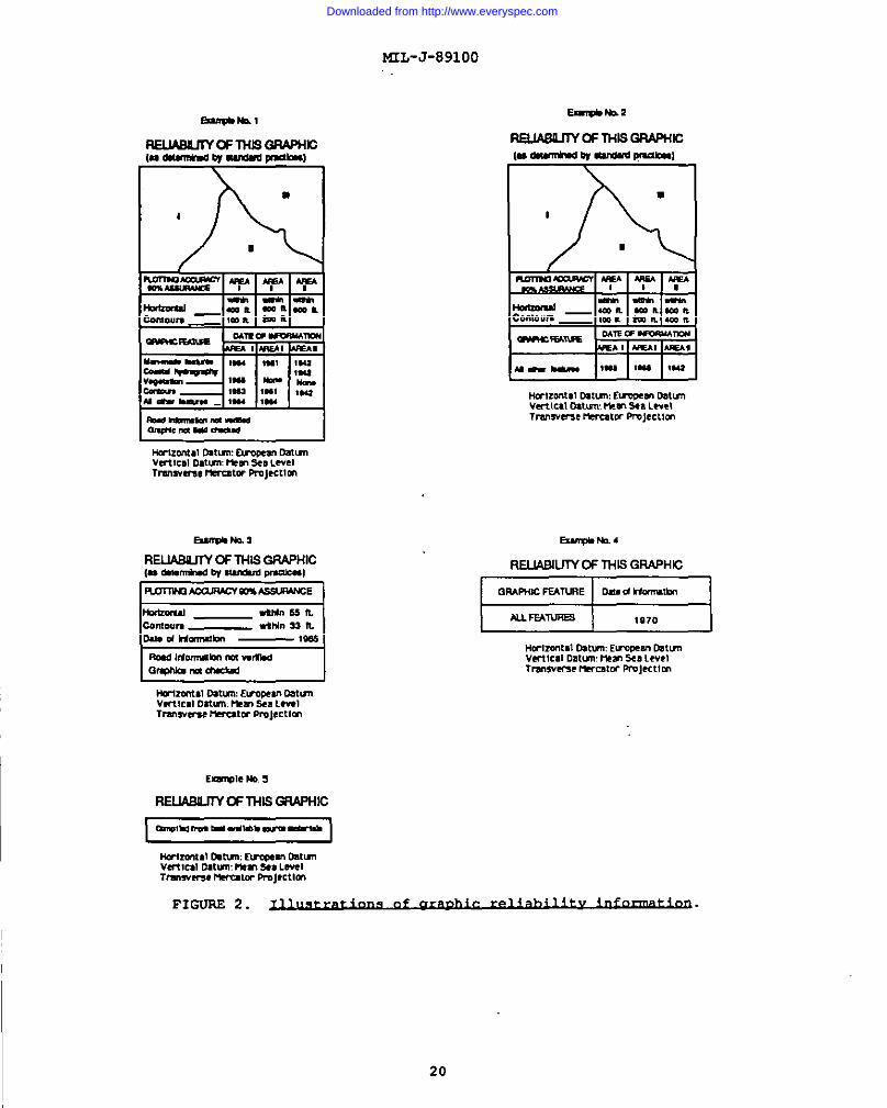
3.11.20 ~.
Each JOG shall contain a diagram which provides anindicationaof the accuracy of the individual graphic.
b. Representative illustrations of the composition ofthe diagram are contained in Figure 2; prevailing mappingcircumstances may necessitate modification.
1. Example No. 1 illustrates area of differentreliability on graphic, and a listing of individual featurecategories.
2. Example No. 2 illustrates areas of differentreliability on a graphic, and a group listings of features whensuch consolidation by category is possible.
3. Example No. 3 illustrates the circumstances whenthe reliability information is common for an entire graphic.
4. Example No. 4 is used when more specificinformation cannot be shown.
5. Example No. 5 is to be used when no informationcan be shown,
18
I
Downloaded from http://www.everyspec.com
I
c. The reliabil,
MIL-J-891OO
ty information includes:
1. Plotting accuracy. (90 Percent Assurance) ofHorizontal Positions and Contours-. A common accuracy range mayaPPIY to the entire graphic, or different ranges may apply todifferent areas of a graphic. As a maximum, three areas arerepresented for an individual graphic. When appropriate, the word“exceeds” is substituted for the word “within” (Reference Example..L) .
2. Dates of information.information is shown for the following
A date (year) of latestcategories:
(a) Man-made features.(b) Contours.(c) Coastal hydrography.(d) Vegetation.(e) All other features.
(1)
throughout a graphic, orcategory, to the maximum
(2)it cannot be determined.
A common date may apply to a categorydifferent dates may apply to the sameof three areas of a graphic.
The date for a category is omitted when
(3) When the data is the same for a group ofcategories, the individual categories are not listed.
(4) Categories not pertinent to a graphic arenot listed.
3. Pertinent notes. Notes providing informationwhich has bearing on the reliability of the graphic are included.Some prevalent notes to be shown are represented in theillustrations; other notes are included, as necessary. Datum andprojection notes are always shown below the diagram (see Figure 2) .
3.11.21 ~.
3.11.21.I ~. The National stock Number(NSN), in both bar code (left set of bars) and human readable form(HRI), is shown on each map, to uniquely identify the map in theDoD Logistics Standard Systems (DLSS). The first four digits ofthe NSN indicate the Federal Supply Classification (FSC), which is7643 for topographic and 7641 for aeronautical products . The nexttwo digits indicate the National Codification Bureau that assignedthe item identification number to the item of supply. Theremaining seven digits are a nonsignificant,serially assiqned itemidentificationshown in frontdistinguish it
nun&ers identifying-the map. The le~ters ‘NSN” areof the human readable National stock number tofrom the DNA stock number.
19
Downloaded from http://www.everyspec.com
MIL-J-891OO
REumunYoFIHBec(.—cy-p+nlka)
ml81
I
--3RELU@JW OFTHISGWPHIC(“.m9mw — -1
IRDTIW3W.UWXW%SSWU4CE I
Hm-mum mum w-opm mumVerl!ml OflmHem9.LevelTmsvuss mrutcr F’ropctlcr,
Hmzmtal mtun Elrmcan @stunVcrwal Oawm mm Sea LevelTrmsvrne llercatw PmJecL!m
GRAWKFEANRE Ommd—
u FEM-mE9 1070
HwlZOntSllllti.mEWPCWI MumVeti!cal mm mmScaLevelTmwveme rwcn:w PrOjecttm
milmltal (Mum EucCe=’1 lhtmVertlc,l Datum mm %, LevelTrar,wcme MKulu Prc+Ctlm
FIGURE2.
I 20
Downloaded from http://www.everyspec.com
MIL-J-891OO
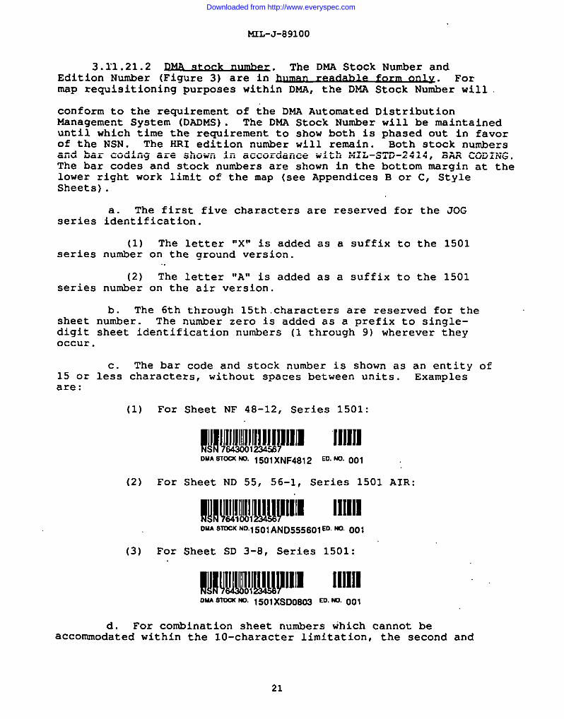
3.11.21.2 ~. TheEdition Number (Figure 3) are in hUIMXI_
DMA Stock Number and
~. FOZ~P reWisitionin9 Purposes within DMA, the DNA stock Number will
conform to the requirement of the DMA Automated DistributionManagement System (DADMS). The DMA Stock Number will be maintaineduntil which time the requirement to show both is phased out in favorof the NSN. The HRI edition number will remin. Both stock numbersand bar coding are shown in accordance with MIL-sTD-2414, BAR CODING.The bar codes and stock numbers are shown in the bottom margin at thelower right work limit of the map (ace Appendices B or C, StyleSheets) .
a. The first five characters are reserved for the JOGseries identification.
(1) The letter “X” is added as a suffix to the 1501series number on the ground version.
(2) The letter “A” is added as a suffix to the 1501series number on the air version.
b. The 6th through 15th.characters are reserved for thesheet number. The number zero is added as a prefix to single-digit sheet identification numbers (1 through 9) wherever theyoccur.
c. The bar code and stock number is shown as an entity of15 or less character, without spaces between units. Examplesare:
(1) For Sheet NF 48-12, Series 1501:
l!!!luw[Jllw~JIJJl111111DMASTH KO. 1501xNF4812ED.NO.Ool
(2) For Sheet ND 55, 56-1, Series 1501 AIR:
I!i!llM!!!wplll~111111mu STOCKNot501AND555601m.Ma001
(3) For Sheet SD 3-6, Series 1501:
OUASmu(ND,1501)(SDIJ603ED.ND.001
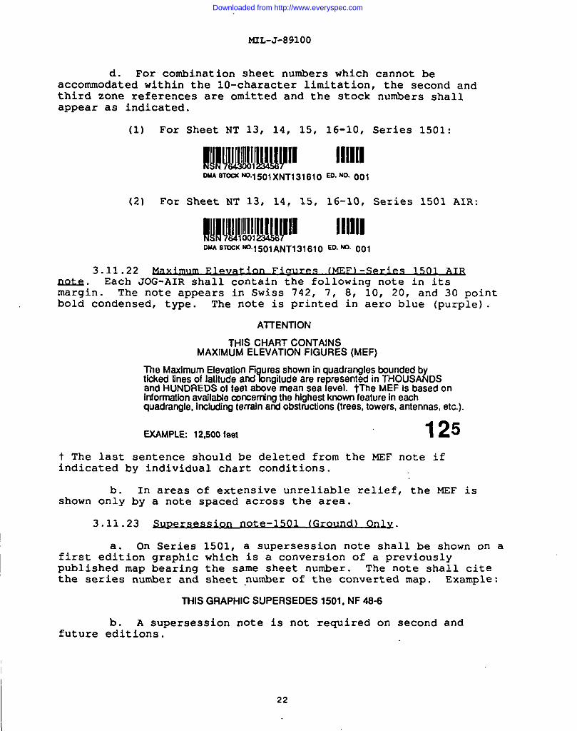
d. For combination sheet numbers which cannot beaccommodated within the 10-character limitation, the second and
21
Downloaded from http://www.everyspec.com
d. For combination
MIL-J-891OO
sheet numbers which cannot beaccommoctated w~thin the 10-character limitation, the second andthird zone references are omitted and the stock numbers shallaPPear as indicated.
(1) For Sheet NT 13, 14, 15, 16-10, Series 1501:
M!!.I!MIIW!JII1111[10UASTW4M .15 O1XNT13161O ED. NO. 001
(2) For Sheet NT 13, 14, 15, 16-10, Series 1s01 AIR:
!!!I!U!!IIIUPII 111111DUASTOCK NO.15O1ANT13161O ED. NO. 001
3.11.22 esm. Each JOG-AIR shall contain the following note in itsmargin . The note appears in Swiss 742, 7, 8, 10, 20, and 30 pointbold condensed, type. The note is printed in aero blue (purple).
AITENTION
THIS CHART CONTAINSMAXIMUM ELEVATION FIGURES (MEF)
The Maximum Elevallon Fi ureaahown inquadrangles boundedbtiokedlinesoflatitude and~ngiludeare ra resented inTHOUSA{DS
fand HUNDREDSof feel above mean sea evel. tTheMEFisbasadonInforrnationsvailable mmerningthehlghesl I(nownfeatureineachquadrangle, Irwluding terrain and obstructions (trees, towers, antennas, etc.).
EXAMPLE 12,500 fee\ 125
t The last sentence should be deleted from the MEF note ifindicated by individual chart conditions.
b. In areas of extensive unreliable relief, the MEF isshown only by a note spaced across the area.
3.11.23 te-1501 lGro~.
a. On Series 1501, a supersession note shall be shown on afirst edition graphic which is a conversion of a previouslypublished map bearing the same sheet number. The note shall citethe series number and sheet number of the converted map. Example:
future
THISGRAPHIC SUPERSEDES 1501,NF46-6
b. A supersession note is not required on second andeditions.
22
Downloaded from http://www.everyspec.com
I
mL-J-89100
c. The supersession note appears in Swiss 742, 7 pointcondensed, upper case type, and is printed in black.
3.11.24 ~. Notes regarding the reliabilityof obstruction information shall be shown on each version of theJOG . The notes shall be as follows:
a. For Series 1501A (Air):
PowerOnes are shown exos~ within populated place tints.Otherobstructions areshown Ii they are 150 feet or moresbovegroundlsvel. Seecautionnote.
b. For Series 1501 (Ground):
Poweriines are ahown except within populated place tima.Other obstructions are shown it they are 46metersormoreabove ground level. Seeosution note.
c. The following note will appear on both JOG
CAUTION
Verticalobstructions,includingpowsrlines,havsbssn sxtractedfrom ths most reliablesourcas available. However,there is noassurancethat all are shown,or that theirlocationsor heightsare exact.
products.
d. Obstruction notes appear in Swiss 7’42,7 and 12 pointcondensed, upper and lower case. The notes are printed in blue
(aero blue).
3.11.25 wy~ ‘ nti. All graphics shall contain a users’note. It shall be positioned as the last item in the center ofthe lower margin of the graphic. The note shall read:
USERSSHOULDREFER rXS3RECT10f4S,ADD~tONS, AND CKWlENTSFC4?tiROVlNG THISPROOUCTTODIRECTO~ DEFENSE MAPPING AGENCY; AllN; P~S613LEEHlGHWAY,FAIRFAX, VA. 22031-2137.
a. On JOG’s of the United States, Central, and SouthAmerica, the UR Users’ Note is not required.
b. Other national producing agencies shall add anappropriate users’ note to their JOG products.
c. The Users’ Note appears in Swiss 742, 6 pointcondensed, upper case type, and is printed in black.
3.11.26 feet conv~ The Meters-Feet(1501) and Feet-Meters (1501 - AIR) Conversion Scales are designedto permit the conversion of intermediate values by interpolation.Where space is available, the complete scales should be shown as
23
Downloaded from http://www.everyspec.com
MIL-J-891OO
indicated on the style sheets (Appendices B and C). The scale forthe 1501 - AIR series should be increased in increments of 10,000feet where necessary to include the highest elevation on thegraphic. The scale appears ‘inSwiss 742, 6 and 8 point condensed,uPPer case type, and is printed in black.
3.11.27 Where graphics are printed fromreproduction material furnished by another country under afacsimile printing agreement, a note containing the agency codeand the facsimile printing date shall be added beneath theoriginal printing note. Example:
RfJPr4nledby ....... .............. .... .......... ..DMA 4-95
a. Except for special notes, when required, no otherchanges shall be made to the margin data on the furnishedreproduction material.
b. The note shall appear in Swiss 742, 7 point lightcondensed, upper and lower case type, and is printed in black.
3.11.28 . Each JOG shall containterrain elevation notes in the margin; these notes will state thehighest known elevation, and give its location in geographic andgrid coordinates. The terrain elevation notes appear in Swiss742, 7 and 8 point condensed, upper and lower case type, and areprinted in black.
3.11.29 leae.nd. The aeronauticalsymbols legend defines and illustrates aeronautical features inthe area of coverage.
a. To the extent feasible, a standard aeronautical symbolslegend is applied to a country or region, even though all symbolsin the legend may not occur on all component graphics.
b The aeronautical symbols legend appears in Swiss 742, 7and 8 point condensed, uPper and lower case type, and is printedin blue (aero blue) .
3.11.30 ~. The air informationcurrency note states the calendar date of currency, and refers theuser to the NOTAMS and other sources for any updated information.The air information currency note appears in Swiss 742, condensedand bold condensed, 8, 10, and.12 point type, upper and lower casetype, and is printed in blue (aero blue) .
3-11.31 ~.
a. Each Series 1501 JOG contains a magnetic note patternedafter the following:
MAGNETIC DECLINATION FOR19951S1”(20 MILS)WESTERLYOVER THEENTIREAREA.
b. Each Series 1501A JOG-AIR containsa magnetic note
24
Downloaded from http://www.everyspec.com
NIL-J-891OO
patterned after the following:
LINESOFEQUAL MAGNETIC VARIATION FOR1885(anrual rate of change S’decrease).
c. The magnetic note appears in Swiss 742, 8 pointcondensed, upper and lower case type, and is printed in blue (aeroblue) .
3.11.32 ~.
a. Each Series 1501 JOG contains the following noteslocated in the margin:
ELEVATIONS IN METERS DEPTHSINMETERS
b. Each Series 1501 A (JOG-AIR) COntainS the followingnotes located in the margins:
ELEVATIONSIN FEET DEPTHSINFEET
c. The depth and elevation unit notes appear in Swiss 742,10 point, bold condensed, upper case type, and are printed inblack.
3.11.33 ~. Each JOG will containmiscellaneous notes below the lower right neatline. These noteswill clarify such things as the width of a lane, powerlineportrayal, etc. The miscellaneous notes appear in Swiss 742, 7point condensed, upper and lower case type. Notes dealing withaeronautical information are printed in blue (aero blue);road/lane information notes in red/brown; the others are printedin black.
3.11.34 Gd&bsui. Each Joint Operations Graphic willcontain a grid box in the lower left margin. The grid box shows asample 10,000 meter grid square and illustrates a sample 1,000meter reference. The Grid Box appears in Swiss 742 condensed,light condensed, and bold condensed 4, 5, 6, and 8 point type, andis printed in blue.
3.11.35 ~. Each JOG will contain a press notelocated in the bottom right margin. The press note will identifyDNA, the month and year of printing. The press note appears inSwiss 742, 7 point light condensed, upper and lower case type, andis printed in black.
3.11.36 ~. The EM% sealwill be shownon all JCG’s. SeeAppendix B or C, Style Sheets for location.
3.11.37 ~. The maP informa;;~datenote contains the year of the latest source information.reflects at least 50% or greater coverage for the sheet. The noteis placed directly under the “Prepared by” note and Is Swiss 742,8 point condensed, upper case type, and is printed in black. SeeAppendix B or C, Style sheets for location.
25
Downloaded from http://www.everyspec.com
MIL-J-891OO
3.12 Cu.ldue.
3.12.1 -. Roads shown on the JOG series must satisfystrategic and tactical operational requirements of ground users;consequently, the maximum number practicable must be shown, withclassifications based on trafficability.
a. Of prime consideration in trafficability are:construction, weatherability, width and use of the roads.
b. Where road classification data are not available and itis anticipated that such information will continue to beunavailable, the roads shall be classified on the basis of thebest logical interpretations of the source material. Theprinciples of classification described in 3.12.1.2 must be adheredto. The continuity, alignment, and situation of the roads asshown on the sources will usually govern the classifications.When conditions permit, roads between the more important populatedplaces shall normally receive the higher classification. Ifaerial photographs are available, photo interpretation will be abasis for determining road classification. When roads areclassified in this manner, an appropriately worded note shall beadded in the margin of the graphic indicating the method ofclassification. Examples are as follows:
Roads are classified from source maps.
Roads are classified from aerial photography,
3.12.1.1 ~. The roadmt shall be wellillustrated and all roads essential to the communications systemmust be included. Alternate routes are shown on a space availablebasis.
a. It is desirable to show as many connecting roads aspossible within the network formed by the main and alternateroads. If choice lies between more than one connecting road,selection shall be governed by classification, continuity,destination, and importance. The road selected shall usually bethe one which supplies the best-surfaced shortcut between pointsshown on the graphic.
b. The density of the road net will, of course, reflectand depend upon the extent of cultural development. In areas ofsparse culture, it is usually possible to show all roads. Whilemost of these should be shown, care must be exercised not tocreate an exaggerated impression of the system in the area byincluding short stretches which dead end at non-symbolized points,or less important roads which are of no significance to the users.In well-developed areas, the road net will usually be so densethat it will be impossible to show every road in the area. Inwell-developed areas, only those of primary importance to the
26
Downloaded from http://www.everyspec.com
communications system shouldclassifications will usually
mL-J-89100
be shown; roads of lowerhave to be omitted.
3.12.1.2 ~.
a. When multiple categories are in question, use thelowest.
b. A road is to be classified according to the predominateclassification.
c. The number of lanes is a controlling factor in roadclassification in certain cases. Where definite information fromauthoritative sources exist as to the number of lanes of roads, itshall be accepted. In considering road widths, only the traveledroadway shall be noted; ditch limits and right-of-way limits shallbe disregarded.
d. Basic road widths used for classification purposesshall be shown in the legend.
3.12.1.3 ~. In plotting roads fromsources of much smaller scale or heterogeneous nature, it issometimes impossible to plot a road in its correct position. Thepoint of change in accuracy of alignment shall be indicated.Appropriate labelinq shall be added on each side of the point.E~~mpies:
3.12.1.4Selected roads
Ih.rouah routes and Sheets wiLhin Dormla.tedDla!=a.and streets shall be included within populated
places which are shown by a plotted outline.
The number of roads to be shown within an outlinedpopulate~ place is dependent on the size of the area:and on thenumber of roads entering the area.
b. Streets in outlined populated places will be shown by astandard road casing symbol within the outlined built-up area.The built-up area tint is omitted from the street symbol.
c. Through roads receiving preference with a connectingnetwork of other roads is shown on a space available basis.
d. Selected through routes shall be shown at the sameclassification as the road within the outlined built-up area.
road
3.12.1.5 ~.
27
Downloaded from http://www.everyspec.com
t.5L-J-89100
a. Roads under construction are defined as new roads onwhich actual construction work haa been initiated and which aredefinitely closed to traffic.
1. Roads under repair shall not be regarded as underconstruction and shall receive normal treatment.
2. Proposed roads shall not be considered as roads underConstruction and shall not be symbolized.
3. If work on a road under construction is nearly completeand it is probable that it will be completed by the time the graphicis published, or within a reasonable time thereafter, the road shallbe given the symbolization of a completed road.
b. Roads under construction shall be indicated by the labelCONSTRUCTION or CONSTR added parallel to the symbol. A short tick(point of change symbol) shall mark the beginning and end of the partof road under construction. The classification of the road whencompleted shall be indicated if the information is available.
3.12.1.6 ~.
a. When the number of lanes along a particular stretch ofroad exceeds two (2), the condition shall be indicated by labeling.
b. Lane information shall be omitted from outlined populatedplaces (Built-up areas) .
c. A tick (point of change symbol) placed at right angles tothe road shall mark the point of change in the number of lanes of anyroad. Labeling identifying the number of lanes”shall always beplaced adjacent to such ticks or, in short stretches, centeredbetween the ticks.
d. If a road leaving a populated area is more than two laneswide, it will not be necessary to add a tick at the point of exitfrom the populated area; the labeling will be considered sufficient.
e. When definite information from an authoritative sourceexists specifying the number of lanes, the information shall be used.When no specific lane information exists, the width of a lane shallgenerally be considered as approximately 2.5 meters (8 feet).
f. In classifying a road as to the number of lanes, if ashort stretch of road less than approximately 12.70 mm in length hasa number of lanes more or less than the rest of the roadway, thevariation in width shall be disregarded. If such a stretch isapproximately 12.70 mm or more in length, the stretch shall beclassified as a unit in itself, independent from the rest of theroadway.
28
Downloaded from http://www.everyspec.com
MIL-J-891OO
9. When a stretch of a road is made up of several shortsections (each less than approximately 12J70 mm in length) which varyin the number of lanes of its narrowest part.
3-12.1.7 ~.
a. Dual lane (divided) highways are hard surface, allweather roads separated by a parkway, median, or barrier between thetwo directions of travel. They shall be treated as described in3.12.1.6 above. In addition, the word DUAL shall be added parallelto the road at fairly frequent intervals to explain the condition.The point of change symbol shall be added at points of change betweendual and other multiple-lane highways.
b. Where scale permits, correct positioning of both sidesof a dual highway shall be shown. Each side shall be treated as anindividual unit.
“3.12.1.8 ~. Road names can be added when spacepermits their inclusion. The accepted names of Important arterialhighways shall be added parallel to the road symbol. Names should beapplied to main trails in areas of sparse culture.
3.12.1.9 ~. Only officially accepted route numberidentifications shall label the roads. Route numbers shall be shownfor international, national and secondary roads. The latter includeroads whose maintenance usually is under the jurisdiction of states,provinces, prefectures, and similar primary administrative politicaldivisions. In many countries, no route number identifications areused; in others, only national routes are identified; in otherregions, as in Central Europe, international routes are Identified.
a. Route number symbols shall be oriented with the southor bottom neatline of the map sheet. The symbols shall usuallyaPPear centered on the roads. If this placement is impossible inareas of heavy culture, the symbol may appear adjacent to the road ina clear area.
b. Careful attention must be given to the location of theroute numbers since ready identification of all roads is required.
(1) Route numbers should be added as close to theinside of the neatline as practicable on all roads intersecting theneatline.
(2) Route numbers shall be shown for all suchdesignated roads leaving larqe populated areas and shall bepositioned as close
(3)important junctions
to ~he n=atii;e as the feature will permit.
Route numbers shall clearly identify roadsand intersections.
at
29
Downloaded from http://www.everyspec.com

MIL-J-891OO
(4) On roads which cover long stretches, routenumbers should be repeated at intervals Sufficiently frequent toinsure easy identification of the road in question.
(5) When roads are combination routee, each routenumber shall be shown by its own separate symbol, where practicable.
(6) Where it is impossible to include all routenumbers, preference shall be given to international and nationalroutea.
a. The south and west borders shall include as many roadobjectives for major through roads as practical without sacrificingthe appearance of the qraphic. A profusion of objectives is bothunsigfi~lyand minimize: tie significance of this ~nformation. Theclassification of roads and the relative importance of destinationsshall be the criteria in selecting objectives to be shown.
b. In areas of sparse culture, it may sometimes be feasible,to show objectives for roads of lower classifications and, in somecases, even for trails; these should be held to a minimum and shownonly when the feature is an important traveled way.
c. A road objective shall consist of the destination, thedistance thereto, and an arrow. The distances shall always beexpressed in kilometers, regardless of the native unit of measure inthe area being mapped.
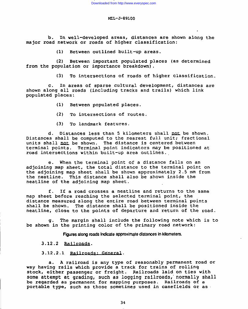
(1) The destination and kilometer distance shall appear onone line and be positioned as close as possible to the neatline as inFigure 3, with proper space being allowed for the grid numbers.Where possible, the labeling should be centered adjacent to thearrowhead.
FIGUFUI 3.
(2) If two roads
--’-r-’Purcellville6km
~.
have the same objective and are within ashort distance apart at the neatline, an arrow shall be shown foreach road and the same note, spaced to embrace both arrowa, used forboth roads.
d. Destinations may be either on the adjacent sheet or,where a road cuts across the corner of an adjacent sheet to an
30
Downloaded from http://www.everyspec.com
I
objectivecorner of
e.
on an adjoiningthe sheet being
MrL-J-89100
sheet’and whosemapped.
corner touches the
Designation of destination will be as follows:
(1) The designation shall usually be the next importantpopulated place.
(2) If a road terminated at another road which isidentified by a route number, the number of the route shall bedesignated. The designation shall be written out; some examples:
FRANCEHV. NO.90 VENEZUELAHY.NO. 3
f. The distance to an objective shall be given to thenearest kilometer.
(1) Kilometer and kilometers shall be abbreviated as km(lower case). .
(2) In figuring distance to a town, the center of thetown shall be regarded as the point of destination.
3.12.1.11
a. All weather, hard surface roads are roads that designedto bear, as a minimum, fairly heavy military loads in all weather.Minimum maintenance requirements are periodical inspection andrepair. The construction of these roads is usually concrete orbituminous macadam.
b. All weather, loose or light surface roads are roadswhich are designed to bear light military loads in all weather.Construction is on light foundation and is usually gravel or stonesurface, or of some stable material, such as selected sand-clay,treated oil gravel, or light tar-bound macadam. The roads aregenerally drained and graded. Periodical maintenance is required.
c. Fair or dry weather, loose surface roads are roadswhich are designed to bear light military loads in fair or dryweather. The structure is usually gravel or sand-clay with pooror no foundation. The road is sometimes drained or graded.Continual maintenance is required.
1. Dirt roads. These are generally suitable only forlight military loads in dry weather. They are sometimes gradedbut are always without surface improvement.
2. Private roads. Regardless of surface improvement,private roads shall be included within this category. Privateroads are defined as those which are maintained by private orneighborhood funds and are not generally open to theroads shall generally be omitted from the map unlesspoints of definite strategic importance.
31
public . Suchthey lead to
Downloaded from http://www.everyspec.com
MrL-J-89100
3. Abandoned roads. When shown, abandoned roads shallbe included within this category unless definite information isavailable that they should be upgraded or downgraded. ?uIabandoned road is one which is no longer used by regular trafficand is no longer maintained. Generally, it is replaced by a newerroad of better construction and straighter alignment. Usually,such roads shall be omitted unless they lead to points of definitestrategic or landmark importance.
4. Fire roads. When fire roads are shown on the map,they will be included in this category. These are defined asroads going through wooded areas and whose entrances are generallyblocked off from public travel. They shall be shown only in areasof sparse culture, provided they are of definite strategic orlandmark value.
5. Lumber and Wood roads. Lumber and Wood roads shallbe included within this category but shall not be shown unlessthey are definitely of strategic importance in the area.
6. Corduroy roads. These and similar roads shall beincluded within this category but shall be shown only when ofdefinite strategic importance. The symbol shall be labeled withCORDUROY. Short stretches of corduroy roads shall not be labeled.
d. Cart tracts.
1. Generally, included in this category are importantcaravan routes, winter roads, natural roadways capable of bearingwheeled vehicles, and tracks which are jeepable, exclusive ofroads.
(a) Important caravan routes shall be identified byname and desi nation added parallel to the symbol, for example:G081CARAVANRO%E.
(b) Winter roads shall be identified by the labelWINTERROAD added parallel to the symbol.
2. Generally, minor tracts shall be omitted. When thes@ol follows the top of a levee, it shall be omitted when thelevee is symbolized.
e. Footpaths, Trails.
1. Generally included in this category are importantfootpaths, foot trails, and pack trails. Minor trails and shortconnecting trails shali gene~ally be omitted. When the symbolfollows the top of a levee, it shall be omitted when the levee iSsymbolized.
2. In certain regions, a classification distinctionbetween tracks and trails may K@. be feasible. In such
32
Downloaded from http://www.everyspec.com
MIL-J-891OO
circumstances, both routes shall be represented as tracts. TheLegend terminology shall be revised to read: Track or Trail.
3.12.1.12
~.
a. A classification distinction between primary andsecondary roads is required for both versions of the JOG in areaswhere the majority of the roads are hard surface.
1. This classification distinction is in addition tothe road classification guidance given in 3.12.1.11.
2. Except for dual lane highways, this classificationdistinction shall be applied to hard surface roads only.
b. Primary roads are those hard surface roads which are ofbasic importance to the existing road network. Primary importancemay be determined on a country or on a geographic regional basis,whichever is most practical.
1. The selection of primary roads shall not beinfluenced by the river or rail transportation system, nor theexistence of dual lane highways. The most direct route is notnecessarily the primary route.
2. When selecting a primary route, consideration shallbe given to such factors as: current usage, continuity, capacity,width, and objectives incurred along the route or at its terminus.
3.12.1.13 w ln+-~pq [~’s) on umi*f=~—.=ux2aS
LQadS.
a. A limited-access road is an express highway (e.g., theAutobahn or the Pennsylvania Turnpike) which is independent of thegeneral road system and to which entrance and departure arerestricted to certain (limited) access points (cloverleaffs or thelike). These access points are identified as road interchanges inthese specifications.
b. In addition to being essential for planning vehicularmovement, road interchanges along limited-access highways areexcellent points of reference for air users. In view of theirimportance, limited-access points (Cloverleaf’s, etc.) shall beplotted as accurately as the map scale permits.
3.12.1.14
a. Distances between selected populated places, roadintersections, road and railroad intersections, shall be shown.Distances shall be expressed in terms of kilometers, regardless ofthe native unit of measure in the area being mapped. The numberof distances to be shown is dependent on the cultural developmentof the area under consideration.
I 33
Downloaded from http://www.everyspec.com
MIL-J-891OO
b. In well-developed areas, distances are shown along themajor road network or roads of higher classification:
(1) Between outlined built-up areas.
(2) Between important populated places (aS determinedfrom the population or importance breakdown) ,
(3) To intersections of roads of higher classification.
c. In areas of sparse cultural development, distances areshown along all roads (including tracks and trails) which linkpopulated places:
(1) Between populated places.
(2) To intersections of routes.
(3) To landmark features.
d. Distances less than 5 kilometers shall DS& be shown.Distances shall be computed to the nearest full unit; fractionalunitS shall DC& be shown. The distance is centered betweenterminal points. Terminal point indicators may be positioned atroad intersections within built-up area outlines.
e. When the terminal point of a distance falls on anadjoining map sheet, the total distance to the terminal point onthe adjoining map sheet shall be shown approximately 2.5 mm fromthe neatline. This distance shall also be shown inside theneatline of the adjoining map sheet.
f. If a road crosses a neatline and returns to the samemap sheet before reaching the selected terminal point, thedistance measured along the entire road between terminal pointsshall be shown. The distance shall be positioned inside theneatline, close to the points of departure and return of the road.
9. The margin shall include the following note which is tobe shown in the printing color of the primary road network:
Flguresalo~roadalndLcase approximaledistances Inkibmelera.
3.12.2 &ilLQMQ.
3.12.2.1
a. A railroad is any type of reasonably permanent road orway having rails which provide a track for trains of rollingstock, either passenger or freight. Railroads laid on ties withsome attempt at grading, such as logging railroads,”normally shallbe regarded as permanent for mapping purposes. Railroads of aportable type, such as those sometimes used in canefields or as
34
I
Downloaded from http://www.everyspec.com
laL-J-89100
spurs at-a strip mine, shall be regarded as temporary and omittedfrom the map.
b. Main line is a track which is part of a continuoustransportation net.
c. Branch line is a feeder track off the main line.
d. Spur tracks are tracks other than a main or branchtrack, intended for passing, storage, and the loading or unloadingof passengers or freight. Sidings are included in this category.
e. The gauge of tracks is based on the width as measuredbetwean the heads of the rails at right angles thereto and at apoint 15.90 mm below the top of the rail.
f. A normal gauge railroad is the gauge that is used onthe majority of the main line railroads of a country.
..
9. Broad gauge railroads are those which the gauge isgreater than the normal gauge used in a country.
h. Narrow gauge railroads are those which are less thanthe normal gauge used in a country.
i. Standard gauge is 1.44 meters.
j. Single track railroads are one track used by trainstraveling in either direction.
k. Double track railroads are two parallel tracks of thesame line, designed to carry trains in opposite directions.
1. Multiple tracks are three or more parallel tracks ofthe same railroad.
m. An operating railroad is one which is in’,regularuse.
n. Non operating railroads are those railroads not in use.Included in this category are railroads under construction,abandoned railroads, and destroyed railroads.
(1) An under construction railroad is a new line ortrack upon which actual construction work has been started.
(2) An abandoned railroad is a non operating railroadwhose ballast, tracks, and bridges remain in place entirely, or inmajor part, and which could with a reasonable minimum of repair,be put into at least limited use.
(3) Destroyed railroads are those which are destroyedin part, either as the result of military operations or of naturalcatastrophe, but whose ballast, tracks, and bridges remain inplace entirely or, in major part, and which could with a
35
Downloaded from http://www.everyspec.com
ML-J-891OO
reasonable minimum repair, be put into at least limited use. Thedistinction between abandoned and destroyed railroads is thatabandoned railroads will probably be repairedoperation.
o. Dismantled railroads are those nowhich have had the major part of their tracksOften, the only visible evidence is a more orway.
and put into
longer in use andand bridges removed.less clear right-of-
P. Railroads in juxtaposition. Two railroads of differentownership which run closely parallel to one another and generally,are on the same right-of-way.
3.12.2.2 ~. Adistimtion shall be madebetween railroads as to gauge, number of tracks, and whether theyare in use
a.
b.I be omitted
or not.
All main line railroads shall be shown.
Branch lines and spur tracks of less than 5.10 mm shallunless thev terminate at a symbolized populated Place
i
or exist in an area 02 sparse culture. -
c. A distinction shall be made between railroads as to:
(1) Gauge.
(2) Number of tracks.
(3) Whether they are in use or not.
d. Railroads within populated places shall be treated thesame as railroads in open country.
3.12.2.3 ~.
a. Gauge classification shall be fixed on a country-by-country basis and not a sheet basis. Thus, it will be possible tohave a sheet containing portions of more than one country whichshows a 1.44 meter (4 ft 8-1/2 in) railroad a’snormal gauge in onecountry and which shows the same railroad in another country asnarrow gauge.
b. No distinction shall be made in basic symbolizationbetween normal and broad gauge railroads, except for the additionof the “broad” label. All gauges must be indicated on the graphicand shall be based on the majority of the common carrier railroadsin the country.
(1) If all the main and branch line railroads shown bya common symbol are of the same gauge, a note shall be added in
36
Downloaded from http://www.everyspec.com
mL-J-89100
the margin of the graphic to that effect, together with a notationof the gauge measurement; for example:
AUrailroadaexc.ept narrowgsugerailroads arel.44metem.
(2) If the gauges vary, they shall be included eitherby labeling added parallel to individual lines or by a marginalnote if the latter means is sufficiently comprehensive. hexample of a marginal note in such cases would be:
Wdhtheexoeptlo nofnanow augerailroads, allrailroads in Russia andthe Comnmnwealthr!?oflndepandentstatesarel. 2matergaugeandthoseinPolatiarel.44metergauge.
c. Where the gauge measurement of all narrow gaugerailroads on the sheet is the same, an appropriate note shall beadded in the margin of the graphic; for eXaMple:
All narrow gauge railroads are 1-meter gauge...
d. When a narrow gauge railroad occurs on the same roadbedwith a broad or normal gauge railroad, only the wider gaugerailroad shall be symbolized. The narrow gauge railroad shall beshown entering and leaving the wider gauge railroad. If thecoincidence occurs over a long stretch, labeling (properlyidentifying the gauge measurement of the narrow gauge railroad)shall be added parallel to the symbol, reading for example:
I-matergauge railroad onsameroadbed.
The point of change in gauge of railroads shall beindicate;”. The gauge identifications shall be added adjacent tothe symbol parallel to the railroad symbol.
3.12.2.4 ~.
A distinction in symbolization is to be made betweensingle-t;~ck railroads and those of more track (double andmultiple track) .
b. Where the number of tracks of a railroad exceeds two,the information shall be shown by labeling added parallel to therailroad symbol at appropriate intervals.
c. The point of change in number of tracks of a multiple-track line shall be indicated.
d. Sidings which are closely parallel to a main lineshall, if shown, be symbolized as sidings and shall not be countedin determining double-track or multiple-track lines.
37
Downloaded from http://www.everyspec.com
MIL-J-891OO
3.12.2 .-5 ~.
a. No distinction in symbolization shall be made betweentypes of non-operating railroads. Distinction, however, shall bemaintained by adding appropriate labeling, parallel to therailroad symbol as follows:
ASANDONED DESTROYED CONSTRUCTON
b. A proposed line does not come within the meaning of thedefinition of railroads under construction and shall not be shown.
c. Any part of a destroyed railroad under repair, or of arailroad under construction which is sufficiently finished to bein use,,shall be regarded as in operation.
d. Operational railroads will include those which arenearly complete though under construction or repair.
e: Lines undergoing repairs which make the railroadinoperative for a short time shall not be regarded as underconstruction and shall receive their usual symbolization.
f. Cases will be encountered where an operating line willhave an additional track or tracks under construction. Thefeature shall be shown by the appropriate symbol for the operationlinewith appropriate labeling indicating the trackage underconstruction added to the symbol; for example:
Htbndtfe*under ccmstnlclbn
Two addiikmal tracks urder consJuction
3.12.2.6 ~.
If the right-of way of a dismantled railroad is beingused as ~“road, it shall be symbolized by the proper road symbol.
b. If there is no road and the feature is of sufficientprominence and importance to serve ae a landmark, it shall besymbolized by the trail symbol. If space permits, labeling shallbe added parallel to the trail symbol reading: Dismantled railroad
3.12.2.7
a. Spur tracks and sidings shall be shown only when theyhave some particular significance, such ae landmark value, orterminate at a symbolized place. In sparsely settled areas,sidings are landmarks, often named, and ehould be shown whereverpossible.
38
Downloaded from http://www.everyspec.com
mL-J-89100
b. Where sidings are short, the crossties may be omittedand, if necessary, the sidings may be slightly exaggerated.
c. Spur tracks and sidings shall be shown as entering themain line in a smooth curve.
d. When the distance between the main line track symboland a parallel siding symbol is too small to portray, the sidingmay be displaced .25 mm from the main track.
3.12.2.8 ~. men two railroads arein juxtaposition, each shall receive its normal symbolization, butthe condition shall be emphasized by staggering tiiecrossties ofthe parallel symbols.
3.12.2.9 ~. Electrified railroads areidentified by unique symbol where two dots are positioned over thetop of the crosstie, each successive pair placed over alternatingcrossties.
3.12.2.1o ~. Railroadswithin populated places shall be treated and symbolized the sameas railroads in open country.
3.12.2.11 ~.
a. The words “Railroad, Railway, Company, Line, System”,and similar terms and abbreviations of these terms shall not beincluded with a name unless the term is a necessary part of thename, as in the case of CentreiR~”fmadofNewJereey.
b. When names are shown, they shallnot be abbreviatedexcept in veryfull name. Inused.
3.12.2.12
congested areas w“here‘it is impossible to carry thesuch cases, only official abbreviations shall be
~.
a. Treatments for bridges, viaducts, causeways, gradecrossings, overpasses, and-underpasses are prescribed in3.12.13.1.
b. Treatments for cuts, fills,3.14.8.
and levees are contained in
3.12.3 ~.
a. Railroad stations shall be shown in areas of sparse”culture. If a railroad station appears with a group of buildings,the buildings and station shall be indicated by the properpopulated place symbol. In areas where railroads are theprincipal means of transportation, railroad stations assumegreater importance and, consequently, more shall be shown; inthese areas, railroad stations may be shown in developed areas.
39
Downloaded from http://www.everyspec.com
MTL-J-891OO
b. When information is available, an isolated or remoterailroad station shall be located in ita correct position relativeto the railroad track. A slight exaggeration in scale ispermissible to achieve this,
c. When the exact location of a railroad station isunknown, it shall be symbolized with the unknown station symbol,placing the symbol straddling the railroad track, at theapproximate location.
d. FlagStops, halts, and similar stops without buildingsshall not be shown.
3.12.4 ~.
a. Selection of Interurban car lines. Interurban carlines, whether or not in operation, shall be shown when they serveas landmarks in open areas or if they are important to theintegrated communications system of an area. All of the samecriterion as specified for railroads applies to Interurban carlines.
b.interurbansymbolized
c.
meaning of
Gauge and tracks. No distinction shall be made betweencar lines as to qauqe or number of tracks; all shall be. .alike.
Non-operating car lines.
(1) A proposed car line does not come within thethe definition of car lines under construction, and
shall not be shown,
(2) If the work on a car line under construction ora destroyed car line under repair is nearly complete and it isprobable that it will be completed by the time the map ispublished, or within a reasonable time thereafter, the featureshall be symbolized as a line in operation.
(3) Lines undergoing repairs which make the car linetemporarily inoperative shall not be regarded as under
I
construction and shall receive their usual
d. Dismantled car line. The sameaPPlieS to dismantled except for the labelreads as follows: Dismantledcar line
e. Car line stops or stations are
symbolization.
criterion as railroadfor this condition
omitted from the map.
3.12’.5 ~. Railroad yards (freight, marshaling,etc.) shall be shown. The correct shape of the yards shall beretained insofar as practicable. No attempt shall be made to showall tracks.
40
Downloaded from http://www.everyspec.com
MIL-J-891OO
3.12.6 ~. Railroad snowsheds provideexcellent landmarks and shall be shown wherever they exist.
3.12.7 eq. ski U*-. conv~. Included In this category are linear features otherthan railroads or car lines whose functions Is the transportationof people or material. Usually, these features are suspendedabove the ground level. The importance of these features, inaddition to landmark value, is their potential hazard to aircraftoperations.
3.12.8~. Special treatments are required when railroads,Interurban car lines, aerial cableways, or similar featurealignments are less reliable than the plotted positions of othercultural features within the area. The point of change Inaccuracy of alignment shall be indicated as shown In Figure 4.
ACCUIAIE ALGNMCNr 1.AP?EOXIMA1t ALIGNMENr
I APFUMMA1[ ALIONMIN1 1.AIIGNMFN1 UNKNOWN
FIGIJRs4. t of Cbng$? for
a. Populated places are portrayed to meet both ground andair operational requirements. In addition to facilitating therapid determination of size, shape, and through-passagecapacities, they also convey the nature of the area from theviewpoint of cultural development.
b. The term populated place Is interpreted to include:cities, towns, villages, settlements, industrial and.militaryareas, resort areas, and communal farms. Populated places mayvary in size from an extensive megalopolis to a small hamlet. Theterm applies to developed areas where more than one family orfamily group lives as a community and does not apply to individualfarms, homesteads, or dwellings.
3.12.9.1 Thegeneral requirement is to show all populated places; however, Indensely populated areas, it will not always be possible to do this“and still produce a legible product. In such cases, the optimumamount Is shown; some of the smaller, less important places mustbe omitted by hierarchical order to retain a balance with othermore important map detail. When populated places are so dense
41
Downloaded from http://www.everyspec.com
NIL-J-891OO
that some have to be omitted, the selection is based on thefollowing:
a. The populated places which are to be symbolized by anoutline are always retained.
b. Populated places which are classified in the highercategories (based on either population or importance) are givenpreference over those in the lower categories.
c. Larger populated places are selected over smaller onesof the same classification.
d. Populated places along the primary routes ofcommunication are given preference over those along adjacentsecondary roads.
e. Populated places located at”road junctions are givenpreference over adjacent ones of a similar size not at roadjunctions.
3.12.9.2 ~.
a. The determination of the limits for the built-up areadepends on the source material and the cartographers judgment. Anyopenings (clear areas) within the outline shall be shown when theminimum clearing size is 2.5 nunby 2.5 mm.
b. The outline should include all buildings that are partof the contiguous pattern. Outlying scattered buildings shall notbe included within the outline, and unless they are landmarks theyshall not be symbolized.
c. Suburbs and other concentrated building developmentsshall be treated as individual populated places and symbolized bybuilt-up outlines or town circles, as applicable. ‘.
d. The limits of the built-up area bear no relationship topolitic-alor administrative boundaries.
e. The distinguishing characteristics of the street ‘pattern should be shown within the populated place outline.
f. Narrow strips of development, such as a single row ofbuildings extending along each side of a road, are not includedwithin the populated place outline.
9. When two or more populated place outlines merge, theyshall be enclosed in a common outline; the dividing lines areomitted.
42
~---— ----:
Downloaded from http://www.everyspec.com
h. Town circles
MIL-J-891OO
shall be used for those DODUlated Dlaceswhich do not meet the requirements for the popula”te”dplace -outline.
(1) Populated places indicated on map sources are to beportrayed when populated places do not meet the area sizerequirements of an outlined area.
(2) Developments made up of singlestrung out on one or both sides of a route ofinclude streams and canals) are shown by this
row of buildingscommunication (tosymbol and not as a
+
A1.d.h.‘
54.*
h...
i ,50,& 1:250,000
FIGURS5. ~em$=.t of ~.
built-up area outline. The circle is positioned over, wheneverpossible, at the center of the village as shown in Figure 5 andpreferably at the junction of the routes of communication.
(3) The relationship between symbolized populatedplaces and transportation routes shall be maintained. Thus, atown circle will not necessarily be positioned along the nearesttransportation route or intersection.
3.12.9.3 of The relativeimportance of populated places shall be determined from a regionalaspect. Symbolized populated places shall be classified inaccordance with five categories which are to be determined asfollows:
a. When complete and up-to-date population figures areavailable, they shall serve as the basis of the five categories.The detailed division into categories by population shall varyfrom region to region.
b. The breakdown of populated places arrived at on such apopulation basis shall always be scrutinized with a view toupgrading those that have enhanced importance by reason of beingadministrative centers, junction of important roads, rail centers,or of having any other significant value to the military user.
When population figures are not available, areincomple~~, or are significantly out-of-date, the size ofs@olization on source material shall be taken as a guide toproducing a basic classification, but the provisions of 3.12.9.3.babove shall then be given paramount importance.
I 43
Downloaded from http://www.everyspec.com
mL-J-89100
d. The classification of populated places shall be shownon the graphic by appropriate type and style. When a map containsonly towns of fifth importance or less, a note shall be added tothe margin in the notes column to read: Alltewnsarefiflhdassorlewer.
e. An example of population breakdown and the relativeImportance breakdown equivalent In a culturally developed areawould be:
1st Class - more than 500,000 or 1st importance.
2nd Class - 50,000 to 500,000 or 2nd importance.
3rd Class - 10,000 to less than 50,000 or 3rd importance.
4th Class - 5,000 to less than 10,000 or 4th importance.
5th Class - less than 5,000 or 5th importance.
f. An example of population breakdown and the relativeimportance breakdow-nequiv-al-entIn a area not yet well developedculturally would be:
1st Class - more than 500,000 or 1st importance.
2nd Class - S0,000 to 500,000 or 2nd importance.
3rd Class - 10,000 to less than 50,000 or 3rd Importance.
4th Class - 2,000 to less than 10,000 or 4th Importance.
5th Class - less than 2,000 or 5th Importance.
3.12.9.4 ~. Names of populated placesof fifth importance shall be included on the 1501 JOG AIR product,except where they conflict with the display of aeronautical,. . .Intormatlon or otnerwise clutter tne cnart. in areas or chartclutter, names of populated places of fifth importance shall bethinned only after attempted repositioning of the name can notresult in chart clarity.
3.12.10 ~.
a. Walls surrounding cities or parts of cities which aresymbolized by an outline (built-up area outline) and shall beindicated by a heavy line (wall symbol) with the word (wallsd)addedin parentheses below the place name.
b. When a wall coincides with the limiting outline of adeveloped area, only the wall symbol shall be shown.
c. Walls occurring within or around populated places whichare not symbolized by an outline shall not be symbolized; it will
44
Downloaded from http://www.everyspec.com
MIL-J-891OO
be sufficient to add the word (waked)in parentheses below the placename.
3.12.11 ~. Continuous habitationareas include widespread areas of huts and native settlements withpoorly defined limits.
The outline shall contain a color tint which is a 21percent ~&een of the color fill specified for an outlined built-UP area.
b. The feature shall be represented by a black outlinewhich defines its limits.
c. Within larger outlines, through routes shall be shownin the same manner specified for outlined built-up areas.
d. Through routes shall be shown withinareas. They will be shown in the same manner asareas.
e. Street patterns shall be shown, when
the outlinedoutlined built-up
feasible.
3.12.12 clor d~ .
a. Ruined, destroyed, and partially destroyed populatedplaces shall not receive any special symbolization; The limits orextent of rUin or destruction shall not be indicated. Such placesshall be depicted, when practical, as they existed prior todestruction, and shall be routinely symbolized.
b. The symbolized places shall be augmented by explanatorylabeling enclosed in parentheses; the preferred labeling shall bepositioned below the place name, as: (Ruinsd),(Destmysd),(Psrlialtjdestroyed),etc. The term “Partially destroyed” shall be interpreted to meandestruction which comprises less than 75 percent of the developedarea.
c. If rehabilitation or reconstruction is evident, theexplanatory labeling is omitted.
3.12.13 ~. The term culturalfeatures as used in this section refers to those features on theterrain which are the result of the work of man. Excepted arepopulated places, roads, railroads and related features.
3.12.13.1 ~.
3.12.13.1.1 ~. All bridv=s that thescale will permit shall be shown, except in those cases where theshowing of bridges would result in the elimination of a moreimportant feature.
45
Downloaded from http://www.everyspec.com
MIL-J-891OO
3.12.13.1.2 ~.
a. Because most bridge symbols are truly symbolic,exaggeration of length is usually necessary (and permissible) inorder to properly accentuate the feature.
b. Where the true length of a bridge is unknown,exaggeration may be re’quiredto portray bridges crossing globulinstreams and open water areas.
Viaducts are to be delineated in the same manner asbridges.c
d. No shorelines shall be added along the causeway toaugment the symbol, unless the distance between the twoshorelines, when plotted to scale, exceeds the width of the roador railroad symbols.
3.12.13.2Overpasses and underpasses shall be shown wherever possible.
3.12.13.2.1
a. For purposes of symbolization a bridge symbol shall beplaced on the overpassing feature.
b. In instances where crossings occur at more than twolevels, they shall be symbolized accordingly, adhering to theabove principles.
c. No special treatments are required for grade crossings.The symbol for each crossing feature shall be continued unbrokenacross the symbol for the other.
3.12.13.3 IUXKQ.S. Tunnels for highways and railroads shallbe shown wherever they exist. Tunnels less than minimum length atmap scale shall be exaggerated.
3.12.13.4 ~.
a. Ferries capable of accommodating vehicular or railroadtraffic shall be shown in all instances.
b. A ferry shall be regarded as such only where it is anestablished feature regularly in operation for transportingtraffic between two points on opposite sides of a stream, river,bay, sound or lake. The landings need not necessarily be directlyoPPosite one another.
c. When steamship routes along coasts, in bays, and uprivers are the main routes of communication, they shall beregarded as ferries.
46
Downloaded from http://www.everyspec.com
MIL-J-891OO
3.12.13.5 ~. Fords for roadsthey exist.
3.12.13.6 ~.
shall be shown wherever
Strip mines and quarries shall be treated as directedin 3.14.~~16.
b. No distinction in symbolization shall be made betweenvertical shafts and mine tunnels. Both shall be commonlysymbolized. If information is available, the nature of themineral mined shall be indicated by labelinq adiacent to thesymbol .
3.12.13.7 ~,
Wells drilled for gas, oil, or minerals shall be shownif they ~~e In operation and of landmark importance in areas ofsparse culture. ~
b. Abandoned wells shall be shown only when sufficientinstallations remain to make the feature a landmark.
Wells drilled or dug for water shall be treated asdirectedc~n 3.13.16.
3.12.13.8 u.
a. Tanks used for the storage of oil, gas, water or otherliquids shall be shown wherever they exist as landmarks in areasof sparse culture. They shall also be shown in other areas wheretheir portrayal does not conflict with the portrayal of othercultural features.
b. Open reservoirs, used for the storage of asphalt, oil,or other liquids except water, shall be shown if of landmarknature.
3.12.13.9 ~. pipelines for gas, oil, andsimilar liquids, whether above or below ground, shall be shownonly when they serve as landmarks in areas of sparse or moderateculture.
a. Only those uiDelines which are obvious on aerialphotographs, ob-viousf~om-inspection on the ground, or which areclearly defined on source maps shall be shown. Undergroundpipelines may be obvious from cleared right-of-ways, ground scars,or levee-like mounds.
1 b. No effort shall be made to show pipelines as continuousfeatures only landmark portions shall be shown.
I 47
Downloaded from http://www.everyspec.com
MIL-J-891OO
3.12.13.10 u. No distinction in symbolization shall bemade between masonry dams and earthen dams or dams constructed of
I other materials.
3.12.13.11 ~.
Piers, breakwaters, jetties, and similar features whichproject ~~to the open water area from the shoreline shall beshown. The linear shape of the feature shall be retained insofaras possible.
b. The extent of man-made shorelines, especially seawallsand extensions of harbor facilities, shall be indicated andlabeled appropriately. Included in this category are seawalls,revetments, ramps, and similar features. The linear shape of thefeature shall be retained insofar as possible.
a. Powerlines are shown as continuous CultUral features,regardless of their landmark significance.
b. Show all power transmission lines regardless of theheight .
c. Power transmission line towers 46 meters and greaterare shown as an obstruction.
d. Telephone and telegraph lines shall be consideredlandmark if they are conspicuous because of height, cleared right-of-way, location, or the sparsity of other cultural features inthe vicinity. Examples would be as follows:
(1) a single-line telephone/telegraph line running fora long distance across grazing or other open country.
(2) a telephone line not parallelbut running through mountainous country.
(3) telephone and telegraph linescanyons.
to a road or trail
across valleys
e. No distinction shail be made between telephone andtelegraph lines. A generic label Telshall be applied above andparallel to the feature.
f. Telephone and telegraph lines shall be broken for allpopulated places.
48
Downloaded from http://www.everyspec.com
MIL-J-891OO
3.12.13.13
~.
a. Generally, walls and fences are not ahown unless theyare of landmark value,
b. Examples would be the Great Wall of China, or certainportions of the very long rabbit fences in Australia.
3.12.13.14 ~.
a. A sufficient number of horizontal control points orastronomic positions shall be selected for symbolization toindicate the basic pattern. The control pattern is intended bothto reflect the reliability of the graphic and to be a source ofprecise information.
b. No control is to be symbolized if, when plottedaccording to the grid, its description, on a reasonable inferenceabout its position, is incompatible with the surrounding detail.
3.12.13.15 ~. Landmarks may be naturalfeatures or man-made objects. A landmark serves as a means ofpositive and rapid orientation because of its unique size, shape,andlor location in contrast to adjacent reference points or linearfeatures.
a. Landmarks are always identified by explanatory labelingunless they are represented by characteristic symbols.
b. Man-made landmarks may be obstructions or non-obstructions. Obstructions are shown wherever they exist (see3.17.7).
c. The need for landmarks is directly related to thecultural development of an area. In areas of dense “or, in somecases, moderate development, there is little need for landmarksbecause there are enough points of reference, such as populatedplaces, road junctions, railroads, powerlines, etc. In areas ofvery sparse development, an isolated ranger station may havelandmark value because of the absence of other points of referenceor orientation. The representation of landmarks is affected bythe following considerations.
(1) In areas of sparse cultural development, landmarksthat can be seen from afar, particularly those that can be seenfrom the main routes of communication, are considered goodorientation and reference points.
(2) Where there are many similar features of a typenormally considered as landmark, none would be shown unless one ofthe features is more conspicuous than the rest. For example, inan area where there are many churches, they would lose their
49
Downloaded from http://www.everyspec.com
MIL-J-891OO
significance as landmarks and none would be shown. However, .ifone of the churches was remarkable in appearance, andconspicuously distinguished from the others, it would be shown.
d. The existence of a feature usually considered as alandmark does not automatically make it a landmark. The ‘featuremust meet at least one of the criteria for lendmarks, which are:isolated location; uniqueness; or consciousness due to height,sizer or shape. Examples of features which may be landmarksprovided they meet the above criteria are: forts, castles,factory complexes, chimneys, historical ruins, race tracks,stadiums, towers, cairns, and lighthouses. Lighthouses are shownfor their landmark value, regardless of whether or not they areoperational.
(1) Structures sufficiently large to plot to scale areshown by correct shape.
(2) Forts, of landmark importance, but too Small toplot to scale, shall be shown by symbol-graphic. Otherfortifications of sufficiently substantial construction toconstitute reasonable permanent landmarks (exposed fortifiedwalls, tank traps, etc.) shall be shown.
(3) Other landmark features shall be appropriatelytreated as directed in previous paragraphs.
e. Cases exist in regions of sparse culture where an areais so different in nature or appearance from the surroundingterrain that it serves as an outstanding landmark. Examples mightbe: areas of stunted growth in deserts; areas of dark soilsurrounded extensively by light soil, or vice versa; cultivatedareas centered in extensive uncultivated-cultivated areas. It iSemphasized that the above-described treatment shall be appliedonly when the area serves as an outstanding landmark.
3.13 Mkcu=@Y.
3.13.1 G~ .
The term “drainage” includes those natural or man-madefeatures~”of which water is a constituent part and which fallwithin the landslide limits of the mean high water shoreline. Theamount of water varies with the feature. It may be considerableas in flowing streams, lakes and aqueducts; it may be moderate asin marshes, intermittent streams, and irrigation ditches; or thepresence may be a temporary condition as in washes and-areassubject to inundation. The features may be perennial,intermittent, or dry. A feature is perennial if it contains waterduring the major portion of the year; it is intermittent if itcontains water only a minor portion of the year. The majorportion of the year is interpreted as being 6 months or more.
50
I
Downloaded from http://www.everyspec.com
mL-J-89100
“b. Areas will be encountered containing similar featuresthat are either too numerous or too small to show to scale.Wells, springs, and pinpoint lakeslponds fall in this category.No attempt should be made to show all the features; instead, arepresentative pattern of the symbols shall be added to cover thearea, augmented where appropriate by an explanatory note as:Numerous smell ponds, Hot springs, etc. Where necessary forclarity only, the symbols for the smell lakeslponds may beexaggerated slightly in size; the shape and orientation shall notbe exaggerated.
c. No special symbol shall be required for streams, lakes,and ponds which are frozen or partially filled with ice.
I 3.13.2 ~. A distinction shall be made betweendefinite shorelines and indefinite or unsurveyed shorelines.
3.13.3 QswLnw=.
a. Open water is defined as the limits (shorelines)coastal features at mean high water for oceans, seas, andassociated waters such as bays, gulfs, sounds, fjords, largeestuaries, etc.
1 b. Inland open water is defined as all other bodiesopen water.
of all
of
3.13.4
~3.13.4.1
a. The shoreline of a perennial lake or pond shall bemapped to correspond to the normal stage of water as evidenced byreliable source data. This may differ from shorelines appearingon aerial photography which may been flown during periods of floodor drought. The shoreline of the normal stage is usually markedby a line of permanent land vegetation.
b. Where marsh “or other vegetation grows down to and intoan inland body of water (non-tidal), it is sometimes difficult orimpossible to establish the actual shoreline. In such cases, theshoreline shall be delineated as unsurveyed.
c. Wherever there is danger of misinterpretation, a tintshall be added within the area of the feature. To avoid confusionwith split streams, this tint must be applied to small bodies ofwater occurring along single-line streams.
II 3.13.4.2 Rw and~.
~
a. Shorelines of dry and intermittent lakes/ponds shall beshown as indefinite.
51
Downloaded from http://www.everyspec.com
MIL-J-891OO
b. Lakes and ponds which are permanently drained underland reclamation projects shall not be treated as dry lakes;instead, they shall be treated similarly to depressions or otherrelief ”formations.
3.13.4.3 Sau-kks.
a. A salt lake is one in which the water is brackish. Itmay be perennial or intermittent and usually occurs in adepression having no outlet.
b. A salt lake shall be mapped the same as any other lakeexcept that it shall be labeled Salt.
3.13.4.4 ~. In areascontaining numerous lakas or ponds which are too small to plot toscale, it shall be permissible to exaggerate a sufficient numberto show bv correct svmbol a representative Dattern for the area.The area ~hall be apfiropriatel~labeled, as-: Numemuslshs,Numemusprods,Numerous dtylakes, etc.
3.13.4.5 kawxdLa.
a. The shoreline shall be the line that represents thewater surface at the normal stage of the lake as controlled by thespillway of the dam.
b. Areas surrounding the reservoir, flooded by the use ofmovable dam crests or flash boards, shall be regarded as landsubject to inundation.
3.13.5 ~.
3.13.5.1 ~.
a. At 1:250,000 scale, streams must be immediately obviouswhen the JOG is used operationally. Additionally, of particularconcern are rugged or mountainous areas where the visibility ofthe streams is overshadowed by a dense pattern of contours,vegetation, shaded relief, and elevation tints.
b. ManY streams are subject to extreme fluctuations inflow, depending upon the season. At normal flow, the streams aresmall and follow channels of various patterns through the widerriver-bed. The channel may be straight, meandering, or braided.During periods of flood, the channels are submerged and theriverbed is often filled. Usually, the banks of the riverbed aresubject to little apparent change. The normal channels, however,are often drastically changed in alignment when the flood watersabate. This is especially true with meandering and braidedstreams.
(1) The riverbed outline is plotted to represent thealignment of the river banks.
Downloaded from http://www.everyspec.com
MIL-J-891OO
(2) The normal channels of streams within the riverbedshall be symbolized as directed in 3.13.5.l.b.
3.13.5.2 ~.
a. NO distinction shall be made between single-lineintermittent and dry streams.
b. The banks of the feature shall be delineated asrepresenting the limits of the river bed at flood.
c. ?my permanent channel shall be shown (within the limitsof the outline) by the appropriate perennial or intermittentSymbol.
3.13.5.3 ~.
a. Many”streams in limestone and’lava regions sinkunderground and continue their course in subterranean channels.
b. A stream sometimes disappears by seeping into theground without continuing underground as a stream. This conditionis common in sandy areas of arid and semiarid countries. Theportion of such a stream which is marked by a definite channelshall be shown by the appropriate perennial or intermittentsymbol.
3.13.5.4 ~. In mapping deltas, all globulin and main-flow distributaries are shown.
3.13.6 ~. Falls and rapids which ar”eoflandmark value shall be shown.
3.13.7 ~. A navigable canal is one that isused by commercial craft operating in that specific area.Canalized streams-shall be considered as canals. ‘
a. Locks, gates and similar appurtenances shall be mapped.
b. Proper names of canals shall be shown whereverfeasible.
3.13.8 @nddLs. Conduits include aqueducts, pipelines,irrigation ditches and canals, drainage ditches and canals,flumes, penstocks, and similar features.
3.13.8.1 ~.
a. An aqueduct may either be opened or closed, and mayoccur on, above, or below the ground.
53
Downloaded from http://www.everyspec.com
MIL-J-891OO
b. Aqueducts and pipelines shall be symbolized alike.Only the important trunk lines shall be shown. Small feeder linesto houses or small villages are omitted.
c. Aqueduct tunnels and tunnel outlets or shafts shall bespecially symbolized.
d. It is common practice to build an aqueduct on or nearthe surface of the ground and to cover the structure with an earthfill which resembles a levee in cross-section. The levee-likefeature shall not be indicated unless it can be shown by contours.
3.13.8.2
a. No distinction in symbolization shall be made betweendrainage and irrigation ditches and canals. These featurea shallbe shown as perennial.
b. The graphic shall portray as complete a pattern of mainditches and canals in an area as possible, omitting the secondaryditches when not required to show the character of the area.
3.13.8.3
a. Flumes, penstocks, and similar features shall be shown.
b. Generally, the major portion of extent is elevated on atrestle over changes in ground level.
c. Penstocks may occur on, above, or below the ground, andusually occur in groups paralleling each other.
d. A distinction in symbolization shall be made betweenfeatures above and below the ground.
3.13.9
a. SeWage disposal beds, filtration beds, fish ponds, andsalt evaporators are portrayed.
b. The graphic shall portray only those artificial bodieswhich are sufficiently large enough to show without exaggerationof scale.
The outline and major separations of the features shallbe drawncto scale.
3.13.10 ~. Marsh and swamp areland areas which are normally so saturated with water that theyare not suitable for cultivation without first being drained. (Inthese specifications, marsh and swamp are synonymous.) Usuallythe area is covered with characteristic grass and reed growths,however, the absence of this vegetation does not necessarilypreclude classifying a normally boggy area as a marsh. Coastal
54
Downloaded from http://www.everyspec.com
MIL-J-891OO
marsh i9 an area occurring in the foreshore area of tidal waterswhich is covered with characteristic thick grass and reed growths.Low or scattered sea-grass growth occurring in the foreshore areawhich cannot be regarded as coastal marsh shall be regarded asforeshore flats.
a.marshes.
b.marsh-land.
c.
No distinction shall be made between fresh and salt
Land subject to inundation shall not be regarded as
Streams entering swamps sometimes divide Into numerousdefinite channels; these shall be ahown wherever possible.
d. Marahes occurring within the limits of inland bodies ofwater shall by shown by the marsh symbol. (See 3.13.2 fortreatment of shorelines.)
e. Coastal marsh occurs in tidal waters and differs fromordinary marsh In that it covers and uncovers with tide. Coastalmarsh shall be regarded as a land feature rather than as a waterfeature, even though It physically falls within the foreshorearea. It shall be treated as an ordinary marsh with theshoreline, delineated as definite, defining its seaside “limits.No other shorelines shall be shown in connection with coastalmarsh. Coastal marshes are often traversed by a network of tidalchannels.
f. Peat cuttings are indicated by outline within theswamp.
3.13.11 MaWm3ce. Mangrove is a thick impenetrable growthof trees with aerial roots found only in salt water swamps, intropical and semitropical country. It occurs on flat areas alongseacoast and rivers to the limits of the tide. Mangrove usuallyaPPears darker than adjacent dry land vegetation. Ita appearanceIs fine in texture, with the uniform height of the trees giving aflat even appearance.
3.13.12 ~. Nipa is a species of palm growing in tidewater estuaries, tidal rivers, or in places flooded with brackisbwater. It is usually found further upstream or further inlandthan mangrove and generally forms narrow strips in the inlandportions of water channels through which tides ebb and flow. Nipa
1
aPPears lighter in tone than mangrove. A speckled (salt andpepper) appearance 1S presented since light Is well reflected fromthe tips of the feather-like fronds.
3.13.13 ~. Cranberry bogs are normallysurrounded and subdivided by drainage ditches or small leveeswhich give a definite character to each bog. The outline andmajor separations shall be retained, preserving the characteristicpattern of the feature. Minor separations may be added compatible
55
Downloaded from http://www.everyspec.com
MIL-J-891OO
with the”scale. No distinction in symbolization shall be madebetween the small levees and ditches.
3.13.14 ~. Rice fields which are subject toinundation’s, either controlled or natural, are shown.
a. Minor levees in or around rice fields are omitted.
b. Terraced ricefields shall be portrayed.
3.13.15 ~. This feature shall besymbolized only where the flood condition exists for a materialperiod to time and the limits of flood are fairly constant yearafter year.
a. Flood control involves controlled inundation of specialareas surrounded by levees and of reservoirs which are normallyempty or partially filled. Fluctuation of the water level hasbearing on the normal pool level and the possible inundationlevel. Any permanent pool shall be symbolized as a reservoir.The maximum area subject to controlled inundation shall be
I outlined.
b. Where a dam ie under construction and the height of thespillway of the dam is known, the backup area shall be shown asland subject to inundation. The limits of the area shall coincidewith shoreline of the filled reservoir at its normal stage ascontrolled by the spillway of the dam.
3.13.16 ~.
a. The importance of representing springs, wells, andwater holes on the map is dependent on their relative usefulnessas a part of the water resources.
b. They shall be shown in arid areas; here they are ofvital importance. The name by which each feature is.known shouldbe indicated, wherever feasible. If the feature is intermittent,mineral, alkaline, or undrinkable, it should be appropriatelylabeled. Hot springs, geysers, and artesian well should also belabeled.
c. In well-watered areas, springs, water holes, and wellsmay be omitted, but conspicuous ones shall be shown in areas whichare sparse in culture.
d. Walled-in springs, water holes, underground watertanks, and cisterns shall be symbolized as wells.
e. The tail of the spring symbol shall run (pOint)downhill from the feature.
56
Downloaded from http://www.everyspec.com
WIL-J-891OO
3.13.17 m@xJdms.
a. Water tanks have the same importance to the map user assprings and wells. In addition, they generally present goodlandmarka.
b. Water tanks include elevated tanks, water towers,standpipes, surge tanks, cisterns (above ground), and similarfeatures.
c. In areas where fresh water features abound, water tanksshall be shown only when they assume landmark importance.
d. Water tanks and cisterns below ground shall be regardedas wells and treated as prescribed in 3.13.16.
e. When more.than one tank exists in the same vicinity, asmany as possible’shall be shown by individual symbols in theirtrue positions. If there are too many to show without creatingarea distortion, some of the symbols may be eliminated but thegeneral ahape of the tank pattern shall be retained.
3.13.18 ~. Drainage features assume unusualimportance in desert areas. Some features rarely contain waterbut due to their characteristic appearance serve as outstandinglandmarks. Some features are more apt to contain water thanothers; these are accentuated since water supply is extremelyimportant in such areas. The following is a brief summary offeatures most likely to be encountered.
3.13.18.1 M. Wadis (dry river bed) are naturalchannels, occurring in desert areas. A symbol distinction shallbe shown between single-line and globulin wadis.
3.13.18.2 ~. Alkali Flats, etc. They are often saltencrusted and are marshy after a rain. Depending upon the degreeof wetness, they may contain more or less scattered marsh likegrowths. Sabkhas show up very clearly as depression areas (with adefinite outline) darker than the surrounding sand. The area ofsabkha is often damp appearing, and often shows marsh-likegrowths.
3.13.18.3 M.* .s.and.
a. Many areas of sand which are normally wet existadjacent to coastlines. The areas are usually extensive, lowflat, and separate the desert form the shore. During spring
and
tidea, the a~eas are often covered with water. These sand areasappear as dark gray and wet.
b. Certain natural depressions in desert areas are usuallydamp. In some, it is possible to find water a few feet below thesurface.
57
Downloaded from http://www.everyspec.com
.
mL-J-89100
3.13.19 ~.
a. Treatments for drainage features in frozen areas shallgenerally agree with those specified in the previous paragraphs.
b. Treatments for glaciers, permanent snowfields,permanent ice fields, ice peaks, ice cliffs, ice shelves, and packice are specified in 3.14.8.
3.13.20 ~. Direction of flow arrows shall beshown when doubt of stream direction exists.
3.14 ~.
3.14.1
a. It is required that the user be presented with maximuminformation pertaining to the typography of a sheet consistentwith scale and operational use and that he be made fully aware ofits accuracy. To achieve this aim, relief shall be portrayed bycontours, spot elevations, form lines, shaded relief, andelevation tints.
b. Contour values and spot elevations shall be expressedin meters on Series 1501 (ground version) and in feet on Series1501 AIR (air version) . Spot elevation value shall be convertedto the nearest equivalents, feet or meters, as appropriate.
3.14.2.1 The principles described inthis paragraph apply to all contours. No distinction insymbolization (solid versus dashed lines) is made to indicate.vertical accuracy’s. Accuracy information is contained in thereliability diagram.
3.14.2.2 ~.
a. When existing topographic maps at 1:250,000 scale areconverted into JOG products, the contour interval used thereonshall be retained when in meters. When the contours are in feet,the meter values for the ground version shall be taken from theconversion tables in Appendix G.
b. Supplementary contours (3.14.2.5) shall be added to the1501 Series where necessary to depict the terrain character morerealistically.
3.14 .2.3 ~.
a. Index contours shall be drawn continuously throughoutthe sheet even though they coalesce. The presentation of unusualrelief features may require an exception to this rule.
Downloaded from http://www.everyspec.com
b.deviations
MIL-J-891OO
Index contours shall be shown as follows, except whenare recruiredwhen converting foot values to meter
values in accordance with 3.14.2.3.a: -
(1) 25-(20) meter interval - 100, 200, 300, etc.(2) 30-meter interval - 150, 300, 450, 600, etc.(3) 50-meter interval - 200, 400, 600, 800, etc.(4) 100-meter interval - 500, 1000, 1500, 2000, etc.
3.14.2.4 ~. Intermediate contours maybe omitted from the graphic where the slope is both steep anduniform. They must never be omitted where they have individualcharacteristic shapes or define the positions of change in slope.
3.14.2.5 ~.
a. The interval of supplementary contours is determinedfrom the prescribed contour interval for the graphic.
(1) Supplementary contours shall not be shown when theprescribed contour interval is 20 or 25 meters, except as noted in3.14.2.5.e.
(2) When the prescribed contour interval is 30 meters(or multiples thereof), the interval of supplementary contoursshall be one-fold the contour interval.
(3) When the prescribed contour interval is 50 meters,supplementations shall be shown at one-fold contour interval.These supplementation shall be delineated to the slone andaccuracy-kriteria specified for contours; i.e., slope: of O to 10percent, 25 meters, 90 percent assurance.
(4) When the prescribed contour interval is 100 metersor 200 meters, supplementaries at one-half the contour intervalare usually shown. If this interval of supplementary contoursdoes not meet the slope criteria, supplementary contours down to a25-meter contour interval shall be added. (This condition willoccur mainly on individual graphics which contain extensive levelvalley areas within predominately high terrain.) Thesupplementary contours shall be delineated to the slope andaccuracy criteria specified for contours. The requirement for the25-meter supplementary contour shall be specified in instructionsfor the project.
b. Supplementary contours are utilized to properly presentimportant topographic formations which would not be revealed bythe normal contour interval.
c. It is not expected that supplementary contours will beshown on all sheets or over the entire area of any one sheet; theyshall be shown where they are essential to proper interpretationof the relief.
59
Downloaded from http://www.everyspec.com
mL-J-89100
d. It is not necessary for supplementary contours to becontinuous. They may be shown, in sections of any length,wherever their presence adds to the readability of the topography.However, supplementary contours, when shown as sections, muststart and end at interpolative points, i.e., midway between thenormal contours. Again, they may be interspaced either wholly orpartially with the regular contours up to any contour line andthen be omitted entirely for their addition in an area of higherelevation.
e. Where the prescribed contour interval is inadequate,supplementary contours should be used to indicate sharp summitsalong ridges and similar features, especially if their omissionwould present the top of the feature as being much flatter thanactually is.
3.14.2.6 ~. The turning point of re-entrant contours’that define steep drainage channels should, ingeneral, be in alignment with one another.
3.~4.2.~ ~. Adequate identification of the
it
contour values must be contained on the graphic.right-reading from the south or east direction of
3.14.3 snot elev~.
3.14 .3.1 w eJev~.,, G.nti.
They shall bethe maplchart.
a. The portrayal of spot elevations, including the highestspot elevation, shall be identical on the air and ground versionsof the graphics except for the difference in the units of measure,feet and meters.
b. The portrayal of the Maximum Elevation Figure in eachquadrangle is restricted to Series 1501 AIR. The information onaccuracy of spot elevations shall be defined in the margin of thegraphic.
c. Where all the elevations shown on the graphic areapproximate, the plus or minus signs shall be omitted and themargin note shall be tailored to reflect the condition. Example:
The accuracyofsfl elavallons shown on the graphic is not within 30 meters.
3.14 .3.2 Rezived elev~.
When the absence of spot elevations results in anincomple~i relief presentation, interpolated spot elevation valuesshall be added. As many interpolated spot elevations shall beadded as necessary to reflect the terrain. The interpolated
60
Downloaded from http://www.everyspec.com
MIL-J-891OO
..
values shall be derived by using eith”er,or a combination of thefollowing methods:
(1) ~.the largest scale source availablenext higher contour on the source.
Elevations may be derived fromby adopting the value of the
(2) . Other methodsfor approximating elevations may be used, provided they result inan accuracy approximately equal to or greater than the above.
b. In the circumstances described above, contour valuesmay be higher than the elevations they enclose. Apply, in orderof preference, either of the following corrective measures:
(1) A increase of 5 meters or 16 feet, whichever isappropriate, to the elevation.
(2) A increase of one-half the contour interval to theelevation.
3.14.3.3 ~.
a. The highest spot elevation on the graphi”c,includingthe overlap areas, shall be indicated. If unknown, the note inthe legend shall read: HiheslelevalionisUNKNOWN
b. In any group of related features (ridges, summits,saddles), the highest elevation (critical) shall be shown for thedominating terrain, even if the most reliable value is on atopographic feature of lesser prominence. When no spot elevationis available for the highest feature, the value”shall beinterpolated from the contours and shall be shown as approximate;the value is located at the approximate point. When extensiveareas are involved, usually three or four critical elevations pergraphic will suffice. ,.
c. A spot elevation shall not be shown indiscriminately onsides of slopes, in flat areas, or in those areas where theycannot be readily identified with a topographic or culturalfeature. However, in areas where there are few elevation points,spot elevations may be shown when the contours are notsufficiently close to be effective aid in determining an elevationvalue by interpolation.
3.14.3.4
a. Maximum elevation figure information is required overall land masses, including areas of unreliable relief.
b. The maximum elevation figure represents”the highestpossible elevation including both terrain and other verticalobstructions (towers, trees, etc.) bounded by ticked lines of the
61
Downloaded from http://www.everyspec.com
MIL-J-891OO
1
I
graticule. Maximum Elevation Figures are shown in 1,000-footdigits with smaller 100 foot digits. The last two digits of thenumber are not shown.
noteeach
c. Where areas of unreliable relief exist on a graphic, aspace’dacross the area is used instead of individual MEF’s.inquadrangle. For example:
imply a
terrainvarious
WAXMUMELEVATICN4 FIGURESARE BELIEVED NOTTOEXCEED7600 FEET
(1) The note will be positioned in such a manner as togeneral condition.
(2) Use of more than one note may be necessary wherecharacteristics vary considerably, in order to describesituations.
d. If it is obvious that the portion of the quadranglecontaining reliable relief represents the highest elevation, thatvalue shall be applied. For example, the quadrangle containingMt . Everest also contains an area of unreliable relief. Since thesummit of Mt. Everest is obviously the highest point in thequadrangle, the MSF shown will not be affected by the unreliablerelief area.
e. In determination of Maximum Elevation Figures, extremecare should be exercised to increase such figures only to thepoint where it is assured that they represent,a safe flyingaltitude based on the existing elevation data shown on sourcematerial. The following procedures will be followed in thecalculation of MEF.
(1) When within a designated quadrangle a man-madevertical obstruction is higher than the highest natural terrainfeature plus an allowance of 46 meters (150 feet) for non-represented man-made obstructions:
(a) Determine the elevation of the top”of theobstruction above sea level.
(b) Add the vertical error of the source material tothe above figure.
(c) Round the resultant figure up to the next higherhundred-foot level if necessary to achieve a complete value ineven hundreds of feet. This final figure is the MEF. Example:
Elevation of obstruction top . 2424(above mean sea level)Possible vertical error =*
Raise to the next higher 100-foot level 2700Maximum Elevation Figure (MEF) . 27
62
Downloaded from http://www.everyspec.com
MIL-J-891OO
(2) When within a designated quadrangle a man-madevertical obstruction is lower than the highest natural terrainfeature plus an allowance of 46 meters (150 feet) for non-represented man-made obstructions or when a natural terrainfeature is the highest point:
(a) Determine the elevation of the feature,
(b) Add the possible vertical error (one contourinterval) of the source to the above figure.
(c) Add a 46 meters (150 foot) allowance for naturalor man-made obstructions which are not portrayed becauae they arebelow the maximum height at which the specification requires theirportrayal by an obstruction symbol.
(d) Round the resultant figure up to the next higherhundred-foot level if necessary to achieve a complete value ineven hundreds of’feet and this final figure is the MEF. Example:
Highest terrain elevation . 3440Possible vertical “error +250Allowance2 . m
. 3890Raise to the next higher 100-foot level = 3900Maximum Elevation Figure (MEF) . 39
f. An explanatory note shall be shown in the margin aspart of the legend and shall read as follows:
ATTENTION
THISCHARTCONTAINS MAXIMUMELEVATION FIGURES(MEF)
The Maximum Elevatbn F@e shown in quadrangle tnundad
%oUSmDSmDHUNDREDSdfeet sbOVema.maaabvel.tbkad lines of latitude and bngituda are raprasentad in
The MEFiabaaad oninlormation available cencamlngthahgheal knc.wnfaature in aach quadrangle, IAuding terrain ati”obatructiona (trees, towem, antennas, etc.). In areas of extensiveunretiablerallef, thaMEFiaahewn byanoteapacad acrossthearea.3
2For ~adrangles””hich cover (totally or partially) areas ofCanada, Denmark, France, Germany; Italy, Netherlands, or Turkey,use a 32S-foot allowance instead of 150 feet.
3The last sentence should be deleted from the MEF note ifindicated by individual chart conditions.
“9. Maximum elevation figures will not be shown in overlapsof the graphic unless the entire land area, in an area not boundedby ticked lines of graticule, is contained on the graphic.
63
Downloaded from http://www.everyspec.com
I.ZL-J-891OO
h. A minus sign (-) shall be shown in front of the MaximumElevation Figure if required to indicate that the MEF is below sealevel.
3.14.4 ~.
a. Form lines are a system of lines applied on a graphicto indicate the general shapes of terrain features and formations.They illustrate no definite vertical interval and should not becapable of interpretation as contours.
b. Form lines shall be used to show relief only whenavailable data does not warrant the use of contours, but aresufficient to show the general shapes of the terrain. Where formlines are shown, they shall not be used as continuations ofcontours, nor shall they be spaced or delineated to resemblecontours.
c. No attempt shall be madelines; however, every available spot
3.14.5
to add contour values to formelevation shall be shown.
a. Where source materials are insufficient to showcomplete illustration of the relief by contouring, the area shallbe outlined on the graphic and labeled: Relief data incomplete.Large areas shall carry an additional note along the edges of theareas reading: Limits of reliable relief information. Everyeffort should be made to avoid portrayal of small areas of thiscategory by tying the contours through the areas.
b. Areas that are obtained from source materials that donot contain contouring, but do permit the illustration of reliefas form lines, shall also be outlined and labeled as above.
3.14.6 ~.
3.14.6.1 SJla.c@d. .rel~. Shaded relief provides a
rapid indication of slope and landforms; it serves as a means Ofcorrelating the contours and spot elevations with emphasis on themost significant terrain”features. These features may beextensive, such as ridges, or they may be localized, such asisolated small hills in a flat plain, etc.
3.14.6.2 of s&@Pd reU.
a. Shaded relief shall be shown for all terrain, includingareas of unreliable relief containing form lines. Omission of theshading is permissible:
(1) in mountainous terrain, where the slopee measuringless than 10 percent do not materially add to the reliefportrayal.
64
Downloaded from http://www.everyspec.com
I
“!4IL-J-891OO
(2) in hill terrain, where slopes measuring less than7 percent do not materially add to the relief portrayal.
(3) in relatively level or gently rolling terrainmeasuring less than 7 percent grade.
b. Miscellaneous terrain features such as escarpments,bluffs, depressions, levees, volcanoes, faults, scarps, etc., maysometimes be more effectively expressed or enhanced by an artisticrendition of the shaded relief than by standard symbolization.
3.14.7 ~.
3.14.7.1
a. Elevation tints are not shown on Series 1501 sheetsthat are located within the boundaries of Allied Command, Europe(ACE) nations.
b. Three recommended elevation tint systems, consisting ofa maximum of six tint bands each, have been developed for regionsof low, moderate, and high elevation. See Appendix F.
c. All graphics within a region shall use the sametint-band system and, consequently, shall be continuous tints fromgraphic to graphic.
d. Where it is impossible to join two regions in a commontint band, the regional boundaries shall coincide with theprojections limits of a graphic so that no graphic contains morethan one tint band system. In such a case, the bleeding edge of agraphic shall carry the tint-band system of the remainder of thegraphic; no attempt shall be made to obtai,nagreements withgraphics to the east and north if they carry a different tint-bandsystem.
3.14.7.2 ~ .
‘Thethree elevation tint-band systems to be shownindicate~below in Figure 6. The interval bands are intendedguides; adjustment with regard to contour interval may benecessary.
areas
I
65
Downloaded from http://www.everyspec.com
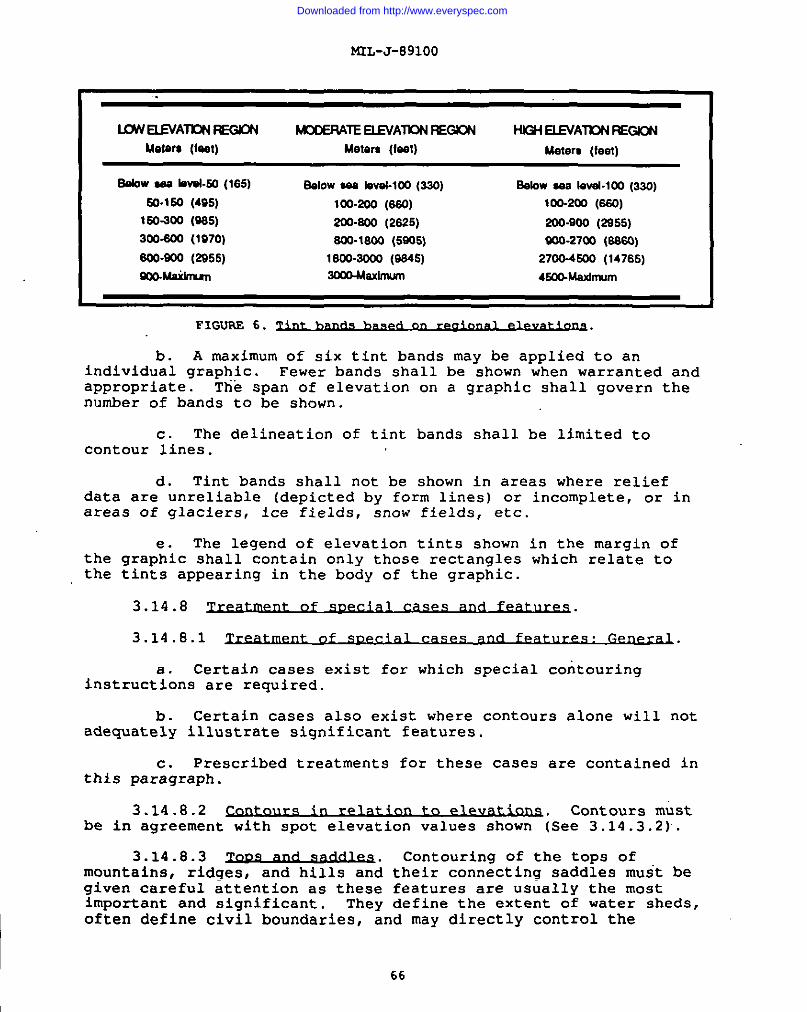
MIL-J-891OO
I
I&WELEVAT?W ~ MCOERATEELEVA~ =GICN Hk3t-1ELEVATKXI M310N
Meters (feet) Metsrs (lsst) Metert (feat)
60&WX bmL50 (165) *IOWM bval-lOO (330) aelow *8 10vst-loo(3so)
E41-150(495) 100-200 (ss0) 1OO-2O2(s50)
150-S00 (9S5) 200-S00 (2S25) 300-900 (2955)300.6Q0 (1970) Sw-laoo (ss0s) 400-27c0 (6s60)
Sw-soo (2s55) 1800-2000 (8s4s) 2700-4500 (14765)
mc-Msihmml [email protected] 4E00-Msximum
FIGUAF,6.
b. A maximum of six tint bands may be applied to anindividual graphic. Fewer bands shall be shown when warranted andappropriate. The span of elevation on a graphic shall govern thenumber of bands to be shown.
c. The delineation of tint bands shall be limited tocontour lines.
d. Tint bands shall not be shown in areas where reliefdata are unreliable (depicted by form lines) or incomplete, or inareas of glaciers, ice fields, snow fields, etc.
e. The legend of elevation tints shown in the margin ofthe graphic shall contain only those rectangles which relate tothe tints appearing in the body of the graphic.
3.14.8 of
3.14.8.1 .
Certain cases exist for which special contouringinstruct~ons are required.
b. Certain cases also exist where contours alone will notadequately illustrate significant features.
c. Prescribed treatments for these cases are contained inthis paragraph.
3.14.8.2 in to e lev~ Contours m;stbe in agreement with spot elevation values shown isee 3.14.3.2).
3.14.8.3 ~. Contouring of the tops ofmountains, ridges, and hills and their connecting saddles muit begiven careful attention as these features are usually the mostimportant and significant. They define the extent of water sheds,often define civil boundaries, and may directly control the
66
Downloaded from http://www.everyspec.com
I
MtL-J-89100
distribution and location of routes of communication. Thesefeaturea present decidedly ”varying characteristics from sharp andwell-defined to flat or gently rolling and vaguely defined. Witha given contour interval that is suitable for the steeper parts ofthe terrain, it is sometimes difficult to portray these featuresaccurately without recourse to use supplementary contours or theliberal uae of spot elevations. Where areas are relatively flatand of considerable extent, the proper uae of supplementarycontours will often provide the solution. The most troublesomesituation is usually encountered when the relief along the top ofthe ridge falls within the range of one or two contour Intervals.A ridge may consist of a series.of distinct tops, but when strictadherence to the.elevation criteria is maintained,’the standardcontour may indicate a smooth unbroken profile. The choice oftreatment is the judicious uae of spot elevations, supplementarycontours, shaded relief, or the application of a sufficient amountof topographic license to bring out the distinctive features bydeliberate and slight alignment of the contours In other thantheir exact positions. Thus, at times, the solution may beobtained by a displacement of contours which does not exceed plusor minus the contour interval.
3.14.8.4~.
a. Where slopes are steep and of uniform grade, only theindex contours shall normally be shown completely. Segments ofthe intermediate contours should appear at salient points atconvenient intervals.
b. Where the gradient of embankments along roads,railroads, and like features is such that the contours definingthe feature tend to coalesce, the contours shall be merged intoone carrying contour. For treatment of banks along canals andditches, see 3.14.8.8.
c. Pinnacles, needle-type peaks and buttes tiithnearlyperpendicular sides offer perplexing problems of portrayal andtheir proper delineation is of extreme importance. The graphicshall employ contours, shaded relief, form lines, and spotelevations to portray the feature properly. When a combination ofthese will not show the proper formation, the relief feature shallbe annotated.
3.14.8.5
a. Depressions of landmark value or affectingtrafficability, which are not adequately portrayed by the normalcontour treatment, shall have ticks added to the contour lines.
b. Care should be taken in the treatment of depressions atsheet edges in orderthe adjacent sheet.depression, it shall
toIfbe
ensure that the feature is continued onthere is no doubt that a feature is agiven the treatment prescribed above.
67
Downloaded from http://www.everyspec.com
KIL-J-891OO
I
c. Artificial depressions formed by construction ofrailroad or road embankments shall be treated as directed in3.14.8.9.
3.14.8.6~.
a. Steep slopes, cliffs, and depressions lower than thecontour interval shall be shown. Where the terrain is very rugged(deeply incised in excess of the contour interval), regard few, ifany, such features. Where the terrain is moderately rugged,interpret only those higher than one-half the contour interval.Where the terrain is fairly flat, regard those equal toone-quarter the contour interval. Usually, those less thanone-quarter the contour interval shall not be portrayed.
b. In certain areas, steep slopes are covered withterraces. Add asuitable note, repeated as necessary, over thearea. Examples:
Terrsow, Imwterracas, Numerousterrixes, Numemuslcwterrases.
c. The extent of terraced areas shall be indicated bylimiting outlines.
3.14.8.7 ~.
a. Levees and spoil banks which are of sufficient size andimportance shall be shown.
b. In areas containing numerous levees, only the mainlevees which form the characteristic pattern of the system shallbe shown. Secondary levees shall be omitted unless they areobviously important, strategically or otherwise, or where theiromission would create an erroneous conception of thecharacteristic pattern.
c. For treatment of levees in cranberry bogs and ricefields, see 3.13.13 and 3.13.14.
3.14.8.8 ~.
a. Man-made irrigation and drainage ditches arecomparatively narrow features usually occurring in areas of lowrelief. Representation of the banks of these features by contoursis impracticable since the result would over emphasize the widthof a narrow feature.
b. The gradient of ditches shall be shown. The contoursshall be drawn continuously along each side of the ditch or canal,and shall be turned upstream a sufficient distance to depict theflatness of the terrain and the direction of flow of the feature,and then drawn across the ditch or canal.
68
Downloaded from http://www.everyspec.com
I MIL-J-89100
3.14.8.9 ~. A carrying contour shall be ueedto indicate cuts or fills whose heights exceed the contourinterval.
3.14.8.10 ~. Drainage treatmentsfor flood control reservoirs and areas subject to inundation areprescribed in 3.13.15.
3.14.8.11 and dxY river h“ds.
a. Contours shall be shown within the limits of wide (morethan 1.25 mm) intermittent and dry river beds.
b. Detailed instructions for depicting these features arecontained in 3.13.5.2.
3.14.8.12 .~. Dry Lakes shall bes~olized with-the wet sand S@JOl and shall contain contours.
3.14.8.13
a. Sand and gravel areas are included for contouring.
b. The portrayal of dunes depends on the quality and typeof the source material, and the nature and extent of the area.
(1) Where adequate photography is available, dunes areshown with the appropriate prepared pattern. The preparedpatterns represent the main types of dune configurations. Thepattern that most closely reflects actual dune characteristics, asseen on the photography, is selected and positioned to indicatethe true orientation of the dunes.
(2) Where adequate photography is not available, thedunes may be shown facsimile as indicated on source maps or by theappropriate prepared pattern.
(3) In areas where individual dunes cannot be shownbecause they change frequently or because they are too small forthe scale of the map, the areas of dunes shall be outlined andlabeled.
(4) Every effort should be made to insure that thetreatment of sand dunes remains consistent with adjoining sheets.
c. Sand dunes/sand hills will not be contoured.
d. Sand occurring in tidal waters shall be treated asdirected in paragraph 3.14.8.31 for Foreshore flats.
3.14.8.14 ~. For the purposes of thesespecifications, a 9ravel-strewn beach is defined as a shore whichis predominately covered with stone of such size (approximately
69
Downloaded from http://www.everyspec.com
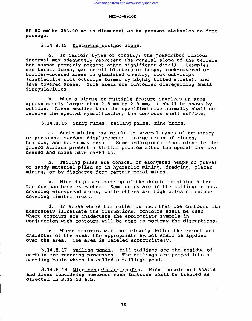
I
MIL-J-891OO
50.80 mitto 254.00 mm in diameter) as topassage.
3.14.8.15
a. In certain tvpes of Countrv,
present obstacles to free
the prescribed contourinterval may adequately ‘~epresent the ~“eneral-slope of the terrainbut cannot properly present other significant detail. Examplesare karst, loess, gas or oil blisters or bumps, rock-covered orboulder-covered areas in glaciated country, rock out-crops(distinctive rock outcrops formed by highly tilted gtrata), andlava-covered areas. Such areas are contoured disregarding smallirregularities.
b. When a single or multiple feature involves an areaapproximately larger than 2.5 mm by 2.5 mm, it shall be shown byoutline. Areas smaller than the specified size normally shall notreceive the special symbolization; the contours shall suffice.
3.14.8.16
a. Strip mining may result in several types of temporaryor permanent surface displacements. Large areas of ridges,hollows, and holes may result. Some underground mines close to theground surface present a similar problem after the operations haveceased and mines have caved in.
b. Tailing piles are conical or elongated heaps of gravelor sandy material piled up in hydraulic mining, dredging, placermining, or by discharge from certain metal mines.
c. Mine dumps are made up of the debris remaining afterthe ore has been extracted. Some dumps are in the tailings class,covering widespread areas, while others are high piles of refusecovering limited areas.
d. In areas where the relief is such that the contours canadequately illustrate the disruptions, contours shall be used.Where contours are inadequate the appropriate symbols inconjunction with contours will be used to portray the disruptions.
e. Where contours will not clearly define the extent andcharacter of the area, the appropriate symbol shall be appliedover the area. The area is labeled appropriately.
3.14.8.17 ~. Mill tailings are the residue ofcert’ainore-reducing processes. The tailings are pumped into asettling basin which is called a tailings pond.
3.14.8.18 ~. Mine tunnels and shaftsand areas containing numerous such features shall be treated asdirected in 3.12.13.6.b.
70
Downloaded from http://www.everyspec.com
MIL-J-891OO
3.14.8.19 ~. Quarries shall be shown and treated thesame as strip mines, as directed in 3.14.8.16.
3.14.8.20 .
Asphalt lakes are natural deposits of this mineral inlarge po~is and may be located in swampy areas or covered withwater. The origin of asphalt lakes can be attributed to anexuding of the material from the earth In a manner similar tospring-fed lakes.
b. SImllar deposits of bitumen’s called also exist.
3.14.8.21 ~. Caves shall be portrayed when of landmarkvalue. The shaft of the cave symbol points in the generaldirection of the cave interior:
I 3.14.8.22 ~. All mountain passes shall beshown. .,
3.14.8.23 lundr.a.
a. Tundra is a prairie-like region of permafrost subsoilin the Arctic and subarctic zones which sustains a growth of verylow vegetation. The vegetation consists of lichens, mosses,grasses, stunted bushes, and stunted trees of very low growth.
b. The surface of some southern areas contains hummocks,formed by the permafrost subsoil.
c. Marshes, swamps, and similar features (muskegs, etc.)which occur within tundra areas shall be treated as directed In3.13.10.
3.14.8.24 ~.
a. The heads of glaciera shall bemeet snow fields or Ice fields.
b. Areas covered by moraine shall
delineated where
be indicated.
they
3.14.8.25 and ice ~ Areas ofpermanent snow fields and ice fields shall be shown. “ Theprinciples of portraying relief, previously described, shall befollowed.
3.14.8.26 ~. Anunatak IS a prominentpromontory of bare rock rising above a surrounding area which Isperpetually covered by snow or ice. ?inice peak is a similarlysituated permanent feature, except that it Is perpetually coveredwith snow or ice.
a. Treatments for both features are similar.
Downloaded from http://www.everyspec.com
I
I
b .applied to
MIL-J-891OO
Previous instructions for portraying relief shall beboth features.
3.14.8.27 ‘~. AI’Iice cliff is a sheer-faced frontof a glacier or ice shelf where it meets the sea. The shape of anice cliff is not permanent.
3.14.8.28 ~. An ice shelf is a floating ice sheetof considerable thickness, attached to the coast, and showingabove sea level. It is usually of great horizontal extent andwith level or gently undulating surface. The ice shelf isnourished by annual snow accumulation and often by the seawardextension of land glaciers. Limited areas may be aground. Theseaward edge of the feature is termed on ice front.
3.14.8.29 ~. Pack ice includes any area of iceoriginating from the freezing of sea water, regardless of whatform it takes or how it is disposed.
a. Pack ice shall be depicted by indicating theapproximate maximum limits of the feature, along with the month inwhich it occurs. The Dortraval of the feature is illustrated inFigure 7. When the en~ire w~ter area of the graphic is coveredpack ice, the following note shall be shown in the approximatecenter of the water area:
APPROXIMATE MAXIMUM LIMIT OF PACK ICE (MONTH) IS SOUTH OF THIS CHART
by
‘--..J.’pIMATE uMITSOF PACKKf FOS FEiSSMSY----------------- _-
‘Figure‘1.
b. The permanent polar ice pack shall be shown.
3.14.8.30 ~.
a. The hydrographic features and related data portrayed onthe Series 1501/1501 AIR sheets are required to provide thefollowing landmark uses which are listed by priority in descendingorder:
(1) Aerial in-flight uses which include visual/radarpilotage and air/sea rescue operations.
(2) Targeting for both air and surface operations:
(3) General tactical planning for air, ground, andamphibious operations.
72
Downloaded from http://www.everyspec.com
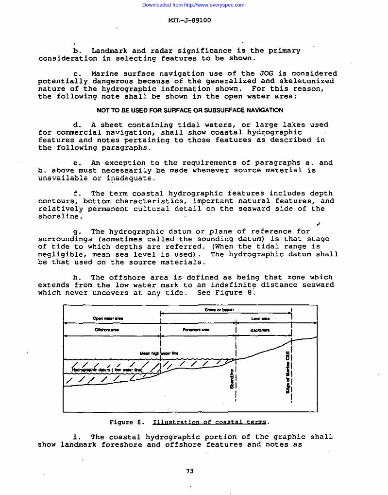
I
MIL-J-891OO
I
b. Landmark and radar significance is the primaryconsideration in selecting features to be shown.
Marine surface navigation use of the JOG is consideredpotentia;iy dangerous because of the generalized and skeletonizednature of the hydrographic information shown. For this reason,the following note shall be shown in the open water area:
NOT TO BE USED FOR SURFACE OR SUBSURFACE NAVE2ATION
d. A sheet containing tidal waters, or large lakes usedfor commercial navigation, shall show coastal hydqographicfeatures and notes pertaining to those features as described inthe following paragraphs.
h exception to the requirements of paragraphs a. andb. abovee~ust necessarily be made whenever source material isunavailable or inadequate.
f. The term coastal hydrographic features includes depthcontours, bottom characteristics, important natural features, andrelatively permanent cultural detail on the seaward side of theshoreline.
*9. The hydrographic datum or plane of reference for
surroundings (sometimes called the sounding datum) is that stageof tide to which depths are referred. (When the tidal range isnegligible, mean sea level is used) . The hydrographic datum shallbe that used on the source materials.
h. The offshore area is defined as being that zone whichextends from the low water mark to an indefinite distance seawardwhich never uncovers at any tide. See Figure 8’.
Figure 8. ~n of c~.
i. The coastal hydrographic portion of the’graphic shallshow landmark foreshore and offshore features and notes as
73
Downloaded from http://www.everyspec.com
!4IL-J-891OO
Idirected in the following paragraphs. when elimination isnecessary because of congestion, items to be retained shall bethose of-most importance-to the air navigator as visual and/orradar landmarks.
I
~. When aerial photography is available, the graphicshould include’features appearing thereon, even though the
I features do not appear on other source materials.
(1) No abbreviations shall aDDear on the CIraDhiC. Theproper conv”eisionsfrom abbreviations t~”full forms ~re-required~I
(2) Careful consideration must be given to the
Iplacement of type, especially notes on the graphic.
(3) Wnbolization of coastal hydroqraphic features iscontained in the-MIL-STD-2402.
I
3.14.8.31 “~.
I a. Foreshore flats occur only in tidal watersbe either contiguous to or detached from a shoreline.
They mayGenerallv.
the flat is dev~id of vegetation, usually being composed of san~igravel, sand and gravel, boulders, boulders and sand, mud, orclay. In some cases, the flat may contain low or sparse sea-grassgrowths; these are to be treated as foreshore flats and not ascoastal marshes. Such foreshore features as reefs and rockyledges are discussed in 3.14.8.32.
b. The limits of foreshore flats shall be shown, but arenot labeled as to composition.
3.14.8.32 ~.
A reef is a rocky or coral feature which may or may notbe abovea~he hydrographic datum and may or may not be detachedfrom the shore. A ledge is a rocky formation connected with andfringing the shore and is generally above the hydrographic datumin elevation.
b. Large reefs or ledges are portrayed when exposed orawash at the hydrographic datum. Open pools in extensive coralreefs shall be shown wherever their size is consideredsignificant.
3.14.8.33 Rocks which uncover orare awash at the hydrographic datum but are covered at high waterare known as rocks uncovering or awash. They shall be shown onlywhen they are landmarks.
3.14.8.34 M=wbmxb.
a. Exposed or stranded wrecks are those having any portionof the hull exposed at the hydrographic datum.
74
Downloaded from http://www.everyspec.com
MrL-J-89100
b. A group of exposed wrecks is indicated by the limit-of-danger line marking the outer limits of the area.
I 3.14.8.35 ~.
a. A depth contour is comparable to a contour on land, thecontour representing an imaginary offshore line, all points of
Iwhich are at the same depth below the hydrographic datum.
~
b. The principles which govern the delineation of depthcontours are similar to those which govern the delineation of landcontours.
~c. Depth contours shall be derived from national
hydrographic charts.
3.15
3.15.1 n: Ge~,
a. While areas of vegetation smaller than the inclusioncondition are normally omitted, exception shall be made on sheetscontaining sparse vegetation. In such cases, small clumps ofvegetation shall be shown if they serve as landmarks, even if aslight exaggeration in scale is necessary. When the vegetationselected for its landmark value cannot be symbolized, the outlineshall be indicated and labeled.
b. To qualify the term, vegetation need not necessarily becontinuous; clear space may appear between individual growths.While no absolute rule can be applied due to peculiarities oflocality, an area of scattered growth having approximately 25percent canopy cover or more shall generally be considered ofsufficient density to be shown.
c. Areas of vegetation shall be shown true to their shapeinsofar as the scale will permit. Exaggeration shall be held to aminimum and used only to show clearings for firebreaks.
d. Wooded marshes (cypress swamps, aago swamps, etc.)other than mangrove and nipa require no special treatment. Thevegetation shall be symbolized .inits prescribed manner on thevegetation copy with the marsh treated as a drainage feature.
“3.15-2 ~. Woods and jungle are growths ofperennial vegetation which are of sufficient stand or height toafford concealment for troops; or any perennial growth which isthick, regardless of height, that it affords obstacles to freepassage, either pedestrian, equestrian, or vehicular. Includedthis category are woods of”any type, such as palm, palmetto,bamboo, orchards or plantations which are irregularly planted orof wild growth, nurseries, reforested areas, and thick lowgrowths,
so
in
I 75
I
Downloaded from http://www.everyspec.com
NrL-J-89100
.
3.15.3 ~.
a. Orchards, vineyards, and similar systematic plantationsof perennial vegetation are collectively defined as areas coveredby planned plantings of perennial trees: tall buihes; or vineswhich yield fruits, nuts, spices, or other conunercialproductsexclusive of timber. Usually, there is open ground visiblebetween the plantings.
b. Regularly planted palms shall be included in thiscategory.
3.15.4 .~. On aerial photographs, tropicalgrasslands appear light gray or whitish in color with an evensurface. In certain lights and depending on the flight height,tropical grass resembles open water.
3.15.5 ~. Discussions of mangrove and nipa arecontained in 3.13.11 and 3.13.12.
3.15.6 ~. Scattered trees shall be portrayed.
3.15.7 ~. Shelter belts are a naturalplanted barrier of trees or shrubs. They are shown onlydevoid of other landmark features.
3.16 Rmam&bn.
or
in areas
3.16.1 ~. Boundaries must be in accordwith the current national policy of the producing nation.
3.16.2 ~.
a. Graphics shall show only major administrativeboundaries: international and primary administrative boundaries.
(1) First-Order Administrative Division boundaries arethose which separate the principal divisions of a country, such asstate, province, prefecture, etc.
(2) Second-Order Administrative Division boundaries arethose which divide the primary administrative divisions of acountry into local administrative units.
b. Reservations shall be shown according to the followingguideline: National, military, tribal, and forest reservations,including national parks, shall be outlined by the boundarysymbol .
3.16.3 De Fart~e$ (ot~s of
a. De Facto boundaries which exist as the result oftreaties that are not necessarily recognized by the producing
I 76
Downloaded from http://www.everyspec.com
ML-J-891OO
nation shall be included only if in accordpolicies.
with current national
b. The accepted boundary, (symbolized normally), must beshown in addition to the defacto boundary.
3.16.4 ~.
a. No general term completely covers the various types ofboundaries encountered in this grouping. However, theseboundaries are generally included in the “Other lines ofseparation” terminology. Included in the grouping are:
(1) Provisional military (internal) demarcation lines;e.g., Korea.
(2) Cease-fire or armistice lines; e.g., boundaries inIsrael.
(3) Zones of occupation.
I (4) Demilitarized Zones; e.g., Korea.
3.16.5 ~. Where source material isinsufficient to Dermit delineation of at least an aDDroximateboundary, then n; boundary shall be shown. Instead~-anappropriately worded note shall be added in the margin.
13.16.6 ~. The margin of the graphic
shall contain a legend of the boundary symbols appearing thereon,with the symbols defined according to the accepted administrativephraseology of the countries concerned.
3.17
3.17.1
a. Unless specified otherwise, aeronautical” requirementsset forth in this section apply to both versions of the JointOperations Graphics.
b. See MIL-STD-2402 for the symbolization of aeronauticalinformation.
I The following installations (military or civil) shallbe showna”
1 (1) Aircraft facilities.
I
I (2) Heliports or pads (limited to hospitals) used forhelicopter operations.
77
Downloaded from http://www.everyspec.com
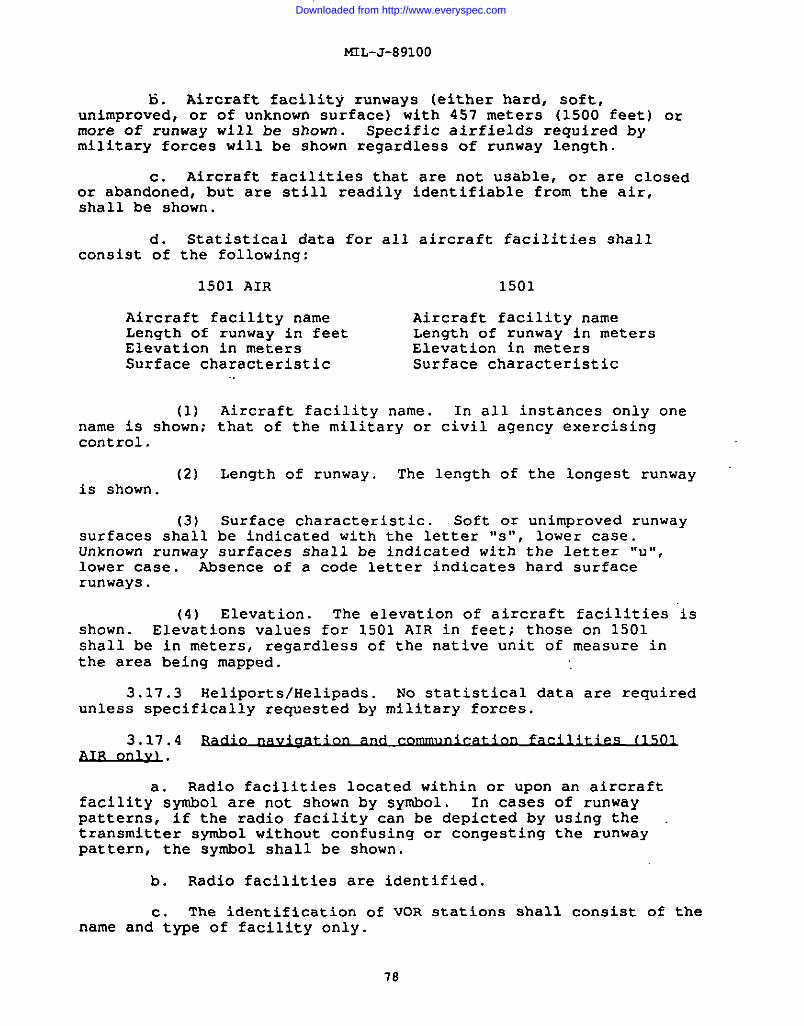
mL-J-89100
6. Aircraft facility runways (either hard, soft,unimproved, or of unknown surface) with 457 meters (1500 feet) ormore of runway will be shown. Specific airfields required bymilitary forces will be shown regardless of runway length.
c. Aircraft facilities that are not usable, or are closedor abandoned, but are still readily identifiable from the air,shall be shown.
d. Statistical data for all aircraft facilities shallconsist of the following:
1501 AIR 1501
Aircraft facility name Aircraft facility nameLength of runway in feet Length of runway in metersElevation in meters Elevation in metersSurface characteristic Surface characteristic
(1) Aircraft facility name. In all instances only onename is shown; that of the military or civil agency exercisingcontrol.
(2) Length of runway. The length of the longest runwayis shown.
(3) Surface characteristic. Soft or unimproved runwaysurfaces shall be indicated with the letter “s”, lower case.Unknown runway surfaces shall be indicated with the letter “u”,lower case. Absence of a code letter indicates hard surfacerunways.
(4) Elevation. The elevation of aircraft facilities isshown. Elevations values for 1501 AIR in feet; those on 1501shall be in meters, regardless of the native unit of measure inthe area being mapped.
3.17.3 Heliports/Helipads. No statistical data are requiredunless specifically requested by military forces.
3.17.4 unavi~ and 11501AIR_mQL.
Radio facilities located within or upon an aircraftfacilitya~ymbol are not shown by symbol. In cases of runwaypatterns, if the radio facility can be depicted by using thetransmitter symbol without confusing or congesting the runwaypattern, the symbol shall be shown.
b. Radio facilities are identified.
c. The identification of VOR stations shall consist of thename and type of facility only.
78
Downloaded from http://www.everyspec.com
MTL-J-891OO
3.17.5
a. Compulsory corridors are shown only as noted in3.17.5.d.
b. The Air Defense Identification ZoneS (ADIZ). When achart falls entirely within one ADIZ, the following boxed noteshall be positioned in the body graphic:
Entireereeofthischertfellsvfthfn(neme)ADIZ.
c. All officially designated Buffer Zones are shown. Whena chart falls entirely within one Buffer Zone, the following boxednote shall be positioned in the body of the graphic:
Entireereaofthischertfellswithinthe(name) BufferZone.I
d. The 20-statute-mile radius Berlin Control Zone andassociated corridors are required.
Ie. Warning notes.
(1) Warning notes will be shown where required.
{2) Add the following sentence to required warning noteson 1501 AIR graphics in the proximity of Chinese Bloc borders.
~
OonsullNOTAMSand Fllghtlnformation
3.17.6 ~s (1501
a. Aeronautical lightswill be identified.
b. Marine lights shall(Landmark).
3.17.7 ~.
and their characteristics, if any,
be shown in areas of isolation
a. All cultural features which extend 46 meters (150 feet)or more above the surrounding terrain are considered a hazard toflight and shall be shown and labeled, indicating nature of
79
Downloaded from http://www.everyspec.com
.,
I
I
hCL-J-89100
obstruction; e.g., buildings, smokestack, etc. Powerlines areconsidered hazards to flight, and are shown.
b. Radio facilities that are also obstructions are shownby a unique obstruction symbol.
c. Group obstructions are shown as illustrated inMIL-STD-2402, Symbology.
d. The height of the structure above ground level, as wellas the elevation of the top of the obstruction above sea level,shall be shown when it is known or can be estimated.
e. Where the highest point of an obstacle or hazard abovesea level is given and its height above ground is not known, anestimation of height above ground should be made.
f. The estimation, based on best source available, must behigh enough to assure clearance of the structure. Estimatedheights shall be portrayed on the graphics in the same manner asaccurate heights, without an indication of reliability. Where theheight of the structure above ground is known and the elevation ofthe highest point above sea level is not known, an estimation ofthe highest point of the structure above sea level should be made,based on the same criteria.
Obstructions that are questionable as to existence orpositiong~hall be shown in the same manner as.reliableobstructions except that an appropriate note shall be placedimmediately below the “above sea’levelt!elevation. Examples ofthe note are: Exis!encs doubtful; Position approximate.
h. The following notes shall be added to the margin ofeach graphic (substitute metric values on Series 1501):
Poweriines areshown exceplwilhin populated place tints. Otherobstructionsareshowniitheyare150feetormoreabove-groundlevsl.SsscautiinrOts.
3.17.8 The aeronautical symbols areaccurately plotted in their true geographic positions, ifpossible, but these symbols may be shifted when required to do so,so that relative position to base detail is maintained.
a. Refer to MIL-STD–2402, Appendix A and thisspecification or MIL-STD-2403 for proper naming and labeling ofapplicable features.
b. The following is a list of features which may or maynot appear in MIL-STD-2402 as a defined feature code or attribute,but may be named on the final product.
80
Downloaded from http://www.everyspec.com
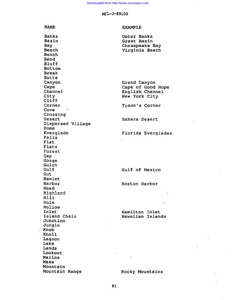
MIL-J-891OO
EXAMPLE
BanksBasinBayBeachBenchBendBluffBottomBreakButteCanyonCapeChannelcitycliffCornerCove -’CrossingDesert“Dispersed VillageDomeEvergladeFallsFlatFlatsForestGapGorgeGulchGulfGutHamletHarborHeadHighlandHillHoleHollowInlet”Island ChainJunctionJungleKnobKnollLagoonLakeLandsLookoutMarinaMesaMountainMountain Range
Outer BanksGreat BasinChesapeake BayVirginia Beach
Grand CanyonCape of Good HopeEnglish ChannelNew York City
Tyson’s Corner
Sahara Desert
Florida Everglades
Gulf of Mexico
Boston Harbor
Hamilton InletHawaiian Islands
Rocky’Mountains
81
Downloaded from http://www.everyspec.com
MIL-J-891OO
..
NAME (continued)
NarrowsNeckOceanParkPassPassagePatchPeakPlainPlateauPointPoolPortRangeRavineRegion ““RidgeRiverRoadsteadRockSandsScattered village
SeaSea MountShelfShoalsSinkSoundspitSpringSpurStraitsummitTownValleyVillageWood
ERANPLE (continued)
Atlantic OceanYellowstone National Park
Pikes PeakGreat PlainsColorado Plateau
Coastal Range
communidads of South Americastreusudlung of Eastern EuropeCaribbean Sea
Puget Sound
Bering Strait
Death ValleyGreenwich Village
3.18.1
a. The density of names on the graphics should be themaximum which is compatible with scale and the development of thearea being portrayed. That is, significant detail shall not beobliterated by the density of the names shown. The cartographermust maintain an awareness of the importance of not cluttering thegraphic with names to the point that it detracts from orobliterates other features. Consider:
(1) The importance of the feature to be named,
82
Downloaded from http://www.everyspec.com
(2) The size andits placement.
(3) The addition
MIL-J-891OO
style of type
of idiographs
to be shown as well aa
in certain areas.
(4) Legibility of all features, including namesidentifications .
b. In areas of sparse culture (development), anY featurewhich can be used as a point of reference assumes a significancefar beyond that which it would have in a developed area. Ifnamed, the name would add materially to its use as a reference orlandmark and should be included.
3.19 RadaX. This section is not applicable to thisspecification.
3.213 ~. This section iS notapplicable to this specification,
3.21 ~. This section is not applicable to thisspecification.
3.22 ~. See MIL-STD-2402.
3.23 See MIL-STD-241O.
3.23.1
Reproduction shall be by lithography. The finalproduct ~hall conform with the best lithographic quality standardswith respect to clearness, conformance with specified colors, andaccuracy of registration.
b.’ Series 1501/1501 AIR shall be printed on JCP E-30 mappaper. Equivalent paper as approved by national authorities maybe used.
c. Color blocks, when used, shall be positioned outsidethe trim lines.
d. The individual features required on eachseparation are specified in of these specifications.
3.23.2
a. The producing agency shall match, within
color
acceptabletolerances, the specified colors and screens. Where necessary,equivalents approved by national authorities may be used.
b. The printing colors and screens requirements are thesame for both the ‘1501 JOG and the 1501A JOG AIR.
83
Downloaded from http://www.everyspec.com
MIL-J-891OO
c . The standard printing colors and screens listed areillustrated as follows:
STWARO PRINTLNG COLOSSANO SCRSENS
SEPRRATXON SCRSEN ANGLE SPC PRINTINGCOLOR
Cltyrl”c ............................ 67&l>@ ............. 45”............. 5860081ackCmtin.m* m.l..tion ................ 21b-120D.............ml.- .............................ml.d ................ F..".".."..."...... FzF..-d. (1501/1501MR) ................ 67* B1,.(31o+4OD..... 30./60.......... SB600BIac,Fairor dry mnathr, lcosa.urfa..
Track.;Trails........................Solid................ - ..............~~~e~i.. ........................... mid ................ — ..............
50600!M,ck
Black~,@Iy (1501/1501Ml, ..... 5olid................ — ..............50600Black58600O1ack
1
tt
t;
ShmdndBnlhf ........................
Dmtrnga .............................*“W,.,, ...........................Imlaticpmlwter ....................M1.cdlane.nuD“lmg. FeatUr.8......D“inaq. ?yps ........................DrainageElwatlms [Feat)...........Drainaq.m (mt.r.) ...............MIMtary G,id (IJ’M..................fU1iUry CrldValumq.................
Halftone.............
solM ................31t-120D.............34Q-120D.............V,ri.aum..............5a11d................Solld................Solid................&lid ................5011d................
w .............— . . . . . . . . . . . . . .45...............45..............
. . . . . . . . . . . . . .
. . . . . . . . . . . . . .
. . . . . . . . . . . . . .
. . . . . . . . . . . . . .
. . . . . . . . . . . . . .— . . . . . . . . . . . . . .
57003cray
48253Blue4S253Blue48253Blue48153Blum48253Blue48253Blue48253Bluo40253Blue48’25301”.
Pok’e,ll,ms...sFylon,................ Solid................ — .............. 4635,al”, ,Aero>
k.-.tical (150111S01AIRI.......... mid ................ - .............. 4635181W ~eml
nell,c(1501,,50,MB., ............... wlid .................— ............... s~~~~~e,$,~mwnsWFJ=4=IItawContours(1501)........ Solid................ — .............. 61121Red/Brown)41,..11.”.0”,Rallef,.,t,,.,........ “,,1.IM.............. — .............. 61]cmt..rv~l.es 1. Feet............... solid.................... .............. 611;SO.,.O!?.!.1.0s1.*ters ............. mid................ .. .. . . . . . . . . . . . . . . .
121Rdlaro”n121R..JlBIamn
61121R.3d/BX.Wn-a F1llS........................... 61* B1.Iw1,-240D..... 30./60........... 61121iled,B,wdnAll “aatltar,100.oor lightsu,face
~~~ ................................ Solid................ — .............. 61121Red,BmwnMl wedtfm,,Hard*“rrace
~.n~w~ewri.t ................... 54*-120cI............. 60.............. 61121Red-BroIMRoadDistance,(1501rely)........... Solid................ - .............. 61121Red-m...
‘~, ................................ Solid................ — ..............ni,cr,llane.u,Vcqmt,cionFnatur...... “.,,OUS .............. -
56435Graen.............. 46435Gmm
shelterBelts........................ SoIld................ - .............. 46435Green
Hwatlm T1”tNO. 1 ................. - ................... - .............. —
~levatl..T1ntN.. 2 ................. LP-15................ 45..............Cla.atio.rlntfm. 3 ................. LP-12................ 135.............
51437Yellow
E1ew,tl.anTintN.. 4 ................. 19,-120D............. ,5..............57437Yellow5’7437Yellml
E1evacl..T1ntNo. 5 ................. LP-15................ 45s............. 56135BrownElevationTintNO. 6 ................. u-5 ................. 45.............. 5B135Brown
PrlntlrqcolorforB,ltlshgrid,.1”,,,tullh ,, spcifli,d0. the grid“wati”e,.ElevationTintNo. 1 include,●rea,ttutam balow‘u 1,”.1and SIU1lb dietingui,hed ‘1OWI1Y,,NMte.
3.23.3 ~.
a. When the simulated five-color process printingtechnique Is employed, the producing agency shall match, withinacceptable tolerances, the printing colors and screens specified.
b. The process printing colors and SC]are the same for both the 1501 JOG and the 150
?ens requirement’sA JOG AIR.
84
Downloaded from http://www.everyspec.com
MIL-J-891OO
c. The process printing colors and screens listed areillustrated as follows:.
PsmEes PRISTISGCOLOSS Mm scsxE3i8
SEPARATION SCREEN ANGLE SPC PRINTINGCOLOR
City?int............................conti”um!mutbltatban ................Culty .............................
................................3’.1,or dry wtlmr, lea” ,Urfam
Trackatmail, .......................Prc.j.ction...........................BlackTypgrapIy (1501/1501AIR) .....
S4+120D ............. 45-............. 58600Black21*-120D............. 45.............. S8600B1ackmolid................ - .............. 50300Black676 S1...21,-2400..... 3LW/6~ ......... S8600Black
SOlla................ — .............. 50300B1ackSolid................ — .............. 5B300B1ackSolid................ — .............. 5B300Black
?*
t
I*t
Shadtiw1l.f ........................ 315-200D............. 27-............’.50600Black
D“lnav .............................*“!4,LW . ..........................Snlalmlcwm.wate.x....................Iu*c*llan..umD“llutm Feature,......Dralr.w.mm... . .. . .. . . . . .. . . . . .. . . .Dnimm E1w.tl.n. (Feet)...........Dn1mtm13Ta Wter.] ...............3U11taryGrid 071’Hl..................3U11taIYQ1d Va1Ues.................Wind............................ ....Hisc.11.neousVoqetaticmFeature.....Shaltermlt’ ........................
Solid................31%-120D.............31*-120D.............various..............Solld................Solid................3011d................Solid................solld................31$-120D.............Vaziou., 31*-120D...31b-120D.............
I Pow.rllrm...dwlon. ................ Solld................ — .............. 46351Blua (Aer9)Aer.ru”tical(1501/1501A1R].......... S.aIld................ — .............. 46351B1tm lAmID)
:
:tt
I t
:t
t:
Relief(1501/1501AIR) ................$Wlr=a.tav contours(1501)........Mimedianaou.ReliefFmr,”res.. . . .Contmrvalu.m 1“ Feat ...............Cmtourvalufzsi“mt,rs .............Roads................................All “eathar,100s.or Mqht ,.*cam
RoadFills...........................All weather,hardsurface
E.nmdarym.rprht ...................BaatiDistances{1501rely))..........EIWatimtJrlt NO. 5 .................ElevationTintNo. 6 .................
54t-120D.............301id................u-15 ‘ 21+-120D ....W-5 & 214-1200......
.............. 61121
.............. 61121— .............. 61121
.............. 61121
.............. 6112130./64.......... 61,21
.............. 61121
30.............. 61121.............. 61121
?5. ............. 6112115-............. 61121
R*d-Bravn
Rnd-8r.mnUea-aro”nRed-mownRa4-aro.
WOOdB................................ 79-120D.............. 30- ............. 51377Y.11ow13isce11,.rm’VatlOtatl.anFeatures ... 19*-120D............. 30- ............. 57377Ye11wSbltar MI1t’........................ 19*-120D............. 30- ............. 51>77Y.llwE1OV~tiO.Tintb. 2 ................. M-15 ‘ 42t-120D..... 15- ............. 51311YmllauE1.vatl.nTintNo. 3 ................. 1.P-12& 42h-120D . .. 75- ............. 57371.YellcnE1mvatlonT1m No. 4 ................. 42t-120D............. 75-............. 51311Yell.mElevationTintNo. 5 ................. LP-156 42*-120D..... 15-............. 51311YalleuE1e.ationTintlb. 6 ................. u-5 & 42t-120D...... 15,............. 57311Y.11ou
3.23.4
a. The shaded relief, elevation tints, and wooded areasshall be masked to avoid overprinting the following features:
I(1) Populated place tints (including continuous
habitations) .
(2) Outlined airfields: Aircraft facilities whose basicsymbol is a circle. Populated-place and continuation-habitationtints are also eliminated from the all aircraft facilities.
85
Downloaded from http://www.everyspec.com
MTL-J-891OO
.. (3) Roads
(4) Drainage features, suchmangroves, salt evaporators, etc.
(5) All route markers.
as intermittent lakes,
(6) Permanent snow, ice, glaciers, (Exception: Shadedrelief shall not be masked from these features.)
(7) Open water areas.
b. A halo mask shall be prepared from the black typographyplate of each version of the JOG for use when processing linearfeatures that print black.
The contours shall be masked from contour values by aphotomec%~nically derived (halo) mask, or some other suitablemethod that emulates the result of photomechanical, prepared fromeach contour value (label) plate.
3.23.5
Trimming. The JOG, when trimmed, shall measure55.880 c~by 73.660 cm, including margins as indicated on thestyle sheets for these products. An exact trimming of the northand east edges (bleed edges) is required in accordance with thetrim marks.
b. Folding, Wrapping (including associated labels). Allfolding and wrapping for the published JOG series shall be inaccordance with national policy (see section 5 PACKAGING) .
3.24 ~.
3.24.1 This section containsfeature, feature attributes category, values, inclusion conditionsand specific rules corresponding to JOG production.
3.24.2~. The following is an explanation of the headerformat for Table I (see Figure 9 for an example) of thisspecification:
ECcldeEeahu33EX ACQda ALLdbus auk(1) (2) (3) (4) (5) (6) (7)
(1) F(Feature) Code - 5 digit alpha numeric, FeatureAttribute Coding Standard (FACS) Code assigned to each feature(e.g., 1 - Culture Category, N = Transportation R/R subcategory).
(2) Feature - Name of feature aa specified in the FACS. Afeature is a physical (e. g., Bridge) or conceptual
86
I
Downloaded from http://www.everyspec.com
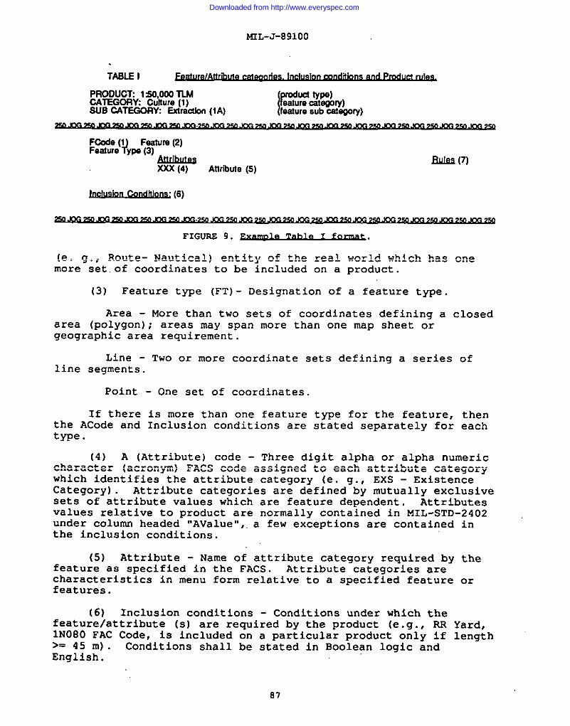
MIL-J-891OO
TASLEI
PRODUCT 150,000TMCATEGORY Culture(1)SUBCATEGOllYGiradbn(1A)
1Pemu%c%%y)leaIuresubcategory)
I
BJl149m
~
~ (6)
IFIG~ 9. ~.
(e. g., Route- Nautical) entity of the real world which has onemore set.of coordinates to be included on a product.
(3) Feature type (FT)- Designation of a feature type.
Area - More than two sets of coordinates defining a closedarea (polygon); areas may span more than one map sheet orgeographic area requirement.
Line - Two or more coordinate sets defining a series ofline segments.
Point - One set of coordinates.
If there is more than one feature type for the feature, thenthe ACode and Inclusion conditions are stated separately for eachtype.
(4) A (Attribute) code - Three digit alpha or alpha numericcharacter (acronym) FACS code assigned to each attribute categorywhich identifies the attribute category (e. g., EXS - ExistenceCategory) . Attribute categories are defined by mutually exclusivesete of attribute values which are feature dependent. Attributesvalues relative to product are normally contained in MIL-STD-2402under column headed ‘,AValuel,,,a few exceptions are contained inthe inclusion conditions.
(5) Attribute - Name of attribute category required by thefeature aa specified in the FACS. Attribute categories arecharacteristics in menu form relative to a specified feature orfeatures.
(6) Inclusion conditions - Conditions under which thefeature/attribute (s) are required by the product (e.q., RR1N080 FAC>= 45 m).English.
Code, i.aincludedConditions shall
on a par~icula~ product oily ifbe stated in Boolean logic and
Yard,length
87
Downloaded from http://www.everyspec.com
MIL-J-891OO
I
L
(7) Rule - 5 digit alpha-numeric code indicating rules(listed in MIL-STD-2403 ) which specify requirements for featuresto satisfy final product format/requirements.
3.25 ~.
3.25.1 ~.
a. Isogonic lines are shown throughout the entire graphic.Intervals on adioinina aranhics shall be consistent. exceDt thatintermediate li~es ma~ ~e ~sed to provide satisfactory po;trayalof unusual variation patterns within the limitations specifiedbelow.
theb. The lines of equal magnetic variation, extending tographic limits, shall normally be shown at intervals of 15minutes. When the total isogonic difference on the graphic islarge, the isogo”hicinterval between the lines should be increasedproportionately. Generally, line spacing closer than 101.60 mm isavoided and no more than four lines are shown. A minimum of twoisogonic lines are shown on each graphic. When the value of themagnetic variation”is the same over all areas of the graphic,isogonic lines are be omitted and the variation value shown by anote in the margin of the graphic reading:
MAGNETIC VARIATION FOR YEAR IS APPROXIMATELY(v.I..) OVER THE ENTII!E AR& (Annual raw cd
chsnge - “incfeass-or “decmass-)
c. Other magnetic variation notes and local magnetic notesshall be shown where applicable.
d. Isogonic information shall be related to 5-year epochs.(Example: 1990, 1995.)
3.25.2 ~:
a. When the declination is constant over the area of thegraphic, i.e., there is no variation between the west and eastedges, the note reads:
h4AGNETlC DECLINAT1ON FOR (year 1S1 lf2”(30MlLS))WESTERLY OVER THE EN IRE AREA
b. When there is a variation between the west and eastedges of the graphic, the note is patterned after the following:
#ARl~S FROMf1230MILS WESTEFILYFOR THEear MAGNETIC DECLINATION FROM TRUE NORTH
cEN7ERoFmEwEs\EoGE k2~40MILs)WES7ERLyFORTHECENTEROFTHEEASTE E
The note shall be related to 5-year epochs.(Example!’ 1990, 1995.)
88
Downloaded from http://www.everyspec.com
I
d. The declinationwith Mil equivalents to the
mL-J-89100
data is expressed to the nearest 1/2°,nearest 10 roils.
4. QUALITY ASSURANCE PROVISIONS
4.1 ~. Unless.otherwisespecified in the contract or purchase order, the contractor isresponsible for the performance of all inspection requirements(examination and tests) as specified herein. Except as otherwisespecified in the contract or purchase order, the contractor mayuse his own or any other facilities suitable for the performanceof the inspection requirements specified herein, unlessdisapproved by the Government. The Government reserves the rightto perform any of the inspections set forth in this specificationwhere such inspections are deemed necessary to ensure supplies andservices conform to prescribed requirements.
4.1.1 ~. All items shall meetall requirements:of sections 3 and 5. The inspection set forth inthis specifications shall become a part of the contractors overallinspection system or quality program. The absence of anyinspection requirements in the specification shall not relieve thecontractor of the responsibility of ensuring that all products orsupplies submitted to the Government for acceptance comply withall requirements of the contract. Sampling inspection, as part ofmanufacturing operations, is an acceptable practice to ascertainconformance to requirements, however, this does not authorizesubmission of known defective material, either indicated oractual, nor does it commit the Government to accept defectivematerial.
4.2 ~. The inspectionrequirements specified herein are classified as follows:
a. Visual examination (see 4.4)
b. Review of construction records (see 4:5)
4.3 ~. When a first articleinspection is required (see 3.1 and 6.2), it shall be examined fordefects as specified in 4.4, and the construction record reviewedfor compliance with 4.5.
4.4 ~. The map/chart shall be examined fordefects and errors as specified by the contract or Government.Required corrections shall be made to manuscripts, draftingpositives, and reproducible material before the maplchart is sentto the next production stage. Defects detected during theinspection of the printed ‘catch copy” shall be evaluated by DMAfor criticality and suitable corrective action.
4.5 ~. Records (histories)about the construction of the map/chart shall be maintained. Therecords shall document sources, decisions regarding reconciliation
89
Downloaded from http://www.everyspec.com
1
I
I
L
ML-J-891OO
of conflicting data, etc. Chart recordalconstruction historiesshall be reviewed concurrently with visual examinations (see 4.4)to ensure that proper cartographic procedures have been followed.
4.6 ~. The contractor shallduplicate, copy, or otherwise reproduce the MChG property forpurposes other than those necessary for the performance of thecontract.
4.7 ~. At the completion of
not
performance of the contract,-the contractor, as directed by thecontracting officer, shall either destroy or return to theGovernment all Government-furnished MC6G property ‘not consumed inthe performance of the contract.
5. PACKAGING
5.1 1:250,000 Joint Operations Graphics(JOG’s) will be Issued as foided stock. Unless a specificrequirement exists for initial automatic distribution of flatstock to support certain agencies and users, all JOG’s shall befolded and packaged as described below. Flat ‘stockwill not beavailable after automatic distribution.
5.2 ~.
a. The map shall be folded in such a way as to displaythe Bar Code (lower right corner of the map margin data), anyCla9sifiCati0n (when aDDliCable) . The classification is to beindicated on both(top margin data)
b. The
the front fold (bottom margin data) and backof the ~.
final folded dimensions are as follows:
184.2 mm by 279.4 mm
5.3 ~.
5.3.1 ~. Packaging shall be level C (see6.2) unless otherwise specified. This packaging provides minimumprotection, and is needed to protect material under knownfavorable conditions. The following criteria determine therequirements for this degree of protection.
Use or consumption of the item at the firstdestinatio~;
b. Shock, vibration, and static loading during thelimited transportation cycle.
c. Favorable warehouse environment for a maximum of 18months.
90
Downloaded from http://www.everyspec.com
I
MIL-J-891OO
- d. Effects of environmental exposure during shipmentand transit delays.
e. Stacking and supporting superimposed loads duringI shipment and temporary storage.
5.3.2 ~. Folded JOG’s are shrink-wrapped inpackages of fifty (50) copies each, 25 copies in one directionwith the remaining 25 copies turned 180° from the first 25. Thepackages are consistent of the same map. When packaged, the topmap in the package shall display the lower right corner containingthe bar code, classification (when the classification is present),and any special handling notes. The back of the last folded flap(which is the top-right side of the printed side of the map thathas the bar code at the bottom when folded over) shall displaythe classification (when the classification is present).
5.4 ~. In addition to any special markings requiredby the contract “br order, markings shall be in accordance withrequirements of MIL-STD-129 for military levels of protection.
6. NOTES
(This section contains information of a general orexplanatory nature that may be helpful, but is not mandatory) .
6.1 ~. The 1:250,000 scale Joint OperationsGraphics (JOG) program provides common-base graphics for use inoperations by the ground and air forces of allied nations. Theprogram provides for the production of a ground series (designatedas 1501) and an air series (designated as 1501 AIR) .
6.2 ~. Acquisition” documents mustspecify the following:
a. Title, number and date of this specification.
b. Issue of the DODISS to be cited in the solicitation,and If required, the specific issue of individual documentsreferenced (see 2.1.1 and 2.2) .
c. When a first article is required see 3.1, 4.3, and6.3.
d. Levels of packaging (see 5.3.1) .
6.3 ~. ~’en a first article is required, itsha~l be inspected and approved under appropriate provisions ofFAR 52.209. The contracting officer shall specify the appropriatetype of first article and the number of units to be furnished inthe eolicitationlcontract. The contracting officer.shall alsoinclude specific instructions in acquisition documents regarding
91
Downloaded from http://www.everyspec.com
MIL-J-891OO
arrangement for selection, inspection, and approval of the firstarticle.
6.4 ~. These specifications supersede productspecifications for Joint Operations Graphic Series 1501 (GROUND)and 1501 (AIR) (JOG A/G), PS/lAE/201, PS/3BB/201, Fourth EditionrNovember 1976 and their amendments and’ change notices.
6.5.1 ~. An accuracy figure representingthe stated percentage of probability that any point expressed as afunction of two linear components (e.g., horizontal position) willbe within the given figure.
6.5.2 ~. A one dimensional error (such asan error in elevation) defined by the normal distributionfunction.
6.6 Certainprovisions of this specification are subject of internationalstandardization agreement. When amendment, revision, orcancellation of this specification is proposed that will modifythe international agreement concerned, the preparing activity willtake appropriate action through international standardizationchannels, including departmental standardization offices, tochange the agreement or make other appropriate accommodation.
6.6.1
This section is not applicable to this specification.
6.6.2
This section is not applicable to this specification.
6.6.3~.
This section is not applicable to this specification.
6.6.4 ~.
This section is not applicable to this specification.
6.6.5
This section is not applicable to this specification.
6.6.6
This section is not applicable to this specification.
92
Downloaded from http://www.everyspec.com
i
mL-J-89100
6.6.7 ~.
1 This section is not applicable to this specification.
6.7 ~.
This section is not applicable to this specification.II
6.8 ~. Margin notations are notused in this revision to identify changes with respect to theprevious issue due to the extensiveness of the changes.
93
Downloaded from http://www.everyspec.com
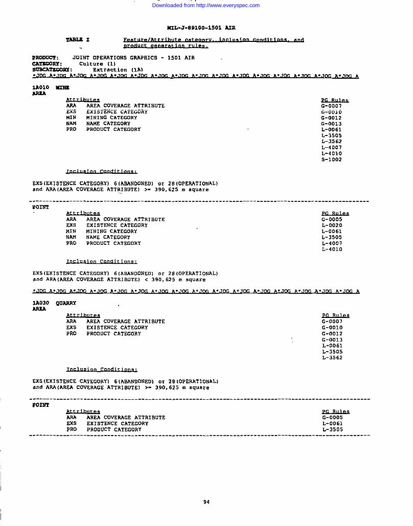
K2L-J-E91OO-1SO1 A2R
-1
mooam : .701tmOPEAATIONS GWOICS - 1501 AIRCA?KGORY : Culture (1)mscAT2Gom ; Extraction (lb)
2AO1O 4mu
y&Lu-AAEA COVERAGE ATTRIBUTE
EXSG-0001
EXISTENCE CATEGORY G-OO1OMIN MINING CATEGORYNAM
G-0012NAME CATEGORY G-0013
PRO PRODUCT CATEGORY L-0061L-3505L-3562L-4007L-4010s-1002
EXS(EXISTENCE CATEGORY) 6(ABANDONED) or 28 IOPERATIONAL)and Am fmsA COVERAGE ATTR,lBuTEI >- 390,625 m square
____________________________________________________________________________________________________
Pom
AAA AREA COVERAGE ATTRIBUTE G-0005EXS ExIsTENCE CATEGORY L-0020MIN MINING CATEGORYNAM
L-0061NAME CA7EG0RY L-3505
PRO PRODUCT CATEGORY L-4001L-401O
EXS(EXISTENCE CATEGORY) 6(ABANDONED] c.r28(OPERATIONAL)and ARAIAREA COVERAGE ATTRIBUTE) c 390,625 m square
M030 QUARRY
&bltaaAREA CDVEAAGE ATTRIBUTE
EXSG-0007
EXISTENCE CATEGORY G-OO1OPRO PRODUCT CATEGORY G-0012
G-0D13L-0061L-3505L-3562
EXS(EXISTENCE CATEGORY) 6{ABANDONED) or 28(OPERATIONAL)and AAACAREA COVERAGE ATTRIBUTE) >. 390,625 m square
----------------------------------------------------------------------------------------------------
Po2212’
AP.A AREA COVEAAGE ATTRIBUTEEss ExIsTENCE CATEGORYPRO PRODUCT CATEGDRY
G-0005L-D061L-3505
----------------------------------------------------------------------------------------------------
94
Downloaded from http://www.everyspec.com
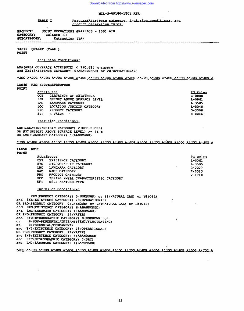
I
M2L-J-891OO-1SO1 NR
TASLS1
PRoQocT : JOINTOPERATIONSGRAPHICS- 1501AIRcArscORY : culture (]1SoscA?scoux : Extraction (1A)----------------------------------------------------------------------------------------------------
2A030 QVAR2tY (Cont.)R022S’2
AAA(AREA CUVEMcs ATTRISVTEI c 390,625 u,squareand EXSIEXISTENCECATEGORY)6(ASANOONEDIor2SIOPERATIONAL).J& *.J~ ~.J&- ~.J~ A.J~ ~.J~ ~.J~ ~.J~ ~.J&- ~.m.J~ ~.J~ ~.J~ ~.JcG *.J~ ~.J~ A
2A040 me /m’P2s9rRocmRsPOIU’2
CDE CERTAINTY OF EXISTENCEIIGT
G-OOOBHEIGHT ABOVE SURFACE LEVEL L-0061
MC LANDWAAS CATEGORY L-3505Lm LOCATION /ORIGIN CATEGORYPRO
L-5040PRODUCT CATEGORY D-3008
ZVL Z VALUE .; R-004 6
LOC(LDCATIONIOR1 GIN cATEGORY) 2(OFF-SHORE)OR OCT(HCIGETASOVESURFACELEVEL]>.46~OR U4C(LAND144RK CATEGORY] l (LANDMARK)
EXS EXISTENCE CATEGDRY L-0061FIYC HYDROGKAPHIC CATEGDRY L-3505USC LANO14ARK CATEGORYNM
R-2027NAME CATEGORY T-0013
PRO PRODUCT CATEGORY V-10186CC SPRING /WELL CRAAACTERISTIC CATEGORYWFT WSLL FEATURE TYPE
PRO(PRODUCT CATEGORY] O(UNWOW) or 12(NATUWIL GAS] or 10(OILland EXS(EXISTENCE CATEGORY). 2E(DPERATIONAL)OR PRO(PROOOCT CATEGORY) O{UNKNOWW) or 121NATUPAL GAS) cm IE (OIL)a“d EXS(EXISTENCE CATEGORY] 6(ABAND0NEDIand LJ4CILAND6L4FWCAT2G0RYI l(LAWDmRK)OR PRO(PRODUCT CATEGORYI 27(wATER]a“d RYCiHYDROGRAPSIC CATEGORY I OIUNswOwwl oror 6lNON-PERENNIAL/l NTEPJ61TTENTlFLUCTUAT1NGIor 8 (PEREwI~, !DWDW*N=NT,and EXS(EXISTEORa“
..-, .-.” -.”.. . ,
ENCE CATEGORY) 2B (OPERATIONAL)t PRO IPRODUCT CATEGORY) 27(wATER),d EXSIEXISTENCE CAT2GDRYI 61ABAN00NEDI
and HYC(BYDRDGRAPRIC CATEGORY) 3(ORY)and IJ4C[IANDMARS cATEcORY) 11LAND14ARK)
95
Downloaded from http://www.everyspec.com
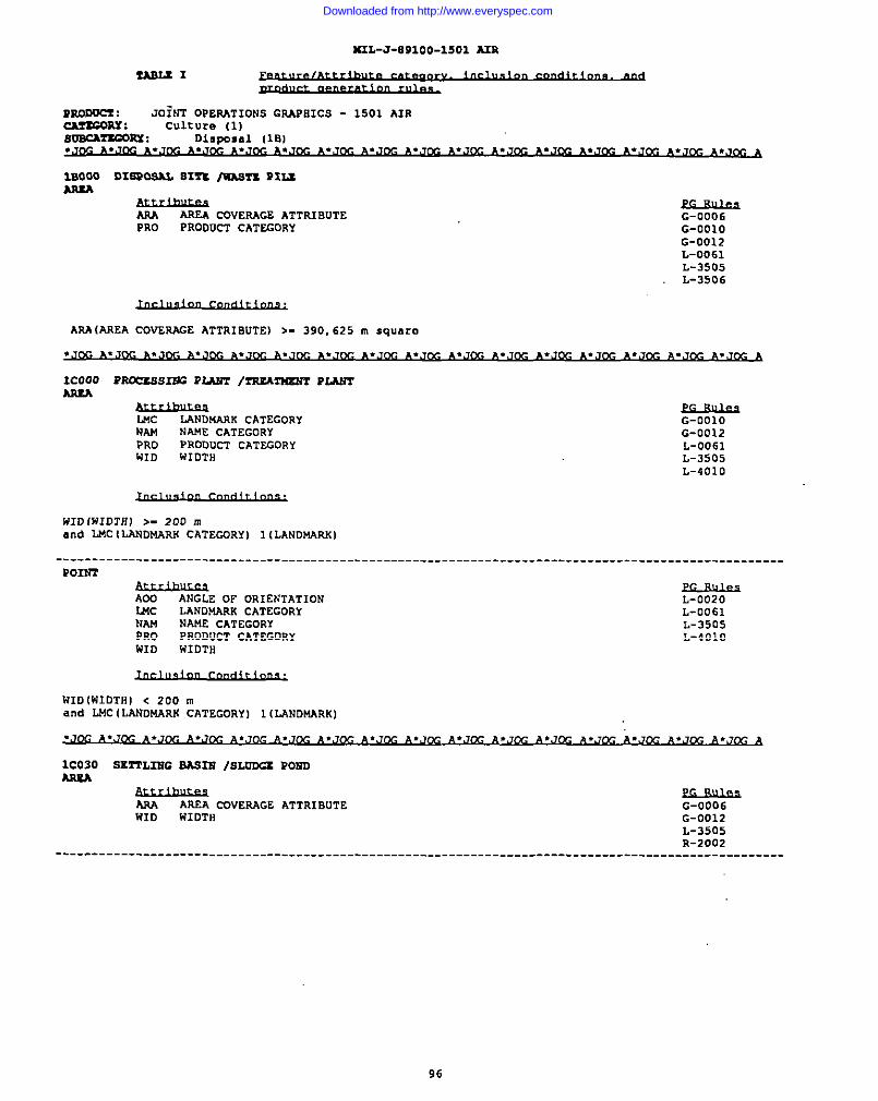
4UL-J-891OO-15O1 A3R
tA212.zl
Puooucf : JO?NT OpEPATIONS mmPHIcs - 1501 AIRcAr3cDRY : Culture (1]sVxAncom : Dinposal (18}
lBOOO DIS3W 815Z Illh!2mPIuam.. —-
Am AREA COVERAGE ATTRIBUTEPRO PRODUCT CATEGORY
G-0006G-ooloG-0012L-0061L-3505L-3506
ARA (AREA COVERAGE ATTRIBUTE) >- 390,625 m square
Icooo moczss= PM3m /rsxA31mm PLAWT
U4c LANDf6AAKCATEGORY G-OO1ONM NA!4ECATEGORY G-0012PRO PRODUCT CATEGORY L-0061UID WIDTH L-3595
L-401O
HID(WIDTH) >- 200 mand LMC ILANDt6ARK CATEcORy) 1(LANDMARK)
----------------------------------------------------------------------------------------------------POIW’3
AOO ANGLE OF OR1ENTATIONUSC
L-0020LANDMARK CATEGORY
NML-0061
NAME CATEGORYPRO
L-3505PRODUCT CATEGORY
WIDL-401O
wIDTH
WID (WIDTH) < 200 mand L14cILANDMARX cATEGORr) 1 (LANDWARKI
1C030 SE~LIBC BA323! /SLODGZ P03mNuM
Am AREA CQVERAGE ATTRIBUTE G-0006WID W1OTH G-0012
L-3505R-2002
----------------------------------------------------------------------------------------------------
P6
Downloaded from http://www.everyspec.com
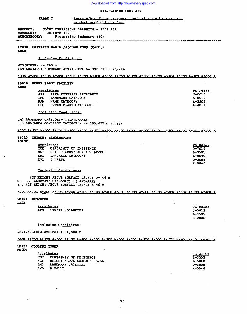
M2L-J-E91OO-15O1 A2R
TML2 I
uRooOcZ : JOiNTOPERATIONSGRAP121CS - 1501 AIR~RY : culture [1)svncAr3GOBx : Procss8ing Industry (ICI
---------------------------------------------------------------------------------------------------
1C030 S3T?L3BG BAsnl /aLoDu POSD (coat.)As3A.
w1O(WIOTH) >- 200 mand ARA(AREA COVZRAGE ATTRIBUTE) >- 390, 625 m square
.Jm A.JDC ~.-..J~ ~.J~ ~.,J~ ~.J~ ~.J~ *.J~ ~ ~.J~ ~.J~ ~.-.,,m ~.J~ ~.J~ A
IDO1O m3i3il P3ANI rsczmmARM
ARA AREA ~VSRAGE ATTRIBuTEMC
G-OO1OLANDM CATEGORY
NAM NM CATEGORYG-0012
PPC pOwsR PL+.WTCATEGORYL-3505L-4011
MCI LANDMARK CATEGORYO 1 (LANDMARK)and ARA(AREA COVERAGE CATEGORY) >- 390,625 m square
.,,&-JA.,,m ~.,~ ~.J&- ~.J~ ~*J~ ~.J~ ~.J&- ~.,&- ~. ,&- ~.,~ ~.,7& *.J~ *.J~ ~.J~ *,J~ A
lrolo cs120fzY /sAIDmTAcsP033r2
COE CERTAINTY OF EXISTENCE 0-7019HGT EEIGRT ABOVE SURFACE LEVEL L-3505U4c LANDMARK CATEGORY L-5040
IZVL Z VALUE O-3008
R-0046
HGT (HEIGHT ABOVE SURFACE LEVEL) >- 46 m
IOR LWC (LANDWARK CATECDRY) 1 (LANDMARK)and HGT (HEIGHT ABOVE suRFACE LEVELI < 46 m
.J ~.*. ~.A.J~ .KA. A. ~. A.. ~. J.J. .J. CG A
wozo C027WYORLIE2
LEN LENGTH /DIANETER G-0012L-3505R-0006
LEN (LENGTE/DIAWSTER) >- 1,500 m
wo30 ccoum 3owmP02m
CDE CERTAINTY OF EXISTENCEHGT HEIGST ABOVE SURFACE LEVELMC LANDNARK CATEGORYZVL Z VALUE
L-3505L-5040o-3ooaR-004 6
97
Downloaded from http://www.everyspec.com
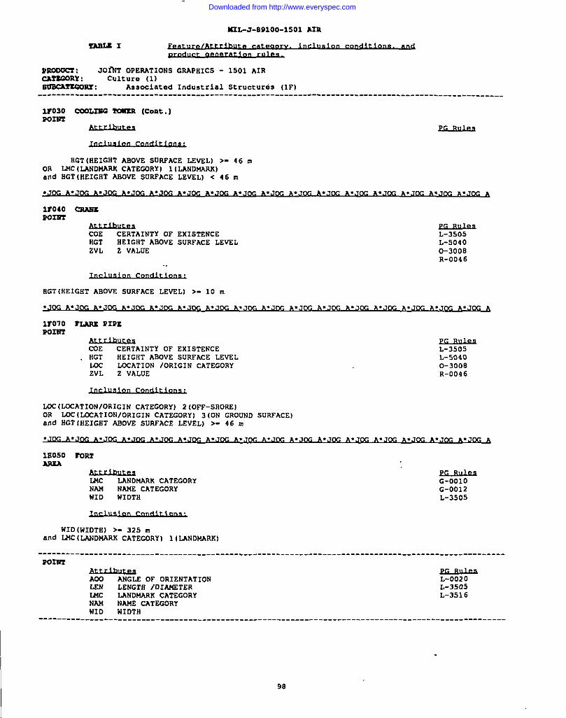
443L-J-8S1OO-15O1 hIR
ns2.tl
P3mocx : JO~T OPERATIONS GRAPSICS - 1501 AIRcA?xGORx : Culture (1)SoacA?rcon : Associated Industrial structures (lFI
---------------------------------------------------------------------------------------------------
2r030 C00L2E0 TOA_xR (Cent.)P02U2
SGT (REIGST ASOV2 SORPACE LEVEL) >- 46 mON LMC (LANDMARK CATECDRY) 1[LANOMRKIand EGT (HEIGST ASDVE SURFACE LEVEL] < 46 m
~.J~ ~,J~ ~.J&- ~.J~ ~.J~ A.J~ ~,J~ *.J~ ~.J~ ~,J~ ~.J~ A
wo40 csmmmm
COE CERTAINTY OF EXISTENCERGT
L-3505HEIGHT ABOVE SURFACE LEVEL
ZVL Z VALUEL-50400-3008R-0046
HGT(REIGHT ABOVE SURFACE LEVEL) >- 10 m
A
wo70 rum m=P02RT
CDE CERTAINTY OF EXISTENCESGT SEIGST ASOVE SURFXE LEVELm LOCATION /ORIGIN CATEGORYZVL Z VALUE
L-3505L-512400-3008R-0046
LGC (LGCATION/ORIGIN CATEGORY) 2 (OFF-SSORE)OR mc (=AT1ON/ORIGIN CATECORYI 3 (0N GROUND SURFACE Iand RGT lHEIGHT mom sURFACE LEVEL) >- 46 m
.J~ ~.J~ *.,M ~.J~ ~.J~ ~.J~ ~.J~ ~.,3~ ~.J~ ~.Jm ~.J~ A
10050 mmMEA
WMC LANDMARK CATEGORYNAW NAME CATEGORYWID
G-0012W1OTH L-3505
WID(wIOTSj >- 325 ~and WC ILmDwARs CATEWRYI 1(L.4NDmRK)
----------------------------------------------------------------------------------------------------POIU2
AoD ANGLE OF OR1ENTATIONLEN LENGTS /DIM4.ETERU4c LANONASK CATEGORYNAM NAME CATEGORYWID WIDTfl
L-0020L-3505L-351 6
L----------------------------------------------------------------------------------------------------
98
Downloaded from http://www.everyspec.com
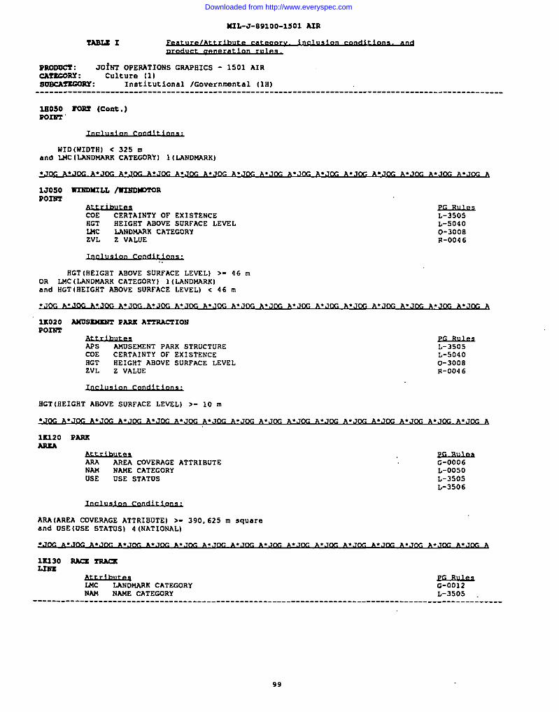
N3L-J-891oo-15O1 NR
PRoooa : JO?NT OPERATIONS GRAPHICS - 1501 AIRCMUORY : Culture [1)soncA2xc0Px : Institutional lGovernmsntal (10)
----------------------------------------------------------------------------------------------------
lssoso mm (Cent.)PO14?’3
WID(WIDTHI < 325 mand I.MCILANDMARK CATEGDRYI 1 (LANDMARK)
1J050 R’ISDMXLL /W’2ROU.VMS4P02’ST
COE CERTAINTY OF EXISTENCEHGT
L-3505HEIGHT ASOVE SURFACE LEVEL
MCL-5040
LANDMARK CATEGORYZVL Z VALUE
0-3008R-0046
RGT IREIGHT ABOVE SURFACE LEVELI >- 46 mOR LMC (LANDMARK CATEGORY I 1ILANDMARK)and RGT (iiEIGHTASOVE sURFACE LEVEL) < 46 m
1K020 AnussMzuT Pm A3’3’Rlm10!4POIsT
APs AMUSEKENT PARK STRUCTORECDE CERTAINTY OF EXISTENCERGT HEIGHT ABOVE SURFACE LEVELZVL Z VALUE
L-3505L-50400-3008R-0046
SGT (HEIGHT ASOVE SURFACE LEVSL) >- 10 m
1K320 PmARtA
AAA AREA cOVERAGE ATTRIBuTENAM NAME CATEGORYUSE DSE STATUS
G-0006L-0050L-3505L-3506
ARA (AREA COVERAGE ATTRIBUTE) >- 390,625 m squar=and USE (USE STATUS) 4 (NATIONAL)
lx130 RAu rsAQ.L2SS
&hu2J?sLANDWK CATEGORY
NAMG-0012
NAME CATEGORY L-3505---------------------------------------------------------------------------------------------- :-----
99
Downloaded from http://www.everyspec.com
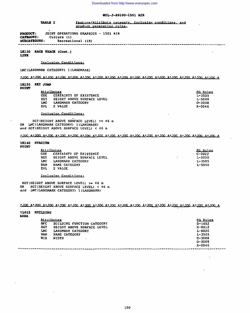
M2L-J-891OO-15OI A2R
rmu 1
?Eoocct : JOIST OPERATIONS GRAPSICS - 1501 AIRcAfEGORY : Culture (1)s02cArr.GOllY: Recreational (lK)
----------------------------------------------------------------------------------------------------
UU30 Usu rmcs (cork. )
LNC (LANDMARs CATEGORY) 1 (LAND14ARK)
12U50 Ssx JnxPP02m
COE CERTAINTY OF EXISTENCEHGT HEIGHT ABOVE SUSFACE LEVELMC LANDUARK CATEGORYZVL Z VALUE
.MiBuk9L-3505L-50400-300SR-004 6
SGT (HEIGHT ABOVE SURFACE LEVZLI >- 46 mOR LMC (LANDMARS CATEGORY) 1 (LANDMARK)and HGT (SEIGST AROVE SURFACE LEVELI c 46 m
1S160 STAOIUNP0n72
COE CERTAINTY OF EXISTENCEHGT HEIGHT ABOVE SURFACE LEV2LWC LANDMARK CATEGORYNAM NwE CATEGORYZVL Z VALUE
~C-0022L-0020L-3505L-5040
HGT{HEIGST ABOVE SURFACE LEVEL) >- 46 mOR HGT (SEIGST ABOVE SURFACE LEVEL) < 46 mand mc (IJINOMARK CATEGORY) 1 ILANDMARK I
1L015 BUILOINGARM
BFC BUILOING FUNCTION CATEGORYaGT
D-1652SEIGHT ASOVE SURFACE LEVEL
MCG-0012
LANDUARK CATEGORYNAM
L-0020NAME CATEGORY
HIDL-3505
wxDTn 0-30080-3009R-004 6
------------------------------------------------------------------------------------------- _________
Downloaded from http://www.everyspec.com
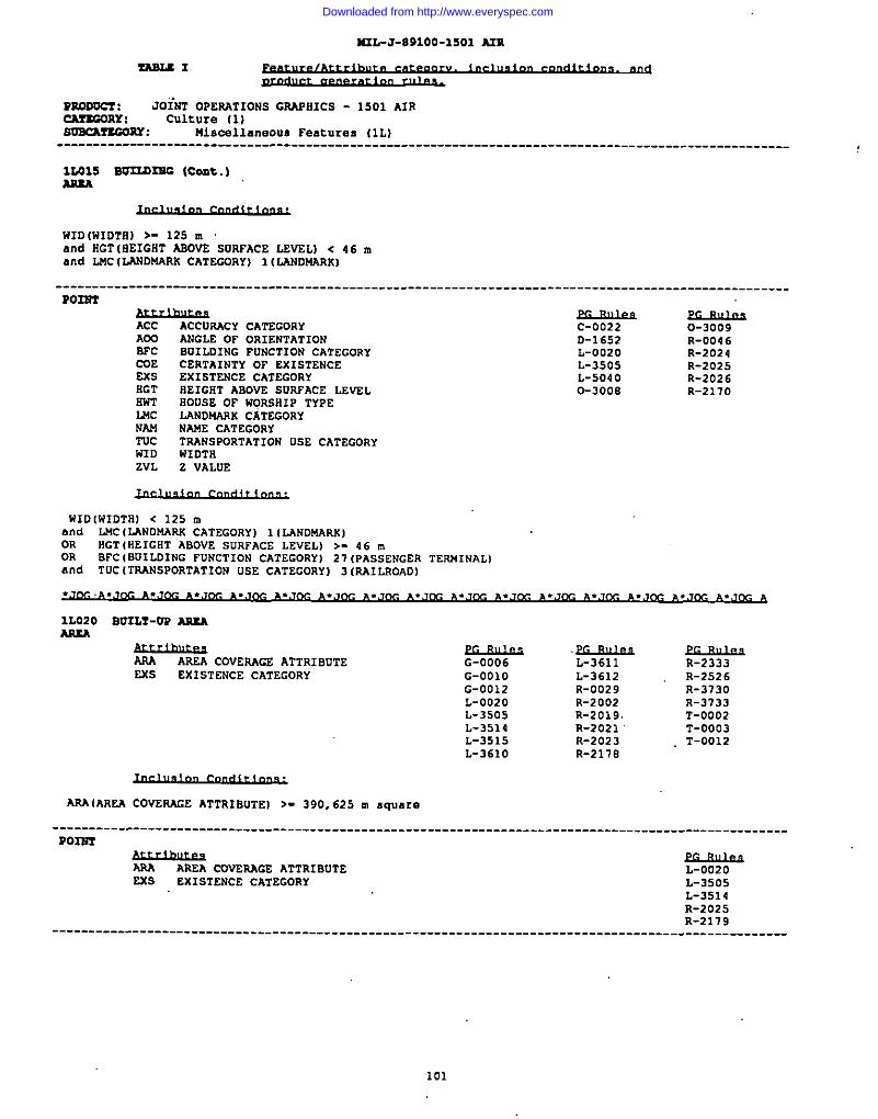
M2L-J-891OO-15O1 AIR
ZASLSI
moocc7 : JOiNT OPERATIONS GRAPHICS - 1501 AIRcAzsGonY : Culture (1)aoncArsGoRT : Miacsll.sneous Features (IL)
----------------------------------------------------------------------------------------------------
12.015 so22ansG (Cent.)
WID (WIDTfl)>- 125 mand HGT [EEIGRT ABOVS SURTACE LEVEL) < 46 ❑
and LJ4C(LANDMARK CATEGDRY) 1 (LANDU4RXI
Po22r2
Acc ACCUSACY CATEGORYADO ANGLE OF OR1EWTATIONBFC BU1LOIWG FDNCTIOW CATEGORYCUE CERTAIWTY OF EXISTEWCEEM EXISTEWCE CATEGORYRGT HEIGHT ABOVE SURFACE LEVELNWT ROosE op w0s6a1p TYPELwc LANDMARx CATEGORYWm! NAWE CATEGORY
------------------------------------ .
c-0022D-16S2L-0020L-3505L-50400-3000
.__---
0-3009R-004 6R-2024R-2025R-2026R-2170
TUC TRAWSPORTATIOW USE CATECDRYWID WIUTNEVL Z VALUE
WID(WIDTBI < 125 mand LNc (LAWDNARK CATEGORY) 1(LANDMARK)OR NGT (HEIGNT ABUVE SURFACE LEVEL) >- 46 mOR BFC (BUILDING FUWCTION CATEGORY) 27 (PASSEWGER TERN INAL)and TUC ITRANSPORTATION USE CATEGORY I 3 IRA1LROAUI
1L020 B02LT-OP ARSAMUA
f&w.esAREA COVERAGE ATTRIBUTE
Exs EXISTENCE CATEGORY
.~G-0006 L-3611 R-2333G-OO1O L-3612 R-2526G-0012 R-0029 R-373uL-0020 R-2002 R-3133L-3505 R-2019. T-0U02L-3514 R-2021 T-0003L-3515 R-2023 T-0012L-361O R-2178
ARA(AREA COVERAGE ATTRIBuTE] >- 390, 625 m square
----------------------------------------------------------------------------------------------------Po3m
yAREA COVEFL4GE ATTRIBUTE L-0U20
EXS EXISTENCE CATEGURY L-3505L-3514R-2025R-2179
----------------------------------------------------------------------------------------------------
101
Downloaded from http://www.everyspec.com
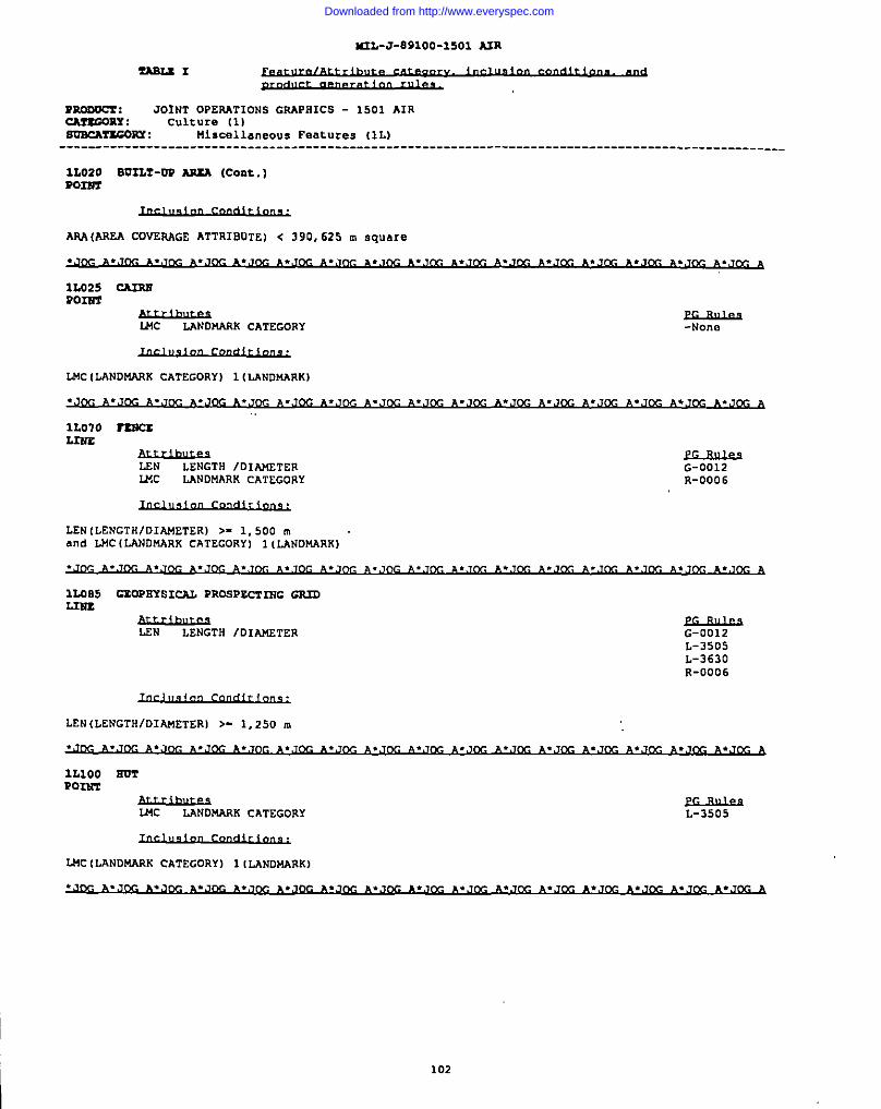
K2L-J-E91OO-15O1 A2R
I!ABLE1undlLc-Lc-
?mnvcr : JOINT OpERATIONS GRApa1c5 - 1501 AIRCAftGOnx : culture [1)svRcArxcOPx : Miscellaneous Features (IL)
---------------------------------------------------------------------------------------------------
1L020 BU2L?-W AP2A (Coat.)P022?z
AP.A(AREA COVEAAGE ATTRIBOTE) < 390,62S m square
1L025 CAINNP031r2
UK LANDMARK CATEGORY~-Non.
LMC (LANDMARK CATEGORY) 1 (LANDMARK)
A.J~ ~.J~ *.J~ ~.JK ~.Jm A
1L070 TENCXL2N%
L2N LENGTH /DIAMETERWC
G-0012LANDMARK CATEGORY R-0006
LEN (LENGTHIDIAMETER) >- 1,500 mand LMC (LANDMARK cATEGORYI 1 (LANDMARK)
1L085 GEOPBYSICAL PROEPECT2EC G2UDLz37r.
LEN LENGTH /D1A14ETERW
L-3505L-3630R-0006
LEN (LENGTH/DIAMETER) >- 1,250 m
1L1oO mP02W2
MC LANDMARK C&TEGORY L-3505
LNC (LANDMARK CATEGORY) 1 [LANDMARK)
102
Downloaded from http://www.everyspec.com
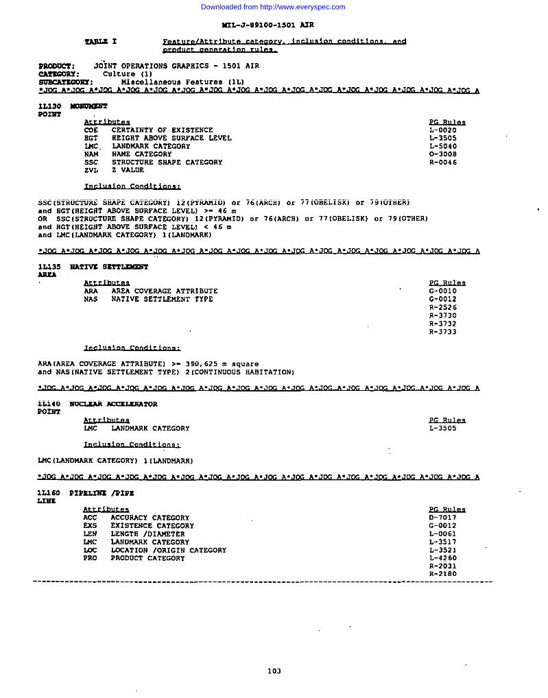
I
422L-J-89100-1501 A2R
n322i31
PaooOCT: ““JoINT OPERATIONS GRAPBICS - 1501 AIRCA?EORY: culture (1)SmcMsGOm : Miscellaneous Features (lL)
IL330Pom
Mouma3m
$&hu.%3CERTAINTY OF EXISTENCE
2!GT EEIGHT ASOVE SORFACE LEVELU4C LANDNARK CATEGORYNAU NAME CATEGORYSsc STRUCTDRE SKAPE CATEGORYZVL Z VALDE
L-0020L-3505L-50400-3008R-004 6
SSCISTRUCTVR6 SWE CATEGORYI 12 (PYRAMID) or 76 [ARCH) or 77 (OBELISK) or 79 IOTHER)and BGT (NEIGflTABOVE SUAPACE LEVEL) >- 46 mOR SSC(STRUCTUAE SNAPE CAT2GORY) 12 (PYRAMID) or 76(ARCMI or 77 (OBELISK) or 79 (OTHER]and HGT(NEIGIIT ABDVE SUAPACE LEVELI c 46 mand L44C(LWDMAAK CATEGORY) 1 {LANDU4RK)
12.235 EA?2VS ss3’r—AREA
AAA AREA COVEP-4GE ATTR18UTE G-ooloNAS NATIVE SETTLEMENT TYPE G-0012
R-2526R-3730R-3732R-3733
ARAIAREA CDVEP.AGE ATTRIBUTE I >- 390.625 m squareand NAS (NATIVE SETTLEI.IZNTTYPE I 2 (CONTINUOUS HAB1TATIONI
MC LANDNARK CATEGORY L-3505
L4!C(LAND14AAK CATEGORY) 1(LANDMARK]
.3
1L260 PIPS3,321S/PIPEL241s
ACC ACCCIWCY CATEGORYExs EXISTENCE CATEGORYUN LENGTH /OIAMETER144c LANDNARK CATEGORYm LCCATION /ORIGIN cATEGORYPRO PRODUCT CATEGORY
D-7017G-0012L-0061L-3517L-3521L-4260R-2031
-...
I ---------------------------------__-____-__--------------_-__-____________
103
Downloaded from http://www.everyspec.com
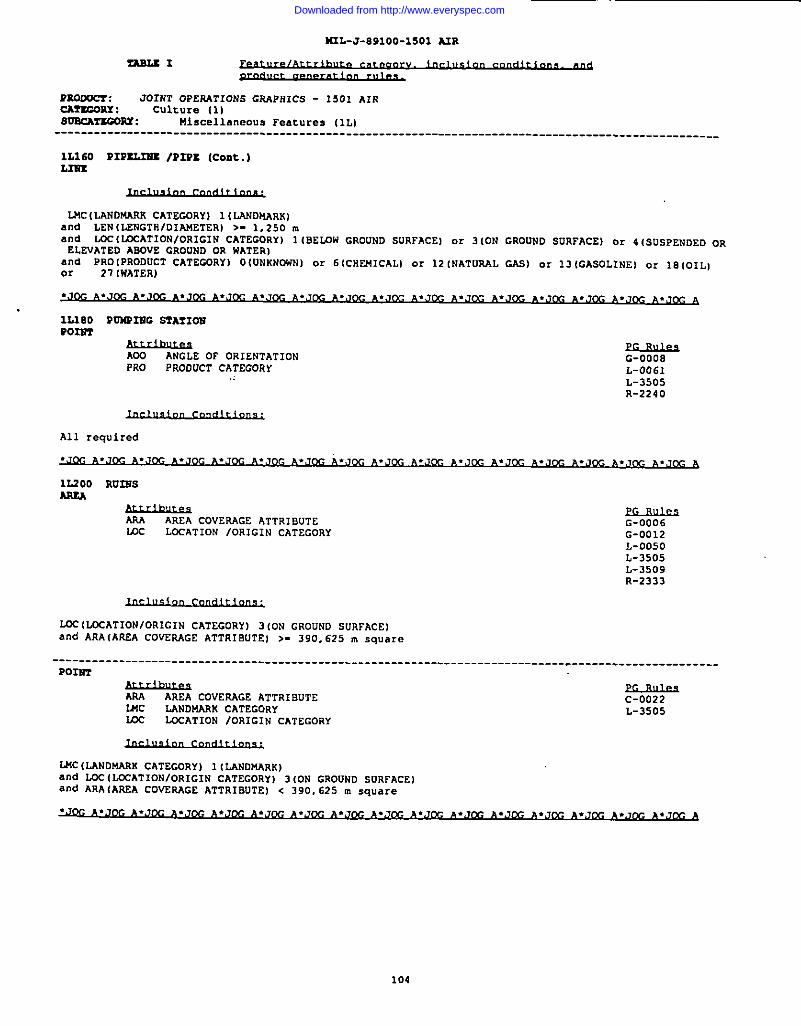
MIL-J-891OO-15O1 AIR
?RmucT : JOINTOPEA.4~10NSGRAPHIC5- 1501AIRCA?2CORY : CUlt”re (1)SNSCA5’KCOSY: Miscellaneous Features (IL)
----------------------------------------------------------------------------------------------------
lL160 PIPSL23SS /PIPx (coat.)L3m
IJ4cIwND~R CATEGORYI 1 ILANDMARK)and LEN (LENGTH/DIAMETER) >- 1,250 mand LCCIUJCATIONIOR1 G1N CATEGORYI 1lBEuIh’GROUND SURFACEI or 3(ON GROUND SORFACEI or 4(SDSPENDED ORELEVATED ABOVE GROUND OR WATER)
and PRO IPRODUCT CATEGORY) OIUNKNONN] or 6(CHENICAL) or 12 [NAT~L GAE) or 13 (GASOLINE) or IS (OIL)or 21 [WATER)
ADO ANGLE OF OR1ENTATIONPRO pRODUCT cATEcoRY
G-0008L-0061L-3505R-2240
All required
.JA, A.. .+. . .*, cc A
1L200 RV322SAAsA
AAA AREA COVERAGE hTTRISUTE G-0006IJ3c LCCATION fORIGIN CATEGORY G-0012
L-0050L-3505L-3509R-2333
LOC (LOCATIONIOR1G1N CATEGORY) 3 ION GROUND SURFACE)and ARA(ARCA cOvrmGE ATTRIBUTE I >. 390,625 m square
----------------------------------------------------------------------------- .-_----.-------------.-Pom
y&ur.esAREA COVERAGE ATTRIBUTE
MCC-0022
LANDMARK CATEGORY L-3505IK)c LDCATION /ORIGIN CATEGORY
LNC (LANDMARK CATEGORY) I (LANDI.IARK).llldLOC (~ATION/ORIGIN CATEGORY) 3 (ON GROUND SURFACE)and ARA (AREA cOvzwGE ATTRIBUTE) < 390.625 m square
.JWA. JWA. JW ● ,*, ● *.. .,, , ● CCA
Downloaded from http://www.everyspec.com
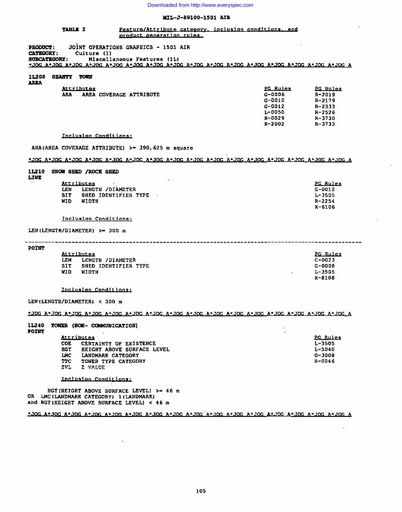
I
M2L-J-891OO-15O1 AIR
~1
PRooOcx : JOiNT OPERATIONS GRAPHICS - 1501 AIRCArEORY: culture (1)soEcArsGORY : Miscellaneous Features (lL)
.J~ ~.J~ ~*,J~ .9
12.20s SEAnTY mAslsA
Am AREA COVERACE ATTRIBUTE
AM (AREA COVERAGE ATTRIBOTE] >- 390,625 m square
G-0006 R-2019G-OO1O R-2119G-0012 R-2333L-0050 R-2526R-0029 R-3730R-2002 R-3733
A.J~ A.J~ ~.J~ ~.J~ .3
2.2210 Ss2aaSmo /Rccs mmL214s
Audhuus .LEN LENGTH /DtA2fETERBIT
G-0012SHED IDENTIFIER TYPE
WIDL-3505
WIDTH R-2254X-8108
LEN (LENGTR/DIAMETER) >- 300 u,
-------------------------------------------------------------------------------------------------- .P02372
LEN LENGTH /DIAMETER C-0023SIT SllED IDENTIFIER TYPE G-0008WID WIDTB L-3505
x-8108
LEN (LENGTil/D1Af4ETER)< 300 m
.J~ A.J~ ~.J~ ~.J@-J ~.J~ ~.,J~ ~.JDc ~.J~ A.J~ ~.J~ A.J~ ~.J~ ~.J~ ~.,J~ ~.Jcc ~.J,-& h
1s4240 rousN (MoN- CCU14DN1=I05J)P02R’2
Suihlu&’CDE CERTAINTY OF EX1 STENCEHGT
L-3505REIGET ABOVE SORFACE LEVEL
SMcL-5040
LANDMAAR CATEGORYTTc
0-3008T0W2R TYPE CATEGORY
EVLR-004 6
z VALUE
BGT [EEIGRT ABOVE SURFACE LEVELI >- 46 mOR WC {LANDMARK CATEGDRY) 1(LANDMARK]and flGT[REIGBT ABOVE BURPACE LEVEL) < 46 m
~.,~ ~.J~ ~.,~ ~.,’j~ A.== ~*Jw A
105
.-
Downloaded from http://www.everyspec.com
I
142L-J-09100 -lSOl A2R
-1
RROOccT : JOINT OPESATIOFIS GSAFHICS - 1501 AIRcAltcoRY : Culture (1)SoxATKcOPx : !liscellaneous Features (lLI
ii
1LZ60 wL2E33
LEN LENGTH /DIAwETERIMc
G-0012LANDWARK CATEGORY L-361O
R-0009R-2178R-211 9
LEN (LENGTfl/DIAUETER) >- 1,250 mand WC [LANDMARK CATEGDRYI 1(LANDMARK)
.J~ ~:=m ~.J~ ~.J~ ~.J~ ~.J&-J~.J~ ~.J&- .,J@J~.J~ ~.J~ ~.J~ ~.J~ ~.J~ ~.J~ ~.J~ A
3M030 GRA2S Z2,WA’?ORPOINT
COE CERTAINTY” OF EXISTENCE L-3505HGT IIEIGRT ABOVE SURFACE LEVEL L-5040IMc LANDMARK CATEGORYZVL Z VALUE
0-300sR-0046
SGT(8E1GHT ABOVE SORFACE LEVEL) >- 46 mOR LWC (LANDMARK cATEGORY ) 1 (LANDMARK)and HGT (HEIGHT ASOVE SURFACE LEVEL) < 46 m
A
341050 Si-wP0322T
COE CERTAINTY OF EXISTENCE L-3505RGT HEIGHT ABOVE SURFACE LEVEL L-5040MC LANDNARK CATEGORYT.VL z VALUE
0-3008R-0046
HGT [flEIGSTABOVE SURFACE LEvEL) >- 46 mOR LUC (LANDWARK CATEGORY) 1(LANDMARK)and OGT IHEIGHT ABOVE SURFACE LEVEL) c 46 m
molo rAN23POIm
CDE CERTAINTY OF EXISTENCESGT
D-1652HEIGHT ASOVE SURFACE LEVEL
MCL-0061
LANDMARK CATEGORY L-3505m LDCATION /ORIGIN CATEGORYPRO
L-3519PRODUCT CATEGORY L-4010
WID W1OTHZVL z VALUE
L-4016L-50400-3008R-004 6R-2027
----------------------------------------------------------------------------------------------------
106
Downloaded from http://www.everyspec.com
=L-J-891OO-15O1 A3R
TASLEI
Ruooocf : JOINT OPERATIONS GRAPOICS - 1501 AIR~: culture [1)SmmmGom: Storage (lM)
--------------------------------------------------------------------------------------------------
2.M070 rAEK (coat.)m2GT
EGT(EEIGRT ABOVE SURPACE LEVEL) >- 46 mOR MC (LMD14411i4CATECDRY) 1(LANDNARK)and 0GT(EEIGi2T ASDVE SUAPACE LEVELI < 46 m
216080 WAlzu Wr6zRQoIsT
CDE CERTAINTY or EXISTENCE L-3505HGT EEIGHT AB43VS SURFACE LEVEL L-504 OWC LANDMARK CATEGORY 0-3008ZVL Z VALUE R-004 6
RGT iREIGHT ABOVE SURFACE LEVEL) >. 46 mOR LMC (LAWDNARK CATEGORY) 1(LANDMARK)and HGT (HEIGIITABOVE SUAPACE LEVEL) < 46 m
1UO1OL2ST,
RA2LROAD TsAcs
Acc ACCU~CY CATEGORYExs EXISTENCE CATEGORYGAi9 GAUGE WIDTHm. L’XATION /ORIGIN CATEGORYLTN LAwE/mmcl(NUMBERNAN NA!42CATEGORYKC RAILROAD GADGE CATEGORYAPs RAILROAD POWER SOURCESAC PAILROM) IROAD CATEGORIES
D-1501D-1650D-1029D-1030G-0012L-3614L-3615L-3616L’--J6~,
L-3618L-3619L-3620
=
L-3622L-3631L-3632L-3633L-3634L-3635L-3636L-3637L-3638L-3649
L-42840-30030-30040-3010R-2195R-2196R-2191R-2198R-2601S-O1O3S-7030
RGc (RAILROAD GADGE CATEGORY) 1 (BRDAD) or 3 (NORMAL (STANDARD))snd U.c (~AT1ON/ORIGIN CATEGORY I 3 (0N GROUND suspAcEj or 4 ISUSPENDED OR ELEVATEO ABOVE GROUNO ORWATERIand ASC lRAILROAD/ROAD CATEGORIES) 1 [wIN LINE/BRANCH LINE]and LTN ILARE/TRACK N13NSERI >. 1OR RGC (RA2LAOAD GADGE CATEGORY) 2 (NARRDN)and UC 3 (ON GROUND sORFAcE) or 4 ISUSPENDED DR ELEVATEO A80VE GROuND OR WATERIand RRC(AAILROAD/ROm CATEGORIES) 3 (MONORAIL] or 0 [U3GG1NGIand GAW(GADGE WIOTEI >- 0.05 ~and LTN (LANE/TwcR NUUBERI >. 1OR ARC (RAILJ(OAO/ROAD CATEGORIES) 2 (CAR-LINE )and I&2 3 (ON GROUND SORPACE] or 4 (SUSPENDED OR ELEVATED mOVE GROUND OR WATER)OR ssc (5A2LROADlR0AD CATEGORIES 13 WARINE RAILROAD I .x 14 (RAILROAD IN RON)and Exs (EX:STENCE CATEGORY) 5 IUNDER CON STRtJCTIONI or 6 {AEANDONED) or 28 (OpEAATIONAL)and LOC 3 ION GROOwD SURFACE)
107
Downloaded from http://www.everyspec.com
442L-J-891OO-15O1 AIR
moDocr : JOINT OPERATIONS GAAP511CS - 1S01AIRcAzsGORY : culcure (1]suBcA?smm : Transportation R/R (lN)
1SI050 m 8202SC /ss WusLn4r.
LEN LENGTH /D1M4ETERLTN LANE/TRACK NUMBERRGc RAILROAD CADGE CATEGORY
0-7028G-0012L-3505
SPs SAILROAD POWER SOURCERSA
L-3630RAIL SIDING /SPVR ATTRIBuTE L-3634
L-4284
L2N (LENGTR/D1AJ4ETERl >- 1,250 m
1E080 PJ4YASCIAslA
AudhLes “’EXS EXISTENCE CATEGORYLEN LENGTH IDIAMETERLTN
G-OO1OLJiNE/TAACK NUMBER G-0012
0-00010-0002
LEN(LENGTH/DIAKETER) >- 1,600 mand EXS [EXISTENCE CATEGORY) 6 (ABANDONED) c.r28 (OPERATIONALI
1U090 TRA5C4AY /2SCL1NS RA32iiAY
Lcc WCATION /ORIGIN CATEGORY G-0012L-3630
WC (L?JCATION/ORIGIN CATEGORY) 3 [ON GROUND SURFACE)
2RO1O CART rmcsL2Ns
ACC ACCURACY CATEGORYLEN
D-1652LENGTH /DIANCETER G-0012
TUC TRANSPORTATION USE CATEGORY 0-0004WTc ROUTE WEATHERABILITY CATEGORY R-0003
R-2186R-2187
----------------------------------------------------------------------------------------------------
100
Downloaded from http://www.everyspec.com
sRL-J-891oo-15O1 A2R
ZASLZI
Rsooccl : J6hlTOPERATIONSGRAPHICS- 1501AIRcArscORY : Culture (1)SoacAnmsx : Transportation IRoads (1P)----------------------------------------------------------------------------------------------------
23010 CAES ~ (Cent.)L2ss
4FTC{ROUTE WEATHERABILITY CATEGORY I 2 (FAIR/DRY WSATHER)and LEN [LENGTS1/DIAKETER) >- 1,250 m
1P020 —L2u2
LEN LENGTtl IDIAMETERRET ROAD/RUNNAY SURFACE TYPEUSE USE STATUSNTc ROUTE WEATHERAB1 LITY CATEGORY
USE (USE STATUS I 50(LIMITED ACCESS)and RST (ROAD/RUNWAY SURFACE TYPE) 1 (HARD SURFACE)a“d WTC (ROUTE i4EATSEAAS1L1TY CATECDRYI 1 (ALL UEATSER]and LEN (LENGTS/DIAMETERl >. 625 m
-N.xe
P02NT
ADD ANGLE OF ORIENTATIONLEN LENGTH IDIAMETERRET ROAD/RUNWAY SURFACE TYPEUSE USE STATUSNTc ROUTE WEATSERABILITY CATEGORY
G-0012R-2233,
USE (USE STATUSI 50 (LIMITED ACCESS)a“d LEN (LENGTSIDIAMETER) < 625 mand WTC IROUTE W~TSEAASILITY CATEGORY] 1IALL ~ATsERIand RST (ROAD/RUNNAY SURFACE TYPE I 1 (SARD SURFACE I
.J~ ~.J~ A.J~ ~.J~ p,.J~ ~.J~ ~.J~ ~.J~ ~.J~ ~.,~ ~.J~ ~,Jcc ~.J~ ~.J~ ~,J~ *.,’J@a
1P030 ROADL2s2
ACC ACCUWCY CATEGORY D-151O L-3649EXS
R-2175EXISTENCE CATEGORY 0-1652 L-3955
LSNR-2176
LENGTS /OIAKETER D-1027 L-4016 R-2181m LOCATION IORIGIN CATEGORY G-0012 L-5015LTN
R-21E2LANE/TSACK NUMBER L-3600 0-0004
MEDR-2185
MEOIAN CATEGORY L-3602 D-0026 R-2186MNo MEDIAN HIDTS L-3622 D-3010NA14
R-21B8NAME CATEGORY L-3635 R-0060 R-21B9
RET ROAD/RUNWAY SURFACE TYPE L-3639 R-2172TUC
S-loloTNANSPORTATION OSE CATEGORY
NTcL-3640
ROUTE NEATHERASILITY CATEGORY----------------------------------------------------------------------------------------------------
109
Downloaded from http://www.everyspec.com
M2L-J-891OO-1SO1 NR
Pumom : JOINT OPER-lTIONS GRAPHICS - 1501 AIRCAllmuY: culture (1)~!ucow : Transportation lRoads (1P)
---------------------------------------------------------------------------------------------------
1P030 ROAD (coat.)L2Nz
LEN(LENGTHID1A14STERI >- 300 m
1P050 ZRA2LL3EX
TuC TRANSPORTATION usE CATEGDRY D-1652 0-0004k-rc ROUTE WEATHEAAB1 LITY CATEGORY G-0012 R-0002
L-3603 R-0003L-3604 R-2171L-3630 R-21E6L-4033 R-2187
All required
.,,M. ~.J~ ~*J~ ~.J~ ~.J~ ~,J~ ~.Jw ~.Jw ~.,w ~.Jm ~.Jm ~.Jw *.Jm ~.J . , % a
1QO1O AER2AL CABLSllAY L~ /SK1 L2TT L2XEL=
LEN LENGTH IDIMTERLMc
G-0012LANDMARK CATEGORY L-3568
USE usE STATUS L-3630
LEN [LENGTH/DIAMETER) >- 1,500 mOR LEN (LENGTH/DIA14ETER) < 1,500 mand Lt4C(LAND~W CATEGORY) 1 (LANDMARK)
lQO~O BR20GS IOVEPJAS.5/V2AODC2’LIN2
SOT BRIDGE OPENING TYPEBvc
C-ooosORIDGE/VIADUCT CATEGORY
2X5G-0012
EXISTENCE CATEGORYLEN
L-3505LENGTH /D1At4ETER
NWL-4008
NAME CATEGORYOHB OVERALL HEIGHT OF BRIDGETUC TP.ANSPORTATION usE CATEGORYZVL Z VALUE
TUC (TAANsPORTATION USE CATEGORY) 1(SOTH ROAD AND sA1LROAD) or 3(AA1LROADl or 4 (ROADI or17 (PEDEsTRIAN) or 19 (AQUEDOCTI or 20 (CANAL)and LEN lLENGTfl/DIWETERI >- 125 m
---------------------- -------- _______________________________________
110
Downloaded from http://www.everyspec.com
M2L-J-891OO-15O1 A3R
RRooocT : J02~ OPERATIONS G~HICS - 1501 AIRCACSGORY : Culture (1)8mcAzsm9x : Associated Transportation (10I
----------------------------------------------------------------------------------------------------
1QIJ40 SR20=/WSWASS N’252)w (Cent. )Pam
WC BRIDGE/V IADOCT CATEGORYCOE CERTAINTY OF EXISTENCEExs EXISTENCE CATEGORYLEN LENGTH /OI~TERNAM NA14ECATEGORY
c-0006C-0007L-3505L-4008L-504 0
oaB OVEMLL &EIGllT OF BRIOGETM TRANSPORTATION USE CATEGDRYZVL Z VALUE
TM (TRANsPoRTATIDN USE CATEGORY I 1(BOTH ROAD AND RA1LROAD) or 3 (AM LROADI or 4 iROAD I or 19 lAOUEDUCTjor 20 (CANAL)and LEN (LENGTB/”DIASNETERl < 125 m
CUE CERTAINTY OF EXISTENCEOSB OVERALL HEIGHT OF BRIDGEZVL Z VALUE
L-3505L-504 O
OHBIOVERALL sExGsT OF BRIDGE] >- 46 m
10060 (XN72ROL _P0334T
ME CERTAINTY OF EXISTENCE8GT SEIGHT A80vE SURFACE LEvELZVL Z VALUE
L-3505L-5D4D0-3008R-004 6
8GT (HEIGST ABDVE SURFACE LE’~L] >: 10 m
10070 rss3w CR09S2.EGL3?2s
-FERRr CROSSXNG LENGTH
NM NANE CATEGORYG-0012L-3505L-3630R-2232R-71 93
--------------------------------------------- :______________________________________________________
111
Downloaded from http://www.everyspec.com
NIL-J-891 OO-15O1 A2R
mooOcz : JOiNT OPERATIONS GRAPHICS - 1501 AIRCArsGORY : culture (1)suBcArzcoux : Associated Transportation (IQ)----------------------------------------------------------------------------------------------------
1Q070 TXNSY CR0662TiG {Cent.)3.31u
FCL (FERRY CROSSING MNGTHI >. 125 ~
----------------------------------------------------------------------------------------------------P0231T
&wLsFERRY CROSSING LENGTH
NAt4 NAME CATEGORYL-3505R-2232
FCL (FERRY CROSSING LENGTH] < 125 m
lQIIO S600NXSC 6WiT ““P02NT
COE CERTAINTY OF EXISTENCERG’2 HEIGHT ABOVE SURFACE LEmLZVL Z VALUE
Eo_suk3L-3505L-50400-3008R-004 6
All required
1Q116 ROUTS ~L$om
NAM NAME CATEGORYTUC TAANSPORTATION USE CATEGORYUSE USE STATUS
~R-21S1R-2182
USE [USE STATUS) 4{NATIONAL) or 5 (STATE) or 23 [1NTERNATIONAL)
1Q131 ?U3NSZLL3Ns
LSN LENGTH /DIAKETER L-3505NAM NAME CATEGORY L-3630TPA TRAVEASAS1 LJTY ATTRISUTETUC TRANSPORTATION USE CATEGDRYWID WIDTH
____________________________________________________________________________________________________
112
Downloaded from http://www.everyspec.com
&-J-89100-1501 AZR
TAsLsx
~..
nooOC?: JOINTOPERATIONSCSAPHICS- 1501AIRCAmGORY: Culture (1)~PY : Associated Transportation (IQ]
----------------------------------------------------------------------------------------------------
19131 ?U?2SSL (Coat.)L23Az
LEN (LENGTH/DIA14ETERl >- 315 m
----------—-- :-------------------------------------------------------------------------------------Pozm
LENEcuu@
LENGTH /DIAWETER C-0020NAM NAME CATEGORY L-3505TRA TRAVERSABILITY ATTRIBUTE R-2227TDc TRANSPORTATION USE CATEGORYHID WIDTH
LEN(LENGTHIDIAWETERI < 315,m
.J~ ~.J~ ~.J~ ~.JDc ~.,J~ ~,JDc ~.J~ ~.J~ ~.J~ ~.J~ ~.J&- ~,Jm ~,Jm ~.Jm ~.Jm ~.J A
1RO1O NRSPACSAPxA
A(IA ATS usE ATTRIBUTE G-OO1ONAM NAME CATEGORY G-0012
L-0025
ADA IATS USE ATTRIBUTE) 2 (AIR DEFENSE IDENTIFlcAT1ON ZONE (AD121Jor 6 (BUFFER ZONE ISzl) or 54 (NON-FREE FLYING AREA) or 76 (CORRIDORS ASSCCIATED WITH THE BERLINCONTROLI
----------------------------------------------------------------------------------------------------L=
ADA ATS USE ATTRIBUTENAM
G-0012NAWE CATEGORY L-0018
L-0021
ADA(ATS DSE ATTRIBUTE) 2 (AIR DEFENSE IDENT1F1CATION 2.DNE (ADIZ))or 6(BUFFER ZONE IBZ)) or 54 (NON-FREE FLYING AREA) or 76 (CORRIDORS ASSDCIATED WITS THE BERLINCONTROL)
WE CERTAINTY OF EXISTEWCEEGT
L-0021HEIGHT ABOVE SURFACE LEVEL L-3505
m LOCATION /ORIGIN CATEGORYNAW
L-5040NAWE CATEGORY
NSTL-1051
RADIO NAVIGATION /COMMUNICATIONVAC
0-0021VISUAL AIDS CATEGORY
ZVL Z VALUE------------------------- :_-_____________________ --______ -_-_____,-----------------------------------
113
Downloaded from http://www.everyspec.com
422L-J-891 OO-15O1 A2R
7AS2.Z x
msDuct : JOiNT OPEAATIONS GRAPHICS - 1501 AIRmrscORs : culture 11)sm4mrsc014x : Air Traffic services (lR)
----------------------------------------------------------------------------------------------------
1R030 SA~DS (~ lW) (Cent.)Pom
NST(RAD1O NAVIGATIONICONNUN1 CATION) or 12 (AAD1O) or 17 (NON-D1AECTIONAL BAD1O BEACON (NDBI or16 [NOB/D14E)or 20 (VOR OMNIRANGEJ or 21 (vOR/DME) cm 22 IVORTAC ONNIRANGEI or 23 ITACANIand I.Oc(IcCATION/ORIGIN CATEGDRY) 3 (DN GROUND SURFACE I
.Jm A.,,m A.J~ A.,,ncA.,,m, ~.~oc A.J~ ~.JDc *.,,~ B..,2~ ~.,,m A.Jm A.JIX A..,m *.J~ p.. ,=&
1TO1O DISSP02N’2
pCERTAINTY OF EXISTENCE L-3505
OGT HEIGHT ABDvE SURFACE LEVEL L-5040MC LANDHARK CATEGORy 0-3008ZVL Z VALOE R-004 6
HGT (REIGHT ABOVS SURFACE LEVEL) >- 46 mOR NGT iHEIGnT ABOVE SURFACE LEVEL) < 46 m
I and LMC (2ANDNAAK cATEGORY) 1ILANDMARK)
1?030 P- T21AllSNISS10ML-LINS
ACC ACCURACY CATEGORYLSN LENGTR /DIAMETERTST TRANSM1SS1ON LINE
D-7020G-0012
SUSPENSION TYPE L-4012R-0007R-2492R-7209
All required
m040 POUER mw2sS10s PYUIUP0m2
yCERTAINTY OF EX1sTENcE L-3505
HGT HEIGHT ABOVE SURFACE LEVEL L-5040ZVL Z VALUE 0-3008
R-004 6----------------------------------------------------------------------------------------------------
114
Downloaded from http://www.everyspec.com
S(2L-J-891OO-15O1 A2R
TASLSI
PsoooCT : JO”iNT OPERATIONS GRAPHICS - 1501 AIRCAncORx : Culture (1)~: Co!nmunicatic.n/Transu,insion (IT)
----------------------------------------------------------------------------------------------------
lro40 ~ TSNSS44ISS1OS4PY-Lal (coat.)mm
EGT (HEIGET/D1At4ETER) >- 46 m
1T050 ~ICMIONS TAC1L2?S
AM AREA COVERAGE ATTRIBuTE L-3505NAN NANE CATEGORYNST
L-4008rmDIO NAVIGATION lC0f44N3NICAT10N L-4813
AlIA(AREA.COVERAGE ATTRIBUTE) >- 390, 625 m square
1T060 TS~EONS L2NS /TSLS64APH LrssL22?’s
LEN LENGTH /D1A14ETERL/4c LANDMARK CATEGORYTEL TELEcOKMUNICATIONS TYPE
D-7015G-0012L-3630R-0008T-0014
LEN (LENGTH/D1At4ETER) >- 1,600 mand Lt4c(MDmK CATECDRY ) 1(LANDMARK I
l?oaoP03NT
~( CCY04UHICA?IOU)
COE CERTAINTY OF EXISTENCEflGT HEIGHT ASOVE SURFACE LEVEL144c LANDMARK CATEGORYNAM NAME CATEGORYNST RAD1O NAVIGATION /C0M14UN1CAT1DNZVL Z VALUE
D-1652L-3505L-50400-3008R-004 6
IIGT(HEIGHT ABOVE SURFACE LEVEL) >- 46 mOR L44C(LANDMARK CATEGORY) 1ILAND4L4RK]and HGTIHEIGIIT ASOVE SURFACE LEVEL) < 46 m
115
Downloaded from http://www.everyspec.com
4UL-J-891OO-15O1 A2R
l!AB3XI
10025 ~ 3M03aG ?AoP02m
AFT AIRcRAFT FACILITY TYPENAM NAUE cATEGORYUSE USE STATUS
L-3505
AFT (AIRCRAFT FACILITY TYPEI 2 (tiELIPORTIand USE (USE STATUS) 10 IOTNER) O? 43 (ROSPITALI
IU030 ~ TACILITYP023T2
AFT AIRCRAFT FAclLITr TYPECOD CERTAINTY:OF DEL1NEATIONEXS EXISTENCE CATEGORYNAM NAME CATEGORYUSE USE STATUSZVL P.vALUE
AFT(AIRCR4FT FACILITY TYPE) O (UNXNOWN) or 1(AIRPORT) or 4 (UNDEFINED LANDINGand EXS (EXISTENCE CATEGORY) 3 (REPORTED) or 6 (ABANDONEDI or 9 (NOT USABLE I or28(OPERATIONAL)
L-0001L-3505R-0039R-0040R-0041R-0042R-0044R-0047R-7293
AREAI27(CL0SEDl or
1V040 A2~T FAC1L13W BEWONP0n4T
LPA LIGHT FUNCTION ATTRIBuTE G-0008L-3505R-0051
All required
1U130 OvsRRom /s?oP14AxL14TS
ys#.tma =LENGTH IDIA142TER
R-6060---------------- L___________________________________________________________________________________
116
Downloaded from http://www.everyspec.com
S22L-J-891OO-15O1 A2R
tAsLt I
nooocz : J;IST OPERATIONS GSAPOICS - 1501 AIRcAzsc02tx: culture (1)SOBCMSGOSY : AirpOrta IIU)
----------------------------------------------------------------------------------------------------
10230 ovnulo2s /s~Iilw (coat.)L2sT.
All required
1u160 RU2WIAYL2tu
Zxs EXISTENCE CATEGORYLEN LENGTH IDIAITSTERR2F RDNWAY PATTERN FOPMATIONSST ROAD/RUNWAY SURFACE TYPEZVL z VALUE
G-0012L-0002L-004 1L-0042L-3505L-7050R-0045R-7293
LEN (LENGTH/DIA!4ETER) >- 451 m (1500 feet]and EXS (EXISTENCE CATEGORY) 6(ASANDONED) or 9(NOT USABLE I or 21 ICLOSED) or 28 (OPESATIONAL)
------------------------------------------------------------------------------------------------- ---P02m
ACUJ ANGLE OF OR1ENTATIONEXS EXISTENCE CATEGDRYLEN LENGTH /DIAUETERSPF RUNNAY PATTERN FOPJ!ATIONSST ROADIRUNWAY SURFACE TYPEZVL Z VALUE
G-0000L-0002L-0041L-0042L-3505L-1050R-7293
LEN{LENGTHIDIA14ETER) < 457 m,”(1500 feet)and EXS (EXISTEWCE CATEGORY) 6 (ABANDoNEDI or 9 [NOT uSABLE) or 27 (CLOSED) or 28 IOPESATIONALIOR EXS (EXISTENCE cATEGDRY) O (UNNNOWN)
2AO1O COASTAL sSORZ~L224’s
ACC ACCURACY CATEGORY G-0012SLT sJIORELINE TYPE CATEGORY G-0013Voc VERTICAL OATUM CATEGDRY 0-3005
R-2000R-2002R-2022R-2023R-2316X-E106
----------------------------------------------------------------------------------------------------
.
117
Downloaded from http://www.everyspec.com
, ,
IUL-J-S91OO-1SO1A2R
2ASL21
molwcr : JOiNT OPERATIONS GRAPHICS - 1501 AIRCA?2CORY : Hydrography (2)suBcAzxc02s : Cocvdtal ilydro (2A)----------------------------------------------------------------------------------------------------
2Aoio ccwru ssosmm (c-t. )
All required
2A020 romsnosx
AAA AREA COVERAGE ATTRIsuTE G-0006WID WIDTEI G-OO1O
G-0012
II ARA(AREA COVERAGE ATTRISLITEI >- 390.625 m square
and WIDIWIDTHI >- 315 m
IAEA 2A040 OP~ UAT2S (2X-T INLAND)
ARA AREA COVE P.AGEATTR1 SUTE G-ooloG-0012G-0013L-3505L-3506R-2316R-3708
I
I - ‘“JK‘“Jm‘“’m‘“J%“-”’o’ ‘“’m ‘“’x ‘“’%‘“m ‘“’m‘“’m ‘“”E‘“’m‘“”x AI 2B040 ~TER
LIN2
LEN LENGTH /DIAMSTERVRc VERTICAL REFERENCE CATEGORYWI(I WIDTH
G-0012
VSC (VERTICAL REFERENCE CATEGDRY] 1(ABOVE SURFACE IDOES NOT COVER (AT HIGH WATER) )~nd LEN ILSNGTH/DIAMETERI >. 125 m
28140 JW?22L2142
LENe
LENGTH /D1A!4ETER
IVRc VERTICAL REFERENCE CATEGORYWID WIDTH
----------------------------------------------------------------------------------------------- -----
118
Downloaded from http://www.everyspec.com
lRL-J-a9100-1501 A2R
ZABLSI
mooucZ : J6iNTOPERATIONS GRAPEICS - 1501 AIRCA?sGonr: Hydrography (2)soBcArEc0n2 ; Ports .m.iEarbors (2B)---------------------------------------------------------------------------------------------------
2B140 JZTTX (Cont..)
vRC IVERTICAL REFERENcE CATEGORYI 1IABOV2 SUAPACEIOOES NOT COVER [AT HIGH WATER) ) or B (GOVERS ANDUNCOVERS)and LEN (LENGTR/DIAHETERl >- 125 m
WID(WIDTFII >- 125 m .,
----------------------------------------------------------------------------------------------------L25iE
LEN LENGTH /DIAK2TERWID WIDTH
WID(WIDTH) < 125 ma“d LEN (LENGTRIDIAUETER) >- 125 m
2s230 SEAUALLLJ3iZ
LEN LENGTH lDIAKSTER G-0012
LEN (LENGTfl/DIAMETER) >- 625 m
A
2C050 L2GETP02NT
CIJL CHARACTER OF LIGHTMC LANDKAP.K CATEGORYLVR LIGHT VISIBILITY RANGE
L-3505
um ILIGRTVISIBII,ITYRANGE]>-5a.~LMCILANDMARK CATEGORY) 1(IANDMAAx)
119
Downloaded from http://www.everyspec.com
? M , a,,
lflL-J-89100-1501 AIR
msLsx
PRomc’2 : JOiHT OPERATIONSGRAPHICS- 1501AIRCAYSMRX : Hydrography [2)SNB2A?SGOSY : Dangers and Underwater Features (2D)
A
‘2DM0 SXR
&tNwAREA ED’JERAGE ATTRIBUTE
coo CERTAINTY OF DELINEATIONNCP UATERIAL CONPOSZTION PRINARYNA14 NAME CATEGORYVRc VSRTICAL REFERENCE CATEGDRY
G-0006G-OO1OG-0012L-3505L-3506R-3700
VRC (VERTICAL REFERENCE CATEGORY] 2 (AWASH AT SOUNDING DATUM) or 8 (COVERS AND UNCOVZRS )and COD (CERTAINTY OF DEL1NEATIONI 1 ILIMITS AND 3NF0 KNOWN Iand A%% (AREA COVERAGE AT’TRISVTE) >- 390, 625 m square
----------------------------------------------------------------------------------------------------L23?’S
Audhwos .cOD CERTAINTY “OF DELINEATIONL2N LENGTH ID1A14ETERMCP MATERIAL COMPOS1TION PRINARYNAM NAME CATEGORYVRc VERTICAL REFERENCE CATECDRY
G-0012L-3630
VRC (VERTICAL REFERENcE CA’TEGDRY\ 2(AWASH AT SOUNDING DATUM) or 8 {COVERS AND UNCOV2RS)and CDDICERTAINTY OF DEL1NEATION) 1 (LIMITS AND INFO KNOWN)and ARA(AR2A COVERAGE ATTRIsuTEI < 390, 625 n!square
2D125 ~ POOLAsxA
f&i.tusAREA COVERAGE ATTRISUTE G-0006
G-OO1OG-0012
ARA (AREA COVERAGE ATTRISUTE) >- 390,625 m Square
20130 RCCKP02R2
Am AREA cOvEsAGE ATTR15uTENO1 8YDRZMFHIC DEpTH /HEIGHT INFORMATIONNCP NATERIAL CONPOSITIDN PRIMARYNAM NAME CATEGORYVRc VERTICAL REFERENCE CATEGORY
G-DO05L-3505T-0E36
----------------------------------------------------------------------------------------------------
,.
120
Downloaded from http://www.everyspec.com
M2L-J-O91OO-1SO1 A2R
%ASL21
Puooccf : JOiNT OPEFL4TIONS GRWHICS - 1501 AIRcATrGORY : Hydrcqrc.phy (2)SUBCA?XGD21Y: Dangers and Underwater Features (2D)
2D130 ~ (Coat.)mm
VRC (VERTICAL REFERENCE CATECDRYI 2 {AWASH AT SOUNDING DATUM) or 8 [COVERS AND UNCOVSRSIand MCP (MATERIAL COMPOSITION PRImsY) 19 (CORALI or 66 (RDCK)
2D1S0 ~mm
EPA EXPDSED PORTION ATTRIBUTEWC LANDMARK CATEGORYVRc VERTICAL REFERENCE CATEGORY
VRC (VERTICAL REFERENCE CATEGORY) 1(ABOVE SURFACE/GOES NOIand LMC ILANDMARK CATECDRY I 1 (LANDKARK)and EPA(EXPOSED PORTIDN ATTRIBUTE) 1 (MAST) or 2 IFUNNEL) oror 5 (NAST AND FUNNEL)
-Nine
cOVER (AT HIGH WATER) 1
3 (SUPERSTRUCTURE) or 4 [HULL]
~.J~ ~.,J~ ~.J~ ~.,J~ ~.J& ~.J~ .3
2E015 DEPTX ~L2m
ACC ACCURACY CATEGORYCRV
L-3576DEPTN CURVE OR CONTOUR VALUE
(JN1 UNITS CATEGORY
CRV (DEPTN CURVE OR CONTDUR VALUE) - 600 ftand UNIIUNITS cATEGORY) 5 (FATNOMS) or 6(FEET)
2GO1O CuRRrsr AR3ton /rm ARRo+fPOIST
CUR cuRRENT TyPE CATEGDRYDOF D1REcTIoN OF FLOW
cuR (CURRENT TYPE CATECDRy] 4IRIIf2R mow]
C-0014R-0031R-2D34R-2168
ATC AQUEDUCT TYPE CATEGORYEXS EXISTENCE CATEGORYLEN LENGTN IDIANETERm L43cAT10N IORIGIN CATEGORYWID WIDTH
D-1654G-0012L-3518L-3521L-3630
121
Downloaded from http://www.everyspec.com
MIL-J-891OO-15O1 NR
ZAE.2.31
Pacoxf : JOiNT OPERATIONS GRAPHICS - 1501 AIRCA?XCDRY : Hydrography (212owmnGDa : Inland wat~r (2EII----------------------------------------------------------------------------------------------------
28010 Aao200cf (Cent.)LIRx
L-3641R-2oo2R-2031R-2433
LEN (LENGTFIIDIAMETERI >- 625 mand A2’C(AQUEDUCT TYPE CATEGORY) 2 IOTHER) o. 3 lQANAT/XANAT/KAREZ TUNNEL)
----------------------------------------------------------------------------------------------------POIR’2
ATc AQUEDUCT TYPE CATEGORY D-1654m LCCATION /ORICIN CATEGORY R-0034
R-0035
ATC (AOUEDUCT TYPE CATEGORY) 1 (QANAT/KANAT/NAREZ MAINTENANCE SNAFT)
~ *.,T~, p,.J~,*.J~ ~.m.J= ~.,~ ~.J~ *.J~ ~.,~ ~.,J~ ~.J~ ~.J~ A.JM *.J~ ~.,J~ A
2E020 ChuALL2E3
2X5 EXISTENCE CA’I’EGORYHYC HYDRCGPAPHIC CATEGORYLEN LENGTH IDIAMJXERNAM NP.WECATEGORYWI D WIDTH
L-3513L-3630L-36500-0006R-2002R-2016
EYC IBYDRQGRAPBIc CATEGORY) 3 (DRY) or 6 (PERENNIAL/PEPJ4ANENT)and LEN (LENGTH/DIA+IETERI >- 2,500 ~
2E030 DITC21LIW3
ynyDRffimnrc CATEGDRY D-1 652
122
LEN LENGTH /DIAKCTERWID
D-1653wIDTR L-3630
0-0006R-2002R-2016R-2116R-2117R-7294
,---------------------------------------------------------------------------------------------------
Downloaded from http://www.everyspec.com
M2L-J-891OO-15O1 A2R
rABLx I
mlOoocf : JOiNT OPEPATIONS GRAPHICS - 1501 AIRaz2120Rx : Hydrography (2)smCATrcOEx : Inland Water (2EI
----------------------------------------------------------------------------------------------------
2B030 DI= (Can t.)L2x2
LEN (LENGTH/01At4ETER) >- 2,500 ~
2E040 TIL?RATIW 1A2RATIOH BEDSAwxA
MC‘ELluLkT
LANDMARK CATEGORY G-0012WID WIDTH L-3505
L-3506L-3509R-2002
WID(WIDTH) >- 315 mand UK ILANDMARK CATEGDRY) 1 [LANDMARK)
.J~ ~.J~ *.J~ ~.J~ *.J~, *.JM ~.J~ ~.J& *.J~ ~.J~ .Jm A.J& A.JE A.J& ~.~~ A.L,a h
26050 TI= EA’2CEERYAREA
U4c LANDMARK CATEGORY!41D
G-0006WIDTH G-0012
L-3505
WID(WIDTH) >- 375 m
.J~ ~.J~ ~.J~ ~.J~ ~.J~ ~.J~ ~.,J~ ~.J~ ~.J~ ~.J~ ~.,J~ ~.J~ ~.J~ ~.J~ ~.,J~ ~.J~ .3
28060 TLUA12L~
LEN LENGTH /DIMETER G-0012Loc LDCATIDN /ORIGIN CATEGORY L-3508
L-3630L-3641
LEN (LENGTH/DIAMETER) >- 315 m
.J~ ~.,J&- ~.J~ A.,J~ ~.J~ ~.,J~ *.J~ ~.J~ ~.J~ ~.,J~ ~.J~ ~.J~ ~.,J~ *.J~ ~.J~ ~.J~ A
2RO1O rounL23i2
L2w LENGTH /D1A14ETER G-0012L-3505L-3630R-0002R-2232R-3902
----------------------------------------------------------------------------------------------------
123
Downloaded from http://www.everyspec.com
M22.-J-891OO-MO1 A3R
mooocY : JOINT OPERATIONS GRAPHICS - 1501 AIRCArEcmx: Hydrography 121mKAfzmm: Inldnd Water (281---------------------------------------------------------------------------------------------------
28070 T02S (Cont..)
LEN lLENGTEIDIAWETERi >- 125 m
---------------------------------------------------------------------------------------------------R022Z
LEN=
Lmms /DImTERL-35o50-3005R-2232R-39o2
LEN(LENGTii/DIMETER) < “i25 m
P.cc ACCUAXY CATEGORYAsc ASSOCIATED HYORDGRAPEIC’ CATEGORYKoc IIYDRCGRAPRICORIGIN CATEGORYSLT sfiORELINE TYPE CATEGORY
All required
$.-J&s
G-0013L-36300-3005R-20o0R-20o2R-2023R-2316X-8105
ANA AREA COVERAGE ATTRIBOTE G-oO1OSYC EYDRffiPAPaIC CATEGDRY G-0012NM Nm CATEGORY G-0013Wsc WATER SALINITY CATEGORY L-35o5ZVL Z VALUE L-3506
L-3507L-4S21R-2001R-2316
----------------------------------------------------------------------------------------------------
Downloaded from http://www.everyspec.com
IS2L-J-B91OO-15O1 A2R
.mDoocr : JOIkT OPEP-4TIONS GR4PHICS - 1501 AIRCArscOsss: Hydrography {2)sOscATsGOPx : Inland Water (2H)----------------------------------------------------------------------------------------------------
2x080 MU - (CO*. 1
AAAIAREA COVERAGE ATTRIBUTE) >- 390, 625 m squareand RYC (HYDRDGfLAiVIICCATEGORrl 6 (NON-PERENNIAL/IN?EAMITTENT/FLUCTUATINGl or 8 (PERENNIAL/PERMANENT)OR ARA(AAM COVERAGE ATTRIBNTEI >- 390, 625 m squareand HrC (EYDRMRAPBIC CATEGORrl 3 (DRY)and USC (HATER SALINITr CATEGDRr) 2 (FRESH)
2s0S0 LANO S0S.7SS7 ?0 ~TIOS-
Am AREA COVERAGE ATTRIBUTEIicc 14rDRDGR4P5iICORIGIN CATEGORY
G-0006G-0010G-0012
ARA(AREA COVERAGE ATTRIBUTE) >- 390,625 m square
.,,m A.Jm A.J~ A.JM A.J~ *.Jm A.JM A.,T~ A.J~ A.,7M A.,7cX A.Jw, K*KG A*.ICG A*.ICK X.J~ h
Zslllo PSNS?OC2CLIES
LEN LENGTH /DIAMETERL4x LCCATION /ORIGIN
G-0012CATEGORr L-3596
L-3630L-3641
LOC (LDCATIDN/ORIGIN CATEGORYI 3 (ON GROUND sURFACE 1 or 4 (SUSPENUEU OR ELEVATEU ABDVE GROUND OR WATER)and LEN (LENGTsIDIAMETER) >- 625 m
28120 24APIDsL2NS
LEN LENGTH IDIANETER G-0012WID wIDTH G-0013
L-35o5R-0006R-2017R-2232R-2429x-elol
----------------------------------------------------------------------------------------------------
125
Downloaded from http://www.everyspec.com
M3L-J-891OO-15O1 A2R
TMLSI
9RODVCZ : J01w2 OPERATIONS GRMV51CS - 1501 AIRCA?sGoux : Hydrography (2)soscArrGORr : Inland Water (211)----------------------------------------------------------------------------------------------------
2E120 SSPIDS (Coat.)L2NS
w1O (WIDTH) >- 125 m
----------------------------------------------------------------------------------------------------
P02E’2
WID WIDTH C-0004G-0008L-3505R-0006R-2017R-2232X-B101
WID(WIDTRI < 125 n
20130 RESSSVOIRART-i
ARA AREA COVERAGE ATTRIBUTE G-0006EXS EXISTENCE CATEGORY G-ooloNAM NAME CATEGORY G-0012
L-35D5L-3506R-2000R-20D2R-2316
AM IAREA COVERAGE ATTRIBUTE) >- 390,625 m square
RnmR /smsAw
ace ACCURACY CATEGORYEYC HYDRDGRAPHIC CATEGORYNAM NAME CATEGORYsLT SHORELINE TYPE CATEGORYTID TIDAL /NDN-TIDAL CATEGORYWID WIDTH
Euukis.L-0062 R-2014L-3506 R-2015G-3007 R-2299R-0031 R-2316R-2009 R-2429R-2010 S-1003
flYC(HYDRCGRAPHIC CATEGORY) 3(DRY) or 6 (NON-PERENNIAL/ iNTERMITTENT/FLUCTUAT ING) or8 lPERENNIAL/PERMANENTland WID(WIDTH) >- 125 m
----------------------------------------------------------------------------------------------------
L. .:
Downloaded from http://www.everyspec.com
KIL-J-891OO-15O1 A2R
vv.000CT: J;lNT OPERATIONS GRAPHICS - 1501 AIRcA?vco21Y: Hydrography (2)fJoxATzcOv.Y: Inland Water (2E)
----------------------------------------------------------------------------------------------------
28140: Iuv2R /s5uAw (coat.)
RYC nyoRcu2wAPH1c CATEGORyLEN LENGTH /DIA!fETERNAN NANE CATEGORYTID TIDAL /NON-TIDAL CATEGORYWID WIDTH
L-36300-3007R-0031R-2000R-2009R-2299R-2316
EYC (RYDR=PAPEIC CA’TEGDRY) 3(DRY) or 6 (NON-PERSNNIALI lN’TERWITTENTJFLDCTUATING) or8 (PERENNIAL/PEPJ44NENT)and W1O(W1DTE) < 125 mand LEN (LENGTH/DIAMETERl >- 3,175 m
2E145 A2VZR OR S- VA2J1s237C P02NTP02UV
C.JF D1RECTION OF FLOWHFC
C-0002HYDRCG!-!APRICFORM CATEGORY G-0008
R-2013R-2232R-3901X-8102
All required
ARA MEA COVEP.AGE ATTRIBUTE G-0006G-UO10G-U012G-0013L-3505L-3506
ARA(AREA COVEP.AGE ATTRIBUTE) >- 390, 625 m square
2n160 VAzxmAAR2A
AAA AREA CUVERAGE ATTRIEUTE G-OO1OG-0012G-0013L-3505L-3506R-3730R-3732
----------------------------------------------------------------------------------------------------
127
Downloaded from http://www.everyspec.com
IUL-J-BS1OO-15O1 AIR
I
ZASLSI
RPaouc!z: J&NT OPERATIONS GRAPHICS - 1501 AIRCA?xmnr : Hydrography (2)smBcA5xcmx : Inland Water 12n)---------------------------------------------------------------------------------------------------
2E160 ~ (cont.)Asss
R-3733
ARAIARCA COVERAGE ATTRISUTEI >- 390,625 m square .
A
28170 SSRIMCPOIaT
ALLA&ssC$3F D1RECTION OF FLOW G-000021YC IIYDRCGAAPHIC CATEGORY L-3505SCc SPRING /WELL CNAAACTERISTIC CATEGORY R-3900
NYC INYDRGGRAPHIC CATEG”6RY) 3 (DRY)or 6 (NON-PERENWIAL/iNTERMITTENT/FLUCTUATINGlor B (PERENNIAL/PERMANENT)
Znleo mX2sRPALLL212s
$t&hlwLENGTN /DIAMETER G-0012
lnc LANDMARX CATEGORYNAM
G-0013NAME CATEGORY L-3505
X-E101
U4c (LANDMARK CATEGORY] 1 (LAN0t4ARKJa“d LEN (LENGTfl/DIAMETER) >- 125 m
----------------------------------------------------------------------------------------------------P015iT
LEN LENGTH /DIAHZTER C-0004u4c LANDMARK CATEGORY G-0008NAM NAME CATEGORY L-3505
x-8101
Mc (LANDMARK CATEGORY I 1 Il,ANDtiRK)and LEN ILENGTH/DIAMETER) < 125 m
21010 .CISTSRIIPo21rr
+.!&dhmEXISTENCE CATEGORY C-0022
G-OOOBL-3505
----------------------------------------------------------------------------------------------------
L 120
Downloaded from http://www.everyspec.com
M2L-J-09100-1501 NR
ns3#x I
9~ : JOiNT OPERATIONS GRAPHICS - 1501 AIRCA?rGow : Hydrography (2)80BCAZXGORX : 14iscellaneoua Inlana water (21)----------------------------------------------------------------------------------------------------
21010 C2SlZUS lCont.)P02RT
“All required
.Jm *..,x A.JK A.JM A.JOC ),..,~ A.,,m A..,ry A.,,m, *.,3(X A.JM A*JI)G A.J(X A.JIX A.Jm A
21020 NAM
&#tu2!a ELsuk -ExIsTENCE CATEGORY
ENL-3505
LENGTH /D1A14ETERWCP WATERIAL COMPOSITION PRIMARYNAM NANE CATEGORYTuc TAANSPDRTATION DSE CATEGORYWID WIDTH
LEN(LENGTH/DI~TERl >= 125 mand WIDIWIDTU) >- 125 m
-----------------------------------------------------------------------------------------------------L2Nx
EXS EXISTENCE CATEGORYLENMCPNAWTUCWID
G-0012LENGTH /DIAMETER L-3505WATERIAL COMPOS1TION PRIMARY R-0004NAME CATEGORY R-2232TRANSPORTATION USE CATEGORY S-O1O2WIDTH V-1013
X-8101
LEN ILENGTHIDIAMETERI >- 125 mand WID(WIDTHI < 125 m
----------------------------------------------------------------------------------------------------Po2m
LEN LENGTS /DIAMETERPCP WATERIAL COI4PDS1TION PRIMARY
C-0003R-0004
NAW NAME CATEGORY R-2232WID WIDTS S-O1O2
V-1013X-8101
LEN(LENGTE/DIAMETERI < 125 mand WID(WIDTH) c 125 m
129
Downloaded from http://www.everyspec.com
, . -v --
SRL-J-891OO-15O1 A3R
I
ZASLZ I
mooocr : JOiNT OPERATIONS GRAPHICS - 1501 AIRcArtGoR3 : Eydrogrc.phy (2)soscATsGoRY : Miscellaneous Inland Water (21)
A
21030 3ACS2.28s
U4c lAND14AKX CATEGORY
LUC (UNDKARK CATEGORY I 1 [IANDNARKI
G-0012L-35o5R-2232X-8103
210S0 UA22R ~ ~Po22m
CUE CERTAINTY OF EXISTENCEHGT HEIGHT ABOVE SURFACE LEVELI.Mc LANDMARX CATEGORYZVL Z VALUE
HGT (HEIGHT A20VE SL!RFACE LEVEL) >- 46 mOR LJ4C(LANDMARK CATEGORY) 1(LANDMARK)and HGT (HEIGHT ABOVE SURFACE LEVEL) < 46 m
L-3505L-5040R-2232
2J020 C2.M22AL IC2RAIUSAszA
W D WIDTH G-0006G-OO1OG-0012G-0013
I WID(WIDTE) >- 625 m
IWID WIDTR G-0006
G-OOIDG-0012G-0013R-2120
----------------------------------------------------------------------------------------------------
I
130
I
Downloaded from http://www.everyspec.com
IM3L-J-B91OO-15O1 SIR
ms2.sz
Psnoocz : JOINT OPERATIONS GR4P01CS - 1501 AIRCArscoss : Hydrography (2)soBcAr2conT : Snow /ice (2JI
------------------ ----------------------------------------------------------------------------------
2JOS0 G2.IC2SS (COnt.)AssA
WID(WID’TSI)>- 625 m
2J040 ICS ~L2Ns
LEN LENGTII 10IWTERILu&iG-0012G-0013R-2128
LEN (LENGTH/DIAKETERl >- 3,115 m
2J060 12s PSAK, 81JEA’3!s3(?02272
MC LANDMARK CATEGORYYCP
-NoneM6TER1AL COMPOS1TION PRIMARY
IJ4C(LANDMARK CATEGORY) 1 (LANDNARK)and MCP (b+ATERIALCOMpOSIT1ON PRIMARY) 66 lRDcKl or 98 (SNOW/ICEI
2J065 Ia SSSLSARxA
&u2utfSAREA COVERAGE ATTR1 BQTE G-0006
G-OO1OG-0012G-0013L-3568
ARA(AREA COVESAGE ATTRIBUTE) >- 390.625 m square
2J070 PACX ICSAslA
ARA AREA COVERAGE ATTRIBUTEHSA
G-0006HYORDCR4PH1C SEASONAL ATTRIBUTE G-OO1O
G-0012G-D013L-3506L-3598R-0061
----------------------------------------------------------------------------------------------------
I131
Downloaded from http://www.everyspec.com
3=. . . . .
M2L-J-00100-1501 A2R
moooC3 : JOiNT OPERATIONS GWEICS - 1501 AIRCA?2GORY : Eydrogrc.phy [2)SOBCSZ2G030!; Snow lice 12J)---------------------------------------------------------------------------------------------------
2J070 PAR 1- (Coat.)
ARAIAREA COVEWGE ATTRIBUTE) >- 390,625 m square
2J300 Sscm rIxm /Ia r12Ln
ARA AREA C?3VEWGE ATTRIBUTE G-0006SIC sN0i4 /ICE CATEGORY G-OO1O
G-0012G-0013L-3505L-3568R-2120
AU(AREA COVERAGE ATTRIBUTE) >. 390, 625 ~ ,quare
2J21O ?v5mSA
AI@ ARP.ACOVERAGE ATTRIBUTE G-0006G-OO1OG-0012G-0013L-3505L-3562L-3566
ARA(AREA COVERAGE ATTRIBOTE) >. 390,625 m sq”?.re
1(X a
2AO1O CQ2?TOOR (LAB-D]L2ME
Kx HYPSCCRAPNY PORTRAYAL CATEGORY L-0002 R-0024 R-204414cP 14ATERIAL COMPOS1TION PRIMARY L-3573 R-0025 R-2045ZVL E VALUE L-3574 R-0026 R-2051
L-3515 R-0027 R-2085L-3576 R-0028 R-2094L-3599 R-2036 R-2097L-3642 R-2031 R-2098L-3643 R-2038 R-2100L-3644 R-2039 R-2101L-3986 R-2040 R-2102L-4036 R-2043
----------------------------------------------------------------------------------------------------
132
Downloaded from http://www.everyspec.com
I~L-J-09100-1501 NR
I
TABLSI
PRoooCY : JOINT OPERATIONS GAAPIIICS - 1501 AIRCArsGaY: Eypaography (3)aowAmGoEY : Relief Portrayal (3A)
----------------------------------------------------------------------------------------------------
3AO1O ComoOn (Usm) (Cent. )LIES
HOC (HYPSCGRAPHY PORTRAYAL CATEGORY) 1(INDEX] or 2 [INTEANEDIATE) or 4 (FORM LINES) or 5 (DEPRESSIONINOEX) or 6(DEPRESSION INTER34EDIATEI or 7 (INDEX APPROXIMATE) or 8 (HOUND INDEX] or 9(MODNDINTERMEDIATEI or 12 (INTERMEDIATE APPROXIMATE)
3A030 SS07 ~LSVA?IOSP028T
ACC ACCURACY CATEGORY L-0004 L-3647EL4 ELEVATION ACCURACY L-0005 L-364SI’!CP MATERIAL COMPOS1TION PRIMARY L-0006 R-0025ZVL Z VALUE L-0001 R-0052
L-3505 R-205SL-3645 R-2063
All required
moos A.WSALT ZA2csAREA
ANA AREA COVERAGE ATTR1 BUTE G-OO1OUC LANDMARK CATEGORY G-0012
G-0013L-3505L-3506
AAA(AREA COVERAGE ATTRIBUTE I >- 99.225 m squareand LNC (LANDMARK CATEGORY) 1(LANDMARK)
4AO1O GRmlm SURXACSAuxA
ARA AREA COVERAGE ATTRIBUTE G-OO1OUcP NATERIAL COKPOS1TION PRIMARY G-0012
G-0013L-3505L-3506L-3562L-356BR-3730R-3732R-3733
----------------------------------------------------------------------------------------------------
I
133
Downloaded from http://www.everyspec.com
I
2UL-J-891OO-15O1 A3R
ZABLSI
RRmoct : JOINT OPEWTIONS GRAPIIICS - 1501 hIRcAr2G0ax : Physiography (4)sm?2GoRY : Exposed Surface Material (4A)
----------------------------------------------------------------------------------------------------
4AO1O C2moo BuP.rm (cost.)
MCP (MATERIAL COI4POS1TION PRIMARY) 61BOUUIERSI or 30(GAS/ OIL BLISTER] or 351GRAUEL) or 40 (SAP-ST)or43(IAVAI or 44 (IJ2ESS)or 117iR0cKY1and ARA (AREA COVERAGE ATTRIBUTE) >- 10,080, 625 m squareOR MCP (MATERIAL COMPOS1TION PRIMARY) 69 (SAND) or 116 ISAND AND GRAVEL)and ARAIAREA COVERAGE ATTRIBUTE) >- 2,520,155 IIsquare
4A020 BAL7 PAR
APA AREA CDVEAAGE ATTRIBuTE G-0D06L-3505L-35D6
ARA(AREA COVERAGE ATTRIBuTE) >- 390,625 m ,q”are
.Jm A.J@ A.J ~.J~ ~.J~ ~.J~ ~.J~ ~.J~ ~.J@ A.J~ ~.J~ A.J~ ~.J~T .,J~ ~.,m ~.J~ A
4BO1O BL027 /CL3PT, LSCARPM2U’2L2N’S
GLI GREATER TliAN/LESS TSAN CONTOUR INTERVALLEN
G-0012LENGTH /DIAt4ETER
PFHG-0013
PREDOMINANT FEATURE HEIGnT R-2095
4B030 CAVZ DUELL157CPomT
ADD ANGLE OF oRIENTATIONMc
L-3505LANDMARK cATEGORY
NAf4 NAME CATEGORYR-2391
LMc IIAND!4AY.KCATEGORY) 1(LANDMARK)
~.J~ ~.J~ ~.J~ A.J~ A.,J~ ~.J~ ~.J~ ~.J~ ~,J@J ~.J@ *,J~ *.,J~ ~.,J~ ~.J~ A.J~ A
42(060 CUXV2CX /CRXVMSZL352Z
LSN LENGTs /DIAlf2TERMCP )L4TERIAL COMPOSITION PRIMARYWID WIDTS
G-0012G-0013L-3505
----------------------------------------------------------------------------------------- ___________
134
Downloaded from http://www.everyspec.com
4UL-J-891OO-15O1 A2R
9ROOOCT: JOINT OPERATIONS GNAPSICS - 1501 AIRCaTtGmY: Physiopraphy (4)Noxk?zmu : Landforms (48)
4B060 ~C2 /CE2VAOSz (Cent.)
LEN lLENGT13/DIAMS2’ER)>- 1,000 mand WXO(WIDTII) >- 65 m
mo712.2?22
CM’ LIN2
GL1 GREATER TBAN/LESS THAW cONTOUR INTERVALLEN
G-0012LENGT8 /DIAMETER
PFDG-0013
PREOOUINANT FEATURE OEPTO R-2113R-2115R-2231R-2269
LEN (LENGTHIDIANETER) >. 1,000 m
.J~ *.J~ A*J~ A.J@ ~.J~ ~.,J~ A.J~ ~.J~ ~.J~ ~.J~ A.J~ A.JM *.J~ A.J~ ~.J~ ~.J~ A
4B090 mshNmEm2.2NZ
ET1 EMBANKMENT /FILL IDENTIFIERGL1
D-1500 R-2115GREATER THANILESS THAN COWTOUR INTERVAL
LswG-0012 R-2171
LENGTH /D1Af4ETER L-3505PFH
R-2231pR2D0HINAwT FEATuwz nEIGHT
TUCL-3630 R-2269
TRANSPORTATION USE CATEGDRY R-0028VFW
S-olooVERTICAL REFERENCE CATEGDRY R-2112 S-O1O1
R-2113
EF1 (EMSANNMENT/FILL IDENTIFIER) 1 (FILL)and PFH (PREDOMINANT FEATURE IIEIGHTI >. 3 mand LEN ILENGTHIDIANETER) >. 1,000 mand GL1 IGREATER TNAN/LEss TNAN CONTOUR lWTERVALI 1(EOUAL TO OR GREATER THAN CONTOUR INTERVAL) or2 (Lsss TRAN c0N2txJR lNTERVALI
OR EF1 (ENSANSWENT/FILL IDENTIFIER) 2 (LEVEEIDIHE)and PFH (PREOOMINANT F2ATURE EEIGET] >- 3 mand LEw (LENGTH/DIAUETERI >. 1,000 mand GL1 (GREATER TllAN/LEss TNAN CONTOUR INTERVAL] 1 IEQUAL TO OR GREATER iRAN CON’P3UR INTERVAL) m2 (Lsss TWIN CONTOUR INTERVALI
OR EF1 (EMSANSWENT/FILL IOENT1ilER) 3 ICAUSEWAY)and LEN ILENGTH/OIAWETERI >. 315 mand VRC (VERTICAL REFENEWCE CATEGORY) 1(ASOVE sURFACEIDOES NOT COVER (AT EIGR WATER)and GLI [GREATER TWILESS TNAN c0t2T0uR INTERVAL) 3 INOT APPLIcABLEI
13s
Downloaded from http://www.everyspec.com
44IL-J-E91OO-15O1 A2R
~z
mmovcT : JoiNT OPERATIONS GRAPOICS - 1501 AIRCAfEGolrf: Physk.graphy (4)sUBcArtGoRx :
w h
4B1OO ZsunL224-s
LSN LENGTH /DIMTER G-0012G-0013L-3505L-3509
LEN(LENGTHIDIANETER) >- 1,000 m
4B11O TA03,?
LEN LENGTH /DIAMETERNAM NAmE CATEGORY
G-0012G-0013L-3630R-2093
LEN (LENGT8/DIAMETER) >- 1,000 ~
4B115 ~~ mnnuP02NT
lxx DIRECTION OF FL.2WGFT GEOTBEP.UAL FEATURE TYPE
G-OODBL-3505
All required
ARA AREA COVERAGE ATTRIBUTENAM NAnE CATEGDRY
No ATTRIBUTE REQUIRED
All required
=0-3012
G-0D12 0-6136G-0013 R-D036L-3505 R-1901L-3506 R-1902L-3613
136
Downloaded from http://www.everyspec.com
4UL-J-891OO-15O1 AIR
rAs2a I
PP.000cz: JOiNT OPERATIONS GRAPHICS - 1501 AIRcArlGOuY : Physioqraphy (4)~: Landforms (40)
A
4B150 Mom4mn3 PASOm33m
ADD ANGLE OF ORIENTATIONNAM NAME CATEGORYZVL Z VALOE
G-0008L-3505R-7214
All required
~.,,m A.JOG A..,m A.Jm A.-.JW A.JDG A.-. JCX .4. .3
48160 - TON41A?I~Auu
?LANDMARK CATEGORY -None
RKF RDCK FORMATIDN TYPE
RKF (RDCK FORMATION TYPE) 1(COLUMNAR]and L16CILANDMARK CATEGDRYI 1 (LANDMARK]
----------------------------------------------------------------------------------------------------PomT
UK LANDMARK CATEGORYASF
R-2092ROCK FOSMATION TYPE
LJ4C(LANDMARK CATEGORY) 1(LANDMARK)
..J~ ~*JDc ~.JDc ~.J~ ~.JDc ~.,J~ ~.J~ ~.JD~ ~.J~ ~.J&- ~.Jcc ~.J~ ~.J~ ~.J~ ~.,J~ ~.Jcc A
4B170 BA320DD31XS /SA31DBIL39AsEA
ANA AREA CUVERAGE ATTRIBUTE G-OO1OSDO SAND DUNE OR1ENTATION G-D012Ssc STRUCTURE SWPE CATEGORY G-0013
L-3505L-3562L-3568R-2395R-313DR-3732R-3133
ARA(AREA COVERAGE ATTRIBUTE) >- 390,625 m square
137
Downloaded from http://www.everyspec.com
443L-J-S91OO-15O1 A3R
?ABLX1
mooccf : J02NT OPERATIONS GRAPEICS - 1501 AIRCh?mzOw. : Physkqraphy (4)~: Landforms (4B)
4B180 VOLCABOARxA
w LOCATION /ORIGIN CATEGORYNW
L-3505NANE CATEGORY L-3506
VCT VOLCA540 GEO1/XIC TYPE
L?X (LCCATIONIOR1G1N CATEGORY) 3 [ON GROUND SURFACEIand VGT (VOLCANIC GEOLCZIC TYPE) 1 (VOLCANO)
SAO1O cAoPLA5m (CuLmvmm)AMA
Am AREA CDVERAGE ATTRIBUTE G-OO1OFTC FAR161NG TYPE CATEGDRYVEG
G-0012VEGETATION :CHARACTERISTICB G-0013
L-3505L-3568R-0033R-2001R-373oR-3732R-3733
VEG(VEGETATION CHARACTERISTICS) 4 (RICE PADDIEs)and FTC (FARMING TYPE CATEGORY I 4 (TERRACEDIand ARA(AAEA COVERAGE ATTRIBUTE] >- 390,625 m square
FTZFARMING TypE CAT2.CORYI 3 IOTHER)and AAA (AREA COVERAGE ATTRIBUTE) >- 390,625 m square
5A040 ORCSARD /PLA4PrAT10u
m AREA COVEPAGE kTTR1BUTEDMT
G-ooloDENSITY MEASURE I4 TREE ICANOPY COVER) G-0012
fIGT HEIGNT AOovE BURFACE LEV2L G-0013PRO pRODUCT CATEGORY L-3505
L-3568L-401OR-3730R-3732R-3733
130
Downloaded from http://www.everyspec.com
UIL-J-891OO-15O1 NR
zaa3.s I
Rmaocz : J;INT OPERATIONS GRAPHICS - 1501 AIRcsrzGo2LY: Veqetat ion {5)~: Cropland (5A).J~ A*J= x.J~ A.-*JK ~.J~ A.JM ~.,)~ A*J~ A.J(X ~.Jm A*J= A.J~ A.J~ A.JM A.,,m A
SAoso v2EmYAsD mossSRxs
ARA AREA CUVERAGE ATTRIBUTE G-OO1OG-0012G-0013R-3730R-3732R-3733
390,625 m squareAM (ARu COVERAGE ATTRIBuTE) >-
.J~ A.J~ ~.J~ ~.J~ A.J~ ~ ~.J~ ~.J~ ~.J~ ~.J~ ~.J~ ~*J~ ~.,)~ A.J~ A.,J~ ~.,,m A
5BO1O cRAssLUmm
AUxMk2s .AREA cOvEtiGE ATTRIOUTE G-OO1O
G-0012G-0013R-3730R-3732R-3733
ARA IAREA COVERAGE ATTRIBuTE) >- 390,625 m square
.J~ ~.,,~ ~.J~ ~.,J~ *.J~ ~.J~ *.J~ ~.,J~~~.,J~ ~.J~ ~.J~ ~.J~ ~.J~ ~,J~ ~.J~ ~. Tm A
SC015 rIsxBREAKL3UI
LEN LENGTH IDIAM2TERWID WIDTH
G-0012L-3630
WIDIWIDTH) >- 37 mand LEN(LENGTH/OIAMETERj >. z,500 m
.J~ ~.J~ ~.Jm *.J~ ~.J~ ~.Jm ~.=m ~, lx h
5C020 ~18ARsa
AAA AREA COVERAGE ATTRIBUTEEoJuki.L-0050L-3505
AW(mu COV2ME ATTRIBuTE) >- 390,625 m square
----------------------------------------------------------------------------------------------------Pom
AAA AREA COVERAGE ATTRIBUTE G-0008L-3505
I
----------------------------------------------------------------------------------------------------
139
Downloaded from http://www.everyspec.com
M2L-J-891OO-1SO1 A2R
?AsLs 1
smoOoc?:. JOINT OPERATIONS GNAPSICS - 1501 AIRCA-w : Veqetat ion (S)OmcArxasx : Woodland 15CI
---------------------------------------------------------------------------------------------------
SC020 OASIS (Cent.)P02mT
AAA (AREA CDVEmGE ATTR1SL7TE) c 390,625 m square
SC030 r3U2sAREA
M_&l&AAA AREA cQVEMGE ATTRIsuTECOD CERTAINTY OF DELINEATIoNDMT
G-OO1ODENSITY MEASURE (+ TREE ICANOPY COVER)
N.%+G-0012
NANE CATEGORYPST
G-0013PREDoMINANT SEIGHT
VEGL-3505
VEGETATION CSAAACTERISTICS L-351OR-0032R-3730R-3732R-3733
DMT (DENSITY MEASURE (~ TREE/CANDPY COVER] >- 254 a“d < 51%a“d pnT (PREDOMINANT REIGHT) >- 3 mand ASAlAREA COVERAGE ATTRIBUTE) >- 390, 625 n!squareOR DMT (DENsITY If2ASURE it TP.2ElCANDPY COVER I >. 51band PHT (PAEDDMINANT HEIGHT) >- 3 mand ARA (AREA COVERAGE ATTRIBUTE] >- 390,625 m squareOR VEG (VEGETATION CSAAACTERISTICS) 16 (NIPA PALN) or 19 (14ANGR0vE)and ARA(ARsA COVERAGE ATTRIBUTE) >- 390,625 m square
----------------------------------------------------------------------------------------- -----------L3?12
DMT DENSITY MEA5uRE (t TREE ICANOPY COVER)LEN LENGTH /DIAMETERPET PREDOMINANT REIGSTSBC SHELTER SELT CONDITIONWID WIDTH
p-.&.eA
G-0013
I
SBC (5sELTER BELT CONDITIONI 1(F0NCTIDN5 AS A SHELTER OELT)and DMT (DENSITY MEASURE (t TREEICANOPY COVER] >- 259and PST.iPR2D0MINANT sEIGHT] >- 3 mand WID (WIDTS] < 65 mand LEN [LENGTs/OIAMETER) >- 1,000 m
5DO1O W
Ez-i#esARA AREA (Y3VSRAGE ATTRIBUTE G-ooloVEG VEGETATION CHARACTERISTICS G-0012 R-2006
G-0013 R-3730L-3505 R-3732L-351O R-3133R-2003
----------------------------------------------------------------------------------------------------
I
140
Downloaded from http://www.everyspec.com
46IL-J-891OO-15O1 A2R
~1
moDOCx : JOiNT OPERATIONS GRAPIIICS - 1501 AIR~: Veoetatlon [5)sOxMzGDBx : 14etlands (5DI----------------------------------------------------------------------------------------------------
SDO1O BCC (Cont..)AsxA
VEG (VEGETATION CSARACTERISTICS) 6 (CRANBERRY) or 1 (PEAT)and ARA [SREA COVXAAGE ATTRIBUTE) >- 390,625 m square
.J~ ~,J~ ~.J~ ~.J~
5D030 ~AsxA
~,Am hREA COVERAGE ATTRIBUTETID
G-OO1OTIDAL lNON-TIDAL CATEGORY G-0012
G-0013R-2002R-2003
., R-2006R-3730R-3732R-3733
ARA(AAEA COVERAGE ATTRIBUTE) >- 390,625 m square
5D040 4LU4SBAPxA.
FAREA COVERAGE ATTRIBUTE
TIDG-OO1O
TIDAL /NON-TIDAL CATEGORY G-0012G-0013R-2002R-2003R-2006R-3730;-3732R-3733
MIA(AREA COVERAGE ATTRIBUTE) >. 390, 625 m square
~.Jm ~.Jm ~.Jm ~.Jm ~.J& ~*Jm *.Jm *.Jm A*JM A
MOOO AD6UllIS=Trvx -MYL2Uz
Acc ACCUmCY CATEGORY D-1655 L-3630 R-001 9SST SDDNDAAY STATUS TYPE G-0011 L-4037 R-0020NN3 NAME 3 L-3505 L-4707Nn4
R-2191NAME 4 L-3623 L-4879 R-2192
OSE USE STATUS L-3625 R-0011 R-2193L-3626 R-0015 R-2194L-3627 R-0016 R-2276L-3628 R-0017 R-2277
I L-3629 R-0018 R-2497------------------ -----------------------------------------------------------------
141
Downloaded from http://www.everyspec.com
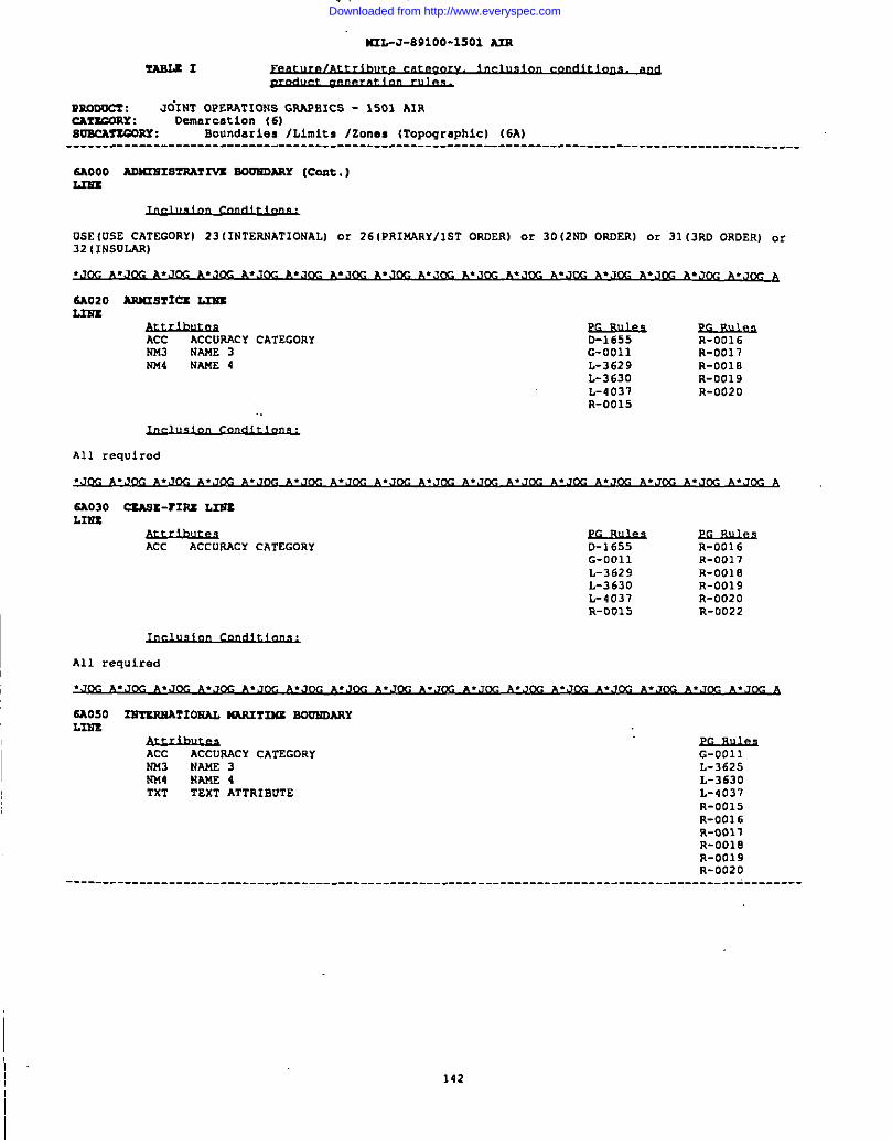
M2L-J-B91OO-15OI An
?ARLEI
m.ooOsx : JdINT OPERATIONS GRAPEICS - 1501 AIRCAfSGORY : Demarcation (6IsmcAr5G0w : Boundaries /Limits /Zones (Topographic) (6A)----------------------------------------------------------------------------------------------------
SAooo AomxIsTRA?2vs sou3mARY (Cent.)L37u
USE (LEE CATEGORY) 23 (INTERNATIONAL) 0? 26 (PRIM4RY/lST ORDER) or 30 (2ND ORDERI or 31 (3RD ORDER) .ar32 (INSULAR)
6A020 ARn29rIa L2sIL2ms
ACC ACCURACY CATEGORYNM3 NAME 3!044 NAME 4
D-1655 R-0016G-0011 R-0017L-3629 R-0010L-3630 R-0019L-4037 R-0020R-0015
All required
6A030 CtAS1-T12U L33T3LIU3
ACC ACCURACY CATEGORY D-1655 R-0016G-0011 R-0017L-3629 R-0018L-3630 R-0019L-4031 R-0020R-0015 R-0022
All required
6A050 2NTsRMATIOUAL WT244S BDO?2DARYL2NS
ACC ACCURACY CATEGORY!043 NAME 3
G-0011L-3625
NU4 NAME 4 L-3630TST TEXT ATTRIBDTE L-4037
R-0015R-0016R-0017R-0018R-001 9R-0020
----------------------------------------------------------------------------------------------------
142
Downloaded from http://www.everyspec.com
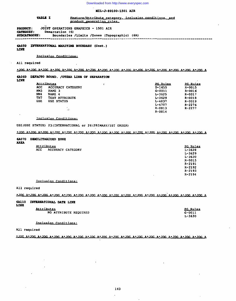
I
?!AsLs I
M3L-J-891OO-15O1 A2R
mmoc7 : JOiNT OPEIWTIONS GTLAP81CS - 1501 AIRCmZeow : Demarcation (6)SoBcAnasx : Boundaries fLimltB /zones [Topographic) (6A)---------------------------------------------------------------------------------------------------
6AOS0 ImzR36A?102iAL 61AR2?26U WmDARx (cent.)L22sz
All required
SAO60 DZTACTO BO03i21. /O?S.SR L32i2Or SSPARA?I~2.236X
Ace ACCURACY CATEGORYNn3 NAME 3NU4 NAME 4TXT TEXT ATTRIBUTEUSE USE STATUS
D-1655G-0011L-3625L-3629L-4037L-4707R-0013R-0014
R-0015R-0016R-0011R-OOIBR-0019R-2216R-2271
USE (fJSESTATUS) 23 (1NTERNATIONAL or 26 (PRIMARY/lST ORDERI
SA070 onmJTA2umo ZeusARsA
ACC ACCURACY CATEGORY L-3628L-3629L-3630R-0015R-2191R-2192R-2193R-2194
All reguired
NO ATTRIBUTE REOUIRED G-0011L-3630
All required
~.Jw ~.Jm ~.Jm **J= ~.=m ~.Jm ~.Jm&
143
Downloaded from http://www.everyspec.com
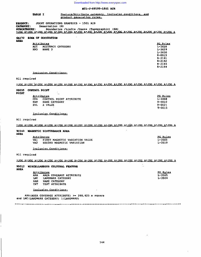
6A2L-J-E91OO-1SOI A3R
I
l!A8Lt1
99.ODOcx: JC-INTOPERATIONS GR4PE1CS - 1501 AIR~RY : Demarcation (6)so2eAT2muY : Boundaries /Limits /zones (Topographic) (6A)
6A170 XONX W ~AfIOBAREA
Acc ACCUSACY CATSGORY L-3628NM3 NAUE 3 L-3629
L-3630R-0015R-2191R-2192R-2193R-2194
All required
9B035 CON?ROL 902HTP022iT
MJA&uR2 ‘“CPA CONTROL POINT ATTRISUTE L-4008NAM NAnE CATEGORY R-OO1OZVL Z VALUE R-0021
T-0015
II All required
9C040 ~T1c DISTuRBANa AREAAREA
$s#iwe2FIRST MAGNETIC VAR1ATION VALUE L-3505
VA2 SECOND MAGNETIC VAA1ATION L-3510
I
All Zeq”ired
9D033 m ScsLLAmous C13L?UAAL TEAmssA9xA
AAA AREA COVERAGE ATTRISUTEWC
L-3505LANDMARK CATEGORY
NAM NAUE CATEGORYL-3506
TXT TEXT ATTRIBUTE
ARA(AsEA COVEIiAGE ATTRIBUTE I >. 390, 625 m squareand LMC ILAJIDNARK CATECORYI 1(LANDNARK)
----------------------------------------------------------------------------------------------------
1-144
Downloaded from http://www.everyspec.com
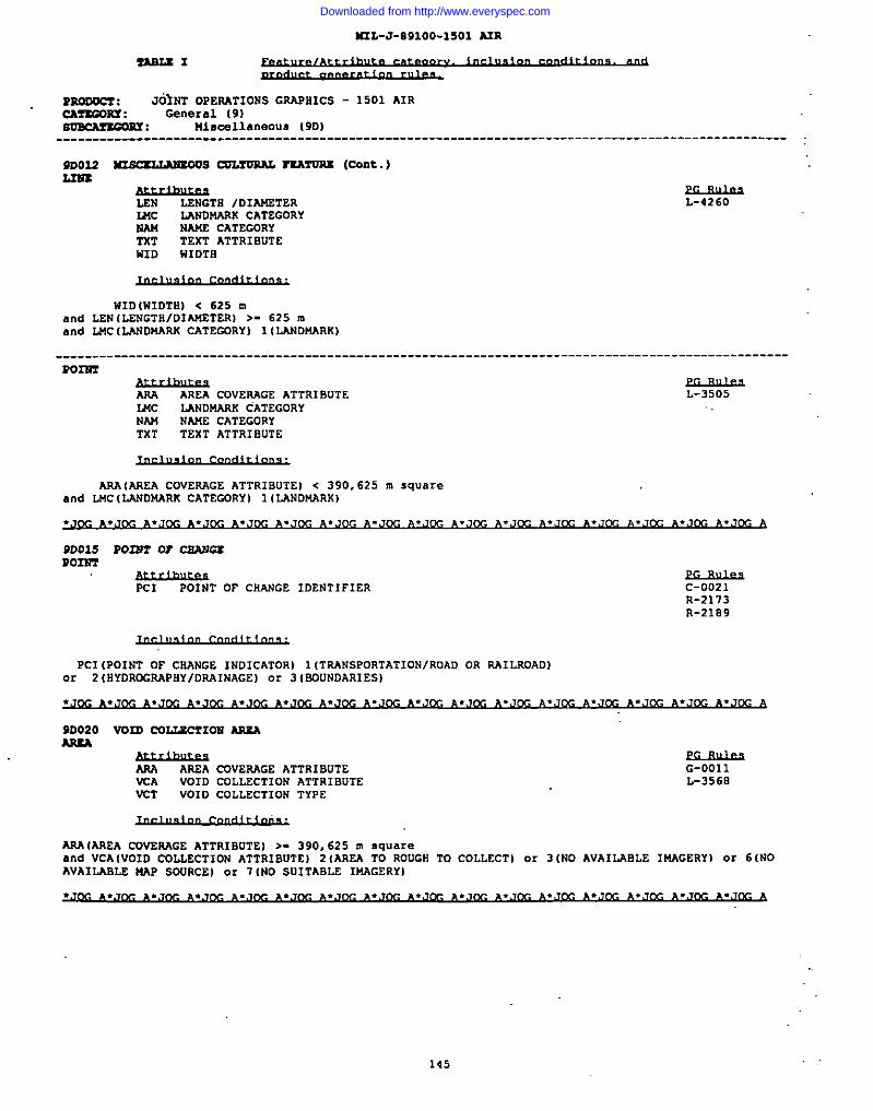
WIL-J-WI1OO-1SO1 A2R
PuooOc! : JOINT OPERATIONS GRAPHICS - 1501 AIRCA?SGORS : General (9)SmcMsmM: Hincellaneous 19DI
----------------------------------------------------------------------------------------------------
9D02S ~S C02XOML TSATDRX (Cnnt.)2.2s2
LSN ~NGTH /DIANETERWC IANDNARK CATEGORYNAM NANE CATEGORYTST TEXT ATTRIBUTEHID i41DTE
L-4260
WID(WIDTH) < 625 mand LEW(LENGTii/DIANETERl >- 625 mand LNC (LANDNARH CATEGDRYI 1(L4NDt4ARK)
-------------------------------------------------------------------------------------------- .-------POm
ARA AREA COVESAGE ATTRIBUTEI.Mc mNow7K CATEGORyNAW NANE CATEGORYTXT TEXT ATTRIBUTE
~L-3505
AAA(AAEA COVEIUGE ATTRIBUTE) < 390,625 m squareand LNC [LANDNARK CATECDRY) 1(LANDMARK)
.JQC ~,J~ ~.J~ A.J~ ~.J~ A.J~ ~.J~ ~.J@-J ~.J~ ~.J~ ~.J~ ~.Jcc ~.J~ ~.Jcc *.J~ ~.J~ A
9D015 P02NT or CsA24uP021P2
PcI POINT OF CHANGE IDENTIFIER c-0021R-2113R-2189
PC1 (POINT OF CSANGE lWOICATOR) 1(TAANSPORTATIONIROAD OR RA1LRDAD)or 2 (HYDROGRAPHY/DRAINAGE) or 3 (SOUNDARI ES)
9D020 VOIO C02.LECTIOR ARXAm
AsA AREA CQVERAGE ATTKIBUTEVCA
G-0011VOID CDLLECTION ATTRIBUTE
VCTL-356B
VOID COLLECTIOW TYPE
AAA(AREA COVERAGE ATTRIBUTE) >- 390, 625 m squareand VCA IVOID COLLECTION ATTRIBUTE I 2 (AREA TO ROUGH To COLLECT) o. 3 INO AVAILABLE lWAGERY) or 6 (NOAVAILABLS XAP SOORCE) or 7 INO SUITABLE IMAGERY)
145
Downloaded from http://www.everyspec.com
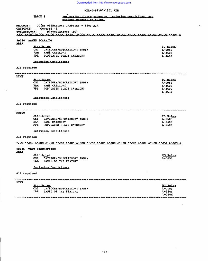
463L-J-891OO-15O1 m
P— : JO”iNTOPERATIONS GRAPHICS - 1501 AIRcm?tGORs : Ganeral (9)smcMzmPx : !!iSW~h”eOUS 19D)
9D040 EA)UO ~XONw
CSIW
CATEGORY/SUBCATEGORY INDEXNAM NAUE CATEGORY L-360EPPL POPULATED PIACE CATEGORY L-3609
All required
----------------------------------------------------------------------------------------------------L3UX
Cs1 CATEGORYISUPCATEGORY INDEXNAM NAME CATEGORYPPL POPOLATED PLACE CATEGORY
L-0051L-3608L-3609L-3630
All required
----------------------------------------------------------------------------------------------------tom
Cs1 CATEGORY/SUBCATEGORY INDEXNAkl NM6E CATEGORYPPL POPDI-4TED PLACE CATEGORY
=
L-3608L-3609
All required
----------------------------------------------------------------------------------------------------L3m
=Cs1 CATEGORY/SUl!CATECORY INDEXLAB LABEL OF THE FEATURE L-35o5
L-3506----------------------------------------------------------------------------------------------------
I 146
Downloaded from http://www.everyspec.com
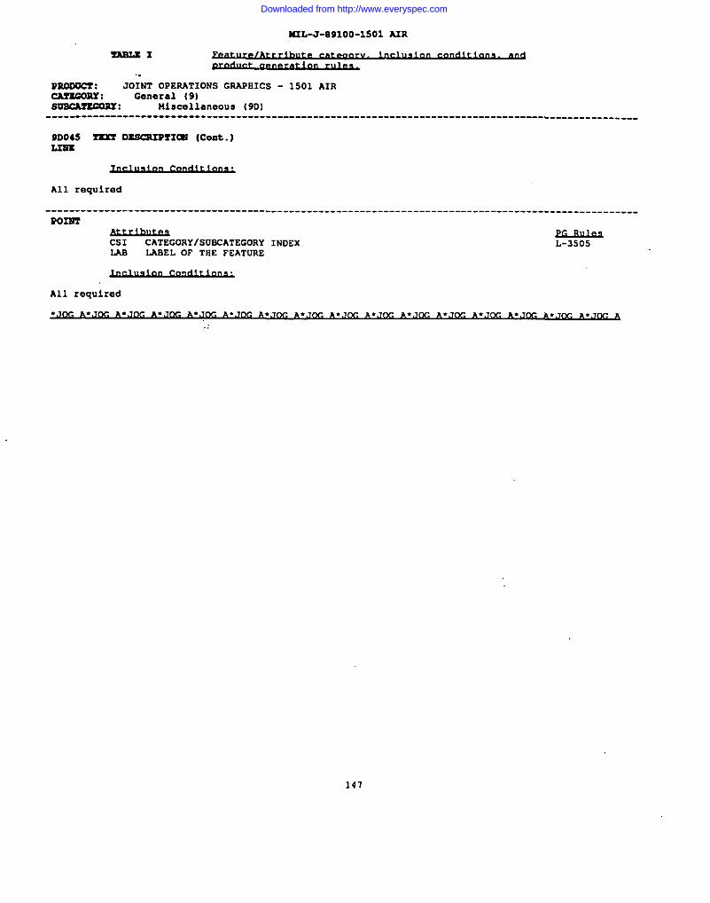
MIL-J-891OO-15O1 AIR
PROOUCZ : JOINT OPERATIONS GRAPHICS - 1501 AIRcAzzcOnY : General {9)suBcmzcORr : Mincelle.neous (9DI
----------------------------------------------------------------------------------------------------
9D045 Z2xr ~91W (Cont.)L3Bx
All required
---------------------------------------------------------------------------------------------------PoI13T
Cs1 CATEGORYISUSCATEGORY INDEXLAB LABEL OF THE FEATURE
L-3505
All required
141
Downloaded from http://www.everyspec.com
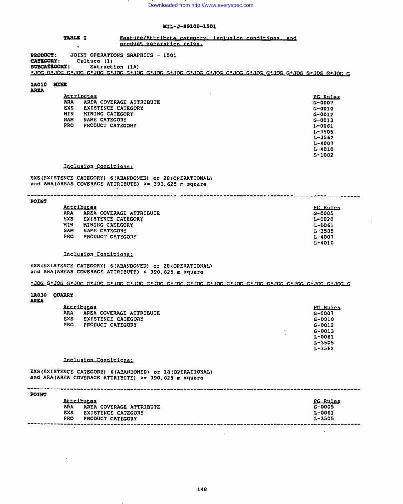
=L-J-B91OO-15O1
m.ODocz : JOINT OPESATIONS GRAPRICS - 1501CAnGmY : culture (1)ouncAnGQPY z Extraction IIA]
2AO1O pm
f&12wAREA COVERAGE ATTRIBUTE
EXS EXISTENCE CATEGORYMIN MINING CATEGORYNAM NAME CATEGORYPRO PRODUCT CATEGORY
‘G-OOO7G-OO1OG-0012G-0013L-0061L-3505L-3562L-4001L-401OS-1OO2
EXSIEXISTENCE CATEGORY) 6[ASANDONEDI o. 28 [OPERATIONAL)and ARAIAREAS COVERAGE ATTRIBUTE) >- 390,625 m square
I ----------------------------------------------------------------------------------------------------
Pom
ARA AREA COVERAGE ATTRIBUTEEXS EXISTENCE CATEGORYMIN MINING CATEGORYNAM NAME CATEGORYPRO eRoL2ucTCATEGORy
~G-0005L-0020L-0061L-3505L-4007L-401O
EXS(EXISTENCE CATEGORY) 6(ABANDONED) or 28 (oPERATIONAL]and ARA (AREAS COVERACE ATTRIBUTE) c 390,625 m s-w...
2A030 QUARRYARIA
&d.huusAREA COVESAGE ATTRIBUTE
EXSG-0007
EXISTENCE CATEGORY G-OO1OPRO PRODUCT CATEGORY G-0012
G-0013L-0061L-3505L-3562
EX5(Ex1sTENCE cATEGORy) 6(ASAND0NED] or 28(0PEsAT10NAL1and ARA(AA2A COVSRAGE ATTRIBUTE) >. 390,625 m square
----------------------------------------------------------------------------------------------------Pom2
yt#hu2sAREA COVERAGE ATTRIBUTE
ExsG-0005
EXISTENCE CATEGORYPRO
L-oo6rPRODUCT CATEGORY L-3505
----------------------------------------------------------------------------------------------------
148
Downloaded from http://www.everyspec.com
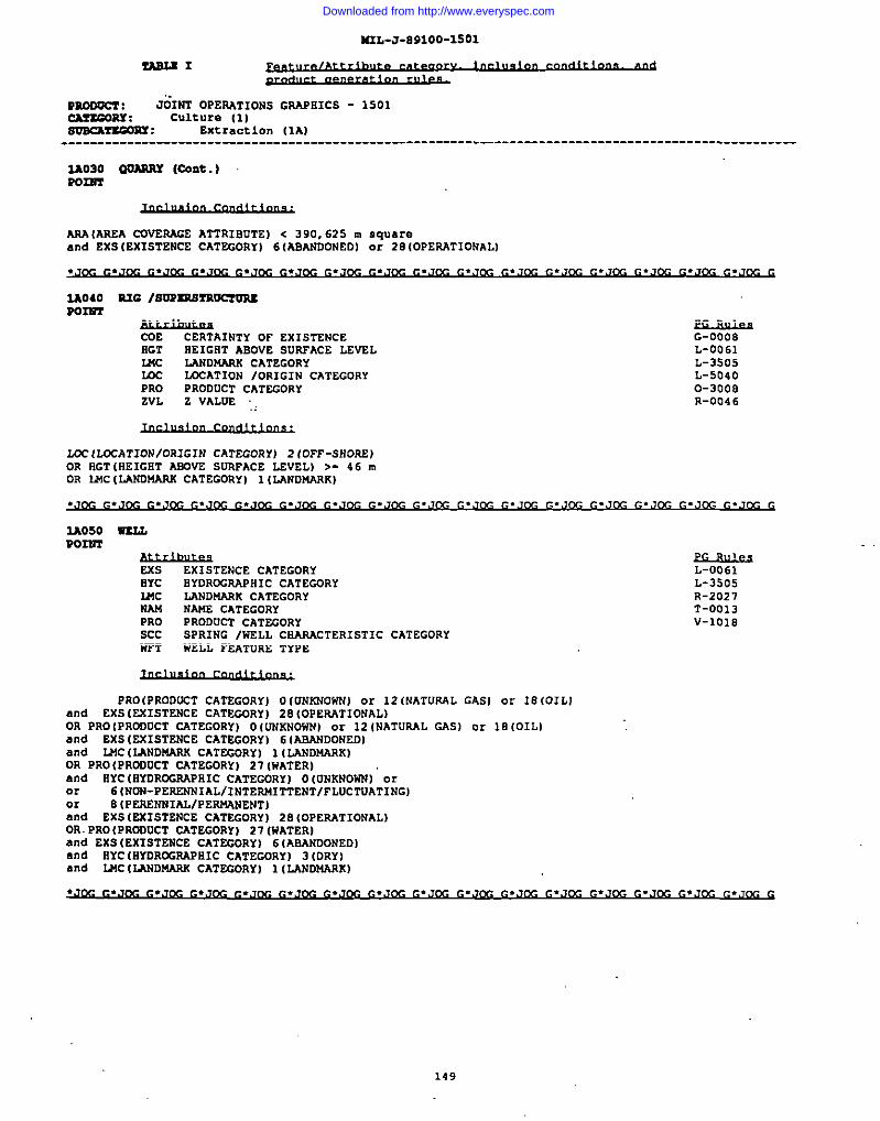
M2L-J-891OO-15O1
-1
mnoo-= : J&2T OPERATIONS GR.AMICS - 1501CAT2G0w: Culture (11sOBcAzxGOxY : Extraction (1A)--------------------------------------------------------------------------------------------------
2A030 00ASRT (cont.)Pam
ARA{AREA COJERAGE ATTRIBUTEI c 390,625 m squareand EXS(EXISTENCS CATEGORY) 6(ASANOONEDI or 20(0PERAT10NALl
2A040 S.2G /so3xsSrR0m02cP02S72
COE CERTAINTY OF EXISTENCE G-0008BGT HEIGRT ABOVE SURFACE LEVEL L-0061WC LANDNARK CATEGORY L-3505w =AT1ON IORIGIN CATEGORY L-5040PRO PRODUCT CATSGORY 0-3008ZVL Z VALD2 .. R-004 6
LCC (LCCATION/ORIGIN CATEGORY) 21OFF-SHOAE)OR flGT[HEIGiiTABOVE SURFACE LEVEL) >- 46 mOR U6C (LANDUARK CATEGORY) 1(LANDWARK)
.J~ ~.J~ ~.J~ ~.J~ ~.J~ ~.(j~ ~.J~ G.J~ ~.J~ ~.J~ ~.J~ ~.Jm ~.J~ ~.J~ ~.J~ ~.J~ G
2A050 WUJ,P02NT
Exs EXISTENCE CATEGORYHYC BYDRCG$APHIC CATEGORYMC LAND14AAK CATEGORYNAf4 NAME CATEGORYPRO PRODUCT CATEGORYSCc spRxNG /WELL CHARACTERISTICNFT w2LL FEATURE TYPE
L-0061L-3505R-2027T-0013V-1018
CATEGORY
PRO(PRODCCT CATEGORY] O (UNANOWN) or 12 (NATURAL GASI or 18 (OIL]and EXS (EXISTENCE CATEwRY) 28 (OPERATIONAL)OR PRO{PRODOCT CATEGORY) O ((lllxt40w)or 12 (NATURAL GAS) or 18 (OIL)and EXS [EXISTENCE CATEGORY) 6 (AEANDONEDIand IJ4C(LANDn4RK CATEGORY I 1 ILANDMARK]OR PRO (PRODUCT cATEGORY) 27 (WATER)and llYCI12YDRCKRAFS1CCATEGORYI o IDNSNOWNI oror 6{NDN-PERENNIAL/INTERMITTENT/FLUCTUATINGlor 8(PEAE~lw/pEwENTIand EXS (EXISTENCE CATEGORY I 28 (OPERATIONAL)OR.PRO (PRODUCT CATEGORY) 27 (WATER)and EXS (EXISTENCE CATEGORYI 6 (ABANDONED]and ziycIHYDRCGRAPSIC CATEGORY I 3 (DRy)and NC ILAwDm CATECORYI 1 (LANDMARKI
.J~ ~.J& ~.J~ G.J~ ~.JK ~.J~ ~.J~ ~.J~ G.J~ G.J~ ~.J~ G.J~ ~.J~ ~.J~ G.J~ G.JK G
149
Downloaded from http://www.everyspec.com
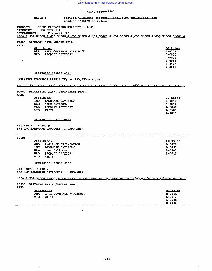
II2L-J-891OO-1SO1
-1
Raooucr : JOiNT OPERATIONS GRAPSICS - 1501CA?XCORX : Culture (1)S021CAT3CORY: Disposal [1S).Jm C.JM G.J,3C G.J~ G.Jm G.J~ ~.Jm G.JW G.JM G.Ja G.Jm G.JCC G.JK G*JM G.JM G*J~. G
lsOOO DISPOSAL SITZ -TZ PIuA2uA
AAA AREA CUVERAGE ATTRISUTE G-0006PRO PRODUCT CATEGORY G-OO1O
G-0012L-0061L-35o5L-3506
ASA (AREA COVERAGE ATTRISUTEI >- 390,625 m sqare
.J~ ~.J~ =.,J~ ~.J~ ~.,J~ ~.J~ C.JW ~.J~ ~.J~ ~.J~ ~.J~ ~.J~ ~.J~ ~.,J~ ~.J@-J ~.J~ G
lCOOO PROCESSm PLUP2 /TP.IATtUtP2PLAS2ARxA
I.Mc LAND14AKK tATEGORY G-0010NAM NAME CATEGORY G-0012PRO PRODUCT CATEGORYWIu
L-0061!41DTH L-3505
L-401O
WIU (WIUTS) >- 200 mand LMC (LANUMARK CATEGORY) 1 (LANDMARK)
----------------------------------------------------------------------------------------------------POIST
AUU ANGLE OF OR1ENTATION L-0020WC LANUMARK CATEGORY L-0U61NAM NAME CATEGORY L-3505PRO PROUUCT CATEGURY L-401OWIu WIUTH
WIUIWIUTBI < 200 ma“d Lt4C(LANUMARK CATECURY) 1(LANUKARK)
G
1C030 SET2L2UC SAS2B /SLUDCZ POSDAsxA
AKA AREA cOvEmGE ATTRISUTE G-0U06WIu WIUTH G-0U12
L-3505R-2002
----------------------------------------------------------------------------------------------------
Downloaded from http://www.everyspec.com
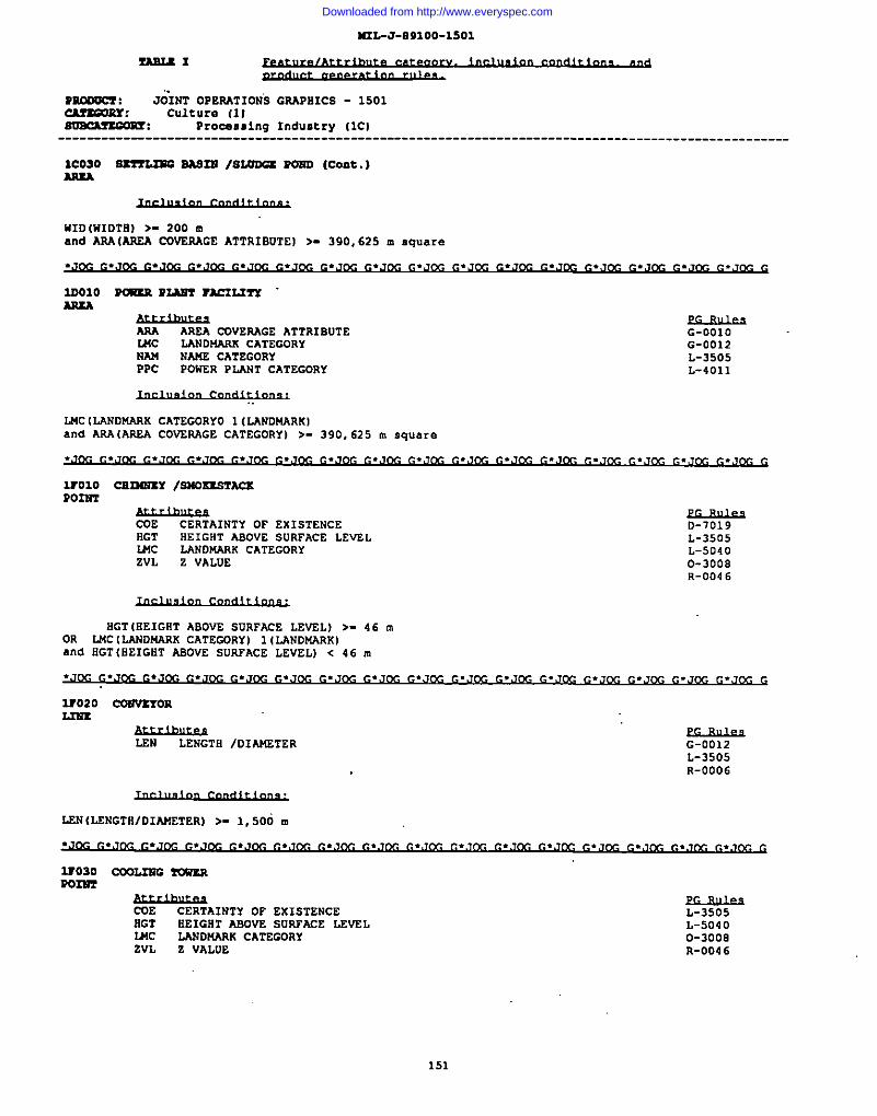
II
I
IUL-J-891OO-15O1
r,AsUI
n~ : J&NT OPERATIONS GRAPRICS - 1501~: Culture (1ISmcAmmm: Procenming Industry (lCI------------------------------------------------------------------------------------------------
lCOSO Sznx.mo BASIS /S2.Ona ?OSD (Cent,)AwxA
HID [WIDTH) >- 200 ❑
and m(AREA CDVEAAGE ATTRIBuTEI >. 390,625 m sqwsre
AnxA
ARA AREA COVERAGE ATTRIBUTEUK LAKDW4RK CATEGORYNAM NAWE CATEGORYPPC POWER PLANT CATEGORY
G-OO1OG-0012L-3505L-4011
LMC ILANDMARK CATEGORYO 1 (LANDMARK)and ARA (AREA COVERAGE CATEGORY) >- 390, 625 m square
3?010 csn4szY /sMOxzsmcsPo2m
A&12ue2CERTAINTY OF EXISTENCE
RGT HEIGHT ABOVE SURFACE LEVELL44c LANDMARK CATEGORYZVL Z VALUE
~D-7019L-3505L-50400-3008R-0D46
OGT (REIGHT ABOVE SURFACE LEVEL) >- 46 mOR u4c ILANDNARK CATEGORY) ](LANDMARK Iand iiGT(HEIGET ABOV2 SURFACE LEVEL) < 46 n
=020 COWVHORL23m
LEN LENGTH IDIAMETER G-0012L-3505R-0006
LSN(LENGTRIDIANETER) >- 1,500 ❑
2?030 ~LIWC YOWERP031iT
$&utf19CERTAINTY OF EXISTENCE
BGT EEIGIIT ASOVE SURFACE LEVELWC LANO144RK CATEGORYZVL Z VALDE
L-3505L-5040O-3008R-OI346
I 151
Downloaded from http://www.everyspec.com
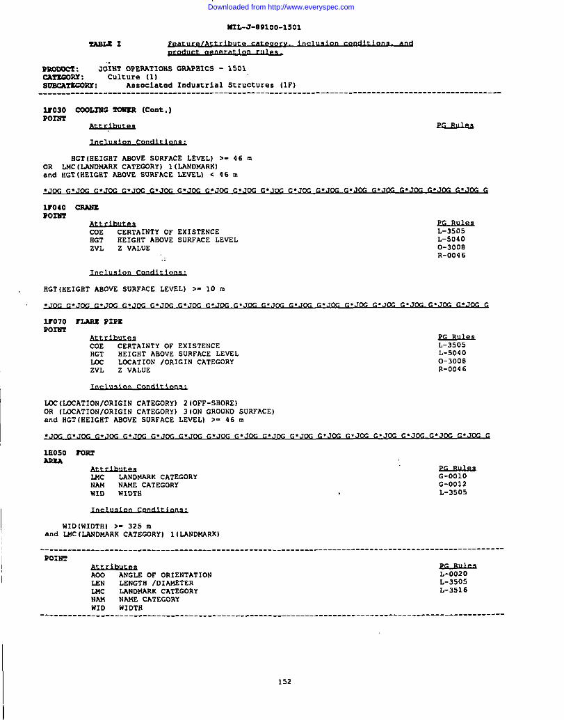
44IL-J-O91OO-15O1
~1
Dr.mom : J;lNT OPERATIONS GRAPBICS - 1501CAT3WRY : Culture {1)8oncA?3GoKY : Associated Industrial Structures (lF)----------------------------------------------------------------------------------------------------
3T030 co0L2EG rc41z21(coat.)Porm
M+21uRs
EGT (HEIGHT mOVE SURFACE LEVEL) >- 46 mOR MCI LANDMARK CATEGDRY) 1 (LANDMARK)and KGT (HEIGHT ASCPIE SURFACE LEVEL) < 46 m
.J~ C.JW C.J~ G.J~ G.J~ G.JM G.JW G.JK G.Jm G.JW G.,JCG G.JCaZG.JCC G.JCG G.JCG G.JK, G
lro40 C3A22zPo2w3
ME CERTAINTY OF EXISTENCE L-3505BGT REIGHT ABOVE SURFACE LEVELZVL Z VALUE
L-50400-3008
., R-004 6
RGT IHEIGHT ABOVE SURFACE LEVEL) >- 10 m
.J~ r.JW G.J~ G.J~ G.J&- G.J~ C.J~ G..7m G.,,m G.Jm G.JM G.JCC G.J(X2 G.JrX G.J,X C,.JCC G
wo70 mmu PIPEPO124-2
COE CERTAINTY OF EX1STENCEHGT
L-3505REIGHT ABOVE SURFACE LEVZL L-5040
mc LCCATION /ORIGIN CATEGORYZVL Z VALUE
O-300BR-004 6
LJX(LCCATIONIOR1 G1N CATEGORY) 2 (OFF-SHORE)OR {LCCATIONIOR1G1N CATEGORY) 3 (ON GROUND SURFACE)and HGT(HEIGHT ASOVE SURFACE LEVELI >- 46 m
.JM G.JR G.,2K =.~~ G.JM G.JR C.J~ G.JW G. ,~ G.JK G.JW G.JK G.JM C.J~ G.JW G.Jm G
IB050 romAR3A
u4c LANDNARK CATEGORYNM
G-0010NAME CATEGORY G-0012
WID WIDTH L-3505
WIDINIDTRI >- 325 ma“d L!4C(LANDMARK CATEGORY) 1ILANDMARK)
------------------------------------------------------------------------------------------ ----------
152
POIW3
AWP_G-##s
ANGLE OF OR1ENTATIONLEN LENGTH /DIAKF.TERMC
L-3505LANDUAAK CATEGORY
NAML-3516
NM CATEGORYHID WIDTH
------------------------------------------------------------------------------------------ ----------
Downloaded from http://www.everyspec.com
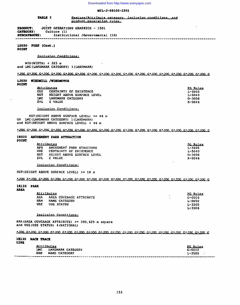
MIL-J-891OO-15O1
ZABLZI
mooom : JOiNT OPERATIONS GRAPHICS - 1501CkrEGonr : Culture (1)aoBcAnGom : Institutional /Gc.vernmental (lH)----------------------------------------------------------------------------------------------------
18050 roar (CO*. )Pam
WID [WIOTH) < 325 mand LMC (LANDNARK CATEGDRY) 1ILANDNARKI
1J050 WXEOMILL /K231DKIT0Rpalm
ELmlk3CUE CERTAINTY OF EXISTENCEEGT
L-3505HEIGHT ABOVE SURFACE LEVEL
WCL-5040
LANDNARK CATEGORYZVL
0-3000Z VALUE R-0046
nGT iBEIGHT ABOVE suRFAcE LEVEL) >- 46 mOR LUC (LANDMARK CATEGORY) 1{LANDMARK)and RGT (HEIGHT AEOVE SURFACE LEVEL) < 46 m
APs ANUSEFC?Ni PARK STRUCTURECOE CERTAINTY OF EXISTENCEEGT HEIGHT ABOVE SURFACE LEvELZVL Z VALUE
PQBILksL-3505L-50400-3008R-0046
Am AREA COVERAGE ATTRIBUTENAM NAME CATEGORYUSE USE STATUS
G-0006L-0050L-3505L-3506
AM IAREA COVERAGE ATTRIBVTEI >- 390,625 m .q.a.eand USE IUSE STATUS) 4 INATIONAL)
FLANDMARK CATEGORY G-0012
NAM NAME CATEGORY L-3505----------------------------------------------------------------------------------------------------
153
Downloaded from http://www.everyspec.com
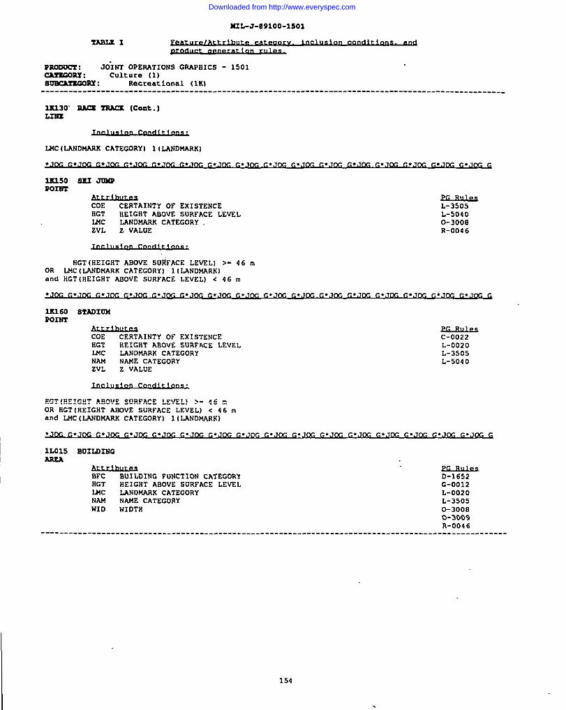
I6IL-J-891OO-15O1
7.AB2.Sx
PsOovCr : JOiNT OPERATIONS GRAPHICS - 1501CAT’uans : Culture (1)8mcAr3G0sx : Retreat Lanai (lK)
. ---------------------------------------------------------------------------------------------------
2X230 U TRAa (Cent.)LIu3
LNC (lJlND14ARKCATEGORY) 1(LANDNARK)
COE CERTAINTY OF EXISTENCEHGT EEIGRT ABOVE SURFACE LEVELMC LANDMARK CATEGORYZVL Z VALOE
L-3505L-50400-3008R-0046
BGT [HEIGHT ABOVE SURFACE LEVEL] >- 46 mOR LMC (IANDMARK CATEGORY) 1 [LANDW4RK)and HGT (HEIGHT ABOVE SURFACE LEVEL) d 46 m
COE CERTAINTY Of EXISTENCERGT HEIGNT ABOVE SURFACE LEVELLnc LANDMARK CATEGORYNAM NAHE CATEGORYZVL Z VALUE
~C-0022L-0020L-3505L-5040
RGT(ilEIGHT ABOVE sURFACE LEVEL) >- 46 mOR HGT(IIEIGHT ABOVE SURFACE LEVEL) < 46 mand LMC (LANDMARK CATEGORY) lILANDMARK)
~.J~ ~.J~ f..J~ ~,J~ G.J~ ~.Jc.#J ~.Jm G.J~ ~.J~ ~.J~ ~.J~ ~.J~ G.J~ ~.J~ ~.J& G
lLO15 BUILDINGAREA
ELsLLksBFc BUILDING FuNC’21ON CATEGORY D-1652HGT HEIGHT ABovE SLIRFACE LEV2L G-0012U6c LANDMARK CATEGORY L-0020NAM NAt4E CATEGORyWID
L-3505w1OTR 0-3008
0-3009R-004 6
----------------------------------------------------------------------------------------------------
154
Downloaded from http://www.everyspec.com
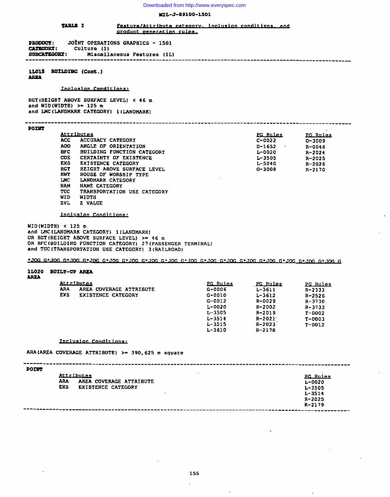
=L-J-O91OO-15O1
TLSUI
v~ : JOiNT OPERATIONS GRAPBICS - 1501~: Culture (1)svBcAr2G0ns : Miscellaneous Features (lL)
--------------------------------------------------------------------------------------------------
12.02s So22ams (cont. )APxA
BGT(liEIGET ABDVE SURFACE LEVELI < 46 mand 141D(W1DTB) >- 125 mand L44C(LANDKARX CATEGDRY) 11LANDU4AX)
----------------------------------------------------------------------------------------------------Po2ssr
Acc ACCURACY CATEGORYACX3 ANGLE OF ORIENTATIONBPc BDILOING FUNCTION CATEGORYCOE CERTAINTY OF EXISTENCEExs EXISTENCE CATEGORYHGT REIGHT ABOVE SURFACE LEuELRwT HOUSE OF WORSHIP TYPEMC LANDWAAK CiTEGORYNAW NAWE CATEGORYT(7C TRANSPORTATION USE CATEGORYWID WIDTH
~C-0022 0-3009&
L-116S2 R-004 60020 R-2024
L-3505 R-2025L-5040 R-20260-3000 R-2170
ZVL Z VALUE
WID(WIDTHI < 125 mand LWC(LANDMARK CATEGDRY) l(LANDwARKIOR HGT(REIGHT ABDVE SURFACE LEVEL) >- 46 mOR SFC(BUILDING FDNCTION CATEGORY) 21(Passenger TERMINAL)and TUCITAANSPORTATION USE CATEGORY) 31AA1LROADI
&t?mAREA c0~5AGE ATTRIBUTE
EXS ExxsTENcE CATEGORYG-0006G-OO1OG-0012L-0020L-3505L-3514L-3515L-361O
.ELslLkiL-3611L-3612R-0029R-2002R-2019R-2021;R-2023R-217B
R-2333R-2526R-3130R-3733T-0002T-0003T-0012
AAA(AAEA COVERAGE ATTRIBDTEI >- 390,625 . square
----------------------------------------------------------------------------------------------------P02SZ
f.&121wAREA mVSIWGE ATTRIBUTE
ms EXISTENCE CATEGORY
.rLro&sL-0020L-3505L-3514R-2025R-2179
----------------------------------------------------------------------------------------------------
155
Downloaded from http://www.everyspec.com
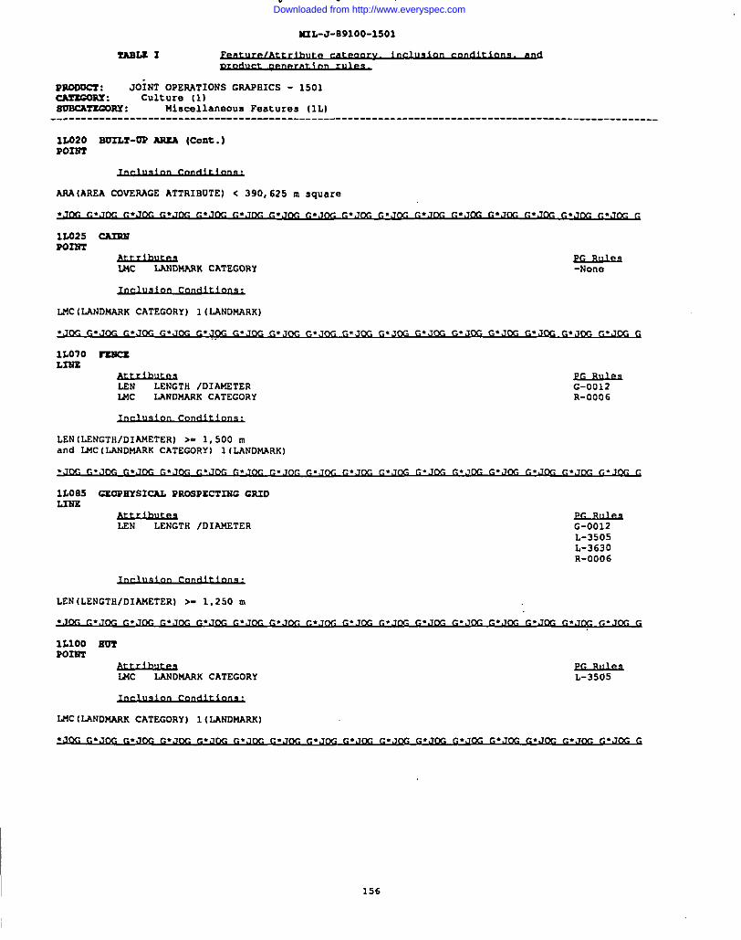
M2L-J-B91OO-15O1
-2.2 I
PNOoum : JOiNT OPERATIONS GPA9EICS - 1501cATsmRx : Culture II)soscA?xGo2Y : Uiacellaneou. Features (lL)----------------------------------------------------------------------------------------------------
1L020 BU2Lr-oP Aw.A (cont.)Po23m
ANA IAREA CQVERAGE ATTRIBUTE] < 390,625 m S~U~r~
1L025 ~Po23rr
WC LANDMANK CATEGORY -None
1L070 -L3SS
LEN LENGTH /DIAITiTERWC LANDMARK CATEGORY
G-0012R-0006
LEN (LENGTH/DIAMETER) >- 1,500 mand I.McILANDMARK CATEGDRYI 1ILANDMARK)
LEN (LENGTH/DIAMETER) >- 1,250 n
MC (LANDMARK CATEGORY) I (I,ANDWRK)
G
II 156
Downloaded from http://www.everyspec.com
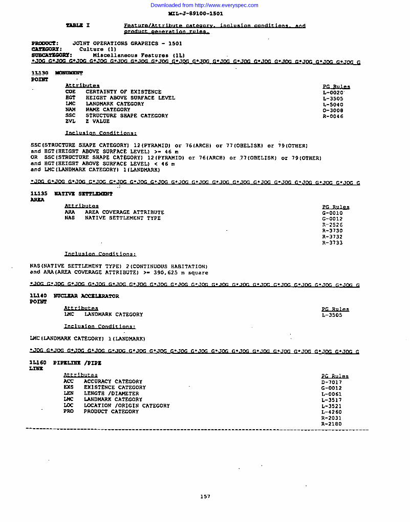
I4IL-J-891OO-15O1
ZASUI
12.230Rorm
COE CERTAINTY OF EXISTENCEEGT EEIGliT ASOVE 5t3RFACE LEVELWc LANCN4ARX CATEGORYNAN NAME CATEGORYSsc STRUCTURE SSAPE CATEGORYZVL Z VALUE
L-0020’L-3505L-50400-3008R-004 6
SSC(STROCTORE SSAPE CATEGORY] 12 (PYRAUID) or 16(ARCS) c.r11 (OSELISKI or 79 [OTHER]and SGT (SEIGST ASOVE SURFACE LEVEL) >- 46 mOR SSC (STROCTURE SSAPE CATEGORY] 12 (PYPJ.!41D)or 761ARCH) or .17(OBELISK) or 79 (OTHER)and SGT ISEIGST ASOVE SURFACE LEVEL) < 46 mand LNC [LAND14ARx CATECJ3RY) 1[LANDMARK]
.J~~.J~. ~. J.,JG .Jm -... . . . . . . . . (A7G
1L135 NA?2V2 S~ARxA
m AREA COVERAGE ATTRIBUTENAS NATIVE SETTLEMENT TYPE
NAS (NATIVE SETTLEMENT TYPE] 2 (CONTINUOUS HAB1TATION)and AAA(AREA COVERAGE ATTRISUTE) >- 390, 625 m square
.,,~ ~,J~ ~.,~ ~.J~ ~.Jw ~.=m ~.Jw ~.Jm ~,Jw . ~ ~, . . . . , cc G
G-OO1OG-0012R-252 6R-3730R-3732R-3733
1L140P02ST
FLANDMARK CATEGORY
LUC (LANDMARK CATEGORY] 1 (LANDMARK)
L-3505
1L160 PIPZLIS2 /P2PZL2sr,
Am ACCVRACY CATEGORYEss EXISTENCE CATEGORYLEN LENGTS /OIAt4STERU4c LANDNARK CATEGORYm LOCATION IORIGIN CATEGORYPRO PRODUCT CATSGORY
~D-1017G-0012L-0061L-3517L-3521L-4260R-2031R-21S0
157
Downloaded from http://www.everyspec.com
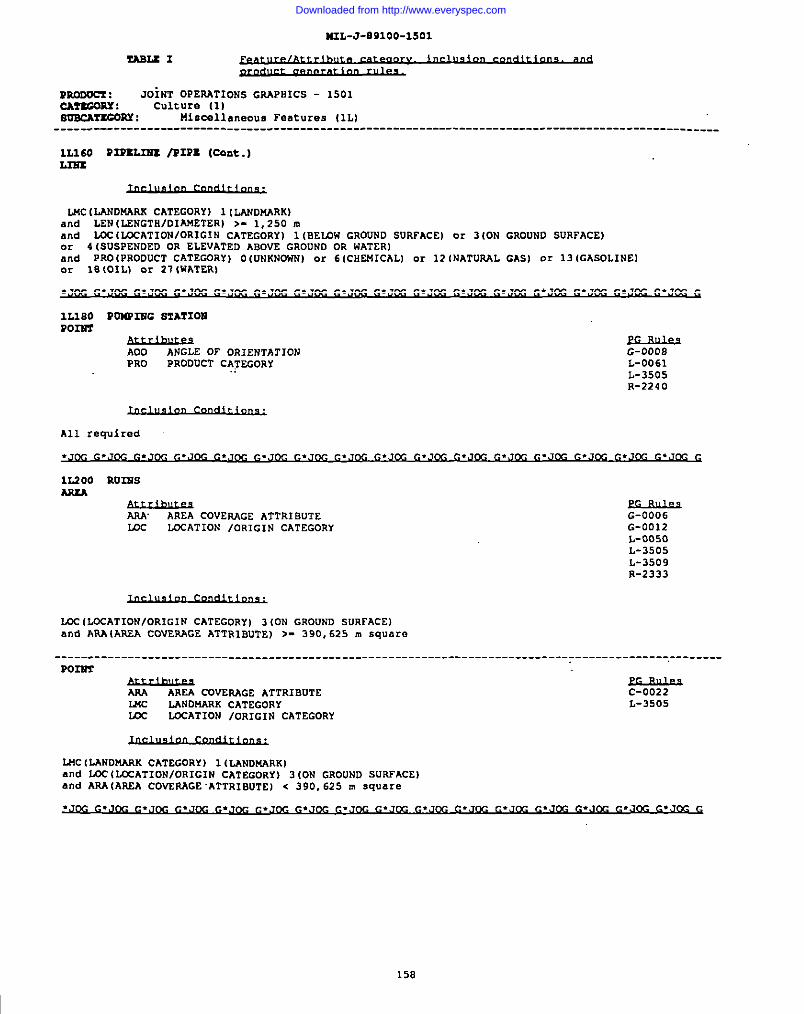
MIL-J-E91OO-15O1
Y!ABU I
moDocr ; JOiNT OPERATIONS GRAPHICS - 1501CMtGOUY : culture (1)Nuacaruou.y : Ulecelleneous Features (lL)--------------------------------------------------------------------------------------------------
1L360 P2PU.IEX /PIPZ (Cant.)
GROUNO SURFACE)
GASI or 13 (GASOLINE)
I
.Jm, G.JDC G.J~ ~.Joc G.J~ ~.J~ ~.J~ ~.,,m G.,J~ ~.-.J~ ~.J~ ~.Jm G.J~ G.Jm G.J~ G
1L380 PO)U’INC STATIOUPomr
AOO ANGLE OF ORIENTATIONPRO
G-0008PRODUCT .2ATECORY
.:L-0061L-3505R-2240
All required
.J~ ~.J@ c.J~ ~.J~ ~.J~ ~.,~ ~,J~ ~,J~ ~,J~ ~.J~ ~.J~ ~.J~ ~.J~ ~.J~ ~.J~ ~.J~ G
1L200 2N21GSAxlA
m AREA COVERAGE ATTRIBUTE G-0006m LcCATION /ORIGIN CATEGORY G-0012
L-0050L-3505L-3509R-2333
LCC(LOCATIONIOR1 G1N CATEGORY) 3 (ON GROUND SURFACEIand AP.AIAREA COVERAGE ATTRIBUTE] >- 390,625 m square
.-__----___-------- ________ ------------- ________ --_----___---___-_-__-----_-_______ --_------,--------
P03UT
ARA AREA COVERAGE ATTRIBUTEL24c
c-0022LANDNARK CATEGORY L-3505
m LOCATION IoRIGIN CATEGORY
Lt4c(tiN0uARK cATEcORy) l (LANDMARKIand LOC(LCCATION/ORIGIN CATEGORY I 3 (ON GROUND SURFACE)and ARAIAR2A COVERAGE .ATTRIBUTE) < 390,625 m square
158
Downloaded from http://www.everyspec.com
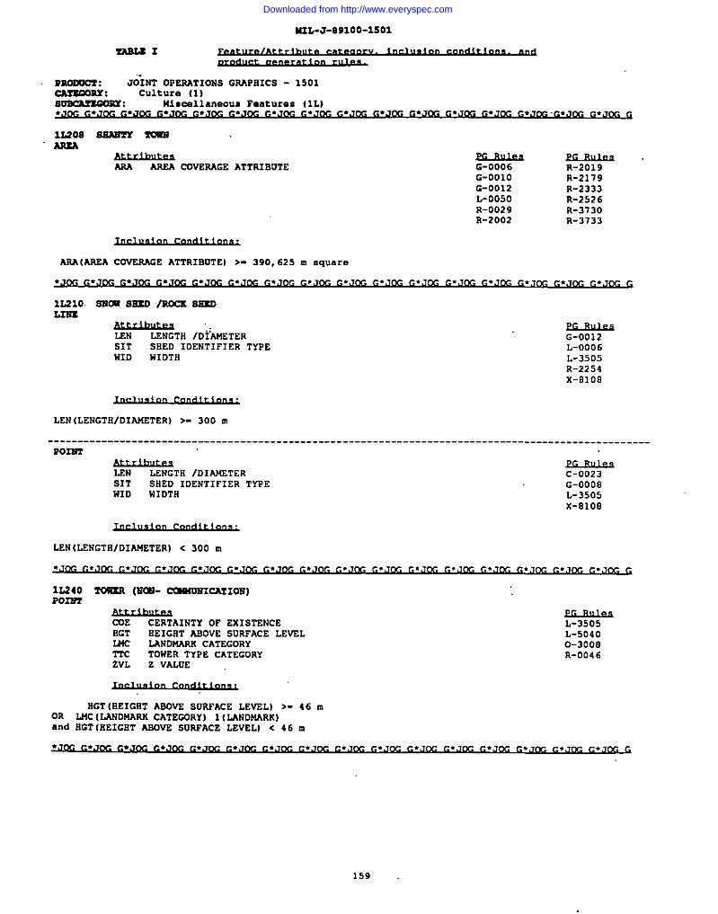
M2L-J-891OO-15O1
rAB2.EI
12208 SEANT2 wAsxA
ARA AREA CtNfERAGE ATTR3BUTE G-0006 R-2019G-OO1O R-2179G-0012 R-2333L-0050 R-2526R-0029 R-3730R-2002 R-3133
ARA(ARSA COVERAGE ATTRIBUTE) >- 390,625 m square
1L21O. SNU4 SHEO /mcs SBxDL2wz
AuLM&3s .LEN LENGTkl /DIAMZTER G-0012SIT SHED IDENTIFIER TYPE L-0006HID WIDTH L-3505
R-2254x-Oloe
LEN (LENGTE/DIAUETER) >- 300 m
----------------------------------------------------------------------------------------------------POzm
LSN LENGTH /DIAMETERSIT
C-0023SHED IDENTIFIER TYPE G-0008
WID WIDTII L-3505X-81OS
LEN (LENGTS/DIAMETER) < 300 n
12,240 2w?nl (r2ca-CCiS4UM1CATIOM)Po22i7
ME CERTAINTY OF EXISTENCE L-3505SGT SEIGET ASOVE SURFACE LEVEL L-5040WC LANDNARX CATEGORY 0-3000TTc TOWER TYPE CATEGORY R-004 6ZVL Z VALUE
HGT (BEIGIiTABOVS SUAFACE LEVEL) >- 46 mOR MC [LAND~ss CATEGORY) 1(LANDMASS)and EGT (BEIGST ASOVE SURFACE LEVEL) < 46 ❑
159
Downloaded from http://www.everyspec.com
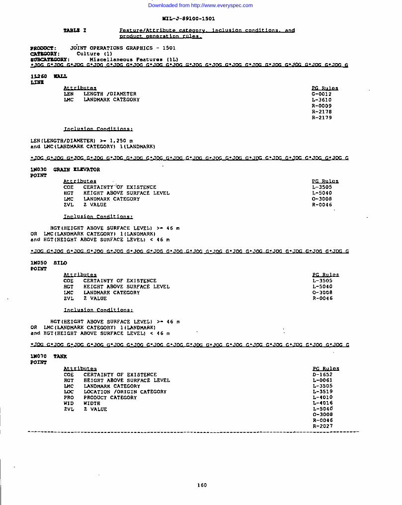
ZRS2X I
mmucr : JO”lNTOPESATIONS GRAPHICS - 1501cATtmRx : Culture 11)410scAmGORY : niscellmeous Features (lL)
I ..70GG. J12S G.JOC G..lm c.JOS G.JCC G..lrlc G.-.,,Ix G.JCC G.JCC G. JC.2 G..7CG G.JCC G.JCC G.JCG G
U2S0 mam
LSN LENGTH /D1~TERMC LANDMARK CATEGORY
G-0012L-361OR-0009R-2118R-2119
LEN (LENGTS/DIAMETERl >- 1,250 mand WC (LANDMARK CATEGDRY) 1(LANDMARK)
. Clc ~.J G.J~ ~.J r.J~ ~.J~ ~.,J ~,J~ ~.J~ ~,J . &- ~.J~ ~.,J&- . C*J ~. % G
lN030 CSA2S 13XVRTORPOINT
CDE CERTAINTY-’OF EXISTENCEHGT
L-3505BEIGHT AsDvE SURFACE LEVEL L-5040
WC LANDMARK CATEGORY 0-3008ZVL Z VALUE R-0046
RGT (HEIGHT ABOVE SURFACE LEVEL I >- 46 mON LNC (LANDMARK CATEGDRY ) 1(LANDMARKIand HGT (HEIGHT AI!rJVESURFACE LEVEL I . 46 m
~.J~ ~.J~ ~,,J~ ~.Joc ~.J~ ~.J~ ~.,J~ ~.J~ ~.J~ ~.J~ ~.J~ ~.J~ ~.,,~ ~.Jm ~.J~ G
2W50 s1r4Ponm
CDE CERTAINTY DF EXISTENCESGT
L-3505HEIGHT AODVE SURFACE LEVSL
MCL-5040
LANDMARK CATEGORY 0-3008ZVL z VALUE R-0046
HGT (HEIGHT ABDVE SORFACE LEVEL) >- 46 mOR LMC (LANDNARK CATESDRY) 1(LANDMARK)and IIGTIHEIGHT ASOVE SURFACE LEVELI . 46 m
lMo70 mmP02ST
CUE CERTAINTY OF EXISTENCEHGT
D-1652SE1G8T ASOVE SURFACE LEVEL
U4cL-0061
LANDMARK CATEGORY L-3505m aATION /ORIGIN cATEcORY L-3519PRO PRODUCT CATEGORYWID
L-401OWIDTH
T.VLL-4016
Z VALUE L-5046O-300BR-004 6R-2027
----------------------------------------------------------------------------------------------------
160
Downloaded from http://www.everyspec.com
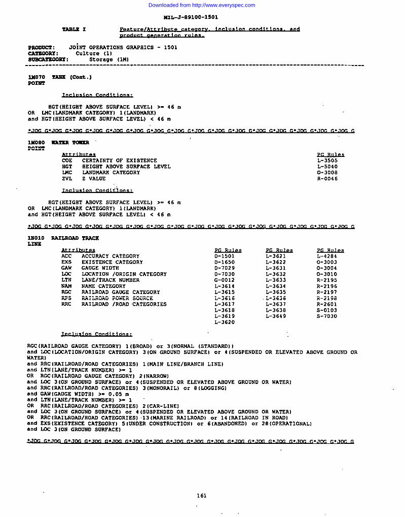
N3L-J-E9100-1501
ZAs2.sz
vsmOoCI : .70it72OPERATIONS GRAPHICS - 1501~: Culture (1)~: Storage (lM)
--------------------------------------------------------------------------------------------------
S31070 fX3JS (cont..)?Om
EGT (HEIGHT ABOVE SUNFACE LEVIL) >- 46 mOR LJ4C(LAND14ARR CATEGORY) 1(LANDUARS)and EGT (EEIGET ABOVE SURPACE LEVEL) c 46 ❑
.L,m, ~.J& ~.J~ ~.J~ ~.J~ ~.J~= ~.J~ ~.J~ G
311080 RAmR ~E02S72
&&llussCERTAINTY OF EXISTENCE
HGT 6E1GST ASOVE SURFACE LEVELWC LANDMARK CATSGORYZVL Z VALOE
L-3505L-50400-3008R-004 6
RGT (REIGRT ABOVE SURFACE LEVEL) >- 46 mOR 2J4CIL4ND14ARR CATEGDRY) 1 (LANDMARK)and SGT (HEIGBT ASOVE SUNFACE LEVELI < 46 m
~.J~ ~,.J~ ~.J& ~.J~ ~.J~ ~.J~ ~.,,~ p. Jfy- Si
1WO1OL2’s2E
SA2LRNAD TNAcs
ACC ACCUPACY CATEGORYSxs
O-1501EXISTENCE CATEGORY D-1650
GAw GAUGE WIDTN D-7029L4x LCCATION /ORIGIN CATEGORY D-7030LTN LANE/TRAcK NUMBER G-0012NAM NAME CATEGORY L-3614m RAILROAD GANGE CATEGORY L-3615RPs RAILROAO POWER SOVRCEARc
L-3616SAXLROAD /ROAO CATEGOR1 S3 L-3617
L-3618L-3619L-3620
~L-3621L-3622L-3631L-3632L-3633L-3634L-3635L-3636L-3637L-3638L-3649
L-4284O-30D30-30040-3010R-2195R-2196R-2191R-2198R-2601S-O1O3S-7030
RGc (P-41LROAD GAUGE CATEGORY) 1 (BROAD] or 3 (NOPJ4AL (STANDARD))and WC (LCCATIONIOR1GIN CATEGORY) 3 ION GROUNO SVRFACE) or 4 [SUSPENDED OR ELEVATED ABOVE GROUND ORHATER Iand RiC lRAILROADIROAo CATEGORIESI 1 INAIN LINE/sAANcH LINE)and LTN(LANE/TILACK NDNSER) >- 1OR RGC (RAILROAD GAUGE CATEGORY] 2 (NANNON]and LOC 3 ION GRODND SDRPACE) or 4 ISUSPENOED OR ELEvATED ABOVE GROUND OR HATER)and NRC (AAILROAD/ROAO CATEGORIES) 3 (MONORAIL) Or 8 [U3GG1NG)and GAW (GAUGE NIDTS) >- 0.05 mand LTN ILANE/TAAcK NDNBER) >- 1OR NRC [NAILROAD/ROAD CATEGORIES] 2 (CAR-LINE]md m 3 ION GROVND SURFACE) or 4 (SUSPENDED OR ELEVATED mvs GROUND OR WATERIOR RRCINAILROAD/RDAD CATEGORIESI .1306AAINE RAILROAD) or 14 (RAILROAD IN ROAD)and EXS (EXISTENCE CATEGORY] 5 [DNOER CONSTRUCTION) or 6 IABANDONEDI 0? 2B(OPERATIONAL).3.0IZJC3 (ON GRODND SNRFACE)
161
Downloaded from http://www.everyspec.com
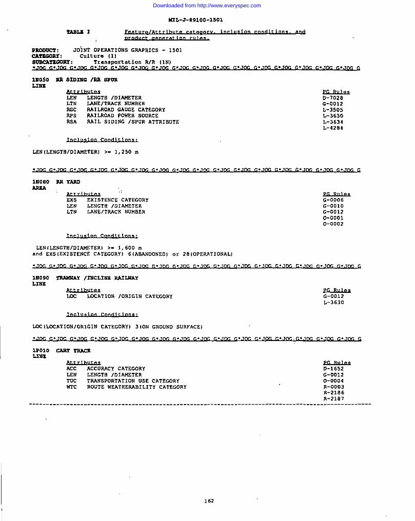
K2L-J-o91oo-15O1
mooOcr: JOiNT OPERATIONS GRAPHICS - 1501CATSGORX : Culture (1)~PY : Transportation RIR (IN)
1~050 BR S20324C ISR SPOR
LEN LENGTH /DIAKSTER D-1020LTN lANE/TRAcK NUMBER G-0012RGc RA1LROAD GAUGE CATEGDRY L-3505APs RAILROAD PONER SODRCE L-3630RSA RAIL SIDING ISPUR ATTRIBUTE L-3634
L-4284
LSN [LENGTRIDIANETERI >- 1,250 m
lHOBO SR YARDAssA
“Audhu3a”EXS EXISTENCE CATEGORY G-0006LEN LENGTR /DIANETERLTN
G-OO1OLANE/TRACK NUMBER G-0012
0-00010-0002
LEN(LENGTH/DIAl.f2TER) >- 1,600 ma“d EXS (EXISTENCE CATEGORY) 6(ABANDONED) or 28 (OPERATIONAL)
1U090 3TiAWdAY /2NCL1NE RNU4AYLINS
m =P. TION/ORxGxN CATEGORY G-0012L-363D
m ILDCATIONjORIGIN CATEGORy) 3 (0N GROUND SDRFACE)
1PO1O CART S%Aa(L2NS
ACC ACCORACY CATEGORYLEN
0-1652LENGTH /DIAMETER
TOCG-0012
TRANSPORTATION USE CATEGDRYNTc
0-0004ROUTE WEATNERAB1 LITY CATEGORY R-0003
R-21B6--------------------------------------------------------- -_---_______ R--__R-2187 _____
I 162
Downloaded from http://www.everyspec.com
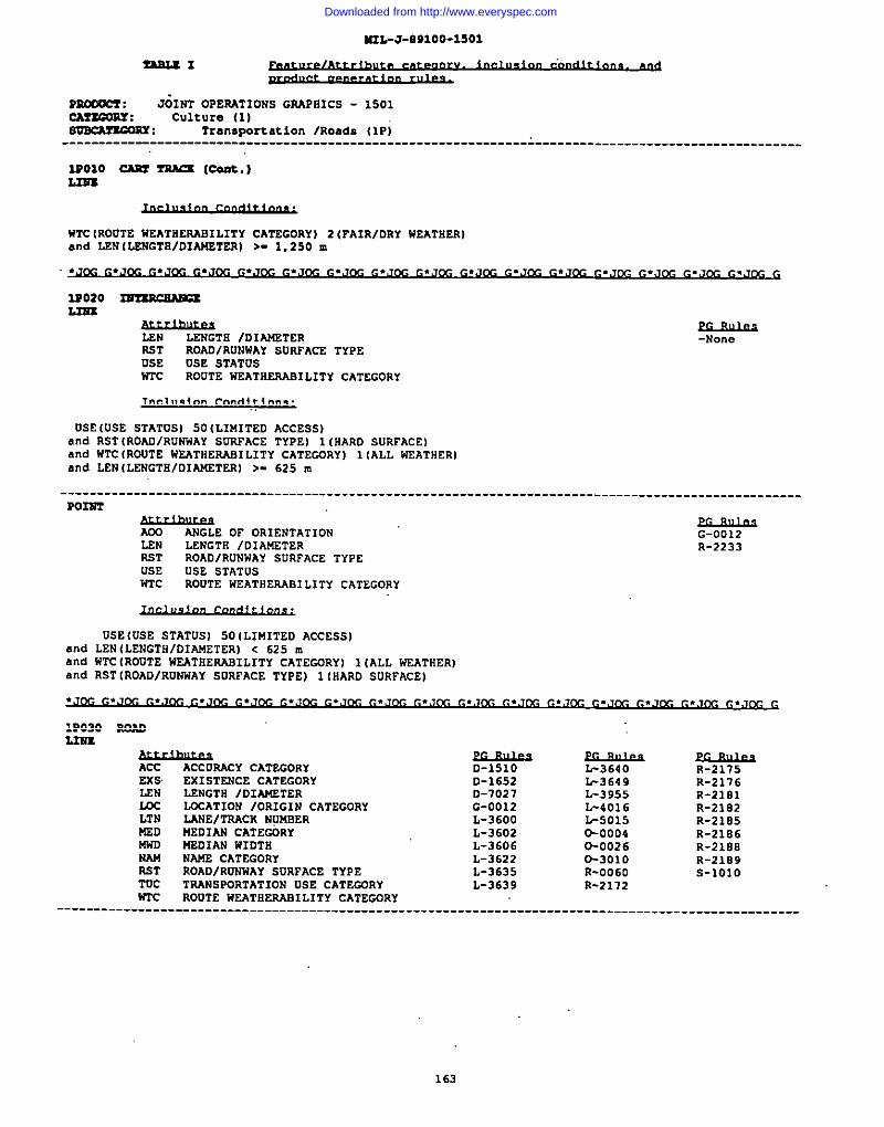
=L-J-09100-1501
ZASLSI
moooCY : J&T OPERATIONS GRAPHICS - 1501CAmGORY: culture (1)~: Transportation lRoads (1P)
-------------------------------------------------------------- L------------------------------------
2PO1O CA3x - (cont.)L2u3
WTC (ROVTE WEATHENASILITY CATEGORY) 2 (FAIR/DRY NEATRER)and LEN [LENGT51/DIAnETER) >- 1,250 m
23020 3mnasNmL2Nx
LEN LENGTR lDIAf.tETER -NoneN.5T ROAD/RUNWAY SURFACE TYPEUSE USE STATUSNTc ROUTE NEATH~BILITY CATEGORY
STATUS) 50(LIMITED ACCESS)USE (USEand RST (ROAD/RUiW4AY“SURFACE TYPE) 1 (HARD SURFACE)
I
and WTC fROUTE N2ATHERABI LITY CATEGORY I 1 IALL WEATHER)and LSN (LSNGTHIDIMETER) >- 625 m
----------------------------------------------------------------------------------------------------P02NT
ADD ANGLE OF OR1ENTATIONLEN
G-0D12LENGTR /DIAMETER R-2233
SST ROAD/RUNWAY suRFAcE TYPEUSE USE STATUSNTc ROUTE WEATNEAAB1 LITY CATEGDRY
USE(USE STATUS] 50 (LIMITED ACCESS)and LEN (LENGTEIDIWETER) < 625 mand WTC IROUTE NEATHElwlILITY CATEGORY] 1IALL WEATHERIand RST (ROAD/RUNWAY SURFACE TYPE) 1 (HAND SDRFACE)
IP030 RoAo
FACCDFL4CY CATEGORY
Ess EXISTENCE CATEGDRYLEN L2NGTN /DIAMETERm U3CATION /ORIGIN CATEGORYLTN lANE/TNACK NUMBERUED MEDIAN CATEGORYNnD 14ED1AH WIDTHSAN NW CATEGORYSST ROAD/RONNAY SURFACE TYPETOC TRANSPORTATION USE CATEGDRYNTc RDOTE WEATHENASILITY CATEGORY
-------------------------------------
D-151OD-1652D-1021G-0012L-3600L-3602L-3606L-3622L-3635L-3639
L-3640L-3649L-3955L-4016L-50150-00040-0026D-3010R-0060R-2172
R-2115R-2116R-2181R-2192R-2185R-2186R-2i8SR-2189S-lolo
---- ----- .-.- -. .- . .-. .. ,- ----------- .----- ----------- .-----
163
Downloaded from http://www.everyspec.com
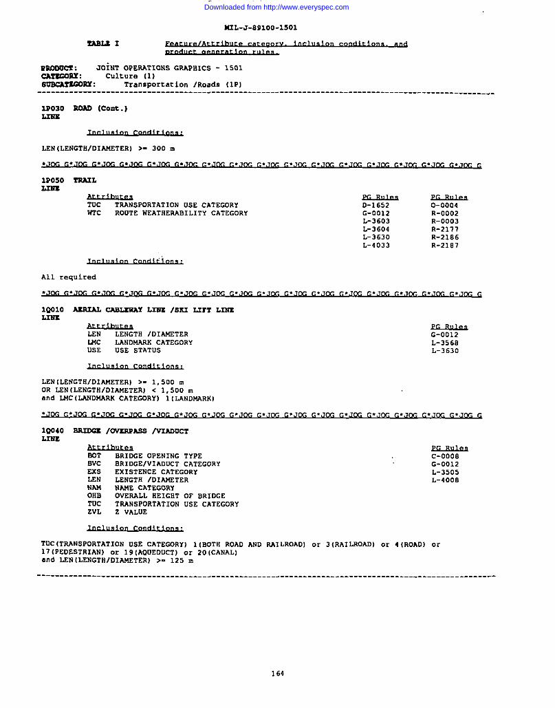
4UL-J-891OO-15O1
mnooc? : JOiNT OPERATIONS GRAPlllCS - 1501CAr3mur : Culture (1)msCA??@$-Y : Transportation /Roads (1P)
----------------------------------------------------------------------------------------------------
3s030 ROAD (cont.)L2ss
LEN(LENGT8/D1AJ4ETER) >- 300 m
1R050 TRA2L3.IN-S
y#hllwlTAANSPORTATION USE CATEGORY D-1652 0-0004
WTc ROUTE WEATIIERABILITY CATEGORY G-0012 R-0002L-3603 R-0003L-3604 R-2177L-3630 R-2186L-4033 R-2187
All required
1QO1O ASRIAL CABLSWAY LIES /81S2L2Y12L2EELm3
LEN LENGTH /OIAMETER G-0012L44c LANDMARK CATEGORY L-3568USE USE STATUS L-3630
LEN (LENGTHIDIAMETER) >- 1,500 mOR LEN (LENGTHIDIAMETER) < 1,500 mand LMC (L4NDMw.K CATEGOKY) 1(LANDMARK)
lQ040 ~ /OVZRPASS /V2ADUCTLIU3,
SOT BRIDGE OPENING TYPEBVC ORIDGEIVl ADUCT CATEGORYExs EXISTENCE CATEGORYLEN LENGTH /D1~TERNAM NAME CATEGORYOHB OVERALL HEIGHT OF BRIDGETUC TRANsPORTATION USE CATEGORYZVL Z VALUE
EL13uksC-ooosG-0012L-3505L-4000
ITUC ITRANSPORTATION USE CATEGQRYI 1IBOTH ROAD AND P.A1LROADI or 3IRA1LROADI or 4 (ROADI or17 (PEDESTRIAN) or 19 [AQUEDUCT) .X 20 ICANAL)and LEN lLENGTI1/DIMETERl >. 125 m
I ----------------------------------------------------------------------------------------------------
164
Downloaded from http://www.everyspec.com
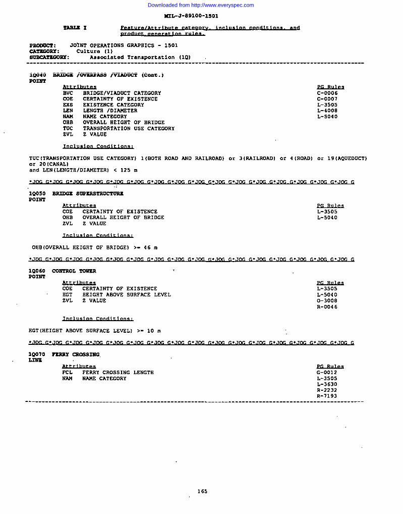
.-. . . . . . . . . . .Ullr.-um.””-aa”,
S!ASLSI
PRcaocl : JOINT OPERATIONS GAAPBICS - 1501cAzxGORx : Culture (1)~ns : Aasoclated Transport c.tion (101
----------------------------------------------------------------------------------------------
1QN40 SsciccsIOV=RASS /v2AnmT (Cot. )9032?2
C-0006C-0007L-3505L-4008L-5040
TUCITRANSPORTATION USE CATEGORY) 1(BOTR ROAD AND AAILROAO) or 3 (RAILROAD) or 4 (ROAD) or 19 (AOUEDUCT)or 20 (CANALIand LEN (LENGTR/DIA14ETER) < 125 m
.J~ ~.J~ ~.Jt3c~.J@-J ~.J~ ~.J~ ~.Jt2c ~.J~ ~. ~.J~ ~.J~ ~.,Jm, ~*J~ ~.J(yJ ~.,Jcc ~.J~ G
“1Q050 BRmSs susss.srRmroSxPOINT
CUE CERTAINTY OF EXISTENCEOlis
L-3505OVERALL EEIGRT OF BRIDGE
ZVLL-5040
Z VALUE
OHB(OVERALL HEIGHT OF BRIDGE] >- 46 m
1Q060P02S2
COSTROL ?O12ZR
COE CERTAINTY OF EXISTENCE L-3505HGT BEIGRT ABDVE SURFACE LEVEL L-5040ZVL Z VALVE 0-3008
R-0046
RGT(HEIGHT ABOVE SURFACE LEVEL] >- 10 m
~ ~*J~ ~*J~ f..J&- ~.J~ ~.J~ ~.u ~,J~ f..J~ ~.J~ ~.J~ G.J~ G,J~ ~*,&- ~.J~ ~,Jcc G
1Q070 SZSRY =S3NG.
Mhlte2FCL FERRY CROSSING LENGTH G-0012NM NANE CATEGORY L-3505
L-363DR-2232R-7193
----------------------------------------------------------------------------------------------------
165
Downloaded from http://www.everyspec.com
ls2L-J-a9100-1501
~1
mOmcl : JOINT OPERATIONS GRAPHICS - 1501CA??COSLY: Culture (1)~sY : Asc.ceiated Transportation (10)
---------------------------------------------------------------------------------------------------
19070 nsR2! -82NG (cont.)2.IES
FCL (FERRY CROSSING LENGTH) >- 125 m
----------------------------------------------------------------------------------------------------
P02ST
XL FERRY CROSSING LENGTHNAM NAME CATEGORY
L-3505R-2232
FCL (FERRY CROSSING LENGTK) c 125 m
1Q1OO DIS’2AMCS MARsxR “’Po2m
FD1STANCE VALUE ATTRISUTE
UN1L-3605
UNITS CATEGORY L-3606R-2183R-21B4
uN1 {UNITS CATEGORY) 10 (KILOMETERS)
1Q11O MooRmc NAs?Po3m
CilE CERTAINTY OF EXISTENCE L-3505liGT HEIGHT ABOVE SURFACE LEVEL L-5040zVL Z VALUE O-3008
R-004 6
NAM NAME CATEGORY R-2181TUC TRANsPORTATION VSE CATEGORY R-2182uSE USE STATUS
---------------------------------------------------------------------------------------------- ------
166
Downloaded from http://www.everyspec.com
I M2Z-J-891OO-15O1
I
msLtl
moOuCz : JOINT OPERATIONS GRAPHICS - 1501CAzxGons : Culture (1)mlscArscQsY : Associated Transportation (IQ)
---------------------------------------------------------------------------------------------------
1Q116 WU?S — (coat.)P02ST
USE (USE CATEGORYI 4(NATIONAL) or 5(STATE) or 23 [INTERNATIONAL)
1Q131 To?2NELL2Ns
LEN LENGTH /DIAWETER L-3505NAN NAMS CATEGORY L-3630TM TNAVENSASILITY ATTRIBUTETuc TN.ANSPORTATION USE CATEGDRYWID WIDTH
LEN (LENGTH/DIAMETER) >- 315 m
---------------------------------------------------------------------------------------- ------------
PO124T
LEN LENGTH /D1A14ETERNAW
c-0020WAJ4ECATEGORY
TWAL-3505
TRAVERSAB1 LITY ATTRIBUTETUC
R-2221TRANSPORTATION USE CATEGORY
WID WIDTH
LEN (LENGTS/DIAMETER) < 315 m
.J~ ~.J~ G.J~G =.J~ G.J~ ~.J~ ~.J~ ~.Jfy- ~.,J~ ~.,m ~..’j~ ~.J~ G.,,m c.J~ G.JM C.JM G
1?010 DI=P02ST
COE CERTAINTY OF EXISTENCEHGT HEIGHT ABOVE SURFACE LEVELL44c LANDNARK CATEGORYZVL Z VALUE
L-3505L-50400-3008R-004 6
IIGTIHEIGST ASOVS SURFACE LEVEL) >- 46 mOR SGT (HEIGHT ASOVE SURFACE LEVEL I < 46 mand L!4C(LANDMASS CATSGORYI 1(L4NDNARKI
1?030 PN42SN ?P.ANSK2SS1OM LINSL2us
Acc ACCDRACY CATEGORYLEN
D-102OLENGTH IDIAW2TER
TSTG-0012
TRANSM1SS1ON LINE SUSPENS1ON TYPE L-4012R-0007
--------------------------------------------------------------------------- -------------------------
167
Downloaded from http://www.everyspec.com
M2L-J-891OO-15O1
-1
93D00ct : JO”INTOPERATIONS GRAPHICS - 1501cMxcORx : Culture (1]soBcArxGORY : Communication lTransmission (lTI
----------------------------------------------------------------------------------------------------
lt030 POUR YKU3M22SS1021 m (Coat.)L2sx
R-2492R-7209
All required
1?040 PORES w31128BIW PXWMPOIm
COE CERTAINTY OF EXISTENCEHGT HEIGET ABOVE SURFACE LEVSLZVL Z VALUE
.:
L-3505L-50400-3000R-0046
flGTIREIGET/DIAMETER) >= 46 m
CG G
1T050 cc4muN1cA?102w rAclLI1’Y
f&hwAREA CDVESAGE ATTRIBUTE
NW NAME CATEGORYNST RADIO NAVIGATION lc0t4t4uN1cATIDN
ARA(AREA COVESAGE ATTRIBUTE) >- 390, 625 m square
~L-3505L-4008L-4E13
LEN LENGTH IDIMTERU4c LANDMARK CATEGORYTEL TELECDMMUN1CATIONS TYPE
D-7015G-0012L-3630R-0008T-0014
LEN (LENGTH/D1A!4ETER) >- 1,600 mand U4C ILANDMARK CATEGDRy) 1(LAND~RKI
CDE CERTAINTY OF EXISTENCEHGT HEIGRT ABOVE SURFACE LEvSLU4c LANDMARK CATEGORYNAf4 NAME CATEGORYNST wDrO NAVIGATION lC0Mt4UNICAT10N
ELs!ue3D-1652L-3505L-5040O-3D08R-004 6
168
Downloaded from http://www.everyspec.com
I
I
IUL-J-8B1OO-15O1
ZAS2.SI
PsDoocl : JOINT OPERATIONS GRAPBICS - 1501cA7sc0RY : Culture (1)~m : communication /Transmission IIT)---------------------------------------------------------------------------------------------------
1T080 ~ (~ SSWIOU) (coat.)POIRT
ZVL Z VALUE
IIGT(HEIGHT ASOVE SURFACE LEVEL) >- 46 mOR EGT [klEIG8TASOVE SURFACE LEVEL) < 46 Mand MC (LANDMASS CATEGORY) 1 (IAND14ANXI
.JOG C.JOC C.JOC C.JDC C.JR C=.J~ G.JCG c.,Tm c.,,~, G.,,= G.Jm c.JCC G.Jm G.JCC G.JM IZ.JCX G
10025 ~ 2.AlI02’6EPSDPo2m
AFTELU3.es
AIRCRAPT FAcILITY TYPENAM
L-3505NAME CATEGORY
USE USE STATUi
AFT(AIRCRAPT FACILITY TYPE) .2(8ELIPORTIand USE{ USE STATUS] 10 (OTHER) or 43 (HOSPITAL]
10030 AI-T TAcIL2TYPOINT
AFT AIRCWT FACILITY TYPEcoo CERTAINTY OF DEL1NEATIONEXS EX1STENCE CATEGORYNAM NAME CATEGORYUSE USE STATUSZVL Z VALUE
L-3505R-0039R-0040R-0041R-0042R-0044R-0047R-7293
AFT(AIRCRAFT FACILITY TYPE) .0{UNKiOWN) or 1 (AIRPORT) or 4 (UNDEFINED LANDING AREA)and EXS (EXISTENCE CATEGORY I 3(REPORTED] or 6 (ABANDONED) or 9 (NOT USASLE) or.27 (CLOSED) or20 (OPERATIONAL)
LEN LENGTN /DIAMETER 0-6201R-6060
----------------------------------------------------------------------------------------------------
169
Downloaded from http://www.everyspec.com
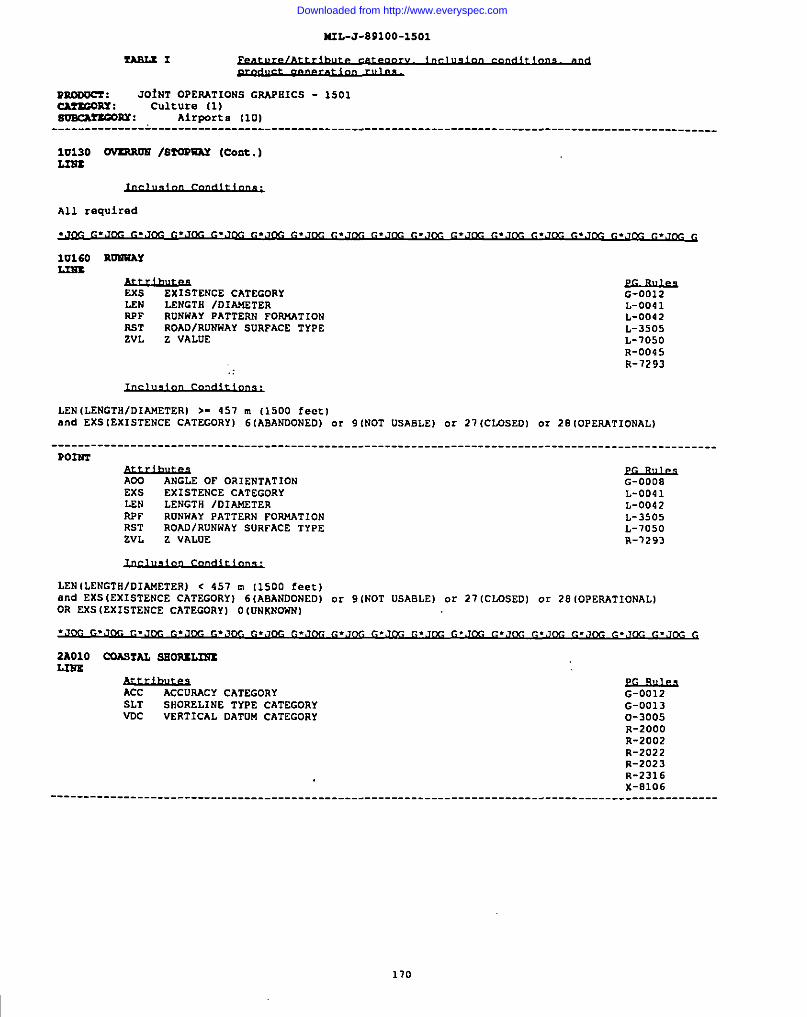
MIL-J-891OO-15O1
l!AB3.tl
m.mum : JOINT OPERATIONS GWHICS - 1501cAz3G0RT : culture (1)~nx : Airports 1101
-------------- L-------------------------------------------------------------------------------------
1U130 0V3RRUS 18WEWAY (Cent.)L22rz
All required
luISO RUETiAYLxsz
G-0012L-0041L-0042L-3505L-7050R-0045R-7293
LEN ILENGTSIDIAMETER) >- 457 m (1500 feet)and EXS [EXISTENCE CATEGORY] 6(ABANDONED) or 9 (NOT USABLE) or 21 (CLOSED) or 28 (OPERATIONAL)
----------------------------------------------------------------------------------------------------
yANGLE OF OR1ENTATION
EXS EXISTENCE CATEGORYLEN LENGTH /D1A14ETERRPF RuNNAr pATTERN FORMATIONRST ROAD IRUNWAY SURFACE TYPEZVL Z VALUE
LEN (LENGTH/DIAMETERl c 457 m 11500 feet 1and EXS (EXISTENCE CATEGORY I 6 (ABANDONED)OR EXS (EXISTENCE CATEGDRY] O (UNKNOWN)
or 9 (NOT USABLE I or 27 (CLOSEDI or
G-0008L-0041L-0042L-3505L-7050R-7293
28 [OPERATIONALI
&tlluAAcCURACY CATEGORY
SLT SHORELINE TYPE CATEGORYWC VERTICAL DATUM CATEGORY
G-0012G-00130-3005R-2000R-2002R-2022R-2023R-231 6X-8106
----------------------------------------------------------------------------------------------------
I 170
Downloaded from http://www.everyspec.com

4UL-J-891OO-15O1
momcr : J&NT OPERATIONS GRAPHICS - 1501CATZCORX : Hydrography [2)SoKAIEosa : coastal Eydro (281
----------------------------------------------------------------------------------------------------
2AO1O COM?AZ, SEOSUL2EX (Cent.)
All required
2A020 roExBnoNxw
ARA AREA COVERAGE ATTRIBUTE G-OO1OHID WIDTH G-0012
G-CXW6
AAA(AREA COVEWGE ATTRIBUTE) >- 390,625 m squareand WID(WIDTN) >- 315 m ““
2A040AREA
oPml WA?ss (Sxwr IN3AND)
f.<wAREA CDVEAAGE ATTRIBuTE G-OO1O
G-0012G-0013L-3505L-3506R-2316R-370E
All required
LEN LENGTN /DIAWETERVT(C VERTICAL REFERENCE CATEGDRYWID WIDTN
G-0012
VRC (VERTICAL REFERENCE CATECDRY) 1(ABDVE SURFACE/DOES NOT COVER (AT NIGN WATER) )and LEN (LENGTH /01AJ4ETER) >- 125 m
LEN LENGTFI IDIAWETER G-0012Vsc VERTICAL REPERENCE CATEGORY
--_-----_--:::---::~:: ------------- -------------- - --:-___-
111
Downloaded from http://www.everyspec.com
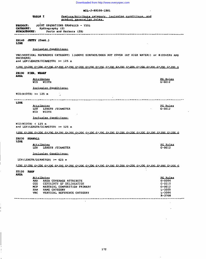
M2L-J-891OO-15O1
TASLSI
msLs2c7 : JOIST OPERATIONS GRAPHICS - 1501CAr2GoRx : Hydrography (2)smcsrEOsY : Ports and iiarbors (2S1
----------------------------------------------------------------------------------------------------
2B140 JKTS (Cant.)L2us
VRc WERTICAL REFERENcE CATEGORY I 1 IABOVE suRFAcE/DOES NOT COVER [AT HIGH HATER) I or 8 ICOVERS ANDUNCOVERS]and LEN (LENGTS/DIANETERl >- 125 m
2B190 P=, USARJAREA
WID WIDTB G-0012
WID(WIDTS) >- 125 m ;,
----------------------------------------------------------------------------------------------------L2NS
LEN LENGTS /DIANETERWID
G-0012wIDTH
iSID(WIDTH) < 125 mand LEN (LENGTNIDIAMETER) >- 125 m
2S230 S2AUALLL2NS
LEN LENGTS /DIAlfSTER G-0012
LEN[LENCTs/DIMTERI >- 625 m
.J(y ~.J~ ~.J~ ~.J~ ~.,J~ ~.,J~ ~.,J,-&~.J~ ~.J~ ~.J~ ~.J~ ~.J~ ~.J~ G.J~ (..J~ ~.J~ G
2D120 RXEFAssA
ARA AREA COVERAGE ATTRIBUTE G-0006CUD CERTAINTY OF DELINEATIONMCP
G-OO1OMATERIAL COWOSITION PRIMARY G-0012
NAN NAME CATEGORYVRc
L-3505VERT lCAL REFERENCE CAT ECXJRY L-3506
R-3708----------------------------------------------------------------------------------------------------
172
Downloaded from http://www.everyspec.com
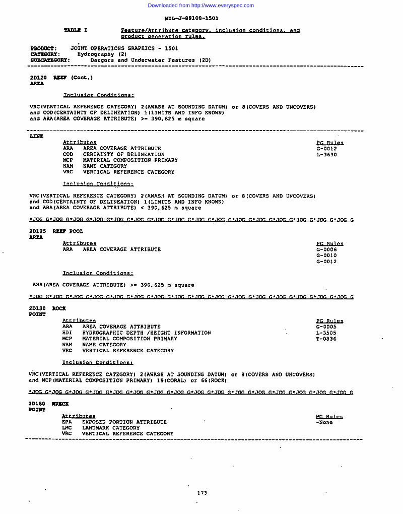
I5IL-J-891OO-15O1
?!ASLSI
mooocz : JOXNT OPERATIONS GSAPlllCS - 1501cArscoRY : Eydicqrc.phy (2)OmclmOOsx : Dangers and Underwater Feat ures (2DI
---------------------------------------------------------------------------------------------------
20120 SXS7 (Cent.)As2A
VNC (VERTICAL AEPERENcE CATEGORY I 2 (AWASE AT SDUNDING DATUN) cm 8 (COVERS AND UNCOVERS)and COD (CERTAINTY OF DELINEATION I 1 (LIMITS AND INFO mOwland ANA (AREA COVSAAGE ATTRIBUTE) >- 390,625 m square
----------------------------------------------------------------------------------------------------Lms
ANA AREA COVERAGE ATTRISUTE G-0012CUD CERTAINTY OF DELINEATIONMCP
L-3630NATERIAL COMPOS1TION PRINARY
NAN NAME CATEGORYVNc VERTICAL REFERENCE CATEGDRY
VRC (VSRTICAL REFERENCE CATEGDRY) 2(AWASH AT SOUNDING OATUM) or 0 (CDVERS AND UNCOVSRS)and COD(CEATAINTY OF DEL1NEATION) 1 ILIMITS ANO INFO KNOWN)and ANA(AREA COVENAGE ATTRIBUTE) < 390, 625 m square
.,J~ ~.Jt3c~.J~ ~,J~ ~,J~ ~.J~ ~.J~ ~*J~ ~.J~ ~.J~ ~*J~ ~.J~ G.J~ ~*J~ ~.J~ ~.J~ G
20125 RSSF POOL
ANA AR2A COVEAAGE ATTRISUTEND1 BYDROGNAPSIC DEPTH /SEIGST 1NFUNMATIONPsP NATERIAL CONPOS1TION PRIUARYNAM NANE CATEGORYVRc VERTICAL REFERENCE CATECDRY
G-0005L-3505T-0836
VilC(VERTICAL REFERENcE CATEGORY) 2 (AWASS AT SOUNDING DATUM) or 8 (COVERS AND UNCOVERS)and MCP [NATERIAL CONPOSITION PRINARY) 19 (CONAL) or 66 (ROCK)
G
2D180 ~Roxsm
EPAELs!J.@
EXPOSED PORTION ATTRIBUTE -NoneWC LANDNARK CATEGORYVAc VERTICAL REFERENCE CATEGORY
173
Downloaded from http://www.everyspec.com
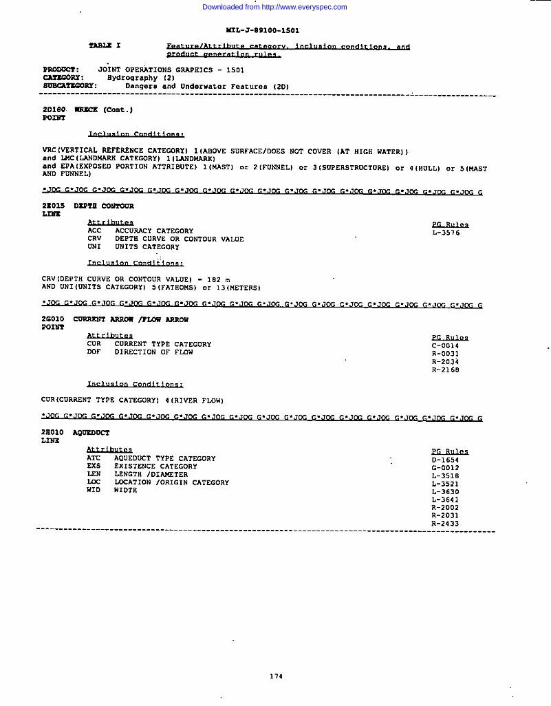
M2L-J-891OO-15O1
I!ASLX12xdu.* ....r~
PAQOUCY : JO;NT OPEF+,TIONS GRAPHICS - 1501cATxcORT : hydrography [2)mRcAmGORT : Dangers and Underwater Features (2D]--------------------------------------------------------------------------------- L_-__------__----_-
2D180 - (cant.)m2321
VRC (VERTICAL REFERENcE CATEGORY) 1(ABOVE SURFACE/DOES NOT COU2R (AT HIGH WATER] ]and WC ILANDMARK CATEGORY) 1(LANDU4RK]and EPA (EXPOSED PORTION ATTRIBUTE) 1 (MAST) or 2 [FUNNELI or 3 (SUPERSTRUCTURE) or 4(HULL) or 5 (NFSTAND FUNNELI
ACC ACCUMCY ChTEGORY L-351 6CRV DEPTH CURVE OR CONTOUR VALUEUN1 UNITS CATEGORY
CRV IDEPTN CURVE OR CONTOUR VALUE) - 182 mAND UNI IUNITS CATEGORYI 5 IFATHOMS) 0. 13 (METERS)
CUR CURRENT TYPE CATEGORYDDF DIRECTION OF FI..3W
c-001 4R-0D31R-2034R-2168
CUR (CDRRENT TYPE CATEGDRY] 4 (RIVER FLOW]
CK G
2BO1O AQ02DU~L3147.
kTC AQUEDUCT TYPE CATEGORYEXS EXISTENCE CATEGORYL2N LENGTH /D1Alf6TERILK ~ATION 10RIGIN cATEGORYWID 441DTS
D-1654G-0012L-351eL-3521L-3630L-3641R-2002R-2031R-2433
--------------------------------------------------------------------------------------------------- -
114
Downloaded from http://www.everyspec.com
=L-J-891OO-1SO1
I
I
ZA8LSI
moowf : J&ST OPERATIONS GRAPHICS - 1501CAFsaQnx : Hydrography (2)mxA?smn: Inland Water (2E)
---------------------------------------------------------------------------------------------------
zaolo AQ0s00c3 [coat.)
LEN (LENGT13/DIANETERl - 625 nand ATC (AOUEDUCT TYPE CATEGORY I 2 (OTHER) Or 3 (QANAT/NANAT/lC4REZ TUNNEL)
----------------------------------------------------------------------------------------------------Po2sf
ATC AQUEDQCT TYPE CAT2GORYm LOcATloN /ORIGIN CATEGORY
A’TC(AQUEDUCT TYPE CATEGORY) 1 (QANAT/RANAT/SAAEZ 14A1NTENANCE SHAFT]
D-1654R-0034R-0035
2U020 CAuuL3Ns
Exs EX1STZNCE CATEGORYHYC FiYDRDGRAPtilcCATECDRYLEN LENGTH IDIA14ETERNAM NAnE CATEGORYWIO WIOTH
L-3513L-3630L-3650O-0006R-2002R-201 6
flYC{HYDRffiRAPfllCCATECDRY] 3 (DRY) or 8 (PERENNIAL/PERMANENT)and LEN [LENGTVDIAMETER) >- 2,500 m
2E030 OIZCSL2XS
IIYC HYDROGPAPHIC CATEGDRYLSN LENGTH /OIAMETERWID WIDTH
O-1652D-1653L-36300-0006R-2002R-2016R-2116R-2117R-1294
LEN(LENGTHID1A16ETER) >- 2,500 m
I175
Downloaded from http://www.everyspec.com
ILIL-J-S91OO-15O1
-I
Pr@nccr : JOiNT OPEFA’TIONS GRAPHICS - 1501~RY : Hydrc.graPhy (2)~w : Inland Hater 12H)..,~ c.J~ G.J~ c.J~ ~..,~ ~ ~.J~ ~.J~ ~.J~ ~.J~ ~*J~ ~.J~ ~.Jfy.~.J~ ~.J~ ~.J~ G
28040 ?12,?RATIrn /=r102? BT,DS
WC LANDWARX CATEGORY G-0012HID WIDTH L-3505
L-3506L-3509R-2002
141D(W1DTR) >- 315 mand lJIC(LANDMmK CATEGORY) 1 (LANDM4RK)
WID (WIDTH) >- 375 m
LEN LENGTH /DIANETERWC LOCATION /ORIGIN CATEGORY
G-0012L-3508L-3630L-3641
LEN lLENGTH/DIAMETER) >- 315 m
G
26070 TORI)L122Z
LEN LENGTH /DIAKETER G-0012L-3505L-3630R-0002R-2232R-3902
----------------------------------------------------------------------------------------------------
176
Downloaded from http://www.everyspec.com
2UL-J-891OO-15OI
TAS3X I
mlooo= : JOiNT OPERATIONS GRAPHICS - 1501cu2coRx: Hydrography 12)s~ : Inland Hater (2S)--------------------------------------------------------------------------------------------------
28070 T0240 (COUS.)
LEN (LENC’YR/DIANETERl >- 125 m
----------------------------------------------------------------------------------------------------P02SY
LEN LENGTR /DIAMSTER G-OOOSL-3SOS0-3005R-2232R-3902
LEN (LENGTH /D1At4ETER) < li5 m
2E075L3372
2N2AND SSORBL2222
ACC ACCURACY CATEGORYARC
G-0012AsSCXIATED HYDRDGPAPHIC CATEGORY
IIKG-0013
HYDRCGRAPHIC ORIGIN CAT2GORYSLT
L-3630SHORELINE TYPE CATEGORY 0-300S
R-2000R-2002R-2023R-2316X-8105
All required
.J~ G.J~ ~.,~ c.J~ ~.J~ c.J~ =.Jm ~.J~ ~.,J~ ~.,J~ ~.J~ c.J~ ~.J~ c.J~ ~*Jm C*JK G
2EOS0 2.6scs/mNDAMA
AM AREA COVEWGE ATTRIBUTE G-OO1OHYC llYDR@31APH1C CATEG@RY G-0012NAM NAt4ECATEGORY G-0013USC WATER SALINITY CATEGORY L-3505ZVL Z VALUE L-3506
L-3507L-4821R-2001R-2316
----------------------------------------------------------------------------------------------------
177
Downloaded from http://www.everyspec.com
M2L-J-891OO-15O1
-1
m0mc7 : JOiNT OPERATIONS GRAPHICS - 1501cM!xaORY : Hydrography (2)ommTxG02Y : Inland Water (2H)--------------------------------------------------------------------------------------------------- .
2n080 - lP03m (coat.)AR2A
AJIA(AREA CDVERAGE ATTRIBUTE) >- 390, 625 m squareand HYCiRYDROGwHIC CATEGORY I 6 lNON-PERENNIAL/ iNTERMITTENT/FLUCTUATINGl or 8 (PEAENNIAL/PEPJ4ANENTIOR ARA(AAEA COVEWGE ATTRIBUTE] >- 390,625 m squareand HYC (HYDROGAAPHIC CATEGORY) 3 (ORY)and wSC (WATER SALINITY CATEGORY] 2 (FRESH)
m AREA COVERAGE ATTRIBUTERDC HYDRDGAAPHIC ORIGIN CATEGORY
G-0006G-0010G-0012
ARAIAREA COVEF.AGE ATTRIBuTE) >- 390,625 m square
(..J~ ~.,fyJ ~, lCG G
2E11O PKNS?OC!KL3112
pLENGTH /DIAMETER G-0012
WE LWATION /ORIGIN CATEGORY L-3596L-3630L-3641
ux (LOcATIONlORIGIN CATEGORY) 3 (oN GROUND SURFACE I 0. 4 ISUSPENDED OR ELEvATED ABovE cROuND oR WATER Iand LEN lLENGTR/DIAMETER) >- 625 m
2R120 mIDSL32i2
Audhue2LEN LENGTH /DIAMETERWID WIDTH
G-0012G-0013L-3505R-0006R-2017R-2232R-2429X-8101
----------------------------------------------------------------------------------------------------
178
Downloaded from http://www.everyspec.com
lUL-J-09100-i501
fAsL21
moocel : JO”INT OPERATIONS GRAPHICS - 1501CArEoRY: Hydrography (2)s~ : Inland Hater (2E)----------------------------------------------------------------------------------------------------
2E220 RSPIDS (Cent.)
i910[MIDTR) >- 125 m
----------------------------------------------------------------------------------------------------
P022?Tm?.th,,**aWID WIDTH c-0004
G-0008L-3505R-0006R-2017R-2232X-8101
WIDIWIDTH) c 125 m
.-—.
ARA AREk COVERAGE ATTRIBUTEEXS
G-0006EXlSTENCE CATEGORY
NAMG-OO1O
NAME CATEGORY G-0012L-3505L-3506R-2000R-2002R-2316
ARA (AREA COVERAGE kTTRIBUTE) >- 390,625 m square
2H140 W1’VZS /S~AMA
Acc&21ul&
ACCURACY CATEGORY L-0062nYc
R-2014HYDRDGRAPHIC CATEGORY L-3506
NANR-2015
NAME CATEGORYSLT
C-3007 R-22995H0AELINE TYPE CATEGORy R-0031
TIDR-2316
TIDAL /NOW-TIDAL CATEGORY R-2009WID
R-2429w1OTH R-2010 S-1OO3
EIYC(HYDRCGRAPSIC CATEJORY) 3 (DRY) or 6 [NON-PEREWNIAL/ 1NTEPJ41TTENT/FLDCTDATING) or8 (PERENNIALIPERWANENT)and WID(WIDTS) D- 125 m
179
Downloaded from http://www.everyspec.com
M2L-J-W1OO-15O1
-uI.
R2@Dvcr : JO~NT OPERATIONS GRAPHICS - 1501CATEGORY : Hydrography (2)~: Inland Water 12R)----------------------------------------------------------------------------------------------------
2E140 2UV2N Is?iw.w (COnt.)
HYC HYDROGRA9H1C CATEGORYLEN LENGTH /DIANETERNAM NAJ4ECATEGORYTID TIDAL /NON-TIDAL CATEGORYW1O WIDTH
=
C-3007R-0D31R-2000R-2009R-2299R-2316
EYC(8YDRDGRAFH1C CATEGDRY) 3 (DRY) or 6 INON-PERENNIAL/ iNTERMITTENT/FLUCTUAT ING) ..8lPERENNIAL/PERM4NENT)and NID(WIDTR) < 125 mand LEN ILENGTH/DIANETER) >- 3,175 m
R-2013R-2232R-3901X-(I1O2
All required
.J~ ~.,J@ ~.J~ ~.J~ ~.J~ ~,J~ ~,,J~ ~.J(.& G.J~ ~.J~ G.J~ ~.J~ ~.J~ ~.JK ~,J~ ~.J~ G
2E150 6ALT XVAPOmTORAmxA
f&hur&sAREA COVERAGE ATTRIBUTE G-0006
G-ooloG-0012G-0013L-3505L-3506
ARA(AREA cOvERAGE ATTRIBUTEI >- 390,625 m square
~ G.J~ ~.J~ G.JW ~.Jm .,m G
2E160 ~
ARA AREA COVERAGE ATTRIBUTE G-OO1OG-0012G-0013L-3505L-3506R-3130R-3132
----------------------------------------------------------------------------------------------------
180
Downloaded from http://www.everyspec.com
M2L-J-S91OO-15O1
ZABLSI
mooom : JOiNT OPERATIONS GRAF+IICS - 1501cArEOnY : Eydrooraphy (2)soBcArsc02u : Inland Water (2E)----------------------------------------------------------------------------------------------------
2B26d ~ (cont.)AMA
R-3733
~(AR2A COVERXE ATTRIBOTE) >- 390,625 m square
.Jm C.JM G.JM G.Jm G.JM G.JK G.JW G.Joc G.JCG G.JCG G.JCX G.J(X G.JCG G.JCG G*JCC G*J(X G
2E170 SPR21iCmm
DOF DIRECTION OF FLOWHYC EYDRCGRAPHIC CATEGORYScc sPRING /WELL CHARACTERISTIC cATEGORY
G-0008L-3505R-3900
NYC (HYOROGRAPHIC CATEGOhYl 3 [DRYIor 6 [NON-PERENNIAL/ lNTERWITTENTIFLUC TUATING)or E {PERENNIAL/PEP.NANENTl
G
2E180 WA?SRYALLL2R2
LEN LENGTH IDIAWETERLMc LANDWARK CATEGORYNAM NAME CATEGORY
G-0012C-0013L-3505X-elol
NC (LANDWARK CATEGORY I 1 (LANDMARK)and LEN(LENGTHIDIANETER) >- 125 m
----------------------------------------------------------------------------------------------------P023P3
,“LEN LENGTH IDIANETER C-0004SJ4c LANDMARK CATEGORY G-0008NAM NAME CATEGORY L-3505
X-elol
LNC (LANDMARK CATEGORY) 1 (LANDMARK)a“d LEN (LENGTH/DIAMETER) < 125 m
21010 CI~Pon?r
Bxs EXISTENCE CATEGORY C-0022G-oooeL-3505
----------------------------------------------------------------------------------------------------
,,.
181
Downloaded from http://www.everyspec.com

4RL-J-891OO-15O1
YnBLxl
PuOoocI : JOINT OPERATIONS GRAPIIICS - 1501CAz2G0w: Hydrography (2)s— : Miscellaneous Inland Water (21)----------------------------------------------------------------------------------------------------
21010 CIS’222U2(cent.)R02397
All required
.Joc c..Jm ~.Jm c.J~ fl.Jnc~.Jm ~.J~ ~.,J~, ~.J~ ~.J~ G.J~ G.J~ G.J~ ~.J~ ~.J~ ~.J&- ~
21020 DAM
Sxs EXISTENCE CATEGORYLEN LsNGTn /DIMTERMCP WTERIAL COI4POS1TION PRINARYNAM NANE CATEGORYT(3c TR4NsPoRTATION USE CATEGDRYWID 441DTS
.,
LEN lLENGTH/DIAMETERI >- 125 mand WIDIWIDTH) >- 125 m
------------------------------------------------------------L2N2
L-3505
EXS EXISTENCE CATEGORYLEN LENGTH /OIAMETERVCP t4ATERIAL COhTOSITION PRINARYNAM NAME CATEGORYTUC TRANSPORTATION USE CATEGORYWID WIDTH
LEN(LENGTH/DIAMETER) >- 125 mand WID(WIDTH) < 125 m
---------------------------------------------------------------------Pom
G-0012L-3505R-0004R-2232S-D102V-1013X-O1O1
,-----
LEN LENGTH /OIAMETERMcP
!3-0003MATERIAL CO!4POS1TION PRIMARY R-0004
NAM NAME CATEGORY R-2232WID WIDTB S-O1O2
V-1013X-8101
LEN(LENGT131DIANETER) < 125 nand WID(wl DTN) < 125 m
182
Downloaded from http://www.everyspec.com
II
AA2L-J-S91OO-15O1
3!A2LCI
v~ : JtiINTOPERATIONS G2APEICS - 1501~: 13ydrography (2)~: !41scallaneous Inland water (21).JM G.JOC G. JOG G* JOG G.J(x G.,Jm G.Jm G.Jc,c G.J(X G..lm G*JW C.JCX G*Jm G*Jcc G.Jm G.Jm G
cOE CERTAINTY OF EXISTENCEHGT HEIGHT ARQVE SURFACE LEVELL14c LANDMARK CATEGORYZVL Z VALUE
L-3505L-5040R-2232
RGT (HEIGHT ASOVZ SURFACE LEVSL] >- 46 mOR Lt4c(LANDMARK CATEGORYJ 1 ILANOPi4RK)and RGT (HEIGflTMJOVE SURFACE LEVEL) < 46 m
●JK G.J~ ~.J~ G.J~ G.J~ G.,J~ ~,J~ ~.Jy ~.J&-J ~.J~ G.J~ ~.J~ ~.,J~ G.J@ ~.J~ G.J~ G
2J020 CLAC2AL msA2u2AREA
WID WIDTH G-0006G-OO1OG-0012G-0013
WIDIWIDTR) >- 625 m
●JK G.J~ G.J~ G.J~ G.J~ ~.J~ ~.J~ ~.J~ ~.J~ ~.J~ G.,J~ ~.,J~ ~*J~ ~.J~ ~.J~ ~.J,-& G
2.7030 GLM21ERAMA
WID HIDTH G-0006G-0010G-0012G-0013R-2120
____________________________________________________________________________________________________
183
Downloaded from http://www.everyspec.com
N2L-J-CI91OO-15O1
I!3SLE 1
PROOOC2: JOINT OPERATIONS GRAPEICS - 1501cAnoonY : Bydroqraphy {2)mScAzrCOuY : Snow /Ica (2J)
---------------------------------------------------------------------------------- ~-----------------
2,7030 G2,AC31R (Coa!t.)AsxA
WID (WIDTB) >- 625 m
2J040 ICX cun2.2s2
LSN LENGTH /DIAMETER G-0012G-0013R-2128
LEN [LENGTH/DIAMETERl >- 3;.~15 m
.J~ ~.J&- ~.J~ ~.J~ ~.Jf)G G.J~ G.J~ G.J~ G.,J~ G.J~ G.J@J ~..Jm c.J~ ~.J~ ~.J~ G,J~ G
2J060 ICE 9zA25, SD?2A=Po2m
UK LANDMARK CATEGORY -No”.WP WTERIAL c0f4T0sIT10N PRIMARy
Lmc (MNDMARK CATEGORY) 1(LANDMARK)and MCP (MATERIAL COMPOS1TION PRIMARY) 66 IRoCK) or 98 (.SNOW/ICE)
~.J~ ~.J~ ~,J~ ~.J&- ~.J~ ~.J~ ~.J~~ ~.Jm c.,,~ ~.,,m c.J~ ~.J~ ~.J~ c.J~ ~,.,~ G
2J06.S 1C2 ssPJ.r
pAREA COVERAGE ATTR18UTE G-0006
G-OO1OG-0012G-D013L-356a
ARAIAREA COVERAGE ATTRIBUTE) >. 390,625 m square
.J~ ~.J~ ~.J~ ~.J~ ~.J~ ~.J~ ~.Jm .J~ ~.J~ ~.J~ ~.J~ ~.J~ ~.J~ =.,~ c.J~ ~.J& G
2JO1O PACK IC2
ARA AREA COVERAGE ATTRIBUTEWA
G-0006HYDROGWPHIC SEASONAL ATTRIBUTE G-0010
G-0012G-0013L-3506L-359aR-0061
----------------------------------------------------------------------------------------------------
104
Downloaded from http://www.everyspec.com
442L-J-O91OO-15O1
P2moocz : JOINT OPERATIONS GRAPBICS - 1501cAr2msr: Slydrography (2)mxMxcOm: Snow /Ice [2J)
---------------------------------------------------------------------------------------------------
2J070 PAC2 1= (Cent.)
ARA(AP.ZA COVERAGE ATTRIBUTE] >- 390, 625 . square
2J300 ma r2sm /Icx r2xuARxs
f&@a’ W3u.&”ASEA COVERAGE ATTRIBUTE G-0006
SIC SNOW /lCE CATEGORY G-ooloG-0012G-0013L-3505L-3560R-2120
.,
ARA(AREA COVERAGE ATTRIBUTE] >- 390.625 m square
AAA AREA COVERAGE ATTRIBUTE G-0006G-0010G-0012G-0013L-3505L-3562L-3568
ARA(AREA COVERAGE ATTRIBUTE) >- 390, 625 m square
SAoloL2r2r.
CWT200R (Ln22D)
yliYPSOGAAPHY PORTRAYAL CATEGORY L-3513 R-0025 R-2044
MCP MATERIAL COMPOS1TION PRIMARY L-3514 R-0026ZVL
R-2045Z VALUE L-3575 R-0021 R-2051
L-3576 R-0028 R-ZOOSL-3599 R-2036 R-2094L-3642 R-2037 R-2091L-3643 R-2038 R-2090L-3644 R-2039 R-21OOL-3986 R-2040 R-2101L-4036 R-2043 R-2102R-0024
--------------------- ______________ ---------------------------------------
185
Downloaded from http://www.everyspec.com
K2L-J-891OO-Z5O1
5ns2.s I
PsDoucf : JOfNT OPERATIONS GRAPHICS - 1501cArsJoRY : Emsography 13)sOncsrsGORY : Relief Portrayal [3A)
----------------------------------------------------------------------------------------------------
SAolo cQsloon (INm) (cont. )L2ES
Ecc (HYPSOGRAPHY PORTRAYAL CATEGORY I 1 (INDEX] or 2 IlNTERMEDIATEI or 3 ISUPPLEMENTARY (1/2)) or 4 (rowLINSS) or 5 (DEPRESS1ON INDEXI or 61DEPRESSION INTEw4ED1ATEI or 7 (INDEX APPROX1n4TEl or 8 iuoulmINOEXI or 9(MOUND 1NTEPJ4ED1ATEI or 12 {INTERMEDIATE APPROXIMATE) or 13 (SUPPLEMENTARY APPROXIMATE)
3A030 SPos ~loumm
ACC ACCUWCY CATEGORY L-0004ELA
L-3647ELEVATION ACCURACY
MCPL-0005 L-3648
MATERIAL COI.!2OS1TIONPRIMARY L-0006 R-0025ZVL Z VALOE L-00D7 R-0052
L-3505 R-2058.: L-3645 R-2063
All required
.,,~ c.J~ ~.J~ ~..,~ ~,,,~ ~ ~.,~ ~.J~ ~.,~ ~.J~ ~.=.Jw ~.J~ ~.J&- ~.J~ ~.,~ G
4AO05 ASPBALT 2ASS
ARA AREA COVERAGE ATTRIBuTEMC
G-OO1OLANDMARK CATEGORY G-0012
G-0013L-3505L-3506
ARA (AREA COVERAGE ATTRIBUTE) >- 99,225 m squareand LMC (LANDMARK CATEGDRY) 1 (LAND~m)
4AO1O GR~ SORPACSAsEA
ARA AREA cO~KAGE ATTRIBUTEMCP
G-OO1OMATERIAL COWOS1TION PRIMARY G-0012
G-0013L-3505L-3506L-3562L-3568R-3730R-3732R-3733
----------------------------------------------------------------------------------------------------
I 1B6
Downloaded from http://www.everyspec.com
I
IUL-J-891OO-15O1
SABLXI
nooacz : JOINT OPERATIONS GRAPHICS - 1501~: Physiography (4)BOwAnmn: ExPosed Surface Material (4A)
----------------------------------------------------------------------------------------------------
4AO1O acQEo Bosrscs (Cent.)As2s
UCP 04ATERIAL COUPOS1TION PRINARY) 6 IBOOLDERB) or 30(GASI OIL BLISTER) or 35 (GRAVEL] or 40 (RAAST) or431LAVA) or 44 (WESSI or 117(ROCKY)and AAAIAREA COVXRAGE ATTRIBUTE) >- 10,080, 625 ❑ squareOR EKP [HATERIAL CONPOSITION PRINARY) 69(SAND) or 116 (SAND AND GRAVEL)and ANA (AREA COVERAGE ATTRIBUTE) >- 2.520.155 m square
ARA(AREA COVERAGE ATTRIBUTE) >- 390, 625 m square
.J~ ~.J~ ~.J~ ~.J~ =.J~ ~.J~ ~.J~ ~.,J-& ~.,J~ =.,J~ ~.J~ ~.J~ ~,J~ ~,Jw ~.Jm ~.Jm G
4BOI0 BLoYr /cL2w, sscAR2kmlTLIN2
GL1 GREATER THANILESS THAN CONTOUR INTERVAL G-0012LEN LENGTH /D1At4ETER G-0013PFH PREDOMINANT FEATURE HEIGHT R-2095
LEN {LENGTfl/OXAMETER) >- 1,000 m
~.. . % G
48030ROmT
CAV2 Dus22,?mc
&tuwANGLE OF OR1ENTATION
WCL-3505
L.AHDNARK CATEGORYNAM
R-2391NANE CATEGORY
L44CILANDNAAK CATEGORY) 1 (LANDMARK)
.J~, G.J~ ~.J~ G.J~ G.JK ~.Jm G.JK ~.Jm ~.Jw ~.Jm ~.Jm =.JK ~,Jm ~. ● . L?G G
4B060 CNxv2cs ICREVASSZ
LEN LENGTH IDIAMETERNcP
G-0012NATERIAL COMPOSITION PRINARY G-0013
---_--_----:::---::::;-------------------------------------___-----------------_-___-_~:::::--------
107
Downloaded from http://www.everyspec.com
M3L-J-B91OO-15O1
PsoovCt : JOiNT OPERATIONS GUFkllCS - 1501CATSMRY : Physiography (4)so2cArsc02u : Landforum (4B)---------------------------------------------------------------------------------------------------
4B060 ~CS /CSSVASBz (cork.)2.2ss
LEN (LENGTHIDIAMETER) >- 1,000 ❑
and WID [WIOTS) >- 65 m
4B071 COT LINSL2us
GL1 GRSATER TflANILESS THAN CONTOUR INTERVALLEN LENGTH IDIAKETERPFD PREDDMINANT FEATURE DEP1’!J
EGJuls9G-0012G-0013R-2113R-2115R-2231R-2269.:
4B090 ~L~
EF1 EMBANKMENT /F1LL IDENTIFIERGL1 GREATER TRAN/LESS TliANCONTOUR INTERVALEN LENGTH /D1A14ETERPFH PREDOMINANT FEATURE SEIGHT
WD-1500G-0012 R-2111L-3505 R-2231L-3630 R-2269
TOC TRANSPORTATION USE CATEGORY R-0028 S-olooVRc VERTICAL REFERENCE CATEWRY R-2112 S-olol
R-2113
EF1 [EM31ANKMENT/FILL IDENTIFIER) 1 {FILL)and PFH (PSEDOMINANT FEATURE lIEIGHT] >. 3 mand LEN (LENGTIi/DIAMETER] >- 1,000 mand GLI IGREATER TSAN/LESS THAN CONTOUR INTERVALI 1 IEQUAL TO OR GREATER THAN CONTOUR INTERVAL) ..2 (LESS THAN CONTOUR INTERVAL)
OR EF1 (E14BANSMENT/FILL IDENTIFIER) 2 (LEVSE/OIKE)and PFH [PREDOMINANT 6’~TURE HEIGHT) >- 3 mand LEN (LENGTH/DIAMETER) >- 1,000 mand GL1 (GREATER THAN/LEss THAN CONTOUR INTERVAL) 1 (EQUAL TO OR GREATER THAN CONTOUR INTERVAL) or2 (LESS THAN CONTUUR INTERVAL)
OR EF1 (EMBANSUENT/FILL IDENTIFIER) 3 (CAUSEWAY)and LEN (LENGTIi/DIAxETER) >- 375 mand VRC IVERTICAL REFERENCE CATEGORYJ 1 IANOVE SURFAcEIDOEs NOT COVER (AT HIGH HATER)and GL1 IGREATER THAN/LESS TRAN CONTOUR INTERVAL) 3 (NOT APPLICABLE)
I
L188
Downloaded from http://www.everyspec.com
MIL-J-891 OO-15O1
?ASUI
mooOCZ : JOINT OPERATIONS GSA9111CS - 1501CA?2msr : Physiograpfiy (4IsOBcArscOsiY:’ Landforma {48).J~ G.JOG G.JCG G.J~ G..J~ G.J~ G.JW G.Jm G.JCG G.J~ G.J~ G.J~ G.J~ G.,,(x G.J~ G.J~ G
4BIO0 Ss=uUNs
LEN LENGTH IDIAME’2ER G-0012G-0013L-3505L-3509
LEN(LENGTE/DIANETERl >- 1,000 m
4B11O rAOLf3.3N2
LEN LENGTH /DIAKETERNAM
G-0012NM cATE”~RY G-0013
L-3630R-2093
LEN (LENGTI1/DIAMETER) >- 1,000 m
48115 au2EIR24AL nATo2uPOINT
IS2F D1REcTION OF FLOWGFT
G-0008GE0THERt4AL FEATURE TYPE L-3505
All required
4B135 18WARPA
m AREA COVERAGE ATTRIBUTENAM NAME GATEGDRY
ND ATTRIBuTE REQUIRED
y&u#a0-3012
G-0012 0-6136G-0013 R-0036L-3505 R-1901L-3506 R-1902L-3613
All required
,.. . . . CG G
I
1s9
Downloaded from http://www.everyspec.com
1 7, .
I
4B150 MoumA2n PABSR02BT
ADO ANGLE OF OR1ENTATION*
NAM NAME CATEGORYZVL
L-3505E VALVE R-7214
All required
4B160 B.KK ~2N4ATI024AF%A
f&#uL&tLANDMARK CATEGORY
RKF ROCK PORMATION TYPE-None
RKP (ROCK FORMATION TYPE) 1[COLUKNARIand LMC (LANDNARK CATEGORY) 1ILANDMARK)
----------------------------------------------------------------------------------------------------P0222T
MC LANDMARK CATEGORYRKF ROCK FDFN4AT1DN TYPE
R-2092
LMC ILANDMARK CATEGORY I I (LANDMARK)
AM AREA cDvm.AcE ATTRIBUTESDO sAND DUNE DRIENTATIDNSsc STRUCTURE SHAPE CATEGORY
AAAIAR2A COVSRACE ATTRIBUTE) >- 390,625 m square
=
G-0012G-001 3L-3505L-3562L-3568R-2395R-3730R-3732R-3733
I
190
Downloaded from http://www.everyspec.com
I1 M3L-J-B91OO-15O1
?ABUI
JOiNT OPERATIONS GRAPHICS - 1501=: Physk.graphy (4)soBcAYxcOBx : Landforms 14B)
~
4B180 VO~AREA
mc WCATION /0A3GIN CATEGORY L-3505
INAM NAME CATEGORY L-3506VGT VOLCANO GEOWCIC TYPE
UC (MXATIONIOR1G1N CATEGORY) 3 ION GROUND SURFACE]and VGT (VOLCANIC GEOL031C TYPE I 1{VOLCANO)
FTC FARMING TYPE CATEGORYVEG VEGETATION CRARACTERI STICS
G-0012G-0013L-3505L-3568R-0033R-2001R-3730R-3732R-3733
VEGIVEGETATION cRAwcTER1sTIcs) 4(RICE PADDIES)and FTC IFARMING TYPE CATEGORY) 4 (TERRACED]and ARA(AREA COVERAGE ATTRIBUTE) >- 390,625 m!square
ORFTc (FAru4mG TYPE CATEGORYI 3 IOTHERI
and ARA(AAEA COV2RAGE ATTRIBDTEI >. 390, 625 m square
5A040 oRCnANn /PLA2=ATIONARxA
ARA AREA CWEIWGE ATTR1 BUTEDMT
G-OO1ODENSITY NEASUA2 [% TREE ICANOPY COVER)
BGTG-0012
HEIGHT ABOVE SURFACE LEVELPRO
G-0013pRODOcT cATffiORY L-3505
L-3568L-401OR-3730R-3732R-3133
ARA(AREA COVERAGE ATTRIBOTE) >- 390,625 m square
191
Downloaded from http://www.everyspec.com
IRL-J-891OO-15O1
TA82Z 1
~
mocmc5 : JOINT OPEPATIONS GAAP511CS - 1501~RY : Vaq.tation (5)SUBCATEGORY : Cropland (5A).Jm G.J~ G.J~ C.JM G.JM G.JK G.JM G.JM C.JM ~ G.J~ G.JW G.JM C.JG G.JR G.J~
G
SA050 V21itYAA0 /E0P8AmA
ARA AREA CQVEAAGE ATTRIBUTE G-OO1OG-0012G-0013R-3730R-3732R-3733
AAA [AREA COVEWGE ATTRIBUTE) >- 390,625 m square
SBO1O GRASSLAU21ARxA
AAA AREA COVEWGE ATTRIBUTE G-OO1OG-0012G-0013R-3730R-3732R-3733
AP.A(AREACOVERAGE ATTRIBUTE) >- 390,625 n!square
5c015 rm20ra2tL3512
LEN LENGTH /OIM4ETERWID WIDTH
G-0012L-3630
LEW [LEWGTR/D1At4ETER) >- 2,500 mand WIDiWIDTBI >- 37 m
5C020 0AS18
AAA AREA COVERAGE ATTRIBUTE L-0050L-3505
AAA(AREA COVERAGE ATTRIBUTE) >- 390,625 m square
----------------------------------------------------------------------------------------------------Ponr2
ARA AREA COVERAGE ATTRIBUTE G-OOOBL-3505
----------------------------------------------------------------------------------------------------
I 192
Downloaded from http://www.everyspec.com
M3L-J-09100-1501
~1
RAoDom : JOiNT OPERATIONS GRAPHICS - 1501CM!SGORY: Vegetation {5)~: Woodland (SC)---------------------------------------------------------------------------------------------------
3c020 _IS (Cent.)mm
AM (ARSA cOVERAGE ATTRIBUTE) < 390,625 m square
.JM G.JM G.JOC G.,lotzG..T~ c.JOc G.JM G.JW c..lm G.Jtx G.,nx G.,TK G.JCC G..nx c..,Tw.G.JCc G
3C030 rsxssARsA
f.&lh#aARU COVERAGE ATTRIBUTE
canG-0002
CER’TAINTYOF OEL1NEATIONOUT
G-0010DENSITY MEASURE (t TREE /CANOPY cOVER) G-0012
NAM NA)4ECATEGORYPET
G-0013PREDOMINANT HEIGHT
VEGL-3505
VEGETATION CHARACTERISTICS L-3510
.: R-0032R-3130R-3732R-3733
DMT(DENSITYMEASURE (9 TREEICANOPY COVER) >- 25% and < 51tand PHTIPRSDOMINANTHEIGHT) >- 3 mand AAA(AARA COVERAGE ATTRIBuTE) >- 390,625 m squareOR DMT(DENSITY MEASURE [* TREE/CANOPY COVER) >- 51tand PHT(PASDOMINANTHEIGHT) >- 3 mand Am IANSA CDVERAGE ATTRIBUTEI >- 390,625 m squareOR VEG(VEGETATIDNCHARACTERISTICS] 16(NIPA PALM) or 19(KANGROV2)and A~{ARSA COVERAGE ATTRIBUTE] >= 390,625 m square
----------------------------------------------------------------------------------------------------S.2ss
DMT DENSITY MEASURE (\ TREE ICANOPY cOVER)LEN LENGTs /D1A!4ETERPST PREDOMINANT BEIGSTSEC SSELTER BELT CONDITIONHID WIDTH
G-0012G-0013
SBC(SHELTERBELT CONDITION] 1(FUNCTIONSAS A sHELTER BELT)and DMT(DENSITY NEASVRE (b TREE/CANOPY COVER] >- 25%and PIIT(PRSDOMINANTREIGsT) >- 3 nand WIDIWIDTHI < 65 mand LSNILENGTs/DrA!!ETER)>- 1,000 m
5DO1OARsA
--_-----
Sos
f.#tlwAREA COVERAGE ATTRIBUTE
VEG VEGETATION CHARACTERISTICSG-OO1O R-2005G-0012 R-2006G-D013 R-373DL-3505 R-3732L-351O R-3733R-2003
---------------------------------------------------------------------------------------------
193
Downloaded from http://www.everyspec.com
MIL-J-891OO-15O1
JOINT OPERATIONS GRAPHICS - 1501L=d : Demarcation 161OoxArxcQRY : Boundaries /LiuIits/Zone. (Topographic (6A)----------------------------------------------------------------------------------------------------
6AOO0 AmmS3mrlmzvx aoomARY (Cent.)
USE(USE STATUS) 23(INTERNATIONAL)or 26(PRIMARY)1ST ORDER) or 30(2ND ORDER) or 3113RD ORDERI or32(INSULAR)
6A020 ARMIsTIa L2NzL3Sm
Am ACCURACY CATEGORYNN3 NAME 3NN4 NANE 4
D-1655 R-0016G-0011 R-0017L-3629 R-0018L-3630 R-0019L-4037 R-0020R-0015
All required
6A030 _Z-T1R5 L2N3L2N3
ACC ACCURACY CATEGORY D-1655 R-0016G-0011 R-0017L-3629 R-OOISL-3630 R-0019L-4037 R-0020R-0015 R-0022
All required
6A050 ~TIONAL w?m SO021DARYL3UX
ACC ACCURACY CATEGORYNN3 NAME 3
G-0011L-3625
NM4 NAME 4TXT
L-3630TEXT ATTRISUTE L-4037
R-0015R-0016R-0017R-0018R-0019R-0020
-------------------- --------------------------------------------------------------------
195
Downloaded from http://www.everyspec.com
I
2aL-J-89100-1501
rAsLs 1
JOiNT OPERATIONS GRAPHICS - 1501L~i% : Vegetation [51~m : Wetlands 15D)
---------------------------------------------------------------------------------------------------
5DO1O Sm (coot. )ARIA
VEGIVEGETATIONCNARACTERISTICS) 6[cRANBERRY]or 1IPEAT)and AP.A(AREACOVERAGE ATTRIBDTE) >- 390,625 m square
5D030 ~ARM
ARA AREA COVERAGE ATTRIB(ITE G-ooloTlo TIOAL INON-TIDAL CATEGORY G-0012
G-0013R-2002R-2003
.: R-2006R-3730R-3732R-3733
ARA(AREA COVERAGE ATTRIBUTE) >- 390,625 m square
.J~ ~.J~ =.J~ ~*J~ ~.J~ =.JW ~.Jm ~.Jm ~,, .J ~.J . . . . .m G
50040 mAR9RAREA
ARA AREA COVERAGE ATTRIBUTETID TIDAL /NON-TIDAL CATEGORY
G-OO1OG-0012G-0013R-2002R-2003R-2006R-3730R-3732R-3733
ARAIhREA COVERAGE ATTRIBUTE) >- 390,625 m square
6AOO0 ADIUNIS?RA?2VZ NOUUDJJLYL26?s
xc AccusAcr CATEGORY D-1655SST
L-3630souNDARr STATUS TYPE G-0011
NN3 NAME 3L-4037
L-3505NN4
L-4107NANE 4 L-3623 L-4879
USE USE STATUS L-3625 R-0011L-3626 R-0015L-3627 R-0016L-362E R-0011L-3629 R-0018
---------------------------------------------------------------------------------.
R-0019R-0020R-2191R-2192R-2193R-2194R-2276R-2277R-2491
194
Downloaded from http://www.everyspec.com
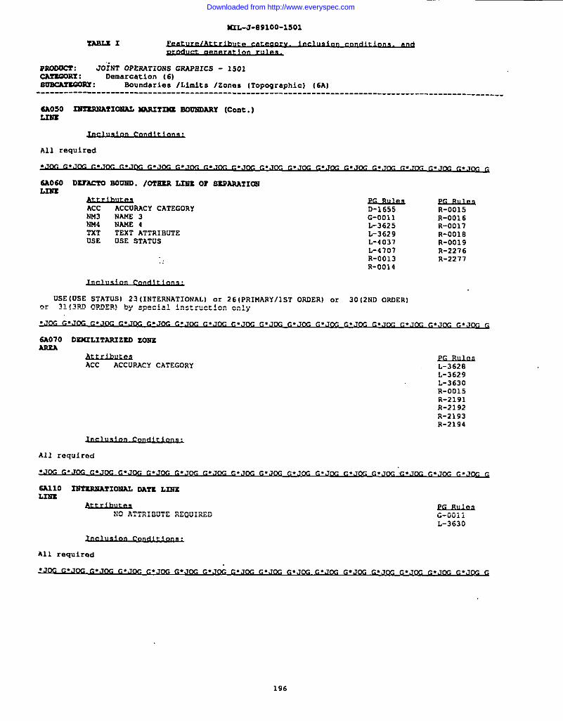
K2L-J-E91OO-15O1
I
~1
mwoocr : JOiNT OPERATIONS GRAP81CS - 1501cA2zwRY : Demarcation (6)SoxMEww: Boundaries lLlu,lts/zones lTopOgraphic)(6A]--------------------------------------------------------------------------------------------------.
All required
.J~ ~.,,~ ~.,~. ~.J(y ~.J~ ~.,&- ~.J~ ~.J= ~.=m .Jw ~.=w .JM ~. ~m ● . . lx G
SA060 DuM?O SOU2Ul. /OTSZS L2s’s0? SSPARMIOS
ACC ACCOUCY CATEGORY D-1655 R-0015NM3 NAK2 3 G-0011NN4 NANE 4
R-0016L-3625
TXTR-0017
TEXT ATTRIBUTEUSE
L-3629 R-OOIEusE STATUS L-4037 R-0019
L-4707 R-2276R-0013., R-2277R-0014
USE(OSE STATUS) 23(1NTERNATIONAL) or 26(PRIMARY/lST ORDER) or 30(2ND ORDER]or 31(3RD ORDER) by special instruction only
.J~ ~.J~ ~.J~ ~.J~ ~.,J~ ~.Jm =,J~ ~.JM ~.Jm ~.Jm ~.J ~.J G. . ● .w. G
SA070 D~~T~ZSO ZONEARxA
ACC ACCURACY CATEGORY L-3620L-3629L-3630R-0015R-2191R-2192R-2193R-2194
All required
NO ATTRIBUTE REQUIRED G-0011L-3630
All required
G.J~G. JwG. ~... ‘.. . .,, . .. m G
196
Downloaded from http://www.everyspec.com
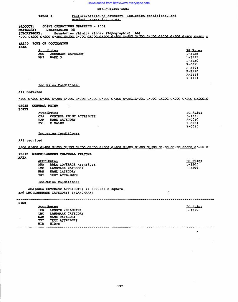
I
I
3RL-J-89100-1501
P3000CZ: “JOINT OPERATIONS GRAPEICS - 1501cAzzGoux: Demarcation (6)8osCMxGoxY : BOundIIrieB/Limits /ZOnes (Topographic][6A).JK G.J~ G.JOG G*JM G*JOC G.Jm G*JOG G*JOC G.J~ G*JOG G*JIX G.JDG G*JOG G.JCG G*J~ C*JffiG
SA210 ZOln or cccoRAnoaAsxA
=AcC ACCUWCY CATEGORYN243 NA1423 L-3629
L-3630R-0015R-2191R-2192R-2193R-2194
All required
9B035 cOmL P02Nl ‘,P02ET
CPA cONTROL pOINT ATTRIOUTENAM NAME cATEGORYZVL z VALUE
L-4008R-OO1OR-0021T-0015
9D012 N3.5CILLAUEOUScUL~ ~’2’OREARxA
*AAA AREA ct3VERAGEATTRIBUTELMc LANDMANK CATEGORYNAM
L-3506NA14ECATEGORY
TXT TEXT ATTRIBUTE
APA(AREA COVERAGE ATTRIBUTE) >- 390,625 m squareand l14C(LANDMARK CATEGORY) 1(LANDMARKI
----------------------------------------------------------------------------------------------------L3NE
f&hrJis =LENGTR IDIMTER
UK LANDMW(K CATEGORYNAM NAME CATEGORY2’5T TEXT ATTRIBUTEWID HIOTH
----------------------------------------------------------------------------------------------------
197
Downloaded from http://www.everyspec.com
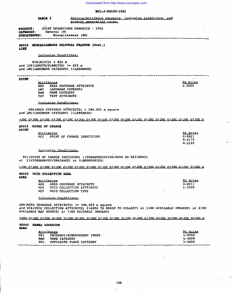
K2L-J-891OO-15O1
fABLZI
moooc7 : J;lNT OPERATIONS GRAPHICS - 1501cA?’2mRY: General (9)soBcArzcoRx: nlswll.sneous (9D)---------------------------------------------------------------------------------------------------
9D012 llISCXIJ.M1009COL~ rlAr’JA2(cant.)
WID{WIDTHI < 625 mand LEN(LENGTH/DIANETER)>- 625 mand LMC(L4NDUAAK CATECDRY) 1(LANDNARK)
----------------------------------------------------------------------------------------------------PoIm
‘&husP.sAREA CUVEAAGE ATTRIBUTE
U6c LANDMARK CATEGORYNAU NAME CATEGORYTxT TEXT ATTRIBUTE
IAAA(AAEA COVERAGE AT-TRIBUTE)c 390,62S m square
L-3505
and LMC(LANDUARK CATECORYI IILAN&+ARK)
9D015 POrnT OT CEA2?CP.POINT
Pc1 POINT OF CNANGE IDENTIFIER C-0021R-2173R-2iB9
Pc1(POINT OF CllANGEINDICATOR) 1(TRANSPORTATIONIROAD OR RA1LROAD)or 2(NYDROGRAPBY/DAAINAGE)or 3[BDUNDARIES)
9D020 V02D CQL2.ECTIDNW&AARxA
ARA AREA COVERAGE ATTRIBUTEVCA VOID COLLECTION ATTRIBUTEVCT VOID COLLECTION TYPE
G-0011L-3568
AAAIAREA cOVEwGE ATTRIBUTE) >. 390,625 m squareand VCAIVOID COLLECTION ATTRIBUTE) 2(AREA TO ROUGH TO COLLECT) m! 3(NO AVAILABLE IMAGERY) or 6(NOAVAILABLE UAP SOURCE) or 7{NO SUITABLE 1!4AGERY1
90040 EAluD 2LKAZ1ONARm
CS1 CATEGORYISUBCATEGORYINDEX L-0050NAM NAME CATEGORY L-36013PPL POPULATED PI.4CECATEGORY L-3609
----------------------------------------------------------------------------------------------------
198
Downloaded from http://www.everyspec.com
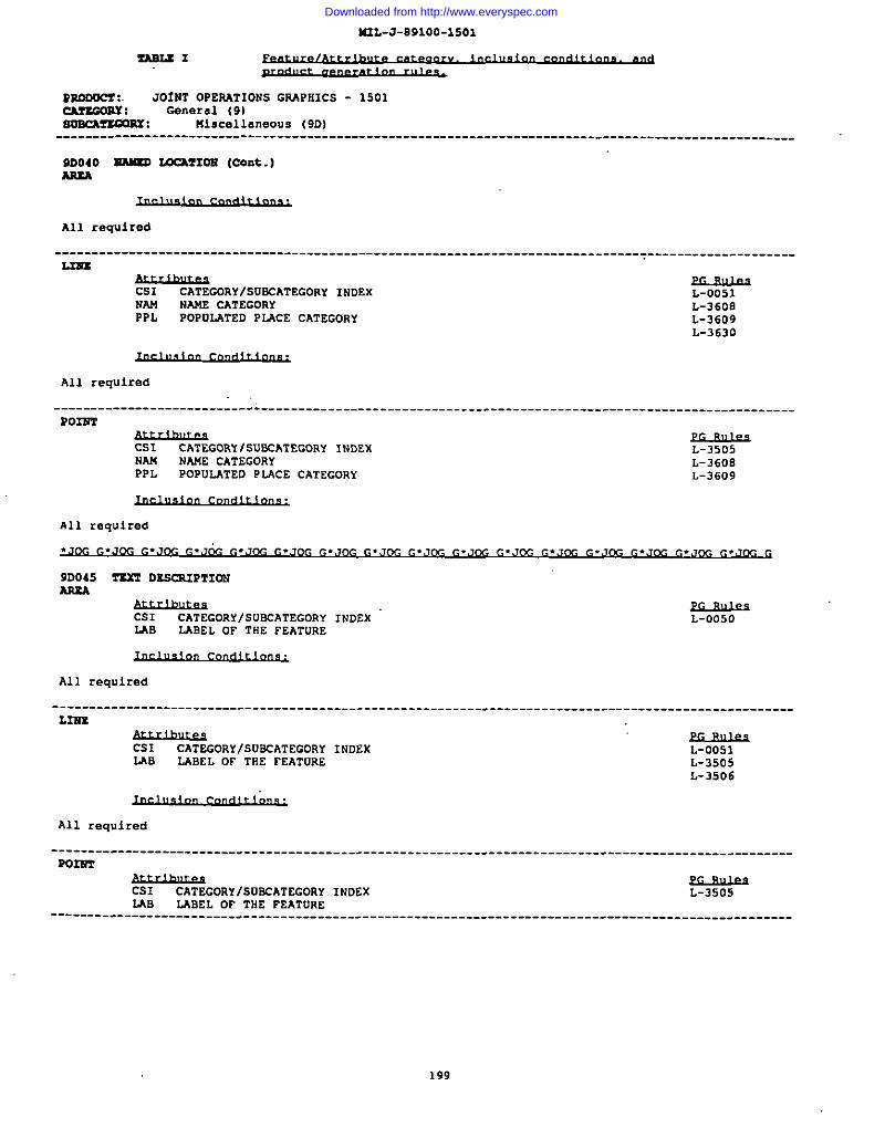
I
4IIL-J-B91OO-15O1
ZASLE3!
Pmooc?: JO!NT OPERATIONS GSAPHICS - 1501CArEGosx: Gsneral 19)~: Miscellaneous (9DI---------------------------------------------------------------------------------------------------
9D040 ~ MCA2103i (COnt.)AstA
All required
-------------------------------------------------------------------------------~--------------------1.311z
CS1 CATEGORY/SVECATEGORYINDEXNAU
L-0051Nm CATEGORY
PPLL-3608
POPULATED PLACE CATEGORY L-3609L-3630
All required
--------------------------.&------------------------------------------------------------------------POIS’3
Cs1 cATEcORi/su=ATEGORY INDEXNAM
L-3505NAME CATEGORY
PPLL-3608
POPULATED PMCE CATEGORY L-3609
All required
.Jm ~.J~ ~.J~ ~.J& ~.J~ ~.J~ ~.Jm ~.JM ~.Jm ~.JM ~.Jw ~.Jm ~.Jm ~.Jm ~. ,J G
90045 TEXT osscsIPT1cmARu
Cs1 CATEGORy/SUKATECORY INDZXLAB
L-0050LABEL OF THE FEATURE
All required
----------------------------------------------------------------------------------------------------L~
Cs1 CATEGORY/S05CATEG0RYINDEXLAB LABEL DF TRE FEATuRE
L-0051L-3505L-3506
All required
----------------------------------------------------------------------------------------------------Pom
I
CS1 CATEGORYISURCATEGORYINDEXLAB
L-3505LABEL OF THE FEATURE
----------------------------------------------------------------------------------------------------
199
Downloaded from http://www.everyspec.com

NIL-J-O91OO-15O1
msLSI
normcs : JOINT OPERATIONS GR4PN1CS - 1501cA?scoRY: General 191msch?uous : Ml$calliweous (9DI----------------------------------------------------------------------------------------------------
9D045 = DX$XRIR?X= (Cord..)Pom
200
I
Downloaded from http://www.everyspec.com
MIL-J-891OO
APPENDIX A
1:250,000 SCALE JOINT OPE~TIONS GRAPHICS PRODUCT RULES
10. SCOPE
10.1 z. This
Droduct rules necessarvappendix provides information about thefor the Production of 1:250,000 JOG’S.
?he information contai;ed herein-
20. APPLICABLE DOCUMENTS
20.1 ~.
is intended for compliance.
20.1.1 Thefollowing specifications, standards, and handbooks form”a part ofthis document to the extent specified herein. Unless otherwisespecified, the fssues of these documents are those listed in thecurrent Department of Defense Index of Specifications andStandards (DODISS) and the supplement thereto, cited in thesolicitation (see 6.2) .
,.MILITARY STANDARDS
MIL-STD-2402 MC6GMIL-STD-2403 MC&GMIL-STD-2408 MChG
Symbology.Product Generation Rules.Glossary of Feature/
Attribute Definitions.
20.2 ~. In the event of a conflictbetween the text of this auDendix and either Table I of this
~
specification, or MIL-STD->i03”cited above, the Table I andMIL-STD-2403 take precedence.
30.
30.1following
Rules are classified into the
PRODUCT RULES
~.types:
A-Segregation;: C-Conflict
D-Displacement:: G-Generalizatione. L-Labelingf. N-No rules written
30.2 ~.alphanumeric order the rule numberstype (area, line and point) of eachto this specification.
9. O-Overrideh. R-Representationi. S-Suppression
j. T-Thinningk. V-Value added1. X-Data segregation
This appendix lists inand rule text for each featureFACS feature listed in Table I
201
Downloaded from http://www.everyspec.com
MIL-J-891OOAPPSNOIX A
JOINT OPERATIONS GPAPHICS PRODUCT RULES
r14xfom: -.. .=010 (-)
MmE.. . LAolo (Asu2A)
a-ooo7
0-0010
44-0012
0-0013
IL-0061
L-3505
L-3562
L-4007
L-401O
S-1OO2
I MINE. .
when 2 or more similar area featurea having matching coded attribution areseparated by less than 0.5 mm at chart scale, the feature will bea9910merated to form an am.a multiple feature outline.
Coincident similar area features having mstching coded attribution will beblended co form a mingle feature.
Area and line featurea will h generalized to detail compatible with scale.
Feature will be generalized to provide a more aeathetic contoured feature(i.e., amothed) .
When PRO-000 (Unknown), omit the PRO label.
Label feature as per hierarchy for topo type placement parallel to southneatline corners reading left to right:1. Positional hierarchy:a. northeast, (preferred position) .b. southeast.:(lst alternate) .c. wrthwest (Z”d alternate)d. ao”thwest (3rd alternate)e. tcip-ce”te.zed(4th alternate)f. bottom-centered (5th alternate)
(Hierarchy is based on type positioning no as to avoid overprintingother type or obscuring detail.)
2. Minim. apace btween typ placement and feature aymtel i- 0.5 mm.3. This method of type placement shall be used for areal featurea when
space doen not permit labeling within that feature.Orop Window.
When SCC - 0
If area i8 not large enough to place type within, move to outside and applypoint hierarchy Rule L-3505.
If MIN-000, omit MIN window.
If PRO-019 (Other), Identify the product if poaaible. If not possible, emitPRO window and close up remaining type.
In an area 25 nunx 25 mn where >- 2 mine symbols coalesce, one tine aymbc.1shall be shown i“ the geographic center a“d the label “Mines” shall bepgaiti.xed parallel with the south “eatli”e emd <- 0.2 nunfrom tbe minesymbol .
.2AO1O (P02NT)
G-0005 A clu.ter of 3 or more coalescing similar point features having matchingcoded attributicm will be aggregated to form a“ area nmltiple featureoutline.
L-0020 NAM label shall be positioned 0.5 mm from respective aide of feature symbolso that wording may be read from left te right except for perpendicularwording which shall be read from bottom to top (east side) of feature.
L-0061 Nhen PRO-000 (U”kn.own), omit the PRO label.
Downloaded from http://www.everyspec.com
MIL-J-891OOAPPENDIX A
JOINT OPERATIONS GRAPHICS PRODUCT RuLES
rzATuRz: =. -.~olo We=)
L-3SOS bbel feature M per hierarchy for top type placement parallel to southneatline corners reading left to right:1. Positional hierarchy:a. noxtlmaat (preferred position) .b. aoutheaat (lst alternate) .c. northwest (2nd alternate)d. southwest (3rd alternate)e. top-ceptered (4th alternate)f. bottom-centered (5th alternate)
(Hierarchy ia based on type positioning ao aa to avoid overprintingother type or obscuring detail. )
2. klinim.xnapace between type placement and featur.a aymbl is 0.5 nun,3. ~ia umthod of type plac-t shall be used for areal features when
space does not permit labeling within that feature. When Scc - 0Orap Window.
L-4007 If 141N-000, omit MIN win&w.
L-4010 If PRO-019 (Other), Identify the product if possible. If not possible, omitPRO window and cloaa up remaining type.
QUARRY ...lAo30 (ARSA
w-00”07 3ihen2 or more similar area features having matching coded attribution areeqare.ted by less thm O.5 nunat chart ecale, the feature will beagglomerated to form an area multiple feature outline.
0-0010 Coincident similar area features having m.tching coded attribution will beblended to form a single feature.
G-0012 Area and line features will be generalized to detail compatible with scale.
Q-0013 Feature will be generalized to provide a more aec.thetic contoured feature(i.8., smothed) .
L-0061 When PRO-000 (Unknown), omit the PRO label.
L-3SOS Iabel feature as per hierarchy for tc.potype placement parallel to southneatline corners reading left to right:1. Positional hierarchy:a. northeast (preferred position) .b. southeast (let alternate) .c. northwest (2nd alternate)d. southwest (3rd alternate)e. top-centered (4th alternate)f. bottom-centered (5th alternate)
(RierarChy is baaed on type positioning so 88 to avoid overprintingother type or obscuring detail. )
2. Wininmm apace between type placement and feature symbol in 0.5 mm.3. Thin method of typ-aplacement shall be used for areal features when
apace does not parmit labeling within that feature. Nhen SCC - 0Drop Window.
L-3562 If area is not large enough to place type within, muve to outside and aPPIYpoint hierarchy Rule L-3505.
Qum... 13A030 (POINT)
c-0005 A cluster of 3 or nure coaleacinq similar paint feetu?x.shaving ~tchimgco.dadattribution will be aggregated to form an area multiple featureoutline.
L-0061 WherePRO-000 (Unknown), omit the PRO label.
203
Downloaded from http://www.everyspec.com
MIL-J-891OOAPPENbIX A
JOINT OPERATIONS GR4PHICS PRODUCT RULES
?xATuns: QUARRY. ..2A030 (POINT)
L-3505 Label feature as par hierarchy for topo type placement parallel to southneatline corners reading left to right:1. Positional hierarchy:a. northeast (preferred position) .b. aoutbeaat (lat alternate) .c. northwest (2nd alternate)d. aouthweat (3rd alternate)e. top-centered (4th alternate)f. bottom-centered (5th alternate)
(Hierarchy is based on t- positioning ao an to avoid overprintingother typa or obscuring detail.)
2. 34ininrdmspace ketueen type placement and feature aymbel is 0.5 mm.3. This method of type placement ehall be used for areal features when
space does not permit labeling within that feature. When SCC - 0DrOP Window.
SXG /SCfPSS9TWCTURX ...3.A040 (P023?2)
Q-0008
L-0061
L-3505
L-5040
0-3008
n-oo46
?6sLL..
Like point featurea which coalesce in clusters of 3 or more will be thinnedto form a representative patter”..
When PRO-000 (Unknown), omit the PRO label.
kbel feature as per hierarchy for topo type placement parallel to southneatline corners reading left to right:1. Positional hierarchy:a. northeaat (preferred pasition) .b. southeast (lat alternate) .c. northwest (2nd alternate)d. southwest (3xd alternate)e. top-centered (4th alternate)f. bottom-centered (5th alternate)
(Hierarchy is based o“ type positioning so as to avoid overprintingother type or obscuring detail. )
2. Minimum apace between type placement and feature aydol in 0.5 nun.3. ‘fhiamethod of sype placement shall be used fox areal feature. when
npace does not permit lakling within that feature. When SCC - 0Drop Window.
If COE (Certe.i”tyof Existence) -001 (Oefi”ite), do not “show COE label onlaymbol. If COE-002, label “Doubtful” If cOE-003, label ‘Reported”
If coalescing features being thinned are a mix of heights (HGT), with some <46 m and some + 46 in,then only the obstruction symbol shall be shown.
When obstructions coalesce at map scale, use Posicut +217 at “obstructionpaint and label with highest obstruction information.
.12A050(POINT)
L-0061 When PRO-000 (Onknow”), omit the PRO label.
L-3505 label feature a. par hierarchy for t.apotype pla=enmnt parallel to southne.atlinecor”erB reading left to right:1. Positional hierarchy:a. northeast (preferred position) .b. aoutheaat (lat alternate) .‘c. northwest (2nd alternate)d. southwest (3rd alternate)”e. top-centered (4th alternate)f. bottom-centered (5th alternate)
(Hierarchy is based o“ type pc.aitio”ing so as to avoid overprintingother typ+ or obscuring detail.)
2. Minimum apace batwee” type placemmt and feature symbol is 0.5 nun.3. Thin method of type placement shall be used for areal features when
apace does not permit labeling within that feature. When SCC - 0Orop Window.
2+2027 All features are depicted i“ arid regions of the world.
204
Downloaded from http://www.everyspec.com
I
MIL-J-891OOAPPSNDIX A
JOINT OPERATIONS G~HICS PRODUCT RULES
rEmORB: RsLL. ..IA050 (POINT)
?-0013 Uhen featurea exist in groups where they coalesce with one another, the area&all be e%presaed by tbe selection of wells without .x.alescance,thoseselected should be aboun in their exact location to form the geaeral pattern.
V-1018 IF W - 000 (Unknown), omit XT2 window.
DISPOSAL SITE /64ASTE PIU ...lBOOO (33tEA)
0-0006
a-oolo
G-0012
L-0061
L-3S05
Xbm 2 c.rmre similar area features having matching aoded attribution areseparated by less than 0.5 mm at chart scale, the features will beaqglomerated.
Coincident similar area features having matchhg coded attribution will beblended to form a single feature.
Area and line features will be generalized to detail compatible with scale.
When PRO-000 (Unknown), omit the PRO label.
Libel feature as per hierarchy for top type placement parallel to southneatline comers rt.adimaleft to ri.aht:1. Positional “hierarchj:
. .
a. northeaat (preferred positicm ).b. southeast (lot alternate) .c. northwest (2nd alternate)d. southwest (3rd alternate).s.top-centered (4th alternate)f. bettom-centered (5th alternate)
(Hierarchy in based on type petitioning so as to avoid overprintingother type or obscuring detail. )
2. Mininnuu apace betwea” typ placement a“d feature symbol ia 0.5 run.3. This method of type placement shall be used for areal features when
apace does not permit labeling within that feature. When SCC - 0Drop Window.
L-3506 Namea placement shall k oriented to the longest axis of the feature redi”gleft to right and placed within the area outline a“d centered. If longestaxis ie.perpendicular to the south neatline, the type shall & placed outsideOf.the area outline, preferred position is northeast of the feature (RuleL-3505), but may be placed at any position around the feature ao as not tooverprint any other feature type and reading left to right.
PRCCESS2NG PLANT /TRxAmEm P2JW2. ..lCOOO (ARJ2A)
G-OO1O Coincidem similar area features having matching coded attribution will beblended to form a single feature. ..
C-0012 Area and line features will be generalized to detail compatible with ecale.
2,-0061 HheJIPRD-000 (Unkmw”) , omit the PRO label.
L-350S Iabel feat”m as per hierarchy for top type placement paral 181 to southneatline corners reading left to right:1. Positional hierarchy:a. northeast (preferred position) .b. eouthea.st (lst alternate) .c. northwest (2nd alternate)d. aouthweat (3rd alternate)e. top-cantered (4th alternate)f. bottom-centered (5th alternate)
(Hierarchy is baaed cm type positioning so aa to avoid overprintingother type or obmcuring detail. )
2. Mtnino.m apace between type placement and feature symbol is 0.5 mm.3. ‘fbiamethod of type placememt shall be used for areal “features when
space does not permit labeling within that feature. When SCC - 0Drop Window .
L-401O If PRO-019 (other), Identify the protict if possible. If not possible, omitPRO window and close up remaining type.
PROCESSING f TREMnwT PLA3P2...lCOOO (POINZ)
2D5
Downloaded from http://www.everyspec.com
MIL-J-891OOAPPSNOIX A
JOINT OPERATIONS GRAPHICS PRODUCT RULES
TgAToRg: PRDCSSS2NG PL324T /TREAT24swT PLAwT. ..lCOOO (POIWT)
L-0020 NAW label shall be positioned 0.5 mm from respective side of feature symbolno that wording may be read from left to right except for perpendicularwording which shall be read from bottom to top (ec.at side) of feature.
L-0061 When PRO-000 (Llnknown), omit the PRO label.
I
d. southwest (3rd alternate)e. top-centered (4th alternate)f. bottom-centered (5th alterm.te)
(Hierarchy ia baaed on type positioning BO a. to avoid overpri”ti”gother type or obecuring detai1.)
2. Mininum space between type placement and feature symbol in 0.5 mm.3. This method of type placement shall be u~ed for areal features when
Bpace doen not permit labeling within that feature. When SCC - 0Drop Window.
R-2002 Where a eeparaticm b.atwee”a Coastal Shoreline (2AO1O) or Inland Shoreline(2H075) and the outline of this feature in too narrow to plot (show toscale) , it shall he depicted by a single line (comms” line), that being the~astal Shoreline (2AO1O), Inland Shoreline (2H075) , Aqueduct (2HO1O) , Cana1(2H020), Ditch (2H030) , or Reservoir (2H130) .
POWSR PLAWT PACILITX ...10010 (A3WA)
C-OO1O @incid.a”t airnilararea fe.aturaahaving nutching coded attribution ill bebkmded to form a single feature.
C-0012 Area cmd line features will be generalized to detail compatible with scale.
L-3505 Label feature as per hierarchy for topo type placement parallel to southneatline corners reading left to right:1. Positional hierarchy:a. nc.rtbeaat (m.sferx.sdmsitic.n 1.b. southeast (ist altemkte) .c. northwem (2nd alternate)d. aouthweat (3rd alternate)e. top-centered (4th altern.tt.a)f. bottom-centered (5th alternate)
(Hierarchy is baaed on type positioning so a.?to avoid overprintingother typ+ or obscuring detail. )
2. Wininmm e.pacebtween typ-splacemsnt and feature aymbc.1is 0.5 mm.3. ‘fhiamethod of type placement shall be used for areal features when
apace doe? not permit labeling within that feature. When SCC - 0Drop Wind6w.
L-401O If PRO-019 (Other), Identify the product if possible. If not possible, omitPRO wind.awand cl.aaeUp remaining type.
SETTLIWG BX33W /SLODGS PONO ...1C030 (AREA)
C-0006 When 2 or more aimilc.rarea features having matching coded attribW.ion areseparated by less than O.5 nunat chart scale, the features will &agglomerated.
G-0012 Area and line features will be gemralized to detail compatible with mcale.
L-3505 Label feature as per hierarchy for topo type placement parallel to southneatlim .sor”ersreading left to right :1. Positional hierarchy:a. northeast (preferred Pcsitio”) .b. c.outheaat (lst alternate) .c. northwest (2nd alternate)
I206
I
Downloaded from http://www.everyspec.com
MIL-J-891OOAPPENDIX A
JOINT OPERATIONS GRAPHICS PRODUCT RULES
~: POW34R PLS342 rACILITT. ..DO1O (AREA)
L-3S05 Label feature an per hierarchy for top type placcnr=.ntParallel to southneatline cornors reading left to right:1. Positional hierarchy:a. nort.beast (preferred position) .b. southeaat (lot alternate) .c. nortbwaat (Snd alternate)d. aouthweot (3rd alternate)a. top-cant.md (4th alternate)f. bettom-centered (5th alternata)
(Siararchy is based o. type positioning a. as to avoid overprintingothr t~ m obscuring detail. )
2. Xiniumm spat. between typa placement and featura symbol is 0.5 nun.3. Thin msthod of type placement shall be used for areal features when
space does not permit labeling within that feature. Nhen SCC - 0Drop Window.
2.-4011 If PPC-000, omit PPC Will&W.
CE23DJEY /s24Qr24sTAa....lrolo (Po22Pr)
D-7019
2.-3505
If a Chimney/S~kamtack (Point 1FO1O) < 46 m RGT coaleaces ~ 0.2 m= withfeatuzea:then displace the Chim.ney/Srmkestack to O.2mm from theme featuzes.
Point 13’010Chimney/SmokestackZAne 1T030 Power Tran.wniaaion LinePoint 1MO1O TankPoint 1T080 Tower (Communications)Line 1P050 TrailLine 1PO1O Cart TrackPoint IL020 Built 0p AreaPoint 10131 TunnelLine 10131 TunnelpOillt1V160 ktlJnUayLine 10160 RunwayPoint 10030.Urcraft FacilityPoint 1P020 Inte.KhBrlgeLine 1P030 RoadPoint 1Q040 Bridge/~ e~asa/ViaductLine 1Q040 Bridge/Overp.aaa/Viaduct2Jne 1N050 145Siding/P14SpurLine lNOIC ckLine 61 w
O Railroad TracAOOO Administrative 8aunda]
IAne 21Line 2H020 canal
,E030Ditch
Line 2H140 River/StreamLine 2f1075Inland ShorelineLine 2AO1O Coastal Shoreline
coaleacea - to grow together, blend, min91eC.aincident-occupy the same space
z,abelSoature as per hierarchy for topo type placement parallel to southneatline corners reading left to right:1. Positioml hierarchy:a.b.c.d.e.f.
northeast (preferrid peaition ).eoutheast (Ist alternate) .northwest (2nd alternate)aoutbwast 13rd alternate).-—.toP%antered (4th altarnite)bottom-cantered (5th alternate)(Hierarchy is based on type positioning 60 as to avoid overprintingother type ox obscuring detail. )
2. Wininum apms batween type placement and feature symbol ie 0.5 unn.3. nit! method of type placement shall be used for areal features when
apace dean not permit labeling within that feature. When SCC - 0Drop Window.
201
Downloaded from http://www.everyspec.com
MIL-J-891OOAPPENDIX A
JOINT OPERATIONS GRAPHICS PRODUCT RULES
smmmx : Cs~ /S440SXSTAC2t. . . MO1O (P0214T)
L-5040 If C02 (Certainty of Existence) -001 (Definite), do not show COE label onsymbol . If COE-002, label “Doubtful” If cOE-003, label “Repert.ed”
0-S008 If coalescing Peaturea being thinned are a mix of heights (HGT), with some <46 m and some > 46 m, then only the obstroCtiOn symbol shall be shown.
R-0046 When obatructicms coalesce at map scale, use Posicut t217 at obstructi.anpoint and label with highest obstruction infornmtion.
CONVSYOR. ..LP020 (L23as)
a.b.c.d.e.f.
G-0012 Area and line features will be generalized co detail compatible with scale.
L-350E. Label feature as per hierarchy fox topo type placement parallel to southrmatline corners reading left to right:1. Positional hierarchy:a. northeaat (preferred position) .b. southeaat (lst alternate) .C. northwest (2nd alternate)d. seutbweat (3rd alternate)e. top-centered (4th altermate)f. bottom-centexed (5th alternate)
(Hierarchy is based on type positioning so as to avoid overprintingother type or obscuring detail. )
2. Mininwm apace between type placement and feature aymb.alis 0.5 mm.3. This method of type placement. shall be used for r.realfeatures when
apace does not permit labeling within that feature. When SCC - 0Drop Window .
R-0006 Feature shall not b shown within Built-up Area (1L020) .
COOLING TOWSR ...12?030 (POINT)
L-3505 Label featuxe as per hierarchy for tops type place!re”tparallel to southneatline corners reading left to right:1. Positional hierarchy:
northeaat (preferred poeition) .southeast (Ist alternate) .northweet (2nd alternate)southwest (3rd alternate)top-cencered (4th alternate)bottourcenterad (5th alternate)(Hierarchy is based on type positioning so as to avoid overprintingother t~ or obscuring detail. )
2.,Winim.nm apace between type placement and feature symbol i,eO.5 um.3. 2%is method of type placement shall be used for arenl features when
space does not permit lab-slingwithin that feature. Uhen SCC - 0Drop Window.
L-5040 If COE (Certainty of Existence) -001 (Definite), do not show COE label onsymbol . If COE-002, label “Daubcful” If COE-003, label “Reported”
0-300s If Coalescing features being thinned are a mix of heights (HGT), with some <46 ❑ and cmme >- 46 n, then only the obstruction symbol shall be ebown.
R-0046 When .abstruction~ coalesce at map scale, “se Posicut 4217 at obstructionpoint and label with highest obstruction information.
CsANz. ..lPo40 (POINT)
208
Downloaded from http://www.everyspec.com
I
MIL-J-891OOAPPENDIX A
JOINT OPERATIONS GRAPH ICS PRODUCT RULES
r12ATUM: ~.. .~040 (~o-)
L-S505 Label faature as par hierarchy for topo type plaCe~nt parallel to southneatline corners reading left to right:1. Positional hi.ararchv:a.b.c.d.e.f.
northeast (preferr&d Wsition ).aoutbeaat (lat alternate) .northwest (2nd alternate)aouthweat (3rd alternate)top-cmtered (4th alternate)bettom-centared (5th alternate)(Hierarchy is based on type positioning so as to avoid overprintingother tyF% or obsturing detail. )
2. Minimum space between type placement and feature symbol in 0.5 mm.3. This method of type placement shall h used for areal features when
apace d-s not permit labeling within that feature. When .SCC- 0Drop Window.
L-5040 If COE (~rtainty of Existence) -001 (Definite), do not show COE label ona-l . If CDE-002, label ‘Doubtful- If CDE-003, label ‘Reported”
0-3008 If coalescing features being thinned are a mix of heights (HGT), with some <46 m and some % 46 ❑, then only the obstruction symbol shall be shown.
R-0044 When obstructions coalesce at map scale, use Pcmicut 4217 at obstructionpoint and label with highest obstruction information.
PLARB PIPE. . . lPo70 (POINT)
L-3505 bkl feature as per hierarchy fox topo type placerant parallel to southneatlimi corners reading left to right:1. Positional hierarchy:a. northeast (preferred pesiti.m ).b. southeast (lst alternate) .c. northwest (2nd alternate)d. southwest (3rd alternate)e. top-ceater.ad (4th alt.armte)f. bottom-centered 15th alternate)
(Hierarchy is baaed on type positioning so aa to avoid overprintingother type or obscuring detail. )
2. Minimum apace between type placement and feature symbol is 0.5 nun.3. This method of type placement shall be used for areal features when
apace does not permit labeling within that feature. When SCC - 0Drop Window.
L-5040 If COE (Certainty of Sximtence)-001 (Definite), do not show COE label onO*1 . If WE-002, label “Doubtful” If COE-003, label “Repbxted-
0-3008 If coale.acingfeatures being thinned are a mix of baights (HGT), with some <46 m and some > 46 m, then only tbe obstruction aymkl shall be shown.
R-0046 When obatructiona coaleace at map ecale, use Poaicut +217 at obstructionpoint and label with highest ob.structio” information.
IPORT. ..lEo50 (AREA)
I C-OO1O Coi”cide”t eimilar area features having matching coded attribution will beblended to form a eingle feature.
I 0-0012 Area a“d line featuree will be generalized to detail compatible with e.cala.,,
209
Downloaded from http://www.everyspec.com
. .
MIL-J-891OOAPPSNDIX A
JOINT OPERATIONS GRAPHICS PRODUCT RULES
I
rEATuM: -...28050 (L2utA)
L-350S 2abel feature as p.r hiararchy for topo typa placement parallel to southneatline corners reading left to right:1. Positional’hierarchy:a. northeast (preferred position) .b. Boutheaot (let alternate) .c. northwest (2nd alternate)d. nouthwest (3rd alternate)e. top-centered (4th alternate)f. bottom-centered (5th alternate)
(Hierarsby is based on type positioning so as to avoid overprintingother t- or obscuring detail. )
2. Minimum space between type placemmt and feature symbol is 0.5 nun.3. ‘L?Iiamethod of type placement ehall be u8ed for areal f eatums when
UPC* does not Pe=it latelinu within that feature.DXOP Window.
14henSCC - 0
PORT. ..lR050 (POINT)
L-0020 ?2AHlabel shall be p.asitioned 0.5 nm fram respective side of feature aymholCIOthat wording:nmy be read from left to right except for perpendicularwording which shall ha read from bottom to top {east side) of featuze.
L-3505 LC.belfeature an per hierarchy for topo typ+!placement parallel to southneatline corners reading left to right:1. Positional hierarchy:a. northeaat (preferred position) .b. southeast (lat alternate) .c. northwest (2nd alternate)d. aouthweet (3rd alternate)e. top-csncered (4th aIternate)f. bottom-centered (5th alternate)
(Hierarchy in baaed on type positi.aning so as to avoid overprintingother type or obscuring detail. )
2. Minimum space between typiaplaceumnt and feature symbol is O.5 mm.3. This method of type placement shall be used for areal feature~ wh.m
space does not permit labeling within that feature. When SCC - 0Drop Hindow.
L-3516 hbal feature as Fort if N?d4is unknown.
~ /W23UU@NR. ..1J050 (POINT)
L-3S05 Xat91 feature ae per hierarchy for topo type plac.me”t parallel to southneatline cormera reading left to right:1. Positional hierarchy:a. northeast (preferred po=iti.an).b. southeast (1st alternate) .c. northwest (2nd alternate)d. southwest (3rd alternate)e. top-centered (4th alternate)f. bottom-centered (5th altesnc.te.)
(Hierarchy is based cm type positioning so as to avoid overprintingother type or obscuring detail. )
2. Mininr.xospace between type placement and feature symbol is 0.5 nun.3. Thin method of type placement shall be used for areal features where
apace does not permit laixling within that feature. When SCC - 0Drop Window.
L-5040 If COE (& fiai”ty of ~istmce) -001 (Definite), & not show COE label onsymbol . If COE-002, labl “Doubtful= If cOE-003, lab-al‘Reported”
0_3008 If coalescing features being thinned are a mix of heights (HGT), with some <46 m and some > 46 m, then only the obstruction symbol shall be shown.
R-0046 xb~ obatnctic.na toale~ce at map scale, use Pc.aicut 8211 at obstructionpoint and label with highest obstruction infamticm.
Anos3n4st4TPARK ~IoN. ..1X020 (POINT)
210
Downloaded from http://www.everyspec.com
MIL-J-891OOAPPENDIX A
JOINT OPERATIONS GNIP561CS PRODUCT RULES
?gA!fmx : A6ursEuztP3 PAM ATTRACZICN. ..Ix020 (P0224T)
2.-S505 Label feature an per hierarchy for topo type placement parallel toneacline corners reading left to right:1. Positional hierarchy:a, nortbeaat (preferred Position) .b. southeast (lat alternate) .c. northwest (2nd alternate)d. eouthweat (3rd alternate)
I e. tw-centared [4th alternate)f. bo~torcentered (5th alternate)
(Rierarchy in baaed on type Positioning so as to avoid overprintiqother type or obscuring detail. )
2. Mininmm space between type placement and feature symbol is 0.5 nun.3. This method of type placement shall bs used for areal features when
space doee not permit labeling within that feature. Xhen 2CC - 0Drop Window.
2.-S040 If COE (Certainty of Sxiatence) -001 (Definite), & not show c4)Elabel onU*1 . If COE-002, label “Doubtful” If COE-0D3, label “Reported”
0-300S If coalescing,features being thinned exe a mix of heightm (HGT), with mmne <46 m and some % 46 m, then cmly the obstruction symbol shall be shown.
R-0046 When .abatructionso.aaleaceat map scale, “m Posicut 4211 at obstructicmpoint and label with highest obatructio” infomtio”.
PASK. . . IX120 (ARZA)
L-0050
I L-35o5
L-35o6
When 2 or more similar area featurea having matching coded attribution areseparated by leaa than O.5 nnmat chart scale, the features will beagglomerated.
~ aizea per area aizea at map/che.rt ecale: AS.. features only.06 point - s 770 mm aq. area a“d S 14 nunwidth07 point - < 2,296 mm aq. area and S 28 mm width09 point - S 5,192 nunaq. area and < 44 mm width10 point - S 9,796 mm aq. area and < 62 w width12 point - S 16,632 nunsq. area and S 84 nm width14 point - S 24.960 nmnLI.q.area and S104 nunwidth16 paint - > 24,960 mu .sq.areaXhexe area maaaurerne”ts are i“co”siste.nt, the largar type size shall be used.mere the full range of typa sizes is not available for a particular label,the closest available type SiZe shall be used.
label feature aa per hierarchy for topo type placement parallel to southneatline corners re.adi”gleft to right :1. Positional hiararahy:a. northeast (preferred position) .b. southeast (lst alternate) .c. northwest [2nd alternate)d. aouthweat (3rd alternate)e. top-centered 14th alternate)f. bottom-centered (5th alternate)
(S.terarcbyia baaed o“ type positioning m as to avoid overprintingother type or obscuring detail. )
2. Minimum apace between type placement and feature symbol ia 0.5 nun.3. This method of typ.aplacament shall be used for areal features when
a~ce d-e not permit labeling within that feature. When SCC - 0Drop Window.
Namna placement shall be oriented to the longest axis of the feature readingleft to right and placed within the area outline and centered. If longestdxis ia perpendicular to the south n.aatline, the type shall be placed outsideof tbe area outline, preferred poeition in northeast of the feature (RuleL-3505), but MAY be.placed at any position around the feature 80 an not tooverprint any o~he.r?gature type-e.~dxeadinq l.aftto right.
= TRAC!Fi...lK230 (LINE)
Q-0012 Area and line features will be generalized to detail compatible with scale.
211
Downloaded from http://www.everyspec.com
MIL-J-891OOAPPENOIX A
JOINT OPERATIONS GPJ@H ICS PRODUCT RULES
~: = ~.. .23t23O(L=)
L-3SOS Iabel feature as per hierarchy for topo type placenmnt paralIel to southneatllne corners reading left to right:1. Poaitianal hierarchy:a. northeast (preferred position) .b. southeast (lot alternate) .c. northwe8t (2nd alternate)d. aouthwaat (3rd alternate)e. top-centered (4th alternate)f. bottom-centered (5th alternate)
(Hierarchy in baaed on typ positioning so as to avoid overprintingother type or obscuring detail. )
2. 14ininumspace htween type placement and feature aymhol is 0.5 mm.3. This me.tbodof type placement ~hall be used for areal features when
apace does not permit labeling within that feature. When SCC - 0Drop Window .
S?amnm. ..lx.L50 (POINT)
L-3505 Label feature as per hierarchy for topo type placement parallel to southneatline corners reading left to right:1. Positional hierarchy:a. northeast (preferred ~sitio”) .b. southeast (lst alternate) .C. northwest (2nd alternate)d. southwest (3rd alternate)e. top-cantered (4th alternate)f. bottom-centered (5th alternate)
(Hierarchy is baaed on type positioning so as to avoid overprintingother type or obscuring detail. )
2. Minimum space between type placement and feature aynbol is 0.5 nun.3. This metbed of type placement shall be used for areal features when
space does not permit lakling within that feature. When SCC - 0Drop Window.
L-5040 If COE (certainty of Exiate”ce)-001 (Defi“ite), do not nhow COE label 0“symbol . If C4JE-002,label “Doubtful- If COE-003, label “Reported”
0-3008 If coalescing features being thinned are a mix of heights (HGT), with some <46 m and some >- 46 m, then only the obstruction symbol shall be shown.
R-0046 Uhen obstructions coalesce at map scale, use Poaicut +217 at obstructionpoint and label with bigheat obetructic.n i“fc.rmation.
ST==. ..1X160 (POIN’i)
C-0022
L-0020
L-3S05
The feature (when HGT <- 46 m or wh.a”HGT is “cata valid attr”ib”teo“ thefeature) shall be oriented perpendicular (90 degrees) to a nearby road(1P030), cart track (1PO1O) , trail (lPOSO), or railroad track [1I401O).
HAM labl shall be positicmed 0.5 ranfrom respective side of feature eymbolso th8t wording may be read from left to right except for perpe”dicmlarwording which shalI be read from bottom to top (east side) of feature.
Late.1feature 8s per hierarchy for tops type placernmt parallel to southneatline corners xeading left to right:1. Positional bier.arahy:a. northeast (preferred position) .b. aoutheaat (lat alternate) .c. northwest (2nd alternate)d. southwest (3rd alternate)e. top-cantered (4th alterm,te )f. bottom-centered (5th alternate)
(Hierarshy in based on type positioning so as to avoid oveq”rintingother t- or obscuring detail. )
2. Uiniuum apace between type placement and feature ayntaolis 0.5 nm.3. Tbia method of type placement shall & used for areal features when
space deem not permit labeling within that feature. When 5CC - 00sop Window.
212
Downloaded from http://www.everyspec.com
MIL-J-891OOAPPENDIx A
JOINT OPERATIONS GRAPH ICS PRODUCT RULES
nZA2URX: S=DIfD4. ..=60 (pow)
L-5040 If COE (Cartainty of Exietence)-001 (Definite), do not chow COE labelm-l . If COE-002, label ‘Ouubtful” If cOE-003, 1*1 “Raporced-
Bux3Dn?G ...1L015 (ASXA)
0-1S32
0-0012
L-0020
L-3505
If features coaleace at rap ecale, when shown in their true positions, theyshall & displaced 0.2 mm from one another.
Area md line features will be generalized to detail compatible with scale.
SAM label shall be positioned 0.5 nunfrom respective aide of feature symbolBO that wording traybe read from left to right except for perpendicularwording which shall be read from bottom to top (eaet aide) of feature.
Ltbel feature am per hierarchy for top type placement Parallel to southneatline corners reading left to right:1. Positional hierarchy:a. northeaat (preferred position) .b. southeast (let alternate) .c. northweet. (2nd alternate)d. southwe.$t.;(3rd alternate)e. top-centered (4th alternate)f. bottom-centered (5th alternate)
(Hierarchy is baaed on type positioning so aa to avoid overprintingother typ+.or obscuring detail. )
2. Wini@sum space betwaen type placemnnt and feature symbol ie 0.5 mm.3. This method of type placement shall be used for areal features when
apace doe.a not permit laltding within that feature. When SCC - 0Drop Window.
If coalescing features hing thinned are a mix of heights (HGT), with some <46 m and some + 46 m, then only the obstruction symbol shall be shown.
If HGT is + 46 metara, then depict Building (1L0151 as an obstmction symbol(posicut # 7) and label as building.
When obatructiona cc.aleaceat map scale, uae Poaicut +217 at obstructionpoint and label with highest obstruction information.
o-3ooe
0-3009
~ R-0046
BUI~~ ...1L015 (POIWT)
C-0022 The feature (when KGT <- 46 m or when 51GTis “ot a valid attribute on thefeature) shall be oriented perpendicular (90 degrees) to a nearby road(1P030) , cart track (1PO1O) , trail (IP050), or railroad track (1NO1O) .
D-1652 If feature.?coalesce at map scale, when shown in their true pasitiona, theyshall be displaced 0.2 mm from o“e another.
3.-0020 NW4 label shall be petitioned 0.5 mm from respective side of feature symbolso that wording may be read from left to right except for perpendicularwording which shall be read from bottom to top (eaat side) of feature.
L-3505 La&l feature as per hierarchy for topo type placement parallel to southneatline corners reading left to right:1. Positional hierarchv:a. northeast (preferr~d position) .b. aoutheaet (lst alternate) .c. northwest (2nd alternate)d. southwest (3rd alternate)e. top-cemtered (4th alternate)f. bottorcentered (5th alternate)
(Sierarcby in baaed on tme POSitioni.g .O an to avoid overprintingother type or obscuring detail. )
2. Uinicnu aynbol ia 0.5 mm.3. ‘rbiamet features when
m apace between type placement and featureLhod of type placement shall be ueed for areal
space does not permit labeling within that feature. When SCC - 0Drop Window.
3.-5040 If COE (@rtainty of Existence) -001 (Definite), do not show COE label on
O-1 . If COE-002, hbel “Doubtful” If COE-003, label “Reported”
213
Downloaded from http://www.everyspec.com
MIL-J-891OOAPPSNDIX A
JOINT OPEIViTIONS GAAPHICS PRODUCT RULES
L
2zATsmx : BM2aIt4G ...1L015 (Po22Pr)
0-3008 If caaIescing features being thimed are a mix of heights (HGT), with some <46 m and some * 46 m, them only the obstruction aymbd shall be shown.
&3009 If HOT in > 46 meters, then depict Building (12.015)as an obstruction symbol[posicut I 7) and label an building.
n-0046 When obstructions coalesce at map scale, .JaePoaicut #217 at obstructionpoint and label with highest obstruction information.
n-2024 If a C.oaatalShoreline (2AO1O) ox Inland shoreline (2H075) coincides with aSuilt-up AIaa (1LQ20) outline at any given point, then the Built-up Area(1L020) outline shall ba deleted to allow the Shoreline to “carry” the limitsof the Built-up Area.
R-2025 men populated developusmta (1L015, 1L020) are made UP Of a 8in91e .OW OfBuildings (1L015) strung out on one or botb aides of a Route of Communication(Roada, I@ilroada, Streams, and canals), the “town ciZCle” (Built-up Area,1L020) is positioned at the nearest junction of the communication Routes orat the approximate center of the groups of Buildings.
n-2026 1“ areas of sparse detail (< 10t), ‘tow” circles” nMY be shown even when noroutes of co.mrmnicaci.a”are present.
2t-2170wban map e.cmrceindicates a populated place by a pattern of Building aymbolathat do not meet inclusion ccmditicma for (1L015) , a town circle shall beshown at the canter of the symbol area.
SUILT-UP ABEA. ..1L020 (Mu2A)
G-0006 When 2 or more similar area f.aatuxeshavin~ matching cod-d a?.tzibutionaresaparated by lees than 0.5 mm at charf scale, the featurea will beagglomerated.
G-0010 Cai”cide”t similar area features havinq matching ceded attribution will hblended to form a single featuxe.
*0012 Az.a and line.featuses will & generalized to detail compatible with ecale.
L-0020 NAM label shall ~ positioned 0.5 nunfrom respective side of feature SP1so that wording may be read from left to right except for perpendicularwording which shall be read fmm bottom to top (east side) of feature.
L-3505 Label feature ae per hierarchy fo= topo typs placement parallel to southneatline corners xeadi”g left to right:1. Positional hierarchy:a. nortbeaat (preferred position) .b. aoutbe.sat (lst alternate) .c. northwest (2nd alternate)d. aouthweat (3rd alternate)● . top-cancgred (4th altexnate)f. bottomc.ntered (5th alternate)
{Biorarohy ia baa.adon typ positioning no as to avoid overprintingothor typa or obscuring detail.)
2. Minimm apaca between type placenmnt and feature symbol ie 0.5 nun.3. This mthod of type plaeeme”t shall be uaad fox .s.realfeatures when
space does not permit labeling within that feature. When SCC - 0Drop Window.
L-3514 -e point size still be used to specify the classification of the Built-upArea baaed on lat through 5th categories of importance:lat importance 12 PC Swiaa 742 caps2nd importance 10 PC swim 742 caps3rd impc.rtmc. 10 pf swim 742 c/14th importance 8 pt SwiSa 742 C.lp=Sth importance 8 pt Swiss 742 =/1 (town circles)
L-3515 Alta~ate n-a (when ~+ailable)’shAll be shown in parentheses positionedfollowing the primary mm (HAM) er cemterad imnediatoly below the primarynamn in the same typo styla but one point size smaller.
214
Downloaded from http://www.everyspec.com
MIL-J-891OOAPPENDIX A
JOINT OPERATIONS GRAPHICS PRODUCT RULSS
\
?BA?ORX: Bmu2-uP AuEh. . .2L020 (Asu2s)
2.-3610 Walla surrounding cities or parta of cities which are symbolized as Built-uptime abAll be indicated by the Wall oymbol and the WOrd “ (walled)- .tddadinpnranthesea tmlow the place name label (HAN).
L-3611 Suined, destroyedand partially destroyed populated placea ehall have&acxiptive labeling in parentheses under place mum label i.a., (minedlldamroy@ (partially deetroyed) . PartiallY deetrOy@d iB < 759 *~tm=iOn.
Z-3612 If ruin-d, dm~troyad or partially dantroyad populated Placea are undarreccmatxuction, EX3 labeling in omitted.
R-OO29 If an open area exists inside of or is surrounded on three sides by aBuilt-up Area (1L020) and haa tn area -.asurement of leaa than 390,625 equaremeters, or IUM a minimx! width of less than 315 muters. it b.accnmeaincludedin tha Built-up ken. If an op.m area exiata inside of or is surrounded ontbrea aides by a Built-up Mea (1L020) and has an area measurement equal toor greater than 390,625 aguare inters, and a minimum width of 315 meters orgreater, delete the Built-up Area tint nd portray the area as an open apace.
SS-2002 Share a map.trationLmtwean a Coaetal shoreline (2AO1O) or Inland Shoreline(26075) and the outlin. of thin feature ie too narrow to plot (show toscale), it shall bo depicted by a single line (ccmmmn line) , that being theCeastal shoreline (2AO1O). Inland shoreline (2H075) , Aqueduct (2HO1O) , Ca”a1(2E020), Ditch (2H030), or Reservoir (2H130).
R-2019 ‘fhaarea outline (1L020) limita shall be ahoun as centinuoum excepc for thoseportions of the outlino which coincide with any other mapped lindar feature.These other u.t~d linear features shall become the Built-up Area limits andtill km retained.
n-2021
m-2029
R-2178
R-2333
R-2526
R-3730
n-3733
If two or rcoreoutlined areas merge (coalesce at nap scale) , they shall be~hg$n~ed in a single coumsm area outline. Dividing outlines shall not be
Saorelbes (2AO1O Coastal and 2H075 Inland) which are coincident withfaaturas 2B190 Pier/Nharf, 2B230 S.aawall,1P030 Aoad, 1NO1O SAlroad Tracks,.1N050 Siding/Spur, and 1L260 Wall ara not ahc.wn.
Nhan a Wall symbol (1L260) eoalaaces with Built-up Araa (IL020) outline, orshantytown (1L208) outline, omit Built-up Area or Shmtytown outline, andahaw Wall with Built-up AXea ttit only.
The limiting outline of the Built-up Area tint shall be dropped when itoverprints linear features (Stretm, Roads, and S@ilroads, etc. ), or if theSP8C4 between the symbols is < 0.5 mm.
Delete perimeter line b.ntwe.encontiguous polygons of Built-up Area (1L020) ,Native Settlement (lL135), and Shantytown (1L208] .
If s clsaring e%iata inside of an area featura, and ttre size of tbo clearingis ●qual to or greater than the area (ASA) Lnclumion condition for thasurrounding area feature, the clearing ia shown ae a open space inside theaurroundinq feature. If the araa of the cleartig is leas than the area(SAA) inclusion condition for the surrounding feature, the clearing iadeletmd and abaorbed into the surrounding area feature
If a portion of an area feature has a minimmm width of leas than 2.5 mm at-P/CbSrt aealf$,delete that portion of the am.a feature that la nat atleant 2.5 m wide. measured frem.perimster to perimeter.If tbe deletion of a portion of the area baaed on the tiVO criteria willreducs the AAA of the remaining Porti,m of the area feature to below theminl!munARA ticluaion, do not delete the narrow portion of the feature thatin 100S than 2.5 m wide.If tht daletien of a portion of the area based on the above criteria willeplit two lug-r ar8aa connected by a narrow strip into two separate araaa,eitbar of which would be below minimum ARA inclusion, do not delete thenarrow portion of the feature that is lees than 2.5 mu wide.
215
Downloaded from http://www.everyspec.com
..
MIL-J-891OO
I
I
JOINT
P3tATORi: =T-W A2X3A...
7-0002
7-0003
T-0012
APPENDIX AOPERATIONS G3uiPHICS PRODUCT
1L020 (AREA)
RULES
~~ez BUilt-up Area (1L020) outlined arena shall be selected over mnallerones of the same clasaificati.a” (PPL 1, 2, 3, 4) importance. The samOprocedure shall apply to each cla~sification PPL clasa (lat, 2nd, 3rd, 4th)importance .
Outlined Built-up ~eaa {1L0201 lecated at Road junctions shall havepreference over adjacent araaa of aitilar size not at bad junctions.
Outlined areae shall be selected al.mg the primary routes of corumnication asfirst conaidexaticm pref.axcmce over adjacent outlined areas of atilar sizaalong adjacmnt E.eccmtisyroutes of cmmm.mication.
BUILT-UP A3WL ...1L020 (POINT)
L-0020
L-350S
L-3514
R-202S
=-2179
C3LXS34.
14AWlabel shall ha petitioned 0.5 mu from respective side of feature symbol80 that wording may & read from left to right except for perpendicularwording which shall b read from bottom to tap (east aide) of feature.
hbel feature,aa pez hierarchy for top tygw placement parallel to southneatline corners reading left to right:1. Positional hierarchy:a. northeast (preferred positi.a”).b. southaaat (lst alternate) .c. notthweat (2nd altetnate)d. southwest (3rd alternate)e. top-centered (4th alternate)f. battom-centered (5th alternate)
(Hierarchy i. based on type psitio”i”g so as to avoid overprintingother type or obscuring detail. I
2. Uininmm space between type plac.aumntand feature symbol is 0.5 mm.3. This method of type placemmt shall be used for areal features when
apace does not permit labeling within that feature. When SCC - 0Drop Window.
Type point size shall be used to specify the classification of the Built-upArea baaad cm lat through 5th categories of i!nprtance:lot i~rtanca 12 pt Swiss 742 capa2nd impartanca 10 pt Swies 742 caps3rd imp0rt6nc.310 pt Swiss 742 c/I4th inlpOrtanCe8 pt Swiss 742 ~p~5th importance 8 pt Swiaa 142 c/1 (town circles)
When populated developmmmts (1L015, 1L020) are made up of a single row ofBuildings (1L015) stru”q out on one ox both aidea of a Route of ccxmnunication(Roada, Railroada, Streams, and Cane.ls), the “town circle” (Built-up Area,1L020) is Poaiti.anedat the “earemt ju”ctio” of the communication Routes oxat the approximate center of tbe groups of Buildings.
Where a Wall in around a populated place that La not symbolized as Built-upArea or shantytown,the Wall symbol shall be omitted but “ (Walled)- will belabeled in parentheses below the place name when placa name is known.
..1L025 (POIWT)
Ps14u. ..lL070 (LIN34)
G_OO12 Area and line features will be gemexalized to detail compatible with scale.
E-0006 Feature .qballnot M ~hc.wrl“ithi” Built-up Area (1L020).
GEOPHYSICAL PRDSP2CT33JG ~ ...lLO 8S (LINS)
G_OO12 Area and liI-@features will M generalized to detail compatible with scale.
216
Downloaded from http://www.everyspec.com
MIL-J-891OO?&P@Ix A
JOINT OPERATIONS GRAPHICS PRODUCT RULES
I
I
~: GSOpE3?SIW PRDS?mING w. ..11)085 (L=)
2,-3505 bbel feature as per hierarchy for tops type placement parallel to southnaatlins colnara reading left to right:1. Positional hierarchy ta. nOZthe.5St (preferred paaition) .b. aoutheaat (lat alternate) .c. northwest (2nd alternate)d. aoutbweat (3rd alternate)e. top-centered (4th alternate)f. battom_centered (5th alternate)
(Shrarthy is baaed on type poaiti.aning so as to avoid overprintingother type or obscuring detail. )
2. 14inisausspace between type placement and feature spbc.1 is 0.5 mm.3. ‘fbiamethod of type placement aball ha used for meal featuree when
apace does not permit labling within that feature. When Scc - 0Drop Window .
L-3630 Iab.d line feature above (preferred)and parallel to the line with a 0.5space between. Above means: readable from south or east Projectionneatline.
R-0006 Feature shall fiotbe ahc.wnwithin Built-up Area (1L020).
Swf. ..ILloo (POINT)
L-3505 Iabel feature aS pez hie.raxchyfor tops type placement parallel te southneatlina cernare raading left to right:1. Positional hierarchy:a. northeast (preferred position) .b. aouthoaat (lst alternate) .c. northwest (2nd alternate)d. southwest (3rd alternate)e. top-centered (4th alternate)f. bottom-centered (5th alternate)
(Sierarchy is baaed on type positioning 80 aa to avoid overprintingother type or obscuring detail.)
2. ILtnimxm space between cypa placement and feature symbol is 0.5 nun.3. Tbia mathod of type placement shall be used for areal features when
upnca dOee not permit labeling within that feature. When SCC - 0Drop Window.
2KWMEMT. ..lLlso (P02NZ)
L-OO2O
L-3505
L-5040
O-3OO6
R-OO46
NAX Zabel shall he po~itioned 0.5 mn from respective aide of feature symbolno that wording ray lx rud from left to right except for perpendicularwording which shall be read from bottom to top (east side) of feature.
Label feature as per hierarchy for topo type placement parallel to southneatlina tern.srareading left to right:1. Positional bierarcby :a. n’artbenst (preferred position) .b. aoutlmaat (let alternate) .c. northwent (2nd alternate)d. aouthtmst (3rd alternate)e. top-cantered (4th alternate)f. bottom-cantered (5th altermt ej
(Rier.srthyin baaed on type p.eitioning 80 .s to avoid overprintingother type or obscuring detail.)
2. Minimum space between typn placamnt and feature symbol is 0.5 nun.3. Thin method of type placement ehall be used for areal features when
s-~ *OO not permit labeling within that feature. when Scc - 0Dmp Window.
If CDS (Cartainty of Exiate.nce}-001 (oafinite) , da not show COE label on-~ . If COE-002, label -DOubcful “ If COE-003, label “Reported”
If Coalescing featurem &ing thinned are a mix of heights (HGT), with sam <46 m md some > 46 m, then only the obstruction symbol shall be shown.
Nhan ebstructiorm coalesce at map scale, use Posi&t #217 at obstructionpoint and label with bigheet obstruction inforn!atio”.
217
Downloaded from http://www.everyspec.com
I
I4IL-J-891OOAPPENOIX A
JOINT OPERATIONS GRAPHICS PRODUCT RULES
~: N3!mPs Smmimmm... 1L135 (AREA)
U3rxva slsmLEl@4T. ..lL135 (AWA)
U-OO1O
Q-0012
U-2526
R-3730
R-3732
P.-3733
Cdncide.nt aim.ilarazea featusen having matching coded attribution will hblended to form a ainqle feature.
ties and line features will be generalized to detail compatible with scale.
Delete p+rimeter line between contiguous polygons of Built-up Area (1L020) ,Native Sattlemant (1L135), and Shantytown (1L208) .
If a clearing axiats inside of ae area feature, and tha size of the clearingia equal to or greater than the area (ARA) inclusion condition far theaurxoundlog area feature, the clearing is shown as a open.space inside thesurrounding featuse. If the area of the clearing is lean than the area(ARA) inclusion condition for the surrounding feature, the clearing isdeleted and abaorbed into the surrounding area feature
If two area features with the same feature code do nOt connect at any paint,and have a space between them of less than 2.5 mm at map/chart scale, deletethe open apace that ia leas than 2.5 mm wide between the features andcombine them into one area feature.
If a Portia” of an area feature has a minimum width of leas than 2.S mm at+Jch=t -ale, ddete that p=t~on of the area feature that is not atleant 2.5 tunwide, measured from perimeter to perimeter.If tha deletion of a portion of the area baaed on the above criteria willreduce the w of the xeeniming partion of the area feature to below theminiam ARA incluaio”, do not delete the narrow portion of the feature thatie leas than 2.5 mm “ids.If the deletion of a portion of the area baaed on the above criteria willsplit two larger areas connected by a narrow atrip into two separate areas,either of which would be below minimum ~ inclusion, do not delete themarrow ~rtion of the feature that is lean than 2.5 mu wide.
IRJCLEAR ~R. ..1L140 (POXN’f)
L-3505 Label feature as per hierarchy for tops typa placement parallel to southneatlino corners reading left to right:1. Poaitienal hierarchy:a. northeast (preferred poe.ition).b. southeast (lat alternate.).c. notihwest (2nd alternate)d. aouthweat (3rd alternate)e. top-centered (4th alternate)f. botto~cent ered (5th alternate)
(Hierarchy is based on type positioning so as to avoid overprintingother type or obscuring detail.)
2. Uininrom space between ty~ placement and feature aymhol is 0.5 mm.3. This method of type placement shall be.used for areal features when
apace does not permit labeling within that feature. When SCC . 0Drop Window.
PIPZL2313 /PIPE. ..1L160 (L-)
218
Downloaded from http://www.everyspec.com
I
I
I
MIL-J-E91OOAPPENDIX A
JOINT OPERATIONS GRAPHICS PRODUCT
~: ?IPZLINS /HPZ ...1L160 (LINE)
RULES
D-1017
0-0012
L-0061
L-3517
L-3521
L-4260
B-2031
B-2180
If a Pipeline./Pipe (Line 1L160) coaleacea <0.2 m with featurea:then displace the Pipeline/Pipe to O.2mn from these features.
Line lLl60 PipelineUna 1T030 Power Tzanmniaaion LineIAne 1P050 TrailLine 1PO1O Cart TrackLine 19131 TunnelLine 10160 RunwayLine 1P030 RoadIAne 1Q040 Bridge/Ove~ss/ViatictLin9 1N050 ~ Siding/RR SPUrLine INO1O -ilroad TrackLine 6AOO0 Administrative EoumiAryLine 2E030 DitchIdne 2E020 canalLine 2R140 River/StreamLine 2H075 Inland ShorelineLine 2AO1O Coaetal Shoreline
Coalescea - ttigrow together, blemd, mingleCoincident- occupy the same space
Area and line featur.m will be generalized to detail compatible with scale.
4iha PRO-000 (Unknown), omit the PRO label.
If feature in elevated (LOC 4), the feature shall be labeled “ELEVATEDPIPELINS- and if the feature ccmtimma for a long distance (> 725 m) , thelabel shall be repeated at 152 mm intervals.
The Road (1P030) or Trail (1P050) symbol shall be labeled “ONDERGRODNOAQD3DuCTW above and parallel to the Road in a position as not to overprintother type or features.
I&d shall be positioned above feature, reading loft to right (or to theleft of vertical featu=.a, r.aadingtot.tomto top) , at a 0.5 nundistance andparallel to xeapectiva feature. hdael shall preferably be positioned at the~xint of the line seg’msnt or symbol; however, it may be displacedlaterally along respective feature te avoid overprinting other eymbola orlabels. If space will not permit placing late.1parallel to feature, offsetthe label in accordance with Rule L-4261 below and use a leader line toidentify ita location along the feature.
If an underground Aqueduct (2HO1O, ATC 3) is coincident with a Road (1P030)or Trail (1P050) , tbe Road or Trail symbol alull be depicted.’
Pipelines shall not be shown within Built-up tinted (1L020) areal features.
?=I!6G STATION. ..1L180 (PO=)
0-000S Like point featuree which coal.sce in clusters of 3 or more will be thinnedto form a r*preaentative pattarn.
3.-0061 Nhen PRO-000 (Unknown), omit the PRO label.
219
Downloaded from http://www.everyspec.com
MIL-J-B91OOAPPSNDIX A
JOINT OPERATIONS GRAPHICS PRODUCT RULES
~: -~ 8T2&!fION...1L180 (P4XNT)
2.-3505 z.abolfaaturo aa per hierarchy for tope type placement parallel to southneatline corners xe,rdingleft to right:1. Positional hierarchy:a. northeaat (praferred position) .b. soutlkaast (lst alternate) .c. northwest (2nd alternate)d. oouthweat (3rd alternate)e. top-cantered (4th alternate)f. bottom-centered (5th alternate)
(Eierarchy is baaed on type positioning so as to avoid overprintingotbor ty-p or obscuring detail. )
2. Hinimum space between type placement and feature nyubal in 0.5 mu.3. ‘fbiaMthod of type placement shall & used for areal features when
space d.aoa “ot permit labeling within that feature. When SCC - 0Drop Window .
R-2240 &nit feature < 46 m HOT in Built-up Ama (1L020), unlosa LMC 001.
WINS ...1L200 (AREA)
-0006 1421en2 or rroresimilar area fe.st”reshaving matching coded attribution areseparated by less than O.5 mm at chart scale, the features will beagglomerated.
Q-0012 Mea and line features will be generalized to detail compatible with scale.
L-OOSO ‘fypeaizea per area sizes at map/chaz% scale: Area features only.06 point - S 770 mm q. area and S 14 mm width07 point - S 2,296 nunaq. .are.aand S 28 mm width09 point - S 5,192 mm aq. araa and S 44 mm width10 point - S 9,796 mm aq. area and 5 62 mm width12 point - S 16,632 nm aq. area and S 84 mn width14 point - S 24,960 mu aq. area and S104 nunwidth16 point - 2.24,960 mm sq. areaWhere area measurements are inconsistent, the larger type size shall be used.Where the full range of typ sizes is not available for a particular label,the aloseat available type size shall be used.
2,-3505 Label feeture as per hierarchy for tops type placemant parallel to southneatline corners reading left to right:1. Positional hierarchy:a. nortbaaat (preferred position) .b. southeast (lst alternate) .c. northwest (2nd altnrnata)d. southwest (3rd alternate)o. top-centered (4th alternate)f. bottom-centered (5th alternate)
(Siararchy is based on type positioning so an co avoid overprintingother type or obscuring detail. )
2. tlininnamspace between type placemant and feature eymbol is 0.5 mm.3. This method of type placement shall be used for are.alfeatures when
apace does not permit labling within that feature.Orop Window.
When SCC . 0
L-3509 Zabeli”q shall b+ positioned outside of the feature using hierarchy ofplacement around the feature aymtol. R.JlaL-3505.
R-2333 l’b.limiting outlin. of tha 2kuiLt-upArea tint shall be dropped when itoverprints linear features (Streams,Roads, and Railroads, etc.), or if theSwae between the symbols is < 0.5 ~.
Rums.. . 12200 (POINT)
C-0022 The fe.sture (when 56GT<- 46 m or when HGT ia not a valid attribute on thefeature) shall be oriented perpendicular (90 degrees) to a nearby road(1P030), cart track (1PO1O), trail (lPOSO), or railroad track (1NO1O) .
220
Downloaded from http://www.everyspec.com
MIL-J-891OOAPPSNDIX A
JOINT OPERATIONS GRAPHICS PRODUCT RULSS
WxAm6u: RU13TS... LL2OO (?0=)
2.-SS0S Label foaturo as par hierarchy for tops type placenmnt parallel to southnoatlino comore raadin9 left te right:1. Positional hierarthy :a. nortbeaat (preferr6d position) .b. southeaet (let alternate) .0. northwest (2nd alternate)d. southwest (3rd alternate)e. top-catered (4th alternate)f. bottom-c.mterod (5th alternate)
(sieXarcby ia baaed on type positioning 00 as to avoid overprintingother typ or obscuring detail.)
2. Nininmm space between type placeuant and feature eymbol 10 0.5 mm.3. ‘fhiemethod of type placement shall be used for areal features when
apace does not permit labeling within that feature. When SCC - 0Drop Window.
SEANZX w. ..1L208 (~)
D-0006 When 2 or mre similar area features having m“tchi”g ceded attribution areseparated by Ipss than 0.5 mm at chrt scale, the features will beagglonkarated.
0-0010 Cdncidenc similar area features having matching coded attribution will beblended to form a eingle feature.
&OO12 Area a“d line featurea will be generalized to detail compatible with scale.
2,-0050TYPO sizes per area sizes at map/chart scale: Area features only.06 point - S 770 mm sq. area and S 14 nm width07 point - s 2,296 mm sq. area and S 28 am width09 paint - s 5,192 mm aq. area and S 44 mm width10 point - S 9.796 m aq. area and S 62 nunwidth12 point - 5 16,632 mm aq. area and S 84 mm width14 point - < 24,960 mm 6q. area and S104 mm width16 point - > 24,960 mu a.q.areaWhere axoa InerMurem?mtaare inc.anaiatent, the larger type size Bhall be used.Where the full range of type sizes ie not available for a particular label,the closest available type size shall be used.
n-oo29 ‘f*-- —- ---- --+-*- ~-.-~-+--* -- ~- ----------~ -- ●h”----+~-- ~.,-
R-2002
R-2019
R-2179
R-2333
R-2526
-- -. --- ---- ----- -.. ”--- -- -- -- ---------- -.. ----- ----- -, “Suilt-up Area (1L020) and has an area cmaaur-t of leaa thm 390,625 squarematere, or has a minimum width of le.m than 315 meters, it becouma includedin the Built-up Area. If an open azea exists inside of or is aurrcunded onthree aides by a Built-up Area (1L02O) and has an area me.aaurementequal toor greater tbm 39o,625 aqu.aremetaxa, and a minimum width of ’.3l5meters orgreat-x, delete the Built-up Area tint nd portray tbe area as an op.” space.
Nbero a separation between a Caaetal Shoreline (2AO1O) or Inland Shoreline(2H075) and tbe outline of this feature ia too narrow to plot (show tosoala), it shall be d.pitted by a single llna (common line), that being theCOaatal Shoreline (2AO1O), Inland Shoreline {2H075) , Aqueduct (2H01O), Canal(2E020),Ditch (2E030),or Reservoir (2E130).
Th. arm outline (IL020) liudte shall be abovn aa continuous except for tboaeportions of the outlino which coincide with any other mapped linear feature.These other rapped linear faaturcm shall beconm the Built-up Area limits andaball h retained.
Xh0r9 ● wall ia around a poPuLktod placa that is not symbolized aa Built-upAraa or Shantytown, th. Wall symbol shall be omitted but ● (Nailed)n will beltiled h Paremthaaam below the place nanm when plaoa mm ie known.
The limiting outline of the Built-up Area tint shall ha dropped when itovorprtits linear features (Streama, RMda, and Railroads, eto.), or if theap6c* between the eymbols in < 0.5 uOn.
De.letsperiumtar line between contiguous polygone of Built_up Area [1L020),Nativo Bettlanmnt (1L135), and Shantytown (1L206).
221
Downloaded from http://www.everyspec.com
I
,.
MIL-J-891OOAPPSNDIX A
JOINT OPERATIONS GW@HICS PRODUCT
sxrmm: SSH2 mxm. ..~moa (ASXA)
R-3730 If a Claaring e.xietainside of an area feature, and
RULES
the eize of the clearingin equal to or greater than the area (ASA) inclusion condition for thesurrounding arae.featuro, tho clearing is shown as a open space inside thesurrounding fa.sturc, If ths area of the Olmri.ng ia less than the area(?ISA)i.ncluaic.ncondition for the warzounding feature, the clearing is&l-ted and abaorbed into the surrounding area fsature
R-3733 If a portion of an area feature haa a mininmm width of leas than 2.5 mm atmap/chart acalo, delete that portion of the area feature that is not atleaat 2.5 IMIwide, maaaured from perimeter to perimeter.If tha daletion of a portion of the area brined on the aba?e criteria willreduce the ARA of the remaining partion of the area feature to below theminiuO.ImARA inclusion, do not delete the narrow portion of the feature that
SNos
is 10SS thm 2.5 mm wide.If the deletion of a portion of the area based on the above criteria willsplit two larger areaa connected by c.narrow strip into two separate areaa,.aithorof which would be be.lewminimum ARA inclusion, & not deleta thenarrow portion of the feature that is la~a than 2.5 mm wide.
Sm /sDa SS3W. ..1LZ1O (LINE)
Q-0012 Mea a“d lime features will be generalized to detail compatible with scale.
L-3505 I.sbelfeature as par hierarchy for topo type placement parallel to southrmatline corners readhg left to right:1. Positional hierarchy:a. northeast (preferred pmitio”) .b. aoutheaat (lst alternate) .c. northwest (2nd alternate)d. aout.bwest (3rd alternate)e. top-centered (4th alternate)f. battom-cantered (5th alternate)
(Nieraxchy is baaed on tp pmitioning so an to avoid overprintingother type or obscuri”q detail.)
2. Xiniaum apace between type placement and feature symbol ia 0.5 mm,.3. ?bia method of type placame”t shall be used for areal feat”res when
8PC* does not permit labeling within that feature. Nhen SCC - 0Drop Window.
R-2254 If a Snow Shed/Rock Shed (1L21OI falls on more than one sheet, it will belabeled on both.
X-81OS If a feature is not associated with (touching) a road (1P030) or railroadtrack (1NO1O), omit the fe.ature.
SN033 Sssn /sncx sm. ..1E21O (mxx’r]
C-0023 ‘rbefeature symbology shall ha positioned such that the longest axis of the-1 in aliw.ed .oincident with the centerline of the aaao.iated road(1P030), railroad track (1NO1O), or RR aiding/RR spur (lNOSO) feature.
G-0008 Like point faaturaa which coaleace in clusters of 3 or mere will be thinnedto form a representative pattern.
L-35o5 Mhel feature as per hierarchy for tc.p.atype placement parallel to southneatline corners reading left to right:1. Positional hierarchy:a. northeaat (preferred Poaiti.a”).b. nouthoaat (lst alternate) .c. northw.at (2nd alternate)d. mutbwest (3rd alternate.)● . top-cantered (4th alternate)f. bottoz-centered (5th alternate)
(Siararcby is baaed on t~ positioning ao aa to avoid overprintingotkmz typa or obscuring detail.)
2. xininuum space between typa placement and faatura symbol is 0.5 mm.3. ‘fbiamethod of t~e placarmnt shall be used for areal features when
apaco doaa not permit labaling within that feature. Nhen SCC - 0Drop Window.
222
Downloaded from http://www.everyspec.com
I
MIL-J-891OOAPPSNDIX A
JOINT OPERATIONS GWAPHICS PRODUCT RULES
rxATuRE: am Sm /wac2! S=. ..1L21O (Pona’r]
X-8108 If a feature is not associated with (touching) a road (1P030) or railroadtrack (1NO1O), omit the feature.
L-3SOS
L-5040
0-s008
n-oo44
w. .
(-- ~CATION) ...12240 (POINT)
2abel feature M per hierarchy for topc.type placement parallel to couthneatline corners reading left to right:1. Positional hierarchy:a. northeast (preferred position) .b. aoutbeaat (lat alternate) .c. nortbweat (3nd alternate)d. southwest (3rd alternate)e. top-centered (4th alternata )f. bottom-centered (5th alternate)
(Sierarcby is baaed on type positioning so as to avoid overprintingother type or obscuring detail.)
2. Niniuum apace between type placement and feature symbol is O.5 mm.3. Tbia mthod of type placement ehall be used for areal features when
space does not permit labeling within that feature. When Scc - 0Orop Window.
If C02 (certainty of Sxistence) -001 (Definite), do not show COE label o“8*1 . If COE-OO2, label “Doubtful” If COE-003, label “Reported”
If coalescingfeature~ being thinned aze a mix of h.aighta (NGT), with some <46 m a“d some > 46 m, than only the obstruction aymhol shall & ahom.
when obstructions coalesce at map scale, uae Posicut #217 at obstructi.mpoint and label with highest obstruction hformation.
.2.L260(-)
G-0012 Area and line featurea will be generalized to detail co~tible with scale.
L-361O Walls Surrounding citim or parts of cities which are symbolized as Built-upAreao shall h indicated by the Wall symbol and the word - (walled)- added inparenthmeo klow the place namn label (NAN).
R-0009 show Wane (1L260) when they’are outstanding landmarks (124C1) that esiatacross great expanses (2 1250 meters) of open country otherwise devoid (haveS 10) of cultural features.
R-2178 When a Wall symbol (1L260) coalescea with Built-up Area (1L020) outline, or.Sbantytown(1L208) outline, omit Built-up Area or Shantytown outline, andehou Hall with Built-up ties tint O“lY.
41-2179 Wb.re a wall is around a populated plats that is riot &nbolizad ae Built-upArat or shantytown, the Wall symbol shall be omitted but -(Walled)_ will belabeled in parenthemea below the place name when place name is known.
~ =SVATOR. ..234030 (POINT)
L-SS05 Idol feature ae ~r biexarchy for top typ placem”t parallel to SOUM
neatlim corners reading left to right:1. Positional hierarchy:a. nortbeaat (preferred position) .b. aoutheaat (lst alternate) .c. northwest (2nd alternate)d. aoutbwest (3rd alternate)● . top.cantorad (4th altemata)f. bottom-cantered (Stb alternate)
(Siorartby in baaed on type positioning ao as to avoid overprintingothr type or obaturing detail. )
2. k!inimm space htw.cm ty+a placement and feature symbol ie 0.5 uar..3. This methed of t- plae~nt shall ba used for areal features when
nptce doee not permit labeling within that feature. When SCC - 0Orop Window.
L-5040 If COS (Certainty of Existence) -001 (Oafinite), “do not show COE label on
e-l . If COE-002, labsl “Ooubtful- If COE-003, label “ReporLed”
223
Downloaded from http://www.everyspec.com
MIL-J-891OOAPPENDIX A
JOINT OPERATIONS GRAPHICS PRODUCT RULES
~: ~U3VA!fOR. ..144030 (P0234T)
0-3008 If coalescing featuredbeing thinned are a mix of heights (flGT), with some <46 n!and aoma * 46 m, th.n only the obstruction symbol shall km ehown.
R-0046 When obstructions coalesc. at map scale, ume Poaicut 8217 at ObBtructionpoint md label with higheet obstruction information.
S1=. ..moso (Ponm)
L-3505 hbel foatur.as per hierarchy for topo type placemmnt parallel to couthneatlino cornere reading left to right:1, Positional hierarchy:a. north-ant (preferred position) .b. aoutbeast (lot alternate) .c. “ortbweat [2nd alternate)d. southwnat (3rd alternate)e. top-centared (4th alternate)f. Ix.ttom-centared (5th alternate)
(Hierarchy is based on type positioning so as to avoid overprintingother typa or obscuring detail. )
2. Xiniuum apace between type placemnnt and feature symbol ie 0.5 nun.3. ‘rhiamethed of type placement shall be used for .arealfeatures when
apace does mat permit labeling within that feature. When SCC - 0Drop Wind.av.
L-5040 If COE (Carr,aintyof Sxht.mce) .001 (Oefinite), do not show COS label on0+01 . If COE-002, label “Doubtful- If COE-003, label ‘Reporte-d-
0-3008 If coalescing features being thinned are a mix of heights (HGT), with some <46 m and some * 46 m, then only the obstruction s*1 ehall be ah.own.
R-004& When obatructionn coalesce at nmp ac.ale,use Posicut 4217 at obstructionpoint and label with highest obstruction information.
TAN3C...3M070 (POINT)
D-1652
L-0061
L-3505
L-3519
L-401O
L-4016
2.-s040
I0-3008
If features coalesce at map scale, when shown in their true positions, theyehall be displaced O.2 ranfrom one another.
When PRO-000 (Unknown), cm.itthe PRO label.
Label feature as per hierarchy for topo type placement parallel to southneatline corners reading left to right:1. Positional hierarchy:a. northeast (preferred position) .b. aoutheaat (lat alternate) .c. northwest (2nd alternate)d. southwemt (3rd alternate)8. top-centered (4thaltermste )f. bottomcentare.d (5th alternate)
(Siararchy in based on type positioning so aa to avoid overprintingotbor type or obscuring detail. )
2. Minimum apace between type placmrmnt and feature symbol is 0.5 IFM.3. Tbia matbod of type placenmrlt shall be used for areal fe.atureawhcm
apace does not petit labeling within that feature. When SCC - 0OXOP Window.
If a Tank 1s surrounded by a Levee /Dike (4B090, EFIO02), it shall blabeled oil Tank, gaa Tank, or other type Tank &nd placed according to RuleL-3505 .
If PRO-OIP (Other), Identify the product if possible, If not poaaible, omitPRO window and close up xe.mainingtype.
ltbn ICC - 3 (On ground mrfilce) , Omit LCC WiildOW.
If COS (Cartainty of Sxiatence)-001 (Definite), do not show COE label ons-l - If COE-002, label ‘Ooubtful - If COE-003, label ‘Reported=
If coalescing featuroe being thinned are a mtx of heights (HOT), with some <46 m and aorn > 46 m, them only the obstruction symbol shall be shown.
I224
Downloaded from http://www.everyspec.com
MIL-J-S91OOAPPENDIX A
JOINT OPERATIONS GRAPHICS PRODUCT RULES
I
~: -...124070 (POINT)
R-0046 Nben obstructions coalesce at IMP scale, use Poaicut #217 at obstructionpoint and label with highest obatruation informtion.
R-2027 AU features are depicted in arid regions of the world.
3MZZR
L-350S
ro4mR. . . W080 (Ponm
hbel feature as per hierarchy for top type place~nt parallel to southneatlins corners reading left to right:1. Positional hierarchy:a. northeaet (preferredposition) .b. eoutbeaet (lat alternate) .c. northwaat (2nd alternate)d. southwest (3rd alternate)a . top-centered (4th alternate)f. bottom-centered (5th alternate)
(Riararchy is based on type pasitianing so as to avoid overprintingother typ or obscuring detail. )
2. Minimum space between type placement and feature symbol ia 0.5 nun.3. This m.nth.adof type placement shall be used for areal features when
space do+k not ~rmit labeling within that featUre. Nhen SCC - 0Drop Window.
L-5040 If COE (~rt.sinty of Sxistrmce)-001 (Oafinite), do nOt show COE label onS*1 - If COE-002, label “Doubtful” If COE-003, label “Reported-
0-3008 If coalescing features being thinned are a mix of heights (HGT), with some <46 m and some * 46 m, then only the obstruction symbol shall be shown.
R-0046 i?henobstructions coalesce et map scale, uae Posicut 4217 at obstructionpint and label with highest obstruction information.
D-lSO1
0-14s0
D-7029
D-7o3o
0-0012
L-3434
2.-342s
If railroad tracks (1NO1O) and parallel sidings (lNo50) symbols cOalasCe atmap scale, tbe siding symbol shall be displaced O.2S mm from the railroadE-1 .
If tuo Railroads are m separate roadbeda, and tha aymbde coalesce, thesWc~9 between rail lines shall be 3.0 m,. Nhen the distance between twoparallel railroads is too small to plot to scale without the symbolscoalescing, the distance between the center lines is ex8gerated to 3.0 mm.
If a Aailroad Track (Line 1NO1O) coaleacea < 0.2 mm with featurea:than displace tbe Railroad Track to 0.2 mn from tnoae features.
Lina 1NO1O Aailroad TrackLine 2B030 OitthLine 2B020 CanalLine 2E140 River/StreamLine 2R075 Inland ShorelineLina 2AO1O Ccaat.alShoreline
Caal*acaa - to grew together, blend, mingleCoincident- octupy the atme apace
If a Aailroad Track (LinelNOIO) is coincident wit31a tinel (Line or Point19131) or Snowc.had (Line or Point 1L21O) , then suppreaa that section ofx.ailsuadtrack.
5rea and lino features will k generalized to de.tdilcompatible with SCAle..
Nhare tba number of Railroad Tracks (LTN >- 3), the information shall beaboun by labeling and positioned parallel to and above tbe Railroad symbolr.ndXapaatad at intervala gf >- 100 ~ to <- 1S0 ~.
Tbe label indicating the number of Traoka (LTN) shall be positioned parallelto tbe symbol and <- 2.5 m from the Point of Chmge (9D015) symbol.
225
Downloaded from http://www.everyspec.com
MIL-J-891OOAPPENDIX A
JOINT OPERATIONS GR+PHICS PRODUCT RULES
~:RAuan3mT3mcx ...22iO10 [LINE)! L-3616 Nhoro an oxrating Railroad having additional Tracks under construction, the
Ifeaturm shall ba ahoun by the symbol of the operating Track (a) and hall beIablad, indicating the trackage under conat.ruction, and parallel to thesyrrbc.1(ax.aaple:‘Two additional Tracks under conatsuction”) .
L-3617 AM l.tbelaof Milrc.ads hall ba positioned parallel to md abave thes*1 ~d shall be repeated >- 12.5 mm.
L-3618 Nan operating car lines shall be identified by a“label positioned parallel toand O.25 nnnabove the symbol (‘abandoned”, ‘destroyed”, or “tc.nat~ction”) .
L-3619 If the dismntled car line is not used F.Ba tiad and the symbol in >- 50 min length at map scale, the label ‘dismantledcar line” shall be positionedxrallel to the symbol.
L-3620 M! source informationis insufficient to position a feature (Railroad, carline, or Aerial -blewayl in its exact alignment, the feature shall he shownin its qmboli zation and shall be labled ‘approximatee alignment- positionedparallel to the symbol.
L-3621 A Point of Charigesymbol shall be positioned vertical to the feature wherethe chmge of alignment beconma approximate. The label ‘approximatealignment- sk1811be paiticmed <- 0.25 mm from the Point of Change symbols atthe beginning and end of the section that is approximate. The label shall bealigned Wrallel to the feature.
L-3622 Tbe label ‘Causeway” shall be paaitioned parallel to the symbol md shall berepeated at intervals of >. 75 UCT,.
L-3631 If LTN < 3, no LTT6label is required. Oelete the word “Track”.
L-3632 If LTN D- 3, the number label is required with the word “Track-.
L-3633 RerOv.sWXS- window when EXS - 28, opsrati.amal.
L-3634 If ROC 2 or 3, no label iS required.
L-3635 If attribute window identifer is not known, requirement to label notapplicable .
L-3436 If ARC - 3, label “Monorail”.
L-3437 If ARC . 8, label ‘Logging” .
L-3638 If L4X - 4, label ‘Elevated”, otherwise no labeling required.
L-3649 If Railroad (1NO1O) is coincident with Road (1P030) , label as “.-Railroadinroad”.
L-4264 If RGC is 001, label “Broad”.If RGC in 003, delete RGC label.
0-3003 Nhtn a dimrantled Railroad ia used aa a Road, the feature shall be ahcnm an aWad (1P030) with no raforence to the Sailxoad required.
0-3004 NiIeraa dismantled Railroad ia not used as a Road the feature shall be lable.d“dismantled Railroad- parallel and above (O.5 nun)the representative aymhol.
0-3010 If a Railroad (1NO1O) ~d a Road (lp030)are coincident, them the followingrule shall apply: Oelete railroad aymbology from coincident portions (s) ofroad and center the label above the Road Railroad coincident segment (8).
R-2195 N1 main line Railroads (1NO1O) shall be shown.
~-2196 hhan a narrow g.auga (RGC 2) Railroad 0CCU18 on the mime roadbed with a normnlor broad gauge Railroad, only the wider gauge Railroad shall be symbolized.If this occurs over a length of the Railroad bed >- 125 mm at IMP scale,labeling shall ha positioned parallel to the symbol identifying the narrowergauge Railroad. Example:
I 1 meter gauge railroad on sam roadbed
I
I 226
Downloaded from http://www.everyspec.com
MIL-J-891OOAPPENDIX A
JOINT OPEWTIONS GRAPHICS PRODUCT
~: RJL2LRDAD TR3a ...2.NO1O (L=)
RULSS
R-2197.Nben Railroad Track, LTT4>- 2, are in juxtaposition, each track gauge shallbe ahoun with ite own symbol. The croaa ticke are ataguered, at normalspacing, to each tratk -
.-
R-2198 Car lines nball not be shown within Built-up tinted’areal (1L020) features.
R-2601 Nhen a Railroad (1NO1O) Mi” line/Brmch line (SRC 1 or 3) enters a RailroadYard (1N080), the Nain line/Branch line shall rerrainat its portrayedlinew.aiqhtwhether or riotthe track terminates at, in or paeses through theyard feature.
S-O1OS NIIena Road (1P030) or a Railroad (1NO1O) coincida or coalesce at map scale,when on the s- Bridge (1Q040) , the Railroad (1NO1O) shall be suppressed toa distance of 0.25 mm back from the wing ticks at each end of the bridge.
8-7030 If a Railroad Track (L1NO1O) is coincident with features P1Q131 (Tunnel), orL1Q131 (Tunnel), then suppress that secti.a”of the Railroad Track.
RR S14322iG/34RSPUR. ,.2.N050 (LJ24E)
D-7028 If a RR Sidin@R Spur (Line 1N050) coalesces < 0.2 nunwith features:then diaplac.a the Railroad Siding/SR Spur to 0.2 MM from those features/
Line”LineLineLineLineLineLine
1N0501NO1O2H0302H0202H14021i0752AO1O
RR Siding/SR SpurRailroad TrackDitchCanalRiver/StreamInlmd ShorelineCoastal Shoreline
Coalesces - to grow together, blemd, mingleCoincide”t- occupy the same apace
C-0012
L-3505
L+ 630
L-3634
2.-4284
Area and line features will be generalized to detail compatible with scale.
Label feature as per hierarchy for topo type placement parallel to southneatline corners reading left to right:1. Positional hierarchy:a. northeast (preferred position) .b. eoutbeast (lat alternate) .c. northwest (2nd alternate)d. southwest (3rd alternate.)e. top-cent e.zed (4th alter”ace)f. bottom-centered (5th alternate)
(Hierarchy is based cm type poaitioni”g so as to avoid overprintingother type or obscuring detail. )
2. Hinimum space between type placement and feature symbol in 0.5 nun.3. This method of type placement shall k used for areal features when
space does not permit labeling within that feature.Drop Window.
When SCC - 0
label line feature above (preferred) and parallel to the line with a 0.5 mmapace between. Above mean a: readable from south or eaat Projectionneatline.
If RGc 2 or 3, no label is required.
If RGC is 001, label “Broad-.If RGC is 003, delete RGC label.
RR TARO. ..lN080 (ASXA)
G-OOO6. ?ihem 2 or more similar area features having matching coded attribution areseparated by leas than 0.5 mm at chart scale, the features will beagglomerated .
D-OO1O Coincident similar area featurea having matching coded attribution will beblended to form a single feature.
221
Downloaded from http://www.everyspec.com
., - . .
MIL-J-891OOA5P-IX A
JOINT OPERATIONS GRAPHICS PRODUCT RULES
m6AToRx: RR -.. .23J080 (AWN
c-0012 hem and line features will be generalized to detail compatible with scale.
0-0001 Depict only “a representative number of tracks (light trunk lineweight) withina Railroad Yard (1N080), running parallel to the longest.axie, and spacedO.Sum betw.snrepzeaentative p+ttern lines at maplchart scale.
0-0002 Nhen Railroad Yard [1N080) , or any part, is m area feature and does notconverge on itself (open at one end), no hardline lineweight symbol shall beshown closing or connecting the feature symbol at the open end.
TRAWiAY /23NX2M41 RAILWAX. ..336090 (L236E)
G-0012 Area a“d line features will be generalized to detail compatible with scale.
L-3630 Label line feature above (preferred) and parallel to t“heline with a 0.5 nunapace between. Above -MB : readabls from south or east Projectionneatline.
CART TwlcK. ..1PO1O (L~)
D-1652
G-0012
0-0004
R-0003
R-2186
R-2187
If features ctilesce at map scale, when shown in their true positions, theyshall be displaced 0.2 urnfrom one another.
Area and line features will be generalized to detail compatible with scale.
For Road (1P030, TUC 4), Cart Track (1PO1O, TUC 18), and Trail (lPOSO) withinBuilt-Up Area (1L020); Symbolize the portion of the feature within theBuilt-Up Area (1L020) as white 1P03LO07.
Where a Road, tart Track, Trail coincides with an underground Pipeline, onlythe Road or Trail shall b show”.
Omit all Roads which do not connect with another Road or do “or,have anotherfeature symbol aa a destination.
In areaa of very dense Road (1P030) symbolization, omit all 10Wel clasn CartTracks (1PO1O) and Trails (1P050) .
~GS. ..1P020 (LINE)
~GB. ..lPo20 (POINT)
G-OOl2 kea .a”dline features will be generalized to detail compatible with scale.
R-2233 Feature under conatructio” (EXS 005), to be operational (EXS“028) by the timethe map in pr.agresa ia to be complete, shall be symbolized as operational.
ROAD. ..1P030 (L-)
D-151o
D-1652
D-1027
1-C-0012
Nhen a road (1P030) of any classification enters a “hairpin turn” condition,such as in a mteep mountanoua region, displace the coalescing road aynb.alapart 0.15nxu (syub.al- *dpe to edge) .
If featurea coc.leaceat -P scale, when shown in their true positions, theyshall be displaced 0.2 mm from o“e another.
If a road (Line 1P030) is coincident with featurea:than aupreaa that aectio” of the road.
Point 10131 TunnelLine 1Q131 Tunnel
C.3e.leaces- to grow together, blend, mingleCoincident- occupy the acme apace
Area and line features will ha generalized to detail co~tible with scale.
228
Downloaded from http://www.everyspec.com
MIL-J-891OOAPPSNDIX A
JOINT OPERATIONS GRAPHICS PRODUCT RULSS
rEAZURX: -...lP030 (L=)
2.-s600 P.oadaunder tormtruction ahtll ba indicated by lakaling constmction orconst. added parallel and above to the symbol reading left to right as viewedfran the sOutb/east neatlines.
L-3602 Nrmea of i!xportmt bighwaya (USE 4 and USE 23) shall be shown,.above symboland not to overprint other feature detail.
2,-S622
L-9435
L-3439
L-3640
3.-364s
L-9955
L-4016
L-5015
0-0004
0-3010
R-0060
R-2172
R-2175
R-2176
R-2181
R-2162
R-2185
R-2186
R-2188
The label ‘Causeway- shall be positioned parallel to the aynbol md shall &~Pated at intervale of D. 75 ~.
If attribute window identifer is “ot known, requirement to label notapplicable.
If LTN < 3, no LTN lab+=lis required. Delete the word “Lane-.
If LTN * 3, number labd is reguired with the word ‘kum”.
If Sailroad (1NO1O) is coincident with Road (1P030) , label as ‘Railroad inroad” .
Nhen a“ elevat~ highway in >- 12.5 nunlong at map ecale, it shall be l.shied“E3EVATSD- parallel to the Road.
Nhen KC - 3 (On ground surface) , omit LOC window.
If AK attribute valua ia 002 (approximate), then feature symbol shall beaccompanied with descriptive label “approximate alignment” or abbreviatirm‘A.P.A- if limited space prevails, in Swiss lower case type h print CO1O.#566oo Black-Solid.
For Road (1P030, TUC 4), Cart Track (1PO1O, TUC 18), and Trail (lPOSO) withinBuilt-Op Area (1L020); S~lize the p.articm of the feature within theBuilt-Op Area (1L020) as white IP03LO07.
If a Railroad (1NO1O) md a P+c.d (1P030) are coincident, then the followingrule shall apply: Delete railroad symbology from coincident Portions (s) ofroad and center the label atmv.athe Road Railroad coincident segment (a).
Retain any road (1P030) of any classificaticm that ia < 12.5 mm at rap scalewhen part of the main road. Sxanple: A two lane road that ohc.ngeato a 3 or4 lane road, and back again. Nhen this condition exists, pertray at thelower road claasificatio”.
Nhen the classification of a Road (1P030) is unknown, it shall be symbolizedan a fair or dry weather, loose tmrface Road. (WTC 002 and LTN-any, RST-003 )
Add Point of Change (9D015) ticks at the &giming and e“d of Roads labeledLTS x 3.
LTN labels shall be positioned adjacent to Point of Change (9D015) ticks onroad stretches >- 2.0 mm at map scale.
Rnute Narkers (lQi16) are positioned on beginning and ending of &sured Roadwhen nmre than 2 kilometers.
S&wte Nerkers are centered within a Built-up Area.
If spn.sepermits - show the following by order of retenticm.
;: ‘temate “’tesIf mm than 2, use highest clans (ace class list)3. If class are the eanm, choose shortest routo.● Selection shall be based on classification, continuity, destination, andlmpert.mice.
Omit all Roads which & not connect with another Road or do not have anotherfeaturo ayubol as a destination.
Nben a Road classification is such that Road 1M% be in mre than oneclassification category, the lesser classification category ah.11 besymbolized.
229
Downloaded from http://www.everyspec.com
MIL-J-891OOAPPENDIX A
JOINT OPERATIONS GMPHICS PRODUCT RULES
R-2169 Md a Point of change (9D015) syubol between dual and othor multiplelane highway. at top aide of Road symbol depicted, when LTN * 3.
S-101O Suppress any road (1P030) of any claaaificacion, cart track (1PO1O) , or trail(1P050) that intersects one aide, and that in < 7.5 um at finishing scale,and does not terminate at a cultural feature. Exception: Any road (1P030) ,cart track, or trail must tm retained when needed to complete the network.
=L ...3.S050 (L=)
D-1652 If featurea coalesce at rap ocal.a,when e.hewnin their true positions, theyehall be displaced 0.2 mm from cm-manother.
-0012 Area and line featurea will be generalized to detail compatible with scale.
L-3603 ~oeas of sparse culture, names of Trails (lPOSO) shall be shown, when
L-3604 Caravan Routes shall be identified by nanm and symbolized as a Trail (1P050)i“ arid or semi-arid regicm. z,abelshall be placed above parallel to thefeature and xepeatinq where nacessary.
L-3630 Label line feature above (preferred) and Parallel to the line with a 0.5 nunspace between. Above mearii: readable fr~m south or east Projectionneatline.
L-4033 Xhen WTC-000 (u”know”) or 002 (F.air/Oryweather) , omit WTC window.
0-0004 For Road (1P030, TUC 4), Cart Track (1PO1O, TUC 18), and Trail (1P050)Built-Up Area (1L020); Symbelize the Wrtion of the feature within theBuilt-up Area (1L020) as white 1P03LO07.
within
R-0002 Ford$ for Trails shall be nhow” cmly in area >- 125 mm x 125 nunat map scalea“d with <- 10% of Road features .
R-0003 Where a Road, Cart Track, Trail coincides with an underground Pipeline, onlythe Road or Trail shall ha show”.
R-2177 When i“formatic.n ia not available on whether symbol should be a Trail (lPOSO)or Cart Track (1PO1O) , the symbolization for Trail (lPOSO) shall be used.
R-2186 Cmit all Roada which do “ot connect with another Road or do not have anotherfe.stuxewf!rbolma a de,c.tirm.tion.
R-2187 1“ areaa of very dense Road (1P030) symbolization, omit all lower claas GrtTracks (1PO1O) emd Traila (lPOSO).
~ 42a~ Lms /SKI LIFT L2NE. ..IQOIO (L=)
C-0012 Area a“d line features will be gcmeralized to detail compatible with scale.
L-3568 If area is large cmough to repeat the labl, 130 mm in any direction, thenrepeat.
L-3630 Ubel line feature above (preferred) and parallel to the line with a O.5 mmaPace between. WVe ~ana, readable from south or east Projectionneatline.
BR.2DGB /OV3tSPABS /=O’CT. ..1Q040 (L2NE)
C-0008 The sides of a linear bridge (IQ040) which is stacked under a road (1P030)shall have the eides of the bridge abutted up against the sidee of the road.
C-0012 Area and line features will ba generalized to detail compatible with scale.
I
1 230
Downloaded from http://www.everyspec.com
I
MIL-J-891OOAPPSNDIX A
JOINT OPERATIONS GRAPHICS PRODUCT RULES
.
TCk2URx: ~ /QVERPAS8 /vxADUC’f. ..1Q040 (L234’E)
2.-S5052.abelfeatura as per hierarchy for top type placement parallel to southneatline eomera reading left to right:1. Positional hierarchy:a.b.0.d..0.f.
nortbe..aat (preferred position) .Soutbesst (lBt alternate) .nortbwemt (2nd alternate)aouthweat (3rd alternate)top-centered (4th alternate)bottom-centered (5th alternate}(Hierarchy in based on type ~sitioning so as to avoid overprintingother type or ohacuring detail. )
2. Uininmm apace between type placement and feature symbol ia 0.5 nun.3. Thin mathod of type placemmt shall be used for areal features when
epace does not permit labeling within that feature. Nhen SCC - 0Drop Window.
L-400E If HAM - onknoun, omit NAM window.
~ /OVERBASS @’LAOOCT. ..1Q040 (POINT)
c-0006 A point bridge”;{1Q040) that ia stacked under a road (1P030) shall have thesides of the bridge abutted “p againat the sides ot the road, and thebridgaorie”t.ed so that the bridge is aligned with the road.
C-0007 Tte supporting feature shall be aligned with a Cart Track (1PO1O) , Trail(1P050), SR Track (1NO1O) , and RR Siding/r@ Spur (1N050) .
L-3505 Label feature as per hierarchy for topo type placement parallel to southneatline corners reading left to right:1. Positional hierarchy:a. northeast (preferred position) .b. southeast (lst alten-m.t.e) .c. northwest (2nd alternate)d. southwest (3rd alternate)e. top-centered (4th alternate)f. bottom-centered (5th alternate)
(Hierarchyin baaed on type positioning DO as to avoid overprintingother type or obscuring detail. )
2. Itininmm space between ty~ placeumnt and feature symbol ia 0.5 mm.3. This method of type placement shall be used for areal features when
space does not permit labeling within that feature. When SCC . 0Drop Window.
L-4008 If NAM - unknown, omtt NAM widow.
L-5040 If COE (Certainty of Existence) -001 (Definite), do not show C’OElabel o“O*1 . If COE-002, label “Ouubtful- If COE-003, label “Reported-
~ 633P12RSTRUCTOM ...1Q050 (POINT)
L-350S Iabel feature m per hierarchy for top-atype placement parallel to southneatline corners reading left to right:1. Positional hierarchy:a. northeast (pr.sferred position) .b. 8outheast (lst alternate) .c. northwaat (2nd alternate)d. southwest (3rd alternate)e. top-centered (4th alternate)f. bottom-centered (5th alternate)
(Hierarchy ia baaed on type positioning so aa to avoid overprintingother type or obscuring detail. )
2. Kiniumm sp.scebetween type placement aridfeature ayniaolin 0.5 mm.3. Tbia method of type placement shall be used for areal featurea when
space does not permit labeling within that feature. When SCC - 0Drop window.
2.-5040 If COE (certainty of Esiatence) -001 (Oefinit.a), & not show COE label-1. If COE-002, label “Doubtful” If COE-003, label “Reported-
CC44TWDL TOWER. ..lQ060 (POINT)
231
Downloaded from http://www.everyspec.com
MIL-J-891OOAPPENOIX A
JOINT OPERATIONS GRAPHICS PRODUCT RULES
nmu’fut: CQNTRDLTOi62tR...1Q060 (P02NT)
L-3505 IfIbelfeature aa per hierarchy for tc.potype placement parallel to southneatlino corners reading left to right:1. Positional hierarchy:a. northeast (preferred position) .b. southeast (lst alternate) .c. northwest (2nd alternate)d. southwest (3rd alternate)e. top-centered (4th alternate)f. bottom-centered (5th alternate)
(Hierarchy ia baaed on typ positioning ao as to avoid overprintingother type or obscuring detail.)
2. Hinimum space between type placement a“d feature symbol is 0.5 mm.3. This method of type placement shal1 ha used for areal featuxea when
apace does not permit Iabgling within that feature. When SCC - 0Drop Window.
L-5040 If COE (Certainty of Existence) .001 (Definite), & not show COE label o“aynbol. If CCJE-002,label “Doubtful” If COE-003, label ‘Repc.rted-
O-3008 If coalescing ,features being thinned are a mix of height= (HG1’), with some <46 m and come >- 46 m, then only the obstruction symb-alshall be shot..”.
R-0046 When obstructions cc.aleaceat nm.pscale, use Posicut +217 at obstructionpoint and label with highest obstruction i“forne.tie”.
PERRY CR13SSRIG. ..1Q070 (L2Ns)
C-0012
L-350S
L-3630
n-2232
R-7193
Area and line features will be generalized to detail compatible with scale.
Label feature as per hierarchy for top. type placmre”t parallel to southneatline corners reading left to right:1. Positional hierarchy:a. northeast (preferred Position) .b. southeast (lst alternate) .c. northwest (2nd alternate)d. aouthweat (3rd alternate)e. top-centered (4th alternate)f. bottom-cemtered (5th alternate)
(Hierarchy ia baaed o“ type gmsitioni”g so as to avoid overprintingother typ+ or obscuring detail. )
2. Minimum space betweem type placeumnt zmd feature symbol ia 0.5 nun.3. This method of type pl,sce,mcmcshall b-aused for areal fe.gt”reswhen
apace doee not permit labeling within that feature. When SCC - 0OroP Window.
Lnbe.1line feature absm (preferred) and parallel to the lins”with a O.5 mapace bstween. Above meana: readable from south or east Projectionneatli”e.
Omit if not shown in conju”cticm with a drainage featuro.
Feature valid only when coincident with portrayed Road (1P030), or portrayedPailroad (1NO1O)
PSRRY (2RDSSING. ..1Q070 (PO~)
232
I
Downloaded from http://www.everyspec.com
MIL-J-891OOAPPSNDIX A
JOINT OPEW!TIONS GRAPHICS PRODUCT RULES
rxAT03m: msRx CROSSING. ..1Q070 (Pomr)
L-S505 Zabel feature M per hierarchy for topo type placement parallel to southneatlino corn.rs reading left to right:1. Positional hierarchv:a.b.c.d.e.f.
nortbeaet (preferred position) .aout.hast (lot alternate) .northwest (2nd alternate)southwest (3rd alternate)top-centered (4th alternate )bottomrcentered (5th alternate)(Hierarchy is based on type positioning 80 aa to avoid overprintingother t~ or obscuring detail. )
2. Uininrum space between type placement and feature symbol is 0.5 mm.3. ‘fhiamethod of type placement shall b used for areal features when
space &en not permit lak.slingwithin that feature. When SCC - 0Drop Window.
R-2232 Omit if not shown in conjuncticm with a drainage featuxe.
4fOO~ MAST. ..1Q11O (POINT)
L-3505
L-5040
0-3008
R-0046
Label feature ns p+r hierarchy for tops type platen’mnt parallel to southneatline corners reading left to right:1. Positional hierarchy:a. northeast (preferred position) .b. aoutheaet (lst alternate) .c. northwest (2nd alternate) ,d. southwest (3rd alternate)e. top-centered (4th alternate)f. bottom-centared (5th alternate)
(Hierarchy ie baaed on ty~ paaitioning so as to avoid overprintingother type or obscuring detail. )
2. Winitmnu apace tmtwee” typs placement and feature symbol is 0.5 mm.’3. This method of type plactmne”t shall be used fox areal features when
epace does not permit labeling within that feature. When Scc - 0Drop Window.
If COE (Certainty of Sxistence) -001 (Definite), do not show WE label onE*1 . If CDE-002, label “Doubtful” If CDE-003, label “Reported”
If coalescing features being thirmed are a mix of heights (HGT), with some <46 m and some + 46 ❑, then only the obstruction Bymbol shall be ahonn.
When obstructions coalesce at trapscale, use Poaicut 4217 at obstructionpoint and label with highest obstruction information.
ROUTS ~. ..1Q116 (P02NT)
R-2181 Route Markers (19116) are positioned on bsgiming and ending of measuredwhen more than 2 kilometers.
R-2182 Route !kmkem are centered within a Suilt-up Area.
TUlrNSL.. .1Q131 (LINE)
L-35o5 2abel feature as per hierarchy for topo type placement parallel to southneatline corners reading left to right:1. Positional hierarchy:
northeast (preferred poeitio”) .a.b.c.d.e“.f.
2.3.
1
southeast (iat alternate) .northwest (2nd alternate)aouthweat (3zd alternate)top-centered (4th alternate)bottom-centered (5th alternate)(Hierarchy ie based on type positioning so aa to avoid overprintingother type or obscuring detail. )!lnimum apace between type placement and feature eymbol is 0.5 nm.fbia method of type placemant e.hallbe used for meal featurea whenspace does not permit labeling within that feature. When SCC - 0Drop Window.
Road
233
Downloaded from http://www.everyspec.com
MIL-J-891OOAPPENDIX A
JOINT OPERATIONS GRAPHICS PRODUCT RULES
rmffuw: ~. . .1Q131 (L-)
L-s6S0 &bal line feature above (preferred) and parallel to the line with a 0.5 nunapace between. Above meane: readable from south or eaat Projectionneatline.
TU3U2EL. ..1Q131 (POINT)
c-0020 The feature shall be aligned coincident with the associated road (1P030) ,cart track (1PO1O) , trail (1P050) , railroad track (1NO1O) , or RS siding/SRspur (1N050) feature.
L-3505 Label feature as per hierarchy for top type placement parallel to southneatline Corners reading left to right:1. Positional hierarchy:a. northeast (preferred position) .b. southeast (let alternate) .e. northwest (2nd alternate)d. southwest (3rd alternate)e. top-centered (4th alternate)f. bottom-centered (5th alternate)
(Hierarchy i. based on type positioning so as to avoid overprintingother typ+ or obscuring detail. )
2. Minimum space between ty~ placement and feature symbol is O.S mm.3. ‘fhiamethod of type placement shall be used for areal features when
space does not permit labeling within that feature. When SCC - 0Orop Window.
R-2227 A Tunnel Entrance - Exit (lQ132-point) shall be shown at each point where aTunnel (lQ131-line) that meets product inclusion conditions begins or ends.
AIR3PAC8 ...I.Rolo (AREA)
G-0010 Coincident similar area features having matching coded attribution will beblended to form a single feature.
C-0012 Area and line features will be generalized to detail compatible with scale.
L-0025 Feature label shall & positioned in the approximate center of feature areaso that wordi”q may h read left to right except for perpendicular wordingwhich shall be readable from bottom to top (east side) of feature.
A2R3P- ...lROIO (LINZ)
13-0012
L-0018
3.-0021
Area and line features will be generalized to detail compatible with scale.
Feature label shall b positioned a distance of 0.5 mm inside,the peripherallimits line so that wording may be read from left to right except for~&rfcU18r wording which shall be read bottom to top (east side) of
Feature label shall be meitiomed i“ the center of the facility box so thatwording my be read fro% left to right and provide a 0.25 mm a~ceaurrou”ding rempactive label.
NAV3AIOS (~xa) ...1R030 (P02NT)
L-0021 Feature label shall be positioned i“ the cemter of the facility box so thatwording may be read from left to right a“d provide a O .25 mm spaceaurrc.unding respective label.
I 234
Downloaded from http://www.everyspec.com
MIL-J-891OOAPPENDIX A
JOINT OPERATIONS GRAPHICS PRODUCT RUl&i
~: NAVA2DS (~ICAL) . . . 2R030 (POINT)
L-3505 bbel feature aa per hierarchy for topo type placement parallel to southneatlina cornexm readina left to riaht:1. Positional hierarch~:a. northeast (preferred position) .b. southeast (lst alternate) .c. northwest (2nd alternate)d. southwest (3rd alternate)@. top-centered (4th alternate.)f. bottom-cantered (5th alternate)
(3iierartbyis baaed on type positioning so ae to avoid overprintingother type or obscuring detail. )
2. Winiw.uuapace between type place.uent and feature symbol ia 0.5 mm.3. ‘fbianmthod of type placement shall be used for areal features when
apace does not ~rmit labeling within that feature. When SCC - 0Drop Window .
L-5040 If COE (Certainty of Sxiste”ce)-001 (Dafi”ite), da not show WE label o“symbol . If CQE-002, label “Doubtful” If COE-003, label ‘Reported-
L-7051 If a NAVAID (IR030)and an aircraft facility (ID030) occupy the same locationand lmve exactly the same name, do not @how the name twice. Show the text ofthe NAVAIO with the elavaticm of the air facility below the NAVAID text box.
0-0021 If NAVAID (1R030) e+nrbolwill k overprinted by Aircraft Facility (19030)s*1 then break facility box and place NST Value (RdioNavigation/Counmmication ) above m (Name category) (graphic representationidentical to L!ymbollR030PO03/POo4. )
DISH ...1TO1O (POIM2)
~
L-350S Label feature as per hierarchy for tops type placement parallel to southneatli”e corners reading left to zight :1. Positiomsl hierarchy:a. northeast (preferred Pc.aitio”).b. southeast (lst alternate) .c. northwest (2nd alternate)d. aouthweat (3rd alternate)e. top-cem.ered (4th alternate)f. bottom-ce”tc.red (5th alternate)
(Hierarthy in based on type positioning no as to avoidother type or obscuring detail. )
2. Wi”immm space between type placemmt a“d feature symbol3. Tbi8 method of type placement shall & ueed for areal feature,swhen
S-cc does nOt permit labeling within that feature. When SCC - 0Drop Window.
L-5040 If COE (Certainty of Existence) -001 (Definite), do not show WE label o“8*1 . If WE-002, label ‘Doubtful” If COE-003, label “Reported-
0-300S If coalescing featurea being thinned are a mix of heights (HGT), with some <46 m and aoma * 46 m, then only the obstruction Bymbel shall b ehown.
overprinting
is 0.5 mm.
S.-0046 When obstructions, coaleace at map Bcale, u~e Poaicut #217 at obstructionpoint and label with highest obstructicm infomti.m.
ES2U,Y WAS2i2NG RADAR SITS. ..1T020 (POINT)
I
235
Downloaded from http://www.everyspec.com
MIL-J-891OOAPPENDIX A
JOINT OPERATIONS GFU@HICS PRODUCT RULES
~: XASLX NAMING SADAR SITE. ..1T020 (PO=)
L-3505 Label feature as per hierarchy for topo typeneatline comers reading left to right:1. Positional hierarchv:
placementparallel to south
a. northeast (preferr~d position) .b. southeast (lat alternate) .c. northwest (2nd alternate)d. southwest (3rd alternate)e. top-centered (4th alternate)f. bottom-centered (5th alternate)
(Nierarchy is based on typs positioning no au to avoid overprintingother type or obscuring detail.)
2. Minimum npace between typa placement and feature symbol ia O.5 mm.3. This ❑ethod of Cype placement shall be used for areal features when
space does not permit labeling within that feature.Drop Window.
Nhen SCC - 0
L-5040 If COE (-rtainty of Sxi.stence).001 (Definite), & not show COE label onO-l . If COE-002, label “Doubtful” If COE-003, label ‘Reported”
R-0046 Nhen obatructiqms coalesce at map scale, u,sePosicut #217 at obstructionpoint and label with highest obstruction information.
PONER TRANSMISSION L2NE ...1T030 (L2t05)
D-7020 If a Power Tranmniaoion Line (Line 1T030) coalesces <0.2 mm with features:then displace the Power Tranmmisaion Line to O.2nmIfrom those features.
Line 1T030 Power Transmission LineLine 1P050 TrailLine 1PO1O Cart TrackPoint 10131 TumeJLine 10131 TunnelPoint 111160RunwayLine 1U160 RunwayPoint 1Q030 Aircraft FacilityPoint 1P020 InterchangeLine 1P030 RoadPoint IQ040 Bridge/Overpass/ViaductLine 19040 Bridge/Overpass/ViaductLine 1N050 As Siding/RR SpurLine 1NO1O Railroad TrackLine 6AOO0 Administrative soundaryLine 2H030 DitchLine 2H020 CanalLine 2HLine Z
1140 River/Stream2H075 Inland Shoreline
Line 2AO1O Coaatal Shoreline
Caaleacea - to grow together, blend, minglecoincident- occupy the same space
G-0012
L-4012
R-0007
R-2492
R-7289
PONZR
Area and line features will be gcmeralized to detail compatible with scale.
If ACC-001 (Accurate), omtt ACC window.
Pylon aymbola shall be ah.awnfor Power Tram.mission Lines at points ofdirectional change >- 15 degrees a“d the aymhol shall be repeated > 12.5 mm<- 50 m.
Place Pylon aymbol~ at 12.5 nm intervals along line feature, a“d also atpoints of line fem.turedirectional change.
If at chart scale a powerline portrayal stops within 4.0 mm distance from aportrayed Built-up Area (1L020) , Building (1L015) or Power Plant (1DO1O)feature than Powerline (1T030) aball be co”ti“ued to connect with respectivefeature.
~WSSI02i PYLON. ..1T040 (P02NT)
236
Downloaded from http://www.everyspec.com
MIL-J-891OOAPPENOIX A
JOINT OperatiOnS GRApHIcs PRODUCT RULES
TEATD3U: POWER TRANS161SSI~ PYLON. ..1T040
L-S505 Lsbel feature no per hierarchy for topsneatline corners reading left to right:1. Positional hierarchy:a. northeast (preferred ~sition) .b. southeast 1lat alternata) .
(POLNT)
type placement parallel to couth
c. northwest ~2nd alternaii jd. southwest (3rd alternate)4. top-cantered (4th alternate)f. bottom-centered (5th alternate)
(Hierarchy is baaed on type positioning ao ae to avoid overprintingother type or obscuring detail. )
2. Minimum apace between type placmnant and feature eymbol is 0.5 mm.3. This method of type placement shall be.uead for areal features when
apace doee not permit labeling within that feature. Nhen SCC - 0Drop Window.
2.-5040 If COE (Grtainty of Existence) -001 (Oefinite), & not show COE label onsymbol. If WE-002, l&bel “Ooubtful” If CIJE-003, label “Reported”
0-3008 If coalescing.,faatures being thinned are a mix of heights (HGT), with some <46 m and some >- 46 m, then only the obstruction sym6501 shall be shown.
R-0046 Nhen obstructions coalesce at map scale, use Pc.sicut 4217 at obstructionpoint md label with highest obstruction information.
~CATIONS PACILITT ...1T050 (AREA)
L-3S05 Label feature as per hierarchy for topo typa placement parallel to southneatline corners reading left to right:1. Poaiti.analhierarchy:a. northeaat (preferred position) .b. southeast (lst alternate) .
I c. northwest (2nd alternate)d. southwest (3rd alternate)e. top-centered (4th alternate)f. bo~tom-centered (5th alternete)
(Hierarchy in based on type positioning so as to avoid overprintingother type or obscuring detail. )
2. l!.inimmnspace between type placemmt .md feature symbol is 0.5 um.3. l%ic.method of t~ placement shall be ueed for areal featurem when
apace does not permit labeling within that feature. Nhen SCC - 0Drop Window.
L-4008 If NAM - unknown, omit NAM wi”dc.w.
L-4813 Descriptive term, e.g., ‘Canal” shall be shown if the name i“snot known. Ifthe deecript ive word appears in the name, for example, “P~ CANALW, thedescriptive type shall not b-ashown, i.e., do not show ‘Panama Canal canal”.
TELEPE024E LINS /~GSAP53 LINE. ..1T060 (L2348)
237
Downloaded from http://www.everyspec.com
MIL-J-891OOAPPENDIX A
JOINT OPERATIONS GRAPHICS PRODUCT RULES
ruwum : 2E2xPEONS LItZS /TZ2@3PME L23= ...1’2060 (L23T)3)
D-701S
I G-0012
I 3.-3630
I R-oooa
I T-0014
1 TOWER
D-1652
L-3505
L-5o4o
0-3008
R-0046
If a Telephone Line/Telegraph Line (Line 1T060) coalesces < 0.2 mu withfeaturee,then displace the Telephone Line/Telegraph Line to 0.2 mm from thesefeat’urea:
Line 1T060 Telephone Line/Telegraph LineLine 1L160 PipelineLine 1T030 Power Tranc.ndasim LineLine 1P050 TrailLine 1PO1O Cart TrackLine 1Q131 ‘funnelLine 1U160 RunwayLine IP030 RoadLine 1Q040 Bridge/Overp+.8a/ViaductLine 1N050 RR Siding/RR SpurLine 1NO1O Railroad TrackLine 6AOO0 Administrative SOundaxyLine 2H030 DitchL.tne2H020 CanalLine 2HI40 River/StreamL+ne 2H075 Inlmd ShorelineLine 2AO1O Coaatal Shoreline
Coalescea - to grow together, blemd, mingleCoincident- occupy the same npace
Area and line featurea will be generalized to detail compatible with scale.
Label line feature abc.ve (preferred) and parallel to the line with a O.5 nunapace between. Above meana: readable from south or east Projectionnaatline.
station /Tower.
>- 125 mm X 125
Telephone Lines shall be ahom ccrmecting to forest ranger
Telephone md Telegraph Lines shall h shown only in areaswith <- 10% if cultural features (lamdme.xk).
(~ICATION) ...lTOSO (POIWT)
If features coalesce at map scale, when shown in their true positions, theyshall be displaced 0.2 nunfrom one another.
Label feature as per hierarchy for topo type placemant parallel to southneatline corners reading left to right:1. Positional hierarchy:a. northeast (preferred p.aaition).b. southeast (lst alternate) .c. northwest (2nd alternate)d. southwest (3rd alternate)e. top-centered (4th alter”at.a)f. bottom-centered (5th alternate)
(Hierarchy ia baaed on typ-apositioning so as ta avoid overprintingother type ox obscuring detail. )
2. bzininu.mspace between tjrpaplacement and feature eymbel is 0.5 mm.3. This method of type placement shall be used for areal features when
apace does not permit labeling within that feature. When .5CC- 0Drop Window.
If COE (Certainty of Existence) -001 (Definite), do not show CfJElabel ons-l . If ~E-002, label ‘Doubtful- If COE-003, label “Reported”
If ccaalesci”g featurea being tbirmed are a mix of heights (HGT), with come <46 m and some % 46 m, then only the obstruction symbol shall be e.hewn.
When obstructions coalemce at map scale, uae Posicut +217 at obstructionpoint and label with highest obstruction i“formation.
I A2RJ2RAPT LANDING PAD. ..1u025 (P013PI)
~ 238
Downloaded from http://www.everyspec.com
JOINT
MIL-J-891OOAPPSNDIX A
OPERATIONS GIUPHICS PRODUCT RULSS
I ~: ~ LM3Dmu PAD. ..11J025 (P02H’3)
I L-sS05 bbel feature as per hierarchy for topo type placement parallel to southneatline corners read.ina left to riaht:1. Positional hierarch~:a . northeaat (nreferr:d mcmiticm Ib . aouthe.aat fist altarn:ie) .c. northwest [2nd alternate)d. southwest {3rd alternate)e. top-centered (4th alternate)f. bottm-centered (5th .slternate)
(Hierarchy is based m type Positio”i”g so as to avoid overprintingother type or obscuring detail. )
2. Minimum space between t~ placement and feature symbol ia 0.5 mm.3. This method of type placemmt shall be used for areal feature.awhen
space does not permit labeling within that feature. Nhen SCC - 0Orop Window.
~ PM!ILITY ...1U030 (P033P2)
L-0001
L-3505
R-0039
R-0040
R-0041
R-0042
R-0044
R-0047
RGT is conveti.edto whole feet..,
Label feature aa wr hierarchy for topo type placement parallel to scwthneatline cc.rnere reading left-to righi: ‘-1. Positional hierarchy:a. northeast (preferred positicm) .b. ~outheast (lc.talternate) .c. northwest (2nd alternate)d. southwest (3rd alternate)e. top-centered (4th altermte)f. bottom-centered (5th alternate)
(Hierarchy is based on type positioning so as to avoid overprintingother type or obscuring detail. )
2. Hini!mxn apace betweem typ placeu.a”t a“d feature ayubol is O.5 mm.3. This method of type placement shall be used for areal features when
apace does not pnmit labeling within that feature. Nhen SCC - 0Drop Window.
If Aircraft Facility (10030) haa more than one Runway (IU160), they shall beportrayed by their true rumtay pattern (lemgth of runway plotted to scale andproperly .arie”ted)with a solid circle (masked only for the runway pattern)aPPrOxi~tOIY centered on the nnway pattern.
If Aircraft Facility (19030) has a single runway (1U160), it shall bedepicted properly oriented, and centered within a solid circle (masked onlyfor the runway).
If Runway (1U160) pattern ia unkmaw”, Aircraft Facility (10030) shall bea@Olized with the wan circle centered over the geographic area.
Aircraft Facilities (1u030) that are not usable, closed, o? abandoned, butare readily identifiable from the air, shall be portrayed the same as activeairCraft facilitie.e, but shall show the annotation ASANDONED, CLOSED, or NGTUSASLS, whichever ia applicable.
The name (NAM) for an Aircraft Facility (10030) shall be only one name, thatof the military or civil agency exercising control .
All names of Aircraft Facilities (10030) shall be those established by thenational authority. Normally, the selection of Aircraft Facility Name 811A11be determined by the following order:1. Nilitary Namas2. Nilit.aryCommand Preference3. The Snglioh text of the national aeronautical source (i.e., NOTA24,AIP,or other offi=ial aeronautical publications published by the country. )
1R-7293 If featuxe falls partially within the thart area and partially beyond the
south or west geographic, limit of chart, then feature shall be ahonn in itsentirety .
I MRCRAPZ PACILITY asAcoN. ..1U040 (Poi2P2)
Downloaded from http://www.everyspec.com
,!, ., - 9
M1L-J-891OOAPPSNUIX A
JOINT OPEFUiTIONS GRAPHICS PROOUCT RULES
rnro24z: AxRcsAr!r rAcxLmY BEACo2i. ..1U040 (P022ZT)
u-0008 2dke point features which coalesce in cluetera of 3 or mm will be thinnedto form a representative pattern.
2.-3505 Lnbsl feature as per hierarchy for tom type placeuant parallel to southneatline cornere reading left to right:1. Positional hierarchy:a. northeaat (preferred position) .b. aoutheaat (lst alternate) .c. northwest (2nd alternate)d. aouthweat (3rd alternate)e. top-centered (4th alternate)f. bottom-centered (5th alternate)
(Hierarchy is based on type positioning so as to avoid overprim.i”gother type or obscuring detail. )
2. Minimum apace between type placement a“d feature symbol ia O.5 mm.3. This method of type placement shall be uned for areal features when
apace does noc permit labeling within that feature. When SCC - 0Drop Window.
R-0051 Place Aircraft Facility Beacon (IU040) syn’.bc.lat the top of the AircraftFacility (IU030), when placemant at actual position conflicts with symbolizedRunway (Iu160). If beacon still interferesthen place symbol to either sideof runway (s) for clarity.
o~ ISTOP36AY. . . 1U130 (L~)
0-6201 Omit featuza if aaaoci.at.adwith a paint sunuay (1U160) and add LSN sf featureto LSN of associated point runway (lU160).
R-6060 Feature ehould h combined with Runway (10160) to form a singlefeature of Runway (10160).
RONWAY. ..1u160 (LINE)
0-0012
L-0002
L-0041
L-0042
L-3505
L-70S0
n-oo45
Area and line features will be generalized to detail compatible
ZVL is converted to whole feet.
linear
with scale.
If RST ia O (“nkmawn), them label with lower caae ““m,to the total runwaylabel.
If RST is 5 (Watural), or 7 (Temporary), then label with lower case “s”added to the total runway label.
Label feature as Per hiexarchy fox topo type Plamne”t parallel to couthneatline corners raading left to right:1. Poaitiomsl hierarchy:a. northeast (preferred pmiticm) .b. aoutheaat (lst alternate) .c. northwest (2nd alternate)d. southwest (3rd alternate)e. top-centered (4th alternate)f. tittom-centered (5th alternate)
(Hierarchy is baaed on type positioning ao aa to avoid overprintingother type or obsc”ri”g detail. )
2. Minimm space between type placerm”t and feature aynbol is 0.5 nun.3. This rrmthodof type placement ehall b used for areal features when
space does not permit labeling Within that feature. when Scc - 0Drop Window.
All text associated with airfields should be center justified. Example:
ASANOONEOSOGGY DRY LAKS/50/a
2ss1
me length of the longest runway (in feet) shall be shown for more th6n one(>1) ronway in a pattern.
240
.
Downloaded from http://www.everyspec.com
MIL-J-891OOAPPENDIX A
JOINT OPERATIONS GIViPHICS PRODUCT RULES
1
I
I
.,
mAmRs: ~.. .11J160 (L=)
R-7293 If feature falla partially withinsouth or west geographic limit ofentiZety .
~. ..10160 (P02!P2)
the chart area and partially beyond thechart, then feature shall be shown in its
0-0000
L-0002
L-oodl
L-OO42
L-350S
L-7050
R-7293
Like point features which coalesce in clusters of 3 or more will & thinnedto form a representative pattern.
SVL ia converted to whole feet.
If R3T is O (unknown), then label with lower caae “u” to the total runwaYlabel.
If RBT is 5 (Natural), or 7 (Temporary), then label with lower case “s”added to the total runway label.
2.abelfeature as “per hierarchy for tops type placement parallel to southneatline corners reading left to right:1. Positional hierarchy:a. northaaat.:(preferred position) .b. eoutheast (lst alternate) .c. northwest (2nd alternate)d.e.f.
southwest (3rd alternate)top-centered (4th alternate)bottom-centered (5th alternate)(Hierarchv iS based on tyve positioning .?oas to avoid overprintingother ‘cyp&or obacuri”g &ail. )
2. M.iniamm apace between type placemant and feature symbol is O.5 mm.3. This method of type pl.acememt shall be used for areal features when
spat.adoes not permit labeling within that feature. when SCC - 0Drop Window.
All text associated with airfields should b center justified. Sxmnple:
ASAWDONSDsow DRY LASE/50/S
2881
If feature falla Dartiallv within the chart area and partially beyond thesouth or west ge+raphic iimit of chart, then feature- shall be eh>wn in itsentirety.
COASTAL SEORXL= ...2AO1O (L-)
C-0012
G-0013
0-3005
R-2000
R-2oo2
R-2022
R-2023
Area and line features will be generalized to detail compatible with scale.
Feature will be generali zad to provide a more aesthetic contoured feature(i.e., snuothed) .
Shorelines of Open Water areal features shall k dropped at the points ofcoincidence with a Oam myubal (21020) and other man made featurea.
Shere Marnh (50040), Swanp (5D030) , or any other vegetation grows down to andinto the body of water, the shoreline shall be delineated as an approximate
shoreline (2AO1O, ACC-002) .
Where a separation between a Coaatal Shoreline (2AO1O) Or Inland Shoreline’(2H075) and the outline of this feature is too narrow to plot (show toscale), it shall be depicted by a eingle line (conmIOnline) , that being theCoastal Shoreline (2AO1O) , Inland Shoreline (2H075) , Aqueduct (2HO1O) , Cana1(2H020), Ditch (2H030), or Raaefvoir (2H130).
Coastal Shorelines (2AO1O) of tidal watera (to include Shorelines of Islands(48135)) shall be delineated aa the outline of all coastal featurea at MeanHigh Water (VW 007) . This also includes mangrove (V2G 019) and nips (VSG016).
shorelines (mOIO coastal and 2H075 Inland) which are coincident withfeatures 2B190 Pier/Wharf, 2B230 Seawall, 1P030 Road, 1NO1O Railroad Tracks,1N050 Siding/Spur, and 12260 wall are not shown.
241
Downloaded from http://www.everyspec.com
MIL-J-S91OOAPPENDIX A
JOINT OPERATIONS GRAPHICS PRODUCT RuLSS
~: UTAL SE03ULX3J2 ...2AO1O (LINs)
R-2316 Symbols md rmaociate.darea patterns of underpaaaing features (exceptdrainage shorelines) are broken for all bridges, except footbridges. Thisrule doee not apply to land tint on Cnmbat CharteI.
x-8106 If a coastal shoreline (2AO1O) is inside of open water (2A040) (i.e., not theshoraline to a large landmaas area) and the coastal shoreline [2AO1O) in notcoincident with m ialmd (4B135), omit the feature.
m3Rss2koRs ...2A020 (MEA)
c-0006 When 2 or nmre similar area features having nm.tchingcoded attribution areeaptrated by less than O.5 mm at chart scale, the featurea will tmagglomerated.
0-0010 Coincident aiudlar area features having tmtchinq coded attribution will beblended to form a single feature.
0-0012 Araa and line features will be generalized to detail compatible with scale.
OPSN HATER (sxCSPT 2NLAWD) ...2A040 (AR12A)
G-OO1O Coincident sitilar area features having matching coded attribution will b-ablended to form a single feature.
0-0012 Area a“d line features will be generalized to detail compatible with scale.
Q-0013 Feature will be ge”erali zed to provide a more aesthetic contoured feature(i.e., mmothed) .
L-3505 Label feature as per hieraxchy for tcpa ty~ placement parallel to southneatli”e corners reading left to right:1. Positional hierarchy:a. northeast (preferred position) .b. aoutheaat (lst alternate) .c. “oxthwest (2nd alternate)d. southwest (3rd alternate)e. top-centered (4th alternate)f. bottom-centered (5th alternate)
(Hierarchy is based on type petitioning so as to avoid overprintingother type or obscuring detail. )
2. Mininmn apace between type placement and feature Bymbol is 0.5 mm.3. lhia method of type placement shall be used for c,realfeatures when
space does not permit labeling within that feature. When SCC . 0Orop Window.
L-3506 Names placement shall bs oriented to the longest axis of the,.feature readingleft to right and placed within the area outline and centered. If longestaxis ia perpendicular to the south neatline, the type shall ti placed o“taideof the area Outline, preferred ~sition is northeast of the feature (RuleL-35o5) , but may h placed at any position around the feature so an not tooverprint any other feature type a“d reading left to right.
R-2316 Symbols and associated area Patter”a of underpasaiq featuxea (exceptdrainage shorelines ) are broken for all bridges, except footbridges. Thiarule does not apply to land tint on Combat Chaztm.
R-37o8 A blue 31% tint shall not ovarpri”t other blue 31* tinte. If two blue tintedsymbola, Or one tinted symbol and water tint overprint, only one 31* tintshall be shown in the area.
BPXAKWA’2E34...2B040 (L2NE)
G-0012 Area and line features will be generalized to detail compatible with scale,.
JSTTY ...28140 (L=)
0-0012 Area and line features will be generalized to detail compatible with scale.
PISR, W34AIW...2B190 (~)
0-0012 Area and line features will he generalized to detail compatible with scale.
242
Downloaded from http://www.everyspec.com
MIL-J-891OOAPPSNDIX A
JOINT OPERATIONS. GRAPHICS PRODUCT RULSS
~: P2xR, 4MARX. ..2B190 (LINB)
PIZ3L ~. ..2B190 (L23fB)
0-0012 Area and line featuree will be generalized to detail compatible with scale.
S~. ..22230 (L=)
-0012 Area and line features will be generalized to detail compatible with scale.
LIG2T ...2C050 (POINT)
L-3S05 hbel feature as per hierarchy for topo type placement parallel to southneatline corners reading left to right:1. Positional hierarchy:a. north.a.aat(preferred position) .b. eoutheaet (lat alternate) .c. northwest (2nd alternate)d. eouthwest (3rd alternate)e. top-centered (4th alternate)f. bottom-centered (5th alternate)
(Hierarchy is based on tym positioning so aa to avoid overprintingother t~”e or obscuring detail. )
2. ~niuo.un space between type placement and feature symbol is 0.5 nun.3. This ❑ethod of type placement shal1 be used for areal features when
space does not permit labeling within that feature. When SCC - 0Drop Window,
RXEr. ..20120 (APX.A)
0-0006
0-0010
0-0012
L-3505
L-3506
R-3708
m..
When 2 or nmre similar .azea featurea having matching coded attributicm areseparated by less them O.5 nunat chart scale, the features will bea9910merated.
Coincident eimilar area features having matching coded attribution will beblended to form a single feature.
Area and line features will be qe”eralized to detail compatible with scale.
Label feature aa per hierarchy for topo type placement parallel to southneatlin.acorners reading left to right:1. Positional hierarchy:.s.northeaet (preferred position) .b. southeast (lst alternate) .c. northwest (2nd alternate)d. southwest (3rd alternate)e. top-cantered (4th alternate)f. bottom-centered (5th alternate)
(Hierarthy is baaed on type positioning so as to avoid overprintingother type or obscuring detail. )
2. Winirmm apace between type plaGermnt and feature symbol ia 0.5 nnn.3. ‘fhimmethod of type placement shall be used for areal featurea when
apace d-s not ~rmit labeling within that feature. When SCC - 0Drop Window.
Narms placenmnt shall be oriented to the longest axi@ of the feature readingleft to right and placed within the area outline a“d centered. If longestaxis is perpendicular to the south neatline, the type shall be placed outsideOf the area Outline, preferred position is northeaat of the feature (RuleL_3505), but may be placed at any positim around the feature cm aa riottooverprint any other feature type and redi”g left to right.
A blue 31* tint shall not c.verpri”t other blue 31% tinte. If two blue tintedo*1o, Or one tinted symbol and water tint overprint, only one 31* tintaball be abown i“ the area.
.2D120 (L131E)
G-0012 Area and line features will & g~eralized to detail compatible with stale.
243
Downloaded from http://www.everyspec.com
?EATORX: -.. .=120 (L=)
MIL-J-891OOAPPENDIX A
JOINT OPERATIONS GRAPHICS PRODUCT RULES
L-3630 2abel line featu~ov~v~ferred) and parallel to the line with a 0.5 mm8pace between. rea&ble from south or east Projectionneatline.
REEP POOL. ..2D125 (ARXA)
0-0006 When 2 or mere similar area featurea having matching c~ed attribution areeeparated by less than O.5 mm at chart scale, the featurea will beagglomerated.
G-OO1O Coincident similar area features having matching coded attribution will beblended to form a single feature.
0-0012 Area and line features will be generalized to detail compatible with scale.
R&K ...2D130 (Pomf)
C-OOOS A cluster of 3 or more coalescing similar paint features having matchingcoded attribution will be aggregated to form an area multiple featureoutline. ..
L-3SOS Label feature aa per hierarchy for topo type placemant parallel to southneatline corners reading left to right:1. Positional hierarchy:a. northeast (preferred positicm) .b. southeast (lst alternate) .c. northwe.sc (2nd alternate)d. aoutbwest (3rd alternate)e. top-centered (4th alternate)f. battom-centare.d (5th alternate)
(Hierarchy is baaed on type positioning so as to avoid overprintingother type or obscuring detail. )
2. Minimum space between type placemant and feature eymbol is O.5 mm.3. This method of type pla=ement shall be used for areal features when
c.pacedoes not permit labeling within that feature. When SCC - 0Drop Window.
7-0636 When central graphic symbols of hydrographic dangers, excluding the dangercurve (dotted line) overprint or coaleace, they shall be thinned, withpreference give” to retaining those dangers with the shallower depth (HDP),if it is known. Danger cutves shall not be affected by this rule.
WRECK. ..2D180 (P02WT)
DEPTH CCOJTC$U34...2E015 (L2NE)
L-3576 Ml tantour valw.s shall be placed eo as to be readable from either the southor east edges of the sheet graphic.
~ ARROW /PLOW -W. ..2GO1O (P02WT)
C-0014 The fec.t”reshall be aligned with a river/etream (2H140) , canal (2H020) ,orditch (2H030) .
R-0031 If River /Stream (2H140) ia Perennial (HYC 8) and <- 3* slope along thisfeature and “o contours (3AO1O) are present, then add Flow Arrow .ajmtel(2GO1OPOO4) to indicate direction of water flow.
~-2034 If River /Streau, (2H140) ia linear and is perennial (HYC S), Rule R-2168shall apply with .xe excepti.m: the azrows shall be placed above tho featureand parallel to the linear feature at a distance of O.5 nun (.020-).
244
Downloaded from http://www.everyspec.com
IMIL-J-891OO
APPSNDIX AJOINT OPERATIONS GRAPHICS PRODUCT RULES
..
PxAmRE: ~ 3RW24 /P’2.QWARRMf. ..2GO1O (?O_)
R-2168 Xben a River /Stream (2H140) ia areal and extends from any sheet border to-Y Other sheet ~fier, to include the am sheet border, the F1OW Arrowshall be placed within and (1) parallel and centered to the longest axia ofthe areal feature 3.5 mm in from the sheet border and again 3.5 mu in fromthe exiting sheet border. The remaining areal (2E140) shall he proportionallyfilled between these two arrowa with additional arrowa placed at a distanceof >- 15.0 am to <- 20.0 mm bet”ecm my aXI-OW. All aXrOWS shall & p.aaitio”~,j
80 as not to overprint other featuraa or type (at map scale).
m=.. .2Eolo (L=)
D-1654
a-oo12
L-3518
L-3521
L-3630
L-3641
R-2002
n-2031
n-2433
Xhen aymbalized feature is < 0.2 mm from a line feature, dieplace to 0.2 mm(map male) .
Area and line features will be generalized to detail compatible with scale.
If feature in elevated (LOC 4 ) , the feature shall b labeled “ELRVATEDAQOSDUCT.- When feature conti”uas for a long distance (> 25 nun), the labelshall be repeated at 152 mm i“tervala, and ia not to overprint a“y type or8*1WY. .,
The Road (1P030) or Trail (1P050) symbol shall Im labeled “ONDERGRODNOAQOSDUCT” above and parallel to the Road in a position as not to overprintother type or features.
Iabel line feature above (preferred) and parallel to the line with a O.5 mmapace between. Above meana: readable from south or east Projectionneatline.
If an elevated Begumnt ia short (i.e., <- 25 mm at map scale) , then thefeature is labeled O“lY with the word “Elevated”.
Where a separation between a Coastal Shoreline (2AO1O) or Inland Shoreline(2H075) and the outline of this feature is too narrow to plot (show toscale), it shall be depicted by a single line (common line) , that being the~aStal Shoreline (2AO1O) , Inlmd Shoreline (2H075) , Aqueduct {2HO1O) , Canal(2H020), Ditch (2H030), or Reservoir (2H130).
If an underground Aqueduct (2HO1O, AK 3) is coincident with a Read (1P030)or Trail (1P050) , the Road or Trail symbol shall be depicted.
Rar.3Z (2HO1O, ATC 001. LDC 001) shall be shown aa an “ndermrou”d ccmd”itwhich carrie~ water from its source to ~ints of distribution. A shaft oroutlet which provides entry for constructicm and maintenance shall be shownat exact locations except when < 1.25 mm apart.
W=ouc’f. ..2EO1O (POR4T)
D-1654 tlhensymbolized feature ia c 0.2 mm from a line feature, displace to 0.2 mm(nmp ecale) .
R-0034 Show actual aqueduct maintenance ehafts (ATC 001) at all changes in aqueduct(2HO1O, LOC 003) direction when the shafts are >- 5.0 nunapart at map scale.
R-0035 show attual Aqueduct maintenance shafta (ATC 001) betw.ae” the chmgea indirection at 5.0 m interval at trapBcale.
CANAL. ..2H020 (LIN2)
L-3513 If a canal io abandoned (EXS 006), any part containing water shall beconsidered an a Canal in use, however,WBANDONEO CANAL.“
this portion shall be labeled
L-363o LDbel line feature above (preferred) and parallel to the line with a 0.5 mmapace between. Above mmna: readable from #outh or eae.tProjectionneatline.
L-3650 If any part of a canal (2H020) is dry (HYC 3) or COntainS little water, thenit shall be labeled as ‘Abandoned canal-.
245
Downloaded from http://www.everyspec.com
., .
MIL-J-891OOAPPSNDIX A
JOINT OPERATIONS GfUiPHICS PRODUCT RULES
~: ~. ..=020 (L=)
0-0006
n-zooz
Incorporate shorter Canala (2H020) and Ditcbea (2Si030)<-2500 m LSN as aoonoector feature and incorporate apaoing of >-1500 m. Always retain theoutermost limite of these featurea before generalization takes place.
Whero a separation between a coastal Shoreline (2AO1O) or Inland Shoreline(21!075)and tb* outline of this feature in too narrow to plot (show toIIcale), it .?h.allbe depicted by a single line (conmmn line). that being the-aatal Shoreline (2AO1O) , Inland Shoreline (2H075) , Agueduct (2HO1O) , Canal(26f0201, Dittb (2H0301, or Reaervofr (2if130).
DITCS. ..2H030 (LLN34)
D-16S2
D-1653
L-3630
0-0006
R-2002
-.
R-2116
n-2117
R-7294
If features coalesce at map scale, when ehown in their true positions, theyLIhallbe displaced O.2 MUIfrom one another.
If one symbol coaleaces with am.ther eiynbolfor tbe name t~ feature,displace aymbola to allow a mininmn separation of O.2nun.
Label line feature above (preferred) and parallel to the line with a 0.5 mmspace between. Above meana: readable from south or east Projectionneatline.
Incorporate shorter cemala (2H020) and Ditches (2H030) <-2500 m LEN aa acoonector feature and incorporate npacing of >-1500 m. A2waya zetain theouterumst limits of these features before generalization takes place.
Xhere a separation between a Coaatal Shoreline (2AO1O) or Inland Shoreline(2H075) and the o“tli”e of this feature is too narrow to plot (show toscale), it shall be depicted by a single line (comma” line], that being theCoaatal Shoreline (2AO1O) , Inland Shoreline (2H075) , Agueduct (2HO1O) , Canal(2H020) , Ditch (2H030), or Reservoir (2H130) .
Contour values (3AO1O) shall be labeled close enough to the feature 80 as notto overprint or touch a feature.
Spot E1.svati~na (3A030) shall be shown along Ditches (2H030) .
If window size ia >- 5.000 m x 5.000 m and contains multinle features smallexthan specified inclusion conditi&, then a label “Numeroui ditches” shall beaPPlied in canter of respective area.
rILTSATION /~IoN REDS. ..2E040 (ARJ3A)
C-0012 Area e,”dlime feature, will k ge”eralize,dto detail compatible with scale.
L-3S05 Iabel feature as per hierarchy for topo type placement parallel to southnoatline corners reading left to right:1. Positional hierarchy:a. northeast (preferred position) .b. aouthe.aat (lst alternate) .c. northwest (2nd alt.arnata)d. eouthweat (3rd alternate)e. top-cantered (4th alternate)f. bottom-centered (5th alternate)
(Hierarchy is baaed on type positioning no aa to avoid overprintingother type or obsturing detail.)
2. Uinimum space between type placemmt and feature eymbol is 0.5 mm.3. TSIiH~tb.ad of type placement shall be used for areal features when
apace does not permit labeling within that feaiure. When .SCC- 0Drop Window.
L-3S06 Na~s placement ehall be oriented to the longest axia of the feature readingleft to right and placed within the area outline and centered. If longectaxia is perp+mdicular to the cmuth neatline, the type shall be placed outside
Iof the area outline, preferred position ia northeast of the feature (RuleL-3505) , b“t MAY be nlaced at anv position around the feature ao aa not to
Ioverpxint any o~her ?ecituxetype-&d reciting
246
left to right.
Downloaded from http://www.everyspec.com
I
MIL-J-891OOAPPSNDIX A
JOINT OPEFUiTIONS GRAPHICS PRODUCT
“T13mur@:T2LTRAmN /AESNIOM B2DS. . . 2E040 (-)
2,-3509 Labeling shall be positioned outside of the featureplacemnt around the feature aynbol. RUle L-3505.
RULSS
using hierarchy of
R-2002 Where a separation between a Coastal Shoreline (2A01O) or Inland Shoreline(2H075) and the outline of this feature in too narrow to plot (show toscale), it shall be depicted by a ai”gle line (conmun line) , that being theCoastal Shoreline (2AO1O) , Inland shoreline (2H075) , Aqueduct (2HO1O) , Canal(2H020) , Ditch (21!030), or Reaenoir (2H130).
rIsa ~.. .235050 (-)
~0006 When 2 or uare similar area features having matching ceded attribution areseparated by 10BS than 0.5 mm at chart scale, the featurea.will beagglomerated.
Q-0012 Area and line features will be generalized to detail compatible with scale.
L-3505 Label feature as per hierarchy for topo type placement parallel to southneatline corners reading left to right:1. Positional hierarchy:a.b.c.d.e.f.
2.3.
northeast .,(preferridpoaitio”) .southeast (let alternate) .northwest (2nd alternate)southwest (3rd alternatetop-centered (4th alternate )bottom-centered (5th alternate)(Hierarchy ia based on type positioning so ae to avoid overprintingother type or obscuring detail. )
Winiumm epaca between type placement and feature symbol is 0.5 nun.Tbia msthod of type placement shall be ‘used for areal featurea whenapace does not permit labeling within that feature. When SCC - 0Drop Window.
TL-. ..2a060 (LINS)
-0012 Area a“d line features will be generalized to detail compatible with scale.
L-3508 If feature ia elevated (ICC 4), the feature shall be labeled ‘SLSVATEOFLOWS. - When feature cent inuee for a long distance (over 175 mu), the labelshall be repeated at 152 mm intervals.
L-343o Label line feature above (preferred) and parallel to the line with a O.5 mmapace between. Above meana: readable from south or east Projectionneatline.
L-3641 If an elevated e.egme”tia short (i.e., <- 25 nunat map scale)~ then thefeature in labeled only with the word ‘Elevated”.
rem.. . 2E070 (L-)
C-0012 Area and line features will be generalized to detail compatible with scale.
L-350S Label feature as per hierarchy for topo type placement parallel to couthneatline corners re.ddingleft to right:1. Poeitimml hierarchy:a. northeast (preferred position) .b. southeaat (lst alternate) .c. northwest (2nd alternate)d. southwest (3rd alternate)e. top-centered (4th alternate)f. bottom-cmt.ered (5th alternate)
(Sierarchy i. based on type positioning so a. to avoid overprintingother type cm obscuring detail. )
2. Mininrum apace batween type placement and feature aymbdl is 0.5 mm.3. Thie mthod of type placement shall be used for areal features when
apace does not permit labeling within that feature. when SCC - 0Drop Window .
247
Downloaded from http://www.everyspec.com
MIL-J-891OOAPPENDIX A
JOIN2’OPERATIONS GRAPHICS PRODUCT
.
r3t3mms: ro~. - .2a070 U==)
I
L-9620
R-0002
R-2232
R-3902
ToPD. .
RULES
Iabel line feature above (preferred) and parallel to the line with aapace between. Above memo : readable from south or east Projectionneatline.
0.5 mm
Fords for TrailB mhall be shown only in area >- 125 nm x 125 mm at map scaleand with <- 10% of Road featurea.
Omit if not shown in conjunction with a drainage feature.
Retain feature only when acisociatedwith c.srtTrack (1PO1O), Road {1P030) , orTrail (1P050) .
.2R070 (P0214’3)
C-0008 Like point features which coaleace in clusters of 3 or more will be thinnedto form a representative pattern.
L-3505 Label feature an per hierarchy for topo type placermnt parallel to southneatline cornora reading left to right:1. Positional hierarchy:a. northeast: (preferred position) .b. southeaat (lst alternate) .c. northwest (2nd alternate)d. southwest [3rd alternate)e. top-centered (4th altermate)f. bottom-centered (5th eltern.ste)
(Hierarchy is baaed on type positioning so 8s to avoid overprintingother type or obscuring detail. )
2. Minimm space between type placement and feature mymbol is 0.5 nun.3. l’biamethod of type placement shall be used for areal features when
space does not permit labeling within that feature. When SCC - 0Drop Window.
0-3005 Shorelines of Open Water areal featurea shall be dropped at the points ofcoincidence with a Dam ayndaol (21020) and other man nm.de featurea.
R-2232 Omit if not show” in conjunction with a drainage feature.
S.-3902 Retain feature only when associated with Cart Track (1PO1O) , Road (1P030) , orTrail (1P050) .
INLAND SRORXLIWE. ..2E075 (L33kE)
C-0012 Area and line featureswill b+ generalizedto detail compatible with scale.
0-0013 Feature will ba generalized to provide a more aesthetic ccmtoured feature(i.e., snuothed) .
L-3630 bbel line feature above (preferred) and parallel to the line with a O.5 mmapace batween. Above u’ama: readable from south or eaat Projectionneatline.
0-3005 Shoxelinea of open Water areal features shall be dropped at the points ofcoincidence with m Dam eymbol (21020) and other ran made featurea.
R-2000 Where Marah (5D040), Swanp (5D030) , or any other vegetation grows down to andinto the body of water, the shorelima shall be delineated as an approximate
Shoreli”a (2AO1O, ACC-002) .
R-2002 Where a separatism b& ween a coastal Shoreline (2A01O) or I“lc.ndShoreline(2H075) and the outline of this feature is too narrow to plot (show toscale), it shAll be depicted by a single line (common line), that b.singtheCoastal Shoreline (2AO1O) , Inland Shoreline (2H075) , Aqueduct (2FIO1O), Cana1(2H020) , Ditch (2H0301. or Reservoir (2H130).
R-2023 ShoreIi”es (ZAO1O coastal and 2H075 I“la”d) which are coincident withfeaturea 28190 Pier/Wharf, 28230 Seawall, 1P030 Road, lt?OIORailroad Tracka,1N050 Siding/Spur, and 12260 Wall are not shown.
24s
Downloaded from http://www.everyspec.com

MIL-J-891OOAPPENDIX A
JOINT OPERATIONS GRAPHICS PRODUCT RULSS
I
I
rBAruss: ~ 82ioREL=. ..28075 (LINE)
R-2316 Syubds and associated area patterna of underpassing features (exceptdrain8ge shorelines) are broken for all bridges, except footbridges. Tbiarole does not apply to land tint on Co&at Charta.
X-81OS If an inland shoreline (2H075) is not coincident with m island (4B135) orlake (2EOSO) , omit the feature.
Lam IPONO. . .2EOS0 (ARM)
C-oolo
0-0012
-0013
L-3SOS
L-3506
L-3507
L-4821
R-2001
R-2316
Coincident similar area features having matching coded attribution will beblended to form a single feature.
Area and line.features will b gemexalized to detail compatible with scale.
Feature will be generalized to provide a nmre aesthetic contoured feature(i.e., nuxwthed) .
Ltbel feature an per hierarchy for top-atype place!nmt parallel to southneatline cor”e.rareading left to right:1. Positional.hierarchy:a. northeaat (preferred position) .b. aoutheaet (lst alternate) .c. northwest (2nd alternate)d. southwest (3rd alternate)e. cop-centered (4th alternate)f. bottom-centered (5th alternate)
(Hierarchy is baaed o“ type positioning no as to avoid overprintingother typ+ or obscuring detail.)
2. Ktninum apace between type placeuant and feature aymtol is 0.5 mm.3. This method of type placement shall be used for areal featvre.swhen
apace does not permit labeling within that feature. when SCC - 0Orop Window.
Wauaa placement shall ba oriented to the longest axii of the feature readingleft to right and placed within the area outline and centered. If longestaxis in perpendicular to the south “eatlirle, the type shall be placed outaidaof the area outline, preferred position ia northeaet of the feature (RuleL-3505), but my be placed at a“y position around the feature so as not tooverprint any other feature type and reading left to right.
In regional arean where there are numerous mall Lakea or Ponds (2HOSO) orReservoirs (2H130) too mnall to meet the inclusion conditions i“ WIO, thearea shall carry a representative label as applicable:NOMF,ROUSLASH (NOMEROUS SALT LAKES [if salt] )NOMEROUS PONDSNOMSUOUS RESERVOIRSThese labels shall be repeated every 152 m apart in any direction, dependingm area size of condition and placed so as not to overprint other type orCJyubolm.
Deacriptive type or name shall be p-aaitioned in the following priority:(1) NOrizontal within area feature, if the type will fit entirely within
the area. If type consists of more than one word, it my be split intoBaveral lima if necessary.
(2) Use Rule L-4722 if type will not fit in area.
A water surface elevatim’ (wL) shall be required if this feature in thelargest water body in a 15s x 15, quadrangle where the minimum feature size* 1,394 q m area (at map scale) .
-1 E ~d ammciatad area pattern. of underpaosing featuree (exceptdrainage shorelines) are broken for all bridges, excePt footbridges. Thisrule does not apply to land tint O“ Car,bat CliArta.
LAND SUBJW’2 TO INUNDATION. ..28090 (AREA)
C-0006 14ben2 or UIDrea~lar area feature.qhaving uatching codedseparated by less than 0.5 m at chart scale. the f.mtureaagglomerate>..
249
attribution arewill be
Downloaded from http://www.everyspec.com
, ,. . .
MIL-J-891OOAPPENDIX A
JOINT OPERATIONS GRAPHICS PRODUCT RULES
3ZhTORE:L3Nn~T0 ~TION. ..2a090 (AREA)
0-0010 Coincident aiudlar area features having matching coded attribution will beblended to f om a single feature.
0-0012 Area and line features will be generalized to detail compatible with scale.
I
PXWSTOU ...2H11O (LIN2)
C-0012 Ar.aaand line features will be generalized to detail compatible with scale.
L-3596 If featur.aia elevated (LOc 4), the feature shall be labeled ‘ELEVATSDPENSTOCRS. - Nhen the condition continues for a long distance (> 175 mm) , thelabel shall he re~ated at 152 mm intervals.
L-3630 hbel line feature above (preferred) and parallel to tbe line with a O.5 nunapace between. Above uaana: readable from south or east Projectionne.atline.
L-3641 If an elevated segm.nt in short (i.e., <- 25 mm at map scale), then thefeature ia labeled only with the word “Elevated-.
RAPms ...2E120 (Lti)
C-0012
0-0013
L-3505
R-0006
R-2017
R-2232
R-2429
X-6101
AIea and line featurea will be generalized to detail compatible with scale.
Feature will be generalized to provide a more aesthetic contoured feature(i.e ., smaothed) .
2.abelfeature a. per hierarchy for topo type placement parallel to mxthneatline corners reading left to right:1. Positional hierarchy:a. northeast (prefexred position) .b. southeast (lst alternate) .c. northwest (2nd alternate)d. southwest (3rd alternate)e. top-centered (4th alternate)f. bottom-centered (5th alternate)
[Hierarchy ia baaed on type petitioning so an to avoid overprintingother type or obscuring detail.)
2. Ninimum apace between type placem%nt and feature symbol is 0.5 mm.3. ‘fhiamethod of twe Dlacement shall be used for aree.1features when
apace does not-~e~t lab-slingwithin that feature. When SCC - 0Drop Window.
Feature shall not be shown within Built-up Area (1L020)
Ml Waterfalls (2H1SO) and Aapids (2H120) shall be depicted cmly if theyexist outside of a Built-up Area (1L020) .
Omit if not shown in conjunction with a drainage feature.
Sapid symbols shall be shown on double-line River/Stream (2H140)-~?ndiCUlar to the River /Stxearn.ee,ncexline.The Rapids,LEN in to baconaldered coincident with the River/Stream centerline.
If a feature ia not aaaociated with (couching) e river (2H140) , omit thefeature.
RApms ...2E120 (Pom’r)
C-0004 T21efeature shall be oriented Perpemdic”lax (90 degreeal with respect tonatural area drainage featuren (2H140 River/Stream) .
G-0006 Like point features which coalesce in clusters of 3 or more will be thinnedto form a xepres.a”tative pattern.
250
Downloaded from http://www.everyspec.com
MIL-J-891OOAPPENDIX A
JOINT OPERATIONS GRAPHICS PRODUCT RULSS
P44M0RE: 4wms. . .222120 (POINT)
2.-S505Label feature aa per hierarchy for topo type placement parallel to southneatline corners read.hg left to right:1. Positional hierarchy:a.b.c.d.e.f.
northeaat (preferred position) .aoutheae.t (let alternate) .northwest (2nd alternate)aouthweat (3rd elternate)top-centered (4th alternate)bottom-centered C5th alt.arnmtal(Hierarthy ie ba~~d O“ type positioning no an to avoid overprintingother typ or obscuring detail.)
2. Uinimum apace between type placement and feature eymbol ia 0.5 mm.3. ‘fbinmethod of type placement ehall be used for meal features when
apace does not permit labeling within that feature. When SCC - 0Drop Window.
R-0006 Feature aball not be shown within Built-up Area (1L020) .
R-2017 A21 Waterfalls (2H180) and Rapids (2H120) shall be depicted only if theyexist outside “of a Built-up Area (1L020) .
R-2232 Omit if not shown in co”junction with a draimage feature.
x-8101 ;ga:uature ia not associated with (touching) a river (2H140) , omit the
RBSZRV0224...2E130 (AREA)
c-0006
G-OO1O
.3-0012
L-3505
L-3506
n-2ooo
n-2o02
14hen2 or nvre similar area featurea having matching coded attribution areseparated by less than 0.5 nunat chart scale, tbe features will beagglomerated.
Coincident similar area features having matching coded attribution will beblended to form a single feature.
Area and line features will be generalized to detail compatible with scale.
hbel feature am par hierarchy for t.apatype placement parallel to ao”thneatli”e cor”era reading left to right:1. Positional hierarchy:a. northeaat (preferredposition) .b. southeast (lot alternate) .c. northwest (2nd alternate)d. southwest (3rd alternate)e. top-centered (4th alternate)f. bottom-centered (5th alternate)
(Hierarchy ia based on type positioning so as to avoid over&intingother type or obscuring detail. )
2. F4ininmm apace betwem type placement and feature eymb.al is 0.5 mm.3. ‘fhiamethod of type placement shall be used for areal features wh.m
space does not permit labeling within that feature. When SCC - 0Drop Window.
Names placement shall be oriemted to the lomgest axis of the fec.turereadingleft to right and placed within the area outline and centered. If longestaxis Is perpendicular to the south neatline, the type shall be placed outsideOf tbe area outline, preferred position ia northeast of the feature (RuleL-3505) , but may be placed at any Poaiti.m around the feature m as not tooverprint any other feature type n“d readhg left to right.
Shere Mar6h (50040), Swamp (5D030) , or any other vegetation grown &wn to andinto the body of water, the shoreline shall be delineated as an approximate
shoreline (2AO1O, ACC-002) .
Xbere a separation between a coastal Shereline (2A01O) or Inland Shoreline(2H075) and the outline of thin feature in tm narrow to plot (show toScala), it shall be depicted by a single line (common Ii”e) , that being thetiastal Shoreline (2AO1O), Inland Shoreline (2H075) , Aqueduct (2S010) , Cana1(2H020), Ditch (2H030), or Reeenoir (2H130).
251
Downloaded from http://www.everyspec.com
. - .– rr . ,.
MIL-J-891OOAPPSNDIX A
JOINT OPERATIONS GWJPHICS PRODUCT RULES
I
I
~: 61ZS2Rvo23k...214130 (ARxA)
R-2316 -1s and amaociated area patterna of underpaeairig featurea (exceptdrainage shorelines) are broken for all bridges, except footbridges. TIIiSrule do.sanot apply to land tint cm COn&m ChArta.
W7JER IsT’RxAn...2E140 (ARxA)
L-0062
L-3506
0-3007
R-0031
R-2009
R-201O
R-2014
M&l area feature with uppex cane t- within its limits and centeredbetween sidee with a proportional size if the width of the feature will allowita inclueion. However, ehould the feature be too narrow, then place thet~ 0.5~ a~ve and parallel to the feature. When the feature iscentinuous, re~at label approximately avery 30 to 40 cm for eithersituation, or at least two times, length permitting. In either condition (inor above fe4atuxc4), cun.a th.atype when neceseary to the cumature of thefeature. Should the feature chmge back a“d forth between an area and a Ii”efeature, the type style will change from upper case type for the areaportions, to upper and lower cane type for the linear portions. The repsatdimensions remain the emne.
Namee placement shall be oriented to the longest axis of the feature readingleft to right and placed within the area outline a“d centered. If longestaxis ia perpendicular to the south “eatline, the type c.hallbe placed outsideof the area outline, preferred position is northeast of the feature (RuleL-35o5) , but may be placed at my positi.m around the faat”re so as not tooverprint any other feature type cmd reading left to right.
Flow Arrow.? ehall be depicted when River /Stream (2H140) is perennial (NYC8), when flow direction is not known.
If River /Str.sam (2H140) ia Perennial (HYC 8) and <- 3% slope along thisfeature and no contoure. (3Ao1o) are present, then add Flow Arrow eymbol(2GO1OPOO4) to indicate direction of water flow.
In arid (< 10 i“chea of rainfall/yaar) a“d semi-arid (>- ‘1O a“d <- 20 inchesof rainfall/year) regions of the world, all River /streams (2H140) aredepicted.
If River /Stream (2H140) cannot be defi”italy determined, the feature shallbe depicted U! ““su-?eyed [ACC 002).
Deltas Aall be represented by all double-line and main-flow River/Stream(2H140) diatributarias.
R-2015 The tidal (TID 002) limits of the delta shall & tbe outline of the featureat Mea” High water (VDC 007).
R-2299 Rivers (2H140) under the influence of the rise and fall of the tide {TIO-002)shall have their banks delineated at the high water line.influence (TID-001),
Inlmd of tidalaverage water level shall be shown for perennial rivers
(HYC-008), and flood stage shall be ehown for intermittent (HYC-006), 0. dry(HYC-003) rivers.
R-2316
R-2429
-10 Md associated area patterns of underpaasi”g featurea (exceptdrainage ohorelinea) are broke” for all bridges, except footbridges. ‘rhiarule does not apply to land tint on combat chartn.
Rapid aymbola shall h shown on double-line River/Stream (2H140)pe~ndicular to the River/Stream centerline. The 2bspidaLEN ie to beConsidered coincident with the River/Stream centerline.
8-1003 Single-1ine Ckiatrihtaries ~“ar/stream (2HI40) shall h added i“ ~ a~~tsuffieiant to represent the characteristic pattern of the delta (outsidelimite, main channels) .
~ /ST2C%A24...28140 (L2NE)
L-3630 Label line feature above (preferred) and parallel to the line with as~ce between. Above meane: readable from south or east Projectimneatline.
0.5 mm
O-3007 Flow Arrows shall be depicted when FUver /stream (2H140) ia perennial (NYCS), when flow directim in not known.
252
Downloaded from http://www.everyspec.com
MIL-J-891OOAPPSNDIX A
JOINT OPEWTIONS GWiPHICS PRODUCT RULSS
rgA!mRx: RxvxR fsTRxAk4...2E140 (L=)
n-oo31
R-2008
R-2009
R-2299
R-2316
If River /stream (2H140) is Perennial (HYC 8) and <- 3$ slope along thisfeature and no contours (3AO1O) are present, than add Flow Arrow symbol(2GO1OPOO4) to indicate direction of water flow.
In Tropical (> 60 and <- 60 inches of rahfall per year) and Semi-tropical (>20 and <- 60 inchee per year average) arena of the world, all River/Stream(211140)are ehown, with the excepticm that Wraller tributaries (<- 3,175 m inlength (LSN) hall be omitted.
In arid (< 10 inches of rainfall/year) a“d semi-arid (* 10 and <- 20 inchesof rainfall/y8ar) regions of the world, all River /Streama (2H140) aredepicted.
Rivers (2H140) under the influence of the rise and fall of the tide (TID-002)shall have their banka delineated at the high water line. Inlmd of tidalinfluence (TID-001), average water level shall be shown for perennial rivers(HYC-008), and flocalstage ehall be shown for intermittent (SYC-006), or dry(NYC-003) rivers.
SvmbolB and aaaociated area cattern~ of unde~aaaina features (extentc&ainage shore’lines) are broken for all bridg~s, ex=ept footbr~dgea; Thisrule does not apply to land tint on Coubat Charts.
~ OR STREA64 VANISBLNG POXNT ...2B145 (POXNT)
C-0002
G-oooa
R-2013
R-2232
R-3901
X-8102
The feature will be aligmd with a rive.r/stream (2H140) .
Like point features which coalesce i“ clusters of 3 or more will be thinnedto form a representative patter”.
River Vanishing Point /Stream Vanishing Point (2H145) shall be depicted attheir points of dis.appearamx.
Omit i“fnot shown in conjunction with a drainage feature.
The apex of ,feature to point uphill, to align with direction of flow (oOF).
If a feature is not associated with (touching, stacked_on, etc.) a lineazriver (2H140), omit the feature.
SALT 8VAPORATOR ...241150 (AREA)
0-0006
G-oolo
a-oo12
G-0013
L-3505
Nhen 2 or rmre similar area featwes having matching ceded attribution areseparated by leas than O.5 nunat chart scale, the features will bea9910merated.
Ceincide”t siwilar area features having matching coded attrikti.m will beblended to form a single feature.
Area and line features will be generalized to detail compatible with scale.
Feature will he ge”er.slized to provide a more aesthetic conto”xed feature(i.e., smoothed) .
Label feature as &r hierarchy for topo type placement parallel to southneatline corners reading left to right:1. Positional hierarchy:a. northeast (preferred position) .b. aouthee.mt (lst alternate) .c. northwest (2nd alternate)d. aouthweat (3rd alternate)e. top-centered (4th alternate)f. bottom-centered (5th alternate)
(Hierarchy is baaed on type poe.itio”ing no as to avoid overprinting.other type or obscuring detail. )
2. Uininum apace between type placement and feature symbol in 0.5 mnm.3. This method of type placement shall be used for areal featurea when
apace does not permit labeling within that feature. Nhen SCC - 0Drop Window.
253
Downloaded from http://www.everyspec.com
MIL-J-891OOAPP.SNDIX A
JOINT OPERATIONS GRAPHICS PRODUCT RULES
rEA!r@x : S3Lz XV3POSATOR ...2a150 (A2u2A)
L-SS06 Namaa placement shall ~ oriented to the longest axio of the feature rendingleft to right and placed within the area outline and centered. If longec.taxiB is perpendicular to the south neatline, the type shall be placed outsideof the area outline, preferred position k! northeast of the feature (RuleL-3505), but may be placed at any ~sitio” around the feature so as not tooverprint any other feature type and reading left to right.
S3ASREA...2E160 (ZLRX3L)
0-0010 Coincidcmt similar area features havi”q mntching coded attributim will beblended to form a single feature.
C-0012 Area and line feature~ will be generalized to detail compatible with scale.
C-0013 Feature will be generalized to provide a more aesthetic aontoured feature(i.e., mmaothed) .
L-3S05 Iabel feature M per hierarchy for t.ap.atype placement parallel to southneatline ccomem reading left to right:1. Positional hierarchy:a. northeast: (preferred position) .b. southeast (let alternate) .c. northwest (2nd alternate)d. aouthw.ast (3rd alternate)e. top-cmt.ared (4th alternate.)f. bottom-centered (5th alternate)
(Hierarchy is baned cm type ~aiticming 80 as to avoid overpxi”tingother type or obscuring detail. )
2. Mhim.mn space between type placermm and feature symbol is 0.5 nm.3. l’biamethod of type placement shall & used for areal features when
apace does not permit labeling within that feature. When 5CC - 0Drop Window.
L-3506 Names placement shall h oriented to the l.a”gestaxis of the feature readingleft to right and placed within the area outline a“d centered. If longee.taxis is perpendicular to the south neatline, the type shall be placed outsideof the area outline, preferred position is northeaat of the feature (RuleL-3505), but may be placed at a“y Position around the feature no as not tooverprint any other feature type and reading left to right.
R-3130 If a clearing exists insido of an area feature, and the size of the clearingin equal to or greater thm the area {MA) inclusion condition for thesurrounding area feature, the clearing ia show” aa a open apace inside thesurrounding feature. If the area of the clearing is less thm the area(ARA) inclusi.m eonditim for the Surzmmding feature, the Clearing isdeleted and absorbed into the aurrou”diq oxen feature
R-3732 If two ores feature.awith the aam feature code do not cmmect at any paint,md have a space between them of less than 2.5 mm at map/chart scale, deletethe open space that is less than 2.5 m wide between the featurea andcombine them into one area feature.
R-3733 If a portion of m area feature has .sminimum width of less than 2.5 mm atmaP/thart scale, delete that portion of the area feature that ia not atleast 2.5 nm wide, mnawared from perimeter to perimeter.If the.deletion of a portion of the area based on the above criteria willreduce tbe ASA of the rwnaini”g porti.a”of the area feature to below theminimum ASA inclusion, do not delete the narrow portion of the feature thatis less than 2.5 m wide.If the deletion of a portion of tbe area baaed on the above criteria willeplit two larger areaa connected by a narrow strip into two separate areas,eitbex of which would be below minimum MA inclu8icm, & not delete thenarrow pQrtion of the feature that is leas than 2.5 mm wide.
SPRING. ..2E170 (POINT)
0-0006 Like pint f~turas which COaleSCe in clusters of 3 or more will be thinnedto form a representative pattern.
254
I
Downloaded from http://www.everyspec.com
MIL-J-891OOAPPENDIX A
JOINT OPERATIONS GRAPHICS PRODUCT RULES
~; 2P-G.. .28170 (PO134W
L-M05 IA&J featura as par hierarchy for top-atype placement parallel to couthneatline comers re-adingleft to right:1. Positimal hierarchy:a. northeaat (preferred position) .b. southeast (let alternate) .c. northwest (2nd alternate)d. eouthwest (3rd alternate)e. top-centered (4th alternate)f. bottom-centered (Sth alternate)
(Hierarchy is baaed on type positioning so an to avoid overprintingother type or obscuring detail. )
2. Minimum apace between type placement and feature symbol iB 0.5 rm.3. This method of typ+ placement shall be used for areal featurea when
space does not permit labeling within that feature. When SCC - 0Drop Window.
R-3900 Squiggly tail of symbol to point downhill to align with the direction of flow(DOF). If DOF cannot be determined, then DDF shall180, which will orient thetail to bottom of the sheet.
MATESJ%LL... 2s3180 (LINE)
C-0012
G-0013
L-3505
X-8101
Area and line features will be generalized to detail compatible with scale.
Feature will be generalized to provide a more aesthetic contoured feature(i.e., snmothed) .
Label feature as par hierarchy for tops type placement parallel to southneatline corners reading left to right:1. Positional hierarchy:a.b.c.d.e.f.
northeast (preferred position) .southeast (lst alternate) .northwec.t (2nd alternate)southwest (3rd alternate)top-centered (4th alternate )bottom-centered {5th alternate)(Hierarchy ia based on type po~itioning so as to avoid overprintingother type or obscuring detail. )
2. Minimum space between type placement and feature symbol in 0.5 cum.3. This method of type placement shall be used for areal featurea when
apace does not permit labeling within that feature. When SCC - 0Drop Window.
If a feature is not associated with (touching) a river (2H140) , omit tbefeature.
MATERPALL... 2E1S0 (POINT)
C-0004 The feature shall be oriented perpendicular (90 degrees) with respect tonatural area drainage featurea (2H140 River/Stream) .
C-0008 Like palm, features which coaleace i“ cl”c.tersof 3 or more will be thinnedto form a repre~entative pattern.
L-3505 Label feature aa par hierarchy for topo type placement parallel to southneatline corners reading left to right:1. Positional hierarchy:a. northec.at (preferred position) .b. southeast (lst alternate) .c. northwest (2nd alternate)d. mouthweat (3rd alternate)m. top-centered (4th alternate)f. bottom-centered (5th alternate)
(Hierarthy is based on type positioning no as to avoid overprintingother type or obscuring detail. )
2. Minimum space between type placement and feature symbol is 0.5 mm.3. ‘fhiemethod of type placement shall be used for areal featurea when
apace does not permit labeling within that feature. When SCC - 0Drop Window.
255
Downloaded from http://www.everyspec.com
MIL-J-891OOAPPENDIX A
JOINT OPERATIONS GMPHICS PRODUCT RuLES
~ : 34trfEw3Au....2H180 (POINZ)
X-8101 If a feature is not associated with (touching) a river (2H14O), on!ltthefeature.
CISTZS24 ...21010 (POINT)
C-0022
Q-0008
L-350S
The featUre (when 2iGT+ 46 m or when HGT is not a valid attribute on thefeature) dhall be oriented perpendicular (90 degrees) to a nearby road(1P030), cart track (1PO1O) , trail (1P050) , or railroad track (1No1O) .
Like point features which coalesce in clusters of 3 or more will be thinnedto form a representative pattern,
hbel feature aa per hierarchy for topo type placermnt parallel to southneatline corners reading left to right:1. Positional hierarchy:a. northeaet (preferred position) .b. southeaat (let alternate) .c. northwest (2nd alternate)d. aouthweat (3rd alternate)e. top-cente,red (4th alternate)f. bottom-centered (5th alternate)
(Hierarchy is based on type positioning so as to avoid overprintingother type or obscuring detail. )
2. klininumapace between type placement cmd feature symbol is 0.5 mm.3. This method of type placement shall be used for areal features when
swce does not permit labeling within that feature. When SCC - 0Drop Window.
DAM. ..21020 (AA12A)
L-3505 hbel feature as per hierarchy for topo type placement parallel to southneatline cormaro reading left to right:1. Positional hierarchy:a. northeast (preferred position) .b. aoutheaat (lst alternate) .c. northwest (2nd alternate)d. aouthweat (3rd alternate)e. top-centered (4th alternate)f. bottom-centered (5th alternate)
(Hierarchy is based on type positioning so as to avoid overprintingother t~ or obscuring detail. )
2. k.2ininwmapace between typ-aplacement a“d feature symbol is O.5 mm.3. This method of type placement shall be ueed for areal features when
apace does not permit labeling within that feature. when SCC - 0Orop Window.
DA64...21020 (L=)
G-0012
L-3505
R-0004
R-2232
Area and line features will t-sgeneralized to detail compatible with scale.
hbel feature aa per hierarchy for topo type placement parallel to southneatline corners reading left to right:1. Positional hierarchy:a. northeaet (preferred position) .b. southeast (let alternate) .c. northwest (2nd alternate)d. southwest (3rd alternate)e. top-center.sd (4th alternate If. bottoui-ccmtered (5th alternate)
(Hierarchy in based on type positioning no as to avoid overprintingother type or obscuring detail. )
2. Mininounenice between type placement and feature symbol is 0.5 nm.3. This method of type placement ehall h ueed fOr areal fe8tUraS when
apace does not permit labeling within that feature. When SCC - 0Drop Window.
Oam (21D20) across eingle line Streams without a back-up Lake/Pond (2H080)e.ballnot be ehown.
Omit if not ~hown in conjunction with a drainage feature.
256
Downloaded from http://www.everyspec.com
JOINT
MIL-J-891OOAPPENDIX A
OPERATIONS GRAPHICS PRODUCT RULSS
rISMURX: -...21020 (L=)
s-O1O2 2upPrase Road (TUC4) when Road (TOC 4), Railroad (TUC 3), or Railroad androad (TDC 1) are coincident with a Dam (21020). Label as “Road on damn forTOC 4, ‘Railroad on dam” for TDc 3, ard “Railroad and road on dam” for TVC 1.
V-101S If MC= - 000, omit MCP WiIldOW.
X-S101 If a feature is not aaaociatad with (touching) a river (2H140), otit thefeature.
MM.. . 21020 (Pomr)
C-0003
R-0004
R-22$2
S-O1O2
V-1013
X-8101
Locx. .
C-0012
L-3505
R-2232
x-elo3
mm
L-35o5
lb feature @hall be oriented perpendicular (90 degrees) with reseed to areadr8iIIagefeatures (2H020 Canal, 2H030 Ditch, 2H140 River/Stream) .
Dams (21020) acroas single line Streams without a back-up Lake/Pond (2H080)shall not be ehown.
Omit if not shown in conjunction with a drainage feature.
Suppreaa Road .(TUC4) when Road (TUC 4), Railroad (TUC 3), or Railroad androad (TUC 1) are coincident with a Oam (21020). Label as “Road on dam” forToc 4, “Railroad on dam” for TUC 3, md “Railroad md road on dam” for TCfC1.
If XP - 000, omit MCP window.
If a feature ia not associated with (touching) a river (2H140) , omit thefeature.
.21030 (L233E)
Area and line features will be generalized to detail compatible with scale.
Mbel feature as per hierarchy for topo type placement parallel to southneatline corners reading left to right:1. Positional hierarchy:a. northeast (preferred positioo) .b. southeast (Iat alternate) .c. northwest (2nd alternate)d. southwest (3rd alternate)e. top-centered (4th alternate)f. bottom-centered (Sth alternate)
(Hierarchy is baaed on type positioning ao as to avoid overprintingother tw or obscurin.a detail. )
2. Minimum ~fice between t- placement and feature symbol in 0.5 mm.3. This nmtbod of type placement shall be used for areal featurea when
space does not permit labeling within that feature.Drop Window .
Omit if not shown in conjunction with a drainage feature.
If a feature is not associated with (touching, stacked_on,(2HI40) or canal (2H020) or &m (21020), omit the feature.
Wiien SCC - 0
etc.) a river
2NT= TOi?ER...210S0 (P0234T)
IAbel feature as per hierarchy for topu type placement parallel to southneatline corners reading left to right:1. Poaiticmal hierarchy:8. northeast (preferred position) .b. sOutheast (Ist altermtej .c. northwest (2nd alternate)d. aOUthwest (3rd alternate)e. top-centered (4th alternate)f. bottom-centered (5th alternate)
(fliaxazohyia baaed an type positioning 80 as to avoid overprintingother typs or obscuring detail. )
2. Minimum space between type placemsnt and faature symbol in O.5 nun.3. This method of type placememt shall be used for areal features when
apace dcas not permit labsling within that feature. When SCC - 0DZOP Window.
257
Downloaded from http://www.everyspec.com
MIL-J-891OOAPPENDIX A
JOINT oPERATIONS GIUPHICS PRODUCT RULES
F2ATlmx: uxfERm’fAmt T’own. ..21050 (P02WZ)
L-5040 If COE (Certainty of Existence)-001 (Definite). do.not chow WE label ons-l . If COE-002, label ‘Doubtful” If COE-003, label ‘Aeported”
R-2232 Omit if not shown in conjunction with a drainage feature.
GLACIAL mSJKNS. ..2J020 (ASEA)
G-0006 When 2 or nure similar area feaiuree having matching coded attribution areeeparatod by less than 0.5 IMUat chart scale, the SeatUrea will beagglomerated.
G-OO1O tiincidnnt similar area features having matching coded attribution will beblended to form a single feature.
G-0012 Area and line features will b-ageneralized to detail compatible with scale.
0-0013 Feature will be generalized to provide a more aesthetic contoured feature(i.e., aamothed) .
GLACIER. ..2J030 (+zA)
0-0006 141mn2 or mxe.””similararea fe+tureehaving nkitching coded attribution areseparated by less than 0.5 nunat chart scale, the features will beagglomerated.
G-OO1O Coincident similar area features having matching coded attribution will &blended to form a ai”gle feature.
c-0012 Mea and line features will be grmeralized to detail compatible with scale.
G-0013 Feature will be ge”er.alized to provide a more aesthetic contoured feature(i.8., smoothed) .
S.-2120 This feature shall include Contours, when possible to portray them. If not,then f‘armlines shall be used in place of C,oncoura.
ICS CLIPP. ..2J040 (LINE)
G-0012 ~aa and line features will be generalized to detail compatible with scale.
G-0013 Feature will be generalized to provide a more aesthetic contoured feature(i.e., smoothed).
R-2126 tlhen feature coincides with coastal Shoreline (2AO1O) or River/Stream(2H140), feature shall replace Coaatal Shoreline or SiVeX/StZEaM atcoalescence.
IC2 PSAK, NoXAT3i5(...2JO6O (PO~)
ICS Sw ...2J065 (ARXA)
G-0006 xhen 2 ox more aiudlaz area feature.c.having matching coded attribution areseparated by less than 0.5 mm at chart scale, the featurea will beagglomerated.
G-OO1O Coincident similar area features having matching coded attribution will b3blended to form a single feature.
0-0012 ties and line featurem will be generalized to detail compatible with OCale.
C-0013 Feature will be generalized to provide a more aesthetic contoured feature(i.e., smothed).
L-3568 If a=aa i= laxge e“oug.h to repeat the label, 130 mm in any direction, thenrepeat.
pACK ICE. ..2J070 (AFU?.A)
258
Downloaded from http://www.everyspec.com
IMIL-J-891OO
APPENDIX AJOINT OPEfWiTIONS GRAPHICS PRODUCT
rEMORS: P= I= ...217070 (ARSA)
0-0006
a-oolo
a-oolz
*0013
3.-3s06
L-3598
RULSS
When 2 or mare similar area featuree havina matchin.a cc.chdattribution areeeparated by leas than 0.5 mm at chart scaie, the f~atures will beagglomerateed.
Coincident eimilar .axeafeature~ having mttching coded attribution will beblended to form a 8ingle feature.
Area and line features will be generalized to detail compatible with scale.
Feature will be generalized to provide a more aesthetic aontoured feature(i.e., aucaothed).
Samo placement ehall be oriented to the Iongeat axis of the feature readingleft to right md placed within the area outline and centered. If longestaxis is perpendicular to the couth neatlina, the type shall be placed outsideof the area outline, preferred position ie northeast of the feature (RuleL-3505), but m.sybe placed at any ~aition around the feature so as not tooverprint any other feature type and reading left to right.
Shen limits of Pack Ice (2J070) axe not known (H2A 0) or are on another mapabeet, the fol-lowingnote shall be placed at tbe approximate center of thewater area (2A040): APPROXIMATE 14AXIMOMLIMIT OF PACX ICS (MONTH) IS 200TH0S THIS SHSF,T
m-0061 T21elimit of Pack Ice (2J070) ehall represent the average extent of pack ice1/8 (12.5}) concentration or greater, for the month of greatest extent. Themmth of greateat extent shall be shown by the HSA attrihte.
SNOW PISLD /ICS FIELO ...2J1OO (AREA)
C-0006
12-oo1o
G-0012
C-0013
L-3505
L-3568
R-2120
When 2 or more ain!ilararea features having matching coded attribution areeeparated by less than 0.5 mm at chart scale, the features will beagglomerated.
Coincident similar area features hc.vi”gmatching coded attxibutio” will beblended to form a single feature.
Area and line features will be qa”eralized to detail compatible with scale.
Feature will bs generalized to provide a more aesthetic contoured feature(i.e., simothed) .
Label feature as per hierarchy fox topo typ+ placement parallel to ao”thneatli”e corners reading left to right:1. Positional hierarchy:a. northeast (preferred position) .b. southeast (lst alternate) .c. northwest (2nd alternate)d. aouthweat (3rd alternate)e. top-centered (4th alternate)f. bottoui-centered (5th alternate)
(Sierarchy is baaed on type positioning so as to avoid overprintingother type OF obmcuring detail. )
2. klinimum apace between type placement and feature symbol is 0.5 mm.3. Thi6 method of type placement shall be used far areal featurea when
apace does not permit labeling within that feature. When SCC - 0Drop Window.
If area is large enough to repeat the label, 130 mm in any direction, thenrepeat,
l%ia feature shall include Contours, wbe” possible to portray them. If not,Sb- form lines shall be used in place of Contours.
1 TUNDRA ...2J21O (AREA)
1 GOO06 men 2 or nwre similarseparated by leas thanaggloamrated.
area featurea having matching coded attribution are’0.5 mm at chart scale, the featurea will be
259
Downloaded from http://www.everyspec.com
MIL-J-891OOAPPENDIX A
JOINT OPERATIONS GRAPHICS PRODUCT
a-oolo
0-0012
0-0013
L-3505
IL-3562
2.-3568
@incident aim.ilararea featuraa having mntching coded attribution will beblended to form a eingle feature.
Area and line fcaturss will be generalized to detail compatible with 8c81o.
Feature will be generalized to provide a more aeethetic contoured feature(i.e., 8m00thed) .
Mbel feature aa por hierarchy for topo t~ placement parallel to southneatline corners reading left to right:1. Positional hierarchy:a. northeast (preferred position) .h. southeast (lst alternate) .c. northweet (2nd alternate)d. eouthwest (3rd alternate)e. top-centered (4th alternate)f. bottom-centered (5th alternate)
(Hierarchy is based on type positioning so as to avoid overprintingother type or obscuring detail. )
2. Minimum space between type placement and feature symbol is 0.5 mm.3. l%ia method of type placement shall be used for areal features when
space does not ~rmit labeling within that feature. When SCC - 0Drop Window.
I repaat.
~OR (UND) ...3AO1O (LINE)
IL-OOO2
L-3573
I L-3574
L-3575
L-3576
L-3599
L-3642
L-3643
IL-3644
I L-3966
L-4036
I Z1-ooza
RuLSS
If area is not large enough to place type within, move to outside and applypoint hierarchy Rule L-35,05.
If area in large enough to repeat the label, 130 nunin any direction, then
ZVL is converted to whole feet.
Contour value labeling shall be at ox near critical positione. These axe:e. TOPS of ri4es .b. Ends of Spur8 md saddles.c. EotComs of valleys.d. Woticeable change in slopeo.e. At the sheet edge - approx. 1.25 mm in from sheet edge.
contours that coincide with the datum plane shall be labeled zero (no value) .
Contours that are below the datum plane shall have the values prefixed withthe word minus.
A21 Cantour values shall be placed m as to h readable from”eicher the southor east edges of the sheet graphic.
Supplementary Contours shall be labded at each end of the entiresupplementary Contour segment, with additional values placed approximately70.5 - 120.6 mm from the last one.
Intermediate contours (HW 2) shall be labded only in areao of the map wherethe I“dax contours (HOC 1) are spread too far apart, ao aa not to be able toeaaily interpolate the values of those intermediate contours.
Label Index contours (Hoc 1) in my area when separation between Indexcontoure 3--20.0 mm at map a.+e.
kbel all Supplementary contours (HOC 3) .
The Gntour valuea shall be positioned no that they progress insmooth-flowing curves, reading uphill towarda the higher elevation. Contourvaluea shall not be psitioned upside down.
Outside VOID area > 75 m X 75 m shall be labeled “LIMITS ‘OF RELIASLSFCSLISV repeated along the perimeter of the contoured area.
If Intermediate Ccmtoura {Hoc 2) coaleace, then omit C0aleScin9 ~ntoura (s).”See Rule R-2044.
260
,
Downloaded from http://www.everyspec.com
JoINT
rxxrmIz: comooR (LAND)..
n-0025
S-0026
S-0027
R-0026
E-2036
s-2037
R-2036
R-2039
=-2040
E-2043
R-2044
R-2045
B-2051
R-2085
U-2064
MIL-J-891OOAPPENDIX A
OPERATIONS GRAPHICS PRODUCT RULES
.SAO1O (LIN8)
Contour values and Spot elevation (3A030) values ah.allb expressed in feet.
Contour values shall be placed within che Contour (3AO1O) depression asrollowac(1) On indexes - first preference.(2) on intmne.diates - second preference, if no indexes.
If Rule R-2038 does not apply due to the elope, than add supplementaziea downto a 2S ue.tercontour Internal.
Shera an Smbankmnnt (4B090) Fill (SFI 001) coincides with a centour, thecontour shall cazrv the fill evmbol and have tick.?added which s-sintdownhill from the top =f the fill.-
*PPle=ntam CantOurs [Hot 3) sh811(for JOG-O only) .
-Pplewntaw Contoum (HQC 3) ~hallContour intezwal is 20 or 25 maters.
The normal Con&ur interval shall be
be depicted in areas with 81OP.SS< 10%
not be depicted if the preacrihed
one of the following:(a) 25 Mter ehall be used when compilation (extraction) or
source materiala permit such portrayal. 20 meter contouring may be used andis preferred over the 25 meter (20 m and 25 m ranges Bhall only apply toregions with less than 10} slope) . 30 meter shall be used only afterconversion from existing topographic map source having Contour intervala at100 feet.
{b) 50 mate= Contour selection shall be used for those regionswhere the predmr,ine,ntslope (> 50\ of area) is within the range of * 10+an~e~; .20\ slope (selection in made by blocks of ahe.eta rather than by one
(c) 100 meter Contour selection shall b.3“theme regions wherethe slope characteristic ia predominantly (> 508 of area] nwre than 20*dope.
(d) 200 meter contour selection shall be those regions wherethe elope characteristic in entirely (1OO* of area) nure tlmn 20t slope.
If it is impoeaible to join (match) groups or blocks of contours (3AO1O) witha common interval, then limits of m interval shall coincide with the sheetprojection limite of a graphic, no that no graphic containa more than oneinterval. In such caaes, the bleeding edge of a graphic (north edge, eastedge) shall carry the contour interval of the remainder of the graphic.
There shall ba no attempt made to obtain agreeu.snts with join graphics to theeaat or north, if these aheete are of a different interval. .
Where index contours begin to coalesce (< 0.5 mm from adjacent contours forMYinterval) the following hierarchy shall apply for dropping intermediatecentonrn:
(a) The two imer-mc.at intermediate contours shall be dropped first.(b) The two outer-uoat intermediate contours shall ha laat to be dropped.
Ml index contours Bhall remain unless they coalesce, then apply Rule R-204S.
?lhencoalescing intermediate contour~ am dropped, they ehall stop 0.5 nunfrom the point of coaleacemce with each other.
Indes cent.aura (HQC 001I shall be drawn cc.nti”uounly throughout the mheetgraphic. li?mIthey coaleace, this condition shall be represented by a singleindax contour for the length of the coal.ascingcondition.
6W@e~ntam COntoura shall be used only where retaining accuracy or uniquehypaographic portrayal ie nece.aaary.
If Spot Elevation (3A030) are depiete.d,them all surrounding Conto”rm (3AO1O)#hall be in agreement with the Spot E1evation.
The ticks of the depre,ysio” contour shall be shortened by one-half ifdimtmce between ccmtoura axe <- 0.40 urnat map actile.
261
Downloaded from http://www.everyspec.com
MIL-J-891OOAPPENDIX A
JOINT OPERATIONS GRAPHICS PRODUCT RULSS
?EATURZ: CONTOOR (LAND) ...SAO1O (L324E)
R-2097 In deep D8pressiona, Spat Elevation (3A030 showing ZVL) aball be shown.
R-2098 C.antourvaluea shall b-aplaced within the Depression aa follows:(1) only on indexee - first preference(2) internmdiatea - second preferanoe, if no indexes(3) supplementary
R-21OO Hhere the prescribed Co”tour interval is 30 uatera (or multiples thereof) ,the intel%sl for supplementary Contours (HW 13) shall & one-hi f theContour internal. JCG-G only.
R-2101 Shere the preacrihed contour intezval is 50 raters, supplementary Contoursshall & one-half the Contour interval. JtG-G only.
R-2102 Where the prescribed Contour interval ia 100 metexa or 200 meters,supplementary Contourn .Yh,illlM one-half the CO”t.Xr internal. If Rule doesnot apply due to the elope, then add supplementariea down to a 25 metercontour interval.
SPOZ 3ZSVATI026. ..3A030 (P02NT).,
L-0004 Normal elevation feature occurring outside Glacier (2J030) or Snow Field/IceField (2J1OO) shall h labeled in Swiss 742,Black-Solid.
8 Pint tYPO in color 458600
IL-0005 u{.-hc.*+-1-v-*~-- ●--+..--.~- -I-----..-,.--:-- -....,A- e,--,-- ,...r.,.,-- ____--------- --- .”----- .- . . . ..s A.. “----- “..-... -..s“..--”- ------- ,.. ”=”, v. =.I.-.W
Field/Ice Field (2J1OO) shall be labeled in swiss 742, 12 ~int tm in =010=#58600 Slack-Solid.
I L-0006
1 L-OOO7
I L-35o5
L-3645
L-3647
IL-3646
44-002s
R-0052
NDrmc.1elevation feature occuxri”g inside Glacier (2J030) or Snow Field/IceField (2J1OO) shall be labeled in Swiaa 742,Blue-Solid.
8 point type in color 448253
Highest elevation feature i“ sheet occurring inside Glacier (zJ030) Or SnOwField /Ice Field (2J1OO) shall be labeled in Swiss 742, lZ pOi”t type i“color +4S253 Blue-Solid.
Label feature as per hierarchy for topo type placement parallel to southneatline comers reading left to right:1. Positional hierarchy:a. northeast (preferred position) .b. southeast (lst alternate) .c. northwest (2nd alternate)d. mxthweat (3rd alternate)e. top-oenter.ad (4th alternate)f. bottom-cemtesred (5th alternate)
(Hierarchy is baaed on type positioning so as to avoid overpri”ti”gother type or obscuring detail. )
2. Uiniuamaapace between type placement and feature s-l is 0.5 mm.3. Tbia mthod of type placement shall be used for areal featuree when
apace does not petit labeling within that feature.Drop Window.
When SCC - 0
If a spot elavati.a” (3A030) is highest i“cerpolated height, then add a plusand minus sign (+-) bahind the ZVL value.
Approximate Z values (ZVL) shall be depictad with a PIUE or Minue (+-) to theright of che value.
If all of the elewatio”s (ZVL) shown on the graphic are approximate, the plusor minus signe (+-) shall be omitted. A border (marginal) note shall betailored to xaflect this condition. Sxcurple: “The accuracy of all●levationa shown on the graphic ia not withh (value) meters. .
Contour valuee and Spot elevation (3A030) val”ea shall be espreased in feat.
Each 15 minute x 15 minute area o“ the auip,as d.afined by the latitude andlongitude grid,should include approximately 3 to 5 normal spot”elevations.
262
I
Downloaded from http://www.everyspec.com
Iz4IL-J-891OO
APPENDIX AJOINT OPERATIONS GRAPHICS PRODUCT RULES
~: 8?02 ~mN ...SA030 [90L2P3)
R-205@ Righeat elevation cm eheet aball be derived from one of two waya, an follows:
(1) Saaed on highest pbotogranudxically determined height (ZVL)(2) Saaed on Mgheet interpolated height (where one-half of the contour
interval in addad to the highest contour value) .
R-206S Mbem an ●levation in identified with inter6ection8 of Aoads (IP030),Railroads (12401OI,stream (2H140), or any crossing co*lnatiOn Of the -ve,almo to include Island Shorelines without Contours, the value shall be placedadjacent to the feature. No dot is shown.
LSP33ALT -.. .4AO05 (LR34A)
G-OO1O Coincident aindlar area features having matching coded attribution will beblended to form a single feature.
d-0012 Area and line featurea will be generalized to detail compatible with scale.
C-0013 Feature will be generalized to provide a more aesthetic contoured feature(i.e., mnoothed) .
L-S505 hbel feature 88 per hierarchy for tops type placement parallel to southneatline corners reading left to right:1. Positional hierarchy:a. north.3aBt (preferred Poaitio”) .b. southeast (lst alternate) .c. northwest (2nd alternate)d. aoutbweat (3rd alternate)e. top-centered (4th alternate)f. bottom-centered (5th alternate)
(Hierarchy is baaed on type positioning so as to avoid overprintingother type or obscuring detail. )
2. 14ininum apace between type placement and feature symbol is 0.5 nun.3. ‘IMa method of type placement shall be used for areal featurea whcm
apace does not permit labeling within that feature. Nhen SCC - 0Drop Window.
L-3506 Names placement shall be oziente.d to the longest axis of the feckure rendingleft to right and placed within the area outline and centered. If longestaxis is perpendicular to the south neatline, the type shall be placed outsideof tbe area outline, preferred position ia northeast of the feature (RuleL-3505) , but rMy be placed at any position around the feature so as not tooverprint any other feature type a“d reading left to right.
GROUND SUiW3CS. ..4AO1O (AR&A)
G-oolo
0-0012
Q-ools.
L-S505
coincident eimilar area features having n’atchi”g coded attribution will beblended to form a single feature.
Area and line featurea will be generalized to detail compatible with scale.
Feature will he.generalized to provide a more aesthetic contoured feature(i.e., amc.othed).
Label feature as per hierarchy for top.atype placemnt p6ralle.1to couthneatline cor”era reading left to right:1. Positional hierarchy:a. northeast (preferred Position) .b. aoutheant (1at alternate) .c. northwest (2nd alternate)d. southwest (3rd alternate)e. top-centered (4th alternate)f. boitoni-centared (Sth alternate)
(Eiorarcby is baaed on type positioning so aa to avoid overprintingother type or obscuring detail. )
2. Ninim.un space hetwaen type placement a“d feature symbol is 0.5 mm.3. ‘fbiamethod of type placenmnt shall be used for areal featurea when
apace d-s not permit labeling within that feature.Drop Window.
Nhen SCC - 0
263
Downloaded from http://www.everyspec.com
?-
MIL-J-891OOAPPENDIX A
JOINT OPERATIONS GMPHICS PRODUCT RULES.
T&FLTom: GRoo3w SOREILC2. ..4AO1O (As23A)
2.-3506 Sames placmc.nntshall be oriented to the longest a%ia of the feature r.ddingleft to right and placed within the area outline and centered. If longest-is is perpendicular to the south neatline, the typo shall be placed outaid.aof the area outline, preferred poeition ia northeaat of the feature (Rule3,-3505), but mty be placad at any position around the feature ao as not tooverprint any other feature type and reading left to right.
L-3562 If area is not larqe enough to place type within, nuve to outside and applypoint hierarchy Rule L-3505.
L-3568 If area ia large enough to repaat tbe label, 130 mm in any direction, thenrepeat.
R-3730 If a clearing axinta ineide of an area feature, and the size of the clearingia equal to or greater than the area (?@A) inclusion condition for thesurrounding area feature, the clearing in shown an a opn apace inside thesurrounding feature. If the area of tbe clearing in less than the area(AM) inclusion condition for th.asurrounding feature, the clearing isdeleted and absorbed into the surrounding area feature
R-3732 If two area features with the sanm feature code & not connect at any point,and have a apace between them of less than 2.5 urnat maplchart scale, deletethe open space that is less than 2.5 mm wide betwesn t!m features andcombine them into o“e area feat.ure.
R-3733 If a portion of M area feature haa a rminimm width of leas than 2.5 nunat~P/*a= ecale, delete that portion of the area feature that is not atleaat 2.5 D wide, meaaured from perimeter to perimeter.If the deletion of a portion of the area based on the above criteria willreduce the ARA of the remaining Pc.rtio”of the area feature to below themininum AM inclusion, do not delete the narrow portion c.fthe feature thatia less than 2.5 mm wide.If the deletion of a portion of the area based on the above criteria willsplit two larger areas connected by a narrow strip into two separate areas,either of which would b below minimum ARA inclusion, do not delete thenarrow portion of the feature that is less than 2.5 nnnwide.
S33/2 PAN. ..4A020 (-)
G-0006 When 2 or owre similar area features having matching coded attrib”ticm areseparated by less than 0.5 mm at chart scale, the features will beagglomerated.
L-3505 Zabe.1feature an par hierarchy for topo type placement parallel to southneatline corners reading left to right:1. Positional hierarchy:a. “ortheaet (preferred poeition) .b. ao”theaat (lst alternate) ,C . northwest (2r,dalternate)d. aouthwemt (3rd alternate)e. top-centered (4th alternate)f. bottom-centered (5th alternate)
(Iiierartbyis based on type positioning so as to avoid overprintingother type or obscuring detail.)
2. Minimum apace btween tw placement and feature aymhol in O.S nun.3. This ❑ethod of type placement shall he used for are.alfeatures when
space does not permit labeling within that feature. When SCC - 0Drop Window.
L-3506 Namea placement shall be oriented to tbe longest axis of the feature readhgleft to right and placed within the area outline and centered. If longestaxis ia perpendicular to the south neatline, the type shall b placed outsideof the area outline, preferred position in northeast of the feature (Rule2.-3S05), but may be placed at MY position around the feature so as not tooverprint any other faature type and reading left to right.
S.= /c2.~, xSC?J@- ...4BO1O (L2?413)
0-0012 Mea a“d line features will & generalized to detail compatible with scale.
264
Downloaded from http://www.everyspec.com
JOINT
MIL-J-891OOApPWIX A
OPERATIONS GIW@HICS PRODUCT RULES
~: B2mrr lam, ascAm243m. ..4BO1O (LRiB)
a-0013 Feature will be generalized to provide a more aesthetic contoured feature(i.e., smoothed) .
3t-209S If space in <- 0.20 nm between Contours, omit ticks on symbol.
CA= DWELLING. ..4B030 (POINT)
L-3S05 Iabel feature as per hierarchy for topo type plaeemnt parallel to southnentline corners reading left to right:1. Positional hierarchy:a. northeast (preferred position) .b. .aouthe.ast(lat alternate) .c. northwest (2n’dalternate)d. aouthweat (3rd alternate)a. top-centered (4th alternate)f. bottom-centered (5th alternate)
(Hierarchy ia based on type positioning so as to avoid overprintingother type or obscuring detail. )
2. Winiunm apace between type placeuant and feature symbol is 0.5 nun.3. This method of type placement shall he used for areal features when
apace does not permit labeling within that feature. When SCC - 0Drop Window.
R-2391 The V-part of the symbol (Cave, 4B030) shall mark the location of theentrance, and the sbaft of the q=tbol shall extend in the an- directiOnas the Cave.
C3wvIcs fcRmrAssE ...48060 (L2NE)
G-0012
G-0013
L-3505
Area and line features will he generalized to detail compatible with scale.
Feature wi11 be generalized to provide a more aesthetic contoured feature(i.e., smoothed) .
Label feature an Wr hierarchy for topo type placement parallel to southneatline corners reading left to right:1. Positional hierarchy:a. northe.aat (preferred position) .b. aoutheaat (lat alternate) .c. northwest (2nd alternate)d. southwest (3rd alternate)e. top-centered (4th alternate)f. bottom-centered (5th alternate)
(Sierarchy is based on type positioning so as to avoid overprintingother type or obscuring detail. )
2, 41inimurn8pace between type placement and feature eymbol 16 0.5 mm.3. ‘fbiamethod of type placement shall he used for areal features when
apace does not permit labeling within that feature. When BCC - 0Drop Window.
COT LIM12 ..4s071 (L23/E)
C-0012
a-oo13
ken and line features will be generalized to detail compatible with sCale.
Feature will be generalized to provide a more aeathetic contoured feature(i.e., auoothed) .
R-2113
R-2115
R-2231
Cut Lines (4B071) and Fills (4B090, EPI 001) whose depths and haigbta do nitequal or ●xceed the contour interval shall be om.tttad. Exception: illflatarena (0-109 slope) where the contour (3AO1O) interval ie large, prominentCut Lines and Fills shall be included even if they do not equal or exceed thecontour interval.
Where a Cut LAne (4B071) or Fill (4B090, SPI 001) coincides with a contour(3AO1O), the Contour shall be aupresaed. The Cut Line8 ticks shall pointdownhill towardm the bottom of the cut.
tit from Built-up Area (1L020) .
26S
Downloaded from http://www.everyspec.com
nuirtmz: COZ LU4S ...6s071 (Lm)
MIL-J-891OOAPPENDIX A
JOINT OPERATIONS GRAPHICS PRODUCT RULES
R-2269 Xh4.na contour (3AO1O) ccdescea with an Bluff/Cliff, Escarpment (4BO1O) ,crevice, Cravasso (4B060) , Eaker (4B1OO), Fault (4B11O), or Rock Fornmtion(4B160), the coalescing Portion of the Contour (3AO1O) shall be omitted.
~. ..6B090 (L23Js)
D-1500
G-0012
L-3505
L-3630
R-0026
R-2112
R-2113
R-2115
R-2X71
26-2231
R-2269
a-oloo
8-0101
EsFl?24.
xhere a Lavee/Dike (4B090, EFIO02) and River /Stream (2H140) parallel leasthm 0.5 mm at map scale, the Levee/Dike shdll be displaced to establish a0.5 am apace between.
Araa and line features will be generalized to detail compatible with scale.
Label feature ae per hierarchy for topo type placement parallel to southneatline corners reading left to right:1. Positional hierarchy:a. northeaat (preferred position) .b. southeast (Iat alternate) .c. northwest (2nd alternate)d. southwest (3rd alternate)e. top-cencaxed (4th alternate,)f. bottom-centered (5th alternate)
(Hierarchy is based on type positioning so as to avoid overprintingother type or obscuring detail.)
2. Mininmm apace between typa placement and feature aymbel is O.5 mm.3. This method of type placement shall be used for area~ features when
space does not permit labeling within that feature. When SCC - 0Drop Window.
Label line feature above (preferred) and parallel to the line with a 0.5 mmapace between. Above means: readable from south or east Projectionneatline.
Where an Embankment (4B090) Fill (EFI 001) coincides with a contour, thecontour shall carry the fill symhd and have ticks added which point downbill from the top of the fill.
Levees or Dikes (4B090, 2FI 002) shall be shown around Tanks (1M070) .
Cut Linen (4B071) and Fills (4B090, EFI 001) whose depths and heights do notegual or exceed the Contour interval ~hall be omitted. .Sxception: in flatazean (O-1ot slope) where the Contour (3AO1O) inten.al 1s large, prominentCut Linen and Fills shall be included eve” if they do not egual or exceed thecontour interval.
Xhere a Cut Line [4B071) or Fill (4B090, EFI 001) coincides witn a Contour(3AO1O), the Contour .?hallbe supressed. The Cut Lines ticks .:shallpointdownhill towarcb the bottom of the C“t .
Xbere a levee or dike (4B090, EFI 002) coincides with a Cnntour (3AO1O) , theContour shall be omitted.
Ckaitfrom Built-up Area (1L0201 .
Xhan a Contour (3AO1O) coalesces with an Bluff/Cliff, Eacarpmenc (4BO1O) ,Crevice, Czevaase (4B060) , Esker (4B1OO), Fault (4B1101 , or Rock Fomtion(4B160) , the coalescing pxtion of the Contour (3AO1O) shall be omitted.
When a Road (TuC 4) is coincident with a UVee (4B090, EFI 2), euppzess theroad and label the levee “Road on levee” following rule L-3630 forplacement .
6WPreSa =uSewaY ehoreline (4B090, EFI 3) when TUC is 1 (Road and Railroad) ,or 3 (Railroad), or 4 (Road], and place the label “CaUSeWaY” abOVe(preferred) the TOC feature and centered between connected aborelines. Closeoff (connect) the remaining gap in the shorelines.
..4B1OO (LINB)
I
C-00L2 tiaa and line features will be generalized CC.detail compatible with scale.
266
Downloaded from http://www.everyspec.com
MIL-J-891OOAPPENDIX A
JOINT OPERATIONS GRAPHICS PRODUCT RULSS
PEATUAB: Es=. [email protected] (L=) .
G-OOIS Feature will be generalized to provide a more aesthetic contoured feature(i.e., .mmot.bed).
L-SSOS Labal feature aa per hierarchy for tops type placement parallel to southnoatline corners reading left to right:1. Positional hierarchy:n. northeaat (preferred position) .b. southeaat (lst alternate) .c. northwest (2nd alternate)d. aouthw.ast (3rd alternate)e. top-centered (4th alternate)f. bottom-centered (5th.alternate)
(Hierarchy h baaed on type positioning so as to avoid overprintingother type or obscuring detail. )
2. Minimum space between type placement and feat.uresymbol is 0.5 nun.3. ‘rhiamethod of type placement shall be used for areal features when
space doss not permit labeling within Chat feature. Xhen SCC . 0Dzop Window.
L-3S09 Ubaling shall.,bepositioned outside of the feature using hierarchy ofplacement around the feature symbol. Rule L-3505.
FAULT ...4B11O (L-)
G-0012
+0013
L-3630
36-2093
I
Ax.ac.and line featurea will be generalized to detail compatible with Dcale.
Feature will k generalized to provide a more aesthetic contoured feature(i.e., smoothed) .
hbel line feature above (preferred) and parallel to the line with a 0.5 nunspace between. Abave me.anm: readable from south or east Projectionneatline.
l%a Contours (3AO1O) around a Fault svmbol ehall be “labeled with Contourvalues starting firet with the index ~ontours, then intermediate Contourveluea if no index Contours are present, and last, if present, supplementaryContour values.
GBOTBBRMAL PBATK7SZ...4B115 (POINT)
0-0008 Like point features which coaleace in clusters of 3 orto form a representative pattern.
L-3505 Label feature as p+r hierarchy for topo type placementneatline corners, reading left to right:1. Positional hierarchy:a. northeast (preferred position) .b. aoutheaat (lnt alternate) .c. northwest (2nd alternate)d. southwest (3rd alternate)e. top-centered (4th alternate)f. bottom-centered [5th altemat e)
more will be thinned
parallel to south
(Hierarchy ia baaed on tyzm positioning so as to avoid overprintingother type or obscuring detail. )
2. !kinheum apace between type placement and feature symbol in 0.5 mm.3. ‘rhiamathod of type placement shall be used for areal features when
apace does not permit labeling within that feature. Xhen SCC - 0Drop Window.
ISLAND ...4B135 (AREA)
50010
I C-0012
Wola
coincident similar area featurea having natching coded attribution will beblended to form a single feature.
Men and line featurea will be generalized to detail compatible with scale.
Feature will h g8nerali zed to provide a more aesthetic contoured feature(i.e., smoothed) .
267
Downloaded from http://www.everyspec.com
JOINT
MIL-J-891OOAPPSNDIX A
OPEFL%TIONS G~HICS PRODUCT RULES
L-3505
L-3506
L-3613
0-3012
0-6136
R-0036
R-1901
R-1902
I&Xl feature .ssper hierarchy for top-otyp placement parallel to southneatline corners reading left to right:1. Poaitio”al hierarchy:a. northeast (preferred position) .b. soutbeaat (lat alternate) .c. northwest (2nd alternate)d. southwest (3rd alternate)e. top-centered (4th alternate)f. tmttomcentered (5th alternate)
(Sierarcby ia based on type positioning so as to avoid overprintingother type or obscuring detail. )
2. Hiniucmnspace between type placement and feature symbol is 0.5 rmn.3. ‘fbismethod of type placement shall be ueed for areal featuree when
space does not permit labeling within that feature.DXOP Window.
When SCC . 0
Nam6s placement shall be oriented to the longest axis of the feature readingleft to right and placed within the area outline and centered. If longestaxis is Perpendicular to tbe south neatline, the type shall be placed outsideof the area outline, prefexr.adposition is northeaat of the feature (RuleL-3505) , but may be placed at any position around the feature so as not tooverprint any other feature type and reading left to right.
Islands located * 25.5 mm from coastal Shoreline shall be labeled with thecountry name governing the Island(s) . The name label shall ha positionedparallel to south neatline.
If two or mre Ialanda (473135)exist within 225 m qoare ARA, than portrayonly one (1) island at inclusion condition size and represent tbe island asWP-= white within the COastal ShOreline (2AO1O) Or Inland ShOreline (2HIJ75).
If any two c.=rare Ialanda (4B135) are <- 1 nundistance to each other at thefinal nap scale, the two shorelines [2AO1O -- Coastal Shorelirie)willcoalesce into one at the Poi”ta they are the closest to form one island,representative in size a“d shape of the coalesced islands. At all pointsthe shoreline of the island mat be -> 0.25mm. apart and represented as paperwhite within the island.
Islands within Inland Shoreland (2h075) that are < 390,625 m. aguare ARA willnot be show”.
If any two or nmre Islands (4B135) are <- 1 mm to each other at the final mapscale, the two ah.azelines (2Ao10--c.oaatal Shoreline) will coalesce into oneat the Poi”ta they are closest to each other.
My island (4B135) or group of islands (when agglomerated) e’eawardofcoaatal shoreline (2AO1O) , that is to small to plot at map or chart.scalewill be portxayed as papex white O.25 nm. diameter within 0.20 mm.limaweight .
440UNTAIN PASS. ..4B150 (POINT)
G-0008 Like point faatupas which coalesce in clusters of 3 or more will be thinnedto fom a representative pattern.
L-3505 Label feature as per hierarchy for topo type placemmt parallel to southneatline corners reading left to right:1. Poaitbanal hierarchy:a. northeast (preferredposition) .b. southeast (1St alternate) .c. northwest (2nd alternate)d. southwest (3rd alternate)e. top-centered (4th alternate)f. bottom-centered (5th alternate)
(Sierarchy ia based on type paitioning so au to avoid overprintingother type or obecuring detail. )
2. ?2ininmmspace between type placement and feature syn4aoli6 0.5 mm.3. ‘rbismethod of type placement shall be vaed’ for areal featuree when
space dews not permit labeling within that feature. 143mn SCC - 0Drop Window.
268
I
Downloaded from http://www.everyspec.com
JOINT
~: nom4’2AR3 PASS. ..
MIL-J-891OOAPPENDIX A
OPEMTIONS GRAPHICS PRODUCT RULSS
48150 (Pom’2)
R-7214 Spot Elevation (3A030) shall be mhown accompanying Hountain Paaa (4B150)
21DCS ~xON. ..4B160 (3KCiA)
ROCK ~R4t3LTI~. ..42160 (POLE6T)
SL-2092 Spot Elevation (3A030) shall be placed on all Pinnacles (4B160, ~ 003).
= DWS I= RILLS.. .4B170 (AREA)
9-0010 Cdncident similar area features having matching coded attribution will beblended to form a single feature.
@-0012 Area and line features will be generalized to detail compatible with ecale.
G-0013 Feature will be generalized to provide a more aesthetic contoured feature(i.e., smoothed) .
.;L-350S ubel feature as pez hierarchy for topo type placement parallel to south
neatline corners reading left to right:1. Positional hierarchy:a. northeaat (preferred position) .b. aouthea.st (lat alternate) .c. northwest (2nd alternate)d. .aouthwest (3rd alternate)e. top-centered (4th alternate)f. bottomcentered (5th alternate)
(Hierarchy is baaed on type positioning so as to avoid overprintingother type or obscuring detail. )
2. Wininrum apace between type placement and feature symbol ie.0.5 mm.3. TM!! method of type placement shall be used for areal features when
space does not parmit labeling within that feature. When Scc - 0Drop Window.
L-3562 If area is not large enough to place type within, move to outside and applypoint hierarchy Rule L-350S.
L-3SS8 If area is large enough to repeat the label, 130 nunin any direction, thenrepeat .
R-2395 Sand Dune (4B170) patterns shall be positioned according co SDO, to theneareat 15” increment, to indicate their orientation relative,.to theprevailing winds.
m-3730 If a clearing exists inside of an area feature, and the size of the clearingis egual to or greater than the area (APA) inclueion condition for thesurrounding area feature, the clearing is shown as a open apace inside thesvxxeunding feature. If the area of the clearing in lean than the area(ABA) inclusion condition for the eurro..ding feature, the clearing isdeleted and absorbed into the surrounding area feature
R-3732 If two area featuree with the eamw featuro code do net connect at any point,and have a space between them of leas than 2.5 mm at map/chart scale, deletethe open apace that is less than 2.5 rim!wide between the features andcorbine tbe!ninto one area feature.
R-3733 If a portion of an area feature has e minimum width of lees than 2.5 mm atmap/obart scale, delete that portion of the area feature that is not atleaat 2.5 mm wide, meaaured from perimeter to perimeter.If the deletion of a portion of the area based on the above criteria willreduce tbe ARA of the remaining portion of the area feature to below theminimum ASA inoluaion, do not delete the narrow portion of the feature that10 leas than 2.5 mm wide.If the deletion of a portion of the area based on the above criteria willsplit two larger areae connected by a narrow strip into two meparate areas,either of which would be below minimum ARA inclusion, do not delete tbenarrow portion of tbe feature that is lean than 2.5 mn wide.
269
Downloaded from http://www.everyspec.com
JOINT
MIL-J-89100APPENDIX A
OPEWTIONS GRAPHICS PRODUCT RULSS
R3&uRs: vwc3No. ..6B1S0 [A3uA)
Vm4xN0... 4B180 (A4u4A)
2.-3s0S Iahel feature an per hierarchy for topo type placement parallel to southneatline corners reading left to right:1. Positional hierarchy:a. northeast (pzeferred position) .b. aoutheaat (lat alteroate) .c. northwest (2nd alternate)d. c.onthweat {3rd alternate)e. top-centered (4th alternate)f. bottom-centered (5th alternate)
(Hierarchy ie based on type ~sitioning EO as to avoid overprintingother type ox obscuring detail.)
2. Wininmm apace between type place~”t and feature ByI&CJ ie 0.5 ~.3. Thin method of type place,mant shall be used for areal featuraa when
space does not permit labeling within that feature. Nhen SCC - 0Drop Window.
L-35o6 Names placement shall be oriented to the longest axis of the feature ree.dingleft to right and placed within the area outline and centered. If longestaxis is perpendicular to the south neatline, the type shall be placed outsideof the area outline, preferred pcmition is noftheast of the feature (RuleL-3505) , but may be placed at my position around the feature so as not tooverprint any other feature type and reading left to right.
CSDP= (CULTIVATED) ...5AO1O (W)
Q-OO1O ScAncident similar area features having matching coded attribution will IM
(3-0012
G-0013
L-35o5
L-3568
a-oo33
R-2007
n-3730
blended to form a single feature.
Area and line features ,will b gcmeraliz.ad to detail compatible with scale,
Feature will be generalized to provide a more aesthetic contoured feature(i.e., amnothed) .
Label feature aa per hierarchy for topo type placement parallel to seuthneatline cormxa reading left to right:1. Positional hierarchy:a. northeaat (preferred position) .b. aoutheaat (lst alternate) .c. northwest (2nd alternate)d. som.hwest (3rd alternate)e. top-centered (4th alcer”ate)f. bottonrcente.z.ad(5th alternate)
(Hierarchy is baaed on typs positioning so as to avoid overprintingother typ or obscuring detail. )
2. Ninimm space between type placement and feature qmbd is 0.s rm.
3. Thin method of type placement shall he used for areal features whenapace does not permit labeling within that feature. Nhen SCC - 0Drop Window .
If area ia large .s”oughto r.ap-aatthe label, 130 nuni“ any direction, the”repeat.
A Characteristic pattern (>- 2.5 mm length at map scale) of levees (48190,SF1 002) >- 1.5 meters HGT shall be depicted in or around rice fields (5AO1O,VSG 004) .
Perennial Ditches (2H030, NYC 008) in or around rice fields (5AO1O, VSG 004),shall be depicted.
If a clearing exi~ts inside of a“ area feature, and the size of the clearingin equal to or greater than the area (ARA) inclusion condition for thesurrounding azea feature, the clearing is shown an a “open space inside thesurrounding feature. If the area of the clearing is less thm the area(ARA) iIiCIUSiOncondition for the surrounding feature, the clearing imdelste.dmd abaorbed hto the surrounding area feature
27o
Downloaded from http://www.everyspec.com
M1L-J-891OOAPPENDIX A
JOINT OPE~TIONS GRAPHICS PRODUCT RULES
I~: CADPL3N0 (C23LTIVATEO)...5A010 (AREA)
B-3732 If two area featurea with the same feature code do not cOnnOCt at arm.Point,
R-3739
md have a space between them of 1CIIJ8than 2.5 nm at mapfchart mcale~ &letethe open apace that is 1.ss8than 2.5 mm wide ktween the features andcombine tham into one area feature.
If a portion of an area feature has a minimum width of leas than 2.5 mm atmaP/Chati .?calO,delete that portion of the area feature that is not atleaat 2.5 IIIUwide, measured from perimeter to periumter.If the deletion of a portion of the area based on the above criteria willreduce the ASA of the remaining portion of the area feature to below theminimum ARA inclueion, do not delete the narrow portion of the feature thatla less than 2.5 IMUwide.If the deletion of a portion of the area based on the above criteria willsplit two larger areas connected by a narrow strip into two separate areas.either of which would be below minimum APA inclusion, do not delete thenarrow portion of the feature that is less than 2.5 nm wide.
0RCE4ARD /PL?i2P3AZION...5A040 (AREA)
0-0010
Q-0012
0-0013
L-3S05
L-3568
L-401O
R-3730
a-3732
Coincident similar area features having matching coded attribution will heblended to foii%a single feature.
Area and line features will be generalized to detail compatible with scale.
Feature will be ge”erali=ed to provide 4 more aesthetic contoured feature(i.e., emvotbed) .
Label feature as per hierarchy for topo ty~ placement parallel to southneatline corners reading left to right:1. Positional hierarchy:a. northeast (preferred position) .b. moutheaat (lst altermate) .C. notihwest (2nd alternate)d. southweet (3rd alternate)e. top-centered (4th altarnate)f. bottom-centered (5th alternate)
(Hierarchy is based on type positioning so as to avoid overprintingother type or obscuring detaiI. )
2. Minimum space between type placement and feature symbol is 0.5 mm.3. This method of type placement shall be used for areal features when
space d~a not petit labeling within that feature. When SCC - 0Drop Window.
If area in large enough to repeat the label, 130 mm in any direction, thenrepeat.
If PRo-019 (other), Identify the product if paasible. If not pasaible, omitPRO window and close up remaining type.
If a clearing exiets i“aide of an area feature, and the size of the clearingis equal to or greater than the area (ARA) inclusion condition for thesurrounding araa featuxe, the clearing is shown as 4 open space inside thesurrounding feature. If the area of the clearing ia leaa than the area(ARA) inClusion eondition for the surrounding feature, the clearing isdeleted md absorbed into the surrounding area feature
If two area features with the same feature code do not connect at any point,and have a space between them of less than 2.5 mm at map/chart scale, deletethe open apace that is less than 2.5 nunwide between the features andcombine them into one area feature.
271
Downloaded from http://www.everyspec.com
MIL-J-891OOAPPENOIX A
JOINT OPERATIONS GRAPH ICS PRODUCT RULES
I~: 02UXARD /PLANTATION ...5A040 (~)
R-3733 If a portion of an area feature h.m a mininmm width of lean than 2.5 mm at-p/Chart scale, delete that portion of the area feature that is not atleast 2.5 MU wide, measured from perimeter to perimuter.If the deletion of a portion of the area baaed on the above criteria willreduce the A2L3of the rcmmaininqportion of the axea feature to below theminimum ARA inclusion, do “ot delete the narrow portion of the featura thatia leas than 2.5 mm wide.If the deletion of a portion of the area based on the above criteria willsplit two larger areas connected by a narrow strip into two separate areas,either of which would h below minimum ARA inclusion, & not delete tbenarrow portion af the feature that ia Ieaa than 2.5 mm wide.
VINEYAiW /EOPS ...5AOS0 (-)
G-oolo
C-0012
G-0013
R-3730
R-3732
II-3733
Coincident eimil~r r.xac,featuxea having matching coded attribution will hblemded to form a single feature.
Area a“d line features will be generalized to detail compatible with ecale.
Feature will be generalized to provide a more aesthetic contoured feature(i.e., smoothed) .
If a clearing exists in~ide of an area feature, and the size of the clearingin equal to cm greater thm the area (ARA) inclusion condition for thesurrounding area feature, the clee.ringis shown ae a op.anapace inside the.aUzrounding feature. If the area of the cleazing is less than the area(APA) inclusion condition for the surrounding feature, the clearing isdeleted md absorbed i“co the surxc.undingarea feature
If two area features with the sama feature code do not connect at any point,and have a apace between them of leaa than 2.5 mm at map/chart aeale. deletethe open IIpacethat i. 1.08 than 2.5 mm wide between the feat”rea andCombine them into one area feature .
If a portion of an area feature has a minimum width of less than 2.5 mm atnnplchart scale, delete that portion of the area fe.SturOthat is not atleast 2.5 nunwide,,urar.sured f%n pezinetsx to perimeter.If the deletion of a portion of the area baaed o“ the above criteria willreduce the ARA of the remai”i”g portion of the area feature to below theminimum AAA inclue,ion, do not delete the narrow portion of the feature thatis leas than 2.5 mm wide.If the deletion of a portion of the area based on the above criteria willsplit two largex areas connected by a narrow strip into two separate areas,either of which would be b.slowminimum ARA inclusion, & not delete thenarrow p-ortionof the feature that in less than 2.5 nunwide.
-SLAND. ..5BO1O (AREA)
G-oolo
G-0012
C-0013
R-3730
R-3732
Coi”cide”t similar area features having matching ceded attribution will beblended to form a single feature.
Area and line features will be generalized to detail compatible with scale.
Feature will be generalized to provide a more aeathatic contoured featureIi.e., smoothed) .
If a clearing exists inside of m area feature, and the size of the clearingis equal to or greater thm the area (ARA) inclusion condition for thesurrounding area feature, the clearing ia shown aa a open apace inside theaurrou”ding feature. If the area of r-heclearing is leas than the area(MA) inclusion condition for the surrounding feature, the clearing iadeleted and alwaxbed im.o the aurrou”ding area feature
If two area featurea with the warm feature code & not connect at any mint,and hAve a apace between them of lese than 2.5 mm at mplcherf ncale, deletethe open apace that ie less than 2.5 nunwide between the features a“dcombine them into one area feature.
272
Downloaded from http://www.everyspec.com
64IL-J-E91OOAPPENDIX A
JOINT OPEWTIONS GRAPHICS PRODUCT RULSS
rm!foPx: WSL3N0 ...5BO1O (AREA)
R-3733 If a Portion of an area feat.urehas a minimum width of 1.ssa than 2.5 mm at=P/~~ mcala, delete that portion of the area feature that ia not atleast 2.5 m wide, meaeured from perimeter to perimeter.If the deletion of a portion of the area baaed on the ~ve criteria wil1reduce the ARA of the remaining portion of the area feature to below theminiurumARA inclusion, do not delete the narrow p.artion of the feature thatin Iesa than 2.5 manwide.If the deletion of a portion of the area based on the above criteria willnpllt two larger area~ connected by a narrow otrip into two separate areas,either of which would be below minimum ARA inclusion, & not delete thenarrow portion of the feature that is lese than 2.5 mm wide.
r22ussxx. ..5C015 (L23u2)
*0012 Area and line features will be $mmmralize.d to detail compatible with scale.
L-3630 2abel line feature above (preferred) and parallel to the line with a 0.5 mmspace between. Above meana: readable from south or eaat Projectionneatline.
OASIS ...5C020 (AREA)
L-0050 Type sizes per area sizes at maplchart scale: Area features cmly.06 point - S 770 urnaq. area and S 14 mu width07 paint - s 2,296 !m aq. area and S 28 mm width09 point - S 5,192 nunaq. area and S 44 mm width10 point - S 9,796 mm sq. area and S 62 mm width12 point - S 16,632 am 8q. area and S 84 m!!width14 point - S 24,960 nunaq. area and S104 mm width16 point - > 24.960 nunaq. areaWhere area ms”mmenta are inconsiate”t, the larger type size shall be used.Where the full range of type sizes is mt available. for a particular label,the closest available type size shall be used.
L-3503 Label feature as per hierarchy foz topo type”placmrant parallel to acmthneatline corners reading left to right:1. Ponitionnl hierarchy:a. noztheaat (preferred position) .b. southeast (1st altemat e) .c. nozthweat (2nd altematejd. southwest (3rd alternate)e. top-centered (4th alternate)f. bottom-centered (5th alternate)
(HieXarChY i. based on type p.aaitioning ao .sst. avoid .?yerprintingother typ or c.hscuring detail. )
2. Winim.un apace between type placauant and feature symbol is 0.5 mm.3. ‘i%iamethod of type placement shall be used for areal features when
SL=ce does not Ptit labeling within that feature. When SCC - 0Drop Window.
OASIS .,.5C020 (P02WT)
Q-0008 Like point featur.aawhich coalesce in cluatera of 3 or more will be thinnedto form a representative pattern.
2.-3505 Label feature ae per hierarchy for topo type placemm parallel to southneatline corners reading left to right:1. Positional hierarchy:a. noztheast (preferred position) .b. southeast (lat alternate) .c. northwest (2nd alternate)d. aouthwemt (3rd alternate)e. top-centered (4th alternate)f. bottom-aentered (5th alternate)
(f4ierarchyis based on type Poiitloni”g ao as to avoid overprintingother type or obscuring detail. )
Winimum epace between type placement and feature symbol ia 0.5 cm.‘fhiamethod of typ+3placement shall b “aed for araal features whenspace does not permit labeling within that feature. When ECC - 0Drop Window.
273
Downloaded from http://www.everyspec.com
L
MIL-J-891OOAPPSNDIX A
JOINT 0P12PATIONS GPAPHICS ‘PRODUCT RULSS
mm: TREK?. ..5C030 (sSEA)
TREss. ..5C030 (AREA)
G-0002
0-0010
G-0012
G-0013
L-3505
L-351O
R-0032
R-3730
R-3132
R-3733
Hhen any portion of the area feature does not meet the minimum geometrioinclusion condition and line delineation for the feature ia Supported on theproduct, the area feature will be partially collapsed.
&incident similar area features having matching ceded.attribution will beblended to form a single feature.
Area and line features will be generalized to detail compatible with scale.
Feature will be generalized to provide a more aesthetic contoured feature(i.e., mnoothed) .
2abel feature ae per hierarchy for topo type placement parallel to a.authneat line corners redinq left to right:1. Positional hierarchy:a. northeast (preferred poaitio”) .b. aouther.at (lat alternate) .c. northwest. {2nd alternate)d. aouthwes<” (3rd alternate)e. top-centered (4th .slter”ate]f. bottom-centered (5th alternate)
(Hierarchy ia baaed on type positioning so as to avoid overprintingother t~e or obscuring detai1.)
2. Mininum apaca between type placement a“d feature symbol is 0.5 nun.3. Thi@ method of type placement shal1 be used for areal features when
apace does not permit labeling within that feature. When SCC - 0Drop Window.
Feature will be lahled at or near the center of the feature inte.rioxif thefeature area is large enough to ‘-house”this label. (If not large enough,uuve the placement to the outside and follow L-3505. )
When LMC-1 and MA < 39o,625 m sguare, show mi”iumm size - 390,625 m square.
If a clearing axista ine.ide of an area feature, and the size of the clearingis equal to or greater than the area (AI@) inclusion condition for thesurrounding area feature, che clearing is shown as a open space inside thesurrounding feature. If the area of the clearing is leas than the area(AP.A)inclusion condition for the surrounding feature, the clearing isdeleted and absorbed into the a“rro””ding area feature
If two azea feacuxes with the same feature code do not connect at any point,and have a apace between them of lees than 2.5 nunat maplche.fi scale, deletethe open apace that in less than 2.5 mm wide between the features andcombine them into one area feature.
If a wrtion of m area feature has a miniumm width of less than 2.5 um atzuap/chartscale, delete that portion of the area feature that is not atleast 2.5 mu wide, meaaured from perimeter to perimeter.If the deletion of a portion of the area based on the above criteria willreduce the ~ of the remaining portion of the area feature co below theminimum ASA inclusion, do not delete the narrow portion of the feature thatis leaa than 2.5 cumwide.If the deletion of a portion of the area baaed on tbe above oriteria willsplit two larger area. connected by a narrow strip into two separate areas,either of which would be below minimum ARA inclusion, da not delete thenarrow portion of the feature that ia leaa than 2.5 mm wide.
T2u3ss...5C030 (L=)
G_OO12 Area and line features will be generalized to detail compatible with scale.
G-0013 Feature will h ge”erali zed to provide a nmre aesthetic contour~d feature(i.e., smoothed) .
SoG. ..5DO1O (AsXA) .“
C-OO1O Coincidentblended to
similar area features having matching coded attribution will beform a e.inglefeature.
274
Downloaded from http://www.everyspec.com
MIL-J-891OOWP=IX A
JOIN’2’OPERATIONS GRAPHICS PRODUCT RULES
r22ATmu: mG.. .3Dolo (3RErb)
a-oolz
9-0019
2!-ss05
L-3510
R-2003
R-2005
n-2o06
R-3730
R-3732
n-3733
SWAMP .
0-0010
G-0012
44-0013
Araa and line features will
Feature will be generalized(i.e., amaothed) .
be generalized to
to provide a more
detail coqatible with scale.
aesthetic contoured feature
Label feature as per hierarchy for tops type placement parallel to aoutbneatline corners reading left to right:1. Positional hierarchy:a. notieaat (preferred position) .b. eoutheaat (lst alternate) .c. northwest (2nd alte~ate)d. aouthwent (3rd alternate)e. top-centered (4th alternate)f. bottom-centered (5th alternate)
(Rierarchy ia based on type positioning so as to avoid overprintingother type or obscuring detail. )
2. Wlnimum apace between t~ placemant and feature symbol ia 0.5 nm.3. This method of type placement shall be used for areal features when
apace does not permit labeling within that feature. When SCC - 0Drop Window.
Feature will be labeled at or near the center of the feature interior if thefeature area is large enough to “house- this label. (If not large .s”ough,move the placement to the outside and follow L-3505. )
If any Road (1P030) , or Railroad (1NO1O) , or Cart ‘Track (1PO1O) , or Trail(lPOSO)crosma this feature, (they) shall be depicted by (their) normalBmlm. ‘he hvee /Dike (4B090, SFI 002) shall be omitted if coincidentwith Track, Trail, Road, or Railroad.
L8veee (4B090, EFI 002) and Oitches (2H030) are omitted from Cranberry sags(VSG 006) .
All River/Stream chamela (2H140) shall be depicted within feature, whenclearly defined.
If a Clearing exists inside of an area feature, and the size of the clearingi8 equal to or gxeate.rthe” the area (ARA) inclusion condition for tbeBurroundirigarea feature, the clac.ring is ah.awnas a open space inside theaurrou”ding feature. If the area of the clearing is lese than the area(ARA) inclusion condition for tbe surrounding feature, the clearing isdeleted and abaorbed into tbe surrounding area feature
If two area featurea with the same feature code & not connect at any Point,and have a space ,between them of lesa than 2.5 nunat map/cha~ scale, deletethe open space that ie leas thm 2.5 nunwide between the features andcombine them into one area feature.
If a portion of an area feature ham e minim.hn width of 1.388than 2.5 mm at~P/*afi scale, delete that portion of the area feature that ia not atleast 2.S m wide. maaured from perimet4r to perimeter.If the deletion of a portion of the area baaed on the above criteria willreduce the w of the ramining portion of the area feature to below theMinimm ARA inclusion,do not delete the narrow portion af the feature thatis leas than 2.5 mm wide.If the deletion of a portion of the area baaed on the above criteria willsplit two larger areas connected by a narrow strip into two separate areas,either of which would be below minimum ~ inclusion, do not delete thenarrow portion of tba feature that is leas than 2.5 mm wide.
..30030 (A2u2A)
Coincident similar area featurea having matching ceded attribution will beblended to form a single feature.
Area and line features wilI & get-er41ized to detail compatible with stale.
Feature will be generalized to provide a mare aesthetic oc.ntoured feature(i.e., mnaothed) .
275
Downloaded from http://www.everyspec.com
MIL-J-891OOAPPSNDIX A
JOINT OPE~TIONS GRAPHICS PRODUCT RVUSS
rzAT03w: ~...3Do3o (-)
I R-2002 Where a semxation between a Coastal Shoreline (2A0101 or Inland Shoreline(2W375) and the outline of thin feature is tm narrow to plot (show toscale), it eball be depicted by a single line (common line), th8t being thecoastal Shoreline (2AO1O), Inland Shoreline (2H075) , Aqueduct (2HO1O), Canal(2H020), Ditch (2H030), or Reservoir (2H13D).
R-2003 If any Road (1P030), or [email protected] (1NO1O) , or Cart ‘track (lPOIO), ox ‘2xail(1P050) crosses this feature, (they) shall be depicted by (their) normalS*l.=9Y . me LWee /Oike (4B090, =1 002) shall be omitted if coincidentwith Track, Trail, Road, or Sailroad.
R-2006 All River/Stream cb,annele (2Hl40) shall k depicted within feature, whenclearly definad.
R-3730 If a clearing exists i“aide of am area feature, and the size of the clearingin qual to or greater than the area (~) inclusion condition fox thesurrounding area featuz.a,the clearing ia mhown an a open apace inside thesurrounding feature. If the area of the clearing is less than the araa(ASA) inclusion condition for the surrounding feature, the clearing isdeleted and absorbed into the c.uxroundingarea feature
R-3732 If two area features with the mm feature code do not.connect at any point,and have a space between them of less than 2.5 mm at maplchart scale, deletethe open space that is less than 2.5 mm wide between the features andcombine them into one area feature.
R-3733 If a p.artionof an area feature has a minimlm width of leas than 2.5 mm at~P/~afi SCale, delete that wrtiOn of the area feature that is n-atatleant 2.5 nunwide, measured from perimeter to perimeter.If the deletion of a purtion of the area baaed on the above criteria willreduce the ASA of the xamaining portion of the area feature to below them.ininmmARA inclusion, do not delete the marrow pc.rtion of the feature thatia leaa than 2.5 nunwide.If the deletion of a portion of the area based on the above criteria willsplit two larger areas connected by a narrow strip into two c.eparateareas,either of which would be below minimum ~ inclusion, do not delete thenarrow p@X-ion of the feature that ia less than 2.5 nunwide.
44A3tskf...30040 (A24xA)
G-OO1O Coincident similar aree featuren having matching coded attribution will beblended to form a single feature.
G-0012 Area a“d line features will be generalized to detail compatible with scale.
G-0013 Feature will be generalized to pzovide a more aesthetic contoured feature(i.e., mnootbed) .
R-2002 Nhere a aeparaticm between a coastal Shoreline {2AO1O) or Inland Shoreline(2H075) and the outline of this feature is too narrow to plot (show toscale), it shall be depicted by a ai”gle line (comnun line), that being theGaatal Shexeline {2AoIO) . Inland Shoreline (2H075) . Acmeduct I2HO1O). canal(2H020), Ditch (2H030), Or Reservoir (2H130)~ -
L
R-2003
R-2006
R-3730
If any Road (1P030) , or Railroad (1NO1O) , or Cart Track (1PO1O), or Trail(1P050) crosses this feature, (they) shall be depicted by (their) normalaymbology . The Levee /Dike (4B090, =X 002) shall be omitted if coincidentwith Track, Trail, Road, or milroad.
kll River/Stre8m channels (2H140) shall b depicted within feature. whenclearly defined.
If a clearing exists inside of an area feature, and the size of the clearingin equal to or greater than the area (~) inclusion condition for thesurrounding area feature, the clearing ia shown as a open apace inside thesurrounding feature. If the area of the clearing is less than the area(ASA) inclusion co”dition for the surrounding feature, the clearing isdeleted and absorbed into the surrounding asea feature
276
Downloaded from http://www.everyspec.com
MIL-J-891OOAPPENDIX A
JoINT OPEWiTIONS GWHICS PRODUCT RULSS
E-S7S2
n-973s
If two area featurea with the same feature code do not connect at any point,and have a apace between them of 108s than 2.5 mm at u,ap/chnrtscale, deletethe open a~oe that ie less than 2 .S nunwide betwe~ the, featurea andcombine them into one area feature.
If a portion of an area feature has a minimum width of lean than 2.5 nunat-Pfchati .aca10.delete that portion of the area feature that is not atleaat 2.5 mm wide, measured from primeter to perimeter.If the deletion of a portion of the area based on the abva criteria willreduce the ARA of the remaining portion of the area feature to below theUdniuum ARA l.ncluaion,do not delete the narrow portion of the feature thatia leaa than 2.5 mm WidO.If the deletion of a portion of the area baaed on the above criteria willSplit two larger areas Cc.n”ectedby a narrow strip into two separate areaa,either of which would be below minimum ASA inclusion, & not delete thenarrow portion of the feature that ia less than 2.5 IMIwide.
A0241N2STRATIVS EOONDARY. ..SAOOO (LINE)
D-1655 If the boudary symbol and the pro jecticm line have the same line weight, thehoodary eyubol shall h shown in it )s entirety 0.25 mm inside the projectio”
C-0011 Feature nust retain all cartographic detail (i.e., “ot thimed or mncmthed) .
L-3505 Label feature an per hierarchy for topo type placement parallel to southneatline corners reading left to right:1. Poe.itionalhierarchy:a. nortbeaat (preferred Position) .b. southeaat (lst alternate) .c. northwest (2nd alternate)d. southwest (3rd alternate)e. top-centered (4th alternate)f. bottourcemtered (5th alternate)
L-3623
I L-3625
L-3626
L-3 627
I L-3626
2.3.
Thethe
(Hierarthy is baaed on type positioning so as to avoid overprintingother typ or obscuring detail. )
Mininmm apace between type placement and feature symbol is 0.5 mm.‘fbismethod of type placement shal1 be used for areal features whenapace does not permit labeling within that feature. When SCC - 0DXOP Window.
name of the resemations shall be positioned within the area enclosed byboundary symbel. If tbe nanm can not be positioned within the bounded
area, the narm shall be positioned adjacent to the area, L-3505.
The names of countries, and administrative divisions shall be positioned oneach res~ctive side of, and parallel to, the boundary symbol separating thecountries.
Where a boundary symbol is known to be more thm one cla~a of administrativedivision, the namn of the dlvie.ion for each shall be shown positioned cm eachaide of, and parallel to, the boun&ry symbol with a 0.5 mm nptce.
Where an international boudary ia i“ dispute between nationm, the boundarys-l shall be shown as claimed (alignment of disputed boundaries) by eachnation in dispute.
Soundariea shall be labeled ‘approximate” when source information isinadequate for accurate delineaticm. The labeling shall be positioned o“either side, top preferred, parallel to the boundary eymbol and shall berepeated > 75 am <- 100 mu.
L-3629 when the ali~mnt of a bOUII&ry ia UIIck.ar as to whether it t-ma along theaide or whether it runs down the center c.fa Road, the symbol aball be shownon either side of the Road and labeled ‘approximate”. The label shall &p.aaitionedparalled boundary ayubol with a 0.5 mm space between thetype and boundary.
to the
271
Downloaded from http://www.everyspec.com
MIL-J-891OOAPPSWDIX A
JOINT OPERATIONS GNQHICS PRODUCT RULES
mtf?ms: ~ISTRMIW BOVNDARX. ..6AOO0 (LINE)
L-3639 b.bel line feature above (preferred)and parallel to the line with a 0.5 nunapace between. Above meana : readable from south or eaat Projectionneatline.
L-4037 If a boundary follows a road and the exact location is unknown, label“mPROX1K4~ BOOtm~Y -.
L-4707 If tbe attribute valua is ACC 001 (Accurate) or EXS 001 (Definite), deletethe window and condense remaining windews.
L-4879 If BST-001 (Definite), delete the SST labsl.
R-0011 Secondary boundaries .slmll~ shown in the Commonwealth if Independent States[ex-USSR) when the limits of a lesser administrative division are coincidentwith a higher administrative division, the boundary shall he that of thehigher division.
R-0015 Where the accuracy of a boundary changes from accurate to approximate thePoint of Change aymhol (9D015) shall be psitioned 90 degrees perpendicularto tbe boundary Bymbol at the change over point and shall be appropriatelylabeled and positioned parallel to the boundary symbol with a 0.5 nunspace.
R-0014 Sound.?.ry aymbola shall be positioned in center of Roads where boundary andRoad are coincident. Every third unit of the boundary symbol shall be shownwithin the Road. The boun&ry symbol shall ha shown wherever tbe boundarydeviates from the Road.
R-0017 The complete boumfary symbol shall be shown 0.25 mm from the Cart Track(1PO1O), Road (1P030) , Trail (1P050) when boundary aligns along the edge of aroad.
R-0018 Soundary qmhla shall be Positioned in the center of double line e.treamsandahoun fully symbolized. If the boundary is coincident with either shoreline,the boundary shall be show” fully symbolized in the open water, spaced 0.25nunadjacent to the ahc.relim.
R-0019 where a bounddry beeou,eecoincident with c,single line (linear, i.e., < 0.5manin width) stream, the boundary symbol shall be shown, beginning at thepoints of coincidence, depicting every third unit set of the symbol.
R-0020 If the etream form a braided drain system, the boundary ayrnbolshall beshc+m in its entirety.
R-2191 A bo”ml.ary@hall be ahcm+nin its complete aymbology, wha” crossing OpenWatmx c.realfeat”rea, when the alignment of the boundary is known.
R-2192 If the alignmmt of the boundary is not known wherecrossi”q coastal openWater areal features, the toundary shall be symbolized in the Opn Waterbeginning at the pc.i”tsof coi”cidenca with the Shoreline, then depictingevery third unit set of the boun&ry symbol along coincidence.
R-2193 When a houmddry interaecta r.heshoreline of coaatal watera and continues tonational territorial cc.aatallimits the symbol ahll be shown extended fromthe Shoreline 25.5 mu in to the Open Water.
R-2194 l?hena )x.umfaryis coincident with a neatline or projection line, it shall beshown, symbolized, i“ ita entirety centered on the neatline or projectionline. !#benthe boundary is an International boundary, the overprint shall beportrayed in its e“tirity.
R-2276 If a boumiaq in “Ot recognized by the Us. Oeptartment of State as anofficial international boundary, but falle under tbe catagory of “Other Lineof Separacionn, and the type of boundary ie not portrayed by anotherSubcategory 6A FACS feature, the Trr attribute is used to label the line inaccordance with Ga.anamea&Wl&~ guidanca : e .g. ‘Administrative Line”,‘Provisional Administrative Li”a.“
R-2277 International bound aziaaand other lines of separation, and their associatedlabels, are shown in margin diagrams as well as in the body of the map orchart.
278
Downloaded from http://www.everyspec.com
MIL-J-891OOAPPENDIX A
JOINT OPERATIONS GMPHICS PRODUCT RULES
rImfo3u: A12MrN2sTRA!f2v12BoomARx ...6AOO0 (L224E)
R-2497 In are.aawhere there is no defined boundary betwean two countries (BST-004),center NM and NM4 in the approximate area on their respective sides of thelabsl ‘NO DEP1N2D BOONDARY” Paira of labelo may he repeated if naceaaary forlarge areaa, but paira ohould be positioned far atough apart no that they DONo’2imply a specific divieion line between the two countries.
MMISTI= L=. ..6A020 (L=)
D-1655
a-ooil
L-3629
L-3630
L-4037
R-0015
R-0016
n-oo17
n-oom
R-0019
n-oo20
If the boundary symbol and the projaction line have the sam line weight, thebeundtry ey?rkolshall be nhown in.it,s entirety 0.25 nuninside the projectionline.
Feature nrmt retain all cartographic detaii (i.e., not thinned or smoothed) .
Xhen the alignment of a boundary in unclear as to whether it runs along theaide or whether it runs &w” the cemter of a Wad, the 6ymbol nhall be shownon either aide of the Road and labeled ‘approximate” . The label shall bepositioned pnralled to the b-sundary symbol with a 0.5 ranapace between thetype and boundary.
Label line feature above (preferred) and parallel to the line with a O.5 nunapace between. Ahve maria: readable from south or east Projectionneatlino.
If a boundary follows a road tmd the .axactlocation is unknown, label“APPROXIMATE BOUNDARY” .
Nhere the accuracy of a boundary changes from accurate to approximate thePoint of Change symbol (90015) shall be positioned 90 degrees perpendicularto the boumdary sy~l at the change over point and shall be appropriatelylakled md positioned parallel to the boundary symbol with a 0.5 mm space.
Boundary aymkola shall be positioned in center of Roada where boundary andRoad are coincident. Every third unit of the boundary aymhol shall be shownwithin the Road. The boundary symbol shall be shown wherever the boundarydeviatea from the Road.
The complete k.undary aydml shall be shown 0.25 mm from the Cart Track(1PO1O) , Road (1P030) , Trail [1P050) when boundary aligns along the edge ef aroad .
Soundary oymbeln shall b-apositioned in the center of double line streama andshown fully symbolized. If the boundary ia coincident with either shoreline,the boundary shall be show” fully symbolized i“ the open water, spaced 0.25mn adjacent to the shoreline.
Where a boundary becomes coincident with a single line (linear, i.e., < 0.5nm in width) stream, the boundary symbol shall be ahawn, beginning at thepoints of coincidence, depicting every third unit aet of the aynbol.
If the stream forms a braided drain twstem, tbe houn&n wmbol ehall be. . . .nhown i“ its entirety.
Z32AS3HIR32 L2NE. ..6A030 (L2NZ)
0-1655
Q-ooll
L-3629
L-363o
If the boundary symbol and the projection line have the same line weight, theboundary aymbal shall be showo in it oa entirety 0.25 mm inside the projectionline.
Feature trustretain all cartographic detail (i.e., not thinned or smoothed) .
Nlaentbe alignmnt of a boundary is unclear as to whether it runs along theside or whether it ms down tbe center of a Road, the symbol shall be shownon either aide of the Road and labeled .-approximate-. The label shall beP6aitioned paralled to the boundary symbol with a 0.5 nrnsoace between thet- and boimdary.
.-
Lnbel line feature above (preferred) and parallel to the line with aspace between. Above meana: readable from south or eaat Projectionneatline.
219
0.5 m
Downloaded from http://www.everyspec.com
I
MIL-J-891OOAPPENDIX A
JOINT OPERATIONS GRAPHICS PRODUCT RULES
?gATuRx : aws-rnx LINE ...6A030 (L=)
L-4037
3.-0015
n-oo14
R-oo17
R-oole
R-0019
R-0020
R-0022
If a boundary followa a road and the exact location in unknown, label“APPRQXIFLATZBOOHDARY” .
Where the accuracy or # boundary changes from accurate to approximate thePoint of Change symbol (9D015) shall be Psitioned 90 de.greoaperpendicularto the bounddry symbol at the chmge over point and shall be appropriatelylabeled and paeitione.dparallel to the boundary symbol with a O.5 ntnopace.
Boundary symbols shall be paaitioned in center of Roads where boundary andRoad are coincident. Every third unit of the boundary symbol shall be shownwithin the Road. 2%.3boundary symbol shall be shown wherever the boundarydeviatea from the Road.
The Complete boundary symbol shall be nhwm 0.25 mm from the Cart Track(1PO1O), Road (1P030), Trail (lPOSO) when beundary aligns al.a”gthe edge of aroad.
SoundaL’Ysymbols shall be p.ae.itioned in the center of double line streams andshown fully symbolized. If the boundary in coincident with either shoreline,the kmundary Shall be shown fully symbolized in the open water, spaced 0.25mm adjacent ta,the shoreline.
Where a boundary becomes coincident with a single line (linear, i.e., < 0.5mm in width) atraam, the boundary SY*O1 shall be shown, beginning at thepoints of coincidence, depicting every third unit set of the symbol.
If the stream forma a braided drain system, the boundary symbol shall beabown in ita entirety.
Soundary shall be shown as 2nd or 3rd order boundary classification depa”dingon next higher order tiu”dary show”.
nemRNATxoN3& MA3Jmns 3iouNDARx...6AOS0 (L2NE)
G-0011 Feature rmat retain all cartographic detail (i.e., not thinned or amthedl .
L-3625 The namea of countries, a“d administrative divisions shall be petitioned oneach respective aide,of, a“d parallel to, the boumiary symbol separating thecountries.
L-363o LBbel line feature above (preferred) and parallel to the line with a 0.5 mmapace between. Above means: readable from south or east Projectionnoatline.
3.-4037 If a bcnmdary Sollowa a road and the exact location is unknown, label“APPROXInhTE BOUNDARY”.
R-0013 Where the accuracy of a boundazy changes fxom accurate to approximate thePoint of Change qmbol (90015) shall be positioned 90 degreen perpendicularto the boundary symbol at the changa over point and shall be appropriatelylabeled and poeitio”ed parallel to the boundary symbol with a 0.5 nm space.
R-0016 Boundary ayubola shall be positioned in center of Roads where boondary andRmad are coincident. Every third unit of the boundary symbol shall be abow”within tbe Road. The boundary synbol shall be shown wherever the boundarydeviates fran the Road.
R-0017 The complete bowdary symbol shall be show” 0.25 mm from the Cart TrackI1PO1O), Road (1P030), Trail (lPOSO) when boundary aligns along the edge of aroad.
R-0018 SOun&ry syu,bolashall be positioned in the center of double line streams andshown fully symbolized. If the boundary is coincident with either shoreline,the bounddry shall be shown fully symbolized in the open water, #paced 0.25am adjacent to the shoxeline.
R-0019 Where a bounddfy &.comea coincident with ,Ssingle line (linear, i.e., < 0.5mm in width) stream, the boudary symbol shall be shown, beginning at thepoints of coincidence, depicting every third unit set of the aymbc.1.
280
Downloaded from http://www.everyspec.com
MIL-J-891OOAPPSNOIX A
JOINT OPERATIONS GRAPHICS PRODUCT RULSS
rEAzuRE: ~?IONAL 34ARIT= EO036DARY...6A050 (L2Nf6)
n-0020 If the stream forma a braided drain system, the boundary symbol shall beshown in ita entirety.
D3VACZ0 BOOND. /OT31ER U Or S12P3JIATION...6A060 (LINE)
D-1635
Q-ooll
L-3625
L-3629
L-4037
L-4707
R-0013
R-0014
R-0015
R-0016
R-0017
R-0018
n-oo19
n-2276
R-2277
If the boundary symbol and the projection line have the sanm line weight, theboo$ry symbol shall be shown in it”a entirety 0.25 mm inmide the projection
Feature mat retain 611 cartographic detail (i.e., not thinned or smoothed) .
The naume of countriee, and adm.iniatrative diviaiona shall be positioned oneach respective aide of, and parallel to, tbe boun&rY symbol separating tbecountries.
When the alignment of a boundary is onclear as to whether it runs along theside or whether it runs down the center of a Road, the symbol shall be shownon either aide of the Road and labeled “approximate-. The lab-alshall bepositioned paralled to the boundary syn’bolwith a 0.5 nunspace between thetype.and boun&.ry.
If a boundary follows a road and the exact location ia unknown, label“APPROXIMATE BOUNDARY” .
If the attribute value is ACC 001 (Accurate) or SSS 001 (Oefinite), deletethe window and condense remaining windows.
International Defacto Boundaries which are coincident with a first orderadministrative division boundary shall be shown by ticks (90015) at points ofMgiming of coincidence and shall be labeled. The name label shall bepositioned within the limiting ticks and parallel to the boundary symbol.
T31aaccepted boundary symbol shall be shown in addition to the defactoboundary symbol where area of disagreement occur between nations.
Shere the accuracy of a boundary changes from accurate to approximate thePoint of Change symbol (9D015) shall be positioned 90 degrees perpendicularto the boundary aymk.olat the change over point and shall be appropriatelylabeled and positioned parallel to the boundary symbol with a 0.5 mm space.
Boundazy symbols shall be positioned in center of Roads where boundary andRoad are coincident. Every third unit of the boundary symbol shall lm shownwithin the Road . l%e boundary symbol shal1 be shown wherever the boundarydeviatea from the Road.
The con@ete boundary symbol shall be shown 0.25 mm from the’Cart Track(1PO1O) , Road (1P030), Trail (1P050) when boundary aligna along the edge of aroad.
SOundary symbols shall k p.aaitioned in the center of double line streams andshown fully symbolized. If tbe boundary is coincident with either aboreline,the boundary shall be shown fully symbolized in the open water, spaced 0.25mm adjacent to the ah.areli”a.
Shere a boundary becomes coincident with a single line (linear, i.e. , < 0.5mm in width) stream, the boundary symbol ehall be shown, beginning at thepoints of coincidence, depicting every third unit met of the symbol.
If a boundary is not recognized by the O.S. Department of State as anofficial international boundaxy, but falls under the category of ‘Other Lineof Separation”, and the type of boundary ia not portrayed by anotherSubcategory 6A FACS feature, the ‘fXTattribute is used to label the line inaccordance with Oeonamea/Boun&ry guidance: e.g. ‘Administrateive Line”,“Provisional Administrative xAne.”
International bound erieaand other lines of separation, and their associatedlabels, are shown in margin diagrams as well as in the body of the map orchart .
1 DEMILZlIAR2Zff0EONB. ..6A070 OiR.SA)
281
Downloaded from http://www.everyspec.com
MIL-J-891OOAPPSNDIX A
JOINT OPEWTIONS GRAPHICS PRoDUCT RULSS
..
~: DZ261L1921RIEEDZONX ...6A070 (AREA)
L-3628
2.-S629
2.-3630
R-0015
R-2191
P.-2192
R-2193
3.-2194
ZOundariea shall be labaled ‘approximate” when eource information iainadequate for accurate delineation. The labeling eball be positioned on●ither Bide, top pxeferred, parallel to the boundary eymbol and nhall bereprinted> 75 MU <- 100 ITMI.
Whmn the alignment of a boun&ry ia unclear as to whether it runs along tbeaida or whether it runn down the center of a Road, the aymk-d shall he shownon either side of the Road and labeled “approxiu.stew. The label shall bepositioned paralled to the boundary symbol with a 0.5 mm apace hetueen thetype and bound. a~.
label line feature above (preferred) and parallel to the line with a 0.5 mmspace between. Above umma: readable from south or eaat Projectionneatline.
Where the accuracy of a boundary ch.angeafrom accurate to approximate tbePoint of Change symbol (9D015) shall be positioned 90 degrae.s perpendicularto the bauxfary aymhol at the change over point and shall he appropriatelylabeled and positioned parallel to the boundary ayrbol with a 0.5 canspace.
A boundary shall te shown in its complete symt.ology,when crossing opcmWater ar.aalfeat”rea, when the alignment of the boundary la known.
If the al@nment of the boundary is not know” when creasing coastal CpenWater areal featuxea, the boundary shall be symbolized i“ the Cpen Waterbegidning at tbe points of coi”cide”ce with the Shoreline, then depictingevery third unit set of the boundary symtd along coincidence.
When a boundary i“ceraeits the Shoreline of coastal waters and continues tonational territorial coaatal 1imits the symbol shall be shown extended fromthe Shoreline 25.5 mm i“ to the open Water.
When a boundarv ia Coi”cide”t with a “eatline or Dr.aiection line. it shall beshOwn, a-li~ed, in its entirety cencered on Chi n=atline or projectionline. When the ho”ndary is an International boundary, the overprint ahail heportrayed in its entirity.
INTERNATIONAL DAT2 LINz. ..6m10 (L2N7J)
C-0011 Feature must retain all cartographic detail (i.e., not thinned or smoothed) .
L-3630 Label line feature above (preferred) and parallel to the line with a 0.5 nunapace between. Ab3ve rnems: readable from south or east Projectionneatline.
ZONE or OCCUPATION. ..6AL70 (AREA)
L-362e
L-3629
L-363o
6+0015
n-zlol
SOtuldarieS shall be labeled “approximate” when source information idinadequate for accurate delineation. The labeling shall be Positioned oneither aide, top pxaferr.sd, parallel to the boundary symbol and shall be~wated 7 75 mu <. 100 ~.
Whan the ali~me”t of a boundary i.sunclear as to whet.he,xit runs along theaida or whether it runs down the center of a Road, tbe symbol shall ha shownon either side of tbe Road and lahe.led“approximate” . ‘he label shall bepositioned paralled to tbe boundary +mbol with a 0.5 nunapace between tbetyl= and hundary.
Label line feature ahaqe (preferred) amd paxr.llelt-ethe line with e,0.5 mmspace between. Above means: readable from south or east Projectionneatline.
Where the accuracy of a boun&ry ahanges from accurate to approximate thepoint of Chimge Byuhl (9D015) shall be positioned 90 degrees perpendicularto the boundary symbol at the change ovex peint and nhall be appropriatelylabeled nod positioned parallel to tha hmndary symbol with a 0.5 IMUapace.
A boundaay shall be shown in ita coqlete @ymbology, when crossing OpenWater areal featuraa, when the alig”mnt of the boundary is known.
282
Downloaded from http://www.everyspec.com
MIL-J-891OOAPPSNDIX A
JOINT OPERATIONS GRAPHICS PRoDUCT
~: Z@lB OP 0U!DP2LTION...6M70 (A3u2A)
RULES
R-2192 If the alignment of the boundary ia not known when creasing coaatal OpenWater areal feature8, the kundary ehall b& symbolized in the open Watertiginning at the points of coincidence with the Shoreline, then depicting●vary third unit set of the boundary symbol along coincidence.
R-2193 When a boundary intersectsthe Shoreline of coastal watera and continues tonational territorial coastal limits the symbol shall be shown extended fromthe Shoreline 25.5 mm in to the CPen Water.
R-2194 When a boundary is coincident with a neatline or projection line, it shall beshown, nyntolized, in ita antirety centered on the neatline or projectionline. Hben the boundary ia an International boundary, the overprint shall beportrayed in its entirity.
~L POINT ...9B035 (P02NT)
=4008 If NA14- unknown, tit NAM window.
R-OO1O Control Poi.ntashall be shown > 25 mm <- 102 mm apart at map scale.
R-0021 C%ntrol Pc.inta‘.yillnever be moved (dieplaced) for any other feature.
T-OOIS In areas, 25 nunx 25 nunat map scale, containing >- 3 Cantrol Points, thetithed of reducing the number of points shall & from the lowest order to the
highest order:(1) Trig station(2) Aatronotic position
~TIC DISTURBAN CE ASEA... 9C040 (AsEA] ..
L-3S05 Label feature as ner hierarchv for tocm tvn.solacement ~arallel to southneatli”e cor”era ~e?.ding left-to riqh~: -- -1. Positional hierarchy:a. northeast (preferred Pc.sitio”).b. mc.uthe.aat(Ist alternate] .C. northwest (2nd alternate)d. southwest (3xd alternate)e. top-centered (4th alternate)f. battomcentered (5th alternate)
(Hierarchy is based on type positioning so as to avoid ovezprinti”gother type or obscuring detail. )
2. Hininrom apace between type placement and feature apubol ia O.5 mm.3. This method of type placement shall b used for areal features when
apace does not permit labeling within that feature. When SCC - 0Drop Window.
L-3S1O Feature wilI be labeled at or near the center of the feature interior if thefeature area ia large e.nc.ughto “house” this label.
~(If not large enough,
nmve the placement to the outside and follow L-3505. )
IMISCELLANEOUS COLTURAL PEATURX ...9D012 (u)
L-3505 Label feature as per hierarchy for tcpo typ placement parallel to southneatli”e c.armsraxa,sding left to right:1. Positional hierarchy:a. northeast (preferred poeition) .b. southeast [1.t altarnata)c. northwest (2nd alternate)d. seuthwe.st (3rd alternate)e. top-centered (4th alternate)f. bottom-centered (5th alternate)
(SiOXar&y is based on type positioning .O an to avoid ..exprintingother type or obscuring detail. )
2. Uinimam apace between type placement and feature symbol is 0.5 nun.3. This method of typ placement shall be ueed for areal features when
apace does not prmit labeling within that feature. Hhen SCC - 0Drop Window.
I283
Downloaded from http://www.everyspec.com
MIL-J-891OOAPPENDIX A
JOINT “OPERATIONS GRAPHICS PRODUCT RULSS
~: M18csLLMzms COLTURAL ~.. .9D012 (AREA)
L-3906 t6am8splacement shall be oriented to the longest axis of the feature readingleft to right and placed within the area outline and centered. If longestaxis in perpendicular to the south neatline, the type shall be placed outsideof the area outline, preferred position is northeast of the feature (RuleL-3505), but may be placed at my position around the feature so m not tooverprint any other feature type and reading left to right.
M2s~OUS COL~ F3tA~ ...9D012 (L2N33)
L-4260 label shall be Positicmed ab-avefeature, reading left to right (or to theleft of vertical feature, reading bottom to top), at a 0.5 nundistance andparallel to respective feature. 2.abd shall preferably be positioned at the.midpoint of the line segment or eymbol: however, it may be displacedlaterally along respective feature to avoid overprinting other ayubele orlabela. If epace will not permit placing labal parallel to feature, offsetthe label in accordance with Rule L-4261 below and use a leader line toidentify its location along the fe.ature.
M2sCELLAN80US COLTURAL PE.A’PURE...9D012 (P02N’T)
L-3505 IAXI1 feature .s par hierarchy for tops typ placement parallel to southneatline corners reading left to right:1. Positional hierarchy:a. nortbeaat (preferred position) .b. southeaat (lat alternate) .0. northwest (2nd alternate)d. southwest (3rdalternate)e. top-centered (4th alternate)f. bottom-centered (5th alternate)
(Hierarchy is based on type positioning ao as to avoid overprintingother type or obscuring detail.)
2. Mininmm apace between type placement and feature aymtol is 0.5 nm.3. This method of type placement shall be used for areal features when
space does not permit. labeling within that feature. When SCC - 0Drep Window.
POLNT OP CHANGE. ..9D015 (P0224T)
C-0021
R-2173
R-21a9
The feature ehall be orie”ced perpendicular to the associated river/stream(2H140) .
Point of Chdnge symbol (9DOI5) ehall he added where approximate alig”mentbegins and ends and placed on top of Road where labels would be placed,~h~~$filar to Road sytilization with @-aff end Qf SYI14X11just touching
Md a Point of Change (9D015) symbol between dual and other tiltiplelane highways at top side of Road symbol depicted, when LTN >- 3.
V02D COLLSC’TION =. ..9D020 (AREA)
C-0011 Feature mm. retain all cartographic detail (i.e., nOt thinned or amcwathed).
L-3568 If area is large enough to repeat the label, 130 nuni“ any direction, thenrepeat.
~ LOCATION. ..9D040 (ARJ4A)
L-OOSO Type sizaa per area sizc,sat map/chart stale: Mea features only.06 point - s 770 OUTIaq. area md s 14 nm width07 pint - S 2,296 mm aq. area and S 28 mm width09 point - 4 S,192 mm sq. area and S 44 mm width10 point - 4 9,796 mm aq. area and S 62 mm width12 point - S 16,632 mu aq. area and S 84 nunwidth14 point - S 24,960 mm aq. area and S104 mm width16 paint - > 2.4,960 mu aq. areaUhere area maasureu.ante ara incc.naiatent,the larger type size ahdl be used.Xhe.xethe full range of type sizes in “ot available for a particular label,the closest available type size shall be used.
2S4
L-
Downloaded from http://www.everyspec.com
I
MIL-J-891OOAPPENDIX A
JOINT OPERATIONS GRAPHICS PRODUCT RULSS
n2Azo2u: ~ LumsxcN. ..9D040 (2ARSA)
., —----- -r------ r----- . . . . ..- - - . . . ...-.” . ..” --. -.” . . . “..”. —...
with five (.5)categories which axe to be determined aa follows:1. When complete and up-to-date population figures are available, they
sh:ll servo an the basin for tbe 5 categories.The population figures of a town with the addition of en~nced
imp&tan.e duo to being administrative centers, junctione.of important Roads,rai$ center or another significant value to a military user.
66henpopulation figures are not available or are incomplete, the eizeof the Built-up Areas shall be a guide to baaic clmsificaticm.
4. C2aa8ification of populated places by claas shall be shown by typasize.
5. Population breakdown and the relative importance breakdown equivalentin culturally daveloped area:lat clams > 500,000.Or 1st importancecase2nd class > 50,000 to <- 500,000.. .orCanal.Opper case3rd claea > 10,000 to <- 50,000...orand. Opper/Lawer4th claaa s .5,000 to <- 10,000. ...arOpper/LOwer “”5th clma <- 5,000 .or 5th importanceCaae
(PPL 1) 14 Pt Bold bndensed Upper
2nd inpmt.mce (PPL 2) 10 Pt Bold
3rd importance (PPL 3) 10 Pt sold
4th importance (PPL 4) 10 Pt C.mdensed
(PPL 5) 8 Pt Condensed Upper/Lower
L-3609 Population breakdown rmd the relative importance equivalent in an area notdeveloped culturally:lBt claaa > 100,000. .or 1st i~ortance (PL 1) 14 Pt Bold Condensed upperCase2nd cl.wa > 50,000 to <- 100,000. ..or Z“d importance (PPL 2) 10 Pt SoldCond. Upper cam3rd clasa > 10,000 to <- 50,000. ..or 3rd importance (PPL 3) 10 Pt BoldCanal.Opper/LYwer4th claaa > 2,000 to <- 10,000. ..or 4th importance (PPL 4) 10 Pt Condensedopper/LO.er5th class <- 2,000.or 5th importance (PPL 5) 8 Pt Condensed Opper/LOwerCaae
~ ~ION. ..9D040 (LINE)
L-0051
L-3600
Type aizea for ai”gle line featurea at map/chart scale.06 point - S eo m lenoth07 point - S 160 nunlength09 point - > 160 mm length
S-lized Pwulated places shall be classified and labeled .in accordancewith five (.5)categories which are to he determined as follows:
1. When complete and up-to-date population figures are available, theyshall serve an the basis for the 5 categories.
2. The population figures of a town with tbe addition of enhancedimportance due to being admini atrative centers, junctions of important Roads,ra$l center or another significant value to a military “ser.
When population figures are not available or are incomplete, the sizeof4tbe Built-up tieaa ahdll be a guide to basic classification.
Clasaifkation of populated placea by class shall h ehown by typesize.5. Population breakdown and the relative importance breakdown equivalent
in culturally developed area:1st claaa > 500,000 .or let importance (PPL 1) 14 Pt Sold Cmdenaed upperCame2nd clana > 50,000 to <- 500,000 ...or 2nd importance (PPL 2) 10 Pt BoldCanal.Oppsr Caae3xd claam > 10,000 to <- 50,000 ...or 3rd importance (PPL 3) 10 pt.’BoldC.and.Opper/Lxier4th claaa > 5,000 to <- 10,000 ...or 4th importance (PPL 4) 10 Pt CondermedOpper/Lower5th clasa <- 5,000..x Sth importance (PPL 5) O Pt Condensed Upper/LowerCase
2e5
Downloaded from http://www.everyspec.com
i}
JOINT
,, 7 [17 . .
MZL-J-891OOAPPBNDIX A
OPERATIONS GRAPHICS PRODUCT RULES
.9D040 (LINE)
2,-3609 Population breakdown and the relative importance equivalent in an area notdeveloped culturally:lat cla.sa > 100,000..or 1st importance (PL 1) 14 Pt Bold Candansed OpperCflae2nd claae > 50,000 to <- 100,000. ..orCanal.Upper Cam
3rd olaaa > 10,OOO to <- 50,000. ...arCond. Upper/Lower4th 01a86 > 2,000 to <- 10,000. ..OXUpper/I.ewer5th olaae <- 2,000 ..ax5th importancecase
-.
2nd importance (PPL 2) 10 Pt Bold
3rd importance (PPL 3) 10 Pt Bold
4th importance (PPL 4) 10 Pt Cc.ndenc.ed
(PPL 5) B Pt Condenmed Uppmr/Lo.er
L-3630 Lab4 line feature above (preferred) and parallel to the line with a 0.5 mmapace between. Above means : readable from south or east Projectionneatli”e.
~ 2AXATION. ..9D040 (POINT)
L-3S05 Iabal feature an per hierarchy for topo type placement parallel to southneatline corners reading left to right:1. Positional hierarchy:a. northeaat (preferred Psition) .b. .wutheast (lat alternate) .c. northwest (2nd alternate)d. southwest (3rd altermace)e. top-centered (4th alternate)f. bottom-centered (5th alternate)
(Hierarchy is based on type positioning so a. to avoid overprintingother typa or obscuring detail. )
2. Minimum space between typa placwmmt and feature symbol in O.5 nun.3. Thie method of type ple.cement shall be used for areal features when
apace does not permit labsling within that feature. When SCC . 0Drop Wi”do!t.
L-3608 Symbolized populated places shall be classified a“d labeled i“ accor&ncewith five (5) categories which are to be determined as follows :
1. When complete and up-to-date population figures are available, theyshall serve M the basia for the 5 categories.2. The population figuren of a town with the addition of enhanced
i~fimce due to bein9 ndministxative centers, junctions of important Roads,rail center or amscher significant value to a military uat!r.
3. When population figures are not available or are incomplete, the sizeof the Built-up Areaa aball be a guide to basio classification.
4. Classification of populated placea by class shall be shown by typesize.
5. Population breakdown a“d the relative importance break&wn equivalentin culturally developed area:1st class > 500,000 .or lat importance (PPL 1) 14 Pt Bold Conde”aed upperCaae2nd clase > 50,000 to <- 500,000.. .or 2nd iupartance (PPL 2) 10 Pt BoldCanal.Opper case3rd claaa > 10,000 to <- 50,000. ..or 3rd iu.+.ortance{PPL 3) 10 Pt BoldCend. Upper/Lower4th da8S > 5,000 to <- 10,000...or 4th importance (PPL 4) 10 Pt CondensedDpper/L.ow.3r5th claaa <- 5,000 .or 5th irp.ortance (PPL 5) B Pt Condensed Upper/LowerCaae
286
Downloaded from http://www.everyspec.com
MIL-J-e9100APPENDIX A
JOINT OPERATIONS GRAPHICS PRODUCT RULSS
~: ~ MC!ATI03i...9D040 (PORP3)
L-3609 Population breakdown and tbe relative importance equivalent in an area notdeveloped culturally:lat class > 100,000. .or lat importance (PL 1) 14 Pt Bold Cnndensed Opperuse2nd class D S0,000 to <- 100,000.. .orCond. Opper Case3rd cla8a > 10,000 to <- 50,000.. .OXCmtd. Opper/Lower4th ClaBS > 2,000 to <- 10,000. ..OXCpper/LOwerSth class <- 2,000.c,rSth iu@YtiallCeCitee
= DKKR2PTION. ..9D045 (AREA)
L-0050 ~. sizes per area size.a at ~oIch,srt
TEXT
2nd i~rtnnce (PPL 2) 10 Pt Bold
3rd importance (PPL 3) 10 Pt Sold
4th importance (PPL 4) 10 Pt Condensed
(PPL 5) 8 Pt Condcmaed Opper/Lewer
scale: Area features only.06 point - s 110 m sq. area and S 14 mu width07 point - S 2,296 mm aq. area and S 28 nunwidth09 point - S 5,192 nunaq. area and S 44 mm width10 point - S 9,796 IMUq. area and -S 62 mm width12 point - S 16,632 mm eq. area and S 84 IIDT,width14 point - S 24,960 mm eq. area md S104 m width16 point - > 24,960 nm eq. areaWhere area maaurementa are i“conaiatent, the larger type size shall be med.Where the full range of type sizes is not available for a particular label,the closest available type size shall be used.
DESCRIPTION ...9D045 (L2NE)
L-0051
L-350S
L-3506
~W;~;ea for single line features at map/chart scale.-s 80 nunlength
07 point - S 160 mm length09 point - > 160 nunlength
Label feature as per hierarchy for topo typ placement parallel to southneatline comers reedi”g left to right :1. Positional hierarchv:a.b.c.d.e.f.
northeast (preferr~d Poaitio” ).southeast (lst alternate).northwest (2nd alternate)aouthweat (3rd alternate)top-centered (4th alternate )Imttom-centered (5th alternate)(Hierarchy is based on type positioning so as to avoid overprintingother type or obscuring detail. )
2. MiniImJm apace between type pl.acema”t a“d feature symbol in 0.5 mm.3. Thin method of type placement shall b-aused for areal features when
space does not permit labeling within that feature. When SCC - 0Drop Window.
Namea placement shall b oriented to the longest axia of the feature readingleft to right and placed within the area outline and centered. If longestnxie 1s perpendicular to the south “eatline, the type shall be placed outsideof the area outline, preferred pasition is northeaat of the feature (RuleL-350S) , but IMV & mlaced at anv c..aaitionaround the feature so as not teoverprint any ~~her ?eature type-a~d reading left to right.
= DESC2UPT142N. ..9D045 (POH)
2S7
Downloaded from http://www.everyspec.com
.-
MIL-J-891OOAPPENDIX
JOINT OPERATIONS GRAPHICSkPRODUCT RULES
~ : ‘fXXTD12SCR2PTI02J...9D045 (POINT)
L-3SOS Label feature as per hierarchy for topo type placement parallel to southneatline Cox”ers reading left to right:1. Positional hierarchy:a.b.0.d.e.f.
2.3.
northeast (preferred positicm) .eoutheaat (let alternate) .northwest (2nd alternate)aouthweat (3rd altefnate)top-centered (4th alternate)bottom-centered (5th alternate)(Sierarchy is based on type poeitio”ing ao aa to avoid .averprintiqother type or obscuring detail. )iininoamapace between type placemmt and fe.atura symbol is 0.5 mm.~is method of type placement shall be used for e.realfeatures whenspace does not permit labeliq within that feature.Orop Window.
When SCC - 0
288
Downloaded from http://www.everyspec.com

The digital copy of MIL-J-89100, dated 28 February 1995 does not include appendix“B”. ‘“C”. “D’ or “F”. Copies of [hese appendixes must be ordered separately, please faxthis page to 215-697-1462 and include your complete mailing address below.
I
Downloaded from http://www.everyspec.com
MIL-J-891OO
APPENDIX B
1:250,000 SCALE JOINT OPERATIONS GRAPHIC1501A (AIR)
10. SCOPE
(JOG) STYLE SHEET
10.1 -. This appendix is a graphic illustration of the
design, composition, and location of the margin data. This
appendix is a mandatory part of the specification. Theinformation contained herein is intended for compliance.
’20. APPLICABLE DOCUMENTS
20.1 ~.
20.1.1
See section 2. APPLICABLE DOCUMENTS
20.2.1
This section is not applicable to this specification.
20.2 ~n-uov.=-~. ,,
This section is not applicable to this specification.
30. 1:250,000 SCALE 1501 JOG (AIR) STYLE SHEET
30.1 swsQh=t. See next page for style sheet informationfoldout.
2091290
I
1- -–––.—–
Downloaded from http://www.everyspec.com
I
I
MIL-J-891OO
APPENDIX C
1:250,000 SCALE JOINT OPERATIONS GRRPHIC (JOG) STYLE SHEET1501 (GROUND)
I 10. SCOPE
10.1 -. This appendix is a graphic illustration of thedesign, composition, and location of the margin data. This
apPendix is a mandatory part of the specification. Theinformation contained herein is intended for compliance.
20. APPLIC-LE DOCUMENTS
20.1.1 ~.
See section 2. APPLICABLE DOCUMSNTS
20.2.1
20.2
30.
30.1foldout.
This section is not applicable to this specification.
W-aOve~.
This section is not applicable to this specification.
1:250,000 SCALE 1501 JOG (GROUND) STYLE SHEET
~. See next page for style sheet information
291/292
Downloaded from http://www.everyspec.com
MIL-J-891OO
I
APPENDIX D
TYPE TEMPLATE
I 10. SCOPE
10.1 -. This appendix is intended as a tool to provideassistance where type sizes are in question or where type rangesare indicated in the referenced MIL-STD-2402.
20.
20.1
I
I 20.2
I 30.
30.1
APPLICABLE DOCUMENTS
~.
This section is not applicable to this
This section is
TYPE TEMPLATE
~.
not applicable to this
See next page for the
specification.
specification.
type template.
293
Downloaded from http://www.everyspec.com
MIL-J-891OO
G
I
v w ~——-----=-_.._—-
.
APPENDIX DTYPE TEMPLATE
Downloaded from http://www.everyspec.com
MIL-J-891OO
APPENDIX E
GUIDE FOR CONTOUR INTERVALS
! 10. SCOPE
10.1 =. This appendix is intended as a tool to provideassistance in selection of contour intervals when in question orwhere contour intervals are indicated in the referenced
I MIL-STD-2402 . Appendix E is a mandatory part of thisspecification. The information contained herein is intended forcompliance.
20.I
I20.1
20.2
30.
30.1guide.
APPLICABLE DOCUMSNTS
~.
This section is not applicable
tkm-uov~.. .
This section is not applicable
GUIDE FOR CONTOUR INTERVALS
our
to this specification.
to this specification.
See next page for the
I 295/296
Downloaded from http://www.everyspec.com
MIL-J-891OO
APPENDIX F
GUIDE FOR ELEVATION TINT SYSTEMS
I 10. SCOPE
10.1 e. This appendix is intended as a tool to provideassistance in selection of correct elevation tints and is amandatory part of this specification. Appendix F is a mandatorypart of this specification. The information contained herein isintended for compliance.
20.
20.1
I
I 20.2
I30.
30.1the guide
APPLICABLE DOCUMENTS
~.
This section is not applicable to this specification.
Non-go e~.,,
v
This section is not applicable to this specification.
GUIDE FOR ELEVATION TINT SYSTEMS
Guide for,.
elev~~on nt Svsta. See next page for
297/298
—
Downloaded from http://www.everyspec.com
MIL-J-891OO
APPENDIX G
CONVERSION TABLES
10. SCOPE
10.1 -. This appendix is intended as a tool to provideassistance in the conversion of metric to feet and feet to metricwhen in question or where conversion values are indicated In thereferenced MIL-STD-2402. Appendix G Is a mandatory part of thisspecification. The information contained herein Is Intended forcompliance.
20.
20.1
20.2
30.
30.1
APPLICABLE DOCUMENTS
~.
This &.ection is not applicable to this specification.
This section Is not applicable to this specificat
CONVERSION TABLES
See next page for the tables
on.
299
Downloaded from http://www.everyspec.com
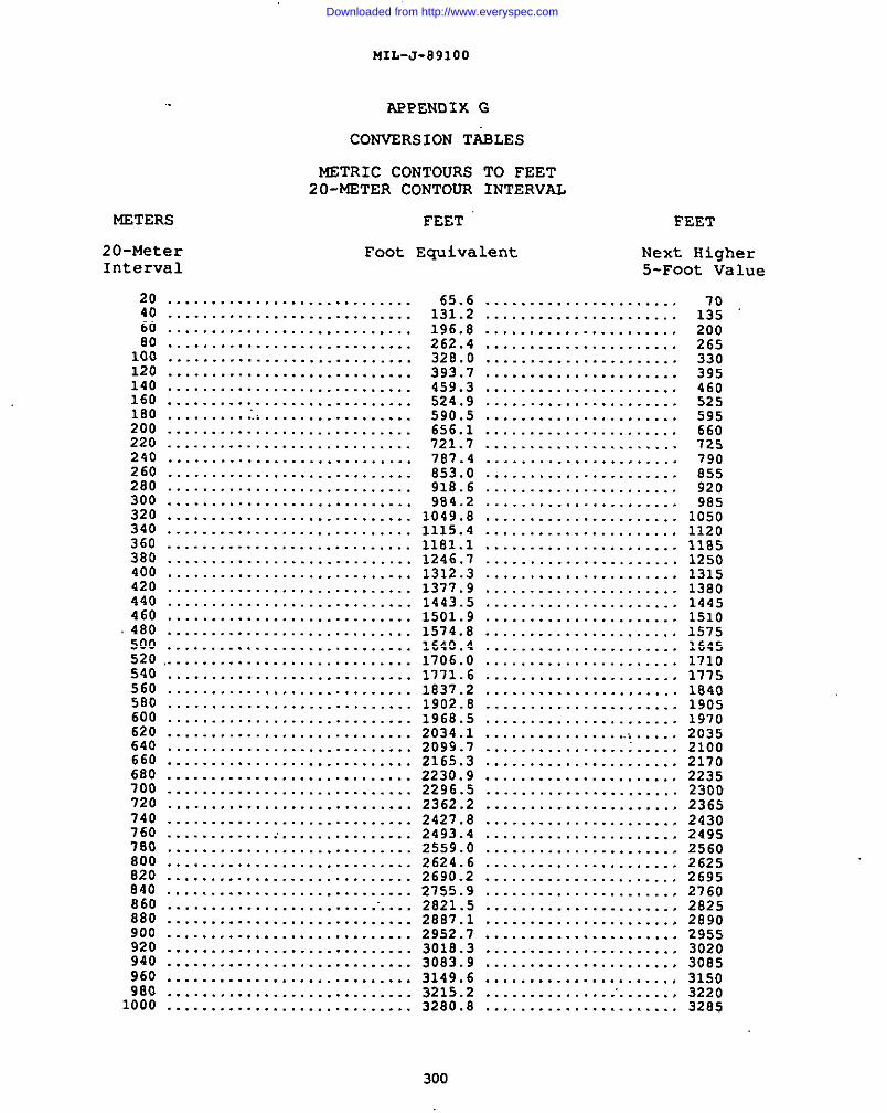
MIL-J-891OO
APPENDIX G
CONVERSION TIiELES
METRIC CONTOURS 2’0 FEET20-METER CONTOUR INTERVAL
NETERS FEET FEET
20-Meter Foot EquiVakrk Next HigherInterval 5-Foot Value
20 ............................40 ............................60 ............................80 ............................100 ............................120 ............................140 ............................160 ............................180 .............................200 ............................220 ............................240 ............................260 ............................280 ............................300 ............................320 ............................340 ............................360 ............................380 ............................400 ............................420 ............................440 ............................460 ............................
.480 ............................500 ............................520,............................540 ............................560 ............................580 ............................600 ............................620 ............................640 ............................660 ............................6B0 ............................700 ............................720 ............................740 ............................760 ............................7s0 ............................800 ............................820 ............................840 ............................860 ............................880 ............................900 ............................920 ............................940 ............................960 ............................980 ............................1000 ...........................,
2821.52887.12952.73018.33083.93149.63215.23280.8
39546052559566072579085592098510501120118512501315138014451510157516451710177518401905197020352100
2625269527602825289o295530203085315032203285
300I
Downloaded from http://www.everyspec.com
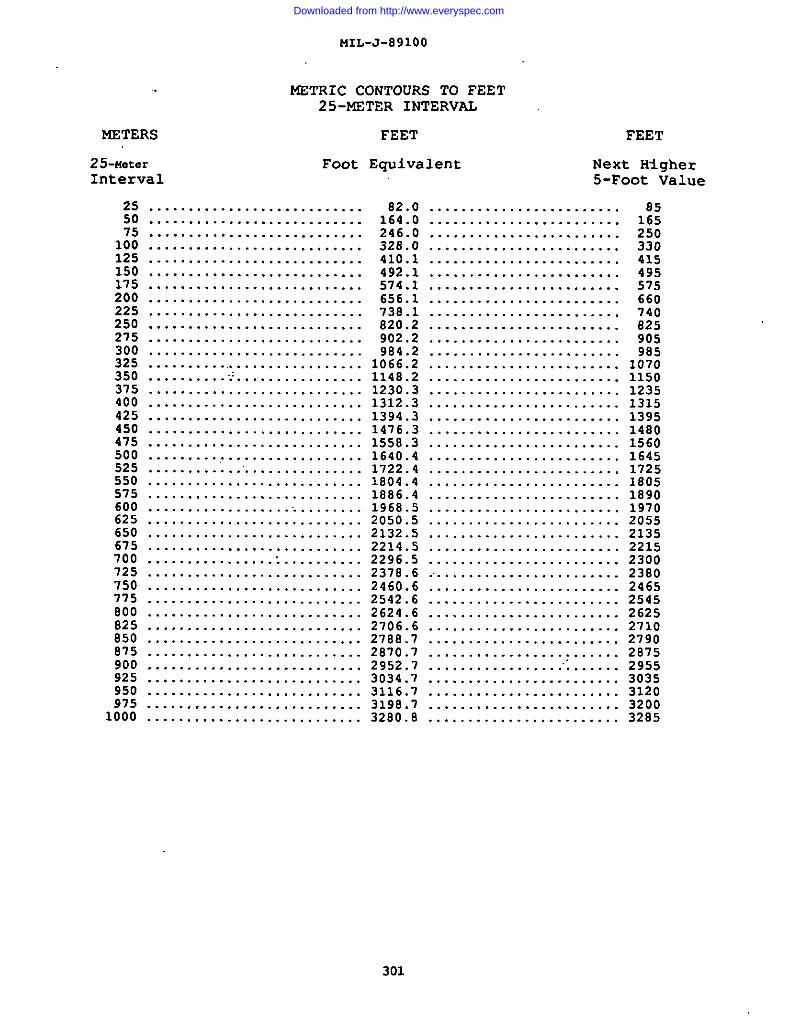
MIL-J-891OO
METRIC CONTOURS TO FEET25-METER INTERVAL
METERS FEET FEET
25-neter Foot Equivalent Next Higher
Interval 5-Foot Value
255075100125150175200225250275300325350375400425450475500525550575600625
. . . . . . . . . . . . . . . . . . . . . . . . . . .
. . . . . . . . . . . . . . . . . . . . . . . . . . .
. . . . . . . . . . . . . . . . . . . . . . . . . . .
. . . . . . . . . . . . . . . . . . . . . . . . . . .
. . . . . . . . . . . . . . . . . . . . . . . . . . .
. . . . . . . . . . . . . . . . . . . . . . . . . . .
. . . . . . . . . . . . . . . . . . . . . . . . . . .
. . . . . . . . . . . . . . . . . . . . . . . . . . .
. . . . . . . . . . . . . . . . . . . . . . . . . . .
. . . . . . . . . . . . . . . . . . . . . . . . . . .
. . . . . . . . . . . . . . . . . . . . . . . . . . .
. . . . . . . . . . . . . . . . . . . . . . . . . . .
. . . . . . . . . . . . . . . . . . . . . . . . . . .
. . . . . . . . . . ... . . . . . . . . . . . . . . . .
. . . . . . . . . . . . . . . . . . . . . . . . . . .
. . . . . . . . . . . . . . . . . . . . . . . . . . .
. . . . . . . . . . . . . . . . . . . . . . . . . . .
. . . . . . . . . . . . . . . . . . . . . . . . . . .
. . . . . . . . . . . . . . . . . . . . . . . . . . .
. . . . . . . . . .. . . . . . . . . . . . . . . . . .
. . . . . . . . . . . . .. . . . . . . . . . . . . . .
. . . . . . . . . . . . . . . . . . . . . . . . . . .
. . . . . . . . . . . . . . . . . . . . . . . . . . .
. . . . . . . . . . . . . . . . . . .. . . . . . . . .
. . . . . . . . . . . . . . . . . . . . . . . . . . .650 ...........................675 ...........................700 ...........................725 ...........................750 ...........................7’75 ...........................800 ...........................825 ...........................850 ...........................875 ...........................900 ...........................925 ...........................950 ...........................975 ...........................
1000 . . . . . . . . . . . . . . . . . . . . . . . . . . .
1312.31394.31476.31558.31640.41722.41804.41886.41968.52050.52132.52214.52296.52378.62460.62542.62624.62706.62788.72870.72952.73034.73116.73198.73280.8
. . . . . . . . . . . . . . . . . . . . . . . . 85
........................ 165
........................ 25o
........................ 330
........................ 415
........................ 495
........................ 575
........................ 660
........................ 740
........................ 625
........................ 905
........................ 985
........................ 1070
........................ 1150
........................ 1235
........................ 1315
........................ 1395
........................ 1480
........................ 1560
........................ 1645
........................ 1725
........................ 1805
........................ 1890
........................ 1970
........................ 2055
. . . . . . . . . . . . . . . . . . . . . . . . 2135
........................ 2215
........................ 2300
......................... 2300
........................ 2465
........................ 2545
........................ 2625
........................ 2710
........................ 2790
........................ 2875
......................... 2955
........................ 3035
........................ 3120
........................ 3200
........................ 3285
301
Downloaded from http://www.everyspec.com
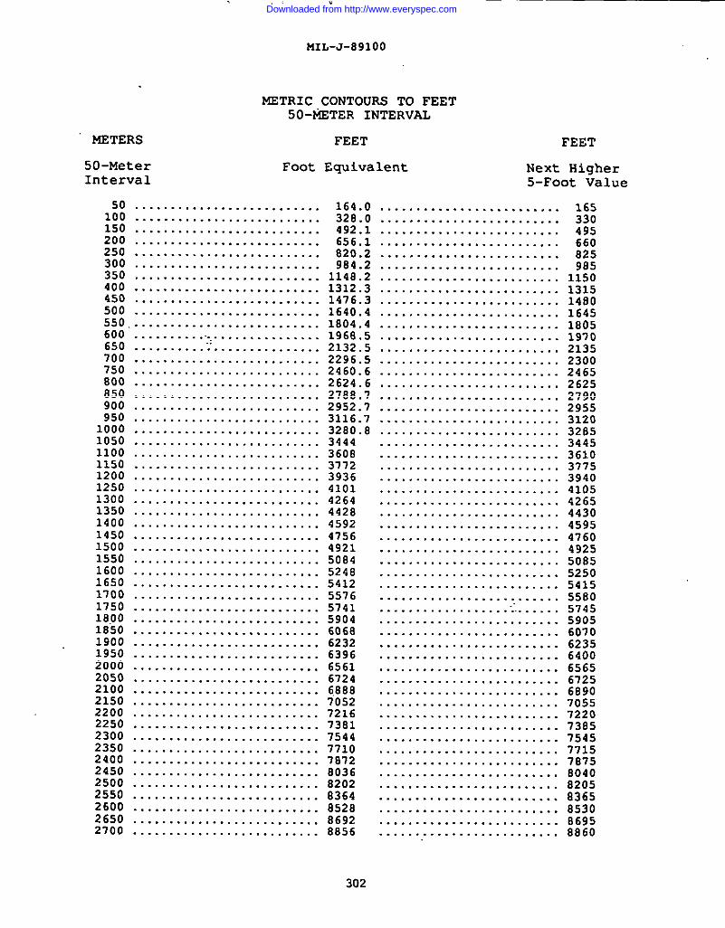
7 .,, .
MIL-J-891OO
METRIC CONTOURS TO FEET50+ETER INTERVAL
METERS FEET FEET
50-Meter Foot Equivalent Next HigherInterval 5-Foot Value
50 164.0 .........................100 :::::::::::::::::::::::::: 328.o .........................150 .......................... 492.1200 656.1250 ““””””””””””””””””””””””””.......................... 820.2300 .......................... 984.2350 1148.2400 ::::::::::::::::::::::::::1312.3450 .......................... 1476.3500 .......................... 1640.4550,.......................... 1s04.4600 . 1968.5650 ““”””””””’:;”””””’’’’’”””””2132.s700 ::::::::::::::::::::::::::2296.5750 .......................... 2460.6800 .......................... 2624.6850 .......................... 2788.7900 .......................... 2952.7950 .......................... 3116.71000 .......................... 32E0. E1050 .......................... 34441100 .......................... 36081150 .......................... 37721200 ..........................39361250 .......................... 41011300 .......................... 42641350 .......................... 44281400 .......................... 45921450 .......................... 47561500 .......................... 49211550 .......................... 50841600 .......................... 52481650 .......................... 54121700 .......................... 55761750 .......................... 574118.00 .......................... 59041850 .......................... 606s1900 .......................... 62321950 .......................... 63962000 .......................... 65612050 .......................... 67242100 .......................... 68882150 .......................... 70522200 .......................... 72162250 .......................... 73812300 .......................... 75442350 .......................... 77102400 .......................... 78722450 .......................... 80362500 .......................... 82022550 .......................... S3642600 .......................... 85282650 .......................... 86922700 .......................... 8856
. . . . . . . . . . . . . . . . . . . . . . . . .
. . . . . . . . . . . . . . . . . . . . . . . . .
. . . . . . . . . . . . . . . . . . . . . . . . .
. . . . . . . . . . . . . . . . . . . . . . . . .
. . . . . . . . . . . . . . . . . . . . . . . . .
. . . . . . . . . . . . . . . . . . . . . . . . .
. . . . . . . . . . . . . . . . . . . . . . . . .
. . . . . . . . . . . . . . . . . . . . . . . . .
. . . . . . . . . . . . . . . . . . . . . . . . .
. . . . . . . . . . . . . . . . . . . . . . . . .
. . . . . . . . . . . . . . . . . . . . . . . . .
. . . . . . . . . . . . . . . . . . . . . . . . .
. . . . . . . . . . . . . . . . . . . . . . . . .
. . . . . . . . . . . . . . . . . . . . . . . . .
. . . . . . . . . . . . . . . . . . . . . . . . .
. . . . . . . . . . . . . . . . . . . . . . . . .
. . . . . . . . . . . . . . . . . . . . . . . . .
. . . . . . . . . . . . . . . . . . . . . . . . .
. . . . . . . . . . . . . . . . . . . . . . . . .
. . . . . . . . . . . . . . . . . . . . . . . . .
. . . . . . . . . . . . . . . . . . . . . . . . .
. . . . . . . . . . . . . . . . . . . . . . . . .
. . . . . . . . . . . . . . . . . . . . . . . . .
. . . . . . . . . . . . . . . . . . . . . . . . .
. . . . . . . . . . . . . . . . . . . . . . . . .
. . . . . . . . . . . . . . . . . . . . . . . . .
. . . . . . . . . . . . . . . . . . . . . . . . .
. . . . . . . . . . . . . . . . . . . . . . . . .
. . . . . . . . . . . . . . . . . . . . . . . . .
. . . . . . . . . . . . . . . . . . . . . . . . .
. . . . . . . . . . . . . . . . . . . . . . . . .
. . . . . . . . . . . . . . . . . . . . . . . . .
. . . . . . . . . . . . . . . . . . .... . . . . .
. . . . . . . . . . . . . . . . . . . . . . . . .
. . . . . . . . . . . . . . . . . . . . . . . . .
. . . . . . . . . . . . . . . . . . . . . . . . .
. . . . . . . . . . . . . . . . . . . . . . . . .
. . . . . . . . . . . . . . . . . . . . . . . . .
. . . . . . . . . . . . . . . . . . . . . . . . .
. . . . . . . . . . . . . . . . . . . . . . . . .
. . . . . . . . . . . . . . . . . . . . . . . . .
. . . . . . . . . . . . . . . . . . . . . . . . .
. . . . . . . . . . . . . . . . . . . . . . . . .
. . . . . . . . . . . . . . . . . . . . . . . . .
. . . . . . . . . . . . . . . . . . . . . . . . .
. . . . . . . . . . . . . . . . . . . . . . . . .
. . . . . . . . . . . . . . . . . . . . . . . . .
. . . . . . . . . . . . . . . . . . . . . . . . .
. . . . . . . . . . . . . . . . . . . . . . . . .
. . . . . . . . . . . . . . . . . . . . . . . . .
. . . . . . . . . . . . . . . . . . . . . . . . .
. . . . . . . . . . . . . . . . . . . . . . . . .
165330.-495
1480164518051970213523002465262527902955312032853445361037753940410542654430459547604925508552505415558057455905607062356400656567256890705572207385
06958860
302
Downloaded from http://www.everyspec.com
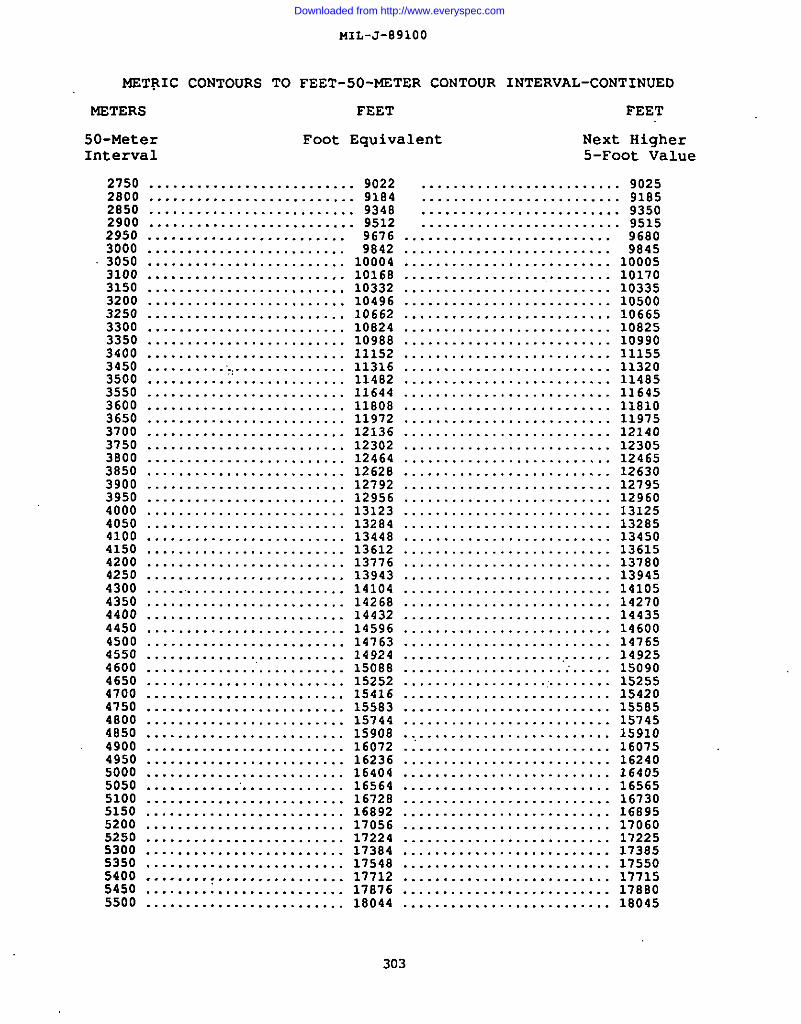
MIL-J-891OO
MSTRIC CONTOURS TO FEET-50-FETER CONTOUR INTERVAL-CONTINUED
METERS FEET
50-Meter Foot Equiva.Interval
FEET
ent Next Higher5-Foot Value
2750 .......................... 9022 ......................... 90252800 .......................... 9184 ......................... 91852850 .......................... 9348 ......................... 935o2900 .......................... 9512 ......................... 95152950 ......................... 9676 .......................... 96803000 ......................... 9842 .......................... 9845
.3050 ......................... 10004 .......................... 100053100 ......................... 10168 .......................... 101703150 ......................... 10332 ........................... 103353200 ......................... 10496 .......................... 105003250 ......................... 10662 .......................... 106653300 ......................... 10824 .......................... 108253350 ......................... 10988 .......................... 109903400 ......................... 11152 .......................... 111553450 .......................... 11316 .......................... 113203500 ......................... 11482 .......................... 114853550 ......................... 11644 .......................... 116453600 ......................... 11808 .......................... 118103650 ......................... 11972 .......................... 119753700 ......................... 12136 .......................... 121403750 ......................... 12302 .......................... 123053800 ......................... 12464 .......................... 124653850 ......................... 12628 .......................... 126303900 ......................... 12792 .......................... 127953950 ......................... 12956 .......................... 129604000 ......................... 13123 .......................... 131254050 ......................... 13284 .......................... 132854100 ......................... 13448 .......................... 134504150 ......................... 13612 .......................... 136154200 ......................... 13776 .......................... 137804250 ......................... 13943 .......................... 139454300 .......................... 14104 .......................... 141054350 ......................... 14268 .......................... 142704400 ......................... 14432 .......................... 144354450 ......................... 14596 .......................... 146004500 ......................... 14763 .......................... 147654550 ......................... 14924 .......................... 149254600 ......................... 15088 .......................... 150904650 ......................... 15252 ..................>....... 152554700 ......................... 15416 .......................... 154204750 ......................... 15583 .......................... 155854800 ......................... 15744 .......................... 157454850 ......................... 15908 .......................... 159104900 ......................... 16072 .;........................ 160754950 ......................... 16236 .......................... 162405000 ......................... 16404 .......................... 164055050 ............’............. 16564 .......................... 165655100 ......................... 16728 .......................... 167305150 ......................... 16892 .......................... 168955200 ......................... 17056 .......................... 170605250 ......................... 17224 .......................... 172255300 ......................... 17384 .......................... 173855350 ......................... 17548 .......................... 17550
I 5400 ......................... 17712 .......................... 17715
I5450 ......................... 17076 .......................... 178805500 ......................... 18044 .......................... 18045
303
I
Downloaded from http://www.everyspec.com
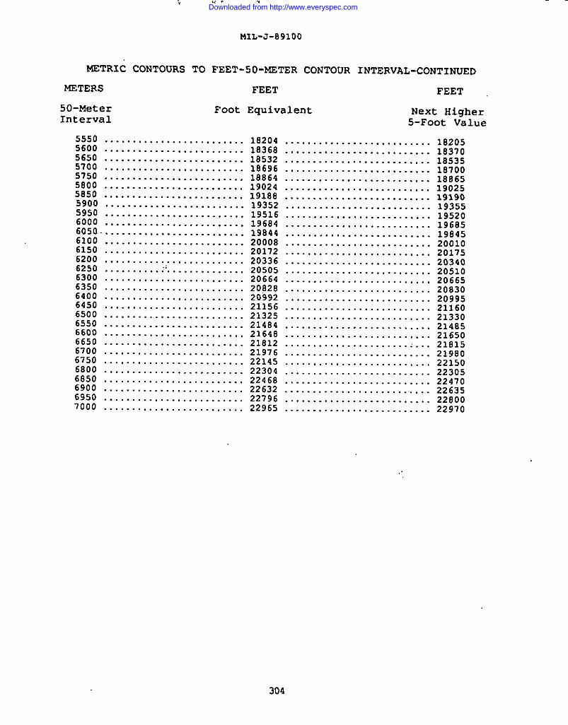
METRIC
METERS
50-MeterInterval
I 5550 .....56005650570057505800585059005950600060506100615062006250630063506400645065006550660066506700675068006850690069507000
;C. .,
MIL-J-891OO
CONTOURS TO FEET-SO-METER CONTOUR INTERVAL-CONTINUED
FEET FEET
Foot Equivalent Next Higher
5-Foot Value
.................... 18204......................... 18368......................... 18532......................... 18696......................... 10864......................... 19024......................... 19188......................... 19352......................... 19516......................... 19684.......................... 19844......................... 20008......................... 20172......................... 20336...........................20505......................... 20664.........................20828......................... 20992......................... 21156......................... 21325......................... 21484......................... 21648......................... 21812.........................21976......................... 22145......................... 22304......................... 22468......................... 22632......................... 22796......................... 22965
182051837018535187001886519025191901935519520196851984520010201752034020510206652083020995211602133021485216502181521980221502230522470226352280022970
304
Downloaded from http://www.everyspec.com
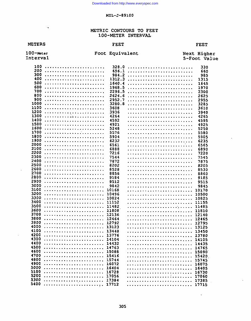
I
I
IMIL-J-891OO
1 NETRIC CONTOURS TO FEET1OO-METER INTERVAL
NETERS FEET FEET
100-Water Foot Equivalent Next HiaherInterval
-–––—S-Foot Value
100 ........................ 328.0 ...........................200 ........................ 656.1 ..........................300 ........................ 984.2 ..........................400
170018001900200021002200230024002500260027002800290030003100320033003400350036003700380039004000410042004300440045004600
1312.3 ..........................1640.4 ..........................1968.5 ..........................2296.5 ..........................2624.6 ..........................2952.7 ..........................3280.8 ..........................
. . . . . . . . . . . . . . . . . . . . . . . .
. . . . . . . . . . . . . . . . . . . . . . . .
. . . . . . . . . . . . . . . . . . . . . . . .
. . . . . . . . . . . . . . . . . . . . . . . .
. . . . . . . . . . . . . . . . . . . . . . . .
. . . . . . . . . . . . . . . . . . . . . . . .
. . . . . . . . . . . . . . . . . . . . . . . .
. . . . . . . . . . . . . . . . . . . . . . . .
. . . . . . . . . . . . . . . . . . . . . . . .
. . . . . . . . . . . . . . . . . . . . . . . .
. . . . . . . . . . . . . . . . . . . . . . . .
. . . . . . . . . . . . . . . . . . . . . . . .
. . . . . . . . . . . . . . . . . . . . . . . .
. . . . . . . . . . . . . . .. . . . . . . . . .
. . . . . . . . . . . . . . . . . . . . . . . .
. . . . . . . . . . . . . . . . . . . . . . . .
. . . . . . . . . . . . . . . . . . . . . . . .
. . . . . . . . . . . . . . . . . . . . . . . .
. . . . . . . . . . . . . . . . . . . . . . . .
. . . . . . . . . . . . . . . . . . . . . . . .
. . . . . . . . . . . . . . . . . . . . . . . .
. . . . . . . . . . . . . . . . . . . . . . . .
. . . . . . . . . . . . . . . . . . . . . . . .
. . . . . . . . . . . . . . . . . . . . . . . .
. . . . . . . . . . . . . . . . . . . . . . . .
. . . . . . . . . . . . . . . . . . . . . . . .
. . . . . . . . . . . . . . . . . . . . . . . .
. . . . . . . . . . . . . . . . . . . . . . . .
. . . . . . . . . . . . . . . . . . . . . . . .
........................ 10824
........................ 11152
........................ 11482
........................ 11808”
........................ 12136
........................ 12464
........................ 12792
........................ 13123
........................ 13448
........................ 13776
........................ 14104
........................ 14432
........................ 14763
........................ 15088
3608393642644592492152485576590462326561688872167544787282o2852888569184951298421016810496
4700 ........................ 154164800 ........................ 157444900 ........................ 160725000 ........................ 164045100 ........................ 16728S200 ........................ 170565300 ........................ 17384S400 ......................... 17712
330660985
1315164519702300262529553285361039404265459549255250558059056235656568907220754578758205853o8860918595159845
.......................... 10170
.......................... 10500
.......................... 10025
.......................... 11155
...................... ..... 11485
.......................... 11810
.......................... 12140
.......................... 12465
.......................... 12795
.......................... 13125
.......................... 13450
.......................... 13780
.......................... 14105
.......................... 14435
.......................... 14765
.......................... 15090’
.......................... 15420.
.......................... 15745
. . . . . . . . . . . . . . . . .
. . . . . . . . . . . . . . . . .
. . . . . . . . . . . . . . . . .
. . . . . . . . . . . . . . . . .
. . . . . . . . . . . . . . . . .
. . . . . . . . . . . . . . . . .
. . . . . . . . 16075
........ 16405
........ 16730
........ 17060
........ 17385
........ 17715
305
Downloaded from http://www.everyspec.com
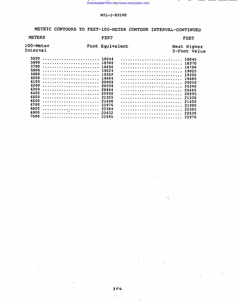
i
MIL-J-891OO
METR”IC CONTOURS TO
METERS
100-MeterInterval
FEET-1OO-METER CONTOUR INTERVAL-CONTINUED
FEET FEET
Foot Equivalent Next Higher
5500 ........................ 180445600 ........................ 183685700 ........................ 186965800 ........................ 190245900 ........................ 193526000 ........................ 196846100 ........................ 2000B6200 ........................ 203366300 ........................ 206646400 ........................ 209926500 ........................ 213256600 ........................216486700 ........................ 219766800 ........................ 223046900 ...........”’............. 226327000 ........................ 22965
5-Foot Value
.....................’..... 18045
.......................... 18370
.......................... 18700
.......................... 19025
.......................... 19355
.......................... 19685
.......................... 20010
.......................... 20340
.......................... 20665
.......................... 20995
.......................... 21330
.......................... 21650
.......................... 21980
.......................... 22305
.......................... 22635
.......................... 22970
Downloaded from http://www.everyspec.com
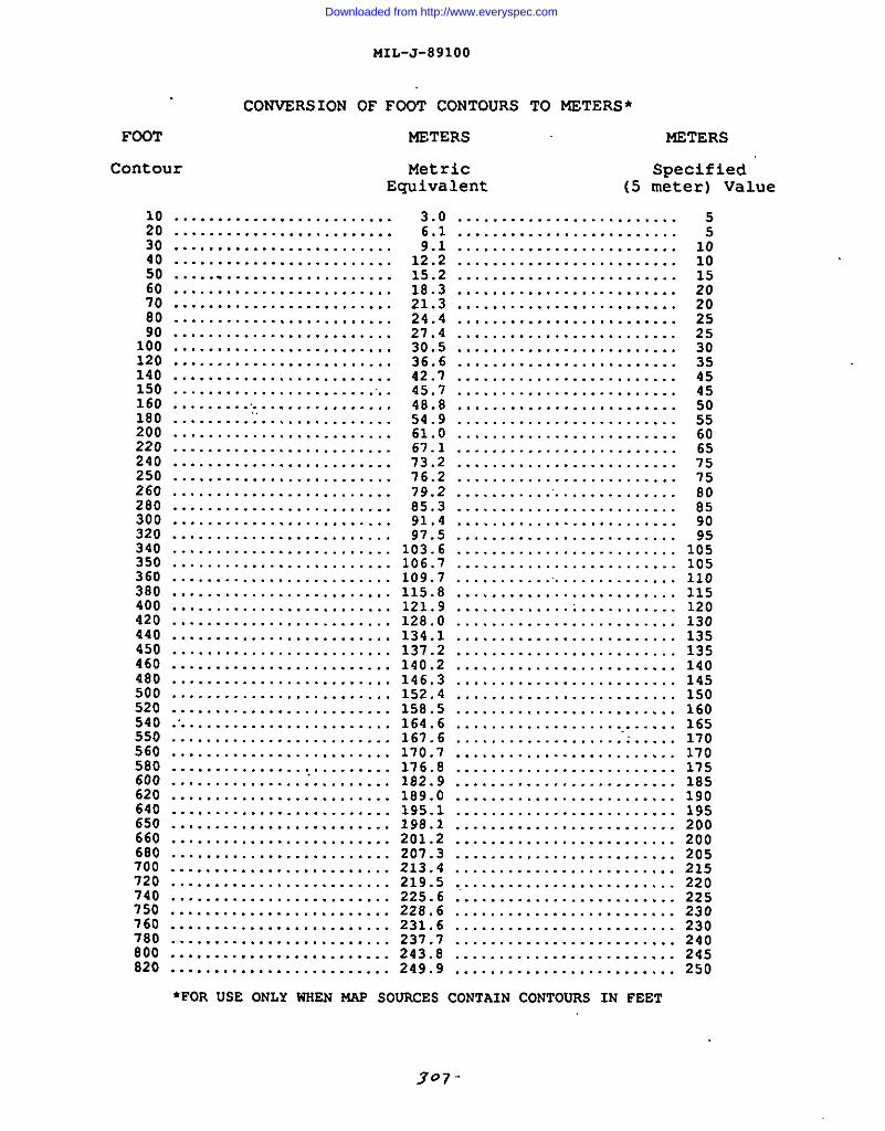
MIL-J-891OO
CONVERSION OF FOOT CONTOURS TO METERS*
FCi3T METERS t.f3TERS
Contour Metric SpecifiedEquivalent (5 meter) Value
. . . . . . . . . . . . . . . . . . . . . . . . .;; . . . . . . . . . . . . . . . . . . . . . . . . .30 .........................
.........................% .........................60 .........................70 .........................80 .........................90 .........................
100 .........120 .........140 .........150 .........160 ..........180 .........200 .........220 ..........240250
. . . . . . . . . . . . . . .
. . . . . . . . . . . . . . .
. . . . . . . . . . . . . . .
. . . . . . . . . . . . . .. .
. . . . . . . . . . . . . . .
. . . . . . . . . . . . . . .
. . . . . . . . . . . . . . .
. . . . . . . . . . . . . . .. . . . . . . . . . . . . . . . . . . . . . . . .. . . . . . . . . . . . . . . . . . . . . . . . .
26o .........................280 .........................300 .........................32o .........................340 .........................350 .........................360 .........................380 .........................400 .........................420 .........................440 .........................450 .........................460 .........................480 .........................500 .........................520 .........................
3.06.19.1
12.215.218.321.324.427.430.536.642.745.748.854.961.067.173.276.279.285.391.497.5
103.6 .........................106.7 .........................109.7 .........................115.8 .........................121.9 .........................128.0 .........................134.1 .........................137.2 .........................140.2 .........................146.3 .........................152.4 .........................158.5 .........................
540 .......................... 164.6 .........................550 ......................... 167.6 ...................”......560 ......................... 17o.7 .........................580 ......................... 176.8 .........................600 .......................... 182.9 .........................620 ......................... 189.o .........................640 ......................... 195.1 .........................65o ......................... 198.1 .........................660 ......................... 201.2 .........................680 ......................... 207.3 .........................700 ......................... 213.4 .........................720 ......................... 219.5 .........................740 ......................... 225.6 ..........................750 ......................... 228.6 .........................760 ......................... 231.6 .........................780 ......................... 237.7 .........................000 ......................... 243.8 .........................820 ......................... 249.9 .........................
●FOR USE ONLY WHEN W@ SOURCES CONTAIN CONTOURS IN FEET
165170170175185190195200200205215220225230230240245250
307.
Downloaded from http://www.everyspec.com
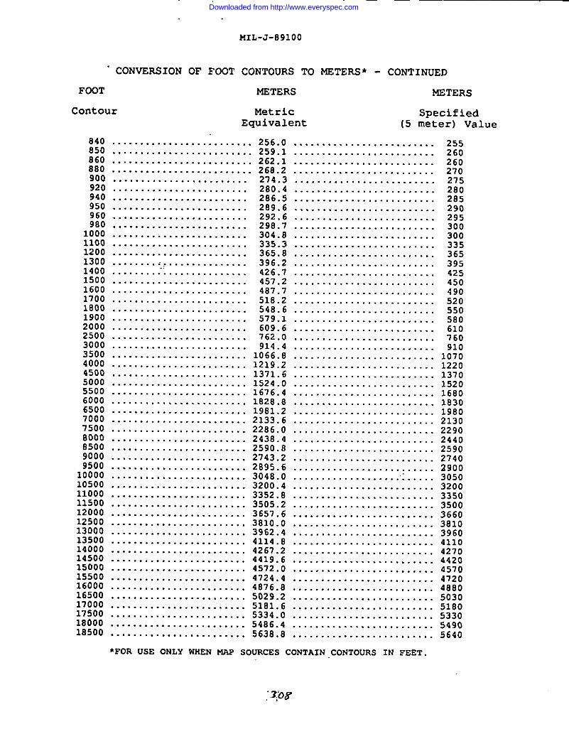
MIL-J-891OO
FOOT
“ CONVERSION OF FOOT CONTOURS TO NSTERS* - CONTINUED
MSTERS METERS
Contour Metric SpecifiedEquivalent (5 meter) Value
840850860880900920940950960980
10001100120013001400150016001700180019002000250030003500400045005000.550060006500700075008000850090009500
100001050011000115001200012500130001350014000145001500015500160001650017000175001800010500
. . . . . . . . . . . . . . . . . . . . . . . . . 256.0 .........................
......................... 259.1 .........................
......................... 262.1 .........................
......................... 268.2 .........................
........................ 274.3 .........................
........................ 280.4 .........................
........................ 286.5 .........................
........................ 289.6 .........................
........................ 292.6 .........................
........................ 298.7 .........................
........................ 304.8 .........................
........................ 335.3 .........................
........................ 365.8 .........................
.......................... 396.2 .........................
........................ 426.7 .........................
........................ 457.2 .........................
........................ 487.7 .........................
........................ 518.2 .........................
........................ 546.6 .........................
........................ 579.1 .........................
........................ 609.6 .........................
........................ 762.0 .........................
........................ 914.4 .........................
........................ 1066.8 .........................
........................ 1219.2 .........................
........................ 1371.6 .........................
........................ 1524.0 .........................
........................ 1676.4 .........................
........................ 1828.8 .........................
........................ 1981.2 .........................
........................ 2133.6 .........................
........................2286.0 .........................
........................ 2438.4 .........................
........................ 2590.8 .........................
........................ 2743.2 .........................
........................ 2895.6 .........................
........................ 3048.0 .........................
........................ 3200.4 .........................
........................ 3352.8 .........................
........................ 3505.2 .........................
........................ 3657.6 .........................
........................ 3810.0 .........................
........................ 3962.4 .........................
........................ 4114.8 .........................
........................ 4267.2 .........................
........................ 4419.6 .........................
........................ 4572.0 .........................
........................ 4724.4 .........................
........................ 4876.8 .........................
........................ 5029.2 .........................
........................ 5181.6 .........................
........................ 5334.0 .........................
........................ 5486.4 .........................
........................ 5638.8 .........................
●FOR USE ONLY WHEN W SOURCES CONTAIN CONTOURS IN FEET.
25526o26o270275280285290295300300335365395425450490520550580610760910
107012201370152016S01830198021302290244025902740290030503200335035003660381039604110427044204570472048S050305180533054905640
Downloaded from http://www.everyspec.com
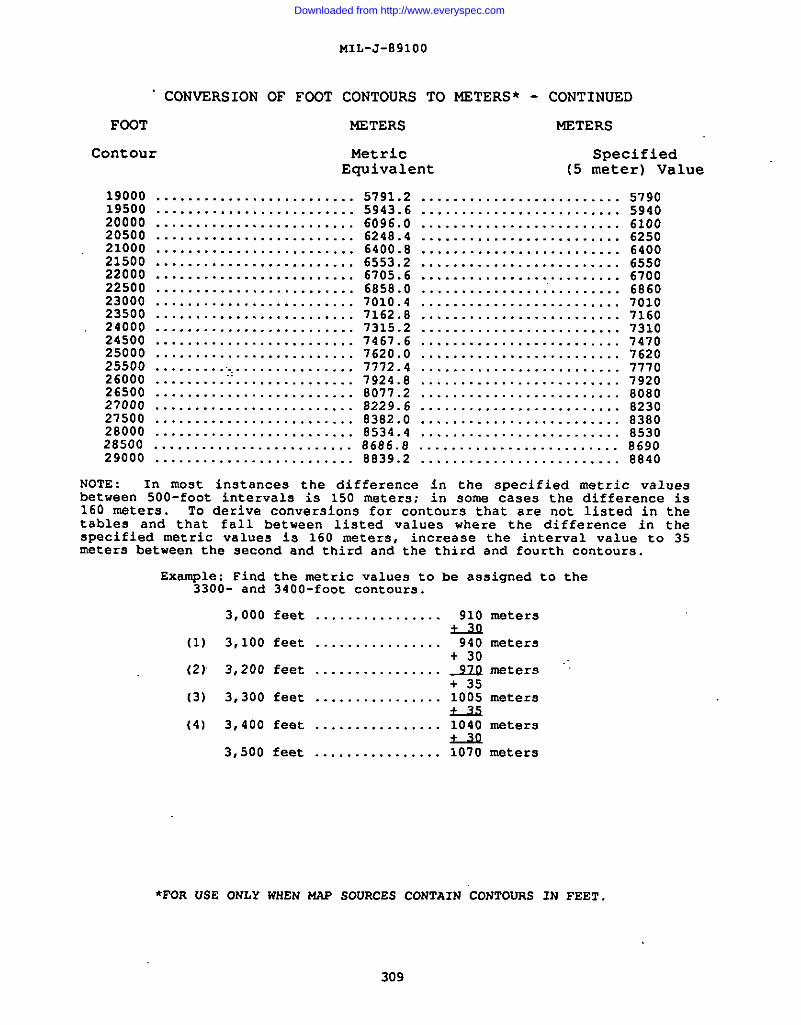
“ CONVERSION OF FOQT
FOOT
Contour
MIL-J-891OO
CONTOURS TO METERS* -
NETERS
MetricEquivalent
19000 .........................19500 .........................20000 .........................20500 .........................21000 .........................21500 .........................22000 .........................22500 .......... ..............23000 ..........23500 ..........24000 ..........24500 ..........25000 ..........25500 ............26000 ..........’26500 ..........
CONTINUED
METERS
Specified
(5 meter) Value
5791.2 ......................... 57905943.6 ......................... 59406096.0 ......................... 61006248.4 ......................... 62506400.8 ......................... 64006553.2 ......................... 65506705.6 ......................... 67006858.0 ................’......... 6860
. . . . . . . . . . . . . . 7010.4 ......................... 7010
.............. 7162.8 ......................... 7160
.............. 7315.2 ......................... 7310
.............. 7467.6 ......................... 7470
.............. 7620.0 ......................... 7620
.............. 7772.4 .....................,...777o
.............. 7924.8 .........................7920............... 8077.2 ......................... 8080
27000 ......................... 0229.6 ......................... 823027500 ......................... 8382.0 ......................... 838028000 ......................... 8534.4 ......................... 853028500 ......................... 8696.8 ......................... E69029000 ......................... 8839.2 ......................... 8840
NOTE : In most instances the difference in the specified metric valuesbetween 500-foot intervals is 150 meters; in some cases the difference is160 maters. To derive conversion for contoure that are not listed in thetablee and that fall between listed values where the difference in thespecified metric values is 160 meters, increase the interval value to 35meters between the second and third and the third and fourth contours.
Example: Find3300- and
3,000
(1) 3,100
(2) 3,200
(3) 3,300
(4) 3,400
3,500
the metric values to be assigned to3400-fOOt contours.
feet ................ 910 meters
feet ................ 940 meters+ 30
feet ................_32Q meters+ 35
feet ................ 1005 meters
feet ................ 1040 meters
feet ..............Q
.. 1070 meters
the
●FOR USE ONLY WHEN MAP SOURCES CONTAIN “CONTOIIRSIN FEET.
309
.
Downloaded from http://www.everyspec.com
.
I
MIL-J-891OO
APPENDIX H
LANGUAGE REQUIREMENTS(for Margin of Graphic)
10. SCOPE
10.1 -. This Appendix provides the requirements forlanguages to be used in the margin data for each country. ThisAppendix is a mandatory part of the specification. The informationcontained herein is intended for compliance.
20. APPLICABLE DOCUMENTSThis section is not applicable to this appendix.
30. MARGIN LANGUAGE REQUIREMENTS.
310
30.1 See next page for languagerequirements information.
Downloaded from http://www.everyspec.com
IMIL-J-891OO
APPENDIX H
LANGUAGE REQUIREMENTS (for Margin of Graphic)
COUNTRY LANGUAGE IWMARKS OR SHEET EXCEPTIONS
Afars and Issas, .......French Territory of the
Afghanistan ............
Albania ................
AlgeriaNorth of 30% .........South of 30% .........
American Samoa ...........
Andorra ................
Angola .................
Annobon ................
I Antartica and ..........adjacent islands
Argentina ..............
A.9ension Island ........
Australia .............
Austria ................
Azores .................
Bahamas ................
Bahrain ................
Balleny Island .........
Bangladesh .............
Barbados ...............
English
English ............. NJ 43-10Chineee and English
Greek and English ... SW 34-4, -10Greek, Italian, andEnglish
French and EnglishEnglish
English
Spanish, French, .... Andorra is completelyand English contained cm Sheet
English
See EquatorialGuinea
English
Spanish and English
English
English
German, Italian, ..and English
NK 31-4
SG 21-8,-16;SG 22-5, -9, -13SH 21-3, -6, -7, -10Spanishr Portuguese,and English
NL 32-2;N?433-1oGerman, French,and English
NL 33-6Italian and English
Engli9h andPortuguese
English
English
English
English
English
311
Downloaded from http://www.everyspec.com
MIL-J-891OO
LANGUAGE REQUIREMENTS - Continued
COUNTRY
Belgium ................
Belize .................
Benin ..................
Bermuda ................
Bhutan .................
Bismark Archipelago ....
Bjornoya ...............(part of Svalbard)
Bolivia ................
Benin Islands ..........
Botswana ...............
Bouvetoya ..............
Brazil .................
LANGUAGE REMARRS OR SHEET EXCEPTIONS
French, Dutchr ...... 1!and English E
x
Spanish and English .
English
English
English . ... ... ... .. .
English
Norwegian andEnglish
Spanish and English .
Portuguese and ......English
312
I
K
English
English
Norwegian and English
04 31-9‘rench and Engliehn4 32-4French, German, andEnglish
IB 16-10, -14English
rG 45-4; NG 46-1, -2~H 45-16; NH 46-13Chinese and English
;C 19-8, -lo, -11, -12,-14, -15;;C 20-5, -9, -13;}D 20-1, -2, -3, -7, -6,-12, -16;;E 20-4; SE 21-1, -2, -6,-1o, -14Spanish, Portuguese,and English
NA 19-7, -8,”’-10,-11,-12, -14, -16;
NA 20-1. -2. -6. -9,-lo -13; “
NB 20-12, -13, -14, -15,-16;
5A 19-2, -6, -10, -14;SB 18-4, -8, -11, -12,-15; SB 19-1, -2;
Sc 10-3, -4, -8SC 19-5, -6, -8, -9, -10-11, -12, -14, -15;
SC 20-5, -9, -13;SD 20-1, -2, -3, -7, -8,-12, -16;
SE 20-4; SE 21-1, -2,-6, -10, -14;
SF 21-2, -6; -10, -11,-16;
SG 21-4, -8, -16;
L
Downloaded from http://www.everyspec.com
COVNTRY
Brazil-continued
MIL-J-891OO
LANGUAGE REQUIRENSNTS
Brunei .................
Bulgaria ...............
Burma ..................
Burundi ................
Cabinda ................
Cambodia ..;............
Cameroon ...............
Canada .................
LANGUAGE
English
Greek, Turkish, ...
- Continued
AEMARKS OR SHEET EXCEPTIONS
. . .and English
English ..............
English
English
SG 22-5, -9, 13;SH 21-3, -7, -10, -11,-15, -16;
SH 22-13;S1 22-1, -5Portugueea, Spenlsh,and Enalish
NA 21-7,--8, -11Dutch, Portuguese, andEnglish
NA 22-5, -14French, Portuguese, andEnglish
NL 34-12Greek, Italian, andEnglish
NC 47-2, -3, -6, -7,-10;
ND 47-2, -6, -7, -10,-11, -15;
NE 47-2, -3, -5, -6,-1o, -14Thai and English
NF 47-1, -2, -3, -7,-11;
NG 47-2, -6, -10, -14;NH 47-13, -14Chinese and English
NF 47-12Lao, Chinese, and English
NF 47-15Lao, Thai, and English
NF 47-16Lao and English
Khmer ................ NC 48-1(where available) and ND 48-5, -6. -13English; otherwiseFrench and English
English
English
Xhmer, Thai, andEnglish
NC 48-3, -4. -5. -6. -7:ND 4s-12, -i6Vietnamese, Khmer, andEnglish
ND 48-7, -8, -11Leo, Xhmer, and English
313
,--
Downloaded from http://www.everyspec.com
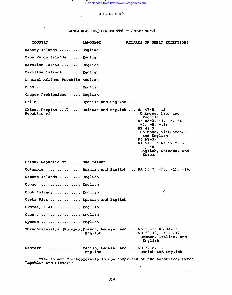
, .,, , . .
MIL-J-891OO
LANGUAGE REQUIREMENTS
COONTRY
Canary Islands .........
Cape Verde Islands .....
Caroline Island ........
Caroline Islands .......
Central African Republic
Chad ...................
Chagos Archipelago .....
Chile ..................
China, Peoples ...”......Republic of
China, Republic of .....
Columbia ...............
Comoro Islands .........
Congo ..................
Cook Islands ...........
Co9ta Rica .............
Crozet, Iles ...........
Cuba ...................
Cyprus .................
LANGUAGE
English
English
English
English
English
English
English
Spanish and English
Chinese and English
- Continued
~S OR SHEET ExCEPTIONS
See Taiwan
Spanish and English
English
English
English
Spanish and English
English
English
English
. . .
. . . NF 47-8, -12Chinese, Lao, andEnglish
~ 48-2, -3, -5, -6,-7, -8, -12;
NF 49-9Chinese, Vietnamese,and English
NJ 51-3;NK 51-12; ~ 52-5, -6,-7, -8English, Chinese, andKorean
... NA 19-7, -10, -12, -14;
●Czechoslovakia (Former) .French, German, and ... NL 33-3; NL 34-1;English NM 33-1o, -11, -12
German, Italian, andEnglish
Denmark ................ Danish. Garman, and ... N032-8. -9English Danish and Englieh
●The former Czechoslovakia i9 now comprised of two countries; CzechRepublic and Slovakia
I314
~. . . . .
Downloaded from http://www.everyspec.com
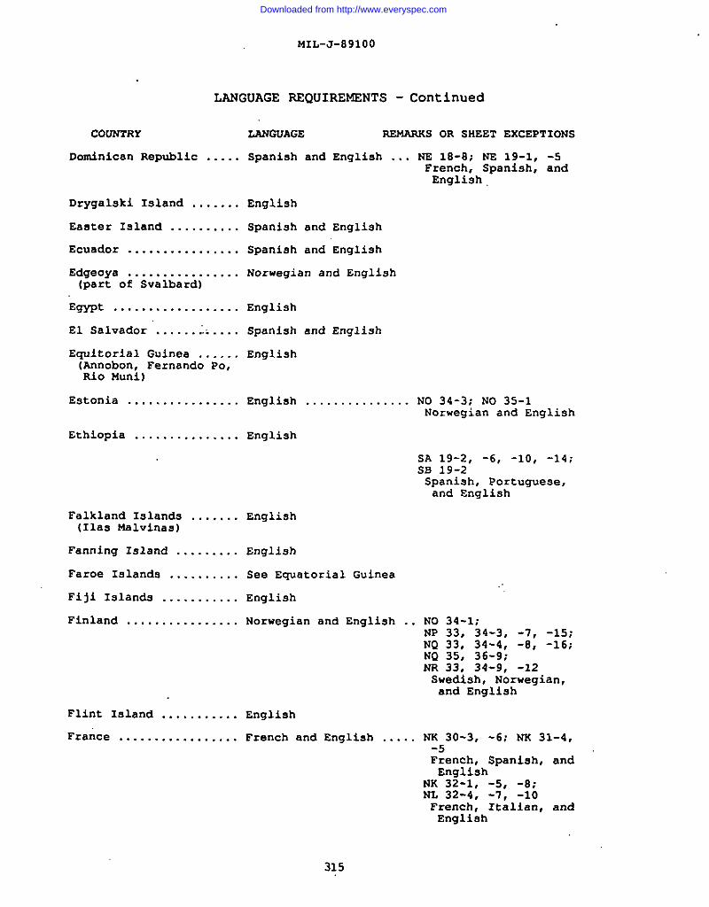
MIL-J-891OO
LANGUAGE REQUIREMENTS - Continued
COUNTRY
Dominican Republic .. ...
Drygalski Island .......
Easter Inland ..........
Ecuador ................
Edgeoya ................(part of Svalbard)
Wwt ..................
El Salvador .............
Equatorial Guinea ......(Annobon, Fernando Po,Rio Muni)
Estonia ................
Ethiopia ...............
Falkland Islands .......(Ilas Malvinas)
Fanning Island .........
Faroe Island9 ..........
Fiji Islands ...........
Finland ................
Flint Island ...........
France .................
LANGuAGE REMARKS OR SHEET EXCEPTIONS
Spanish and English ... NE 18-8; NS 19-1, -5French, Spanish, andEnglish
English
Spanish and English
Spanish and English
Norwegian and English
English
Spaniah and English
English
English ............... NO 34-3; NO 35-1Norwegian and English
English
5A 19-2, -6, -10, -14;SB 19-2Spanish, Portuguese,and English
English
English
See Equatorial Guinea
English
Norwegian and English .. NO 34-1;NP 33, 34-3, -7, -15;NQ 33, 34-4, -S, -16:NQ 35, 36-9;NR 33, 34-9, -12Swedish, Norwegian,and English
Englieh
French and English ..... NK 30-3, -6; NK 31-4,-5French, Spaniah, andEnglish
NK 32-1, -5, -S;NL 32-4, -7, -10French, Italian, andEnglish
315
Downloaded from http://www.everyspec.com
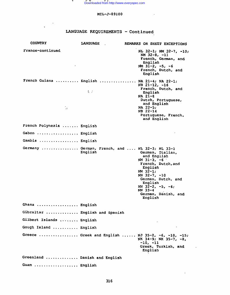
MIL-J-891OO
LANGUAGE REQUIlW4SNTS - Continued
COUNTRY LANGUAGE REMARKS OR SHEET EXCEPTIONS
France-cent inued NL 32-1; NM 32-7, -10;NM 32-8, -11French, German, andEnglish
NM 31-2, -5, -6French, Dutch, andEnglish
I French Guiana .......... English ................ NA 21-4; NA 22-1;NE 21-12, -16French, Dutch, and
!,., EnglishNA 21-8Dutch, Portuguese,and English
NA 22-5;NB 22-14Portuguese, French,and English
.:
French Polynesia ....... English
Gabon .................. English
Gambia ................. English
Germany ................ German, French, and .... NL 32-3; NL 33-1English German, Italian,
and EnglishNM 31-3, -6French, Dutch, andEnglish
NM 32-1;NN 32-7, -10German, Dutch, andEnglish
NN 32-2, -5, -6;NN 33-4German, Di”nish, andEnglish
Ghana .................. English
Gibraltar .............. English and Spanish
Gilbert Ielands ........ English
GOugh Island ........... English
Greece ................. Greek and English ...... NJ 35-2. -6, -10, -15;Nx 34-9: m 35-7, -8,
~%k~1~urki9h, andEnglish
Greenland .............. Danish and English
GUam ................... E”glish
316
Downloaded from http://www.everyspec.com
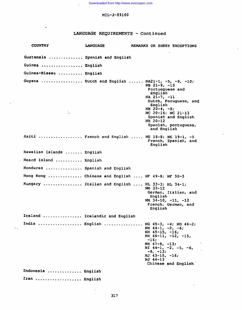
MIL-J-891OO
LANGUAGE REQUIREMENTS - Continued
COUNTRY LANGUAGE REMARKS OR SHEET EXCEPTIONS
Guatemala .............. Spaniah and English
Guinea ................. English
Guinea-Bissau .......... English
Guyana ................. Dutch and English ...
Haiti .................. Frenghand E”glish ..
Hawaiian Islanda ....... English
Heard Island ........... English
Honduraa ............... Spanish and English
Hong Kong .............. Chinese and English .
Hungary .. ... .. .. ... .. .. Italiana”dEnglish ... .
Iceland ................ Icelandic and English
India .................. English ................
NA21-1, -5, -9, -10;NE 21-9, -13Portue~ese andEnglish
NA 21-7, -11Dutch, ”Poruguese, andEnglish
NS 20-4, -8;NC 20-16; NC 21-13Spaniah and English
NE 20-12Spanish, Portuguese,and English
NE lB-8; NE 19-1, -5French, Spanish, andEnglish
NF 49-S; NF 50-5
Nl,33-3; NL 34-1;NM 33-12German, Italian, andEnglish
NM 34-1o, -11, -12French, German, andEnglish
NG 45-3, -4; NG 46-2;NH 44-1, -2, -6;NH 45-15, -16;NH 46-11, -12, -15,-16,-..
NH 47-9, -13;NI 44-1, -2, ‘5, -6,-9, -13;
NJ 43-15, -16;NJ 44-13”Chinese and English
Indonesia .............. English
Iran ................... English
317
/
Downloaded from http://www.everyspec.com
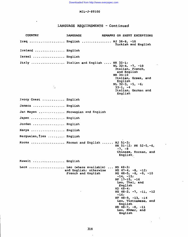
MIIJ-J-891OO
LANGUAGE REQUIREMENTS - Continued
COUNTRY LANGUAGE REMARKS OR SHEET EXCEPTIONS
Iraq ................... English ................ NJ 38-9, -10Turkish and English
Ireland ................ English
Israel ................. English
Italy .................. Italian and English .... NK 32-1;t4L 32-4, -7, -10Italian, French,and English
NK 34-1oItalian, Greek, andEnglish
NL 32-3, -5, -6;33-1, -4Italian, German andEnglish
.:
Ivory Coast ............ English
Jameca ................. English
Jan Mayen .............. Norwegian and English
Japan .................. English
~ Jordan ................. English
Kenya .................. English
Kerguelen, ties ......... English
Korea .................. Korean and English ....... NJ 51-3;NK 51-12; NK 52-5,-6,-7, -aChinese, Korean, andEnglish..
Kuwait ................. English
Laos ................... Lao (where available) ..and English; otherwiseFrench and English
ND 48-3;NS 47-4, -8, -12;NE 48-5, -6, -9, -10-14, -15;
NF 17-15, -16Lao, Thai, andEnglish
NO 48-4;NE 48-2, -7, -11, -12-16;
NF 48-9, -13, -14Lao, Vietnamese, and!?.nalieh
ND 4s-7, -8, -11Lao, Khiner, andEnglish
318
Downloaded from http://www.everyspec.com
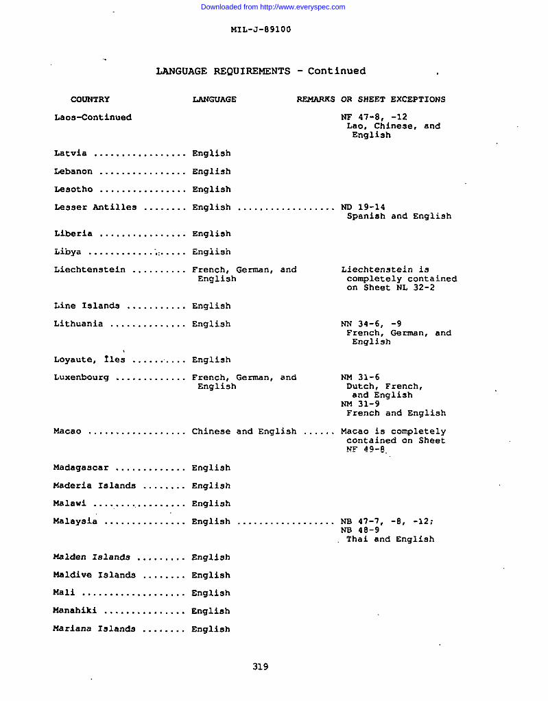
I
MIL-J-891OO
LANGUAGE REQUIREMENTS - Continued
I COUNTRY
I LacJs-CcIntinued
Latvia .................
Lebanon ................
Lesotho ................
La9ser Antilles ........
Liberia ................
Libya ............’.:.....
Liechtenstein ..........
Line Islands ...........
Lithuania ..............
Loyaute, fles ..........
Luxembourg .............
Flacao .. ... .. ... .. .. .. ..
Madagascar .............
Maderia Islands ........
Malawi ..................
Malaysia ...............
Uslden 181ands .........
Maldive Ielanda ........
Mali ...................
Msnahiki ...............
Msriana Island9 ........
LANGUAGE REMARKS OR SHEET EXCEPTIONS
NF 47-8, -12Lao, Chinese, andEnglish
English
English
English
English .................. ND 19-14Spanish and English
English
English
French, German, andEnglish
English
English
English
French, German, andEnglish
Chinese and English
English
English
English
English ...........
English
English
English
English
English
Liechtenstein iscompletely containedon Sheet NL 32-2
NN 34-6, -9French, Germsn, andEnglish
NM 31-6Dutch, French,and English
NN 31-9French and English
. . . . Macao is completelycontained on SheetNF 49-8..
. . . . NB 47-7, -8, -12;NS 48-9Thai and English
319
Downloaded from http://www.everyspec.com
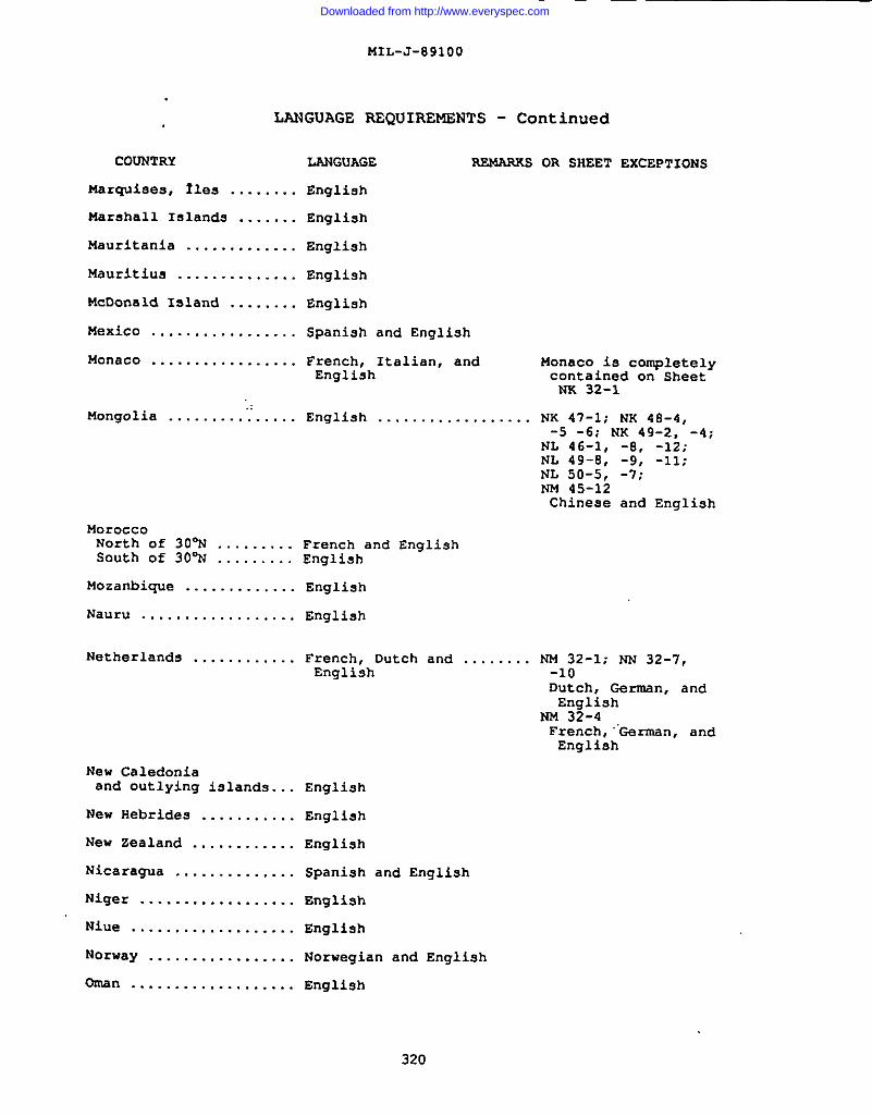
MIL-J-891OO
LANGUAGE REQUIREMENTS - Continued
COUNTRY
marquises, Iles ........
Marahall Islands .......
Mauritania .............
Mauritius ..............
McDonald Island ........
Mexico .................
Monaco .................
M.angolia .........”......
MoroccoNorth of 30% .........South of 30% .........
Mozambique .............
Nauru ..................
Netherlands ............
New Caledoniaand outlying islands. ..
New Hebrides ...........
New Zealand ............
Nicaragua ..............
Niger ..................
Niue ...................
Norway .................
Oman ...................
LANGUAGE PJIMARKs
English
English
English
English
English
Spanish and English
French, Italian, andEnglish
English .................
French and EnglishEnglish
English
English
French, Dutch and .......English
English
English
English
Spanish and English
English
English
Norwegian and English
Engli9h
OR SHEET EXCEPTIONS
Monaco is completelycontained cm SheetNK 32-1
NK 47-1; NK 48-4,-5 -6: NK 49-2, -4;
NL 46-1, -S, -12;NL 49-S, -9, -11;NL 50-5. -7:NM 45-12Chinese and English
NM 32-1; NN 32-7,-loDutch, German, andEnglish
NM 32-4French, .“German,andEnglish
320
Downloaded from http://www.everyspec.com
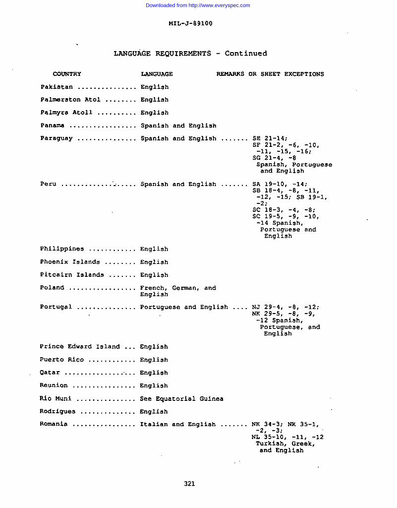
I
MIL-J-891OO
LANGUAGE REQUIREMENTS
COUNTRY
Pakistan ...............
Palmarston Atol ........
Palmyra Atoll ..........
Panama .................
Paraguay ...............
Peru .............”<.....
Philippines ............
Phoenix Islands ........
PitCairn Islands .......
Poland .................
Portugal ...............
Prince Edward Island ...
Puerto Rico ............
Qatar ..................
Reunion ................
Rio Muni ...............
Rodriguea ..............
Romania ................
LANGUAGE
English
English
Engli8h
- Continued
REMARKS OR SHEET
Spanish and English
Spanish and English .......
Spanish and English .......
English
English
English
French, German, andEnglish
Portuguese and English ....
English
English
English
English
See Equatorial Guinea
English
Italian and Englieh .......
SE 21-14:
EXCEPTIONS
SF 21-2, ”-6, -10,-11, -15, -16;
SG 21-4, -8Spanish, Portugueseand English
5A 19-10, -14;SB 18-4, -8, -11,-12, -15; SB 19-1,-2;”
Sc 1s-3, -4, -8;Sc 19-s, -9, -lo,-14 Spanish,Portuguese andEnglish
NJ 29-4, -8, -12;NK 29-5, -8, -9,-12 Spanish,Portuguese, andEnglish
NK 34-3; NK 35-1,-2, -3;
NL 35-10, -11, -12Turkish, Greek,and English
321
Downloaded from http://www.everyspec.com
i
COUNTRY
Romania-Cent inued
Rotuma Island ...
●USSR (Former) ..
MIL-J-891OO
LANGUAGE RSQUIRSMENTS
LANGUAGE
.;..... English
...... English ..........
322
—
- Continued
PE14ARKSOR SHEET EXCEPTIONS
. . . . . . . .
NL 34-11, -12Italian, Greek,and English
NL 35-1, -4, -7Italian, Turkish,and English
NL 35-2, -3, -5,-6, -S, -9;
NM 35-11Turkish andEnglish
NM 34-12French, German, andEnglish
Sheets to the southof 48W and west of54”E are in Turkishand English,except;
NJ 43-2, -5, -6, -10;NK 43-9, -10, -11,-12;
NK 44-2, -4, -5, -7NK 52-3; NL 44-3,-6, -7, -8, -9,-10, -11;
NL 45-1, -4;NL 52-3, -9, -12;NL 53-1, -2, -4,-5, --l:
NM 45-8, -lo, -11:NM 50-3, -6, -S,-9; NM 51-1;
NU 52-1. -4. -7,-s, -Ii.,-iz;
NM 53-1o’, -11;NN 51-7, -0, -9,-10,-12;
NN 52-10Chinese andEnglish
NK 52-6Chinese, Korean,and Engli9h
NL 34-3Italian andEnglish
NL 35-1Italian, Turkish,and English
NM 34-3, -6, -9, -12;NN 34-6, -9, -12German, French,and English
Downloaded from http://www.everyspec.com
MIL-J-891OO
LANGUAGE REQUIREMENTS
COUNTRY LANGUAGE
*USSR (Former)-Continued
- Continued
REMARKS OR SHEET EXCEPTIONS
NP 35, 36-3, -7,-1o, -11, -14;
NR 35, 36-8, -11Norwegian andEnglish
R!#an& ................. English
Saint Helena Island .... Engli9h
Saint Paul, Ile ........ English
Saint Pierre andMiquelon .............. English
Sala y G6mez, Isle;:..... Spanish and English
San Marino ............. Italian and English
Sao Tome and Principe .. English
Saudi Arabia ........... Englieh
Scott Island ........... English
Senegal ................ English
Seychelles ............. English
Sierra Leone ........... English
Singapore .............. English ................... Singapore isCOII@etely containedon Sheet NA 48-10
Socotra ................ English
Solomon Islands ........ English
Somalia ................ English
South Africa, Republicof .................... English
Southern Rhodesia ...... English
South
South
South
South
Georgia .......... English
Orkney Islande ... English
Sandwich Islands . English
Shetland Islands . English
●USSR (Former)-Aa of this printing the former USSR now is comprisedof 15 independent countries; Russia, Armenia, Azerbaijan, Byelarus,Estonia, Georgia, Kazakhstan, Kyrgyzetan, Latviar Lithuania, and Moldova
323
Downloaded from http://www.everyspec.com
II
I
I
~
L
MIL-J-891OO
LANGUAGE REQUIREMENTS - Continued
COUNTRY LANGUAGE REMARXS OR SHEET EXCEPTIONS
South-West Africa ...... English
Spain .................. Spanish and English ....... NJ 29-3Portuguese andEnglish
NJ 29-4, -8, -12;NW 29-5, -8, -9,-12Spanish, Portuguese,and English
NW 30-3, -6;NW 31-4, -5Spanish, French,and English
Sri Lanka .............. English
Starbuck Island ........ English
Sudan .................. English
Surinam ................ Dutch and English ........
Svalbard ............... Norwegian and English
Swaziland .............. English
Sweden ................. Norwegian and English ...
NA 21-4:NA 22-1;NS 21-12, -16Dutch, French.and English
NA 21-7Portuguese, andEnglish
NA 21-8Dutch, Portugueseand English
m 33-1, -2;NO 33-10.Danish, -Garman, andEnglish
NO 32-3. -6;ND 34-1;w 33, 34-1, -3, -5-7, -9, -13, -15;
M633,34-2, -4, -5,.- 8. -9:
NQ”34-i2, -i3, -16;NQ 35, 36-5NQ 35, 36-9;NR 33, 34-9, -11Norweaian andEngli=h
NO 32-9Danieh and English
NO 34-2;NP 31, 32-4:NP 33; 34-4:
324
Downloaded from http://www.everyspec.com
MIL-J-891OO
LANGUAGE REQUIREMENTS - Continued
I COUNTRY LhNGUAGE RE14APKS OR SHEET EXCEPTIONS
Switzerland ........................................ NL 31-6French and Enalish
NL 32-1, -2 -French, German,
I and EnglishNL 32-3, -5, -6German, Italian,and English
NL 32-4. -7
Syria ................... English ...................
Taiwan ................. Chinese and English
Tanzania ............... English
Thailand ............... Thai and English ..........
Timor ..................
Togo ...................
Tokelau Islands ........
TOnga Islands ..........
Trinidad and Tobago ....
Tristan da Cunha .......
Tuamc.tu, fles ..........
Tubuai, lles ...........
Tunisia ................
Turkey .................
Italian, Franch,and English
NL 32-8Italian and English
NI 37-1; NJ 37-11,-12, -13,-14, -15;NJ 38-9 Turkishand English
NC 40-1:NO 48-5, -6, -9,-13 Thai, Khmsr, andEnglish”
ND 48-3; NE 47-4, -8,-12;
NE 48-5, -6, -9, -10,-14, -15;
NF 47-15, -16Thai, Lao, andEnglish
English
English
English
English
English ................... NC 20-7Spanish and English
English
English
English
French and English
Turkish and English ....... N.1 35-2, -6, -10,NK 35-5, -s, -1o,Turkish, Greek,and English
-15;-11
325
Downloaded from http://www.everyspec.com
,. ,,
MIL-J-891OO
LANGUAGE REQUIREMENTS
COUNTRY LANGUAGE
Tuvalu ................. English
UgandB ................. English
United Arab Emirates ....English
United Kingdom ..........English
upper Volta .............English
- Continued
~S OR SHEET
Uruguay ................ Spanish and English .......
.,
Venezuela .............. Spanish and English .......
Vietnam ................ Vietnamese and English ....
EXCEPTIONS
SH 21-10, -11, -12,-15, -16;
SH 22-13:S1 22-1, ”-5Spanish,Portuguese, andEnglish
NA 19-7, -8, -12,-16;
NA 20-1, -2, -6,-10, -13;
NB 20-12, -13, -14,-15, -16Spanish, English,and Portug~ese
NF 48-1, -3. -6.-7, -8; -12;
NF 49-9Vietnamese,Chine3e, andEnglish
NF 48-5Chinese,Vietnamese, andEnglish
NO 48-4:NS 48-2;.-7, -11,-12, -16;
NE 48-9, -13, -14Vietname.ge, Lao,and English
NC 48-3, -4, -5,-6, -7;
m 48-12, -16Vietnamese, Khmer,and English
Wake Island ............ English
Wallie and Futuna ...... English
Walvis Bay ............. English
Western Sehara ......... English
Western Samoa .......... English
326
Downloaded from http://www.everyspec.com
MIL-J-891OO
I LANGUAGE REQUIREMENTS - Continued
I COUNTRY LANGUAGE REMARUS OR SHEET EXCEPTIONS
Yamen (Aden) ........... English
I Yemen (Sana) ........... English
●Yugoslavia (Formar) ..... Italian and English ...... NK 34-1; NK 34-2,NL 34-11, -12Italian, German,and English
NK 34-3, -6, -9Greek, Turkish,and English
NK 34-5, -7, -e,
-4:
-11Greek and English
NL 33-4, -5Italian, German,and Englieh
Zaire .................. English
Zambiam ................ Englieh
● Aa of this printing the United States view is thatFederal Renublic of Yugoslavia has dissolved and that none
the Socialistof the successor
states ( M<enegro, M~&&donia, Slovenia, Croatia, Bosnia and Hercegovina,and Serbia) represents its continuation.
I
327
Downloaded from http://www.everyspec.com
MIL-J-891OO
INDEX
Accuracy ...............................................3.2Acquisition requirement ................................6.2Ad~oining data set and chart match .....................3.4Aerial cables, ski lifts, conveyor belts, and
e.imilarfeatures ..................................3.Iz .7Aeronautical .......................................... 3.17Aeronautical symbols legend ........................ 3.11.2gAeronautical: General ...............................3.17.1Agency agreements for matching .......................3.4.1Air information currency ...........................3.11.30Air Standardization Coordinating Committees
Agreements (ASCC AIR STDS/STDS/ADV PUBS) 6.6.3Aircraft Facility ...................................”3.17.2Alignment of contours 3.14.2.6APPENDIX APRODUCTRULE~” “:::::::::::::::::::::: :::: .....30.APPENDIX B 1:250,000 JOINT OPERATIONS GRAPHIC (JOG)
Ea.ae3
914
417724775
24
927760
201
STYLE SHEET 1361A (AIR)AppENDIX C 1:250,000 J01NT”opitiii0Li”&tip;i6 “~~o&; ””””””””
289/290
STYLE SHEET 1501 (GROUND)APPENDIX D TYPE TEMPLATE ....:::::::::::::::::: ::::::::::::
291/292293
APPENDIx E GUIDE FOR CONTOUR INTERVALS .................... 295/296APPENDIx F GUIDE FOR ELEVATION TINT SYSTEMS ............... 297/298APPENDIX G CONVERSION TABLES .................................APPENDIX H LANGUAGE REQUIREMENTS (Margin only) .............Appendix organization ..............1...... ~...........3o.2APPLICABLE DOCUMENTS ................... .................2.Aqueducts and pipelines ...........................3.13.8.1Artificial bodies of water ..........................3.13.9Asphalt lakes (surficial material) 3.14.8,20Barcode ..........................llI;j~IuI:HIl;I..3 .11.21Bar scales ......................................... . 3<11.8Boundary disclaimer notes . . . . . . . . . . . . . . . . . . . . . . . . 3.11.15.1Boundary selection . . . . . . . . . . . . . . . . . . . . . . . . . . . . . . . ...3.16.2Bridge delineation . . . . . . . . . . . . . . . . . . . . . . . . . . ...3.12.13.1.2Bridges, viaducts, causeways . . . . . . . . . . . . . . . . . . . . . 3..12 .13.1Caves ............................................3;14 .8.21Changes from previous issue ............................6.8Circular error (CE) ..................................6.5.1Classification marking ...........................3.11.19.1Classification of inspection ...........................4.2Classification of populated places ................ 3.12.9.3Classification of rules ................................30.1Classification principles ......................... 3.12.1.2Coastal beaches .............................. ....3.14.8. 14Coastal hydrography ........ ...................... 3.14.8.30CONCLUDING MATERIAL ..................... ........... .......Conduits ............................................3 .13.8Continuous habitation areas ........................ 3.12.11Contour application ...............................3.14 .2.IContour interval ..................................3.14.2.2Contour interval note ...............................3.11.9
299310942
53547119111676464571939218894394276972
3355345585812
328
Downloaded from http://www.everyspec.com
MIL-J-891OO
INDEX
El&X@
Contour numbers ................................ ...3.14.2 .7Contouring .......................................... 3.14.2Contours in relation to elevations ................ 3.14.8.2Control points ................................ 3.12.13.14Controlled airsp~ce (1501 AIR only) ................. 3.17.5Copyright note ..................................... 3.11.11Cranberry bogs ..................................... 3.13.13Credit (Prepared by) note .......................... 3.11.18Culture .........................................’......3.12,Cuts and fills ....................................3.14.E.gDams ............................................ 3.12.13.1oDatum . . . . . . . . . . . . . . . . . . . . . . . . . . . . . . . . . . . . . . . . . . . . . . . ...3.3De Facto boundaries (Other lines of separation) ..... 3.16.3Definitions ............................................ 6.5Deltas ............................................ 3.13.5.4Demarcation ..;;.......................................3.16Demarcation policy ..................................3.16.1Density and selection ..............................3.12.1.1Density requirements and selection criteria ....... 3.12.9.1Depressions greater than contour interval ......... 3.14.8.5Depth and elevation unit notes ..................... 3.11.32Depth contours ...................................3.14. 8.35Derived elevations ................................3.14.3.2Desert areas .......................................3. 13.18Disappearing streams ..............................3.13.5.3Disclaimer notes ...................................3.11.15Dismantled railroads ..............................3.12.2.6Displaced features ...................................3.2.3Distorted surface areas .......................... 3.14.8.15Ditches and canals (irrigation or drainage) ....... 3.13.8.2Ditches and canals ................................3.14.8.8DNAseal ...........................................3 .11.36DNA stock number .................................3.11.21.2Downgrading/declassification note ................ 3.11.19.2Dry and intermittent lakes and ponds .............. 3.13.4.2Dry lakes and ponds .............................. 3.14.8.12Dual lane (divided) highways ...................... 3.12.1.7Edition number ......................................3..11. 4Electrified railroads ........................,....3.12.2.9Elevation tint bands ..............................3.14.7.2Elevation tint diagram .............................3.11.17Elevation tints .....................................3.I4 .7Elevation tints: General ..........................3.14.7.1Executive orders .....................................6.6.5Exposed wrecks ................................... 3.14.8.34Facsimile printing .................................3.11.27Falls, rapids .......................................3.13.6Feature/Attribute .....................................3.24Feature/Attribute category, inclusions
and product generation rules ......................3.24.2Feature/Attribute: General ..........................3.24.1
6058664979135517266948
7;9253767626416725756057531638
4705468252118516929103965176565927424
::
8686
329
Downloaded from http://www.everyspec.com
I
MIL-J-891OO
INDEX
Ferries .......................................... 3.12.13.4Finishing instructions ........................ ......3.23.sFirst article .......................................... 3*IFirst article .......................................... 6.3First article inspection ..................... ..........4.3Flow arrows ........................................3.13.20Flumes, penstocks, and similar features ....... 3.13.8.3Folding ...................................l OF........ 5.2Fords ............................................ 3cl~~13.5Foreshore flats ..................................3.14.8. 31Form lines .......................................... 3.14.4Frozen areas .......................................3. 13.19Glaciers .........................................3. 14.8.24Glossary ................................ ...........3 .11.13Government documents .. .................................2.1Government docuni&nts ......................... .........20.1Government furnished material ........... ...............4.6Government property surplusGrid box .....................1 jlj; ljlul; :: :; :: ;;:: ;”~~il~~~Grid note .................................... ......3 .11.12Harbor structures ............................... 3.12.13.11Horizontal accuracy .................... ...... ........3.2.1Horizontal datum .....................................3.3. 1Hydrography ...........................................3. 13HydrOgraphy: General ................................3.13.1Hypsography/Physiography ..............................3.14Hypsography/Physiography: GeneralIce cliffs .......................lllI1l::V1ll:lll
3.14.1“;:14.8.27
Ice shelf .........................................3.14 .8.28Inaccurate alignments .............................3.12.1.3Inaccurate boundaries ...............................3.16.5Index contOurs ....................................3.14. 2.3Intelligence Annotation ...................... .........3.20Intended use ............................................6.1Inter-Agency agreements ...’...........................6.6.6Intermediate contours .............................3.14.2.4Intermittent and dry streams ...................... 3.13.5.2International 14ChG agreements ........................ 6.6.4International Standardization Agreements (STANAGS) ... 6.6.1International standardization agreements ............... 6.6Interurban car lines ................................3.12.4Items requiring translation 3.11.16.2JOINT OPERATIONS GRAPHIC-1501” AI; T&~E” ;“ ”.”.”.”.”.”.”.”.”..........JOINT OPERATIONS GRAPHIC-1501 TABLE I ......................Kilometric distances (1501-Ground only) .......... 3.12.1.14Lakes, ponds, reaervoira ............................3.13.4Land sub~ect to inundation .........................3.13.15Land subject to inundation .......................3.14 .8.1oLandmerk features ............................... 3.12.13.15Lane and road width information ................... 3.12.1.6Language requirements ..............................3.11.16
4686
39189585490477464587113
29490
x1348
34
5050585872722777
;:91925953929292401794
14833515669
%16
330
I
Downloaded from http://www.everyspec.com
I Language requirements:Lan&age seiectionLevees ...............Level of protection ..Linear “error (LE) ....Location diaaram .....
MIL-J-891OO
INDEX
General ...................3. 11.i6.i............................ 3.11.16.3............................. 3.14.8.7. . . . . . . . . . . . . . . . . . . . . . . . . . . . . . . . 5.3.1. . . . . . . . . . . . . . . . . . . . . . . . . . . . . . . . 6.5.2. . . . . . . . . . . . . . . . . . . . . . . . . . . . . . 3.11.14
Msgnetic not& . . . . . . . . . . . . . . . . . . . . . . . . . . . . . . . . . . . . ..3.11.31Magnetic variation 3.25Magnetic variation f;;”k~;i~i”iiOi””(GiO&D; ““: :::::: ::”;.25.2Magnetic VariatiOn for Series 1501 AIR .......1...... 3.25.1Mengrove ........................ . . . . . . . . . . . . . . . . ...3. 13.11Mangrove, nipa . . . . . . . . . . . . . . . . . . . . . . . . . . . . . . . . . . . ...3.15.5Map information as of note . . . . . . . . . . . . . . . . . . . . . . . ..3.11.37Map/Chartdesign . . . . . . . . . . . . . . . . . . . . . . . . . . . . . . . . . . . . ...3.8Margin data . . . . . . . . . . . . . . . . . . . . . . . . . . . . . . . . . . . . . . . . ...3 .11Margin data: General 3.11.1Marking .............lIII;IIII; 1111111111111111111111. ..5.4Marshes, swamps, coastal marsh 3.13.10Maximum Elevation Figures (~F)-S~~~~~”;~O;”AIk”~~~~” 3.11.22Maximum Elevation Figures (MEF)-Series 1501 AIR ... 3.14.3.4Meters-feet conversion scale ....................... 3.11.26Military grids ......................................3.1O.2Mlnetunnels and shafts .......................... 3.14.8.18Mining. features ..................................3.12.13.6Miscellaneous cultural features .................... 3.12.13Miscellaneous notes ................................3.11.33Mountain passes .................................. 3.14.8.22Names and labeling .................................... 3.18Names disclaimer notes ...........................3.11.15.2Names requirements .................................. 3.18.1National stock number ............................3.11.21.1Navigable canals ....................................3.13.7Nipa ...............................................3.13.12Nonoperating railroads ............................3.12.2.5Non-Government publications ............................2.2Non-standard sheet limits and insets ................. 3.8.2NOTES ...................................................6.Nunataks and ice peaks ........................... 3.14.8.26Obstruction notes ..................................3.11.24Obstructions ........................................ 3.17.7oil or gas pipelines .............................3.12.13.9Open water ..........................................3.13.3Orchards, plantations, vineyards .................... 3.15.3Order of precedence ....................................2.3Order of precedence ................................... 20.2Other boundaries ....................................3.16.4Other documentation ..................................6.6.7Other Government documents, drawings, and publications 2.1.2Overlap areas ........................................3.8.3Overpaas, underpass, grade crossing delineation 3.12.13.2.1overpasses, underpasses, grade crossings ......... 3.12.13.2
1617689092142488888855762558
9?542261237
70474525718016821953553835
917123794751763
94779325
4646
331
Downloaded from http://www.everyspec.com
MIL-J-891OO
INDEX
!
Pack ice .........................................3. 14.8.29Package size .........................................5.3.2PACKAGING ...............................................5 .Packaging: General .....................................5.1Packaging .............................................. 5.3Perennial lakes and ponds .........................3.13.4.1Perennial streams .................................3.13.5.1Permanent snow fields and ice fields ............. 3.14 .8.2splOtting reCpJireInents . . . . . . . . . . . . . . . . . . . . . . . . . . . . ...3.17.8
Populated place names .............................3.12.g.4Populated places ....................................3.12.9Portrayal of populated places ..................... 3.12.g.2Portrayal of shaded relief ........................3.14.6.2Power transmission, telephone,
and telegraph”’lines 3.12.13.12Press Note .....................:::::::::::: :::: :...3 .I1.35Primary and secondary roads(classification principles) ..................... 3.12.1.12
Process printing colors and screens 3.23.3Projection .............................................3.9Projection note ....................................3.11. 10Prominent walls and fences of landmark importance 3.12.13.13Purpose ................................................1.2Quadripartite Standardization Agreements (QSTAGS) .... 6.6.2QUALITY ASSURANCE PROVISIONSQuality .........................:::::::::::::::::: :~:::.3~~Quarries .........................................3.14.8 .19Questionable alignments of railroads
and similar features 3.12.8Radar .....................::::::::::::::::::::: :::: :..3.19Radio navigation and communication facilities(1501 AIR only) ....................................3.17.4
Railroad gauge .....................................3.12.2.3Railroad names ...................................3.12.2 .11Railroad selection ................................3.12.2.2Railroad snowsheds ..................................3.12.6Railroad stations ...................................3.12.3Railroad tracks ...................................3.12.2 .4Railroad yards ......................................3.12.5Railroads ...........................................3.12.2Railroads in juxtaposition ........................ 3.12.2.8Railroads within populated places 3.12.2.10Railroads: General .....................::::::::: :.3.12.2.1Reefs and rocky ledges ........................... 3.14.8.32Reference system ......................................3.10Related features ................................. 3.12.2.12Reliability diagram ................................3.11.20Relief data incomplete ..............................3.14.sRelief elevations ....................... . . . . . . . ...3.14.3.3Reproduction .......................................... 3.23
72919090905152718044414264
4825
3384
61249
9;89
571
4183
78363936413937
::39393474
3;18646183
332
Downloaded from http://www.everyspec.com
MIL-J-891OO
INDEX
Reproduction masks ..................................3.23.4Reproduction: General ...............................3.23.1REQUIREMENTS ............................................3 .Reservoirs ........................................3 .13.4.5Responsibility for compliance ........................4.1.1Responsibility for inspection ..........................4.1Review of construction records .....................4 .5Rice fields ......................:................. 3.13.14Road classification .............................. 3.12.1.11Road. interchanges (cloverleaf’s)
on limited-access roads ........................ 3.12.1.13Road names ...........................~.............3.l2 .1.8Road objectives .................................. 3.12.1.10Roads ...............................................3.12.1Roads under construction ........................... 3.12.1.5Rocks uncovering or awash ........................ 3.14.8.33Route numbers .....................................3.12 .1.9Ruined or destroyed populated places ............... 3.12.12Sabkhas ...........................................3 .13.18.2Salt lakes ........................................3.13 .4.3Sand dunes/sand hills, sand and sand-gravel areas 3.14.8.13Scale ..................................................3.7Scattered trees .....................................3.15.6SCOPE ...................................................1.Scope ..................................................1.1Security ...............................................1.3Security classification ..............................1.3.1Security classification notes ...................... 3.11.19Series .................................................3.5Series number .......................................3.11 .6Shaded relief .......................................3.14.6Shaded rellef: General ............................3.14.6.1Sheet name ...........................................3.11.3Sheet number ......................................1.3.11.5Shelter belts .......................................3.15.7Shorelines ..........................................3 .13.2Small lakes not plottable to scale ................. 3.13.4.4Special Area ..........................................3 .21Special handling notes ...........................3.11.19.3Specifications, standards, and handbooks ............. 2.1.1Spot elevations .....................................3.14.3Spot elevations: General ..........................3.14.3.1Springs, wells, water holes ........................ 3.13.16Spur track and sidings .............................3.12.2.7Standard parallel ...................................3.10.1Standard printing colors and screens ................ 3.23.2.Standard sheet lines .................................3.8.1Steep” slopes, cliffs, and depressions
lower than contour interval ..................... 3.14.8.6
Qiie
8583
3528989895631
3329302627742945575269
576
1122
185
116464
9117651528318
260605638
783
5
68
333
Downloaded from http://www.everyspec.com
. . ..P— —. _
MIL-J-891OO
INDEX
Steep slopes, scarps, cliffs, etc. ,higher than contour interval 3.14.8.4
Streams .......................::::::::::::::::::::. .3.13.5Strip mines, tailing piles, mine dumps 3.14.8.16Subject term (keyword) listing ..............1........ .6.7Supersession ...........................................6.4SUperSeSSiOn nOte-1501 (Ground) only ............... 3.11.23Supplementary contours 3.14.2.5Symbol legend .......................:::::::::::: ::..3.11.7Symbology ...............O........ ............. 3.22Tailing ponds ....................................3.14. B-17
........
Tanks ...........................................$3.~2.~38Terrain elevation noteg ............................3.11.~EThrough routes and streets within populated places 3.12.1.4Tops and saddles ..................................3.14.8.3Treatment of special cases and features ............. 3.14.ETreatment of special cases and features: General ... 3.14.8.1Trim size ............................................3.8.5Tropical grass ....................................003.15. 4Tundra .................................. 3.14.8.23Tunnels ...................O. ..................... 3.12.13.3Users’ note ............................ 3.11.25Vegetation ............................................3.15Vegetation: General ..................................3.15.1Vertical accuracy ....................................3.2.2Vertical datum .................................Visual aids (150;”AIR” only) .........................
3.3.23.17.6
Visual examinationWadis ......................:::::::::::::::::::::: “~~i~~l~:~Walled cities ................................<.....3.12 .10Water tanks .................................. 3.13.17Wet sand .........................$..,........::::”~ .13.18.3Wide intermittent and dry river beds ............. 3.14.8.11Woods, jungle ........................................3*I5 .2Work limits :.. 3.8.4World Geograp~~~” Re;~~~~~~”s~~~~rn “(GEO&j””::::::::.. 3.11.2
Ea3e
67527093922259
;:704724276666666
76714623757534
798957445757697569
334
Downloaded from http://www.everyspec.com
MIL-J-891OO
CONCLUOfNG MATERIAL
Custodians:DNA-NP
Review activitiesARMYAIR FORCE - 09NAVY - NO; MC
(Project MCGT-0019)
335
Preparing activity:DMA-MP
Downloaded from http://www.everyspec.com
. . . .
STANDARDIZATION DOCUMENT IMPROVEMENT PROPOSAL
JNsTRUCTIONS1. The preparing acttity must mmplete blocks 1, 2, 3, and 8. In block 1, both the document number and reviaiin
letter should be gtien.
2. The submitter of this form must complete bloska 4,5,6, end 7.
3. The preparing aciivii must provide a reply wfthln 30 daya from reseipt of the form.
NOTE: This form may not be usad to request copies of documents, nor to request waivers, or clarification ofrequirements on current mntrsds. Comments submitted on this form do not constitute or imply authorization towake any portion of the referenced dccumant(a) or to amend contractual requirements.
I’RECOMMENDACHAKIGE 1, LY3CUMENTNUMBER 2. DOCUMENT DATE fwMhfDD)MIL-J-891OO
I. 00CUMENTTITLE Milita~ specification for 1:250,000 Joint Operations Graphics 1501 & 1501A
1. NATURE OF CHANGE (ldwrti&’ pamgrrqh numbersndrndude pmpesnd mwhe, impossible. Afiati Mm dwets as nfmded)
.:
5, REASON FOR RECOMMENOAllON
,.
B. SUSWITER
E .NAME @t H* &fidrJe/nit&f) .b. ‘ORGANIVTION,, ..{.
K ADDRESS (klCbfdS ~Q Gale)
.
,d; TELEPI+?.NE (hduds Ama cads) 7. DATE SUaMllTED
(1) @ins@(YVMMDD).” : ~~
(2)AUTOVON,fil,.&3wtic3E?)
S. PREPARING ACTIVllY
a NAMEDefense Mapping Agency
b, TELEPHONE (Include Area W)
AlTN: PR, ST A-13(1) Comm-axisl (2) AUTOVON
(703)265-9333 356-9333G ADORESS (Imzltde Z@ Cede) IF YOU DO NOT RECEIVE A REPLY WITHIN450AY!3, CONTAC~
S613 Lee HighwayOefensnQuality ~d SIandadzatin Office..
Fairfax, VA 22031-21375203 LaesburgRke, Suite 1403, Falls Chwch, VA 220414446Telephone fT03) 7SS.2340 AUTOVON 2ee-2340
mm-–. . . . . ----- “—-------- <-------- .—,--- ,m-..-
Downloaded from http://www.everyspec.com