y=”'”'”-””'''”””-''””” - everyspec
TRANSCRIPT
Y=”’”’”-””’’’”””-’’”””“-”-”-”’““,,
AMSC N/A
MKLITARY EANDBOOK
LIGHTNING PROTECITON
MnA’lDBK-lLm4/63oMAY 1988SUPEMEOJNGDM 4.61DECEMEER 1979
DISTRIBUTION SrATEMENTA APPROVED FOR PUBLIC RELEASE. DISTRIBUTION 1SI UNUMITED
ARE4 FACR
Downloaded from http://www.everyspec.com
HIL-EDBK 1004/6
●
0
ii
Downloaded from http://www.everyspec.com
?UL-EDSK 1004/6
IABSTEWT
This hendbook provides bad c design guidance developed frnm extaneivere-evaluation of facilities. It Is intended for use by experienced architectsend engineere. The contente cover electrical design cooaiderationa applyingto lightning protection systems.
Iii
II..L — _ \,
Downloaded from http://www.everyspec.com

MIL-HIJBK1004/6
Downloaded from http://www.everyspec.com
., .. -... : ... . . . . ...... . . .
●
I
I
I
I
10
I
I
I
oI
I
?UL-EDBK 1004/6
\POSZWORD
This hamdbook has been developed from am evaluation of facilities in the shoreestablishment, from surveys of the availe.hilityof new materials andcoostroction-methods, and from selection of the best design practices of-theNaval Facilities Engineering Comm.emd(RAVFACEI?GCOM),other Governmentagencies, end the private .eector. ‘fhiehandbook vee prepared ueing, to themaximmo extent feeeible, netiona2 professional society, association, andinetitute aterulerds. Devietioae from thie criteria, in the Plemning,emsimaering, design, aad coaetructimm of Ravel shore facilities, cemnot bemade V2thout prior approval of NAVFACSIQGCOMEQCode 04.
Design cemmot remeim stetic IIU.Pmore than can the functione it serves or theteehoologiea it uses. Accordingly, recoamwnthtioma for improvement areencouraged end should be furnished to CormoaadingOfficer, Chesapeake Division,Reval Facilities Engineering Coumend, Code 406, Washington Navy Yard, Building212, Washington, D .C. 20374-2121; telephome (2112)433-3314
THIS EANDBOOK SBALL NOT ES USED AS A RKFE~liCE DOCUMENT POE PXO~ OFFACILITIES COI17STRUCTIOR.IT IS TO BE USED In TEE PUSCEASE OF FACILITIESEHSIRKEMEG STUDIES AND DESIGS (FIRAL PLANS, SPECIPYCATIOHS, AND COSTXSTIMATES). DO NOT RBFERSWS IT IN “!91LITAEYOR FEDESAL SPECIFI(XTIONS OROTEEI FEocusEmKr DOCUMERTS.
v
Downloaded from http://www.everyspec.com
CriterieU141!la
MIL-1lDSK-1004/1
ruL-maK-loo4/2
mIL-BDBK-loo4/3
KIL-IIDBK-1OO4I4
I DM-4.05
?UL-BDBK-loo4/6
IDM+ .07
I m!-4 .09
@lIL-HDBK-loo4/lo
KXL-EDBK 1004/6
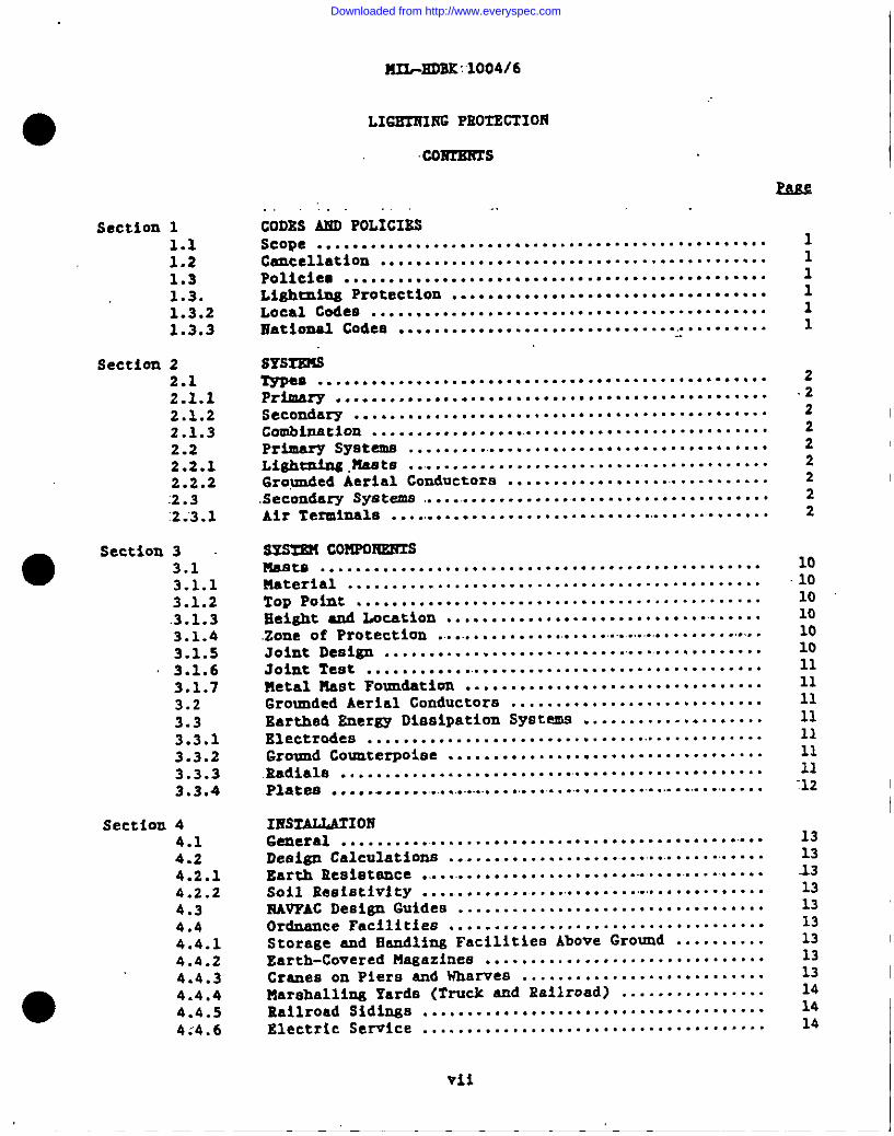
BLECT2UCAL Et?GIREBRIIfGCIUIESIA MANUALS
Preliminary Deeign Coaaiderationa
Power I)iatribntionSysteme
Svitzhgear and Relaying
Electrical Utilization Systeme
400-Hz Generation end DistributionSyeteme
Lightning Proteetiun
Wire COmmunicatlon and signalSyatema
Energy Monitoring mnd .ControlSystZma
Cathodic Protection (Proposed)
PA
CIDISDIV
PACDIV
CEESDIV
GEXSDIV
CESSDIV
CEESDIV
WSDIV
mmL
I
rams: Design manuals, when rwiaed, will be converted to military handbooke.
I
Thie headbook is .iseued to provide inmw=diateguidance to the user.However, it mey or may not conform to format requirements ofHIL-EOBK-1006/3 and will be corrected on the next update.
vi
Downloaded from http://www.everyspec.com
BS2L-EDSK:‘1OO4I6
●
Section 11.11.21.31.3.1.3.21.3.3
Section 22.12.1.12.1.22.1.32.22.2.12.2.2:2.3:2;3.1
Section 33.13.1.13.1.2.3.1.33.1.43.1.53.1.6
I 3.1.73.23.33.3.13.3.23.3.33.3.4
Section 44.14.24.2.14.2.24.34.44.4.14.4.24.4.34.4.44.4.54:’4.6
LIGEIH2NG PKOTSCTIOR
co2mKsTs
Fas2. ..’. . . .
CODES MD POLICIZSScope . . . . . . . . . . . . . . . . . . . . . . . . . . . . . . . . . . . . . . . . . . . . . . . . . .Cancellation ...........................................Policies ...............................................Lightning Protection ...................................Local Codes ............................................national Codee ............................................
SYSIXUSTppea ..................................................Primary ................................................Secondary ..............................................Commnat ion . . . . . . . . . . . . . . . . . .. . . . . . . . . . . . . . . . . . . . . . . . . . .
Primary Syateme .........................................LQihtnins.Ua.Ste ............................ ‘..........6roynded Aerial Conductors ...............................SecOndery Sy.9tem8............. ........................Air Tezminale .............................- .............
SYs= coMPoIwmrsmeets .................................................Material ..............................................TopPoint .............................................Beight and LOcation .....................................Zone of Protection ...........................................Joint DeBigII.................................... .....Joint Teat .............................................Metal Mast Foundation .................................6rounded Aerial Conductore ............................Earthed Znergy Dioaipat%on System ....................Electrodes .............................................Ground Counterpoise .....................................Radiala .................................................Platea ....................................................
IESTALLAIIORGeneral .................................................Design Calculations ....................................ItarthResistance .........................................soil Ih%9L9tivity....................................RAVPAC Deeisn Guides ..................................Ordnence Facilities ...................................Storese end ikndling Facilities Above Ground ..........Earth-Covered Magazines ...............................Creneson Piers end Wharves ...........................Marahallins Yarda (Truck end Railroad) ................Railroad Sidings ......................................Electric Service ......................................
111111
2.22222222
10101010101011111111111111-12
131313131313131313141414
vii
Downloaded from http://www.everyspec.com
?U.L-EDBK 1004/6
4.4.74.4.84.54.5.14.5.24.64.6.14.6.2.4.6.34.74.7.14.7.24.7.34.84.94.104.114.12
APPZJID2XA
APPENDIX B
1234567
KxteriorOverheed.Pipelines ...........................Fences . . . . . . . . . . . . . . . . . . . . . . . . . . . . . . . . . . . . . . . . . . . . . . . .Generating Plents .....................................surge .PrOtection . . . . . . . . . . . . . .. . . . . . . .. . . . . . . . . . . . . . .. . . .
Ground2ng ..................s.s.....i.i.ii.i. ................Qutdoor Substation or Switching Statione .............Air Term2neLa .........................................Grounded Aerh2 Conductors .............................Cround2ng .............................................Trenemiaaion and Dlat-rlbuthn Lines ...................Distribution Line Clearances ..........................Trenemission Line Clearances ..........................Cleerence Calculation .................................Flegpolea end Ghimneya .................’...............~owera arkd Antenna8 . . . . . . . . . . . . . . . . . . . . . . . . . . . . . . . . . . .
Aircraft end Aircraft Eengars ..........................Ordinery Buildings ....................................Obstruction L@hts ....................................
‘APPmDxc2s
Primary Lishtnins Protetiinn “for. 0~ EarIdling :
Facilities ................................ .............
International System of Units (S1) ConversionFactors ..............................................
PIGOESS
Primery .Li@tmins Protection @w+tmn ...~......’.............4.......Lishtnins Meat Ground Connection Detaila ........................Secondary Lightning Protection or Gruundins System ..............Bondins and Gronudiasof Railroad Track ..........................Concrete and Steel Ground Cmnectione for Secondary System ......~OtherGrounding .Details for :Secondary.System .........................‘Or.hrGrounding Details ......................................................
,.-
BIELIOGSAPEY ........ ............... ......................................
sH-ERsl?cEs ..............................................................
I!RsR ●14141414;,1515151515151515161616161616
17 ●37
3456789
40
41
0
viii
Downloaded from http://www.everyspec.com
~L-BDSK 1004/6
1.1 kllrle-necessary for the
Section,1: CODES MD POLICIES
Thie handbook preacnt~ data end coneideratione that areproper design of lightning protection ❑yatema.
1.2 ~. This handbook cancels end auperaedes fiAVPACCM-4.6,Protectti of December 1979.
Cathodic protection in DM-4.6 is to be covered in the proposed militaryhandbmok, KIL-EDBK-1004/10 .
1.3 . ‘fhepolicy of the xiavaiFacilities Engineering Command ieI to provide the most effective degree Of ligbtn.1.n8protection. ‘-
1.3.1 ~. Aeam.iuimm, for. 821 ordimary, am-ordnanceI facilities raquiring lightning protecthn, the requirements of Rational Fire
Protection Aaaociation (lG?PA)NPPA 7S, Prote.tlon CO* , should beI followed. The requirements of thla handbook muet be followed for ordnenca
facilities end thoee facilities wid.tinthe scope of HPPA 78. Ordnancefacilities, such aa magar.inee-end other structures, truck and railroadmarehalling yards, railroad sidinge, end Vharvea aud Piers *ere Or@=ce ~explosives are handled and stored, :shallbe providad vitb speci,elprotectivemeaaurea. Daaigm for these syate=ia&hall be in accord with criteria in thishandbook; DOD-STD-6055 .9, ivea ‘StafetvS~ d;HII.-EDBK+19 ,
~; ‘~d .IUvsm OP-5 , v~~. 1,~...”. . . . -. .-
1.3.’2 ~- Although the fed&el Gmverumant .ianot’ required toconform to local (cicy or district) building and electrical codes forinetellationa within Government ovnerehip lima, consideration should be givento local .etendardaend regulation whrirever practicable.
1.3.3 ~m. The RFPA end the Eationel Electrical ManufacturersI Aeaociation (l!B14A)have eatebliahed beaic min.imm atandarda of design end
installation practice including: NPPA 70,fWPA 70B, ~; AA 78; =d ~eric~ IT~~~~l
C*
Stendarde Institute (AfiSI)ANSI C2, lectrirnl Code. Theseatendards .ahell be complied with in all projects. .Approval of theIlnderwriters Laboratoryes Inc. should be considered for all electricd.meteriala,fittings, and appliance vhere ,poaaible. Refer to IJndervriters’Laboratory .(UL).DL’96, Pr tection0 GmP9R@a, ~ ‘96A,~
far ~ t~.
, and ‘TIL467, :tioundi_
1
, ..
Downloaded from http://www.everyspec.com
M2L-SDSK -1004/6
Section 2: SYSTEMS
2.1 Xxr!eS. Li@mning protection aysteme are either primary,”secondary,or a combination of primary end secondary.
2.1.1 Pxlmarx. Daaism prima= protection to prevemt damage fram directlightming strokes by diverting anY chargea from structures through a 10Vraaietamce path to earth.
2.1.2 . Design secondary protection to prevent metal parte ofbuildimgs, buildimg cemi=ts, or other typee of strmctnres frnm accumulatingelactric charges that cam cauee sparking or flashover. Sparkimg or f laahoverie likely to occur when metal objects are proximate. In the event of alightning diamharge, the potantial of Indepemdemtlw grounded metal ehjecta cam-e ~th resPeet to nearbY objects twmeratix flaehOver betvem the objects.
2.1.3 ~. The Installation of a primary end a eeconilaryprotection system for the aa!aestructure is not ah?eys reqni’red. A ‘eecondaryetatic ground ayetem providiti am intercomneetimn of,❑etallic mesmee vlthin ~abuildlrtgor on piers and wharvea may alao be required vith a,primary lfg.htmingprotectirm system. flhena structure is euuipped with both primary ~secondary xvystams, intercemmeet all :gronmde.
2.2 :~. Design protectloo baaed on 100 ift”(30.“5m)lightning strike arc. Design either primary or.sac-.. typa ..anddetetm.inemaat locatione or grounded aerial conductors and “theirheighte. ?laetlocntloma or Sreunded aarial ‘conductor and +eir :heighta.influ~e the tjTe
●of masts along with mast fomndatlon requirements end the location of theground coumte~iee. Primary protection shall c-ist of l~6h~~z@ ~sts orgrounded aerial conductors as described in paras. “2.2.1.- 2.2.2.
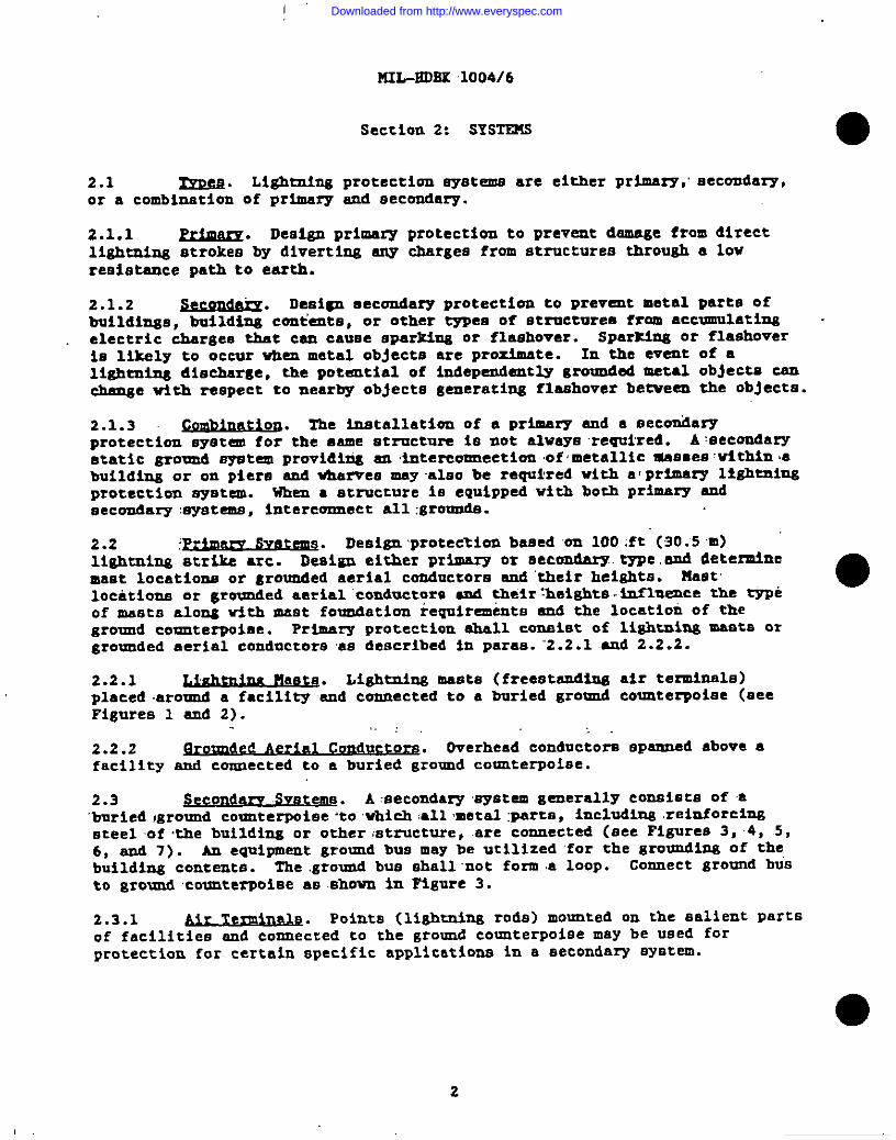
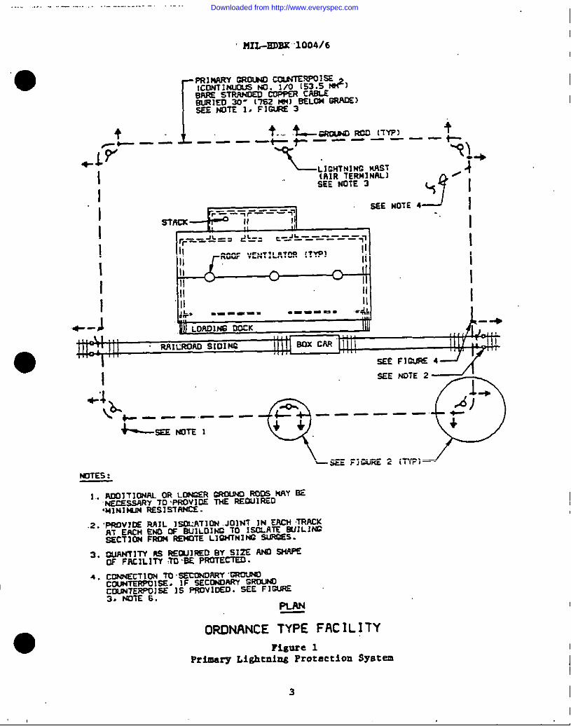
2.2.1 Lightming masta (freestaudimg air tensinels)placed .aromnd a facility and cennectad to e buried gro!md coumterpoiaa (aceFigures 1 and 2).
,., ,
2.2.2 ~. Overhead condnctora apem.nedabove afacility and connected to a buried ground counterpoise.
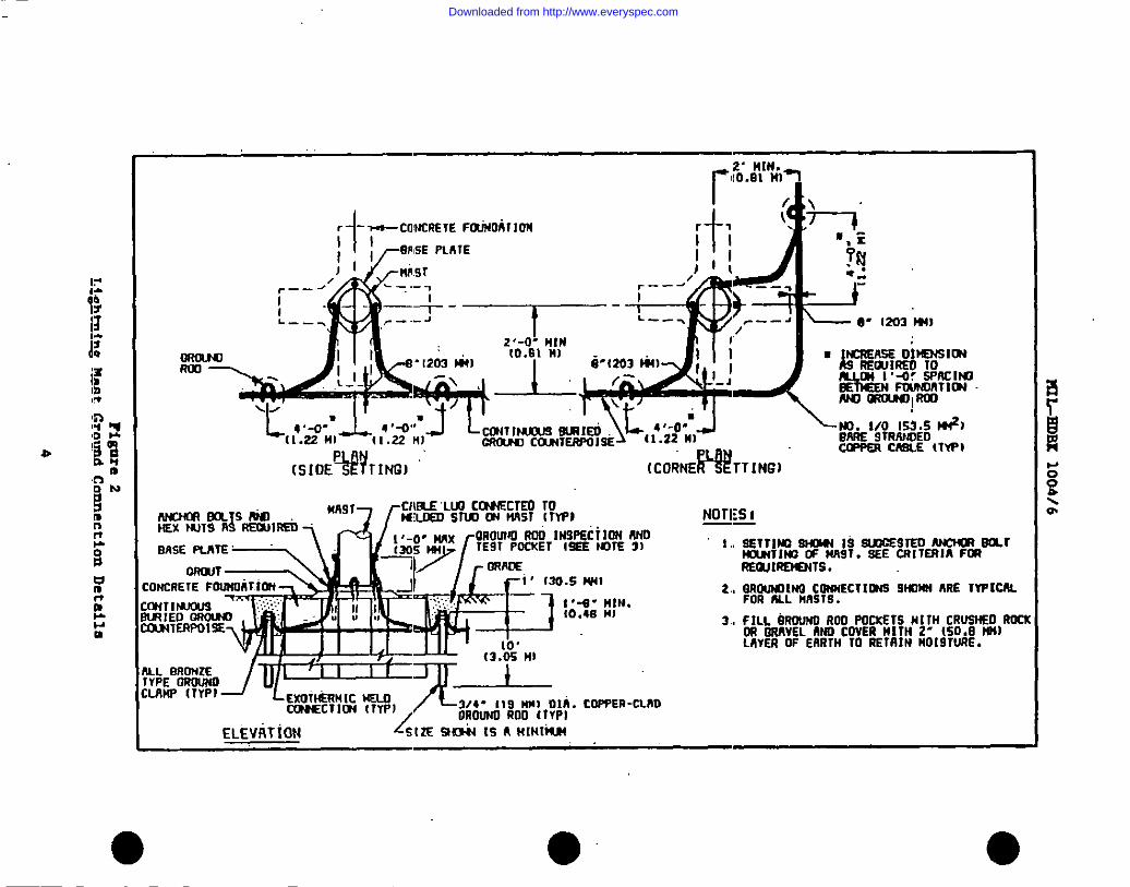
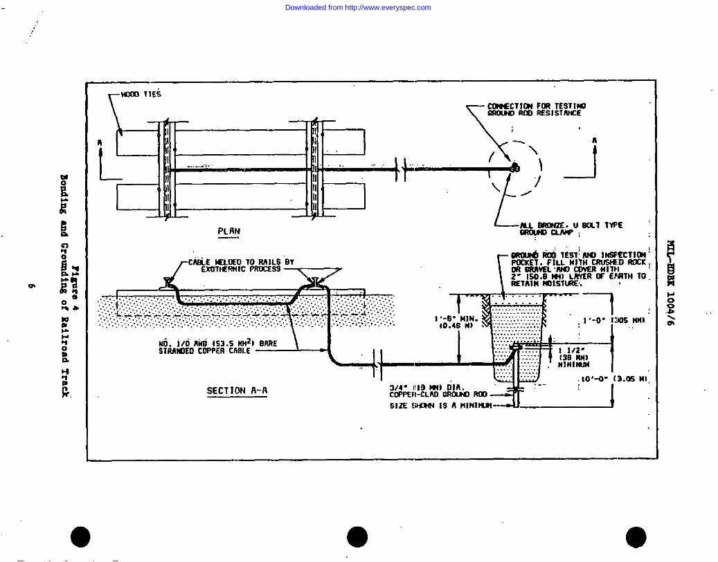
2.3 SecOnd- s~at~ e. A secondary wyatem gamerally consists of a‘buriedIground countewise ‘towhich :allmetal :perta, including .reinforcinssteel of the building or other mtructure, are connected (ace Figures 3, 4, .5,6, emd 7). AU Gquipmat ground bue ❑ay be utilized ‘forthe gr0@iM2 Of the,buildimg contents. The ground bus shall ‘not form a loop. Connect gromd busto ground counterpolee as sheum in Figure 3.
2.3.1 Air Term~. points (lightning rods) mounted On the salient Partsof facilities and connected to the ground counterpoise may be used forprotection for certain specific applications in a eecondary syatam.
2
Downloaded from http://www.everyspec.com
I -- ---- ----- . ---------- .-
~PIIL-EDBX1004/6
IFR114ARYORolNo cm.NT’s~l=lcmffl~ No. 1/0 [s3.5&lEwEmmgNoSD COPPERc-
- ITS?14M)SELOM~)SEE NOTE 1, FIWRS 3
f f.....~6Aow0 ROO [TT7J +.—— —+ j——— ———— t-
.~?- – –x
w+
IL1CHTt41NCMAST(AIRTERMINALI
g
.;
I
SEE NOTE 39
ISEE NOTE 4 I
II
rr----J&=‘ d‘—-=I
c-_+-_-----_--—71
III
II Roof vENTILATORITYPI
I
II III Il.
I
n nII w II I
II!! II I
-4
J
d!+= ‘-==-” “====-
LOAOlN600CK
wuuwm strnu
1
sEE FIOI.IFK4
+4
M3TES:
1. ~ITIM OR LtB=EACROUW ROOS NAY SE“N’E~Y TOWmvlcls THE AEOU]RED,MINIMM RESISTANCE.
.2.‘PROVID5AAIL IsCURTIONJOINT IN EACHTRACKAT EACH ENO OF BuILOINCTO ISOLATEMJILJNCsECTION= KNOTE LIBH_lNlffiW@SS.
3. WANTITY A3 REWIRED BY SIZE Awl 94WEOF FACILlm 70+3S PROTECTEO.
4. CONNECTIONTosscmoARY ‘molRQCOW4TERPOISE.IF s4XmARY GRUWQCOLIWEWOISE IS PROV1OED.SEE FII=J=3. NOTE 6.
PLAN
ORDNANCE TYPE FACILITY
?igure 1Primary Lightning Protection
3
syBtem
Downloaded from http://www.everyspec.com
HIL-EDBK
1004/6
.—-—
—.
..
.
A#W
.
_-T“- ,.-!
----—
—4.
\5
)‘(
●,sg
II‘p
;
IIL---
(p
=
i Ii?
—
?igure2
Li@tning
MuetGroundConnection
Details
4
Downloaded from http://www.everyspec.com
,.
...2.,---,
...
.................
...
......
......
...........
..
..
MILAEOBK’”1004/6
Zdz0aIL
.3,-—
—-
.
ryp+
rea
SecondaryL+lhtning
Protection
orGronndlnsSyBte.m
‘5
Downloaded from http://www.everyspec.com
MIL-8DBK
1004/6
II
?i~re
4Bonding
endGrouuding
ofRailroadTra*
6
Downloaded from http://www.everyspec.com
..... ,..-”. ,... -..- . -,------- ..- .-.. . . . . . .. .. . . . .. . . . . . .. . . . . ..- -. ..-, .- -
10”
I
I
Hl%EDEK:”10D4/6
-s’m. Calsu
“’-““Mxm4AYE W’ER!m cmu37rlm-I@. 1/0wals3.5 -) M S“mCw?ERm
‘IeAosE17HER=1S0 COL*COWECTlm NITH
%%% %#%%l%Tl#)OR ExOTIEPJIICNSLOcOW8SCTf~I!JYSE liSEOIN’LIEUOFCO?WECTIONlNOICSTSO. ELEVflTION
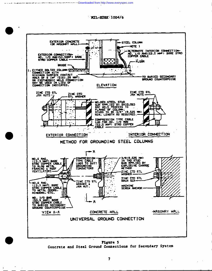
EXTERIOR CONNECTION “ ““ “ ‘ liJIERI& cohNEcTIOR
IIIETHOO FOR GROUNDING STEEL COLUMNS
‘VIEH R-R CONCRETE .UALL ‘W!SONRY WILL
UN] VERSAL CROUNO CONNECT 10N
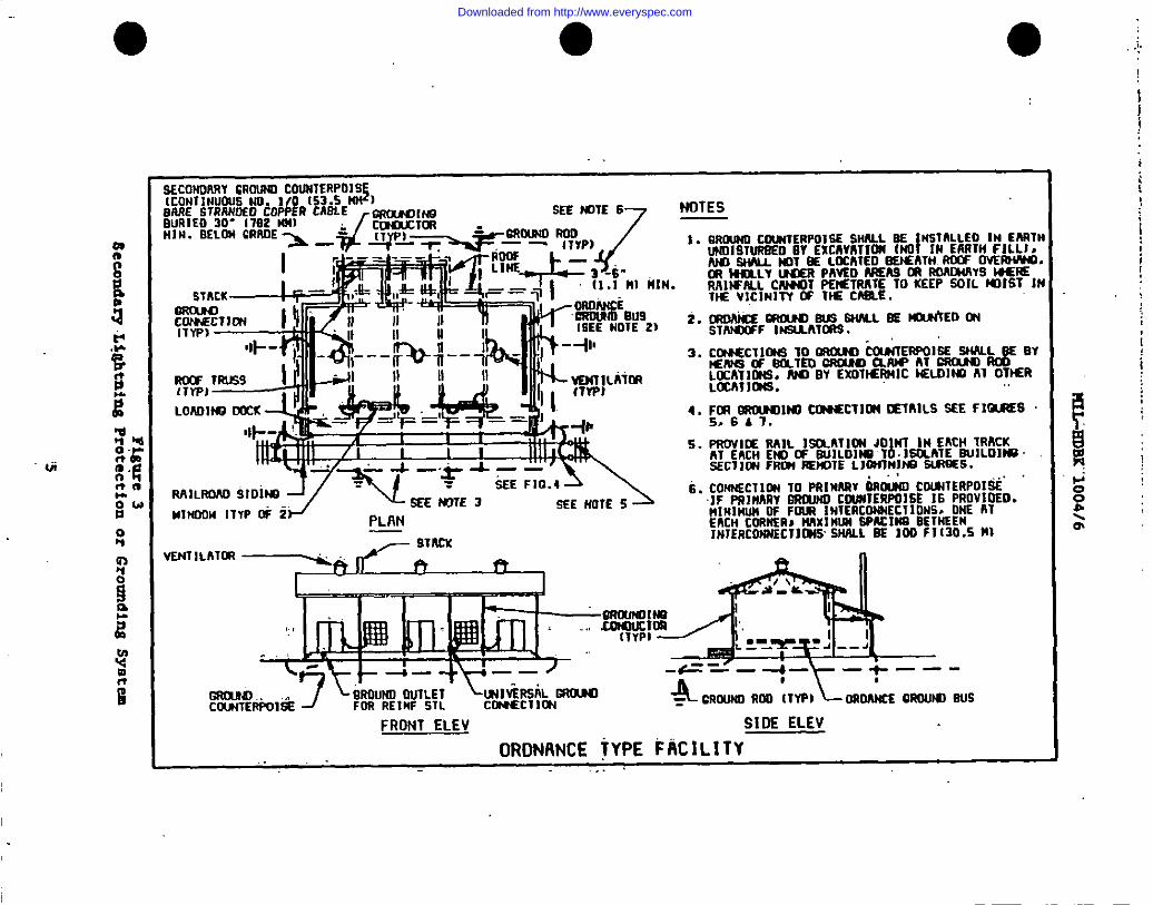
Figure 5Concrete nnd Steel Ground Connections for Secondary System
7
Downloaded from http://www.everyspec.com
HIL-EDK.1004/6
INoTE:
NC ALTERHA71VE FAST INC METHOD FORB~IN2 STWP WY SE W OF THEFOLLOHINC :
1. :E:~; *:N JAM wTS
2. SELF TAPPIHC SCRENS &FLAT MASH5RS... .
NATERIk 1 ZINC CORTEO STEEL.
TEEL 000S (OA SHUTTERI
OooA LEXIBLE Tlt0r2U COPPER SAA1O SO1501NSTRAP IAPPROX 1-125.4 m) H1OE./S-13 .1TS KN)THK. LIZTHs Am m)
\ HEx HO ZINC CTO STL SCR IN TAPPEOWE
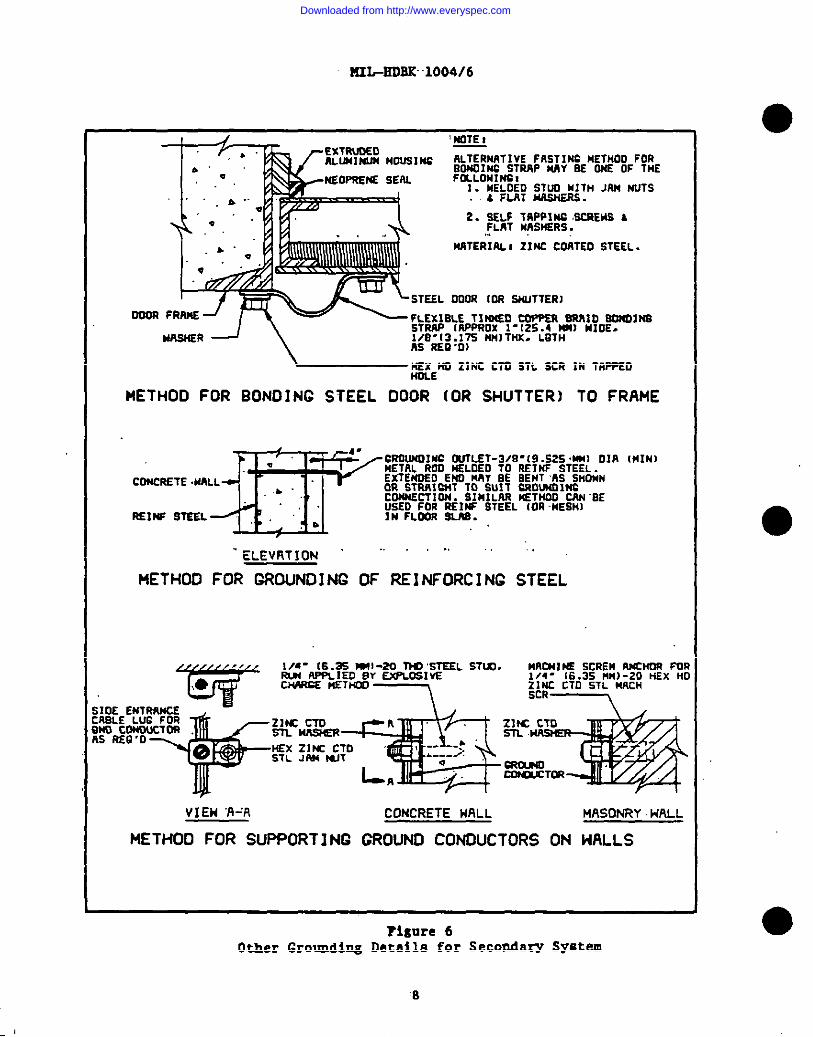
METHOD FOR BONOING STEEL DOOR (OR SHUTTER) TO FRAME
‘m4-
CROWOINC MLET-3/B-(9.S25.MW DIR IMIN)e“ NETAL ROO NELOEO TO REIHF STEEL.COWRETE .NALL ExTENOELY ENO MAY BE BENT AS SHWN
..&. OR STRWC14T 10 SW’S CROWOINCCONNECTION. SIMILAR NETNOO W-SE
,. :;E:LO! ~&ff STEEL (OR-MESH]R51WST22L “,b
,.
“ELEVRTION ““ “ “ ‘“”
METHOD FOR GRDuNOI NC OF REI NFORC I NC STEEL
MAC4tl )SS SCREM A?4CNOA PO1/4- [6.3S MM)-ZO liEx HI
i~8+;g;;:& Z,X,TD,,LMKH
VIEH ‘I%% CONCRETE MALL MASONRY HALL
NETHOD FOR SUPPORT I NC CROWD CONDUCTORS ON HALLS
?ignre 6Other Grounding Details for Secondary System
●
8
Downloaded from http://www.everyspec.com
, . . . .... . .. ..... .... ... 4 ... .. . .. ...,....,4.? . . . . .. . . . . t ..A..4 . . . . . . . . . . . ,. . . . . . . . . . . . ., . . . ..-— — . . . . .
PIItiIiOBK1004/6
3- [76 1wIN
TO =lWHIW S- ATTLPF#mmrrm.mCQccauu
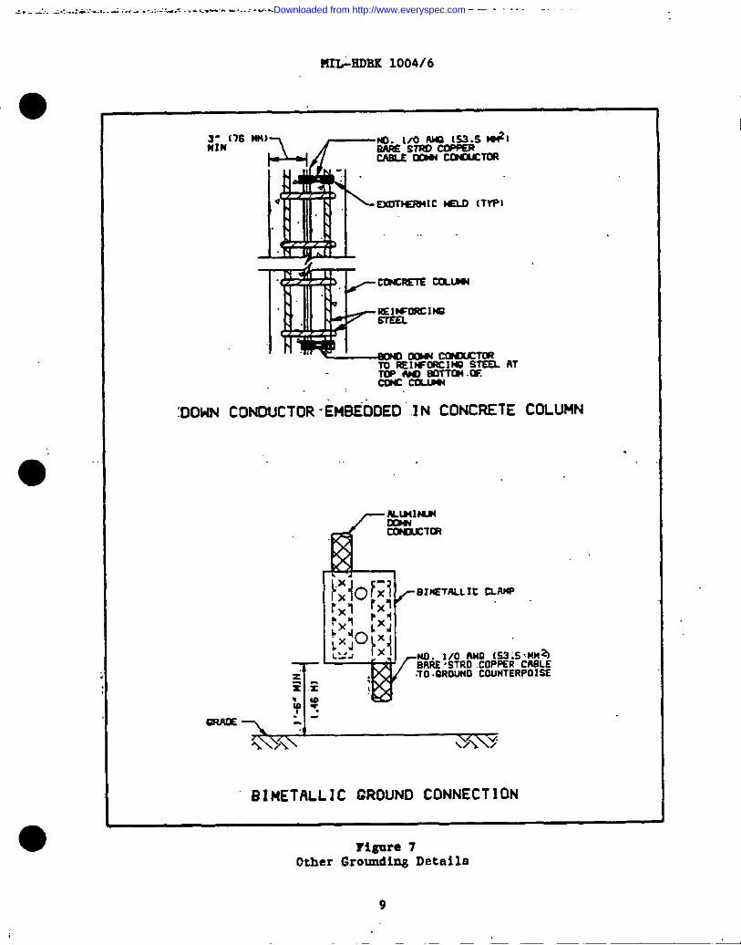
:DOldN CONDUCTOR “EMBEODED IN CONCRETE COLUMN
-.GRPIE\ --
%3+ / v\’/\ /“
BIMETALLIC GROUND CONNECT ION
Tlgure 7Other GrotaulingDetails
9
Downloaded from http://www.everyspec.com
?UL-HDBK 10,04/6
Section 3: SYSTSM coKPof&NTs ●3.1 w. Lizhtnins -Eta shall be tapered metal, self-supportingtype, (single section deeign or multisection design) with slip joints, asdictated by total heisht of maat. The croaa-section shell be circular orpolygonal, symmetrical about the longitudinal ex.la,end uniform inconfiguration throughout the entire lamgti. Wood maeta may be used only whenheights end structural strength permit and shall be electrical pole lineembedded type, topped with a lightning rod or metal ca CWI with tWCIbare
!copper ground wirea not lass than l?o.1/0 AUS .(5S.S mm ), run down each sideof the pole to the ground ayatem. The ground wires shall have a protectivemoldi~ axtandi~ from grade leval to a petit at la-t 10 ft (3.05 ~) abovegrade.
3.1.1 ~. PIetalmaterial shall ba corrosion-resintant ateel,noncorroaion-resiatant ateel with hot-dipped galvanized finieh, or almainumfor single section or multiple eection meets vitb anchor bolt mounting. HOcombination of materiala shall be used that form en electrolytic couple which,in the preeamce of moieture, ceases ●ccelerated corrosion.
3.1.2 14eettop shell be.fitted”with a copper or bronze airterminal or metal cap to take the lightning stroke. The point shall beincluded in the determined overall height of the mast.
3.1.3 end Loeati~ . SZefarto Appendix A for determination of maatheight and for location aa related to atrocture being protected. Masts of ●heights up to 40 ft (12.2 m) shall be of single section design. Masta .4o to
70 ft (12:2 to 21.34 m) in height should be single-section design if deliveryto the site ia practical. Design for meats in excees of 150 ft (45 m) receivespecial conaideretion.
3.1.4 he of Prot~. A [email protected] maet eystem establishes azone-of-protection. me zone-of-protection la described by an arc having eradiua not greater than 100 ft (3O.5 m). To prevent sideflashes, eech mastshall be separated from the etrocture by not lees than one-half of the heightof the .aaeumed salient plane, bot never leas than 6 ft (2 m). The maximumdiatence from the structure shall be 25 ft (7.6 m).
3.1.5 ~. Slip-joint design aball meet the follmwing,requirements:
a) Assure overall atructural integrity of the mast.
b) Include field eesembly requirement to eeaure la snug fit, eo !thatjoints .of the mast will not loosen when subjected to vibrational .modea causedby wind or other meana after erection.
C) Be compatible with field erection requirements to assure ●ase ofinstallation at the site.
d) Have good metal-to-metal contact, ao that electricalconductivity will be equal to or better then the parent metal used. ●
10
Downloaded from http://www.everyspec.com
a
1
“.U2L-KOBX .1004/6
3.1.6 ~. After eeaembly, each joimt shall be tested at the citemmd ehall .be meeeured by c digital ohmeter. vitk a ,0.014hm resolution .emd amaccuracy of 5 percamt of the reading, plus one digit. Zeeta shell .comeistofcomparative meaaurememta 8Cr0B8 sllp joints, with equal epacing of meterprobes at least 4 ft (1.22 m) apart. & acceptable joint is one yielding a.mesauramemt, easel te ,er-lees them -admilu. .—asur ement.of-the .parumt meti .ima given aactien of the mast, with the name spacl.msof the meter probes. 2heloveatmeter range providing an Indication la the scale rcgimn of greatest
.cccure~ should be mead. If the meter reads zero or infinity, am incorrectscale bee bees cbesen or the meter 1s brokem.
3.1.7 ~ Mast Fo~. Foundations for setting metal masta shall bein ●ccordemce with the following:
a) Steel or e3uminum, mouoted by enthor bolts aet in a cencretefoundation poured im place. Follow memfectnrer *a recommendatimna forfotmuiatlondesign emd type emd for setting of emthor bolts.
b) Steel, mounted by means of a stub eet directly into a cencretefotmdatioa. Corrosion-resletent steeI masts meY be set directly into earthwhere .aoilcomditiom permit.
3.2 Overheed conductors sheU ,be.epenmad.betveenmasts emd ‘conmected to .a grouod comnterpolae to euit :thetype ofinstallation. (Refer :to:Appendlz.A.)
3.3
3.3.1 ~. Pfedeelectrodes, ,ae defined in the ITEC,ehall cemaiatof ground rods not .lesathen 3/4 in. (19 mm) diameter end 10 ft (3.05m)long. :Ground rods ;ebnllbe copper clad steel ,or solid .cOPper. .Connectionatoground rode shall be made by bolted clamp type devices.
3.3.2 mound Count~. .Ilachground counte~oiae ehell consist of al!o.1/0 AWG (53.5 mm2) bare copper ceble completely surrounding thefecility, with ita ends crmmected together to form a closed loop. “The size ofany strand of the table shell be not lees then No. 17 .AWG (1.04 mm2). Thecounterpoise shall be buried at least 30 in. (762 mm) below grade, external tothe structure -andaway from structural ,fotmdationa or foacingB (see Figures 1aid 3).. .Xaehcounterpoise ~ahell be fixed IV drivam grotmulrods. .Comnectionmt each igroumdrod ,ehdl :be#madew.ith * “boltedclamp ‘typedevice :to‘facilitate~discommection of the fceumterpoiae from ,.the,grmundrod :for periedic :testims.
.3.3.3 ~. 2edial eyateme ehell consist of “Ho. 1/0 AWG (53.’Smm2)bare copper cablee arranged In a mar ,pattem with the structure *et,the,center. The size .ofany strand :shellbe not leas rham IVo.17 AWG(1.04 mm?). The radiala ehall be buried et leaat 30 in. (762 mm) belowgrade, external to the strmcture. Eatb redial shall be fixed by ground rods.Connection at each ground rod shall be made with a bolted device to facilitatediaconuection of the redials from the ground rods for periodic testing.Quantity ad length of radiala shell be ●a required to provide the requiredground resistance. Refer to IKE2 142, ~tice for Gr UOSUII&0
Pove~, for resistance calculations.
11
Downloaded from http://www.everyspec.com
I 3.3.4 -.c08t of achieving
IUL-EDBK 1004/6
The uee of plate e.leetrodee1s discouraged due to the highproper grounding effects with this system.
. . .. . . .
12
Downloaded from http://www.everyspec.com
?UL-BDBK 1004/6
Sectien 4: IIfSZALLAZIOIi
4.1 &zuzxdl. Lishtnix PrOtectiOn eyste.mashall be provided ineccordeneewith.this menual. . . ..
4.2 ~. Design calctiation.eshe21 consider earthresistance end shell be based upon the soil resietivity for the specificlocation. Computer programs are available end should be used wheneverpossible. Project design criteria ahsll include namee of approved computerprogrema for use in design.
4.2.1 ~. Heximm ground reaiatence for q lightningprotection eystemehould mt exceed 10 ohms. In high resistemce coils or rockformation, it may be neceanary to provide ground cotmterpoisea or artificialgrounds or to sink ground wells. After installation, eaeh syst- shall betested by the simgle, direct reading instrummt method. Where cheracterieticsare unltnovn,triel grounds should be installed end periodically tested duringthe couree of at leaat 1 year to include eeamnal variation. Refer topara. 4.5.2 for approved grouodi.ng.methods.
4.2.2 ~. Project criteria will eet forth the specific 8011reaiativity value.eto be used ‘forgrounding ,ayatem design.
4.3 ~. For specific criteria and sample layouts for.9yetema,refer to NAVS2AOP-5, Vol. I, and Appendix A of this handbook.
4.4. ~. Ordnance facllitiea shall be protected inaccordance with the folloving criteria: DOO-STD-6055.9; ?UL-BDBK-419; fLtVS2A0PU5, vol. I; HPPA 78; end Appendix,A of ‘thiehandbook.,
4.4.1 eB Above rround. Provide a primaryprotection system consisting of lightning meste or overhead cenductora spacedaround the facility. Connect the masts end all metalwork in the vicinity,such as railroad tracks, metal eheathe of underground tablea, and metal piping
end conduits below ground that do not extend into the building or otheretrocture being protected, to the :primeryground counterpoise. All reilroad‘tracks:tbat!extendinto the building or structure shall also be grounded at aminimum of :10‘ft (3.05 m) .frem~thebuilding or structure.
4.4.2 j~-Covered ~ . “Provide:asecondary [pro,tectimnX!3Wtem.Where ,ametal ventilator provides a salient point above the etrncture, :monnt apointed .llghtningrod on the ventilator and connect it to the secondary groundcounterpoise. A pointed lightning rod should .alao be mounted on the concretepertal wall ,end connected to the secondary ground cosnterpoiae. “Bond togetherreinforcing steel by wrepping it with wire end connecting it to the eecondaryground counterpoise.
4.4.3 ~. Provide e primary protection systemconsisting of overhead conductors spanned between structural eupports andconnected to ground rods or to metal plates eubmersed In water.
13
1
Downloaded from http://www.everyspec.com
MIL-EDBK 1004/6
4.4.4 “~. prOvide a Primryprotection aystam coneiating of,ovarhaad conductors spanned batwean structural ●supports and conmected to ● primsry ground counterpoise. Ground all matalparts and reinforcing steel of above grade structure to tie groticonnterpolee. The reinforcing steel of preceet cencrete slabs ahonld begrounded, but where inacceezible vitbln the slsbs, .it.is.permieaible.to amitsuch grounding. Ground railroed trecke 10 ft (3.05 m) or more outside ofbarriers et entrances and ezite to the yerd and .vhere they croes ecounterpoise (see Figure 1).
4.4.5 ~. Provide a primary protection aystea cana~ting ofoverhaad conductors spanned betwean structural supperts and connected toground rods. Ground ali metal parts amd reinforcing steel of above-groundatrocture to driven ground reda. Ground all railroad tracka to ground retilocated 10 ft (3.05 m) or more outside of the entrance to barrier.
4.4.6 ~~i. Elactric end comasunicationservices to explosivesoperating buildings and magezines shell be run underground in meta21ic conduit
~
for the lest 50 ft (15 m). Semricea to buildinge mot containing explosivesmay be ovarhead. Tha line side of tha maim protective dsvice sbdl beDrovided with euitable surze arrestere. Surttearresters shall be located at‘tieservice transition to ~darground condui~”outside the 50 ft (15 m) limit.A separate gronud .-11 be provided at tbe aacmdary electric serviceentrance. “Thieground shall be “bondad to the facility ~ground counterpoise.“Theelectric supply to au .exploslvaa.aree shall be arranged :eo that it can ,beCut off by t3witchin&devicee located at one or more contr,elpolnta outaide ofand immediately adjacent to the exploaivee areas.
4.4.7 ~. llond overhead pipes whlcb enter abuilding, ,storaga facility, or area to all matal objacu that are withinsideflash clearemce of the pipee where they are in a zone of .lightnimgprotection. Pipe aegmente shall be electrically continuous.
4.4.8 ~. Fences *11 be grounded on each side of avery gate, atpoints 150 ft (45 m) on each side of high-tension line crossings, end at150 ft (45 m) intarvala along the fenca .~ere high-tension lines (am definedlw ANSI ‘C2) are directly ovarhaad .emd run ~arallel to the femce. Femces shallb_egrounded every 1,000-ft to 1,500 ft (30~ m to 45o m) of length when fencesare In ieolated placee and at leseer distances depending upon proximity offence to public roads, highwaye, and buildinge. The .groti shell be made witha bolted connection at a f enca peat by the uae of Ho. :2/0:AWC (67.4 mmz )copper cable. Jthera:plaeticcoated fabric is used, the post shall be bolted,emd aacb atrend of the fence shell be brazed to the metallic bare conductors.The conductors shall then be grounded.
4.5, ~. Commercial type, metal-oxide, surge .arrasterashell be provided on all overhend faeders adjecant to a plant as described inpares. 4.5.1 and 4.S.2.
4.5.1 Surxe Prot*ctin. Surge protection shall be provided between theaerial surge arresters and generator or on a bus for several generators.Where a generator ia coomected to an ovarhead line through a transfonaer,provide a station type surge arreater on the high voltage aide of the ●transformer.
14
Downloaded from http://www.everyspec.com
a
I
o
.
H2LJHDSK 1004/6
“4.5.2 ~. Provide protection for smokestacks as described inpara. 4,8, amd ground all steel columne, beams, troasea, and equipment fremasat their levest points to a lov reeietance atatien gmumdimg sYstam.
4.6 @tdo r Subs.tatione or SIi~.o All overhead feedersshall be previdad -vitlteurge arreeters at the atatioa which-aball-ba connectedto their own ground rod system. The gronnd rod system shall be connectedbalow grade to the station ground met. Itefarto I= 80, ~~, ~ I= 81, - for N as~ar~ Reaisti i*.e v
Additiona3protection shell be ae described in paraa. 4.6.1 through 4.6.3.
4.6.1ligbtnlng
strnctnreequi~enteyBtam.
4.6.2urevalent.
~. On $Letribution metal station structures, providerods at each corner af the station, extending rode above theend the electric condnctore. Cenmect the atructnre end ●llframea, trenafo=era, tanks, and baaea to a lW resistance gromnding
~. In areae where lightning storme areinstall overhead ground conductors above the transmission end
~iatribut~on ayatam coaducto=e to form a gromid wire .netverk over dlstributfen.etatlons. Extend the overhead .grotmdwires out over transmission lines ‘for aminimma of .1/2mile (O.8 km). Aerial groond wires aball be grounded at :the.statian&nd at each ,pele.
4.6.3 QQMWU.U. Provide a ground system of HO. 2/0 AWG (67.4 moiz)copper cable, welded to the columns amd ●quipment fremes and connected to aground system. Provide ‘aground mat for wtacions supplying distribution
Ivoltagee and a cbunterpolse for substations supplying utilization Voltases.A ,groumd mat ehall consist of ,a.eystem of -bare conductors located on or belowgrade throughout. the station end connected .to:a counterpoise to :provideprotection ‘frem dangerous touch voltagem.
4.7 ~. “overhead aerial lines sM1 beprovided with lightning protection coordinated with NFGS-16302 and inaccordance with standard utility practice at the project location. Acceptableshieldhg rcsults when e perpendicular line from grade to the gro=d wire andwhen .slime from the ground wire to tha cenductor protected do not result in~ -le greater than 30-. Overhead ground wires may be steel, copper,{aluminum, or copper clad steel, with sizes dependent u on mechanical
%requirements :butnot smaller than *Ro..1/0,AWG,(S3.-5am ) copper-equivalent.Ground the overhead ground wiree ,et each pole. .Where an overhead :electrictrenemisaion and distribution line transitions to mulerground, the undergroundcable aball be provided with lightning .protectien.
4..7.1 ~. The towers or poles .eupportingdistribution linee operating at lees than 69 kV, and unmanned electriceubstatione operating at less than 69 kV, shall not be closer to ordnancefacilities than public traffic route dietences ae defined in DOD-STO-6055 .9.
4,7.2 ~. For tranamiasion lines operating at69 kV and above, end for electric subatetiona operating at 69 kV end abovevhich ere part of a eystem nerving a substantial off baae area, both thetowers or poles supporting the lines end the ststione shall not be closer to
15
,,.
Downloaded from http://www.everyspec.com
HIL+D~ 1004/6
ordnance facilities than inhabited building dlstanc&, as deflned inDO>STD-6055 .9. When failure of the ltiea end statione will not cauae serious ●hardabips, both the towers or poles supporting the linen end the .StatiOM meYbe located at public traffic route distancea.
.4.7,.3... .~. _.Line cleer~c? diatoncc.calcula!l.ona,shall.be baaed OB airblqat over praasure -Y: Fragm~t ,$iatences,-,vill~t be used.. . .
I 4.8.. ..
~. Provide gr&ndimg at the baaea Of metalchimneys or flagpoles at the loveat ,pointsin accordance with l’fPPA78.Provide protecting for other ~imrm.ya and flagpolea in accordance vitb NPPA 78.
I4.9 ~. Provide grounding at the basea of”metallictowers or at the lowest points in ●eeord&ee with EPPA 78. At leant twocolumea ehotid be connected to en adequate grmuud by Ho. 2/0 AV6 (67.4, ,~)copper cable. Provide the eeme grounding for metellic watcld.enweillemcetowar stmcturea. Stmccures adjscent to metallic towera and vithin theirzene of protection do not require prlmerg protection, but all metal frames,ventilatara, doors, end window frames shell be bonded together end adequatelygrounded. Provide antenna lead-inn with .aparkgap protection connected toground ad~scent to supporting structure of ant ennea.
4.10 ~. provide aircraft ~ aircrafthangara in .eccordence with HPPA “78. Grounding receptacles ehell be located inaccordance with DM-21.1, ~, end DX-21.9, .91sid
~. ... .. . . .. . . . . .. .. .
4.11 ~. “Prw~de protection in taccordemcewith RPPA 78.e
Eealth care facllitiea are included under ordinary buildings, exceptprotection for flammable llquida and genes 8hall apply .as appropriate. Whereair terminals are located on flat reofa, either neer .mecbanical equipment orin .areae traveraed by maintenance perammel, epecial coneideratiem mnat .begiven to preventing injury from tripping over air terminal pointa, .Bucb eninstalling lomger or elevated air terminala.
4.12 ~. Provide ●ir,.terminele 1 ft (O.3048 m) above thetop of the obstruction lights. Provide surge arrestors connected to thelighting circuit conductors and bonded to the lightni~ protection eyotem.
16
Downloaded from http://www.everyspec.com
I ,---------------- -----------
0- IIIE-BDBK:1004/6
APPEIUUX A,.
PX& LX&&R6 PR&BiTIOIl &OEDRUW2B BANDLIffiFACILIIIH
1. S&QE3. me followiw d-ie Metiod will Provide adewwe wh-vlightning protection for ordnance hendlins bm.ilditw via vertical ~sta, Or.overhead aerial wirins, in the vicinity of the buildins to be protected. Thismethod cam ●lso be used to pro?ide protection for a group of C1OSC2Yassociated structures or complexes.
2. ~. Xxperimemt8 have indicated that under certain asmmed teatconditioma, a vertical conductor will generally divert to itself directlightning stri.keewhich might otherviee fe21 within a cone mhepe or wedgeshape space zone-of-protection epaee in vhicb the apex ia the top ef thevertical moat, or the overhead horizontal ground viring of the wedge. In thiscase, the baae is approximete2y two timee the height of the meat or theoverhead horizontal ground cable.
2.1 ~. 2’helightning protection syate=employed herein is baaed on the zene-ef-protection me determined by clearancearcs end a 100 ft (30.5 m) lightning striking distance. All meote endoverhead ground wirinq that is ueed for the protection of a strncture met .be:adequetaly.groumdad. If the structure being :protected is of metal, groundingmnet alen be bonded *o- the structure. Xhe ground reelstemce .ahou2d not beover 10 ohms. A emffieient number of masts or overhead groumd wires. must beused eo that the entire etructure is eOvered by their z~=f-PrOtectfW..
3. ~. 2he f ollowimg criteria ,epply to pr~ry.lishtningprotection: ,“
●) Baaic requirement are en adequate deeign for lightningprotection end ecanamlcal cost of the eyatem provided.
b) All three dimeneiene. the leocth. the width. ,end the heieht, Ofa structure”to be protected ~ a P&wu_Y llhrnlns proteckm .w=tam a~e ifmajor importance in determining the haight, number, ad location of the =etsor the overbead aerial wiring which trill”be used to protect the r$trmcrure.
<c) The zepac”ingof the masts ,alongthe Mngth ,of!themtiucture ,shallbe -a.minlmom :of.1-1/2 times the height ,of the masts and .amaximum of ’200 ft(61 m).
d) The .distence ‘C.” of the meats from the structure shell beone-half the height of -the asaumed saliant plame (S/2) bmt-,.net?erless them6 ft (1.8 m) Or’more than 25 ft (7.6 m). In ceeea where a minor readjustmentmay be necessary to accommodate road clearence, en exceptian shell not grosslywceed the limits.
17
Downloaded from http://www.everyspec.com
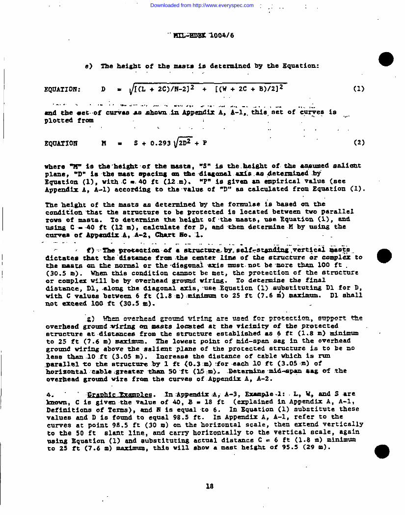
e) TIM height of the meats is determined by the Equation: ●,. ,.,
EQllATIOff: D= [(L + 2C)/l?-2]2 + [(W + 2C + 8)/2]2 (1)
.-, . . ., .;! t... . ... ,.. , ..-, .. . . .. . . . ., . . . ,“. -., -. ,., , .,. .,., ,:.
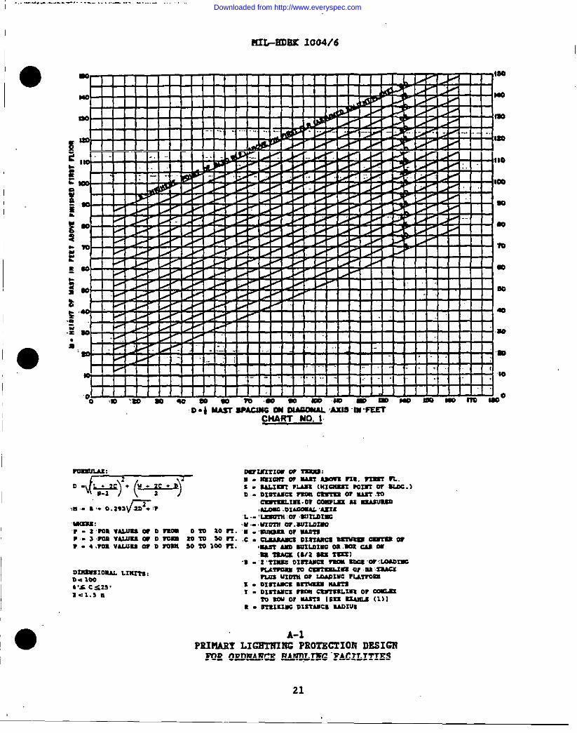
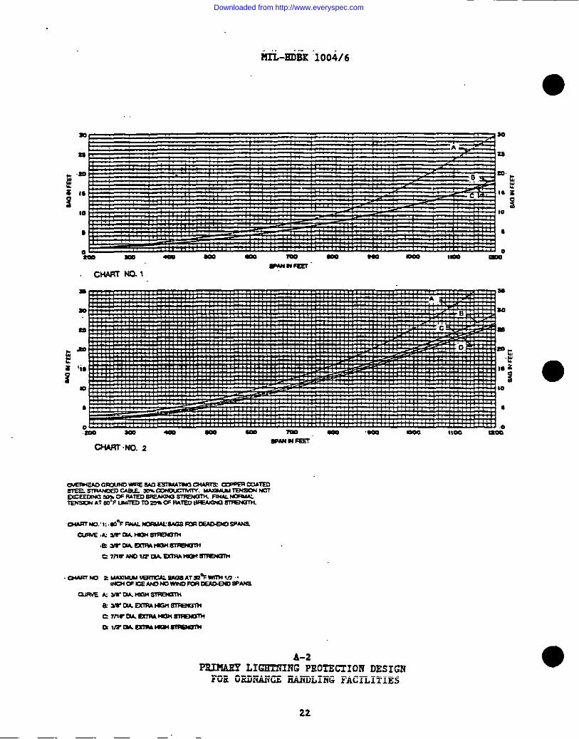
ad the .etof CUI+SS a ahOWM l= APPem$lx & A-1,. ~s. set of c?qe? IS .-.plotted from
,, . . . . . . . . ,.,
EQuAZIOfi n= S + 0.293@+P (2)
where ‘W’ ie the’heightof the masts, ‘S” 5.sthe.~isht of the as#umed sa.liemt~1==, -~. ia ~ Wst spacAms en ~e diqona2 aXIS.- dete~ -~’
IIquetiem (l), wkh C =.40 ft (12 m). ‘P” is givem an empirical va2ue (aceApPamdk A, A-1) according to the value of ‘D” se cekulated from Eqmation (1).
The height of the masts as determined by the formulae 1s baaed en thecomditien ‘thatthe structure to be protected 1s located between two parallelrowa of maata. To determine the heigh% of the -te. USI! Equat50n (1), =dmeinizC = 40 ft (2.2 m), ealcm.hte for D, and them determine M by usimg thecorm! of APPti .A. A-2* Chart He. :1.
.-. . . . . . . ,., .-., .,. ..,,- -: f) -:zhe&eeetlam.0S A atrsemrer by.edf+tbadni-,+irticti es$p,.
--------
&ictatea that the “d.ietamee from the c~ter line of the structure or compla tothe .MAste em the mormal or the ,diegemalmatiemat. not bemare tbam 100 ft
●(30.5 m). When tb.lscondition cemumt be met, the protection of the strnctureor complex till be by overhead grawmd wirimg. ro dete~e the finddistance, Dl, .aloogtha diagonal axis, use Equation (1) .sybstitutingD1 for D,with C values between 6 ft (1.8 m) mimimm to 25 ft (7.6 m) maximum. D1 shallmet exceed 100 ft (30. S sO.
“g) Whereoverhead ground wiring are need for protection, support theoverhead grouod .xriringam meets located at the vicimizy of the protectedetruature at .distsncae from the strocture eetabliahed as 6 ft (1.8 m)to 25 ft (7.6 m) maximum.
dnim’um2he loweet point of mid-span aag in the overhead
ground wiring above the sali!rotplane of the protected structure is to be noIesa than .10.ft (3.05 m). Increase the distamce of cable which is run.parallcl to the structore by 1 ft (0.3:m):for.easb10 ft (3.05 m) ofherizamtal .ceble greater them 50 f t (25 :m). .Mtati ~-EJW SSK ~ theoverhead groumd wire from the curves of .AppandixA, A-2.
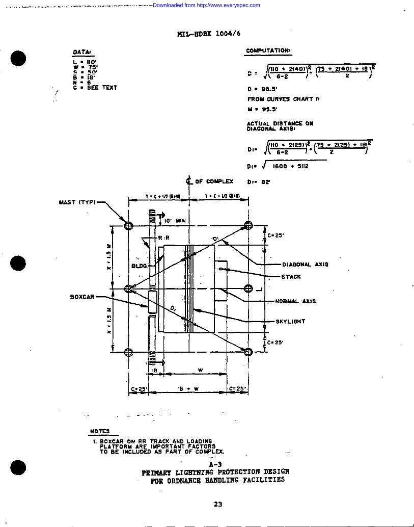
4. ‘~ . .lnAppandix :AiA-3, ~e .1: L, ~ amd S are~, C ie given the value of 40, S - 18 ft (explained in Append- A, A-1,Definltione of Term), smd H ie ●qual to 6. In Equation (1) substitute thesevalues and D is found to equal 98.5 ft. In Appendix A, A-1, refer to thecurvee at point 98.5 ft (30 m) on the hOrizOntal scale, th~ =t~d vertical~Yto the 50 ft slant line, emd carry horizontally to the vertical scale, againmaims Bquatian (1) and Subetitutlng actual distamce C . 6 ft (1.8 m) mimiunssto 25 ft (7.6 m) meximum, thie will chow a maat height of 95.5 (29 m).
o
18
Downloaded from http://www.everyspec.com
.. . . . . . . . . . . .. .
~ “-”””””
● IrI●ccordance with PU6. 3, Appti A, determine actue2 D1 distance from thecenter-l- of the;Ltuildinaor complam to row of manta au the diagonal axis.With C =’2S ft, D 16 equal to82 ft.’. .,
After the height end location of the mesta have been determined,Vrocead U follm:... ... .. ........ ..... ..“.’.,,.. .’,:.,, .:. _.:.:.: .-.:.-.:;. ..:
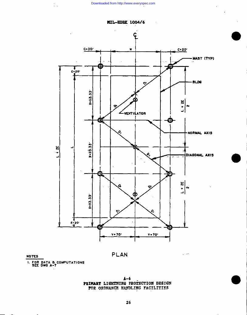
●) Draw a plan of the building to scale. .Locate the masts atdistcucee which ara detenained by the method shown in APPaudis A, A-9,=ple 1, Figwe 1. ~ . .. .. . .
,.
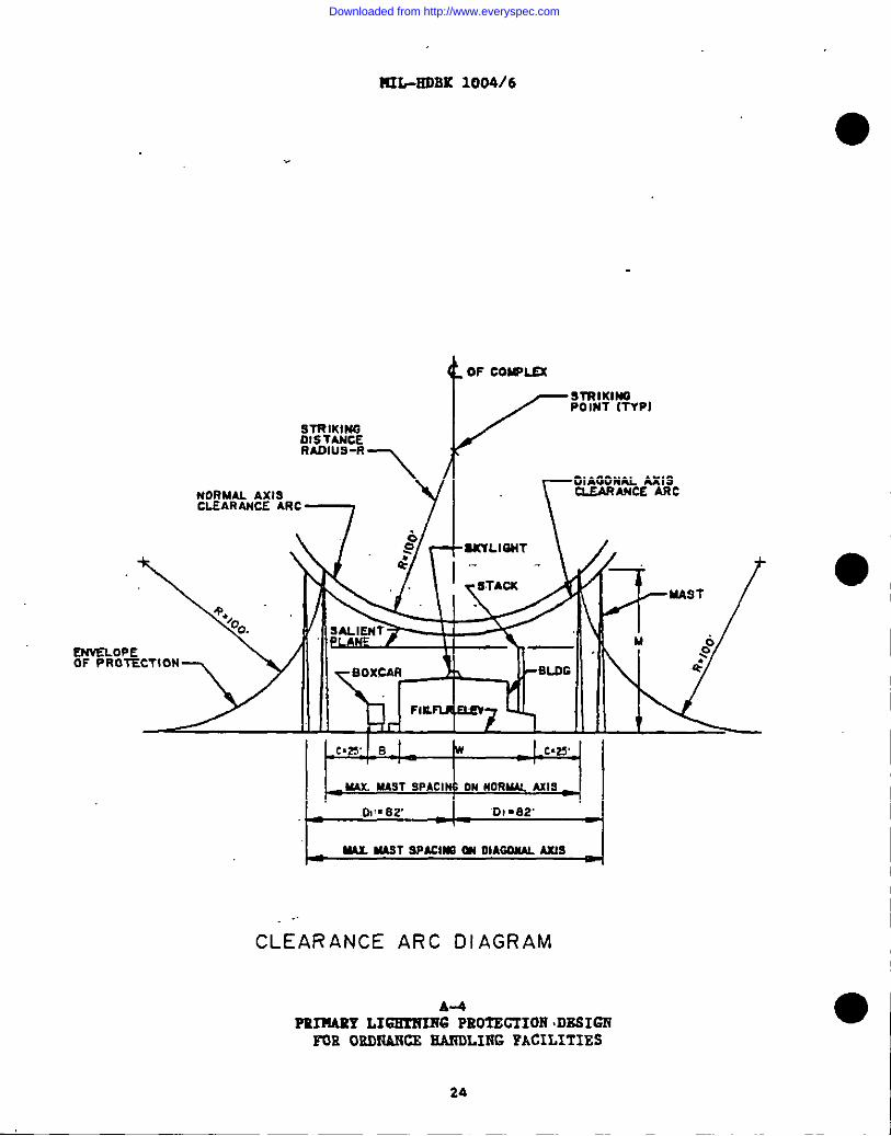
b) Draw an elevation of the building to scale. Locate the mamta atdiatencas which ●re datarminad by the method ehOWM h APPEC@fi A. A-3. Draw a100 ft striking distance radium from the apem of the meats to the cemtar-lineof the building or complex as ahewn. Draw two arcs (the nonaal emia end thediegona3 uie clearenca arcs) MM ehown in Appendix A, A4, from the point ofintersection with the center-line of the building. These arcs must clear thesalimm plane.
I
I
II
1.
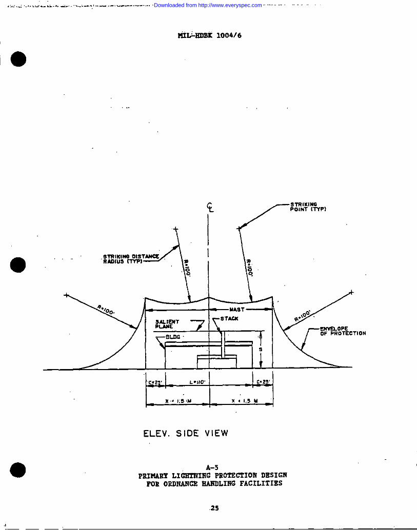
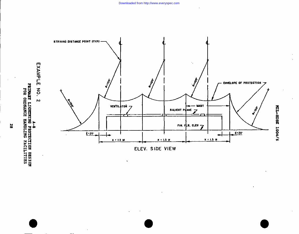
c) Draw a lengthwlae scale ●levatiun of the buildimg. Locate themeets ae shown in ApPendim A, A-S (refer to pare. 4b, Appeudix A). NO part ofthe protected buildimg should lie outside the zone-of-protection. Appemdti A,A-6 through A-n provide emamplea which illustrate application of thisprimtiple.
“5. ~“. ~ fO~Ov@ criteria apply fOrfacilities other then atructurea.
a) I’hlatype of facility can be protected by using overhead .groumdcable spamne.dbetween two metal towere or pmlea which are effectively gro-dedemd .maet criteria In ,pera. 3, Appendix A.
b) In .thie myatem, the overhead cable will intercept llghtmitulstrikes emd the resulted electrical current will be safely carried to .groumdvia the cable and supporting towers or poles.
c) The design method established the height of the horizontalgroumd cable at mid-epan to provida the required zone-of-protection for aspecific fecility.
d) .fie.mid-apem(nag of the overhead cable met be ‘lmcluded‘when‘thehei.Qbt of the eupport ing tOwers or poles ‘iadetermined (==e ‘APP~~ ‘A,‘A-2).
e) ‘Selectionof cablea ia baaed on mechanical strength rather thenelectrical .coneiderations. The overhead ground cable should :be!atrenilesi,nen-corrosive, copper .coacedsteel wire. .Minimum eize shall “be“318“in.(9.5 mm) high strength (7 No. 8 atremds).
f) The conatructlon of the towers emd their structural members orthe class of poles should be based on considerations of mechemlcal end windloading stresees.
19
I ,.
Downloaded from http://www.everyspec.com
:H3L+D3K- 1004/6
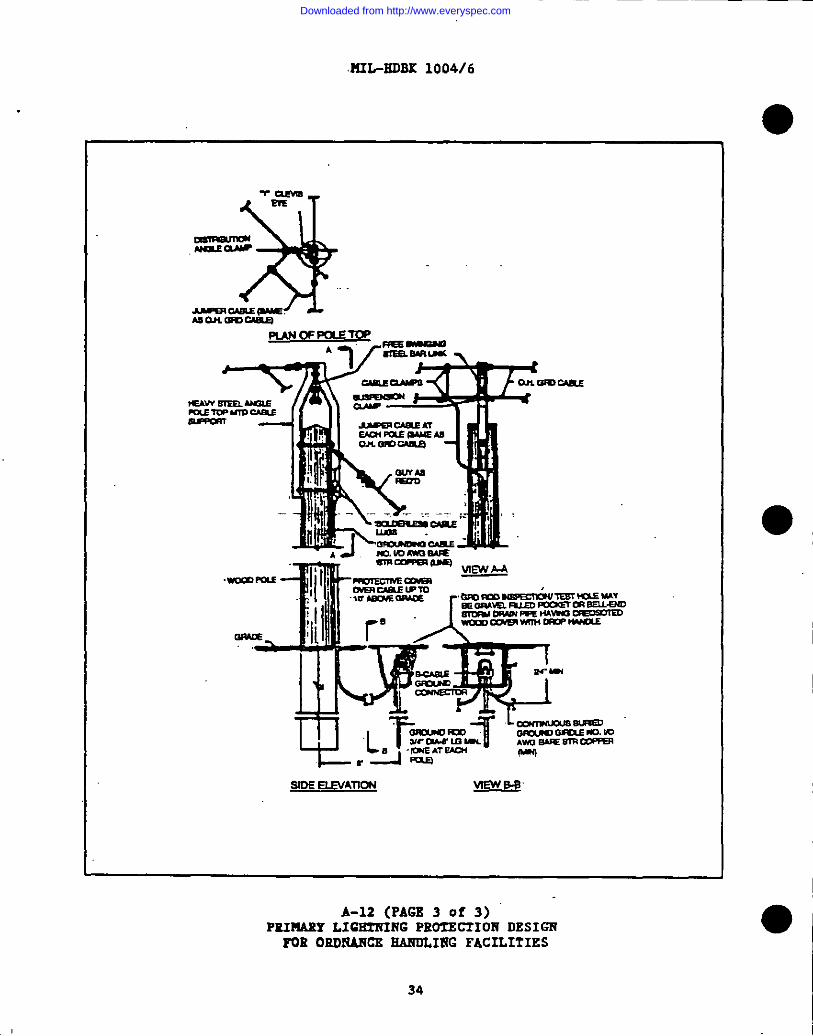
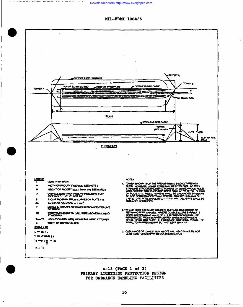
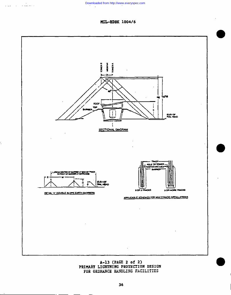
g) 4Pmdix Ai A-12 and A-13 illeatrate primary lightningprotection by overhead greund cable.9for railroad end tzuck marahd.ling garde, ●railroad aiding end detail of overheed ground wire supporting polee endcounterpoise. Piers end vharve8 should be protected by meeting requirememtastated in pane. 1 end 3, Appendix A.
.,
h) To chtttkthe adeuoacy of the zone-of-prot&ti-&%& &e””h&&of surmortinc towers or noles Is determined. &raw sketches to scale aa shown
I inAP;-&idiXi, A-3.2end i-19.The effective height of the overhead ground ;cable shall be maintained between the 10V point of the eag cad,the protectedfacility.
. . . -. ... . . . ...- .- . .
.20
Downloaded from http://www.everyspec.com
; . . .. . ..-
1
●
I
1“
I
0
. . . . . . . .. . . ... . ..-
PfI&ED6K 1004/6
D-tMASl?AClW~DlAUM4L Xtla INTEETCHART NO. I
●
—:
‘-ki+t”r”$-:r.amnv-wc. mu 0
?.> JunvuuEsw Drum X0
?.4\?01vAuJu arD108n so
DULW XOUL Lm ,D<1OO
U8rurrzw w T5n:S-luxmrrwmux-mt. rrn?rt..s . Su.xux P1.uz (Ilxm mm 0? m.)D.nxsruccm -o? -.93
—xn. o* Calm.U as —,UaBc Dmcau .Uxs
L .- UWI’WDI .mXtXS
.W.. wzm W.mnumm-,-ovum,
c . — 01- Bnwc6-w
lust am WILDXMO 01.mmus wn - (Ua m ?EI1
.1 . 2- Dxsruca m - .0?:-s=
?uTmm to COtcaun w.mbszKIFuJs Uxmtl 0? -we rum=
1 . 0197ADm ●-mxn nunx . DX81UCI nom cu7nL1n 0? -
m -or m 1s= - [1)]
1 . STmuuc msmsct tALllua
A-1PE.I?IAEYLIGETRIl?CPROTECTION DRSIGR~B ORDRANCX HA@LIliG “FACILITIES
21
Downloaded from http://www.everyspec.com
. . .HIL-BDBK ‘1004/6
CHARr+m. 2WW5
.-m z 1.WMW-WAT=+WI14VJ .wOlwcEAJmmmNDFm -lD-AJa
- tim-9A10an —eYrcu Emwwsr=N3nl
c7rlr M-laM—
Q 117Lualmmm —
A-2P2XMARY LIGE7x7117GPXOTSCTION DESIG’R
FOR ORDNANCEHANDLING FACILITIES
Downloaded from http://www.everyspec.com
I
I
.,, . -,. . . . . . . . . . .... .. ... .. . .. .. . .. ... . --.- .. ------- -.. ..— ..—
K2L-E12BK1004/6
DAT&
L . 110’w = 75”s . 50,0 . 18”N-6C=9EE TUT D = 98.9
FROIA CURWS9 mART II
M * S5.!I’
ACTUAL OISTANCE ONDIAGONAL AX181
01.
01=
f-OF COMPLEX Dt.
/(’’!2:22(2’’)’4’--2~ 1600 + S112
82’
PYtc. lfzlnt K I l.c*Ln O*m
UA2T (TYP)_ 1-
AX19
BOXCAR8
NOTE6
1. BOXCAR ON RR TRACK AND LOADINGPLATFORM ARE IMPORTANT FACTORSTO BE IMCLUOEO A’ PART OF COWLCX. .-
. .
A-3PE~ X.IGElliIRCPROTECTION DES16TJ
FOR OEDNAHCB EAI?DLIlfGFACILITIES
“23
Downloaded from http://www.everyspec.com
MIL-EDBK 1004/6
I
1,
I
I
I
I
L
+.OF COW~
K!4TRIKIN0POINT ITYP)
STRIKINQDISTANCERAOIUS-R
\
NORMAL AXISCLEARANCE ARC YI r DIAOONAL AXIS
WANCE ARC
“b++”,~oo.
ENVELOPEOF PROTECTION
CLEARANCE ARC DIAGRAM
AAPU’HAEY L16ETt71HGPR07ECIION *DESIGNPOE ORDNANCE BARDLIliGFACILITIES
24
Downloaded from http://www.everyspec.com
I
I
,,,.-.., .... .. ..,. ,+. ,--- .-, ~-- ... . . .. . , . ..... . . .. . .. . . . . . .. -. .. . . .. . . . . . . .
@iitiEDIIk1004/6
●
/-’’’’’’’”
●
OF PROTECTION
ELEV. SIDE VIEW
A-5
PXIMAUY LIGETliIl!GPEOTSCTIOIiDBSIG1’1FOB ORD?LIIKEEARDLII?G
.25
FACILITIES
Downloaded from http://www.everyspec.com
NIL-EDRE 1004/6
c
I
f
c=20,
NOTES1. goy :&TAA87C0hWUTAT10N9
4-t-—
.
/
\
Iii—
4 0’
0’ a,—
—
nMST [TYP)
BLDO
I Y= 70, v. 70,
I
PLAN
A-6
4 NORMAL AXIS
7OIAOONAL AXIS. .. . ●
PX2PIASTL16ETFJIRGPIIOiSCTIOlf DESIGNPOE!ORDI?AIKSEANDLI~G FACILITIES
26
Downloaded from http://www.everyspec.com
I . . . . . . . -----
●
1’
DATAI
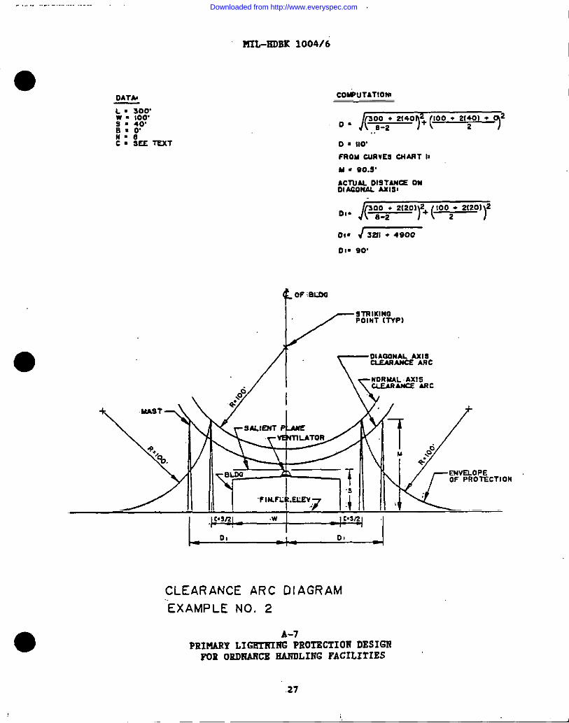
L I 300’w . 100’s . 40,0=0,n-eC= SEE TEXT
?m-HOBK 1004/6
COtiUTATIONI
o “ &%=’N’OO‘ 2’7 ‘ 720 ● 110,PROU CURVESWART II
u = *0.YACTUALOISTAM=onOtworw. Axlm
01. /(-)Y+(-’r
01. J MI . 4900
01. 90,
fomoo
KYI’RIKIMOPOINT (TYP)
r“*M&Aipc
.3
.FIN.FL LE!Am
IORMAL AXISMARAWE ARc
!
d7 ,$M
+“’EWELOPEOF PROTECTION
‘1L 00 I Dt -1
CLEARANCE ARC DIAGRAM
““EXAMPLE NO. 2
A-7PRIMARY LIGEIT?INGPROTECTION DESIGI?FOE oRDNANCE EANDLING FACILITIES
.27
1,
Downloaded from http://www.everyspec.com
UIL-EDBK
1004/6
,
III
EX
AM
PLE
NO
.2
A-8
IPUHMY
LI~l?C
PROTECTIONDESIGN
IFOK
02DNJUWEHARDLINGFACILITIES
28
L
Downloaded from http://www.everyspec.com
,1 .-. . . . . . . . . . . . . . . -+ ---,,. ..-.~.-... ,----------- --, . --- .. . . . . . . . . . . . . .- ---- -- ----- ,-—
“o
?UL-EOEK 1004/6
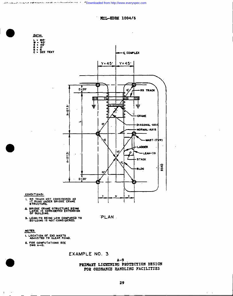
J?4Mo~’
s . 46,[email protected]. SEE TUT
C0ND1T10N3S
I. m mACK MoT COM91DERED uIT RUMS UNDER BRIDGE CRANE
9TRUCTURL
:L ORIDOE =ANE STRUCTURE BEINOLAROE !5 CONS1=ED EX1’EN510MoF. Bu1LOIN6.
3. I.EAM-TO BEINO LOW COMPARED 10 ‘P.LAN.Bu!LOIMG IS ,NOT. CONSIDERED.
mom1. LOCA?1ON Or W MASTS
ADJUSTED 10 UEAR RoM.
t. ;0.: y4UF#TAT10KS SEE
EXAMPLE NO. 3
PI
‘s
?:
Px.nmn LIG=K&:Ro==o~D~sII=POR ORDXANCE EANDLING FACILITIES
29
Downloaded from http://www.everyspec.com
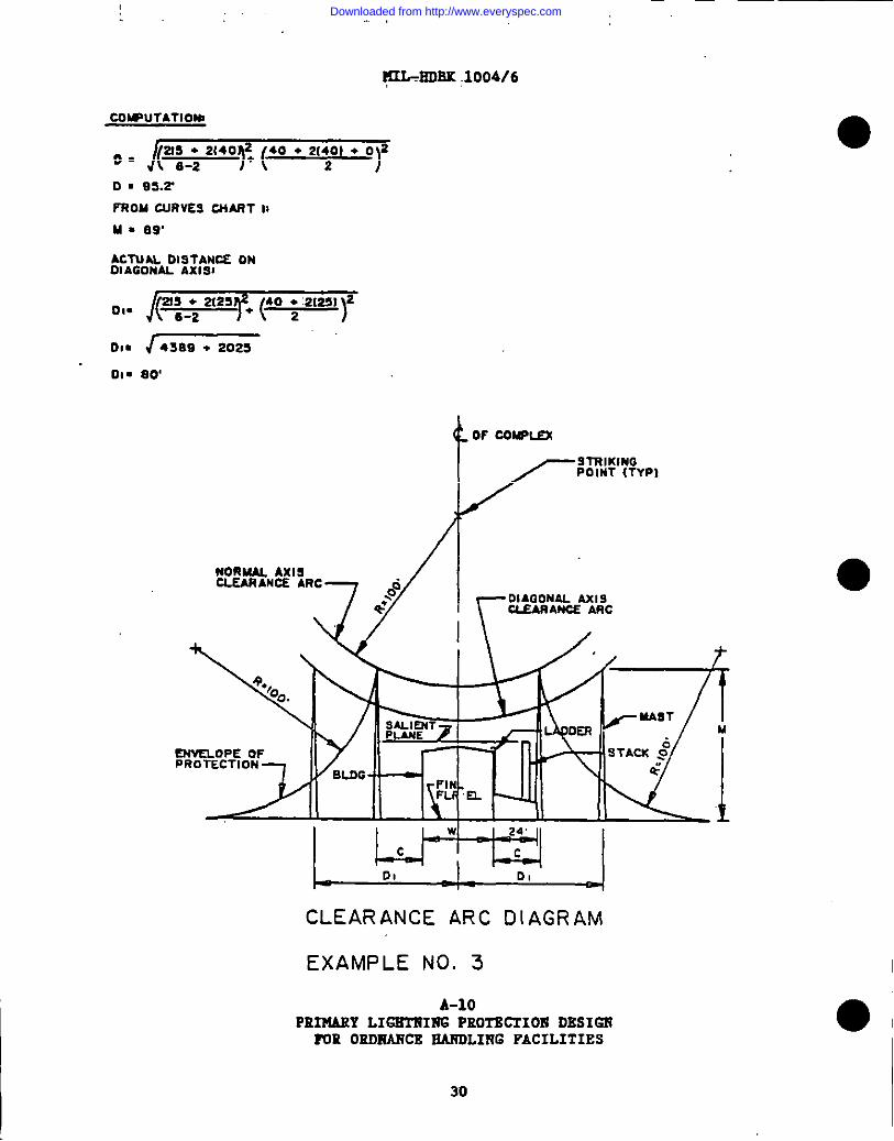
~IiOBK .1004/6
cOtmuTATloNl
o● &:;’’’”fi(40“22”’“‘rD ■ SW?’
FNOM CURVES CNART II
u = 89’
AcTuu D19TAN12E ONOIAGONAL AxISI
I0s. 4389 + 2025
01. 80
mhaux
/--%wRP,
/’F’
kk17fUASTOER IA
ENVELOPE OFPROTECTION
I LJ?-t51 I1- 01 I D, J
CLEARANCE ARC DIAGRAhIl
EXAMPLE NO. 3
A-10PRIMARY LIGETIPIH6PKOTBCIIOB DESIGl!POE OROHAHCS EAKOLIt?GFACILITIES
30
Downloaded from http://www.everyspec.com
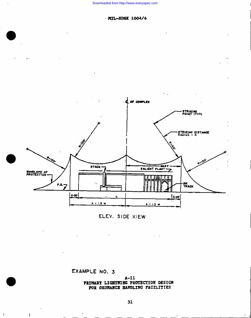
HI&EOEK .1004/6
ELEV. SI.DE V.IEW
EXAMPLE NO. 3A-X1
“PEI’!!AXYLICEZXIRG PROTECTIO17DESIGH~E ORDR6MCE EARDLIIVGFACILITIES
31
,,
Downloaded from http://www.everyspec.com
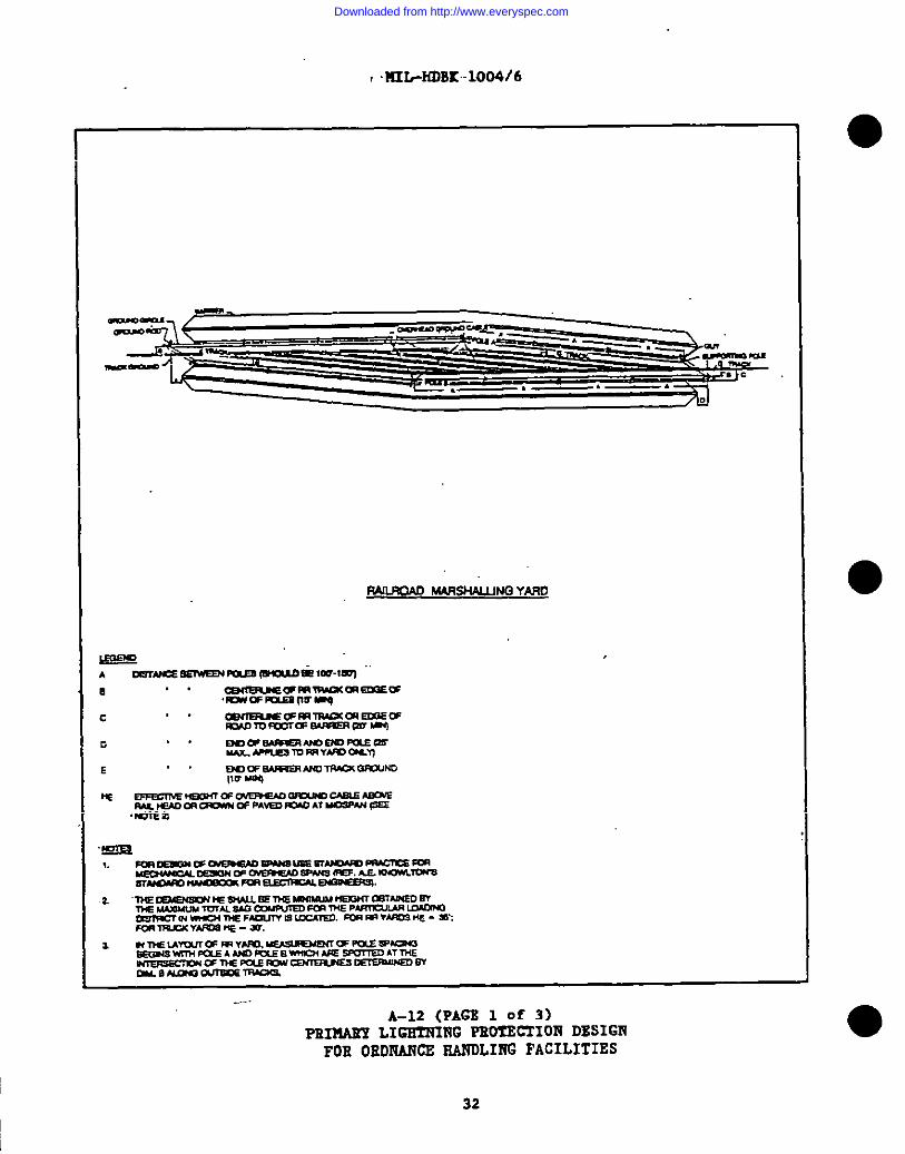
r.lf2L-mBK-loo4/6
fwL?clAJJ M4RSHN.LINQ YAWI
.A-12 (PAGS 1 of 3)
PSI19AEYLIGETNING PROTECTION DESIGNFOR OROI’UNCEHANDLIRG FACILITIES
32
Downloaded from http://www.everyspec.com
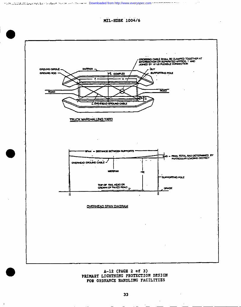
tiL-HIiBX1004/6
TRucxMARSH4LIJNQYAfm
A-12 (PAGE 2 Of 3)PRIHARY LIGIilTfINGPROTECTION DESIGN
POE!ORDNANCE EANDLING FACILITIES
33
Downloaded from http://www.everyspec.com
!
I
I
1.
MIL-XDBK 1004/6
.---
,~ r -4 ti ‘–”’
SloE ELEVATION m
I A-12 (PAGS 3 of 3)PIIIMAXYLIGIilYfIIiGPIIOTECIIOI!DESIGNPOil020KANCX EARDLIRG FACILITIES
34
Downloaded from http://www.everyspec.com
. . . . . ..—. . . .. .. . . . . .——....
lU&P&IBK-1004/6
/ .mwr?AJn?!—(“ / L
-A . .——------- . . . . .
—--—— —... -.. ———. —
L —.
&g.!
—am-
—.. ____________ -------- ----
— ....-.-..-.-...... -----.-—.-----------..——-. —
A-13 (PA6S 1 of 2)PRIMARY LIGHTHINC PROTECTION DESIGNFOR 0RDIiA27CSEA1’lDLIl?6FACILITIES
35
Downloaded from http://www.everyspec.com
UL-EOBK 1004/6
iSECilONAL Du13RAM
A-13 (PAGE 2 Of 2)PKIMAliYLIGHTNING PROTECTION DESIGN
FOR ORDNANCE~LING FACILITIES
36
Downloaded from http://www.everyspec.com
I
●
I
I
II
I
II
‘o
I
I
,.
II12L-EOti1004/6
APP2zRD2XB
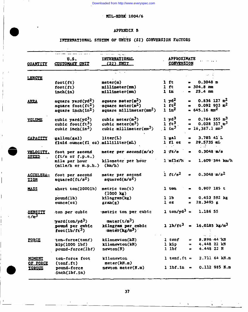
I~TIO!IAL SYSfS511OF OiIiS (S1 ) COtWZ2SI01’JFACTORS
. . .. . . .. . ..—. . . .. . . .. .
YmzlmAIxom!)QAEm~ I) ~AWo=%m ., ,, .. .
SIOE
foot(ft)foot (ft)inch(in)
square yard(yd2)square foot( ftz)square *ch( in2)
cubic yard(yd3)cubic foot(ft3)cubic hch(2m3)
gallon(gel )fluid ,ounce(fl,OZ)
foot per second(ft/s or f.p.a.)mile per hour(mile/h or m.p.h.)
foot per secondequared(ft/s2)
short ton(20001b)
~ound(lb)ounce(oz)
ton ,percubic
~ard( tom/yd3)pound per cmbicfoot(lb/ft3)
ton-force(tonf )kip(1000 lbf)pound-force(lbf)
ton-force foot(tonf.ft)pound-force
meter(m)milltieter(mm)millimeter
square meter(m2)square meter(m2)aquere millimeter(mm2)
cubic meter(m3)cubic meter(m3)cubic .millimeter(mm3)
liter(L)milliliter
meter per eecond(da)
kilometer”per hour(km/h)
meter per secondsquared(m/s2)
metric ton(t)(1000 kg)
ktlogrem(kg)grem(g)
metric ton per
\meter(t/m3)
cubiC
kilogram,par cnbic:met&r(kg/mg)“’
kilanewton(kK)ltilmnewton(ld?)newt0n(17)
kilonevtonmeter(kN.m)nevton meter(N.m)
,. -
lft = 0.3048 m1 ft n 304.8 mlili - 25.4 nm
1*2 . 0.836 127 ra21 ftz - 0.092 903 ra21 inz . 645.16 f4m2
lyd3 = 0.764 55S m31 ftg 0.028 317 m31 in3” I 16,3S7.1 MM3
l:gel = 3.78S 41”L1 fl 0S! = 29.573SmL.,
1 ,ft)e - ‘“0.3048 mfa
1 ‘m{le71i = 1.609’344 km/h
i ft!e2 = 0.3048 m/132
ltnn - 0.907 185 t
llb = 0.453 592 kg1 Oe = 28.3495 g
1 ton/yd3 = 1.186 55
1 lb/ft3 = 16.0285 ‘Xalti3
‘1tonf = 8.S96 .44‘kll1 kip = 4.44a 22 M1 lbf = 4,448 22 N
1 tonf.ft = 2.711 64 Mi.m
1 lbf.in = 0.112 985 H.m-inch(lbf.in)
37
I(
,1,.
Downloaded from http://www.everyspec.com
KIL-EDBK 1004/6
oIBTXEEATIOEAL
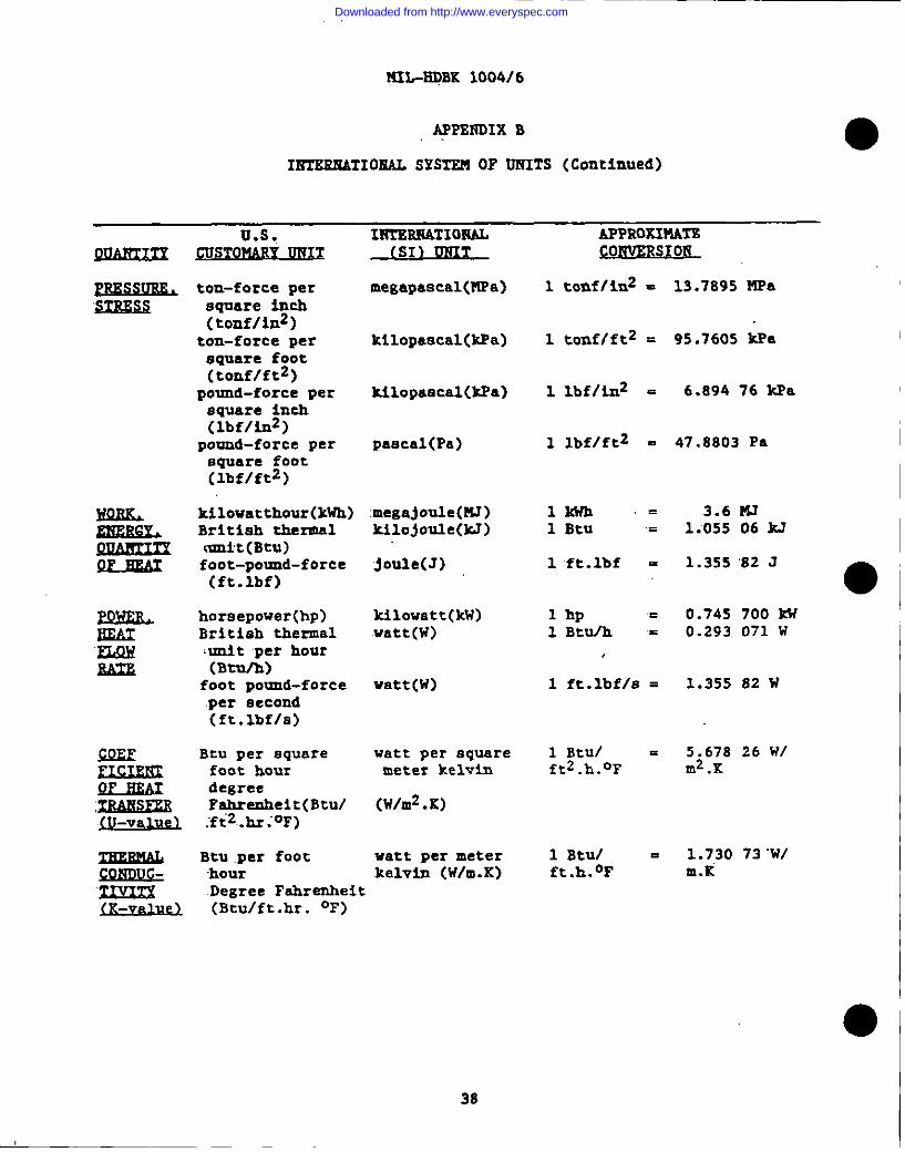
APPBNDIX B
SYSTEM OF UNITS (Continued)
Us. IRTBBMATIORAL APPRaKIFINfF.WSTOMMY WiXX
ton-force persquare inch(tonf/inz)
ton-force persquare foot(tonf/ft2)
pound-force persquare inch(lbf/in2)
pound-force persquare foot(lbf/ftz)
kilowatthour(kWh)British thermalmni’t(Btu)foot-pound-force(ft.lbf)
horsepowerBritish thermalunit per hour(Btu/h)
foot pound-forceper second(ft.lbfla)
Btu per squarefoot hourdegreeFahrenheit(Btuf~f~2,_~~0F)
Btu per foot‘hourDegree Fahrenheit(Btu/ft.hr. OF)
(S1) UNIT
megapaacal(MPa)
kilopaacal(kPa)
kilOpaacal(kPa)
pascal(Pa)
megajoule(15J)kilojoule(M)
joule(J)
kilowattwatt(w)
watt(w)
watt per squaremeter kelvin
(W/m2.K)
watt per meterkelvin (W/m.K)
-S1 Ro
1 tonf/in2 = 13.7S95 MFa
1 tonflftz = 95.7605 kPa
1 lbf/i.n2 = 6.894 76 kPa
1 lbf/ft2 = 47.8803 Pa
lkwh=1 Btu =
1 ft.lbf =
1 hp .1 Btu/h =
1 ft.lbf/s =
1 Btu/ =ft.h.°F
3.6 FU1.055 06 kJ
1.355 ’82J
●0.745 700 kw0.293 071 W
1.355 82 w
5.678 26 WIm2.K
1.730 73 ‘WIm.K’
I 3s
Downloaded from http://www.everyspec.com
.,... “..M2L-EDBK 1004/6
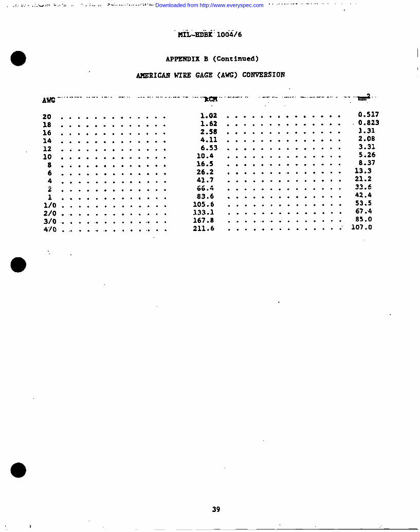
APPEKOIX B (Centinued)
A?LEEICAXWIRE GAGE (AWG) CO17VBESIOR
AWG. . . .. .... . . .. . . . . . . . . . . . . ... . ------
201816141210864211/02/03/04/0
. . . . . . . . . . . . .
. . . . . . . . . . . . .
. . . . . . . . . . . . .
. . . . . . . . . . . . .
. . . . . . . . . . . . .
. . . . . . . . . . . . .
. . . . . . . . . . . . .
. . . . . . . . . . . . .
. . . . . . . . . . . . .
. . . . . . . . . . . . .
. . . . . . . . . . . . .
. . . . . . . . . . . . .
. . . . . . . . . . . .
. .. . . . . . . . . .. . .
●
.-. ...lm ----- . . --- . . . . —----- . . . --”E+
1.021.622.584.116.5310.416.526.241.766.483.6105.6133.1167.8211.6
. . . . . . . . . . . . . .
. . . . . . . . . . . . . .
. . . . . . . . . . . . . .
. . . . . . . . . . . . . .
. . . . . . . . . . . . . .
. . . . . . . . . . . . . .
. . . . . . . . . . . . . .
. . . . . . . .. . . . . .
. . . . . . . . . . . . . .
. . . . . . . . . . . . . .
. . . . . . . . . . . . . .
. . . . . . . . . . . . . .
. . . . . . . . . . . . . .
. . . . . . . . . . . . . .
. . . . . . . . . . . . . .
0.5170.8231.312.083.315.268.3713.321.233.642.453.567.485.0107.0
39
Downloaded from http://www.everyspec.com
MIL-KDBK 1004/6
BIBLIOGSAPEY
~ Government agencies may obtain copies of militaryhandbooks from the United States Naval Publications and Forma Center,5801 Zabor Avenue, Philadelphia, PA 19120, TWX: 710-670-1685, TELEK: 834295,AUTOVON telephone 422-3321. lLxagovamment organizations may obtain copies ofmilitary handbooks from the same source.
MIL-HDBK-1OO8A Fire Protection for Facilities Engineering,Design, and Construction
●
40
Downloaded from http://www.everyspec.com
I .. .... . .. . ... . ..4”, .-.. . . . . ....-?... .>.. ---------- . .- -. . ..-. .-—- . . .
I
I
●
M2L-iWJBK1004/6
sEImEmEs
(MSI), 1430 Broadvay, lfevYork; NY 10017.,.. ,.
C2 !iationelElectric Safety Code
~tute of Elec trical end Electronies Enaineers. ~. , USE publications,345 East 47th Street, Nev York, NY 10017.
so Chide for Safety in Sub6tatisxiGroumdins
81 Guide for Measuring Earth P.esistlvity,GroundImpedsnce, and Esrth Surface Potentials Of a GrO=dSyatem
142 Recommended Practice for Grounding Industrial endCommercial Power .Systams
~JJwrds and mdbooke, ,Goveromentagenciee taey obtain copies of+military sr.sndardsand handbooks from the United States17av?Jpublications end‘Forms Csntsr, 5801 Tabor .“Avenue,Philadelphia, :PA 19120, TWX: 710-670-1685,TELEX: 834295, AUTOVOR telephcme 422-3S21. l!omswermment organizations meyobtain copies from the Superintendent of Documamts, United States’Government .Printing Office, Waahinston, DC 20402.
KIL-BDBK-419 Grounding, Banding, end Shielditw fOr ElectrOnic.Ewipments ,amd‘Facilities. ,
DOD-6055.9-STD Ammunition end Explosives Safety Scsndards
rII 0 so on (WA), Batterymarcb”Park,~incy, MA 0;269.
70 ?lationalElectrical Code
70B Electrical Equipment Maintenance
78 “LlghtninsProtection Code
.
41
Downloaded from http://www.everyspec.com
MIL-BDBK 1004/6
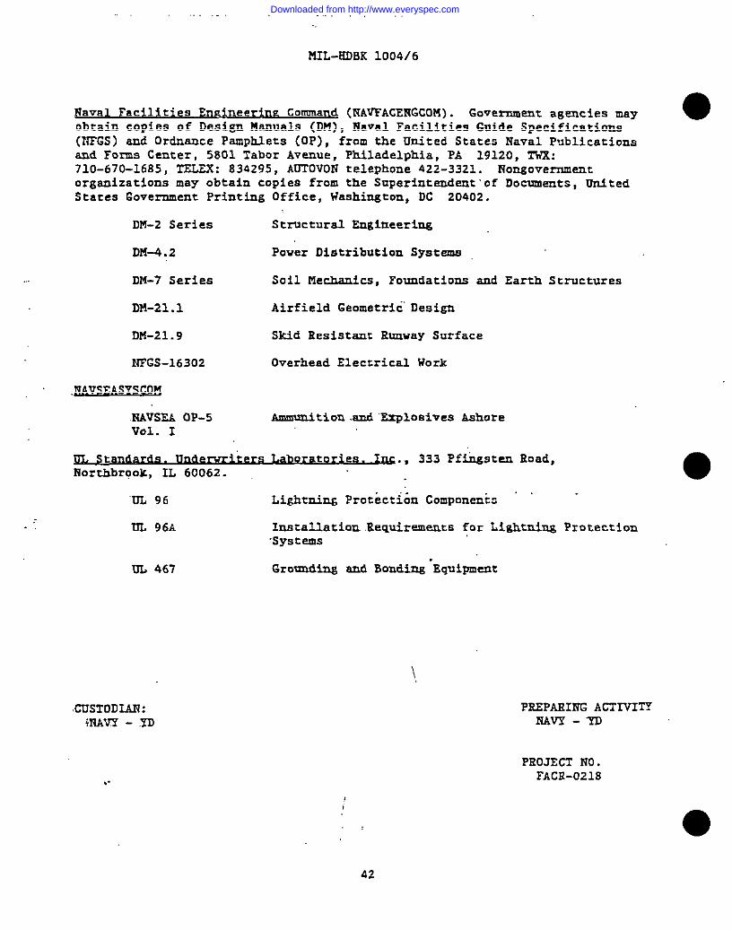
Naval FaciI*ties EruzineeriruzCommand (l?AVFACENGCOM). Government agencies may ●obtain copies of Design Manuals (DM), Naval Facilities Guide Specifications(WFGS) snd Ordnance PsmpMets (OP), from the United States Naval Publicationsand Forms Center, 5801 7abor Avenue, Philadelphia, PA 19120, TWK:710-670-1685, TELEK: 834295, AUTOVON telephone 422-3321. Nongovernmentorganizations may obtain copies from the Superintendent’of Documsnts, UnitedStates Government Printing Office, Washington, DC 20402,
DM-2 Series Structural Engiueerimg
DS4-4.2 Power Distribution Systems
D*-7 Series Soil FSechsnics,Foundations snd Earth Structures
DM-21 .1 Airfield Geometric Design
DM-21.9 Skid Resistant Runway Surface
NFGS-16302 Overhead Eleccrics2 Work
,~VSEASYSCOM
KAVSEA OP-5 Ammunition and Explosives AshoreVol. I
!lL S and~t t ., 333 Pfi&sten Eoad,fiorthbrook,IL 60062.
‘UL 96 Lightniw Prockcti6n Componen& -
UL 96A Imtal.latlon .Eequirementsfor Lightning Protection‘systems
UL 467 Grounding snd Bonding .Equipment
CUSTOD~:4NAVY - .YD
..
42
PE.SPASINGACTMTYNAVY-YU
PROJECT S’?0.FACE-021S
Downloaded from http://www.everyspec.com
I
● “...... ,.:,
., .’.
,rotd .,0.., ,.” ,(,”,
0W6R1MENT OF THE NAVY - . . . . . . .
.
●:”.
COMNANDIIfG OFFICER“~
CHZSAPEARE DIVISIONNAVAL FACILITIES ENGINEERING COW!AND ~COi)E 406WASHINGTON NAVY YARD , BUILDING 212WASHINGTON, D.C. 20374-2121
Downloaded from http://www.everyspec.com
;:
.
I i
“1I
.,..... I“,1
.. ,.
. .—— . . .. . .
.. “-m..--.— 1-.-—:
RENA” RS
. .
. . .. .
●
●
I
NAVFAC 0“9mv.1
Downloaded from http://www.everyspec.com