unclassified ad number - everyspec
TRANSCRIPT
UNCLASSIFIED
AD NUMBER
AD840582
NEW LIMITATION CHANGETOApproved for public release, distributionunlimited
FROMDistribution authorized to U.S. Gov't.agencies and their contractors; CriticalTechnology; JUL 1968. Other requests shallbe referred to Army Materiel Command,Attn: AMCRD-TV, Washington, DC 20315.
AUTHORITY
usamc ltr, 14 jan 1972
THIS PAGE IS UNCLASSIFIED
Downloaded from http://www.everyspec.com
UNCLASSIFIED
AD NUMBER
AD840582
NEW LIMITATION CHANGETODistribution authorized to U.S. Gov't.agencies and their contractors; SpecificAuthority; JUL 1968. Other requests shallbe referred to Army Materiel Command,Attn: AMCRD-TV, Washington, DC 20315.
FROMDistribution: Further dissemination onlyas directed by Army Materiel Command,Attn: AMCRD-TV, Washington, DC 20315, JUL1968, or higher DoD authority.
AUTHORITY
amc per dtic form 55
THIS PAGE IS UNCLASSIFIED
Downloaded from http://www.everyspec.com
AMC PAMPHLET AMCP 706-2$0
0
a ENGINEERING DESIGNKJ: HANDBOOK
DI DSIGN OF AERODYNAMICALLY I
STATEMREN' #2 UNCLASSIFIED
±i&.t' doaci.leL is su!ject to special export 1 L---
controls and each transmittal to foreign ntvrQgovernments or foreign nationals may be madeonly with prior approval of: Army MaterielCommand, Attn: AMCRD-TV, Washin,. on, D.C.20315 _
HEADQUARTERS, U.S ARMY MATERIEL COMMAND JULY 1968
* .~-.--'-~.-.--.41
Downloaded from http://www.everyspec.com

DISCLAIMER NOTICE
THIS DOCUMENT IS BEST QUALITYPRACTICABLE! THE COPY FURNISHEDTO DTIC CONTAINED A SIGNIFICANTNUMBER OF PAGES WHICH DO NOTREPRODUCE LEGIBLY.
Downloaded from http://www.everyspec.com
'3
'3
AMCP 703-200
WA
PREFACE
The Engineering Design Handbook Series of the Army Materiel Commandis a coordinated series of handbooks containing basic information and fun-damental data useful in the design and development of Army materiel andsystems. The handbooks are authoritativt, reference books of practical informa-tion and quantitative facts helpful in the design and development uf Armymateriel so that it will meet the tactical and technical needs of the Armed Forces.
0; t This handbook pro -ides extremely useful data for the engineer prmarilyinterested in the preliminary design of aerodynamically stabilized free rockets.The data are arranged in a convenient format-tables, graphs, and solutionguides-which permits ready access and easy application in order to makepossible the rapid respons- rq--ired of preliminary design activities. As abonus, the chapter arrangemetnt provides each technical area having responsi-bilities in the preliminary design phase with an appreciation for the datarenuirements and applications of the supporting technical areas.
The pieparation of this handbook was initially an in-house effort of theU. S. Army Missile Command. The organizatica of the text, data, and muchof the written material originated with that agency The Chrysler CorporctionSpace Division, Hunthville, Alabama, under subcontract to the EngineeringHandbook Office of Duke University, prime contractor to the Army ResearchOffice-Durham for the Engineering Design Handbook Series-with the 2on-tinuet -issistance of the U. S. Army Missile Command-completed the handbook.
The Handbooks are readily available to all elements of AMC mcl, dingpersonnel and contractors having a need and or requirement. The ArmyMateriel Command policy ir, to release these Engineering Design Handbooksto other DOD activities and their contractors, and other Government agenciesin accordance with urrent Army Regulation 70-31, datei' 9 September 1966.Procedures for acquiring thpse Handbooks follow
a. Activities within AMC and other DOD agencies should direct theirrpntipqt on an official form to:
Publications Distribution BranchLetterkenny Army DepotATTN: AMXLE-ATDChambersburg, Pennsylvania 17201
b. Contractors who have Department of Defense contracts should submittheir request, through their contracting officer with proper justification, to:
Downloaded from http://www.everyspec.com
AMiCP 7C-20
DirectorDefense Documentation Center
(for Scientific and Technical Information)Cameron StationAlexandria, Virgin'a 22314
c. Government agencies other than DOD may submit their requestdirectly to:
Commanding GeneralU. S. Army Materiel CommandATTN: AMCAD-PPWashington, D. C. 90315
or
DirectorDefense Documentation Center
(for Scientific and Technical Information)Cameron Statio,Alexandria, Virginia 22314
d. industry not having a Governmont cntract (this includes Universities)must forward their requests to:
Commanding GeneralU. S. Army Materiel CommandATTN: ANICRD-TVWashingtor., D. C. 20315
e. All foreign requests must be submitted through the Washington, D. C.Embassy to: Office of the Assistant Chief of Staff for Intelligence
ATTN: Foreign Liaison OfficeDepartment of the ArmyWashington, D. C. 20310
All requests, other than those originating within the DOD, must beaccompanied by a valid justification.
Comments and suggestions on this handbook are welcome and should beaddressed to Army Research Office-Durham, Box CM, Duke Station, NorthCarolina 27706.
I I
Downloaded from http://www.everyspec.com
AMCP 703-280
TABLE OF CONTENTSPREFACELIST OF ILLUSTRTIONS ixLIST OF TABLES xvi
CHAPTER 1. INTRODUCTION
CHAPTER 2. ATMOSPHERIC DATA
Paragraph Page
3-1 Introduction .. 2-12-2 Atmospheric Properties . 2-12-2.1 Atmospheric Density, Temperature and Pressure 2-12-2.2 Winds, Upper Level 2-12-2.3 Winds, Lcwer Level 2-22-2.4 Regional Annual and Seasonai Density Models 2-2
References .. 2-4
CHAPTFR 3. SYSTEM DFSICN
3-1 General ..S3-2 Cla.-ses of Rockets 3-1
3-2.1.1 Artillery . .... 3-13-2.1.2 Infantry .. .... .. . 3-13-2.1.3 Air Defense ........... .. 3-1
3-2.14 Armor .. ..... 3-23-2.1.. Aviation ......... ..... 3-23-2.1.6 Logitz-ic 3-2
z 3-2.1.7 Support ..... 3-23-2.2 Research Rocket Systems ,. 3-23-2.2.1 General .. ......... .. ... 3-23-2.2.2 Meteorological .................... 3-33-2.2.3 iigh Altitude Sounding .. ... 3-33-2.2.4 Satellites . .................... 3-33-2 2.5 Dispensing ... ........ 3-33-3 Operational Modes ................ 3-33-3.1 General ..... ... .. ..... .. ..... . 3403-3.2 Ground-to-Ground ... .....
-, -3-3.3 Ground-to-Air ....... ... .......... . . 3-43-3 4 Air-to-Air ....... 3-43-3.5 Air-to-Ground .... ....................... 3-43-3.6 Underwater-to-Air ............................ 3-43-3.7 Surface/Air-to-Underwat.. . 3-43-4 Launching Methods. . ........ ................. 3-43-4.1 General .3.............. . 3-43-4.2 Rail Launchers ........... 3-434 .2.1 Single .... ........................................ 3-5
III
Vf
Downloaded from http://www.everyspec.com
AMCP 7Z.2C3
TABLE OF CONTENTS (cont)
Paragraph Pagr
3-4.2.2 Multiple .......... 3-53-42.3 Helical .................................. .. 3-53-43 Tube Launcherm ...... ... 3-53-4.3.1 Single ......... 3-534.3.P Multiple ... ............ . 3-53-4.3.3 Open Breech 3-53-4.3.4 Close B.~lreech . .. ............. ... 3-634.3.5 Restricted Breech ............. .. 3-63-4.3. Gaffing 3-3-4.4 Other Launcher Types . ................. 3-63-4.5 Variations .. .. 3-63-4.5.1 Autospin .. ............ ............... ........ 3-63-4.5.2 Prespin, Automatic Dynamic-Alignment (PADA) 3-73-4.5.3 Spin-on-Straight-Rail (SOSR) 3-73-4.6 Meth ods of Transport . . .. ...... 3-73-5 Systet ra nts ................................. 3-83-5.1 General ................ 3-83-5.2 Rocket ... ........ ..................... . . .. 3-83-5.2.1 Warhead Design....................... -3..3-83-52.2 Motor - ....................... .. 3-93-5.2.. Structure ............ ..... ........... . 3-153-5.3 Launcher .na.c........................... .. 3-i3-5.4 Anillary Equipment ............................ '-133-6 Concept Selection . .. .......................... 3-133-6.1 Requirements .... ....... ....... .......... 3-133-6.2 Constraints .................................. 3-143-6.3 Parametrics ............ ................. 3-143-6.4 sYste.m Selection . ............ 3-143-7 Preliminary Design .... .............. 3-143-7.1 Payload .. ........................... ..... .. 3-153-7.2 Populsion ....on ......... ....... 3-153-7.3 Aerodynamics .. ......................... ..... . . 3-153-7.4 Dynamics . . ........... ....... ... .......... 3-153-7.5 Strueturet. . 3-153-7.6 Performance Estimates 3-153-7.7 Auxiliary Devices ..... ....................... 3-153-8 Design Optit -ft tion ., . . . . .3-16 I3-9 System Integration .. .... ............... 3-16 "
4-i0 Ceotn. ........ ..... .................... 3-18Il.3-10.1 Static Testhig ... . ............ 3-17
3-10.2 Flight Testing ... ............. ........ 3-173-10.3 Structural Testing . .. .... 3-173-10.4 Aerodynamic Testing . ..... ..... ......... 3-183-10.5 Envirowtnental Testing ....................... 3-183-11 Cost Effectiveness ......... .. .................... 3-18 "
IV
Downloaded from http://www.everyspec.com
~oj
AMCP 705-280
TABLE OF CONTENTS (cont)
Paragraph Page
KCHAPTER 4. PERFORMANCE PAPAMETRICS
Symbols 4-14-1 Introduction 4-2
, 4-2 Performance Parameters 4-24-2.1 Performance Factors 4-24-2.2 Propulsion System Factors 4-24-2.3 Aerodynamic Considerations 4-2
V 4-3 Appr,,ximation Techniqi~es and Applicable Equations 4-34-3.1 Estanation of Velocitq Requirement 4-34-3.1.1 Indirect-Fire Systems 4-3
1 4-3.1.2 Direct-Fire Rockets 4-34-3.1.3 Sounding Rockets 4-54-3.2 Estimation of Rocket Motor Requirements 4-54-3.2.1 Sperific Impulse and Booster-Mass Ratio 4-54-3.2.2 Propellant-Weight Fraction 4.54-3.2.3 Growth Factor 4-5
V 4 4-3.3 Summary 4-54-4 Parametric Performance Data for Indirect-Fire Systems 4-84-41 Delivery Techniques 4-8
-4.1.1 Trajectory Profile 4-8, 4-4.1.2 Energy Management Techniques 4-8
4-4.2 Parametric Performance Data 4-84-5 Parametric Performance Data for Direct-Fire Systems 4-124-5.1 Delivery Techniques 4-154-5.1.1 Trajectory Profiles 4-124-5.1.2 Energy-Management Techniques 4-124-5.2 Parametric Performance LDa 4-134-6 Parametric Performance Data for Sounding Rockets 4-154-6.1 Delivery Techniques 4-154-6.1.1 Trajectory Profile 4-1544.1 2 Energy-Management Techniques 4-15
4-t;.2 Parametric Performai.ce Data 4-154-7 Parametric Pe'formance Data for Surface-to-Air Rockets 4-164-7 1 Delivery Techniques 4-164-7.1.1 Trajectory Profile 4-164-7.1.2 Energy-Management Techniqu2s 4-1647 Paramtr.ic 0-.i ...... Data 4-18
" 4-8 Numerical Examiple 4-19
CHAPTER 5. PRCPULSION
Symbols ... .... ......... 5-15-1 General ................... 5-25-2 Nozzle .... 5-35-2.1 Thermodynamic Rclations .... 5-4
S'Q 5-2.1.1 Ideal Flow 5-4
V
Downloaded from http://www.everyspec.com
AMI CP 703-=
TABLE OF COITENTS (cant),1 Paragraph Pay'e
5-2.1.2 Real Mow ............... 5-7
5-2.2 Noz,,e Contours ... 5-75-2.3 Nozzle Erosion 5-75-3 Propellants 5-75-3.1 Grain .. 5.75-3.l Chemical Compositions ... .... .. 5-105-3.1.2 Configuration Geometry 5-105-3.1.3 Burning Rate 5-115-3.L4 Erosion . ................ 5-125-3.2 Ignition .......... .. 5-125-3.3 Hodling ....... .................. 5-135-4 Internal Ballistics .. ... . 5-13
5-5 Scaling of Solid Propellant Motors .... 5-135-6 .15
References ................................. 5-16
CHAPTER 6. STRUCTURES
Symbols ..................................... 6-16-1 General ........ 6-26-2 Weight and Balance .. ............. 6-26-2.1 Mass and Center of Gravity 'Sstimation . 6-26-2.2 Pitch Inertia . . ........................ 6-26-2.3 Roll Inertia ..................... ............ 6-76-3 Loads ...... ............. .......... 6-106-3.2 Transport and Handling Loads 6-106-3.2 Flight Loads .............................. 6-11
FlgStrea ................................. 6-13
641 Beams ......... .. . 6-136-42 Columns .... .... ....... .... 6-156-403 tP e Vessels .......... ............. .... 6-156-4.4 Plates ............................... . 6-156- .5 Joints ..... ..... ... . . ......... 6-156-5 Safety Factors ........ 6-19
qu-' n~auing ................ . ............... b-196-6.1 General ...... 6-196-6.L1 Conduction Heat Transfer ........ 6-19&S6.L 2 Radiation Heat Transfer .................... 6-206-6.13 Convection Heat Transfer ................. 6-216-6.1.4 Conibined Heat Transfer 6-216-6.1.5 Transient Heat Transfer 6-21"2 Combustion Chamber Heating ............... 6-26-6.3 Exhaust Plume Heailng .... 6-226-6.4 Aerodynamic Friction Heaing . ......... 6-226-7 Tting ....... 6-24
Refer e es ........... .. '.. . . ....... . .. ...... 6-2Ct
Downloaded from http://www.everyspec.com
AMrP 703-280
TALF OF CONTENTS (cont)
Paragrapi Pagr
CHAPTER 7. ACCURACYSymbols 7-1
7-1 Introduction 7-27-2 Definitions of Error Sources 7-27-3 Design Considerations Influencing Accuracy 7-27-' 1 Design Considerations Associated With Speed Change
- Errors 7-27-3.2 Design Considerations Associpted With Angular Errors 7-37-3.2.1 The Effect of Aerodynamic Stbdilty 7-37-3.2.2 The Effect vf Wind 7-37-3.2.3 The Effect of Thrust Mala.inment 7-37-3.2.4 The Effect of a Slow Spin 7-57-3.25 Tie Effect of Dispersion Reduction on the Optimum or 7-77-4 Prelaunch Error. 7-77-4.1 Aiming Errors 7-77-4 2 Errors Due to Variations in Meteorological Conditions 7-87-5 Calculation of Angular Errors. 77-6 Launch Phase Errors 7-107-6.1 Angular Velocity 7-10
--. 7-6.2 Translational Velocity 7-107-6.3 Dynamic Unbalance 7-14
- -7-7 Propulsion Phase Errors 7-147-7.1 Nonrotating Rucket 7-147-7.2 Dispersion Reducton Technques 7-187-7.2.1 Constait Spin Rate 7-187-7.2.2 Constant Spin Acceleration 7-207-7 2.3 Slowly Unifinily Decreasing Sri (SUDS) 7-207-7.2.4 Spin-Buck 7-207-7.2.5 Prespin Automatic Dynamic Alignment (PADA) 7-247-7.2.6 Variable Acceleration 7-247-8 Ballistic Phase Errors 7-257-.1 Forces Acting on the Project!c 7257-8.2 Sources of Error 7-25
• 7-8.2.1 Errors Due to Winds 7-267-8.2.2 Change in Drag 7-277-8.2.3 Nonstandard Condition,; 7-977-8.2.4 Malalignment of Fins 7-277-8.2.5 Static Unbalance 7-277-8.2.6 Dynamic Unbalance 7-277-8.2.7 Curvature of the Trajectory 7-277-8.2.8 Fuzing Errors 7-277-8.3 Calculation of Dispersion 7-277-8.3.1 Launch Error. 7-287-8.3.1.1 Malaim .. 7-287-8.3.1.2 Mallaunch .... 7-297-8.3.2 Propulsion Errors 7-30
C, " 7-8.3.2.1 Wind •. • 7-30
vii
Downloaded from http://www.everyspec.com
Af.1CP ,-
TABLE OF CONTENTS (cont)
Para graph Pagr
7-8.3.22 Thrust MiJalignmerit 7-307-8.3.2.3 impulse Vae-iatio.i 7-307-8-.3.3 Balliatic Errors 7-307-8.3..1 Density .7-j0
7-3.3.32 Buflistic Wind 7-31f 7-8.3.3.3 Z&a3istic Coefficient 7-31
7-8.3.4 Tabulation o, Result', 7-317-8.3.5 Additional Reference Grapl's 7-317-9 Statistical Method, 7 317-9.1 Measures of Di.,persion for One Error Source 7-327-9.1.1 Variance 7-327-9.1-2 Standard Deviation 7-327-9.1.3 Probable Error 7-327-92 Measures o1 Dispersion for Several Error Sources 7-347-9.3 Use of Figures 742 and 7-43 7-347-10 Computation of Accuracy 7-347-10.1 Range Probable Error (RPE) 7-357-10.2 Deflection Probable Error (DPE) 7-357-10.3 Circular Probable Error (CPE) 7-35
References 7-92
CHAPTER 9. AERODYNAMICSSymboLs ..... ... 8-1.
8-1 General Design Considerations 8-38-2 Stability Characteristics of Rockets 8-48-2.1 Bodies of Revolution 8-48-2.1.1 Nose Cylinder 8-48-2.1.2 Boattail 8-58-2.1.3 Conical-Flare Afterbody 8-58-21.4 Oversize Head Configtxations 8-168-2.2 Fins 8-178-2.3 Ring Tail 8-228-2.4 Stability of Complete Configuration ,8-22
8-2.4.1 General 8-228-2.4.2 Fin-Body Inter-erence 8-348-2.4.3 Fin-Fin Interference 8-378-2.4.4 Sample Calculation Sheet 8-428-3 Drag -
8-3.1 Wave Drag 3-448-3.1.1 Nose Wave Drag 8-448-3.1.2 Boattail Wave Drag ..... 8-458-3.1.3 Flare Wave Drag b-68-3.1.4 Fin Wave Drag 8-438-3.1.5 Ring Tail Wave Drag 8-48"8-32 Friction Drag 8-518-3.3 Base Drag P-51
vii 8-3.3.1 Body-of-Revolution Base Drag, Rocket Jft Off 8-51
Vill
Downloaded from http://www.everyspec.com
/
!.MCP 703-263
TABLE OF CONTENTS (cont)Paragraph Page
3-3.3.2 Body-of-Revolution Base Drag. Rocket Jet On F-638-3.3.3 Fm Base Drag 8-658-3.4 Drag Characteistics of Complete Configurations 8-658-3.4.1 Interference Effects-Fin on Iase 8-658-3.4.2 Compuitational Table 8-668-4 Aerodynamic Testing 8-67
References 8-71Index 1-1
LIST OF ILLUSIRATIONS
Fig. No. Title Page
2-1 Maximum Speed and Associated Shear 2-32-2 Stror -st Wind for Temperature Range 2-122-3 Density Deviation Versus Altitude-Worldwide, Annual 2-13
* 2-4(A) Subtropics and Tropics-Annual Density Model 2-192-4 (B) Temperate Zone--Annual Density Model 2-202-4(C) Polar Zone-Annual Density Model 2-212-4(T) Subtropics-Seasonal Density Models 2-222-4(E) 2ropics-S-.azonal Density Models 2-232-4(F) Temperate Zone-Seasonal Density Models 2-242-4(G) Polar Zone-Seasonal Density Models 2-?5/,2-264-1 Effect of Ballistic Coefficient on Burnout Velocity 4-44-2 Effect ut Ideal Burnout Velocity on Booster-Mass RR.'io 4-64-3 f , -zt f Growth Factor cr Ideal Burnout Vekoc,#.y 4-74-4 Indirect Fire-All-Boost; Ffect of Thrust-toWAVeigbt Ratio
on Optizium Launch Quadrant Blevatio:. 4-94-5 Indirect Fire-Boost 'Sustain; Efect ,of Impulse Ratio
on Optimum Latuch Quadrant Elevation 4-94-6 Indirect Fire-All-2oost; Effeec of Range on Growth Factor 4-104-7 Boost/Sustain Engine; Variation of Specific Impulse
With Thrust 4-104-A Tndliragpt Fire -B^ost,'""- A$n 41..1.. ~ A2~
4-9 Indirect Fire-Boost/Sustain, Effect of Range onGrowth Factor 4-11
4-10 Indirect Fire-All-Boost; Effect of Propellant WeightFraction on Growth Factor --12
4-1 Indirect Fire-All-Boost; Ffect of Ballistic Coefficient, on Growth Factor 4-2.2
4-12 Direct Fire-Boost/Sustain; Effect of impulse Ratio oni" Time to Target 4-13
4-13 Direct Fire--All-Boost; Effect of Growth Factor onMinimum Time to Target 4-14
Downloaded from http://www.everyspec.com
LIST OF ILLUSTRATIONS .cont)
Fig9. No. Title Page
4-14 Direct Fire-Ail-Boost; Fffect of Ballistic Coefficienton Growth Factor 4-14
4-15 Direct Fire-All-Boost; Effect of Propellant WeightFraction on Growth Factor 4-15
4-16 Sounding Rocket-All-Boost and Boost/Sustain; Effectof Growth ractor on Summit Altitude 4-16
4-17 Sounding Rocket-A)l-Boost; Effect of PrGpellant WeightFraction on Growth F'actor 4-17
4-18 Sounding 'Rocket-All-Boost; Effect of BallisticCoefficient on Growth Factor 4-17
4-19 Surface to-Air-All-Boost; Effect of Time to Altitudeon Growth Factor 4-18
4-20 Surface-to-Air-All-Boost; Effect of Propellant WeightFraction on GrowLh Factor 4-18
4-21 Surface-to-Air-All-Boost; Effect of Ballistic Coefficienton Growth Factor 4-19
4-22 Flow Diagram 4-205-1 Schematic of a Case-Bonded, Unrestricted-Burning
Solid-Prpellant Rocket Motor 5-25-2 Subsonic Flow Through a Converging Nozzle 5-35-3 Flow Through a Supersonic (DeLaval) Nozzle 5-55-4 Supemonic Nozzle Area Expansion Ratios 5-65-5(A) Thrust Coefficient Versus Aita Ratio for y = 1.3 5-85-5(B) Thrust Coefficient Versus Area Ratio for y 1.2 5-95-6 Examples of Grain Cros i-Sections 5-115-7 Typical Grain Installations ..... 5-115-8 Typical Igniter 5-12l - Volumes of Cones . 6-56-2(A) Ratio of Volume of Ogiv to Cone Versus 1/r at V,"riour 1id's 6-66-2(B) Ratio of Volume of Ogive to Cone Versus Z/r at Various I/d's 6-66-2 (C) Ratio of Volume of Tangent Ogive to Cone With Identical t/d 6-76-3 Surface Area of Cones 6-36.4(A) Ratio of Area of Ogive to Cone With Identical lid
Versus /r at Various lid's Less Than or Equal To 0.5 6-9C-4 (B) Ratio of Area of Ogive to Cone With Identical l/d
aVeI ,, t Vijc17- - ', ....t . Th-- .5 A64(C) Ratio of Area of Tangent Ogive to Cone With Identical lid 6-106-5 Axial Loads on Free Flight Rocket 6-116-6 Concentrated Bending Loads on Free Rocket 6-126-7 Circamferential Loads on Combustion Chamber 6-136-8 Beam-Sction Load Distribution 6-146-9 Flat Plate Stress Width-to-Length Ratio Parameter 6-176-10 Riveted and Bolted Joints 6-176-11 Welded Joints .. . 6-186-12 Bolted Joints 6-196-13 Plane Conduction Heat Transfer Medium 6-236-14 Cylindical Conduction of Heat Transfer Medium 6-20
X
Downloaded from http://www.everyspec.com
AMCP 703-20d
P LIST OF ILLUSTRATIONS :ont)
Fig. No. Title Page
6-15 General Geomet ry of Rocket Exhaust Plumes 6-237-1 Variation of Angular Dispersion and Wavelength of Yaw
During Flight 7-47.2 Effect of Wind on an Aerodynamically Stable Rocket 7-47-3 Effect of Wavelength of Yaw on Angular Dispersion Due
to Wind 7-47-4 Effect of a Thrust Malalignment on an Aerodynamically
Stable Rocket 7-57-5 Effect of Wavelength of Yaw on Angulhr Dispersion Due
to Thrust Malalignment 7-57-6 Optimum Wavelength of Yaw for Minimum Total Dispersion 7-57-7 , Growth of Angular Dispersion for a Rocket With a Thrust
Malalignment and No Spin 7-57-8 Growth of Angular Dispersion for a Rocket With a Thrust
Malalignment and a Slow Spin 7-57-9 Effect of Spin on the Build-Up of Angular Dispersion Due
to Thrust Malalignment 7-67-10 Aiming Errors 7-87-11 Definitions of Sign Conventions for the Rocket Equations
of Motion 7-8. 7-12 (A i Angular Dispersion Due to Mallaunch-Initial Angular Rate 7-11
7-12 (B) Angular Dispersion Due to Mallaunch- -initial Angular Rate 7-117-12 (C) Angular Dispersion Due to Mallaunch-Initial Angular Rate. 7-127-13 (A) Angular Dispersion Due to Mallaunch-Initial Translational
Velocify 7-127-13 (B) Angular Dispersion Due to Mallaunch-Initial Translational
Velocity 7-137-13 (C) Angular Dispersion Due to Mallaunch-Initial Translational
Velocity .7-33
7-14(A) Angular Dispersion Due to Wind 7-157-14(D) Angular Dispersion Due to Wind 7-157-14(C) Angular Dispersion Due t( Wind-Initial Translational
'velocity . .................... 7-167-15 (A) Angular Dispersion Due to Thrust Malalignment-Zero Spin 7-167-15 (B) Angular Dispersion Due to Thrust Malalignment-Zero Spin 7-177-15(C) Angular Dispersion Due to Thrust Malalignment-Zero Spin 7-177-16 Effect of Constant Spin on Angular Dispersion 7-487-17(A) Constant Spin 7-197-17 (B) Constant Spin 7-197-17(C) Cor.,-.nt Spin 7-207-18(A' Constant Spin Acceleration 7-217-18(B) Constant Spin Acceleration 7-217-18 (C) Constant Spin Acceleration 7-227-19(A) Slowly Uniformly Decreasing Spin (SUDS) 7-227-19(B) Slowly Uniformly Decreasing Spin (SUDS) 7-232 7-19(C) Slowly Uniformly Decreasing Spin (SUDS) 7-23
• __ _X!
Downloaded from http://www.everyspec.com
LIST OF ILLUSTRATIONS (cont)
Fig. N,. Title Page
7-20 Effect of Wavelength of Yaw on Buck Distance forZero Angular Dispersion .. ...... 7-24
7-21 Effect of Buck Distance on Dispersion Reduction ... 7-257-22 Action of Winds on a Free Rocket 7-267-23 Initial Velocity Versus Maximum Range 7-297-24(A) Unit Effect, Range/Departure Angle Versus
R/Rma--Impact Fuze 7-367-04(B) Unit Effect, Range/Departure Angle Versus
R/Rmax--Impaet Fuze 7-377-24(C) Unit Effect, Range/Departure Angle Versus
R/Rmax--Impact Fuze 7-387-25(A) Unit Effect, Range/Velocity Versus R/Rmax-Impact Fuze 7-397-25(B) Unit Effect, Range/Velocity Versus R/Rmax-Imp~ct Fuze 7-407-25(C) Unit Effect, Range/Velocity Versus R/Rmax-lmpact Fuze. 7-411-26(A) Unit Effect, Range/Density Versus R/Rmax--npact Fuze 7-427-26(B) Unit Effect, Range/Density Versus R/Rmax--Impact Fuze, 7-437-26(C) Unit Effect, Range/Density Versus R/Rmax--Impact Fuze. 7-447-27(A) Unit Effect, Range/Wind Versus R/Rrnax-Impact Fuze.... 7-457-27(B) Unit Effect, Range/Wind Versus R/Rmax-Impact Fuze. 7-467-27(C) Unit Effect, Range/Wind Versus R/Rm"x--Impact Fuze 7-477-28(A) Unit Effect, Deflection/Wind Versus R/Rmax-Imract Fuze.. 7-487-28(B) Unit Effct, Deflection/Wind Versus R/Rmax-Impact Fuze 749 A7-28(C) Unit Effect, Deflection/Wind Versus R/Rmax-Impact Fuze.. 7-507-29(A) QE Versus R/Rmax--Impact Fuze ............ 7-517,29(B) QE Versus R/Rmax-Impact Fuze .. ............. 7-527-29(C) QE Versus R/Rmax-Impact Fuze . ............. .. 7-537-30(A) Time of Fight Versus R/Rmax-Impac t Fuze .......... 7-547-30(B) Time of Flight Versus R/Rmax-Impact Fuze .. 7-557-30(C) Time of Flight Versus R/Rma-Inpact Fuze ............ 7-56
7-31(A) QE Versus R/Rmax-Time Fuze ............... .... 7-577-31(B) QE Versus R/Rmax--Time Fuze .................. 7-587-31(C) QE Versus R/Rmax--Time Fuze ................... 7-597-32(A) Time of Flight Versus R/Rmax-Time Fuze 7-607-32(B) Time of Flight Versus R/Rmax-Time Fuze .. 7-61
7-32(C) Time of Flight Versus R/Rmax-Time Fuze ... . 7-627-33(A) Unit Effect, Range/)ensity Versus R/Rmnax-Ti.e Fuze 7-637-_° .I R I T~n~t r~ffrt, Ranae/De, ify Versus R/R----Tirre F,.v' 7.-M7-33(C) Unit Effect, Range/Density Versus R/Rmax-Time Fu5e 7-65
7 7- (A) Unit Effect, Range/Velocity Versus R/(riax---Time Fuze 7.667-34(b) Unit Effect, Range/Velhcity Versus R/Rmba-.- Time Fuze. 7-677-34(C) Unit Effect, Range/Velocity Versus R/Rmax-Time Fuze 7-687-35(A) Unit Effect, Range/Wind Versus R/Rmax-Time Fuze 7-697-35(B) Unit Effect, Range/Wid Versus R/Rmax-Time Fuze 7-0
01 7-35(C) Unit Effect, iRange/Wind Versus R/Rmax- Time Fuze 7-717-36(A) Unit Effect, Range/Departure Angle Versus R/'max-Tute
Fuze .... .................................. 7-72
Xii
Downloaded from http://www.everyspec.com
K AMCP 703-260
CA jLIST OF ILLUSTRATIONS (cont)Fig. No. Title Pager
0 7-36(B) Unit Effect, Range/Departure Angle Versus R/Rmax--Time
Fuze 7-737-36(C) Unit Effect, Range/Departure Angle Versus R/Rn,ax-Time
Fuze ...... 7-747-37 (A) Unit Effect, Deflection/Wind Versus R/Rmax--Time Fuze 7-757-37 (B) Unit Effect, Deflection/Wind Versus R/Rmax-Time Fuze 7-767-37 (C) Unit Effect, Deflection/Wind Versus R/Rmax-Time Fuze 7-777-38 (A) Unit Effect, Altitude/Density Versus R/Rmax-Time Fuze 7-787-38 (B) Unit Effect, Altitude/Density Versus R,/Rmax-Time Fuze 7-797-38(C) Unit Effect, Altitude/Density Versus R/Rmax-Tme Fuze 7-807-39(A) Unit Effect, Altitude/Velocity Versus R/Rmax-Time Fuze 7-817-39(B) Unit Effect, Altitude/Velocity Versus R/Rmax-Time Fuze 7-82
7-39(C) Unit Effect, Altitude/Velocity Versus R/Rmnax-Time Fuze 7-837-40(A) Unit Effect, Range/Time Versus R/Rmay.--Time Fuze 7-84740(B) Unit Effect, Range/Time Versus R/Rmax- i:me Fuze 7-85740(C) Unit Effect, Range/Time Versus R/Rmax- Tune Fuze 7-867-41 (A) Unit Effect, Altitude/Time Versus R/Rmax-Time Fuze 7-87741 (B) Unit Effect, Altitude/Time Versus R/Rmx--Time Fuze 7-887-41 (C) Unit Effect, Altitude/Time Versus R/Rmax-Tiie Fuze 7-897-42 Ratio of CPE to a, la y for Elliptical Distribution 7-907-43 Chart for Determination of Circular Probable Error 7-917-44 Variation of Range Probable Error With Range-Impact Fuze 7-917-45 Variation of Deflection Accuracy With Rang--Impact Fuze 7-917.46 Variation of CPE With Range-Impact Fuze 7-918-1 Apparent Mass Factor ... 8-48-2 Normal Force Coefficient Gradient for Tangent
U. Ogive-Cylinder Configurations 8-68-3 Center of Pressure for Tangent Ogive-Cylinder Configurations 8-78-4 Normal Force Coefficient Gradi mt for Cone-Cylinder
Configurations ... ........ 8-88-5 Center of Pressure for Cone-Cylinder Configurations .... 8-98-6(A) Normal Force Coefficient Gradient and Center of Pressure-4-Caliber Tangent Ogive With Varying Afterbody Length . .8-108-6(B) Normal Force Coefficient Gradient and Center of Pressure-
7.1250 Cone With Varying Afterbod'y Length 8-118-6(C) Normal Force Coefficient Gradient and Center of Pressure--
1/2-Power Nose With Varying Afterbody Length 8-127 1 A I .-- -. r..! F Cccfficc... - .d n ,G. .Ce ntr o -r--
Varying Tangent Ogive Nose Length With Constantf Afterbody Length of 6 Calibers 8-138-7 (B) Normal Force Coefficient Gradient and Center of Pressure-
Varying Conical Nose Angle With Constant AfterbodyLength of 6 Calibers ... .... 8-14
8-7(C) Normal Force Coefficient Gradient and Center of Pressure-Varying n-Power Nose Shape With Constant AfterbodyLength of 6 Calibers 8-15
8,-8 Normal Fo:ce Coefficient Gradient for a Boattail .. 8-16
_ _ _ __ _ _ _
Downloaded from http://www.everyspec.com
At=' MC-23L
LIST OF ILLUSTRATIONS (cont)Fig. No. "'tle Page
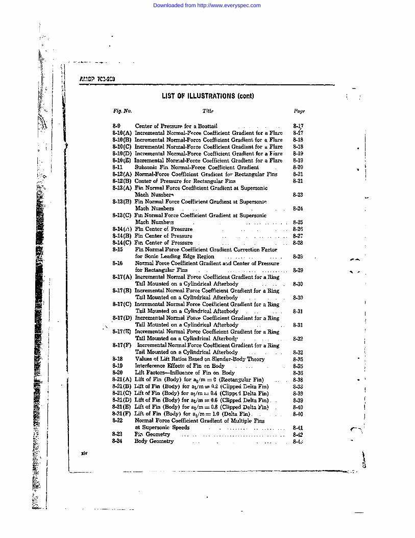
8-9 Center of Pressure for a Boattail ....... 8-178-10(A) Incremental Normal-Force Coefficient Gradient for a Flare 8.,78-10(B) Incremental Normal-Force Coefficient Gradient for a Flare 8-188-10(C) Incremental Normal-Force Coefficient Gradient for a Flare 8-18
S8-10(D) Incremental Normal-Force Coefficient Gradient for a IFiare 8-198-10(E) Incremental Normal-Force Coefficient Gradient for a Flare 8-19
8-11 Subsonic Fin Normal-Force Coefficient Gradient 8-208-12(A) Normal-Force Coefficient Gradient for Rectangular Fins 8-21j 8-12 (B) Center of Pressure for Rectangular Fins 8-218-13(A) Fin Normal Force Coefficient Gradient at Supersonic
Mach Numberq 8-238-13(B) Fin Normal Force Coefficient Gradient at Supersonic
Mach Numbers 8-248-13(C) Fin Normal Force Coefficient Gradient at Supersonic
Mach Numbe's ... 8-258-14(A ) Fin Center ot Pressure .... .. 8-268-14(B) Fin Center of Pressure 8-278-14(C) Fm Center of Pressure ..... 8-288-15 Fin Normal Force Coefficient Gradient Correction Factor
for Sonic Leading Edge Region ......... . 8-298-16 Normal Force Coefficient Gradient arid Center of Pressure
for Rectangular Fins ....... .......... 8-298-17(A) Incremental Normal Force Coefficient Gradient for a Ring
Tail Mounted on a Cylindrical Afterbody ... 8-308-17(B) Incremental Normal Force Coefficient Gradient for a Ring
Tail Mounted on a Cylindrical Afterbody 8-308-17 (C) Incremental Normal Force Coefficient Gradient for a Ring
Tail Mounted on a Cylindrical Afterbody .... 8-318-17 (D) Incremental Normal Forke Coefficient Gradient for a Ring
Tail Mounted on a Cylindrical Afterbody .. . 8-318-17(E) Incremental Normal Force Coefficient Gradient for a Ring
Tail Mounted on a Cylindrical Afterbody. ......... 8-328-17 (F) Incremental Normal Force Coefficient Gradient for a Ring
Tail Mounted on a Cylindrical Afterbody .. 8-328-18 Values of Lift Ratios Based on Slender-Body Theory 8-358-19 Interference Effects of Fin on Body . .8-358-20 Lift Factors-Influence of Fin on Body 8-368-21(A) Lift of Fin (Body) for at/m = 0 (Rectangular Fin) .. 8-38 -8-21(B) Lift of Fin (Body) for at/m = 0.2 (Clipped Delta Fin) 8-338-21(C) Lift of Fin (Body) for at/m = 0.4 (Clippl Delta Fin) 8-398-21(D) Lift of Fin (Body) for at/m = 0.6 (Clipped Delta Fin) 8-398-21(E) Lift of Fin (Body) for at/m = 0.8 (Clipped Delta Yin) 8-408-21(F) Lift of Fin (Body) for at/m = 1.0 (Delta Fin) 8-408-22 Normal Force Coefficient Gradient of Multiple Fins
at Supersonic Speeds ...... ....... 8-418-23 Fizx Geometry ................... 8-428-24 Body Geometry .. .. . 8
Downloaded from http://www.everyspec.com
AMCP 703-280
LIST OF ILLUSTRATIONS (cont)
Fig. No. Title Page
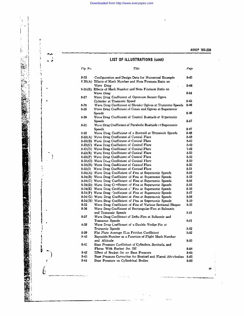
8-25 Configuration and Design Data for Numerical Example 8-43': :. Tt I'8-26(A) Effects of Mach Number and Nose Fineness Ratio on
Wave Drag 8-448-26(B) Effects of Mach Number and Nose Fineness Ratio on
Wave Drag 8448-27 Wave Drag Coefficient of Optimum Secant Ogive
Cylinder at Transonic Speed 8-458-28 Wave Drag Coefficient of Slender Ogives at Transonic Speeds 846
[ 8-29 Wave Drag Coefficient of Cones and Ogives at SupersonicSpeeds 8-46
8-30 Wave Drag Coefficient of Conical Boattails at S:personicSpeeds 8-47
8-31 Wave Drag Coefficient of Parabolic Boattails rt SupersonicSpeeds 8-47
8-32 Wave Drag Coefficient of a Boattail at Transonic Speeds 8-488-33 (A) Wave Drag Coefficient of Conical Flare 8-498-33(B) Wave Drag Coefficient of Conical Flare 8-498-33 (C) Wave Drag Coefficient of Conical Flare 8-498-33(D) Wave Drag Coefficient 3f Conical Flare 3-498-33(E) Wave Drag Coefficient of Conical Flare 8-508-33 (F) Wave Drag Coefficient of Conical Flare 8-508-33 (G) Wave Drag Coefficient of Conical Flare 8-508-33(H) Wave Drag Coefficient of Conical Flare 8-508-33(I) Wave Drag Coefficient of Conical Flare 8-518-34 (A) Wave Drag Coefficient of Fins at Supersonic Speeds 8-528-34(B) Wave Drag Coefficient of Fins at Supersonic Speeds 8-538-34 (C) Wave Drag Coefficient of Fins at Supersonic Speeds 8-548-34(D) Wave Drag Ccefficient of Fins at Supersonic Speeds 8-558-34(E) Wave Drag Coofficicnt o' Fins at Supersonic Speeds 8-568-34 (F) Wave Drag ',oefficient of Fins at Supersonic Speeds 8-578-34 (G) Wave Drag Coefficient of Fins at Supersonic Speeds 8-588-34 (H) Wave Drag Coefficient of Fins at Supersonic Speeds 8-598-35 Wave Drag Coefficient of Fins of Various Sectional Shapes 8-5608-36 Wave Drag Coefficient of Rectangular Fins at Subsonic
and Transonic Speeds 8.618-37 Wave Drag Coefficient of Delta Fins at Subsonic and
Transonic Speeds 8..61Al 8-38 Wave Drag Coefficient of a Double Wedge Fin at
8-9 Transonic Speeds -628-39 Flat Plate Average S'in Friction Coefficient 8-628-40 Reynolds Number as a Function of Flight Mach Number
and Altitude 8-638-41 Base Pressure Coefficient of Cylinders, Boattails, and
Flares With Rocket Jet Off 8-648-42 Effect of Rocket Jet on Base Pressure 8-648-43 Base Pressure Correction for Boattail and Flared Aft'-rbodies 8-658-44 Base Pressure on Cylindrical Bodies 8-66
L ____
Downloaded from http://www.everyspec.com
AM1CP 72SO
LIST OF ILLUSTRATIONS (cont)
Fig. No. "itlr Pagr
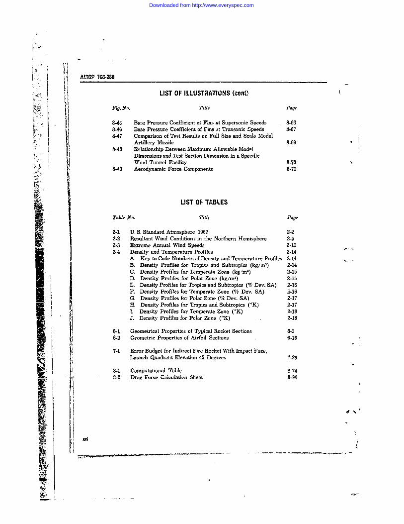
8-45 Base Pressure Coefficient ot Fins at Supersonic Speeds 8-668-46 Base Pressure Coefficient of Fins it Transonic Speeds 8-678-47 Comparison of Test Results on Full Size and Scale Model
Artillery Missile 8-698-48 Relationship Between Maximum Allowable Modil
Dimensions and Test Section Dimension in a SpecificWind Tunnel Facility 8-70
8-49 Aerodynamic Force Components 8-71
LIST OF TABLESI Tablr No. Tith Page
2-1 U. S. Standard Atmosphere 1962 2-22-2 Resultant Wind Condition s in the Northern Hemisphere 2-52-3 Extreme Annual Wind Speeds 2-112-4 Density and Temperature Profiles 2-14
A. Key to Code Numbers of Density and Temperature Profiles 2-14B. Density Profiles for Tropic.; and Subtropics (kg/im) 2-14C. Density Profiles for Temperate Zone (kg 'm 3 ) 2-15D. Density Profiles for Polar Zone (kg/m 3) 2-15E. Density Profiles for Tropics and Subtropics (% Dev. SA) 2-16F. Density Profiles for Temperate Zone (% Dev. SA) 2-46G. Density Profiles for Polar Zone (% Dev. SA) 2-17H. Density Profiles for Tropics and Subtropics ('K) 2-17T. Dersity Profiles for Temperate Zone (*K) 2-18J. Density Profiles for Polar Zone ('K) 2-18
6-1 Geometrical Properties of Typical Rocket Sections 6-36-2 Geometric Properties of Airfoil Sections 6-16
7-1 Error Budget for Indirect Fire Rocket With Impact Fuze,Launch Quadrant Elevation 45 Degrees 7-28
8-1 Computational Table e 74S2 Ding Force Calculati-,n Sheei' 8-96
'Ff4[
A!
xvi -
Downloaded from http://www.everyspec.com
L
AMCP 7M,-280
0. CHAPTER 1INTRODUCTION
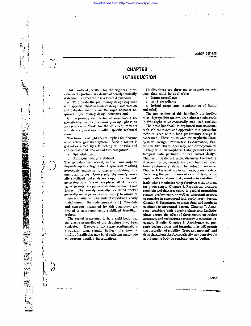
This handbook, written for the engineer inter- Finally, there are three major propulsion sys-ested iii the preliminary design of aerodynamically tems that could be applicable:stabilized free rockets, has a twofold purpose: a. liquid propellants
a. To provide the preliminary design engineer b. solid propellantswith specific, "best available" design information c. hybrid propellants (combination of liquidand data devised to allo, the rapid response rc- and solid)quired of preliminary design activities, and The applications of this handbook are limited
b. To provide each technical area having re- to solid-propellant motors, used almost exclusivelysponsibilitzeE in the preliminary design phase an in free-flight aerodynamically stabilized rockets.appreciation or "feel" for the data requirements The basic handbook is organized into chapters,and data applications of other specific technical each self-contained and applicable to a particularareas. technical area w'th which preliminary design is
The term free-flight rocket implies the absence concerned. These ai,-as are" tmospheric Data,of an active guidance system. Such a rocket is Systems Design, Parametric Performance, Pro-guided or aimed by a launching rail or tube and pulsion, Structures, Accuracy, and Aerodynain:cs.I ' can be classified into one of two categories, Chapter 2, Atmospheric Data, presents clima-
a. Spin-stabilized tological data partinent to free rocket design.b. Aerodynamically stabilized Chapter 3, Systems Design. discusses the factors
0 The spin-stabilized rocket, as the name implies, affecting design, considering each technical area) depends upon a high rate of spin and resulting from prliminary design to actual hardware.gyroscopic moments to oppose disturbing mo- Chapter 4, Paiametric Performance, presents dataments and forces. Conversely, the aerodynamic- describing the performance of various design con-ally stabilized rocket depends upon the moments cepts, with variations that permit consideration ofgenerated by a flare or fins placed aft of the cen- trade-offs to maximize range for given mass or mass
* ter of gravity to oppose disturbing moments and for givin range. Chapter 5, Propulsion, presentsforces. The aerodynamically stabilized rocket concepts and data necessary to predict propulsiongenerally employs some spin history to minimize system nprformance, o well a- imp.rtnt aspectsdispersion due to nonstandard conditions (body to consider in conceptual and preliminary design.malalignment, fin malalignment, etc.). The data Chapter 6, Structurcs, presents data and methodsand concepts presented by this handbook are pertinent to structural design. Chapter 7, Accu-limited to aerodynamically stabilized free-flight racy, considers both burning-phase and ballistic-rockets. phase errors, the effect of these errors on rocket
The rocket is assumed to be a rigid body, i.e., accuracy, and techniques necessary to estimate ac-the elastic properties of the structure have been curacy. Finally, Chapter 8, Aerodynamics, pre-neglected. However, for some configurations sents design curves and formulas that will permit(primariay long, slender bodies) the dynamic the prediction of stability (force and moment) andiau&. uf uCillaion may be of sufficient amplitude drag characteristics for practically any conceivableto warrant detailed investigations, aerodynamic body or combinations of bodies.
x1 -111-2
Downloaded from http://www.everyspec.com
0
AMCF 703-2e0
CHAPTER 2ATMOSPHERIC DATA
2-1 INTRODUCTION ard Atmosphere The major reason for revisingstandard atmospheres in recent years has been
Atmospheric information is a ve.y important the ubserved ozbit pertu rbationb of artificial satc!.-.ons,"eraton in the prelimmary design of rvckets. lItes due to atmospheric drag. This sub,--t isparticularly those that are free-fl.ght or uncon- beyond the present scope of Anteres-t. See RIefer-
Strolled after launch. Since atmospheric data are ence 2 for complete tables.Lime- and space-dependent, and therefore widely Table 2-1 presents a useful summar. of at-variable, statistical processes are normally used mospheric properties taken from Reference 2.
- : for their presentation, analyss, and utilizatin.
:' Because some types of statistical data are sub-ject to considerable controversy, one can hardly 2-2.2 WINDS, UPPER LEVELhope to develop standardized actual climatologicaldata profiles, and perturbations to them, that w.ll The problem of Lelecurg wind profile infcrma-receive universal acceptance. Instead, meteor- tiun fur ute a-s design Lriteria led to development; ,. ologists have developed synthetic .tandard pro- of dri ebtirmated synthetic profile ,%hich presentedfiles, independent of physi-al location. Means and th- 1 perment probable % knd speed and associatedextremes of these profile- were then developed. shedr at thE mu%. Lr, ital altitude, and speeds of
' dependent upon rather general geographic lOCd- other altitL des ty pica, for such wind fields. Sub-tion. Finally, models of microclunatologivei (1o- _equent investigation revealed that, if accuracycalized) conditions can be accomplished to meet in ,he calculated risk is desired, the use of syn-specific conditions. thetic wind profils is hazardous. However, logi-
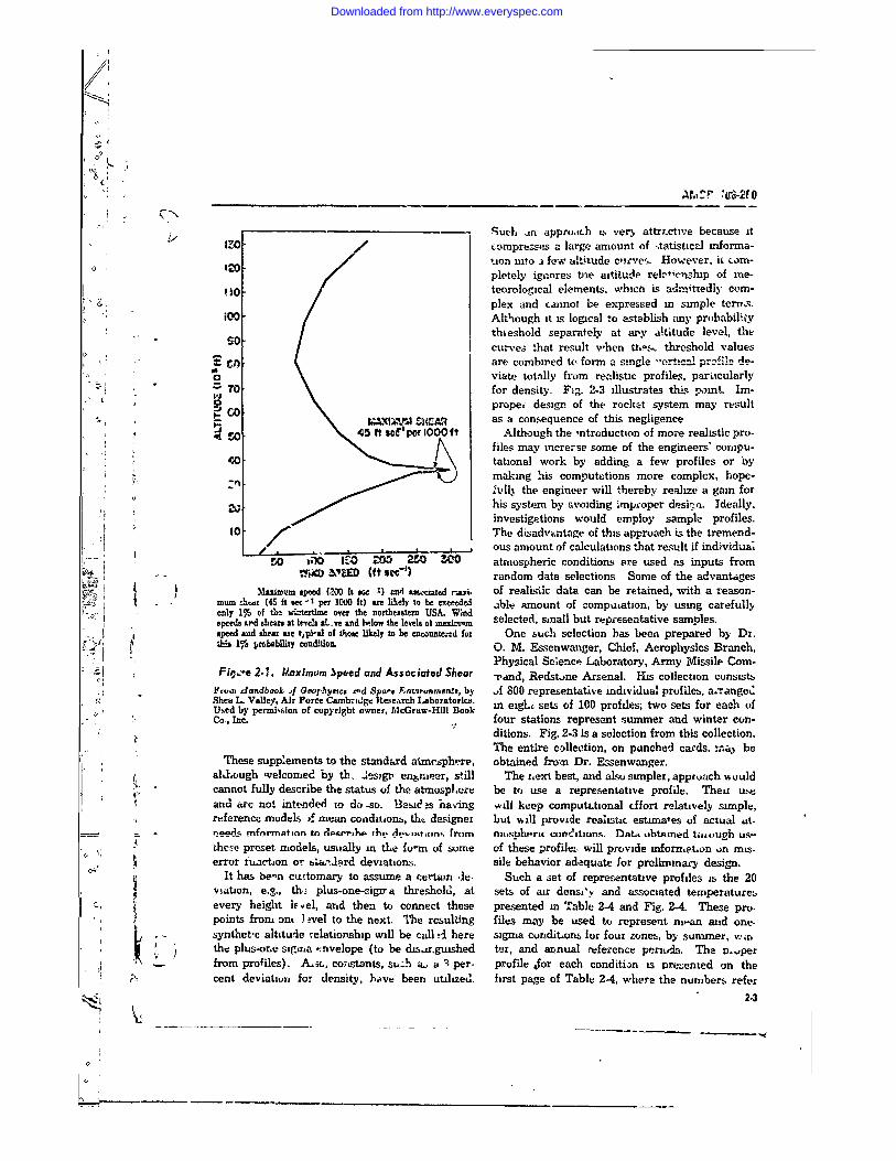
In rocket design, the prelumary design phase cally developed synthetic orofiles are useful inis concerned primarily with macrocl.natolog. prelimm.ry design. Fig. 2 1 is a synthetic wind(large-scale conditrons). Density, temperature, profile that was developed in 1954 to cletermmeand presure profiles (variation of these factors %ehicle responses that wuuld bl. exceeded duringwith altitude) must be presenteo to the trajectory only 1 percent of the windiest season of the yearwnalyst so that configuration performance can be in that area of the U. S. where tropospheric winddetermined. Wind profiles and wind shear in- streams were considered the strongest. It is teaformation are necessary for structural design as sunable to shift thE curve upward or downwardvell as for accaracy studies. Finally, considera- by as much as 5000 ft to make the peak windt,on of extreme cundition is necessary to ensure speed coincide ,i ith the altitude of maximum windcomplete system integration and operation. influence.
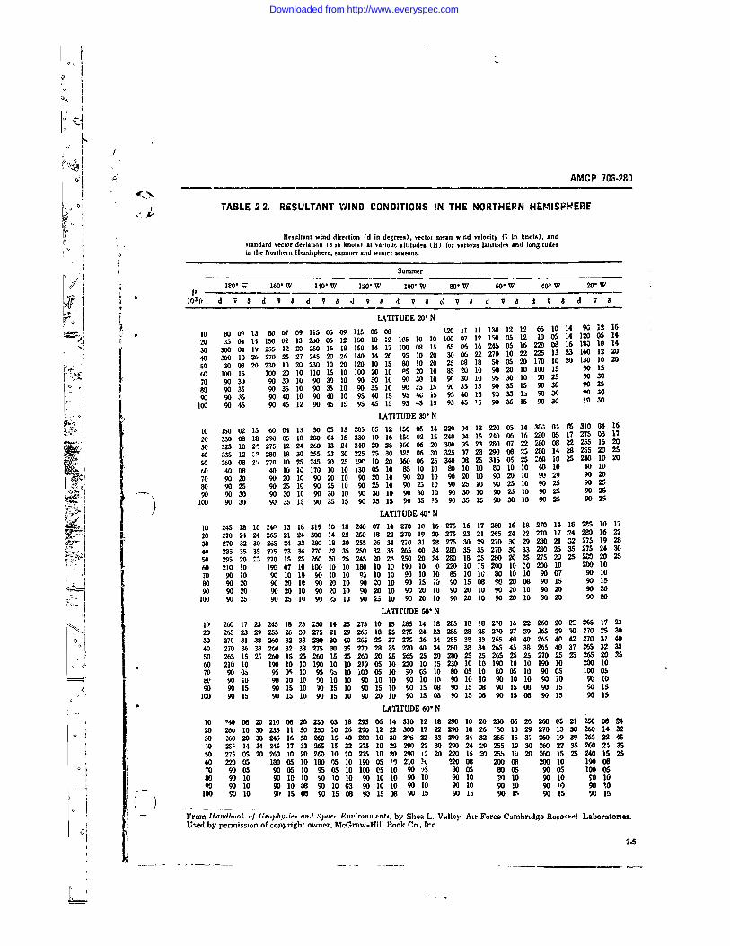
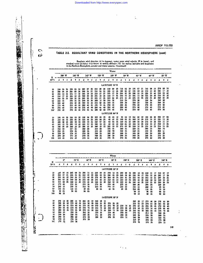
C~ Ideally, in missile design and accuracy studies., the designer must know mean wind velocity and
2-2 ATMOSPHERIC PROPERTIES standard deviation for both hemispheres. Tab..e2-2 gihes the resultant wind direction, vector
2-2. ATMOSPHERIC DENSITY, TEMPERATURE mean wid velocitv and the standard vdctor de-AND PRESSURE viation for the No:thern hemisphere between
20°N and 800N at altitudes from 10,000 to 100,000The U. S. Standard Atmosphere (USSA) is ft for winter and summer.
based upon the International Civil Aviatimn Or- See Reference 4. the llandbool of Grophyjz;cse ganzatin (ICAO) Standard Atmosphere to 20 and Spa(# Entiranmrnts, 1965, Chapter 4. for the
kin altitude. and upon the proposed ICAO exten- mean wind speed, standard dev:ation, and corre,,n from 20 km to 32 kma. Data for the first lation between levels for a series of altitudes
20, kr are in ag.reement with the Air Research for each vector component at specific stations dux-( iiard Development Command (ARDC) 1959 Stand- ing the winter season.
7 24
Downloaded from http://www.everyspec.com
SA IC? 7C3.2
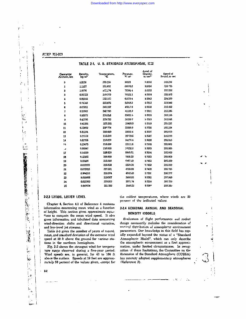
TADLE 2-1. U. S. ST,,DARD ATrOSPHERE, I. 12
ActceJ. ofGeornetril De-sity, Temperature, Prewure. Gravity, Speed of
Altitude, km kN %m ,, m/seet Sound, m, sec
0 12250 283 !50 10325 9.80G6 340.2941 11.117 281.651 89376.2 9.8036 336,A352 LW M, 79501 4 9.3055 312.53
,3 0.0=5 2a.059 70121.1 9.7974 328.&R34 0.81935 =52.1C4 61650.4 9.7943 324.5S9
5 0.7343 255.678 540482 9.7912 320.5456 0.0,.1 249,187 47217.6 9.7882 316.4527 0.5002 242.700 41105.2 97851 312.306
f, 8 0.52579 23G215 35651.6 9.7820 303.1059 0.467063 229.733 303007 97789 303.848
10 0.41351 223252 26499.9 9.7759 299.53211 0=,I4' 0 210 774 22699.9 9.7728 295.15412 0,31194 216.650 19399 4 9.7697 295.069
13 02CC00 216.6,O 1679.6 9.7G67 205.0,3914 0227eS 216.C50 14170.4 9.7636 295.069
Clo 0.19475 216.650 12111.8 9.7605 295.069
0.1647 216.650 30352.8 9.7575 295.06917 0.1230 216.650 8849.71 9.7544 295.0691 0.12165 216.650 756522 9.7513 295.0919 0.10400 216.650 f47.4-8 9.7483 295.06920 0.0m3810 216.650 5529.30 9.7452 295.05921 0.075715 217.531 4728.93 9.7422 295.70322 0.064510 218.574 4047.49 9.7391 296.37723 0.055006 219.567 3466.86 9.7361 297.04924 0.010233 220.5.0 2971.74 9.7330 297.7202 0.040034 221.552 2549.22 9.7301) 293.389
2-2.3 WINJDS, LOWER LEVEL the coldest temperatures, where winds are 50percent of the indicated values.
Chapter 4, Section 4.1 of Reference 4 containsinformation concerning mean wind as a function 2-2.4 REGIONAL ANNUAL AND SEASONALof height. This section gives approximate equa-;ons to compute the mean wind speed. It also DENSITYMODELS
gives infornnatioti and tabulated data concerning Evaluation of flight performance iud rocketwind-direction shifts and directional variation, design necessarily includes the consideration of
L and low-;eve] jet streamrs. vprii,,o distrib'.."rn uf aiospheric environment 9
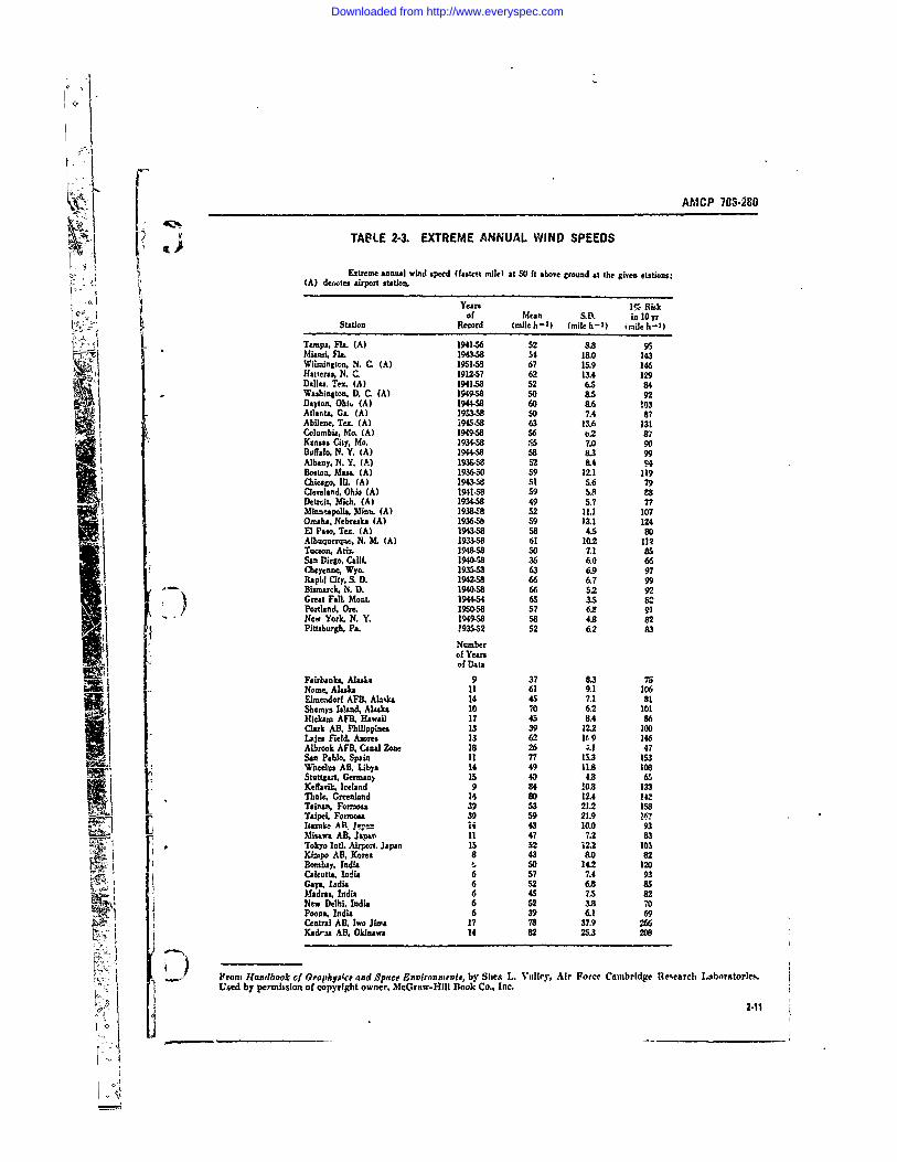
Labie 2-3 gives the number of years of record, parameters, Our knowledge in this field has rap-mean, and standard deviation of the extreme wind idly expandecd beyond the status of a "Standardspeed at 50 ft above the ground for various sta- Atmospheric Model", which can only describetions in the northern hemizphere. the atmospheric environment as a first approxi-
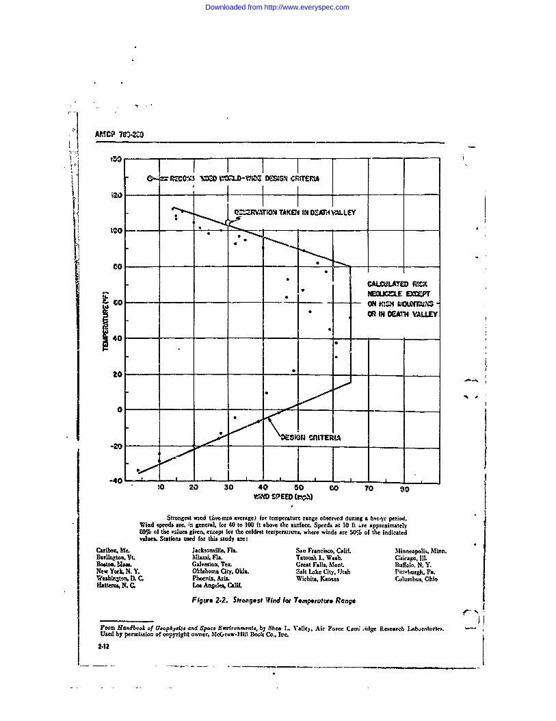
Fig. 2-2 shows the strongest wind for tempera- mation, under limited circumstmces. In recog-l.ure rangre observed during a five-year period. nition .)f these limitations, the Committee on thpWind speeds are, in general, for 40 to 100 ft Extension of the Standard Atmosphere (COESA)abo.,e the surface. Speeds at 10 feet are approxi- has recency adopted supplemntmy atmospheresmtely SO percent of the values given, .xcept for (Reference 2). .
2-4
Downloaded from http://www.everyspec.com
AfoI~r 70'-2f 0
S~.uch wi approach is .er* attri'.ctive because it130- comprezzes a large amount of tatistical informa-
uon into ai fe-w Altitude cuirve,. However, it co~m-0 120.pletely ignores vie aitiiude relrt4cn:lup of me-
'10- teorological elements, whicti is admittedly corm-plex and cannot be expressed in simple tern,.7,.
300Although it is logical to establish any probabil~y
thi eshold separately at ary altitude level, the
are combined to form a stigle -ert.-cal 4,_~'~0 ~viate totally from realistic profiles, par-Licularly- 70for density. Fig. 2-3 illustrates this point. un-
prope. design of the rocket system may resultco =1XvMA SIA as a consequence of this negligence
~ ro45 ft scf' por 1000 ft Although the -ntroduction of more realistic pro-files may incre-se some of the engineers' corapu-
Z 40 tational work by adding a few profiles or by:n making his computations more complex, hope-
V11l3 the engineer will thereby realize a gain for20 his system by avoiding inpicoper deskri. Ideally,
investigations would employ sample profiles,10- The disadvantage of this approach is the tremend-
___________________ ous amount of calculations that result if individuai50 iMo IEO MO: 2W zo atmsospheric conditions are used xis inputs from
Z.4)I WEED (ft 8ft-) random data selections Some of the advantagesMm'marn speed 01M0 ft see -) =n' sciated ,.wj. of realistic data can be retained, with a reason-
mum shli! (45 ft sec-I per 1000 ft) are likely to be exceedeZ ablte amount of compua~ation, by using carefullyonly 1% of thz win-tertime over the northeastern USA. Windspeeds &j'd shears at levels aL.Ye and 1below the levels ot mgaxlinra selected, sinall but representative samples.speed aud shear azo tp5-sl of those likely to be encounterted for One such selection has been prepared by Dr.
tl±~ 1%Proal~lit cod~ton.0. M. Essenwailger, Chief, Aerophysics Branch,Physical Science Laboratory, Army Missile Comn-
Fir,... 2.1. Maximum Npeed and Associated Shear -rind, Redstiane Arsenal. His collection consistsFro~rdandbook of Oeot-hysics zd Spar~e Fnrnruients, by ..,f 800 ropresentative individual profiles, a.-rangetdShea L. Valley, Air Force Cambz.tLgc Research Laboratorics. i g-,set f10poie;tost o ahoUsed by permlission of copyright owner, McGraw-Hill Book eg f10poie;tost o ahoCo., Inc. four stations represent summer and winter con-
ditions. Fig. 2-3 is a selection from this collection.TVhe entire collection, on panched cacds. rtaa, be
These suppements to the standurd airrncsphere, obtained fromn Dr. Essenwanger.al~hough wvelcomied 'by th, Jesigm euarneer, still The x~ext best, and also simpler, approach wouldcannot fully describe the status of the atmnosph~ere be to use a representative profile. Their useand are not intendeti to do -so. Eebid is ha 'ing -vill keep computational (cffort relatively simple,ref erence models )f mean coniduiorib, th, designer but will provide realistic estimates of actual at-
* naot infnrmatann tn eApeibh the Ae~atmmn%~ from mt,slahtpnc ccmneiitions. Data obtained ti1 &uuwh use'the~e preset models, usually in the fo'-m of some of these profilerz. will provide inforirrPt~on on mis-
Cerror iuaction or bta:-Ie1rd deviations. sile behavior adequate for preliminacy design.It has be'-n cEmitomary to assume a certain de- Such a set of representative profiles is the 20
v jation, e.g., th,. plus-one-sign- a threshold, at sets of air densi %y and associated temperaturesevery height le vel, and then to connect these presented in Table 2-4 and Fig. 2-4. These pro.points fronm ont 1 tvel to the next. The resulting files may be used to represent nu~an and one-synthet-c altituie relationship will be call!.1 here sigma coraditionf, for four zone:, by summer, v. .rthe plus-or& sigara kvnvelope (to be disar.guished ter, and arknual referenice peruids. The ri.uperfrom profiles). A..ic, co;-istants, su h &_~ a 1~ per- profile jor each conditi.,n is oresented on the
F, cent deviation for density, ha~ve been utilized, first page of Table 2-4, where the numbers refer2-3
Downloaded from http://www.everyspec.com
Af, CP 70 -280-
to the subscripts in subsequent column headings REFERENCESand the various curves of Fig. 24.
rt. H. P. Dudel of the Aerophysics Branch,V ,¢ Plysical Sciences Lab, R&DD, U. S. Army Missile l ACP 706-283. Engineering Design Handbook,
p < ', Command, hr published a report (Reference 7) .1crod.yn ntcsd.giving the mean, rinus-one sigra. and plus-one 2. 1'. S. Standard Atmosphere, 1962 COESA,
sigma density profiles for the midseason months NASA, USAF, U. S. Weather Bureau, U. S.of January and JLly at latitudes of 150N, 30 0N, Government Printing (ffice, Dec 1962.450N, OoN and 75° N. The associated tempera- : Iir Force Interim Supplemental Atmosphere totures are not yet available, bat will be included 0 Kilometers, Air Force Surveys in Geophysicsin a forthroiwing report. In the meantime, the No. 1.53, 1963.Committee o,, Extension of the Standard Atmo- t. Handbook of Geophysics and Space Environ-bphere (COESA) has announced adoption and nents, AFCRL, McGraw-Hill, April 65.proposed republication of the Air Force Interim .5. AR 705-I5, Change 1. Op,,ration of Me.t ,rial Un-Supp'emental Atmospheres as publish..1 by Cole der Extreme Conditions of Environment.and Kntar (Reference 3). These -upplemen- 6. MIL-STD-210A, Climatic Extremes in Militarytary atmospheres to the U. S. Standard Atmos- Equzpment.phere, 1962, approximate mean conditions at the 7. It. P. D'del, Regona'.deasoral One-Sigmasame geographic latitudes and months as does Denait# Profiles, Aewophystes Branch, PhysicalH. P. Dudel's repcrt, Ref. 7. Scienzes Lab. R&DD, USAMICOM.
° I
414
2
OJ,24
Downloaded from http://www.everyspec.com
-I
AMCP 703-280
TABLE 22. RESULTANT WIND CONDITIONS IN THE NORTHERN HEMISPIERE
Resultant wind direction (d in degrees), vectot mean wind velocity ( in knots), and%tandard vector deviation (8 in knotsb at variouo, altitudes (H) for various latitudes and longitudesin the Northern Hemisphere. summer and winter seasons.
Summer71 180* W 160" W 140" W 120" W 100, W 80" W 60'W 40" W 20" W103f, d V a d 9 a d V 1 J 9 d V a d V a d v a d V I d v a
LATITUDE 20* N
10 80 00 13 80 07 09 115 05 09 115 05 08 120 11 11 130 12 12 65 10 14 9G 12 16
20 35 04 14 150 02 13 240 06 12 150 10 12 105 10 10 100 07 12 150 05 12 10 05 14 120 05 14
30 300 01 19 255 12 20 250 16 18 150 14 17 100 08 15 65 06 16 245 05 16 220 08 16 1 10 144o 300 10 26 270 25 27 25 20 26 140 14 20 95 020 30 06 22 270 10 22 5 13 23 160 12 20
50 30 03 20 230 10 20 230 10 20 120 10 15 80 10 20 25 C3 18 50 05 20 170 10 20 130 10 2060 100 15 100 20 10 110 15 10 100 20 10 P5 20 10 85 20 10 90 20 10 100 15 90 15
70 90 30 90 30 10 90 30 10 90 30 10 90 30 10 9' 30 10 95 30 10 90 25 90 3080 90 35 go 35 I090 35 10 90 35 10 9 3S 1I 90 35 15 90 35 15 90 36 90 3590 90 35 9 0 40 l 0 9 0 4 0 10 9 5 40 15 95 4 15 95 40 15 90 351 b 90 30 0 30
; 100 90 45 90 45 12 90 45 1 95 45 15 95 45 15 95 45 15 90 35 15 90 30 0 0" " !LATITUDE 30" N
.% I0 1z)0 02 15 60 04 13 50 05 13 205 05 12 150 05 14 220 04 13 220 05 14 3W 04 1115 310 04 16
20 330 08 18 2 05 18 200 04 15 230 10 16 150 02 15 240 04 15 240 06 16 20 05 17 275 08730 325 10 2V 275 12 24 260 13 24 240 20 25 360 06 20 300 05 23 2ro 07 22 M8 08 22 2&5 15 20
40 335 12 "1 280 18 30 26 23 30 225 25 30 325 06 30 325 07 23 290 08 25 280 14 28 255 20 2550 360 08 2' 270 10 25 245 20 25 IX 10 20 360 06 25 340 08 25 315 0.5 25 :W 10 25 240 10 20
60 40 08 40 10 10 170 10 10 130 05 10 85 10 10 80 10 10 80 10 10 40 10 40 1070 90 20 90 20 10 90 20 10 90 20 10 90 20 10 90 20 10 90 20 109020 90 2080 90 25 90 25 10 90 25 10 90 25 10 90 251 0 90 25 10 90 25 10 90 25 90 2590 90 30 90 30 10 90 30 10 90 30 10 90 30 10 90 30 10 90 251 0 90 25 90 25
10 9030 903515903515903515 90 35 5 90 351590 30 10 90 25 90 25
LATITUDE 40" N0 245181824 131835l018 240 07 14 270 10 16 275 16 17 260 16 18 270 14 18 285 10 17
20 270 24 24 265 21 24 300 14 22 250 18 22 270 19 20 27E 23 21 265 24 22 270 17 24 275 16 22
30 270 32 30 265 24 32 280 18 30 255 26 34 270 31 28 275 30 29 270 30 29 280213227519284o 28s 35 35 25 23 34 270 22 35 250 32 36 265 40 34 20 3s 35 270 333 20 25 35 275 24 3050 295 20 Z 270 1S 25 260 20 25 245 20 2 -450 20 74 280 18 25 2O 20 25275 20 25 20 20 2560 210 10 190 071010010101801010190 10 .0 220 10 5 200 10 '0 200 10 200 1070 90 10 90 10 10 W 10 10 95 10 10 90 10 0 85 10 it 80 10 10 90 07 90 1080 90 20 0 0 1 90 20 10 90 20 10 90 15 i; 90 15 08 90 20 08 90 15 90 1590 90 20 90 20 10 90 2 10 90 20 10 90 20 10 90 20 10 90 20 10 90 20 90 20
-- r 100 90 25 90 25 10 90 2 10 90 25 10 90 20 10 90 20 10 90 20 10 90 20 90 20
K 1LATI rUDE 50 N10 260 17 23 245 18 23 250 14 23 275 10 15 285 14 18 285 18 !8 270 16 22 260 20 2: 265 17 2320 2(5 23 29 255 26 30 275 21 29 265 18 25 275 24 23 28528 25 270 27 29 265 29 10 270 5 3030 270 31 38 260 32 38 280 30 40 265 25 37 275 36 34 285 3 33 265 40 40 M 4P 42 270 3: 4040 270 36 38 2W 32 38 275 30 35 270 28 35 270 40 34 280 38 34 265 45 38 265 40 37 265 32 3850 265 15 25 260 15 25 260 15 25 260 20 25 265 25 20 200 25 25 265 25 25 270 25 25 265 20 2560 210 10 190 10 10 190 10 10 210 05 10 220 10 15 230 10 10 190 10 10 190 10 200 1070 90 05 95 05 10 95 o 10 j00 05 10 90 05 10 80 05 10 6005 10 90 05 100 05&I 9U io 90 10 10 90 10 10 90 10 10 90 10 I0 90 10 10 90 10 10 90 10 90 1090 90 15 90 15 10 0 15 10 90 15 10 90 15 08 90 is 06 90 15 06 9015 s 15
100 9015 90 15 10 90 15 10 90 20 10 90 15 08 90 15 08 90 15 08 90 15 90 15
LATITUDE 60 N10 940 08 2 0 2 10 06 20 230 05 18 295 06 14 310 12 18 290 10 20 230 06 20 260 05 21 250 00 2420 26v 10 30 235 11 30 250 10 2% 290 12 22 300 17 22 290 18 26 "50 10 29 270 13 30 260 14 3230 60 20 38 245 16 38 260 15 40 20 10 30 295 22 33 290 24 32 25.5 15 3j 260 19 39 265 22 4510 25!; 14 34 245 17 33 265 15 32 275 10 - 290 22 30 290 24 29 255 19 30 260 22 35 260 21 3550 275 05 20 260 10 20 260 10 0 275 10 20 290 15 20 290 15 20 255 I 20 260 15 25 240 15 2560 220 05 180 05 10 180 05 10 190 05 '9 21 0 220 06 200 08 200 10 190 0670 90 05 90 05 10 95 05 10 100 e5 10 90 1). 80 05 80 05 90 05 100 0580 90 10 90 10109010109010 10 g10 90 10 90 10 90 10 0 1090 90 10 9010089010039 0 10 90 10 90 10 90 10 90 10 90 10
100 90 10 9( 15 0 901508 90 15 08 90 15 90 15 90 1 90 15 90 15
From llandhr,4o/fi f ;etph'birx ,and? S,,r Enironnonts, by Shea L. Valley. Air Force Cambridge Resc-"l Laboratories.Used by permission of copyright owner, McGraw-Hill Book Co., Irc.
2-5
L
Downloaded from http://www.everyspec.com
TALE 2-2. RESULTANT IVIND COCI!DITIONS IN THE NORTHRN HEMISPHERE (cont)
AResultant, wind diretion (d in degrces), vector mean wind %elocity (T "n knnt%), and
standard vector deviation (a an knots) at various altitudes tH I for various latitudes and unjitudr.In the Norhern Hemisphere, tsur.ner and winter scasone. (Coeinued)
Summer
Ica* W 160 W 140dW 120" W 100" W 30" W 60" W W 0 WHft d 1 6d & d 3 d 2 15 210 8 d V a
LATITUDE 70" N
1 10 IR 210 07 17 250 C7 16 300 09 13 330 08 18 2,0 04 18 140 03 17 65 03 16 330 04 1829 250 12 27 240 11 26 260 11 21 30 15 18 320 13 24 280 07 26 210 06 25 270 04 24 270 04 273 0 24;0 13 36 230 12 36 260 14 29 290 17 24 320 1- -029 280 06 32 235 08 32 250 08 33 270 05 3840 250 10 2 230 .2 28 250 13 24 2B5 13 22 315 16 24 270 10 23 230 07 25 M 07 25 M 08 25
50 255 O 1 5 253 05 IS 270 05 15 290 10 15 310 10 15 283515 245 05 15 210 03 10 210 05 2060 210 05 190 03 10 180 03 10 190 03 10 210 03 230 05 230 03 140 02 150 02
0 90 05 90 05 10 90 05 10 80 05 10 90 05 90 05 90 05 90 05 100 05to 90 W 90 03 10 90 08 10 9o 08 10 90 08 90 08 90 08 90 08 90 0890 90 03 90 03 10 90 10 08 90 08 0 90 03 90 08 90 08 90 08 90 08100 90 10 90 10 06 90 10 0I 90 in W E 90 0 90 10 90 10 90 10 90 10
LATITUDE 80" N
10 250 07 16 255 06 17 265 06 17 285 06 17 280 04 16 195 03 16 205 04 14 315 04 15 3100 152D 3. 11 24 260 12 24 2O 0 24 290 08 23 285 04 23 04 26 230 05 24 265 07 23 285 05 2430 270 G7 32 275 10 32 30 0 30 320 10 30 280 04 30 26S 04 30 215 06 30 270 06 34 300 09 3240 270 10 23 285 10 22 300 10 20 0 10 20 315 05 19 240 04 20 195 04 20 245 04 20 280 05 20SO 220 05 10 270 05 10 405 05 10 310 05 10 280 05 15 260 02 10 170 02 10 180 02 10 240 03 1560 200 05 200 05 190 05 190 05 30 02 30 02 40 02 150 02 150 0270 90 05 90 05 80 05 60 05 70 05 80 05 90 05 100 05 110 0580 90 05 90 05 90 GS 80 05 90 5 90 05 100 05 90 05 100 0590 90 05 9D 05 90 05 90 05 90 05 9u 05 90 05 9005 90 05
100 90 05 90 03 90 08 90 08 90 O 90 05 90 05 90 05 90 05
Summer
H 0 ° 20" E 0, E 60" E 801 E 100" E 120" E 140" E 160" EICA it d V I d T 3 - V 8 d V a d V 8 d a d 7 a d ; 6 d ; a
LATITUDE 2" N
10 115 15 1S 30 10 12 05 10 13 33 03 12 240 05 15 280 07 17 210 05 15 160 05 15 150 08 1020 U15 03 15 25 08 14 05 07 15 70 07 12 110 05 1, 115 05 14 165 05 b 170 03 15 130 05 1330 165 05 15 20 05 17 05 12 15 70 12 12 80 15 15 90 15 15 90 05 15 25 03 15 350 03 1840 150 10 20 30 05 22 110 22 18 70 28 18 90 25 20 85 25 20 85 10 25 30 05 25 355 05 23SO 120 15 20 110 25 25 110 30 20 90 40 25 0 45 25 75 40 25 75 20 25 65 15 25 0 10 2060 100 20 100 2 100 35 90 35 90 40 yu Wo 65 q 90 50 070 90 3D 90 30 90 30 90 30 90 30 90 30 90 40 90 40 90 30tO go 3 9085 9 35 90 35 90 35 90 35 90 40 90 40 90 4090 9035 90 35 90 45 90 45 90 401M so 8S 90 35 90 50 90 55 90 50
LATITUDE o0, N J10 130 03 16 33 10 15 295 0 It 345 04 15 245 6 18 230 07 15 245 10 1520 2 07 18 31S 13 18 270 12 17 360 07 15 173 05 15 245 1;. 20 250 15 2 250 10 18110 O0 13 19 270 17 20 240 10 21 345 03 18 225 05 20 170 10 25 220 15 30 270 13 27 290 12 2340 0 20 25 755 2- 220 17 23 320 07 25 260 08 25 190 15 30 225 15 35 305 20 35 310 15 30W Z45 !5 20 = 15 25 195 10 20 180 07 25 30 05 25 60 15 30 340 10 35 340 10 30 345 10 30CO 17015 15010 150 15 90 10 90 10 90 20 so 20 70 15 40 10
S9020 90 20 10020 I00 20 90 20 90 20 90 25 90 20 90 20
W 90 25 9025 90 25 90 30 90 30 90 30 90 30 90 2b 90 2590 90 25 90 25 90 25 90 30 00 30 90 30 "|1W0 so 30 M 0 90 30 90 35 90 40 90 40
24
Downloaded from http://www.everyspec.com
/1
AMCP 706-280
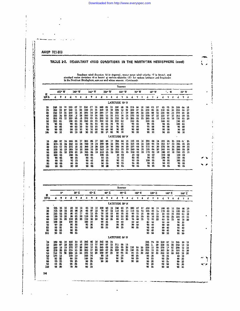
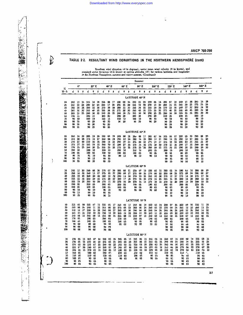
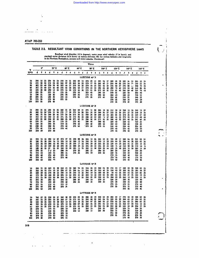
TABLE 2-2. RESULTANT WIND CONDITIONS IN THE NORTHERN HEMISPHERE (cant)
Resultant wind direction (d in degrees), vector mean wind velocity (v in knots), andstandard vector deviation 16 in knots) at various altitude, (H1) for various latitudes and longitude,in the Northern Hemisphere. summer and winter seasons. (Continued)
Summer0. 20* E 40" E 6o" E 80" E 100" E 120" E 140" E 160* Et H
.idt d V a d V 8 d V a d V a d v ad V ad V a d VI
LATITUDE 40" N
10 265 13 16 315 14 18 255 08 17 330 08 16 250 05 09 290 06 16 285 07 18 260 11 18 265 16 1820 265 22 20 290 22 23 240 17 20 295 15 20 255 12 20 270 13 20 2&0 14 25 265 20 25 275 24 2430 265 30 28 280 32 30 270 38 30 20 33 30 260 34 25 255 20 26 270 23 35 260 37 37 280 34 .32W, 265 32 30 265 40 30 255 38 35 275 38 30 260 43 35 275 35 35 275 40 35 265 40 45 280 39 3850 265 25 25 260 30 25 260 35 25 260 30 25 265 30 30 290 25 25 280 30 30 285 25 35 285 20 3060 190 15 200 15 200 20 200 20 200 20 200 20 210 20 220 15 220 1070 90 10 100 10 100 15 100 10 100 10 90 10 90 10 90 10 80 1080 90 20 90 20 90 20 90 20 90 20 90 20 90 20 90 20 90 2090 9020 9020 9020 9020 9020 9020
100 9025 9025 9025 9020 9020 9025
LATITUDE 50" N10 260 14 20 285 10 20 260 06 19 310 08 18 280 08 17 285 07 16 315 06 17 280 05 19 290 08 2020 25 20 28 275 14 27 260 08 24 295 13 24 280 14 25 280 13 21 290 13 25 280 12 27 285 16 2830 270 27 40 270 20 35 260 14 32 290 27 33 275 20 31 2"75 20 27 275 18 35 285 23 35 285 25 3740 270 27 35 265 24 3S 260 70 35 280 27 35 270 34 32 275 30 30 270 25 36 290 27 35 290 30 4050 270 1 25 260 20 25 255 25 20 275 25 25 270 2525 280 20 25 27s 20 25 290 20 25 290 20 3060 20010 200 0 20010 2 10 23 10 2 015 2o10 200 10 220 1070 100 05 100 05 100 10 100 05 100 05 90 05 90 05 80 05 90 0580 90 10 90 10 90 10 90 12 90 12 90 12 90 10 90 10 90 1090 90 15 90 15 90 15 90 15 90 15 90 15
100 90 20 90 20 90 20 90 10 90 10 90 10
LAaITUDE 60" N10 245 12 20 260 08 20 270 07 20 285 08 21 250 07 19 250 05 15 280 05 16 280 05 18 280 05 1920 250 16 30 260 13 27 275 10 27 290 09 27 270 09 26 270 08 22 280 08 24 275 08 24 280 08 2730 255 22 45 260 20 40 280 15 32 290 14 34 270 10 35 265 10 30 270 12 27 275 14 30 275 17 3440 255 22 35 260 20 32 275 20 27 280 17 28 270 18 26 270 15 25 265 16 26 280 16 28 280 12 3350 255 10 20 260 10 20 270 15 20 270 15 20 270 15 15 270 10 15 270 12 20 290 10 20 300 10 2560 190 05 200 05 200 05 200 05 190 05 190 05 200 05 200 05 220 05d0 100 05 100 05 100 05 100 05 90 05 90 05 90 05 90 05 900580 90 10 90 10 90 10 90 10 90 08 90 08 90 10 90 10 90 1090 90 13 90 10 90 10 90 10 90 10 90 10
100 90 15 90 15 90 1 90 10 90 10 90 10
LATITUDE 70" N10 255 05 18 225 07 15 235 05 17 225 05 17 210 05 19 210 05 14 240 07 15 250 09 16 250 11 1820 240 08 26 240 11 22 265 08 23 275 05 23 260 05 24 260 05 22 270 09 24 265 12 23 260 13 2530 210 14 37 230 16 28 260 08 27 265 05 30 260 04 30 260 04 26 260 08 24 260 12 26 260 14 3240 245 13 26 240 12 24 260 12 22 265 11 22 260 ]1 20 255 11 21 255 09 22 255 09 23 255 09 25S0 240 08 15245 0815 255 0815 255 081525007 15240 0813 2500815 25007 15 24505 1560 170 05 180 05 200 05 210 05 210 05 190 05 200 05 200 05 210 0570 100 o5 100 05 100 05 100 05 90 05 90 05 90 05 90 05 90 05[ 80 90 08 90 08 VOOR 909 e 90 0 roc 9,1 08oa VU wts90 90 08 90 08 90 M 90 08 90 08 90 08
100 90 08 90 08 90 08 90 05 90 5 90 5
LATITUDE 80" N10 270 05 1526507 14260 0515 245 0515 245 06 15245 0514 23007 IS 250 08 14 255 08 1620 270 0523 27006 22 255 0521 255 05 20255 0822 255 05 23260 0924 260 1024 2SS 11 2430 270 03 30 235 07 25 240 05 25 245 05 25 250 03 26 250 03 26 260 04 26 265 05 28 265 07 3040 25507202400719240071824507182500618255051826506202700620 270072050 245 05 15 270 05 IS 240 05 12 230 05 10 220 04 10 220 05 10 210 03 10 210 03 10 210 (13 10C 160 05 180 05 210 0; 210 05 210 02 210 03 210 05 2W % 210 0570 11005 110 05 110 us 110 05 100 05 90 a 90 05 90 05 90 0580 100 0 90 05 90 05 90 05 90 05 90 05 80 o; 9005 90 05
- , 90 90 05 90 05 90 05 0 05 90 05 90 05100 90 05 90 05 90 05 90 03 90 03 90 03
2-7
Li_ _ _ _ __ ___
Downloaded from http://www.everyspec.com
AMCP 70320
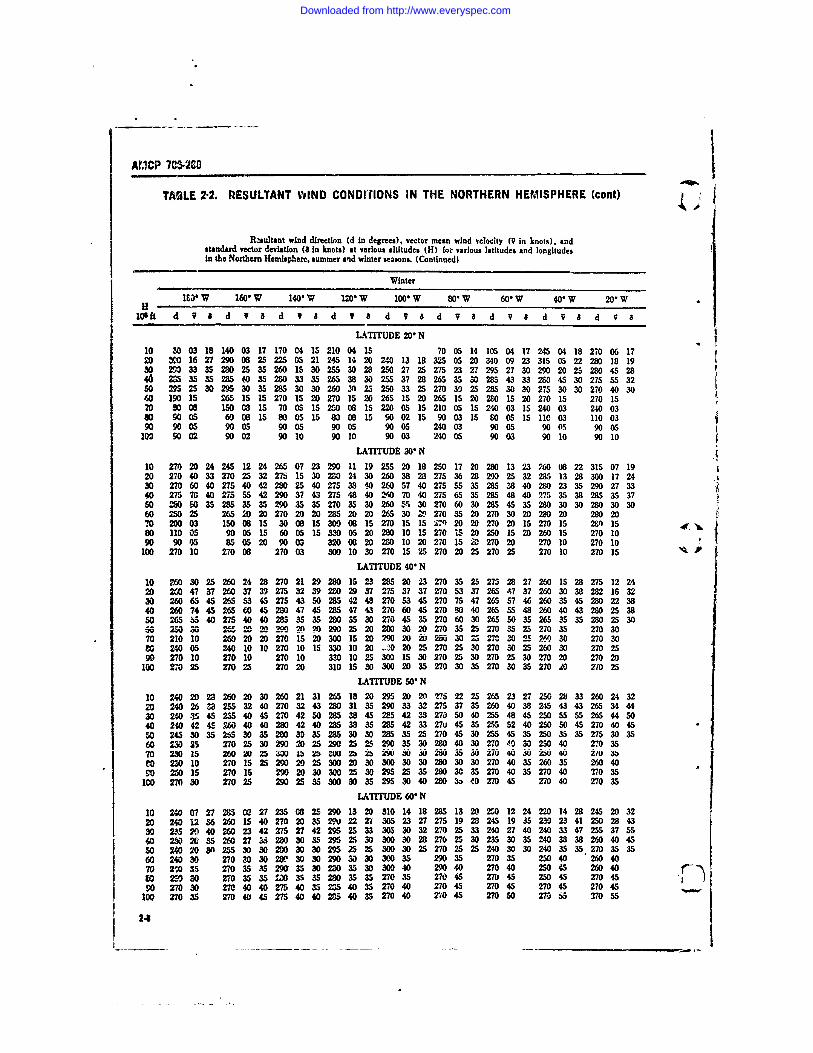
TAULE 2-2. RESULTANT WIND CONDIlONS IN THE NORTHERN HEMISPHERE (cont)
R.aultant wind direction (d In degrees), vector mean wind velocity (9 in knots), andstandard vector deviation (8 in knots) at various altitudes (H) for various latitudes and longitudesIn the Northern Hemisphere, summer and winter seasons. (Continued)
Winter
It" W 160" W 140"W 120" W 100" W 80, W 60" W 40" W 20" W
lOft d 9 a d V & d V a d V 8 d V 8 d V B d V 8 d V a d V 8
LATITUDE 20"N
10 80 03 18 140 03 17 170 04 15 210 04 15 70 05 14 105 04 17 245 04 18 270 06 1720 M0 16 27 290 08 25 225 05 21 245 14 20 240 13 18 325 05 20 340 09 23 315 05 22 280 18 1930 290 33 35 20 25 35 260 15 30 255 30 28 250 27 25 275 23 27 295 27 30 290 20 2S 280 45 2840 25 35 35 285 40 35 280 33 35 265 38 30 255 37 28 265 35 30 285 43 33 20 4S 3 275 3250 295 25 30 295 30 35 285 30 30 260 2 25 20 33 25 270 30 25 285 30 30 275 30 30 270 40 3060 190 is 265 15 15 270 15 20 270 15 20 265 15 20 265 15 20 280 15 20 270 15 270 1570 800 6 1508 15 70 05 15 = 08 15 220 05 15 210 05 15 240 03 15 240 03 240 0380 90 05 60 08 15 80 05 15 80 08 15 90 02 15 90 03 15 80 05 15 110 03 110 0390 90 05 90 05 90 05 90 05 90 05 240 03 90 05 90 05 90 05100 90 02 90 02 90 10 90 10 90 03 240 05 90 03 90 10 90 10
LATITUDE 300 N
10 270 20 24 245 12 24 265 07 23 290 11 19 255 20 18 250 17 20 280 13 23 26008 22 315 07 1920 270 40 33 270 25 32 275 15 30 280 24 30 260 38 28 275 36 28 29 25 32 285 13 28 300 17 2430 270 60 40 275 40 A-280 25 40 275 33 40 260 57 40 275 55 35 285 38 40 280 23 35 290 27 3340 275 70 40 275 55 42 290 37 43 275 48 40 w 70 40 275 65 3S 285 48 40 275 35 38 28S 3 3750 50 0 35 2s 35 35 290 35 270 35 30 260 5 30 270 60 30 285 45 35 280 30 30 280 30 3060 250 25 265 20 20 270 20 20 285 20 20 265 30 Z 270 35 20 270 30 20 280 20 280 207 20003 150 08 15 30 08 15 300 08 15 270 15 S 2'") 20 20 270 20 15 270 15 20 1580 110 05 90 05 15 60 05 15 330 05 20 280 10 15 270 15 20 250 15 20 260 15 270 1090 90 05 85 05 20 90 03 320 08 20 280 10 20 270 15 2 270 20 270 10 270 10
100 270 10 270 08 270 03 300 10 30 270 15 25 270 20 25 270 25 270 10 270 15LATITUDE 40" N
10 260 30 25 260 24 28 270 21 29 280 15 23 285 20 23 270 35 25 275 28 27 260 15 28 275 12 2420 20 47 37 260 37 39 275 32 39 200 29 37 275 37 37 270 53 37 265 7 37 260 30 38 282 16 3230 260 65 45 265 53 45 275 43 50 285 42 48 270 53 45 270 75 47 265 57 46 260 35 45 280 22 3840 260 74 4S 265 60 45 20 47 45 28S 47 43 270 60 45 270 80 40 265 55 48 260 40 43 280 25 3850 265 55 40 275 40 40 285 35 35 280 5 30 270 45 35 270 60 30 265 50 35 265 35 35 280 25 30
2500 s 202 2 290 ?. 20 290 25 20280 30 20 270 35 25 270 35 25 270 35 270 3070 210 10 260 20 20 2015 20 300 15 20 290 2D 20 250 513 25 ,3 = - 25260 .30 270 3080 240 05 240 10 10 270 10 15 330 10 20 -0 20 25 270 25 30270302526030 270 2590 270 10 270 10 270 10 330 10 25 300 15 30 270 25 30 270 25 30 270 20 270 20
100 270 25 270 25 270 20 310 15 0 300 20 35 270 30 35 270 30 35 270 20 2710 25LATITUDE 50" N
10 240 20 23 260 20 30 260 21 31 265 18 20 295 20 20 275 22 25 265 23 27 250 28 33 260 24 3220 240 263 25 32 40 270 32 43 280 31 35 290 33 32 275 37 35 260 40 38 245 43 43 265 34 4430 240 1 45 255 40 45 270 42 SO285 38 45 285 42 38 270 50 40 255 48 45 250 SS 55 265 44 5040 240 42 45 60 40 40 280 42 40 285 38 35 285 42 33 270 45 35 25S 52 40 250 50 45 270 40 45so 24s 30 35 265 30 35 200 3o 35 2a 30 30 25 35 25 270 45 30 255 45 35 250 35 35 275 30 3560 230 25 270 25 30 290 20 25 290 25 S 290 35 30 280 40 30 270 00 30 250 40 270 3570 230 15 mo w im 4 b2 zb jb i ju ', 5 30 "2O3276 w vj 250 w 210 230 10 270 15 25 290 20 25 300 20 30 300 30 30 280 30 30 270 40 35 260 35 260 40
90 260 15 270 15 990 20 30 300 25 30 295 25 35 280 30 35 270 40 35 270 40 '270 35100 270 30 270 25 290 25 35 300 30 35 295 30 40 280 3 40 270 45 270 40 270 35
LATITUDE 60" N
10 240 07 27 235 0 27 235 08 25 290 13 20 310 14 18 285 13 20 2S0 12 24 220 14 28 245 20 3220 240 12 36 260 15 40 270 20 35 290 22 27 305 23 27 275 19 28 245 19 35 230 23 41 250 28 4330 2.15 2 40 260 23 42 275 27 42 295 25 33 305 30 32 270 25 33 240 27 40 240 33 47 255 37 5540 23 Z 35 260 27 i 20 30 35 295 25 30 00 30 28 270 25 30 235 30 35 240 38 38 260 40 45SO 240 20 30 255 30 30 200 30 30 295 25 25 300 30 25 270 25 25 240 30 30 240 35 35 270 35 3560 240 30 270 30 30 280 30 30 290 30 30 300 35 290 35 270 35 250 40 260 4070 2,0 35 270 35 35 290 35 30 280 35 30 300 40 290 40 270 40 250 45 260 4090 20 30 270 35 35 L0 &% 35 2D0 35 35 270 35 270 45 270 45 250 45 270 4590 2703 270 40 40 275 40 35 20S 40 35 270 40 270 45 270 45 270 45 270 45100 270 35 270 40 45 275 40 40 205 40 35 270 40 20 45 270 50 270 55 370 55
2-4
Downloaded from http://www.everyspec.com
AMCP 716-280
TABLE 2-2. RESULTANT WIND CONDITIONS IN THE NORTHERN HEMISPHERE (cont)
Resultant wind direction (d in degrees), vector mean wind velocity (I in knots), andstandgrd vector deviation (Q in knots) at various altitudes (H) for various latitudes and longitudesin the Northern Hemisphere, summer and winter -casos. (Continued)
Winter
180 W 160" W 14* W 120" W 100" W 80 W 60" W 40" W 20* W
1Gl ft d V 4 d V 8 d V a d V 8 d 7 8 d V 8 d q 8 d V 8 d V a
LATITUDE 70' N
i 0O 0 03 26 300 04 24 285 07 20 310 08 20 330 08 18 10 02 18 195 07 21 165 08 24 270 09 220 28006 30 280 09 30 290 15 27 310 14 24 325 13 24 190 03 27 195 13 33 215 13 36 245 176 630 265 13 34 275 17 35 285 19 33 310 17 27 325 17 28 250 05 29 200 15 35 225 15 40 250 23 4640 240 17 30 265 23 28 290 20 28 315 18 25 320 17 25 260 15 25 205 15 30 225 20 30 255 25 320 240 25 25 260 25 25 285 25 25 305 2r, 25 310 20 25 275 15 25 225 15 25 230 .5 30 260 25 3060 250 35 270 35 35 290 35 30 300 5 30 310 30 310 20 270 20 250 30 260 3070 250 40 270 35 35 290 .35 35310 40 35 310 35 320 30 280 25 250 35 260 3580 270 40 270 40 35 280 40 35 .% 10 3 M 35 300 35 270 30 270 35 270 4090 270 40 270 40 40 275 40 40 280 4b 40 280 40 280 40 270 30 270 40 270 45
100' 270 40 270 45 45 275 45 45 280 40 40 270 45 270 45 270 40 270 45 270 50
LATITUDE 80" N
10 330 03 20 330 03 20 330 04 20 355 05 20 30 03 18 95 03 19 155 06 19 180 06 20 220 07 2320 310 04 25 320 05 25 325 06 25 355 04 25 45 02 25 120 05 25 160 10 29 210 10 32 225 13 3030 300 08 25 32D 10 25 320 10 25 345 07 25 60 03 25 140 05 25 190 10 30 215 10 33 230 15 3740 265 12 23 295 13 25 325 12 25 36 0 25 60 03 25 160 05 25 180 10 25 210 10 27 240 15 2550 260 20 20 260 20 25 280 15 25 300 15 25 285 10 25 275 08 25 230 10 25 235 10 25 250 15 25(60 250 20 27, 25 280 20 310 2D 320 15 340 15 320 15 290 10 260 )070 250 25 270 35 280 25 310 20 320 20 330 15 330 15 310 15 250 1.e80 270 30 270 35 270 30 290 25 300 20 300 15 300 20 290 20 260 2090 270 30 27( 35 270 35 280 25 280 20 290 20 290 20 280 25 270 25
100 270 35 270 35 270 35 270 30 270 25 270 25 270 25 270 30 270 30
Winter
0. 2GE E 40. E 60 E 80" E 100 E 120 E 1400 E 160' E[104 it d 7 8 dV a8 d a dv a d a 8d V d V 3d V a d V aLATITUDE 20" N
10 -40 06 16 265 08 15 290 13 15 250 09 15 270 12 15 290 08 15 200 12 14 210 11 17 210 07 1720 265 27 21 245 15 25 260 22 22 285 23 23 285 22 20 265 24 20 230 20 17 225 25 20 285 17 2030 265 55 32 260 35 27 275 40 30 270 45 28 260 40 25 250 45 25 255 40 22 245 32 25 295 30 2540 265 62 35 260 50 30 275 50 30 2!5 65 33 250 65 W0 250 52 25 250 45 25 240 30 2d 280 35 3050 265 50 25 260 45 30 270 45 25 260 5 30 250 55 32 250 45 25 240 40 25 230 25 25 220 30 256 (0 270 40 270 35 270 35 270 35 270 40 270 35 260 30 260 20 150 2070 250 10 250 15 210 15 210 25 M9f 255- 25010 2201 0 90 C5
" 05 10 5 i6 05 30 05 30 05 30 05 30 05 230 05 110 05 70 1090 90 05 90 05 90 05 90 10 96 10 90 10100 90 10 90 10 90 15 90 10
LATITUDE 30' N
10 290 14 20 280 16 20 265 20 19 250 18 15 28 28 17 275 30 20 270 30 2020 280 36 30 270 32 33 255 38 28 265 35 25 270 35 25 270 55 25 270 65 30 265 60 3030 28 50 45 270 60 45 270 65 40 270 5 3 275 58 35 270 70 35 270 65 35 M 90 35 270 So 4040 280 55 45 270 6S 40 270 75 40 255 75 40 260 80 0 270 80 35 270 90 35 270 10 40 270 95 4010 280 0 35 270 55 30 270 65 30 265 70 35 260 75 35 265 80 35 265 &5 3s 25 85 35 275 7 35
60 2803) 280 35 26035 27035 27040 2700 27 055 %35 2603570 29020 28020 260 25 276 30 270 0 280 30 260 25 240 20 200 1580 290 15 280 20 270 20 2 20 280 20 270 15 240 20 220 15 250 0590 20 is 270 25 270 20 2302 260 20 270 06IV, 270, 270 30 270 25 270 25 270 15
V 24
Downloaded from http://www.everyspec.com
TADLE 2-2. RESULTANT WIND CONDITIONS IN THE NORTHERN HEMI1SPHERE (cant)Resultant wind direction (d in degrees), vector mean wind velocity ( in knots). and
standard veclor deviation (a In knots) at various altitudes (H) for various latitudes and longitudesin the Northern Hemisphere, summer and winter seasons. (Continued)
Winter
06 20" E 40- E 60" E CO E 100" E 120 E 140" E 160" E
10 ft d V I d V 1 d V a d V a d V a 4 V a d V 8 J V 8 d V 8
LATITUDE 401N
10 290 12 23 200 14 24 260 16 21 260 09 15 270 09 11 295 23 17 300 28 18 28S 34 23 265 53 242D W 18 32 0 20 32 265 27 29 265 16 22 270 27 25 285 40 Z7 290 44 32 270 54 31 260 52 3430 3M 23 40 0 33 45 26S 40 37 270 33 35 270 44 3 285 36 2 60 37 270 260 75 4540 305 32 040= 40 40 270 55 33 265 43 37 270 55 3 280 65 40 W 70 40 270 90 40 M 80 4550 295 30 00 20 S335 275 45 35 270 4S 30 270 50 3S 270 60 35 1 6S 40 260 80 40 265 70 4060 290 25 20 35 270 35 270 35 2M 45 29 50 270 55 250 50 250 4070 290 2 M0 30 270 30 260 30 270 35 280 40 260 4 230 40 220 2580 290 25 2= 30 270 50 270 35 270 35 270 40 250 40 210 25 140 15
0 270 30 270 30 270 35 270 35 260 30 240 20100 270 35 270 40 270 35 27035 270 30LTITUDE 500 N
10 290 15 26 280 12 26 260 11 25 260 08 21 275 11 20 295 18 20 315 20 18 290 15 24 0 12 2720 30023362901634270N3 270142828520 300 26 27 310 25 30 275 2. 35 20 18 3530 30 M 50 290 20 45 275 2 34 275 18 35 290 3038300 35 33 305 25 3S 270 26 35 '240 27 4040 35 30 40 290 20 35 2b 25 32 270 25 352 0 30 33 295 N 37 300 45 35 270 535 24 40 4050 MOO 2S 30 290 25 35 280 25 30 275 30 25 230 30 30 275 335 290 40 35 255 40 35 24S 40 3560 M 00 290 30 270 35 270 40 280 40 290 40 260 40 230 40 230 3570 280 30 290 30 270 35 270 40 200 40 280 40 250 40 230 45 230 3590 2040 2704 0 270 50 270 45 240 40 220 40 236 2590 28 40 270 40 270 40 270 40 270 40 270 2
100 270 50 270 50 270 45 270 40 270 40
LATITUDE 600 N
10 270 16 26 2 9 W 25 270 07 26 260 08 24 265 12 2 2:5 13 21 320 09 17 300 04 22 255 03 2620 230 25 38 290 14 33 285 10 32 2aO 12 34 290 16 33 310 15 28 320 09 25 290 04 28 225 05 3530 2M 32 50 280 20 45 290 15 33 2 17 35 295 20 38 315 20 32 330 09 30 260 05 31 210 10 3540 5354029 2540 290 20 35 20 20 35 29 2 35 315 20 33 320 15 3 240 08 28 210 10 I5SO 280 30 35 2, 25 35 290 2 30 285 15 25 290 15 30 290 20 W z90 15 30 245 15 30 220 153000 270 35 7') 33 280 30 270 25 280 25 280 25 260 20 220 30 230 2070 27040 2 035 20 35 270 35 2 40 20 40 250 35 220 40 230 3080 270 40 270 40 270 35 270 35 230 40 230 3590 270 4 270 45 270 40 270 '35 270 40 270 35
100 270 50 270 c4 210 40 270 45 270 45
LATITUDE 70" N
10 260 11 23 260 11 22 255 05 23 240 5 23 245 04 23 260 04 2 310 03 17 300 03 20 300 03 2320 25 18 32 270 13 26 2D0 07 25 280 o 26 290 06 26 310 06 24 330 03 22 300 03 25 285 04 2730 260 28 44 270 18 33 20 10 30 290 12 3300 0 3 320 08 26 50 03 25 210 02 25 250 05 2840 270 25 32 200 20 30 2 15 30 290 10 30 300 10 30 32D 05 28 300 03 25 2200 O 25 220 10 2550 27S 25 30 285 20 30 290 15 25 290 10 25 300 05 25 290 05 25 280 03 25 240 10 25 230 15 2560 270 30 20 35 290 35 280 30 M0 30 270 25 220 20 220 30 230 4070 270 30 20 40 290 40 20 35 230 35 260 30 220 30 240 5 230 40ior0 1705 Il ra aga 27-B V z &J f SU 2) IV 4090 270 40 270 40 270 - 270 25 270 35 270 40
100 270 50 270 50 270 40 270 45
LAT-%rUDE 80 N
10 M 07 21 250 06 21 240 06 20 230 05 20 230 03 2D 250 03 20 300 02 17 315 03 2D 330 03 2D20 240 12 23 250 10 26 260 07 20 27505 25 290 04 22 305 04 23 320 03 22 300 03 25 310 03 2520 240 i 36 250 16 30 2 10 25 270 10 25 20 07 25 300 04 3 270 03 25 245 03 25 200 5 2540 255 15 23 270 13 2 20 10 25 290 07 25 300 05 25 295 05 23 270 05 25 250 07 20 260 10 25b; 250 15 25 270 10 25 275 10 25 27S 05 25 20 05 25 260 05 2D 260 08 25 25 10 20 250 15 2060 270 15 27015 0 10 200 10 250 10 230 10 210 15 220 15 230 2570 5 is Z 250 270 20 260 5 230 15 230 20 210 26 220 25 230 3020 270 20 270 20 270 10 270 20 270 25 270 3090 27020 270 20 270 15 270 25 270 30 270 30
100 270 40 270 40 270 35 V 040 270 35
2.10
Downloaded from http://www.everyspec.com
AMCP 705-290
TABLE 2-3. EXTREME ANNUAL WIND SPEEDSSExtreme annual wind speed (fastest mile) At 50 ft above cround at the ge stations;
4 (A) dcotes airport station.
Years 1%Riekof Mean S.D. in 10yr
Station Record (mile h- 1 ) (mile h-1) (mile h-1)
" ,Tampa, FIr. (A) 1941-56 52 8.8 95F Miami, Fla. 1943-58 54 18.0 143Wilmington, N. C. (A) 1951.58 67 15.9 146Hatteras, N. C. 1912-57 62 13.4 129Dallas, Tex. (A) 1941.58 52 6.5 84Washington D. C. (A) 1949-58 so 8&5 92Dayton. Ohii. (A) 1944.8 60 8.6 103Atlanta. Ga. (A) 193358 50 7.4 87Abilene. Tex. (A) 2945.58 63 116 131Columbia. Mo. (A) 1949.58 56 b.2 8,Kansas City, Mo. 1934.58 &5 7.0 90Buffalo. N. Y. (A) 1944-58 58 8.3 99Albany. N. Y. (A) 193&58 52 8.4 94Boston, Mass. (A) 1936-50 59 12.1 119Chicago. III. (A) 1943.58 St 5.6 79Cleveland, Ohio (A) 1941.58 59 S.I 88Detroit, Mich. (A) 1934-58 49 5.7 77Minneapolis, Minu. (A) 1938-8 52 11.1 107Omaha. Nebraska (A) 1936.S% 59 13.1 124El Pao, Tex. (A) 1943-58 58 4.5 80Albuquerque, N. M. (A) 1933-58 61 10.2 112Tucson, Ariz. 1948-58 so 7.1 85San Diego. Callf. 194058 36 6.0 66Cheyenne, Wyo. 1935.58 63 6.9 97Rapid City, S. D. 1942-58 66 6.7 99Bismarck. N.D. 1940.58 66 5.2 92Great Fall Mont. 1944-54 6S 3.5 82Portland, Ore. 19,0-58 57 6.8 91New York. N.Y. 1949-58 58 4.8 82Pittsburgh, Pa. 1935-52 52 6.2 83
Numberof Yearsof Data
Fairbanks. Alas.a 9 37 8.3Nome, Alaska 11 61 9.1 106Elmendorf AFB, Ala-&a 14 43 7.1 81Shemys Island, Alaska 10 70 6.2 101Hickam AFB, Hawaii 17 45 8.4 86Clark AD, Philippines 13 39 12.2 100Ljes Field. Azores 13 62 169 146Albrook AFB, Canal Zone 18 26 ;.1 47San Pablo. Spain 11 77 13.3 153Wheelus AD, LUbya 14 49 11.8 108Stuttgart, German) 15 40 4.8 65Keflavik, Iceland 9 84 10.8 138Thole, Greenland 14 80 12.4 142Talnan, Formosa 39 53 21.2 158Taipei, Formosa 39 59 21.9Itaka AR Jo ,- U 43 10.0 93Misawa Ali, Japar. 11 47 7.2 83Tokyo Intl. Airport. Japan 15 52 12.2 103Kimpo AD, Korea 8 43 8.0 82Bombay, India A, 50 14.2 120Calcutta, India 6 57 7.4 93Gays, Idia 6 52 6.8 85Madras, India 6 45 7.5 82New Delhi, India 6 52 3.8 70Poona, India 6 39 6.1 69Central AB, lwoJlna 17 78 37.9 266Kade AD, Oktinawa 14 82 25.3 208
Front Handbook cf eolphys;,cs and Space Envirannerts, by Shei L. Valley, Air Force Cambridge fresearch iLoboratorles.Used by permission of copyright owner, McGraw-Hill Book Co., Inc.
2-11
Downloaded from http://www.everyspec.com
AMCP 71r2^D
VA 130
F] _______ _______
I0 I
OZ= ON TAKE IN DZM' VALLEY0
CALCULATED R=C~MOM= E PT
0COR IN DEATH VALLEY
400
20
-40 - -
10 20 30 40 50 0 70 l0
W-UN SPEED (M~))Strongest wind Uivenmn average) for temperature range observed during a hve.yr period.
Wind speeds are, in general, for 40 to 100 ft above the surface. Speeds at 10 ft -re approximately80% of the values given, exc.ept for the coldest temperatwres, where winds are 50% of the indicatedvalues. Stations used for this study are:
Cariboo, Me. Jacksonville, Fla. San Francisco, Calif. Minneapolis, Minn.Burlington, Vt. Mismi, Fla. Tatoosh I., Wash. Ciicago, IlLBoston, Mas. Galveston, Tex. Great Falls. Mont. Ruffalo, N. Y.New York, N. Y. Oklahoma City, Okla. alt Lake City, Utah Pile'lhurgh, Pa.Washin~ton, D. C. Phoenix, Ariz. Wichita, Ksr 4ss Columbus, OhioHatteras, N. C. Los Angles, CaUL
Figure 2.2. Strongest Wind for Temperc ur, Range
From Handbook of Geophyrdic and Space Endironmena, by Shea I.. Valle), Air Force Carn :idge Research LaborAtories. -
Used by permission of copyright owner, McGraw-Hill Book Co., Ie.
2-12
Downloaded from http://www.everyspec.com
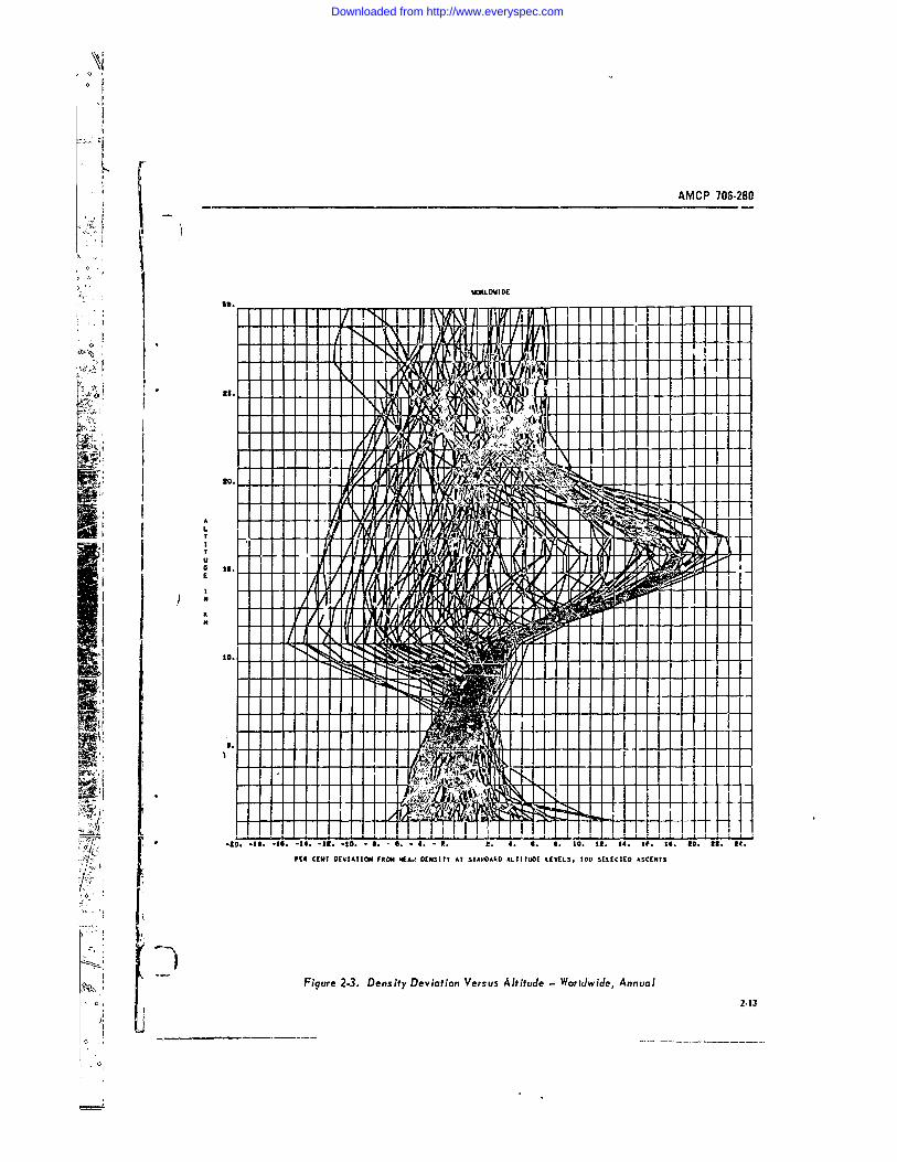
- I AMCP 708.280
I.so.
Its
T -
III
ITFigure 2-3. Density Deviation Versus Altitude -Worldwide, Annual
2-13
Downloaded from http://www.everyspec.com
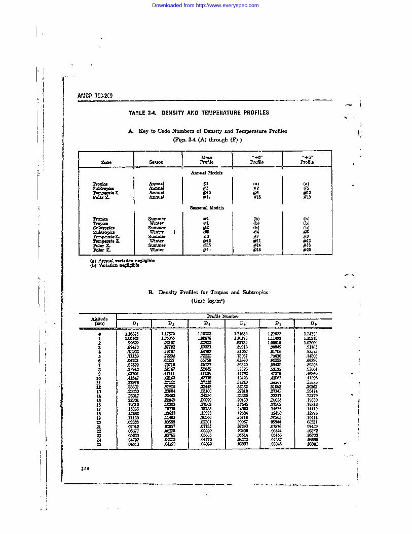
AMCP 7C-2MD
TABLE 2-4. DENSITY AMD TEMPERATURE PROFILES
A. Key to Code Numbers of Density and Temperature Profiles(Figs. 2-4 (A) throlugh (F))
rMean o+0oZoS609 Profile Profile Profile
Annu3a Models
TrON011 Annual #1 (a) (a)Subtzipics Annual #3#2 #
Z. Annual #l0 fl #12P Z. Annual #11 #15 #19i Seasonal Models
TrONcs Summer #1 (b) (b)Trovics Winter #1 (b) (b)Subtropics Summer #2 (b) (b)Subtro-ica Witir 1e #4 #6
po r Z. Winter #12 #11 #13
(a) Annual variatica ne1 ble(b) Varat negligble
B. Density Profiles for Tropics and Subtropics
(Unit.: kg/l')
A~tltvde ,,__Profile NumberV D2 D3 D 4 D D6
a 11375 117579 1.19953 1.21632 1.2202 1243321 1185 1.C&S, .(R6"76 1.10178 1.11493 1.123182 .9= .087 .9730 1.00910 1.020903 £7470 £7702 M2 Ze-013 .XO39 .917854 .7= .70707 £0783 .81057 £1786 824155 .711 .I32 .723,, .73067 .73636 .7420M6 f=413 A=22 .65750 .6536 R6223 .W6%867 .2 ///16 .59127 .59320 .59433 Z95568 .5190 .52747 0 .53326 .53195 .530649 .43706 .47241 .474U .47792 47376 .46960
10 .4147 .4214 .42116 .42A43 .41862 .41296"A- .I..-- ~.. * .i-1 00( Z88
1Z =02 .2906 .23100 27810 27142 28474
14 =17 Z403 .24250 23355 .23317 .2277915 .2 20 200 2049 2054 .1=9631 .1010 .138 .179M2 .17545 .17209 .1637,317 .12=5 .16175 I 14953 .14G6% .14419is .42 .2333 .12=3 12_34 194w) .1227619 .1110 .11403 1091 0 .0716 .10565 .1041420 .09arm .0953 0201 ODM07 ow94 033121 .07912 03057 .077= .07,33 .07576 0748922 .077 .0325 .0 0 06496 .06124 .0 2M .054,CS .0=7m.0 3 .05514 05456 .0530324 .04792 .Ow9 .04770 .04=09 .04637 .04530F
21.040 .0=0 .0= 0391 .03046 .0=12-1
Downloaded from http://www.everyspec.com
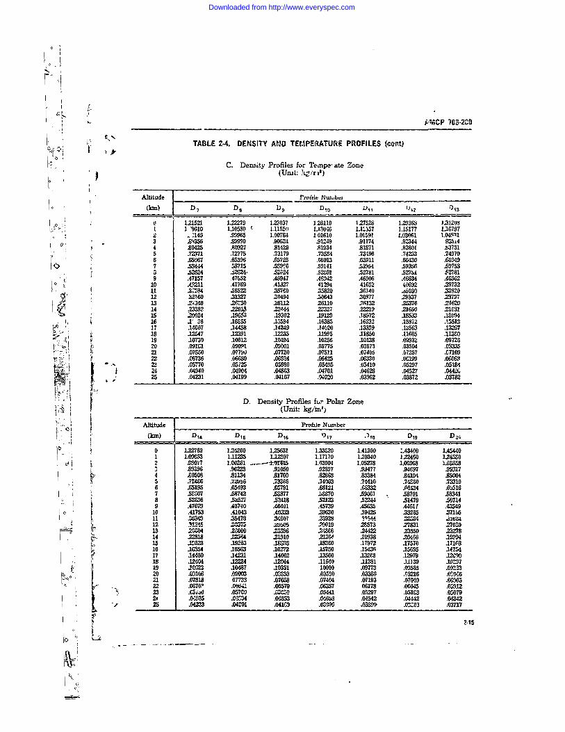
kM%"hP 703-2CB
N: TABLE 2-4. DENSITY AND TEMPERATURE PROFILES (cont)
C. Density Profiles for Teaipe, ate Zone(Umt: k!/ril)
Altitude Profile N u abe_0 (kmn) D 7 De D 9 D. vii D12 1I3
o , 121521 122279 123037 126119 127528 1.29363 113.121 1 "9610 1.10530 r- 1.11550 1130*16 1.,557 1.15177 1167972 . 145 19965 1.00794 1 01610 1.01591 1.03061 1.0M3 .84356 ,89990 90624 .91249 .91174 .92344 93544 £0425 .80927 .81429 .91934 .81871 .82801 B83731
( 5 .72371 .72775 .73179 .735,4 .73496 .74233 .749706 .65067 .65396 .65725 .66013 .65911 .66430 .6694.97 .58444 53715 .5,916 .59141 .53954 .59356 .59753a .5264 .jI834. .52824 .52001 .52781 .527U .527819 .47157 ,47652 .46947 .46942 .46906 .4M634 .46362
10 .411 .41769 .41327 41294 41652 40692 .33732.115 .3"244 ,622 .35760 35820 36140 .,6030 33920
12 732160 .31327 .30494 .30643 30377 29837 .2379713 2348 .26730 .26112 26110 .2A132 25376 .2,'--14 .233 2 .2291 22.44 .22327 22219 21650 2103115 .20024 19Ag0 19302 .9129 .18972 .18533 .1803416 .1 36 .16865 13594 .16385 .16232 .15872 .1551217 .14667 .14458 .14249 .14020 .1359 .13563 .13267s 18 12547 12391 .12235 .11995 11850 .11605 am
19 .10730 .10612 10494 .10256 .10138 .09932 .0972620 .091C1 .09091 .09001 .08775 .03673 .03504 .0333521 .0760 .077W .07720 .07511 .07405 .07257 .710922 .06736 .63 .06524 .06425 .06330 M199 .06062, .05,o70 .05125 0560 .05495 .05410 .05297 .0518424 .04940 .04904 .04863 .04701 .04628 .04527 .044225 .04231 .04199 .04167 .4020 .03962 .03872 .03782
D. Density Profiles ftr Polar Zone/P , (Unit: kg/mi)
Altitude Profile Number, " (kmn) DI D1sD6 5 .i D19 D26
0 1.22769 12=420 125631 1.3320 1.41360 :.43400 1.454401 1.09=,3 1.11235 1.1M 1.17170 120340 122460 1.245802 .9027 1.00261 .... M 5 1.03904 1.05278 1.06963 1.068
.9 £396 .9022 .91050 .92697 .93477 .94697 .959174 £0508 81134 .81760 £8268 m3384 24194 £5005 .72466 32U16 .7336 .740O3 .74410 .74&30 .753106 .65195 .65493 .65791 .66121 .632 .MA24 .605167 .5&07 .58742 .5877 .b70 .5961 .53701 5M3418 .5236 .5252 2418 523 .52244 .51479 W507149 .47079 .46740 .46401 .45739 .45&95 .44611 .43549
0 10 .41753 .41043 .40333 9630 .39425 8265 .3710511 2639 25478 Y,407 .33928 P .544 2258,12 w#5 .... =Wtu5 29019 2S573 27831 2703913 2680 Iwo00 .253 .248M .24422 .2W5 .232814 .22818 22364 .21910 .21W .20938 .2066 M15 .19263 I= .18360 .17972 .17570 .171M316 .10354 16563 .16272 .15780 .1543W .15095 3475417 .1 0 34231 .14002 33560 13268 .12979 1209018 .12404 .12224 .12044 .11640 .11381 JM139 .105719 .10M2 .10487 .10351 10000 .09773 .09M6 .092M320 .0106 .09003 .03 .0350 .0336 .03216 .0S34621 .07818 077O 3 .07653 .07404 .07193 .07049 .0C90522 .097(P .0%4; .06579 .06357 06178 .0,045 .0591223 .Csio0 .05700 .4=26 05441 .00297 .05193 .050792 .0=5 .01434 .0653 .040b .0542 .0"42 0=225 .04233 .0201 .041C9 .0399 .03,,9- .02303 .03717
Downloaded from http://www.everyspec.com
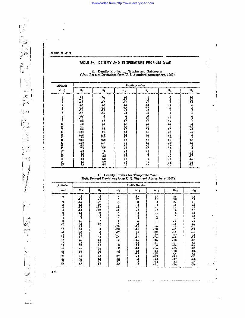
0
AMCP 76-2a'
TABLE 2-4. DENSITY AND TEMPERATURE PROFILES (cont)
E. Density Profiles for Tropics and Subtropics(Unit: Percent Deviations from U. S. Standard Atmosphere, 1962)
Alitwe Profile Number -0m (km) D, 1 DD 3 D D4 D5 D
0 -5.0 -4.0 -2.1 -7 .4 1.51 -4.5 .6 -2.2 -.9 .3 1.52 -4.0 -4.3 -2.0 -.9 .2 1.43 -3.8 -3.5 -1.8 -1,1 -.1 .94 -3.7 -2.7 -1.4 .1 -.2 .75 -3.4 -1.9 -.9 -.8 .0 .86 -2.8 1.2 -.4 ..2 .3 .97 -2.0 -. 2 .5 .7 .98 -1.2 .3 .9 1.4 1.2 .99 0.0 1.1 15 2.3 1.4 .5
10 1.2 1.9 1.8 2.6 1.2 -. 111 4.1 2.3 1.7 2.1 .2 -1.61 1.2 8.0 6.0 4.0 3.7 1.5 -. 7
00 13 12.0 9.1 5.4 4.3 1.8 -. 7Sii 1.5 11.5 6.4 4.7 2.3 -. 0L15 18.0 13.2 7.3 5.1 3.0 .8
18 19.0 13.9 7.6 5.4 3.4 1.317 15.0 13.7 7.2 5.1 3.2 1.318 10.5 12.1 6.2 4.3 2.6 .919 7.5 9.7 4.8 3.0 1.6 .120 5.0 7.5 3.5 1.9 .6 -721 42 6.1 2.5 .9 -.2 -1.322 .5 5.8 2.3 .7 -.4 -1.5
- 23 3.0 5.3 1.9 .2 -.8 -1.924 2.1 5.0 1.6 -.1 -1.2 -2.3
0 25 1.5 4.8 1.3 -.4 -1.5 -2.7
F. Density Profiles for Temperate Zone(Unit: Percent Deviations from U. S. Standard Atmosphere, 1962)
Altitude Profile Number
M) D7 D .. D I 10 D11 D,30 -.8 -2 .4 2.9 4.1 5.6 7.11 -1.4 -.5 .3 1.7 2.1 3.6 5.12 -1.5 -.7 1 .9 .9 2.4 3.8•3 -1.7 -1.0 -3 .3 3 1.6 2.8
3 1 4 -1.8 -1.2 -.6 -.0 -.1 .. 2.25 -1.7 -1.2 -.6 -. 1 -.2 .8 1.86 -1.4 -.9 -.4 .0 -.1 6 1.47 -9 -.5 -.0 .2 -.1 .6 1.33 .A .1 .4 4 .4 .49 1.0 7 .5 .. .4 -.1 -.7
10 2.1 1.0 -.0 -.1 .7 -1.6 -3.911 2.2 .1 -2.0 -1.8 -9 A A
-- 3.1 .4 -2.2 -1.8 -1.0 4 -7.7S13 2.6 .3 -2.0 -2.1 -2.0 -4.8 -7.6
i4 I 2.6 .5 -1., -2.0 -2.5 -5.0 -7515 2.8 ).0 -.9 -18 -2.6 -4.8 -7.118 2.9 1.3 -.3 -1.6 -2.5 -4.6 -6.817 3.1 1.6 .1 -1.5 -21, -4.7 -6.818 M 1.8 .A .1.4 -4.6 -4.6 -6.619 3.2 2.0 .9 -1.4 _. -4.5 -6.5
_ 0., 3 1.2 -1.3 -24 -4.3 -6-221 3.5 2,6 1.7 -1.1 -2.5 -4.4 -6.4
, 4A3.2. -.A -1.9 -3 5.91 5.9 4.1 3,- .1 -1. -3. -5.6
34 5.6 4.9 4 .3 -1. -3. -5.6
Downloaded from http://www.everyspec.com
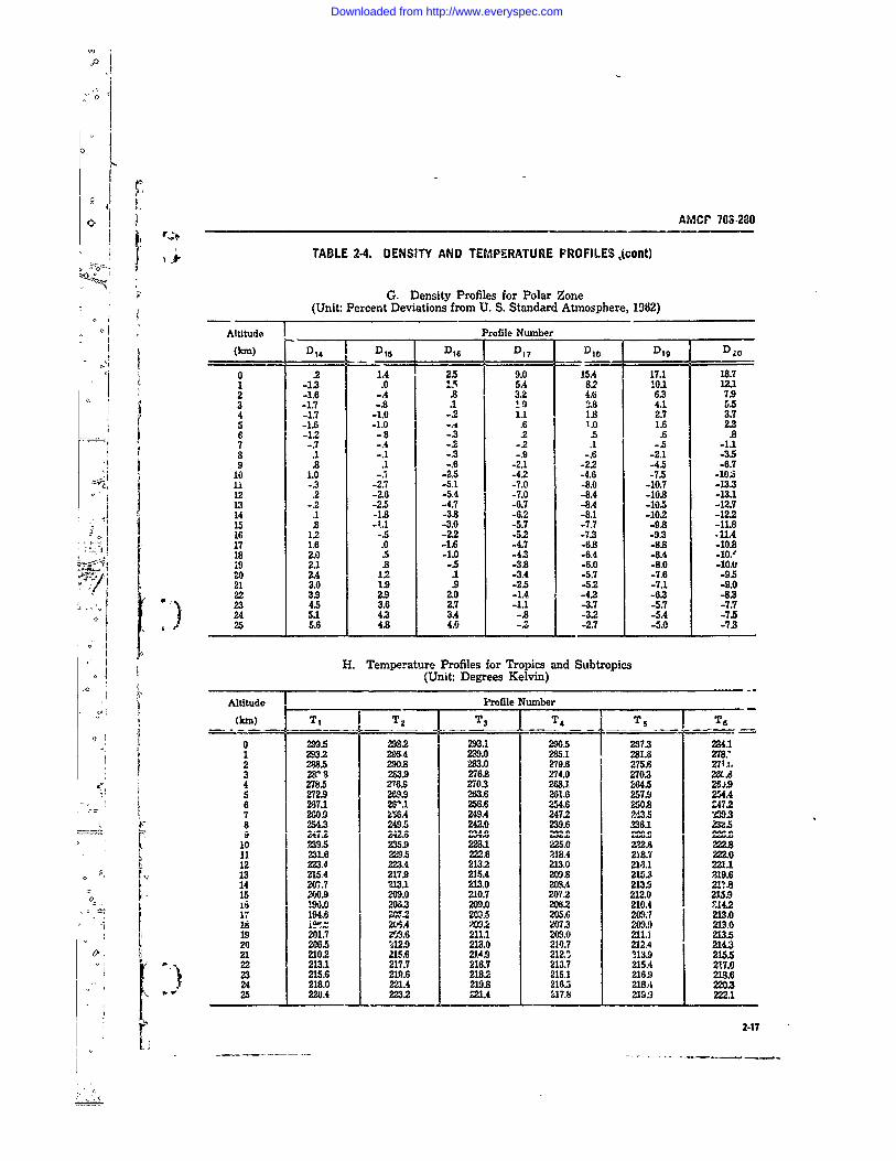
),j]
AMCP 703-280
TABLE 2-4. DENSITY AND TEMPERATURE PROFILES,(cont)
G. Density Profiles for Polar Zone(Unit: Percent Deviations from U. S. Standard Atmosphere, 1962)
Altitude Profile Number
(kin) D 14 D s D1 6 D D7 Die D19 D2 0
0 2 1.4 2.5 9.0 15.4 17.1 18.71 -13 .0 15 5.4 8.2 10.1 12.12 -1.6 -.4 .8 3.2 4. 6.3 7.93 -1.7 -.8 .1 1 9 2.8 4.1 5.54 -1.7 -1.0 -.2 1.1 1.8 2.7 3.75 -1.6 -1.0 -. i .6 1 0 1.6 2.3C. -1.2 -8 -3.2 .5 .6 .87 -.7 -.4 -.2 -.2 .1 -. 5 -1.18 .1 -.1 -.3 -.9 -. 6 -2.1 -3.59 .8 .1 -.6 -2.1 -2.2 -4.5 -6.7
10 1.0 -. 1 -2.5 -4.2 -4.6 -7.5 -10.511 -.3 -2.7 -5.1 -7.0 -8.0 -10.7 -13.312 .2 -2.6 -5.4 -7.0 -8.4 -10.8 -13.113 -2 -2.5 -4.7 -6.7 -8.4 -10.5 -12.714 .1 -1.8 -3.8 -6.2 -8.1 -102 -12.215 .8 -1 -3.0 -5.7 -7.7 -9.8 -11.816 12 -. 5 -22 -52 -7.3 -9.3 -11.4
-4 17 1.6 .0 -1.6 -4.7 -6.8 -8. -10.818 2.0 .5 -1.0 -4.3 -6.4 -8.4 -10.'19 2.1 .8 -.5 -3.8 -6.0 -8.0 -10.020 2.4 1.2 .1 -3.4 -5.7 -7.6 -9.521 3.0 1.9 .9 -2.5 -52 -7.1 -9.022 3.9 2.9 2.0 -1.4 -4.2 -6.3 -8.323 4.5 3.6 2.7 -1.1 -3.7 -5.7 -7.7i24 5.1 4.3 3.A-. -3.2 -5.4 -7.525 5.6 4.8 4.0 2-.7 -5.0 -7.3
H. Temperature Profiles for Tropics and Subtropics(Unit: Degrees Kelvin)
Altitude Profile Number
(kin) T T2 T3 T4_ Ts T 6
0 299.5 2932 293.1 290.5 273 2a4.11 2932 29S.4 239.0 285.1 281.6 278.:2 288.5 290.8 283.0 279.6 275.6 2711,3 28918 283.9 276.8 274.0 2703 2G.$4 278.5 276. 2703 268.1 84.5 M2,.95 272.9 269.9 263.6 261.6 257.9 254.46 267.1 261.1 256.6 254.6 250.8 24727 2009 A6.4 249.4 247.2 243.5 'M938 254.3 249.5 242.0 239.6 W. 1 2U.5
10 239.5 235.9 2281 225.0 222.8 222.811 231.6 229.5 222.6 218.4 218.7 222.012 223.4 223.4 2132 213.0 213.1 221.113 215A 217.9 21.5.4 2093.8 215.3 219.614 207.7 213.1 213.0 203.4 213.9 217.8
[ 15 200.9 209.0 210.7 207.2 212.0 215.917 194.0 20.3 209.0 20562 210A 11421 194.6 2 203.-5 205.6 209: 213.018 i t 204A 202 207.3 2091) 213.019 201.7 49.6 211.1 209.0 211.1 213.520 206.5 %12.9 213.0 210.7 212.4 214321 210.2 215.6 214.9 212. 113.9 215.522 213.1 217.7 216.7 213.7 215.A 217.023 215.6 219.6 218.2 215.1 216.9 218.624 218.0 221.4 219.8 216.5 218.A 220.325 220.4 223.2 21.4 217.8 2192 222.1
2-17
Downloaded from http://www.everyspec.com
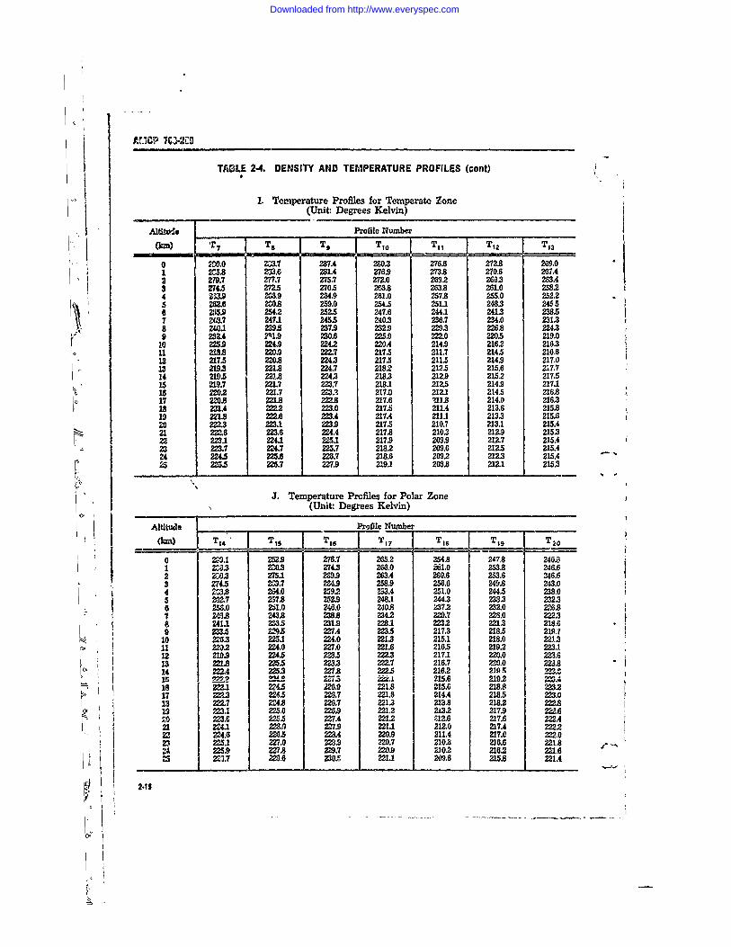
AIICP 70i10
TADLE 2-4. DENSITY AND TEMPERATURE PROFILES (cont)
I. Temperature Profiles for Temperate Zone(Unit: Degrees Kelvin)
/dti.wJo FProfile Numberi. (kin) Tr7 i Te T9 Tjo -. iT11 T12 T13
0 ,0.0 233.7 287.4 2&0.3 276.6 272.8 269.01 2C5.8 233.6 231.4 276.9 273.8 270.6 267.42 279.7 277.7 275.7 272.0 2692 2&53 263.43 2145 2725 270.5 266.8 263.8 261.0 258.2
14 3.9 =. .9 261.0 257.8 205 252.25 219. 221.8 259.0 254.5 251.1 248.3 24556 255.9 254.2 252.3 247.6 244.1 241.3 238.51 2.7 2247.1 24.5 240.3 236.7 234.0 2313
-8 230.1 229.5 237. 232.9 229.3 226.8 224.39 232.4 21.9 230. 2217. 222.0 220.5 219.0
1 2254 224.9 2242 220. 2142 2162 21631 218.8 220.9 223.7 217.4 211.7 214. 216.612 217.5 220.8 22.3 217.5 211.5 214.9 217.013 2M.8 221.8 224.7 21.82 212. 215.6 217.714 2191 221.1 224.3 218.3 219 215.2 217.515 M9.7 221.7 223.7 218.1 212.5 214.9 217.1is 12 227 223? 217. 212.1 214.5 216817 2M0.8 221J.8 222.8 217.6 ?11.8 214.0 2163is 2;U.4 222,2 223.0 217.5 211.4 213.6 215.819 221.8 =2.6 223.A 217.4 211.1 213.3 215.6z1 W2.3 223.1 =$4. 217. 210.7 213.1 215.421 : 222.8 223.6 MA3, 217. 210.7 212.9 215.3
•22 223.1 224.1 225.1 217.9 209.9 212.7 215.423 223.7 224.7 225.7 218.2 209.6 212.5 215A424 224.5 225.6 228.7 218.6 209.2 212.3 215.425 225.5 228.7 227.9 219.1 203.8 212.1 215.3
J. Temperature Prcfiles for Polar Zone(Unit: Degrees Kelvin)
Altitude Profile Number 9(0 T14" TOS T16 T17 Tie T19 . T20
0 229.1 282.9 276.7 265.2 254.8 240111 =.3 30 274.3 26.0 261.0 253.8 246.62 2C0.3 275.1 269.9 263.4 260.6 253.6 246.63 74.5 2G9.7 24.9 258.9 256.6 249.8 243.04 3.8 264.0 259.2 253.4 251.0 244. 238.05 2=7 X-37.8 252.9 248.1 244.3 238.3 232.36 25.0 251.0 246.0 240.8 237.2 232.0 226.87 2.8 243.8 238.8 234.2 229.7 228.0 22238 241.1 23.5 231.9 228.1 223.2 223 218.69 233.5 229.5 227.4 223,5 2173 2185 219.7
1 10 2203 2251 224.0 221.3 215.1 218.0 221.3U 220.2 224.0 227.0 221.6 216.5 219.2 223.112 219.9 224.5 228.5 222.3 217.1 220.0 223.613 221.8 225.5 223.3 222.7 216.7 220.0 223.814 222.4 225.3 227.8 222.5 216.2 2195 222.315 M__ 20 227.3 -.. I 215.6 219.2 22.4
S222.1 224.5 226.9 221.8 215.0 218.8 23.217 2223 22M5 220.7 221.6 214.4 218.5 223.013 222.7 224.8 223.7 221.3 213.8 218.2 222.819 223.1 225.0 226,9 221.2 213.2 217.9 222.6:0 223.6 22,5.5 227.4 221.2 212.6 217.6 222.421 224.1 223.0 227.9 221.1 212.0 217.4 222.222 224.6 228.5 228.4 220.9 211.4 217.0 222.0X" 225.1 227.0 228.9 220.7 210.8 216.6 221.824 2219 227.8 229.7 220.9 210.2 216.2 221.623 2M.7 228.6 230. 221.1 209.6 215.8 221.4
2-1__2.1
Downloaded from http://www.everyspec.com
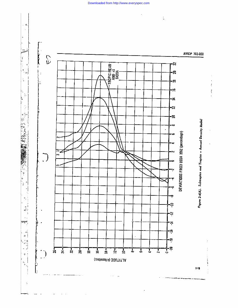
AMCP 703.2C0
-L- L- - - - _
+i
s~im
- C)
cc
- N al
cn4
94
I-I
Im.
mCVco ca -Wco to -W 0
(SJGOW~i 3Ium
~2-1
Downloaded from http://www.everyspec.com
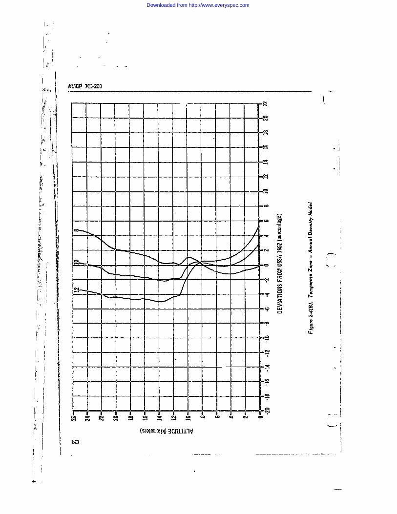
K(tICP 7IDi2CO
CDJ
'1 -q
co
0)0 X
CA - - -
C-%I C'4
K (sJewojp) ~uritto
Downloaded from http://www.everyspec.com
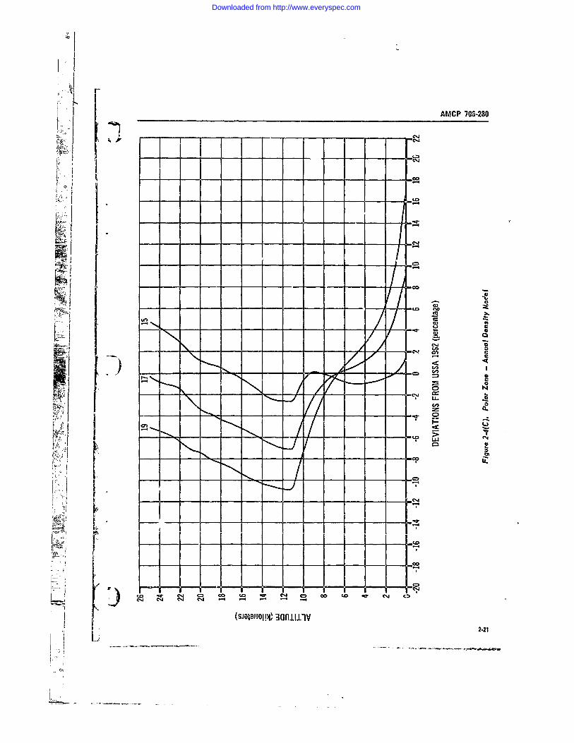
AMCP 703-280
I0i
4-4
-4
--
- -m- - 102
1A I
C3
t Fh
S - A - ~ S - , I 5,- - o
C14 C~j -4 -. 4 - 4 - -4
(SMOILuoIN' 3aniiiv .2
Downloaded from http://www.everyspec.com
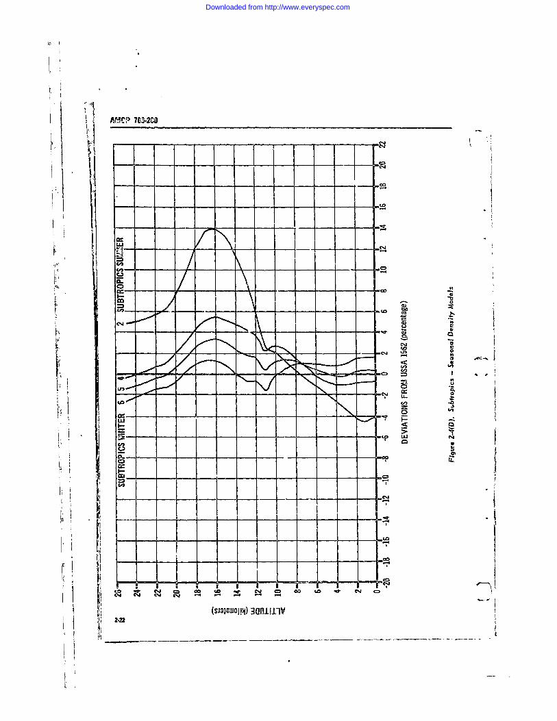
AM'CP 7a$2CO
( -600 -. 0
I- L
1.0
-q- 0
Cd,,
C4,
co,
co to4= c to 4- C
~~cm (SIMO)Mi-I--
Downloaded from http://www.everyspec.com
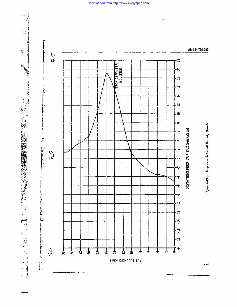
A MCP 70-280J ~
--- 4o
-cc
CD I00
ICCI I I7IIIF~ I -00 LD o
~anhI1a
Downloaded from http://www.everyspec.com
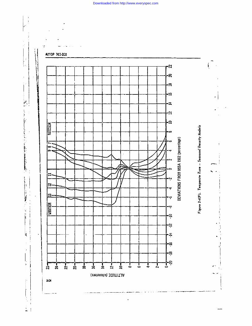
AMCP 7OS.2CD
-4
EL FII
a) 1
0
Sk a
,00 W3
C0)
-w 0
I I I ~- ~IUC
-? %J C) D mC 00 to S.WC
2.24
Downloaded from http://www.everyspec.com
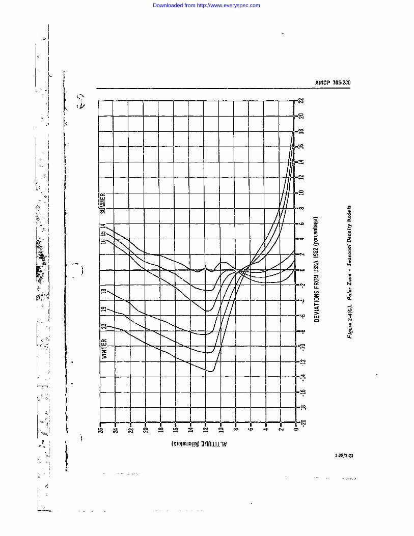
AMCP 705-2CO
C','
-0
cko
C141
- 0
C03
oy CL%
0 0
-Kr-
7) _
4.0 C= co 00 to .t Cj
(SJOIDOJOI 39fl.II.IV2-25/2.2's
Downloaded from http://www.everyspec.com
AMCP 703-2C0
CHAPTER 3SYSTEM DES!Gr
3-1 GENERAL They have long range capability and vary in sizefrom small, man-handled rocket.., t very large
The first point to be considered A the design rockets requiring heavy eq,,pmeat for handlingof a rocket system is the purpose of the system and loading The primary functiun of ar -.rtdleryWe shall attempt to answer 0he first questions rocket system is support by indirect lire, butusually asked: To what uso will the system be most systems have some capa.i'hty for direct fire.put; who will use it, and how wil 1 it be used' System accuracy Le probably the most ,mportantNext will be a more precise and detailed exammn- consideration in artillery rocket systems.ation of the requi, ements to provide a basis fordeveloping, first, the conceptual approach and, 3-2.1.2 Intan.rythen, the detailed design. Rocket system require-
ments can be documented in various forms, as Infantry rocket s3 stems are used by tersonnelwill be explained in more detail later, or they in ior.,ard areas, in direct contact with the op-
0 can be orally expressed statements in anticipation posing forces. Infantry systems ar-. generally di-of later, formally documented statements Re- rect-fire-type weapns, usually wraller than ar-gardless of form, requirements based on real or tillery systems, and, frequently, man.carried andanticipated needs should precede any system d- -fired. The most notable tyne of irf-intry systemsign in order for the design to be meaningful. is the antitank weapon, carried by the individualWith the requirements as a basis, an orderly ard soldiei and des.g,.ed o be fire-i from the shoul-systematic procedure leading to a successful con- der Many special factors must be considered inclusion can then be established, such systams since the rocket and man are in
Before discissing the systemz+.,c procedure such close contact. The weapon must bc effe,:-9 for the design of a rocket system, howev er, a brief tive, yet -,dfF to be handled and fired without en-survey of classes of rockets, operational modes, dangering the user. Infantry systems a.. light.
and launching methods will give us a common easily transported by men, and simple to facli-background and terminology for the discussion tate fast re.iction to changing battlefield condi-
tions.
3-2 CLASSES OF ROCKETS3-2.1.3 Air Dtfenst
3-2.1 MILITARY ROCKET SYSTEMSAir defense rocket systems are used to protect
In general, rocket systems used by the several the ground soldier from enemy aircraft. Theybranches of the armed forces are classed as mili- range in size from small, individually carried andtary systems They are used, except in several fired systems to large, complicated systems cap-
o instances which will be noted later, to deliver able of attaining very high alt;tudes Many ofsome form of destructive warhead on an enemy these employ some type of guidance system to
___ target TY types used most freauentlv by the enable the roeket tn m vne,,wr - ,4 .Army are briefly described in the paragraphs the aircraft evasive tactics. The free rocket sys-which follow. teins are generally fired in number into an area
where the aircraft is or is expected to be This3-2.1.1 Artillery results in a pattern in the target areD similar to
a pattern of shotgun pellets fired at a flymg bird.Artillery rocket systems are usei in the same The rocketL in thee systeras are usually sroadl
manner as artillery gun systems--to suppor p-br- and simple in design to oermit b-3rge numbers tosonnel in contact with the enemy in foi ' -d are-:s be used economically
0
4(
C
Downloaded from http://www.everyspec.com
AMCP 70G-295_______________
3-2.1.4 Armor direct method of delivering to ground forces Iall types of supplies needed on the battlefield. In 41
Rocket systems used by the armored forces are, this concept the payload, in tead of being a de-in manv instances, the same as those used by the structive mechanism, is composed of food, cloth-Inf&ntry and artillery. The tank, armed with a ing, ammunition, medical items, or any other items, hrcot-firing gun or rocket system, is the primary of supply needed by personnel, and can be anyvoeapon of the armored forces. The primary tar- single item or any desired mixture of items. AtEet of tanks is enemy tanks; consequently, the the destination, the payload is separated and para- Iantitank type of rocket is generally employed. chuted to the ground. Rapid movement of men3owever, tank weapons are also used against to forward areas and distant points by means ofmny types of ground targets. Fow this re&son. rocket transport has been proposed; however,they carry ammunition mixes suitable to the more much more elaborate techniques must be de-prevalent targets expected. veloped and utilized before this method of trans-
port becomes practical.3-1.1.5 AviAtion
Rocket systems to be mounted cn, and fired 3-2.1.7 Supportfrom, Ainy fixed and rotary wing aircraft have Rocket systems can also be used to supportbeen of in-.xeasing interest. The need for these other operations. Examples of such systems are I;mall aircrat to have some type of defense, and flare rockets for night operations in the batt!eto be able to pairrn an attack function in close area, tactical meteorological rockets for obtainingsupport of the ground soldier, has been shown to data necessary in artillery fire operations, rocketsbe of covsiderable importance, as evident in for delivery of some type of electronic equipmnentbrush-fire activity in several parts of the world to a specified point for place-marking or trans-Wh-. ths need for aerial rocket weapons firvt mittal of intelligence, and rockets that will pro-bee-ime urgent, attention was turned to adapting duce smoke or other visual means of spotting on . ,an appropriate rocket system originally developed a target. The uses to which rocket systems can beto fill other requirements. Since aircraft are used put in their support role seem to have no par-by the individu,-l branches of the Army ground ticular limit. The same design approach is usedforces, rocket systems are used to accompliph for support rocket systems as for any other rocketthe missions assigned the using branch. In ad- system; the designer is limited only by thg par-dition, airborne rockets are used for the de- ticular dictates of the specific requirement.fense against aircraft of the orposing forces. Thenotable difference in these systems is that theyare fired from an elevated platform that is un- 3-2.2 RESEARCH ROCKET SYSTEMSstable and in many instances rapidly moving.Rotary wing aircraft can stop and hover but, un-like a tank, they have no flrm ground base as asteady firing point. Many additional factors must Research rocket systems have. in common withbe considered in the design of aircraft systems military rockets systems, the general character- 4to prmit attainment of the tactcal performance ist, Of dellms4nIv paoad to I ome Je-i....-desired without endangering the aircraft or its point. Research rockets are also made up of theer '. same general group of components. Their prime
function, however, is different. They are designed3-2.1.6 Logictic to accomplish a mission from which useful tech-
nological data will be obtaineca to further a scien-Although no significant development of logistic tific understanding of a svecific discipline. In
rocket sys" ms has occurred up to this tie L this role, the pyload beecmrs a devce to gatherthis class of rocket, it will undoubtedly play rn data for later evaluation. Su 11 a payload ob-inportant role in future large scale warfare. The viously necessitates a means for payload recoveryligiztic rocket is proposed as an extremely fast and a means to prevent payload damage or de-
3-2
Downloaded from http://www.everyspec.com
AMCP 70G-280
struction that would negate mission completion. 3-2.2.5 Dispensing" In a sense, many military rockets serve as re-
search rockets during their developmental phase. Dispensing rocket systems cpn be either re-In this phase, the payload is a ballast weight or search or military The purpose of such a rocketdata gathering device; equipment exterior to the system is to dispense a material, or materials, atsystem also is used to gather information on the some point in the rocket's trajectory. Examplesrocket flight. The knowledge obtained is used are chaff-dispensing rockets, leaflet-dispensingto further the understanding of rockets and their rockets, smoke screen rockets, and ockets to dis-behavior as powered airborne vehicles. seminate crystals of varius substances for cloud
seeding to induce rain. The chaff dispensers areused to put large quantities of very small metallic
3-2.2.2 Meteorological wires into an area at some height above theRocket systems have been used to place sensing ground. These wires, or dipoles, are then tracked
devices at various altitudes in and out of the by ground radar to determine the nature of windevices atvous altitues inand thepupou of currents at various altitudes. Leaflet rockets are
eart's tmophee. hesehav th pupos of used to deliver propaganda leaflets over areas notproviding information about the earth's air, the
winds, temperature, radiation, moisture, and accessible from the ground. The psyload is re-leased at a specific altitude and thE 1ceflets flutter,other phenomena. Because these systems utilize spread, and are carried over large ground areas
a vertical or near-vertical trajectory, the object- by the wind. Although not in general use, cloud-ive is the attainment of altit.ude, seeding rnckets have been proposed, e.g., P rocket
to dispense small pellets of dry ice into fog banks3-2.2.3 High Altitude Sounding for fog removal over airports and similar areas.
Rocket systems for sounding at high Atitudis It appears practical to use rocket delivery meth-Rfs for dispensing materials such as those de-
are used for obtaining some specific bit of infor- scribed above, prticularly where other meansmation at altitudes ranging to several hundred requiring human presence are not practical ormites above the earth's surface. These, like the are denied. The rocket's presence is almost un-
meterological rockets, utilize a vertical or near- known until after it has accmplished its mission.
vertical trajectory.
3-3 OPERATIONAL MODES3-2.2.4 Satellites
Unguided, aerodynamically stabilized rocket 3-3.1 General
systems can be used to place a payload into earth Rockets may be designed and used In an alnostorbit. The payloads of these systems are usually unlimited nutmber of ways. They have been usedsmall sensing devices for gathering information not only to serve military and research purposes.and transmitting it back to earth. These systenis as discussed in the foregoing paragraphs, bit alsoare usually multistage, with the first, and perhaps to propel aircraft and land-based vehicles, anda second, stage operating in the unguided or free- for other similar purposes. it is not the p irposeflipht mode. In later stages, it is necessary to of this handbook to di-muss the many fa.ets ofprovide somv type of guidance to permit maneu- rocket uses, but only U. present the use , mostvering into at, attitude to attain the desired or- commonly employed in military systems Thebital path. In these stages, the purpose of the paragraphs which follow will briefly describe theunguided phase is to place the vehicle at some modes normally used for military rocket s3 stems.appropriate altitade from which the orbital phasecan be initiated. For small payloads, this system 3-3.2 GOUND-T0-GROUNDapproach results in considerable saving in guid-oance hardware, particularly where precise orbital In the ground-to-ground mode the rocket ismechanics are not t-equired. launched from a point on the ground to a target
3-3
Downloaded from http://www.everyspec.com
AMCP 706-280
on the ground. Most artillery, infantr5, and ar- functioning in this mode. The cnti:al factor ismor systems are used in this mcde. accuracy since the purpose of firing this type of 4k A
rocket is to hit a target.
3-3.3 GROUND-TO-AIR3-3.7 SURFACE/AIR-TO-UNDERWATER
In the ground-to-air mode the rocket is launch- These systems are the reverse of those describeded from the ground against an airborne target. in the preceding paragraph. I. these systems,The target may be a manned airplane, an un- the rocket is fired from a surfac or air launchingmanned drone, another rouket or missile, or simply t, eters fibd f aterr and onin ia point in space. The air defense, meteorological, trajectory in that medium. One current examplehigh altitude sounding, and dispensing rocket is the SUBROC, or submarine rocket, used bysystems operate i n this mode. the Navy to attack underwater targets from sur-
face ships.3-3.4 AIR-TO-AIR
The air-to-air rocket systems are used in de- 3-4 LAUNCHING METHODSfensive and offenrive operations from aircraftagainst other airborne targets. Some of the avia- 3-4.1 GENERALt;on rocket systems for use on fixed and rotary A rocket is primarily a powered, airborne ve-wing aircraft are in this category. hicle. As such, it must have some point of de-
parture, cr launching point. Rocket launchers3-3.,5 AIR-Th..ROUND have assumed many varied shapes and sizes, de-
pending on system requirements and intended-Air-to-ground rocket systems are used in sup- uses. The launcher supports the rocket and
pressive fire over areas of ground, for point tar- points it in the desired direction before launch-gets on the ground, and to deny, an enemy a ing. During the launch operation, the launcherground position. They are fired from fixed wing guides the rocket in is first motion and preventsnd rotary wing aircraft, usually at relatively low smdil disturbance!, irom diverting it from the
altitudes. It is extremely difficult, except in un- desired path. The launcher can also be used forusual circumstances, to recognize and identify other purposes, such as a packaging and shippingground targets from an aircraft, and the higher case, as a transporter, and for imparting otherthe viewing position, the more difficult this be- desired motions (such as spin) to the rocket dur-comes. For this reason most air-to-g-ound rock- ing the launch phase. The paragraphs whichcts do not need extremely long range: capability; follow describe the more common launchers ardhowever, they do need to be as accurate as pos- launching systenos.sible to permit effective fire from the unstableaircraft firing platform. 34.2 RAIL LAUNCHERS
3-3.6 UNDERWATER-TO-AIR Rail launchers derive their name from theiiSnsaisarity to 0he rail of a railroad track. The
Rocket systems have been designed and built to rocket is supported on the rail with shoes whichbe fired from under the surface of a body of slide along the rail as the rocket moves forward.water and to continue flight after emerging into The launching shoes are usually a part of the.the atmosphere. At present, the submarine- rocket and can be fixed, retractable, or jettisonedlaunched POLARIS missile system is the most after leaving the launcher. Since the sliding mo-notable example. Although the POLARIS is a tion occurs only over a few feet of travel, frictionguided missile of considerable complexity, there is usually not of critical concerp. Rail launchers Iis nothing inherent in rocket technology to pre- may have a number of variations, the most con-vent any rocket system, guided or un ided, from mon of which are described below.
a4
Downloaded from http://www.everyspec.com
AMCP 706-280
3-4.2.1 Single bore or may be grooved in some manner to pro-' '' vide or prevent rotational motion during the
Single-rail launchers have one rail along which launching. No launching shoes ae required on athe rocket moves. The rail must have sufficient tube-launched rocket, although devices known aswidth, and the launching shoes must be so de- bore-riders may be used to support a portion ofsigned that lateral, or rocking, motion is prevented the rocket that is smaller than the tube. Theor held to a minimum as the rocket moves over bore-riders prevent the rocket from wobbling, orthe rail. balloting, as it moves through the tube, and as-
sure its continuing in the desired direction. Tube3-4.2.2 Multiple launchers may be designed to be reusable or
may be designed to be disposable after the firingMultiple-rail launchers may be interpreted in of one rocket. The latter is found quite often as
two ways. One concept is a launcher having two a part of small rocket systems. particularly theor more rails, each of which serves as the launch small infantry antitank systems. This allows theguidance for a rocket. The barrage-type rocket individual soldier to discard unnecessary encum-systems, which launch a number of rockets simul- brances on the battlefield. For similar reasons,taneously, often use this launching scheme. On disposable launchers are also incorporated inthe other hand, a launcher with two or more rails aviation rocket systems to permit the launchercan be used to launch one rocket. Such schemes fo be jettisoned after use. Th, most commonare used to provide a more rigid launching sup- types of tube launcher -re bri.=fly AiscumPd inport and, in some instances, to dispense with the paragraphs which follow.launching shoes. The rocket slides through therail structure the sanie as it would through a tube. 3-4.3.1 Single
3Single-tube launchers are generally used in. Hec hand-held or single-man-operated rocket systems
For this launcher concept, the rail is twisted and in some systems with automatic feed mecha-through :A helical angle in order to impart spin to nisms. As with any rocket system, the choice of athe rocket. Generally, the helical rail launcher single tube results from considerations of thehas two or more rails to provide a torsional couple system requirements and rocket characteristics.to the rocket because it is impractical to imparta torsional cuple with one rail. The technique 3432 Multipleis analogous to the rifling grooves in the bore ofa gun or rifle. Unlike the gun, however, helical- Multiple-tube launchers are used to provide arail launchers are nr.t used for spin rates of suf- fast firing rate where the complexity of automaticficient magnitude to provide spin, or gyroscopic. feed mechanisms in conjunction with a single tube
* stabilization. The spin produced is low in mag- is either undesirable or is prohibitive. With thenitude for the purpose of reducing errors resulting employment of a multjple-tube launcher, the
Y from some of the rocket imperfections. This is rockets can be fired all at once, in salvo, or ir,discued inore fully In Chapter 7. fast ripples. The ability to fire one rocket at a
time is also inherent and can save considerabletime by not requiring reloading after each firing.
3-4.3 TUBE lAUNCHERS Multiple-tube launchers are frequently employedas barrage weapons, replacing a number of gunsRockets mey be launched from tubes in much cnetae nasalae.,muy A~A inconcentrated in a small area.
the same way as gun projectiles. The lengthi ofthe tube can vary from about one rocket lengthto several rocket lengths, depending on the char- 3-4.3.3 Open Brerichacteristics of the rocket, its intended use, theenvircnment in which it will be used, and accu- An open-breech launcher is one where the rear
OL racy considerations. This tube can have a smooth end of thc tube is completely open and is the
'3
Downloaded from http://www.everyspec.com
AMCP 706-280
full diameter of the tube. This is the most corn- type of launcher, using the closed-breech type Nfmon form of tube launcher. The gases exiting tube mentioned above.(from the rocket are unrestricted in passingthrough and out the rear of the tube, and the tubeexperiences little if any reaction force. 34.4 OTHER LAUNCHER TYPES
In many instrnces the simple approach to a3-4..4 Closed Breech launcher design is not adequate. It then becomes
A closed-breech launcher is one in which the necessary to examine techniques and designs thatrear end of the tube is completely closed. The will provide a necessary function, a particular mo-gases from the rocket cannot escape, and pressure tion or effect, or will impart to the rocket somebuilds up between the closed tube-end and the required characteristic. The result may be arocket. This type of tube launcher experiences a modification of one of the types described in thereaction force, or recoil, similar to that of a gun. preceding paragraphs, a combination of severalTubes of this type are generally used in places types, or a completely new approach. It may bewhere the rocket exhaust gases would be unde- necessary to add varying degrees of sophistica-sirable or dangerous if allowed to exhaust rear- tion, or to provide additional equipment cr devicesward. The tube launcher of a tank-mounted sys- for a particular effect or function. One of thetem is an example of the closed-breech launcher. more notable t es is the zero-length launcher.In this instance, the rocket is loaded into the tube This launcher is, as its name implies, one thatfrom within the tank but the racket exhaust gases, supports the rocket but releases it from con-for obvious reasons, cannot be tolerated inside straints immediately, or with zero guidance, uponthe tank. first rocket motion. It is not too practical in most
instances to achieve a true zero-length guidance;however, guidance lengths of a fraction of an inch3-43.5 Restricted Breech have been achieved for small rocket systems and
A restricted-bree-.h tube launcher is one in several inches for large systems. The rocketwhich the rear end of the launcher has been re- must be adequately supported on the launcherduced to some diameter less than the bore dia- and must maintain its aim alignment until it is
fcompletely. This form launched. Mechanical considerations generallyof tube launcher is used only in instances where will dictate the size and lengt t nhe attachingsome particular effect is desired. If the restriction i z ng, launede.is made in the formr of a rocket nozzle, some useful in zero-length launchers.forward thrust may be obtained that will counter-act to some degree the recoil resulting from the 34.5 VARIATIONSrestriction. The higher pressures resulting in thetube may be utilized to afford a higher muzzle 3.4.5.1 Autospinvelocity to the rocket without changing the rocketor increasing its size. " As has already been stated, it is sometimes de-
sirable to impa- t a sJow spin to rockets in orderto..... ......... nzw some type jif error during
343.6 W1141; the flight phase. One method of imparting spinthat has been aaalyzed and tested uses in the
As this name implies, the gatling launcher i. rocket a device that spins the rocket warhead inderivecl from the old Gatling gun concept. It is one direction; the reaction spins the propulsiona form, of automatic feeding launcher since, as motor in the opposite direction. Spinning duringone or several rockets ae firing, one or several the flight phase, or even before rocket iton oc-rwe being fed into empty tubes. The tube cluster curs is desirable. Since simplicity is also impor-tot.ates so that those tubes firing are always at a tant, the rocket is made to spin after it has traveledfixed position', as are those being loaded. Several approximately one inch. In this case, the zero-rocket systems have been designed around this length launcher is necessary, because the rocket
34
Downloaded from http://www.everyspec.com
AMCP 706-2f0
must be free of launcher constrai. ts at the time is desirable to stay below the critical rate or, ifspinning begins. It must be borne in mind that it is necessary to go above, to provide a spin P.-the tht ust and acceleratiun characteristicb of the celeration sufficient to carry through the reso-rocket motor must be suit,..!- t , maintain the nant point as rapidly as possible. The name as-rocket An an acceptable flight attitude at thks time, cribed to this launcher concept is prespin, auto-otherwise, the rocket ma3 drop -, deviate in such matic dynamic :.!;Snment launcher, or PADAa manner as to make its flight mniiiahig e . (pronounced "Payday").
3-4.5.2 Prespin, Automatic Cynamic-Alignment 3-4.5.3 Spin-On-Straight-Rail (SOSR)(PADA) Although the effects of shifting axes produce
One effect of spinning a rocket is to cause the undesirable results, prespinning a rocket beforeaccrual of errors from dynamic unbalance. No launch on a rigid launcher is nevertheless some-accrualenofierrorsThfromedynamicriunbalance.aNorocket is perfectly balanced, and the center of times beneficial. The benefits derived overshadow
the ill effects of dynamic unbalance sufficientlymass will not lie exactly on the longitudinal axis. to justify the inflexible launcher. The rocketE v en th e lo n g itu d in a l a x is can n o t b e ex p ected to " t u r v d d w t e r n y t m n w i h ibe perfectly aligned since the rocket is usually ca rovde with anyem n whic itcan rotate while on the launcher and then bemade of components joined together. Consequent- launched along a rail in the usual manner. Thisly. the rocket will not spin these components technique has been termed spin-on-straight-rail.around the longitudinal axis of symmetry, but teh iu h e r a o uldr beht-ai,will seek to spin about some other axis which is oreyRma ltouhu hlilrals couse d,the dynamic axis. The rocket, if spun on a rigid they may be undesirable because of lengthtauher namic aishe roche, fsunr o rigid weight, or other factors. Also, the spin rate de-
mountswillbetconstrained to rotate around t sired may not be attainable with any reasonablet wrail length and helix angle. In the SOSR systemlongitudinal axis of symmetry purely from me- almost any desired spin rate can be obtained.chanical aspects. Once released from the launch- Temthodeof spinning can be antineg per constraints, however, the rocket will seek im- The tho c o r launcher. e spin permediately to spin around its dynamic axis, which of ither the rocket in ualresults in errors along the flight path. The dy- chanism, if it is a part of the rocket, is usuallynamics and errors resulting from this phenomenon a system of small rocket motors exhausting tan-are discussed in more detail in Chapter 7. The gentially to the longitudinal axis. If the spin
mechanism is a part of the launcher, it may bezero-length launcher with flexible arms support- electrical, hydraulc, mechanical, or it may useing the rocket is one approach to gaining the whatever power source is most applicable. Powerbeneficial effects of spinning the rocket before tr oe rce t a bel gerlaunching without the undesirable effects of jump tra propte ma Te dynaictreat-at release of launcher constraints. This is morepractical than attempting to design flexible shoes ment of th-s technique is also covered in Chapteror the rocket. Zero length is the logical launch 7.
approach since it would be very difficult to pro-vide flexitle rails that would fuiction in the dt- 3-4.6 METHODS OF TRANSPORTsired manner during the guidance phasL. Theflexible launcher arm: permit the rocket to find Rocket launchers can be transported .n manyand align itself along its dnaic axis as it spins, different wtyb, with or without rocket loads. Theand when launched, to maintain the attitude at- small infantry launchers designed for the indi-tamed during the spin-up period. The critical %idual soldier are usually hand-carried and strap-consideration r. this schem.. is to make sure that suspended, much the same as a rifle. Largerthe spia rate of the rocke, does not couple with types may still be man-transportable by dividingthe resonant frequency of the launther arms. the system into man.load component, althoughThis can cause violent pertuibations of the rocket the assembled launcher when it is fired may haveand possible failure of the launcher structure. It to be supported on a tripod or other appropriate
3.7
Downloaded from http://www.everyspec.com
AMCP 7 M200
base. The larger, heavier, artillery rocket launch- detail. This is not to imply that the other ele-ers are mounted on wheels and towed behind a ments are any less important, but they are morevehicle as a trailer, or are mounted on a vehicle properly considered in other handbooks dealingthat is then an integral part of the launcher sys- with their particular disciplines. The launchertern. The largest of these systems are frequently and fire control elements will be described suE-mounted on self-propelled, tracked vehicles to ficier.tly to permit an evaluation and appreciationprovide a maximum cross-country capability. The of the particular problems attendant upon thesemobility characteristics of the rocket-and-launcher elements. This approach is also taken with thesystem are dictated by the system requirements payload, or warhead, of the rocket, which is coy-and the rocket characteristics. Many of the me- ered in considerable detail in other handbooks.diurA and large rocket systems are required tobeair transportable. Here the designer must beconscious of both weight and size if he is to 3-5.2 ROCKETachieve a system small enough to fit into moderntransport aircraft and light enough to be carried. The rocket is composed of a payload, or war-The aviation rocket systems are mounted on, and head, a propulsion motor, and an airframe toare an integral part of, the aircraft. Size, weight, provide structural rigidity. In the smaller, sim-and aerodynamic characteristics of the configura- pler rockets the warhead and propulsion motortion are paramount. A high-drag design can slow serve also as the airframe, and no additionalan aircraft to the point where its vulnerability structure is required other than the fins or other
device to provide aerodynamic stabilization.to enemy air and, ground fire becomes acute.Rocket armament for a tank is also an integralpart of its transporter. The factors for seriousconsideration with these systems are that of 3-5.2.1 Warheadspace in the tank and that of the burned gases The rocket warhead has a shell, or casing, whichfrom the rocket. The launcher designer must is hollow, and which may be aerodynamically 4
provide means of exhausting the gases, must pro- sh ollow, a s h nose aero ket.ialy
vide adequate room for the tank crew to operate, shaped to serve as the nose of the rocket. Anand must provide means for handling and load- appropriate high explosive is loaded into the cas- Iand the rockets from within the tank. Consler- ing. Actuation of the explosive is performed bying t c fthe fuze. The fuze may be located in a numberable ingenuity is required to achieve: an accept- o p iable balance of space, weight, and safety for sys- af positions in the warhead structure, dependinters t at r .tobe pe r ted ia u h c osey c n- on its type and m ethod of operatioon, and on thetems that are to be operated in such closely con- type of detonation desired. For high explosivefined spaces. warheads, the fuze may be placed at the forward
tip of the warhead and may be actuated by strik-ing the ground or another object. The shape of
3-5 SYSTEM ELEMENTS the warhead may take a number of forms, theselection usually being determined by the type
3.5.1 GENERAL of warhead, the aerodynamic characteristics andrequirements for the rocket, the fuze type, and
A rocket system is made up of a number of ele- structural considerations. The warhead has twoments, or subsystems, each of which performs a general parts, the shaped nose portion, or ogive,function necessary to the successful performance and a body, usually a cylindrical portion. Theof the system. In general the system is composed cylindrical portion may or may not be present,of three main elements: (a) the rocket, (b) the depending on the design requirements, but thelauncher, and (c) the fire control device. Each tiose or ogival portion is always used. The ogiveof thes, in turn is compased of subelements, or may have a numbr of shaes. It may be contcalcompo ents, each of which has a necessary une it may have curvature and be termed a tangent,tion to perrnii succrssful operation of the whole. o secant ogive, or it may be hemispherical. Ogi-
In keeping with the intent and purpose if this val shapes and their aerodynamic charat.teristicshandbook, only the rocket will be discussed in are covered in i.;jre detail in Chapter 8.
34
Downloaded from http://www.everyspec.com
AMCP 706-280
The material for the warhead casing is also a blocking device between the fuze detonator airdselected according to requirements. It may be the high explosive.cast , iron, steel, aluminum, or a combination of For a full and comprehensive treatmept uf e>,-these or other materials. The mateiial, in corn- plosives, warhead design, and fuze types and de-bination with the high explosive, is the destruct- sign, the reader is referred to other hridbooksive mechanism, and thus must have characteris- in this series.tics that will produce the maximum desired effecton the target. 3-5.2.2 Motor
Fuzes, as mentioned above, can be of severaltypes. The point-detonating fuze initiates the ex- The rocket motor is the engine that propels theplosive charge immediately upon striking an ob- rocket from the launch point to the target. Forject. The delay fuze initiates a powder train that present purposes a general description of itsdelays the actual explosion for a period of time components will suffice A more detailed cover-ranging from several seconds to minutes, and in age of its design is presented in Chapter 5.some cases to hours and days. The air-burst fuze The motor is an internal combustion engineis timed to actuate at some desired point in the with a combustion chamber, an orifice throughair above or in the proximity of the target. Fuzes which the burning gases are expelled at highmay also be located at the aft end of the explosive velocity, and the propellant :harge that producescharge with an actuating device in the nose. On the high-temperature high-pressure gases as o-impact with an object, the actuating device gen- ducts of the combustion process. Also includederates an electrical impulse to initiate action of is the igniter which starts the combustion pro-the fuze. For some aircraft rockets the warhead cess in the chamber.should penetrate and enter the aircraft structure The propellant charge, or grain, is a mixturebefore detonation. These warheads may use a of a suitable fuel and an oxidizer. Thus, unlikecoil-type actuator, located behind the warhead, most air-breathing internal combustion engines,
whic-h will generate an electrical impulse on pass- a rocket motor does not utilize or need the sur-ing through the metal structure. Fuzes for ac- rounding air to operate. In fact, it can and doestuating the explosive charge may be simple, or function equally as well in a vacuum or in outermay be intric~ate devices requiring the technical sprce When the propellant charge is ignited, thecompetence of a watchmaker to design, build, and heat generated causes a decomposition of theassemble. These mechanisms, though precise, chemical compounds in :*s str|_ct .i.t to producemust be rugged and must perform well under the combustible gases -r. he grain surface. The gasesnost trying conditions. are burned, and the process proceeds in an orderly
A necessary aspect of fuze design and function- ad predictable fashion. The products of theijg is that of safins and arming. The roc:,. war- combustion process are high temperature gaseshead must be kept safe to handle, even to drop, and, in some cases, solids in suspension in thewithout endangering persoiinel to accidental ex- gases.plosion. For this reason fuzes have built-in safety Propellant grains mnay be obtained in a largedevices that :nust be actuated in some manner variety of compositions and shapes. Each is de-beforp the f uze can function. These safety devices signed to operite in a specified manner and en-r-ange from simple pull wires, which are removed vironment, the particular manner of operation isby hand just prior to firing the rocket, to intricate selected to fit the perfornance requirements. Themechanical and electrical mechanisms that are grains may be cast directly into the notor com-actuated by the forward acceleration of the rock. bustion chamber, or may be molded or cast intoet. In many instances, for safety reasons, the a separate container that L. loaded into the cham-fuze should not be fully armed until the rocket bet as a cartridge. A grain may be end-burning,has moved for some distance away from its launch as a cigarette burns, or it may have perforationspoint. For these cases the safing and arming in which the burning occurs. Some motors, calleddevice may be a small escapement mechanism multi-grain mutorb. may be loRded with -! num-(similar to that of a watch) that is actuated by ber of small grahns. Generally the evd-burningthe forward a'cceleratioA of the rocket, removing grains operatt- at low pressure over relatively long
- 3-9 1
Downloaded from http://www.everyspec.com
AMCP 706-280
periods of time, whereas the perforated grains with the properties of the exhauxst gases. The de-operate at medium and high pressures for rela- bign usually is in the form of the De Laval nozzletively sl;ort periods of time. Multi-grain motors with converging-diverging sections. The con-are usually employed to provide extremely short verging section, located before the throat orifice,burning periods at very high temperatures. is commonly called tne expansion cone. Mater-
Grain compositions vary in operational char- ials used in nozzle construction are generally theacteristies. The more general types of fuel mLx- same as those used for the motor chamber. How-tures are single base, double base, triple base, and ever, it is not unusual to employ a reinforcedcomposite propellants. To the fuel is added the plastic nozzle with a steel or aluminum motorchemical oxidizer. Other chemical agents are case. Sometimes the nozzle throat is lined withadded to the mixture to obtain desired perform- graphite. This material resists the erosive char-ance characteristics. These agents act to inhibit acteristics of the exhaust gases much better thanor slow down the burning, to speed up burning, most materials and it changes dimensions veryto stabilize the burning, to counteract or mini- little with changes of temperature. Because itmize temperature and pressure effects on the is brittle and has little physical strength, this ma-burning, and to produce other desirable effects. terial must be adequately supported in the noz-
Propellant compositions are in many instances zle throat to prevent disintegration. Protectivedeveloped to provide desirable physical charac- coatings 6f other types also are used to cover theteristics. The propellant strength should be fair- entire inside surface Particularly applicable toly uniform over wide temperature ranges, and .ts nozzles made of aluminum, the coatings providedensity and specific volume remain as constant a very hard, erosion-resistant surface. Theseas possible despite temperature change. Powdered coatings, too, are very brittle in nature and mustmetals are adc ed to some propellants to raise the be adequately supporbd to prevent disintegration.combustion. temperature and the usable energy. Variations of the De Laval nozzle have beenThe designer is concerned with obtaining the pro- employed on rockets. ThL.y are designed to pro-pellant with the highest possible density and vide a particular effect on, or enhancement of, theenergy per unit weight since these factors will motor thrust characteristics. The production costsprovide the least weight and size of motor to do for some of these variations may be appreciablythe reuair"d job. higher than for the simple conical-section De La-The motor combustion chamber is a pressure val nozzle. Therefore, the effect to be gained
vessel to contain the propellant and the high-tem- must be weighed carefully against the added cost.perature, high-pressure gases during burning. An One variation that has been of considerable inter-opening is provided at one end through which est and study is the plug nozzle. This is essen-the gases are expelled. The size of the orifice tially an inside-out De Laval nozzle which hasrelative to the physical dimensions and burning the characteristic of providing optimum or near-characteristics of the propellant grain is governed optimum expansion characteristics for the ex-by precise mathematical relationships and differs haust gases at all altitudes, or, more properlywith types of propellant and operating conditions. stated, at all ambient pressures. Thus, this nozzleThe motor case may be constructed of any ma- has the potential of ,?erfcrming equally as wellterial capable of withstanding the presrure gen- at Sea leve as , ,U', :_. L , C
eri ed, but it is of primary interest to keep the space. It is not too difficult to build and shouldweight to a minimum. For this reason, the very compare favorably with the conventional nozzlehigh-strength steels, high-strength aluminum, and in cost and weight.the glass-reinforced plastics are most often ustd. A necessary consideration for some types ofOther metals, such as titanium and rmagnesium, rocket motors is that of insulating the case wallhave neen used, usually to obtain some particular For the long-tLme, end-burner type of propellantcharacteristic not afforded by the more common grairib, and for cartridge-type grains where thematerials, gases may impinge directly on the case wall, the
The motor exit:rjirice, UK nozzle, is designed . loss of strength in the material can cause ruptureto have precise geometric and mathematical re- and failure of the system. To prevent th- occur-ladonslii.,, both with the propellant grain and ence, an insulating lining that will prevej.t over-3.10
Downloaded from http://www.everyspec.com
AMCP 706-280
heating and loss of strength shuuld be applied to pressure, usually lower than the operating pres-the wall The material selected for insulation sure of the motor. The igniter cup may functionmay be applie'l directly to the wall b3 painting, also as the nozzle closure, or a separate closurecasting and curing it in place, or by other suitabl, may be provided. The closure may be of anymrezin Insu!.tion ma also be fabricated dnd suitable material, usually plastic or metal. It mustinserted into the motor case. The liner must be exit at the desired pressure level and must bebonded to the wall with an adhesive since it will constructed in such a manner that -le nozzle ornot function properly if the hat gases flew be- expansion cone will be undamaged as it leaves.tween the insulation liner and the wall. Insulat- For some aircraft rockets, the nozzle closure maying materials may be of several types. Some are be ejected at a fairly high velocity. If it werecharring in nature, others ablative. No one type to strike a vital part of the aircraft, it could en-is superior, some work best in one type of en- danger both aircraft and crew. In such instancesvironment, others best in another environment. tb', nozzle closure should be made of a materialThe best guide to selection is past experience and that is very light and that preferably will disin-experiment The primary consideration is maxi- tegrate into a powder when ejection occurs. Othermum effect for minimum thickness and weight problems and environmental requirements maysince insulation reduces space available in a given dictate that different materials and techniqueschamber for propellant. be used in designing the nozzle closure.
Some device is necessary to initiate propellantcombustion in the chamber. The device that per- 3-5.,3 Structureforms this function is called the igniter. Although:i may take a number of forms, they all have the The rocket must have a frame of some sort tosame general characteristics. The squib, a Jevice tie the parts together and to provide the desiredthat receives the firing signal, may be electrical aerodynamic shape. For the smaller and simpleror mechanical, the latter usually being of the rockets, the components themselves frequentlypercussion type The electrical squib is in es- constitute the airframe, being joined together bysence an electric match. The current pas.es threaded sections, by bolts or screws, or by a sine-through a re.,istance wire that becomes very hot, ple crimping process. The components, warheadmuch as the cooking element of an electric stove, and motor, are shaped so that the d. sired aero-The hot wire ignites a small powder charge that dynamic configuration is obtained v hen they aregenerates hot gases. The hot igniter gases are joined. As size andor complexity inc ease, itdirected against the propellant grain surface that ma ; be desirable or necessary to pro% ide a proper-is in turn ignited. The sma.1 container in which ly configured frame that will enclose the fune-the igniter is housed is usually of a britte or very tional co.nponents. The warhead need be shapedflexible material, plastic in most cases, so that only from a maximum effectiveness swl.dpfin".,it may be easily ejected through the nozzle after and the motor for maximum perfurzaance. Onepropellant ignition. The igniter cup mut not be or both may be enclosed in the airframe, -epend-Prmitte t bc t h pe h'. l thoa ---.. th-- =ul". ... n.1 man the. p.-.,.#...1.. :.Y r . c..USAW4SQ
cause an extremely fast pressure rise in the motor The skin of the airframe is made of a lightweightchamber, resulting in chamber rupture. material, usually alumi-nm or reinforced plastic.
Most propellants exhibit better ignition char- It may be shaped by drawing, hot or cold, by roll-acteristics under pressures considerably higher ing and welding, by stretch forming, or by anythan atmc.:pheric. The surface of the grain ig- other appropriate process. The pait.ular formingrites faster, and the flame front covers the entire process used is the result of considerations of rW-burning surface much faster under elevated pres- quirements, materials, and ecunornics. The skinsure. To provide this pressure condition a closure, i6 supported on a framework consisting of bulk-called the nozzle closure, is rlaced in the nozzle heads and, in some cases, stringers. The i iorethroat. It is designed so that the igniter gasas elaborate the structure becomes, the more sfxin-are not permitted to escape, but build up pressare gent become the Lequirenents for close tolerances,in the combustion chamber. It is also designed alignments, positioning, and shaping. For a fulyto blow out of the nozzle at some predetermined enclosed system, the comp^,nents are tied to sev-
3-11
Downloaded from http://www.everyspec.com
AMCP 706.280
eral key bulkheads; where only part of the com- the available space, launching technique, andponents are er-2losed, they may be attached to weight restrictions also play important roles inbulkheads and/or the nonenclosed member. designing the fin planfornt.
For some types of rockets, several propulsion The methca o! attaching the fins b the air-motors are used in a cluster. This arrangement frame is again 3etermLed from physical and me-provides the capability for obtaining different chanical consideratiors of the parficular s.stem.thrust levels by firing varying numbers of the They may be welded, riveted, boited, screwed,motors to meet varying operational conditions. The or cemented on. It is often desirable to nountclustered motor configuration is one that is usual- them with a small cant angle t,. the rocket center-ly fully enclosed widiin the airframe, line so that the aerodynamic reactions on the cant-
Tha rockets of immediate concern in this hand- ed fins will produce a roll in the rocket.book are the free-flight aerodynamically stabilized The rocket must be attached to the "auacher,rockets. The component that provides the aero- except m the tube launcher, where tht rocketdynamic stabilization is most often a set of fins merely slides through the tube and no speciallocated at the aft end of the airframe. Other means attachment devices are requi ed. Other typ - ofof aerodynamically stabilizing a rocket have been launchers such as rail launchers uc a cunnectingused and a number of proposed methods have device, or launching shoe, to constcain the rocketbeen studied. The functional action of fins and to move in a precise and preletermined mannerother aerodynamic stabilization methods are coy- during the launch operation. The number ofered in considerable detail in Chapters 7 and 8. shoes required is determined 1, the size of the I
In order to stabilize a rocket along the flight rocket and the degree of comple m.ty of launchingpath, a minimum of three fins, equally spaced motion imparted y the launchei to the rocket.circuraferentially around the body, is required. For most rocket a minimum cf two shoes isThe more usual configuration has four fins; how- usually adequate, pazticularly w.ere the motion . tever. as many as six and eight have been used to is simply a straight, nonrotating movement alongsatisfy a particular set of environmental require- the rail. The shues may be fixel permanentlyme.. j. Generally the fins are either rectangular to the rocket, may be fclding or retractable, oror triangular, with any number of variations of may be of an ejection type.these. They may be mounted normal to tle rocket Other devices are at times included in a freecenterline, or tangential to the airframe. They rocket system to provide some desirable or nec-may be fixed or, if necessary, folded, in which essary function. One frequently employed is acase they open after the rocket Ls launched. They mechanism to produce sljw bpin i, the rocketmay open due to rocket acceleration or may be prior to or immediately after launching. Thisopened by some mechanical device such as springs, mecharism ranges from the small canted vanespistons and cylinders, or other appropriate means. in the e haut nuzzzle of the rocket that reactFolding miy be radial or longitudinal; for the to the exhaust gases, io complex devices such aslatter, they are either forward folding or rearward gear trams, drive shafts, pistons operated pneu-folding. For some rockets it may be necessary to matically throu.gh helixes, and other similar iys-curve the fins to the same curvature as the air- tems. Other devices for providing spin xvny beframe to provide a smooth contour prior to launch. a component that (a) must be tied into the icketThis is especially true for some tube-launched system by the airframe, (,) may be a part ofrockets where restrictions of size and weight are the airframe, or (c) may be a simple attachment-imposed and where there is insufficient space to whatever the d-vice, it must have proper con-mount other types of fins. sideration and emphasis in the overall structural
The size and configuration of the fin are de- assembly. In addition, the. effect of the spin pro-termined from a comprehensive study by the duced must be considered along with the aero-aerodynamicist of the flight path environment,.the dynamic and acceleralun forces when analyzingperformance characteristics, and the config6rh- the structural integrity of tht airframe and coin-tion of the body of the rocket. As mentioned, ponent assembly.
3.12
Downloaded from http://www.everyspec.com
AMCP 706-260
3.5.3 LAUNCHER rocket; the firing mechanism, either electrical ork.mechanical; and cranes or hoists to assist loadixigThe launcher,'liko the rocket, consists of several the rocket on the 4,I for the larger systems.
components each df which performs a function Launchvrs may consist of less than the threeto provide the total required Derformance (see basic components-rail, upper carriage, and low-par. 3-4 above). Many of the terms used for er carriage-but, of course, must always havelauncher components have been carried over from the rail or other device for supporting or guidingartillery practice since much of the design and the rocket. For the antitank rocket sybtems ofdevelopment work has been done by gui, design- the bazooka type, where the launcher is a tubeers. The similarity between a rocket launcher supported on the man's shoulder, the other com-and an artillery field piece is in many instances ponents do not exist; the flexibility of the manquite evident, the gun tube being replaced by provides the necessary motion capability forthe launcher rail. Only a brief description of the changing azimuth and quadrant elevation. inthree basic launcher components will be given other systems the carriages may not exist asL~ oince this subject is more properly covered m :uch, being reduced to nothing more than pinnedother texts and handbooks. joints or very simple support members.. When
The launcher rail is the component on which the system is self-propelled, the vehicle on whichthe rocket rests and which guides it in its first it is mounted may corstitute the lower carriage;motion of travel. The rail may take any number however, it would not be identifiable as such ifof forms and may also be a tube through which the launcher were removed. The particular sys-the rocket slides. It must have sufficient strength tem and the dictates of the system requirementsto support the rocket and must be srfficieudy 4ill determnine how the launcher rail is to be sup-rigid to prevent successive deflections and oscilla- ported and how the required motions are to be
__ tions that could cause mallaunch of the rocket. provided.The launcher rail is supported on an upper car-
riage through a truimion connection. This is the 3-5.4 ANCILLARY EQUIPMENTjoint that provides for the angular elevation anddepression of the rail, or change in quadrant ele- Many rocket systems require items of special.vation, nece' gary to achieve varying ranges for ized equipment necessary to effect total operation.the rocket. If the rocket system is large, a means Military systems are required to have the capa-of assisting the elevation change-through gear bility of functioning in all ty es of weather andtrains, hydraulic pistons, or other suitable means terrain conditions anywhere in the world. Some-may be nccessary. Th,. assist meehanisra may rocket components, such as propellant grains,be manually operated or may be mechanized for may be limited in their operatinnal characteristicsremote conhol, faster opration, or for lessening by temperature or some other factor. In order to
F the burden on the launcher crew. provide total capability, it is at times necessary foThe launcher rail and upper carriage assembly provide sme piece of equipment to aid, facilitate,
is mounted on a lower carriage through a vertical or accomplish some function to offset the restric-pin conmection around which it can rotate. This tions. In the case of the propellant grains thatprovides the change in azimuth, or directiori of ar, temperature-limited, a heating blanket is pro.fire. Manual operatiors or mechanized means of vided that can be wrapped around the outsideassisting the motion may be provided. The lower of the motor case. This blanket has electriccarriage also torms the base of the launcher. It resistance heating elements very similar to thosemay have wheels mounted to it for towing behind found in commercial electric blankets for homea vehicle; it may be mounted on a wheeled or use.tracked vehicle as a self-propelled unit; or it may,for small rocket systems, have legs or a base to 3-6 CONCEPT SELECTIONstand diarectly on the ground.
Other equipment that may be a part of the 341 REQUIREMENTSlauncher to provide a specific function or capa- The need for a new weapo., sysem becores 'ibility includqs dewcesfor imparting spin to the established when a situation that cannot be
3-13
Downloaded from http://www.everyspec.com
AMCP 706-2 O
hc.nrd!cd by '%*ting weapons is enccuntered tend the tme required to put the weapon in theeither in actal battle or by projection of what fiefd should unforeseen probiems appear mis expected to occur in future conflicts. When drveiopmg the component. In fact, it is possiblethe need fer a weapon becomes apparent, a set that the rbquired performance cannot beof general requirements can be esablished that achic-cd, and t w. wcap,,n system isay bufferwill satisfy the needs. The requirement! might . . - Laa A xisting componentsbe in the form of the amount of explosive force had been specified at the beginning.required to dcstroy the objectives as well as the The second alternative is to iestricl. the selec-mobility of th weapon and any adverse condition tion of components to those that are tmmediatelythat might hizider its use. For instance, a re- available. In this situation the analyst is at-quirement zijigi. t exist for a weapon system that tempting to reduce development time at the costcould destroy a "arget of defined size and hard- of system performance. Naturally, considexableness in a mountainous environment, thought must be given to either approach so that
These general taquirements for weapon sys- the best possible weapon can be obtained in theens are usually d,-.umented Andl _ made .un-,a-fi- Uhe available.
to various groups fo - zonceptual studies. At thispoint parametric stdies are made of a widerange of concepts th t might meet the require- 3.6.3 PARAMETRICSments. The purpose of these studies is to deter-mine whether the 'eapun should be a Van, mortar, The requirements and components having beenrocket, etc., and whethex the concept lies in the specified, a range of weapon concepts is con-present or foreseeable state-of-the-art. sidered that will satisfy them. The performance
The end results of the conceptual studies are: of each system is studied in terms of parametricthe definition of the weapon system; specification variations of the important system variables. Inof acceptable limits in range, weight, accuracy, this way it is possible further to identify prob-etc.; and establishment of problem areas. These lem areas and to understand the sensitivity ofrequirements cre documented and used as the the overall system performance to changes inbasis for the preliminary design of the weapon the performance of critical items. These studiessystem. pave the wa. for detailed trade-offs and the
selection of the concept that best meets therequirements.
342 CONSTRAiNTS
It is not usually possible to proceed directly 3-6.4 SYSTEM SELECTIONinto the selection of the weapon concept. Circum-stances beyond the control of the designer always The results of the parametric studies allowexist that prevent him from achieving the wea- each weapon concept to be compared to all others,pon performance he desires. Inevitably, there arc Weighting factors can be applied to the advan-components of each system concept whose per- tages and disadvantages of each concept. Finally,formance is limited by the siate-of-tlie-art o a concept is selected; the system is then definedsomething less than required. Therefore, con- as a rocket, gun, etc.; and its Acceptable perform-mu rt w 3 i - wlthi whi 'he az'nyst ance is specified. These specifications are docu-must work. mented and released for the preliminary design
There are two alternatives. The time allowable of the weapon system.for the development of the weapon may permitcomponents to be included that are outside thepresent capability of these components but are 3-7 PRELIMINARY DESIGNconsidered feasible within the development timeof the weapon. Th-s, a prediction of future coin- The preliminary design phase, like all the otherponent availability is made that is based on pres- stages of the development of a weapon system,ent research and expected results. In this case, is simply a more detailed refinement of the workthe analyst is taking the chance of having to ex- that preceded it. The overall process consists of
3.14
Downloaded from http://www.everyspec.com
- AMCP 706-280
a continuous review and rework of the design. 3-7.4 DYNAMICSThe depth of the refinements increases, until thefinal phase when the requiremeiits for each rivet Estimates of the accuracy must be made.have been cstablished. Parametric studies are made uf the accuracy
We wl ,scum f,,, the remainder of the chap- available with different launcher lengths and le.or ter that the weapon system is a free rocket. vels of stability, as well as spin or other disper-
sion reduction techniques. Problems associatedwith launcher requirements and spin methods13-7.1 PAYLOAD are identified. In addition, manufacturing toler-
ances -- static and dynamic balances are estab-L - The c,,nceptuai design phase establishes the lished.function :! the payload and the limits of its size Computations are made of the dynamic luadsand weigL*. During the preliminary phase, more under all conditions to w*ich the rocket is ex-detailed questions are studied such as the nature pected to be subjected.of the device to accomplish the objective (anti-personnel, hardened site .Ztruction, armor pen- 3-7.5 STRUCTURESetration, etc.) as well as more exact determina-tion of the size, shape, and weight. A tabulation of the weight and balance char-
Scteristi. of all. the preliminary design config-1 3-7.2 PROPULSION urations under consideration must be constantly
kept up to date. In addition, the informationIn the prelimintry design of the propulsion from the dynamics analysis must be used to de-
system, parametric studies are made to deter- fine the proper sizing of all the structural elemine the required thrust of the rocket motor, its ments.specific impulse, total impulse, burning rate, etc. The preliminary aerodynamics analysis wihStudies are made of available propellants and place requirements on any insulation materialgrain cross sections. in this process problem that must be considered in the structural analy-areas may be uncovered that require further sis. Problems in welght and balance must bestudy. identified as early as possible so that a wide
Detailed accounts of thE methods used to de- range of structural materials may be considered.termine the required motor performance and thedesign of the motor elemerts are presented in
Chapters 4 and'5. 3-7.6 PERFORMANCE ESTIMATES
Each preliminary design configuration must3-7.3 AERODYNAMICS be evaluated for performance. Comparisons are
made between the systems, and changes are de-Aerodynamic shapes must bu developed that fined. The preliminary performance estimates
will contain the payload and motor while keep- are the basis for important design modifications.ing drag to a minimum. In addition, the amountof aerodynamic stability required by the modeof operation of the weaporr must - established. 3-7.7 AUXILIARY DEVICES"he amount of stability required % affected byany dispersion reduction techniques that may be The preliminary design phase defines the re-employed. These subjects are discus- :i in Chap- quirements for devices that are not consideredters 7 and 8. a part of the primary rotcket system but are
Ln addition to drag and stability considera- necessaxy for its operation. Such devices are:tions, the pr.Aiminary aerodynamic analysis must heating blankets for propellant temperature con-consider the aerodynamic heating tit is en- trol, anemometers for field wind measurements,countered in high speed flight. The results of and firing equipment and other devices thatthese studies determinc the requiremer.,s for in- might be required to perform functions uniquesulation and ablative materials, to a given system.
I-,
a3_H
Downloaded from http://www.everyspec.com
AMCP 7C6-280
3-8 DESIGN OPTIMIZATION fhroughout this period, coordination must be ac-complished among the design groups to assure
It was mentioned above that the design prc. cclpatibility and to resolve design compromises.cess is repetitive. The conceptual and preilrm- A propulsion design group may desuii , highnary des',gn phases involve similar computation, chamber preiss.rc. tu provide higher engine per.the only ditterence is the amount of detail that formance. The structural design group mey de-is included. However, the consideration of some sire lower pre:sure to save Fvirictural weight.of these details may invalidate or at least modify These are the obvious considerations of thesome of the prea 4 w , . i1ts., rr.= 1 -iled _problemi and do not represent all considerationsconsiderations nre possible because- the -grois that must be made. The total rage Of possiblefactors have previously been identified. This chambei pressure must be investigated with re-allows individual areas to be studied in depth. spect to effects on all systems and total rockeiThe optimization process is the consideration of performance. The objective is to determine thethe design deta' !zand the combii.ation of these pressure that results in maximum overall rocketdetails in such a way that cost, performance, and performance within cost and schedule limita-reliability are optimum. tions. Similar comprorises must be resolved in
all areas of rocket design. Each must be madeon the basis of performance of all elements and
3-9 SYSTEM INTEGRATION the total rocket, and must include considerationsof cost, schedule, performance, and reliability.
System integration is first accomplished dur- As the design becomes more refined, the de-ing the concept phase design. Estimates of the sign and performance estimates must be altered.design and performance characteristics of vorious Mission requirements, and the design and per-elements of a total system are integrated to make formance characteristics of various elementsup a hypothetical design. An infinite number change. Payload weight may increa.e; missionof design options are available. Conponens or profiles may change. A problem may occur dur-elements in a range of sizes may be assembled in ing the development of an engine, resulting incombinations to make up various configurations, lower than anticipated thrust. Strutural weight,Them design and performance characteristics of rigidity, etc. may vary from that originallyeach selected component or element affect the planned. Product improvement proposals may
design and performance characteristics of each of be presented that alter the design and perform-the components or elements of the overall rocket. ance characteristics of various systems. SinceThe selection and integration of these elements, the design and performaiice characteristics oftherefore, involve the resolution of numerGs de- each element affect or interact with the designsign compromises and the formulation of numer- and performance characteristics of each of theous design decisions. The objective k; to select other elements, each alteration of original esti-and integrate those elements that provide the mates requires reintegrat.3n of the i ocket sys-best promise of achieving system perfo'nance tern. As in the problem of integrating the ori-requirements, with high reliability and minimum ginal rocket design, numerous solutions to eachcost by some specified availability date.* integration problem are possible. Any of several
A-. A .g- A V "ressc +haI da. fn~n,-h0n~ aon n~w , maaat rlsign of each subsystem becomes more specific. mission requirements. Numerous redesigns can
be initiated to regain a performance loss due toThe manufacturing, operations, malnt~nance, and logistics failure of a system to meet expectations. Evalua-
problems and costs associated with each candidate design tion of a produced improvement propesal maymust also be considered, and can easily be controlling fac- present several design alternatives. Once again,tors in the selection of design options. Fixed and variablecosts for anticipated launch rates etc. must be considered. the objective is to select that approach that bestHowever, ti a indbook Is concerned primarily with the meets project objectives of performance, cost,integration of the rocket system, particularly with respect ece-to design and performance characteristics and design and reliability, and schedules.dwvlopment costs and schedules of rocket systems. There- Any of numerous design changes may be em-foie no extensive discussion of manufacturing, operations,malzntance, an~d logistics factors is included. ployed to meet increased mission requirements.
*11
Downloaded from http://www.everyspec.com
AMCP 706-280
Upon development of a design problem, such as test rocket may be actual flight hardware or a, an engine that will not produce desired thrust, boilerplaie model that has a structure designed
several redesign alternatives must be considered to permit firing the rocket motors without theThe alternative that offers the best promise of danger of damage.restoring the original performance with miui- Stai, testing permits the use of extensive in-mum cost. and schedule impact must be estab- strumentation. The testing can be carried outlished. Each proposed product improvement under closely controlled conditions. For thesechange must be evaluated on the basis of effect reasons static testing reveals much about the de-on all rocket systems, overall vehicle perform- tail characteristics of many of the rocket systemance, cost and schtduIe impact of the change, components. However, many of the conditionsetc. System integration, therefore, must be ac- 'ountered n;-. = ;uch as aerodynamic andcomplished constantly throughout design and de- dynamic loads, are not present.velopment.
In summary, system integration is first accom- 3-10.2 FLIGHT TESTINGplished during conceptual design. Throughoutthe remainder of design and development, design Final evaluation of the rocket system perform-compromises must be resolved and design op- ance, as well as some phases of development,tions must be selected. Mission requirements can only be accomplished by actual flight.change, and design and performance character- Development flight testing consists off makingistics of variouz elements of the rocket change. final adjustments of the aerodynamic configura-Each of these changes may require reintegration tion to provide the required stability. Study ofof the total design. For each reintegration prob- the rocket on the launcher determines if the re-lem, thcre are numerous alternate solutions or leasing mechanism and rocket clearances provideapproaches to reintegrafing the -ystem. The ob- satisfactory initial conditions for the flight. Spinjective is to ensure that the selected approach systems require extensive development testing,best meets performance and reliability require- especially those whose ignition timing is critical,nients with a minimum cost by a delivery date. such as the Spin-Buck concept.
The final phase of testing is the performancetesting where range and accuracy are compared
3-10 TESTING METHODS against the expected values. Range testing isstraightforward and consists of firing rounds at
Before a rocket system can be released for use various quadrant elevations and propellant grainin the field, it must undergo a series of rigorous temperatures. However, a precise knowledge oftests that verify its performance and integrity, atmospheric conditions is required. ExtensiveTesting, therefore, is also a part of the develop- meteorological data are collected over the entirement process. Aerodynamic testing of scale flight trajectory. Measurements of winds, tem-models, as well as characteristics, structures, and perature, and density are made on the groundmaterials, help to establish the rocket configura- and at altitudes along the path of the rocket.tioa by supplementing theoretical analyses. Accuracy testing requires many rockets to be
This paragraph discusses the role of testing in fired so that the impac points can be combinedthe development of the rocket system... M o. e stati-tichl!-, to deteine.. . acuracy.
[ tailed coverages of testing methods are available Atmospheric effects are eliminated by firing thein other parts of this handbook and in the cited rockets in pairs.reference material.
3-10.3 STRUCTURAL TESTING3-10.1 STATIC TESTINGThe complexity of rocket structures makes it
Static testing is primarily a check of the rocket difficult to predict the structural strength of amotor performance that is accomplished by tying design with sufficient confidence. The availabledown the rocket so that it cannot move. The analytical methods are inadequate to consider
3471
Downloaded from http://www.everyspec.com
AMCP 706-260
the effects of stress concentzations, fasteners, tached to performance. The cost of de-'elopingbonding materials, etc. The heavy loss in per- higher levels of performance must be consideredformance caused by excess structural weight in relation to' time and money. Often perform-makes it important to keep the structure as light ance becomes all-important. For example, theas possible. Therefore, the design process for need for a rocket of a given capability might berocket structures is a cormbination of predictions, so great that any cost is justified. Other situa-based on results of theory and past experience tions may justify sacrificing performance poten-with similar structures, and of verification by tial to meet an urgent time requirement. An-testing. other possibility is that the highest level of per-
Chapter 0 presents a more complete discussion fornmance possible is not needed to satisfy theof structural testing methods. existing requirement. The framework within
which these cost-performance trade-offs are 'madeis called the design economy. Under war con-
3-10.4 AERODYNAMIC TESTING ditions, time and performance are of utmost iu-
The design of the aerodynamic configuration portance; cost plays a relatively minor role.requires the development of a shape that will It should be emphasized that cost effective-provide adequate volume for the payload while ness is not so much a design method as an aware-obtaining minimum drag. In addition, the ac- ness of the relationship between cost, perform-curacy requirements determine a specific level of ance, and reliability. Cost effectiveness is theaerodynamic stability. Aerodynamic testing, like conscious evaluation of the trade-offs betweenstructural testing, is a prr.ess of theoretical pre- these items according to a set of establisheddiction and verification. Aerodynamic testing is ground rules throughout the design of & rockelthus an integral part of the development process. system.
A more complete discussion of aerodynamictesting methods is presented In Chapter G. Increased performance capability does not nec-
esstrily indicate greater probability of destroy-ing a target. The reliability of weapon tiystems
3-10.5 ENVIRONMENTAL TESTING usually decreascs with increased performanceMilitary rockets must be able to operate under since performance is usually gained at the cost
a wide range of climatic conditions. Investiga- of complexity.tion of the effects of temperature, humidity, and Another consideration is the evaluation of theother environmental influences, such as sand and importance to be given the accuracy of he sys-rain, on the deployment and firing of the rocket tern From a cost ffectiveness standpoint it maysystem plays a very important role fit determin- be more desirable to fire several rounds of a
ing its value as a field weapon. Some propellants les accurate weapon than to py the increased smoke excessively under humid conditions. Most cost o developing a more accurate weapon that solid propellants must be heated by special may require only one round. .blankets in cold climates. Factors such as these ca b e n ly fec r n trmust be identified before a weapon is ready for The cost and reliability of a weapon system
use J anygive are of he wrldcan be significantly affected by the concentrated° i
effort of the people invoived in Ui~le design aiid3-11 COST EFFECTIVENESS manufacturing process to avoid mistakes and
waste. The Army has called attention to thisCost effectiveness might be thought of as get- fact in its Zero Defects program. The time and
ting the most performance for t.he money spent money saved by avoiding the repetition of workon a rocket system. However, the concept is because of errors reflect directly in the cost ofmuch more complex. There are many factors the weapon and its availability for use againstthat must be considered before a value can be at- an enemy.
3.13- -- ---
Downloaded from http://www.everyspec.com
AMCP 706-280
CHAPTER 4PERFORMANCE PARAMETRICS
Li fkV OU3AVI~
,,ST 113 SYMBLSS
Symbol Meaning Symbol .oningC Ballistic coefficient parameter(i7-), psi Q Growth factor, the ratio of gross weight toC' Modified form of ballistic coefficient (IWVp), payload weight (1_)., nondimensionalPsi (7dw RP fL)CD Drag coefficient of projectile, nondimen-
sional QE Quadrant eievation, or launch angle meas-CD Drag coefficient of a standard projectile, ured from horizontal, deg
nondimensional rB Booster mass ratio, the ratio of gross rocketd Maximum diameter of projectile, in. weight to total weight without propellant
- d2 Reference area for aerodynamic coeie,- I W° \ , nondimensionalcierits, in.2 V-77 WpJ
FB Thrust of booster motor, lb R Range, kmFs Thrust of sustainer motor, lb
Gravitational acceleration constant, ft/sec' RT Range to target, kmi Drag form factor/ CD\, nundimensional t5 Booster burning time, sec
Ic t t Time to target, sec\D STD/ V8 Velocity increment imparted by booster,
1B Total impulse of booster motor, lb-sec (burnout velocity) fps -
Is Total impulse of sustainer motor, lb-sec VI DEAL Velocity increment by booster in absenceIp Specific impulse delivered by rocket mo- of drag and gravity, fps
tor, sec 1$ Weight, lbin; 2 n Natural logarithmin H B Weight of rocket at burnout, lbPWF Propellant weight fraction, the ratio of pro- Ho Initial or gross weight of rocket, lb
pellant weight to loaded motor weight lip Propellant weight, lbI Wp \, nondimensional K1PL Payload weight, lbio "ItPL! eMAX Summit altitude, ft
)-1* -1
Downloaded from http://www.everyspec.com
AMCP 1=46100
4-1 INTRODUCTION c. Aerodynamic considerations such as shape,
means of stabilization, drag characteristics, andIn the Jesign of any iocket system, the deter- diameter
mination of peformance parametrics is a neces-sary first stzp since these define the relationshipbetween the performance requiremeit and phys- 421 PERFORMANCE FACTORSical characteristics. Performance parmnetrics Generally speaking, those factors assocatedr only serve &.- the basis for trade-off considera- with performance will be specified as fixed con-tions among competing requirements and char- ditions for the solution of a given problem, withacteristics, but they also serve to show the sensi- the possible exception of launch angle (m thetivity of the rockev's physical characteristics to case of indirect-fire artillery rockets) and timevariations in performance requirement, propul- of flight.
I! sion system efficiency. aerodynanic oharacteris-tics (primarily drag), and energy management
- technique. 4-2.2 PROPULSION SYSTEM FACTORSI t is not possible, in a handbook of this scope, W
to present parametric performance dat which ables, it is necessary to examine the effects ofV will cover every conceivable situation. The pur- variations in the following:j poses of this discussion, therefore, will be to
call attention to those parameters which affect a. 1,P specific impulse delivered by thethe performance of a ro.ket; to illustrate various rocket motorapproximation teclniques; and to present a lim- b. F /Wfo : ratio of booster tirust to rocket
1 itei amount of parametric performance informa- takeoff weight (a measure of boosttion. wphase acceleration)
dcuion w beimitedto items neces- c. FS /FB: ratio of sustainer thrust to booster -
sary to define the relationships between perform-F once and physical characteristics for the follow- d. Js/Ie: ratio ot sustainer total impulse toing types of rockret: booster total impulse
a. Indirect-fire, or surface-to-surface artillery e. PJIF: propellant weight fraction (ratio ofrockets u~able propeilant weight to loaded
b. Direct-fire rockets of the type normally motor weight)employed in antitank or similar roles f. Time and duration of propulsive
c. Sounding rockets which are launched ver-tically for the purpose of reaching extreme alti- Determination or selection of optimum valuestudes of the propulsion-system variables for a rocket
d. Surface-to-air rockets for an interceptor system is called energy-management. Energy-role management determines the magnitude of the
boost and sustainer thrusts, and their duration.It also considers the duration of coast periods.
4-2 PIRFORMANCE PARAMETERS The objective of energy-management is to de-posit the payload at the target with a minimum
.......--- -...... ,, , ..... expenditure of Drovulsive ener v while meetingered in the evaluation of the rocket's perform- performance, cyst, and reliability requirements.ance can be divided into three major categories: 4-23 AERODYNAMII CONSIDERATIONS
a. Those factors associated with 'performanice 2such i payload, velocity, range, altitude, time With regard to the aerodynamic considerations,of flight, and launch angle it is generally assumed that, for the types of :1
b. Factors associated with the propulsion sys- rockets being discussed, drag is of paramounttern such as energy management technique, spe- concern. Discussions of the effects of drag on A
cific impulse, thrust, burning tirae, and propel- projectile trajectories are given in Reference 1.lant-weight fraction It shall suffice here to say that the effects of dag 0.
A 4-2
Downloaded from http://www.everyspec.com
AMCP 706-280
on the trajectory are the functions of the drag ;t is possible to estbate the velocity incrementcoefficient i, the mass of the projectile 15", and that the propulsion system must impart to thethe diameter of th. projectile d. The ballistic pay7o0. ARIt x s miliiple matter to caicul-atecoefficient pr-m,-ter given in Reference 1 is the size of the propulsion system required. ThereC W/idM2 and is useful in describing the effects are various methods for estimating the velocityof drag on the rocket during the post-burnout requirement, depending upon the application,flight phase. and the degree of accuracy desired. These are
Although the ballistic coefficient is a useful discussed in the paragraphs which follow.parameter for the determination of drag effectsfor the post-burnout trajectory phase, it is noti" -3.11 Indirect-F~ire $y~ternsuseful for the propulsive phase of the trajectorybecause of the effects of thrust and weight A crude approximation of the velocity require-changes. In the compilation of parametric per- ment for the indirect-fire rocket is given by theformance data, it is more convenient to work drag-free range equationwith a modified form of the ballistic coefficientC, defined as C'= WpL/id 2 , where WpL is the V2 S'n (2QE)payload weight in pounds. This form of the g(ballistic-ccefficient parameter is more conveni-ent to use because the rocket payload is usually which, for the optimum launch angle of 45" ,
spe.ified as an initial condition, as opposed to the yields the required velocity incrementsituation for artillery projectiles where the Vweight of te complete projectile is specified. (42)
Performance pa'axnetrics provide data relating In the above equations, R is the range; VB isperformance to physical characteristics. Weight the velocity increment imparted by the booster;
his th principal physical characteristic with QE is the quadrant elevation, or launch angle,) which the rocket designer bs usually concerned. measured from the horizontal, in degrees; andTom g is the gravitational acceleration constant. Anyweight consideration. although other physicali consistent set of units may be used.characterstics-such as length, diameter, or vol- While the drag-fxee approximations are ade-Iume-may sometimes also be limiAting factors. Wiet- rgfe prxmtosaeaeTheeim parsometesfo alsoe sing fa . quate for preliminary work on most rocket sys-The weight parameter for a rocket design may tems, the relatively greater effect of drag on thebe stated in a nondirnensional form, as the ?atio indirect-fire tystem often requires a more ac-of rocket gross weight to payload weight. This curate: calculation. This can be obtained throughit idtesito the igrow mchr is rckse use of ballistic range tables (Reference 1), whichit indicates to the designer how much his rocket introduce the effect of drag in the form of themust weigh in relation to the payload, or how ballistic coefficient 2/id2. Fig. 4-1 presents themuch the overall weight must "grow" to account relationship between range, burnout velocityfor unit increases in payload. The growth factor and ballistic coefficient, taken from Reference 1.is useful, not only as a nondimensional measure Since the bhligic coefficient is not independentof the weight of the rocket, but also as an indi-cator of the efficiency of the chosen method f of burnout velocity, the use of Fig. 4-1 requires
an iterative procedure for any given payload anddelivery; a low growth factor indicates high ef- diameter. However, these data are extremelyficiency, useful for rapid, accurate estimation of perform-
ance parametrics for high acceleration, surface-4-3 APPROXIMATION TECHNIQUES AND to-surface rockets.
APPLICABLE EQUATIONS4-3.1.2 Direct-Fira Rockets
4-3.1 ESTIMATION OF VELOCITY REQUIREMENTIf we asume that the effects of drag can be
Where the effecs of drag can be estimated accounted for, it is usually a simple matter toaccurately ot neglectea without undue effect, determine the velocity requirement for a direct-
4-3I[ - -_
Downloaded from http://www.everyspec.com
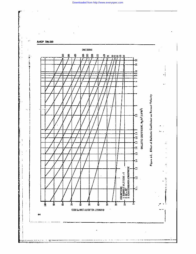
AVACP 706-280
-_ cmr-I.vfe T
J f I
1414
A- 1 I// IIL
- U 0
C" . u
- c- c"
CD,
o
t~~~..; wD W~ %
(33S/IU DOI) A1t3O13A 1flONMna
44
Downloaded from http://www.everyspec.com
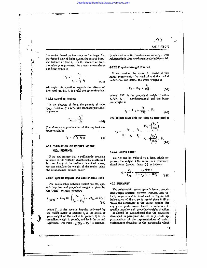
AMCP 706-280
fire rocket, based on the rage to the target 1T, ly referred to as ti. bovrner-mass ratio rB . This' the desired time of flight z .and the desired burn- relationship is illus rated graphically in Figure 4-2.
1,46 ing distance or time t, . In the absence of drag,the velocity requirement for a constant-accelera-tion boost phase is 4-122 Propellant-Weigbt Fraction
= RT If we consider he racket to consist of two
- D major components--the paylcad and the rockett 2 - (4-3) motor-.we can define tbe gross weight as
Although this equation neglects the effects of WP
drag and gravity, it ir usefui for approximation.' where P11F is the propellant weight fraction
4-3.1.3 Suunding Rockets Wp/(Wo-WpL) , nondimensional, and the burn-out weight as
In the absence of drag, the summit altitudeYMAx reached by a vertioally launched projectile WP -
is given as B - (4-8)(MX VB 2 The booster-mass ritio can then be ,expressed as
2g (4-4)WP
Therefore, an approximation of the rtquired ve- W Flocity would be . rIt. . . -V/I
WWPot - WpVB = 2g _,, A_ ) P
4-3.2 ESTIMATION OF ROCKET MOTOR
REQUIREMENTS 43.2.3 Growth Facter
If we can assume that a sufficiently accurate Eq. 4-9 can be reducd to a form which ex-estimate of the velocity requirement is achieved presses the weightd t .he rocket in a nondimen-by use of any of the methods described above, sional form (growti factor Q) as follows:we can calculate the weight of the rocket usingthe relationships defined below. W0 ra (PWF)
PL r,, (I - PWF) (4-10)4-3.2.1 Specific Impulse and Booster-Mass Ratio
The relationship between rocket weight, spe- 4-3.3 SUMMARYcific impulse, aid propellant weight is given bythe "ideal" velocity equatiou The relationship among P.owth factor, propel-lant-weight fraction swvnifie ;_mm .lue, and ve-
/O p I locity requirement ;s illustrated in Figure 4-3.VIDEAL = ( n gI, in (r 5 ) Information of this f4 *pe, is useful since it illus-
(4-6) fxates the sensitivity of the rocket weight (for
any given performaone level) to variations inwhere I,, is the spccific impulse delivered by specific impulse and propellant-weight fraction.the rocket /otor in seconds, WI is the initial or it should be reeinbered that the equationsgross weight of the rocket in pounds, W. is the developed in paragraph 4-3 are only cdeSpropellant weight in poimds, and In is the natural proximations f the representations of rocketoart v. he aio ,'/ o -W )i co ,o, ero an ed s iei hep ag a s w ic
logaith. Te raio V,)/(N - W ) s cwn-on, erfrmace escrbet inthepararaps ..c
Downloaded from http://www.everyspec.com
AMCF' 70&.280
16-
4-
~~3.
1 2024
11EA BUNU VEOCT (10 8TS 10 12
I Figure 4.2. Effect !d.l l'urnaut Velocity on 8..,ster-iass Ratio
Downloaded from http://www.everyspec.com
I ______________________________________AMCP 706-280
co
-In
ccn
glag
Cii
-4-
Downloaded from http://www.everyspec.com
AMCP 706-280
follow. Nevertheless, they are extremely valu- tages over the boost appronch for some appli- (able in the preliminary design of any rocket. As cations, it requires a more complex and costlydemonstrated in the example problem .at the cQnd motor construction.of this chapter, these relationships are used in In the staged boost approach, the total thrustthe early phases of design to establish the ap- is delivered by a series of booster motors, eachproximate values of the important rocket vari- jettisoned upon burnout. This is the most ef-ables such as I e and growth factor. These values ficient means of energy-management but its usewill determine if the design requirements are in- is limited to those cases where weight considera-consistent with the state of the art. In addition, tions override the cost and reliability penaltiesthe approximate numbers will establish the re. of staging, and where the hazards of falling mo-gion of interest for the more detailed analysis tor cas s can be permitted. Since very fewof the variables, rockets within the scope of this handbook meet
these limitations, this discussion will not includethe staged boost approach.
4-4 PARAMETRIC PERFORMANCE DATAFOR INDIRECT-FIRE SYSTEMS 4-4.2 PARAMETRIC PERFORMANCE DATA
4-4.1 DELIVERY'TECHNIQUES The relationship between growth factor (ratioof gross rocket weight to paylood weight) and
4-4.1.1 Trajectory Profile range for an indirect-fire rocket system is afunction of the following items:
The trajectory profile for = unguided surface- a. (: launch elevation angleto-surface rocket (ballistic rocket) is 3haped- b. I,: propellant specific impulsegenerally like a parabola, with an initial depart- c. PHW: motor propellant weight fractionure angle of between 450 and 60d for maximum d. Weird 2 : ratio of payload weight to diameterrange. Some large ballistic rockets are launched squaredVertically; however, these require a maneuver e. i: drag-form factor, ratio of drag coef-to tilt the rocket onto a ballistic path. The dis- ficient of rocket under considerationcussion that follows will be limited to the non- to drag coefficient of standard rocketmaneuvering type of rocket. shape for which range tables bhve
been computed44.1.2 Eneriy-MansgempntTechniques f. F/W o : initial-thrust-to-weight ratio (boost
acceleration)Among the methods that have been used to g. FS /Fr: ratio of sustain thrust to boost thrust
Impart propulsive energy to indirect-fire rocket h. ./i s I: ratio of sustain impulse to boostsystems are: impulse
Boost The angle at which the rocket must beb. Boost/sustain launched in order to achieve maximum range is. Staged. boost of initial interest to the designer. Fig. 4-4 pre-X' the boost method, the boosier motor nren V V"U V.V G, _A /W_ r"4
continuously throughout the fight of the r'ocket, growth factor Q on the optimum launch angle-or until fuel is depleted. This approach ia by for an all-boost system, with fixed values offar the leat complexof the above and has found 1,p,7P#F, and WpL/id 2 . Although the data woulduae generally in the field of simple, unguided, be different if these parameters (1',p, PWF, WPL/id)ballistic rockets were varied, the trends of the curve are worth
The booat/aluste approach consists of an ini- noting. Low accelerations require the highesttial thrust of the booster motor, followed by a lamch angles, with the dependence of launch angleonstant oustaining thrust of lesser magnitude. on acceleration being -ongest at low accelera- "
While this approach offers performance advan- tions. Higher growth ft.jrs indicate higher launch
' 4. ....... ._. ... 1 .. J_
Downloaded from http://www.everyspec.com
OPTIMUM LAUNCH QE AMCP 706-20
INDIRECT FIRE BOOST/SUSTAIN
QQ.2 FBVO. 40
250secPW -.7
0WPL/id2 2
. 60-50 . .
Pa'TIMUM LAUNCH QE Fs/FBINDIhECT FIRE - ALL BOOST
I .0PWIPt 7 2WfId2~WpL/id - 2 , " , - .. -. 4
40 50.'
V 20 40 60 80
FBO44"
Figure 4.4. Indirect Fire - All-Boost; Effect ofThrust-to-Weight Ratio on Optimum Launch 0
Quadrant Elevation o
IS/AB
angles because the," arn , equivalent to longer boost Figure 4-5. Indirect Fire - Boost/Sustain; Effectburning times at any given level of acceleration. of Impulse Ratio on Optimum Launch QuadrantFor a boost/sust,-n system, the optimum Elevation
launch angle will be a little grczater than for anall-boost syster, aor shown in Fig. 4-5. As the of about 2 is required for a range of 30 kilometers,ratio of sustainer thrust to booster thrust is de- a 25 percent increase in missile weight (an in-creased and/or th. ratio of sustainer impulse to crease of Q from 2.0 to 2.5) doubles the rangebooster impulse is increased, an increase in op. (to 60 kin).timu., launch angle is indicated. The relationship between growth factor and
Fig. 4-6 presents the relationship between rang-- for a boost/sustain system will be depen-growth factor and range for ax. all-boust system, dent upon the choice of sustainer parameters inwith QE optimized and PWIF, I,,o and 1P'PL/td2 addition to the parameters discussed above forheld constant. It La seen that the lower accelera- the all-boost system. There is no unique methodtions permit more efficient energy-management for determining optimum sustainer parametersschemes since they yield a lower growth factor since the choice will depend upon which chai-for any specified range. Although this curve is acteristics of the rocket the designer is attempt-constructed for only one value each of IP, PKF, ing to optimize; for example, weight or accuracy.and NntLIid 2 . it i., indieativp of trends; we m!y The designer has a choice of methods for provid-therefore say that the growth factor (for a given ing the sustainer impulse. This can be done withrange) will be inversely proportional to I,p, PIF, separate booster and sustainer motors, or by -oneand WpL/id 2 . The designer would, of course, motor with two thrust levels. In the case ofexamine trade-offs between these parameters, as separate motors, it is possible to achieve highdiscussed later on in this chapter. Before leav- specific impuise with each motor, 1:t the pro-ing Fig. 4-6, however, we should note another pellant weight fraction of the combination istrend of significance to the designer or to the usually lower than for a single motor. In therequirements originator. Examination of the case of a single motor with two thrust levels, the' curve show-s that significant range increases can specific impulse of the sustainer will be less thanbe obtained for relatively minor rocket-weight for the booster (due to decreased chamber pres-increases. For example, whereas a growth factor sure during the sustainer phase) if a constant-
4-4
Downloaded from http://www.everyspec.com
AMCP 706.2__
INDIRECT FIRE FBIWOhp.2%O € PWF..7 pL,'id2-2
ALL BOOSt40
0 10 0 0 . 60 70 80 90 100 0
Figure 4.6. Indirect Fire - All.Boost; Effect of Range on Growth Factor
geometry nozzle is used. For this discussion it __
will be assumed, that c single motor with twothrus levels ant fixed nozzle geometry is used. __The relationship between the ratio of msiaierthrust to boos~ir thrust and the resulting ratio S00 StAM EWNEI
of specific impulse is presented in Fig. 4-7. AT .TA" C ?oEO S.- 4 N
Fig. 4-8 indicates the type of parametric data ___A___ 1
which should be generated for optimization ofsustainer parameters in situations where mini-mizing weight itf the prmary cocern. w -
Fig. 4-9 presents the relationship betweengrowth factor and range for a boost-sustain sys- 5.tem, where the sustminer parameters are as-sumed to have been fixed by considerations other _ _ _ _
than minimum weight. A comparison of thesedata with the data for the all-boost system will _-
show that there arc conditions fer which the
system. This results from the reduction in sus-tainer apecific impulse as discussed earlier.1
The data above bzve been presented for onlyone value each of lop, PM, and WPLlid 2
The designer will be interested in knowing the o .
sensitivity of the missile weight to variations inthese parameters also. Fig. 4-10 presents the KAX hp
effects of 1, , and PWF on the growth factor fora spch-& range, acceleration level, and ballistic Figure 4.7. Boost/So 0an Zg.qne; Variation ofcoefficient. Fig. 4-11 presents a similar trade- Specific Irmrulse With Thrust4.11
Downloaded from http://www.everyspec.com
AMCP 706-2,40
INDIECTFIR- BOST/SUSTAIN
~2 2 1Isp -250 sec PWF,..7 WPL/1d2 -2
04 - 90 105~lo
RANE (1000FT)
Figure 4-8. Indirect Fire - Boost/Sustain; Effect of Range on Impulse Ratio
INIETFRE BOOST/SUSTAINFs/FB - .1 IsiB - .5FBIW olp-250sec PWF..7
OPTIMIZED QE
3./ 1 2 24
20c!
2
0 10 2 0 3 0 40 510 610 0 810 910
Figre -9.Indrec Fie -Boost/Sustain; Effect of Range on Growth Factor
* 4-11
Downloaded from http://www.everyspec.com
AMCP 706-280
INDIRECT FIRE ALL BOOST off with acceleration and ballistic coefficient as (RANGE- 50 Pm QE - 53- variables.
FBIWo,40 WPL/Id2.2 The data presented above have not been in-tended to cover every situation. They are anindication of trends and serve to illustrate thevarious trade-offs which the designer must con-sider.
5-
4-5 PARAMETRIC PERFORMANCE DATA4 FOR DIRECT-FIRE SYSTEMS3- Is we 4541 DELIVERY TECHNCUES
20 4-5.1.1 Trajectory Profiles
i 240"" Both beJlistic and mavieuverine types of tra-jectories have been used for direct-fire systemsEither of these is essentially flat, however, and
. ! the degree of maneuver, ii used, is generallylimited. Therefore, for purposes of parameter-ization, no distinction is made betwten the two
- - types. Generally speaking, it is stfficient for0F .5 .6 .7 .8 .9 performance calculations to assume a constant- f-,-
PWF altitude, line-of-sight trajectory. s
Figure 4-10. Inoirecs Fire - All-Boost; Effect ofPropellant Weight Fraction on Growth Factor 4-5.1.2 Energy-Management Techniques
Among the commonly employed energy-man-uRECT FIRE- ALL MW agement techniques for direct fire rockets are:
6 0mc ? ..- QE, .3 a. BoostPA so'i b. Boost/sustain
S _c. Boost/coast/sustainThe choice here will depend to some extent
on the level of performance required and on the6" intended method of use. Considering the method
of use, we must determine whether burning out-4. side the launch tube can be permitted. i the
case of direct-fire infantry weapons, this cannotnt-- permte,-tUc; wereas for weapons to[ " " F~ IO be employed on armored vehicles, there is nio
I problem (aside from accuracy considerations)
o involved in burning outside the launch tube. Ifburning outside the launch tube is permitted,
: ..... .either the boost or the boostleustain approachest | 0 L0 . will apply. Where burning outside :he tube is|
• Fty2 not permitted, the choice is between the boostand the boost/coast/rastain approaches, with the
Figure 4.11. Indirect Fire - All-Boost; Effect of boost approach generally limited to low per-Ballistic Coefficient on Growth Factor formance systems by the maximum velocity j
4-12_ _ _ _ -- _ _ _
Downloaded from http://www.everyspec.com
AMCP 706-280
which can be attained within the limitations of DRECT FIRE RoKET
the tube length and the rocket acceleration. F.S
4-5.2 PARAMETRIC PERFORMANCE DATA v.2
In defining the relationship between perform- IS
ance and physical characteristics for direct-fire IFl/VS 1 L
rockets, it is not necessary to separate those rock- A'l
ets which must have a coast phase from thosethat do not. The reason for this is that, in the t2 - fusual case, the additinnal time of flight will be .negligible, on the order of 1/10 sec. a ___0. _____
The relationships between growth factor (ratio 9of rocket weight to payload weight), range, and _
ti,.. of flight are determined by: ________
a. I1 propellant specific impulse 2k%b. PPF: motor propellnt weight fraction .c. HpL/d 2: ratio of payload weight to diam- 2k,
eter squared 4 - 1 --d. i: drag-form factor - --e. FB/W o : ratio of initial thrust to weight 2_f. FS IF : ratio of sustain thrust to boost
thrustg. Is/I s: ratio of sustain impulse to boost I 2
impulse hsFor initial considerations, the first four of these Figure 4-12. Direct Fira - Boost/Sustain;
parameters (IP. PHF, WpL /d 2 , i) can usually Effect of !mpulse Ratio on Time to Targetbe estimated with adequate accuracy; however,it is desirable also to examine variations of these yields minimum time of flight, namely, the boostparameters if the situation permits. system.
Fig. 4-12 presents the relationship between Fig. 4-13 presents trade-offs with respect totarget range, time of flight, and energy-manage- growth factor, time of flight, range, and boostment scheme for a given set of missile charac- acceleration. A performance limit appears to.beteristics. The best energy-management scheme reached at a growth factor of about 3.0 because
is seen to be the boost (no sustainer-) in cases increases beyond this point reduce the time ofwhere a minimum time of flight is desired. This flight an insigi i icant amount. Increasing theis usually the c-e for systems in which the gun- boost acceleration rua..es th'e time of flight, butr er has no control over the projectile after decreases the percentage of powerid flight. Forlaunch. However, in cases where command guid- example, at a growth factor of l.7 and F5 /Wo = 20ance is used, time of flight is a secondary con- the burning distance is about 3 km, and wesideration, with the velocity of th2 projectile be- reach 4 nkm in 9.7 sec. if we increase iil IW O to 80,ing limited by considerations of gunner capa- the burning distance is reduced to about 1 km andbilities, command data rates, type of command we reach 4 km in 8.5 sec. This illustration pointslink, etc. Since the considerations involved in out another of the choices facing the designer,the determination of time of flight (or average namely, the trade-off between time to target andvelocity) for the command-guided case are many percentage of powered flight.and varied, it is desirable to concentrate for the Once the designer has examined the trade-offs
S remainder of this discussion on the system which between range and time of flight, he may wish to74-13
Downloaded from http://www.everyspec.com
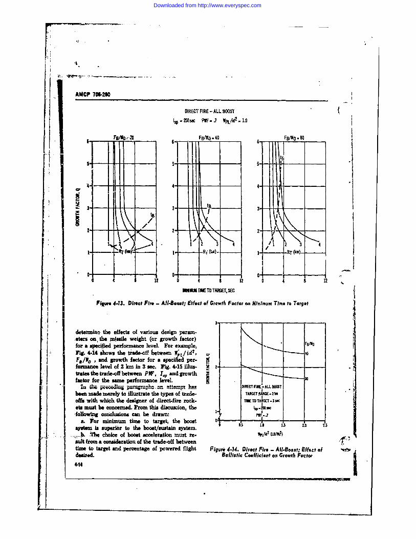
AMCP 706.200
DIRECT FIRE -ALL BOOSTIS -25 se PF- .7 W ./.2.1.0
6 FB/i FBNO -40 FBO -80
'4- 4- 4.-C!
2 2 -
4 12 2' /1 2 3 4k on - - M. - / RT(km)-
0 A 8 12 0 4 8 12 0 4 8 12MNIUM E M TAMEGE, SEC
Figwe 4.?3. Direct Fire - Al.8oost; Effect of Grewth Factor on Minimum Time to Target
determin the effects of various design param-,eters on, the miuile weight (or growth factor)for a specied performance level. For example, - FfOFig. 4-14 shows the trade-cf between WL/i 40F/o, and growth factor for a specified per- 40formance level of 2 km in 3 sec. Fig. 4-15 lus- V 2. -,-
Utates the trade-off between PW, I,, and growth i
factor for the same performance level.An "- atep atDRC - ALL -C.
ben made merely to llustrate the types of trade- [ TARGETNG-offs with which the designer of direct-fire rock- TOETO TARGCi -s3 ceta must be concerned. From this dlscusdon, the I . 01,following conclusions can be drawn: 1- -
a. For minimum time to target, the boost 0 I .system Is superior to the boost/sustain syste. .5 1.0 15 2.0 25
IL T- e choice of boost acceleration must re- WpLM (VL2 )suit from a consideration of the trade-off betweentime to targt and percentage of powered flight Figure 4-14. Direct Fire - All-Boost; Effact ofdesired. Ballistic Coefficient on Growth Factor44
Downloaded from http://www.everyspec.com
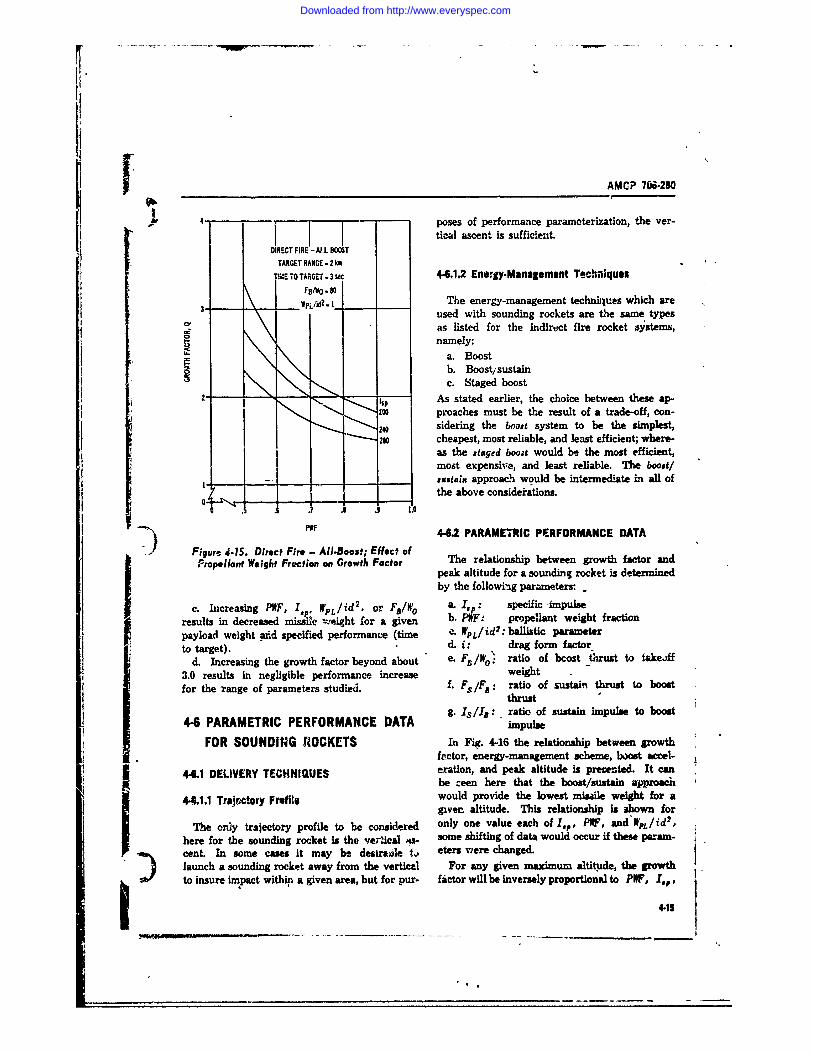
AMC? 706-280
T T E3 -poses of performance paramoterization, the ver-i tical ascent is sufficienzt.
DIRECT FIRE -A. BOOSTTARGET RANGE - 2 km
TIMdE TO TARGET - 3 W 4-6,1.2 Energy-M anagement Techniques
3,10 -3, Vj IpL/Ad. 1_ The energy-management techrilues which areused with sounding rockets are the same types
C! as listed for the indirect fire rocket systems,
namely:a. BoostI_ b. Boostisustainc. Staged boost
- - As stated earlier, the choice between these ap-proaches must be the result of a trade-off, con-
240 sidering the booat system to be the simplest,24 cheapest, most reliable, and least efficient; where-
as the staged booit would be the most efficient,most expensive, and least reliable. The boost/-utaix approach would be intermediate in all ofthe above consideiations.
0 . 1.PF 442 PARAMETRIC PERFORMANCE DATA
Figure 4.1S. Direct Fire - All-Boost; Effect ofPropellant Weight Fraction on Growth Factor The relationship between growth factor and
peak altitude for a sounding rocket is determinedby the following parameters: _
c. Increasing PWF, Ipe WL/id2 . or FB/Wo a.I ,: specific -impulseresults in decreased missile weight for a given b. PWF: propellant weight fraction
payload weight aid specified performance (time .. WP/ id 2 : ballistic parameterto target). d. i: drag form factor
d. Increasing the growth factor beyond about "/e. Ff/Wo' ratio of bcost thrust to takeoff3.0 results in negligible performance increase weightfor the -range of parameters studied. L F /F8 : ratio of sustain thrust to boost
thrustg. Is/Ia : ratio of sustain impulse to boost
4-6 PARAMETRIC PERFORMANCE DATA impulseFOR SOUNDING ROCKETS In Fig. 4-16 the relationship between growthIector, energy-management scheme, booL t accel-
44.1 DELIVERY TECHNI2UES eration, and peak altitude is presented. It canbe ceen here that the boost/sustain approach
44.1.1 Trajnctcry Fril would provide the lowest misaile weight for agiven altitude. This relationship is shown for
The only trajectory profile to be considered only one value each of lP, PWF, and'WpL/id2 ,here for the sounding rocket is the ve;'lical a- some shifting of data would occur if these param-cent. In some cases it may be desire ', eters vwere changed.launch a sounding rocket away from the vertical For any given maximum altitude, the growthto insure impact within a given area, but for pur- factor will be inversely proportional to PWF, I,p,
4.15
Downloaded from http://www.everyspec.com
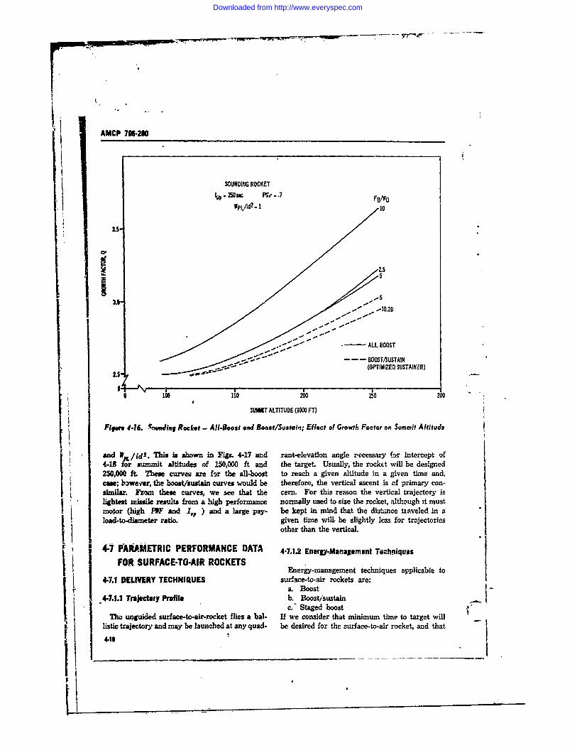
AMCP 7-20
SOUNDING ROCKET. 250 sec P -.7 FB/W0
Wpjfd2" 1 I0
3.55
/ / _.-" I .40.20
" " '- - ALL BOOST
" - BOOST/SUSTAIN. .- "f "(OPTIMIZED SUSTAINER)
2.5"-
10-A 20 250 300
SUMIT ALTITUDE (1000 FT)
Figure 4-16. e tndin Rocket - All-Boost and Boost/Sustaui; Effect of Growth Factor on Summit Altitude
and WN/id 2 . This is shown in Figs. 4-17 and rant-elevation angle recessry far intercept of4-18 for summit altitudes of 150,000 ft and the target Usually, the rocket will be designed250,000 ft. These curveau are f!ir the all-boost to reach a given altitude in a given time and,cae; bzwever, the boost/sustain curves would be therefore, the vertica ascent is Pf primary con-similar. Fron these curves, we see that the cern. For this reason the vertical trajectory islightest missile results from a high performance normally used to size the rocket, alth.ugh it mustmotor (high POF and 1,.. ) and a large pay- be kept in mind that the dis-tnce tizkveled in a
load-to-diameter ratio. given time will- be slightly less for trajectoriesother than the vertical.
V7 PARMETRIC PERFORMANCE DATA 4-7.1.2 Energy-Management TechniquesFOR SURFACE-TO-AIR ROCKETS
Energy-management techniques applikabe to4-7.1 DELIVERY TECHNIQUES surface-to-air rockets are:
a. Boost.4-7.1.1 Trajectory Profile b. Boost/sustain
c.' Staged boostIta unguided surface-to-air-rocket flies a hal- If we consider that minimum time to target will
listic trajectory and may be launched at any quad- be desired for the surface-to-air rocket, and that
448__ ,, __ __ __ __ __ _ _ _ _ _ _ _ _ _ _ _ _ _ _ - - -
11 4
Downloaded from http://www.everyspec.com
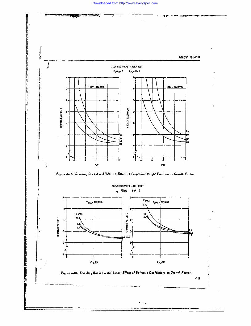
AMCP 706-280
SCUM DINdG RM'IET -ALL IWOSTF81 0 5 WPLrjd2. I
p .- 4AX IWA It- 7"MAX -250,000 ft.
CUD IL.
3 - sp 3 -200200 240
2 ____ __________ 0240 - -280
t0 .5 .6 . .8 .9 0 .5 .6 .7 .8 .9) PVF
Figure 4-17, Soundting Roclc~t - All-Boost; Effect of Propellant Weight Fraction on Growth Factor
SOUNDING ROCKET - ALL BOOST
YMA 50000it MAX no25 000 ft
a' ~~~10.0%0 ___ _____
IILU5.0
2.5
1 10.2
VPLAd2 WPLfld2
Flgura 4.18. Soundiag Rocket - All-Boos t; Effect of, Ballistic Coef ficient on Growth Factor4-17
Downloaded from http://www.everyspec.com
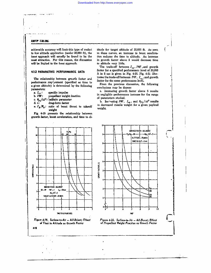
AMCP 7041-286,
achievable accuracy will limit this type of rocket titude for target altitude of 20,000 ft. As seento low altitude application (under 30,000 ft), the in these curves, an increase in boost accelera-boost apprcach will usually be found to be the tion reduces the time to altitude. An increasemoat attractive. For this reason, the discussion in growth factor above 5 would decrease timewill be liited to the boost approach. to altitude very little.
The trade-off between I.,.. PWF,and growth
4-7.2 PARAMETRIC PERFORMANCE, DATA factor for a specified performance level of 20,000ft in 5 sec is given in Fig. 4-20. Fig. 4-21 illis.
The relationship between growth factor and trates the trade-off between PWF, I, and growthperforeainp reteen (speciied actor d factor for the same performance level.performce req,,;ement (specified as time to From the previous discussion, the following
a given altitude) is determined by the following conclusions may be drawn:parameters:
a. 1,,: specific impulse a. increasing growth factor above 5 resultsb. P F: propellant weight fraction in negligible performance increase for the rangec. WPL/id : ballistic parameter of parameters studied.c. #/id2: drag-form factor b. Inp-z.asing PIWF, I,,, and WpL.id2 results
e. F,1WO; ratio of boost thirust to takeoi In decreased missile weight for a given payloadweight weight.
Fig. 4-19 presents the relationship betweengrowth factor, boost acceleration, and time to -d-
10-"
SURFAME.TAI -ALL-BOOSIM ,0 401 9 Fg- - so B/ -.-- PLfd-.2-I ALTITUDE - 20.000 ft- - -8- - tTIME TO ALT - 5 sec
,. .
6 - --
CD
S, Pr - 2.-502 --- rI 2YWPL/2
TARGEt ALTITIJOF .20j=0 f
11 T0M.Tlhj0ESEC) PWF (
Figum 4.19. Surface-to-Air - All-Boost; Effect Figure 4.20. Surfzce.to.Air - AlI.Boot; Effoctof hlm to Altitude on Growth Factor of Propellant Weight Fraction on Growt& . Factor
4--1_
Downloaded from http://www.everyspec.com
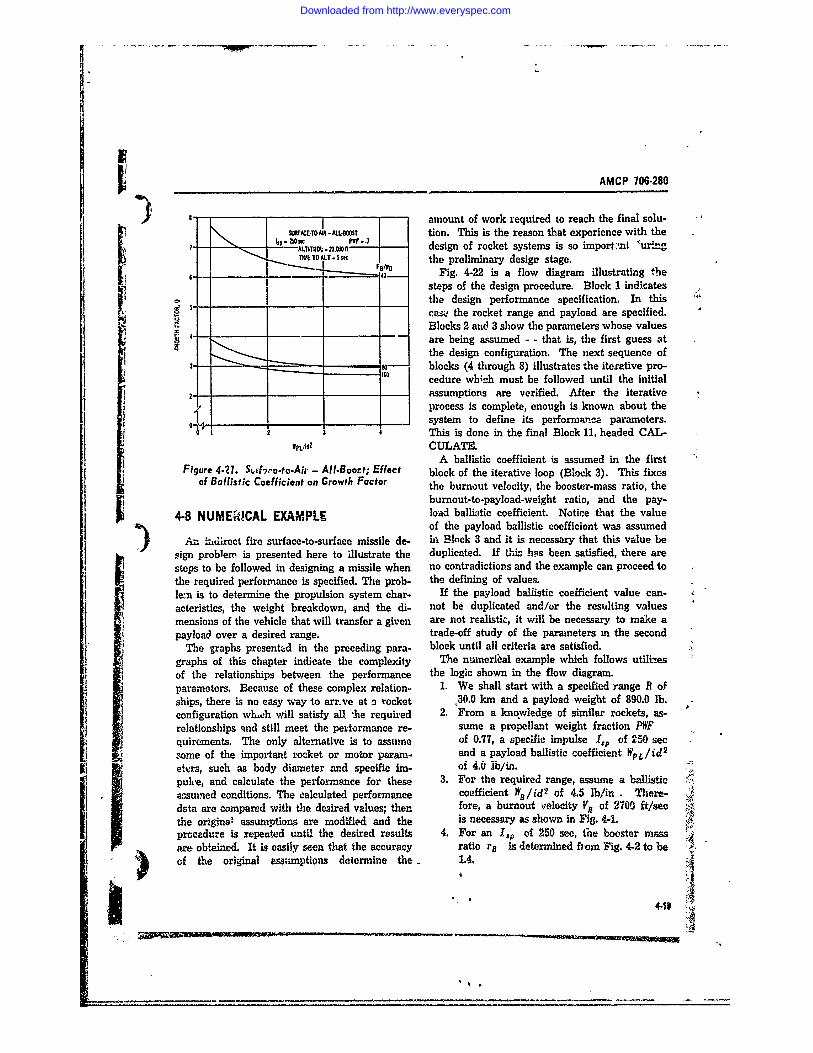
AMCP 706-280
I" - amount of work required to reach the final solu-
TSEMR-.ARL tion. This is the reason that experience with theIkp 250 3 PVF - .I u .ALT-ITu0 .0 - 2 - design of rocket systems is so import ,nt l"uringTW1TO ALTS the preliminary design stage.
6-.. -40- Fig. 4-22 is a flow diagram illustrating the
steps of the design procedure. Block 1 indicates_ _ _ _ _the design performance specification. In this
ca&- the rocket range and payload are specified.Blocks 2 and 3 show the parameters whose values
4 are being assumed - - that is, the first guess atthe design configuration. The next sequence of
---- blocks (4 through 8) illustrates the iterative pro-190 cedure whi!:h must be followed until the initial
2. ssumptiors are verified. After the iterativeprocess is complete, enough is known about the.J system to define its performance parameters.
1 2 3 4 This is done in the final Block 11, headed CAL-, .,id? CULATE.
A ballistic coefficient is assumed in the firstFigure 4.7. S.,&fv-e.to.Air - AII.Boort; Effect block of the iterative loop (Block 3). This fixes
of Ballistic Coefficient on Growth Factor the burnout velocity, the booster-mass ratio, the
burnout-to-payload-weight ratio, and the pay-4-8 NUMEW!CAL EXAMPLE load ballistic coefficient. Notice that the value
of the payload ballistic coefficient was assumedAn "idirect fire surface-to-surface missile de- in Block 3 and it is necessary that thk; value be
sign problem is presented here to illustrate the duplicated. If thz. has been satisfied, there aresteps to be followed in designing a missile when no contradictions and the example can proceed tothe required performance is specified. The prob- the defining of values.len is to determine the propulsion system char- If the payload ballistic coefficient value can-acteristics, the weight breakdown, and the di- not be duplicated and/or the resulting valuesmensions of the vehicle that will transfer a given are not realistic, it will be necessary to make apayload over a desired range. trade-off study of the parameters m the second
The graphs presented in the preceding para- block until all criteria are satisfied.graphs of this chapter indicate the complexity The numeribal example which follows utiliaesof the relationships between the performance the logic shown in the flow diagram.parameters. Because of these complex relation- 1. We shall start with a specified range R ofships, there is no easy way to arr-ve at a rocket 130.0 km and a payload weight of 890.0 lb.configuration wh,ch will satisfy all ,he required 2. From a knowledge of similar rockets, as-relationships and still meet the performance re- sume a propellant weight fraction PWFquiroments. The only alternative is to assume of 0.77, a specific impulse 1,p of 250 seesime of the important rocket or motor param- and a payload ballistic coefficient WpL/id 2
etvrs, such as body diameter and specific im- of 4.0 lb/in.
puhe, and calculate the performance for these 3. For the required range, assume a ballistic '4.assumed conditions. The calculated performance coefficient WO /id of 4.5 lb/in . There-fore a unu vlct
dsta are compared with the desired values; then fore, a burnout velocity V 2 o 2700 ft/secthe original assumptions are modified and the is necessary as shown in Fig. 4-1.procedure is repeated until the desired results 4. For an 7,, of 250 see, the booster massare obtained. It is easy seen that the accuracy ratio rB is determined fhom Fig. 4-2 to beof the original assumptions determine the 1.4.
41
Downloaded from http://www.everyspec.com
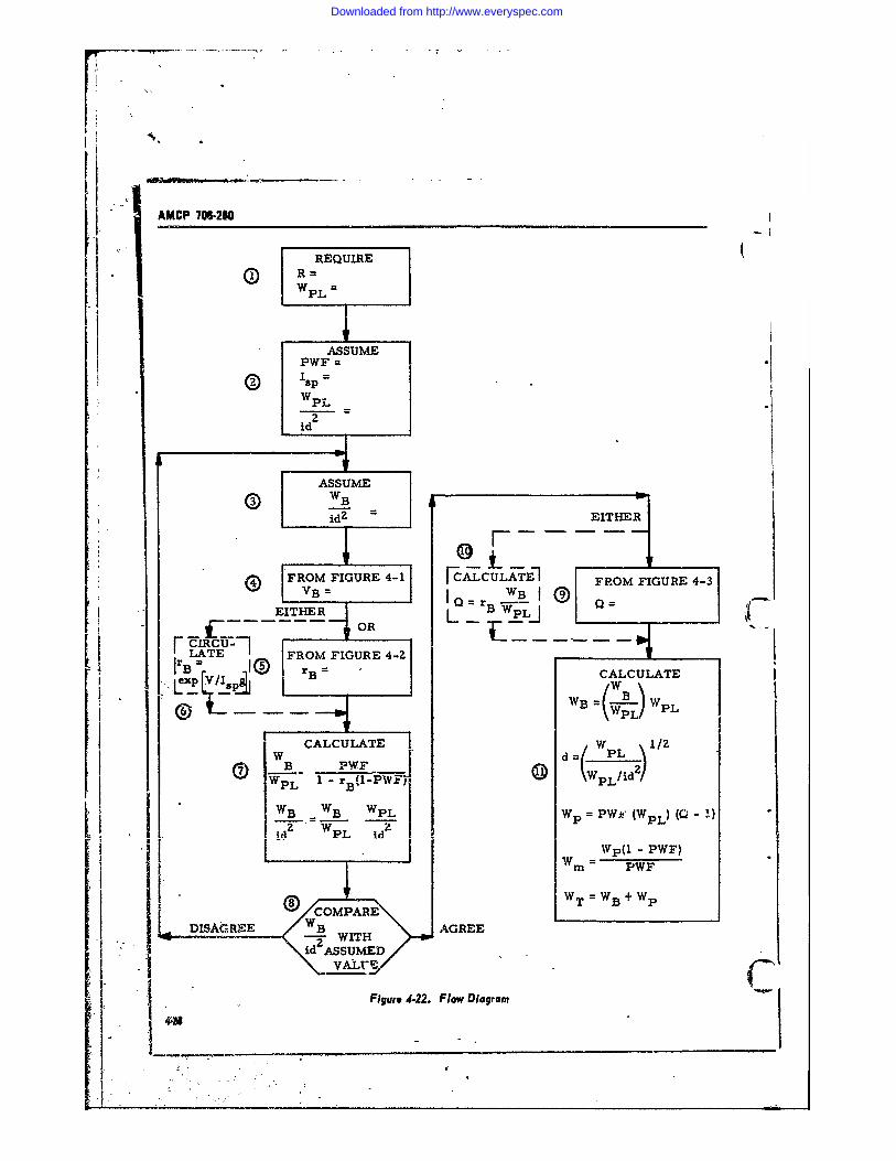
AMCP 706280
REQUIREWp =
ASSUMEPWF =S IsP =WpL
2Id
ASSUME :id?- EITHE
V FIGURE 4-1I FCALCULATE1 FROM FIGURE 4-3VB rB
__-EITHER OR
LATE 7 FROM FIGURE 4-2BV/I 2 rB- CALCULATE
6 WB =(WL WPL
W CALCULATE W w 21/2w B PWF @ d=(PL)
WPL B- 1--PWF-IWB WB WPL Wp =PWi" (WpL) (Q - 1)
M2z WpL id z I. IWp(1 - PWF)Z -Wm = PWF
CO E WT = B + Wp
DISAGREE AGREE
? HFigure 4.22. Flow Diagram
40
Downloaded from http://www.everyspec.com
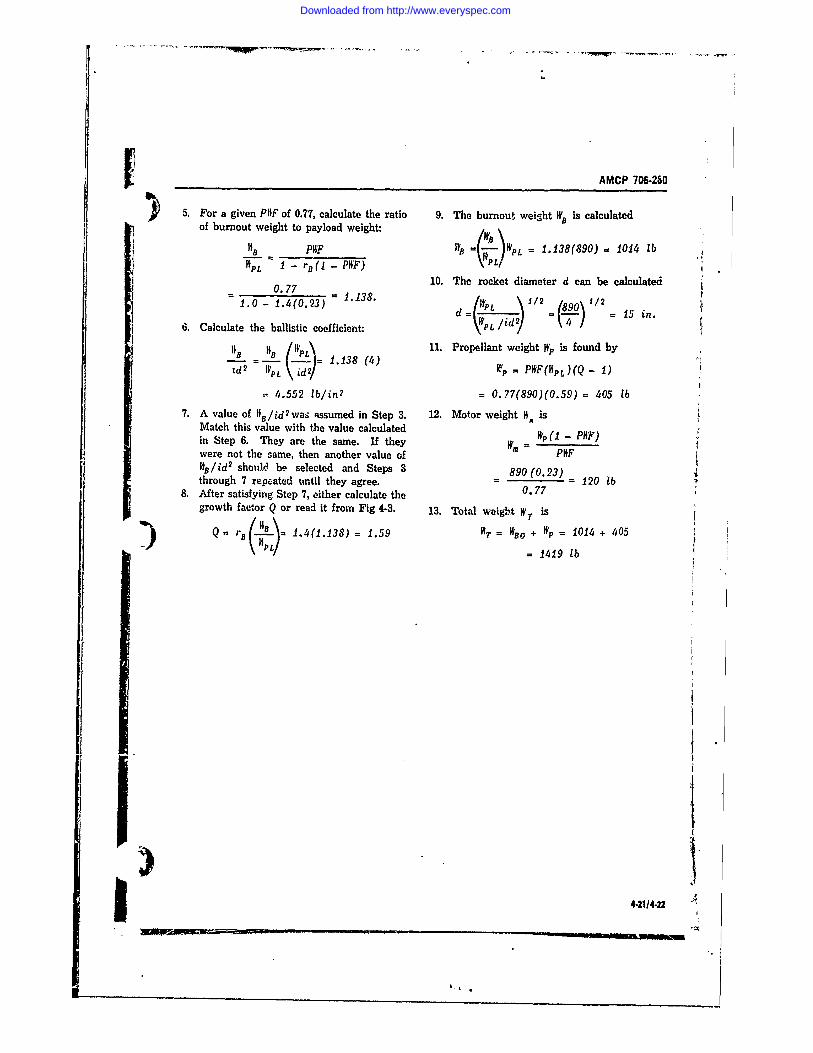
[AMCP 706-280
5. For a given PIhF of 0.77, calculate the ratio 9. The burnout weight WB is calculatedof burnout weight to payload weight: \
___ PHIF 'VB =(- )WPL = 1.138(890)= 1014 lbtPL 1 r. P(IP ) W
. .77 110. The rocket diameter d can be calculated1.0- (0.3) 1 1 /P2 1 890) /2 1d= WL ld/2 15 in.
6. Calculate the ballistic coefficient: V=(L/i )118 B IPL\ 11. Propellant weight Wp is found by
- = - - = 1,138 (4) = PtF(hpL(Q- 1)td2 PL (id) U 2/Kp)Q-1
4.552 lb/in2 = 0.77(890)(0.59)= 405 lb7. A value of IIB/id 2waS assumed in Step 3. 12. Motor weight 14 is
Match this value with the value calculated W(1 - PHF)in Step 6. They are the same. If they WM = -were not the same, then another value of POFlls/id2 should be selected and Steps 3 890(0.23)through 7 repeated until they agree. - 120 lb
8. After satisfying Step 7, either calculate the 0.77growth actor Q or read it from Fig 4-3. 13. Total we7ght W is
Q=rB .= 14(1.138) = 1.59 "= WIBO + W = 1014 + 405P L)= 1419 lb
) 31i4-2114.22 *1.
I t
Downloaded from http://www.everyspec.com
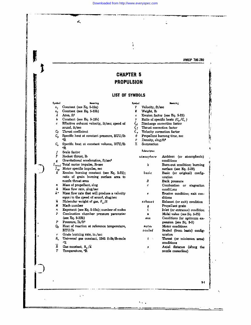
AMCP 706-280
CHAPTER 5PROPULSION
LIST OF SYMBOLSSymbol Mooning Symbol Meanirg,
a, Constant (see Eq. 5-19a) V Velocity, ft/seca2 Constant (see Eq. 5-19b) W Weight, lbA Area, ft2 Erosion factor (see Eq. 5-21)b Constant (see Eq. 5-19b) Y Ratio of specific heats (C. /C.)c Effective exhaust velocity, ft/sec; speed of Cd Discharge correction factor
sound, ft/sec jf Thrust correction factorCF Thrust ccefficient , Velocity correction factorCP Specific heat at constant pressure, BTU/lb 0 Propelleant burning time, sec
OR P Density, slug/ft,C,, Specific heat at constant volume, BTU/lb X Summation
OR
f Scale faetcor Subciptst
F Rocket thrust, lb atmosphere Ambient (or atmospheric)g Gravitational acceleration, ft/sec' conditions
TtotaL Total motor impulse, lb-sec b Burn-out condition; burningISP Motor specific impulse, sec surface (see Eq. 5-20)K Erosion burning constant (see Eq. 5-21); basic Basic (or original) config-
ratio of grain burning surface area to urationnozzle throat area B Back pressure
m Mass of propellant, slug c Combustion or stagnationit Mass flow rate, slug/sec conditonsA* Mass flow rate that will produce a velocity e Erosion condition; exit con-
equi to the speed of sound, slug/see ditionsi Molecular weight of gas, R/R exhaust Exhaust (or exit) conditionM Mach number g Propellant grainn Exponent (see Eq. 5-19a); number of moles i Inlet (or entrance) conditionP Combustion chpmber pressure parameter m Molal value (see Eq. 5-25)
(see Eq. 523b) max Conditions for optimum ex-P Pressure, lb/ft2 pansion (see Eq 5-9)
QR Heat of reaction at reference temperature, motot Motor condition),BTU/Ib scaled Scaled (from basic) config-
r Gkha buurnhg rate, hn./sec 11kH.z'II
R,, Universal gas constant, 1545 ft-lb/lb-mole t Throat (or minimum area)conditions
R Gas constant, 8,, /i x Axial distance (along theT Temperature, OR nozzle centerline)
_ 54
Downloaded from http://www.everyspec.com
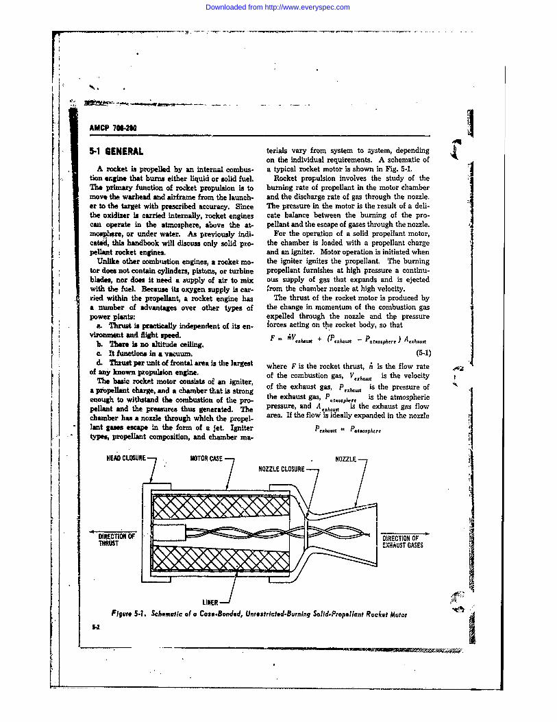
AMCP 706-280
5-1 GENERAL terials vary from system to system, dependingon the individual requirements. A schematic of
A rocket is propelled by an interjmal combus. a typical rocket motor is shown in Fig. 5-1.tion ergine that burns either liquid or solid fuel. Rocket propulsion involves the study of theThe primary function of rocket propulsion is to burning rate of propellant in the motor chambermove the warhead and airframe from the launch- and the discharge rate of gas through the nozzle.er to the target with prescribed accuracy. Since The pressure in the motor is the result of a deli-the oxidizer is carried internally, rocket engines cate balance between the burning of the pro-cau operate in the atmosphere, above the at- pellant and the escape of gases through the nozzle.mosp e, or under water. As previously indi- For the operation of a solid propellant motor,cated, this handbook will discuss only solid pro- the chamber is loaded with a propellant chargepellant rocket engines, and an igniter. Motor operation is initiated when
Unlike other combstion engines, a rocket mo- the igniter ignites the propellant. The burningtor does not contain cylinders, pistons, or turbine propellant furnishes at high pressure a continu-blades, nor does It need a supply of air to mix ous supply of gas that expands and is ejectedwith the fuel. Because Its oxygen supply is car- ,rom the chamber nozzle at high velocity.tied within the propellant, a rocket engine has The thrust of the rocket motor is produced bya number of advantages over other types of the change in momentum of the combustion gaspower plants: expelled through the nozzle and thp pressure
a. Thrust is practically independent of its en- forces acting on t e rocket body, so thatvfrflmIF -n Bightus "pe. ' ("exhaust - Patbosphere ) Aehas
b. There is no altitude ceiling.c. It funtions in a vawuum. (5-1)d. Thrust per unit of frontal area Is the largest where F is the rocket thrust, ' is the flow rate
of any known propulsion engine. of the combustion gas, A is the velocityThe basic rocket motor consists oi an igniter, of the exhaust gas, P ~ is the pressure of
a propellant charge, and a chamber that is strongenough to withstand the combustion of the pro- the exhaust gas, P, re is the atmosphericpelant and the pressures thus generated. The pressure, and A exhaust is the exhaust gas flowchamber has a nozzle through which the propel- area. If the floW is ideally expanded in the nozzlelant gases escape in the form of a jet. Igniter Pexhaust = Pataosphere
types, propellant composition, and chamber ma-
I-HEAD CLOSURE MAOTOR CASE NZLNOZL CLOZUR
THRUSTA OFDRECTION OF
LINER
Figure 5.1. Schmatic of a Case.Bonded, Unrestricted-Burning Solid.Propellant Rocket Motor
54 ____4
£0
Downloaded from http://www.everyspec.com
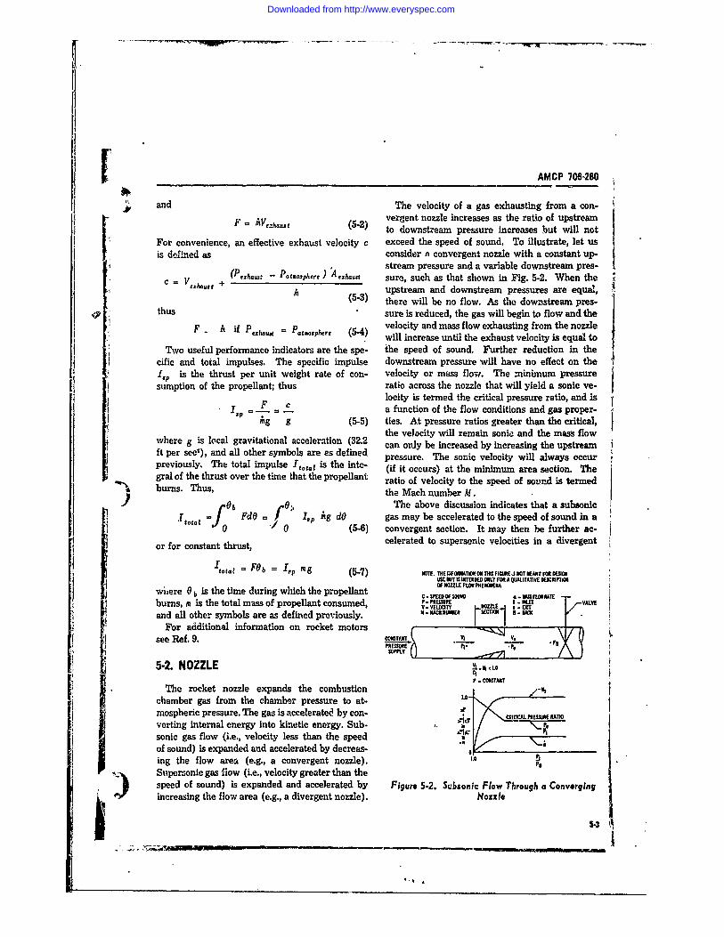
AMCP 706-280
and The velocity of a gas exhausting from a con-F =iVe-h.t (5-2) vergent nozzle increases as the ratio of upstreamto downstream pressure increases but will not
For convenience, an effective exhaust velocity c exceed the speed of sound. To illu.trate, let usis dolned as consider a convergent nozzle with a constant up-
stream pressure and a variable downstream pres-'_(Pe_ - Patoe ) A sure, such as that shown in Fig. 5-2. When the
c = I/(5-3) upstream and downstream pressures are equal,: thus3 there will be no flow. As the downstream pres-
i thus sure is reduced, the gas will begin to flow and theiF Ai(if4P velocity and mass flow exhausting from the nozzle
s F iP = P.satmosphere (5-4 will increase until the exhaust velocity is equal to
Two useful performance indicators are the spe- the speed of sound. Further reduction in thecific and total impulses. The specific impulse downstream pressure will have no effect on the i1,P is the thrust per unit weight rate of con- velocity or mss flow. The minimum pressuresurnption of the propellant; thus ratio across the nozzle that will yield a sonic ve-
locity is termed the critical pressure ratio, and isIP = . a function of the flow conditions and gas proper-ig g (5-5) ties. At pressure ratios greater than the critical,
the velocity will remain sonic and the mass flowftherec) an aslocl grvttimeaacceleration (5-)32.2 rsueraisgete hnte rtclhere g is local gravitational only be increased by increasing the upstreamft per sect), and all other sym bols are s defined p e s r . T e s nc vl ct il a w y c upreviously. The total impulse Itt,, is the inte- (if it occurs) at the minimum area section. Thegral of the thrust over the time that the propellant ratio of velocity to the speed of sound is termedburns. Thus, the Mach number M.
)6b 0o, The above discussion indicates that a subsonic•total FdO f Ip Ag dO gas may be accelerated to the speed of sound in a
0 (5-6) convergent section. It may then be further ac-or for constant thrust, celerated to supersonic velocities in a divergent
total = FOb =,p mg (5-7) NTE THEINFORMATIONON THISF1GURE$ NOTIMEAATFAESIGNUSE BUT It ITEKDED ONLY MR A AlITATIVE DESCRIPTAI
wiere 0 b is the time during which the propellant OF NOME FLOW PHEM.AC - SKIED OF $OI a- V MtO1IATE --
burns, m is the total mass of propellant consumed, . ' I. VALVEand all other symbols are as defined previously. .uM KPMNA-P a M
For additional information on rocket motors Isee Ref. 9. V er~PIT __ _ _ _ _ t_ _ _ _
5-2. NOZZLEP - COMTANT
The rocket nozzle expands the combustion .chamber gas from the chamber pressure to at- ___mospheric pressure. The gas is accelerated by con- CRTCLfESR AIverting internal energy into kinetic energy. Sub- a \_P
sonic gas flow (i.e., velocity less than the speedof sound) is expanded and accelerated by decreas-ing the flow area (e.g., a convergent nozzle). Io PaF Supersonic gas flow (i.e., velocity greater than the
speed of sound) is expanded and accelerated by Figure 5-2. Subsonic Flow Through a Convergingincreasing the flow area (e.g., a divergent nozzle). Nozzle
5-3t
*~r~ i~ iu--OW-N
Downloaded from http://www.everyspec.com
AMCP 706-260Aq
section. Such a nozzle with convergent and di- 5-2.1.1 Ideal Flowvergent swetL', is called a supersonic or De Lavalnozzle. The velocity at the section of minimum Flow through nozzles is considered to be idealarea (throat) will always be less than or equal to when: (a) there is no friction, (b) there is no heatIthe speed of sound, depending upon the pressure transfer (adiabatic), (c) flow is steady, (d) flowratio across the nozzle. To illustrate the flow is unifeim across sections normal to the nozzlephenomena, let us consider a supersonic nozzle longitudinal axis, (e) flow exhausting to the at-with a constant upstream pressure and a variable mosphere .s parallel to the nozzle longitudinaldownstream pressure as shown in Fig. 5-3. When axis, (f) the gas (products of propellant combus-the upstream and downstream pressures are tion) is homogeneous, (g) the gas is in chemicalequal, ̂ "-ri will be no flow. As the downstream equilibrium and does not shift, and (h) the gaspressure is Yeduced, the gas will begin to flow, obeys the perfect gas laws. The above assump-and the exhaust velocity and mass flow will in- tions allow the definition of flow through thecrease until the velocity at the throat is equal to nozzle to be based on the isentropic thermody-the speed of sound. As the downstream pressure namic relations and the perfect gas laws. Flow1 furnhe 'educed, the mass flow will xemain con- across pressure shocks cannot be considered asstant -,,l he velocity at the throat will remain at ideal.the speed of sound. A downstream pressure will If we apply the principle of the conservation ofbe reached at which the gas is completely ex- energy and consider the isentropic flow of a per-panded Ideally within the nozzle and the exhaust feet gas, the nozzle exhaust velocity is
5.velocity is supersonic. At downstream pressureslower than this, the exhaust flow remains super- /2 [ , y-lsonic but the gas is underexpanded within the Vex.., = Ty
nozzle; therefore, additional expansion takes place P[outside the nozzle. At higher downstream pres- (5-8)sures the ga is overexpanded in the divergent where g is gravitational acceleration (32.2 ft/sec2 ),section of the nozzle, resulting in pressure shock y is the ratio of the gas constant pressure specificwaves and in flow separation from the nozzle wall. heat to constant volume specific heat, R is the gasPressure shock waves are distinguished by abrupt constant (R./-R), T, is the temperature of the gaspressure rises and a velocity change from super- in the combustion chamber, P. is the pressure ofsonic to subsonic. the gas in the combustion hamber, and P,h
As internal energy is converted to kinetic en- is the pressure of the exhaust gas. For optimumergy throughout the nozzle, the gas temperature expansion, the pressure of the exhaust gas willdecreases. The gas pressure and density also be equal to the atmospheric pressure. If the ex-decrease as the gas expands through the nozzle. haust gas pressnre is greater than atmospheric,
The above discussion presents a qualitative the gas will be underexpanded (because the ex-description of nozzle flow phenomena. The dis- haust flow area is too small) and expansion willcussion which follows will present methods of continue to take place outside the nozzle. Thedefining the flow phenomena quantitatively, relationship between the area ratio (exhaust to1-rt, ,,a ,.,u er-t;,% I( ahae to o it.., i
5.2.1 THERMODYNAMIC RELATIONS for ideal expansion in the dive.gent section of asupersonic nozzle is shown in Fig. 5-4. If, for aTo design and evaluate the performance if a given area ratio, the exhaust pressure (deter-rocket, it is necessary to define the thermody- mined from Fig. 5-4) is less than atmospheric, the
- namic relations rf the gas flow through the nozzle. gas will be overexpanded (as the exhaust flowThe normal approach is to evaluate the thermo- area is too large) restating in shock waves anddynamic relatons based on the ideal flow of an flow separation within the diveigent section ofideal gas an .hen modify these relations for the the nozzle. When the gas is overexpanded, areal flow of ta, real gen. Generally, the actual portiol of the divergent section of the nozzle ismcket motor performance is within 10 percent of unused and, therefore, is unnecessary weight. Thethe performance calculated for ideal conditions. decrease of atmospheric pressure with altitude[4
Downloaded from http://www.everyspec.com
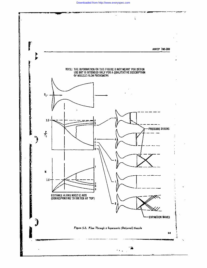
r AMCP 706-280
NOTE: THE INFORMATION ON THIS FIGURE IS NOT MEANT FOR DESIGNUSE BUT IS INiTENDED ONLY FOR A QUALITATIVE DESCRIPTIONOF NOZZLE FLOW PHENOMENA
PC.
1.0 abC
PRESSURE SHOCKSP
d I) e
f
b_ _ _ a
DISTANCE ALONG NOZZI.E AXIS(CORRESPONDING 70 SKETCH AT TOP)
EXPANSION WAVES
Figure 53. Flow Through a Supersonic (DLavaI) Nozzle -
Downloaded from http://www.everyspec.com
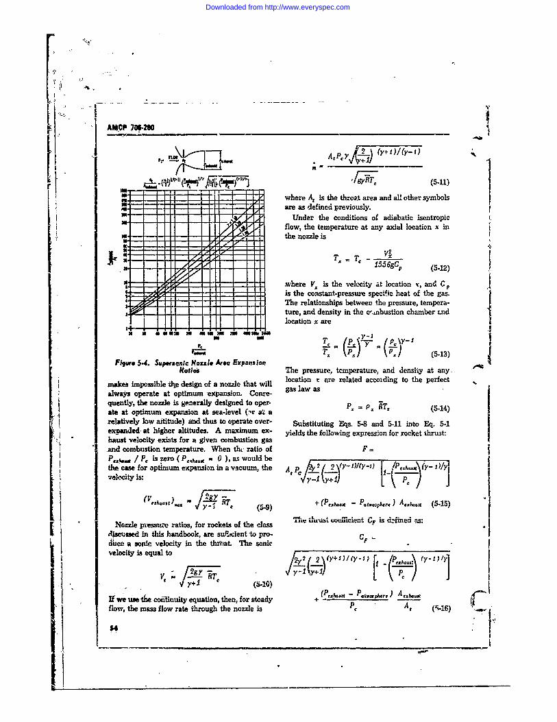
AMCP 7W290- -
U". Apy 2. (y.1)/(y-x) 1It.P
where At Is the throat area and all other symbolsare as defincd previously.
Under the conditions of adiabatic isentropicflow, the temperature at any axial location x in
m. - ithe nozzle is
01x
o"17 -, ' where Vx is the velocity at location x, and C p5.3= I ::ZZ is the constant-pressure specific heat of the gas.
The relationships between the pressure, tempera-"- ture, and density in the c-.,bustion chamber tnd
location x are
razi (P.) (5413)Filgw 5.4. Supersonic Nozzle Arta Expansion
Ratios The pressure, tcmperature, and densiy at any.-makes impossible tl design of a nozzle that will location r are related accoiding to the perfectalways operate at optimum expansion. Cone- gas law asquently, the nozzle is generally designed to oper- P, -P. RT' (5-14)ate at optimum expansion at sea-level (:-r a'4 arelatively low altitude) fnd thus to operate over- Substituting Eqs. 5-8 and 5-11 into Eq. 5-1expanded at higher altitudes. A maximum ex- yields the following expression for rocket thrust:haust velocity exists for a given combustion gasand combustion temperature. When thc ratio of F =Pcx Ss / P, is zero ( P,,h..g - 0 ), as would bethe case for optimum expansion in a vacuum, the At PC )-+2 '2-\Y 1)/(Y'.i) !Pez \(Y- I )/Y]veloc(Yty is. CIVI +~ '\-
(V e ) c (r 9 + (Pexhuat - Patmo~phete) Ae1 hai (5-15)
ISM..L, ulrust w.elflcient GF is d,:rined, -i:Nozzle piessuri ratios, for rockets of the class UF
discussed in this handbook, are su.tcient -to pro- CFScu a soni, velocity in the tlh)at. The sonicvelocity is equal to /\Y )I .1
- [,jehcus.(5-10)A (/ 1
If we use the confinuity equation, then, for steady + - Pataui~ra) Aeflow, the mass flow rate through the nozzle is PA, (5-16) 154 ___
Downloaded from http://www.everyspec.com
AMCP 766280
Thus, tal computers as outlined in Reference 3. InFgeneral, the contour of the divergent section isF = CFAPP (5-17) critical. The primary re-ui.rement on the con-
vergent and throat sections is that they be wallThe thrust cofficient is shown graphically in rounded to avoid disturbaaces in the flow.Fig. 5-5 (A) and (B). For ease of mrnufacture an, I design, the use
of a conical divergent section is often desirable.52.1.2 Real FI~w The cone half angle of such a section, according
to Reference 4, should be appoximately 9 degto obtain maximum thrust Since the nozzle should
In real noes, friction is present, heat is t be as short as pos3ible to reduce weight, a coneferred; flow may be unsteady; flow and gas prop- half angle as large as 18 deg can be used witherties across sections of the nozzle are nonuni-form; flow is nonaxial, equilibrium shifts in the only a 2 percent reductior in thrust. To preventnozzle; and the gas is nonhomogeneous and im- flow separation, angles greater than 18 deg shouldperfect. An empirically derived correction factor be avoided. The nozzle exit should be manu-is generally used to account for all deviations factured with a sharp edge to prevent overexpan-from the ideal flow performance. sion and flow separation.
Reference 1 presents indications oi the magni- The thrust way be increased by roughly 1 per-tude of the deviations from ideal conditions. The cent by using a parabolic instead of a conical di-velocity, discharge, and thrust correction factors vergent section. A method of appreximastding theaccount for frictior, effects, heat transfer, imper- optin parabolic ontour is presented in Reffect gases, nonaxial flow, nonuniformity of the erence 4.gases, and nonuniformity of the flow distribution.The velocity correction factor C. is the ratio ofactu&l exhaust velocity to ideal exhaust velo.ity, 5-2.3 NOZZLE EROSIONand ranges between 0.85 and 4.98, with an aver-age of 0.92. The discharge correction factor is n The high-velocity gases passing throug thethe ratio of the actual mass flow rate to the ideal nozzle contain solid particles that erode the innermass flow rate, P.d ranges between 0.98 and 1.15, surfates of the nozzle. Erosion a the nozzlew:'th on average, of 1.04. The thrust correction throat is particularly serious since the flow areafactor an iterati of a4Th thrust oretion is increased, which alters the combustion cham-fandor Ci. bteen 0.92o of 1.0l wtht an erag ber pressure, mass flow rate, velocities, and, con-and ranges between 0.92 end 1.0, with an average sequently, the rocket performance. Erosion mayof 0.96. The correction factors are related asfollows: be controlled for short duratioras through use of
protective coatings such as chrome plating, or forlonger duratiow by using ceramic or graphite
CI = v C (5-18) in ets.The average values, of the correction factors
indicated above are recommended for preliminarydesign. In advanced design, it will be necessary 5-3 PROPELLANTSto consider chemical equilibrium shifts through
4. V aiis Wurus5secuionsof the nozzle, and other effects treated only asaveragez in this handbook The body or mass of the sld propellant, which
For a more detailed study of flow in nozzles, is formed by casting, molding, or extrusion, isconsult Refercnces 1 and 2. called the grain. It is a specific chemical compo-
sition that sustains combustion. The grain , whenit is properly designed, bums at a uniform rate
5. 22 HOW. CONTOURS in a direction normal to the burning surface. Bum-The design of the optimum nozzle contour re- ing may be prevented on surfaces by employing
quires complex aRnalyses ut .izing high-speed digi- inhibitors that are chemically inert substan.a . .
Downloaded from http://www.everyspec.com
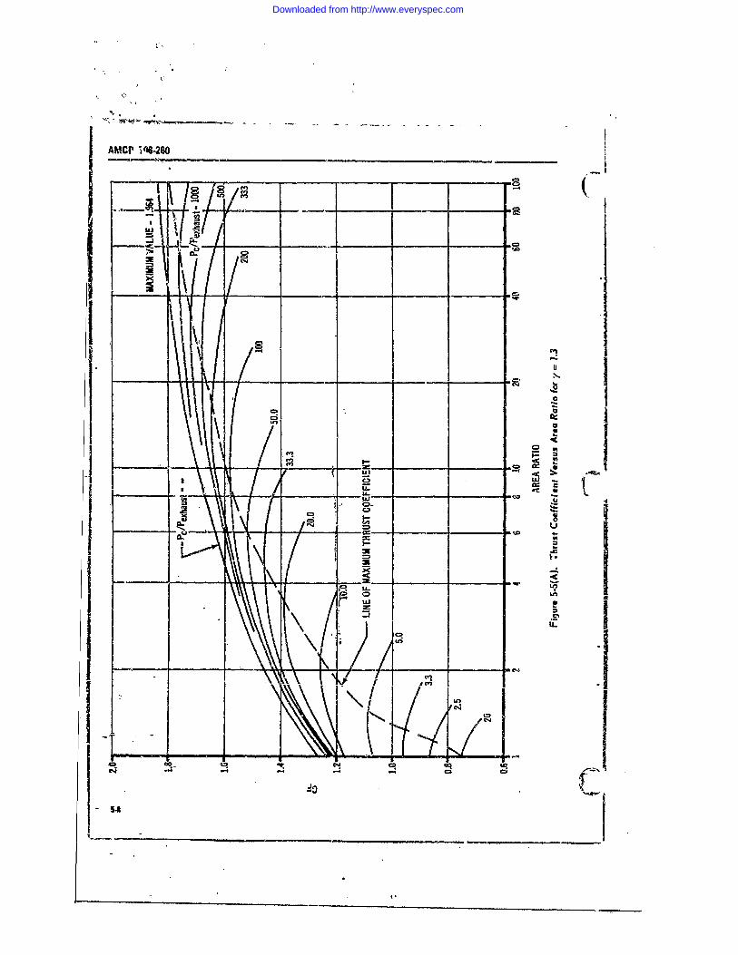
AMCP i6-8O
-- m
2 vi
U-Ur
- r - -W_
LL. L70 LOL&J 0
C3,.
o4It "
I- L9* IV * _ ____ ___ ____ ___
_ _I_ _0.__q
C.)R
Downloaded from http://www.everyspec.com
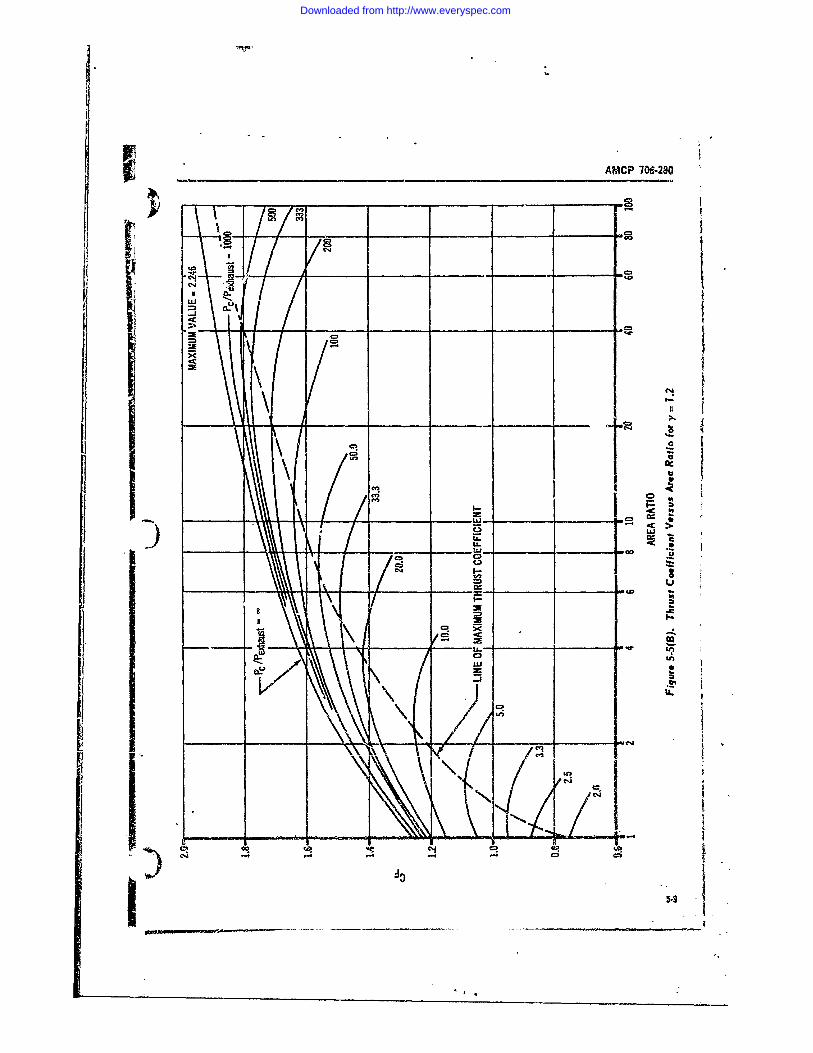
AMCP 709-280
_ _ __o
cv,
IL
U--
C-cI
Downloaded from http://www.everyspec.com
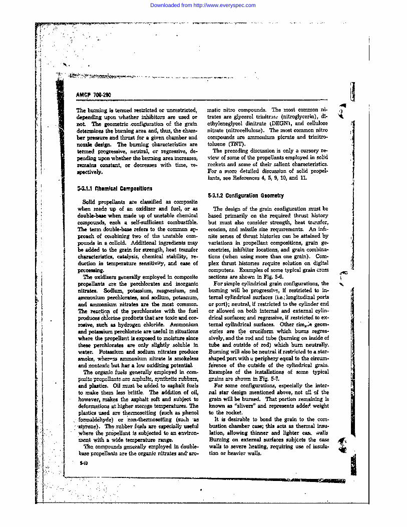
AMCP 70W280
The burning is termed restricted or unrestricted, matic nitro compounds. The most common ni-depending upon whether inhibitors are used or trates are glycerol triihtrate (nitroglycerin), d-not. The geometric .configuration of the grain ethyleneglycol dinitrate (DEGNI, and cellulosedetermines the burning area and, thus, the chain- nitrate (nitrocellulose). The most common nitroher pressure and thrust for a given chamber and compounds are ammonium picrate and trinitro-nozzle design. The burning characteristics are toluene (TNT).termed pragressive, neutral, or regressive, de- The preceding discussion is only a cursory re-peading upon whether the btmning area increases, view of some of the propellants employed in solidremains constant, or decreases with time, re. rockets and some of their salient characteristics.spectively. For a more detailed discussion of solid propel-
lants, see References 4, 5, 9, 10, and 11.V4.1.1 Phemnical compositions
5-3.12 Configuration Geometry
Solid propellants are classified as compositewhen meA up of an oxidizer and fuel, or as The design of the grain configuration must bedouble-base when made up of urstable chemical based primarily on the required thrust history
compounds, each a self-sufficient combustible, but must also consider strength, heat transfer,The term double-base refers to the common ap- erosion, and missile size requirements. An ifi-proach of conbining two of the unstable com- nite series of thrust histories can be attained bypounds in a colloid. Additional ingredients may variations in propellant compositions, grain ge-be added to the grsan for strength, heat transder ometries, inhibitor locations, and grain combina-characteristics, catalysis, chemical stability, re- tions (when using more than one grain). Com-duction in temperature sensitivity, and ease of plex thrust histories require solution on digitalprocessing, computers. Examples of some typical grain cross
The oxidizers generally employed in composite sections are shown in Fig. 5-6.propellants am the perchlorates and inorganic For simple cylindrical grain configurations, thenitrates. Sodium, potassium, magnesium, end burning will be progressive, if restricted to in-
ammonium perchlorates, and sodium, potassium, ternal cylindrical surfaces (i.e.; longitudinal portsand ammonium nitrates are the most common. or port); neutral, if restricted to the cylinder endThe reation of the perchlorates with the fuel or allowed on both internal and external cylin-produces chlorine prodticts that are toxic and cor- drical surfaces; and regressive, if restricted to ex-rosive, such as hydrogen chloride. Am onium ternal cylindrical surfaces. Other sim.e geom-and potassium perchlorate are useful in situations eWr'es are the cruciform which burns regres-where the propellant is exposed to moisture since sively, and the rod and tube (burning on inside ofthese perchlorates are only slightly soluble in tube and outside of rod) which burn neutrally.water. Potassium and sodium nitrates produce Burning will also be neutral if restricted to a star-smoke, wherpas ammonium nitrate Is smokeless shaped port with Q periphery equal to the circum-and nontoxic but has a low oxidizing potential. firence of the outside of the cylindrical grahi.
The organic fuels generally employed in com- Exwmples of the installations of some typical
and plastics, Oil must be added to asphalt fuels For some configurations, especially the inter-to make them less brittle. The addition of oil, nal star design mentioned above, not =.' of thehowever, m kes the asphalt soft and subject to grain will be burned. That portion remaining isdeformations at higher storage temperatures. The known as "slivers" and represents added weightpltics used are thermosetting (such as phenol to the rocket.formadehyde) or non-thermosetting (suth -as It is desirable to bond the grain to the corn-
The rubber fuels are especially useful bustion chamber case; this acts as thermal insu-y. ) w ee the propellant is subjected to an environ- l tiotin, allowing thinner and lighter cas. walls
-. Xrit vith a wide, temperature range. Burning on external surfaces subjccts the caseThea compounds generally employed in double- walls to severe heating, requiring use of hisula-I , base propellsat are the organic nitrates and, aro- tion or heavier walls.
'~540 [1~ _LAS
Downloaded from http://www.everyspec.com
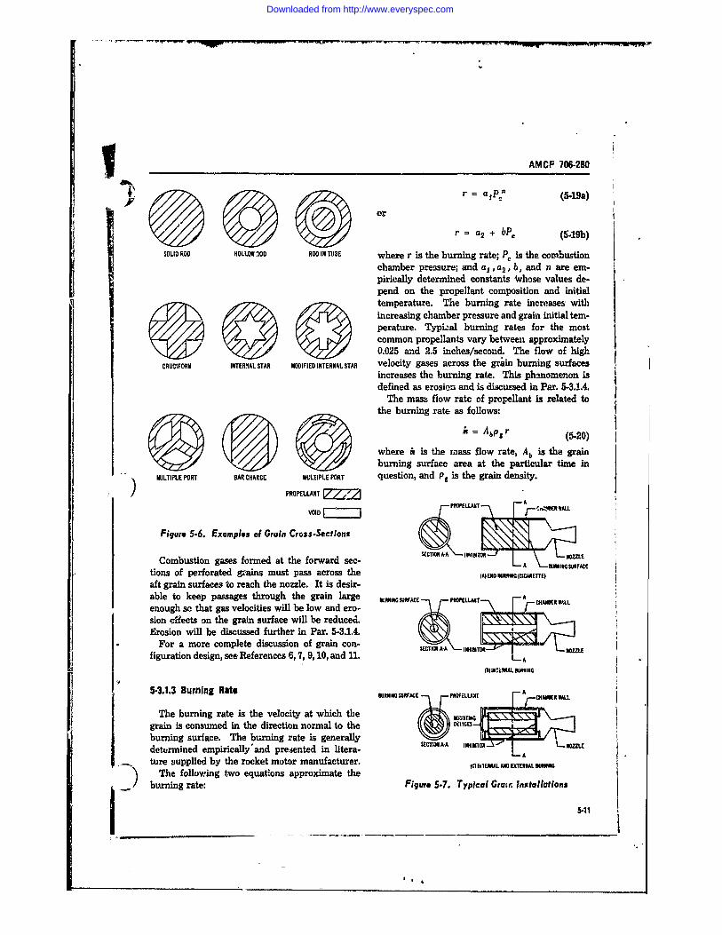
AMCP 706-280
r =a~p, 51a
r = a2 + bP0 (6-19b)
SOLID ROD HOLLOW IOD ROD IN T11SE where r is the burning rate; P, is the comnbustionchamber pressure; and a,, a 2 , b, and n are em-pirically determined constants *hose values de-pend on the propellant composition and initial
/temperature. The burning rate increases withincreasing chamber pressure and grain initial tem-perature. Typi.zal burning rates for the mostcommon propellants vary between approximately0.025 and 2.5 inches/second. The flow of high
CRUCIFORM INTERNIAL STAR MODIFIED INTERNAL STAR velocity gases across the grain burning surfacesincreases the burning rate. This phenomenon isdefined as erosion and is discussed in Par. 5-3.1A.
The mass flow rate of propellant is related tothe burning rate as follows:
A = Abp~r (5-20)
where it is the mass flow rate, Ab is the grainburning surface area at the particular time in) MULTIPLE PORT BAR CHARGE MULTIPLE PORT question, and P. is the grain density.
PROPELLANT L A
VOID
Figure 5-6. Examples of Grain Cross-SectionsCombustion gases formed at the forward sec- DA mrn uvc
tions of perforated 5ains must pass across the A U0RNINGOc E
aft grain surfaces to reach the nozzle. It is desir-able to keep passages through the grain large BRWMIGSURFACE PIMftLAjT Aenough so that gas velocities will be low and ero- -TF -
Erosion will be discussed further in Par. 5-3.1.4.For a more complete discussion of grain con- kSECTI.OA.A 01011 LZL.
figuration design, see References 6, 7, 9, 10, and 11. T •4 (5I) IiIALB SIIG
5-3.1.3 Burning Rate RNI-SURFACCK ftW
The burning rate is the velocity at which thegrain is consumed in the direction normal to the c-VIiE.burning surface. The burning rate is generallydetermined empirically'and presented in litera- =0111 A-A INIWO L NOZL
ture supplied by the rocket motor manufacturer. ) IhTERNAL AN ETERNAL WAVING) The following two equations approximate thebirning rate: Figure 5-7. Typical Grain Installations
Downloaded from http://www.everyspec.com
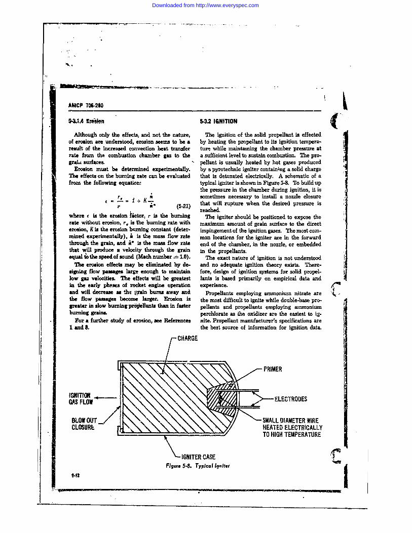
AMCP 706-280
.4 Ar n 5-3.2 IGNITION
Although only the effects, and not the nature, The ignition of the solid propellant is effectedof erosion are understood, erosion seems to be a by heating the propellant to its ignition tempera-result of the increased convection heat transfer ture while maintaining the chamber pressure atrate from the combustion chamber gas to the a sufficient level to sustain combustion. The pro-graLi surfaces. pellant is usually heated by hot gases produced
Erosion must be determined experimentally, by a pyrotechnic igniter containJng a solid chargeThe effects on the burning rate can be evaluated that is detonated electrically. A schematic of afrom the following equation: typical igniter is shown in Figure 5-8. To build up
the pressure in the chamber during ignition, it isr I Ksometimes necessary to install a nozzle closurer * (" 1 that will rupture when the desired pressure is
reached.where e is the erosion iictor, r is the burning The igniter should be positioned to expose therate without erosion, r, is the burning rate with maximum amount of grain surface to the directerosion, K is the erosion burning constant (deter- impingement of the ignition gases. The most corn-mined experimentally), i is the mass flow rate mon locations for the igniter are in the forwardthrough the grain, and i* is the mass flow rate end of the chamber, in the nozzle, or embeddedthat will produce a velocity through the grain in the propellants.equal io the speed of sound (Mach number 1.0). The exact nature of ignition is not understood
The erosion effects may be eliminated by de- and no adequate ignition theory exists. There-signing flow passages large enough to maintain fore, design of ignition systems for solid propel-low gaS velocities. The effects will be greatest lants is based primarily on empirical data andIn the early phesms of rocket engine operation experience.and will decrease as .ht gain burns away and Propellants employing ammonium nitrate are ' -
the flow passages become larger. Erosion is the most difficult to ignite while double-base pro-greater in slow burning prdoellants than in faster pellants and propellants employing ammoniumburning grains. perchlorate as the oxidizer are the easiest to i3-
For a further study of erosion, see References nite. Propellant manufacturer's specifications are1 and 8. the best source of information for ignition data.
CHARGE
~PRIMER
GAS FLOW E
BLOW OUT SMALL DIAMETER WIRECLOSURI HEATED ELECTRICALLY
TO HIGH TEMPERATURE
\ -IGNITER CASEFigure 5-8. Typical Igniter
5-12
Downloaded from http://www.everyspec.com
AMCP 706-280
5-3.3 HANDLING The evaluation of Ine combustion chicuiber gastemperature requires a detailed analysis of the
Because they are susceptible to cracking, solid chemical reaction, product composition, and pro-propellant grains must be handled carefully. duct quantities. Equating the heat of reactionCracks increase the burning surface area, altering and the summation of the change of each of thethe rocket performance. Chapter 6 discusses combustion chamber products yieldshandling procedures that can be applied to thegrans. T
nl (C dTQR [j 0 r j~5-4 INTERNAL BALLISTICS (5-25)
The combustion chamber pressure, for a given where QR is the heat of reaction at referencepropellant composition, is a function of the ratio temperature T., n is the number of moles of eachof the grain burning area to the nozzle throat product formed, (Cp). is the constant-pressurearea. Equating the na-ss generation rate for steady molal specific heat of each product formed, andflow (Eq. 5-20) with, the nozzle mass flow rate fT (C)dT is the enthalpy change of the(Eq. 5-11), utilizing the burning rate equation Te(Eq. 5-19), and rearranging the terms, yields product formed associated with the enthalpy
I_ I change from reference temperature T, to com-_n bustion chamber gas temperature T. The heat of
preaction is the algebraic difference between thePc -heat of formation of the products and the heat of)) formation of the reactants. The heat of formation. ~(;+2 /0' and the ccnstant-pressure molal specific heat of(5-22) the various compounds are available in standard
chemical handbooks. A more detailed discussionwhen of the evaluation of chamber gas temperatures is
presented in Reference 1. Rocket "motor manu-k Ab facturer's specifications and performance reports
A t(5-23a) should be consulted to estimate gas temperatures.Other factors associated with internal ballistics
(such as burning rate, erosion, grain configura-_ tion, and ignition) were discussed under Para-(= p Pa 1 --gRT-ngraph 5-3. Consult Reference 8 for a further
P/ ". + 1) / -I) discussion of internal ballistics.
/ Y (5-23b) 5-5 SCALING OF SOLID PROPELLANTthen MOTORS
The performance characteristics of solid pro-
.p k pellant rocket motors may be scaled within cer-w p k (5-24) tair limitations. This means that performancewhere P is the combustion chamber presssure, data available for a basic motor may be modifiedAb is thl grain burning area, At is the nozzle and applied to a similar motor that differs from
throat area, Pc iz the density of the grain, a, and the basic in size, thrust level, total impulse, andn are constants from the burning rate equation(Eq. 5-19), R is the gas constant, T, is the tern- propellant composition.perature of the gas in the combustion chamber, When all dimensions are varied from the basic~ g is the gravitational constant, and y is the ratio motor dimensions by the same scale factorof the constant-pressure specific heat of the gas m f2to its constant-volume specific heat. FCaled FI (5-26)
5-13
Downloaded from http://www.everyspec.com
AMCP 706-20
F F where CF is the thrust coefficient, is specificf (F- =impulse, and all other symbols are as defined pre-Ssa 4 r basic (52) vAously. The above technique is not applicable
(5-27) if the grain erosion effects are altered signifi- r(t., .f3 (totol ) basi (5-28) cantly.
" The motor thrust level may be changed byand scaling the nozzle throat area bv the faL-tor f so
- f(64., (5-29) that
whereF is the thrust, N,.:r is the weight of n (
the rocket motor, IMota is the total Impulse, f is FsclGd = f Fsia cale facior, and 0 & is the time required for thepropellant to be consumed. In evaluating the F )s (5-37)rocket motor weight, it is assumed that the samemateriak and structural criteria are applied to -the basic and scaled motors. (P5
When only the length of the grain (with ends ),,.td f (p )b,,,, (5-38)restricted) is varied from the basic by the scale -
factor f, and when the nozzle flow areas are ad- r-3justed to maintain the same chamber pressure asin the basic motor,
FcaUe = fF64.. , (5-30) (o0 ),caled f (O )bahlc (5-40)(4,)..c,,i = (At,),,.+c (5-31) (Cpta )sae (.t+.1.asi
(21 ) basic l (5-41)(A.;,..,.t )scled f I(Atzhaathsi (5-32) andand
where A. Is the nozzle throat area, A s,,,.., isthe nozzle exhaust flow area, and all other sym- where p . is the combustion chamber pressure, rb.-ls are as defined previously. If it is desirable is th-,- grain burning rate, n is the exponent in theto change the nozzle thk-oat area by utilizing in- bw-Aing rate equation (Eq. 5-19), and all otherserts while maintaining the -same exhaust Ara symbols are as defined previously. If the grainas the buic nozzle, erosion effects are significantly altered, or if the
cham ) pressure during burning is not constant,)f ,,a,, this technique is not applicable. The above tech-(Cs) ,a-,, (5.34) nique requires an iterative solution because the
thst coefficient is -a function of the nozzleX.-10 scaled th pre~a. nd comhubution chamber nramsure.
(I"e ).,.ld I --U ( ."i. The total impulse may be changed by scaling(CF)is (5-35) the nozzle exhaust flow area, thus changing the
and expansion ratio so that
&i')ascled total hai Fs aled (C-) ba s .)a, .C , (5-36) (CF )asic (543)
$.14
Downloaded from http://www.everyspec.com
AMCP 706-280
(CF )scaled Care must be exercised in scaling motors in('p )sc ea = - cf, a s).ic which erosion is significant. Erosion character-
(CF )basic (544) istics may not scale well even when the ratio ofand grain internal flow area to nozzle throat area is
preserved in the scaling.(CF )scaled
(Itota scaled = (CF)scal (Iotal )basic 5-6 TESTING(545) Tests must be conducted on rocket propulsion
where all symbols are as defined previously, systems during the periods of development, man-When the propellant composition is changed, ufacture, and qualification. These tests are usu-
and when it is desirable to maintain the same ally of the following types, although additionalchamber pre ssure as the basic motor by changing tests may be required depending on the peculiari-the nozzlp ,.on.iguration ties of the particular system:
a. Pressure proof and leak checks(At )scaled b. Component functional and operational
checks
_ '_n sca led 1-nbasic c. Static firingsPC (At ) basic d. Flight performance
In some cases it may be desirable and neces-(5-46) sary to test only statistical samples, while in other
cases every item produced must be tested. Often(At)scaled it is possible to test scale models-utilizing scal-
(A exhus )scaled (A exhaus )baic ing techniques discussed in Par. 5-5-thus reduc-(A )bu ic (547) ing the cost, the size of the test item, and the size
of the test facility. Rather than formulate rigid(At )saaled rules for designing test programs, the test de-
Fs aled =Fbic signer should exercise freedom in establishing(At )basic (5-48) test criteria, basing his parameters upon the in-
formation required from the test and utilizing the( 0 b )scaled = most economical and expeditious testing methods.
7(a,)b C 1r (nbasic -4ca led Propulsion testing will be discussed in theI(Ob )b.c paragraphs which follow. For a more complete
( ,a ll (5-49) presentation and an excellent bibliography, seeHReference 1.
where P is the constant (combustion chamber Instrumentation is required to measure forces,pressure paramvter) in Eq. 5-23, a, is the con- flows, temperatures, pressures, structural stresses,stant in Eq. 5-19, n,c.led is the new propellant time sequences, and all other parameters--suchexponent hi Eq. 5-19, nb i, is the old propellant as acceleration and vibrations-that are of inter-exponent in Eq. 5-19, and all other symbols are as est. Instrumentation consists basically of a pick-defined previously. The above technique is only up, a sensing element, and an indicator. Auxili-nnwnirnhla i ~ minm -- __4 .... ~ .. - a . j.L....: Iz±
altered significantly and the chamber pressure telemetering devices to transmit flight measure-does not vary significantly during burning. ments to ground stations, may also be needed.
When changes in the basic motor require more The pickup is installed at the location where thethan one of the techniques described above, the value of a particular parameter is to be measuredscaling should be performed in steps. One scal. and transmits the magnitude of the parameter toing technique should be completed and all scaled the sensing elements. The scnsirg element, whichcharacteristics computed. This new information often is integral part of the pickup, gauges theis used to complete the next scaling technique, magnitude of the pari neter under considerationI ~ and so on. by mechanical, electrical, or other means. The
5-15
Downloaded from http://www.everyspec.com
AMCP 7W280
!indcator then displays the measurements of the initiated from a remote location, and the instru-sensing element. 'Ate American Society of Me- ments must be capable of remote indication, tochanical EngineerS' Power Test Codes describe allow personnel to monitor and control the testvarious forms of, instrumentation and present rec- In ! dety. Photography and television are em-ommendations for-their use. ployed extensively to observe the rocket closely
ctensdve and elaborate safety precautions are during the test. For flight tests, a range mustrequired, especially during the rocket develop- be constructed that is instrumented and is locatedment periW. Although solid propellants do not awaW from inhabited areas. For long-range flightpresent the explosive hazard exhibited by liquid tests, it is 3 -essary to build into the rocket apropellants, peronel must be located remotely destruction ,jstem that can be activated fromwhem the rocket is launched, in case of explosion the ground if the trajectory should present aor an uncontrolied flight. The ignition must be hazard to personnel or property.
REFERENCES
1. G. P. Sutton, Rocket Prcplio, Elemests, John Rockets: The Family Tree of Change Designs".Wiley and Sons, Inc., New York, 1956. Jet Propulsion 26,102, (1956).
2. H. W. iAepman and A. Roshko, Elements of Giu- 7. L. I. Epstein, "The Design of Cylindrical Pro-dynamices, John Wiley and Sons, Inc., New York, pellant Grains", Jet Propulsion 26, 7.57. (1986).1957* 8. R. N. Wimpress, Internal Ballistics of Solid Fuel
5. 0. V. R. Rao, "Exhaust Nosle Contour for O - Rockets, McGraw-Hill Book Company, Inc., Newtimum Thruot", Jet Propulsion 28, (June 1958). York, 1950.
4. H. H. Koelle, Handbook of Aatroxautical En-
gineering, McGraw-Hill Book Company, Inc., 9. AMCP 706-282, Engineering Design Handbook, --
New York, 1961. Propulsion and Propellants.5. F. A. Warren, Rocket Propellants, Reinhold Pub. 10. AMCP 706-175, Engineering Design Handbook,
lishing Corporation, New York, 1958. Solid Propellants, Part One.6 .1. M. Vogel, "A Quasi-monphological Approach 11. AMCP 706-176 (C), Engineering Design Hand-
to the Geometry of Changes for Solid Propellant book, Solid Propellants, Part Twr, (U).
Downloaded from http://www.everyspec.com
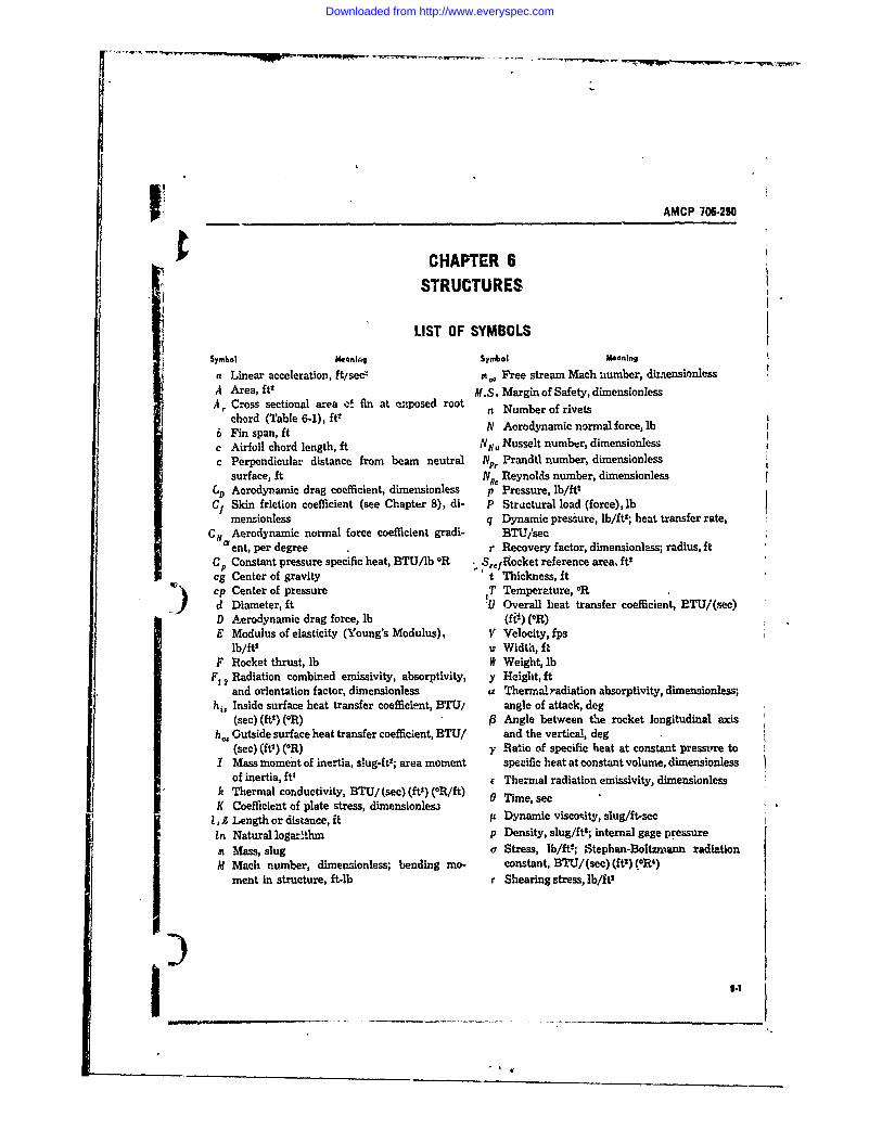
AMCP 706.280
CHAPTER 6STRUCTURES
LIST OF SYMBOLSSymbol Meanhkg Symbol Meaning
a Linear acceleration, ftisec- m0 Free stream Mach %,umber, diraensionlessA Area, ft1 M.S. Margin of Safety, dimensionlessAr Cross sectional area ef fin at enposed root
chord (Table 6-1), ft- ' Number of rivets6Fin span, ft N Aerodynamic normal force, lb
c Airfoil chord length, ft NN, Nsselt number, dimensionlessc Perpendicular distance from beam neutral Np, Prandtl number, dimensionless
surface, ft Nfi, Reynolds number, dimensionlessL) Aerodynamic drag coefficient, dimensionless p Pressure, lb/ft'Cf Skin friction coefficient (see Chapter 8), di- P Structural load (force), lb
mensionless q Dynamic pressure, lb/ft; heat transfer rate,Cm Aerodynamic normal force coefficient gradi- BTU/secI ent, per degree .r Recovery factor, dimensionless; radius, ftC Constant pressure specific heat, BTU/lb OR SrefRocket reference area, ft2cg Center of gravity "t Thickness, ftcp Center of pressure IT Temperature, ORd Diameter, ft 'U Overall heat transfer coefficient, ETU/(sec)D Aerodynamic drag force, lb (fil) ("R)E Modulus of elasticity (Young's Modulus), V Velocity, fps
lb/ftt w Widti, ftF Rocket thrust, lb It Weight, lb
F1 2 Radiation combined emissivity, absorptivity, y Height, ftand orientation factor, dimensionless a Thermal radiation absorptivity, dimensionless;
hi, Inside surface heat transfer coefficient, BTU/ angle of attack, deg(sec) (ftt ) (OR) 0 Angle between the rocket longitudinal axis
h., Outside surface heat transfer coefficient, BTU/ and the vertical, deg(sec) (ftt ) (0R) y Betio of specific heat at constant pressvre to
I Mass moment of inertia, slug-ft2; area moment specific heat at constant volume, dimensionlessof inertia, ft4 e Thermal radiation emissivity, dimensionless
k Thermal conductivity, BTU/ (see) (ftl) (OR/ft) a Time, secK Coefficient of plate stress, dimensionles0 m
1, Z Length or distance, it i Dynamic visco~ity, slug/ft-secIn Natural logarfhm p Density, slug/fts; internal gage pressure
rn Mass, slug a Stress, lb/ft"; Stephan-Boltzmann radiationM Mach number, dimensionless; bending mo- constant, BTU/(sec) (it2) (R4)
ment in structure, ft-lb r Shearing stress, lb/it2
)6
Downloaded from http://www.everyspec.com
H -
AMCP 706-2Nl
6-1 GENERAL geneous materials and vo'rmcs that are easilydefined. 'The mass of the sections may be esti-
The rocket structure provides a specific ex- matd by multiptymg the a.cion volume by the
ternal shape, a protective envelope, and a plat- material density. The volume of thin-skin sec-form for t*- delivery of a payload to a target. tions is easily approximated by multiplying theT chapter will pret methods of desgning surface area by the skin thickness.a etrueture with m~inimum weight and sufficient The equations for evaluating the volumes ofstrength to withstand ground handling and flight some typical rocket sct ions are presented in Tah.
&6-1. The volume of an ogive nose cannot be soThe strength of a structure depends on the easily determined. A method of approximating the
physical and mechanical properties of the ma- volume of an ogive was developed in Reference 1,terials, and the geometric configurations of the based on the relationship between the ogive vol-stvwtural members. The proportional limit, elas- ume and volume of a cone with the same lengthtic limit, yield point, ultihte strength, modlu and diameter. The equivalent cone volume caaof elasticity, ductility, and hardness are the s!g- be evaluated from the nomograph in Fig. 6-1,nifcant properties of materials for preliminary and the ratio of ogive volume to cone volume candeign. These roperties are defined as follows: be obtained from Fig. 6-2. The equivalent cone
a. Proportional limit is the maxmum stress surface area can be evaiuated from the nomographthat a material can resist without deviating from in Fig. 6-3, and the ratio of ogive surface areathe law of proportionality of stre to strain t cone surface area can be obtained from Fig. 6-4.(Hooke',s law). The location of the center of gravity of some
b. Elastic limit is the maximum strew that typiea rocket sections is presnted in Table 6-1.a material can resist without permanent deforma- For convenience theso locatdons should be identi-tion. The proportional limit and elastic limit fled as rocket dtation nymbers, i.e., distaices;are-often taken as the same value, from the nose tip. The lo ation of the center of
c. Yild Point is the minimum stress at which gravity of the complete configuration can bethe material will deform without an increase in estimated by summing moments of the sectionload, and also often will dso:p with an abrupt mae about the nose eip and dividing by thedecrease in load. total rocket mass, maki'g sure that corsistent
d. Ultimate strength is the maximum stress units are used.in a material before -fracture.
e. Modulus of elasticity is the ratio of stress 62. PITCH INERTIAto strain, at stresses below the proportional limit.
f. Ductility of a material is the percet of The rocket pitch inertia is the mass momente~ongation at the time of fracture in tension. of inertia of the complete configuration with re-
v. 'Har ew of a material is a measure of the spect to the pitch axis, which passes through thereiistance to scratching, abrasion, and indentation. center of gravity and is perpendicadar to the
7he phycal dimensions, moment of inertia, longitudinal axis of symnitry. For analysis theand c tiona), area are tha significant geo- rocket should be divided, a ore, into sectionsmetric factors of te structural members. maile isp of homogeneous materials and easily
• "-- -. il-:vi-. Lmh1 um pi=- in a of2 W H the complete configuration is the algebraic sum€.-2 WEIGHT AND BALANCE of the individual section mnoments of inertia with
62.1 MASS AND CENTER OF GRAVITY respect to the pitch axis. 'or convenience, theIESiMATIOO G section moments of inertia may be evaluated withrespect to an axis through the section center of
The mas of much of the rocket structure and gravity and transferred to the parallel pitch axismany of the r cket components will not be known by the following formuland musl'.st'mated. For analysis, the rocket 26-1) lshould be divided into sections made up of homo- (&I)
62 - -m : -' ' ,. "
Downloaded from http://www.everyspec.com
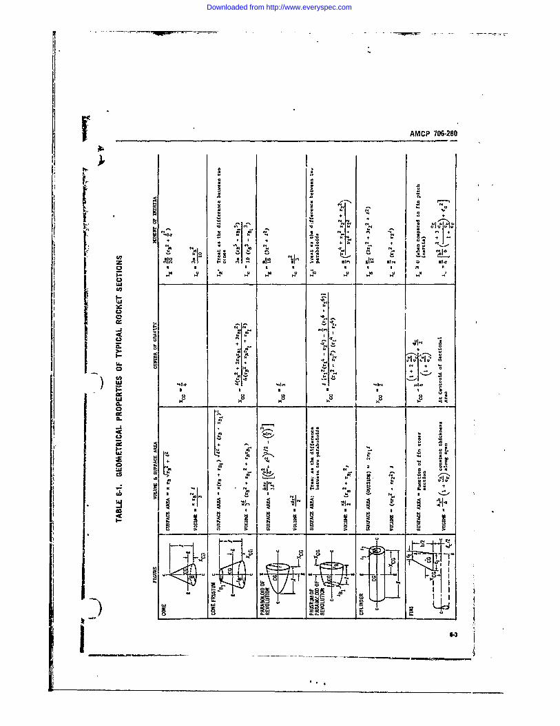
JeAMCP 706-280
wo 0
N N N4 .
14 M4 so 0 o Nw
M4 el} N 9
414 U4+ 1
L N 41
IQ N NN.044I0~ WE14
[1 1
+ 0
I At 14 ANa N r
IKI[ I._ _ _ _ ~ . . 4W
L)- 2
ca ~ 44 *
Downloaded from http://www.everyspec.com
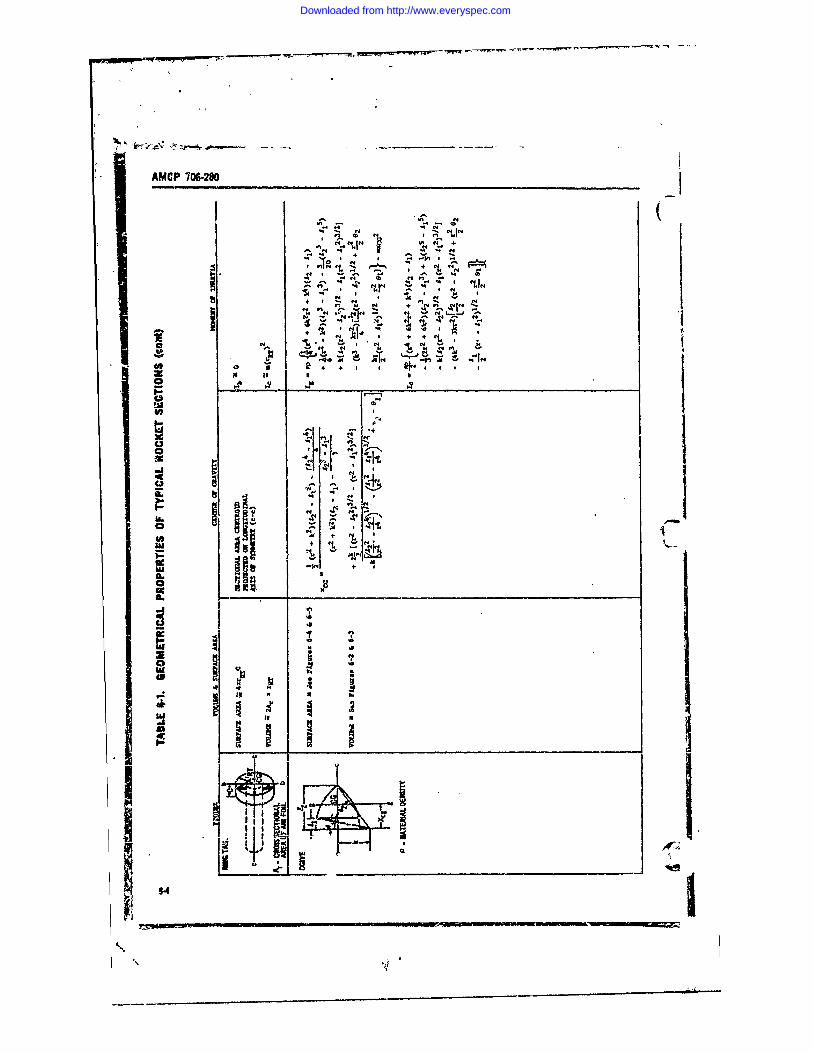
AMCP 706M
~. - -~"LIN
a4 4 ~ Q~
$ nt,
.4iii .
La,
co IN
44.44 a
Downloaded from http://www.everyspec.com
S LENGTH CONE VOLUME IAMETER AC 0-8
It cufIt Itv d
-8.0 -8.0-7.0 :100.0 70k I--6.0 15. 6.0
5.0 -30.0 -5.0
4.0 -20.0 4.03. EXAMPLE
::3.0 ::8. LENGTH -2.0 it5.0d - DIAMETER -1.0OIt
2.5 .5.. VOLUME -.524 cu It2.0 --2~.0 :2'
1.8 1.8
NOTE: IF CONE DIMENSIONS ARE121.2 OUTSIDE THE RANGE OF
THIS FIGURE, CALCULATE--. . 1.0 VOLUME AS:
.9-.
1:8.8 12
.6 .
.4 -. 24
1.0
XV X
Figure 6-1. Volumhes of Cones
IC5
Downloaded from http://www.everyspec.com
AMCP 70620
2.0~1/ -. 0.500__
1.8 -t -,/ .4
oiI 1.6d0.0
1.4 00
0.6.4 0.8 1.0
Fig,,, 6-2(A). Ratio of Volume of 0gi'. to Cone Versus Qir at Various P/d's
IVI
01040.6 0.8 1.0
Fi!gure 6.2(B). Ratio of Volume of Ogivo to Cane Versus Phr at Various aid's
Downloaded from http://www.everyspec.com
L .. .-AMCP 706-20
2.0-
1.9 1.87 FOR 1/d - 0.625I~l
1.7.
1.6 I
_~I _
tLI I1.6
0 1 2 3 4 5
_ ) ~W~/dFigure 6-2(C). Ratio of Volum"e of Tangent Ogive to Cone With Identical Qid
where ICG is the section moment of inertia with materials. The moments of inertia of these sec-respect to the pitch axis, I is the section moment tions can be evaluated by employing the principleof inertia with respect to the local axis that is that, with respect to a common axis, the totalparallel to the pitch axis, m is the mass of the moment of inertia is equal to the algebraic sumsection, and 1 is the distance between axes. of the moments of inertia of the parts. For exam-
The moments of inertia of typical rocket sec- pie, the total moment of inertia of a cone withtions can be determined from Table 6-1. The a hollow cylindrical center is equal to the mo-pitch moments of inertia of fins and ring tails ment of inertia of the solid cone less the momentmay be approximated for preliminary design by of inertia of the cylindrical portion.considering the fin mass to be concentrated atthe rocket base. Then,
IG= m1 (6-2) 6-2.3 ROLL INERTIA
where m is the mass of the fins and I is the The rocket roll inertia is the mass moment ofdistance between the rocket center of gravity and inertia of the complete rocket configuration withthe base. The error due to this approximation respect to the longitudinal axis of symmet.will be less than 4 percent if the fin root chord For analysis, the rocket should be divided, asis less than one-third, and the span less than two- before, into sections made up of homogeneousthirds, of the distance between the rocket base materials and easily defined geometries. Thenand the rocket center of gravity, the roll inertia of the complete configuration is
The moments of inertia are not explicitl de- the algebraic sum of the individual section m -fined in Table 6-1 for rocket sections that are ments of inertia with respect to the longitudinalpartially hollow and/or made up of composite axis.
Downloaded from http://www.everyspec.com
AIACP 701-290-
M4C 70400SURFACE AREA DIAMETER
A dI sq ft ft.5.0
,7.0•4.0 :6.0
EXAMPLE: :,5.0:.0044.2
3.0 d. DIAMETER -.1.0 ft -502.8 A SURFACE AREA -3.24 sq It :3.012.6 .30-..4 NOTE: IF CONE DIMENSIONS ARE OUTSIDETHE RANGE OF THIS FIGURE, CALCULATE :20, "2.2 AREAS AS:" .d /.,2 ,21/2 ..0 A.- wd + 12 :10 '
1.5
! ~.3 .1.0
1.4 2.9 1.8
-11 .7-1.2 .7
-.6-1.0 ..50 .5
-O. .30 X0.8 .20:.4
-9.20
-0.7
0.10..07,o.5 :o
0.4 " :.2° .03
.13!
Figure 6.3. Sw face Area of Cones -I
Downloaded from http://www.everyspec.com
AMCP 706-280
jet
OL 1.3-
.-
FT
1 f
RASU
Figure 6.4(B). Ratio of Arga of 0giv. to Cone Versus Qir at Various Pd5
Downloaded from http://www.everyspec.com
AMCP, 7*260
1.42 - - -
1.0 1.392 FORIM - 0.625
w!
1' is,
132
1 0 - 1 I ... ..... ... .--
0 2 3 4 5
Figure 6-4(. Matio of Area of Tangent Ogive to Cone With Identical R/dThe moments of inertia of typca, rocket sectionb 2 presents packaging techniques for shipment.
can be determined from Fig. 6-1. The moments The loads during shipment by truck, ship, rail-of inert*,- are not explicitly defined in Table 6-1 way, or airplane are specified in References 3, 4,forvocket~,ections that are partially hollow and/or 5, 6, 7, 8, and 17. Truck transportation subjects
&mad. up of a composite of materials but may be the rocket to the most severe vibration and shockevaluatei as outlined in Par. 6-2.2 by algebraic loade, and airplane transportation to the leastsummation o, the moments of inertia of the Parts. severe, under normal conditions.
The human factor involved in handling makesthe problem of specifying loads very 2ifficult. Ingeneral, realistic field conditions are simulated
6-3 LOADS by drop tests. Heights used for these twts vary,from three and oie-half feet for tv;enty pound
$..1 TRANSPORT AND HANDLING LOADS articles, to one foot for articles weighing more
The preliminary design phase must consider Rockets launched from air vehicles may beflht loads in conjunction with transportation subjected to severe vibrations. 'These loadsloads to insure fhat one does not predominate should be determined from manufacturer's per-the other. However, flight loads are generally formance reports for the particular vehicle in-the most severe since adequate containers con- volved.tainiag shock mounts can be designed to account In general, military specificatioas are availablefor expectd cr unexpedced transportation loads, to dejine the design environnyantal conditions
Ehaing transportation the rocket package will for a particular class of rockets. These specifica-be siabjected to vibrations, shocks, variable tem- tions should be consulted in evaluating designperatLure environments, and, moLture. Reference loads.
- - - - - - - - - n - -
Downloaded from http://www.everyspec.com
AMCP 706-280
6-3.2 FLIGHT LOADS where a is the rocket acceleration along the longi-tudinal axis, r. is the rocket mass, F is the engine
During flight the rocket will be subjected to thrust, D is the total drag, W is the rocket weight,loads from engine thrust, aerodynamic lift, aero- and I is the angle botween the body longitudinaldynamic drag, inertia of rocket mass, structural axis and the vertical. Likewise, the axial loadweight, and internal pressures. For structural (P,) at any plane x-x is found by the formulastress analysis, the loads may be divided intoaxial components acting along the body longi- P.= am +D + W cos -pA (6-)tudinal axis, bending components acting perpen-dicular to the body axis, and internal pressure where % is the rocket mass forward of planeforces acting circumferentially. x..x, Dx is the total drag on the rocket forward
The axial load component is made up of forces of plane x-x, W, is the weight of the rocket for-from the engine thrust, aerodynamic drag, inertia ward of plane x-x, p is the internal gage pres-of the rocket mass in the axial direction, struc- sure, and A is the area of the plane perpendiculartural weight component acting along the body to the longitudinal axis on which the internalaxis, and internal pressures. Fig. 6-5 shows a pressure actz.free-body diagram of the axial forces acting on The drag coefficient on the rocket sections cana rocket in flight. The sum of these forces is be evaluated as indicated in par. 8-3. 111e dragzero. Therefore, force D can then be determined as follows:
-am + F.- D - W cos = 0 (6-3) D = CoqS,, ! (6-5)
q~l, / ' ROSE IVAYE DRAG
AND FRICTION DRAG
o,<//,
WOx -TOTAL DRAGON
P ROCKET FORWADI OF PLAN4E x.x
FIN VAVE IDRAG. FRICTIONDRAG & BASE DRAG ,
//IF D
ENGINE BDE RAG"THRUSTUEDA
wx- WEIGHTOF ROCKETFORWARD OF PLANE wx
Figure 6.5. Axial Loads on Fret Flight Rocket" i -11 ,
! --- - .
Downloaded from http://www.everyspec.com
AMCP 70,-210whe C is the drag coefficient, q is the dynamic the mass a of the section, multiplied by accelera- (presmre, and Sr,, Is the rocket reference area. tiori a, acting in a direction perpendicular to the
The bending load components are made up of longitudinal axis, andfore. from aerodynamic lift and inertia of therocket nun in the dJ r = ixo perpendicular to a = - W sin , (6-)the body axis. Manufacturing techniques per- where iV is the total lift on the rocket, W is themit thrust alignment to within approximately 10 total weight, and 6 ;s the angle between the bodywe of longitudinal axis, resulting in negligible longitudinal axis and the vertical.bending loads. For preliminary design, the rocket The normal-force coefficient gradients on thesection masses can be considered concentrated at rocket sections can be evaluated as indicated in Ithe section centers of gravity, and the section lift par. 8-2. The normal force N can be deteiminedforce concentrated at the section centers of as follows:pressure.
Fig. S* shows the bending ioads acting on a N C acqSr frocket In flight. The inertia loads are equal to (6-7)
DIRECTIONM noOF FLIGHT-m nosea
N -BODY NORMAL FORCE
/ Wnosesin/C
V1hoseFIN NORMlAL FORCE -b
FIN NORMAL FORCE I / Wbcdysl~n
, 'in > WinstnpIn&P Wfins n W~in
WfinsinpFigure 6.6. Co.*:e#,itrated Bending Loads on Free Rocket
Downloaded from http://www.everyspec.com
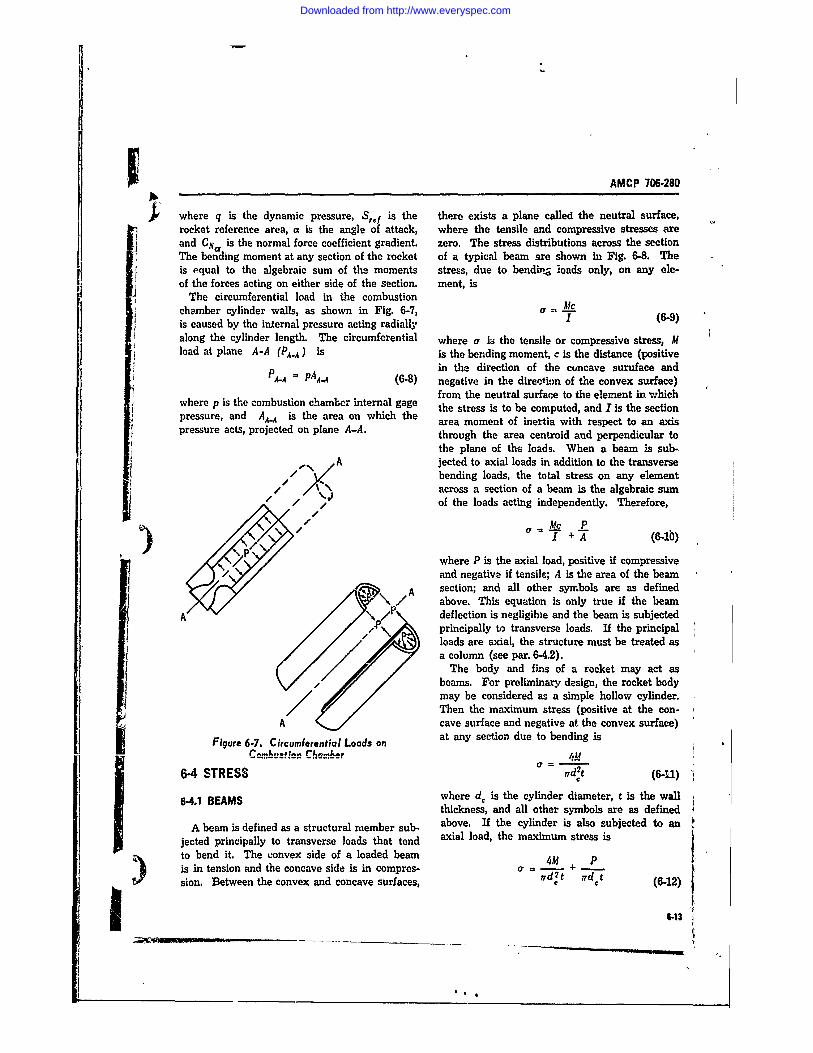
AMCP 706-280
where q is the dynamic pressure, Sref is the there exists a plane called the neutral surface,rocket reference area, a is the angle of attack, where the tensile and compressive stresses areand CNi is the normal force coefficient gradient. zero. The stress distributions across the sectionThe bending moment at any section of the rocket of a typical beam are shown in Fig. 6-8. Theis equal to the algebraic sum of the moments stress, due to bendi-,g loads only, on any ele-of the forces acting on either side of the section. ment, is
The circumferential load in the combustionchamber cylinder walls, as shown in Fig. 6-7, a - fcis caused by the iniernal pressure acting radially I (6-9)along the cylinder length. The circumferential where a is the tensile or compressive stress, Mload at plane A-A (PA.A) is is the bending moment, c is the distance (positive
in the direction of the concave suruface andP = PAA-..4 (6-8) negative in the direction of the convex surface)from the neutral surface to the element in which
where p is the combustion cwhambr internal gage the stress is to be computed, and I is the section
pressure, ats projected on plane AeA. area moment of inertia with respect to an axispressure acts, pthrough the area centroid and perpendicular tothe plane of the loads. When a beam is sub-
A jected to axial loads int addition to the transverse// bending loads, the total stress on any element
/X " N across a section of a beam is the algebraic sum/ / >1 of the loads acting independently. Therefore,
a AtC P
I) (6-1b)P /where P is the axial load, positive if compressive
and negative if tensile; A is the area of the beam, A section; and all other symbols are as defined
above. This equation is only true if the beamprincipally to transverse loads. If the principal
loads are axial, the structure must be treated asa column (see par. 6-4.2).
~The body and fis of a rocket may act as
beams. For preliminary design, the rocket bodymay be considered as a simple hollow cylinder.Then the maximum stress (positive at the con-
El cave surface and negative at the convex surface)Figure 6-7. Circumferential Loads on at any section due to bending is
6-4 STRESS d~t (6-11)
'TC
6-4.1 BEAMS where d. is the cylinder diameter, t is the wallthickness, and all other symbols are as defined
A beam is defined as a structural member sub- above. If the cylinder is also subjected to anjected principally to transverse loads that tend axial load, the maximum stress isto bend it. The convex side of a loaded beam 0 Pis in tension and the concave side is in compres- a - + +
sion. Between the convex and concave surfaces, , (6-12)
6-13
Downloaded from http://www.everyspec.com
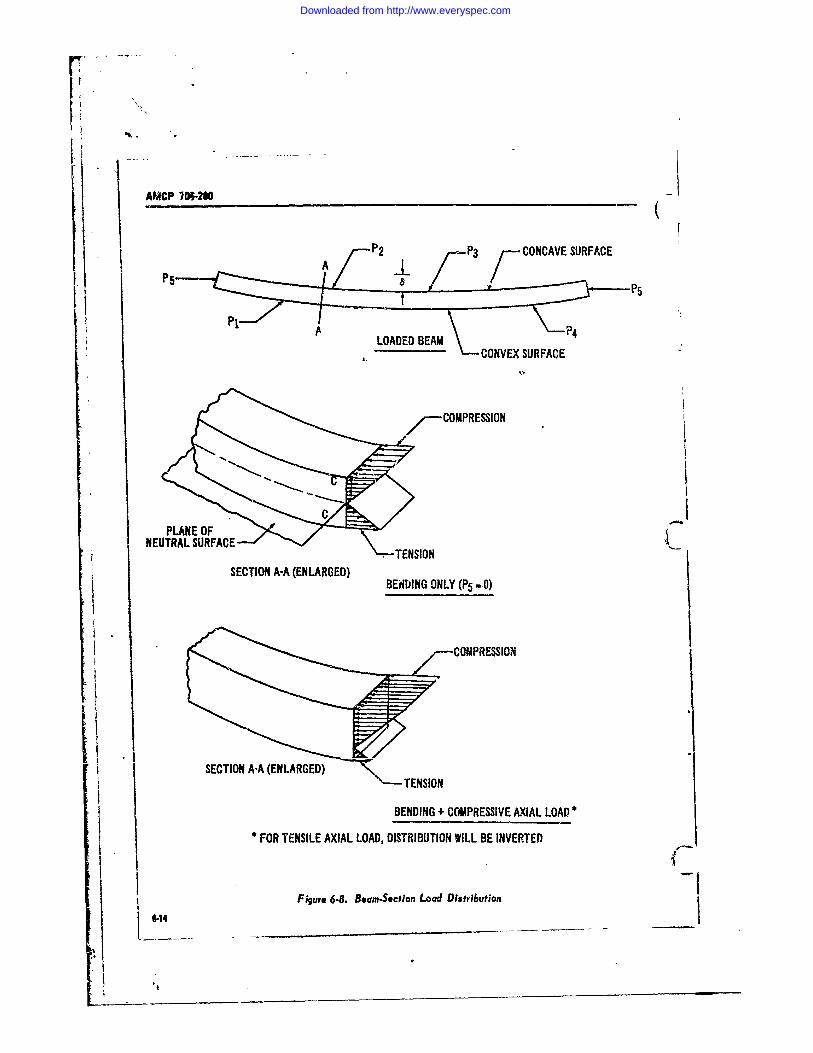
VPU 7:M2 P 3 . CONCAVE SURFACE
P1PI
NEUTRAL SURFACESECTIONA-A TELARGED
SECTON AA (NLARED) BENIJNG ONLY (P5 -.0)
COMPRESSION
SECTION A-A (ENLARGED) <
*-TENSION
BENDING + COMPRESSIVE AXIAL LOAD
FOR TENSILE AXIAL LOAD, DISTRIBUTION WILL BE INVERTED
Figure 6-8. Boorn-Section Load Distribution6-14
Downloaded from http://www.everyspec.com
IAMCP 706-280
where P is the axial lozd (positive if compressive 9EOt)l. 6 - 4Mand negative if tensile), and other symbols are cr \dJ 'd2t (6-6)as shown above. The rocket 5ns act as canti- C
lever beams (one end fixed), with the maximum where At is the bending moment due to trarwversebending moment occuring at the point of attach- loads.ment to the rocket body. The maximum stressdue to bending at any section of the fin is
Mt 6-4.3 PRESSURE VESSELS
21 (6-13) For the classes of solid propellant rc'ckets dis-cussed in this handbook, the combustion chamberwhere t is the airfoil thckness-. The ME-thodswhe c t ig the ari thick toinesr.the structure is the primary prsure vessel. This
of calculating the area moments of inertia A structure is generally cylindrical and is subject tovarious airfoil sections are presented in Table 6-2. circumferential te-nsile (or hoop) stresses in the
walls due to the loads discussed in par. 6-32 and6-42 COLUMNS shown "ii Fig. 6-7. This tensile stress is
prA column is defined as a structural member t (6-17)
principally loaded axially in compression and of where a is the unit tensile stress, p is the internalsufficient length that failure tends to -occur bybuckling at compressi'e stresses below the elastic pressure, r is the cylinder inside radius, ard t islimit. The classical formula for buckling is that the all thickness.developed by Euler as The internal pressure, acting on the ends of the
cylindrical vessel, applies in the wAlls a longi-p = 'EI tudinal tensile stress Ithat helps support the weight,
,J2 (6-14) drag, and inertia compressive stresses.
where P is the buckling load, E is the materialmodulus of elasticity (Young's Modulus),I is the A.4.4 PLATESminimum centroidal moment of ineria of thecross section, and I is the column lergth. Euler's Some of the rocket structure-such as accessformula is only appli-akle to very long columns. doors or fin panels--may be considered as flatGenerally, columns must be designed on the basis plates, uniformly loaded and fixed around theof empirically-derived relationships. edges. For such a rectangular plate, the unit
The rocket body may be a column susceptible stress isto buckling. A method of evaluating the critical Pwbuckling stress in thin-walled cylindrical columns, a = 6K 0 (6-18)such as rocket bodies, was developed in Refer- It 2
ence 9 as where a is the unit stress, w is the plate width,I is the plate length, P is the total load on the/2t\4. 1-AV.
dr 9(6-15) of the width-to-length ratio, as shown in Fig. 6-9.Reference 10 presents methods of calculating the
where ac, is the unit compresswe stress in the unit stress in plates of other geometries and edgecylinder wall at wh~ch buckling will commence, conditions.E is the material modulus of elasticity, I is thecylinder wall thickness, and d, is the cylinder 6-4,5 JOINTS
S diameter. If th- cylindve !s aIso subjected totransverse loads, the -riti-cal buckli.g stress due Riveted, welded, and bolted joints are used into the axial load is rockets of the class discussed in this hmidbook
• 4
Downloaded from http://www.everyspec.com
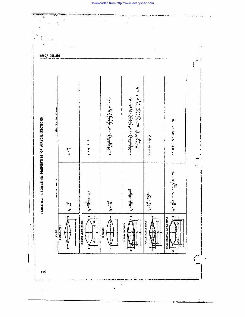
AM(k 706-280
-4tiC,
N-44
4, ,
W
u.I" ' I-,"
'a9
Ifn
!''
T-
. . . , , , t,
$.1| -4
Downloaded from http://www.everyspec.com
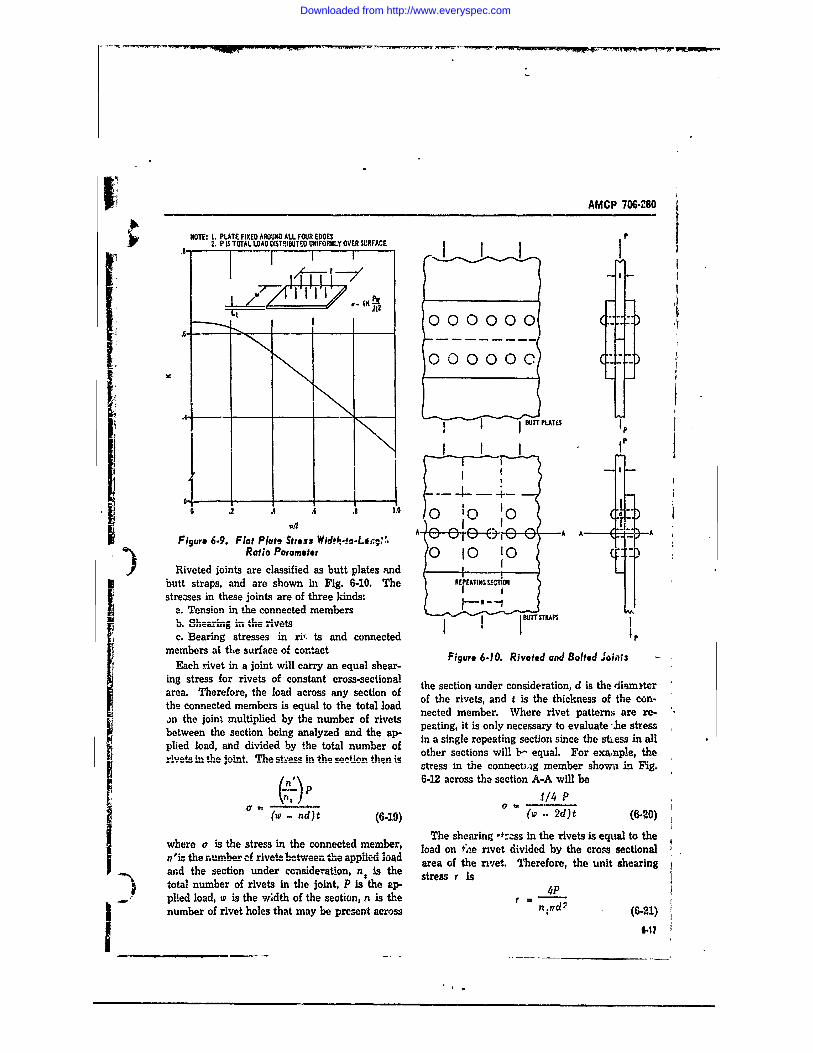
IAMCP 706-280
NOTE: 1. PLATE FIXED AROUND ALL FOUR EDGES2. P IS TOTAL LOAD DISTRIBUTEO UNIFORMLY OVER SURFACE
I .000000-
000000c
.BUTTPLATESj
SI 1 t
0 .. . 1 . 0 F 0 10
Figure 6.9. Flat Plate Stress Wid*h-fo-Li:g,'. !Ratio Parameter 0 1O I0
Riveted joints are classified as butt plates and Ibutt straps, and are shown in Fig. 6-10. The REPEATING SECTION Istre:ses in these joints are of three kinds: I I
a. Tension in the connected members -U ~ * I BUITTSTRPSm .c -.- - - v t " ] - I m' r I
.1e c lvxis A v I
c. Bearing stresses in ri,. ts and connected Pmembers ai the surface of con~tactmembrs a thesurfce o conactFigure 6.10. Riveted and Bolted JointsEach rivet in a joint will carry an equal shear-
ing stress for rivets of constant cross-sectional the section under consideration, d is the diamAerarea. Therefore, the load across any section of of the rivets, and t is the thickness of the con-the connected members is equal to the total loadan the joint multiplied by the number of rivets nected member. Where rivet patterns are re-peating, it is only necessary to evaluate "%he stressbetween the section being analyzed and the ap- in a single repeating section since the stress in allplied load, and divided by the total number of oth er section le For ex n ale
.,,,+,0;n fl ,a loin q .a ct'.Ac in fk a ,C rt n" fn t L other sections w ill 1 - equal. .For exam ple, theri.e ....n.t.e..in.. The st~es sectonstress in the connecti-ig member shown in Fig.
n)\ 6-12 across the section A-A will be1/4 P
(o .- nd)t (6-19) (w .. 2d)t (6-20)The shearing -':ss in the rivets is equal to the
where a is the stress in the connected member, load on zse rivet divided by the cross sectional
n'is the number cf rivets between the appted load reaot ri two.d the section under consideration, n, Is the atreawf rivt hrfrtesntserntotal number of rivets in the joint, P is the ap- te.lplied load, v is the width of the section, n s the r= 4 nnumber of rivet holes that may be present across n (6-21)
." 147 I
Downloaded from http://www.everyspec.com
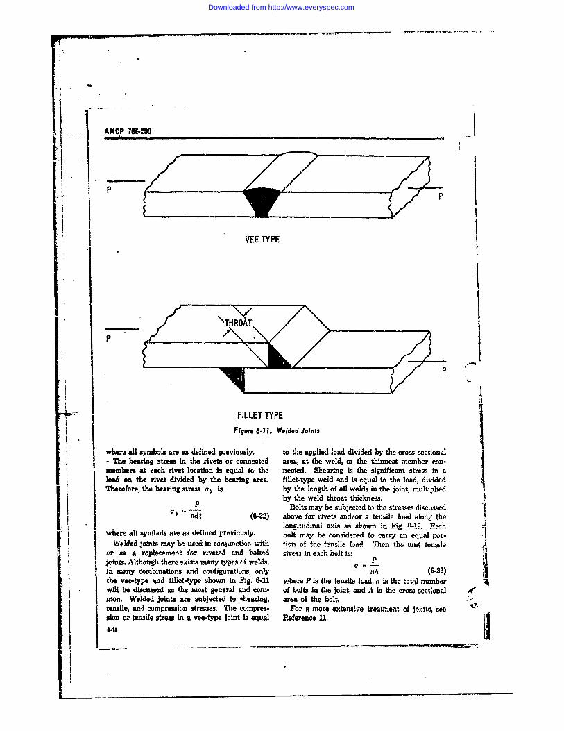
i
IAMCP 70t-.40
P
IIIPFILLET TYPE
SFigure 6.11. Welded Joints
whr" all symbols are as defined previously. to the applied load divided by the cross sectional- The bearing stress in the rivets or connected area, at the weld, ot the thinnest member con-members at each rivet location is equal to the nected. Shearing is the significant stress in &load on the rivet divided by the bearing area. fillet-type weld and is equal to the load, dividedTherefore, the bearing stress ab is by the length of all welds in the joint, multiplied
by the weld throat thickness.P Bolts may be subjected to the stresses discussedab jndt (6-22) above for rivets and/or a tensile load along thelongitudinal axis as sbwn in Vig -192. Ench
I where all symbols are as defined previously. bolt may be considered to carry an equal per-Welded joints may be used in conjunction with tion of the tewle load. Then the unit tensileor I a mlwemernt for riveted and bolted stress in each bolt is:Joints, Although there exit many types of welds, Pin many combinations and configuratiuns, only a- (6-23)the vet.type *nd fillet-type shown in Fig. 6-U where P Is the tensile load, n is the total numberwill be discussed as the most general and corn- of bolts in the joint, and A is the cross sectionalmon. Welded joints are subjected to ahearing, area of the bolt. '4tensile, and compression stresses. The compres- For a more extensive treatment of joints, seesion or tensile stress in a vee-type joint i3 equal Reference 11. 4. -
Downloaded from http://www.everyspec.com
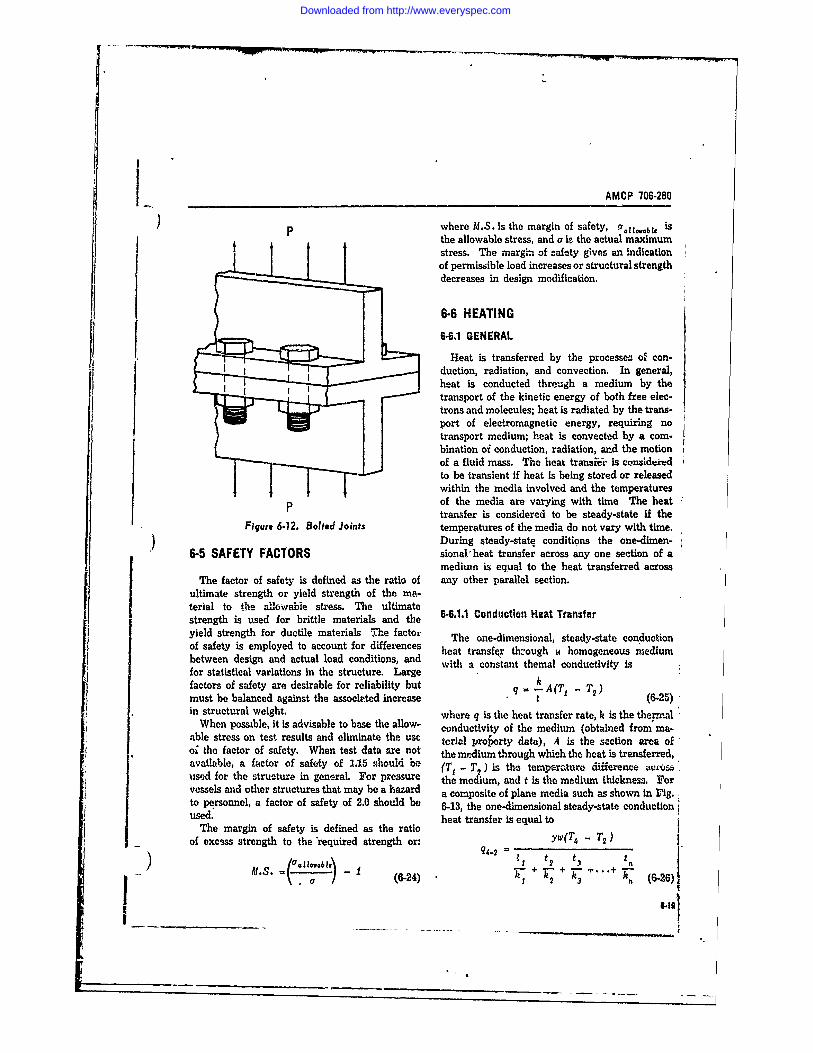
AMCP 706-280
) p where M.S. is the margin of safety, iaslvab 1.the allowable stress, and a is the actual maximumstress. The margin of safety gives an indicationof permissible load increases or structural strengthdecreases in design modification.
6-6 HEATING6-4.1 GENERAL
Heat is transferred by the processea of con-duction, radiation, and convection. In general,heat is conducted through a medium by thetransport of the kinetic energy of both free elec-trons and molecules; heat is radiated by the trans-port of electromagnetic energy, requiring notransport medium; heat is convected by a com-bination oi conduction, radiation, and the motionof a fluid mass. The heat transi-i is considered Ito be transient if heat is being stored or releasedwithin the media involved and the temperatures
p of the media are varying with time The heattransfer is considered to be steady-state if the
Figure 6.12. Bolted Joints temperatures of the media do not vary with time.During steady-state conditions the one-dimen-
6-5 SAFETY FACTORS sionalheat transfer across any one section of amediun is equal to the heat transferred across
The factor of safety is defined as the ratio of any other parallel section.ultimate strength or yield strength of the ina-
terial to the allowable stress. The ultimatestrength is used for brittle materials and the 6-6.1.1 Conduction Heat Transferyield strength for ductile materials The factor The one-dimensional, steady-state conductionof safety is employed to account for differences heat transfer thzough homogeneous mediumbetween design and actual load conditions, and with a constant themal conductivity is
for statistical variations in the structure. Largefactors of safety are desirable for reliability but q A - T2)
must be balanced against the associeted increase t (6-25)in structural weight. where q is the heat transfer rate, k is the thermal
When possible, it is advisable to base the allow- conductivity of the medium (obtained from ma-able stress on test results and eliminate the use terial ooi te fcto ofsafey. hentes dat ar no teialproerty data), A is the sction area ofoi the factor of safety. When test data are not the medium through which the heat is transferred,available, a factor of safety of 1.15 should be (T1 - T ) is the temperature diference ivcisaused for the structure in general. For pressure the medium, and t is the medium thickness. Forvessels and other structures that may be a hazard a composite of plane media such as shown in rig.:to personnel, a factor of safety of 2.0 should be 6-13, the one-dimensional steady-state conductionSused. heat transfer is equal to
The margin of safety is defined as the ratioof excess strength to the 'required strength or: ywT -T2)
-1711v~ - -I ? t 2 t 3 t
M.s. (6-24) + T + T3 h+ (6.26)
I~t
Downloaded from http://www.everyspec.com
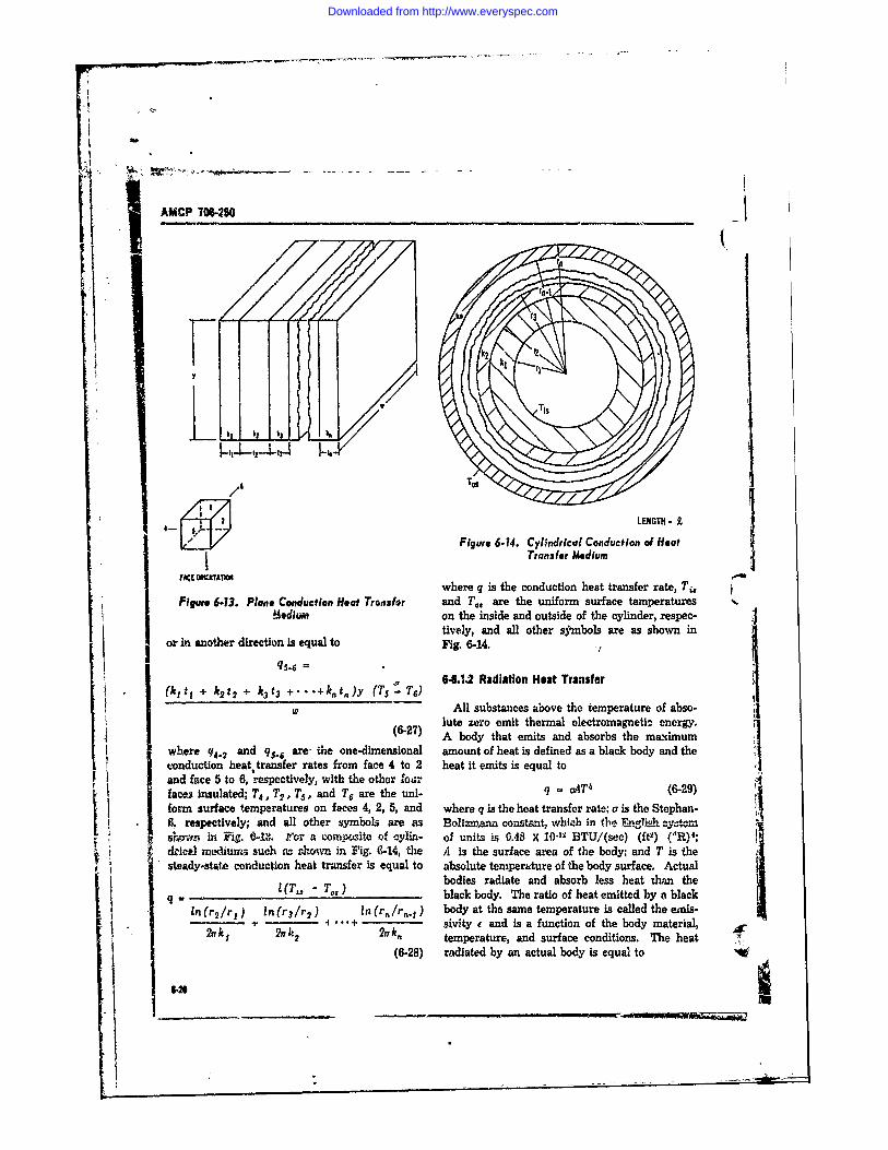
S
AMCP 706-280
TI
/1
LENGTH. -£
Figure 6-14. Cylindrical Conduction of HeatTransfer Medium
FACE OSWJITATIO -where q is the conduction heat transfer rate, Ti,
Figure 6.13. Plane Conduction Heat Tronsfor and T., are the uniform surface temperatures.aium on the inside and outside of the cylinder, respec-
tively, and all other symbols are as shown inor in another direction is equal to Fig. 6-14.
(kitI + k2 t2 + k3 t3 +' "+ kt,)y (TS -f T6) 6-6.1,2 Radiation Heat Transfer
All substances above the temperature of abso-lute zero emit thermal electromagnetiz energy.
(6-27) A body that emits and absorbs the maximum
where q4.2 and q,..6 are- mile one-dimensional amount of heat is defined as a black body and the iconduction heattransfer rates from face 4 to 2 heat it emits is equal toand face 5 to 6, respectively, with the other ourfacts insulated; T4 , T2, T5 , and T6 are the uni- q MT 4 (8-29)foym surface temperatures on faces 4, 2, 5, and where q is the heat transfer rate: a is the Stephan-6, respectively; and all other symbols are as Boltnamnn constant. wheih in the . lgTish ySrowr in Fig. 6-1,. Iror a compoite o cylin- of units is 0.48 X 10 -1' BTU/(sec) (ft) (R) 4 ;
d'ic reediuryk-i such is romv in Fig. 9-14, the A is the surface area of the body; and T is thesteady-state conduction heat transfer is equal to absolute temperature of the body surface. Actual
bodies radiate and absorb less heat than theq (T, - T-,) black body. The ratio of heat emitted by a black
In (r2/rj ln(r 3 /r 2 ) In (r,/r. 1 ) body at the same temperature is called the emLs-+ s "+ sivity e and is a function of the body material,
kl 2n k2 2nkn temperature, and surface conditions. The heat(6-28) radiated by an actual body is equal to
Downloaded from http://www.everyspec.com
AMCP 706-280
q = a AT4 (6-30) The methods of evaluating convection coefficientsfor a variety of cond'tions are presented in Ref-The ratio of heat absorbed by an actual body to erence 14.
the total amount of heat incident on the body(that which would be absorbed by a black body)is called the absorptivity a and is a function of 6-6.1.4 Combined Heat Transferbody material, temperature, surface condition,and heat source temperature. Emissivity and Often the heat transfer under consideration fabsorptivity values may be obtained from stan- takes place by the modes of conduction, radiation,dard material handbooks. and convection acting simultaneously. Therefore,
The net radiation heat transfer between two it is convenient to define an overall heat transferbodies is a function of the bodies' emissivities, coefficient U which will include all modes of heatabsorptivities, geometries, temperatures and ori- transfer present. For illustration, consider theentations. This transfer is equal to cylinder in Fig. 6-14 with a hot fluid at tempera-
ture T,, flowing on the inside and a cold fluidq, = F12 Al o(T1 - T24) (631) at temperature T, flowing on the outside. Then
the steady-state heat transfer from the insidewhere q, is the radiation heat transfer rate of fluid to the outside fluid isbody 1; F1 2 is the combined emissivity, absorp-tivity, and orientation factor, which may be ob- q = UA (TI, - T) (6-35)tained from such sources as Reference 12; A. is wherethe surface area of body 1; and 'f, and T2 arethe surface temperatures of bodies 1 and 2, re- In (r 2 /r,) In (r3 /r 2)spectively. Methods of obtaining the heat trans- U + - _ + - -
fer between three or more bodies are desczibed it r 2fk 2rk2in Reference 13.
Following Reference 13, we may define a ra- In (r. /r._ )diation heat transfer coefficient as +...+ +
hR ,,F1 2 (T1
4 - T 24 ) h,/ (6-36)
(TR - TO (6-32) h, and h., are the inside and outside heat trans-fer coefficients, respectively, for convection plus
By transposition and substitution in Eq. 6-31, radiation.
q1 - hRd A (T1 - T 2 ) (6-33) 6-6.1.5 Transient Heat Transfer
When the heat transfer is transient, the rate6-6.1.3 Conviction Heat Transfer at which heat is stored in a medium with a con-
stant specific heat is equal toThe convection heat transfer between a fluidin motion and a solid is equal to dTqhA (Tf - T, (6-34) q = p (6-37)
where q is the convection heat transfer rate, h where q is the rate at ,vhich heat is stored, mis the convection heat transfer coefficient, A is is the mass of the medium in which the heat isthe area across which the heat is transferred, stored, GCp is the constant pressure specific heatand Tf and T, are the temperatures of the fluid of the medium, dT/d6 is the time rate of tem-and solid, respectively. The convection coefficient perature change in the medium.is a function of the temperatures, fluid proper. The solutions oi three-dimensional transientties, solid geometry, and solid surface conditions. heat transfer problems are more difficult than
S.21 ~
Downloaded from http://www.everyspec.com
AMCP 70-20
the above iolutions and generally must be solved an increment of time. The temperature rise in (on hIS14peed digital ,omputeis. the structure due to heat storage can then be
evaluated. Then the net heat transfer to thestructure at the new temperature for the next
W, COMBUSTION CHAMBER HEATING increment oY Lime is evaluated, and so cn. Theaccuracy of this method can e increased by tak-
The combustion process produces gas tempera- ing smaller time increments.t.r of 400O to 7000°R depending on the propel- The methods outlined above can also be usedlant employed. Heat Is' transferred from the on the rocket nozzle with sufficient accuracy forcombuition chamber gases t lrough the structure preliminary design.to the environment by conduction, convection,and radlation. The structire may be piotected 4.3 EXHAUST PLUME HEATINGfrom overheating by employing insulathin ma-tering a high heat ca ty mass, or by trans- The rocket exhawt plume transfers heat byferting heat away to the cnvironment n radiation to the rocket structure, and by convec-
he convection heat tr fer coefficient on the tion to the launcher and surrounding equipment.inside of a cylindrical combustion chamber may The heat transferred is a function of the geom-be evaluated by the following relationship ob- etry, temperature, flow properties, and radia-tained from Reference 14: tion properties of the plume; it is also a function
of the orientation, temperature, radiation proper-NN. 0.023 (NR,)0.8 (N, )0.3 ties, and configuration of the rocket structure,A launcher, and surrounding equipment.
The plume geometry is deperlent on the ex-p-D haust gas pressure and atmospheric pressure as .-
(6-39) shown generally in Fig. 615. The plume geom-etry, temperature, and flow properties can be
N Co defined specifically, as outlined in Chapter 5,NN -(410 par. 5-2.1. The convection heat transfer coef-- (60) ficients on the launcher and surrounding equip-
where N&, N&o and Np, are the dimensio ess ment may be determined from references citedNusuelt, 1Ruynolds, and Prsndtl numbers, respec- previously. The radiation properties of the plumetively; h in the convection coefficient; D is the depend on the operating characteristics of theinside iAmeter of the chamber. k is the thermal rocket engine. Since this information is gener-conduclAvity; p liz the density; V is the velocity; ally not available for preliminary design, theSis ~ite viseoay; and C the constant pressure conservative approach should be taken and the
sgpmefic heat of the chamber gas. emissivity and absorptivity assumed to be equal)1e oonveption heat transfer coefficient on the to 0.9.
outside surface of the combustion chamber is afunction of, the airflow properties at the par- 6".4 AERODYNAMIC FRICTION HEATINGticular location under consideration. If the out-side surface is expoved to the aistream, the heat The heating due to aerodynamic friction ontranserfae evaluated as indicaited in par. rockets of the cla discussed in this handbook64.3-,,. i ,or .v4r iu rs, the convection hea2 gentriiy wi not be significant enough for con-trander coefficients may be evaluated from ref- sideration in preliminary design. Therefore, only
erences cited previously, a cursory discussion of aerodynamic heating willIf the combustion is over a short period of time, be presented. For a more detailed presentation,
steady-state conditions roay not be reached. In consult such sources as Reference 15.this cw*, for prediminary design, it is recom- Kinetic energy is imparted by fri-tion to theMendedA that two net heat transfer to (he struc. air surrounding a rocket in flight. Therefore, inture at the Initial tmperature beevaluated over the rocket boundary layer there is a kinetic tern
Downloaded from http://www.everyspec.com
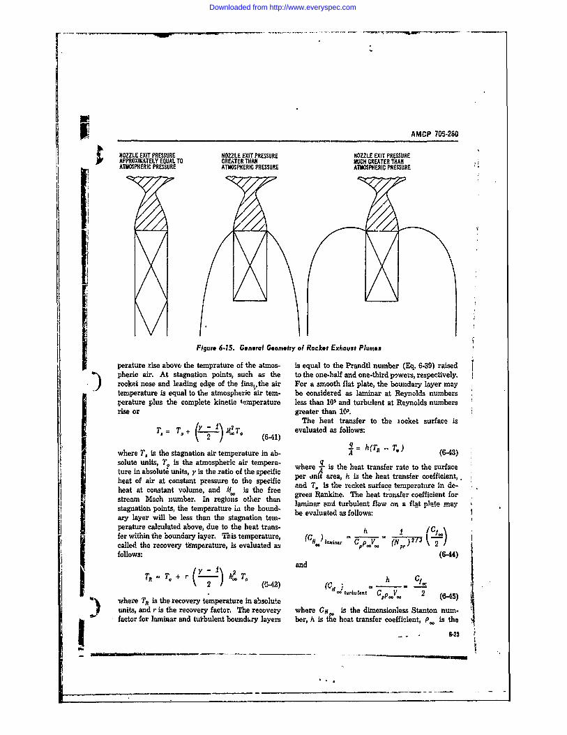
AMCP 70S-280
NOZZLE EXIT PRESSURE NOZZLE EXIT PRESSURE NOZZLE EXIT PRESSUREAPPROXIItTELY EQUAL TO GREATER THAN MUCH GREATER THANATMOSPHERIC PRESSURE ATMOSPHERIC PRESSURE ATMOSPHERIC PRESSURE
Figure 6.15. General Geometry of Rocket Exhaust Plumes
perature rise above the temprature of the atmos- is equal to the Prandtl number (Eq. 6-39) raisedpheric air. At stagnation points, such as the to the one-half and one-third poweis, respectively.rocket no and leading edge of the fins, the air For a smooth flat plate, the boundary layer maytemperature is equal to the atmospheric air tern- be considered as laminar at Reynolds numbersperature plus the complete kinetic ipmperature less than 10 and turbulent at Reynolds numbersrise or greater than 103.
The heat transfer to the xocket surface is
T.= T,+ evaluated as follows:q =hITR - T.)
where T, is the stagnation air temperature in ab- " = (6-43)solute units, T. is the atmospheric air tempera- qwhere l- is the heat transfer rate to the surfaceture in absolute units, y is the ratio of the specific per at area, h is the heat trnser coefficient,.heat of air at constant pressure to the specific ni , is the het ransferacoefint,
heatat onstnt olue, ad A is he ree and T . is the rocket surface temperature in de-volume, grees Rankine. The heat transfer coefficient forstream Mach number. In regions other than laminar .=on' turbulent flow on a flat ple maystagnation points, the temperature in the bound- be evaluated as follows:ary layer will be less than the stagnation tem-perature calculated above, due to the heat trans- IF 1c, kfer witin the oundary layer. Th1is temperature, (cl) - (,, 3called the recovery tfmperature, is evaluated as 0follows: (6-44)
I and
turbulent Cpp 2 (6-45)
wheie TR is the recovery temperature in absoluteunits, and r is the recovery factor. The recovery where Ci is the dimensionless Stanton num.
ow factor for laminar and tutbulent boundury layers ber, h is the heat transfer coefficient, P. is the
_6.23
Wks*
Downloaded from http://www.everyspec.com
AMCP 7Mo.2610
dAty of td free stream air, V the free fore, samples of materials are prepared andstream ve),oity, Cf. is the ireerstrean skin tested, conforming to standards set by organiza--frction (caefficient, which is obtained as outlined tions such as ASME and ASTM.L A detailed dis-in Chapter 8, par. 8-32. The heat transfer co- cussion of the testing of -_terials is presented inefficiont on cones Is approximately 73 percent Reference 16.
and 15 percent higher than flat platt values for When evaluating structural members, it is gen-|aminar and turbulent boundary layers, respec- €rally desirable to employ nondestructive teststively. Fins and cylindrical bodies may be con- so as not to impair the usefulness of the testedsidered as flat plates for purposes of preliminary item. Deep-seated irregularities such as cracksdesign. and voids in the structure can be identified by
X-ray. Surface or near-surface irregularities canbe identified by Magnaflux or Zyglo inspections.
6-7 TESTING In the Mrignaflax inspection the test item is cov-ered by small magnetic particles which ar at-
A test program is often required to supplement tracted to local magnetic leakage fields aroundthe structural analyses outlibed above since these imperfections in the magnetized test item. In thanalyses do not consider such factors as s=eas Zyglo inspection, used on nonmagnetic materials,concentrations, statistical variations, fabrication the test item is immersed in a fluores-ent fluidvariations, and imperfections in structuzal ma- that penetrates and thus reveals cracks, voids,terials and members. Although structural testing and other imperfections. Observation of the prop-generally will not be performed during the pre- erties of sound waves passed through the struc-liminary phases of rocket design, a cursory dis- ture will also reveal imperfections.cussion Is presented here to indicate the types of When using small factors of safety and whentest3 usually conducted and the testing methods uncertainties exist concerning the structuralusually employed. Tests are classified as de- strength, it is usually desirable to verify the -structive if the test item is permanently deformed structure by subjecting it to a proof test. Thisor fractured, and as nondestructive if the test is especially true for pressure vessels. In general,item is structuraIy useful after the test. proof tests are designed to subject the structure
Thq actual mechanical properties of materials to a lopd that will permanently deform it 0.01may vary statistically from the generally pub- percent or less.li~wl values. These variations may aignificently For a more thorough discussion of structuralaffect the, structural strength since factors of testing-including vibration, creep, and impact-
safety must be low to minimize weight. There- see Reference 16.
REFERENCES. M. Rhoden and D. Ifslin, Simplified Method for 1'ransportatLion, Tele-Ach and Electronic Indus-
Calculating the Area, Skin Weight, and Free tris, December 1954.l'olume of Ogive#, Special Report, U. S. Army 1. Ride and Fibration Data, Special Publication ofVls in Command. Redstone Arsenal, Alabaina, the Society of Altowotive Engineers, New York,I January 1965. N.Y.
2. G. A. Greathouse cad C. J. Wesoel, Eds., De- .1. The Applicability of Existing Truck and Rai*teriorisat-on of Mat-rials, Causes and Preventa- Shock, and Fibration Data to Freight Shipmenttive Techniques, Division of Chemistry and Criteria, Technical Report No. 58, Vitro Corpora-Chemical Technology, National Academy of tion of America, Silver Springs Laboratory, Sil-Qh .mc ---- I --p--- -r Council, w--,- ver-Sprnige,_Md., Mereh 1954.ton,D. C. f6. D, A. Firmage, Transportation Shock and Vibra°
.' G. K. Gijttwein, F. K. Priebe, and S. M. Jee, lion Studies, Project No. 8-91-06-002, Engineer- q
Behavior of Eleatronic Equipment in Vehicular ing and Industrial Exp. Station, University of f4
4
Downloaded from http://www.everyspec.com
AMCP 706-280
) REFERENCES (Pont)Florida, Engineering Research and Development 11. D. J. Peery, Aircraft Structur. s, M cGraw-HillLaboratories, Fort Belvoir, Va., February 1952. book Co. Inc.. New York, N. Y. 1950.
7. L. E. Lamkin, 1Packaging Criteria, Shock and Vi- 12. Aero-Space Applied Thermodynamics Manual,bration Bulletin No. 21, RDB. Society of Automotive Engineers Inc.. Committee
8. K. W. Jolnson, )esign Criteria for Military A-9. Acro-Space Environmental Control Systems.Eqvipment Transported by1 Common Carrier, New York, rebruary 1960.Shock and Vibration Bulletin No. 16, Octcbcr 1w. F. Kreith, PrKnciples of Heat 2'ransfer, Interna-1950. tional Textbooi, Co., Scranton, Pa.. 1958.
9. S. Kanemitsu and H. Nojima,:Lxial Compression l4. W. H. MeAdams, Heat Transmission, McGraw-'ests of Thin Circular Cylinders, M. S. Thesis, Hill Book Co. Inc., New York, 1954.
Guggenheim Aeronautical Laboratory, Californin 15. Robert W. Truitt, Fundamentals of AerodynamicInstitute of Technology. 1939. Reviewed in H. S. Heating, The Ronald Press Co., New York 1960.Siefert, K. Brown. Ballistic Missile and Space 16. Proceedings of the Society for ExperimentalI'ehicle Systems, John Wiley and Sons, Inc., New Stress Analyses. All volumes, B. E. Rossi, So-York. N. Y. 1961• ciety for Experimental Stress Analyres, 21 Bridge
10. .f. Seely and J. 0. Smith. :dvaac Meehan- Square, Westport, Conn.ics of Materials, John Wiley and Sons. Inc.. New 17. AMCP 706-134, Engineering )esign Huyidbook,York, N. Y. 1952. Maintainability Guide for )esign.
It
'L)
________ -6-25!/6-26
Downloaded from http://www.everyspec.com
-AMCP 706-280
CHAPTER 7I ACCURACY
LIST OF SYMBOLSSymba! Meaning Symbol Meaning
CD Aerodynamic drag coefficient, nondimen- V Estimate of population variancesional V Projectile velocity, Al/seeC Aerodynamic damping moment coefficient, V, Wi-d velocity, ft/sec
aq nondimensional w Wind velocity in flght-path plane, ft/sec
C Aerodynamic , rmal force coefficient, per wz Wind velocity normal to flight path, it/seerad Z,¥, Z Earth-fixed lawnch coordinate system
CPE Circular probablq.error xo y Specific sample value taken from a universed Reference diameter of projectile or rocket, of statistiual valuesft 7,'y Estimate of gL based on available sample
G Rocket acceleration due to thrust, ft/sec2 valuesg Gravitational acceleration, ft/sec2 a Angle of attack, degrees or radI Moment of inertia, slug-ft2 13 Dspersion reduction parameter (13 = dis-
1,P Specific impulse, sec persion with reduction technique/disper-k Radius of gyration, ft sion with no reduction technique)L Thrust moment arm due to malalignment, ft y s Steady state flight path angle with no dis-
AX, I Aerodynamic static margin, cal turbances, milsp lt Distance from center of gravity to point of A Incremental change in the variable follow-
thrust application, ft ing the symbolI n Natural logarithm a Thrust malalignment angle, milsm Projectile mass, slug a Aerodynamic malalignment angle, mils
m Prjectle mss, lug Angle between rocket longitudinal axis andN Number of sample values taken from a uni- prinl axis, rklverse of statistical values principal axis, mi
na Number of revoluton: made by rocket 0 Projectile pitch attitude angle, measuredduring first wavelenwgth of yaw from horizontal, rad
P Nondimensional launcher length (actual 1. Mean of a universe of statistical valuesiwuncher length/a) p Atmospheric density, slug/ft
PE Probable errorRocket spin rate, radse a Yaw oscillation distance or wavelength, ft;
standard deviation of a sample of size Nq Component of projectile angtlar velocity inthe direction of projectile y axis, radisec a. Initial oscillation distance, ft
R Standard range, km ays Standard deviation of a system containings Computed standard deviation n statistical variablesS Aerodynamic reference area, ft' 0,(a,) Standard deviation of the x(y) valuesS Nondimensional burning distance (actual 6' Projectile roll angle, rad i
burning distance a)Time of flight, sec; Student's t vaue V Projectile yaw attitude angle, measured
U, w Components of projectile velocity in the di- from vertical launch plane, radrection of x and z axes, ft/sec a Partial derivative
)
Downloaded from http://www.everyspec.com
AMCP 706-280
7- INTRODUCTION . Proulve Phase Errors. The dispersions7-1 iT~oDUTION htti result 1rurn such errors as thrust malalign-Accuracy is the measure of the ability of the ment, nonstandard meteorological conditions,
- rocket system to position thL. payload at a given aerodynamic assymmetries, and propulsion van-point at warhead event. Various error sources atious.I nherent in the rocket system, together widh ex- d- B.gl!is.tic PIbae Errnrs. Those dispers*,.Tj ternal conditions su,-h as winds, cause a dispersion that occur during the period from propulsion cut-
of the payload I;xox Its intended path. To deter- off to the end of flight.mine the accuray , of A rocket system, a series The following paragraphs will be concernedconditions. The & ual flight paths of the rockets for computing approximate dispersions.
are compared to P,, idealized '.niectory in orderto calculate the dispersion. As in the study ofthe accuracy of any mechanical instrument or 7-3 DESIGN CONSIDERATIONSsystem, the error souces -re iirst identified and INFLUENCING ACCURACYthen categorized as to whether they are predict-able (allowing a comransation to be made) or The effect of design variables on accuracy andrandom. The most sigr ificant factors influencing the delicate trade-off process involved )n disper-the accuracy of free rockets have been identified sion reduction can be more easily understood byby extensive comparisons between experimental dividing all errors into two groups: (1) speedtests and theory. This che pter is a detailed dis- change errors, and (2) :ngular errors.cussion of the error sources. The main objectiveis to describe how the designer mtus compensatefor the error in order to achieve the level of ac- 7-3.1 DESIGN CONSIDERATIOMS ASSOCIATEDcuracy required by the mission specifications. WITH SPEED CHANGE ERRORS
The speed change errors are characterized by7-2 DEFINITIONS CF ERROR SOURCES a change from the nominal velocity attained at
propellant burnout. These errors, which resultThe flight' of a rocket is divided into three in an error in the plane of the trajectory, are due
ph.:z(1) the launch phase, (2) the propulsive primarily to the variability present in the propul-or burning phase, and (3) the ballistic phase. sion system. Any variation in a parameter thatError sources are labeled according to the phase influences the delivered total impulse will ob-of flight during which the error causes the rocket viously resu4 in a different burnout velocity ofto deviate from the idealized trajectory. For the rocket. These include variations in:example, a burning phase error will cause 3 de- a. Total loaded propellantviation to occur between launch and M.-nout. b. Propellant specific impulse due to chem-If no additional errors are encountered during ical compositionthe ballistic phase, the burning phase error will c. Specific impulse due to physical quantitiesstill result in a dispersion of the warhead event. (e.g., nozzle throat diameter)The total error, including prelaunch errors not d. Inert parts weightassociated with flight, is the net dlspersion due In addition to propulsion system variability ef-to allr errors, deciw, the burning time and ihrust of solid propel-
a. Prelaunch Errors. All errors, including lant rockets are effected by propellant tempera-aiming errors and prelaunch corrections, that are ture, Even .hough the temperature has a neg-accrued before rocket ignition. ligible effect on total impulse, it does affect the
b. Launch Phase Errors. Thiose errors that burnout velocity because the rocket is subjectedare associated with and result from the launch to a different drag history.phas , including the initial conditions transmitted Speed clange errors are a function of mechani-to the rocket by the launcher and dynamic un- cal desi gmanufacturing control, and propellant 1'
effects of the rocket. selection These items are discussed in more de-
72
Downloaded from http://www.everyspec.com
[ ~ AMCP 706-280
Ii tail in Chapters 5 and 6. The remainder of this I moment of inertia of the rocket about; chapter will deal exclusively with the angular a lateral axis, slug/ft
errors. p atmospheric density, slug/ftsS aerodynamic reference area, ft21, = rocket static margin, cal
7-3.2 DES:GN CONSIDERATIONS ASSOCIATED d = rocket reference diameter, ftWITH ANGULAR ERRORS a= rocket normal force 'oefficiet gradi-
4 ent, rad-1The angular errors are characterized by a Since a depends on the aerodynamic coefficients
chanan frnn- the d, -- e dire-timn of the veJocity of the rch.t. It ,, ,ubjcct to a large chngo dur-vector at propellanv burnout. The errors have ing flight as thc velocity and/or altitude of thecomponents both in the plane of the nominal tra- rocket change. Fig. 7-1 shows the variation of ajectory and normal to that plane, and are caused and the building of angular dispersion for a typi-by; cal flight.
a. Wind normal to te velocity vector From the figure, it is seen that most of theb. Thrust malalignment or the failure of the dispersion takes place during the first yaw oscil-
thrust vector to pass through the center of gravity lation. During this tine a does not change ap-c. Dynamic unbalance preciably (this has been found to be generallyd. Aerodynamic assymmetries true). Therefore, the dependence of dispersionSince the effect of the last two errors can be on a is mainly determined by the initial wave-
shown to be equivalent to thrust malalignment, length of yaw. This initial value will be usedin the paragraphs which follow we shall discuss to describe the wavelength of a flight.only wind and thrust n.alalignment effects.
: , 7-3.2.2 The Effect of Wind
7-3.2,1 The Effect of Aerodynamic StabilityFig. 7-2 illustrates the effect of a wind on a
The aerodynamic stability of a rocket is the stable rocket.measure of the tendency of the rtcket to align It can be seen that the rottion of the rocketitself with the relative wind. If an aerodynamical- into the relative wind causes the thrust to drively stable rocket in steady flight with no aero- the rocket from the intended path. Fig. 7-3 showsdynamic moments should be given a di-sturbance the effect of a on the dispersion due to wind. Assuch as a sudden increase in angle of attack, the the rocket becomes !ess statically stable (therebyaerodynamic forces caused by the disturbance di- increasing a ), 'the sensitivity to wind reduces.rect the rocket back to its original state. The This suggests that the designer should adjust pa-motion of the rocket immediately followhlg the rameters so as to maximize a. However, as willdmsturbanee is generally a rotational osc llation be shown in, the next paragraph, consideration
about a lateral axis. One of the most important of the dispesion due to thrust malalignment im-parameters in the study of the behavior of free poses a conflicting requirement on P.rockets is the distance the rocket travels duringone oscillation. The yaw oscillation distan.c, a
k is related to the aerodynamic stability of the 7-32.3 The Effect of Thrust Mallignment "rocket by the static margin (the moment arm ofthe corrective aerodynamic forcea): Fig. 7-4 shows the effect of a malalignment of
the rocket thrust with the vehicle axis. An angu-a_=_2___2 lar malalignment is indicated. However, the
2rpS i~d cNO(- same moment can also be caused by the vehicle.wheea (7-1 center of gravity lying off the centerline of thewhere vehicle. In fact, a displaced center of gravity
a = yaw oscillation distance or wavelength has been shown to produce larger angular errorof yaw, ft them does an angular malalignment.
-7-3
I _ _ _ _ _ _ ___ _ _ _ _ _ _ _ _ _
Downloaded from http://www.everyspec.com
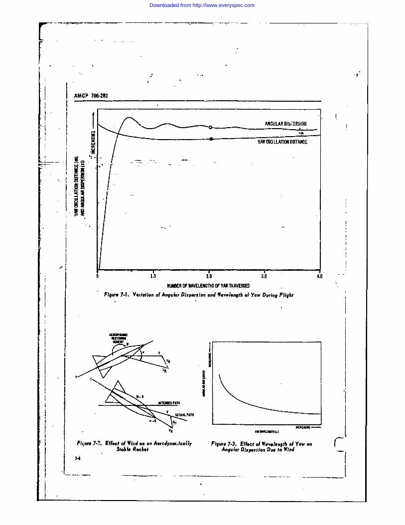
AMCP 706-280
ANGULAR DI5ERSION
m ~YAW OSO LLATlON DISTANCE
I I
0 1.0 2.0 3.0 4.0NUMBER OF WAVELE OF YAW TIAVERED
Figure 7-1. Variation of Angular Dispersion and Wavelength of Yaw During Flight
~,
V QIUAL PATH
Fh.,re 7-?. Effect of Wind on an Aerrdyna,,ically Figure 7.3. Effect of Wavelength of Yaw onStaide Rocket Angular Disperzion Due to Wind74 __ __ _ ___ __ ___ __-"__ _ __
Downloaded from http://www.everyspec.com
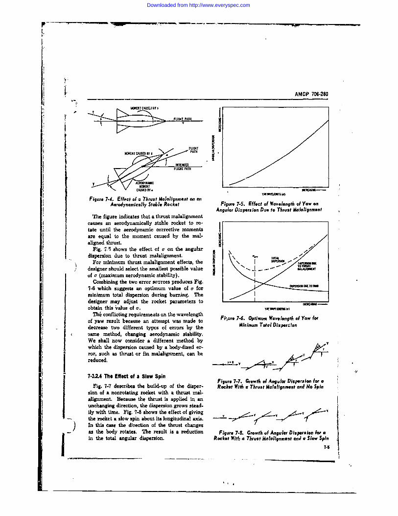
AMCP 706-280
UOMNTCAUEJBaTf
r a £LIGHT PATH i
FLGH
. // I INTENDED
Figure 7-4. Effect of a Thrust Malalignment on Fiue75.Efc ofm Wvelengt ofYao
Aeodnaicli~tbl~oetAngular fiispersion Due to Thrust Malaiignment
causs anaerodynamically stable rocket to r- t
tasuntil the aerodynamic corrective moments Izaeequal to the moment caused by the mal- j1
aligned thrust.Fig. 7° .shows the effect of a on the angular
For minimum thrust malalignment effects, the I .SPWOU
MAT
dXefgr niae htathutmllgmn nua ispersion ue to hrust alalignnient.
designer should select the smallest possible value to ro-
of a (maximum aerodynamic stability). m enCombining the two error sorces produces Fig.
7-6 which suggests an optimum value of a forminimum total dispersion during burning. TheI TOTAL
designer may adjust the rocket parameters to TO -
obtain this S alue of a. rrowrsour(e) e Fig.
The' conflicting requirements on the wavelengthof yaw result because an attempt was made to Fijure 7-6. Optimum wavelength of Yaw fordecrease two different types of errors by the Minimum Total Disperclon.ame method, changing aerodynamic stability.We shall now consider a different method bywhich the dispersion caused by a body-fixed er- •ror, such as thrust or fin malalignment, can bereduced. V.-'
7-42.4 The Effect of a Slow Spin Figure 7-7. Growth of Angular Dispersion for aFig. 7-7 describes the build-up of the disper- Rocket With a Thrust Malalignment and Ho Spin
sion of a nonrotating rocket with a thrust mal-alignment. Because the thrust is applied in anunchanging direction, the dispersion grows stead-ily with time. Fig. 7-8 shows the effect of givingthe rocket a slow spin about its longitudinal axis. ..__) In this case the direction of the thrust changesas the body rotates. The result is a, reduction Figure 7.8. Growth of Angular Dispersion for ain the total angular dispersion. Rocket With a Thrust Mloalignment anJ a Slow Spin
a, *
Downloaded from http://www.everyspec.com
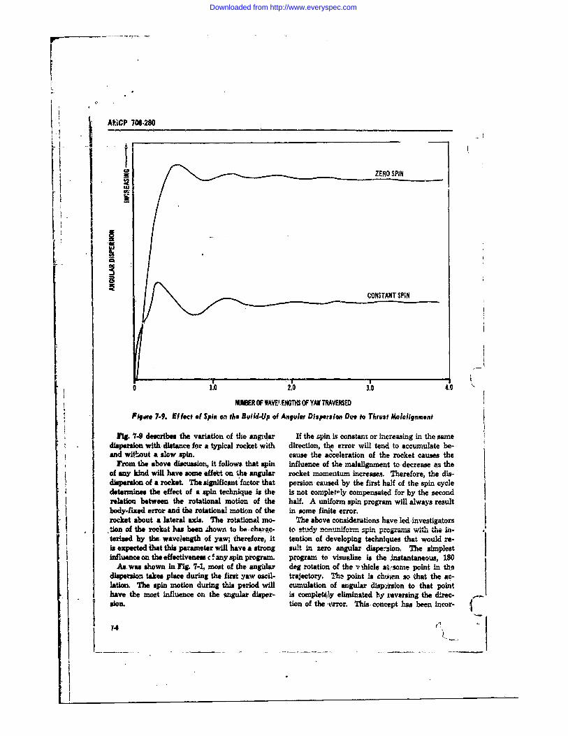
AICP 7O6-280
_ s A -iZERO SPIN
I
CONSTANT SPIN
0 1.0 2,0 3.0 4.0
NMBER OF WAVE.ENGTH$ OF YAW TRAVERSEDFigare 7-9. Effect of Spin on the Build-Up of Angular Dispersion Dee to Thrust Malalignment
Fig. 7-9 dcribes the variation of the anLlar If the spin is constant or increasing in the same1 dispersion with distance for a typical rocket with direction, th error will tend to accumulate be-and without a slow spin. cause the acceleration of the rocket causes the
From the above discussion, it follows that spin influence of the malalignment to-decrease es theof any kind will have some effelet on the angular rocket momentum increase. Therefore, the dis-dispersion of a rocket. The significant factor that persion, caused by the first half of the spin cycledetermines the effect of a spin technique Is the is not complet-ly compensated for by the secondrelation between the rotational motion of the half. A uniform spin program will always resultbody-fixed error and the rotational motion of the in some finite error.rocket about a lateral axis. The rotational mo- The above considerations have led-investigatorstAon of the rocket has been -hown to be -ch C- to study ,,,,,,,,,prorans w... t,- In-teried by the wavelength of yaw; therefore, it tention of developing techniques that would re-is expected that this parameter will have a strong suit in zero angular dispexsion. The simplestinfluence on the effectiveness c! any spin program. program to visualize is the instantaneous, 180
As wax shown in Fg. 7-1, most of the angidar deg rotation of the v ihicle at;,some point in thidispersion takes place during the first yaw oscil- trajectory. Thz point is chcyien so that the ac-lation. The spin motion during this period will cumulation of angular disporsion to that pointhave the most Influence on the sngular disper- is completily eliminated ly reversing the drec- .son. tion of the ,rror. This, concept has been Incor-
74 t
Downloaded from http://www.everyspec.com
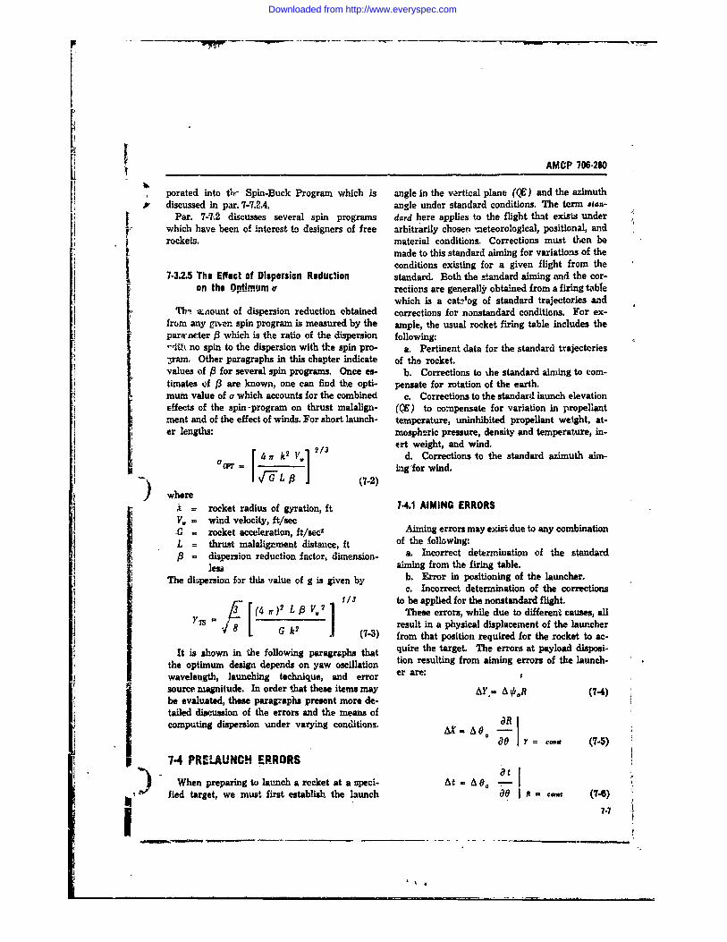
V[1 AMCP 706-280
porated into thr Spin-Buck Program which is angle in the vertcal plane ((9) and the azimuthp discussed in par. 7-7.2.4. angle under standard conditions. The term *tan-
Par. 7-42 discusses several spin programs dard here applies to the flight that exisis underwhich have been of interest to designers of free arbitrarily choser, mneteorological, positional, androckets. material conditions Corrections must then be
made to this standard aiming for variations of thei conditions existing for a given flight from the7-3.2.5 The Effect of Dispersion Roduclion standard. Both the s tandard aiming and the cor-
>an the 0pimum c rections are generally obtained from a firing tblewhich is a cat-elog of standard trajectories and
Tbi -xnount of dispersion reduction obtained corrections for nonstandard conditions. For ex-fr(m any gnen spin program is measured by the ample, the usual rocket firing table includes theparjrn~ter P which is the ratio of the dispersion following:-ih no spin to the dispersion with t.e spin pro- a. Pertinent data for the standard trajectories3ram. Other paragraphs in this chapter indicate of the rocket.values of (3 for several spin programs. Once es- b. Corrections to Lbe standard aiming to com-timates of 3 are known, one can find the opti- pensate for rotation of the earth.mum value of a which accounts for the combined c. Corrections to the standard launch elevationeffects of the spin-program on thrust malalign- (QE) to compensate for variation in propellantment and of the effect of winds. For short launch- temperature, uninhibited propellant weight, at-er lengths: mospheric pressure, density and temperature in-
213 ert weight, and wind.4 1r k2 y V d. Corrections to the standard azimuth aim-
CY(WT L hag'for wind.
) whererocket radius of gyration, ft 7.4.1 AIMING ERRORS
V roiket avelitn, ft/se Aiming errors may ex-ist due to any combinationL = thus malaligxnent distance, ft of the following:
dispersion reduction ,a. Incorrect determination of the standard
less aiming from the firing table.The ditipersion for this value of g is given by b. Error in positioning of the launcher.
c. Incorrect determination of the corrections_____________ 9__ V .2____ ]____ 1 3 to b e a p p lie d f o r th e n o n s ta n d a r d f lig h t .(4 C 3 L (4 These errors, while due to different causes, all
8 G V 1 result in a physical displacement of the launcher(7-3) from that position required for the rocket to ac-
It is shown in the following paragraphs that quire the target. The errors at payload disposi-the optimum design depends on yaw oscillation tion resulting from aiming errors of the launch-wavelength, launching technique, and error er are:source magnitude. In order 1hat these items may AY.= A VolR (74)be evaluated, these paragraphs present more de-tailed discussion of the errors and the means of 8,Rcomputing dispersion under varying conditions. =A0 -Y= ,, (-5
74 PRELAUNCH ERRORSWhen preparing to launch a rocket at a speci- At = A 0, - 1-
fled target, we must first establish the launch 00 I = ome (7-6)7-7__ __ _ _ __ _ __ _7"7 '.
Downloaded from http://www.everyspec.com
AMCP 1o6.280
O AZJ ° "0--Z 7-5 CALCULATIONS OF ANGULARso - g (7-7) ERRORE
S - (7-4) The angular error of a rocket is obtained bysolving the differential equations of motionA 0.o Oa - 0 (7-9) throughout the flight. The equations can be solvedw00 e ) with as much generality as desired on an auto-
AY e flt ematic computer. Values are chosen for the errorsources and a number of parametric runs areAX = range error, r made. The results can then be combined statis-
At - time of fi!ght error, see tically a., outlined in par. 7-10.AZ - altitude enror, mR -R standard range, kmA~o = azimuth airJiing error, milsAO. . elevation aiming error, mils
The errors are determined by calculating the dif- "ference between a flight with an error and a xstandard trajectory. Fig. 7-10 illustrates thesequantities.V
The derivatives-aR/0, 8 t /aO, and 8Z/B0 -will be discussed in more de(ail in par. 7-8.
STANDAID TRAJECTORY
%X
Figure 7.10. Aiming Errors #
Figure 7.11. Definitions of Sign Conventions forthe Rocket Equations of Motion
7-4.2 ERRORS DUE TO VARIATIONS IN If we assume missile symmetry about the Ion-METEOROLOGICAL CflNPITInfNf g,,A,,.l .-,;. I(: ,. .h _angle approximations are valid--and if we omit
In making correctionr for nonstandard condi- gyro effects due to missile roll, then the six-de-tions, one assumes a knowledge of the existing gree-of-freedomn equations of motion become de-nonstandard conditions. Any variation in condi- coupled in the vertical and horizontal planes.tions from the assumed values introduces an error Furthermore, the motion in the two planes isat the point of warhead disposition. These errors identical except for the gravity terms in ihe ver-may be treated in the same manner as those de- tical plone. (The effect of gravity is equivalentscjbed below for the launch, propulsive: and to a bias erior and will not be considered in theseWalistic pnases. equations.) We can then determine the solution "
I I4
Downloaded from http://www.everyspec.com
AMCP 706-20
in only one pbnp, thus simplifying the prnhlem CN = aerodynamic normal force gradient,'onsiderably. The equations to be solved then tad -I
become CGq aerodynamic damping moment coeffi-cient, dimensionless
f= uG : 'D is acrodynarnic static zaargin, cal2LmJ (t10) (!stance from center of gravity to point
of ttxust application, it[C S ]1 d refezence body diameter, ftp k rocket radius of gyration, ft
u [ 2 (w + wz + [G] 8coso 8 thrust malalignmcnt angle, rad
(7-11) F = aerodynamic malalignment angie, radwz = component of wind in direction of the[ 11Zb body axis, ft/sec
q=-u -+ wz a wavelength of yaw, ftg? Jj p atmospheric density, slug/fto
b, Yb , Zb = body-fixed axes vith origin atC-qd +rGll] the center of gravity and Xb along the
q + bjcos9 8cosO missile axis2C I t k2 JThe six expressions in brackets completely
specify all the rocket characteristics needed V)(7-12) calculate its motion. Therefore, if the rocket mo-
tion is tabulated for variations in each of the six= u (7-13) expressions, the results will be applicable to any
configuration for which these parameters areZ= w- u 0 (7-14) known.
Examination of the solutions of the above equa-(7%15) tions for typical rocket systems indicates that
only P. relatively few parameters have first-order= f(t) (This is specified by the spin effects on the angular dispersion. These are the
program.) rocket acceleration G, the wavelength of yaw a,(7-16) the nondiinensional launcher length P, and the
where burning distance S.u, w = components of the rocket veletity in For the equations above, the launcher affects
the directions of the Xb and Zb body the motion of the rocket through the initial con-axes, ft/sec ditions. For convenience, we shall use a non-
q, - components of the rocket angular veloc- dimensional expression for the launcher length:ity in the drections about the Y, andXb body axen, rad/sec p . launcher length
0 - rocket pitch angle, rad a= rocket roll angle, rad
X = component of the rocket velocity in the The effect of launcher length, then, is representedslant range directon, !t/e by an initial value of velocity;
= component of the rocket velocity normalto the slant range direction, ft/sec up= (7-17)
G = rocket acceleration due ta the thrust, where up = velocity in ft/sec at the end of theft/sec' launcher.
C , aerodynamic drag coefficient, nondi- These equations card now be solved on an ana-mensional log or digital computer and the dispersion at the
m rocket mass, slug end of flight, determined for any given errorS = aerodynamic reference area, ft2 source.
7.'
Downloaded from http://www.everyspec.com
AMCP 706.280
A more informative approach for the designer steady state, post-boost angular dispersion of theis to consider each phase separately and identify direction of the velocity. Tas, for calculatingthe major contributors to the J.tte1nt error.* In the effect of the boost phase on dispersion at war-,ach flight phase difrent forces predominate; head eveht, y, , may be treated as an aimingtherefore. the important parameters change. In error. The missile is assumed to be launchedthe following subparagraphs the important pa- with the initial cmdiions taken from boosterrameters for each phase will be discussed. burnout.
Considerig the errors in each flight phaseseparately ha. two advantages: (1) the equationscan be simplified by including only the forces 7-6 LAUNCH PHASE ERRORSthat predominate during the phase, and (2) thesimplified equations can be manipulated to pro- During the launching process the rocket is de-vide analytical solutions. The availability of flected from its intended path by motion of theanalytical solutions is of great benefit to the zie- launcher and motion caused by the release ofsigner because the important variables or ,m- the launcher constraints. The results are con-binations of variables that determine the angular diti.ra undesirable at the beginning of the pro-error can be ealy identified. These results can pulsion phase. These conditions are separatedthen be ombined with computer calculations into three modes of motion: (1) initial angularthat provide the required accuracy. velocity about a lateral axis, (2) initial transla-
Analytital results have been prepared wherever tional velocity normal to the launcher axis, andpossible and have been plotted with computer (3) angular velocity resulting from rocket dy--iWiults *iKMnuae their accuracy. namic unbalance when some form of spin on the
The criterion chosen for determining the ac- launcher is used. Subparagraphs 7-6.1 throug-hcuracy of a rocket system during the launch and 7-6.3 present the angular dispersion at flightpropulsive phases is the dispersion at warhead termination caused by these initial conditions.event. The effects of various errors and the ef-fectivenams of several dispersion reduction tech-niques will be considered in terms of the steady- 74.1 ANGULAR VELOCITYstate fiAght path angular et'ror. Tis representa-tion alkiws rapid evaluation of the accuracy of Figs. 7-12 (A), (B), (C) show the angular dis-the rocket without resorting to the complex meth- persion caused by an initial angular velocity ofode of accounting for ballistic phase errors pre- 100 mils per sec. The launcher length, the wave-sented in par. 7-9. length of yaw, and acceleration have substantialThe roket equatiorm, were solved, using an effects on the dispersion. The dispersion is mini-automatic computer, for the burning phase of mized by increasing the launcher length and the
flight. Thw angular dispersion at the end of the rocket acceleration while keeping the aerody-boost phase is approximated by the following ex- namic stability as high as possible, i.e., a smallpresulon: value of a.
+" qk 2 P~Caq+ -.- (0 + WZ) 7-6.2 TRANSLATIONAL VELOCITY
(7-18) Figs. 7-13 (A), (B), (C) show the effect of anwhere the values of 0, w, u, q and the aerody- initial translational velocity of 1 ft per sec, normalnamic parameters are those at burnout. y7s is to the launcher line, on the angular dispersion.
dm The launcher length does not significantly affectdetermined by computing I in lI which M the the dispersion. An increase in the wavelength of
t, I U yaw has a beneficial effect that is significant fore edtrockets with high aerodynamic stability. Inczeas-
tent sgular error is th. error at the end of a ing the rocket acceleration causes a decrease into determine the error at the end of flight. the dispersion for all cases considered.
7-94.1
Downloaded from http://www.everyspec.com
I AMCP 706-280
0,4'4 G/ 1
3 A
- ESULTS OF COMPUTERCIWUTATIONALTCLRESULTS FROM REFERENCE 2
WAVELEI:GT OF YAW w, 160 FEE71 Figure 7.12(A). Angular Dispersion Due to Malflaunch - Initial An; tar Rate
60 -I~O~G- 20
40-O _q 100 IAIL/SEC_
~3G 0-401 5 - ~ G080
21 WAVELENGTH OF~ YAW a*, 100 FEETFigure 7-12(B). Angular Dispersion Duo to Nallaunch - Initial Anuivir Rate
Downloaded from http://www.everyspec.com
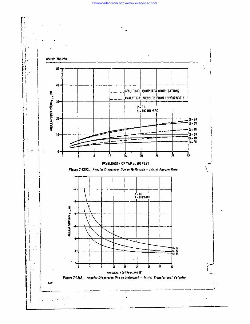
~ Ii AMCP 706-280-
440
-..1.RESULTS OF COMPUTER COMPUTATIONSI I I I .P30 ____ANALYTICAL RESULTS FROM REFERENCE 2
P .0.1
q0 ._100_____EiG .. 2.5. -- ""'- -801o..:~~~~~~ .... _ .- ,, _ --. 40
.._... . . - 0
0 4 8 12 16 20 24 28 32
WAVELENGTH OF YAW o' 00 FEET -
Figure 7-12(C). Angular Disprsion Due to Mlallounch - Initial Angular Rate
-7 .4 - - -
-
F - 0.0, " W .1.0 FTiSEC
G 20H--__ - -• _-_
G- 80
41 8, i 6 20 24 2 32('
WAVELENGTH OF YAW (r, 100 FEET -.
Figure 7-13(A). Angular Dispersion Di. to MaHllaunch - Initial Translational Velocity
Downloaded from http://www.everyspec.com
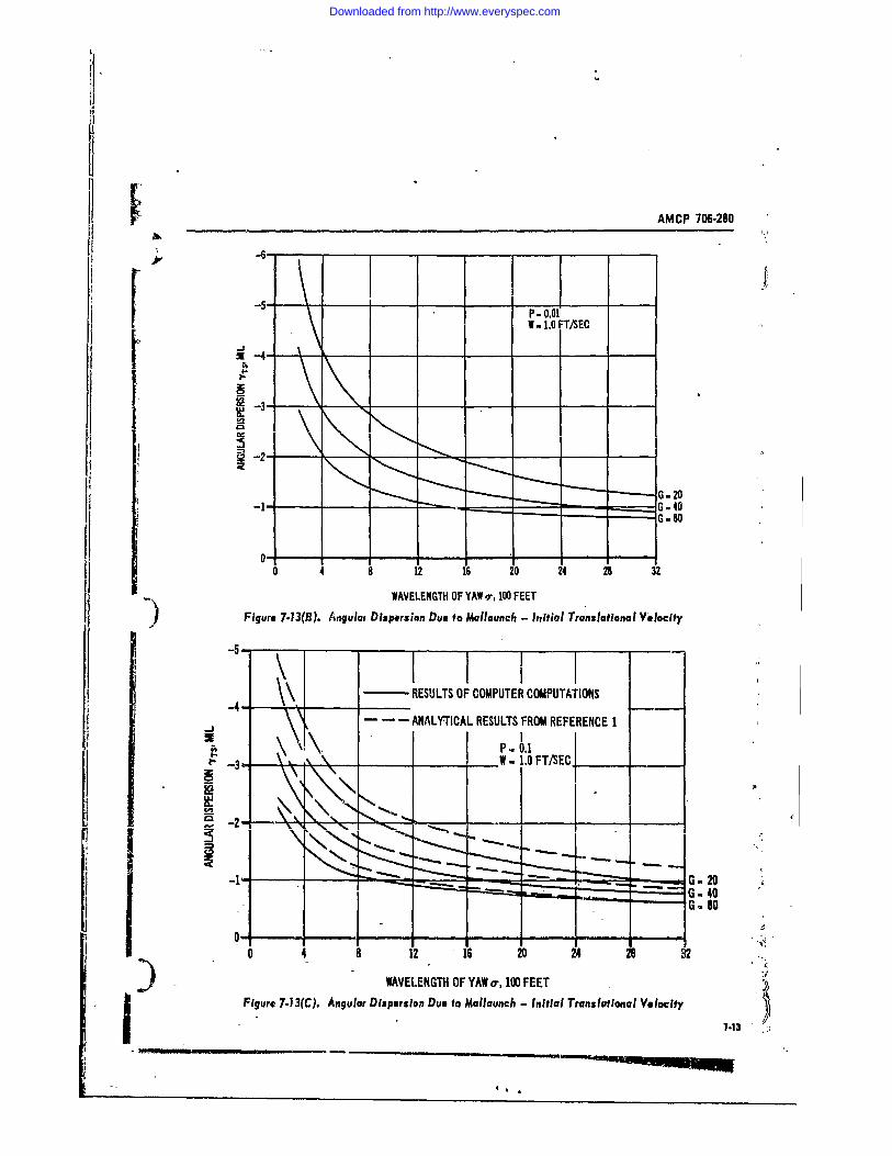
AMCP 706-280
-6-
W - 1.0 FT/SEC
G -0
G -40-8
0 4 8 12 16 20 24 28 32
WAVELENGTH OF YAW ', 100 FEETFigure 7-13(B). Aitgulai Dispersion Due to Mallaunch - Initial Translational Velocity
- RESULTS OF COMPUTER COMPUTATIONS
- -- ANALYTICAL RESULTS FROM REFERENCE 1
I.-, \~...~. W. 1.0 FT/SEC_
-i " -2--
G. 80
04- 8 12 16 20 24 2832
WAVELENGTH OF YAW ar, 100 FEETi ~ Figure 7-13(Q. Angular Dispersion Due to Mallaunch - Initial Translational Velocity
7-30- t n -
Downloaded from http://www.everyspec.com
AMCP 706.280
The angular dispersion due to initial trans- wind normal to the direction of flight, and thrust klational velocity is minimized by making the rock- malalignment. A qualitative description of theet acceleration as high as possible and the aero- effect of wind and thrust malalignment was givendynamic stability low. in par. 7-3. This paragraph presents some quan-
titative results which describe the effects of theimportant rocke', parameters on the angular dis-
74.3 DYNAMIC UNBALANCE persion caused by the same two error sources,wind and thrust malalignment. These results
Dynamic unbalance is caused by spinning the can be used for preliminary accuracy estimates.rocket about its get metric longitudinal axis rather Par. 7-3 showed how spinning the rocket aboutthan its principal axis of inertia. When the- its longitudinal axis will reduce dispersion causedrocket Is spun on the launcher, release of the by body-fixed error sources such as thrust nial-launcher constraints will result in a motior char- alignment. The major portion of this paragraphacteristic of the force-free prceession of a rigid is devoted to describing the effectiveness of sev-body unless the rocket is spinning about its prin- eral spin programs developed to minimize thecipal axis of inertia (i.e., its dynamic axis). The angular error due to body-fixed error sourcesdynamic unbalance effect limits the spin rate In most applications, the choice of a spin tech-that can be used to reduce thrust malaignment nique is heavily influenced by the difficulty ofeffects. mechanically impleme.ting it. Therefore, while
The precescion motion is, for all practical pur- several of the methods presented here result inposes, an angular velocity at launch. The magni- near-zero dispersion, complexity of the devicestude of this initial angular velocity is: needed to carry out the spin program limit its
qtqui, ' P1 use to systems where high accuracy requirements
where: justify extreme measures.p - rocket spin rate, rad/sec d
. equivalent initial, angular rate due 7-7.1dynamic unbalance, rad/sec
= angle between the rocket longitudinal Figs. 7-14 (A), (B), (C) and 7-15 (A), (B),sad p-incipal axes, rad (C) show the angular error caused by a 10 ft per
After determining the equivalent angular ve. sec wind normal to the flight path of the rocketlocity, Figs. 7-12, 7-13, and 7-14 can be used to and by a 0.5-mil thrust malalignment on a non-determine the angular dispersion. rotating rocket.
The dispersion due to dynamic unbalance is Since the .wind force on a symmetric rocketminimized by incr-asing the launcher length and does not depend on the roll orientation, spin does
the rocket acceleration while maintaining a high not affect the dispersion due to wind. Therefore,level of aerody-namic stability. In addition, the Figs. 7-14 (A), (B), (C) are applicable o anydynamic unbalance -angle c should be kept as rocket system.small as possible by careful design and care in As was pointed out in par. 7-3, the angularmanufacturing. The spin rate should be kept as dispersion, due to wind is minimized by keepinglow as possible after considering the requirenent the aerodynamic stability as low as possible. The%ur reducing the dispersion due to thrust mal- figures indicate that ivuncher length has veryalignment, little effect on the wind dsperseon. The rocket
Par. 7-7.2.6 describes how the effect of dynamic acceleration should be large.unbalance at launch can be reduced by a unique The dispersion due to thrust malalignment isiauncher design. minimized by keeping the aerodynamic stability
as high as possible. The effect of acceleration ismost significant for rockets with low stability.
741 PROPULSION PHASE ERRRS The angular dispersion increases with increaingacceleration. The effect of launcher length is
Angular errors which originate during the pro- significant under all conditions-a long launcher -pulsion phasi of flight are primarily caused by is desirable.7-14
Downloaded from http://www.everyspec.com
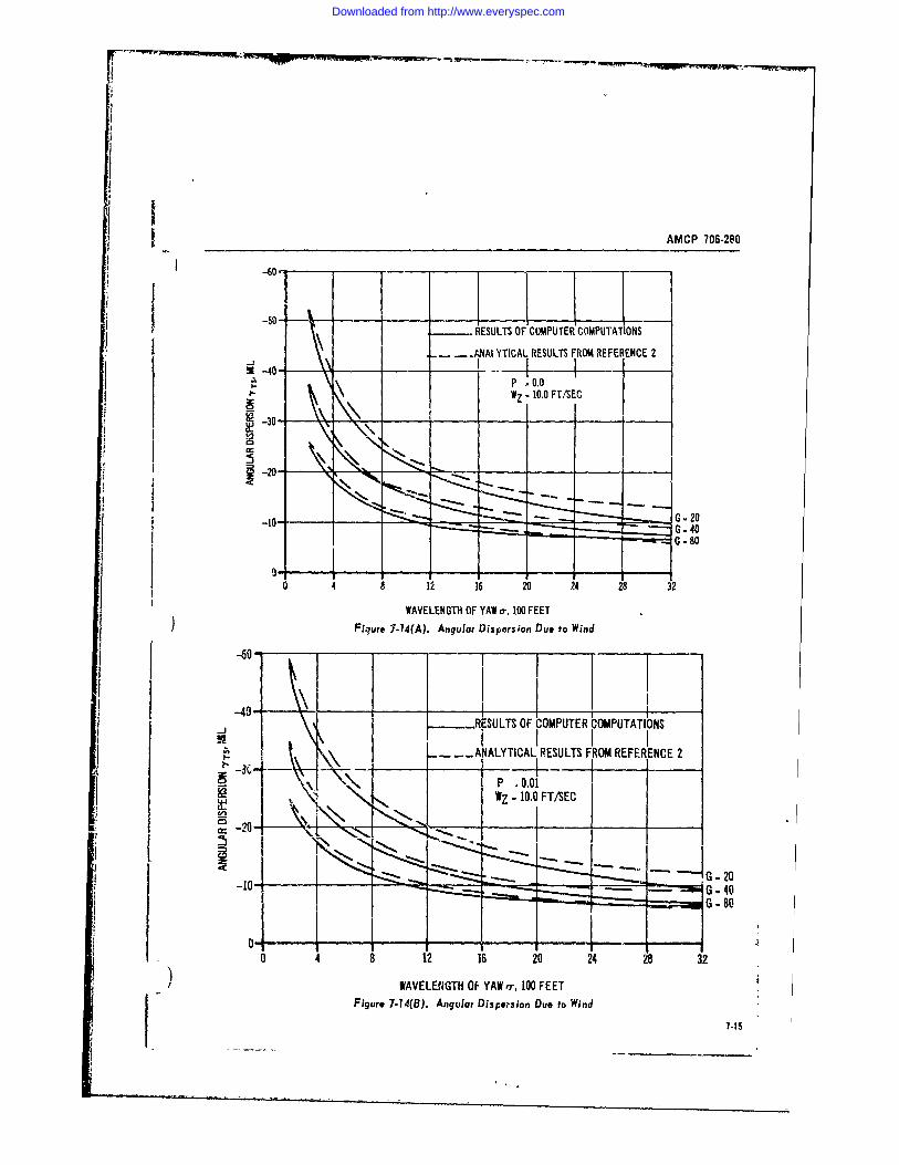
AMCP 706-280
401
I I--50- - ESULTS OF COMPUTERCOMPUTATIONS
- .AAYTICAL RESULTS FROM REFERENCE 2-j _ __
3 -40-H .WZ . 10.0 FT/SEC
0-
-10-
0 4 8 12 16 20 24 28 32
WAVELENGTH OF YAW o,100 FEET)Floure 7.14(A). Angular Dispersion Due to Wind
$ ~~-50
-RESULT OF COMPUTER bOMPUTATIO)NS
-- NALYTICAL RESULTS FROM REFERENCE 2
-20
0 4 8 12 16 20 24 28 32
) WAVELENGTH OF YAW V,100 FEETFigure 7.14(B). Angular Dispe?.sion Due to Wind
7-15
Downloaded from http://www.everyspec.com
AMCP 703-2e0
_______ ______ _______ _____RESULTS OF COMPUTER COMPUTATIONS
4 -- ANALYTICAL RESULTS FROM REFERENCE 2
P .0.1
2 -30
WAVELENGTH OF YAW 1400 FEETFigure 7-14(C). Angular Dispersion Due to Wind - Initial Translational Velocity A
240 GF3PE -ACLAI 80 ::200E I G -LT0
REUTIO PTR AU I IN-1- -ANALYTICAL RESULTS FROM P.EFERENCE G - 20
.O MIL
20-
WAVELENGTH OF YAW a-, 100 FEETFigure 7-15(A). Angular Dispersion Due to Thrust Malalignment - Zero Spinz
Downloaded from http://www.everyspec.com
_AMCP 706-280
k ~~240 __ _ _
200-- __ G-80RESULTS OF COMPUTER COMPUTATIONSANALYTI AL RUL FROM REFERENCE 1
IP . 0.01v 0.5 MIL
-.120-S80- - - / -
40. _ _ -
Bo-]
0 4 12 16 ? 24 28 32WAVELENGTH OF YAWo, 100 FEET
6) Fiqu'o 7-15(B). Angular Dispersik. Due to Thrus, Malalignment - Zero Spin
240 -
200.-_RESULTS OF COMPUTER COMPUTATIONS
A.N4ALYT;CAL RESUL'S FRO, REFERENCE 2160- G. 80IP .0.10 /
a. 0.5 MIL/
S120- i / G.- 4
I 2 1 0 2 8 3WAVELENGTH OF YAW o, 100 FEET ,
Figure 7-15(C). Angular Dispersion Due to Thrust Malalignment - Zero Spin7*.17
Downloaded from http://www.everyspec.com
AMCP 706-280
7-7.2 DISPERSION REDUCTIOK TECHNIQUES 3'-
Par. 7.3 pointed out that the conflicting re- 32- -- G.4 --quirements on aerodynamic stab;!ty caused by 2.01,\ --wind and thrust malalignment could be overcome
by reducing the effects of the malalignment with .. - -
a separate technique. The most cmmon meth-ods used to reduce the malalignment error em- 24--G-W 8
ploy spin; however, there are other possibilities, Isuch as the variabl! acceleration program de-scribed in par. 7-7.2.6. P
The efiectiveness of a given method in reducing -
angular dispersion 's represented by the disper- 9 -sion reductin~n factor j6. j6 is the ratio of the \value of aL"Jar dispersion associated with the i2z -, " i
dispersion reduction scheme being considered to *\s. ithe value of dispersion for a nonrotated rocket. 09_ I
7-7.2.1 Constant Spin Rate 04 ___ ____
11g. 7-9 indicates that, with constant spin, thrust o-malahgnment has its grehte:t effect during 'te 0 ' 4 5
first wavelength of yaw, but is almost negligible NUMBER OF REVOLUTIONS IN THE FIRST WAVE'ENTh. n,
during t1e rem&laner of the flight. This observa- Figure 7-16. Effect of Constant Spin ontion leads to lie use of the number oi revolutions Angular Dispersionmade by the rocket during this initial period as Fig. 7-16 shows that the angular dispersion de-one of the most u.nportant -oin parameters. na creases as the rnunber of revolutions in te firstis the number of revolutions the rocket makes wavelength increases. On the other hand, theduring the first wavelength. Fig. 7-16 shows the dispersion due to dynamic unbalance increasesdependence of the dispersion reduction facbtr 83 with spin. These two effects result in an opti-on n.. mum spin rate, beyond which the dispersion re-
duction associated with thrust malalignment isVarious techniques can be used to achieve pin. lost to the dynamic unbalance effect. The spin
Any method u~sed must be capable of spinning rates used for the constant-spin results are thethe rocket without impartL g unwanted motion optimum values for a dynamic uxis malalignmentto the rocket. The importance of spin during the c of 0.5 (ail.early portion of flight eliminates aerodynamic Figs.fin.s as a weans of obtonig it since fins are least stant spin-present the effects of rocket accelera-
effective during this time. The most common tion C, nondimensional launcher length P, andmethod of providing spin is through auxiliary wavelength of yaw a, on the dispersion reductionrockets fired in a circumferential direction. , . ,L _'C I_ -.i
The importance of early spit: has led to the to have thc greatest influence on the dispersiondevelopment of systems where the spin is ac- reduction.complished while the rocket is still on the launch- In practice, constant spin is not achieved. Theer. These systems involve many mechanical prob- programs that are called constant spin are actu-lems because of the difficulties invol-Ted in clear- ally composed of a period of high angular acceler-ing the rocket fins and in releasing the launcher ntion when the spin rockets are fired, followedconstraints without introducing translatio ial or by a slow deceleration ca,sed by aerodyramicangular motion to the rocket. for- on .he fin.-
7-18
Downloaded from http://www.everyspec.com
___AMCP 706-280
.4- .5 -0. i.- _____ P.1--. .4 "'a-0.9 MIL ,
- .3
C.J|0-
.2 1
LU
5~~~~~ -1 2C9________G -409-0 - Ga BN
4 8 12 16 20 24 28 32WAVELENGTH OF YA. o,100 FEET
Figure 7.17(A). Constant Spin
_._.4_ _ _P - 0.01o-0.5 mIL
° n I.3
w .
I 4 0 9
0----G --0 4 8 12 16 20 24 28 32
)WAVELENGTH OF YAW, 00 FEETFigure 7-17(B). Constant Spin
1-1|
Downloaded from http://www.everyspec.com
AMCP 706-280
. .4-
C) P- 0.1< a- 0.5 MIL
0
..
LU
1220
0 4 8 12 1J 20 24 28 32
WAVELENGTH OF YAW , 100 FEET -"
Figure 7.17(C). Constant Spin
7-7.2.2 Constant Spin Acceleration ult in zero angular dispersion. One such pro-gram is that of a Slowly Uniformly Decreasing
The dispersIon reduction technique which is Spin (SUDS); another is the Spin-Buck program.probably the easiest to implement is the constant The SUDS progrnm begins with a constantspin acce!eration. This can be achieved by cant- spin which is followed by a constant deceleration.ing the nuzzles of the rocket motors (if more than The initial spin rate and the value of the decelera-one motor is used) or by placing fins in the tion .ue functions of the rocket parameters. The Irocket exhaust. Unfortunately, due to the slow angular error is very sensitive to changes in theinitial spin, the technique is not as effective as spin rate or the deceleration. For this reasonthe constant spin. it is not possible to achieve zero dispersion in
Figs. 7-18 (A), (B), (C) present the effects of practice. Also, the limitations of the rocket the-the rocket variables on the dispersion reduction ory make the zero dispersion result invalid. Figs.factor for constant spin acceleration. The most 7-19 (A), (B), (C) present the dispersion redur-significant variable is the wavelength of yaw. tion for SUDS when the assumptions of the rock-The wavplpnoth c h, _ b l.ng %..o- the et thuiy are removed.dispersion.
7-7.2.4 Spin-Buck7-7.2.3 Slowly Uniformly Decreasing Spin (SUDS)
The Spin-Buck program is an attempt to elimi-The preceding spin programs always result in nate the angular dispersion caused by thrust mal-
some finite dispersion. According to the mathe- alignment by reversing the spin direction of thematical theory of rocket flight (see Reference 6), rocket. By this reversal, the err,, accumulatedit is possible to devise spin programs which re- prior to the reversal should be cancelled by the
7.20
Downloaded from http://www.everyspec.com
AMCP 706-280
1.. P.- 0.0 __
.. 0.5 MIL.8.
C-3F-- .4-wC)
G 0
.2- G - 80g
0I0 4 12 16 20 24 28 32
WAVELENGTH OF YAW a-, 100 FEETFigure 7-18(A). Constant Spin Acceleration
/ 1.2-
.P,- 0.0
C)
Lh
~.G t 0
. ._ _ ......... G - 40S- - G-4 0o
0 4 8 12 •16 210 24 28 32
WAVELENCTH OF YAWo. 100 FEETFigure 7.78(B). Constant Spin Acceleration
74~1
Downloaded from http://www.everyspec.com
AMCP 706-280
1.0- I P.0.1
,6 - 0.5 MIL
U.3
z
- -~ -G.80g-G G-209
G G409
0 4 8 12 16 21) 24 32 28
WAVELENGTH OF YAW o,. 100 FEETFigure 7-18(C). Constant Spin Acceleration
03"
C3
-__- _ G.20
.0!. 0* - 409
10 2 16 - 1 2WAVELENRTH OF YAW o- 100 FEET
Figure 7.19(A). Slowly Uniformly Decreasing Spin (SUD5)7-22
I~t
Downloaded from http://www.everyspec.com
AMCP 706-280
II 06 0.01x. 0.5 MIL
I-0"_ __ _ _
& 04--I ______ _____
0 4 8 12 16 20 24 28 32
- WAVELENGTH OF YAWor, iW FEETOG Figure 7-19(B). Slowly Uniformly Decreasing Spin (SUDS)
.05-,
P. C 10C" , 0.5 MILC.>I .-LA-
LU
a. IS.012 I~~~ -- -- -G409
-''"-'- -G. 809
0 4 8 12 16 20 4 28 32
WAVELENGTH OF YAW oMJ FEET
Figure 7-19(C). Slowly Unift.'mly Decreasing Spin (SUDS)
Downloaded from http://www.everyspec.com
AMCP 105-28G
subsequent error The motivation behind this duce the effect of any error related to maccu-concept can be better understood if we consider racies in the system.che ease of a nonrotating rocket with a thrust Field tests of the Spin-Buck program indicatemalalignment. We know from Fig. 7-1 that the that a dispersion reauction factor of 0.1 is possiblreispenion builds up rapidly during the first wave-length. If at some instant during this build.upth%; r,,-ket were rotated 180 degrees, the thrust 7-7.2.5 Prespin Automatic Dynamic Alii.,gmentmialalignment would cause the dispersion to go (PADA)
j to the negative direction. With the proper choice The PADA concept for disperon reductionof the rotation point, the resultant dispersion will differs from those discussed above in that it isbe zero. not simply a method of spinning the rocket to
Since most of the angular disp.rsion occurs i reduce :'Ie effect of thrust malalignmen , but in-a ver small portion of the flight, it might be ex- corporates a novel launcher design to reduce er-pected ihat the point at which the rotation occurs rors due to mallaunch, thrust malalignmert, and
ver near the launch point. Fig. 7-20 shows rosdet aluchutmllin nadi e t cynamic unbalance. Par. 7-3.2.2 pointed out that
how the distance for the instantaneous rotation control of these errors allows the aerodynamic% exies with rocket acceleration and wavelength stability requirement to be reduced. This controlof. yaw. also results in a decrease in the rocket's wind
sensitivity..I I /Development of the PADA launcher evolved
a. I [from the desire to launch a rocket with an initial
spin rate. The problem of bulky launchers, whichdeveloped in past attempts at launching spinning
-1~~i o-| rockets, was eliminated by mounting the launch-S-/ ing shoes on ring.q -ttached to the rocket by bear-
" $ 1 t ings. The dynamic unbalance effect-which nor-mally limits the maximum spin rate (par. 7-7.
/ . 2.1)-has been overcome by a spring suspensionsystem, designed so that natural frequency of
" / /transverse angular motion of the rocket on the
!auicher is coniderably les , than the rocket spin. - -frequency. The result is that the recket dynamic
axis aligns itself with the spin axis. Theoretically(Reference 3), PADA launchers can be con-
IAYEL~ YA 2 cc 14 structed that will reduce the effect of dynamic un-FAVtLE*IG 1, OF YAW a, FEET balance by more than 90 percent, and possiblyFiguwe 7.20. Effect of Wavelength of Yaw on even by as nuch as 99 percent.Ruck Distcnce for Zero Angular Dispersion
From a practical standpoint, one shortcoining 7-7.2.6 Variable Accelerationa f thinz pnept ic +%a h-db , "f the dispersion reduction factor o errors in the rotation The final dispersion reductior. teclm!q-:' is un-
distavce. Fig. 7-21 indicates that, for a rocket usual in that it does not utilize spin of any kind.acceleration of 40 g';, an error in rotation or back Instead, the dispersion reduction izs a.comphshectdistance of 7 percent produces a 40-percent change by chang~ng the acceleration history of the rock-in the dispersion reduction factor. et. This can be done with a throttleable rocket
The Spin.Buck program is a c'mplished by motor or with a combination of rocket motors.firing two banks of spin rockets, one following The example we shall consider here is a rocketthe other and in oppxsing directions. The ,iet re- with two levels of acceieration. The thrtmt, levelsu:-" is similar to the idealized case discussed is assumed to vary instanta:,emusly at the samea6-r7e. A small residual shin is allowed, to re- point in the flight (Reference 9).
7-
Downloaded from http://www.everyspec.com
AMCP 706-280i i1.0 G_ -_ 20_ _ _ _ _
P P. 0.0 G-4o- - 800 FEET
LL
2 ...... . 8
.4-
.2-
0
'4'
0 1.2 .3.4 .5.6 .7 ,8 l.
BUCK DISIANCE, WAVELENGTHS OF YAW
Figure 7-21. Fffect of Buck Distance on Dispersion Reduction
How the rocket translational acceleration af- 7-8 BALLISTIC PHASE ERRORSfects the angular dispersion is not immediatelyobvious. Reference 9 indicates that the disper- 7-8.1 FORCES PCTING ON THE PROJECTILE,-on due to various error, sources, such as mal-launch and thrust malahghment, is affected dif- The only forces acting during the ballistic phaseferently by the change of acceleration. However, are aerodynamic and gravitational. The aerody-the description below, taken from Reference 9, narnic forces can be separated into drag and thosedescribes the phenomenon. forces acting normal to the flight path.
The dispersion y is found by integrating 5, with The aerodynamic forces acting normal to theflight time. It can hic shown that . is an oscil- flight path are due to lift and -ross spin. The
latiig function whose magnitude varies as 1V 2. aerodynamic lift force is well known; the cross
Therefore, the first half-cycle (when 5, has one spin force is a result of the air flow being dis-sign) has greater amplitude than the second half- turbed bv rotation of the projectile about a lateralcycle (hen has the opposite sign). The result axis The rotation causes a variation of the anglecycl (vhen hs te oposie sgn) Th reult of attack aiong the body, resuitmng in an unsyrn-obtained when )5 is integrated over the entirecycle is that the first half-cycle dominates the metric force.second. If the acceleration is decreased at sometime before ,.. second cycle begins, the con- 7-8.2 SOURCES OF ERRORtribution of the second half-cycle can be increasedand made to offset the first half. Fror the d,;finition of dispersion, any force
The variable acceleration technique is pre- whch causes the projectile to deviate from thesented here to show that there s a possibility for idealized trajectory will be inluded as a bource
dispersion reduction without spin. How-.ver, the of error Siice only drag is considered il cal-technique requires more research 1.efore its use- culaitn, the ideali;.ed tiajec:,r3. nolinal forces asfulness can be evaluated. well as changes ili drag will introduce dispersion
7.25
Downloaded from http://www.everyspec.com
AMCP 706-280
AXIAL DRAG LIFT (PROPORTIONAL TOa)TRANSIENT
Vb -( E W ZERO WIND PATH
TORQUE (PROPORTIONAL VR (AIR SPEED WITH WIND)
TO STATIC MARGIN)
TOTAL DRAG VECTOR
STEADY STATE
V
VR
Figus, 7.22. Action of Winds on a Free Rocket
in addition to dispersion of the flight path, er- ment of a lift force. Since this is a transient effect,rors associated with fuzing the warhead must also it is usually very small.be considered. c. Change in Drag Direction. In its steady
state response to a normal wind. a stable missile
wil be oriented at some angle with respect to itszero-wind flight path Sinva the totei drag force
The action of winds on a free rocket in its vector still lies alorn the missile axis, it will causeballisticphase (Figur generatc.i three per- an acceleration in the downwnd direction untilturbing forces that affect the missile trajectory: the missile dispersion velocity reaches the winda. Change in Drag Magnitude. Bllistic wind velocity. This is the predominant force causingwill cause a change in air speed and, consequently, 4allistic wind error. Since high-altitude windsin dynamic pressure and drag force magnitude. can reach high velocity--e.g., the jet stream-anThis effect will usually be negligible, attempt is frequently mede to compensate for the
b. Lift Ferces. A change in w'nd velocity winds in the aiming process. This can be ac- ,*normal to the ballistic flight path will cause an complished by use of data from firing tables, Aangle of attack, and consequently, the develop- weather balloons, etc.
Downloaded from http://www.everyspec.com
AMCP 706-280
7-8.2.2 Change in Drag 7-8.2.7 Cun'ature of the Trajectory
A projectile will seJdom have an actual drag The trajectory of the projectile during the bal-history exactly the same as the one used in the stic phase will app;oximate a parabolic arc Ancalculation of the idealized trajectory. Inaccu- aerodynamically stable vehicle w-l! attempt toracies inherent in the methods of determining keep its wis aligned with the flight path. How-drag-as well as inaccuracies resulting frcm man- ever, the inherent resistnce of the body to ro-ufacturing errors aid damage in handling-are tation (aerodynamic damping) will cause thetypical causes of these drag deviations. There- projectile axis to lag behind the changing flightfore, the effect of changes in the ballistic coeffi- path direction. This phenomenon is called the jcient C must be considered as a source of dis- yaw of repose (Reference 1, p. 58), which causespersion. a small dispersion unaffected by spin.
7-8.2.3 Nonstandard Conditions -8.2.8 Fuzing Errors
A departure from nonstandard atmosphericconditions will also be considered. This effect i3 a. Impact Fuzing: With impact fuzing (aequivalent to a change in drag. special case of altitude fuzing), the errors are
those associated with the dispersion of the tra-jectory. There are no errors introduced by "he
7-8.2.4 Malalignment of Fins fuzing technique itself.b. Time Fuziig: With time fuzing, variation
Projectiles with fins that have become mal- in fuze action time introduces errors in additionaligned or bent due to careless handling or manu- to those associated with the dispersion of the tra-facturing error will cause aerodynamic forces re- jectory. The result will be additional range andsulting in dispersion. Howe-.ver, fin malalignment altitude disnersions of the warhead at the timewill also cause a slow spin which tends to reduce of detonation.the effect of the error (Reference 1, p. 60).
7-8.2.5 Static Unbalance 7-8.3 CALCULATION OF DISPERSIONThe preceding paragraphs have presenteu meth-
Manufacturing tolerances usually result in the ods that can be used to determine the conditionprojectile center of gravity being located off the of the rocket at motor burnout. The dispersion atlongitudinal axis. The aerodynamic forces will burnout associated with the launch and propulsior,then produce a moment resulting in an angle of phases has been given. With the burrout condi-attack. The dispersion due to static unbalance tions as inputs, the graphs in this paragraph de-can be reduced by a slow spin. termine the dispersion of the rocket at warhead
event. In addition to the launch and propulsion7-8.2.6 Dynamic Unbalance errors, the errors associated with the ballistic
phase are introduced. The final results are the dis-
unsymmetric placement of small components or the error sources throughout the flight. For theuneven propel]ant-burning will result in the in- purpose of this handbook only those ballistic phaseertial spin axis being displaced from the pro!-c- errors which have the greatest influence on thetile centerline. Therefore, if spin is used tn reduce accuracy have been included. These errors haveother sources of dispersion, error will be intro- been taken to be (1) change in atmospheric den-duced due to dynamic unbalance. Fortunetely sity, (2) change in the ballistic coefficient, and (3)this effect can usually be kept small by careful ballistic wind.) design and manufacturing control so that the con- The graphs in tiAis paragraph give the changesflicting requirements can be satisfied without in range and deflection for unit changes in theintroduLing a significant amiount of dispersion. several rocket variables. The plotted data are
?-27
Downloaded from http://www.everyspec.com
AMCP 706.280
TABLE 7-1. ERROR BUDGET FOR INDIRECT FIRE ROCKET WITH IMPACT FUZE
LAUNCH QUADRANT ELEVATION 45 DEGREES
One Sigma AY, AR, AY, All,Source Magnitude meters meters mils mils
1. Launch Errors
A. MhJaim 0.5 mil 14.2 0 0.5 0
B. Mallaunch
a. Translation 1.0 ft sec -71.0 0 -2.50 0
b. Rotation q 10.0ft sec 55.6 0 1.95 0c. Dynamic Unbalance 1.0 mil 55.6 0 1.95 0
11. Propulsive Errors
A. Wind 3.9 ft/sec 222.0 0 7.80 0B. Thrust Malalignment 1.0 mil 182.0 0 6.40 0
C. Impulse 2.0/ 0 76.0 0 2.67
III. Ballistic Errors
A. Density 1.0% 0 222.0 0 7.80
B. Ballistic Wind 8.1 ft. sec 117.0 148.0 4.11 5.20C. Ballistic Coefficient 1.0% 0 222.0 0 7.80
the results nf numerous digital computer calcu- impulse , = 250 sec; mass ratio rE
lations. The graphs are used by determining the 1.4 G = 48.0 g; quadrant elevation QE= 45 deg; nondimensional launcher
nominal quadrant elevation and range, which in length P = 0.0. Typical one-sigmaturn are used to establish the unit ef.ects. The values assumed for the errors are as
. .Pxamp ..le i.... i -. 7-.-.. ...1 listed in Table 7r1.7-8.3. illustrate how the dispersion at warhead Find: The disp.,:sins at warhead event.event is calculated and tabulated into an error Solution: See calculations which follow.budget, used in the further calculation of pro!;,-able error components (see par. 7-19).Given: Indirect fire rocket with impact fuze and 74.3.1 Launch Errorsimac 'i 7.310anc rrr
constant spin; ballistic coefficient C = f
____ 4 . 0; range at quadrant eleva- 74.3.1.1 MAlaimA id?
tion for maximum range = 28.5 km; Malaim errors will result in the impact pint72 wavelcngth of yaw a = 510 ft; specific being deflected off to the side of the desired im-7-2
Downloaded from http://www.everyspec.com
AMCP 706-280
AA
5000
3 2000
03000 5
0
S10 20 30 40 50 60 70 80 90
)Rmax (KM)
Figure 7.23. Initial Velocity Versus Maximum Range
pact. if the malaim error A I is 0.5 mil , the 74.3.1.2 Mallauncherror will be A translational error of 1.0 fps will result in
AY = (Ati)R an angular dispersion, 's, of -2.5 mils as ob-tained from Fig. 7-13(A). If the same formula
rad is used as in par. 7-8.3.1.1 above, the error inAY = 0.5 mil - 28,500 m deflection becomes
(i000 mtlS /s
AY' = 14.23 in AY' (= .. s 28,500
With a ballistic coefficient C of 4.0, a maximumrange R of 28,500 m and with the use of Fig. 7-23, AY = -71. mthe initial velocity is determined to be 3000 fps.By use of Fig. 7-24(B) in conjunction with the The ;iange in range as the result of a mallaunchabove information, the ratio of a percent change is zero for the samne reason as presented above.in range per change in departure angle is deter- A rotation error q of 10 mil sec will result in anmined. In this example, the range we are inter- angular dispersion, as found in Fig. 7-12(A), ofested in is the maximrnum value. Thus, the ratioof range desired to maximum range is unity. As 1 t1 atlleeseen in Fig. 7-24(B), the partial derivative -M Y13 19 ms 0 u/sec)
is zero; thus, an error in malitim results in anegligible error in range for maximum range. Y = 1.95 mils
7-29
Downloaded from http://www.everyspec.com
AMCP 76-280
This usumes that the angular dispersion, as a Fig. 7-15(A) gives the angular dispersionfunction of G and a, is affected linearly by rota-tion rate q. Y = 20 mt/s
( 9AY= -A 28,500 2
1000 =AY 0.32 28,500
AY = 55.6 eA =182 m
For a dynamic unbalance error of 1.0 mil witha spin rate of 10 rad,'sec
q = PA = 10(1) = 10 itl/sec 7-8.32.3 Impulse Variation
From Fig. 7-12 From Fig. 4-8, if we generate a plot of 1versus burnout velocity for a constant booster-
Y rs = 1. 95 Pt i Is mass-ratio and calculate
AY - - 28,500 AVB= 9.1
\1 0 00 ) Al.
Al' 55. 6 en For an impulse error of 2 percent
AR - Av8 = 9.1 AI,~
7-L32 Propulsion Errors Al, =0.02 Ip
7-1.3.1 Wind AVB = 9. 1 (0.02 I,P)With a wind error of 3.9 fps, and the use of = 0.182 (250) ft/sec
Fig. 7-14(A), the angular disnersion is AVB = 5.5 ft/sec
YTS= 20 (3.) 7.8 mil From Fig. 7-25(B)
(I.'!!.. 1.67AY 7.8 28,500 (9V =
AY 222 Al = (1 67)(45.5)
tii.,,AR' 76AY 0
74.U Thrst Malalignment 74.3.3 Ballistic ErrorsThe spinning of the vehicle is an attempt to 74.3.3.1 Dnsity
minimize the thrust malalignment error. Fig. '11e density error s 1.0 percent.7-17(A) gives a dispersion reduction factor 6 : Fig. erro (S)
F'rom Fig. 7-2C 'B)
/=0.16 (L = 0.32 M --- o 7
74.
Downloaded from http://www.everyspec.com
AMCP 706-280
MAR = 1%(0.78) = 0. 0078 7-8.3.4 Tabulation of Results
AR = 0.0078 (28,500) The results of the above calculations are tabu-
AR = 222 m lated in Table 7-1.
AY = 0 7-8.3.5 Additional Reference Graphs
The sample calculations above have all dealt74.3.3.2 Ballistic Wind with a rocket armed with an impact fuze. Figs.
7-29 and 7-30 give additional referencc data forThe ballistic wind error is 8.1 fps. this type of rocket, and Figs. 7-31 through 7-41From Fig. 7-27(B) give similar reference data for a rocket with a
time fuze.aR _%0.064 fps 7-9 STATISTICAL METHODS
7,R= 0. 064 (9.1) Up to this point, this chapter has been con-= 0.519% " 0.005 2 cerned with identifying the sources of error in
a rocket system and determining the effect ofAR = 0.0052 (28,500) each error source on the dispersion of the rocket
at warhead event. We shall now consider howAR = 148 m to use this information to determine the prob-
From Fig. 7-28(B) ability of hitting a given target with a rocketsystem subject xo known error sources. More
a. = O.0 -%- precisely, the problem is find the radius of the) =circle within which one-half of all the rocketsaV fps will impact.%AY = 0. 05 (8. 1) Since the error sources are statistical in na-
ture, we can only speak in terms of expected= 0. 4 5 / = o. 004 values and probabilities, and it will be necessary
to separate the error sources according to theirAY = 0.0041 (28,500) statistical nature. Let us first summarize the
basic concepts of statistical analysis used to de-AY- 117 m termine the accuracy of rocket systems. We
shall then apply these concepts to determine thecircular probable error CPE for the exampleproblem of par. 7-8.3. The following definitionsare useful:The ballistic nt error is 1.0 percent. a. Fixed Bias Errors. Let us assume that,
This error is estimated as if it were a, error because of a manufacturing error, the sight forin density. Thus, from Fig. 1-26(13)beasofamnacuigrothsgtfra particular rocket launcher is maialigned withthe launcher rail. This will result in a center= 0.78 of impact that is not in line with the intended
ac direction as established by the sight. Th.is +-ype
%AR 1% (0. 78) 0. 7A, 0,0078 of error is called a fixed bias error. We shallnot consider fixed bias errors further b-cause
AR = 0.0078 (28,500) we may assume that they can always be dis-
AR = 222 m covered, and compensated for, by systematic tests.b. Random Bias Errors. Errors which eAist
AY = 0 for a specific set of shots fixed at the same ele-
7.31
Downloaded from http://www.everyspec.com
AMCP 706-280
vation and deflection setting--such as the mis- Generally, p is not known, and an estimated jreading of an unchanging wind or the missetting mean x of the sample values must be used. Ifof the quadrant elevation angle-are called ran- " is substituted for g, V becomes a biased estima-dom bias ekrors. Methods vwill be described for tor of the variance. (Reference 17, pp. 31-32)computation of thcse errors; however, in the de- This bias can be corrected by using (N-I) insteadscription of dispersion, the errors will not be con- of N. The unbiased estimator s2 of the populationsidered since, when prior knowledge of these variance then becomesdisturbances exists, correction can be madethrough such methods a3 prelaunch computaton Nand aiming.
c. Random Errors. The computation of theseerrors is the main topic of pars. 7-4 through 7-8. i 1These errors are due to thrust malalignment, 2
* weight variations, malaim, incomplete compensa- N - 1 (7-20)tion for random bias errors, and many othercauses. 7-9.1.2 Standard Deviation
The remainder of this chapter is concerned withdetrmining the CPE from a knowledge of the The stand;?rd deviation a is the most importantrandom errors. measure of dispersion. The standard deviation is
the deviation from the mean value It of a set ofraiidom values such that approximately 68 percent7-9.1 MEASURES OF DISPERSION FOR ONEERROR SOURCE of the values are between p milius oa and it plus a.It is a more understandable measure of dispersion
than the variante, because the standard deviationInis the square root of the variance and, therefore.,mine the accuracy of a missile system, we must hs the same d o ns s the variale thersfor-show h ow th e val es re istri~u ed bou, t eir has the sam e dim ensions a-, the variable. T he s;an-showdard deviation is estimated from a sample of sizecenter of impact. This discussion will include dr deviation iprocedures used to 'compute these measures of Ndispersion in one- and two-dimensional distribu- 1tions. s =[ (x _-')]/ -M
The most common measures of dispersion for N-L 1 (7-21)one-dimensional distribution are the variance, t=1standard deviation,, and probable error. where s is the estimator of a . Computation can
be simplified by the algebraicaliy equivalent form~7-9.1.1 Va~iance
The variance a 2 of a population (the whole I1 /
class about which conclusions are to be made) is N(N-1)defined as the average of the squares of the dis. 'tances from the universe mean. If a sample of LN values is drawn from a nnn-,,12tien, '-.:.;'
, the variance of the population is estimated( 7722)by the equation 7-9.1.3 Probable Error
(x. -) The probable error PE is the deviation from'=S the mean p such that 50 percent of the observa-N tions are expected to lie between p minus the
i= ] (7-19) probable error and p pl,.. the probable errorIt can be found from a percentage of the normal
where x, are the sample values, distribution table (Reference 20. p. 230). that the
7-32
Downloaded from http://www.everyspec.com
_AMCP 706-280
probable error for a normal distribution is equal a chi-squared distribution table.to 0.674 times the standard deviation. The confidence interval about the mean is com-
PE = 0. 6 71a (7-23) puted by the formula
To convert probable error to the standard de- o-m-at-the< . +viation , trltiply by 1.48: wherN
1.48 PE (7-24) t- = Student's t value for (N-i) degrees of free-
The standard deviation is also a very impor dom at the point and t is the same for thetant measure of dispersion for two-dimezisional -point. 2
distributions. Considering a sample size of less The most widely used measure of dispersionthan 30 items, for a two-dimensional distribution for determining missile accuracy for a two-di-(x and y), the standard deviation can be estimated mensional distribution is the Circular Probableby using the formula Error C PE The CPE is defined as the radius
of a circle within which one-half of the valuesr-? 221/2 are expected to fall. The centor of the circle is
% - the mean of the values. The most popular for-CP = 17 a(-8, -x)"(Y" confi~ii~, mula used to compute the CPE is2 (N-1
=CFE = I .1774 (7-28)
(7-25) which can be estimated byIt is often desirable tw establish an interval
about the sample standard deviation or mean in CP =(x, 7)' + (Y, - 2
which we can state, with a specified confidence,that the true standard deviation or true mean 2(N-1
lies. This is the confidence interval. The con- (7-29)fidence interval for the standard deviation can wherebe computed from h formula
K = 1.1774
<1<This formula is true only when the horizontal- - J positions x and vertical positions y are inde-
(7-26) pendent. normally distributed, and have a com-
where mon standard deviation a, where a. = ax = 0.X XFor distributions where there is no common2 1 2. standard deviation, the distribution becomes el-
2 liptical instead of circular. An approximation
and of the CPE for an elliptical distribution can bedetermined by the equaion
21 2, with N-i .1.grees of freedom
CPE = 1.17 74 - )
and s is the computed standard deviation. The 2 (7-30),value of a is found by subtracting the desired where a. and a are the standard deviations inconfidence interval from 1: the x and y positions. This approximation is
a = I- (confidence interval) correct to within 2.5 pervent if the ratios of the(7-27) standard deviations are le3s than 7:1. (Reference
The values for Xa and X 4. are obtained from If a more accurate estimation of the CPE for2 an elliptical distribution (a . a,) is desired,Yl
7-33
_____-
Downloaded from http://www.everyspec.com
AMCP 706-290 ]Figs. 7-42 and 743 can be used. Their use will requirements, some or all of the components that ;be described in par. 7-9.3. contribute to the total error muist be improved.
In this manrer, the best design of the missile7-4.2 MEASURES OF DISPERSION FOR components can be determined.
SEVERAL ERROR SOURCES Figs. 7-42 and 1-43 can be used to estimate thesouce.Forth toal rro rsulingfro sv- ~9. E OFa eliGS.ca 12dis7ut3n
The measures of dispersion previously dis- CPE of an elliptical distribution.
cussed are used when the erro= ire from onesource. For the total error resulting from sev- 7-9.3 USE OF FIGS. 7-42 AND 7-43eral independent ermor sources, the root-sumn-square (vector sum) method is used. The total Figs. 7-42 and 7-43 provide a more accurate,error is determined by squaring the errors from estimate of the circular proable error for an el-each source and then summing them. The square liptical distribution. The value of K in the equa-rooT of this summation i3 the total error. (Ref- tionerence 15, p. 201.) .n equaticn form CPE = ,K) x (Standard Dev tat ton)
(7-36)ot = va + a+ . . . + G . can be more accurately determined. The value
(7-31) 1 1774 is the standard value used for K, but thisFor tw-diensona disribtio, te ttal value is correct only when the horizontal and
vertical standard leviations are equal:err- in each dimension must be found ar thehavtor,.ge of the two taken to obtain the total error ax = ayfor the system
The major difference between Figs. 7-42 and( )tot - + a. + . . + 743 is that Fig 7-42 uses the aveiage of thest,ndard deviation in the horizontal and verti-
(7-32) ca position for the computation of the CP, whileFig. 7-43 uses the larger of "the two standard7 2 2 " 2
1= "yI Y2 + + aYN deviations, i.e.:( 7 -3 3 )a A_ o
, (a. )mo + (a ', CPE = K ) (Fig. 7-42)Y2,= 2 (7-34) 2 (7-37)
The CPE is then found by the equation CPZ = K a (Fig. 7-43) (7-38)
CPE = 1.1774ay, (7-35) For Fig. 7-42, the smaller of t he two standard=1 deviations is divided by the larger. The ratio
This method is uspd extensively in the research is then read on the horizontal axis and extendedand development phase of a missile system. The to the curve. The vertica . value of this point
w ~ ~ ~ ~ ~ ~ ~ ~~ o the cverve acrcreurmnisfndF ig.7s3 the miimvalue of Eq7-.CPE required in- order for the missile system t on the curve is the value of lu in Eq. 7-37.The average (one-sigma) errors of each of the suu' u~vLati, is ....... b ..... .independent error sources are found by tes~ing and the ratio is the vertical value on the curve.each of these components. By simulation, the This point on the curve is the value of A in Eq.effects of these one-sigma values on the range 7-38.and deflection of the missile at the impact pointam found. These errors in range and deflection 7-10 COMPUTATION OF ACCURACYare then combined by the root-sum-square methodto get the total error for the system. The CPE Using the results of the example dispersionis computed and compared with Lhe required calculation which are presented in Table 7.-, oneCPE. If this computed CPE does not meet the can determine the probable errors in range and-341
Downloaded from http://www.everyspec.com
MMCP 706-280 A
deflection as well as the CPE. The example cal-culation considers only one quadrant elvvafion. -(0.5)2 + (2.50)2 + (1.95)2The change in tbe accuracy of a rocket systemwith range is very important since a variation V112in target range is t be expected. + (1.95)2 4 !7.80)2 (6.40)2 + 00-11)J
= 11,5 MnIis
7-10.1 RANGE PROBABLE ERROR (RPEI Deflection probable error
The values given in Table 7-1 are one-sigma DPE = (0.674) (11.5) = 7.75 mlsdispersions. Theiefore, using the formula frompar. 7-9.2 Fig. 7-45 indicates +he variation of DPE with
"WTAL range for a typical free rocket with impact fuze.= (.6)2+ 7.C E + (5.TOTA (780)
7-10.3 CIRCULAR PROBABLE ERROR (CPE)
12.5 mi ls From the results presented in par. 7-9.2
From par. 7-9.1.3, range probable error UpOTL a + TOMALOrY
2yPI.E = 0. 6 74 (apv) 2
12.5 + 11.50.674 (12.5) = 8.42 mils 2
Fig. 7-44 indicates the va-iation of IP withraage for a typical free rocket with an inpa 't12.0
- fuze. CPE = 1.1774 YS
7-10.2 DEFLECTION PROBABLE ERROR (OPE) 1.1774(12.0)
= 14.1 milsAgain from Table 7-1
Fig. 7-46 indicates the variation of CPE with0 DFEFLECTION =aUOMA range for a typical free rocket with impact fuze.
73
7-3k
' I ~ ~ ~ ~ ~~~~~~ -~~~~ ,t________- ______________________
Downloaded from http://www.everyspec.com
170 6280
IZI
... ... . .. .. --- --- ---
N to 4
Downloaded from http://www.everyspec.com
Iii AMCP 706-280
---- ... I" 0 £
-- 3 Go t
09
co
04
Q.
SjF S
1-3
Downloaded from http://www.everyspec.com
AMCP 703-260
00
00
IIx
M I'l II
uIN!
749
Downloaded from http://www.everyspec.com
AMCP 706-280
cc 0 a
el,
I..... .... ..... ....
............
.........
coa
(Ok OWA Q/I.
7-3
Downloaded from http://www.everyspec.com
U AMCP 706-280
N LN
a 40
. .. ..... rLL
(04/0) A I
Downloaded from http://www.everyspec.com
Ii AMCP 706-280
1-4 N2
N cn
U.
%41
Downloaded from http://www.everyspec.com
AMCP 706-280--
NNCD 0 C
C) 4D 4C.ua06
.........^3 co
clI
742.
Downloaded from http://www.everyspec.com
AMCP 706-280
CNO-4
0*Z
I aco C% D cnx
5 n i 0
o CS
0 US
a
N co 0 0N)k o4 o de *(%/o/o)de/~7-43
Downloaded from http://www.everyspec.com
AMCP 706-280 __
_-
(Z D
* 4
u
LU
co N
MAIO de /u
Downloaded from http://www.everyspec.com
F AMCP 706-280
+ f+ +4 1. .. ..... .. ... ... .. )4- " .... ....
. . . . . . . .. ~ ~ .
. . . .. . ..
. . . .. . . . . .
.... .... .... .. . .. . . .. . . . .. . . .. . .
+S
N I-o
01 0 0 0umU *I _ _ _ _ _ _ _ _ _ _ _ _ _ _ _ _ _ _ _ _ _ _ _ _ _ _S - - n~-Ln
Downloaded from http://www.everyspec.com

AMCP 706-280
... .. .....
NON
44 4.
* Sh
wu
cnN
t(---- ---- ---- --- --- .... ...
0......1.
--- -- --- -- --- --
Downloaded from http://www.everyspec.com
AMCP 706-280
(t4cqi
cdN
P-4.
.... ...............................
Go qq
iMA Q/d-
79-4
Downloaded from http://www.everyspec.com
AMCP 706-280
I ti-~,q p.
---- --- -------
Ln 04C% 44
coz
C) Q Q t P4:4-3 0 N cn i
..........
N... ........
.. ... ..
"U 0
Downloaded from http://www.everyspec.com
AMCP 706-280
LIL
ca
C!C
7%4
"Rss
Downloaded from http://www.everyspec.com
AMCP 7W6280
~ O~r-o
PE09
* aLE-s
(Sda O) fiA740
Downloaded from http://www.everyspec.com
MP~CP 706.280
tilt ;Ir:
g~
2w
',TU
X IL.
N m OR
, 4 0 0 0
4-b)u N cn;in1
12__ __ __
--
II>j _______ _____
Downloaded from http://www.everyspec.com
AMCP 7W6280
000
11
00 Coll 0occo 4VU
>a
'0 0.
oY
.2
L1
......1. ...... ....... .....
...... ............ ......
Downloaded from http://www.everyspec.com
____________________________AMCP 706-280
CC
ocoa
u ;> a
Ci
iin(03X1) ao
7-53
Downloaded from http://www.everyspec.com
AWCP 7LW48
tvt
t
Go N
7444
Downloaded from http://www.everyspec.com
I AMCP 706-280
IIL4e
0
00 r0
Cn.
COO.
N gLJ
1%i:1oc UiLDU~ I 4
Downloaded from http://www.everyspec.com
AMCP 703-280
UUS
NN N LL.Nd 0 01
eq
I-
7I5M_ _...........-..-.
Downloaded from http://www.everyspec.com
AMCP 706-280
.. ..... ..
I'll 14
-+++. . . . . . . ...
r-41
LU
0 0
tt m -4
(oa) so7.57
Downloaded from http://www.everyspec.com
AMCP 706280
R
co
0U .0I 0 M%00 i jv n
t:l a, Cola
LLU
0 N m
* IL.
E-40 v
(Daa) ao
Downloaded from http://www.everyspec.com
AMCP 796-280 '
0
0 00'
V-4 N Co
AM HMO
..... .....
..... ..... ..... ....
*15
7-5
Downloaded from http://www.everyspec.com
AMCP 706-200
cI,'
LAL
EAwl 0%
N N;
7-440
Downloaded from http://www.everyspec.com
AMcrP 706-200
I n:..
IIMP
:4 14
T! 41
U 7i44.
.~a ...I. ....I.
7g7
Downloaded from http://www.everyspec.com
AMCP 706-2CO
.4
t'. 0 %
E
.I
ITH ail
7-32.
Downloaded from http://www.everyspec.com
- AMOP MG-280
I
a
N cn 04
) en v L .....
E-4Na
743
Downloaded from http://www.everyspec.com
AMCP 706-280 _____________________ ____1
ItI1444 ...... 11it?
in
. . . . . . . . . .
44
0 CS)
-14.
7-944
Downloaded from http://www.everyspec.com
AMCP 706-280
00
XI o
T11I
+h40... . . . .. .. ..... .... .....
..... .. . . . . . .. . . ..
..........
T i an
t4 a
N A
00 V;0
___ _______745
Downloaded from http://www.everyspec.com
AM-6P 706280
.... ....
14Rx
r- C% v .........U I0
cocoa4 .000...Iv tvPin
OMm v inC00
I ... M IN
p 1* F
---------
%0 .
(0404 AQ/
Downloaded from http://www.everyspec.com
I.T
1 4tAllI
ti.
IC CiI '~'~Icoo 'U
E-4.
.. . . ... . .. .... ... ...
) 747
Downloaded from http://www.everyspec.com
AMCP 7W280
t- aa
C 0 C0
48~
741~
Downloaded from http://www.everyspec.com
[ AMCP 706-280
....k..
..... ttttft0
x
NK
P-4.
(OA10) ""Q/'g
Downloaded from http://www.everyspec.com
AMCP 706280
.I ... . .....
t4-
0 0 Coen V
sm. a
c4vu
LU
LO
N 0 O0- - 00 0 0LI
(%I% 10!~3IA7-___
Downloaded from http://www.everyspec.com
12 AMCP 706-280..........
IL
', 0 DNe
E-1-
emn
vtw
-71
Downloaded from http://www.everyspec.com
LI
AMCP~~C 7-2D__ __ __ _
cocoa
wC
Downloaded from http://www.everyspec.com
AMCP 706-200
co 0
ii
7-3
Downloaded from http://www.everyspec.com
j AMCP 706-280
a
U.~~~~ ~ .4....... ..
MKID 8 /
7-74
Downloaded from http://www.everyspec.com
AMCP 706-280
t-4
C1 .
I >
IA
(S d'.0'A/
Downloaded from http://www.everyspec.com
I AMCP 706-280Go 'D m
00EN.IL.
E-4-
enN
p ...... ........ ............ .......
. .. ... ... .... .... ... .... ...
do %0
(S &JOW ""A Z
Downloaded from http://www.everyspec.com
AMCP .06-180
'0Y
il til I4 1 .,c'c'rn
ImU 1H 4 MO ig; 4 A WB
1- N
. . . . . . . . . . .
£e
..... .....
co %0
74.7
Downloaded from http://www.everyspec.com
AMCP 7W-280
NInV nLt ~0EIe
- - - - - - - - - - - - --------- --- -------- ....------------ is.
---- --- II -M --- ----- ---- -- .. .. ... ...- - -----
Downloaded from http://www.everyspec.com
Ug~g~ooAMCP 706-280
I tit
t- %C O
M HUE 4.
t4~~' .. 10,
-44
C.C
Is.
o ( vi pv. q
T-71
Downloaded from http://www.everyspec.com
1AMCP 706-280
IC1
IlPI0
0000 >
4.
de/tip
Downloaded from http://www.everyspec.com
AMCP 706-280
rr
f4 oC)N
741
Downloaded from http://www.everyspec.com
AMCP 706&280
Coco
7424
Downloaded from http://www.everyspec.com
AMCP 706-280
.. .. 0.. . . ... .. ..
aI'a,!~
II...
.......
A Qllq174
Downloaded from http://www.everyspec.com
AMCP 706.290
40.100 57
30. 3 30 64
20. i l
10.
72.
3.3
... .4 .6 .8 .0 (~~~~~~~~~~~~~~~~~ Fiui74() ntEfcRne/i.Vru /mX-Tm e.
_ _ _ __ _ _ _ _ _
Downloaded from http://www.everyspec.com
AMCP 706-280
6o.
4 0. 100 78
1 5.
U 1 3.
U ~2.
14/0
II
0.2 .4 .iL .6 .8 1
Figure 7.40(B). Undt Effect, age~m Versus R R im . Fuze~
Downloaded from http://www.everyspec.com
AMCP 7M623
Time fuze, C 64
40.1 100 70
30. 3 30 90
4 . - - - - - -
U 3. . . . . . . .
I i
.1
0 .2 .4 .6 .8 1.0R/ Rrnax
Figure 7-40(C),.ni Effect, Ran ge/Tim. Versus RIRox-Tm sz
Downloaded from http://www.everyspec.com
AMCP 706-280
60. - ~~Time fuze, C =250. -~-Curve V0 , fps Rmax. km40. 1 00 57
Z- 2000 10.?730. 3 3000 164
4.4
iii
8.7.
6.4
14.1) .2 .43.R/ma
I iur .4().UitEfet AttueTieVess /ma 4lm FsI~~~_ -_T~~ -1
0j
Downloaded from http://www.everyspec.com
AMCP- 706-230
5.1
4.
o, I~ ya ,k30. 100 7.0
.1F 2L~ 2000 16.39
__0__I____
Downloaded from http://www.everyspec.com
I _ _ _AMCP 706-280
4.4
~30.
I000 19.9
ILI
) RI Rrn0.9.u,74() ntEfet liueTm eru I ieFZ 8I. -4 -a
Downloaded from http://www.everyspec.com
AMCP 70S.260
.o-
.-- I -
....-_ _ _ _ _ 0
C .._ _ .. . . _
Downloaded from http://www.everyspec.com
ii
AMCP 706-260
11IIf
0.s-
b- Figure 744. Variation of Range Probable
Error With Range - Impact Fuze04- {
07--
06 0.7 08 0.9 I0 1.10 1.20R - CPE/a, 'AE CREON IG
Figure 7-43. Chart for Determination of Figure 7.4 . Variation of Oaflection AccuracyCircular Probable Error Wifh Range - Impact Fuze
RANGE
Figure 7-46. Variation ol CPE With ,9onge -Impact Fuze
7-11
Downloaded from http://www.everyspec.com
__________ 706-280______________________________________
REFERENCES
I. J. B. Rosser, ct 31, Mathematical Theory of I I S. S. Chin. 1Missil- ('on figurato 1) sign. NlcRocket Flight, McGrsw-Hill, Inc., New Yo-k, Graw-Hili. Inc., 1961.1947. 12. L Davis, Statwsical Methods n Research and
2 L. Davis Jr., et al, Ezterior Ballistic# of Rockets, P'roduction, Third Edlition. F. t*er New York.1). Va~n Nostrand Co., 1958. 1961.
:1. R. A. Ra:Jrin, "True Mathematical Theory of the 13. E. Freud, Modern Elementary Statistwcs, Pren-KMotion of Rotated and Unjrotated Rockets"', tice-Hl-al, Ne w York, 1952.
Philosophical Transactions of tihe Royal Society I ;. E. S. Keeping and J, F. Keeney, Mathematics ofof London, Series A, No. 837, 241, 457-585, Stalistics, ]'art One, Third Edition, D. Van ",os-Cambridge University Press, London, 1949. trand, New York, 195 1.
s. Rt. R. Newton, Spin Programs Which Cause the 15. G. A. Korn and r'. MJ. Korn~, Math-maticalD~ispersion Produced bt Thrust Malalignmcnt to 11amdbook for 'Scientists and Engineers, Me-I'nish, The University of Tennessee, Knoxville, Graw-Hill, Inc., New York, 1931.
Tenn., 1955. 16. F. Mosteller, R. B. F. Rourke, and G. B. Thomias,~.R. E. Maexker and R. R. Newton, Spin Pro- Jr., Probability and Statistics, Addison-Wesley,
grams Which Cause Dispersion Prn-d-.zd by Readiag, Massachusetts, 1961.Thrust Malalignment to V'anish, Part 11, The 17. E. L. Crow, F. A. Davi-s. and M. W. Maxield,University of Tennessee, Knoxville, Tenn., 1955. Statisic, Manuel, U. S, Naval Ordnance Test
6. R. R. Newton, Spin Programs Which Cause Dis- Station, China Lake, Callfornia, 1955.persion Produced by Thrust Malalignmemt to 18. W. Volk, Applied Statistics for Engineers, -J'amish, Part I I , D, nartment of Ph-aics, Tulane Urmw-Hill, Inc., New York, 1955.University, New Orleans, La., 1956. 19. H. S. Scigjent, Required Accuracy of Corporal
7. MJ. W. Hunter, et a.. "Some Recent Aicrodynxinic Fire, JPL Publication 2?5, 15 April 1954.Techniques in Design of Fin-Stabilized Free- 20. J1. NV. Haughy, taiculation of Missilc AccuracyF.light Nitssiles for Mlinimum Dispersion.- Jour- Fromn .1ctual Test Flight Data, Army Ballisticmat of the Aeronautical Sciences, 571-7 (June Niissilr Agency Report No. RG-TN-2-61, 131936). Jan 1961.
8. W. C. NicCorkle. Recent JDevelo,,-,t in High 21. C.E.)'. for 'Correln ted Unequal Standard Devia-.lecuracy Free Rocket Werapons Systems (U), tions, G.M. 41.2-108, Ramo-Woolridge, 28 OctCarde Report !; AX!' 8, Rcdstone Scientific In- 1957.formation Center, Redstone Arsenal, Ala., Apiril. 22. Approximating to the Circular Prbal Error1959. (of an Elliptical Gaussian 1.)stribution 'C), Royal
1). R. ii. Newton, Effect of Variable Acceleration Aircraft Fstablisnliment. Tr. MJ. No. Ci. W. 300.Upon the Dispersion of Fin-Stabilized RocA eta, M arci 1957.Report PH-RR-1O, University of Trenn see Dje- 24J. Pat Maxwell, Jlr., Estimation of the C.E.P. of alartwiiit of Physics, Kiioxville, Tenn., April 1. Missile Systemn from the Results of Firings,
1953. 6;. IN. 'fR-!39. Rtamc-Woolride. a April I957'.R. . S. Buringtoii and 1). C. May, Jr., Handbook 2. . L. Eaton, Accuracy C.E.P. 'Estimates,of Probability and Statistics With Tables, Hand- NAMNTC 'f.fll 105, Bureau of Aeronautics, Ibook Publishers%, Inc .Sandusky, (hdo, 1953. .Jan 1957.
Downloaded from http://www.everyspec.com
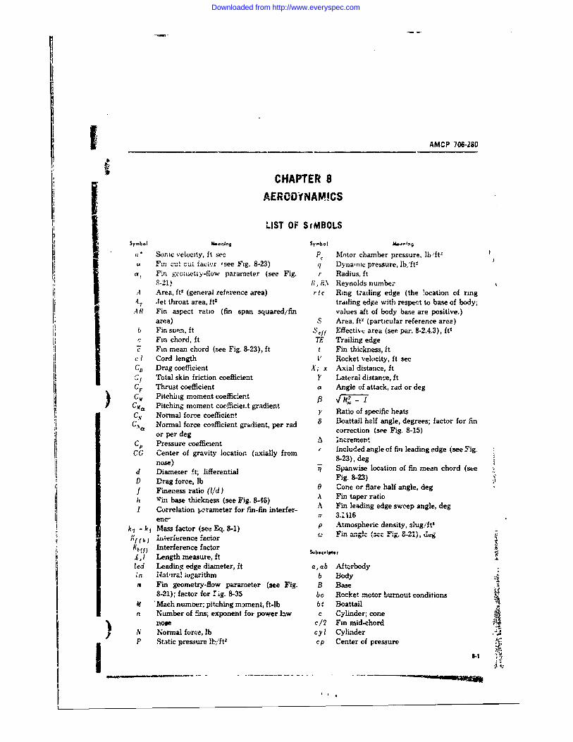
AMCP 706-280
CHAPTER 8
AERODINAM!CS
LIST OF SfMBOLSSymbol Me oning Sy-bl MO.,In;
" Soic velocity, ft sec P, Motor chamber pressure, lb'ft-
F.% . .. . factr ,see Fig. 8-23) q Dynamic pressure, lb,'ft2at W .n gccoiietu y-flow parameter (see Fig. r Radius, ft
8-21) 1I, R.\ Reynolds numbe:A Area, ft' (general reference area) r c Ring trailing edge (the location of ring4T Jet throat area, ft2 trailing edge with respect to base of body;.4 R Fin aspect ratio (fin span squared/fin values aft of body base are positive.)
area) S Area, it' (particular reference area)b Fin sp-'n, it .,eil Effective area (see par. 8-2.4.3), itr Fin chord, ft TE Trailing edge" Fin mean chord (see Fig. 8-23), ft t Fin thickness, it
c I Cord length V Rocket velocity, ft sec'D Drag coefficient X; x Axial distance, ft
C)" Total skin friction coefficient 1 Laterai distance, ftCF Thrust coefficient a Angle of attack, rad or degCM Pitching moment coefficientCba Pitching moment coefficiei-t gradient y i of s hC., Normal force coefficient y Ratio of specific heats11.C Normal force coefficient gradient, per rad 8 Boattail half angle, degrees; factor for fina or per correction (see Fig. 8-15)
or per degCP Pressure coefficient h ncremengtCG Center of gravity location (axially from Included angle of fin leading edge (see Fig.
nose) 8-23), degd Diameter ft; tiferentia1 Spanwise location of fin mean chord (steV Drag force, lb Fig. 8-23)f Fineness ratio (l/d) 0 Cone or flare half angle, degh Vin base thickness (see Fig. 8-46) A Fin taper ratioI Correlation parameter for fin-fin interfer- A Fin leading edge sweep angle, deg
enc, ff 3.1116
sfator (see Eq. 8-1) p Atmospheric density, slug/ft
n zJ1 iterlerence zactorK (f Interference factor Subscript:Z, I Length measure, Itsbl .
led Leading edge diameter, ft a, ab Aft-rbodyIn Natira! ogarithm b Body
m Fin geometry-flow parameter (see Fig. B Base8-21); factor for 1ig. 8-35 bo Rocket motor burnout conditions
Af 'Mach numoer; pitching moment, ft-lb b : Boattailn Number of fins; exponent for power law c Cylinder; cone
nos c/2 Fin mid-chordN Normal force, lb cyl CylinderP Static pressure lh,/ftl cp Center of pressure
i t ,I
Downloaded from http://www.everyspec.com

AMCP 706-280
LIST OF SYMBOLS (Cont)
Subs ~hf*~ an I nol Subscr ipts: Meaning
e raxw valut r Root chordIF Flare; fin-, friction re Exposed root chord
fb Forebody ref Reference conditionfe Exposed fin r t Ring tailf l Flare T Totalg Rocket launch condition t Tip chord
IF Interference t-et riigegI Jet (or nozzle exit plane) conditions t riigegle Leading edge theory Theortical prediction4 None IV Wave drag; "wetted" conoion
o, P ree stream or stagnation eonditions 21) Two dimensional considerptionp Plwndorm .I Perpendic ,!ar measure
I
SI
II3 -
.11
I.III
LIST F SYBOLS Cent~ I wbst~pt: Mrn~n Suscrpts:M~o~i!
Downloaded from http://www.everyspec.com
___AMCP 706-260
8-1 GENERAL DESIGN CONSIDERATIONS length, weight, and structural rigidity. Reduc-tion of the axial force c oefficient is more impor-
This chapter will discuss the aerodynamic as- tant generally for inairect-fire, artillery-typepects of free rocket design and will Lidlcate rockets where the sustain and ballistic flightmean: of predicting the significant aerodynamic times are much greater than that of the boostcoefficients. Simply stated, the usual aerodynamic phase. Axial force reduction in this case candesign goal is to ,/cet an external configuration result in either a lighter and smaller rocket forwhich provides stable flight with mirimum drag a specified maximum range, or increased rangethrough the desired altitude-velocity range. for a fixed rocket size and we:ght. In addition,
For a rocket to possess flight stability, a re- improved accuracy is achieved by r-duced rensi-storing moment must be produced when its Ion- tivity to atmospheric variations during the bal-gitudinal axis is rotated from the flight dirc- listic flight because it is primarily through thetion, i.e., when an angle of attack exists. This aerodynanic axial force that non-graitational ;flight stability is achieved in the case of aero- acceleratior.s are t'ansmitted to the rocket.dynamically stabilized rockets by selecting the The external configuration of a free rocket canexternal configuration such that the center of vary significantly depending on the trad--off be-pressure of aerodynamic forces normal to the tween aer'odynamic requirements inposed bylongitudinal axis is located farther aft of the performance and accuracy considerations, androcket's nose tip than the center ot gravity. Since other system requirements. Some generalizationthe aerodynamic forces are proportional to angle- can be made, however, based on past designs.of-attack (the angle between the flight direction Typically, the rocket's external configuration con-or velocity vector and the longitudinal axis of sists of a pointed body-of-revolution housing pay-the rocket), any deviation will produce a mo- load and propulsion unit. with a stabilizing de-ment to restore the axis to its a)i ned condition. vice attached to the aft section. A circvlar cross-When the center of pressure is aft of the center section is preferred because its syrrmunetry aboutof gravity, the rocket is said to be statically stable. the longitudinal axis makes for simplicity, both
in manufacturing and in determining aerodynamicThe degree of aerodynamic stability, or the cefcet n asietapoete.T h3tatic margin requirement, varies with the de- rocet od wh inra isoaerodynamioallysired ac,racy of each ro:ket and its design ap- uroctable, various normal-fore-producing devicesproach. For example, a rozket designed for mini- are attached at its aft end to provide the neces-mum dispersion during powered free flight re- ary reti moment rostbilty. Thin -quiressary restoring moment for stability. Thin-profileover its Mach number ri while a high-ac- planar fins, spaced evenly around the circum-olerits Mc hich aherregime, fe hits-ae- ference of the body, are used in many rocket de-celeration releas whic achiees msofis signs as stabilizing devices. This type of finlocity prior to release from t..3 launcher requires usually will produce the maximum stabilizingonly ti.ut the stability margin remain with cer- moment with minium t h t and ailiforctane omoment with minimum wight and axial forcetawuppr tld owe bonds Th with f tis penalties. Waen minimum overall diameter isstability band is governed primarily by the re- a na . esinm o erao te i
a dominwit desian consideration. the ringz-tailquiremeni to mainiain a significant spread be- and conical ilare become of greater interest. Atween the roll and p'tch-yaw frequencies. ring-tail will produce, at both subsonic and super-
Although the static margin is of paramount sonic velocities, approximately twice the restor-inttrest to the accuracy of a free rocket during ing moment of a cruciform planar fin with equalthe powered, high-ac Aleration phase, the aero- total span and chord. The conical flare is ofdynamic drag or axial force is a prime factor interest for restricted-diameter rockets with maxi-affecting the accuwracy and performance during mum velocities above approximately 5000 ft/sec.the sustain and ballistic flight phases. For an O the basis of projected planform area, a coni-anguided rocket, the angle of attack is nomi- cal flare will produce better than twice the normalnally zero; therefore, the axial and drag forces force of cruciform fins at hypervlocity speeds.ra-e equal. The general goal ;s to keen the axial However, the axial force of a flare greatly ex-for,! coefficient as *low as possible, consistent ceeds that of fins providing equal restoring mo-with other design considerations such as body ment.
Downloaded from http://www.everyspec.com
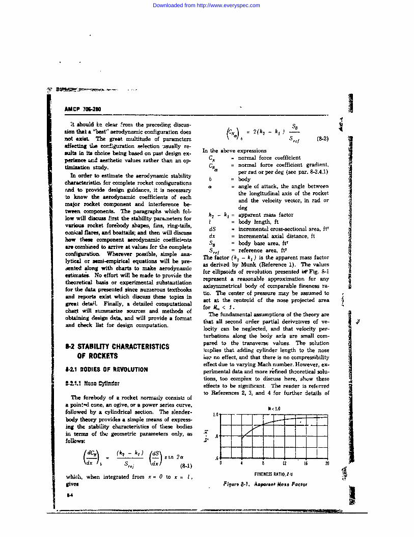
AMCP 706-280 1'4't should bt clear from the preceding discus- SB
sion that a "best" aerodynamic configuration does (CN = 2(k 2 -k 1 ) -
not exist. The great multitude of paramcters Src (8-2)affecting he coneguration selection -sually re-sults in its choice being based on past design ex- In the above expressions e nperience un aesthetic values rather than an op- CN = normal force coefficient
In order to estimate the aerodynamic stability bper rad or per deg (see par. 8-2.4.1)
characteristics for complete rocket configurations b = ao fa
rind to provide design guidance, it is necessary the longitudinal axis of the rocket-to know the aerodynamic coefficients of each and the velocity vector, in tad or
major rocket component and interference be- degtween components. The paragraphs which fol- denlow will discuss first the stability parameters for - = apparentma ftvarious rocket forebody shapes, fins, ring-tails, l = body length, ftconical flares, and boattails; and then -will discuss dx = incremental axial disetance, fthow these component aerodynamic coefficients SB = body base area, ft'are combined to arrive at values for the complete Sref = reference area, ft'configuration. Wherever possible, simple ana- The factor (k2 - k ) is the apparent mass factorlytical or semi-empirical equations will be prT- acorived y kun iteapren t mas factor
sened log wth hats o mkeaerodynamic as derived by Munk (Reference 1). The valuessented along with charts to make aerodeahec for ellipsoids of revolution presented iW Fig. 8-1estimates. No effort will be made to provide the rpeetaraoal prxmto o nrepresent a reasonable approximation for anytheoretical basis or experimental substantiation axisymmetrical body of comparable fineness ra-for the data presented since numerous textbooks io. The center of pressure may be assumed toand reports exist which discuss these topics tin the centr of se mose assued todetal. inalya dtaild cmpuatinal act at the centroid of the nose projected area 'great detail. Finally, a detailed computational for X,, < I. •chart wsources and methods of he fundamental assumptions of the theory areobtaining design data, and will provide a format that all second order partial derivatives of ve-and check list for design computation. locity can be neglected, and that velocity per-
turbations along the body axis are small com-
8-2 STABILITY CHARACTERISTICS pared to the transverse values. The solutionimiplies that adding cylinder length to the nose
OF ROCKETS i no effect, and that there is no compressibilityeffect due to varying Mach number. However, ex-
4-2.1 BODIES OF REVOLUTION pLrimental data and more refined theoretical solu-44 ,tions, too complex to discuss here, shuw these
.......... . efects to be significant. The reader is referredto References 2, 3, and 4 for further detals ofThe forebody of a rocket norrmaly consists of
a pointad cone, an ogive, or a power series curve, M 1.0followed by a cylindrical section. The slender- .I
body theory provides a simple means of express-ing the stability characteristics of these bodiesin terms of the geometric parameters only, asfollows:
k1)= (k2 s En 2a .6 i-
Se. %dx/ (8-1)4 , 1 16 2...L:- FIFIENESS RATIO, I /d !
&"uCI, when integrated from x = 0 to x = 1, Igives Figurq 8-1. /Aoporonf Mass Factor
14
Downloaded from http://www.everyspec.com
- AMCP 706-280
) these solutions. In the absence of more prec ise 86 rdbsolutions, the slender- body theory should be tved \2.. I i- -in the subsonic-throuh.-sonic Mach number r"age. dSrf dj
At supersonic Mach numbers, the normal-force (8-3)coefficient gradient and center-of-pressure esti- wheremates should be obtained, respectively, from Sbt = cross-sectional area of boattail at itsFigs. 8-2 and 3-3 for tangent-ogive-cylinder bodies, smallest diameter, A"and from Figs. 8-4 and 8-5 for cone-cylinder d = diameter, ftbodies. These curves were extracted from Ref- b t = boattailerence 5 end were constructed from empirical c = cylinderdata covering a Mach-number range from 1.4 to A increment7.0 and a nose-fineness ratio range from 3.0 to It is recommended that slender-body theory pre-7.0. Stated accuracies are = 10 percent for dictions be used for the subsonic-to-sonic Mach-normal-force coefficient and 0.5 calibers for cen- number range since systematic empirical investi-ter of pressure. gations are not available.effects of particular nose shapes and cylindrical ence 5) w.'l provide normal-force coefficient gra-
lengths is presented in Reference 6. Aerody- dients for conical boattails located behind a semi-naxnic-stability parameters were deternned at infinite cylinder; i.e., tle local flow conditions up-Mach numbers from 0.8 to 4.5 for tangent-ogive, stream of the boattail are equal to the free streamconical, and power-series noses, all with a fine- conditions. These data, derived from linearizedness ratio of four, combined with cylinder lengths theory calculations and slender-body theory pre-of from 4 to 11 calibers. The effect of changing dictions, have not been verified by a detailedthe nose-fineness ratio from 3 to 5 for conical comparison with experimental data. Therefore,-ud tangcnt-ogive shapes was determined for a no statement can be made concerning the ex-cyiindrical afterbody length of 6 calibers. Since pected accuracy.the overall study covers body configuratinas of The center-of-pressure for the boattail normalgeneral interest to free rocket design, the per- force is located approximately 0.6 16, from thetinent results are presented in Figs. 8-6(A), (B), cylinder-boattail juncture at subsonic Mach num-(C) and 8-7(A), (B), (C). These results should bers. The center of pressure at supersonic Machgive normal-force coefficient gradients within - 5 numbers may be evaluated from Fig. 8-9, takenpercent and center of pressure within ± .1 cali- from Reference 5.ber for the range of test variables. Whenever It is recommended that the data in this section
the body of interest falls within the range of test be used for bohttail angles of less than 10 degvariables, it is recommended that the stability and ratios of d greater than 0.8 to avoid flowparameters be established from these data. separation fromcthe boattail.
62.12 9., 5-2.1.3 Conical-Flare Afterbody
A conical-flare afterbody can be added to noseWhere the rocket propulsive nozzle is smaller cylinder configurations to provide aerodynamic
in diameter than the body cylinder, the rocket stability. The slender-body prediction for 'e in-afterbody may be tapered to form a boattail, which cremental normal force coefficient gr',lien of areduces base drag. The normal loading over this flared afterbody isboattail is negative, thus reducing the total nor-real-force coefficient and shifting the center of S/ .. [I / 2]'pressure forward. The slender-body theory pre- (AC2dicts the normal-force coefficient gradient W be: Q1 fl tre 7reiL (dfi (a-4)
e "- I J L : ----- I___. t .
Downloaded from http://www.everyspec.com
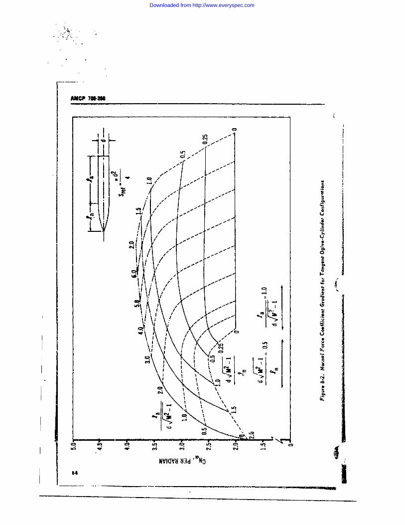
AMCP 16M
--
CF -
-c
CDC
- -
-C
CDCcl; C4
Nviavs83d N
Downloaded from http://www.everyspec.com
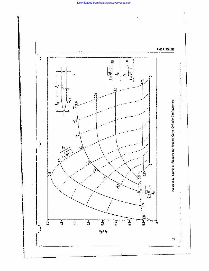
AMCP 1O6-2
)Z
~LCL1.
xJtI --
----- - -- jl-. -- -- I
C*4- -l
I - 1/
-i-
Downloaded from http://www.everyspec.com
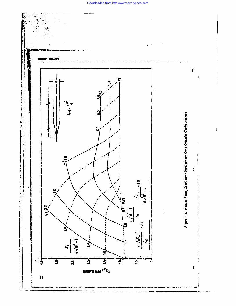
C4,InZIkn t
% 40
- 0.1~] A
I I . - -
q- CS o-
a N DNVIOVS HU
Downloaded from http://www.everyspec.com
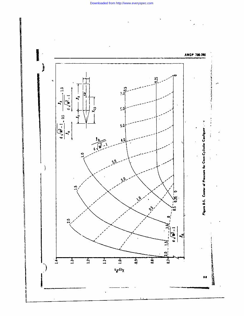
AMCP 706-MI.p-- 4
U .11 LC!- * I7 o[
I, * C.u.;
i i -i
II -A-
w- InCI
U/O
Downloaded from http://www.everyspec.com
OWC 7WM2UTsC,..
*4-- -4 ell
IL'
CA CD
m C4 4
33HO)30 H':d' P/ l3D2O 3 -,. . .
I -4 "4 --1- i
to *
-T-
.. C -
3 3 .813.1do N".- \ I "-
, U, o .. Cl,..
- IA-'a
*-1S
Downloaded from http://www.everyspec.com
AMCP 706-280
hr -W li C4
00 Kow
a3D3 83d 'ONO P/
001'1
R -- - S C -
cm - - -- hi.
Go,
~33803 8J3d 'ON3 pidox
Downloaded from http://www.everyspec.com
AMCP 706-280
ail,
Gof
-40 3
-411
33O 83d awN3 P/ dox
FT r-r
3393 - No -/o
Downloaded from http://www.everyspec.com
ANICP 706.280
r co-c
I 4,
r, enu -' CD
- -1-- xI3N3 83- -" - -
.1 -. iij~r lotS S
U -.
EUR <n OR0)O1 1D -- ,.JD-1 '.1
33)JD3Q Ull 0 /,
8.12
Downloaded from http://www.everyspec.com
j _____________________AMCP 706-280
) uj L.-- Ln U
I I
'
CV)~'~f -l a) '
-q -C
I.
cz >
Ln-
U I.0
3386310 83d 'DOp/dov
8-13
Downloaded from http://www.everyspec.com
AMCP 706-20O
, ji ,-,-*-A.
4b/
I 0'll" 1. _ . .I- , ._. o .
C.4"
" " I>
3393a83d N P/d:x 4
Ic,--, T *7- ,- -- !>
il, / r
,,U)-o o . . i C" (%J C)Ili i ,/i e -0iz~zzz/ zj3z 3,
U.
il- II
3380308 d 4 /,%
8-14
Downloaded from http://www.everyspec.com
AMCP 706-280
U U ,) Ur1:u, Ln '
4aC'
\n C.
0-
to - C4 C%
If I elf CI
I, fil 1,1 1 Ii4338030 83d NOP dxl
Downloaded from http://www.everyspec.com
AMCP 709-20
NOTE Values of -Z measured (• rearward from the 1 eylinder-fiare
juncture are negative.The important geometric parameter is seen to be
anf: N, Ithe ratio of forebody cylinder -diameter to base____: 01______ diameter. Flare angle and Mach number do not
_" -_ influence the flare normal-force within the lim-tations of the slender-body assumptions. To a f
IA. -limiied degree, the experimental data of Refer-Eence 7 verify this trend at transonic Mach num--_ bers and for flare angles of less than 8 degrees.
The actual normal-force contribution of flaredIA afterxodies is shown by other theories (Refer-
jences 8 and 9) and by experimental results to1.2 be influenced by flow conditions forward of the
flare, as well az by flare angle and length. Also,large flare angles (greater than about 10 deg)Sare known to cause flow separation at the cyiin-
L U. der-frustunt juncture, which alters considerably8 __ _ _ *the local normal-force loadirg in this region. Pre-
k else estimates of the flared-afterbody stabilitycontribuinn must coniider the complete upstreamt4, .flow field, including boundary-layer character-
L, / [ ,, itics.For preliminary design estinates, however, the
incremental normal-force coefficient gradientsW 1 01% 4 t presented in Figs. 8-10(A) through (E) a.re con-
S1A/( '.I) sidered adequate. These data were computedfrom slender-body theory and correlate fairly well
Figiw 8-8. Ncimal Force CaeHicint with the experimental data presented in Refer-GnyJent for a Bowall ence 10.
For values of dId. greater than 1.5, locationand center of pressure of the noruml-force -in- of the center of pressure of the incremental normalcrement is force - as predicted by slender-body theory -
varies from approximately 50 percent to W~ per-d / d \ cent of the flare lngth aft of the flare leading
Ix ( d -? edge. The use of 60 percent, for flare geometric-' = *. ~ variations wi&jtn the parameters of the investi-
2 !gations described in References 7 and 10, is there-3 1- fore consist-nt with the overall experimental ac-
(8-' curacy. The combination of data in Figs. 8-10with cone-cylinder or ogive-cylinder forebodydata derived from par, 8-2.1.1 should provide
where overall normal-force coefficint gradients withinxi, - axial distance from -y:!.der-flare = 10 p*rient and center-of-prensre locations
juncture to the Bare center of within ± 0.5 Cpliber.pre.'re, {ft
/ total flare length, ft 8-2.1.4 Oversize Head Coofipirationsd - cone diameter . ft Occasionally the nose section is required to \df flare diameter fit have a larger diameter than that of the cy;indric!
Downloaded from http://www.everyspec.com
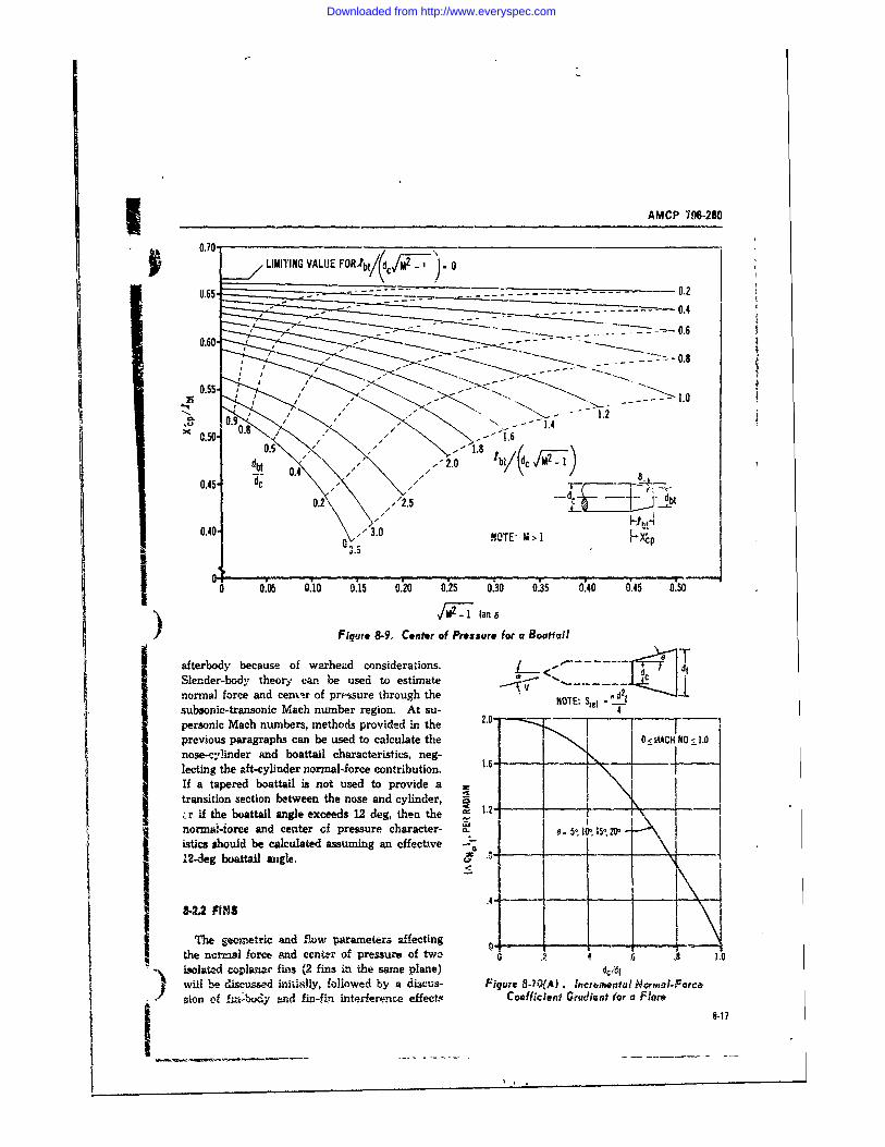
UAMCP 796-280
0.70. Nj _0.70 LIMITING VALUE FORfbt/(dfM1j 0
(.65. - ---.-- . . . 2
0,i0."-----'- --. -.- 0.4
0.55. /-" o.9 " .- ----1.2
, 0 50.4' " 1.8 b"(c iuS," 2.0 I
0.45- dc "
0.2 /.2.5_
0.0 . OTE- M > 1 ..Nfl * 1 i Fxi
0 0.05 0.10 0.15 0.20 0.25 0.30 0.35 0.40 0.45 0.50
Figure 8-9, Center of Pressure for a Bootfail
afterbody because of warhead considerations. < dI dSlender-body theory canbe used to estimate < ,normal force and cenv.r of prussure through the " HT: - 2
prrssure NOTE: t--subsonic-transonic Mach number region. At su -0- 4personic Mach numbers, methods provided in the .|previous paragraphs can be used to calculate the 0< MACH N0 < 1.0nose-cylinder and boattail characteristics, neg-lecting the aft-cylinder normal-force contribution .If a tapered boattail is not used to provide atransition section between the nose and cylinder, !;r if the boattail angle exceeds 12 deg, then the 12- \\ inormna-iorce and center of pressure character- 5 101,I5Iistics should be calculated assuming an eff___eX12,4eg boattail angle. c" "
-
141-2.2 FINSThe seometric and Eow parameters raffecting O
the norms! force and ccn r of pressure of two 0 .2 4 .6 .8 .0SLtol~f. coplanwar fins (2 fins in the same plane) dc/dr
b will be discussed inidlly, followed by a discus- Figure 8-? ".4). Incromental Hormal-Force-ion of fir,bi'y and fin-fin interferpnee effects Coefficient Gradient for a FlareI ~ - -- -8-17
Downloaded from http://www.everyspec.com
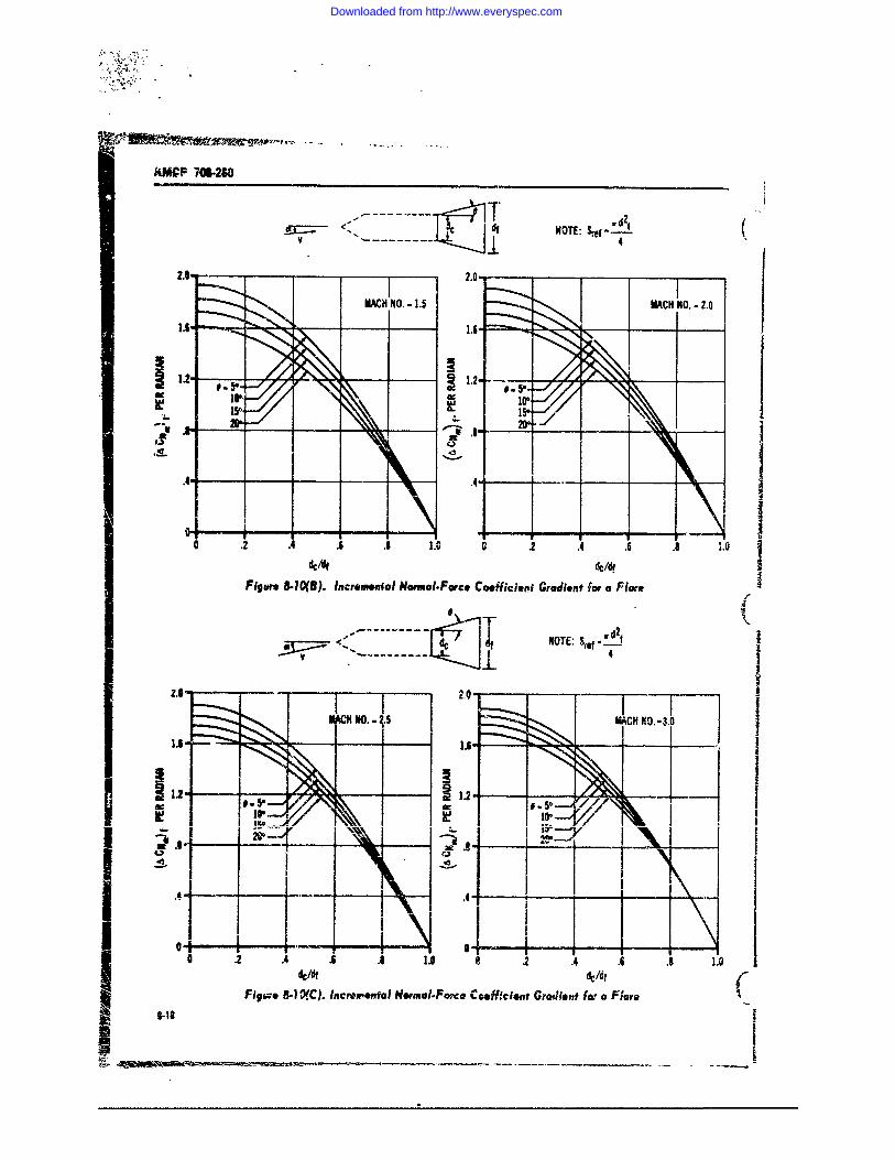
-MCP 706.260
0d 2cr di NOTE: S gt f-
v 4
2.0_ _ __ __ 2.0 1_ _ _ _ ____ _ _ _MACH NO. - 1.5 MACH NO. - 2.0
1.6-
*~V pi v ~ ' ~.1.2
, • ._ ._ _ . . ,- ,, __ - , ___
0 2 .4 .ti .8 1.0 8 ,2 .4 .6 .8 1.0
dc /f /dFigure 8.10(8). Increm~ol ormal.Force Coefficieni Gradient for a Flare
I.7 N" OTE: ,r,.
,H NO.iI1 - 5 I KIII
_-__" ___ I"~~29
. - -
o 2 4 A . 1.0 0 .2 *4 .6 .8 10dc/dI dc/dt
Figue 8-1 WC). Incretvtol Normal-F',c Coofflclont Gradient for a Flare- -8
Downloaded from http://www.everyspec.com
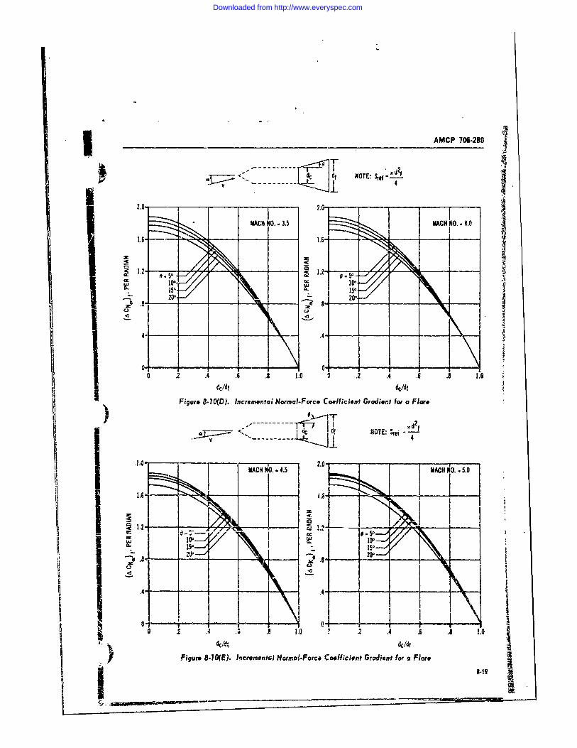
- AMCP 706-280
----- ~df NOTE: Sre-2Y
* 22.
MACH NO. ,73.5 MACH NO.. 4.0Ip I 1..
1.2 1~1.2J 5
100- lo
id/, d c/. ,.d .
15" 5,
------- InOE ;e dN
41 1.0 1
MAC NO 4.5s MAHNo-.
z ,
I. I Nzx-
06. ,O 0 .2 . 4 . 1 1.0It|Figure 8.10(D). Incremental Normal-Forc. Coefficient Gradient for a Flre
-.
- , -,,--0-,JT f iv-- '- . ... -
1 MCHNO . MACH INO. ,,5.0
4: I .I _ I oi - 1 '.
___0 . i .1 . 10 . .4 .6 . 1.0
• c/e :!f]Figure 8.1O(E). Incroeta)o Normo,.Forc. Coefficient Gradientfor a Fiore
11 Ii __ ,J I_
I 10
Downloaded from http://www.everyspec.com
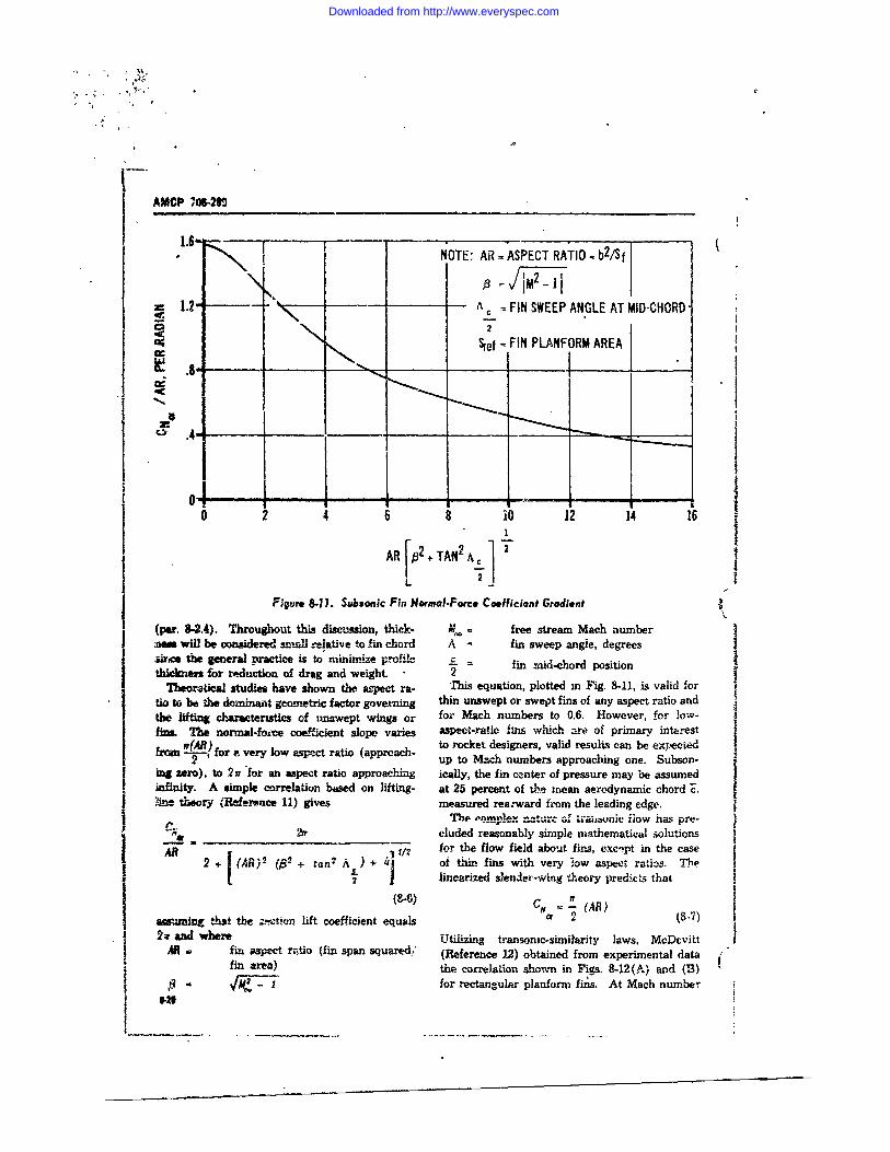
1.6 .6I NOTE: AR = ASPECT RATIO - b2/sf\ . IM 2 _
1.2- A C. FIN SWEEP ANGLE AT MID-CHORD2
Sref = FIN PLANFORM AREA
.48
0 4 6 8 i1 12 14 161
AR [2 + TAN2 A 2 1L I ,
Figure 8.11. Subsonic Fin Normal.Forc. Coefficiont Gradient
(par. 8-2.4). Throughout this discu,4sion, thick- :L = free stream Mach numberla m will be considered small relative to fin chord A - fin sweep angle, degrees |sire the general practice is to minimize profile c fin mid-chord positionithicknes for reduction of drag and weight 2 f I
Theoratical studies have shown the aspect ra- This equation, plotted in Fig. 8-11, is valid fortio to be the dominant 5g-emetric factor governing thin unswept or swept fins of any aspect ratio andthe lifting charactenstics of tmwept wings or for Mach numbers to 0.6. However, for low-fina. The normal-fozxce coefficient slope varies aspect-ratio fins which -re of primary interest Ihm _4fo) f very low aspect ratio (approach- to rocket designers, valid resuls can be ex ected f
f . up to Mach numbers approaching one. Subson- jing zero), to 2 rfor an aspect ratio approaching ically, the fin center of pressure may be assumed j,infinity. A simple correlation based on lifting- at 25 percent of the mean aerodynamic chord j.lne theory (Reference 11) gives measured rearward from the leading edge.
Thpe "nnlpex Of t-aiibunic flow has pre-- -. _ ____ _ eluded reasonably simple mathematical solution-s
2 A 11/2 for the flow field about fins, exc!pt in the case2 . (ian- (P" + ran" + of thin fins with very low aspect ratias. The
2 linearized slender-wing theory predicts that(8) CN (AR)
aw.imin tht the z!!ztcicn lift coefficient equals e 2 (8.7) 12 W and Where Utilizing transonic-similarity laws, McDcvitt I
AR fin aP4."t rptio (fin span squared,' (Reference 12) obtained from experimental datafin area) the correlation shown in Figs. 8-12(A) and (B)I l- for rectangular planform fins. At Mach number
'4,1
Downloaded from http://www.everyspec.com
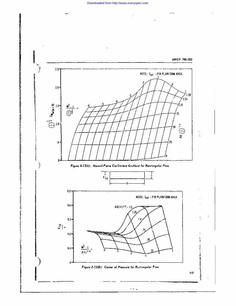
jAMCP 706-200
2.5NOTE' ef FIN PLAN FORM AREA
.21
12.0- 1.504 71.2b)
S 1.5- M2 1 -6 -.
A 2
00
] Figure 8-12(A). Norm,71-Force Copfficient Gradient for Rect-,ngulat Fins
Ii- I i l- -
r|
1 0
0.50
0.1- M2 -.1
2/3 1 .2
V Figure 8-12(B). Ccntnr of Prissure for R Rctangular Fins
Downloaded from http://www.everyspec.com
AMCP 706-20
1, linear~med-wing-theory prediction ma.tches the dashed, and dashed lines.experimenta, data where (AR)(tic ) 1/3 is less As ring tails re often use in conj'--%m,onthan one. Therefore, it i suggested that linear- with oversized hf-ads, it should be note. tlirt theired-wing theory be used as a guide for plan- reference an a o, the lift curve is the coss-sec-forms o'jsr than rectangular m the sonic region. tional area of the cylindrical afterbody or which
Lne.rized fiow theory has been found to be the ring is installed. The data use, ir, £i'q 8-17j an ac.rate means of predicting supersoi.ic 5ta- were obtained from w-nd tunnel tests on ringsbilit) characteristics of thin-profile fins. Thick- having a 40 dcuble-wedge section,, with the insidenes i effects are important, primarily when the surface of the ring diverging at 40 Irom the bodyMixah line emanating from rhe leading edge root- centerline. (See sketch on rig. 8-17.) Includeds.ction lies close to the leaing edge. Reference are the effects of interference be1: 6 ody,)3 prtgents charts, bas,d on linearmed theory, to support strut, and ring on the norn.al-force co-estimata normal-force coefficient gradient and efficient gradient.cepter of pressure for swept leading-edge fins of It should be noted that the test data are fornearly arbitrary planform. rings whose trailing-edge diameter is lpxger thaki
Figs. 8-13(A), (B), (C) and 8-14(A), (B), the leading-edge diameter. However, the charts(C), respectively, are duplications of the general- should provide reasonably accurate lift estimatesized charts for normal-force coefficient gradient for other ring configurations, provided that theand center of pressure. Fig. 8-14 prevides tea- minimum and maximum diameters of the ringj onable estimates of center of pressurf for the are vwithiL the limuts of minimum and maximumsubsonic. transonic, and supersonic regions for all dipxieters of the 40 ring case.fin planforms other than rectangular. A correc- The center-of-pressure is assumed to be at theton to the theoretical Civa for thickness effects ring mid-chord point.is given in Fig. h-15 for swept fins with wedge
S leading edges. Use of this figure is explained in 8-2.4 STABILITY OF COMPLETEI th computational srheets, par. 8-2.4.4. Thickness CONF!UiiA¥ION
has only a minor effect on center-of-pr-Zre.ue: and 84A1 GaoI lno correctio ' to the theoretical estimas is con-sidered neceanery. In the previous paragraphs, consideration has
The .apersonic norma!-Iorce coefficient slope been given to the prediction of force and momentmacd center-of-pressure of rn.ctangular-pnfarm characteristim of individual free flight rocket
ifus a derived by linearized -theory (Reference components. When the force and moment char-14) are pres nted in Fig. 8-16. 1tese data axe acteristics of the complete configuration are corn-v.lid for 9(.48,'> 0.5. puted, L-o major factors must be considered:
A .general presentation of linearized-supersonic- a. The data for the individual componentswing theory and terodynamic estimation -arts may be summed for the total t niy if a consistentcan be found in Referenp 15; the reader is re- set of data is used.I ferred to this work for fin planform not covered b. C'.rtain interference effects must be ac-by" the charts herein. counted for when the components are joined to
form the complete configuration.'h firett fartnr innrnt-a tnisatihility.y..r,
X-23 RING TAIL the force and moment coefficients; i.e., the force-T'efficients must be reduced on a common refer-
The noruzA- oree coeffcient gradient- for ring ence area and the momEnt oefficients must befins installed hn a cylindrical afterbody are pre- reduced on a common reference area and lengthsented in Figs. 8-17(A) through (F), taken from_Reference 16, for Mach numbers from 0.8 to 3.0. as well as a common reference point.
Thefree 1hors th numb e froi t To explain further, the normal force coefficientThe figure shows the normal-force coefficients defined asgradient for various chord lengths and ring di-ameters plotted in a "carpet plot". Thre . differ- c NI ent positions of the rhg t.railing-edge relative to N 2 q*A,-- for small valus of rx
the body base are indicated by the solid, chain- (8-8)8-22
Downloaded from http://www.everyspec.com
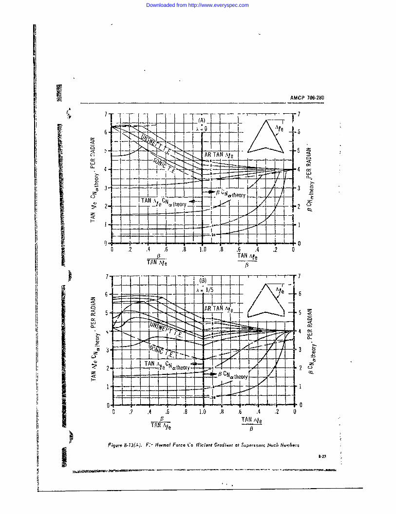
IAMCP 706-280
_4_
cN AR TAN Ale
2 - __7IIL-Iz~~~~~~ C -.T7/ LNteY"
Nr lCN eory ., c .th-ory2 .- -- 2
VS 0 .2 .4 .6 .8 1.0 .8 .6 .2 0-_.P_._ TAN! Af e
TAN Ale
7_ 7
TAN-AR TAN pe
cc 5
L4 I
2: .:-,~2--= --- r--. , e ",=theory-.'
13CNatheorrj0i 0 - z '
I i . i.4 .6 .8 1.0 . .6 .4 .2 0TAN ANe
TAN Al
Figure 8-13( ;. F:- o mal Force C ' ifici nt Gr iienr at Supersonec %. ch Nu ,bers
3 8-23
Downloaded from http://www.everyspec.com
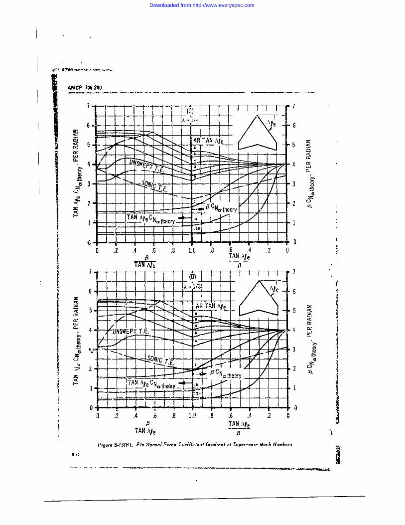
IAMCP 7W6280
7 7
6 .\I 6~
Ielahea - < ----
J-4-
TAN Ale p~hoy
A -7 _
0
4~JSETTNe -9 11
III i.L~YANieC~tho x 1/3
TA Ale 6
< ~ ue81() i IimIFreCefc~~ rdeta ue~cMc Numbers--
Downloaded from http://www.everyspec.com
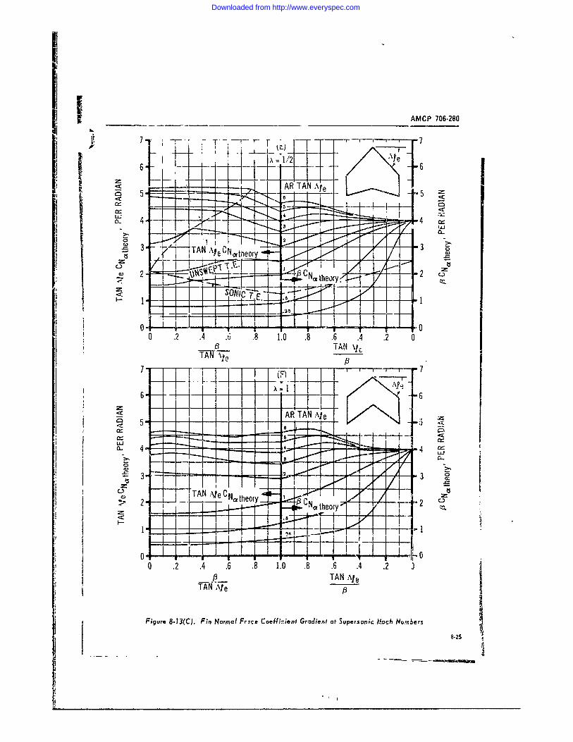
r ___ _________AMCP 706-280
7f 7I7 T
6- __F 6_
yAR TAA e
7.- Ile 4
6- 1 2
I/ _
0 -
TI A P \1
____ TAN I [ 0e0A R e
Fiur5 - 3(.FiNomlFreC f-inGrin PSpsni ocHubr 82
Downloaded from http://www.everyspec.com
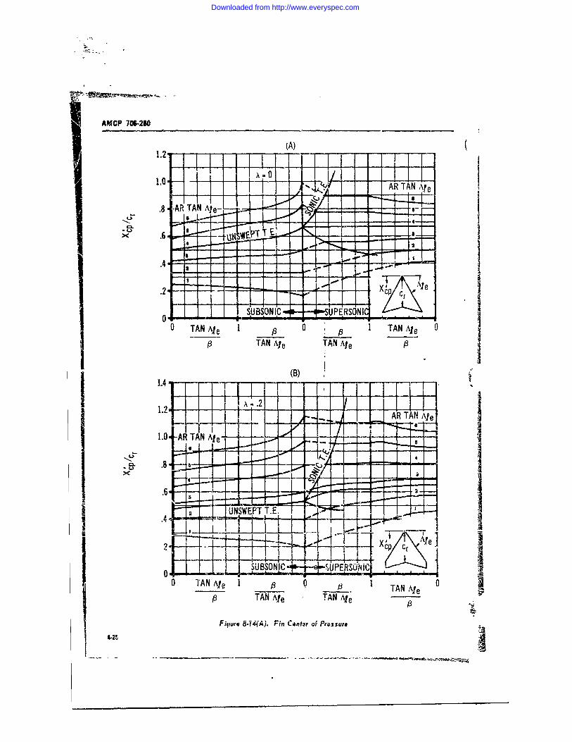
AMCP 70W-280
(A)1.2. l I3 *TI1I TI 1ri '-4-
x - -1.0 .. ] <.i AR TAN M ie
.8 AR TAN Ae- - RA p
.6 - -" -
.4
- - -1 1 1 -4 . .- ,7
.2 F L- i-______ %CreO ! ~~SUBSON IC. o-- --- ,.,SUPERSONIC .. . ,l
TANAe0 TAN Ae1A TAle~ 10s
9 TAN Ale TAN Ale P
(B)
-C-
1 .2 1 1 x R T A N A l e
0 --- _TN Ale# 0 TAN e 0
fl~~ TAcl TNA , Ale
Fiuurt 8-14(A). Fin Centzr of Pr.ssuro
I _______ ____________________,,_____,____._.-.__...__---_____
Downloaded from http://www.everyspec.com
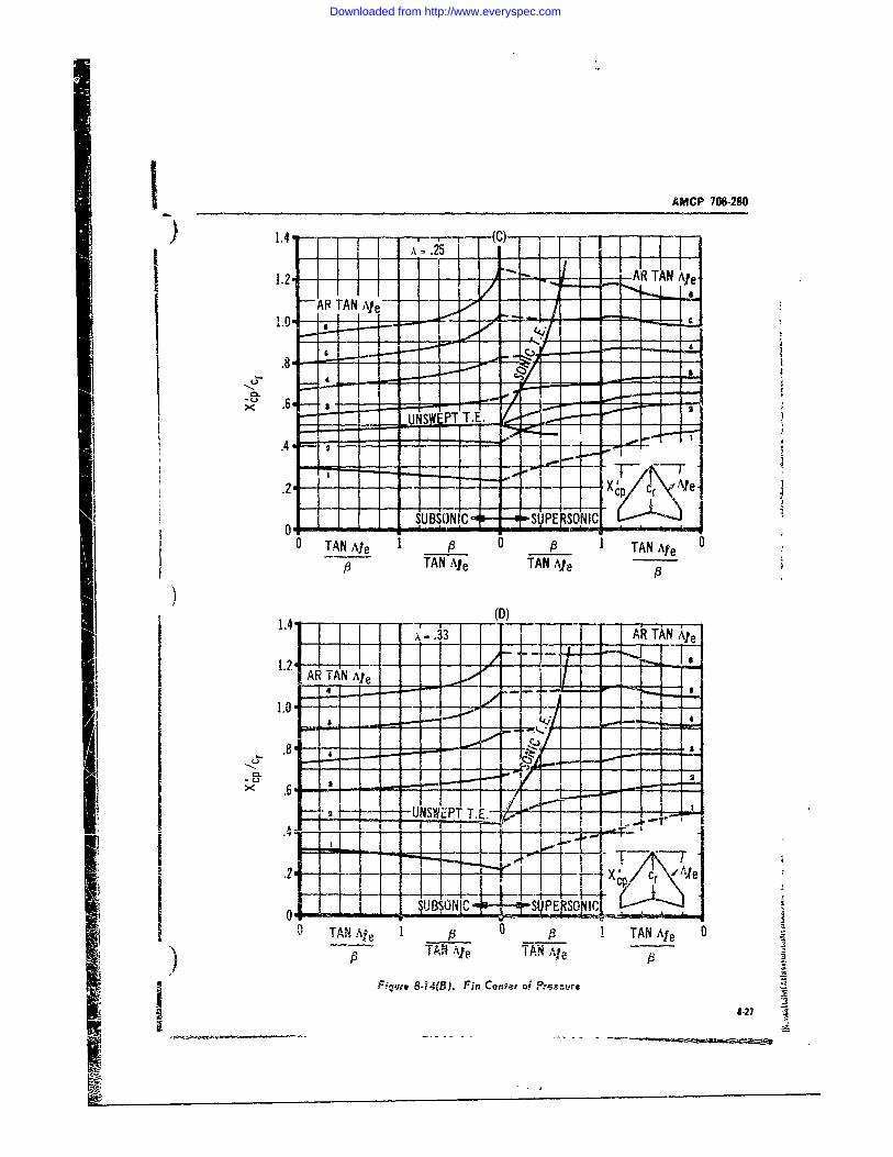
I _____________AMCP 706-2-40
L t~ I NAeI AR TAN Ate -10. --
LLI
.47
AR TAN Ale
* 2 1 ~ UBONIC E1-i'-I TNI~N I& IESC0 TAN Ale 1 9 0 9 1TAN Ae
TAN Ale TAN Ale
,6
.2 A8.27I r V
__5!5I S E SO I
Downloaded from http://www.everyspec.com
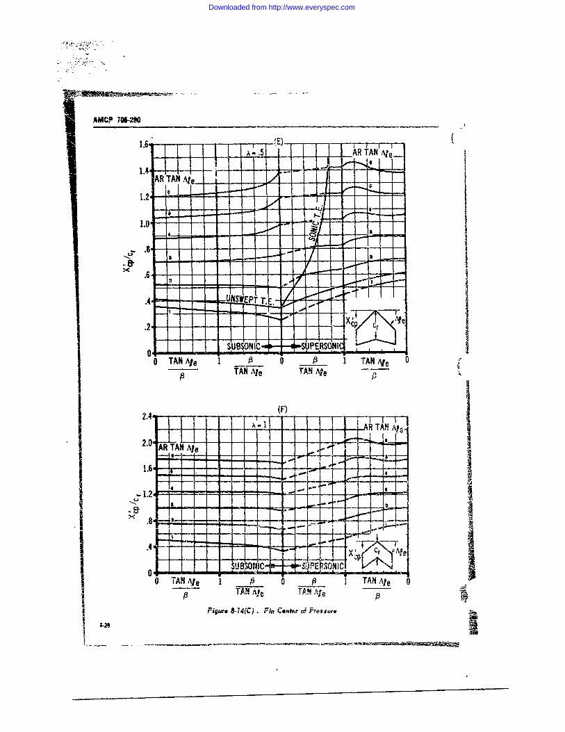
AMCP 7W.2-%
AR~ TN.eAR TAN Ale1.4 F-AR TA A--
A.
.8-
o. ~ON S ,O T7- - -,.. • .CIIAW~r
*4 i + .IISI PT T. E. -j-00
I f'
o-S.UBSONIPC -- -SP ROI 40 TAN Ale I A 0 A I TAN Al e0 TTAN Ale TAN e
2.4~ -(F)2 _. I _
A TN- - A
2.AR TAN
Ale
• --.- -- - , L .I- -_. .
II pI L- ! ,- - - - . i !
i tSB0 St 1 ! se l,, - '- PEF. N~ St' I, IS
0 TAN Ae 1 I 0 P_ TAN leP TAN AMe T. AN qp
Figure 8-714(C). Fint Cenfti'r ef Prtsgi.
Downloaded from http://www.everyspec.com
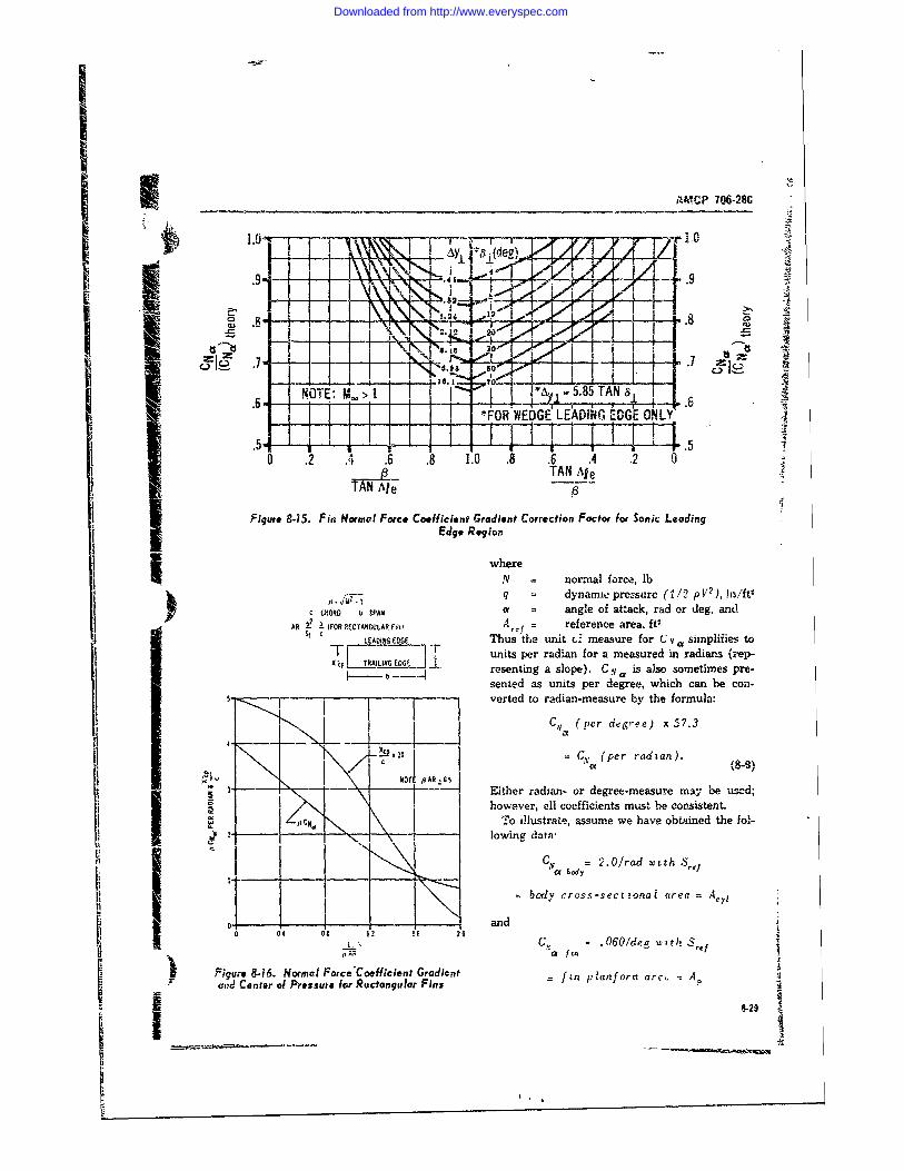
APMCP 706-28CIIL1I1LN1 4o' Iit
'° ...i•_--TL, -.- j -) ... -;uw - ,.9)
_, L_1+' ,h . J ---_ II : m,-,..+-LI I I =
C, , . -_ I !4 I I L 7 .7 .NOTE: M > 1 8' 5 TAN _
!.6 . . .os oit ~ I_*FOR WEDGE LEADING EDGE ONLY', 1= .5.,, I dl v.'li , iiIi+0 .2 .4 .6 .8 1.0 .8 .6 .4 .2 10
TAN Ae1h. TAN Ale
Figure 815. Fin Normal Force Coefficient Gradient Correction Factor for Sonic LeadingEdge Region
whereN = normal force, lbq = dynanne pressure (112 pV 2 ), ioft,
C o.0ORD b SPAN a = angle of attack, rad or deg, andAR 02 i(FOR RECTANGULAR F10 Ar = reference area, ft'
$f c LEAIM, EDGE Thus 'the unit c. measure for C csimplifies toX~jTRAIN E "F units per radian for a measured in radian s (zvp-
resenting a slope). C y a is also sometimes pre-sented as units per degree, which can be con..verted to radian-measure by the formula:
C(yL (per degree) x 57.3
0= (per radan).)
3 Either radian- or degree-measure may be used;_however, 01 coefficients must be consistent.
,oC N. To illustrate, assume we have obtained the folb2,z I + lowing data-
I l body= 2.0/rad wtth Sr3
bad y cross-sectonal area
0 andS o.o Co. - .0601deg wit)h S re
0.AR a fin
Figure 8-16. Normol Force&Coefficient Gradient = anform arc, = 4ad Center of Pressute for Rectangular Fins
8-.29
Downloaded from http://www.everyspec.com
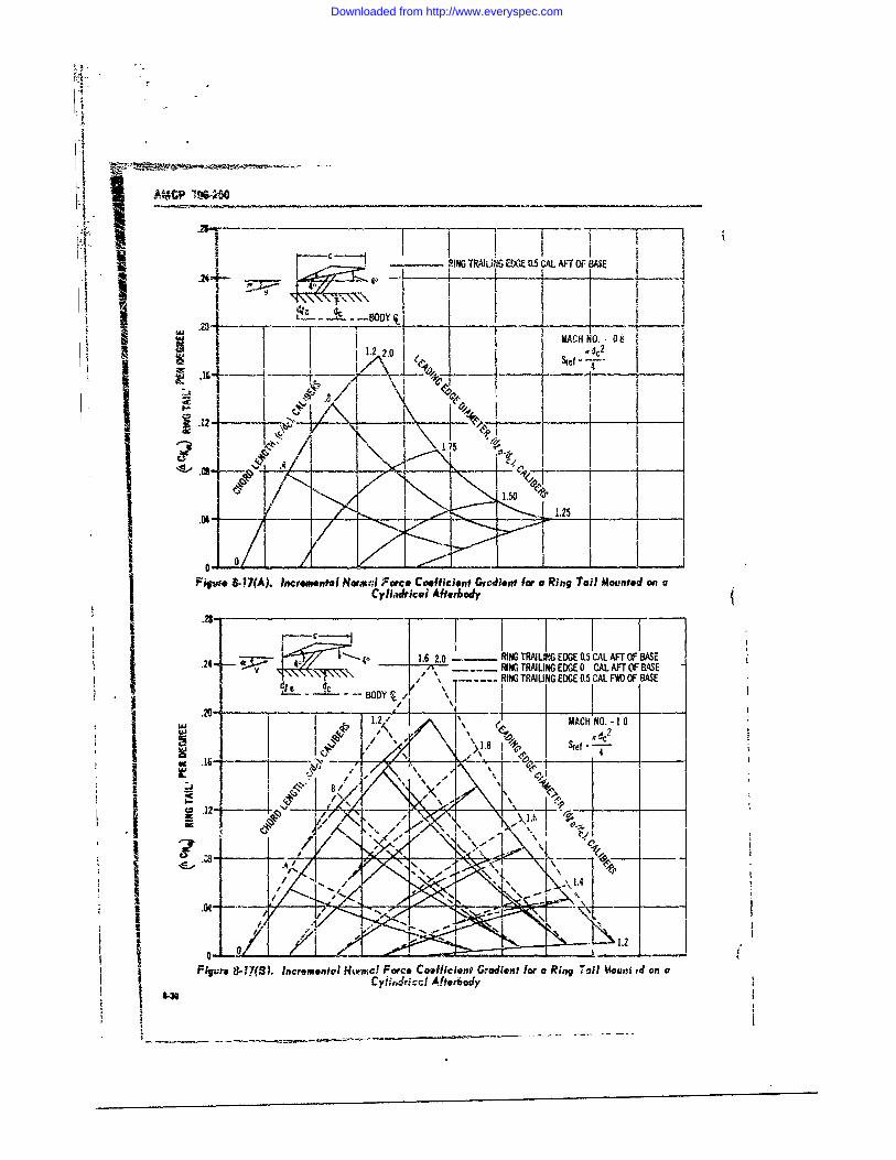
r- °[ -. I -, . o
II .20 i jN..o i;A%..p ...._____ I
U- - .-- - . -----...
C?--*'.: IN I I
9!NG TRMLiN1G EDE05CAL ATO S
,,.244 j t . • -.,v. --
,C NO. _ 8
.1 ii C
o ..- " I I
Fiqu,',. & !7(A). Incremental Nornal Force CcffIcint Gra.dient for a Ring Tail M1ounted] onaCyII~icai Aftebody
.. 2.0 - RING TRAILI, G EDGE 0.5 CAL AFT OF BASE. -- ~/~4 . R...IIN TRALING EDGE 0 CAL AFT OFBASE"j \\\/, <, .... RING TRAIUNGEDGE 0.5 CALFV)OF BASE
I " , -1 --
.-.I I 'MC O-1
I 4-.'
Filure 8,17(A). Incrementol Normrc Force Coefficien' Gradent for a Ring Tail Moun ed on aCyil.4ricc! After6ody
* -
'Se -
Downloaded from http://www.everyspec.com
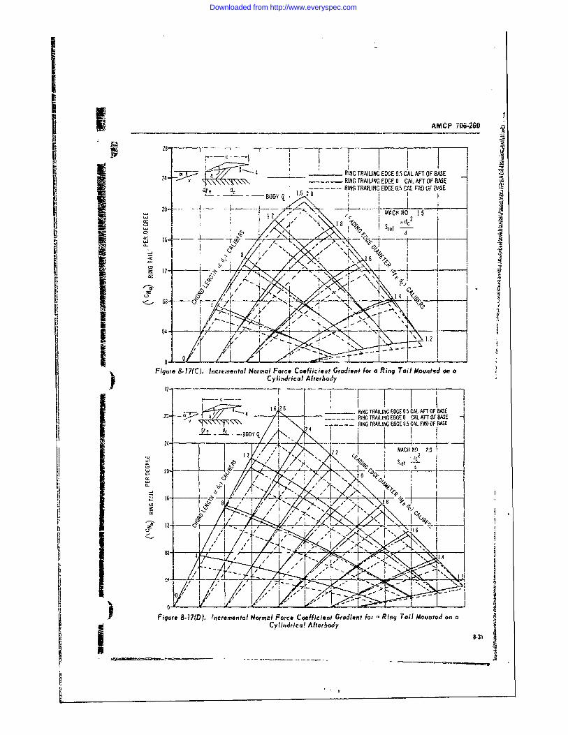
AMCP 70962
28 - y- - _ __ _1_ -- 1I i ._ RING TRAILING EDG'E 0.5 CAL AFT OF BASE
2-"RING TRAILING EDGE 0 CAL AFT OF BASEdi I - - ---- -- -- RING TRAILING EDGE O.S CAL F-' OF .A4SE
,' 12-"',, ° " \ I dc 2
,I ' T - _112 MAC N2o2 * 1 8 dc
, .~ ~ ~ ~ ~ ~ ~ ~ ~~-. ---- ,_ ×__ , -. , -. \ .. ---- ,
' 1'O-* /.i- .... '/I -, I A ..
Figure 8-17(C). lncre mental Normal Force Coefficient Gradient for a Ring Tail Mouned on a_________Cylindrical Afterbody
1272
z. -'3 -- 66 2 RMGTRAILING EDGE 0 CAL AFTOF BAS..f 9i'R ,iNO TRAILING EDGE 9.5 CAL FE OF BASE
. .. . 1
I,,' /I t" / ' ¢ ' 0I. ..
Figure 8-17(D). Incremental Normal Force Coefficient Gradient for a Ring Tail Mounted on a
32- Cylindrical Afterbody
* 8-3'..
6 2
Downloaded from http://www.everyspec.com
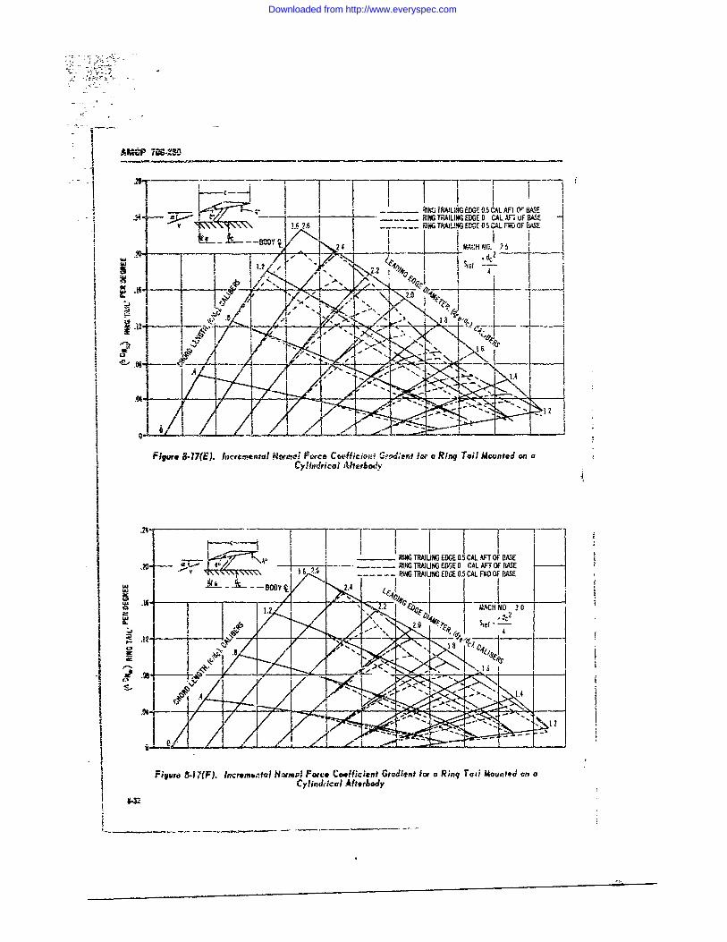
______ -_______ MAIMN EDGE 0.5 CAL Anl Or WAE-24 , ; ,1 .TILA G EDGE0.0 CAL AF 1 OF'BASE
V 9 7 i---- FIJJNG TAN DGED 5 AL FWD OF SE#-i I II I eHN
k _ 4__' t " •
,MV,
114
Figure 8-17(E). Incre.ental tHamd Fo rce Coo-tifen i t fix a Ring Tail Mounted on aI Cylindrical Aherhody
I
-.---- Fj -- ' RAU EE -JL FT F ASRIG TRAI N1G EDGE 0.5 CAL AFT OF BASE
-~~- -A ~ - -- N R!UGEG 05CLF FBS
I I/
I .16j ~ ~ -- ~----BODY~ __ __ __
.2 9.t CH NO 30
2, 1 Sef
!Figurc, t-17(F). lncremo,tal Nom'm7l Fore Coefficient Gradient for a Ring, Tw! Mounted on aCylind|iial Afttrbodly
11
I _II
Downloaded from http://www.everyspec.com
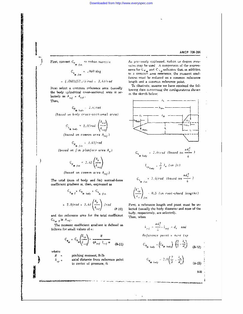
I
AMCP 706.28GFirst, convert C. tn radn nA,, prev:iously explamcd, radan ,r degree mea-
f fin ,u'e may be_ ume-d' A comparison of the expres-
. 06Odeg sions for C;; and C :ndicates fthat, in additiona fin tn a cmomv, area reterence, the moment coef-
ficient must be reduced on a common reference= (.060)(57.5.,ad -3.43irad length and a common reference point.eTo illustrate, assume we have obtained the fol-
the body select ca c ossectinal area lowing data concerning the configurations shownthe body zylindrical cross-sectional area s s.e-lected) ~~ ~ asA, Amthe sketch bcelow:S iected) as Ar = Ay I
Then,
" e b d, [
(based ,n b,-y cross-sectional area) i
I I. Ira I "i - ,:+-\,/ra #~ _ I
I (based on common area Aref
C . .. /radI
(bnsed on fn planforra area Ap) C = 01rqd (based on- )a body, 4
(based on common area Aref) nd
The total (sum of body and fin) normal-force C% in .0'rad (based on
coefficient gradient is, then, expressed as
T a body a fin 0.5 (in root-chord lengths)
= 2.0/rad ± 3.43 /rad Fzrst. a reference length and point must be se-\-e/ (P.10) lected (usually the body diameter and nose of the
body. respectively, are selected).and the reference area for the total coefficient Then, whenC'V a I is A rH.
The moment coefficient Rrad.ent is defined as dai4 I r f, = d , a ndfollows for small values of a:
Al Reference point = nc-se tip
C "a G N(~1 qA 'A\rrf/ a body = (Ca boy) \3 d~/-) 2
whereM = pitching moment, ft-lb /
= axial distance from reference point C b . -.O cener of pressure, ft C (.13)
8B-33
Downloaded from http://www.everyspec.com
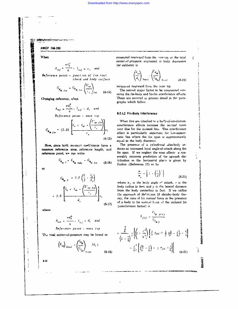
AMCP 7W -280
f Whtn measured rearward fs-om tdi "o e tip, or the totalh I ,entLr-o-prer. ,x-,,.--! .r.,y dzarnetzrs.14 (or cahLei) is.q r] I = c and
L Reference point =junctiton of f in rootcao-d and biy s'rfare IO - 11!t~a= f,. = ¢ .= -, .)rneszuied rearward fron,.e ics tip.
-r.- The second major factor to be- corsiterefd con-r , f 8i) cernt. +he lin-body and fi'n-fin interfeerence eff=cts.
0,s--ig refrenc.. wbThen e are eove.d in greater detail in ... para-~~graph-s which oow
.4i s I - d. andn-2.4.2 Fin-ody InterferenceReference point =nose tip
r( 1 W4hen fins are attached to a bordy-of-revolution,+ + - I anterference effets increase the noInal force
. .(3.0)1 \ / over that for the Lslated fim,. This interferenceL effect is particularly imnortan- for low-aspect-
Iratio fins where the hn span is approximatelyI equal to the body diametu r.
" Now, rdee both mom--:! coofficients have a The presence of a cylindrical afterbody an-coah.on reierence area, referene length, and duces an increased local angle-of-attack along therefaernce point, w- car write fin span. If we neglect the nose effect a rea-
sonabl, accurate prediction of 'he upwash dis-= C I C tribution vi the horizontal plare is given bya T M boy .i (8-1) .eskin (Reference 17) to be
or 4
r r 3 d where a is the body angle ,, attack. r is theI r' +body radius in feet. and y is the lateral distance
1j*Lb f - from the body centerline in feet. If we utilizer I jChe atpprooeh of Itet-r-nce 18 slender-body the-i 3.0 c ory, the ratio of fin rormal force in the presence
J of a body tc tin no,-.-a ftrce (J the isolated fin(8-17' a +S(interference factor) is
where
rd,~ ",a f( )A d, arm nd a f
Reference point nose tip 2ceter-of-pressure may be foi,d as Tar.- p ~i ]
((d)ro.) r2 /b r 2T2 +2 %n
Tot
Downloaded from http://www.everyspec.com
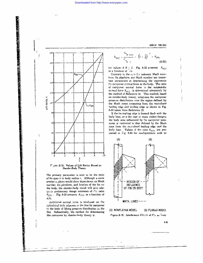
___AMCTP 106-2i
W . ( 4 1 A8-18i~11 , ! .A-
+-- f t .
"IfConirary the '--r subzoric Mach numn-* I /( c'rs. fin pianform anci Mach nulnber ame im por-
- .1fj arit paran.eiers Ln determining the supersonicf --. carrYOver on'rrma] force to the body, The ratio
I A ,o of carryover romal force t the tlated-fin
the /aethod of Reference 18. This method, based
-_~~~pesr distribu l . g.-/_i._] . afn tion o ve thrgondeiedb
'~~~~A. i ',fnpaar n chnm raein.rr
I t Ma cone from the rodemined a nd theI /it -- ~ ~ ~ - tke n frtomo Reference 18. Ti ehd ae
"I nsldrbody o teras the casei r yoerigs
i prsure istrition toe th eo defined by acLG- - icthe Mc oe mnt from the rot-chord laigeg n h
SW_ I body base Values the ratio Kmay are pre--s ted in lucg 8-20 for conafguron with noI
0 .2 .4 . 8 Lo
- I
"' " ,KF~r -18. Values of Lift Ratios Bosed on /
Sl~nder-Body Theory
The primary parameter is seen to be the ratio -..
of fin span b to body radius r. Although a more / I
precise &.,alysis would show adeperidence on Mach r -REGION OFnumber, fin plenform, and location of the fin on INFLUENCEth e b o d y , t h e s le n d e r -b o d y r e s u l t w il l g iv e a d e - -F *i n- _ -n n k .qu.r preiliminfary design estimates of Oi." ratiollK f. . Fig. 8-18 presents K 1 ,.) as a function of
A*d&.o-l normal ierce is produced on the MACH. LINES---_--:J- -.-. L , "ujventto the fins by carryovert the body of lifting pressure distribution o, the 'A Lfins. Subsorically, the method for determining (A) NONPLANAR MODEL (B) PLANAR MODEl
this carryover by slender-body theo:y is Figure 8-19. Interference ,r.....5 of Fe., w,
8-35It
Mli
Downloaded from http://www.everyspec.com
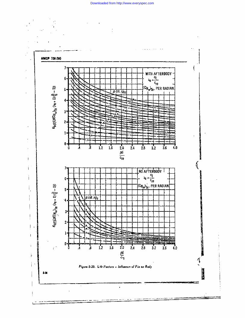
AMCP 7O6-W2
7 4 'WIT H AFTERBODY-I .... . re. "':N_' ,. I -, ___e_ I
3~- . -- -- (Ca-e, PER RADIAN
2
0 .4 .8 1.2 1.6 2.0 2.4 2.8 3.2 3.6 4.0
ere iI (. i NO AFTERBODY
i i --- 1-(CNIc)f PER RADIAN
+ .4.- P Ot le
I : O,2~~ 1 LiN-~----.4 .8 1.2 1.6 2.0 2.4 2.8 3.2 3.6 4.0
Figure 8-20. Lf Factors - InfIuenc4 of Fin on Body Ind
' -3. . _-_,_.. . . . .1
Downloaded from http://www.everyspec.com
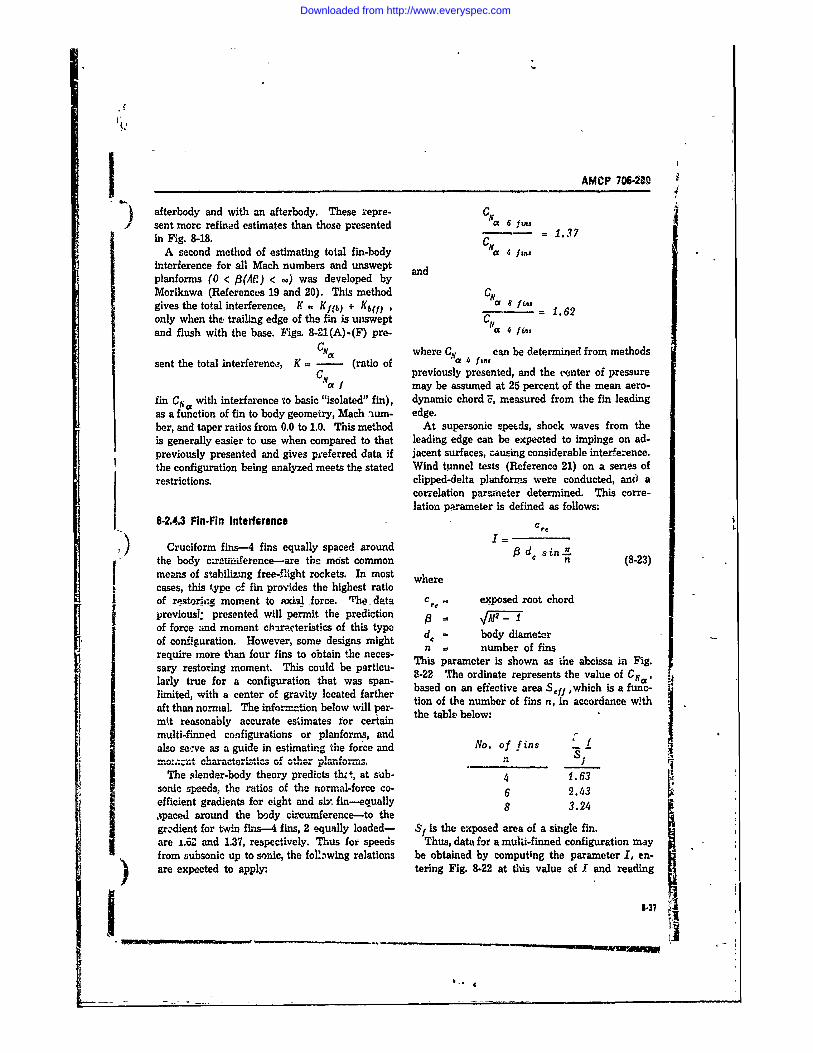
AMCP 706-210
afterbody and with an afterbody. These repre- CNsent more refined estimates than those presented a 6 f.n7in Fig. 8-18. 1.37
A second method of estimating total fin-body Na 4 fininterference for all Mach numbers and unswept andplanforms (0 < P3(AR) < oo) was developed byMorikawa (References 19 and 20). This method CNo8igives the total interferences K = Kf b) + Kb(f) 1.fin, 1.62only when the trailing edge of the fin is tuswept CNand flush with the base. Figs. 8-21(A)-(F) pre- a 4 fin,
CS a where Cf can be determined from methodssent the total interferenco, K = - (ratio of a 4 fins
CN previously presented, and the center of pressure"a may be assumed at 25 percent of the mean aero-
fin CIV with interference to basic "isolated" fin), dynamic chord?, measured from the fin leadingas a function of fin to body geometry, Mach aum- edge.ber, and taper ratios from 0.0 to 1.0. This method At supersonic speeds, shock waves from theis generally easier to use when compared to that leading edge can be expected to impinge on ad-previously presented and gives preferred data if jacent surfaces, causing considerable interference.the configuration being analyzed meets the stated Wind tmnel tests (Reference 21) on a series ofrestrictions, clipped-delta planforns were conducted, and a
correlation paraeter determined. This corre-lation parameter is defined as follows:
8-2.4.3 Fin-Fin Interference
[)" Cruciform fins-4 fins equally spaced around = d. sinthe body c=-ruinerence-are the most common n (8-23)means of stabilizing free-flight rockets. In most wherecases, this type of fin provides the highest ratioof reriaq moment to axial force. The- data cre exposed root chordpreviousl: presented will permit the predictionof force and moment chlarcterisfics of this type de body diameterof configuration. However, some designs might n = number of finsrequire more than four fins to obtain the neces- This parameter is shown as the abcissa in Fig.sary restoring moment. This could be particu- B-22 The ordinate represents the value of CNai tjlarly true for a configuration that was span- based on an efiective area S fwhich is a fune-limited, with a center of gravity located farther tion of the number of fins n, in accordance withaft than normal. The inforn.tion below will per- the te beomkt reasonably accurate estimates for certain the table below:multi-finned configurations or planforms, and offf.also se:ve as a guide in estimating the force and No. of fins
The slender-body theory predicts thz t, at sub- 4 1.63sonic speeds, the ratios of the normal-force co- 6 2.43efficient gradients for eight and sW fin--equally 6
,ipaced around the body circumference-to the 8 3.24
gr-dient for twin fins-4 fins, 2 equally loaded- S/is the exposed area of a single fin.are L.6. and 1.37, respectively. Thus for speeds Thus, data for a multi-finned configuration mayfrom gubsonic up to sonic, the fo1bwing relations be obtained by computing the parameter I, en-are expected to apply: tering Fig. 8-22 at this value of I and reading
1.37
I _____________________.-in.. 4 -
Downloaded from http://www.everyspec.com
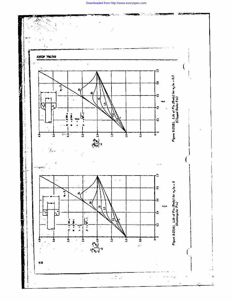
01
I P
0aq
.4
Wl Ui t CM -
on 4 CDQ
0
Downloaded from http://www.everyspec.com
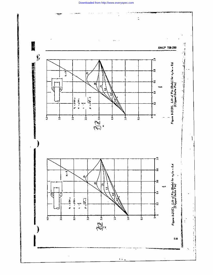
AMCP 706-280
~0 4.
-u
wn b.c4cyc
0 f0
NI
.4.4
li q ui r4 In 0 l wi 0
~N)
Downloaded from http://www.everyspec.com
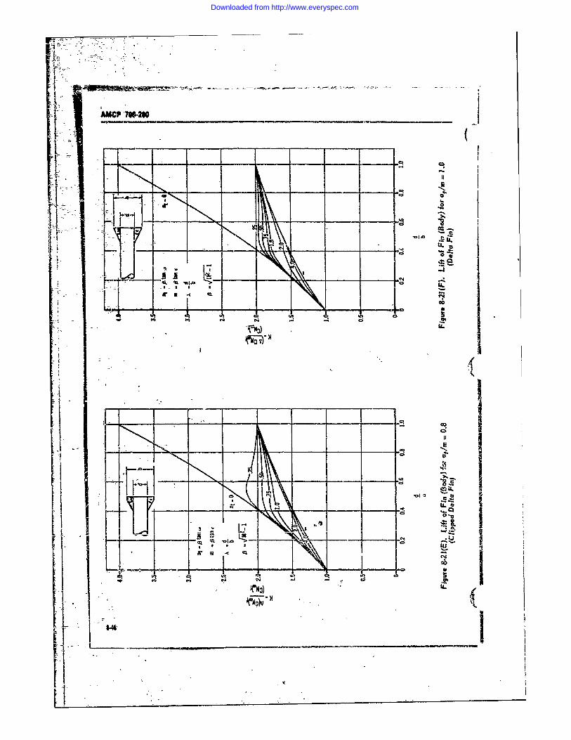
jAMCP 7P.W _________ __________
IfiI
- CD
in q- u lc 0
Downloaded from http://www.everyspec.com
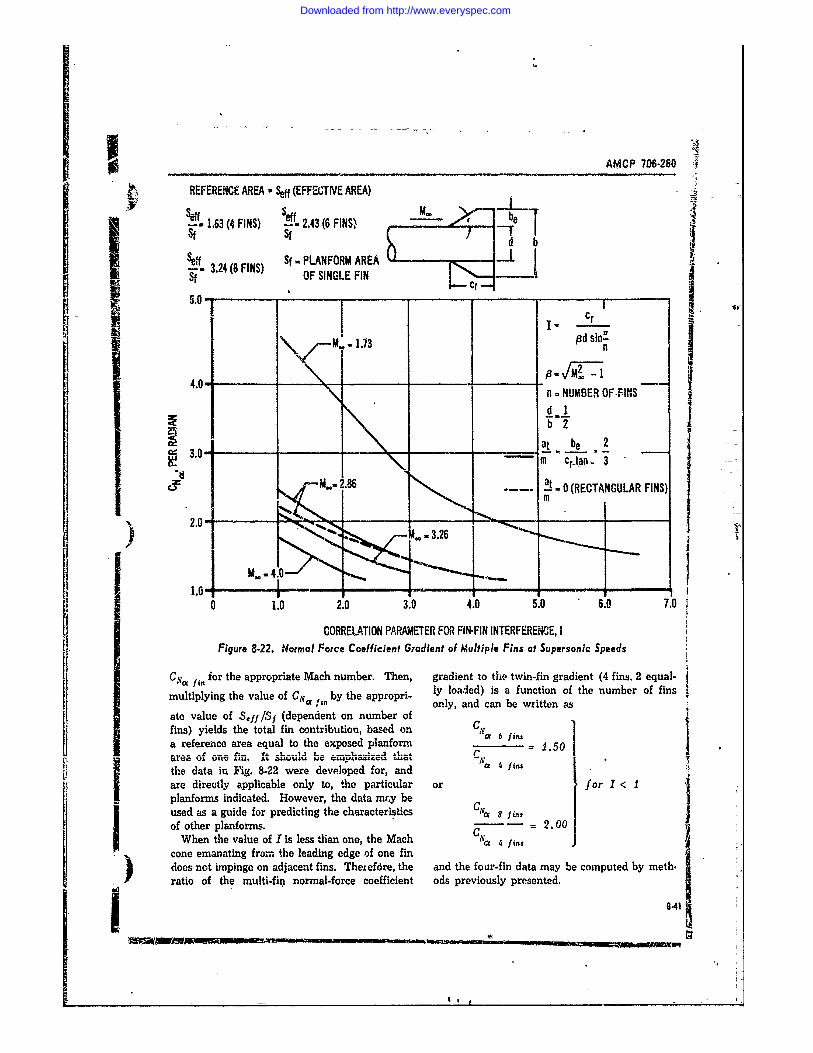
L.S
AMCP 706-280
REFERENCE AREA -.ff (EFFEGTIVE AREA)
--" 1.63 (4 FINS) -- 2.43 (6 FINS) efSlfd b
Seff Sf -PLANFORM AREA .S-3.24(8FINS) OF SINGLE FIN
I..-- 1 --
Ir
IM. 1.73 Pd sin"n
4.0 20 -n - NUMBER OF FINS
I~ IlI _ _ - - I
at be 2,,, 3.0 -- NI Citan. 3-
2.86 ... 0 (RECTANGULAR FINS)
1. M
I ~ ___ ____01
0 1.0 2.0 3.0 4.0 5.0 6.0 7.0
CORRELIATION PARAMETER FOR FIN-FIN INTERFERENCE, IFigure 8-22. Normal Force Coefficient Gradient of Multiple Fins at Supersonic Speeds
C-a fin for the appropriate Mach number. Then, gradient to the twin-fin gradient (4 fins. 2 equal-ly loaded) is a function of the number of finsmultiplying the value of CNoa4 1n by the appropri- only, and can be written as
ate value of Seff /Sf (dependent on number offins) yields the total fin contribution, based on C.a 6 fins
a reference area equal to the exposed planform 1.50the data iu Fig. 8-22 were developed for, and a fI, 2 o
are directly applicable only to, the particular or for I <planfarms indicated. However, the data mry beused as a guide for predicting the characteristics Cla 8 f ns
of other planforms. - 2.O0When the value of I is less than one, the Mach N 4 f/ins
cone emanating from the leading edge of one fin
does not impinge on adjacent fins. Theiefdre, the and the four-fin data may be computed by meth.ratio of the multi-fin normal-force coefficient ods previously presented.1_ _0_411
Downloaded from http://www.everyspec.com
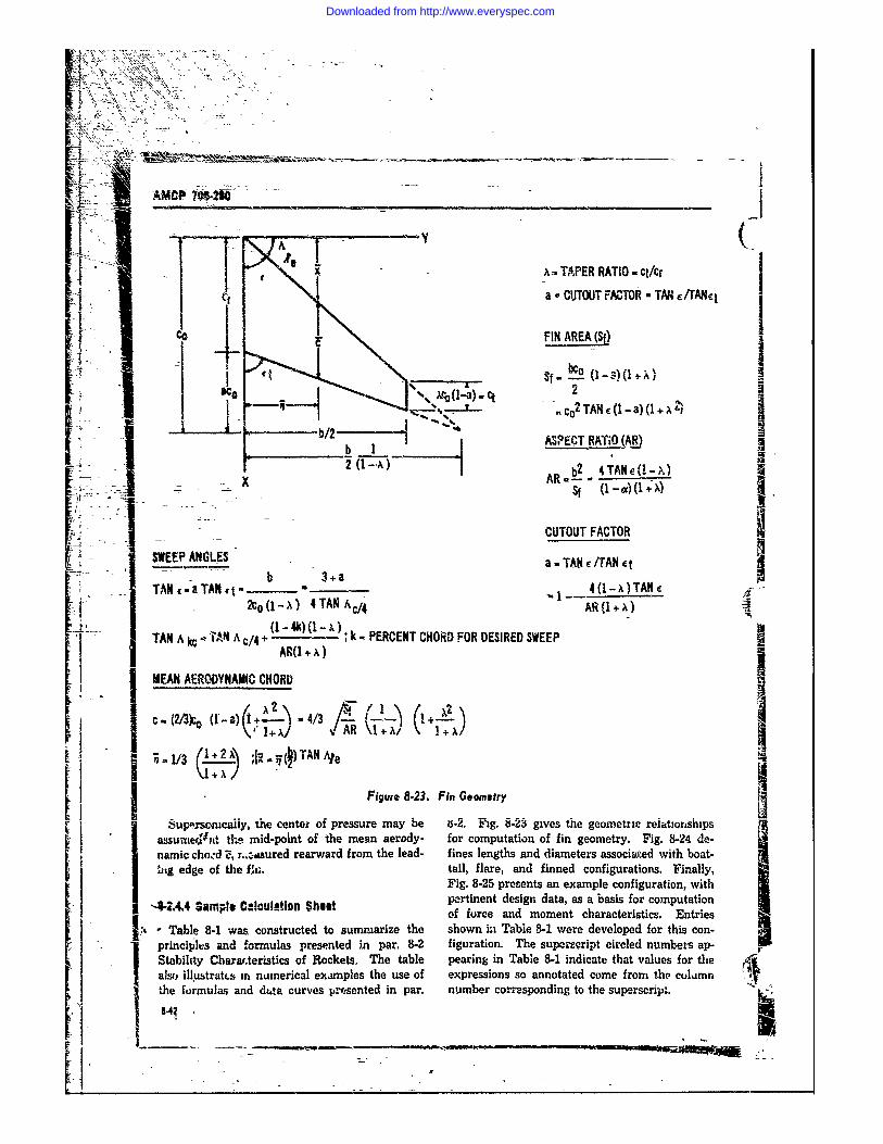
: L -111 ~ 'ikMCP~t4O __ __ _ __ ___ __
YISj .x =TAPER RATIO ct/cr
C a- CUTOUT FACTOR TAN /rANq
CO - FIN AREA (Sf)
: ~~~ ~ ~ x (1-a ctj s- _o 1.)(:i .,Co 2 TAN c (I - a) (I x 21[1 1 t ____b/2 n 0 TN1)(+'
I r _ _"__I ASPECT RATtO (A)
b .!a
2- -(1 -4X TANe
4TNX/ AR (A A
1 ~ AN ~ ~N A (1-.)(-) "k- PERCENT CHIORD FOR DESIRED SWEEP
f (I -t) G+ A
C MEAN AERODYNAMIC CHORDF
FSWEEP ANGLES ai Geoetr eTNe
S( 2 c (1x TAN ACAA1+x
Ul -,'eflcai~y, the center oi pressure may be is-2. Fig. 8.23 gives the geometric reiat. onshaps
H~ ~ ~~ ( - Figur 8.23 F- Gxn
Tassume N t th mid-point of the mean aerody- for computation of fin geometry. Fig. 8-24 e-
3 hnamic cho.d , r..:.aured rearward from the lead- fines lengths and diameters associaed with boat-* ,ig edge of the fi . tail, flare, and finned configurations. Finally,IFig. 8-25 presents an example configuration, with
I -1244Sml, !u_.inShe pertinent design data, as a basis for comnputation* -4.4, SapleC:Iclatan hutof force and moment characteristics. Entries
I, Table 84wsconstructed tosumniarize the shown ini Table 8-1er developed for this con
c 8 2 - -9) to 4/3 on
Sprineiphl~s and f ormulas presented hn par, 8-2 figuration. The supersript circled numbers apI Stabilhty Charar.teristics of Rockets. The table pearing in Table 8-1 indicate that values for the Alals. ilustrat.s m numerical exampies the use of expressions so annotated come from the column
the formulas and diga curves presented in par. number corresponding to the superscript. wtH|4 "a mu
offread1oetcarceitcs nreTabl 8- a osrce osmaiete on inTbe81wrdvlodfrthsc-
Downloaded from http://www.everyspec.com
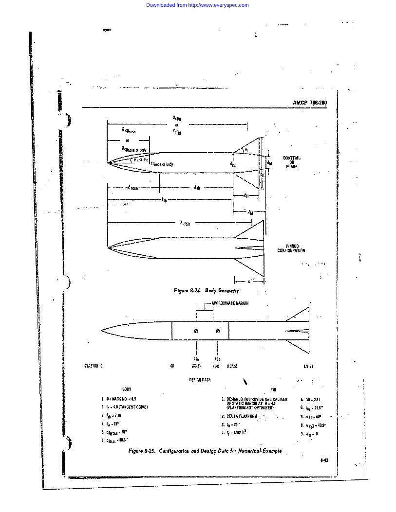
AMCP 706-280
oorX cPnose XCT
:C .,n,. --- db FLARE
. ... ,ose 4b i
S S
U A
I CONFIGURATION
L - i-I-.i
i Figure 3.24. Body Geometry
APPROXIMlATE MARGIN
itt
I STATION 0 VI (0) (107.5) 176.31
DESIGN DATNFG ,
BODY FIN1, 0 <IAC4.4O, < 4.5 1. DESIGNED TO PROVIDE ONE CALIBER 5. ,RI31
OF STATIC MARGIN AT M 4.52. n "O4.0 (TANGENT OGIVE) (PLANFORM NOT OPTIZED)6.33. DibE-7.76 . DELTA PLANFORM"4. (bT-N15" T 3. beG-V25" NE. Ac12-40.
1 3. t i4. 7 .08APLNM2 -IAaSz
36 C.b.o.."..3"
6.c~*-503"Figure 8-25. Con figuration and Design Coutc IQr Numerical. Example ;I___
Downloaded from http://www.everyspec.com
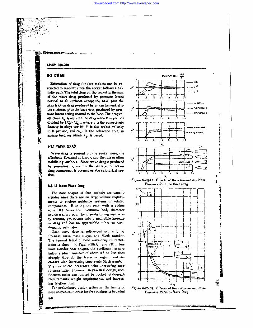
AMCP 7W2 0
IAG EREIF.RCE AREA -
Esimtion o! drag for free rreckets can be re-sticted to zero-lift since the rocket follows a bal- .ist. paV. The total drug on tho rocket is the sum--o the wave drag producvd by pressure fo.-ces 1 10 1 1' .
wromal to all surfaces evcept the base, plus the -Anfction drag prodid by forces tangential ',o 9 - ;*Ai oO"A
-~ - 3/4 PARABOLA
5111 f~COS ctig --- U PARABOLAeffkiiet C* eqta to the drag force ) inpounds , 10 12 14 ,. Is 29
divided by 1/2V s, where p is the atmospheric -
denity in shlua perft, V is the rtcket velocity O -- VOKAMW
in ft per see, and Sr,1 .is the reference area, in _j .. . . ---- tVHACK
square feet on whichC ,is based. Rg , j ,1 1 .1 II !b i A
8-3.1 WAVE URAb I, - 3-~- ---- r ,
Wave &rag is present on the rocket nose, the . .-- " C=
afterlody (imttail or flare), and the fins or other " - : ... . 3s3abilitIng suriaces. Since wave drag is produced ,O K + IAMiA C=:3
* y pressure notmal to the surface, no wave- k I < 2drag component is pesent on the cylindrical sec.. 0 . . ..tion.
Figure 8-26(A). Effects of Mach Number and NoseFineness Ratio on Wave Drag
&he nose shaves of free rockelts are usually '... I I TT Fslder since there am no lWge volume requit-
ments to enclose guidance systems or relatodemiponents. Bh, -.r g tne nos . wit!) a radius .. . ... .
equal 0.1 times the mximnum body diamneteravoids a sharp point for manufacturing and s"fe-I , i i
j -- ty reasons, yet causes only a negligible increase p .----- "- --- - . -
in drag and has no appreciable effect -,it zen,-dynamic estimates. .- ..
Nose wave drag is influeticed primar:iy by I 4 ,"---!iximeness rato, nose shape, and Math number. T-1The general trend of nose wave-drag character- I Iistics is shown in Figs. 8-26(A) and (B). For I SCO O-RDER - -most slender nose shapes, th.! coefficient is zero 4 7 2 -V -
below a Mach number of about 0.8 to 0.9: rises \-sbarply through the transonic region; and de- 3 \ I- -creases withl increasing supersonic Mach number. \.The coefficient decreases with increaing nose -dfineneas ratio. However. in practii 'Ieign, nose. -_." -.. lfineness ratios are limited by rocket total-length Io*Irequirements, weight requirements, and increat- 0 - - 3 - 5 6-1 j
__ friction drag. 0 I 2 1 , ,4cFor preliminary design estimates, the family of Figure 8.26(8). Effects of Macb Number and Nose
nose shapes-of-inter-ct for free rockets is bounded Fineness Ratio o,, Wave Drag
Iil
Downloaded from http://www.everyspec.com
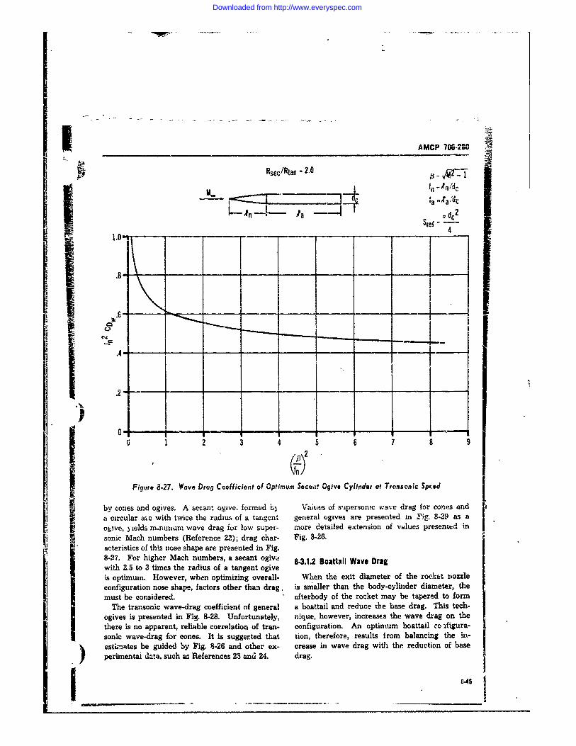
AMCP 706-280
Rsec/Rtan - 2.0
M.3 fa"/drA- aa Ir , dc2
Sref 7
l.O Y' e 1 eae .i2 .• 4 4
10 * T-a
0 2 7 a 9
Figure 8.27. Wave Drug Coefficient of Optimum Secu,;t Ogive Cylinder at Transonic Sped
by cozies and ogives. A secant ogive. formed L Vaiues of supersonic wave drag for cones anda circular aie with twice the radius of a tangent general ogives are presented m Fig. 8-29 as aogive, yields m-ranum wave drag ior low super- more detailed extension of values presented insonic Mach numbers (Reference 22); drag char- Fig. 8-26.acteristics of this nose shape are presented in Fig.8-27. For higher Mach numbers, a secant ogive 8-3.1.2 Boattall Wave Dragwith 2.5 to 3 times the radius of a tangent ogiveis optimum. However, when optimizing overall- When the exit diameter of the rocket nozzleconfiguration nose shape, factors other than drag, is snmaller than the body-cylinder diameter, themust be considered. afterbody of the rocket may be tapered to form
The transonic wave-drag coefficient of general a boattail and reduce the base drag. This tech-ogives is presented in Fig. 8-28. Unfortunately, nique, however, increases the wave drag on thethere is no apparent, reliable correlation of tran- configuration. An optimum boattail coi.figura-sonic wave-drag for cones. It is suggerted that tion, therefore, results Irom balancing the iu-estnates be guided by Fig. 8-26 and other ex- crease in wave drag with the reduction of baseperimentai dta, such as References 23 and 24. drag.
I 8-45
Downloaded from http://www.everyspec.com
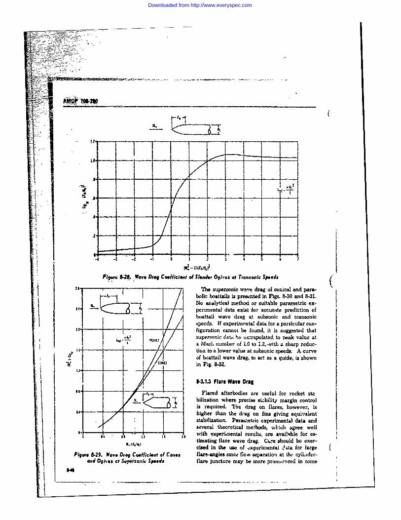
a :
-~.2-
oic i li i i .
-'- - - V i "e
2A pcuena dat exs oicuatrdcino
I ! !!
:iecs If exermntl dat fo a patcua con-f2.u0 f-8 aeIa otl i rtio l nde 1 cant be fn it ies sugsedta
=42 supersiinic ave d__rag_ o na ad at
i-i
4, a- a c b 1.0 to suita parp edc-F6i e. C icteo lowr val e at eubsoni sd c ur v epedisupr'onc wave drag ot onict l d ara-son
'1~ ~ ~ ~ ~ ~i F ig. pr8-n32i.is.830ad -
I -/Flare anataetod ore suble fararocet ex-- ~ peimldata wexre to crt preciedymrincontrol
~i requtired wae drag tson a ras onic
Ibzspeeds. If experimental data for a pricular eon-evfiguration cannol be found, it is suggested that
. ,i superrnic d-n. e n xtrapolated to eak value at""7" vi'7 a MacI. nunmber of 1.0 to 1.2, ,with a sharp reduc-i ---- - -- - -/c tion to a lower value at subsonic speeds. A curve
1 /0 of 1 2 t attil wave drag, to act as a guide, is shown
,* .~ Fled ter sae use fulrmnWe for re t
-r ~ bilization where precise si bility margin control
Figure 829. Wave Drag Coefficieis required. The drag on flares, however, isand- -, , t i higher than the dag on fins giving equivalent/ • stabilization. Plraa'etric experimental data and
0.- - -,eM hortcaehds-- -h geewl*" 'with -,xperiimental results, are available for es-
r4 O 1 li l timating flare wave drag. C 'e should be exer-i~llni ciid s e i f cxporimenta1 z ta for large (Fliu 829. Wave Drag Coefficient of Cofes flare-angles since flow, separation at thc, cylder-,
iand Ogit~s ct Sup.er=o/k $peeds flare juncture may be more proncdced in some
V#
i! • " - -- " - '-
Downloaded from http://www.everyspec.com
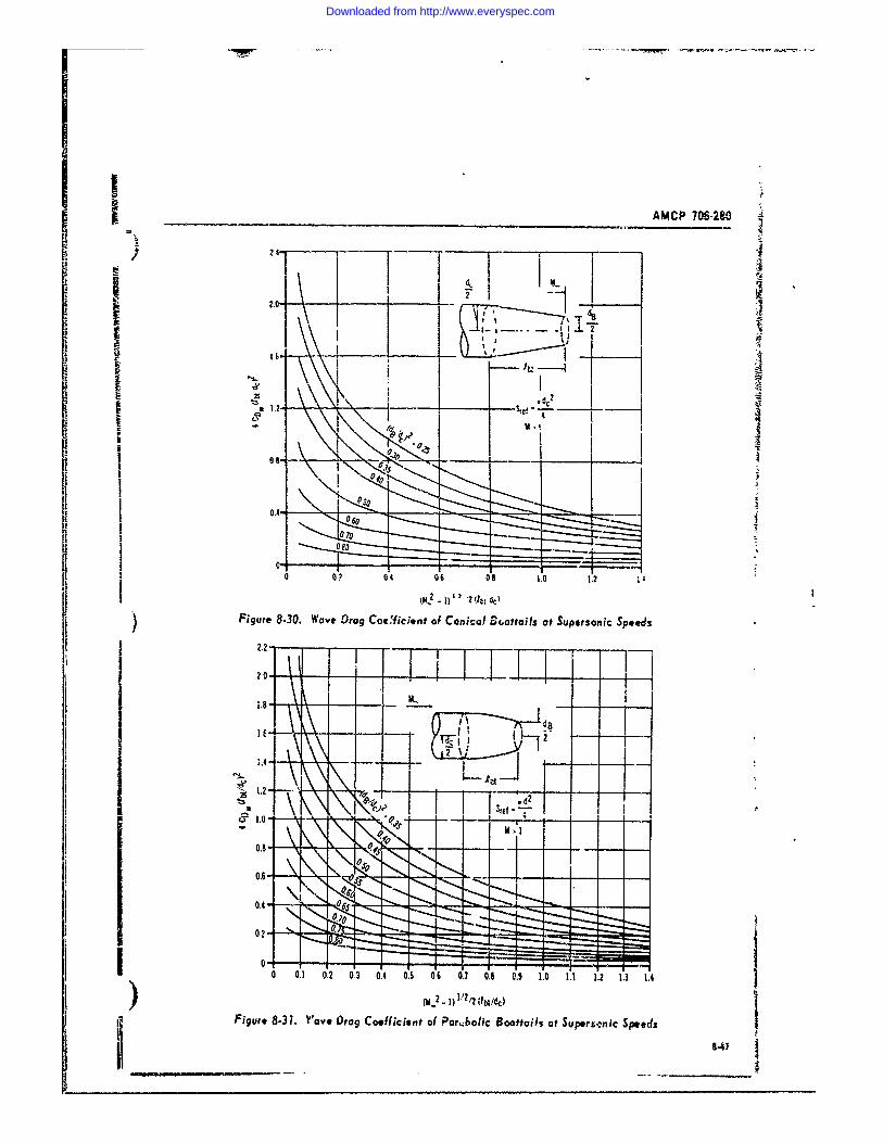
____ ___ _ _ ____ ___ ___ ___AMCP 706-280
I' ------------~24-
r~ ~2I 2
0 _ _ _ _ 08 112
E1
lU\I I - A
T T
II
IL
0 1 0 ' 0 04 0 6 AO s70 5 . 1.0 I' 21. 3 1 .
j(M -2. -1 V2 I ,'dLlb
) Figure 8.3. ove Drag Coefficient of on~ic Bottais at Supersonic Speeds
22'47
Downloaded from http://www.everyspec.com
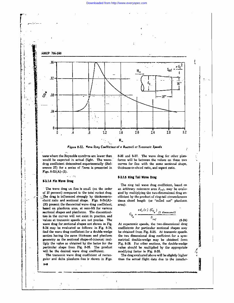
L
I I AMCP 706-280I --- 6----C- --
- 46k=" "F 6 F-A
5.08- ,L___18"
' 04-
0v
0 .4 .8 1.2 1.6 2.0 2.4 2.8 3.2
Figure 8.32. Wave Drag Coefficient of a Boattail ct Transonic Speeds
tests where the Reynolds nwumLrs are lower than 8-36 and 8-37. The wave drag for other plan-would be expected in actual flight. The wave-' forms will be between the values on these twodrag coefficient determined experimentally (Ref- curves for fins with the same sectional shape,erence 27) for a series of ., ares is presented in thickness-to-ch.rd ratio, and aspect ratio.Figs. 8-33 (A) -(I).
1 a.- - 8-3.1.5 Ring Tail Wave Drag10.1.4 Fin Wave Drag
J The ring tail wave drag coefficient, based onThe wave drag on fins is small (on the order an arbitrary reierence area Srej , may be evalu-
of 10 percent) compared to the total rocket drag. ated by multiplying the two-dimensional drag co-- .-_The drag is influenced strongly by thickness-to- efficient by the product of ring-tail circumference
chord ratio and sectional shape. Figs. 8-34 (A)- times chord length (or "rolled out" planform(H) present the theoretical wave drag coefficient, area):based on planform area, at zero-lift for various nd(c) (C )-sectional shapes and planforms. The discontinui- CD d ( (2 dinenstonal)ties in the curves will not exist in practice, and C V
. values at transonic speeds are not precise. The -ref (8-24)wave drag for sectional shapes not shown in Fig. At supersonic speeds, the two-dimensional drag8-34 may be evaluated as follows: in Fig. 8-34, coefficients for particular sectional shapes mayfind the wave drag coefficient for a double-wedge be obtained from Fig. 8-35. At transonic speeds.section having the same thickness and planform the two dimensional drag coefficient for a sym-geometry as the sectional shape-of-interest; mul- metrical double-wedge may be obtained fromtiply the value so obtained by the factor for the Fig. 8-38. For other sections, the double-wedge
* particular shape from Fig. 8-35. The product value should be multiplied by the appropriatewill be the desired wave drag uoefficient. modifying factor in Fig. 8-35.
The transonic wave drag cqefficient of rectan- The drag evaluated above will be slightly highergulnr and delta planform fins is shown in Figs. than the actual flight data due to the interfer-
, 8.48
Downloaded from http://www.everyspec.com
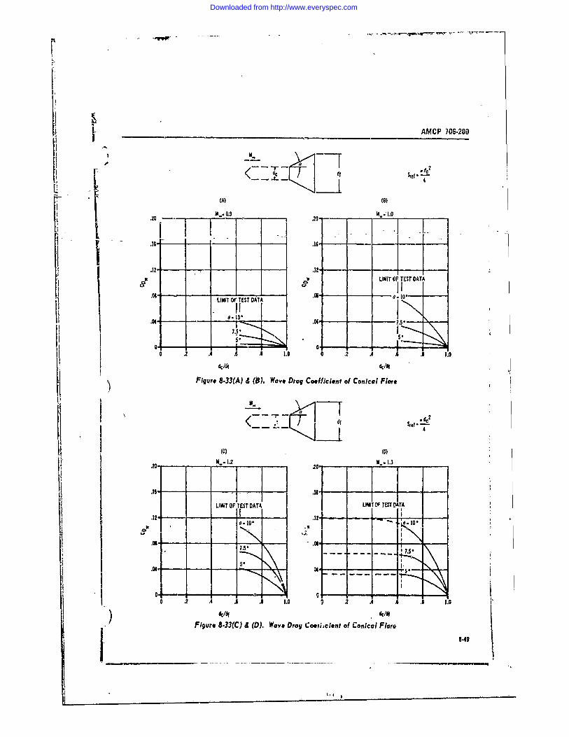
L- AMCP 706-200
(A) (6)--. ... M. oro-e.-I
.29 i. 9 .20- . 1...
.16 - .16- I -
.2 kLIMIT OF TEST DATA
LIMIT OF TEST DATA .iO.
-0 ON -I-.-50 2 .4 .6 .3 1.0 0 2 . . .3 1.0
dc/df de/di
Figure 8.33(A) & (B). Wave Drag Coefficient of Conical Flare
M.
4
(C)1.- 3.2 20o M.- 1.3
LIMIT OF TEST DATA UNT OF TEST TA.12- 7 .12- - 0
So
0 '-
0 .2 A .6 1.0 2 .4 .A . 1.0
1101, c/dfFigure 8-33(C) d (D). Wave Drag Coetjcient of Conical Flare
3.43
Downloaded from http://www.everyspec.com
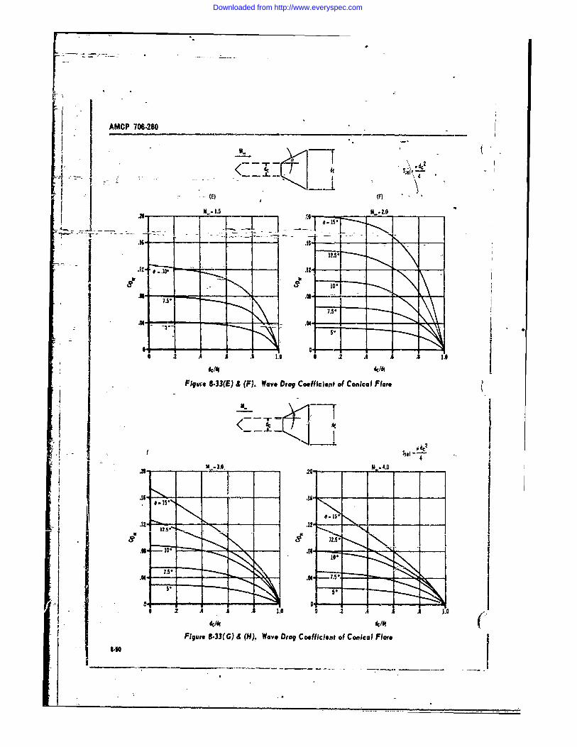
AMCP 706-280 ________
AA
T2 0 -- 0 .14---
T07 11A71771
Ic/i ic/diI Figure 8.33(E) & (F). Wave Drag Coefficient of Conical Flare
.1M.
I.1
dc/dl ic/dIFigure 8-33(G) 4 (H), Wave Drag Coefficient of Conical Flare
Downloaded from http://www.everyspec.com
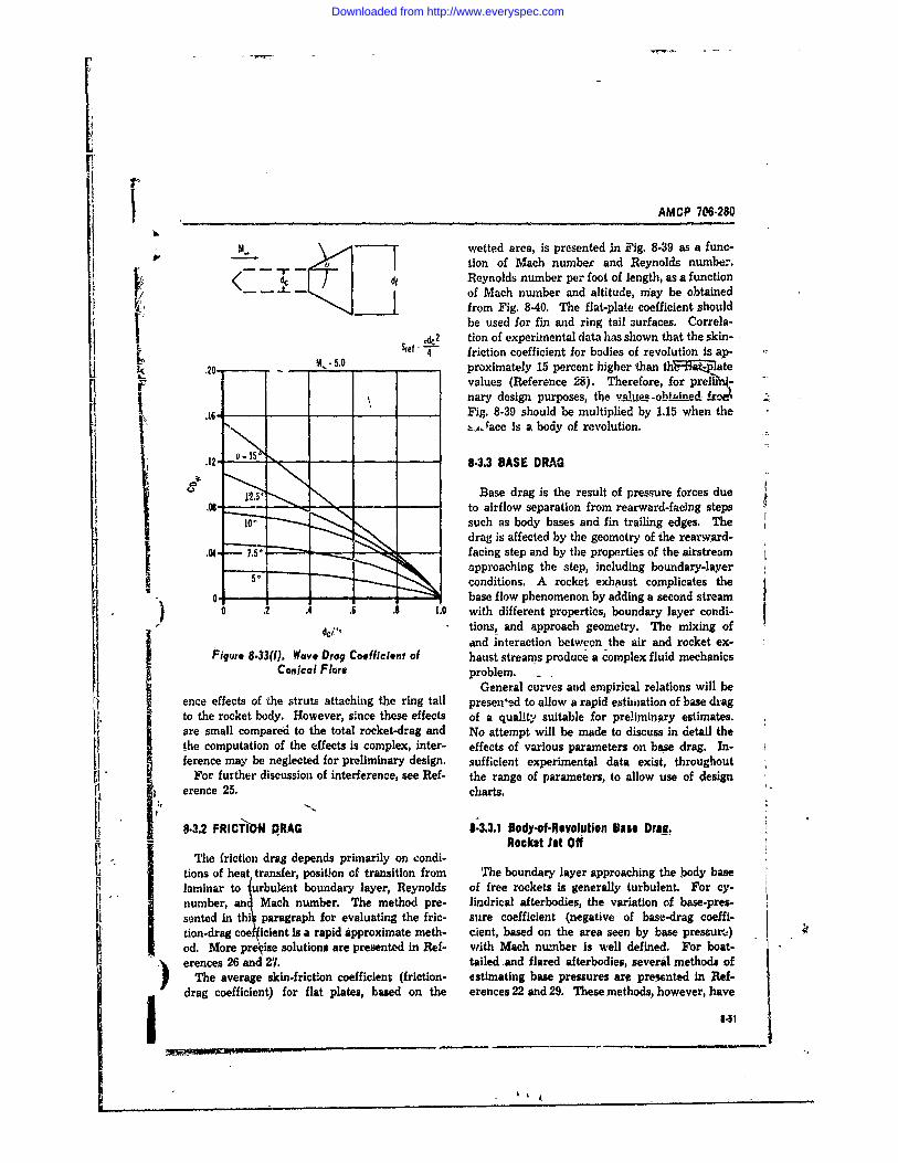
FAMCP 706-280
wetted area, is presented in Fig. 8-39 as a func-' tion of Mach number and Reynolds number.
Reynolds number per foot of length, as a function..L - of Mach number and altitude, may be obtained
... Jfrom Fig. 8-40. The flat-plate coefficient Bhouldbe used for fin and ring tail surfaces. Correla-
Sfef -e2 tion of experimental data has shown that the skin-
L S- -,0 4 friction coefficient for bodies of revolution is ap-.20 proximately 15 percent higher than hte
values (Reference 28). Therefore, for preli-L ~ ~~~nary design purposes, the va.l-l~ises -
.16- Fig. 8-39 should be multiplied by 1.15 when theVi ,, race is a body of revolution.
.12- 8-3.3 BASE DRAG
Base drag is the result of pressure forces due"' to airflow separation from rearward-facing steps
such as body bases and fin trailing edges. Thedrag is affected by the geometry of the rearward-
.04 7.-- - facing step and by the properties of the airstreamapproaching the step, including boundary-layerconditions. A rocket exhikust complicates the
0 t. base flow phenomenon by adding a second stream0 . .4 .6 .8 1.0 with different properties boundary layer condi-
dc/,", tions, and approach geometry. The mixing ofand interaction between the air and rocket ex-
Figure 8-33(l). Wove Drag Coefficient of haust streams produce a complex fluid mechanicsConical Flare problem. .
General curves and empirical relations will beence effects of the struts attaching the ring tail presen'ed to allow a rapid estimation of base dragto the rocket body. However, since these effects of a quality suitable for preliminary estimates.are small compared to the total rocket-drag and No attempt will be made to discuss in detail thethe computation of the effects is complex, inter- effects of various parameters on base drag. In-ference may be neglected for preliminary design. sufficient experimental data exist, throughoutFor further discussion of interference, see Ref- the range of parameters, to allow use of design
erence 25. charts.
8-3.2 FRICTION DRAG 8-3.3.1 Body-of-Revolution Base Drag.- Rockst Jet Off-
The friction drag depends primarily on condi-tions of heat transfer, position of transition from The boundary layer approaching the body baslaminar to urbulent boundary layer, Reynolds of free rockets is generally turbulent. For cy-number, an4 Mach number. The method pre- lindrical afterbodies, the variation of base-pressented in thil paragraph for evaluating the fric- slire coefficient (negative of base-drag coeffi-
tion-drag coelicient is a rapid approximate meth- cient, based on the area seen by base pressurm)od. More preoise solutions are presented in Ref- with Mach number is well defined. For boat-
.' erences 26 and 27. tailed .and flared afterbodies, several methods ofThe average skin-frictlon coefficient (friction- estimating base pressures are presented in Ref-
drag coefficient) for flat plates, based on the erences 22 and 29. These methods, however, have1.51l
.-ew--.------------. ,- --,
Downloaded from http://www.everyspec.com
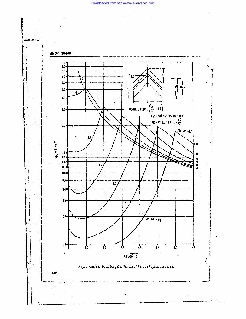
AMCP 705-210
10.019.07.0 " A --I7.i.0 1/2,,
. DOUBLE WEDGE( .0.0 )
Stef -FIN PLANFORM AREA
AR - ASPECT RATIO - - tAR TANA 1/2
0.9086.0
0.7 .4.0 . 6 3 .0 _2 . o
- 0.3 't -IIt
0.2c AR TAN ^112
6*0 1.0 2.0 3.0 4.0 5.0 6.07.
AR/W (Figure 8.34(A. Wav. DD'o Coefficient of Fin s ot Syperonic Sp. da
,000o )000
6 3 , * I n [ = i l
Downloaded from http://www.everyspec.com
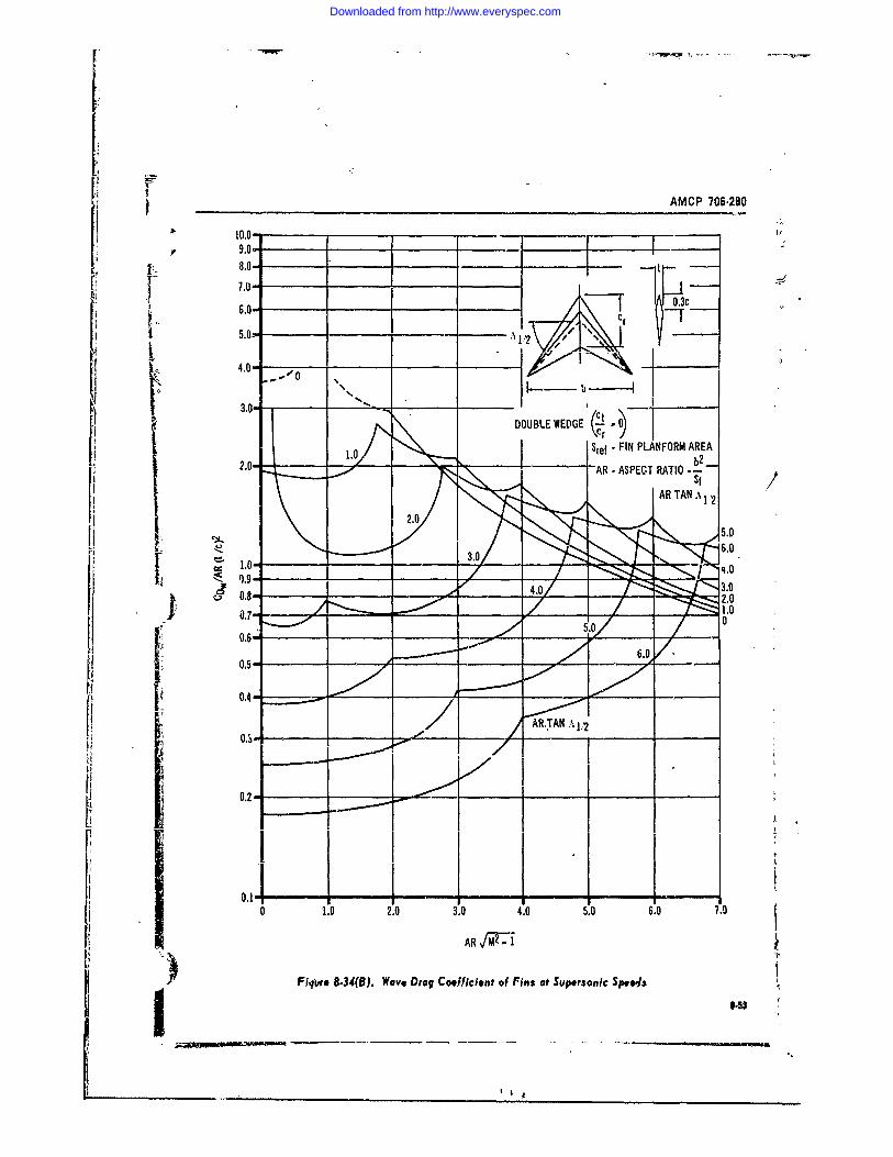
[pwri AMCP 706-280
10.0- -I__ _ _
6.0-
6.0- -r -7~
5.0- A _____
4.0-
304. .060 .
ARRTAN.
5
Downloaded from http://www.everyspec.com
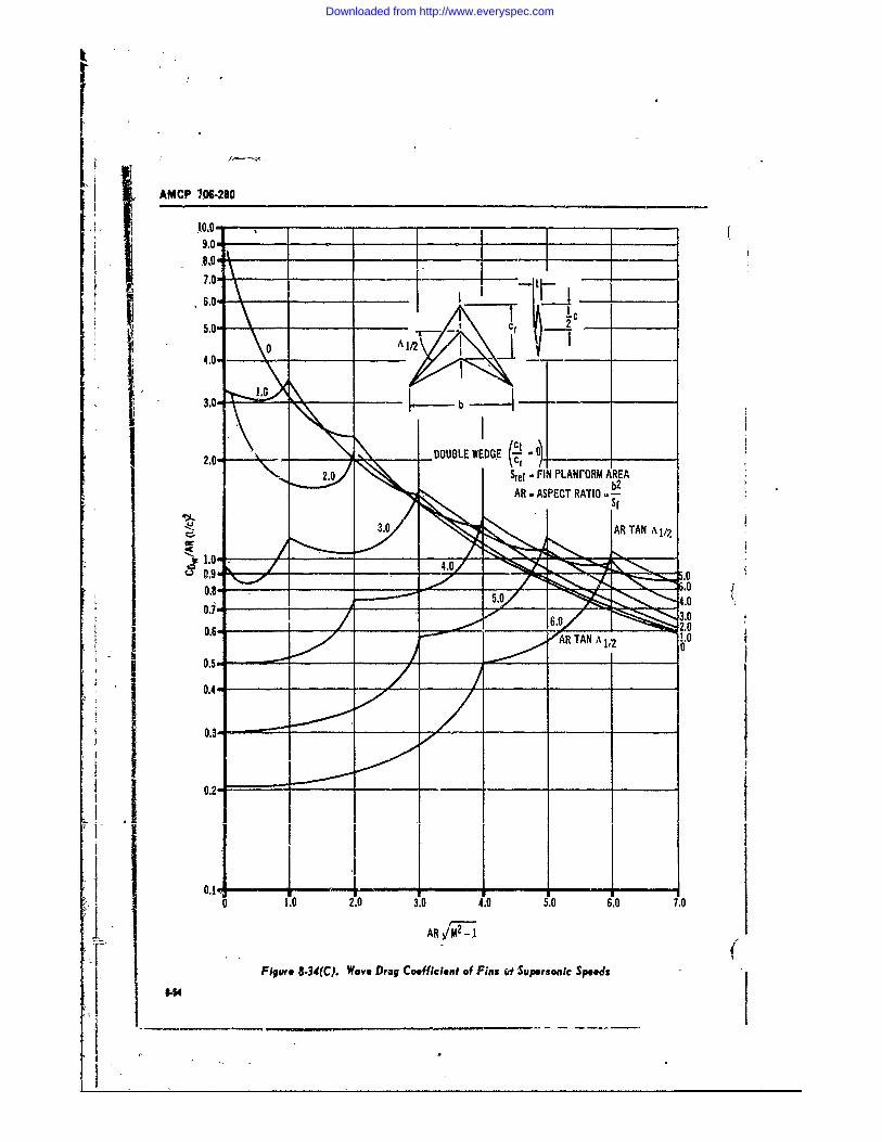
A P7,06-280
V 109.0r
j 107.0m-
4.0-' \
3.0-'
Ic2O el -FIN LAVAM A .REA
3. LA TRA A N A 0/
I09 4.0_ _ _ -y 6
.14.0
Downloaded from http://www.everyspec.com
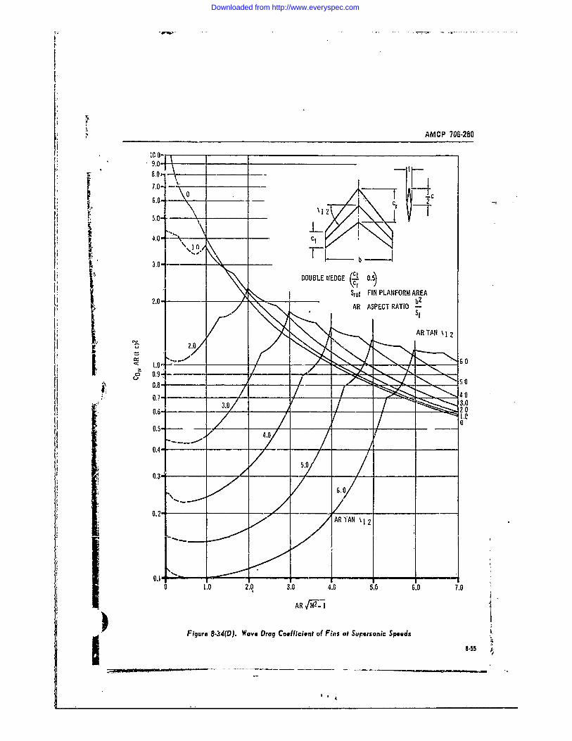
AI4CP 706-280
it II IL-. 4-
40- - C1
I b -3O~DOUBLE WIEDGE C~ 0.5)
2.0- 1Stcf FIN PLANFORM AREA
2.0 2.b2_
4,/.
0.30
0.2
0.7 - 1. 2.3. . . . .0
0.4-
Downloaded from http://www.everyspec.com
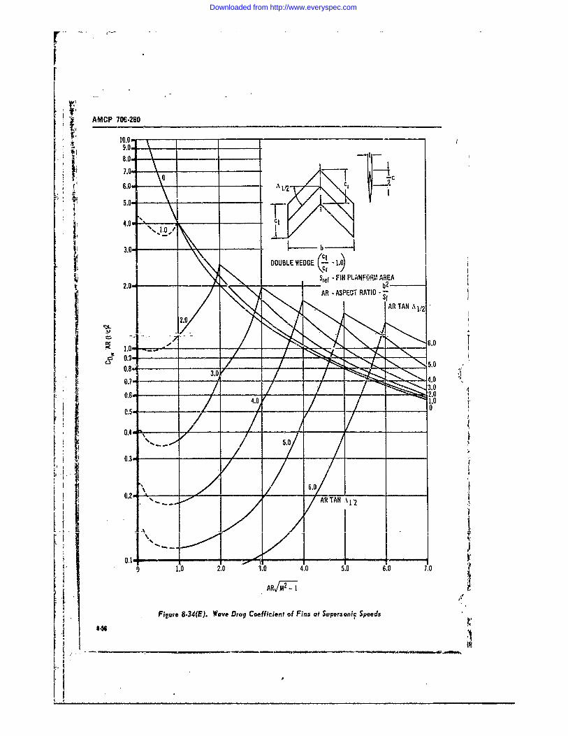
AMCP 7O6.28O
8.0
7.0.- c
CtC
530
[ !2.0 b2 _
2.0.
6'.0
9 1. 2.03,0 .0 5056.
4,
3.
0.6 4igr 2-4E.Wv.rgC0fiin fFn a uesncSed
Oj 1'A0
Downloaded from http://www.everyspec.com
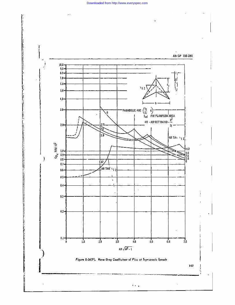
I Afv,'CP 706-280
10.0--9.0-
I 8.0-7.0--_ _ _ -
6.0 / -
3.0- 0ARABOLIC ARC( )
2.I -0 l
2.03.-
C4.6
Q 0.8-2
0.7-- 4.67/___ ______
0.6- ARTA 12
* ~0.5" u-
J 0. 4
-_4
-
-
j 0.34
1 0.2
a 1.0 2.0 3.0 4.0 5.0 6.0 7.0
AR AR Tj Figure 8-34(F). Wave Drag Coufficient of Fin:, ct Sunv-rsonic Speeds
1 8.57
Lit
Downloaded from http://www.everyspec.com
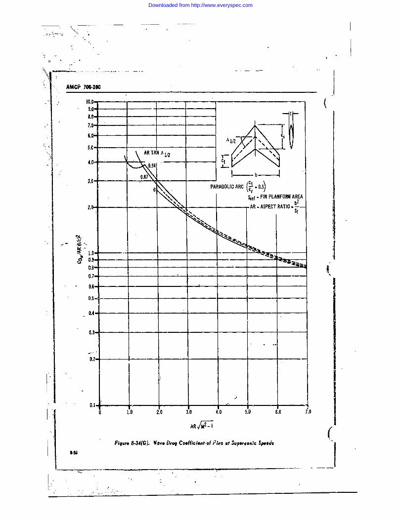
AMCP 706-280
10.0-_ _ _ _ _ _ _ _
9.0-8.0-
7.0.-
AR TAN A I
4.0 ~ 0.91 C
3.0- 0.670.5b
- Sref - FIN PLANFORM AREA II2-0-A - ____
'C A -
0.5- _ _ _ _
0.4-
0.3- ______
01 0.2--
0.1--- , -
o 1.0 2.0 3.0 4.0 5.0 6.0 7.0
ARVT (MFigure 8.34(G). Wave brag Coefficient of Fins at Supersonic Speedsf
Downloaded from http://www.everyspec.com
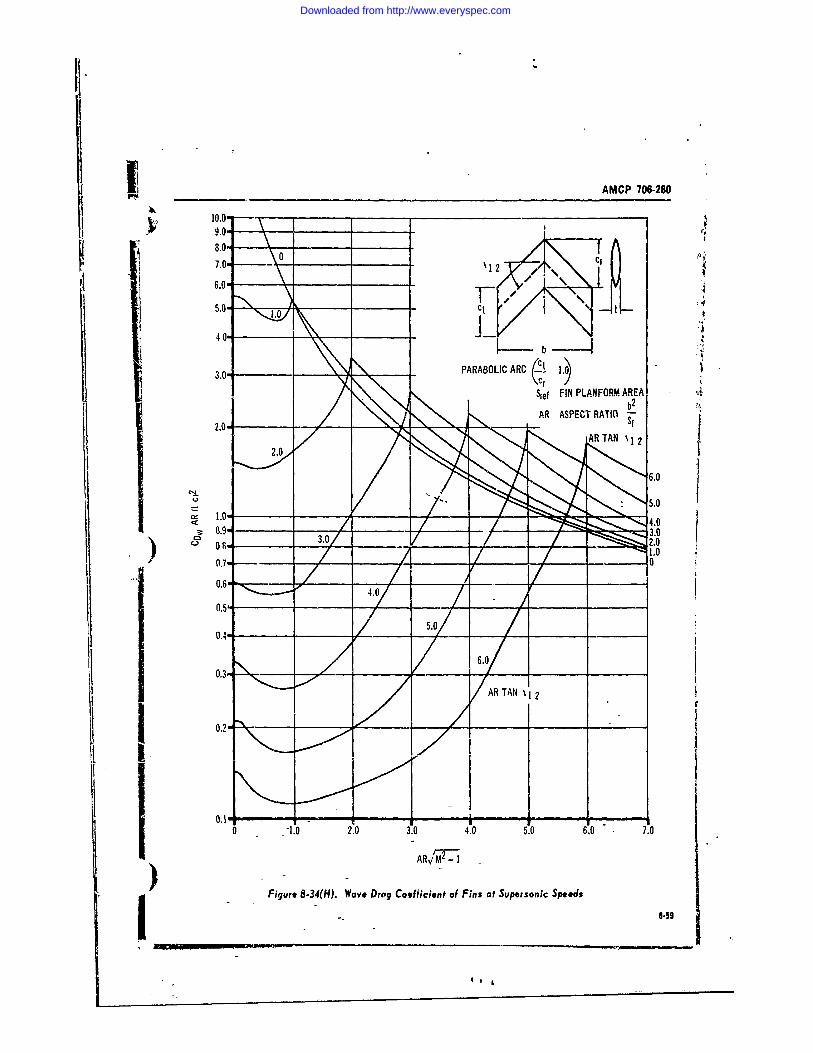
Ii AMCP 706-28010.0-
8.0'7.0" _ __ '12 C
15.0- c- . .1 -4
3.0'_____ PARABOLIC ARC
Sief FIN PLANFORM AREA
C'5.0
0C1.m2 3.0/ 4.3. . .0) A2.0I -igue 8.4(H. Wve Dog oeficiet o Fin atSuprsonc S1ed
Ij 0
Downloaded from http://www.everyspec.com
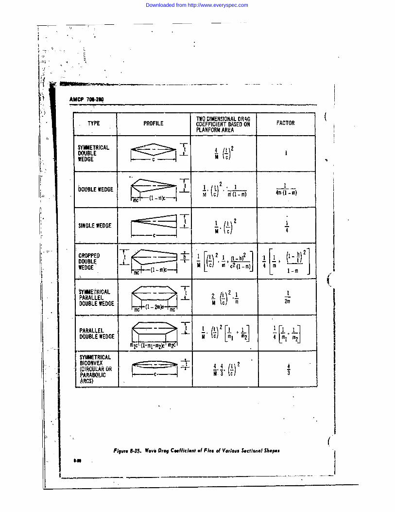
0
r
C" ,
AMCP 706-2 0
TWO DIMENSIONAL DRAG F
TYPE PROFILE COEFFICIENT BASED ON FACTORPLANFORM AREA
DOUBLE tE?~I3~I t 4WEDGE C t)V1
bOBEWDE I-i( - mcM ni (1 -m) 4m (! -m)
SINGLE WEDGE _ - 2 --
Mcc
C1 2
PARALLEL ..... __)ii2DOUBLE WEDGE 1 -c2m 1.M 4't 2 j
SINGLE WEDGE f 1 !-" -C " "m 2
j SYMMETRICAL nC(--i2mcBICONVEX ,----- -- ~ 4 'iI' (ciRCUJLAR OR ,.1 c5. 44 'PARABQLIC , -c -------. ' Ic 3"I'ARCS)_
(Figure 8.35. Wav.e Drag Coefficient of Fins of Various Sectional $hapes
D_____ - -
Downloaded from http://www.everyspec.com
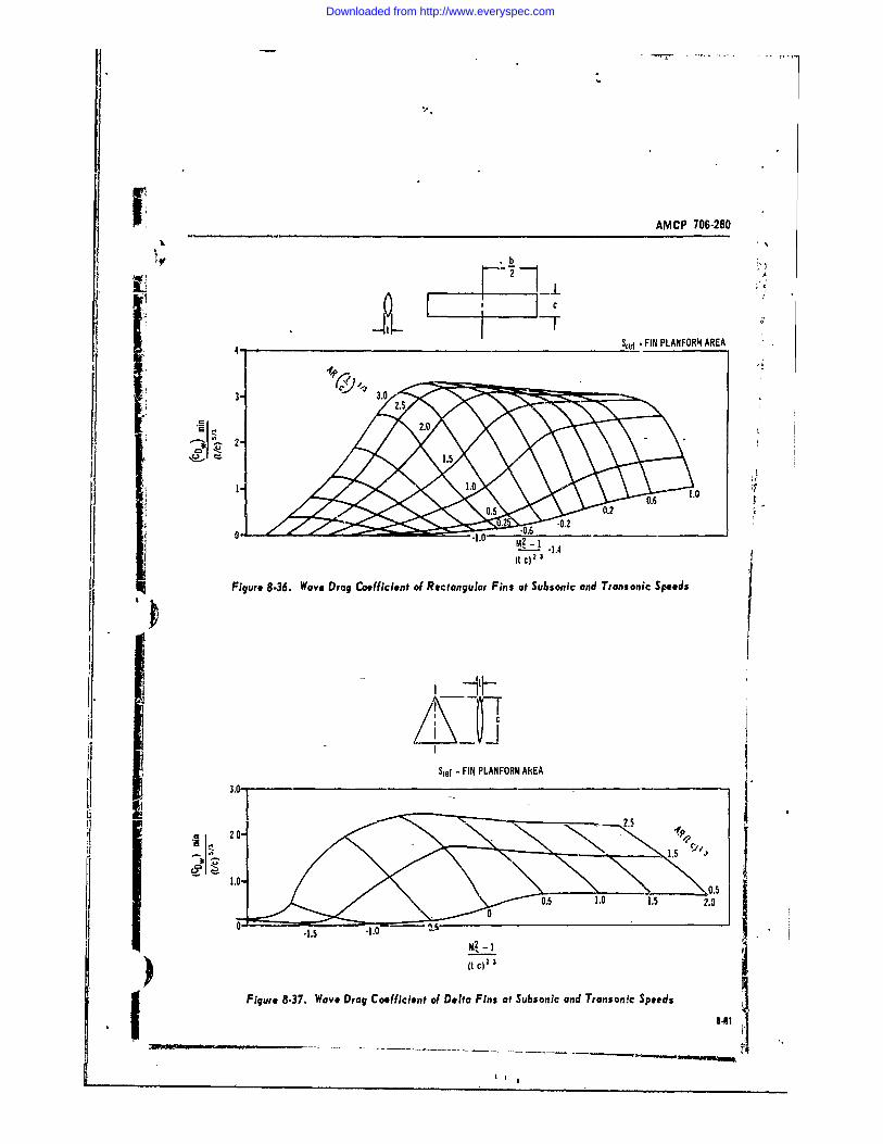
i. AMCP 706-280
CC
22.5
2.
'e, 1.4
Sif.. - I0PLN.R2AE
01 ~ ~-1 -.)I ()C2 3
Figure 8.3. Wave Drag Coefficient of etaua Fins at Subsonic and Trans onic SpeedsI
C
Downloaded from http://www.everyspec.com
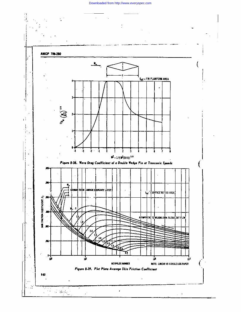
T_ I
AMCP 706-280
00
M2. - FIN PLANFOM AREA
0a -
- 2 W TSIN L NAR U~ LAYEIP
(' AR......
.3u0
REYP'OLOS NUMBER NOTE: LINEAR VS 4 CYCLE LOG PAPER
Figure 8.39. Flat Plate Average Skin Friction Coefficient
Downloaded from http://www.everyspec.com
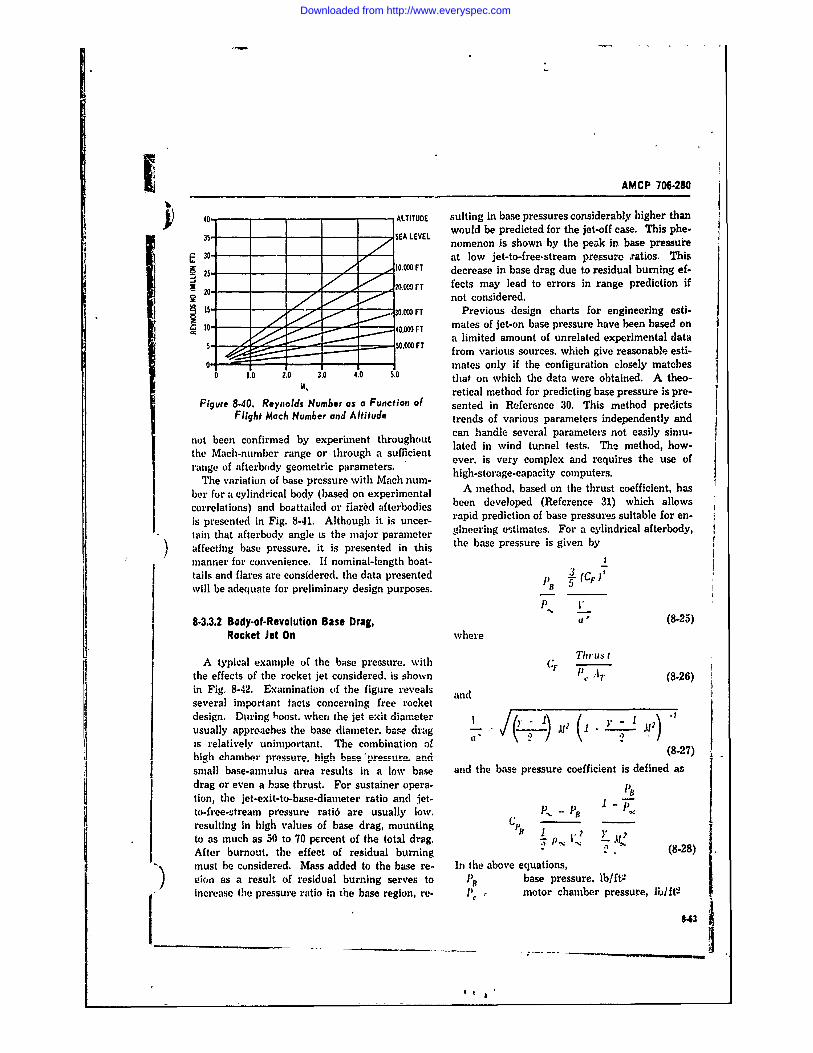
AMCP 706-280
40- ALTITUDE suiting in base pressures considerably higher than35, - - -EA LEVEL would be predicted for the jet-off case. This phe-
,, SA nomenon is shown by the peak in base pressureE 30- - - at low jet-to-free.stream pressu-re ,ratios. This
25- 10.000 FT decrease in base drag due to residual burning ef-X___ 20 000 FT fects may lead to errors in range prediction if
________ not considered.15 00 FT Previous design charts for engineering esti-
to / 40.000 FT mates of jet-on base pressure have been based ona limited amount of unrelated experimental data
. - 50.00-0 FT from various sources, which give reasonable esti-mates only if the configuration closely matchesS1.0 2.0 3.0 4.0 5.0 that on which the data were obtained. A theo-
A " retical method for predicting base pressure is pre-
Figure 8.40. Reynolds Number as a Function of sented in Reference 30. This method predictsFlight Mach Number and Altitude trends of various parameters independently and
not been confirmed by experiment throughout can handle several parameters not easily simu-
the Mach-number range or through a sufficient lated in wind tunnel tests. The method, how-
range of afterbody geometric parameters. ever. is very complex and requires the use ofrang of ftebodygeoetri paametrshigh-storage-capacity computers.The variation of base pressure with Mach num- highoaepacity c pe
ber for a cylindrical body (based on experimental A method, based on the thrust coefficient, hascorrelations) and boattailed or ilared afterbodies been developed (Reference 31) which allowsicorelatisean d nF ig. 8-41. Although it er-s rapid prediction of base pressures suitable for en-is presented in Fig. 8-41. Although it is uncer-
tain that afterbody angle is the major parameter gineering estimates. For a cylindrical afterbody,
affecting base pressure. it is presented in this the base pressure is given by
manner for convenience. If nominal-length boat-tails and flares are considered. the data presented 3 (CF)"will be adequate for preliminary design purposes. BT
P . -'_
8-3.3.2 Body-of-Revolution Base Drag, u(' (8-25)Rocket Jet On where
A typical example of the base pressure, with (.4 I 1the effects of the rocket jet considered. is shown (8-26)
in Fig. 8-42. Examination f the figure reveals andseveral important tacts concerning free rocketdesign. During toost. when the jet exit diameter /[ 1\ ( [ - 1 .1usually approaches the base diameter. base drag )- .----- 1, - 2 ,I1)is relatively unimportant. The combination of (8'27)high ehamber pressure- high base (8-27)small base-annulus area results in a low base and the base pressure coefficient is defined asdrag or even a base thrust. For sustainer opera-
tion, the jet-exit-to-base-diameter ratio and jet- 1 -to-free-stream p'essure rati6 are usually low. P, - t -
resulting in high values of base drag, mounting f 1: - -to as much as 50 to 70 percent of the total drag.. p. 7 (8--8After burnout, the effect of residual burning . (8-28)must be considered. Mass added to the base re- In the above equations,) gion as a result of residual burning serves to t)B base pressure, lb/ftVincrease the pressure ratio in the base region, re- P e motor chamber pressure, lb/ft-
-____ ___ - - - 43
L It~
Downloaded from http://www.everyspec.com
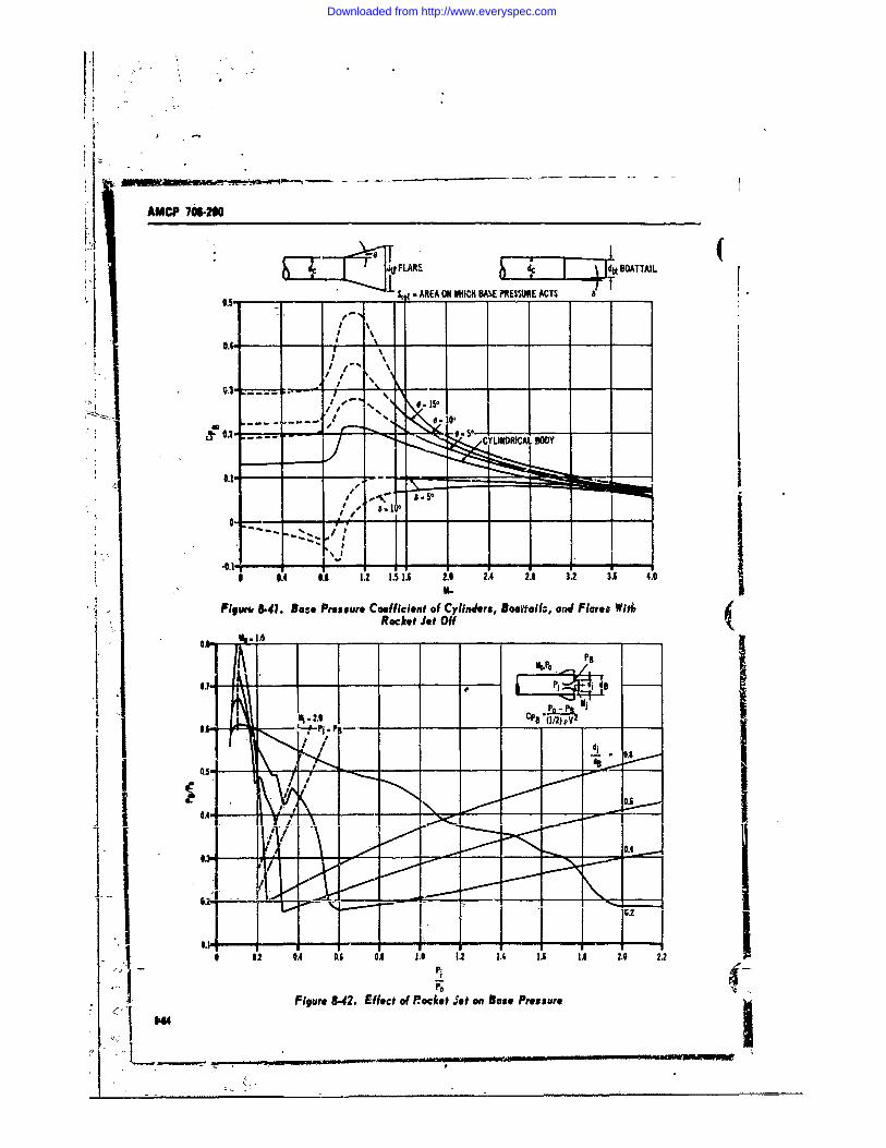
AMCP 7*S2-
FL~F ARE 4 dtBOATTAIL
05 - S * ." AREA ON WHICH BAX PRES URE ACTS
0.I I
, II ,"% ' \~~
0.3
/0' CYINRIALMI j I
6 0.4 0.5 1.2 1.5 1.6 2.0 2.4 2.8 3.2 3.1 4.0
Figw* 8.41. Be-e Pressure Coefficient of Cylinders, Bowall, end Flares WithRocket Jet OffI~~~~p -00 _______ 5____11.
d0 .
i .2 0.4 0.6 0.- 1o. 0o - - - -12 1.A 2.0 1.2
Figure 8-42. Effect of R~ocket S et on Base Pressure14
Downloaded from http://www.everyspec.com
-AMCP 706-280
P = free stream prersure. Ib/ft- 8-3.3.3 Fin Base DragV Q velocity, fpsi free stream velocity, fps The boundary layer approaching the base ofac* sonic velocity, fps fins and other stabilizing urfaces is generallyCF thrust coefficient turbulent. The effects of profile shape on theAT jet throat area, ft! base-pressure coefficient at supersonic speedsCp8 base pressure coefficient with a turbulent boundary layer is small. Fig.Poo atmospheric density. slug ftV 8-45 provides a good estimate of fin base-pressurey ratio of specific heats coefficient at supersonic speeds. At transonic andNt Mach number subsonic speeds, the ratio of trailing edge thick-For bodies with flared or boattailed afterbodies, ness to chord length is significant, and Fig. 8-46
PB,' P. is corrected by use of Fig. 8-43. The should be used as a guide for estimating the basestated correlation agrees well with most of the pressures.available experimental data. It is applicable atjet-to-free-stream pressure ratios above the value 8-3.4 DRAG CHARACTERISTICS OF COMPLETEwhere base pressure is minimum (represented by CONIIGURATIONSthe nearly linear portion of the curves in Fig.8-42). 8-3.4.1 Interterence Effects-Fin on Base
To give an indication of the characteristics ofb;.se pressure through a more complete Mach The presence of fins on rockets affects the ex-number and jet-pressure range, Fig. 844 has been ternal flow characteristics and usually results inprepared. This figure represents a cylindrical increased base drag. The most important pa-body and a nozzle having a jet Mach numaber of raineters appear to be fin thickness, fin longitu-about 3.0. The solid curves represent either ex- dinal position. number of fins. and free-stream) perimental data or. the correlation curve. The Mach number. Experimental data on the ef-dashed curves are extrapolated values. fects of fEns are sparse if all important parameters
B (FLARE OR BOATTAIL) B (CYLINDER . Y
2.=P, P, rBbt.!2.4
1.2-
0 .. 1.0 1.2 1.4 1.6 1.8 2.0 2.2 2,
SB 'ScylFigure .43. Base Pressure Correction for Boattalied and Flared Afterbodi~s
Downloaded from http://www.everyspec.com
A CP 7M-2N -
"N 4 .(
1.4- -
1 2I
IzI
. 1 .rZ i
0.2.0
0.0
CFFigure 8-44. Base Pressure on Cylindrical Bodies
i~~~----~ - --- ae cons~.ered. It is suggested that the empiricaij relation developed in Reference 29 be used in es--timating fin effects on base dag:
FI BAEAE
where
I ; ____ I 1,~RAfi ! (.85~ . 5
.. ~ .~CPB t- thickness-to-chord ratio of fins andn number of fins
_a Teis relation is limited to the case where thefinatrailing edge is flush with the base. Predictedvalues using this relation appear to be high atMach numbers below -about 2; with reascnn)Ie-agreement for Mach numbers greater than 2.
8-3.4.2 Computational Table
The drag characteristics of the complete con-,, -- figuration are computed by summing the indi-
vidual component drag coefficients, based- on acommon reference area. Table 8-2, Drag Force
Figue 8-45. Base Pressure Coefficient of Calculation Sheets, which follow, indicate the, FI~ Fins at Superson;e Speeds method' of obtaining the drag coefficients of the
--
Downloaded from http://www.everyspec.com
AMCP 706-280
I )M h
C
II* -0- ref , FIN BASE AREAh1
h.0.104 ","
-0.8
0.025-0.6
C.,
-0.4-_ _ _ _ _ _ _ _ _
- WITHOUT ROUGHNESS BAND-- WITH ROUGHNESS BAND -
0.012
0.2 0.4 0.6 0.8 1.0 1.2 1.4
Figure 8-46. Bus* Pressure Coefficient of Fins at Transonic Speeds
individual components and of the complete con- ticle; and is expensive because the test article isfiguration based on the configuration presented usually expended. Wind tunnel testing, how-in Fig. 3-25. if ever, allows precise control of the parameters in-
fluencing flight characteristics. A wide scope of8-4 AERODYNAMIC TESTING the problems associated with placing a rocket in
a selected trajectory-such as stability, drag, andThe aerodynamic performance of rockets may propulsion system iafluence-may be investigated
be evaluated by theoretical estimates, flight test- in a complete wind tunnel program.ing, or wind tunnel testing. Theoretical estimates, An indication of the wind tunnels available indue to lack of xefinement, often fail to provide the United States is given in References 32 andadequate quantitative aerodynamic data. Flight 36. While this list is not current and thereforetesting provides a slow rate of data collection; incomplete, the uniqu.-ness of the available tun-does not allow adequate control of the test ar- nels dictates the necessity for matching particular
347
S4
Downloaded from http://www.everyspec.com
AMCP 766280
tunnel characteristics to the particular test re- produc,.d by reentry trajectories. Flight environ- (quirements. Tunnel operating capabilities and ment temperatures are not significant on theaize are foremost among the considerations iii se- ciasses of rocket considered in this handbook.lecting a test facility. However, consideration of The investigation of the influence of a propul-availability, accessory equipment, and cost of test sion system on the aerodynamic characteristics oftime cannot be ignored. a rocket requires a facility with the capability of
Wind tunnels are normally classified according propulsion testing or propulsion jet simulation.to their operating speed range as follows: Operation of a propulsion system in a tunnel re-
quires a means for removing the combustionTunne I Class if icat ion Mfach Number Range products from the tunnel airstream, and createsSUbSOAC Less than 0.7 fire and e:plosion hazards. Propulsion jet simu-
lation is much simpler. Jets of compressed gasesTransonic 0. 7 !o 1.2 such as air or nitrogen will closely simulate ex-
haust flow patterns. The hazards connected withSupersonic 1.2 to 5.0 this technique are only those normal to high pres-
lypersonic Greater than 5._0 sure storige and transmission. Jet exhaust con-ditions may be more closely simulated by the de-
Due to inherent problems associated with oper- composition of hydrogen peroxide. but personnelating at different speed (or Mach number) ranges, hazards require special storage and handlingwind tunmel facilities usually elect to operate only procedures.within the range of their classifica6on Mach num- It is desirable to test the full-size rocket in 4bers. Since a large portion of the rockets con- oider to have the maximum degree of confidencesidered in this handbook operate ovter a wide in the data. Generally, however, this is not prac- 4xang2 of the Mach number spectrum, complete tical, and a scaled-down test model must be fab-testing will require more than one facility. The ricated. Model-size decisions must be based onupper limit for supersonic tunnels, N - 5.0, has (1) characteristics to be investigated, .2) instru-been set from considew.cisns of operating pro- mentation located in the model interior, (3) modelcedures and not abrupt changes in flight char- support capabilities, and (4) size of available testacteristics. When air is expanded to a Mach num- facilities.ber of approximately five and above, the atten- The model scale must be large enough so thatdant large change in the temperature resulis in the component parts which are normally exposedliquefaction of the air. To prevent this, heaters to free stream flow on the full-size article willof large capacity, or a medium other than air, not be submerged in the boundary layer of theimay be used t0 maintain temperatures above the test model. It is desirable that the selected scaleliquefaction point. provide a boundary layer of the same character
The Reynolds-number capability of a wind that will exist on the full-size article. To main-tunnel is ai important consideration. Matching tain a desirable scale and duplicate boundary-the full-size-rocket Mach number and Reynolds l&yer conditions, the boundary layer often mustnumber on the scale model insures that flow pat- be controlled by artificial means. There are prac-terns are similar and that the measgired forces tical l1mits to the duplication of small details ofand moments may be scaled up to the full-size the full-size rocket. Daplicated details such as
number and altitude is presented in Fig. 8-40. heads, and small gaps in the scale model usuallyThe flow litterns become fully established at a -'.rve only to increase the fabrication cost, andReynolds number of approximately two million, affect the data to such a small extent that meas-and therefore the requirement for matching uring accuracies do not reveal their pr!sence.Repnolds nwamber above this value n,.ay be ie- The tolerances used in manufacturing the full--Ji~d, size rocket should be considered in development7he capability for matching flight environment of the test nmdel. The data prese'nted in Fig. 8-47 ,temperature In a wind tunnel is only important show a comparison of the test results oe.tained
in the study of high velocities, such as may be from a full-size ,nodel and Am eight-percent scale
14l
-l [ 1 [ i l i i 1 i I i i i i i ! i i l
Downloaded from http://www.everyspec.com
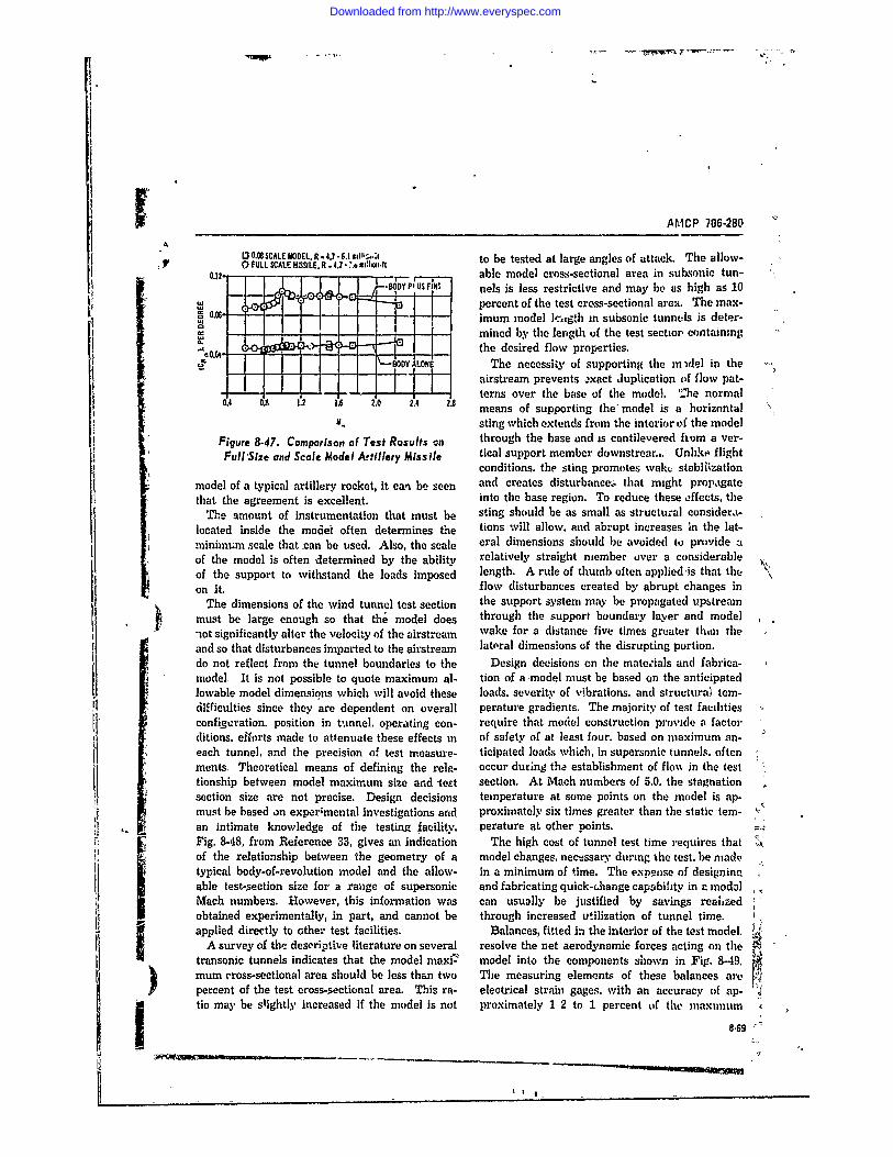
AfMCP 706-280 "'
O0.ULCALEMO0EL. R 4.-6..,Ili.,.;1 to be tested at large angles of attack. The allow-0.12, r- -, able model cross-sectional area in subsonic tun-006 'i: 4 "=" -"BODY P1 US5 FIN"S nels is less restrictive and may be as high as 10
*Wa percent of the test cross-sectional area. The max-imum model lczgth in subsonic tunnels is deter-mined by the length of the test sectior, containing
.the desired flow properties.----BODY ALONE The necessity of supporting the midel in the ,,
- --airstream prevents *!xact duplication of flow pat-terns over the base of the model. 'he normal
0.4 08 1.2 16 2.0 2.4 2.8 means of supporting the' model is a horizontal "M. sting which extends from the interior of the model
Figure 8-47. Comparison of Test Rosults an through the base and is cantilevered fiom a ver-Full'Size and Scale Model Artillery Missile tical support member downstrear.,. Unhke flight
conditions. the sting promotes waku stabiiizationmodel of a typical artillery rocket, it can be seen and creates disturbance.s that might propagatethat the agreement is excellent into the base region. To reduce these effects, the
The amount of instrumentation that must be sting should be as small as structural considera-located inside the model often determines the tions will allow, and abrupt increases in the lat-minimum scale that can be used. Also, the scale eral dimensions should be avoided to provide aof the model is often determined by the ability relatively straight member over a considerableof the support to withstand the loads imposed length. A rule of thumb often applied ,is that theon it. flow disturbances created by abrupt changes in
The dimensions of the wind tunnel test section the support system may be propagated upstreammust be large enough so that the model does through the support boundary layer and model-ot significantly alter the velocity of the airstream wake for a distance five times greater than theand so that disturbances imparted to the airstream lateral dimensions of the disrupting portion.do not reflect from "the tunnel boundaries to the Design decisions on the materials and fabrica-model. It is not possible to quote maximum al- tion of a model must be based on the anticipatedlowable model dimensions which will avoid these loads. severity of vibrations. and structuraJ tem-difficulties since they are dependent on overall perature gradients. The majority of test facilitiesconfigaration. position in ttmnnel. operating con- require that model construction provide a factorditions. efforts made to attenuate these effects in of safety of at least four. based on maximum an-each tunnel, and the precision of test measure- ticipated loads which, in supersonic tunnels. oftenments. Theoretical means of defining the rela- occur during the establishment of flo%% in the testtionship between model maximum size and test section. At Mach numbers of 5.0. the stagnationsection size are not precise. Design decisions temperature at some points on the model is ap-must be based on experimental investigations and proximately six times greater than the static'tem-an intimate knowledge of tihe testing facility. perature at other points.Fig. 8-48, from Reference 33, gives an indication The high cost of tunnel test time requires that ,of the relationship between the geometry of a model changes. necessary during the test. be madt,typical body-of-revolution model and the allow- in a minimum of time. The expense of designinpable test-section size for a range of supersonic and fabricating quick-Lhange capability in a modalMach numbers. However, this information was can usually be justified by savings reahzedobtained experimentally, in part, and cannot be through increased utilization of tunnel time.applied directly to other test facilities. Balances, fitted in the interior of the test model. ?
A survey of the descriptive literature on several resolve the net aerodynamic forces acting on thetransonic tunnels indicates that the model maxi - model into the components shown in Fig. 8-49.mum cross-sectional area should be less than two The measuring elements of these balances arepercent of the test cross-sectional area. This ra- electrical strain gages, with an accuracy of ap-tio may be slightly increased if the model is not proximately 1 2 to 1 percent of the maximum
8.69
I,
Downloaded from http://www.everyspec.com
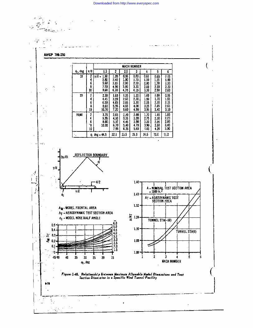
AMCP 706-230L
MACH NUMBER (.,, deg x!d 1.5 2 2.5 3 4 5 6
!0 2 y/d 1.90 1.20 0.95 0.80 0.65 0.60 554 3.80 2.40 1.90 1.70 1.30 1.15 1.006 5.60 3.65 2.80 2.50 2.00 1.70 1.508 7.50 4.90 3.80 3.30 2.60 2.30 2.13
101 9.60 6.10 4.70 4.15 3.30 2.90 2.6320 2 2.30 1.60 1.35 1.20 1.00 1.00 0.95
4 4.45 3.20 2.60 2.30 1.90 1.70 1.556 6.50 4.65 3.65 3.10 2.55 2.30 2.158 8.60 5.95 4.65 4.00 3.25 2.85 2.65
10 10.70 71.20 5.60 4.90 3.95 3.40 3.10HEMI 2 3.75 2.65 2.20 2.00 1.70 1.65 1.60I
4 5.95 4.10 3.35 3.00. 2.75 2.30 2.236 8.00 5.37 4.45 3.90 3.20 2.95 2.80-8 10.05 6.70 5.40 4.70 3.90 3.60 3.40
1 10 7.95 6.35 5.60 1 .65 4.20 3.90_.- _ e deg 44.5 32.5 2.5 21,5 16.0 3 111.0
REFLECTION BOUNDARY
Y/(
d/2 1.48 7777A . NOMINA. TEST SECTION AREA
x/d . 1600 in. _ _
AT - AERODYNAMIC TESTSECTION AREA
:AM.;MODEL FRONTAL AREA 1.32 - f iAT v4~ER0DYNAMiC TEST SECTION AREAoc - ODEL NOSE HALF ANGLE 1.24-
- TUNNEL STA(-30)
4.5 116 TUNNEL 3TA(,)-3.5'0.2 5 1.0 - ,,. 7.0 i5i._ ..
45-90 40 35 30 25 20 15 1 2 3 4 5 6Uoc, deg MACH NUMBER
Figure C.48. Relatlonship Sfween Maxiimum Allowable Model Dimensions and Test (Section Dime.ision in a Specific Wind Tunne" Facility
- _ _ _ _ _ _ _
Downloaded from http://www.everyspec.com
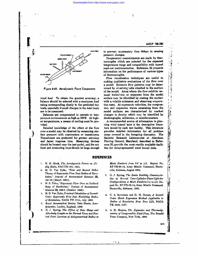
AMCP 706-280
AXIAL FOKE to prevent utuecessary time delays in sensing""PITCHL0, 7 WEN pressure changes. :
MLFORCE Temperature measurements are made by ther-mocouples which are selected for the expected
WE rOW, temperature range and compatibility with tunnel
read-out instrumentation. Reference 34 presentsYA. Winformation on the performance of various types j
ROLLING MOMENof thermocouples.Flow visualization techniques are useful in
KY making qualitative evaluations of the flow overa model. Subsonic flow patterns may be deter-
F,'gur 8-49. ynmlc Force Components mined by observing tufts attached to the surfaceof the model. Areas where the flow exhibits un-
usual turbul ncee or separates from the modelraFMd load. To obtain the greatest accuracy, a surface may be identified by coating the surfaca f
balance should be selected with a maximum load with a volatile substance and observing evapora-rating corresponding closely to the predictte tion rates. At supersonic velocities, the compres-loads, especially if small changes in the total loads sion and expansion waves emanating from the iare to be measured model surfaces are characterized by marked f
Balances are compensated to operate in tern- changes in density which may be identified byperature environments as high as 1800F. At high- shadowgraphs, schlierens, or interferometers.er temperatures, a means of cooling must be pro- A recommended source of information in plan-vided. ning wind tunnel tests is the descriptive litera-
Detailed knowledge of the effect of the flow ture issued by each test facility. This literature frover a model may be obtained by measuring sur- provides detailed information for all problemface pressure .with manometers or transducers. areas covered in the foregoing discussion. TheTransducers are preferred for greater accuracy Ballistic Research Laboratories at Aberdeenand faster response time. Measuring devices Proving Ground, Maryland, described in Refer-should be located near the test model, and the ori- ence 35, provide the most readily available facili-fices and connecting lines should be large enough ties ior Army-sponsored wind tunnel tests.
REFERENCES
IM. M. Munk, The Aerodynamic Force on .- Mach Numbers from 0.8 to 4.5, Report No.'ship Hulls, NAC-TR-184, 1924. RF-TR-64-13, Army Missile Command, Hunts-
2. M. D. Van Dyke, "First and Second Ordcr ville, Alabama, August 1964.Theory of Supersonic Flow Past Bodies of Revo- 7. D. J. Spring, The Static Stability Charact.ri"-lution," Jour3al of Aeronautical Sciences 18, . of Sra Ce-Cyainder-FlarCteri,161-78 (Marc 9of cral Cone-Clinder-Flare-C95)der..,Bodyof (March 1951). Configurations i Mach Numbers 0.4 to 4.6, Re-. , Tsie,, "Supersonic Flow Overa .-.!incnd L
port No. RF-TR-68-34, Army Missile Command,Body of Revolution," Journal of Aeronautical Huntsville, Alabama, 1968.Sciences 12, 480-8 (October 1938).
t, M. D. Van Dyke, Practical Calculation of Second- 8. C. A. Syvertson and D. H. Dennis, A SecondOrder Supersonic Flo Pas.' Nonlifing Bodie Order Shock Expansion Method Applicable toof Revolution, NACA TN 2744, July 1952. Bodies of Revolution Near Zero Lift, NACARoyal Aeronautical Society Data Sheets, Aero- TR 1828, 1957.dynamics, London, England, 1960.
11. D. J. Spring, The Effect of Note Shape and 9. A. H. Shapiro, The Dynamca and Thermody-Afterbody Length on the Normal Force and Neu- namic* of Compressible Fluid Flow, The Ronaldtral Point Location of Asziymmetrical Bodies at Press Company, New York, 1958.
1-71
slow-
Downloaded from http://www.everyspec.com
AMCP 1W-20
REFERENCES (Cont) (10. J. H. Henderson, Normal Force Pitchisg Mo- 2R12F,. Ordnance Missile Laboratories, Hunts-
went and Center of Pressure of Eighty Cone- ville, Alabama, May 1956.Cylisder-Frstrnum Bodie of Revolution at Mach 22. Handbook of Supersonic Aerodynamics, SectionNumbers 1.5 to 4.04, IReport No. 6R3F, Ordnance 8, "Bodies of Revolution," Report 1488 (Volume]M;"UIkLaboratores, Huntsville, Alabama, 1956. 3), Bureau of Naval Weapons, Department of
11. J. 0. Lowry and F.. C. Polhamus, A Method for the Favy, Washington, D. ':., October 1961.Predicting Lift Iscremeste Due to Flep Deflec- 23. W. E. Stoney, Jr., Collection of Zero-Lift Dragtion at Low Angles of Attack in Incompressible Data on Bodies of Revolution from Free-FlightFlow, NACA TN 89 1, January 1957. Investigations. NASA TR-R-100, 1961.
12. J. B. McDevitt, A Correlation by Means of 24. Aerodynamics Facilities Section Staff, Aerody-Transonic Simitarity Rules of Ezperi wentaUy samic Characteristics of Spherically BluntedDetermiln d Characteristics of a Series of Sym- Coses at Mach Numbers from 0.5 to 5.0, Reportmetrical and Cambered Wings of Rectangular MTP-AERO-61-88, Marshall Space Flight Cen-Planform, NACA TR 128, 1955. ter, Huntsville, Alabama, 196i.
is. D. E. Hook and J. W. Carlson, USAF Stability 25. P. R. Connolly, The Zero-Lift Foredrag and Bodyand Control Handbook, Wright Patterson Air Bcae Drag Coefficient of a Series of Ring-Tail-Force Base, Ohio. Strt-body Configurations at Mach Numbers
14 P. A. Lagerstrom and M. E. Graham, Low As- from 0.8 to 4.5, Report No. RD-TR-05-8, Armypect Raio Rectangular Wings in Supersonic 'Missile Command, Huntsville, Alabama, 196..Flow, Report No. SM 18110, Douglas Aircraft 26. D. R. Chapman and M. W. Rubesin, "Tempera-Company,, Santa Monica, Californiaj Dee=ber ture and Velocity Profiles in the Compressible1947. Laminar Boundary Layer with Arbitrary Distri-
i5. E. Lapin, Charts for Ike Computation of Lift and btion of Surface Temperature," Journal ofDrag of Fi4ife Wing* at Supersonic Speeds, Re- Aeronautical Sciences 16, 547-05 (September,port No. SM 18460, Douglas Aircraft Company: 1949).Santa Monica, California, 1949. 27. D B. Lee and N1. A. Faget, Charts Adapted fromr6. Longitudinal StVlitity Characteristics of a Series 1';sn D'r.ests Turbulent Flat Plate Theory for
of Ring Tals on Bodiea of Revolution at Mkik Determining Values of Tu'rbulent AerodynamicNumbers from 0.8' to 4.5, Report No. RF-TR- Friction and Heat Tvssfer Coefficient, NACA65-7, Army, Missile Comi, and, Huntrville, Ala- TN 3811, October, 1956.basm. 28. R. W. Truitt, Fundamei tals of Aerodynamic
17. 1, _Beain, Determination of Up"As Around a heating, The Ronald Press Company, New York,Body of Rvilation at Supereoni Velocities. Re- 19(X)port No. CM-451, Applied Physics Laboratory, 29. E. E. Hnneywell, Completion of Power-Off BaseThe John Hopkins University, 19M. Drag'Data and Empirical Methods for Predicting
18. W. C. Pitts, J. N. Nielsen, and G. E. Kattari, Power-Off Base Drag, Repo-t No. TM 884-887,Lift awd Center of Pressure of Wing-Bod f-Tail Convair, Pomona, California, 1959.
Cominaios a Susoic.Trasoecanieor. -4.f H. Ker-t) W. L. Chew, znd G. W.epeeds, NACA TR 1807, 1959. Research on Transonic and Supersonic Flow of
19. G. Morikawa, "Supersonic W;ng Body Lift," -a Real Fluid at Abrupt lsrcases ii Cross See-Journal of Aeronautical Sciences 15, 217-28 t , ME Tech Note 8925, University of Illinois,(April 1951). Urbano. Illinois) December 1959.
20. G. Morikawaj The Win-Body Problem for Lis- 31. C. i )jassell, A Correlation of the Base Pres.eorised Supertonic Flow, Progress Deport No. -sure on a Body of Revolution With A ',old Jet4116, Jet Propulsion Laboratory, California Erhausting Through tke Bast, Army MissileInsAttute of Techoology, 1949. Commaad, Huntsville, Alabama,
11. J. L Potter, N. M. Shapiro, and W. D. Mur- 82. National Wind Tanel gumifory, Aeronauticsphree, An Interfere"ce Factor for Mulatilnned Panel of the Aeronautics and Astronautics Co- (Tail Assemblies in Supeforsc'k Flow, Report No. ordination- Board, Department of Defense and
1-7
• . '9
Downloaded from http://www.everyspec.com
I AMCP 706-260
REFERENCES (Cont)
National Aeronautics and Space Administration, 35. J. C. McMullen, Wind Tunnel Testing FacilitiesWashington, D. C., 19Ni. at the Ballistic Research Laborat'ries, Aberdeen
33. Test Facilities Handbook, Arnold Engineering Proving Ground, Maryland, 1960.and Development Center, Arnold Air Force Sta-tion, Tennessee, July 1968. 80. AMCP 706-242, Engineering Design Handbook,
34. R. L. Walker, Heat and Temperature Measrc- Design for Cotirol of Projectile Flight Charac-ment, Prentice-Hall, Inc., New York, 1950. teristics.
)
______-___-a73
Downloaded from http://www.everyspec.com
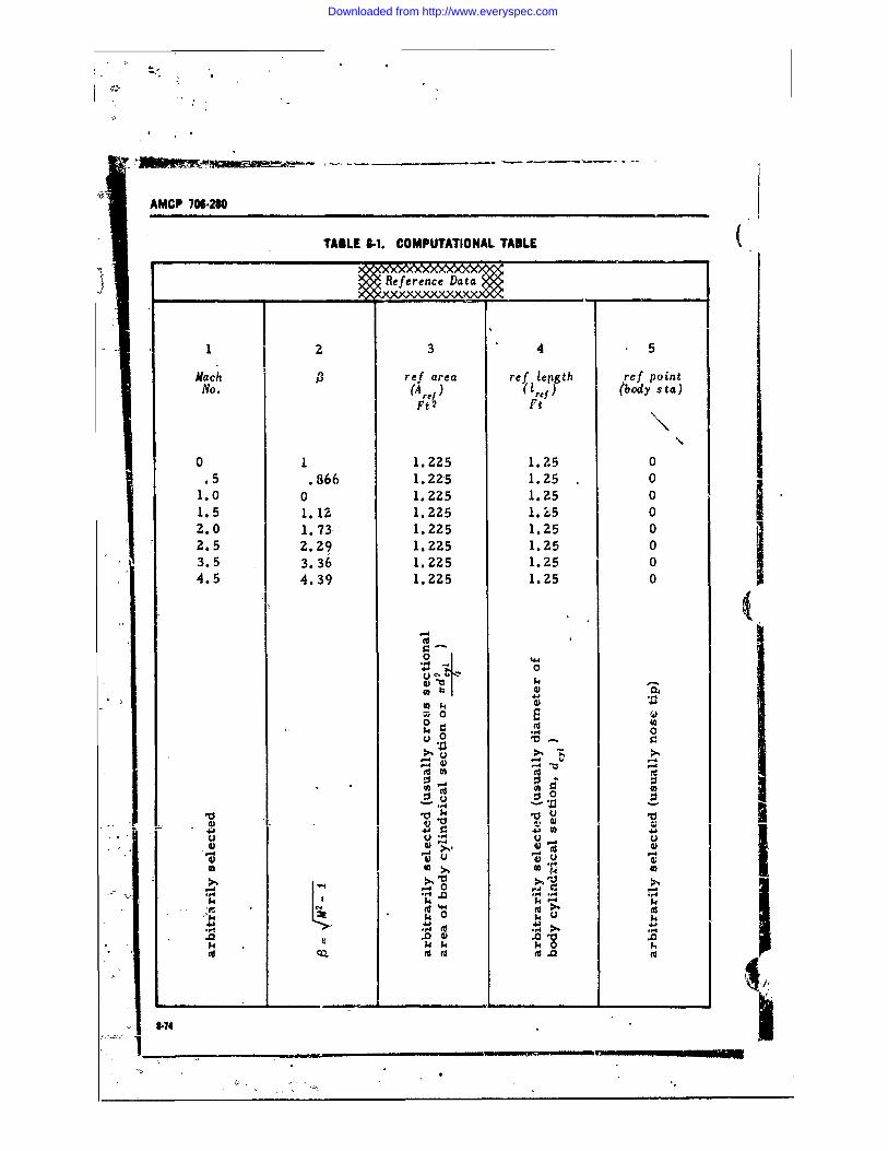
AMCP 706-M
TABLE -1. COMPUTATIONAL TABLE (
1 2 3 4 5
Mach is ref area ref lepgth ref pointNo. (A 1,{) ( )ret) (body sta)
Ft2 Ft
0 1 1.225 1.2500 1 1.225 1.25 0.5 .866 1.225 1.25 0
1.0 0 1.2Z25 1.25 01.5 1.12 1.225 1. 25 02.0 1.73 1.225 1.25 02.5 2.29 1.225 1.25 03.5 3.36 1.225 1.25 04.5 4.39 1. 225 1.25 0
0 44o 0
0kk
I 4Iu 4.0
,4 4)
0 004.-A
cU
d) M "4)did
-a-
-4r
.0~., .0 0 .
$4 % $4
(d 8.1 -% -4
.0 0 .
Downloaded from http://www.everyspec.com
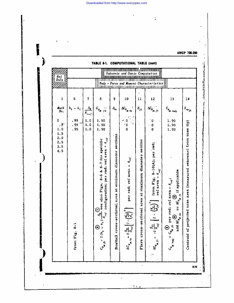
AMCP 70 260
TABLE 8-1. COMPUTATIONAL TABLE (cent)
Subsbonic an d Sonic Computation II
Body - Force and Moment Characteristics
1 6 7 8 lO 10 I1 12 13 14
M a c h k 2 - k i S b t C H . S f I A t /'I C m . b ." X .PfbNo. A---- r.I
0 .95 1.0 1.90 0 0 1.90 -.5 .95 1.0 1.90 '0 /1.90
1 0 .95 1.0 1.90 0 0 1.901.5 02.0 .0. 0,2.5 . 03.5 4)
at4) 144.5 1
0 ~ 4j) . *- 1
.d4Wo0,,- .o at 0
.. 4
-O.,0 .4 U .
0 4 -b)
0) $4 d 4 4
'- 4 d4 '4(
-.- - % $4 to4) 0
0,
-8 0 0
CA ..... 0 0
o_ __ -,, o 5CIk I-T5 %"4
{~~ is',
Downloaded from http://www.everyspec.com
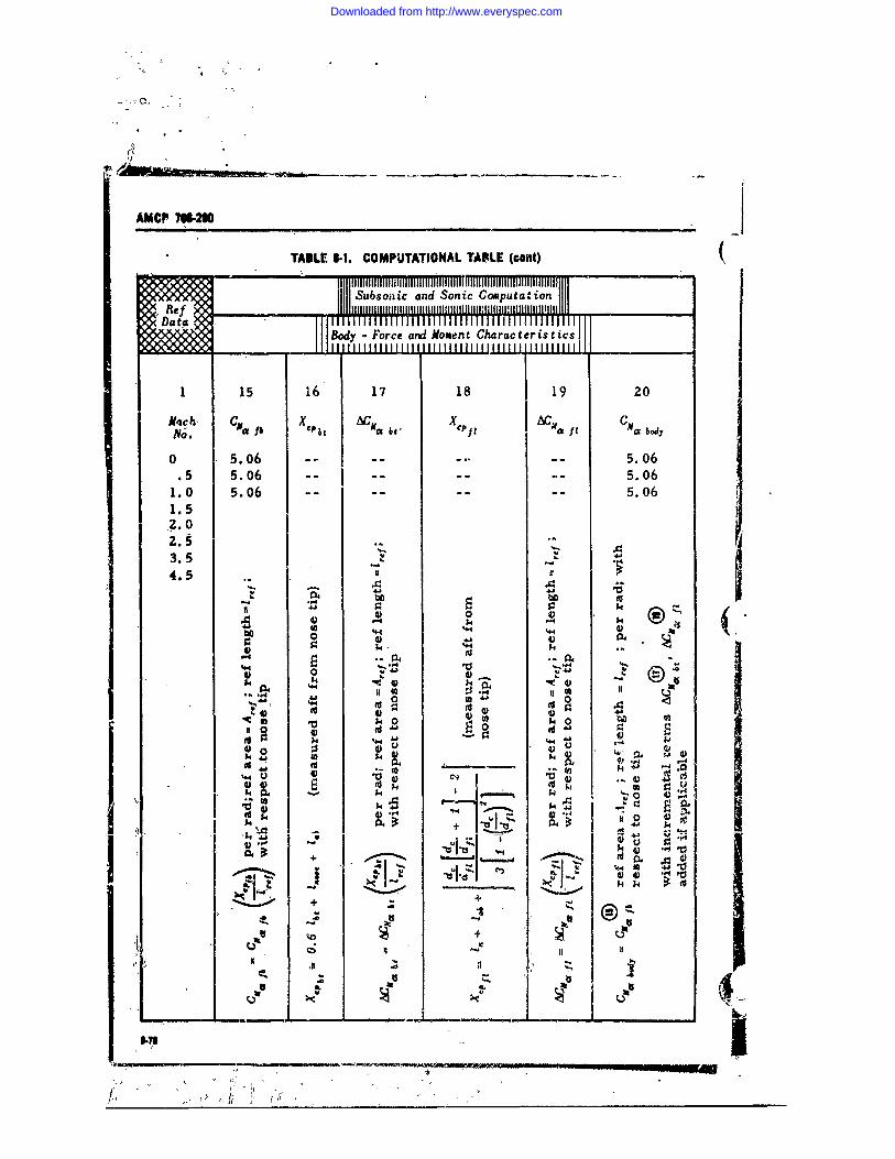
AMCPR 70200
TABLE 11-1. COMPUTATIONAL TAKLE (cent)(
I i flI 15 16 17 18 19 20j
Mah ma Xcp AM bt xplwM l CNo. bt or bodyc
0 5.06 -- - -5.06
.5 5.06 - --- 5.061.0 5.06 - -- 5.061.5-2. 02.53.5SI4.5 .
V4-
0 44
0- 41
or") 00;4~~
Downloaded from http://www.everyspec.com
_-AMCP 706-260
TABLE -I1. COMPUTATIONAL TABLE (coat) i3Subsonic and Sonic CoMputation
Fin - Force and Moment Characteristics
1 21 22 23 24 25 26 27 28
M hbSf AR 92 tun 2A ,p. F1 C N."No_
0 2.08 1.882 2.31 1.0 0, 75 3.06 1.11 2.56.5 2.08 1.882 2.31 .75 0.75 2.83 1.15 2.66
1.0 2.,08 1.882 2.31 0 0.75 2.00 1.30 3.001.52.02.53.54.5
4
'44
14 i/ N14
II4 '" +
4)0 0C4b
iff
-,I -- 40 a-
o 1 o 4.
_K _l _* -4
Ell"7
Downloaded from http://www.everyspec.com
f3
AMCP 1i620
TABLE 8-1. COMPUTATIONAL TABLE (cont) (pI Suonc and Sonic Co-puIa I i on
Fi -F)-eadNen ectangultar Fins -Force an
1 29 30 31 32 33 34 35
\//
0 3.93 165.5 43.4.5 4.09 165.5 45.1
11.0 4.61 165.5 50.91.5
2.0-2.53.5
4.5 p
-- , -- .N
"A ""- p) r--
_- % .e- l' a
1-70
El --
? 44
o 00
0 4-
Li. f£
-1 f4
Downloaded from http://www.everyspec.com
AMCP 706-280
TABLE 8-1. COMPUTATI NAL TABLE (cont)
D Rectangular Ftns - Force and Moment Characteru ilcs
1 36 37 38 39 40
Mlach " ,,,No. 41) ."
0.5 V
1.01.5 c2.0 >.
3.5 J .,4 . 5 e "
I C
CC)
-44 0 0
1 ' 4CL 4
" %_(
t __
87
Downloaded from http://www.everyspec.com
IAMCP 706.280
TABLE 9-1. COMPUTATIONAL TABLE (cont) (i Subsonic and Sonic Computation
''*Ring Tail - Forc.e and Moment Characteristics*-.**-............ I.. ... .. ............. . ..... . ... .. ..._ .. -- - -.-- - - -. ".:- :..' :.y .- -,v - .:y --" ---"- .. -.-.. .... ".. v ".... .." . .......... ...
1 41 42 43 44 45 46 47cMah leading chord ring te A%. AI xp A(C' a
No. edge length location , "r rU
diameter (cl)(led)
.51.5 I
2.0 I2.53.5
V Go0 It
. 0
0.t CISa' 0O
(L))
00
CIt
o r. . o ,
O'j "-4 ,4 Cfe- -
-4 .-ILI-
0 B - :- ,,700- %-- - -.~-,
0_ _ _ _ __ 4_ __
Downloaded from http://www.everyspec.com
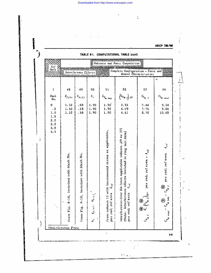
AMCP 706-POO
)TABLE 8-1. COMPUTATIONAL TABLE (cunt)
Subsonic and Sonic Computation
Dlata / / ~ - Complete Configuration -Force and. Interference Efferts/ __
Moen mhrce stic
1 48 49 50 51 52 53 54
,',ach Kf (b KK1 I' ;Vo f) vp total
15 1:32 .58 1.90 1.90 I 4.09 7.76 9.6611 .0 1.2 .8 19 .0 4.61 8.75 10.65
2.53.5_4.
c
> $.4
9 .- Ai
44.
4. 5
-'4
Downloaded from http://www.everyspec.com
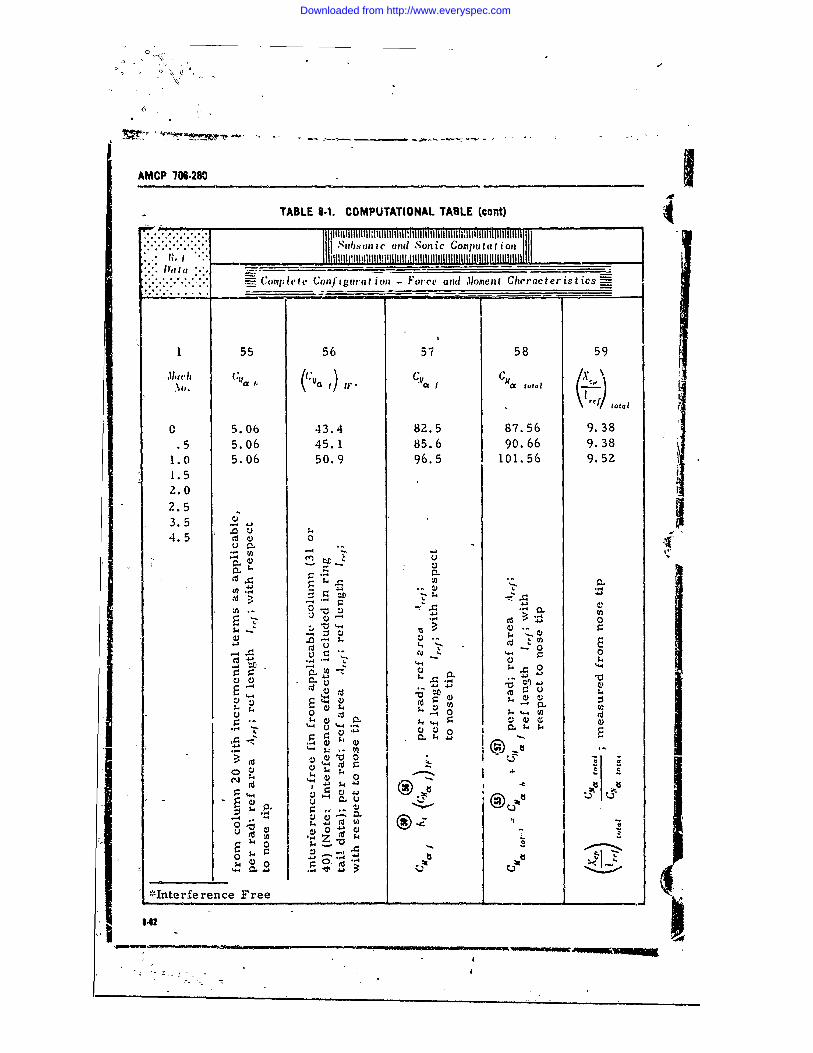
) '-
AMCP 70 .280
TABLE 8.1. COMPUTATIONAL TABLE (cont): ; ,,,..,,,,.,.
.Sub on COmUtton
" .. oml e Configuration Force aid ,loment Cheracteristics-
1 55 56 57 58 59
.,t) i " f a total
0 5.06 43.4 82.5 87.56 9.38.5 5.06 45.1 85.6 90.66 9.38
1.0 5.06 50.9 96.5 101.56 9.521.52.02.53.54.5
41- W - .,I
4). "4$ 4.. $4
• E
•U ' 0 >' "0 .
U 0r_ 0
4).- . E I
tn) 00
u 41
-0 .-. 0) L=-4 (n
r 4 ;4 %. 0
. . . I-. - III . .--- -I .. ..'' '
CIL
~Intrfernce ree ___________
342
Downloaded from http://www.everyspec.com
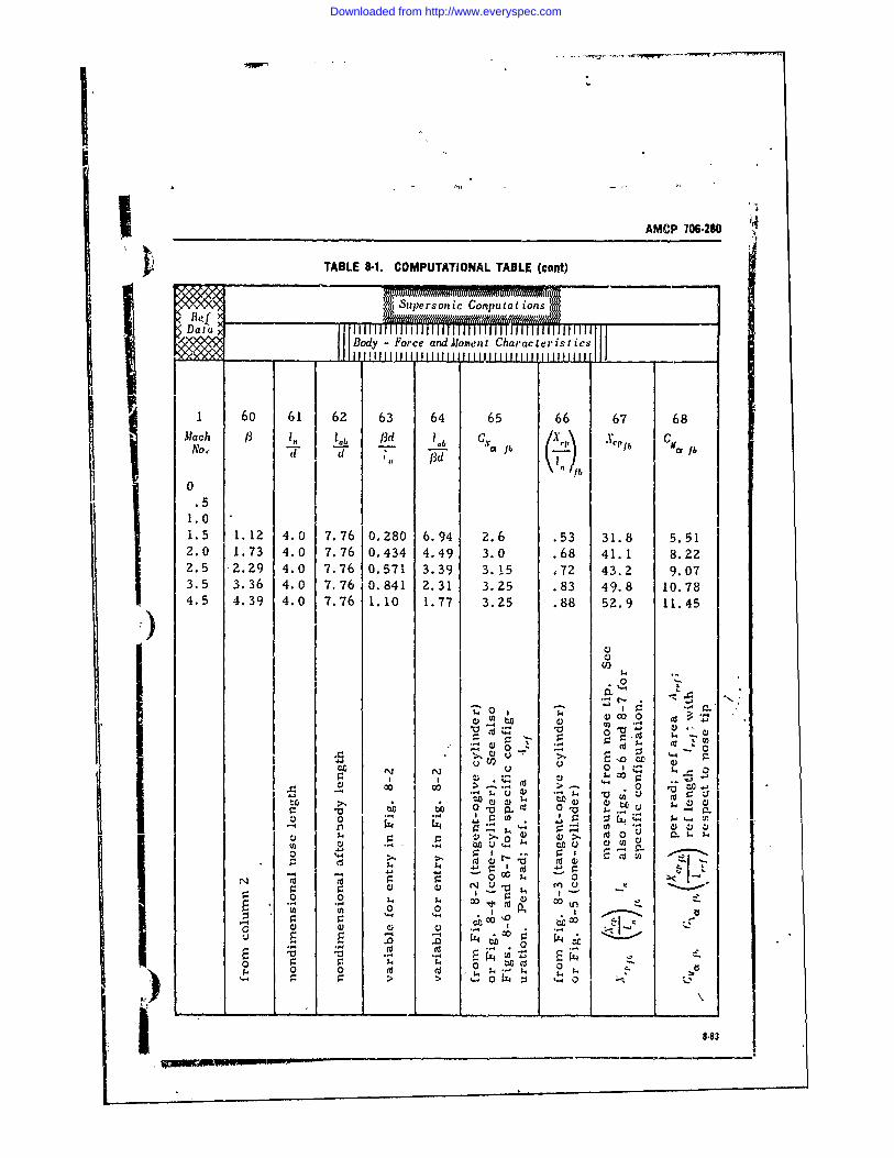
AMCP 706-280
TABLE 8-1. COMPUTATIONAL TABLE (cont)
I 60 61 62 63 64 65 66 67 68Alach /3 In lab f3d c~ /x x~, Y
No., Ivb (..2. lb Ca fbd d (3dlb
.51.01.5 1.12 4.0 7.76 0.280 6.94 2.6 .53 31.8 5.512.0 1.73 4.0 7.76 0.434 4.49 3.0 .68 41.1 8.222.5 -2.29 4.0 7.76 0.571 3.39 3.15 .72 43.2Z 9.073.5 3.36 4.0 7.76 0.841 2.31 3.25 .83 49.8 10.784.5 4.39 4.0 7.76 1.10 1.77 3.25 .88 52.9 11.45
410 ~0 0
0 -1 -0
>
01 CU CU U a) .4 100
-o -4 to - C
t tj 00 8u83~-w-0
Downloaded from http://www.everyspec.com
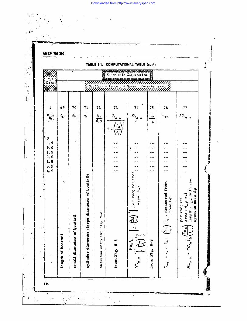
AMCP7W1
TABLE 1.1. COMPUTATIONAL TABLE (cont)
D~aa Boattail -Force and .1oment Charactitics/
1.51
1. 69 7I1 7 3 4 7 67
NO.1 'a- bt a4)
d4)to0~
2.0,.
'4--40o1
0.C 4 4)-.4 4 U.*4 '. .
00
0 ., 00 --t c_ _ _ E- .4
14 41~
0 0-
00 0.
.4441
-- ----- --
Downloaded from http://www.everyspec.com
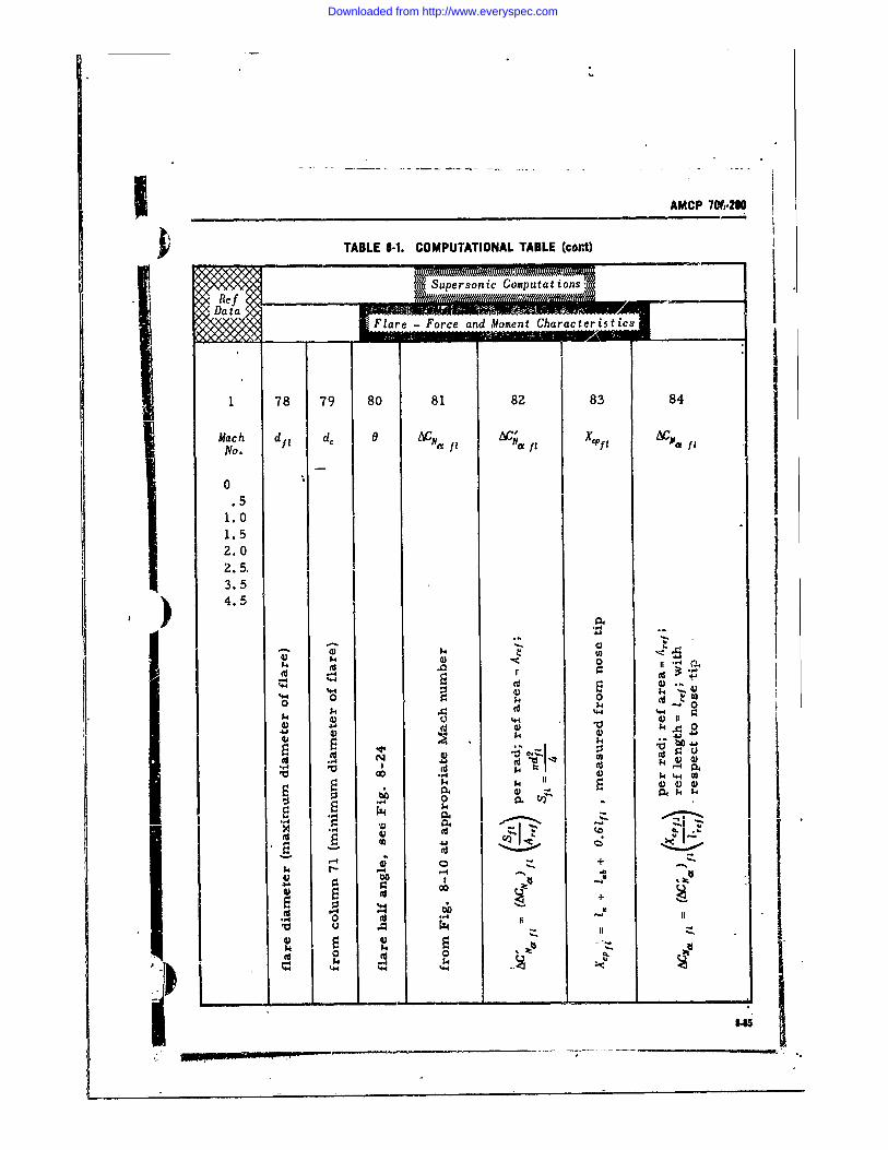
AMCP 70021f0
TABLE 8-1. COMPUTATIONAL TABLE (cant)
Flare -Force and MomentChrceits
1 78 79 80 81 82 83 84
Mach d l 1 t C a f Idf I 'm pNo.
0. 51.0
1.52.02.513.54.5
4) -
%#4
%H4 44I1I
4) +.0
V 0V
" ~~ 0 10 ,0m..
l 0 CIIE k
.r. 00 XI "
'4 44 44 444
- - . .
Downloaded from http://www.everyspec.com
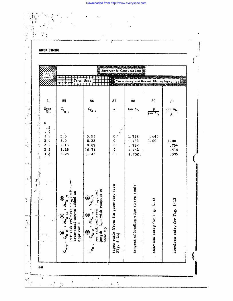
K/
AMCP 706-M
i t
(
-.-~Toal Body Fin -Force and Moment Characteristis
85 86 87 88 89 90
4Ach " CMa A tan A,, tan Ai,N't'o. atan At.
0
1.01.5 2.6 5.51 0 1.732 .6462.0 3.0 8.22 0 1.732 1.00 1.002.5 3.15 9.07 0 1.732 .7563.5 3.25 10.78 0 1.732 .5164. 3,25 rl.45 0 1.732. .395
lDO
IPU
0 fnS0,
. .. -w 0 ,. I >
.. :. .'. - - ..
4 E
0 -4 fn @
-. 1.4 4) .4,,. ~ 4 ~U
04 -A______(__ tv4$ I
Downloaded from http://www.everyspec.com
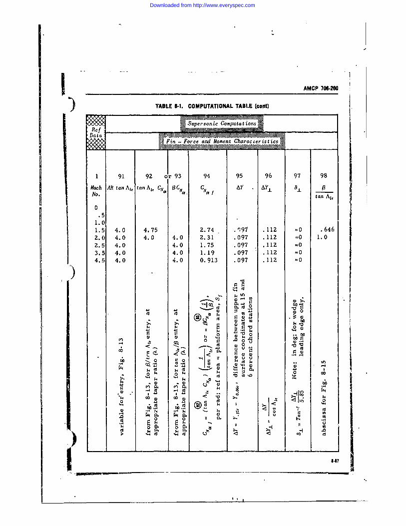
AMCP 706-280
) TABLE -1. COMPUTATIONAL TABLE (cont)
Supersonic Computat ions
DataII Fin Force and Moment Characceristics
1 91 92 or 93 94 95 96 97 98
Mach AR tan Ai tan A,, CN 3CI C AY AY.L 8 .e a. vaf tan A,,
0.1510
1.5 4.0 4.75 2.74 97 .112 =0 .6462.0 4.0 4.0 4.0 2.31 .097 .112 =0 1.0
2.5 4.0 4.0 1.75 .097 .112 =03.5 4.0 4.0 1.19 .097 .112 =0
4.5 4.0 4.0 0.913 .097 .112 =0
4)4-1
, , ' : ,, .Lin
@ 4j o A
oA'.' t.oo o-j 114 4 p. -4 144-
' 7 4-° o r% l
.0 0
0 0 I 0u k $4?% k . . . . ... . . .
k 44 W V (A %-0 44
4) _ _; _ _ _ _ _ __I-n __PI_3
Downloaded from http://www.everyspec.com
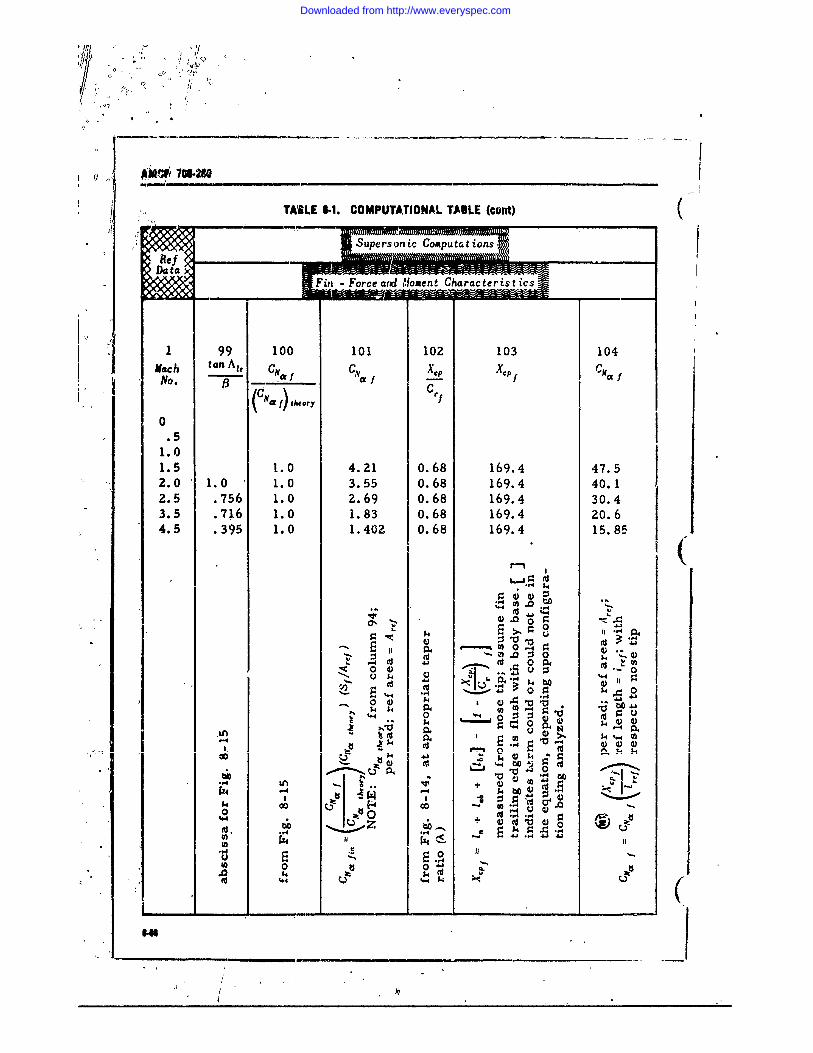
TABLE I-1. COMPUTATIONAL TABLE (cont) (Supers on i, Compu ta tions
-Fin Force and Mloment Characteristics
1 99 100 101 102 103 104Nach, tan A,, CNi C~ "Xe, XCP-(No. 13 , ) --(Cii ,) ,,,
0 .
1.0
1.5 1.0 4.21 0.68 169.4 47.52.0 1.0 1.0 3.55 0.68 169.4 40.12.5 .756 1.0 2.69 0.68 169.4 30.43.5 .716 1.0 1.83 0.68 169.4 20.64.5 .395 1.0 1.402 0.68 169.4 15.85
. , 4
04
I,
U$4 0a.0 00I
0 C:
04 $4 bO%4L 1.4 0 g0
44 41 $4
04$4
p0 4
.0~1 -4 'Ia
Sn +
Downloaded from http://www.everyspec.com
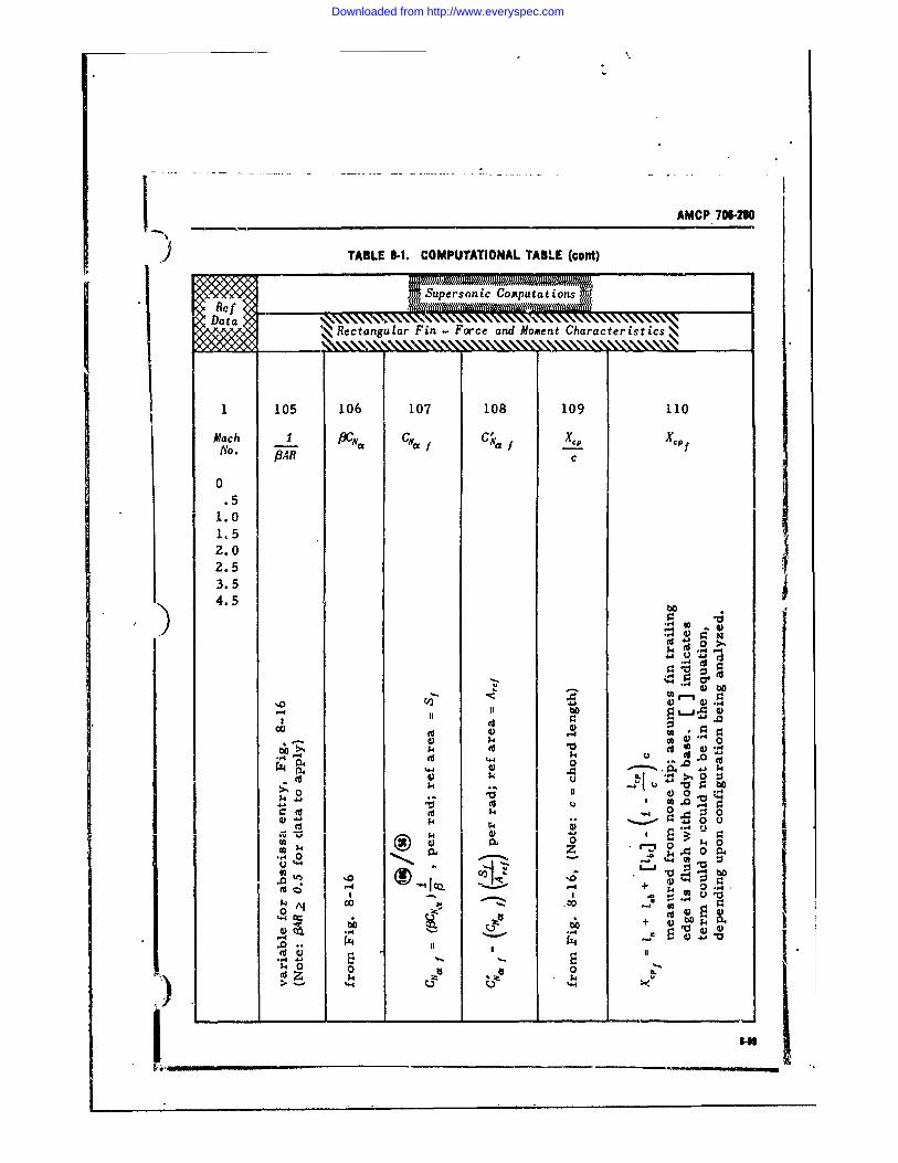
AMCP 706-2810I I -TABLE 8-I. COMPUTATIONAL TABLE (cont)
Supersonic Computtons
RectanguLar Fin -Force and Moment Character istics,
1 105 106 107 108 109 110
M'ach I PfC, CN f CNa f XIP XPfNo. f3A-- c
0.51,.0
1.52.02.53.54.5
4)bI-4
Ii ,a,.-d.
t..
ou
44 04
U0 0
),, ;a,., .
0 5 _ r o9: IV 14 :J"- 0 d
0~ 0 U
N.,
0' .z. k A 0 0j
•~~4 0_- ,. . . .
Downloaded from http://www.everyspec.com
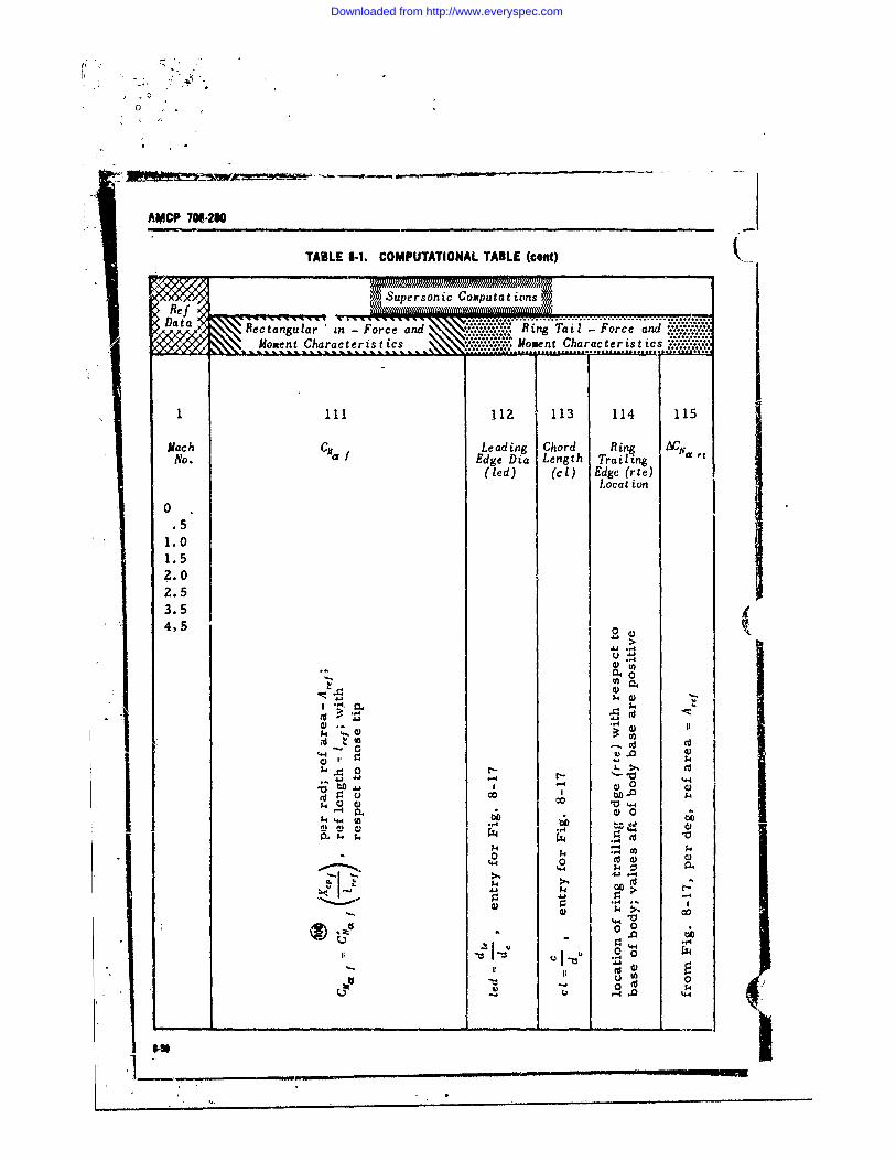
0
AMCP 706,290
TABLE 8-1. COMPUTATIONAL TABLE (cont)(
0DLcatia1.0nua n-Foc n .. in a oc n1.5t hratrsis o n hratrsi
... .......
0..7 i
1.5
4.) ..
Downloaded from http://www.everyspec.com
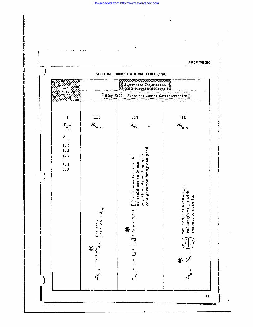
AMCP 706-20
) TABLE 8-I. COMPUTATIONAL TABLE (-ont)
Supersonic Computations-
: Ring Tail - Force and Moment Characteristics*"
1 116 117 118Mach ACN a Xcprt "Ac-aNo.
0.5
1.0 .1.52.0 20~ -o0 >2 .5 "3.5 U .b4.5
)4 0
.,4U-
0 zV -4
'4 V
It0 U
)______V
8-4 W
a)V
Downloaded from http://www.everyspec.com
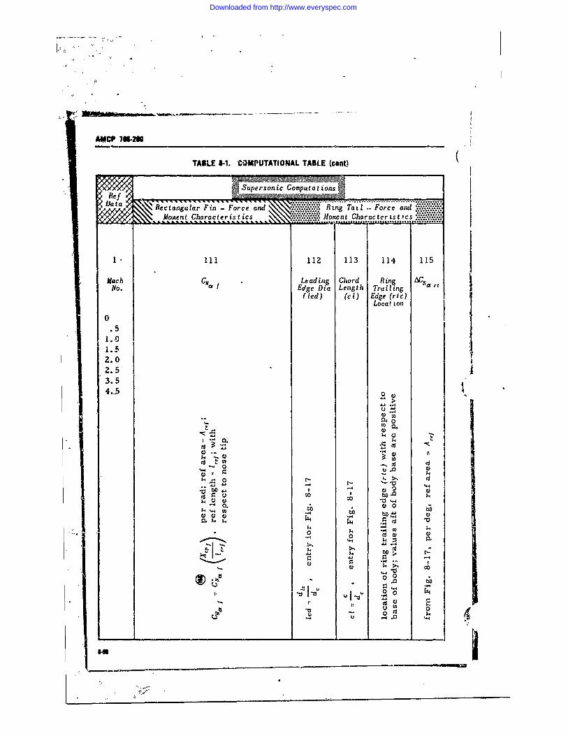
A0CIP 7W6210
TABLE 5-1. COMPUTATIONAL TABLE (cont) (
Mo~nn haraterSrsoi Charpceratsicsns'
Fi oFr.' Eng' i ng Tth1'-Fo-~- .Trail nd*'**%'***
f(e ) (i Edge (i eg h r nc)
0 Loca! ton
.51.01-.52.02.53.5
0 U)
v04
41 0
$4 04- 0) 10 4)0
IL, 4 .t0 0
$44
k- CID
0 0 V
07 k
Downloaded from http://www.everyspec.com
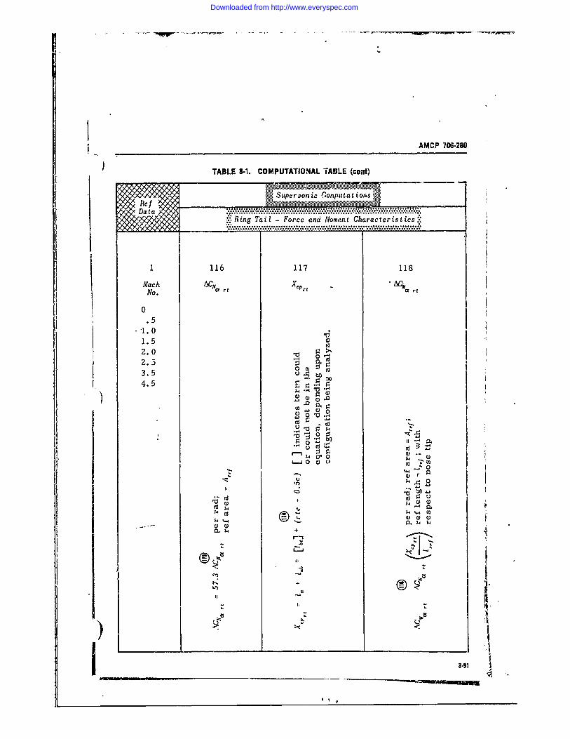
AMCP 706-280
TABLE 8-1. COMPUTATIONAL TABLE (cont)
Supersonic .omputat tions
Da.-.t".."."a...'... .. -.' . .................. . }.F . .}............Y:: Ring Tail- Force and Moment Characteristics::
• .........* . , ...... *.............. .... . ....... * .......
1 116 117 118
Mach -Cta tX-t t " O tNo. rt rt
0.51.01.5
2.0 - 03.5 0.m-5
4.5
3.5
r--
- III
1)1~~: 14_ _ _ _ _ _
89
Downloaded from http://www.everyspec.com
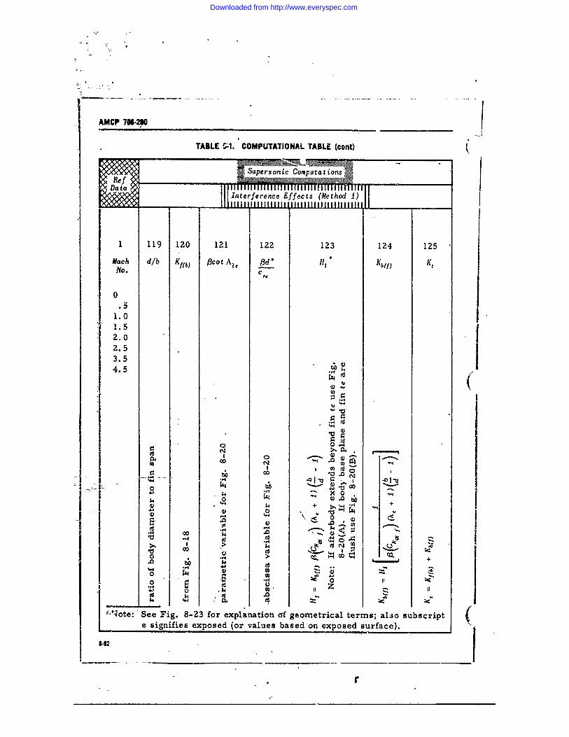
AMCP 706-280
TABLE !;1. COMPUTATIONAL TABLE (cont)
Supers onic Computa tions,
Data=j nterference ffects (Method 1)
I_
1 119 120 121 122 123 124 125
Mach dib Kgb) Pcot A,, 1d* llH Kbef) KtNo. c
0
1.01.52.02.53.54.54
f14
'44
00
0N W
0-'-
14 -00
4j o
1 20 t04 + )~ V440
0 r4 '.
0 (dN z
'r 4.1-..-
0)
0~ U
,N'ote: See Fig. 8-23 for explanatiotn of geometrical terms; aljo subscript (e signifies exposed (or values based on exposed surface).
9-42
* r
Downloaded from http://www.everyspec.com
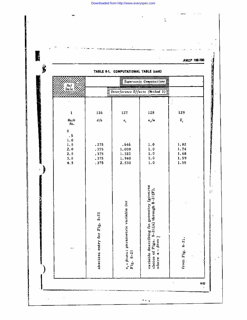
.AMCP 706280
TABLE 6.1. COMPUTATIONAL TABLE (cant)
(Supersonic Compu tatin
y = Interference Effects (Me thod 2)
1 126 127 128 129
Mach-' d/b ata/nNo.
.5 It1.5 .375 .646 1.0 1.822.0 .375 1.000 1.0 1.742.5 .375 1 .3 2Z 1.0 1.683.5 .375 1.940 1.0 1.594.5 .375 2.530 1.0 1.55
N S
00
-- 4
U. blN
4J U) 01) __ ____ __ ____ ___ ___ ___ ___ ___ ____ ___4-N 0,,
13 00 0 4) t
Downloaded from http://www.everyspec.com
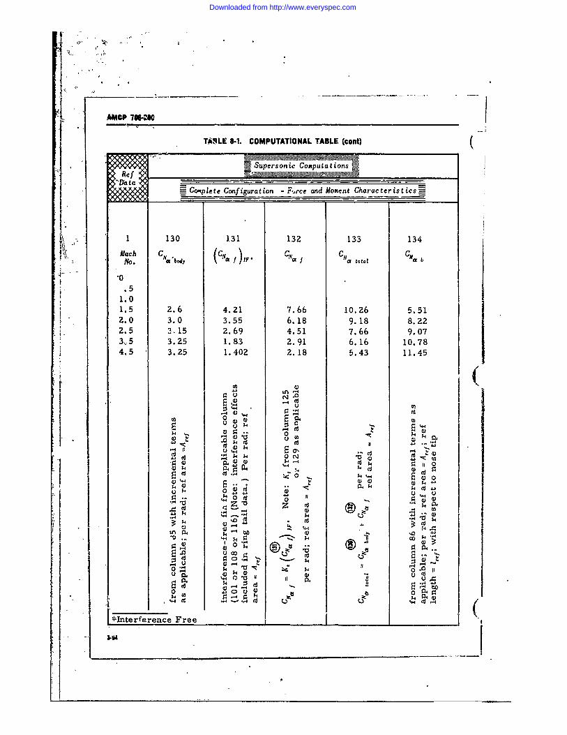
I0I
A MP 706-280
TASLE 1-1. COMPUTATIONAL TABLE (cont) ((Supersonic Computations
_Cotplete Configuration - F-.rce and Moment Characteristics-* I1 130 131 132 133 134
Alach C " N C-M bNo. W'body iqy* "f")IF* Caa total
0
1.01.5 2.6 4.21 7.66 10.26 5.512.0 3.0 3.55 6.18 9.18 8.222.5 3.15 2.69 4.51 7.66 9.073.5 3.25 1.83 2.91 6.16 10.784.5 3.25 1.402 2.18 5.43 11.45
U(
0 a)-4 GIV 0- w "It.
0 0,4~
_P ,-4
4-4O 0 0
•F- 0..,. -4ZI -0Z 04
4J1.4
rI' .,,4-A % ID "4
1. 4 W0~ 1)4 r P
0 4 ILI ko4-
4. U
.34 ____ _
____D____________________
Downloaded from http://www.everyspec.com
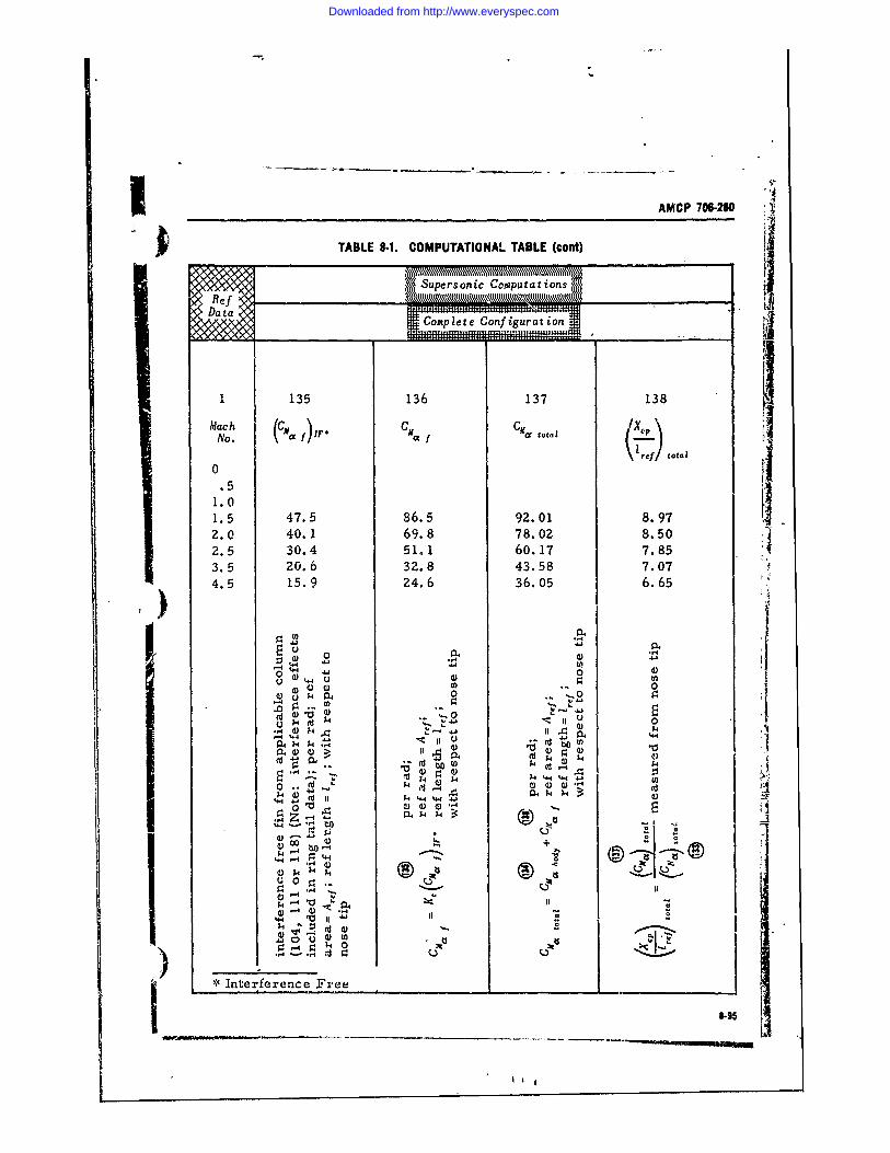
AMCP 706-280
TABLE 8-1. COMPUTATIONAL TABLE (cont)
Supersonic Cai puta tions,
II
I 135 136 137 138
Mach CG M)FCI C-40 total ,~No. / zr. f ~ f j
(\ f) total
0.51.01.5 47.5 86.5 92.01 8.972.0 40.1 69.8 78.02 8.502.5 30.4 51.1 60.17 7.853.5 20.6 32.8 43.58 7.074.5 15.9 24.6 36.05 6.65
"4b
0 0
4-4 4j0
R4-4 .., 0
- ( o- " 7
.,.4 .- t
0 0
0,
'* Interference Free
I4 114__ _ %Hto.-I__ _
_ 0 "
4- 4k )
Downloaded from http://www.everyspec.com
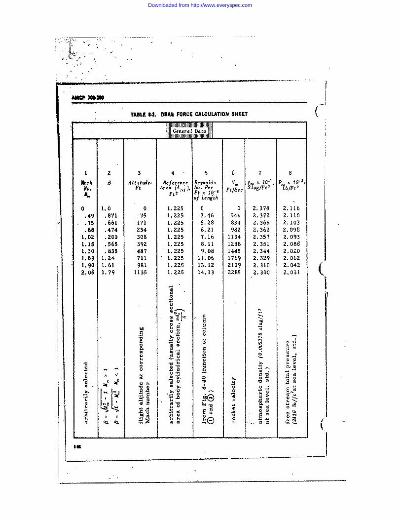
ITABLE -2 DRAG FORCE CALCULATION SHEET
General Data
I 2 3 4 5 7 8
*,ch 1 Altitude, Reference Reynolds V. p. - 10 " 1 P x 1O"3
i ~o. F, Area (A.,, No. Per F,1Sec Slug/Ft3 0tb/Ft2Ft2 Ft x 10.6
of Length
0 1.0 0 1.225 0 0 2.378 2.116• 49 .871 75 1.225 3.46 546 2.372 2.110.75 .661 171 1.225 5.28 834 2. 366 2.103.88 .474 234 1.225 6,21 982 2.362 2.0981.02 .200 308 1.225 7.16 1134 2.357 2.0931,15 .565 392 1.225 8.11 1288 2.351 2.0861.30 .835 487 1.225 9.08 1445 2.344 2.0 Z01.59 1.24 711 1.2Z5 11.06 1769 2.329 2.0621.90 1.61 981 1.225 13.12 2109 2.310 2.0422.05 1.79 1135 1.225 14.13 2285 2.300 2.031
0
.,44oou o o
.e -P4 0 00
0
I U 424
4.4 I E ,
4-4
00J4
it4 .14. 0 I 1
1.4 E). -L.4
___ -M -4k v9
Downloaded from http://www.everyspec.com
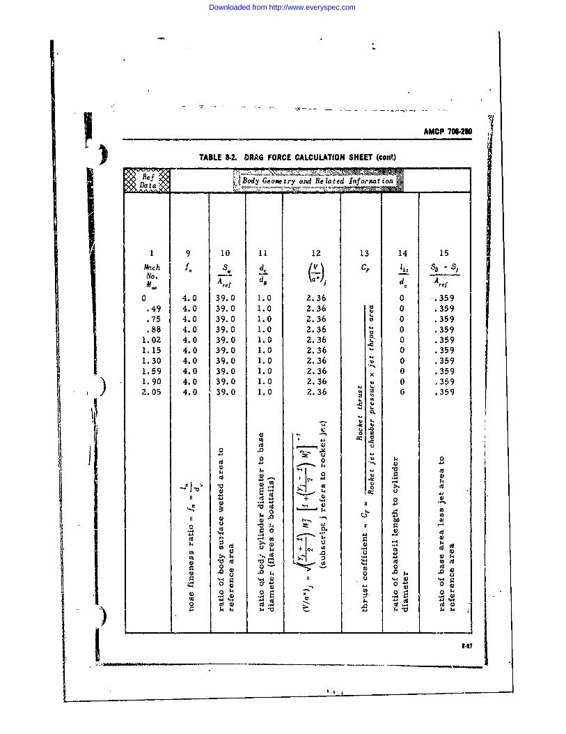
AMCP 706-230
) TABLE 8-2. DRAG FORCE CALCULATION SHEET (cont,)
Datamtr -n Related Information~ ___
1 9 10 11 12 13 14 15
f S. de /V" C 1b Ss SiNo. A, d d A .o
0 4.0 39.0 1.0 2.36 0 .359.49 4.0 39.0 1.0 2.36 0 359.75 4.0 39.0 1.0 2.36 0 .359.88 4.0 39.0 1.0 2.36 0 .359
1.02 4.0 39.0 1.0 2.36 0 .3591.15 4.0 39.0 1.0 2.36 . 0 .3591.30 4.0 39.0 1.0 2.36 0 .359I.59 4.0 39.0 1.0 2.36 x 0 .3591.90 4.0 39.0 1.0 2.36 0 .359
2.05 4.0 39.0 1.0 2.36 : to 0 .359
0U
4.4)
.- 4 a.II • + d;|
0: . .-. o.
U:4
00 0
',,.44) II U 14 '4.4I
) 4. )I- Q4
1A10 4 ) ...03 -4 -- 44 -
4j .9(d_ _
Downloaded from http://www.everyspec.com
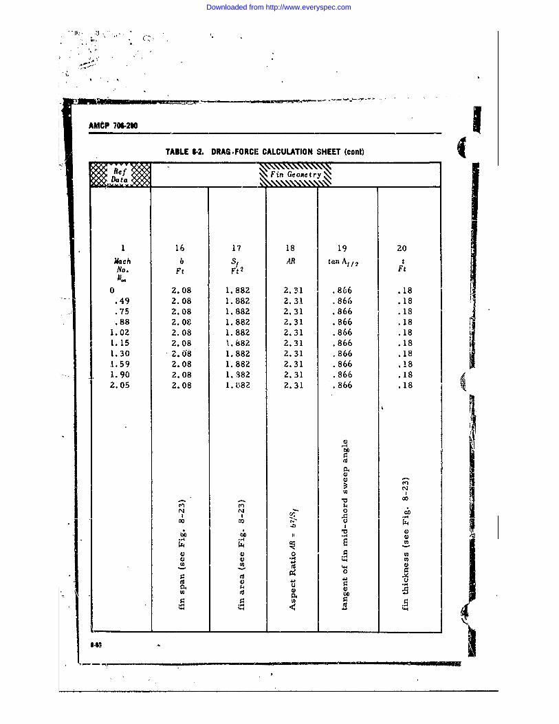
AMP 716.20 1
TABLE 8-2. DRAG.FORCr CALCULATION SHEET (cont) i
fFin Geoetry
1 16 17 18 19 20
Mach b S1 AR tan A/ 2 tNo. Ft Ft2 Ft
0 2.08 1.882 2.1 .866 . 18049 2.08 1.882 2.31 .866 .18
4 2.08 1.882 2.31 .866 .18.75 2.08 1.882 2.31 .866 .18.88 2.08 1.882 2.31 .866 .18
1.02 2.08 1.882 2.31 .866 .181.15 2.08 1.882 2.31 .866 .181.30 "z.08 1.882 2.31 .866 .181.59 2.08 1.882 2.31 .866 i181.90 2.08 1.382 2.31 .866 .182.05 2.08 1. 082 2.31 .866 .18
to
00
M I4N N,
00C0 0o o04 0 " C,
• 4.4 -4
0 I .,
I4 ,o <-
Downloaded from http://www.everyspec.com
; AMCP 706-280
TASLE 8 2. DRAG FORCE CALCULATION SHEET (cont)
Ref GDataFin Geometry
1 21 22 23 24 25 26Mach c t/c hf i . S. ",in bas dn sNo. Ft fi FtM . " AFf
0 1.8 .1 .1 6.14 .306 0.49 1.8 .1 .1 6.14 .306 0.75 1.8 .1 .1 6.14 .306 0.88 1.8 .1 .1 6.14 .306 0
1.02 1.8 .1 .1 6.14 .306 01.15 1.8 .1 .1 6.14 .306 01.30 1.8 .1 .1 6.14 .306 01.59 1.8 .1 .1 6.14 .306 01.90 1.8 .1 .1 6.14 .306 02.05 1.8 .1 .1 6.14 .306 0
k d
4)4
u
0
00
0 I 0
A) CJ 4j
04 0 P,0
4 Cfl
I -- -
4.4
0 j 0 0
.,.4 *4 .4..
Downloaded from http://www.everyspec.com
AWCP 706-280 -
TABLE 3-2. 'DRAG FORCE CALCULATION SHEET (cont)
Subsonic Computations
Data NBody Drag Force
27 28 129 30 31 32 33 34
Aao 1 n ) lJ h nos, C0 b Reynolds Number S. C/. d 10.6 Ft2
0 40 .063 16 0 0 0 39.0.49 4.0 .048 12.2 0 0 50.9 79.0 .0022.75 4.0 .027 7.04 0 0 77.6 39.0 .00204.88 4.0 .014 3.62 .0025 0 91.2 39.0 .00195
1.02 4.0 .003 .64 .0469 0 105.2 39.0 .001861.151.301.591.90 u2.05 , N 0- =
%0 S4 (no0" N N
-. 4 .
0 :%0 0 04
. .,, ®) "(d- U 14
X 1 r -4= >. o, 10 tri2 U)0
W' t , - -U) 0
r.4 .41< U)q..-. 00
430 0ra_ _ _ _ I _ __ _ _ _'4211@1
0 -- 0*4e
Downloaded from http://www.everyspec.com
IMCP 706.280
) TABLE 8-2. DRAG FORCE CALCULATION SHEET (cont)
Subsonic Computations
.Body Drag Force
1 35 36 37 38
Mach CD CD8 cylNo.M (Jet Off) (Jet On)
0049 .0986 .131 .128 94
.75 .0915 .135 .100 .89
.88 .0874 .145 .099 .851.02 .0834 .215 .133 .731.151.301.591.902.05
0 $4"coc
ILII 0 %-
0O 9$, C
C 1
_ _ _ _ _ _ _ _ __ _ _ _ _ _ _ '~0
I$
Downloaded from http://www.everyspec.com
TABLE I-L DRAG FORCE CALCULATiON SHEET (cent)Sb sonic Coxpu,,,ons, II
39 40 41 42P chC CD total
Mah Pabt or l f (1 or bt CD b total
" Py (Jet Of) (Jet On) (Jet On/Jet Off)0.49 1.2296/. 2266
.75 .2265/. 1915
.88 ,.2349/.1889.1 .3453/.26331.15
1.301.59k°
1.90 C2.05
00 .
;4 + J001
44 (dS42 1o
Downloaded from http://www.everyspec.com
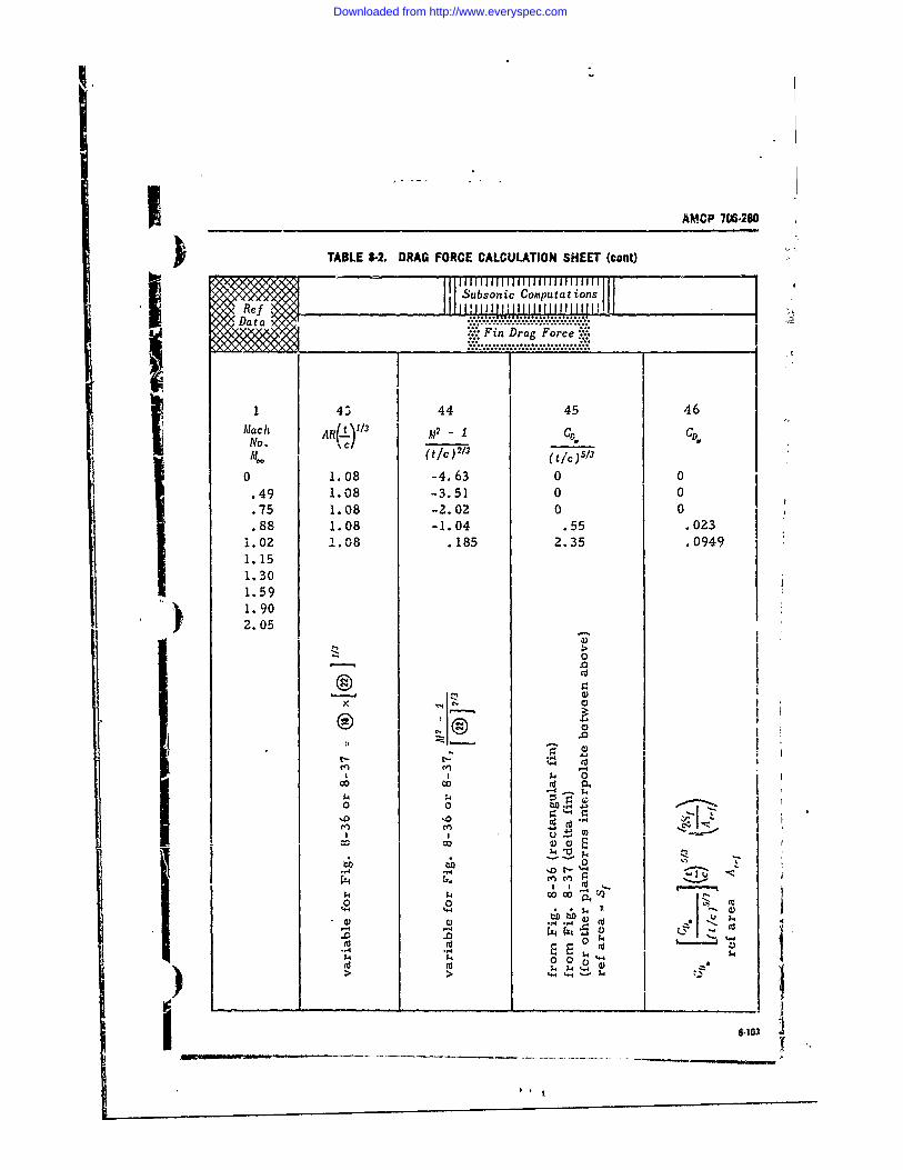
AMCP 706-280
TABLE 8-2. DRAG FORCE CALCULATION SHEET (cont)
___ __I_ _ _ I.4Da1.08so3.5 0 0i..; Fn Dag Force :::
8Mach AR0 -1.0 C CD.No.
0 1.08 -4.63 0 0•.49 1.08 -3.51 0 0.75 1.08 -2..02 0 0. 88 1.08 -1.04 .55 o 023
1.02 1.08 . 185 2.35 .o09491.15
1.59
• 2.05
o >0
®n
@@n I o .4 , 0
Cn Cd
8.0. 1 ;
-4 4
.0 .0 lCd Cd
042
-,4 -
Downloaded from http://www.everyspec.com
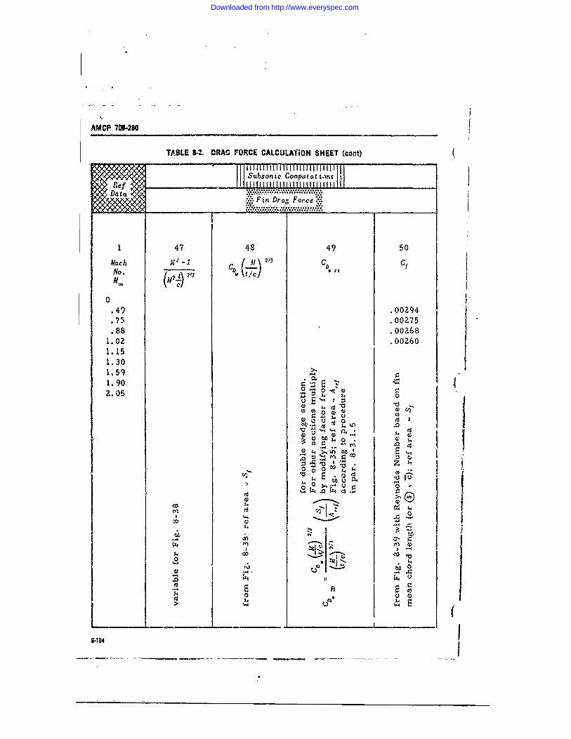
AMCP 70W260
TABLE 8-2. DRAC FORCE CALCULA'iON SHEET (cont)
/ Subsonic Computat i.ns,
......... ...... ......;:-"" "':........,
I
1 47 48 49 50Mach__ CD Cf.aCh3 CD'-I (Ac) 3 .
0
:C). 41 .00294. 7 -5 .00275.88 .o02681. 02 .00260
1. 151.301. 59 -
1.90 0 U
z~6. 4) 0 0
Z
V ,i 0 ,a Ito U 13 -4
a.,. ,., 11 ? - 94 ,
rd 0
I8-104
Downloaded from http://www.everyspec.com
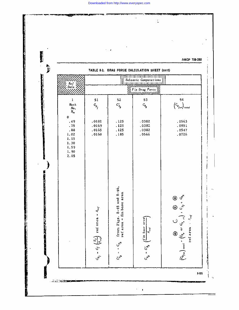
AMCP 706.280
TABLE 8-2. DRAG FORCE CALCULATION SHEET (cont)
Subsonic Computat ionsI 1 I1 111111 I IIIIIIIlI...:
V.1: F'n Dr ag Forc e. •a ll 1,............ ,
1 51 52 53 54Mach CD C; (CD) toNo.
0
.49 .0181 .125 .0382 .0563
.75 .0169 .125 .0382 .0551
.88 .0165 .125 .0382 .05471.02 .0160 .185 .0566 .07261.151.301.591.902.05 I
iI
I '=0
II : I I.
It
P @ - 'co14 ;4 C
iii
Downloaded from http://www.everyspec.com
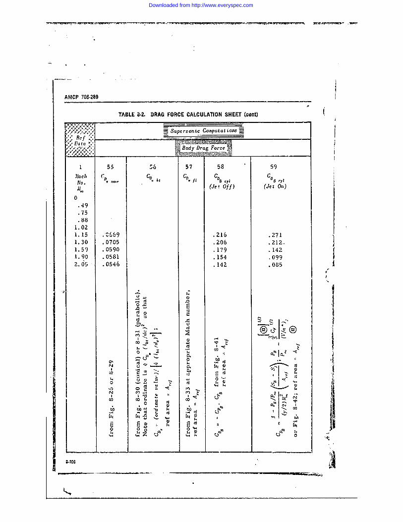
AMCP ?06-280
TABLE 8-2, DRAG FORCE CALCULATION SHEET (cont)
// x.' , ,' =_ Supersonic Coputat ionsV Rt a
Body Drag Force _
1 55 56 57 58 59
Mach {: CD DDN 0o. D V nose I
(Jet Off) (Jet On)0
49.75* 88
I 021. 15 .216 .2711.30 .0705 .206 .212.1. 59 .0590 .179 .1421.90 .0581 .154 .0992. 05 .0546 .142 .085
0 A1 0€
IL
,- N ,,4 Z-. C, u l
-0
0. 1j
o_ _-_ __ __ __ _ __ __ _ __ __ _
.o . ' .... ,
ce en t
4 i
Downloaded from http://www.everyspec.com
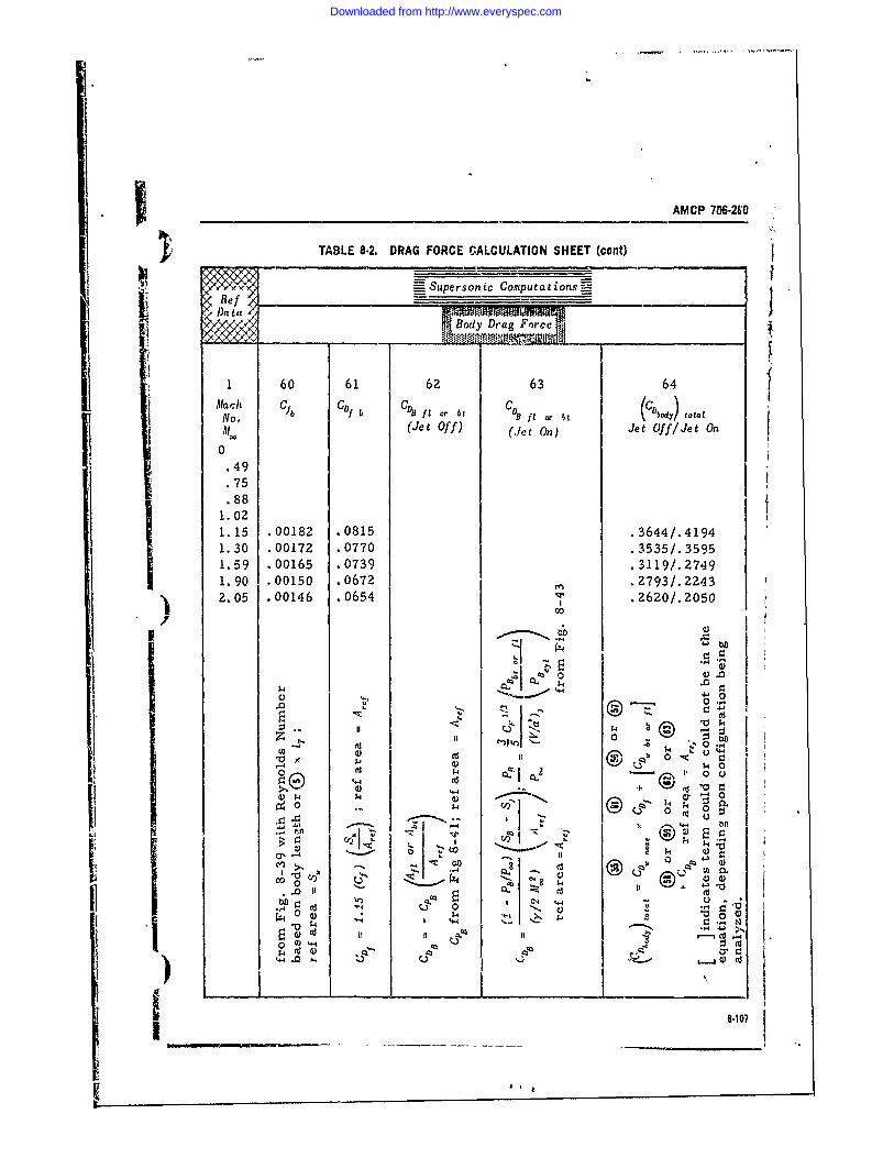
AMCP 706-260
TABLE 8-2. DRAG FORCE CALCULATION SHEET (cant)
- Supersonic Computationsr _
11Datay Drag Force
1 60 6162 63 64AMach Gib CD1 b GD f1 or bt C8 Sf, or ~c total
AiI o. (Jet Of f) (Jet On) Jet Off/Jet On0
.75. 88
1.021.15 .00182 .0815 .3644/. 41941.30 .00172 .0770 .3535/.35951.59 .00165 .0739 .3119/.27491.90 .00150 .0672 .2793/.22432.05 .00146 .0654v.20/05
z 0!U) at . t
o-~.-4 0'I
$4 =1
1s.4.0 140 ;)) c.,c' -__ to 4
00 8414 7
.0 (d
Downloaded from http://www.everyspec.com
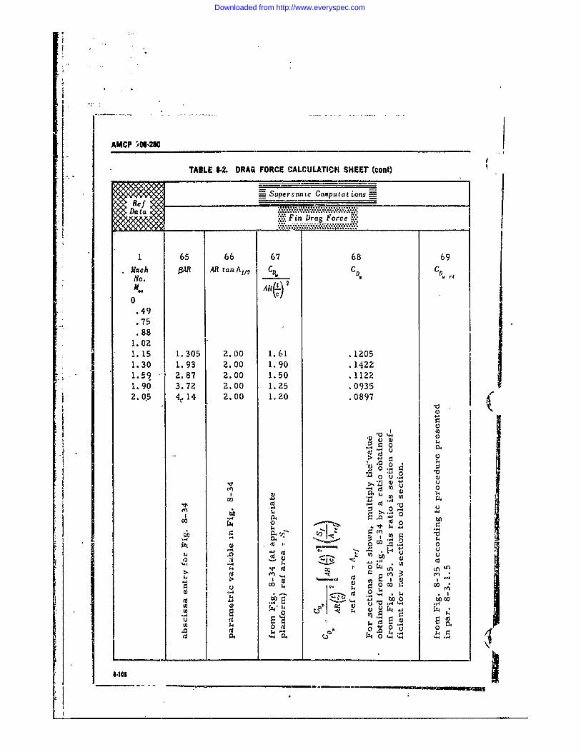
AMCP 41-260
TABLE 8-2. DRAG FORCE CALCULATICM SHEET' (cont)
Superscintc ComputationsE
............................ ........ ...Data ..................
1 65 66 67 68 69Mach MAR AR tan A1I2 CD C D CD rt
M.ARl) 2
0.49.75.88
1.02
i. 15 1.305 2.00 1.61 .12051.30 1.93 2.00 1.90 .14221.59 2.87 2.00 1.50 .11221.90 3.72 2.00 1.25 .09352. 05 4..14 2.00 1.20 .0897"(
S0 o
.0 .0 ..,. 0 .-.
0 U . (.
c0j -W 0
-4 0
cc ~ ~ 0 W4~cc ~
0-100
S"- " 4 0
".4~$ Wr) ~ ±
~~L.~e -_ _ _ _ _
Downloaded from http://www.everyspec.com
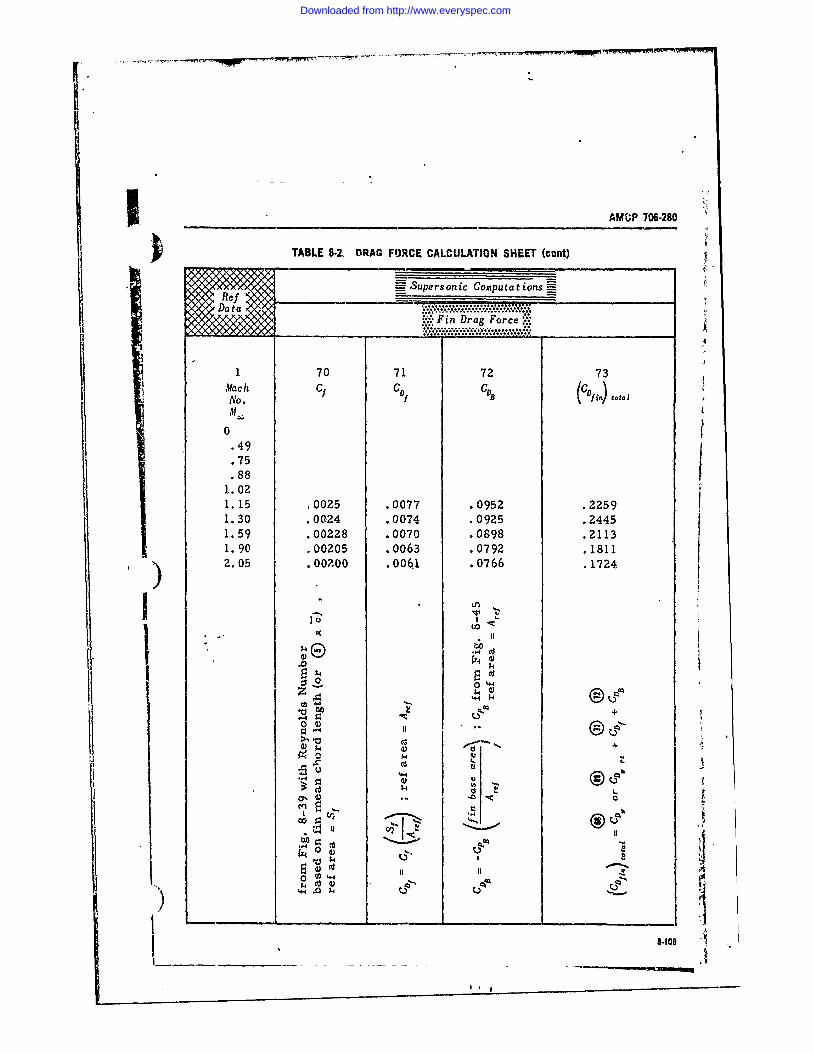
-};
AMiP 706-280
TABLE 8-2. DRAG FORCE CALCULATION SHEET (cont)
~~%~~9 Supersonic Computations=-toa
.0077 ** .0952 .2259ooeoeeee
0 ..Fn Drag Force,, .. .. ee~eee.e...........ee
1 70 71 72 73.21
0.49.75.88
1.021. 15 , 0025 . 0077 •.0952 •.22591.30 .0024 .0074 •.0925 .24451.59 . 00228 . 0070 •.0898 . 2113
1.90 .00205 .0063 .0792 .18112.05 .. 006.1 .0766 .1724
* Ln
1x " II
i 7: +0 4)
'•'- I, II
P4
J 8-109I~~~~~ ~~~ 4___ ______ - ----------
Downloaded from http://www.everyspec.com
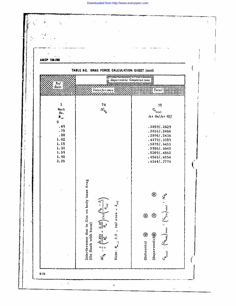
AMCP 70-290
TABLE 8-. DRAG FORCE CALCULATION SHEET (cont)
ine 74nc 75 41+144-144 oa
Vfac h AC DBCDtaINo.
m Jet On/Jet Off0
.49 .2859/.2829
.75 Z2816/.2466
.88 .2896/. 24361.02 .4179/.33591.15 .5878/.64531.30 .5956/.60401.59 .5209/.48621.90 .4583/.40542.05 .4344/. 3774
I L00
44
-- 1 -I -40 - I I u
~ 0 -00 z
Downloaded from http://www.everyspec.com
RAMCP 706-280
INDEX
i (Paragrnph Ntmnhirs in ]lmmlan F.ilre.T; Pagei. .Xie, t'rx in Hold Fl,qitrrx.)
A Constraints. Weapons, 3-6.2, 3-14Cost Effectiveness, 3-11, 3-18
Absorptivity, 6-6.1.2. 6-21 Cruciform, 5-3.1.2, 5-10Accuracy - Rocket System, 7-1, 7-2I t Actuating Device, 3-5.2.1, 3-9
i Aerodynamic Friction Heating. 6-6.4, 6-22Aerodynamic Stability, 7-3.2.1, 7-3 Deflection Probable Error, 7-10.2, 7-35
I Aerodynamic Testing, 3-10.4, 3-18; 8-4, 8-67 De Laval Nozzle, 3-5.2.2, 3-10Angular Errors, 7-3, 7-2; 7-5, 7-8 Density ModelAngular Dispersion, 7-3.2.1, 7-3 Annual, 2-2.4, 2-2Autospin, 34.5.1, 3-6 Seasonal, 2-2.4, 2-2Auxiliary Devices, 3-7.7, 3-15 Design Data, Figure 8-25, 8-43Axial Load Component, 6-3.2, 6-1 Design Optimization, 3-8, 3-16Axis of Inertia, 7-6.3, 7-14 Direct Fire Rockets, 4-3.1.2, 4-3
Discharge Correction Factor, 5-2.1.2. 5-7,B Dispersion
At Warhead Event, 7-8.3, 7-27Ballistic Coefficient, 4-2.3, 4-3; 7-8.3.3.3. 7-31 Due to Wind, 7-3.2.2, 7-3Ballistic Phase Errors, 7-2, 7-2; 7-8, 7-25 Reduction, 7-3.2.5, 7-7; 7-7.2, 7-18Base Drag, 8-3.3, 8-51 Double-Base Propellants, 5-3.1.1, 5-10Beams, 6-4.1, 6-13 Drag Form Factor, 4-4.2e, 4-8Bearing Stress, 6-4.5, 6-18 Drag, Free Range Equation, 4-3.1.1, 4-3Bending Load Components, 6-0.2, 6-U Ductility, 6-1, 6.2Boattail Wave Drag, 8-3.1.2, 8-45 Dynamic Unbalance, 7-8.2.6, 7-27Body Drag Force Calculation Sheet, 8-3.4.2, 8-46 Dynamic Unbalance Effect, 7-6.3, 7-14Body Geometry, Figure 8-24, 8-43 EBody in Presence of Fin, 8-2.4.2, 8-34Body-of-Revolution Base Drag Elastic Limit, 6-1, 6-2
Rocket Jet Oft, 641.3.1, 8-51 Emissivity, 6-6.1.2, 6.21Rocket Jet On, 8-3.3.2, 8-63 Energy-Management Techniques, 4-2. 4.2; 4-4.1.2.
Boost/Sustain System, 4-4.2, 4.. 4-8; 4-5.1.2, 4-12; 4-6.1.2, 4-15; 4-7.1.2. 4.16Boost System, 4-5.2, 4-14 Environmental Testing, 3-10.5, 3-18Booster Mass Ratio, 4-3.2.1, 4.5 Erosion, 5-3.1.4, 5-12 4
Burning Phase Error, 7-2, 7-2 Exhaust Plume Heating, 6-6.3. 6-22Burning Rate, 5-.1.3, F
C Fin Base Drag, 8-3.3.3, 8-65Fin Geometry, Figure 8-23, 8-42
Center of Gravity, 6-2.1, 6-2 Fin in Presence of Body, 8-2.4.2, 8-34Circular Probable Error, 7-9, 7-31; 7-10.3, 7-35 Fin Wave Drag, 8-3.1.4, 8-48Column-, 6-4.2, 6-15 Fin Body Interferences, 8-2.4.2, 8.34Combustion Chamber Heating, 6-6.2, 6-22 FinsCombustion Chamber Pressure, 5-4, 5-13 Coplanar, 8-2.2, 8-19Composite Propellants, 5-3.1.1, 5-10 Cruciform, 8-2.4.3, 8.37Computational Table, 8-3.4.2, 8.66 Low Aspect Ratio, 8-2.2. 8-20 t) Conical Divergent Section, 5-2.2, 5-7 Rectangular Planform, 8-2.2, 8-20)Constant Spin Acceleration, 7-7.2.2, 7-20 Ring Tail, 8-2.3, 8-22
I -1
Downloaded from http://www.everyspec.com
AMCP 706.280
Swept, 8.2.2, 8-20 Mallaunch, 7-8.3.1.2, 7-29 (Unswept, 8-2.2, 8-20 Margin of Safety. 6-5. 6-19
Flare Wave Drag, 8-3.1.3, 8-46 Mass, 6-2.1. 6-2Tlight Te.3ting, 3-10.2, 3-17 Flow Rate. 5.2.1.2, 5-7Friction Drag, 8-3.2,8-51 Material Modulus of Elasticity, 6-4.2. 6-15
Fuze, 3-5.2,1, 3-9 Methods of Rocket Transport, 3-4.E. 3-7
Fuzing Errors, 7-8.2.8, 7.27 Military Rocket Systems, 3-2.1, 3-1Modulus of Elasticity, 6-1, 6-2
G MotorCombustion Chamber, 3-5.2.2. 3-14Exit Orifice, 3-5.2.2,3.10
Grain, 5.31, Thrust Level, 5-5, 5-13Grain Composition. 3.5.2.2, 3.9Growth Factor, 4-2.3, 4-3; 4-3.2.3, 4-5; 4-3. 4-i Multi-Fin Configuration, 8-2.4.3, 8-37
H N
Hardness, 6-1, 6-2 Nose Wave Drag, 8-3.1.1. 8-44Heat Transfer, 6.6., 6-19 Nozzle
Closure, 3-5.2.2, 3-11Contours. 5-2.2. 5-7Erosion, 5-2.3, 5-7
Ideal Flow, 5-2.1.1, 5.4 Exhaust Velocity, 5-2.1.1, 5-4Ideal Velocity Equation, 4-3.2.1, 45 Numerical Example, 4-8, 4-19Ignition, 5-3.2, 5-12Impulse Variation, 7-8.3,2.3, 7-30Indirect Fire Systems, 4-3.1.1, 4-3Insulating Materials, 3-5.2.2, 3-1,0 Ogive Nose, 62.1, 6-2
Internal Combustion Engine, 5-1. 5-2Internal Cylindrical Surfaces, 5-3.1.2, 5-11) Operational Modes, 3-3. 3-3Internal Star Design. 5-3.1.2, 5-10 Oversize Head Configuration, 8-2.1.4, 8-16
Joints. 6-4.5,6-15 Parabolic Section, 5-2.2, 5-7Parametric Performance, 4-2, 4-2; 4-4, 4-8; 4-5.2.
4-13; 4-6.2, 4-15; 4-7, 4-16; 4-7.2. 4-18
Parametrics. 3-6.3. 3.14Launch Phase Errors, 7-6. 7-10 Payload, 3-7.1, 3-15Launcher Length, 7-7.2.1, 7-18 Performance Estimates. 3.7.6. 3-15Launcher Rail, 3.5.3, 3.13 Plates, 6-4.4, 6-15Law of Proportionality of Stress to Strain. 6-1, 6-2 Plug Nozzle, 3-5.2.2. 3-10L,inearized Flow Theory, Fins. 8-2.2.8-22 Prelaunch Errors, 7-4, 7.7Linearized Slender Wing Theory. Fins. 8-2.2, 8-20 Preliminary Design, 3-7, 3-14Linearized Supersonic Wing Theory, Fins, 8-2.2, Prespin Automatic Dynamic
8-22 Alignment (PADA), 7-7.2.5, 7-24Ldfting Line Theory, Fins. 8-2.2, 8.20 Launcher, 3-4.5.2, 3-7Loads, -3, 6.10 Pressure Vessels, 3-4.3, 6.15
PropellantM Charge or Grain, 3.5.2.2, 3.9; 5-3.1, 5-7
Weight Fraction, 4-3.2.2, 4.5
Malaim. 7-8.3.1.1. 7-28 Proportional Limit, 6-1: 6-2Malalignment of Fins. 7-3.2.4. 7-27 Propulsion Phase Error. 7-7, 7-14
Ii I-2
Downloaded from http://www.everyspec.com
AMOP 706.280
Range Probable Error, 7-10.1, 7-35 Temperature Profile, 2-2.4, 2-3; Table 2-4,2-14Real Flow, 5-2.1.2, 5-7 Testing, 5-6, 5-15; 6-7, 6-24Recovery Temperature, 6-6.4,6-23 Thickness Effect, Fins, 8-2.2, 8-22Requirements, Weapons, 3-6.1, 3-13 Thrust Correction Factor, 5-2.1.2, 5-7Research Rocket Systems, 3-2.2, 3-2 Thrust Malalignment, 7-3.2.3, 7-3Ring Tail Wave Drag, 8-3.1.5, 8-48 Total Drag, 8-3, 8-44Rocket Total Error, 7-2, 7-2
Launchers, 3-4.1,3-4 Total Moment of Inertia, 6-2.2, 6-7Motor, 3-5.2.2, 3-9 Trajectrry Profile, 4-4.1.1, 4-8; 4-5.1.1, 4-12; 4-6.1.1,Motor Requirement, 4-3.2, 4-5 4-15; 4-7.1.1, 4-16Nozzle, 5-2, 5-3 Twin Fins, 8-2.4.3, 8-37Pitch Inertia, 6-2.2, 6-2Roll Inertia, 6-2.3, 6-7
Rod and Tube, 5-3.1.2, 5-10U
SUltimate Strength, 6-1, 6-2
Sample Calculation Sheet, 8-2.4.4, 8-42Shearing Stress, 6-4.5, 6-17Six Degree of Freedom Equations, 7-5, 7-8 ySlender Body Theory
Boattail, 8-2.1.2, 8-5 Variable Acceleration Technique, 7-7.2.6, 7-24) Conical Flare Afterbody, 8-2.1.3, 8-5 VelocityNose Cylinder, 8-2.1.1, 8-4 Correction Factor, 5-2.1.2, 5-7
Slowly Uniformly Decreasing Requirement, 4-3.1,4-3Spin (SUDS), 7-7.2.3, 7-20 Verticar Ascent, 4-6.1.1, 4-15
Solid Propellant Motor, Ve-c, 5-2Sonic Velocity, 5-2.1.1, 5-6Sounding Rockets, 4-3.1.3, 4-5; 4-6, 4-15Specific Impulse, 4-3.2.1, 4-5 WSpeed Change Errors, 7-3.1, 7-2Spin, 7-3.2.4, 7-5 Warhead, 3-5.2.1, 3-8Spin Buck, 7-7.2.4, 7-20 Wave Drag, 8-3.1, 8-44Spin-On-Straight Rail (SOSR), 34.5.3. 3.7 WindsSquib, 3-5.2.2, 3-11 Lower Level, 2-2.3, 2-2Standard Atmospheric Model, 2-2.1, 2-1 Upper Level, 2-2.2,2-1Static Testing, 3-10.1, 3-17Static Unbalance, 7-8.2.5, 7-27Stress, 6-4, 6-13Structural Testing, 3-10.3, 3-17 YSynthetic Wind Profile, 2-2.2, 2-1System Elemcnts, 3-5, 3-8 Yaw Oscillation Distance, 7-3.2.1, 7-3System Integration, 3-9, 3-16 Yield Point, 6-1, 6-2
I1-311-4
US. GO*VRUMZNr PRIING oIrOC 10 0-16-$4)
Downloaded from http://www.everyspec.com