inot measurement sensitive j - #lil-s - everyspec
TRANSCRIPT
INOT MEASUREMENT SENSITIVE j
#lIL-S
PHL-STD-1364tt NAVYn29 NOVEMBE 198
MILITARYSTANDARD
GENERALPURPOSEELECTRONICTEST EQUIPMENT
AMSC N4790DISTRIBUTION STATEMENT A
Approved for publlc release; distribution is unlimitedFSC 6625
..
Downloaded from http://www.everyspec.com
MIL-STD-1364J
FOREWORD
1. This military standard is approved for use by the Department ofthe#iavy and is available for use by all Departments and Agencies of theDepartment of Defense.
2. Beneficial comments (reconnnendations,additions, deletions) andany pertfnent data which may be of use in improving this document should beaddressed to: Comnander, Naval Sea Systems Command, SEA 55Z3, Department ofthe Navy, Washington, DC 20362-5101 by using the self-addressed Standardiza-tion Document Improvement Proposal (DD Form 1426) appearing at the end ofthis document or by letter.
ii
Downloaded from http://www.everyspec.com
MIL-STD-1364J
CONTENTS
1.1.1
2.2.12.1.12.1.2
2.2
3.3.13.1.13.1.23.23.33.43.53.63.73.8
4.4.14.2
5.5.15*1.15.1.25.1.35.1.4
SCOPE . . . . . . . . . . . . . . . . . . . ...***.* . . . . . . . . . . . . . . . . . . .Scope ● ...*,*....*.*****● ..**...*● *....***.*****..
APPLICABLEDOCUMENTS● ***.**.** ● O*.**.*.* . ..******. ●
Government documents .***.*..*● **..........***.*.*$pecificatlons, standards, and handbooks ..***....Other Government documents, drawings, andpublications ● ..******. ● -******** ● *4******* .* **...
Order of precedence 9. ***9**** ● ******... . .*.***.*.
DEFINITIONS ...****.*b..........**.*..........00..**GPETE .....0..0..*....**● 00****0*● ****O.*..*9*****Standard GPETE ● .********● ******.,*● .********● ****Nonstandard GPETE ● .**.****.****..*.● *...*.**● **8.GSI ● **8*9*.**● *********● 9*9***.*..0..0..-00&*..*.GUPEE ● ****.*....**.**.*.● *.***..*....*...*.*.....GPETE master group (GHG) ...................**..*.NAVSEA subcategory (SCAT)
8● ****.*..,...........*,.
GPETEinitial outfitting ● *****O..*...**.****.● e**GPETE supply support ● **O*****.● ..**..**.● **O**.**Emergent GPETE ..-****.*● ***....*................0
GENERAL REQUIREMENTS ● ****=***● ******....***..&.....Selection of GPETE ● **.*****● ********..*...**e● ..*
Nonstandard equipment .**.**.....*...**..**.**.**●
DETAILED REQUIREMENTS ● .*.****.● **..................Guidance for use ..........0.0......*.**.*...**..*Appendix A. Standard models .....................Appendix B. SCAT to GMG codes ...................Appendix C. GPETE configurations ................Appendix D. Purchase descriptions ...............
5.1.4.1 Ghkcode revision letter .........................5.1.4.2 Environmental classification .....................
11
111
12
22222222333
333
33334444
5.2 GPETE, GSI, and GUPEE status list ................. 45.3 Acquisition of test equipment ....*.......● .b● .... 45.3.1 GPETE initial outfitting deficiencies ............ 45.3.2 Emergent GPETE acquisition program ............... 55.3.2.1 Application procedures ● ● ● ******...● ..● ● ● ● ● .**.,** 55.3.2.2 Program responsibilities .b,..**..● .,● ● ● .● ● ● ● **..● 55.3.3 GPETE supply support procedures ........● ......... 5
iii
Downloaded from http://www.everyspec.com
MIL-STD-1364J
CONTENTS - Continued
Paragraph 5.45.4.15.4.25.4.35.4.45.4.55.4.65.4.75.5
6.6.16.26.36.46.56.6
Appendix A.B.c.D.
Nonstandard GPETE application procedure .● ..● *● ● 00Application review 9*99● 8o● ● ..● .● ● ● ● 6 . 9 ● . , . ● . . ● 9 ● b
Application approval ● ● ***● ● ● ...● ● O● ● ..● ...● .● ● e● *Life-cycle support ● **● **● .● ● ● ● ● *● =● ● .● .● ● ● ● *9*● *Term of approval .● eaea..0● ..● ● ....● ..● .......● ...Application disapproval 90● ● ● ..● ● *● *● ..● ● ● ..● .● .● .Resulxnissionafter disapproval ..0● ● ...● ...● ● .● 09.Nonstandard 6PETE requisition requirements ...● .● *GPETE BBS ● a9● *******9● ***● ● ● *● ● ● ● ● *● ● ● ● ● ● .● ● *● *● *
566667777
NOTES .0..00...***..● 00............****.*.....*.● * 7Intended use .....0......................0.....*O●
7Consideration of data requirements ● ● *● ● ● ● ● ● ● *● *** 7User inquiries 9● ● *O**● v● ● ● ● ● *● ● ● O● *● .● ● ● .● ● ● *● *● * 8Listing inquiries 9***● ● *● ● ● ● *● 9● ● ● .● .● ● ..● ● ● *● ● ● * 8Subject term (key word) listing .0.........● .0..● ● 9Changes from previous issue .*● ...● ..............0 9
Standard Equipment Index ● 8● **● ● .*● ● ● ● ● .● ● .● ● ● ● ● ● * 11SCAT to 6HG Code ● O***● ● *9● ● ● *● ● ● ● ● *● ● ● ● .● ● ● ● *● ● ● * 19GPETE Configurations ........*.****● 00.000 ● *O**** ●
25Purchase Descriptions .*....*.● O.*.**......0.● **** 33
iv
Downloaded from http://www.everyspec.com
MIL-STO-1364J
1. SCOPE
1.1 scope. This standard identifies standard General PurposeElectronic Test Equipment (GPETE), GPETE support Items (GSI), and GeneralUse Portable Electrical Equipment (6UPEE) which have been determined to besuitable for Navy use and for which thellaval Sea Systems Command(NAVSEA)exercises material support responsibility by management of item entry. Thisstandard also establishes unifora procedures for submission of applicationsto procure nonstandard 6PETE.
2. APPLICABLE DOCUMENTS
2.1 Government documentsw
2.1.1 ecifications, st ndards. and handbooks. The followingspecifications, standards, and ;andbooks form a part of this document to theextent specified herein. Unless otherwise specified, the issues of thesedocuments are those listed in the Issue of the Department of Defense Indexof Specifications and Standards (DODISS) and supplement thereto, cited inthe solicitation.
SPECIFICATIONS
MILITARYMIL-T-28800 - Test Equ@ment for Use With Electrical and
Electron~c Equipment, General Specificationfor
(Unless otherwise indicated, copies of federal and military specifica-tions, standards, and handbooks are avaflable from the StandardizationDocument Order Desk, Building 4D, 700 Robbins Avenue, Philadelphia, PA19111-5094.)
2.1.2 9ther Government docu-s. drawin~s. and ~ublicati~ Thefollowing other Government documents, drawings, and publications fofi a partof this document to the extent specified herein. Unless othewise speci-fied, the issues are those cited in the solicitation.
PUBLICATIONSDOD Cataloging -Handbook H4/H8NAVAIR 16-1-525 -NAVSEAOD 45845 -NAVSEA STOOO-AA- -IDX-O1O-PEETE
NAVSUP P-4000 -
Section B Conmnercialand Government Entity(CA6E)Preferred Avbnics ConunonSupport EquipmentMetrology Requirements List (METRL)Index for Support Requirements of ShipboardEhctronic, Electrical, IC, Weapons, andReactors Systems (TE Index)Navy Management Data List (Master CrossReference List)
-1
Downloaded from http://www.everyspec.com
MIL-STD-1364J
NAVSUP P-485 - Afloat Supply ProceduresSPCC MIAPL - Master Index of Allowance Parts List/
Allowance Equipment List
(Copies ofDODCatalogingHandbookH4/ti8 are available from the Commander,Defense Logistic Services Center, Battle Creek, MI 49017-3084. Copies ofNAVAIR 16-1-525, MVSEAOD 45845 and STOOO-AA-IDX-O1O-PEETE, NAVSUP P-4000and P-485, and SPCC HIAPL ●re available from the Standardization DocumentOrder Desk, Building 4D, 700 Robbins Avenue, Philadelphia, PA 19111-5094.
2.2 order of r)rec~n ce. In the event of a conflict between the textof this document and the references cited herein, the text of this documenttakes precedence. Nothing in this document, however, supersedes applicablelaws and regulations unless a specific exemption has been obtained.
3. DEFINITIONS
3.1 ~. GPETE is electronic test equipment capable of generating,modifying, or measuring a range of electronic functions to test two or moresystems or equipment of basically different design.
3.1.1 Standard GPETL Standard GPETE is GPETE preferred for acquisi-tion listed in Appendix A. “
3.1.2 JJonstandardGPFTC. Nonstandard GPETE is any GPETE item notlisted in Appendix A. Application procedures of 5.4 apply for acquisitionof these items.
3.2 ~. MI is the complement of equipment, supplemental to GPETE,which is necessary to facilitate a complete test measurement capability.(XI includes ratio transfonaers, couplers, decade capacitors, adapters,attenuators, dunny loads, filters, terminations, oscilloscope probes, noisesources, and so forth.
3.3 JXJPK. GUPEE is test equipment normally associated with evaluat-ing, monitoring, and troubleshooting electrical generators, motors, andpower distribution systems. 6UPEE includes portable ammeters, voltmeters,single and polyphase wattmeters, phase-sequence indicators, frequencymeters, and so forth.
3.4 WETF master arouD [~ A GMG is a five-character code thatidentifies instrument requirements within a generic family of equipment.The first three characters identify the generic family.
3.5 NAVSEA subcategory [SCAT~ A SCAT code is a four-digit numericcode used by NAVSEA to identify a ra;ge of measurement requirements byfunctional category. Test equipment is assigned to SCAT codes in the 4000to 4999 series.
2
Downloaded from http://www.everyspec.com
MIL-STD-1364J
3.6 GpFTE initial outfitting GPETE initial outfitting is GPETEacquired to satisfy requirements fo~ newly installed prime systems.
3.7 6PETE SUDDIY SUDllOrt. GPETE supply suppa~t fs 6PETE acquired tosatisfy the Navy’s replenishment program.
3.8 f~v ent GPFT~. Emergent GPETE is unplanned, unprogranuned,7ZCOG items for initial outfitting; not.replenishment or turn-ins.
4. GENERAL REQUIREMENTS
4.1 ~election of Gp~ This standard contains purchase descriptionsfor GPETE and associated typi~al models which are planned for acquisition tofill the bulk of electronic test equipent applications Navy-wide. Cross--referencesneeded to identify older or previous GPETE to current electronictest e @merit applications may be found in NAVSEASTOOO-M-IDX-O1O-PEETE
r(TE In ex) for NAVSEA and shore activities, and NAVAIl?16-1-525 for NAVAIRactivities.
4.2 ~tm e~. Approval for acquisition of nonstandardGPETE must be fully justified (see 5.4). Nonstandard application proceduresalso apply for other configurations and modifications of standard GPETE inorder to identify and document new or expanded test procedures. Applica-tions are required for GPETE mainframes and plug-ins when acquired separate-ly, as well as self-contained units intended to augment the operational~ capability of GPETE such as modulators, tracking generators, and so forth.Applications for nonstandard (XI and GUPEE are not requfred but users areencouraged to submit applications for guidance purposes.
5. DETAILED REQUIREMENTS
5.1 Guidance for use Naval activities initiating or specifyingrequirements for GPETE, GSI; and GUPEE shall select standard models listedherein using guidance obtained from the following appendixes.
5.1.1.
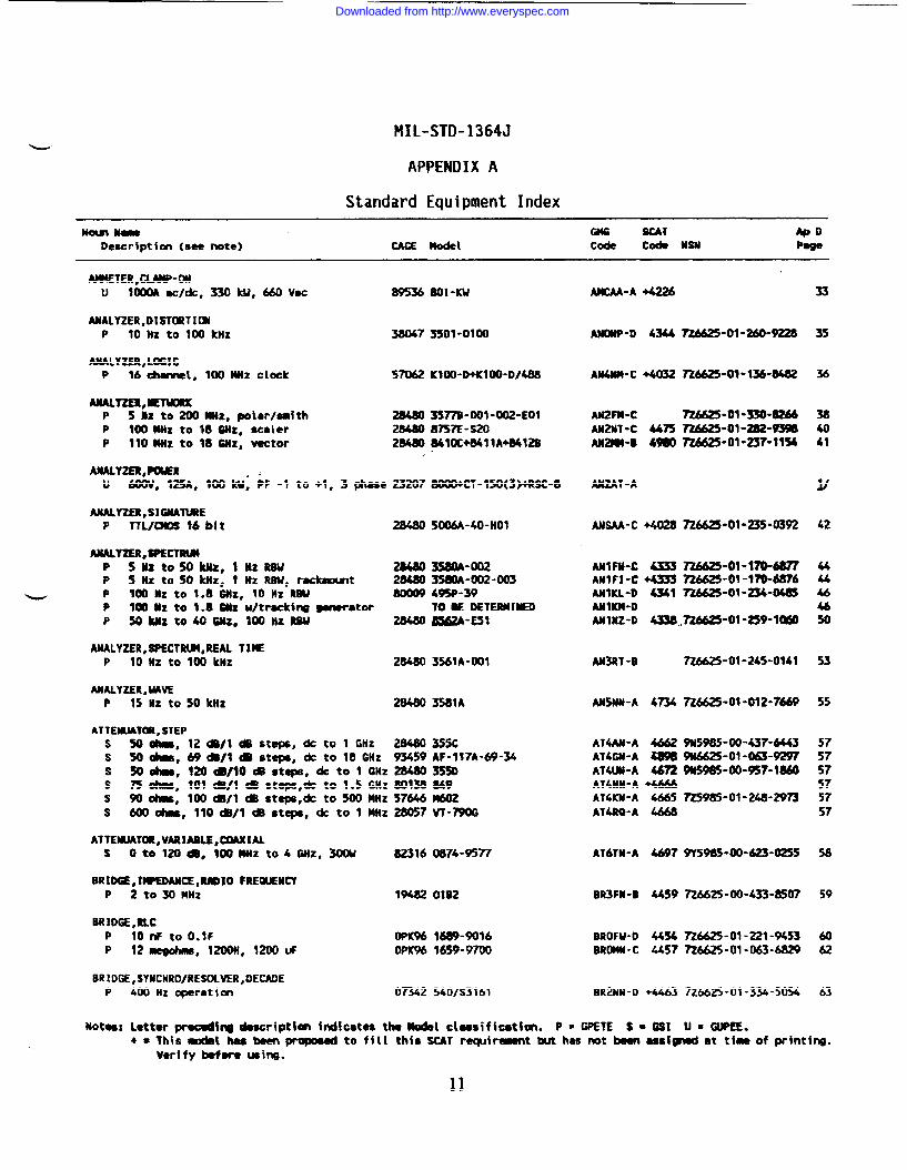
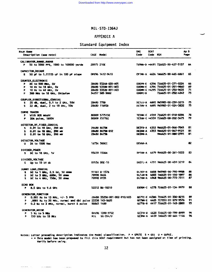
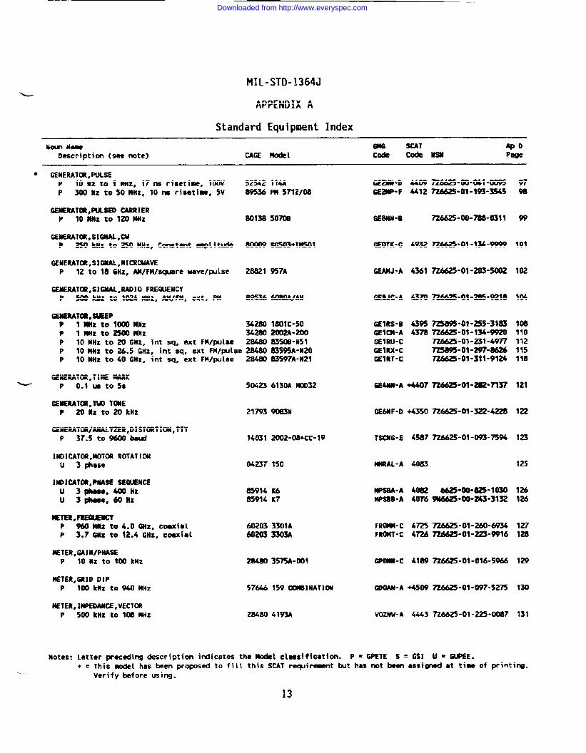
DDendlx A. Standard eauipment index Thts appendix listsstandard 6PETE, 6S1, and GUPEE in noun name sequen~e referenced to GMG code,SCAT code, and national stock number (NSN). The commercial and Governmententity (CAGE) code specified in DOD H4-2 is listed with each commercialmodel. A page number is listed which indexes the Appendix D purchasedescription to the referenced model.
5.1.2 ~Dendix B. SCAT to GMG code Hany documents, including theTE Index, cite the NAVSEA SCAT code to ide~tify the famfly group of aparticular test equipment application. Appendtx B identifies the GMG codeand its head of family (standard model) for each relevant SCAT code.Previous toappendix in
preferred-model cross-referencing is found by using thisconjunction with the TE Index.
3
Downloaded from http://www.everyspec.com
IIIL-STD-1364J
5.1.3 dix C~ confiauratlon~.
Hany comerctal, off-the-shelf GP dels are provided to the ?lav~with configuration numbersassigned which are not found in the manufacturers’ catalogs. Appendix C wascompiled to assist the user wtth identification of these models and theircomponents. This appendix is sorted by the configuration number and listsmodel numbers of mainframes, plug-ins, their options, and major accessories.
5.1.4 Dendix D. Purc~se descrintiMs. Appendix D containstechnical acquisition specifications for standard GPETE, 6S1, and GUPEE.This appendix Is arranged in noun name sequence. The specifications reflectthe known minimum technical requirements of the Navy and are not necessarilythose of the standard models listed in Appendix A. Accordingly, each modelshould be considered typical as alternate manufacturers may be selected todeliver substitute models using these specificationsfor qualification.
5.1.4.1 revision let~ Each Appendix O purchase descrip-tion is identified by a five-character &G code followed by a revision1etter. Because of changing test requirements for new and evolving primesystems and modernized test methods, the revision letter Is necessary toidentify updated issues of the purchase description used for solicitation.The current GM code revision letter may be found in the MIL-STD-1364 GPETE,GSI, and 6UPEE Status List (see 5.2). Details of modifications noted byrevision letter changes can be obtained from the NAVSEA Test and MonitoringSystems (TAMS) Division or from the GPETE Bulletin Board System (BBS) (seeK K\
5.1.4.2 $ronnlenta1 Clitssiflcatierr. +%?’~e severity ofenvironmental conditions in which the test equtpment ttem is capable ofbeing operated and stored may be determined from the type, class, and stylecharacteristics found in the purchase description and as defined in MIL-T-28800.
5.2 GSI. an- SUS llst.●
● Guidance to interim additionsand deletions of standard test equipment is rovided in the GPETE, 6S1, and
!0GUPEE Status List between revisions ofHIL-S -1364. This status list isissued semi-annually in April and October by the Naval Electronic SystemsEngineering Activity (NESEA), St. Inigoes, HD 20684-0010. Direct Inquiriesto Code 2261. The status 1ist is alternately available from the GPETE BBS(see 5.5) which is updated quarterly.
5*3 ~- Users shall not interpret thisdocument as authority to acquire 6PETE, GSI, or WPEE on a sole-sourcebasis. Acquisition shall be In accordance with federal acquisition regula-tions and maximum competition between manufacturers shall be sought.Specific details for requisitioning 6PETE arecwtaiaed tn NAVSUP P-485 andtype comander directives.
5.3.1 ~pETE initial outfitting deficieocie~. New or increasedallowances of 72 Cog GPETE are not to be requisitioned by the requiringactivity except as authorized below by the emergent GPETE requirement
—
4
Downloaded from http://www.everyspec.com
MIL-ST’D-1364J
program. Initial outfitting deficiencies of GPETE will redetermined byTAMS managers. These deficiencies are consolidated by the NAVSEA TAMSDivision for acquisition.
5.3.2 ~~ment GPETE acquisition Drowam. Extensive time is requiredto coordinate and budget for Navy-wide 72 Cog GPETE assets. A three-yearacquisition process is normal for programmed buys. To allow for non-programd, time-critical acquisition of7Z Cog GPETE, the emergent 6PETEacquisition program was established.
5*3*2*1 ~. Requesting activities shall coor-dinate their acute GPETE needs with their type conmnanderwho, in turn, shallcoordinate allowancing data with respective TAMS managers. The requestingactivity shall submit a funded requisition with a routing identifier of P90to the ConanandingOfficer, Naval Electronic Systems Engineering Activity,Code 2261, St. Inigoes, MD 20684-0010. Requisitions by message may besubmitted to NAVELEXSYSENGACT St Inigoes, MD. The subject line shouldstate: 6PETE MILSTRIP. Requirements for nonstandard 7Z Cog 6PETEwst besubmitted in accordance with the nonstandard GPETE application procedure(see 5.4) prior to submission of the requisition.
5*3*2*2 ~. Upon receipt of a funded requisi-tion, NESEA personnel will verify requirements with the respective TAMSmanager. A control number will be assigned to an approved requisition whichwill then be forwarded to Navy Ships Parts Control Center (SPCC). SPCCpersonnel will report the status to the requesting activity, procure theGPETE”ltem, and, upon receipt, ship the item to the requester. “#’disap-proved requisition or a requisition submitted directly to the SPCCWI1l becancelled and returned to the requesting activity.
5.3.3 GPETE SUDDIV surwort rwocedure$. GPETE supply support proce-dures apply when a 6PETE item designated in NAVSEA STOOO-AA-IDX-O1O-PEETE asa standard item, substitute standard, or limited standard is to be turnedin. As directed in NAVSUP P-485, a survey report will be completed onmissing or unserviceable GPETE and, in turn, an Issue Release ReceiptDocument, DD Form 1348 will be prepared for the replacement item. Carcassturn-in credit is applicable for standard and substitute standard 6PETE.When ● limited standard item is turned in, users are charged the standardprice for the replacement GPETE because repair of the carcass is no longercost effective. Ifan obsolescent or obsolete item is to be surveyed andreplaced, the replacement item falls under the GPETE initial outfittingprogram. Report the deficiency to your type conmnanderfor subsequentsubmission to NAVSEA TAMS Division for acquisition.
5.4 Wnstandard GPETE acmlication Rrocedure. Uhen a Navy acttvitydetermines it has a unique measurement requirement and needs to acquirenonstandard GPETE, the applicant shall evaluate criteria specified in a andb below for planning purposas. The Navy activity must narrow its nonstan-dard GPETE selection to best meet the logistics and performance criteriacited above below. Once this is done, the activity must fill out a nonstan-
Downloaded from http://www.everyspec.com
MIL-STD-1364J
—
dard GPETE application in accordance with DID DI-MISC-80056 (see 6.2) andsubmit it to NESEA (Code 2261).
a. Lodstics consideration. The ideal selected nonstandardGPETE is a model currently in the Navy inventory, has spare parts support,and an instrument calibration procedure (ICP) listed in NAVSEA OD 45845Metrology Requirements List (METRL). Existence in Navy inventory may befound by consulting publications listed in NAVSUP P-4000. Provisioningsupport information is available from the SPCC MIAPL.
b. ce considerateion. The ideal selected nonstandardGPETE is suitable for use in the intended environment. Environmental type,class, and style characteristics of the nonstandard GPETE may be identifiedthrough the use of ?IiIL-T-2S800.
5*4.1 d ication Review. NESEA personnel will review each nonstan-dard GPETE application within 10 working days from the date of receipt. Anonstandard GPETE control number will be assigned to each application andreferenced in all correspondence. Each nonstandard GPETE application willbe evaluated for approval based on the application data, technical jus-tification, and life-cycle cost. An item previously selected and proven inan equivalent system test application will be considered as a substitute tominimize proliferation.
5.4.2 lication amro al. Applicants will be advised by NAVSEA(Code 040S) i~mitingof application approval or disapproval. Upon receiptof the nonstandard 6PETE application review package from NESEA (Code 2261),NAVSEA (Code 04DS) forwards a letter within 10 working days that eitherapproves or disapproves the application. Nonstandard GPETE applicationapprovals shall be interpreted as granting authority to deviate from thestandard GPETE models listed in Appendix A. Authority to initiate anacquisition and expend funds is beyond the scope of NAVSEA authority. SPCCprocures all approved 7Z and IH cognizance standard and nonstandard GPETE,GSI, and 6UPEE unless they grant local procurement authority. Other itemsare procured by the agency assigned cognizance.
5.4.3 ~fe-cvcle sumort The activity desiring the nonstandardGPETE will be responsible for d~veloping new life-cycle support includingInstrument Calibration Procedure (ICP) development and provisioning. Theactivity should contact the Naval Weapons Assessment Center (Code 3112C),Comm (714) 273-5361 orAV 933-5361 to coordinate the development and fundingof the ICP. To determine provisioning and its associated cost, contact theNaval Sea Logistics Center (Code 416), Coumn(717) 790-3246 or AV 430-3246.Under no circumstances shall nonstandard GPETE be placed on the ShipsPortable Electrical/Electronic Test Equipment Requirements List (SPETERL)for any Navy ship before the requirements for an ICP and provisioning areinvestigated.
5.4.4 Term ofaDDro al.v A nonstandard GPETE application approvalwill be valid for one year from the issue date except when based on specific
6
Downloaded from http://www.everyspec.com
MIL-STD-1364J
out-year projections. Contact NESEA (Code 2261), Conm (301) 862-8288 orAutovon 326-3512 extension 8288, if the approval period will expire prior toacquisition initiation and an extension is required. The applicant shallstipulate the reason for the extension request and specify the extensionperiod required.
5.4.5 D1ication dis~ro al. Nonstandard GPETE applications willbe disapproved by NAVSEA (Code O&) when they are incomplete or nottechnically justified. The applicant will be not~fied in writing and willbe given the reason for the application disapproval.
5.4.6 ~esubmission after disaollroval. If a nonstandard GPETEapplication has been disapproved by NAVSEA (Code 04DS) and the applicantwishes to reapply, the new application shall include cited omissions oradditional justification as described in the disapproval letter. Theapplicant may contact NESEA (Code 2261) for clarification or questions.
5.4.7 Nonstandard GpE?E reauisitionina reauirements. The controlnumber shall be referenced in the remarks portion of any funded requisitionsfor nonstandard GPETE. Requlsitlons shall be submitted in accordance withthe GPETE initial outfitting acquisition procedures (see 5.3).
5.5 GPETF B~ Because of printing and mailing cost restrictions,distribution of the 6PETE, 6S1, and GUPEE Status List is limited. Thestatus list may be obtained from the GPETE user’s conference on the GPETEBBS at NESEA. This BBS also maintains updated revisions of purchasedescriptions and other pertinent GPETE matters. The BBS wy be contactedvia 1200-9600 baud phone modem at (301) 862-8048. Access to the GP~Econference is normally granted one working day following initial registra-tion. To register, complete the initial quick registration form and thencomplete the new user registration by accessing the “door2” mode. In-quiries, suggestions, or comments concerning electronic test equipment mayalso be made through this service (see 6.3).
6. NOTES
(This section contains information of a general or explanatory naturethat may be helpful, but is not mandatory.)
6.1 Intended use. This standard applies to all direct Navy acquisi-tion and procurement through contractors and subcontractors for standard andnonstandard GPETE, GSI, and GUPEE. The standard 6PETE, CSI, and GUPEEidentified herein should be cited in all planning and support documentswhich specify electronic and electrical test equipment.
6.2 Consideration of data reaui rements. The following data require-ments should be considered when this specification is applied on a contract.The applicable Data Item Description (DID’s) should be reviewed in con-junction with the specific acquisition to ensure that only essential dataare requested/provided and that the DID’s are tailored to reflect the
7
Downloaded from http://www.everyspec.com
MIL-STD-1364J
requirements of the specific acquisition. To insure correct contractualapplication of the data requirements, a Contract Data Requirements List (DDForm 1423) must be prepared to obtain the data, except where DoD FARSupplement 27.475-1 exempts the requirements for a DD Form 1423.
Referenced SuggestedParaciraDfi DIDNumber DID Title
5.4 DI-MISC-80056 Request for approval ----of nonstandardgeneral purposeelectronic testequ@ment
The above DID’s were those cleared as of the data of this specification.The current issue of DoD 501O.12-L, Acquisition Management Systems and DataRequirements Control List (ANSDL), must be researched to ensure that onlycurrent, cleared DID’s are cited on the DD Form 1423.
6.3 ~er in~iriea. Navy test equipment users are invited to contactNAVSEA TANS Division concerning new or modified test methods and trouble-shooting procedures which would require changes to the minimum technicalrequirements specified in the appendix D purchase descriptions. PIeaseidentify the prime system under test and details of the test procedure,including copies of technical manual pages, maintenance requirement cards,and other pertinent documentation.
6.4 ~lstina inauiries. The Navy need for GPETE, (31, and 6UPEE is afunction of the specific test and measurement capabilities required tomaintain and repair weapon systems and ancillary subsystems. The standardelectronic and electrical test instruments listed in this document wereextensively tested and evaluated in consideration of current and projectedGPETE requirements. Manufacturers’ inquiries relative to a product whichcan lead to significant operational improvements and economy are welcome.
Inquiries should be addressed to Naval Sea Systems Conxnand,Test andMonitoring Systems (TAMS) Division, Washington, DC 20362-5101. Provide fulldescriptive information, a technical manual, support availability, and testdata in accordance with MIL-T-28800.
Indicate why the item should be listed and supply supporting informationconcerning a known or projected Navy measurement requirement. Identify theparticular weapon system, measurement setup, and, where possible, the useractivity.
8
Downloaded from http://www.everyspec.com
MIL-STD-1364J
6.5 Subject term [kev word] listinq.
ApplicationsCommercial and government entity (CAGE)Emergent GPETE acquisition programGPETEGSIGUPEEInstrument calibration procedure (ICP)Item entryGPETE initial outfittingGPETE master group (GMG)6PETE supply supportNational stock numberNonstandardSubcategory (SCAT)Support itemsTest and monitoring systems (TAMS)
6.6 Lhanae~ from wevtous issu Marginal notations are not used inthis revision to identify changes wit~”respect to the previous issue due tothe extensiveness of the changes.
Preparing activity:Navy - SH(Project No. 6625-NB 30)
Review activities:Navy - AS, SA
User activities:Navy - OS, CG, YD, EC, MC, TD, NO, OM
9/10
Downloaded from http://www.everyspec.com

Downloaded from http://www.everyspec.com
—
FIIL-STD-1364J
APPENDIX A
Standard Equipment Index
NoLmm ScN ApDDescription (see note) CAGE MO&l co& code USN Poge
AIUETER,CLAMP-(Mu lm adck, 330 w, 660VU 8%36
ANALYZER,DIST(MTIONP 10 Hz to 100 kHz 38047
ANALYZER,LCXHCP 16 chunel, 1~ MHZ clock 5-
ANALY2ER,IETUXKP S #Z to =~Z, polmmstthP WOMHZ to 18 Wz, sealerP ltO MHz to 18 6ttZ, vector
801 -Ku
3501-0100
KIDO-O+KIOO-D/488
3577B-001-002-EOl8757E -s20841a+8411A+8412B
8o00+cT-150(3)+Rsc-8
5006A-40-1101
3wM-oo23580A-002-0034m-39TO W DETERMINEDm-E51
3561A-001
3581A
355CAF-I17A-69-34
849
VT-7900
0874-95n
01s2
1689-90161659-9700
540/S3161
MCAA-A +4226
AMDw-o 4344
Alum-c +4032
AN2FM”CAN2NT-C 44=AN~-B 4W0
AN2.At-A
ANSAA-C +4028
ANIFU-G 4S33ANIFi-C ~ANIKL-D 4341ANIICM-D
33
R6625-01-260-9228 35
726625-01-136-8482 36
n6625-ol-3304t266n6625-ol-282”93mn6625-ol”237-1154
384041
ANALY2ER,WWRu 600V, 125A, 100 IdJ; PF -1 to +1, 3 @use 23207
ANALY2ER,S1(MATUREP TTL/Q#3S 16 bf t
ANALY2ER,sPEcTRwiP Smtosok Nz,t NzRBuP 5 M to 50 kffz, 1 Hz RBU, racfmxmt 28480P 100 Hz to 1.8 6Hz, 10 Hz RWP IM Ilz to t.8 Gitz Wtr.ckirqi guwatorP 5okuzto 40 GNZ, lmnz RBu
ANALYZER,SPECTRtM,REAL TIMEP 10 HZ to 100 kMz 28480
ANALY2ER,UAVEP 15 ffZ to 50 kliz
ATTEMJATUl, STEPs 50 ~, 12 ~/1 dB stefx, dc to 1 GHz 28480S M -, 69 &fj & stefm, & to 18 6~Z 93459s 50 Ohm, 120 allo * steps, de to 1 GHZ 28480s m Ohms, 101 Cm/l * Steps,* to 1.5 GHZ 80138s m Ohm, 100 */l * Steps,ck to 500 UHZ 57646s 6m *, 110 cB/1 @ steps, k to 1 MHZ 28057
ATTEIBJAT~,VAR1 A8LE ,COAKIALs oto120dI, wNlltNzto6BNz,30w 82316
BRtW, WEMNCE ,~10 FREWENCYP 2 to 30 MHz 19482
BRIDGE,RLCP 10 tW to O.lF 0PK96P 12 asgohme, 1200N, 1200 UF 0PK96
BRIDGE, SYNCHRO/RESOLVER,DEWEP 400 Hz operation 07342
l)
726625 -ol-m-0392 42
726625-01-170--n6625-09-170-6876n6625-ol-234--
AN1N2-D B,. M-01 -2S9-lMO 50
AN3RT-B 726625-01-245-0141 53
AN5MU-A 4734 7z6625-0$-012-76@ 55
AT4AN-A 4662AT4GN-A mATWN-A 46~AT4NN-A +4666ATWN-A 4%5A74RQ-A 4668
9N5985-00-437-6443W6625-01-063-9297w5985-m-957-1860
m985-ol-248-2973
575757575757
AT6tH-A 4697 9Y5985-00-623-0255 58
BR3FM-B 4459726625-00-433-8507 59
BROFW-D 44%SAWN -c 4457
n6625-ol -221-9453726625-01-063-6829
6062
726625-01-334-5054BR2NN-D +4463 63
[email protected]*Notaw Letter procdfM tiriptim ideates the Modd clusificatlav P = GPETE S ● GSI+ = Thii -[ ~ been- ~ to ffll th{a SCAT re@nmsnt Wt hes not been usfgtted at ti~ Of
Verify before wing.prfnting.
11
Downloaded from http://www.everyspec.com
MIL-STD-1364J
APPENDIX A
Standard Equipment Index
Nom h SCAT ApoDeecriptim (xnote) CAGE Modd code code NW Pege
cALIBRATat,RMaE,RADARP 50 to 5m0 PPS, 1000 to 100ooo yards
CAPACITOR,DECADEs 50pF to 1.11115 W h 100pF steps
CCRMTER,ELECTRWICP Dctosoom,wP 10 02 to 18MX, wP lonz to40GJix, wP mtutz to 18 GM, cu/pu18e
caxwR,olEEctIaAL,aMxMLs 26*, chml, 0.1to2GNz, SWs 22ds, Ad, 2 to 18GHZ, 5(N
amw T-P Wths amamP 2(MPU1U, 1600V
DETECTC#l,RF,FIXED,CWXIALs 0.01 to 18GNZ, m-s 0.01 to 18 Gltz, 200Ws 0.01 te ?8CHz, 200 w
DETECTOR,UWTAGEu 24 to lSWVU
DIV1DER,PC4ERs DC to 18 GMZ, Iu
DIVIDER, VOLTAOES uptolOkVdc
DMY L(MD,CZMXIALS DCtol G#z,2.5ku,50ms Dcto3Gllz, 6CMM,500bs DC to 4 SRz, 15(M, 50 *
ECNO _P 8.5 6Nz to 9.6 WZ
GEmTm, FwcTlmP O*W1 Rz to 1s MNz, +/- 5 w?!
28975 21OE
DPK% 1412-%10
28480 5334S-030-W528480 535a-ml”No328@0 5352B”a)l -M0334257 MS-5862
28480778028480 116920
8(IOW 5~15E80009 F5~2
2s480 Mm28480 84m”olz28480 84m
16= 300cC
93459 1506A
89536 8OE-10
91161 B-1576709988404709980135
5221286-18210
28480 33250 -001 -tK12-910/H03P .U1 Hz to20MNz, no-l -*[ pulse 23338 145-S620P 0.2 Mz to 3 MNz, normet, b-st k pulse 8s865 14W
GENERATOR,MOISEP 5HZ*05MMZ WI(% 1390”9702P 150 ktiz to 10 ~Z NIL sG-354/u
TS9W-D +4491
CPIMN-A 4624
~FM-E 4296C(MMN-C 4294Ctlom-c +4295CQ@c-o
DCIJJ-A 4692DCINH-A 46%
TE5NN-C 4559TE5GN-C +4559
DE2YN-A 4352DEW-A 4353DE2tM-A
MVAA-A
DPIW-A 46~
DR2FL-A 4791
DLIEY-A 6#8DLIJ1l-B 4683OLISlbA 4948
EIMKWC _
CE7TC-E +4386GE7NM-E 4405GE7T8-S 444?
GE3FH-8 4420GE3MN-A 4419
Notes: Letter wecodfrm descriptim fndicates the model classification. P = GPETE S = 0S1
7z6625-00-427-5 ~57 64
1N6625-00-465-686165
~6625-01-271-0224 667M62!5-01-251-W6U 69n6625-ol-250-w35 71n6625-ol-252-4242 73
9u5985”fnl-239-3215 n9N59@5-01-024-3832 ~
=-01-018-8204 76726625-oo-202-34n 79
W6625-01-046-7045 819n6625-Ot-047+121 819M6625-01-~-2791 81
--
82
9V6625-00-261”5033 83
9u6625-00-459-3219 84
~-w-m-wa 85~N6625-ol-150-m97 uW6625-w-m-nll 87
7M625-oJ-134-wn 88
ZM625-01-330-821S wR7050-01-0~-9576 917Z6625-ot-14s-m m
726625-00-799-8999 94IN6625-00-W-1146 %
+ m ~i~ ~1 ies been-pr~ to fill this SCAT reqi~t but has not been essignsd at time of printing.
Vedfy before ~ing.
12
Downloaded from http://www.everyspec.com
MIL-STD-1364J
APPENDIX A
Standard Equipinent Index
Nom N- SCAT ApoDescription (see note) CAGE Model Cocie code iisu Page
● GEbiERATCXt,PULSEP 10 Hz to 1 Wiz, 17ns risetime, I(IOV 52542 114AP 300iiz to50Mtlz, 10ns risetime, 5V 89536PM 5712/08
GEMERAT~,PLKED CARR!ERP 10MNZ to 120 MNz 80138 507iX
GEWRATOR,SIGMAL,CUP 250 kHz to 250NHz, C-tMt a@itude 800W SG503+TM501
GENERATOR,SIGNAL,MICROUAVEP 12 to 18 Wz, AM/FM/~re uave/Wise 28821 957A
GENERATOR,SIGNAL,RADIO FREGUEMCYP 500 kitz to 1024 MHz, AM/FM, ext. PM 89536 6080A/AN
GEMERAToR,SilEEPP 1 Wix to lmmiiz 34280 1801C-50P ImNztom Mliz 34280 2’(X)2A-200P 10 Miiz to 20 GHz, int sq, axt FWpulse 28480 835m-N51P 10MHz to26.5 GHz, int sq, cxt FM/pulse 28480835%A-N20P 10 MHz to 40 GMz, int sq, ext FM/@se 28480 83597A-H21
GENERATOR,TIME MARK~ P 0.1 m toss 50423 6130A NO032
GENERAICNl,M TONEP 20 Hz to 20 kiIz 21793 W83N
GEMERATCR/ANALY2ER,DISTCRTICNi,TTYP 37.5 towoobsd 14031 2002-D8+CC-19
INDICATOR,lUIT~ ROTATICBIu 3 phase 04237150
IaoIcA7m,pnAsE SEOUEUCEu 3phau,44Xliiz 85914 K6u 3pho8e,60iiz 85914 K7
iEwR#FREawEYP %oMiiz to4.o GNz, coaxial 60203 33(I1AP 3.78iiz to 12.4 GHz, coaxial 60203 3303A
METER,GAlti/PNASEP 10 HZ to 1(XIkllz 28480 3575A-001
METER,GRIO DIPP 100 kiiz to940 MHZ 57646 159com81NATltM
IETER,lMPEOANCE ,VECTCMP 500 kuz tO t~ MHZ 28480 4193A
GE2W-D 4409SE2W-F U12
GE8W-B
GEollc”c 4932
GEAMJ-A 4361
CE6JC-A 4370
GEtRS-B 4395GEIU-A 4378GEIRU-CGEIRX-CGEIR1-C
GE4NN-A +4407
GE6NF-D +43S0
TSCNG-E 4587
HURAL-A 4083
MPS6A-A 4(MQNPSW-A 4076
FROM-C 4725FRW’T-C 4~
GPoMN-c 41W
GDOAN-A +4SW
VOZNU-A 4443
P=@ETE S=GS1
7z6625-Do-041-m95n662s-ol”193-3545
97w
w
n6625-ol-134-w99 101
n6625-ot-2m-5m2 102
104
--01 ”2s5-31=~-ol”U4”W20726625 ”01-231”4977~-ol-297”8626~“ol-311-9124
w110112115118
7z6625”ol-a2-7137 121
726625-01”322”4228 122
7z6625-ol-m-7594 123
125
6625-aH25”lo30W6623”OO”W”3132
126126
726625-01-260+W34R6625-01-223-W16
127128
--01-016-S%6 129
~-ol”w7-5275 130
n6625-ol-225”oo87 131
Notes: Letter preceding description indicates the Model clea$ificatfon.+ = This -[ has been proposed to filt this SCAT requir~t but has not been assi~ at time of printi~.
..Verify before using.
13
Downloaded from http://www.everyspec.com
HIL-STD-1364J
APPENDIX A
Standard Equipment Index
NOUI Nme SCAT Apt)Description (see note) CAGE Nodel Cotk NW Page
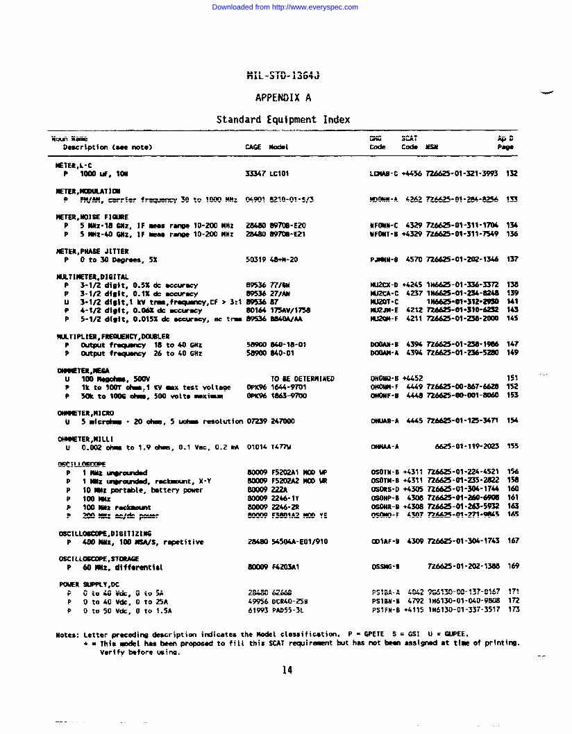
)ETER,L-CP 1000UF, ton 33347 Lclol
iE’TER,~Tl~P FWAM, oarrisr frewency 30 to 1000MHZ 04901 8210-01-s/3
iETER,tiOISE FIOUREP 5Hz-18CNZ, IF ~ r- 10-200 MHZ 2M80 W7GB-E20P 5MHz-40GJIz, IF mess range 10-200 MHZ 28480 W70B-E21
NETER,PNABE JITTERP oto30~rees,5x 50319 48+N-20
NLKTIETER,DIWTALP 3-3/2digit* o.5%dc accuracy 89536 77fBNP 3-1/2digit, O.l%dc accuracy ~36 271AuU 3-1/2digft,l kV t-,f~,P
CF ~3:1 -874-1/2diglt, O.-* ~acy 80164 mAv/1758
P 5-1/2digft, 0.015X& accuracy, ac t- W5368840WAA
llJLTIPLIER,F~CY,DOIJBLER: wf~ 18 to40 GHz 58WOMO”W”OI
output t~ 26 toko GHz 5WO0 840-01
019BETER,=GAu lmMegc4mc, 500V TOBE DETERMINEDP lk to 100T *,1 KV-X test voltage WX96 1644-9701P SW to loos *, 500 Voltsmxim OPK% 1863-9700
CMMETER,MICROu Smfc* - XI*, 5* resotutionom924mO0
OWMETER,MILLIu 0.D02~ to 1.9 ohmi, 0.1 Vet, 0.21rA 01014 T477U
06CILL~P lwz~ 80009 F5202A1 MID UPP 1 -~, r=~t, X-y 80009 F5202A2KXILRIP 10 J!itz Wt*le, bettery pouer 800D9222AP 10D MHz 80W9 2246-lYP 100WZ rdaamt Bow9 2246-aP 2W MNz ac/dc power 80009 F3801A2 ~ YE
OSCILL~,OIfiITIZINGP 400 MNz, 100 MSWS, repetitive 2G4B0 54504A-EOl/910
OBCILL~,STORAGEP 60iUizo dfffwential 80009 F4203A1
POWR SUPPLY,DCP 0t040V&,0t05A 2$4B0 6266sP O t04tl VdC, O to 25A 49956 DCR40-25BP O to 50 Vdc, O to 1.5A 61W3 PAD55-3L
LOIAB-C +44%
IQONN-A 4262
NFONN-C 4329NFDNT-B +4329
PJNNN-8 4570
W2CX-D +4245W2cA-c 4237U20T-CW2JN-E 4212IU2W-F 4211
DOmN-B 43%DOOAM-A 4394
OHONO-B+4452OHONN-F 4449ONONF-B 4448
OWAB-A 4445
(MMAA-A
OSOTN-B +4311OSOTM-B +4311OSDRS-D +4305OSOHP-B 4308OSONR-il +4308osOm-F 4307
~lAF-B 4309
OSSUG-B
PSIBA-A 4042PSIBN-B 4792PSIFM-B +4115
p . WETE s . Gs~
n6625-ol-321-3993 132
n6&s-ol-284-8256133
726625”01-311-17(X7z662s-m-319”m9
134136
~-ol-202-1346 137
IH6625-01-336-3372lN6625-ol-234-82481N6625-01-312-29307Z6625-01-3W4Z32726625-01 -238--
138139941m145
n6625”ol-2.3e”lwm1625-ol-zs6-528D
14?149
151 ‘-152153
7z6625-m-867-6628n6625-oo-wl-8Mo
7z6625”ol-125-3471 154
6625-01-119-2023 155
~6625-01-224-4521n6625-ol-235”2a22726625-01-304-1744mws-ol-m”t$m726625 -01-263”s932n6625-ol”27f-9845
156158160161963165
n&?5-ol”304-1743 167
726625-01-202-1386 169
9G6130-00-137-01671H6130-01-040-9BOB1H6130-01-337-3517
171172173
Motes: Letter CWecedina description indicates the -1 c~a~$ffic~ti~m+ = Thi8 b{ ias been”~oposd to fill this SCAT requirement but has not been assigned at the of pr!ntin9.
Verify before using.
14
Downloaded from http://www.everyspec.com
MIL-STD-1364J
APPENDIX A
Standard Equipment Index
uobm- SCAT ApD
Description (see note) CAGE *1 code cock wan Pegs
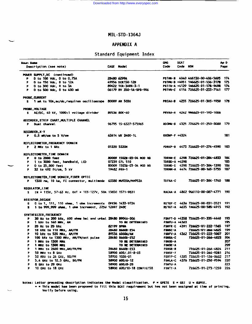
PinER SWPLY,OC (cmtirnJsd)P O to 10 Vdc, O to O.~A 284806299AP oto150vdc, oto 12A 49956 DCR150-12SP oto300vdc, oto3A 89022 TCR-=-3-1P oto5mvdc, oto400ti 06179 W 350-lA-BPB-906
PROBE,~REbJTs 1 * to 10A,ec/dc, re@res oscilloscope 800@ AM 503S
PINM,VOLTAGEs AC/OC, 40 kV, 1000:1 voltege divider 89536 8W”40
RECCMiDER,STRtP CHART,MULTIPLE CHAXNELP Dual charnel %795 15-6327-575%5
REcmOER,x-YP 0.5 */a to 5 v/a 62634 U 24m-lL
REFLECTCETER, FREOUEWCY-INP 2mHztol Gnz 01220 522W
REFLECTCUETER,TME DCNAINP oto2fxx)foet 8tX)09 1502S-03-04 ~ MBP 1 to 3000 feet, hancheld, LCD 07239 CFL 510
~ P o to 25,000 feet 80009 1503S-03-04 MOONBP 32 to 492 ftl-, 5 kV 19482 PRH-1
REFL~,T)- DOMAIN, FIBER OPTICP 1300 ~, 10 km, FC connector, mltimode 63380 MU920A/W952A
RE(UATOR, LINEs In = 115v, 57-63 Hz. WT = 103-127V, 50A 13850 1571-9831
RESI STOR,OECADEs O to 1, 111, 110 k, 1 ohm increments (WC% 1433-9724s 1 to 999,999 ohwB, 1 ohm htmment, 225U 12697 240C
SYNTHESIZER, FREQIEMCYPPPPPPPPPPPPPP
301h-to200kIIz, 60001Ns bel end-l1 km to 140 MHz, Am2oBzto20kHz10 ktlz to 110 MHz, AWFN10 IcHz to 520 MHz, AWFM100 kiiz to 1300 MHz, AWFM/ext pulse1 miz to 1300 Mtixlanztolmmtz1 MHz to 2600 MHz, AWFM/PM50 Hz to 8 GHz50 MHz to 26 cm, Sclfw5.4 i#tZ to 12.5 @iZ, SVPH8GHzto200Hz10 6HZ to 18 GHz
284ao 8904A-m6TO ~ DETERMIWD
aaw SPtui28480 86MD-E5489536 606WAN28480 866mE52
m E oETEM1nEDTo M mTEWINED
28480 8!WD-E5358900 600/.01-8-03589(XI 1-158900 60W6- 1258900 600/8-2058900 600/10-18 CWFIG158
PSIHU-B 4040PSIMU-B +4051PSITM-A +4129Pslw-c 4114
PRCAA-B 4235
PRVAA-A 4242
RDOMN-6 4325
RX(IMP-F +4324
FORKP-B 44~
TDRNN-E 42SMTORSO-A +4298TDRND-E 4298TDRUM-A 4474
TDFM-C
RACAA-A 4802
REIGY-C 4636REIGT-A 4635
FSUFT-D +4358FSWFU-A +4363FSWFR-C 4391FSMSC-AFSUFV-A 4362FStSA-CFSWO-AFSNSE-AFSMSB-OFSNSF-FFSNTP*C 4385FSULA-C 4376FSUW-AFSNTT-A
Motes: Letter preceding description indicates the -1 e{seeiffcetion. P = GPETE S = GSI
4G6130-(m”#-5695 174lHM25-ol-m6-317a InW6625”ol-Wa-94m 17672A62S”OI-233-7141 177
726625-01-303-1930 1A
9U6625-01-W3-IW
726625 -01”250-0088 779
7Z4625-01”276-45WI 183
n6625-09”a4-4a33 184185
n6625-ol-304-13m 186726625 ”00-165-5755 187
ZM25-01-304-97U las
9G67 10-00-087-4771 190
726625-W-031 -3521 1911H6625-DO-585-4915 192
726625 ”01-335-4440
n6625-ol-222-1565726625-01-266-U325n6625-ol-222-5m772662!5-01--4s25
726625-01-266-4824n6625-ol-2M-92al7WW5-01-136-B602n6625-ol-250-9594
726625 -01-273 -12S9
193195197lW201
207
211214217220223226
15
Downloaded from http://www.everyspec.com
HIL-STD-1364J
APPENDIX A
Standard Equipment Index
NoLmurn SCAT ApoDescription (see note) CAGE Bodd code code mu Poge
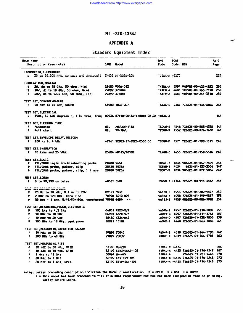
TACNOMETER,ELECTRONICu 50 to 10,000 RPM, contact and photocell
TERMIUATIW,-lALsss
TESTP
TESTu
TESTPP
TESTP
TESTP
TESTPPP
TESTP
TESTPP●
TESTPPPP
TESTPP
TESTPPPPP
aJ, & to18GNz, Sooham, u(m)IOU, dc to 18GHz, 50 ohms, N(uI)&lb/, dc to lZ.4GHZ, 500hms, N(f)
SET,CWNTE-WRESoMHz to40 GJlz, SWPU
SET,ELECTRICAL1~, 50-~degrees F, 1 kV t-, freq
SET,ELECTRW TIUAutaetdRoll oimrt
SET,ENVELWE DELAY,TELECW~ HZ to4 knz
SET,IWULATIW10 kVocaru125 kvdc
SET,LOGICTTL/(XOS t~ic troubieehooti~ probeTTL/UOS probe, plser, clipTTL~ probe, ~tser, clip, I trecer
SET, L-o to99,999usdetey
SET,MEAWIING,PWER20 HZ to20kHz, 0.1 IIU to 20U2MNZ to 520WHZ, thru-line
7P458
89536
MILMIL
42161
252fM
28480
28480
60621
0%53
DT-2050+2tXl TCIM-A +42~
W9A-012 TWRL-A 45943mM TMIFN-A 4685376BNF TMIFN-A 4684
1026-(MI7 TSXAA-C 4384
87+Y81OO+$OTK+8OTK-2A,3A tSMA-A
AN/us+l18sTV-70AJ
520B3-t7w220-0500-53
NOI2W1OIK
545A5021A5023A
650T
709m 4410-02530MNZ” 1 6NZ, 5f15/50/15w, terdrmted 7WWI*” ‘“
SET,lEASURING,~R,ELECTRONIC100 Miz to4.2 GHz 04901 4220-s/410 mlz to 18 GHz 04Wl 4220-s/3loMlzto40GHz 28480 432A-E42lWMHZ to 18 GHz, pod power 28821 1018s
SET,MEASUUNG,RADIATIOU MZARD10 MHz to40 Gllz3~ MHz to40 GHz %x%
SET,OEASURING,RIFI10 kUZ to30 tttiZ, GPIE 63380 ML428N10 knz to30MMz, GPIB 82199ESU3+ESN2-1051 Hz to 18 6btZ 88869 NM-67N2oMfz to 1 Gm 82199 ESV+ESV-10520 MHz to 1 GHz, GP18 821W ESVP+ESV-105
TEOGN-B 4540TEWM-B 4552
TSONN-D 4571
TE4GN-C 4453
TS3NF-A 403sTS3M-B 4034TS3UT-8 4034
TS7NN-B +4364
UAICN-C 4953UAIMA-A 4958WISJ-B 4959
WOW-F 4957UAOFV-G 495?UAOFR-D 495?UAOXK-F 4%0
RHONR-E 4019RHONP-E 4019
FIMJ-C +4434F1OAL-A MSFIOAY-AFIOAK-A +4425F1OAM-A +442S
Notes: Letter preceding description t~icttu the Model clsssificatia. P = GPETE S = GS1
229
w59e5”m-422-4E52 230Imslm-a-w-?lm 2309u5985-W-241-3S18 230
ma625”ol”m3-6m4 231
14J
~-00-_-4376 241~-00-*16t# 241
7Z6625-01-*W-1511 242
7Z6625-01-1S8-531624s
~-03 -047-73w 246 —6625-01-133-3504 247
9N6625-01-072-S 249
7Z6625-00-9W-33S2 251
n6625-Ql-2m’w 2527z6625-ol-w9-mY7 253wM25+O+MmHm 254
7Z6625-0*-3+0-W02 255~-ol”311-3742 257n6625-ol-w2-m 259n6625-09-M3-3oM 261
n6625-ol”244-5m M2n662’5-ol-244-5m a62
mM25-ol”170-4247 27n6625-ol-221-w5 2m726625-01-170-4248 272~6625-01-170-4249 275
(J = ~E*
16
Downloaded from http://www.everyspec.com
MIL-STD-1364J
APPENDIX A
Standard Equipment Index
#mm N- SCAT ApDDescription (see note) CAGE modal code cock NSN Page
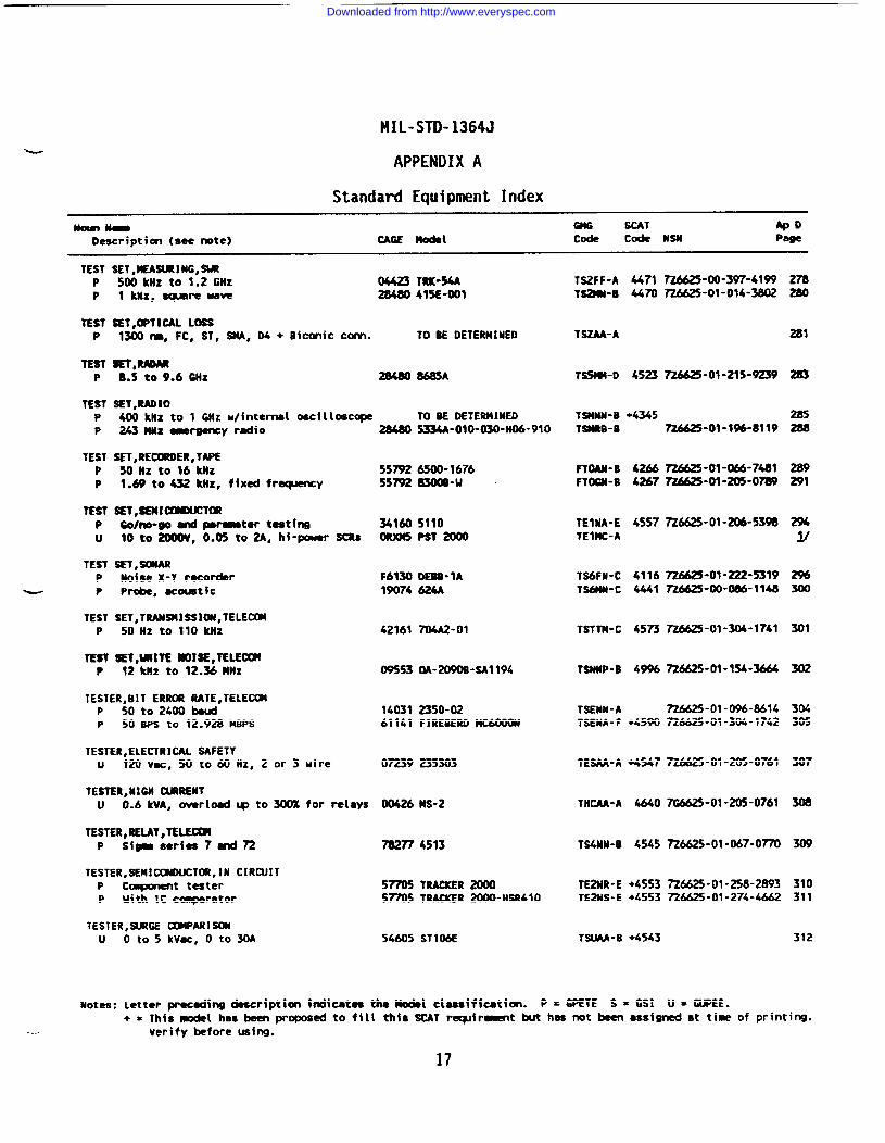
TEST SET,MEASURING,-? 500 knz to 1.2 GHZ 04423 TRK-54AP 1 kMz, aqmre ww 28480 415E”OOI
TEST SET,OPTICAL LOSSP 1300 m, FC, ST, SttA, 04 + Biconic COM. TO BE DETERMINED
TEST 8W,RADARP 8.5 to9.6GHz 28480 8685A
TEST SET,RAOIOP 400 kllz to 1 GHZ u/internal oscilloscope TO BE DETERMINEDP 243 MNz wrgancy radio 28480 5334A-O1O-O3O-HD6-91O
TEST SET,RECOROER,TAPEP 50~Z to 16 kMz 55~ 6500-1676P 1.69 to432 kllz, fixed frequency 5s79283mB-u “
TEST SET,smaxwclmP Go/no-go and parmtcr testing 341605110u 10t02(XMV, 0.05 to 2A, ht-pouer SCRS 0RXM5PST 2000
TEST SET,SONARP Noise X-Y recorder F61300EBB-lA
~ P Probe, acmtic 19074 624A
TEST SET,TRANSUISSl(Ml,TELECOMP 50 HZ to 110 kHz 42161 704A2-01
TEST ~l,tR!lTE WOISE,TELECKM!P 12kHz to 12.36 MHz 09553 aA-2090B-sAl194
TESTER,BIT ERR(X RATE,TELECWP 50 to 240D baud 14031 2350-02P 50 BPS to 12.928 MBPS 61141 FIREBERll MC6000N
TESTER,ELECTRICAL SAFETYu 120 Vat, 50 to60 Hz, 2 or 3 wire om9 2353D3
TESTER,NIGH WRRENTu 0.6 kVA, owrload~ to300% for relays 00426 MS-2
TESTER,RELAY,TELEMIP Sim seriaa 7and~ 782774513
TESTER,SENICCMLNJCTOR,lN CIRCUITP c~t t-ter 5~ TRACJCER2WXIP Uith IC qrator 57705 TRACKER 2OOO-HSR41O
TESTER,SIJRGE COMPARISONu 0t05kVas,0t030A 54605 ST106E
TS2FF-A 4471 7Z6625-00-397-41WTSMi-B 4470 726625-01-014-3802
278
TSZAA-A 281
TS5W4-D 4523 ~-01-215-9239
TSUNN-B +4345TSIM8-B 726625-01-1%-81 19
291FTOAN-B 4266 ~-01-M-7481FTOGN-B 4267~-01-~-0~
TEINA-E 4557 ~6625-01-=-5398TEINC-A
TS6FH-C 4116 =-01-222-5319TS&N-C 4441 ~-00-086-1148
301TSTTM-C 4573 726625-01-306-1741
TSNNP-B 49% ~6625-OJ-154-3664
304305
TSEMN-A 726625-01-096-8614TSENA-F +4590 ~6625-01-304-1742
TESAA-A +4547 726625-01-205-0761 307
THCAA-A 4640 7G6625-01-205-0761
TS4NN-B 4545 ~6625-01-067-0~
TE2NR-E +4553 ~6625-01-258-2893TE21bs-E +45S3 ~6625-01-274-4662
310311
TSUA4-B +4543 312
Notes: Letter Pr=adimdeacrfptfon Wicataa thebdel clua!ffatfon. P = GJWTE S x GSI U = GUPEE.+ = This model has been proposed to fill this SCAT raqdr~t but has not been assigned at tine of printi~.
—- Verify before using.
Downloaded from http://www.everyspec.com
.-
MIL-STD-1364J
APPENDIX A
Standard Equipment Index
Nom k SCAT @oDescription (so@ note) CAGE *1 Cti Code NSN Psge
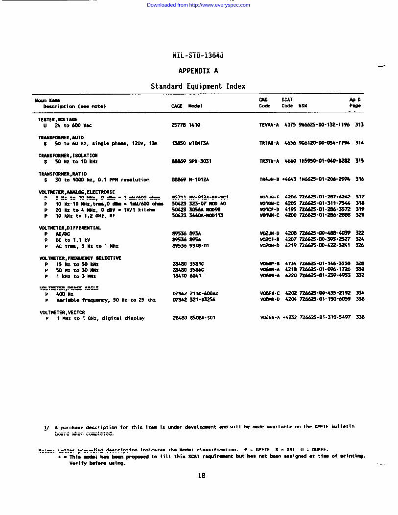
TESTER,WLTAGEu 24 tom vu 25778 1410 TEVAA-A 4075 W6625-00-W-11% 313
TRANSFORMER,AUTOs 50 to60 Hz, Single@laSO, 120V, 10A lnso ulamA TRIAWA 4656 -120--054-77% 314
TRANSFORMER,IBOMTIWs 50 HZ to 10 kItz 88869 SPX-3031 TR3Yn”A 4660 11+5950-01-040”0282 315
TRANSFUUER,RATIOs 30 to WOO h, 0.1 PPM msolutiorl 88869 M-1OI2A TR4JH-B +4643 1=-01-*-2974 316
WL~TER,ANALOG,SISCTRUICP 5nztolonnz,o*=l@i/6C@ * 85711 MV-912A”BP-SC1 VOIJ6-F i2M7z6625”91-2s7-&M2 317P 10 Nz-lomlz,t-,o-= tw/6ooti 50423323-07 m 40 ml--c 4205 m-ol-311-w 318P 2011zto4Wz, OW=lV/1 kilohm 50$23305Mmmm WICF-D 4W5 ~-01-206-35~ 319P 10 kliz to 1.2SUZ, RF 5W23 *-mDl13 Volw-c 42W ~-ol-2S6”M88 320
VOLTIEWR,DIFFEREMTIALP At/DC mm W12JM-O 42tM3=*~-4039 322P DC toll kV 89536W5A W2CF-B 4207 n6625-oo-w3-2s27 324P Actrm,5Nztolmiiz 89536 931B-01 V02W-D 4219 ~6625-lMM22-3241 326
WLTMETER, ~ BELSCTIVEP 15 nz to50M2 28480 3581C *P-B 4734 ~-01-146-355U 328P 50 Hz to30mnz 2a4803586c M-A 4218726625-01-O!Wl~ 330P 1 kliz to3191z W41O 4041 W61tB-A 4220 726625+-W-4%3 =
VaTIETER,PMASE ANGLEP m Hz om2 213C-4(X)HZ vmFN-c 4202 ~“~-2192 334P Vsrfsblc f~, 50 Hz to 25 kHz Ow 321-s3254 VUWR-D 4204 726625-01-150-6059 334
VOLTMETER,VECT~P 1 Mtiz to 1 GHz, digital display 28480 8508A-SO1 V@NN-A +4232 ~&625-01-310-5497 338
lJ A~rchasedescriptim for this itaa is -r development anduill bemde avei(able onthe CPETE bulletinbosrdtdwn cqleted.
Notes: letter precodinB ckscription irdicates the Modd cisssificsti~. P = GPETE S = GSI U = GUPEE.+ = nfs -l h.s ~ prqmed to fill this SCAT rqf~t but has ~t been Qssi- at tiw of pr~ntf~.
Vwffyboforo Uoing. ---
18
Downloaded from http://www.everyspec.com
MIL-STD-1364J
APPENDIX B
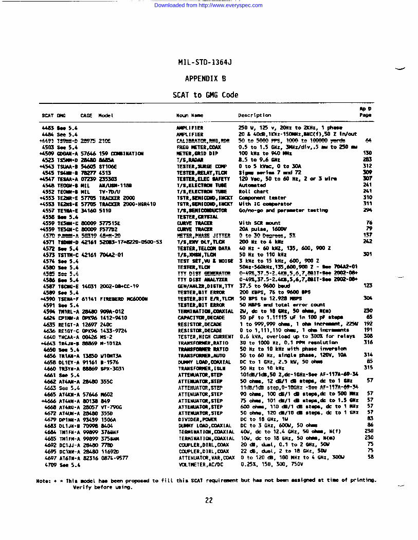
SCAT to GMG Code ‘
ApDSCAT GMG CAGE Model Nom NW Description
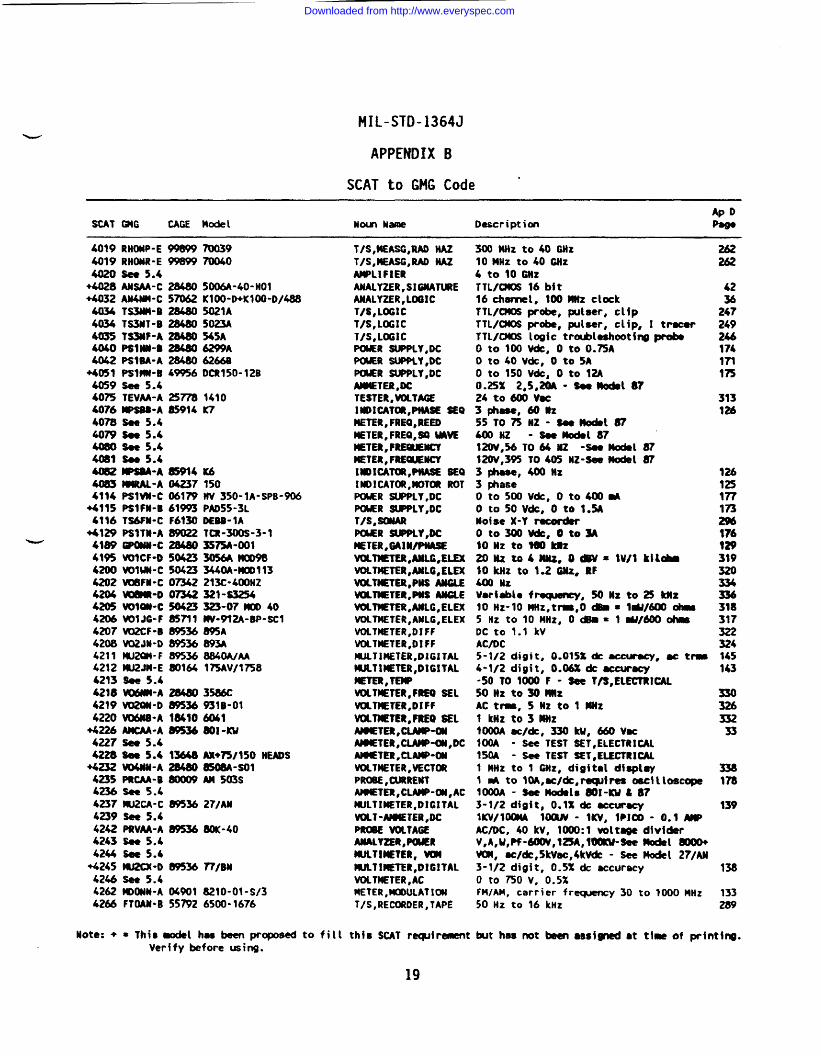
4019 RHOW-E 99S99 700394019RWNR-E 99S99700404020 see 5.4
+W8 M*-C ~ 5M-40-HO1+4032 AN4MI-C S= KIOO-D+KIOO-D/48S
4034 TSMN-B 21!480 5021A= TS3NT-B 28480 5023A4035 TS31tF-A 2G480 545A4040 PSIIU-B 28480 6299A4042 PSIBA-A 2M80 62669
+4051 PsIM-B 49956 DCR150-12B4059 see 5.440~ TEVM-A 25778 14104076 WPSBR-A S914 K7407B see 5.44079 Boe 5.640B0 S’oe 5.440BI Sse 5.4~ MPSM-A 83914 K64083 --A 042371504114 Pslvn-c 06179 w 350-lA-SPB-906
+4115 PSIFM-B 61~ PAD55-3L6116 TB6PU-C F6130 DEBB-lA
+4129 PSITH-A fW022 tCR-3(KiS-3-lw 4109 OPwN-c 284G03575A-001
4195 WICF-O 50423 3056AWD964200 WIUN-C 50423 344m-uml134202 WYBFU-C 07342 213C-4WtiZ4204 WllNR-o 07342 321-s32544205 WIOU-C 50423323-07 MOD 404206 WIJG-F 85711 W-912A-BP-SCl4207 W12CF-B 89536 8%A4200 V02JN-D $9536 893A4211 MU20M-F 09536 G840A/AA4212 W2JM-E 80164 J~Vl17584213 Me 5.44218 W%MM-A 2M80 3586C4219 VU2M-D 89536 931S-014220 --A 184106041
+4226 MCAA-A WS36 WI -KU4227 see 5.44228 Bee 5.4 13648 Aw7W150 NEADS
+4232 W4W-A 2S480 U50BA-SOI4235 PRCAA-B ~ M 503S4236 see 5.44237 W2CA-C 89536 271Alt4239 see 5.44242 PRVM-A 89536 GOK-404263 See 5.44244 W 5.4
+4245 W2CX-O EW536 7?1BN4246 See 5.44262 ~OMU-A 04901 S210-01-S/342U FTOAN*B 557926500-1676
T/S, MEASG,RAD HAZT/S,l!EASG,RAO HAZAWLIFIERANALYZER, S1GXATUREANALYZER,LfX?ICT/S, LOGICT/S, L(XXCT/S, LOGIC-R SWPLY,DC-R SUPPLY,DCPWER SWPLY,DCAMETER,OCTESTER, VOLTAGEINDICATOR, PUASE S20METER, FREO,REEDIETER, FREO,= UAW)WER, mmmmMETER,FREUNCYIUDICAWX,PMASE SEaINDICATUl,)U)T~ ROT=R SWPLY,DCPUER WPPLY,DC1/s, SONARPtXER SIPPLY,DCHETER,GAIWPMSEVU~TER,ANLG,ELEXVOLTMETER,AMLG,ELEXVOL~TER,PUS AWLSWKTETER,PUS MOLEVOLTUETER,MLG,ELEXVOLTMETER,AULG,ELEXVOLTMETER,DIFFV13LTMETER,D1FFMULTIMETER,DIGITMWLTIMETER,DIGITALMETER,TEMPVCITMETER,FREO SELVOLTPETER,DIFFWTMETER, FREO SELAmETER,cLAmP-miAMIETER,CLAUWX),DC-TER,CLAW-ONVOLTMETER,VECT(XPROBE,CURRENTAMETER,CLAMP-W,ACWLTIMETER,DIGITALUULT-AMETER,DCPROBE ~TAGEMALYZEQ ,PWERWLTIW?ER, WUWLT!METER,DIGITALVOLTMETER,ACUETER,!UXNJLATSCBIT/S, RECORDER,TAPE
Note: + = Thic mdel hss been proposed to fill this SCAT reqdrasentVerffy before using.
300 Mllz to 40 Mz10 MHz to 40 GHz4 to 10 GllzTTL/CMIS 16 bit16th-1, 100Mz clockTIL/CtUJS probe, putser, clfpTTL/CMOS probe, pulser, clip, I trsoerTTL/CNOS logic trtileshooti~ probeO to 100 Vdc, O to O.75AO to 40 Vdc, O to 5Ao to 150 V&, o to 12A0.25% 2,5,20A - s,s~l 8724 to m Vsc3phse,60Bz55 T075HZ-Be8tit87a Hz -seemode187120V,% T064 X2 -S@etil 87120V,3% 10405 Nz-seawdsl 873pkse,400nz3 phaseot05mv*, ot0400tio to 50 Vdc, o to 1.5ANotse X-Y ~oto300vdc, otosA9oHztotmkRz20#lZto 4mZ, oa’v=wlkilobn$0 IcHz to 1.2 GNz, RF400 NxVariabl~ freqwtey, 5’ollzto2sknz10 Hz-10 MHz, t~, O ~ ● IW1600 ~5Hzto10HHz, ()@m=l W4/~ ~DC to 1.1 kvACfOC5-1/2 digit, 0.015Zti ~, w tm4-1/2 digit, 0.06% dcaccwq-50 TO 10W F - Bee T/S, ELIZTKKAL50 Hz to30 nmAC tma, 5 HZ to 1 UHZ1 kliz to3MMz1000A ec/&, 330 ku, 660 vu100A - See TEST SET, ELECTRICAL150A - See TEST SET, ELECTRI~L1 Ntlz to 1 GHz, digital dfsploy1 w to loA,ac/dc, re@re8 odlmmope1000A - see Mdels 801-Kut873-112 digit, O.1%* ucurscylKv/wMA 1O(W - WV, l?lco - 0.1 wAC/DC, 40 kV, 1000:1 voltsge dfviderV, A, U, Pf-600V,123A, WWtMeetlodet 8000+VW, sc/~,5kVsc,4kVdc - See Node[ 27/AN3-1/2 digit, 0.5% dc accuracyo to 750 v, 0.5%FM/AM, carrier fr~y 30 to 1000 MHz50 HZ to 16 knz
262262
4236
247249
174171175
313la
126125177
E176929319320w
318317322324145143
330326332
33
33a17G
139
138
133289
Mt has not bmn SSsfgnsd ●t tb of prfnting.
19
Downloaded from http://www.everyspec.com
MIL-STD-1364J
APPENDIX B
SCAT to WIG Code
ApDSCAT m CAGE Motkl Nm m Description Pa@a!
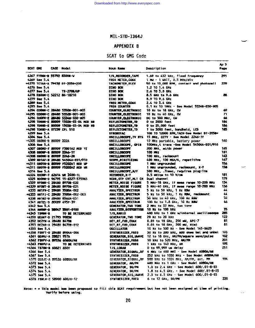
4267FYOSW”0 55792m-u4-$895.4
+4270 TCIM-A7F4580T-20SB+2004276 -5.44277 we 5.4-w-c 52212en see 5.442W 8905.44m $085.4&w --c Z1480
+4293mc2Mm42% _-E ~am TDRm-E aow~ =-E ~
~ TDR9D-A _4299 $9@ 5.443M m S.4
- OsoRs-o m43M Sa 5.443070sam=f -43DOmw+u
-m wan-s amw@m mlAF”B a4m+4311aoTn-B-+4311mo’m-9-4314$885.4
+4324 RXOW-F 62614432S ~-D%7954329 UF~-C 28M0
4329 WOWT-B -m MIFIi”c 2114m
+4333 AMFI-C=4338AXIB12-O m4341 MIQ-D80W94342 $ce 5.4
:+4
444
+444
+4+4
44444444
Ts-27avuP86-18210
53500-ml -Xm533a-ool-lmS334B-030-M0513029-03-04moo MlsmB-03”04mm NsCFL S10
F3801A2KI0 YEa4&lY2246-2R!wMA-solmoFs202Almw~aoom
w xOO-lL15-6327-s75%5997m-E20897m-E213580A-m23S8M-002-0038S62A-E51495P-39
44E-Dm7 SO1-omo45 TSNW-8 TOSE MTERMIXEDSO 6EMF-D 21793 ~S2DE2W-A 28480 84?USS3DE2AS-A M 84700-012155 So@ 5.4W FSXFT-D ~ ~-006M GEMJ-A =1 957A162 FSUW-A~M60A/M& FSIIFU-A TU E DETERMINEDi64 TS7W”B awl 65DTK6see 5.4i6? Soo 5.4Lm GEBJC-A W5% ~AN72 Sa 5.4173 see 5.4174 see 5.4i75 So@ 5,4~b FSXLA-C 5890060016-12
T/s, REcoRDER,TAPEFREO METER,CtMXTACIKBETER,ELEXECIIIO BOXEM WKECNO _ECHO BCXFREa ETER,cmxFREQ ~~Ca%mER, ELEmmccamma,ELEcY&mxcaaJuTER*EucTmlllcREF~,TDREFLECW@TER,YOREFLECTCBHER,YDsmlBoTAc0SC1LL06MPE,TV SYSmcl~OSC1LUJ6CWE, GPIB=J~om~08clJ&08cwESOOPE,DM!TIZINGmcl~mcl~OSCILL~,W/FRE~R,X-YRCDR,STP Cl(Y,MLT CM14ETER,IUJ:SE FIUEMETER,UO19E F1amEANALY2Ea,sPEcTRlmAuALY2fa#sFEcTmANALY2E&.%%cTRuAMLY%gk~RLnGEMERATOR,TW ToaEAaALY2ER,er8uTlaT/s,RmloGENEMTOR,TW TONEDET,Rf, ~,CXMXDET,RF,FX),(XMXOSCILLAT=sYJmmlzER, FREOGEnERAToR,81G,lhwESYMWESi2ER,FRE0SYUTXE$i2ER , PREOT/S, LORAXGENERATOC,SIGXAL,WSYNTHES12ER,FRE0GENERAWX,SIWAL,HGENERATOR,WP14GENERATOR, SQ/PMGENERATOR, S9/PMGENERATUl,SIG,WAVESYNTNESIZER, FREO
Note: + = this mdel b banpropoced to fill thfs SCAT mquiramtVorffy WON Ucfng.
1.69 to 432 kHz, fixed fr~lw- 1 UATT, 0.5 MHz/div50 to 10,000 RPM, cxmtect and @totocdl1.2 TO 1.4 GHz2.6 TO 3.0 GNz8.5 GHz to 9.6 Cuz8.9109.6 G~Z2.6 T03.4 6tiZ0.1 Hz TO lMHz - Satil m-m-m10 MZ to 18 6Hz, W10 Hz to 40 GHz, WDcto5001tNz, cuo to 2000 f-to to 25,000 fo@1 tO~ feet, htield, LCD100 70 1- RPM,TAC$Hee -t DT-205B+15 Hz, CCw - seenodel 2246-W10 IQHZportable, battery power10WNZ,4 tr~ -~tit S4504A-EOlt9102fxlxNz, actdc powermo Hllz100 MHze r8c~t400 MHZ, lm WA/S, I-opetftiw1 MRz ~rolnied1 * ~r~, r~t, X-Y500 Hz, .7n8ec, reqdres plW-im0.s Wlca to 10 VI=Dml chanel5 OWZ-18 GHz, IF H ~ 10-200 HZ5 MHZ-40 Wz, rF seas range 10-m JatzSllztos ok.nz, lllzmu5 HZ to 50 knz, 1 HZ RW, rdmotmt50 kliz to 40 GHz, 1(XI Rz RW100 HZ to 1.8 G!tz, 10 NZ RBU2 MHZto 32 MHZ, two tone1082 to 100 kIlz400 kltz to 1 GNz u/internml oocilieumpo~ HZ tO ~ knz0.01 to 18 GHZ, 200 d, WC-70.01 to 18 Hz, m w, N(m)10 Hz to 500 Hz - see model 14s-s62030 Hzto200kHz, 600hbd Utd til12 to 18 6HZ, N!/fU/aq#Br8 wmfe/fXJi=10 tiZ to520 MHz, M/FU1 kHz to 140 MHz, AMo to 99,999 w delay4 MHz to 4cm Nnz -scemode1608w/Aa252 ktiz to 1030 MHZ - See -1 -AM= knz to 1024 MHZ, AM/FM, ext. PM400 MHz to 1 GHz - see model WlOA/Ax1.0 to 2.4 GHz - se@m@el 600/.01-8-031.8 to 4.5 GMz. - see Model 600/.09 ”8-032.3 to 6.5 CHZ - see model 600/.01 ”8-036 to 12 GHZ, SQ]w
M has not been assigned at t~-of prin
291
88
69n66
184186185
160
1651611631671%1s8
18117913413644u5046
35
1228181
193
%195251
220
Itfrg.--
20
Downloaded from http://www.everyspec.com
MIL-STD-1364J
APPENDIX B
SCAT to GNG Code
ApDSCAT GMG CAGE Model Nom Name Description Pm
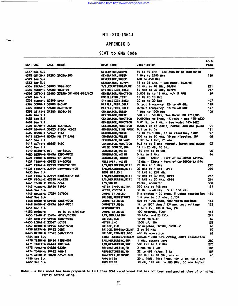
4377 Baa 5.44378SEltWA S4379 Boc 5.4b3u3 S8e 5.44384 tw-c 5WO04385 FBNTP-C 58900
+43860E7TC-E 2M8043W see 5.44391 FSNFR-C 821W43% IMX)AN-A 5890043% DcmAN-E 5890D43% GEiRS-B 342804402 -5.44403 Boo 5.44404 u 5.44405 GE7Mi-E 23338
+4407 GE&N-A 5042344W GE2kiN-D 525424412 GE2WP-F -364416 Sae 5.4U17GE7T8-B m8654418s00 5.444396EWbA ML4420sE3?ws-
W 4421 w-s 0195s34424 Tsuw”o W5S3
+4425 FIW-A 82t*+4&3 F1OAM-A 821-4433 Baa 5.44434 FIWL-A 821W
+4434 F! OAJ-C 633804441 TS6M-C 990744443 VOZNU-A 284804444 Sae 5.44445 OWAB-A 07239444? S@o S.44448 -F-8 WKw4449 --F WKMU51 sea 5.4
+U52 --B4453 w--c 252M4454 BRoFwo m
+44% Lw-c 33347U57 BRmRi”c OPK%U59 BR3F’W-B 19482
+4463 BR2NN-D O=4464 see 5.44470 TSwi-B 28480U?l TS2W”A M4473 FoRKP-c 0U2$U74 TDRW-A f-4475 AN2Nt-c 2848044s0 s8e 5.44482 see 5.4
9026”0071026-013325B-001-002-910/H03
SPMn840-01840-18-01mote-50
145”s620613M ~32114APM 5712f08
14(M
SO-354AI1-9702W-winTF-2092$EswEsv-lo5EBW+ESV-105
ESH3+ESI12-105MLUBH624A4193A
247000
IM3-97003644-9701
TO BE DETERMINEDND12W101821689-9016LclolM59-9m01B2540/S3161
415E-W1TRK-54A
m-l8?WE-S20
GENERATW, SO/P!!GENERAT~ , WEEPGENERATOR, *EPGENERATOR, SO/PMT/S, C(RJNTEIHASLRIESYNTHESIZER, FREOGENERATOR,FLJMCT!ONOSCILLATOR,TESTSYNTHESIZER, FREOHLTPLR, FREO,DBLRHLTPLR, FREO,DBLRGENERATtXl,tlwEPGENERATOR,PULSEcEaERAm, FwCT1cmCENERAl~, FWCT IONGENERATUt, FiBiCTiOUGENERATCM,TIIE MRKGaERATcn,PIJLsEGENERATm,PuLsEGEtdERAT(Xl,SOUAWGENERATOR,FWCTIONNOISE soLtRcE,smAGENERATCM,~ISEGENERAT~,MWiEGEuEiwm, NOISERECEIVER, NOI~T/S, MEASLIRING,RIFlT/S,MEASLkING,RIFITEST SET,Ei41T/S, MEA~lliG,RIFiT/S, WASURIffi, RIFIT/S, SONARMETER, lMPO,VECTORMETER,VECTDR ZOHMNETER,MICROBR1D6E,RESISTANCEOliMETER,tEGAOIOETER,NEGANEOOOWETERCWBQETER,tEGAT/S, lMWTIWBRIDGE, RLCNETER,L-CBRIDGE, RLCBRIOGE, Il@WDANCE,RFBRIDGE, SYN/RES,DECSINIJL,SYNCRO/REWIVT/S, MEASURING,SbRT\S,UEASLIRMG,SWREFLCCT(METER, FOREFLECT(BETER, TOANALYZER,NETIUXKAMPLIFIERAMPLIFIER
10 to 15 GHZ - see 6oo/lo-18c#if?c1581 MHZ to 2500mlz400 to 450 MHz15 to21 Gllz. - See model 1026-0150MHz to400Hz, SVPU5omHzto26sHz, SQ/PuO.ml Hz to 13MHZ, +/- 5 PPm10 Hz to lomiizZollztozokilzOut- freqtency 26 to40 GNz~t~t fracpncy 18 to 40 G)lzt MHz to 1000mz3ooltz- 50MHZ, x-1 M5712/080.U)0511Z to5MHz, lXFREO - Soe 145-M20().01 Nz to 1 ~Z “ Sac-l 14s-s620O.0001 Hz to20aHz, fwmal Ord*l pdae0.1 u to5s10 Hz to 1 ItHz, 17ns rf8atha, 100VMOW to50MUz, 10ns rioathe, 5VlHztol MHz, 750ha0.2 Hz to3MNz, ~1, ht andputse14 to25 ~, 18GNz150 kllz to 10 @tZ5 Hz to 5 Mtlz12kHz - 12MNZ - Part of QA-~-BAllM12kIIz - 12UHZ - Part of W-~-SAl19420HHz to 1 GHz20UHZ to 1 GHz, GPIB10 kNZ to250 UZ10 kHz to30Wz, 9P1610 kHZ to30tlHz, GPIBPro&, acoustic500 kHz to 108 MHZ30 Hz to 40 kHz, .5 to t~ kHz5 microhms - 20 ohnis, 5 uotma resolution1 Mohntoo.1 *, 0.15%50k to 1(IOG ~, 500voltsmiualk to 100T ohs,l KVmx test volt-0t05kV,100Gohm,2%loo Megohms, SOW10 kVac uid25 Wdc10nF toO.lF1000UF, ton12me90hm, 1200H, 1200uF2 to30 MHz600 Hz operation60/400/10kHz,359.999deg,.001% resolution1 kHz, scpare wave500 kuz to 1.2 GHz2 MHZto 1 (WZ32 to 492 ft/~, 5 kV100 MHz to 18 GHz, scaler20 t 40dB, 10Hz-lMMz, 10M Z in, 50 Z out30*, l~OMHz to 180MHz, 50 ohm in/out
110
231217w
197149147Im
91la97*
m
%%
275
267264300131
1%
153152
151245
60132625963
28027818318740
Note: += This modal h8s been proposed to fill this SCAT requfrment but has not been assifp’tedat ti~of printing.Verify before using.
21
Downloaded from http://www.everyspec.com
MIL-STD-1364J
APPENDIX B
SCAT to GMGCode
APOSCAT m CAOE Model Nowl N= Description Psge
4463 Boe 5.44484 se 5.4
+4491 T*-D ~ 21X4s03 see!i.b
+45W QOAli-A 57646 159~lUTJ4X45U t~-D W S6U5A
+4543 TSMA-B * ST106E454s ts4u-B n2774513
4547 tEsAA-A072392353034548TEOGN-BMIL An/wM-l18B4552 TE~-BMiL
+4553 TE~-E 5~+4553 TE29W-E 57705
4s57TEtiwE 341604550 $0e5.44559 W511ii-c Ooow
4559 TE5u-c UoDo94570PM-A 503194571 Tin-D 421614572 S8e 5.44573 TSTTM-C 421614574 Sees.h4!ml SOS 5.44585 B8e 5.44586 h 5.445WTBCM-E 140314589Su 5.4
+4590TgNA-F 611414591 Bce5.44594 TWIRL-A S4626 -lMW-A OPU%4635 RE1GT-A 12697M36RE1GY-C OPK%4640 THCAA-A 00424
+4643 TR4JN-B aBB694650 Bee 5.44656 TRIAU-A 1385046% DLIEY-A 911614660 TR3W-A 888W4661 s9e5.4
TV-7WUTRAUCER_TRAUCER2000-HsR4105110
577515EF5~248W-20520m-17-”D5m-53
M-ol
2002-08+CC-19
FIREBERD iU600W
-“0121412-9410240C1433-9724ns-2M-1012A
U1OMT3A0-1576SPX-3031
4662 AMAii-A 28480355cM63 see 5.44665 A74UM-A 57646M02
+- A~&N-A ~j~ ~94668AT4RQ-A 2m57vT-790G4672 AT4UN-A 28480355046mDPlYH-A 93459 1506A4683 DLIJw-B 7099e 8404~ THIFH-A 99$W 3760NF4685 T141FH-A 99899375BW4692 DCIJJ-A 28480~4695 DCIHN-A 28480 716920M97AT6TH-A 82316 0874-~~4709 see 5.4
NPLIFIERAIWLIFIERcAL1sRAmR,Ru’G,RDRFREO ETER,CMXETER,SR1ODIPT/S,RADARTESTER,SiRtGE _TEs’TEa,REUY,TmTESTER,ELEC SAFETYT/S,ELECTRCM TUBET/S,ELECTRCX TWETSTR,BEIQl~,lbKKTTSTR,SEi!i~,lBCU’TT/S,sEmI~mm,avswcuRvE~amw~iETER,PiiASE JITTERT/s,EuvoLv,nfxTESTER,TELCOMOATAT/S,lOW,TLOlTEST SH,WZMMSETESTER,TLCXTTYDIST ~~TTYDIST MALY2ERGEN/AML2R,DISTN, TTYTESTER,DIT ERRORTESTER,81T E/U,TLUTESTER,BIT ERRORTERMIMATION,UMXIALCAPAC1m,OECADERESISTOR,OECADERESIST(XI,DE-lESTER,HIGH CWRENTTRAMSF~R,RAT!OTwtwmmR RATIOTRMS~,ALITOm LW,WIALTRANSFORMER,ISLUATTENLIATOR,STEPATTEiiLNOR,STEPATTEIRJAT(Xt,STEPATTENUATOR,STEPATTENLIATOR,STEPATTEMJAT~,STEPATTE#LtATOR,STEPDIVIDER,PIMRDIBW LW,CthAXIALTEWINATl~,COAXIALTERMINATMXI,COAXIAL(WPLER,DIRL,COAXCCXJPLER,DIRL,COAXATTENUATOR,VAR,CfMXVOLTMETER,AC/OC
250U, 125v, 20HZ tozicnz, 1 phsu20 &40m,lKHz-150aHz,BNc(f),50 z iwxrt5oto5000PPs, wOOtoMOOO0 y9rds0.5 to 1.5 @iZ, 3MNz/div,.5mtto250w100 kuz to940Miz8-5 to9.6 mZoto5kvsc,oto30ASfm wies7aKi72Ullvsc,50t060iiz,20r3ufreAutmtedRolt chart~t t-tefWith XC ctqeratorGo/no-go snd per~tcr teeting
Uith ScR -t20A ~lse, 160WO to3DDq)mes, 5XzoDlizto4knz40 HZ -60W,135,600,9CMIZ50 HZ to llOkHz3 kIiz to15 kHz, 600, WOZ5oHz-560kHz,135,6m,900z - - 704A2-010-49%,37.5-2.4KB,5,6,7,8iilT-S8@ =-08+O-49%,37.5-2.4XB,5,6,7,SOIT-SOO 2002--37.5 to%oo bed200 KBPS,76t09600 BPS50BPS to 12.92amPs50MBPS d totst error c-tw, dc to 18Biiz, 50-, M{-)50pF tol.llllSuP hlDOpFstqslto999,999 chl, lohml~, 225Uo to l,lll,lloohmJ, 1 tiinc~ts0.6 kVA, overlood w to300% for relays30 to 1000 Hz, 0.1 PPH resolution50 HZ to 10kiiz with ~sse inverston50 to60 Hz, sinele@mseo 120V, IWDC to 1 @iZ, 2.5 Id/, 50-50 HZ to 10 kHz10l&/ldiI,502,dc-10iiz-See AF-117A-69-M500has, 12wl*stqls,* tolwz~ldslla Step,o-leotiz -SOS AF-197A”69-349oohn6, 100W1 a stepe,dc to5wmNz75 *, 101 */l *steps,dc to I.soiiz600 *, llodvl CB Stsps, & to 1 nllz50 C)hlm, 120*/loal step6, * to 1 G?lzDC to 18 GHz, WDC tos GHZ, ~, 50+4(IU, * to 12.4 @iZ, ~dhu, N(f)10u, & to 18 GHz, 50 h, N(m)20&, duel, 0.1 to2GHz, 5W22dB, dial, 2to18GNz, 5WO to 120 ~, 100WHZ to~ GHz, _0.25%, 150, 300, 750V
64
1302833123W3072412413103112W
76m
t37242
301
123
23065
192191
316
31485
315
57
575757578386
230n7558
--
Note: + = This model hss been proposedVerify before wing.
to fill this SCAT rtqirement but has not been assigned at timeof printing.
22
Downloaded from http://www.everyspec.com
MIL-STD-1364J
APPENDIX B
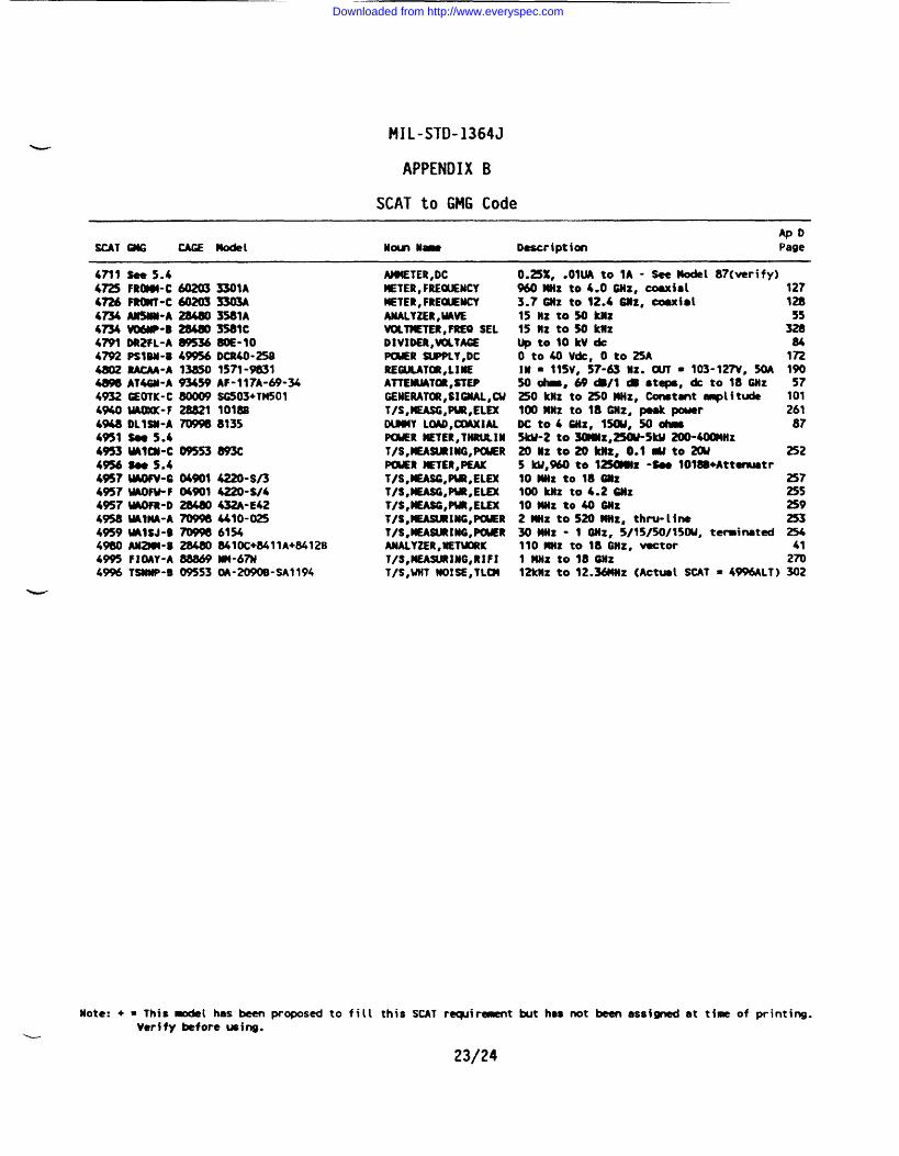
SCAT to GMCI Code
APOSCAT QtG CAGE model Nom n- Description Page
4711 sae5.44~ FROMt-C 6020333UA4ni6 mm-c 60203 3303A4Z54 Amm-A 284803581A4~ W-B 284803581C4791 DR2FL-A WS368OE-104792 PS1BU-U 49956DCR40-25B4802 RACM-A 13830 1s71-98334898 AV4SM-A 93459 AF-ll?A-@-344932 GEOTK-C - SC503+TM5014%OW(MC-F 28821 1018B4948 DLlsm-A 7D9W 81354951 sa5.44953 ww11-c 09553893C49s6 Boa S*44%7tMFV-6 04901 4220-S/34957 uAoFu-F 04901 4220-s/44957MOfR-D 28M0432A-E424958WWA-A m9984410-0254959 W1SJ-B -61%4980 AN--B 28480 841OC+8411A+8412B4= F1OAY-A 88869 w-67M49% TSMMP-B 09553 OA-2090B-SA1194
AIB!ETER,DCUETER,FREWEMCYMETER,FRE-MCYANALY2ER,UAVEVCk=TER,FREO SELDIVIDER,WTACEPCRER SUPPLY,DCREOULATOR,LMEATTEIRiATOR,STEPGENERATOR,SIUAL,CUT/S,EASG,PUZ,ELEXDWNY LOAD,~iAL-R WTER,THRULINT/S,MEASURING,PtWRPWER METER,PEAKT/S,lEASG,PUR,ELEXT/S,-,PW,ELEXT/S,MEASOnWR,ELEXT/S,MEASIJRIM,PCSERT/S,EA~lltG,PChERANALYZER,NETWtKT/S,MEASLMUMG,RIFIT/S,UUT )UMSE,TLCM
0.25%, .Olwto 1A - See#del 87(verify)9MWIZ to4.0 GHx, coaxial 1273.7CUZ to 12.46M, Coufd 12815 HZ tow knz 5515 UZ ten kIIz 328l)ptolOkVdc 840t040Vck,0t025A 172IH - llSV, 57.& HZ. OUT s 103-12~, 5DA 190
50 *, 69&/1 @ steps, * to 18 6Hz 57250 knz to 250 MZ, Constant ampl i tda 1011~ MHZ to 18 ~Z, p@8k powar 261Dcto4BHz,15w,50dma 875ku-2 to 3mmz,250u-5ku 200-400MZ2ollzto 20knz, o.l*to2w 2525 kU,%O to l-z -S@@ 1018B+Attmtr10 MHz to 16 Gltz 257100 Mz to 4.2 Cnz 25s10 Wz to 40 Ollz 2592 *Z tO Sm WZ, thru-lfne 2533otiHx” 1 OHz, S/lS/M/lSW, tewirmted 254110 MZ to 18 ~Z, v8ctor 411 ullz to 18 Omz 27012k!lz to 12.36WZ {Actua{ SCAT = 4996ALT) 302
Note: + = This mdel has been proposed to fill this SCAT recp#iramentbut has not been assigned at time of printing.Verify before ming.
~
23/24
Downloaded from http://www.everyspec.com

—-
Downloaded from http://www.everyspec.com
MIL-STD-1364J
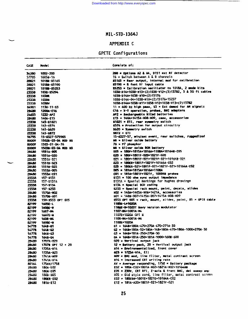
APPENDIX C
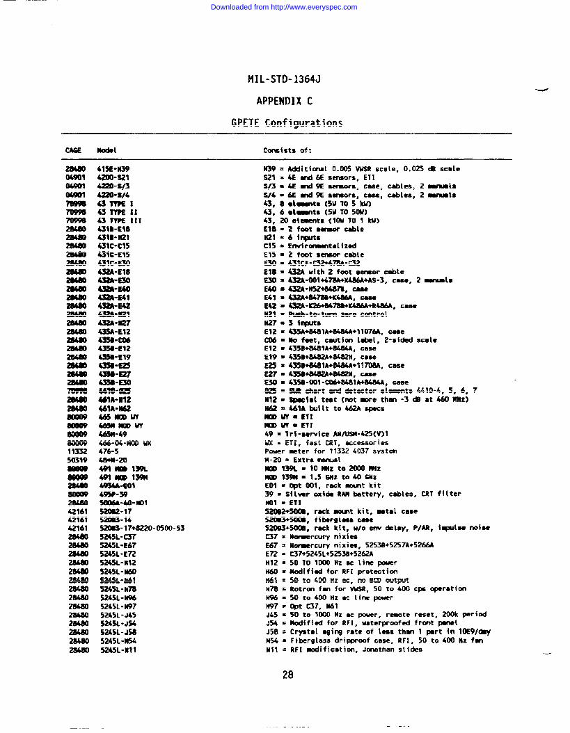
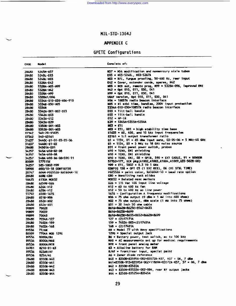
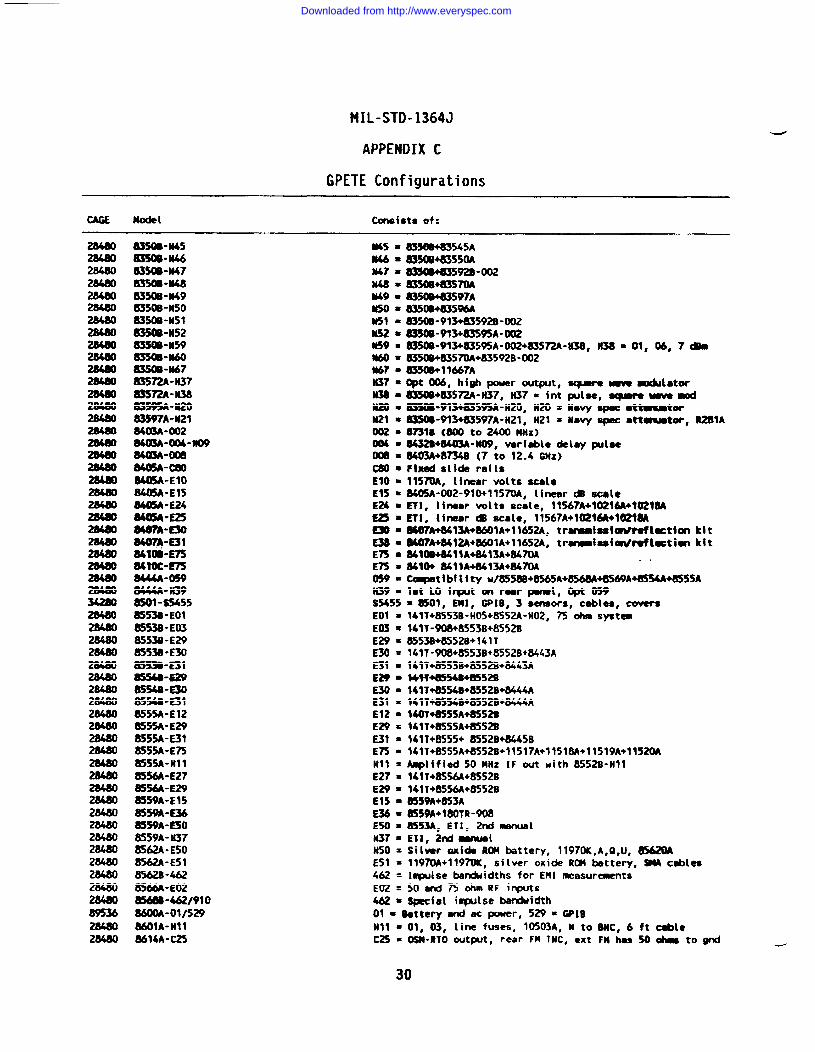
GPETE Configurations
CAGE
Sm288212882128821
04901
24655
%795
u
821W821W82199821W821W821W54778%m54mnm
801642848028480
E
Model
1002-20010058-1S1018s-S51651018s-s51909018s-s52531038-s5294103M1038sI038V1130-91”s3120M-C161232-AP2140A-E1514s-s1021145-s574145-s620145-s8n15-6327”575%51502s-03-Mm MB1503-01-04-76lB-03-04~ NB1551A-O(%1531A-0201559A-02115510-02315510”0251553A-005t553A-col15?-s131~57-S131A15?-s134157”s23315m-no21570S-HO1159-S553 WT 0051605E-Ll--a1607-n4160n-liMO&w16ME-U164s-ill164a-G2MU-a164s-64l~7A-020l~7B WT 12 + 201725A-N141725A-N231741A-H091741A-H14l~Avl1758180A-E02180A-E05MOD”H0518WR-E02181A-E12
consists of:
~=~i~uSA4, 0151 ext RF detector~$=~ftchbat~A&S chsrmels
$5165 =*ar output, internsl mod for calibmtimS5WO=8 foot RF fnput cableS5253= Calibmtiono scillator to 101?3A, 2- kitsIW8-DW+I(B8-H13+(2)1038-V12+(3)13782, 5 &50 ft cables1038-D14A+W38-N1O+(2)151761~-Dlti-ti+tO~-til@(2)1517&15~71038-DWA+1038-Hll+1038-V12+1038-V13+(2)13~11 =m Hzhigh pass, $3 = Ext dad for M si~ls
C16 = X-Y operatim, probes, WC adaptersAp2 = R*r~le HiCad batteriesE15 = 140A41415A-H08-HW, case, accessoriesS1021 = HI, mar s-try switchS574=Protaction for output circuitry~ =-try switch~ * ETI15-6327-57, ●in/see avant, rear switches, mtzed~ =$il~r Olxidebattary76 ● P7Wor~ 9 $fl~ OX{* ~ ~tt*~()@$ * lmF+lul*181*+llwlolw-cm~= lWF+180tF-~1821F-020~ ● ~~F+lWIF-~+l~lf-Ul+101&B-021~ = l~+jWlF+1821F+10M4A-C02~ = 1~-lJ21+laolF-021+1821F-021+lo164A-co2ous = lm*m15A+w16A+lw8A~ - l~A+l~lF+lwlF, 10004B probesS131 = 100 ohm sync output iqmdanceS131A = Special wkines for Hu@ws drauinesS134 = special Sm codings233 = Special rack~t, ps~nt, decals, slidesH02 = MOA+M05A-H06+1421A, accessoriesHOl = 140S-007+1415A-007+1415A-H08-H09SSS30PT 005 = rack, mmt, slides, paint,05 = GPIBcablello5E-ima21MIWE-WW20T Mwyversimmocblator1IO7-W4+1OO1A-H4llofi+$~ *T M1108*W+1CX)1A-U411D8E+102MG1 - M@+IW-470+270A-470+271A-3002 = 1~1~-5&l~-lWl~-4ntm-1~2~-30~ = lW+181A-250t27W-30@ s l*181A-n@lulA-lmlm-ao~=~tical out- jack12 * ~tery ~k, 20 = Vertical outp.it jackU14 = Enviromantalized, front coveru23* 1725A-N14, ET1n . ~] ~, lim filter, ~ta[ contrast scrm
H14 = Increawd CRT uriting rateAV = Auerage respoding, 1758 = BatterypeckageE02 = 18OA-CO2+18O1A-HO2+1821A-HO2+1O164ANE05 = 23(JV, CRT RFI, Z-axis G front SMC, del sweep snpH05 = Old style cord, line filter, metal contrast screenE02 = l~RN+1801E+1821E+10164A-C02E12= 181A-A33+1801F-021+182?F-021
25
Downloaded from http://www.everyspec.com
—
MIL-STD-1364J
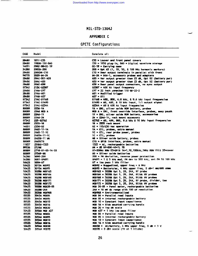
APPENDIX C
GPETE Configurations
CAGE Model consists of:
284ao1403134280
9U770
07342
07342Omz07342
Ozw
14031
11037
342s034280504235042350423504235042350423504aSW50423504235(%23055350553505535055350553550423055350553505535055355042350423
1811-(331980s-150-8602002-W’CC”992002A-200~-clo2020-s4-24204C”O01-H20204C”H20204C-W39Z13C”S2387Zlti-m214A-HO1214B-H272MC-S116621U-S1490214c-sm2236-YA2246~A2246”IY2246-2R225-s2762m5-lR2350-022465-II-VA2465-11-YC2465A-11-YC2465B-11 w2465CYS25mE+132527/AM2710-01-03-14-332754P-USm-m=1 -SP69130W-U73015A MCR923015A mD95m MOD1633028S MOD1643028S Wtll168- ml?l3028s MO0172302m mm-es--24H30360-3045AMOD043045A ~053(M5A ~103045A M(X)16WA ~303056A MOOA37H mDo43056A mDo53056A Mmlo3056A MOD163056A mo3B3056A MCD98
C33=louver-frcmpenelcovers150= 1950 plug-fn, 860 = Digttal wavefom storagecc-19”carryirg a~c~ A3 (1, 10, ~, & l~nHz ha~ic-rkers)
CIO=Raar output temfnel$ inparallol uith front$4-24 = $4&l, ~wx d adapteraN20=var outpt graaterthan 23 *, Opt oz (btt*WW)n209v8r~gmttr*23 *, 0pt02 (battery pur)!139=Raarpenet~comectors, nOSyWOUtpUtS2387=400 Hz irqxX frapency~r=~ f~ J~th~ lIOW-22-2HOl -Modified tri~r=7 = EylSlW8*~, ~, 4.8 ktiz, & 9.6 kHz irpt freqnncieaS1490=60, 400, t 10 ktiz input, 1:1 out~t ●iwwiS2344 =60&400 Hz input fr~iesYA= EMI, silver wfdeROM battery, W*~ A= EM, front override interface, probes, aeey pouchly 8 m:, Sf[w ~fa m battery, aeeeaawiae~ = ~-~y, r~k -t ~~oryS2762 060, 400, 800, 9.6 kllz & 10 kllz input frecpencieelRm~r&~
02 = 115/230 Vu oparatfcmYA = CYI, prdes, extra ~1YC = En, rear probe -r, probesYC = ETI, ~W = Silver oxide battery, probes~$ = @XC fnterfmc, ~, extra ~1
1325 = AC, rechargeable batteriesM ~ @ @F~-~TL ~(Jl=~z ~ ~IB 14=l,lo,lmHZ,l MZ RW fflt ~=coverMS = $f~~r oxi~ ~tteri~
200 = FM deviati~, reverse power protectionm91 ‘ 1 * 5 klh d, FM dev to 500 ktlz, ext FM TO 100 kllzU? = 10U pass 1 kllz filter~ = ~iztd, qr freq = 6 MHZ~ = Rattery/ac, 4 MHz qqaer freq, O *=1 WWIO *~163 = 3028S Opt 5, 20, 24H, RF probe~164 = 3028S @t 5, 20, 24H, RF/de W probee-168 = 302BB Opt 5, 20, 24H, RF/de HV probesmD171 = 3028S @t 5, 20, 24N, RF w-, divfder, t-MO01?2 = 30286 @t 5, 20, 24M, RF/de W pr-W 20-05 = Panel inter,rechargeable batteries24H = 10 * dc r- with 1(XI UV resolutionKDlHi8=Envi ~tal i ZedMOO04 = Pwsllel read fqwtsWY) 05 = Internel rechargeable batteryW 10 = Constant input capeeitenceIUXl $6 = Siti ~tad carrying handleIUX)3O=TOP*UC81O~ A37 = 1 kltz 10U pass filterD 04 = Parallel reed irqxksMOO05 = Internal r=hargeeble btteryMOD 10 = Constant i- capacitanceMOO 16 ● Side -ted corryfng handleMOD3U ● AC/Sattery, 4 MHz qiper freq,MO09S = O dBV scale (1V ●t 1 k{lohm)
26
Downloaded from http://www.everyspec.com

MIL-STD-1364J
APPENDIX C
GPETE Configurations
CAGE MOdel consists of:
50423
0734250423504235CU2350423
v
284805042350423504233804738047
284M
28480
113321133211332113321133211332
28480
L
3056A OPT04311-W320WE02320A-S232M-lM321-s32.54323-06 mo40323”07MO0 40323-20-0323-21 Woo40323L-20 moo 403333333333343434343434343434
:343434
=-OOI-W-H37-91O2SB-mt-oo2-No3-910=-E023A-C1OU-N05m-cloQOA-C85m“H65~-J79toe-Hoim-wion-llwm-mm-mi2A-N24m-H67m-J30D-PMQA-R16
3440A-mollo3440A-mol1234mA-lml133501-01003501-OIWO355a-c243551A-C(I13551A-C053551A-N27355c-Ct@3550”C083S~A-EOl3577B-O01-O02-E0135tmA-co53581A-H373722A-HOI400GL-CO14o17c/14ot7c/1-oo34otm/1-oo44o17c/1-oo54o17c/24037415E-EW415E-W5415E-H12415E”H22
OPT 04 = Rear BNC comectorW = Limar inter scaleEU = 13515A fr~ doder probe~ = R~k~t~= 2 tim ~tmts
S3254 = Isolated ref/*ioml i-t, rear comectoraIUD40 = Erwirormentalizad07=AC rely, ~ 40 = Envir~ta[ized20 = AC/httery, MO040 = Envirormsntalized21 = Acmly, m40 = Enviromentalized
m40=Envf rumentalizedETISchmetica inclded intech menual3325B-OO1-OO2-91OReer panel IJO teminels in parallel tdth front30 kHz loupasa filter, edd 10* toneter300V range from 3-10NHz is8~entNo feet/handlea, *V 8cale (90 *v=lv), pi~l mintLinew 20 CB scale, input termimls in raw211Z to 10MHZ, -a tom 109, floatim irqmt1- frequencies of 15 and60 MHzInput fr~ies of 21.4 and60 MIzIqlmt frequencies of 30 d45 MHzIqx#t frequencies of 1S and30 MHzInpn freqnnciea of 27.7 ad 60.0 MHz30 to 200 MHz frequency mdificatiom1- fr~ies of 21.4, 30, 60, 105 * 160 MHzInP@ frequencies of 21.4, 30, 60, 120 * 160 NHzI-t frawmci- of 21.4, 27.7, 30, 60, 70 & 160 MHzlmut fmmenciee of 12, 15, 21.4, 608 160 MHz
~110 =- No rtite progr~ing, 34401AWO0112 = 7 kHz TO 1.2 GHz probe, 34401AHOOl13 = 10 kHz TO 1.2 GHz probe, 3441OA3S01A Mavy version3501 Opt 04
Rack martRuk -t
Convert ible rack mmt11 inch rack -t, rear ac pwer, ac only, ETIw(f) c~torsN(f) Comectors35~A+35677A+35678A+356~A*l 1850A356~A+356~+35679A+l 1850CRack nomtETIAdditional binary wtputGromd isolation fras input comectors
476+N4240A, attenuator set476+N4204A, attenuator set47tiA4240A+A4240C, at temat or set47W240A+K4240C+M240C, attenuator set476+4400- 1476-5+N4240A+K4240c -5+A4240C-5, caseEm = 415E-()(II+~+H81 (JC+X810B+X444A+816 -Z2+447B
H05 = 100 Hz i~t frequencyH12 = ~oo Hz iqxt fr~yH= = *t W2 front & rear inputs, C15 f~us proofing
27
Downloaded from http://www.everyspec.com
MIL-STD-1364J
APPENDIX C
GPETE Configurations
Model Consists of:
2w0 415E-N39 n39 = A&iitional 0.005 WSR scale, 0.025 &i scale04901 4200-s21 ~1 a~E ~&E s~o~, ETI
04901 4220-s/3 s~n@&~ aaiwrs, case, cables, Z mamalsUml 4Za-s/4 S/4 =M and9E sansom, case, cables, 2 manualsm 43WVE1 43, aou-ts (5UTOS W)mm 43TYPEII 43, 6olmts (5MT050U)- 431YPElIt 43, 20 elements (1OU TO 1 kU)
mm60so11:SaO@802s802s4242422Ba
wQ909Q932119wmamIao161161161aW
4319-HO431B-N214MC”C15431C-E15431C-E3043WE1843WE30a-B4043WW$43WE424m”i121432A”m2743%-E12435B-CM435S-E12435S-E19
.g.:?
?&z44~A-WIZ4MA-M2ailmw46mmuYm-49466-W-MOD w476-548+M-20*itmlm49tkOm13mW54A+ol495P-395ooM-40-nol520s2-1752m3-145a-17+a220-0500-535245L-C375245L-E67
2 foot aemor cable6 inputsEw~ romsntal i zad2 foot sensor cable431 CF-C32+478A-C32432A uith 2 foot sensor cable432A-001 +4AA+X4MA+AS-3, cm, 2 ~ls432A”N52+S487B, mea4s2A+fJ47BB+K4s6A, case4S2A-K26+B47tlD+K486A+R486A, casePtA-to- turn zero centrol3 inputs435A+8481A+84MA+I 1076A, CaaeNo feat, caution label, 2-si&d Scelc435B+84U1A+84.B4A, case
~w~+-H, case435B+84U1A+8484A+1170M, case435B+84S2A+8482N, ~=~-~t -C06@4BlA+8484A, CUSeM chart ad detector ●lements 4410-4, 5, 6, 7SpaCid test (not more thn -3 Ql at 460 Milz)UIA bitt to m -S
mmw=mlmmuT~ETl49 = Trf -ge~fce AN~-~(V)l
Ux= ETI, fast CRT, accessoriesPower meter for 11332 4037 systemM-20 = Extra mnualmo139L= lo MNzto2(Xm MNzMm13mt= l.56Nzto40GNzEOI = @t 001, rack momt kit39 = Silver oxide RAMbattery, cables, CRT filterMl s ETI
5~+500B, rack mtmt kit, meta~ case520S3+W, fiberglass ceae5~+500B, rack kit, w/o em delay, P/AR, iqdse noiseC37 = N~rcury nixiaaE67 = Nornercury ni xi es, 5253B+5257A+5266A
= 5245L-E72 En s c37+5245L+5~3$+52W
28480 5245L-n12 H12 = 50 TO 1000 Hz sc line power28480 S245L-N60 N60 = Modified for RFI protection2a480 5M54”WI N61=50to mOHzac, noBCOoutput
2B4ao264802B4802M80
5245L-wa5245L-N%5245L -W?S245L -J45S245L-J545a5L-J5a5245L-M545245L-1111
m!
N97J4SJ%J58H54Mll
= Rotron fan for ~, 50 to ~00■ %lto400Hzacl{ne power= *t C37, N61= 50 to lMO Hz ●c pouer, remote= Mif ied for RFI, waterproofed
cpa operation
reset, 200k pari odfront panel
= Crystal aging rate of l& thm 1 part in 10E9/daY= Fiberglass dripproof case, RF], 50 to 400 Hz fan= RFI modification, Jonathan slides
28
Downloaded from http://www.everyspec.com
PIIL-STD-1364J
APPENDIX C
GPETE Configurations
CAGE Model consists of:
m480284802848028480
07342073423163731637
3425734257
- 34257
34257
20?47
5(%23
2848028480557922848028480
284802M8089536
89536895368953604901895368953628480284ao284802848028480
5245+1-H375W$L-E035248L-H03S~-E425328A-M03-N99532$A- H425328A-H99532BAFI0965334A-O1O-O3O-HO6-91O5334B-030-W55334R5342A-001-002-E035342A-E035M5A-0125345A-E295350B-001-H035352B-m-Ho3540-20-SM35540-s3161544W-G1-01-03-05-M5440C-Gl-~54501A-EOl545A-uw-02-m545A-UIO-08548A-ulo-06-ow590-915m15E585-5802-YW6W1O-18-F!G15U604M-P025526-RAT604M-10608E-C806130A m3262598-026626A-H12628A-H126500-16766518-MM652A-H02652A-SO1
70039
7034A-1277402A- 1597402A- 96877/AN~A~ 129G8oooA/Bu8oooA/mAs8000WMTR8210-01-s3823AUAF825A/AG8350B-U408350B-N418350B-N4283W-N438350B-N44
W7=W tiificatim and normmcurynixie ttiECi3 = H03-5248L, li03-5267A~=RFI, f~ pmoffng, 50-400 Hz, rear i-E42 - Cover, extender cards, spares, H42~=B(3 out, remoteprog, W9=5328A-0%, iqrweciEitlli42=qX 010, 011, 030, 041~=opt 010, 011, ()~, M1
UsAf version, *t 010, 011, 030, 041H~ . 1-7A r~fo ~ interf~e~ = ~f stbi ti~, M1os, m input protactitlfl5334A-O1O-O3O+1O857A redio beacon interfsceEm= Ti\t-~il h~ieEm = Ti(t-~il h~le012 = NP-IBE29 = 5345A+5355A+5356A~=~r~-ETt, ml =hfghgt~ilityti~~
S1635 =60, 400, and 10 kHz i- fr~iesS3161 = 1:1 output transformer ratioG~ = l15v, 01 = 65 * i-t aens, 03-05-06= 5 MHz-40 GilZ61 = 115v, 03 = 5 MHZ to 18 GHZ noise SOU~
EO1 = Front panel pwer suitch, probesWO= Tcxo, EMI shieldingutO = TCXO, Eml shieldingMO = Tao, EN1, U= ~18, 590 = E)(T WBLE, 91 = ~577Lw177, SCR pks(A1002,A1003,A1004,A1009,U35-5028-00)V(B=mI, 5802=0.3101 6MZ~IG 158=WT 03 (1 KHZ RES), 06 (H: ~BL TIK)P025526= paint color, RAT604M-10 = baud rote optionc80 = Mtflting rack slides=32 = Deleted nsec smrkers026= 115 Vac 10% i- line voltageH12 = 60 to400 Hz fanH12 = 50 to 400 Hz ec line power1676 = Configuration A freqency modificationsu06=750hmoutput (OdBm= lnUinto6000hms)W(I2 =750hm output, -scale (1 W into7S ~)S01 =30 inch 500hmcable8616+86628+862X+8562+86330616+M230+MW861W&3w8@3+8652+8662B+86W127= (2)~7171A159= 7402A-003+(2)17401A~6B= (2)17401Au = ~{ 77with liavyspeeifications1290 = special output jackw = Battery pouer, test switch, ac to 100 kHzMS = AC measurements set @ fOr *iCal r~ir~tSMTR ~ Front panel analog meter$3 = Alkaline battery for RAMR/AF = Front/rear input, special paintAC = 2mar diode referenceMO = 83509+835%A-002+83572A-H37, H37 = 06, 7*N41=8350B-913+U3595A-002+11869A+83572A-H37, 37= 06, 7dBJsu42 = 8350B+83522AH43 = 8350B+83522A-002-W, rear RF output jacksMU u 8350B+83525A+83%5A
29
Downloaded from http://www.everyspec.com
MIL-STD-1364J
APPENDIX C
GPETE Configurations
-
model consists of:
28480
28480
28480
284802848028480
28480
2848028480284802848028480284802848028480
83SOB-W5S350WM468350B-M7l1350S-M488350B-M498350B-N50llxm-nslB-N5283SWM598350B”N60--M783S72A-H3783S72A-N3883W5A-U2083597A-M218403A-00284mA-oo4-No9840uA-w8W-C80W-E1OM%A-E15840SA-E24u4a5A”E25M8n-E30u40m”E31%mB”E75w~-mw-m8444A-N39awl -ss4558SS3B-EOI8S53B-E038553B-E298S53B-E308553B-E31t5S4&E2985S4B-E308S54B-E318555A-E128555A-E298555A-al8S55A-E7585SSA-H1l8SS6A-E278556A-E298S59A-E158S59A”E36@iS9A-E508559A-N378562A- E508S62A-E5185628-4628566A-E02856uB-4&2/910
8350B+83545Aasoin3550A835WU3592B-0028350B+83570A83-597A835m*51MiA83~-913+83592B-002U350B-913+8359SA-0028350B-913+835BA-002+83S~-li38, H38=01, 06, 7-83SOB+8357DA+83592B -002~!ioB+l 1667A~t U)6, high pouer output, sqmrewvemoddator~5m-H37, H37= int pulse, 8qmremmad6.MOB-913+83595A-H20, N20 = Movy apoc ●ttaumtorU3SOB-913+83597A-H21, H21 = NaVyS~ 8ttauntor, R281A~lB (800 to 2400 MHz)8432B+8403A-N09, v*riabledelaypu18e8403A+8734B (7 to 12.4 CHz)Fixed slide rails11570A, linear volts scale8405A-OO2-91O+1157OA,linear C9 scaleETI, linear vo[ts scale, 11567A+W216A+W2WAETI, linear * scale, 11567A+102I6A+1O2I*8607A+8413A+8601A*11652A, trrnissiW?efluthnkitwA+84UA+8601A+l1652A, transmimi~~lutim kit841OB+B411A+8413A+847OA8410+ K1M+8413A+8470A
,.
-t ibf 1i w w/8S58B+8565A+8568A+8S69A+8S54A+855SA1st LO input on rear pmel, ~ 059=~1, EMI, GPIB, 3 sensors, C(9b[M, ~141T+8553B-H05+8552A-H02, 75 ohm system1417 -908+85539+8552s8553B+8552B+141 T141T-908+8553B+8552B+ 8443A141T+8553B+8S52B+8443Aww8554m+8s520149T+8554B+8552B+W14JT+85%B+8552B+8444A140T+8555A+8S52B141T+8555A+8S52B141T+8555+ 8552B+8445B1411+8555A+8552B+ 11517A+ I 1518A+11519A+1152WA@ified50 MHz IF out uith8552B-Hll141T+8556A+8552B1417+8556A+8552B8559A+853ABSS9A+180TR-9088553A, ET1, 2nd manualETI, i!d~lSilver oxide R@l battery, 11970K,A,0,U, 85&Wl1970A+l197W, silver oxide ROM &ttery, W cableslapulse bandwidths for EM! measurements50 and 75 olm RF inpts5pecfal invmlse bandwidth
89536 860w-ol/s29 01 _ Battery and”ec power, 529 = GPIB
28480 8601 A-H1l N1l = 01, 03, line fuses, 10503A, N to BNC, 6 ft cable28480 8614A-C25 c= = ~-RTO ~t~t, rear FM TNC, ext FM h- 50 ~ to gnd
30
Downloaded from http://www.everyspec.com
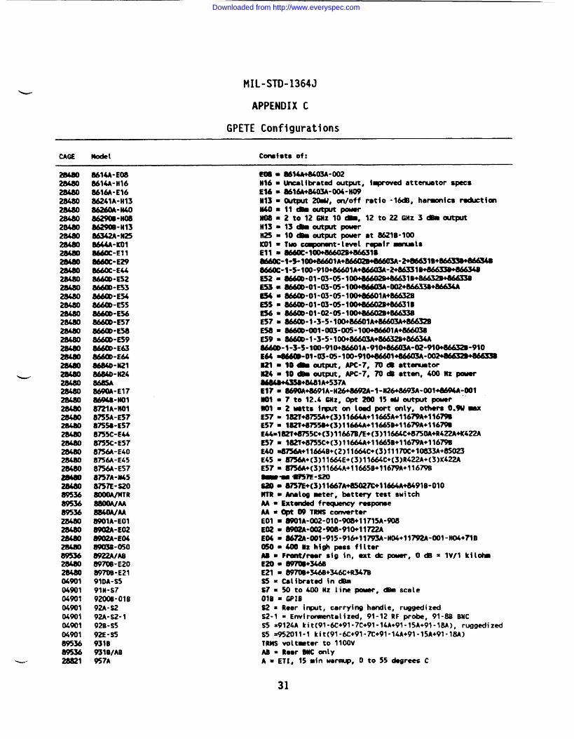
MIL-STD-1364J
APPENDIX C
GPETE Configurations
CAGE Model cm%fst* of:
28480
E
-
28480
895368953689536
0490104901049010490104901(wOl04901
%2~ 28821
8634A-E0886MA-H16861&-E~686241A-H13862!6#-li40--W886290B-H1386342A”M25H-m~-El 18660C-E298660C-EU86600-ES28660D-E53M@D-E%H-ESS8660D-E568MO0-E578660D-E588660D-E59W-E63~-E648684D”li218684D-H24
~-E1784MB-NO18mA-fm8755A-ES?8755B-E578755C-EU8755C-E578756A-E408756A-E458756A-E578n7A-w50757E-s208000A/MTRUM8840A/AA89WA-EO18W2A-E02
wmB-0508922A/AB~-E20W7tWE2191DA-S591H-S7920w-o1692A-S292A-S2-1928-sS92E”S59310931B/AB957A
aIMA+8403A”oo2Uncalibmtsd wtput, iqmved attmtor specs0616A+8403A-004-N09~~Puc@/ ratio -1~, harmonics ~tim
2t012GNz 10_, 12to~Gtiz 3tBkmou@Jt13c9moutFaJt power10~out~ potter ●t 8621B-1OO
l-~t-l~t -fr~ts8660c-100dw02B+M631B
8660c-W-100+8LW9A+W@WW13A—mlB+~8660C-1-S-100-910+8660~A+86603A—2+86331B~E52=86@D-Ot-03-05- lUH&WWW31B+~~=e-ol-m-m-l ~-u+86633B+M634A~ =~-ol-~-~-l~lh+mES5=~-01-03-05-lW+M602B+86631B-w ~.o~-@~-1~~E57=~-1-3-5*10WJ6601A+86603A+86632BEn = ~-@l-~-()(&l~lA~E59= ~-1-3-5- loo+~+m+MtJ34A
--1->5-lW-WWWIA-91~-W-M~*910E64 9866m”ol”03-05-loo”910+86601+866u3A”w~~1 ● I@ *@put, APC-7, 7oa ●ttmnmtor~4m lo~~t~t, ApC-7, 70* ●tten, 400 Uz pwar~+wjl A+537AE17= ~WIA-H*~-t-H2~-Wl~-Wfml*7to12.4mz,opt*15 WoutputpouerUO1 = 2uma irput on hod port onty, others O.W-E57= 3~M~W+c3)l~W+ll&A+l16~A+l16~ES7= lUT*n%(3)llm+llU5B+l16mA+l16mEU-182T+8755C+(3)1 1667B/E+(3)l1664c+87soA+R422A4KG!2AE57= 102T+8755c+(3)l1664A+l166SB+l1679A+l16~E40 =8=11664B+(2)11664c+(3)11 17W+10833A+85O23E45 =8756A+(3)11664E+(3)11664C+(3)R422A+(3)K422AES7m m+(3)lM64A+lM65B+j1679A+l1679B-’m WTE-si!o8iW=8757E+(3)l 1667A+85027C+1M64A+8491B-010MTR = -log meter, battery test switchAA - Ext~ freqmwy responseM =~ @ T= Cmrter
EO1 =O9O1A-W2-O1O-9O8+117I5A-9O8E02= 8902A-m2-908”910+l1722AE04 = ~-Wt-915-91&ll~-HW+ll~-~1-W+~B050= 4001tz high paus filtarM. F~/~r sfg in, ext k-, O@ = lV/1 kiltiEm = ~+~E21 - ~+346B+346C+R347Bs5 = Calibmted ind?mS7= W to~Hz line-, ~sca[e
018 = GP18S2 = ~ear i~t, carrying handle, ruggedizedS2-1 = Env~romentalizd, 91-12RF probe, 91-8B BNCSS =9124A kit(91-6C+91-7C+91-14A+91-15A+91 -18A), ruggedized
S5 =952011-1 kit(91-6C+91-7C+91-14A+91-15A+91 -18A)TRMS voltneter to 11OOVW = R-r ~ ~[y
A =ETI, 15 min waw, O to 55 degrees C
Downloaded from http://www.everyspec.com
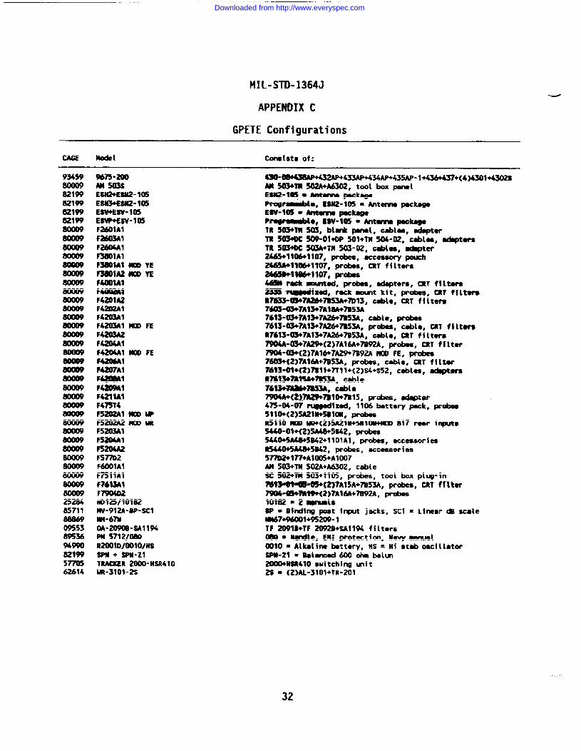
—
MIL-STD-1364J
APPENDIX C
GPETE Configurations
node[ consists of:
93459
821W8Z1W829W621W
2528685711
0955389536%990821WSnm62614
Wn-aulM503SESW+ESU2-105E~-tQ5ESV+ESV- 105ESW+ESV-105F2601A1f26wAlf~lF3601A1F3MMAl MOO YE~lA2 MOD YEMmlAlF40awF4201A2F4202AIF4203A1F4203A1 m FEF42Q31A2F4204A1F42MA1 MOO FE
~1-AlF41ZW1FalF4211A1F475Y4F3202Al mowF5202A2 ~ MFS203A1FS204AlF520M2F5~2F6@lAlF7511AIw613Al
HO125I1OW2MV-912A-BP-SC1rn-67NW-20908-SA1194PM !J7121(MIQR2001D/UW)/HSSpn + m-zlT-R 2W0-HSR410W-3101-2S
4S0-muwMnw+433AP+434AP+435AP- 1+436+a7+(4~301~Am 503’+mso2A+A6302#tool box penalE8t12-1~ = ~ ~kegePrqJ~lo, ESN2-105 ● Antm peclmgeEW-W3 = ~ ~P~*, Ew”los = mm peckegeTU503+TM503, blink psnol, cebles, edspterm 5a3+ocso9-ol+oP 501+lm50w2, Cebles, ethpters7R303+Dc 503A+m503-02, Cebles, eapter2465+1106+1107, probes, accessory pouch2663A+1106+1IO7,probes, CRTfflturs2M6WW9107, pr&18Sa * ~ed, prCbS, edspters, CRT filter’e- ~lmd, reck ~t kft, probes, CRT ffltereR7~W7AM47K3A+7D13, csble, CRTf i ~tere7~-03+7A13+7A14hA+7Bs3A7613-W7AW7A26+7BS3A, ceble, probes7613-~7A13+7AM+7853A, probes, cebie, CRT fi ltereR7613-03+7A13+7~7B53A, ceblc, CRT f i Itere790M-0W7A29+(2)7A16A+7B92A, probes, CRT ff lter7904 -03+( 2)7A16+7A29+7B92A MOO FE, m7603+( 2)7A16A+7B53A, probes, tile, CRT f i ltar76W09+C2)7S19+7T1 1+(2 )s4+s52, cebles, ~mRmwmA+m3A, Csble7613+7AW~, tie~(Z)7h29W81W7M5, probes, sdapter475-W-07 ~tzed, 1106 bettery peck, probes511 O+(2)5A21W8IW, probesR5110 )KID W+(2)5A21U+5Bl~ 817 reor irputs5U0-01M2)5A4’$+5B62, pm&sSUO+5A@+SU2+l 101Al, probes, ecceesoriesR5440+5A41h5B42,probes, eccessori ee~l~+AWJ5+AlW7M 503+m WA+A6302, csbleSC S02+TW503+t105, prb, tool box piug-in
~(2>7A15A+n53A, probes, CRT f f~ter79W-ti!WMW(2)7A16A+7892A, probes10182 = 2 ~1*BP = Birding post irqwt jecks, SC1 = Linear C8 sateNM674WO01+95209-1TF 2091D+TF 2092B+sA1194 f f ltersWQ = Nude, EMIprotection, Mavy ~1~10 = Alkelins tmttery, MS = tif steb oscillator$PU-Z1 = Belenced 600 ohm bellm2OW+WR41O switching mi t2s ● {2 ML-3101+TR-2OI
32
Downloaded from http://www.everyspec.com
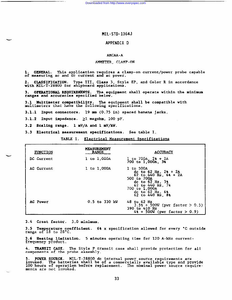
1. GENERAL. This applicationof measuring ac and dc current
2. CLASSIFICATION ● T e III,8with MIL-T-28800 for s pboard
3. OPERATIONAL REWIMMENTS.
MIL-STD-1364J
APPENDIX D
AMCU-A
~ER, CLAMP-ON
re uires a clamp-on current/power1an ac power.
Class 3, Style EP, and Color R inapplications.
probe capable
accordance
The eauimment shall operate within the minimumranges and accuracies specified belo~. ‘
.
3.1 Multimeter compatibility .I
The equi ment shall be compatible with?multimeters that have the fo lowing spec fications.
3.1.1 Input connectors. 19 mm (0.75 in) spaced banana jacks.
3.1.2 Input impedance. al megohm, 100 pF.
3.2 Scaling range. 1 mV/A and 1 mV/kW.
3.3 Electrical measurement specifications. See table I.
TABLE I. El=crkal M=Surement Spec&tio~
MEASUREMENTFUNCTION RANGE #LccuIwcY
DC Current 1 to 1,000A 1 to 700A 2% + 2A700 to 1,600A, 3%
AC Current 1 to 1,000A 1 to 500Adc to 62 Hz, 2% + 2A62 to 440 Hz, 6% + 2A
500 to 700Adc to 62 Hz, 3%62 to 440 Hz, 7%
700 to 1,000Adc to 62 Hz, 6%62 to 440 Hz, 8%
AC Power 0.5 to 330 kW 48 to 62 Hz3.5% + 500W (pwr factor > 0.5)
390 to 410 Hz4% + 500W (pwr factor > 0.9)
3.4 Crest factor. 3.0 minimum.
3.5 Temperature coefficient. 6% x specification allowed for every “C outsiderange of 18 to 28’c.
3.6 Heating limitation. 5 minutes operating time for 120 A-kHz current-frequency product.
4. TRANSIT CASE. The Style P transit case shall provide protection for allcomponents of the probe assembly.
5. POWERinvoked.100 hoursments are
SOURCE . MIL-T-28800 dc internal power source re uirements are1The batteries shall be of a commercially availab e type and provide
of o eration before replacement.!
The nominal power source require-not nvoked.
33
Downloaded from http://www.everyspec.com
MIL-STD-1364J
APPENDIX D
6. WEIGHT . 1 kg (2.2 lb) maximum.
34
Downloaded from http://www.everyspec.com
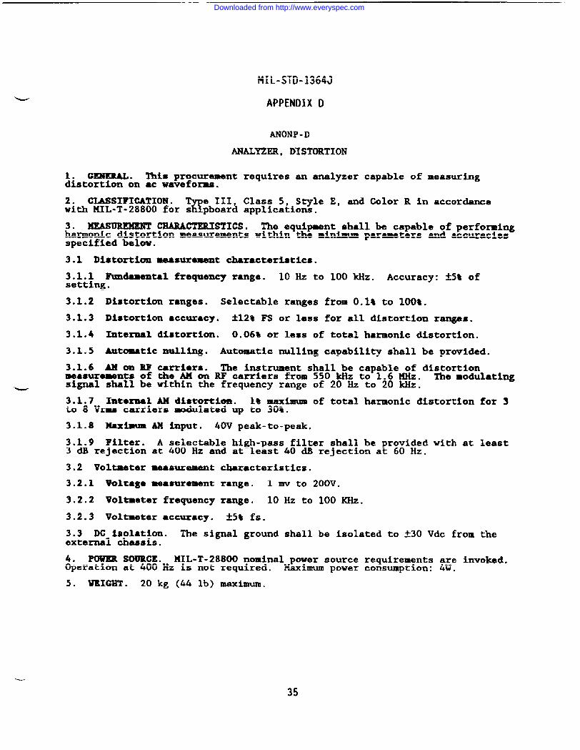
MIL-STD-1364J
APPENDIX D
ANONP -D
ANALYZER, DISTORTION
GENERAL. ‘!%1sprocurement requires an analyzer capable of measuring&tortion on ●c waveforms.
2. CLASSIFICATION .%
e III, Class 5, Style E, ad Color R in accordancewith MIL-T-28800 for s pboard applications.
3. ~ CHARACTERISTICS. The equipment shall be capable of performingharmonic distortion measurements within the minimum parameters and accuraciesspecified below.
3.1 Distortion measurement characteristics.
3.1.1 Fundamental frquenc~ range. 10 Hz to 100 kHZ. Accuracy: ~5% ofsetting.
3.1.2 Distortion ranges. Selectable ranges from O.lt to 100%.
3.1.3 Distortion ●ccuracy. ~12% F’Sor less for all distortion ranges.
3.1.4 Intezmal distortion. 0.06% or less of total harmonic distortion.
3.1.5 Automatic mulling. Automatic nulling capability shall be provided.
3.1.6 AM m RF carriers. The instrument shall be capable of distortionmeasurements of the AM on RF carriers from 550 kliz to 1.6 MHz. The modulatingsignal shall be within the frequency range of 20 Hz to 20 kHz.-
3.1.7 Xntornal AM distortion. 1% maximum of total harmonic distortion for 3to 8 Vrms carriers modulated up to 30t.
3.1.8 Maximum AM input. 40V peak-to-peak.
3.1.9 Filter. A selectable high-pass filter shall be provided with at least3 dB rejection at 400 Hz and at least 40 CM rejection at 60 Hz.
3.2 Voltmeter measurement characteristics.
3.2.1 Voltage measurement range. 1 mv to 200V.
3.2.2 Voltmeter frequency range. 10 Hz to 100 ~Z.
3.2.3 Voltmeter ●ccuracy. ~5% fs.
3.3 DC isolation. The signal ground shall be isolated to *3O Vdc from theexternal chassis.
4. POWIELSOURCE.NIL-T-288(X) nominal power source requirements are invoked.Operation at 400 Hz is not required. Maximum power consumption: 4W.
5. WEIGHT . 20 kg (44 lb) maximum.
35
Downloaded from http://www.everyspec.com
MIL-STD-1364J
APPENDIX D
AN4NH -c
ANALYZER, IAGIC
1. GENERAL. This procurement requires a multichannel timin and state analy-zer that can record and displa
d5logic signals and data from i ital circuitry.
The analyzer shall have speci fIEEE 488.1 logic interface.
c probing and recording capabil ties for an
2. GLASSIFIGATION ●
wIII, Class 5, Style E, and Color R in accordance
with KIL-T-28800 for a pboard applications.
3. OPERATIONAL REQUIMMENTSo The equipment shall be capable of both s -Ychronous and asynchronous data domain and time domain recording of para lel
$~g~~~~&~ls & ‘Pecified belOw” ~.r connection to me unit mderAll s edifications contained below shall
at t e probe or lead tip usedtest.
3.1 Time ~in. A timing format of at least 16 channels shall be recordedand displayed. Horizontal expansion capabilities shall be provided to dis laya portion of the total memory for more detailed examination. !A positional ecursor that identifies recorded data words and time positions shall be pro-vided. The trl~ering event shall be marked or annotated on the timing dis-play. Oparator assignment of the displayed channel order shall be provided.
3.2 Data domain. Displays of recorded data in binary, octal, and hexadeci=lbases shall be provided.
3.3 Die lay. Cathode ray tube. Minimum usable viewing area: 100 m (4 in)high by !20 mm (5 in) wide.
3.4 signal * ts.Y
The analyzer shall be provided with a minimum uf 20separate sigma input channels including probes, pods, cables, and o*rrequired accessories.
3.4.1 Data channels. The analyzer shall have a minimum capability ofreceivin
Lrecording, and displaying
iarallel data words of at least 16 bits
in the t ‘ing and data domains, and s all be expandable to at least 32 bits.
3.4.2 Trigger channels. The analyzer shall have at least two trigger quali-fier input channels.
3.4.3 Clock channels. The analyzer shall have an external clock input and aclock qualifier input channel.
3.4.4 Input RC. 1 megohm minimum shunted by 8 pF or less.
3.4.5 Threshold. The 10 ic anal zer shall perform as s ecified when used toanal ze TTL circuitry.
x& K ~e TTL t reshold shall be 1.5 f .lV. The equi ment
tshal be rovided with a variable threshold adjustable to within *0.15 from!-6.4V or ess to at least +6.3V. High and iow true logic polarity shall be
selectable for each channel.
3.4.6 Maximum input. *3o Vdc referenced to ground.
3.4.7 Input modes.
3.4.7.1 Sample mode. The detected 10 ic level present on each probe and ateach clock transition shall be stored !n the sample mode.
3.4.7,2 Latch mode. Whenever multiple transitions occur between two succes-sive clock htends, the state opposite that stored during the
Erevious clock
intenml shall be stored on the next clock. A litch memory wit correspond-king glitch markers on the display may satisfy t is requirement.
36
Downloaded from http://www.everyspec.com
MIL-STD-1364J
APPENDIX D
3.4.7.3 Unimum pulse. In the timing and state modes, when the logic analy-zer threshold is set for TTL in the latch or
Rlitch modes the equipment
shall detect a 5 ns?ulse with a level that c anges from iess than +0.25V to
anyY
litude from + V to +5V and then returning to less than +0.25V. Detec-tion s all also be provided for a 5 ns pulse with a level that changes from+2v to +0.83V or less and returning to +2V.
3.5 Internal clock. b internal clock with selectable pexiods from 10 ns orless to at least 50 m shall be providad.
3.6 External clock. DC to at least 50 MHz with selactablo positivo and nega-tive edge active modes. Minimum clock pulse width: 10 ns or less.
3.6.1 Setup ●nd hold time. 12 ns or less.
3.7 Memory. At least 250 data word samples. A second memory of e ual depth?shall be provided for comparing word samples and searching for spec fic word
occurrences within the recording memory.
3.8 Self-check. A self-check function that verifies operation of all basicfunctions shall be provided.
3.9” Interface robing.!
The e uipment shall be provided with a probin1 !accessory and a 1 required cab es that allow the analyzer to record bi irec-
tional data flow and the associated management signals required for IEEE 488.1digital interface operation.
K%mR SOURCE.MIL-T-28800 nominal power source requirements a~~o~nvoked.&eration at 400 Hz is not required. Maximum power consumption: .
w 5. WEIGHT . 30 kg (66 lb) maximum.
-.
37
Downloaded from http://www.everyspec.com
MIL-STD-1364J
APPENDIX D
AN2FM-C
ANALYZER, NETWORK
1. GENERAL. This procurement requires a network analyzer with polar andSmith chart displays.
2. CIASSIFIGATION .%
e III, Class 5, S~le E, and Color R in accordancewith KIL-T-28800 for s pboard applications.
3. ~ CAPABILITIES. The equipment shall be capable of magnitude,base, and delay measurements within the minimum specifications identified
~1e OW.
3.1 Dis la characteristics.!1
A dual-trace display shall be provided with ausable d sp ay area of 9.5 cm x 12 cm.
3.1.1 Graticules. Selectable polar and Smith chart.
3.1.2 Resolution.
a. Magnitude: 0.01 dB/div.
b. Phase: 0.01 deg/dtv.
c. Real and imaginary: 0.1 nV/div.
d. Group delay: 0.01 ns/div.
3.2 Source characteristics.
3.2.1 Wurce frequency range. 5 Hz to 200 MHz,
3.2.2 Source frequancy resolution. 0.001 Hz or less.
3.2,3 Output level range. -49 to 15 dBm.
3.2.4 Source impedance. 50 ohms nominal,
3.2.5 Output connector. Type N(f).
3.2.6 &urce sweep mode. Selectable single, continuous, and manual sweepmodes shall be provided.
3.2.6.1 Iag and linear sweep frequency range. 5 Hz to 200 ~Z.
3.2.6.2 Log and linear sweep frequency span. ().01Hz to 200 ~Z.
3.2.6.3 Sweep time.
a. Log : 200 ins/span to 6,500 s/span.
b. Linear: 100 ins/span to 6,500 s/span.
3.2.6.4 Sweep trig er modes.f
Free run, line, and external sweep triggermodes shall be prov ded.
3.3 Receiver characteristics.
3.3.1 Receiver frequency range. 5 Hz to 200 ~Z.
3.3.2 Input R. Selectable 50 ohms and 1 megohm nominal.
38
Downloaded from http://www.everyspec.com
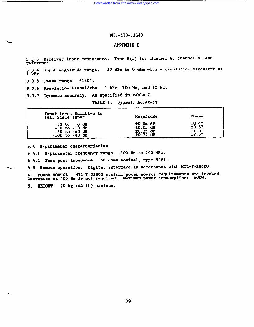
MIL-STD-1364J
APPENDIX D
3.3.3 Receiver input connectors. Type N(f) for channel A, channel B, andreference.
3.3.4 Input magnitude range. -80 dBm to O dBm with a resolution bandwidth of1 kHz.
3.3.5 Phase range. &180” .
3.3.6 Resolution bandwidths. 1 kHz, 100 Hz, and 10 Hz.
3.3.7 -C accuracy. AS specified in table 1.
I In ut Level Relative toYFu 1 Scale Input Magnitude Phase
W.4”*o*s”*1.5”27.5°
3.4 S-paraeter characteristic*.
3.4.1 S-parameter frequency range. 100”Hz to 200 ~Z.
3.4.2 Test port impedance. 50 ohms nominal, type N(f).
3.5 Remote operation. Digital interface in accordance with MIL-T-28800.
4. POWER SOURCE. MIL-T-28800 nominal power source requirements af;~nvoked.Operation at 400 Hz is not required. Maximwm~wer conmnn’ptim: .
-.
5. WEIGHT . 20 kg (44 lb) maximum.
39
Downloaded from http://www.everyspec.com
MIL-STD-1364J
APPENDIX D
Configuration A: AN2NT-CConfiguration B: AN2NV-C
ANALYZER, NETWORK
1. GENERAL. This procurement requires a scalar network analyzer.
2* CLASSIFICATION . T e III, Class 5, Style E, and Color R in accordanceK!with MIL-T-28800 for s pboard applications.
3* MEASUREMENT CAPABILITIES. The e ui ment shall be capable of absolute?!power and power zatio measurements w th n the minimum s edifications iden-
tified below. TA display of VSUR or a chart for convert ng return loss andreflection coefficient to VSWR shall be provided.
3.1 Frqmncy range.
3.1.1 Configuraticm A: 100 MHz to 18 GHz.
3.1.2 Configuration B: 100 MHz to 40 GHz.
3.2 Dynamic range. -50 db to 10 dBm.
3.3 Input channels. Channel A, channel B, and a reference channel. Ratiomeasurement capabilities shall be provided for channel A to reference andcharnel B to reference.
3.4 Resolution. Selectable resolutions such as 0.2, 0.5, 1, 5, and 10 dB perdivision shall be provided.
3.5 Display offset. *59 ~ for each ch~el. Resolution: 0.1 dB.
3.6 Frequency respcmse. tl dllor less.
3.7 Accuracy. fl-1 ~ excludin ~iswtch -d frequency response errors, forfinputs that are 10 to 5~ dB from he reference.
3.8 Impedance. 50 ohms nominal.
3.9 VSUR* Configuration A: 1.92 maximum. Configuration B: 1.7 maximum.
3.10 Dis lay. The equi ment shall contain a rectangular graphic display ofno less &an 76 mm(3 in X 102 mm $4 in) . The horizontal and vertical
Icenterlines shall be mar ed in 0.2 ivision sub-increments and one divisioncardinal increments. In lieu of division increments the equi ment may be
1!provided with positionable markers that provide a readout of requency andamplitude.
3.11 External input. The equi ment shall be provided with an external sweepin ut compatible with a O to 10!
t ramp signal such that the ramp will cause afu l-screen horizontal deflection of the CRT beam.
4. ACCESSORIES. Shielded o en,L
shielded short, 50 ohm termination, 10 dBpad, 50 ohm power splitter, tectors (2 es), and return loss bridge.
4.1 Connectors. Confi uration A:t
Type N. Configuration B: Connectorsshall allow 100 MHz to O GHz operation.
5. POWER SOURCE. MIL-T-28800 nominal power source requirements a~;5nvoked.Operation at 400 Hz is not required. Maximum power consumption: .
6. WEIGHT. 30 kg (66 lb) maximum.
40
-4
Downloaded from http://www.everyspec.com
MIL-STD-1364J
APPENDIX D
AN2MM-B
ANALYZER, NETWORK
10 GENERAL. This rocurement requires a vector network anal zer capable of!measuring transmiss on and reflection
Yarameters on a awe t
F?requency and W
basis with readouts of attenuation, ga n, phase shift, re lection coefficient,return loss, and impedance.
2. CIASSIFIGATION .%!
e III, Class 5, Style E, and Color R in accordancewith MIL-T-28800 for s pboard applications.
3. O?ERATIOIUAL REQUIREMENTS. The equipment shall be capable of measuriYtransmission and reflection parameters on a swe t frequency or GU basis w thin
!the minimum ranges, accuracies, and limits spec fied below.
3.1 Gonverter. An rf converter shall be rovided as part of the equipment!and shall be capable of processing rf inpu signals for presentation by the
display within the parameters and accuracies specified below.
3.1.1 Fxequancy range. 110 MHz to 18 GHz.
3.1.2 Input impedance. 50 ohms nominal. SWR: 2.0 maximum from 11O MHz to 6G&, 3.0 maximum from 6 to 18 GHz.
3.1.3 Ghannel isolation. 60 d.Bminimum from 110 MHz to 12.4 GHz, 50 dBminimum from 12.4 to 18 GHz.
3.1.4 Magnitude range.u
3.1.4.1 Refarence channel power range. -35 dBm to -18 dBm from 110 MHz to12.4 C?Hz, -25 dBm to -18 dlhnfrom 12.4 to 18 GHz.
3.1.4.2 Test channel pover range. -75 dBm to -10 dBm from 110 MHz to 12.4GHz , -68 dBm or less to at least -10 dBxnfrom 12.4 to 18 GHz.
3.1.4.3 Maximum RF input. 50 mW.
3.1.4.4 IF ain control.%B
The IF gain control shall have a ran e of at least69 dB in 10 and 1 dB steps with a maximum cumulative error of W.2 dB.
3.1.5. Phase measurement range. 0° to 360°.
3.2 Display. A display shall be provided to display relativeT
litude in dBand relative phase in degrees between reference and test channel nputs versusfrequency.
3.2.1 Amplitude Display range. 80 dB minimum. Accuracy:from midscreen.
3.2.2 Phase display range. +180°. Accuracy: k0.065° perscreen.
ti.08 dBper dB
degree from mid
3.2.2.1 Phase offset. The phase offset shall not exceed 0.3° per 20° stepand shall not exceed 3° for a 360” change.
MIL-T-28800 nominal power source requirements a~~o~voked.$er~~ %%*Hz is not required. Maximum power consumption: .
5. WEIGHT . 47 kg (104 lb) maximum.
L
Downloaded from http://www.everyspec.com
MIL-STD-1364J
APPENDIX D
ANSM- c
ANALYZER, SIGNATURE
1. GENEML. This rocurement requires a solid-state four digit si! F
tureanalyzer controllab e via an IEEE STD 488-1978 Generai Purpose Inter ace Bus.
2. CLASSIPICA!!OB .w
III, Class 6, Style E, and Color R in accordancewith KIL-T-28800 for s pboard applications.
2.1 Zloctromagnetic interference X- uiraments. The re uiremenggOgf ~~iT-28800 arc limited to CEOl, CE03, CSO? CS02 (0.05 to 10~ MHz(back panel s-arch e=cluded), &RE02 (14MztolGHz), mdRs$. ‘
3. ~ =Q~* Tkn equipment shall be capable of sianalysis within the clock, data, start, and sto
!specifications conr i-rode
below. ml specifications contained below shal be measured at the point ofconnection to the unit under test.
3.1 Signature generation. The siY
ture displa ed shall be identical to thesignature generated by u 16-bit sh ft register J th feedback given by theboolean logic equation:
SmmRK’K’TER= [SIGNAL INPUT] 0 [(BIT 11 0 BIT 15) @ (BIT 6 OBIT 8)]
The SIGNAL INPUT rafers to the serial data accessed by the probe andsele~~ed by the control signals.
b. The BIT numbers refer to a shift re ister with 16 bits numbered from Oto 150 BIT O receives the SHIFT RWIST~ &UT &nd each clock pulse shiftsthe data one bit toward BIT 15, the most significant bit.
c. The symbol O refers to the exclusive OR operation (or half-adder).
3.2 Signature data ●pecXfications. The signature analyzer shall be providedwith a probe for data acquisition from the unit under test.
3.2.1 ~ta thresholds. The data threshold for a 10 ic one shall be 2 W.4Vand the threshold for a 10 ic zero shall be 0.8 ~0.3
%6. Voltages above the
logic one threshold shall e interpreted as a logic one and voltages below thelogic zero threshold shall be interpreted as a logic zero.
3.2.2 Data input setup time. 15 ns or less relative to the active clockedge.
3.2.3 Hold time. Zero, relative to the active clock edge.
3.2.4 Data input pulse width. The ntinimum detectable data pulse width shallbe 15 m or less.
3.2.5 Data input overload protection. The data input overload protectionshall be at least 150 Vdc continuous or 140 Vrms for one minute.
3.3 Clock, start, and stop signal specifications.
3.3.1 Clock, start, and sto thresholds.d
The clock, start,holds shall be 1.4 *0.6V.
and stop thres-e analyzer shall inter ret voltages above the
~ ldthreshold as logic one and voltages below the thres o as logic zero. Ameans shall be provided to reverse the interpretation of either or boththresholds. When the inter retation is reversed, volts es above the threshold
f ishall be interpreted as log c zero and voltages below t e threshold as logicone .
42
Downloaded from http://www.everyspec.com
MIL-STD-1364J
APPENDIX D
3.3.2 Clock, start, and stop overloadErotection. The clock, start, and stop
overload protection shall be at least 2 Vdc.
3.3.3 Maximum clock frequency. 20 MHz or greater.
3.3.4 Minimum clock pulse width. 15 ns or less.
3.4 Input RC. 47 kilohms minimum shunted b 15 F or less.J or TOW.
The analyzerinputs shall pull tri-state buses either hi
3.5 Signature display. The signature display shall be composed of fouralphanumeric characters.
3.5.1 Signature d$splay decod?
The siF
ture displa ed shall be identicalrto a signature obtained b &cod & the sh ft register b ts as follows. The
contents of the shift re 1f
ster may be considered as a binary number with bitzero as the least signif cant bit. The displayed signature is obtained bydecoding the bine
2number as a hexadecimal number and making the following
substitutions in t e hexadecimal numbers. The hexadecimal B is displayed asC, CasF, DasH, Eas P,andFasU.
3.6 Remote operation. Digital interface In accordance with MIL-T-28800.
4. POWER SOURCE. MIL-T-28800 nominal power source requirements are invoked.Operation at 400 Hz is not required. Maximum power consumption: 65W.
-.
5. UEIGHT . 10 kg (22 lb) maximum.
43
Downloaded from http://www.everyspec.com
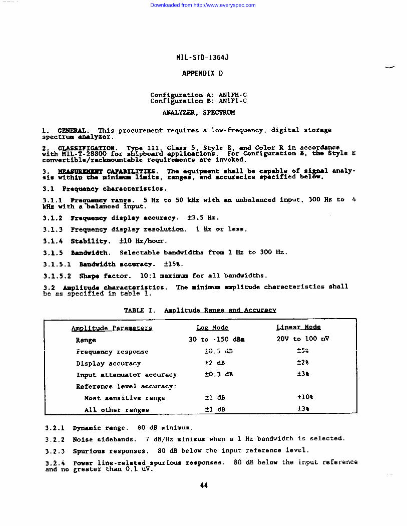
HIL-STD-1364J
APPENDIX D
Configuration A: ANIFH-CConfiguration B: ANIFI-C
ANALYZER, SPECTRUM
1. GENERAL. This procurement requires a low-frequency, digital storagespectrum analyzer.
2. CLASSIFXUE1ON .w
111, Class 5, Style E, and Color R in accordancewith MIL-T-28800 for s pboard applications. For Configuration B, the Style Econvertible/racbountable requirements are invoked.
3. ~ CAPABILITIES. Tha equipment shall be capable of signal analy-sts within the minimum limits, ranges, and accuracies spec%fted below.
3.1 Frequency charactexisticso
3.1.1 Reauancv rawze. 5 Hz to 50 kHz with an unbalanced input, 300 Hz to 4ldlzwith a~alabced Input.
3.1.2 Fxoquency display accuracy. 23.5 Hz.
3.1.3 Requency display resolution. 1 Hz or less.
3.1.4 Stability. *1O Hz/hour.
3.105 Bandwidth. Selectable bandwidths from 1 Hz to 300 Hz.
3.1.5.1 Bandwidth accuracy. *lS*.
3.1.5.2 Shape factor. 10:1 maximum for all bandwidths.
3.2 Amplituda characteristics. The minimum amplitude characteristics shallbe as specified in table I.
TABLE I. _ @ Accura vc
tude ParameteU E Mode wear Mode
Range 30 to -150 am 20V to 100 nV
Frequency response ~o.5 ~ -t5*
Display accuracy *2 ~ 22*
Input attenuator accuracy *().3 @ *3Q
Reference level accuracy:
Most sensitive range fl ~ ~lo%
I All other ranges *1 * 23%
3.2.1 Dynamic range. 80 dB minimum.
3.2.2 Noise sidebands. 7 dB/Hz minimum when a 1 Hz bandwidth is selected.
3.2.3 Spurious responses. 80 dB below the input reference level.
3.2.4 Power line-related spurious responses. 80 dB below the input referenceand no greater than 0.1 uV.
44
Downloaded from http://www.everyspec.com
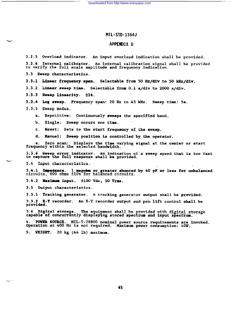
MIL-STD-1364J
APPENDIX D
3.2.5 Overload indicator. An input overload indication shall be provided.
3.2.6 Internal calibrator. An internal calibration signal shall be providedto verify the full scale amplitude and frequency indication.
3.3 Sweep characteristics.
3.3.1 Linear frequency span. Selectable from 50 Hz/diw to 50 kHz/di~.
3.3.2 Linear sweep time. Selectable from 0.1 s/div to 2000 s/div.
3.3.3 Sweep limarity. *1*.
3.3.4 @g sweep. Requency span: 20 Hz to 43 kllz. Sweep ts: 5s.
3.3.5 Sweep modes.
a. Repetitive: Continuously sweeps the specified band.
b. Single: Sweep occurs one time.
c. Reset: Sets to the start frequency of the sweep.
d. Manual: Sweep position is controlled by the operator.
Zero scan: Dis lays the time varying signal at the centerYfreq&cy within the se ected bandwidth.
3.3.6 Sweep error Indicator. An indication of a sweep speed thatto capture the full response shall be provided.
-3.4 Input characteristics.
or start
is too fast
3.4.1 ~dance. 1 megob or greater shunted by 40 pF or less for unbalancedcircuits, 600 ohms ~10% for balanced circuits.
3.4.2 Max- input. k100 Vdc, 50VrmS.
3.5 Output characteristics.
3.5.1 Tracking generator. A tracking generator output shall be provided.
3.5.2 X-Y recorder. An X-Y recorder output and pen lift control shall beprovided.
3.6 Digital storage. The e ui ment shall be provided with digital storageIfcapable of concurrently disp ay ng stored spectrum and input spectrum.
MIL-T-28800 nominal power source requirements are invoked.&er= ~~~~~”Hz is not required. Maximum power consumption: 40W.
5. UEICHT . 20 kg (44 lb) maximum.
45
Downloaded from http://www.everyspec.com
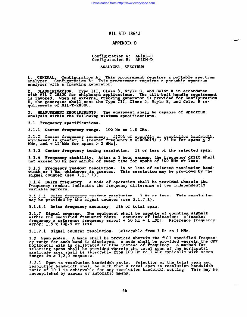
MIL-STD-1364J
APPENDIX 1)
Configuration A: ANllU-DConfiguration B: ANIKM-D
ANALYZER, SPECTRUM
1. GENERAL . Configuration A: This procurement requires a portable spectrumanalyzer. This procurement requires a portable spectrum
cotii~a:i!~~ ~ine.ator.analyzer with a
2. CLASSIFICATION .Q
e III, Class 3, Style C, and Color R in accordancewith KIL-T-28800 for s pboard applications. The tilt-bail handle re uirementiS invoked. When an external trackin 1B, the generator shall meet the Type fIYn:z::r5:ssgi?dsc2z f’%:io”quirements of !41L-T-28800.
3. MEASUREMENT REQUIREMENTS. The equipment shall be capable of spectrumanalysis within the following minimm specifications.
3.1 Frequency specifications.
3.1.1 Center frequency xange. 100 Hz to 1.8 GHz.
3.1.2 Genter frequency ●ccuracy. *[208 of span div or resolution bandwidth,whichever is greater, 6+ (center fre uency x 0.00 015) + 25 Hz for spans ~ 2
7MHz, and+ 15 kHz for spans > 2 MHz .
3.1.3 Center frequency tuning resolution. lS or less of the selected span.
3.1.4 Frequency stzbility. After a 1 hour warmxp, the frequen~ drift shallnot exceed 50 Hz per minute of sweep time for spans of 100 kHz or less.
3.1.5 Frequency readout resolution. 1% or less of selected resolution band-width or 1 Hz, whichever is greater. This r~solution Uy be prov%d-d by thesignal counter (see 3.1.7.1)0
3.1.6 Delta frequent .T
A mode of operation shall be rovided wherein the!fre uency readout ind cates the frequency difference o two independently
1var able markers.
3.1.6.1 Delta frequency readout resolution. 1 Hz or less. IMs resolutionmay be provided by the signal counter (see 3.1.7.1).
3.1.6.2 Delta freqmency ●ccuracy. *1% of total span.
3.1.7 Signal counter. The equipment shall be ca able of countin signalswithin the specified frequency range. FAccuracy o indication: ft (markerfrequency x reference frequency error) + 50 Hz + 1 LSD]. Reference frequencyerror: 1.5 x 1OE-5 or less.
3.1.7.1 Signal counter resolution. Selectable from 1 HZ to 1 Mz.
3.2 Span modes. A mode shall be provided wherein the full specified frequen-cy range for each band is displayed. A mode shall be provided wherein the CRThorizontal axis is calibrated in time instead of frequency. A method forselecting spans shall be provided wherein the total s an of the horizontal
Egraticule area shall be selectable from 100 Hz to 1 G z typically with sevenranges in a 1,2,5 sequence.
3.2.1 Span to resolution bandwidth ratio. Selection of the total span andresolution bandwidth shall be such that a total span to resolution bandwidthratio of 10:1 is achievable for any resolution bandwidth setting. This may beaccomplished by manual or automatic means.
--
46
Downloaded from http://www.everyspec.com
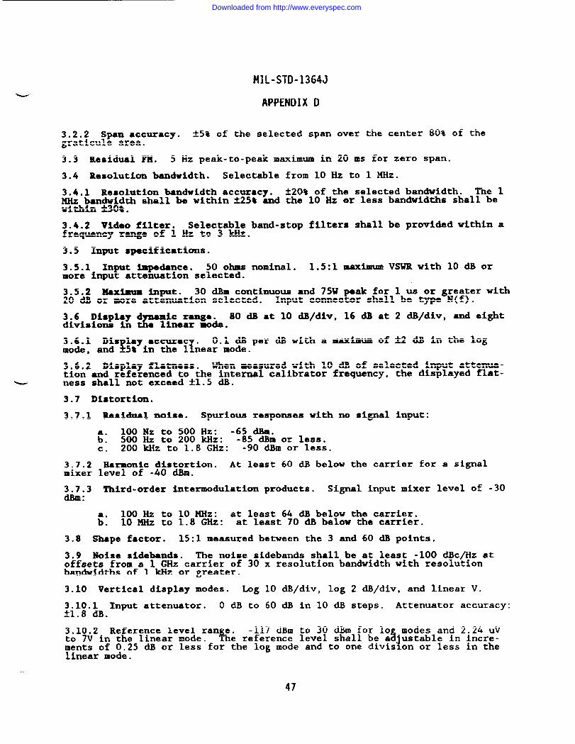
MIL-STD-1364J
APPENDIX D
3.2.2 Span ●ccuracy. ~s% of the selected spangraticule area.
3.3 Residual FM. 5 Hz peak-to-peak maximum in
over the center 80% of the
20 ms for zero span.
3.4 Resolution bandwidth. Selectable from 10 Hz to 1 MHz.
3.4.1 Resolution bandwidth accuracy. t20% of the selected bandwidth. me 1MHz bandwidth shall be within ~25t and the 10 Hz or less bandwidths shall bewithin flO~.
3.4.2 Vldao filter. Selectable band-stop filters shallfrequency range of 1 Hz to 3 kHz.
3.5 Input specifications.
3.5.1 Input Impedance. 50 ohms nominal. 1.5:1 maximummore input attenuation selected.
be provided within
VSWR with 10 dB or
a
3.5.2 Maximum input. 30 dBm continuous and 75W peak for 1 us or greater with20 dB or more attenuation selected. Input connector shall be type N(f).
3.6 DisplayP
ic ranga. 80 dB at 10 dB/div, 16 dB at 2 dB/div, and eightdivisions in Q linear mode.
3.6.1 Dis 18y 8CCU=C .$ T
0.1 dB per dB with a maximum of~ dB in the logmode, and -5% in the 1 near mode.
3.6.2 Display flatness. When measured with 10 dB of selected input attenua-tion and referenced to the internal calibrator frequency, the displayed flat-
G ness shall not exceed *1.5 dB.
3.7 Di*tortkn.
3.7.1 Residual noise. Spurious respomes with no signal input:
lM Nz to 500 Hz: -65 dBm.& 500 Hz to 200 Wz: -85 dBm or less.c. 200 ~Z to 1.8 GHz: -90 dBm or less.
3.7.2 harmonic distortion. At least 60 dB below the carrier formixer level of -40 dBm.
a signal
3.7.3 Third-order intermodulation products. Signal input mixer level of -30dBm:
100 Hz to 10 MHz: at least 64 dB below the carrier.& 10 MHz to 1.8 GHz: at least 70 dB below the carrier.
3.8 Shape factor. 15:1 measured between the 3 and 60 dB points.
3.9 Noise sidebands. The noise sidebands shall be at least -100 dBc/Hz atoffsets from a 1 GHz carrier of 30 x resolution bandwidth with resolutionbandwidths of 1 kHz or greater.
3.10 Vertical display modes. Log 10 dB/div, log 2 dB/div, and linear V.
3.10,1 Input attenuator. O dB to 60 dB in 10 dB steps. Attenuator accuracy:~1.8 ~.
3.10.2 Reference level ran e. -117 dBm to 30 dBm for 10 modes and 2.24 UVto 7V in the linear mode. hf %e re erence level shall be a ustable in lncre-
iments of 0.25 dl!or less for the log mode and to one divis on or less in thelinear mode.
47
Downloaded from http://www.everyspec.com
MIL-STD-1364J
APPENDIX D
3.10.3 IF gain. *1 dB for any 10 dB change in the reference level.
3.11 Swee time.!
ZOO us to SOS in zero span mode. Accuracy: 120% ofsetting. nternal and auto sweep modes shall be provided.
3.12 Tri er.H
Internal, external, free run, and single sweep triggeringmodes sha be provided.
3.13 Digital stoxage. Di ital stora e shall be provided with selectablefmodes that compare and sub ract two a 1s and save maximum signal values
and noise-avera e spectral dis lays.! !
‘r is 1c d ita storage function shall becapable of stor ng an:=d~~~:~ ng at least e ght spectrums Including thereadout measurement
EWhen batteries are required for di ital
stora e circuitry,f
&st ey shall bve a useful life of at least 12 mon undernorms operating conditions within the operating temperature range.
3.14 Markez8. The e uipment shall pxovide frequency and% ?
litude markersusing one marker for a solute measurements and - markers or relative mea-surements. Marker positionln will provide a readout of frequency and ampli-tude of any point For the dif erence in amplitude or frequency between twopoints, along a displayed spectrum.
3.14.1 Marker ~litude accuracy. At the referenca level, the marker ampli-tude uncertainty shall not exceed *2 dB in log mode and 5% In linear mode.The total uncertainty shall degrade to no more than (6.8 ~ at M* *via-tion from the reference level.
3.15 CRT specifications. A displa with an internal graticule of at least 8x 10 divisions shall be provided. k e dis lay shall
! srovide a readout of
center fre uency, span or span/div,1
resolu ion bandwi th, vertical scalefactor, re erence level marker readout of frequent and amplitude, videofilter selection, and I@ attention. 1“The CRT disp ay area shall be at least6.5 cm (2.56 in) highby 7.5 cm (2.95 in) wide.
3.16 Outputs. Ou uts for an Internal calibrator signal, an X-Y recorder, apenlift control, 3an a tracking generator shall be provided.
3.17 Refsrence input. Frequency: 10 HHz. Amplitude range: -2 to 10 CiBm.
3.18 Calibrator signal accuracies. 3X1.3 dB for amplitude, t10 ppm for fre-quency.
3.19 llemote operation. Digital interface in accordance with MIL-T-28800.
3.20 Tracking generator. Configuration B equipment shall be provided with atracking generator that meets the following specifications.
3.20.1 Frequency range. 300 kHz to 1.8 GHz.
3.20.2 Output level. O dllm.
3.20.3 Attenuation range. 60 dB in 10 and 1 dB steps.
3.20.4 Flatness. f2.25 dB.
3.20.5 Dynamic Range. 95 dB.
3,20.6 Residual FM. 50 Hz peak-to-peak.
3.20.7 Output impedance. 50 ohms nominal.
3.20.8 SpuriouB outputs. -20 dBc.
3.20.9 Accessories. All accessories necessa~ for proper tracking generatoroperation shall be supplied with the equipment.
48
Downloaded from http://www.everyspec.com
MIL-STD-1364J
APPENDIX D
4. POWER SOURCE. MIL-T-288~~Oominal power source requirements are invoked. .Maximum power consumption: .
5. WEIGHT . Configuration A: 20 kg (44 lb) maximum. Configuration B with aninternal tracking generator: 21 k (46 lb) maximum.
fWhen an external track-
enerator is provided for Conf guration B,& fb).
neither unit shall exceed 20 kg
49
Downloaded from http://www.everyspec.com
MIL-STD-1364J-
APPENDIX D
ANINZ-D
ANALYZER, SPECTRUM
1. ~. This procurement re uires a portable spectrum analyzer. Theequipment shall be capable of IEE~ Std 488-1978 digital bus control and datatransfer digital storage, and marker-aided relative and absolute frequencyand amplitude measurements of microwave and RF signals.
2. CLMSI?WATIOX ●
wIII, Class 3, S~le G, and Color R in accordance
with KIL-T-28800 for s pboard applications with the following exceptions:
a. The digital readout shall be designed for use at arms length.
b. The tilt-bail handle requirement is invoked.
3. ~ =Q~s. The equipment shall be ca able of s ectrumanalysis within the following minimum specifications. & ? Nisen specif ed,the number of the harmonic component of the local oscillator.
3.1 Fxoquancy specifications.
3.1.1 Frequency range. 50 kHz to 40 GHz.
3.1.2 Frequency ●ccuracy./)
t 5% of span + 15% of resolution bandwidth + 250Hz + (center frequency X 0.00 015)].
3.1.3 Frequency stability. 300 Hz X N drift per minute of sweep time forspans of 1 MHz or less.
3.1.4 ?re uency readout resolution.1
1% or less of selected span or 1 kllz,whichever s greater.
3.1.5 Delta frequency range. A mode of operation shall be provided whereinthe frequent
zreadout indicates the frequency difference of two independently
variable mar ers.
3.1.5.1 Delta frequency readout resolution. 100 Hz or less.
3.1.5.2 Delta frequency accuracy. tl% of total span.
3.1.6 Center frer
ency tuning resolution. 0.1 divisions or less of the se-lected span or 20 Hz, whichever is greater.
3.1.7 Signal counter. The equi ment shall be capable of counting signalsEwithin the frequency ran e speci ied in 3.1.1.
! ‘Ccuracizo: Sd$c?’wi ●4-[~rker freq~ncy x re erence fre uency error) + (50
\Re erence frequency error: 1.5 x 18E-5 or less.
3.1.7.1 Signal counter resolution. Selectable from 1 HZ to 1 W.
3.2 Span modes. A mode shall be provided wherein the full specified frequen-cy range for each band is displayed. A mode shall be provided wherein the CRThorizontal axis is calibrated in time instead of frequency. A method forselecting spans shall be provided wherein the total s an of the horizontal
Egraticule area shall be selectable from 2.5 kHz to 1 Hz typically with sevenranges in a 1,2,5 sequence.
3.2.1 S n to resolution bandwidth ratio.Y
The selecting of the total spanand reso ution bandwidth shall be such that a total span to resolutionbandwidth ratio of 10:1 is achievable for any span setting. This may beaccomplished by manual or automatic means.
50
Downloaded from http://www.everyspec.com
MIL-STD-1364J
APPENDIX D
3.2.2 Span accuracy. AS% of the selected span over the center 80% of thegraticule area.
3.3 Residual FM. 50 Hz x N peak-to-peak maximum in 20 ms for zero span.
3.4 Resolution bandwidth. Selectable from 100 Hz to 1 MHz.
3.4.1 Resolution bandwidth accuracy. *20% of the selected bandwidth. The 1MHz bandwidth shall be within *25* and the 100 Hz or less bandwidths shall bewithin k30%.
3.4.2 Video filter. Selectable band-stop filters shall be provided within afrequency range of 300 Hz or less to at least 3 kHz.
3.5 Input specifications.
3.5.1 Input Impedance. 50 ohms nominal. With 10 dB or more input attenua-tion selected, the VSWR shall not exceed 2.3:1 for frequencies to ●t least 18GHz .
3.5.2 Maximum in t.r
30 dBm continuous and 75W peak when using ~ Wconnectors with 2 dB or more attenuation selected. The maximum input forwaveguide: 20 dBm continuous.
3.6 Display dF
c range. 80 dB at 10 dB/div, 16 dB at 2 dB/div, and eightdivisions in t e linear mode.
3.6.1 Display accuracy. M dB at 10 dB/div, ~1.5 ~ at 2 ~/div, ~ fit inthe linear mode.
u3.6.2 Display flatn~ss. When measured with 10 dB of selected input ●ttama-tion and referenced to the internal calibrator frequency, the displayed. flat-ness shall be ~6 dB for frequencies to at least 18 GHz.
3.7 Spurious response specifications.
3.7.1 Residual. Spurious response: -90 d.Bmwith no input signal a lied;:Of :H;O 6.46 GHz. The response shall degrade to no worse than -70Rm at
. .
3.7.2 Distortion. Spurious harmonic distortion shall be at leas~06~8~~belowthe carrier for a signal input mixer level of -40 dBm or less u
YThird-order intermodulation products shall be at least 70 dB be ow the carrierfor a signal input mixer level of -30 dBm or less.
3.8 Input noise sensitivity. -90 dBm or less when a 100 Hz resolution hnd-width and O dB attenuation are selected.
3.9 Shape factor. 15:1 or less at the 3 dB and 60 dB points.
3.10 Hoise sidebands. The noise sidebands shall be at least -100 to 20 Log NdBc/Hz at offsets from the carrier of 30 x resolution bandwidth with resolu-tion bandwidths of 1 kHz or greater.
3.11 Vertical display modes. Log 10 dB/div, Log 2 dB/div, and Linear V.
3.11.1 Input attenuator range. O dB to 60 dB in 10 dB steps. Attenuatoraccuracy: A1.8 ~ per 10 dB steps to a maximum of 3.5 ~.
3.11.2 Reference level ran e.#
-117 dBm to 30 dBm for 10 modes and 2.24 UVto 7V in the linear mode. %e reference level shall be a justable in incre-ments of 0.25 dB or less for the log ❑ode and to one division or less in thelinear mode.
. ..
51
Downloaded from http://www.everyspec.com
MIL-STD-1364J
APPENDIX D
3.11.3 IF gain variation. ~1 dB maximum for any 10 dB change in the refer-ence level.
3.12 sweep. Sweep time: selectable from 50 us to 50s in zero s an mode.Accuracy: ~20% of setting. EInternal and auto sweep modes shall e provided.
3.13 Tri er.R
Internal, external, free run, and single sweep triggering.modes sha be prwided.
3.14 Digital storage. Di ital stora e shall be provided with selectable!modes that compare and sub ract two sf
and noise-avera e spectral dis lays.f !
E’!lfE<tS.~%$;=k<il?:capable of stor ng and display ng at least e ght spectrums including thereadout measurement
[arameters. When batteries are required for digital
stora e circuitry,f
t ey shall have a useful life of at least 12 months undernorms operating conditions within the operating temperature range.
3.15 Markers. The e uipment shall provide frequency and amplitude markersusing one marker for %1so ute measurements and two markers for relative mea-surements. Marker positioning
!will provide a readout of frequent
Land ampli-
tude of any point or the dif erence in amplitude or frequency be een twopoints, along a &played spectrum.
3.16 CR? specifications. A displa with an internal graticule of at least 8x 10 divisions shall be provided. h e dis lay shall rovide a readout ofcenter fre uency, span or span/div,
1! zresolu ion bandwi th, vertical scale
factor, re erence level marker readout of frequency and litude, videofilter selection, and r~ attenuation. TThe display area sha 1 be at least 6.5cm (2.6 in) high by 7.5 cm (3 in) wide.
3.17 outputs. Outputs for an internal calibrator signal an X~Y1~~~~r&r, apen-lift control and a tracking
fenerator shall be provi~ed.
oscillator and mixer outputs’ shal also be provided.
3.18 Reference input. Frequency: 10 MHz. Amplitude range: -2 to 10 dBm.
3.19 Calibrator signal ●ccuracies. kO.3 dB for amplitude, *1O PP* for fre-quency.
3.20 Remote operation. Digital interface in accordance with MIL-T-28800.
3.21 Internal preelection. Zntemal preelection shall be provided.
3.22 Mxer waveguide flanges. UG-595/U and UG-599/U.
4. POWER SOURCE. MIL-T-288Cl~O~minal power source requirements are invoked.Maximum power consumption: .
5. WEIGHT . 20 kg (44 lb) maximum.
52
Downloaded from http://www.everyspec.com
MIL-STD-1364J
APPENDIX D
AN3RT-B
ANALYZER, SPECTRUM, REAL TIME
-----
1. GENEML. ‘lhis procurement requires a spectrum analyzer with the ca abili-
8Yof measuring absolute amplitude and frequency characteristics of aud o and
signals .
2. cxAssIFxcA’rIoml●%!
e III Class 5, Style E, and Color R in accordancewith MIL-T-28800 for s pboar~ applications. The convertible/rackmountablerequirement is invoked.
3. ~ REQUIMXENTS. The equipment shall be capable of spectrumanalysis within the minimum specifications contained below.
3.1 Frequency specifications.
a. Real time: 10 Hz to 3 kHZ.
b. Spectrum analysis: 10 Hz to 100 kHz.
3.1.1 Frequency accuracy. 0.1% FS.
3.1.2 Frequency resolution.
a. Normal: 400 lines.
b. Expanded (zoom): At least 32 times. Zoom operation permits selectedresolution expansion of the baseband resolution around a desired frequency.
3.1.3 FLltars.
a. Anti-aliasing: 96 dB/octave rolloff.
b. 1/3 octave: Shall meet ANSI S1.11-1966 Class III.
3.2 Input amplitude specifications.
3.2.1 Input amplitude range. 15 mVrms to 10
3.2.2 Madxnam input without damage. 30 Vrms
3.2.3 Imput RC. 1 megohm or greater shunted
3.2.4 Dynamic range. 70 dB.
3.2.5 Frequency response. ~1 dB or less.
Vrms . Accuracy: -t5~ FS.
or greater.
by 200 pF or less.
3.2.6 In t overload indicator.Y
The overload indicator threshold shall bebetween 9 % and 110% FS.
3.3 Memo=. The eauinment shall be mrovided with a means of storing andrecalling bp to 32 ;ighal traces. “
3.4 Outputs. The equipment shall be provided with outputs forX-Y recorder.
3.5 Handle. A tilt bail handle in accordance with MIL-T-28800ed.
3.6 Display dimensions. 101.6 mm (4 in) by 69.8 mm (2-3/4 in)
a Plotter or
may be provid-
minimum.
3.7 Rackmounting. The equipment shall be contained in a Style E enclosurefor portability and shall be provided with a conversion kit which will allow
53
Downloaded from http://www.everyspec.com
MIL-STD-1364J
APPENDIX D
raclanounting in accordance with the convertible/rackmountable requirements ofMIL-T-28800.
3.8 Di ital interface. A digital interface is required in accordance withMIL-T-2~800.
4. POWER SOURCE. MIL-T-28800 nominal power source requirements a;;~ked.Operation at 400 Hz is not required. Maximum power consumption: .
5. WEIGHT . 20 kg (44 lb) IMXiOWU1.
54
Downloaded from http://www.everyspec.com
MIL-STD-1364J
APPENDIX D
AN5NN-A
ANALYZER, WAVE
1. GENERAL. This procurement requires a wave analyzer that resolves and mea-sures the amplitude and frequency of spectral components.
2. CLASSIFICATION. T e III, Class 5, Style E, and Color R in accordanceK!with MIL-T-28800 for s pboard applications.
3. OPERATIOIUAL lLEQUIUMERTS. The equipment shall be ca able of arforming! Tspectral analysis within the minimum specifications Iden ified be w.
3.1 Froquemcy Specification.
3.1.1 Frequency range. 15 Hz to 50 kHZ.
3.1.2 Frequency display resolution. 1 Hz or less.
3.1.3 Frequency ●ccurscy. ~3.5 Hz.
3&~~41 &ulMMICy stability. *1O Hz per hour after a warm-up time of not more.
3.1.5 Automatic fxoquency control. The automatic frequency control AFC&)hold-in ran e shall be at least ~800 Hz. An indication of an Unlocke condi-
%tion shall e provided.
3.2 Amplitude specifications.~
3.2.1
3.2.2
3.2.3
3.2.4
Amplitude ranse. 100 nV to 30 Vrms.
Amplitude display. Digital or mirror-backed analog meter.
kplitude accuracy. Log: tz dB. Linear: Y4% of indication.
xic range. 80 dB minimum. An indication of input amplifier over-load shall be provided.
-.
3.2.5 Noise sidebands. 70 dB down 10 bandwidths away from the CW inputsignal.
3.2.6 Calibrator. An internal calibrator capable of verifying the amplitudeaccuracy to at least *1.5% shall be provided.
3.3 Sweep specifications.
3.3.1 Resolution bandwidth. Selectable from 3 Hz to 300 Hz.
3.3.2 Scan width. Selectable from 50 Hz to 50 kHz.
3.3.3 Sweep tlmee Selectable from 0.1s to 2,000s.
3.3.4 Sweep modes. Repetitive, triggered single sweep, ~~d manual sweepmodes shall be provided.
3.3.5 Sweep error light. A light that indicates when a sweep rate is toofast to capture the full response shall be provided.
3.4 Input specifications.
3.4.1 Input RC. 1 megohm or greater shunted by 40 pF or less.
3.4.2 Xaximum input without damage.
55
Downloaded from http://www.everyspec.com
?41L-STD-1364J
APPENDIX D
a. ~loo”vdc or v- on the 0.2V and higher ranges.
b. *50 Vdc or Vms on the ().lVand lower ranges.
3.4.3 Input connector. Female banana.
3.5 outputs.
Tracking generator: ~ output for use with a compatible trackinggene&tor.
b. X-Y recorder: Outputs shall include vertical and horizontal drives.Pen lift control shall be provided.
4. POWER SOURCE. MIL-T-28800 nominal power source requirements a~;vinvoked.Operation at 400 Hz is not required. Maximum power consumption: .
5* WEIGHT . 20 kg (44 lb) max-.
56
-—
Downloaded from http://www.everyspec.com
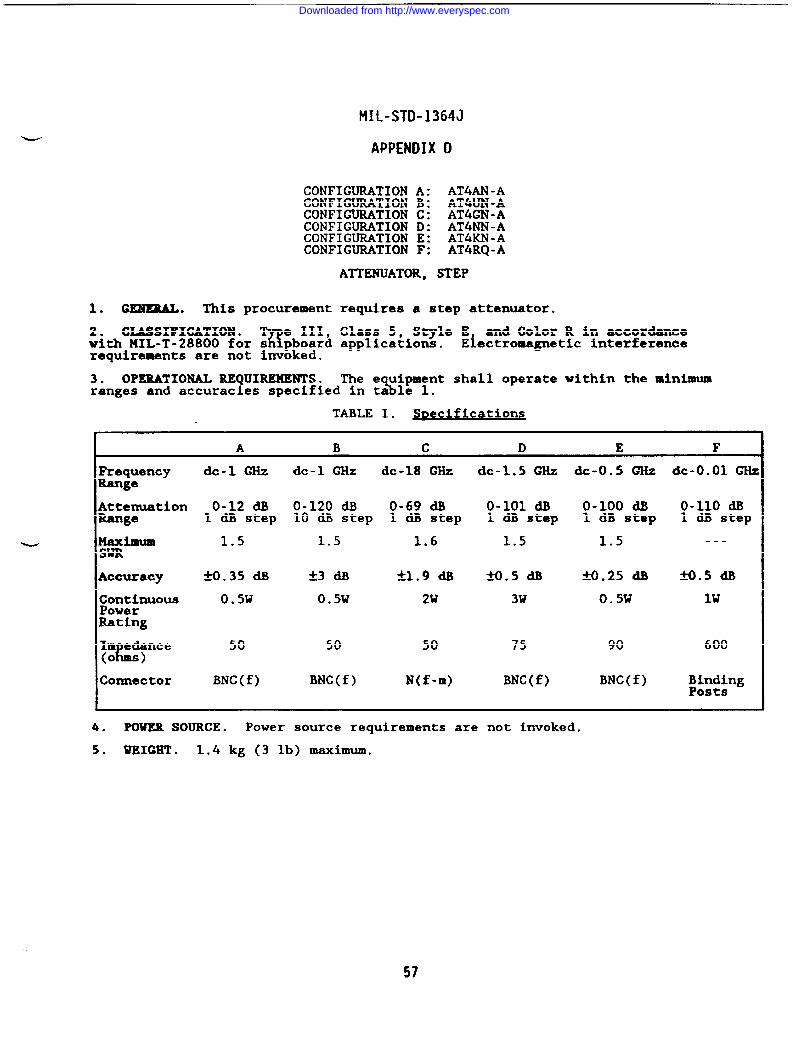
MIL-STD-1364J
APPENDIX D
CONFIGURATION A: AT4AN-ACONFIGUMTION B: AT4UN-ACONFIGURATION C: AT4GN-ACONFIGURATION D: AT4NN-ACONFIGURATION E: AT4KN -ACONFIGURATION F: AT4RQ -A
ATTENUATOR, STEP
1. GENERAL. This procurement
2. CXASSIFICATION .%
e III,with MIL-T-28800 for s pboardrequirements are not invoked.
requires a step attenuator.
Class 5, Style E and Color R in accordanceapplications. Electromagnetic interference
3. OPERATIONAL REQUIREMENTS. The e uipment shall operate within the minimum\ranges and accuracies specified in ta le 1.
TABLE 1. fications
I A B c D E F
FrequencyRange
AttenuationRange
y#lBum
Accuracy
I edance(%ms)
Connector
de-l GHz
0-12 dB1 dB step
1.5
M.35 dB
0.5W
50
BNC(f)
de-l ~Z dc-18 ~Z
0-120 dB O-69 dB10 dB step 1 dB step
1.5 1.6
50 50
BNC(f) N(f-m)
dc-1.5 GHz dc-O.5 GHz dc-O.01 G&
0-101 a o-1oo m 0-110 dB1 dB step 1 dB step 1 dB step
1.5 1.5 ---
*O*5 & W.25 dB 9.5 a
3W 0.5W lW
75 90 600
BNC(f) BNC(f) ~&$~ng
4. POWER SOURCE. Power source requirements are not invoked.
5. WEIGET . 1.4 kg (3 lb) maximum.
57
Downloaded from http://www.everyspec.com
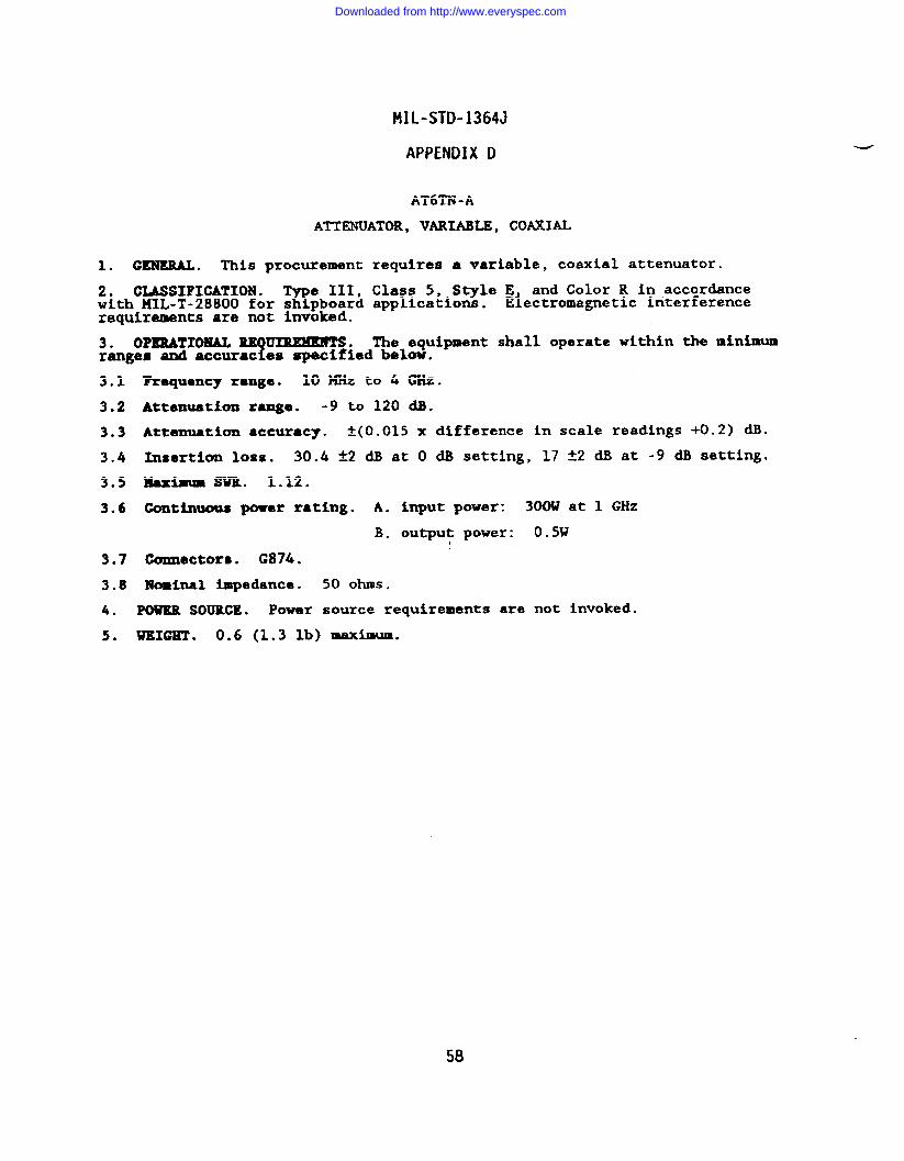
MIL-STD-1364J
APPENDIX D
AT6TN-A
ATTENUATOR, VARIABLE, COAXIAL
1. GENERAL. This procurement requires a variable, coaxial attenuator.
2* CIMSIFICATION .%
e III, Class 5, Style E and Color R in ,accordancewith HIL-T-28800 for s pboard application. Electromagnetic interferencerequirements are not invoked.
3. OPERATIONAL RE ~.!
The equipment shall operate within the minimumranges and accurac es spacified below.
3.1
3.2
3.3
3.4
3*5
3.6
3.7
3.8
4.
5.
Frequency range. 10 MHz to 4 GHz.
Attenuation range. -9 to 120 a.
Attenuation accuracy. f(O.015 x difference in scale readings +0.2) dB.
Insertion 10ssO 30.4 *2 dB at O dB setting, 17 *2 dB at -9 dB setting.
maximum SwR. 1.12.
Continuous powar rating. A. input power: 300W at 1 GHz
B. output power: 0.5W
Connectors. G874.
Nominal impedance. 50 ohms.
POWER SOURCE. Power source requirements are not invoked.
WXXGHT ● 0.6 (1.3 lb) maximum.
58
Downloaded from http://www.everyspec.com
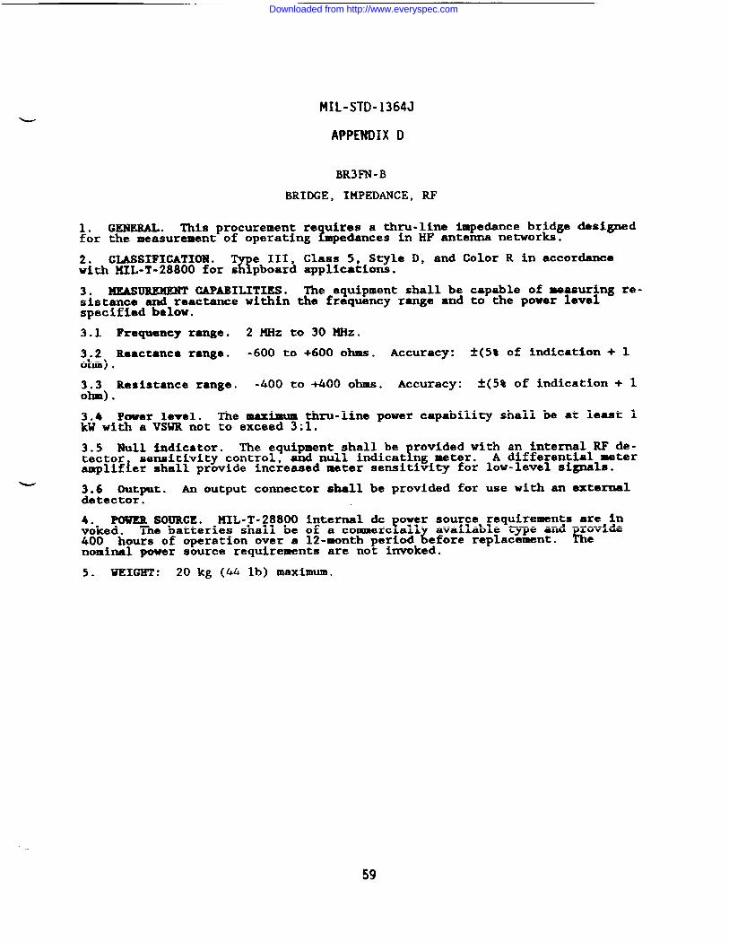
MIL-STD-1364J
APPENDIX D
BR3FN-B
BRIDGE, IMPEDANCE, RF
1. GENERAL. This procurement re uires a thru-line impedance bridge designedfor the measurement of operating L edances in HF antenna networks.
2. CLASSIFICATION .%
e III, Class 5, Style D, and Color R in accordancewith MIL-T-28800 for s pboard applications.
3. MEASUREMENT CAPABILITIES. The equipment shall be capable of measuring re-sistance and reactance within the frequency range and to the power levelspecified below.
3.1 Frequency range. 2 MHz to 30 MHz.
3.2 Reactance range. -600 to +600 OhUS. Accuracy: i-(5~ of i~icat~on + 1ohm) .
3.3 Resistance range. -400 to +400 ohms. Accuracy: -t(5% of indication + 1ohm) .
3.4 Power level. The maximum thru-line power capability shall be at least 1kW with a VSWR not to exceed 3:1.
3.5 Null indicator. The equipment shall be!rovided with an internal RF de-
sensitivity control, and null indicat ng meter. A differential =ter~~;;~er shall provide increased meter sensitivity for low-level signals.
w3.6 Output. An output connector shall be provided for use with an exterualdetector.
4. POWER SOURCE* !41L-T-28800 internal cic ower source requirements are invoked. FThe batteries shall be of a commerc all available type and rovlde
~ L400 hours of operation over a 12-month period efore replace=nt. enominal power source requirements are not invoked.
5. WEIGHT : 20 kg (44 lb) maximum.
59
Downloaded from http://www.everyspec.com
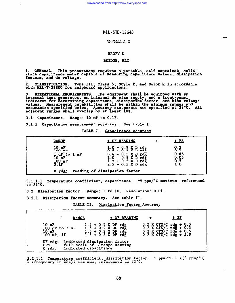
MIL-STD-1364J
APPENDIX D
BROFW- D
NUDGE, RIX
1. c~. This procurement re uires a portable self-contained solid-state capacitance meter capable o? measuring capacitance values, dissipationfactors, and & voltage.
2. CIASSI?ICATIOH .%
e III Class 5, Style E, and Color R in accordancewith MIL-T-28800 for s pboar~ applications.
3. OPXRATIOBIAL RILQ~ -‘e ‘qd;: :g:: ;$::P!::::P-Yinternal test enerator, an internal dc bias s ply
indicator for %8termining ca acitance! i
and bias voltagevalues. Measurement ca abil ;~~hr~ail be w thin the min&um ranges and
faccuracies specified be OW.x
statements are specified at 23°C. filadjacent ranges shall overlap by at east 10%.
3.1 Capacitance. Range: 10 nF to O.lF.
3.1.1 Capacitance measurement accuracy. See table I.
TABLE I.
10 nF 1.0 + o100 nF 0.5 + oluFtolmF 0.4 + o10 mF 1.0 + o100 mF 1.5 + oO.IF 2.5 + O
.9 )SD rdg 0.2
.5 XDrdg 0.1
.5 Xhxlg 0.05
.5XDrdg :.:5
.5 Xllrdg
.5X Drdg 1:0
D rdg: reading of dissipation factor
3,1.1.1 Temperature coefficient, capacitance. *S pPm/oC maximum, referencedto 23°C.
3.2 Dissipation factor. Range: 1 to 10. Resolution: 0.01.
3.2.1 Dissipation factor accuracy. See table 11.
TABLE II. Di D tion Factor Accuracvssi a
u2LMAuw+ % F$
10 * 1.5 + 0.5XDF rdg 0.2XCFS/C rdg+ 0.3100 nF to 1 mF 1.S + 0.2 X DF rdg 0.2 X CFS/C rdg+ 0.310 mF 1.5 + 0.2 XDF rdg 0.2 XCFS/C rdg+ 0.5100 mF, lF 15+0.2XDFrdg 0.2 X CFS/C rdg + 3.0
I))Srdg: indicated dissipation factor. full scale of C range setting
C rag: indicated capacitance
3.2.1.1 Temperature coefficient, dissipation factor. 2 ppm/°C + ((3 ppm/°C)x (frequency in kHz)) maximum, referenced to 23”c.
60
Downloaded from http://www.everyspec.com
MIL-STD-1364J
APPENDIX D
3.3 Bias voltage. The equipment shall be provided with an internal & biasvoltage source of at least 2 volts. The capability of operating with anexternal source of at least 50 Vdc shall be provided.
3.4 Internal test generator. Frequency: 120 Hz. Amplitude: 1.5 Vrms maxi-mum.
4. ACCESSORIES. The e uipment shall be provided with precision test lead,2sets capable of all co igurations required for each measurement function
specified above.
5. POWER SOURCE. liIL-T-28800 nominal power source requirements are invoked.operation at 400 Hz is not required. Maxiuum power cona~tion: 70U.
6. WEIGHT . 10 kg (22 lb) maximum.
61
Downloaded from http://www.everyspec.com
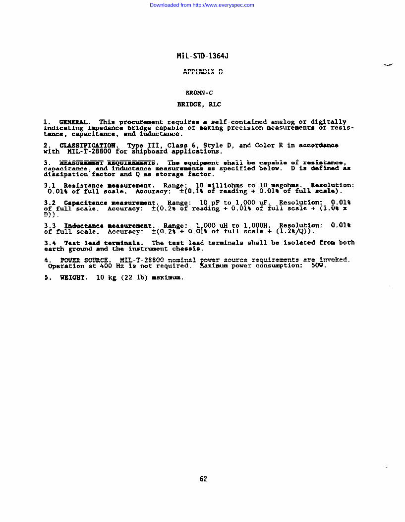
MIL-STD-1364J
APPENDIX D
BROMN-C
BRIDGE, ~
1. GENERAL. This procurement re uires a self-contained analog or digitall1indicating impedance bridge capab e of making precision measurements of res s-$
tance, capacitance, and inductance.
2. CL4SSIFICATIO19.T
e III, Class 6, Style D, and Color R in accordancewith MIL-T-28800 for s ipboard applications.
3. ~ =Q~s ● Tho ●quipment shall be ca Ale of reshtance,capacitance, fand inductance measurements as specified be OW. D is defined asdissipation factor and Q as storage factor.
3.1 Resistance measurement. Range: 10 xnilliohms to 10 megohms. Resolution:0.01% of full scale. Accuracy: ~(Oel$ of reading + 0.01% of full scale).
3.2 Capacitance measurement. Range: 10 pF to 1 000 uF. Resolution: 0.01sof full scale. Accuracy: *(0.2% of reading + 0.61% of full scale + (1.0% xD)).
3.3 Inductance measurement. Range: 1 000 UH to 1,000H. Resolution: O.Oltof full scale. Accuracy: f(O.2% + O.Oi% of full scale + (1.2%/Q)).
3.4 Test lead terminals. The test lead terminals shall be isolated from bothearth ground and the instrument chassis.
4. POWERSOURCE* HIL-T-28800 nominal ower source requirements ar?o~nvoked.Operation at 400 Hz is not required. iaximum power consumption: .
5* WEIGHT . 10 kg (22 lb) maximum.
62
—
Downloaded from http://www.everyspec.com
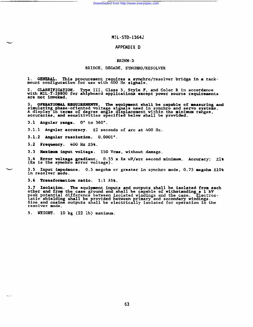
!fIL-STD-1364J
APPENDIX D
BR2NN -D
BRIDGE, DEGADE, SYNGHRO/RESOLVER
1. GENERAL. This procurement re uires a synchro/resolver bridge in a rack-mount configuration for use with z00 Hz si~h.
2. CLASSIFICATION .%
e III, Class 5, Style F, and Color R in accordancewith MIL-T-28800 for s pboard applications except power source requirementsare not invoked.
3. OPERATIONAL XEQ~. The equiY
nt shall be capable of measuring andsimulating phase-oriented voltage si
Ys used in s
rchro and servo Bystems.
A display in terms of de ree angle d splacement wit in the minimum ranges,accuracies, fand sensitiv ties specified below shall be provided.
3.1 Angular range. 0° to 360°.
3.1.1 Angular accuracy. &2 secon& of arc at @() Hz.
3.1.2 Angular resolution. 0.0001”.
3.2 Freqnency. 400 Hz 25%.
3.3 Maximum input voltage. 150 Vrms, without damage.
3.4 Error voltage gradient. 0.55 x Es uV/arc second minimum. Accuracy: ~1*(Es is the synchro error voltage).
3.5 In t impedance.r
0.5 megohm or greater in spchro mode, 0.75 megohm ~10%in reso ver mode.
3.6 Transformation ratio, 1:1 *~*.
3.7 Isolation. The equipment inputs and outputs shall be isolated from eachother and from the case ground and shall be capable of withstanding a 1 kVpeak potential difference between isolated windings and the case. Electros-tatic shielding shall be rovided between
K !rimary and secondary windings.
Sine and cosine outputs s all be electrica ly isolated for operation in theresolver mode.
5. WEIGHT . 10 kg (22 lb) maximum.
63
Downloaded from http://www.everyspec.com
MIL-STD-1364J
APPENDIX D
TS9NN-D
CALIBMTOR, RANGE, MDAR
1. GE~ . ~is procurement requires a solid-state, radar range calibrator.
2* CLASSIFKATIOM .%’!
e XII Class 5, Style C, and Color R in accordancewith MIL-T-28800 for s pboar~ applications.
3. OPERA?IOMAL REQtmunmTs. The equipment shall be capable of rovidingfmarker pulses at preselected s acin s for introduction into the v &o line of
a radar display syetem within L!e m nimum ranges and ●ccuracies specifiedbelow.
3.1 Marker output.
3.1.1 Ranges. 1,000, 2,000, 10,000, 20,000, and 100,000 yds.
3.1.2 Accuracy. M).01% of range.
3.1.3 Amplitude. Variable from O to ~3.5V into 75 ohms.
3.1.4 Pulse width. Continuously variable from 0.1 us to 2 us into 75 ohms.
3.2 Trigger output.
3.2.1 Repetition rate. Variable from 50 pps to 5,000 pps.
3.2.2 Tr@ger amplitude. Variable from *1V to ~lOV into 75 ohms.
3.2.3 Trigger delay. Variable from O to t2 us.
3.2.4 Tri~ar pulso width. 0.3 us M.05 us.
3.3 Source ~edance. Switch selectable 75 ohm and 1,000 ohm loads for trig-ger and marker outputs.
3.4 kternal trigger input. Required amplitude range: 2.5V to 20V into 75ohms .
3.5 Connectors. BNC(f) .
4. POWER SOURCE. MIL-T-28800 nominal power source requirements a;; invoked.operation at 400 Hz is not required. Maximum power cons=ption: .
5. WEIGHT . 20 kg (44 lb) IMtXi-.
64
Downloaded from http://www.everyspec.com
MIL-STD-1364J
APPENDIX D
CPIMN-A
CAPACITOR, DECADE
1. GENERAL. This procurement requires a decade capacitor.
2. CLASSIFICATION . Type III Class 5, St le E and Color R in accordance withMIL-T-28800 for shipboard applications. E~ectromagnetic interferencerequirements are not invoked.
3. OPERATIONALT
UIREMENTS. The equipment shall operate within the minimumranges and accurac es specified below.
3.1 Capacitance range. 50 pF to 1.1115 UP in 100 pF steps.
3.2 Accuracy. ~(0.5% + 5 pF) at 1 kHz.
3.3 Maximum voltage. 500V peak for frequencies up to 30 kHz.
3.4 Fro ency characteristics.Y
The effective capacitance shall notdeviate rom the nominal capacitance by more than 1% from 1 to 30 kllz.
305 Tarni.nals. Four binding posts with grounding links.
4. POWER SOURCE. Power source requirements are not invoked.
5. WEIGHT . 4.6 kg (10 lb) maximum.
65
Downloaded from http://www.everyspec.com
MIL-STD-1364J
APPENDIX D
COOFPI-E
COUNTER, ELECTRONIC
I
i
1. GENERAL. This procurement requires a dc to 500 MHz solid-state,universal electronic counter capable of IEEE 488-1978 digital bus operation.
2. CIASSI?ICATION .%
e 1110 Class 5, Style E, and Color R in accordancewith MIL-T-28800 for s pboard applications.
3. ~ =Q~~ ●The e uipment shall be capable of frequent ,
Eferiod, period average, time interva , and ratio measurements as specifie3
elow.
3.1 Time base. Frequency: 10 KHz.
3.1.1 Aging rate. k5 x 10E-10/day after a 24-hour stabilization period.
3.1.2 Oscillator ●djustment range. *1O Hz.
3.1.3 External standard input. The e ui ment shall be capable of operationL%from an external 10 HHz frequency stan r with an amplitude of 1 Vrms into 50
ohms . The load RC at the external standard input port shall be 1 kilohm ormore paralleled by 30 pF or less.
3.2 !)i8phy.
3.2.1 Measurement units. MHz, kHz, Hz, s, ms, and us.
3.3 Gate lamp. A front-panel display device shall indicate gate operation.
3.4 Eold. The equipment shall provide a means of holding the displayed read-ing indefinitely.
3.5 Reset. A manual reset control that initiates a new measurement cycleshall be provided.
3.6 Self-check. A self-check function that verifies operation of thefrequency measurement mode shall be provided.
3.7 Input characteristics. Three input channels shall be provided.
3.7.1 Input hp4?Jd811Ce. Channels A and B: 1 megohm or greater. Channel C: SOohms nominal.
3.7.2 C~ input ● Channels A and B shall have provisions for selection ofcommon or separate in uts.
fWhen common in ut is selected, a signal applied to
one channel shall be nternally routed to goth channels.
3.7.3 Attenuators. Channels A and B shall each be provided with selection ofXl and X1O attenuation.
3,7.4 Sensitivity .d
The channel C sensitivity90 to 500 MHz. I
shall be 15 mVrms or less frome channels A and B sensitiv ty shall be as follows:
a. 25 mVrms or less up to 35 MHz.
b. 50 mVrms or less from 35 MHz to 100 MHz.
c. 140 mV peak-to-peak or less for pulse measurement.
3.7.5 Damage level. See table I.
66
Downloaded from http://www.everyspec.com
MIL-STD-1364J
APPENDIX D
TABLE I. J)amaze level
Attenuator1 ett~ Fre Ut Volta=
A and B xl o to 3.5 kHz 200V (dc +peak ac)
3.5 to lookHz 5xl&vrWS
loozkllz to 100 5 VrmsI
A and B Xlo o to 35 kHz 200V (dc +peak ac)
35 kHz to 1 HHz 5X1 0E6 v-Hz
1 to 100 MHz 50 Vrms
c xl 90 to 500 MHz 5 Vrms*
3.7.6 ProtectIon. Channel C input shall be protected from input overloads.Protective devices desi
w Ped to permanently o en the circuit to comply with
this requirement shall Ee replaceable from t e front panel.
3.7.7 Co’?lpling. Channels A and B: ac and dc. Channel C: ac.
3.7.8 Triggering.
3.7.8.1 Trigger slope. Channels A and B shall have inde endent selection ofKtriggering for both the positive and negative slopes of t e input signal.
3.7.8.2 Tri ger level.f
Channels A and B shall have independent selection ofany trigger evel t2.5V times the attenuator settin .
!Channel C tri gering
shall occur at OV nominal. f/m indication of the tr gger points shal beprovided.
3.7.8.3 Txigger error. The maximum allowable trigger error shall be lessthan 2 times the peak noise voltage divided by the signal slew rate (involts/second) .
3.7.9 Arming. Operator armin5Eca ability shall be provided for an measure-ment. Uhen armin is activate
1!zt e measurement channel (A B, or ) shall be
allowed to initia e the measure~ent only u on application O* an arming signalto the arm input. !Removal of the arming s gnal shall not hinder the measure-ment in progress.
3.8 Frequency characteristics. The equi ment shall automatically measure anddirectly indicate the signal frequency. h e equipment shall pro erly measuresine wave and pulse signals that have a
Kulse width of at least Y ns for
channels A and B and at least 1 ns for c annel C. The frequent composing a1burst signal when the burst length is at least 11 ms for channe s A, B, and C
shall be directly measurable with no other signal connections to the counternecessary.
3.8.1 Frequency range. Channels A and B: dc to 100 MHz. Channel C: 100 to500 KHz,
-..
I
67
Downloaded from http://www.everyspec.com
MIL-STD-1364J
APPENDIX D
3.8.2 Frequency accuracy. ~ resolution f time base error x frequency.
3.8.3 Frequency resolution. 0.1 Hz to 1 MHz.
3.9 Time inte~al characteristics. The equipment shall measure and directlyindicate the time inte~al between signals.
3.9.1 Time Internal range. 0.1 us to 1,000s.
3.9.2 Pulse width. 25 ns minimum.
3.9.3 Time tita=al ●CCUSCy. t resolution A time base error ~ triggertiming error.
3.9.4 Time intc-al resolution. 10 ns to 1s.
3.10 Time intervel average or hi h resolution characteristics.f
The equip-ment shall provide increased reso ution for time inte=al measurements.Averaging may be used to achieve time resolution.
3.11 Period characteristics. The equipment shall ❑easure and directly indi-cate the period and the period average of signals.
3.11.1 Period range. 10 ns to 1000s.
3.11.2 Period accuracy. The period measurement accuracy shall be within~ (time base error + resolution) x the period.
3.11.3 Period resolution. The eriod resolution shall be from 10 m to 1sfor a single period and 1 ps to !00 ns for period averaging.
3.12 Ratio characteristics. The equipment shall measure and dire~tl indi-cate the ratio and ratio average of two signals below Identified as a and f2where fl is the signal applied to the decimal counters throu
Pf2 Is the frequency used as a gating signal through channel .channel B and
3.1.2.1 Ratio range. 1 Hz to 100MHZ.
3,12.2 Ratio accuracy. f (least significant digit + B trigger error/gatetime) x the ratio.
3.13 output. The equipment shall be provided with a 10 MHz standard frequen-cy output.
3.14 Remote operation. Digital interface in accordance with MIL-T-28800.
MIL-T-28800 nominal power source requirements are invoked.&er~~ %%;*Hz is not required. Maximum power consumption: 150W.
4.1 Time-base power. The equi ment shall be provided with a power controlposition wherein only the time Ease oscillator and oven are energized.
5. WEIGHT . 20 kg (44 lb) maximum.
68
Downloaded from http://www.everyspec.com
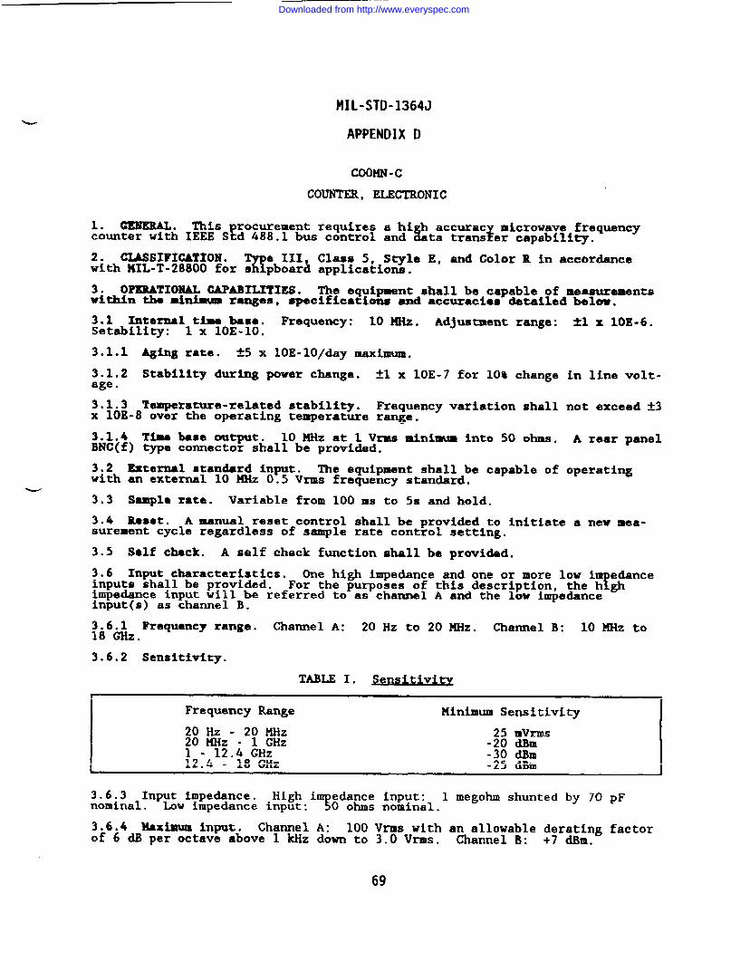
MIL-STD-1364J
APPENDIXD
COOMN-c
COUNTER, ELECTRONIC
1. GENERAL. T’hisprocurement requires a hi h accurac microwave frequencycounter with IEEE Std 488.1 bus control and L zta trans er capabili~.
2. CLASSIFICATION .%
e III Class 5, Style E, and Color R in accordancewith 141L-T-28800 for s pboar~ applications.
3. OPERATIONAL CAPABILITIES. The equipment shall be capable of measurementswithin the m~ ranges, specifications and accuraci~s &tailed below.
3.1 Internal time base. Frequency: 10 MHz. Adjustment range:Setability: 1 x 1OE-10.
3.1.1 Aging rate. *5 x loE-lo/day maximum.
3.1.2 Stability dur~ power change. ~1 x 1OE-7 for 10% changeage.
3.1.3 Temperature-related stability. Frequency variation shallx 1OE-8 over the operating temperature range.
3.1.4 Time base output. 10 HHz at 1 Vrms minimum into 50 ohms.BNC(f) type connector shall be provided.
3.2 External standard input. The equipment shall be capable ofwith an external 10 MHz 0.5 Vrms frequency standard.
*1 x 1OE-6.
in line volt-
not exceed *3
A rear panel
operating
3.3 Sample rate. Variable from 100 ms to 5s and hold.
3.4 Reset. A manual reset control shall be provided to initiate a new mea-surement cycle regardless of sample rate control setting.
3.5 Self check. A self check function shall be provided.
3.6 Input characteristics. One high impedance and one or more low i edanceinputs shall be provided. ?For the purposes of this description, the h ghimpedance input will be referred to as channel A and the low impedanceinput(s) as channel B.
3.6.1 Frequency range. Channel A: 20 Hz to 20 MHz. Channel B: 10 KHz to18 ~Z.
3.6.2 Sensitivity.
TABLE I. Sensitivi ty
Frequency Range Minimum Sensitivity
20 Hz --2: M&:0 MHz
25 mVrms-20 dlhll
- 12.4 GHz -30 dBm12.4 - 18 GHz -25 dBm,
3.6.3 Input impedance. High i?
edance input: 1 megohm shunted by 70 pFnominal. Low impedance input: O ohms nominal.
3.6.4 Maximum input. Charnel A: 100 Vrms withof 6 dB per octave above 1 kHz down to 3.0 Vrms.
an allowable derating factorChannel B: +7 dBm.
69
Downloaded from http://www.everyspec.com
MIL-STD-1364J
APPENDIX D
3.6.5?
litude discrimination. The lar er of two or more signals shall befcounted w en there is at least 20 dB ampl tude difference between signals from
500 ~Z to 18 ~Z.
3.6.6 FM tolerance. Maximum deviation: 20 MHz. Maximum rate: 10 MHz.
3.7 Resolution. 1 Hz.
3.8 Meaauramnt ●ccuracy. f 1 count ~ time base error.
3.9 Remote operation. Digital interface in accordance with MIL-T-28800.
4. POWER SOURCE* NIL-T-28800 nominal power source requirements a~~O;moked.Operation at 400 Hz is not required. Maximum power consumption: .
5. WEIGHT . 15 kg (33 lb) maximum.
70
Downloaded from http://www.everyspec.com
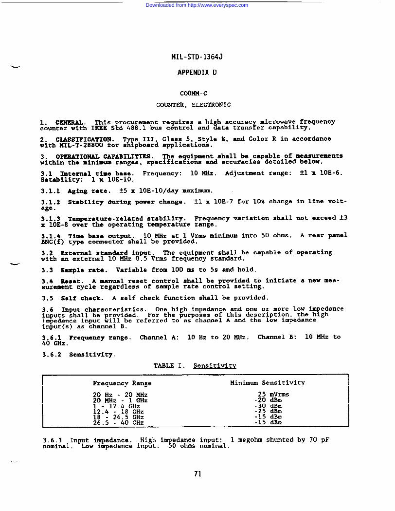
MIL-STD-1364J
APPENDIX D
COOMM-c
COUNTER, ELECTRONIC
1. CENEMLo This procurement requires a hi h accurac microwave frequencycounter with IEEE Std 488.1 bus control and L %ta trans er capability.
2. CIASSIFIGATIOl!?.%
e III, Class 5, Style E, and Color R in accordancewith MIL-T-28800 for s pboard applications.
3. OPERATIONAL CAPABILITIES. The equipment shall be capable of measurementswithin the minimum ranges, specifications and accuracies detailed below.
3.1 Internal time base. Frequency: 10 MHz. Adjustment range: i-lx 10E-6.Stability: 1 x 1OE-10.
3.1.1 Aging rate. t5 x 10E-10/day maximum.
3.1.2 Stability during power change. ~1 x 1OE-7 for 10% change in line volt-age.
3.1.3 Temperature-related stability. Requency variation shall not exceed ~3x 1OE-8 over the operating temperature range.
3.1.4 Time baSO output. 10 MHz at 1 Vrms minimum into 50 ohms. A rear panelBNC(f) type connector shall be provided.
3.2 External standard input. The equipment shall be capable of operatingwith an external 10 MHz 0.5 Vrms frequency standard.
w3.3 Sample rate. Variable from 100 ma to 5s and hold.
3.4 Reset. A manual reset control shall be provided to initiate a new mea-surement cycle regardless of sample rate control setting.
3.5 Self check. A self check function shall be provided.
3.6 Input characteristics. One high impedance and one or more low im edanceinputs shall be provided. !For the purposes of this description, the h ghimpedance input will be referred to as channel A and the low impedanceinput(s) as channel B.
3.6.1 Frequency range. Channel A: 10 Hz to 20 MHz. Channel B: 10 MHz to40 GHZ.
3.6.2 Sensitivity.
TABLE I. Sensitivity
Frequency Range Minimum Sensitivity
20 Hz - 20 MHz 25 mVrmsfo KHz - 1 GHz -20 dBm
- 12.4 GHz -30 dBm12.4 - 18 GHz -25 dBm18 - 26.5 GHz -15 dBm26.5 - 40 GHz -15 dBm
. .
3.6.3 Input impedance. High i edance input:?
1 megohm shunted by 70 pFnominal. Low impedance input: O ohms nominal.
71
Downloaded from http://www.everyspec.com
MIL-STD-1364J
APPENDIX D
3.6.4 Maximum input. Channel A: 100 Vrms with ana~~~~;a~le ~ra~~g factorof 6 dB per octave above 1 kHz down to 3.0 Vrms. .. .
3.6.5 Am litude discrimination.E
The lar er of two or more signals shall be!counted w en there is at least 20 dB ampl tude difference between signals from
5ooHHz to 40 GHz.
3.6.6 FM tolerance. Haximm deviation: 20 mz. HaXiIIIUIB rate: 10 MHz.
3.7 Resolution. 1 Hz.
3.8 Measurement ●ccuracy: ~ 1 count ~ time base error.
3.9 Remote operation. Digital interface in accordance with MIL-T-28800.
POWER SOURCE. MIL-T-28800 nominal power source requirements afiO;nvoked.~eration at 400 Hz is not required. Maximum power consumption: .
5. UEIGET . 15 kg (33 lb) maximum.
72
Downloaded from http://www.everyspec.com
MIL-STD-1364J
APPENDIX D
COOPC -D
COUNTER, ELECTRONIC
1. GENERAL . This procurement requires a solid-state, microwave pulse countercapable of IEEE Std 488-1978 digital bus control and data transfer.
2. CLASSIFICATION .%
e III, Class 5, S~le E, and Color R in accordancewith MIL-T-28800 for s pboard applications.
3. XEASUREKENT REQUIREMENTS. The equipment shall be capable of CU and pulsedfrequency measurements as specified below.
3.1 Time base. Frequency: 10 MHz. Adjustment range: *1 x 1OE-6.
3.1.1 Aging rate. ~3 x 1OE-7 per month.
3.1.2 Stabilit during power change.1
*1 x 1OE-7 for a 10% line voltagechange from nom nal.
3.2 Display. An electronic digital display shall be provided.
3.2.1 Measurement units. GHz, MHz, and Hz.
3.3 Gate lamp. A front-panel display device shall indicate gate operation.
3.4 Bold. The equipment shall provide a means of holding the displayedreading indefinitely, independent of the gate time or resolution control.
_. 3.5 Reset. A manual reset control that initiates a new measurement cycleshall be provided.
3.6 Self-check. A self-check function that verifies operation of thefrequency measurement mode shall be provided.
3.7 Input characteristics. Impedance: 50 ohms nominal.
3.7.1 Dynamic range. -10 dBxD to +5 dBm.
3.7.2 ~imm input. +25 dBm peak.
3.8 Frequency characteristics. The equipment shall automatically measure anddirectly indicate sine wave and pulsed signal frequencies.
3.8.1 Frequency range. 300 ~Z to 18 GHz.
3.8.2 Frequency ●ccuracy. The frequency measurement accuracy shall bewithin:
a. Cw: ~ resolution ~ ti~ base error.
b. Pulse: A500 klizor less for 200 ns pulses, improving to t150 kHz orless for a 1 us, or wider, pulse.
3.8.3 Frequency resolution. 10 kllzor less.
3.8.4 Pulse measurement specifications. The e uipment shall be ca able of7 ~measuring the frequency of pulse modulated carr ers with a PRF in t e range of
50 Hz to 11 kllzand a pulse width of 200 ns to 1 us.
3.9 output.put ,
3.10 Remote. .
The equipment shall be provided with a 10.0 MHz
operation. Digital interface in accordance with
73
reference out-
MIL-T-28800.
Downloaded from http://www.everyspec.com
MIL-STD-1364J
APPENDIX D
MIL-T-28800 nominal power source requirements are invoked.$er%% ~~~;;”Hz is not required. Maximum power consumption: 250W.
4.1 Time baser
When equip ed with a temperature stabilized oscillator,fthe equipment s al!rbe provided w th a power control position wherein only the
time base oscillator and oven are energized.
5. WEIGMT . 20 kg (44 lb) naximum.
74
Downloaded from http://www.everyspec.com
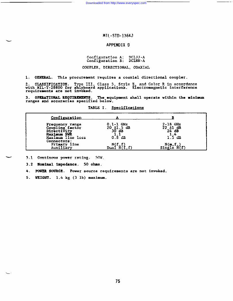
MIL-STD-1364J
APPENDIX D
Configuration A: DCIJJ -AConfiguration B: DCI.NN-A
COUPLER, DIRECTIONAL, COAXIAL
1. GENERAL. This procurement requires a coaxial directional coupler.
2. CLASSIFICATION .Q
e III, Class 5, Style E and Color R in accordancewith MIL-T-28800 for s pboard applications. Electromagnetic interferencerequirements are not invoked.
3. OPERATIONAL RE UIREMENTS.?
The equipment shall operate within the minimumranges and accurac es specified below.
TABLE I. Svec@ation s
- 3.1
3.2
4.
5.
Frequency range 0.1-1 GHz 2-18 GHzCoupling factor 203#& dB 222*l*aDlrectiviMaximum sz 1.1 1.4Maximum line loss 0.8 dB 1.5 dBConnectors:
Primary linei
N f,f) N(m,f,)Auxiliary Dua N(f,f) Single N(f)
Contimus power rating. 50W .
IUominal impedance. 50 ohms.
POWER SOURCE. Power source requirements are not invoked.
WEIGHT . 1.4 kg (3 lb) maximum.
L-
75
Downloaded from http://www.everyspec.com
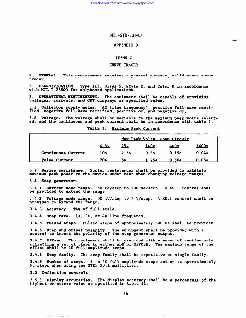
MIL-STD-1364J
APPENDIX D
TE5NN-C
CURVE TRACm
1. GESJERAL. This procurement requires a general purpose, solid-state tunetracer.
2. CLASSIFICATION . T e III, Class 5, Style E, and Color R in accordanceawith HIL-T-28800 for s pboard applications.
3. OPERATIONAL REQUIREMENTS. The equipment shall be capable of providingvoltages, currents, and CRT displays as specified below.
3.1 Collector ● ly modes.R h
AC line frequency), positive full-wave recti-fied, negative fu -wave rectifia , positive &, and negative dc.
3.2 Voltage. The voltage shall be variable to the maximum peak volts select-ed, and the continuous and peak current shall be in accordance with table 1.
TABLE I. Peak C~
Peak volts . c~
U= lQQY4QQY -
Continuous Current 10A 2.5A O*6A O.15A O.04A
Pulse Current 20A 5A 1.25A O.30A 0.08A●
3.3 Serio8 rosistmce. Series resistances shall be provided to maintainmaximum peak power to the device under test when changing voltage ranges.
3.4 Step generator.
3.4.1 Ourrent mode ran e.E
50 nA/step to 200 mA/step. A XO.1 control shallbe provided to extend t e range.
3.4.2 Voltage mode range. 50 mV/step to 2 V/step. A XO.1 control shall beprovided to extend the range.
3.4.3 Accuracy. *4% of full scale.
3.4.4 Step rate. lx, 2X, or 4X line frequency.
3.4.5 Raised steps. Pulsed steps of approximately 300 us shall be provided.
3.4.6 Step and offset pdarlty. The equipment shall be provided with acontrol to invert the polarity of the step generator output.
3.4,7 Offset. The equipment shall be provided with a means of continuouslyoffsetting a set of steps to either ADD or OPPOSE. The maximum range of theoffset shall be 10 full amplitude steps.
3.4.8 Step family. The step family shall be repetitive or single family.
3.4.9 Number of steps. 1 to 10 full am litude steps and up to approximatelyT95 steps when using the STEP XO.1 multip ier.
3.5 Deflection controls.
3.5.1 Display accuracies. The dis lay accurac% T
shall be a percentage of thehighest on-screen value as specifie in table I .
76
Downloaded from http://www.everyspec.com
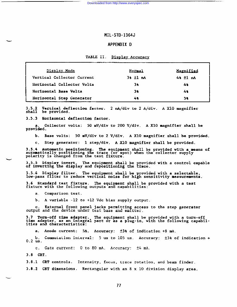
MIL-STD-1364J
APPENDIX D
TABLE II. DisDlav Accuracy
DisDlav Mode Nmw.L
Vertical Collector Current 3% ~1 A ~% *1 ~
Horizontal Collector Volts 3% 4%
Horizontal Base Volts 3% 48
Horizontal Step Generator 4% 58
3.5.2 Vertical deflection factor. 2 nA/div to 2shall be provided.
3.5.3 Horizontal deflection factor.
Collector volts: 50 mV/div to 200 V/div.prov~ded.
b. Base volts: 50 mV/div to 2 V/div. A X1O
A/div .
A X1O
A X1O magnifier
magnifier shall be
magnifier shall be provided.
c. Step generator: 1 step/div. A X1O magnifier shall be provided.
3.5.4 AutomaticP 9
sition . The e uipment shall be provided with a means ofautomatically pos tioning t e trace 7or spot) when the collector supplypolarity is changed from the test fixture.
3.5.5 Display invert. The equipment shall be provided with a control capableof inverting the display and repositioning the trace.
3.5.6 Dis lay filter.!
The equipment shall be provided with a selectable,low-pass f lter to reduce vertical noise for high sensitivity measurements.
3.6 Standard test fixture. The equipment shall be provided with a testfixture with the following outputs and capabilities:
a. Comparison test.
b. A variable -12 to +12 Vdc bias supply output.
c. External front panel jacks permittinf
access to the step generatoroutput and the device under test base and em tter.
3.7 Turn-off time adapter. The equipment shall be rovided with a turn-offtime adapter, !as an integral part or as a plug-in, w th the following capabil-ities and characteristics:
a. Anode current: 5A. Accuracy: *3% of indication +8 ~.
b. Commutation intenal: 5 us to 105 us. Accuracy: ~3% of indication +0.2 us.
c. Gate current: O to 80 mA. Accuracy: ?4 mA.
3.8 CRT.
3.8.1 CRT controls. Intensity, focus, trace rotation, and beam finder.
3.8.2 CRT dimensions. Rectangular with an 8 x 10 division display area.
77
Downloaded from http://www.everyspec.com
MIL-STD-1364J
APPENDIX D
4. ACCESSORIES. The following accessories shall be provided with theequipment:
a. Transistor adapter for bipolar transistor and MOS FETs.
b. Axial lead diode adapter with Kelvin sensing terminals.
c. Protective shield for test connection area.
5. POWER SOURCE. 141L-T-28800 nominal power source requirements a~~5~nvoked.Operation at 400 Hz is not required. Maximum power consumption: .
6. WEIGHT . 24 kg (53 lb) maximum.
78
Downloaded from http://www.everyspec.com
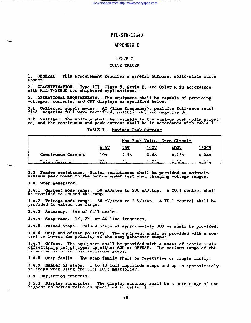
MIL-STD-1364J
APPENDIX D
TE5GN-C
CURVE TRACER
1. GENERAL. This procurement requires a general purpose, solid-state curvetracer.
2. CLMSIFIGATIOR .%
e 111, Class 5, Style E, and Color R in accordancewith MIL-T-28800 for s pboard application.
3. OPEMTIOBUL REQUIWMENTS. The equipment shall be capable of providingvoltages, currents, and CRT displays as specified below.
3.1 (bllcctor m ly modes.Y! &
AC line frequency), positive full-wave recti-fied, negative fu -wave rectifie , positive &, and negative dc.
3.2 Voltage. The voltage shall be variable to the maximum peak volts select-ed, and the continuous and peak current shall be in accordance with table I.
TABLE I. Peak Curren~
\ f
P* vow. en
-m MAQQY m
Continuous Current 10A 2.5A O*6A O.15A 0.04A
I Pulse Current 20A 5A 1.25A 0.30A 0.08A I
3.3 Series resistance. Series resistances shall be provided to maintainmaximum peak powar to the device under test when changing voltage ranges.
3.4 Step ganerstor.
3.4.1 Gurrent mode ran e.R
50 nA/step to 200 mA/step. A XO.1 control shallbe provided to extend t e range.
3.4.2 Voltage wde range. 50 mV/step to 2 V/step. A XO.1 control shall beprovided to extend the range.
3.4.3 Accuracy. *4% of full scale.
3.4.4 Step rate. lx, 2X, or 4X line frequency.
3.4.5 Pulsed steps. Pulsed steps of approximately 300 us shall be provided.
3.4.6 Step and offset polarity. The equipment shall be provided with a con-trol to invert the polari~ of the step generator output.
3.4.7 Offset. The equipment shall be provided with a means of continuouslyoffsetting a set of steps to either ADD or OPPOSE. The maximum range of theoffset shall be 10 full amplitude steps.
3.4.8 Step family. The step family shall be repetitive or single family.
3.4.9 Number of steps. 1 to 10 full am litude steps and up to approximately!95 steps when using the STEP XO.1 multip ier.
3.5 Deflection controls.
3.5.1 Display ●ccuracies. The dis lay accurac shall be a percentage of thes 1highest on-screen value as specifie in table I .
79
Downloaded from http://www.everyspec.com
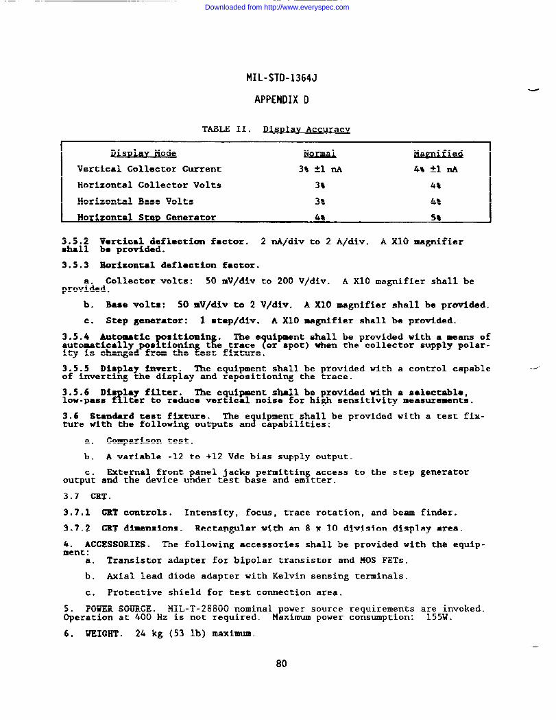
MIL-STD-1364J
APPENDIX D
TABLE II. J)) urac
Pi D1.wMs ode NQmd Mazni fied
Vertical Collector Current 3$ Al A 4% -tl~
Horizontal Collector Volts 3% 4%
Horizontal Base Volts 3% 4*
3.5.2 Vartical deflection factor. 2 nA/div to 2 A/div. A X1O magnifiershall be provided.
3.5.3 Horizontal deflation factor.
Collector volts: 50 mV/div to 200 V/div. A X1O magnifier shall beprov%ed.
b. Base volts: 50 mV/div to 2 V/div. A X1O magnifier shall be provided.
c. Step generator: 1 step/div. A XIO magnifier shall be provided.
3.5.4 Automaticr
Sltionin .i
The e ipment shall be provided with a means ofautomatically pos tionin T
L;tefi%%.or spot) when the collector supply polar-
ity is changed from the
3.5.5 Display invert. The equipment shall be provided with a control capableof inverting the display and repositioning the trace.
3.5.6 Dis lay filter.&
The equipment shall be provided with a salectablc,low-pass lter to reduce vertical noise for high sensitivity measurements.
3.6 Standard test fixture. The e uipment shall be provided with a test fix-ture with the following outputs ana capabilities:
a. Comparison test.
b. A variable -12 to +12 Vdc bias supply output.
c. External front panel jacks permitting access to the step generatoroutput and the device under test base and emitter.
3.7 CRT.
3.7.1 (XT controls. Intensity, focus, trace rotation, and beam finder.
3.7.2 GRT dimensions. Rectangular with an 8 x 10 division display area.
4. ACCESSORIES. The following accessories shall be provided with the equip-ment:
a. Transistor adapter for bipolar transistor and MOS FETs.
b. Axial lead diode adapter with Kelvin sensing terminals.
c. Protective shield for test connection area.
5. POWER SOURCE. !41L-T-28800 nominal power source requirements a~;5nvoked.Operation at 400 Hz is not required. Maximum power consumption: .
6. WEIGHT . 24 kg (53 lb) maximum.
80
-—
Downloaded from http://www.everyspec.com
MIL-STD-1364J
APPENDIX D
Configuration A: DE2YN-AConfiguration B: DEZiB -AConfiguration C: DE2NN-A
DETECTOR, RF, COAXIAL
1. GIJNERAL. This procurement requires a RF Coaxial Detector.
2. CIASSIFIGATION .w
III, Class 5, Style E and Color R in accordancewith MIL-T-28800 for s pboard applications. Eiectromagnetlc interferencerequirements are not invoked.
3. OPERATIONAL RE UXMXENTS.?
The equipment shall operate within the minimxmranges and accurac es specified below.
3.1 Frequency range. 0.01-18 GHz.
3.2 Frequency response. N.6 dB.
3.3 Maximum swR. 1.5.
3.4 Iaw 1UV81O 0.5 mv/uw
3.5 Continous power rating. 200 mu.
3.6 Input connector. Configuration A: APC-7 ● Configuration B: N(m) .
Configuration C: 3.5mm (m).
w 4. POWER SOURCE. Power source requirements are not invoked.
5. WEIGHT . .23 kg (0.5 lb) maximum.
Downloaded from http://www.everyspec.com
MIL-STD-1364J
APPENDIX D
DEVAA-A
DETECTOR, VOLTAGE
1. GENERAL. This procurement re uires a hand-held ac voltage detector thatfdetects voltages without making e ectrical contact.
2. CIASSIFICATIO19. Type III, Class 5, Style E, and Color R in accomiancewith IUL-T-28800.
3. om’rIORAL R.EQUIMxEns. The equipment shall detect ac voltages inaccordance with the following minimum specifications.
3.1 Voltage range. 25 to 1,500V.
3.2 Charging rate. 1 UP/s.
3.3 Indicator. Audible tone.
4. POWER SOURCE. MIL-T-28800 dc internal power source re uirements ●reinvoked. ?The batteries shall be of a commercially availab e type and provide100 hours of o er~;~~n before replacement.
1The nominal power source require-
ments are not .
5. DIMENSIONS. 0.45 kg (1 lb) maximum.
82
Downloaded from http://www.everyspec.com
MIL-STD-1364J
APPENDIX D
DPINN-A
DIVIDER, POWER
GEN’EIUU. This procurement requires a three-port, resistive, coaxial power~~vider.
2. CLASSIFICATION.%
e 111, Class 5, Style E, and Color R in accordancewith MIL-T-28800 for s pboard applications. The Electromagnetic interferencerequirements are not invoked.
3. OPERATIONAL REQUIREMENTS. The equipment shall be capable of operationwithin the minimum specifications set forth below.
3.1
3.2
3.3
3.4
3.5
3.6
4.
5.
Frequency range. & to 18 GHz.
HOminal impedance. 50 ohms.
Maximum VSWR. 1.35.
Phase difference. t2% maximum.
Maximum input power. lW continuous, 1 kW peak for 5 msec.
Connectors. Input: N(m), Output: N(f).
POWER SOURCE. The power source requirements are not invoked.
WEIGliT. 0.5 kg (1.1 lb) maximum.
--
83
Downloaded from http://www.everyspec.com
MIL-STD-1364J
APPENDIX D
DR2FL-A
DIVIDER, VOLTAGE
1. GENERAL . This procurement requires a voltage divider.
2. CLASSIFICATION. Tr
111, Class 5, Style E, and Color R in accordancewith 141L-T-28800 for s pboard applications.
3. OPEUkTIOMAL REQ~S. The equipment shall be capable of voltage divi-sion within the minimum ranges and accuracies detailed below.
3.1 Maamsrewmt range. O to 10 kV &.
3.2 Division ratios. 1,000:1 and 10,000:1.
3.3 Accuracy. tool% into digital voltmeter input impedance of 10 megohms orgreater.
4. ACCESSORIES. The equi ment shall be provided with safety-designed testTleads in accordance with M L-T-28800.
5. WEIGHT . 5 kg (11 lb) maximum.
84
—-
.
Downloaded from http://www.everyspec.com

MIL-STD-1364J
APPENDIX D
DLIEY-A
DUMMY UMiD, COAXIAL
1. GR!IZML. IIIisprocurement requires a portable, RF, coaxial d- load.
2. CL4SSIFIGATION . ‘lYpe III, Class 5, S le E, and Color R in accordancewith MIL-T-28800. ?Power source requirement s are not imvoked.
3* OPERATIONAL BEQUIREXENTS. The e uipment shall terminate ●n RF sigml?source in accordance with the specif cations set forth below.
3.1 ?raquency range. DC to 1 ~z rein-.
3.2 Input impedance. 50-ohms nominal.
3.3 Power dissipation. 2.5 kW continuous and 3 kW for a minimum of 2 hours.
3.4 VSWR* 1.1:1 maximum.
3.5 Connector. IX female (UG-287B/U) with a cap attached to the equipment.
4. DIMENSIONS. 283 mn (11.5 in) high, 203 mm (8 in) wide, and 635 =s (25 in)deep, maximum.
\
5. WEIGHT . 20 kg (44 lb) maximum.
85
Downloaded from http://www.everyspec.com
MIL-STD-1364J
APPENDIX D
DLIJN-B
DUMMY IxMID,COAXIAL
1. GENERAL. This procurement requires a portable, coaxial dummy load.
2. CLASSIFICATION .%
e 111, Class 5, Style E, and Golor R in accordancewith ML-T-28800 for s pboard applications.
3. OPERATIONAL REQUIREMENTS. The e uipment shall terminate an RF signal1source in ●ccordance with the specif cations set forth below.
3.1
3.2
3.3
3.4
3.5
4.
Frequency range. DC to 3 GHz minimum.
Input i.lItpOdAIkCOo 50 ohm nominal.
VSUR.
a. 1.1:1 maximum from & to 1 GHz
b. 1.35:1 maximum from 1 to 3 Giiz
Power rating. 600W continuously and 900W for 0.25 hour at 23”C.
Gonnector. Type N(f) (UG-57B/U) . A protective cap shall be provided.
WEIGHT . 10 kg (22 lb) maximum.
86
Downloaded from http://www.everyspec.com
MIL-STD-1364J
APPENDIX D
DLISN-A
DUMMY XIMD, COAXIAL
1. GENERAL. This procurement requires a coaxial dummy load.
2* CLASSIFICATION .%
e III, Class 5, Style E and Color R in accordancewith MIL-T-28800 for s pboard applications. Electromagnetic interferencerequirements are not invoked.
3. OPZIMTIONAL RE UIREXENTS.!
The equipment shall operate within the minimumranges and accurac es specified below.
3.1
3.2
3.3
3.4
3.5
4.
5.
Gontinwtas power rating. 150W.
Frequency range. dc to 4 GHz.
Maximum SwR. 1.3.
Connector. N(f) .
Nominal impedance. 50 ohms.
mm SOURCE. Power source requirements are not invoked.
WEIGHT . 2.7 kg (6 lbs) maximum.
Downloaded from http://www.everyspec.com
MIL-STD-1364J
APPENDIX D
EBoQn-cECHO BOX
1. GENERAL . This procurement requires a portable, hand-tuned, 10W-1OSS,high-Q echo box for use in performance testing and maintenance of radars.
2. CMSSIFICATION .%
e III, Class 5, S~le D, and Color R in ●ccordancewith MIL-T-28800 for s pboard applications. The electromagnetic interferencerequirements are not invoked.
9. MwmmmmT clAPABILITnw* The equipment shall be ca able of radar per-!formance testing within the minimum specifications ident fied below.
3.1 Ring the measurements.
3.1.1 Frequency range. 8.5 to 9.6 GHz.
3.1.2 Ring time. The equi ment shall be capable of generatin a ring timeequivalent to 5,000 yards & fen used with a radar set with the ollowingparameters:
a. Receiver sensitivity: -120 dBm.
b. Transmitter peak power: 250 kW.
c. PRF : 1,000 Hz.
d. Pulse width: 0.5 us.
e. Directional coupler: 25 dB.
f. Coaxial cable loss: 3.6 dB.
3.1.3 Ring time sensitivity. Charts shall be provided with the equipment toexpress the ring time sensitivity in terms of yards of ring time lost perdecibel lost.
3.1.4 Resonant cavity Q. 80,000 minimum.
3.2 Wavemeter operation. Frequency range: 8.5 to 9.6 GHz. Accuracy: *2MHz.
3.2.1 Indicating meter. The equipment shall beFrovided with an analog meter
for use in determining the mode of operation and requency.
3.3 Input impedance. 50 ohms nominal.
--
4. WEIGHT . 20 kg (44 lb) maximum.
88
Downloaded from http://www.everyspec.com
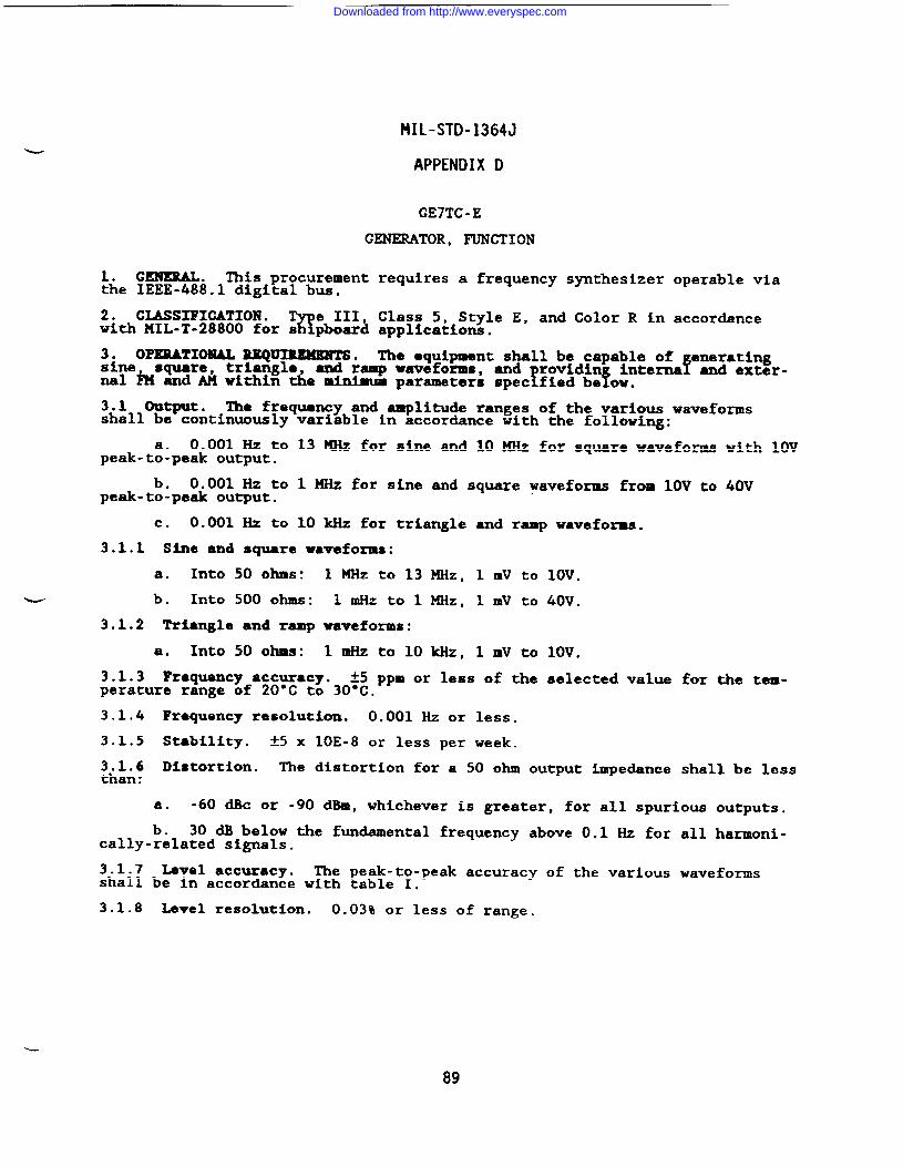
MIL-STD-1364J
APPENDIX D
GE7TC -E
1.the
2.
GENERATOR ,
GENEML . This procurement requiresIEEE-488.1 digital bus.
CIASSIFIGATION .%
e III, Class 5,with MIL-T-28800 for s pboard applicatioti.
FUNCTION
a frequency synthesizer operable via
-Style E, and Color R in accordance
3. OPERATIONAL REQUXMXENTS. The equipment shall be capable of eneratingsine square, triangle, and ramp waveforms, fand rwidin interns and exter-
! fnal h and AM within the minimum parameters spec fied be OW.
3.1 output. The frequency and amplitude ranges of the various waveformsshall be continuously variable in accordance with the following:
0.001 Hz topeak-t~~peak output.
b. 0.001 Hz topeak-to-peak output.
c. 0.001 Hz to
13 KHz for sine and 10 MHz for square waveforms with 10V
1 MHz for sine and square waveforms from 10V to 40V
10 kHz for triangle and ramp waveforms.
3.1.1 Sine and square waveforms:
a. Into 50 ohms: 1 KHz to 13 KHz, 1 mv to 10V.
%u- b. Into 500 ohms: 1 mHz to 1 MHz, 1 Inv to 40V.
3.1.2 Triangle and ramp waveforms:
a. Into 50 ohms: 1 mHz to 10kHz, 1 mV to 10V.
3.1.3 Fzequency accuracy. *5 ppm or less of the selected value for the tem-perature range of 20°C to 30°C.
3.1.4 Frequency resolution. 0.001 Hz or less.
3.1.5 Stability. *5 x 1oE-8 or less per week.
~h~i6 Distortion. The distortion for a 50 ohm output impedance shall be less.●
a. -60 dBc or -90 dBIR,whichever is greater, for all spurious outputs.
b. 30 dB below the fundamental frequency above 0.1 Hz for all harmoni-cally-related signals.
3.1.7 Level accuracy. The peak-to-peak accuracy of the various waveformsshall be in accordance with table I.
3.1.8 Level resolution. 0.03% or less of range.
L
89
Downloaded from http://www.everyspec.com
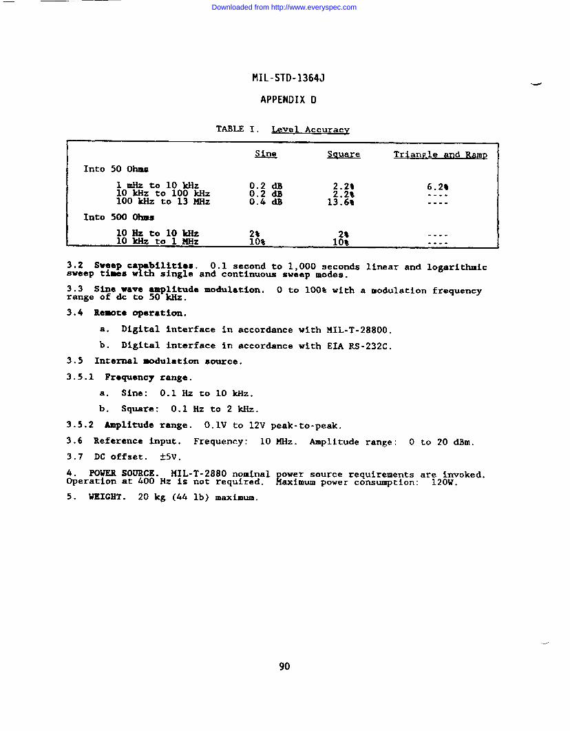
MIL-STD-1364J
APPENDIX D
TABLE I. Level Accuracy
.4
Sine Sauare TrianEle and RamP
Into 50 Ohms
lmllztolokllz 0.2 dB 2.2% 6.2%10 kHz to 100 kHz 0.2 dB 2.2%100 w to 13 MHz
----0.4 dB 13.69 ----
Into 500 Ohms
loll ztol okliz 2% 2%10 kHz to 1 MHz
----10% 10% ----
3.2 Sweep ca bilitlas.Y
0.1 second to 1,000 seconds linear and logarithmicsweep times w th single and continuous sweep modes.
3.3 Sine wave amplitude modulation. O to 100% with a modulation frequencyrange of & to 50 kllz.
3.4 Remote operation.
a. Digital interface in accordance with MIL-T-28800.
b. Digital interface in accordance with EIA RS-232C.
3.5 Internal modulation source.
3.5.1 Frequency range.
a. Sine: 0.1 Hz to 10 kHz.
b. Square: 0.1 Hz to 2 kHz.
3.5.2 Amplitude range. O.lV to 12V peak-to-peak.
3.6 Reference input. Frequency: 10
3.7 DC offset. 55V .
4. POWER SOURCE. MIL-T-2880 nominalOperation at 400 Hz is not required.
5. WEIGHT . 20 kg (44 lb) maximum.
MHz . Amplitude range: o to 20 dlhll.
Rower source requirements ar;2~voked.aximum power consumption: .
90
Downloaded from http://www.everyspec.com
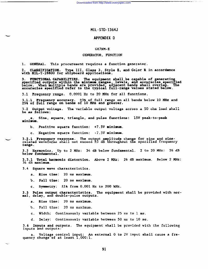
MIL-STD-1364J
APPENDIX D
GE7NM-E
GENERATOR, FUNCTION
1. GENERAL . This procurement requires a function generator.
2. CLASSIFICATION . T e 111, Class 3, Style E, and Color R in accordanceawith MIL-T-28800 for s pboard applications.
3. FUNCTIONAL CAPABILITIES. The equipment shall be ca able of eneratispecified outputs within the minimum ranges s f Ylevels an accurac es speci&dbelow. When multiple bands are provided a~ acmt kids shall overla .
! !accuracies specified refer to the typica~ fu l-range values stated be OW.
3.1 Fraquemcy range. 0.0001 Hz to 20 MHz for ●ll functions.
3.1.1 Re uency ●ccuracy.!
A3% of full range on all bands below 10 KHz andfs% of ful range on bands of 10 MHz and greater.
3.2 Out t voltage.r
The variable output voltage across a 50 ohm load shallbe as fo 10WS:
Sine, square, triangle, and pulse functions: 15V peak-to-peakmin&m.
b. Positive square function: +7.5V minimum.
c. Negative square function: -7.5V minimum.
w 3.2.1 Frequency response. The out ut amplitude than e for sine and sine-related waveforms shall not exceed $ E-3 dB throughout t e specified frequencyrange.
3.3 Marmonics. up to 2 MHz: 34 dB below fundamental. 2 to 20 MHz: 26 dBbelow fundamental.
~L3& ~;~harmonic distortion. Above 2 MHz: 26 d.Bmaximm. Below 2 HHz:.
3.4 Square wave characteristics.
a. Rise time: 20 ns maximum.
b. Fall time: 20 ns maximum.
c* Sjmlmetry: Al% from 0.001 Hz to 200 ~z.
3.5 Pulse output characteristics. The equipment shall be provided with nor-mal, delay, and double-pulse outputs.
a. Rise time: 20 ns maximum.
b. Fall time: 20 ns maximum.
c. Width: Continuously variable between 25 ns to 1 ms.
d. Delay: Continuously variable between 50 ns to 10 ms.
3.6 Inputs and outputs. The equipment shall be provided with the followinginputs
quen~y
and outputs:-—
Voltage control in ut:Y
An external O to 2V input shall cause a fre-change of at least ,000:1.
91
Downloaded from http://www.everyspec.com
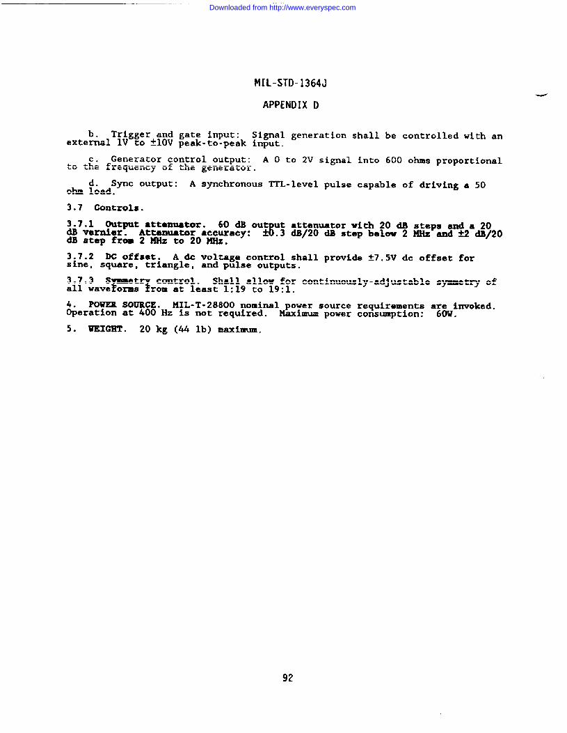
MIL-STD-1364J
APPENDIX D
b. Trigger and gate input: Signal generation shall be controlled with anexternal lV to ~lOV peak-to-peak input.
c. Generator control output: A O to 2V signal into 600 ohms proportionalto the frequency of the generator.
d. sync output: A synchronous ITL-level pulse capable of driving a 50ohm load.
3.7 controls.
3.7.1 Output ●ttomuator. 60 dB ou ut attenuator with 20 dB steps and a 20dB vernier. Attenuator accuracy: 3 .3 dB/20 dB step belw 2 MHz and S dB/20dB step from 2 X& to 20MHz.
3.7.2 DC offset. A & voltage control shall provide f7.5V dc offset forsine, square, triangle, and pulse outputs.
Shall allow for continuously-adjustable symmetry of~i!0iavSe&~7&~Y~&ast 1:19 to 19:1.
POWER SOURCE. MIL-T-28800 nominal power source requirements a~OWinvoked.&eration at 400 Hz is not required. Maximum power consumption: .
5. WEIGET . 20 kg (44 lb) maximum.
92
—
Downloaded from http://www.everyspec.com
MIL-STD-1364J
APPENDIX D
GE7TB-B
GENEMTOR, FUNCTION
1. GEXEUL. This procurement requires a general purpose, solid-state, sweepfunction generator.
2. CLASSIFICATIOM .%
e III, Class 5, Style E, and Color R in accordancewith MIL-T-28800 for a pboard applications.
3. OPERATIONAL REQUIREMENTS. The equipment shall be capable of producingsine, square, triangle positive pulse, and ne ative pulse waveforms withsweep and burst o erat~on.
AThe equi ment shal
fF operate within the minimum
modes, r es,%
accuracies specif ed below. Specifications shall apply atmaximum Ou Ut.
3.1 Frequence range. O.Z Hz to 3 MHz.
3.1.1 Rquency ●ccuracy. *20% of indication.
3.1.2 Frequency r~sponse. Al dB maximum for sine-wave outputs.
3.1.3 Sine-wave distortion. 3% maximum.
3.1.4 ~iS@ and fall times. 40 ns or less for square and pulse waveforms whenthe equipment is terminated into 50 ohms.
3.1.5 Triangle linearity. 95% minimum.
~ 3.2 Amplitude control. Adjustable 5 mV to 10V peak-to-peak into 50 ohms.
3.3 Impedanc*. 50 ohms *5%.
3.4 Sweep function.
3.4.1 Start and stop fre uencies.?
The sweep function start and stop frequen-cies shall be independent y settable throughout the selected range.
3.4.2 Sweep duration. Variable from 1 ms to 100s.
3.5 Tri ger and ●te.b &
Manual trigger, external trigger, and external gatlngcapabili shall e provided.
3.6 Pulse width. 160 M to 2.5s with a repetition rate adjustable from 0.01Hz to 1 ~Z.
3.7 External voltage control. The capability shall be provided to proportionally vary the output frequency by application of a voltage.
3~~m:f::et. The ca ability shall be provided to vary the waveform about
$rat least -10 volts peak. Peak ac plus dc offset shall be at least
-lo volts.
4. POWER SOURCE. MIL-T-28800 nominal power source requirements are invoked.Operation at 400 Hz is not required. Maximum power consumption: 120W.
93
Downloaded from http://www.everyspec.com
MIL-STD-1364J
APPENDIX D
GE3FN-B
GENERATOR, NOISE
1. GENSRAL. This rocurement requires an instrument capable of generatingErandom noise at uni orm levels from 5 Hz to 5 KHz.
2. CIASSIFICATIOBl. The equipment shall meet the requirements of IIIIL-T-28800,Type III Class 5, Style E, Color R for Navy shi board, submarine, and shore
Sapplicat~ons with the following modifications an exceptions:
a. The relative humldi~ requirement is limited to 95s noncondensating.
b. The operating and nonoperating altitude requirements are notirrvoked.
The electromagnetic interference requirements of MIL-T-28800 are notinvoke: :
3. OPERATIONAL RE UIRE14ENTS.f
The e uipment shall be capable of generating?random noise signs s within the spec fications and accuracies contained
herein.
3.1 Output frequency. 5Hzto5 KHz.
3.1.1 Ranges. 3 selectable by filter.
3.1.1.1 5 Hz to 20 kHz.
3.1.1.2 5 Hz to 500kHz.
3.1.1.3 5 Hz to S“KHz.
3.2 Output voltage. Hax open-circuit voltage > lV.
3.2.1 Range. Continuously variable from 30 pV to 3V.
3.2.2 Spectrum level un~formity.
3.2.2.1 ~1 dB (20 Hz to 20 HZ).
3.2.2.2 *3 dB (20 Hz to 500 ~Z).
3.2.2.3 t8 dB (500 kHZ to 5 ~Z).
3.2.3 Level indicator. Meter.
3.2.3.1 Range. O-5 Vrms.
3.2.3.2 Scale/Multiplying factors. Min 500 pV; mm 5V.
3.3 Output impedance.
3.3.1 Max output. 9oon *lo%.
3.3.2 Attenuated output. 2oon flo%.
4. GEN- REQUIREMENTS.
$.: &mar source. 115 or 230 Vac A1O%, single phase 50, 60, and 400 Hz ~10%,
4.2 Di&ensions. The total volume shall not exceed 16,000 cm3 (975 in3).
94
Downloaded from http://www.everyspec.com

MIL-STD-1364J
APPENDIX D
~b~l Weight. The overall weight of the unit shall be nominally 10 kg (22.
95
Downloaded from http://www.everyspec.com
MIL-STO-1364J
APPENDIX D
GE3MN-A
GENERATOR, NOISE
1.0 GENEML. This procurement re uires a self-contained, battery operated,
~?ortable noise generator capable o generating RF noise radiation over the
requency range of 150 kllzto 10 X&.
2.0 CLASSIFICATION. The e uipment described herein shall meet the re uire-~&n~rf~eMIL- T-28800,
T? \e II, Class 5, S le E, Color R for Navy ship oard,
D and shore app ications with theY ollowing exceptions:
The nonoperating temperature requirement is llmited to the range of-40”:”to +70”C.
b. The
c. The
d. The
e. The
relative humidity requirement is limited to 95% noncondensating.
operating and nonoperating altitude requirements are not invoked.
E’MIrequirement is not invoked.
warm-up time is extended to one hour.
3.0 OPERATIONAL REQUIREMENTS. The equipment shall be capable of generatingsignals within the parameters and accuracies specified herein.
3.1 Frequency range. At least 150 ldlzto 10 MHz.
3.2 Maximum effective distance. 9014m (30 ft).
4.0 GENERAL REQ~S.
4.1 Power. Internal battery, (average life - 50 hours).
4.2 Dimensions. The total volume of the unit shall nominally not exceed 432cubic in (7,076 cc).
4.3 Uetght. The total weight of the unit shall not exceed 10 lbs (4.5 kg).
96
Downloaded from http://www.everyspec.com
MIL-STD-1364J
APPENDIX D
GE2NN -D
GENERATOR, PULSE
1. cm3ERAL. This procurement requires a pulse generator.
2. CUSSIFICATIOM .%
a 111, Class 5, Style E, and Color R in accordancewith KIL-T-28800 for s pboard applications.
3. PUME GEEXRATION REQMRXMENTS. The minimum requirements below shall applyto both sin lo or double ulse mode operations and shall include positive or
bnegative ou Uts . YAll pu se specifications are applicable into a 50 ohm load.
3.1 W*O amplitude. 0.3V to 100V peak-to-peak.
3.2 Pulso rise ●nd fall times. 17 ns or less.
3.3 Pulse ●berrations. 5% maximum for preshoot and wershoot, 6% maximum fordroop and top variations.
3.4 Pulse width. 50 ns to lores.
3.4.1 Pulse width jittar. O.lt maximum of selected width.
3.5 Fulsa repetition rate. 10 Hz to 1 MHz.
3.6 Maxkpu.lse duty c cle.?!
50% for ou utAd&?
litudes below 10V, 25* from10V to 20V, and 10t from OV to 100V. cyc e limit indicator shall beprovided.
~ 3.7 Minimum double pulge atpacing. 1 us or 25* of the upper limit of thepulse vidth range setting, whichever is greater.
3.8 Dela~ed ●nd advanced pulse range. O to 10 ms.
3.9 Synchronisbd output. A tri ger output that is synchronized with the8generated pulse shall be provide .
3.10 Cated operation. The equipment shall operate normally during the timeinternal of an input gate signal with an amplltude of at least 500 W.
3.11 External tri er.F
The instrument shall be triggerable from an externaltrigger source as Ollows :
a. Amplitude: 0.5V to 40V into 1 megohm.
b. Repetition rates: 1 MHz and less.
3.12 Output protection. The equipment shall be provided with protectionagainst a shorted or open output.
3.13 Connectors. BNC(f) .
4. POWER SOURCE.?iIL-T-28800 nominal power source requirements az_~O~nvoked.Operation at 400 Hz is not required. Maximum power consumption: .
5. WEIGHT . 20 kg (44 lb) maximum.
--
Downloaded from http://www.everyspec.com
MIL-STD-1364J
APPENOIX D
-
GE2!?P-F
GENERATOR, PULSE
1. GENERAL . This procurement requires a general purpose pulse generator.
2. CLASSIFICATION .%
e 111, Class 5, Style E, and Color R in accordancewith MIL-T-28800 for s pboard applications.
3. OPERATIOI?ALREQUIPMENTS. The equipment shall be capable of operationwithin the mlnkma ranges and accuracies specified below. The requirementsshall apply to both positive and negative outputs.
3.1 Pulse amplitude range. 0.5V to 5V peak-to-peak into a 50 ohm load.
3.2 Ralsa rise/fall times. 10 ns or less.
3.3 Pulse ●berrations. ~(5* maxh of pulse amplitude +100 mV) into 50ohms ,
3.4 hdSe width. Variable from 100 m to 5 ms.
3.4.1 Pulse width jitter. 0.1s +50 ps of the selected pulse width value.
3.5 Pulse repartition rate. Variable from 300 Hz to 50 MHz.
3.6 S chronized output.r’
A tri er output that is synchronized with thePgenera ed pulse shall be provide .
3.7 External trigger. Amplitude: ~1.5V. Width: 12 m.
3.8 cm t pr0t8cts~.r“ The equipment shall be provided with protectionagahs t oth a shorted and open output.
4. POWER SOURCE. lJIIL-T-28800nominal power source requirements af;Winvoked.Operation at 400 Hz is not required. Maximum power consumption: .
5. WEIGHT . 20 kg (44 lb) maximum.
98
Downloaded from http://www.everyspec.com
tlIL-STD-1364J
APPENDIX D
GE8NN-B
GENERATOR, PULSED CARRIER
1.0 GENERAL. This procurement requires a solid-state RF generator providingpulsed RF, video pulses or GW outputs.
;8~OOGLASSIFICATIOKf. The equipment shall meet the requirements of KIL-T-
Te III, Class S, S le E, Color R for Navy shipboard, submarine, and
shore’app ications with the? ollowing modifications and exceptions:
The nonoperating temperature requirement is limited to the range of-40’:”to +70’C.
b. The relative humidity requirement is limited to 95% noncondensating.
c. The operating and nonoperating altitude requirement is not invoked.
3.0 OPERATIONAL REQUIREMENTS.
3.1 Carrier frequency range. At least 10 to 120 MHz.
3.1.1 Accmacy. *1% of dial indication.
3.2 Output amplitude.
3.2.1 CU. 0.5 Vrms minimum into 50 ohms.
3.2.2 Pulsed RF. 0.5 Vrms minimum into 50 ohms.-
3.2.3 Video pulse. ~3V peak minimum into 50 ohms.
3.3 Attenuator.
3.3.1 Range. At least 100 dB in 1 dB steps.
3.3.2 Accuracy. ~0.1 dB/step.
3.3.3 VSUR. 1.2:1.
3.4 Pulse characteristics.
3.4.1 Rate. 50 PPS tO 5 kpps.
3.4.2 On/Off ratio. At least 70 dBc.
3.4.3 Width. Variable, 100 ns to 100 us.
3.4.4 Rise and fall time. Less than 20 ns for video pulse, and less than 10ns for pulsed RF.
3.4*5 sync output. At least 2.OV peak into 10 kilohms with 20 ns rise time,and at least 35 ns ahead of the pulsed RF.
3.5 External inputs.
3.5.1 Trigger. Pulses at least 2V peak, and at least 50 Hz to 5 kHz.
3.5.2 Modulation. Pulses at least 2V peak, and at least 50 Hz to 5 kHz.
3.5.3 Oscillator. At least 1 Vrms, 10 to 120 MHz.
4.0 GENERAL SPECIFICATIONS.
99
Downloaded from http://www.everyspec.com
MIL-STD-1364J
APPENDIX D
4.1 Power. 115/230 Vac (10%, 50/60 Hz, 30W maximum.
4.2 Dimensions. The total volume of the unit shall be nominally 33,233 cubiccm (2028 cubic in).
4.3 Weight. 13.2 kg (29 lbs) nominal.
-
100
Downloaded from http://www.everyspec.com
—
HIL-STO-1364J
APPENDIX D
GEOTK-C
GENEMTOR, SIGNAL, CW
1. GENEML DESCRIPTION, This procurement requires a solid-state, CW SignalGenerator capable of
8eneratin a constant amplitude sine wave with a variable
5frequency range of 25 kllz to 50 KHz.
2. CIASSIFICATI031. The equipment shall meet t& requirements of KIL-T-28800,Type III Class 5, Style E, Color R for Navy #hipboard, mabaarine, and shoreapplicat~ons with the following modifications and exceptions:
a. The relative humidi~ requirement is limited to 95% noncondemating.
b. The operating and nonoperating altitude require~nts are notinvoked.
The electroma etic interference reF
rements of MIL-T-28800 arelimite~-to CEO1 CE03 &Ol CS02 0.05 to 10 MHz), CS06, REO1 (back panelsearch excluded~, REO~ (14 &z to ! GHz), and RS03.
d. The warm-up time Is extended to one hour.
3. OPERATIONAL REQUIREMENTS. The equipment shall be capable of generatingsignals within the parameters and accuracies specified herein.
3.1 Frequency characteristics.
3.1.1 Frequency range. At least 250 kHz to 250 MHz.~
3.1.2 Resolution. At least 3-digit display.
3.1.3 Accuracy. 5S1.7 of least significant digit for indicated frequency.
3.1.4 Spectral purity (equal to or better than limits specified below).
3.1.4.1 Earmonics. 2nd harmonic at least -35 dBc, 3rd and higher harmonicsat least -40 dBc.
3.2 Output characteristics.
3.2.1 Range. At least S.0 mV to 5.5 Vp-p into 50-ohm termination.
3.2.2 Accuracy. Within at least 5% of indicated amplitude (50 kHz refer-ence ).
3.2.3 Flatness (peak toYeakk
50 kHz reference). At least ~t.5% from 250kHz to 100 MHz; at least _3% rom 100 to 250 MHz.
3.2.4 Output impedance\connector. 50$2;BNC type connector.
4. GENERAL REQ~.
4.1 Power. 115/230 Vac *1O%, 50, 60, or 400 Hz tlOt, 250 VA maximum.
4.2 Dimensions. The total volume shall not exceed 5,867 cnt~(358 in3).
4.3 Weight. The overall weight shall not exceed 4.5 kg (10 pounds).
-
101
Downloaded from http://www.everyspec.com
MIL-STD-1364J
APPENDIX D
GEAMJ-A
GENERATOR, SIGNAL
1.0 GIEMERAL. This procurement requires a solid state, microwave si
l!!enerator capable of generating signals over the frequency range of f’?%O 18Hz.
$8~wCWSIFICATIOM . The equipment shall meat the requirements of KIL-T-
Te 111, Class 5, S la E, Color R for Navy shipboard, miburina, and
shore’app Icatlons with the? ollowing modification and exceptions:
The nonoperating temperature requirement is limited to the range of-40&o +70”C.
b. The relative humidity requirement is limited to 95% noncondensating.
c. The operating and nomperating altitude requirements are not invoked.
d. The warm-up time is 15 minutes.
3.0 OPERATIONAL REQUIRXHUBTS. The equipment shall be capable of generatingsignals within the parameters and accuracies specified herein.
3.1 Raquency charactuiatica.
3.1.1 Fzequency range. At least 12 to 18 GHz.
3.1.2 Frsquency resolution. At least 10 MHz.
3.1.3 Frequency accuracy. At least ~1% of reading at maximum power and 25gCj5ec.
3.1.4 ~OqUellC stability.7
At 25°C ~5’C (equal to or better than limitsspecified below .
3.1.4.1 short term. Frequency drift less than *1 pp 10E4 for 5 minutes.
3.1.4.2 Long term. Frequency drift less than ~6.7 pp 10E4 for 1 hour.
3.1.5 Tempera-e drift. Less than 0.4% total change over O to 50<”Ctempera-ture range.
3.1.6 Spectral purity.
3.1.6.1 Earmonic level. At leaat -20 dB.
3.1.6.2 Spuriuus, At least -55 dBc.
3.1.6.3 Residual FM. Less than 15 kHz peak (measured at 50 Hz to 15 Hz BW).
3.2 Output characteristics.
3.2.1 Mnge. At least +7 to -18 dBm.
3.2.2 Level control. Continuous over at least a 25 dB range.
3.2.3 Output impedance. 50 ohms nominal.
3.2.4 Output connector. Type N female.
3.3 Modulation characteristics.
3.3.1 Amplitude modulation (AH).
102
Downloaded from http://www.everyspec.com
MIL-STD-1364J
APPENDIX Cl
3.3.1.1 Internal (square wave).
3.3.1.1.1 Rate. Variable, at least 20 Hz to 5 kHz.
3.3.1.1.2 On/Off ratio. Greater than 25 dB.
3.3.1.1.3 Rise/Fall time. 5 us maximum.
3.3.1.2 External.
3.3.1.2.1 Rate. At least 20 Hz to 50
3.3.1.2.2 Input level. O to&lUV.
3.3.1.2.3 On/Off xatio. Greater then
kllz.
25 dB.
3.3.1.2.4 Rise/Fall time. 5 us maximum.
3.3.2 Frequency modulation (FM).
3.3.2.1 Internal (savtooth). .
3.3.2.1.1 Deviation. AS MHz.
3.3.2.1.2 Rate. At least 10 Hz to 5 kllz.
3.3.2.2 External.
3.3.2.2.1 Deviatiun. *5 ~Z.
w 3.3.2.2.2 Rate. At least dc to SO kHz.
3.3.2.2.3 Input. hss than *5V for 5 MHz deviation.
4.0 GEHERALREQU~S.
4.1 Pover source. 115 or 230 Vac klO~, single phase, at line freqwncies of50/60 Hz *1O*, 20W maximum.
4.2 Dimensions. The total volume of the unit shall not exceed 2,800 cubic in(46,000 CUbiC Cm).
4.3 %leight. The overall weight of the unit shall not exceed 8.75 pounds (4kg) .
----
103
Downloaded from http://www.everyspec.com
PIIL-STD-1364J
APPENDIX D
GEKJC-A
GENERATOR, SIGNAL, RAD1O FREQUENCY
1.0 GENERAL DESCRIPTION. This procurement requires a solid-state si 1Ygenerator covering the fre uency ran e of 0.5 to 1024 MHz; ou ut ieve conti-
All1~~~lad ustable from +1 to -137 % ?m; GW o eration, intema AM/F?l and
I/FH and Pulse modulation capabilit es.
;8~OOCLMSIFKATIOM. The equipment shall meet the requirements of MIL-T-
Te III, Class 5, S le E, Color R for Navy shipboard, submarine, and
shore’app ications with the? ollowing modifications and exceptions:
The nonoperating temperature requirement is limited to the range of-40”8”to +70”C.
b. The relative humidity requirement is limited to 95% noncondensating.
c. The operating and nonoperating altitude requirements are not invoked.
e. The warm-up time is extended to two hours.
3.0 OPERATIONAL REQUIREMENTS. The equipment shall be capable of generatingsignals within the parameters and accuracies specified herein.
3.1 Frequency characteristics. (Where F - RF output frequency).
3.1.1 Range. At least 0.5 to 1,024 HHz.
3.1.2 Resolution. 1 Hz.
3.1.3 Accuracy. Same as time base.
3.1.4 Stability (after 2 hour warn-up).
3.1.4.1 Internal standard. Less than 5 pp 10E8/h (at 25*C t5°C after warm-q) ●
3.1.4.2 External standard. Stability of external standard.
3.1.4.2.1 Input frequency. Accepts either 5 or 10 MHz inputs.
3.1.4.2.2 Level. Greater than 0.5 Vrms and less than 2.0 Vrms.
3.1.4.3 Standazd output. 10 KHz into 50 ohms; level greater than O dBmnominal; BNC female comector.
3.1.4.4 Temperature. Less than 10 ppm (O°C to 50”C).
3.1.5 Spectral purity (equal to or better than limits specified below).
3.1.5.1 Harmontcs/Subharmonics. -30 dBc (output level less than +7 dBm).
3.1.5.2 Nonharmonics/Spurious. -100 dBc (signals more than ~15 kHz from car-rier) .
3.1.5.3 Power line spurious. Less than -40 dBc (signals within f15 kHz ofcarrier).
3.1.5.4 Phase noise (1 Hz BW at 20 kHz offset from carrier).
3.1.5.4.1 At least -130 dBc/Hz (F less than 512 MHz).
3.1.5.4.2 At least -124 dBc/Hz (F greater than 512 MHz).
104
Downloaded from http://www.everyspec.com
MIL-STD-1364J
APPENDIX D
3.1.5.5 Residual FM. Less than 20 Hz rms (50 Hz to 15 kHz post detectionbandwidth).
3.1.5.6 Residual AM. Less than -80 dBc (50 Hz to 15 klizpost detectionbandwidth).
3.1.6 RF leakage. Less than 1 UV into 50 ohms (-107 dBm) (using 2-turn, 1inch diameter loop at least 1 inch from any surface, with output connectorterminated in 50 ohms).
3.2 Output characteristics.
3.2.1 Range. +13 to -137 dhlo
3.2.2 Accurac indicated out t level vs externally measured level). &l.5~ (+13 to -11? ~); *3 ~ (-E7 to -137 dBm).
3.2.3 Flatness (out u~miatim measured at +10 dBm). ~1.O dB (peak-peakvariation less than ! ●
3.2.4 Display (digital). Output level selectable in units of either power(Mm) or volts into 50 ohms.
3.2.4.1 Resolution. At least 0.1 dB.
nominal.
output levels less than -10 dBm.
output levels greater
Resettable RF circuit
(Where F = RF output
than -10 dBm.
breaker capable of
frequency).
At least 10 Hz to 100 kHz variable (synthe-
3.2.5 Output impedance. 50 ohms
3.2.6 Connector. Type N female.
3,2.6.1 VSWR less than 1.5:1 for_.
3.2.6.2 VSWR less than 2.5:1 for
3.2.7 Reversa power protection.withstanding inputs up to 50W.
3.3 Modulation characteristics.
3.3.1 Amplitude modulation (AM).
3.3.1.1 Internal AM.
3.3.1.1.1 Rate (3 dB bandwidth).sized from frequency reference).
3.3.1.1.2 Depth. O to 99% (output levels below O dBm).
3.3.1.1.2.1 Display/Resolution. Digital O-99% with 1% resolution.
3.3.1.1.2.2 Accuracy. Al% (measured vs indicated depth at 1 kHz rate).
3.3.1.1.3 Distortion. Less than 5% (at 50% depth; 0.1, 1, and 10 kHz rate).
3.3.1.1.4 Incidental FM. Less than 200 Hz (at 50% depth; 1 kHz rate).
3.3.1.2 External AM.
3.3.1.2,1 Rates (3 dB bandwidth).
3.3.1.2.1.1 Variable from 10 Hz to 5 kHz (0.5 MHz less than F less than 10MHz) .
3.3.1.2.1.2 Variable from 10 Hz to 10 kllz (10 MHz less than F less than 150HHz).
105
Downloaded from http://www.everyspec.com
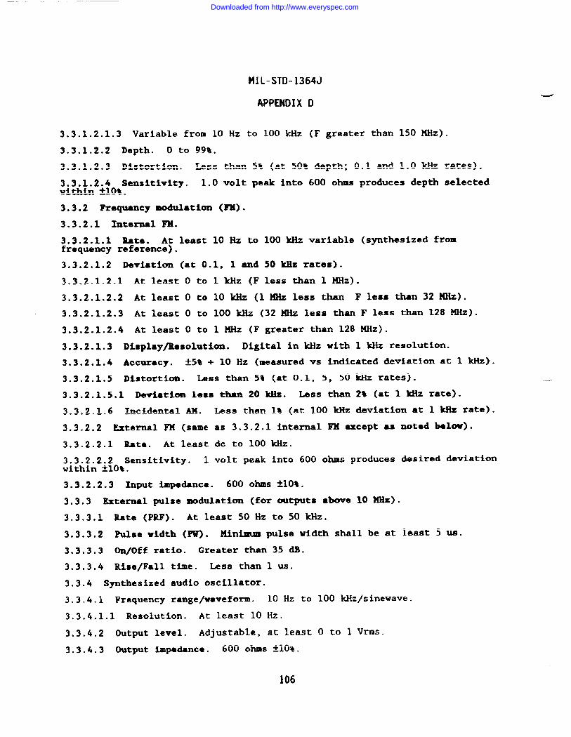
MIL-STD-1364J
APPENDIX D
3.3.1.2.1.3 Variable from 10 Hz to 100 kHz (F greater than 150 MHz).
3.3.1.2.2 Depth. o to 99%.
3.3.1.2.3 Distortion. Less than 5% (at 50% depth; 0.1 and 1.0 kllzrates).
3.3.1.2.4 Sensitivity. 1.0 volt peak into 600 ohms produces depth selectedwithin *1O%.
3.3.2 Frequency modulation (FM).
3.3.2.1 Internal FM.
3.3.2.1.1 Rate. At least 10 Hz to 100 kllzvariable (synthesized fromfrequency reference).
3.3.2.1.2 Deviation (at 0.1, 1 and 50 ldlzrates).
3.3.2.1.2.1 At least O to 1 kHz (F less than 1 MHz).
3.3.2.1.2.2 At least O to 10 kliz (1 XHz less than F less thn 32 MHz).
3.3.2.1.2.3 At least O to 100kHz (32HHz less thanF less than 128 MHz).
3.3.2.1.2.4 At least O to 1 MHz (F greater than 128 MHz).
3.3.2.1.3 Display/Resolution. Digital in kllzwith 1 kllzresolution.
3.3.2.1.4 Accuracy. -t5%+ 10 Hz (=asured vs indicated deviation at 1 kHz).
3.3.2.1.5 Distortion. IASS than 5% (at 0.1, 5, 50 ldizrates).
3.3.2.1.5.1 Deviation less than 20 Hz. Less than 2% (at 1 kHz rate).
3.3.2.1.6 Incidental AX. Less than 1% (at 100 kHz deviation at 1 MZ rate).
3.3.2.2 External FX (same as 3.3.2.1 internal FX except as noted below).
3.3.2.2.1 Rate. At least dc to 100 kHz.
3.3.2.2.2 Sensitivity. 1 volt peak into 600 ohms produces desired deviationwithin &lO%.
3.3.2.2.3 Input impedance. 600 OhS *1O%.
3.3.3 External pulse modulation (for outputs above 10 XHz).
3.3.3.1 Rate (PRF). At least 50 Hz to 50 kHz.
3.3.3.2 Pulse width (PW). Minimum pulse width shall be at least 5 US.
3.3.3.3 On/Off ratio. Greater than 35 dB.
3.3.3.4 Rise/Fall time. Less than 1 US.
3.3.4 Synthesized audio oscillator.
3.3.4.1 Frequency range/waveform. 10 Hz to 100 kHz/sinewave.
3.3.4.1.1 Resolution. At least 10 Hz.
3.3.4.2 Output level. Adjustable, at least O to 1 Vrms.
3.3.4.3 Output impdance. 600 OhS *1O%.
106
Downloaded from http://www.everyspec.com
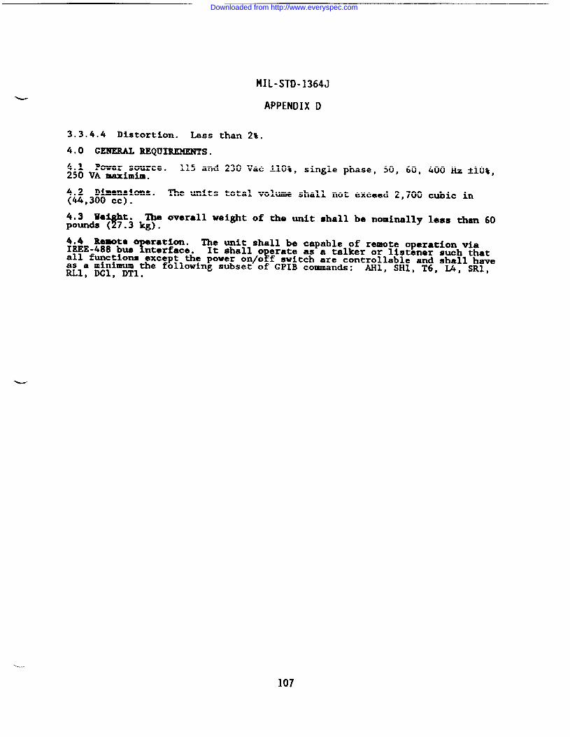
MIL-STD-1364J
APPENDIX D
3.3.4.4 Distortion. Less than 2%.
4,0 GENERAL REQU~S.
4.1 Power source. 115 and 230 Vac ~10%, single phase, 50, 60, 400 HZ A1O%,250 VA maximi.m.
4.2 Dimensions. The units total volume shall not exceed 2,700 cubic in(44,300 Cc).
4.3 mY
The overall weight of the unit shall be nominally less than 60pounds ( 7?~ kg).
4.4 Rewte o ration. The unit shall be capable of remote operation viaIEEE-488 bus ~nterface. It shall o crate as a talker or listener such that
Fall functions except the power on/o f switch are controllable and shall haveas a minimum the following subset of GPIB commands: AHl, SH1, T6, L4, SRI,RLl, DC1, DT1.
107
Downloaded from http://www.everyspec.com
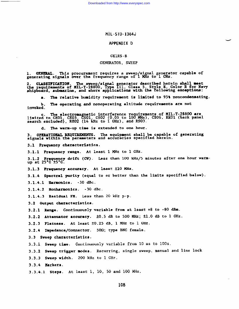
MIL-STD-1364J
APPENDIX D
GEIRS -B
GEN~TOR, SWEEP
1. GENERAL. ~is procurement requires a sweep Si al generator capable ofgenerating signals over the frequency range of {a z to 1 GHz.
2. CLASSITICATIOM . The swee /si 1 enerator described herein shall meetthe requirements of MIL-T-288~0, q!!e II, Class 5, S le E, Color R for Navyshipboard, ?submarine, and shore app ications with the ollowing exceptions:
a. The relative humidity requirement is limited to 95% noncondensating.
b. The operating and nonoperating altitude requirements are notinvoked .
The electroma etic interference re uirements of KIL-T-28800 arelimite~”to CEO1 CE03 ~01 CS02 (0.05 to 108 MHz), CS06, REO1 (back panelsearch excluded~, REO~ (14 hz to 1 GHz), and RS03.
d. The warm-up time is extended to one hour.
3. OPERATIONAL REQU3MWENTS. The equipment shall be capable of generatingsignals within the parameters and accuracies specified herein.
3.1 Frequency characteristics.
3.1.1 Frequency range. At least 1 MHz to 1 GHz.
3.1.2 Fraquency drift (Cl?). Less than 100 kHz/5 minutes after one hour warm-up at 25*C AS*C.
3.1.3 Fraquency accuracy. At least A1O MHz.
3.1.4 Spectral purity (equal to or better than the limits specified below).
3.1.4.1 Earmonlcs. -30 dBc.
3.1.4.2 Nonharmonics. -30 mc.
3.1.4.3 Residual FM. IASS than 20 kHz p-p.
3.2 Output characteristics.
3.2.1 Range. Continuously variable from at least +8 to -80 dBm.
3.2.2 Attenuator accuracy. AO.5 * to 500 ~z; tl.o ~ to 1 GHz.
3.2.3 Flatness. At least fO.25 dB, 1 MHz to 1 GHz.
3.2.4 Impedance/Connector. 50fl;type BNC female.
3.3 Sweep characteristics.
3.3.1 Sweep time. Continuously variable from 10 ms to 100s.
3.3.2 Sweep tr%gger modes. Recurring, single sweep, manual and line lock
3.3.3 Sweep width. 200 kllz to 1 GHz.
3.3.4 Markers.
3.3.4.1 Steps. At least 1, 10, 50 and 100 MHz.
108
Downloaded from http://www.everyspec.com
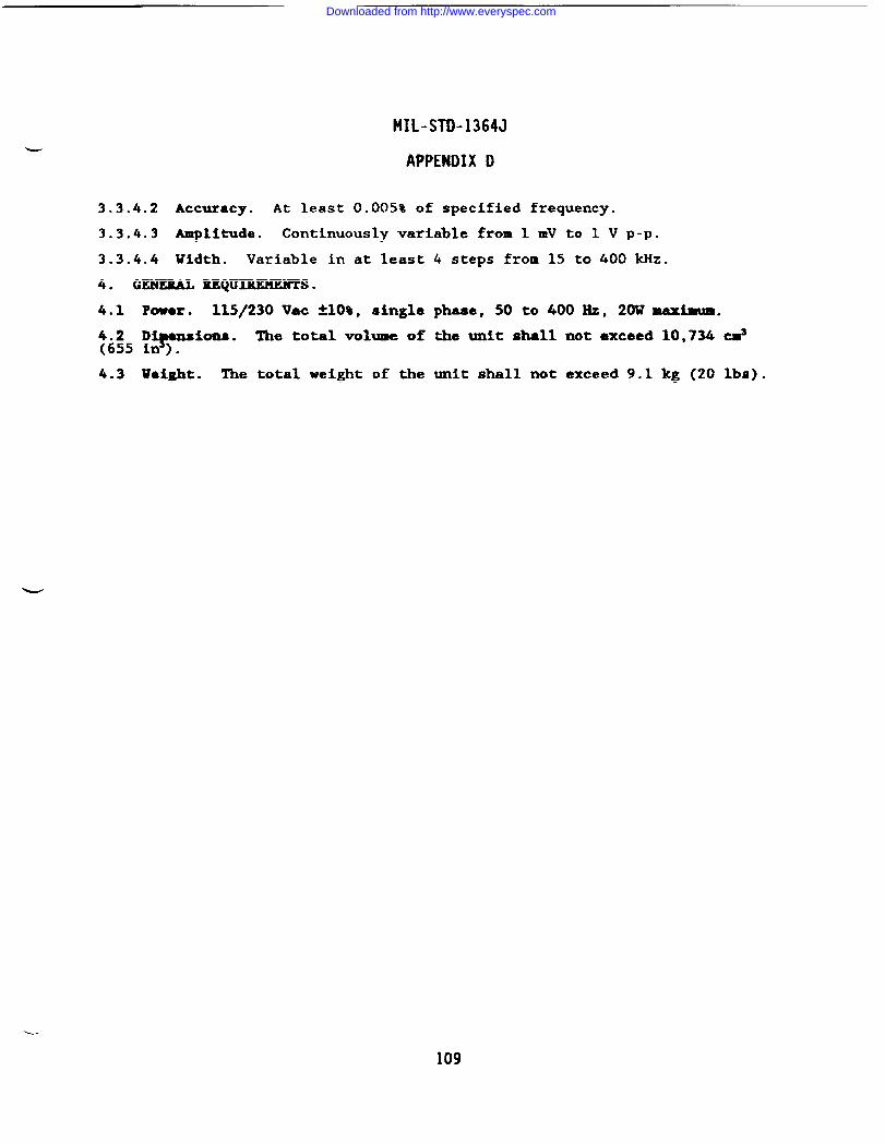
MIL-STD-1364J
APPENDIX D
3.3.4.2 Accuracy. At least 0.005% of specified frequency.
3.3.4.3 Amplitude. Continuously variable from 1 mV to 1 V p-p.
3.3.4.4 Vidth. Variable in at least 4 steps from 15 to 400 kHz.
4. GENEML REQ~S.
4.1 Power. 115/230 Vac *1O%, single phaae, 50 to 400 Hz, 20U maxima.
y5 M#lpaiom8. The total volume of the unit shall not exceed 10,734 cms.
4.3 weight. The total weight of the unit shall not exceed 9.1 kg (20 lbs).
109
Downloaded from http://www.everyspec.com
MIL-STD-1364J
APPENOIXD
GEICM-A
GENERATOR, SWEEP
-
1.0 GENERAL* This procurewnC requires ● swee enerator capable of generat-ing signals over a frequency range of 1 MHz to !.! GHz.
;&&CIASSIFIGATIOH . The ●quipment shall meet the requirements of HIL-T-
9e 111, Class 5, S le E, Color R for Navy shipboard, suharine, and
shore’app ications with the? ollowing modifications and exceptions:
The nonoperating temperature requirement is limited to the range of-40”&to +70°c.
b. The relative humidity requirement is limited to 953 noncondensating.
c. The operating and nonoperating altitude requirement is not invoked.
d. The warm-up time is extended to one hour.
3.0 OPZMTIOMAL ltEQU~. The equipment shall be capable of generatingsignals within the parameters and accuracies specified herein.
3.1 Frequency characteristics.
3.1.1 Frequency range. At least 1 MHz to 2.5 GHz.
3.1.2 Fraqtmncy drift (after 1 hour warm-up at 25°C *5”C).
3.1.2.1 1 to 1500 HEz. hss than 250 kllzfi.
3.1.2.2 1500 to 2500 XHz. Less than 500 kHZ/h.
3.1.3 Frequency accuracy (C’U).
3.1.3.1 1 to 500 MHz. At least *1O MHz.
3.1.3.2 500 to 2500 MXz. At least f20 KHz.
3.1.4 Spectral purity (equal to or less than the limits specified below).
3.1.4.1 MaZwmics. -20 dk from 1 to 10 MHz; -30 dBc from 10 MHZ to 2.5 GHz.
3.1.4.2 Nonharmonlcs. -35 dBc.
3.1.4.3 Residual FM. Less than 20 kHz p-p.
3.2 Output characteristics.
3.2.1 Range. At least -77 to +13 dBm; continuously variable.
3,2.2 VSUR. Less than 1.5:1 (10 dB attenuation minimum).
3.2.3 Accuracy. At least A1.O dB from +13 dBm to -20 dBm with an additiomlfo.3 dB/10 dB step below -20 dl!m.
3.2.4 Flatness. Less than fO.5 dB at O dBm.
3.2.5 Impedance/Connector. 50 ohms; type N female.
3.3 Sweep characteristics.
3.3.1 Frequency range. 1 MHz to 2,500 MHz.
110
Downloaded from http://www.everyspec.com
MIL-STD-1364J
APPENDIX D
3.3.2 Sweep time. At least 10 ms to 100s; continuously adjustable.
3.3.3 Sweep trigger modes. Repetitive, single, external trigger, manual andline lock sweep.
3.3.4 Markers.
3.3.4.1 stops. At least 1, 10, 50, 100 MHz.
3.3.4.2 Accuracy. At least .005t of setting.
3.3.4.3 width. Adjustable from 15 to 400 kliz.
3.4 Modulation characteristics.
3.4.1 Internal.
3.4.1.1 Square wave. At least 1 kliz.
3.4.2 External.
3.4.2.1 Frequency modulation.
3.4.2.1.1 Rate. 50 Hz to 10 kHz.
3.4.2.1.2 FM deviation. O to at least 50 ~z.
3.4.2.2 Amplitude modulation.
3.4.2.2.1 Range. At least DC to 10 kHz.
3.4.2.2.2 Depth. At least 10 to 90%.
3.4.2.2.3 sensitivity. Lass than lV p-p for 10% modulation.
4.4 GENERAL RBQUIREKERTS.
4.1 Powere 115/230 Vac ~10%, single phase, 50, 60 or 400 Hz, 60 VA.
4.2 Dimensions. The total unit volume shall not exceed 1,250 cubic in(20,450 CC).
4.3 Weight. The total weight of the unit shall not exceed 23 lb (10.5 kg).
111
Downloaded from http://www.everyspec.com
MIL-STD-1364J
APPENDIX D
GEIRU-C
GENERATOR, SWEEP
1. GENERAL . These salient characteristics describe a microwave sweepgenerator covering a frequent
$range of 10 MHz to 20 GHz employing no more
than one plug-in and one main ram.
2. GXASSIFICATION . The swee generator described herein shall meet there uirements of MIL-T-28800, &pa III, Class 5
?Style E, Color R for Navy
sh pboard, s&marine, and shore applications w!th the following modificationsand exceptions:
a. Humidity . Relative humidity is limited to 95% noncondensating.
b. Altitude. Not required
The electroma etic interference re uirements of MIL-T-28800 arealimite~”to CEO1 CE03 &Ol CS02 0.05 to 10 MHz), CS06, REOI (back panelsearch excluded~, REO~ (14 &z to 1 GHz), and RS03.
d. 400 Hz Power Source. Not required
e. The equipment warm-up period is increased to 1 hour.
3. OPERATIONAL CHARACTERISTICS.
3.1 Frequency characteristics.
3.1.1 Frequency rsnge. 10 MHz to 20 GHz; a maximum of one plug-in or RFoutput is allowed.
~i~~~ ~F~uency resolution. The displayed frequency resolution shall be at.
3.1.3 Frequency ●ccuracy. Measured accuracy within t10 MHz at 25-C ~5°C.
3.1.4 Frequency stability (less than the limits specified below).
3.1.4.1 Temperature. *1 MHz/”C (over O to 50°C operating range).
3.1.4.2 Line voltage. ~200 WZ (&lo~ li~ voltage variation about 115 Vat).
3.1.4.3 Warm-up. +-1~z\lo minutes after 1 hour warm-up.
3.1.5 Rcsiciual FM in G’Umode. Less than 10 kHz peak (measured in 50 Hz to 15kHz bandwidth).
3.1.6 Spectral purity (at least the limits specified below).
3.1.6.1 Harmonics/Subharmonlcs. -20 mc.
3.1.6.2 Spurious/Nonharmonics. -25 ~C.
3.2 Output characteristics.
3.2.1 Output connector. Type N.
3.2.1.1 VSUR. Less than 2:1.
3.2.2 Output level. +7 dBm leveled (minimum value of maximum leveledoutput).
._/
3.2.3 Output level adjustment range. At least 60 dB.—-
112
Downloaded from http://www.everyspec.com
3.2.43.2.3;
3.2.5
3.2.6
3.2.7
MIL-STD-1364J
APPENDIX D
Output di.spla .T
Digital readout of output power level specified inresolution O. dB.
Level ●ccuracy. kl.5 dB (displayed level vs measured output level).
Output level variation. -tt*()~.
Attenuator error. Maximum attenuator error shall be less than *3.3 dB.
3.3 Modulatfom characteristics.
3.3.1 Amplitude modulation (AM).
3.3.1.1 Internal AM (square uave).
3.3.1.1.1 Rate. 1 kHz and 27.8 kHz.
3.3.1.1.2 On/Off ratio, Greater than 30 dB.
3.3.1.2 External AM (square wave or pulse).
3.3.1.2.1 Rate. 10 Hz to 50 kHZ.
3.3.1.2.2 Input levels. TTL co~atible.
3.3.1.2.3 Sensitivity. 1 dB/v, maximuM input
3.3.2 Frequency modulation (FM).
3.3.2.1 External FM.
15V .
w3.3.2.1.1
3.3.2.1.2
3.3.2.1.3
3.4 Sweep
Deviation. At least O to *7 MHz.
Rate. 10 Hz to 100 ~Z.
Sensitivity. Greater than 5 KHz/V.
characteristics.
3.4.1 Range. 10 MHz to 20 GHz.
3.4.2 Sweep function. Start/Stop, CW, AF, Marker.
3.4.3 Trigger modes. Internal (automatic), Line, External, Single, Manual.
3.4.4 Frequency markers. At least 5; both amplitude and frequency.
3.4.5 Sweep output. O to 10V ~0.5V, direct coupled, coincident with theswept RF output .
3.4.6 Sweep time. Adjustable from at least 10 msec to 99 sec over anyportion of the band.
3.5 Displays (digital).
3.5.1 Frequency. Start/Stop, CW, CF/AF (4 digits).
3.5.2 Marker/Time. Marker frequency or sweep time (3 digits).
3.5.3 Output level. Output signal level in dBm (3 digits).
4. GENERAL
4.1 Power,~
REQUIREMENTS .
115 or 230 Vac ~10%, single phase, 50 or 60 Hz, 400W maximum.
113
Downloaded from http://www.everyspec.com
MIL-STD-1364J
APPENDIX D
4.2 Dimensions. Less than 32,774 cm3 (2,000 in3); maximum height allowable15.24 cm (6 in) including feet.
4.3 Ueight. LSSS than 27.3 kg (60 lbs).
4.4 Local operation. All front panel control settings shall be storable innon-volatile memory for future recall.
4.5 Rewta rogramm! ?
The generator shall be capable of being remotelycontrolled v a the IEE 1488 interface bus, operating as both a tal~ an~dlistener, havin at least the following subset of bus functions:SH1, T6, SR1, D&, andRL1.
* 9
4.6 Diagnostics. ~ctional self-test and trouble shooting shall be accom-plished using front panel controlled diagnostic functions.
4.7 Rac~tabho
-
Downloaded from http://www.everyspec.com
—
1.0 GENERAL. Thesegenerator covering athan one plug-in and
MIL-STD-1364J
APPENDIX D
GEIRX-C
G-TOR, SUE~P
salient characteristics describe a microwave sweepfrequent
$range of 10 MHz to 26.5 GHz, employing no mote
one main rame.
2.0 GIASSIFICATION. The sweep enerator described herein shall met there uirements of MIL-T-28800( ),
? %e III, Class 5, S le E, Color R for Navy
Ysh pboard, submarine and shore app ications with the ollowi~ modificationsand exceptions:
a. Non-operating temperature: -40*C to +70”C.
b. Temperaturefhumldi ty: Non-condensating.
c. Altitude: Not required.
d. The Electromagnetic Interference re uirements of MIL-T-28800( ) are8limited to CEO1 CE03 CSO1 CS02 0.05 to 1 0 KHz), CS06, REOl (back panelsearch excluded~, REO~ (14 ~z to i GHz), and RS03.
e. 400 Hz Power Source: Not required.
f. The equipment warm-up period is increased to 1 hour.
3.0 OPERATIONAL CHARACTERISTICS.
- 3.1 Frequemcy characteristics.
3.1.1 Range: 10MHz to 26.5 GHz; amaxhunt @fallowed.
3.1.2 Resolution: At least 1 MHZ.
3.1.3 Accuracy: In CW mode, measured accuracy
one plug-in or RF outpixt is
within ~20 UHz at 25eC ?5°C.
3.1.4 Stability (less than the limits specified below).
3.1.4.1 Temperature: ~1 KHz/°C (over 0-50°C operating range).
3.1.4.2 Line voltage: t200 kHz (*1O% line voltage variation about 115 Vat).
3.1.4.3 Warm-up: tl MHz/10 minutes after 1 hour warm-up.
3.1.5 Rcsiduel FX in GUmode: Less than 15 kHz peak (measured in 50 Hz to 15kHz bandwidth).
3.1.6 Spectral purity (at least the limits specified below).
3.1.6.1 Harmonics/Sub-harmonics: <-20 dBc.
3.1.6.2 S~iOUS/Non-harmon%C#:[2.4 to 26.5 GHz].
<-25 dBc [10 MHz to 2.4 GHz] and < -50 dBc
3.2 Output characteristics.
3.2.1 Connector: Ruggedized coaxial (SMA compatible); VSWR less than 2.0:1.
3.2.2 Maximum leveled output: > +7 dBm [10 MHz to 18 GHz], > +1 dBm [18 to26 GHz].
3.2.3 Level adjustment range: At least S5 dB,
115
Downloaded from http://www.everyspec.com
MIL-STD-1364J
APPENDIX D
3.2.4 Display: Digital readoutl; resolution 0.1 dB.
3.2.5 Level ●ccuracy: YZ.O n (displayed level V$ measured output level).
3.2.6 Flatness: *1.5 dB.
3.2.7 Attenuator error: < =.3 dB.
3.3 Modulation characteristics.
3.3.1 ~litxule modulation (AH).
3.3.1.1 Internal AM (square -e).
3.3.1.1.1 Rate: 1 kHz and 27.8 kHz.
3.3.1.1.2 On/Off ratio: Greater than 30 cM.
3.3.1.2 External AM (square wave or pulse).
3.3.1.2.1 Rate: 10 Hz to 50 kHz.
3.3.1.2.2 Input levels: TTL compatible.
3.3.1.2.3 Sanaitivity: 1 dB/V, maximum input 15V.
3.3.2 Fraquency modulation (FX).
3.3.2.1 External FM.
3.3.2.1.1 Deviation: At least O to *7 ~.
3.3.2.1.2 Raze: At least 10 Hz to 100 kblz.
3.3.2.1.3 Sensitivity: Greater than 5 ~fl.
3.4 Sweep characteristics.
3.4.1 Range: 10 ~Z to 26.5 GHz.
3.4.2 Sweep function: Start/Stop, CW, AF, Marker.
3.4.3 Trigger modes: Internal (automatic), Line, External, Single.
3.4.4 Markers: At least 5; both amplitude and frequency.
3.4.5 Sweep output: O to 10 V ~0.5 V, direct coupled, coincident with theswept RF output.
3.4.6 Sweep time: At least 10 msec to 33.5 sec.
3.5 Displays (digital).
3.5.1 Frequency: Start/Stop, CW, CF/AF (4 digits minimum).
3.5.2 Marker/Time: Marker frequency or sweep time (3 digits minimum).
3.5.3 Output level: Output signal level in dBm (3 digits minimum).
4.0 GENERAL REQUIREMENTS.
4.1 Power: 115 or 230 Vac flO%, 50/60 Hz, 400 W maximw.
4.2 Dimensions: Mss than 36 052 cubic cm ( 2200 cubic in ); maximum heightallowable 153 mm (6 in) including feet.
116
Downloaded from http://www.everyspec.com
MIL-STD-1364J
APPENDIX D
4.3 Weight: Less than 27.3 kg (60 lbs).
4.4 Local operation: All front panel control settings shall be storable innon-volatile memory for future recall.
4.5 R~te contol: Instrument must be ca able of o eratin via the IEEE-488f !interface bus and shall provide the capabi ity to ta k and fisten.
4.6 Diagnostics: Functional self-test and trouble shooting shall be accom-plished using front panel controlled diagnostic functions.
-
4.7 Reclmountable.
117
Downloaded from http://www.everyspec.com
MIL-STD-1364J
APPENDIX D
GEIRT -C
GENERATOR, SWEEP
1. GEBULBAL. These salient characteristics describe a ~icrowave sweep
Lenarator coverin a frequency range of 10 MHz to 40 GHz employing no more
two plug-in teada and one mainfrsae.
2. CIASSIFICATION . The swee generator described herein shall meet there uirements of MIL-T-28800, ?ype III, Class 5,
7sh pboard, submarine and shore applications with ‘z:e2i&:g L%Ezonsand exceptions:
a. Nonoperating temperature: -40”C to +70”C.
b. Temperature/’humidity: Noncondensating.
c. Altitude: Not required.
d. The electromalimited to CEO1 CE03 l?’
etic interference re uirements of 141L-T-28800 aresol CS02 0.05 to 1
fd MHz) , CS06, REO1 (back panel
search excluded~, REO~ (14 b to GHz), and RS03.
e. The equipment warm-up period is increased to 1 hour.
3. 0P&RATION6L REQD~.
3.1 Frequency charactcrktics.
3.1.1 Fro llencyfoutputs ●l owsd.
;;:;: ~Flm#ency.
3.1.3 Frequency(WZ .
3.1.4 Frequency
mnge. 10 MHz to 40 GHz; a maximum of two plug-ins or RF
resolution. The displayed frequency resolution shall be at
accuracy (measured at 25’C ~5°C). *20 ~ from 10 ~z to 40
stability (less than the limits specified below).
3.1.4.1 Te}
rature over 0-50°C o crating range).8
kl KHz/°C from 10 MHZ to20 W and&HHz/°C rom 20 to 40 Hz.
3.1.4.2 Line volts e (*1O% line voltage variation about 115 Vat). *200 kHz1!from 10 MHz to 20 G z and 1400 kHz from 20 to 40 GHz.
:A;”&%HE &J%m%xS?x% $&;O:&”GHz.*1 ~z/lo minutes from 10 ~z
3.1.5 Residual FM in GU mode (measured in 50 Hz to 15 kllzbandwidth). Lessthan 15 kHz eak for fre uencies below 20 GHz and less than 20 kHz peak forfrequencies koxn 20 to 48 GHz.
3.1.6 Spectral purity (at least the limits specified below).
3.1.6.1 Harmonics/Subharmonics. -25 dBc for frequencies from 10 KHz to 2.4GHz, - 40 dBc for fxe uencies from 2.4 to 26.5 GHz and - 20 dBc for frequen-
aties from 26.5 to 40 Hz.
3.1.6.2 S rious/Nonharmonics.r
-25 dBc for fre uencies from 10 MHz to 2.4iGHz and -5 dBc for frequencies from 2.4 to 40 G z.
3.2 output characteristics.
118
Downloaded from http://www.everyspec.com
MIL-STD-1364J
APPENDIX D
3.2.1 Output connectors. Rug edized coaxial (SMA compatible); VSWR ~:1 forfrequencies from 10 MHz to 26.f GHz and WR 28 wave uide or ruggedized coaxial,SMA compatible; VSWR <2.5:1 for frequencies above ~6.5 GHz.
3.2.2 Output level (minimum value of maximum leveled output). +2 dBm leveledfor frequencies from 10 MHz to 18.6 GHz and O dBm leveled for frequencies from18.6 to 40 GHz.
3.2.3GHZ .
3.2.4dB.
3.2.5
Output level adjustment range. 60 dB for frequencies from 10 MHz to 40
Output display. Digital readout of output power level; resolution 0.1
Level ●~ccma:y2(~is la ed level vs measured output level, measured at
~=l~ds-c)”. dEZrf requencies from 10 MHz to 40 GHz internally
.
3.2.6 Output level variation. ~1.5 dB for frequencies from 10 MHZ to 40 GHZleveled.
3.2.7 Attenuator error. Maximum attenuator error shall be less than *2.O dB(1OMHZ to40GHz).
3.3 Modulation characteristics.
3.3.1 Amplitude modulation (AH).
3.3.1.1 Internal AH (square wave).
u 3.3.1.1.1 Rate. 1 kHz and 27.8 kHz.
3.3.1.1.2 On\Off ratio. Greater than
3.3.1.2 External AX.
3.3.1.2.1 Rate. 10HZ to 50 kHz.
3.3.1.2.2 Input impedance. Nominally
20 dB.
less than 30 Ml.
3.3.1.2.3 Amplitude control. At least 13 dB.
3.3.1.2.4 Maximum input. 15V.
3.3.2 Frequency modulation (FM).
3.3.2.1 External FM.
3.3.2.1.1 Deviation. O to ~7 MHz for frequencies from 10 MHz to 40 GHz.
3.3.2.1.2 Rate. 10 Hz to 100 kHz.
3.3.2.1.3 Sensitivity. Greater than 5 MHz/V.
3.4 Sweep characteristics.
3.4.1 Range. 10 MHz to 40 GHz.
3.4.2 Sweep function. Start/Stop, CW, AF, Marker.
3.4.3 Trigger modes. Internal (automatic), line, external, single.
3.4.4 Frequency markers. At least 5; both amplitude and frequency.
119
Downloaded from http://www.everyspec.com
MIL-STD-1364J
APPHU)IX D
3.4.5 Sweep time. Adjustable from at least 150portion of the band.
3.5 Displays (digital).
msec to 99 sec over any
3.5.1 Frequency. Start/Stop, CW, CF/AF (4 digits).
3.5.2 Marker/Time. Marker frequency or sweep time (3 digits).
3.s.s output lelml. Output signal level in dlks (3 digits).
4.1 Power. 115 Vat, 50/60 Hz klO%, 400W.
4.2 Dimensions. Less than 2,000 cubic in (32,744 cubic cm); maximum heightallowable 153 mm (6 inches) including feet.
4.3 Weight. Less than 65 lbs (29.5 kg).
4.4 Local operat%om. All front panel control settings shall be storable innon-volatile memory for future recall.
4.5 Remote programming .f
Instrument must be capable of o e~!~~~ via the IEEEinterface bus and shal provide the capabili~ to talk A .
4.6 Diagnostics. Functional self-test and troubleshooting shall be accom-plished using front panel controlled diagnostic functions.
4.7 Rachountable.
4.8 Accessories.
4.8.1 If coaxial output connector is not SMA compatible, a~pter to SW isrequired.
4.8.2 If ou ut is coaxial to 40 GHz, coaxial to WR-28 waveguida adapter forT26 to 40 GM s required.
120
Downloaded from http://www.everyspec.com
MIL-STD-1364J
APPENDIX f)
GE4NN-A
GENERATOR, TIME MARK
1. GElmuu. This procurement requires a general purpose time mark generator.
2. CXASSIFICA710N ●
%?e III Class 5, Style E, and Color R in accordance
with MIL-T-28800 for s pboar~ applications.
30 OPEBATIOEAL REQMRKMEHTS. The equipment shall be ca able of enerstingf !!calibrated outputs within the minimum ranges and accurac es speci ied below.
3.1 Calibrated urkcr ram ●s. 0.1 us to 5s.!
The marker pulse shall have abase width typically 10t o pulse intewal for markers from 1 us div to ●t
dleast 5 s/div and a base width typically 30t of pulse intend or -rkersbelow 1 us/div.
3.1.1 Marker amplitude. 500 mV peak-to-peak minimum into 50 ohms.
3.2 Calibrated trigger ranges. 100 M to 1s in decade ste s. The tri er
KSha f Pshall be a fast rise square wave with leading edge co ncident wit timemar .
3.2.1 Trigger riso time. 3 ns maximum into 50 ohms.
3.2.2 ?r~er amplitude. 500 mV peak minimum into 50 ohms.
3.2.3 Trigger aberrations. Overshoot and pre-swing shall be less than 2%and the flatness of the waveform shall be M.5% or less of trigger amplitude.
3.3 Internal reference frequent stabilit .6 E
7? ppn per month within anoperating temperature range of 2 “C to “50” .
3.4 External reference Input. The equipment shall be capable of specifiedoperation during use of an external reference frequency standard.
4. POWER SOURCE. 141L-T-28800 nominal power source requirements are invoked.Operation at 400 Hz is not required. Maximum power consumption: 35W.
5. UHGHT . 20 kg (44 lb) maximum.
121
Downloaded from http://www.everyspec.com
MIL-STD-1364J
APPENDIX D
GE6NF-D
GENERATOR, TWO-TONE
1. GENERAL ● This procurement requires a solid-state, two-tone signal genera-tor.
2. OIASSIFICATIOl!l.%
e 111, Class 5, Style E, and Color R in accordancewith MIL-T-28800 for s pboard applications.
3. OPERATIONAL ltEQunmmzTs. The quipment shall be p;:v~~d with two inde-pendent oscillators each vari~le in frequency and
TTh; :~i~nt
shall be rovided with a method to monitor the level o each SiEcotiine t e two oscillator signals into one co
‘Ysite output. r e commosite
Si!?’
1 shall be ad ustuble by means of a built- n attenuator.1in icated the min mum characteristics identified below shall
the indi~dual oscillators and to the composite signal.
Except areapply both to
3.1 Reqmency range. 20RZ to 20 H’’LZ.
3.1.1 Frequency ●ccurscy. ~(lt + 0.2 Hz).
3.1.2 Freqmency response. M.5 dB.
3.2 Intermodnlation dtstort%on. 60 dB below the signal level.
3.3 Harmonic distortion. 0.05% maximum from 63 Hz to 6.3 kHz and 0.1% overthe remaining specified frequency range.
3.4
3.5
3.7
3.8
4.400
5.
Hum. 66 dB below the output signal.
C)utpmt impdamce. 600 ohms nominal.
Output ●ttcmuatoxe O dB to 70 dB in 1 dB steps. Attenuator accuracy:+ 0.2 cm).
Output level. Continuously adjustable from -25 dBm to +15 dBm.
Level monitor. dBm and voltage readout. Accuracy: 35% FS.
POWER SOURCE. MIL-T-28800 nominal power source requirements are invoked.Hz operation is not required. Ihximum power consumption: 15W.
WEIGHT . 20 kg (44 lb) maximum.
—-
122
Downloaded from http://www.everyspec.com
MIL-STD-1364J
APPENDIX D
TSCNG-E
GENIWiTOR/ANALYZER, DISTORTION, ZTY
1. GENERAL. This rocurement requires a rackmountable modular type distor-!tion test set ca ab o of generating, measuring, and analyzing data and tele-
Ltypewriter signs .
2. CLASSIFICATION .%
e III Class 5, Style PG, and Color R in accordancewith KIL-T-28800 for s pboar~ applications.
3. OPEMTIOMAL lU!Q~. The equipment shall be capable of acce tinin uts (anal
&er and providing outputs (generator) over ● range of 3?.5 !!0
9 &)O baud ~r e message forms pattern types, and modes of o ●ration speci-fied below. The followi
Y7Ysci~ic baud rates shall be include in both the
generator and analyzer: 45.5, 50, 61.12, 74.2, 100, 110, and 75 x 2Enwhere n is an integer from O Lo 70
3.1 Anal zer input signals.1
The e uipment shall be capable of accepting bothhigh leve and 10V level signals. k is interface may be provided by the useof bridging and series inputs.
3.1.1 Bridg~l~ t. The bridging in ut, for low 18-1 SiK I
1s (0.5 to 25V& olar)
fve an impedance of 7 to 68 kilohms.
g
Tl#input shall berov dad with a switch-selectable input filter for use with data xates of 75aud or less.
3&~i~ Series Input. High level signals: 20 to 60 mA neutral, 20 to 30 mA
~ !This input shall have a means of reversing the polari~ of the
ncoming sigwl.
3.1.3 Inputs. 5, 6, 7, and 8 level codes, either llynclwonous’or @nchro-nous.
3.1.3.1 spchromOua operation. The-i
uipment shall beTrov~ded with a means
of phase locking internal timing with t e incoming signs .
3.1.3.2 Asynchronous operation. The equipment shall have a single-unit startas well as stop selections at inte=als of 1.0, 1.5, and 2.0 units.
3.1.4 External frequency input. The equipment shall be capable of operationfrom an external frequency source.
3.2 Analyzer distortion measurements. The equipment shall analyze and indi-cate, in percentage, the following distortions:
Bias or end distortion: The equi mmt shall indicate the average ofeith~; bias or end distortion, as sele.te~, and whether it is marking orspacing.
b. Total, earl The equi ment shall provide a peakdistortion reading ~&l~fi ~~~~~:~~~~ark and mar~-to-spa.e transitions andshall select the total (all
1early, or late distortion transitions. Peak
distortion measurements sha i be retained on the e ipment display until theFdistortion belnz monitored increases or until a se ected automatic (3 to 5——
secon& nominal~ or manual reset is Initiated.
3.2.1 Parity. The equipment shall have odd and even parity
3.2.2 Type dis lay.f
The equipment shall be provided with ameter capable o reading percent distortion in 1% incrementsto at least 49%.
3.2.3 Dlaplay accuracy. t20 FS.
check capability.
D’Arsonval typeover a range of O
123
Downloaded from http://www.everyspec.com
MIL-STD-1364J
APPENDIX i)
3.2.4 Signal state. The equipment shall be provided with an input signalindicator.
3.2.5 Mark-s ce distortion.!?’
The equipment shall be provided with markingand spacing d stortion indicators.
3.3 Generator, output functions. The generator shall be capable of producingsc
chronoua and asynchronous 5, 6, 7, or 8 level code. Asynchronous o eration!$ 11 have single-unit start as well as stop selections at intervals o 1.0,
1.5, and 2.0 units.
3.3.1 Data eneratiom.f
The equipment shall be capable of generating thefollowing se ec-le test data messages.
a. Standard “Fox” message (ITA2 ●nd ASCII).
b. Selected programmed characters (1 to at least 4).
c. Message and selected characters.
d. Steady mark.
e. Steady space.
f. 1:1 continuous reversal.
3.3.2 Output ke ing.r
The equipment shall be provided with the followingoutput capabilit es:
a. Low level polar (6V ((lV).
b. HiP
level, fully Zsolated polar and neutral keyer rated for a nominal100 to 270 at 40 to 70 mA.
3.3.3 Distortion. The equipment shall be capable of generating the followingdistortion in 1% increments over a range of at least O to 49S:
a. Marking bias.
b. Spacing bias.
c. Switching bias.
d. Marking end.
e. Spacing end.
4. POWER SOURCE. MIL-T-28800 nominal power source requirements a$~~nvoked.Operation at 400 Hz is not required. Maximum power consumption: .
5. WEIGHT . 20 kg (44 lb) maximum.
124
Downloaded from http://www.everyspec.com
MIL-STD-1364J
APPENDIX 1)
MMRAL-A
INDICATOR, MOTOR ROTATION
1. GENEWU . This procurement requires a motor rotation indicator for three-phase motors.
2. CUSSIFIGATIOM .%
e 111, Claas 5, Style E, and Color R in accordancewith 141L-T-28800 for s pboard application.
3. OPERATIONAL REQUIREMENTS. The equipment shall Indicate motor rotation inaccordance with the following minimum specifications.
3.1 Rotation indicators. ABC and CBA.
3.2 Leads. Color coded alligator clips.
4. mm souRcE. MIL-T-28800 dc internal power source re uirements areinvoked. ?The batteries shall be of a commercially availab e type and provide100 hours of o eration before replacement.
%voked.The nominal power source require-
ments are not
.
5. WEIGHT . 0.45 kg (1 lb) maximum.
125
Downloaded from http://www.everyspec.com
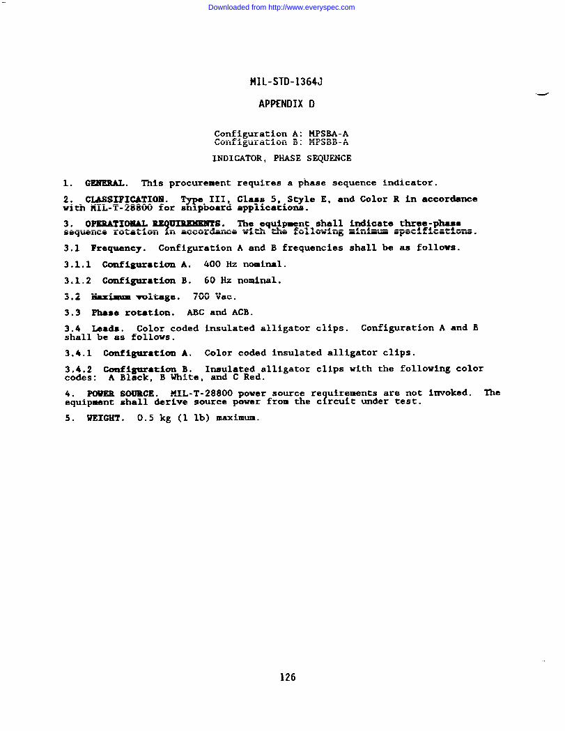
MIL-STD-1364J
APPENDIX D
Configuration A: MPSBA-AConfiguration B: MPSBB-A
INDICATOR, PHASE SEQUENCE
1. GENERAL. This procurement requires a phase sequence indicator.
2. CLASSXFIGATIOIQ.w
III, Class 5, Style E, and Color R in accordancewith MIL-T-28800 for s pboard applications.
3. OPERATIONAL ~S. The equipment shall indicate three-phaaeYsequence rotation n accordance with the following minimum specifications.
3.1 Frequency. Configuration A and B frequencies shall be as follows.
3.1.1 Configuration A. 400 Hz nominal.
3.1.2 Configuration B. 60 Hz nominal.
3.2 Maximum voltage. 700 Vat.
3.3 Phase rotation. ABC and ACB.
3.4 Leads. Color coded insulated alligator clips. Configuration A and Bshall be as follows.
3.4.1 Configuration A. Color coded insulated alligator clips.
3,4.2 Configuration B. Insulated alligator clips with the following colorcodes: A Black, B White, and C Red.
4. POWER SOURCE. HIL-T-28800 power source re uirements are not invoked. The?equipment shall derive source power from the c rcuit under test.
5. WEIGHT . 0.5 kg (1 lb) maximum.
126
Downloaded from http://www.everyspec.com
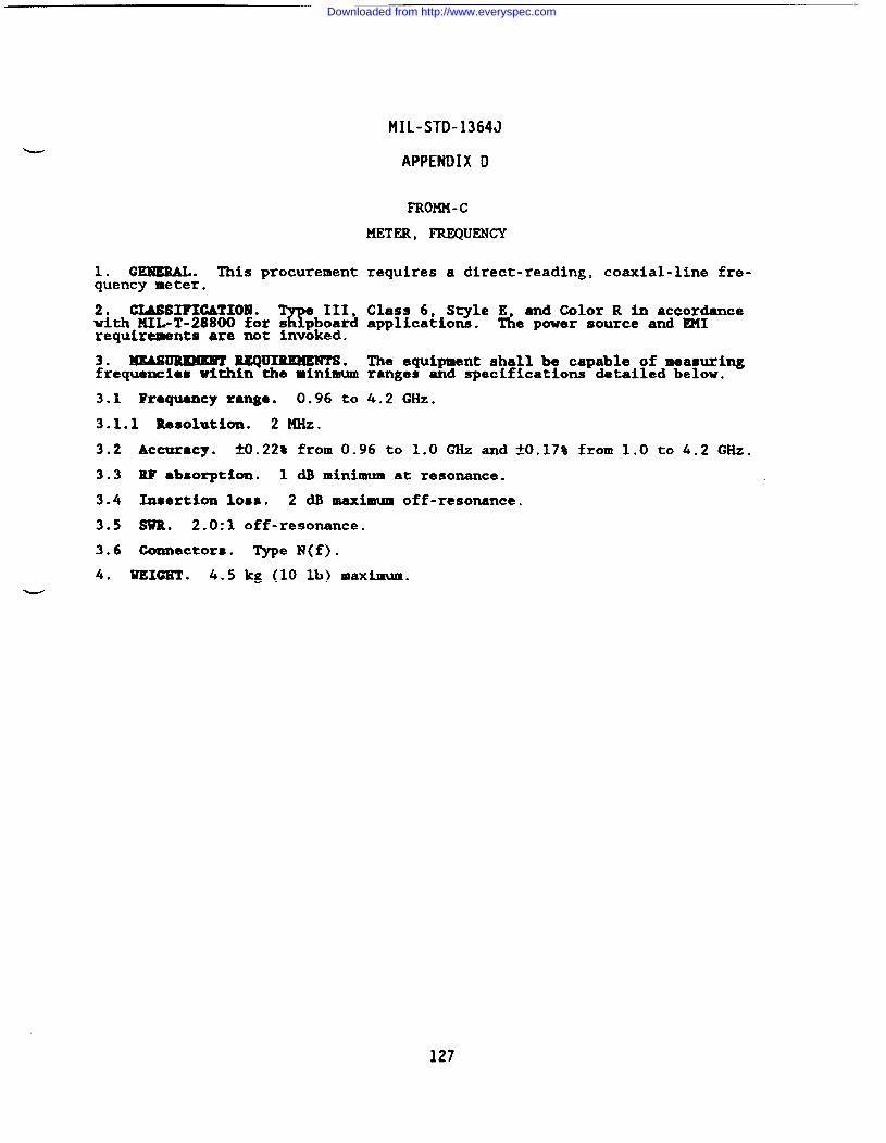
MIL-STD-1364J
APPENDIX D
FROMU- c
METER, FREQUENCY
1. G~. This procurement requires a direct-reading, coaxial-line fre-quency meter.
2. CLASSIF1CATIOM .%
e III, Class 6, Style E, and Color R in accordancewith MIL-T-28800 for s pboard applications. The power source and EMIrequirmnts are not invoked.
3. ~ lUQu~ . The equipment shall be capable of measuringfrequencies within the minimum ranges and specifications detailed below.
3.1 Frequency range. 0.96 to 4.2 ~Z.
3.1.1 Resolution. 2 MHz.
3.2 Accuracy. M.22% from 0.96 to 1.0 GHz and ~0.17% from 1.0 to 4.2 GHz.
3.3 RF absorption. 1 dB minimum at resonance.
3.4 Insertion 10SS. 2 dB maximum off-resonance.
3.5 SwR. 2.0:1 off-resonance.
3.6 Connectors. Type N(f).
4. WEIGHT . 4.5 kg (10 lb) maximum.
127
Downloaded from http://www.everyspec.com
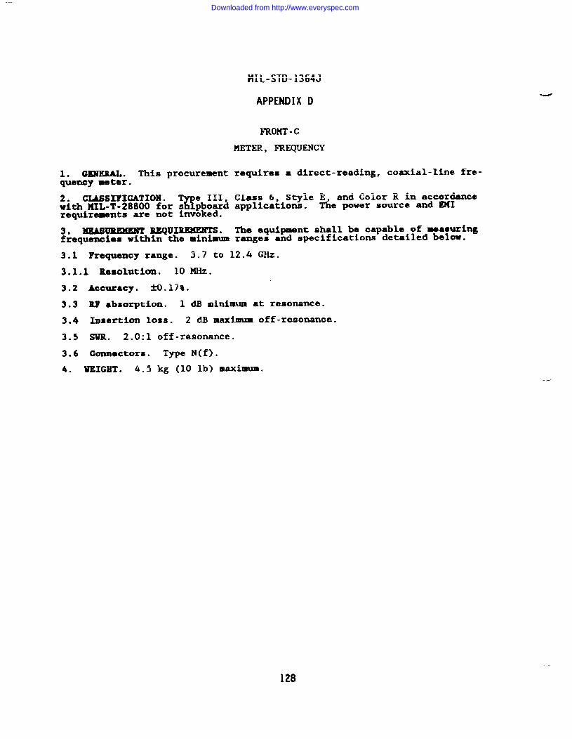
1. GISUERAL. This procurementquency meter.
2. CLASSIFICATION .%
e III,with KIL-T-28800 for s pboardrequirements are not iwoked.
3. MEASUREMENT REQUIUXENTS.frequencies within the minimum
MIL-STD-1364J
APPENDIX D
FRom -c
METER, FREQUENCY
requires a direct-reading, coaxial-line fre-
Class 6, Style E, and Color R in accordanceapplications. The power source and ~1
The equipment shall be capable of measuringranges and specifications detailed below.
3.1 Frequency range. 3.7 to 12.4 GHz.
3.1.1 Resolution. 10 ~Z.
3.2 Accuracy. 3fl.17%.
3.3 N’ ●bsorption. 1 dB minimum at resonance.
3.4 Insertion loss. 2 dB maximum off-resonance.
3.5 SwR. 2.0:1 off-resonance.
3.6 connectors. Type N(f).
4. WEIGHT . 4.5 kg (10 lb) maximum.
..
128
Downloaded from http://www.everyspec.com
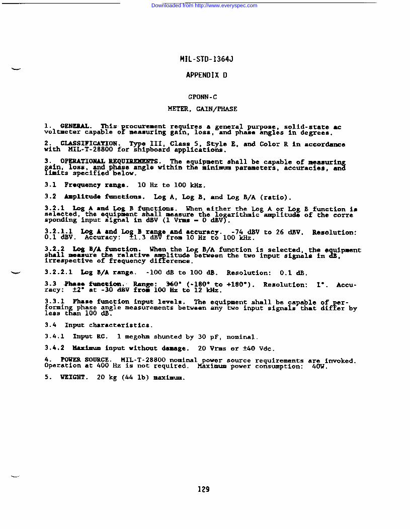
?tIL-STD-1364J
APPENDIX D
GPONN -c
METER, GAIN/PHASE
1. GENKRAL . This rocurement re uires a general purpose, solid-state acvoltmeter capable oF 1measuring ga n, loss, and phase angles in degrees.
2. CLASSIFICATION .9
e III, Class 5, Style E, and Color R in accordancewith MIL-T-28800 for s ipboard applications.
3. OPERATIONAL REQUIREMENTS. The equipment shall be capable of measurl
fsin, loss, 3and phase angle within the minimum parameters, accuracies, animits specified below.
3.1 Frequency ramga. 10 Hz to 100 kHz.
3.2 Amplitude functions. Log A, Log B, and Log B/A (ratio).
3.2.1 Log A and Log B functions. When either the Log A or Log B function isselected, the equipment shall measure the 10 arithmic amplitude of the corre
fspending input signal in dBV (1 Vrms = O dBV .
3.2.1.1 Log A and Lo B ra e ●nd accuracy.$
-74 dBV to 26 dBV. Resolution:0.1 dBv. Accuracy: –1.3 c&~ from 10 Hz to 100 kHz.
3.2.2 Log B/A function. When the Lo B/A function is selected, the e uipmentshall measure the relatlve
T&litude %etween the two input signals in ,
irrespective of frequency di erence,
‘w 3.2.2.1 Xag B/Arange. -1oo dB to 100 dB. Resolution: 0.1 dBo
3.3 lhas9 function.’ Range : 360° (-180° to +180”). Resolution: 1°. Accu-racy: N“ at -30 dBV from 100 Hz to 12 kilz.
3.3.1 Phase function input levels. The equipment shall be capable offormin phase angle measurements between any two input signals that dif e;-by
Er
less t an 100 dB.
3.4 Input characteristics.
3.4.1 Input RC. 1 megohm shunted by 30 pF, nominal.
3.4.2 Maximum input without damage. 20 Vrms or f40 Vdc.
4. POWER SOURCE. MIL-T-28800 nominal power source requirements are invoked.Operation at 400 Hz is not required. Maximum power cotiumption: 40W.
5. WEIGHT . 20 kg (44 lb) maximum.
129
Downloaded from http://www.everyspec.com
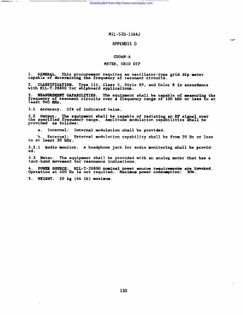
MIL-STD-1364J
APPENDIX D
GDOAN -A
METER, GRID DIP
1. GENERAL. This rocurement requires an oscillator-type grid dip meter!capable of &termin ng the frequency of resonant circuits.
2. CMSSIFIGATIOM .7(!
e 111,with lJIIL-T-28800for s pboard
3. XEASUREMEMT CAPABILITIES.frequent
8of resonant circuits
least 94 MHZ.
Class 5, Style EP, and Color R in accordanceapplications.
The equipment shall be capable of measurin theover a frequency range of 100 kliz or less fo at
3.1 Accuracy. *29 of indicated value.
3.2 Ou t.T
The equipment shall be ca able of radiatin an RF si al overthe spec fied frequency range. s % %Amplitu e modulation capa ilities s all beprovided as follows:
a. Internal: Internal modulation shall be provided.
b. External: External modulation capabilityto at least 20 kllz.
3.2.1 Audio monitor. A headphone jack for audioed.
3.3 Meter. The equipment shall be rovided with!taut-band movement for resonance ind cations.
shall be from 20 Hz or less
monitoring shall be provid-
an analog meter that has a
4. POWER SOURGE. KXL-T-28800 nominal power souroe requiremen~ a~Wimvoked.Operation at 400 Hz is not required. Maximum power consuqtion: .
5. WKCGHT ● 20 kg (44 lb) maximum.
130
Downloaded from http://www.everyspec.com
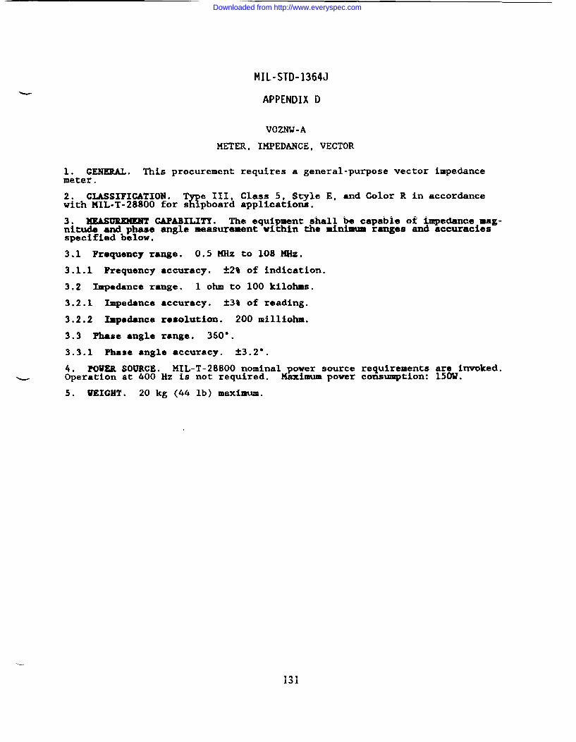
MIL-STD-1364J
APPENDIX D
VOZNW-A
METER, IKPEDANCE, VECTOR
1. GENERALO This procurement requires a general-purpose vector impedancemeter.
2. CLASSIFICATION .%
e III, Class 5, Style E, and Color R in accordancewith MIL-T-28800 for s pboard applications.
3. MEASUREMENT GAPABILITY. The equipment shall be capable of impedance mag-nitude and phase angle measurement within the minimum ranges and accuraciesspecified below.
3.1 Frequency range. 0.5 MHz to 108 MHz.
3.1.1 Requency accuracy. ~2% of indication.
3.2 Impedance range. 1 OhIllto 100 kilohms.
3.2.1 Impedance accuracy. i3% of reading.
3.2.2 Im@ance resolution. 200 milliohm.
3.3 Phase angle range. 360°.
3.3.1 Phase angle accuracy. t3.2°.
4. POWER SOURCE* MIL-T-28800 nominal power source requirements are invoked.u Operation at 400 Hz is not required. Maximum power consumption: 15(MJ.
5. WEIGHT . 20 kg (44 lb) maximum.
-.
131
Downloaded from http://www.everyspec.com
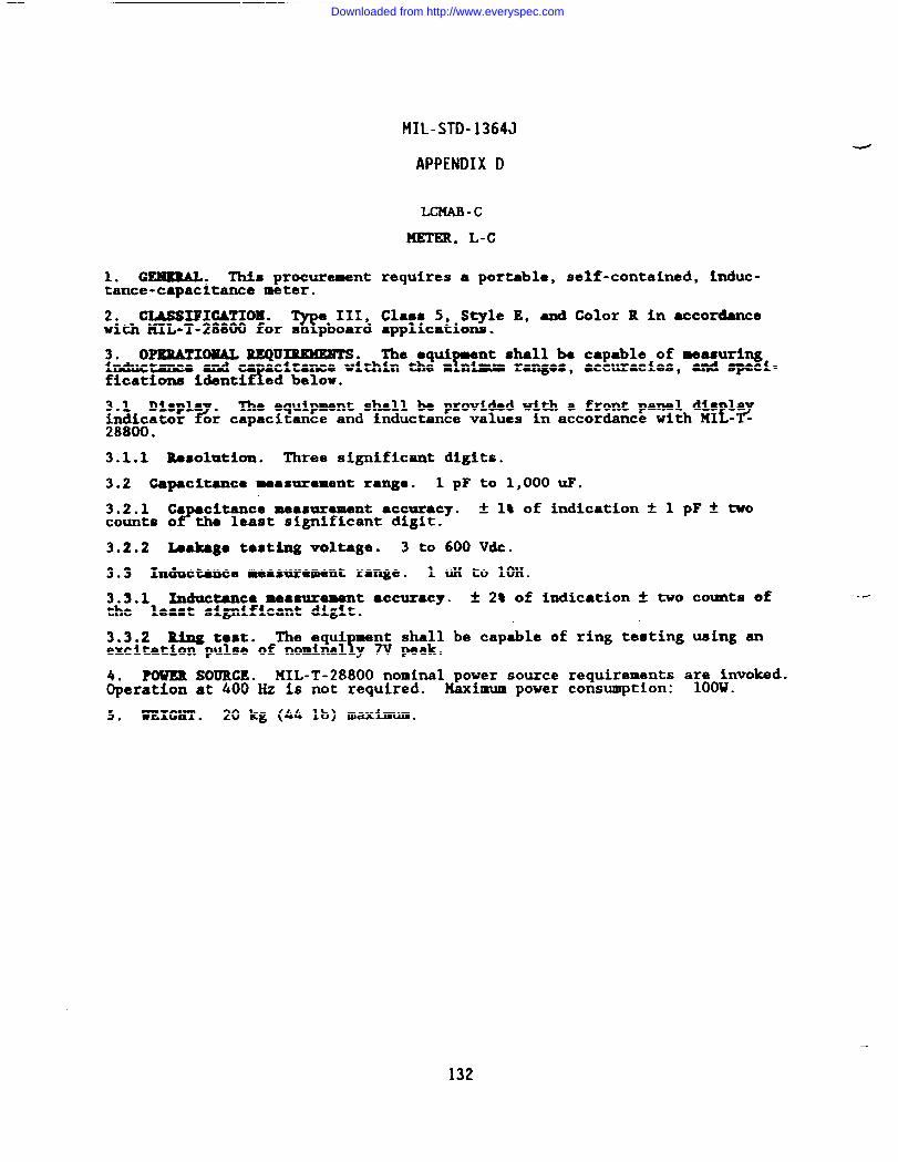
1. GEMKRAL. This procurementtance-capacitance meter.
2. CIASSIPICATIOE .w
III,with MIL-T-28800 for s pboard
3. OPEUTIOEAL REQU3MWEXTS.
MIL-STD-1364J
APPENDIX D
LCxAB-c
METER, L-C
requires a portable, self-contained, induc-
Class 5, Style E, and Color R in accordanceapplications.
The equir
nt shall be capable of measuringInductance and ca~acltance within the m niaum ranges, ●ccuracies. and speci-fications identified below.
-- -
3.1 Displa .?
The equipment shall be provided with a front panel dis laindicator t?or capacitance and inductance values in accordance with MI - -28800.
3.1.1 Resolution. Three significant digits.
3.2 Capacitance measurement range. 1 pF to 1,000uF.
3.2.1 Ca citance measur~rnent accuracy.?
2 1% of indication * 1 pF * twocounts o the least significant digit.
3.2.2 Leakago testing voltage. 3 to 600 Vdc.
3.3 Inductance measurement range. 1 UH to 10H.
3.3.1 Inductance measurement ●ccuracy. * 2% of indication ~ two counts ofthe least significant digit.
3.3.2 Ring tast. The equi sent shall be capable of ring testing using an!excitation pulse of nominal y 7V peak.
4. POUER SOURCE. MIL-T-28800 nominal power source requirements a~;onvoked.Operation at 400 Hz is not required. Xaximum power consumption: .
5* WEIGHT . 20 kg (44 lb) maximum.
132
Downloaded from http://www.everyspec.com
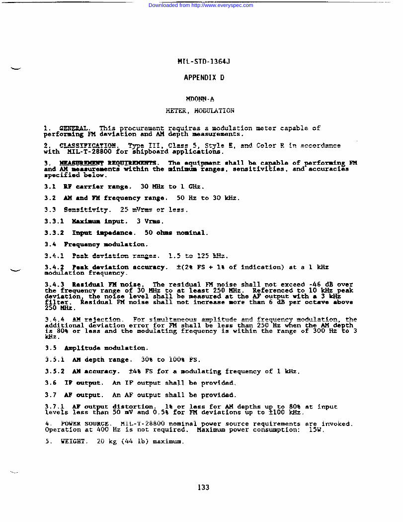
MIL-STD-1364J
APPENDIX D
MIXMN-A
METER, MODULATION
1. GENERAL. This procurement requires a modulation meter capable ofperforming FM deviation and AM depth measurements.
2. CLASSIFICATION .T
e III, Class 5, Style E, and Color R in accordancewith klIL-T-28800 for s ipboard applications.
3. mAmmmmn RISQ~. The equipment shall be cY
le of performing FMand AM measurements within the minimum ranges, sensitivi ies, and accuraciesspecified below.
3.1 RF carrier range. 30KHZ to 1 GHz.
3.2 AX and FM frequency range. 50 Hz to 30 w.
3.3 Sensitivity. 25 mVrms or less.
3.3.1 Maximlm input. 3 Vrlns.
3.3.2 Input impedance. 50 ohms noxmhal.
3.4 Frequency modulation.
3.4.1 Peak deviation ranges. 1.5 to 125 kHz.
- 3.4.2 Peak deviation accuracy. *(2% FS + 1% of indication) at a 1 ~modulation frequency.
3.4.3 Residual FM noise. The residual F?JInoise shall not exceed -46 dB overthe frequent
iranrOf 30mzt0at 1eas’2’Omz” ‘eferenced’OIO*pe*de;egion, t e no se level shall be measured at the AF output with a 3 kHzResidual FM noise shall not increase more than 6 dB per octave above
250 ti.
3.4.4 AM rejection. For simultaneous amplitude and frequent modulation, theadditional &viation error for FM shall be less than 250 Hz d en the AM depthis 80% or less and the modulating frequency is within the range of 300 Hz to 3kllz.
3.5 Amplitude modulation.
3.5.1 AM depth range. 30% to 100% FS.
3.5.2 AM accuracy. &4% FS for a modulating frequency of 1 kHz.
3.6 IF output. An IF output shall be provided.
3.7 M output. An AF output shall be provided.
3.7.1 A.Fout t distortion.1?
1% or less for AM depths u to 80% at input$levels less t an 50 mV and 0.5% for FM deviations up to _100 kHz.
POWER SOURCE. MIL-T-28800 nominal power source requirements are invoked.$eration at 400 Hz is not required. Maximum power consumption: 15W.
5. WEIGHT . 20 kg (44 lb) maximum.
133
Downloaded from http://www.everyspec.com
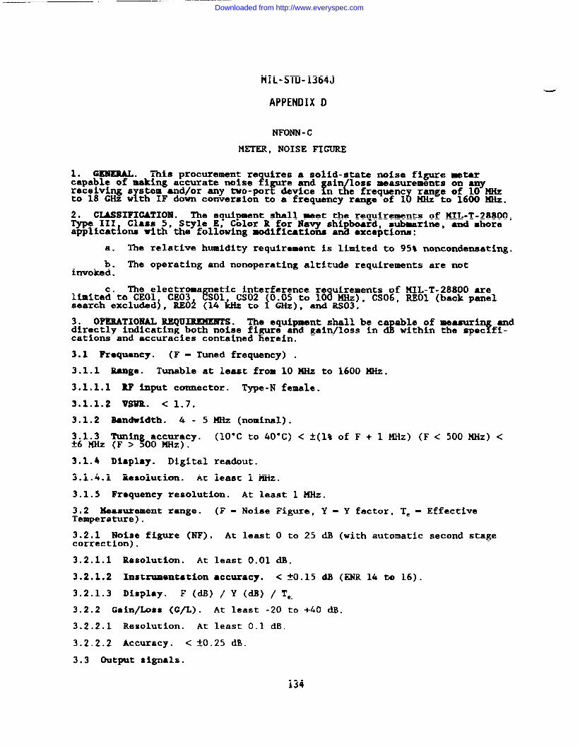
MIL-STD-1364J
APPENDIX D
NFONN -C
METER, NOISE FIGURE
1. GENERAL. This procurement re uires a solid-state noise figure metarcapable of making accurate noise zigure ~a ain loss measurements on any
fdreceiving s stem and/or any two-port device n1
e frequent range of 10 MHz6to 18 GHz w th IF down conversion to a frequency range of 1 MHz to 1600 KHz.
2. CL&SSIFICATIOll. The equipment shall meet the requirements of KXL-T-28800,~ 111 Class 5, Style E, Color R for Havy shi board, submarine, ●nd shoreapplications vith the following modifications & exceptions :
a. The relative humidity requirement is limited to 95% noncondensating.
b. The operating and nonoperating altitude requirements are notinvoked .
The electroma etic interference re uirements of MIL-T-28800 arellmite~”to CEO1 CE03 ~01 CS02 (0.05 to 103 MHz), CS06, REO1 (back panelsearch excluded~, REO~ (14 & to 1 GHz), and Rs03.
3. OPERATIONAL REQURUXENTS. The equipment shall be ca able of measuri anddirectly indicating both noise fi
Pe and gain/loss in d Twithin the spec fi-
cations and accuracies contained erein.
3.1 Frequency. (F - Tuned frequency) .
3.1.1 Range. Tunable at least from 10 MHz to 1600 HHz.
3.1.1.1 U Input connector. Type-N female.
3.1.1.2 VSUR. < 1.7.
3.1.2 Bandwidth. 4 - 5
3.1.3 l!unin accuracy.!!A6 ~z (F > 00 ~z).
3.1.4 Display. Digital
3.1.4.1 Resolution. At
KHz (nominal).
(10”C to 40°C) < ~(1% of F+ 1 ~Z) (F< 500MHz) <
readout.
least 1 HHz.
3.1.5 Frequency resolution. At least 1 MHz.
3.2 Measurement range. (F - Noise Figure, Y = Y factor, T= - EffectiveTemperature ).
3.2.1 Noise figure (NF). At least O to 25 dB (with automatic second stagecorrection) .
3.2.1.1 Resolution. At least 0.01 dB.
3.2.1.2 Instrumentation ●ccuracy. < ~().15 ~ (~ 14 t~ 16).
3.2.1.3 Display. F (dB) / y (~) / Te.
3.2.2 Gain/Loss (G/L). At least -20 to +40 dB.
3.2.2.1 Resolution. At least 0.1 dB.
3.2.2.2 Accuracy. < tO.25 dB.
3.3 Output signals.
134
Downloaded from http://www.everyspec.com
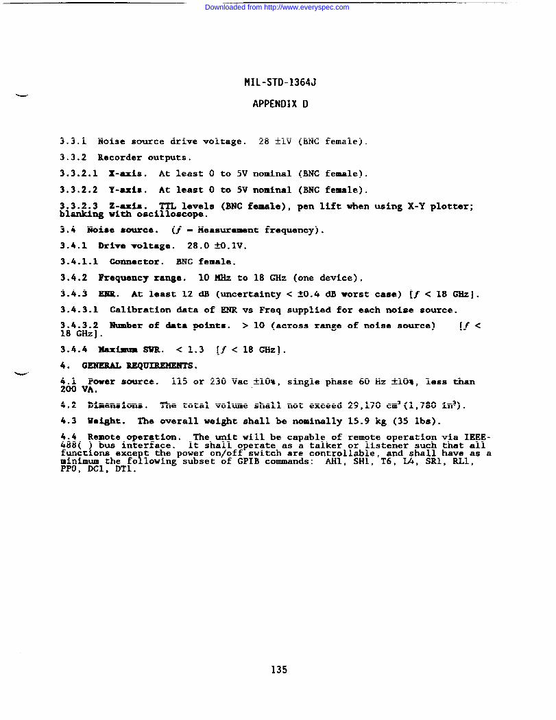
MIL-STD-1364J
APPENDIX D
3.3.1 Noise source drive voltage. 28 tlV (BNC female).
3.3.2 Recorder outputs.
3.3.2.1 X-KiS. At least O to 5V nominal (BNC female).
3.3.2.2 Y-axis. At least O to 5V nominal (BNC female).
3.3.2.3 Z-axis. TTL levels (BNC female), pen lift when using X-Y plotter;blanking With oscilloscope.
3.4 Noise source. (f -Measurement frequency).
3.4.1 Drive voltage. 28.0 N.lV.
3.4.1.1 Connector. BNC female.
3.4.2 Frequency xange. 10 MHz to 18 GHz (one device).
3.4.3 EluR. At least 12 d.B (uncertainty < ~0.4 dB worst case) [~ < 18 GHz].
3.4.3.1 Calibration data of ENR vs Freq supplied for each noise source.
3.4.3.2 Number of data points. > 10 (across range of noise source) [f <18 GHz].
3.4.4 Maximum SWR. < 1.3 [/< 18 ~Z].
4._.
4.1200
4.2
4.3
4.4
GENERAL REQUIREMENTS ●
Power source. 115 or 230 Vac ~10%, single phase 60 Hz *10~, less thanVA.
Dimensions. The total volume shall not exceed 29,170 CIQ3(1,780 ln3).
Waight . The overall weight shall be nominally 15.9 kg (35 lbs).
Remote o~eration. The unit will be caDable of remote oneration via IEEE-488( ) bus interface. It shall operate as i talker or listefier such that allfunctions exce t the power on/off switch are controllable, and shall have as a
!minimum the fo lowing subset of GPIB commands: AHl, SH1, T6, U, SR1, RL1,PPO, DC1, DT1.
Downloaded from http://www.everyspec.com
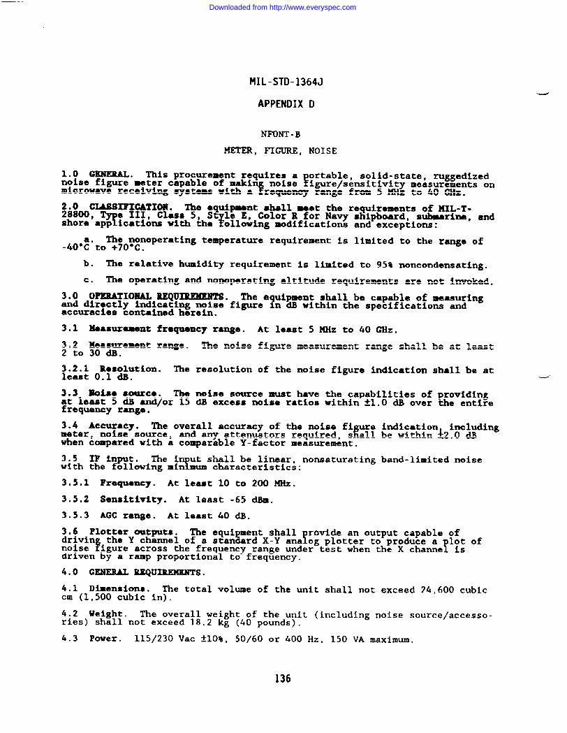
MIL-STD-1364J
APPENDIX D
NFONT -B
METER, FIGURE, NOISE
1.0 GENERAL. This procurement requires a ortable, solid-state, mggedizednoise figure meter capable of makin noise
e!!igure/sensitivity measurements on
microwave receiving systems with a requancy range from 5 MHz to 40 GHz.
~8~OoCUM31?1CATIOH ● The equipment shall meet the requirements of llIL-T-
9e III, Class 5, S le E, Color R for Navy shipboard, submarine, and
shore’app ications with the7 ollowing modifications and exceptions:
The nonoperating temperature requirement is limited to the range of-40”l!to +70”C.
b. The relative humidity requirement is limited to 95% noncondensating.
c. The operating and nonoperating altitude requirements are not invoked.
3.0 OPERATIONAL REQUIREMENTS. The e uipment shall be capable of measuringand directly indicating noise figure 1n dB within the specifications andaccuracies contained herein.
3.1 Measurement frequency range.
3.2 Measurement range. The noise2 to 30 dB.
3.2.1 Ihsolution. The resolutionleast 0.1 dB.
At least 5 MHz to 40 GHz.
figure measurement range shall be at least
of the noise figure indication shall be at
3.3 Moi.aa emarca. The noise source must have the capabilities of providingat least 5 dB and/or 15 dB excess noise ratios within H.O dB over the entirefrequency range.
3.4 Accuracy. The overall accuracy of the noise fir
e indication includingmeter, noise source, and any attenuators required, s all be within 12.0 dllwhen compared with a comparable Y-factor measurement.
3.5 IF in t.F
The i ut shall be linear,Y
nonsaturating band-limited noisewith the ollowing min mum characteristics:
3.5.1 Frequency. At least 10 to 200 M’Xz.
3.5.2 Sensitivity. At least -65 dBm.
3.5.3 AGC range. At least 40 dB.
3.6 Plotter outputs, The equi ment shallL !
rovlde an output capable ofdrivin the Y channel of a stan
Frd X-Y ana og plotter to produce a lot of
noise Yigure across the frequency range under test when the X channe isdriven by a ramp proportional to frequency.
4.0 GENERAL REQUIREMENTS.
4.1 Dimensions. The total volume of the unit shall not exceed 24,600 cubiccm (1,500 cubic in).
4.2 Weight. The overall weight of the unit (including noise source/accesso-ries) shall not exceed 18.2 kg (40 pounds).
4.3 Power. 115/230 Vac tlO%, 50/60 or 400 Hz, 150 VA maximum.
136
Downloaded from http://www.everyspec.com
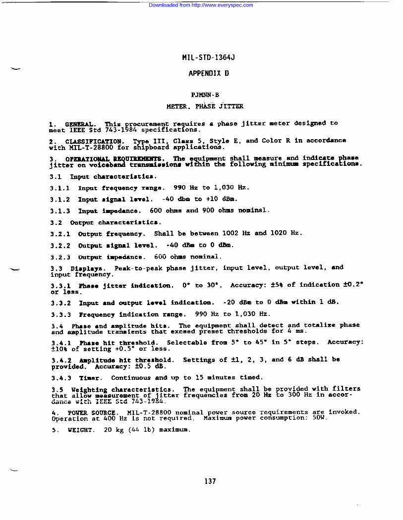
MIL-STD-1364J
APPENDIX D
PJMNN -B
METER, P@iSk iITTER
1. GENERAL. This rocurement re uires a phase jitter meter designed to?meet IEEE Std 743-1~84 specificat ens.
2. CWSIFICATIOEl .%
e III, Class 5, Style E, and Color R in accordancewith MIL-T-28800 for s pboard applications.
3. OPERATIONAL UIUMEBTS. The e ipment shall measure and indicate base3jitter onvoiceba % ttransmismiona wi in the follwing minimum specifics ions.
3.1 Input characteristics.
3.1.1 Input freqtiency range. 990 Hz to 1,030 Hz.
3.1.2 Input signal level. -40 dbm to +10 dBm.
3.1.3 Input impedance. 600 ohms and 900 ohms nominal.
3.2 Output characteristics.
3.2.1 Output frequency. Shall be between 1002 Hz and 1020 Hz.
3.2.2 Output xignal level. -40 dBm to o dbl.
3.2.3 Output Impedance. 600 ohms nominal.
- 3.3 Displays. Peak-to-peak phase jitter, input level, output level. -dinput frequency.
3.3.1 Phase jitter indication. O’ to 30°. Accuracy: *5% of indication ~.2”or less.
3.3.2 Input ●nd output leval indication. -20 h to O dkw ithin 1 dB.
3.3.3 Frequency indication range. 990 Hz to 1,030 Hz.
3.4 Phase ●nd ●mplitude hits. The equipment shall detect and totalize phaseand amplitude transients that exceed preset thresholds for 4 ms.
3.4.1 Phase hit threshold. Selectable from 5“ to 45° tn 5“ steps. Accuracy:*10* of setting +0.5” or less.
3.4.2 Amplitude hit threshold. Settings of *1, 2, 3, and 6 dB shall beprovided. Accuracy: ~.5 m.
3.4.3 Timer. Continuous and up to 15 minutes timed.
3.5 Weighting characteristics. The equi ment shall be provided with filtersthat allow measurement of
Jfitter frequent es from 20 Hz to 300 Hz in accor-
dance with IEEE Std 743-19 4.
POWER SOURCE. MIL-T-28800 nominal power source requirements are invoked.&eration at 400 Hz is not required. Maximum power consumption: 50W.
5. WEIGHT . 20 kg (44 lb) maximum.
L
137
Downloaded from http://www.everyspec.com
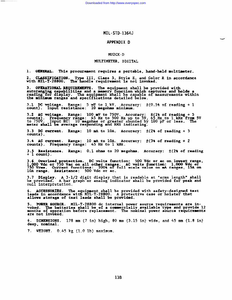
MIL-STD-1364J
APPENDIX D
MU2CX-D
MULTIKETER, DIGITAL
1. GRZERAL. This procurement requires a portable, hand-held multimeter.
2. CLASSIFICATION .%
III, Class 3, St le E, and Color R in accordancewith !41L-T-28800. The ndle requirement xs not invoked.
3* OPERATIONAL Rlsu~.?
The equipment shall be provided withautoranging cap~i ities and a memory function which ca tures ●nd holds areading for display. FThe e uipment shall be ca able o measurements within
? Ethe minimum ranges and spec fications detailed elow.
3.1 DC voltage. Range: 5 mV to 1 kV. Accuracy: *(0.5% of reading + 1count) . Input resistance: 10 megohms minimum.
3.2 AC voltage. Range: 100 IN to 750V.
Jcounts . ~q~ncy range: ‘Ccurac$v :$2L0::?d&wGo: 5V45 Hz to 500 Hz Up toto 750
c. 10 megohms or greater shunted b~ 100 pF or less. The
metez skall avekage responding and RPIS indicating.
~:~t~ current. Range: 10 mA to lOA. Accuracy: *(2% of reading + 3.
3.4 AC current. Range: 10 mA to 10A. Accuracy: *(3% of reading + 2counts) ● Frequency range: 45 Hz to 1 kHz.
3.5 Resistance. Range: 0.1 ohms to 20 megohms. Accuracy: A(2* of reading+ 1 count).
3.6 Owrkad rotection. DC volts function:!
500 Vdc or ac onll~sg~an~,1 000 Vdc or 7 0 Vac on all other r AC volts fuxmction:750 Vrma. Current functions: 200*~e?&ll scale value on mA raiges, 15A on10A range. Resistance: 500 Vdc or ac.
3.7 Dis lay.s
A 3-1/2 digit di.slay that is readable at “arms length” shallbe rovi ed.
!fA bar graph or ana og indicator shall be provided for peak and
nul interpretation.
4. ACCESSORIES. The equi ment shall be provided with safet -designed testfleads in ●ccordance with H L-T-28800. xA protective case or olster that
allows storage of test leads shall be provided.
5. POuER SOURCE* MIL-T-28800 dc internal ower source requirements are in-voked . !The batteries shall be of a commerc ally available type and provide 12months of operation before replacement. The nominal power source requirementsare not invoked.
DIXEMSIO19S. 178 mm (7 in) high, 80 mm (3.15 in) wide, and 45 mm (1.8 in)!8ep, nominal.
7. WEIGHT . 0.45 kg (1.0 lb) maximum.
138
Downloaded from http://www.everyspec.com
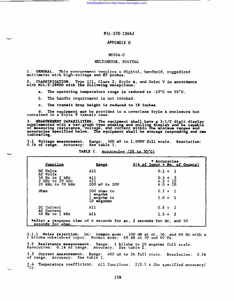
MIL-STD-1364J
APPENDIX D
XU2CA-C
MULTIMETER, DIGITAL
1. GENEIUU. This rocurement re uires a digital, handheld, ruggedizedmultimeter with hiJ -voltage and b probes.
2. CLASSIFICATION .W. ;~+iowing ex~ep~ons:
Class 2 S le A, and Color V in accordancewith MIL-T-28800 With
a. The operating temperature range is reduced to -15-C to 55”C.
b. The handle requirement is not invoked.
c. The transit drop height is reduced to 18 inches.
d. The equipment may be provided in a coverless Style A enclosure butcontained in a Style P transit case.
3. MEASUREMENT CAPABILITIES. The equi ment shall have a 3-1/2 digit display
#fsu plemented with a bar-gra h type peak ng and nulli
measuring resistance Yvo ta e, xdi:f~~”:~e:ag:l’and current within~ccuracies specified beiow. d e equipment shall be average responding and IESindicating.
3.1 Voltage measurement, Range: 500 mV to 1,000V full scale. Resolution:0.1% of range. Accuracy: See table I.
TABLE 1, Accuracies (70 to 30 cl●
* Accurac~egof Inmat + No. of counts~
DC volts All 0.1 + 1AC Volts50 Hz to 2 kHZ All 0.5 + 32 kllzto 20 kHz All ;.: : ;g20 kHz to 70 kHz 200 mV to 20V .
ohms 200 ohms to 0.2 + 11 megohm1 megohm to 1.0 + 110 megohms
DC Current Al1 0.8 + 2AC Current4oHztolkHz All 1.5 + 2
*After a response time of 4 seconds for ac, 2 seconds for dc, and 10
3.1.1 Noise rejection. DC: Common mode: 100 dB at dc, 50, and 60 Hz with a1 kilohm unbalanced input. Normal mode: 60 dB at 50 and 60 Hz.
3.2 Resistance measurement. Range: 1 kilohm to 10 megohms full scale.Resolution: 0.1% of range. Accuracy: See table I.
3.3 Current measurement. Range: 400”UA to 2A full scale. Resolution; 0,1%of range. Accuracy: See table I.
~c~ Temperature coefficient. All functions: *(0.1 x the specified accuracy/L .
139
Downloaded from http://www.everyspec.com
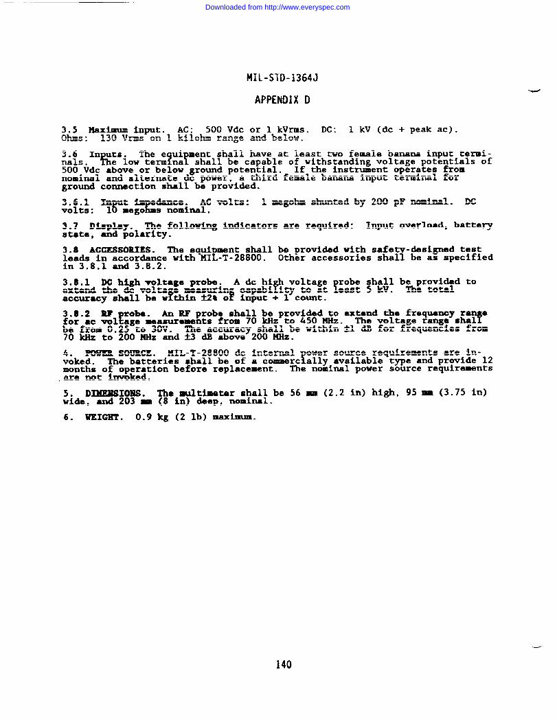
—
MIL-STD-1364J
APPENDIX D
3.5 Haximum input. AC: 500 Vdc or 1 kVrms. DC: 1 kV (dc + peak at).ohms : 130 Vrms on 1 kilohm range and below.
The e ui ment shall have at least two female bananaiA!~.ln~S’iO~ term?na!
input termi-shall be capable of withstanding voltage potentials of
500 Vdc above or below ground potential. If the instrument operates fromnominal and alternate dc power, a third female banana input terminal forground connection shall be provided.
3.6.1 Im t dance.%
AC volts: 1 megohm shunted by 200 pF ncmhal. DCvolts : l~mego s nominal.
3.7 Display. The following indicators are required: Input overload, batterystate, -d polarity.
3.8 ACCESSORIES. The equi ment shall be provided with safe -designed testtleads in accordance with MI -T-28800. 7Other accessories shal be as specified
in 3.8.1 and 3.8.2.
3.8.1 DC high mltage probe. A dc hiP
voltageextend the & volts e measurin capabi iv to at
f !Ket ;hc+: bh:r::L?d ‘0
accuracy shall be w thin i2% o input + 1 count.
3.8.2 W robe.!!
An RF probe shall be provided to extend the frequency r efor ●c vol age measurements from 70 kHz to 450 MHz. The voltage range shalYbe from 0.25 to 30V. The accuracy shall be within ~1 dB for frequencies from70 kllzto 200 HHz and M dB above 200 MHz.
4. POWER SOURCE. HIL-T-28800 dc internal ower source requirements are in-voked. fThe batteries shall be of a commerc ally available type and provide 12months of operation before replacement. The nominal power source requirements.ara not invoked.
5. D-IOU ● The multimeter shall be 56 mm (2.2 in) high, 95 M (3.75 in)wide, and 203 M (8 in) deep, nominal.
6. UEIGET . 0.9 kg (2 lb) maximum.
140
Downloaded from http://www.everyspec.com
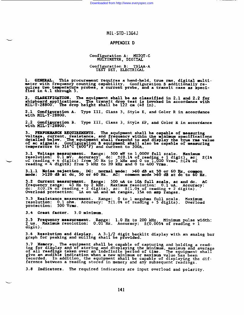
MIL-STD-1364J
APPENDIX D
Confi ration A:&
MU2QT -cTIMETER, DIGITAL
Confi uration B: TSIAA-ATEA SET, ELECTRICAL
1. GENERAL. This procurement re uires a hand-held, tme rms, digital multi-%meter with frequency counting capa ility. Configuration B additionally re-
uires two temperature probes, a current probe,1ted in4.1 through 5.
and a transit case as speci-
2. GIASSIFIGATIOBl. The equipment shall be as classified in 2.1 and 2.2 forshipboard application. The transit dro test is invoked in accordance withI141L-T-28800. !!The drop height shall be 1 2 cm (48 in).
2.1 Configuration A. Type III, Class 3, Style E, and Color R in accordanceWith XIL-T-28800.
2.2 Configuration B. Type III, Class 3, Style EP, and Color R in accordanceWith MIL-T-28800.
3. PERFORMANCE REQUIREMENTS. The equipment shall be ca able of measurinvolts e
fcurrent, resistance,
detai e~ below.! fand frequency within the m nlmum s eciflcat ons
tThe equipment shall respond to and display the rue rms valueof ac signals. Con.fi
Fation B equipment shall also be capable of measuring
temperature to 316°C 600”F) and current to 200A.
3.1 Voltage ~fs~ement. Range: 500 mV to 1 000V full scale. Maximumresolution: Accurac : dc:
- 6~(0.1% O* readin + 1 digit) ac: ~(1%
of reading + 4“digi~s) from 5 8Hz to 5 kHz and O to 1, 00 Vrms, -@% ofreading + 4 digits) from 5 kHz to 20 kllzand O to 400 Vrms.
3.1.1 SOiaa mj*cti4m. lx: normal mode: %0 dB at 50 or 60 Hz, commonmode: >120 dB ●t &, 50 or 60 Hz. AC: comaon mode SO dB at dc to 60 Hz.
3.2 Current measurement. Ran e:d
500 UA to 10A full scale, ac and &. ACfrequency ran e: 45 Hz to 2
FMaximum resolution: 0.1 UA. Accuracy:
dc : ~(0.2% o reading~ ~ndi i~s), ac:J
~(1.0% of reading + 2 digits).Overload protection: and mA ranges, 15A on amp ranges.
3.3 Resistan;elm~~urement. Range: O to 1 me ohms full scale.5
Maximumresolution: Accuracy: ~(1.0% of rea ing + 5 digits). Overloadprotection: 500 V*.
3.4 Crest factor. 3.0 minimum,
3.5 Frequency measurement. Range: 1.0 Hz to 200 kHZ. Minimum ulse width:2 us. Maximum resolution: 0.01 Hz. Accuracy: fA(O.005% of read ng + 1digit) .
3.6 Resolution ●nd displa .1
A 3-1/2 digit backlit display with an analog bargraph for peaking and null ng shall be provided.
3.7 Memory. The equipment shall be ca able of capturing and holding a read-Ying for dis lay and of storing and disp ayin
f !the minimum, maximum and avera e
of all read n s taken over an indefinite er od of time.f Y
The equipment shalfgive an audib e indication when a new min mum or maximum value has beenrecorded. In addition, the equipment shall be capable of displaying the dif-ference between a reading stored in memory and any subsequent readings.
3,8 Indicators. The required indicators are input overload and polarity.
141
Downloaded from http://www.everyspec.com
MIL-STD-1364J
APPENDIX D
4. ACCESSORIES. The equi ment shall be provided with safety-designed test!leads in accordance with M L-T-28800. A shock absorbing protective holster
with a flexible stand device shall also be provided.
4.1 I~ersion probe. Configuration B equipment shall be provided with an-rsion probe in accordance with the following specifications.
4.1.1 Temperature z-a. 00 co 316°C (32 SO 600”F).
$i~i~ &~~Cy. fl.2°c from 0° to 275°C and fO.75t of indication from 275 to●
4.2 Stsrfaco probe. Configuration B equipment shall be provided with ●
surface probe in accordance with the following specifications.
4.2.1 Temperature range. 0“ to 260”C (32 to 500*F).
4.2.2 Accuracy. *l.l-C.
4.3 Current probe. Confi ration B equi ment shall be provided with a dc andac clamp-on current probe Y Yn accordance w th the following specifications.
4.3.1 Ranges. 20A and 200A.
4.3.2 Accuracy. DC to 200 Hz, k2Q of range. 200Hz to 1 kHz, addk3% ofreading for readings below lOOA and f6t of reading for readings above lOOA.
4.3.3 Cl- sise. The clamp shall be capable of encompassing conductors upto but no larger than 1.9 cm (0.75 in).
5. TBAMSIT CASE. The Style P transit case shall provide protection for allcomponents of the Configuration B equipment.
6. mm SOURCE. HIL-T-28800 & internal power source r. irements areinvoked. YThe batteries shall be of a c~rcially availab e
Te and rovlde
500 hours of operation before re lacement. A batteT ?
!state ind cater srequired in accordance with MIL- -28800. The nomina power source require-ments are not invoked.
7, DIMENSIONS. The multimeter shall be 56 mm 2.2 in) hi& P
100 mn (3.94 inwide and 203 mm (8 in) long, nominal. The Co i ration
r~ransit case shal1
be 162 m (4 in) high, 457 ~ (18 in) wide, and 3 1 M (15 in) long, nominal.
UEICHT ● Configuration A: 1.0 kg (2.2 lb) maximum. Configuration B: 4.5& (10 lb) maximum.
142
Downloaded from http://www.everyspec.com
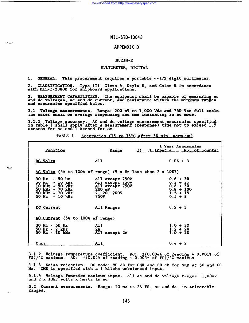
MIL-STD-1364J
APPENDIX D
KU2JM-E
MULTIMETER, DIGITAL
1. GENERAL. This procurement requires a portable 4-1/2 digit multimeter.
2. CLASSIFICATION .%
e III, Class S, Style E, and Color R in accordancewith MIL-T-28800 for s pboard applications.
3. ME6SURKMENT CAPABILITIES. The equipment shall be capable of measuring acand dc voltages, ac and & current, and resistance within the minimum rangesand accuracies specified below.
3.1 Voltage measurements. Range: 200 mV to 1 000 V& and 750 Vac full scale.The meter ohall be average responding and ma hdicating in ac mode.
3.1.1 Volta e ●ccuracy.k
AC and dc volts e measurement accuracies specifiedin table I s all ap ly after a measurement
YE( response) time not to exceed 1.5
seconds for ac and second for dc.
TABLE I. es (15 to 35 C afyer 30 ~.● warm -Un>
1 Year Accuracies- ‘+( a imut + o. of co-s )
~ Volta Al1 0.06 + 3
AC Volta (5% to 100% of range) (V XHZ less than 2 x 10E7)
30 Hz -50HZ All except 750V 0.8 + 3050 Hz - 10 kHz All except 750V 0.3 + 20lokll z-sow $~$ ~~cept 750V 0.8 + 30;: C)-70MZ ~.; : ;p
- 70 kHz 2 20, 200V50 Hz - 10 kHz 730V 0:5 + 8
Pc Current All Ranges 0.2 + 3
M C~enQ (5% to 100% of range)
30Hz-50Hz A~l 1.0 + 3050Hz-2kHz 1.2 + 2050 Hz - 10 kllz All except 2A 1.0 + 20
ohms All 0.4 + 2
3.1.2 Voltage teT
erature coefficient. DC: ~ 0.004% of reading + 0.001% ofFS)/”C maximum. A : $A(O.02% of reading + 0.00 % of FS)/°C maximum.
3.1.3 Noise rejection. DC mode: 90 dB for CMR and 60 dB for NMR at 50 and 60Hz. CMR is specified with a 1 kilohm unbalanced input.
3.1.4 Voltage function maximum input. All ac and dc voltage ranges: 1,000Vand 2 x 10E7 volts x hertz in ac.
3.2 Current measurements. Range: 10 mA to 2A FS, ac and dc, in selectableranges.
143
Downloaded from http://www.everyspec.com
MIL-STD-1364J
APPENDIX D
3.2.1 Current accuracy. The alternating and direct current measurementaccuracy
7arameters specified in table I shall apply after a measurement
(response time not to exceed one second.
3.2.2 Current te erature coefficient. DC: ~ 0.005% of reading + 0.001% ofFs)/*c maxiEum. $~: *(0.02% of reading + 0.00 % of FS)/”C maximum.
3.2.3 Gurmnt function input protection. All alternating and direct currentranges: 2A. Protection above this current level shall be provided by a fuseor resettable circuit breaker.
3.3 Re8istuwe measurement. Range: 200 ohms to 20 megohms full scale.
3.3.1 Re8iatamco ●ccllrac ●
IThe resistance measurement accuracy arsmeters
specified in table I shal appl after ● measurement
?1 i
response) tL not toexceed one second throu ut se ●ctablo ranges below O megohms ●nd fourseconds throughout the O megohm range.
~63&i~istance temperature coefficient. f(O.lt of reading + 0.001% of =)/●
3.3.3 Open-circuit voltage. 5V maximum.
3.3.4 Gurrent through the unkhown resistance. 1 M maximum.
3.3.5 Resistance function input protection. 250 Vdc or 250 WmS.
3.4 Controls ●nd displays.
3.4.1 Gonttols. The equipment shall beYrovided with manual selection for
all ranges specified above and an interns battery status test or indication.
3.4.2 Dis lap.f
The equipment shall be provided with a digital readout andan indicat on of ●xcess input level.
3.4.3 Automatic features. The equipment shall be provided with automaticranging except in current functions, autmtic polarity selection for all &functions, and automatic zeroing for all functiom.
3.5 Inputs.
3.5.1 Gommon input floating voltage level. 1,000V (dc + peak ac) referencedto case ground.
3.5.2 Input impedance. DC: 10 megohms. AC input RC: 1 megob with no morethan 100 pF shunt capacitance.
3.6 Test leads. Test leads that are desi ed for operator rotection agaiwthazardous potentials in accordance with MI~T-28800 are requ!red.
4. POWER SOURCE. MIL-T-28800 nominal and dc internal power source require-ments are invoked as detailed below.
4,1 Nominal power s~&Wce. Operation at 400 Hz is not required. Maximumpower conswption: .
4.2 DC internal power source: Internal batteries and charger are required.14~n~i-soperating time shall be 6 hours following a maximum recharge time of
.
5. WEIGHT . 5 kg (11 lb) maximum.
144
Downloaded from http://www.everyspec.com
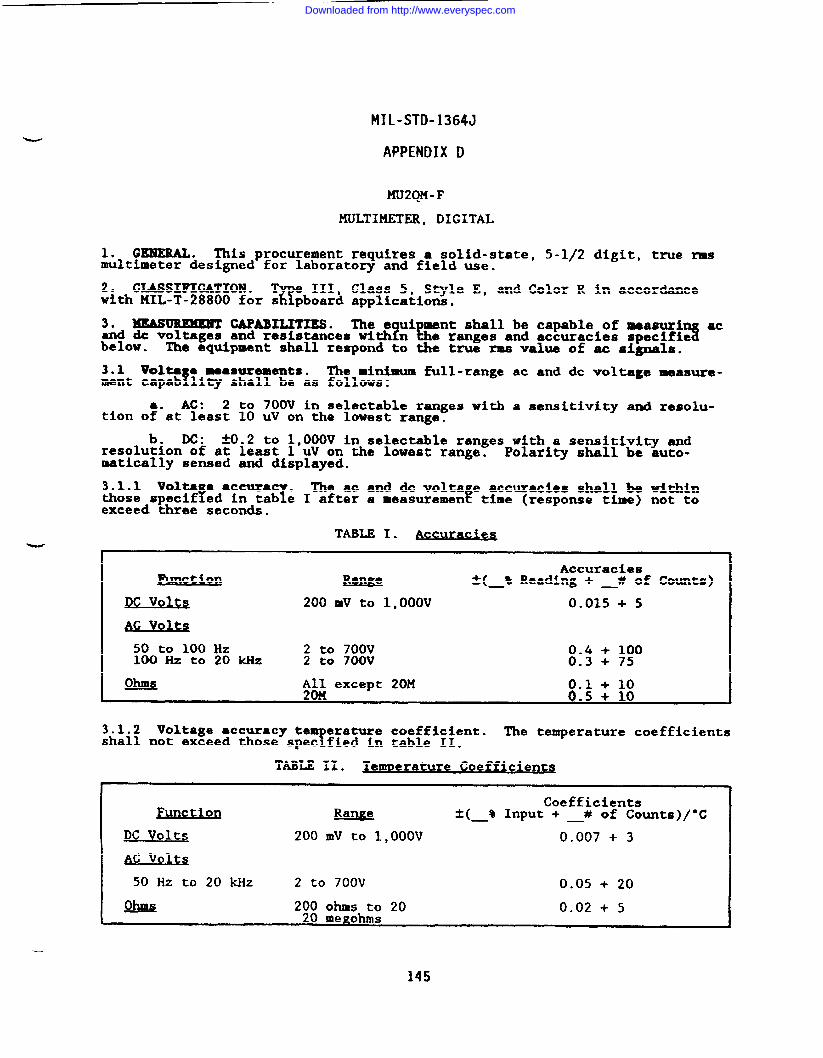
—
MIL-STD-1364J
APPENDIX D
MU2QM-F
KULTIMETER, DIGITAL
1. GEHERAL. This procurement requires a solid-state, 5-1/2 digit, true ~multimeter designed for laboratory and field use.
2* CLASSIFICATION .%
e III, Class 5, Style E, and Color R in accordancewith MIL-T-28800 for s pboard applications.
3. MEAslmEMENT cAPABmImEs* The e ui ment shall be capable of measuri ac?&and & voltagea and resistances with n
below.3e ranges and accuracies specifie
The equipment shall respond to the true rma value of ac signals.
3.1 Volta a measlarements.!
The minimum full-range ac and dc voltage measure-ment capab lity shall be as follows:
● ✎ AC: 2 to 700V in selectable ranges with a sensitivity and resolu-tion of at least 10 UV on the lowest range.
b. DC: *0.2 to 1,000V in selectable ranges with a sensitivity andresolution of at least 1 UV on the lowest range. Polarity shall be auto-matically sensed and displayed.
3.1.1 Volta ● accurac .! T
The ac and & volts e accuracies shall be withinthose specif ed in tab e I after a measurementf time (response time) not toexceed three seconds.
TABLE I. Accura~
Accuraciesu ~( % Reading + # of counts)
Ix volt~ 200 mv to 1,000V 0.015 + 5
50 to 100 Hz 2 to 700V 0.4 + 100100 Hz to 20 kHz 2 to 700V 0.3 + 75
3.1.2 Voltage accuracy te erature coefficient.?
The temperature coefficientsshall not exceed those spec fied in table II.
TABLE II. ~enmerature Coeffici ntqe
Coefficientstion IWlL!2 &( % Input + # of counts)/”c
DC Volts 200 mV to 1,000V 0.007 + 3
AC volts
50 Hz to 20 MZ 2 to 700V 0.05 + 20
Q!M?& 200 ohms to 20 0.02 + 5L 20 me~ohms *
145
Downloaded from http://www.everyspec.com
MIL-STD-1364J
APPENDIX D
3.1.3 Noise rejection. The dc input noise rejection ratios shall be asspecified below:
a. CMR: 110 dB at &, 50 and 60 Hz with 1 kilohm in either input lead.
b. Mm: 30 dB at 50 and60 Xz.
3.1.4 kimam input. DC volts ranges: 1,000 WC or peak ac. AC voltsranges: 700 Vrms, 1,000V peak or 2 x 10IC7volts-hertz product, whiclmver isless ●
3.2 Resistance measurements. The full range resistance measurement capabili-~ shall be from 200 ohM to 20 megohms in selectable ranges.
3.2.1 Resistance accuracy. The resistanm accuracies shall be within thosespecified in table I after a measurement time (response time) not to ●xceedfour seconds.
3.2.2 Resistance ●ccuracz
temperature coefficient. The temperature coeffi-cients shall not exceed t ose specified in table II.
3.2.3 Open-circuit voltage. 13V maximum.
3.2.4 Current through the unknown resistance. 2 mA maximum.
3.2.5 Resistance in t protection.Y
All resistance ranges shall have inputprotection from appl ed voltages of at least 250 Vrms.
3.3 Controls and dkplays.
3.3.1 Controls. The equipment shall be provided with manual ranging for allfunctions.
3.3.2 Di8phyS. The equipment shall be provided with the following displays:
a. Excess input indication.
b. Digital readout: A 5-1/2 digit LED, LCD, or a vacuum fluorescentdisplay.
3.3.3 Automatic features. The equipment shall be provided with automaticranging and automatic dc polarity indication.
3.4 Inputs. The e uipment shall have two input terminals for voltage mea-surements and four ?
Tut terminals for resistance measurements. The common
in ut terminal shall e capable of withstanding voltage potentials of *500 VdcFre erenced to ground potential.
3.4.1 Input Impedance.
a. AC voltage function: At least 1 megohm shunted by 100 pF or less.
b. DC voltage function: At least 10 megohms on all ranges.
3.5 Di ital interface. A digital interface is required in accordance withMIL-T-2!800.
4. ACCESSORIES. The equipment shall beYrovided with safety-designed bamna
plug test leads in accordance with MIL-T- 8800.
5. POWER SOURCE. MIL-T-28800 nominal power source requirements a;;uinvoked.Operation at 400 Hz is not required. Maximum power consumption: .
6. UEIGHT . 5 kg (11 lb) maximum.
146
Downloaded from http://www.everyspec.com
MIL-STD-1364J
APPENDIX D
DOOAN-B
MULTIPLIER, FREQUENCY, DOUBLER
1.0 GENEML DESCRIPTION. This procurement re uires a solid-state frequencydoubler/tripler capable of
~ irod~~hg l! to=o~=~Hz (2X and 26 to 46 GHz (3X)
signals froinany 8.6 to 13.Y
The nstrument shall providea controllable output to at least + dBm in th~ (2X) mode and to at least -3dBm in the (3X) mode reproducing sweep or modulation as defined by the Inputsource.
;8~OoGLASSIFICATIOK The equipment shall meet the requirements of HIL-T-
Te III, Class 5, S le E, Colox R for Navy shipboard, submarirae, and
shore’app ications with the% ollowing modifications and exceptions:
The nonoperating temperature requirement is limited to the range of.40”t”to +70”C.
b. The relative humidity requirement is limited to 95% noncondenaating.
c. The operating and nonoperating altitude requirements are not invoked.
d. The warm-up time is extended to one hour.
3.0 OPERATIONAL REQUIREMENTS. The equipment shall be capable of doubling ortripling input frequencies within the parameters and accuracies specifiedherein.
3.1 Frequency characteristics.-
3.1.1 Input. 8.6 to 13.4 GHz; -2 to +5 dBm.
3.1.2 Output range. 18 to 26 GHz for (2X) mode; 26 to 40 GHz for (3X) mode.
3.1.3 Output resolution. Two times the resolution of the input fre uencthe (2X) mode and three times the resolution of the input frequency lor t~efor(3X) mode.
3.1.4 Out ut accuracy and stability.f
Two times the accuracy and stability ofthe input requency for the (2X) mode and three times the accuracy and sta-bility of the input frequency for the (3X) mode.
3.2 Output characteristics.
3.2.1 Level. At least +5 dBm for (2X) mode; at least -3 dBm for (3X) mode.
3.2.2 Leveled range. At least -15 to +5 dBm adjustable in at least 1.0 dBsteps with at least -2 dBm input level in the 2X mode; at least -15 to -3 dBm
Aad ustable in at least 1.0 dB steps with at least -2 dBm input level in the 3Xmo e.
3.2.3 Accurac and flatness.z
At least k3.O dB for (2X) mode and at least~3,() ~ for (3 ) mode be~een O and 50”C0
3.2.4 Impedance. 50 ohms nominal.
3.2.5 Output connector. WR-42 WG wave uide with UG-595/U t e flan e for the(2X) mode and wR-28 WC waveguide with U~-599/U type flange ~ the (%) mode.
3.2.5.1 VSWR. Less than or equal to 2:1.
3.2.6 Input connector. Type WPM-3(f).
3.3 Spectral purity.
147
Downloaded from http://www.everyspec.com
MIL-STD-1364J
APPENDIX D
3.3.1 Harmonics/Subharmonics. Less than -20 dBc.
3.3.2 Sp’UriOuS. Less than -40 dBc.
3.4 Modulation compliance.
3.4.1 Frquency modulation. Follows input with 2 ti~s(2X) mode and 3 times the deviation for the (3X) mode.
3.4.2 Pulse/Square wave modulation. Follows input withMHz; minimum pulse width of 0.1 us.
4.0 GmIERALREQmBmmrrso
4.1 Dimensions. The total volume of the unit shall not(531 cubic in).
the deviation for the
PRF of 100 Hz to 1
exceed 8,702 cubic cm
~b~) Voight. The overall weight of the unit shall not exceed 4.0 kg (8.8.
4.3 Power source. 115/230 Vac ~10%, 60 or 400 Hz A1O%, 25W maximum.
4.4 Remote operation. Instrument shall be capable of operating via the IEEE-488 interface bus and providing the capabili~ to talk and listen.
148
Downloaded from http://www.everyspec.com
MIL-STD-1364J
APPENDIX D
DOOAM-A
MULTIPLIER, FIQUENCY, DOUBLER
1.0 GENERAL DESCRIPTION. This procurement requires a solid-state frequencydoubler ca able of producln
A f26 to 40 GHz signals from any 13 to 26 GHz signal
source. instrument sha 1 provide a controllable output to at least +5 dBmreproducing sweep or modulation as defined by the input source.
;8~oOCIASSIYICATIOM. The equipment shall meet the requirements of HIL-T-
T111, Class 5, S le E, Color R for Navy shipboard, submarine, and
shore’app ications with the? ollowing modification and exceptions:
The nonoperating temperature requirement is limited to the range of-40”&to +70°ce
b. The relative humidity requirement i- limlted to 95% noncondensating.
c. The operating and nonoperating altitude requirements are not invoked.
d. The warm-up time is extended to one hour.
3.0 OPERATIONAL REQUIREMENTS. The equipment shall be ca able of doublingfrequencies within the parameters and accuracies specifie~ herein.
3.1 Requency characteristics.
3.1.1 Input. 13 to 20 GHz; -2 to +5 dBm.
w 3.1.2 Output range. 26 to 40 GHz.
3.1.3 Output resolution. Two times the resolution of the input frequency.
3.1.4 Out t accuracy and stability.r
Two times the accuracy and stabilitythe input requency.
3.2 Output characteristics.
3.2.1 hVel. At least +S dBm.
of
3.2.2 Leveled range. At least -15 to +5 dBm adjustable in 0.1 dB steps withat least -2 dBm input level.
3.2.3 Accuracy and flatness. At least ~3.5 dB at O to 50”C.
3.2.4 Impedance. 50 ohms nominal.
3.2.5 Output connector. WR-28 WG waveguide with UG-599/U type flange.
3.2.5.1 VSWR. Less than or equal to 2:1.
3.2.6 Input connector. Type WPM-3 female.
3.3 Spectral purity.
3.3.1 Harmonics/Subharmonics. Less than -20 dBc.
3.3.2 Spurious. Less than -20 dBc.
3.4 Modulation compliance.
3.4.1 Frequency modulation. Follows input with 2 times deviation.
149
Downloaded from http://www.everyspec.com
MIL-STD-1364J
APPENDIX D
3.4.2 Pulse/Square vave modulation: Follows input with PRF of 100 Hz to 1MHz; minimum pulse width of 0.1 us.
4.0 GENERAL REQUIREMENTS.
4.1 Power source. 115/230 Vac ~10%, single phase, 50, 60 or 400 Hz ~10%.
j~li~tt:nput power. The maximum power required for operation shall not exceed.
4.2 DimemsioAs. The total volume of the unit shall not exceed 531 cubic in(8,702 CUbiC cm).
4.3 Weight. The overall weight of the unit shall not exceed 8.8 pounds (4.0kg) .
4.4 Rewte operation: Instrument shall be ca able of o eratin via the IEEE-Y Y !488 interface bus and shall provide the capabi ity to ta k and isten.
150
Downloaded from http://www.everyspec.com
MIL-STD-1364J
APPENDIX D
OHONQ -B
OHMMETER, MEGA
1. GENERAL. This procurement re uires a hand-held, batte8 ?t
owered electri-cal insulation tester for use in etermining insulation res s ante o# electri-cal circuits, motor windings, antenna transmission lines, and system compo-nents.
2. CLASSIFICATION .%
e III, Class 3, Style ES, and Color R in accordancewith MIL-T-28800 for s pboard applications with the following exceptions.
The handle requirement is not irrvoked.$: The electromagnetic interference requirements are not invoked.c. The transit drop test is invoked with a drop height of 122 cm (48
in) .
3. OPERATIONAL REQUIREMENTS. The equipment shall operate within the minimumranges and accuracies specified below.
3.1 Test voltages. Selectable 250, 500, and 1,000 Vdc. Accuracy: *10$ into20 megohms.
3.2 Insulation test range. 500 kilohms to 200 megohms. Accuracy: *3* ofreading.
3.3 Display. LCD: 3 digits minimum. 9 mm (0.35 in.) digit height minimum.
3.3.1 Battery monitor. The equipment shall monitor battery status andb indicate a low battery condition.
3.4 Safety operation. The equi ment shall provide a visible indication when!leads are connected to volts es n excess of 30 Vrms, 60 Vdc, and 24.8 Vdc
Einterrupted at a rate of 24 0 200 Hz.
3.4.1 Circuit discharge. The circuit under test shall be automaticallydischarged upon com letion of an insulation test.
~00 kilohms.The internal discharge load
shall be less than
3.5 Voltmeter operation.O to 600 Vac and O to 350
3.6 Ohmmeter operation.
3.7 Accessories. Two lminsulated spring clips.
The equipment shallVdc . !
rovide voltmeter operation forAccuracy: *5% ull scale.
O to 200 ohms ~5% of reading.
(40 in.) test leads with probes and detachable
4. POWER SOURCE. MIL-T-28800 dc internal power source requirements areinvoked in lieu of nominal power source re uirements.
?Batteries shall be of a
commercially available type and shall prov de 12 months of normal operationbefore replacement is required.
5* DIMENSIONS AND WEIGHT. 203 mm (8 in.) hi hx 96.5 mm (3.8 in.) wide x 51mm (2 in.) deep nominal. 1 kg (2.2 lb) with Batteries installed.
151
Downloaded from http://www.everyspec.com
)fIL-STD-1364J
APPENDIX D
OHONM- F
OHMNETER, MEGA
1. GKHEML. This procurement requires a portable!recision, self-contained
megohm bridge to measure and directly indicate resls ante.
2* CLASSIFICA’HO19.Q
e 111, Class 5, S~le D, and Color R in accordancewith KIL-T-28800 for s pboard ap lications except the operating altituderequirement ia limited to l,829B !6,000 ft).
3. OPEMTIOMAL REQurRlwmTs. The equipment shall be capable of resistancemeasurements within the minimum ranges, accuracies, and sensitivitiesspecified below.
3.1 Tast voltagss. Range: 10 Vdc to 1,000 Vdc in selectable increments.Accuracy: *(3* + 0.5V).
3.1.1 Short-circuit current limit. 15 mA maximum from 10 to 50V, and 10 mAmaximm above 50V.
3.2 Resistance measurement. Range: 1 megohm to 100 teraohms.
3.2.1 Resistance measurement ●ccaracy.
a. 1 megohm to 1 teraohm: Alt of indication.
b. 1 teraohm to 10 teraohms: *2* of indication.
c. 10 teraohms to 100 teraohms: *1O* of indication.
IUL-T-28800ncdnal power eource requirements are ifnroked.~er~- =~’liz is not requlrad. Maxi.RuE power aONUUptiOn: 2SW*
5. WEICET . 10 kg (22 lb) aaximum.
152
Downloaded from http://www.everyspec.com
MIL-STD-1364J
APPENDIX D
OHONF- B
OHMMETER, !ISEGA
1. GEHERAL. This procurement re uires a self-contained megohmmeter capable1of measuring and directly indicat ng resistance.
2. CLASSIFICATION .%
e III, Class 5, Style E, and Color R in accordanceWith KIL-T-28800 for s b~rd applications except relative humidi~ roquire-
&manta are ltiited to 75 .
30 OPERA?IOXAL R.EUIREXENTS.3
The equipment shall be ca able of providingOu
YUt voltages an resistance measurements within the m!nimum ranges, accu-
rac es, and sensitivities specified below.
3.1 Test voltages. Range: 50 Vdc to 500 Vdc.
3.1.1 Voltago ●ccuracy. *3% of indication.
3.1.2 Short-circuit current. 6 mA maximum.
3.2 Resistance measurement. tinge: At 50V output - 50 kilohms to 10gigohms . Above 50V output - 1 megohm to 100 gigohms.
3.2.1 Resistance accuracy. ~lot of indication.
3.3 Indicat9
meter. Resistm~e3s$a~e length: 76.2 mm (3 in) minimum.Resistance sca e resolution: An instmment that has a digitalindicator with equal or better resistance resolution and accuracy is accep-
W table.
3.4 Volta e warnin indicator.f n%
The equipment shall be provided with a frontpanel disp &y to i icate the presence of voltage at the equipment terminals.
3.5 Terminals. The equipment input shall be equip ed with guard, round, and3floating terminals to permit measurement of grounde or ungrounded L or
three-terminal components.
4. ACCESSORIES. Shielded test leads compatible with the equipment inputterminals and terminated with insulated spring-loaded clips shall be provided.
5. POWER SOURCE. MIL-T-28800 nominal power source requirements a~~invoked.Operation at 400 Hz is not required. Maximum power consumption: .
6. UEIGUT . 10 kg (22 lb) ❑aximum.
—
153
Downloaded from http://www.everyspec.com
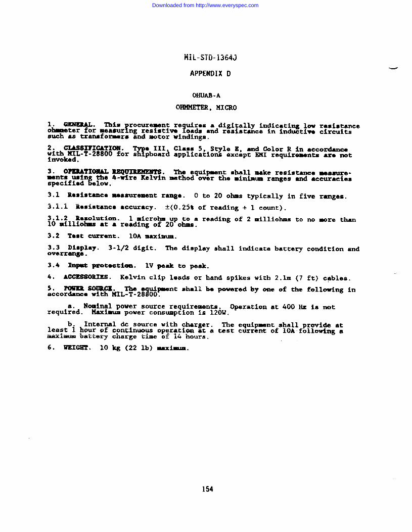
MIL-STD-1364J
APPENDIX D
OHUAO -A
omml’Im, MICRO
1. GENERAL. This rocurement re uires a digitally indicating low resistancefohmmeter for measur ng resistive foads and resistance in inductive circuits
such as transfomrs and motor windings.
2. CIASSIFICAT1019.%
e III, Class 5, S~le E, and Color R in accordancewith HIL-T-28800 for s pboard applications except EXI requirements aro nothvoked .
3. O?ERATIWAL uQmuMENTs. The equipment shall make resistance measure’ments ush the 4-wire Kelvin method wer the minimum ranges and accuract.ea
&lspecified OV.
3.1 Resistance measurement range. O to 20 ohms typically in five ranges.
3.1.1 Resistance accuracy. 1(0.25% of reading + 1 count).
3.1.2 Resolution. 1 microlun up to a reading of 2 milliohms to no more than10 milliohms at a reading of 20 ohms.
3.2 Test current. 10A maximum.
3.3 Display. 3-1/2 digit. The display shall indicate battery condition andoverrange.
3.4 Input pgotectiom. lV peak to peak.
4. ACCESSORIES . Kelvin clip leads or hand spikes with 2.lm (7 ft) cables.
5. PWIRR SOURCE. The e u.ipment shall be powered by one of the following inaccordance with IIIfIL-T-28~00.
Nominal power source requirements. Operation at 400 Hz is notrequi;~d. Maximum power consumption is 120W.
b. Internal & source with charger. The equipment shall provide atleast 1 hour of continuous operation at a test current of 10A following amaximum battery charge time of 14 hours.
6. WEIGHT . 10 kg (22 lb) maximam.
154
Downloaded from http://www.everyspec.com
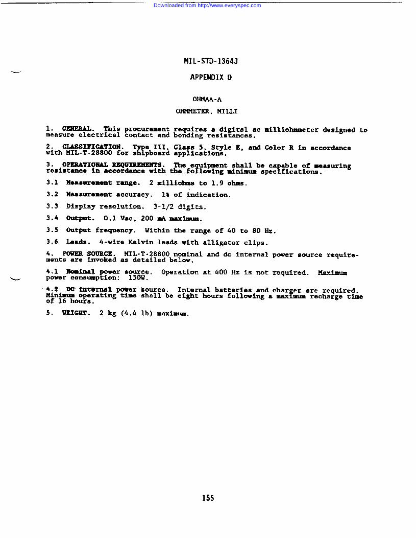
—
MIL-STD-1364J
APPENDIX D
OHMAA-A
OHMMETER, MILLI
requires a di ital ac milliohmmeter designed to!bonding resis antes.
Class 5, Style E, and Color R in accordanceappltcationn.
The e ipment shall be ca able of measuringY !resistance in acco~dance with the fo lowing minimum spec fications.
1. GEXEML* This procurementmeasure electrical contact and
2. CLASSIFI~IOl!l .%
e III,with 141L-T-28800 for s pboard
3. OPERATXOXAL mu~o
3.1 Measurement range. 2 milliohms to 1.9 ohms.
3.2 Measurement accuracy. 1* of indication.
3.3 Display resolution. 3-1/2 digits.
3.4 output. 0.1 Vat, 2oomAmaxilmam.
3.5 Output frequency. Within the range of 40 to 80 Hz.
3.6 Lads. 4-wire Kelvin leads with alligator clips.
4. POWER SOUROE. MIL-T-28800 nominal and dc internal power source require-ments are invoked as detailed below.
4.1 hind power s~~o Operation at 400 Hz is not required. Maximumb power consumption: .
4.2 lXYint@rnal ~er source. Internal batteries and char er are required.!Minimum operating time shall be eight hours following a max mum recharge time
of 16 hours.
5. liKxGET. 2 kg (4.4 lb) maximum.
155
Downloaded from http://www.everyspec.com
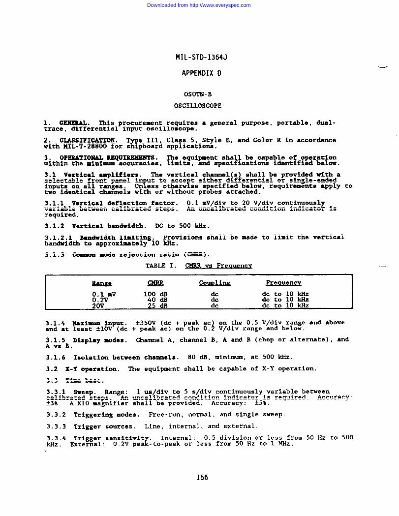
-—
MIL-STD-1364J
APPENDIX D
OSOTN-B
OSCIUSCOPE
1. GENEML. This procurement requires a general purpose, portable, dual-trace, differential input oscilloscope.
2. CLASSIFICATION . T e III, Class 5, Style E, and Color R in accordanceEwith MIL-T-28800 for s pboard applications.
3. OPERATIONAL EEQUIRXMENTS. The equipment shall be capable of operationwithin the minimum ●ccuracies, limits, and specifications Identifisdbelow.
3.1 vertical -lifier%. The vertical channel(s) shall be pruvided with aselectable front-panel i
Tut to acce t either dif~erential o~ single-ended
inputs on all ranges. !Un ess otherw se specified below, requirements apply totwo identical channels with or without probes attached.
3.1.1 Vertical deflection factor. 0.1 mV/div to 20 V/div continuouslyvariable between calibrated steps. An uncalibrated condition indicator isrequired.
3.1.2 Vertical bandvidth. DC to 500 kHz.
3.1.2.1 Bandwidth l-ting. Provisions shall be made to limit the verticalbandwidth to approximately 10 ldiz.
3.1.3 Common mode rejectiun ratio (CXRR).
cowl i- Preauency
0.1 mv 100 dB & dc to 10 ~Z0.2V 40 CM & dctolokHz
3.1.4 xaxiEum input. t350V (dc + peak aci
on the 0.5 V/div range and aboveand at least ~lOV (dc + peak ac) on the O. V/div range and below.
3.1.5 Display tieS. Channel A, channel B, A and B (chop or alternate), andA VS B.
3.1.6 Isolation between channels. 80 dB, minimum, at 500 kHz.
3.2 X-Y operation. The equipment shall be capable of X-Y operation.
3.3 Time base.
3.3.1 Sweep. Range: 1 us/div to 5 s/div continuously variable betweencalibrated steps. An uncalibrated condition indicato;5;s required. Accuracy:23% . A X1O magnifier shall be provided. Accuracy: _ .
3.3.2 Triggering modes. Free-run, normal, and single sweep.
3.3.3 Trigger sources. Line, internal, and external.
--
3.3.4 T~;g$ge; sensitivity .z
Internal: 0.5 division or less from 50 Hz to 500kHz . .. 0.2V pea -to-peak or less from 50 Hz to 1 MHz.
156
Downloaded from http://www.everyspec.com
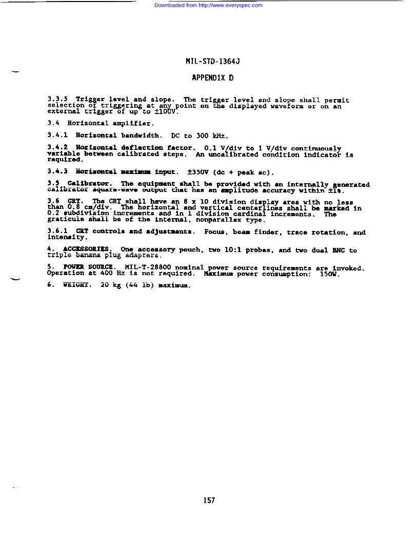
MIL-STD-1364J
APPENDIX D
3.3.5 Tri er level and slope.Y
The tri er level and S1O e shall permitselection o triggering at an point on
6% fe displayed wave ona or on an
external trigger of up to k10 V.
3.4 Horizontal amplifier.
3.4.1 Horizontal bandwidth. DC to 300 kHz.
3.4.2 Horizontal deflection factor. 0.1 V div to 1 V/div continuouslyvariable between calibrated steps. {An unca ibrated condition indicator isrequired.
3.4.3 Morimmtalmaximm Input. *350V (CIC + peak at).
3.5 calibrator. The equipment shall be provided with an internally eneratedfcalibrator square-wave output that has an amplitude accuracy within ~ t.
3.6 CRT. The CRT shall have an 8 x 10 division din lay area with no lessthan 0.8 cm/div. !The horizontal and vertical center ines shall be marked in0.2 subdivision increments and in 1 division cardinal increments. Thegraticule shall be of the internal, nonparallax type.
3.6.1 CRT controls and ●djustments. Focus, beam finder, trace rotation, andintensi~.
4. ACCESSORIES . (he accessory pouch, two 10:1 probes, -d two d-l MC totriple banana plug adapters.
mm SOURCE. MIL-T-28800 nominal power source requirements a~~o~nvoked.~eration at 400 Hz is not required. Maximum power consumption: .
6. WEIGHT . 20 kg (44 lb) maximum.
157
Downloaded from http://www.everyspec.com
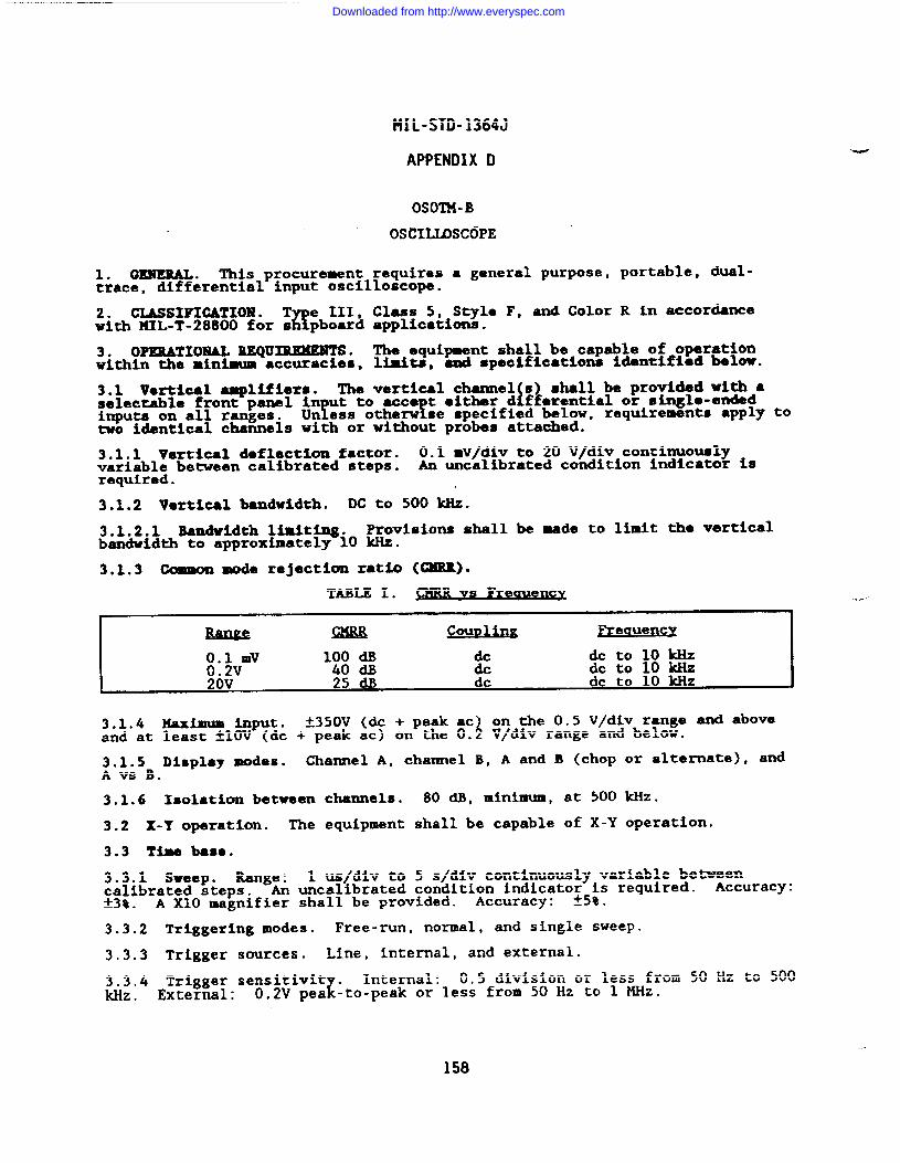
MIL-STD-1364J
APPENDIX D
OSOTM-B
OSCIUSCOPE
1. GENERAL. TMs procurement requires ● general purpose, portable, dual-trace, differential input oscilloscope.
2. CLASSIFICATION . T e III, Class 5, Style F, and Color R in accordanceawith HIL-T-28800 for s pboard applications.
3. OPERATIONAL REQUIREMENTS. The equipment shall be capable of operationwithin the minimum accuracies, limits, and specifications identified beluw.
3.1 Vortloal amplifiers. The vertical channel s) shall be provided with aiselectable front panel in ut to acce t ●ither d fferential or single-ended
inputs on all ranges. Y !Un ess otherw se specified below, requirements apply totwo identical channels with or without probes attached.
3.1.1 Vertical deflection factor. 0.1 mV/div to 20 V/div continuouslyvariable between calibrated steps. An uncalibrated condition indicator isrequired.
3.1.2 Vertical bandwidth. M to 500 W.
3.1.2.1 Bandwidth limiting. Provisions shall be made to limit the verticalbandwidth to approximately 10 kHz.
3.1.3 Commom mode rejection ratio (CXRIL).
TABLE I. Vs Fregyency
I couv~ FreauencyI
~.$VmV 100 dB & &tolok Hz40 dB & dc to 10 kkiZ
20V 25 dl) dc dc to 10 k?iZ●
3.1.4 MJUCimUminput. k350V (dc + p-k =4
on the 0.5 V/div range and aboveand at least AIOV (dc + peak ac) on the O. V/div range and below.
3.1.5 Display modes. Channel A, channel B, A and B (chop or alternate), andA VS B.
3.1.6 Isolation between channels. 80 dB, minimum, at 500 kHz.
3.2 X-Y operation. The equipment shall be capable of X-Y operation.
3.3 Time bas8.
3.3.1 Sweep. Range: 1 us/div to 5 s/div continuously variable betweencalibrated steps. An uncalibrated condition indicato$5~s required. Accuracy:*38 . A X1O magnifier shall be provided. Accuracy: _ .
3.3.2 Triggering modes. Free-run, normal, and single sweep.
3.3.3 Trigger sources. Line, internal, and external.
3.3.4 Trigger sensitivity .z
Internal: 0.5 division or less from 50 Hz to 500kHz, External: 0.2V pea -to-peak or less from 50 Hz to 1 MHz.
158
Downloaded from http://www.everyspec.com
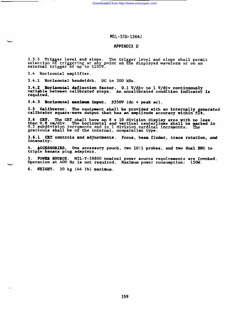
MIL-STD-1364J
APPENDIX D
3.3.5 Trig er level and slope.!
The trig er level and S1O e shall permitselection o k ftriggering at an point on t e displayed wave orm or on an
6external trigger of up to t10 V.
3.4 Horizontal amplifier.
3.4.1 Horizontal bandwidth. DC to 300 kllz.
3.4.2 Horizontal deflection factor. 0.1 V div to 1 V/dlv continuouslyvariable between calibrated steps. {An unca ibrated condition indicator isrequired.
3.4.3 Horizontal maximxm input. f150V (dc + peak at).
3.5 Calibrator. The equipment shall be provided with an internally eneratedfcalibrator square-wave output that has an amplitude accuracy within k t.
3.6 CRT. The CRT shall have an 8 x 10 division dis lay area with no lessthan 0.8 cm/div. 1The horizontal and vertical center ines shall be marked in0.2 subdivision increments and in 1 division cardinal increments. Thegraticule shall be of the internal, nonparallax type.
~~~~~i’l controls and adjustments. Focus, beam finder, trace rotation, and●
4. ACCESSORIES. One accessory pouch, two 10:1 probes, and two dual BNC totriple banana plug adapters.
5. POWER SOURCE. MIL-T-28800 nominal power source requirements a~~~nvoked.Operation at 400 Hz is not required. Maximum power consumption: .b“6. WEIGHT . 20 kg (44 lb) maximum.
159
Downloaded from http://www.everyspec.com
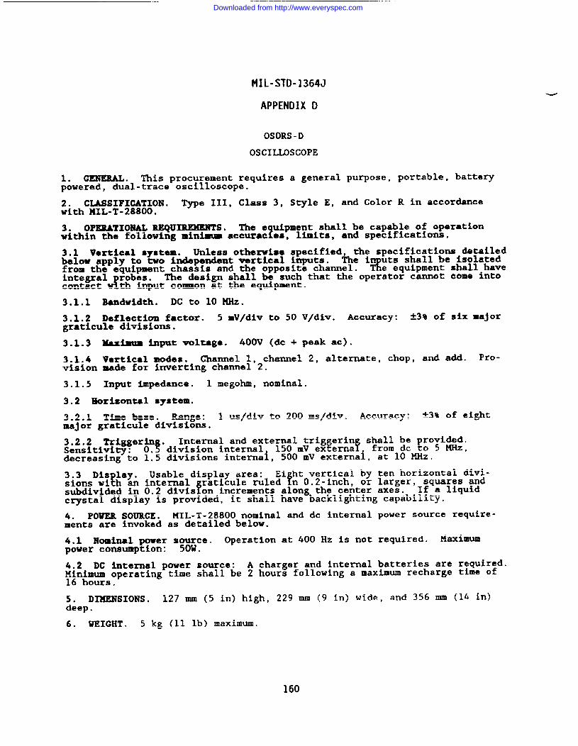
MIL-STD-1364J
APPENDIX D
OSORS-D
OSCIDSCOPE
1. GENERAL. This procurement requires a general purpose, portable, batterypowered, dual-trace oscilloscope.
2. CLASSIFICATION . -e III, Class 3, Style E, and Color R in accor~cewith 141L-T-28800.
3. OPERATIONAL REQUIREMENTS. The e uipment shall be capable of operation? Mmits,a ndspecifi.atiom.within the following minimum accurac es,
3.1 Vertical system. Unless otherwise specified, the specifications detailedbelow apply to two independent vertical inputs. The i uts shall be isolatedfrom the equipment chassis and the opposite channel. R e equipment shall haveintegral robes.
w!The design shall be such that the operator cannot come into
contact th input common at the equipment.
3.1.1 Bandwidth. DC to 10 W.
3.1.2 Deflection factor. 5 mV/div to 50 V/div. Accuracy: 23% of six majorgraticule divisions.
3.1.3 Maximum input voltag~. 400V (dc + peak at).
3.1.4 Vertical modes. Channel 1, channel 2, alternate, chop, and add. Pro-vision made for inverting channel 2.
3.1.5 Input impedance. 1 megohm, nominal.
3.2 Horizontal system.
3.2.1 Time base. Range: 1 us~div to 200 ms/div. Accuracy: *3% of ei@tmajor graticule divisions.
3.2.2 Triggerin . Internal and external triggerin shall be provided.Sensitivity: O.~ division internal 150 mV extema f from dc to 5 MHz,decreasing to 1.5 divisions internai, 500 mv externai, at 10 ~z.
3.3 Illslay.!
Usable display area: Ei ht vertical by ten horizontal divi-sions wi h an internal
f!raticule ruled n O.Z-inch, or larger, squares and
subdivided in 0.2 dlvis on increments along the center axes. If a liquidcrystal display is provided, it shall have backlighting capability.
4. POWER SOURCE. MIL-T-28800 nominal and dc internal power source require-ments are invoked as detailed below.
4.1 Nominal power sywce. Operation at 400 Hz is not required. Maximumpower consumption: .
4.2 DC internal power source: A charger and internal batteries are required.~~n~~~operating time shall be 2 hours following a maximum recharge time of
.
5. DIMENSIONS. 127 mm (5 in) high, 229 mm (9 in) wide, and 356 IIIR (14 in)deep.
6. WEIGHT . 5 kg (11 lb) maximum.
160
Downloaded from http://www.everyspec.com
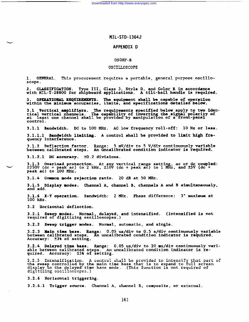
MIL-STD-1364J
APPENDIX D
OSOHP -B
OSCILLOSCOPE
1. GENERAL. ~is procurement requires a portable, general purpose oscillos-cope.
2. CLASSIFICATION .%
e III, Class 3, Style D, and Color R in accordancewith MIL-T-28800 for s pboard applications. A tilt-bail handle is required.
3. OPERATIONAL REQUIREMENTS. The equipment shall be capable of operationwithin the minimum accuracies, limits, and specifications detailed below.
3.1 Vertical“B
Mfiars. The re uirements specified belw apply t~a~Wi~-tical vertical c annels. %The capa ility of invertin the signal
? !?~~nt~~~st one channel shall be provided by manipulat on of a fron -panel●
3.1.1 Bandwidth. DC to 100 MHz. AC low frequency roll-off: 10 Hz or less.
3.1.1.1 Bandwidth limiting. A control shall be provided to limit high fre-quency interference.
3.1.2 Deflection factor. Range: 5 mV/div to 5 V/div continuously variablebetween calibrated steps. - uncalibrated condition indicator is required.
3.1.2.1 DC ●ccuracy. fO.2 divisions,
3.1.3 Overload protection. At an vertical range settinw ~250v (dc +
!~d d
ac or dc coupled:eak ac) to 2 kHz, A1O ( c +peak ac) to 1 ;, andtiV (dc +
peak ac) to 00 MHz.
3.1.4 Common mode rejection ratio. 20 * at 50 KHz.
3.1.5 Display modes. Channel A, channel B, channels A and B simultaneously,and add.
3.1.6 X-Y operation. Bandwidth: 2 MHz. Phase difference:100 kllz.
3° nSXimUm at
3.2 Horizontal deflection.
3.2.1 Sweep modes. Normal delayed, and intensified. (Intensified is notrequired of digitizing oscilloscopes.)
3.2.2 Sweep trigger modes. Normal, automatic, and single.
3.2.3 Main time base. Ran e:h
0.05 us/div to 0.5 s/div continuously variablebetween calibrated ste s.
!uncalibrated condition indicator is required.
Accuracy: *3% of sett ng.
3.2.4 Delayed time base. Range: 0.05 us/div to 20 ms/div continuously vari-able between calibrated steps. An uncalibrated condition indicator is re-quired. Accuracy: 23% of setting.
3.2.5 Intensification. A control shall beErovided to intensif that part of
the sweeT
controlled by the main time base t at is to expand to fu1l screendis lay
!n the delayed time base mode. (This function is not required of
dig tizing oscilloscopes. )
3.2.6 Horizontal triggering.
3.2.6.1 Trigger source. Channel A, channel B, composite, or external...
161
Downloaded from http://www.everyspec.com
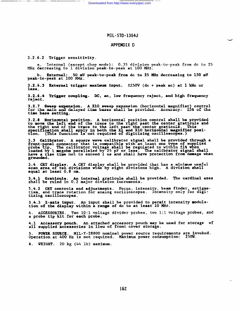
MIL-STD-1364J
APPENDIX D
3.2.6.2 Trigger sensitivity.
Internal (except chop mode): 0.35 division peak-to-peak from dc to 25MHz adcreasing to 1 division peak-to-peak at 100 MHz.
b. External : 50 MV peak-to-peak from dc to 25 XHz decreasing to 150 mVpeak-to-peak at 100 MHz.
3.2.6.3 External trigger uxinrum input. MSOV (dc + peak ac) at 1 kllzOrless.
k~k$i4 Trigger coupling. DC, ac, low frequency reject, and high frequency.
W~.7~Sv~ig e3
na ion. A X1O sweep ex ansion (horizontal magnifier control! 2delayed time baaes sha 1 be provided. Accuracy: + ~ of the
time base setting.
3.2.8 Horizontal position. A horizontalfositlon control shall be provided
to move the left end of the trace to the r ght past the center grat&ic~e and
Pthe ri t end of the trace to the left ast the center graticule.s ecif cation shall ap ly in both thef f
I&(This function
and X1O horizontal magnifier posi-t on. s not required of digitizing oscilloscopes.)
3.3 Calibrator. A square wave calibrator signal shall be provided through afront- anel connector that is compatible with at least one
!robe ?ip. ~ecalibrator voltage shall bere&lated towi=n$~#*~~iedoaded b 1 megohm
x faralleled b 25 pF or less.
1The calibrator signal shall
have a r se time no to exceed us and shall have protection from damage whengrounded.
3.4 CR? display. A CRT dis lay shall bew! !
rovided that has a minimum usefulscan area of ten di~s%ons de by eight d v5sions high. A division shallequal at least 0.8 cm.
3.4.1 Graticule. An internal raticule shall be provided.f
The cardinal axesshall be ruled in 0.2 major div sion increments.
l~m2 CRT controls and adjustments. Focus , intensity, beam finder astigma-and trace rotation for analog oscilloscopes. Intensity only ~or digi-
tizi~g oscilloscopes.
3.4.3 z-axis i t.T
An input shall be provided to permit intensity modula-tion of the disp ay within a range of & to at least 10 MHz.
4. ACCESSORIES . Two 10:1 voltage divider probes, two 1:1 voltage probes, anda probe tip kit for each probe.
4.1 ACC8SSOry pouch. An attached accessory pouch may be used for storage ofall supplied accessories in lieu of front cover storage.
MIL-T-28800 nominal power source requirements a~onvoked.&erZn %%*Hz is not required. Maximum power consumption: .
6. WEIGHT . 20 kg (44 lb) maximum.
162
Downloaded from http://www.everyspec.com
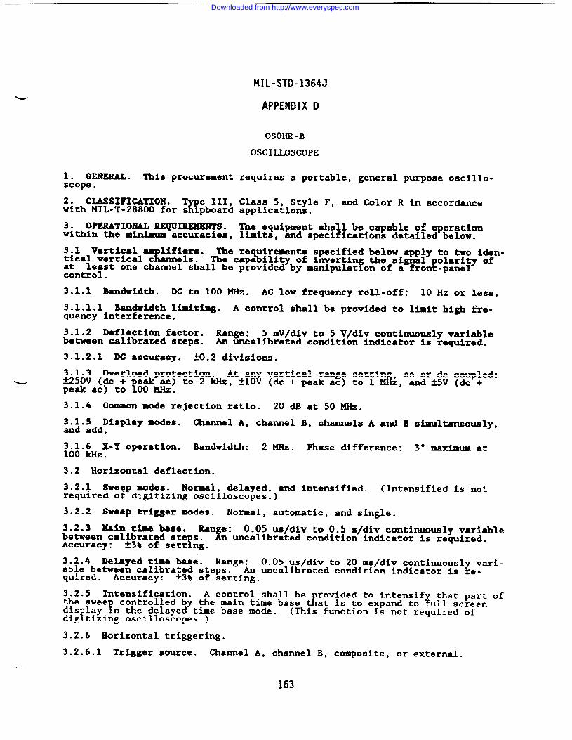
MIL-STD-1364J
APPENDIX D
OSOHR-B
OSCILLOSCOPE
1. GENERAL. This procurement requires a portable, general purpose oscillo-scope.
2. CLASSIFICATION.%
e III, Class 5, Style F, and Color R in accordancewith MIL-T-28800 for s pboard applications.
3. OPERATIONAL BEQUIMMENTS. The equipment shall be capable of operationwithin the minimum accuracies, limits, and speciflcatiom detailed below.
3.1 vertical The re uirements specified below apply to two iden-%%::” %tical vertical c The capa ili~ of invertin the signal olarity of
f !!at least one channel shall be provided by manipulat on of a fron -panelcontrol.
3.1.1 Bandwidth. DC to 100MHz. AC low frequency roll-off: 10 Hz or less.
3.1.1.1 Bandwidth limiting. A control shall be provided to limit high fre-quency interference.
3.1.2 Deflactiom factor. Range: 5 mV/div to S V/div continuously variablebetween calibrated steps. An uncalibrated condition indicator is required.
3.1.2.1 DC ●ccuracy. 9.2 divisions.
3.1.3 Overload protection. At an vertical range settin , ac or dc coupled:w *250v (d= +
!eak ac) to 2 Miz, klO? (dc + peak ac) to 1 & and &5V (dc +
peak ac) to 00 MHz.8
3.1.4 Common mode rejection ratio. 20 dB at 50 MHz.
3.1.5 Display modes. Channel A, channeland add.
3.1.6 X-Y operation. Bandwidth: 2 MHz.100 kHz.
3.2 Horizontal deflection.
3.2.1 Sweep modes. Normal delayed, andrequired of digitizing oscilloscopes.)
B, channels A and B simultaneously,
Phase difference: 3° maximum at
intensified. (Intemified is not
3.2.2 Sweep trigger modes. Normal, automatic, and ~ingle.
3.2.3 Main tba base. Rane:L
0.05 us/div to 0.5 s/div continuously variablebetween calibrated ste s.
funcalibrated condition indicator is required.
Accuracy: *3% of sett ng.
3.2.4 Delayed time base. Range: 0.05 us/div to 20 ms/div continuously vari-able between calibrated steps. An uncalibrated condition indicator is re-quired. Accuracy: *3% of setting.
~h~.~wentensification. A control shall be rovided to intensif that part of
!Econtrolled by the main time base t at is to expand to $u1l screen
dis layf
n the delayed time base mode. (This function is not required ofdig tizing oscilloscopes. )
3.2.6 Horizontal triggering.
3.2.6.1 Trigger source. Channel A, channel B, composite, or exterwl.
—-
163
Downloaded from http://www.everyspec.com
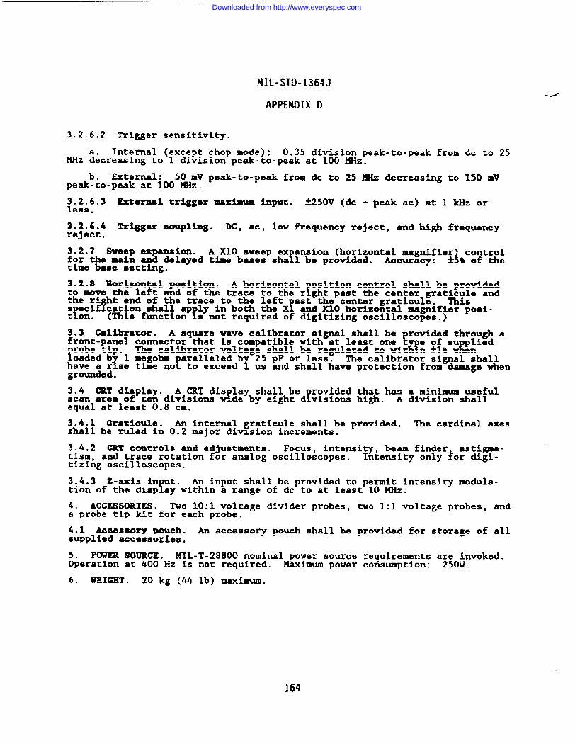
MIL-STD-1364J
APPENDIX D
3.2.6.2 Trigger sensitivity.
Internal (except chop mode): 0.35 division peak-to-peak from dc to 25MHz ~ecreasing to 1 division peak-to-peak at 100 MHz.
b. External: 50 mV peak-to-peak from & to 25 MHz decreasing to 150 mVpeak-to-peak at 100 MHz.
3.2.6.3 External trigger maximum input. fiSOV (& + peak ac) at 1 klizorless.
3.2.6.4 lki~er coupling. DC, ac, low frequency reject, and high frequencyreject.
3.2.7 *@epa?
nsion. A X1O sweep efor the main Y
ansion (horizontal magnifier controlidelayed time bases sha 1 bc provided. Accuracy: * t of the
time base setting.
3.2.8 Horizontal position. A horizontal osition control shall be providedfto move the left end of the trace to the r ght past the center grat~;~e and
Pthe ri t end of the trace to the left ast the center graticule.
!s ecif cation shall ap ly in both the X! f
and X1O horizontal magnifier posi-t on. (This function s not required of digitizing oscilloscopes.)
3.3 Calibrator. A square wave calibrator signal shall be provided through afroot- anal connector that is compatible with at least one
!.!ip . %!
e of su pliedThe calibrator voltage shall be regulated to wit n klt WE
oadedY
1 megohm paralleled~
25 pF or less. The calibrator signale;hallhave a r se time not to exceed us and shall have protection from damage whengrounded.
3.4 CRT display. A CRT dis lay shall be! f
rovided that has a minimum usefulscan area of ten divisions w de by eight d visions high. A divis%on shallequal at least 0.8 cm.
3.4.1 Craticule. An internal raticule shall be provided.f
The cardinal axesshall be ruled in 0.2 major div sion increments.
3.4.2 CRT controls and ●djustments. Focus, intensity, beam finder astigma-tism, and trace rotation for analog oscilloscopes. Intensity only kor digi-tizing oscilloscopes.
3.4.3 Z-axis in t.r
An input shall be provided to permit intensity modula-tion of the disp ay within a range of dc to at least 10 MHz.
4. ACCESSORIES. Two 10:1 voltage divider probes, two 1:1 voltage probes, anda probe tip kit for each probe.
4.1 Accessory pouch. An accessory pouch shall be provided for storage of allsupplied accessories.
5* POWER SOURCE. MIL-T-28800 nominal power source requirements a;;o~nvoked.Operation at 400 Hz is not required. Maximum power consumption: .
6. WEIGHT . 20 kg (44 lb) maximum,
164
—-
Downloaded from http://www.everyspec.com
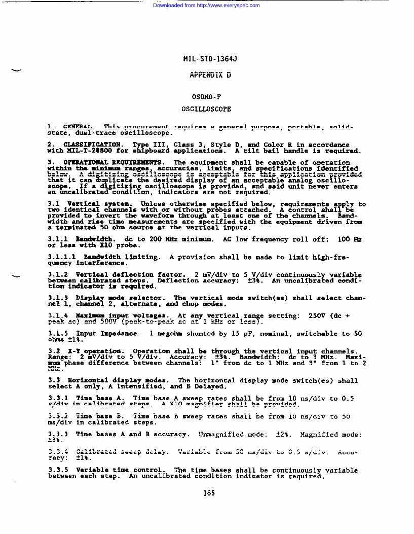
—
MIL-STD-1364J
APPENDIX D
OSOMO-F
OSCIIJQSCOPE
1. GENERAL. This procurement requires a general purpose, portable, solid-state, dual-trace oscilloscope.
2. CLASSIPICATION .w
III, Class 3, Style D, and Color R in accordancewith KIL-T-28800 for s pboard applications. A tilt bail handle is required.
3. OPERATIONAL REQUIMHENTS. The equi ment shall be ca able of o erationwithin the •i~ ranges accuracies, inits end s ci ications denti e
A dl itlzin oscilloscope is acceptable for:g::t;Fa~tit:,y o=c,1108=opeff ~’Jap’=&?~dlica e the desired dis lay of an acceptable analog osc 11o
s provided, and ●aid unit never entersan uncalibrated condit on, indicators are not required.
3.1 Vartical s tam.L
Unless othe-ise specified below, requirements a ply totwo identical c els with or without probes attached. fA control shal beprovided to imvert the waveform through at least one of the channels. Band-width and rise time measurements are s ecified with the equipment driven from
!a terminated 50 ohm source at the vert cal inputs.
3.1.1 Bandwidth. & to 200 MHz minimum. AC low frequency roll off: 100Hzor less with X1O probe.
3.1.1.1 Bandwidth limiting. A provision shall be made to limit high-fre-quency Interference.
L 3.1.2 Vertical deflection factor. 2 mV/div to 5*~<div continuous variablebetween calibrated ste s.
?Deflection accuracy: . ~An uncalibra ed condi-
tion indicator is requ red.
3.1.3 DisplaT
mode selector. The vertical mode switch(es) shall select chan-nel 1, channe 2, alternate, and chop modes.
3.1.4 Maximum input voltages. At any vertical ran e setting:f
250V (dc +peak ac) and 500V (peak-to-peak ac at 1 kHz or less .
3.1.5 Input Impedance. 1 megohm shunted by 15 pF, no~inal, switchable to 50ohms *1%.
3.2 X-Y Opexation.Range: ?
eration shall be through the vertical input channels.2 mV/div to 5 /div. Accuracy: 33%. Bandwidth: & to 3 XHz. Maxi-
mum phase difference between channels: 1° from dc to 1 MHz and 3° from 1 to 2MHz.
3.3 Horizontal display modes. The horizontal display mode switch(es) shallselect A only, A Intensified, and B Delayed.
3.3.1 Time base A. Time base A sweep rates shall be from 10 ns/div to 0.5s/div in calibrated steps. A X1O magnifier shall be provided.
3.3.2ms/div
3.3.3*3!$.
3.3.4racy:
3.3.5
Time base B. Time base B sweep rates shall be from 10 ns/div to 50in calibrated steps.
Time bases A and B accuracy. Unmagnified mode: ~z~a Magnified mode:
Calibrated sweep delay. Variable from 50 ns/div to 0.5 s/div.*l!$.
Accu-
Variable time control. The time bases shall be continuously variablebetween each step. An uncalibrated condition indicator is required.
-...
165
Downloaded from http://www.everyspec.com
MIL-STD-1364J
APPENDIX D
3.4 Triggering. Time bases A and B shall be capable of internal and externaltriggering.
3.4.1 The base A trig aring modes. Time base A shall have no~al, aUtomat-?ic, and single sweep tr gger modes.
~.4C~2baf:mA tri ering kources.an!!P
Time base A shall have normal, channel* # o external trigger sources.
3.4.3 TIM base B triggering modes. Tin baae B trigger modes shall be auto-matic and triggered.
3.4.4 Time base B triggering sourc~s. Time base B shall have normal, channel1, channel 2, and external trigger sources.
3.4.5 Timo base A and B triggez coupling. DC, AC, low-frequency rejection,and high frequency rejection.
3.4.6 Time base A ●nd B trigger sensitivity. 0.7 vertical division or lessinternal or 50 mV or less external from & to 40 MEiz,decreasing to 1.5 verti-cal divisions internal or 250 mV external at 400 MHz.
3.4.7 Trigger level ●nd slope. Selection of triggering at any point on thedisplayed waveform shall be provided.
3.4.8 Maximam external trig er input. ~20V or 40V peak-to-peak. Externaltrigger damage level: 250V ~& + peak ac) minimum.
3.4.9 Trigger hold-off: A variable trigger hold-off control shall beprovided for the A time base.
3.5 Amplitude callbr~tor. A calibrator siY
shall be provided through ●
front-panel connector and shall have protec ion from ~ge when”groandec!.Accuracy: *1* into 1 rngohm.
3.6 CBT. The CRT shall have an 8 x 10 division dis lay area with no lessthan 0.8 cm/div. !The horizontal and vertical center inas shall be marked in0.2 subdivision increments and in 1 division cardinal increments. Thegraticule shall be of the internal, nonparallax type.
4. ACCESSORIES. Two X1O probes one accessory pouch, and one grounding postshall be furnished with each osc~lloscope.
5. POWEB SOURCE. I141L-T-28800nominal and dc internal power source require-ments are invoked as detailed below.
5.1 Nominal power s~~. Operation at 400 Hz is not required. Maximumpower consumption: .
5.2 DC internal power source: Internal batteries and charger are re uired.1~~fum operating time shall be 1 hour following a maximum recharge t me of 16
.
6. WEIGHT . 20 kg (44 lb) maximum.
166
.._.
Downloaded from http://www.everyspec.com

MIL-STD-1364J
APPENDIX D
ODIAP-B
OSCIIJXKCOPE, DIGITIZING
1. GENERAL. This procurement requires a digital storage oscilloscope.
2. CLASSIFICATION .%
e III, Class 5, Style E, and Color R in accordancewith HIL-T-28800 for s pboard applications.
3. OPXRATIOMAL REQUIMWEHTS. The e uipment shall be capable of measuring,Ldisplaying, and storin waveforms wi in the minimum ranges, specifications,
5and accuracies detaile below.
3.1 Vertical system. The equipment shall be ca able of simultaneous and8synchronous acquisition, measurement, display an storage of two inputs.
3.1.1 Bandwidth. DG to 400 MHz for repetitive signals. AC coupled low fre-quency roll-off: 100 Hz or less.
3.1.1.1 Bandwidth llmit. At least one input shall have a selectable low-passfilter to reduce high-frequency interference.
3.1.2 Sensitivity. 5 mV/div to 5 V/div.
3.1.2.1 Effective bits. 6 minimum.
3.1.2.2 Accuracy. *2% of full scale.
3.1.3 Display modes. Channel 1 only, channel 2 only, or both channels simul-- taneoualy.
3.1.4 Maximum vertical input. At any vertical deflection factor: *250v (dc+ peak ac) at frequencies up to 10 kHz.
3.1.5 Input impedance. 1 megohm paralleled by 20 pF, nominal.
3.1.6 Waveform math. The equi ment shall be capable of performing addition,subtraction, Kand channel 1 vs c annel 2 on the input signals. The equipmentshall be capable of inverting at least one of the input signals.
3.2 Horizontal system.
3.2.1 Resolution. 500 points per channel minimum.
3.2.2 Sample rate. 100 megasamples per charnel per second.
3.2.3 Time base range. 5 ns/div to 5 s/div. Accuracy: Ml%.
3.2.4 Delay. Pre-trigger: 7/8 screen. Post trigger: 10 divisions minimum.
3.2.5 Tri er sensitivity.8%
0.5 division or less (dc to ~O()~MHz), 1 divisionor less (1 to 400 MHz). Minimum trigger pulse width: ●
3.2.6 Time base expansion. The equipment shall be ca able of simult~eouslyFdispla ing a reference sweep and an expanded portion o that sweep.
1expans on ratio shall range from 1:1 to 20:1 or greater.
3.3 Parametric measurements, The equipment shall be capable of automaticallymeasurin
!and displayin
Ethe following parameters of the displayed signal:
period, requency, wldt (+ and -), r~se time fall time, eak (+ and -),
teak-to-peak, and rms amplitude. !Rise and fail times shal be measuredetween the proximal and distal points, and width shall be measured between
Pulse parameters shall be as defined in;FEEm;FtiL!Zi?6;-?;7Y~1~e ‘avefoms”Standard Pulse Terms and Definitions.”
167
Downloaded from http://www.everyspec.com
MIL-STD-1364J
APPENDIX 1)
3.4 CRT. The si al display(3.75 in). F R
rid shall measure at least 76 mm (3 in) x 95 mmThe d splay grid s all be ruled in ei t vertical and ten horizon-
tal divisions with the center axes subdivided in r?.2 division increments.
3.5 Automatic setup. The equipment shall be equipped with a single ush-!button control that will initiate automatic ad ustment of the vertica and
horizontal deflection factors and tri er leveE
i for an optimized displa ofthe input signals. ~is function sha Ioperate with signals exceeding % dutycycle and frequencies of 50 Hz.
3.6 Waveform storage. The equipment shall be ca able of storin not 1.sst !than four waveforms with associated vertical and orizontal sett ngs in
nonvolatile memory.
3.7 Di ital intexface. A digital interface is required in accordance withMIL-T-2~800.
4. ACCESSORIES. Two X1O and two Xl probes with cables approximately 1.5m(4.9 ft) long.
5. POWER SOURCE. MIL-T-28800 nominal power source requirements a~e~nvoked.Operation at 400 Hz is not required. Maximum power consumption: .
6. WEIGHT ● 13.6 kg (30 lb) maximum.
168
Downloaded from http://www.everyspec.com
MIL-STD-1364J
APPENDIX D
OSSMG-B
OSCILLOSCOPE, STOWiGE
1. GENERAL. ~is procurement requires a eneral- urpose dual-trace, storage! foscilloscope with a dual time base and dif erentla capab~lities.
2. CLASSIFICATION .w
III, Class 5, Style E, and Color R in accordancewith HIL-T-28800 for s pboard applications.
3. OPERATIONAL lZEQUIREMEETS. The equipment shall be capable of owithin the minimum accuracies, limits, and specifications containe %%:%?
3.1 Vertical system. The oscilloscope vertical system shall consist of twoidentical input channels with differential and comparator capability.
3.1.1 Bandwidth. DC to 50KHz. AC coupled low-frequency roll off: 10 Hz orless.
3.1.2 Deflection factor. 5 mV/div to 5 V/div continuously variable betweencalibrated steps. Accuracy: *1.5% of setting. An uncalibrated conditionindicator is required.
3.1.2.1 Wimum input voltages.
DG coupled: 1 V/div to 5 V/div: ~SOOV (dc + peak ac at 1 m)dera& to no less than k40V (dc + peak ac at 1 kHz).
+ b. AC coupled: *500V”. (dc +peakac at 1 W).
3.1.2.2 ~ mode rejection rdtio. The common mode rejection ratio shallbe at least 20,000 to 1 from dc to 100 kHz.
3.1.3 Comparison voltage. h internal comparison voltage source is required.Range: O to 10V positive and negative. Resolution: 4 digits. Accuracy:~(0.1% of setting + 3 mV).
3.2 Horizontal system.
3.2.1 Main sweep. 50 ns/div to 5 s/div continuous variable between cali-$brated steps. Accuracy: A4.0% of setting. An uncal brated co~ition in-
dicator Is required.
3.2.2 Uain tri gering.F
The equipment shall be provided with selectable maintrl er modes o
Bauto, normal, and sin le sweep.
fSelectable couplin s of AC,
AC -i
reject, AC-HF re ect, and DC sha 1 be provided. fSelectable tr ersources of internal, T1 ne, external, and external divided by 10 shall e pro-vided.
3.2.2.1 Auto and normal mode sensitivity.
AC selected: 0.3 division internal or 100 mV external from 30 Hz to10 ~a; and 1.5 divisions internal or 500 mV external from 10 MHz to 100 MHz.
b. AC-HF reject selected: 0.3 division internal or 100 mV external from30 Hz to 50 ~Z.
DC selected: 0.3 division internal or 100 mV external from DC to 10MHz ~nd 1.5 divisions internal or 500 ❑V external from 10 KHz to 100 MHz.
AC-LF re ect selected:d
Internal 0.3 div, 30 kHz to 10 MHz and 1.5div ‘1O MHz to 1 0 MHz; external 100 mV, 150 IcHz to 10 MHz and 500 IN, 10 MHzto ioo MHz.
169
Downloaded from http://www.everyspec.com
MIL-STD-1364J
APPENDIX D
3.2.2.2 Internal trigger jitter. The internal trigger jitter shall notexceed 1 ns at 75 MHz.
3.2.2.3 Extermal trigger. The tri ger level range shall be at least ~1~~ inRthe external position and f15V in t e external divided-by-10 position.
inputs shall withstand 500V (dc + peak at).
3.3 CRT display.
3.3.1 Automatic focus. Automatic focusing shall eliminate the need formanual focusing of the display with changes in intensity following an initialadjustment.
3.3.2 Beam finder. A beam finder control shall permit display centeringwhile limiting the display to the graticule area.
3.3,3 CRT storage display. The equipment shall be capable of variable per-sistence to extend viewing time to 15s minimum.
3.4 outputs.
3.4.1 Calibrator. A calibrator signal shall be rovided throu! f?
a front-panel connector that is compatible with the s eci ied probes.
Je calibrator
voltage shall be regulated to within i-l-at 1 ‘C to 35 C and when loabd bthe specified vertical amplifiers. ?The calibrator shall have protection romdamage when grounded.
3.5 Probes. Two Xl probes shall be provided and shall be compatible withthe vertical amplifiers specified.
POWER SOURCE. MIL-T-28800 nominal power source requirements are invoked.~eration at 400 Hz is not required. Maximum power consumption: 200W.
5. WEIGHT . 20 kg (44 lbs) maximum.
170
Downloaded from http://www.everyspec.com
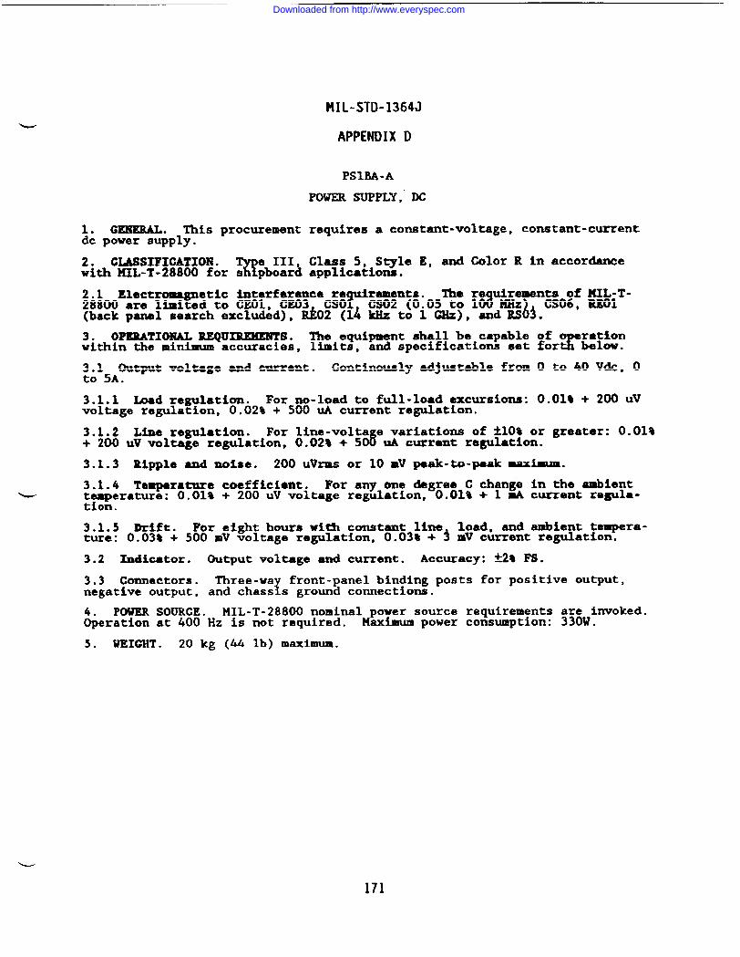
MIL-STD-1364J
APPENDIX D
PSIM-A
POWER SUPPLY, DC
1. GEHERAL. This procurement requires a constant-voltage, constant-currentdc power supply.
2. CLASSIFICATION ●
%e III, Class 5, S~le E, and Color R in accordance
with MIL-T-28800 for s pboard applications.
2.1 Elect etic Interference re The re8
remen~O;f ~~iT-28800 are =ii to CEO1, CE03 CSO~ik~n?~105 to 1 MHz
b(back panel search excluded), Rk02 (14 kMz to 1 GMz), andRS ~. ‘
3. OPERATIONAL REQUIREMENTS. The equipment shall be capable of owithin the minimum accuracies, limits, and specifications set forZCK?
~~15AOutput voltage and current. Continuously adjustable from O to 40 Vdc, O.
3.1.1 Load regulation. For no-load to full-load excursions: 0.01% + 200 UVvoltage regulation, 0.02% + 500 UA current regulation.
3.1.2 Line regulation. For line-volts e variations of *1O% or greater: 0.01%+ 200 UV voltage regulation, 0.02* + 5C# UA current regulation.
3.1.3 Ripple and noise* 200 Uvrms or 10 mv peak-to-paak maximum.
3.1.4 Temperature coefficient. For any one degree C change in the ambientw temperature: 0.01% + 200 UV voltage regulation, 0.01% + 1 mA current regula-
tion.
3.1.5 Drtft. For eight hours witi constant line load, and ambient tempera-ture: 0.03% + 500 mV voltage regulation, 0.03% + 3 mV current regulation.
3.2 Xmdicator. Output voltage and current. Accuracy: *2* F8.
3.3 Connectors. Three-wax
front-panel binding posts for positive output,negative output, and chass s ground connections.
POWER SOURCE. MIL-T-28800 nominal power source requirements are invoked.~eration at 400 Hz is not required. Maximum power consumption: 330W.
5. WEIGHT . 20 kg (44 lb) maximum.
171
Downloaded from http://www.everyspec.com
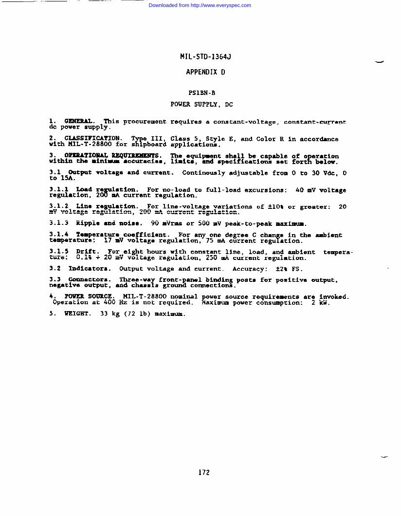
MIL-STD-1364J
APPENDIX D
PSIBN-B
POWER SUPPLY, DC
1. GENERAL. This procurement requires a constant-voltage, constant-currentdc power supply.
2. CLASSIFICATION . T e III, Class 5, Style E, and Color R in accordanceK!with MIL-T-28800 for s pboard applications.
3. OPERATIONAL REQ~So The equipment shall be capable of o erationwithin the mintmm ●ccuracies, limite, and specifications set fo& beluw.
:6115utput voltage and current. Continuously adjustable from O to 30 Vdc, O.
3.1.1 Load reC@
at%on. For no-load to full-load excursions: 40 mV voltageregulation, 2 mA current regulation.
3.1.2 Lima regulation. For line-voltage variations of A1O% or greater: 20mV voltage regulation, 200 mA current regulation.
3.1.3 Ripple and noise. 90 mVrma or 500 mV peak-to-peak maximum.
3.1.4 Temperatur~ coefficient. For any one degree C than e in the ambienttemperature: f17 mV voltage regulation, 75 mA current regu ation.
3.1.5 Drift. For eight hours with constant line, load, and ambient tempera-ture: O.lt + 20 mV voltage regulation, 250 mA current regulation.
3.2 Indicators. Output voltage and current. Accuracy: 32% FS.
3.3 connectors. front- anel binding posts for positive output,negative output, %%2%s groun% connections.
4. PouKR SOURCE. IIJHL-T-28800nominalOperation at 400 Hz is not required. r
wer source requirements ar; &voked.aximum power consumption: .
5. WEIGHT . 33 kg (72 lb) maximum.
172
Downloaded from http://www.everyspec.com
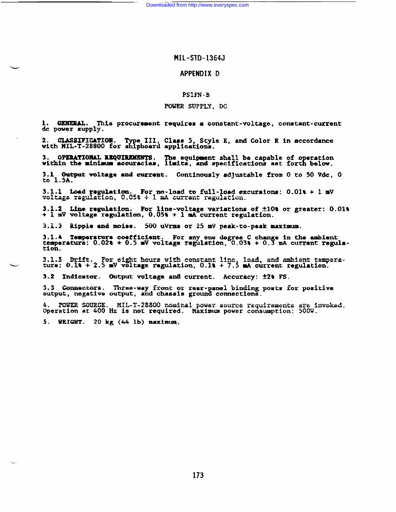
1.dc
2.
CENEML. This procurementpower supply.
CL4SSIFIOATIOlU.%
e III,with HIL-T-28800 for s pboard
3. OPEBATIOHAL lKQU~.within the minimum ●ccuracies,
MIL-STD-1364J
APPENDIX D
PSIFN-B
POWER SUPPLY, DC
requires a constant-voltage, constant-current
Class 5, Style E, and Color R in accordanceapplications.
The equipment shall be capable of o eration[ below.limits, end specifications set fort
3.1 Output voltage and current. Continuously adjustable from O to 50 V&, Oto 1.5A.
3.1.1 bad regulation. For no-load to full-load excursions: 0.01% + 1 mVvoltage regulation, 0.05% + 1 mA current regulation.
3.1.2 Line regulation. For line-voltage variations of tlOt or greater: 0.01%+ 1 mV voltage regulation, O.OS* + 1 mA current regulation.
3.1.3 ~pph and noise. 500 UVrIRS or 25 mV pew-to-peak maximum.
3.1.4 Temperature coefficient. For any one degree C than e in the ambienttemperature: 0.02* + 0.5 mV voltage regulation, 0.03% + 0.? mA current regula-tion.
3.1.5 Drift. For eight hours with constant line load, and ambient tempera-L ture: O.lt + 2.5 # voltage regulation, 0.18 + 7.3 mA current regulation.
9.2 Indicator. Output voltage an~ current. Accuracy: *2% FS.
3.3 Connectors. Three-way front or rear-%anel binding posts for positive
output, negative output, and chassis groun connections.
4. mm SOURCE. llIL-T-28800 nominal power source requirements are invoked.Operation at 400 Hz is not required. Maximum power consumption: 500W.
5. WEIGHT . 20 kg (44 lb) maximum.
173
Downloaded from http://www.everyspec.com
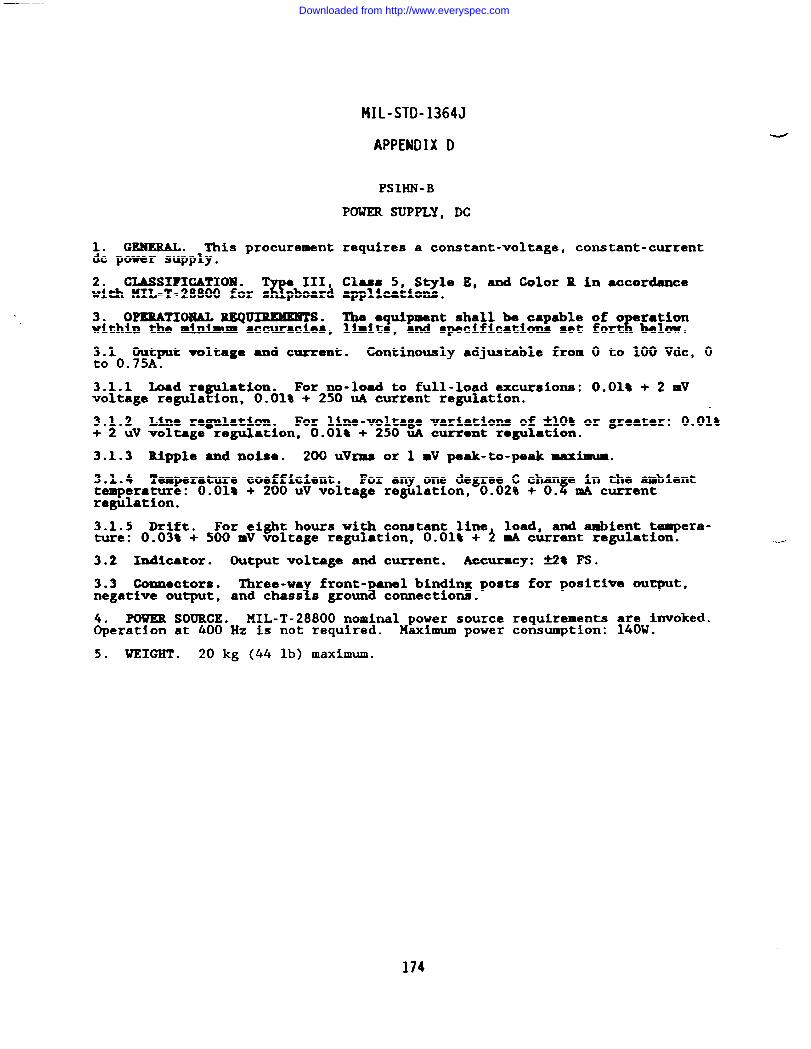
1. GENERAL. This procurementdc power supply.
2. CLMSIFICATION .w
III,with KIL-T-28800 for s pboard
3. OPERATIONAL Rl?QURUXEMTS.within the rni~ ●ccuracies,
F!IL-STD-1364J
APPENDIX D
PSIHN-B
POWER SUPPLY, DC
requires a constant-voltage, constant-current
Class 5, S~le E, and Color R in accordanceapplications ●
lb ●quipment shall be capable of ori:ik?limits, and specifications set fort
~~10 Ou~mt voltage ●nd current. Continuously adjustable from O to 100 Vdc, O. .
3.1.1 Load reP
●tion. For no-load to full-load excursions: O.Olt + 2 mVvoltage regula ion, 0.01% + 250 UA current regulation.
3.1.2 Line regulation. For line-voltage variations of flOt or greater: 0.01%+ 2 UV voltage regulation, O.Olt + 250 UA currant regulation.
3.1.3 Ripple and noisa. 200 uVrms or 1 mV peak-to-peak maximum.
3.1.4 Temperature coefficient. For any one degree C than e in the anbienttemperature: O.Olt + 200 UV voltage regulation, 0.02% + O.~ mA currentregulation.
3.1.5 Drift. For eight hours with constant line load, and ambient tempera-ture: 0.03t + 500 mV voltage regulation, 0.01% + 2 mA current regulation.
3.2 Indicator. Output voltage and current. Accuracy: 52% Fs.
3.3 Comnactoza. Three-wa front- anel binding posts for positlwe output,negative output, % sand chass s groun connections.
POWER SOURCE. MIL-T-28800 nominal power source requirements are invoked.~eration at 400 Hz is not required. Maximum power consumption: 140W.
5* WEIGHT . 20 kg (44 lb) maximum.
174
Downloaded from http://www.everyspec.com
MIL-STD-1364J
APPENDIX D
PSIMN-B
POWER SUPPLY, DC
1. GENEIUL. This procurement requires a constant-voltage, constant-currentdc power supply.
2. CLASSIFICATION .%
e III, Class 5, Style E, and Color R in accordancewith MIL-T-28800 for s pboard applications.
3. OPERATIONAL REQU~. The equipment shall be capable of o erationwithin the minimum accuracies, limits, and specifications set for4 below.
;JJWput voltag~ and current. Continuously adjustable from O to 150 Vdc, O.
3.1.1 -d regulation. For no-load to full-load excursions: 120 mV voltageregulation, 32 mA current regulation.
3.1.2 Line regulation. For line-voltage variations of ~10% or greater: 60mV voltage regulation, 25 mA current regulation.
3.1.3 Ripple ●nd noise. 300 mVrms or 500 mV peak-to-peak maximum.
3.1.4 Zemperatur9 coeffic~ent. For any one degree C change in the ambienttemperature: 56 mV voltage regulation, 8 mA current regulation.
3.1.5 Drift. For eight hours with constant line$ load, and ambient tempera-ture: O,lt + 60 mV voltage regulation, 25 mA current regulation.
w3.2 Indicators. Output voltage and current. Accuracy: *2* ps*
3.3 (kxmcctors. Three-wa front- anel binding posts for positive output,negative output, T Sand chass s groun connection.
4. P’ou’n SOUILCE. HIL-T-28800 nominal power source requirements a~k$mvokaci.Operation ●t 400 Hz is not required. 14aacimumpower consumption: .
5. WEIGHT . 41 kg (90 lb) maximum.
175
Downloaded from http://www.everyspec.com
HIL-STD-1364J
APPENDIX D
PSITN-A
POWER SUPPLY, DC
1. WNERAL. This procurement requires a constant-voltage, constant-current& power supply.
2. CUWSIFICATIOl# .%
e 111, Class 5, Style E, and Color R in accordancewith KIL-T-28800 for s pboard applications.
3. OPERATIOl!ZAL?
~. The equipment shall operate within the minimumranges and accurac as specified below.
;&13AOutput voltage and current. Continuously adjustable from O to 300 Vdc, O.
3.1.1 Load reguMtiono For no-load to full-load excursions: 300 W voltageregulation, 3 mA current regulation.
3.1.2 Line regulation. For line-voltage variations of *1O% or greater: 300mV voltage regulation, 3 mA current regulation.
3.1.3 Ripple and noise. 250 mlkms.
3.1.4 Temperature coefficient. For any one degree C change in the ambienttemperature: 60 mV voltage regulation, 0.9 A current regulation.
3.1.5 Drift, For eight hours with constant line, load, and ambient tempera-wre: 50.05t of set voltage indication.
3.2 Indicators. Output mltage and current. Accuracy: &2@ fs.
3.3 Ccxumctors.a2Z;~Zf&K#?onnections.
el binding posts for positive output,negative output,
4. POWER SOURCE. HIL-T-28800 nominal power source requirements a~ek~voked.Operation at 400 Hz is not required. Maximum power consumption: .
5. WEIGHT . 29 kg (64 lb) maximum.
176
Downloaded from http://www.everyspec.com
1. GEMERAL. This procurementSupply .
2. CIASSIFIGATION .%
e III,with 141L-T-28800 for s pboard
3. OPERATIONAL REQ~.within the minimum accuracies,
3.1 Output voltage. O to 500
MIL-STD-1364J
APPENDIX D
PSIVN-C
POWER SUPPLY, DC
requires a portable, constant voltage, & power
Class 5, Style E, and Color R in accordanceapplications.
The equipment shall be capable of operationlimits, and specifications identified below.
Vdc ●
3.1.1 Output voltage re lation.r
0.01% of output or 1 JIIV,whichever iSgreater, for 9% line var ations or 100% load variations.
3.1.2 Output voltage ripple and noise. 1 mvrms maxim.
3.1.4 Output voltage stability. -M).06t or 6 mV, whichever is greater, foreight hours with constant line load conditions.
3.2 Output current. O to 400 tio
3.3 output voltage and current indicators. &2% accuracy.
3.4 Output connectors. Insulated binding posts for positive output, negativeoutput, and chassis ground.
uPOWER SOURCE. 141L-T-28800 nominal power source requirements a~O$mvoked.
&eration at 400 Hz is not required. Maximum power consumption: .
5. WEIGHT . 21 kg (46 lb) maximum.
Downloaded from http://www.everyspec.com
MIL-STD-1364J
APPENDIX O
PRCAA-B
PROBE, CURRENT
1. GEMERAL. This procurement requires a clamp-on & ~eter or currtit probeaccessory.
2. CLASSIFICATION ●
%e 111, Class 5, Style D, and Color R in accordance
with PIIL-T-28800 for s pboard applications.
3. OPERATIONAL REQUXUMESTS. The equipment shall be ca able of measuridirect current within the minimum ranges and accuracies ~t.iled below. W.equipment may be a stand-alone unit or an accesso
%rzfosz: gcz”:;$?:lo-that can be used in conjunction with either a digiscope.
3.1 Measurement range. 1 W to 10A.
3.3 Robe ●perture. 0.15 in. minimum, 0.25 in. maxlmua.
4. POWER SOURCE. KIL-T-28800 nominal or & internal power source require-ments as detailed below.
4.1 Nodnal power s~~e. Operation at 400 Hz is not required. XaXlmumpower consumption: .
4.2 DC imternel power source: Internal batteries and charger are required.~~~~~operating time shall be 8 hours following a maximum recharge time of
.
4.2.1 Alternate & imternal pcnrer source. The batteries shall be of acommercially available type and provide 12 months of operation before replace-ment.
5. WEIGHT . 20 kg (44 lb) maximum.
178
—
Downloaded from http://www.everyspec.com
MIL-STD-1364J
APPENDIX D
RDOHN-B
RECORDER, OSCILIXIGRAPHIC
1.0 GENERAL. This rocurement requires a high performance two-channel oscil-!10 ra hic recorder w th input ranges from 1.0 mV/division to 5.0 V/division in
f!a,, 5 sequence.
:6~oOCLMSIFIGATIOl?. The equipment shall meet the requirements of NIL-T-
Te 111, Class 5, S le E, Color R for Navy shipboard, submarine, and
shore’app ications with the? ollowing modifications and exceptions:
The nonoperating temperature requirement is limited to the range of-40”:”to +70”C.
b. The relative humidity requirement is limited to 95% noncondensating.
c. The operating and nonoperating altitude requirement is not invoked.
3.0 OPERATIONAL REQUIREMENTS.
3.1 Input channels. Two analog channels are required.
3.2 Chart descri tbn.!
Two 40 m (minimum) wide channels are required with40 divisions (reinmum) full scale and with time lines every 2 mm.
3.3 Chart speeds. At least 4 selectable speeds to include 5, 25, 125, and500 rn/sec are required.
3.4 Chart speed ●ccuracy. The chart speed accuracy shall be ~5t plus powerline frequency variations at all temperatures across the range.
3.5 Plug-in reampliflers.T
If plug-in preamplifiers are used, they shall beinterchangeab e without recalibration.
3.6 Input ran es.!!!
The recorder shall provide at least 12 input ran es from1.0 mV/div to .OV/div in a 1, f2, 5 sequence with a continuous vem erbetween ranges.
3.7 Input resistance. A 1 megohm (minimum) input resistance is required.
3.8 Maximum ●llowable input. The maximum allowable input voltage shall be atleast 230 Vdc (or Vrms).
3.9 Common mode volts e. The common mode voltage shall be at least 250 Vdcor peak ac on 500 mV/d!v range and above.
3.10 Event marker/timer. An event marker and a timer are required. Eventmarkers shall be capable of being o erated from the front panel or rear termi-
!nal via contact closure or TTL leve . Timer marks shall be in uniform inter-vals of at least l/see, 6/rein, l/rein, and 6/hour.
3.11 Fre uency response.1
For 10 divisions deflection, the frequency responseshall be lat within ~2% to 100 Hz and a maximum of 3 dB down at 125 Hz.
3.12 Pen. The writing system shall produce a clear, concise trace at amaximum width of 0.5 mm. Either thermal printing or a fiber tipped pen may beused. At maximum chart speed, the resultlng recording shall be a permanent,blot-proof, smudge-proof presentation of the data.
3.13 Paper take up. The recorder must have a paper take-up reel.
4.0 GENERAL SPECIFICATIONS..—
179
Downloaded from http://www.everyspec.com
MIL-STD-1364J
APPENDIX D
4.1 Dimensions. 254 mm x 432 mm x 280 mm (10 in x 17 in x 11 in ) nominal
4.2 Weight. 15.9 kg (35 lbs ) nominal.
4.3 Power. 115/230 Vac *1O%, 50/60 Hz, 190 VA maxim~.
—.
--
180
Downloaded from http://www.everyspec.com
MIL-STD-1364J
APPENDIX D
RXONP -F
RECORDER, X-Y
1.0 GEMEEAL. This procurement re uires a hi h performance X-Y recorder whichwill ~ccept paper sizes no larger $han216x !80mm(8-1/2xll in).
2.0 CYASSI?XCATIOB?. The equipment shall meet the requirements of MIL-T-28800( ), Type III Class 5, Style E, Color R for Navy shi board, submarine,
%and shore applicat~ons with the following modifications an exceptions:
The Electromagnetic Interference re uirements of MIL-T-28800( ) are8limit~d to CEO1 CE03 CSO1 CS02 0.05 to 1 0 MHz , CS06, REO1 (back panel
i $search excluded~, REO~ (14 kz to O GHz), and RSO .
3.0 OPERATIONAL REQUIREMENTS.
3.1 Xain frame.
3.1.1 Paper size: The writin surface shall accommodate paper sizes of 216 xf280 M (8-1/2 x 11 in) or smal er.
3.1.2 Paper holddown: The paper holddown shall be of the electrostatic typeor inch rollers in order to accommodate various paper sizes and to require no
fper odic maintenance other than cleaning.
3.1.3 Pens: A fast drying, disposable fiber tipped pen shall be used in thewriting system.
w 3.1.4 Zero set: Zero reference shall be capable of being placed anywhere onthe writing area.
3.1.S Writing speed: shall be at least 1,300 mm/second (51.2 in/second).
3.1.6 Linearity: Shall be *0.15% of full scale or better.
3.1.7 Resettability: Shall be better than -H.2% full scale.
3.1.8 Pen lift: Local and remote control via contact closure or TTL level.
3.1.9 Range vernier: The range vernier shall be a continuous adjusaentoverlapping adjacent ranges, and shall be lockable.
3.2 DC preamplifiers.
3.2.1 X-Y input ranges: Shall be at least 0.5 mV/cm to 5 V/cm.
3.2.2 X-Y inputs: Floating signal
tYairs shall be available through front
anel or rear connectors. Input shal be capable of being operated up to ~200dc with respect to chassis ground.
3.2.3 Accuracy: Shall be -W.3% of full scale or better.
3.2.4 Input impedance: The input impedance shall be a constant 1 Hegohm (orgreater) on all ranges.
3.2.5 Common mode rejection: The common mode rejection shall be 100 cll!lminimum for cicand 90 dB minimum for ac.
3.3 Internal time base: An internal time base capability is required for Y-Tapplications in plotting a single input versus the internal time reference.
3.3.1 Swee times:?
Shall include a minimum of four settings over a range ofat least 1. 5 to 25 see/in.~
181
Downloaded from http://www.everyspec.com
MIL-STD-1364J
APPENDIX D
3.3.2 Accuracy: At least ~3.0% of full scale.
3.3.3 Linearity: At least tl.0% of full scale.
4.0 GENERAL REQUIMHEITTSo
4.1 Pover: 115/230 Vac flOf&single phase, 50, 60 or 400 Hz, 150 VA maximum.
4.2 Dimensions: U 500mm; D 350-; H 150ma (19.6 inx 13.7 inx 5.9 in).maximum .
4.3 weight: 11 kg (24.5 lb) Mximum.
182
Downloaded from http://www.everyspec.com
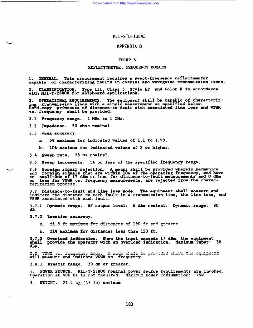
MIL-STD-1364J
APPENDIX D
FDRKP-B
REFLECTOKETER, ?lQUENCY DOMAIN
1. GENERAL. This procurement requires a swept-frequency reflectometercapable of characterizing faults in coaxial and waveguide transmission lines.
2. CIASSIFICATIOW .%
e III, Class 5, Sqle EP, and Color R in accordancewith MIL-T-28800 for s pboard applications.
3. OPERATIONAL RE UIREHENTS.?
The equipment shall be capable of characteriz-ing transmission ines with a single measurement as
?ecified below.
Hard-copy printouts of distance-to-fault with associa ed line loss and VSWRvs. frequency shall be provided.
3.1 Frequency range. 2 HHz to 1 GHz.
3.2 Impedance. 50 ohms nominal.
3.3 VSUR ●ccuracy.
a. St maximum for indicated values of 1.1 to 1.99.
b. 10* maximum for indicated values of 2 or higher.
3.4 Sweep rate. 25 ms nominal.
3.5 Sweep increments. 5% or less of the specified frequency range.
w 3.6 For@n signa;sre ection.da
A means shall be provided Whexeinharmnicsand foreign Gian F
t are witiin 10% of the o rating frequen7 7
md haveamplitude o 17 dlh or less for distance-to- ault measurement Ad O d!bs
or less for VSUR vs. frequency measurements, are rejected from the charac-terization process.
3.7 Di8tance-to-fault and line ~O&a mode. The equipaent shall naaure andindicate the distance to each fault in a transmission line, the line 10SS, -dVSWR associated with each fault.
3.7.1 Dynamic range. RF output level: O dBm nominal. ~amic range: 80dBm
3.7.2 Location ●ccuracy.
a. ~1.5 ft maximum for distances of 150 ft and greater.
b. ~1% ~~ for distances less man 150 ft.
3.7.3 -xload indication. When the in ut exceeds 17 dl!m, the equlpwntfshall provide the operator with an over oad indication. Maxlnnm input: 30
dBm.
3.8 VSUR vs. fr uency mode.?
A mode shall be provided where the equipmentwill measure and ndicate VSWR vs. frequency.
3.8.1 Dynamic range. 30 dB or greater.
POWER SOURCE. MIL-T-288C0 nominal power source requirements a~:vinvoked.~eration at 400 Hz is not required. Maximum power consumption: .
5. WEIGHT . 21.4 kg (47 lb) maximum.
—
183
Downloaded from http://www.everyspec.com
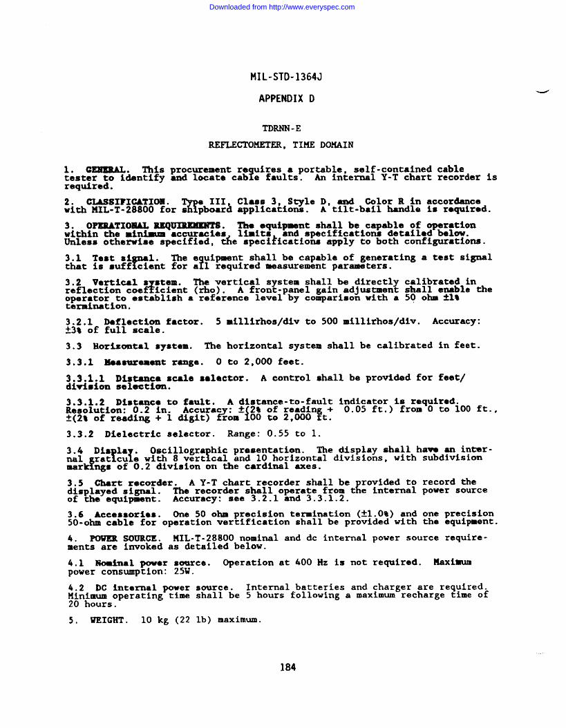
MIL-STD-1364J
APPENDIX D
TDRNN-E
REFLECTOMETKR, TIME DOMAIN
10 CEMEEAL. TMs procurement re uires a portable, self-contained cable?tester to identify and locate cab e faults. An internal Y-T chart recorder is
required.
2. CLASSIFICATIOBI.%
e III Class 3, S~le D, and Color R in accordancewith MIL-T-28800 for s pboar~ applications. A tilt-bail handle is required.
3. OPISRATIOMALREQ~. The equipment shall be capable of operationwithin the rni~ ●ccuracies 11.mits and specifications detafled below.Unless othend.se specified, &e speci~ications apply to both configurations.
3.1 Test si 1.Y
The e uipment shall be capable of generating a test signal?that is suff cient for a 1 required measurement parameters.
3.2 Vertical s stem.d
The vertical system shall be dlrectl calibrated inreflection coe icient (rho). { shall enable theA front-panel gain adjustmenoperator to establish a reference level by comparison with a 50 ohm *1*termination.
3.2.1 Deflection factor. 5 millirhos/div to 500 millirhos/div. Accuracy:~3* of full scale.
3.3 Horizontal system. The horizontal system shall be calibrated in feet.
3.3.1 Meaetarememt range. O to 2,000 feet.
3.3.1.1 DLstamcs scale sslector. A control shall be provided for feet/division selection.
3.3.1.2 Distance to fault. A distance-to-fault Indicator is required.Resolution: 0.2 in. Accurac : & 2% of readin + 0.05 ft.) from O to 100 ft.,k(2% of reading + 1 digit) f?om i00 to 2,000 ft.
3.3.2 Dielectric selector. Range: 0.55 to 1.
3.4 Dis la .!1
Oscillogra hic presentation.!
The display shall ha- an inter-nal rat cu e with 8 vert cal and 10 horizontal divisions, with subdivision
dmar ngs of 0.2 division on the cardinal axes.
3.5 Chart recorder. A Y-T chart recorder shall be rovided to record thedisplayed signal. KThe recorder shall operate from t e internal power sourceof the equipment. Accuracy: see 3.2.1 and 3.3.1.2.
3.6 Accessories. One 50 ohm precision termination (*1.0%) and one precision50-ohm cable for operation verification shall be provided with the equipment.
4. POWER SOURCE. MIL-T-28800 nominal and dc internal power source require-ments are invoked as detailed below.
4.1 Nomimal power source. Operation at 400 Hz is not required. Maximumpower consumption: 25W.
4.2 DC internal power source. Internal batteries and charger are required.;~n;~soperating time shall be 5 hours following a maximum recharge time of
.
5, WEIGHT . 10 kg (22 lb) maximum.
184
Downloaded from http://www.everyspec.com
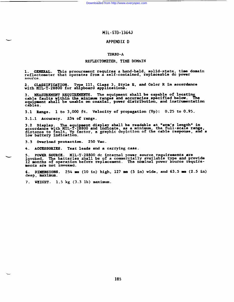
—
MIL-STD-1364J
APPENDIX D
TDRBD -A
REFLECTOKETER, TIME DOMAIN
1. GENEML. This procurement requires a hand-held, solid-state, time domainreflectometer that operates from a self-contained, replaceable dc powersource.
2. CLASSIFICATION .%
e 111 Class 3, Style E, and Color R in accordancewith KIL-T-28800 for s pboar~ applications.
3. mMmmENT RICQu~s. The equipment shall be capable of locaticable faults within the minimum ran as and accuracies specified below.
f% e
e uipment shall be usable on coaxia , power distribution, and imtrumentation%ca 18s.
3.1 Range. 1 to 3,000 ft. Velocity of propagation (Vp): 0.25 to 0.95.
3.1.1 Accuracy. k3% of range.
3.2 Display. The e ui ment dis la shall be readable at “arm’s len th” inaccordance with HIL -?-2~800 and ?n~cate, as a minimum, the full-scafe range,distance to fault, Vp factor, a graphic depiction of the cable response, and alow battery indication.
3.3 tiorload protection. 250 Vat.
4. ACCESSORIES. Test leads and a carrying case.
- 5. m= SOURCE. NIL-T-28800 dc internal power source re uirements areinvoked. ?The batteries shall be of a commercially availab e type and provide12 months of o ~~~~n before replacement.
!The nominal power source require-
ments are not .
6. DIMENSIONS. 254 mm (10 in) high, 127 mm (5 in) wide, and 63.5 - (2.5 in)deep, maximum.
7. WEIGHT . 1.5 kg (3.3 lb) maximum.
185
Downloaded from http://www.everyspec.com
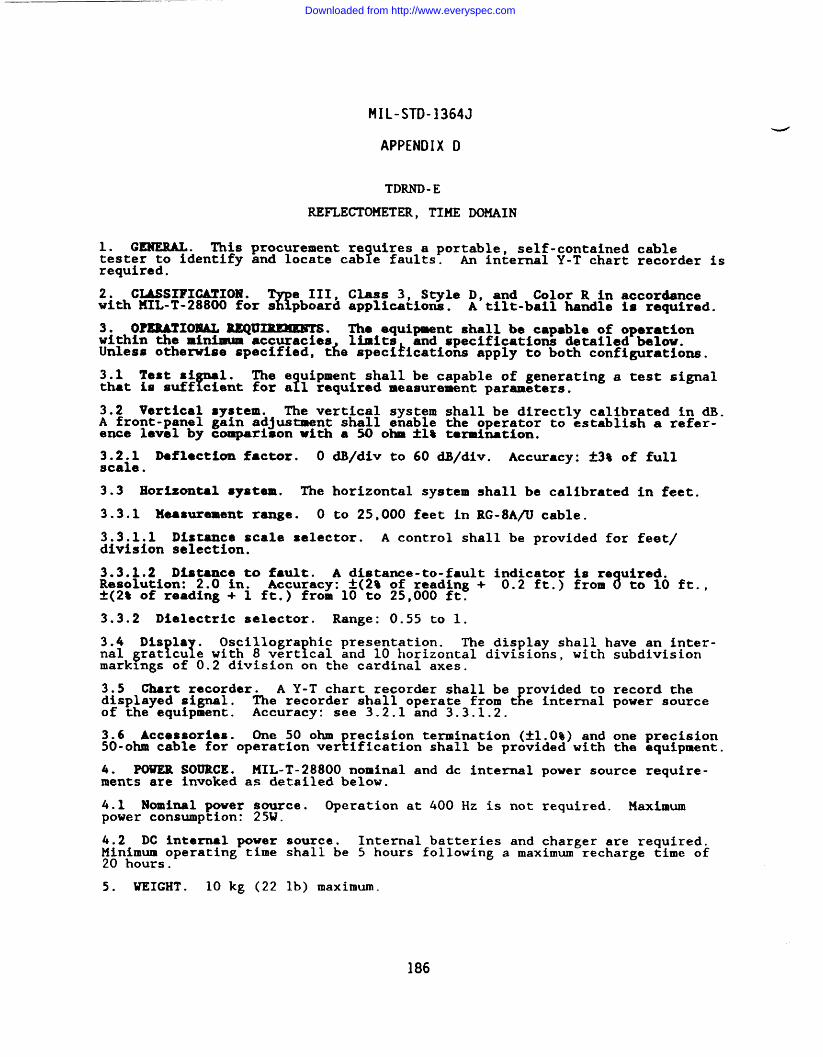
MIL-STD-1364J
APPENDIX D
TDRND-E
REFLECTOMETER, TIME DOMAIN
1. GENERAL. This procurement re uires a portable, self-contained cableYtester to identify and locate cab e faults. An internal Y-T chart recorder is
required.
2. CIASSIPIGATION .%
e III, Class 3, Style D, and Color R in accordancewith HIL-T-28800 for s pboard applications. A tilt-bail handle is required.
3. OPERATIONAL lEQU~. The equipment shall be capable of operationwithin the minimum accuracies limits and specifications detailed below.Unless otherwise specified, de specifications apply to both configurations.
3.1 Test si 1.r
The e uipment shall be capable of generating a test signalfthat is suff cient for a 1 required measurement parameters.
3.2 Vertical system. The vertical system shall be directly calibrated in dB.A front-panel gain adjustment shall enable the operator to establish a refer-ence level by comparison with a 50 ohm *1% termination.
3.2.1 Dafl@ctlon factor. O dB/div to 60 dB/div. Accuracy: *3% of fullscale.
3.3 Horlsontal system. The horizontal system shall be calibrated in feet.
3.3.1 Measurement range. O to 25,000 feet in RG-8A/U cable.
3.3.1.1 Distance scale selector. A control shall be provided for feet/division selection.
3.3.1.2 Dlntance to fault. A distance-to-fault indicator is re uired.Resolution: 2.0 in. Accuracy: t(2% of reading + 0.2 ft.) from 8 to 10 ft.,t(2~ of reading + 1 ft.) from 10 to 25,000 ft.
3.3.2 Dielectric selector. Range: 0.55 to 1.
3.4 Dis la .!1
Oscillogra hic presentation.f
The display shall have an inter-nal ~rat cu e with 8 vert cal and 10 horizontal divisions, with subdivisionmarkings of 0.2 division on the cardinal axes.
3.5 Ghart recorder. A Y-T chart zecorder shall be rovided to record thedisplayed signal. EThe recorder shall operate from t e internal power sourceof the equipment. Accuracy: see 3.2.1 and 3.3.1.2.
3.6 Accessories. One 50 ohm precision termination (~1.0%) and one precision50-ohm cable for operation verification shall be provided with the equipment.
4. POWER SOURCE. MIL-T-28800 nominal and dc internal power source require-ments are invoked as detailed below.
4.1 Nominal power source. Operation at 400 Hz is not required. Maximumpower consumption: 25W.
4.2 DC internal power source. Internal batteries and charger are required.;in~im~operating time shall be 5 hours following a maximum recharge time of
.
5. WEIGHT . 10 kg (22 lb) ❑aximum.
186
Downloaded from http://www.everyspec.com
MIL-STD-1364J
APPENDIX D
TDRNM-A
REFLECTOMETER, TIME DOMAIN
1. GENERAL. This procurement requires a pulse reflectometer.
2. CLASSIFICATION .%
e III, Class 5, Style E, and Color R in accordancewith MIL-T-28800 for s pboard applications
3. OPKUATIOMAL REQUIREMENTS. The equipment shall be capablo of operatingwithin the following limits and minimum specifications.
3.1 Pulse amplitude. Adjustable from O.lV to 5 kV into 50 ohms A1O%.
3.2 Pulse w%dth. Typically 30 ns.
3.3 Output connectors. The equi ment shall be provided with a female N typeconnector for pulse output and a ~emale BNC type connector for oscilloscope.display of the pulse.
4. PowIm SOURCE. MIL-T-28800 nominal power source requirements a~minvo~d.Operation at 400 Hz is not required. Haximum power consumption: .
5. WEIGHT . 20 kg (44 lb) maximum.
187
Downloaded from http://www.everyspec.com
MIL-STD-1364J
APPENDIX D
TDFM- C
REFLECTOHETER, TIKE DOMAIN, FIBER OPTIC
1.0 GENEML* Thts procurement requires ●
!ortable, general purpose, solid
state, pro ramable optical time domain ref ectometer (OTDR capable ofylyming E 1●ults and s licas in msltimode optical fiber cab es at wavmle ths
7nanometers (nm . YThe OTDR shall be capable of performing calibra edoptical attenuation and distance measurements.
2.0 CLASSIFICATION. The equi28800( ), Type 111 r
nt shall meet the requirements of KXL-I-Claas 5, S le E, Color R for Navy shipboard, wbmarine
and shore applications with the following modifications and exceptions:
a. The non-operating temperature requirement is limited to the range of-40”C to +65°C.
b. The operating temperature requirement is limited to the range of O’Cto +40°c,
The Electromali.mit~d to CEOI
i
tic Interference re uirements of MIL-T-28800 are-20 & CE03 CSO1, CS02 (8.05 to 100 KHz), CS06, REOl (back
panel search exc uded), k02 (i4 kHz to 10 GHz), and RS03.
3.0 OPERATIONAL REQUIMMENTS. The e uipment shall be capable of making1measurements within the parameters an accuracies specified herein.
3.1 Light source.
3.1.1 Wavelength: 1300 nm ~ 30 m.
3.1.2 P1Y
-In module: Light source shall be interchangeable as plug-inmodule wit out need to disassemble mainframe.
3.1.3 Connector: FC type.
3.1.4 Pulse widths: At least 3 widths.
3.1.4.1 Mini.mum PU: 3 nsec or less.
3.1.5 I%lse recovery time (dead zone): 10 m maximum.
3.2 Vertical exis: Attenuation/Loss Parameters.
3.2.1 Scale factor.
3.2.1.1 Minimum: 0.5 d.B/div or less.
3.2.1.2 Maximum: 4.0 dB/div or more.
3.2.2 Dynemic range: 10 dB.
3.2.3 Resolution: 0.02 dB or better.
3.2.4 Measurement modes:
Loss between 2 pointsLoss by least squares approximationLoss per unit length
3.3 Horizontal axis: Distance Measurement.
3.3.1 Range: At least 15 \ 40 km. .—
188
Downloaded from http://www.everyspec.com
MIL-STD-1364J
APPENDIX D
-----
3.3.2 ACCUraCy: * [1.0 m + 2x10-~ D] [D - measured distance in meters]
3.3.3 Resolution: FS/500 [FS - full scale distance in meters].
3.3.4 Index of refraction.
3.3.4.1 Range: 1.4000 to 1.6000.
3.3.4.2 Resolution: 0.0001.
3.4 Signal avarag?
Noise reduction shall be rovided b se uentialaveraging of fiber u ‘
rture trace. Parameters o! 3.2 and~.3 hllbe
achieved within two m mutes of signal averaging.
3.5 Display. OTDR shall resent the data from measurements in a graphical!and alphanumeric form simu taneously.
3.5.1 Graphical: CRT visual obse~ation of fiber characteristic in dB on thevertical axis verses fiber distance in meters on the horizontal axis. Traceshall show entire characteristic or a magnified portion of range.
3.5.2 Alphanumeric: Integral part of graphical display. The followingparameters shall be displaysci:
(7)
DateTitle (manual entry)Distance RangeHorizontal Scale (m/div)Vertical Scale (dB/div)Horizontal Trace StartDistanceWavelength
8 Marker Distance
i~ Pulse Width
/
Index of Refraction11 Distance between Markers (@km)12 Splice Loss (dB)13 Loss between Markers (dB)14 Fiber bss (dB~)
Note: Alphanumeric data must appear with data recalled from storage.
3.5.2.2 Markers/Cursors: At least two movable on-screen indicators, capableof being positioned at any point on graphical trace with resolution of 1.0 m.
3.5.2.3 Loss measurement.
3.5.2.3.1 2 point: Wss in dB between any two points (markers).
3.5.2.3.2 Slope: Fiber loss per unit distance (dB/km).
3.5.2.4 Averaging status indicator: Indicator shall provide current statusof signal averaging.
3.5.3 Hardco y printout:E
A hard copy du licate of the complete CRT datascreen shall e available from an internaT printer/plotter.
4.0 GENERAL REQUIREMENTS.
4.1 Power source: 115 and 230 Vac *1O%, single base, at frequencies of 50and 60 Hz tlO%; and 400 Hz ~10% at 115 Vac only, 2~0 watts maximum.
4.2 Dimensions: Portable less than 200 mm (H); 350 mm (W); 450 mm (D).
4.3 Wet ht:f
The overall weight of the unit with one plug-in shall not exceed20 kg (4 lbs) .
4.4 Remote operation: The unit will be capable of remote o eration viaIEEE-488( ) bus interface. fIt shall operate as a talker or istener such thatall functions except the power on/off switch are controllable and shall haveas a minimum the following subset of GPIB commands: AHl, SH1, T6, M, SR1,RL1, DC1, DT1.
189
Downloaded from http://www.everyspec.com
MIL-STD-1364J
APPENDIX D
LUWAA-A
REGULATOR, LINE
1. CENEmu, This procurement requires a single-phase line voltage regulator.
2. CLASSIFICATION .%
e III, Class 3, Style E, and Color R in accordancewith 141L-T-28800 for s pboard applications. The convertible/rackmounta.blerequirement Is invoked.
3. OPEMTIOMAL REQUIMMmTS. The ● ipower line voltages in accordance wi% KnEo:P2knpG3Es;:cEK%% .
3.1 output specifications.
3.1.1 voltage. 103 to 127 Vac continuously adjustable.
3.1.2 Currant rating. 50A irrespective of load conditions.
3.1.3 Correction rate. 42 msec + 25 msec/lV change.
3.1.4 Regulation. M.25t of output voltage setting.
4. PmKR SOURCE. KIL-T-28800 nominal power source re uirements are iuvoked\except operation at 50 and 400 Hz is not required and t e operatin voltage
range is limited to 103.5 to 126.5V. ~ kWMaximum power consumption: .
5. UEIGRT . 25 kg (55 lb) maximum.
190
Downloaded from http://www.everyspec.com
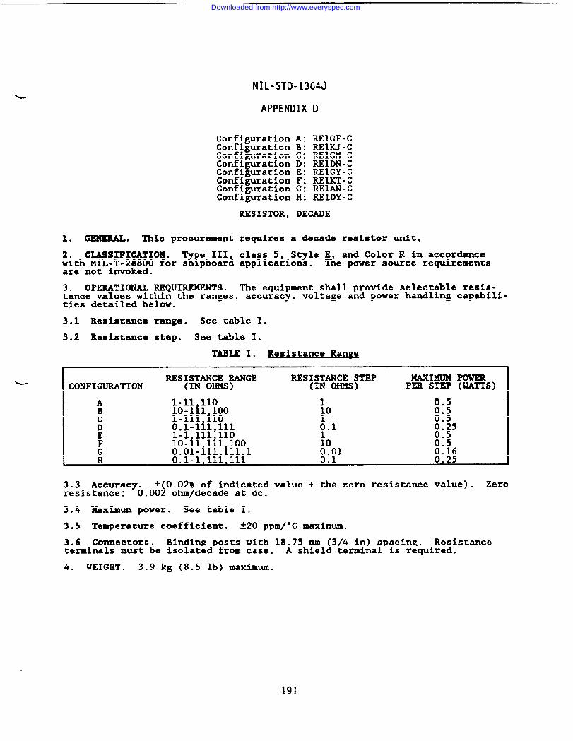
MIL-STD-1364J
APPENDIX D
Configuration A: REIGF-CConfiguration B: REIKJ-CConfiguration C: REIGM-CConfiguration D: REIDN-CConfiguration E: REIGY-CConfiguration F: REIKT-CConfiguration G: REIAN-CConfiguration H: REIDY-C
RESISTOR, DECADE
1. GENERAL. This procurement requires a decade resistor unit.
2. CLASSIFICATION .%
e III, class 5, Style E, and Color R in accordancewith MIL-T-28800 for s pboard applications. The power source requirementsare not invoked.
3. OPERATIONAL REQUIREMENTS. The equipment shall provide selectable resis-tance values within the ranges, accuracy, voltage and power handling capabili-ties detailed below.
3.1 Resistance range. See table I.
3.2 Resistance step. See table I.
TABLE 1. Bes stani ce Raw
u I RESISTANCE RANGE RESISTANCE STEP MAXIMUM POWERCONFIGURATION (IN OHMS) (IN OHMS) PER STEP (WATTS)
1-11 110lo-lil 1001-111 iloO.1-lil,lll1-1 111 110lo-il lil 100O.ol-ill,ill.l
1lo
~.1
100.01
0.50.50.50.250.50.50.16
3.3 Accuracy. ~(Oo02% of indicated value + the zero resistance value). Zeroresistance: 0.002 ohm/decade at dc.
3.4 Maximum power. See table I.
3.5 Temperature coefficient. *2O ppm/’C maximum.
3.6 Connectors. Binding posts with 18.75 mm 3 4 in) spacing.Al Resistanceterminals must be isolated from case. A shiel terminal is required.
4. WEIGHT . 3.9 kg (8.5 lb) maximum.
191
Downloaded from http://www.everyspec.com
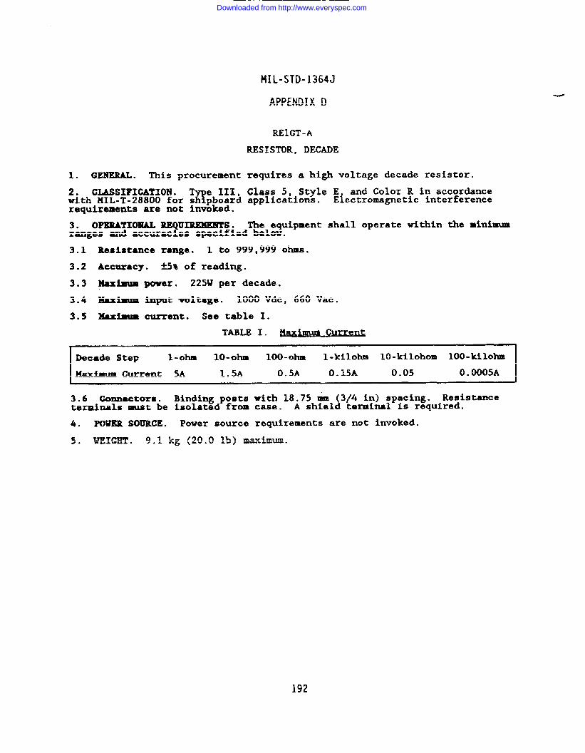
1. GENERAL. This procurement
2. CLASSIFICATION. T e 111,K!with KXL-T-28800 for s pboard
requirements are not invoked.
MIL-STD-1364J
APPENDIX D
REIGT-A
RESISTOR, DECADE
requires a high voltage decade resistor.
Class 5. Style E. and Color R in accordanceapplication=.
3. OPERATIONAL UIREMERTS. The equipmentTranges and accurac es Specifi8d below.
3.1 Resistance range. 1 to 999,999 ohms.
3.2 Accuracy. +3% of reading.
3.3 ~imum power. 22SW per decade.
Electromagnetic interference
shall operate within the minimum
3.4 Maximum input voltage. 1000 Vdc, 660 Vat.
3.5 Xaxfmm current. See table I.
TABLE I. CurrenC
IDecade Step l-ohm lo-ohm 100-ohm l-kilohm 10-kilohom 100-kilohm
Max- Current 5A 1.5A 0.5A O.15A 0.05 0.0005A
3.6 Connectors. Binding posts with 18.75 ~ 3 4 in) spacing. Resist=ceterminals must be Isolated from case.
AlA shiel terminal is required.
4. POWER SOURCE. Power source requirements are not invoked.
5. WEIGET . 9.1 kg (20.0 lb) maximum.
192
Downloaded from http://www.everyspec.com
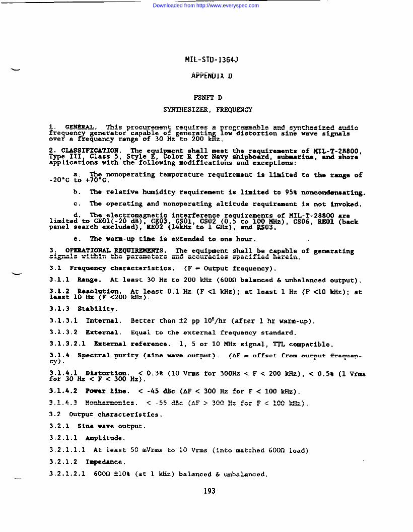
MIL-STD-1364J
APPENDIX D
FSNFT -D
SYNTHESIZER, FREQUENCY
1. GENERAL. This procurement requires aYrogrammable and synthesized audio
frequent generator capable of generatinf? d
ow distortion sine wave signalsover a requency range of 30 Hz to 200 z.
2. CLASSIFICATION. The e ui ment shall meet the requirements of MIL-T-28800,Type III Class 5, Style ~, &lo. R for Navy shied, mibma.ine, and shor,applicat~ons with the following modifications an exceptions:
The nonoperating temperature requirement is limited to the range of-20”C :0 +70”C.
b. The relative humidity requirement is limited to 958 noncondensating.
c. The operating and nonoperating altitude requirement is not invoked.
The electromagnetic interference re uirements of MIL-T-28800 arelimite$”to CEO1(-20 dB), CE03, CSO1, CS02 O.~ to 100 MHz), CS06, REOl (backpanel search excluded), LRE02 (14kHz to 1 G ), and RS03.
e. The warm-up time is extended to one hour.
3. OPERATIONAL REQUIREMENTS. The equipment shall be capable of generatingsignals within the parameters and accuracies specified herein.
3.1 Frequency characteristics. (F - Output frequency).w
3.1.1 Range. At least 30 Hz to 200 ldlz (60(Xlbalanced & unbalanced output).
3.1.2 Resolution. At least 0.1 Hz (F <1 kHz); at least 1 Hz (F <10 ld-lz);atleast 10 Hz (F <200 kHz).
301.3 Stability.
3.1.3,1 Internal. Better than ~2 pp l@/hr (after 1 hr warm-up).
3.1.3.2 External. Equal to the external frequency standard.
3.1.3.2.1 External reference. 1, 5 or 10 MHz signal, TTL compatible.
3.1.4 Spectral purity (sine wave output). (AF - offset from output frequen-. .Cy) .
3.1.4.1 Distortion. < 0.3% (lo Vrmsfor 30 Hz< F<300 Hz).
3.1.4.2 Power line. < -45 dBc (AF <
3.1.4.3 Nonharmonics. < -55 dBc (AF
3.2 Output characteristics.
3.2.1 Sine wave output.
3.2.1.1 Amplitude.
for 300Hz < F < 200 kHz), c 0.5% (1 v~s
300 Hz for F < 100 kHz).
> 300 Hz for F < 100 kHz).
3.2.1.1.1 At least 50 mVrms to 10 Vrms (into matched 600G load)
3.2.1.2 Impedance.
3.2.1.2.1 6000 ~10% (at 1 kHz) balanced & unbalanced.-\-
193
Downloaded from http://www.everyspec.com
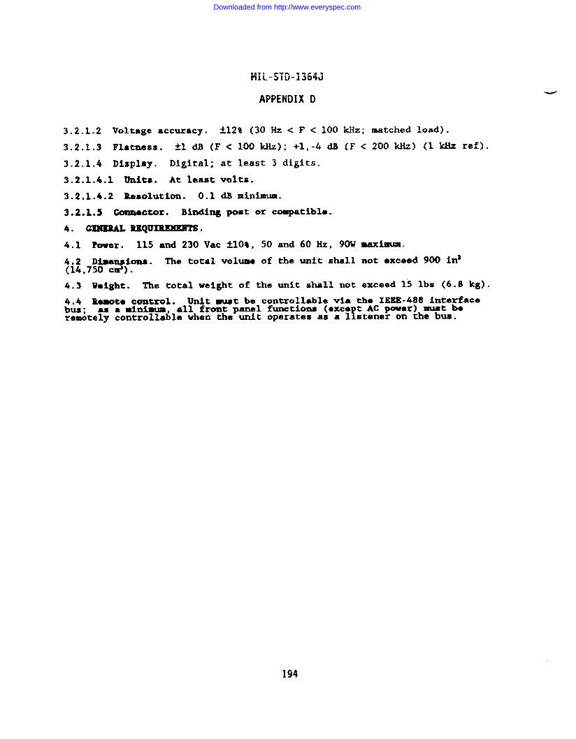
MIL-STD-1364J
APPENDIX D
3.2.1.2 Voltage accuracy. ~~2% (30 Hz < F < 100 ~z; ~tched load).
3.2.1.3 Flatness. kldB (F<100kHz); +1,-4dB (F<200kHz) (lklizref).
3.2.1.4 Display. Digital; at least 3 digits.
3.2.1.4.1 Units. At least volts.
3.2.1.4.2 Resolution. 0.1 dB minima.
3.2.1.S Conmactor. Binding post or coapatibla.
4. cm9EML lUEQuIREMEEM .
4.1 Power. 115 and 230 Vac *1O*, 50 and 60 Hz, 90W maximm.
4.2 Dimmfions. The total volume of the unit shall not exceed 900 ina(14,750 cm).
4.3 weight. The total weight of the unit shall not exceed 15 lbs (6.8 kg).
4.4 ReBoto control. Unit must be controllable via the IEEE-488 interfacebus : as a minhum, all front panel functions (exca t AC power) must b.
!remotely controllable when the unit operates as a 1 stener on the bus.
194
Downloaded from http://www.everyspec.com
MIL-STD-1364J
APPENDIX D
FSNFU-A
SYNTHESIZER, FREQUENCY
1.0 GENERAL. This procurement requires a stable RF synthesizer ca able ofgenerating signals over the fre uency range of 1 kliz to 140 MHZ wi
1& internal
and external modulation capabil ties.
~8:OOCLASSIFICAT1031. The equipment shall meet the requirements of KIL-T-
Te 111, Class 5, S le E, Color R for Navy shipboard, submarine, and
shore’app ications with the? ollowing modifications and exceptions:
The nonoperating temperature requirement is limited to the range of.40”:”to +70”C.
b. The relative humidity requirement is limited to 95% noncondensating.
c. The operating and nonoperating altitude requirement is not invoked.
d. The warm-up time is extended to one hour.
3.0 OPERATIONAL REQUIREMENTS. The equipment shall be capable of generatingsignals within the parameters and accuracies specified herein.
3.1 Frequency characteristics.
3.1.1 Frequency range. At least 1 kHz to 140 XHz.
3.1.2 Requency resol~tion. At least 1 Hz.v
3.1.3 Frequency accuracy. At least ~lxlOE-5 after a one hour warm-up orequal to external reference.
3.1.4 Spectral purity (equal to or better than the limits specified below).
3.1.4.1 Harmonics. -30 dBc.
3.1.4.2 Nonharmonlcs. -65 dBc.
3.1.4.3 Phase noise. Less than -120 dBc/Hz measured 20 kHz from the carrier.
3.2 Output characteristics.
3.2.1 Power output ran e. At least +19 to -127 dBm for CW and FM operationand at least +13 to -129 dBm for AM operation.
3.2.2 Output level resolution. At least 1 dB over the entire output range.
3.2.3 Power out t accuracy.%
At least *1.5 dB from +19 to -40 dBm with anadditional &O.1 /step for levels below -40 d,b.
3.2.4 Impedance/Connector. 50 ohms; type BNC(f).
3.2.4.1 VSWR. Better than 1.5:1 for output levels less than O dBm.
3.3 Modulation characteristics.
3.3.1 Amplitude modulation (AM).
3.3.1.1 Internal.
3.3.1.1.1 Rates. At least 400 Hz and 1 kHz.
3.3.1.1.2 Depth. At least 1 to 90% modulation with less than 3% distortion.~-
195
Downloaded from http://www.everyspec.com
MIL-STD-1364J
APPENDIX (l
3.3.1.2 External.
3.3.1.2.1 Rates. Variable from 20 Hz to 15 Mz minimum.
3.3.1.2.2 Depth. At least 1 to 90% modulation with less than 3% distortion.
3.3.2 Frequency modulation (FM).
3.3.2.1 Intarnal.
3.3.2.1.1 Wtas. At least 400 Hz and 1 kHz.
3.3.2.1.2 FM deviation. O Hz to at least 1% of the carrier for frequenciesbelow 20 MHz; O Hz to at least 199 kllzfor carrier frequencies above 20 MHz.
3.3.2.2 External.
3.3.2.2.1 Rates. Variable from 20 Hz to 20 kHz minimum.
3.3.2.2.2 FM deviation. O Hz to at least 1% of the carrier for frequenciesbelow 20 MHz; O Hz to at least 199 kHz for carrier frequencies above 20 KHz.
4.0 GEXERALREQU~.
4.1 Power. 115/230 Vac *1O%, 50/60 Hz, 120 VA maximum.
4.2 Dimensions. The total volume of the unit shall not exceed 4,347 cubic in(71,235 cubic cm).
4.3 Veight. The total weight of the unit shall not exceed 50 lbs (23 kg).
The enerator shall be capable of being4“4 ‘e=te~~o~?=?#~488 in~erfacebmcontroll~d P*’el?operating as both a tal er anlistener, havin at least the following s~bset of bus functions: AHl, LA,SH1, T6, SR1, K& andRL1.
.-
196
Downloaded from http://www.everyspec.com
MIL-STD-1364J
APPENDIX D
FSNFR-C
SYNTHESIZER, FREQUENCY
1.0 GENERAL. This procurement requires a!rogrammable audio frequency
generator capable of generating low distort on high am ~itu~ level, sine andsquare wave signals over a frequency range of 10 Hz to ? .
2.0 CSASSIFICATIOM. The equipment shall meet the requirements of MXL-T-28800( ), Type 111 Class 5, Style E, Color R for Navy shi board, subaarine,
8and shore applications with the following modifications an exceptions:
a. The Ehctroma etic Interference requirements of HIL-T-288W arelimited to CEO1(-20 dB~ CE03, CSO1, CS02 (0.05 to 100 MHz), cS06, REO1 (backpanel search excluded), RE02 (14kHz to 10 GHz), and RS03.
b. The warm-up time is extended to one hour.
3.0 OPERATIONAL REQUIMKENTS. The equipment shall be capable of generatingsignals within the parameters and accuracies specified herein.
3.1 Frequency characteristics.
3.1.1 Range: At least 20 Hz to 20 kHz.
3.1.2 Resolution: Digital; at least 4 digits.
3.1.3 Stability.
~ 3.1.3.1 Internal: Better than *2 pp l&/h (after 1 h warm-up).
3.1.3.2 External: Equal to the external frequency standard.
3.1.3.2.1 External reference: 1, 5 or 10 KHz signal, ITL compatible.
3.1.4 Spectral purity (equal to or better than the limits specified below).
3.1.4.1 Harmonics: -40 dBc.
3.1.4.2 Nonharmonics: -65 dBc.
3.1.4.3 Distortion: Less than 0.5% from 50 Hz to 20 kHz at 1 W; less than 1%from 20 Hz to 20 kHz at 3 W.
3.2 Output characteristics.
3.2.1 Sine wave output.
3.2.1.1 Amplitude (sine): 10 mV to 42 Vrms.
3.2.1.2 Impedence: 600 OhmS ~10%.
3.2.1.3 ACCUdkCy: At least *5% of indication at 1 kHz.
3.2.1.4 Flatness: -i-ldB (1 ~z ref),
3.2.1.5 Display: Digital in units of volts/millivolts.
3.2.1.6 Resolution: 3 digits.
3.2.1.7 Connector: Type BNC female.
3.2.2 Squarewave output: TTL levels, positive.
-..
197
Downloaded from http://www.everyspec.com
MIL-STD-1364J
APPENDIX D
3.2.2.1 Rise/Fall Time: Less than 50 ns.
4.0 GENERAL REQUXREHYWTS.
4.1 Power: 115/230 Vac *1O%, 50/60 Hz, 100 watts maximum.
:i&oD~)mim : The total volume of the unit shall not exceed 16,400 c#.
4.3 Wetght: The total weight of the unit shall not exceed 6.8 kg (15 lb).
4.4 *to control: Wnit must be controllable via the IEEE-488( ) interfacebus; as a minimum, all front panel functions (exce t AC power) must beremotely controllable when the unit operates as a !istener on the bus.
.-
198
Downloaded from http://www.everyspec.com
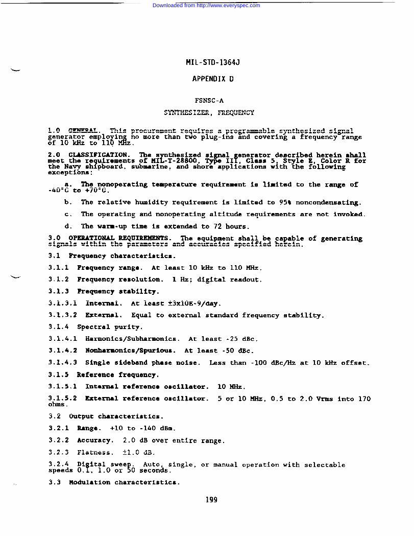
MIL-STD-1364J
APPENDIX D
FSNSC-A
SYNTHESIZER, FREQUENCY
1.0 GENERAL. This procurement requires a programmable synthesized signal
5;”!6’= ::’;?6’%.no more than two plug-ins and covering a frequency range
2.0 CLASSIFICATION. The s thesized signalr
enerator described herein shallmeet the re uirements of MI -T-28800, Type IIf, Claas 5 Style E, Color R for
1the Navy sh pboard, submarine, and shore applications with the followingexceptiom:
The nonoperating temperature requirement is limited to the range of.ko”:”to +70”C.
b. The relative humidity requirement is limited to 95% noncondensating.
c. The operating and nonoperating altitude requirements are not invoked.
d. The warm-up time is extended to 72 hours.
3.0 OPERATIONAL REQUIREMENTS. The equipment shall be capable of generatingsignals within the parameters and accuracies specified herein.
3.1 Requency characteristics.
3.1.1 Frequency range. At least 10 kHz to 110 MHz.L 3.1.2 Frequency resolution. 1 Hz; digital readout.
3.1.3 Requency stabillty.
3.1.3.1 Internal. At least *3x10E-9/day.
3.1.3.2 External. Equal to external standard frequency stability.
3.1.4 Spectral purity.
3.1.4.1 Harmonics/Subharmonics. At least -25 dBc.
3.1.4.2 Nom.harmonics\Spurious. At least -SO dBc.
3.1.4.3 Single sideband phase noise. Less than -100 dBc/Hz at 10 kHz offset.
3.1.5 Reference frequency.
3.1.5.1 Inte~l reference oscillator. 10 MHz.
3.1.5.2 External reference oscillator. 5 or 10 MHz, 0.5 to 2.0 Vrms into 170ohms .
3.2 Output characteristics.
3.2.1 Range. +10 to -140 dBm.
3.2.2 Accuracy. 2.0 dB over entire range.
3.2.3 Flatness. tl.o dB.
3.2.4 Di ital swee . Auto,f !
single, or manual operation with selectablespeeds O. , 1.0 or O seconds.
3.3 Modulation characteristics.
199
Downloaded from http://www.everyspec.com
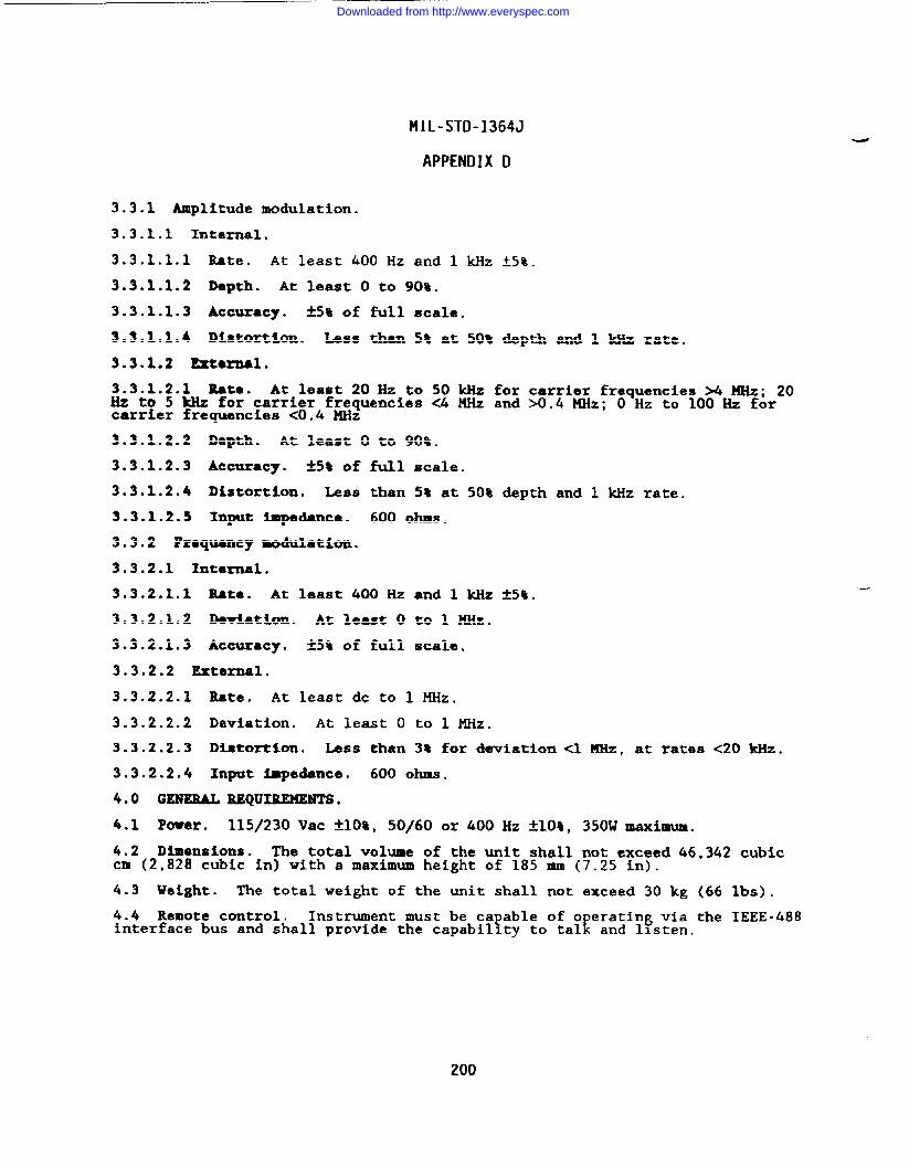
MIL-STD-1364J
APPENDIX D
3.3.1 Amplitude modulation.
3.3.1.1 Internal.
3.3.1.1.1 Rate. At least 400 Hz and 1 kHz ~5%.
3.3.1.1.2 Depth. At least O to 90%.
3.3.1.1.3 Accuracy. H% of full scale.
3.3.1.1.4 Distortion. Less than 5% at 50% depth and 1 kllzrate.
3.3.1.2 External.
3.3.1.2.1 Rata. At least 20 Hz to 50 kHz for carrier frequencies M MHz; 20Hz to 5 kHz for carrier frequencies <4 MHz and X).4 MHz; O Hz to 100 Hz forcarrier frequencies <0.4 MHz
3.3.1.2.2 Depth. At least O to 90%.
3.3.1.2.3 ACctUaCy. *5% of f~l scale.
3.3.1.2.4 Distortion. Less than 5% at 50% depth and 1 kllzrate.
3.3.1.2.5 Input Impedance. 600 Ohs.
3.3.2 Fraquency modulation.
3.3.2.1 Internal.
3.3.2.1.1 Rate. At least 400 Hz and 1 kilzk5%.
3.3.2.1.2 Deviation. At least O to 1 MHz.
3.3.2.1.3 Accuracy. A5% of full scale.
3.3.2.2 External.
3.3.2.2.1 Rate, At least dc to 1 MHz.
3.3.2.2.2 Deviation. At least O to 1 MHZ.
3.3.2.2.3 Di.atortlon. Less than 3t for dwiatiom <1 MHz, at rates <20 kllz.
3.3.2.2.4 Input impedance. 600 OhlllS.
4.0 GENEIUL REQUIREMENTS.
4.1 Pwer. 115/230 Vac &lO%, 50/60 or 400 Hz ~108, 350W maximum.
4.2 Dimensions. The total volume of the unit shall not exceed 46,342 cubiccm (2,828 cubic in) with a maximum height of 185 mm (7.25 in).
4.3 Ueight. The total weight of the unit shall not exceed 30 kg (66 lbs).
4.4 Remote control. Instrument ❑ust be capable of o crating via the IEEE-488Einterface bus and shall provide the capability to tal and llsten.
200
Downloaded from http://www.everyspec.com
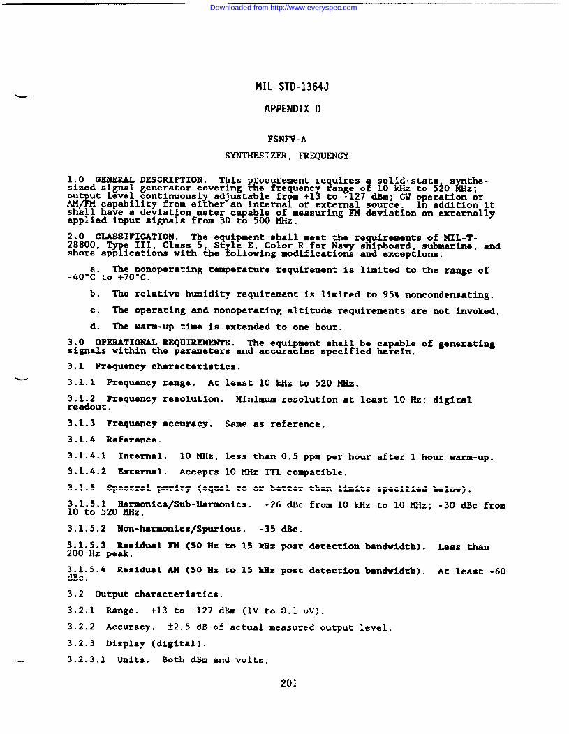
MIL-STD-1364J
APPENDIX D
FSNFV-A
SYNTHESIZER, FREQUENCY
1.0 GENERAL DESCRIPTION. This procurement requires a solid-state s the-sized signal generator covering the frequent
%3
range of 10 kHz to 5}0 Bz;ou ut level continuously adjustable from +1 to -127 c3Bxn;W operation orAM/ capability from either an internal or external source. In addition itshall have a deviation meter capable of measuring FM deviation on externallyapplied input signals from 30 to 500 MHz.
:&~ooCIASSI?ICATXOKl. The equipment shall meet the requirements of lllL-T-
Te III, Class 5, St le E, Color R for Navy shipboard, submarine, and
shore’app ications with the ;c)llowing modifications and exceptions:
The nonoperating temperature requirement is limited to the range ofJ&:-to +70”C.
b. The relative humidity requirement is limited to 95% noncondensating.
c. The operating and nonoperating altituda requirements are not invoked.
d. The warE-up time is extended to one hour.
3.0 OPERATIONAL REQURUMENTS. The equipment shall be capable of generatingsignals within the parameters and accuracies specified herein.
3.1 Frequency characteristics.
~ 3.1.1 Frequency range. At least 10 ldlzto 520 MHz.
3.1.2 Frequency resolution. Minimum resolution at least 10 Hz; digitalreadout.
3.1.3 Frequency accuracy. Same as reference.
3.1.4 Reference.
3.1.4.1 Internal. 10 MHz, less than 0.5 ppm per hour after 1 hour warm-up.
3.1.4.2 External. Accepts 10 MHz TTL compatible.
3.1.5 Spectral purity (equal to or better than limits specified below).
3.1.5.1 Harmonics/Sub-Harmonics. -26 dBc from 10 kHz to 10 MHz; -30 dBc from10 to 520 ~Z.
3.1.5.2 Non-harmonics/Spurious. -35 dBc.
3.1.5.3 Residual FM (50 Es to 15 kllzpost detection bandwidth). Less than200 Hz peak.
3.1.5.4 Residual M (50 Hz to 15 kllzpost detection bandwidth).dBc .
At least -60
3.2 Output characteristics.
3.2.1 Range. +13 to -127 dBm (1V to 0.1 uV).
3.2.2 Accuracy. ~2.5 dB of actual measured output level.
3.2.3 Display (digital).
- 3.2.3.1 Units. Both dBm and volts.
201
Downloaded from http://www.everyspec.com
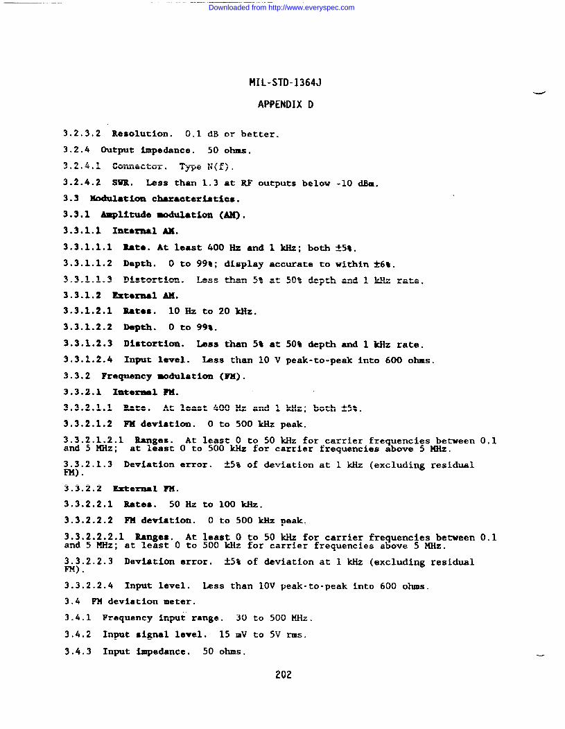
-.
MIL-STD-1364J
APPENDIX D
3.2.3.2 Resolution. 0.1 dB or better.
3.2.4 Output impedance. 50 ohms.
3.2.4.1 Connector. Type N(f).
3.2.4.2 ~. Less than 1.3 at RF outputs below -10 dBQ.
3.3 Modulation characteristics.
3.3.1 &plftude modulation (AM).
3.3.1.1 Intarmal AX.
3.3.1.1.1 Rat.. At least 400 Hz and 1 kHz; both *5t.
3.3.1.1.2 Depth. O to 99~; display accurate to within *6%.
3.3.1.1.3 Distortion. Less than 5% at 50% depth and 1 kHz rate.
3.3.1.2 Extoraal AM.
3.3.1.2.1 Rates. 10 Hz to 20 Wz.
3.3.1.2.2 Depth. O to 99t.
3.3.1.2.3 Distortion. lass than 5% at 50% depth and 1 kHz rate.
3.3.1.2.4 Input level. Less than 10 V peak-to-peak into 600 ohms.
3.3.2 Frequency -dulation (~).
3.3.2.1 Snternal ?M.
3.3.2.1.1 Rate. At least 400 Hz and 1 kHz; both f5%.
3.3.2.1.2 FM deviation. O to 500 kHz peak.
X~.~.~~.l Ranges. At least O to 50 kHz for carrier fre uencies between 0.1.t \at least O to 500 kHz for carrier frequencies a ove 5 MHz.
3.3.2.1,3 Deviation error. k5% of deviation at 1 W (excluding residualFM) .
3.3.2.2 External ?W.
3.3.2.2.1 Rates. 50 Hz to 100 kHz.
3.3.2.2.2 FM deviation. O to 500 kHz peak.
3.3.2.2.2.1 Rangea. At least O to 50 kHz for carrier frequencies between 0.1and 5 KHz; at least O to 500 kHz for carrier frequencies above 5 KHz.
3.3.2.2.3 Deviation error. *5% of deviation at 1 kHz (excluding residualFM) .
3.3.2.2.4 Input level. Less than 10V peak-to-peak into 600 ohms.
3.4 FM deviation meter.
3.4.1 Frequency input range. 30 to 500 MHz.
3.4.2 Input signal level. 15 mV to 5V rms.
3.4.3 Input impedance. 50 ohms.
202
Downloaded from http://www.everyspec.com
MIL-STD-1364J
APPENDIX D
3.4.4 Measurement range. o to 500 Mz.
3.4.4.1 Polarity. Selectable
3.4.4.2 Modulation rate. 100
3.4.4.3 Accuracy. 6* of full
4.0 GmEBALREQuIREMmm*
4.1 POwar smrca. 115 or 230
;~ Input pcwer. The aaxi=m.
positive or negative.
HZ to 8 ~Z.
scale from 100 Hz to 8 kHz.
Vac *lOt, single phase, 50, 60 or 400 Hz.
power required for operation shall not exceed
4.3 Rewte ope~atiom. Instrument shall be c able of o ratin v#n*e IEEB-Y Y488 interface bus and shall provide the capabi ity to ta k and f .
4.4 DiQenaiWla. The total volume of the unit shall not exceed 2,270 cubic in(37,200 cubic cm) with amaximun height of 6.0 inches.
4.5 Weight. The overall weight of the unit shall not exceed 40 pounds (18.2kg) .
4.6 RF leabga. Less than 1 UV when measured with a 2 turn, 1 inch diameterloop held 1 inch from any surface using a 50 ohm input receiver.
$& Reverse power protection. Resettable RF circuit breaker up to inputs of.
203
Downloaded from http://www.everyspec.com
MIL-STD-1364J
APPENDIX D
FSNSA-C
SYNTHESIZER, FREQUENCY
1. GENERAL. TMS procurement requires a ro amable s~thesized Si algenerator covering a frequent
1range of 108 ~ ..2 GHz with interna~and
external modulation capabilit es.
2* CLASSIFICATION . The s thesized signal~-T-28800, Type IfI, Cla.ss5 S~le E, Color Rfor
enerator described herein shallmeet the re uirements of
?the Navy sh pboard, submarine, and shore applications w!th the followingexceptions:
a. The relative humidity requirement is limited to 95* noncondensating.
b. The opezating and nonoperating altitude requirements ue not invoked.
c. The electromagnetic interference re uirements of MIL-T-28800 arealimited to CEO1, CE03 CSO1, CS02 0.5 to 1 0 MHz) cS06, REO1 (relaxed 20 dB;
back panel search exciuded), iRE02 14 Wz to 1 GHzj, and RS03.
d. The warm-up time is extended to 2 hours.
3. OPERATIONAL BEQUIUMENTS . The equipment shall be capable of generatingsignals within the parameters and accuracies specified herein.
3.1 Frequency characteristics. F - carrier freqw=y.
3.1.1 Range. At least 100 kHz to 2 CHZ.
3.1.2 Resolution. At least 1 Hz.
3.1.3 Stability (GW mode).
3.1.3.1 Internal. < *2 pp l&/hr.
3.1.3.2 Temperature. < 1 pp 107 O-SO°C.
3.1.3.3 External. Equal to external standard frequency stability.
3.1.4 Spectral purity. (level S 8 dBtu).
3.1.4.1 Earmonica/Subharmonics. At least -30 dBc (F < 1 GHz) at least -25dBc (> 1 GHz).
3.1.4.2 Nonllarmonic~/Spurious. At least -90 dBc (>15 kllz from carrier).
3.1.4.3 Signal sideband phase noise. S -120 dBc/Hz (at 20 * offset).
3.1.4.4 Residual AX. <0.1% rms (300Hz to 3 kHz BW).
3.1.4.5 Residual FH. < 10 Hz YIIIS(50 Hz to 15 ~Z BW).
3.1.5 Frequency sweap.
3.1.5.1 Type. Linear, stepped.
3.1.5,2 Sweep width. At least 10 kHz to 1 GHz.
3.1.5.3 Step size. At least 1 Hz to 10 MHz.
3.1.5.4 Modes. Manual, auto.
3.1.6 Reference frequency.
204
Downloaded from http://www.everyspec.com
MIL-STD-1364J
APPENDIX D
3.1.6.1 Internal. 10 MHz.
3.1.6.1.1 Output level. > 0.1 Vrms into 50 ohm BNC female comector.
3.1.6.2 External. 5 or 10 MHz.
3.1.6.2.1 Input level. > 0.5 Vrms into 50 ohm BNC female connector.
3.2 Output characteristics.
3.2.1 Range. +13 to -127 dBm.
3.2.2 Accuracy. Within *1.5 dll.
3.2.2.1 Resolution. 0.1 dB,
3.2.3 Flatness. -tl~ (measured at ()mm).
3.2.4 Output impedance/connector. 50-ohm; Type-N.
3.2.4.1 VSWR. < 2 (Level < 0 dBm).
3.2.5 Reverse power protection.
3.2.5.1 Max CU power. 25W.
3.2.5.2 Max dc voltage. 25V .
3.3 Modulation characteristics. (F - carrier frequency) Any simultaneouscombination of AH, FM, or pulse.
~3.3.1 Amplitude modulation (AM). (Level 5 0 dBm.)
3.3.1.1 Internal AM. (F>10 MHZ.)
3.3.1.1.1 Rate. At least 20 Hz to 50 kHz synthesized.
3.3.1.1.2 Depth. O to 99%.
3.3.1.1.3 Accuracy. *7% of selected depth (< 90% depth @l kHz).
3.3.1.1.4 Distortion. < 5% (50% depth @l kHz).
3.3.1.1.5 Incidental +X. < 0.3 radians (30% depth @ 1 kllz), (50 Hz to 15 kHzBW) .
3.3.1.2 External AX. (F > 10 MHz.)
3.3.1.2.1 Rate. At least 20 Hz to 50 kHz.
3.3.1.2.2 Depth. O to 99%.
3.3.1.2.3 Sensitivity. < 1 Vpk (produce selected depth within 10%).
3.3.1.2.4 Distortion. s 5% (50% depth @ 1 kliz).
3.3.1.2.5 Input impedance. 600n .
3.3.2 Frequency modulation (FM). (AF = FM deviation).
3.3.2.1 Internal FM. (F > 10 ~Z).
3.3.2.1.1 Rate. At least 20 Hz to 100 kHz synthesized.
3.3.2.1.2 Deviation. At least O to 100 kHz.-._.
205
Downloaded from http://www.everyspec.com
MIL-STD-1364J
APPENDIX D
3.3.2.1.3 Accuracy. 26% of set value + 20 HZ (50 HZ to 25 kHz rate).
3.3.2.1.4 Distortion. s 3% [AF - 2okHz@lkHz].
3.3.2.2 External FM. (F > 10 kfiiZ).
3.3.2.2.1 Rata. At least DC to 100 kHz.
3.3.2.2.2 Deviation. At least O to 100 kllz.
3.3.2.2.3 DLatortlon. s3%(AF-20kHz@l Mz).
3.3.2.2.4 Incidental AX. <l*(AF- 2okHz@ lkllz), (50HZ to 15 Hz Bw).
3.3.2.2.5 Input impedance. 6000.
3.3.3 Pulse modulation (PM).
3.3.3.1 External PM [m 10MHZ].
3.3.3.1.1 Rate. At least 20 Hz to 1 MHz.
3.3.3.1.2 Level Accuracy. s & 2 dB.
3.3.3.1.3 Mm Pulse Width. < 500 nsec.
3.3.3.1.4 Oil/OFF ratio. > 80 dB.
3.3.3.1.5 Rise/Fall Time. < 100nsec.
3.3.3.1.6 bvel. > 3 Vpk ON; < 1 Vpk OFF.
3.3.3.1.7 Input Impedance. 50 ohms or 600 ohms.
3.3.4 Internal Modulation Source (Synthesized).
3.3.4.1 Ratas. 1 Hz to 100 kHz.
3.3.4.2 Accuracy/Stability. Same as reference.
3.3.4.3 Resolution. At least 3 digits.
3.3.4.4 Level. O to 2 Vpeak.
3.3.4.5 Output Impedance. 600 OhIIIS.
4. GEIUERAL REQUIREMENTS
4.1 Power. 115/230 Vac *1O%, single phase, 50-60 HZ *5%, 400 VAm~~W.
4.2 Dim~nsions. The total volume of the unit shall not exceed 49200 cm3(3000 in).
4.3 Weight. The total weight of the unit shall not exceed 31.8 kg (70 lbs).
4.4 Remote Programming .E
The generator shall be capable of being remotelycontrolled via the IEE -488( ) interface bust OPeratinlistener, havin
l!!f
as both a ta~ke~andat least the following subset of bus unctions:
SHI, T6, SR1, D 1, and RL1.B ?
Downloaded from http://www.everyspec.com
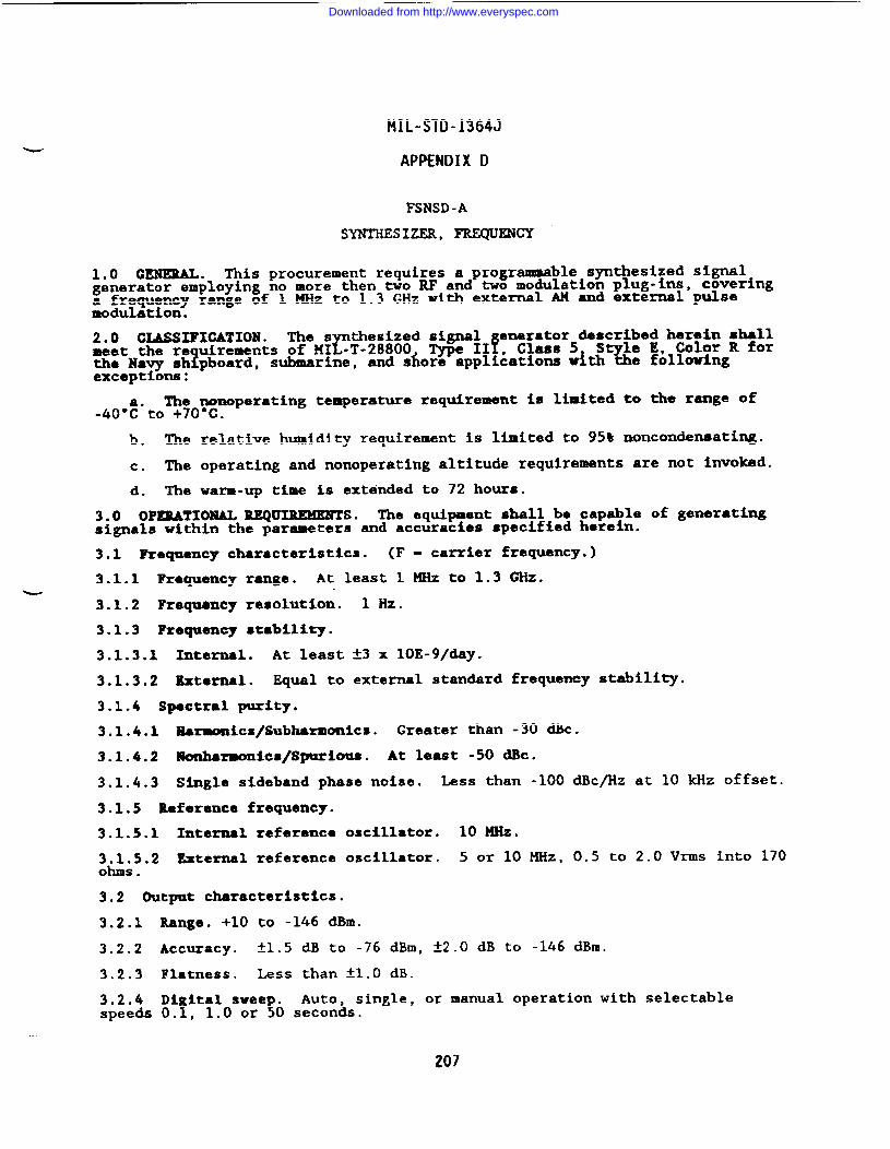
MIL-STD-1364J
APPENDIX D
FSNSD-A
SYNTHESIZER, -ENCY
1.0 G~. This procurement requires a programmable synthesized signalgenerator employing no more then two RF and two modulation plug-ins, coveringa frequency range of 1 KHz to 1.3 GHz with external AH and external pulsemodulation.
2.0 CIASSXFIGATION. The s thesized signalr
and sfioreappl!~a~~~= ~t;~e !&l~~&R ‘“r
enerator described harein shallmeet the re uirements of MI -T-28800 Type 11
?the Navy sh pboard, submarine,exceptions:
The nonoperating temperature requirement is limited to the range of-40”:*to +70°c.
b. The relative humidity requirement is limited to 95% noncondensating.
c. The operating and nonoperating altitude requirements are not invoked.
d. The warm-up time is extended to 72 hours.
3.0 OPERATIONAL REQUIREMENTS. The equipment shall be capable of generatingsignals within the parameters and accuracies specified herein.
3.1 Requency characteristics. (F - carrier frequency.)
3.1.1 Frequency range. At least 1 MHz to 1.3 GHz.-
3.1.2 Frequency resolution. 1 Hz.
3.1.3 Frequency stability.
3.1.3.1 Internal. At least *3 x 10E-9/day.
3.1.3.2 External. Equal to external standard frequency stability.
3.1.4 Spectral purity.
3.1.4.1 Earmonics/Subherm-ics. Greater than -30 -c.
3.1.4.2 lUonhar-onics/SpuriOUS. At least -50 dBc.
3.1.4.3 Single sideband phase noise. Less than -100 dBc/Hz at 10 kllz offset.
3.1.5 Reference frequency.
3.1.5.1 Internal reference oscillator. 10 MHz.
3.1.5.2 External reference oscillator. 5 or 10 MHz, 0.5 to 2.OVrms into 170ohms .
3.2 Output characteristics.
3.2.1
3.2.2
3.2.3
3.2.4speeds
Range. +10 to -146 dBm.
Accuracy. tl.5 dB to -76 dBm, t2.O dB to -146 dBm.
Flatness. Less than tl.O dB.
Di Ital svee .!
single, or manual operation with selectable0.!, 1.0 or O s~~~~s.
207
Downloaded from http://www.everyspec.com
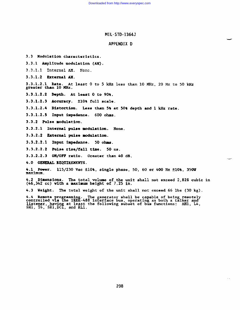
MIL-STD-1364J
APPENDIX D
3.3 Modulation characteristics.
3.3.1 Amplitude modulation (AH).
3.3.1.1 Internal AH. None.
3.3.1.2 External AM.
3.3.1.2.1 Rate. At least O to 5 kHz less than 10 MHz, 20 Hz to 50 kHzgreater than 10 MHz.
3.3.1.2.2 D8pth. At least O to 90%.
3.3.1.2.3 Accuracy. A1O% full scale.
3.3.1.2.4 Distortion. kss than St at 50% depth ●nd 1 kHz rate.
3.3.1.2.5 Input impedance. 600 ohms.
3.3.2 Mlse modulation.
3.3.2.1 Xntornal pulse modulation. None.
3.3.2.2 External pulse modulation.
3.3.2.2.1 Input impedance. 50 ohms.
3.3.2.2.2 Pulse rise/fall time. 50 ns.
3.3.2.2.3 OE1/OFT ratio. Greater than 40 dB.
4.0 GEHERAL REQUIREMENTS.
4.1 Power. 115/230 Vac *1O%, single phase, 50, 60 or 400 Hz klO&, 350Wmaximum .
4.2 Dimensions. The total volume of the unit shall not exceed 2,828 cubic in{46,342 cc) with a maximum height of 7.25 in.
4.3 Ve@ht. The total weight of the unit shall not exceed 66 lbs (30 kg).
4.4 Remoterrogrammin .
iThe enerator shall be capable of being remotely
fcontrolled v a the IEE -488 in erface bus, operating as both a talker andlistener, havin at least the following subset of bus functions: AHl, L4,SH1, T6, SRl,DCf, and RL1.
208
Downloaded from http://www.everyspec.com
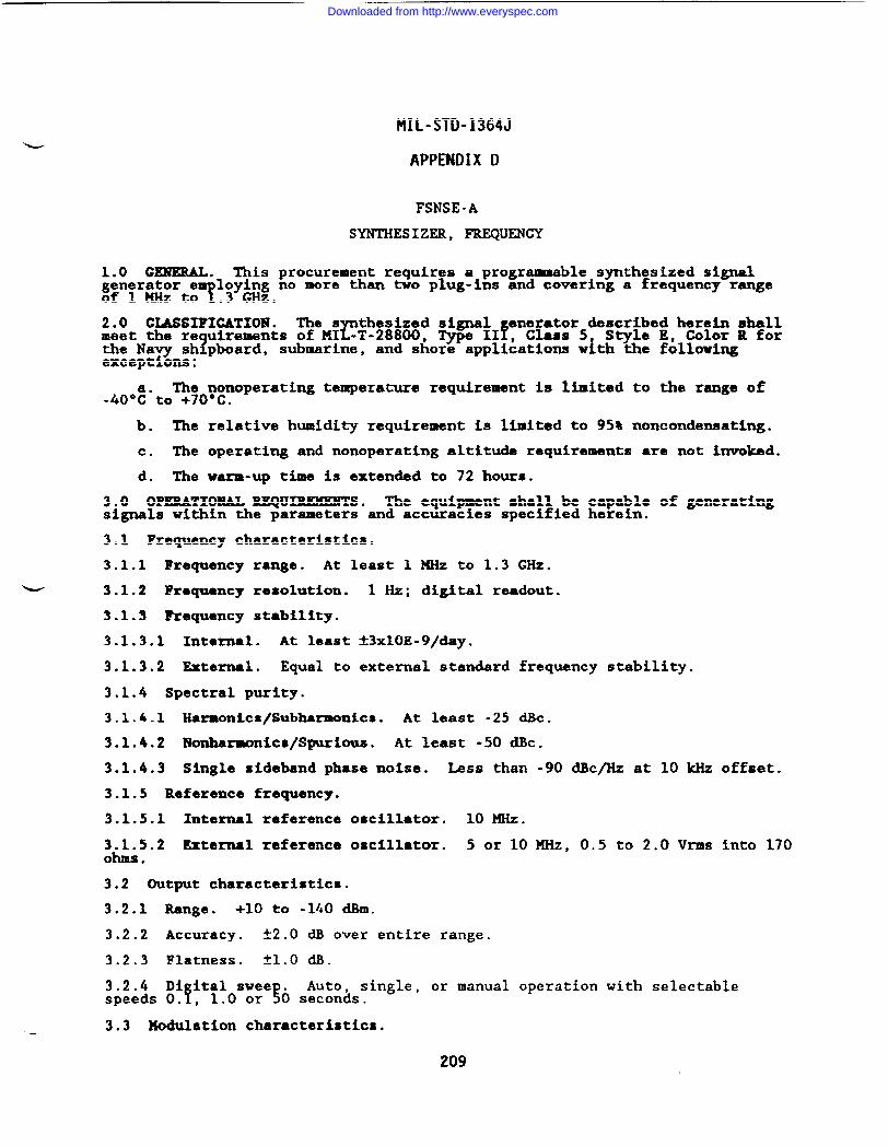
MIL-STD-1364J
APPENDIX D
FSNSE-A
SYNTHESIZER, FREQUENCY
1.0 GENERAL. This procurement requires a programmable synthesized signalgenerator e
T~~yin~ no more than two plug-ins and covering a frequency range
of 1 KHz to .
2.0 CLASSIFICATION. The s thesized signal enerator described herein shallrmeet the re uirements of MI -T-28800, Type XIf, Class 5 Style E, Color R for
1the Navy sh pboard, submarine, and shore applications with the followingexceptions:
The nonoperating temperature requirement is limited to the range of-40”t”to +70’C.
b. The relative humidity requirement is limited to 95% noncondensating.
c. The operating and nonoperating altitude requirements are not invoked.
d. The warm-up time is extended to 72 hours.
3.0 OPERATIONAL KEQUXREKENTS. The equipment shall be capable of generatingsignals within the parameters and accuracies specified herein.
3.1 Frequency characteristics.
3.1.1 Frequency range. At least 1 MHz to 1.3 GHz.
3.1.2 Frequency resolution. 1 Hz; digital readout.
3.1.3 ?requency stability.
3.1.3.1 Internal. At least t3x10E-9/day.
3.1.3.2 External. Equal to external standard frequency stability.
3.1.4 Spectral purity.
3.1.4.1 Harmonics/Subharmonics. At least -25 &c.
3.1.4.2 Nonharwnics/Spurious. At least -50 d.Bc.
3.1.4.3 Single sideband phase noise. Less than -90 dBc/Hz at 10 klizoffset.
3.1.5 Reference frequency.
3.1.5.1 Internal reference oscillator, 10 MHz.
3.1.5.2 External reference oscillator. 5 or 10 MHz, 0.5 to 2.0 Vrms into 170ohms .
3.2 Output characteristics.
3.2.1 Range. +10 to -140 dBm.
3.2.2 Accuracy. t2.O dB over entire range.
3.2.3 Flatness. *1.O dB.
3.2.4 Di ital swee . Auto,f !
single, or manual operation with selectablespeeds O. , 1.0 or O seconds.
-— 3.3 Modulation characteristics.
209
Downloaded from http://www.everyspec.com
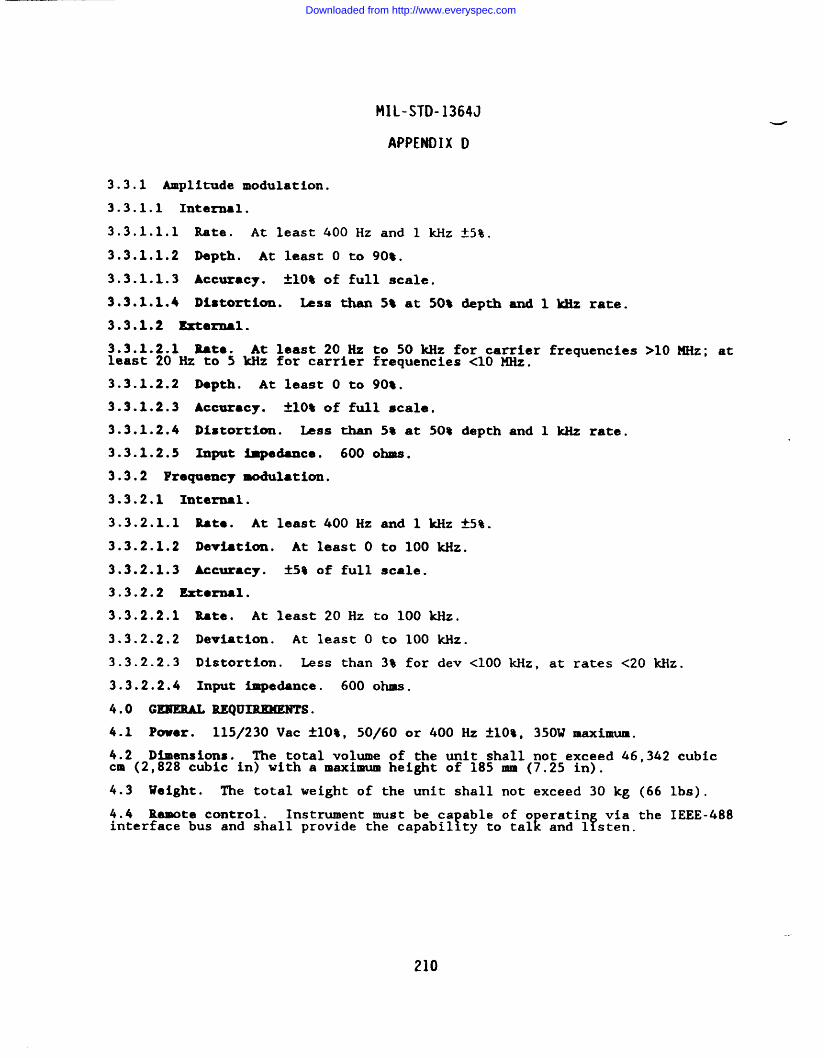
MIL-STD-1364J
APPENDIX D
3.3.1 Amplitude modulation.
3.3.1.1 Internal.
3.3.1.1.1 Rate. At least 400 Hz and 1 kllz~5%.
3.3.1.1.2 Depth. At least O to 90%.
3.3.1.1.3 Accuracy. i30% of full scale.
3.3.1.1.4 Distortion. Less then 5% at 50% &pth and 1 kliz rate.
3.3.1.2 Mernal.
3.3.1.2.1 Rate. At least 20 Hz to 50 kllz for carrier frequencies >10 MHz; atleast 20 Hz to 5 kllz for carrier frequencies <10 MHz.
3.3.1.2.2 Depth. At least O to 90%.
3.3.1.2.3 Accuracy. ~10% of full scale.
3.3.1.2.4 Distortion. Less than 5% at 50? depth and 1 kHz rate.
3.3.1.2.5 Input impedance. 600 OhQS.
3.3.2 Frequency modulation.
3.3.2.1 Internal.
3.3.2.1.1 Rate. At least 400 Hz and 1 kllz~5%.
3.3.2.1.2 Deviation. At least O to 100 Mz.
3.3.2.1.3 Accuracy. *5% of full scale.
3.3.2.2 Ertarnal.
3.3.2.2.1 Rate. At least 20 Hz to 100 kliz.
3.3.2.2.2 Deviation. At least O to 100 kHz.
3.3.2.2.3 Distortion. Less than 3% for dev <100 kliz,at rates <20 kllz.
3.3.2.2.4 Input impe&nce. 600 OhlSS.
4.0 GE19EML REQUIIUIKENTS.
4.1 Pover. 115/230 Vac A1O%, 50/60 or 400 Hz A1O%, 350W maximum.
4.2 Dimensions. The total volume of the unit shall not exceed 46,342 cubiccm (2,828 cubic in) with a maximum height of 185 mm (7.25 in).
4.3 Weight. The total weight of the unit shall not exceed 30 kg (66 lbs).
4.4 Remote control. Instrument must be ca able of o eratin via the IEEE-488rinterface bus and shall provide the capabil ty to talE fand 1 sten.
210
Downloaded from http://www.everyspec.com
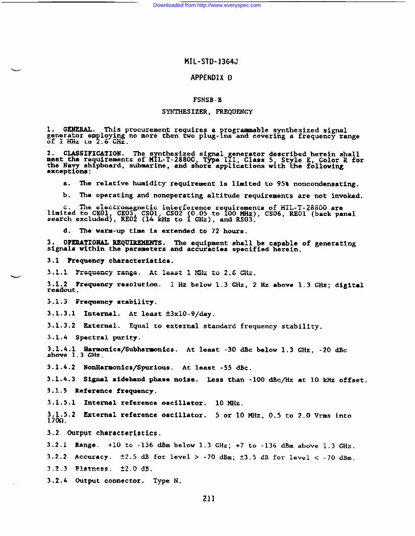
MIL-STD-1364J
APPENDIX D
FSNSB -B
SYNTHESIZER, FREQUENCY
1. GENERAL. This procurement requires afrogrammable synthesized signal
generator em ~:y&wg no more *en two plug- ns and covering a frequency rangeof 1 MHz to ? .
2. CLASSIFICATION . The s thesized signalz
enerator described herein shallmeet the re uirements of
1L-T-28800, Type IfI, Class 5 Style E, Color R for
the Navy sh pboard, submarine, and shore applications with the followingexceptions:
a. The relative humidity requirement is limited to 95% noncondensating.
b. The operating and nonoperating altitude requirements are not invoked.
The electromagnetic interference re uirements of MIL-T-28800 are1limi~~d to CEO1 CE03 CSO1 CS02 0.05 to 00 KHz), CS06, REO1 (back panel
search excluded~, REO~ (14 &z to f GHz), and RS03.
d. The warm-up time is extended to 72 hours.
3. OPERATIONAL REQ~S. The equipment shall be capable of generatingsignals within the parameters and accuracies specified herein.
3.1 Requency characteristics.
3.1.1 Frequency range. At least 1 MHz to 2.6 GHz.w3.1.2 Frequency resolution.readout.
3.1.3 Frequency stability.
3.1.3.1 Internal. At least
3.1.3.2 External. Equal to
3.1.4 Spectral purity,
1 Hz below 1.3 GHz, 2 Hz above 1.3 GHz; digital
t3xlo-9/day.
external standard
3.1.4.1 Hermonics/Subharmonics. At least -30above 1.3 GHz.
frequency stability.
dBc below 1.3 GHz, -20 dBc
3.1.4.2 NonHarmonics/Spurious. At least -55 dBC.
3.1.4.3 Signal sideband phase noise. Less than -100 dBc/Hz at 10 kHz offset.
3.1.5 Reference frequency.
3.1.5.1 Internal reference oscillator. 10 MHz.
~j~5.2 External reference oscillator. 5 or 10 MHz, 0.5 to 2.0 Vrms into.
3.2 Output characteristics.
3.2.1 Range. +-10 to -136 dBm below 1.3 GHz; +7 to -136 dBm above 1.3 GHz,
3.2.2 Accuracy. +2.5 ~ for level > -70 ~m; ~3c5 dB for level < -70 ~m.
3.2.3 Flatness. t2.O dB.
3.2.4 Output connector. Type N.
211
Downloaded from http://www.everyspec.com
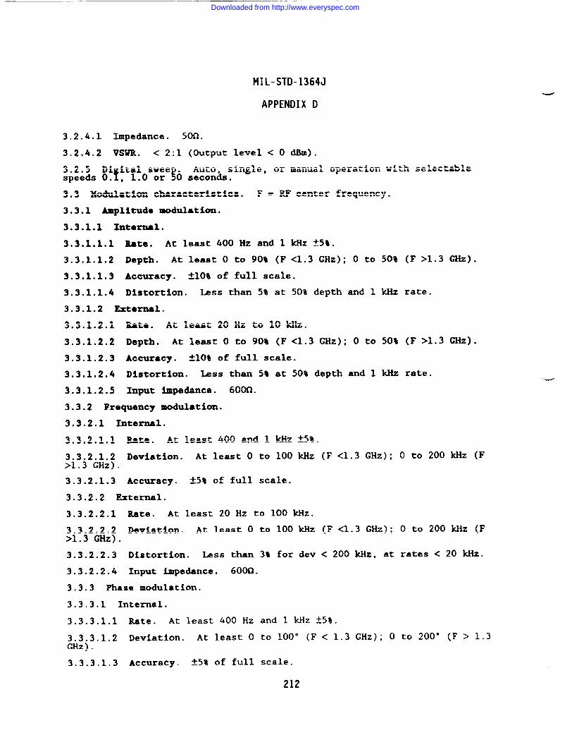
MIL-STD-1364J
APPENDIX D
3.2.4.1 Impedance. son ●
3.2.4.2 VSUR. < 2:1 (Output level < 0 db).
:p:eis8!?:’!:0s:’?0 s:::% ●
single, or manual operation with selectable
3.3 Modulation characteristics. F D RF center frequency.
3.3.1 Amplitude modulation.
3.3.1.1 Intarnal.
3.3.1.1.1 Rate. At least 400 Hz and 1 kHz f5S.
3.3.1.1.2 Depth. At least O to 90% (F <1.3 GHz); O to 50% (F >1.3 GHz).
3.3.1.1.3 Accuracy. *1O% of full scale.
3.3.1.1.4 Distortion. Less than 5% at 50% depth and 1 kHz rate.
3.3.1.2 External.
3.3.1.2.1 Rate. At least 20 Hz to 10 kHz.
3.3.1.2.2 Depth. At least O to 90% (F<l.3 GHz); O to 50% (F >1.3 GHz).
3.3.1.2.3 ACCur8Cy. +-1(’)$of full scale.
3.3.1.2.4 Distortion. Less than St at 50% depth and 1 kHz rate.
3.3.1.2.5 Input impedanca. 600CJ.
3.3.2 Frequency modulation.
3.3.2.1 Internal.
3.3.2.1.1 Rate. At least 400 and 1 kHz f5%.
3.3.2.1.2 Deviation. At least O to 100 kHz (F <1.3 GHz); O to 200 M-iz (F>1.3 GHz).
3.3.2.1.3 Accuracy. +-5%of full scale.
3.3.2.2 External.
3.3.2.2.1 Rate. At least 20 Hz to 100 kHz.
3.3.2.2.2 Deviation. At least O to 100 kHz (F <1.3 GHz); O to 200 kllz (F>1.3 GHz).
3.3.2.2.3 Distortion. Less than 3% for dev < 200 kHz, at rates < 20 kHz.
3.3.2.2.4 Input impedance. 6000.
3.3.3 Phase modulation.
3.3.3.1 Internal.
-
3.3.3.1.1 Rate. At least 400 Hz and 1 kHz ~5%.
3.3.3.1.2 Deviation. At least O to 100° (F< 1.3 GHz); O to 200” (F > 1.3GHz).
3.3.3.1.3 Accuracy. t5% of full scale.
212
Downloaded from http://www.everyspec.com
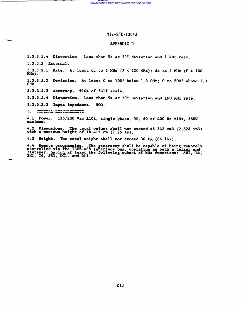
MIL-STD-1364J
APPENDIX D
3.3.3.1.4 Distortion. Less than 5% at 50° deviation and 1 kHz rate.
3.3.3.2 External.
3.3.3.2.1 Rate. At least dc to 1 MHz (F< 100 MHz); dc to 5 MHz (F > 100MHz) .
3.3.3.2.2 Deviation. At least O to 100° below 1.3 GHz; O to 200° above 1.3GHz ●
3.3.3.2.3 Accuracy. tlO% of full scale.
3.3.3.2.4 Distort&on. kss than St ●t 50° deviation and 100 kHz rate.
3.3.3.2.5 Input ~danca. 5M1.
4. GEBEBAL REQUIREMENTS.
4.1 Power. 115/230 Vac klO%, single phase, 50, 60 or 400 Hz fro%, 350wInaxlmum .
4.2 Dimensions. The total volume shall not exceed 46,342 cm3 (2,828 in3)with a maximum height of 18.415 cm (7.25 in).
4.3 Weight. The total weight shall not exceed 30 kg (66 lbs).
4.4 Remote r rammin . The enerator shall be capable of being remotely!%. IEE~-488 in~e.face bus, ope.a.hg u both a talker andcontrolled v a
listener, havln at least the following subset of bus functions: AU, IA,SH1, T6, SR1, D&, and RL1.
~
-.
213
Downloaded from http://www.everyspec.com
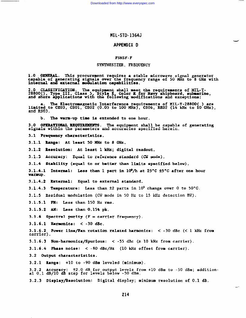
—
HIL-STD-1364J
APPENDIX D
FSNSF-F
SYNTHESIZER, FREQUENCY
This procurement requires a stable microwave si al eneratorcapable of‘“O ‘~emra’i”f s:i%L$!l&WY’ran’e0f50&’ 0g8’w withinternal d externa
2.0 CLASSIFICATION. The equlpwmt shall meet the requirements of lfIL-T-288000, Type III, Class 5 Style E Color R for Navy shipboard, submarine,and shore applications wit~ the foliowing modifications and exceptions:
The Electromagnetic Interference re uirements of ?lIL-T-28800 ) are?Mmit:d to CE03, CSO1, CS02 (0.05 to 100 ~Z , iCS06, RE02 (14 kHz to O GHz),
and RS03.
b. The warm-up time is extended to one hour.
3.0 OPERATIONAL ltEQ~. The equipment shall be capable of generatingsignals within the parameters and accuracies specified herein.
3.1 Fzequency characteristics.
3.1.1 Raqe: At least 50 KHz to 8 GHz.
3.1.2 Resolution: At least 1 kHz; digital readout.
3.1.3 Accuracy: Equal to reference standard (CW mode).
3.1.4 Stability (equal to or better than limits specified below).
3.1.4.1 Intermal: Less than 1 part in I&/h at 25*C &5°C after one hourwarmup.
3.1.4.2 External: Equal to external standard.
3.1.4.3 Temperature: Less than &2 parts in 10S change over O to 50°C.
3.1.5 Residual modulation (CW mode in 50 Hz to 15 kHz detection BW).
3.1.5.1 FM: Less than 150 Hz rms.
3.1.5.2 AM: tiss than 0.15% pk.
3.1.6 Spectral purity (F - carrier frequency).
3.1.6.1 fi~iCS: < -30 dk.
3.1.6.2 Power line/Fan rotation related harmonics: < -30 dBc (< 1 kHz fromcarrier).
3.1.6.3 Non-harmonics/Spurious: < -55 dBc (> 10 kHz from carrier).
3.1.6.4 Phase noise: < -80 dBc/Hz (10 kHz offset from carrier).
3.2 Output characteristics.
3.2.1 Range: +10 to -90 dBm leveled (minimum).
3.2.2 Accurac :d
t2.O dB for output levels from +10 dBm to -50 dBm; addition-al 0.1 dB/10 step for levels below -50 dBrn.
3.2.3 Display/Resolution: Digital display; minimum resolution of 0.1 dB.
Downloaded from http://www.everyspec.com
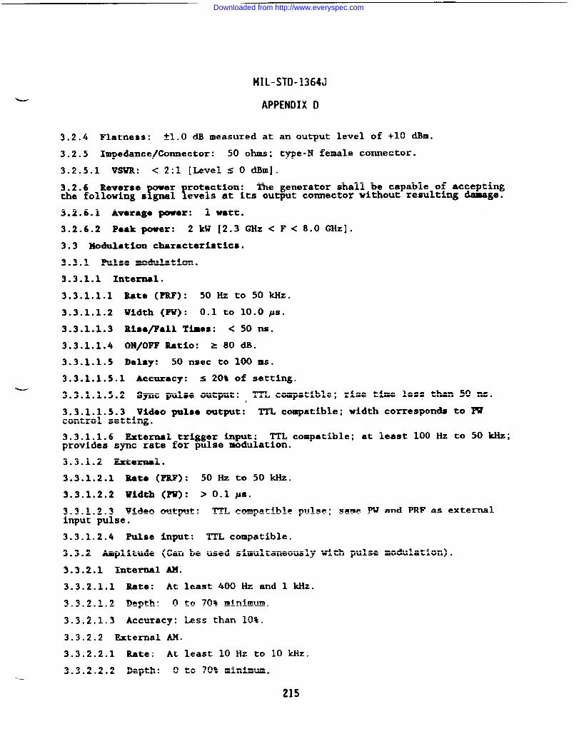
MIL-STD-1364J
APPENDIX D
3.2.4 Flatness: -tt.o ~ measured at an output level of +10 dBm.
3.2.5 Impedance/Connector: 50 ohms; type-N female connector.
3.2.5.1 VSWR: < 2:1 [Level S O dBm].
3.2.6 Reversethe following s= !r”’ec’inn:
The generator shall be capable of acceptingevels at Its output connector without resulting ~ge.
3.2.6.1 Avarage power: 1 watt.
3.2.6.2 Puk power: 2 kW [2.3 ~Z< F< 8.0 ~Z].
3.3 Modulation characteristics.
3.3.1 Pulsa modulation.
3.3.1.1 Internal.
3.3.1.1.1 Rate (PRF): 50 Hz to SokHz.
3.3.1.1.2 Width (PW): 0.1 to 10.0 ~S.
3.3.1*1.3 Ri8*/Fall Times: < 50 m.
3.3.1.1.4 ON/OFF Ratio: z 80 dB.
3.3.1.1.5 Delay: 50 nsec to 100 ma.
3.3.1.1.5.1 Accuracy: s 20% of setting.~
3.3.1.1.5.2 Sync pulse output: TTL compatible; rise ti~ lesp twn 50 ~.
3.3.1.1.5.3 Video PISO out~t: TTL compatible; width corresponds to PWcontrol setting.
3.3.1.1.6 External trigger input: TTL compatible; at least 100 Hz to 50 kHz;provides sync rate for pulse modulation.
3.3.1.2 External.
3.3.1.2.1 Rata (PRF): 50 Hz to 50kHz.
3.3.1.2.2 Width (PW): >0.1 #s.
3.3.1.2.3 Video output: TTL compatible pulse;input pulse.
same PW and PRF as external
3.3.1.2.4 pulse input: TTL compatible.
3.3.2 Amplitude (Can be used simultaneously with pulse modulation).
3.3.2.1 Internal AM.
3.3.2.1.1 Rate: At least 400 Hz and 1 kHz.
3.3.2.1.2 Depth: O to 70% minimum.
3.3.2.1.3 Accuracy: Less than 10%.
3.3.2.2 External AM.
3.3.2.2.1 Rate: At least 10 Hz to 10 kHz.
3.3.2.2.2 Depth: O to 70% minimum.
215
Downloaded from http://www.everyspec.com
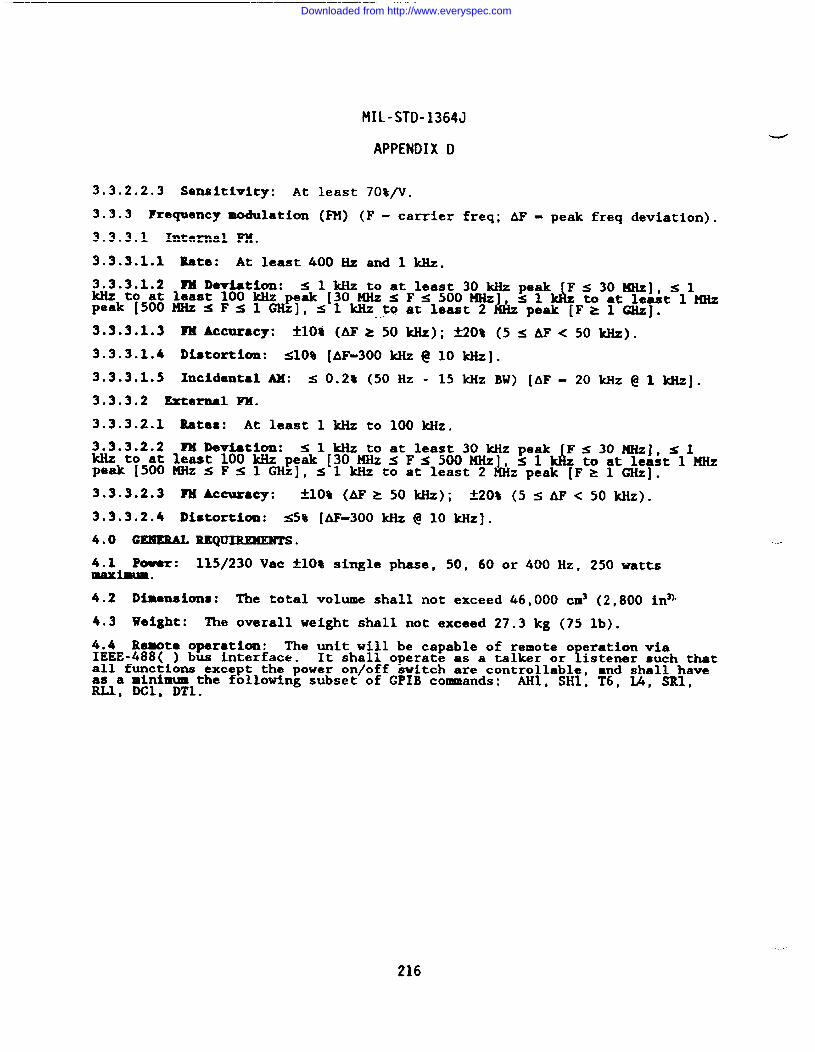
MIL-STD-1364J
APPENDIX 1)
3.3.2.2.3 Sensitivity: At least 70%/V.
3.3.3 Frequency modulation (FM) (F - carrier freq; AF - peak freq deviation).
3.3.3.1 Intanal FM.
3.3.3.1.1 Bate: At least 400 Hz and 1 kllz.
3.3.3.1.2 ?M Deviation: <lkIiztoatleast30 Mizpeak Fs3011Hz], slkHztoat least 100kHz peak [30 MHz <Fs500HHz, sl
Ld z to at least 1 MHz
peak [500MHzSF~lW], ~lkHztoatleast2 peak [F>l CHZ]..-.
3.3.301.3 ~&Cur8Cy: Aloll (ti& 50 ~); k20% (5 ~ AF< 50 ~).
3.3.3.1.4 Diatort~on: S1O% [AF-300 kllz@ 10 kliz].
3,3.3.1.5 Incidental AM: s 0.2t (50 Hz - 15 kHz BW) [AF- 20 Wz @ 1 W].
3.3.3.2 External FM.
3.3.3.2.1 Rates: At least 1 ldiz to 100 kHz.
3.3.3.2.2 FX Deviation: <lkHz to at least 30kHz peak Fs301qHz], slkHztoat least 100 k&peak [30 KHzs Fs500 MHz], S1 & to at least 1 MHzpeak [500MHz $ F$ 1 GHz], s 1 kllz to at least 2 MHz peak [F= 1 GHz].
3.3.3.2.3 PH Accuracy: *10* (Ap > 50 &); *20* (5~Ap< 50*).
3.3.3.2.4 IMatortlon: <58 [AF-300 kHz @ 10 kliz].
400 GEXERAL UQmREnENTs .
4.L Power: 115/230 Vac +10% single phase, 50, 60 or 400 Hz, 250 wattsIBaximam.
4.2 Dimensions: The total volume shall not exceed 46,000 cm3 (2,800 in~
4.3 Weight: The overall weight shall not exceed 27.3 kg (75 lb).
4.4 Remta operation: The unit will be capable of remote o eration viaIEEE-488( ) bus interface. fIt shall operate as a talker or istener such thatall functions except the power on/off switch are controllable, and shall haveas a ainlmum the following subset of GPIB commands: AHl, SH1, T6, L4, SRI,NJ, DCl, DT1.
216
Downloaded from http://www.everyspec.com
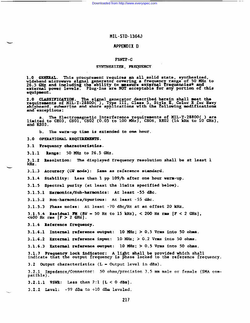
MIL-STD-1364J
APPENDIXD
FSNTP -c
SYNTHESIZER, FREQUENCY
1.0 GENEMLL. This rocurement requires an all solid state, synthesized,Iwideband microwave s gnal generator covering a frequent
5range of 50 MHz to
26.5 GHz and including the ability to measure external requencles* andexternal power levels. Plug-ins are NOT acceptable for any portion of thisequipment.
2.0 GIASSIFIGATION. The signal generator described herein shall meet there uireaents of I141L-T-28800(),
? 9e III, Class 5, S le E, Color R for Navy
?sh pboard, submarine and shore app ications with the ollowing modificationsand exceptions:
The Electromagnetic Interference requirements of KIL-T-28800( ) arel~i~&o CE03, CSO1, CS02 (0.05 to 100 HHz), CS06, RE02 (14 kHz to 10 GM),
.
b. The warm-up time is extended to one hour.
3.0 OPERATIONAL R.EQUXUMENTS.
3.1 Frsquency characteristics.
3.1.1 Range: 50 MHz to 26.5 GHz.
3.1.2 Resolution: The displayed frequency resolution shall be at least 1kHz.
-3.1.3 Accuracy (CU mode): Same as reference standard.
3.1.4 Stability: Less than 1 pp 109/h after one hour warm-up.
3.1.5 Spectral purity (at least the limits specified below).
3.1.5.1 Harmonics/Sub-harmonics: At least -55 dBc.
3.1.5.2 Non-harmonics/Spurious: At least -55 dBc.
3.1.5.3 Phase noise: At least -70 dBcfiz at an offset ZO kllz.
3.1.5.4 Residual FM (BW- 50 Hz to 15 kllz),< 200Hz rms [F< 2 G&],<400 Hz rms [F> 2 GHz].
3.1.6 Reference frequency.
3.1.6.1 Internal reference output: 10MHz; > 0.5 Vrms into 50 ohms.
3.1.6.2 External reference Input: 10 MHz: > 0.2 Vrns into 50 ohms.
3.1.6.3 External refexence output: 10 MHz; > 0.5 Vrms into 50 ohms.
3.1.7 FrequenT
lock Indicator: A light shall be provided which shallindicate that t e output frequency is phase locked to the reference frequency.
3.2 Output characteristics (L - Output level in dBm).
3.2.1 Impedance/Connector: 50 ohms/precision 3.5 mm male or female (SMA com-patible).
3.2.1,1 VSUR: Less than 2:1 [L< O dBm].
3.2.2 Level: -99 dBm to +10 dBm leveled.--
217
Downloaded from http://www.everyspec.com
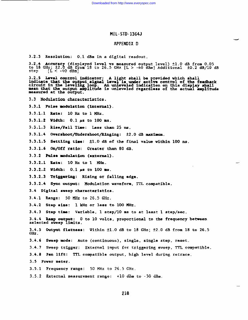
MIL-STD-1364J
APPENDIX D
3.2.3 Resolution: 0.1 dBm in a digital readout.
~&2i$ ~~ctuac displayed level vs measured output level) ~1.O dB from 0.05; *2*8$B from 18 to 26.5 GHz [L > -40 dh] Additional ~0.2 dB/10 dB
step [L< -40 dBm]
3.2.5 Level control indicator: A light shall be rovided which shall?indicate that the output signal level is under act ve control of the feedback
circuit In the leveling loop. An unleveled indication on this display shallmean that the output ~litude is unleveled regardless of the actual axsplitudemeasured at the output.
3.3 MOdulatim characteristics.
3.3.1 Pulse modulation (internal).
3.3.1.1 Rate: 10 Hz to 1 KHz.
3.3.1.2 Width: 0.1 ps to 100 ms.
3.3.1.3 Rise/Fall Time: LW3S than 25 ns.
3.3.1.4 Ovarshoot/UndershootfRinging: ~2.O dB maximum.
3.3.1.5 Settling time: ~lOo ~ Of the fi~l val~ wi~in 100 ~0
3.3.1.6 On/Off ratio: Greater than 80 dB.
3.3.2 Pulso fiulation (external).
3.3.2.1 Rata: loll ztol MHz.
3.3.2.2 Uidth: 0.1 ps to 100 Rs.
3.3.2.3 Triggming: Rising or falling edge.
3.3.2.4 Sync output: Modulation waveform, TTL compatible,
3.4 Digital sweep characteristics.
3.4.1 Range: 50 ~Z to 26.5 GHz.
3.4.2 Step sise: 1 kHz or less to 100 MHz.
3.4.3 Step time: Variable, 1 step/10 ms to at least 1 step/see.
3.4.4 Mskp out t:Y
O to 10 volts, proportional to the frequency betweenselected sweep bits .
3.4.5 Output flatness: Within ~1.O dB to 18 GHz; ~2.O dB from 18 to 26,5GHz .
3.4.6 Sweep mode: Auto (continuous), single, single step, reset.
3.4.7 Sweep triggar: External input for triggering sweep, TTL compatible.
3.4.8 Pen lift: TTL compatible output, high level during retrace.
3.5 Power meter.
3.5.1 Frequency range: 50 ~Z to 26.5 GHz.
3.5.2 External measurement range: +10 &m to -30 dBm.
---
218
Downloaded from http://www.everyspec.com
MIL-STD-1364J
APPENDIX D
3.5.3 Accurac indicated power level vs externally measured level): flOO dB(+10 dBm to -1? $Bm); ~2-() * (.10 am to -30 &m).
3.5.4 Display (digital): 3.5 digits minimum.
3.5.4.1 Resolution: 0.1 dB minimum for all power readings.
3.5.5 Input connector: Precision 3.5 mm male or female (SMA compatible).
3.6 Frequency counter.~
3.6.1 Xnput range: At least 100 MHz to 26.5 GHz.
3,6.2 Resolution: At least 100 Hz.
3.6.3 Sensitivity: -25 dBm to 18 GHz; -20 dBm from 18 to 26.5 GHz.
3.6.4 Hode: CU or Pulsed RF Input.
3.6.4.1 Minimum PU for pulsed RF input: 0.5 #s.
3.6.5 &~8Cy: (CW) At least 1 ppm.
3.6.6 Input impedance: 50 ohms nominal.
3.6.7 Input connector: Precision 3.5 mm male or female (WA compatible).
4.0 GENERAL REQUIRE!KENTS,
4.1 Power: 115/230 Vac fiO% single phase 50, 60 or 400 Hz, 350 watts~ maximum.
4.2 Volume: Less than 65,548 cm3 (4,000 in3).
4.3 Wdght: Less than 29.55 kg (65 lb).
4.4 Rewte control: The enerator shall be capable of being remotelycontrolled via the IEEE-48~ interface bus, operating as both a talker andlistener, havin at least the following subset of bus functions: AH1, IA,SH1, T6, SR1, D& and RL1. Control of the following parameters is required:
Output Fre uencyY
External Power MeasureOutput -p itude (-99 to +10 dBm) Exter~~~Fr~yu~nc MeasureSweep Function Modulation: &Frequency Lock Status
z PRFAmplitude Le~el Status
5.0 ACCESSORIES. The following list of accessories shall be provided witheach equipment.
5.1 One Gore-tex GMCA 190-1265 or equivalent coaxial cable, 6 ft lon , withmale precision 3.5 mm ESMA compatible connectors or equivalent on eac end.
5.2 One Gore-tex GMCA 190-1265 or equivalent coaxial cable, 18 in long, withmale precision 3.5 mm SMA compatible connectors or equivalent on each end.
5.3 One male to female adapter with precision 3.5 mm SW compatible connectoror equivalent.
5.4 (he female to female adapter with precision 3.5 mm WA compatibleconnector or equivalent.
* Frequency counter may be supplied as a separate piece of equipment;however, weight and volume restrictions apply to signal generatorpackages only,
219
Downloaded from http://www.everyspec.com
MIL-STD-1364J
APPENDIX D
FSNIA-C
WNTHESIZER, FREQUENCY
1. GEREML. This procurement requires a stable xnicruwave signal enerator1!capable of generating signals over the frequency ran e of 5.4 GHz o 12.5 GHZ
f~~~ internal and external AM, RI, and pulse aodulat ofiwith delay capabili-.
2. CMSSIFICATIOX . The equipment shall meet the requirements of MIL-T-28800,TYpe III Class 5, Style E, Color R for Navy shi board, subaarine, and shore
sapplications with the following modifications an exceptions:
a. The relative humidity requirement 1s limited to 95* noncondensat-ing.
b. The operating and nonoperating altitude requirements are not ixvoked.
The electroma etic interference re uirements of HIL-T-28800 arelim[~ed to CEO1 CEO?’ CSO1 CS02 O~)to~M~), CS06, REO1 (back panelsearch excluded~, REO~ (14 & to i t .
d. The warm-up time is extended to one hour.
3. 0PXRATXOH4L REQUIREMENTS. The equipment shall be capable of generatingsignals within the parameters and accuracies specified herein.
3.1.1 l’re~cy range. At least 5.4 GHz to 12.5 G&.
3.1.2 Frequency resolution. Minimum resolution at least 1 I&z: digitalreadout.
3.1.3 Frequency accuracy. Equal to accuracy of reference standard (CW wale).
3.1.4 Frequency stability (equal to or better then limits specified below).
3.1.4.1 Internal. Less than 1 part in l@/hr at 25°C +J”C after one hourwarmup.
3.1.4.2 External. Equal to external standard frequency stabillty.
3.1.4.3 ?~rature. Less than *2 parts in l&change over O to 50°C tempera-ture range.
3.1.5 Roaidual modulation (CW mode in 50 Hz to 15 kHz detection BW).
3.1.5.1 m. Less than 200 Hz rms.
3.1.5.2 AU. hss than 0.3% pk.
3.1.6 Spectral purity.
3.1.6.1 ~X9011iCS. < -30 *C.
3.1.6.2 Power line/fan rotation related harmonics. < -30 dBc (< 1 kHz fromcarrier).
3.1.6.3 Nonharmonics/Spurious. < -55 dBc (> 10 kHz from carrier).
3,1.6.4 Phase noise. < -75 dBc/Hz at 10 kHz offset from carrier.
3.2 Output characteristics.
220
Downloaded from http://www.everyspec.com
t41L-STD-1364J
APPENDIX D
3.2.1 Range. +10 to -120 dBm (minimum).
3.2.2 RF output. Leveled output shall be available at +10 dBm or less.
3.2.3 ACCurlkCy. *2 ~ for out Ut le~e~s from +10 & to -50 am; additioml!0.1 dB/10 dB step for levels be ow -50 d.b.
3.2.4 Display/Resolution. Digital display; minimum resolution of 0.1 dB.
3.2.5 Flatness. *1 dB measured at an output level of +10 dBm.
3.2.6 Impedance/Connector. 50-ohm type-N female connector.
3.2.6.1 VSWR. < 2:1 (at levels < 0 dh).
3.2.7 Reversethe following s~~ ~rotectim”
The generator shall be capable of accept!ngevels at its output connector without resulting damage.
3.2.7.1 Average power. 5W.
3.2.7.2 Peak power. 2 kw (widths < 10 J4S).
3.3 Modulation characteristics.
3.3.1 Pulse modulation.
3.3.1.1 Internal.
3.3.1.1.1 Rate (PRF). At least 50 Hz to 50 ldlz.
b 3.3.1.1.2 Width (PW). 0.1 to 10 ps.
3.3.1.1.3 Rise ●nd fall times. Less than 50 ns.
3.3.1.1.4 ON/OFF ratio. Greater than 80 dB.
3.3.1.1.5 Delay. At least 50 ns to 100 MS; accuracy 20% of setting.
3.3.1.1.5.1 Sync pulse output. TTL compatible; rise time less than 50 ns.
3.3.1.1.5.2 Video pulse output. TTL compatible; width corresponds to PWcontrol setting.
3.3.1.1.6 External trigger input. TTL compatible; at least 100 Hz to 50 kHz,provides sync rate for pulse modulation.
3.3.1.2 External.
3.3.1.2.1 Rate (PRF). At least 50 Hz to 50 kHz.
3.3.1.2.2 Width (PW). Greater than 0.1 ps.
3.3.1.2.3 Video output. TTL compatible pulse; same PW and PRF as externalinput pulse.
3.3.1.2.4 Pulse input. TTL compatible.
3.3,2 Amplitude modulation (AM) (level s O dBm),
3.3.2.1 Internal AM.
3.3.2.1.1 Rate. At least 400 Hz and 1 kHz.
3.3.2,1.2 Depth. O to 90% minimum...
221
Downloaded from http://www.everyspec.com
IIIL-STD-1364J
APPENDIX D
3.3.2.1.3 Accuracy. ~10% of setting (50% depth @ 1 mz).
3.3.2.1.4 Distortion. s 10% (50% depth @ 1 kHz).
3.3.2.1.5 Incidental FM. s 200 Hz rms (0.5 - 15 kHz BW) 50% depth @ 1 kHz.
3.3.2.1.6 Residual AM (AH mode). s 0.3% pk (0.5 - 15 W W O* *pth@ 1kHz.
3.3.2.2 External AM.
3.3.2.2.1 Rates. At least 10 Hz to 10 kliz.
3.3.2.2.2 Depth. O to 90% rein-.
3.3.2.2.3 Distortion. s 10% 50% d43pth@ 1 W.
~i&3) ?ze~mcy -ddati~ (PM). (F - carrier freq / AF- peak freq &via-.
3.3.3.1 Internal FK.
3.3.3.1.1 Rata. At least 400 Hz and 1 kHz.
3.3.3.1.2 FM devlatbn. O to at least 1 KHz peak.
3.3.3.1.3 FM ●ccuracy. tlO%.
3.3.3.1.4 Incidental AM. s 0.2% (50 Hz - 15 kHz BW) (AF-20 ~Z @ 1 kllz).
3.3.3.1.s Residual FM (~~de). s 1.5 w = (0.5 - 15 ~ BW) (~~ * @lkHz).
3.3.3.2 External FM.
3.3.3.2.1 Rates. At least 20 Hz to 100 kHz.
3.3.3.2.2 FM deviation. O to at least 1 MHz peak.
3.3.3.2.4 Distortion. s 5% (AF-300 kHz @ 50 kHz).
4. GENERAL REQUIREMENTS .
4.1 Power source. 115 and 230 Vac *1O%, single phase, at line frequencies of50, 60, and 400 Hz within ~10%, 250 VA m=imum.
4.2 Dimensions. The total volume shall not exceed 46,000 cm3 (2,800 in3).
4.3 Weight. The overall weight shall not exceed 34.1 kg (75 lbs).
—
4.4 Remote operation. The unit will be ca able of remote operation via IEEE-488( ) bus interface. At a minimw it shal!
!o crate as a listener such that
all major functions exce t the power on/off sw tch areY
con~~ll:~~e ~nd shallhave as a minimum the fo lowing subset of GPIB commands: # 9 .
222
Downloaded from http://www.everyspec.com
MIL-STD-1364J
APPENOIX D
FSNTU -A
SYNTHESIZER, FREQUENCY
1. GENEML . This procurement requires a stable ❑icrowave sicapable of
%‘nera’i”f ‘iw1s over the fre uenc
L xran!eOf 8’K;0g5yEgo:i’hinternal an externa AM, FM, ●nd Pulse mo lat on w th delay capabilities.
2. cUSsIFIcA7101!!. The equipment shall meet the requirements of KIL-T-28800(), Type III, Class 5 Style E, Color R for Navy shipboard, submarine, andshore applications with the following modifications and exceptions:
The Electroma etic Interference re uirements of MIL-T-28800(1lim?~ed to cE03, CSOr CS02 (0.05 to 100 K&), CS06, U02 (14 W to oa~),
and RS03.
b. The warm-up time is extended to one hour.
3.0 OPERATIONAL REQUIREMENTS. The equipment shall be capable of generatingsignals within the parameters and accuracies specified herein.
3.1 Frequency Characteristics.
3.1.1 Rang@: At least 8.0 G& to 20.0 GHz.
3.1.2 Resolution: At least 1 kHz; digital readout.
3.1.3 Accuracy: Equal to reference standard (CW mode).
3.1.4 Stability: (Equal to or better than limits specified below).
3.1.4.1 Internal: Less than 1 part in I@fi at 25*C +fi*C after one’houkwarmup.
3.1.4.2 External: Equal to external standard.
3.1.4.3 Temperature: Less than *2 parts in 1~ change over O to 50”C.
3.1.5 Residual modulation: (GW mode in 50 Hz to 15 kHz detection BW).
3.1.5.1 m: Less than 300 Hz rms.
3.1.5.2 AM: Less than 0.3% pk.
3.1.6 Spectral Purity:
3.1.6.1 ~~iCS: < -55 d.Bc.
3.1.6.2 Power line/Fan rotation related harmonics: < -40 dBc (< 1 ldlz fromcarrier).
3.1.6.3 Non-harmonics/Spurious: < -55 dBc (> 10 kHz from carrier).
3.1.6.4 Phase Noise: < -70 dBc/Hz (10 kHz offset from carrier).
3.2 Output Characteristics: (F - Output Frequency).
3.2.1 Range: +10 to -90 dBm (minimum) [F < 18 GHz], +7 to -90 dBm (minimum)[F>18 GHz].
3.2.2 RF Output: Leveled output +10 dBm or less [F < 18 GHz], +7 dBm [F >18 GHz].
-.
223
Downloaded from http://www.everyspec.com
MIL-STD-1364J
APPENDIX D
3.2.3 Accuracy: *1.5 dB for out ut levels from +10 dBm to -50 dBm;additional 0.1 dB/10 dB step for !evels below -50 db.
3.2.4 Display/Resolution: Digital display; minimum resolution of 0.1 dB.
3.2.5 Flatnaas: *1.5 dB measured at an output level of +10 dllm.
3.2.6 Impedance/Connector: 50 ohms: type-N female connector or WA.
3.2.6.1 WUR: < 2.5:1 [at levels < 0 dl)m].
3.2.7 Reverse Power Protection: The generator shall be capable of acceptingthe following signal levels at its output connector without resulting damage.
3.2.7.1 Average Power: 4 watts [F < 12 GHz]; 1 watt [F > 12 GHZ].
3.2.7.2 Peak Power: 3.5 kW [F< 12 GHz] [Widths < 10 /AS].
3.3 Modulation Characteristics:
3.3.1 Pulse Modulation:
3.3.1.1 Internal:
3.3.1.1.1 RAt* (PRF): At least 100 Hz to 1 MHz.
3.3.1.1.2 Width (PU): 0.1 to 10.OMS.
3.3.1.1.3 Rise/?all Times: Less than 25 ns.
3.3.1.1.4 ole/oFF Ratio: Greater than 80 dB.
3.3.1.1.5 Delay: At least 100 ns to 100 ms; accuracy: t20?J of setting.
3.3.1.1.5.1 Sync Pulse Output: TTL compatible; rise time less than 50 mj.
3.3.1.1.5.2 Video Pulse Output: TTL compatible; width corresponds to PWcontrol setting.
3.3.1.1.6 External Trigger Input: TTL compatible; at least 100 Hz to 50 kHz,provides sync rate for pulse modulation.
3.3.1.2 External:
3.3.1.2.1 Rate (PRF): At least 100 Hz to 1 MHz.
3.3.1.2.2 Width (PIT): Greater than 0.1 ps.
3.3.1.2.3 Video Output: TTL compatible pulse; same PW and Pm as externalInput pulse.
3.3.1.2.4 Pulse Input: TTL compatible.
3.3.2 Amplitude Modulation (AH): {Can be used simultaneously with pulsemodulation].
3.3.2.1 External:
3.3.2.1.1 Rate: At least 0.1 - 10 kHz.
3,3.2.1.2 Depth: O to 70% minimum.
3.3.2.1.3 Sensitivity: At least 70%/v.
224
Downloaded from http://www.everyspec.com
MIL-STD-1364J
APPENDIX D
3.3.3 Frequency Modulation (FM): {F - carrier freq / AF - peak freqdeviation}.
3.3.3.1 Internal FM:
3.3.3.1.1 Rate: At least 1 kHz to 100 kiiz.
3.3.3.1.2 FM Deviation: At least 10 kllzto 1 MHz peak.
3.3.3.1.3 FM Accuracy: ~20%.
3.3.3.1.4 Incidental AM: s 7% (50 Hz - 15 kllzBW) [AF- lookHz@lokHz].
3.3.3.2 External FM:
3.3.3.2.1 Rates: At least 1 kHz to 1 MHz.
3.3.3.2.2 I?HDevlatlon: At least 10 kHz to 1 MHz peak.
3.3.3.2.3 FH Accuracy: ~20%.
3.3.3.2.4 Distortion: s 10%[AF - 100 kHz @ 10 kllz].
4. GENERAL REQUIREMENTS.
4.1 Power: 115/230 Vac ~10% single phase, 50, 60 or 400 Hz, 250 VA maximum.
4.2 Dimensions: The total volume shall not exceed 39,400 cm3 (2,400 in3).
4.3 weight: The overall weight shall not exceed 22.7 kg (50 lb).+
4.4 Remote Operation: The unit will be capable of remote ope ation viaIEEE-488( ) bus interface. At a minimum it shall operate as a fistener suchthat all major functions except the power on/off switch are controllable’andshall have as a minimum the following subset of GPIB commands : AHl, SH1, IA.
Downloaded from http://www.everyspec.com
MIL-STD-1364J
APPENDIX O
FSNTT-A
SYNTHESIZER, FREQUENCY
1.0 GEMIUUiL. This procurement requires a stable microwave signal eneratorcapable ofinternal A ‘E::%f 2%
als over the fre uency range of 10 to 18 &Iz with1Iation capabilit es.
2.0 CLASSIFICATION. The equipment shall meet the requirements of MIL-T-28800,
9e III, Class 5, S le E, Color R for Navy shipboard, submarine, and
shore app ications with theY ollowing modifications and exceptions:
The nonoperating temperature requirement is limited to the range of-40”:*to +70”C.
b. The relative humidity requirement is limited to 95% noncondensating.
c. The operating and nonoperating altitude requirements are not invoked.
d. The warm-up time is extended to one hour.
3.0 O~TIOIUAL REQUIREMENTS. The equipment shall be capable of generatingsignals within the parameters and accuracies specified herein.
3.1 Frcquoncy characteristics.
3.1.1 Frequency range. At least 10 to 18 ~.
3.1.2 Prequency resolution. Minimum resolution ●t l~ast 1 kliz; digitalreadout.
3.1.9 Iqueln cy ●ccurac .Le
Indicated frequency shall be with ~1 kllzplus themeasured o fsat of the t base when measured on an external counter.
3.1.4 Frequency stability (equal to or better than limits specified below).
3.1.4.1 Internal. Better than 1 part in 10E9/hour after one hour warmup.
3.1.4.2 External. Equal to external standard frequency stability.
3.1.S Residual FM (CV mode in 50 Hz to 15 kllzdetection BW). Less than 1.0kklzpeak.
3.1.6 Spectral purity (equal to or better than llmits specified below).
3.1.6.1 ~~iCS. All harmonically related outputs shall be at least -45dBc.
3.1.6.2 Nonha~ics/Spurious. At least -55 dBc at frequencies greater than1 kllzfrom carrier.
3.1.6.3 Phase noise. At least -65 dBc/Hz at 10 kHz offset from carrier.
3.2 Output characteristics.
3.2.1 Range. +10 to -110 dBm (minimum).
3.2.2 RF output. Leveled output shall be at least +10 dBm.
3.2.3 Accuracy. ~2.5 dB of the actual measured output level, +10 to -110dBm .
—
3.2.4 Display/Resolution. Digital display; minimum resolution of 0.1 dB.
226
Downloaded from http://www.everyspec.com
MIL-STD-1364J
APPENDIX D
3.2.5 Flatness. -tt.o ~ measured at an output level of +10 dBm.
3.2.6 Impedance/Co-ector. SO ohms; type-N female connector.
3.2.6.1 VSWR. The maximum VSWR of the output connector shall be no greaterthan 2:1.
3.2.7 Reverse power rotectlm.!
The generator shall be capable of acceptingthe following signal evels at its output connector without resulting damage.
3.2.7.1 Average power. 2W.
3.2.7.2 Peak paer. 100W peak for pulse widths of less than 1 microsecond.
3.3 Modulation characteristics.
3.3.1 Pulse modulation.
3.3.1.1 Internal.
3.3.1.1.1 Pulse rate (PRF). At least 100 Hz to SO kllz.
3.3.1.1.2 Pulse vidth (PU). 0.1 to 10.0 microseconds.
3.3.1.1.3 Rise and fall times. tiSS ~an 50 ~noseconds.
3.3.1.1.4 OI!?/OFFratio. Greater than 80 dB.
3.3.1.1.5 Delay. At least 100 nanoseconds to 10 milliseconds; accuracy 20%of setting.
:&:o.$5.1 sync pulse output. TTL compatible; risetime less than 50 nano-●
3.3.1.1.5.2 Video pulse output. TTL compatible; width corresponti to PUcontrol setting.
3.3.1.2 External.
3.3.1.3.1 Pulse rate. At least 100 Hz to 50 kHz.
3.3.1.2.2 Pulse width. Greater than 0.1 microseconds.
3.3.2 Amplitude wdulation (AU).
3.3.2.1 Internal AM (squarewave).
3.3.2.1.1 Rate. At least 1 ~z.
3.3.2.2 External AH.
3.3.2.2.1 Rates. At least 10 Hz to 10 kHz.
3.3.2.2.2 Depth. At least O to 70%.
3.3.2.2.3 Distortion. bss than 10% at 50% depth and 1 kHz rate.
3.3.3 Frequency modulation (FM).
3.3.3.1 Internal FM.
3.3.3.1.1 Rate. At least 100 Hz to 50 k!iz.
3.3.3.1.2 FM deviation. At least 1 MHz peak locked or unlocked; unlockcenter frequency shift less than 1%....
227
Downloaded from http://www.everyspec.com
MIL-STD-1364J
APPENDIX D
3.3.3.2 External FM.
3.3.3.2.1 Rates. At least 100 Hz to 50 kliz.
3.3.3.2.2 FM dev~ation. At least 1 KHz peak locked or unlocked; unlockcunter frequency shift less than 1%.
4.0 General requireaenta.
4.1 Pwer source. 115 or 230 Vac A1O%, single phase, 50, 60, and 400 Hzwithin &lO%.
& Input power. The maximum power required for operation shall not exceed.
4.3 Dimensions. The units total volume shall not exceed 1,800 cubic in(29,500 CUbiC ClB).
4.4 weight. The overall weight of the unit shall not exceed 50 pounds (22.7kg) .
4.5 Remote operation. Instrument shall be capable of operating via the IEEE-488 interface bus, and provide capability to talk and listen.
228
Downloaded from http://www.everyspec.com
MIL-STD-1364J
APPENDIX D
TCIAA-A
TACHOMETER, ELECTRONIC
1. GENERAL ● TMs procurement requires a digital tachometer that makescontact and noncontact measurements.
2. CLASSIFICATION .%
e III, Class 5, Style E, and Color R in accordancewith MIL-T-28800 for s pboard applications.
3. OPERATIONAL RBQ~S. The e uipment shall be capable of measurin anddis laying angular velocity in accor
fL fnce with the following minimum spec fi-
cat ens.
3.1 Units of measure. Revolutions per minute, second, and hour.
3.2 Ueamsrement d%atance. 12 in minimum.
3.3 Accuracy of indication. *0.025% *1 LSD.
3.4 Memory. Last reading, maximum, minimum, and average.
4. POUE’RSOURCE. MIL-T-28800 & internal power source re uirements areinvoked. 1The batteries shall be of a commercially availab e type and provide100 hours of o erm~~~n before replacement.
iThe nominal power source require-
ments are not .
--
5 UEIGRT. 0.9 kg (2 lb) maximum.
229
Downloaded from http://www.everyspec.com
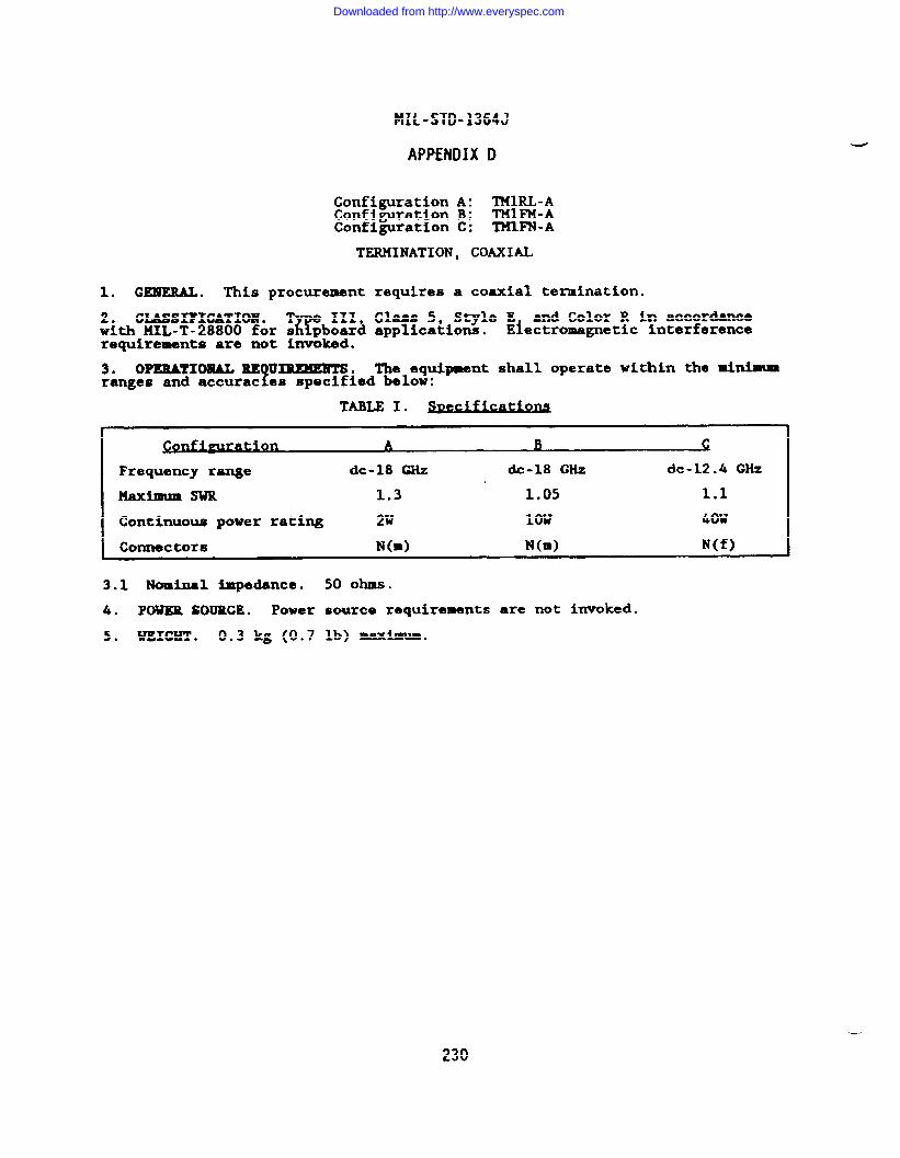
MIL-STD-1364J
APPENDIX D
Configuration A: TMIRL-AConfiguration B: THIFM-AConfiguration C: TMIFN-A
TERMINATION, COAXIAL
1. GENERAL. This procurement requires a coaxial termination.
2* CLA.SSIFICATXOl!l. T e 111, Class 5, Style E and Color R In accordanceK!with !4XL-T-28800 for s pboard applications. Electromagnetic interference
requirements are not invoked.
3* OPERATIONAL RE U~.?
The equipment shall operate within the minimumranges and accurac es specified below:
Frequency range dc-18 CHz dc-18 GHz dc-12.4 Gliz
Maximum SwR 1.3 1.05 1.1
Continuous power rating 2W low 40W
Connectors N(m) N(m) N(f)
3.1 Nominal impedance. 50 ohms.
4. POWER SOURCE. Power source requirements are not invoked.
5* WEIGHT . 0.3 kg (0.7 lb) maximum.
230
Downloaded from http://www.everyspec.com
MIL-STD-1364J
APPENDIX D
TSXAA-C
TEST SET COUNTERMEASURE
The followin urchase descri tion describes the individual units whichf%make up an all so i sstate Wideban Electronic Countermeasures Test Set with a
frequency rarqge of 50 MHz to 40 GHz. The units are as follows:
1. Synthesized Microwave Signal Generator (50 MHz to 26.5 GHz)2. Syaten Controller3. Countermeasures Test Set Accessories4. Vid.eband 14icrwave Frequency Extender5. Digital Voltmeter
231
Downloaded from http://www.everyspec.com
MIL-STD-1364J
APPENDIX D
WIDEBAND MICROWAVE SIGNAL GENERATOR
1.0 GEMEML. This rocurement requires an all solid state, synthesized,!wideband microwave s gnal generator covering a frequent
$range of 50 MHz to
26.5 G& and including ~ ability to measure external requencies* andexternal power levels.
Y-ins are NOT acceptable for any ortion of this
equipment. Additiotlall si should be capable of driving an controlling theoutput of a 26-40 G13z f?kquency extender.
2.0 GLASSX?IGATION. The signal generator described herein shall meet there uirements of BIIL-T-28800( ), Type III Class 5, Style E, tiler R for Navy
1sh pboard, submarine, and shore applications with the following modificationsand exceptions:
a. The Electromagnetic Interference requirements of MIL-T-28800 ) are1llmited to CE03, CSO1, CS02 (0.05 to 100 MHz), CS06, RE02 (14 HZ to o G*),
and RS03.
b. The warm-up time is extended to one hour.
3.0 OPERATIONAL REQUIREKE=S.
Note: FE means operating in Frequency Extension mode.
3.1 Frequency characteristics.
3.1.1 Range: 50 MHz to 26.5 ~Z.
3.1.1.1 FE: 26-40 GHz.
3.1.2 Resolution: The displayed frequency resolution shall be at least 1kHz.
3.1.2.1 FE: At least 2 kliz.
3.1.3 Accuracy (CW mode): Same as reference standard.
3.1.4 Stability: Less than 1 pp 10g/h after one hour warmup.
3.1.5 Spectral purity (at least the limits specified below).
3.1.5.1 Harmonics/Sub-harwaics: At least -55 dBc.
3.1.5.2 Nom-harmonics/Spurious: At least -5S dBc.
3.1.5.3 Phase noise: At least -70 dBcfHz at an offset 20 kliz.
3.1.5.4 Residual FX (BW- 50 Hz to 15 kHz), c 200 Hz rms [F< 2 GHz], < 400Hzrms[F>2GHz].
3.1.6 Reference frequency.
3.1.6.1 Internal reference output: 10 MHz; 0.5 Vrms into 50 ohms.
3.1.6.2 External reference input: 10 MHz; 0.2 Vrms into 50 ohms.
3.1.6.3 External reference output: 10 MHz; 0.5 Vrms into 50 ohms.
3.1.7 Lock indicator: A light shall be provided which shall indicate thatthe output frequency is phase locked to the reference frequency.
3.2 Output characteri.~tics (L - Output level in dBm).
-—
232
Downloaded from http://www.everyspec.com
HIL-STD-1364J
APPENDIX D
3.2.1 Impedance/Connector: 50 ohms / precision 3.5 mm male or female (SMAcompatible) .
3.2.1.1 VSWR: Less than 2:1 [L< O dBm].
3.2.2 kVel: -99 dBm to +10 dBm leveled.
3.2.3 Resolution: 0.1 dBm in a digital readout.
::zi: ~A~CU$C displayed level vs measured output level). kl.O a from 0.05. ?iL from 18 to 26.5 GHz [L> -40 ~]. Atitioml H.2 ~/10
dB step [i< ~40 dlks].
3.2.5 Level control indicator: A light shall be!rovided which shall
indicate that the output signal level is under act ve control of the feedbackcircuit in the leveling loop. h unleveled indication on this display shallmean that the output amplitude is unleveled regardless of the actual amplitudemeasured at the output.
3.3 Modulation characteristics.
3.3.1 Fu18c modulation (internal).
3.3.1.1 Rata: 10 Hz to 1 MHz.
3.3.1.2 Width: 0.1 ps to 100 ms.
3.3.1.3 Rise/Fall Time: Less than 25 ns.
3.3.1.4 Overshoot/Undersh-t/Ringing: ~zeo ~ m~i~.
3.3.1.5 Settling time: A1.O dB of the final value within 100 ns.
3.3.1.6 On\Off ratio: Greater than 80 m.
3.3.2 Pulse modulation (external).
3.3.2.1 Rate: 10 Hz to 1 ~Z.
3.3.2.2 Width: 0.1 ps to 100 ms.
3.3.2.3 Triggering: Rising or falling edge.
3.3.2.4 sync output: Modulation waveform, TTL compatible.
3.4 Digital sweep characteristics.
3.4.1 Range: 50 MHz to 26.5 GHz.
3.4.2 Step size: 1 kHz or less to 100 MHz.
3.4.3 Step time: Variable, 1 step/10 ms to at least 1 step/see.
3.4.4 Ramp out Ut:f
O to 10 volts, proportional to the frequency betweenselected sweep imits ●
3.4.5 Output flatness: Within tl.O dB to 18 GHz; t2.O dB from 18 to 26.5GHz .
3.4.6 Sweep mode: Auto (continuous), singlet single step, reset.
3.4.7 Sweep trigger: External input for triggering sweep, ~L compatible.
3.4.8 Pen lift: TTL compatible output, high level during retrace.
233
Downloaded from http://www.everyspec.com
MIL-STD-1364J
APPENDIX D
3.5 Power meter.
3.5.1 Frequency range: 50 ~Z to 26.5 GHz.
3.5.2 External measurement range: +10 dBm to -30 dBm.
3.5.3 Accurac indicated power level w ~~:e~~ly measured level): &l.O d.B(+10 dmnto -It $Bm); ~2.O dB (-10 dBm to .
3.5.4 Display (digital): 3.5 dig~t~ ~in~==
3.5.4.1 Resolution: 0.1 dllminimum for all power readings.
3.5.5 Input connector: Precision 3.5 mm male or female (SXA compatible).
3.6 Frequency counter *.
3.6.1 Input ranse: At least 100 MHz to 26.5 GHz.
3.6.2 Resolution: At least 100 Hz.
3.6.3 Sensitivity: -25 dBm to 18 GHz; -2o - from 18 to 26.5 GHz.
3.6.4 Mode: CW or pulsed RF input.
3.6.4.1 Minimum PW for pulsed RF input: 0.5 ps.
3.6.5 Accuracy: At least 1 ppm.
3.6.6 Input impedance: 50 ohms nominal.
3.6.7 Input connector: Precision 3.5 mm male or female (SMA compatible).
4.0 GEmRALREQuxlwMENTs.
4.1 Power: 115/230 Vac ~10% single phase, 50, 60 or 400 Hz, 350 wattsmaximum.
4.2 Volume: Less than 65,548 cm3 (4000 in3).
4.3 Weight: Less than 29.1 kg (64 lb).
4.4 Remote!rogrammin :
5The generator shall be ca able of bein remotely
controlled v a a RS-23 interface operating as bo& % 11a talker an stener,having control of at least the foilowing parameters is required.
Output Fre uency?
External Power MeasureOutput Amp itude (-99 to +5 dBm) External Frequency MeasureSweep Function Modulation: 1 usec PW; 1 kHz PRFFrequency Lock Status Amplitude Level Status
4.4.1 In FE mode: Capable of controlling external frequency and amplitude offrequency extender via external cable.
5.0 ACCESSOMES: The following list of accessories shall be provided witheach equipment.
5.1 Microwave coaxial cables.
5.1.1 One Gore-tex GMCA 190-1265 or equivalent coaxial cable, 24 ft long,with male precision 3.5 mm SMA compatible connectors or equivalent on eachend.
5.1.2 One Gore-tex GMCA 190-1265 or equivalent 6 ft long, with male preci-sion 3.5 mm SMA compatible connectors or equivalent on each end.
234
Downloaded from http://www.everyspec.com
MIL-STD-1364J
APPENDIX D
5.1.3 One Gore-tex GMCA 190-1265 or equivalent, 18 in long, with maleprecision 3.5 mm SMA compatible connectors or equivalent on each end.
5.2 Interface cables.
5.2.1 (2) RS-232, male one end, female other end, SO ft length.
5.2.2 (2) RS-232, male one end, female other end, 25 ft length.
5.2.3 FE (1) Source-to-Frequency25 ft length.
5.3 Adapters.
5.3.1 One male to female adapterconnector or equivalent.
Extender comection cable, male both ends,
with precision 3.5 mm SMA compatible
5.3.2 One female to female adapter with precision 3.5 mm SMA compatibleconnector or equivalent.
* Frequency counter may be supplied as a separate piece of equipment;however, wei
Pt and volume restrictions apply to signal generator
packages on y.
SYSTEM CONTROLLER
1.0 GENERAL DESCRIPTION. This procurement re uires a computer systemcontroller capable of interfacing with extema
~ !? (instruments in oth IEEE-488
and RS-232 bus configurations.following internal features:
n addition the controller must possess the(1) type=iter keyboard with separate numeric
pad, (2) screen for display of program interface with operator,
F{3) hardco y
rinter for permanent output of test results, (4) memory device ftape or d SC)or storage of data and programs.
2.0 CIASSIFIGATION. The requirements of llIL-T-28800( ) are hereby waived forthis device. The following operating conditions are imposed:
a. The operating teT
erature requirement is limited to the range of 15-Cto 35°C and the non-operat ng temperature requirement is limited to the rangeof O“c to So”c.
3.0 OPERATIONAL REQUIREMENTS.
3.1 Storage (capacity and medium).
3.1.1 RAM: At least 32 kbytes.
3.1.2 ~SS: Magnetic; at least 200 kbytes Amplitude Level Status.
3.2 Language.
3.2.1 HP enhanced basic.
3.2.2 Compatibility: Must be compatible with previously prepared software.
3.3 Printer (hardcopy output).
3.3.1 Type: Thermal with bidirectional printing head; ink is Dot acceptable.
3.3.2 Line length: At least 32 characters.
3.3.3 Character size: At least 10 point.
~
235
Downloaded from http://www.everyspec.com
MIL-STD-1364J
APPENDIX D
3.4 Operator interface.
3.4*1 Display.
3.4.1.1 Type: CRT or XXD.
3.4.1.2 Size: 103 C* (16 in2) minimum.
3.4.1.3 Line=: 16 minimum.
3.4.1.3.1 Length: 32 characters minimum.
3.4.1.4 Graphics: At least 256 x 196 pixels.
3.4.2 Keyboard: Full size typewriter-like alphanumeric with separate numerickeypad.
3.4.3 special function key%: At laast 8 available; function to be defined byoperator.
3.4.4 Built-in debugging facilities.
3.5 Featurose
3.5.1 IEEE-488(L
interface: Capable of communicating with external instru-ments as both tal r and listener.
3.5.2 RS-232 serial interface (with male connector): Capable of communicat-ing with external instruments as both talker and listener.
3.5.3 clock: Built in system clock.
3.5.3.1 Ti.mars: At hast 3 independent timers.
3.5.4 hpansion capability: A minimum of four ports for interfacing andexpansion.
3.5.5 Full self-test capability.
4.0 GENERAL REQUIREMENTS.
4.1 Power source: 115/230 Vac *1O% single phase, 50, 60 or 400 Hz, 50 VAmaximum .
4.2 D~nsions: The total volume of the unit shall not exceed 40967 cd(2500 in).
;b~ Weight: The overall weight of the unit shall be less than 11.4 kg (25.
5.0 ACCESSORIES.
5.1 ROM-drawer: Holds up to 6 external ROMs.
5.2 1/0 ROM.
5.3 Advenced programming ROM.
COUNTERMEASURES TEST SET ACCESSORIES
1.0 GENEUL DESCRIPTION. TheseCMTS in order to permit radiatedsystem.
accessories are required for use with themeasurements to be performed using the
236
Downloaded from http://www.everyspec.com
MIL-STD-1364J
APPENDIX D
2.0 CLASSIFICATION. The requirements of MIL-T-28800( ) are hereby waived forthese accessories.
3.0 OPERATIONAL REQUIREMENTS.
3.1 Test antennas.
3.1.1 Spiral antenna (0.3 to 1 G&): Antenna Corp of Amezica M/N 3127-RC-N.
3.1.1.1 Antcmna moumt ●dapter (Gigs-tronics Stock #198CF02600).
3.1.2 Horn antenna, ridged wave~ide (1 to 12.4 GHz): ~erican ElectronicLab M/N H1479.
3.1.3 Horn antenna, ridged waveguide (2 to 18 CHZ): American Electronic MbM/N H1498-T.
3.1.4 Horn antenna (18 to 26.5 GHz): Narda 14/N 638.
3.1.4.1 Antenna mount adapter (UT Technical Senices M/N 81995 00 0002 29).
3.1.5 Standard gain horn (26 to 40 GHz): Scientific Atlanta R@ 12A-26.
3.2 Adapters. ●
3.2.1 TNC (M) to SMA (F): Midwest Microwave n/N 2686.
3.2.2 Type M (M) to SMA (F): Omni Spectra M/N 3082-2240-00.
3.2.3 Waveguide-to-coax adapter (18 to 26.5 GHz): Omni SpectxaM/N 2000-6-256.
3.3 Fixed Attenuators.
3.3.1 Wavegulde WR-28.
3.3.1.1 15 a
3.3.1.2 20 d.B
3.3.1.3 30 *
3.4 Antmna mounting hardware case. $
3.4.1 Part #81995-00-002: Used to hysically attach test antennas toTexisting superstmcture when perform ng radiated systems testing.
3.5 Shipping/Carrying/Storage cases.
3.5.1 Cases.
4 Gigs-tronics PCGO 010011 Gigs-tronics PCCO 02001
3.5.2 Case Liners.
1 Gigs-tronics PCCL 010011 Gigs-tronics PCCL 010021 Gigs-tronics PCCL O1OO31 Gigs-tronics PCCL O1OO41 Gigs-tronics PCCL 02001
237
Downloaded from http://www.everyspec.com
MIL-STD-1364J
APPENDIX C)
VIDEBAND MICROWAVE FREQUENCY ExmNDER
1.0 GEMEUL DESCRIPTION. This rocurement requires - all solid state syn-!thesized, microwave frequency ex ender covering the frequent
40 G& using input fre uencies of 13 to 20 GHz at +5 to1
-7 ~an~eo~taa~u~mlevel of the extended requency shall be variable from at least +5 toleveled.
2.0 CWSIFICATIO1l. The fre uency extender described herein shall meet there uirements of MIL-T-28800( ?, ~ III Class 5,
1Style E, Color R for Navy
sh plmard, suburine, and shore applications.
3.0 oMRATIm RuQ~.
3.1 Raquency characteristics.
3.1.1 Output frequency rang.: At least 26 to ~ GHz.
3.1.2 Input frequency ranga: At least 13 to 20 GNz.
3.1.3 output frqtammy r~soltatiom: 2 times the resolution of the inputfrequency.
3.1.4 Output frequency ●ccuracy: Same as the input frequency.
3.1.5 Output frequency stability: Input stability degraded by factor of 2.
3.1.6 Spectral purity.
3.1.6.1 Earmonics/Sub-harmoaics: At least -20 d.k.
3.1.6.2 Bkm-Barwnfcs/Spurim: At least -20 dBc.
3.1.7 Freqnenc display:5
The output frequency shall be displayed directly onthe extender’s rent panel or remotely on its driving source synthesizer.
3.2 Output characteristics.
~i2& Output level: -15 dh to +5 dBm leveled for input levels of at least●
3.2.2 Output level resolution: 0.1 am.
3.2.3 Output level display: The output level shall be displayed directly onthe extender’s front panel or remotely on its driving source. s~thesizer.
3.2.4 Output level control.
3.2.4.1 -l operation: The output level of the frequency extender shall becontrollable from the unit’s front panel when operating under manual control.An indicator shall be provided indicating the leveled status of the output ofthe extender.
3.2.4.2 Remote operation: The output level of the frequency extender shallbe controllable from the signal generator.
3.2.5 Output level accuracy: t2.5 dB.
3.2.6 Output level flatness: t2.5 dB.
3.2.7 Output connector: WR-28 WG waveguide with type UG-599/U flange.
3.2.7.1 Impedance: SO ~ nominal.
./
Downloaded from http://www.everyspec.com
MIL-STD-1364J
APPENDIX D
3.2,7.2 VSWR: Less than 2:1 worst case.
3.2.8 Input connector: Precision 3.5 mm male or female (SMA compatible).
3.3 Modulation characteristics.
3.3.1 Pulse/Square wave modulation.
3.3.1.1 Rate: 100 Hz to 50 kHz minimum.
3.3.1.2 Width: 0.1 to 10 psec minimum.
4.0 GENERAL MQUIREMENTS.
4.1 Power: 115/230 Vac A1O% single phase, 50, 60 or 400 Hz, 20 wattsmaximum .
4.2 Volume: Less than 9850 cm3 (600 in3).
4.3 Weight: The overall weight of the unit shall not exceed 4.5 kg (10 lb).
4.4 Interface control: Level must be remotely controllable through the syn-thesized, wideband microwave signal generator driving source via an externalcable.
DIGITAL VOL=ER
1.0 GENERAL DESCRIPTION. This rocurement requires an all solid state, tne- frms, digital voltmeter for use w th the Countermeasures Test Set.
2.0 CLASSIFICATION. The voltmeter described herein shall meet the re uire-ments of I141L-T-28800(~D TYP %e III, Class 5, Style E, Color R for Navy s ip-board, submarine and s ore applications.
3.0 OPERATIONAL REQUIREMENTS.
3.1 Measurement ranges.
3.1.1 DC voltage: o to f300v.
3.1.1.1 Resolution: At least 1 mV for 20V full scale reading.
3.1.2 AC voltage: 50 pV to 300V (true rms).
3.1.2.1 Frequency response: 10 Hz to 10 MHz.
3.1.2.2 Resolution: At least 1 mV for 20V full scale reading.
3.2 Input connector: Binding posts (balanced) or BNC female (unbalanced).
3.2.1 Input impedance: At least 1 Ml shunted by < 50 pF.
3.2.2 Common mode rejection: > 80 dB for ac; > 120 dB for dc.
3.3 Measurement rate: At least 2 or more readings/see.
3.4 Accuracy.
3.4.1 DC: Within +0.5% of range selected.
3.4.2 AC: Within *2% of range selected.
3.4.2.1 Maximum crest factor: 4\
239
Downloaded from http://www.everyspec.com
MIL-STD-1364J
APPENDIX D
3.5 Display: At least 4 1/2 digit display.
3.5.1 units: Volts ac and dc.
4.0 GENEML REQUIREMENTS.
4.1 Power: 115/230 Vac A1O% single phase, 50, 60 or 400 Hz, 40 VA maximum.
4.2 Dimensions: 25.4 cmx 35.56 cm x 10.16 cm (10 inx 14 in x 4 in).
4.2.1 volume: 9200 ca.3 (560 in3).
4.3 weight: 4.5 kg (10 lb) maxbua.
4.4 Rewte operatbn: All front panal functions controllable via IEEE-488( )interface bus.
4.4.1 Talkar function: Unit capable of sending readings via IEEE-488( ) tosystem controller.
-
240
Downloaded from http://www.everyspec.com
HIL-STD-1364J
APPENDIX D
Configuration A: TEOGN-BConfiguration B: TEONN-B
TEST SET, ELEGTRON TUBE
1. CEHERAL. This procurement requires a portable test set for evaluatingelectron tube characteristics.
20 CLASSIFICATION .%
e III, Class 5, Style D, and Color R in accordancewith KIL-T-28800 for s pboard applications.
3. OPERATIONAL RE uxRmEms.?
The equir
nt shall be capable of evaluatingoperational capabi ities of low and med um power electronic tubes under testconditions which simulate actual operatin
kconditions. Configuration A equip
ment shall use an automated techni ue suc\
as punched cardcilitate testing. Operator-adjusta le test parameters shal ‘~er~$?%e~OfZ-YgConfiguration B equipment.
3.1 Tube types. The e uipment shall be capable of testing diodes (gas regu-1lators, detectors, rect fiers, etc.), triodes, tetro~s, pentodes, hexodes.
Provlsbns are required for checking lax e 4, 5, 6,;%?d~?; ?$~~&~~&tal and loctal tubes, 9 pin jumbo, 7 and $ pi.miniature, 7 pin in-line, and octal subminiature tubes.
3.2 General performance requirements. The test set shall be ca ~~&ro~oper-forming the following tests: shorts between any tube elements, E --cathode leakage, gas, grid emission, cathode activity, transconductamce, andplate current.
u 4. ACCESSORIES. When unched-card pro rsmminE f 8
is used in Configuration Aequipment, the tester s all include at east 5 blank test cards, a hand punchto progr~n~~ank test cards tube testin cards
%and self-test and calibration
cards.Y
ation B equipment shall e provided with a chart, manual, orother means o providing switch setup information for each tube type.
5. POWERSOURCE. MIL-T-28800 nominal power source requirements a~o~nv:~d.Operation at 400 Hz is not required. Maximum power consumption:Configuration A and SOW for Configuration B.
6. WEIGHT . 25 kg (55 lb) maximum, not including tube test cards.
241
Downloaded from http://www.everyspec.com
MIL-STD-1364J
APPENDIX D
TSDNN-D
TEST SET, ENVEIX)PEDETAY, TELECOM
1. GEIUEML . This procurement requires an envelope delay test set containinga digital storage oscilloscope.
2. CLASSIFICATION.7$
e III, Class 5, Style E, and Color R in accordancewith MIL-T-28800 for s pboard applications.
3. OPEUATIOHAL REQUIREMENTS. The equipment shall be capable of circuitquality measurement of voice band transmission networks within the minimumparameters and accuracies specified below.
3.1 !han-ittar output lavel. Adjustable from -39 dBmto+9dBminldBsteps.
3.1.1 Molding tone. 1.004 kHz within ~0.1 Hz.
3.1.2 Garrier fraquenc range.5
200 Hz to 4 Miz. Selectable modulation fre-quencies of 25 Hz and 8 .3 Hz shall provide up to 50% modulation.
3.1.3 Oscillator tuning. llanual, single sweep, and auto sweep. The sweeprate shall be variable up to at least one second.
3.1.4 Distortion tone=.
a. Pair A: Centered at 860 Hz, 6 Hz apart.
b. Pair B: Centered at 1.38 kHz, 16 Hz apart.
3.1.5 Output i9pedanae. Selectable 600 ohms and 900 ohms nominal.
3.1.6 Mamonic distortion. 0.5* or less of the fundamental amplitude.
3.2 Receiver.
3.2.1 Frequency range. 200 Hz to 4 kHZ.
3.2.2 Input level. -50 dBm to +9 dBmo
3.2.3 Input Impedance.
a. Bridged: Greater than 25 kilohms.
b. Terminated: 600 ohms and 900 ohms nominal.
3.3 Level measurement.
3.3.1 Dynamic range. 59.9 dB.
3.3.2 Level measurement accuracy. tO.2 dB from +9 dBm to -40 am.
3.3.3 Level measuremmt resolution. 0.1 dB or less.
3.4 Eloisemeasurement. Noise-with-tone and idle noise measurement capabili-ties shall be provided.
3.4.1 Filters. C-message and 3 I&z filter wei hting shall be provided. Anotch filter from 995 Hz to 1.025 kHz reference 5 at -50 dB or greater shall beprovided.
3.4.2 Receiver range. 99 dBrn to 20 dBrn.
242
Downloaded from http://www.everyspec.com
MIL-STD-1364J
APPENDIX D
3.4.3 Noise measurement resolution. 1 dB or less.
3.5 Phase jittex.
3.5.1 Holding tone range. 990 Hz to 1.03 kllz.
3.5.2 Phase jitter bandwidth. 20HZ to 300HZ.
3.5.3 Phase jittex messur~nt range. O“ to 30° peak-to-peak.
3.5.4 Phase $Ittar ●ccuracy. 5% M1.2* of indication.
3.6 Distortion. The equipment shall be capable of nonlinear second and thirdorder distortion measurements.
3.6.1 Distortion measurement zan@. 10 cm to 55 dB.
3.6.2 Distortion ●ccuracy. al dB.
3.6.3 Distortion measurement resolution. 1 dB or less.
3.7 Envelope delay.
3.7.1 Envelope delay measurement range.
b. +-10ms wi~ 50* fiulation at 25 Hz.
&7522 Elope delay measurement ●ccuracy. ~1.75 MS over the range of 500 HZw . ●
3.703 Sync control. The equipment shall be provided with a variable sync
4control to ad ust the internal modulation reference to the modulating sourcefrequency at he far end of two-wire circuits.
3.8 Hit measurements. The equipment shall be capable of gain and phase tran-sient variations, impulse noise, and signal dropout measurements.
3.8.1 Timer. Selectable ranges of 5 minutes, 15 minutes, and continuousshall be provided.
3.8.2 C-t rate. 7 per second minimum.
3.8.3 Count range. O to 9,999.
3.8.4 Hit duration. The equipment shall seine hits of a width of 4 ma orgreater.
3.8.5 Dropout. The equi ment shall sense dropouts of 4 M or greater. TheEdropout threshold value s all be adjustable to a constant value of 12 dB below
the input level setting.
3.8.6 Phase hit thrashold. Adjustable in 5“ increments from 5° to 45°.
3.8.7 Gain hit threshold. Adjustable in 1 dB increments from ~1 dB to A6 dB.
3.8.8 Impulse threshold. Adjustable in 1 d.Bincrements from 99 dllrn to 40dBm.
3.9 Peak to average ratio (PAR).
3.9.1 Display range. O to 120 PAR units.
3.9.2 PAR measurement accuracy. *4 Willunits.
243
Downloaded from http://www.everyspec.com
MIL-STD-1364J
APPENDIX D
3.10 Oscilloscope. The equipment shall contain a dual memory storageoscilloscope. ..
3.10.1 DX@ay controls. Focus, intensity, astigmatism, ati graticule illu-mination controls shall be provided.
3.10.2 MewY
Selectim. A mlnlmm of three memory positions shall be pro-vided, typica ly memory A, memory B, and memories A and B.
3.10.3 Mm& salection. The following mode positions shall be provided:
a. Clear: Selected memory is reset.
b. Load: Selected memory is loaded with the response signal.
c. Input : Input signals are displayed in raal time.
d. Mlmory : Display is derived from the selected memory.
Input and memory: Both the selected memory and the real t- inputare d;splayeci.
f* mic: Both A and B memories are displayed. B mem~ is alsoupdated continuously by the input signal.
3.11 outputs. The equipment shall be provided with ou uta for =teml
S&!~a~& buffered and TTL compatible.recording, and equipment control as follows. ?H t countez outputs
● ✎ Gain hit.
b. Phase hit.
d. Dropout.
e. Phase jitter.
f. X-Y plotter, *2V full scale.
g“ X-Y axis for CRT display.
3.11.1 Monitor. The equipment shall be provided with an internally mountedmonitor speaker.
4. POWER SOURCE. HIL-T-28800 nominal power source requirements are invoked.Operation at 400 Hz is not required. l!aximum power consumption: 50W.
-.
5. WEIGHT . 20 kg (44 lb) maximam.
Downloaded from http://www.everyspec.com
FIIL-STD-1364J
APPENDIX D
TE4GN -C
TEST SET, INSULATION
1. GZLUEUL . This rocurement requires an ac and & tester capable of testingfinsulation dielectr c stren th by appl ing high voltage to a test sample and
L Tmeasuring the resulting lea ge curren .
2. CLASSIFICATION .%
e III, Class 6, Style E, and Color R in accordancewith NIL-T-28800 for s pboard applications.
3. OPERATIONAL REQ~, The e uipment shall be capable of providing acand & test voltage ou
??uts and shal monitor volts es and currents within the
minimum ranges, accurac es, !and sensitivities speci ied below.
3.1 Test voltages. O to 10 kVac, OV to 25 kVdc, continuously adjustable.
3.2 Breakdown leakage currant. 5 mA maximum at any test voltage.
3.3 Voltage monitor. The equipment shall be provided with a meter to indi-cate the test voltage. Range: O to 25 kV in two or more ranges. Accuracy:*28 of range.
3.4 Gurrent monitor. The equipment shall be provided with a meter for moni-torin output current.
fRange: O to 5 mA in two or more ranges. Accuracy:
*2t o range.
3.5 overload circuit. The equipment shall be provided with a current over-load circuit that has a continuously ad us&able sensitivity range of 50 UA or
~ 4less to a maximum breakdown current of .
3.5.1 Failure indication. An audible and visible indication of test iteminsulation breakdown shall be provided.
4. POWER SOURCE. HIL-T-28800 nominal power source requirements a;;5~nvoked.Operation ●t 400 Hz is not required. Maximum power consumption: .
5. WEIGHT . 20 kg (44 lb) maximum.
---
245
Downloaded from http://www.everyspec.com
MIL-STD-1364J
APPENDIX D
TS3NF-A
TEST SET, IJICIC
1. GBXERAL. This rocurement requires ● hand-held logic troubleshootingprobe ca able of i
Ts f)icatin logic levels in transistor-transistor-logic TTL
fand co- imantary netal-ox de semiconductor (CXOS) logic circuits.
2. CIASSIFICATXON . -9 111HIL-T-28800 except the nominai
3* Operational zw
-nts .level analysis ofbelow.
and CMOS
3.1 Logic lavels.
A. lTL:
Class 5, Style E and Color R in ●ccordance withpcmer source zequire=ants are not imvoked.
Tho probe shall be ca abl~ of in-circuit 10 icL fcircuits within the m imna parameters data led
1. Logic ONE: 1.8 to 2.4V peak.
2. Logic ZERO: 0.4 to IV peak.
B. CMos: 3 to 10 Vdc supply
1. Logic ONE: 0.7 x Vsupply *0.5 Vdc.
2. Logic ZERO: 0.3 X Vsupply ~0.5 Vdc.
c. ~OS: 10 to 18 Vdc SUpply
1. tigic OUR: 0.7 Xvsupplykl.ovde.
2. Logic ZERO: 0.3 x Vsupply *1.O Vdc.
3.2 Pulse width. 10 ns mi~. A pulse stretching feature shall beprovided to allow viewing of narrow pulses.
3.3 Pulse repetition frequency limlt. TTL: 80 MHz. CMOS: 40 MHz.
3.4 Impedance. 25 kilohms.
3.5 Dis by.!
The robe shall indicate logic highs, logic 10WS, open a-short n%c rcuits, a excessive input levels by means of a light.
3.6 Probe overload protection. 120V continuous from cicto 1 KHz.
4. POWER, The robe shall be powered by the circuit under test.t
Ovenoltageprotection: fzs dc for ~ minute.
5. WEIGHT . 1 kg (2.2 lb) maximum.
246
Downloaded from http://www.everyspec.com
MIL-STD-1364J
APPENDIX D
TS3NM-B
TEST SET, MGIC
1. GENEML. l’his procurement requires a self-contained, solid-state logictroubleshooting kit ca able of detecting and analyzing in-circuit logicfailures.
‘e ‘it ‘ha~l be ab’e ‘0 ‘nlec’ Y’ses ‘n’” ‘ogic circuitv ‘dmonitor the level transitions. The ki sha 1 consist of a logic probe, logicpulser, and a dual-in-line package (DIP) monitor clip.
2. CLASSIFICATION .v
e III, Class 5, Style EP, and Color R in accordancewith MIL-T-28800 excep nominal power source requirements are not invoked.
3. OPERATIONAL REQ~. The probe pulser, and monitor clip shall beca able of in-circuit logic level analysls of transistor-transistor 10 ic(’#L) and complementary metal oxide semiconductor (CMOS) logic within heminimum ranges and accuracies specified below.
3.1 Logic probe.
3.1.1 TTL 10giC levels.
Logic one: 1.8 to 2.4 volts peak,& Logic zero: 0.4 to 1 volt peak.
3.1.2 CMOS logic levels.
3.1.2.1 3 to 10 Vdc SUp@y.
~ Logic one: (0.7 x Suppl voltage) _~.5V;: Logic zero: 1(0.3 X supp y voltage) *0.5V
3.1.2.2 10 to 18 Vdc Supply.
Logic one: (0.7 X suppl voltage) AIVt: Logic zero: I(0.3 X supp y voltage) AIV
3.1.3 RobeP
se width. Minimum detectable pulse width: 10 ns or less. Apulse-stretch ng feature shall be provided to cause a flashing light duringpulse activity.
3.1.4 Pulse repetition frequency limit. 80 MHz for TTL and 40 MHz for CMOS.
3.1.5 Probe impedance. 25 kilohms minimum.
3.1.6 Probe display. The logic probe display shall be capable of indicatingthe following conditions via a light:
Normal 10 ic levels (HI-IDW).t: fPulse act vity.c* Open and short circuits.d. Excessive and inadequate levels.
3.1.7 Probe overload protection. 120V continuous from dc to 1 kHz.
3.1.8 Power. The logic$robe shall be powered by the circuit under test.
Overvoltage protection: –25 Vdc for 1 minute.
3.2 Lo ic pulser.k
The pulser shall automatically drive circuits connected toit to t eir opposite state. Operational parameters shall be as detailedbelow.
3.2.1 Output current, 0.65A for TTL and O.lA for CMOS.
L
247
Downloaded from http://www.everyspec.com
?41L-STD-1364J
APPENDIX D
3.2.2 Pulse width. 0.5 us for TTL and 5 us for CMOS .
3.2.3 Pulse voltages. TTL: high - 3V or greater, low - 0.8V or less. CMOS:high - supply voltage minus 1 Vdc or greater, low - 0.5V or less.
3.2.4 Pulsar -dance. Less than 2 ohms when active and more than 1 megohmwhen off.
3.2.5 Pulser power. The logic$ulser shall be powered by the circuit under
test. Ovenroltage protection: -25 V& for 1 minute.
3.3 Logic clip. The logic clip shall be co%
atible with DIP integratedcircuits of up to 16 pins and have a state in cater for each pin.
3.3.1 Imput. Turn-on threshold: (0.4 fi.06 V&) X supply voltage or greaterfor logic high indication.
3.3.2 Clip overload protection. 30 Vdc for one minute.
3.3.3 Power. The clip shall be powered by the DIP underto 18 V& across any two pins.
test that provides 4
4. WEIGHT . 1.4 kg (3 lb) maximum.
Downloaded from http://www.everyspec.com
MIL-STD-1364J
APPENDIX D
TS3NT-B
TEST SET, M(XC
1. G~. This procurement requires a self-contained, solid-state logictroubleshooting kit ca able of detecting and analyzing in-circuit logicfailures. !The kit sha 1 be able to in ect ulses into logic circuitry andmonitor the level transitions. ifThe ki sha 1 consist of a logic probe, logic
!ulser, and a dual-in-line package (DIP) monitor clip, current tracer, and aogic comparator.
2. CIASSIFICATIOH .T
e III, Class 5, S~le EP, and Color R in accordancewith 141L-T-28800 excep nominal power source requirements are not imvoked.
3. OPERATIONAL REQUIREMENTS. The probe pulser, and monitor clip shall beca able of in-circuit logic level analysis of transistor-transistor logic(&L) and complementary metal oxide semiconductor (CMOS) logic within theminimum ranges and accuracies specified below.
3.1 Logic probe.
3.1.1 TTL logic levels.
Logic one: 1.8 to 2.4 volts peak.t: bgic zero: 0.4 to 1 volt peak.
3.1.2 CMOS logic levels.
* 3.1.2.1 3 to 10 Vdc SU~ly.
Mgic one: (0.7 X suppl voltage) &O.5Vt: Logic zero: 1(0.3 X supp y voltage) AO.5V
3.1.2.2 10 to 18 VdC 8UPP1Y.
Logic one: (0.7 X suppl voltage) *1Vt: Logic zero: T(0.3 Xsupp y voltage) *1V
3.1.3 Probe ulse width.T
Minimum detectable pulse width: 10 ns or less. Apulse-stretch ng feature shall be provided to cause a flashing light duringpulse activity.
3.1.4 Pulse repetition frequency limit. 80 MHz for TTL and 40 MHz for CMOS.
3.1.5 Probe impedance. 25 kilohms minimum,
3.1.6 ~ObQ display. The logic probe display shall be capable of indicatingthe following conditions via a light: ~
Normal 10 ic levels (HI-MW).& fPulse act vity.c. Open and short circuits.d. Excessive and inadequate levels.
3.1.7 Probe overload protection. 120V continuous from dc to 1 kHz.
3.1.8 Power. The logic$robe shall be owered by the circuit under test.
OveNoltage protection: !-25 Vdc for 1 m nute.
3.2 Lo ic pulser.k
The pulser shall automatically drive circuits connected toit to t eir opposite state. Operational parameters shall be as detailedbelow.
3.2.1 Output current. 0.65A for TTL and O.lA for CMOS.
249
Downloaded from http://www.everyspec.com
MIL-STD-1364J
APPENDIX O
3.2.2 Pulse width. 0.5 us for TTL and 5 us for CMOS.
3.2.3 Pulse voltages. TTL: high - 3V or greater, low - 0.8V or less. CMOS:high - supply voltage minus 1 Vclcor greater, low - 0.5V or less.
3.2.4 Pulser impedance. bss than 2 ohms when active and more than 1 megohmwhen off.
3.2.5 PulserE“
The logic ulser shall be powered by the circuit undertest . Overvol g~rprotection: $-25 V& for 1 minute.
3.3 IA)gic clip. The logic clip shall be com atible with DIP integrated$circuits of up to 16 pins and have a state in icator for each pin.
303.1 Input. Turn-on threshold: (0.4 4X1.06Vdc) X supply voltage or greaterfox logic high indication.
3.3.2 Clip omrload protection. 30 Vdc for one minute.
3.3.3 Pwar. The clip shall be powered by the DIP under test that provides 4to 18 Vdc across any two pins.
3.4 Gurrent txacer.
3.4.1 Sensitivity. Range: lmA tolAo
3.4.2 Frequency ~esponse. 10 MHz.
3.4.3 Gurrent transition detection. Risetime: 200 ns or less at 1 A,degrading to 200 us or less at lA.
3.4.4 Pw8r. The tracer shall be powered by the circuit under test.ovemoltage protection: +Q5 V& for 1 minute.
XO!WcO%l?~EoEip L
The 10 ic comparator shall be TTL compatible and clipIt s 11 compare the o eration of a paralleled, good
integrated circu t (IC)”of the same type inaerteSi nto a reference board.
3.5.1 Sensitivity. 1.4 Vdc or 200 ns or greater pulse timing errors betweencompared IC pins.
3.5.2 Frequency limit. 3 MHz or greater.
3.5*3-’Y
rator display. The logic comparator shall use a logic levelindicator or each IC pin. An error existing for at least 200 ns shall bestretched and displayed for at least 0.1 second.
3.5.4 Comparator overload rotecticm.!!
The 10 ic comparator shall be able towithstand a voltage range a any pin of $-1 to 7 Vdc.
3.5.5 Comparator power. The logic comparator shall be powered by the circuitunder test.
3.5.6 Accessories. The logic comparator shall be provided with the followingaccessories:
At least 10 reference boards.t: A manually
%rogrammable socket board.
c. A test boar for verification of proper operation.
4. WEIGHT . 1.4 kg (3 lb) maximum.
250
Downloaded from http://www.everyspec.com
MIL-STD-1364J
APPENDIX D
TS7NN”B
TEST SET, K)RAN
1. GENERAL. This procurement requires a test set that generates master andslave pulses synchronized with the repetition rate of any C or CS IDRANstation.
2. CLMSIFIGATION .w
III, Class 6, Style E, and Color R in accordancewith MIL-T-28800 for s pboard applications.
3. OPERATIONAL REQ~. The e ipment shall be ca able of U)RAN signalT L1generation within the minimrm spec~f cations Identified OW.
3.1 Frequent .1
Selectable frequencies of 100 kHz, 1,850 kHz, 1,900 kHz, and1,950 kHz sha 1 be provided. Accuracy: ~.001*.
3.2 Attenuator range. O dB to 60 dB in 10 dB steps. Accuracy: t(le ofreading + 0.1 dB).
3.3 Output level ran e.!
5 uVrms to 5 mVrms into 50 ohms. Additionally, anuncalibrated output w th a ~ical 1 Vrma level, regardless of the attenuatorsetting, shall be provided.
3.4 Pulse dalay. O to 99,999 us. Accuracy: tl us.
3.5 Pulse rate. Adjustable repetition interval from 29,300 to 100,000 us.
3.6 Connectors. BNC female.~
3.7 Antenna. A switch shall be provided to permit the output signal to beradiated by an integral antenna.
4. PCWER SOURCE. MIL-T-28800 nominal and dc internal power source require-ments are invoked as detailed below.
4.1 Nominal power s;~e. Operation at 400 Hz is not required. Maximumpower consumption: .
4.2 DC internal power source. Internal batteries and charger are required.W&imsoperating time shall be 2 hours following a maximum recharge time of
.
5. WEIGET . 20 kg (44 lb) maximum.
251
Downloaded from http://www.everyspec.com
MIL-STD-1364J
APPENDIX D
WAICN-C
TEST SET, MEASURING, POWER
1. GENERAL. This procurement requires a true rms power measuring test setfor use in the audio range.
2. CLASSIFICATION .w
III, Class 5, Style E, and Color R in accordancewith MIL-T-28800 for s pboard applications except the power source requirements are not invoked.
3. MEASWREMEMT GAPABILX~. The a uipaant shall be capablo of ma8urlnoutput
‘“?”t ?-e’ J fErquency characteristics of audio re-
!?%~eKTev c~s wi hin t e mlnlmum ranges, accuracies, and sensitivities speci-
3.1 Frequency range. 20 HZ to ZO kHz.
3.2 Power meamrement range. 0.1 mu to 20W*
3.2.1 Power rneasurament ●ccurscy.
a. ~1.5 m from 20 to 30 HZ.
b. +--.O ~ from 30 to 50 m -d from 6 to 10 kHz.
c. tO.5 CM from 50 Hz to 6 kHz.
d. M dB from 10 to 20 kliz.
3.3 Impedance. 2.5 Ohs to 20 kilohms.
3.3.1 Impedance accuracy. At full-scale Volmge:
a. ~15t from 20 to 70 HZ.
b. &7% from 70 Hz to 2.5 kHz.
c. t7% from 2.5 to 5 kliz for impedances of less than 10 kilohms.
d. &50s from 5 to 20 kHZ.
3.4 Dis la .YT
The equipment display shall indicate power in watts and -.If a dig ta display is used, an analog meter shall also be incorporated fortuning purposes.
—
4. WEIGHT . 10 kg (22 lb) maximum.
252
Downloaded from http://www.everyspec.com
MIL-STD-1364J
APPENDIX D
WAI.UA-A
TEST SET, MEMURING, POWER
1. GENERAL. This procurement requires an in-line power measuring test setcapable of measuring incident and reflected power levels in watts.
2. CLASSIFICATION .w
III, Class 3, Style EP, and Color R in accordancewith 141L-T-28800 for s pboard applications. The power source requirementsare not invoked.
3. OPXBATIOliAL RIEQ~. The e uipment shall be capable of measuringki-i&nt -d reflected power Wlghln- @ Minim power level% freq==Y.-.
ranges, and accuracies
:.1 Power. The power●
specified below.
measurement capability shall be as specified in table
TABLE I. ~reauencv and pO ezw
Incident and Reflected
2t030 MHz low to 10 W25 to 520 ~Z lWtolkW
3.1.1 Accuracy. M% of reading.u
3.2 Maximum input without damage. 120% of the selected power range.
3.3 Input and output connectors, The equipment shall be equipped with a TypeN(f) input connector and a Type N(m) output connector.
3.4 Insertion VSUR. 1.2:1 maximum.
3.5 Transit case. The Style P transit case shall store all components of thepower measuring test set.
4. WEIGHT . 20 kg (44 lb) maximum.
253
Downloaded from http://www.everyspec.com
141L-STD-1364J
APPENDIX D
WAISJ -B
TEST SET, MEASURING, POWER
1. GENERAL. This procurement requires a portable, terminated, RF power measuring set.
2. CLASSIFICATION .%
e III, Class 5, S~le D, and Color R in accordancewith XIL-T-28800 for s pboard applications except the power source requirements are not imvoked.
~. The equipment shall be capable of maas=ing andd~ssi atin RF power within the frequency range, power levels, and accuracies;pec;;;=.w
3.1 Frsquency range. 30 KHz to 1,000 MHz.
3.2 Power measurement and dissipation. 150W continuous.
3.2.1 Power measurement ●ccuracy. *5* of full scale up to 500 MHZ, *20% Offull scale above 500 HHz.
3.2.2 Pwer derati.ng. lt/°C maximum from 40°C to 50.C.
3.3 Connector. Type N female.
3.4 Input impedance. 50 ohms nominal.
3.5 v=. 1.15 maximsm.
4. WEIGHT . 20 kg (44 lb) maximam.
254
----
Downloaded from http://www.everyspec.com
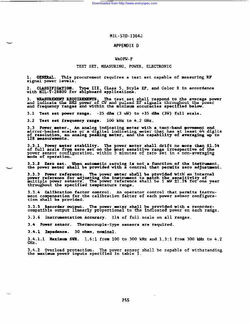
MIL-STD-1364J
APPENDIX D
WAOFW-F
TEST SET, MEASURING, POWER, ELECTRONIC
1. GENERAL. This procurement requires a test set capable of measuring RFsignal power levels.
2. CLASSIFIGATIOM .w
III, Class 5, Style EP, and Color R in accordancewith MIL-T-28800 for s pboard applications.
3* MEASUREMENT U~. The test set shall respond to the average powerand indicate the% power of CW and ulsed RF signals throu out the power
! Pand frequency ranges and within the m nimum accuracies speci ied below.
3.1 Test sst power range. -25 dBm (3 W) to +35 dBm (3W) full scale.
3.2 Test set frequency range. 100 kHz to 4.2 GHz.
3.3 Power mater. An analo indicating meter with a taut-bend movement andfmirror-backed scales or a d ital indicating meter that has at least W digits
of resolution, an analog pe2128 measurements.
Ing meter, and the capability of averaging up to
3.3.1 Power meter stability. The power meter shall drift no more than *1.5*of full scale from zero set on the most sensitive range irrespective of thepower sensor configuration, within 5 minutes of zero set in a non-avaragingmode of operation.
3.3.2 Zero @@t. When autoutic zeroing Is not a function of the instrument,- the power meter shall be providad with a control that permits zero adjustment.
3.3.3 Power reference. The power mbter shdll be ptovl?led WitIi’an ’internalpowor referonoe for adjuating the instrument to match the sensitivl~ ofmultiple power semors. The puwer reference shall be 1 mW A1.2t for one yearthroughout the specified temperature range.
3.3.4 Calibration factor control. An operator control that permits instru-ment co
Tmation for the calibration factor of each power sensor configura-
tion sha 1 be provided.
3.3.5 Recorder out t.r
The power meter shall befrovided with a Fecordex-
compatible output 1 nearly proportional’to the lnd cated power on each range.
3.3.6 Instrumentation Accuracy, fl~ of full scale on all ranges.
3.4 Power sensor. Thermocouple-type sensors are required.
3.4.1 Impedance. 50 ohms, nominal.
3.4.1.1 MaxiMum SWR. 1.6:1 from 100 to 300 kliz and 1.3:1 from 300 kHz to 4.2GHz.
3.4.2 Overload protection. The power sensor shall be capable of withstandingthe maximum power inputs specified in table I.
--
255
Downloaded from http://www.everyspec.com
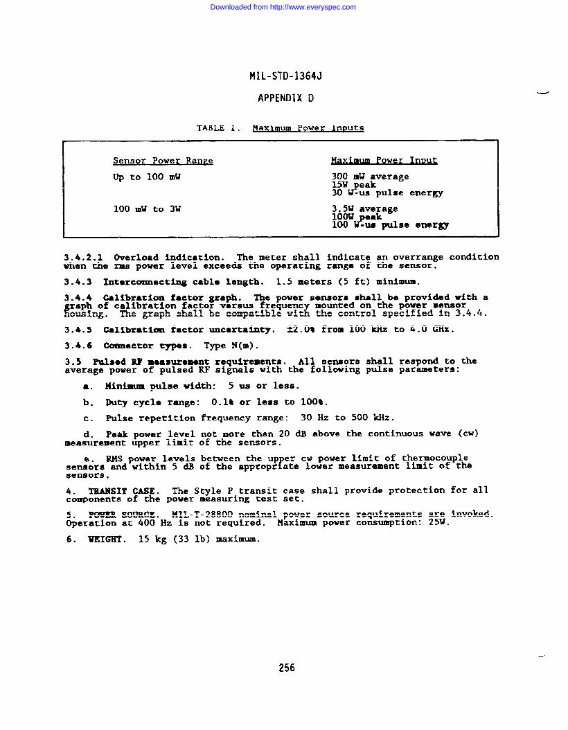
MIL-STD-1364J
APPENDIX D
TABLE I. Maximum power Inputs
Sensor Power Raw e Um Po erw I=
Up to 100 mW 300 mW average15W peak30 W-us pulse energy
100 mW to 3W :0:: av;~age
100 #w pulse energy
3.4.2.1 Overload indication. The meter shall indicate an overrange conditionwhen the rms power level exceeds the operating range of the sensor.
3.4.3 Intorconnectlng cable length. 1.5 meters (5 ft) minimum.
3.4.4 Calibration factor graph. The power sensors shall be provided with a
raph of calibration factor versus frequent
~mounted on the power ‘sensor
ousing. The graph shall be compatible wit the control specified in 3.4.4.
3.4.5 Calibration factor uncertainty. *2.Ot from 100 kHz to 4.0 az.
3.4.6 Connector types. we N(m).
3.5 Pulsed RF measurement requirements. All sensors shall respond to theaverage power of pulsed RF signals with the following pulse parameters:
● , Minimum pulse width: 5 us or less.
b. Duty cycle range: 0.1% or less to 100*.
c. Pulse repetition
d. Peak power levelmeasurement upper limit
RMS power levelssemeors and within 5 dBsensors.
frequency range: 30 Hz to 500 kHz.
not more than 20 dB above the continuous wave (cw)of the sensors.
between the up er cw power limit of thermocouplerof the appropr ate lower measurement limit of the
4. TRANSIT CASE. The Style P transit case shall provide protection for allcomponents of the power measuring test set.
POWER SOURCE. MIL-T-28800 nominal power source requirements are invoked.&eration at 400 Hz is not required. Maximum power consumption: 25W.
6. WEIGHT . 15 kg (33 lb) maximum.
256
Downloaded from http://www.everyspec.com
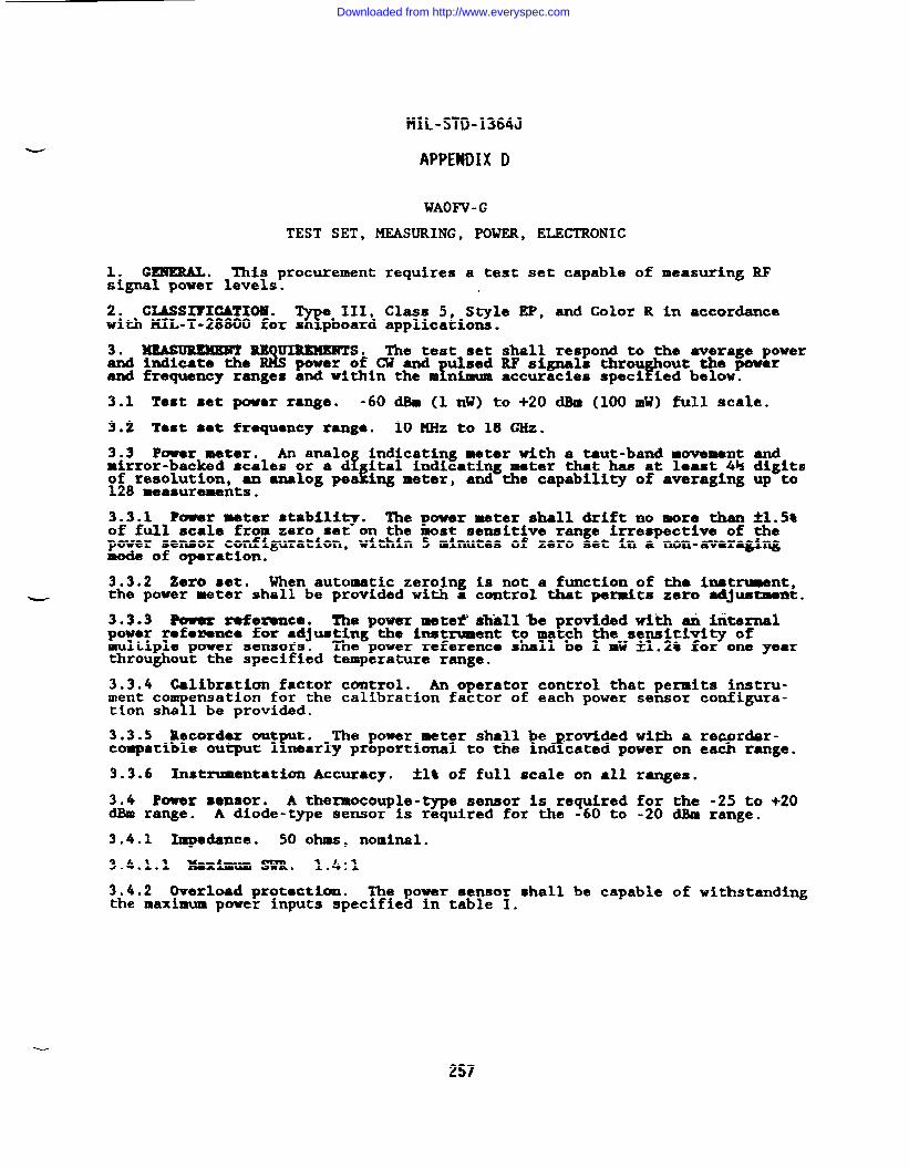
MIL-STD-1364J
APPENDIX D
WAOFV -G
TEST SET, MEASURING, POWER, ELECTRONIC
1. CZHERAL. This procurement requires a test set capable of measuring RFsignal power levels.
2. CIASSI?ICATIOH .%
e III, Class 5, Style EP, and Color R in accordancewith KIL-T-28800 fox s pboard applications.
3. MmsmmmT RE UmEMm’TsoS$s
The test set shall respond to the average powerand indicate the power of CU and
f Pulsed RF signals throu out the power
and frequency ranges and within the m nimum accuracies speci ied below.
3.1 Test set power range. -60 dBm (1 nW) to +20 dBm (100 mW) full scale.
3.2 T@st sot frequency rang~. 10 MHz to 18 GHz.
3.3 Povor meter. An analo!
indicating meter with a taut-band movement andmirror-backed scales or a d ital indicating meter that has at least 4H digits
1!of resolution, an analog pea ing meter, and the capabili~ of averaging up to128 measurements.
3.3.1 Power meter stability. The power meter shall drift no more than *1.5%of full scale from zero set on the most sensitive range irrespective of thepower sensor configuration, within 5 minutes of zero set in a non-averagingmode of operation.
3.3.2 Zero set. When automatic zeroing is not a function of tb instnaent,- the power meter shall be provided with a control that permits zero adjustment.
3.3.3 ?ow’ar refclmnce. The power mete~ shhll%e provided wikh & internalpowar rofemnco for adjusting the instrument to match the sensitivity ofmultiple power sensors. The power reference shall be 1 mW *1.2% for one yearthroughout the specified temperature range.
3.3.4 Calibration factor control. An operator control that permits instru-ment co
‘“Tensation for the calibration factor of each power sensor configura-
tion sha 1 be provided.
3.3.5 Recorder out t.r
The power meter shall be xovide~ with a zecor&r-!compatible output 1 nearly proportional to the ind cated power on each range.
3.3.6 Instrumentation Accuracy. *1% of full scale on ●ll ranges.
3.4 Power sensor. A thermocouple--e sensor is required for the -25 to +20dBm range. A diode-type sensor is required for the -60 to -20 dBm range.
3.4.1 Impedance. 50 ohms, nominal.
3.4.1.1 Maximum SwR. 1.4:1
3.4.2 Overload protection. The power sensor shall be capable of withstandingthe maximum power inputs specified in table I.
-
257
Downloaded from http://www.everyspec.com
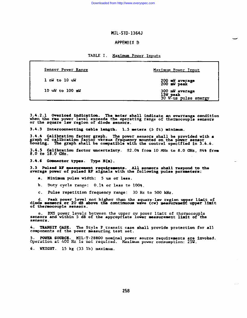
MIL-STD-1364J
APPENDIX D
TABLE I. Haximum Power Inmts
sensor Power Ranze Max~um Po er _w
1 nW to 10 UW 200 mW average200 mu peak
10 uW to 100 mW 300 mW~verage&
P .W t9u19a4emarw
3.4.2.1 Overload indication. The meter shall indicatewhen the rms power level exceeds the operating range ofor the square law region of diode sensors.
3.4.3 Imtarcomnact~ cable length. 1.5 meters (5 ft)
an overran e condition?thermocoup e sensors
minimum.
3.4.4 Callbrstion factor graph. The power sensors shall be provided with ●
1?aph of calibration factor versus frequent
zmounted on the power sensor
ousing. The graph shall be compatible wit the control specified in 3.4.4.
3.4.5 Calibration factor uncertainty. ~2.Ot from 10 ~ to 8.0 ~, ~4~ from8.0 to 18.0 ~Z.
3.4.6 Cammector types. Type N(m).
3.5 Pu18ed w measuxomemtraqd(remnta. All sensors shall respond to theaverage power of pulsed RF signals with the following pulse parameters:
a. Minimum pulse width: 5 us or less.
b. Duty cycle range: 0.1% or less to 100%.
c. Pulse repetition frequency range: 30 Hz to 500 kHz.
d. Peak power level not higher than the square-law region upper limit ofdiode ~nmors or 20 dllabove the ccmtinuoua wave (CW) measuremerst upper ltmitof thermocouple sensors.
RKS power levels between the up er cw power limit of thermocouplefsen&s and within 5 dB of the appropr ate lower measurement limit of the
sensors.
4. TMNSIT GASE. The Style P transit case shall Drovid@ Drotectlon for allcomponents of the power mbasuring test set.
. .
POWER souRcl!* HIL-T-28800 nominal power source requirementsaeration at 400 Hz is not required. Maximum power consumption:
6. WEIGHT . 15 kg (33 lb) maximum.
.-
...
258
Downloaded from http://www.everyspec.com
MIL-STD-1364J
APPENDIX D
WAOFlt-D
TEST SET, MEASURING, POWER, ELECTRONIC
1. CENEML. This procurement requires a test set capable of measuring RFsignal power levels.
2. CLASSIFICATION .%
e III, Class 5, Sty”leEP, and Color R in accordancewith llIL-T-28800 for s pboard application.
3. MEAmMmm%
UIMMKNTS. The test set shall respond to the average powerand tndicata the power of Cl? and ulsed RF signals throu out the power
T Pand frequency ranges and within the m nimum accuracies speci ied below.
3.1 Tsst sat power mngo. -20 dBm (10 @ to +20 dBm (100 roll)full scale.
3.2 Test set frequency range. loMHz to 40 GHz.
3.3 Power meter. An analo indicating meter with a taut-band movement andfmirror-backed scales or a d ital indicating meter that has at least 4h digitsEof resolution, an analog pea ing meter, and the capability of averaging up to.
128 measurements.
3.3.1 Power meter stability. The power meter shall drift no more than ~1.5tof full scale from zero set on the most sensitive range irrespective of thepower sensor configuration, within 5 minutes of zero set in a non-averagingmode of operation.
3.3.2 Zero set. When automatic zeroing is not a function of the instrument,the power meter shall be provided with a control that permits zero adjustment.
3.3.3 Power referent.. The power meter #hall be provfded with an internalpower reference for adjusting the instnzaent to match the sensititi~ ofmultiple power sensors. The power reference shall be 1 mW ~1.2% fox one yearthroughout the specified temperature range.
3.3.4 Calibration factor control. An operator control that permits instru-ment co
Tensation for the calibration factor of each power sensor configura-
tion sha 1 be provided.
3.3.5 Recorder out t.r
The power meter shall be roviciedwi~ a recor&r-?compatible output 1 nearly proportional to the ind cated power on each range.
3.3.6 Inatnmentation Accuracy. kl* of full scale on all ranges.
3.4 Power sensor. Thermocouple-type sensors are required.
3.4.1 Impedance. 50 ohms, nominal.
3.4.1.1 Maxi.mum SWR. 1.4:1
3.4.2 Overload protection. The power sensor shall be capable of withstandingthe maximum power inputs specified in table I.
259
Downloaded from http://www.everyspec.com
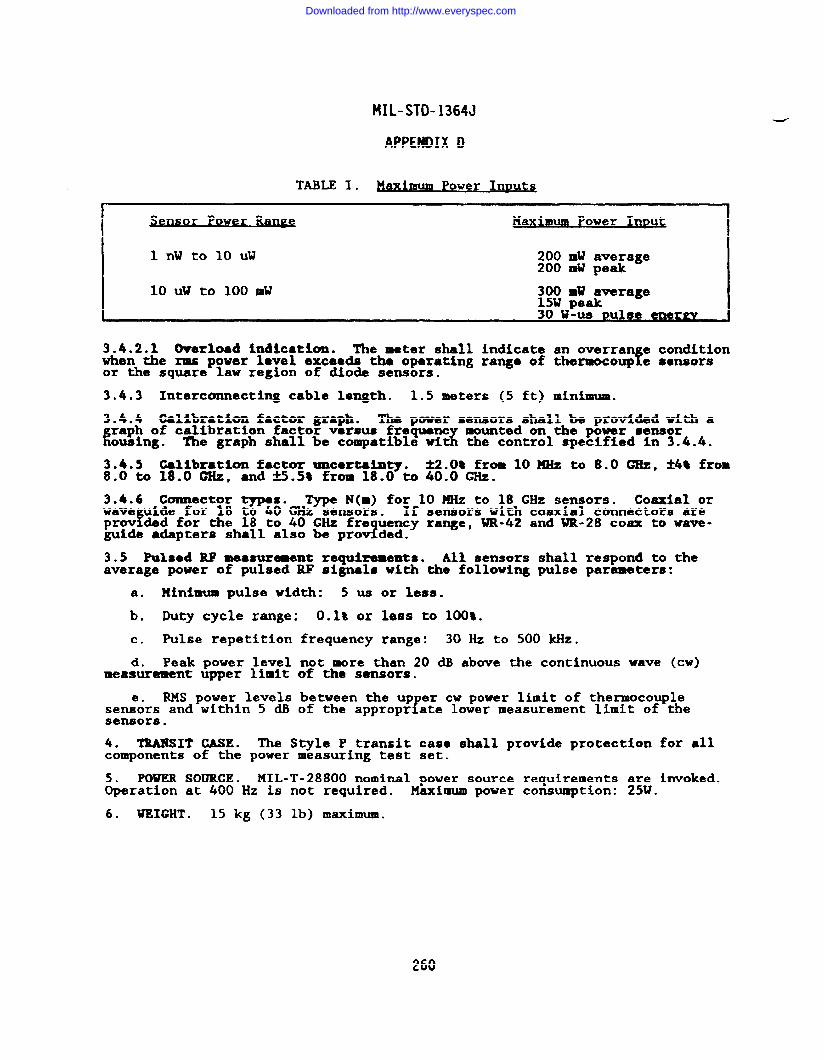
HIL-STD-1364J
APPENOIX O
TABLE I. Power Inmts
h
nsor Power Maximum Power lllDUc
1 nW to 10 UW 200 IDWaverage200 mW peak
10 Uw to 100 mu 300 MW average15W peak30 W-us Pulse enegm*
3.4.2.1 Overload ind~cation. The meter shall indicate an overran e conditionfwhen the ma power level exceeds the operating range of thermocoup e sensors
or the square law region of diode sensors.
3.4.3 Interconnecting cable length. 1.5 meters (5 ft) minimum.
3.4.4 Calibration factor graph. The power sensors shall be provided with a
Rraph of calibration factor varsus frequent
&mounted on the power sensor
ousing. The graph shall be compatible wi the control specified in 3.4.4.
3.4.5 Calibration factor uncertainty. ti.0% from 10MHz to 8.0 GHz, *4* from8.0 to 18.0 GHz, and fi.5t from 18.0 to40.OGHz.
3.4.6 Connector types. Type N(m) for 10 MHz to 18 GHz sensors. Coaxial orwave i.defor 18 to 40 GHz sensors.
YIf sensors with coaxial connectors are
prov dad for the 18 to 40 GHz fre uency range, WR-42 and WR-28 coax to wave-1guide ●dapters shall also be prov ded.
3.5 Pulsed RF measurement requirements. AU sensors shall respond to theaverage power of pulsed RF signals with the following pulse parameters:
a. Minimum pulse width: 5 us or less.
b. Duty cycle range: 0.1% or less to 100%.
c. Pulse repetition frequency range: 30 Hz to 500 k?iZ.
d. Peak power level not more than 20 dB above the continuous wave (CW)measurement upper limit of the sensors.
RMS power levels between the up er cw power limit of thermocouple1’semeors and within 5 dB of the appropr ate lower measurement limit of the
sensors.
4. TXUU!?SITCASE. The Style P transit case shall provide protection for allcomponents of the power measuring test set.
POWER SOURCE. MIL-T-28800 nominal power source requirements ~;; invoked.&eration at 400 Hz is not required. Maximum power consumption: .
6. WEIGHT . 15 kg (33 lb) maximum.
260
Downloaded from http://www.everyspec.com
MIL-STD-1364J
APPENDIX D
WAOXK- F
TEST SET, MEASURING, POWER, ELECTRONIC
1. GENERAL. This procurement requires an RF peak power measuring set.
2. CIASSIFICATIOH .73!
e 111, Class 5, Style E, and Color R in accordancewith 141L-T-28800 for s pboard applications.
3. ~ CAPABILITY. The equipment shall be c able of measuring ak‘? Ypower at the center of a s ecific ulse in a pulse tra n, and the pulao w dth
f !at the 3 dB points of a pu se enve ope, within the minimum frequency and powerranges, and with the modulation characteristics specified below.
3.1 Modulation. The equipment shall be capable of measurin&#~::~-;hty~d#ation rates of 25 pps to 10,000 pps, and with pulse wid
.
3.2 Power meter. ~ analo indicating meter with a taut-band movement andmirror-backed scales or a & gital indicating display with a resolution of3-1/2 digits shall be provided.
3.2.1 Resolution. 2% of full scale.
3.3 Trigger. The equipment shall have internal and external trigger modes.
3.3.1 Txi e~a~+~ ~~o O to 200 M. Resolution: 0.1 na. Accuracy:%*(0.01% of T .
~ 3.3.2 Extarmal txiggu. Uvel: TTL. Connectox type: BK(f).
3.4 Calibration factor control. A calibrated control that permits compensa-tion for the frequency response of the power sensor is required.
3.5 Powar *enaor.
3.5.1 Requency range. 100 ~Z to 18 GHz,
3.5.2 Peak power range. -20 CiBmto +20 dBm.
3.5.3 Overload protection. 200 mW peak.
3.5.4 Volta ● standtng ws~ ratiof
iv=). 1.15 from 100MHz to 2.OGHz, 1.25from 2.0 to 2.4 GHz, and 1.4 from 2.4 to 18.0 GHz.
3.5.5 Connector. me N(m).
3.5.6 Interconnecting cable length. 1.2 meters (4 ft).
3.5.7 Calibration factor graph. The power sensor shall be provided with a
fraph of calibration factor versus fre uency mounted on the power sensor hous-ng. The graph shall be compatible wi&h t e control specified in 3.3.
3.6 Accuracy. ~lo~ of full scale.
3*7 output. The e uipment shall have an output proportional to the detectedRF envelope. 1Riset me: 50 ns or less. Impedance: 50 ohms, nominal.
P(WER SOURCE.MIL-T-28800 nominal power source requirements a~;Winvoked.&eration at 400 Hz is not required. Maximum power consumption: .
5. UEICXT . 20 kg (44 lb) maximum.
----
Downloaded from http://www.everyspec.com
MIL-STD-1364J
APPENDIX D
Configuration A: RHONP-EConfiguration B: RHONR- E
TEST SET, MEASURING, RADIATION HAZARD
1. GEI!!WUU. This procurement requires a true rms, isotropic, bxoadband,hand-held, radiation hazard meter.
2. GIASSIFIGATIOIU.%
e III Class 3, Style EP, and Color R in accordancewith MIL-T-28800 for s pboar~ applications.
3. 0PIRATIOX4L REQU~S. Both equi ment confi3
rations shall be capableof operation within CW fields or compoun YCW and pu se modulated fields withinthe minimum accuracies and limits specified below.
3.1 Electric field.
3.1.1 E field frequency range. 300
3.1.2 E field measurement ranga. 1
3.2 Ma etic field.r
Magnetic fieldration equipment.
3.2.1 M field frequency range. 300
3.2.2 H field measurement zange. 1for Configuration B.
kHz to 40 GHz.
mW per square cm to 100 mW per square cm.
measurements are not required of Configu-
kHz to 300 KHz for Configuration B.
mW per square cm to 100 mW per square cm
3.3 Accuracy. *3 dllor better excluding elipticity and isotropic errors.Use of calibration charts or other correction methods are acceptable to meetthis requirement.
3.4 I&sr
se time. The typical res ome time for Configuration A and Config-uration shall be one second. fConf guration B shall be provided with anadditional response tbe selection of typically 3 seconds.
3.5 Recorder output. The equipment shall provide a dc voltage proportionalto the meter indication for use with a recorder.
3.6 Peak hold control. A selectable mode shall be provided that willindicate and hold the msximum value of the field intensity until reset.
3.7 Power density ●larm. An audible power density alarm shall be adjustablefor any percentage of full scale.
3.8 Probes.
Configuration A: The equi menttwo %bes to cover the required E !ield3.1.! and 3.1.2).
b. Configuration B: The equi ment!two robes to cover the required E ield
3.1.! and 3.1.2) and two probes to covermeasurement ranges (see 3.2.1 and 3.2.2).
shall be provided with no more thanfrequency and measurement ranges (see
shall be provided with no more thanfrequent
1and measurement ranges (see
the requ red H field frequency and
3.8.1 Maximum power. E field measurements: lW per s uare cm for GW and 300W
%ra:auare cm forpeakpowe’” ‘field measurements’ a“omwpersqwrecm for300W per square centimeter for peak power.
3.9 Display. An analog ❑eter which displays in mW per square cm shall beprovided.
—
262
Downloaded from http://www.everyspec.com
MIL-STD-1364J
APPENDIX D
3.9.1 Display resolution. 5% or less of full scale.
3.10 Battery check. An indication of battery condition shall be provided.
3.11 Operational check source. The e uipment shall be provided with an RF?source used to determine proper operat on of the system.
3.12 Transit Ca88. One transit case shall be provided which shall be capableof storing all equipment.
4. mm SOURGE. llIL-T-28800 nominal and dc intarnal powor source r*quira-ments are invoked as detailed below.
4.1 MOmizlalv? %5””
Operation at 400 Hz im not required. Maximumpower comunp ion.
4.2 DC internal power source: Internal batteries and charger are required.~~~~=operating time shall be 40 hours following a maximum recharge time of
.. .
5. WEIGHT. 209(
44 lb) maximum including transit case, 4.5 kg (10 lb)maximum when conf gured for operation.
Downloaded from http://www.everyspec.com
MIL-STD-1364J
APPENDIX D
FIOAJ-C
TEST SET, MEASURING, RIFI
-
1. GENERAL. This rocurement re uires a portable, solid state interference?analyzer/receiver w th synthesize a local oscillator capable of detecting RF
signals over the frequency range of 10 kHz to 30 MHz.
2. CLASSIFICATION . The equipment shall meet the requirements of MIL-T-28800,Type III Class 5, Style E, Golor R for Navy shipboard, submarine, and shoreapplications with the following modifications and exceptions:
The nonoperating%
temperature re uirement is limited to the range of-25s6 to +70”C without atteries, -lO”& to +60”C with batteries.
b. The relative humidity requirement is limited to 95% noncondensating.
c. The operating and nonoperating altitude requirements are not invoked.
d. The electroma etic interference re uirements of MIL-T-28800 are\limited to CEO1 CEO~CSOl CS02 0.05 to 00 MHz), cS06, REOl (back panel
search excluded~, REO~ (14 & to 4 GHz), and RS03.
e. The warm-up time Is extended to 30 minutes.
3. OPERATIONAL REQU~. ThisAM, FM, and pulse modulated signals
3.1 Frequency characteristics.
3.1.1 Range. 10 Hz to 30 MHz.
equipment shall be ca able of demodulatingover its measurement ?requency range.
3.1.2 Display. Digital (5 digits minimum).
3.1.2.1 Resolution. At least 1 ldiz.
3.1.3 Resolvable frequency. At least 100 Hz.
3.1.4 Accuracy.
3.1,4.1 Internal reference. ~2xlo-S+50 Hz (max error f650 Hz at 30 ~z).
3.1.4.2 External reference. Dependent on stability of external reference.
3.1.4.2.1 Input. 5/10 MHz, 1 Vrms into 500.
3.2 Level measurement.
3.2.1 Dynamic range. At least 135 dB.
3.2.1.1 Maximum input. At least 110 dBpV (3 dBm).
3.2.2 Display. Digital and/or analog in units of at least dBPV.
3.2.2.1 Resolution. Minimum resolution of at least 1 dB over entire levelrange.
3.2.3 Accuracy. -tto5 ~ of actual level (average value measurement ofsignals > 0 dBPV).
3.2.4 IF bandwidths (at least).
3.2.4.1 Minimum. 200 Hz.
-.
264
Downloaded from http://www.everyspec.com
MIL-STD-1364J
APPENDIX D
3.2.4.2 Maximum. 9 kHz.
3.2.5 Sensitivity (CTJsignal) S+N/N - 3 dB. At least -20 dBpV.
3.2.6 Input impedance. 500.
3.2.6.1 VSUR. Less than 1.5:1 for levels < 100 dBpV.
3.2.6.2 Connector. BNC (female).
3.2.7 Gallbration. IF gain adjusted to stored, nonvolatile correctionfactors when CAL is activated.
3.2.8 Detector functions. Average, peak, peak with prograxmuable hold.
3.3 Extraneous signals.
3.3.1 bcal oscillator emission. Less than 25 dBpV with input connectorterminated in Sm.
3.3.2 IF rejection. > 80 dB.
3.3.3 Wge rejection. > 70 dB.
3.3.4 Cross-modulation. A 100 dBpV SiP
1 with 30% AM at 1 kHz spaced > 100kllzaway from a received signal of 20 pV shall produce less than 3% AM onthe received signal.
3.4 Outpmts.
~ 3.4.1 Tracking generator.
3.4.1.1 Level. At least -30 dBm.
3.4.1.2 Frequency. Receiver’s tuned frequency.
3.4.1.3 Output. 50-ohm, BNC female connector.
3.4.1.4 Accuracy. ~2xlo-s +50 Hz (max error -t650 Hz at 30 ~z)o
3.4.2 Intermediate frequency (IF). For connection to oscilloscope.
3.4.3 AM. Demodulated amplitude ❑ovulation signal.
3.4.4 m. Demodulated frequency modulation.
3.4.5 Recorder. At least 1 volt full scale; level proportional to detectedsignal ●
4. GENERAL REQUIREMENTS.
4.1 Power source. 115 and 230 Vac ~10%, 50, 60, or 400 Hz, 75 VA maximum.
4.1.2 Direct current. 11 to 14V at 2A nominal or less.
4.2 Volume. The total volume shall not exceed 54,077 cm3(3,300 in3).
:<; Jyight. The total weight including battery pack shall not exceed 22.7 kg.
5. ACCESSORIES.
5.1 Rod antenna. (9 kHz to 30MHZ).
5.2 Loop antenna. (9 kl+z to 30MHZ).
265
Downloaded from http://www.everyspec.com

— —-
MIL-STD-1364J
APPENDIX D
5.3 Tripod.
Downloaded from http://www.everyspec.com
!lIL-STD-1364J
APPENDIX D
FIOAL-A
TEST SET, MEASURING, RIFI
1,0 GENERAL. This procurement requires a portable, solid state interferenceanalyzer/receiver with synthesized local oscillator capable of detecting RFsignals over the frequency range of 10 kHz to 30 MKz.
:8:OOCLASSIFICATION. The equipment shall meet the requirements of MIL-T-
Ye 111, Class 5, S le E, Color R for Navy shipboard, submarine, and
shore’app ications with the? ollowing modifications and exceptions:
The nono eratin!
temperature requirement is llmited to the range of-25°;”to +70°C W thout %atteries; -10”C to +60”C with batteries.
b. The relative humidity requirement is limited to 95% noncondensating.
c. The operating and nonoperating altitude requirement is not invoked.
d. The warm-up time is extended to 30 minutes.
3.0 OPERATIONAL REQUIMMENTS. This equipment shall be capable of &modulat-in AM, FM or pulse modulated signals over its measurement fre uencWi& its wide dynamic range and tracking generator, 1 ?S:?:siveit is capab e ovoltage and two-port measurements.
3.1 Frequency characteristics.
3.1.1 Range. 10 kHz to 30 MHz.w
3.1.2 Display. Digital (6 digits minimum).
3.1.3 Ruolution. At least 100 Hz.
3.1.4 Accuracy.
3.1.4.1 Internal reference. t2x10E-5 + 50 Hz (max error *650 Hz at 30 ~).
3.1.4.2 External reference. Dependent on stability of external reference.
3.1.4.2.1 Input. 5/10 MHz, 1 Vrms into 50 ohms.
3.1.5 Frequency scan. Tunin of receiver may be automatically swept over a!range of frequencies by speci ying start, stop, and step frequency size.
3.2 Level measurement.
3.2.1 Dynamic range. At least 150 d.11.
3.2.1.1 Maximum input. At least 130 dBuV (23 dBm).
3.2.2 Display. Digital and/or analog in units of at least dBuV, dBm, and uV.
3.2.2.1 AMlog resolution. Minimum resolution of 1 dB over entire levelrange.
3.2.2.1.1 Scale ranges. 20 dB and 40 dB minimum.
3.2.2.2 Digital resolution. Minimum resolution of 0.1 dB over entire levelrange.
3.2.3 Accurac .6
tl.5 dB of actual level (average value measurement ofsignals X dlh ).
---
267
Downloaded from http://www.everyspec.com
?41L-STD-1364J
APPENDIX D
3.2.4 IF bandwidths (at least).
3.2.4.1 Htnimum. 200 Hz.
3.2.4.2 Maximum. 10 kHz.
3.2.5 Sensitivity (GW signal) S+19/N= 9 dB. At least -20 dBuV.
3.2.6 Input impedance. 50 ohms.
3.2.6.1 VSUB. Less than 1.5:1 for levels <100 dBuV.
3.2.6.2 (knanector. BNC(f) .
3.2.7 Calfbratton.
3.2.7.1 Automatic. IF gain adjusted to stored, non-volitile correctionfactors when IF BW changed.
3.2.7.2 Manual.‘F %ak ;+:%t;ti!.scored’when CAL key depresse
non-volitile correction factors
3.2.8 Det@ctor funct~ons. Average, peak, peak with programmable hold.
3.3 Extraneous signals.
3.3.1 *al oscillator ●mission. Less than 25 dBuV with input connectorterminated in 50 ohms.
3.3.2 IF rejection. >100 dB.
3.3.3 Image rejection. >100 dB.
3.3.4 Cross modulation. A 100 dBuV si 1 with 30t AH at 1 kllzspaoed >100klizaway from ● received signal of 20 & shall produce less than 3* AM onthe received signal.
3.4 Outputs.
3.4.1 Tracking generator.
3.4.1.1 Level. At least -30 dBm.
3.4.1.2 Frequency. Receiver’s tuned frequency.
3.4.1.3 output. 50 ohm, BNC connector.
3.4.2 Intermediate frequency. For connection to oscilloscope.
3.4,3 An. Demodulated amplitude modulation signal.
3.4.4 FM. Demodulated frequency modulation.
3.4.5 X-Y plotter. Outputs capable of driving an X-Y plotter.
3.4.6 Pen lift. Signal shall lift plotter pen during retrace.
4.0 GENERAL REQUIREMENTS.
4.1 Power.
4.1.1 Alternating current. 115/230 Vac tlO%, SO, 60, or 400 Hz, 120 VAmaximum .
4.1,2 Direct current. 22-32 Vdc, 4A maximum..
268
Downloaded from http://www.everyspec.com
.
MIL-STD-1364J
APPENDIX D
4.2 Volume. The total volume of the unit shall not exceed 3969 cubic in(65,040 cubic cm).
4.3 Vei@t. The total weight of the unit shall not exceed 50 lb (22.7 kg).
4.4 Rewte rogrammin .L B
The receiver shall be capable of beincontrolled v the IEE -488 interface bus, operatin as both a
!!a~$~’~~
listener, havin the following subset of bus funct ens: AHl, IA, Sill,T5,SRI, PP1, DC1, D$l, and I&l.
5.0 Accessories.
5.1 EFH 2-21. Rod antenna (9 kHz to 30 MHz).
5.2 HFH 2-Z2. hop antenna (9 kHz to 30 MHz).
5.3 m-z. Tripod.
...
269
Downloaded from http://www.everyspec.com
MIL-STD-1364J
APPENDIX D
FIOAY-A
TEST SET, MEASURING, RIFI
1.0 GENSRAL. This procurement requires a&
ortable, solid state interferenceanalyzer/receiver capable of detecting an output over the range of 1 to 18GHZ .
2.0 GLASSIFIGATIOU. The equipment shall meet the requirements of HIL-T-28800,
T111, Class 5, S le E, Color R for Navy shipboard, submarine, and
shore app ications with the? ollowing modifications and exceptions:
a. The nonoperating temperature requirement is limited to the range of-40”C to +70”C.
b. The relative humidity requirement is limited to 95* noncondenaating.
c. The operating and nonoperating altitude requirement is not invoked.
d. The warm-up time is extended to 30 minutes.
3.0 OPEMTIONAL REQUIREMENTS. The equipment shall have RF preelection witha minimum selectivity of 12 dB/octave and be ca able of detecting an RF signal
Ewithin the parameters and accuracies specified erein.
3.1 RF froqumlcy.
3.1.1 Ramgeo At least 1 to 18 GHz in no more than 5 overlapping bands.
3.1.2 Accuracy. At least *1$ of the actual detected RF frequency when thereceiver is properly tuned to the incoming signal.
3.1.3 Gapturc ranga. At least 50% of the IF bandwidth selected with theAutomatic Frequency Control (AFC) activated.
3.1.4 Stability (AFC off).
3.1.4.1 Short term. Less than or equal to 1 pp 10E5; 15 minute warm-up,25-C, time period 10 seconds.
3.1.4.2 Lon term.!!
bss than or equal to 5 pp 10E5; 30 minute warm-up, 25”C,time period minutes.
3.2 Voltage measurement.
3.2.1 Range. At least 120 dB (1.0 UV to 1.0 V).
3.2.2 Attenuator. At least O to 60 dB in 10 dB steps.
3.2.3 ACCUXaC .T
Within *2 dB of actual detected CW signals above +40 dBuV;*3 * for leve s below 40 dBUV.
3.2.4 Sensitivity. For (S+N)/N - 3 dB.
3.2.4.1 Narrowband. Less than or equal to 7 d.BuV (-100 dBm) for BW less thanor equal to 100 kHz.
3.2.4,2 Wideband. Less than or equal to 27 dBuV (-80 dBm) for BW less thanor equal to 10 MHz.
3.2.5 Calibrator. The unit shall have an internal calibrator of the impulsegenerator type.
3.2.6 Input connector. 50 ohms nominal; precision type N.
270
Downloaded from http://www.everyspec.com
MIL-STD-1364J
APPENDIX D
3.2.6.1 VSWR. 2:1 typical; 3:1 maximum.
3.3 Swee capability.!
The frequency to which the receiver is tuned shall becapable o being swept in a linear manner over any portion of the frequencyrange in any frequency band.
3.3.1 Band sweep. Repetitive or single sweep over the entire band selected.
3.3.2 Sector sweep. Sweep width is controllable from 0.1% to 10% of thefrequency range in any frequency band.
3.4 Extraneous 8@nals.
3.4.1 IF rejection. Equal to or greater than 80 dB.
3.4.2 Image reflection. Equal to or greater than 60 dll.
3.4.3 Spurimaz rejection. Equal to or greater than 60 dB.
3.4.4 @cal oscillator emission. Equal to or less than -70 dBm at the RFinput connector when terminated itito50 ohms.
3.5 Detector functions. The unit shall provide detector functions ofcarrier, peak and slideback peak calibrated in rms equivalent.
3.6 Outputs. All outputs are into minimum impedance of 1 kilohm unlessotherwise specified.
3.6.1 Xacal oscillator. At least -20 dBm into 50 ohms.
w 3.6.2 Eorizomtal. The unit shall provide a dc coupled output which variesfrom O to at least 1.0 V whose voltage is proportional to the frequency beingswept in either the “ban~- or ‘sector mode.
3.6.3 Vertical. The unit shall provide a dc cou led ou ut which varies from! %O to at least 1.0 V, whose voltage is proportiona to eit er the log or the
linear displacement of the peak, average or slicleback detector used.
3.6.4 Blankin .f
The unit shall provide a retrace blanking pulse whosepolarity is se ectable.
3.6.5 Video. FM, linear and log.
3.6.6 Audio. AH and FM.
3.6.7 X-Y plotter. Outputs capable of driving an X-Y plotter shall be pro-vided.
3,6.8 Pen lift. A TTL compatible voltage or contact closure shall beprovided to lift the plotter pen during retrace.
4.0 GENERAL REQUIREMENTS,
4.1 Power. 115/230 Vac flO%, 50/60 Hz, 170W maximum.
4,2 Dimensions. The e uipment shall be rack mountable and shall occupy avolume not to exceed 2,Y50 cubic in (45,065 cubic cm).
4.3 Weight. The total weight of the unit shall not exceed 66 lbs (30 kg).
271
Downloaded from http://www.everyspec.com
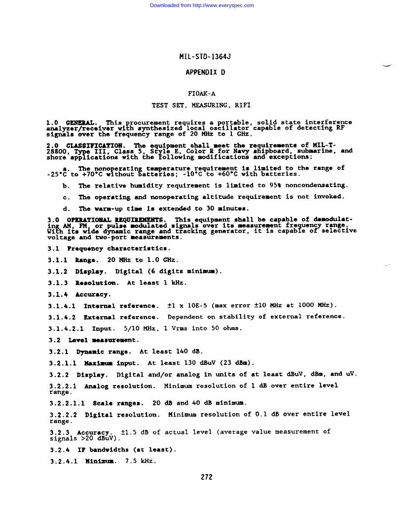
MiL-STD-1364J
APPENDIX D
FIOAK-A
TEST SET, MEASURING, RIFI
1.0 GENERAL. This procurement requires a portable, solid state interferenceanalyzer/receiver with synthesized local oscillator capable of detecting RFsignals over the frequency range of 20 MHz to 1 GHz.
;8:ooCUSSIFICATIOm. The equipment shall meet the requirements of MIL-T-
Te 111, Class 5, S le E, Color R for Navy shipboard, submarine, and
shore’app ications with theY ollowing modifications and exceptions:
The nono eratin temperature requirement Is limited to the range of!-25”t”to +70°C w thout %atteries; -10”C to +60°C with batteries.
b. The relative humidity requirement is limited to 95% noncondensating.
c. The operating and nonoperating altitude requirement is not invoked.
d. The warm-up time is extended to 30 minutes.
3.0 OPERATIONAL REQUIREMENTS. This equipment shall be capable of demodulat-ing AM, FM or pulse modulated signals over its measurement fre uencWi& its w~de dynamic range and tracking generator, 1 ?s;?~f:iveit is capab e ovoltage and -o-port measurements.
3.1 Frequency characteristics.
3.1.1 Range. 20MHZ to 1.0 GHz.
3.1.2 Disp18y. Digital (6 digits minimum).
3.1.3 Resolution. At least 1 kllz.
3.1.4 Accuracy.
3.1.4.1 Internal refarance. fl x 1OE-5 (max error f10 MHz at 1000 w).
3.1.4.2 External reference. Dependent on stability of external reference.
3.1.4.2.1 Input. 5/10 MHz, 1 Vrms into 50 ohms.
3.2 Level measurement.
3.2.1 Dynamic range. At least 140 dB.
3.2.1.1 Maximum input. At least 130 dBuV (23 dBm).
3.2.2 Display. Digital and/or analog in units of at least dBuV, dBm, and uV.
3.2.2.1 Analog resolution. Minimum resolution of 1 dB over entire levelrange.
3.2.2.1.1 Scale ranges. 20 dB and 40 dB minimum.
3.2.2.2 Digital resolution. liinimum resolution of 0.1 dB over entire levelrange.
3.2.3 Accuracy. fl.5 dB of actual level (average value measurement Ofsignals >20 dBuV),
3.2.4 IF bandwidths (at least).
3.2.4.1 Minimum. 7.5 Hz.
272
Downloaded from http://www.everyspec.com
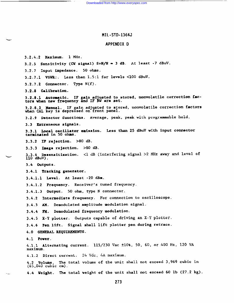
MIL-STD-1364J
APPENDIX D
3.2.4.2 ~X_. 1 MHz.
3.2.5 Sensitivity (GW signal) S+N@ = 3 dB. At least -7 dBuv.
3.2.7 Input impedance. 50 ohms.
3.2.7.1 VSWR:. Less than 1.5:1 for levels <100 dBuV.
3.2.7.2 Connector. Type N(f).
3.2.8 Galibzation.
3.2.8.1 Automatic. IF gain ad usted to stored, nonvolatile correction fac-itors when new frequency and IF W are set.
3.2.8.2 Manual. IF gain adjusted to stored, nonvolatile correction factorswhen CAL key is depressed on front panel.
3.2.9 Detector functions. Average, peak, peak with programmable hold.
3.3 Extraneous signals.
3.3.1 Iacal oscillator emission. Less than 25 dBuV with input connectortermimted in 50 ohms.
3.3.2 IF rejection. >80 dB.
3.3.3 Image rejection. >80 dB.
3.3.4 Desensitization. <1 dB (interfering signal >2 MHz away and level ofu110 dlklv).
3.4 Outputs.
3.4.1 Tracking generator.
3.4.1.1 Level. At least -20 dBm.
3.4.1.2 Frequency. Receiver’s tuned frequency.
3,4.1.3 output. 50 ohm, type N connector.
3.4.2 Intermediate frequency. For connection to oscilloscope.
3.4.3 AM. Demodulated amplitude modulation signal.
3.4.4 FM. Demodulated frequency modulation.
3.4.5 X-Y plotter. Outputs capable of driving an X-Y plotter.
3.4.6 Pen lift. Signal shall lift plotter pen during retrace.
4.0 GENERAL REQUIREMENTS.
4.1 Power.
4.1.1 Alternating current. 115/230 Vac *1O%, 50, 60, or 400 Hz, 120 VAmaximum.
4.1.2 Direct current. 24 Vdc, 4A maximum.
4.2 Volume. The total volume of the unit shall not exceed 3,969 cubic in(65,040 cubic cm).
k. 4.4 Ueight. The total weight of the unit shall not exceed 60 lb (27.2 kg).
273
Downloaded from http://www.everyspec.com
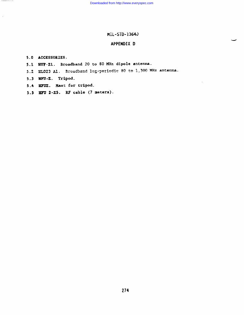
MIL-STD-1364J
APPENDIX D
5.0 ACCESSORIES.
5.1 HUP-zl. Broadband 20 to 80 MHz dipole antenna.
5.2 HL023 Al. Broadband log-periodic 80 to 1,300 KHz antenna.
5*3 m-z. Tripod.
5.4 HFuz. Hast for tripod.
5.5 HFU 2-25. RF cable (7 meters).
274
Downloaded from http://www.everyspec.com
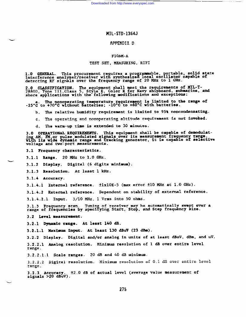
FIIL-STD-1364J
APPENDIX D
FIOAM-A
TEST SET, MEASURING, RIFI
1,0 GENERAL. This procurement requires a!ror-?1:icff!2:ieL;::i: :?’=interference analyzer/receiver with synthes ze
detecting RF signals over the frequency range of 20 MHz to 1 GHz.
;8~OOGWSIFICATION. The equipment shall meet the re uirements of KIL-T-
Te III,Class 5, Style E, 1Color R for Navy sh board, submarine, and
shore’app ications with the following modifications an% exceptions:
The nono eratln temperature requirement is limited to the r-e off.25°~”to +~O*C w thout %atteries; -lC)-Cto +60-C with batteries.
b. The relative humidity requirement is limited to 95* noncondensating.
c. The operating and nonoperating altitude requirement is not invoked.
d. The warm-up time is extended to 30 minutes.
3.0 OPERATIONAL REQUIREMENTS. This equipment shall be capable of demodulat-ing AM, F14or ulse modulated signals over its measurement frequentWifh its wide &amic range and tracking generator, it is capable o$ ;~?&ivevoltage and two-port measurements.
3.1 Requency characteristics.
3.1,1 Range. 20 MHz to 1.0 GHz.u
3.1.2 Display. Digital (6 digits minimum).
3.1.3 Resolution. At least 1 kllz.
3.1.4 Accuracy.
3.1.4.1 Internal reference. ~l~lOE.5 (m= error *1O MHz at 1.0 GHz).
3.1.4.2 External reference. Dependent on stability of external reference.
3.1.4.2.1 Input. 5/10 MHz, 1 Vrm into 50 ohms.
3.1.5 Frequency scan. Tunin of receiver may be automatically swept over afrange of frequencies by speci ying Start, Stop, and Step frequency s%ze.
3.2 Level measurement.
3.2.1 Dynamic range. At least 140 dB.
3.2.1.1 Haxbum input. At least 130 dBuV (23 dBm).
3.2.2 Display. Digital and/or analog in units of at least dBuV, dBm, and uV.
3.2.2.1 Analog resolution. Minimum resolution of 1 dB over entire levelrange.
3.2.2.1.1 Scale ranges. 20 dB and 40 dB minimum.
3.2.2.2 Digital resolution. Minimum resolution of 0.1 dB over entire levelrange.
3.2.3 Accuracy. *2.() dB of actual level (average value measurement Ofsignals >20 dBuV).
275
Downloaded from http://www.everyspec.com
MIL-STD-1364J
APPENDIX D
3.2.4 IF bandwidths (at least).
3.2.4.1 Minimum. 7.5 ICHz.
3.2.4.2 ~XiSIUlll. ~ ~Z.
3.2.5 Sensitivity (CU signal) S+N/N = 3 dB. At least -7 dBuV.
3.2.7.1 VSUR. Less than 1.5:1 for levels <100 dBuV.
3.2.7.2 Connector. Type N(f)
3.2.0 Galibratbn.
3.2.8.1 Autoutic. IF gain ad usted to 6tored, nonvolatile correction fac-4tors when new frequency and IF W are set.
3.2.8.2 Manual. IF gain adjusted to stored, nonvolatile correction factorswhen CAL key is depressed on front panel.
3.2.9 Detector functions. Average, peak, peak with programmable hold.
3.3 Extraneous signals.
3.3.1 14xal oscillator emission. Less than 25 dBuV with input connectorterminated in 50 ohms.
3.3.2 IF Rejection. >80 dB.
3.3.3 Image rejection. >80 dB.
3.3.4 Desensitization. <1 cIB (interfering signal >2 MHz away and level of110 dBuv).
3.4 outputs.
3.4.1 Tracking Generator.
3.4.1.1 Level. At least -20 dBm.
3.4.1.2 Frequency. Receiver’s tuned frequency.
3.4.1.3 output . 50 ohm, type N connector.
3.4.2 Intermediate frequenc~. 50 ohm output of IF frequency.
3.4*3 AM. Demodulated amplitude modulation signal; impedance <600 okms.
3.4.4 FM: Demodulated frequency modulation; impedance <600 ohms.
3,4.5 X-Y plotter. Outputs capable of driving an X-Y plotter.
3.4.6 Pen lift. Signal shall lift plotter pen during retrace.
4.0 GENERAL REQUIREMENTS.
4.1 Power.
4.1.1 Alternating current. 115/230 Vac tlO%, 50, 60, or 400 Hz, 120 VAmaximum.
4.1.2 Direct current. 22-32 Vdc, 4A maximum.
4.2 Volume. The total volume of the unit shall not exceed 3969 cubic in(65040 cubic cm).
276
Downloaded from http://www.everyspec.com
MIL-STD-1364J
APPENDIX D
4.3 Weight. The total weight of the unit shall not exceed 65 lb (29.5 kg).
4.4 Remote!rogramming. The receiver shall be capable of being remotely
controlled v a theIEEE-488 interface bus, operating as both a talker and lis-tener, having the following subset of bus functio~: ml, L4, SH1, T5,SR1,PI, DC1, DT1, and RL1.
5.0 ACCESSORIES.
5.1 HUF-zl. Broadband 20-80 XHz dipole antenna.
5.2 HL023 Al. Broadband log-periodic 80-1300 MHz antenna.
5.3 Em-z. Tripod.
5.4 HFUz. Mast for tripod.
5.5 HFU 2-Z5. RF cable (7 meters).
277
Downloaded from http://www.everyspec.com
MIL-STD-1364J
APPENDIX II
TS2FF-A
TEST SET, MEASURING, SWR
1.0 G~. This procurement requires a VSWR measuring test set consistinof an impedance comparator, ftwo matched terminations and six mismatched term -nations . The test set, when used with ● sweep generator and an oscillosco ,will rovide a direct display of VSWR vs. fre uency.
dz
an output for si~lgeneratorswi*mln~p. =:~==:=eaccurate calibrated SWR standards from 1:1 to . .
2.0 CLASSIFICATION. The generator described herein shall meet the re uire-me~er~~eMIL-T- 28800,
The III, Class 5, S le E, Color R for Navy shi oard,
t and shore app ications with the~ ollowing exceptions:
The nonoperating temperature requirement is limited to the range of-40”:”to +70”C.
b. The relative humidity requirement is limited to 95* noncondensating.
c. The operating and nonoperating altitude requirements are not invoked.
3.0 OPERATIONAL REQUIREMENTS. The equipment shall be capable of operatingwithin the parameters and accuracies specified herein.
3.1 Impedance comparator.
3.1.1 Frequency range. At least O.OS to 1,200 MHz.
3.1.2 Bridge accuracy. *1% of Vsm measurement.
3.1.3 Impedance. 50 ohms.
3.1.4 Connectors.
3.1.4.1 RF input. Type N female.
3.1.4.2 2122. Type N female.
3.1.4.3 Output. Type BNC female.
3.1.4.4 AM. we BNC female.
3.1.5 VSWR output time constant. At least 10 usec.
3.1.6 VSWR and AIL output polarity. Negative.
3.1.7 Maximum Power output. At least O.SW.
3.2 Terminations ●nd mismathes.
3.2.1 Frequency range. O to 3 GHz.
3.2.2 Reference impedance. Nominally 50 ohms.
3.2.3 VSWR accuracy. 5% of VSWR value.
--
3.2.4 Power rating. lW maximum.
3.2.5 Connectors. Type N male.
4.0 GENEML REQUIREMENTS.
278
./
Downloaded from http://www.everyspec.com
MIL-STD-1364J
APPENDIX D
4.1 Dimensions. The total volume of the test set shall not exceed 105 cubicin (1,720 cc).
4.2 Weight. The total weight of the unit shall not exceed 5 lbs (2.3 kg).
Downloaded from http://www.everyspec.com
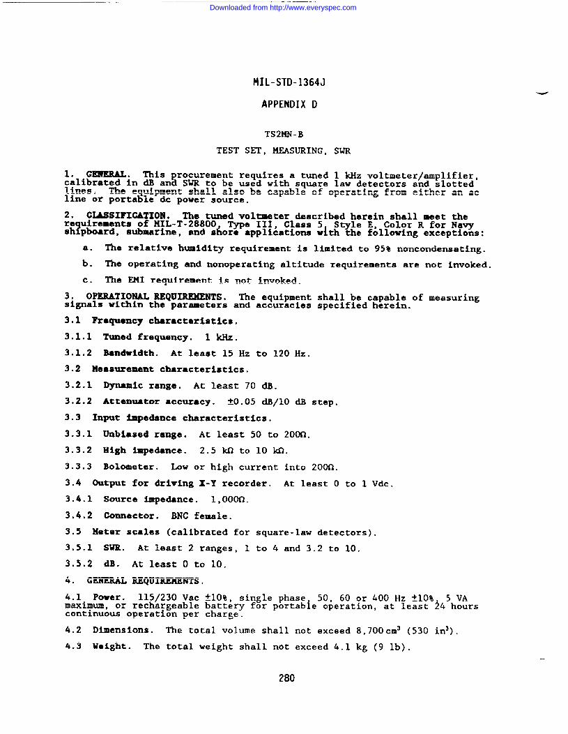
MIL-STD-1364J
APPENDIX D
TS2MN-B
TEST SET, MZASURING, SWR
1. GEHERAL. This procurement requires a tuned 1 kHz voltmeter/amplifier,calibrated in dB and SWR to be used with square law detectors and slottedlines. The equipment shall also be capable of operating from either an acline or portable dc power source.
2. CXJWSXFIGATION. The tuned voltmeter described herein shall meet there uirements of MIL-T-28800, Type 111, Class 5
?S le E, Color R for Navy
sh pboard, submarine, and shore applications with % e following exceptions:
a. The relative humidity requirement is limited to 95% noncondensating.
b. The operating and nonoperating altitude requirements are not invoked.
c. The EMI requirement is not invoked.
3. OPERATIONAL REQUIREMENTS. The equipment shall be capable of measuringsignals within the parameters and accuracies specified herein.
3.1 Frquency characteristics.
3.1.1 Tuned frequency. 1 kHz.
3.1.2 Bandwidth. At least 15 Hz to 120 Hz.
3.2 Measurement characteristics.
3.2.1 Dynamic range. At least 70 dB.
3.2.2 Attenuator accuracy. *0.05 dB/10 dB step.
3.3 Input Impedance characteristics.
3.3.1 Unbiased range. At least 50 to 200c1.
3.3.2 High ~edance. 2.5 M to 10 m.
3.3.3 Bolometer. Low or high current into 2000.
3.4 Output for driving X-Y recorder. At least O to 1 Vdc.
3.4.1 Source impedance. l,oom.
3,4.2 Connector. BNC female.
3.5 Meter scales (calibrated for square-law detectors).
3.5.1 sm. At least 2 ranges, 1 to 4 and 3.2 to 10.
3.5.2 dB. At least O to 10.
4. GENERAL REQUIREMENTS,
4.1 Power. 115/230 Vac flO%, single phase 50, 60 or 400 Hz flO% 5 VAmaximum, or rechargeable battery for portab~e operation, at least 24 hourscontinuous operation per charge.
4.2 Dimensions. The total volume shall not exceed 8,700cm3 (530 in3).
4.3 Veight. The total weight shall not exceed 4.1 kg (9 lb).
280
Downloaded from http://www.everyspec.com
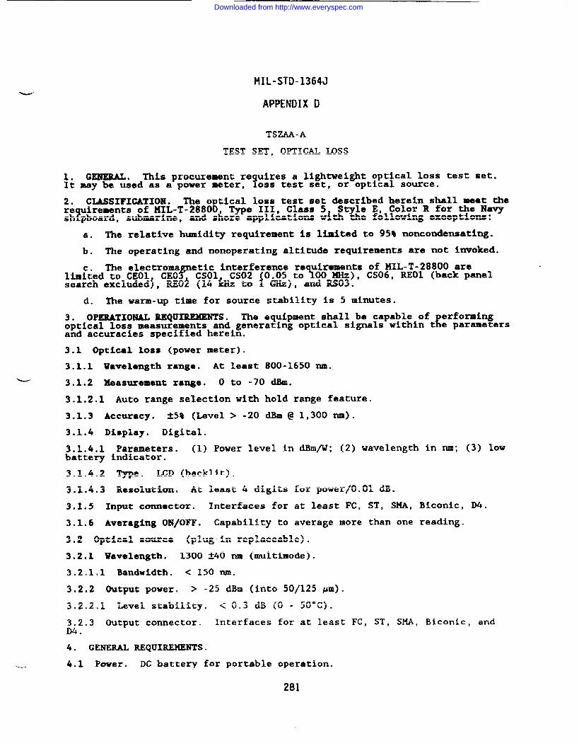
MIL-STD-1364J
APPENDIX D
TSZAA-A
TEST SET, OYHCAL MSS
1. GENERAL. This procurement re uires a lightweight optical loss test set.It may be used as a power meter, Y0ss test set, or optical source.
2. GLASSIFICATIOEJ. The o tical loss test set described herein shall meat there
Firements of MIL-T-288(%, Type III, Class 5 Style E, Color R for the Navy
sh pboard, submarine, and shore applications with the following exceptions:
a. The relative humidity requirement is limited to 95% noncondensating.
b. The operating and nonoperating altitude requirements are not invoked.
The electromalim;ted to CEO1 CEOP
etic interference re uirements of MIL-T-28800 are%CSO1 CS02 0.05 to 00 MHz), CS06, REO1 (back panel
search excluded~, REO~ (14 ~z to i GHz), and RS03.
d. The warm-up time for source stability is 5 minutes.
3. OPERATIONAL REQUIREMENTS. The equipment shall be capable of erformingEoptical loss measurements and generating optical signals within t e parameters
and accuracies specified herein.
3.1 Optical 10ss (power meter).
3.1.1 Wavelength range. At least 800-1650 nm.
~ 3.1.2 Measurement range. o to -70 cmm.
3.1.2.1 Auto range selection with hold range feature.
3.1.3 Accuracy. &5* (~vel > -20 dBm@ 1,300 rim).
3.1.4 Display. Digital.
3.1.4.1 Parameters. (1) Power level in dBm/W; (2) wavelength in nm; (3) 10Vbattery indicator.
3.1.4.2 -e. MD (backlit).
3.1.4.3 Resolution. At least 4 digits for power/O.01 dB.
3.2.5 Input connector. Interfaces for at least FC, ST, WA, Biconic, D4.
3.1.6 Averaging ON/OFF. Capability to average more than one reading.
3.2 Optical source (plug-in replaceable).
3.2.1 Wavelength. 1300 *4O M (multimode).
3.2.1.1 Bandwidth. < 150 nm.
3.2.2 Output power. > -25 dBm (into 50/125 pm).
3.2.2.1 Level stability. < 0.3 dB (O - 50°C).
3.2.3 Output connector. interfaces for at least FC, ST, SMA, Biconic, andD4 .
4. GENERAL REQUIREMENTS.
— 4.1 Power. DC battery for portable operation.
281
Downloaded from http://www.everyspec.com
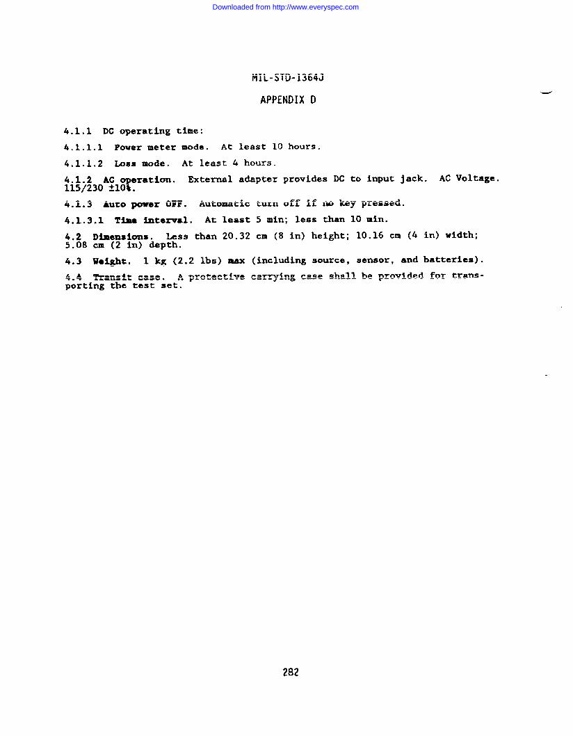
MIL-STD-1364J
APPENDIX D
4.1.1 DC operating time:
4.1.1.1 Power meter mode. At least 10 hours.
4.1.1.2 LOBS mode. At least 4 hours.
4.1.2 ACT
ration. External adapter provides DC to input jack. AC Voltage.115/230 HO .
4.1.3 Auto pomm OFF. Automatic turn off if no key pressed.
4.1.3.1 Tiaa intezwal. At least 5 rein; less than 10 min.
4.2 Dimensions. Less than 20.32 cm (8 in) height; 10.16 cm (4 in) width;5.08 cm (2 in) depth.
4.3 Waight. 1 kg (2.2 lbs) max (including source, sensor, and batteries).
4.4 Transit case. A protective carrying case shall be provided for trans-porting the test set.
282
Downloaded from http://www.everyspec.com
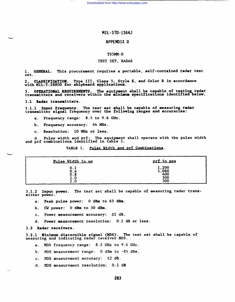
—
MIL-STD-1364J
APPENDIX D
TS5MM-D
TEST SET, RADAR
1. GENERAL . This procurement requires a portable, self-contained radar testset.
2* CLASSIFICATION.%
e III, Class 5, Style E, and Color R in accordancewith 141L-T-28800 for s pboard applications.
3. OPERATIONAL REQUIREMENTS. The equi ment shall be ca able of testiY f 5%!%transmitters and receivers within the m nimum specificat ons identified
3.1 Radar transmitters.
3.1.1 Input frequency. The test set shall be capabletransmitter signal frequency over the following ranges
of measurin radarfand accurac es:
a.
b.
c.
d.and prf
w
Frequency range: 8.5 to 9.6 ~Z.
Requency accuracy: *4 MHz.
Resolution: 10 MHz or less.
Pulse width and prf: The equi ment shall operate with the pulse widthYcombinations identified in tab e I.
T~~I. ~.
?
lse Width in us prf in D=
0.1 1,2000.4 1,:;:0.82.0 5002.0 300
3.1.2 Input power. The test set shall be capable of measuring radar trans-mitter power.
a. Peak pulse power: O dBm to 65 dBm.
b. C’Upower: odBmto30dBm.
c. Power measurement accuracy: ~1 ~.
d. Power measurement resolution: 0.2 dB or less.
3.2 Radar receivers.
3.2.1 Minimum discernible signal (MM). The test set shall be capable ofmeasuring and indicating radar receiver MDS.
—-
a. MDS frequency range: 8.5 GHz to 9.6 GHz.
b. MDS ❑easurement range: O dBm to -85 dBm.
c. MDS measurement accuracy: *2 dB.
d. MM measurement resolution: 0.1 dB
283
Downloaded from http://www.everyspec.com
lJtIL-STD-1364J
APPENDIX D
3.2.2 KF trigger. The test set shall be capable of triggering from an RFsignal that has the following characteristics:
a. Peak power range: 15 dEm peak to 65 dBm peak.
b. Pulse width: 0.1 us to 6 ua.
c. Pulse repetition frequency: 300 pps to 1,500 pps.
3.2.3 RF trigger delay. 50 us to 1 M continuously adjustable.
3.3 Commctors. N(f) .
3.4 Impadence. 50 ohms nominal.
4. POWER SOURCE. MIL-T-28800 nominal power source requirements a:~5$nvoked.Operation at 400 Hz is not required. Maximum power comumption: .
5. WEIGHT . 20 kg (44 lb) maximum.
-—
284
Downloaded from http://www.everyspec.com
MIL-STD-1364J
APPENDIX D
TSMNN- B
TEST SET, RADIO
1. GENERAL. ‘lhis procurement requires a portable radio test set for use withradio receiving and transmitting equipment.
2. CLASSIFXCATICMU.%
e III Class 3, S~le C, and Color R in accordancewith MILoT-28800 for s pboar~ applications.
3* ?’UHCTIOXAL EEQU~. The equipment shall be capable of signal gener-ation, monitoring, amplitude level and frequency measurement, power measure-ment, wdulation anal sis,
zand receiv~r signal-to-noise measurement, within
the minimum specifics ions identified below.
3.1 RF signal gene=ator.
3.1.1nents
3.1.23.9).
Generator frequencyof 100 Hz.
Generator frequency
range. 400 kHz to 999.99 MHz tuneable in incre-
●ccuracy. Equal to the master oscillator (see
301.3
3.1.4racy:
3.1.5L other
3.1.6supplied microphone.
R@sldual FM. 100 Hz rms from 300 Hz to 3 kHz.
Generator output power. Adjustable from -127 dBm to -20 dBm.*4 dB.
Accu-
Cenerator spectral pu.rfty. -15 d.Bcfor harmonics, -35 dBc for allspurious ●ignals.
Modulation. FM and AM from internal source, external source, ati
3.1.6.1 Frequency modulation.
3.1.6.1.1 Modulation dewiation. O to 25 kHz peak from 400 kHz to 999.99 MHz.
3.1.6.1.2 Modulation frequency response. 20 Hz to 10 ~Z.
3.1.6.2 Amplitude modulation.
3.1.6.2.1 AM frequency =esponse. 100 Hz to 10 kHz.
3.1.6.2.2 Percentage of modulation range. O to 70% with modulating frequen-cies from 100 Hz to 5 kllz.
3.2 RF signal monitor.
3.2.1 Monitor frequency range. 1.5 MHz to 999.99 HHz.
3.2.2 Monitor frequency accuracy. Equal to master oscillator (see 3.9).
3.2.3 Monitor input sensitivity. For 10 dB EIA SINAD: 5.0 Uv.
3.2.4 Beat fre uency oscillator.7
A beat frequency oscillator that providesan audible carr er indication shall be provided.
3.2.5 Monitor frequency error measurement. The monitor shall indicate thedifference in frequency between a signal under test and a predetermined valueentered by the operator.
3.2.5.1 Monitor frequency error measurement range. t10 kllzor greater.
285
Downloaded from http://www.everyspec.com
FIIL-STD-1364J
APPENDIX D
3.2.5.2 Monitor frequency error measurement resolution. 10 Hz or less.
3.2.6 Monitor FM deviation range. O to 25 kHz peak deviation. Accuracy:t7.5% plus the peak residual FM at modulation frequencies of 30 HZ to 10 Mz.
3.2.7 llonitor AM ercentage range. O to 100%. Accuracy: A8% FS at modula-tion frequencies oF 300 Hz to 10 kHz.
3.2.8 Monitor alr
1 strength measurement. A means shall bemeasure the relat ve level of off-the-air signals received byplied with the instrument.
provided toan antenna sup-
s. Frequency range: 3 MHz to 999.99 MHZ.
b. Level range. -1oo am to +10 dBm.
3.3 RF wattmeter. An RF wattmeter and load shall be provided to measure the
Rower generated by units under test, and to terminate a 50-ohm system with anWR of 1.5 or less.
a. Power range. lW to sow.
b. Accuracy. &20~ of indication.
c. Load. The RF load shall be capable of terminating 100W for at leastone minute.
3.3.1 Wattmeter over-temperature protectkn. An over-temperature warningshall be provided.
3~~vi& lex generator. A duplexx f
enerator function or other means shall be
Fto test equipment transm tting and receiving simultaneously on
requencies offset from each other.
3.4.1 Duplex frequency offset. O to +10 MHz with a resolution of 10 kHz.
3.4.2 Duplex output level. -50 d.llmminimum into a 50-ohm load.
3.4.3 Duplexfenerator deviation. The carrier shall be capable of being
frequency modu ated at deviations from O to 20 kHz peak.
3.4.4 Duplex generator frequency response. 20 Hz to 10 kHz at 3 dB.
3.5 Oscilloscope. An oscilloscope function shall be provided to monitor themodulation characteristics of AM and FM signals.
3.5.1 Oscilloscope display size. At least five square inches.
3.5.2 Oscilloscope frequency response. DC to 6 kHz.
3.5.3 Oscilloscope vertical input ranges. 10 mV to 10 V/div.
3.5.4 Oscilloscope horizontal sweep rate. 100 us/div to 20 ms/div.
3.6 Frequency counter. A frequency counter function shall be provided tomeasure audio frequencies.
3.6.1 Counter frequency range. 20 Hz to 10 kHz with a resolution of 1 Hz.Accuracy: ~2 counts.
3.7 AF signal generator. An audio frequency signal generator shall be pro-vided to generate the tones required by various two-tone signaling systems.
-“
3.7.1 AF generator frequency range. 10 Hz to 20 kHz with a resolution of 1Hz.
286
Downloaded from http://www.everyspec.com
MIL-STD-1364J
APPENDIX D
3.7.2 AF generator output level. 2.5 Vrms minimum into 600 ohms.
3.8 SINAD meter. A means shall be rovided to measure the sensitivity of areceiver with respect to the ratio of the signal plus noise and distortion tonoise and distortion.
3.8.1 SINAD meter frequency. The equipment shall provide a test signal modu-lated by 1 kHz to the receiver under test.
3.8.2 SXIUD meter in~t range. 0.5 VX=S to 10 V=.
3.8.3 SSMAD meter measurement range. 1 dB to 20 all!.Accuracy: *1.5 dB at12 dB SINAD.
3.9 Master oscillator frequency accuracy. 2 ppm.
3.9.1 Oscillator aging stability. A2 ppm per year.
3.9.2 Oscillator temperature stability. o to Ss”c: Al ppm.
3.10 Loudspeaker. The equipment shall contain an internal loudspeaker.
3.11 Remote operation. Tb e d ment shall be provided with a digitalinterface in accordance with M?L-?-28800 .
4. POWER SOURCE. MIL-T-28800 nominal and & external power source require-ments are invoked as detailed below.
4.1 Nominal power s~~. Operation at 400 Hz is not required. Maximumpower consumption: .
4.2 DC external-power source. 11-18 Vdc, 120W maximum.
5. UEIGH’I. 21 kg (46 lb) maximum.
287
Downloaded from http://www.everyspec.com
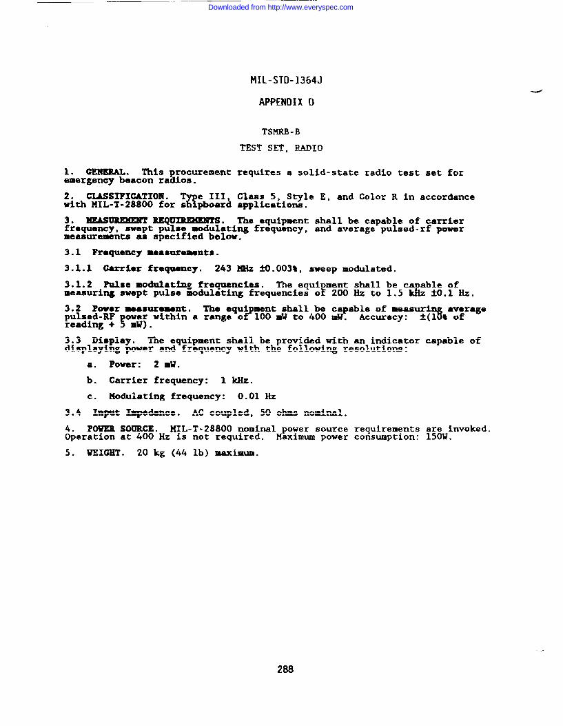
MIL-STD-1364J
APPENDIX D
TSMRB -B
TEST SET, RADIO
1. GENERAL. This rocurement requires a solid-state radio test set forsemergency beacon ra ios.
2. CLASSIFICATION .%
e III, Class 5, Style E, and Color R in accordancewith MIL-T-28800 for s pboaxd applications.
3* ~ =Q~* The equipment shall be capable of carrierfrequency, swept pulse modulating frequency, and average pulsed-rf powermeasurements as specified below.
3.1 Roquemcy naamtrementa.
3.1.1 Carrier frequency. 243 MHz ifl.003%, sweep modulated.
3.1.2 Pulse modulating frequencies. The equi ment shall be ca able ofmeasuring swept pulse modulating frequencies oE 200Hz to 1.5 &z ~.1 Hz.
3.2 Powoz measurement. The equi ment shall be capable of measurif? 3
averagepulsed-RF ow~f within a range o 100 mW to 400 mW. Accuracy: ~(1 t ofreading + 5 ●
3.3 Display. The equipment shall be provided with an indicator capable ofdisplaying power and frequency with the following resolutions:
a. Power: 2 ml?.
b. Carrier frequency: 1 kllz.
c. Modulating frequency: 0.01 Hz
3.4 Input Impedance. AC coupled, 50 ohms nominal.
4. POWEB SOURCE. MIL-T-28800 nominal power source requirements are invoked.Operation at 400 Hz is not required. Maximum power consumption: 150W.
5. WEIGHT . 20 kg (44 lb) maximum.
288
Downloaded from http://www.everyspec.com
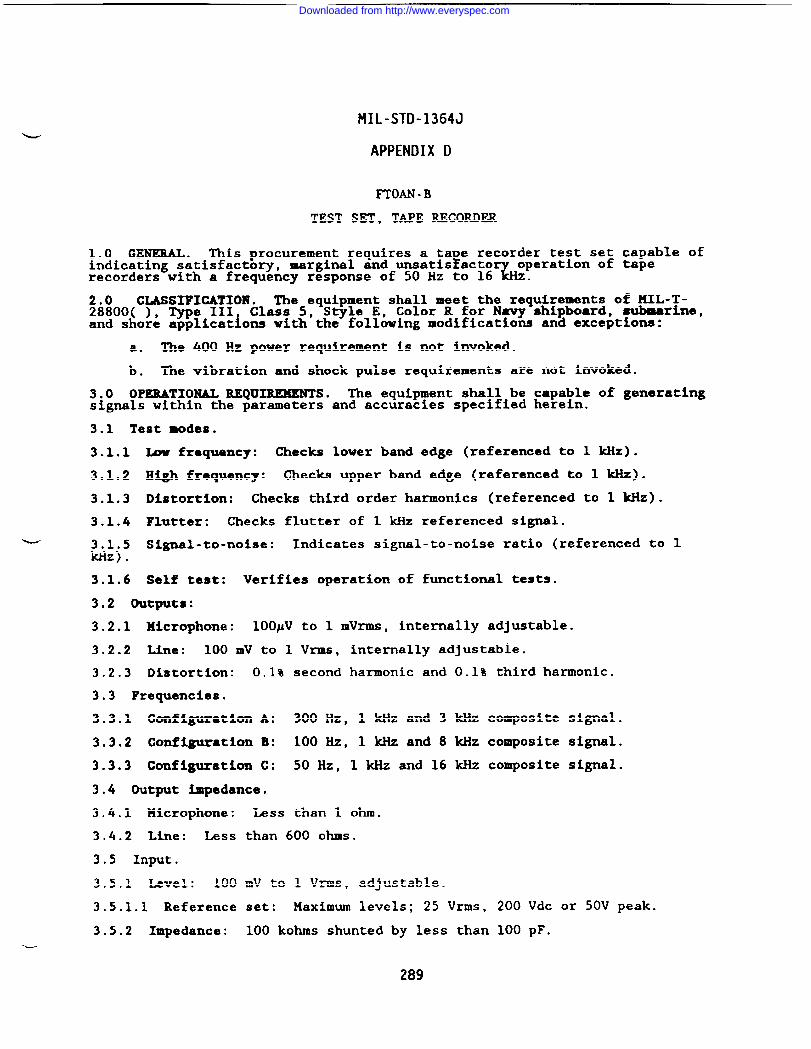
MIL-STD-1364J
APPENDIX D
FTOAN -B
TEST SET, TAPE RECORDER
1.0 GENERAL. This procurement requires a ta e recorder test set capable ofFindicating satisfactory, marginal and unsatis acto
%operation of tape
recorders with a frequency response of 50 Hz to 16 z.
2.0 CLASSIFICATION . The equipment shall meet the requirements of MIL-T-28800( ), Type III Class 5, Style E, Color R for N- shipboard, submarine,and shore applications with the following modifications and exceptions:
a. The 400 Hz power requirement is not invoked.
b. The vibration and shock pulse requirements are not invoked.
3.0 OPERATIONAL REQUIREKENTSo The equipment shall be capable of generatingsignals within the parameters and accuracies specified herein.
3.1 Test modes.
3.1.1 k frequency: Checks lower band edge (referenced to 1 kllz).
3.1.2 High frequency: Checks upper band edge (referenced to 1 kHz).
3.1.3 Distortion: Checks third order harmonics (referenced to 1 kHz).
3.1.4 Flutter: Checks flutter of 1 kHz referenced signal.
- 3.1.5 Signal-to-noise: Indicates signal-to-noise ratio (referenced to 1ldiz).
3.1.6 Self test: Verifies operation of functional tests.
3.2 Outputs:
3.2.1 Microphone: 100PV to 1 mVrms, internally adjustable.
3.2.2 Line: 100 mV to 1 Vrms, internally adjustable.
3.2.3 Distortion: 0.1% second harmonic and 0.1% third harmonic.
3.3 Frequencies.
3.3.1 Configuration A: 300 Hz, 1 kllzand 3 kHz composite signal.
3.3.2 Configuration B: 100 Hz, 1 kHz and 8 kHz composite signal.
3.3.3 Configllration c: 50 Hz, 1 kHz and 16 kHz composite signal.
3.4 Output impedance.
3.4.1 Microphone: Less than 1 ohm.
3.4.2 Line: Less than 600 ohms.
3.5 Input.
3.5.1 Level: 100 mV to 1 Vrms, adjustable.
3.5.1.1 Reference set: Maximum levels; 25 Vrms, 200 Vdc or 50V peak.
3.5.2 Impedance: 100 kohms shunted by less than 100 pF.-
Downloaded from http://www.everyspec.com
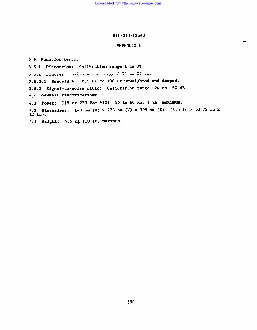
MIL-STD-1364J
APPENDIX D
3.6 Function tests.
3.6.1 Distortion: Calibration range 1 to 3%.
3.6.2 Flutter: Calibration range 0.15 to 3% rms.
3.6.2.1 Bandvidth: 0.5 Hz to 100 Hz unveighted and damped.
3.6.3 Signal-to-noise ratio: Calibration range -20 to -S0 a.
4,0 GEHERAL SPZCIFICATIOBS.
4.1 Power: 115 or 230 Vac *1O*, 50 to 60 Hz, 1 VA Mxhum.
4.2 Dimensions: 140- (H) x 273 mm (W) x 305- (D), (5.5 inx 10.75 inx12 in).
4.3 weight: 4.5 kg (10 lb) maximum.
290
Downloaded from http://www.everyspec.com
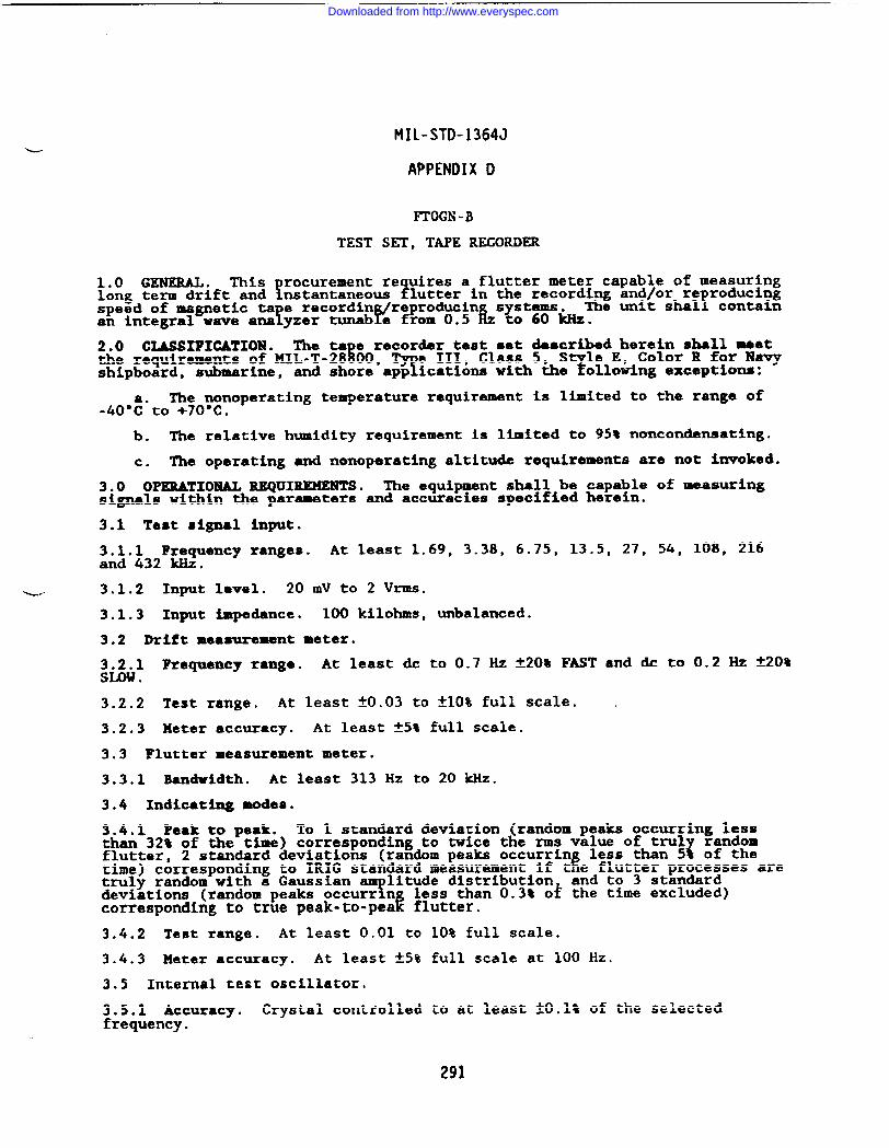
MIL-STD-1364J
APPENDIX D
FTOGN -B
TEST SET, TAPE RECORDER
1.0 GEN’EUL. ~is rocurement re uires a flutter meter capable of measuring!long term drift and nstantaneo~ $1utter in the recording and/or re reducing
speed of magnetic ta e recordin reproducing s stems.! v
!The unit shal containan integral wave ana yzer tunab e from 0.5 ~ $060 kHz.
2.0 CLASSIFICATION. The ta e recorder test set described herein shall meetthe requirements of MIL-T-28$00,
Te III, Class 5, S le E, Color R for Navy
shipboard, submarine, ?and shore app ications with the ollowing exceptions:
The nonoperating temperature requirement is limited to the range of-40’:”to +70”C.
b. The relative humidity requirement is limited to 95% noncondensating.
c. The operating and nonoperating altitude requirements are not invoked.
3.0 OPERATIONAL REQUIREMENTS. The equipment shall be capable of measuringsignals within the parameters and accuracies specif%ed herein.
3.1 Test signal input.
3.1.1 Frequency ranges. At least 1.69, 3.38, 6.75, 13.5, 27, 54, 108, 216and 432 kliz.
~ 3.1.2 Input level. 20 mV to 2 Vrms.
3.1.3 Input impedance. 100 kilohms, unbalanced.
3.2 DrXft meamrement meter.
3.2.1 Frequency range. At least dc to 0.7 Hz ~20% FAST and dc to 0.2 Hz Y20~Su)w .
3.2.2 Test range. At least fO.03 to ~10% full scale. .
3.2.3 Meter accuracy. At least *5% full scale.
3.3 Flutter measurement meter.
3.3.1 Bandwidth. At least 313 Hz to 20 k.llz.
3.4 Indicating modes.
3.4.1 Peak to peak. To 1 standard deviation (random peaks occurring lessthan 32% of the time) corresponding to twice the rms value of tml
{random
flutter, 2 standard deviations (random peaks occurrin less than 5 of theitime) corresponding to IRIG standard measurement if t e flutter processes are
truly random with a GaussianT
litude distribution and to 3 standarddeviations (random peaks occurr n less than 0.3% of the time excluded)corresponding to true peak-to-pea k flutter.
3.4.2 Test range. At least 0.01 to 10% full scale.
3.4.3 Z4eeer accuracy. At least *5% full scale at 100 Hz.
3.5 Internal test oscillator.
3.5.1 Accuracy. Crystal controlled to at least ~0.1% of the selectedfrequency.
291
Downloaded from http://www.everyspec.com
MIL-STD-1364J
APPENDIX D
3.5.2 Output voltage. At least 1 Vrms tlO%.
3.5.3 Impedance. 50 ohms unbalanced.
3.6 Drift modulator output (BNC).
3.6.1 Pre ency ran e.r b
-3 dB down at 30 Hz A20% and -3 dB at greater than0.7 Hzin ASTandS .
3.6.2 Output voltage. At least till V for full scale meter indication.
3.6.3 Impedance. 1 kilohms unbalanced.
3.6.4 Bandwtdtli. Less than 1 dB at 10 Hz and -3 dB at 30 Hz.
3.6.5 Accuracy. At least *3% of full scale at dc.
3.7 Fluttaz d~modulator output (BNC).
3.7.1 Fro ency ranges.a
At least -3 dB from less than 0.2 Hz to 313 Hz, 625Hz, 1.25 , 2.5 kliz, 5 kHz, 10 kHz, and 20kHz.
3.7.2from 1
3.7.3
3.7.4
3.7.5
3.7.6
Response ● At least fO.5 dllfrom 2 Hz to 60$ BV and at least fl.O dl!Hz to 80% BW.
Attenuathn. bss than 22 dB at 2 times BW.
Output voltage. At least O.lV p-p full scale meter indication.
Impedance. 600 ohms unbalanced.
Accuracy. At least *3% of full scale ●t 100 Hz.
3.8 Equivalent internal instmmentatim noise. Less than 0.005% p-p.
3.9 External meter input.
3.9.1 lWequancy. Less than *1 dB from 2 Hz to 20 kllz.
3.9.2 Impedance. 2.5 kilohms unbalanced.
3.9.3 Sensitivity. 1 mV to lV p-p full scale.
3.9.4 Accuracy. At least Y5% of full scale at 100 Hz.
3.10 Wave Analyzer.
3.10.1 Frequency range. 0.5 Hz to 20 kHz continuously tunable.
3.10.2 ACCuraCy. At least *1O* from 0.5 Hz to 50 Hz and at least *5* frm 50Hz to 2okHz.
3.10.3 Response. At least tl.S dB.
3.10.4 Bandwidth. At least 3 dB down at *5% of selected frequency and atleast 20 dB down at 0.5 and 2 times the selected frequency.
3.10.5 Output voltage. At least 1.2V p-p.
3.10.6 Impedance. 1 kohms.
4.0 GENERAL REQUIREMENTS.
4.1 Dimensions. The total volume of the unit shall not exceed 25,300 cubiccm (1,544 cubic in) with maximum height 89 mm (3.5 in).
292
Downloaded from http://www.everyspec.com
MIL-STD-1364J
APPENDIX D
4.2 Weight. The total weight of the unit shall not exceed 9.1 kg (20 lbs).
4.3 Power. 115/230 Vac *1O%, 50 to 60 Hz ~lo%, 25W maximum.
-
293
Downloaded from http://www.everyspec.com
!!IL-STD-1364J
APPENDIX D
TEINA-E
TEST SET, SEMICONDUCTOR
1. GENERAL. This procurement re uires a solid-state semiconductor anal zercapable of both in-circuit GOflO-& testing and out-o~-circuit parameter Test-ing.
2. CLASSIFIGATIOBl.w
III Class 5, Style EP, and Color R in accordancewith MIL-T-28800 for s pboar~ applications.
3. OPERATIONAL REQ~So The equipment shall be capable of operationwithin the minimum accuracies, limits, and specifications identified below.
3.1 In-circuit. The equipment shall be ca able of testin semiconductors in$ fa circuit with circuit power removed, provi ing an indicat on of an operative
(GO) or inoperative (NO-GO) condition. If tests are conducted within theshunt limitations specified below, the GO/NO-GO test indication shall be validregardless of semiconductor to equipment test lead orientation. Correct testlead orientation may be required to obtain the following:
a. The base lead identification and proper operating polarity of an oper-ative device.
b. The type of failure of an inoperative device, such as an open orshort, and the junction involved.
3.1.1 shunt limits. The equipment shall be capable of in-circuit testing ofdiodes and transistors with the following shunt limits:
Resistance: 180 ohms or greaterCapacitance: 5 UP or less
3.2 Out-of-circuit. The equipment shall beErovided with out-of-circuit
dynamic transistor parameter measurement capa ilities as follows:
a. Beta, from O to 500.
b. Collector-to-base leakage current of 1 UA to 5 mA with a resolution of200 M on the most sensitive range.
3.2.1 ACCUrSCy. i-lot of indication.
3.2.2 Bias current range. Bias currents for low and high power transistorsshall be provided.
3.3 Indicators. The equi ment shall include a meter having a linear scaletor scales such that parame er values are defined in an ascending left-to-right
sequence, or an e uivale~gv~$:~tal dis la .?
For analog meters, front-panelmeter zeroing sha 1 be R GO/N~-d information shall be conveyed byvisual indicators and s all inciude a selectable audio indicating mode.
3.4 Test sockets. The equi ment shall be provided with front-panel-mountedtransistor test sockets for ~0-3, TO-5, and TO-66 case configurations.
POWER SOURCE. MIL-T-28800 nominal power source requirements are invoked.&eration at 400 Hz is not required. Maximum power consumption: 25W.
s. TRANSIT CASE. The Style P transit case shall store all components of thesemiconductor test set.
6. ACCESSORIES. The following accessories shall be provided with the equip-ment:
294
Downloaded from http://www.everyspec.com
MIL-STD-1364J
APPENDIX D
One set of color coded clip-on test leads at least 0.457m (1.5 ft)longs”
b. One s ares kit consisting of replacement fuses, replacement lampassemblies (iF applicable), spare semiconductor sockets, and any requiredcalibration components.
7. WEIGHT . 5 kg (11 lb) maximum.
295
Downloaded from http://www.everyspec.com
HIL-STD-1364J
APPENDIX D
TS6FN-C
TEST SET, SONAR
10 GEMERAL. This procurement requires a ortable self contained sorer testEset capable of measuring both noise and co erent signals detected by shipboard
sonar. The detected signals will be displa ed and plotted ●s a function ofbearing or time. The equipment shall also zave a built-in ta e cassette
?recorder capable of storing measurements made by the sonar no se recorder.
2. CIASSIFICATIOBJ● The equipment shall meet the requirements of MIL-T-28800,Type III Class 5, S~le E, Color R for Navy shipboard, submarine, and shoreapplications with the following modifications and exceptions:
a. The
b. The
c. The
d. The
relative humidity requirement is limited to 95% noncondensating.
operating and nonoperating altitude requirements are not invoked.
EMI requirement is not invoked.
warm-up time is extended to one hour.
3. OPERATIONAL REQUIREMENTS. The equipment shall be capable of performingwithin the parameters and accuracies specified herein.
3.1 Y-&is (signal channel).
3.1.1 Voltage range. 1 PVrme (-120 d.B)to 7 Vrms (17 dB) with a maximumcrest factor of 5.
3.1.2v
ic ran e.%B
Selectable to be 60 dB or 120 dB; full scale from -60dBto+2dBinl steps
3.1.3 Input impedance. Greater than or equal to 1 lKlshunted by no more than50 pF.
+1 ~ from 500 Hz to 15 ~Z with constant ampli-kk’.?~~:~~~?!%~~ fiput probe.
3.1.4.1 High pass filter. With 18 dB/octave roll-off.
3.1.4.2 Low pass filter. With 12 dB/octave roll-off.
:;li; I&earity. Within 0.5 dB over the 120 dB measurement range from 500 Hz,
3.1.6 Resolution. 0.2 dB or better.
3.1.7 Equivalent noise input. With input terminated with 1 @ the noisemeasured will be less than 2 AVrma.
3.1.8 Ttme constants. Selectable at 10 or 100 msec.
3.1.9 Overshoot. The Y-axis overshoot shall be 1 dB or less for a 10 dlllevel change.
3.1.10 Pen mitin s eedok!
At least 150 dB/sec at the 10 msec time constantand 15 dB/sec at t e 00 msec time constant.
3.2 x-his.
3.2.1 Operating modes. The equipment shall be capable of operatin as affunction of time and as a function of bearing with the equipment dr ving the
sonar synchro system.
296
.-
Downloaded from http://www.everyspec.com
MIL-STD-1364J
APPENDIX D
3.2.2 Bearing ranges.
3.2.2.1 360°. Full scale equals 360’, origin selectable at any bearing in 1°steps.
3.2.2.2 72°. PU1l scale equals 72”, origin selectable at any bearing In 1°steps.
3.2.3 sweep.
3.2.3.1 Bear%
mode. fill scale sweep times of 30, 60 or 120 sec in eithernormal or expa d W&.
3.2.3.2 Time mode. Full scale sweep times of 12, 30, 60 or 120 sac in eithernormal or expanded mode.
3.2.3.3 Bait and reverse. The equipment shall have the capabili~ to halt,reverse direction and continue the sweep, in either the bearing or time mode.
3.2.4 Return time. The pen return time shall not exceed 12 sec.
3.2.5 Synchro output. The s chro output shall operate into 1-s ed or 36-s eed sonar synchro system, lEV reference, 90V line to line, at 60 Hz; 1.5Vg er stator, maxiEuM.
!The reference and signal leads must be fuse protected
aga nst over current or over voltage conditions.
3.2.5.1 S chro output interface.F
The synchro output interface cable must becapable o direct connection for the following sonar system configurations.
3.2.5.1.1 Cable A. Cable must be at least 10 feet lon with eight si le~ f %conductors of at least 18 inches in length terminated w th pin jacks wi the
following connections:
AB
:E
:H
Pin Signallx-sllx-s2lx-s336X-S136X-S236X-S3R2R1
3.2.5.1.2 Cable B. Cable must be at least 10 feet long terminated with aMS3106A-18-1P connector with the following connections:
Pin SignalA lX-SlB lX-S2c 1.X-s3D 36X-S1E 36X-S2F 36X-S3G R2H RI
3.2.5.1.3 Cable C. Cable must be at least 10 feet long terminated with aMS3106A-18-1P connector with the following connections:
297
Downloaded from http://www.everyspec.com
MIL-STD-1364J
APPENDIX D
F 36X-S1G R1H R2
3.2.6 Accuracy. tl” for the 360° range and ~0.3° for the 72” expanded range
3.2.7 Resolution. 0.2° or better in the bearing modes; 15 msec or better forthe fastest speed in the time mode; 60 msec or better for the slowest speed inthe time mode.
3.3 Recordex paper and pen.
3.3.1 Paper type. Preprinted single sheet with degrees and decibels scales
3.3.2 Paper holddown. Positive paper holddown must be provided.
3.3.3 Paper positioning. Guide lines shall be provided for accuratelypositioning recording paper.
3.3.4 Pen type. Disposable cartridge with fiber tip.
3.4 Tape recorder built-in cassette type.
3.4.1 Tape speed. At least 10 inches/second.
3.4.2 Data format. Each record will correspond to one swee ~t~he X-axisand consist of one set of parameters followed by the measure3 ●
3.4.3 Tape capacity. At least 30 records (sweeps) per cassette.
3.4.4 Read/Store time. hss than 10 seconds after starting point is found.
3.4.5 Search speed. At least 40 inches/second.
3.4.6 Gassette. Magnetic tape shall be in cassette format and capable ofoperating from O°C to +55°C.
3.4.7 File identification. Access to the files shall be controlled byoperator entry of a file number. New data will be recorded at the end of thelast record or in place of a previous file identified by the operator.
3.5 Built-In testing.
3.5.1 Self-?eet. An automatic self test function shall be provided.
3.5.2 Adjttstments. The pen shall be capable of being set to origin and fullscale of each axisunder operator control for internal adjustments.
3.6Displays and controls.
3.6.1 Display. 20 character minimum, alphanumeric readout; used for dialoguewith the operator, display of entry data and display of measurement data.
3.6.2 Keyboard. The recorder shall be provided with either a key-pad or pushbuttons for data entry as necessary to operate the equipment.
3.6.3 Trigger output. A TTL pulse for triggering other equipments shall beprovided on the front panel to indicate when a recording is started.
4. GENERAL REQUIREMENTS.
4.1 Power. 115/230 Vac flO%, 50/60 Hz, 200W maximum.
4.2 Dimensions, The total volume shall not exceed 63,910 cmW(3,900 in3).
298
Downloaded from http://www.everyspec.com
—
MIL-STD-1364J
APPENDIX D
4.3 Weight. The total weight shall not exceed 27.3 kg (60 lbs).
4.4 Remote control. The enerator shall be capable of being remotelyfcontrolled via the IEEE-48 interface bus,
listener, havioperating as both a talker and
at least the following sdset of bus functions. Ml, L4,SH1, T6, SRl, &l, andRL1.
4.5 Collllectims. All external connections shall be keyed to prevent acciden-tal or improper connection.
299
Downloaded from http://www.everyspec.com
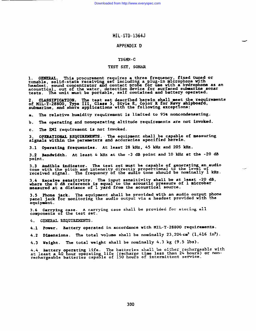
MIL-STD-1364J
APPENDIX D
TS6KN-C
TEST SET, SONAR
1. GENERAL. This procurement requires a three frequent , fixed tuned or1tunable, solid-state receiving set includin a plug-in m crophone tith
headset, sound concentrator and contactacoustical, out of the water, %‘0%= ‘or ‘e with a ‘Zr!E?Z~ndetection evice for surfaced stests. The unit must be portable, self contained and battery operated.
2. CLASSIFICATION. The test set described herein shall meet the requirementsof 141L-T-28800, Type III Class 5, S le E, Color R for N
% Tshipboard,
submarine, and shore applications wit the following except om:
a. The relative humidity requirement is limited to 95% noncondensating.
b. The operating and nonoperating altitude requirements are not invoked.
c. The E!41requirement is not invoked.
3. OPERATIONAL REQUIREMENT S. ~ The equipment shall be capable of measuringsignals within the parameters and accuracies specified herein.
3.1 Operating frequencies. At least 28 kHz, 45 Mz and 205 kliz.
3.2 Bandw5dth. At least 4 kHz at the -3 dB point and 10 kHz at the -20 dBpoint.
3.3 Audible indicator. The test set must be capable of generating an audiotone with the
!itch and intensity directly proportional to the level of
received signs . The frequency of the audio tone should be nominally 1 kHz.
3.4 Receive sensitivity. The input sensitiviY
shall be at least -20 dB,where the O dB reference is equal to the acoust c pressure of 1 microbarmeasured at a distance of 1 yard from the acoustical source. -
3.5 Phone ●ck.4
The equipment shall be provided with an audio ou ut phonepanel jack Tor monitoring the audio output via a headset provided w. th theequipment.
3.6 Carryin case.f
A carrying case shall be provided for storing allcomponents o the test set.
4. GENERAL REQUIREMENTS.
4.1 Power. Battery operated in accordance with MIL-T-28800 requirements.
4.2 Dimensions. The total volume shall be nominally 23,204cm3 (1,416 in3).
4.3 Weight. The total weight shall be nominally 4.3 kg (9.5 lbs).
Zi41eEEti7CEESt;~A;Ti%The batteries shall be either rechargeable withlife (recharge time less than 24 hours) or non-
rechargeable batteries capa le of 150 hours of inte~ittent senice.
300
Downloaded from http://www.everyspec.com
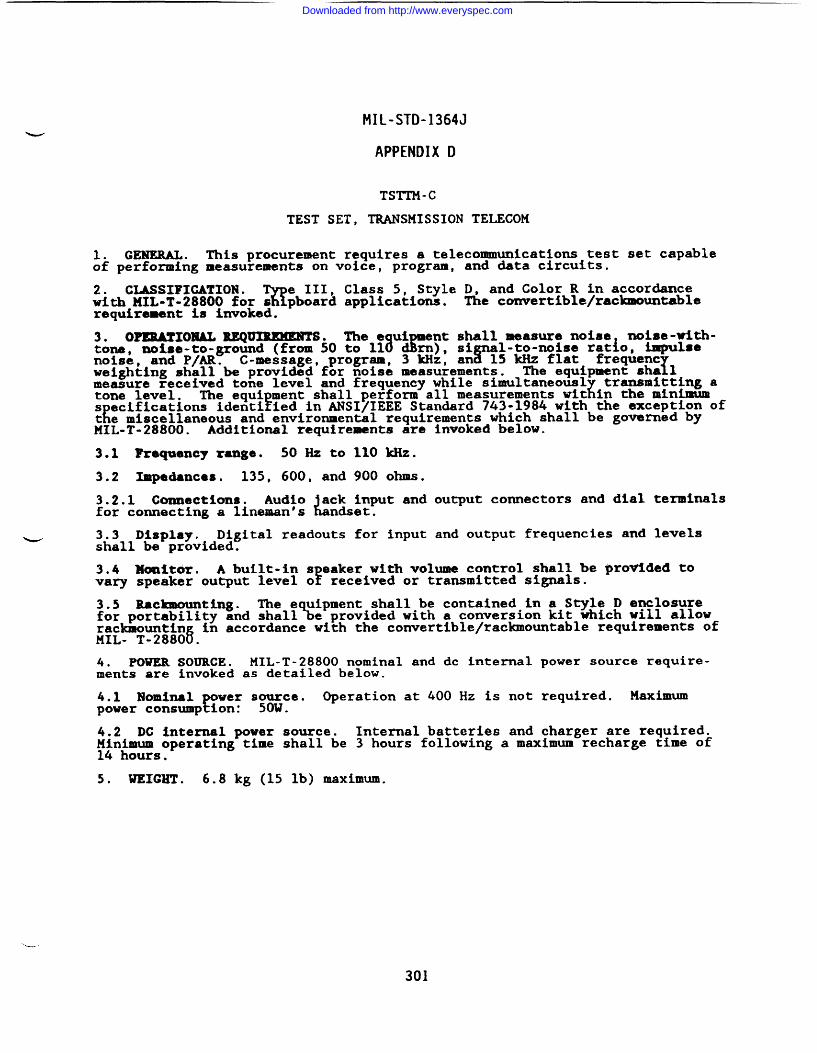
MIL-STD-1364J
APPENDIX D
TSTTM-C
TEST SET, TRANSMISSION TELECOM
1. GENERAL. This procurement requires a telecommunications test set capableof performing measurements on voice, program, and data circuits.
2. CLASSIFICATION .%
e III, Class 5, Style D, and Color R in accordancewith 141L-T-28800 for s pboard applications. The convertible/rackmountablerequirement is invoked.
3. OPEBATIOXAL REQ~.‘e ‘a”~~y: :&l::%:z;zloYiG7:?-tone, noise-to-ground (from 50 to 11
noise, and P/AR. C-message, program, 3 kHz, an 15 kHz flat frequentweighting shall be provided for noise measurements. fThe equipment sha 1measure received tone level and frequency while simultaneous
xtransmitting a
tone level. The equi ment shall perform all measurements wit in the minimumEs edifications identi ied in ANSI/IEEE Standard 743-1984 with the exception of
Kt e miscellaneous and environmental requirements which shall be governed byMIL-T-28800. Additional requirements are invoked below.
3.1 Fre~ency mnge. 50 Hz to 110 kHz.
3.2 Impedances. 135, 600, and 900 ohms.
3.2.1 Connections. Audio a~kti~~put and output comectors and dial terminalsfor comecting a lineman’s L .
3.3 Display. Digital readouts for input and output frequencies and levelsshall be provided.
3.4 lkmitor. A built-in s eaker with volume control shall be provided tovary speaker output level of received or transmitted signals.
3.5 Rackmounting. The e uipment shall-be contained-in a Style D enclosurefor portability and shall% e provided with a conversion kit which will allow
in accordance with the converti.ble/rackmountable requirements of:?;~T~;~&
4. mum SOURCE. MIL-T-28800 nominal and dc internal power source require-ments are invoked as detailed below.
4.1 Nominal over sg~wce.{
Operation at 400 Hz is not required. Maximumpower consump ion: .
4.2 DC internal power source. Internal batteries and charger are required.~&~soperating time shall be 3 hours following a maximum recharge time of
.
5. WEIGHT . 6.8 kg (15 lb) maximum.
301
Downloaded from http://www.everyspec.com
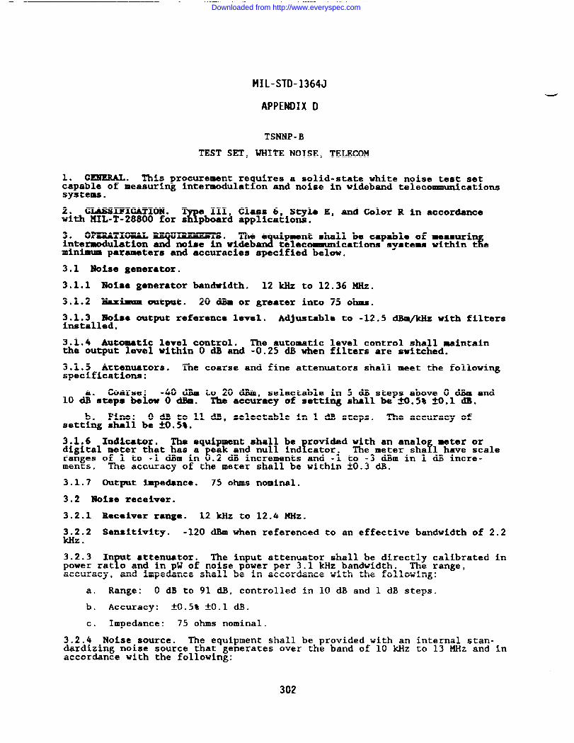
MIL-STD-1364J
APPENDIX D
TSNNP -B
TEST SET, WHITE NOISE, TELECOM
1. GENERAL. This procurement re uires a solid-state white noise test set?capable of measuring intermodulat on and noise in wideband telecommunications
systems.
2. CLASSIFICATIO19.w
III Class 6, Styla E, and Color R in accordancewith llIL-T-28800 for s pboar~ applications.
3. OPEUJLTIOXAL U~. The e uii~t shall be capable of measurinintermodulation 3 noise in wideb A %ommunications systems within t eminimum parameters and accuracies specified below.
3.1 Noise generator.
3.1.1 Noise generator bandwidth. 12 klizto 12.36 MHz.
3.1.2 Maximzm output. 20 dBm or greater into 75 ohms.
3.1.3 Moise output referamco level. Adjustable to -12.5 dBm/kHz with filtersinstalled.
3.1.4 Automatic level control. The automatic level control shall maintainthe output level within O dB and -0.25 dB when filters are switched.
3.1.5 Attenuators. The coarse and fine attenuators shall meet the followingspecifications:
Coarse: -40 dBm to 20 dBm, selectable in 5 dB steps above O dBm and10 ti”steps below O dl!m. The accuracy of setting shall be fi.5% H.1 dB.
. 0 dB to 11 dB, selectable in 1 dB steps. The accuracy ofsett& ~~n?i be --.58.
3.1.6 Indicator. The equipment shall befrovided with an analo meter or
digital meter that has a eak and null ind cater.8
fThe meter sha 1 have scaleranges of 1 to -1 dBm in .2 dB increments and -1 to -3 dBm in 1 dB incre-ments, The accuracy of the meter shall be within ~0.3 dB.
3.1.7 Output Impedance. 75 ohms nominal.
3.2 Notse receiver.
3.2.1 Receiver range. 12 kllzto 12.4 ~Z.
3.2.2 Sensitivity. -120 dBm when referenced to an effective bandwidth of 2.2kHz .
3.2.3 In t attenuator.r
The input attenuator shall be directly calibrated inpower rat o and in pW of noise power per 3.1 kHz bandwidth. The range,accuracy, and impedance shall be in accordance with the following:
a. Range: O dB to 91 dB, controlled in 10 dB and 1 dB steps.
b. Accuracy: _w.5% *0.1 dB.
c. Impedance: 75 ohms nominal.
3.2.4 Noise source. The equipment shall be provided with an internal stan-dardizing noise source that generates over the band of 10 kHz to 13 MHz and inaccordance with the following:
302
Downloaded from http://www.everyspec.com
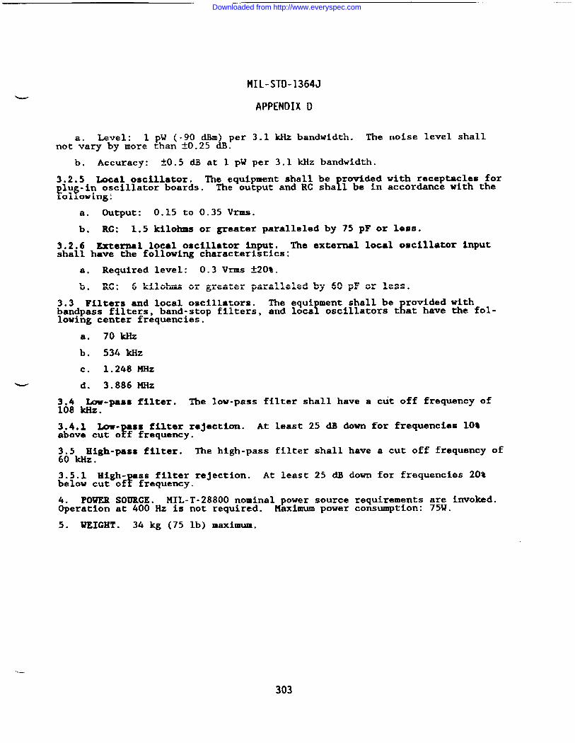
MIL-STD-1364J
APPENDIX D
Level: 1 pW (-90 d$m) per 3.1 kllzbandwidth. Thenota~ary by more than ~0.25 dB.
b. Accuracy: ~0.5 dB at 1 pW per 3.1 kHz bandwidth.
3.2.5 Local oscillator. The equipment shall be rovidedlU -in oscillator boards.
Ff!The output and RC sha 1 be in
01 owing:
a. output : 0.15 to 0.35 Vrms.
noise level shall
with receptacles foraccordance with the
b. RC: 1.5 kilohms or greater paralleled by 75 pF or less.
3.2.6 External local oscillator input. The external local oscillator inputshall have the following characteristics:
a. Required level: 0.3 Vrms k20%.
b. RC: 6 kilohms or greater paralleled by 60 pF or less.
3.3 Filters and local oscillators. The equi ment shall be rovided withbandpass filters, fband-stop filters, and loca tlowing center frequencies.
oscillators t at have the fol-
a. 70 kllz
b. 534 kHz
c. 1.248 ~Z
U d. 3.886 ~Z
:6: ~h-pass filter. The low-pass filter shall have a cut off frequency of.
3.4.1 b-Y
ss filter rajection. At least 25 dB down for frequencies 10%above cut o f frequency.
3.5 High-pass filter. The high-pass filter shall have a cut off frequency of60 HZ.
3.5.1 High-F
ss filter rejection. At least 25 dB down for frequencies 20%below cut of frequency.
4. POWER SOURCE. MIL-T-28800 nominal power source requirements are invoked.Operation at 400 Hz is not required. Maximum power consumption: 751J.
5. WEIGHT . 34 kg (75 lb) maximum.
303
Downloaded from http://www.everyspec.com
MIL-STD-1364J
APPENDIX D
TSENN-A
TESTER, BIT ERROR RATE, TELECOM
1. GENERAL. This procurement requires a bit error rate test set capable ofindicating data errors in bit streams.
2. CLASSIFICATION.%
e III,with ?lIL-T-28800 for s pboard
3. OPBBATXOMALRBQUXWMEBTS.counting bit errors in a knownties specified below.
3.1 Output message forms.
Class 5, Style C, and Color R in accordanceapplications.
The equipment shall be capable of in ecting andJdata stream within the parameters an accura-
a. Random: Three pseudorandom test messages of 63, 511, and 2,047 bits.
b. Reversals: A 1:1 reversal signal.
c. Mark: A steady mark output.
d. Space: A steady space output.
3.2 Displays.
3.2.1 Error count display. 2-1/2 digit numerical readout.
3.2.2 Excess indicator. An excess indicator shall be provided for errorcounts that exceed the error count display capability.
3.2.3 Sync loss indfcator. A synchronization loss indicator shall be provid-ed .
3.3 Modem. The equipment shall be provided with switch-activated modem hand-shakl~ capabilities.
3.4 S eeds.Y
The equipment shall be provided with the following crystal-contro led speeds:
a. 50, 75, 110, 135, 150, 300, 600, 1,200, 1,800, 2,000, and 2,400 baud.
b. 50 kilobits and less with a modem-supplied clock.
3.5 External timing. Operation from an external timing input shall be pro-vided.
MIL-T-28800 nominal power source requirements a~~ invoked.&er~~ ~~~;~”Hz is not required. Maximum power consumption: .
5. WEIGHT . 20 kg (44 lb) maximum.
—-
304
Downloaded from http://www.everyspec.com
MIL-STD-1364J
APPENDIX D
Configuration A: TSEMA-FConfiguration B: TSENA-F
TESTER, BIT ERROR MTE, TELECOM
1. GENERAL. This rocurement reE T
ires a bit error rate tester for digitalcoamuunications capa le of IEEE ST 488.1-1987 digital bus control.
2. CLASSIFICATION .%
e III, Class 5, Style E and Color R in accordancewith PIIL-T-28800for s pboard applications. fie convertible/rackmounteblerequirement is imwoked.
3. OPEMTIOMAL REQUXUMEMTS. The equipment shall have the capibil~ty ofdetectln&#ia2 date errors on data transmissions heviM’bps. Y
rates up to 12.928
=~~;~~ ~$=;;~;~ ~?e~~~%;;CaZ1stiZe~?%~gGe-The equipmenquirements specified belov.
3.1 Bit error testing.
3.1.1 Clock frequency. 50 Hz to 12.928 MHz continuously.selectable.
3.1.1.1 Clock stability and accuracy. *5 ppm.
3.1.2 Synchronous rates. 50 bps to 12.928 -S.
3.1.3 Asynchronous requirements.
3.1.3.1 Rates. 50 bps to 20 kbpS.
3.1.3.2 Codes. ASCII, BAUMT.
3.1.3.3 Levels. 5P 6, 7, and 8 bits.
3.1.3.4 Parity. Even, odd, and none.
3.1.3.5 Stop bits. Selectable 1 or 2.
3.1.4 Test results. Bit errors, bit-error-rate, block errors, block-erroF-rate , errored seconds, error-free seconds, percent error-free seconds, availa-bility, bipolar violations, excess zero detection.
3.1.5 Block SiZd!t. 100 bits to 1 X 10E6 bits.
3.1.6 Test period. 1s to 24 hours with 1s resolution and continuous mode.
3.1.7 TestY
tterns and messa es.f
63 bits to 2E20-1 bit suedorandom.Selectable f xed patterns of a 1 marks and 1:1 shall also LMessages:
provided.Fox and one user-programmable message up to 256 characters.
3.1.8 Signal monitoring. Monitor ports or other means shall be provided tomonitor data and clock to and from the device under test.
3.1.9 Error insertion. Single error.
3.1.10 Interfaces.
3.1.10.1 MIL-STD-188-114. The equipment shall beErovided with balanced and
unbalanced NRZ data interfaces conformin%
to MIL-ST -188-114. A 37-pinconnector in accordance with EIA Standar RS-449 shall be
Erovided. A 37- in
to 25-pin adapter shall also be provided in accordance wit EEIA Standard R -449.
305
Downloaded from http://www.everyspec.com
MIL-STD-1364J
APPENDIX D
3.1.10.2 RS-232. The equipment shall be provided with an NRZ data andprinter interface conforming to EIA Standard RS-232.
3.1.10.3 T1. The Configuration B equipment shall be provided with a RZ datainterface dedicated to testing 1.544 Kb/s data rates.
3.1.10.3.1 coding. Binary Eight Zero Substitution (B8ZS) and Alternate HarkInversion (AMI).
3.1.10.3.2 Impedance. Terminated or bridged.
3.1.10.4 Remote control. A digital interface in accordance with KIL-T-28800shall be provided.
3.2 Jitter tssting. The Confi ration B equipment shall be ca able ofPgenerating and testing phase ji ter in accordance with HIL-STD- !88-323.
3.3 Rackmounting. The e uipment shall be contained in a Style E enclosurefor portability and shall\ e provided with a conversion kit which will allowrackmounting in accordance with the convertible/raclanountable requirements ofMIL-T-28800.
4. POWER SOURCE. MIL-T-28800 nominal power source requirements a~onvoked.Operation at 400 HZ is not required. Maximum power consumption: .
5. WEIGHT . 20 kg (44 lb) maximum.
-d
306
Downloaded from http://www.everyspec.com
MIL-STD-1364J
APPENDIX D
TESAA-A
TESTER, ELECTRICAL SAFETY
1. GENERAL. This procurement requires an electrical safety tester designedto test for hazardous shock potentials of electrical equipment.
2. CTASSIFIGATION . T e III, Class 5, Style E, and Color R in accordanceBwith MIL-T-28800 for s pboard application.
3. OPERATIONAL REQU~. The e uipment shall be ca able of testingelectrical equi ment for shock hazar
!3 conditions within L. minimum ~ifl-
cations identif ed below. Tests shall include ground continuity, le gecurrent, short circuits, and insulation breakdown.
3.1 Ground continuity. The equipment shall test ground conductor integrityat a minimum of 25A.
3.2 Leakage. The equipment shall test leakage current on devices that havethe ground connection opened.
3.3 Short circuits. The equipment shall detect a short circuit in theequipment, power cord, and power switch.
3.4 Insulation breakdown. Power cord insulation integrity shall be tested ata minimum potential of 0.5 kV at 20 mA or less.
4. POWER SOURCE. MIL-T-28800 nominal power source requirements are invoked.Operation at 400 Hz is not required. Maximum power consumption: 500W.
5. WEIGHT . 20 kg (44 lb) maximum.
307
Downloaded from http://www.everyspec.com
MIL-STD-1364J
APPENDIX D
THCAA-A
TESTER, HIGH CURRENT
1. C?mEML. This procurement re uires a high current test set designed toLtest overload relays, circuit bre rs, trip devices, current transformers and
panel board ameters.
2. CIASSIFICA7XON .%
e 111, Class 5, Style Et and Color R in accordancewith MIL-T-28800 for s pboard applications.
3. OPEMTIOMAL REQ~. The equipment shall be capable of o c~ft&nwithin the minimum
Tcifications outlined below. The equipment sL
provided with a buil -in digital ammeter and timer.
3.1 Gurrent ratsxlg. 750A minimum.
3.2 Voltage rat~. 120V minimum.
3.3 -alter. 3-1/2 digits.
3.3.1 kmge. O to 750A.
3.3.2 Accuracy. Al% of reading Al digit.
3.3.3 Memory. The ammeter shall be provided with a memory to measure andhold maximum short duration current readings.
3.4 Tbez. The timer shall start when the output is energized and stop whenthe device-under-test actuates.
3.4.1 Range. O to 1,000s.
3.4.2 AC-aCy. fO.005% of reading ~1 digit.
3.5 Accessories. Timer control circuit leads and high current leads.
4. POWER SOURCE. MIL-T-28800 nominal power source requirements a~;O&Wvoked.Operation at 400 Hz is not required. Maximum power consumption: .
5* WEIGHT . 20 kg (44 lb) maximum.
308
Downloaded from http://www.everyspec.com
MIL-STD-1364J
APPENDIX D
TS4NN-B
TESTER, RELAY, TELECOM
1. c~. l?his rocurement requires a relay test set ca able of testing! !high speed polar re ays of the type commonly used in telepr nter equipment.
2. CLASSIFICATION.%
e III, Class 6, S le E, and Color R for Navy applica-tions in accordance wi ?KIL-T-28800 for s ipboard applications.
3. OPERATIONAL REQU~. The test set shall be ca able of measuring sen-!mesitivity, contact circuit bias, contact circuit break t , and insulation
resistance (hipot).
3.1 output 8igMlo 30 to 60 Vdc for oscilloscope viewing of contact per-formance .
3.1.1 Signal distortion. The out ut signal shall not distort when connectedEto oscilloscopes having an input R of 1 megohm or greater shunted by 100 pF
or less.
3.2 Test socket. Octal socket wired for Sigma Series 72 and Series 7 tele-printer relays.
4. POWER SOURCE. MIL-T-28800 nominal power source requirements afivinvoked.Operation at 400 Hz is not required. Maximum power consumption: .
-—
5. WEIGHT . 20 kg (44 lb) maximum.
309
Downloaded from http://www.everyspec.com
MIL-STD-1364J
APPENDIX D
TE2NR-E
TEST SET, SEMICONDUCTOR
1. GENERAL. This procurement requires a solid-state test set that presents avoltage versus current display of electronic components under test.
2. CMSIFICATIOM .Q
e III, Class 5, Style E, and Color R in accordancewith kiIL-T-28800for s pboard applications.
3. OPEEATIOXAL UIREMENTS. The equipment shall be capable of displaying on?a GRT the electron c signature of discrete and integrated circuit semicomiuc-
tor junctions, capacitance, inductance, and resistance in and out of circuit.
3.1 Display. The e uipaent shall be provided witi an integral CRT dls lay.Controls for vertica ? and horizontal sweep position and brightness shal! beprovided.
3.2 Input channels. The equipment shall be provided with charnels A and B,and alternating A and B.
3.3 Test signal. An internally generated transformer-coupled sine wave testsignal shall be provided.
3.3.1 Frequencies. Line frequency, 400 Hz and 2 kliz.
3.4 Gate signal generator. The equipment shall be provided with a variablepulse/de generator as detailed below.
3.4.1 Output level. -5V to +5V.
3.4.2 Duty cycle. 00 (Cic)to 50%.
3.4.3 Current limit. 50 mA maximum.
3.4.4 Synchronization. The pulse signal shall be synchronized with the sinewave test signal.
3.4.5 Number of outputs. 2.
3.5 Accessories. Safety-designed test probes in accordance with MIL-T-28800and other test leads necessary for comparison testing shall be provided.
POWER SOURCE. MIL-T-28800 nominal power source requirements are invoked.aeration at 50 and 400 Hz is not required. Maximum power consumption: 20W.
5. UHGHT . 10 kg (22 lb) maximum.
310
Downloaded from http://www.everyspec.com
—
MIL-STD-1364J
APPENDIX D
TE2NS-E
TEST SET, SEMICONDUCTOR
1. GENEML . This procurement requires a solid-state test set that presents avoltage versus current display of electronic components under test.
2. GL4SSIFIGATIOR .%
e III, Class 5, Style E, and Color R in accordancewith MIL-T-28800 for s pboard applications.
3. OPERATIONAL M U~.?
The equipment shall be capable of displaying ona CRT the electron c signature of discrete and integrated circuit semiconduc-tor junctions, capacitance, inductance, and resistance in and out of circuit.
3.1 Display. The e uipment shall be provided with an integral CRT dis lay.Controls for vertica ? !band horizontal sweep position and brightness shal eprovided.
3.2 Input channels. The equipment shall be provided with channels A and B,and alternating A and B.
3.3 Test signal. An internally generated transformer-coupled sine wave testsignal shall be provided.
3.3.1 Frequencies. Line frequency, 400 Hz and 2 kHz.
3.4 Gate signal generator. The equipment shall be provided with a variablepulse/de generator as detailed below.
u 3.4.1 Output level. -5V to +5V.
3.4.2 Duty cycle. O% (de) to SO%.
3.4.3 Current limit. 50 mA maximum.
3.4.4 Synchronization. The pulse signal shall be synchronized with the sinewave test signal.
3.4.5 Number of outputs. 2.
3.5 Comparator. The e uipment shall be capable of alternately presentingvoltage versus current 31isp ays of two integrated circuits as specified below.
3.5.1 Comparison modes. The equipment shall allow for manual and automaticcomparison at a rate variable from once per second or less to at least eighttimes per second.
3.5.2 Pin selection. The equipment shall be capable of com aring integratedcircuits that have 6
Yins or less to at least 40 in dual in-?.ine packages
(DIPS) . Each pin sha 1 be operator selectable as a reference.
3.6 Accessories. Safety-designed test probes in accordance with MIL-T-28800and other test leads necessary for comparison testing shall be provided.
3.6.1 DIP cli S.!
The equipment shall be provided with 40-pin and 16-pin DIPclips for in-c rcuit testing of integrated circuits.
4. POWER SOURCE. WL-T-28800 nominal power source requirements are invoked.Operation at 50 and 400 Hz is not required. Maximum power consumption: 20W.
5. WEIGHT. 10 kg (22 lb) maximum.
311
Downloaded from http://www.everyspec.com
.
MIL-STD-1364J
APPENDIX D
TSUAA-B
TESTER, SURGE COMPARISON
1. GENERAL. This procurement requires a surge comparison tester capable oftesting the windings of ac and & motors and generators.
2. CLASSIFICATION .%
e III, Class 5, Style E, and Color R in accordancewith llIL-T-28800 for s pboard applications.
3. OPXBATXOMAL REQUIREMENTS. fie equipment shall test turn-to-turn coil-to-coil, coil-to- round, and phase-to- base insulation.
f sIn addition, the
e ipment shal be provided with a c high potential capability to at least 5k~and shall be capable of testing three-phase devices.
3.1 Surge test.
3.1.1 Output voltage. Adjustable to 5 kV.
3.1.2 Current rating. O to 30A.
3.1.3 Display. 8 x 10 division oscillographic display for viewing comparisonwaveforms.
3.2 DC high potential test.
3.2.1 Output voltage. 5 kV minimum.
3.2.2 ?Iaxhua current. 5 mA.
POWER SOURCE. KIL-T-28800 nominal power source requirements afiO$mvoked.&eration at 400 Hz is not required. Maximum power consumption: .
5. WEIGHT . 20 kg (44 lb) maximum.
312
Downloaded from http://www.everyspec.com
1. GENEML . This procurement
2. CIJSSIFIGATIOIJ. T e III,K!with MIL-T-28800 for s pboard
3* OPERATIONAL REQUIREMENTS.
MIL-STD-1364J
APPENDIX D
TEVAA-A
TESTER, VOLTAGE
requires a prod-type voltage tester.
Class 5. Stvle E. and Color R in accordanceapplicatioti. “
The equipment shall ind~catq—-voltages within the minimum ranges aid &ccuracies specified
3.1 Measurement range. 24 to 600 Vat.
3.2 Frequency. 25 to 60 Hz.
the presence of acbelow .
3.3 Indication. Neon lamp. A nominal numeric indication of the voltagelevel shall also be provided.
3.4 Proben. The e uipment shall be provided with safety-designed test leads8in accordance with IL-T-28800.
4. POWER SOURCE. The nominal power source re uirements are not iwoked.Power for the equipment shall be derived from L e circuit under test.
5. DIMENSIONS. 203 mm (8 in) high, 102 mm (4 in) wide, and 39 mm (1.S in)deep, maximum.
- 6. WEIGHT . 0.45 kg (1 lb) maximum.
---
313
Downloaded from http://www.everyspec.com
MIL-STD-1364J
APPENDIX D
TRI.AN-A
TRANS~RKER, AUTO
1. GENERAL. This procurement requires a single-phase autotransformer withmeters for monitoring output voltage and current.
2. CXASSIFICAT.ION.%
e III, Class 5, Style E, and Color R in accordancewith HIL-T-28800 for s pboard applications.
3, OPERATIONAL REQUXUMEMTS. The equi ment shall be capable of operationwithin the minimum specifications liste ~ below.
3.1 Output voltage. O to 140V with over range capability.
3.2 Rated continou current output. 10A .
3.3 Meter ranges (FS). Voltage: 150V. Current: 2A and 10A.
3.3.1 Meter ●ccuracy. A38 FS.
POWER SOURCE. MIL-T-28800 nominal power source requirements a~e6i~ked.~eration at 400 Hz is not required. Maximum power consumption: . .
5. VEIGHT . 9 kg (20 lb) maximum.
314
Downloaded from http://www.everyspec.com
MIL-STD-1364J
APPENDIX D
m3m -A
TMNSFORMER, ISOLATION
1. G~* This procurement requires an isolation transformer. “
2. CLASSIFICATION .%
e III Class 5, S~le E, and Color R in accordancewith MIL-T-28800 for s pboar~ applications.
3. OPERATIONAL RXQU~S. The equi ment shall be capable of operationfwithin the following minimum specificat ens.
3.1 Turns ratio. 1 to 1.
3.1.1 Ratio ●ccuracy. 0.005% at 400 Hz.
3.2 Frequency range. 50 HZ to 5 kHz.
3.3 Input impedance. 250 kilohms at 400 Hz.
3.4 Maximum input voltage. 0.35f where f is frequency in Hz.
4. POWER SOURCE. The power source requirements are not invoked.
---
5. WEIGHT . 8 kg (3.6 lb) maximum.
315
Downloaded from http://www.everyspec.com
b’lIL-sTD-1364J
APPENDIX D
TR4JN-B
TRANSFORMER, RATIO
1. GlmERAL, This procurement requires a precision series-decade type ratiotransformer.
2. CLASSXFICATIOH .%
e 111, Class 5, S~le E, and Color R in accordancewith MIL-T-28800 for s pboard applications. Power source requirements arenot invoked.
3. OPKUATIOMAL REQUIREMENTS. The equi ment shall be capable of voltage divi-Ksions for sinusoidal waveforms within t e specifications set forth below.
3.1 Frequancy Xangc. 3oHztolkHz.
3.2 Ratio range. -0.111111 to 1.111111.
3.3 Ratio accuracy. 1 ppm + (0.5 ppm/ratio).
3.4 Range wer18p. 10* mink.
3.5 Terminal linearit .$h
1 ppm maximum. The terminal lineari~ is &fined asthe series impedance o t e equipment versus the indicated ratio as the ratiois varied over its entire range.
3.6 Output ~edance. 5 ohms shunted by 350 uH.
3.7 Maximum input. (2.5 x frequency in Hz) Vrms or 350V maximum.
4. WEIGHT . 20 kg (44 lb) maximum.
316
.-
Downloaded from http://www.everyspec.com
MIL-STD-1364J
APPENDIX D
VOIJG-F
VOLTMETER, AN-, ELECTRONIC
1. GENERAL. This procurement requires a solid-state, average responding, rMSindicating, analog ac voltmeter.
‘2 ● CIASSIFIGATXOI!l. T e III, Class 3, Style E, and Color R in accordanceBwith MIL-T-28800 for s pboard applications.
3. ~ m~* The equipment shall be ca able of measurr~dacvoltages withtn the minimum ranges, !accuracies, and sens tivitiesbelow. TThe meter shall respond to the average value of the input s gnal andshall be calibrated in rms volts and decibels.
3.1 Frequency range. 10 Hz to 2 HHz.
3.2 Voltage measurement. Range: 1 mV to 300V full scale. Resolution: 1% Offull scale.
3.2.1 Voltage measurement ●ccuracy. *2% of indication.
3.3 Decibel measurement. Range: -70 dBm to 52 dBm. Resolution: 0.1 dB.oa- lmW referenced to 600 ohms.
3.3.1 Decibel measurement accuracy. tO.2 dB of indication.
3.4 In t.r
The equi ment shall be provided with a three-teminalbanana- ack input on T9.05 mm (3/4 in) centers. The equipment shail be
~ capable of input isolation of at least &500V (dc + peak ac) above ground.
3.4.1 Input RC. 2 megohms shunted by 60 pF, nominal.
3.4.2 Xeximum input. 300 Vdc and 500 Vrms (not additive) on any range.
3.5 Indicator. A meter shall be provided with a taut-band movement havingmirrored, linear dB and logarithmic volts e scales.
%A di ital voltage and dB
findicator with equivalent resolution ca~a Ilities along w th an analog indi-cator designed for peaking and nulling 1s acceptable for this application.
4. POWER SOURCE. MIL-T-28800 nominal and dc internal power source require-ments are invoked as detailed below.
4.1 Hominal power source. Operation at 400 Hz is not required. Maximumpower consumption: 10W.
4.2 DC internal power source. Internal batteries and charger are required.~~n~~~operating time shall be 8 hours following a maximum recharge time of
●
5. WEIGHT . 10 kg (22 lb) maximum.
317
Downloaded from http://www.everyspec.com
MIL-STD-1364J
APPENDIX D
VOIQN -C
VOLTMETER, ANAI@, ELECTRONIC
1. GSMERAL. This procurement requires a solid-state, true rms analog acvoltmeter.
2. CLASSIFICATION .%
e III, Class 5, Style E, and Color R in accordancewith MIL-T-28800 for s pboard applications.
3. HXASuulfENT REQUXUXENTS. The equipment shall be ca able of measuring acvoltages within the minimum ranges, accuracies, fand sens tivities specifiedbelw. The metaz shall respond to and indicate the true rms value of theinput signal in volts and decibels.
3.1 Frequency range. 10 Hz to 10 kfiiZ.
3.2 Voltago measurement. Range: 2 mV to 300V full scale in multiple rangeswith a resolution of 10 UV on the most sensitive range.
3.2.1 Volta e measurement accurac . *2% of indication at 200 kHz and no!! Tworse than ~ t throughout the spec fied frequency range.
3.3 Decibel ●easurement. Range: -70 to +52 dBm in 10 dB steps with aresolution of 0.1 dB. Zero decibels shall equal 1 mW referenced to 600 ohms.
3.3.1 Decibel measurement accuracy. M.2 dB of indication at 200 kHz and noworse than ~.5 dB throughout the specified frequency range.
3.4 Crest factor. 6:1 at full scale.
3.5 Input !kC. 1 megohm minbum shunted by 40 pF or less.
3.6 Maximm input. 500 V& or 350 Vrms on any range.
3.7 Indicator. A meter shall be provided with a taut-band movement havingmirrored, linear dB and logarithmic volts e scales.
%A di ital voltage and dB
findicator with equivalent resolution capa ilities along w th an analog indica-tor designed for peaking and nulling is acceptable for this application.
3.8 Input connector. BNC(f).
3.9 output. TheJequipment shall be provided with a dc output proportional tothe meter voltage indication.
POWER SOURCE. HIL-T-28800 nominal power source requirements are invoked,&eration at 400 Hz is not required. Maximum power consumption: 10W.
5. WEIGHT . 10 kg (22 lb) maximum.
Downloaded from http://www.everyspec.com
MIL-STD-1364J
APPENDIX D
VOICF-D
VOLTMETER, ANAXQG, ELECTRONIC
1. GENERAL. This procurement requires a portable, solid-state analog rmsvoltmeter.
2. CLASSIFICATION●
%
e III, Class 3, Style E, and Color R in accordancewith llIL-T-28800 for s pboard applications.
3. MEASUREMENT REQUIREMENTS. The equipment shall be capable of mess-hg rmsvoltage within the Animus specifications and accuracies specified below. Themeter shall respond to the avera e value of the input signal and shall be
%calibrated in rms volts and deci els.
3.1 Frequency range. 20 Hz to 4 MHz.
3.2 Voltage range. 0.1 mV to 1 kV full scale.
3.2.1 Voltage ●ccuracy. t2% of indication.
3.3 Decibel measurement. Range: -80 to +60 dB where O dB equals lV.
3.4 Input RC. 10 megohms shunted by 30 pF, nominel.
3.5 Maximum input. 300 Vdc or 1 kVrms.
3.6 Floating in t. The sir r
1 ground must be isolated to at least *300 V&+ peak ac from c assis groun .
w3.7 output
Tlifier. h output proportional to the meter voltage indication
shall be provi ed.
3.7.1 Out t level.r
1 Vrms, open circuit, for full-scale meter deflection(0.5 Vrms nto 600 ohms).
3.7.2 Output Impedance. 600 OhXES.
3.8 Filter. 100 kHz low-pass, switchable.
3.9 Noise. The noise referred to input when terminated with 1 kilohm shallnot exceed 5 UV with low-pass filtering and 30 UV without filtering.
3.10 Mater. The meter shall have a taut-band movement and mirror-backedscales. The uppermost scale shall be linear dB with O dB equalling 1 Vrms. Alogarithmic ma volts scale shall be provided. A digital indicating meter isnot acceptable for this application.
4. POWER SOURCE. HIL-T-28800 nominal and dc internal power source require-ments are invoked as detailed below.
4.1 Nominal power s~:rce. Operation at 400 Hz is not required. Maximumpower consumption: .
4.2 DC internal power source: Internal batteries and charger are required.Minimum operating time shall be 8 hours following a maximum recharge time of16 hours. A front-panel battery state indicator is required.
5. WEIGHT . 10 kg (22 lb) maximum.
-%-
319
Downloaded from http://www.everyspec.com
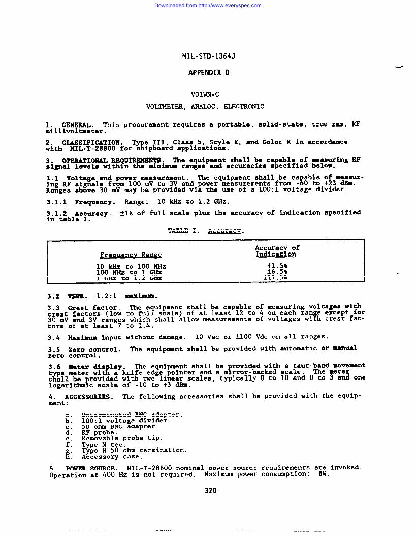
MIL-STD-1364J
APPENDIX D
VOIWN-C
VOLTMETER, ANAIAG, ELECTRONIC
1. GENERAL. This procurement requires a portable, solid-state, true rms, mmillivol~eter.
2. CLASSIFIGAZION.3
e III, Class 5, S~le E, and klor R in accordancewith KIL-T-28800 for s ipboard applications.
3. oPERATIolaALRE uIRExm’Ts.?
The equipment shall be capable of measuring RFsignal levels with n the minimum ranges and accuracies specified below.
3.1 Voltage and power meamrement. The equipment shall be ca able of measur-Eing RF signals from 100 UV to 3V and power measurements from - 0 to +23 dBm.
Ranges above 30 mV may be provided via the use of a 100:1 voltage divider.
3.1.1 Requency. Range: 10 k?lzto 1.2 *.
X&21cftaxacy . -+1%of full scale plUS the acc~acy of indication specified.
TABLE 1. AsGwaGY.
~reauencv Ra~
10 kllz to 100 MHz *1,5*loo MHztol GHz ~6c5$1 GHZ to 1.2 GHz *11.5*
t
3.2 VSUR. 1.2:1 maximum.
3.3 Crest factor. The e uipment shall be capable of measuring voltages withcrest factors (low to ful? scale) of at least 12 to 4 on each ran e except for30 mV and 3V ranges which shall allow measurements of voltages wi h crest fac-ftors of at least 7 to 1,4.
3.4 Maximum input vithout damage. 10 Vac or *1OO Vdc on all ranges.
3.5 Zero control. The equipment shall be provided with automatic or manualzero control.
3.6= Mee~ ~;s lay.4
The equipment shall be
Tfrovided with a taut-band movement
a knife edge pointer and a m rror-backed scale. The meters all be rovided with two linear scales,
ftypically O to 10 and O to 3 and one
logarithm c scale of -10 to +3 dBm.
4. ACCESSORIES. The following accessories shall be provided with the equip-ment:
Unterminated BNC adapter.& 100:1 voltage divider.c. 50 ohm BNC adapter.d. RF probe.
Removable probe tip.i: Type N tee.
k. Type N SO ohm termination.. Accessory case.
5. POWER SOURCE. MIL-T-28800 nominal power source requirements a~: invoked.Operation at 400 Hz is not required. Maximum power consumption: .
320
Downloaded from http://www.everyspec.com
HIL-STD-1364J
APPENDIX D
6. WEIGHT . 10 kg (22 lb) maximum.
321
Downloaded from http://www.everyspec.com
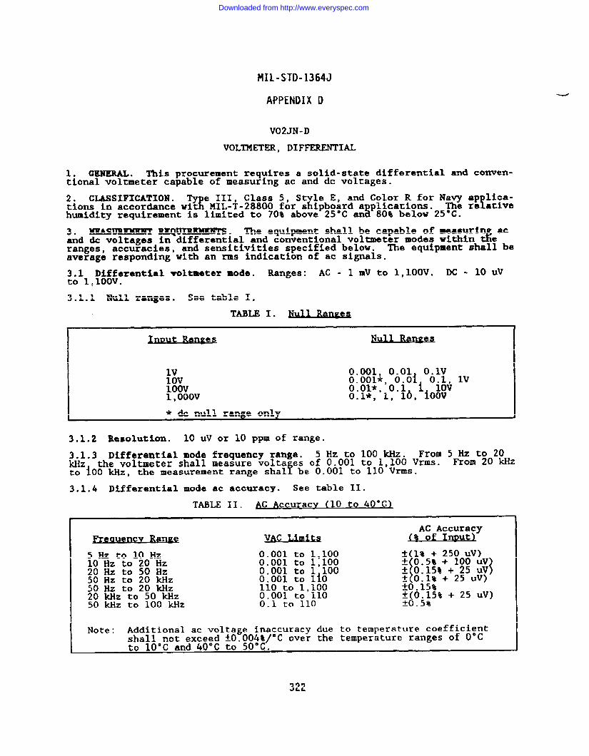
?41L-STD-1364J
APPENDIX D
V02JN-D
VOLTMETER, DIFFERENTIAL
1. GENERAL . This procurement requires a solid-state differential and conven-tional voltmeter capable of measuring ac and dc voltages.
2. CLASSIFICATION .3
e III, Class 5, St le E, and Color R for Navy ap lica-Xtions in accordance wit MIL-T-28800 for s ipboard a placations. f
~ 80% below 25? ‘e atiVehumidity requirement is limited to 70% above 25°C an
3. HEASUREMEMT REQUIREMENTS. The equipment shall be capable of measuri acand & voltages in differential and conventional voltmeter modes within %ranges, accuracies, and sensitivities specified below. The equipment shal? beaverage responding with an rms indication of ac signals.
3.1 Differential voltmeter mode. Ranges: AC - 1 mv to 1,1OOV. DC - 10 Uvto 1,1OOV.
3.1.1 Null ranges. See table I.
I Ut Raw JIUl1 Ran= IlV 0.001, 0.01 O.lv10V100V
O.001*, O.oi 0.1, lV
1,OoovO.01*, 0.1 i 10V().1*, 1, lb, ioov
* & null ranze onlv
3.1.2 Resolution. 10 UV or 10 ppm of range.
3.1.3 Differential mode frequency range. 5 Hz to 100 kHz. From 5 Hz to 20kHz the voltmeter shall measure volts es of 0.001 to 1,1OO Vrms. From 20 WZto iOO kHz, the measurement range shal! be 0.001 to 110 Vrms.
3.1.4 Differential mode ac accuracy. See table II.
TABLE II. AC Accuracv (10 to 40°C)
J?reauencv Raw V!?l Q%%.&Sy
5Hzto10Hz 0.001 to 1,100 * 1% + 250 uV)10 Hz to 20 Hz 0.001 to 1,100
\
t 0.5% + 100 Uv20 Hz to 50 Hz 0.001 to 1 100 f 0.15% + 25 UV{50 Hz tO 20 kHZ 0.001 to lio f 0.1% + 25 uV)50 Hz to 20 kHZ 110 to 1,100 *0015%20 Mz to 50 kHz :.yo:ot;l:lo *(0.15% + 25 uV)50 kHz to 100 kHz *(3-5!3.
I Note: Additional ac voltage inaccuracy due to temperature coefficientshall not exceed f0.004%/°C over the temperature ranges of O“C I
322
Downloaded from http://www.everyspec.com
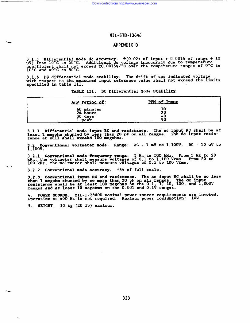
MIL-STD-1364J
APPENDIX D
3.1.5 Differential mode dc accuracy. * 0.02% of input + 0.001% of range + 10uV) from 10’C to 40’C. iAdditional dc vo tage inaccuracy due to temperaturecoefficient shall not exceed M.0015%/°C over the temperature ranges of O“C to10”C and 40”C to 50°C.
3.1.6 DC differential mode stability. The drift of the indicated volts ewith res ect to the measured input reference value shall not exceed the
8fimits
specifie in table III.
TABLE III. PC Diff rential He ode Stability
3.1.7 Differential mode input RC and resistance. The ac input RC shall be atleast 1 megohm shunted by less than 20 pF on all ranges. The & input resis-tance at null shall emeed 100 megohms.
3.2 Conventional voltmeter mode: Range: AC - 1 mV to 1,1OOV. DC - 10 UV to1,100V ●
3.2.1 (kmventiomal mode frequency xanga. 5 Hz to 100 m. FrOm:o~2&Ot~okHz, the voltmeter shall measure voltages of 0.1 to 1,100 Vrms.100 kHz, the voltmeter shall measure voltages of 0.1 to 100 Vrms.
u3.2.2 Conventional mode accuracy. k3%.of full scale.
3.2.3 Cmwentiunal in t RC and resistance.r
The ac hput RQha&libeU~ lessthan 1 megohm shunted
1no more than 20 pF on all ranges.
Yresistance shall be at east 100 me ohms on the 0.1, 1, 10, 100, -dk
,Ooovranges and at least 10 megohms on t e 0.001 and O.lV ranges.
4. POWER SOURCE. MIL-T-28800 nominal power source requirements a~~vinvoked.Operation at 400 Hz is not required. Maximum power Cons-ption: .
5. WEIGHT . 10 kg (20 lb) maximum.
L
323
Downloaded from http://www.everyspec.com
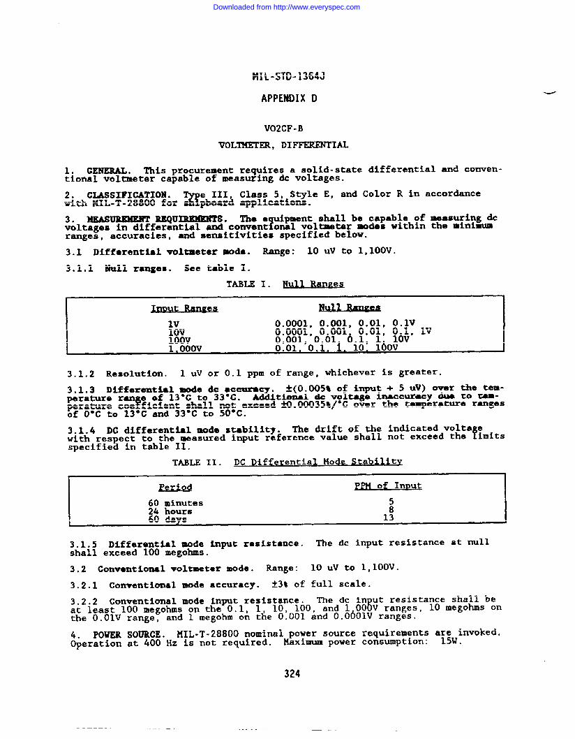
HIL-STD-1364J
APPENDIX D
V02CF-B
VOLTMETER, DIFFEKZNTIA.L
1. GENERAL . This procurement requires a solid-statetional voltmeter capable of measuring & voltages.
differential and conven-
2. CLASSIFICATION .B
e III, Class 5, Style E, and Color R in accordancewith 141L-T-28800 for pboard applications.
3* MEASUREMENT REQUIREMENTS ● The e uipment shall be capable of measuring &1voltages in differential and convent onal voltmeter modes within the minimum
ranges, accuracies, and sensitivities specified below.
3.1 Differential voltmeter mode. Range: 10 Uv to 1,1OOV.
3.1.1 Null ranges. See table 1.
TABLE I. Null R4QDS
I Ut 11-
lV 0.0001, 0.001, 0.01, O.lv10V 0.0001, 0.001 0.01, 0.l, lV100V 0.001, 0.01 6.1, 1 10V1.OoOv 0.01. 0.1, i. 10* lbov
3.1.2 Resolution. 1 UV or 0.1 ppm of range, whichever iS greater.
3.1.3 Differential mode de ●ccuracy. ~(Oo~5~ of i~ut + 5 N) ever the temp-erature ran e of 13°C to 33-C.
!!Additional & voltage inaccur-y dua to Tem-
perature coe ficient shall not exceed N.00035t/°C over the temperature rangesof O°C to 13*C and 33°C to 50°C.
3.1.4 DC differential mode stability. The drift of the indicated volts ewith respect to the measured input reference value shall not exceed the fimitsspecified in table II.
TABLE II. DC Differential Mode Stability,
Pl? ~PM of InDut
~~ ;m;es 58
\ 60 C@W 13
3.1.5 Differential mode input resistance. The dc input resistance at nullshall exceed 100 megohms.
3.2 Conventional voltmeter mode. Range: 10 Uv to 1,1OOV.
3.2.1 Conventional mode accuracy. *3* of full scale.
3.2.2 Conventional mode input resistance. The de in ut resistance shall beat least 100 megohms on the 0.1, 61, 10, 100, and 1 00 V ranges, 10 megohs onthe O.OIV range, and 1 megohm on the 0.001 and O.O~OIV ranges.
4. POWER SOURCE. MIL-T-28800 nominal power source requirements a~;vinvoked.Operation at 400 Hz is not required. Plaximum power consumption: .
324
Downloaded from http://www.everyspec.com
MIL-STD-1364J
APPE?lllIXD
5. WEIGHT . 10 kg (22 lb) maximum.
325
Downloaded from http://www.everyspec.com
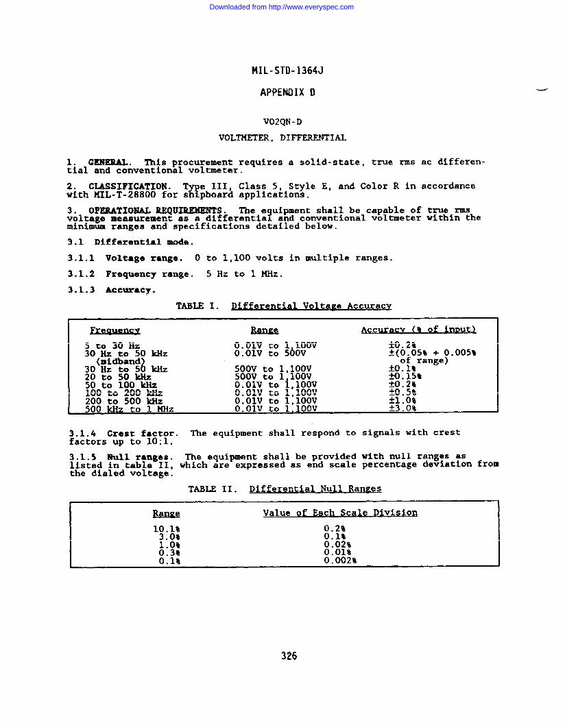
MIL-STD-1364J
APPENDIX D
V02QN -D
VOLTMETER, DIFFERENTIAL
1. cln!muL. This procurement requires a solid-state, true rms ac differen-tial and conventional voltmeter.
2. CWSIFICATION . T e III, Class 5, Style E, and Color R in accordanceZ!with MIL-T-28800 for s pboard applications.
3. OPERATIONAL REQUIREMENTS. The e uipment shall be capable of true rmsvoltage measurement as a differential? and conventional voltmeter within theminimum ranges and specifications detailed below.
3.1 Differential mode.
3.1.1 Voltage range. O to 1,100 volts in multiple ranges.
3.1.2 Frequency range. 5HztolMHz.
3.1.3 Accuracy.
TABLE I. Volta~ e Accuracy
Fr-wsx ACC -wu (% of i-
5 to 30 Hz O.olv to 1 100V 3.2%30 Hz to 50 Wz O.olv to 5bov *(O-05* + (,).005%
(mldbandi30 Hz to 5 kHZ 500V to 1,1OOV
of range)fool%
20 to 50 w 500V to 1 100V S ● 15*50 to 100 w Ooolv to i,loov M.2%100 to 200 kHz O.olv to 1,1OOV *oo5~200 to 500 kHz O.olv to 1,1OOV *1.()%500 w to 1 MHz O.olv to 1,1OOV ~3 .()%
3.1.4 Crest factor. The equipment shall respond to signals with crestfactors up to 10:1.
3.1.5 Null ranges. The equipment shall be provided with null ranges aslisted in table 11, which are expressed as end scale percentage deviation fromthe dialed voltage.
TABLE 11. Differential Null Ran~e s
M4E Value of Each Scale Division
1:.;: 0.2%0.1%
1:0% 0.02%0.3% 0.01%0.1% 0.002%
Downloaded from http://www.everyspec.com
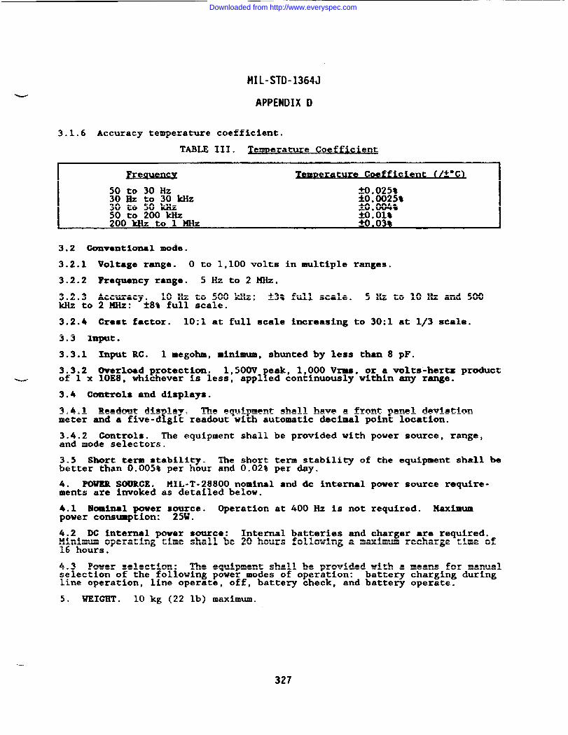
MIL-STD-1364J
APPENDIX D
3.1.6 Accuracy temperature coefficient.
TABLE III. ~emerature Coeffic ient
I J’reauency Zemn r=e ture Coefficient (/&“c)
50 to 30 Hz 2X).0258;; ~ ;; &kHz W.00259
9.004850 to 200 w Molt200 kllz to 1 XHz S. 03%
3.2 Conventional mode.
3.2.1 Voltage range. O to 1,100 volts in multiple ranges.
3.2.2 Frequency range. 5Hzto2MHz.
3.2.3 Accuracy. 10 Hz to 500 IcHz: t3% full scale. 5Hzto10Hzand 500kllztozw: *8% full scale.
3.2.4 Crest factor. 10:1 at full scale increasing to 30:1 at 1/3 scale.
3.3 Input.
3.3.1 Input RC. 1 megohm, minimum, shunted by less than 8 pF.
3.3.2 (barbed protection. 1,500V eak, 1,000 Vrms, or a volts-hertz product~ of 1 x 10E8, whichever is less, !appl ed continuously within any range.
3.4 Controls and displays.
3.4.1 Readout dis lay.!
The equipment shall have a front panel deviationmeter and a five-d git readout with automatic decimal point location.
3.4.2 Controls. The equipment shall be provided with power source, range,and mode selectors.
3.5 Short term stability. The short term stability of the equipment shall bebetter than 0.005% per hour and 0.02% per day.
4. POWER SOURCE. MIL-T-28800 nominal and & internal power source require-ments are invoked as detailed below.
4.1 Bkmlnal power s&Wce. Operation at 400 Hz is not required. Haximumpower consumption: .
4.2 DC internal power source: Internal batteries and charger are required.~~n~~soperating time shall be 20 hours following a maximum recharge time of
.
4.3 Power selection: The equipment shall be provided with ● means for manualselection of the following power modes of operation: battery charging duringline operation, line operate, off, battery check, and battery operate.
5. WEIGHT . 10 kg (22 lb) maximum.
327
Downloaded from http://www.everyspec.com
MIL-STD-1364J
APPENDIX D
V06NP-B
VOLTMETER, FREQUENCY SELECTIVE
-
1. GENERAL. This procurement requires a frequency selective voltmeter fortelecommunications measurements.
2. CLASSIFICATION .%
e III, Class 5, Style E, and Color R in accordmcewith lJIIL-T-28800for s pboard applications.
3. OPERATIONAL REQUIREMENTS. The equi ment shall be capable of performing!spectral analysis within the specificat ons identified below.
3.1 Frequency specifications.
3.1.1 Frequency range. 15 Hz to 50 kHZ.
3,1.2 Frequency display resolution. 1 Hz or less.
3.1.3 Frequency accuracy. *3.5 Hz.
3.1.4 Stability. The frequency stability shall be within A1O Hz per hourafter a warm-up time of not more than one hour.
3.1.5 Aatomatlc frequency control. The equi ment shall be provided withautomatic frequency control. EHold-in range s all be at least *800 Hz. Anindication of an unlocked condition shall be provided.
3.2 Amplitude specifications.
3.2.1 Amplitude range. 100 nV to 30 Vrms.
3.2.2 Amplitude display. Digital or mirror-backed analog meter.
3.2.3 Amplitude ●ccur@cy. Log: *2 dB, Linear: *4%.
3.2.4 Dynamic range. 80 dB minimum.
3.2.5 Noise sidebands. 70 dB down 10 bandwidths away from the W inputsignal.
3.2.6 Calibrator. h internal calibrator capable of verifying the amplitudeaccuracy to at least fl.5% shall be provided.
3.3 Sweep specifications.
3.3.1 Resolution bandwidth. Selectable from 3 Hz to 300 Hz.
3.3.2 Scan width. Selectable from 50 Hz to 50 kHz.
3.3.3 Sweep time. Selectable from 0.1s to 2,000s.
3.3.4 Sweep modes. Repetitive, single scan, man-l.
3.3.5 Sweep error light. A sweep error light shall be provided which indicates that a sweep rate is too fast to capture the full response.
3.4 Input specifications.
3.4.1 Unbalanced input RC. 1 megohm or greater shunted by 40 pF or less.
3.4.2 Balanced bridged impedance. 10 kilohms nominal.
Downloaded from http://www.everyspec.com
HIL-STD-1364J
APPENDIX D
3.4.3 Balanced terminated impedance. Selectable between 600 ohms or 900 ohmsnominal.
3.4.4 Maximum input.
a. k100 Vdc or Vrms on the 0.2V ●nd higher ranges.
b. *5O V* or v~s
3.4.5 Input connector.310 plug.
on the O.lV and lower ranges.
The equipment input connector shall mate with a WECO
3.5 Outputs. Tracki‘%outputs shall be provi ed.
generator and X-Y recor&r with pen lift
4. PcwE’RSOURCE.lJIIL-T-28800nominal power sourceOperation at 400 Hz i.snot required. Maximum power
5. WEIGHT . 20 kg (44 lb) maximua.
requiramentaconsumption:
329
Downloaded from http://www.everyspec.com
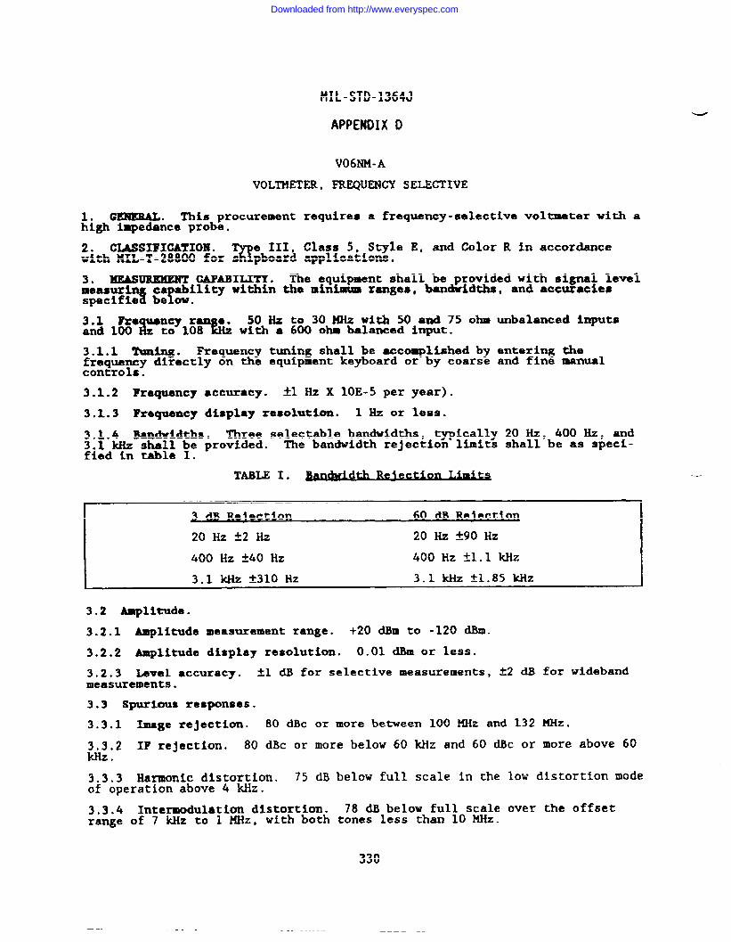
MIL-STD-1364J
APPENDIX D
V06NM-A
VOLTMETER, FREQUENCY SELECTIVE
1. GENERAL. This procurement requires a frequency-selective voltmeter with ahigh impedance probe.
2. CLASSIFICATION .%
e III, Class 5, Style E, and Color R in accordancewith HIL-T-28800 for s pboard applications.
3. HEASUIUMENT CAPABILITY. The equipment shall be provided with signal level
specifies be?ow.measurin ca ability within the minimum ranges, bandwidths, and accuracies
s. 50 Hz to 30 MHz with 50 and 75 ohm unbalanced inputs~; ~~~?~~ with a 600 ohD balanced input.
3.1.1 Ihllling. Frequency tuning shall be accomplished by entering thefrequency directly on the equipment keyboard or by coarse and fine manualcontrols.
3.1.2 Frequency accuracy. *1 Hz X 1OE-5 per year).
3.1.3 Frequency display resolution. 1 Hz or less.
3.1.4 Bandwidths. Three selectable bandwidths, typically 20 Hz, 400 Hz, and3.1 kHz shall be provided. The bandwidth rejection limits shall be as speci-fied in table I.
3 a W ection 60 dB R lectio~e
2oHzk2Hz 20 _ f90 HZ
400 Hz t40 Hz 400 Hz *1.1 kHZ
3.1 kHz t310 Hz 3.1 kktZ fl.85 ~Z
3.2 Amplitude.
3.2.1 Amplitude measurement range. +20 dBm to -120 dBm.
3.2.2 Amplitude display resolution. 0.01 dBm or less.
3.2.3 Level ●ccuracy. *I ~ for selective measurements, ~2 dB for widebandmeasurements.
3.3 Spurious responses.
3.3.1 Image rejection. 80 dBc or more between 100 MHz and 132 KHz.
3.3.2 IF rejection. 80 dBc or more below 60 k?izand 60 dBc or more above 60Wz .
3.3.3 Harmonic distortion. 75 dB below full scale in the low distortion modeof operation above 4 Mz.
3.3.4 Intermodulation distortion. 78 dB below full scale over the offsetrange of 7 kllzto 1 MHz, with both tones less than 10 MHz.
330
Downloaded from http://www.everyspec.com
MIL-STD-1364J
APPEMDIX D
3.4 Demodulated audio output. A demodulated audio out u~~hfl_~dbe providedwith an output level of O dBm when terminated into a 606 .
3.5 Input impedance. Operator selectable 50 and 75 ohms using BNC connectorsand 600 ohms using 3 banana jacks (high, low, and ground).
3.5.1 Unbalanced input impedance.
a. 50 ohms k7%.
b. 75 ohms *7*.
3.5.2 Balanced input Impedanca. 600 Oh!BS *12%.
3.5.3 High impedance probe. The e uipment shall be provided with a probe?that has the following characterist CS:
a. Frequency response: 50 Hz to 30 MHz.
b. Input RC: 10 Megohms or greater shunted by 10 pF or less.
c. Attenuation ratios: 10:1 * 5%, 100:1 * 5%.
d. lieximum input: 10:1 * 300V & + peak at), 100:1 k 500V (dc + peak00$at); & component not to exceed 2 .
3.6 l’unlngmeter. An analog meter shall be included as part of the amplitudemeasurement display for tuning purposes.
4. PO?lJEBSOURCE. !iIL-T-28800 nominal power source requirements are invoked.w operation at 400Hz is not ZBquired. Maximum power consumption: 15W.
5. WEIGHT . 20 kg (44 lb) maximum. .
-
331
Downloaded from http://www.everyspec.com
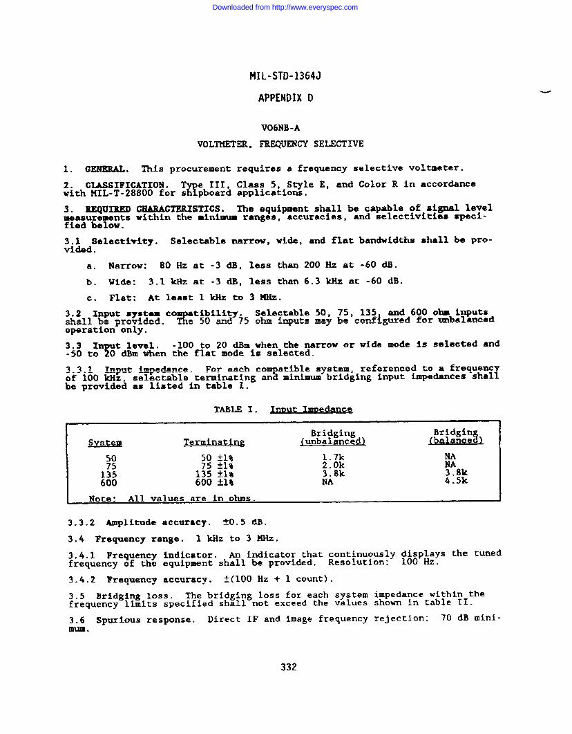
MIL-STD-1364J
APPENDIX D
V06NB-A
VOLTMETER, FREQUENCY SELECTIVE
1. GENERAL. This procurement requires a frequency selective voltmeter.
2. CLASSIFICATION . T e III, Class 5, Style E, and Color R in accor~nceX?with MIL-T-28800 for s pboard applications.
3. IUZQIKRJIDCE4EUWTERISTICS. The equipment shall be capable of signal levelmeasurements within the minimum ranges, accuracies, and selectivities speci-fied below.
3,1 selectivity. Selectable narrow, wide, and flat bandwidths shall be pro-vided .
a. Narrow: 80 Hz at -3 dB, less than 200 Hz at -60 dB.
b. Wide: 3.1 k.llzat -3 dB, less than 6.3 kHz at -60 dB.
c. Flat: At least 1 kHz to 3 MHz.
3.2 Input system cT
tibility. Selectable 50, 75, 135 and 600 ohB inputsshall be provided. e 50 and 75 ohm inputs may be configured for unbalancedoperation only.
3.3 In t level.Y
-100 to 20 dBm when the narrow or wide mode is selected and-50 to O dBm when the flat mode is selected.
3.3.1 Input impedance. For each coT
atible system, referenced to a frequentof 100 kHz, selectable terminating an minimum bridging input impedances shalIbe provided as listed in table I.
TABLE I.
Bridging BridginSystem Terminating ~unbalanced) (balance%)
50 50 ~1% 1.7k NA75 75 ~1$ 2.Ok NA135 135 *1% 3.8k 3.8k600 600 fl% NA 4.5k
3.3.2 Amplitude accuracy. *0.5 dll.
3.4 Frequency range. 1 kHz to 3 MHz.
3.4.1 Frequency indicator. ~ indicator that continuously ;~~p~lys the tunedfrequency of the equipment shall be provided. Resolution: .
3.4.2 Frequency accuracy. f(100 HZ + 1 count).
3.5 Bridging loss. The bridging loss for each system impedance within thefrequency limits specified shall not exceed the values show in table II.
3.6 Spurious response. Direct IF and image frequency rejection: 70 dB mini-mum.
332
Downloaded from http://www.everyspec.com
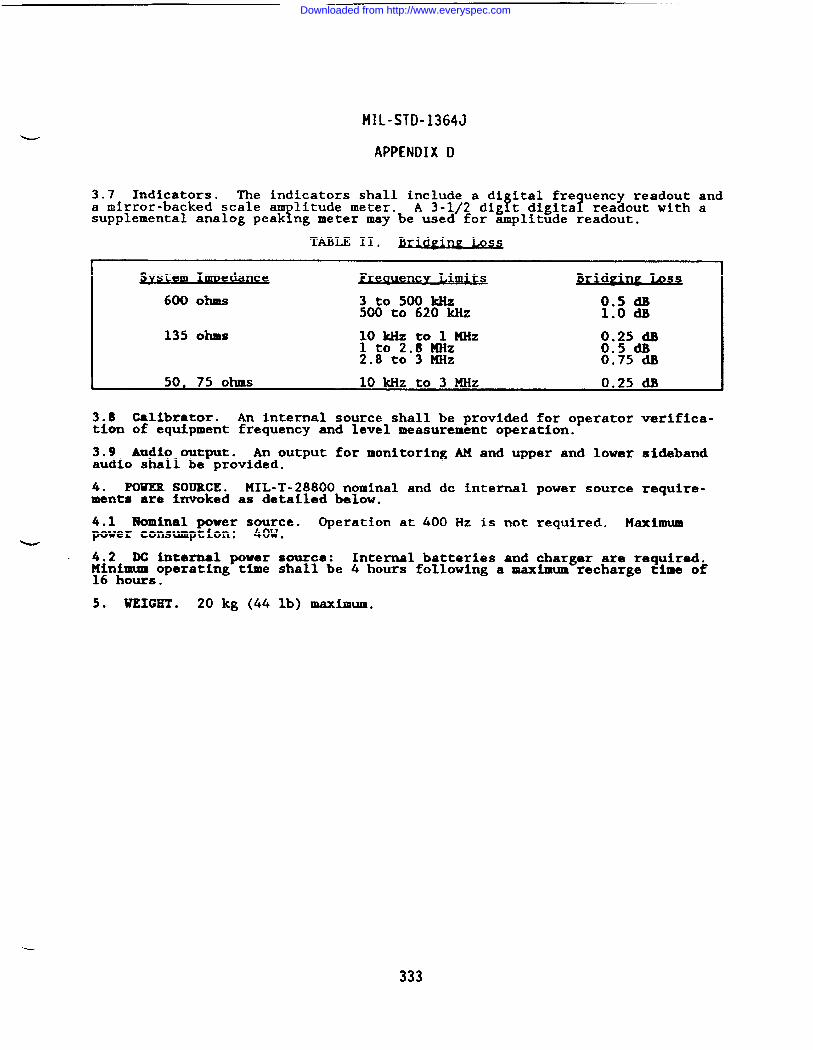
MIL-STD-1364J
APPENDIX D
3.7 Indicators. The indicators shall include a dizital freauencv readout anda mirror-backed scale am litude meter.
fA 3-1/2 dig~t digitaf readout with a
supplemental analog peak ng meter may be used for amplitude readout.
TABLE II. Ss
em ImDedance encv Limits ~ri ging Lossd
600 Ohs 3t0500kHz :.8 g500 to 620 ~Z .
135 ohms ~ot~ p&zMHz 0.25 dB0.5 dB
2.8 to”3 ~Z 0.75 a
50, 75 ohms 10 kHz to 3 MHz 0.25 dB
3.8 Calibrator. An internal source shall be provided for operator verifica-tion of equipment frequency and level measurement operation.
3.9 Audio output. An output for monitoring AM and upper and lower sidebandaudio shall be provided.
4. mm SOURCE. MIL-T-28800 nominal and dc internal power source require-ments are invoked as &tailed below.
4.1 Nominal power s~vce. Operation at 400 Hz is not required. Maximumpower consumption: .
u4,2 DC internal power source: Internal batteries and charger are required.~~n~~=operating time shall be 4 hours following a maximum recharge time of
.
5. WEIGHT . 20 kg (44 lb) maximum.
333
Downloaded from http://www.everyspec.com
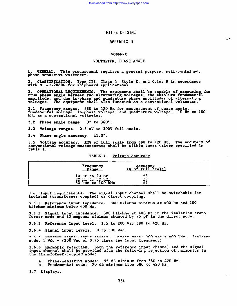
MIL-STD-1364J
APPENDIX D
V08FN-C
VOLTMETER, PHASE ANGLE
10 GP!NEML. This procurement requires a general purpose, self-contained,phase-sensitive voltmeter.
2. CLASSIFICATION .%
e III, Class 5, Style E, and Color R in accordancewith llIL-T-28800 for s pboard applications.
3. OPXRATXONAL REQU~. The equipment shall be ca able of measuring theEtrue phaaa an le between two alternating voltages, the a solute fundamental
T%litude, an the in-phase and
Yuadrature phase amplitudes of alternating
vo tageso The equipment shall a so function as a conventional vol~eter.
3.1 Frequency ranges. 380 to 420 Hz for measurement of phase an le,fundamental voltage, in- base voltage, and quadrature voltage.
!15 Hz to 100
kHz as a conventional vo tmeter.
3.2 Phase ●ngle range. O“ to 360°.
3.3 Voltage ranges. 0.3 mV to 300V full scale.
3.4 Phase ●ngle accuracy. il.O”.
3.5 Voltage ●ccuracy. *2% of full scale from 380 to 420 Hz. The accuracy ofconventional voltage measurements shall be within those values specified intable I. ~
TABLE I. Volta~e Accuracy
Frequency AccuracyRange <% of full scale)
lo Hzto20HZ -t520 Hz to 50 kHz &250 kHz to 100 kHz *5
~~~la~ t requirements.r
The signal input channel shall be switchable for(transformer coupled) or direct coupling.
3.6.1 Reference input impedance. 300 kilohms minimum at 400 Hz and 100kilohms minimum below 400 Hz.
;k~~r ~XY#n!Y ‘pea”=”300 kilohms at 400 Hz in the isolation trans-
megohms minimum shunted by 75 pF in the direct mode.
3.6.3 Reference input level. 1.5 to 200 Vac 380 to 420 Hz.
3.6.4 Signal input levels. O to 300 Vat.
3.6.5 Maximum si al input levels. Direct mode: 300 Vac + 400 Vdc. Isolatedmode: 1 Vdc + (30~Vac or 0.75 times the input frequency).
3.6.6 Harmonic re ection.!
Both the reference input channel and the signalinput channel shal be provided with the following rejection of harmonics inthe transformer-coupled mode:
Phase-sensitive modes: 55 dB minimum from 380 to 420 Hz.t: Fundamental mode: 20 dB minimum from 380 to 420 Hz.
3.7 Displays.
334
Downloaded from http://www.everyspec.com
MIL-STD-1364J
APPENDIX D
3.7.1 Phase angle display. Resolution: 0.2°.
3.7.2 Voltage display. Resolution: tO.2% of full scale.
4. POUER SOURCE. MIL-T-28800 nominal power source requirements are invoked.Operation at 400 Hz is not required. Maximum power consumption: 15W.
5. WEIGHT . 20 kg (44 lb) maximum.
.,.
Downloaded from http://www.everyspec.com
MIL-STD-1364J
APPENDIX D
V08KR-D
VOLTMETER, PHASE ANGLE
1. GENERAL. This procurement requires a general purpose, self-contained,wideband phase angle voltmeter.
2. CLASSIFICATION .9
e III, Class 5, Style E, and Color R in accordancewith liIL-T-28800 for s ipboard applications.
3. OPERATIONAL REQUIREMENTS. The equipment shall be ca able of measuring theEtrue phase an le between two alternating volts es, the a solute fundamental
E famplitude wit out the presence of reference vo tage, and the In-phase andquadrature-phase am litude of alternating voltage over the frequency rangespecified below. & e equipment shall be ca able of measuring the in- base andquadrature nulls of the input signsl, Eand s all have the capability oI! baseshifting the reference 360 . fThe equipment shall function as a convent onalvoltmeter measuring the total voltage over the specified frequency range.
3.1 Frequency range. 50 Hz to 25 kHZ.
3.2 Phase angle range. 0° to 360°.
3.3 Voltage range. 300 uV to 300 Vrms full scale.
3.4 Signal channels.
3.4.1 Reference channel. The reference signal channel shall be isolated fromthe e uipment chassis and the input signal charnel. Reference signal range:150 m?rms to 150 Vrms.
3.4.2 Input channel. The signal channel shall be isolated fromchassis and the reference signal channel. Input signal range: 1Vrms .
the equipment❑vrlns to 300
3.5 Harmonic rejection. 45 dB minimum.
3.6 Phase accuracy. 2-.5’ from 50 Hz to 17 ~z, fOo80 from 17 ~z to 25 ~z.
3.7 Voltage accuracy. t2% of full scale.
3.8 Input RC.
3.8.1 Reference channel. 1 megohm or greater paralleled by 100 pF or less.
3.8.2 Signal channel. 1 megohm or greater paralleled by 100 pF or less.
3.9 Nulling sensitivity. 3 UV or less for in-phase and quadrature modes.
3.10 Readout devices.
3.10.1 Phase angle readout device. The phase an le shall be displayed infdegrees on either an analog meter calibrated dia (s), or on an equivalent
digital display. Resolution: O.$O or better.
3.10.2 Voltage readout device. The voltage shall be displa ed on a zero-centered meter or an equivalent digital dis lay.
YThe space xetween zero and
full scale on the most sensitive range shal have at least 30 equally spaceddivisions. If a digital display is rovided, polarit identification and an
!analog meter for use in nulllng shal be provided. T?e null meter shall be atleast equivalent to a panel meter having a scale length of 2 inches.
-d
4. POWER SOURCE. MIL-T-28800 nominal power source requirements a~~winvoked.Operation at 400 Hz is not required. Maximum power consumption: .
336
Downloaded from http://www.everyspec.com

MIL-STD-1364J
APPENDIX D
5. WEIGHT . 20 kg (44 lb) maximum.
337
Downloaded from http://www.everyspec.com
10 GEHERAL. This procurement
2. CLASSIFICATION .%
e 111,with HIL-T-28800 for s pboard
3. MEASUREMENT REQUIREMENTS.magnitude and phase within thefied b810W.
3.1 Input characteristics.
3.1.1 Frequency range. 1 nHz
MIL-STD-1364J
APPENDIX D
V04NN-A
VOLTMETER, VECTOR
requires a two-channel vector
Class 5, Style E, and Color Rapplications.
voltmeter.
in accordance
The equipment shall measure volts e vectors byLminimum ranges, accuracies, and 1 its speci-
to 1 GHz.
3.1.2 Isolation. 80 dB minimum.
3.1.3 In t Rc.r
0.1 me ohm or greater shunted by 2.5 pF or less. It shallEbe possib e to convert t e input to a 50-ohm impedance without the use of
adapters. The 50-ohm input connector shall b8 type N.
3“1”4‘O1ta?e-’fe” The equipment shall be capable of measuring as aminimum the O11OW ng voltages:
a. Channel A: 1.5 mv to 1 Vrms: 1 MHZ to 10 MHz.300 Uv to 1 Vrms: 10 MHz to 500 MHz.500 Uv to 1 Vrms: 500 MHz to 1 GHz.
b. Ghnnel B: 20 Uv to 1 Vrms.
3.1.5 14aximm input. AC: 2V peak. DC: ~50V.
3.2 Voltmeter characteristics.
3.2.1 Voltmeter dis lay.i
A digital readout that displays rms Volta e and dBshall be provided. n analo
%meter that has linear rms voltage and fOg dB
scales is considered accepta le.
3.2.2 Voltmeter ranges. Selectable from 100 UV to 1 Vrms in 10 dB steps.
3.2.3 Absolute voltage accuracy.
a. ~4~: 1 to 100 MHz.
b. ~a$: 100 to 400 MHz.
c. -+14*: 400 MHz to 1 GHz.
3.2.4 Voltage ratio accuracy.
a. ~0.2 dB for -60 to O dB ranges from 1 to 200 MHz.
b. ~0.z dB for -60 to -10 dB ranges from 200 MHz to 1 GHz.
c. ~0.s dB for -70 and +10 dB ranges from 1 to 200 ~z.
d. -t0,5 ~ for -70 and O dB ranges from 200 MHz to 1 GHz.
e. fl.5 dB for +10 dllrange from 200 MHz to 1 GHz.
3.2.5 Residual noise. The residual noise shall be 10 UV or less as indicatedon the meter.
338
Downloaded from http://www.everyspec.com
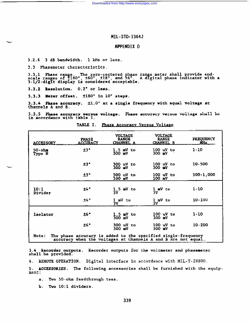
MIL-STD-1364J
APPENDIX D
3.2.6 3 dB bandwidth. 1 klizor less.
3.3 Phasemeter characteristics.
3.3.1 Phase ran e.$
The zero-centered base ran e meter shall provide end-$scale ra es of –180”, A60° ~18°, and -6°. fA d gital phase indicator with a
3-1/2-di~t display is cons~dered acceptable.
3.3.2 Resolution. 0.2° or less.
3.3.3 Metsr offset. ~180° in 10” steps.
3.3.4 Phase ●ccuracy. &toO” at a single frequency with equal voltage atChanne18 A and B.
3.3.5 Phase ●ccuracy versus voltage. Phase accuracy versus voltage shall bein accordance with table I.
TABLE I. ase Accuracv Versus vol~ e
VOLT$;E VOLT;:EPHASE
A C~~ B
50-ohm *3 o~o: Iuu to 100 Uv to 1-1o
Type N 300 mV
*3 “ 300 Uv to ;:: :: to300 mv
10-500
23“ 500 Uv to ;:: 111to 500-1,000100 mV
10:1 240 ~v5 mV to ~VmV to 1-1oDivider
*4 o 1 mV to :Vlnvto3V
1o-1oo
Isolator -+6O 1.5 mV to ::: :1 to 1-1o300 mV
~e● 300 Uv to ;:: :: to 10-200300 mV
Note: The phase accuracy is added to the specified single-frequent1accuracy when the voltages at Channels A and B are not equa .
3.4 Recorder outputs. Recorder outputs for the voltmeter and phasemetershall be provided.
4. REMOTE OPERATION. Digital interface in
5. ACCESSORIES. The following accessoriesment:
a. Two 50-ohm feedthrough tees.
b. Two 10:1 dividers.
accordance with MIL-T-28800.
shall be furnished with the equip-
Downloaded from http://www.everyspec.com
MIL-STD-1364J
APPENDIX D
c. Two isolators.
d. Two BNC adapters.
e. Ground clips.
f. Replacement probe tips.
g“ One’50-ohm power splitter.
h. Two 50-ohm terminations.
i. One ~ N(m) shorting plug.
6. POWER SOURCE. MIL-T-28800 nominal power source requirements a~~winvoked.Operation at 400 Hz is not required. Max- power corm=ption: .
7. UEICET . 20 kg (44 lb) maximum.
4
340
Downloaded from http://www.everyspec.com
STANDARDIZATION DOCUMENT IMPROVEMENT PROPOSAL.
INSTRUCTIONS
‘1. The preparing activity must complete blocks 1, 2, 3, and 8. In block 1, both the document number and revisionletter should be given.
2. The submitter of this form must complete blocks 4,5,6, and 7.
3. The preparing activity must provide a reply within 30 days from receipt of the form.
NOTE: This form may not be used to request copies of documents, nor to request waivers, or clarification ofrequirements on current contracts. Comments submitted on this form do not constitute or imply authorization towaiveany~on of the referenced document(s) or to amend contractual requirements.
1. DOCUMENT NUMBER 2.DOCUMENT DATE (WMM130)
MIL-S~-l 364J (NAVY) 7 OCTOBER 19913.DOCUMENT TITLE
GENERAL PURPOSE ELECTRONIC TEST EQUIPMENTk #ATURE Of CHANGE @tnt#& paragraph number wxi hciude prqmsed rewrite, if possibk. Attach extm shett$ 8S ~.)
8. NAME b. TELEPHONE (/l?C/UdP Area Code)
COMMANDER (1)Commercial (2) AUTOVON
NAVAL SEA SYSTEMS COMMAND (SEA 55Z3) 1(703) 602-6020 (AV) 332-6020c. ADDRESS (/rid* Zip Code)
IIF YOU DO NOT RECEIVE A REPLY WITHIN 45 DAYS. CONTACT:
WASHINGTON, DC 20362-5101 Defense Quai~ty and Standardlzatlon Office5203 Leesburg Pike, Suite 1403, Falls Church, VA 22041-3466Telephone (703) 75&2340 AUTOVON 289-2340
Downloaded from http://www.everyspec.com

Downloaded from http://www.everyspec.com