sengineering design - everyspec
TRANSCRIPT
AMC PAMPHLEI AMCP 706-133
18'1062
SENGINEERING DESIGN
HANDBOOK
MAINTAINABILITY
ENGINEERING
THEORY ANDPRACTICE
qFPRODUCED ByNATIONAL TECHNICAL
INFORMATION SERVICEV.S. DEPARIIMENT OF COMVERCI
SPRINGFIELD, VA. 2215
".EADQUARTERS, US ARMY MATERIEL COMMAND JANUARY 1976
Downloaded from http://www.everyspec.com
AMCP 706-133
This Pamphlet Contains Copyright&d Material.
DEPARTMEIT OF THE ARMYHEADQUARTERS UNITED STATES ARMY MATERIEL COMMAND
5001 Eisenhower Ave.., Alaxandria, VA 22333
AMC PAMPHLET 10 January 1976No. 706-133
ENGINEERING DESIGN HANDBOOKMAINTA!NABI LITY ENGINEERING THEORY AND PRACTICE
TABLE OF CONTENTS
Paragraph Page
LIST OF ILLUSTRATIONS ............... xvLIST OF TABLES ...................... xixPREFACE ........................... xxi
' -~-~--~ -CHAPTER I
( THE MAINTAINABILITY CONCEPTt.o-C U.0 o,
-3...L u o a ....... 1SECTION IINTRODUCTION
1- 1 General ............................. 1-1
1-2 The Importance of Maintainability ........... 1-4:.. ..1-3 Purpose of Maintainability ................. 1-6
1-4 Maintenance Engineering and Maintainability Ensi-neefing ............................ 1-7
1-4.1 The User-Producer Dialogue ............... 1-7A 1-4.2 Maintenance Engineering ................ 1-71-4.3 Maintainability Engineering ............... 1-81-4.4 Examples of Maintenance Policy Interrelation-
ships ............................ 1-81-5 Primary Considerations ................... 1--9
SECTION IIQUANTIFICATION OF MAINTAINABILITY
1-6 Maintainability Measures ................. !-111-6.1 The Exponential Case ................... . . 1-111-6.2 The Concepts of Median Repair Time and M,A X 1-111-6.3 The Repair Ratep ..................... 1-131-6.4 The Mean Time to Repair (MTTR) ........... 1-131-7 Specific Measures in Maintainibility ........... 1-141-7.1 Meas,%.;s of Maintenance Downtime ......... 1-151-7.2 Time Factors in Maintenance .............. 1-181-7.3 Availability [-actors .................... 1-201-7.4 Maintenance Manhours .................. 1-201-8 Statistical Aspects and Statistical Distr-butions ... 1-20
PRICES SUBJECT TO CHAGE
Downloaded from http://www.everyspec.com
AMCP 706-133
TABLE OF CONT.ENTS (ContiU;
Paragraph F',ge
SECTION IIIEQUIPMENT CONSIDERATIONS IN MAINTAINABILITY
1-9 Categories of Equipment ................... 1-351-9.1 Electrical-Electronic Systems .............. 1-351-9.2 Electromechanical Systems ............... 1 3(.1-9.3 Mechanical Systems ................... 1-361-9.4 Hydraulic and Pneumatic Systems ........... 1-371-9.5 OtherSystems......................... 1-371-10 Nonreversible Devices .. ................... 1-371-11 Design Guides ......................... 1-38
References ........................... 1-33
CIGAPTEK 2SYSTEM EFFECTIVENESS
SECTION 1INTRODULI.ON
2-1 General ............................. 2-12-2 System Effectiveness Concepts ............. 2-22-2.1 The ARINC Concept of System Effectiveness .... 2-2
2-2.2 The Air Force (WSEIAC) Concept ........... 2--32-2.3 The Navy Concept ..................... 2-82-2.4 Operational Readiness. Availability, and Depens-
aiflity ... ........................ 2 3
2-2.4.1 Operational Readiness .................. -9
2-2.4.2 Availability ........................ 2-9
2-2.4.3 Dependabi;lity .... ................. 2-92-2.5 Performance, Utilization, Capability, and Design
Adequacy .......................... 2-102-2.6 Total Package Planning and System Effectiveness. 2-i12-Z.6.1 Operationai States .............. .... 2-112-2.6.2 Efftt of ,Logistic Support on System Effec-
tiveness ................. ....... 14
= SECTION BSYSTEM EFFECTIVENESS METHODS
2-3 System Effectiveness Measures ............. 2-152-3.1 Typical Effectiveness Measures ............. 2-152-3.2 Associated Measures ................... . 2162-3.2.1 Performance Measures ................. . -172-3.2.2 Modes of Operation ................... !- 172-3.2.3 Reliability Measures ................... :'.-172-3.2.4 Maintainability Measures ................ :'- 172-3.2.5 Failure Rate Concepts ................. . -172-4 S atem Effectiveness Models ............... 2-182-4.1 ThePurposeofModels ................. 2 -182-4.2 Modeling Techniques ................... 2 -212-4.2.1 Op-rational Readiness Models ............. 2 -21
Downloaded from http://www.everyspec.com
AMCP 7G6-133
TABLE OF CONTENTS (Cont'd)
Paragraph Page
2-4.2.2 Availability Models .................. 2-302-4.3 Complex Models ...................... 2-382-4.3.1 The WSEIAC Model ................... 2-402-4.3.2 Other Models ....................... 2-412-5 Trade-Off Techniques .................... 2-442-5.1 General ............................ 2-442-5.2 Reliability vs Maintainability .............. 2-442-5.3 Linear Programming .................... 2-462-5.3.1 General Features of a Linear Programming
Problem and an Example ............... 2-48
2-53.2 Preliminaries to the Simplex Method ........ 2-522-5.3.3 The Simplex Method ................... 2-532-5.3.4 Other Linear Programming Formulations ..... 2-572-5.3.5 Mainienance Applications ............... 2-61
References ......................... 2-61
CHAPTER 3MAINTAINABILITY ORGANIZATION AND MANAGEMENT
3-1 General ............................. 3-13-1.1 Organizational Activities ................. 3-13-1.1.1 Maintainability Management and Admrirstra-
tion ....... ........ .............. 3-13-1.1.2 Maintainability Analysis ............ ... 3-23-1.1.3 Maintainability Design ................. 3-23-1.1.4 Maintainability Documentation ........... 3-23-1.1.5 Maintainability Coordination ............. 3-33-1.2 Organizational Structures for Maintainability .... 3-33-1.2.1 Maintainability Engineering as a Centralized
Functional Organization ............... 3-33-1.2.2 Maintainability as a System Engineering
Staff Function ...................... 3-63-1.2-3 Maintainability in a Decentralized Organization . 3-163-2 Effective Maintainability Management ......... 3-93-2.1 Management Functions Throughout the Life
Cycle ............................ 3-93-2.1.1 The System Life Cycle ................. 3-103-2.1.1.1 Concept Development ................. 3-103-2.1.1.2 Validation Phase .................... . 3-133-2.1.1.3 Production Phase .................... 3-153-2.1.1.4 Operation Phase .................... 3-15
References ........................ 3-18
CHAPTER 4MAINTAINABILITY ALLOCATION AND PREDICTION
SECTION IINTRODUCTI( ON
4-1 General ............................. 4- 14-1.1 Maintainability Factors ................. 4-1 i:i4-1.2 Methodologies .. ........ .............. 4-2
Downloaded from http://www.everyspec.com
AMCP76-133
TABLE OF CONTENTS (Cont'd)
Paragraph Page
SECTION 11
4-2 Allocation Factors ALLOCA.TION........... 4-54-2.1 Building Block Theory of Allocation ......... 4-54-2.1.1 System Description ................... 4-74-2.1.1.1 Maintenance Functional Flow Block
Diagram ......................... 4-74-2.1.1.2 System Functional-Level Building Block
Diagram ......................... 4-74-2.1.1.3 Failire Modes, Effects, and Criticality
Analysis ......................... 4-104-2.1.2 Assignment of Maintainability Factors ....... 4-104-2.1.2.1 System Maintainability Synthesis ......... 4-124-2.1.2.2 Maintainability Improvement Allocation ..... 4--124-2.2 Compatibility of Maintainability Factors ...... .. 4-134-22 Statistical Interdependence .......... ..... 4-13
SECTION IIIMAINTAINABILITY PREDITION
4-3 General ............................. 4-154-4 Development of a Maintainability Criterion ..... 4-154-4.1 Basic Assumptions ...................... 4-154-4.1.1 Time-to-repair as an Index ............... 4-164-4.1.2 Time to-repair Characteristics ............. 4-174-4.2 Prediction Elements ................. 4-174-4.2.1 Failure Rates-Schedulec Maintenance Rates... 4-184-4.2.2 Repair Time ........................ 4-194-5 Prediction Methods ..................... . - 194-5.1 Extrapolation Methods ................. 4-19
4-5.1.1 Predictio. By Srmoothiing ................ 4--204-5.1.2 Prediction By Assuming Distribution
Characteristics ...................... 4-204-5.1.3 Nonparame.ric Statistics ................ 4-214-5.1.4 Estimation of the Distribution Function ...... 4-214-5.1.5 Estimation of the Population Median ........ .4 -224-5.2 Time Summation Schemes .............. 4-264-53 Simulation Methods .................... 4-304-5.3.1 Random Variates for Simulations .......... 4-314-5.3.2 Computer Generation of Random Variates .... 4-314-5.3.3 Example ........................... 4-324-5.4 Expert Judgment Method ................ 4-384-5.5 Matrix Tabulation Methods ................ 4-394-5.5.1 The ARINC Symptom Matrix ............. 4-394-5.5.2 The EPRG Symptom-hypothesis Matrix ...... 4--39
References ......................... 4-40
iv
Downloaded from http://www.everyspec.com
AMCP 70C-133
TABLE OF CONTENTS (Cont'd)
Paragraph Page
CHAPTER 5MAINTAINABILITY DESIGN TECHNIQUES AND INTERFACES
SECTION IMAINTAINABILITY DESIGN AND MAINTENA1 %.E
SUPPORT TLANNING
5-1 General ......... ................... 5-15-2 Integrated Logistic Support and Maintenance
Support Planning ..................... 5-25-3 Operation Concept ..................... 5-35-4 Maintenance Concept ................... 5-45-4.1 Levels of Maintenance .................. 5-75-4.1.1 Organizational Maintenance .............. 5_. 7
5-4.1.2 Direct Support Maintenance .............. 5-75-4.1.3 General Support Maintenance ............. 5-75-4.1.4 Depot Maintenance ................... 5-95-4.2 Maintenance Policies .................... 5-95-5 Development of Maintainability Design Require-
ments ............................. 5-105- '.1 Maintenance Time Phases ................ 5-105-5.2 Corrective Maintenance Downtime .......... 5-16
SECTION IIMAINTAINABILITY DESIGN CONSIDERATIONS
5-6 Maintainability and System Design ........... .. 5-195-6.1 Input Information-The Background for Main-
tainability Design ..................... 5-215-6.2 Formulation of the Value Model (Effectiveness
Criteria) ................... ....... . 5-215-63 Synthesis of Maintainability Design Models ..... 5-215-6A Maintainability Analysis ................. 5-215-6.5 Maintainability Evaluation ............... 5-225-6.6 Dec,.ion ........................... 5-225-6.7 Optimization ......................... 5-225-6.8 Output Information .................... 5-225-7 A Model of Maintainability Design ........... 5-235-7.1 Maintainability Design Requirements ......... 5-235-7.2 An Illustration of Maintainability Design-
Fault Detection ...................... 5-295-7.3 Monitoring as a Fault Detection Techaique ..... 5-325-8 Maintainability Design Characteristics ......... 5-345-8.1 Checklists .......................... 5-345-8.1.1 Checklist Information Pertaining to Main-
tenance Downtimes ................... 5-375-8.1.2 Checklits for Consideration of Maintain-
ability Design Factors ................. 5-375-8.2 Packaging ........................... 5-375-8.2.1 Accessibility ........................ 5-37
Downloaded from http://www.everyspec.com
AMCP 706-133
TABLE GF CONTENTS (Cont'd)
Aagraph Jle
5-8.2.2 Logical 5,ow Packaging (Functional Modulari.zation) ........................... 5-40
5-8.3 Standardization and Interchangeability ....... 5-415-.A. Human Factors Considerations ............. 5-435-8.4.1 Man and His Characteristics end Capabilities ... 5--46
5-8.4.1.1 Humar, Body Measurement (Anthroponetry) . 5-465-8.4.1.2 Man's St-sory Capability and Psychological
Makeup . ......................... 5--465-8.4.13 Man as an Information Processor .......... 5-475-8.4.1.4 Man's Adaptability ................... 5-475-8A.2 Environmental Considerations ............ 5-475-8.4.2.1 Temperature, Humidity, and Air Circulation .. 5-485-8.4.2.2 Illumination ....................... 5-485-8.4.2.3 Noise ........................... 5-505-8.4.2.4 Vibration ......................... 5-505-8.4.2.5 Work Space Arrangement ............... 5-525-8.4.3 Human Factors Elements in Designing for
Maintainability ...................... 5-535-8.5 Safety ............................. 5-545-8.5.1 System Safety Analysis ................. 5-555-8.5.1.1 Hazard Analysis ..................... 5-55
5-8.5.1.2 Failure Modes, Effects, and Criticality Analysis(FMECA) ........................ 5-56
5-8.5.A.3 Fault Tree Analysis ................... .5-575-8.5.2 Safety and Maintainability Design .......... 5-585-8.6 Test and Checkout .................... 5-625-8.6.1 Elements of Test and Checkout ............ 5-635-8,6.2 Purpose and Type of Tests .............. 5-655-8,.6.2.1 Test Methods ....................... 5-655-8.6.2.2 Types of Tests ..................... 5-675-8.6.2.2.1 System vs Component Tests ............. 5-675-8.6.2.2.2 Static vs Dynamic Tests ................ 5-675-8.6.2.23 Open-loop vs Closed-loop Tests ........... 5-685-8.6.2.2.4 On-hne vs Off-line ................... 5-685-8.6.2.2.5 Quantitative vs Qualitative .............. 5-685-8,6.2.2.6 Go/no-go vs Interpretive ............... 5-685-8.6.3 Classification of Test Equipment ........... 5-685-8.63.1 Method of Operation ................. 5-695-8.6-3.2 Point of Application .................. 5-695-8.63.3 Design Origin ....................... 5-695-8.6.3.4 Versatility ........................ 5-705-8.63.5 Interface W'th Prime Equipment .......... 5-705-8.6.4 Automatic Test and Checkout Equipment ..... 5-715-8.6.4.1 Rapidly Advancing Technology ........... 5-715-8.6.4.2 Broader Scope of Application ............ 5-715-8.6.43 Greater Emphasis on Equipment Degradation.. 5-715-8.6.4.4 More Effective Self-testing Capabilities ...... 5-725-8.6.4.5 ATE Designs Compressed/ATE Application
Broadened ........................ 5-72vi 5-8.6.4.6 ATE Cost ......................... 5-72
5-8.6.4.7 Standardization of ATE ............... 5-72
Downloaded from http://www.everyspec.com
AMCP 706-133
TABLE OF CONTENTS (Coft'd)
Pargraph Page
5-8.6.4.8 ATE Policies ....... ................ 5-735-8.6.5 Diagnostic Techniques .................. 5-735-8.6.6 Test and Checkout Design Considerations .... 5-745-8.6.6.1 Test Philosophy ..................... 5-745-8.6.6.2 Test Equipment Design Characteristics ...... 5-7E5-8.7 Trade-offs ............ .............. 5-7(5-8.7.1 Reability-Maintainability-Availability Trade-off. 5-785-9.7.2 The NSIA Trade-off Technique ............. 5-835-8.7.3 RepairiDiscard Tn de-off Decisions ......... 5-865-8.7.3.1 RepairlDiscard M dels ................. 5-935-8.7-3.2 Impact of Repair/Discard Decisions on
Maintainbility ...................... 5-955-,.8 Cost Considerations ..................... 5-97
References ........................... 5-98
CHAPTER 6MAINTAINABILITY TEST AND DEMONSTRATION
SECION 1INTRODUCTION
6-1 General Requirements ................... 6-16-1.1 Planning and Control Requirements ......... 6-26-2 Test Approaches ....................... 6-66-2.1 Typs ofT. t .-rn-nhes ................ 6-106-2.2 User-Service Tests ..................... 6-126-2.3 Task Selection ....................... 6-13
SECTION IIMETHODS OF TES'ING
6-3 Test Techniques ....................... 6-156-4 Samoling and Sample Size Selection .......... 6-166-4.1 Statistical Methods in Sample Selection ....... 6-166-5 Reduction of Testing ................... 6-25F-6 Demonstration Data ..................... 6-25
6-6.1 Collection of Demonstraticn Data ........... 6-256-6.2 Reporting, Storage, and Recovery of
Demonstration Data ................... 6-266-7 Demonstration Methods .................. 6-266-7.1 Sequential Test Plans ................... 6-27;--7.2 Test Pha Based on the Central Limit Theorem.. 6-276-7.2.1 Tests in MIL-STD-471 ................. 6-326-7.2.2 The Test of MINLSTD-473 ............... 6-356-7.3 Equipment Repair T-te (ERT) Techniques ..... 6-366-7.4 Technique. when Underlying Distributions of
Data art Unknown .................... 6-376-7.4.1 Procedure of MILSTD473 ............. 6-376-7.4.2 Procedures of MIL-STD-471 ............. 6-386-7.5 Goodness-of-Fit Tecmilques ............... 6-416-7.5.1 Chi.square Proc-Aures ................. 6--1 vii
-5-7.5.2 Exponentih1 Distribution ................ 6-42
Downloaded from http://www.everyspec.com
AMCP 706-133
TABLE OF CONTENTS (Cont'd)
Fargraph Page
6-7.5.3 Normal Dintribution ................... 6-436-7.5.4 Lognormal Distribution .................. 6-436-7.5.5 Kolmogorov-Smimov Tests ............... 6--436-8 Confidence Intervals for Demonstration Methods.. 6-456-8.1 Normal Distribution .................... 6-456-8.1.1 02 Known .......................... 6-456-8.1.2 a2 Unknown ......................... 6-486-8.2 Lognormal Distribution ................. 6-48
6-8.3 Exponential Distribution ................. 6-496-8.4 Binomial Distribution .................... 6-50
References ........................... 6-50
CHAPTER 7ECONOMETRICS
SECTION 1COST FACTORS & ANALYSES
7-1 Introduction .......................... 7-17-1.1 Maintainability Costs ................... 7-17-1.2 Ownerhip Costs ...................... 7-17-2 Cost Factors of Equipment ................ 7-27-2.1 Indiidual Cos! Elements ................ 7-27-2.1.1 Investment ......................... 7-37-2.1.1.1 Prime Equipn .. t .................... 7-37-2.1.1.2 Support Equipment ................... 7-37-2.1.1-3 System Test and Evaluation ............. 7-37-2.1.1.4 System Engineering/Management ......... 7-37-2.1.1.5 T . ..... ..................... 7-37-2 1.1.6 Data ..... ....................... 7-37-2.1.1.7 Operational Facilities ................. 7-37-2.1.1.8 Replacement Components and Repair Parts... 7-37-2.1.2 Operations and Support Costs ............ 7-37-2.1.2.1 Organizational Maintenance Man-owai ...... 7-47-2.1.2.2 Maintenance, Repair, and Modification
Suppo'rt ......................... 7-47-2.1.2.2.1 Modifications ....................... 7-47-2.1.2.2.2 Maintenance and Repair (Other Than
Overhaul) ........................ 7-47-2.1.2.23 Overhaul .......................... 7-47-2.1.2.3 Organizational Material Support .......... 7-47-2.2 System: and Subsystems .................. 7-47-2-3 Cost Element Breakdown Techniques and Coding
S)st-ms for Cost Structures ............... 7-47-3 Cost Anlysis ......................... 7--77-3.1 Cost Estimatin in Early Concept States ....... 7-77-3.1.1 Analogous Systems ................... 7-87-3.1.2 Example: Source Systems With Weapon System
Features ......................... 7-87-3.1.3 Prior System Data .................... 7-9
viii 7-3.2 Prediction and Cost Analysis Data .......... 7-9-3.2.1 Manpowa.r Data ...................... 7-9
---- 71
Downloaded from http://www.everyspec.com
AMCP 7W61 33
TAELE OF CONTENT- (Contd)
PRagaph Page
7-3.2.2 Material Data ....................... 7-107-3.2.3 Time Data ......................... 7-167-3-3 Maintainabhuty and Manpower Consumption ... 7-1i7-3A Methods for T-hrow-Aw.ay Versus Repair Design
Decisions .......................... 7-1i
SECTION IlCOST ANALYSIS
7-4 Model Development ....................... -13
7-4.1 Cost Estimating Relationships and BasicB,.ilding Blocks ..................... 7-13
7-4.1.1 Parameters and Planning Factors .......... 7-137-4.; .2 Variables ......................... 7-137-4.13 Equations ......................... 7-137-4.1.4 Engineering Cost Estimate .............. 7-147-4-2 Statistical CER Developrnt .............. 7-147-4-3 Cost Estimating Relationships ............. 7-167-43.1 Generalied Estimatioa for Budgetary
Purposes ......................... 7-167-43.2 Detailed Cost Estimating Relationdps-
Parar eters ....................... 7-167-432.1 Annual Operating Hours for Equipment (0) 7-167-4322 Structural Cost of End Itern!Component
(CAQ) ......................... 7-187-4323 Manpower Per Repair Action (MR) ........ 7-187-432.4 Manpower Utilization Rate (UI) ........ 7-17-4.32.5 ire-e-t. j Cost of Manpower (CP) ....... 7-18
7-4.32.6 Reorder Cost of Feld (Repair) Parts(CH, C"I) ................... 7-18
7-4.32.7 Size and Weight of Item/Component (EIS.EIW) ............................ 7-18
7-432.8 Packaging 2ad Transportation Costs (CTRI) . 7-187-432.9 Storage and Shop Space Costs (CSI. CSA) 7-187-432.10 Traizng Costs (CM, M )............ ... 7-187-432.11 Annual Administrative Cost Per Item
(CIA) .......................... 7-197-432.12 Cost of Entr) of New Line Items in the
Federal Sup bly System (CII) ........... 7-197-433 Cost Estimating Relationship Examples ..... 7-197-43.3.1 Related Cost (0.00) .................. 7-197-4332 Publication Costs (2.04) .............. . 7-197-4333 Building Costs (2.051) ............... 7-207-433.4 Mainteraae Equpment Costs (2-052) .... 7-207-4335 Logistic Catalogn Co-ts (2.07) ......... 7-207-43-3.6 Acquisition Cost of Item (3.04) ......... 7-207-43-3.7 Repair Cost; Maintenance (4.012) ....... 7-207-433.8 Repair Costs; Norepairable Parts (4-021) 7-217-433.9 Repair Costs; Repairable Parts (4.022).... 7-217-433.10 Logistic Processing Costs (4.031) ........ 7-24
Downloaded from http://www.everyspec.com
AMCP 706-133
TABLE OF CONTENTS (Cont'd)
Paragraph Page
7-4.3.3.11 Logistic Cataloginr Annual Costs (4.032) .... 7_2 A
7-4.3.3.12 Transportation Costs (4.05) ............. 7-247-4.3.3.13 Building Maintenance Costs (4.06) ........ 7-257-4.3.4 Costs Per Unit of Use ............. .... 7-257-4.4 Cost States of a System; Time Profiles ........ 7-257-4.4.1 Time Phasirg ....................... 7-257-4.4.2 Discounting ........................ 7-287-4.4.3 Escalation ......................... 7-287-4.4.4 CER's with Escalating and Discounting ....... 7-287-5 Cost Analysis Utility .................... 7-317-5.1 Costing System Availability ............... 7-317-5.2 System Development-Alternatives .......... 7-327-5.2.1 The Value of Information ............... 7-327-5.2.2 Selection of Maintenance Interval and Manpower
Levels ........................... 7-327-6 Economics of Trade-Off Decisions; Applied Cost
Models . ............................ 7-337-6.1 The Geometry of Trade.Offs .............. 7-347-6.2 Mathematical Models for Trade-Off Decisions ... 7-407-6.2.1 Formulating the Trade-off .............. 7-437-6.2.2 The Point Trade-off ................... 7--437-6.2.3 The Simple Descriptive (Accounting) Trade-
off Model ......................... 7-447-6.2.4 The Descriptive Trade-off Model With Decision . 7-447-6.2.5 Prescriptive Trade-off Models ............. 7-457-7 Life Cycle Costing ...................... 7-487-7.1 Life-Cycle Costing Management-Large-Scale
System Example ..................... 7-487-7.1.1 System Parametric Analysis .............. 7-487-7.1.2 Subsystem Design and Special Studies ....... 7-497-7.1.3 Final Life-cycle Costing and Procurement
Analysis ............. ............ 7-497-7.1.4 Life-cycle Cost Evaluation ............... 7-507-7.1.5 Life-cycle Cost Validation and Moritoring .... 7-507-7.2 t.ife.Cycle Costing Management-Subtasks ..... 7-50
1c ,-erences .......................... 7-50
CHAPTER 8STATISTICAL MAINTAINABILITY
SECTION IINTRODUCTION
8-1 General ............................. 8-18-1.1 Use of Statistics in Technology ............. 8-18-1.2 Applying Statistics to Maintainability ........ 8-18-1.3 Statistical Analysis of Maintainability Data ..... 8-28-1.3.1 Statistical Tests ...................... 8-28-1.3.2 Consumer and Producer Risks ........... 8-48-1.3.3 Sequential Testing .................... 8-5
x 8-1.4 Sampling Problems in MaintainabilityDemonstration ...................... 8-5
Downloaded from http://www.everyspec.com
AMCP 706-133
TABLE OF CONTENTS (Cont'd)
Parag~aph Page
8-2 Maintainability Figures of Merit ................ 8-6[8-2.1 Downtime ............................. 8-68-2.2 Specifications ........................... 8-78-3 Probability Distributions in Maintainability ... 8-8
8-3.1 Basic Laws of Probability ................... 8-88-3.2 Cumulative Distribution and Probability Density
Functions............................8-98-3.3 Measures of Central Tendency ................ 8-108-3.4 Other Meastircs ........................... *, , * , 8-12I8-3.4.1 Measures of Dispersion .................... 8-128-3.4.1.1 Variance...................8-128-3.4.1.2 Standard Deviation ..................... 8-128-3.4.1.3 Coefficient of Variatioi-n..................8-128-3.4.2 Covariance ...................... .....- 128-3.4.3 Percentiles ............................ 8-128-3.5 Conditional Probability and Total Probability 8-138-4 Classes of Probability Distributions ............. 8-138-4.1 The Normal Ciass of Functions ............... 8-138-4.2 The Lognormal Class of Functions ............. 8-178-4.3 The Exponential Class of Functions ............ 8-218-4.3.1 The Gamma Distribution...................-218-4.3.2 The Chi-square Distribution ........... ..... 8-238-4.3.3 Exponential Distribution .................. 3-238-5 Estimation .............................. 8-238-5.1 Point Estimation Problems in General ........... 8-238-5.1.1 Maximum likelihood Estimates .............. 8-258-5.1.2 Methnd of Moments ..................... 8-258-5.2 Interval ESLLnvtes ........................ 8-25
SECTION 11PRACTICAL APPUICATION1S
8-6 Point Estimators for Specific Distributions 8-278-6.1 Estimating fromn Normal Populations...........8-278-6.2 Estimation from Lognormnal Populafions... 8-298-6.3 Point Estimates of the Exponential Distribution 8-308-7 Confidence Intervals for Specific Distributions .. 8-308-7.1 Mean of Normal Distribution ................ 8 -308-7.2 Standard Deviation of the Normal Distribution 8-318-7.3 The Lognormal Distribution ................. 8-318-7.4 Examples..............................8-318-8 Limit Theorems ......................... 8-348-8.1 Law of Large Numbers ..................... 8-348-8.2 Central Limit Thieorem.....................8-358-9 Histograms ............................. 8-358-9.1 Use .................................. 8-358-9.2 Frequency istogramn and Polygon ............. 8-36
References ..............................- 39
Xi
Downloaded from http://www.everyspec.com
AMCP 706-133
TABLE OF CONTENTS (Contd)
Paragraph Page
CHAPTER 9MAINTAINABILITY DATA
SECTION 1LIFE CYCLE DATA
9-1 Introduction ......................... 9-19-2 Data Types ........................... 9-39-2.1 Historical Data ....................... 9-59-2.2 Anthropometric Data ................... 9-69-2.3 Operational Requirments ................. 9-69-2.4 Failure Rates ........................ 9-99-2.4.1 Manufacturer's Data ................... 9-99-2.4.2 Operational Use Data ................... 9-99-3 Equipment Validation Data ............... 9-99-3.1 General ............................ 9-99-3.2 Operational Equipment Data .............. 9-109-3.3 Design Data ......................... 9-109-3.4 Proposed Parts and Components Test Data ..... 9-119-3.5 Records of Trade-off Decisions ............. 9-119-3.6 Engineering Test and Service Test Data ....... 9-129-3.7 Historical Data from Components and Parts .... 9-12
SECTION I!DATA ACQUISITION
9-4 Principles of Data Acquisition .............. 9-139-4.1 Methods of Acquiring Maintainability Data ..... 9-139-4.2 Methods of Procuring Design Package Data ..... 9-149-4.3 Data from Manufacturer's Specifications and Bro-
chures .............................. 9-149-4.4 Incident Statistics Reporting Failures ......... 9-149-4.5 Government Data Collection Systems ........ 9-149-4.6 Latest Thirking on Controlled Data Collection... 9-149-5 Central Data Bank ...................... 9-149-6 Data Retrieval and Processing ............... 9-16
References ........................... 9-16
CHAPTER 10CONTRACTING RESPONSIBILITIES
SECTION 1INTRODUCTION
10-1 General ............................. 10-110-2 Government Responsibilities ............... 1,1_ 1
10-3 Contractor Responsibilities .... ............ 10-2
xii
Downloaded from http://www.everyspec.com
AMCP 706-133
TABLE OF CONTENTS (Cont'd)
Paragraph Page
SECTION 11THE CONTRACTING CYCLE AND MAINTAINABILITY
INPUTS TO CONTRACTING
10-4 General ..... ....................... 10-510-5 Maintainability Inputs to Contracting ......... 10-510-6 Government Furnished Equipment ........... 10-710-7 Design Reviews ........................ 10-710-8 Design Changes ........................ 10-8
APPENDIX ASPECIMEN FOR MAINTAINABILITY PROGRAM REQUIREMENTS
A-1
INDEX ............................. I-I
xiii
Downloaded from http://www.everyspec.com
AMCP 706-133
LIST OF ILLUSTRATIONS
Figure No. Title Page
1-1 The Framework of System Design ............ 1-21-2 The Lever Effect ....................... 1-51-3 Two Exponential Maintainability Functions ..... 1-121-4 Equipment Repair Time (ERT) ............. 1-171-5 Maxunum Maintenance Time "A I ..........I II1-191-6 Time Relationship ...................... 1-211-7 Availability Nomograph ................... 1-221-8 Normal Density Function ................. 1-241_9 Normal Cumulative Distribution ............. 1-251-10 A Typical Lognormal Distribution ........... 1-261-11 Normal Transformation of the Lognormcl
Distribution ......................... 1-281-12 The Poisson Distribution (a = kt = 5) .......... 1-311-13 The Binomial Distribution (N= 10 0 ,Ps = 0.9 ) .... 1-332-1 Conceots Associated With System Effectiveness... 2-42-2 System Effecti-'eness Models ............... 2-72-3 Ideal Mission State Profile ................. 2-122-4 Real Life Mission Profile .................. 2-132-5 Renewal Rate and Hazard Rate .............. 2-192-6 The Principal Tasks in System Effectiveness
Evaluation ................. ........ 2-22
2-7 The Process of System Effectiw-%:; evaluation ... 2-232-8 Availability of System With MaintenanL, Time
Ratio 1:4 ........................... 2-322-9 Average and Pointwise Availability ........... 2-342-10 Hypothetical History of Machine Gun Usage ..... 2-372-11 Renewal Process in Terms of Rounds Fired ...... 2-392-12 Interrelationships of Effectiveness Models ...... 2-422-13 Complex Models Relationship .............. 2-432-14 Block Diagram of a Series System ............ 2-452-15 Reliability-Maintainability Trade-offs ......... 2-472-16 Constraints and Feasible Region ............. 2-502-17 Equal Profit Lines Superimposed on the Feasible
Region ............................. 2-513-1 Maintainability Engineering as a Line Function ... 3-43-2 Centralized Maintainability Engineering Organiza.
tion .............................. 3-53-3 Maintainability Engineering as Part of System
Engineering/System Effectiveness ........... 3-73-4 Example of Decentralized Maintainability Func-
tions in a Matrix Organization ............. 3-83-5 The System Life Cycle ................... 3-113-6 Stages in the Concept Development Phase ....... 3-123-7 Validation Phase ....................... 3-143-8 Maintenance Engineering Analysis During Early
Program Stages ....................... 3-163-9 Stages in Engineering Development Aspects of Preceding page blank
Validation .......................... 3-174-1 Typical Illustration of Maintenance Functional
Flow Block Diagram (Top Level Flow) ....... 4-8 x"
Downloaded from http://www.everyspec.com
= "M
AMCP 706-133
LIST OF ILLUSTRATIONS (Cont'd)
Figure No. Title Page
4-2 Functional Analysis of General SupportMaintenance Level ..................... 4-9
4-3 Functional-level Building Block Diagram ....... 4-114-4 Empirical Cumulative istribution Function ..... 4-234-5 Confidence Band for True, Unknowp Cumulative
Distribution Function ................... 4-254-6 Solving x = P-1 (u) Graphically ............ 4-334-7 Cumulative Distribution Function for a Discrete
Random Variable ...................... 4-344-8 Generating a Random Variate from a Discrete
Distribution ......................... 4-354-9 Simulated Valve Failure Experience ........... 4-375-1 Flow Chart of Maintenance/Supply Support Plan-
ning .............................. .5 -55-2 Primary Subsets of Maintenance Activities ...... 5--145-3 Major Events and Activities Comprising Corrective
Maintenance ......................... 5-155-4 Steps in Active Downtime ................. 5-175-5 The System Design Process ................ 5-205-6 Maintainability Design Relationships ........... 5-24
5-7 Maintainability Design Relationships .......... 5-255-8 Maintainability Design Relationships .......... 5-265-9 The Fault Detection Process ............... 5-305-10 Flow Chart-Fault Detection Process ......... 5-315-11 Test Equipment Complexity vs Detection Time
and Cost . ........................... 5-335-12 Maintainability Design Considerations ......... 5-355-13 The Man-Machine System ................. 5-455-14 Effective Temperature (ET) Curves ........... 5-495-15 Fault Tree Example ..................... 5-595-16 Block Diagram-Test and Chekcut System .... 5-645-17 Reliability.Maintainability-Availability Relation-
ships ............................. 5-795-18 Availabihty as a Function of XVp ............. 5-805-19 Availability as a Function ofMTBFand 1/MTTR.. 5-815-20 Basic Rating Scale ...................... 5-855-21 Replaceable Power Supply Evaluation ......... 5-895-22 Plug-in Transformer Evaluation ............. 5-905-23 Flow Chart of Replace/Repair/Discard Decisions.. 5-915-24 Repair vs Discard Decision Points ............ 5-926-1 Decision Points Requiring Maintairability Test
Data .............................. 6-76-2 Probability Statement ................... 6-186-3 Trade-off Between Accuracy and Confidence .... 6-216-4 Graphic Presentation of Eq. 6-12 ............ 6-226-5 Graphic Representation of Plans A, and B2 of Test
Method 1 ........................... 6-317-1 Estimated Cost Per Military Manhour vs Time .... 7-227-2 Estimated Cost Per Cicilian Manhour vs Time .... 7-23
xvi 7-3 Depot Supply Action Cost v Weight .......... 7-267-4 Hypothetical Availability Surface ............ 7-36
Downloaded from http://www.everyspec.com
AMCP 706-133
LIST OF ILLUSTRATIONS (Cont'd)
F18ure No. Title Page
7-5 Two-dimensional Projection of AvailabilitySurface ............................ 7 -37
7-6 Hypothetical Budget Curves ............... 7-387-7 Optimal Combinations of M and R ........... 7-397-8 Cost Along Availability Isoquant ............ 7-417-9 Cost Curve for Figure 7-8 ................. 7-42
8-1 Probability Distribution of Dnwntime ......... 8-38-2 The Standard Normal Distribution N(XI0,1) ..... 8--58-3 Shapes of Normal Densities for Different o's..... 8-168-4 Three Lognormal Distributions With the Same
Median M = 15 min .................... 8-208-5 Shapes of Some Gamma pdf's for X = 1 ........ 8-248-6 Two-sided 1 - o Confidence Interval ......... 8-328-7 One-sided Upper I - a Confidence Interval ..... 8-338-8 Relative Frequency Histogram .............. 8-378-9 Cumulative Frequency Diagram ............. 8-38
9-1 Computer Print-out of the Operational MT8FAchievement ......................... 9-4
9-2 Graphic Display of Historical Data ........... 9-7
xviixvmi
Downloaded from http://www.everyspec.com
AMCP 706-133
LIST OF TABLES
Table No. Title Page
2-1 Defnitions ........................... 2-5
2-2 Simplex Tableau ....................... 2-532-3 Initial Simplex Ta*Jleau ................... 2-552-4 Second Tableau ........................ 2-552-5 Third Tableau .......................... 2-572-6 Initial Tableau ......................... 2-592-7 Second Tableat ......................... 2-592-8 Third Tableau ......................... 2-602-9 Fourth Tableau ....................... 2-604-1 Values of e(n ) ....................... 4-244-2 Maintenance Cost (Expressed in Mechanics Time).. 4-364-3 Analysis of .aternative Maintenance Policies ..... 4-385-1 Classifiuaticn of Maintenance Policies and Goals... 5-35-2 Categories of Maintenance in a Theater of Opera-
tions ....................... 5-95-3 Examples of Maintenance Poicies ........... 5-115-4 Maintainability Dtsign Characteristics ......... 5--275-5 Most Often Mentioned Maintainability Design Factors
and Thehi Cardinal Weighting .............. 5-285-6 Maintenance Downtime Checklist ........... 5-385-7 Recommended Equipment Accesses ........... -75-405-8 Recommended Illumination Levels ..... 5-515-9 Sound Intensity Levels ............. 5-525-10 Scope of Analyses ..................... 5-615-11 Alternative Design Trade-Off Configurations ..... 5-825-12 Cost Comparison of Alternative Design Config-
urations ........................... 5-835-13 Data Sheet-Replaceable Power Supply (Solution
No. 1) ............................. 5-875-14 Data Sheet-Plug-In Transformer (Solution No. 2) 5-88
Quantititive Factors in Repair/IDiscard Models .... 5-94Effect of Repair/Discard Consideration on Maintain-
ability Design Factors ................... 5-%6-A Maintainability Test Data Requirements at
Designated Decision Points ............... 6-86-2 Trade-Off Between Accuracy and Confidence for a
Sample of Size n = 100 for Example 6-1a ...... 6-206-3 Accept/Reject Criteria for Plan A, of Test Method 1
(From Table I, MIL-STD-471) ............. 6-286-4 Accept/Reject Criteria for Plan B1 of Test Method 1
(From Table II, MIL-STD-47 1) ............. 6-29;--5 Accept/Reject Criteria for Plan B2 of Test Method 2
(From Table III, MIL-STD-471 )............. 6-30
xix
Downloaded from http://www.everyspec.com
AMCP 706-133
LIST OF TABLES (Cont'd)
Table No. Title Page
6-6 Risks Associated with the Use of Plans A,, B,and B2 . . . . . . . . . . . . . . . . . . . . . . . . . . . . . . . 6-32
6-7 Standard Normal Deviate Exceeded With Proba-bility a ............................. 6-36
6-8 Sampling Plans for Specified Po, Pi , a, and l WhenPo is Small (e.g.,po <0.20) ............... 6-39
6-9 Acceptance Numbers: Maximum Number of Tasksin a Sample of 50 Which May Exceed the CriticalT nie T .............................. 6-40
6-10 N For Certain Combinations of Z and P ........ 6-406-11 Critical Values for the Kolmogorov-Shirnov Test
of Goodness of Fit ..................... 6-446-12 Tablc of Critical Values of D (Testing for Exponen-
tiality) .............................. 6-466--13 Table of Critical Values of D (Testing for Nor-
mality) ............................. 6-477-1 Simple M-Related Cost Breakdown ........... 7-67-2 Cost Breakdown Dimensionality Change ........ 7-77-3 Cost Data Sources ..................... 7-97-4 Icremental Force Dependent Maintenance Related
Annual Operating Costs ................. 7-177-5 Factor SII ........................... 7-217-6 Factor U7 ........................... 7-217-7 Factor 3 ....................... ... 7-247-8 Factor S21 ........................... 7-247-9 Cost of Supply Processing Action ............ 7-257-10 Piecewise Costing .... .................. 7-277-11 Discounted Present Value Calculation ......... 7-297-12 Cost Calculation Form ................... 7-307-13 Annual Maintenance Cost of a Hypothetical
System ............................. 7-348-1 Common Percentiles of N(U/0,l) ............ 8-148-2 Some Distributions of the Exponential Family .... 8-228-3 Values of an ......................... 8-288-4 Values of b . ......................... 8-288-5 Tabulation of Observations ................ 8-36
xx
_A
Downloaded from http://www.everyspec.com
AMCP 706-133
PREFACE
The Engie-erirg Design Handbooks of the US Army Materiel Command haveevolved over a number of years for the purpose of making readily available basicinformation, technical data, and practical guides for the development of military equip-ment.
This handbook was prepared by Igor Bazovsky and Associates, Inc., of ShermanOaks, California, for the Engineering Handbook Office of Duke University, primecontractor to the US Army Materiel Command. it was completed through the coor-dinated efforts of Mr. Bazovsky, Sr., and the Engineering Handbook Office of theResearch Triangle Institute, prime contractor to the US Army Materiel Command.Technical guidance was provided by an Ad Hoc Working Group under the chairman-ship of Mr. H. J. Bukowski. Headquarteis, US Army Materiel Command.
Igor Bazovsky, Sr., Igor Bazovsky, Jr., George W. Dauncey, Dr. Melvin B. Kline,Dr. Ernest M. Scheuer, and Dr. David Sternlight participated as co-authors in thewriting of the handbook; each centributed his particular expertise and practical experi-ences.
The individual chapters were written to stand on their own, with a minimum ofcross-referencing between the chapters, so that the reader can concentrate on thechapters which are of specific interest to him or to his activity. The interrelations ofmaintainabi!iy with design engineering and other disciplines (reliability, system effec-tiveness, logistic support, and life cycle costing) are highlighted through the whole text.Notation and symbols differ in some instances because of the variety of subjectscovered, and in an attempt to be consistent with notation used in the referencedstandard texts, documents, and papers pertaining to the various subjects. A standardi-zation of notation is long overdue, as evidenced throughout the maintainability andreliability literature and also in statistics and probability theory.
The En gineering Design Handbooks fall into two basic categories-those approved forrelease and sale, and those classified for security reasons. The US Army MaterielCommand policy is to release these Engineering Design Handbooks in accordance withcurrent DOD Directive 7230.7, dated 18 September 1973. All unclassified Handbookscan be obtained from the National Technical Information Service (NTIS). Procedures foracquiring these Handbooks follow:
a. All Department of Army activities having need for the Handbooks must subittheir request on an official requisiticn form (DA Form 17, dated Jan 70) directly to:
CommanderLetterkenny Army DepotATTN: AMXLEATDChambersburg, PA 17201
(Requests for classified documents must be submitted, with appropriate "Need toKnow" justification, to Letterkenny Army Depot.) DA activities will not requisitionHandbooks for further free distribution.
xxi
Downloaded from http://www.everyspec.com
AMCP 706-133
b. All other requestors-DOD, Navy, Air Force, Marine Corps, nonmilitaryGovernment agencies, contractors, private industry, individuals, universities, andothers-must purchase these Handbooks from:
National Technical Information ServiceDepartment of Commerce
Springfield, VA 22151
Classified documents may be released on a "Need to Know" basis verified by an officialDepartment ef Army representative and processed from Defense Documentation Center(DDC), ATTN: DDC-TSR, Cameron Station, Alexandria, VA 22314.
Comments and suggestions on this Handbook are welcome and should be addressedto:
ComnanderUS A-my Materiel Developmentand Readiness CommandATTN: DRCRD-TTAlexandria, VA 22333
.DA Forms 2028, Recommended Changes to Publications, which are available throughnormal publications supply channels, may be used for comments/sugge..ions.)
xxii
Downloaded from http://www.everyspec.com
.. .- . .. ... ... - - = = = -- _ r--.T- -. --- .=_
AMCP 706-133
CHAPTER 1
THE MAINTAINABILITY CONCEPT
SECTION I
INTRODUCTION
1-1 GENERAL ability to perform its intended function reliably. Inspite of this, system designers are often more concernedwith system performance '-atures-than wi!h reliabilityThe rapid technological advances which have oc- dn ~iiyand maintainability.
curred in thm past 25 years have made oper,ing reali-ties today of complex and costly systems. With the Reliability, as an engineering discipline, experiencedadvent of jet aircraft, large helicopters, nuclear subma- rapid development shortly after World War II zs an
rines, dtgital computers, automated com':|at vehicles outgrowth of the requirements of missile and space
and guns, satellites, manned spacecraft, worldw.vide technology. Within recent years, the realization thaLt, incommand and communication systems, and other ;o- many cases, a more cost-effective system can be ob-phisticated systems, greater emphasis has been placed L 'ned by trading off some reliability for the ability toon the need for efficient and effective design in terms maintain a system easily has led to a considerable re-of system perfo.rmance, support, cost, and life. search and development effort to describe a new engi-
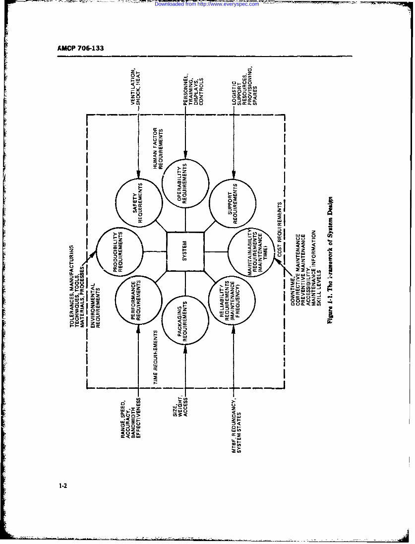
In the design of - system, man) different require- neering discipline-maintainability. This discipline isments must be taken into considertion. Some of these new not in basic concept, but rather in the concentra-are shown in Fig. I- . In addition to the more familiar tion given to its attributes, its relationship to otherrequirements of performance, pckaging, and environ-ment, there are requirements for supportability, human system parameters, the quantitative predicton andfactors, safety, reliability. maintainability, ard evaluation of maintainability during desn, and itsproduci'ility-al! of which contribute to the measure management.
of system worLh and utilizatior.. These requirements Maintainability is a characteristic of system and
exist within the constrainis of time and cost which also equipmen design. It is concerned with such systemmust be satisfied by tne system, during its acquisition attributcs as accessibility,, test points, controls, dis-period as well as its use period, plays, test equipment, tools, connectors, mainteranm
In order to achieve the effective design desired, we manuais, chicklists, tcst and checkout, and sefeay.must be able to handle qualitatively and quantitatively Maintainability engineering is the discipline which isall of these parameters in our systern models. Optimiza- corcerned with the design and development of weapontion of the syst,-em design will then consist of cost- systems and equipment to ensure effective andeffective trade-offs among pertinent parameters. The economical maintenance within prescribed readinessmethodology ,or combining each of these parameters requirements.into the optimized system, as well as for handling each Maintainability may be deined as a characteristic ofone separately within its own discipline, is called the design and installatipn which imparts to a system orSystem Engineering Process. end item a greater inherent ability to be maintained, so
Maintainability is one of the system design parame- as to lower the required maintenance manhours, skillters which must be given careful consideration, along levels, tools, facilities, and logisic costs, and to achievewith the other parameters of design, as part of system greater mission availability.engineering. The ability of a system to be maintained- This engineering handbook is concerned with the-i.e., retained in or restored to effective usable condi- theory and practice of maintzinability as an engineer-tion-is often as important to system usefulness as is its ing discipline which influences design.
~1-I
Downloaded from http://www.everyspec.com
AMCP 706-133
Zwzocui-J uioZ
z R<Z Oacn 0<
Ow
In ...
>~~Z IL I 0L
LL. W WL
0Z1 O~crcc
.j
UA
~ccc
>1.2a
_ _:
AiU
Downloaded from http://www.everyspec.com
AMCP 706-133
Maintainability, as an engineering discipline, is not Parallel with the development of the Miitay Stand-quite 20 years old. However, the ability to maintain ards and Specifications of the 1960"s. the trend in main-equipment has been of concern for a much longer time tainability turned awa) from guides for maintainabilityFor example, in 1901 the Army Si3nal Corps contract design and human factors to the quantification of main-for the development of the Wright Brothers7 famous tainablhty, with time generally adopted as the commonairplane contained a requirement that the airplane be measure. Significant effort has been given to the dv -"simple to operate and maintain". However, in itsmodern context, maintainability dates back to the early opment of techniques for trediction. demonstration.
1950's as an outgrowth of the intensive development of and evaluation of maintainability using statistical
reliability after World War II. At that time, concern measures, such as mean time to repair (MTTR) andwith rega, d to maintainability was centered on the abil- median repair time, as the Quantification parameters.ity of systems to be serviced and repaired, without a Other measures frequently used are maintenance man-formal approach. hours per unit of use (e.g.. flying hour-- miles. rounds).
By the late 1950's, concern with maintainability was minimum time to failure, maximum time to repair.focused on specific maintainability features in equip- minimum time between overhaul. In addition, consid-ment design. Human factors engineers and psycholo- erable attention has been eiien to maintainability pro-gists, rather than equipment designers, took the lead in gram management throughout system deveiopmentthe development of maintainability. Nu,..,tous confer- and design, as part of system engineeing. ncluding theences, seminars, and informal group and panel rneet- interface relationship of maintainability with reiiabil-ings resulted in the development of a number of good ity. integrated logist'c support, and Lost-cffectiveness.design guides to an extent not continued in the 1960s. The rapid development of maintainability as a disci-These design guides contain many worthwhile consid- pline in the 19605. along with other s~stem engineeringerations still applicable to design for maintainability. disciplines, has resulted in some instances in specific.-
The growing concern for maintainability resulted in tion of maintainability program requirements that bavethe development of military specifications as part of becomc too costly when applied. Recently. it has beensystem requirements, the first of which. MIT.-M- recognized that maintainability, as well as other s)sen.26512(USAF). appeared in June 1959. Subsequently, in disciplines, must be selectively tailored to the needs ofthe early 1960*s general specifications for maintainabii- each particular program or specific categories of equip-ity were issued by various Army and Navy Materiel meat.Command organizations, in addition to the Air Force. Fxperin-nce has shown that specificatios often haveAs a result of the rapid proliferation of reliability and expressed optimistic desires r-iher than operationalmaintainability specificaions-along with the develop- needs. k-aintainabilit% demonstrations and predictionsment of the concept of system effectiveness as a comb- have not agreed with subsequent field use of systems.nation of perormance. reliability, and maintainabil- with actual repair times proving to be several timesity-the Department of Defense in the mid-1960"s lc.ger than predictions -and demonstrations had in-launched a standardization effort to reduce the number dicated (Refs. 6.8).of specilications and to replace them with DoD-wide It is already apparent that the 1970's will see thestandards and a common language applicable to all the continued developmeat and accelerated matiuaon ofmil.ary services One of the first of these was MIL- maintainabi!ty as one of the system engineering disci-STD-778 on definition of maintainability terms. Subse- plines. Current specifications, and standards will un-quently, DoD issued in 1966 MIL-STD-470 on main- doubtedly be modified as expcrience dictates a.d astainability program requirements (Ref. I). new technology requires. For example. the advent ofMIL-STD-471 on maintainability demonstration (Ref. microelectronics aid new methods of constructing and2), MIL-HDBK-472 on maintainability prediction packaging lectrot ic systems requires that data for-(Ref. 3), and MIL-STD-721B on definition cf effective- merly applicable foi vacuum tube. discrete component.hess terms for reliability, maintinability, human fac- and conventional wiring and construction contained intors, and safety (Ref. 4). The latter standard replaced current maintainability prediction and demonstrationMIL-STD-778, and the others revlaced the individual specifications be ,-evised. New maintenance zonceptsservice maintainability specificatio.-is. In addition, con- and maintainability design techniques must also be de-tinued efforts in the maintainability engineering disci- vised to kI,cp up with such change. The long neglectedpline resulted in refined techniques and additional and more difficult need :o develop maintainability de-maintainability design guides, such is AMCP 706-134 sign and quantification techaiques for nonelectronic(Ref. 5\, systems and equmpment. partaiclary mechanical and
1-3
- 2_-
Downloaded from http://www.everyspec.com
AMCP 706-133
hydraulic, has been recognized and will become one of for a logical, cost-effective approacb to mainianabilitythe primary areas to receive considerable attention. is emphasized.
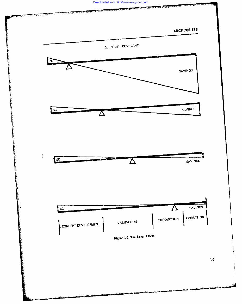
There is a multiplier or leverage effect involved insystem design, particularly with respect to maintaina-
1-2 THE IMPORTANCE OF bility and logistic support. In effect this means, as illus-MAINTAINABILITY trated in Fig 1-2, that maintenance and support con-
siderations have a strong leverage effect on system costIf a system is to be cost-effective over its designated and effectiveness when taken into account early in the
operational life, its ability to meet performance require- system life cyc!e and have much less effect later on. Onements is only one of many considerations. Also of con- can consider the system life cycle to be a long lever withcern is system ability to perform when needed and for its fulcrum placed at t . life-cycle ph, se where main-the duration of its assigned mission. This latter concern tainability and logistic support are considered. Thus, indeals with system operational readiness and mission the conceptual development phases, a relatively moder-reliability; for this, a proper balance between system ate investment in reliability, maintainability, and sup-reliability and maintainability is required. Not only is port design requirements can produce very substantialsuch a balance necessary, but in order to be achieved, savings in the operation phase. On the other hand,reliability and maintainability considerations must be- waiting until late validation or production phases togin early in the conceptual and definition phases of consider maintainability and support features may tipsystem acquisition, as part of the overall system engi- the balance in the other direction and result in excessiveneering effort. maintenance and support ccsts. No other factor affects
The need for maintainability is emphasized by the the life-cycle logistic cost with the preponderance ofalarmingly high operating and support costs which ex- inclusion of proper implementations of its maintana-ist due to failures and the necessary subsequent mainte- ;' and reliability.nance. Lack of reliability and poor maintainability In pe'sonnel costs alone, the savings realized fromcarry the major responsibility for this situation. using just cne less maintenance technician has been
Ore study, made in the 1950's, showed that one- estimated to be approximately $15,000 per year in paythird of all Air Force operating cost was for mainte- and allowances, administrative support, and trainingnance, and one-third of all Air Force personnel was costs. Couple with this the savings in repair parts,engaged in maintenance, even though a large portion of maintenance information, and support equipmentthe maintenance was done by contract (Ref. 9). Army costs, and a significant impact on life-cycle cost can bestudies indicate that the orginal purchase price of elec- achieved.tronic equipment represented only 25 to 40 percent of It is readily seen, tOerefore, that an original invest-the total life-cycle cost, with the remainder resulting ment in maintainability made during system acquisi-from operation and maintenance (Ref. 10, Chapter 1; tion may produce a manifold saving in c:-erating costsRef 11). and a substantial improvement in systern effectiveness.
No exact dr up-to-date data on the cost of mainte- The Weapons Systems Effectiveness Industry Advisorynance of military equipment exist at present. Service Committee (WSEIAC) study on system effectivenessand General Accounting Office studies indicate that, (Ref. 12) states:when averaging maintenance costs over all systems de- "The high cost and complexity of modern militaryployed, these costs exceed t.',ree to ten times the pro- systems require the most efficient management pos-curement costs during the life cycle of equipment. sible to avoid wasting significant resources on inade-
The system resources associated with maintainabil- ouate equipment.ity, and their attendant costs, include test and support "Efficient systems management depends on theequipmerit, repair parts, maintenance personnel and successful evaluation and integration of numerous dif-their training, training equipment, maintenance facili- ferent but interrelated system characteristics such asties, maintenance instructions and data, and other log- reliability, maintainability, performance and cost. Ifistic costs. The extent of the resources depends upon such evaluation and integration is to be accomplishedthe specific reliability and maintainability features de- in a scier, tific rather than intuitive manner, a methodsigned into the equipment and specified in contract must be f-.rmulated to assess quantitatively the effectswork statements Because they represen* uch a :ignifi- of each system characteristic on overall system effec-cant part of total system resources and costs, the need tiveness."
1-4
-4
Downloaded from http://www.everyspec.com
AMCP 706-133
NC INPUT =CONSTANT
SAVINGS
beSVIG
SAVINGS
CONCEPT DEVELOPMECNT VALIDATION
POUTO
Figr 12 The Lever Effect
Downloaded from http://www.everyspec.com
AMCP 706-133
However, although extremely important, cost is not maintainability program are to assure that during thethe only consideration with regard to the need for life cycle, items of materiel provided to Army forcesmaintainability engineering. The ability of a system to will be ready for use when needed, will be able tooperate when needed and to do so for the duration of successfully perform their assigned functions, and willthe specified mission is often as important, and some- fulfill all required maintenance characteristics" (Ref.times even more important, than cost savings. This 13).suggests then that time is an important paiameter in It is possible to achieve operational readiness bymaintainability. Time is used as a common measure in making the system so reliable that failures are rare.I system effectiveness. A system to which maintainabil- However, such a system, if feasible within the state-of-ity engineering has been properly applied can be ex- the-art, could require components that might be sopected to have: costly that the system would not be economical or
1. Lower downtime, and therefore a higher opera- cost-effective. On the other hand, it is possible to design:ional readiness (availability) a system in such a manner that any failure could occur
2. The capability of being restored quickly to oper- frequently but the failure could be corrected in a shortating status when downtime is due to random failures time. Such a system might also be 'very expensive in(corrective maintenance) terms of its design characteristics (number of test
3. The capability of being retained in an operation- points, accessibility, skill levels required, displays, tron-ally ready state 'y inihibiting those types of failures bleshooting i6gic, repair levels), or in terms of mainte-
nance resources required (skilled technicians, mainte-which result from age or wearout (preventive mainte-nance). nance float, repair cycle float, repair parts, tools and
test equipment, manuals), so that it also would not beIn some Army systems, the failure of one critical cost-effective. In addition, when considering system or
item of equipment due to lack of maintenance or provi- equipment utilization in terms of mission times, a sys-
sion of adequate maintainability features may cause an :em that might fail frequently, even though it could beimportant mission or battle to be lost, with a resultant repaired quickly, might be intolerable to a field con-loss of life and equipment. This could be vital to our mander and might well result in loss of confidence bynational security. the user or in mission failure, with consequent disas-
The need, therefore, is to provide a maintainability trous results. Operational readiness, therefore, requiresprogram which wiil assure that maintainability features a suitable balance between reliability and maintainabil-reflecting operational maintenance requirements are ity. Maintainability, then, is used to obtain maximumincluded in system design throughout system acquisi- operational readiness in such a vay that an end itemtinn from the early conceptual phase through at least can be maintained in the least time consistent withsystem development, test. and evaluation, other system requirements, and with a minimum ex-
penditure of support resources.In order to achieve such a proper balance, maintain-
1-3 PURPOSE OF MAINTAINABILITY ability considerations, like reliability, must start withthe original materiel requirement in the concept devel-
Maintainability engineering is concerned with the opment phase of the system life cycle. Maintenance andoperational readiness of a s';'stem or equipment. Opera- maintainability considerations must be part of thetional readiness (sometimes called materiel readiness in original system/equipment planning effort. Integratedthe Army) is the term used to indicate the ability of a logistic support concepts must be developed duringsystem to be utilized u-pon demand. It consists of a these early phases and must be approved before subse-number of factors--primary ors being the inherent quent phases can be entered by the developer. Further,reliability of the system/equipment, its ability to be there must be a proper balance of logistic support re-maintained, and its m-;sion or operational demand re- source needs versus cost, schedule, and performance inquirement in its operational environment. AR 702-3 order to achieve maximum system effectiveness andstates "The primary objectives of the reliability and operational readiness.
1-6
Downloaded from http://www.everyspec.com
AMCP 706-133
1-4 MAINTENANCE ENGINEERING The user-producer dialogue allows maintenance enAND MAINTAINABILITY gineering and maintainability engineering to be put into
ENGINEERING proper perspective. Maintenance engineering repre-sents the user's needs; maintainability engineeringrepresents the producer's response to these needs. The
Maintenance and maintainability have different responsibility for the conduct of both maintenance andmeanings. Maintenance is concerned with those actions maintainability engineering rests with the AMC corn-taken by a system user to retain an existing system/ modity commands.equipment in, or restore it to, an operable condition.Maintainability is concerned with those actions taken 1-4.2 MAINTENANCE ENGINEERINGby a system/equipment designer, during development,to incorporate those design features which will enhance Maintenance engineering is defined in AMCRease of maintenance. Its function is to ensure that- 75042 as "that activity of equipment maintenancewhen produced, installed, and operated-the fielded sys- which develops and maintains concepts, criteria, andtern/equipment can be maintained at minimum life- technical requirements from concept through obsoles-cycle support cost and with minimum downtime. cence of materiel to assure timely, adequate, wnd eco-
The life-cycle support (user) aspects are the responsi- nomic maintenance support of AMC materiel" (Ref.bility of maintenance engineering, and they influence 16). It is defined in AMCP 706-134 as "the applicationthe design aspects which are the responsibility of main- of techniques, engineering skills, and effort organizedtainability engineenng. This difference in perspective to ensure that the design and development of weapons,and responv;bility is recognized in AR 750-1 (Ref. 14) systems, and equipment provide adequately for effec-and TM 38- t03 (Ref. 15). tive and economical maintenance" (Ref. 5). Of particu-
lar note in these definitions is the important role as-signed to maintenance engineering in the concepi,
1-4.1 THE USER-PRODUCER DIALOGUE validation, end design phases of system and equipmentdevelopment.
Every system has a user and a producer. The system This is further emphasized in AMCR 75042 as fol-user is the one whose needs for the system must be met lows:by the system producer. Thus, a dialogue is necessary "During the concept formulation, validation andbetween system users and producers, as, for example, production phases, the maintenance engineering activ-between someone who wants a house built and the ity provi'e -ecessary maintenance support concepts,architect and builder who design and produce the plans, ana maintenance experience data to be used inhouse to satisfy the user's needs. developing technical requirements for new weapons
The system user is concerned with formulating and and equipments. Maintenance engineers participate indeveloping the needs and concepts for the system and the dt :,n reviews and evaluation of test results tofor its operation and support. He provides the require- redu. the need for maintenance support. Thus, effec-ments to which the producer designs. The producer is tive maintenance engineering participation signifi-concerned with translating the user's formulated needs cantly influences technical requirements in designinto the design, production, and installation of the sys- which, in general, dictate initial and future supporttern which meets these needs and which can be oper- investments and operating costs associat& with newated and supported in a cost-effective manner. The military hardware."system life cycle is the logical framework for carrying The maintenance engineer is concerned with how theout the user/producer dialogue. (See par. 3-2.) fielded system will be operated and maintained. Since
There is a user-producer relationship within the he represents the user needs, he is concerned with sys-Army. The ultimate users in the Army are the various tern mission/operational and support profiles, the eni-combat Field Army Commanders and other ( ¢rating tonment in which the system will be operated andforces. The Army Materiel Command (AMC) is re- maintained, the levels of maintenance, maintenancesponsible for system and equipment research and devel- and other support resources, and maintenance actions.opment, acquisition, and support; and the Training and It is his responsibility to see that user needs with regardDoctrine Command is responsible for training. These to maintenance are reflected in system developmentare the internal producers in the Army. AMC repre- and design requirements.sents the Army as user and developer to the industry Within the defined operational use concepts, thewhich is the external producer. maintenance engineer must help develop the overall
1-7
Downloaded from http://www.everyspec.com
AMCP 706-133
system integrated logistic support (ILS) concept and stated operational readiness and system effectivenesthe maintet.ance concepts and constraints which will goals within specified mission and logistic time profiles.guide the system designer with respect to maintainabil- Maintainability engineering is concerned with design-ity design. Maintainability design requirements for ing for specified manpower skills and with the develop-maintainability engineers are provided through the ment of maintenance instructions, aids, and training forprocess of maintenance engineering analysis, the deve!- maintenance personnel.opment of mainterance concepts, the analysis oi main- AMCP 706-134, Maintainability Guide for Designtenance tasks and requirements, and the determination (Ref. 5), is an engineering design handbook which con-of maintenance resource requirements. The develop- tains many of the design requirements, features, andment of a maintenance concept must precede maintain- concepts that maintainability engineers will apply toability design, not result from it. Maintenance and Army systems and equipment.maintainability engineering must influence system de-sign to be effective. The output of maintenance engi- 1-4.4 EXAMPLES OF MAINTENANCE POLICYneering analysis should be a "Plan for Maintenance" INTERRELATIONSHIPSwhich is consistent with the maintenan e concept andwhich serves as the basis for maintenance planning for The following examples illustrate the interrelation-the system during its use period as well as a basis for ships between maintenance engineering and mairtaina-maintainab-ility design. bility engineering. In each example, a maintenance con-
cept is stated, followed by the resulting maintainability
1-4 3 MAINTAINABILITY ENGINEERING design implications.Example 1. Maintenance Concept. Organizational
Since mainiainability is defined as 'ihe inherent abil- maintenance shall be performed by equipment opera-ity of a design to be maintained" (Refs. I and 2), main- tors, organization repairmen, and direct support tech-tainability engineering is concerned with incorporating nicians as needed. Organizational maintenance activi-required maintainability features in system/equipment ties shall be limited to inspection, preventivedesign. Maintainability design requirements are an out- maintenance, servicing, and minor adjustment. Onlyput of the maintenance engineering analysis which re- minor repairs and replacements shall be made by directflects user needs. It is the task of the maintainability support technicians. No special tools or limited gener-engineer to see that maintainability features required to al-purpose test equipment shall be required for thismeet these needs are incorporated in the system/equip- maintenance level.ment design contracts. Maintainability engineering Maintainability Design Implication. Organizationalmust be integrated with the other elements of system repairmen shall not require high skill levels. BITE fea-engineering so as to provide the necessary effectiveness, tures shall be incorporated into equipment so that theconsidering all costs over the entire life cycle of the operator need only turn a function test switch and notesystem equipment (Ref. 13). an indicator reading, preferably by a go/no-go or lo-go-
Maintainability engineering is concerned with spe- hi type of indication. Repairs shall be made primarilycific features of system/equipment design and with by replacing faulty items without the need for specialother physical characteristics of the system pertinent to tools and test equipment, utilizing built-in signalits rapid maintenance with the least logistic resources. sources and indicators, and with minimum dependenceExamples of such design features are accessibility, hu- on repair parts.man factors considerations, test, checkout, calibration, Example 2. Maintenance Concept. M7TR at the or-and replace/repair/discard features resulting from the ganizational level shall not exceed 10 min.selected maintenance concept and from maintenance Maintainability Design Implication. No time for de-engineering analysis. tailed troubleshooting and repair is allowed at organi-
Maintainability engineering is also concerned with zational level. Fault localization and isolation andspecific features for fault detection-Built-in Tist verification features must be incorporated directly inEquipment (BITE), fault isolation, correction, and the equipment, using a test function switch. Repairsverification-at each maintensace levc!. it i- c.jncerned shall be made by replacement, using plug-in units andwith contributions of various parts of the system to the standard tools. Quick-access fasteners shall be used toallocation, prediction, and demonstration of quantita- gain access to units.tive measures of maintainability. It is concerned with Example 3. Maintenance Concept. Organizati. nalincorporating preventive and corrective maintenance level maintenance shall make maximum feasible use ofrequiremets in such a way that the system will meet plug-in modules which can be discarded at failure. No
1-8
Downloaded from http://www.everyspec.com
AMCP 706-133
module repair shall be performed at the organizational its components--such a stress-strain relationships,level. A repair/discard criterion of $100 might be used. failure modes and effects, and environmental factors.
Maintainability Design Implication. Module design Mission (operational) reliability is dependent, in addi-shall be such that, insofar as possible, those modules tion to the stated physical characteristics, on the num-requiring replacement at the organizational level ber and skill level of the equipment operators and,should cost less than $100. Where modules costing therefore, of the specific human engineering featuresmore than $100 must be removed, they should be re- which have been incorporated in the equipment to as-placed and the failed unit sent back to general support sist the operator in performing his task reliably.or depot for repair. Inherent maintainability cannot be divorced from
Example 4. Maintenance Concept. At the direct sup- human factors considerations, except in the improbableport level, replacement cf one module shall not require event of completely self-hmling systems.removal or adjustment of other modules or important By self-healing is meant the ability of a system tounits, except for those adjustments normally provided correct its own defect or failure, such as removing aby BITE for operator use in order to align unit per- short or restoring an imbalance. The automatic switch-formance to peak efficiency. ing in a standby redundant item to replace a failed item
Maintainability Design Implication. Replaceable does not constitute self-healing. From the outset, there.modules must be designed so that they contain all nec- fore, the maintainability engineer must be concernedessary performance functions, components, and adjust- with human factors, maintenance technician skill levelsments within the module, except for interface adjust- and capabilities, and safety. Thus, maintainability engi-ments. neering requires a multi-disciplined approach utilizing
personnel with backgrounds in such areas as equipmentdesign, statistical techniques, safety, and human fac-
1-5 PRIMARY CONSIDERATIONS tors. Maintainability is a joint effort of these types ofpersonnel with the reliability and system effectiveness
Reliability and maintainability are elements of sys- engineers, maintenance and logistic engineers, and sys-tem engineering and are viewed as interrelated charac- tern engineers (see Fig. 1-1).teristics (Ref. 13). They are different but complemen- The actual preventive and corrective maintenancetary engineering disciplines, tasks which can be performed on a system are a direct
Reliability engineering provides the methodologies consequence of the maintainability characteristicsfor increasing the ability of a system to operate without which have been des. -A into the system. To designfailure or serious degradation for prolonged periods of for these features is the responsibility of the maintaina-time in its operational environment (Ref. 17). It is thus bility enginmrs and equipment designers. The main-concerned with extending system "up" time. Maintain- tainability d-..gn requirements are derived from main-ability engineering, oa the other hand, provides the tenance a.d lcgistic support concepts and operationalmethodologies for reducing the "down" time of sys- requiremneits. Maintainability design considerationste. s when maintenance becomes necessary because of are discus,e i. Chapter 5.failures or in order to reduce the need for preventive Mainta,b.iLlity as an element of system effectivenessmaintenance actions when system performance is drif.- is predicated on tht fact that system maintainabii!tying out of.the specified performance limits. requirements can be specified quantitatively and, there-
Reliability and maintainability of a system are fore, can be predicted, measured, demonstrated, andrelated to each other in terms of operational readiness, evaluated. Maintainablity quantification, as part ofmission success, and system availability which measure system effectiveness, is discussed in Chapters 2, 4, 6,
system uptime with respect to the total time the system and 8.is required to operate. Maintainability is part of integrated logistic support,
Although reliability and maintainability are closely system engineering and pr(gram management, and,allied disciplines, one significant difference between therefore, must be considered in terms of tl'! system lifethem is the extent to which they are dependent upon cycle with respect to program and syste-- nkInning,the use of manpower, and, therefore, human factors. system trade-offs, and life-cycle costs. Th.se er, ptts ofInherent (equipment) reliability is primarily dependent maintainability are discussed in Chaapters 3, 7, 9, andupon the physical characteristics of the equipment and 10.
1-911-10
Downloaded from http://www.everyspec.com
AMCP 706-133
SECTION II
QUANTIFICATION OF MAINTAINABILITY
1-6 MAINTAINABILITY MEASURES M(t) 1 - exp (- t/MTTR) (1-1)
In MIL-STD-721B (Ref. 4) maintainability is de- wherefined as "a characteristic of design and installation ex- Mg) = probability that repair will bepressed as a probability that an item will be retained in successfully completed in time tor restored to specified conditions within a given period when it starts at t = 0of time, when maintenance action is performed in ac- t = variable repair timecordance with prescribed procedures and resources."Expressed somewhat differently, maintainability is the exp = base of the natural logarithmprobability that an item in need of maintenance will be (e = 2.71828....retained in/or restored to a specified operational condi-tion within a given period of time. The varip , in thi. Looking at this equation, we see that it has only a single
probabilistic definition of maintainability is the mainte- parameter, namely the MTTR. Once the M7TR is
nance time. given, I) can be calculated for any specific value of
Obviously, maintenance time will differ from case to L Thus for each value of t, the probability KOt) of
case according to the nature of the failure or malfunc- completing repair in t is fully defined by the
tion which requires maintenance. Therefore, mainte- MTTR. Fig. 1-3 illustrates two such maintainability
nance time is not a constant but is in some way stalisti- functions AAt--one for an equipment with an MTTR
cally distributed. This is in a sense similar to the of O.5 hr and the other for an equipment with an M7TR
distribution of time-to-failure in reliability. The differ- of ' hr.
ence is that in maintainability the variable is alwaystime, while in reliability the variable may be the time 1-6.2 THE CONCEPTS OF MEDIAN REPAIRto failure, or miles to failure, or rounds fired to failure, TIME AND Mm,,or cycles to failure, or number of successful trials tofailure, etc. This difference, as will be seen later in the From Fig. 1-3 we can make some interesting obser-text, shows up in evaluating the availability of systems, vations and draw definite conclusions. Looking at thewhere uptime may be measured in miles traveled or maintainability function AAO = 1 - exp( - 20 ofrounds fired without failure and downtime is measured the equipment which has an MIT of 0.5 hr, we seein hours or minutes; it is thus not always easy to con- that the probability of accomplishing repair -4t) in abine the two into meaningful and realistic measures of time t = 0.5 hr (30 min) is approximately 0.63 or 63availability. Another difference between reliability and percent, while the probability of accomplishing repairmaintainability is the fact that while reliability is the in t = 0.25 hr (15 min) is only about 0.40 or 40 per-probability that an event, i.e., failure, will no, occur in cent. On the other hand, the probability of accomplish-a specific time, maintainability is the probability that ing repairs in 1 hr becomes approximately 0.865 or 86.5the event, i.e., successful completion of maintenance, percent, and we find that for a repair time of 2.3 Xwilloccur in a specific time. M7TR, or for t = 1.15 hr (about 69 min) there is a
probability of !46 = 0.9 or 90% of accomplishing
1-6.1 THE EXPONENTIAL CASE repair.To generalize, an exponentially repaired equipment
The simplest and mathematically easiest way to han- has a probability of about 63% of accomplishing repairdle a case is with exponential distribution. It applies in in a time t which equals its MTTR (i.e., t =
maintainability to corrective maintenance when the du- MTTR), a probability of about 40% for t - 0.5ration of repair times is exponentially distributed, ac- MTTR, a probability of abtxat 22% for t 0.25cording to the equation MTTR, a probability of about 90% for t = 2.3 X
1-11
Downloaded from http://www.everyspec.com
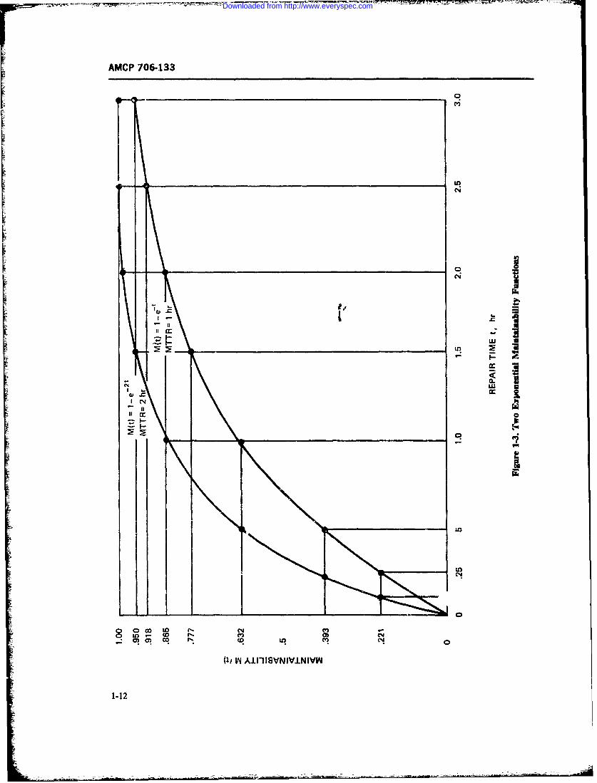
AMCP 706-133
C14
It La
I
I L
co V)N
V4 AIIISVNVINIV
1-12
Downloaded from http://www.everyspec.com
AMCP 706-133
MTTR and a probability of about 95% for t = 3 X and MITR =- AMAX/In a -1/(-2.30259) =
MTTR. Finally, there is a 50% probability of accom- 0.434 hr or about 26 min.plishing repair it, approximately t = 0.7 M77R which So far we have determined that one of the maintaina-is called the median time to repair. bility measures is the length of time it takes to perform
Of specific interest in maintainability specifications maintenance actions and that this time may be dis-are the last two numbers, i.e., 50% and 90% probabili- tributed according to a maintainability functionties. It is often desirable to specify a maximum repair At), such as the exponential function in Eq. 1-1. Whenor maintenance time MmAx which should possibly not the exponential distribution is applicable, a specific,be exceeded or, exceeded only with a small probability, unique, and sufficient measure of maintainability is theSuch constraints on maximum maintenance time are MTTR. When this is specified, all percentile points areusually associated with the 90th or 95th percentile, i.e., also automatically defined, such as 4M4.Ax and -ass.i-the probability of accomplishing maintenance in a spec- ated with this, the median time to repair. The math-ified time t = MMAx should be 0.9 or 0.95, according ematical formulas by which these measures are inter-to what the specification demands. In the case of an related have been shown, and the relationships areexponential distribution of repair times, MAt) = 0.9 for illustrated in Fig. 1-3. It must be emphasized tl'at allapproximately t = Mm,,x = 2.3 X M7TR and the equations presented so far apply only to the case ofj1t0 = 0.95 for t = MM," = 3 X M7TR. The ex- the exponeardal distribution of repair or maintcnanceplanation of such a requirement is that 90% or 95% of time. However, the maintainability measures devel-all repair actions .hall require less than t 2.3 X oped-i.e., the concept of maintainability functionMTTR or t = 3 X MITR, respectively, accordii to M), mean time to repair M7TR, maximumi repairwhich percentage is associated with the Mlur reqtre- time M., and median time to repair-apply also toment. For example, if the M7TR is 1 hr (refer to Fig. other statistical maintenance time distributions, such as1-3), 90% of all repair actions should take less than 2.3 the lognormal, normal, gamma, and others; only thehr and 95% should take less than 3 hr. mathematical formulas by which these measures are
In the exponential case it makes no differenc. interrelated become different.whether the M7TR or the Mmx are specified a-.,gwith the associated probability or percentile. If Mr 1-6.3 THE REPAIR RATE f±(maximum maintenance time) is specified with proba-biliy M(t) = 1 - a, i.e., In the maintainability literature one often finds the
concept of maintenance rate or repair rate I, especially
M(t) = 1 - a = 1 - exp (- MMAX/MTTR) (1-2) when dealinigwith theexponential distribution. Fortheexponential case, the repair rate is given as the recipro-cal of the MTA, i.e.,
which may also be written as=i = 1/MTTR (1-5)
Ina - MAx/MTTR (1-3)Since the MTTR is a fixed number, the -pair rate
SL is a constant for the exponential distribution. For allwe obtain from such requirement the M77TR as a de- other distributions, the repair rate is nouiconstant. I!sign goal by taking the natural logarithm of the above ohrdsrbtos h earrt sntcntn.I
inoalby takeng hen a r of, the aoveng usually increases as a function of the progressing main-equation, i.e., In a = - MMAx/MATTR, and solving tenance time L When this is the case, the probability of
completing or finishing a repair in a short period dtwhen repair started t time units ago, i.e., p(t)dt, in-
MTTR = - MMAx/ln a (1-4) creases the longer repair has been in progress. On theother hand, in the exponential case p.dt is always con-stant, regardless of how long a repair action has been
For example, if the assumption of an exponential in progress.distribution of maintenance time is valid and a cus-tomer specifies that with probability M(t) = 1 - a = 1-6.4 THE MEAN TIME TO REPAIR (AFT)0.9, the maintenance time must not exceed I hr, i.e..MMA X = 1 hr, the MTTR to design for is obtained To return to the concept of MTTR, this is an impor-from Eq. 1-4 by finding a = 0.1, In 0.1 = - 230259, tant parameter, easy to quantify, and easy to measure
1-13
Downloaded from http://www.everyspec.com
AMCP 706-133
(Ref. 18). Unfortunately, by itself, except for the expo- testability, and packaging concept for the equipment.nential distribution, MTTR does not tell us enough Trade-off techniques are used to change design andabout the tails of the distribution, such as the fre- packaging characteristics, as well as test capabilities, toquency and duration of the very long main:enance ac- achieve the desired repair times t, for the various typestions. Still, MTTR is an important design requirement of failures and thus to comply with the MTTR require-especially for complex piecs of equipment and sys- ment. As to the measured MTTR, this is determinedtems, and it can te measured when the hardware is from hardware test. simulated maintainability demon-tested. strations, or field data by computing the total observed
By :ts nature, MTTR depends on the frequencies at repair downtime over an extended period of time (thewhich various replaceable or repairable components in sum of all individual downtimes), and dividing this bythe equipment fail (i.e., on the failure rates or replace- the number of repair actions N, which occurred in thement rates), and on the times it takes to repair the period of observation, i.e.,equipment as the different kinds of failure occur. Thereis a predicted MTTR for which we need to know the Nrpredicted failure rates and estimated repair times down .11TTR = F, ti/Nr (1-7)to the lowest repair level at a given repair levei. and i_there is the measured MTTR observed on actual hard-ware. Idea!ly, the two MTTRs will be close to ezch Observing Eqs. 1-6 and 1-7, one can see that theother. But if the predicted failure rates are not correct, MT7'R computations are very simple, requiring onlythe measured MTTR may deviate significantly from simple summations, multiplications, and divisions/the predicted value, even though the individual repair easily done by the help of an inexpensive desk cal-times initially were well estimated When designing an culator or sl;de rule. As to the preceding Eqs. 1-1equipment for maintainability, prediction techniques through 1-5, 'hese are also easily handled by exponen-such as are in MIL-HDBK-472 are used. An M7TR tial tables (Ref. 18) and slide rules. Some more complexestimate of an exponentially failing equipment is ob- mathematics, however, will be involved when discuss-tained from the formula ing the specifics of the more complicated distributions.
X
.ITT1i =i _Niii,1 (1 -6) 1-7 SPECIFIC MEASURES INMAINTAINABILITY
In par. 1-6, certain measures in maintainability havewhere been iden.ified and some equations f3r these. * asures
N = to:al number of replaceable or developed, with an cmphasis on the simple exponentialrepairable components distribution of repair time. However, in many instances
X, = failure rate of the ith maintenance is performed not only when a system orcompv'nent equipment develops a failure or malfunction but also
t, = equipment repair time when the preventively to forestall the possible occurrence of suchith component fails an undersirable event. Maintenance actions can thus be
X = failure rate of the whole divided into two major categories.equipment, usually taken as the 1. Corrective maintenance, performed when thesum of the failure rates of all equipment fails to perform to required performancecomponents is. the equipment specifications.
Eq. 1-6 is a very practical design too' for maintaina- . Preventive maintenance, performed to avoid thebility. When the predicted failure rates are available,
equipment getting into a condition requiring correctivethe maintainability engineer evaluates the expected re- maintenance.pair times t. They are estimated by maintenance timeanalysis methods based on previous field data or expert Whether maintenance is corrective or preventive, itengineering judgment which consider fault verification, usually causes a definite amount of downtime for thefault localization, fault isolation, disassembly, replace- equipment so it cannot be used while the maintenancement, reassembly, adjustment, servicing, and checkoet. actions are performed. But there is a distinct differenceEach of these actions takes a certain time to perform, between downtime due to corrective maintenance ac-but these times can well be estimated from the design. tions and do%% ntime due to preventive maintenance ac-
1-14
Downloaded from http://www.everyspec.com
AMCP 706-133
dons. While the need for corrective maintenance is tion. Other useful measures applicable to specificusually due to equipment breakdowns and malfunc- systems are time between overhauls, turnaround time,tions which occur at random times when the equipment and a nmber of maintenance downtime measures cur-is operating and therefore interfere with equipment op- rently used by maintainability enojneers. such as meanerational schedules, preventive maintenance can be time to repair (MTR), mean active corrective mainte-scheduled so that it is performed at predetermined nance time (M), mean active preventive maintenancetimes when the equipment is not required to operate or time (M,), mean active correcti% e and preventive main-when substitute equipment can be used, so that either tenance time (Al), median equipment repair timeno undesired reduction of output or use is encountered, (ER7), maximum equipment i'epair time (ER T7,A),or effects of such are minimized, geometric mean time to repair (MTTR), and maxi-
Still, it is obvious that the need for preventive or mum maintenance time (M.Aj). Ref. 19, Chapter 4,scheduled maintenance imposes additional burdens on and Ref. 3, pages 2-3 ;hrough 2-6, define these variousan undisturbed equipment operation in terms of the terms somewhat differently. In the paragraphs that fol-costs associated with it, the possible need for substitute low definitions are us"d which give more consistentequipment, or the loss of the function for some periods results.of time. In the context of maintainability, it is therefore 1. Mean Time to Repair(M7FR) is defined as thenecessary to consider preventive maintenance as well as mean of the distribution of equipment or system repaircorrective maintenance when evaluating the usefulness, time. In its simplest form, the M7TR is given by themaintenance costs, and availability of an equipment. equation
Though the penalties due to scheduled preventivemaintenance may be smaller than those resulting from N N
corrective maintenance, they are still real losses and MTTR XX,1/Z.'i (1-8)subtract fror the value of the equipment to the user.T' / zi
Even though such loss is usually not of the same magni-tude as the loss suffered due to failures during opera-tion, to assess it and to include it in the evaluation of whereoverall wortb af the equipment to the user in terms of X. = failure rate of the ith repairablemaintainability, a.ailability, and pay-off capability or replaceable component in
becomes a neccssity. the equipment/systemt, = time required to repair the
1-7.1 MEASURES OF MAINTENANCE system v'hen the ith componentfails
DOWNTIME The MTTA" is sometimes gihen in hours and at other
Although maintainability has been defined as a prob- times in minutes. It is important to use the same time
ability (Ref. 4), there are a number of useful time meas- units for the X's and for the i's Failure rates are usuallyures by'which quantitative maintainability require- (but not always) given in units of "failures per hour".
ments can be specified and trade-offs performed with Then the repair times should also be given in hours.
reliability, availability, and other system engineering This becomes obvious in availability calculations.
disciplines. Quantitative requirements for maintaina- As an example of MTTR computation, assume a
bility may be expressed in different ways according to system consisting of three replaceable subassembliesthe type of equipment/system, their usage, and the (components) which have the following MTBF's andmaintenance concept. There may be a quantitative replacement tim.%:availability requirement specified which, in conjunc- Subassembly 1: MTBF = 1000 hr, i, - 1 hr
tion with the reliability requirement, yields a quantita- Subassembly 2: MTBF, = 500 hr, t. = 0.5 hr
tive maintainability requirement in terms of the mean Subassembly 3: MYBF = 500 hr, t; 1 hr
time to repair (MTTR) or mean downtime. In other To compute the MTTR of the system, we first convertinstances, the maintenance manhours per systen oper- the MTBFs into failure rates, i.e., X, = 1/1000ating hour (MMH/OIH) may be specified and maintain- 0.001; A, = 1/500 = 0.002; anc X3 = 1/500 failures
ability design goals then derived from such specifica- per hour. Then, using Eq. 1-8 we calculate
1-15
Downloaded from http://www.everyspec.com
AMCP 706-133
.1-TTR 11 4A2- AA where , frequency at which the Ah: + X2 +"
(0. 001)(1) + (0. 002)(0. 5) + (0. 02)(1) preventive maintenarce task is=(. 1 hr 0performed0.001 0. 002 + 0.002 Mr = system active maintenance time
0.004 when the Ah preventiveI 0.8 hr (1-8a) maintenance task is performed.If the frequencies f are given in maintenance tasks perhour, the downtimes M, should also be given in hours.
When the time to failure is exponentially distributed 4. Mean Active Corrective and Preventive Mainte-according to the reliability equation nance Time (A) is defined as the mean of the distribu-
tion of time of all maintenance actions, both correctiveR(r) = exp (- Ari (1-9) and preventive, of an equipment or system. It is given
by the equation
whereX = failure rate YA 1 + fL(17 = operating time A > t (1-12)
the reciprocal of X is the mean time between failures,i.e., MTBF = I/X (Ref. 20, Chapter 3). The MTBFisoften used as a measure of reliability, just as the MTTRis often used as a measure of maintainability, where the terms X, f, ,, and M,, are as defined in the
2. Mean Active Corrective Maintenance Time preceding paragraphs. In this equation the same units(M,), is defined the same way as the MTTR, excepi that must be used for the X,'s and fs, and the same timeemphasis is on active maintenance time, which means units for Mds and Mes.that no idle time must be included when measuring the 5 Equipment Repair Time(ER 7) i5 defined as theduration of maintenance tasks. However, this applies to median of the distribution of repair times of an equip-the MTTR measure, also. ment/system. It was discussed in par. 1-6.2 in connec-
Denoting the active maintenance time of a system by tion with the exponential distribution. Fig. 1-4 is pre-
M, when the ith component with failure rate X, fails, sented here to indicate more generalization. As seen in
the mean active maintenance time of the system is given Fig. 1-4, the EAT corresponds to that repair time
by within which 50% of all repair actions can be accom-plished.
The numerical relationships between ERT andT(1-10) =TR are different for different distributions. For the
normal distribution, because of its symmetry, themedian and the mean coincide
3. Mean Active Prerentive Maintenance Time(M,), is defined as the arithmetic mean of the activepreventive maintenance times of an equipment or sys- ERT = MTTR (1-13)tem and is given by
For the exponential distribution, we have approxi-J~e= ELi.li,/f (1-11) mately
1-16
Downloaded from http://www.everyspec.com
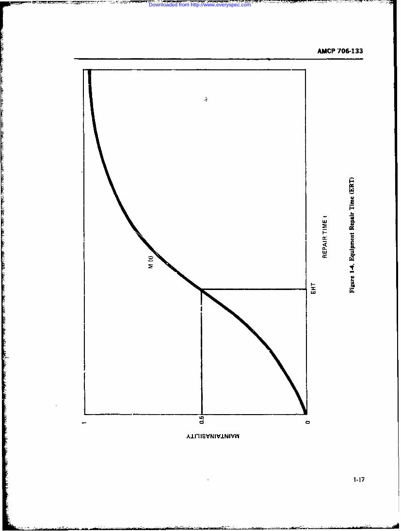
AMCP 706-133
I. p
CL2i
uiF
Downloaded from http://www.everyspec.com
AMCP 706-133
ERT = 0.7 MTTR (1-14) tributed maintenance time. For the exponential distri-bution M.,x is approximately
For the lognormal distribution the relationship holds3I1lA = 3 MTTR (-21)
.M1TTR = ERTexp(az/2) (1-15)
and for the lognormal distribution the relationshipwhich yields holds
ERT = .lITTR/exp (a 2 /2) (1-16) ln.ilJ2 x = ? - 1.65 c (1-22)
where or2 is the variance around the mean of the natu-rat logarithm of repair times. where m is given by Eq. 1-18, and a- is the standard
6. Geometric Mean 7hme to Repair (MTTRc is deviation of the natural logarithm of the repair times.
used in the lognormal distribution, where it happens to In some instances the concept of Maximum Equip-
be identical with ERT It is given by Eq. 1-17 which is ment Repair Time (ERTt,,) also has been introducedidentical with Eq. 1-16, i.e., into maintainability. It is defined as the "maximum
allowable value" of ER7? and is quoted to beTTR = VTT(1 ) ERTp a 0.45 , for the onormal distributirn
=MTR/exp(cT/2) (-) (R~~. 19. page 7)
It can be directly obtained from tie mean m of the 1-7.2 TIME FACTORS I MAINTENANCE-natural logarithms of the repair times t, which is given
by In the preceding paragraph specific maintenancedowntime measures were defined, mostly pertaining to
in = D it . 11-18) the active maintenance time as it occurs in repairs andIn preventive maintenance tasks. The active maintenance
time can be corrective or preventive-The acti,.e corrective maintenance time consists of
and the MTTRG is then given by the sum of certaia elemental times it tales to performthe various activities which jointly result in the corn-
.1TTRc = e' (1-19) pieted repair. These are failure verification time. faultlocation time- fault isolation time., access time., faultcorrection time reassembly time. adjustment-calibra-
7. Maximum Maintenance Tme(MJ,) is defined tion time, checkout time, and cleanup-serv-cing time.as the 95th percentile of the maintainability function Fault correction time may involve repair in place: or,,A). as shown in Fig. 1-5. MAY is that maintenance remove, repair and rcplace: or remove and -eplace withtime within which 95% of all maintenance action can a like item. The active preventive maintenance tinebe accomplished, i.e., not more than 5% of the mainte- irvolves inspection time and sevicing tine or turn-nance may exceed , , For the normal distribution around time in the case of scheui=Icd maintenanceM.', occurs at approximately actions (Ref. 21).
However, when considering the total downtime. al-"vAX =most invaiably delays occur, such aL supply delay
time. administrative time. and work breaks, which canbe summarized under the concept of delay time. Fig.
where a-is the standard deviation of the normally dis- 1-6 presents a useful block diagram of tirrm relation-
1-18
Downloaded from http://www.everyspec.com
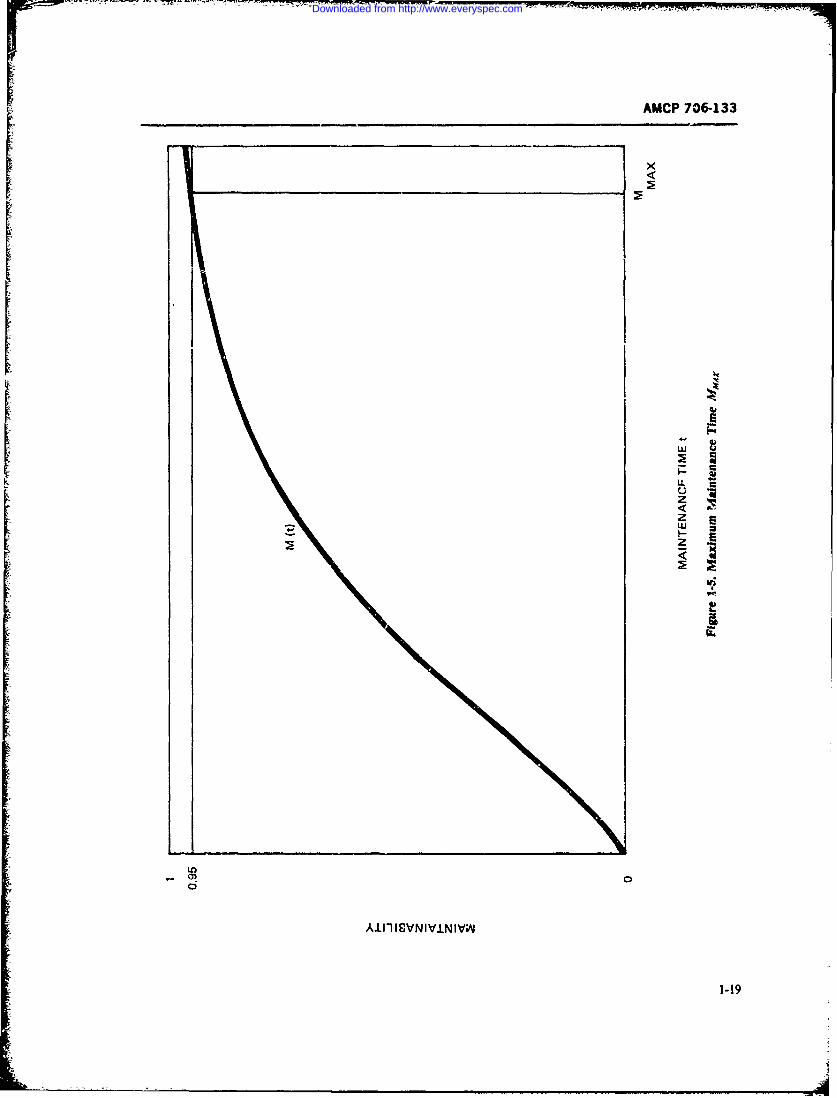
AMCP 706-133
1-1
Downloaded from http://www.everyspec.com
- - : - - ---- - ____- -r
AMCP 706-133
ships which considers system uptime as well as down- MDT = M + Mean Waiting Timetime and thus establishes a good basis for the dicussion + Mean Logistic Timeof availability and related factors (Ref. 4). + Meaia Administrative Time
and adds to the uptime the ready time RT, i.e.,
1-7.3 AVAILABILITY FACTORS Ag = (MTB.t ;- RT),/(.MTBI - RT + MIDT)
The concept of availability is best explained in terms (1-26)of a continuously operating system which is either op-erating and thus "up", or is in maintenance and thus It is important to realize that RTis the system average
"down". Availability is then defined as the probability ready time in a complete operational cycle, the cyclethat at an arbitrary point in time the system is operable, being MTBM + MDT + RT
i.e., is "up".Of specific interest to maintainability engineers, who 1-7.4 MAINTENANCE MANHOURS
look at the long-term or steady-state operation of sys-tms, are the concepis of Inherent Availability A, The maintenarnce manhours expended in equipmentAcieved Availability A,, and Operational Availability maintenance are not identical with active maintenance
Aoie. Avaiability 6 and Operatidowntime. This would be so only in a case where aA0 (Ref. 19, pages 6, 7, 82-84).Inherent Availability A, onsiders he mean time e- single maintenance man would perform the mainte-tween failures (MTBI) and the MT R of a system and nance actions. Quite frequently two or more men, or ais by definition given by the formula whole maintenance crew, work or. a system. In addi-tion, maintenance manhours are expended at various
maintenance levels--such as at the organizationalA1 = MTBF/(MTBF + MTTR) (1-23) level, direct support level, general support level, and
depot level.For instance, a system may have only a short mainte-
It excludes idle time, logistic time, waiting time, and nance downtime to replace a failed "black box". Butpreventive maintenance time and is therefore a useful the failed black box may require many maintenanceparamete. .nr equipment/system design. Fig. 1-7 is a manhours at some rear maintenance level to be re-nomograph for fast determination of A, MTBIF or paired and made available again as a spare part.M7TR if two of these parameters are known. Since maintenance manhours are expensive, it
Achieved A iailability A, includes preventive mainte- became necessary to specify certain constraint for thesenarce and is given by the formula support labor costs in terms of an index called mainte-
nance manhours per system operating hourA. = MTBM/(MTBM + J-l) (1-24) (MMH/OH). This is a necessity especially for largerAsystems where several maintenance levels are usually
involved. The MMH/OH index, when specified, must
where .4 is the m.-an active corrective and preventive be and can be considered in maintainability design andwere"is tie mas agive orE.tive2, and pretie becomes a design parameter not only for the maintaina-t main..aance time as given by Eq. 1-12, and MTBMis bility of the system, but also for maintainability of thethe meai, interval between corrective and preventive "black boxes" at rear levels and for appropriate plan-maintenance actions equal to the reciprocal of the fre- ning of the maintenance concept.quency at which these actions occur, *L.ich is the sumof the frequency or rate X at which corrective actionsoccur, and the frequency or nate fat which preventive 1-8 STATISTICAL ASPECTS ANDmaintenance actions occur. STATISTICAL DISTRIBUTIONSTherefore
Statistics play an important role in the estimation ofMTBM = 1/(X +f) (1-25) the various measures in maintainability. Maintenance
downtime is always in some way statistically dis-tributed, and when maintenance time data are collected
Operational Availability includes in addition to A, they must first be ordered in some way. The kind oflogistic time, waiting time, and administrative time, so statistical distribution they most likely belong to mustthat the total mean downtime MDTbecomes be determined, and then the parameters of the distribu-
1-20
Downloaded from http://www.everyspec.com
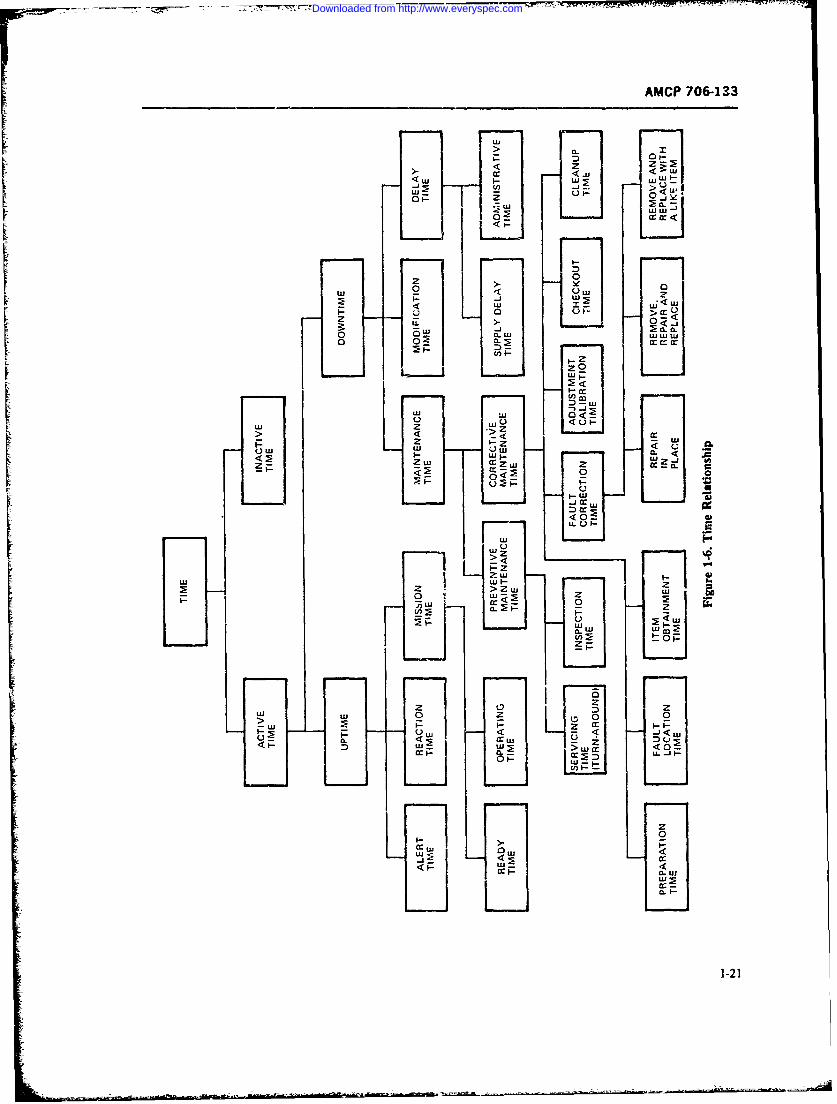
AMCP 706-133
Lu
< UJu Lu -t
IS-
__
< az
zz0 0
ow <<IL >
21-2
Downloaded from http://www.everyspec.com
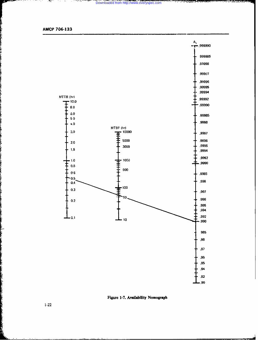
AMCP 706-133
- -. 999990
999985
.99998
.99997
.99996
.99995
.99994
MTTR (hr) .9999210.0
.99985
T ;3.0 100.99985
250
.9998
3.0 10000 991.50 .9996
2.0
0.2 .9965
0.4 .995.9992
0.8 Z L.9992500
03 16 .9985
0.1
985.995
.994
.990
Figure 1-7. Availability Nomograph
1-22
Downloaded from http://www.everyspec.com
AMCP 706-133
io are predicted using estimation techniques. Esti- and the standard deviation o- is estimated by the equa-mates thus obtained also serve to verify whether the tionpredicted parameters, i.e., the maintenance downtimemeasures, were predicted closely enough during thedesign phase. 0 = ( - .11)/(n - 1) (1-30)
Probability is an important aspect of maintainability,in view of the fact that maintenance times are statisti-cally distributed. There are several statistical distribu- We c..11 the normal distribution a two-parameter dis-tions which can be well applied in maintainability andare used commonly in solving maintainability prob- deviation siare known, the mhape of the curvestA* and
lems. Some of these distributions are now discussed. dev)aio a- ekine.
In this paragraph the major statistical distributions M~) is fully defined.
are introduced in a form usually given in texts on statis- 2. The Lognormal Distribution
tics and probability (Refs. 22, 23, 24), and for simplicity The lognormal distribution is a skewed two-parame-of presentation, will use the notation t for the variable ter distribution, widely used in maintainability. In itsmaintenance time and M for the mean of the distribu- most general form the probability density functiontion of maintenance time. The exponential distribution At) of the lognormal distribution is given by:has already been introduced in par. 1-6. All distribu-tions introduced in this paragraph, including the expo- 1 1 [ln(I - ])nential distribution, are discussed in great detail with 2 --
numerical examples in Chapter 8. (1-31)1. The Normal Distribution
The probability density function (pdflof the normal wheredistribution (Ref. 22, Chapter 10, and Ref. 23, Chapter3) has the equation m = mean of the natural logarithms
of the maintenance timeso- = standard deviation with which
! [ (1-27)M"the natural logarithm of thef, exp -(1-27)v f-i [ L 2 or Jmaintenance times are spread
around the mean mc = a constant, the shortest time
where a- is the standard deviation of the variable main- below whicl no maintenancetenance time t around the mean M. Fig. 1-8 shows a action can be performed.typical normal density function, which is always sym- The effec! of c is to shift the origin of At) from t = 0metrical about the mean M. to t = c. In subsequent discussions, w- assume c to beThe area under this curve, taken from the left to any zero so that At) starts at t = 0. Fig. 1-10 shows apoint tis the cumulative distribution M(1) which is the typical density.At) and maintainability A(t) function ofmaintainability function (see Fig. 1-9). the lognormal distribution.
Therefore, the maintainability function M.') is given Like all skewed distributions, the lognormal densityby function has three characteristic points (Ref. 24),
which are sh,.: in Fig. 1-10: the mode M. at which
21 ep l - w \2 At) has its maximum; the median M which bisects theM(t) exp 2\ /J d (1-28) area under At) into two equal parts of 50 percent; and
the mean Mwhich is the expected or average value of
maintenance time t and is defined as the first moment
The mean M, which corresponds to the M7TR, is of the distribution.
estimated from observed and measured maintenancetimes t, + 21() = /f(t)dt
" , r oep 1/ln -,,,)1
M= tE+2+1t.fl tl/? (1-29) 1 -exp • - (1-32)1?r 0 L C1-
1-23
-'--4' ~ -- '--. -- ~~---- - - -'--- - - - -=- =
Downloaded from http://www.everyspec.com
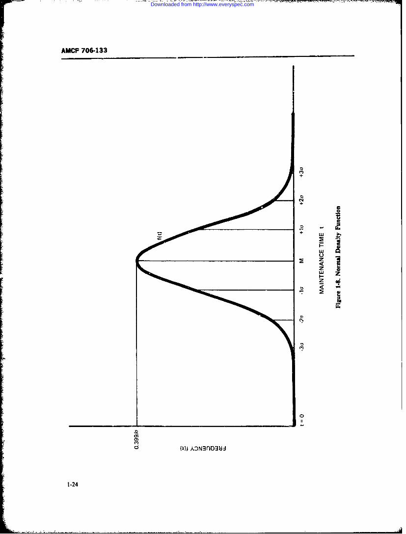
AMCP 706-133
ClC
z
-: z
z
Ci'
(1); AN~nD3,
1-24
Downloaded from http://www.everyspec.com
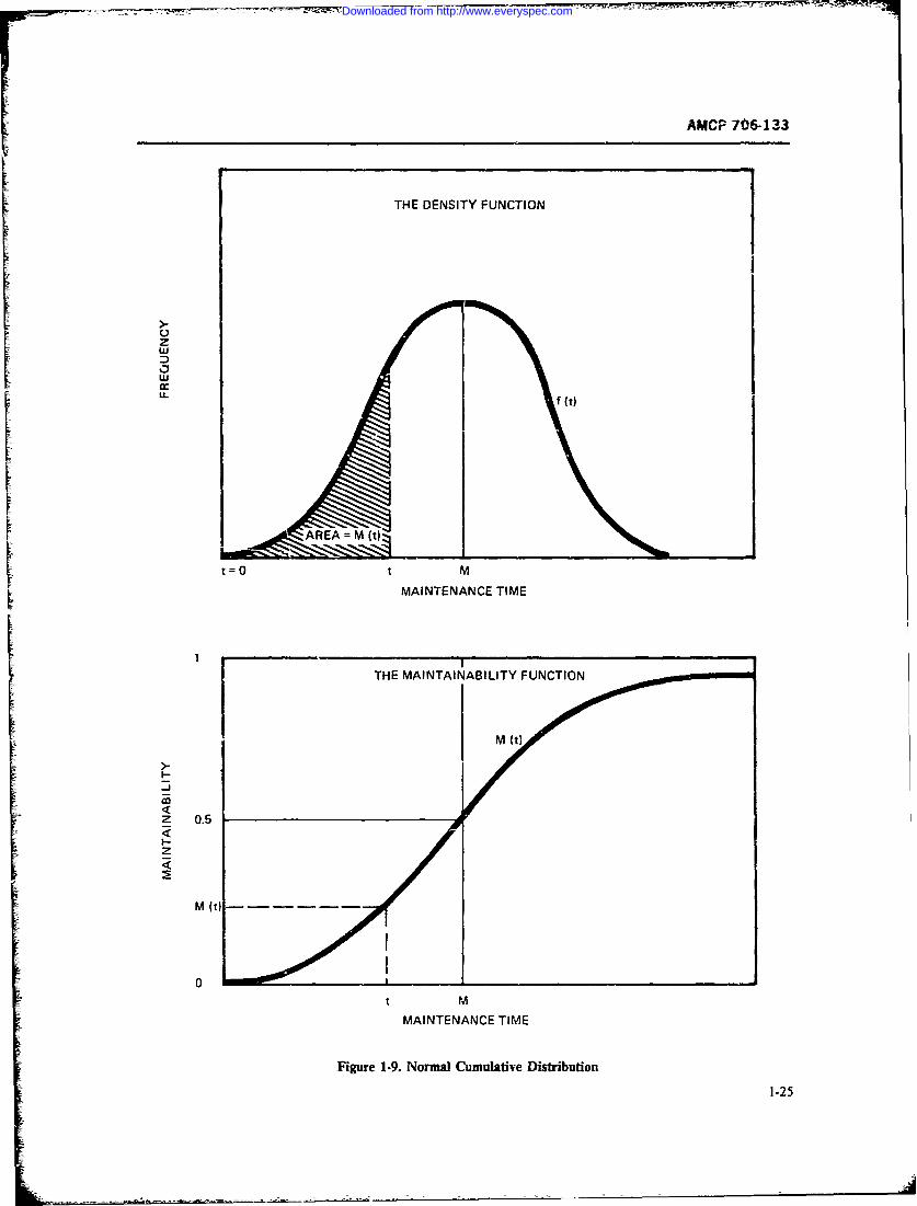
AMCP 7064133
THE DENSITY FUNCTION
z
ci
t=0 t M
MAINTENANCE TIME
[ THE MAINTAINABILITY FUNCTION
M (t)
<J
z 0.5
0t MMAINTENANCE TIME
Figure 1.9. Normal Cumulative Distribution
1-25
Downloaded from http://www.everyspec.com
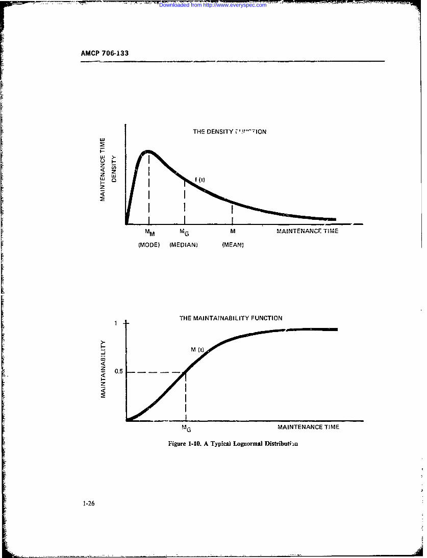
AMCP 706-133
[ THE DENSITY Pr'--ION
2w
-j
2< 05
MVG MI'A INTEN'ANCE TIME
IV 1vt
(MD)-MDIN26EN
Downloaded from http://www.everyspec.com
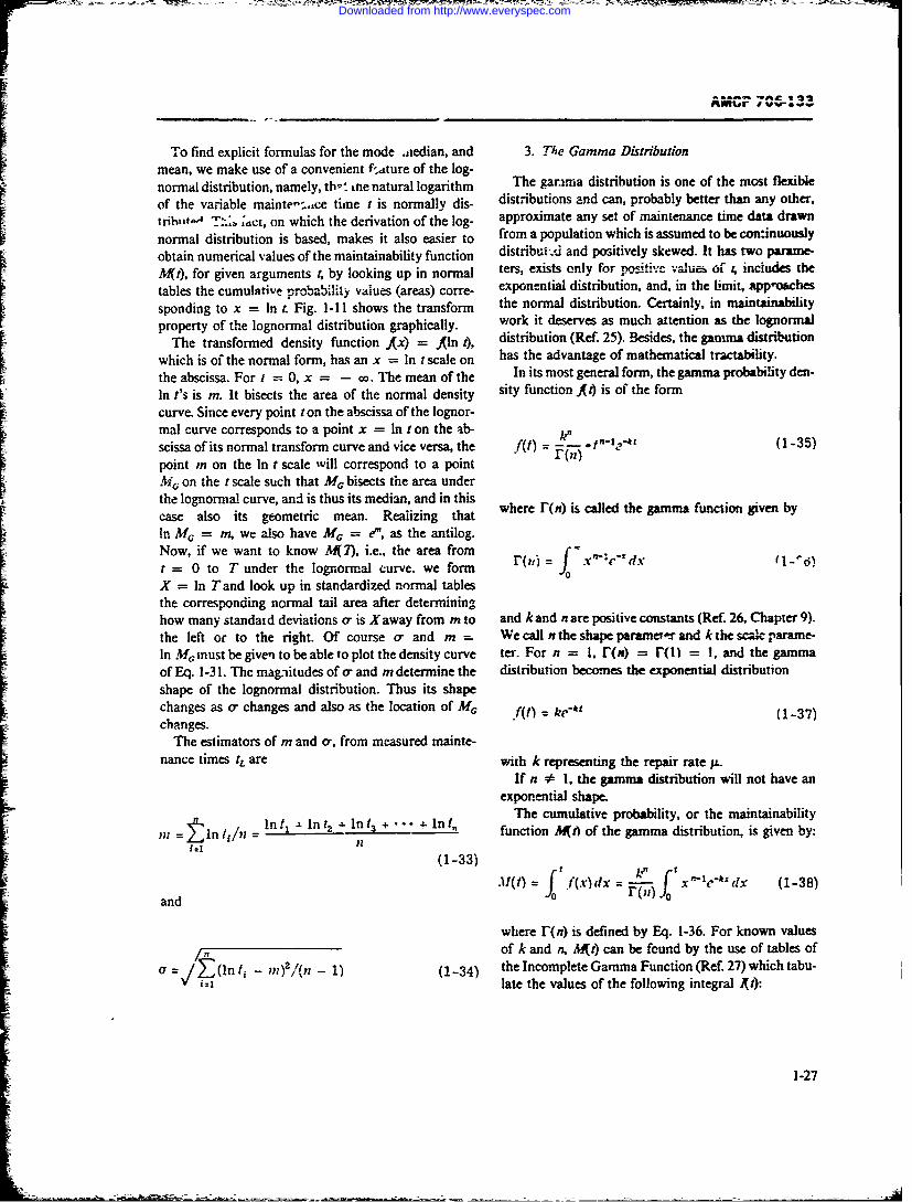
To find explicit formulas for the mode .iedian, and 3. The Gamma Distributionmean, we make use of a convenient f.,tture of the log-normal distribution, namely, th: tne natural logarithm The garma distribution is one of the most flexible
of the variable mainte-s..,ce time t is normally dis- distributions and can, probably better than any other,triht, T:., ;act, on which the derivation of the log- approximate any set of maintenance time data drawn
normal distribution is based, makes it also easier to from a population which is assumed to be confinuously
obtain numerical values of the maintainability function distributA and positively skewed. It has two parane-Mt), for given arguments t, by looking up in normal ters, exists only for pasitive values of t, includes the
tables the cumulative probability values (areas) corre- exponential distribution, and, in the limit, approaches
sponding to x = In t. Fig. 1-11 shows the transform the normal distribution. Certainly, in maintainabilityproperty of the lognormal distribution graphically. work it deserves as much attention as the lognormal
The transformed density function Kx) = Aln t), distribution (Ref. 25). Besides, the gamma distribution
which is of the normal form, has an x = In t scale on has the advantage of mathematical tractability.
the abscissa. For t = 0, x = - o. The mean of the In its most general form, the gamma probability den-
In t's is m. It bisects the area of the normal density sity function A') is of the form
curve. Since every point ton the abscissa of the lognor-mal curve corresponds to a point x = In t on the ab-scissa of its normal transform curve and vice versa, the f(t) (1-35)
point m on the In t scale ill correspond to a point (n)
M. on the t scale such that MG bisects the area underthe lognormal curve, and is thus its median, and in this
caseals itsgeoetri men. Raliing hat where r(n) is called the gamma function given bycase also its geometric mean. Realizing that
In M. = m, we also have M, = e", as the antilog.Now, if we want to know -417), i.e., the area from fo.X c dxt = 0 to T under the lognormal curve, we form f o = "' "d
X = In T and look up in standardized normal tablesthe corresponding normal tail area after determininghow many standaid deviations o- is Xaway from m to and k and n are positive constants (Ref. 26, Chapter 9).the left or to the right. Of course a- and m . We call n the shape parameo'r and k the scale parame-In M. must be given to be able to plot the density curve ter. For n = I, r(n) = r() = 1, and the gammaof Eq. 1-31. The magnitudes of a- and m determine the distribution becomes the exponential distributionshape of the lognormal distribution. Thus its shapechanges as a- changes and also as the location of MG f(t) = ke- (1-37)changes.
The estimators of m and o-, from measured mainte-nance times tL are with k representing the repair rate p.
If n * I, the gamma distribution will not have anexponential shape.
The cumulative probability, or the maintainability
n11 n b/n = nt- In tz 4. In 13 + + In 1, function MAA of the gamma distribution, is given by:
(1-33)
.1i(t) f f(x)dx = - x e-'dx (1-38)and T,0
where r(n) is defined by Eq. 1-36. For known values57- of k and n, W~t) can be found by the use of tables of
a= I (in ti - m) 2/(n - 1) (1-34) the Incomplete Gamma Function (Ref. 27) which tabu-= i~ilate the values of the following integral ](I):
1-27
Downloaded from http://www.everyspec.com
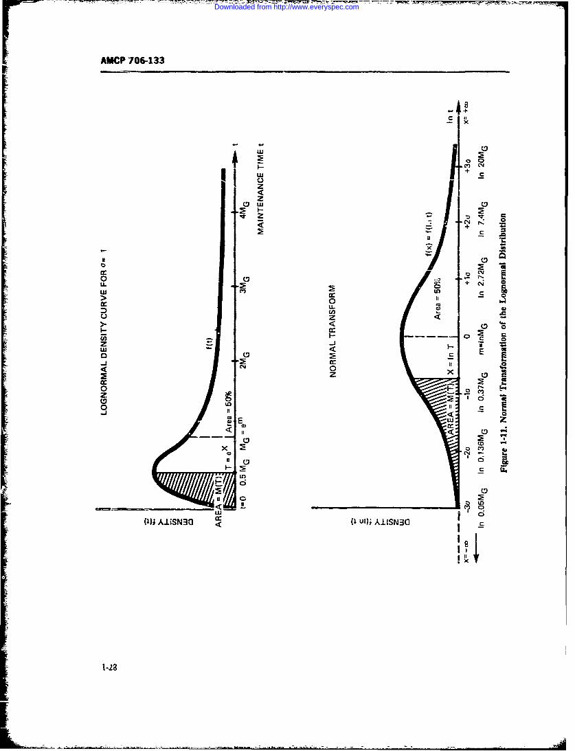
AMCP 706-133
CDj
w + c
zz
CCV
> 0D
z <
C
I CD
11(0
Ml) AJUSN3cJ (I uW) AIISN30
Downloaded from http://www.everyspec.com
AMCP 706-133
1~~~~~ rf--Xq~oX n with the argument U=kA sinceI~~t) n= e-A x"t'dx (1-39) C(X~for X =n-1 t eh tU=/ e
() e(- the summations are the cumulative temis of the Pois-son distribution. Also, the density function A ) of Eq.1-44 can be written in individual Poisson terms multi-
This integral A() has the same shape as Aft) of Eq. plied by the scale factor k, i.e.,1-38, except for the missing multiplication factor k.
Using (t), we may write for Aft),
M(t) = k"I(t) (1-4
4. The Weibull Distribution
which gives us direct numerical nswers when k and
n are known and reading (t) from tables. At times it is a-sumed that ti - field maintenanceThe mean Mof the gamma distribution has the sim- time of complex electronic eqpni c. is Weibull dis-
ple form of tributed. In fact, it was foumd in some specific cases thatthe distribution of administrative times which deiay
M = n/k (1-41) field maintenance can be closely approximated by theWeibull distribution (Ref. 29, page 366). Of course, a
gamma distribution also can be fitted as closely to suchwhich is the ratio of the shape parameter to the scale data. In general, the Weibull distribution in maintaina-parameter, and the variance Var(t) is bility work has not become popular or useful.
Var (t) = n/10 = Mk (1-42) byThe Weibull density function A) (Ref 30) is given
so that standard deviation o- of the gamma distribution fit) = (n/k")t"1 ? cp [(tk)"] (1-47)is
r = "/k = Flk (1-43) where n is the shape parameter and k is the scale pa-n rameter. The maintainability function -K4 is then
For positive integer values of the shape parametern, the gamma density function A4) assumes a simple m( = 1 - ext (t/kr ] (1-48)
form because r(n) = (n - 1)!, so that we get
f(t) [k/(n - 1) It -le-' (1-44) and the mean maintenance time M is
M = kr(l + l/n) (1-49)
This is often referred to as the Special Erlangian distri-
bution. It has the physical interpretation of a "stage-by-stage" repair. The corresponding ,-aintainability func- 5. The Poiron Disibutionion M11t) is then given by
The Poisson distribition (Re. 22, Chapter 8) is a1- t [ k /]discrete distribution with the density function pMYt) = 1 - k le (kt)'/i! I =z.. [e' t*iI,,o "" (1-45)
P(Ns = n) = p(n, t) = e *t(kt)n/n! (1-50)
and cap be read directly from Poisson tables (Rt. 28)as Mt)= D(A) for X= n. or asM~t)= 1- which in maintainaoility work is interpreted as the
1-29
Downloaded from http://www.everyspec.com
AMCP 706-133
probability that in time ta single repair channel, man, X-1or crew winlsuccessfiflly complete exactly n mainte- P(Ns X 1) Ipn,=ek1 + kI + --nance actions in sequence, when the maintenance time 4-5
ofthe actions is exponenfiaiy distributed with a mean 4 (kt)X1 /(X - 1)!] (1-53)maintenance time of M = 1/k The variable is hereN(#, i.e., the number of successfully completed main-tenance actions in time 1, where tis fixed znd the main- which is the probability that at thenmost X - I mainte-tenance rate of k =- z is known. N(4 theoretically can nance actions will be completed in . Consequently, weassume any integer value of n from zero to ininity. The getvalues of p(,) are found as individual terms F(X inPoisson tables, where the cumulative terms C(A) alsoare tabulated (Ref. 28). P(Ns X) = Jp. = e;-*[(kt)x/X!
The mean E of the Poisson distribution is .x
+ (kt)x'1 /(X + 1)! + -- -- (1-54)E(Ns) = kt = t/M (1-51)
as the probability that Xor more (or at least A) mainte-which is the expected number of successfUliy completed nance actions will be completed in r, so that by addingmaintenance actions in time t, when the actions are Eqs. 1-53 and 1-54, we getperformed in sequence.
Observing Eq. 1-50, we may writeP(Ns -< X -1) . P(N s > X) = F P = 1 (1-55)
P(Ns = 0) =P0 = ekt (1-50a)
Fig. 1-12 shows the probability density and thewhich is the probability no maintenance action will be cumulative probabilit, of a Poisson distribution with acompleted in 4 repair rate ofk = 0.5 per hr id an observaion time
oft = 10 hr, so that kt = 5 is the mean or the ex-P(NS = 1) =p, = Re"t (1-50b) pected number ofcompleted maintenance actions in 10
hr, when equipments are repaired in sequence (i.e., noparallel simultaneous repairs take place in this repair
which is the probability that exactly oj;- and only one channel).maint. _..nce action will be completed in I The bars in the upper graph of Fig. 1-12 represent
the probabilities of completing exactly n 0 0, 1, 2, 3,P(N s = 2) =p2 = [(kt#/2 !]e* tt (1-50c) .. maintenance actions in 10hr, while the lower graph
of Fig. 1-12 represents the cumulative probability ofcompleting at least n maintenance actions in t hours
which is the prooability that exactly two maintenance (i.e, n or more).
actions will be completed in t etc. To conclude this discussion let us mention the veyAs to the cumulative probability, we get interesting relationship between the diszrete Poisson
distribution and the time-continuous gamma distribu-
tion. When we observe a Poisson maintenance process,X) . we may ask what is the expected or mean time B(t.) to
the occurrence of the iah successfully completed re-
+ (kt)n/X1 (1 -52) pair. This is given by
E(t,.) = n/k (1-561which is the probability that X or less maintenanceactions will be completed in time t, or, we may say, theprobability that at the most Xmaintenance actions will since the time t, to the nth completed repair when thebe completed in time L We may also write Eq. 1-52 in Poisson maintenance process starts at : 0, is gammathe form distributed with the density At.)1-30
Downloaded from http://www.everyspec.com
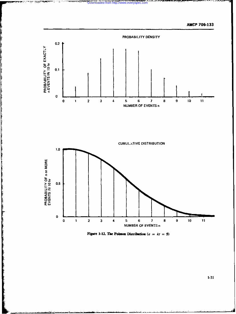
AMCP 706-133
PROBABILITY DENSITY
0.2I 0.1II
< Z
0 >CLC
0 1 2 3 4 5 6 7 8 9 10 11NUMBER OF EVENTS n
CUMULATIVE DISTRIBUTION
1.0
0
c
ow
>- o 0.5
0111
0 1 2 3 4 5 6 7 8 9 10 11
NUMBER OF EVENTS n
Fqpgure 1-1. Il"e Poimse IDistibtion. (a = ki = s)
Downloaded from http://www.everyspec.com
AMCP 706-133
f(l) = [k1(n - 1)! I t exp kt) %1-57) bility that not a single success will occur in Ntrials. i.e..p(S. = 0). is given by
which, as we know, has the mean n/k PC = P(S.v = 0) = (1 - Ps)V .!-61)
6. The Binomial Distribution
Another discrete distribution frequently used in sta- which is obtained by setting K = 0 in the Eq. 1-58. Thetistical work is the binomia: distribution. Its applica- robauility that exactly one success will be observed intion in maintainability appears to be rather limited. ,Ytrials is
The binomial distribution applies to so-called Ber-noulli trials where each trial has the same probabilityof success P, P1 = P(SV = 1) = NPs(1 - Ps)"V (1-62)
Assume that one has to perform a fixed number Nof trials of the same kind where each trial can end witha success or with a failure and where S, successes are The probability that exactly two successes will be ob-counted i.ithe Ntrials, so that there are N - S vfail- served in Ntrials isures. If one would observe the number of successesS. in a repeated seriesof Ntrials, the number .S.would Pz = p(S., = 2) = I.V(. - 1)/2! I s(1 - Ps)-
very likely change in each N trials. In fact, S, is a (1-63)random variable which may assume all integer valuesfrom zero to N, i.e., S, K where K = 0. 1. 2 3. etc.. until one gets the probability that all trials will be
. The probability that S, assumes a definite value successful. i.e.. S ; = , isof K is then given by the binomial probability densityfunction p as[
p(S., = X) = P (1-64)Pr =P(S=K)=( P(1 - Ps ". V- r (1-58)
The cumulative binomial diistribution I(S, >) iswhere, by definition then given by the partial sum of the probability densi-[ ties p, summing from K = X to K = N i.c.,
P = (PS. - X) !P r ]( Ipl-9 - P..VK=X r. X
The mean value of this distribution is the expected (1-65)or average number of suxesses E(S) in N trials givenby which is the probability that in N trials X or more
successes will be observed.E(S~) = VPs (1-60) To perform these calculations one must know the
probability of success PS in any one Bernoulli trial. Inreal life one obtains only an estimate of P, beczuse it
That is, if one would run a large series of experi- is not possible to run an infinite series of N trials eachments, with N trials performed in each experiment. the to get the true value of P. Running just one set of Nawraged number of successes observed per N trials trials one obtains only an estimate of P, denoted byshould approach the value of Eq. 1-60. P, as
Observing the binomial probability density function.oe can write the equations for S, assuming any of thevalues K = 0,1.2.3 . N. For example, theproba- Ps Sx/. (1-66)
1-32
Downloaded from http://www.everyspec.com
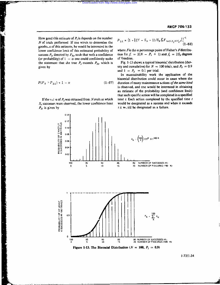
AMCP 706-133
How good this estimate of P, is depends on the number P L (.V - S 1)/S " I F. I x
N of trials performed If one wants to determine the = 18 it
goodn..s of this estimate, he would be interested in the (1-68)lower confidence limit of this estimated probability of where Fis the a percentage point of Fisher's Fdistribu-success Ps, denoted by PSL, such that with a confidence tion for f = 2(N - Ps + I) and / = 2 S degrees(or probability) of I - a one could confidently make of freedom.the statement that the true Ps exceeds Ps, which is Fig. 1-13 shows a typical binomiaz distribution (dep-given by sity and cumulative) for N = 100 triais, and P. = 0.9
and I - Ps = 0.1 per trial.
In maintainability work the application of thebinomial distribution could occur in cases where the
P(Ps > PSL) z 1 - C (1-67) duration oftmany maintenance actions ofthe same kind
is observed, and one would be interested in obtainingan estimate of the probability (and confidence limit)that such specific action will be completed in a specified
If the v%,i ie of Ps was obtained from Ntmals in which time t. Each action completed by the specified time t, successes were observed, the lower confidence limit would be designated as a success and when it exceedsPs1 is g;ven by t it w.-ild be designated as a failure.
014
012U,oS010
0080oz>- V K 1) S
K 0 1100 KV()w 006°) D
002
100 35 90 85 80 NUMBER OF SUCCESSES (K?
0 5 10 15 20 NUMBER OF FAILURES ('00 Ki
I-------------------------------
,I-
1000oz 05 .1000 0NUMRK O S K
0 96 10 85 20 NUMBER OF SAUSSS (10K)
Figure 1-13. The Binomial Distribution (N = 100, Ps = 0.9)
1-33/! -34
Downloaded from http://www.everyspec.com
AMCP 706-133
SECTION III
EQUIPMENT CONSIDERATIONS IN MAINTAINABILITY
1-9 CATEGORIES OF EQUIPMENT 3. Tcst methods such as built-in autorn'.ic check-out, monitoring, marginal testing, periodic check, andI' calibration.
It would b:- convenient and would simplify the task
of both the reliability and the maintainability engineer 1-9.1 ELECTRICAL-ELECTRONIC SYSTEMS
if different categories of systems and equipment could Electrical-electronic systems are in many ways thebe treated in the same manner with respect to their easiest to handle from a reliability and maintainabilityreiiability and maintainability characteristics. Unfortu-nately, this is not the case. Each category of equipment standpoint. More is known about their behavior, moremay require specific considerations which are peculiar reliability and maintainability data have been collected
to it. For example, reliability and maintainability con- for such systems and prediction and demonstration
sideratiuns for mechanical systems (Ref. 20, Chapter 6) techniques have been developed for these systems.
systems in wrich the-e are moving parts subject to Electrical systems generally are associated with thewear - have different maintenance requirements and generation and distribution of electrical energy andimplications for irrintainability design than do elec- may contain continuously rotating components, suchtronic systems. as motors and generators. Electronic systems contain
This paragraph contains a discussion of salient active as well as passive devices used for amplification,points of maintainability applicable to different catego- transformation, and shaping of electrical signals. Theyries of equipment, including electrical-electronic sys- generally do not contain continuous rotating devices,tems, electromechanical systems, hydraulic and rneu- but may contain intermittently operated electrome-matic systems, optical systems, chemical systems, and chanical items, such as switches, relays, variable resis-systems containing nonreversible devices.
There are a number of considerations which affect tors, capacitors, and inductors.maintainability design regardless of the category of Experience with reliability and maintainability ofmaint.bThese include: electronic systems has shown that where a constantequipment. Thazard rate is experienced, (the flat bottom of the well-
1 The operational level at which maintenance is to known bathtub curve in reliability), chance (random)be performed (organizational, direct support, general failure is the predominant reliabi!ity phenomenon.support, depot levels) Maintainability, in this case, primarily L- concerned
2. The system maintenance level (system, subsys- with corrective maintenance upon the occurrence of atem, equipment, group, unit, assembly, subassembly, failure. Indeed, it has been shown in such instances thatstage, piece part) the best maintenance policy may be to do no mainte-
3. The maintenance task to be performed (detec- nance until failure occurs, the so-called hands-off ortion, diagnosis, correction, replacement verification). "leave well enough alone" policy. Studies have shown
that where preventive maintenance, other than periodicIn addition to these common considerations, there are test or performarce monitoring, is performed, mainte-those which arc peculiar to the spific ,category of nance-induced faiur.:s often resu't. In these cases, andequipment. Among these are: where the wearout portion of tb. failure rate curve is
1. Equipment attributes such as accessibility, test sufficiently far away in time, the assumption of thepoints, connectors, controls, displays, inspection exponential failure distribution and the lognormal cor-points, fittings, lubrication points, and packaging. rective maintenance distribution frequently have been
2. Maintenance methods such as module replace- shown to be valid for electronic systems.ment, repair in place, periodic maintenance, adjust- A similar situation is true for electrical systems. Inment, c]ignment, inspection, overhaul, remove, repair these cases-where rotating components such as mo-in shop, and reinstall. tors, generators, and servos are used-wearout life
1-35
Downloaded from http://www.everyspec.com
characteristics can be expected to be approached at items as servo systems, actuators for moving missileearlier points in time than for purely electronic systems control surfaces, autopilots, radar gun laying devices,in which no moving parts are involved. Preventive track.ng radars, and the like.mpintenance tasks--such as brush and contact irspec- Electromechanical systems combine components intion and replacement, lubrication aud other servicing, equipments which fail in different modes, and, there-or inspection of shafts and bearings for alignment and fore, have different failure distribution statistics. Somefrictional wear-may be necessary in order to retain the of the items may have constant hazard rates and thussystem in its serviceable condition, effectively prevent- obey an exponential failure distribution. Other partsing the rising portion of the wearout curve from occur- may exhibit a hazard rate which increases with timering too soon. and, therefore, may be described by onc of a number of
The inclusion of maintainability features and mainte- other distributions such as the Weibull distribution.nance tasks in equipment design is usually simpler for For those parts which do have a constant hazard rate,electrical-electronic systems than for other types. Elec- corrective maintenance features are predominant; fortrical-electronic systems lend themselves readily by those which have an increasing hazard rate, preventivetheir very nature to the use of automation wai. regard maintenance features are more significant. Thus, oneto monitoring, fault diagnosis, and veriication. It is thing whizh distinguishes electroi.iechanical systemsalso simpler to achieve low corrective maintenance from electronic systems is the necessity for concerndowntimes. Many of the studies and dati c(!lect:d as with preventive maintenance features--such as peri-to the actual percentage of corrective maine..nce odic servicing, lubrication, and inspection-in additiontimes in the principal areas of detection, diagnosis, cor- to the corrective maintainability features provided forrection, and verification have been on electronic sys- electronic systems.tems and equipment. Since corrective maintenance andthe associated corrective maintenance tasks are gener- 1-9.3 MECHANICAL SYSTEMSally of greater importance in electrical-electronic sys-tems than preventive maintenance, maintainability For purely mechanical systems, or those systemscharacteristics which should be considered include: which are essentially mechanical, the situation with
a. built-in test points regard to maintainability considerations becomes quiteb. built-in test equipment different. Mechanical systems, in general, do not have
c. automatic monitoring constant hazard rates. They begin to wear out as soonas they are put to use. This does not mean that theynecessarily have short wearout lives; it just means that
e. functional packaging into unit replaceable friction and aging characteristics resulting from me-modules with provision for test points and failure in- chanical motion begin to exhibit themselves ratherdicators early. In order to obtain reasonable life expectancies or
f. controls reasonable MTBFs, therefore, the maintainabilityg. displays designer's attention must be focused on those equip-h. connectors ment considerations which will inhibit failures and will
i. parallel or standby redundancy to increase sys- prolong component and equipment life.
tem availability One approach to this is to design long-life, low-fric-ternovaila y moduletion elements, such as air bearings, or to use hard sur-j. throwaway modules face finishes. !i many instances this may be costly andk. the possibility of accomplishing a significant unrealistic, particularly when one considers the various
amount of corrective maintenance by replacement at envirojiments in which the equipment will be expectedthe organizational and direct support level, to operate. This approach puts the emphasis on des.gn
for high reliability.1-9.2 ELECTROMECHANICAL SYSTEMS Another approach, which is often more cost-effac-
tive, is to recognize the essential nature of mechanicalThe primary difference between electromechanical systems with regard to the physics of failure and to
systems and electrical-electronic systems is that me- incorporate maintainability features during system de-chanical actuating elements are utilized in electrome- sign which will inhibit the rapidly rising wearout char-chanical systems to perform some of the system prime actenstic. Nttention, therefore, must be on preventivefunctions in addition to electrical or electronic ele- maintenance features such as periodic inspection andments. Electromechanical systems may include such replacement, lubrication, calibration and alignment,
1-36
Downloaded from http://www.everyspec.com
AMCP 706-133
and overhaul (Ref. 20, Chapter 20). Indeed, for me- as well as external sources are of great importance.chanical systems, this might be the most realistic means Maintainability design considerations are concernedfor achieving high operational readiness, with preventive maintenance as the principal means of
Cost-effective trade-offs between item life and main- obtaining long-lived hydraulic and pneumatic systems.tenance intervals, maintenance personnel, and other Alignment, lubrication, visual indicators (such as sightmaintenance resource requirements are of concern in gages, pressure and temperature indicators), oil and airmechanical systems. The ability to remove assemblies spectral and chemical analysis, filter characteristics,and components with a minimum of teardown empha- and inspection and replacement are some of the pri-sizes thd need for modularization, interchangeability, mary maintainability considerations.and standardization. These ;.re also important, ofcourse, in electrical-electronic systems, but more dif- 1-9.5 OTHER SYSTEMSficult to accompish in mechanical systems.
With regard to maintenance levels for mechanical Among other categories of systems to which main-systems, the simplest preventive maintenance func- tainability consideration may have to be given are opti-tions--such as inspection, lubrication, removal and re- cal and chemical systems. For fixed optical systems (noplacement, and adjustment and .lignment-should be moving parts), reliability is generally high, and primaryperformed at organizational levels, assisted by Direct maintainability requirements are those of keeping theSupport technicians and tools. Additional detailed system clean, aligned, and calibrated. For electro-opti-maintenance tasks must be performed at the General cal sys:tac' without moving parts, maintainability con-Support level. For complex mechanical items, most siderations for electronic systems apply. Similarly,corrective maintenance, repairs, and overhaul can be when there are moving parts so that the systems areexpected to be accomplished at the General Support mechanico-optical or electromechanico-optical, thenand Depot levels. The concept of rotatable pools of maintainability considerations for these types of equip-mechanical components, assemblies, and equipments, ments and systems, as discussed earlier in this para-such as the Army Direct Exchange Program (DX), is graph, will also apply.a feasible one. This concept, discussed in more detail in For chemical systems, maintain.i!Lit, t.0i=:era-Chapter 5, is one in which forward level repairs are tions have to do with contamination, cleanliness,primarily accomplished by replacement of assemblies, safety, visual inspection, chemical analysis, and withcomponents, and equipments, with detail repair in field the specific nature of the chemical apparatus involvedoperations performed at rear levels, and the repaired in the chemical reaction. The chemical system mayitems returned to a repaired rotatable pool. As a matter contain features of several of the previously discussedof fact, when it is desirable to overhaul ce:tain items categories of systems, and thus maintainability consid-after so many hours of use, the rotatable pool concept erations of these will also apply where appropriate.can be very cost-effective. Propulsion systems are examples of chemical systems.
1-9.4 HYDRAULIC AND PNEUMATICSYSTEMS 1-10 NONREVERSIBLE DEVICES
Hydraulic and pneumatic systems are examples of Nonreversible devices are items which depend uponsystems in which fluid flow is the primary energy trans- some physical, chemical, or biological reaction or effectfer means. While there are instanccs of purely hydrau- which, once started, cam:t be reversed or changedlic and pneumatic systems, generally these types of back to its original form or state. Ammunition, radi-equipment are combined with electrical or mechanical oactive substances, and chemical processes are nonrev-equipments to form electrohydraulic and other combi- ersible devices. Bullets, bombs, and missiles are exam-nation systems. Reliability and maintainability prob- pies of the first; atomic bombs and nuclear power orlems with respect to hydraulic and pneumatic systems propulsion of the second; napalm and rocket propel-are primarily concerned with pressure strengths, ero- lants of the third. Reliability and maintainability con-sion, contamination and leakage of the fluids used (liq- siderations for such devices are different from theuid or gas), ond the reliability of seals, gaskets, and categories of equipments discussed in par. 1-9. Becauseother seal'ag devices. Of concern to the designer then their reactions cannot be reversed and are thus notare the material ,,nd life characteristics of components, repairable once the action is initiated, it is essential thatsuch as pressure vessels, piping, 0-rings, gaskets, the mission reliability of such devices be high. Empha-pumps, filters, and ports. Contamination from internal sis on these devices therefore has been and will continue
1-37
Downloaded from http://www.everyspec.com
AMCP 706-133
to be high inherent reliability and safety. This does not device effectiveness from test results. Of prime concernmean that there are no maintainability considerations are:involved in nonreversible devices. It only means that 1. The ability to simulate the operation of the non-once the mission has been started, maintainability can reversible device where necessary in order to properlyno longer be effected, such as is possible with a commu- exercise and test the total systemnication or radar system, aircraft, or tank. 2. The ability to safely test the system under vari-
Maintainability considerations for these types of de- ous operational situations and environments withoutvices primarily reside in the maintainability of the re- initiating the nonversible reactionmaining parts of the system of which the nonreversible 3. The ability to obtain high confideace levels ofdevice is a part. These remaining pars include such successful operation once committed to the mission.items as launching and aiming devices, fuzing, and ini-tiating devices. In the early guided missile days, many This places great emphasis on the areas of safety, test,valuable lessons were learned with regard to reliability and checkout as prime equipment design considera-and maintainability. One of the principal lessons tions for the maintainability of nonreversible devices.learned was that, although missiles are designed to op- Such test and checkout ranges all the way from rela-erate for a short duration, measured in minutes, relia- tively simple manual tests to highly sophisticated andbility design was originally performed so that the parts complex automatic checkout equipment and proce-of the missile would operate only for the mission time. dures.The necessity for test and checkout was not consideredby the designers, and this resulted in many of the earlymissiles being worn out because of the need for frequent 1-11 DESIGN GUIDEStest and checkout and the accumulation of significantlymore operating time than the missile components were A number of equipment design guides for maintaina-designed for. In order to assure high mission reliability. bility have been written. These guides, in general. dis-however, it was necessary to exercise and test all those cuss the maintainability design features and problemsparts of the system except the nonreversible devices up in terms of maintenance methods, maintenance tasks orto and including its fuzing circuitry. actions, maintenance time distributions, maintenance
With the emphasis almost completely on reliability levels, and equipment attributes. No attempts are madein the early missile developments, there was a lack of to relate these to the maintainability quantitative re-maintainability considerations, and the consequent quirements. except by implication in generic terms. Indrastic effect on operational availability of the missile addition, many of these design guides, includingsystems due to repeated testing helped spur the devel- AMCP 706-134 (Ref. 5), contain specific anthropomet-opment of maintainability as a system design discipline. ric and other human factors considerations, specific
Maintainability considerations, therefore, of nonrev- equipment design features, and designer's checklistsersible devices have to do with the state of readiness which can be applied to a wide variety of equipmentprior to the mission start. They have to do with design- and maintenance concepts (Refs. 31-39). Chapter 5ing features into the equipment which emphasize pen- treats equipment design for maintainability in greaterodic test and checkout, and the prediction of the overall detail.
REFERENCES
I. MIL-STD-470, Maintainability Program book, Maintainability Guide for Design.Requirements, 21 March !966. 6. A. Coppola and A. D. Pettinato, "RADC Case
2. MIL-STD-471, Maintainability Demonstra- Histories in R & M Demonstration", Proceed-tion, 15 February 1966. ings of the 1o66 Annual Symposium on Relia-
3. MIL-HDBK-472. Maintainability Predic- bility, IEEE, 1966, pp. 395-408.tion, 24 May 1966. 7. J. E. Daveau and A. Coppola, "Reliability and
4. MIL-STD-721R, Definition of Effectivenesv Maintainability Case Histories". ProceedingsTerms for Reliability. Maintainability. Human of the Sixth Annual RIM Conferenre, JulyFactors. and Safety, 25 August '966. 1967, Society of Aut.'motive Engineers, pp.
5. AMCP 706-134. Engineering Design Hand- 582-586.
1-38
Downloaded from http://www.everyspec.com
AMCP 706-133
8. D. W. Lowry, "Maintainability Demonstra- 24. Melvin B. Kline, "Application of the Lognor-tion Test Performed on a Computer System", mal Distribution to Maintainability Design",Proceedings of the 1970 Annual Symposium on The Logistics Spectrum 1, No. 2, 13-20 (1967-Reliability, IEEE, 1970, pp. 308-318. 68).
9. A. C. Hall, Relationship Between Operational 25. An Application of the Gamma Distribution toEffectiveness of Electronic Systems and Main- Downtime Distribution Functions, Maintaina-tenance Minimization and Training, in Pro- bility Bulletin No. 13, Electronic Industriesceedings, Symposium on Electronics Mainte- Association, Washington, D.C., Septembernance, OASD (R&D), Washington, D.C., 1968.1955. 26. Paul L. M-yer, Introductor Probability and
10. F. L. Ankenbrandt, Ed., Electronic Statistical Applications, Addi-on- Wesley Pub-Maintainability, Vol. 3, Engineering Publish- lishing Company, Inc., Reading, Massa-ers, Elizabeth, N.J., 1960. chusetts, 1965.
11. Headquarters AMC Memo AMCRD-ES, 21 27. Karl Pearson, Tables of b1 e IncompleteJan. 1971. Subject: "Economy vs. Life Cycle Gamma Function, Cambridge UniversityCost", signed by Maj.-Gen. John R. Guthrie, Press, Cambridge, England, 1934.
Director, Research, Development and Engi- 28. Tables of the Individual and Cumulativeneering. Terms of Poisson Distribution, Defense Sys-
12. Weapons System Effectiveness Industry Advi- tems Dept, General Electric Company, D. Vansory Committee (WSEIAC), "Requirements Nostrand Company, Inc., Princeton, N.J.,Methodology, Final Report of Task Group 1", 1962.Air Fore Systems Comm;,and, AFSC-TR-65- 29. William H. von Alven, Ed., Reliability1, Jan. 1965 (AD-458 453). Engineering, Prentice-Hall, Inc., Englewood
13. AR 702-3 Army Materiel Reliability, Avail- Cliffs, N.J., 1964.ability, and Maintainability. 30. Waloddi Weibull, "A Statistical Distribution
14. AR 750-1, Maintenance Concepts. Function of Wide Applicability", Journal of15. TM 38-703, Integrated Logistic Support, 5 Applied Mechanics 18, No. 3, 293-297 (1951).
Volumes, Dept. of the Army, 1969. 31. L. V. Rigby, J. I. Cooper, and W. A. Soickard,16. AMCR 750-42, Maintenance of Supplies and Guide to Integrated System D.sign for Main-
Equipment; AMC Maintenance Engineering tainability, ASD Technic?; report 61-424,Activity. U S Air Force, Wright -Patterson Air Force
17. MIL-STD-785A, Reliability Program for Sys- Base, Ohio. October i9ol, AD-271 477.tems and Equipment Development and Froduc- 3?. Melvin B. Kline. Maintainability Considera-tion, 28 March 1969. tions in System Design, Doctoral Dissertation,
18. Tables of the Exponential Function, National Dept. of Engineering, University of California,Bureau of Standards, Applied Mathematics Los Angeles, 1966. University Microfilms,Series No. 14, June 1951. Ann Arbor, Michigan.
19. B. S. Blanchard, Jr. and E. E. Lowery, Main- 33. J. M. McKendry, et al.. Maintainability Hand-tainability Princ-pies and Practices McGraw- book for Electronic Equipment Design, Supple-Hill Book Company, Inc., N.Y., 1969. ment IV to NAVTRADEVCEN 330-1, US
20. Igor Bazovsky, Reliability Theory and Naval Training Device Center, Port Washing-Practice, Prentice-Hall, Inc., Englewood ton, N Y., April 1960, AD-241 284.Cliffs, N.J., 1961. 34. J. G. Wohl. "Why Design for Maintainabil-
21. Orest A. Meykar, "Maintainability Ter- ity?", IRETransactions on Human Factors inminology Supports the Effectiveness Con- Electronics HFE-2, 87-92 (1961).cept", IEEE Transactions on Reliability R-16, 35. J. D. Folley, Jr. and J. W. Altman, Guide toNo. 1, 10-15 (1967). Design of Electronic Equipmentfor Maintaina-
22. M. J. Moroney, Facts from Figures Penguin bility, WADC Technical Report 56-218, U SBooks, Inc., Baltimore, Md., 1951. Air Force, Wright-Patterson Air Force Base,
23. A. H. Bowker and G. J. Lieberman, Engineer- Ohio, April 1956, AD-101 729.ing Statistics, Prentice-Hall, Inc., Englewood 36. J. W. Altman, et a!.. Guide to Design fJ Me-Cliffs, N.J.. 1959. chanical Equipment for Maintainability, ASD
1-39
Downloaded from http://www.everyspec.com
AMCP 706-133
Technical Report 61-381, US Air Force, sign of Equipmen4 NAVWEPS OD 18413A,Wright-Patterson Air Force Base, Ohio, Au- August 1962.gust 1961, AD-259 332. 39. J. Cooper, "An lwegrated Approach to Sys-
37. Maintainability Design Criteria for Designers tern Ma*ntz;nability", Chapter 14 in Electronicof Shipboard Electronic Equipmen4 NAV- Maintainability, Vol. 3, ed. by F. L. Anken-SHIPS 94324, Change No. 2, March 1965. brandt, Engineering Publishers, Elizabeth,
38. Human Factors Design Standards for the Fleet N.J., 1960.Ballistic Missile Weapon System, VoL II - De-
I
Downloaded from http://www.everyspec.com
AMCP 706-133
CHAPTER 2
SYSTEM EFFECTIVENESSSECTION I
INTRODUCTION
2-1 GENERAL tions. Obviously, with repeated usage ease of mainte-
As pointed out in par. 1-2, the realization that in nance assumes a very significant role.
many cases a more cost-effective system can be ob- An Air Force study on system effectiveness states:
tained by trading off some reliability for the ability to "The high cost and complexity of modem military
maintain a system has led to a consderable research systems require the most efficient management possible
and development effort into describing maintainability to avoid wasting significant resources on inadequateas an engineering discipline. Thin, in turn, has led to the equipment.
concepts of operational readiness, availability, and sys- "Efficient systems management depends on the
tem effectiveness as elements of sys.em worth-the ul- successful evaluation and integration of numeroustimate measure of a system. Army Technical Manual different but interrelated system characteristics such C3
TM 38-703-1 (Ref. !) states: reliability, maintainability, performance, and costs. IfThe fectivenwirth whichys it detmine.pSubsesuch evaluation and integration are to be accomplished
"The worth of a system is determined prmarily by in a scientific rather than intuitive manner, a methodthemust be formulated to assess quantitatively the effectsto World War II, system reliability came to the forefront of each system characteristic on overall systemas a measure of system performance. More recently the effectiveness." (Ref. 2).systems approach requiring such consideration as systemmaintainability and availability has received increasing How do availability, readiness, and maintainability
attention. All of these factors are highly interdependent relate to other system parameters? Considerable atten-and tend to make the measurement of system tion has been paid to this question in recent years, andperformance very complex. A measure of system many concepts have been proposed. Of these concepts,performance may be generally defined as a quantified system effectiveness has been elevated to the position ofassessment of the ability of a system to fulfill a specified highest rank.function, when both the system and function are The notions of effectiveness and measures of effec-thoroughly defined. The narameter to be defined by tiveness are not new. Such measures have been used forsuch a measure is called system effectiveness."Specification of the support environment is also many years for determining how well a device performsessential in system effectiveness assessment. or for comparing one device with another. The use of
figure-of-merit comparison is well known, e.g., theIt is recognized by system designers today, particu- gain-bandwidth product for electronic amplifiers.
larly for systems that are not of the "one-shot" type but Th,. extension to measuring system performance onwhich are required to have a long operational life with cme overall mission basis is, however, relatively re-repeated usage, that system effectiveness considera- cent. Many of the operations rese,-rch and system anal-tions, in which maintainability is indeed as significar: ysis efforts, which became prominent starting in Worlda parameter as. reliability, consist of more than just War 11, were initiated in order to find quantitativesystem performance and mission reliability ceisidera- methods for assessing and optimi-Ing system effective-
2-1
Downloaded from http://www.everyspec.com
AMCP 706-133
ness. Cost-effectiveness considerations have become a put forth and are being used today, the semantic barri-major item of system design in defense and space sys- ers (sometimes very great) that have arisen, their pointstems, due largely to the emphasis given by former As- of similarity and difference, and the ease or difficultysistant Secretary of Defense Hitch. of their application.
A system is designed to perform a function or set offunctions (meet a need). System effectiveness is a meas-ure of how well the system performs its intended func-tion in its operating environment. In order to :e a 2-2 SYSTEM EFFECTIVENESSuseful measure, it is necessary to express system effec- CONCEPTStiveness in quantitative terms. A number of such meas-ures have been derived, most in a probability sense.
The effectiveness of a system, in the final analysis, The three generally recognized components of sys-can only be really measured when the system is per- tem effectiveness described in the previous paragraphforming its mission in the environment for which it was (reliability, availability, performance) will be used asdesigned or other accurately simulated environment, the basis for description and comparison of the con-Of great concern, however, is how system effectiveness cepts and formulations of system effectiveness whichcan be predicted while the system design concepts are are currently in use. It should be recognized that all ofbeing formulated and again later when the system is these effectiveness components must be derived frombeing designed and evaluated. Thus, most system effec- an analysis of the operational needs and mission re-tiveness methodologies deal more with the predictive quie.-rnts of the system, since it is only in relation todesign and test aspects of effectiveness'of the system needs ard missions #hat these three basic componentsthan with the later use of the system. can be meaningfully established.
The effectiveness of a system, then, is concerned with Many semantic diffic.ties arise when discussing sys-
1. The ability of the system to perform satisfac- tern effectiveness and its components. These difficulties
torily for the duration of an assigned mission, often result from the fact that some people use the samestated as mission reliability words to mean different things or different words tomean the same thing.
2. The ability of the system to begin performing itsmission when called upon to do so, often stated asoperational readiness or availability; and 2-2.1 ThE ARINC CONCEPT OF SYSTEM
3. The actual performance mesures -f the system EFFECTIVENE3Sin tzr-s of its performance functions and environment
in which it performs, often stated as design adequacyo7 One of the early attempts to develop concepts ofcapability. system effectiveness was delineated by the ARINC Re-
These may be related, as in AMCP 706-134 (Ref. 3), as search Corporation in Chapter I of their book, Reliabil-System Effectiveness = Reliability X Availability X ity Engineering (Ref. 4). It contains some of the earliesiPerformance (How Long?) (How Often?) (How published co--::epts of system effectiveness and repre-
Well?) sents one of the clearest presentations of these concepts,
Just about all system effectiveness methodologies from which many of the subsequent descriptions haveJustabot al sytem ffetiveessbeen derived. The de-inition of system effectiveness in
which have been developed in the past 10 to 15 yr ai e n ei Io isfasifollows ytem effectivenest is
concerned with these fundamental questions in one therly that th sys can efullyveet an
way or another. They include such system attributes as the probability hat the system can succeshully meet en
performance parameters, reliahility, maintainability, operational demand within a given time when operated
and logistic supportability, as well as such other attrib- under specified conditions".
utes as human factors, safety, and standardization, all This definition includes the following concepts:
of which condition the zbility of a system to perform 1. That system effectiveness can be measured as aits assigned missions. (See Fig. 1-1.) probability
It is instructive, therefore, to discuss and compare 2. That system effectiveness is related to opera-the various concepts and methodologies that have been tional performance
2-2
Downloaded from http://www.everyspec.com
AMCP 706-133
3. That system effectiveness is a function of probability that the system will continue to operatetime satisfactorily for the period of time required for the
4. That system effectiveness is a fanction of the mission, (3) the probability that the system will success-
environment or conditions under which the system is fully accomplish its missit a given that it is operatingu-.ed within design limits (Fig. 2-2(A)).
5. That system effectiveness rn.y vaiy with the Each of these terms may then be developed in terms
mission to be performed. of the specific problem. (See, for example, Chapter 11of Ref. 4.)
What is rot obvious in this definition, with regard to.ystem effectiveness as a function of time, is that thereare two kinds of time to be considered. One is the point 2-2.2 THE AIR FORCE (WSEIAC) CONCEPTin time in which we wish to make use of the systau andwhet.k,;r or not the system is usable at that time. The A more recent definition of system effectiveness re-other is the continued period of time, starting with this suits from the work of the Weap'n System Effective-point in time, for which we want the system to continue ness Industry Advisory Committee (WSEIAC) estab-to operate (mission tim".). The three components of lished in late 1963 by the Air Force Systems Commandsystem effectiveness, act ording to the ARINC model "to provide technical guidance and assistance to AirFig. 2-2(C), are mission reliability, operational readi- Force Systems Command in the development of a tech-hess, and design adequacy, as shown in Fig. 2-1. Defini- nique to apprise management of current and predict-dtions of the words used in this figure are given in Table weapon system c'Tectiveness at all phases of weapon2-1. These are essentially the three factors which con- system life". Five task groups worked for one year ontribute to system effectiveness as indicated a. the begin- various aspects of this problem. The result of thesening of this paragraph. A study of these definitions and efforts has been published as Air Force Systems Coin-their meaniig is of particular significance. While most mand Technical Reports TR-65-1, TR-65-2, TR-65-3,of these detinitions are left to the reader to study, cer- TR-654, TR-65-5, and TR-65-6 (Ref. 2). Thetain definitions and their meanings or implications will WSEIAC definition of system effectiveness, Fig. 2-be discussed in more detail. This will be particularly 2(B), ishelpful when cther concepts of system effectiveness "System effectiveness is a measure of the extent towhich have been developed are discussed. which a system may be expected to achieve a set of
Although it is not essential to describe system effec- specific mission requirements and is a function of avail-tiveness and its comtoneri parts in terms of probabili- ability, dependability, and capability" (Ref. 2).
ties as opposed to other quantitative measures, it has This definition may be expressed asoften beeai found to be convenient to do so. TheARINC model may be expressed such :hat system ef-fectiveness probability PsE is the product of threeprobabilities as follows:
where
PSE = )< PMR XPDA (2-1) A = aailability, a measure of thesystem condition at the start ofa mission, when the mission is
where called for at an unknownPox = operational readiness (random) point in time
probability D = dc2endabihty, a measure of the= mission reliability probability system condition at one or
PD, = design adequacy probability more points during theThis equation states that the effectiveness of the svs- performance of the mission,
tern is the product of three probabilities: (1) the proba- given the system conditionbility that the system is operating satisfactorily or is (availability) at the start of theready to be placed in operation when needed, (2) the mist-:on
2-3
Downloaded from http://www.everyspec.com
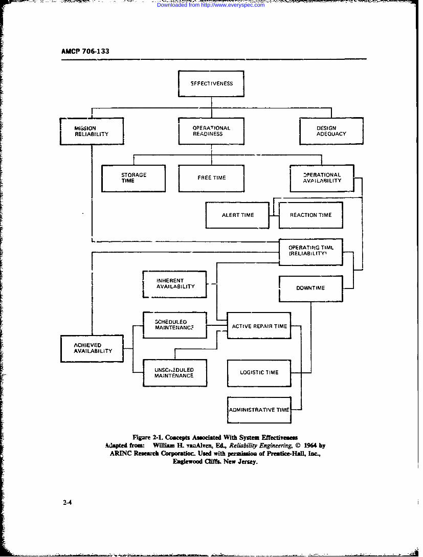
AMCP 706-133
E FFECTrIVENESS JI MiSSION OPRAIOA DESIGNI ELIAL j R OEAINALS ADEQIUACY J
TI
ALERTTIME] [jRATOIMEr ~~L__ __ _ _ _
OPERATING TIMI(RELIABiLITY'
HE RENT_I AVAILABILITY DWTM
L__________F SCHEDULED
Am:W IhTEfNgnennC9 ACIERPARTMF1 1h A,
ACHEVE
Downloaded from http://www.everyspec.com

AMCP 706-133
TABLE 2-1.DErI._r IONS
Definitions of Concepts:
System Effectiveness is the probability that the system can successfully meet an operationaldemand withir a given time when operated under specified cond*tior,s.
System Effectiveness (for a one-shot device rich as a missile) is the probability that the system(missile) will operate sucoessfully (kill the target) when called upon to do so under specifiedconditions.
Reliability is the probability that the system will perform satisfactorily for at least a givenperiod of time when used under stated conditions.
Mission Reliability is the probability that, under stated condition , the system will operate in-che mode for which it was designed (i.e., with no malfunctions) for th" durttion of a mission,given that it was operaxing in this mode at the beginning of the missir,.
Operat, 7nal Readiness is the probability that, at any point in time, the system is eitheroperating satisfactorily or ready to be placed in operation on demand when used under statedconditions, including stated allowable warning time. Thus, total calendar time is the basis forcomputation of operational readiness.
Availability is the probability that the system is operating satisfactorily at any point in timewhen used under stated conditions, where the total time considered includes operating time, activerepair time, administrative time, and logistic time.
Intrinsic Availability is the probability that the system is operating satisfactorily at any pointin time when used under stated conditions, where the time considered is operating time and activerepair time.
Design Adequacy is the probability that the system will accomplish its mission successfully,given that the system is operating within design specifications.
Maintainability is the prooability that, when maintenance action is initiated under statedconditions, a failed system will be restored to operable condition within a specified total downtime.
Repairability is the probability that a iailed system will be restored to operable conditionwithin a specified active repair time.
Serviceability is the degree of ease or difficulty with which a system can be repaired.
2-5
Downloaded from http://www.everyspec.com
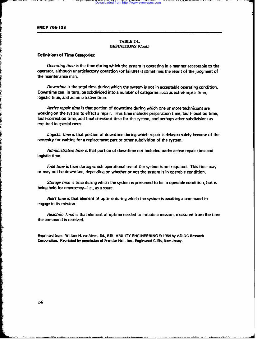
AMCP 706-133
TABLE 2-1.DEFINITIONS (CaL)
Definitions of Time Categories:
Operting time is the time during which the system is operating in a manner acceptable to theoperator, although unsatisfactory operation (or failure) is sometimes the result of the judgment ofthe maintenance man.
Downtime is the total time during which the system is not in acceptable operating condition.Downtime can, in turn, be subdivided into a number of categories such as active repair time,logistic time, and administrative time.
Active repair time is that portion of downtime during which one or more technicians areworking on the system to effect a repair. This time includes preparation time, fault-location time,fault-correctson time, and final checkout time for the system, and perhaps other subdivisions asI required in special cases.
Logistic time is that portion of downtime during which repair is delayea solely because of thenecessity for waiting for a replacement part or other subdivision of the system.
Administrative time is that portion of downtime not included under active repair time andlogistic time.
Free time is time during which operational use of the system is not required. This time mayor may not be downtime, depending on whether or not the system is in operable condition.
Storage time is tine during which the system is presumed to be in operable condition, but isbeing held for emergency-i.e., as a spare.
Alert time is that element of uptime during which the system is awaiting a command toengage in its mission.
Reaction Time is that element of uptime needed to initiate a mission, measured from the timethe command is received.
Reprinted from iWilliam H. vanAlven, Ed., RELIABILITY ENGINEERING @ 1964 by ARINC ResearchCorporation. Reprinted by permission of Prentice-Hall, Inc., Englewood Cliffs, New Jersey.
2-6
Downloaded from http://www.everyspec.com
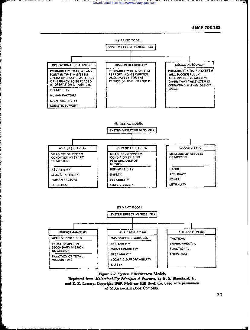
AMP 70H&133
(A- AR INC MODEL
POINT IN TIME. A SYSTEM PE RFORMING ITS PURPOSE WILL SUCCESSFULLYOPERATING SATISFACTORILY ADEQUATELY FOR THE ACCOMPLISH ITS M4ISSION.OR IS READY TO BE PLACED PERIOD OF TIME INTENDED G!IcEN TI-EAT THE SYSTEM ISIN OPERATION C" DEMAND- OPERATING WITHIN DESIGN
RELIABILITYSPC
HUMAN FACTORSI
MAINTAINABILITY IFlI LOGISTIC SUPPORT
(6) VWSEIACMDE
[CONDITION AT START CONDITION DURINGOFMS!-OF MISSION PERFORMANCE OF
MISSION
RELIABILITY REPA. FPABILITY RANGE
MAINTAINABILITY SAFETY ACCURACY
HUMAN FACTORS FLEXIBILITY I PO WE R
LOGISTICS1 SURVIVASILITY I LETHALITY
iCl NAVY MODEL
PERFORMANCE ;PI AVAILABILITY (A) UTILIZATION (U)
ACHIEVEDJDESIRED MAN MACHINE MODULES TACTICAL
PRIMARY MISSION EEIBLIY;NVIRONiMEN:'TALSECONDARY MISSION MAINTAINABILITY FUNCTIONALNO MISSION
FRACTION OF TOTAL OPERABILITY LOGISTICAL
MISSION TIME LOGIST~C SUPPORTABILITY
--SAFETY
Figure 2-2. System Effectrness ModelsReprinted from M4aintanabiv prznc~ples & Practicfs, by B. S. Blanchard. Jr.
and E. E. Lowery. Copyright 1969. McGraw-Hill Book Co. Used with pemoof McGraw-HMl Book Company-
2-7
Downloaded from http://www.everyspec.com
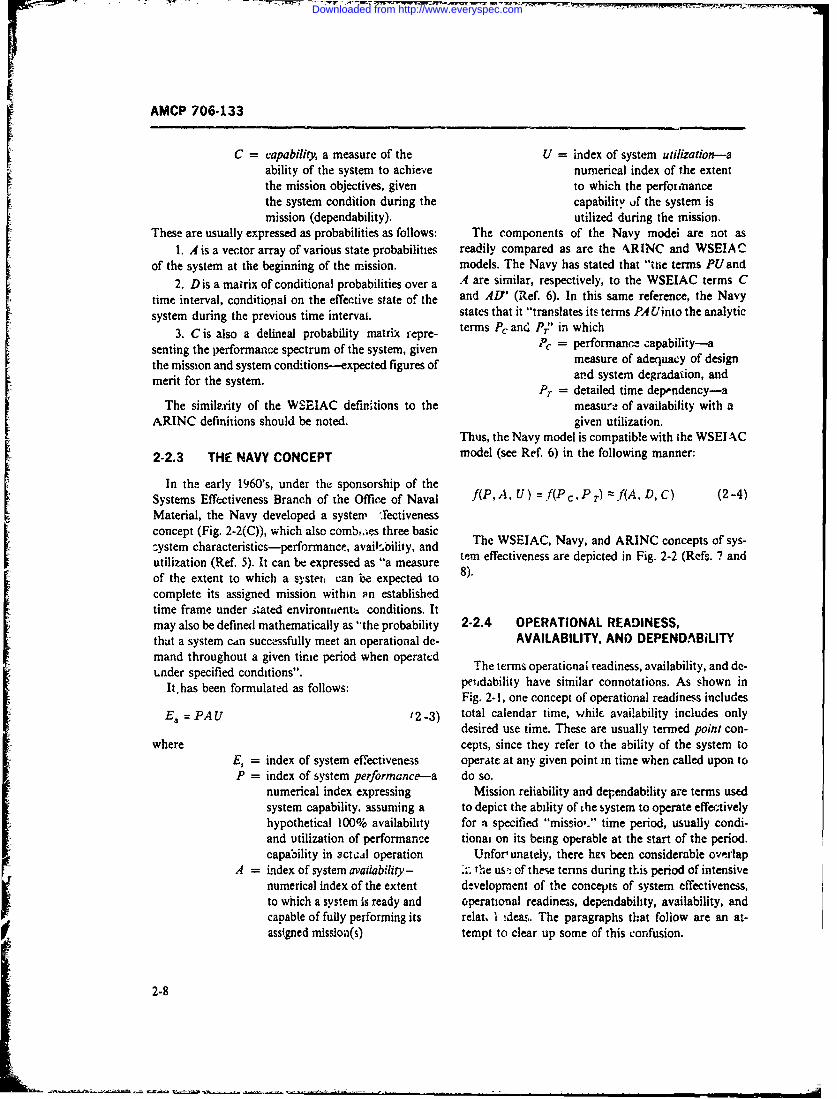
AMCP 706-133
C = capability, a measure of the U = index of system utilization--aability of the system to achieve numerical index of the extentthe mission objectives, given to which the perfornancethe system condition during the capability of the system ismission (dependability). utilized during the mission.
These are usually expressed as probabilities as follows: The components of the Navy modei are not as1. A is a vector array of various state probabilities readily compared as are the ,RINC and WSEIAC
of the system at the beginning of the mission. models. The Navy has stated that "tWe terms PU and
2. D is a matrix of conditional probabilities over a A are similar, respectively, to the WSEIAC terms Ctime interval, conditional on the effective state of the and AV' (Ref. 6). In this same reference, the Navysystem during the previous time interval. states that it "translates its terms PA Uinto the analytic
3. C is also a delineal probability matrix repre- terms P, and P," in which
senting the performance spectrum of the system, given Pc = performance capability-a
the mission and system conditions--expected figures of measure of adequacy of designand system degradation, andmerit for the system.
P = detailed time dependency-aThe similv.ity of the WSEIAC definitions to the measure of availability with a
ARINC definitions should be noted. given utilization.Thus, the Navy model is compatible with the WSEI AC
2-2.3 THE NAVY CONCEPT model (see Ref. 6) in the following manner:
In the early 1960's, under the sponsorship of theSystems Effectiveness Branch of the Office of Naval f(P, A, U) f(P c, P r) :zf(A. D, C) (2-4)
Material, the Navy developed a system ,'ectivenessconcept (Fig. 2-2(C)), which also comb:.es three basiczystem characteristics-performance, avaiikoility, and Thc WSEIAC, Navy, and ARINC concepts of sys-Iutan ) c anracterbstics-pepressed, asail: 'oil, " a nd te-m effectiveness are depicted in Fig. 2-2 (Refs. 7 andutilization (Ref. 5). It can be expressed as "a measure 8)of the extent to which a systent can be expected tocomplete its assigned mission within an establishedtime frame under tated environrient conditions. Itmay also be defined mathematically as "the probability 2-2.4 OPERATIONAL READINESS,that a system can successfully meet an operational de- AVAILABILITY, AND DEPENDABILITYmand throughout a given tirnie period when operatd The terms operational readiness, availability, and de-tLnder specified conditions".It.has been formulated as follows: petidability have similar connotations. As shown inFig. 2-1, one concept of operational readiness includes
E"= PAU '2-3) total calendar time, whilc availability includes onlydesired use time. These are usually termed point con-
where cepts, since they refer to the ability of the system toE, = index of system effectiveness operate at any given point in time when called upon toP = index of system performance--a do so.
numerical index expressing Mission reliability and dependability are terms usedsystem capability, assuming a to depict the ability of the system to operate effectivelyhypothetical 100% availability for a specified "missio,." time period, usually condi-and utilization of performance tionai on its being operable at the start of the period.capability in actcal operation Unfor' unately, there has been considerable ove-rlap
A = index of system availability- .r the us' of these terms during this period of intensivenumerical index of the extent development of the concepts of system effectiveness,to which a system is ready and operational readiness, dependability, availability, andcapable of fully performing its relat, I ,deas. The paragraphs that follow are an at-assigned mission(s) tempt to clear up some of this confusion.
2-8
Downloaded from http://www.everyspec.com
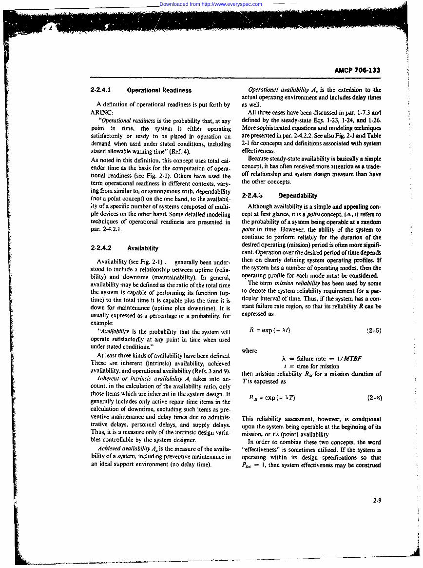
AMCP 706-133
2-2.4.1 Operational Readiness Operational availability A. is the exteision to theactual operating environment and includes delay times
A definition of operational readiness is put forth by as well.ARINC: All three cases have been discussed in par. 1-7.3 and
"Operational readiness is the probability that, at any defined by the steady-state Eqs. 1-23, 1-24, and 1-26.point in time, the system is either operating More sophisticated equations and modeling techniquessatisfactorily or ready to be placed ip operation on are presented in par. 2-4.2.2. See also Fig. 2-1 and Tabledemand when used under stated conditions, including 2-1 for concepts and definitions associated with systemstated allowable warning time" (Ref. 4). effectiveness.As noted in this definition, this concept uses total cal- Because steady-state availability is basically a simpleendar time as the basis for the computation of opera- concept, it has often received more attention as a trade-tional readiness (see Fig. 2-1). Others have used the off relationship and s)stem design measure than haveterm operational readiness in different contexts, vary- the other concepts.ing from similar to, or synonymous with, dependability(not a point concept) on the one hand, to the availabil- 2-2.4.S Dependabilitys;y of a specific number of systems composed of multi- Although availability is a simple and appealing con-pie devices on the other hand. Some detailed modeling cept at first glance, it is a point concept, i.e., it refers totechniques of operational readiness are presented in the probability of a system being operable at a randompar. 2-4.2.1. point in time. However, the ability of the system to
continue to perform reliably for the duration of the2-2.4.2 Availability desired operating (mission) period is often more signifi-
cant. Operation over the desired period of time depends
Availability (see Fig. 2-1), generally been under- then on clearly defining system operating profiles. Ifstood to include a relationship oetween uptime (relia- the system has a number of operating modes, then thebility) and downtime (maintainability). In general, operating profile for each mode must be considered.availability may be defined as the ratio of the total time The term mission reliability has been used by somethe system is capable of performing its function (up- to denote the system reliability requirement for a par-time) to the total time it is capable plus the time it is ticular interval of time. Thus, if the system has a con-down for maintenance (uptime plus downtime). It is stant failure rate region, so that its reliability R can beusually expressed as a percentage or a probability, for expressed asexample:
"Availability is the probability that the system will R = exp (- Xt) ',2-5)operate satisfactorily at any point in time when usedunder stated conditions." where
At least three kinds of availability have been define. w= failure rate = /MTBF
These ire inherent (intrinsic) availability, achieved X time r miinI = time for mission
availability, and operational availability (Refs. 3 and 9). then mission reliability Ru for a mission duration ofInherent or intrinsic availability A, takes into ac- Tis expressed as
count, in the calculation of the availability ratio, onlythose items which are inherent in the system design. Itgenerally includes only active repair time items in thecalculation of downtime, excluding such items as pre-ventive maintenance and delay times due to adminis- This reliability assessment, however, is conditionaltrative delays, personnel delays, and supply delays, upon the system being operable at the beginning of itsThus, it is a measure only of the intrinsic design varia- mission, or i.s (point) availability.bles controllable by the system designer. In order to combine these two concepts, the word
Achieved availability A0 is the measure of the availa- ~effectiveness" is sometimes utilized. If the system isbility of a system, including preventive maintenance in operating within its design specifications so thatan ideal support environment (no delay time). P 1A I, then system effectiveness may be construed
2-9
Downloaded from http://www.everyspec.com
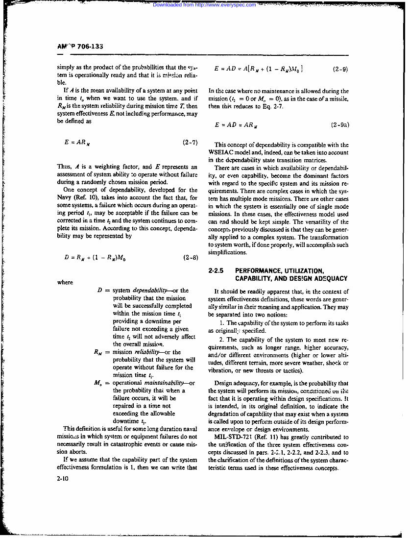
AM'"P 706-133
simply as the product of the probabilities that the c,'- E = AD z- A[RM + (1 - R)M 0 1 (2-9)tern is operationally ready and that it is mission relia-ble.
If A is the mean availability of a system at any point In the case where no maintenance is allowed during thein time to when we want to use the system, and if mission (t2 = 0 or M. = 0), as in the case of a missile,RM is the system reliability during mission time T, then then thiq reduces to Eq. 2-7.system effectiveness E not including performance, maybe defined as E = AD = ARM (2-9a)
E = ARM (2-7) This concept of dependability is compatible with the
WSEIAC model and, indeed, can be taken into accountin the dependability state transition matrices.
Thus, A is a weighting factor, and E represents an There are cases in which availability or dependabil-assessment of system ability :o operate without failure ity, or even capability, become the dominant factorsduring a randomly chosen mission period. with regard to the specific system and its mission re-
One concept of dependability, developed for the quirements. There are complex cases in which the sys-Navy (Ref. 10), takes into account the fact that, for tern has multiple mode missions. There are other casessome systems, a failure which occurs during an operat- in which the system is essentially one of single modeing period t, may be acceptable if the failure can be missions. In these cases, the effectiveness model usedcorrected in a time 2 and the system continues to corn- can and should be kept simple. The versatility of theplete its mission. According to this concept, dependa- concepts previously discussed is that they can be gener-bility may be represented by ally applied to a complex system. The transformation
to system worth, if done properly, will accomplish such
D = R, + (1 - R)M o (2-8) simplifications.
2-2.5 PERFORMANCE, UTILIZATION,where CAPABILITY, AND DES!GN ADEQUACY
D system dependability--or the It should be readily apparent that, in the context ofprobability that the mission system effectiveness definitions, these words are gener-will be successfully completed ally similar in zheir meaning and application. They maywithin the mission time t, be separated into two notions:providing a downtime per 1. The capability of the system to perform its tasksfailure not exceeding a given as originall:; specified.time 12 will not adversely affect 2. The capability of the system to meet new re-the overall mission. quirements, such as longer range, higher accuracy,pR = mission reliability---or the and/or different environments (higher or lower alti-probability that the system will tudes, different terrain, more severe weather, shck oroperate without failure for the vibration, or new threats or tactics).mission time t,.
Mo = operational maintainability-or Design adequacy, for example, is the probability thatthe probability thai when a the system will perform its mission, conditione.d i on., U '-failure occurs, it will be fact that it is operating within design specifications. itrepaired in a time not is intended, in its original definition, to indicate theexceeding the allowable degradation of capability that may exist when a systemdowntime ;. is called upon to perform outside of its design perform-
This definition is useful for some long duration naval ance en,-elope or design environments.missiois in which syqtem or equipment failures do not MIL-STD-72 I (Ref. 11) has greatly contributed tonecessarily result in catastrophic events or cause mis- the un;fication of the three system effectiveness con-sion aborts. cepts discussed in pars. 2-2.1, 2-2.2, and 2-2.3, and to
If we assume that the capability part of the system the clarification of the definitions of the system charac-effectiveness formulation is 1, then we can write that teristic terms used in these effectiveness concepis.
2-10
Downloaded from http://www.everyspec.com
AMCP 706-133
In this Military Standard system effectiveness is de- ma) be at any givea time. Par. 2-2.6.1 discusses systemfined as "A measure of the degree to which an item can operational states.be expected to achieve a set of specific mission require-ments, and which may be expressed as a function of 2-2.6.1 Operational Statesavailability, dependability, and capability". The ARINC concept of operational readiness and
In turn, availability is defined as "A measure of thedegree to which an item is in the operable and commit- the states of system aspareers f
table state at the start of the mission, when the mission interest. In the cate of operational readiness, the states
is called for at an unknown (random) point in time." are concerned with the various time periods into whichDependability is defined as "A measure of the item the system operational demands may be classified. Aoperating condition at one or more points during the discussion of the operational state considerations in
mission, including the effects of reliability and main-
tainhbility, given the item condition(s) at the start of terms of time periods is, therefore, in order.A system may be considered to be in one of three
the mission." It may be stated as the probability thatan item will (a) enter or occupy any one of its required ionacte s that peiod o m e
operational modes during a specified mission, and (b) s . Inactive period is that perid of time when the
perform the functions associated with those operational system is not required for use and is essentially shut
modes. Capability is defined as "A measure of the abil- down. It is possible for maintenance to be performed
ity of an item to achieve mission objectives given the during this period.
conditions during the mission". 2. Scheduled downtime is that period of time when
This system effectiveness definition comes conceptu- preventive maintenance is performed. It is possible for
ally closest to the WSEIAC concept, though it does not deferred corrective maintenance to be performed dur-
necessarily adopt the WSEIAC mathematical model. ing this period also.
However, it states clearly that system effectiveness has 3. Operational demand is that period of time dur-to be viewed as a function of availability, dependability, ing which the system must be available for performing
and capability. This concept of system effectiveness has operational missions. It is critical to syst.-m effective-been adopted also by AMCR 11-1 (Ref. 12). ness. Operational demand may be partitioned into
standby, alert, reaction, mission, and deactivation time
2-2.6 TOTAL PACKAGE PLANNING AND periods.
SYSTEM EFFECTIVENESS Ideally, a system should be able to start performingits mission immediately upon receipt of the command
The key to system effectiveness lies in total package to do so and to return to its designated notimission stateplanning, sometimes called system engineering--the similarly upon command as shown in Fig. 2-3. As a
application of the system approach to total system de- prcial matr there as s sm t-asign (Ref. 13). Total package planning is concerned practical matter, there always exists some transientsign (Ref 13).em Tlfe cyclepaa pl2an e incerd period of time before the system is fully activated (per-with the system life cycle (par. 3-2.1.1) and the integra- forming its mission at or above threshold effectiveness
tio n o f all sy stem elem en ts in to an eff ectiv e w h o le, as l o rd act i v a t d a s how n in Fig. 2 4.depitedin Fg. -1.level) or deactivated as shown in Fig. 2-4.
depicted in Fig. i-. The definitions of these partitions of operational de-Maintainability requirements, as part of total pack- mand time are:
age planning, must -be derived from system mission
requirements and logistic support concepts during the 1. Standby is thze fraction of operational demand
early life cycle ph. ses. (See par. 3-2.1.1 and Fig. 3-8.) during which a system is available for a mission, but
These, in turn, dictate the operational readiness por- requires relatively minor action to be performed before
,..,',; cf sysorn effectiveness described in this chapter a mission can be initiated.
in terms of system availability or dependability, and 2. Alert time (as defined in MIL-STD-721) is that
their related reliability, maintainability, and integrated element of uptime during which an item is thought tologistic support requirements (see also par. 1-2). be in specified operating condition and is awaiting a
Maintainability considerations, including both cor- command to perform its intended mission.rective and preventive maintenance, are primarily de- 3. Reaction time (as defined in MIL-STD-721) ispendent upon the system mission profiles and system that element of uptime needed to initiate a mission,effectiveness requirements for each mission and mis- measured from the time the command is received. It ission mode. These, in turn, are derived from an analysis the transient time between nonmission and missionof the various operational states in which the system states of the system. Since the command to initiate a
2-11
Downloaded from http://www.everyspec.com
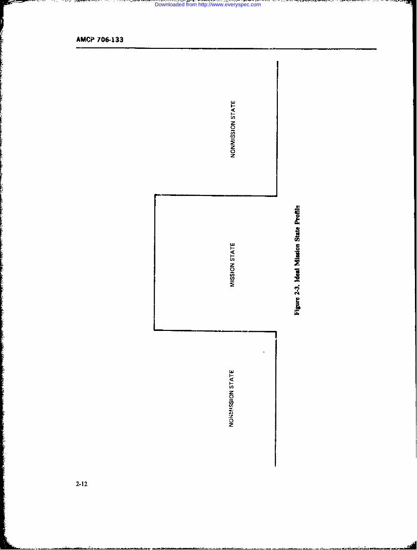
AMCIP 706-133
ui
z0
z
___________________________0__
w a
LUI
EnAzI
I-
U,z0
0z
2-12
Downloaded from http://www.everyspec.com
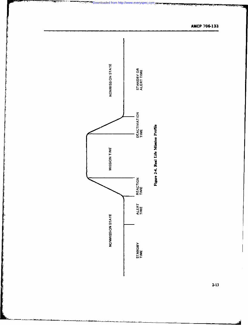
AMCP 706-133
wUI--
00
I-J
00
00
z~00cnpwo
2
00
<2
I--
cc .-
2-1
- ~ --- -
Downloaded from http://www.everyspec.com
AMCP 706-133
mission may be given any time during operational de- nel are at their duty stations, and only the signal to startmand, reaction time depends on the period the system the mission is required to initiate the transient tetweenis in when such command is given, mission and nonmission sta:us. At the end of a minsion,
4. Deactivation. time is that fraction of operational tht system can be returned to any of these states. An
demand tir.c required to shut down the system and illustration of the application of these is given in Ref.re *Jr it to standby or alert portions of operational 14.
demand or to inactive or scheduled downtime periods.5. Mission time is that element of aptime during 2-2.6.2 Effect of Lagistic Support on
which the item is performing its designated mission System Effectiveness(MIL-STD-721).
6. Unscheduled downtime is the fraction of time in par. 2-2.4.2, several availability measures are de-during which the system is known to possess faults oris undergoing corrective maintenance, those items of the system design which are normally
7. LUptime is the fraction of operational demand design controllable; achieved availability assumes anideal support environment. Only operrtional availabil-during which the system is not undergoing mainte-
nance, ity takes into account administrative and logistic sup-port effects upon system effrtiveness. It is also theIn many cases, the reaction time and deactivation effectiveness measure that is most difficult to demon-
time may be so small as compared with the other time strate.periods as to be considered negligible. In other cases, The lack of repair parts, spares, consumables, andespecially in the case of reaction time, this time r.iod p-upcr tools; inadequate test and support equipment,might be of prime importance to successful mission maintenance facilities, and maintenance and supply in-accomplishment. Generally, deactivation time is not of formation; and deficiencies in trained operating andsignificance since it occurs at the end of a mission maintenance personnel can easily negate the best relia-period when the -ystem is no longer required to be bility and main-ainability design effort. Thus, whileoperating. inherent and achieved availability goals may be met,
Reaction time, on the other hand, may be variable actual operational availability can be readily comprc-depending upon whether the command for system op- mised as a result of poor logistic support planning anderation occurs when the system is in an inactive state, implementation.in scheduled downtime, in standby, or in alert periods. Experience with a number of fielded systems hm-These periods represent varying degrees of readiness shown that significant improvements in opcrational ca-for a mission. For example, durisig inactive time, dust pability can be achieved without a system hardwarecovers may be on, power is off, and operating personnel rede-,ign effort if proper attention is given to the logisticmay be unavailable to operate the system; during support factors during the early system planningscheduled downtime, the system may be partiaiiy disas- phases. It is for these reasons, as well as the significantsembled for servicing; during standby, dust covers are cost of logistic support, that such great emphasis hasoff, standby power is on, but safety switches are in been given in recent years to integrated lagistL- support"safe" position, and operating personnel, although as an element of system design and effectiveness and toavailable, are not at duty station; during alert, power is reduce life cycle cost, as detailed in such documents ason, safety switches are in armed or go position, person- AMCR 750-15 (Ref. 15) and TM 38-703-I (Ref. 1).
2-14
Downloaded from http://www.everyspec.com
AMCP 706-133
SECTION II
SYSTEM EFFECTIVENESS METHODS
2-3 SYSTEM EFFECTIVENESS able attributes such as oversimplification, nonsen-MEASURES sitivity to critical parameters, hidden calculations, and
difficulty in exercising the model. This technique is
characterized by mathematical models, computer pro-Every system is designed to accomplish some desig- grams, and attempted optimizations". The secondnated objectives, such as a specified function(s) or mis- gram s tt ons i mftiiens Th secondsion(s). "System Effectiveness" is the name given to viewpoint o cosireffctine as specifiedrandany measure which quantitatively describes how well concentrate on cost reduction, which has the danger ofthe system will do its intended job. This ability of a formulating all technicalproblems in terms of cost. Thesystem depends to a iarge degree on its performance or third viewpoint distrusts the "numbers game" andcapability, but other factors such as reliability and sticks to management actions that have, in the past,maintainability must also be considered. A system with yielded cost-effective products. The result may be aeven the best performance designed in will not do its job well-run project yielding a product less than satisfac-well if it lacks reliability. If it lacks maintainability, it tory for mission success. In the further text of his work,will require excessive downtimes for maintenance when Kranz advocates a blending of all three viewpoints andfailures occur and will not be operationally ready every suggests how to achieve this so as to assure manage-time when it is needed. Jointly, reliability and main- ment decisions resulting in a product with high proba-tainability determine system operational readiness or bilitv of mission accomplishment, a program with mini-availability.
To predict system effectiveness quantitatively, math- mum risks, and product and program costs withinematical models that combine system performance, acceptable values of resources expended.~This appears to be a very reasonable approach toreliability, and maintainability into one or more effec- his syto eatveresonble appoach totiveness measures are used. Before the mathematical achieving system effectiveness. The first viewpoint is tomodels are formulated, the mission and mission pro- quantify everything that is quantifiable in terms of sys-
tem effectiveness measures and to use these numbers asfies must be defined and appropriate measures of sys- inputs into system effectiveness models. However, sincetem ffetivnes mus beselcte. Thse easres not everything is quantifiable, and because constraintsshould be both system and mission oriented so that not verythinglis a leand ease containtson costs acid schedules always exist, the advantageouswhen the numencal answers are obtained through theexercise of the mathematical models, these answers will parts of the second and third viewpoints must be inte-
quantitatively relate the expected response of the sys- grated into the overall approach to system effective-tem with regard to the requirements and objectives of ness. Thus, there is a need for mathematical modelstem wisith , rthat are compatible with the selection effectivenessthe mission.
IT'he selction or development of appropriate effc- measures, and are used to allocate and define design
tiveness measures is not always easy. In some cases., criteria; a need to control the program so that the
such as communication systems, one must be content established design criteria are met with minimum cost;with using submodels yielding different kinds of meas- and a need to apply managt
ures that cannot be combined into a single overall effec- proven successful on previos program cared outtiveness measure or a single figure of merit (Ref. 16, p.
2-24).F. H. Kranz (Ref. 17, p. 11) states that there are 2-3.1 TYPICAL EFFECTIVENESS MEASURES
three different viewpoints concerning the problem ofsystem effectiveness quantification: "The first view- The philosophy of choosing an appropriate measurepoint is to quantify everything and to consider every- of system effectiveness related to the system missionthing quantifiable into a figure of merit. The result is can be illustrated by considering an essentially continu-a numerical decision aid that usually has some undesir- ously operating commercial system, such as a passen-
2-15
Downloaded from http://www.everyspec.com
AMCP 706-133
ger airliner (Ref. 18). Its effectiveness can be measured 2. Expected valuesin terms of expected seat miles flown per annum, con- 3. Ratessidering delays, aborted flights, navigational d, via-tions, emergency landings, turnaround times, etc. is Probability measures are used when a mission can benumber could be compared with an "ideal" airplane of exactly defined with a unique and definite objective forthe same type with normal, scheduled turnaround its outcome. Such is the case of a ballistic missile aimedtimes and with no delays due to failures, unscheduled at a definite target or a bomber aircraft sent to destroymaintenance, or degraded operation. a specific target.
Going one step f!rther, one could look at passenger Expected values are more appropriate for missions
miles flown per annum, as against seat miles. This re- with more general objectives and no specific single ob-flects utilization and revenue, and thus cost-effective- jective defined or even definable. For example, a recon-
ness, when the expected annual maintenance and oper- naissance mission may have the objective of surveyingating costs are added to the prorated acquisition costs. some enemy-held territory. In this case it is more mean-
The same or similar considerations in choosing effec- ingful to select as an appropriate measure the expectedtiveness measures can apply to many other systems. area surveyed, rather than a probability of mission suc-Some typical measures are: cess. This is not a case where the mission outcome can
1. Expected number of ton-miles transported and be only one of two possible occurrences-success ordelivereci per unit time failure. In such missions one is more concerned with
degrees of success, such as how much of the area getstime2. Enpected number of miles travelled per unit surveyed or destroyed, or how much damage is done to
the enemy.3. Expected number of bits processed per unit time Rates are appropriate measures of system effective-4. Expected number of message units transmitted ness for weapons required to continuously repeat one
per unit time and the same defined action. This would be the case of5. Expected number of kilowatt hours produced a gun, or battery of guns, required to fire into a specific
per unit time area to prevent enemy penetration or infiltration whileno specific targets are identified. Of course, the terms
The "unit time" may be any time measure appropriate "expected values" and "rates" are often synonymous.for the specific system operation, such as mission time, Whichever measure is properly chosen, the math-hour, day, battlefield day, month, or year. ematical model for system effectiveness must then be
As to weapon systems, typical system effectiveness geared to that measure and be capable of giving quanti-measures are: tative, i.e., numerical, answers in terms of the chosen
1. Expected number of targets destroyed per sys- m,:asure. As already stated, performance. reliability,tern per mission and maintainability are important inputs for such a
2. Expected area destroyed per system per mission model. For military systems, additional factors which3. Expected area reconnoitered per system per will enter the picture are vulnerability, survivability,
mission penetrability, lethality, countermeasures, enemy capa-4. bility, and many other factors according to the nature
tem per mi ausion of the system and the job it is intended to perform. Fortr p te m o areadeinstance, to determine the effectiveness of a fighter air-
craft, the capabilities and characteristics of the enemy6. Rate of payload delivery aircraft it will meet in air-to-air combat must be in-7. Kill rate ciuded in the system effectiveness model. Ref. 19 is a8. Sweep rate very useful classical text for the readers who want to9. Single-shot kill prcbability gain more insight into the complexities of evaluating
the performance effectiveness of various weapon sys-10. Probability of mission success.tems.
There are many other system effectiveness measuresthat are appropriatc for specific weapon systems and 2-3.2 ASSOCIATED MEASURESspecific types of tactical and strategic situations. Ingeneral, three types of system effectiveness measurcs Reliability, maintainability, and performance haveare most frequently used: their own measures that need to be considered in sys-
I. Probabilities tem effectiveness modeling, and that provide numerical
2-16
Downloaded from http://www.everyspec.com
AMCP 706-133
inputs into the system effectiveness models. First, let us tic support has been planned and executed becomesmention some performance measures that in most cases important at this point.will vary greatly with the nature of the system to beanalyzed and with the mission or missions it is intended 2-3.2.3 Reliability Measuresto perform. In the case of reliability and maintainability Typical reliability measures are mean-time-between-the situation is much simpler since their characteristic failures (MTBF), failure rate, renewal rate, and themeasures, such as MTBF and MTTR, are always the probability of no failure in a given time interval. In thesame. simplest case, when the system is of a serial configura-
tion and all components exhibit an exponential distri-2-3.2.1 Performar.ce Measures bution of time-to-failure, the reliability R(t) of such
Examples of a few typical performance measures are s is given by
speed, range without refuelling, and load-carryingcapacity for vehicles and transports in general; caliber, R(t) = exp (- Xt) (2-10)
range, accuracy, and firing rate for g-ans and similarweapons; accuracy, speed of processing, and storage where X is the sum of the failure rates of all systemcapability for computers; range, signal-to-noise ratio, components and tis the mission time. The MTBFoftheand bandwidth for communication systems. Obviously, system is then given byeach category or class of systems will have its owncharacteristic performance measures. When thenumerical values of all important performai.ze meas-
ures of a system are known, it is possible to calculatehow well a system can perform its job or the missions This applies strictly to the exponential case only. In thefor which it was designed, if all essential system ele- more general case, the MTBF is given byments perform satisfactorily. In the past, system effec-tiveness evaluations were based on performance meas-ures only, without considering reliability or MTBF f R(t) dt (2-12)maintainability. This gave an overly optimistic picture.The hardware produced was sometimes unreliable anddifficul, to maintain. In the new concept of system which applies als to systems containing various formseffectiveness, reliability and maintainability play a very of redundancy and also to nonexponentially failingimportant role. components. For instance, many mechanical and
related components are known to have Weibull or2-3.2.2 Modes of Operation gamma distributions of time-to-failure.
Reliability determines the capability of a system to 2-3.2.4 Maintainability Measuressustain its performance over specific periods of time ofinterest, such as the mission time. If the system can Typical maintainability measuies are the mean-time-
operate in an alternate or dgraded mode when partial to-repair (MITR), the mean corrective maintenance
failures occur, again reliability determines in which time (M,), the mean preventive maintenance time
state, or operating mode, the system can be expected to (W), the mean corrective and preventive maintenance
operate during a'arious phases of a mission. If some time (M), thc equipment reir time (ER7), the geo-
maintenance can be performne6 during the mission, the metric mean-time-to-repair (M7TRa), the maximum
maintainability designed into the system will co-deter- maintenance time (M , and the probability of ac-
mine in which state the system will operate. That is, complishing repair in a given time interval t, called the
when during the mission the system transits into a maintainability function AWt). These maintainability
degraded mode due to a faiture, and the failure can be measures are discuss,!d in detail in Chapter 1. pars. 1-6
fixed-say, by replacing a failed mc.ule with a good 1 1-7.
available spare-then the system will transit again intoits full capability mode of operation. And when thesystem requires higher level maintenance due to in. A measure common to both reliability and maintain-capacitating failures that cannot be fixed by the opera- ability is the "failure rate". Unfortunately, this term istor, maintainability determines how long it will tak: to used in different context,. by different people, and thismake the system operational again. How well the iogis- can easily lead to confusion (Ref. 16. p. 4-15).
2-17
Downloaded from http://www.everyspec.com
AMCP 706-133
In reliability the terra failure rate X(6 is defined as Fig. 2-5 shows the renewal rate h(o and the hazardrate W,() of a component which has a normal distribu-tion of time-to-failure.
X(t) = f(t)/R (t) (2-13) As stated before, the hazard rate X(O is a measure ofthe hazard of one component to fail as it accumulatesoperating hours and therefore ages. As may be seen in
where At) is the probability density function (pdf) of Fig. 2-5, in the case of the normal distribution, )()
time-to-failure, and R(r) is the reliability function, i.e., climbs indefinitely, which means that the older thethe probability of no failure in time t This failure rate component is, the greater is the hazard that it will fail.X() may be constant, decreasing, or increasing with the The renewal rate JK4) is a measure of the frequency atage of a component. It is a measure of the instantaneous which the component fails and must be replacedhazard of one and the same component to fal as it ages (renewed). In other words it is the replacement rate of
with operating time L It is also referred to as the hazard the component. It may greatly fluctuate initially. Butrate or instantaneous failure rate. In the case of expo- as replacements repeatedly occur,Mi) stabilizes withnentially failing components, the failure rate is constant time to a steady-state value ofat a given stress sevel. This is often the case with elec-tronic components. However, many notelectroniccomponents exhibit a nonconstant, mostly increasing, h = 1/MTBF (2-15)failu'e rate. The reliability Eq. 2-10 applies only to thecase when the failure rate is constant. When a compo- It is this steady-state constant value of the renewal ratenent has a nonconstant failure rate X(4, the reliability which in maintainability is called the failure rate X andzquation becomes which is used to compute component failure frequen-
cies, and to compute equipment mean-time-to-repairrT.t 1 (MTTR) and other maintainability factors. Eiven
R(T t) =f X(x)dxj (2-14) though the steady-state value h of the renewal rate is---' numerically equal to the constant )L of Eq. 2-I1, the two
concepts are quite different, as previously explained.
where t is the mission time and Tis the operating ageof the component at the start of the mission. Obviously, 2-4 SYSTEM EFFECTIVENESSii this case the MYBFcannot be expressed as a recipro- MODELS.,_ of X(0, which is a variable, but is computed bymeans of Eq. 2-12. Chapters 4 and 6, Ref. 20, discuss 2-4.1 THE PURPOSE OF MODELSthe failure rate concept in detail.
In maintainability the concept of failure rate is used To design and produce effective military systemsto compute the frequencies at which components fail that will achieve the intended -bjectives, an integratedand must be replaced so as to restore a system to its full approach to system effectiveness methodology andoperational capability. However, in this concept of fail- management has become mandatory. The effectivenessure rate one is not concerned with the variable X(*) as of a system starts to shape up early Lin the conceptualdefined by Eq. 2-13, since the maintainability engineer and design phases. There are many elements thatis usually not interested in the instantaneous hazard of jointly impact on system effectiveness in the desian anda component to fail as t ages, but rather is interested development phase, and additional elements have anin the successive rate at which a component must be impact on the operational effectiveness of field de-replaced by a good item (renewed) as it faiLs and again ployed systems. All these elements must be cor.sideredreplaced upon second failure, etc. He calls this the to produce systems of balanced design that will per-"'filure rate", and uses this concept to evaluate the form effe.vely in their operational environment andfrcquency at which a component will have to be re- can be properly supported from a logistic support view-placed in a succession of failures as they occur over a point in order to maintain their effective performancelong period of time. This "failure rate" appears in the in the field.lite.ature on mathematical statistics and stochastic Same of the basic elements of system effectivenessprocesses as the renewal density h(t) or renewal rate have been discussed in the preceding paragraphs. The(Ref. 21), and is the rate at which a component is performance, reliability, and maintainability designedreplaced. into a system determine what the system is inherently
2-18
Downloaded from http://www.everyspec.com
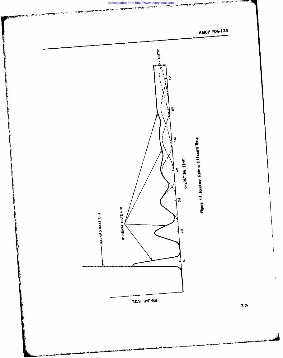
AIACP 706-133
co
I I
I I
cc ui
ccI
31V-dIvWN32-I3
Downloaded from http://www.everyspec.com
AMCP 706-133
capable of doing. When, via mathematical models, one The duration of diffresnt missions also affects systemcompares this inherent ability of a system to perform effectiveness. In longer flights reduced reliability.the specific operational tasks or mission requirements larger navigational errors, and possibly more exposurethat it is intended to accomplish in a specified environ- to enemy action lessen the probability of mission suc-ment, the effectivenes of the system comes to light. cen. Bt even much simpler systems, suh as a howitzer,One may call this the inherent system effectiveness, will have different effectiveness aainst t.rgetsAlso, when one considers the logistic support aspects of different hardness and size, and at different distan-and changing operational environment that often have ces--the greater the range, the greater the projectilea tendency to degrade operational effectiveness in the dispersion.field, one may speak of an operationalsystem effective- With the realization that everything must be consid-ness. This is quite similar to the concept of inherent and ered and is involved in system effectiveness modelingoperational availability, and evaluation, it becomes obvious that system effec-
C. B. Moore (Ref. 22, p. 3) defines for an aircraft the tiveness is not the concern of a single activity, such bsaspects a system effectiveness analyst must take into the reliability or maintainability organization, butconsideration in an integrated approach to operational rather is the concern of everybody associated with aeffectiveness analysis, namely: specific project. Therefore, an integrated approach is a
1. The military objectives, requirements, and oper- must As stated in the WSEIAC Final Summary Re-ational employment port (Ref. 2, p. 1), "Vhat was once merely considered
2. The vehicle characteristics and associated set of desirable is now considered mandatory-an integratedsubsystems required to accomplish the operational methodology of system management using all availabletasks data both to pinpoint problem areas and to provid- a
numerical estimate of system effectiveness during all3. The operational environment (msios phssodhesseeif-yl-fenses, penetration, survival, basing, tactics, etc.) phases of the system life-cyce.
To provide such numerical estimate, or better stated,4. The men, training, and material required for numerical estimates, system effectivenes -matlnmatical
support (personnel, skills, spares, equipment, safety, models must be developed for the specific systems andetc.). missions. It is usually the task of the operations re-
search groups and operation analysts to develop andHe further specifically cites the elements which impact exercise the mathematical models and to present theon system operational effectiveness: reliability, main- numerical answers. In the process of system synthesistainability, performance, survivability, environment, and design optimization, the system effectiveness mod-safety, weapon delivery, operational postures, opera- els serve several purposes:tional usage, logistics, personnel, repair parts, training.time,, and cost. The cost element, of course, plays a bi 1. To evaluate the effectiveness of a system of arole in cost-effectiveness studies and in making deci- specific proposed design to accomplish various opera-ion. in all these elements involved in deerin i tions (missions) for which it is designcd and to calculatesios. Given ahethe effectiveness of other competing designs, so thethe operational system effectiveness of a complex sys- decisi maker can select that design which is mosttern, it is easy to see that no single mathematical model delysio meet cn s e ents.will handle all the elements simultaneously, but rather *ikely to meet specified requirements.several models are needed to perform the computa- 2. To perfrm trade-offs among system character-tions, trade-offs, sensitivity analyses, and optirniza- i performance, relia ility, maintainability, etc. intions. order to achieve the most desirable balance among
Further compications arise when a system, such aE those which result in highest effectiveneO.a fighter-bomber, is designed to perform several differ- 3. To perform pametric sensitivity analyses inent kinds of missions or mission mixes. For each kind which the numerical value of each parameter is variedof mission, different mathemstical models may be in turn, and to determine its effect on the numericalneeded rnd the system effectiveness will usually be outputs of the model Parameters that have little or nonumericall) different for different missions. Also, the effect can be treated as outants and the model simpli-selected measure of system effectivenem may change fled accordingly. Parameters to which the model out-according to mission objectives. For example, an air- puts show large sensitivity are then ex amind in detail,craft will have different measures of effectivenes in siNce small im vements in the highly sensitiveattacking targets of different sizes and kinds, parameters may result in substantial improvements in
2-20
Downloaded from http://www.everyspec.com
AMCP 706-133
system effectiveness at very acceptable cost (Ref. 13, p. straints on the analysis to be conducted- After complet-21). ing :hese four tasks, it becomes possible to proceed with
4. To "flag" problem areas in the design whiih Task 5. the construction of the mathematical models.seriously limit the ability of the design to achieve the To obtain numerical answers from the models, numeri-desired level of system effectiveness. crl values of all parameters included in :he models
must be established or estimated (Task 7). To do this,The evaluation of system effectiveness is an iterative good and reliable data must first be acquired from data
process that continues through all life cycle phases of sources, tests, etc. (Task 6). The final Task 8 exercisesa system; i.e.. concept development, validation, produc- the models by feeding in the numerical parametric val-tion, and operation. In each of these phases system ues to obtain system effectiveness estimates and per-effectiveness is continually being "measured" by exer- form opti-nizations. Fig. 2-7 (Ref 7) illustrates in morecising the system effectiveness raodels. In the early de- detail the whole process of system effectiveness evalu2-sign stage, system effectiveness predictions are made tions, beginning with the military operational require-for va.ious possible system configurations. When ex- ments and leading, through the e_,rcising of !he systemperimental hardware is initially tested, first real-life effectiveness modelts), to the decision-making stage-information is obtained about performance, reliability,and maintainability characteristics and this informa-tion is fed into the models to update the original predic- 2-4.2 MODELiNG TECHNIQUEStion and to further exercise the models in an attempt As discussed in par. 2-4.1, system effectiveness moe-to improve the design. This continues when advanced els integrate a number of system characteristics withdevelopment ha.dware is tested to *,ain assurance that the mission objectives, the mission profiles and envi-the improvements in system design are effective or to ronments, and the logistic support. The main cluarac-learn what other improvements can still be made before teistis of the system are, in the bxoadest sense, itsthe system is fully devcloped, type classified, and de--ployed for operational use. Once in operation, field data performance, reliability, and maintainability. Theystart to flow in and the models are then used to evaluate jointly dete-zine system capability.
Reliability and maintainability define sy-stem availa-thebility and/or operational readiness Reliability deter-by the field environment, including the act"ual logistic biiyadooertnaraies.Rlbltyde-
.. mines the state probabilities of the system during thesupport and maintenance practices provided in the mission. i.e.. the system dependability If repairs can befield. The modes again serve to disclose or-flag- prob- performed during the mission, maintainability also
becomes a factor in dependability evaluations: this caseOne may summarize th- need for system effective- is often reerred to as "reiabilit" with repair". Then
ness models as follows. First of all they provide insight, there is the impact of logistic support on the downtimemake an empirical approach to system design and syn- and turnaround time of the system sincr hortcomingsthesis economically feasible., and are a practical method in the logistic support may cause delays over and abovefor circumventing a variety of exterior constraints. Fur- the maintenance time as determined b) the systemther, the models aid in establishing requirements, pro- maintainability design. Finally. there are the perform-vide an assessment of the odds for successful mission ance characteristics of the systemn that are affected bycompletion. isolate problems to definite areas, and rank the state in which the system may be at any point inproblems in their relative seriousnm of impact on the time during a mission, i.e., by the system dependability.mission. They also provide a rational basis for evalua- Before system effectiveness models can b_ con-tion and choice o proposed system configuraticns and structed, a great deal of submodelmg must be done.pros solutions to discovered problems (Re. 23). Availability. operational readines, downtime distribu-
Thus, system effectiveness models are an essentialtool for the quantitative evaluation of system effective- tions, dependability. etc., require in most cases their
own modeling to obtan the numerical answe-s ihatness and for designing e tffe ctive weapon s ystems. ig. may be fed into an 4,verall system effectivenns model.2-6 identifies eight principal tasks in.olved in system if such can be cons.. ucted. Some of thesc submodelingeffectiveness evaluation (Ref. 2 p. 170). Task 1 is mis- techniques will now be discussed.sion definition. Task 2 is system description, Task 3 isselectioa of figures of merit or. in a more general sense, 2-4.2.1 , Redis Modelsthe selection of appropriate system effectiveness meas-
ures, and Task 4 is the identification of acountable Avilabilitv. being defined as the i-,time ratio, is notfactors that impose boundary conditions and con- always a sufficient measure to describe the ability of a
2-21
Downloaded from http://www.everyspec.com
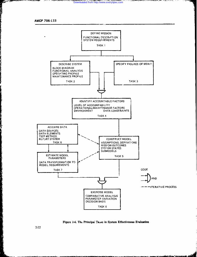
AMCP 706-133
DEFINE MISSION
FUNCTIONAL DESCRIPTIONSYSTEM REQUIREMENTS
TASK 1
DESCRIBE SYSTEM SPECIFY FIGURES OF MERIT
BLOCK DIAGRAMFUNCTIONAL ANALYSISOPEfP.TING PROFILEMAINT.-NANCE PROFILE
TASK 2 TASK 3
IDENTIFY ACCOUNTABLE FACTORS
LEVEL OF ACCOUNTABILITYOPE RATIONAL/MAINTE NANCE FACTORSENVIRONMENT DATA CONSTRAINTS
TASK 4
ACQUI RE DATA
DATA SOURCESDATA ELEMENTS LTEST METHOD FRLT YTM " CONSTRUCT MODEL
TASK 6 ASSUMPTIONS, DEFINITIONSRLOR SYSTEMSJ CONSTRUTOE L
MISSION OUTCOMES______ _SYSI_ EM STATES
SUBMODELS
ESTIMATE MODEL TASK 5PARAMETERS L
DATA TRANSFORMATION TOMODEL REUI REMENTS
TASK 7 /CODE
I . AND
_--ITERATIVE PROCESS
EXERCISE MODEL
COMPARATIVE ANALYSISPARAMETER VARIATIONDECISION BASIS
TASK 8
Figure 2-6. The Princilai Tacs in System Effectiveness Ewaluation
2-22
Downloaded from http://www.everyspec.com
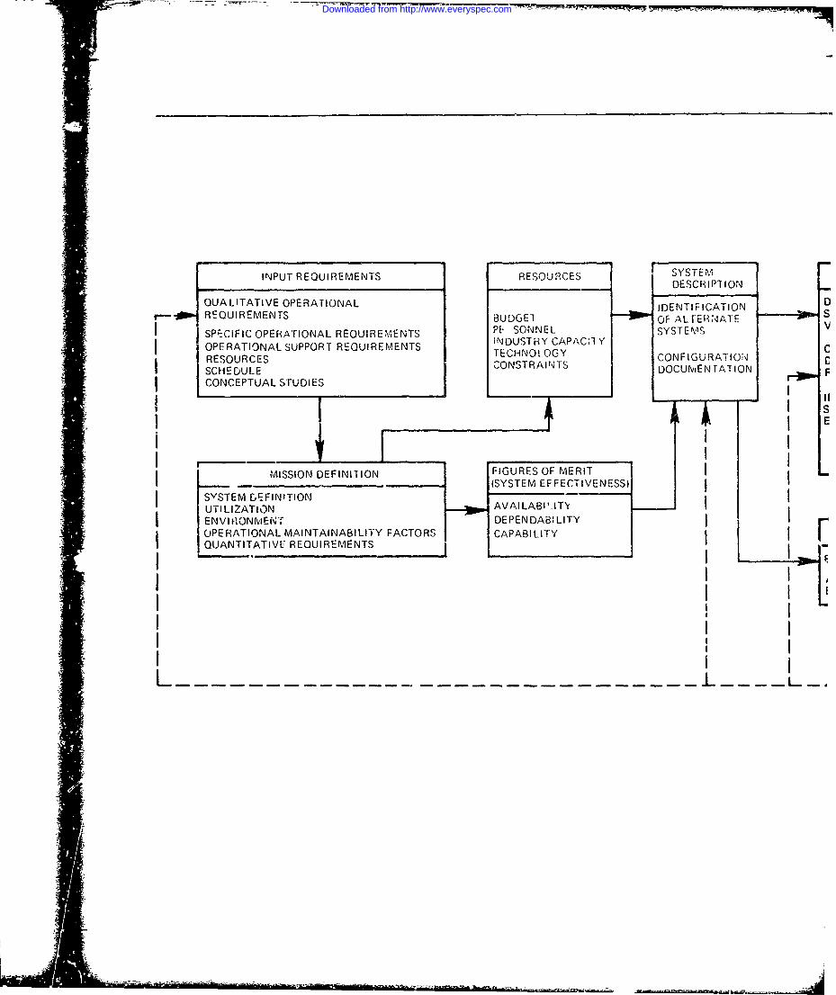
INPUT REQUIREMENTS RESOURCES SYSTEM____ ___ ___ ___ ____ ___ ___ ___ __ _ ___ ___ ___DESCRIPTION
QUALITATIVE OPERATIONAL IDENTIF:ICATION 0__ REQUIREMENTS BUDGET OF ALTERiNATE
*I SP;ECIFIC OPERATIONAL REQUIREMENTS P& SON SYSTEMSv
SCEDUTOLE SUPPORT REURMET NSTRY APAC YRESOURCES TEHOOYCONFIGURATION
CONCEPTUAL STUDIESDOUEAIN
MISSION DEFINITION FIGURES OF MERITI______ _____(SYSTEM EFFECTIVENESS)
SvSTEM GEFINITION AALB'I'UTI LIZATIONAVLAIT\
I ENVI 1IONMENT DEPENDABILITY
OPERATIONAL MAINTAINABILITY FACTORS CAPABILITY
QUANTITATIVE REQUIREMENTS
Downloaded from http://www.everyspec.com
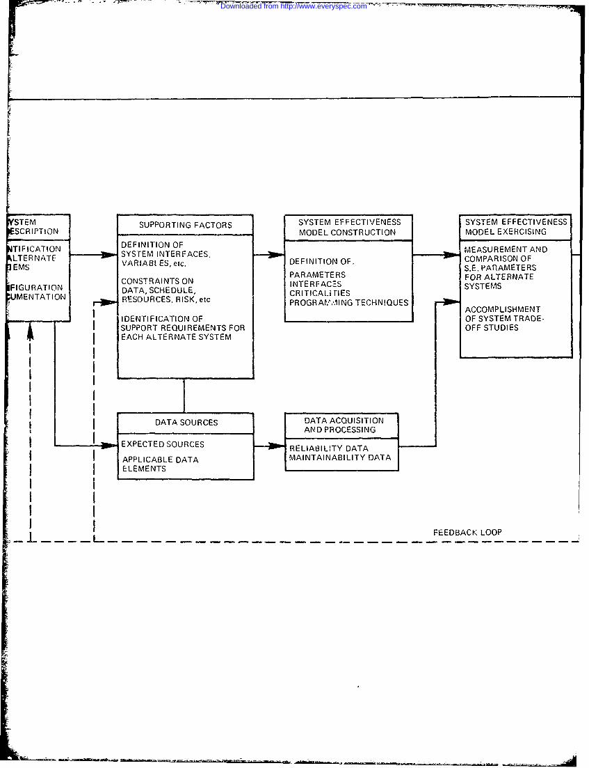
II
STEM SUPPORTING FACTORS SYSTEM EFFECTIVENESS SYSTEM EFFECTIVENESSSCRIPTION MODEL CONSTRUCTION MODEL EXERCISING
TIFICATION DEFINITION OF
ILTERNATE SYSTEM INTERFACES, MEASUREMENT AND
EMS VARIAB ES, etc. DEFINITION OF. COMPARISON OFPARAMTERSS.E. PARAMETERS
PARAMETERS FOR ALTERNATEF A CONSTRAINTS ON INTERFACES SYSTEMSFIGURATION DATA, SCHEDULE, CRITICALi SIESUMENTATION RIESOURCES, RISK. etc RTCiIE
-PROGRAV.',ING TECHN!QUES ACCOMPLISHMENT
-- - IDENTI FICATION OF IOF SYSTEM TRADE-I SUPPORT REQUIREMENTS FOR OFF STUDIESI i EACH ALTERNATE SYSTEM
III DATA SOURCES DATA ACQUISITION
I. E X P E C T E D S O U R C E S --a w lA BD LP T Y E S A T A
APPLICABLE DATA MAINTAINABILITY DATA
ELEMENTS
FEEDBACK LOOP
Downloaded from http://www.everyspec.com
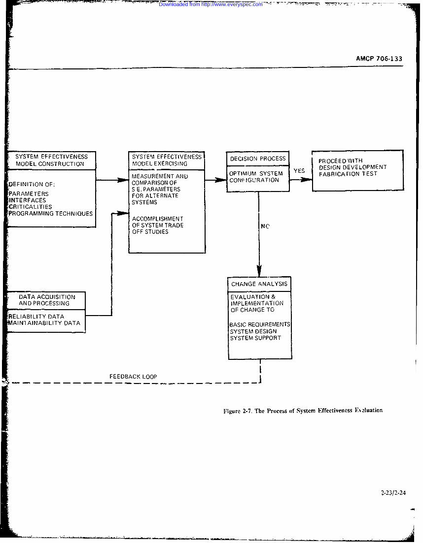
AMCP 706-133
* SYSTEM EFFECTIVENESS SYSTEM EFFECTIVENESS DECISION PROCESS PROCEED WITHMODEL CONSTRUCTION MODEL EXERCISING DESIGN DEVELOPMENT
MEASUREMENT AND OPTIMUM SYSTEM FABRICATION TEST
DEFINITION OF: COMPARISON OF 0 CONFIGURATIONFLARAETERSS E. PARAMETERS
PARAMETERS FOR ALTERNATEINTERFACES SYSTEMSCRITICALITIESPROGRAMMING TECHNIQUES
ACCOMPLISHMENTOF SYSTEM TRADE NOOFF STUDIES
CHANGE ANALYSIS
DATA ACQUISITION EVALUATION &AND PROCESSING IMPLEMENTATION
--- OF CHANGE TO
RELIABILITY DATA
AINl AINABI LITY DATA BASIC REQUIREMENTS
SYSTEM DESIGNSYSTEM SUPPORT
FEEDBACK LOOP I
Figure 2-7. The Process of System Effectiveness E- luation
2-23/2-24
Downloaded from http://www.everyspec.com
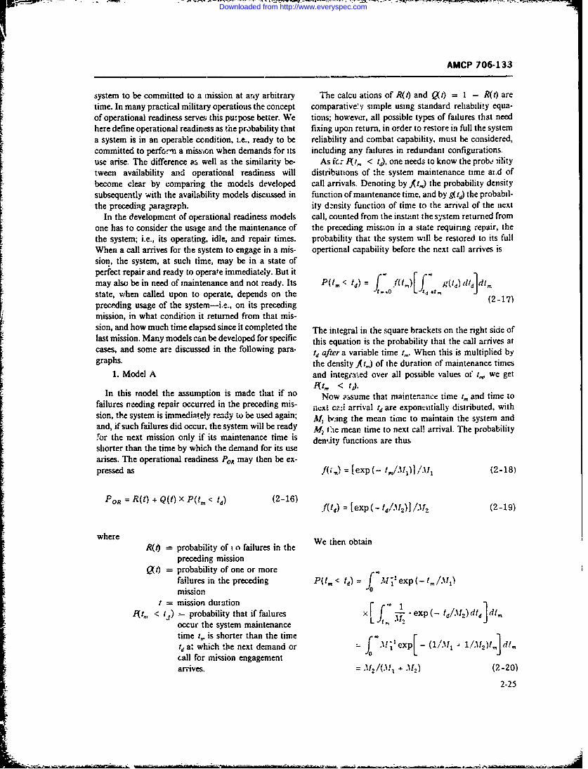
AMCP 706-133
system to be committed to a mission at any arbitrary The calcu ations of R(t) and Q(t) = I - R(t) aretime. In many practical military operatioas the concept comparative'.y simple using standard reliability equa-of operational readiness serve; this pupose better. We tions; however, all possible types of failures that needhere define operational readiness as the probability that fixing upon return, in order to restore in full the system
a system is in an operable condition, i.e., ready to be reliability and combat capability, must be considered,committed to perfo.'n a misson when demands for its including any failures in redundant configurations.use arise. The difference a. well as the similarity be- As fez At, < td), one needs to know the probe ,ilitytween availability and operational readiness will distributions of :he system maintenance time at.d ofbecome clear by comparing the models developed call arrivals. Denoting by fi,,) the probability densitysubsequently with the availability models discussed in function of maintenance time, and by g(t) the probabil-the preceding paragraph. ity dznsity function of time to the arrival of the next
In the development of operational readiness models call, counted from the instant the system returned fromone has to consider the usage and the maintenance of the preceding mission in a state requinng repair, thethe system; i.e., its operating, idle, and repair times. probability that the system will be restored to its fullWhen a call arrives for the system to engage in a mis- opertional capability before the next call arrives ission, the system, at such time, may be in a state ofperiect repair and ready to operate immediately. But itmay also be in need of maintenance and not ready. Its P(tm < td) = f(t. )If g(Ia) d Jdt,
state, when called upon to operate, depends on the f, - (O-2-17)preceding usage of the system-i.e., on its precedingmission, in what condition it returned from that mis-sion, and how much time elapsed since it completed the The integral in the square brackets on the right side oflast mission. Many models can be developed for specific this equation is the probability that the call arrives atcases, and some are discussed in the following para- td after a variable time t.,. When this is multiplied bygraphs. the density f,, ) of the duration of maintenance times
1. Model A and intege3aed over all possible values of t,,, wc getA t, < t').
In this model the assumption is made that if no Now assume that maintenance time t,, and time tofailures needing repair occurred in the preceding mis- iext cai arrival t
d are exponzatially distributed, withsion, the system is immediately r--dy to be used again; ,1, bv:ing the mean time to maintain the system andand, if such failures did occur, the system will be ready M2 the mean time to next cal! arrival. The probability
!or the next mission only if its maintenance time is density functions are thusshorter than the time by which the demand for its usearises. The operational readiness POR may then be ex-pressed as f( ,) = [exp (- t,,/M 1)].W 1 (2-18)
FOR = R(t) + Q(t) x P(tm < t) (2-16) = CeXP(tdM 2 ) (2-19)
where W hnotiR(6 = probability of i o failures in the We then obtain
preceding missionQ(t) = probability of one or more
failures in the preceding P(tm < td) = I-exp t,,/3I1)m ission -'
= mission duration rr " 1< t ) probability that if failures x f. exp (- ta. z ) dtd dt.
occur the system maintenance L-', J
time ,. is shorter than the timeta. which he next demand or f.'texp - (l/ 1 .dcall for mission engagementarrives. A21/(.1 + 31) (2-20)
2-25
Downloaded from http://www.everyspec.com
AMCP 706-133
In this exponential case, system operational readi- Pt, < t) = p(z)dz (2-23)ness becomes ,PI7PoR = R(t) + Q(tJJA1z/(M1 + A12)] (2-21)
Returning to the exponential case treated in Eq. 2-20,
and using Eq. 2-22, we obtain
As a numerical example let us look at a system witha probability of R = 0.8 of returning from a mission p(z) = j [Mi' exp t4/M2)Jof say t = I-hr duration without requiring repair, and, td -0
thetfore, had a probability of Q = 0.2 that it willreqjire repair. If systen. mean maintenance time is x I -xp (t. - z)/.1f dtd
M4', = 1 hr and the mean time to next call arrival is (m11 pM, = 2 hr, the operational readiness of the systembecomes y exp ( - tdIM 2) •exp(- t,,1) dtd
PoR = 0.8 + 0.2 (2/3) = 0.933 p-a -/
Comparing this result with the conventional steady- = 1/(M1 + M2 ) exp (- z/M) (2-24,
state availability concept and assuming that the systemhas a mean maintenance time of M, = 1 hr and a meantime to failure of M2 = 5 hr (roughly corresponding The probability At,, < t ) is then, according to Eq.to the exponential cse of R = 0.8 for a one-hour 2-23,mission), we obtain a system availability of
A = M,/(M + M 2) = 5/6=0.833
which is a result quite different from P, = 0.933. XAn equation fo- P t, < td), which yields identical
results as Eq. 2-17, can be derived by convolution when (2-25)
introducing a new random variable, z = td - t,,which is the difference between the time a call arrives which agrees with the result of Eq. 2-20.
td and the time when system maintenance is completedtr, Whenever z is positive, the system is operationally 2 oeready. The density p(z) of z is the joint density of the The operational readiness model of Eq. 2-16 can be
difference of two random variables td and t,, given by extended to the case when mission duration time t is
not the same for each mission but is distributed with adensity q(t). We then getp(Z) = [*g(td)f(td - z)dtd (2-22)
t=,Port = foR(t) q(t) dt + P(t, < td) foQkt)q(t)dt
(2-26)
where =(t) is the density of syste alleand Since the integrals in Eq. 2-26 are fixed numbers, weAQ A., is tdensity of ytm o ntecalande may wrt qO t+Pt, d ~tq
time since t, can be substituted by td - z which fol- my writelows from z = td - t,_. The integration limits go from R = R 17q(1)dt
,td = zto t = o, since for t1 < z t, - z becomes (2-27)negative and p(z) = 0 by defini lon, i.e., system is notready. The probability /(t,, < t,) is then Q = r (t)q(t)dt
2-26
Downloaded from http://www.everyspec.com
IMF- - -
AMCP 706-133
[ and using the symbol P for f9t. < t,), i.e., P = In the computation of RD. we use the fact that dor-1(t,, < t0). Eq. 2-26 may be written in the form mancy time Idis the same as the time to next call aririval
which has the density g(t4) of Model A, i.e.,
PoR =1R + QP (2-28)PO? =R +Q 2 2 ) R D g(t )RD(td) dt d (2-31)In this equation R is the probability that the systemreturns without failures from the last mission; Q = I- R is the probability that one or more failures deve-
loped in the last mission; and Pis the probability that which is the probability of no drmant failure(s) occur-the system will be repaired before the next call arrives ring in the variable dormancy time t, when at 14 = 0if it developed failures. The mission times are variabk the system returned without failures.here with density q(,). As an exercise let us assume that all vailAble times
3. Model C a-e exponentiallydistnbuted with the following iieans:M,= mean maintenance time of the
A further extension of the POR model of Eq. 2-28 is systempossible by considering the case when so called dor- , mean time to next caii arrivalmant failures may develop after the system checks out M3 = m?-an time of R(t). i.e.. of theO.K. and before the next call to engage in a mission pruiAbility of no failure(s)arrives. That is the period when the system is dormant, uccurning in mission tin" e ii.e., not operating, and is beheed to be ready. M = mean mission time when
Denoting by RD the proba:bility of no failure(s) in the miss;c, durations aredormancy state, by td thl - variable time to next call distributcd with density q(t)arrival counted from the time of return from the M, - mean time -'If R. i e., of thepreceding mission, and by P0 the probability that the probability th't no dormantsystem will be repaired before the next nall arrives and faiiares occur.will not fail in dormancy, operational reainess may be We cGmpute first R and Q of Eq. 2-ZB as follows:written as
PoR = RRD - QPD (2-29) R [ exp(- t/M 3), exp(- t/' 4 )!.Mljdt
txOwhere R and Q are defined in the same way as in Eq. = AM (M3 +1 4) (2-32)2-27 in Model B, and RDis the probability of no failuresin the state of dormancy in the waiting period r, Q = 1 - R = M4/(1 3 - '114)
In the computation of P we make use of Eq. 2-23,conditioning it by the requirement that no dormantfailure occurs after t,, in the interval : = t - r,,., the Next we compute P. using Eqs. 2-30 and 2-24:probability of which is given by RD(z). With this condi-tion we get PD= [1/(M1, + M2)] exp(- z/1 2 )
PDo Pf%(z)R(z)dz (2-30) e z/M 5)dz
0 = 12M )x( "s -) (2-33)Thus PO is the probability that maintenance time t,, is =21 + 25
/ J Ismaller than the time td to next call arrival and nodormant failure occurs after completing mainten.a'eeat t. Finally w: compute R, using Eq. 2-31:
2-27
Downloaded from http://www.everyspec.com
AMCP 706-133
D= f [exp(- t/M 2).exp(-t/M5s)/M 2Jdt ond chance is given to make the system ready bytd + t.
+ )(2-34) In the model which follows we assume that a mini-mum alert time of z, is allowed after a call arrives at
Eq. 2-29 then assumes the form: t,, Operational readiness may then be expressed as:
POP ( 3 )x ( 'H5 ) x( PoR = R[B , (1 + R)"' I ' QIPD + (1 PD,)M.P '13 4 M 4 M + M"5 + 13 1 4 (2-37)
(M + M2 M +4- ; In this equation the first term on the right is the proba-
-__ / I__ . . + V bility that the system returned without need for repairM2 + MS \M 3 + A 4 + 'l l 4- 3 -' 4 4 from the preceding mission (R) and checks O.K. at(2-35) t,(RD) ordoes not check O.K. at t, (l - R) but can
be fixed in t. (M). The second term is the probabilityAnd when no dormant ailures can occur, i.e., when that the system needed repair after returning from the
d preceding mission (Q = I - R) and !s ready at r,R : =h(P) oris not ready at t(l - P,) but can be fixed in
M3 Al x ( .11, t.(M.). The equations for R. , P,, and RD are the samerA 3 + M 4 Al1 + 'M2) T \ 3
+ 3I/ as given in Models B and C, and the equation for(2-36) M, the probability of repairing the system in t, is givenby
For a numerical example assume M, = 1, M = 2, "M, = 5, M, = 1, and M, = 10. We obtain from Eq. m, =J f(t) dt, (2-38)2-35: 1'.0
Po, - (10/12)[(5/6) + (2/3) (1!/6) = 0.787And from Eq. 2-36, i.e., no dormant failures, we obtain: where t,, = 0 at , when alert is sounded, and At, is
,= 5/6 + (2/3) (1/6) = 0.833 + 3.111 the probability density of the maintenance time t,.
= 0.944 5. Model E
In this example we took the mean time to dormant Returning to Eq. 2-16 we 'decompose" the termfailure Ms to be twice that of mear. time to failure when Q(t)P (t,, < t,) into its "constituent elements", andoperating M. In reality we would expect Mf, to be at writeleast ten times M,, or even more. In some systems
dormant failures may not occur at all.4. ModelD PoR B ZO P, (2-39)
Models A through C are "strict" in the sense that noallowance for turn-around time or fr- alert time ismade. The models can be "relaxed" ifa minimum turn- This decomposition makes the mode! more tractablearound time t. is allowed for refueling, checkout, etc.; for complex systems that may include redundancies ofi.e., if a call arrives within to after the system returns the parallel and stanxdby type. The system may returnfrom a mission, it will not count as a failure to be ready, from the preceding mission in a variety of states requir-and if an alert is given at r, there is an alert time of ing repair. say jstates, where the Ah state occurs withto allowed for pre-mission checkout and correcting any- probability P, in which case A t,, < t,) = Thesum
thinz that needs repairing before t. expires, i.e.. a sec- of all (Q P) is then the term QR(t,, < td) of Eq. 2-16
2-23
Downloaded from http://www.everyspec.com
APCP 706-133
Assume a system consists of a subsystem with the sequential maintenance type (i.e., one -t a time) or ofith subsystem having a probability of q, that it will need the parallel type (i.e., simulafteous maintenance).repair and a probability of r, that it will not need repair. In the sequential case we form the joint densities ofThe number of states j in which any one or more sub- downtime by convolutions and obtainsystems will require repair or replacement is then thecombination of any one out of n, any two out of n, any f, = f*A f = f. *f; A. = A *f;three out of n, etc., subsystems requiing repair, i.e.,
J =fC*fb*fC (2-43)
+ ( + - (- - 2 - 1 (2-40)We use. then, these joint densities in Eq. 2-17 to getP to P.
For instance the system consists of three subsystems In the case of paraile! repair, where each subsystema, b and c (such as black boxes or system replaceable has its own crew to work on it, we compute the P,s asunits) and each of these can suffer some kind nf failure follows. We transform Eq. 2-17 by changing the inte-or malfunction in a mission independently of the other gration limits and getsubsystems, the number of states requiring repair is
(3)( 3+7 P(t3 = t3) = f - g(t-) 1 f(t<t)dt]d,
[: (2-41)i= ~)+ ~)-~(~)=3 3+ = ~ 1 dSU 1(, I t (2-44)
Each of these seven states occurs with a certain proba- g(Id) M(t,) di (2-44)bisity. The first three states are: a needs repair (b andcdo not) which occurs with probability q. r, r; b needsrepair (a and c do not) whch occurs with probability since 3 4t), the maintainability function, is given by
r. qb r,. and cneeds repair (aand bdo not) which occurswith probability r. r, q,. The following tabulation listsall seven cases: M(td) =J .(tm) dtm (2-45)
State Units Probability P, (ready byNumber j Failed of state Q, ti/given Q1) For the fkh state we get then P as
_ a Q, = qr;bre P1
2 b Q2 = rq,r) P2 p= g(t)MJ(t,)dt, (2-46
3 C Q3 = 'Izbqc P 3
4 a. b Q4 = qaqb'C P4 where M is the maintainability function, i.e., the sys-
5 a, c Q5 = q.rq, P tern downtime distribution for either one, or two ormore subsystems in simultaneous repair. Thus
6 b=c QM=rqqC PM M(t); M. = X (f
7 a. b. c Q7 = qqbqc P7( and M, = m(
(2-42) for single repair of subsystems a. b, and c treated in theprevious example and further, for simultaneous repairs,
As to the computation of the P. terms, the mainte- w ewe get
nance time distributions of the three subsystems at thesystem maintenance level must be known, i.e., f,(tm) ,fb (tin). and f (t). We get thenPi,P2 ,andP 3 '114 = 1 -(1 - M1 )(1 - M2)by substituting fa (Q), fb (tin), and f (t,.
respectively, into Eq..2-17. .s to P4, PS. etc., there Ms = 1 - (1 - 11)(1 - A3) (2-47)are two or more subsystems to be repaired. The
distribution of system downtime in those cases
depends on the maintenance policy that may be of the .117 = 1 - (1 - M1 )(1 - ' 2)(1 -3)
2-29
Downloaded from http://www.everyspec.com
AMCP 706-133I The terms M4 th, .ugh At; in Eq. 2-47 are maintain4- probability that the system does not fail at all up to timebility functions, i.e., M, is the probability that system t, and the second term is the probability that the sys-maintenance will bt completed by td when subsystems tern, prior to t failed one or more times, was last res-a and b need repair, etc., and , is the probability that tored to operation at time y < t and survived withoutsystem maintenance will be completed on time when all failure the following period (t - y) so that at time t itthree subsystems need repair or must be replaced, is operating. The function ngr) is the renewal rate of the
To recapitulate, in the case of sequential repair we syrten, i.e., the rate at which the system enters theform the joint density functions of the subsystems re- "'up" state as it undergoes a series of operation-failure-quiring repair, while in the case of parallel repair we repair-and "up" again cycles. This renewal rate is givenform the maintainability functions M, through M, by by the renewal equationsimple probability equations of simultaneously pro-
ceeding maintenance events (i.e., in parallel).Many other operational readiness models can be n(t) = h(t) . h( - y)n( )Idv (2-49)
developed and the models here discussed can be further "0refined, for instance, by cosidering imperfect check-out so that some failures are not detected, etc. Thepurpose followed here was to introduce the reader to where h~z)is thejoint probability density function (pdf)certain modeling techniques so he can develop his own of the sum of two random variables, i.e., the time-to-
models to suit specific weapons, missions, and mainte- failure and the time-to-repair. If we denote the pdf of
i,3nce policies. In par. 2-4.2.2 we show some availabil- time-to-failure (.,., of the "up" time) by g(t). and the
ity modeling techniques, following the same purpose. pdf of the time-to-repair (i.e., of the "down" time) byA'), we get h(t) by convoluting g(t) with At), i.e.,
2-4.2.2 Availability Model-
The concept of availability was originally dcvelopedfor repairable systems that are required to operate con- hi(t) J g(I - v).f( v) dy (2-50)tinuous!v, i.e., round-the-clock, and Are at any random
point in time either operating or are "down" becauseof failure and are being worked upon so as to restore As an example assume a system with the followingtheir operation in minimum time. In this original con- exponential density functions for uptime and downtimecept a system is considered to be i;a only two possiblestates-operating or in repair-and availability is de- i(t) = X exp (- 1t) (2-51)fi:ied as the probability that a system is operating satis-factorily at any random point in time t when subject toa sequence of "up" and "down" cycles which constitute fit) = p exp(- p t) (2-52)an alternating renewal process (Ref. 21, pp. 80-86).
1. Model A
Consider first a single unit system or a strictly serial where X is the failure rate and is the repair rate.
system that has a stationary reliability R(t); its availa- To solve for A(t), we take the Laplace transforms of
bility .4(t) that it will be in an "up" stzte (i.e., will I.b Eqs. 2-18 through 2-52 and get
operating) at time t when it started in an "up" condi-tion at t = 0, is given by the renewal equation A*(s) = R*(s) - R*(s)n*(s) (2-53)
A(t) = R(t) -f R(t - Y)n(y)dy (2-48) e (S) g* (s) v (S) (2-54)
SO h* (s) =g*(s ( s) (2-55)
In this equation the first term on the right, R(t), is the Substituting Eq. 2-55 into Eq. 2-54 we get
2-30
Downloaded from http://www.everyspec.com
AMCP 706-133
Sn'(s) = .g*(s) f* (s) 1 - g* s)f*(s) I 2-56) When we study this equation we see that as t increases
the second term on the right diminishes and th-at a vaila-bility .n the limit becomes a constant, i.e.,
which in turn we substitute into Eq. 2-53. and realizingthat R*(s) can be written in terms of the density func-tion g*(s) as limA(I) = A = MTBF (2-63)
t-0MTBF - MTTR
R* (s) = (1/s)( 1 - g(s)i (2-57) We call this the steady-state or equi!ibrium availability
of a serial system. It is equivalent to the intrinsic availa-
Eq. 2-55 obtains the form bility of Eq. 1-23, Chapter 1.We may see in Fig. 2-8 that an exponentially failing
A* (s) =1 - g* (s) /{s-1 -f* (s)g* (s)j} and exponentially r,-paired system with a maintenance
(2-58) time ratio of 1:4 approaches the steady state ratherrapidly, in a calendar time of just over one-half of the
Since the Laplace transforn:s of the density fi.-ctions system MTBF For lower maintenance tine ratios theg(t) and jK h) are process stabilizes even more rapidly.
Looking again at Eq. 2-63. we may divide the numer-
,i!or and the denominator by the MTBFand write theg* (s) = X/. + S (2-59) steady-state availability in terms of the maintenance
ratiof* (s) =/(p " (2-60)
A = 1/(1 . a) (2-64)
We substitute these into Eq. 2-58 and transforming into where a = VTTRIMTBF. the maintenance timethe time domain we get ratio (MTR). Thus the availability .4 does not depend
on the actual values of the MTBFor A1 TTR but onlyA(t) p, *) - [X/( - p)]expI- (A p) t l on their ratio. A system with an MTBFofsay4hrand
(2-61) an MTTR of I hr wilP ha% e the same steady-state avail-
ability .)f 80% as a system with an MTBFof 100 hr andFig. 2-8 shows the availability function A(1) for the an MTTR of 25 hr. But from a mission accomplish-
case when the repair rate u is four times that of the ment viewpoint it may maKe all the difference 'Ahetherfailure rate. Stated differently, the MTBFis four times the system has an MTBFof 100 hr or 4 hr!that of the MfTTR: or the maintenance time ratio. de- An a7ailability of 80%. shown in Fig. 2-8. is in mostfined zs MITR/MTBF. is 1:4. practical cases not adequate. Much higher availabilities
We may write Eq. 2-61 also in terms of the reciprocal can be achie ,ed when properly designing for reliabilityvalues of the failure and repair rates-i.e. .n terms of and maintainability. High reliabilities are required forthe MTBF and the MTTR-remembering, however, mission accomplishments and. with modular design forthat both time-to-failure and time-to-repair must be maintenance where failed items can be quickly replacedexponentially distributed for the equation to hold: as modules, much better maintenance time ratios
should be achievable.
MTBF MTTR 2. Modi BA(I) = MTBF .IJTTR °MTBJF -MTTRWhat we discussed so far is the concept of the so-
x~ ex t (2-62) called pointwise availability which, as in Fig. 2-8. shows×e -. ITTB Y MTTR t -2 us the probabilit; that a system is "up" and operating
2-31
Downloaded from http://www.everyspec.com
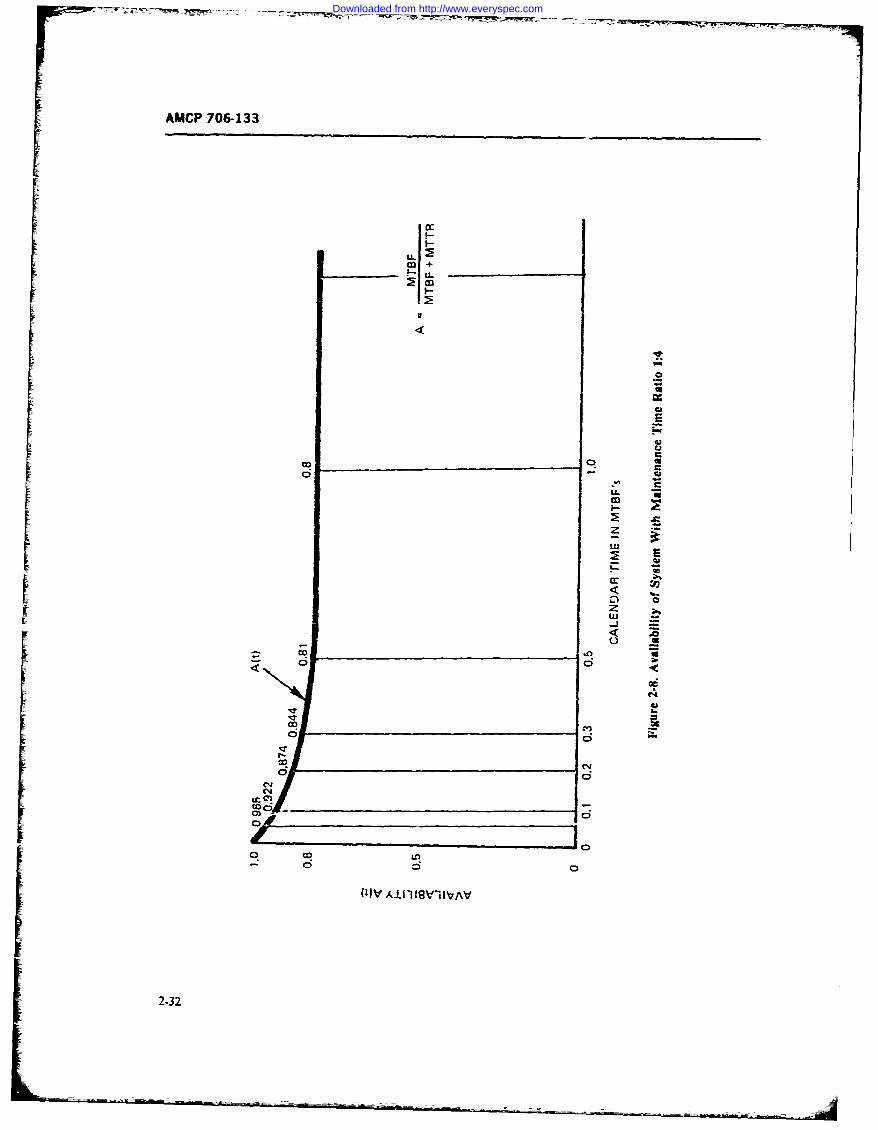
AMCP 706-133
cc
U-
UU
-4<
D to
OFrq ?IC
'im
C140
0 U
2-32__ _ _ __ _ _ __ _ _ __ _
Downloaded from http://www.everyspec.com
AMCP 706-133
t any point in time. Often, however, one may be inter- tem goes down because of any one unit faling, theested in knowing what percent or fraction of a time steady-state availability of such a series system i giveninterval [ab] a system can be expected to operate. This byis called the interval or average availability A,, of asystem and is given by the time average of the availabil-ity function A(O, averaged over the interval [a.b]: A ( - ai (-68)
AAV(a, b) = [1/(b - a)] fA(t)dt (2-65).a where a, is the maintenance time ratio cf the ith unit
in the system, i.e.,For instance, if we want to know the fraction of time
a system such as shown in Fig. 2-8 will be operatingcounting from t = 0 to any time t, we substitute a= (MTTRh/(MTBF), (2-69),A4 of Eqs. 2-61 or 2-62 into Eq. 2-65 and perform theintegration. The result is (Ref. 24, p. 34) Caution is necessary in computing ai, since Eq. 2-68
A (t r, t t applies to the availability of the whole system. Thus,AAV(t)= t d jo . f when the units are replaceable as line replaceable units
U 0 or system replaceable units, the M7TR, is the mean
xexp[- (A, + p)t]dtI time required to replace the unit by a good one at thesystem maintenance level and is not the mean repair
time of the failed removed unit. On the other hand ifis __
t(X + - exp[- (X + g)tl} failed units are not replaced but are repaired at 'hesystem level, M7TR, is the mean-time-to-repair the
(2-66) unit, which becomes also the downtime for the system.Thus, when computing the a's of the units and the
Fig. 2-9 shows the relationship of A(t) to A,,(i) for availability A of the s-btem, all MTTR's must be thosethe exponential case. Note that in the limit, in the repair times that the system experences as its ownsteady state, we again get the availability A of Eq. 2-63. downtime. The MTTRi of the ith unit is thus hei.e., system mean repair time when the ith unit fails.
If we compare Eq. 2-68 with Eq. 2-64 in Model A we
limAAV(t) =il/ + P) find tha: they are identical. The system mainenancet- - time ratio is
= MTBF/(MTBF + MTTR) (2-67)e = MITTR/M.ATBF (2-70)
3ut in the transient state of the process, as shown in thefigure for an interval 10, T), before equilibrium isreached, AA,(* is in the exponential case larger than But the serial system MTTR as shown in Chapter 1 isA(&. for an interval [0,]. This is not true for all distri- given bybutions since A1) and AR(i) may be subject to verylarge fluctuations in the transient state.
From Eq. 2-66 we may also get the average or ex- M TTR = E L iti/ .Xi (2-71)pected "on" time in an interval [0,11, by multiplyingAA,() and 4 the length of the time interval of interest.Ref. 25, pp. 74-83, contains an excellent mathematical while its MTBFistreatment of the pointwise and interal availability, andrelated concepts. Earlier work in these areas is 'oundin Ref. 26 and 27.
3. Mode C MTBF =LAi i2-72)
When a series system consists of N units that areseparately repairable or replaceable whenever the sys- The ratio a is, therefore, also
2-33
Downloaded from http://www.everyspec.com
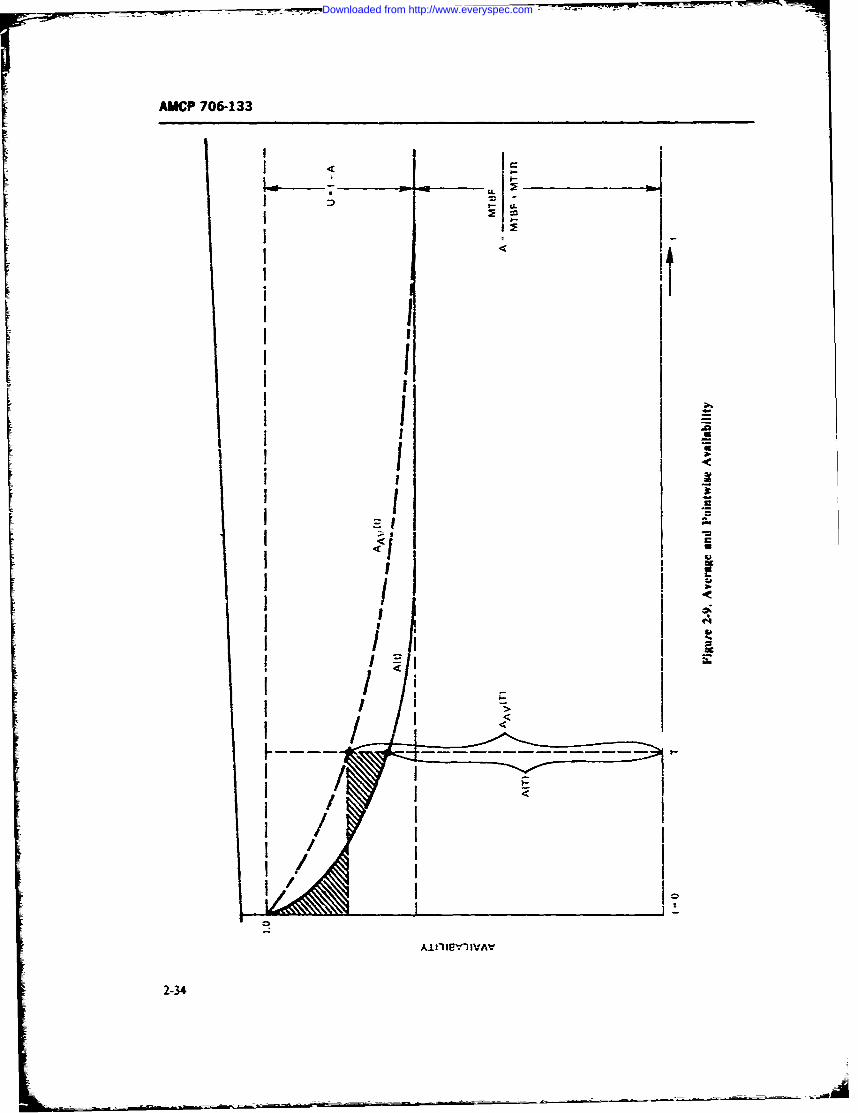
AMdCP7O6-133
II
I I iI
ii
I -
I -II ' ;i1 11I ii I
I I
I I_
i-3
Downloaded from http://www.everyspec.com
-M--77MM --
AMCP 706-.33
a 4kj)(Z )/=Ei=Yfj A,n1*.. A2 + 2AU (-8
(2-73) whic:i gives us the probability A2 that bath units areoperating at any point in time, and the probability 2
where X; =/MTBF, and t, = M7YR, AUthat only one unit is working. Over a period of timeThe maintenance time ratio (MTX) is ly t. T, the sy.,tem will, on the average, be for a time TA
average system downtime per systmn operating hor, operating with both units up, while for 2 TA Uonly oneConceptually, it is very similar to the maintenance tio unit will be up. If the performance of the system is
(MA) defined as riaintenance manhours expended per P, when both tnits are up, but only P2 when only onesystem operating hour. The difference is that. in the Un~t is up, the system output or effectiveness SE overMTR one looks only at system downtime in terms of Tis expected t ) be
clock hours of system repair, whereas in the MR onelooks at all maintenance manhours, expended at allmaintenance levels to support system operation. (2-79)
4. Model D
In this model the availability of some redundant sys- Assume a ship with two engines which are subject totems is considcred (Ref. 24, pp. 36-38). First we del on-board repair when they fail. When both engineswith two equal, independet units in a parallel redun- work the hip speed is 30 kt, and when only one enginedant arrangement with ,mtch unit being separately works it is 20 kt. Let engine MTBFbe 90 hr and let itsrepairable or replaceable while the other unit continues M77R be 10 hr, so that the availability of an engine isoperating. Thus, the system is "up" if both or any one A = 0.9 and its unavailability is U = 0.1. Over aof the two units operates. 24-hr cruise the ship will be expected to travel on the
If we define the uravailability U of a unit as averageSE= 30 X 24X 81 +2X 20X 0.9
X 0.1 =5832 + 86A =669.6 nmi.U=I-A,:MTTR/(MTBF+MTTR) (2-7-% The expected time ;2zt !ae ship to be found idle with
both engines out for a 24-hr cruise is
then the probab;lity thar the system is unavailable is theprobability thai both units are down at the same time, Ti1 u = 24U2 = 24(0.01) = 0.24 hr (2-79a)which is
U2 (2-75) For three units in parallel we get
and system availability is (A + U) = A3 + 3AZU + 3AUZ + U3 (2-80)
= 1 - U (2-76) Ifthe system goes down only ifall three units are down,system availability is
Further, using the binomial expansionA -,,= = A' + 3AU + 3AU 2 (2-81)
(A + ) A2 + 2AU + U (2-77) but ifat least tw) units are needed for system operation
since a single unit is not sufficient, system arailabilitywe find that we miry write Eq. 2-76 also in the form becomes
2-35
i l I mm II It I miim mlm m m oi2
Downloaded from http://www.everyspec.com
AMCP 706.133
AsY.,tem A3 3A 2 U (2-82) measures, as illustrated in the Ghip engines example.
In general, for a system with n equal, redundant S. Model E
units, we expa. d the binomial term (A + 1,) whichyields the probabilities of being in any one of the possi- A very different situation in avail.biJitv modeling is
ble states. Then, by adding the probabilities of the ac-. encountered when system "uptime" is aoi cmeasured in
ceptablestates, we obtain the aailability of the system. hours of operation or any time parameter, out rather it
As stated earlier, the units must be independent of each terms of number of rounds fired, miles travelled, actua-other, both in terms of their failures and in terms of tions or cycles perormed, etc. The reliability parametertheir repairs or replacements, with no queuing up fcr is then no longer expressed in terms of MTBF butrepair. rather in mean-rounds-between-failures (AMRBIF),
Ref. 28 -.ontains, throughout the text, extensive tabu- mean-miles-between-filures (MMBF). meancycles-be-lations of a ailability and related measures of mtlltiple tween-failures (MCBF), etc. Th. failure rate then a1-oparallel and standby redundant systems for cases of is expressed in number of failures per round- r mile.unrestricted as well as ,estricted repair when failedredundant units must queue up and wait until their u titurn come. to get repaired.
Returning briefly to Eq. 2-75, when the two redun- Fot straightforward reliability calculations thisdant units are not equal but have unavailabilities poses no problem since 'he same reliability eqttations
U - A, and U, 1 - A:, system unavailibil- apply as in the time domain, except that the variableity becomes time t in ho irs is reriaced by the variable number of
rounds, number of miles, etc. We may then calculatethe reliability of such systetms for one. ten, one hun.-
U1 U2 (2-83) dred, or any number of rounds fired or miles travelled,
at we wish. The maintainability calculations remain asand availability bef-orc, since downtime will always be measured in
terms, c-f time, and the parameter of main interest re- ]Asystert = 1 - UXUz (2-84) mains the M7TR.
However, when it comes to availability, which usu-ally combines two time parameters, i.e., the MTBFand
Again, we may expand the multinomial tie MTTR into a probability of the system being up atsonie time t, a difficult problem arises when the time
(A, - U1)(A, 4. U2) = AIA, .- AtU2 - A2 U, - U1U, I is replaced by rodnds or miles since the correlation
(2-85) between time and rounds or time Lad miles is quitevariable.
and may write system availability in the form An equation for the steady-state availability of ma-chine guns is given in Ref. 29. This equation is based
A, : A= A2 + AU Z -L AZU, (2-86) on a mission profile that at discrete times t,, t., t,, etc.,requires the firing of A', J, N,, etc., bunts of rounds.-When the gun fails during a firing. :- wet time t,, it fires
For n-unequal units we expand the term only frounds instead of N, rounds at,4 must undergorepair during whiich repair time it is not available to
S * =12 7 fire, i.e., fails to fire let's say a required , rounds at11 (A 4 A2) 1 (2-87) t, and a further N, rounds at t, before becoming again
available (see Fig. 2-10). Its availability A based on theand add together the probabilities of acceptable states rounds not fired during repa.r may be expressed, for theto obtain sysIem availability and other effectiveness described history, as
2-36 1
Downloaded from http://www.everyspec.com
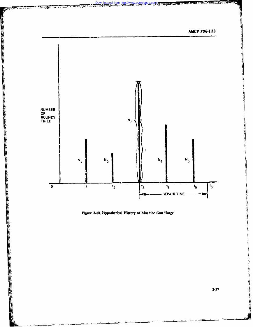
AMCP 706-133
NUMBEROF
~~ROUNDS
FIRE NNN
233
Downloaded from http://www.everyspec.com
AMCP 706-133
A = (N1 + NZ +f)/(Nl + N2 + N3 + N 4'+ V,) The dimensions for 0.28 is gun system maintenance
(2-88) manhours per vehicle operating hour. The correctivemaintenance time ratio a (called maintenance clockSuch sequence of rounds fired followed by roundshour in~dex fl) is, according to this example, given bymissed (not fired) constitutes a renewal process in
terms of rounds fired, as shown in Fig. 2-i1, where thegun fails after firing x rounds, fails to fire I(x) rounds attc, = 0. 628(0. 28)0'o95 = 0. 187 (2-91)in the burst of rounds du;ng which it failed and alsomisses firing the required bursts of rounds while inrepair for an M7TR = M. Assume that the require- The numbers 0.628 and 0.952 are the intercept and thements for firing bursts of -ounds arrives at random regression coefficients, respectively, obtaired by regres-according to a Poisson process with rate r and the sion analysis as developed in Ref. 30, p. 18, Table 1.average number of runds per burst is N, then, the The dimension for a,, is gun system downtime perlimiting availability of the gun may be expressed as vehicle operating hour. The inherent availability of the
gun system is then, according to the conventional time
A =MRBF/(MRBF N + rMN) (2-89) equation, Eq. 2-64,
where MRBFis the mean number of rounds to failure. A 1 = (1. 187r 1 = 0.842 (2-92)The derivation of this formula developed by R. E. Bar-low, is contained in the Appendix of Ref. 29. To calcu-late A from Eq. 2-89 one must know the MRBFand This may be interpreted as ,he -un system being avaiia-MTTRof the gun, the average rounds Nfired per burst, ble for 84.2% o' the vehicle operating time. Cautior. isand the rate rat which requirements for firing busts required in using this approach for weapon availabilityof rounds arrive. ca'culation since in the case whe'e the vehicle would
Similar availability equations can be developed for have to be stationary and the gun would still fireother types of weapons, and also for vehicles where the rounds, MR and a would become infinitely large andrenewal process is in terms of miles travelled. Other the inherent availability of the guit system, wouidapproaches to calculating the availability of grins, as become zero.well as vehicles, are found in Ref. 30, and are b2.sed oncalculating, from histori.:! field data, the maintenanceratios and, via regression analysis, the maintenance 2-4.3 COMPLEX MODELStime ratio (called the "maintenance clock hour in-dex") that are in iurn used it the cenvertioral time- In complex system effectiveness mathematical mod-based equations of inherent, achieved, and operational els an attempt is made to 'elate the impact of systemavailability. reliability, maintainabiliky, and performance to tGe
For example, consider a machite gun system in a mission p.files, scenario, use, and logistic support.tank on which historical data are available, showing Only in simple situations can a meaningful single modelthat 0.014 corrective maintenance manhours are ex- be devele.t-d that will relate all these parameters andpended per round fired, and tha: p,..r year 4800 rounds yield a single quantitative measure of system effective-are fired while the vehicle travels for 240 hr per yr. The ness. Numerous comp!ex models exist and, as a mattermaintenance ratio (MR) for tir! gun system is then c~ffact, every major company in the aerospace basinesscomputed as (Ref. 30, pp. 36-38): has developed a multitude of such models, claimed to
be unique and the only meaningful ones, and uses themMMl Rnmber of £?ouCds Fired per Anum ptmarilv as sales tools. In the following paragraphs wep Hours per Annum discuss some of these models which have achieved a
= 0.014 X (4800/240) 0. 28 (2-90) certain popularity and a degree of acceptance.
2-38
Downloaded from http://www.everyspec.com
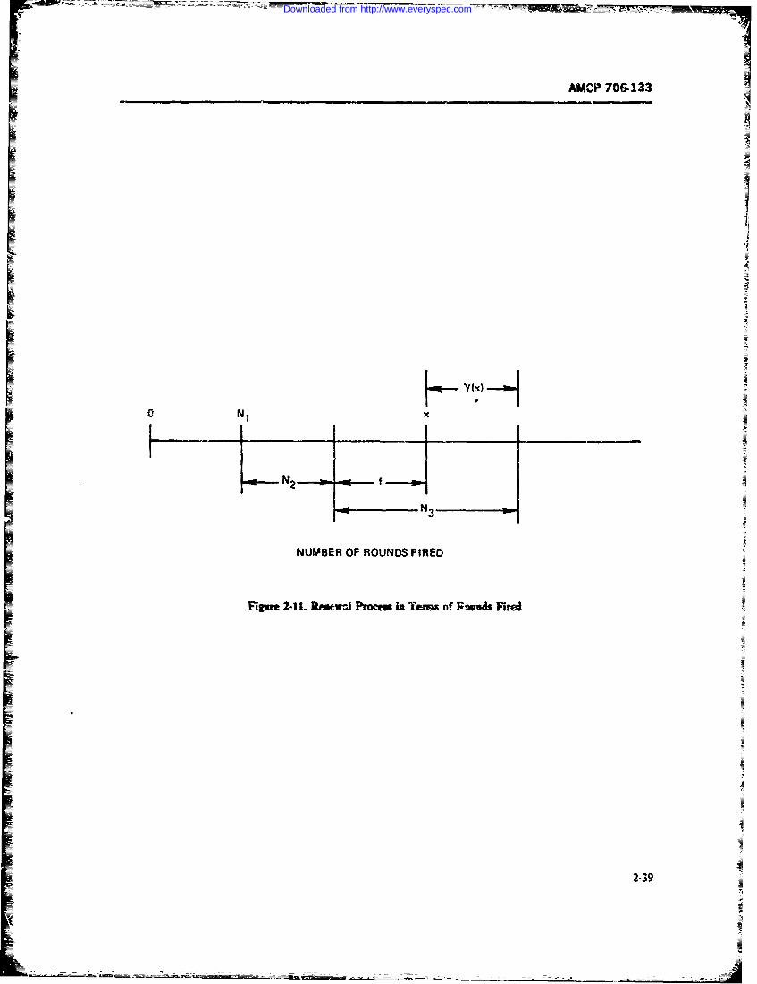
AC?70&.133
NI
N2
NUMBER OF ROUNDS FIRED
Figur 2-11. Resew-.1 Procem in Termi of 1FNuds Fired
239
Downloaded from http://www.everyspec.com
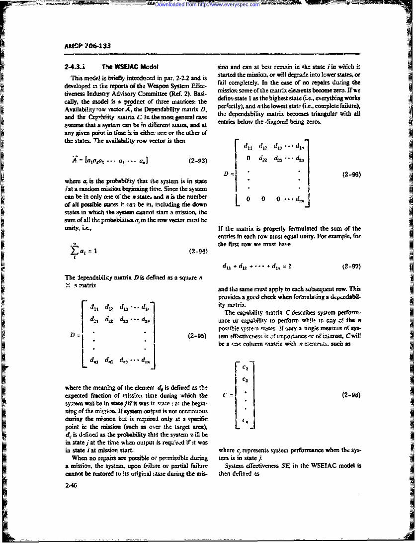
AMCP 7O6-133
2-4.3.i The WSEIAC Mcdel sion and can at best renan in tlie state i in which it
Tis mod&! is briefl introduced in par. 2-2-2 and is started the missio, or will degrade into lower stae orfail completely. In the case of no repairs during thedeve~o-d in the reports of tht Weapon System Effec-
Am 2). B mission some of the matrix eleaents become zo. If wete Indsdiso mtreematie e defi. state I as the highest state (i.e., everything worksV cally, the model is & product of three matrices: theAvailability row vector A, the .Dependablity matrix D, perfectly), and n the lowest statr (Le, complete failure),the dependability matrix becomes triangular with alla nd th e C ,q"t M .ty m atrix C in h e m ost ge nt ral ca se e t i s b l m t e di g n l b i g z r r,essume that a system can be in different states, and at ei
any givren poi t in time : in either e or the other ofthe states. rMe availbli row vectur is then r dd it d r- d 13 -d .
=aj,i-, ... a, ... a1] (2-93) 0 d1 d--- d7
D1 - (2-96) A ,where a is the probal ity that the sva is in statefrat a random mi--s.--oi--t betinnin tim Since the system""can be in only oe of the n satec r. n is the number 0 0 0 ".""..aof all possi'ble st-t it ca be in, ibrduding the downL
states in which the system cannot start a mission, thesum ofal the probabilities a, in the row vector must beunity, itr, If the matrix is properly formulated the sum ,.)f the
entries in each row must eqaal unity. For examile. for", (the first row we must hateFa, (2-9-4)
f
dit + dj .... d Z = (2-97)
The 3eendutlirIy matrix Dis defined as 3 square n
and the same rA apply to each subsequet row. Thisprov.ides a gad check when formulating a - acndabd-
d nl du du -.dv ityrmatrix.
The capstility matrix C describes syscar perform-I d Zdz anc or _,p.Nlity to perform while in . the n
poss:e ,, -n F-et,- if 2-) a .agie meas-e osy.-D= "(2-95) tern dc i sg z4 u , portana~ -"-v r^ M~~ Cvfill
be a =ti -ohann rnv;r A with n ensenii. sucn as
where the meaning of the emen d is defined as the
expected fraction of nssut time during which the C = * (2-98)sysem wiM b in state jifit was it s ae , at the begin-ning of the minon. If system outpat is not continuousduring the mission but is required only a; a 4xcificpoint i- the mission (such as over the tayget sna)r -.
d is dtiaed as the probability tlht the sirvem v-ill bein state j at the timne when out-.pt is req ;,.Ai it wasin state/iat mis~on start, whe-re c represents systei performanice when the sys-
When no rps are possible ot permissible during teran is in statea m the s upon a-ire or p failure System effectivene S& ip the WSEIAC model iscannot be rtaored to its original -;P e durn t mis- then defined as
2-46
Downloaded from http://www.everyspec.com
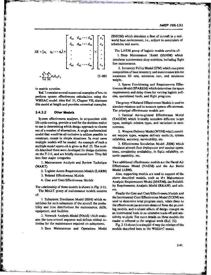
JACP 706-133
d 1 d • di n c (BMOM) which simulates a fleet of icraft in a real-world base environment, i.e., subject to constraints of
d; d, ... dp,, c schedules and assets.
SE =[a 1 a...ajx The LARM group of logistic models consists of:" ". Shop Maintenance Model (SHiMM) which
simulates maintenance shop activities, including flight
d.1 d,, ... d' cn line maintenance... .. fi 2. Inventory Poicy Model (IPM)' -which c"-punc;
n .composition of base inventory rnd mainteac kits tbr=E~art/c1,2-99) maximum fill ,-ate, minimum cost,' nd minimum
.t 14 weight.3. Spares Provisioning and Requiremnts Effec-
in matrix notation. tiveness M-Ael (SPAREM) which determinee the spareRef. 2 contains several numerical examples of how to requirements and delay times for varying logistic poli-
perform system effectiveness cWlculaions using tle cies, operational loads, and flight programs.WSEEAC model. A15o Ref. 31, Chant.er VII, disa.'ssesWSELLC ode. Alo Rf. 1, Cantr VI. dscuses the group rf Related Fffectiveness Models is used tothis model at length and provides numerical examples. te mons ad t ae ytem eo ess
simulate missions and to meure stmM effk, iveness.
2-4.3.2 tW models The principal efeciven models mrem1. Tactical Air-to-ground Effectivca,=. M&.el
System effectiveness analysm in ccajunction with (TAGEM) which b.-sically considers different ta.-,etlife cycle costing. provide a tool for the decision mak-r types. multiple mission types. arn_ "ve ationq ina envi-
to use in determining which desist approach to choose tonment.out of a number of ahernafives. A sagle mathemat'ical 2. Wespon Delivery Model (WD14) which consid.model that would be all-inclusive is seldom possib~le to ers weapon types, weapon delivery ft.hcJs, system
construct, except in simple situations. In most cases reliability, accuracy, survivability, etc.multiple models will be needee. An example of such a 3. Effectiveness Simulation Model ESM) whichmultiple modk-l apr m.ch is given in Ref. 22. The mod- simutes ai-,=at flet deplqyment and combat opera-els described there were developed ,or design decisions tios, considerin availability, in fiigit reliability,on the F-i 11, ad are briefly discussd 1:err. They fall sortie capability, etc-into four major categories:
1. Maintenance Analysis and Review Technique Two additional effectiveness modAs are the Naval Air(MART) Effectiveness Model (NAEM) and the Air Battle
2. U'.gistic Assets Requirements Modeh- (LARM) Modl (ABM).
3. Related Effectiveness Mod-I Also, supporting modils are used in support of theabove described models, su.ch as tkt- Maintenance4. Cost zd Cost/Effectiveness Models Aralysis Requirements Mcdel (MAPM), the Reliabil-
Th- ielationship of these models is shown in Fig.:2 ityRequirenis Analyss Model (RRAM, and orb-The .MART group or ma ,ntcnance Trrels comtsists ers.
of: Finally the Cost and Cost/Effectivenes Miodels and
SSubsystemSmulation Modl(M) wthe Incremental Cost/Effecti,-eness Model (ICEM) areused to determine toal program costs, relate thes toliblishcs for each subsystem of the aircraft the prob- the cfectives pai eter, obtained from the prced-
bility "d! time distributions for maint~mz-.. skil1% ing models, and eoaluate effe:ts of design changes onequipment, and facilitie.- an incremental bs6 in -m extensive trade-off and sen-
2. Network knalysis Model (NAM) -hich evalu- sitivity stlysis. For more details on these models theates the turn-around sequence and defines critical ac- reader is referred to the original work (Ref. 22).tivities for the maintenance required on subsystems. ig. 2.13 shows in a sfinplifld way the relation ef the
3. Base Maintenance and Operations Moddl models described here to the WSEIAC moiel.
2-41
I
Downloaded from http://www.everyspec.com
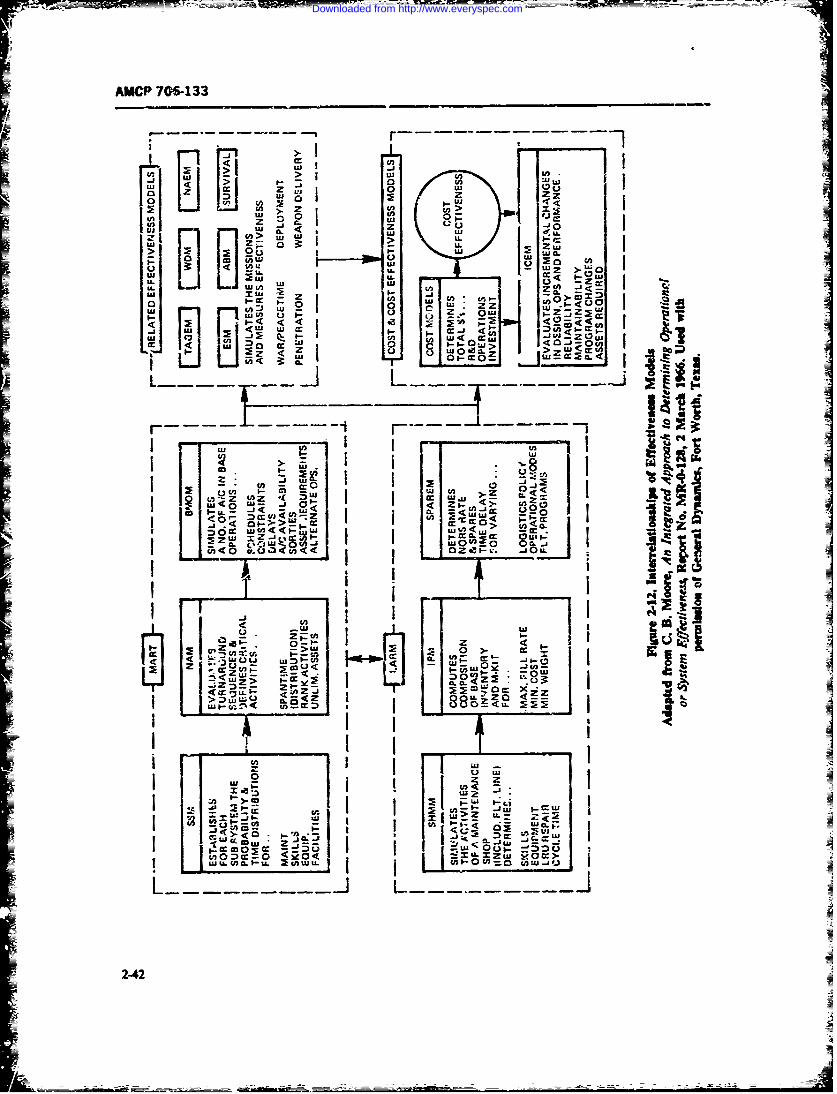
AMCP 706-133
o wJ
I0 4j 1 2 z Z0 .U) (jU 2u 0 w U~
-:- OZLL ~ .~.-
Ul -U I- ULLU -- i
zz
LU - Z 0 u4 U i -1< U,
I wow.j z 4Ii
Z c, 4 - 6 ~Ua
LL. 0 ~i F-I I . Ul oo 1U.-O 7~ LflW-Ich
L .i .< W->c
no 2 (P 42gu
Downloaded from http://www.everyspec.com
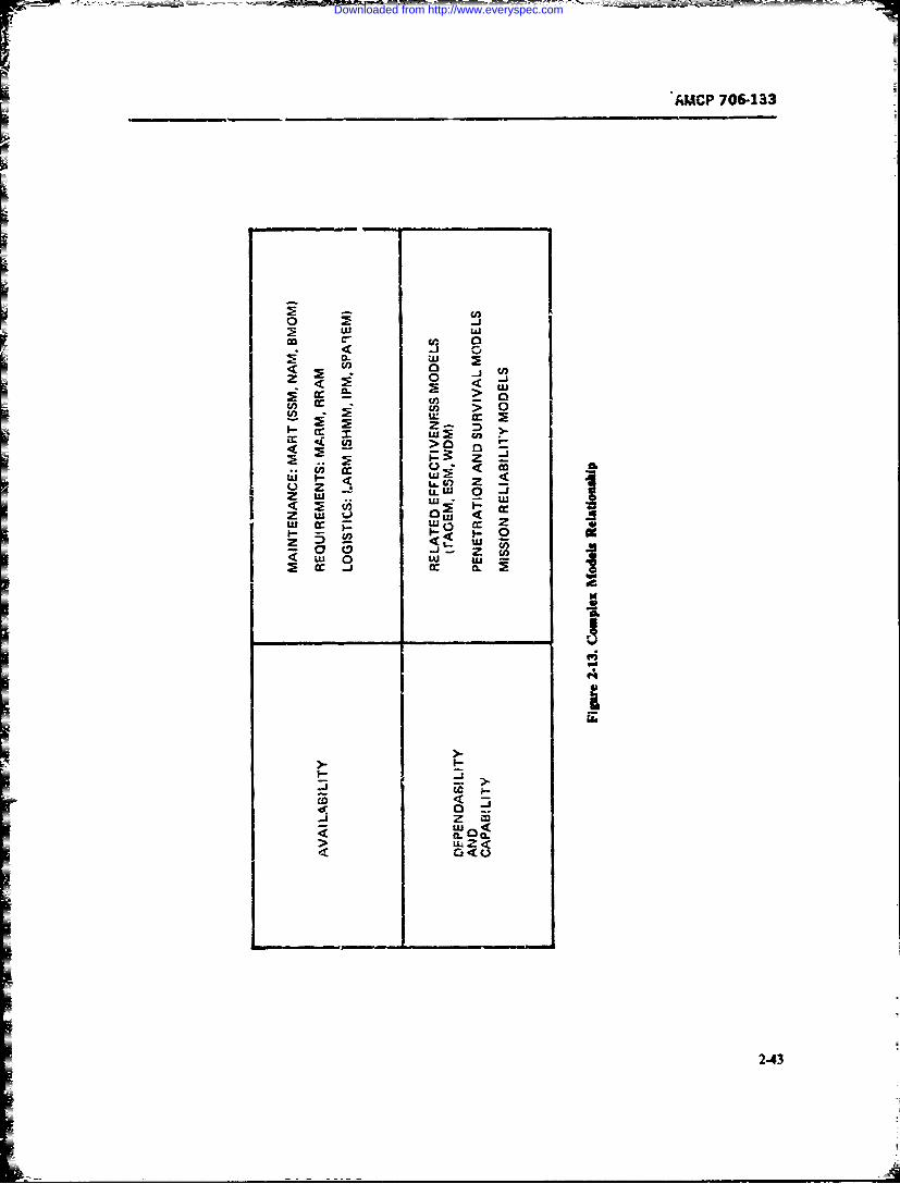
AMCP 706-133
-_
fn >, 0w x mJc
cc z
cr U_ > 0 -1
z w 0 S
US ccU 0 Cc Z
Ln < 0 UUJ
zK
-. 2.
-jz w
(4 CL
2-43
Downloaded from http://www.everyspec.com
AMP 706-133
2-5 TRADE-OFF TECHNIQUES Now, obviously, innumerabie combinations ofWTIRand WBh will yield the same a and, thereore, the
2-5.1 GENERAL same availability A, However, there is usually also amission rehatlit; requiremen: specified and also a
System effectiveness and cost/effectiveness models maintainabilty requiremwt. Both of these require-provide the best tools for performnag trade-off studies ments must also be met in addition to the avilabilityon the system level. Through the computerized models requirement-any chnnges in any of the multituce of reliability. main- t ef. 32 Firovides a trade-offexample that is repea:edtainability, performance, mission proufle, logiic sup- hc:e. for convenience, in a somewhat different form.
port, and other parameters can be immediately evalu- Fig. 2-14 rmpe-s a system consisting of five majorated as to their effect on the effectiveness and toul cost subsyri,.n ir a sies arranement The MTSFof thisof a sy--tem. Thus cot effectiveness modeling and eval systemn isuation, btnides being used for selJecting a specific system . '-
+ ~ ~~~design appren..ch from amcrng several c.ompeting alter- ,rF ; J=(.07) =1.h
natives, is a very powerful tool for performing paramet- I = (0. 0775r 12. 9 hrtic sensitivity stdies and trade-offs down to compo- (2-102)nent level when optimizing designs to provide the most
effective system for a given budgexaz} and life-cycle and its MTRCost constraint or the least costly s3 stem for a desirereffectiveness level.
At times, howev x, especially in the case of the more MTTR =LA 1 (MTTR) ,/ -- 0.33(0. 0775) "tsimple systems, trade-offs may be limited to chie-ving 4.26 hr (2-103)
a required system availability while meeting the speci-fled reliability and maitainability nuirements. Cr-an Since the mnntenance t ratio equals-~paraively simple trade-off techniques can then be used
as shown *in the following paragraph. This is rh., fol-lowed by a discussion a:d explanation of linear pro- a = 4.23(12. 9)1 = 0.33 (2-104)ganmmning as a general mathematica! tool for cetaintrade-off situations. The maintainability design trade- which is the sun of the raintenance ratios of the fiveoff aspects aid the cost-orientel trade-ofrs are dis- serial subsystemscussed at length in Chapters 5 and 7.
- R I L M M Mis ="j = 2/100 i/zo+ 5/25 + 5/50 2/400&Z-5.2 RELIABILITY VS MAINTAINABILITYr = 0.33 (2-1051As stated earlier in this chapter arAx in Chapter 1.
-diability and mntainaibility jointly determine the in-hernit availability of a system. Thus, when an avuilabil-ity requirem-it is specified. ther is a distinct possibil-ity of trading off between reliability and manutanabiliy A = (1 + 4.26/12. 9)"1 0. 72 (2-106)since, in the steady state, availability depends only onthe ratio or ratios of MtR/MTBFthat in par. 242.2,-e reerred to as maintenanc time ratio (.MTR) ad By inspection of Eq. 2-105 we see that Subsystem 3
used the symbcl a, i Lad 4 have the highest maintena-ce time ratios, Le., 0.and 0.1, and therefore are the 'culprits" in limitiucvsystem availabili- t 0.752 which may be cometely
a = M T R/-TBF (2-100) unacoeptable.If. because of state-of-the-art limitions it is not
posuble to increar the Al BF: of thtse two subsys-so that the inherent availability equation asnmed the tears and their (7TR's cannot be reduced by repack-fofrIn aging the first recoure could be the addg of a paral-
le redundua subsystem to Subsytema 3. Now twomay have to be considered (a) te ce 'where io
A 0 1/(1 'a) (2-101; .e-ar oft failed redundant unit is pcs'be il b th
2-44
Downloaded from http://www.everyspec.com
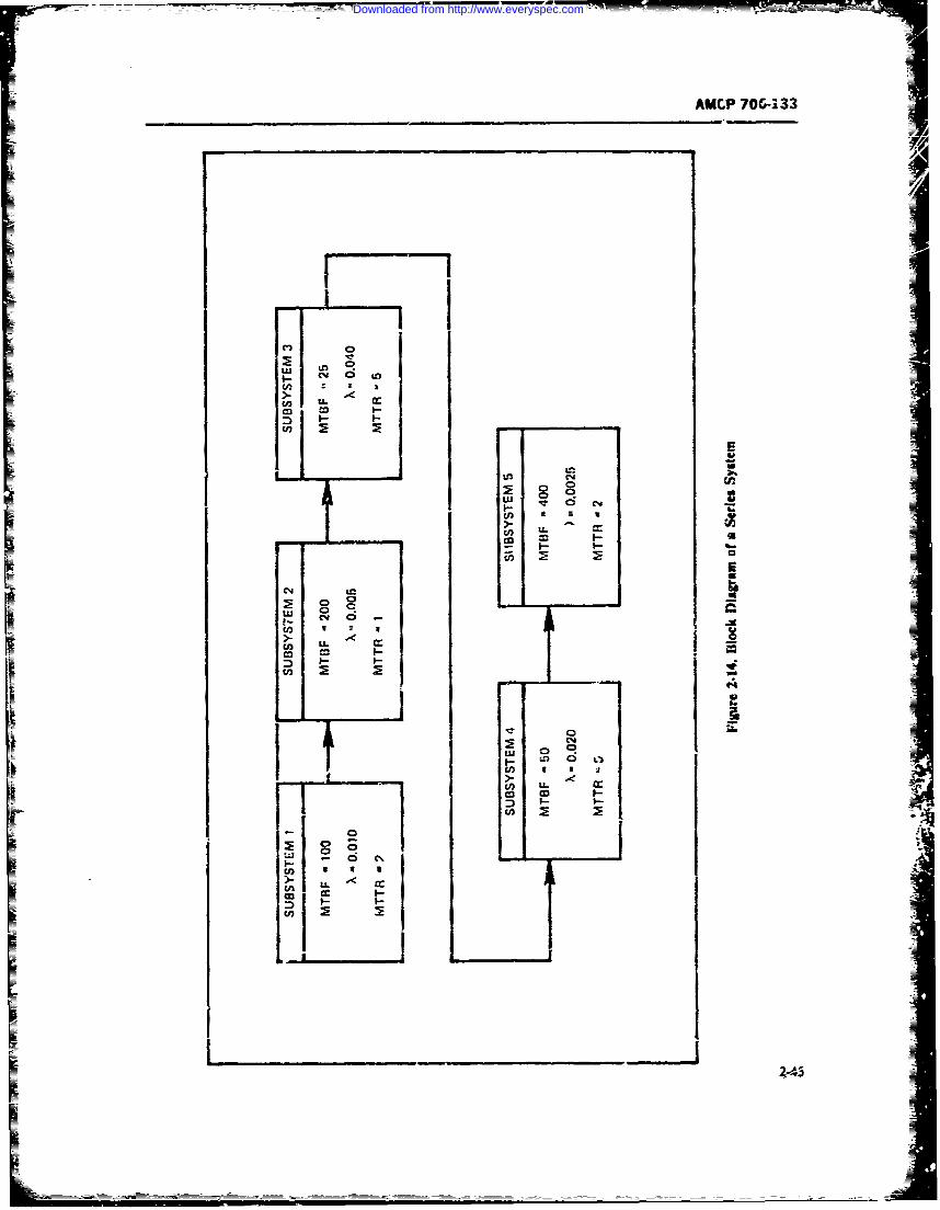
AMCP 706-133
I I
i Q !
6 !u- c -Co Io 3I
I- I-
inu 5 2U)
D0
1
0 c%
I- I L0M
Icn-
Downloaded from http://www.everyspec.com
iAMCP 706-133
fail and the system stops operatin& or (1) repair is repair of failed redndant un-its must be pws ,ie while
possible while the- system is operating. the system is operating. "1his is called availability withIn the first cise the MTHFof Subsem 3. which reptr Otherwise. redundanry will not increase avail-
now consists oi two parall units, becomes 1.5 tim cs it, and may en rcds= it. even thouh itthat of a single unit. i-e., 1.5 x 2 = 37-5 hr. Witr litdboth units failed, both must be repaired. If a 5Ulgle crew A ifferent method of szraajnforwr zrae-of be-repairs both in seqnence, he new JM7TR becomes 2 hr A riabilt and m-ibtyis s in Rand availabti)y actually drops. If two repair t twe%3 reliablty and maiaability is s i Fig.simuht-cotusly repair both failed units, and repair time 2-15 (Ref 34. i 81) T wedflc trade-off enrpleis assumed exponentially distributed, the MrTR of shown in this agure is based an a tcauiretant that the
both urits is again 1.5 time, that of a single unit. or, I.5 inrent aaflability or. the $)V-tm raut be a leasthr, and system zvailabih.ty remains the me as before. A 0.99. the MTFrFmrust not l beow 200 hr. andwith nothing gained. But if repair of a failed redundant the MTTR must not cetd 4 hr. The trde-off limosunit i4 possible whAle the system operate, the steady- are within the shaded area of the grp!. resulat in fromstate aailabilitq of Subsystem 3 becomes (Ref. 33. p- the equation for inherent avaiability133 and- Ref 28. p. 123)
A3 = (.2 2Xt:)/(pz - 2A - p-) (2-107) A. = .MTBF/WMTBF - IITTRI (2-112) 1fir a single repair crew. Since, for a single unit in thissubsystem the faflure -r-e X = U4and the repair rate the straight line fr A = 0.99 goes through thejL = 1/5 0.2. we get poits (200.2) a (400.4). the fins numb= being the
MT!BF~nd "the swn number b-.zg the JM.R- An
A, = 042X 0.Ar x 0.2)(0.04 2 x 0.04 sem s 't h an MTBFlarg than 200 hr amd
x 0. 02 . :> 0.0016)-- Ml7R srualler ta4hraln h m- e cee the mini- jmanyailabiliiy requirment ofA = .99. If ther ae
= 0. 0-6(0. 0592r' = 0.946 (2-1016%1 s-vr sy, c p anternatives that comply with thespoifict requirements, the design decision is made
a. compared .o 0.833 when no red--an&ncy, ued. by computing the lia.-cycle costs of esah LauativeThe vaue of , = 0.946 if the redundant configura- and usu'nu-Ir s iae ng &Oe tet expnmcie systar- unn
tion aon----xds to a maintenance time ;atio of -a pins in m effc arewhich womuld warmnt izxreasing the expenditures
&3 = (1 -A,)A;' = 0. 054(0. 4 r6Y = 0.0,;7(2-109) UNEAR PROGRAM ING
The whole s trem mainter.ance time ratio now becomes
devising an optimal allocation of Searor raoUMCa =L ,= 0. a, 0. 005 0.057 0. 10. 005 among copeng acve in an cptimumausn . 2
0. 187 (2-110) 1 h-adjecv lInea" m n t the variable thatI
appearin the jeolan in both the ottectic functionand the coistrai-ns. do so as inear f-nctio s. The word
and syste-n availability A is "progai-mine is used in the sense v pha in& W in
theA=-0"= e of preparing 187): for a -m ----al-A =(1 0- 187V (1.181r,: =0. 842 though, of coune. -'omptAs are ofta awd in the
(2-1111) solucix of linear p-oramning problems-A gencral statmens of the hnar p-vaming rob -
as compared with 0.752 without redundancy in Subsys- Iea i fir? vales ofY;. z. .. X-4ich Mnwirae tbete- 3. If t!it new value of availability is still not ,=cept- a fntiooablt, redudaxncy wuld also have to be. ar d to Sub- Z = c1 x. + o i + ... + . ,system 4. But to achieve hese gains in availability. suta to the conditions
= 2-46
Downloaded from http://www.everyspec.com
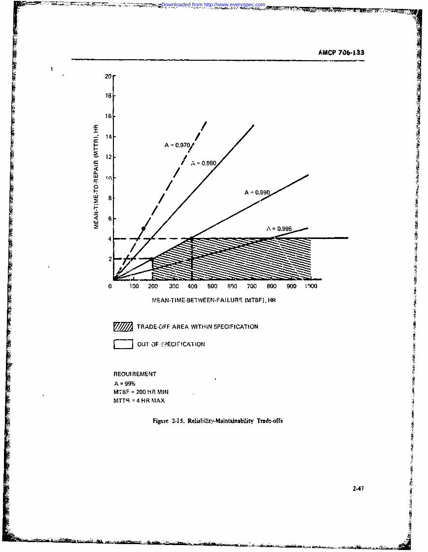
AMCP 706-133
20 - - -
18-
j 16 /-:14 /
A =0.97?/ :
=12 -
(A= 0.980 /N<
- / A =0.990
E ARD.F ARAWI.99PCIIAT5
mOUT OF -JECIFICAI ION
REOUI REMENTA = 99%MT BF =200 HR MINMTTR:4 HR MAX
Figure 2-15. Re iiity-Maintainability Trade.=offs
2-47
Downloaded from http://www.everyspec.com
AMCP 706-133
anxi + anx2 +... +,xV :S II signs ( ) or equalities ( - ), rather than less-than-or-
a +1x i a2,x2 + "'. - a2nXn lh- bequal-to (_).
1. Example... (2-113)
an.1x 1 + a 2 x2 + + . b A small machine shop manufactures two models,standard and deluxe, of an unspecified product. Each
......................... ..... -standard model requires 4 hr of grinding and 2 hr ofpolishing; each deluxe model requires 2 hr of grinding
The function whose oaximum value is being sought is and 5 hr of polishing. The manufacturer has two grind-called the objective funcion, the variables x1, X, ers and three polishers: in his 40-hr week, therefore, hex, are called decision variablee the conditions under has 80 hr of grinding capacity and 120 hr of polishingwhich the maximum value of the objectivo function is capacity. -e make a profit of $3 on each standardsought are called constraints-in particular, those ap- model and $4 on each delst:e model. He can sell all he
pearing on the last live are called tie non-negativitycani makc of bothconstraints The quantitits c, a,, and bare known con- ca icke d thstants. The b, are required to be positive. How shculd the manufacturer allocate his produc-
The quantities x,, .x,. . ., x, represent the level of the tion capacity to standard and deluxe models; i.e., how
n-competing activities: Zis the measuri of effectiveness many of each model should he make in order to maxi-
by which the optirriality of the allocation of resources mize his profit? (This example comes from Ref. 35.)among the activities is judged, c, represents t; e change This verbal description must be converted to an alge-in Z per unit increase in x- Ti'ere ate m-scarce re- braic one. Let x, denote the number of standard modelssources with b, representing the amount of the Ah re- produced, x, the number of deluxe models produced,source available for allocation among the n activities; and P the profit in dollars.a,, is the amount of the ith resource needed for one unit The grinder is ased 4 hr for each standard model and
of the fth activity-thus, ith constraint is the amount 2 hr for each deluxe rn.del, so 4x, + 2x, is the numberof the Ah resource used up. The non.regativity con- of hours of grinde: time used. This cannot exceed the
straints state the condition that no activity ievel can be number of hours of grinder time available, 80 hr. Thus
negative, the grinder constraint can be stated asAny n-tuple (x,, x,,. .. , x) that simultaneously sat-
isfies all the constraints is called a feasibte .Ihttion. Theset ofali feasible solutions is sometimes called the feasi- 4xi -" 2x 1 80 (2-114)ble region. One seeks, then, to find the maximum valueof the objective function over the feasible region-
Note that a less-than-or.:qual-to sig&i xs appropriate2-5.3.1 General Features of a Linear here. not an eq,,ality sign. This comes about because an
Programming Problem and an optimal (i.e., m.aximum profit) allocation may leave
Example some grinder capacity unused.
The specification of - linear programming problem The polasner is used 2 hr for each standar modeljust given will row he illustrated and a met-od of solu- and 5 hr for each deluxe model, so 2x1 + 5x is thetion will be outlined. In addition, other forms of linear number of hours of polisher timc used- This cannotprogramming problems will be treated. These ether exceed the number of hours of polikher time available,
progrmming;20 hir. Thus, the polisher conotraint is"orms involve the minimization, rather than the max-
imization, of the objective function: also, some or all of(he constraints may involve greater-thate-or-equal-to 2xi 4 5x2 120 (2-115)
248
Downloaded from http://www.everyspec.com
AMCP 706-133
Again, the less-than-or-equal-to sign is proper because simultaneously, are shown in Fig. 2-16.an optimal solution may leave some polisher caprity It should be ncted that the f easible region is a convexunused. polygon. A set of points is ccnvex if the line segment
Negative amounts of production of standard and joining any pair of points in ti~e set lies entirely withindeluxe models do not make sense, so that we have the the set. It is a fact that the feasble region for any linearnon-negativity constraints: x, > 0, x, _ 0.
Each standard unit sold contributes $3 to profit, programming problem is a cot vex polygon. If the lin-ear programming problem invLlves more than two de-while each deluxe unit sold contributes $4. Thus, the c ar a ble iblreo wlre a ti-
total profit is P = 3x, + 4x2. cision variables, then the feasibh region will be a multi-
Stated mathematically, then, the problem of optimal dimensional polygon, not a plttar (i.e., two-dimen-
(i.e., maximum profit) allocation of resources (grinder sional) polygon as in the example.
and polisher) between activities (production of stand- In Fig. 2-17 we superimpose equai-profit lines ou theard units and production of deluxe units) is: feasible region. That is, we plot 3 x; + 4 = P for
variois values of P. (Note that this produces a familya. maximize P = 3x1 + 4 of parallel lines.) Our goal is to incr,. se Pas much asb. subject to: possible while still havng the line .'x, + 4; = P
4x, + 2x, _ 80 retain contact with (i.e., intersect) the feasible regicn.
2x1 + 5; < 120 (Note that as P increases, the line 3x, + 4x = PX- 0, X2 0- moves away from the origin.) The largest velue that P
Since only two variables, .x, and x, are involved in can have, compatible with the requirement.-, is seen to
this formulation, it is possible to show the feasible re- be 110. This value is attained at the vertex !10,20) ofgion graphically as well as to superimpose various the feasible region. (The coordinates of this vertex canequas-profit lines on this feasible region and, thereby, be read off from a carefully prepared graph or, moreto determine the maximum profit. Later, we will pre- generally, by sclving simultaneously the pair of equa-s.nt and discuss purely analytical proceduras for solv- tions describing the lines which intersect at tie vertex.ing linear programming problems. Such methods are, These equations are: 4x, + 2x = 80 and 2x, +of course, needed as the general linear programming 5x, = 120.)will typically involve more than two variables and We have now reached a solution to our inear pro-graphicl methods will not be sufficient. gramming problem. The maximum profit attainable,
Returning now to the example we first note that the subject to the stated constraints on grinder and polishernon-negativity constraints require that the feasible re-gion be in the firs quadrant of the x, ; plane. The setof points satist'ying the grinder constraint, 4.x + the manufacturer produces 10 standard models and 20
2x - 80, are those which lie on and below the line deluxe models per week.4, + 2x = 80. While in this example the optimum allocation of the
The set of points which satisfy ar inequality two resources, grinder time and polisher time, used allax, + bx :_ c lies on, and on one siee of, the line that was available of each, this will not always occur,ax, + bx :< c Which side of the line can be deter- i.e., an optimum allocation of resources may leave somemined by checking somz point off the line to see if it amount of resources unused.satisfies the inequality. If it does, so do all points on the We call attention to the fact that the optimum valuesame side of the line;, if not, the other side of the line of the objective function in this example was found atis appropriate. The origin (0,0) is a convenient test a vertex of the feasible region. This was not a fortuitouspoint unless the line passes through the origin. (This occu-rence, but is a general property of linear program-happens if and only if c = 0.) In that event, one of the ming problems. It obtains also if one seeks the mini-points (1,0) or (0,I) may be a suitable test point. The mum of i linear objective function. or if some of theset of points satisfying the polisher constraint, coustraints involve equalities or greater-than-or-equal-2x, + 5x : 120, lies on and below the line 2x,, + to inequalities. The reader can gain further insight into5x = 120. The separate constraint sets and the feasi- this fact by considering families of equal profit lines ofie region (shaded), where all constraints are satisfied differing slopes and observing that in each case the
2-49
A
Downloaded from http://www.everyspec.com
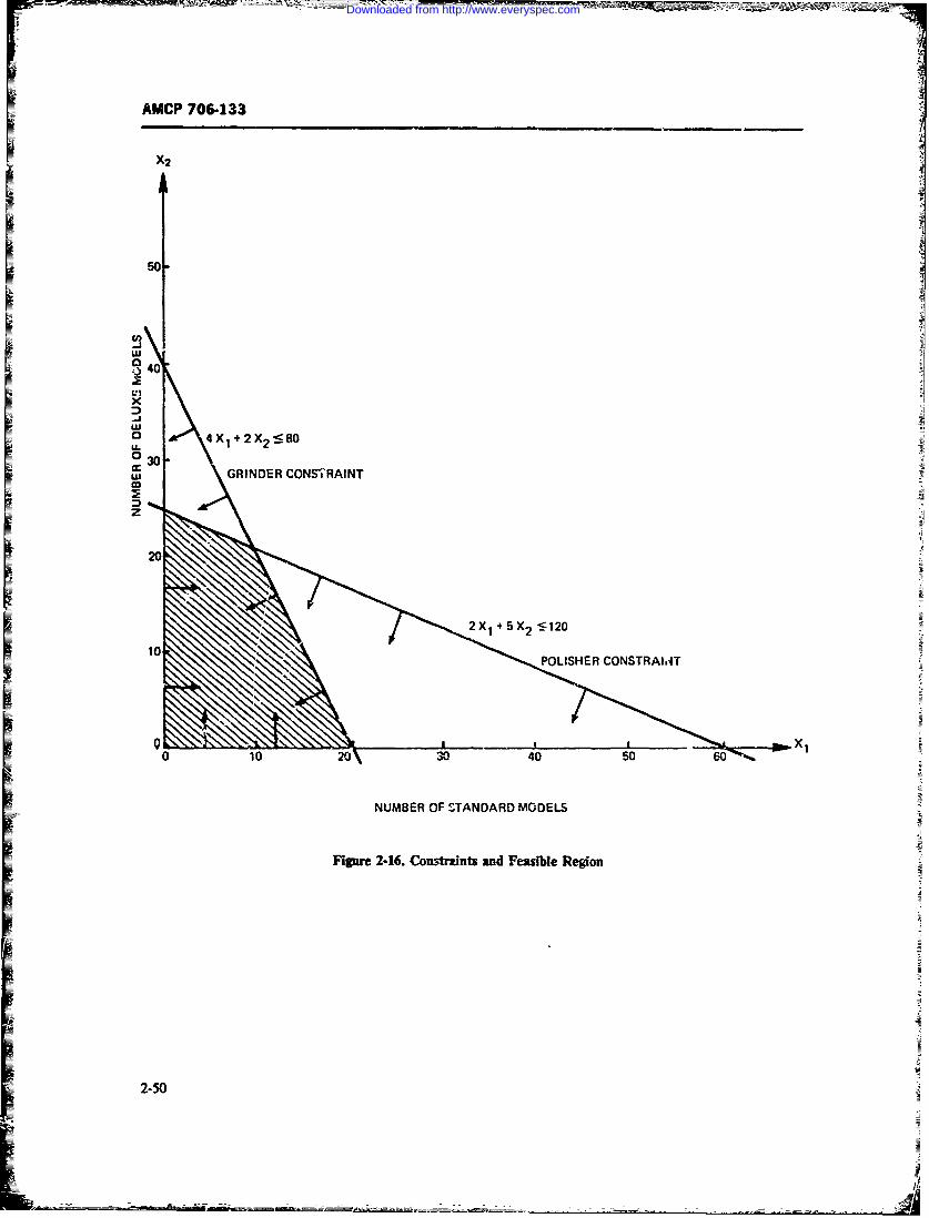
AMCP 706-133
1 50-
Q40
x
o 4X 1 +2X 2 8
030,wl GRINDER CONSTRAINT
= z
- 20
POLISHER CONSTRAlIff
0 1020\30 4 5060
NUMBER OF STANDARD MODELS
Figure 2-16. Constraints and Feasible Region
2-50
Downloaded from http://www.everyspec.com
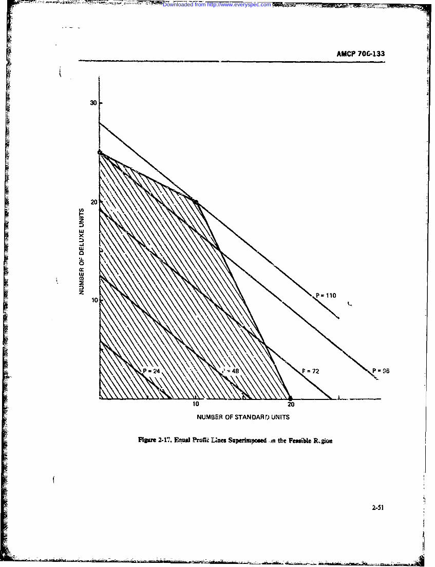
AMCP 70C-133
t 30
020
LU
0
10 P= 110
NUMBER OF STAN OARDr UNITS
Figure 2-11' Equa Profki Lines Superimposed am the Feasibe Rz glow
Downloaded from http://www.everyspec.com
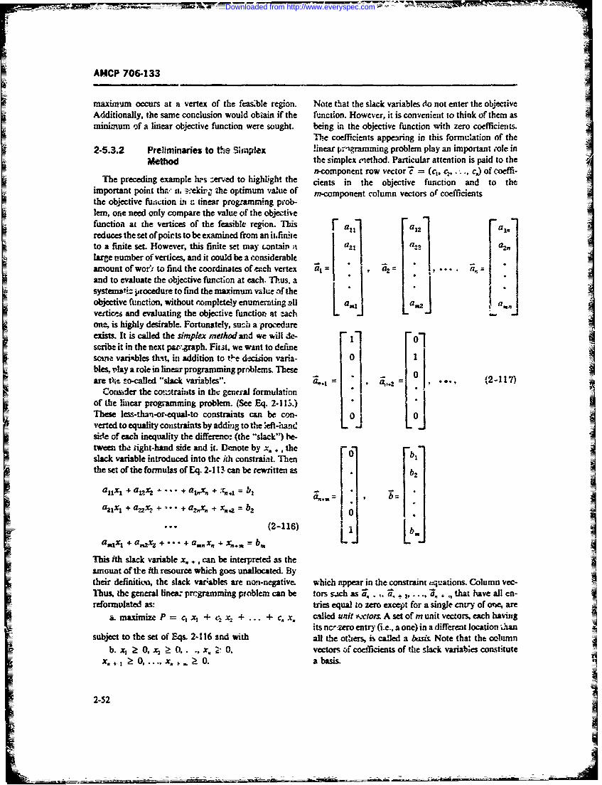
___ ___ 0 7
AHCP 706-133
maxin,.m occurs at a vertex of the feasble region. Note that the slack variables do not enter the objectiveAdditionally, the same conclusion would obtain if the function. However, it is convenient to think of them asminimum of a linear objective function were sought. being in the objective function with zero coefficients.
The coefficients appearing in this formulation of the2-5.3.2 Preliminaries to tie Simp!ex inear prlgramming problem play an important sole in
Method the simplex enethod. Particular attention is paid to the
n-component row vector' = (c3, . . ., c) of coeffi-The preceding example h's zer.ed to highlight the dents in the objective function and to :he
important point thrv ii. e,eidr ",he optimum vaue of m-component column vectors of" coefficientsthe objective fuzction i z linear prog-am.ning prob-lem, one need only compare the value of the objectivefunction at the vertices of the feasible region. This F a1 -1 a1inreduces the set of poirts to be examined from an ii~finite lto a finite set. However, this finite set may czntairi a azl q2 a..large number of vertices, and it could be a considerable . -
amount ofwor; to find the coordinates ofeach vertex a,= a2 aand to evaluate the objective function at each. Thus. a -systemat;i procedure to find the maximum value of thea' 1objective function, without 'tompletely enumemting all [ , a, awnveitic-, and evaluating the objective function at each - .-one, is highly desirable. Fortunately, su_.h a procedareexists. It is called the simplex method and we will de- "Olscribe it in the next pavgraph. Fist. we w nt to define 01soie varipbles that, in addition to t'e dtcision varia- 0 jbles, .tAzy a role in linear programming problems. Thee 0 Aare tt so-called "slack variables". 1,.1 , ... (2-117)
~~Con&, der the contraints in the general formulation""of the lha le programming problem. (See Eq. 2-1h.)e
These less-thn-or-equal-to constraits can be con- 0F 0rel veted to equality constraints by adding to the ' eft-h - -Lside of each inequality the diff~e--ena: (the -slack") be-tweem the iight-hand side and it. Dm.ote by x. , , the - -bslack variable introduced into the ith constraiat. Tien 0bthe set of the formulas of Eq. 2-111 can be rewritten as .b2
alx, + at~ .. + aA + b,. b t .a UtX , + a-22h + "• + a Xg + x f.2 b 2 0.
(2-116) La,1 1; + a nAx + ... + a wtx + xn.9 = bLb
This ith slack variable x. +, can be interpreted as theamount of tt-e ith resource which goes unallocated. Bytheir definition, the slack var;ables are non-negative, which appear in the constraint cqations. Column vec-Thus, the general linea prcgramming problem can be tors sgich as 2. . +,.... .,, that have all en-reformulated as: tries equal to zero except for a single entry of one, are
a. maximize P = c x, + x ... + c. x. clled unit rctor A set of m unit vectors, each havingits ncr-zero entry (i.e., a one) in a different location ihan
subject to the set of E, qs. 2-116 and with all the others, is called a basi& Note that the columnb. xi 0, x2 : 0_ . .x, Z0. vectors of coefficents of the ack riabks consitute
x.+ 0, .... x. O. a basis.
2-52
-2-7
Downloaded from http://www.everyspec.com
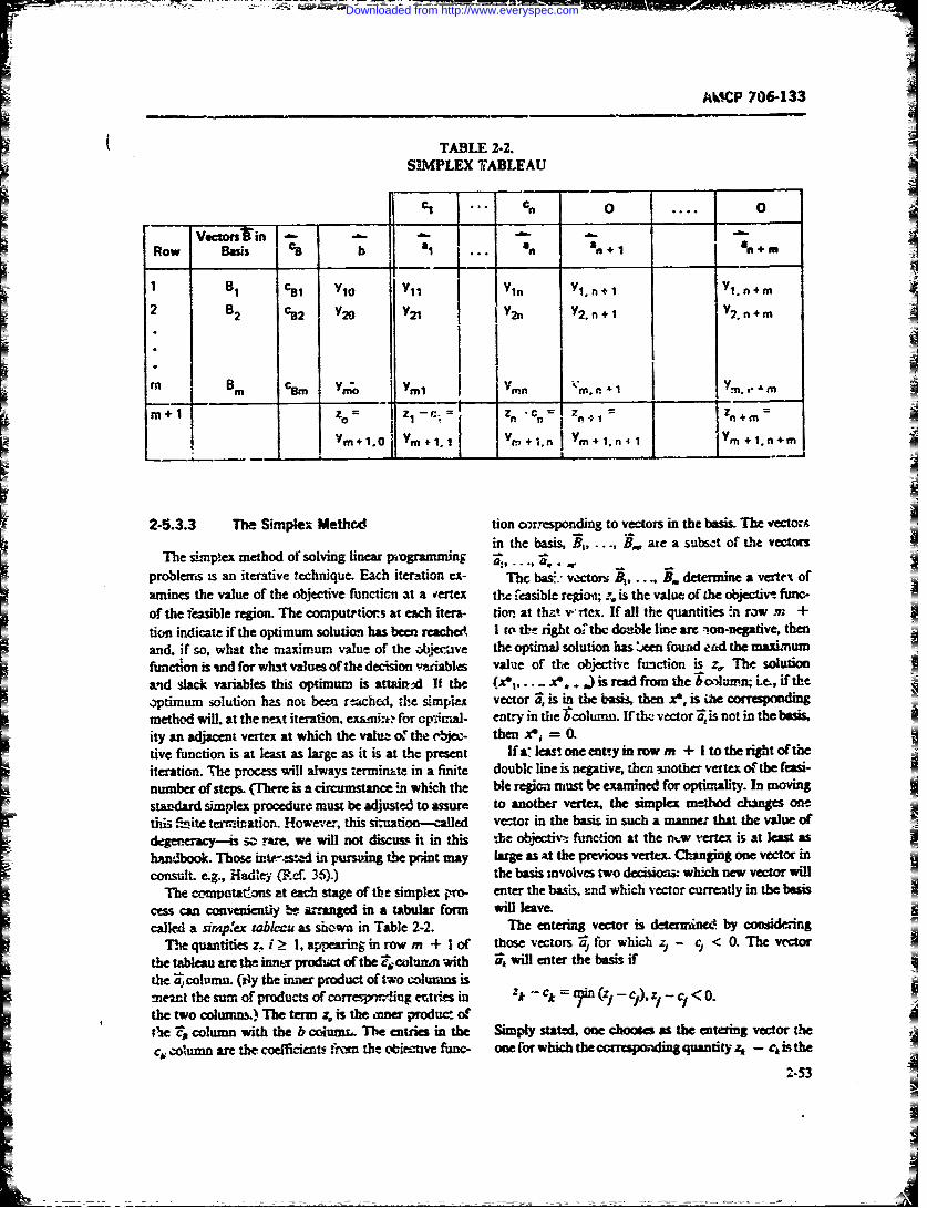
AMCP 706-133
TABLE 2-2.SIMPLEX TABLEAU
%i .. o. 0o..Vectors'in ..
Row Basis C. b a1 1 1 a + m
BI C81 Y1o Yi Yin Yl, n+l Y1. n+m
2 B2 c 2 Y20 Y21 Yn Y2.n l _ I .n+m
Mr Bm, VnC Ymn " on"1Y-, m
Ym+1.0 + m+1,n4 J Ym+l.n+m
2-5.3.3 The Simplex Meth d tion o rvesponding to vectors in the basis. The vectoin the basis, B.. are a subset of the vectors
The simplex method of solving linear pixgrunming a,, ..... ,rt =o
problems is an iterative technique. Each iteration e- The bas:- vectors B, B. determine a vertex ofamines the value of the objective functicm at a Vertex thc fcasible regioe; is the value of the objective func-
of the easible region. The computrtiors at each itera- tio. at that w rtex. If all the quantities !n row . +tin indicate if the optimum solution has been reached I to thl right o thc do-ible line arc -on-negative, thenand. if so, what the maximum value of the obte -ive the optimal solution has :Am fouad e.d the maximumftmction is mod for what values of the decision variables value of the objective function is z, The solutionand slack variables this optimum is attait-d If the (Xe,.... x, ,, is read from the bcluwi Le., if theoptimum solution has not been r-ched, the simpes vector is in the basis, then Xe, is i correspondigmethod will, at the next iteration, exasnjat for opticial- entry in the bcolumn. If th, vector nis not in the basis,ity an adjacent vertex at which the value- of the rbjec- then x =0.tive function is at least as large as it is at the present If a:' e one envy in row m + I to the right oftheiteration. The process will always erminkte in a finite doublk line is negative, then vtother vertex ofthe feasi-number of steps. (Thrre is a circumstance in which the ble regicn must be examined for optimality. In movingstandard simplex procedure must be adjusted to assure to another vertex, the simplex method changes oethis fimite ternivation. However, this siuation-called vecto in the basis in such a manner that the value ofdegere-Acy--s s rare, we will not discuss it in this %be obiectiv' function at the .w vertex is at least ashamnibook. Those intr,-ted in purviing the print may large as at the previous vertex. Ckanging one vector inconsult e.g., Hadley (Ref. 36).) the basis involves two decisios. which new vector will
The compatatfris at each stage of tbe simplex 1-no- enter the basis. rnd which vector currently in the basiscess can conveniently I-- a Ranged in a tabular form will leave.called a sirpex tableau as shown in Table 2-2. The entering vector is deterined by consideAng
The quantities z. i 1. appearing in row m + I of those vectors aforwhich c < 0. The vectorthe tableau are the innt prodc=t of the Z colaum with 4j will enter the basis ifthe colnumn. (ily the inra product of two colu m ns ismemn thesuiof products of correpvx1ing entries in 1ZV Ck r i(Z- C),1 ~< 0.the two colunm) The term zo is the inner product of)e a column with the b cc4umr. The entries in the Simply stated, one chooses as the entering vector thec, olun are the coefticient iroi the oblective func- one for which the cresponding quantity z - cis the
2-53
Downloaded from http://www.everyspec.com
MAP 706-133
rost negativ, of all the zj -- 1tLrms. if there isa tie multiple of the corresponding element in the pivot row.among two or more v=rtor; to enter, any one of them This multiple is the ratio of the entry in the rcw beingmay be chosen. One possible rule is to choose as e:.ter- transformed and the pivot column to the pivot element.ing vector the one with the lowest index (Le., subscript This L-ansfornition procm wil be illialated when weJ) anong those eligible- carry through the solution of a linear prograwming
Having dtmined the vector to enter the basis, one problem by the simplex method. Before we do this,must next determine the vector :o leave 6.e basis. This however, we must indicate the form that the initialis aczomplished by considering the ratios of terms in tableau takes. It will be described by giving values tothe b colu-'n to corresponding koitire terms in the the entries in Table 2-2- They are.
k0 column (,h. colun of the entering vector). Theleaving ve.or, the onein row r, is the one for which It= ar l, 12= a .....
this ratio is lesst, ie., the vector in row r is removed =frcrn the basis if c1 =0,c =0.... co. = 0
-Y'= min- ryi ,,• > -0s Y- b. y. + =.
Y,* ' LYik 0 i = al, = 41,y., =a.,y.,. = -- c3 ;
It poa'be tat her isno osiiveenty i coanm............................ ...........
kQe,y A 0for i = 1, ... m). h that case thereis isnopon:.e, yyi=ca,, ...an unbounded solutien to the linear pnr yr.m = a,,.
troblem Le., the objective function can be made arbi- Y. - 4,trrxily larg While thisis a mathematical possibility, Y,.. = 1,. ,. 0....,
it is seldom the cme for a real-life, non?exzbk- prob- yO.P = 0, y. + + 0;lem and, sijould this situation anix, one should check ..................ardullythe formulatio. or the Jproblem to inte sute A. +M = 0, y., + .= , ... ,
it is corVxL -- + ,I M+ .,+ 0.Aswmingthatatleanoney, > 0, iti possiblethat Y ' 0.
there i a tie for the leaving vector Again, one may T simplex cal bill be illustrated througchooe arbitrarily anong the driPble vectors to deer- the example that was previously considered from amine s leaving vectot. i lvmel vca point 4fview. Upo n int4oducing slzck vai-
Having chosen a vactm to enter e , the problem is sated as:anether vector to leave the basis, it bmcomcs nec-.m-y
Str asform the entrics in the tabezu. We will use a a. maxmizr 3x -4- 4x,
prime ) to desgnate the new cntries; unprimed lettrs b. subject to:refer to the old tableau. It is conveniet to refer tothe 4xr + 212 + x .- 80entry y,, as the pit ekemenL This is the entry in col- 2x, + S-k + x, = 120unm of the enterig Vacto (column P and the row of J; 2t (L X >_ 0- X3 a 0- A4 ?>. O.
1,hvin: vector 'row ). The transformation equa-
fiz. are fori - 0, !.... m + n, We arrangethecoeflicients intoan initialdmplex tab-leau as shown in TAble- 2-3. The most negative entry inthe ltI row, - 4, is i. he colu-mn; therefore ,4 willente the basis, i.e. k = 2. ro determine the leavingvector, we consid the ratios (O/I2) = 40=0d(20/5)
- 24 and renove the vector --responding to the= y %, i= ... ,m+1 iinimmoftheseratios. Thisv tcior is4 which is in
i Y'J Y . Y(2-:20) row7; Le., r = 2Thusthenewbiswllbe and
these votton will appear, in that order, :n the "Baiis-The first equation states that all old entries in th. row comm of -me second tables (see Table 24). The cor-in which the pivot element appears are di- iled by the responding coefficients from the objective fnction, 0pivot element to obtain the new entries in that row. The and 4, wil appear in the Z volumn.wccond eqiaion states that old entries in any nonpiot The pivot element . (the entry in the column of therow are replaced by the existing entry minus a certain entering vector and the row of the leaving vecto) is 5.
2-54
Downloaded from http://www.everyspec.com
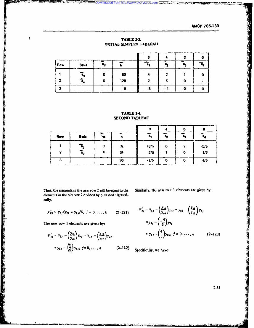
AMCP 706-133
TABLE 2-3.YNMAL SIMPLEX TABLE4A, I
_ _ _3 4 0
Row __si __& 2 s a
1 0 80 j 2 10
a3 4__ 2 3 02 0 120 2 5 0aII
_ I. o i
TABLE 2-4.SECOND TABLEAU
0 0
ROW Bea$i b I2
1 0 32 I aI -M'32 2 4 24 215 10 11
___ _715_ -- -0i 4/5L%!
Thus, the elements ; the ew raw 2 will te equal to the Similmly, th-, new raj 3 elements am given by:elements in the old row 2 divided by 5. Staed algebrai-cally,
Y Z' -- Y2zf = Y2.j5, = 0,.., 4 (2-121) Y33 - Y
The new row I elements ar given by: j 5 )YzI ,
.,, / Y . y,Fl. ,,, = y, + (I y, , 0- =o. .,4 (2-19-3)
Iv. 0, 442l"
' 5' Specific-tiy. we have I
2-55
Downloaded from http://www.everyspec.com
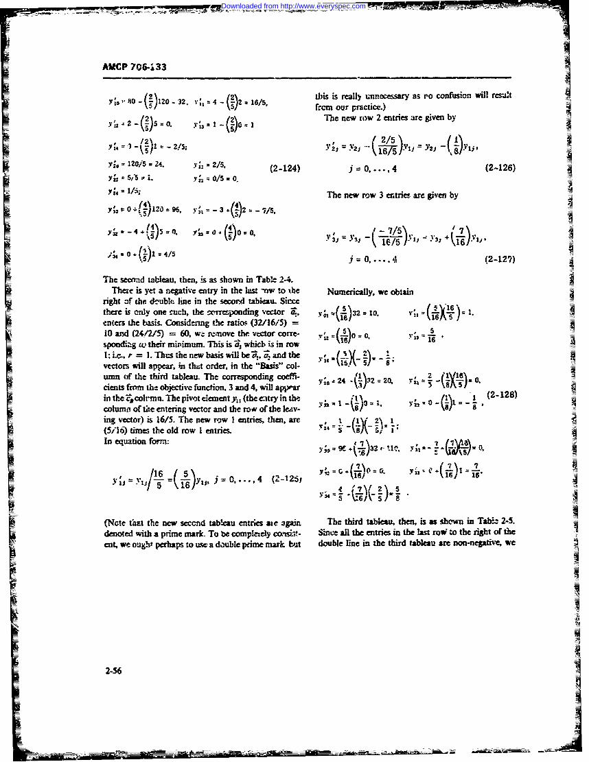
AMCP 706-133
0t)is-isreally unnecessary as Po confuimon will res2='S)120 2 16/5,from our practice.)
Y~za~7J50 3~1The new row 2 entries arc given byY6 yh 2 -Q)5o. - o'] =1
-1 =-- 2/5; Y 2j, y'i 1 Yii Y2- Yi
= 120/5 = 24. y= 2/. (2-124) j - 0, , 4 (2-126)yi5 '5. y;= o/5 0.
Y; /.,; The new row 3 entries are given byyi ,:0,~~~0f4Ylo ;=3 :vs
,:.-4 , 0oo 0, 7/ ),;%.o.( 5 j=O. 4 (2-127)
The secnad tableau, then, is as shown in Tab'-- 2-4.There is yet a negative entry in the l= -nw to the Numerically, we obtain
right of hc d--uble line in the secord tableau. Sincethere is only one .uch, the (o1rresonding vetor ., y ()32 - 10, vt, =6/X" .enters the basim Consi&-rmg the ratios (32/16/5)=10 and (24,/2/59 = 60, w- rimove the vector corre- V1 =(5o 0,spondiz;g c th-ir mipimum. This is V. whicb is in rowI.:i..,r = l. Th.s the new basis will be-,, andtevectorswill appear, in tht order, in the "Basis" col-umn fo the third tableau. The corresponding cof-'-24 .4n= 20, -
ients frorm the objective function. 3 and 4. will apjrarin the cornfn. Thepivot elementy, (theetryin th- - (2-128)
column of tle entering vector and the row of the leAv- " 8ing vector) is 16/5. The new row I entries, then, arc t (fl 2\ 1(5ii) time.; the old row Ientries. Y \-/% - -1In equation form: Y;9e+t.-)32i,1. Yi= = - 0.
YrJ Yt' 416 , ., .. , 4 (2-125j r (j7 1o1.
(Note t1at the new second tablcau entries aic 3pi. The third tabkeau, then, is as shown in Tab 2-5.denoted %ith a prime mark To be completely caisi-V- Suine all the entries in the last row to the right of the A
ent, we ought perhaps to usc a double prime mark but double line in the third tableau are non-negative, we
2-56
Downloaded from http://www.everyspec.com
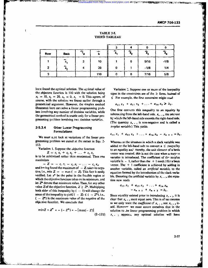
AMCP 706-133
TABLE 2-5.THIRD) TABLEAU
Row_ Bas a L j _ a23&t 3j 10 1 05 16 -182 001 -1/8 j 114
3110 0 07/116 5/8
hstve found the optimal solution. The or imal value of Variation Suppose one or nxre of the inequalitythz objective functicis is 110 with the solution being signs in the constraints are of the 2t form, instead ofCi = 10, *x, =20 x = 0., = 0. This agrees, of _ For example. the first constraint might rewidcourse, with the solm~ious we founa earlier through ageometticial argument. However, the simplex method all Xi + al. xt. + .. .+ aijix,)' b1 .illustrated here can solve a Inear programming prob- On first conrts this inequality to an equality bykem involving any numbier of decision variables, whaile sbrLigfo h ethn ie .. 1 tt ru'nthe gwometricr! tattthod is usable only for a linear pro- sbr~igfo h ethn i-x feacngramming prcoblein involving two; decision variahles. bv which the !eft-hand side exceeds the right-hand side
(The quantity x. . ,is non-negative and is called aF2-5.3-4 Ofhe Lnear Progranmming sy-plzis variabe) This yIids
Formulation 1 X 1 xm+.- jt,,-X 1 1
We must n-xt look at variaions of the linear pro- al 1442 x_+--tax.- .+ bi
gramming problem we stated at the outset in Eqls. 2- Wherea3 in the situatichi in which a slack variable wasF113: added to the left-hand side to convert a 5 mequaityIalVariadon 1. Suppose the objective function to an equality anO thiereby, the unit element of a bas
RE Z= C X,+ C X,+ .. 4 C.vector was created, this is not the case when a sum'iIf is to be minim-.ized rather tha-n maximized. Then one variable is introduced. The coefficient of th- sulpis
maxiize variable is - 1.rather than the + I1needcI fcr a b*s
and liasing found the maximum of -Z take- its nega- another variable, called an artifiial wzriab&e to the
tive; i.e., min Z - max( Z ). This fact is easily equation formed by the introduction of the slack varia-Iverified. Let x* be the point in the feas-ible region at ble. Denoting the artificial variable by x~ . the eqjua-which the objective function takes on its minimum, and tion now readslet. 2' denote that minimum vaiuw. Then. for any other+a1X2+ + ,""value Zof the objective function, Z : P. Multiplying al I X1 . Ii 2 +-- 1 f
both side of this inequality by( %-~ ill change the - R+ I + x. + 2 =Ilsense of the inequality to yield Z ) :5 ( I2). .. , Since eqality existed prior to introducing x., it is
( - ') is One maximum -alue of the negative of the clear *hat x. ,must equal zero. This is of no conen
objetive functiar. We conctade that as we oniy wanit the coefficient of x. .,not x. . 2 it-I3elf. Howev.- we must assure ourselves that in the
Mi-n7Z* =-( Z*) = -nax- Zi solution to .he linear programming problem in which(2-129) x, appear3 , any optimal solution will have
2 -57
Downloaded from http://www.everyspec.com
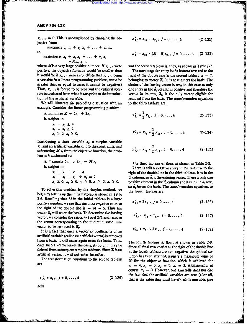
AMCP 706-133
x,.: =0. This is acrompished by changing theob- xl,=x, -xZ. j=0,...,4 (2-131)jective from:
mamnfize c, c + cx +... + c. x,,to: 'V (M *5)x, 1 , 1= 0,..4 (2-132)
maximize c, x, + c, -i + ... 3- X3 Oti (-12
-Mx. + 2,
where Mis a very large positive number. If x, . were and the second tableau is, then, as shown in Table 2-7.positive, the objective function wouid be smaller than The most negative entry in the bottom row and to theit would be if x,, were zero. (Note that x,..being right of the double line : the second tableau is - 7.a v iae !n a linear programming problem, must be belonging to -ecter 5.,. 1 his next euters the basis. Thegreater than or equal to zero;, .t cannot be negative.) choice of the leaving vector is e"sy in this case as onlyThus, x. 2is forcd to be zero and the optimal solu- one entry in the a column is positive and therre thet.on is utaltered from what it was prior to the introduc- ecor in its r, w, -0 is the o.zdy vector eligible fortion of the artificial variable- removal from the basis. The transformation equations
We wili illustrate the preceding discussicn with an to the third tableau are:example. Consider the linear programming problem:
a. minimze Z = 5Sx + 2x. ,G. 4 (2-133)- xz: -- xxJ j~i- j G..4(-13b. suebject to:
x, + x2 < 4x , -- 134) 2X- 0 > 0, x'- -C2 ; 0.....4 (2-134)
Introducing a slack variable xj. a surplus vriablex,, and an artificial variable x into the constraints, and 7subtracting Mx1 from the objective function, the prob- X 2 : x x ) 0lem is transformed to:
a. maximize 5x 2, - M z The third tableau is. then, as shown in Table 2-8.b. subject to: The is still a negative niry in the last rcw to the
x, + x2 + x, = 4 rght of the double line in the third taqeau. It is in th!X- - x4 + 3 7 column,soistheeting vector. Te-re is only aex: 0,. 0 x) 0, x,> 0, x, >0. positive dement in the column and it r. Lthe . row.
so po Laves the basis. The transformation equation toTo solve this oblem by the simplex method. t fourth tableau are:
begin by setting up the initial tableau as shown in Table2-6. Recalling-that Min the initial tableau is a largepositive number, we see t=ha the most r--gative entry to i- .2t = 0 .... 4 (2-136)the right of the doubl, lie is - M - 5. Thils thev-or a, will enter the basis. To determine the leavingvector, weconsider the ratios 4/I - 2/l and remove 2J 'CZ, .- x11. 0.... ,. (2-137)the vector corresponding to the minimum ratio. Thevector to be removed is 2.
it is a fact that once a veoor r_. cofficients ofan x x .3x, 3. j 0,... 4 (2-138)art3ficial variable (called an artificial vector' is removedfrom a bzsis, it %..ill never again enter the basis. Thus. The fourth tableau is. the, as shown in Table 2-9.one such a vector leaves the basis, its olumn may b Since all final row entrie:s tu the ight of the double linedcleted from subsequent simplex tableaus. Since 0 vs an in the fourth tableau r non-negative, the optmalariffie"A vector, it will not enter hereafter. lu has been attain& n. y a maximum valu of
The transformtion e s to the send tableau 20 for the objective function whk-h is achieved forae xi = 4,x. = 0.x. = .x. = 2. A4ditionaly, of
cotrse, x, = 0. However, o,,e generlly does not citethe fact ,Iat the artificiL variables are zero (after all,
X;=x 2 ,, j=20,...,4 (2-120) tha. is th. value they must have whione oes give
2-58
Downloaded from http://www.everyspec.com
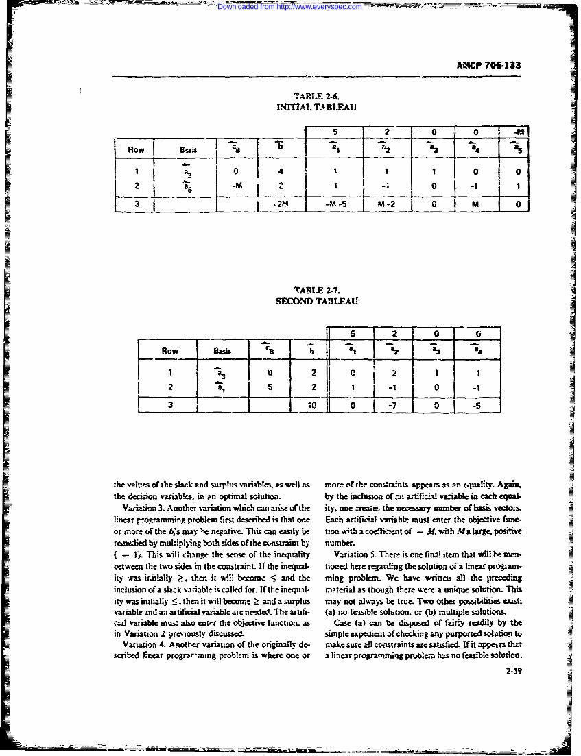
AMCP 706-133
TABIE 2-6.INITIAL T.BLEAU j
5_ 2__ 0__ 0_ _ 2 4A
A31 1 1 0 0j
3 2H -M- 1 2 0 M 0
TABLE 2-7.SECOND TABLEAU
Row Basis r 3
2 a 5 2 10
,,7It JL.2
the values of the slack and surplus variables, as well as more of the consra!nts appears as an equality. Again,the deiso vw-iabkcs, in sn optivialI solution, by the inclusion of ait artificial vaiablet in achd equal-
Vai-iation 3. Another variation which can arise of the ity, one :reates the necessary number of basis vectors.
linear, ogramming problem first described is that one Each artificial variable must enter the objective frnc-or more &f the bs may he negativr This can easily be tion *jth a coefficient of - M, with Ma hlrge, positivereimedied by muhiplying both sides of the cunstraint by number.(- i. This will change the sense of the inequality Variation 5. Ther is one fmal item that will te -oetween the two sides in the constraint. If the inequal- tioned here regarding the solution of a linear program-ityas iitially . then it will become _< and the ming problem. We have writteu all the precedinginclusion of a slack variable is called for. If the inequal- material as though there were a unique solution. Thisity was intially _<. then it will become _- and a surplus may not always be true. Two other possilities exisl:variable and an artificial vaziable are ne-ded. The artifi- (a) no feasible solhtion or (b) multiple solutiLn=W variable mus also enter the objective function, as Case (a) can be disposed of failry readily by thein Variation 2 previously discussed. simple expedient of checking any purported so.-'tion- W
Variation 4. Anoher variation of the originally de- make sure all contraints are safeicld. If it appe-.rs thscribed lira1 r progra-ming problem is where one or a linear programmning pr.blem has no feasible solution.
2-39
- A
Downloaded from http://www.everyspec.com
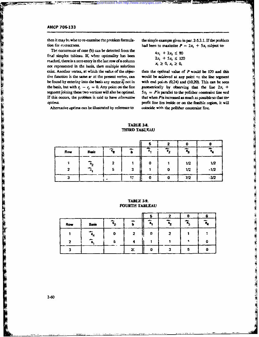
AMCP 706-133
then it may b. wise to re-eamine thie pirrA formula- the simple capte given in par. 2-53.1. If the probkotion for ,iectaess- had been !o aximize P = 2x + 5x. sj ect to
Tho. occurrance of case (b) cn be detected fromte 4.r + 2t. hfi,J simplex tableau- If, when Amihy has been"
rached, there is a zero entry in the last row ofa column 2z, + 5x, : 12D
not represented in the basis, the multiple solu~oos x 0 , 0Oexist. Another vertex at whuch te valre of the objec- then the oimal value of P wamid be 120 and thistie function is the Same a- at the prese t V .can would be e at any poi ,m th line segmentbe fmd by ente' into the basis any vector not in with end pcx.u -0.24) and (10,20)L This can be seenthe bssbutwithz-c =a Any point on the line e tri by v n that the imen t 2 +segutent joining these fwo vertices will also be optimal 5= = Pis parallel to the polisher .3.ssint line *=dIf this occurs, the problem is sai: to have a tt when Pis ncre as much as po so that thopthna proff line ics mide or on the feail repi4 it will
Alternative op.ima can be illustrated by reference to coincide with the plisher constraint rxt.
3____ ____" __ .__ 0 0 7
TABLE 24.FOURTH TABLEAU
5 2 0 a
ROW Bsk _ _ _ _j12
I - °2 i 2 1 j 1/2 1 2
5-62
Ro36kb2 -0
S4 0 0 2
Downloaded from http://www.everyspec.com
AMCP 706-133
The purpose of these discussions has been to define 2-5,.3.5 Mainteilance Appji"-ationswhat constitutcs a linear programming problem; tomotivate, by an example, the solution process; and toillustrate the solution of a linear programming problem We close by referring to some applizatior3 of linearby the simple% inethod. The problems we examined progiamming to the determination of optimal mainte-were small scale, i.e., involved only few decision varia- nance policies. The moidals are rather complicated andblt., and few constraints. Real-life lin;:ar programming require considerable pialitinaries even to state. Thusproblems can involve hundreds of decision variables %~e shall mereli refer the interested rea~er to someand constraints. For problems of such magnitude hand- sources. One such is Section 5, Chapter 5 "Optimalcalculated simplex solutions are, of course, out of the Maintenance Policies Under Markovian Dcteriora-question. Fortunately there are efficient, accurate com- tion" in the book by Barlow and Proschan (Ref. 25).puter progranis .vailable to hanzile such problems. Anothet is the bock by Dernian (Ref. 37).
REFERENCES
1TM 38-703-1, Integrated Logistic Support: 13. M. S3. Kline and M. W. Lifson, "Systems Engi-Suppcrt Integration, Dept. of the Army, neering", Chapter 2in Cost-Effjectivenc-: TheNovember 1969. Economic Evaluatrion of Engineered, Systems. J.
2. AFSC-TR-65-6, Chairman's Final Report, M. English: Ed., John Wiley & Sons, Inc.,Weapon System Efftectiveness Induzstry Advi- N.Y., 1968.
soyComtte(WSEIAC), Air Force Sys- 14. M. B. Kline, Maintainability Considerations in~tes oman, anar 165(AD-467 816j. System Design, Doctoral Dissertation, De"-
3.AMP 0613, ngnerigDesign Hanu- ment of Engineering, Univcrsity of CaliforniabokMinaiailtyGid frDesign. Los Angeles, 1966, University Microfilms,
4. W H. on lven Ed. ReiabiityInc., Ann Arbor, Michigan.Engineering, Prentice-Hall, Int.., Englewood 15. AMCR 750-15, Integrated Logistics Suppori
CifNJ,1964. 19 February 1969.5.SsesEffectiveness S-,;stems Eifehnivene.-; 16. AMCP 706-191, Engineering Design Hand-BrnhOfieof Naval Mate:4al, Washing- book, System Analysis and Cost-Effecti-ermsstnD..195(AD-659 52C). 17. Inte'gration Engineering for System Efective-
6. NAVMAT P 3941 A, Navy Systems Perjbrin- ness. EIA Effectiv'eness Quantification flulle-once Effectiveness Manual Headquarters, Na- tin No. 2, EIA Committee G47 with F. H.val Material Command, I July 1968. Kranz. Electronic Industries Ass-ociation,
7. B. S. Blanchard, "Ccst Effectiveness, System Washington, D.C., March 1970.Effectiveness, Integrated TAQ;.stic Support, 18. Igor Bazovsky and Glen E. Ben?, "Effective-and Maintainability", IEEE Transactions on ness of Ship Systems and Machinery", in Pro-Relkahility R-16, No. 3. pp. 117-126, 1967. ceedings 1968 Annual Syrnposhjm on Reliabil-
8. B. S. Blanichavd .3-3 E. E. Lowery, ity, Boston, Mass., January 1968.Maintainability, McGraw--ifl Boo Coin- 19. P. M. Morsc and G. E. Kimball, Mlethods of
pany, Inc., N.Y., 1909. 'Meo,.4 T.. M-IT Prm, Cam-9. A. S. Goldman and T. B. Slattery, Maintaina- bridge, Mass., 1951.
biity: A Major Element of System Effecti'e- 20. Igor Bazovsky, Re!&zbility The ory andness, John Wiley & Sons, Inc., N.Y., 1964. Practice, Prentice-Hall, Inc., Englewood
10. NAV_;TIPS 94324, Mfaintainability Design Cliffs, N.J., 1961.Crteria Yandbook for Designers of Shipboard 21. D. R. Cox, Renewal Theory John Wiley &
Electr'nic Equiomenz, Dept. of the Navy. Sons, Inc., N.Y., 1962.Change 2, 1965. 22. C. B. Moore, An Integrated App roach to Deter-
11. MIL-STD-72 1, Definitions of Effectivencss mining Operational Effectiveness. PublicationTerms for Reliability, Mfaintainability, Human No. MR-0-128, General DynamicS . FortFactors and Safety, 25 A%:,csst 1966. Worth Division, March 1966.
12. AMCR 11-1, Army Programs, .).'stenis Anaiy- 23. A. J. Monroe, "WSEIAC Findings aridsis, 21 April 1970. Rcommendations" in Proceedings of the First
2-61
Downloaded from http://www.everyspec.com
AMCP 706-133
EJA Conference on Systems Effectiveness Elec- LDevelopments; Command Mo.-itenance Agency,tronic Industries Association, Washington, Aberdeen Proving Gro'tnp. Md., NovemberD.C., October 1965. 1970.
24. !. Bazovsky, N. R. MacFarlane, and R. L. 31. Elements of ReliaN'iy and Maintainability,Wunderman, Study of Maintenance Cost Op- DOD Joint Courie 1330k, US Army Manage-timLation and Reliability of Shipboard Ma- ment Engineering I raininig Agenicy, Rock Is-chinery, Uaited Control Corporation, Seatle, land, Ill., 1967.Wash., June 1962 (AD-283 428). 32. Maintainability Engineerin Guide, Report
25. R. E. Barlow and F. Proschan, Mathemazrical RC-S-65-2, Revision A, US Army MissileTheory of Reliability, John Wiley & Sons, Inc., Command, Redstone Arsenal, Ala., April 1967.N.Y., 1965. 33. Gerald A. Sandier, System Reliability
26. R. E. Barlow and L. C. Iiu,.. 2r, "Mathemati- Engineering, Prentice-Hall, Inc., Englewoodcal Model for System Reliability", The Syl- Ciffs, N.J., 1963.vania Technologist 13, Nos. I and 2, 1960. 34. Maintainability Trade-Off Techniques; EIA
27. J. E. !iosford, "Measures c tpendability"', Maintainability Bulietizi No. 8, Electronic In-Oiverations Research, 8, No. ., 1960. dustries Association, Washington, DC, July
28. B. A. Kozlov and 1. A. Ushakoi.. Reliability 1966.Handbook. Ho' t, Rinehart and Winston, Inc., 35. Anonymous. An Introduction to LinearN.Y., 1970. Programming, International Business Ma-
29. Mathematical Models for A Yailabiity of Ma- chines Orp., White Plains, N.Y., 1964.cine Gun Systems% Technical Peport No. 3, 36. G. HAley, Linear Programming, Addison-Prepared by Igor Bazovsky and Associates, Wesley Publishing Co., Inc;., R..,ding, Mass.,Inc. for the Small Arms Systems L4boratory, 1962.US Army Weapons Command, Februasy 1970. 37. Cyrus Dermnan, Finite State Markovian Deci-
30. PAM 69-8, Arailability, US -Armny Combat sion Proce.-% Academic Press, N.Y., 1970.
2-62
Downloaded from http://www.everyspec.com
AMCP 706-133
CHAPTER 3
MAINTAINABILITY ORGANIZATION ANDMANAGEMENT
3-1 GENERAL 3-1.1 ORGANIZATIONAL ACTIVITIES
In order to determine the organizational sirctu:e,.V!here does the maintainability effort fit into the for the management of maintainability, one must first
overall management organization? Should it be organ- determine the functions and tasks performed by theized and managed within its own centralized structure? maintainability organization. These activities may beHow des it interface with other organizational ele- classified into the following functions:ments7 Should it be combined with the reliability engi- 1. Management and administrativeneering or system effectiveness efforts? Is it part of the 2. Test and analyticalsystfm engineering, design engineering, or integrated 3. Designlogistic support organization? What is its relationship 4 oto mainteance engineering? Should the structure ofthe contractor's organization reflect either the military
customer's organization or what is perceived as the Each of these activities is described in the followingdesires of the military customer? These are among the paragraphs.questions which concern maintainability engineers andmanagement. It is the purpose of this chapter to exam- 3-1.1.1 Maintainability Management andine these questions with regard tn the maintainability Admnistrationengineering organization and its ravriagement.Maitaiabiitymangemnt an - dscusedin cv- Maintsinsoility management and administrative
aincontxta nait management thsed ainai functions include those tasks concerned with perform-esal contexts. One is the management of the maintaina-
ance, cost, and schedule and which give overall direc-bility engineering function as an engineering discipline. tion and control to t effective performance of theA second is the organizational structure and relation- maintainability enginLering effort aspect of program
ships for carrying out the maintainability function. A management (Ref, 1). These tasks include:third context has to do with the phase in the sy .stemife 1. Prepaing maintainability progrlife plan-in-cycle of concern at the moment. This latter implies "hat cluding milestones, schedule, and budgets--in accord-there are dynamic (temporal) aspects of maintainability ance with specified program managemimt require-management and organization which may require a ments, system requirement specifications. u,.d otherchange of emphasis, if not of organization and responsi- management duments.bility, depending upon the stage and phase of the .ys- 2. Preparin, and issuing policies and procedurestern life cycle in which the .ystem design happens to be. for use in the peffrinance of !he maintairability engi-
Since maintainability is defined (par. 1-1) as a char- neering function.actaidti of dedygn, it follows that maintainability engi- 3. Participating in program management and de-neering is ef primary concern and has its greatest im- sign reviews which impact on maintainability.pact during those phases of the system life cycle which 4. Organizing and stafThig the inaatainability en-are cocerned iith system and equipment design and gineering effolttest. Also, a its name implies, maintainability engi- 5. Preparing budgets and schedules, and assigningneering belongs in the engineering (technical) organiza- respo.nbilities, tasks, ane work orders for the main-tion. tainability effort.
3-1
=--- ==- , . i = - --- -- = I
Downloaded from http://www.everyspec.com
AMCP 706--, 33
6. Monitoring and controlling the output of the 10. Analyzing maintainability fedback data frommaintainability engineering organization. the field and tinr aoerccs.
7. Providing r,'anagement liais a and coordina- 11. Participating in statistical analyses with egardtion with higher level management, other related disci- to maintainability and system effectiveness.plines, and subcontractors. 12. Participating in industry/Gov-,ment meet-
8. Providing training and indoctrination with re- ings and 3ymposia involving maintainability analy3is.
gard to maintainability. Specific maintainability analysis techniques are dis-9. Participating in industry/Government meet- cussed in Chapters 4, 6. 7, and 8.
ings and sympotia with regard to maintainability man-agement. 3-1.1.3 Maintainability Design
Since maintainability engineering is part of an inter- Maintainability design is concerned with those sys-disciplinary system engineering cifort, the coordination ,em and equipment feature. and characterL.tics whichand liaison aspects of maintainability with other disci- will promote cost-effective ease of ianteakince andplines are considerable if an optimal total system design thus will reduce logistic support requirements. Amongis to be achieved. The coordination function, therefore, the activities of concern are the following:is listed separately in par. 3-1.1.5. 1. Monitoring and reviewing system/equipment
3.1.1.2 Maintainability Analysis designs with regard to maintainability features.2. Participating in the preparation of maitainabil-
A significant portion of the maintainability engineer- ity engineering design criteria, guidlines, and hand-ing effort i concerned with the analytical aspects books for use by design engineers..Thes,- e include maintainibihty rex.rer ents, predlic- 3. Providing consulting services to ,esigp engi-tions, allocations, demonstrations, and field data ner.evaljations, as well as providing information for sys- 4.tem engineering analyses and trade-offs. 4. Reviewing and approving design drawings and
data for maintainability features and compliance withMaintainability analysis tasks ~may include the fol- specification requirements with regard to maintainabil-lowing:ity.
I. Reviewing operational and system requirement i. in design reviews where mintain-5. Particpatingindsg eiwwhrman -documents and specifications with regard to maintaina- ability is concerned.bility requirements. 6. )aring maintainability design reports.
2. Participating -n system engineering analyses asthcy affect or are affected by maintainability. 7. Participating in industry/Government meet-
ings and symposia with regard to maintainability de-3. Participating in or performing ma:ntenance en- si
gineeriig analyses.
4. Performing maintainability predictions and al- Siecific maintainability design characteristics andlocations, features are discussed in Chapter 5.
5. Assisting in preparation of maintainabilitydemonstration plans and analysis of maintainability 3-1.1.4 Maintairabi|Ry Documentationdemonstration results. The maintainability engineering effort gener-gen and
6. Preparing maintainability demoustmttien re- utilizes a considerable amount of data and information.ports. The eff tive and efficient handling of this information
7. Performing maintainability trade-off analyses is important to the achievemeat of a or-t.eJaective, cc-within the maintainability engineering discipline. herent, iot-! system design. Maintairbiliy documen-
8. Providirg maintainability studies, data. and tation includes:other information for system h.vel trade-offs involving 1. Establishment and maintenancc of a mAiutainaother discipiines, ic- as reliability or safety. bility data bank and library of pertinent maintainability
9. Assisting mai mance engineering in the per- documents and information.formance of'detsiled i intainability studies, such as 2. Preparation and maintenance of handbook datadevelopment of repa 'discard criteria, level of auto- and information with regard to maintainability.inatio. studi-s, use ot bailt-in test features, and moan. 3. Preparation o! maintainablty data and feed-tainability skill level analyses. back reports.
3-2
Downloaded from http://www.everyspec.com
AMCP 7I6-133
4. Documentution of maintainability trade-offs ganizational elements, -ill go a long way towards ob-and the rtz,,lts of maintainability analyses. taining an dficient and effective total organization.
5. Documen~ztion of the results of maintainabml; Considerations which should be carefully directed bydesign reviews, top nt,2nagement are whether the maintainability func-
6. Documentation of maininability management tion should. be (1) an implicit rather than explicit partinformation, of the engineering organization, (2) a distinct line or-
Maintainability data requirements are disLzsed in ganizational elemert within the engineri' -0 , rt-Chapter 9. mn;t, (3) a staff function operating in an auvsory
capacity to project management and in an anaytic and31.1.5 Maintainability Coordination cusuitative capacity to designers, or (4) a part of pro-
As pointed out in par. 3-1.1.1, a significant part of gram UxRnagement or systerm engineering in a project or
the maintainability management effort is concerned matrix orgf.tization. Such considerations are affected
with coordination and liaison. The coordination effort by the ov-rall size of the enterprise and the project, the
is often one of the key elements in assuring a successful emphasis placed on maintainability by the customer inand.optimized system design. Maintainability coordi- his system saecification,, the extent to which th main-nation inludes: tainability activities described in par. 3-1.1 are requirednatin Intre sste eand emphasized by both customer and producer, and1. Interface with system engineering and other en- the cosW-ffe-rtiveaess requirements of the particular
ineering disciplines, such as maintenance, design, reli- projectability, safety, human factors, integrated logistic sup- In small engineering organizations, maintainabilityport, and system effectiveness, tends to be an implicit part of the normal engineering2. Provision of maintainability training and indoc- design effort and is not treated analytically in any greattrination for all program personnel, detail.
3. Subcontractor liaison and c.zcrdination as partof contractor responsibility, including training and in-doctrination with regard to maintainability. 3-1.2.1 Maintainability Engineering as aCentralized Funmtio)nal Organizatio
4. Maintairbility liaison and coordination withthe customer/contractor as directed by program man- The simplest explicit organizational structure placesagtnent. maintainnbility engineering as a distinct, i'inctional,
5. Liaisou coordination with industry/Govern- line organization within the overall engineering organi-ment advisory actinvies, ineluding trade associations zation, as illustrated in Figs. 3-1 and 3-2. In this organi-and professional societies. zational form, all maintainability effort is centralized
under a single manager. He has full responsibility for3-1.2 ORGANIZATIONAL STRUCTURES FOR and control over all personnel and activities which are
MAINTAINABILITY part of the maintainability discipline, as described inpar. 3-1.1 and its subparagraphs. Such an organiza-
Now that the maintainability management and engi- tional structute gives emphasis to maintainability as aneering functions have been defined and described, we desigr discipline. It is effective and efficient whencan address the organizational questions enumnerated in managers and engineers recognize maintrnability as apar. 3-1. First, where does maintainability fit in the naturAl part of good engineering design.overall management organization? There is no unique The in-tainability engineering manager is able toor conventional organizational structure for maintaina- effect strong liaison and coordination k4th the interfac-bility. There are many versions and variations which ing disciplines mentioned in par. 3-1.1.5. He is able toare used by both customer and producer organizations. control intra-maiwainability trade-offs as well a3 theThe structure used is often dependent upon the en:er- maintainability portions of system level trade-offs. Inprise's overall organizational philosophy and method particular, he can maintain a proper imt raction withof doing business. There are, however, as discussed in maintenance engineering activities (par. 14.2).par. 3-1. 1, certain activities with which maintainability Centralization of the maintainability engineering ef-is concerned and which must be included within what- fort also works well when there is only one major pro-ever organizational structure exists. Advanced plan- ject of concern or when there are a number of retativelyning and a rz-ognition % viiese activities, as well as small projects concerning basically similar products ortheir relation tn other engme-ri.ig disciplines and or- customers (Ref. 2).
3-3
Downloaded from http://www.everyspec.com
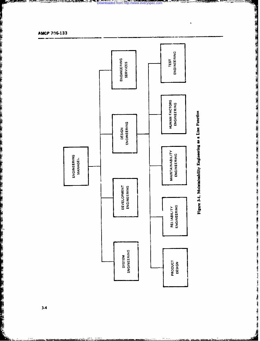
AMCP 706-133
______ ____-- -cc
z J
LUU
0
ZL
LUU
LUU
SZ zw
z Z Zz-
La ~.w
CL
o w I4
>0ow I
~LU
to La
0z
La UI'- a-
3-4
Downloaded from http://www.everyspec.com
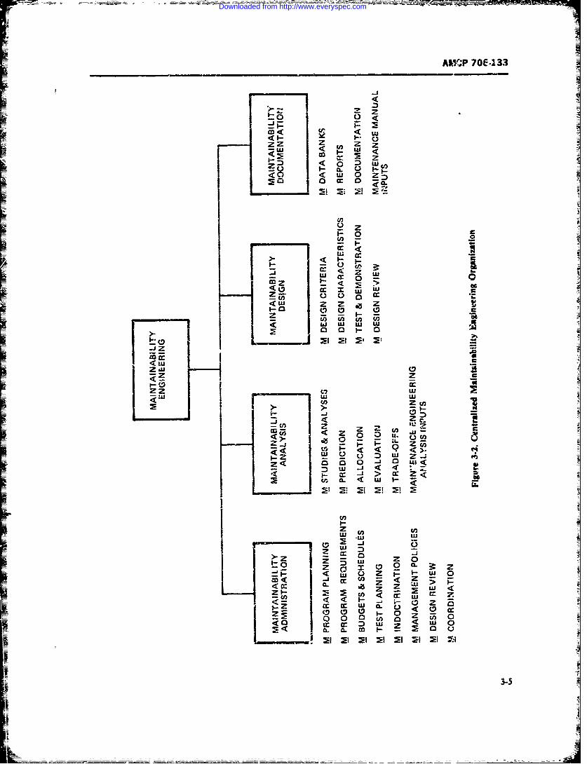
MY.?P 70f-233
<I <
zI D < . C5-LU 4 L
C> c
U, a
ui M 0
(3 c.) T< LU z z *~z
<o W
ZEZ
~ LU V) LU
<LU.zw -C
-- 2
Vz , CL ' U .
UJ L LU
> Z ZU4 z 0 13
W~~ (3LU U Z
C Zcc Irw CL4<
wz
133-5
Downloaded from http://www.everyspec.com
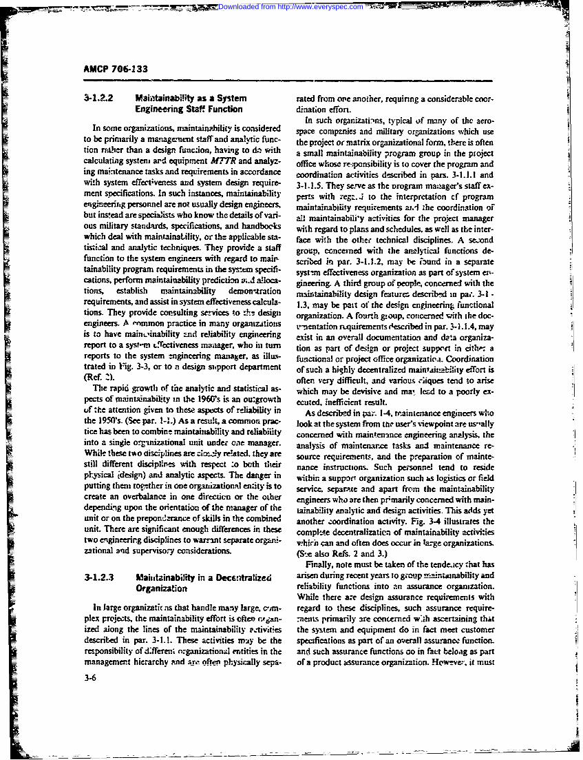
AMCP 706-133
3-1.2.2 Maiatainability as a System rated from on'e another, requiring a considerable coor-Engineering Staff Function dination eff'on.
In such organizati-ins, typical of many of the aero-In some organizations, maintain.Aility is considered spae companies and military organizations which use
to be primarily a management staff and analytic func- the project or matrix organizational form, there is oftention ria-her than a design func:ion, having to da with a small maintainability program group in the ptojectcalculating Systeni ard equipment M27'R and analyz- office whose rce:,xonsibility is to cover the program anding maintenance tasks and requirements in accordance coordination activities described in pars. 3-1.1.1 andwith system effectveness and swsemn design require- 3-1.1.5. They serve as the orogram ma-.ager's staff ex-ment specifications. An such instances, maintainability perts with iegzrJ to the interpretation cf programengihneerig personnel are not usually design eiiecrs, maintainabilisy requirements ax.l 1he coordination ofbut instead are specialists who know the details of vani- a maintainabili'y activities for the project mianager
ous iliarystadars, pecfictios, nd andooks with regard to plans and schedules, as well as the inter-which deal with maintanatility, or the applicable sta- face with the other technical disciplines. A se.,odtistical and analytic techniques. they provide a staff grow), concerned with the analytical functions de-function to the system engineers with regard to maw cie]i pr -.. , a eiud nasprttainability program requirements in the system specifi- syst-mn effectiveness organization as part of systemn ei'-ctions. peiform maintainability prediction u-d a~loca- gineering. A third group ofveopk, concerned with the
tions, establish maintainability demonn*ration naintainability design features describ-ed in pa;. 3-1 -
requirements, and assist in system effectiveness cakiila- 1.3, may be pait of the design engineering functionalTin.hey provide com'sulting scervices to t design organization. A fourth goup. concerned with the doc-engineers. A -nmmon practice in many organhzjtons u-ntntation riquirements Ocscnbed in par. 3- 1.l1.4, mayInis to have main~..inability and reliability engineering exist in an overall documentation and data organiza-
reports to tesse rgnri manager, a lu- fntolorpjetoffice raitca.Codnintrated in 1g3-,otoadsgsuprdeatet oschahighly decentralized maintAitnability CiTort is
(Rcf 2).oftr vey dfficltand various iaiques tend to ariseThe rapid growth of the analytic and statistical as- which may be devisive and ma, lead to a poorly ex-
pects of maintainability in thme 1960s is an ou-growth ecuted, inefflicient result.uf :ite atningvntths scsofreliability in As described in par. 14. traintentance engineers whothe 1950's. (See par. 1-1.) As a result, a common prac- look at the system from tnr user's %iewpoint are ts-allytice has been to combine maintainability and reliabiiity concerned with maintenance engineering analysis, theinto a singie organizational Wnit Wnder one mnanager. analysis of maintenance tasks and maintenance re-While these tvo disciplines are ziom1y reltatc-d, they are source requiremnents, and the preparation of mainte-still different disciplives with respect :o both their nance instructions. Such personnel tend to residepl-,ysical ,'design) and analytic aspects. The danger in wiihin. a support organization such is logistics or fieldputting them togtther in one orgutizationAl entity is to service, separstte and apart from the maintainabilitycreate an overbalance in one direction or the other engineers who are then prmmarily concern ed with main-dependinig upon the orientation of the manager of the tainability analytic and design activities. This adds yetunit or on the prepomn'!aranie of skills in the combined another zoordination activity. Fig. 3-4 illustrates theunit. There are significant enough differences in these compl'.e decenitralizaticn of maintainability activi:iestwo engineerirSg disciplines to warra2nt separate organi vhirb can and often does occur in large organizations.zational and superviso,- cnsiderations.(SeasRf.2an3)
Finally, note must be taker of the tendeaicy that has
3-1.2.3 Maivitainability in a Decf-!Aralizecd arisen during recet years to garoup mim.intainability andOrganization reliability functions into an assurance organization.
While there arec design assurance requirements withIn large organizatic as that handle manmy large, c'im- regard to these disciplines, such assurance require-
plex projects, the maintainability effort is often 'vpn- -nen~s primarily are concerned w..h ascertaining thatized along the lines of the maintainability -. tivities the system and equipment do in fact meet customerdescribed in par. 3-1.1. These activities ma&y be the specifications as part of an ov.erall assurance function.responsibility of d~feren! nrganizational entities in the and such assurance functions do in fact beloaig as partmanagemnent hierarchy -nd arr offten physically sepfi- of a product russurance organization. !{'w-ve:r, it must
3-6
Downloaded from http://www.everyspec.com
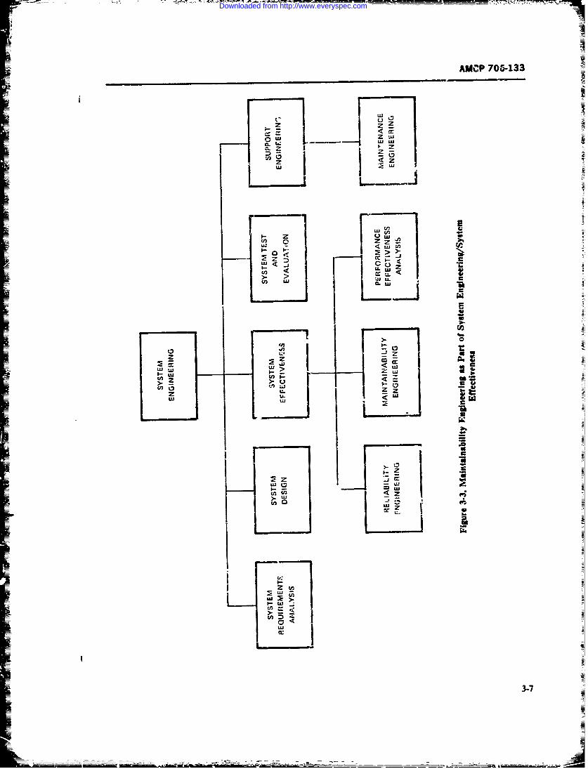
AMCP 7&&133
Z
0. Ii Z u
z U'S
0< Z
U' U
>. >- U
ci, U' 2
U- a
LU c
U;U
- u'
cn
3-7
Downloaded from http://www.everyspec.com
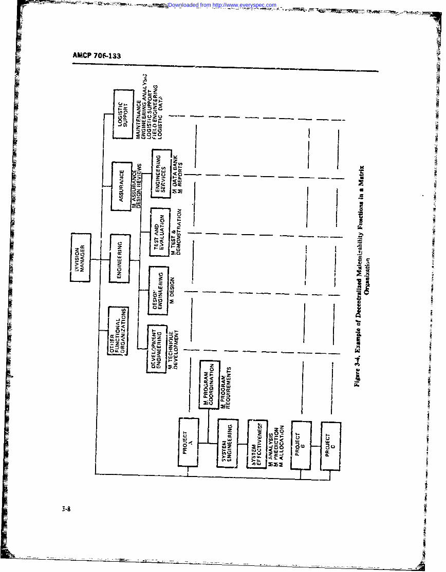
AMICP 70f-133
Zw~ -a - -CZ-
W j IWj <,
Z~z
00
OP <w<
z~ wUVcoo u
5 z L:-
ww
-. 1
Downloaded from http://www.everyspec.com
AMCP 706-133
be remnembered that maintanability (and relability) zation- whc-re tep m-anagement is fully aware of this
are engineering disciplines and rightfully' belong in the se, has e.,tablislied policies for the effective application
engineering organizaton. Because of their effect apon of naintainability engineering (Refs. 2t 3). Second issytem_ design, thmse disciplines must be in a position to the establishment of maintainability engineeinig as a
influence design. functional entity in the company organization, as de-
There has been a tendency on the part of many con- scribed in par. 3-1. at an organizational leve.4 such thatr___ tractors to restructure their internal organizations as its relationships and functions with r-espect to other
they think the customer wanis them to or to reflect the organizational entities can be effectively carriedt outcustomer's organdian. In many cases, this has r,- (Ref. 2). Third, not only must maintainability be recug-suited from the customer essentizlly sp.ifying, directly nizrd and receive official sanction and status within theor indirectly. how it wanted the organization to be. In overall enterpiise, it mist also be accepted by all merr-others, i.uch restructu-ing has been a direct result of the bers of the organization rs one of the technical disci-fact tat the request for propesal anti specification re- plines. along with design engineering, reliability engi-
quirements p!ace undue emphasis on the organiza- neering. human factors engineering, safety engtneering.tional aspects of the project or the company's manage- test and evaluation, mnaintenance engineering. and inte-ment structure. This reactive tendency on the part of grated logiac support, with all of which it has strongcontractoms has created confusion within ;be internal interfaces. The physia location of the imaintainabilitycompany organizations, particularly in those aerospace organization and the extent to which~ its functions are
companies which deal with different defense and space centralized or deceniralized may have a significant im-
agencies. It has also led in some cases to efficient, well pact on the effectiveness -a :be maintainability effortrun company organtizations becoming ine'tective, with Isolation or de-r'.tralization of the group creates prob-a consequent ircrtase in both dircet and indirect per- lems of coc-rdiazution znd tends to de-einohasize thesonnel, increaed emphasis on pper design and un- importance of the maintainability engineering effort.
LFne.;es-y documentation efforts, and increastid costs- bi adition, effective maintainability managementeven ixitcuding large overruns, requires that the maintainability function be planned.
It is incumbent on company and project manage- organized, dirc~ed, budgeted, monitored, and con-ment to organize and manage not only its maintainabil- trolled in thec same manner as the other disciplines. Ofity effort, but its entire progrim in the manner which particular inificanze is the 2stablishment of maintain-is most natural. effective, and efficient for the company. ability policies and procedures as part Ji total engineer-Such an organization should have littie difficuity in ing mnagement and their inciusion in policy and pro--ccnvincing the- cnsioter that it can meet program ob- cedure manals. Establishment of pogram plans forjectives. carr)ing out the mnaintainahility function is vita to
Ax an outgrowtin of the recognition of the necessity effiective maiatainability mAn-agement. These plansof effective m anzigement to design and eingineer n-ture must be in accordance with life-cycle managementsystcms. a strong trend hss developed intelre fo h eontion of the ed analysis oftemaerospace companies to combine under one "hat" all requirerments with respect to maintainabi~ity, establish-supporting engineering disciplines tha' have a direct meet of maintenanice concepts and features, and incmr-impact on design. This leads to such organizational oration of maintainabiity as a significant design char-strrctures as product effectivreness directorat..s that cp - acteristic.erate under the enginecering organiza:!on and enrom-pass reliability, maintainability, safety, humain fact-ars, 3-2.1 MANAGEMENT FUNC'1ONSvalie er-giren. and cost-effec.iveness as de-par- THROUGHOUT THE LIFE CYCLEments or b-anches.
In o-der to achieve in effiective and efficient systeric. jg, maintainability considerations must occu
3-2 EFFECTIVE MAINTAINABIUTY thro)ughout the system life cycle. The life cycle forMANAGEMENT Ariny systems extends from the &delopmnent o the
cnceept cf a new end itemi arisig out of DoD andEffttive maintaina2bility management depends upon Amy opemfior-al capa I.lity studies through viiida-
a number of factors. First is the recognilion by top tion, design and development, production, installation.management that viaintainability is an essential char- .smptirt. and om-'a~ir (Rds. 4-7).actenistic of syseni/equipment design. Prope atten- E.Flcti':e imlelmntation of the maintainability pro-tion will be p~aid to maintair-3tlility only in thos- org:-ni- gam includes a phases of the systen life cyJe Ly
3-9
Downloaded from http://www.everyspec.com
AMCP 706-133
neans of the user-producer reationship described in sary preumrmnary work has been done. Threat and oper-1 -".14.1. A stated Army principle concerning life- ational analyses, trade-Et cost and mission decti e.cycle mangement of reliability and main:asnability is: ness studies, ar-I the state of d-evelopment of
".fTectivy and thorough managerial direcL.on, plan- compnents znd technology provide a fim foundationning, programming, and rezource allocation will be for entering the validation phase.provided throughout the life -.'ydz ofeach.ite. so sto During Concept development, the prin-y mtamian-enable the objtctives of the reliabiity and maintain- ability concern is the derivation of system ffectiveness
ability tiogram to be achieved fc-r that item. Reliability requirements and criteria as d6cussed in Chater 2,and maintainability will be identified as principal and the determination from opemational and missioncharacteistics of the item, and the status of these profiles of the maintenance a logistic support polickscharacteristica will be assessed thoughout all phases of and the bounearies requft r meet .missiobjetiveits life cycle" (Ref. 8). As a result of threat and mission analyses and a descrip-
e on of the operating environment, and consistent with2.1 The System Life Cycle Army doctrine and logistic support policies, the follow-
The system life cycle consists basically of the follow- itg mW. be accomplished in order to establish systeming phases: maintaisbility ureets:
1. Cbc..cept Development i. Descrip,.on of mission and perflom.,ance en-2. Validt. velopes and system operating rw es
I. Protuction 2. Determ.nafion of mission time fictors and sys-
4. Operaion. te.I tilizatior me3. Determinaton ,the duration of the system life
These phases are ilksrwated in Fig. 3-5. cycle, incudiag system &-ployment a"d out-of-sericeD'dting orccp'. devetopRment, an operatioisi need or conditions
threat is transformed into a set of operational require- 4. ElaIXttioD of s tuw criteria ex-ments. nt; high risk areas ,re identified. During vi- pressed in arssion-oriented termsdation, tke conccpts are veried. high risk areas re-.Ived or mlaLinized, and the operaional teuirements ti i c i maistc pottransformed ;nto a set of sy"stem -equirer,.ants. he ties s,.d concepts, including mainte-ace conceptrrequirements re then tuznsformed into a system de-sign. prototype tor test and evaluation, and dmwings Army policy reqtires that:and specificatins to be used in the pro'uhctzi phase. "Suitable planning and cozuideratioa bG giv= toDuring productimi. the system is produLrzL acceted relbility, maintaihability, and availability durng theand installed in a ready-o-use condition for subsequent concept develooment phase. In the condMut ofoperation. During the .Veration phase, tne orating feasibility studies and component development, consid-systm is used, logi:-tcaly s-uppoted and n.xifled mrrtn m0' be given to the rehability and maintain-when necessary. These phases are discuw. cd in geater ability gotential of the equipmen: and its components.detail in the paragrs.ph3 which follow. Reliabity and u aity predictions and informa-
tion ftom sizmiar systems should be as rilated to assist3-2.1.1.1 Concept Development if proper technical aproA-^ to identify
The obective of concept develfApeet (Fg. 3-6) is to areas of bcgh technical risk, and to asist both indevelop zand select the best materiel approacb to satisfy tradeoff and co.effecwenz tudies am in finalan tstablished operatonal need and to prove the feast- concpt selection. PLanning ad requirwmt documentsbility of ti,' approach frcm a technical cost, and shmold be b. wd on relability and maintain b-ity dataschedule standpoinL In addition to the prepaaton of from sinmar systems and fror f&ibWiity studies andmateriel development objectives, some of the ctivriues shoud indude sa a ent detail to saow how reliabilitywhich .haracterize this phase include the preparation and maintainabiliti requirements am to be attained.of a recommended aa och, advanced development Availability, relibility, and maintzmabIity require-objectives, a system development plan, and other docu- merts must be stted ;n terms app te to the itemmenwtion associate with the prerequisite for systew considering its intended purpose, cxrWlexity, anddefinition. At the concusion of concept developxoent, quantity expected to be produced, anc must be ceara review and wstein status evaluation of "he system and capable of bebg measured, tested fir, or otherwiedevalonient plan i3 condvSt-d to assure that the neces- verified (Ref. 7).
3-10
Downloaded from http://www.everyspec.com
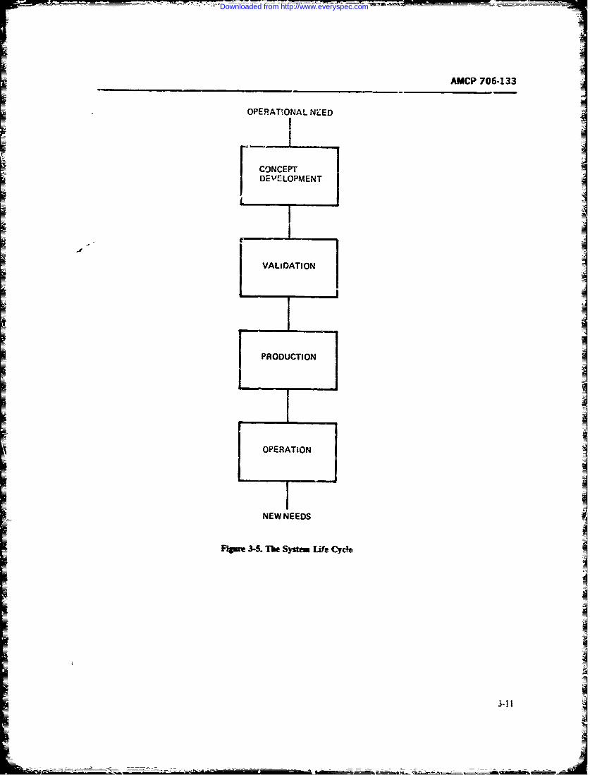
AMCP 706-133
OPERATIONAL NZED
CONCEPT IDCVCLOPMENT
I
VALIDATION
PRODUCTION I_- I
1- OPERATION -
NEW NEEDS
F'pme 3-5. T1-e System Life Cy c
341I
_I
Downloaded from http://www.everyspec.com
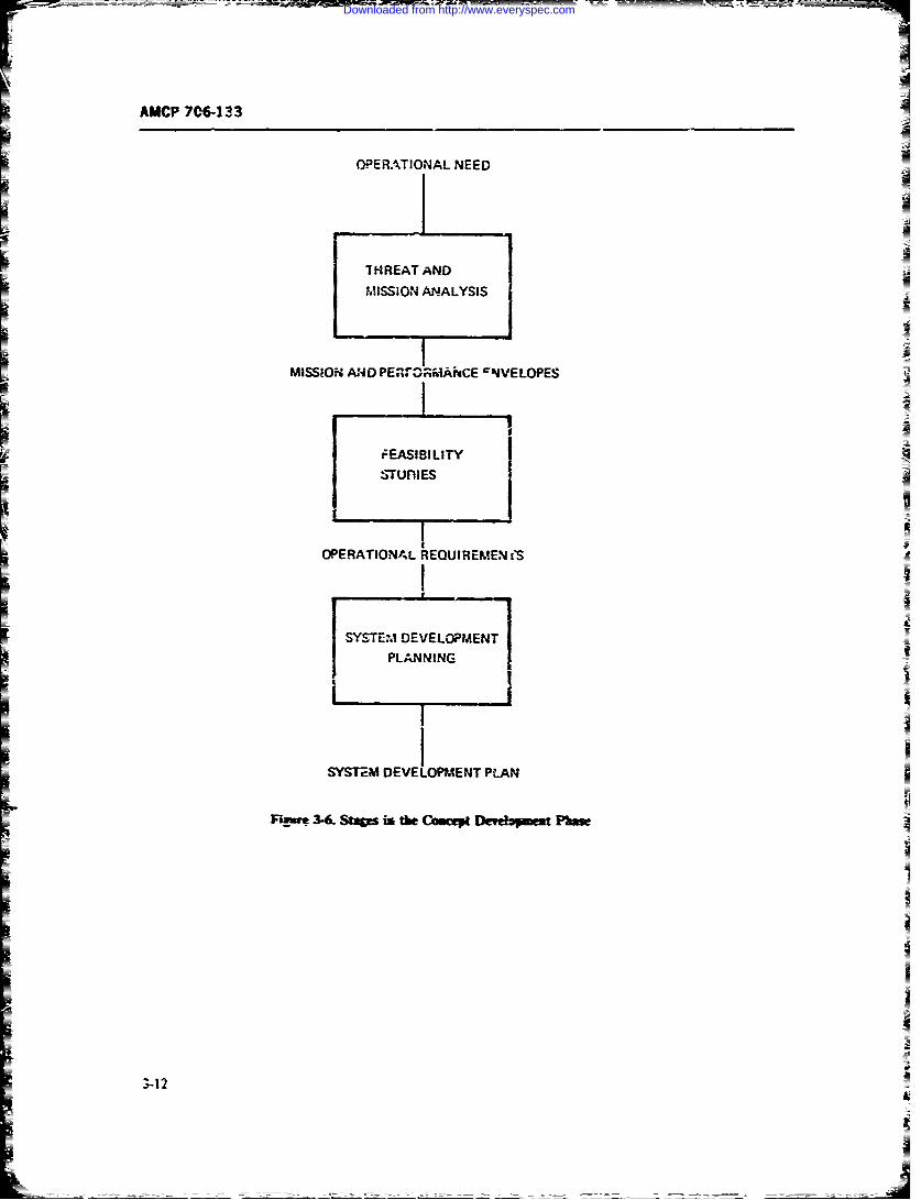
AMCP 7C613
OPERATIONAL NEED
THREAT AND IMISSION ANALYSIS
IMISSIO-f- AND PE,-%r30;W-Ai'CE NVELOPES
t EASIBI LIT? JASTUliES
OPERATIONAL REQUIREMEN (S
SYSTEM DEVELOPMENT A
Fm- -r3-C. Sups is the Cbsciep Detdpmst Pbms
3.-12
Downloaded from http://www.everyspec.com
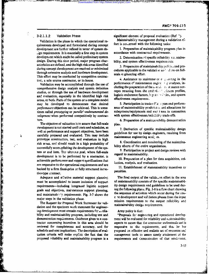
AMMI' 706.i133
3-2.1.1.2 Validation P'hase significant element of proposal evaluatioa (Ref')Validation is the phase in which the operational re- Manaabl' iag endungavidtmc-
quirements developed and formulated during cocp fort is cor.;emed with the following tasks:
development are further refined in terar of system de- 1. Preparation of maintainability program Tplan in
.;gn requirements, It Is essentially a first step in system accordance with contrc.h.w requirements.developirent which might be called preliminary system 2. Determination M4 specific reliab-lity t.i;.. titaina-design. During this tirme period, major program char- bility, and system tffectiveness requirern±nitsacteristics are defined, and the high risk areas identified3.PeraoofmitanbJiyjd . ndp-during concept development are resolved or minimized cdrsapial otevldt~ i* ~ :vo ulthrough extensive analysis and hardware development. efo.This effort may be conducted by competitive contrac-tor, a sole source contractor, or iti-house.4.sitacto ainew' nth
Validation may be accomplished through the use of performance of maintenance euigir f, p a'ialyses, in-comprehensive design analysis and system definition cluding the preparation of the o ;e~,v it mance con-studies, or through the use of hardware development cepts remulting from the n i, i .. v~ profiles,an,, evaluation, especially in the identified high risk lgsi nuac atr,~~ t ~radsseartas, or both. Parts of the system or a complete model effeciveness requie'n~may be developed to demonstrate that desired 5. Participation in trade-4 Ta. a: yses and perform-performaisir objectives can be achieved. This is some, ance of maintainabiiity predict in d allocations Ibortimes called prowtyping or parallel zrndoeumented de- subosystem/equipments znd en, t i-ems in connectionvelopment when performned competitively by contrac- with system effectivenes,./reli_-1i1-y trade-offs.tors. 6. Preparation of a mainiuaaility demonstration
The objective of valictation is to assure that full-scale pla.development is not started until costs and schedules, as.Drvto fseiicmitiaiiydsg
wellas erfrmace nd uppot ojecive, hve een guidelines for use by design engineers, resulting fromcarefully prepared and evaluated. This may include mitnneegneigaa~sprototype ccinstruction, test, and evaluation in high 8.ntnac Coorin rin ana oitoin f hemincia
risk artus, imcd sxi.oald result in & high probability of bi.t Colordt o n intrn of the entre rgaizaionsuccessfully accom.plishing tho development of the sys- ityelrsofhenieogazto.tem or enid item. TI-. ultirrpte poai, where fuill-scale 9. Participation in priject and design reviews withdevelopment is to be performed by a contractor. is regard to maintainability.
achevale erfrrace nti~ ~10. Prearation of a plan f'or data acquisition, col-
achievable~~cton peralysisce andd evaluation.tinsth&t tare resporisive to the operational requirements and are ecton stalismantdo evainatinablt netvsbacked bit a firm fixed-price or fully structured inrn- I I tbls hetomaniablyicnivsr
Adequate and e,",ctii'e materie! support planning The tial output of the validntn effort in the areamust be accomplish~l to insure inclusion of support of maintainability consists of the speeific maintainabi)-requirements-including integrated logistic capport ity design requirement,;s nd guidelines to be used dur-goals and objectives, mai-itenance support planning, ing the following pha.c. Fig. 3-8 is a (low chart showingand maintainabi'!.- requirement--,. Fig. 3-7 shows the the sequtnce of activitim- which occur during the coii-
major~~~~~ ~ ~ ~ stp nte'dto hie t development and vaEdation pbases from the input
The Request for Proposal Work Statement for vali- missinahlt, deiequ ~ tirements teotu eitlt ndation and the specimen work statement for engineer- aniahltdegnrjuem ts
ing development must contain requirements fer6 'eia Army policy is. that:bility and maintainability programn, including test and "Proposals for engineering and operatiowd~ dcv ."ap-demonstration requiiements. Guidance given to a con- nient will be evaluated for reliability and u.3intainabiiinytractor concerning incentives in this area should be aspects to cs~ure that the contractor understands and( isreviewed for completeness and accuracy, and for respons'he to the raquirements, and that he h isschedule and cost implications. The description of eval- proposed an effective and realistic set of relources ane
iuation criteria will make ex.p~cie the fact that the mranagement tools to assure timely attainment of theproposed -elfiability and maintainability program is a requirements and 4emonirtntion of thiat att~i~nie11i.
Downloaded from http://www.everyspec.com
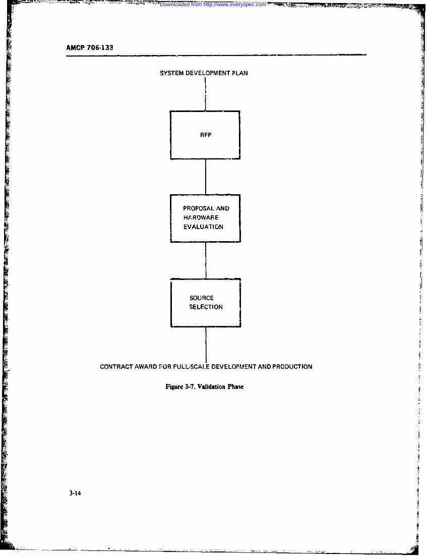
AMCP 706-133
SYSTEM DEVELOPMENT PLAN
R FP
SPROPOSAL AND
HARDWAR EEVALUATION J
I SOURCE /SELECTION
CONTRACT AWARD r10R FULL-SCALE DEVELOPMENT AND PRODUCTION
Figare 3-7. Validation Phase
3-14
Downloaded from http://www.everyspec.com
AMCP 706-133
Specific detailcd evaluation will be made of the 7. Preparation of specific maintainability tev andreliability and maintainability program plans. The demonstration plans as part of equipment and systemsystem description and development descriptions also test and evaluation, including the collection and2 analy-will be reviewed for technical adequacy in those areas sis of test data, initiation of corrective actions as P. resultpertaining to reliability and maintainability character- of test and demonstration, and t1hc preparation of main-istics. Subsequent to source selection, refinements will tainability demonstration reports.be made as required to assure a complete, technically 8. Provision of consultation to design engineersacceptable package" (Ref. 7). with regard to specific mvintainability design featu:es
and evaluatien of the effects of maintainability designIn some cases engineering and prototype develop- on overall maintainability and system effectiveness
ment and pilot production are among the final objec- quantitative requirements.tives of the validation phase. There is sometimes an 9. Coordination and monitoring of subcontractoroverlap with the production phase when advanced pro- maintainability efforts.duction engineering, production planning, and long 10. Participe.tion in detai!e-J project and design re-lead-time item procurement or fabrication are required views and drawing approval with retmrd to maintaina-concurrenily with development. Engineering and pro-totype testing is performed to demonstrate that a sys-
tem or end item satisfies the military requirement. !1. Assurance that the interfaces among other engi-The final product of validation i% information which neering discip!l.nes such as reliabiiity, huma,- facto,-s.
can be provided to a chosen contractor for use in pro- safety, logistic support, test aria support equipment de-ducing the end item or system developed and in the sign, and zciiica1l data are coordinated with respect tologistic support of the fielded system. Fig. 3-9 illus- maintainability.trates the stages in the engineering development aspectsof validation. Detailed descriptions of these stages are 3-2.1.1.3 Production Phasecontained in Refs. 8, 9, and 10. The purpose of the production phase is to manufac-
The bulk of the maintainability engineering effort ture, test, deliver, and in some cases install the specifiedoccurs during concept development and validation, system in accordance with the technical data packageMaintainabiliy management is particu!arly crit cal at resulting from the previoas life-cycle phases. The main-this time. It includes the activities described in par. 3-1. tainability engineering design effort will be largelyMore specifically, the following functions must be ac- completed at this time. However, the continuing life-complished pror to production: cycle management of mainm anability should ther be
1. Updating of the maintainability program plan carried on as part of a sustvining engineering effort,in accordance with fi.ial development contract specifi- during which the m-intairab itY design is reviewedcation requirements. and updated as a ;esult of in;tia! field experience, engi-
2. Preparation and issuance of detailed program neering changes, and logistic sapport modifications.schedules, milestones, budgets, work orders. and their The maintainability effor, durin this phase includes:periodic review and updating. I. Monitoring the production process
3. Monitoring and controlling of the raintainabil- 2. Evaluating productien tcst trends (o assure thatity engineering effort in accordance with the approved there are no adverse effects on maintanability, mainte-program plan and management policies and proce- nance concepts, provisioning plans, ea'.dures. 3. Assuring correction of all discrepancies having
4. Detai!ed prediction and allocation of quantita- an adverse effect on maintainabilitytive maintainability requirements down to the lowest 4. Reviewing and evaluating all change proposals
configuration end item. for their impact on maintainability5. Participation in system effe..tiveness and design 5. Participating in the establis..ment ot controls
trade-offs involving maintainability in order to meet for prucess variations, errors (workmanship and de-prede:ermined maintainability :)redictions and a!boca- sign). and other fabrication and lest dicrepances thattions anc overall system effectiveness requirements. could affect maintainability.
6. Assistance to maint.nance ,mgineering in theperformance of detailed m;,intenance engineering anal- 3-2.1.1.4 Operation Phaseyses (Ref. 11). The operation phase of the life cycle of Arn,,y
3-15
Downloaded from http://www.everyspec.com
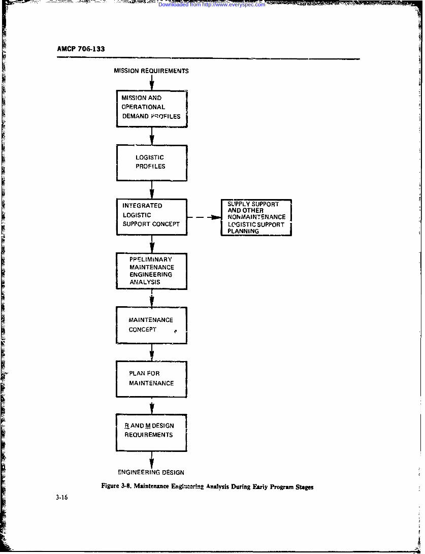
AMCP 706T-133
MISSION REQUIREMENTS
MISSION AND
OPERATIONAL
DEMAND PROFILES !
LOGISTIC
PROFILES
INTEGRT C E PT S LYS SUPPORTPANNIN OTHER
MAINTENANCEENGINEERINGANALYSIS
MAINTENANCE~~CONCEFPT I
PLAN FOR~MAINTENANCE
i ~ ENGINEERING DESIGN
i ~ ~Figure 3-8. Maintenance En . oAnalysis During Eariy Program Stag~es
3-16
Downloaded from http://www.everyspec.com
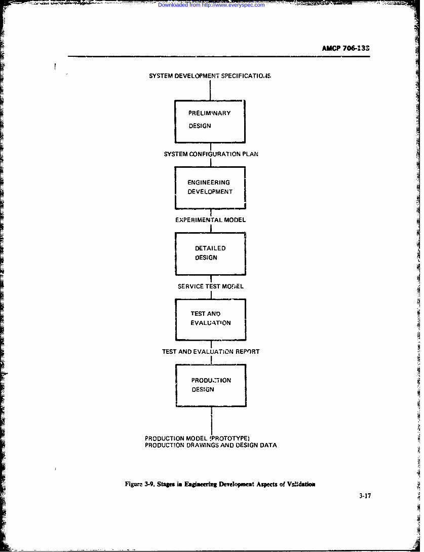
AUCP 706- 33
SYSTEM DEVELOPMENJT SPECIFICATIO.,S.
I i :: i,:iiPRELIMINARY
DESIGN
SYSTEM CONFIGURATION PLAN
ENGINEERING IDEVELOPMENT
EXPERIMENTAL MODEL
DETAILED
DESIGN
SERVICE TEST MO.rEL
TEST AN 75
EVALUATION
TEST AND EVALUATION REPORT
i PRODUZ'TION
DES;GN
PRODUCTION MODEL !PROTOTYPE)PRODUCTION DRAWINGS AND DESIGN DATA
Figure 3-9. Stages in Eaginering Development Aspects of Vsldation
3-17
Downloaded from http://www.everyspec.com
-t __ _
AMCP 706-133
materiel starts when the firs', military unit is eq sipped, c. Periodic stockpile reliability evaluation of se-zand ends when the end item or system haven de- lected it-ams (an integral part of the surveiliance pro-dlared obsolete and has been ren.iaoved from Avrmy in- gram).ventory. This phase is characterized by supply train- d. Evaluaicn of the effects of repetitive inainte-ing, maintenance, overh,%ul, and materiel readiness nace
Pilloperations 01. 6e~ end item or syst-m being uied by e. Effective program to control application of ap-opcrational units. This time period is most signficant proved modifications.becaux- it is here that the true cost-effectiveness of the f otnosassmn frlaiiyadansystem and its logistic support are demonstrated, and tiaiiycaatrsis ae notainldthistorical maintainability data are recorded for use on fnailt 7). ceitcs ae not-ainldt
future prodiucts.There are no specific maintainability engineering re--
quirements during this phase. Feedback data from thefield with regard to system effectiveness, reliability, ac- Disposal takes place when iun end item or system has
tual field maintenance, and maintainability sliculd be been elrdoslt n olne utbefruebusedas bais or rodct mprvemnt nd ue or- Army units. The item is theit removed from inventory
rection of deficiencies as a result of system operation and scnapped or salvaged.and support. Summarizing this chapter, to make nmnagement of
maintainability most effective, maintavnability engi-Army policy sates that th... following elements, as neering should be so ptaced organizationally that it can
appropriate, will be executed: impact on design and also interface drectly with othera. Effective collection, analysis, and follow-up of discipline, such as safety, reliability, human factoirs.
failure data in accordance with the selected data collec- value enginecnng and system-cost effectiveness, writhtion plan; timely identification and resolution of prob- whom maintainability is inseparably interrel-itod. Thelems, including product improvement where required. benefits of such organizational !Aructurt are conserva-
b. Effective controls over parts substitution during tion of resources and specialists, experience retention,maintenance operations, less duplicat. on. and lower program costs (Ref~ 12).
REFERENCES
I. MIL-STD-470, Maintainability Program Re- mrmt o'Engineering, lUCI A, 1966, Universityquirements (for Systems and Equipments). 21 Microfilms. Inc., Ann Arbor, Michigan.March 1966. 9. M. B. Kline and M. W. Lifso-, "Syste m. Engi-
2. B. S. Blanchard and E. E. Lowery, neering-. Chapter 2 in Cs-Effectivrnt.s Eco7-MVaintainability McGraw-flill, New York, nomic Eivalmation of Eitgineered Systems,]J. M.1969. English. Ed.. Wiley. Newi York, 1968.
3. DA Pam 7T15-1I, Maintainability Fngineer- 10. M. B. Kline and M. W. Lifson. Systems.ngEngineering. Notes for UCLA short course,
. AR 70-1, Arwmy Research. Developnztef Engineering & Physical Sciences Exteiision,141cquisricon. UCLA ixws Angeles,, 1970.
5. Deleted 11. TM 38-7-03, Integrated Logioiic Support, 56. DA Pr m 11 -2. Life CirleV Management.Model VoL-, Nov. 1969.
for Army Sy,;.erns. 12. S. L. Roush and i. L. Maybell, Effectiveness7. AR 702-3 Army Ma2teriel Reliability. Avail- Engineering Organization in the Aerospce In-
ability, Mfintainability. dustry, McDcnnell Douglaz Corporation,8. M. I. kline, Maintainabiiity Co'.siderations in Douglas Paper No. 3768. October 1966.
System Design. Doctoral diss-rtation, Lepart-
3-18
Downloaded from http://www.everyspec.com
AMCP 7064133
CHAPTER 4
MAINTAIVIABILITY ALLOCATION AND PREDICTIONSECTION I
INTRODUCTION
4-1 GENERAL meet the system maintainability goal and to ptas themaintainmbility demonstra.-ion test. if such is rcuu'jrzd.
Allocation and prediction may use diffetent techl-Maintainability aflocation and prediction Z7c tasks nqusHoeetyarbsdonwoscii factcts
reurdby MJL-STD-470 (Ref. 1) within the frame- thtar omon to all n*intainability asstssmnentwork of establizhig an.1 maintaining an effective main- techniques and must be quantitatively determined intsinability program. In this Standard. twelve specific each case.tasks arr defined. We are here concerned with two ofthese tauks, namely, Task, 5.2 and 5.6.
Task 5 requires the performance of a traintainabil- 4-1.1 MAINTAINABIMIY FACTORSit)- analysis of which maintainability allocation is anmprtant part, stated in the foliowing terms: "As a There arz two specilrc maintainability factors tha.
majcr task of the anzlysis. the contrartor shall allocate have been recogniz-ed as the basi ingredients of main-quantitative maintainability requirements to all signif- tainability techniques. Txh-ir quantitative values are of
cantfuntionl lvelsof he sste~cqupmet". decisive importance in meeting maintainability objec-cant~~ties Thecioa twoel bosi fthor are:/qupen
Allocation is performed in4 the initial phases of a lvs h w ai atr;ac
program when a system,~ is deiinet! and its overall main- 1. The time required to restore a failed system ortainability objectives are established. A lHocation appor- equipment 'Lo an operanally ready stat'- by perform-tions the overall system otqjeciives to the functional tiag corrective (unscheduled) maintenance, or to sustainblock, thus providing the designers with maintainabil- a desire-'I per formance and reliabilitzy level by perfhrm -ity requiremaits that they have to meet, pos',ibly down ing preventive (scheduled) maintenance.to repairable itemc level. Reellocations maiy be neces- 2. the frequency at which corrective and preven-~.ary as the design features gradually are established. tive mainite-nace actions occur at the systemn/equip-
Task 5.6 requires the prediction of maintainability, ment leyel.sivating that such prediction "sball estimate quarntita-tively the mamnanability system/equipment parameter These two factors jointly determine the quantitativevalues for !be planned design configuration. The quan- maintainability characteristics of a design. Specifically,titative estimates shafls be used to judge the adequacy of ilhe) detterm zac the mean aztive corrective maintenancethe proposed design to meet the maintainability quanti- time M1, the mean active preventive maintenance timetative requirements and identify desi&-n features requir- M,, the m,!an active corrective and pev-entive mainte-ing corrective action". nanci ti'-e '.' the maximum maintenance time
Prediction p~eriodically assess--- zhe maintainablit% A~, and the equipment maintainability functioncharacteristics of emergiiig designs to insure that the MA Ls alreatly defined and discussed in Chapter 1,allocated maintainability reqiuireents are being me: or Section 11.to identify qualitative design featues that requie cor- As an illustration Af'he impact of the maintenance-ective action so as to meet the ovtrall system maintain- time and of the frequency of occurrence of miakitenanceAbility requiremnts. Prediction is performed periodi- on maintainability let us recall here some basic equa--ally until the design configuration has the potential tc ti-ins.
4-1
Downloaded from http://www.everyspec.com
-- - - - -- - - - - - - - - - ---- --- -
AMCP 706-133
The mean active corrective maintenance tims M, of in Eq. 4-3 the frequencies be exp.essed in Ih*e samea system consisting of n replact&,-, or repairable items unit3, i.e., number of i'ystem maintenance actriIs peris given by system operating hour, and that the mear active cor-
rectiv- and mean preventive maintenance times also ben (4-1) expressed in the same time units, i.e., seconds, minutes,
M € ,Mcg , (4-1) or hours.8=1 18.1l By i.spection of the given equations we see that the
system mean downtime in.. ; ir measures dependwhere only on system mainte=,ance oi:time and on the fre-
MV, = system active corrective or quency at which system outag-s occur. At first glance,repair downtime when the fth it would appear that these equations apply only to se-itcrn fails ries systems. However, if system.r, contain redundant
f = frequency of the ith item elements and the ft1t item is defined as a serial element
failures, usually expressc .- which may or may not contain redundancy, the preced-terms 3f the failre rate A ing equations become generally valid as long as we
the ith item in units of recognize that the time element M applies to system" rumte- of failure per one downtime and the frequencylement f, is rtl' frequencysystem opcrating ho'., at which the system goes into a down condition. In
The mean active preventive maintenance tine is addition, when considering Eq. .4-3, )ne mtu- realizegiven by that preventive maintenance may, and usually does,
have an effect on the frequency j:.of corrective mainte-nance actions because preventive rnnisitenance isa-
ma=. f (4-2) plied to postpone the occurraic of failr.' Thus, if theit item is subject to pcriodi- pr ,lnive maintenance(such as scheduled replacement), system N.iures on
where account of the ith item will no longer occur at the iiem's
M= system active preventive own failure rate but at a rate determired by the naturemaintenance downtine whe-n of the preventive maintow,,ce policy (Ref. 2. Chaptersnranenace owatme hom 3 and 4).the ith item is preventivelyreplaced or otherwisepteventively maintained 4-1.2 METKODCLOGIES
a = fi .auency of such ev'ent pr As already stated, seteral methods exist to allocate.T nystern operating hour. and prmdict system or equipment maintaiLabilit-,.
The mean active corrective and preventive These are in MIL-11BK472 (Ref. 3) and the Airnance time R is given by Force Design HAndbook (Ref. 4, Section 3B). In gen-
erze, these tecbniques 'itilize the time auamationM = ( M:f, + ",fJ.)Af +.f,) %4-3) method of indi-idual nnainteatance action, baud on the
freqtuency of occurrence of individual maintenance ac-_ n tions "nd their average duration, ii order to determine
where , and M. a defined as befor and the nveaall system mean maintenance time and relatedmaintainability indices.Ai methods ue various "building block" type
= 1 (4.-4) brekdown diagrams to establish the required respec-tive maintenance actions. The mean maintnance timedeterminations are based on the equipment qualitativedesign features. The maintenznce times are derived
(4-5) from statistical .iistorical data, selced obtmvatiodata, expertise judgments, simuhtion and synthesismodeling, design checklists. ertraolation, or matrix
are the frequencies at which the system is correctively tabulation methods.or preventively maintained, both expressed it system In the selection of specific prediction and allocationoperating hours, not calendar time. It is essenti-l that techniques, the maintainability analyst need r.o con-
4-2
Downloaded from http://www.everyspec.com
AMCP 76-133
_.Ine himself to a single method. He -Ay utilize several mock-up determinations would be called for.meth xls in a single project. O:dinmily, there may be 3. Suppost factor 4 is impotmnt because high ac-one major allocation and prediction method approach cracy is r, quircd. Then, extrapolafion ard expertiseupon wbich principal relisnce is place- The selution judgment would probably not be suitable; a time syn-of a sp.- aethod wi1 affect the plans for data colec- fiis method appears most a e, using a detailedtion and pi 0ram control As discussed in Ref. 5, which qualitative checlist.incltdes some of the prediction methods of MIL- 4. Suppose management places high vaiue oa Fw-HDBK-472, certain practical considerations or factcs tcr 5. Then the sphere of interest not only wo.v- ' it .may control the choice of a predictvio technique, clde the "gross" maintainability estimte, l' a ±:o Lfaenamely: fcie "causes" or "st- -Ac de!,ign f ea9-" affecting
1. Environment co.isideration (maintenance level a pr.,xiction. This v-- ,Tairr -un extensive qualita-and type, mintet.&we -'oncept-whal, when, where, tive-qanti3tv, .-' 4e- .-kk simulation and syn-why, and how mnaintenani" will be dons, and the logis- thesih n, _.dr 'c '-' .-.Alback to the designerstic support situation)ti .suppo t ta equ tin an-, case, before a uethod is selected, one must5i
2. Similarity Zo oth-r equipment43. Scope of the prediction and allo~ation eflort develop a maintenance conchi upon which to base amaintenance functional flow block dikgram o, the4. Accura-cy of ,stimate required maiatenance tasks to be performed which defin what,5- Degree of design auidance required when, where, why, and how much raaintenanct From6. Poin' 3f applimtion in the design cycle (early or this, a "building block" maintenance functional flow
late)- diagram can be devloped for the preposed equipmentdesen to be sue that all maintenance tasks are ac-
As exampies of the apIiattion of thse factor, Ml counted for. Alo of great importance are failuresider the foliowing situatiocs rrxvie, effects, anii criticality analysis requirer-ents, in
1. Suppose that factor 3 is very limited becaus- order to define the need for correc r. maintenance andthere is not much time or money availble; then the prevent.ve intenance actions. One tust cof, le theoest one could do would b- to (a) attempt rmugh ex- field operational eviroamen: when deeloping mainte-trapolation from tnaintenance history of Similar equip- uance uime distnbtions uased to determine the ieanment, or (b) conduct a briefjudgn.ni-type review by time and maamum time indices. Too often inherentexperts. iadices are used, based on biased experm mtal vahes
2. Now consider a new system which is "low" on under laboratory envirinemts, or controlled ckserva-the sirr:larity factor 2, being quite different in concept dions ufilizing hi gly trained and bias technicianand realization. In this case extrapolation is not in- skills n rqesentatiie of field environments. Also,dicated, and the chechlist approach may have to be field operational environm=nt dcgaded failure ratesexcudad if the tasks required of the maintenace tech- should be user; instead Cf the ienemt fail ure ratesnician Pre not well enough reptimscted in the usual wienemve operatiorml field mainti inaLity is of inter-checklist. Probably some simiuhition modeling or et.
4-3/4-4
Downloaded from http://www.everyspec.com
AMCP 706-133
SECTIOK !1
ALLOCATION
4-2 ALLOCATION FACTORS gain access for disassembly4. Adjustment and/or alignment (may be part of
the sequence of step 3)4-2.1 BUILDING BLOCK THEORY OF 5 Servicing. Performance of steps required to
ALLOCATION keep the item in an operating condition, such as clean-ing. lubricating, fueling. and iling.
In the systematic c',,lopvent of realistic allocation 6. Check out and i"pedion. Vtrification o thefactors, the maintaimnIlity engi n--" must consider all maintenance action to ascertain that the equipment isof the following: restored to its operpAional performance readiness
1. Two types of maintenance 7. Item tirpair. Maintenance actions needed t. re-2. Seven categories of matenance action time e. store a removed item if such item is not of the throw-
merits away type;, includes one, all, or a combination of the3. Three l.-vels of mamtc.ance steps previously listed- may be performd! at ny level1. Five major steps of allocation of maintenance as stated in the established riinte-
3. Mine fr iiiouzI breakdown levels of a syste m. ce
The three levels of maintenance where the two tjpesof maintenance and the seven maintenance steps can be
Corrective or unscheduled mnamtenanct (repxr performed (ief . 6 and 7) ar-or restcie equipmtent wich has filed to eet'th oer- 1. Organizationa' Maintenance Level-mnainte-
esaiona performance to e, mantenace tat nance peeormed by the using organization .,n its ownc rmott:..-eO be schedulekd 4,uae to rwxk of -dure). eaiprmentL This maint-ance consists of repai of a
2- Prmentive or scvI led n intenance (maintain first and secono level-type -.-ithin the capabilities of theeqwwprzen! to sustain ze ptrational pCtforuax re- authorized operator or organization maintenanze tech-I qure i-e., -maintenazie that an be scheduled on an nician and within repair parts, tools, and test supportope-rating time or calendar basis). equipment available- Normally the skill level require.
mte lowest skills developed for maintenance work. Or-ganizat. level personnel are generall) o-zupied with
tions ar time elanents reqi.ied tn perform the two the oeration and use of the ,I.uipment and have mini-types of maintenance. .Arargei in order of sequnce of mum time available for det-iled maintenance oz diag-ogal steps, ow. all, or a combination of the follow-ng no, ic chek-out This is vbe level of mantenancesteps may be requirjd for maintenance (corrective- where the minimmn eqmument downtime fc. mainte-I- unsc l or pm ntivschetule) of i s)stem, rnce must be arhieved in order to obiain the highes,
I. Preparation. Inspection: ,btaining support equipment -.vailability or io m=cieve operational readi-tooLs, equipmen- repair parts and supplies; Warm up ness for war-time us of the equipment- Maintenance isand check out; "verifiation or the system status usually revxi%:zed to perio.; scheduled vwti,
2. DsgnpLs. L-olizatin and determination of maintemrm checks, cleaning of equipment, frcnt pa-the cause of ;ailure or condition; isoL.tion or determi- nel-type adjustments, and replacement of items on anation of the item locatton causing the falurn or condi- goss acc-ss'bi ty level.tion of item to be mainrned 2. Intermediate Maintenance Le.vel-maintenance
3. Replacement- Dismssembly and gaining &cezss performed by ri*ibLe semi-mobile, and/or fixed spe-to the item: interchange of the item with a serviceable ciudized arganizations and installations. For :he Army,item; reassembiv. i cluding closing ofaccesscs required this is broken down into direct support and general
4-5
-A-
Downloaded from http://www.everyspec.com
AMCP 706-133
support functions, w th highly trained specialists forv Maintah-ubility allocations m~ust lbe weighted andipecializ~d c' Iipmenl. balanced for the economic use of tic :hree levels of
maintenance. Manipulation of thie allccations directlyThe direct support units are often designated to. pro- affects the system logistic support casts and availability.
Mie close support of the combat organizational-lele1 The five major steps involved in maintainability alloca-
tainanaute to' facilitatc tactical operations. The direct inaeinaintennce su~pport usually is limited to the repair of i. Identify maintenance function to be performed
znd-itemr or unserviceable assemablies ir, support of thneessema ahl~elo aneane(raiacobat units on a return-to-user basis. A Larger supply tional, intermediate, and depot) required to restore the
orearassemblies ancecomponents of major modular ysetoaoprinl su&of rpair2. Identify the elements maat coneu:z -t a systemtypes is -usually authorized for direct support.. The diag- down to the replaceable throw-3w6ay part.
rnostic equipment is usualiy iinstalled in mobile wins.
The direct support maintenance is also geared to pr~o- 3. Determine the frequencies for (a) comrec'ive,Mie the highest equipment availability with mimum unschediuled maintenance, and (b) preventive, sched-
equimen maitennce ownizrz. Rpidturniran tiled niaintenanc, fL- each itemn of the system' down toti is an essential citeriba in the maintennno! time the replaceble throw-away part.
allocaton indices. 4. Determinme the task times (mean zime. median
at semi-mobile or temporary txed installations in the percentiles) for eachi itemn of the systenz down to the
baitlefield area to support the tactical battlefieldi oigan- throw-away part.iztizs and dirct support units. The maintenance 5 Compute the mean times, modian times, and
support is that whi~h cannot be provided by direct mAximumn :imes ai given percentiles -as required' forspport mobile units, General support units have Ligh both corrective annj preventive suaintenance of the en-
W-nelskills, additional test support equiprient. and tire systent.better facilities. Equipment repair is generally the r-patir of those itemns replaced by diret support to a srW- Fina!,ly, the nine~ functionsl breakdown levels forroodule or piece part (throw-away) level. Fapid turn- system- tvcognuzze by military 'specificztioms and usedaround time is not as imperative at the gen,,ral supr in making allocation (str. Ref. 3, pp. 2-9 and 2-as at the direct support and organizaticnal levels of 1)aemaintenance. I. System.
3. Depot Level-the highest lcrel of irinnance 2. Subsystemprovides support for maintaiwm %-, ieyo~zd thte 3. Equipmentcapabilities pornded r- ic ,wer !eveh,. 1the '.ozatin 4.Groupis generally rtmoved from the theater of opematcts: and i. Uvimay provide mazinteniance for &several thevier of opernt- 6.A bltion. In some areas subdetiots ma eusedi safc
- maybe in7. Subassemblyhavens of the theater of operation or in countries scja-cent to the theate.r of operation. The support equipment 8. Stagemay be of extretme bulk and compiextity. Usually maicir 9. part.overhxaul and rebuilding arm performed at depots The I re oahzeteaanantt betvsilarge numbtr of support requitrnez'ts lend themselves I re oaheeteniti~tt betvsito the eYeci-.e use 1of assembly-line techniq=e That. in iseenalttthtotpsofmneactesvnzurn- permit the use of relatively unskilled labor major categories or maintenance actions. t-.e- three 1ev-greater part of the wark-loa:d, with concentration of els of miaintenance, !he five major iteps frer takirghighly skilled Epccialists in ke3 positions. For newly allocations, and the nine fiinctional breakcdown levels ofprocured equipment in the mi~itary inventory, the con- a systemn be brought to bear in pioper perspective. Intracto- who 'jroduced ;he equipment may be emnpihyed order to achie-ve this and to make cer-tain that all as-fcr depot functions until such titm! as the depot staffed !~t fmitnreaecvrdadjsiid an
with Army personnE! has enouvh work and expetience tainablity enpneers must use the following analyticaltacoplish the maintenance. T'he depots are usually tos
mcal upon to provide the necessary standards and I . Maintenance functioali flow block diagrams'-Alibration maintenarze tunnctis. Z. System fixnctionai-level building block diagrams
Downloaded from http://www.everyspec.com
AMCP 706 133
3. Failure modes ,ffects and criticality analysis. 4-2.1.1.2 System Functional-Level Building~Block Diagram
The .- tet of the application of these toots depends onmaiy factors incluaing the system constraints and the This is a sytematic method of showing and definingphave of the system life cycle the maintenance features and task alions required for
each of the system-to-part breakdowns. This type of4-2.1.1 !;stem escriptin visual display is essential in order to explain further the
equipment details that comprise the maintenance func-4-2.1.1. 1 Maintenance Functional Row Block tions shown in the maintenance functi(.nal flow block
D-agram diagram. This also camplements the established main-This is a s.stinatic method ofioutlining. interfacing. ronance concept in that it shows the essential mainte-
and relating the two types of maintenance (corrective a wnce tasks for each item of the requirements break-and preventive) at earh level of taaintenanc- from the down. The breakdown does no. show the "where' oftime a system goes down for maintenaice until the last a maintenance action but does show -what" is neededn'aintnmance function has beep performed to restor an and the equipment level at which an action takes placit.item to its operational readiness. Stated in ,cxms of Each branch of the equipment diagram should indi-svstem breakdown, the functional flow breakdown cate a termination point indicated by a consistent, iden-starts when t -e equipment goes down for mainte-ance tifying symbol or code Examples follow:and continues until the replaced item either is repaired I. A cimle enclosing the item: to indicate the levelfor use in the original equipmient, placed in stock as a at which a replacement (throw-amay type) completesreplacement part, o" thrown aay. The fncon is ex- the correction of a malfunctioning itemprescd in a noun-verb fawhion: 2. A retatale enclosing an item: to indicate the
1. .'Org-izational Level Maintenance- For rkiled equipment breakdownequipment, the first level function is -perform orrec- 3. A tngle enclosing an L"ierted next to the
tiv maintenance"; the second level function is -per- rectangular block: to indicate the level that an itemform inspectio", -diagnose failure, "°remoe faulty may be fault localized" without employing accessoryitzm". "replace", and -checkcat" until the equipment support equipmentis eored; the third Itel function is concerned with 4. A a.angleencingan "r"inserted next "o ..ethe repair of the rer- ved faulty item. rectangular block. to indicate the level to which an item
2. Intermediate Level Maintenance: For failed may be fault "isolated" using built-in or accessoryequipment which cannot be repaired at the orpaniza- epmenttional level, the firv ieviel function is again "pectorm 5. A triangle enckoing an "Acorrective maintenance". followed by the secon =A andthird level functions.. This is continued until the faulty o- Inserted next to a rectangular bloc5: to indi-item han been broken down to its throwaway status in cate adjustment or alignment before removalthe functional flow block dzagram. for illustration, of a rpWaceable itemFigs. 4-1 ar'4 4-2 are typical formats for a top level b. Inserted next to a circle to indicate adjust-maintenavnce functional flow block diagram, -howing a m t, or lignmen at, "r relacemet ofa re-typical breakdown, numbering sy)stem, and entries paeb iemmade of the aliocations. For each funcsional break- 'o A riangk enclosing a "C- inserted nen .) thedown, the mean time to repair and frueqv.,y alloca- symbol: to verify operation by built-in 'tf-wst or. ol.tbrtions are entered as the analysis prcAeeds. The func- testing equipmn:nLtionm flow block diagram is nothing more than puttingdown the &alyss's thinking in a chronological and sys- Examples of the application of these symbols i-a com-
tematic order to assure that all maintenano: functions bination to indicate degrees of .ccess level ar I termina-ad actions have b.e covered in his analyis and allo- tion points follow:antiont It also is a visual aid in explairing to manage- 1. Faulty, replaceable throw-away item requiringment that all the factors and indices necemar- tojustify disassembly t..aintenance action of a higher order:.the imaintainability quantitative and cpaltative design a. Place a rectangular block above the item, en-requirements have been included. If trade-offs become closing (dentifying) the next highr assemblynecmsry or corrective actiors are needed, the interre- to be broker, down.lationship effects can be determ ined and the efTects b. Encircle the faulty item to indicate thtviw-justified (see Ref. 8). away replaLemet.
Downloaded from http://www.everyspec.com
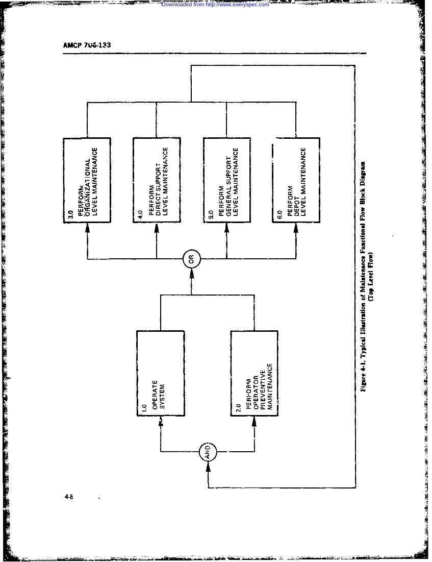
AMCP 7U&-133
I I31 i I-iD '
k- z L cn
_jIcc *1U0cr
O'A 0 CCWA u LL i U LL J u LL w
C
CL
a: > zU) uj Z
CL >.tu Cov) ft
Is
w J-
Downloaded from http://www.everyspec.com
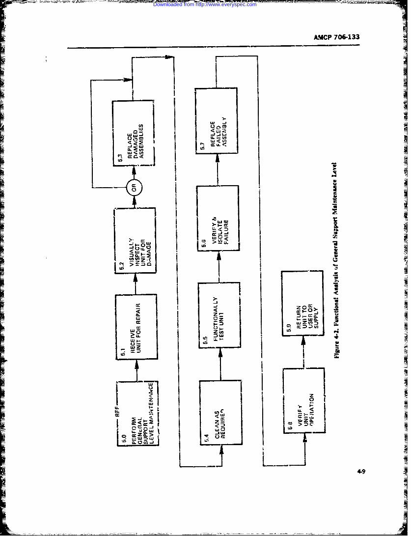
AMCP 706-133
wj I,rLji
> A
Iz 00 Z = C
> DU
z La
- I
< DI
U. yU
4-0
Downloaded from http://www.everyspec.com
AMCP 706-133
2. Faulty, replaceable component that requires sis formats is not included in this text, since it is readilyfurther maintenance and disassembly maintezance of a availble in texts on reliability. It is important that thehighe- order: maintainability engineer be aware of these methods,
a. Place a rectangular block above the item, e - however, and integrate hs activity with !he reliability
closing (identifying) the next higher assem'v engineer in order to receive thu full benefits that this
to be broken down. analytical tool offers.
b. Place a circle a, ve the component, enclosing In the use of thev- maintainability analytical tools
(identifying) the item to be replaced for subse- and methods, the mainianability engineer should give
quent repair. adequate consideration to the time distributions inher-
c. Encircle the faulty component to indicate ent in maintenance actions. Human factors and system
throw-away replacement. complexities have a bearing on a technicLan's skill andcapabilities to handle th., miintenance actions and thus
The connecting lines on the diagram should indicato on the time distributions. Specific attention should bea physical relationship and not an electrical or mehan- given to the type, degree, aid range of skiils availableical conveision. The electrical or mechanical connec- at the various levels of maintenance.tion is obtained from an interfaze or detail drawing ofthe ite-ms, which--coupled with the failure modes- 4-2.1.2 Assignment of Maintainabilityeffects-criticality-and detection analysis-furnishes the Factorseffects on performance interface. Fig. 4-3 is a typicalexample of a functional level building block diagram In par. 4-2.1.1 three analytical tools are described.(Ref. 7, p. 64). Once the extent of the utilization of tnese three foois
When coupling the maintenance action time and the has been established. the assignment of maintainabilityrespective failure rates for correctiv.- maintenance -r fators is made.frequency for preventive actions, the effects of the If a desired maintainability quantitative goal or cgn-m inteaance-as revealed by the building block dia- straint has been specified, allocations for the eight func-grams-arc realized and the cptimization of the main- tional level system breakdowns are performed andtainability goals can -,e achieved or corrective actions summations made to ascertain that the specified main-and associated trade-,ff studies justified, such as tainability goal is achievable. The extent of breakdownchanges in the maintainability qualitative design re- to the lowes: level depends upon the phase othe equip-quirements. .nent life cycle. e.g., at the contract development phase
As an additional visual aid, an allocation tunctional allocations may be only possible to toe group assemblysystem block diagram of the system breakdown could level for which end-item specifications will indicate thebe used !o display the related quantitative allocations constraints, wherea. in the validation phas;e the analy-for each ,.idependent level of equipment, where aif val- sif would be to the throw-away part ieiel. In caseues which have been extracted from the analysis can be where the summation indicates that the quantitativeentered in the respective blocks of the breakdown to goals or constraints are not achievable, further analysisshow the allotments for each block and the surnmations of the design concepts must be performned to effectup to the top system level, design changes and provide justificatios for changes4 3M s tby associated trade-of." studies, as neceary.
In general, allocations are made to de lowest possi-Criticality Analysis ble breakdown level for which reliable and realistically
This may be used as a tool fc-" Cr ermining the main- achiev-'e projections can bt. made. Th: specific alloca~tenance requirements. This type ,if analysis is the basis tion values are maintenance mean times, riedian times,iur ctermination of the frequency of naintenance and and maximum dimes at given percent.les, as requi;ed,may be used for detenmination of the qp.alitative main- and the failure rates for corrective maintenance andtainabiluy design features to te incorporated. It also frequencies for prevet:'ive maintenan:ce. In some in-
will indicate the need for and the effecti"eness of pre- stances, maintenance man-hours per operating hours,ventive maintenance. Early analyris in the concept aihd per miles trael.ed, or per round fired may be used indefinition phases is essential, even if on a gross system lieu of maintenance action times and frequencies.basis, because it affects not only maintainability and Whatever factors are used, they must be compatiblereliability but also design char, :teristics and require- throughout the analysis, not mixing, corrective actionsments for new system concepts and planning. A discus- and preventive actions and their frequcicies in thesion of the failure modes, effects, and criticalit. analy- summations. For each functional evel system break-
4-10
Downloaded from http://www.everyspec.com
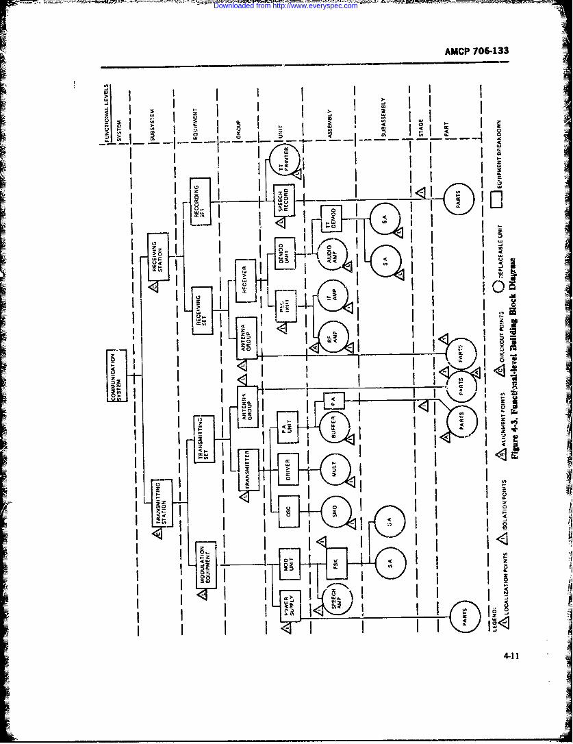
AMCP 706-133
Ii i I , II! II
SI I ' . i! I + I. ' i I'i
I "- L+ ,l I -, .a I I -u
, I l i
[II . I ,LQ l <L I Il1 Ii I
+c ul+ o
I I . 4,+ IK Ii I I °+
4-11
Z TZEccIccJ
Downloaded from http://www.everyspec.com
WM4CP 706-133
down, the factors may be listed on the maintenance (z ,(48
functional flow block diagrams, or functional level In .i = .' I)/ (4-8)
breakdown charts and diagrams, or arranged in othersuitable format for ease of the summation process. Toperform the summation, Eqs. 4-1 thro;:gh 4-5 are used, whereremembering, however, that when an itein is subject to M sr- itied median maintenancepreventive replacements it a frequency f, its corrective downtime of the systemmaintenance frequency f, 6,-comes a functic' of the M= estimated median maintenancepreventive maintenance policy (see Ref. 2, Chb,;:ers 3 downtime of the system if theand 4). ith block fails.
Two allocation methods for systems that apply to The allocations of M,,, and M, and M are made socorrective maintenance only are shown in Ref. 4, See- that the system requirements are met. If the specifiedtion 3B. The first allocation method is based on syst.m value-, of the system requirements are met, the alloca-maintainability synthesis; the seond me.hcd applies to tion is considered complete. If the allocations at themaintainability improvement allocatiot. These two block level do not result in meeting the system main-methods are now discussed. tainability requirements, the second method is applied.
4-2.1.2.1 System Maintainabiiity Synthesis 4-2.1.2.2 Maintainability Improvement-1-21.21 SstemMaitaiabiAllocation
-- Fi-st, a buidding block diagram of the system isFLsabiligbokdiga=fth ytm~Assuming that the maintainability improvementdeveloped, with each block cpresenting an indepen- wh icng be a he inainablis i pro -dently maintained unit, and a failure rate estimate is
tokeiportional to the originally allocated or predicted value_- a igaed to each block, with X1 being the failure rate
of the ith block. The next step is to ehmate the of maintainability of the block and is independent of
mean corrctive maintenance downtime id, for the the failure frequency of the block we get
system when the ith block fails. The system estimatedmean downtime pei failure Mc! is then - = ' .Mc/.ii t (4-9)
n n where(46) M,.,., improved allocated mean
A maintenance downtime of thesystem when the ith block fails
M = originally estimated meanwhich is the equivalent of out" Eq. 4-1. mahitenance downtime of the
If the specification imposes a requirement on the system when the ith block failssystem maintenance man-hours per system operating .dZ = specified system meanhour, the following allcation equation is used: maintenance downtime
M, as defined by Eq. 4-6, When, under the same assumptions, a systemZ E J (4-7) MMH/OH requirement is specified, we get
3 1 = ' I 3 I / .i I ̂( 4 - 1 0 )N
whereM, specified system mean where
maintenance man-hours Per M, improved allocated MMH/OHsystem operating hour when the ith block fails(MMH/OH) M, = system MMH/Oh spccrcatin
,= estimated mean maintenance requirementman-hours required to repair M,= originally estimated systemthe system if the ith block fails. MMH/OH when the ith
if the specification imposes a requirement on the component failssystem median maintenance time per failure, we use M, = as defined by Eq. 4-7
4-12
Downloaded from http://www.everyspec.com
AMCP 706-133
4-2.2 COMPATIBILITY OF MAINTAINABILITY with mean times; such summations result in erroneousFACTORS conclusions which can cause very serious over- or un-
der-design characteristics to be built into equipment-As has been previously stated, total system maintain- To make certain of the compatibility oftach assigned
ability factors cannot be determined by summation of parameter the maintainability analyst should adhere toindividual lower system breakdown factors unless the the following procedure:indices are consistent and the preventive maintenance 1. Review the maintainability constraints, goals,and ce-rective maintenance determinations are not and objectives and determine the basic indices desired.combined in an overall summation process. 2. Define the maintainability quantitative time
For instance, maintenance man-hours per operating parameters desired in compatible terms, such as meanhour for one item cannot be added to the maintenance times, man-hours, median times, or maximum times atman-hours per mile for another item to obtain total a specific =ercentile. Select the base to be used in theman-hours; nn-hours and mean time to repair cannot analysis (mean time is the most commonly used and isbe added together or multiplied together by irequencies easily handled for various types of distributions andof occurrence;, frequency for corrective maintenance summations).cAnnot be added to frequency for preventive mainte- 3. Determine the time unit reference base, such asnance unless the rate base is the same-such as per seconds, minutes, hours, calendar time, or operatingoperating hour. or per mile. Maximum times at given period. Prepare a conversion table of the various timespercentiles vary according to the task and are niit addi- to the base selected.tive. A critical area is the possible task-step frequency 4. D the frequency baseline, such as meanvariant. Too often when explaining total time to per- time between actions (which is I/frequency in hours,form a furction, one adds times required to perform thefunction, without consideration of the different fre- calendar time, operating hours, miles, rounds, etc.);
quencies of the respective task steps. For example, if the failure rates per hour per 100 hr, per mile, per round,adjustuaent step occurs only 20 percent of the time, and scheduled maintenance rates per calendar time,
then that step is weighted accordingly in the summa- operating hour or hours, rounds, miles. Prepare a cor-
tion. version table for the base selected, making certain it is
During demonstration tests there is a tendency to compatible with Item 3.compute tota man-hours and mean times by adding 5. Define frequency derating factors for inherent,the times and dividing by the number of actions or laboratory, peace-time, and/or war-time environments.failures. This is only valid when sufficient maintenance Select the base in accordance with the quantitative con-
samples have resulted from total life test a&,d all the straints imposed. Note: a single derating factor is not
reliability prediction frequency factors have been veri- compatible with various types of hardware at diffr',-tfled. This is why simulation of malntenance tasks is operating evironments.conducted and the times are multiplied by the expected 6. In establishing the maintenance action meanfailure rates to determine whether the maintainability times, etc., make certain that the data are based on adesigni is accepted or rejected. sufficient sample size to show the variance and confi-
Another am of incompatibility is the use of a con- dence level desired.stant systen derating factor for field failure rate usage 7. When using mathematical formulas and a=,ci-versus inherent laboratory failure rates. All items do ated statistics, review the definiions and terms to makenot fail during field use at the same derating factors; the certain the parameters are consistent and compatiblesame applies for varying environment such as airborne with the baselines previously established. Apples andand ground environments. oranges cannot be added, subtracted, multiplied, di-
On the maintenance enginetring analysis sheets, pro- vided, integrated, or analyzed as a comnvn item.visions are made for differences in measurement in-dices-such as operating hours, miles, or rounds. Un- 4-2.3 STATISTICAL !NTERDEPENDENCEless comsis~va indices are 6sed, the summations are notvalid. Another common error is mixing seconds, mm. In developing maintainability quintitative parame-utes, hours, znd calendar times as individual units, ters and a"sociated maintainability design -haracteris-instead of decimals of an established mit. tics, the reliability quantitative and qu.ditative design
A critical incompatibility in the summations is the features and characteristics must be kept in mind. Ac-mixing of a task time based on a single sample time or compiishment of the maintainability objectives is solelya single expert judgment time, and maximum times dependent upon the frt.iuencv for a maintenance ac-
4-13
Downloaded from http://www.everyspec.com
AMCP 706-133
tion, which is definitely determined by reliability, bo.h dependence of reliability and maintainabilit) must befor unscheduled random failure rates and scheduled considered.rates for preventive maintenance actions. An cO'd saying For example, when the maintainallity engineeramong reliability engineers is thi if equipmnt doesn't makes his statistical predictions and allocations, he isfail, there is no need for maintainability; maintairabil- dependent on failure rate statistics; if his analysis showsity engineers answer "Show me the equipment that has he has exceeded his constraint, he must first look tonever failed". reliability to determine how the failure rate can be
VIa -e reliability engineering failure modes, effects, and reduced by design trade-off. In the smine fashion, whencriticality analyses define the specific needs for main- the failure rate is excessive, the reliability engineertainability design and for detecting failures. This is not looks to maintainability to determine how the down-only a real interdependence, but is a statistical relation- time can be reduced by design trade.off. Both are vi-ship. This relationship exists n the distribution of times tally concerned with availability Secause the availabil-to failure and the wearout otistics for preventive ity ratio depends upon "uptime" (reliability) andmaintenance replacements. It reflects distribution of "downtime" (ma.atainability). Historicalty, newlymaintenance action times due to variations in equip- developed complex systems have been designed withment complexity and human skill. Human factors in lowv MTSFs, and logistic support costs have risen; thisrelation to equipment maintenance are of considerale indicates that the reliability-maintainability inter-concern in- reliability. Therefore when (a) allocating dependence has not been realistically considered andand predicting the maintainability quantitative param- meshed. The new trend in the Army is to pay greatereters of time to perform maintenance, (b) establishing attention to this interdependence by combining the twuithe qualitative design features, and (c) the determining disciplines in an RAM Integrated Program Plan (Reli-of technician skill requirements, repair parts, and other ability, Availability, Maintainability) from the first al-integrated logistic support needs, the statistical inter- location of system requirements.
4-14
Downloaded from http://www.everyspec.com
AMCP 766-133
SECTION III
MAINTAINABILITY PREDICTION
4-3 GENERAL Depeiding, on the choice of these figures of Lierit and
on the de -opmcntal phase of the syst-rm, one -'ny usediffernt prediction techniques. Distinct predictiontechniques can emerge for phases of syster life
While maintainability allocation is initially made to ech ue cethroughout the life cycle.Lnajc r funLtional building blocks of a proposed systemin order to serve as a guideline for detalel design oftb,. Predictions from the opzrational phase are usually
maintainabijity features of each block (such as subsys- most acurate if the data base of he operational re-tems) maintainability prediction is ctncerned witb the cords is statistica~ly reliable One may queston thequantitative estimation of the maintainability parame- usefwness of prtdicting during the operational phase;ters of specific design configurations to determine however, such predicion will provide estimates forwhether or not such configurations have the potential next year's performance at required coufidence levelsto meet the maintainability specification requirements and is also very useful in comparing the operational
and, where necessary, to identify maintainability prob- -results with predictions made in the previous phases oflcm areas in the .Jesign which require changes. the system life cycle, just to evaluate their accuracies
M aintaina ility prediction evaluates designs as to the e xe ri ee.and to gain the experience
their effect on system maintenance and repair, the &sso- The fulness of prediction in the early life-cycleciated downtimes, maintenance labor, repair parts,and, ultimately, maintenance costs. The prime purpose, phase is obvious, since it is at such times that them
hovevei, is to predict the maintenance time parameters features of maintainability should be incorporated in
of the design from the qualitative design features, con- the basic design to avoid costly redesigns, schedule
sidering the time elements involved in performing sippes and even bi; flops. The maintzinability,maintenance actions- namely, preparation, diagnosis, along with the reliability, designed into a system has anreplacement, adjustment, sercing, check-out, and immense impact on the operational availability andfailed item repair if the item is not o; the throw-away life-cycle costs of the hardware to be built. Because oftype. Also, prediction is concerned with all applicable this impact, maintainability prediction must be appliedmaintenance levels (orgaiizational, direct support, as an iterative process to all phases of the _ystem lifegeneral support, and depot) since it is not only the cycle to dett any shortcomings and to perform cor-sy.tem downtime which is of importance for system rective actions at the earliest possible time. This is theavailability, but also the maintenance midn-hours and most economical approach.repair pmrt expended at the lower maintenance levelsto keep the system operational. A detailed descriptionof the maintenance task time elements and mainte- 44 DEVELOPMENT OF Anance levels is presented in par. 4-2.1 MAINTAINABILITY CRITERION
To predict the maintainability quantitative parame-ters or figures of mert--such as M, M, Mw,, 4-4.1 BASIC ASSUMPTfMSMMI/OH-avaiabilty we must estimate the maint-n-ance task time elementa, synthesize these into esti- An often made basic assumption is that ieodedmates of maintenance action duration for each kind of reliability and maintaieability data previocy obtainedfailure or repair action (including prevantive mainten- from comparable systems and components operatingance actions), obtain frequency of occurence estimates under similar conditions are, "transferable" and can be(such as failure rates), and then through mathematical used to predict the maintainability of new designs ofmodels or other techniques (such as ;rraphic methods) comparable systems (Ref. 3, p. 2). This assumption,evaluate the quantitative figures of merit mentioned. alopg with other assumptions that follow, reqiLires aNot all of these need to be evaluated on e-,:h occasion. critical and very careful evaluation in each instance.
4-15
Downloaded from http://www.everyspec.com
AMCP 706-133
efore the numerical maintainability prediction in complex equipment always encounter the problem ofstars, there should be a "gathering of facts" phase to time-to-repair cnteria. In fact, this term refers to thesubstantiate or wugh the assumptions as to their ac- collection of logical and empirical is-ues involved inceptability, jusiifitaticn, and applicability to a new pro- establishing some class of data as a standard for hegram or to disall, -w them. Some of the assumptions to performance of t1~e maintenance function and its asso-be evaluated as t) their applicability are. cated maintenance tasks.
1. Historical .iata from existing similar equipment The principal feature of the time--o-reair ctiterion2. Maintenance levels at which repairs are p:- is its relcvance. Logical relevance is established
formed through a network or a maintenance funrctional flow3. Established maintenance task time clements &-;.."uam end equipment functiona: level process. In
tables lmining ane applying this logical equence, it is desira-4. Human factor tables and standards for techni- ae that each step in the chin back to the srster
cian skills objectives be clearly traceable so that separatt sterPs can5. Traditionally ,.s'd statisticai distributions be explicated and extended. The explication can be
6. State-of-an tools and test equioment tested for logical relevancc and thereby enhance (or7. ,xisting logistic support system deti act from) the acceptarce of the functional flow as
8 Cost estimating procedures znd cost rates defining the criterion series. Practical considerations
9. Personnel skill popuiations so,'etimes resulZ in biased allocation, imperfect dis-10. Mathematical model-, crimination between absolute criteria and noncriteriafacts, and less than univocal scoring weights. Recogni-1 1. Time-to-repair indices and characteristics12. Timueate d tion of such facts must be stated in the analysis assump-
12. F'eilure rates Iions, but they do not reduce the requiremnent for logi-13. Maintenance task sequences cal relevance.14. System operational profiles Reliability of the variable criteria must be -st.b-15. Prvediction methods. lished. There must be some regularity in the critera ar
else the series will consist of random numbers andMany of thee and other assumptions may have i-'n would he unpredictable in principle. Reliablity is de-
defined during the concept formulation stage, m,.y fined in terms of pre'ailing situations there may be nomay need cxp-nsion, and some may not exist. In all fixed number, although numerical estimates over acases, in the "data gathering stage", the va::dty must wide range of maintenance functions and associated
be justified and/or analyzed to show justification for tais may be consisten: to encourage geeralization.
the assumption. The key point is that assumptions must The most meaningful reliability is one associated withbe stated in order to show the baselines for :he predic- measurement of tinies and environments by selectedtions. There is no limitation imposed upon assump- data observation, collection and evaluation-or-tions, but if not stated, the result, and validity of pre- dinarily, a simpe correlation between one observeddictions are left open to question. Assumptions that are system and another during th2 same period of time willnot validated are then iseA to define risk areas that may provide a satisfactory estimite of the reliability of theneed further definition and acknowledgment if th-y are prediction-or some elaborate statistical designs can becritical to the relizatign of the maintainability objectives employed to define the "error of variance" or unrelia-and goals. bility due to the sev ,ral sourtes of variation.
4-4.1.1 Time-to-repair as an Index A subproblem in ,stablishing the time-to-repair crit-enia invol-es the "statistical" distribution of the indices
As an example of an assumption, the time to repair repesenng the f',ctional flow series. If the criteriais an index of the maintainability cuantitative criterion consist of discreto. states, then some fair portion of theupon which the maintainability qualititive design fea- total frequency must b_- registered for each "state rate-ture requirements are established. Conv.rsely, the gory". If the cr'tericn vi .iable is continuous, then thereq-ialitative design features built into equipment estab- should be a sa.isfactory spread of values. There is ootlish both the time-to-repair quantitative criteria and the much use in predicting mean repair times af differentassociated technician skills and integrated logistic life- equipment configurations if the means are all aboutcycle support requirements. ,herefore, the quantitative equal. The importumt principle is that the criterion dis-time to repair is the prediction index upon which the tribution be regular enough to be specifically meaning-maintainability objectives kre based. Prediction stu.lies ful and manageable.
4-16
Downloaded from http://www.everyspec.com
AMCP 706-133
Closely assoiated with distribution characteristics is 2. Those human factors characteristics of a main-the "sampling" problem. Arty criterion variable might tenance technician which enable him to perform thebe incomplete, but it is often possille to show that it is tasks of a maintenance functionunbiased, in that the events included in the tabulation 3. Those dsign and operatioc,. characteristics ofare su.f.ciently representative of the total collection of r..aintenance support equipment (built-in or auxiliary)events. The .mpling problem is seldom mentioned in and the associated integrated logistic support elementsthe reporting of maintainability prediction methodol- which assist the technician to perform the tasks of aogy, but ;his does riot reduce its significance, maintenance functie'i.
The understanding of the variable criterion alsohelps to explicate the reliability ot a specific prediction In each of these assumptions there are statisticalThe important concern is to show that the prediction attributes with associated relevance, reliability, andis of demonstrable significance. When the measurable certainty factors of the time-to-repair distribution. Thetime-to-repair is implemented by competent analysis. it mean-time-to-repair parameter for the "maintenanceshoula lead to practical and "real life" changes where function" of a system "functional level breakdown" isthe effects are generally positive, and the criteron derived from these assumptions. in order to incorporateshould gradually assume a more imporant role in the these in the determination of the next higher functionaldetermination of the system quantitative parameters. It breakdown time to repair. The relevance, reliability,is important that "intrinsic" maintainability criteria be statistical attributes, demonstrable significance, andimmersed in realistic field operational environment certainty are discussed briefly in the previous para-performance. This invariably introduces large vari- graph and in detail in Ref. 5. In applying the character-ances in the maint.nanc performant.e function which istic assumptions to prediction, the andyst must bemust be recognized, analyzed. and justified. The ade- aware of the significant intezrelationship of these as-quate state-canability assumption ..id estimation must sumptions (see par. 4-2). A!so. the . laionship of re-be included, especially in the early formulation of the pair times and frequency of repaits must be evaluated.system design, because it cannot be satisfactorily intro- The characteristic assumptions must be recorded atduced later. each step in the analysis so that the relevance of the
To many maintainability analysts, the preceding re- logical analyses can be justified and substantir-ted. Ofmarks about the repair time criterion attributes may special importance are the design features of the systemseem unnecessary. The military field commander wants that affect the time decision. The extrapolation of thesesome clear assurance that a "Repair or Maintenance" charact.eristics from "inherent" state to the "field optr-function to restore an equ-pT.uent to operational status ation environment" must be considered and justified.will be completed within the downtime constraint and The analyst must be aware of the interface of maintain-will assure the system availability. Ther-fore, the time- ability objectives with other design performance objec-to-repair criterion is intuitively correct and has been tives and should utilize trade-off procedures to resolveaccepted by the military as "the design for niaintaina- areas of conflic. which serve as the basis for predic-bility indee" which is formalized in military specifica- tions. Also. his predictions may result in additionaltions. The index is consonant in implied viewpoirt and maiitainability features that are designed to h-Apstructure with other modeling tor system operational achieve the established prediction goals which wil in-effectiveness modeling and for life cycle costs. It also volve additional trade-off study. When using designhas a direct relation to the qoalitative characteristics of feature checklists, the attribute relc-vance criterion forsystem deJgn for maintainability. Thus, the criteria are scoring niust be exerc-.sed in the same fashion as inessential attributes to be exercised by the maintainabil- methods of equipment samoling.ity anaalyt in the establishment of his predictions and The statistical princinles pertaining to maintainabil-allocations (Ref. 5). ity are discussed in Chapter S. "Statistical Maintaina-
bility".
4-4.1.2 Time-to-repair Characteristics
The prediction assumptions concerning time-to- 4-4.2 PREDICTION ELEMENTSrepair characteristics are definud as:
1. Those design features of the system that cause There are two prime elements in predicton:or enable a maintenance tecbnician to perform the 1. The combinatioa of failure rates (correctivetasls of a mintenance function needed to restore an maintenance functions) and scheduled rates (preven-equipment to "operational ready for use" status tive maintenance functions)
4-17
L_%
Downloaded from http://www.everyspec.com
AMCP 706-133
2. Repair time-s (corrective and preventive muainte- individual maintenance repar actions att the respectivenance functions). levcl of maintenance.
In bfe use of the various Predicticn rncthods. theThe prediction analyst must analyze the two mainte- "principle of transerabilit y" can b~e justified when the
nancr functions separately; they may not be mixed. degree of commonality between systems can be estab-The constant failure rate (random bfilures used in lished. Usually duiwng the early concept and design
making correc~ive mainteriance frequency ccmputa- phase, commonality can only be inferred on abroadtions) lies between early mortality failures (burn-jr. fkaz- basis depending upon the relevance. reiability, and ac-ures for clectror..ic-electnical itets, and/or wear-in fail- curacy of the tus'orical da-a (extrapolation of totalures for electrical-mechanical and mezbanical itemns) p~opulation us= and/or sjpiflc observztion of usagtlano. the increase in faures due to wear-out. Th e sched- However, as the design becomes meined d-ning lateruhl frequeni .y of preventive marntenance is tha-t pe.:od phases or the Incd cc.oroaan !s extended if abetween maintenanrce functions whim mainteniancet high positi- e curs ela~.o is established with regard toI mtr4 be performed in order to avoid an increase of equipment functions, to maintenance task times.m-wear-out and resulting filure The determination of tenance frequencies, and to levels of maintetantceearly mortality rue is i quality coetrol function to (maintenance concept). When using the principle ofinsure that the itemis are beyond the possibility of early transterability to establish correlation and cominoial-mortality before being installed in system; ... wear- ity, one must always consider the statistical parametersing-in af an assemb?ved engine o.- the burning-in of ele- of the maintenance function.;. the repair time dxstribu-tronic: items. For purposes of predicting, such early tion, and the frequency of occur.-ence (mean, median,mnortalities are assumned to have been eliminated. This mnaximum at given percenti!as. standard deviation, and
assumption must be justified by the analysts by such confidence limits).techniq'zes as reviewing the quality assinance specifica-tions of the item oeing analyzed. (including those items 421 IfU R -ceuethat will be used to replace failed item in the tiele 4,42.1n~u e Ratesceudenvirnents). In establishing the rates, the antalysts
must consider the rAtes as a function of the use and the Measures of cot rective maintenance rates arc inenvironment, correlating them per unit of tilrre. The terms of mean time between failures (MTBF = 1/fai;-unit of time must be constant in the summation process ure rate, expriessea in terms of failures per hour, mile.used. The rates can also be utilized in applicable regres- round, etc.). Time and other basic constants varysion equations to calculate maintenance action times. among main'y historical records and data collection pro-In addition, rates are used in all predictions to weight cesses, as well as the- assumptions of the various operat-the repair times for the various categries of repair ing conditions. environments, and rating fac-tors.activity, thereby providing an estimate of its contrnbu- Therefore. the analyst mus: eval'luate the basis for thetion to the tots maintenance time. rate avid t)-. con~sistent in its use during [lie analysis. The
The repair times are broken up into the batsic "mijn- simplest acid most widely cedrate in a maintainabilityte-tance actior." tasks whoce times are summrede to oh- analysis is ~he reliability term X orf (failurin rVer a~rtain the ;ctal time for a repair action. In most c.tscs, the ni;e. m und, eic.). In the early 1950's the reliability
task times are-surrmed, without regard to frequeni-cy, in term was X expressed in failure per 100 hr.a single repair time function, because the reason and Preven*.ive- maintenance- frequency measures art; in
-= need for maintenance repair are constant for a single terms of nean time 5vewecn preventive (schedulcd)=logica! repair action. The analyst must use- caution in mtaintenance actions (MfTBAM~ expressed in terms of
summing the task steps, because --s some itistnces the hours, rounds. mims ecc The times vary among his-steps may need to be oxepitated with a certain probabil- torical records and reliability analyses, and there are
=ity; for exwmple a repeat of the fault diagnocsis and/rr differences in the assumptions made concerning vani-cneck-nut for certain types of malfunctions may be ous operating co-d-Itionsenvironments, and rating faz-necessary for a ce-rtain portion of tL~e events. Also, to-rs. There has been angaing reference to calevdarjdtuin, the sequence tasks the sequence -,.ay need -c- times, which seemis to infier that maintciance must bepeating when two or more items may have caused i.ie pvnformed whether the need exists or not. The %nalystmalfunction. This also applies to maintenance-inductd must be aware that the reed for preventive mainte-faults. Whrere difterent "repair actions- of varying fr :- nance shrudd tie based on the objective, namely, thequencies are involved, the mean repair times are prevention of wear-out and/or resulting failurms Ex-summed using the frequency of contributitirs of the arnpies art luorisaiion. cleaning, and calibratioa tinder
4-18
Downloaded from http://www.everyspec.com
AMCIP 706-133
;,-.rating co~vitions. Shcaild oil be changed accordng in imy maintainability prediction method the repairto cAlendar times or miles of use whether or aot it needs tCmes are essential elements in developin., *he predic-it? If an oil sampling shows -to degradatkm or contruni- tion analysis and are exprt sd4 in secoi ..uinutes.orniation, why should it be chinged? The Army is pres- hours. The simplest base is in terms of houn; and deci-ently considering using a simple scheduled sampling mals of hours. The repair times are determined for eachand analysis to be performed by the organizational of the task steps based on the compleities of the rnai:-technician. 'Therefore, the maintainability analyst must tainabitity design features and characteristics, the mso-justify tht scheduled rates for preventive mai7ntenace ciated complexity of human factors, and the interrein-in terms cf actual usage ratms The simplest index for tien Of' the logistic support equipment.rates Ls MTBPM in hours of use stated in terms ofhotrs, milts, rounds, etc. The rate shouild je the %amebesic units ,s corrective maintenance; this allows a 4-5 PREDICTION MAET MODSsimple correpton w-i:h the. same time base that can bemathemnatically handled to determine the overall sys- *Flere are n-.any mnainitainability prediction ted.-temn aiono ~lth twyon.llf maintenance thes niques presently in ume by industry and Governmet
combnatin ofthe wo ~organization,;. The procedures vary acrding to the44.2. Repar moespecific re~ason for nteasuremnent, imposed ric
ments peculiarities or similarities of system Leing eval-MIL-STD-21 R (Ref. 9, Fig. 1). shows the relaion- uatee- an-1 the individual preferences of tte agencies
sh.9 of the various maintenance function times and invjilved. It is not the purpose of this handbook totheir respective references to active uptimes and down- discuss tt.4 details of the basis for these predictious buttinme'. Maintenance time and repair time are synony- rather to describe the overall pattern and interpreta-zmous, 1-tinS a relation c-f the two. maintenance func- tion. leaving the details to ttE- cited references.tionis (corrective and preveaniive): One of the prime considerations in choosing a spe-
cific mnethod is to rect wize the limitations of the diff'er-M ( ~ .~ ,) (-11) ent methods and the corstraints impofood by the type of
MJf 01, , ff)e,4-11 equipment and its use- Each maintainability group ina particulr industry or railitary activity should declopa usable rnethodulo;,Y based upon the historkcil
where data for the equipment of interest. Coupled with theM mean time for both preventive operational use en-Aronment and the mintenance coa-
and crrecive minteance ccpt plan, a staial background can be establishedcorretivefr~uncy pen wh~ich the essential time and trequency factors1 J.~.ntiv freqencycan be used in the respective pr#~dirion methods. Some
of the more important prediction methods are dis-
= an - iL~f L~f cussed in the panagraphs that -ollow.i-I~ ' a1
(4-11a) 4-5.1 EXT-APOLA71ON METHODS[where Extrapolation is the process of inferring or predAic--Pd., = ccorrective tas tim- ing beyond known infonna-tion to an area hat is, to
Pd.= preventive task .!rne some degree, unknown. As applied to the field rf mrain-nnd , =assciaed fequnc~'a f =tainabilit;, extrapolat-on is concerned wih aeitng
lI'T Ic /ATB-,V maintenance characteristics of new equipment fromit,respcctively) design features and firom observed relatiowhips be-
In the z-_e of temis, the aalysts rnust be alert r'the tween dcsizn features and maintenance charac-teristics,use of synonyms and labels by the maintainabili*Y of existing. similar equipm.ent. The amount of uncetprofession. znd the use of le-tters by the mathemnati- tainty inherent in the e1Etrapolation depeirti anl i.-cians. For instr.ce in maithemnatical communication, degree to which the ne-w equipment differs firemn ex;- -MTR, MTDF, U278PM,4 Af 8M~ symTbolize- produtcts it.,i equipm tnt, and or. the precision with which t'vof terms .44 T JR. P. F, etc,. whereas to the rnaintaina- rela.3on between design features and a-ainteriance char-bility en -ie hey symbolize snecific m=a tines. aczeris,;Lzs for the ext-ting eqluipmnent is kiiowun.
4.19
Downloaded from http://www.everyspec.com
PPICP 706-133
4-.1.1 Prediction By Smoothing originates. It lso indicatzs a property of exponential
The term "smoothing" as applied to a sequence of smoothing, namely, that the immediate past plays r.data means to remove irregularities by fitting a smloth arger role in the prediction than does the more remotecurve through the data. ,oints. This curve presumably past. This follows from the fact that 0 < a < 1, alsoavera ot the "noise" or random dstur e 0 < 1 - a < 1, and successively higher powess of
number between 0 and I decrease to zero.sent in the data and reprerts th... underlying processor trend inh i in thedThe paper by Brown and Meyer disctzes "higher
Once the curve is availabk it can be used predic- o-d'r" smoothing (tLbat given by Eq. 4-12 beiL-g of firstively. For example, if the data were measurements order) and the choice of the smoothing constant a.
made at time 0, 1,. . _, a curve fitted to these data among other matters. It also provides an example oftrpe(iLe., Ehird-order) smoothing.could be used to predict what the measurement would triple
A brief discussion of higher order smoothing is ap-
I: must oce emphasized that such extrapolition is a pro1riate. Eq. 4-12 can be wr. ten in the formlogically hazardous process. Even if vi smoothingfunction fits the empirical dta vcry well, there is no SC(x) cr at. (1 - a)S:_11x) (4-14)
guarantee that the pattern exhibited by these data willcar.y on ino the future. The further hw:-.. me dataore seeks to predict. the more prone to error he is likely Th'. smoothing operator of order n is defmed byto be. The extrapolation is, cl e-ur-s, all the more riskyif the fit of the curve to the data is poor. A classical, 7(x) = S[S7t(x)l = a S' 1 (x) .(1 - a )S7.(x)ccprehesive source or- carve fitting is Milne, Ref 10. (4-15)
A related smoothing technique is that of exponentialstivoothing. (See B rown and Meyer, Ref. 11.) This is an with zero-order smoothing defined byiter-tive techniqui: in which the mro3othed value at timeI is fohaned by taking a we ighted average of the actual 4.(x) = :(4 -16)
nbservation at time tand tue smoothed estimate :. time- ). Algebraically, letting x, denote the actual ob-
servation at time a and x the smoothed estimate at This convention makes Eq. 4-15 consistent with Eq.time a the meethod ot exponential stmoothing states 4-14.
Finally, the fundamental theorem referred to in the
= ax - (1 - c (4-12) tideofBrown and Meyer's papershould be mentioned.
It statcs that if one prtdicts Y, + 7 by a polynomialdegree N in .- then the coeffientsa, a2 ... a -of this
where a. the "smoothing cottanr, is a fixed number polynomia! -an be estimiated as linear combinations ofsuch that 0 < a 1. By substituting Eq. 4-12 into vzlues obtained from th:e first P' + degrees ofitself repeatedly, on can express x, in terms of xf* smoothing applied to a time series Ix.,.x.. .. x,! withxt . x. The ft st step is observations equally spaced in time- (Brown and Meyer
give explicit formulas for these coefficients for N - 0.1,2-) In sum, using equally spaced data through time
t axt + (1 - lctxrAc 1 - (1 - a)., I tand coeffcients a,.a .. , bat'd on N + I empo-nential smoothings cff these datm, one n prodict
pras x 2xatar~. a (4-17)iI(I-a j, 417aax ~ ~ ~ ~ ~ ~ ~ ~~~X 7 ( ~t t I-a 3. 41a .. = 1, 27-.. by a polynow;:: of degree ,.
Repeating this process yiel..t-.I
x ="aE(l - a')x., + (1 - a) x (4-13) the "ilde (-) deigtes a-. "vaue.
4-5.1.2 Prdiction By Ass.wningDistrbto Characteristica
whe- . asmed here to be a positive integer. (This C
corrects Eq. 3 on p. 675 of Brown and Meyer. Ref. 1I.) If one knew tre precise form of the distribution of teEq. 4-13 shows where the adjective "exp stial" time to repair an item, he could obtain, with -o uncer-
4-23
Downloaded from http://www.everyspec.com
AMCP 706-133
taikity. any desired property of this %listribution-c.g., "distribunon-free" or "nonpararnetric". The latter;Ithre mean, vaniar-e. and other momenctts of repair tm term comes from the fact that, for a given famnily ofthe percentiles of the repuir time distribution; or the dribuitions. specifying a set of pra meters willprobability that tepar ill excee.!, or be concluded uniquely identify a distributio.t withir. tha: family butIwithin, a given time. However, this knowledge is rarely, noit senerally. Thus, the term -distribution free- mayif ever, avatiale. Instead one must Pssu e that the bc more dexcrptive of what is discassed in this subpara-repair time distribution belongs to somr. family of dis- grzph than the term "*nonparan,-ric**.tributicns (e. exponential, lognonnal. gammai, and Consider a sample of size n of times to repair soniethien estimate its paramneters, percenitiles, etc. oq the itern. No as-Aumption will be taade concerning the dis-iasis of a sample of values. tributional family to which the repair time random
On what basis can one &wssat thiat the time to repair var"abz belongs. We will show how to estimate thea given item is distributed 2ardmg to some distribu- distuibu:ion function of repair time -nd percentiles oftional famn.ily? Frs, if one has certain data that he this distribution fu .,tion..thinks come from some class ck dis~ributipn fur. -tk~-n. We remark that in this situation it is not appropriatehe can test Lh-.s: 'Jnia for fit to this class. There K. a to estimaute moments, e.g., the mean and variance, forwealth of material available 4iving such tests. So-we there is no guarantee that they exist. Instead of therrferences are- testing for e~xpcqiensiality, Epstein (Rt- mean, one estimates the mediean (the 50th percenile of12) rand Lillidors (Ref 13); testing for lognormalitr,, the distribution functim. ). Instead of the variance. oneAitchison and Brown, (Ref 14). testing far gamma, esfimates some other measura of vari,-bility such as theMickey. e! al. (Rcr. 15). interquartile distance (the difFerence between the 75th
Second. the nature of the repair activity may yield a and 25th percentiles).cli'z as to tite distribution of repair time. For examnple,-Goldman anl Slattery (Ref. 16. p. 46s state that the 4-5.1.4 Estimation 9! the Distribuitionidistribution ef downtimne (i.e., active maii~tmiance time) Functiontends to be exponential for 'requipmecnt that reqire Suppose that a sample of size r.:is taken. thec observa-relatively frequt adjustments of very shiort durail"U tions ame ordered from smallest to largzst. and denoted:er which ziay be put back into srict vint a qi-ick X,<X<..< , heeore-obcvaremove and replacet operaftion. Occasionally. muc are <Xle th.. or X.,.it (Thes iato ordr e obs er-nlonger time,; may be required fo~r major repair Or lyn uuaiedsrbtofncosA)isgvnyspares-. They go on to say Th.e lognormnal distritrxtion lpgcm0 tv itiuinfntos1x sgvnbdescribes th;2 downtime for z. -vide variety of reasorNtby the empi-icac cumulan ve duisibn ofuncuio F.(x) de-complex equipments This distribution is useful in dec- t b
scribing the -situtation where there are few downtimes of F()=[ubro X.'z... ,sbtart duration. a large number of observations closely F()=(ubro X.X.. I/
= grouped about some modal vaue, and a not insignifi- N-148)cant number of long dos-rtimes". They further state (~p.45) that the gapmau distribution -is rectiving incret'- T-he empirical cumulative distribution Function has theing atten#-ion as a sibstitute for the logno.-mal because value zero for x less thin the smalles observ-Atimof algebraic simrlicity". l/e at the smallest observation and up to (but not
including) the second ordered observalion. 2/1. at the
4-5.!.3 Nonparametric Statistics second smallest observation and up to (but not iniclud-ing) the third smallest observation. etc. At and beyond
In the preceding sabparagraph we touched on analy- -h- haast observation the empirical distribution f~c-
ses requiring the assumption of a particular class of tion has the ralue L.distribution function or the repair time rAnidi -;aria- A simll expimple wil Mlustrate the construction ofble. In this subp-a-zrs-p;. we d-iss methcods :appro- the empirical cumulative distribution function. Sup-priate when no specific assumptious (other than the pose a sample of sizez 5 is taken and the ordered valuesconitinuity of the r-lom variable) concerning this dis- are I ,3.,4. 7. 12. The eml-trical cimsdative distributiontribution iunction are made. Such methods are termed iA this :szance is
4-21
Downloaded from http://www.everyspec.com
A_ -T ?-=106~ -
AWP 706-133
0 x< I and the iewer part of the confidence contour L(x) is;iven by
1/5 1-- x< 3
2/5 <4 (4-19) 0. x <4FSA 3/5 4 4 X< 7
0 -0.154=0. 54. 4 x<74/5 7 :5X<I S(x L 0.2-0.154 = ).354. 7 x< 121 ; 12
0.2 - 0.354 = 0.554. x 12
(4- 22)Its graph is shown in Fig. 4-4. The dots on the graphat th- jump points indicate that value of the furxtionat these points. A graph of U() and L,(x) is shown in Fi,. 4-5.
Generally, for a sample of size n, the empirical The readtr may consider this confidence contcr *ocumulative distrbut n fumntion can be expressed as be quite brcd-as, indeed it is. However, it must be
remembered that this band is based on a sample of oniy0 X-C Xx 5 obseratons. Also- no c__mn,.,,, oncerning the
,< < k = 1, ... , n - 1 form of the distribution being estim d has be'.made.z W k/n X -5x <Xi,, , n-I-
The less one asuiEs, -fuzer" his cstmites will1 x-X, (4-20) be. Note Li Table 4-1 tha-. for each value of a. the
values e(,a) deace with *th n. In the limitO(na) is inversely proportional io hesquare root ofA distibutic -free confidence contour can be given
for the "true", underlying distrbutio fun-tion IRx)based on the empirical ct'mulative distribution functionF.(.x) and some constants e'(ia) related to the -Ko-mogorov-Smimov" statistic. With a confidence of I -
a, N~x) will lie within the band F(x) ± (n'a). A table 4-5.1.5 Estimation of the Populationof (e,,a) is iven in Table-l.Also, using this table, an 80% confidence contour isconstructed for the data of the previous example. "he populatOn median v is Chat value of the ran&=m
The confhience band is obtained as F(x) variable which divides the range of the cumulative dis-*(5,20) = F(x) ± 0.446. and taking account of the tnbut fu.ction iato tmo equal parts. Let Xdenotefact that a cumulri-ve distrib'tion function must be the -andom -amble of in%=-est and s e tht itsnead cr.o i one Thus, the upper ~cum disriution function Rx) is continuous andpart of i confidence contour Us(x) is given by o nyen has the preperty:
F(X v)=P(X z') 1/2 (4-23)0. 2 0. 446 0. 646 1 ix <3
x)= 0 2 0. F46 0.846 , 3; x< 4
0.2 .' 0.t':6 1.046, x 4 Apoint.stikiatcforvisthemiddleorderstatisticifthe snmple sine "s odd, or the xverav of the twmo middle
Scannot exceed I order statistics zcmte i s even That is, ng(4-21) " de- te an estimate fv,
4 -22
Downloaded from http://www.everyspec.com
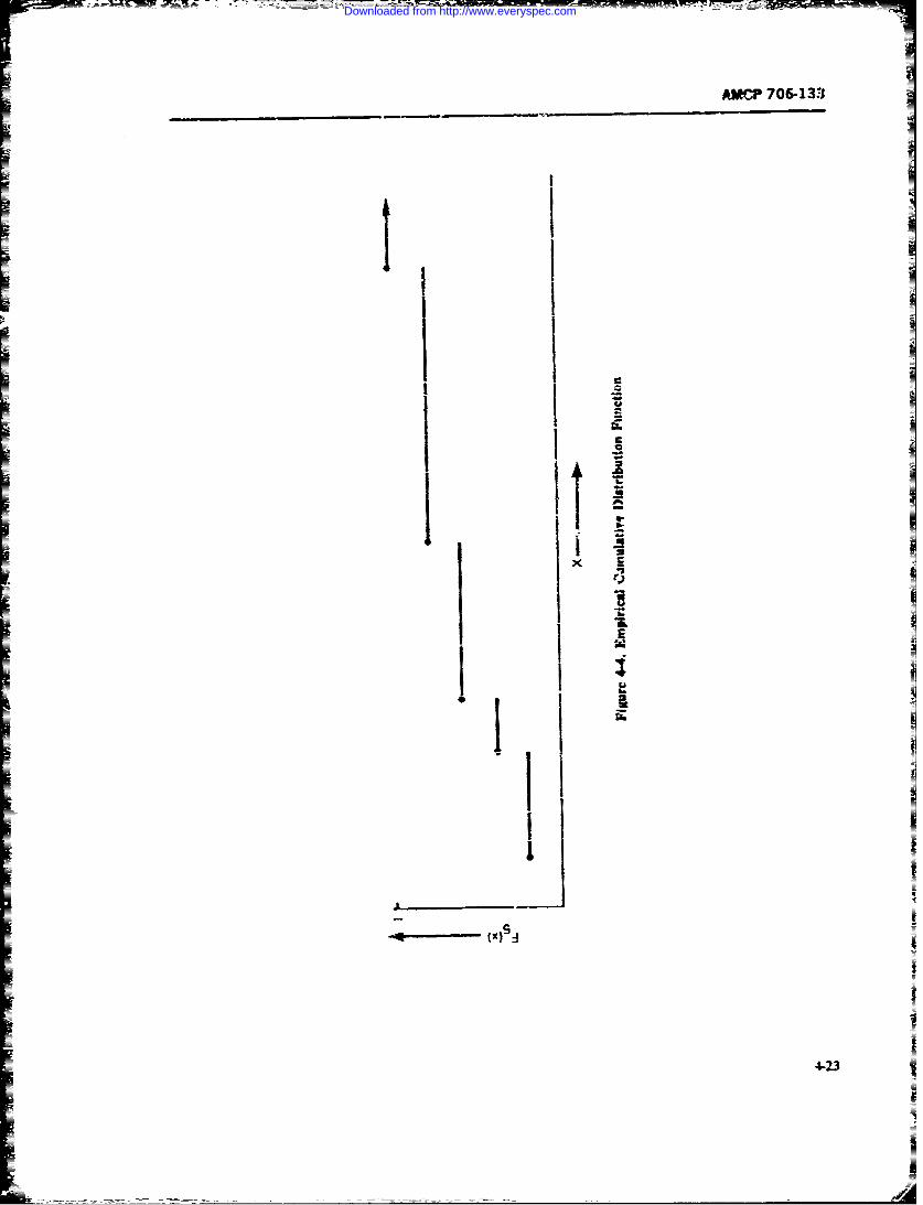
-
AMGP 706-135
IIInIC
2I
iix U
UI-
I AA.I I;* I
U
-Ii____I-]_____________ S
4-2~3
'I
Downloaded from http://www.everyspec.com
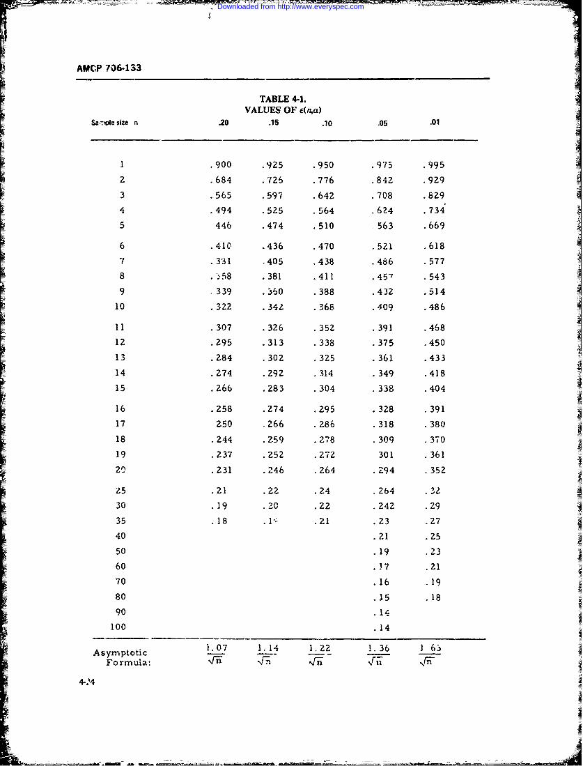
AMCP 706-133
TABLE 4-1.VALUES OF c(Na)
S2.-.ple size n 20 .15 .10 .05 .01
S.900 .925 .950 .975 .995
. 684 .726 .776 .842 .929
3 .565 .597 .642 .708 .829
4 .494 .525 .564 .624 .734'
5 446 .474 .510 563 .669
6 .410 .436 .470 .521 .618
7 .3131 .405 .438 .486 .577
8 . ,58 .381 .411 .45-/ .543
9 .339 .360 .388 .432 .51410 .322 .342 .368 .409 .486
11 .307 .326 .352 .391 .468
12 .295 .313 .338 .375 .450
13 .284 .302 .325 .361 .433
14 .274 .292 .314 .349 .418
15 .266 .283 .304 .338 .404
16 .258 .274 .295 .328 .391
17 250 .266 .286 .318 .380
18 .244 .259 .278 .309 .370
19 .237 .252 .272 301 .361
20.231 .246 .264 .294 .352
Z5 .21 .22 .24 .264 32
30 .19 .20 .22 .242 .2935 .18 .l .21 .23 .27
40 .21 .25
50 19 .23
60 )7 .21
70 16 19
80 15 18
90 14
100 14
Asy.ptotic i.07 1. 14 1.22 1.36 ] 63
Formula: %rn4 NIn I.n
4-.4
Downloaded from http://www.everyspec.com
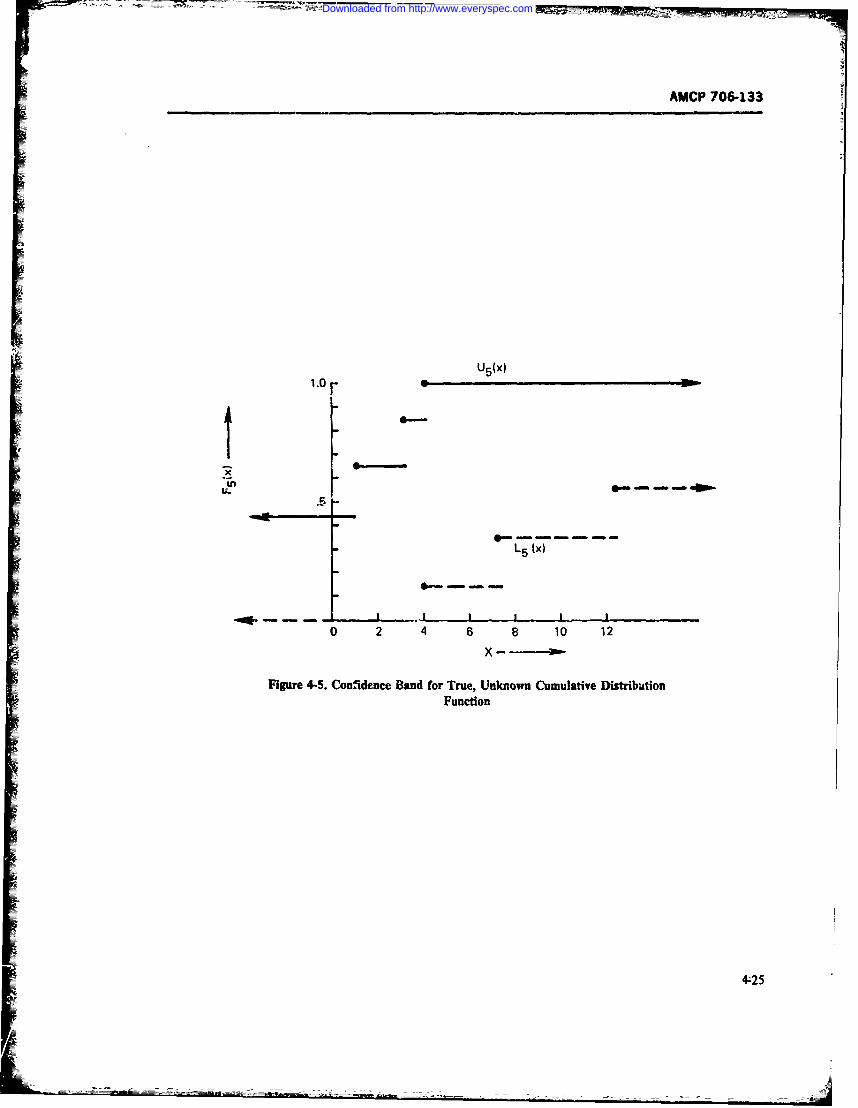
AMCP 706-133
U5 (x)
xL rU-
L5 (x)
I I I
0 2 4 6 8 10 12
x-
Figure 4-5. Confidence Band for True, Unknown Cumulative DistributionFunction
4 25
Downloaded from http://www.everyspec.com
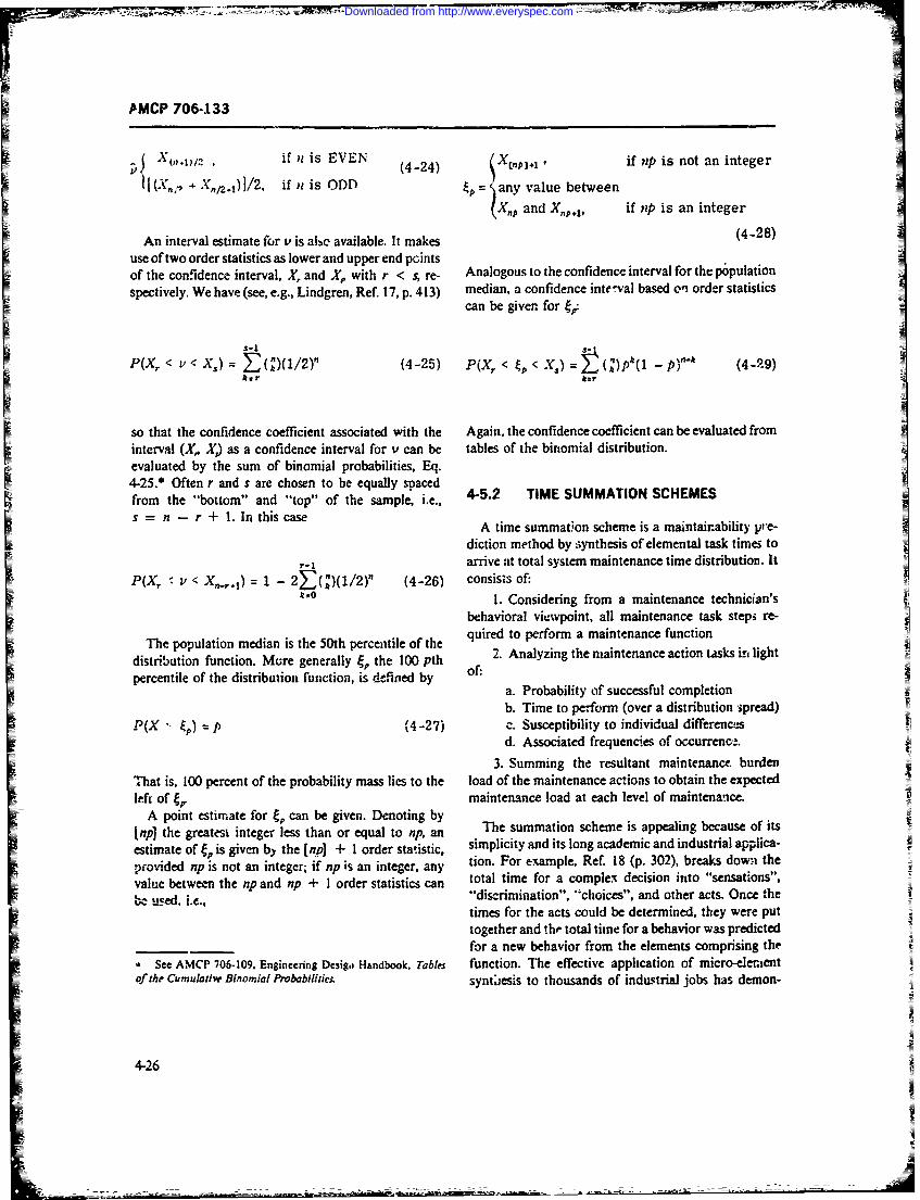
AMCP 706-133
. 0"\',D ' if n is EVEN Xi i snta neev. ~~~~~~~ ~~(4-24)Xtp.,ifpisntaiter
I (X,, + X,/. 1) 1/2, if n is ODD = any value between
SX., and X.,,., , if np is an integer
An interval estimate for v is albe available. It makes (4-28)
use of two order statistics as lower and upper end pointsof the confidence interval, X, and X,, with r < s, re- Analogous to the confidence interval for the population
spectively. We have (see, e.g., Lindgren, Ref. 17, p. 413) median, a confidence inteval based oni order statisticscan be giver for gr:
P(X< v ()(1/2)" (4-25) P(Xr < p< X) ()pt(1 p)'" (4-99)r
so that the confidence coefficient associated with the Again, the confidence coefficient can be evaluated frominterval (X,. X) as a confidence interval for v can be tables of the binomial distribution.evaluated by the sum of binomial probabilities, Eq.4-25.* Often r and s are chosen to be equally spacedfrom the "bottom" and "top" of the sample, i.e., 4-5.2 TIME SUMMATION SCHEMES
s =n - r + l. InthiscaseA time summat;on scheme is a maintainability pre-
diction method by synthesis of elemental task time5 to- ~ arrive at total system maintenance time distribution. It
P(X v < -,,,..) 1 2F(")(1/2)" (4-26) consists of:kso I. Considering from a maintenance technician's
behavioral viewpoint, all maintenance task steps re-
The population median is the 50th percentile of the quired to perform a maintenance function
distribution function. More generally /j the 100 pth 2. Analyzing the maintenance action tsks in lightpercentile of the distribution function, is defined by of:
a. Probability of successful completionb. Time to perform (over a distribution ,spread)
P(X " ) p (4-27) c. Susceptibility to individual differencesd. Associated frequencies of occurreno.
3. Summing the resultant maintenance burdenThat is, 100 percent of the probability mass lies to the load of the maintenance actions to obtain the expectedleft of 4, maintenance load at each level of maintenance.
A point estimate for e, can be given. Denoting by[np] the greatest integer less than or equal to np, an The summation scheme is appealing because of its
estimate of t; is given by the [tnp] + I order statistic, simplicity and its long academic and industrial applica-
provided tip is not an integer; if np is an integer, any tion. For example. Ref. 18 (p. 302), breaks down the
value between the np and ip + I order statistics can total time for a complex decision into "sensations",
,, used. i.e., "discrimination", "choices", and other acts. Once thetimes for the acts could be determined, they were puttogether and the total time for a behavior was predictedfor a new behavior from the elements comprising the
' See AMCP 706-109. Engineering Dcsigo Handbook. Tables function. The effective application of micro-elementof the Cumulative Binomial Probabilitie. syntiesis to thousands of industrial jobs has demon-
4-26
Downloaded from http://www.everyspec.com
AMCP 706-133
strated the practical power of time synthesis modeling f = frequency of the sub-element(Ref. 5, p. 35). This time summation synthesis has been task.applied to military maintenance behavioral tasks, as This basic formula presently is used in all predictionshown, for example, n the four developed techniques summation processes (not necessarily using the sameshown in MIL-HDBK-472 (Ref. 3). symbols as shown). There is no single assigned time to
The following basic maintainability engineering tools perform a maintenance task; the times vary in propor-must be utilized in summation synthesis: tion to the complexity of the tasks. Thetefore, in the
1. Functional flow block diagrams summation the time used is an average or meer of t2. Functional level systcm breakdown charts distribution of times; a simple. routine or automatic
I- Ftask involves a small deviation and can be assumed to3. Reliability failure modes, effects, criticality, and follow a normal distribution, while a complex task
detection analysis (diagnosis) may follow a skewed distribut.ion, such as
4. Maintenance concept-plan maintenance func- lognormal. For example, there is no "common mainte-tion breakdown (what, where, how, why, and when nance man"; the common man is an average man fromfactors for maintenance). the distribution of a given populatien of technicians.
When these fundamental factors have been correlated Time to perform a maintenance step, time to poformwith the requirements for the system operational per- a series of steps which omprise a maintenance func-f~rmane (mission-primary and scondary€) the use of tion, and time to perform a series of maintence func-thetime amsmmionprimary s ntismetodloy egis. tic.A s which. comprise system time are summations ofthe time a summation synthsisthe mean times of th various distributics involved,
Using the summation process to determine the main- here te o te s dienc lve ,teniance task load, one can start either with the system weetedsrbto yecni.nelvlrss
tenace askload on ca stat ethe wit th sytem variances, standard deviatior-, median times at the 50thoperational maintainability goals/objectives and apply vercee and m axi m times at tie canthe time sumn,ation process in reverse, i.e., from the percentile. and maximum times at given percentiles can
system down to the lowest maintenane level equip~t- be determined at each level of a series. These lattermenit breakdown allcation (, hrow-away part or some determinations are made using the principles cited inytem owent tee aloesti(thawce level o equip- Chapter 8 and the nonparametric methods cited in par.
et bco n ldesired a. s t lup o equip- 4-5.1.3. The same principles apply in the developmentter level, of the regression analyses used to relate maintenance
The accepted key factors used to define the mainte- action times to equipment and human characteristics.
nance burden load are: In all cases the time factors a.e associated with andbased upon the characteristics of design, support equip-
I. Time to perform a maintenance task ment, and human factors. In some cases, regression2. Frequency of the task analysis and design cLecklists are correlated to arrive3. Probability of completing the task at the time summation factors. In other cases, the
4. Standard deviation (variance) and confidence regression analysis is combined with functional analy-level of the task performance sis of equipment maintenancz tasks to define the time-
5. Effects of the related maintainability qualitaive synthesis modeling. In all cases, historical datp and/ordsign characteristics and associated qualitative-quart- selected observations of maintenance function activitytitative behavioral characteristics of mainteatance tech- on existing equipment are used to define the time and
nicians. frequency data for the synthesis 3ummations of newlydeveloped equipment or to improve the maintainability
The basic summation elements are expressti: ,-aalitative characteristics and the quantitative timeand frequency fa-:tors. In most cases, the developedsynthesis is used to justify decisions.
.Ti = M, .f/'f, (4-30) MIL-HDBK-472 (Ref. 3) describes four prediction'_- ' 'ti"' methods i. ase: the procedural steps, application, and
limitation of the ARINC approach (see Re. 19, fordetails upon ;vhich Procedure I is based); the Federal
where Electric -.heme (see Ref. 20 for details of the studyM, = mean time o, a higher level upon which Procedure II is basei); the RCA scheme
breakdown task function (see Ref. 21, for details on which Procedure III isM, = mean time of a sub-element based); The Republic Aviation/Fairchild Hiller devel-
maintenance task opment (see Ref. 22, for details upon which Procedure
4-27
Downloaded from http://www.everyspec.com
-m _____________
AMCP 706-133
IV is based). These methods are discussed in the mates based on known characteristics of the systemliterature-Ref. 23 discusses in summary form the vari- being developed. Method B includes mathematical for-ous prediction techniques used in MIL-HDBK-472; mulation for both corrective and preventive mainte-Re'. 5 discusses the variou maintainability prediction nance summations of the mean times. Method A doesmethods and results of the MIL-HDBK-472 evaluation not give adequate recognition of what effect the newiyas well as the extrapolation, time summation, checklist, designed features may have on mean time to repairsimulation, expert iudgment, and the matrix tabulation Both methods use -he seven maintenance action sum-
schemes; Rei. 24 dis:usses the four MIL-HDBK-472 mation steps, and system functional level breakdown inprediction methods as well as interim approaches and developing the tasks which determine the next higherfollow-un studies. Further, Ref. 25 gives details of the level maintenance time. In order to use Method A intel-corrcctive mainterance border procedure, Ref. 26 dc- ligently, one must verify the times by comparison withscribes the Muager. Willis checklist scheme for predict- existing. or similar, equipment. The diagnostic tasking maintainability featare characterisvics, and Ref. 27 valiables are of prime importance ii, use of tir.es fordescribes the TEAM technique for evaluation and anal- determining a new equipment maintainability; suchysis of maintainability, analysis %hould encompass the many complications in-
The purpose of this subparagraph is to outline the volved in justifying modifications and exceptions. Theadvantages, disadvantages, limitations, and assump- analyst, in using this method, should develop tablestions of some important methods of predicting main- with vartan..es for the equipment of concern (- ef. 5, p.tainability and to orient the analyst in their use. It is 36; Ref. 23, p. 21; and Ref. 24. p. 14). Jthen up to the analyst to develop a ..iethodology to suit 2. Corrective Maintenance Burden Predictionthe equipment of particular concern. As brought out in Technique. This method (Ref. 25) utilizes the tech-Rcfs. 3, 23, and 24, there is no mandatory method, and niques of Method A of the Federal Electric schemeeach approach chosen by an analyst need not be con- with its limitations, advantages, and disLdvantages.fined to a single scheme. The underlying pnnciple is with the exception ti.at the original seven maintenancethat the analyst must know and understand the type of category steps have been extended to thirt en by ex-equipment and its associated characteristics, the mis- panding the fault isolation and localization steps. Insion, the support objectives and the environment. He addition, consideration of the skill and knowledgemust develop a technique that is based on the historical needed for the thirteen steps is included. Maintenancedata available for the type of equipment of concern, requirements are correlated with the formal categoriesThese backisp data provide justification for the time of available technician qualifications, training require-and frequency factors used in the prediction methodol- meits, and associated times. Thus one achieves ulti-ogy, the mathematical models, and the associated mate trade-offs of training need and equipment com-qualitative factors and rgrssion analyses tha' best fit plexity. Unfortunately, the procedures for relating taskhis adaptations, In all cases, the selected method must difficulty to technician proficienc) are rot penetratingrelate to the mainta;nability characteristics designed enough to be valid. The techniqLe 6 pends upon the.nio the equ'pment, the charaLteristicr of thei.;c.rated use of the fundamental maintainabilt\ analytiallogistic support equipment and associated maintenance tools-such as functional flop, block diagma-ns, func-concept-plan and the maintenance and supervisory per- tional level equipment breakdown. mainterance con-sonnel skill :evels available. A discussion of the impor- cept, the failure modes, effects. criticality ,.nalysis. andtant methods follows. associated fault tree logic networks (Ref. 5. p. 45).
1. Federal Electric Scheme (Procedure I1. MIL- 3. ARINC Scheme (Procedure I. MIL-HDBK-.'IDBK-472) The two methods of predicting maintain- 472). This prediction method concerns itself with pre-ability given are for ship-based and shore-based electric dicting system downtime resulting from unscheduledsystem-. Method A predicts mean time to repair (corrective) flight-line maintenance of airborne elec-(4fTTR) for corrective maintenance only, using tabu- tronic and electromechanical systems insolving modu-lated maintenance task times based on 300 observations lar type repl.cement. Flight-line maintenance is di-of maintenance activity in the US Fleet in,. ian of vided into six "Maintenance Categones" The buildingindividual repairs is expressed by spec!fic mate..nance block method is used (Elemental ActivitN) from whichformulations for vanous types of distributtans (namely, other measures of downtime are deseloped th oughnormal, exponential, and lognormal). Method B pre- synthesis o'time distribution. For each of the elementaldiets mean time in terms of man-hours required to activities the mean and standard drcvia:ion aidperform the maintenance tasks, allowing for time esti- probabilities are calculated. A pros ison for estimating
4-28
_
Downloaded from http://www.everyspec.com
AMCP 703-133
logistic delays is given. The synthesis fo.mulation re- facilities, a-sistance from cher perso)nnel. external sup-suited fromn observing many trials in order to calculate port equipment, etc.the mean time and standard d,.viatiun. The elemental c. iMaintenance skill time factors through the useactivity i; directly related to the six maintenance ot a regression analysis (mathematical model) of thecategories. The model is statistically sophisticated, and effe--ts of observed mantenance actions on the qualita-considers the distribution characteristics of the various tive tactors.related phenomena: the chain of inferences from as- The reserch u:ilized a multi )re correlation ap-sumption through sampling :o final probability state- pror-h, where mainte.ance time (appropriately delin-ments appears clear. The philosophy of prediction tech- eated) is the crit-rion that relates the three qualitativeniques is based upon the principles of synthesis and parameters. The data were b.'sed on corrective mainte-transferability, nmnce actions observtA on grond electronics equip-
ment at three selccted Air Force oases. A total of moreAltho, th the meth.d is applicable to flight-line (or- than onc "tundred events were monitored over an ex-
ganizational level) maintenance, it may also be used for tended peiod. Although the re& !ssion model developedinterinediate and depot levels by extending the for- was a result of gathering data a specific type ofmulas to include other elemental units. The niethod !- equipment at selected site. cf the total population, itogy :ends itself to computer modeling -irrulation. As does clearly demonstrate the u .""iness of such a pre-presently formulated, however, it Joes not lend itself to "iction technique. If new equitrment is being developedtaking major improved maintainability features into to replace similar deployed ecsu, n, nt, ,n technique isaccount for new systems/equipment sunless the elemeus- u2e!uahle in deve!oping a l.stifiable ba is .or the "nes
tal activities for a new system synthesize the systert and certain qualitative featu ic, -.- .---3- ,
upon ,hich the formulas were developed. The princi- equipnt.mLt. When coupled with tote tools of ma;ntair.a-
pal advantage of this method is the fact that inainte- bility anaiysis. the analyst has a meams of basing predic-nance time detern ations are based on time distribu- tioas on !he design characteristics, support factor_ and
ti,w. and not a point estimate (Rd 5, p. 4' Ref. 23, v- skill level requi-ements. Once the need for maintenance
2': and Ref. 24, p. 11). and the main'enance tasks are defined in sufficient de-
4. Munger-Willis Checklist Scheme (Ref. 26). This tail, the tasks are scored and summations made andI 4.Muner- ills Chcklst chem (Rf. 2). his inserted t'-to the regression equation or related uuono-method was a pioreering study in 1959 which selected
241 design features " ith potenti.1 maintainability sia- graph to determine the quantitativc mean times. ifnifi2 nce for Signal Corps equipment. An elaborate desired, the analysis can be carried further and thecentral tendencv and dispersion indices determined.scoring system was used which showed the spread of Checklist scorng must be done objectively to eliminatescores and their related standard deviation The scoringconsidered the specific consequences of a design f"a- optimistic assumptions regarding control of theture. The method provides sensitivity to the differing qualitative facmors during design and production. If theimportance o;f the listed features. From this summation population of problems can be defined with confidence,
of coring. a *maintainability index", or checklist, is the checksts method produces excellent forecasts. Thedeveloped. A fundamental problem of this checklist, as methaisobas ed o the "mepair by mplac ci-well as any other type of checklist, is the weighting ple and the associated steps to dhefrmine the replacea-factor of an individual item. It is vey difficult to allot nbe item and checkout repair; therefore, the analysisquantitative weights to the attributes nd pr vide con- can be caried out at any level of maintenance in avincing justification. In favor of the checklist i.; the fact functional level item b;eakdown of the system (Ref. 5.that it prevides a basis for time estimates once the p. 65: Ref. 23, p. 2i. and Ref. 24, p. 17).complex qualitative relationships of th, design features 6. Republic Aviation/Fairchild Hil:.r Scheme
and the technical skill requirements are known (Ref. 5, (Procedure IV. MIL-HDBK-472). This prediction
p. 63). method is based on historical experience. subjecii'-eevaluaticn, expert judgment. and secotiv,. -neasure-
5. RCA Checklist and Prediction Scheme (Proce-ment to predict downtime of a system. It was developed
one of the bst proc- dures developed. It Mates in the late 1950s using data from an aircraft sytem asthe basis for prediction It was one off he ft,': attempts
a. The qualita.ive design dictate characteristucs of to tie the quahtati'e fc 'ures of maintainability into thesyltem quantitati'e determina;tions. The technique is based on
b. The a-ociated qualitative dest p dictates- an orderl, combiiation of maintenance task times.h-29
Downloaded from http://www.everyspec.com
AMCP 706-:33
through summation, by integratirg the -eds for main- used. Some relate the delay times due to opeationaltenance on the various operational modes and func- readiness and standby, administrative, and/or logistictions involved. The methodology assumes (!at the time times. All methods use or imply the use of the basicdeterminations are made by an analyst working closely tools of maintainability engineering analysis-i.e.,with an equipment designer !o assure thet task times functional flow block diagrams, functional level break-are practical, realistic, and applicable to the mainte- downs, maintenance concept, and the reliability faiiurenance functions required to support the operational modes, effects, criticality, and detection analysis. Allmodes of the equipment. The method uses Only single methods are based on trends observed in a limited typeelapsed times for each maintenance task which are of equipment. Most methods reveal that the summationequal to the mean times to perform the task under the of mean times follows the lognormaW distribution at therange of operational environmen: factors. higher level summations.
It is evident that the maintainabili!y analyst need notThe method takes into account the inherent main- confine himself to a single method, with the choice
tainability of the system, since administrative and other based on the usefulness of a given m;thod under thedelays are not normally definable during the design of ptticular circumstances of the equipment of interest.the equipment. However, the mathematical formulas A wise choice of method will eliminate the trertain-developed can be extended to include administrative ties involved in the present state of the maintainabilityand logistic times, especially where such factors are prediction art, especially with regard to behavicral facknown from historical data on similar equipmaet and tots of the maintenance technicians. The approach se-logistic environments. The times will vary as a function lected b the analyst will affect the plans for data cal-of the conceptual and physical constraints such as de- lection, --valuation, analysis, and control which aresign features, physical resource support, and opera- essential in justification of the predictions made. Care-tional and maintenance concepts. Such applicable con- ful selection is therefore of the utmost importance.straints must be documented to justify the task timepredictions. The methodology combines corrective and
preventive maintenance at vairious summation levels 4-5.3 SMULATION METHODS(each task being analyzed Eeps' .ately). An innovation inthis method is the conside-Atiok that corrective action By the term "simulation" is meant the use of a modelmay occur during preventive actions and thereby be to capture some aspects of a situation without ex-evaluated as part of the to.a: previntive task times. For periencing the situation itself. Simulation is an impor-example, maintc -tnce-induced faults or malfunction tant tool of designers and decision makers. For exam-may be deferred until preventive action is performed. pie, wittd tunnel :ests of scale models of differentNormally, the frequency of corrective actions is consid- fuselage and airfoil configurations are used to simulatex-ed in the computed action analysis and the failure actual flights of corresponding full-scale aircraft.
rates apportioned accordingly. The use cf the maintain- Changes in the conAguration of the scale model areability analytical tools mentioned pre-'iously is tsg ntial easy and inexpensive to make (if not absolutely, thenfor this method (Ref. 23). certainly relative to making similar changes in an ac-
In summary, the basic technique used by all me- :ual aircraft), and thus a number of alternative config-thodologies is the summation synthesis o? tu-ne (mean rations can be considered and the best design from/average) to perform maintenance task, muftipliod by among the available choices can be identified.the frequency of maintenance action (need fcr mainte- The example that follows contains the essentials of anance). Such summations are based upon the step; to simulation. Given a model of same real situation, thebe performed for each action for a maintrantc func- designer or decision maker has under hi.. control cer-tion at each level of maintenance activty for the respec- lain factors or inputs. Other factors or inputs aretive functional level breakdown of a system. Th meth- beyond his control. For each set of inputs (controllableods var; with regard to the relation of the maintenance and uncontrollable). there results a response or output.task to the system functional level breakdon, and :he This output is translated into a measure of r -n-equipment design characteristics, and behavioral fa- ance Thus, it is possible to re)ate values of the cozn,tots, and the factors of the integrated logi-tic life cycle. abe inputs to values of some mcasure of per'ornanMost methods utilize rgression analysr. to relate th,, Having this relationship. one can det.rmine the .p--Aserved data, the extrapelations. and experiiece judg- timum inputs, i.. those inputs from among the set ofnoent factors on scoring of the design checklists. All allowable input- which yield the best measure of per.mn. "hods suggest or infer the type of distribution to be formance.
4-30
Downloaded from http://www.everyspec.com
AMCP 706-133
Much of thc iiscussion that follows concerning the of the large amount of computing ordinarily requiredmerits o' a simulatior approach in comparison with in a simulation.puresy m-qthematical methods is either taken directly erparaphrased from Hillier and Lieberman, Ref. 28, 4-5.3.1 Random Variates for SiwlationsChap. 14 Random variatEs arise as inputs in maintainability
If it is pessible to construct a mathemritical model simulations in modeling time-to-failure and repair
which abstracts the essence of a real situation, reveals time. More complicated models may also entail ran-its underlying structure, provides insights into cause- dora variates involved with delays due to limited re-and-effect r-Jationships, and is Amenable to solution, sources of manpower, repair parts, maintenance equip-
then the analytical approach is usually superior to sim- ment, faciliti-s, etc. These r-ndom variates must beulation. However, mny problems are so complex that selected from appropriate, completely specified distri-they cannot be solved analytically, and simulation is bution functions.the cmily practical approach. We will presently give a brief discussion of how rar-
While the wind t .-nel example is a physical simula- dom variates from prescribed distributions can be gene-tion, most operations research-type sirhulations (in rated on a computer. First, we refer the reader back towhich ara many maintainability analyses could be said par. 4-5.1.2 in which we gave a brief discussion of howto fal) 2re mathematical in nature. Such simulation one might select a particular distribution to describemodels describe the operation of systems in terms of some random variates. This, of course is not at allindividual events that their components experience. In definitive. The choice of a distrihution function Cor aa simulatior model the system under study is parti- random vari:r!.e is an area in which jidgment, exper-tioned into elements or subsystems whose behavior can tise, experience, and statistical methodology can all bebe predicted (at least probabilistically) for each possible brought to bear. As these kinds of choices determinestate of the system and its inputs. The interactions and some of the inputs to a simulation, they also influenceinterrelktions among these dements are also built into the outcome of the simulation experiment. One cannott: t model. Thus, :.imulation provides a way of dividing say a priori how sensitive the results are to the input.the model-buildingjob into, smaller units and then com- In some cases the influence of the input on the outputbiaing them appropriately -o that interactions are will be substantial; in other cases ther, w.il be littleproperly represented. clange in th- output over a considerable range of varia-
When a 3imulation moiel has been constructed, it is tion of the input. In any given simulation, one ought toaLtivated ("run") and the actual operation of the proto- make an analysis of the sensitivity of the experimintaltype system is simulated. This requires that input data results (i.e., the output) to variations in the inputs. Thisbe supplied to the model, and that the output of the will reveal how crucial the inputs are to the outputs. Ifmodel be recorded. In some instances there may be a particular input can be considerably varied withoutinterest in certain of the inner workings of the model changing the output more than a limited amount (ex-so that system states intermediate to input and output pressed either as an absolute or a relative change), thenmust be recorded as well. By repeating this for the perhaps less attention needs to be paid to the spc-ifica-various system configurations under consideration and tion of the input than to inputs which affect the outputcomparing their performance, the optimum configura- s:rongly.tion cia be approximated. Because of statistical error,one c&nnot guarantee that the configuration yielding 4-5.3.2 Computer Generation of Randomthe optimum simdated performance has actually bee Variatesfo.md. But, if the simulation was properly run, the All computer generation ofrandom variabler beginsresult ought to be near optimum. from the eins
Thus, simulation is essentially a form of random with uniform random variabl
sampling experiment on the model of a system. Tht Such a random variate u has probability density Vr-
experimentation is done on the model rather than the tion
system itself, bem,.use the latter would be too inconven-ient, expensive, time-consuming, or usafe. in some (1. 0 . (4-31)institcms, the system being modeled does not yet exist; . =0. elsewherethe stmtlation is performed as an aid to proper systemdesign.) Most often simulation experiments are per-formed en a computer. This is not for any inherent and are themselves produced by a computer process.superiority of compuzer techniques but rather because Eiery conipute ..enter will have a routine which pro-
4-3 1
Downloaded from http://www.everyspec.com
AMCP 706-133
vides such uniform randon, va.-iates. These routines are u F(x) for x, one obtains(34typicauly called random numbe-r generators. The casualitser has no need to know how these work, so we con- X=-(1A) ln (1 - 1)tex.! ourselves with citing the papet by Mactare.-t~lnd
Marsaglia (Ref. 29) and Chap. 3 of Naylor, et al. (Ref.3)frtoewown odleiy hi ne ok Random variables taking on only discree values,
ings.instead of a continuum of values, itre obtained ini ain ad-"io tocmuer schemes for producing ra- similar manner. A slight modification iaust be made,
dcm numbers, there are available tables of such ra hwvrn-cuete uilt~edsrbtinfmtov. dam numbers. The most famous and comprehensive of for discrete random variables is not strictly incrasin&~
these was produced by the RAND Corporation (Ref. but consists of a series of horizontal segments ((cften31). The introd,ction to the RAND tabulation de called a "steP" function). Fig. 4-7 is a representattion ofscribes how the random numbers were produced and a typical cumnulative distribution function for a discrategives instructions concerning the use of the tables ndmvral.Weoeetesnthvriclxi
With a uniform randc-m variate u. one can obtain a at 5 random level 14he is unlikely to intersec any ofrandom variate x, having a striciy increasing cumula- the horizontal segments. (Indeed, such an intersectica Ative distribution function 9Yx) by solving the equation occurs with probability zero.) Thus, instead of solving
the equation x = F -'(), one selects thea smallest xfor which 1(x) : u.
uF(x) (4.) Tis procedure is illustrated in Fig. 4-8. There u is(4-32)) the (uniform) randonia number that was selected and.
P(O for that value of it, the corresponding value of x isxj-
The method of generating random variates- from spe-This follo-ws from the fact (!%ec, e.g.. Lindgren, Ref. 17, cific probability distributions via the invers of thep. 408 or Naylor, et al., Ref. 30, p. 70), that if x is a cumulative distribution function (the method just de-randcrn variabic with cumulative distribution function scribed) is completely gen, ral. It will always "work'.F. then R.x) has the uniform distribution on the unit However, this does not m-'an that it is always the most
interval, efficient method. The generation of random variates
terms oltwl eillustrated first graphically and then cheaply (in the sense of amount of computer time perAalgbracaly. rapicaly asshon i Fi. 46,one random variate) by taking account of the special char-
enters th rp ttepoint u on the vertical axis, acteristics of the distribution at hand. We will not pur-proceeds horizontally to the cumulative distribution suc this here, but will refer the reader to Chap. 4 offunction curv-. drops vertically down Z,- the horizontal Naylor, et al.. Ref. 30 (and the bibliography thereto) foraxis, and th?-u reads off the value x The ilgure shows a very good discussion.a distribution function for a random variable which cantake on negative as well as positive values. Most ran- 4-5.3.3 Exampledom variables encountered in maintainability analysisare non-negative, typically, being times measured from Wewlcosthsprgahihanxa lefaa reference point until an c-,'-nt occurs (e.g.. failure. -szmuzation used to evaluate some alter-native mainte-repairs). rance policies for a series of hi~4i-presslre injection
Now to an algebraic example. Suppose one wants to t~mps. (This example is taken from Bowman and Fet-generate random variates from an exponential distribu- tr :'3,p.464 )tion with failure rate X. The cumulative distribution c~ c' -, company hrs a series of high-pressure
funtio isinjec-:,* -t pumps operating under similar conditions andwi.lI. _ t-) determine a proper maintenance policy. Thepumaj valves are subjiet- to failure, and their routine
0 X < 0maintenance costs about 9,500 mawj-hours per y,.ar.F(Y) 4-33 Each pump has three intake va~ves and three exhaust
*Ad~pfcd with per..isson fron lfowrmn and Fetter. 4i!}mifo:- rd:h and Oprrvd.anoMagrmnt 3rd ed.; Homewoodf,
Solving Eq. 4-33 for Ill. Richrd D Irwin. Inc.. Mp 426-31.
4-32
Downloaded from http://www.everyspec.com
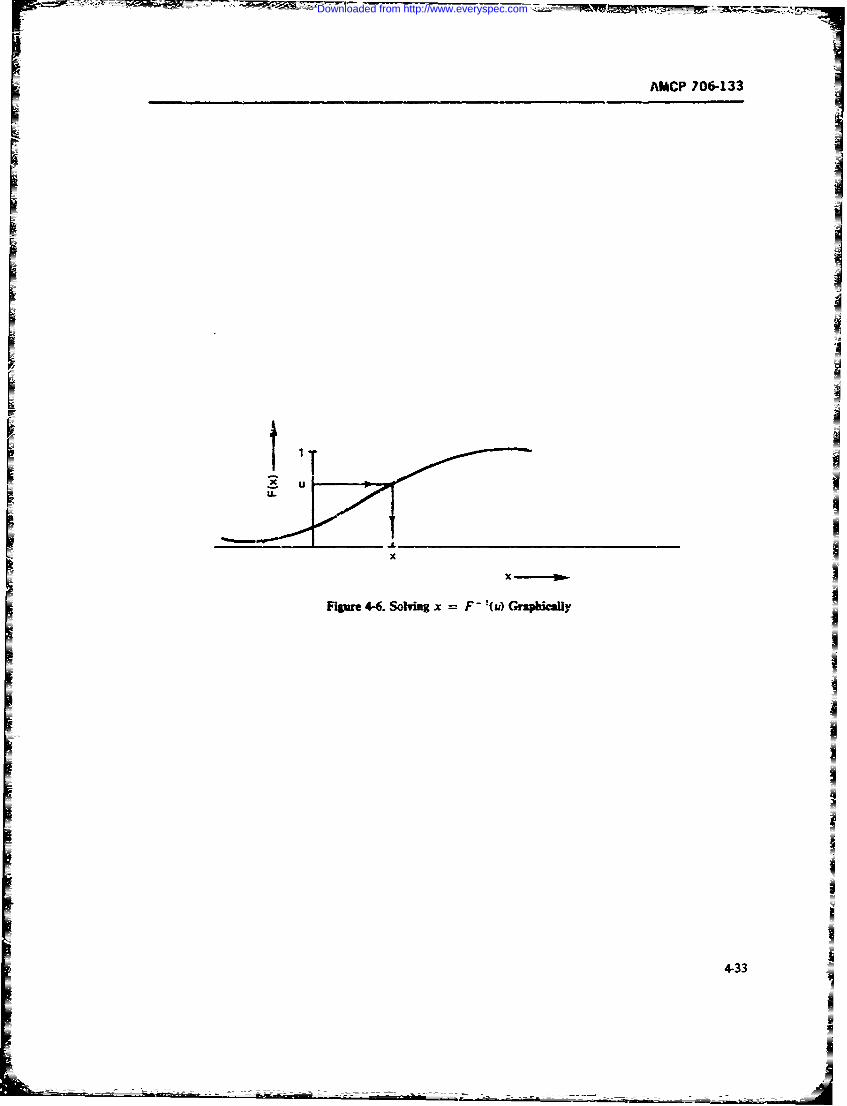
MCP 706-133
xx
Fgur 4-6. Solving x F 1 (u) GriphicalY
4-33
Downloaded from http://www.everyspec.com
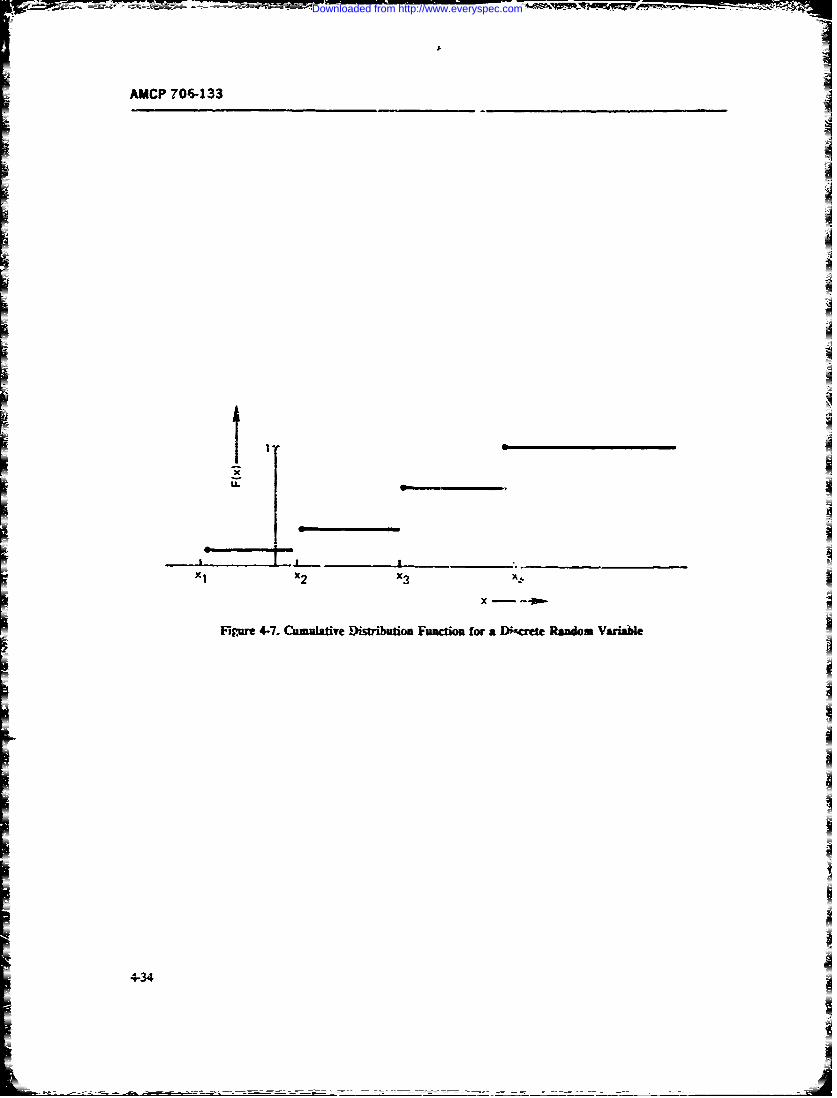
AMCP 706-133
<1x2 x3 X..
FP__M- 4-7. Cum__ Distnbutio Function for a __e Random Variale
4-34
I
Downloaded from http://www.everyspec.com
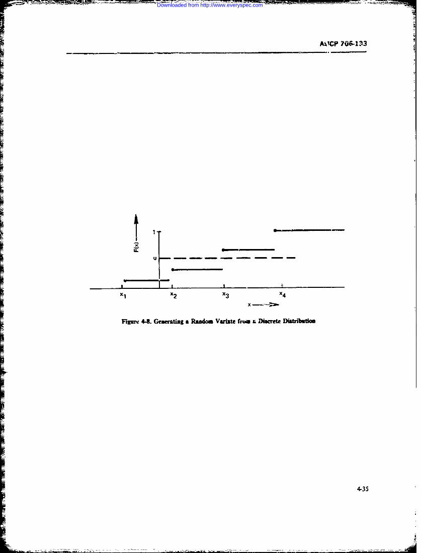
A,14P 706-133
EU
Xix 3xIxIqft4LGwsm admVtt rmr urt itW
U-A
Downloaded from http://www.everyspec.com
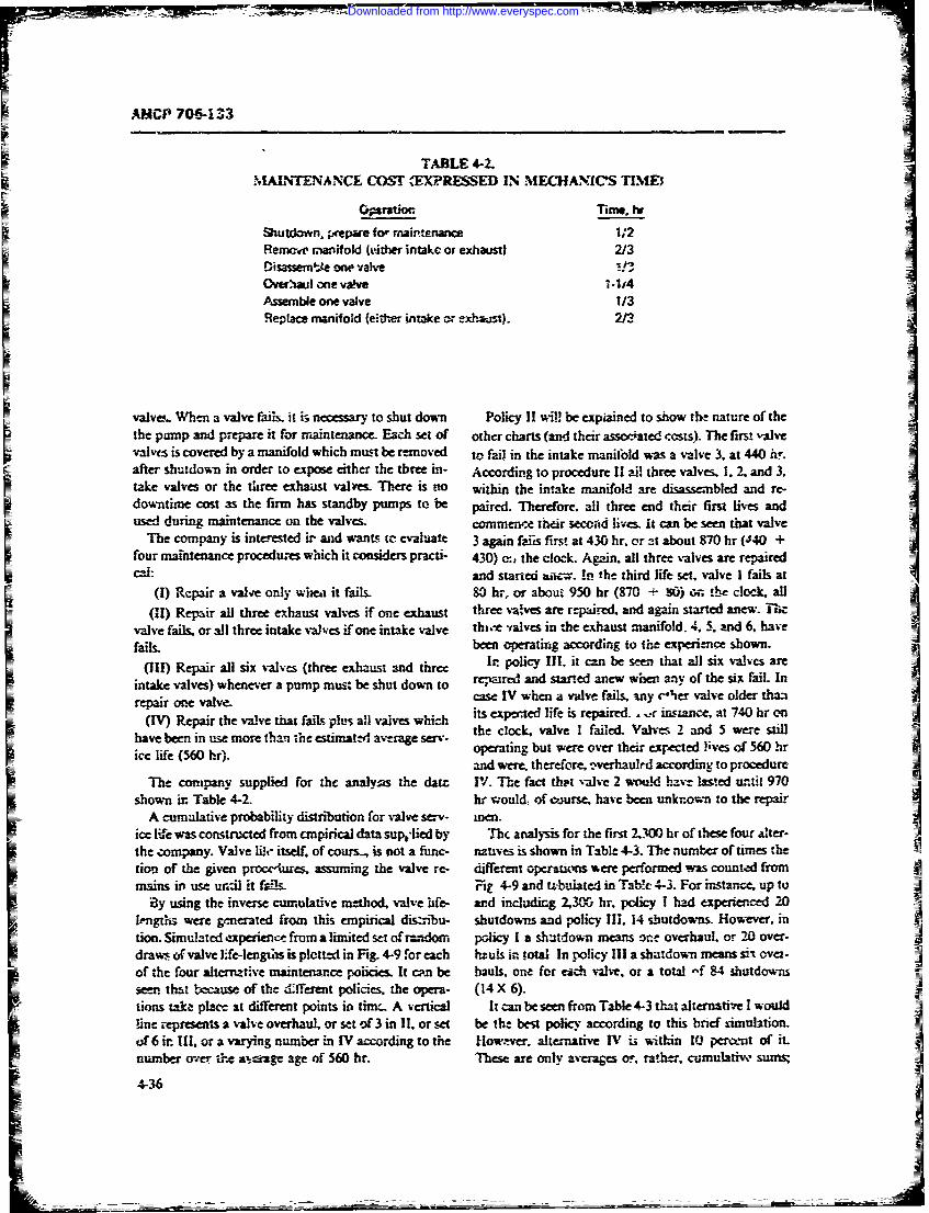
AMCP 70C-133
TABLE 4-2.MAINTENANCE COS ,EXPRESSED IN MECHANICS TIME)
Oration. Time, hr
Shutdown, repare fo- maintenance 1,2Remen manifold (either intake or exhaust) 2/3Disassemmte we valveOverhaul one valve l-1'4A-ssemble one valve 1/3Replace manifold (either intake or exhaust). 2/3
valva. When a valve fails. it is necessary to shut down Policy II will be expiained to show the nature of thethe pump and prepare it for maintenance. Each set of other charts (and their assoc'ated costs). The first valvevalves is covered by a manifold which must be removed to fail in the intake manifold was a valve 3. at 440 hr.after shutdown in order to expose either the three in- According to procedure II all three valves. 1. 2. and 3.take valves or the three exhaust valves. There is -no wthin the intake manifold are disassembled and re-
downtime cost as the firm has standby pumps to be paired. Therefore, all three end their first lives andused durina maintenance on the valves. cormene their secead lives. it can be seen that valve
The company is interested ir and wants, t evaluate 3 again faiis first at 430 hr. or at about 870 hr (40 +four maintenance procedures which it considers practi- 430) a, the clock. Again. all three valves are repairedc..i: and started atc.-. In the third life set. valve I fails at
(I) Repair a valve only whea it fails. 80 hr, or about 950 hr (870 + W) o.0n Lhe clock, all(U1) Repair all three exhaust valvs if one exhaust three valves are repaired., and again started anew. Thc
valve fails, or all three intake valves if one intake valve thwe valves in the exhaust manifold. 4, 5. and 6. havefails. been operating according to the experience shown.
(II) Repair al six valves (three exhaust and th: I. policy Ill. it can be see that all six valves are
intake valves) wheneer a pump mus, be shut down to repared and started anew when ay of the six fail- Inrepair one valve- case IV when a valve fails, any cher valve older than
(IV) Repair the valve that fail us all valves which its expected life is repaired., .r insane, at 740 hrshave been in use more than the estimated average se v . the clock, valve I failed. Vals 2 and 5 were stillice life (560 hr,. operating but wre over their expected lives of 560 hr
and were. therefore, -verhaulrd according to procedureThe company supplied for the analy as the dart IV. The fact that valve 2 wuld have lasted until 970
shown in Table 4-2. hr wjould, of ojumrse, have been unknown to the repairA cumulative probability distribution for valve serv- men.
ice l;.e was construted from e.mpirica data sups~lied by Th!c analysis for the first _7300 hr of thee four alter-
the company. Valve Ifet " itself of cours, is not a func- natives is shown in Table 4-3. The number of times thetiom of the given proc,'ture. assuming the valve re- differet operatins ere peformed was counted frommains in use unt-il ft fais r 4-9 and t alted in Tab- 4-3. For intrw- up to
By using the inverse cumulative method, valve life- and including 2,300 hr, policy I had experi-ced 20length were gcnerated from this empirical dis.rinbu- shutdowns and policy Ill. 14 shutdowns. Howe-vr. intion. Simulated experience from a limited set ofrmadom policy I a shutdown means one overhaul, or 20 over-draw ovalve life-lengtsis plotted in Fig. 4-9 for each haulsir i ot In policy IIIa shutdown meanssnov- 4of the four alternative maintewnce policies. It c'n be hauls, one for each valve, or a total -f 84 hutdownssewn that because of the d:ffeet policies. the opera- (14 X 6).tions take place at different points in timt. A vertical It can be seen from Table 4-3 that alternative I would!ine represents a valve overhaul, or set of 3 in II, or -t be the best policy according to this brief Aimulation.of 6 ir 11, or a varying number in IV according to the fo.-ver. alternative IV i3 within I0 pecent of it.number o-er t-e na-p- age of 560 hr. These are only averages or, rather. cumulative' sums;
2-36
Downloaded from http://www.everyspec.com
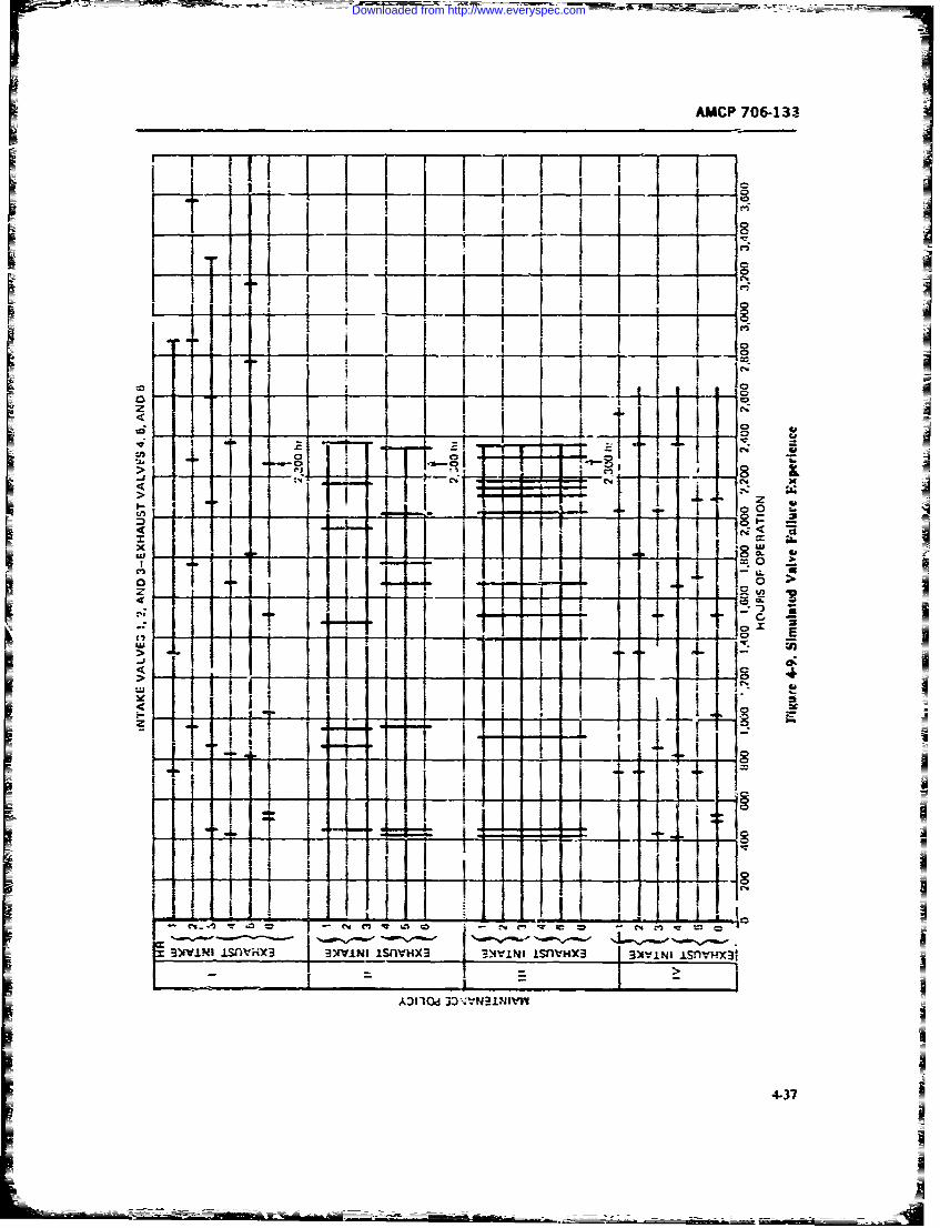
AMCP 706-133
1~.~ I 0
TI~f f-I-
m- ,% vj -. m
I0 Q r
3:s.~ lIM fmX33)w.I I i~ V X -)v~ ~ ~ hW3 3[ i~ i -s -H
4I37
Downloaded from http://www.everyspec.com
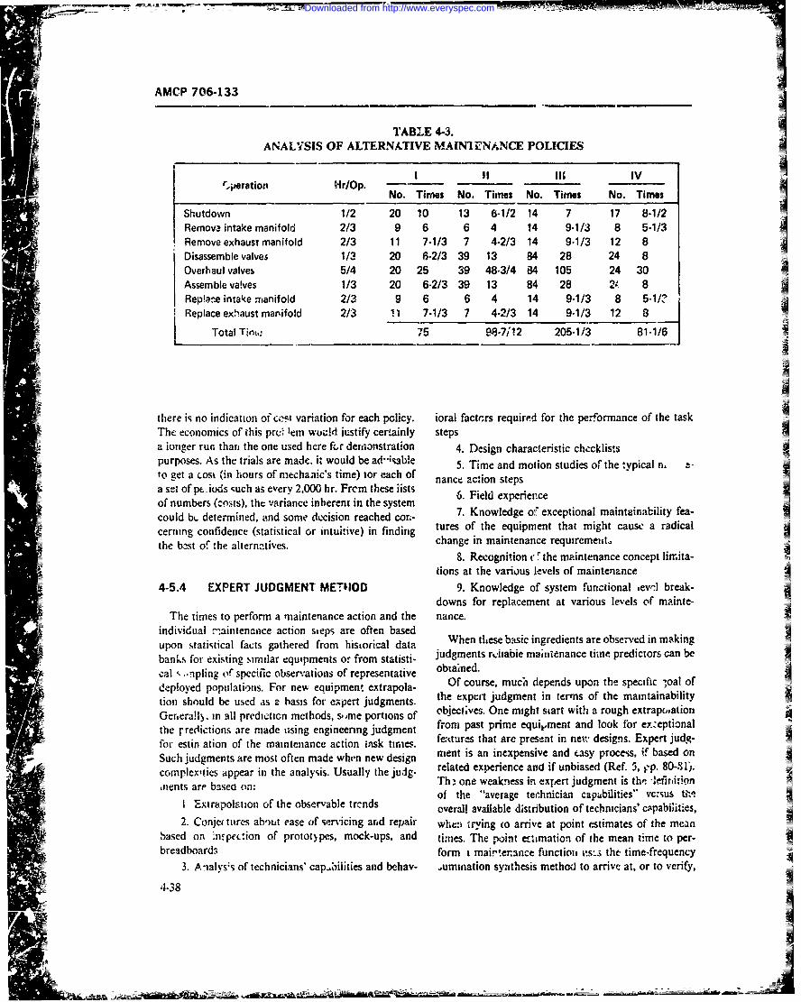
AMCP 706-133
TABI E 4-3.ANALYSIS OF ALTERNATIVE MA[NIENANCE POLICIES
I IIII IV_____________ Hr/_______ __________-~.eainNo. Times No. Times No. Times No. Times
Shutdown 1/2 20 10 13 6-1/2 14 7 17 8-1/2
Remova intake manifold 2/3 9 6 6 4 14 9-1/3 8 5-1/3Remove exhaust manifold 2/3 11 7-1/3 7 4-2/3 14 9-1/3 12 8IDisassemble valves 1/3 20 6-2/3 39 13 84 28 24 8
Overhaul valves 5/4 20 25 39 48-3/4 84 105 24 30
Assemble va!ves 1/3 20 6-2/3 39 13 84 28 1t 8
Rep!a!-e intake manifold 2/3 9 6 6 4 14 9-1/3 8 5-1/?IReplace exh'aust manifold 2/3 11 7-1/3 7 4-2/3 14 9-1/3 12 8 z
Total Tint, 75 98-V;12 205-1/3 81-1/6
there is no indication of co~t variation for each policy. ioral fact'rrs required for the performance of the taskThe economics of this pruO lem wou!4 justify certainly stepsA
a ionger run than, the one used here frr demionstration 4. Design characteristic chc-cklistsIpurposes. As the trials are made. it would be ae-iable 5. Time and motion studies of the :vpical n. tto get a cost k'in hours of mrechanic's time) tor each of nnea~o tpa set of pt .iods 'qucli as every 2,000 hr. Frcm these iistS 6.Fedxprecof numbers (costs), the variance inherent in the system
coul bcdetemind, ad sme ecison eachd cr.- 7. Knowledge of exceptional maintainability fea-cerning confidence (statistical or intuitive) in finding tueofheqip nthamgtcusardcl
the estof te aterm.ties.change in maintenance requirement.8. Recognition c* !the maintenance concept limita-
tions at the vario.us levels of maintenance
4-5.4 EXPERT JUDGMENT METHOD 9. Knowledge of system functional aevol break-downs for replacement at various levels of mainte-
The timnes to perform a maintenance action and the nance.individual m~aintenance action steps are often based Whnteebscigdetsaeoerdinmkgupon statistical facts gathered from historical data We leebscigeinsaeosre nmknbanks for existing similar equipments or from statisti- judgments rviiabie maintienance tihne predictors can be
cal .. -rpling of specific observations of representative obtined.deployed populations. For new equipment extrapola- Of course, much depends upon the specific -,oal of
tionshold e ued s abass fr eper jugmets. the expert judgment in terms of the maintainability
Gerierall. in all precticn methods, s-ime portions of beC' vs OnAih tr iharuhetantothe rredictions are made tising engineering judgment from past prime equipment and look for exzeptional4P
for sti aton o th mantennceacton tsk ir~es. features that are present in new~ designs. Expert judg-Such Judgments are most often made when new design nient is an inexpensive and easy proce'm, if based onAcomplexities appear in the analysis. Usually the judg- readexrinendfubasd(f., - 8-S.ments are' basea on: Thz one weakness in expert judgment is th! 1efirition
of the "averagep technician capubflities" versus tiv!1 'Extrapolation of the observable trc-nds overall available distribution of technicians' cppabflit-es,2. Conjt titres about case of servicing arnd repair wheni trying (o arrive at point estimates of the mean
based on :ncpeclion of prototypes, mock-ups, and times. The point ectimatio'i of the mean time to per-breadhoard3 form imai!-enaince functioni ts: the, time-frequency
3. A -ialss of technicians' cap~bilities aiid behav- 0umination synthesis method to arrive at, or to verify,
4-38
Downloaded from http://www.everyspec.com
AMCP 706-133
the next higher subclass mean tine up to the system 4-5.5.1 The ARINC Symptom Matrixmean downtime predict;on. Since errors in judgment This scheme was devised primarily to evaluateare cumulative thcy must be controllt-! by applying the check-out and trouble-shooting procedures. However,principles cited in par. 4-5.2. in addition the scheme yields information which is per-
tinent to ease of servicing and some quantitative indicesof this attribute. The analysis starts with a lis, of symp-
4-5.5 MATRIX TABULATION METHODS toms or gross output states of the prime equipment.Each of the major output states has associated with it
Complicated relationships among several variables one or more subsyniptoms. Next, one examines thecan often be expressed in a matrix format. Maintait'a- possible failure modes of each part of the system, and
bility engineers over the past two decades have used from this output the symptom significance of each kindof fhi/ure is dletermined. Through appropriate summa-various matrix models to describe the need fot mainte- o ae isemned throgh a uropriat etion, one assembles a list of probable causes which arenance tasks and the interrelationship among various weighted according to their failure rates, and an esti-elements-such as operational requirements, design mate of the likelihood of each failure mode for eachcharacteristics, costs, and integrated logistic support given symptom is tabulated in the form of symptomrequirements. They usually have been qualitative, but matrix. Ti's useful tool for diagnostic time predictionhave lacked quantitative mathematical relat; iships analysis starts with ihe symptom which is where thebecause of the complexity of combining the variables technician starts. Also, it furnishes a complete rank-common to the tows and columns of such matrices, ordering of the "potential culprits" in a diagnosis prob-This is clearly shown in Ref. 26 in the developmen! of lem. Since the essential output of the symptom matrix
the checklist matrix. is a probability for each possible malfunction, cost fac-
There are several appiications of quantitative mz- tors can be applied in a direct way. If one knows the
trices but these have been limited to small sections of cot of checking each alternative, and the costs ofdowntime, then optimal diagnosis sequences are readilythe maintainability prediction problem, such as the in- calculated.
:erface of the technician and the fault diagnostic action.
To be useful, maintainability prediction matricesshould display quantitative relationships, such as cor- 4-5.5.2 The EPRG Symptom-hypothesisrelation :oefficients, transition probabilities, variances, Matrixand quantitative factors of time and frequency.
Two matrix tabulation methods, which might be of The matr',:es of symptoms produced by defined
significance for maintainability predictions, are the classes of failure modes of components, stages, or largerSympton Matrix (Ref. 33) developed by H. R. Leuba, functional level items of a system are the basis forand the EPRG Symptom-Hypothesis Matrix (Ref. 5. developing several measurements and ihe predictionpp. 86-88) developed by the Electronic Per onnel Re- schemes. The original interest was in scoring the tech-search Group of the University ot Southern California. nician's fault localization and isolation proficiencyBoth schemes are Iaimarily concerned, ith the diagno- R. L. Weis of the University of Southern Californiass of malfunctions and the optimization of diagnostic in 1963 developed a concept of :his kind of problemprocedures. Historically, in complex electronics the solving as an iterative process in which, each time, onetime required to diagnose what is wrong (fault, verifica- of a set of alternative tests is selected. The consequencetion, isolation, and localiza'ion) consumes a major pot- of each selected test is to reduce the initia! uncertaintytion of the maintenance downtime (in some cases from in the situation by some amount. This initial uncer-50 to 75 percent). Also, the distribution of the diagnos- tainty was defined as a function of the failure modes oftic time has a large variance and usually displays mul- components (or stages, or subsystems, etc.) and whetimodz! effects. Thus, an opimization of the diagnostic number of omucomes of a test.proce,;-.es and step sequences in searching for the The amount of uncertainty reduction for any ore test"culprit" is certainly in order. (or move) in a sequence of such responses is then com-
In the paragraphs that follow the ARINC and puted, and by applying a decision rule for selecting theEPRG matrices ate briefly disc u!s.td. The discussior is 'next test" or "next move", the diagnostic test se-based on the text )f Ref. 5, vu3ted almost verbatim in quence is optimized.places but greatly abbreviate.l. Fhe interested reader is The matrix is composed of a set of conditicnalreferred to the original tex:s (Refs. 5 and 33). probabilities of obtaining a given data outrut. given one
4-39
Downloaded from http://www.everyspec.com
AMCP 706-133
of the hypotheses (malfunctions). The matrix can be system. Such know~ledge can be used for design im-computerized to score records of tehnicians' f'ault 10- provementb, beforo. hardware is built.calization and isolation behi'vior. An extension of the In summary, thnis chapter discusses the various main-uncertainty reduction concept to predicting diagnostic tainability factors and characteristics that mvut be con-complexity !evels of systems is a very promising devel- sidered in maintainability prediction and allocation. Itopment. presents two allocation mnethod., four prediction meth-3
It is appealing thav source uncertainty reduction ods of MIL-HDBK-472; and, in addition, the predic-ieasure can be computed fromn these matrices tion methods by extrapolation (smoothing and non-
(ARINC and EPRG) ard predictions can be made of parametric), by simulation, by use of expert judgment,how difficult the diagnostic job will be for a given and by matrix tabulation.
REFERENCES3
1 . MIL-STD-470, Maintainability Program Re- 15. M. R. Mickey, et At, Test ('riteriafor Pearsoitquiremenhs March 1966. Tyvpe 111 Distributions, ARL 63-100~,
2. R. E. Barlow and F. Proschan, Mathematical Aeronautical Research Laboratories, Wright-Theory of Reliability, John Wiley & Sons, New Patterson AFB, Ohio, June 1963.York, 1965. 16. A. S. Goldman and T. B. Slattery, Mlairtraina-
3. MIL-HDBK-472, Maintainability Predic- biiy: A4 Major Element of Systenvs Effective-tion, May 1966. ness, John Wiley and Sons, Inc., New York,
4. AFSC, DH 1-9, Maintainability, December 1967.1970. 17. B. W. Lindgren, Statistical Theory, 2nd Ed.,
5. J. W. Rigby, et al., Technical Report No. 40, MacMillan, New Yoik:, 1968.Maintainability Prediction' ehd n e 18. R. W. Woodworth, Experimental Psv- -stilts, University of Southern California, June chology, New York, 1938.1964. 19. ARING Maintainability Prediction, Theoreti-
6. B. S. Blanchard, et al., Maintainability Princi- cal Bass and Approaches (Rev), 31 Dec. 1963,p/es and Practice McGraw-Hill Book Co., Publicition 267-02-6-420.a1969. 20. Federal Electric Corp., A Maintainability Pre-
7. DA Pam 705-1, Maintainability Engineet- diction -Procedure for Designers of Shipboardi ng. Electronic Equipment and Systems, July 1960.
-8. AFSCM 345-5, Systemn Management; June 2i. RCA Final Report IV Progress Report, Main-1964. tainabdity Prediction Technique, 15 MarchQ
9. MIL-STD-721B, Definitions of 2fectiveness 1962, RADC Report TDR 62-156.Terms, 25 Aug. 1966. 22 Republic Aviazion Corp. Maintainabdity and
10. W. E. Milne, Numerical Cakculus, Princeton Supportability Evaluation rechnique, WADDUniv. Press. Princeton, N.J., 1949. Tech Note 60-82 Part 2, March 1960.
11. R. G. Brown and R. F. Meyer, "The Funda- 23. P. Sgouros and S. R. Calabro, "Maintainabil-mental Theorem of Exponentiai Smoothing", ity Prediction in Dept. of Defense Develop-
FOperations Research, 9, No. 5, 673-685 (1961). ment Progiess", IEEE Transactions on Relia-12. .1. Epstein. "Testing for the Validity of the bility, R-16 No. 1, 25 (1967).
A stiptantht heUnelyin~g Distribution 24. NSIA Task Group M& R Panel, Main taita-of Life is Exponential", Technometrics, 2, 83- biity Pre.'dictions Task Group Report, April101, and 167-184 (196S0). 196Z.
03. H. W. Lifiefors.. "On the Kolmogorov-Srnlir- 25. Federai Electric Report ND 65-36, Co,'rectivenc'- Tst for the Exponential Distribusion wath '.fr iamannce Burden Prediction Procedur? andMean Unknown", j'ournal of the Aircrican Procedural Instruction June 1965.Statistical Associarion, 64, 387-389 (1969). 26. American Institute for Research, A De-velop-
14. J. Aitchison and J. A. C. Brewn, The Lognor- ment of an Inde, of Electronic Mo 'vtainabil-mat Distrihutio,; Cambridge L'niverstty Press, ity-.-A Research Report; Army Sigr al Corps
fCambridge, 1969. Agency, 1959.
4-40
Downloaded from http://www.everyspec.com
AMCP 706-133
21. D. R. Bunger & D. R. Dibble, Technique for K. Chu, Computer Simulation Techniques,Evaluation and Analysis cf Maintainability John Wiley and Sons, Inc., New York, 1966.(TEAM) AIAA Aircraft Design and Tecb- 31. The RAND Corporation, A Million Randomnology Meeting, los Angeles, Calif., Nov. 15- Digits with 100,000 Normal Deviates. The Free18, 1965, Paper 65-793. Press, Gl,!ncoe, Ill., 1955.
28. F. S. Hillier and G. J. Lieberman, Introduction 32. E. H. Bowman and R. B, Fetter, Analysisforto Operations Research, Holden-Day, Inc., San Production and Operations Mt,-nagemen,Francisco, 1967. Richard 1). irwin, Inc., Homewoex, Ill., 1967.
29. .. D. Ma caren and G. Marsaglia, "Uniform 33. H. R Leuba, The Symptom Matrix, AnAnalyti-Random Number Generators", Journal of the cal Tool jr Evaluating System-MainienanceAssociation for Computing Machinery, 12, Checkout Procedure, ARINC Research Cor-No. 1, 83-89 (1965). poration, Publication 4607-1-29., April 16,
30. T. H. Naylor, J. L. Balintfy, D. S. Burdick, and 1962.
4-41/4-42
74
Downloaded from http://www.everyspec.com
AMCP 706-133
CHAPTER 5
MAINTAINABILiTY DESIGN TECHNIQUES ANDINTERFACES
SECTION I
MAINTAINABILITY DESIGN AND MAINTENANCESUPPORT PLANNING
5-1 GENERAL brought to bear as part of total system des.ign from theearliest life cycle phases, as described in Chapter 3.
In the preceding chapters, the basis for maintainabil- Of primary significance to design for maintainabilityity as a charcteristic of svstem design has been -stab- is the development, e rly in the system life cycle, of the
lished. Chapter 1 deals with m-intainability as a con- system maintenance concept so that all design featurescept. It describes maintainability as one of the will be consistent with operational and logistic supportimportant elements of system design (Fig. 1-1). Indeed, concepts. This is the concern of Integrated Supportthe accepted definition of maintainability states that Planning (Refs. 3 and 4). No longer is it adequate formaintainability is a characteristic of design and instal- the design engineer to design to performance and pack-lation. Chapter 2 shows how maintainability is a signifl- aging requirements only, leaving maintenance conceptscant contributing factor to system effectiveness. In to be developed as a consequence of design instead ofChanter 3, the various activities with which the main- as a prerequisite to design. Maintenance Support Plan-tainability engineering function is concerned are de- ning is the rviethod for determining maintainatbility de-scribed. Design is one of those activities. The system sign requirements from operational and logistic sup-and equipment features which will promote cost-effec- port concepts. The Maintenance Supporttive ease of maintenance are of prime concern to the Plan--initiated during the latter part of concpt formu-maintainability enginzer. lation--documents the maintenance cxjncept developed
In the final analysis, the design engineer must design from operational and maintenance poli-.ies and systemmaintainability into the equipment. Al statements of requirements, and identifies reliability and maintaina-maintenance concepts and requirements will be of little bility characteristics and requirements for system/significance if a conscious design effort is not made to equipment design.include those .pecific features of equipment design Sez-tion I of this chapter 's concerned with the devel-which "rll promote ease of maintenance. Maintainabil- opment of the maintenance concept and mLntainabi-ity is that portion of the maintenance function over ity design requirenents resulting from the analysis ofwhich the designer has control (Refs. i and 2). operational and logistic support requirements and con-
Although specific attributes of concern for equip- cepts.ment design are listed in many excell;,nt maintainabil- Maintainability has been described as dealirg writhity design guides and handbooks, maintainability has features of equipment design, support, and personneloften been relegated to a position of secondary impor- (Refs. 5 and 6). More specifically, maintainabidity de-tance by design engineers. It is the function of th. sign is concerned with such sys err and equipmentmaintainability engineer to isurc that maintainability characteristics as accessibtity, controls, displays, tes,considerations do not fall out of the design as after- points, test equipment, tools, connectors. mountingsthoughts during late stag,-: of equipment development and fasteners, labeling and coding, and mainteninceso that effc .tive maintenance and maintainability can- info! -nation. Of significant importmnce to maintainatil-n-t be reitlized. Rather, the maintainabiFy engineer ity are such additional items as personnel numbers andmut see that maintainability conside,-ations are skill levc!s. training, human factors, and safety. Relia-
5-1
- A -~ - --
Downloaded from http://www.everyspec.com
AMCP 706-133
bility engineering is usually concerned only with the Logistic support planning must begin during thephysical characteristics of the system or equipment. In con:-ept development phase r /en though a fcrmaliedcontrast, maintaiiability engineering cannot divorce it- program with a detailed ILS Plan may be deferat " un'ilself from these personntl-related factors. This is why the validation phase. In the Army. !he IHS Han in-human factors, safety, and training re engineering d; - cludes the Mainmenance Support Plan, the Logisticcipines which are so closely allied to maintainability. Support Plan, and other related plans (e.g.. trainingSection II of this chapter discusses maintainability plans) as appropnate.
dtsign considerations, including specific techniques The elements of Integrated Logistic Support areand interfas, and the methodology ioi achieving a listed in DoD Directive 4100.35 2:
cost-efective.system/equipmet design with respect to 1, The Maintenance Plaanmintainability and its all-ed disciplines. It includes a 2. Support and Test Equitmxentmethod, described in Section 1, for determining main- 3.SpySpor
tainability design reqIt;rements resulting from opera-tional and maintenam concepts in terms of the system 4. Transport ;tion gnd Handling
life cycle, maintenance tasks. sysicin/equipment levels 5. Technical DIxaat wh ch maintenance is performed, and specific equip- 6. Facilitiesment attributer. 7. Personnel and Training
8. Logistic Sapport R~eoorce Funds
9. Logistic Support Management Inform:ation.SUPPORT NT AED L ITC A E The first of these elements is ,mtral to the rest. The
pman is a periodically upchted drcument initiated in theSUPrMRT PLANNING latter part of the concept-l phase for an item of mili-
tvty design and during planning for procurement for aSystem engineering (par. 2-2.6) requires that all mat- commercial item (Ref. 3).
ters which relate to sy,-tem design and acquisition be To achieve the required operational capability andsysemaicaif, considered. Emphasis is given to inte- availability of Army systems and equipment on a life-grated logistic support and maintenance support plan- cycle, cost-effective iasis, logistic support considera-ning a design-influercing considerations which are tions must have a mleaningful relationship to design,often as significant to the achievement of a life-cycle, development, test, evaluation, production, and opera-cost-effective 3ystem design as the performance charac- tions at all stages of the system cycle beginning withteristWs of the prime operxating system. ,Maintenance early conceptual studies. This requires that the designsupport bianning considerations and their implications of operational systems take into account the aspects offor maintainability design are included under the head- logistic support, in view of the available resources anding of Integrated Logistic Suppert (ILS) in the total under the conditions and in the environment ir. whichplanning process (Refs. 3, 7, and 8). the systems will be used. Thus, trade-offs appropriate
Integrated Logistic Support is defined as"... a com- to the stage of development must be made to maximizeposite of all the support considerations necessary to the effectiveness and efficiency of the support sy.tem toassure the effective and economical support of a system a degree wich is consonant with the overall systemIor equipment for its life cycle. It is an integral part of operational requirements It is the purpose of logisticall other aspects of system or equipment acquisition support planning and maintenance support planning toand operation" (Ref. 7). DoD Directive 4100.35 states achi-ve this balance.that "A complete system approach shall be used for The Maintenance Support Plan for a system orplanning. analyzing, designing, and managing the in- eo'ipment is - detailed description of how, when, andcorporation of logistic support into the acquisition of where the equipment and each of its end items will besystems." in a joint -n-morandum to the service secre- maintained, and what resources will be required totaries from the Director of Defense Research and Engi- accomplish each maintenance task. It is the major out-netr.ng and the Assistant Secretary of Defense (Instal- put of maintenance support planning.lation & Logistacs) on the subject or revisio. to the Maintenance suppot planning is illustrated in theIntegrateJ Logistic Support Planning Guide, 4100.35- flow chart of Fig. 5-1. The input to the process is theG, ILS 6 i6etified "not as a separate entity, but as an set of operational and logistic support policies and con-integral part of the system engineering process" (Ref. straints stated in the system "perational requirement9). documents. The operationa! conczpt is a "Plan For5-2
5.2 J
Downloaded from http://www.everyspec.com
AMCP 706-133
Use" of the sy .tem n is derived from an analysis of Maintenance tupport planning during validation is
system op .rational requirements developed by the sys- concerned with the developmen: of more detailedtern user or requirements developer, eg., US Army maintenance concepts, specific maintenance task andTraining and Doctrine Command (TRADOC). The,- resource requirements. specific desirn features, and theintegrated lcoiiszic support concept aand its subsidizry prediction, demonstration, and e-valuation of mainte-maintenance and surply support cor;:epts-prepared nance and mailmainabilky to the lowest required ex4up-
thesysem 'iadwae) eveope c~prouce, eg.. ment and end-item levcisc. Maintenanice )Jingineeringby th ytr.(adae eeee -poueeg. Analysis Data 3heets (TM 38-703-3) are used to docu-US Army Materiel Command (AMC)--cinstitute a "Plan mn aneac upr lnigdcsosFor Support" of the system. These are derived frontm etnuean:spor anigdcin.
the operation.al concept. It is important to develop,early in the sy, erp definition phase, an interface 53 OEAW O CPbetwieen the Plan For Support and system/equipment 5- OPRT NC NETdesign. This interface is a set of design criteria for As described in par. 3-2. 1. 1, the dete.-mirtation of ' heIr-gistic elements which result from the inte,1rated logis- operational corncept of the systeri-prepared by TRA-tic support, maintenance, and supply support concepts. DOG to specify the requi. -A operational capability-isThese criteria should include both qualitative and one of the primary activities of the concept develop--quantitative statements to provide guideline informa- ment phase. I: is the starting point for all system dei'ei-tion to desiga engincers. One of the important outputs opment plaining. Tne operational wrncept includes:of maintenance support planning is the set of reliability 1 ecito ftetra roeainlneand maintainability design requirements necessary to 2. A description of the anticipated operational en-Taeet system opera~ion and support requirements. rnet
Among thec activilics whi.ch come under the heading iomnof maintenanice support planning and which have im- 3. A description of mirsion and performance en-pact on' maintainability design .are- -elopes and system operating modes resulting from
threat and mission analyses1. Te frmuatio ofmaitenace oncpts4. A detrmination of missic, profiles, operational
2. The determination of maintenance tasks and re- time factors, and system and equipment utilizationsource requirementsrae
3. The determinationt of maintainability design re- 5. An elaboratian of system .zffe iveness criteriacjuirew..ents from the support viewpoint and requiremenis in miadton-oriented terms to include
4. The r'erformnsice of analysis and evaluation of maintainabilitydevelopment ana production hardware configurations 6- A determitnation of the system life cycle, includ-
-=to determine the support required. ing systemn deployment. logistic endurance factors, and
out-of-sei vice conditioniMaineuace upprt laning erfrme duingthe 7. A description of other system conditions and
concept development and validaion phaszs is con- cotntsceried with applicable mazintenancte policies and goals,collectively called the system maintenance concept, The description of the threat or operational needderivea from operational and logistic support concepts. details why and when the system is needed. the zn-Maintenance policies and goals, from the user's 1.iew- tended purpose for which the system is to be desir-ed.point, consist of stateinents--both qualitative and and the resultant effect of not meeting the r.eed. .:o
quantitative--concerning system operaticr.t. mainte- anti-npated opt.-ational environment includes geo-nance activities, maintenance resourres, and system ef.. graphic, physical, political, lega, and social faqctorsfectivenecss. These, in turn, w;ien logically combined by which influence 6he anticipated operational nee~d. Ofthe system developer, IeL4 to ce-r iguration policies and specific concern, to *I-e naintainabilit) engineer a!re the,oals and to the resultant implications for system de- geogratphic and physical environments which dictate
sign for maintainability. A method for accomplishing the const-ain'3 under which the system mutst be oper-this is given in. Ref. 10. It ailows the apprai.,J of main- ated and supported. For example, the reqjuirement fortenance needs in terms of their effcts upon system operatio in extreme cold climn'tes necessimi.cs the lay-design and upon lire cycle c-ost-s. art! should result in out of con~trols far enough apar .othat the operator otthe establishment of realistic mnainte-ainnc, and main- nizint-nance :echnician wearing arctic-type gloves cai,tainabi!: - obiectives, grasp and turn the controls, a human factors conside.a-
5-3
Downloaded from http://www.everyspec.com
AMCP 706-133
tion. For the maintainability engineer, low temperature endurance factors. 1?,e logistic endurance factors indi-
extremes require consideration of lubrication, cleaning, cate when support actities may take place, what mayand adjustments and what maintenance tasks can be be done at these times, when preventive maintenancepeformed under these conditions. Chapter 10, AMCP actions are allowable and for what duration, the influ-706-i 15 (Ref. 91), desciibes th- environmental condi- ence -)f miss-on criticality on maintenan'e and logistictions with which the designer must be concerned, support, requiied turn-arond times, and other opera-
Once the operational need and environment have tional influences on logistic support and support de-been analy'ed and described, it is possible to synthesize sign.and anlvze va.ious mission concepts and s,.enarios Analysis of these logistic endurance factors, alongand to determine how well these alterrAtive approaches with stated logistic support doctrine and policies, formmeet the stated needs. In fact.- mission anaysis is per- the framework for the development cf an overall inte-formed together w,:h the- needs or threat analysis in a grated logistic support concept for the syst-m. Thisclosely linked iterat;ve process. approach represents a radical departure frorn pastAmong the factors which must be considered are the p,-actice in which an overall logistic support concept
force str-cture in terms of types and composition, unit :arcly existed, often resulting in a system with equip-,imsions, the numbc7 of systems/equipments required ments designed by different contractors under differentper operational installation, mobility, distance from and loosely defined support ground rules and will: con-support facilities, the length of the supply pipeline, sur- flicting and inconsistent support policies and practices.vivab;lfty as a result of enemy action, vulnerability to The integraied averall/lcgistic support conceptenemy action and accidental damage, safety of person- forms the basis for maintenance support planning andr- and equipment, and geographical atd other physi- supply support piannivg, as shown in r. 5.-. All ofca= environment factors. the pr-,ceding considerations form the opeaional con-The resuit of iterative, threat-and-:assion analyses is cept to which the system desigr- must respond.
a set of mission and performance envelopes withinwhich die system must optrate and be supprted. Mis-sio. profiles may tien be cos'ructed from the mission 5-4 MAINTENANCE CONCEPTand performance envelope descriptions, indicating theduration aid frequency of the various time pizods The development of the maintenance concept is thedescribed in par. 2-2.6.1. These include alternate modes cmtral acti~ity of maintenance support planning. Theas P result of varying mission requirements or ps a maintenance concept defines criteria for maintenanceresit of a failure of some part of the system. Goldman activities and resources allowable at each of the spei-ana Slattery (Ref. 12) discuss the use of mission profiles flied maintenance levels. It is derived from the opera-ar.d their effect on maintainability. tional and IS concepts of the system and from the
System performance and effectiv .-ess requirements policy statements which form thv conrtraints andc= now be established along with the operational time boundaries of the support system as expressed in re-factors, and system and equipment utilization rates. quiremnts documents. The rmz.intenar.-e conceptThis information is e-sential for both reliability and serves two purposes:maintainability design, and for the trzde-offs necessary 1. It provides the basis for the establishment ofbetween these disdplin, and system performance ca- maintainability design requirements.paility in order to meet the specified s)sem effective- 2. It provides the basis for th- establishment ofness. Performance and effectiveness Irameters and maintenance support requi-ements in ter,s of tasks tocriteria can be speciFi-d and weighied with espect t. oe performed, frequency f maintenance, preventivether cont-ibuion to .hi~on .AccesS. and correct:ve maintenance downtimes, personnelThc threat and mission ant, ses, along with the aim numbers and skill levels. test and support equipment,
sion profiles ane utiization fictorm, allow the d&.ration tools, repair parts, fncilities, and information.ofe tk yg life cycle to be defined in detail. ThisI inziudes policies rearding svstem deployments, the For example, if the maintenance policy is that noduration of such deploymn=,s. inactive periods, and external test equipment is allowabe Icr organizationalout-of-service conditions such a. overhaul or modifica- level maintenace, one dcsign implication is that built-tion. in test featur- must be incorporated to allow any nec-
Aa,.,ther result fro'r the development of iaission pro- ewary checkout and al:gnment at this level. Or, if thefiles. or.e which is of specific importance to ,maintaina- corrective maintenance policy is ao repair at the organ-bility dciign, is the determination of a set of logistic izaiional level -.xcept to replace i-iled items, then the
Downloaded from http://www.everyspec.com
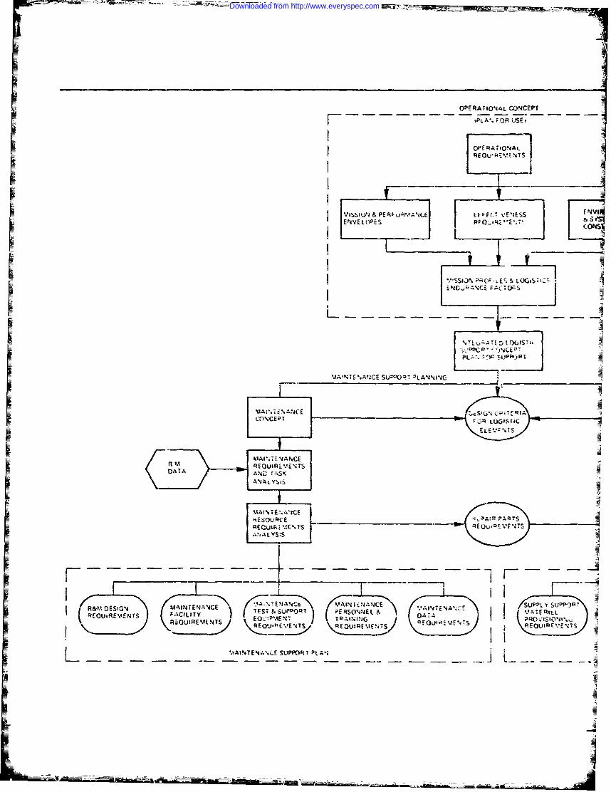
OPERATIONJAL CON4CEPT
4PA4 FOR USEi
I pr RA,.OAl.
F~ -N __I_
-.EtU &
&E .
Sir
. A'NTS%Af-CE SUPPORT~ AV.
VA 04 EA4C E
(~MCP CURi~T
DT
------------------------------------------
=G U LA 1 E:'IN TENA'ICE SU.P Y
)SU
..N% A L S U P O R T P ij
_ _M _f
E j.Iup1
Downloaded from http://www.everyspec.com
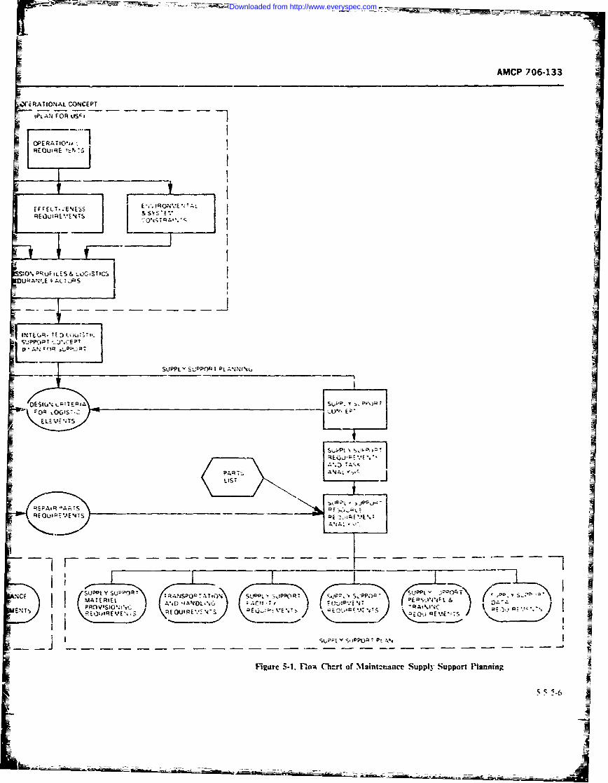
AMCP ?06-133
E RAT IO14AL CONCEPT
P OR AT0'
REQUtRE
I - -L' -i IIIi,
:0%. ~uF ILES & )G.STIC$DURA~~v.(JYV .INE~R 77:) I I3
SUP JlY TU~ ~~.~~Ozz L,TE' P
-OR OG15
R. -I- - - a; j--- - - - - -
A4L Y -AL;- 3- a Sy'E T ,
RI ~,U9LV ;PPCOP P
Figure 5-1. fltow (Thcrt of Nisint~'.ance Supply Support Piaing
Downloaded from http://www.everyspec.com
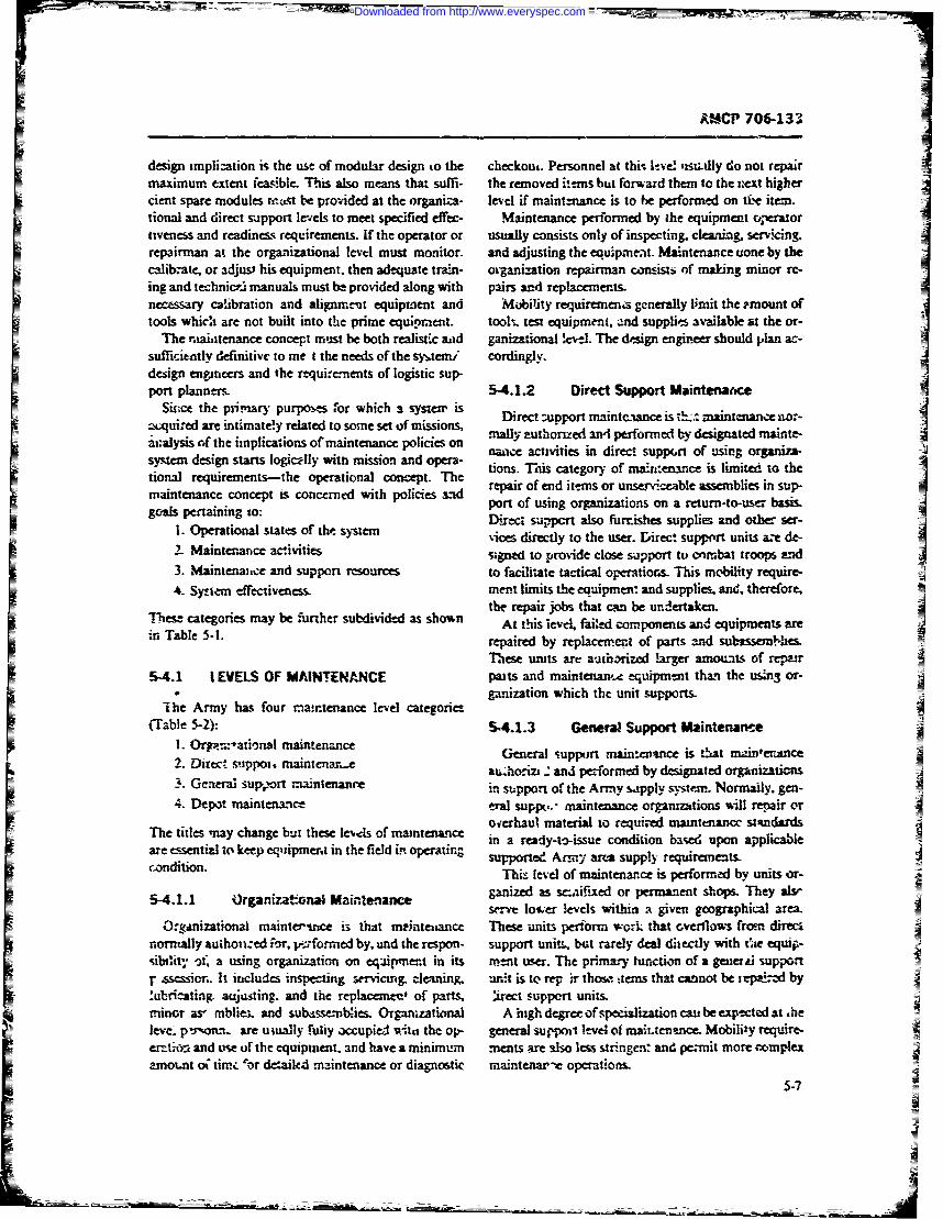
A*M-CP 706-133
design implization is the use of modular design to the checkout. Personnel at thi- ltve l isuailly do not repairmaximumn extent feasible. This also means that suffi- the removed itemis but forward them to the :iext highercient spare modules rittst be provided at the organiza- level if maintntance is to be performed on ii'e item.Itional and direct support levels to meet specified effec- Maintenance performed by the equipment operitortiveness and readiness requirements. If the operator or usually consists only of inspecting, clewning, servicing.repairman at the organizational levtl must monitor. and adjusting the equispMeat. Maintenance tione by thecalibat, or adjust his equipment. then adequate tran cvanization repairman consists of making minor re-I
cing and technic~t manuals must be provided along with pairs and replacemnts-
necessary calibration and alignment equipmient and Mobility requiremena generally limit the -mount oftools whicua are not built into the prime equipment. tool,. team equipment. and supplies available at the or-I
The m~aiiitenance concept must be both realistic aad ganizational !evtl. The design enginee should plan ac-sufficiently definitive to me tthe needs of the sy,.temi cordingly.design engineers and the rtequirenents; of logistic sup-port planners. 5-4.1.2 Direct Support Maintenatice
Sitc= the pim~ary purpoics or which a systen, is Direuppovrt maintcennce is s!.t maintenancenr-acquired are intimately related to some set of missions, mal thud ipsfre ydsgntdOanean~alysis cif the implications of maintenance policies an nance activities in direct supp(,rt of using organiza-
system design starts logically wini mission and opera- tions. This egory of tmintnne slmie o htional requirements-the operational concept. TheThs ym oislitdote
Emaintenance concept is concerned with policies &id repair of end items or unserviceaible assemblies in sup-gcoals pertaining to: saeofport of using organizations on a return-to-user basis.
1. Operational stt ieo t- system Direct sa-,pcrt also furrishes supplies and other ser-
2.Mitnneaclvte iesdrcl othe user. Dire&. supprt units aze de-2. Mantennce ciwiies gned to provide close support to cntubat troops arid
3. Maintenai.,e and support resources to facilitate tactical operation~s. This mobility require-
4. Sy-efem effectiveness. ment limits the equiprnen: and supplies and. therefore-
Thesze categories may be f-urher subdivided as shown tthrpirs fate cnwoben andaeupns r
in Tble -I.repaired by replacemn.to parts and subxss=Nx&es
These units are authorized larer amounts of rp"4.1 IEVELS OF MAINTENANCE paits and maintenaw-e equipme~nt thwi the usi.ng or-A
ganization which the unit supports.The Army has four raimtenance level categories
-Tabie 5-2) 54.1.3 General Support Maintenance1. Orpm:-ational maintenance manenc
2~ Drectsuppt *ma~nenar..eau.horizt. and performed by designated orgaiautins3. Geeral sup,ort maintenance in support of& the Army saspply system. Normally. gen-
4. Depot maintentce tral supp.- maintenance organizaitions will repair or
The itls my cangebutthee l-.cl ofmaitennce oierhaut material to requir-ed matntenancc standards;The itls my cang bu thee lvel ofmaitennce in a ready-to-issue condition based upon applicable
are essential! to keep eqlipment in the field in operatingcondition.
541.1 Oganizat*-TW Maintetiance he
OrgAnizational maintersrice is that meintetance These units perform work that cverflows from directnormally auion--ed ior. V~rformed by, und the respon- support unit, but rarely deal ditrctly with tsiie equsj -sibility Af a using organization on eqiimena in its nient user. The primary function of a gener *1 supportr sessiou. It includes inspecting servicing, cleaning. unit is to rep Ir thw., tem that cannot be irpai:=d by!'ubricating. aujusting. and the reptacemnee' of parts, irect support units.minor as mbliet. and subasse-mblies, Organzatimnal A igh degree of specitlization cast be exptcted at -heleve- p's'rnn are utually fully accupied wits, the op- general svu'poil level of maittenance Mobility require-errtion and tse- of the equipment,. and haeamnmm mas& lols tgen: and pemit mor coplexaznount o titrz "or dtailed maintenance or diagnostic maintenar-t operations.
S-7
Downloaded from http://www.everyspec.com
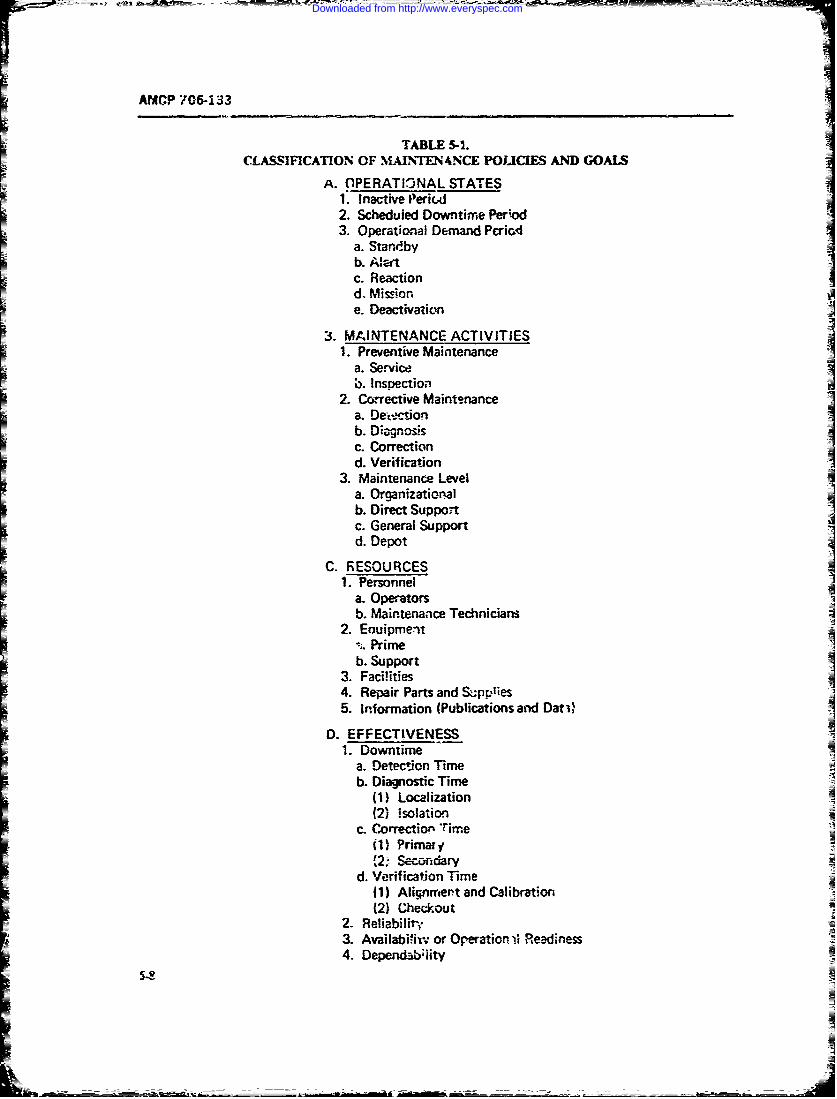
ANCP 706-133
TABLE 5-1.CLASSIFICATION OF MAINTENANCE POUCIES AND GOALS
A. OPERATIONAL STATES1. Inactive Perid2. Scheduled Downtime Period3. Operational Demand Pcriod
a. Stardbyb. A;eftc. Reactiond. Missione. Deactivation
3. MAINTENANCE ACTIVITIES1. Preventive Maintenance
a. Serviceb. Inspection
2. Cowrective Maintenancea. De-ctionb. Diagnosisc. Correction
d. Verification3. Maintenance Level
a. Organizationalb. Direct SuppoIc. General Supportd. Depot
C. RESOURCES1. Personnel
a- Operatorsb. Maintenance Technicians
2. EauipmentPrime
b. Support3. Facilities4. Repair Parts and S;pplies5. Information (Publications and Dati)
D. EFFECTIVENESS
1. Downtimea. Detection Timeb. Diagnostic Time
(1) Localization(2) isolation
c. Co rrection Time(11 Primar y1,2! Secoandary
d. Verification Time(1) Alignmert and Calibration(2) Ched.out
2. Reliability3. Availabi=ir; or Operation ii Readiness4. Dependabiity
Downloaded from http://www.everyspec.com
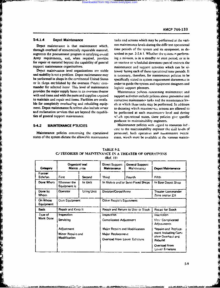
AMCP 706-133
3-4.1.4 Depot Maintenance tasks znd actions which may be performed at the vani-
Depot mainterance: is that maintenance which. ous mairtenance levels during the diffi-ent ocieatiornalthrough overhaul of economically repairable materiel, time periods of the system and its equipment. as de-vigramts the procurement program in satisfying oY,.ral scribed in par- 2-2.6. 1. Whether the sy steni i-, performn-IArmy requirEtrrents, and, when required, provides ing a mi-sion. is in a standby or alert period. or is infor repair ot materiel beyona the capability of gencral an inactive or scheduled downtime perid restincts thesupport maintenance organizations. maintenance and support actiivities which can be si.
Depot inaintrice level organditions are stable towed luring each of these operational time periods. Itand mobility is not a problem- Depot mairtenance MY is necessary, therefore. for maintenance policies to bebe =eformed in shops in the continental United State's specifically'stzted in system requirement docuins inor in chops estrblished by the overseas tkeate. com- order to guide the system and equipcment designers andman&-- for selected item! Tis level of maintenance logistic support plnners.Iprovides :he major supply bases in rn overseas theater Maintenance '-o'ies rcnni mraintenainc. andwith end itemnsand with the parts ard supplies iz-guired sup-Fort aLtIVuIeIs Include policies aboui preiecntiie andto maintain and repair end items. Facilities arz a%-aila correc;tve mainterianci, tasks and the maintenan-e 1ev-ble fer completely oyrrhauL-ng and rebuilding equip- els at which *h-se tasks may be performed. In additionMeent. Depot maintenance fuictioens also include rereair to dictating which maintencti actions arc allowed tcard rcclamnation services that are beyond the capabili- be perfo;ined at each ma-atentanee level and du'ringties of general support maintennc. %%Ich ope.-aticnal siates, tiese pol.cies give specific
5-4.2 MAINTENANCE P11UCIES Main:euance policies with zzgard to resources ind -cate to the mai-=ainabihity engineer the sliil levels of
Maintenance policies concerning the eperational persoanel. both operatmts and rit,nenance totcrc-iistates of the sys-temn dictate the allowable maintenance cians. w 71.Ch musi be available a! tht various inainte-
CITEGORIES 3F N1AJNTENANCE 1% A a-HEATER OF OPERAIT9NS(Ref. 11)
O19nazat aNa Direct ootGer. UW
Fcorme Fis j Secon______ Third Fourth F__________DoneWhee Wiervw~rthe in nit In Mobile andfor Stmmi-Fixed Shops
Done~~~Mdfiao Whr hrvrte -nI a ep t S ho
Iten Equipment t
Lwo w a-wni wP opl e E cens ejt
Eqimn
Bass Rpai an Kep t IReo irw-,' ettrn o Uer r Soc Reca: i(r Soc
Iy) _f _npcto _ _n _ _ _ci
Downloaded from http://www.everyspec.com
MCP 706-13Z________________:6______________
nance ievtlIs and for which the sysem must be de- sssuta, that the systen./eqwipmcnt whe= produced, in-Isigned Resource policies also indicate maintenance t'led. and opaawed. ca- be effectively maintained. Inconcepts with regard to test and support equipment. cider to deterne what nfrornatwn is of importancesuch as the extent to whi :h built-in test techniques will in designing for maintabil-ity, it is necessary to de-be used, the extent to which automatic test andi Lheck- hseate those factors which, in combination. make upotsaow tdh6_ccrnng etzalpupsev ;;nenanct: tasks:o actJsspecial' test equipment. ciibration equipment reqwre- Maintenance activities ray be partitioned into two]
'qstems and equipments. nasqce performed, preferably an a scheduled basis. bI Resou~rce policies dictate fat lit1 concepts. spares the purpose of renainmg an item in a satisfactor: oper-Iand repair parts policies including invemno5. control ating conditon- It includes periic uist. mniltoring.
and stocking leel ndic'os. and repair/discar serv-cirg. a.4 :nspectson. Corrtrr've minznenance isc:riterie_ They also include polcies, concevrning mainte- that mraintenanze pernneud to t~r_-e an equipment toInanse infrmation such as technical mamd-s. provi- operating conrtu aftet- a failure or other malf(unctionPsi.fng documenta-tion, and field data Thec, po.icies has occurred. Ccrrecti.: maintenance includs, detec-II mist no! only the mairtainabilty engineer but logistic ticat. dnnosis.m correction and verification (Refs. M&supply support and facility planners as %*ell- and 12) Detectioni of a fault insy aMs or-cur during
Mlaintenance policies corz-errng istem effvct!'-e- preventive maintenanice. The relationstip bn-weenIness inclt- many of the quantitative requirements these primar% subse-ts of maintenance is illustrated inwhich bear upon sy-stemn availability and oper-ati-onal Fe, $12. A more detailed partitionig of correctivrereaditcss. These include sutchraL'e as availability, mnaiaeocance activittes. :rnciidmgi the secondar-y main-
= endability reliability. an mantaizlit- They tenance loop for rear echelo repair. i~ sho-wn in Fit 1=also iniciude allowable preve-rt'v and corrective main- 3'
:eane owtiesan lgist ic su pp 1) ich Y '; ms Uf- Aithot ghdsg for -natntainabi-.N mtust tnch-detecti'entsi poLircs are the bridge betsteen ope-anona b oth pre% -mti crand correct-% e mamnt.±nancr considers-arid support req-nrezncnts f.s the, retblast and main- turns. criti --a problcnn oflen .nter around cot xct.*vetainability engineers and ystentequipment designers. rnatniznant since this ic'-.-vs, the restoration of &nled -
Thecy hat e a significant :m pavi on maintainability dt- items to an apenble s.t' -.often during ..w-risison andsign- They p-rwudc Fbrher guidance for piedicnoa. al- w~ithin a4 rehtively short tinc p'-nod.A It is evideant thatlocation, demonstration, test. ri-d evaluation of main- tu-ne tz' tnt ci ucal paramete in correc maintenanceItainability as the -.ystem moves fiom the requiremernt and. therefoee an, e "Wtm factor in rnaintznabthtvjphase to act uai dev-ek-p~neur. design. test. produczo_-n. dcesianand operational phases, Since mat-itzabilhtv is a5-oxia~eo with the t6C3;n
Table- 5-3 ji " some representative exampies of main- features of - systemz eq~uipmnt in oarder to facilitattenance ponlcits wiitch .. gh be tnciuded in the m--nte- rntt-ttt -se would hi:c to analyze niaiittenatcenatce concecpt for a system, All oJ :he,.- rxhieq -t 1-4 i sf-c o .Nme and pic-.de those niaiitt'-aapply to c-.ery systai. Actuai polics t.o t6±- u-sed for a '"-it dsg features %% hich will mirat n aintenance- A
given syrtem arc derived = part of logitc supper- andl ta,. ti-es Tune.- enter. unfiainlt-lit) considerationsmaintenance support plannin.. described in par i n two way,. -
%ad as illustrater iz -i. -
,ed g. . -.: polici . should be I In terms of long-tecrmn or h.fet'harac-enisocs ofcobndinIia sets, as descrinbed in Ref. 10. itt st rh i%'te msc-n. eg., reniamu'iv el! ira-.ensncs ant ti-cNe_.a mnanner as to op1tie operationa reaciness tasaila- twetloeruu
btizy)anduif cyle ~iL2.In :erms of shor-termn charwr-trisn_ orv the-
abilin! to keep a-n operating i-ntern in operation 'pr-e-
5,5 '-enin-r :.'ztn:enani-cc\ or to it-tore anpr be s%.s-55 M LMNTAABLT DEIG tento in atrational s-'nz icorrecnive ntaintenance)
REQUIREMENTS5-5.1 MAINTENANCE TIME PHASES -
= In Chapte; 1. mairtainabmilty eninieering i~s de-scribed a. ::.cludin5 those acions tale--n b, a system .4 Co.'rcctn~e mnncnamrc tak my tie searated iniq
eq-.rpment designer durng; enniriecring dcdowncnrt t' the tallow tig sequenula: innee v-iRds.0 ai121-
Downloaded from http://www.everyspec.com
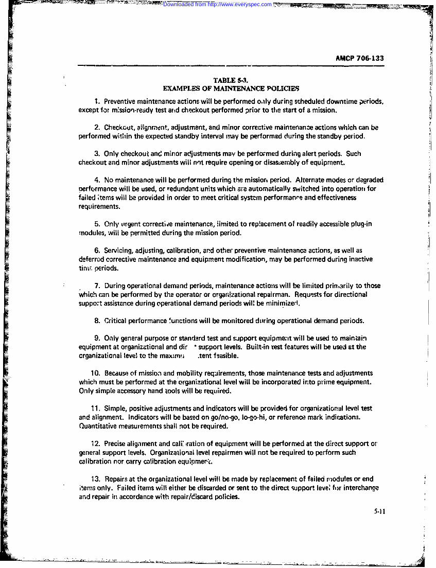
AMCP 706-133
TABLE 5-3.EXAMPLES OF MAINTENANCE POLICIES
1. Preventive maintenance actions will be performed oaiy during scheduled downtime periods,except for m.ssion-ready test arid checkout performed prior to the start of a mission.
2. Checkcut, alignment, adjustment, and minor correctve maintenanze actions which can beperformed within the expected standby interval may be performed during the standby period.
3. Only checkout and minor adjustments may be performed during alert periods. Suchcheckout and minor adjustments will nnt require opening or disa-sermbly of equipment.
4. No maintenance will be performed during the missior period. Alternate modes or degradedoerformance will be used, or redundant units which are automatically switched into operatior forfailed ;tems will be provided in order to meet critical system performanre and effectivenessrequirements.
5. Only tirgent correctiie maintenance, Himited to rep!acement of readily accessible plug-in:nodules, will be permitted during the mission period.
6. Servicing, adjusting, calibration, and other preventive maintenance actions, as well asdeferrod corrective maintenance and equipment modification, may be performed during inactivetim--, periods.
7. During operational demand periods, maintenance actions will be limited prinarily to thosewhich can be performed by the operator or orgar;izational repairman. Requests for directionalsupport assistance during operational demand periods wil: be minimiz-l.
8. Critical performance functions will be monitored during operational demand periods.
9. Only general purpose or standard test and support equipme;at will be used to mainzainequipment at organizational and dir * support levels. Built-in test features will be used at thecrganizational level to the max~m( tent fsasible.
10. Because of mission and mobility requirements, those maintenance tests and adjustmentswhich must be performed at the organizational level will be incorporated into prime equipment.Only simple accessory hand tools will be required.
11. Simple, positive adjustments and indicators will be provided for organizational level testand alignment. indicators will be based on go/no-go, lo-go-hi, or reference mark indications.Quantitative measurements shall not be required.
12. Precise alignment and cali .ration of equipment will be performed at the direct support orgeneral support levels. Organizational level repairmen will not be required to perform suchcalibration nor carry calibration equipmerc.
13. Repairs at the organizational level will be made by replacement of failed modules or enditems only. Failed items will either be discarded or sent to the direct support leve; for interchangeand repair in accordance with repair/discard policies.
5-11I
Downloaded from http://www.everyspec.com
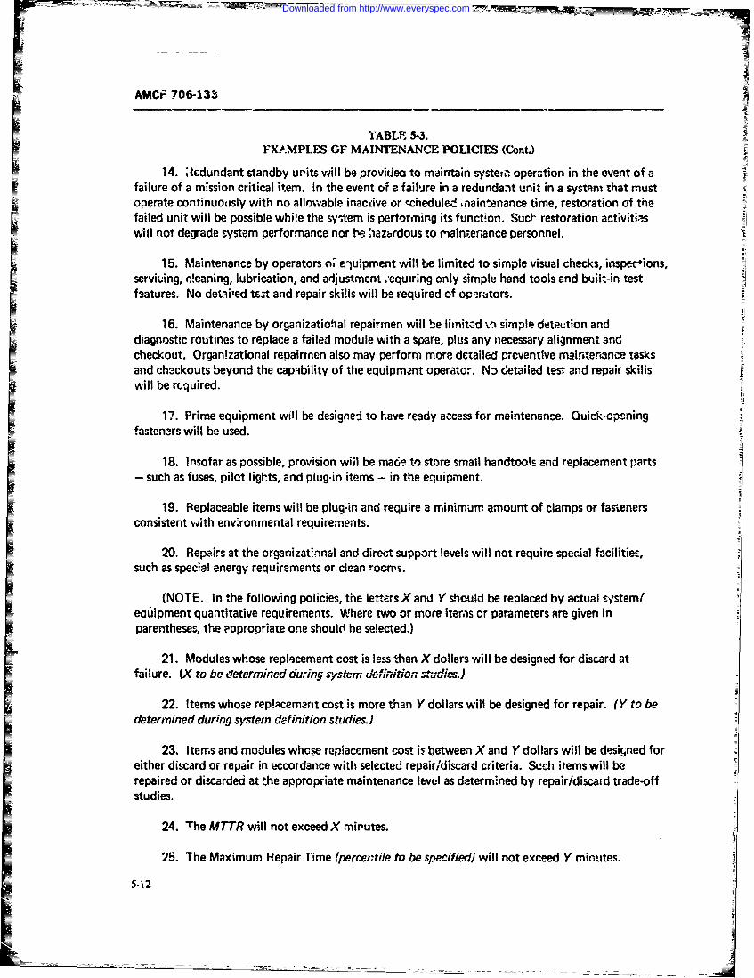
AMCtF 706-133
TABLE 5. 3.IFX.MPLES GF MAINTENANCE POLICIES (Cont.)
14. ;Icdundant standby urits will be provideo to maintain systein operation in the event of afailure of a mission critical item. in the event of a fail-ire in a redundant unit in a system that mustoperate continuously with no allowable inactive or echedulee ,naintenance time, restoration of thefailed unit will be possible while the system is pertorming its function. SucF restoration activiti-swill not degrade system performance nor be haztrdous to maintenance personnel.
15. Maintenance by operators o, e-upment will be limited to simple visual checks, inspections,serviuing, ,!eaning, lubrication, and adjustment .-equiring only simple hand tools and built-in testf-atures. No detmied tWAt and repair skills will be required of operators.
16. Maintenance by organizatiohal repairmen will be limitcd -%o simple deteution anddiagnostic routines to replace a failed module with a spare, plus any necessary alignment andcheckout. Organizational repairmen also may perform more detailed preventive maintenance tasksand ch3ckouts beyond the capability of the equipmant operator. N:) detailed test and repair skillswill be required.
17. Prime equipment will be designed to have re3dy access for maintenance. Quick-opening
fasten3rs will be used.
18. Insofar as possible, provision wiHl be mare to store small handtools and replacement parts- such as fuses, pilct lights, and plug-in items - in the equipment.
19. Replaceable items will be plug-in and require a minimurn amount of clamps or fastenersconsistent with env'ronmental requirements.
F20. Repairs at the organizatinnai and direct support levels will not require special facilities,such as special energy requirements or clean rooms.
(NOTE. In the following policies, the letters X and Y should be replaced by actual system/equipment quantitative requirements. Where two or more iters or parameters ctre given inparentheses, the eppropriate one should he seiected.)
21. Modules whose replacement cost is less than X dollars will be designed for discard atfailure. (X to be determined during system definition studies.)
22. Items whose rep!lcemartt cost is more than Y dollars will be designed for repair. (Y to bedetermined during system definition studies.)
23. Iters and modules whose replacement cost is between X and Y dollars will be designed foreither discard or repair in accordance with selected repairi'discafd criteria. Such items will berepaired or discarded at the appropriate maintenance level as determined by repair/discatd trade-offstudies.
24. The MTTR will not exceed X minutes.
25. The Maximum Repair Time (percentile to be specified) will not exceed Y minutes.
5.12
Downloaded from http://www.everyspec.com

AMCP 706-133
TABLE 5-3.
EXAMPLES OF MAINT&NANCi POLICIES (CoucL)
26. The system/equipment (inherent, operational) availability will Ua at ierst OX
It 27. System dependability will be at least O.YYY when operating ii' the specified moJe.
28. Mission critica! parameters will be (periodkiihiy monitored, antomnatically sensed) and anI alarm given to indicate failure Within X minutes after the failure has cccurred.29. A system failure will be localized to the (equipmentr~, unit, assembly, moduls) level within
X minutes after the failure has been detected.
30. A system failure will be icniated to the replaceatie/repairaole item or mnodulde within XI minutes after the failure has been localized.31. A failed item/imodule will b- feplacedfrepaired within X minutes after the failvre tms been
isolated.
32. It will be possible to align thc, repaired item and verify system/iequipmenit effecrtiveoperation within X ininutes after the c:orrection has been completed.
33. The probability of having a repair part or replaceable module when needed at theorganizational ievel will be at least 0.XX.
34. The probabi-lity of having a repair part o- replaceable item w-rien needed at the directsupport level will be at least 0.YY.
35. Repair parts will be carried at the organizational or direct support !evels for thoserepairable items which have an MT8F of less than Y hours.
36. Organizational level maintenance will be limited to those tasks which can bn perform-dby an organ~izational repairman with the following skilt levels: (specifics to be furnisheddurings, stem conceptual and definition stude& 1.
'37. Direct support maintenance will be limited to those tasks which can be merormed by amaintenance technician with the following skill levels: fspicifics to ba furnished during systemconcep tual and definition studes).
38. Requirements for special trainIng for organizational and direct support le~vel maintenancepersonnel will be minimized an~j will be. consistzrit with deW - d general aptitudes and skill levelsof sucn peronneI.
39. Preventive maintenance tasks. performed at the organizaional and direct suooort levelswill be able to be accomplished wi thin the following defined time periods: ',o be specified frmdefined operational derandprofles and logistic endurarn-e f4ac.ows).
3-13
Downloaded from http://www.everyspec.com
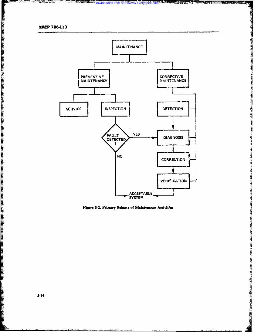
AMCP 106-133
MAINTENANCE MAINTZNANCE
SERVIE INSECTII DETECTION
DETECTEDIAGNOSIS
CORRECTION
LVERIFI CATlONZ
ACCEPTABLJSSYSTEM
F-gue S-2. Primary Subeat of Maintenance Acuiiiftff
5-14
Downloaded from http://www.everyspec.com
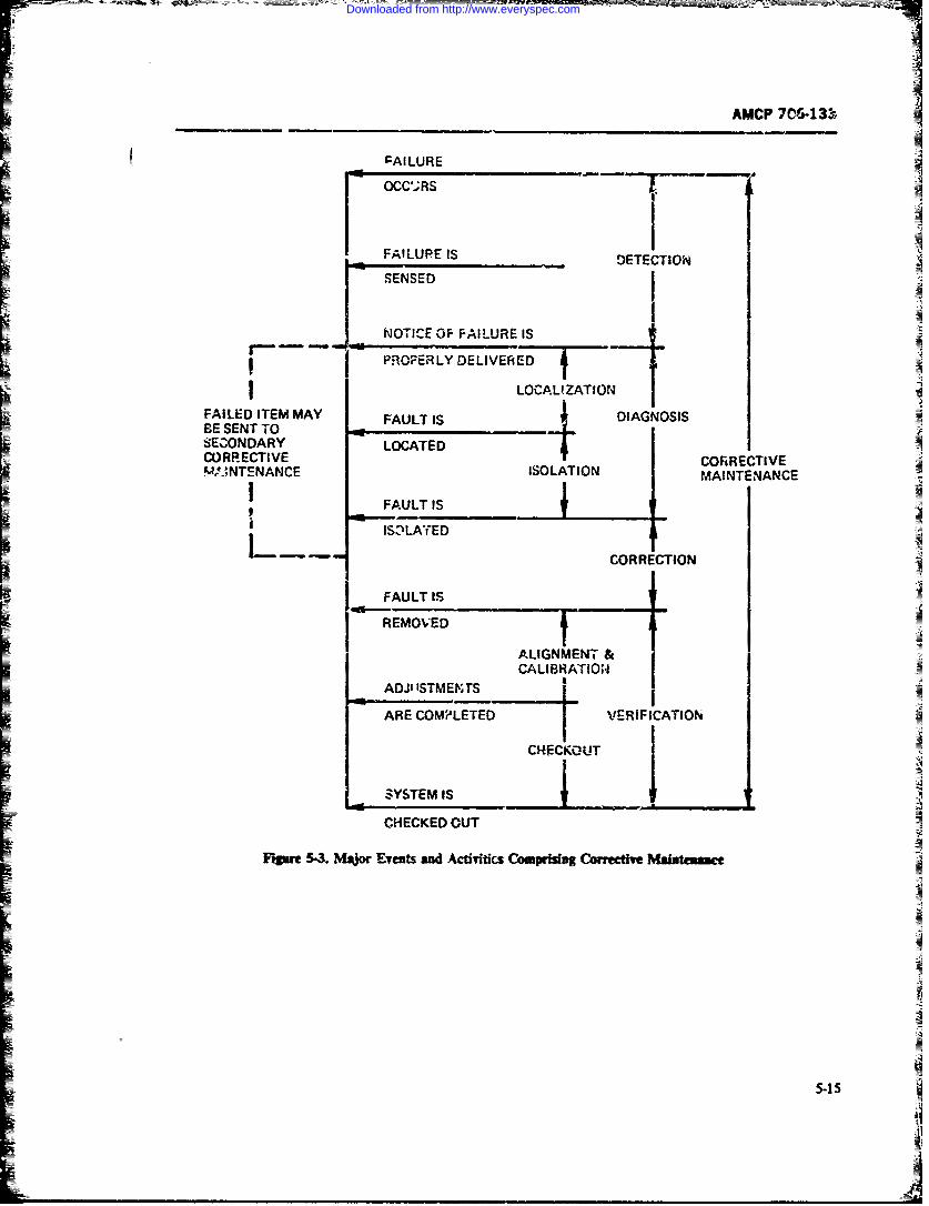
AMCP 706-131.
FAILURE
FAILURE IsDTEIO
NO TICE OF FAI LURE IS
LOCALIZATIONFAILED ITEM MAYDANOSBE SENT TO ..SECONDARY LOCATED 4CRETVSA."ANTENANCE ISOLATIONMANEAC
FAULT IS
ISZnLAfED
COSRRE CTION
/ FAULT IS-I REMOVED
ALIGNMENT &CALIBRATION
ADJ"ISTMENTS ____
ARE COMPLETED I VGRIFICATION
CHECKOU'T
SYSTEM IS
CHECKED OUT
Figar 5-3. IMsjor Evests sd Acuttcs Coupina Corretie MakAte
5-iS
_ _ _ _ _ _A
Downloaded from http://www.everyspec.com
A MCP 70&-133
1. Detectoni time--- recognition of a f~ault remove the fault and to restore the system to scceptabic2. fliagnseic time-fault location and isolation operating condition. Correction is a matter of pining
3. 1orr.ction time-replace or repair access to the faulty item an' of removzng it, and replac-
4. V--rFication time-test and elipn. ing it ytith a good itemn or repairing it in place.The fourth and final time phase, the Yenfication
These four tawsnteuanze time phlases may be comn~ared phse Ti inciw- 'wuit ijutetcliiato simnilar phasein thtetetf-Ptelb tion, te..t and finvi verification by checkout.doctor. T'he detection phase corresponds to th- symp-tmnatic pha..e in the human; a fatult maay have occurredand must be detected by some mear-s of sensing symp.toam ar symptomatic responses beibore any corrective 5-b.2 CORRECTIVE MAAINTENA ME
action may be prescribed. DOWNTCMEA fault may be dsssifled in one of three categories
= First, tbe fault may be one that aflows the systemn to Ther are two types of dcwntime .f concern in theperform but at a reduced capability or effickn4c -- this is cretemannne(rtoigopaio.One iscalled 4egadai Initially, the result of the fault is a called acibe downtime or active repair time, dependingreduction in performance capability. If aUowved to con- upon whether dete-tion tfim is included o: not, durinCtinue, however , the degradation may result in -Ither which repair actions described in par. S-5.1I are actively*mlfpkete loss of perfmnance or a permanent vate of taken by the muintenance technician. This is illustrated
reducrci perforntance cpbly.it, Fig. 5-4. The other time category is wuidnWgor delay
Mh second type of fault is critikal failure in which tiMe during which the ma'intenance technician is alhe- 's either a reduction in performaunce below a.ce t- to do little nc nothing I wards actively i estotig :be
able levels or a cormplete lack of performance. In this equipmient to operatkig condition Delay time is nor-
case, performance within dcceptabc limits cannot be mally delinul to ine iude administrative timne and logs-restoed without teking corrective aczion. tic supply time.
The thir-d type of failure is due io the occurrence of It is hdlpfil to distinguish between these two type.a calr'~wphic evcnt, fPor which there is no recovery, of time for a n i iber of reasons. Fi rst, active repair time?
this lkilure accurs precipitously. can be controle by design. Delay time, -o a large
=T'hese types of failures may occur in any system. lit extent cannot, being primarily a function or operating= a military s-stem, degradation is a reduction in system and environmental condit~ois of the system and the
performnc capat~lbty bec'v- a prescribed minimum availability of perrsonntel and system resources. Seond,= level ofeffectiveess. Thistype of failure can be ihib- actire rtrair times usually may be de=cie yacas
ited or minimized by propes preventive mainttmance tical divtribution such as the lopnorrnal, while delayaction 7W.I regard to design for maintainability, this times zaay be generally charicterized by a distribto
menswoviding for periodic test, inspection or servic:- such its the exponential distrb,?io.in&, or for monit-rinh certain criticai performance A. defined in Chapter 2, operational availability in,-
paraniet-A3 either continaously or periodically. chuies both types of time while intrisic axuAiaiyCritca faifures are correctable by taking correctivt includes only elements of active repair time. Because of
maintenance satons, wkh-h require means for boratin, the diffficulty of measuring delay times and demonsra-and nsotating the fault to a replaceable/repairable, item, ing operationial availabliLy during system test and eval-
correction of the faut, mnd verification of systemn per. umtion, most specifications use active repair time meas-formanc-. Maintainability design features for this in- urms such as MTT and *,,, see par. 1-6), andclike accemsibility, test points, test equipment, display.. intiimSW availability as requirements fer maintainabil-
conectoma faul-t inkasts, maintenance instructmos. ity and system effectiv'enes. In recent years, attemptsand other- features whrih are discussed in Section II of have been umdz to use operational .svailability and
= this cl'apter. In the case of a catatrophic event. -le mean active downtime or mnean downtime (soc par.equipment may be noorepairable and must be replaced. 2-2.4.2) to more nearly simulate actual operating con-
The diaga~ostic phase the second of t*. nzaintemmwne ditios.time phL^s includes localizaton and iscolation of the In genervJ maintenance actionis taken during thefault in order that proper corrective measure may be four corrective ma:-itenanc downtime periods and thetekern m.-ntzin'ability design chmacre.'istics required to min:-
The third time phase the corretmw phase, is that mize thesw downtime periods are different. These are
time period in which w-imethirl is actively done to discussed in par. 5-8.
3-16
Downloaded from http://www.everyspec.com
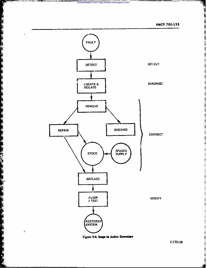
AMCP 706-133
DETECT DE-iECT
I LOCATE & DIAGNOSZISOLATE
REMOVE
REPAIR DISCARD]CORRECT
-7 UIG 1 VERIFY
RESTOREDSYSTEM
i-4pe 5-k. Step in Aclift Dowstime
Downloaded from http://www.everyspec.com
AMC? 706-133
SECTION~ If
MAINTAINABILITY DESIGN CON51ClREATONS
5-6 MAINTAINABILITY AND SYSTEM The st9,- labeled -formulaticn of a value moel- isDESIGN often called 'Jining the problei'i". It involves galx-r-
In Chape 3. iispated ou htmaintainability Sytmop vsa osrans u oeta emconsideraw~ns must he ir.4uded in all phases -f the !ng the problem~ it abo involves the mesitial, task of
sysern life cycle if a cost-efecC .cr- suvportax4e system formulating the criteria of system worth or efecivv-
sucr a ffe cclesystm aproac tsthe yste desgn ill be evalutted. W~thout ,-nch evaltwtiotitei.spro.es= ("H- 5-5). ins order to examine the inercios ne opflinlzai o is not possibie.
ofmaintainability with system &esign (Fig. i-1), one Once the neee (problem) has ceen defined and themust firs understand the system design process. system ifoctiveness criteria establisieAI alternative
At the begining of their book Systerr Eigireer means for satisfyi-n. the system ropequns may beM&Code and Macolinarthat -or ore than a synthedc& Thesealnaives atten anlyzc
benpoorly unesodadloosely dsrl .Iths needed-.ti aeocurnefra optima! ig tb=e called system desm system anayfs aW often the be achieved the first time through the design prcss
= Tms approacR" (Ref. 13). In the ensuin; years sb= ___lz a number of iterations are- usually ru~wad intGoodr- and Machol's book was published, tbere have wich design parameter; are v~ired in ordtr to meetbeen numerous 4:forts to describe system enginemra stated performance requirvmenss or to teduce the un-and eystemn design (Refs. 10 and 14-17). As a result, a certainty of unacceptable or marginrl pefonaae-d cear pattern of the system design proc. - is now evi- This iterati-le p--rcess is calles optimization and is the
dmLfeedback loop shown in Fig. 5-S. Occasionaly, the re-An accepted definition of engineering dazsign is- -De- suit of evaluation and iteratimn will require that the
sign is defined w~ an iteradve, decisicn-mnaking process value model (systuin effctivcess critera) be inodified-for develoluing angirneering systems or dei-ies whereby Thi-s is shown us the dotted feedback path in 1'41 5-5.
resurces ,%Tr or qrmy converted into desired ends" Risk analysis techniqlues should be employed in the(Refs. 14 and 17). Fig. 5-5 is a model of this definiti-,n decision proces. Ref 92 provdei basic informnation *.-aof the- systemi de.:,n process. It rqesets a imdback risk analysis.control sy-tem for transorminE a set of inputs inc Wlien the drirn has been fruren, it is thea con-outputs it! an opuwi~J (economnic) mncner. wvat-m 7A- municated to otiers for impleineritltior. Stich c-mmu-lowable cmistraints, i- orcer- to met gtated n-ted in .rcation is in the form of drawingr. s.-eciflcations, re-secord&-a with 2 de-ined measure of system worth or pok ts, te3 and acceptazce prccdures, mnvfiacturingea ctivencs. It is applicable throughout all the hOe 4n~tructiocus. installation and support information, op-cycle phase&. A m'jre couupete description cf the sys- erattinjg and maintena=c mzructions, Peisn'l anmtem life cydz and the system design process is con- tmmin requrements. etc.tained in Refs. 10 =1d 17. the systent design proces way be applied to min-
The input to, the desip process is infaion-4n- tainaility des*gn Maintainability ei:g6zee..ing. then. is= formation about the need for the system the systzm concerned with :he koical procesin of those system
operational eionmeait, constrairts on the system, its design factors about which maintaiability is coct-design, w,~ and =mpporf, wid any other pertinent infer- cerned, and the techniues for so doing in arccorda,~ce
mataci'. with the system design poces.
5-19
Downloaded from http://www.everyspec.com
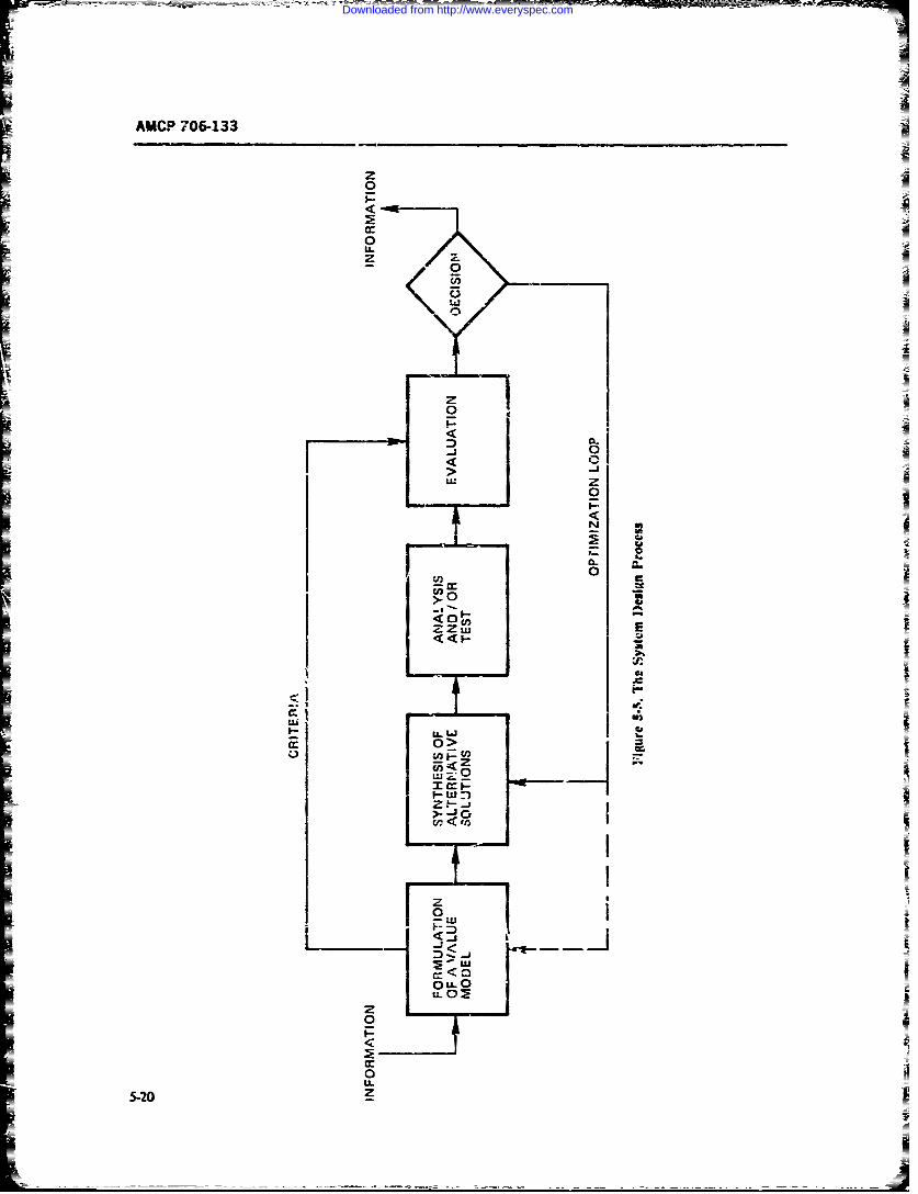
AMCP 706-133
z0
0
U.S
00
0z
LUL
702 z
lL ---
Downloaded from http://www.everyspec.com
AMCP 706-133
5-6.1 INPUT INFORMATION-THE contribute to the establishment of measures of effec-BACKGROUND FOR MAINTAINABILITY tiveness to be used in evaluating the system design forDESiGN maintainability during each of the life cycle design
stages. Quantitative maintainability criteria are dis-Input requirements with respect to aintanaity cussed i Chapters 1. 2. and 4.
are often incomplete and in primitive form. In order to OY particular inportance during the formulation ofutilin this information during system design, thb main- ".e value model i "he analysis of mai-tenanc pciestainalty e ngineer must find answers to .he folowing and goals stated in system reytiremev-1 documents,statement: -ong with such uantitativ- systm effectiveness re-
I. Why the system is being designed-the opera- quiremets as availability, dependability, an zissiontio.,al Peed. relin-.Iity, and the defined operational capability of the
2. What tl.e wnvironmentl and policy consir- systn. It is the maintainability engineer's role o per-dtons are-operational and resource constraints, main- form these analyses and to inzerpret the desigi' reuire-
tenance policies, integrated logistic support concept, thets to the eeuixI-ptt designers.
applicable maintaiability standards, design hand-
books, and guidelines. 5-6.3 SYNTHESIS OF MAINTAINABILITY3. What the maintenance objectivs are-mte DESIGN MODELS
nane concepts, system effittiveness requirenmets.cost, and other support criteria. The sinthesis of modzs useful for n aintainability4. When the ,ys!m can be m tained-mission design is complicaed by the fEct that r_# all of the
- profiles, logistic endurance factors, preventive vs cor- piyscai iariables with which maictainability is con-rective maintenatce. cerned can be quantified. In addition, maintainability
5. Where it is to be snpported-o'anizations, di- is concerned with wch nm-machine interfaces as hu-rect su;pport, general support, or depot levels man eng eering factos and safety. which, when meas-
6. How it ,-an be _-'upported--tepair/repa./ds- aurble, often rcquire tne use of subjective &nd stochas-tic mea.sures or simulaticu techniques.
card policies, depth of nxtenance, ase of standby N o model ofmaintainability designredundancy, p -.'odic test and checkout, ov-xhaL N ipe rgn.a oe fmitiaiiydsgis available. Howevex. it is possible to construct a con-
7. Who is to support it--operators, organization ceptual model comb.ning bose items of concern torepairmen, rear :. -ei ,intenaan technicians- maintainability engineering. Por example, maintaina
The maintainabihity engineer should obtain field bility engineering is certainly concerned with m;.nimiz-feedback ;nformation on similar syu-s and environ- ing systm (end item) mrintenec downtimes. :t isments to assist in the formul.Iion of answcrs. Th: also concerned with the system level at which mainte-Army and other strvice data banks should be carefully nance z-c"ns will be performed ind with 'he .pecificsearched for pertinent data; The Army Maintenarce maintainabiity attmbutes of !he s-.en. Finally, it isManageSi System (TAMMS) is such a bank. I the concerned with the mairtair-hility design activitiestst maintenance feedback information from the fielJ which are rxxformed at each o" tre i stages of t!'ehas gen-rally betn limited in scope and dfficult to use s stem lile cycle. Stch I model is disc--.ed in par. 5-7.for design znalysis. A number of programs have beeninitiated by the milita:y servitv and industry to :m- 5.4 MAINTAINA=UTY u-,Qm.SSprove the quality ane. reia bility- of such information.
Maintainability analyst is prirmipally wucerned5-6.2 FORULATION OF THE VALUE M(OMEL with the prediction and demons ratiorn of the resultant
(EFFECTINESS CRITERIA) efforts of maitai ility design considerations, usually( CT Aesur by calculating. estimating. or measuing
The input infcrmation is i.sed to formulate both d--wntime under simulated operating conditi-As. It isqualitative and qoanti~t~tve maintninaIlity objectives also concerned with the determination of !be effects ofduring system synthmsi4 evaluation, and optimniatior maintainability design char-eristics of the equipmetin order to achieve the best possible maintainibility on required mahitnance rwqurces.design within the established constraints. Quantitative Typical analytic techniques include simulation.maiAtainability criteria such as alowable downt. . maintainability prediAmn. ailocation, and demonstra-turn-around times, time between overhau.. mainte- tion tmts depending upon the design stage of the systemnance and support costs, and repair/discard criteris life cycle- Statistical techniques are requir.xL Chap=%
5-21
Downloaded from http://www.everyspec.com
AMCP 706-1331
1, 4. and 6 disetss measures of maintainabilir; ai.d independent of othr system parameters. Exterior deci.existing prediction and demonstration technques. In sioas are thcse wC-ic affect other system pa.rametersaddition to the current techniques described in Military such as reliability, safety, or surply support. Rtsk anal-St dad (Refs. 18 and '9). :he preciction and evalua- ysis techniques should be employed in re ii daci-tion techniques need :o be developed which can be sions.
more usefully applie during the early life cy.le plan- As each desip stage milestone is reached, certainning and design phas.s. Also needed are quantitative design data and other informatn should be cvohdata representative of current design packaging te-.h- and presented in proper form to sfrve as a basis 'orniques suc;- as *te use of solid -statc de-ices, inicroelec- design review (Ref. 21). These sawe to facilitate pro-trones, and mechanical items. gram managemem-t decis*ons.
Maintenance engineering analys s (Refs. 3 and 20) isalso an important analytical tool for nzaintainabilirl 5-6.7 OPTIzAoNanalysis during the design stages for determning bothmaintenance task times and actions as well zs for deter- As mentioaed earii.r in this section, optimizixn ismining maintenance resour-es. the iterative feedba* loap which i - used to mocify the
st.= model, analyze the resulting change, ev--uate.5.6.5 MAINTAINABILITY EVALUATION tad decide. The process is repmted until the marginal
cost of additicral itertion is ro longer commenurtMaintainabihty evaiuation compares the results of with the expected icrease in benefits (effectiveness)-
maintainability analyses against system eiTectiveness It is posaiIe to optimizc maintainability raquire-criteria in order to obtain a decision as to whether the ments hfiependently of cther syrste parameters baseddesign is acceptable or further iteratioin is desired. on specified maintainability criteria oray. This is main-Maitainility must bp- evaluated not or.y against i. tainability su i . If valabity or dependa-own sta,-I requirements and reliability, but also bility are specified as the vitm dfc -iveness require-against higher levd sy stem effectiveness requirements mients. tbe it is possible for the system engineer tosuch as availability, dependability, and reliability, allocate and trade-off reliability and maintainability re-
The earliest life cycle qtaluaions are con=aed with quirements. a higher level optimizatiom than that ofmaintainability predictions and al;ocations fro-i the maintainability alone.system level to equipment levels. The-e occur during A tride-off may or may no; be an optimization Thesystem definition and p-eliminary design sages. Lower difference is wh-ther the va.'ae of tim hirer level crite-levl zlloctions and premiciow- fo~w during detail rion function which relates the t being traded offdesign stages, and fin-ally, the resalts of maintainality is changed cr not. For exanpK if a zrade-off is madetests and demonstrations are evaluatet, during the test between reliability and mamtainability for a constant=d evaluation stage. Additional maintainability availaftlity (along an availability isoclme), then rn op-
evaluations may occur dur.ng opermional system test- timization has been effected with respect to s-siM
ing by the user. effectivness we havejut swap or -traded off" oneesource (reliability) for another (mainaiability) with
5-6.6 DECISION no increase in beneit. If, on the other hand. a trade-offis maewhich increases the value of availability, then
D)ecisions must te nade during each of the design optimization is being performed Such trade-o s arestzges of the systev i life cycle. These d-xisions wilt described in Rcf 12 and 22. Additional discussion ofnormally be ti.her t-3 leave one design -ti-se and enter trade-offs and trade-off techniq-e is given in War. 5-the succecding ont or to iterate the existing stage Le- 8.7.cause some criterm. has not been optirdlly met orbecausn some conr-iat boundary has b~i emw- 5-6.8 O3UTPUT INFORMATRUC4Wi..hi, each design stage many subdecisis will bew-de. Occasionally. the decisioi wiV be to return to z 'The final output zfth system desig proczss is infor-preceding stage- ination. This information nclW the- desin charac-
,oth interior and exterior dxisions must be made teistics appearing in the detailed dr.-vings reflectingv-itb regard to maim-nability design. Interior deci- the finished design. These design characteristics in-sions are those which are mide to reduce downtime or dude maintamability features. The output infomationto nd4 some dasign attribute to effect a chnge or also includes the data rtsulting from maintzinaitrade-off in one cr more o the maintenarce tat times. design analyses, predictions. Imacstwation te.
22
Downloaded from http://www.everyspec.com
AMCP 706-133
.tvaluattotts, design re'riews, rnaintenmum~ engineering iniii-ize fa.'1t remorvA, one should provide ibr rapidanalyses, and other prtinent infomatioa. The total acess, e )f rteplacemeat, lug-in sparm To miX-maintaintbilty enginee'ig dr ort should indicate, with mie rerification time, sianpl and upnbWguous me-a high deg= of cod' tde. that systezm/equipyents chaimi alignni pmro.edurts, ader,,ate ountrols widpioduced and instalied in accordance with the design indimoix3 and rapie., 1ocal checkout fmares shoulddata package will operate with the required effectin. be. provido-ness if maintaired and suppoted as speched. It is po&sWie to consider separately the ewdipmeWt
At each stage of the design proces certain informa- characterist= for each ot these mjor dowd aastion must be availabl, to allow design reiiew and eval - and to deineate tb_ design ret.iremeats for them atzton. it shou.d be presented in sch a format as to each stagge of the nsten li% cycle. This shoed mskefacilitate the evfluatioa ane decision-makiag proces& evii3ent bktn independent and intemdpendent optimiExarples of the kir.ds of reformation requred 0'or de- zatin 1trade-o(1) po iblities- (1Use the DOD Worksign reviews are given in Ref& 20, 7i, and 23. Breakdown Structure (W3S)
Information for reliability and aintenace plans is Mairtainability dsip may be conside.--d :o be apart of this output- fanction of four primary p•ra" "ters-n al
design factorsf maintenance task tmes t. szcn evelat which maiatenance ;-- permed 2, and life cycle
5-7 A MODEL OF MAINTAINABILITY desin supsg s(ReE 10. 1Thus:DESIGN
M=f(, tt ,s) (5-1)Maintainability design is co-c-trned with providing
those sysem/equipment features whb.-ih will facilitatepreventive and corrective mainteiance. Figs. 5-2 and As a First step formulating a model of 'naintama-5-3 indicate that buth preventive and correcze-e mainte- bility design, the ltitiship iong tbae uanance zre concerned with similar acivities. The em- vectoM nt be defineited. These may be sho*a in aphasis in preventive maintenan--z is (I) to service those four-dimzen kxal deptudaecy matrtia as in RI- 5-&.s),sten elements known to have short wearout lves and Eac i of thme pximary .ectors is. in turn. multidimen-which can be expected to fail or degrade in a succeeding sl-atime period unless serviced., and Q) to inspect those The intmsections depxctrA by the X's on each of thesystem elemenzs or their pe=formance whose failure or plane surfaces xw,- that th. two fEato a r related.peformance degradation is critical to system opera- A projection of the X3s into the thinS or fourth -6:n-tions and m.ssion succes. The emphasis in corrcive sio='z volumes ftuther ind&ate that there is a third ormaintenance is to promptly detect, diagnose, and cr- frurth parameter relationship existing. 'or example.rect a s)ytem failure, and to verify that the system %i toos are of concern -t :he asemhly level, detailed de-bee" restoreid to proper operation. sip Ag. and correctiom task tme, but nx at the
Maintainability engineering is conce'ned with ptovi- system defiiftro start or during detection time.tug those features in the design of a system whtxic will Since the use of a for.-dmensional oXaceptufacilitate maimtenmce activities at the system mainte- model as itcared in Fig. 5.6. offers practical ,dfcl-nance level that will be effective. It is aho concerned tie. it is hepful to unfold t e sint-rrelat ne pl swith I-ow these system attribuus should be considered into flat t s trttatio Matrices ofat each Stage of d&Sg., maxntt.tace ts* time. tmnainabin i design actors,
system L-vtls and life cy--vce design stages an.how in
5-7.1 MINTAINABILITY DESIGI the --fcdied - of F,. 5-7 arbet 5.. (NOT -REQUiREMEHM These figures are presented as z c-sceptual illustation
iand i t s a gutide.) W- will delay the discussion of
it is rtAily apparent that the design ftturm to mini- Figs. 5-7 and s:-8 until T~b ks 5-4 and 5-5 have bmMize each of :he active downtime scgments discussed introduced.in par. 5-- z~i differ to a consier.-'- extent For A szsreli of a tiumber of ezuszng nazntmcabitfexawple. 'o mtrimize detection tm one wouid "xz-nt desig guids AM related documen indsaiem t.hocto consider such equiF=zt features as perf.-brnce primary equipment caracteristis *b5ch sloc3d bemonitoring .nd failure alarums. To ur e oagcoac emphasized during desin for in ia bility (Rtf. 10.time. onw- .. ould provide adequate test points, te The wseare lised in Tale -,-4 *--A discusd in detail inequipment. and logical troublhooting procedure To Ref. I I and also i Re& 24-. Those mos: frequently
5-23
Downloaded from http://www.everyspec.com
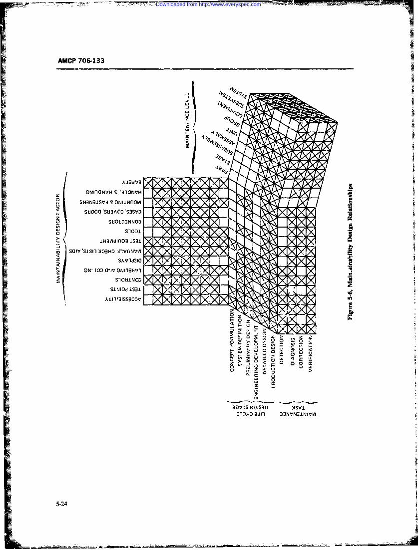
-7~- -TriW
AMCP 706-133
A.l3dIVS S
ONI1ONVH 19 'Y1QINVH a0a
0 St43N3.LSVJ '9 DNiINOwA
z SUOIDSNNOD c
coSI'SJ Sil >133HO1 S!VfiNVVn
Z SAb'ldSiO -
z ON' 103 G"JV DNll3bVl
All 1191SS3Db' V
z Fms
2~ z
2
U ca:C. z z
BlA 3d1 o3VN 0lv39 0 ND.537
5-24
Downloaded from http://www.everyspec.com
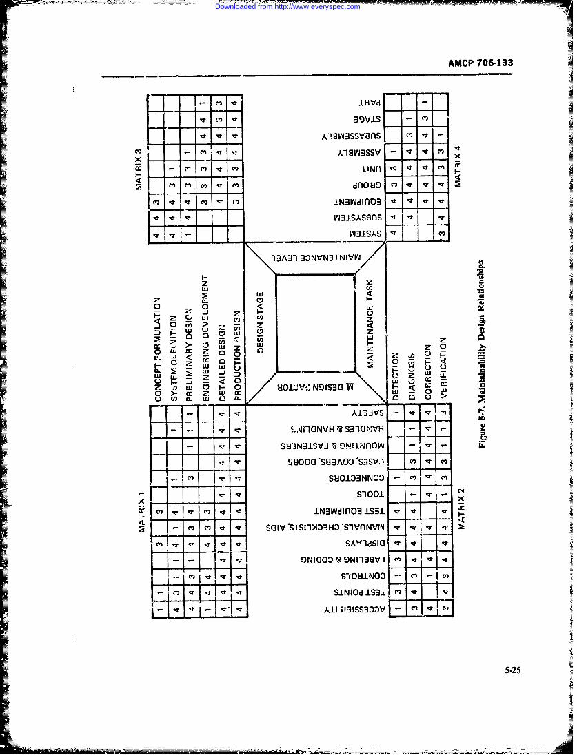
AMCP 706-133
I8Vd-
39VLS v
xC A kIS3SSV - I -I
r CMI) m, II~ M v v
C ') q ) oC3W i3 ' cr
IA J IS A sflVY1SAS
-1EA3-1 3NVN3.NIVW~
z2 w
0 0<* u I- w
_.j 0 m >w I-
~ U
CLZ~ cJ LU z9
U w- z c: z C
0 n w o z O c)W NU 0o) CL w0 mo~
- A.L3IVS~
- -~ E.A1-lONVH)RSTIGMVH -
S "1N.S QOLNn oV~ vw
t - ) OO G 'SH AO D SHSV -- v C.-r S8013NNO v) c',
C) v Cl S3~ iOWn Q S3 v v, .- Wc
SNIOdIRO 1S.laV v"
C..2
_________ - ~<f* N-~- - i m - -
Downloaded from http://www.everyspec.com
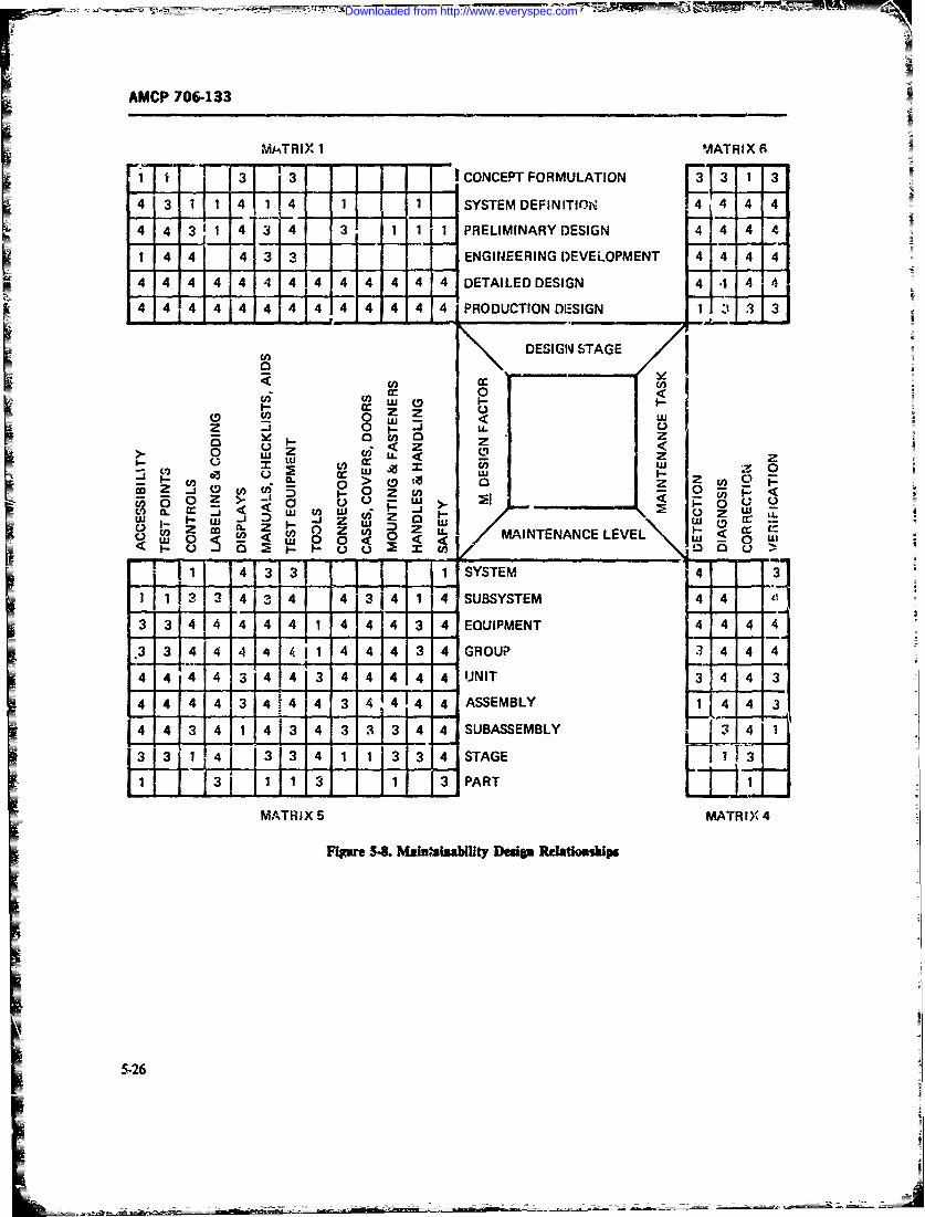
AMCP 706-133
M-TRIX 1 MATRIX 6
1i 1.. 3 i~ 3 ] CONCEPT FORMULATION 33 1 34 3 1 1 4 1 4 1 1 SYSTEMDEFINITION 4 4 4 4
4 4 3 1 4 3 4 3 1 1 -I PRELIMINARY DESIGN 4 4 44
1 4 4 4 3 ENGINEERING DEVELOPMENT 4 4 4 44 4 ,,4 ,,4- 4 4, 4 4 4, ALO i ' Ipt 4 4 4 4 DETAILED DESIGN 4 4 4 1 4
u DESIGN STAGE
4 4 4 4 4"4 4 4 4 4 4 4 4 PUN'TIONE3IN 4 3 3!
"- 4~ 4 - 4 ... 3 4i 4 3 -;1 4- SEBY {
cn Icn -
MANTNAC LEVEr
3 3 LI4 I 3 1 13 3 STAGE
MATRIX 5 MATRI)', 4
Fipre 5.S. Ma~iaabWtty ]Desi Rda~tiomhlps
5-26
t_ _ (r - --
_ .) L ouE: c.>=
Downloaded from http://www.everyspec.com
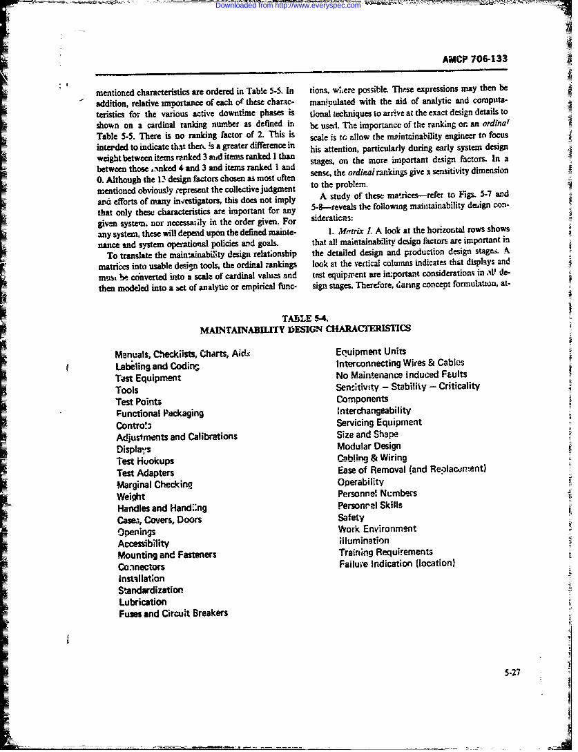
AMCP 706-133
mentioned characteristics are ordered in Table 5-5. In tions, wuere possible. These expressions may then be
addition, relative imnortance of each of these charac- manipulated with the aid of analytic and computa-
teristics fo7- the various active downtime phases is tional techniques to arrive at the exact design details to
shown on a cardinal ranking number as defned in bec used. The importance of the ranking or. an ordinal
Table 5-5. There is no ranking factor of 2. This is scale is to allow the maintainability engineer to focusinterded to indicatc tMat ther. s a greater difernc in his attention, particularly during early system designweight between itm ranked 3 aditenmsranked I ha stages, on the more important design factors In abetween those ..xnked 4 and 3 and items ranked I and0. Althougi h 3dsg factors chosen as most ofe sense, the ordinal rankings gives% sensitivity dimension
metioned obviously , epresent the collective judgment to the problem.
ard efforts of many inv!estigators, this does not imply Asuyo hs arcsrfrt is - n
that only thest: characteristics are important for any 5-8-reveals the following mahitainability design con-
given systern, nor necsfily in the order given. For sideraticas:
any system, these will depend upon the defined mainte- 1. Merrix L. A look at the horizontalI rows shows
nance and system operatiotial policies and goals. that all maintainability design factors are important in
=To translate the main*inabiNty design relationship the detailed design and production design stages. .4
matrices into usable desi~n tools, the ordinal -rankings look at the vertical columns indicates that displays and
must be converted into a scale of cardinal values and tst equipm~ent are important considerations i ' e
then modeled into a bet of analytic or empirical fuinc- sign stages. Therefore, daring concept formulation, at-
TA15LE 5-4.MAINTAINABILITY D~ESIGN CHARACTERISTICS
Manuals, C'eckiists, Charts, Aic4- Eq'uipmenit UnitsLabefling and Codins Interconnecting Wires & Cables
Tant Equipment NoMaintenance Induced Faults
Tools Sensitivity - Stability - Criticality
Test Points ComponentsFunctional Paackaging InterchangeabilityContro!a Servicing EquipmentAdjustments and Calibrations Size and ShapeDispla-,s Modular Design
T est Huokups Abin Wro
Test Adapters Ease of Removal (and Reolacwsrtent)
MAarginal Checkinq. OperabilityWeiht Personnel Numbers
Handles and Hand:,ng Personrel SkillsICases, Covers, Doors Safetyopenings Work EnvironmentAccessibility illuminationMounting and Fasteners Training Requirements
Coninectors Failum' Indication (location)
InstallationStandardizationLubricationFuses and Circuit Breakers
5-27
Downloaded from http://www.everyspec.com
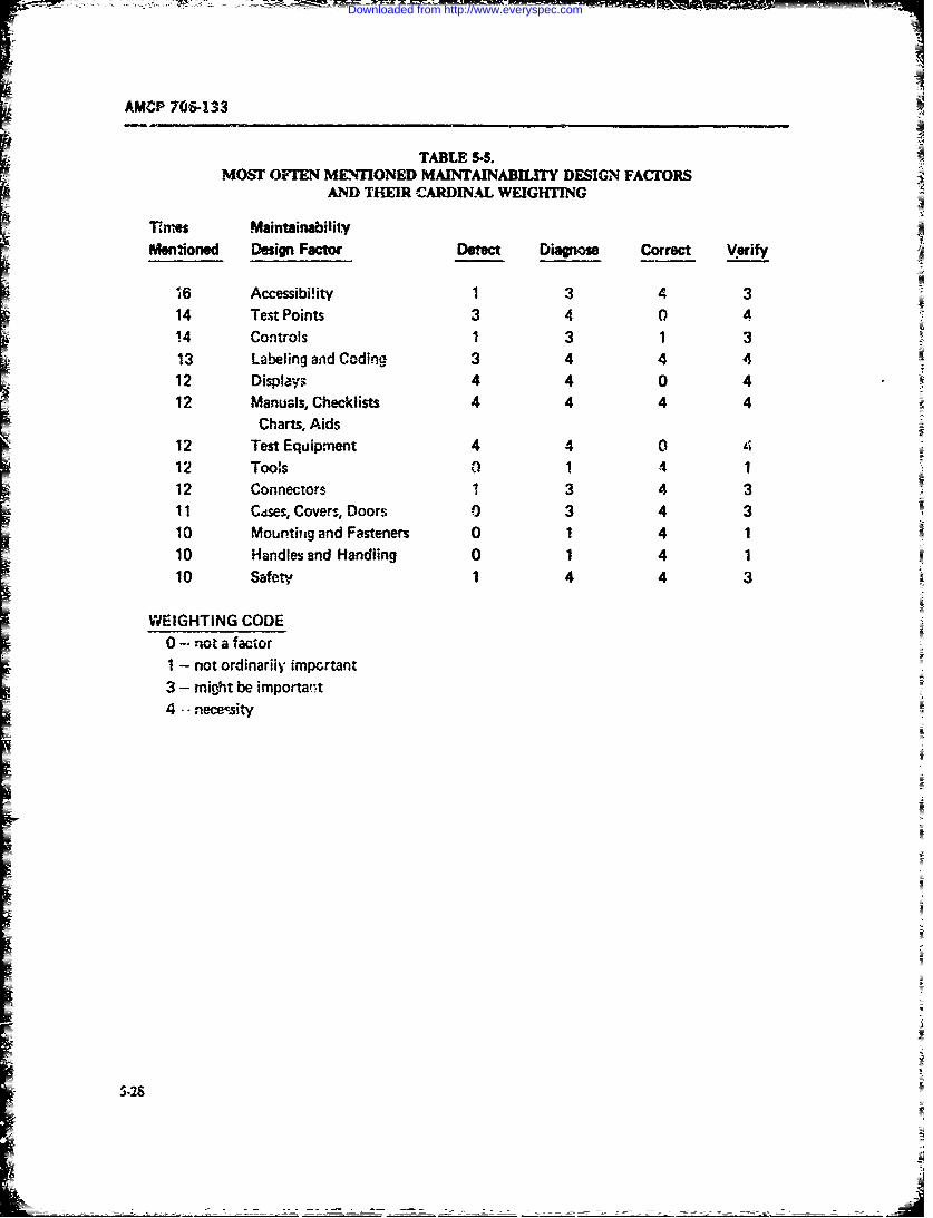
AMCP 706-133
TABLE 55.
MOST OFT'EN M MONED MAINTAINABILITY DESIGN FACORSAND THEIR CARDINAL WEIGHTING
T.nes MaintainabilityMentioned Design Factor Detect Diagnose Correct Verify
16 Accessibi!ity 1 3 4 314 Test Points 3 4 0 414 Controls 1 3 1 313 Labeling and Coding 3 4 4 412 Displays 4 4 0 412 Manuals, Checklists 4 4 4 4
Charts, Aids12 Test Equipment 4 4 0 412 Toos a 1 4 112 Connectors 1 3 4 311 Cdses, Covers, Doors 0 3 4 310 Mountiag and Fasteners 0 1 4 110 Handles and Handling 0 1 4 110 Safety 1 4 4 3
WEIGHTING CODE0 - not a factor1 - not ordinarily impertant3 - might be importa,t4 -- nece-csity
[528
Downloaded from http://www.everyspec.com
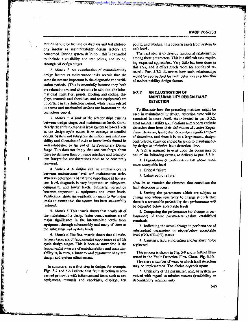
- ~ ~ -_ _ _M
AMCP 706-133
tention should be focused on displays and test philoso- poinL--, and labeling; this concern exists from system tophy insofar as maintainability design factor. are unit leveL.concerned. During system definition, this is expanded The next ste-p is te develop ftrnctional relationships^3 include a cessibility and test points, and so on, aming these pna'ameters. This is a diffic'jlt taskc requir-
throgh ll dsig staes.ing empirical approaches. Very little has been done inthrogh ll d sig staes.this area, and it offers much room for continued re-
2. atrx 2 Anexainaionof maintainab~tity sac.Par. 5-12 illustrates how such relationships
cation periodis. (This is esnilybms hybtare related t.) test and checkout.) in addiio-i, the infor- 5-.2 A ILUT TON Fmational items (test points, Lk>beling and coding, dis- M'ANTAAILUTR TO PEINF ALI ~~ph-ys, manuals and checklists, and test equipment) ar DETETINAIT ESG-ULimportant in the detection period, while item-, reladDTCIOto a:=es and mechanical a.ciins are irnortant in the To illustrate how the preceding matrices might becuirctiofl pervid used in maintainability design, detection !line will be
3. Matrix 3. A look at the relationships existing examined in more detail. As ii&-ted in par. 5-5.2,between design stages und maintenance levels shov.., most maintainability specification-, and reports excludeclearly the shift iir emp!'.asis fbin system to lower levels detection time from their definitions J -.Mtve Repairas the Jesign cycle moves frcn concelA to de.railed hie. However, fault detection can be - signifiesmt partdesign. System and suz systemt definition, and maintain- of downtime. and since it is. toI a large ex*,rnt, dezign.ability and allocation of "-~k to lower levels should be controllable, r!-ention should be givzm to maintainabil-well estoblished by thc end of the Preliminary LDesign ity design -o !ninimize fault detection uime.&age. This does not imply that one can forget zboiut A fault is assumed to exist upon the occurrence ofthese levels frcom then on, since interface and total sys- one of the following event-:, as defined in par. 5-5.1:tern integratian considerations nced to be constantly 1. Derdto of pefrao bu abv iireviewed. raum acceptable levelI 4. W4atrix 4. A similar shift in emphasis occurs 2. Critical faurebetween maintenance level artd maintenance taks 3. Catastrophic failure.Whereas detection is of extreme importainct. at th~e sys-
tern It -J, diagnosis is very important at subsystemn 01ow et us txaniine the elementa that constitute theI equipment, and lower levels. Similurly, -correction fault dttem~on process:becomes important at equipment and lower levels. 1. Sensing the parameters which are subject to'Verification shii1s the emphasis up again to 'he higher change and whose sensitivity to change is Luch thatlevels to -ssure that the system has been =%X'cessfullY them is a reasonable prooability the performanice v6illrestored. be degraded below accepable levels
5. Matrix 5. This Eatrix shows that nearly all of 2. Comparing the performance (or change in per-Ithe mzintainability design factor considerations ire of formance) of these pararafters against establishedmajor significance in the interrnidi.-te levels from staiidardseTqtipment through subassembly and many of them at 3 Indcatin the awml chnein perfermanice ofthe subsystem ar-d system letis. wL-~ fandar'd parameters or abovt/below acceptableI 6. Matrix 6 The final matrix shows that all main- level (G-1Ojt4O)) statustenance tasks are of fundamnental importance at all life 4. Causing a faiure indic~zion and/or alurm to becycle design stages. This is becaurw downcime is thr regitered.
fanaun'-aeasure of maintainability and maintain-ability is, in turn, a f(undamiuW -parneter of syte This process is shown in H&g 5-9 and is further illus-designi and system cd erv~eess. trated in the Fault Detection F~o% Chart. Fig. 5-10.
Th-re are a number Gf ways in which krut detectionzIn sumrmusy as a first stpp in design, for e7ampie, may be implemented The choice d4encl upon:
Figs. 5-7 and 5-8 Lidicet that fault det~ctio is cmn- ~ .Criticality cf the parameter, tiLt or system ii'-cerned primnily with informational item such as test volved with regard to iision success (availability oreqrupnent, manuals and checklists, displays, test depeneability requirement)
5-29IA
Downloaded from http://www.everyspec.com
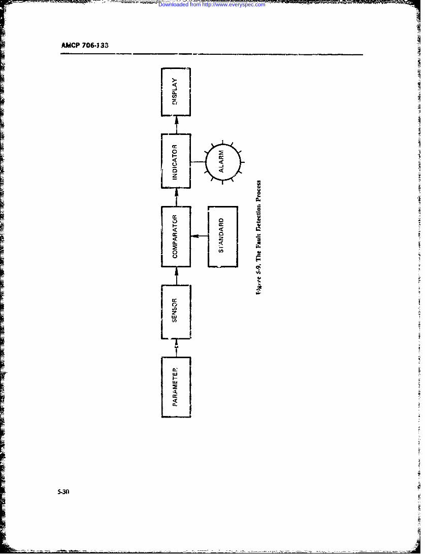
ANCP 706-3 33
r
a:-J
z
a:0~1 00..a:
.~
0
1<
IC.)
j
Ia:LWi
a:wtEa
4a:0.I
5-30
Downloaded from http://www.everyspec.com
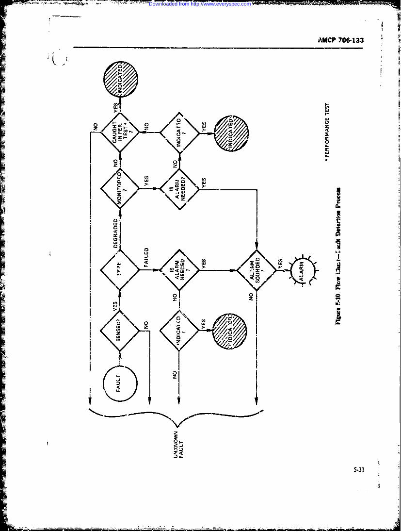
AMCP 706-133
U.,,
Z I.-
_ U.
U2U
C4 ( C(3'. u i2r (Z i
j. ...'7J
U:
24
5-3
Downloaded from http://www.everyspec.com
AMCP 706-133
. Failure rate of the param-ter, unit, or systent tiveiy little or no manual or chekrs information re-
3. Overall operational mainiertnce and tea policy quireients, and simple labeling and coding. The
adopted manual features require significant amounts of these4. Cost-effectiveness of the proposed scheme. items.
Automatic de: xtion features require leks accessibil-
Amon., the possible fault detection strategies are- ity. Periodic test. op the other hand, tn..y require est
1. Autoimatic monitoring with aarm indication point, control. wid display accessibiity.
caly2. Automatic fault indicatiun with alarm for criti- 5-7.3 MONONG AS A FAULT
cal p-.:meters and with degradation level/failu-e in- DETECTION TECHNIQUEdicators or recorders
dicaors t ~There are several wvays in which hiults, may be de-3. Periodic t,.t and inspection sy maintenance tected. One is by continuous monitoring of the sensiti;e
personnel system parameters. Another i- by interrittent xni-4. Periodic sclf-est and calibration by the operator toing or sampling. A third is by periodic test. 1h;e
5. Abnormal ope'ations noted by the ( perator, method chosen sheold be determined by the systembased on his experience and knowleage of the equip- effctivenes requirements of each syst_, subsyst.,mert operationai characteristics, or parameter, its sensitivity to change or degradatiom
snoobrationa deand requirements; ard crsL Manit-r-
In Table 5-5, detection time is seen to be a functior ingt; defindhereastheprocess ofdetenrunig changeof a number of maintainability design factors. Express- in the parameter. functic, or item under examinationing detection time t, as a function of the more impor- based on its own state of operation in the system, andtunt factors (rating of 3 or 4). we obtain witheut the injection ot externai stimum - is defined
t,h, TP LC D_ MC TE) as the interruption of the normal -)peratic- and theWI,'re injection of a standurd t. s4-u-L This sigdl m-, be
TP = Test Points either a sdf-test signal mjwetd autonr ticifly at peri-LC ! ..abell'ng and Codi.g odic or rarcon intervals or upon call, or an exter.ally
D = D)plays introduced stimulus.IVMC - Manuais Checklists, Aids Monitoring can be a valuable and effi,-tive meas ofTE T.t .: .ui me~t fault detetzon and location and. to som --dtr fault
The test tquipment factor . (ne of the ,ore signiffi- i:,qation- There has been a t .ency in the past tocant of thes-e Depend-itg upen the operational :juTre- m~nitor tro many item--for example. such eeails asmets, the nature of the equipmen; under considera- iridividval refs:anc values or cutrent znd voltage iation, its impomrtamc to mission effectiveness, the o-,ru-al ek-romc equipment, even where ch.-ges n thtsemaintenanc policy, and ost -siid.rations, a decisic, items ha't. ltt: effect on system perfor-m1maybe made from ote extrcr.ic of n, specific provision Th,. rm-.itoring or dcticn of varmtiun ir nearlyfor fault detection tc the othr cxtr-c.e of fully auto- every c--omnt and -,&rn e, only e-',.tnber thematic monitoring of r'J pa-amete of ipaportance The taaintenance frivfion, and caze a greater potentialeffnct of these on detection tie and their costs can be re-4 uction it. sytseP, maintairJ'1ility aad irliability thanexpected to vary omewnat. as shown in Fig. 5-11 tonitonng ,o a &.w.ed subsystem zA hinctirci_ Ie'r-
It is readily seen how the other design factors art Th's is la-gey dhie to tht added complexity ad io falseaftected by the teAt equipment factor. For exanmpte, alarms which put the system down Onlj those systemAutomatic Monitormni and Automatic Tcst Equipment performance .nrameters that mate.aJy afiect system
imply a large number ofb Ot -itisensors and referet.s perfomiance shmold be monitored for ul* rications.Built-in Test Equipment (SITE), General Purpose Cest Set-sivity analysis cap be used to dete-mine whichEquipment (GP1 E), and Specid -urpose Test Equip- puram-ters tl.ese %houid be. A prop e-l desiged moni-ment (SPTE) imply fewer senrors but rnc're exterual toting systemn ba.sed ,- a l,,cai .,nalysis of systemter. points (for detection). Operx-o. failu.. s'ming im- rN,- m..cnts and maintetmnce prAic" can be an invmlu-plies few or no test points. Similarl, autonic nz 'ri- able aid to minimiing system downtime.terig or testing imAy 2:mple GO/NO-Q)3 disclay or To proviee adeuiate sy3tem efectiveness, it is neces-alarm prG.ions, wherea general purgxe checks and sary to h-.we a rapid and timely indicition of sytteiz
operator sensirg and indication imply more interpr. failure or deg 3dation. There are ce-vral ways ;- whichtive types of display. Aut;iatic features imply reha- this ma-" be accomp itt. 5oss system filure *0
5-32
Downloaded from http://www.everyspec.com
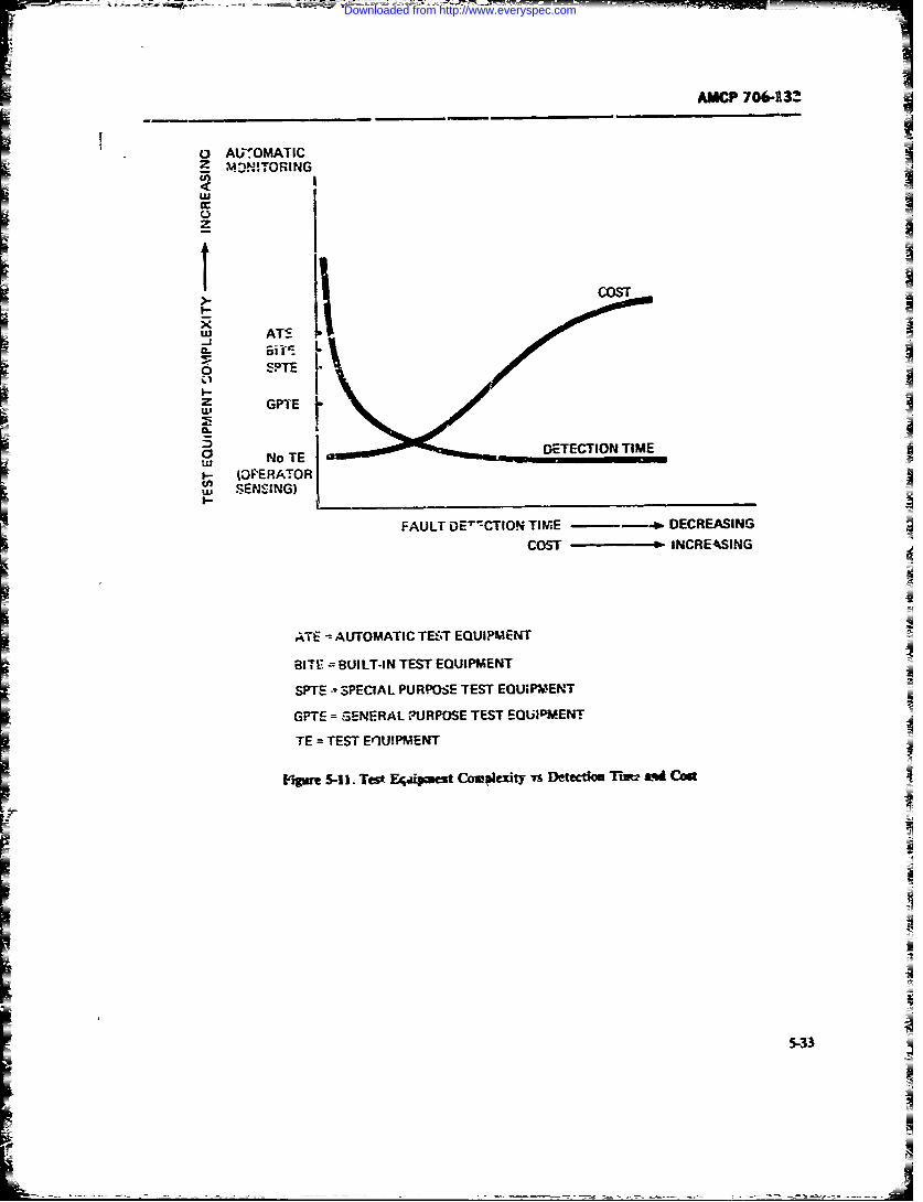
-= - ___ __=-- -*- _
AMCP 706-13
fIc AUTOMATICZ MOVi T ORINGU0
COST
Lu ATS -
z Gq
tu No TE lW-IIERATOR
u~SENSING)FALIf~TO TIME -- ~ DECREASING
COST PINCREAkSING
ATE AUTO~MATIC TEST EQUIPMENT
81-1 E BUILT-IN TEST EQUIPMENT
SPTE -SPECIAL PURPOSE TEST EOLJsP?,'Et.T
GPTE = SENERAL,~URPOSE TEST EQUIPM.EN-T
TE TEST Eq2UIPMENT
Vqii~t 5-11. Test Eq,~4m~et COWuleiitY Ts Dlfecim Tim?; ind Cod
MWI -- AM
Downloaded from http://www.everyspec.com
AUCP 7064M)
often be recognin r- oy the operator if the system is in tkne and an increase in availability. Factori to consideruse. Degradation may sometimys be recognized by the ,oe.operator even before a built-in monitor does so. It isnecessar), however, to take other measures to minimize
uncertinties or the risk of failure to detect an inopera- 2. Minimization of preventive and correctiveble condition which is critical to mission success. mainterance tasks to be performed
Monitoring or testing may be on a GO/NO-GO ba- 3. Minimization of the logistical burden by a re-sis, by LO-CO-HI sectors, or by means of actual value duoi need for maintenance and support r-sau-ces,indication. All of these may be caantitative in nature. sh a peronnel nutebns and skill l.ve support
the first of these, howver, merely indicates that theand special mainten I=parameter or function being monitored is in one of two tbiay states, Le., above or bSow an acceptable level. tiesTe second method gives an indication of shift in pa- 4. ReductiX in support costs.rnmeter value or .arginal warning wtile the thirdgivcs an actual numeric reading. a an absolute value ,Many of the princpa factors whh affect desija foror percentage. These latter two types of indication are maintainabity are listed in TeAe 5-4 and are relatedof value if the -,ena it inditative of the degradatio in schematically in Fig. 5-12. T-.- Primary m tainabilityperformance so that preventive mantnace actions design chuan-teristics hav. been ranked h Table 5-5.can be taken at appropriate tiJ. The information SpeciE: featur-s and their effect on maintainbilityavailable may also be us.-d for reliability and maintain&- -,vgn dhre dc e,Af par. 93. The inclu& thebifty analysis. and thu for improement of system __f cbewisas. jcAgig flanda ntes anddesvL
Mcnitoi icheckout, human facto.s considerati.* safes. trade-M o n i t o r i n g i m p l i e s a n o n li n 6 oe r a r . W h a t O . a d o t c n i e a i m M r e W d s gshould be monitored epems upon the sysam effec- ogi, and irconsdeaons. Mere deaied designtiveness numeric the 4ATBFof the,'aiw. -eyst--"s= guie info tion is ,.ontain in Re 11 andl 24-,qupmnts. and functonal cuitsme ano th s 38. In particc--br. Res I I and 31 are especially recom-
sih!';ty of tl system to variations in these. Whether me.Ced.continuous or internittent monitoring should be usedis deteumined by the following %actors:
Total --umber of mousrr.-g points 5-.! CHECKLISTS2- Wheth-r system availabaity and operational de-
mand ar-ow for test and preventive maintenanc dine C are an imptitmet and usefi,!id fa, systemioan equipment designers to insur that aJ essential
3. Whether monitor indications at th, e tuipent n factors which equiepe the nadrtor module location are satisactory or whether a central juacteg-tcs of the svem/"4uipmet have been
monitoring (and perhaps recording) facility is feasible i' adequate consideration in much the sane wthat Table 5-1 serves as a checklist to insure that main-tenance policies and go !s have been prorerly consid-
Of the various equipments that make up a system. ered in developing te mainte.,ance coacepe and main,-some widl L-e performing viral functions at all times. tenanct support plan.some .art -f tnt time, while thers will be performing Maintainbility checkis are counterparts to and
largely auxilary functions. The extent to which morn- hould be hnlLded in main ainabilzy design guides.trinzg should be carried cut is t functin of such car eklists may be used in three ways:swderations. - By rnaintaisbili'y and ,.sign engineer for
considering the influence of sprc ..- maintainability de-sign features (Ref . 4i. Appendic A. Ref 40)
5-8 MAINTAINABILfTY DESIGN 2. By system engineers and p-rject mamgers for
CHARACTERISTICS design reviews during the vmrieas system lif cyclep:asm. particularly in tbt design sages (Fig. 3-9)
The raintuinability design caracteristics of a q'ys- (Reft 'I, Y!, 41.1ten o7 equipn cnt include those equipmen features and 3. By maintainabiity e for manabili
t design factors which will promote a decrease in down- prediction (PefS 1 and 39, Append B).
5-34
Downloaded from http://www.everyspec.com
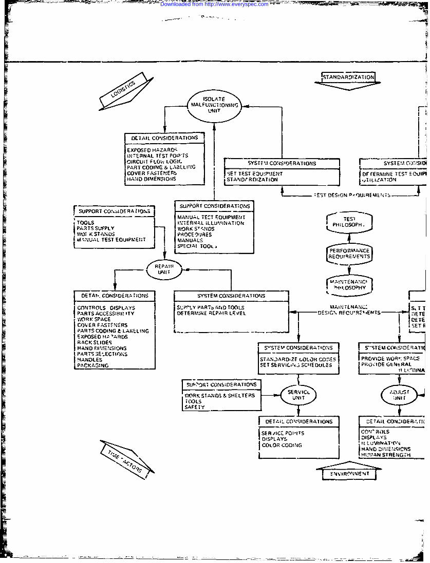
IANAGDZATION
LIRUN ILi TO!~ SYFMCN',RTOSI 5yTMCS
PAR C DIN & LA L G Nr
RM N
COVR_7 FASEER iE ES 3UPEN ES SuP
INERA TEST OES!GCICIrFO- SLOG! OR COSORTOSY USDRTMSS A(.%II
SUPAOR CODIORAING& A;.SINCOVER ~ MAUA FATETE! FOIi.ETETFWAETDFCRi ESEhj
HANDS SUMENPLYN STA~fDVARKO TILANO
TTEST DrjanO CE,_U.EMES
I &ULTS ~l7ETMANUALSTC OIMETTESSCIlTOOL PE RNA LUFNTO MOSOPH E
II
RE
IE-NT
I HANDA TIES IMN T MATNUALSRTIN -~E C~S AIPAS3LCCION TIt.
RKSTANDS&SIIELTrUS UNI
Al-. COSIDEII 4YSTMCO SERA ICS
CONTOLS ISPLYS S--#"LY PRT AND OOLSIAI.DTSAN LA &S
tXPOSEIHA'AVD
RACK SLIDEILND _MNIN _ TVCN!EAIISEmtCC-
Downloaded from http://www.everyspec.com
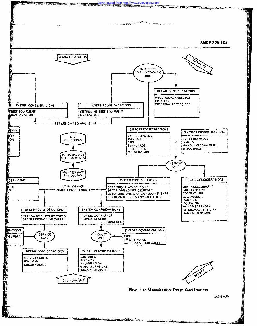
-~ AMCP 706-133
rl =ARDIZA-10h,
I MA LF UUCTiqQ'uuG
DETAIL CONSIDERATIONS
I________________ tEPLAYSSY STEM CC NS:DERATIONS I SYSTEM GNS.D;_ 1ATIONS XE4ATSTPlS
EST EOUIPMAENT ~DETERMINE TEST E(.YJIi'&.1E'4TDARCIZATIGN4 WJILIZATION
-~~~ ~TEST DESIGN 'AcOJREM ENS ________
ions ~S,;PO~tT (O\StOERATIO* I S sPPGAT CONs:OERATIOUSUJT TEST 71-5 EQOIW.ENTN MANUAL$"' TEST FOUiPmENT
US SPARESCTAI ARNOl4,iiG EOQUIPMENT
F '.'I- v6JRK SPACE
___N.A._______F1f'~~~~~~~ E'sAC ___________
t E Gi tR E'AEN S
AI qTNANCESE VAY4E1L ur'CSIBiT
EO ESIS" REG JitIEMENTST OF 7DE 1RUNE L-GI-( SUPPOR T UNII LASELING,
7 j DEEMN ~ IAIN~OIR~ETCOAMEC1 JRS
SE EPA LEV EE LS N D FA JLITIE ; f;l ic-N% iO NS1
HIAN S=EVTSr~U S lN CE C O S Y T M C N S=_A I , j
I ItE. CNI-AI~ Ss" SUMAN RC'E AITY
ff TA4DAROCIZE COLOR CODES! PRiOVIDE 'WVRK 5VACE AN cAI.lu
-Z rSRVICIN 4L ES)-:cG CNEtRAL
I- ILLU2MIN.4TI~ki
)POTCCAISIDERATIOlS ISE RVICE ADUS TS t
DETIL OISIDRAIO ,SUMEA. C&USIVRATIONS
SERV:C9 1rO1ITs LC-NTROI S
W.tOR ~DZ ~O
_________ A.FNGTH
Ftjc5-12. Mrutm zisyuiI Cousidwitfioa
~55 36
Downloaded from http://www.everyspec.com
AMCP 706-133
5-8.1.1 Checklist Infovrntion Partining to "-82 PACKAGINGWiintenance flowntirms
1The mnanner in which the equqxnent isdowntimies incltres Lhose- tie mn which will help reduce The Izvu -& cornpeiL. nd sem'bies, theirpreventivre mnaintenance times (servicing and ur-sW- monn. ,- adcaeo reo _- of reaAn %
nents (delectio diagnosis, zorrection. And venifica- na ont- n sh 'Y-- desipned to facilitate
sh.uld ',v ot concern to design engincers as well as toreliabilhiy and maintainability -'tgineers. 2.Md~xz~o ntzto
In addition to exami'i- t"e tra&-o!S- bctween ritli- 3 iidriain!qfeeability and mantainability. maintainability and 6cti3n 4. Reliability ftc..sengineers must soxk meam for mmnvarnn Vemeati'e S. (>,,ratmg strm vibra4on, tempator. a
and correctie mintenance task&. Thee iodude. other ciiroiairntal Considerations
1. Reducing ~h rqe of srchiedue maneance- Prdcbll ndohrmvcc.nc Seacngcdtin.m q~i e sdp~
2. RSucqing the .eqimtn h rent ivry main- 7 Rcqudicnxs 9. ul-n: & etPieac as i. Cwac-stc re La ient or einn UM i suc -
3. Inarxnn the atmon s n d Oarer a in. wehitem khils~'aga~~t ofbwpnn ndtoue. Tooli nd es tviet rt a ks m ro
T.able cin r~* of th cor-ti, mf.tnac Spttiulc Chnmn nba ~tcinn do'antim es.t -Srrcig dutg q qar sdpo
Specilist £hcdit forac- Consideratio -o ofig r-
inmeneaf tain co es nd module 5e5) Tool and testd thupat p gvxS t qu
aTeic f ~ins a ndkis o eusten in cai peo bt manmzn art-!n_.wigt ant and bWupmn p3ra~-
S-&bA' .2 indu e ki foonsidrnnso'aiy. casei oes
-= a~~ngeersa prinerim wonithru is aetohsefCI- Ae ss;Ndtdy, istheo the adve.4 cf ntdmo% fa-atr.it is essnti , tatd conscios aueriri age o find ao reoltyi many syszit, 2nd Nacce*o ithe m dur'x as stompann n einpa'- W~OC~nme n tbeL(al -)
,ie (oaf 1V-i) eifar r , menis ofg Inurn 1~S i~t' was bes ad a erltv ewt
suchiyinl cons i Cerc-ss oel Whybo csesia and~v t"Mic an - voe cnbe w.dmvn., ltndios. fonigoasen nca.S rM insjeC~e repair.ol Nvpzcmens bor sen-1.
Cb-e ~tha p. c desig n ies uvlten 10 the c xeiv st ni" mc to- tn the unlt oinacceifm
factrs listed n(pabr. 1-6) arer, ieans of A m niP Accesibiht canbe_____aw__te m it
suh(Ref. =CohrL el aheq 1!). v iS~e an d asswb or~z~i CO erM ca c Pr
revk S-Utio for"PI~ 1-.01aeme-t- r S.37w
Downloaded from http://www.everyspec.com

AMCP 706-133
TABLE 5-6.MAINTENANCE DOWNTYME CHECKLIST
1. Have servicing and inspection intervals been maximized or otherwise chosen to assuremaximum material readiness consistent with mission and ope-ationai requirements?
2. Have adequate provisions been made for inspection - such as appropriate access doors,inspection windows or ports, test points and displays, inspection instructions located next toinrpection points, proper working height for the operator or technician, adequate lighting, indsafety?
3. Fas pro-,sions been r:,ede to facilitate rapid fault detect: n?
4. Ate mi;.sion critical performance parameters automatically monitored?
5. Do performance monitoring features ncludn means for degradation measurement andtailure prediction?
6. Where autumatic monitoring is not ieasible, are provisions for periodic checkout provided?
7. Ca.n significant failures be readily localized to the affected equipment; assembly, or uniti
8. Are provisions for automatic faust I.. Ai!n feasible?
9. Have features been provided to isolate the failel item to the replaceable or repairablemodule(s) or part?
10 Are indicators or alarms provided and located in such p;aces and manner as to assist themaintanance technician to locate and isolate the failed item promptly?
11. Have provisions been rnde for rapid and ready access to failed items?
12. Are the failed iterri" readily -. piaccaL.!e or repairab!e?
13. Has a replace/repair/discard policy been established?
14. Have adequate spares and repbir parts been provided Lnd located so as to facilitate inter-change time?
15. Have adequate csntcol., displays, adjustments test points, and checkout procedures beenprovided to facilitatx alignment, calibration, and checkout of the unit after rapair has been made?
16. Have built-in test f6atres been provided to facditcte veeification of corrective mcintenancaactions?
5.38
Downloaded from http://www.everyspec.com

AMCP 706-133
Th technician will tend to delay or omit maintenance 8. Distance to which the technician must reach-actions, make mistakes, and accidentally damage within !be accesrequipment if he cannot adequately see, reach, and 9. Vual requirements of the technician in per-manipulate the items on which he must work. Poor forming the taskaccessibility to rc ;re service and inspection points 10. Packaging of items and elements behind the ac-and parts of equipminnt reduces the efficiency and in- cesscreases he time of the maintenance operation. If it is 11. Mounting of items, units, and elements, behindnecessary to di~rantle a given component complately the ac'-essor partially r) reach a given part, the availability of th th
equipment decrerses and maintenance costs increa.e. 12. Hazards involved in or relaed to use of theControls, check points, inspection windows, lubrica- accestion, and pneumatic and hydraulic service points ar s3. Size, shap, weight, and cle.ra'ce requirementsbuilt into the equipment so that it can be ,=pt operating; of logical combinations of human appendages, tools,at peak performancc. If these scrvice points are inaces- untts, etc., that must enter the access (Ref. 11).sible, routine maintenance becomes difficah
Accessibility, however, when zonsidered separately, O, ce access has been gained to an area in which andoes tot comite %-,mnteinability. The Mf.-re fact that assembly oi part is to be repaired or replaced, access toa technician ra- "get at something" does rizt mean that that particular item trust be provider'. Guidelines forhe can meirtaii. it. Accessibility require'ents are de- the designer in planning for ease cf maintenance in-termined by the -secessary maintenance action, wbich clide:may be visaal. ithyic,4, or both, depending on whe!ther I. L a.te each unit in the equipment in such a waythe task is inspeciien, ,tr" cing, adjusting, repairing, or that no other unit or equipment has to be removed toreplacing. Generall,, they represent two needs: acess get to th. "nit.to an item for instction ad testing, and space "1 2. Locate assemblies and parts so that structuralwhich to adjust, repair, or replace it. items and other parts do not block access to them.
Weli designee equipment accesses are essential for 3. If it is necessary t put one unit beh;'id another,ease of mo'ntenante. and should be provided whenever place the Lnit requiring less frequent attention in backa mainte.jance prosedure would otherwise require of the one requiring mre frequent attention.removing a case or covering, opening a fitting, or dis- 4. Do not locate a unit in a recess or behind ormantling a unit. Before designing equipment accesses, under structural members, floor boards, operator'sthe eninecr should list the parts of the equipm.nt that seats, hoses, pipes, or other parts of the equip, ent thathave to be reached, their failure ratt and the operations are difficult to reineve unless this serves some purpose,that are likely to have to be perf.rme- on each part. such as protecting the unit.The access then should b. designed to make those optr- 5. Removing any line replaceable unit (LRU)ations as -'nvenier.t as possible. Table 5-7 gives recon'-mended equipment accesses. shottid req-ire te echnician to open only one access.
-Factors affecting accessibility incluoi: 6. Jnit.v generally should be designed for removal!- Operatinal locatin,, setting, and tA'ronment through the front rather than through the side or back
of' the unit of the equiptent.7. Units should be removrble from the installation
tered along a straght or moderately curved line; they shouldnot have to bejuggled around comerm.
3. Manteane functions to be perfoied through 8. Piace assemblies and parts so that sufficientteroom is availa,-le for the use of test probes and other
4. Time requirements for the performance of there tools needed.functions 9. Place throw-away items 3o that they can be
5. Types of tools and accessories required by these removed without the nectssity of. -moving other items.functions 10. Design each assembly so that it need not be
6. Work clearances required for performance of removed in ordc: to troubleshoot any of its cempo-these functions neata.
7. Type of clothing likely to be worn by the techni- 11. Use plug-in modi-les wherever economicallycian feasible.
5-3Q
Downloaded from http://www.everyspec.com
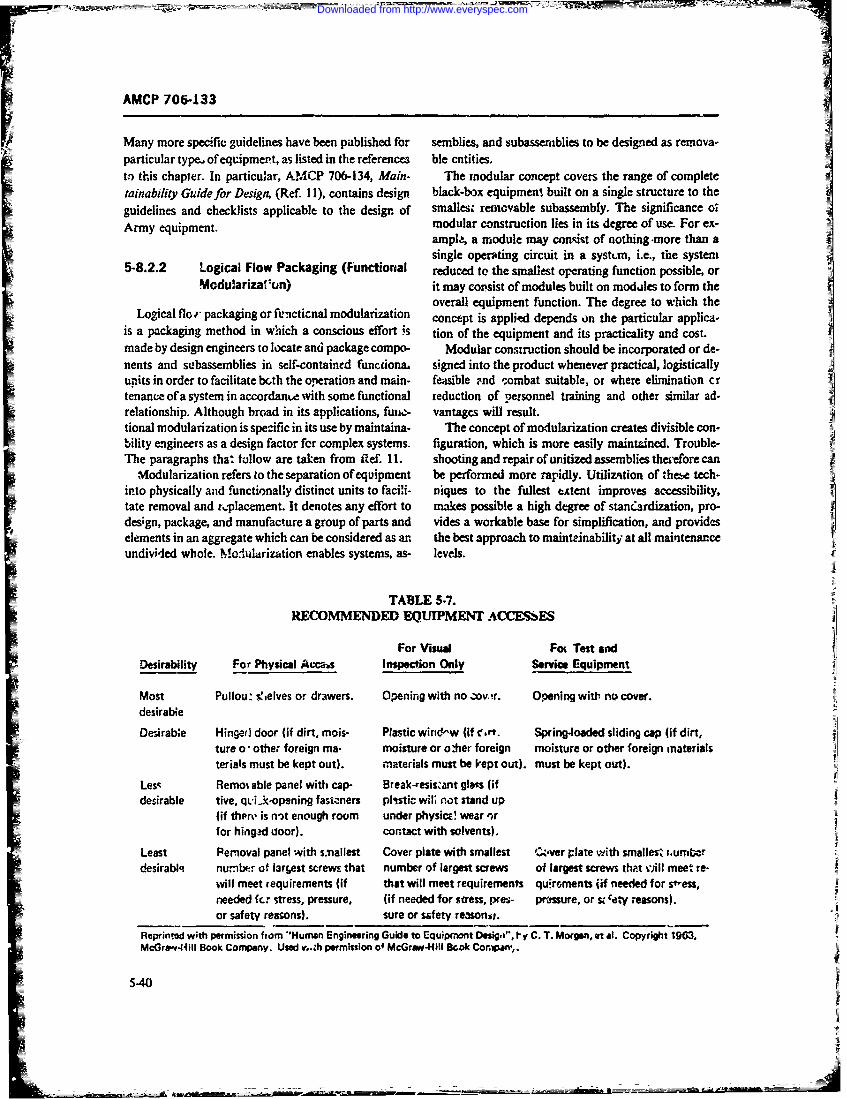
77k- I
AMCP 706-133
Many more specific guidelines have been published for seniblies, and subassemblies to be designed as reinova-=particular type of equipment, as listed in the references ble enitities.
ti) this chapter. In particular, AMjCP 706-134, Main- The modular concept covets the range of completetainablity Guide for Design, (Ref. 11), contains design black-box equipmen! built on a single structure to the
=guidelines and checklists applicable to the design of smallesz removable subassembly. The significance oxArmy equipment. modular construction lies in its degree of use. For ex-
amp.4 a module may consist of nothing -more than asingle operating circuit in a systun, i.e., the system
5-8.2.2 Logical Flow Packaging (Functional reduced to the smallest operating function possible, orModu~arizafi) it may copsist of modules built on modiles to form the
overall equipment function. The degree to which theLogical floi packaging or ft'ncticnal modularization concept is applitd depends on the particular applica-
is a packaging method in which a conscious effort is tion of the equipment and its practicality and cost.made by design engineers to locate and package compo- Modular construction should be incorporated or de-nents and subassemblies in self-contained functiona. signed into the product whenever practical, logisticallyurits in order to facilitate bath the operation and main- feasible -nd -.ombat suitable, or where elimination crteniance of a system in accordante with some functional reduction of Personnel training and other similar ad-relationship. Although broad in its applications, finic- vantages will result.tional modularization is specific in its use by maintaina- T7he concept of modularization creates divisible con-bility engineers as a design factor for complex systems. figuration, which is more easily maintained. Trouble-The paragraphs that follow are taken from Rtef. 11. shooting and repair of unitized assemblies therefore can
Modularization refers to the separation of equipment b efre oerpdy tlztino hs ehinto physically and functionally distinct units to facili- niques to the fullest ettent improves accessibility,tate removal and r..'placement. It denotes any effort to makes possible a high degree of stancardization, pro-design, package, and manufacture a group of parts and vides a workable base for simplification, and provideselements in an aggregate which can be considered as an the best approach to maintrinability at all mai'itenarceundivided whole. Molsularizatiort enables systems, as- levels.
TABLE 5-7.RECOMMENDED EQUIPMENT ACXCESSES
For Vi"ua Fo,. Test andDesirability For Physical Accaw Inspection Only Service Equipment
Most Pullouz: s!,elves or drawers. Opening with no )ov.!r. Opening witlh no cover.desirabe
Desirabe Hinged door (if dirt, mois- Plastic wiri&'w (if c.". Spring-loaded sliding cap (if dirt,ture o -other foreign ma- moisture or oiier foreign moisture or other foreign materialsterials must be kept out). materials must be krept out), must be kept out).
Les,- Remo% able panel with cap- Break-resizzant glens (ifdesirable tive, qii.kopening fasicners plistic wil, not stand up
(if thtre is n-)t enough room under physice! wear nrfor hingad door). contact with solvents).
Least Permoval panel with smnallest Cover plate with smallest 'I.ver plate with smalles^, i.umW~desirablq! number of la3rtest screws that number of largest screws of largest screws thpt viB meet. re-
will meet requirements (if that will meet requirements quirroents f if needed for s"'ess,needed fcr stress, pressure, (if needed for stress, pres- prmssure, or s;Caty reasons).or safety reasons). sure or safety reasonit.
Reprinted with permission from "Human Engineering Guie to Equipmont Oesigai', 1%y C. T. Morgan, ot at. Copyright 1903,McGra.'4IiII Book Company. Used v.,h permission of McGr#*V4V1U Bczak Cor.ipin,.
5-40
Downloaded from http://www.everyspec.com
AMCP 706-133
Another important advantage of unitize or modular insotir as possible, only single input .nd output checksconstruction from a maintenance viewpoint is the divi- are necessary to isolat a fault within an item.sion of maintenance responsibility. Modular replace- 3. Clear indication is given of the utnidirectionalment can be accomplished in the field with relatively signal flow within a given piece of equipment.low skill levels and few tools. This accomplishes aprime objective of maintainability-reduce downtime In order to make use of logical flow packaging, oneto a minimum. Defective modules can be discarded (if must construct funcional block diagrams which relatenotimairtainable), salvaged, or sent to a higher mainte- the logical flow of information, signals, or energy in thenance level for repair. equipment or assembly, or use. timing logic, test logic,
Modular design canaot be applied to all types of or maintenance logic diagrams. The half-split tech-equipment with equal advantage. Its greatest applica- nique (Ref. 43) or Design Disclosure Format (Refs. 23tion has been in electronic equipment. It has applica- and 24) are two of the many techniques useful fortion in complex equipment of other types, but becomes logical flow packaging, both of which are maiintenanceincreasingly difficult to exploit in simpler icvies. t'ol- related.lowing are a few additional advantages of modular con- The advent in recent years of solid state devices re-struction: quiring less power and thus reducing heat dissipation
1. New equipment design can be simplified and needs, along with microelectronies and cordwooddesign time shortened by tou. of previoutly developed packaging tecl-niques, has permitted packaging densi-stndard "build;ng blocks"e ties several orders of magnitude higher than heretofore
possible. These advances now allow multifunctien2. Current equipment can be modified with newer module packaging and, together with advances in lest
and better ,.nctional onits that replace older assem- techniques, perimit testing of a replace".ble module to beblies of component part , accomplished automatically.
3. The standard "buiding blocks" can be nanu- As contrasted with logical flow packaging, jtandardfactured by fully automated methods. packaging methods have no clear-cut procedures.
4. Maintenance responsibilitis can be divided Rather, the final product is packaged by balancing aamong the various maintenance levels best equipped to number of factors such as heat loss, component size,fulfill them. unit size and weight, and design and mt.iufacturing
5. The recotgnition, isnlation, and replucement of convenience rather than ease of maintenance. The logi-
faulty units is facilitated, permitting rapid maintenance cal flow rp-thod is superior in minimizing downtimes,at the user mevel, with c.-nsequent reduction of down- reducin _ie requirements for high skill levcls and intime. optimizing the amount of infe.mation gained per -nit
of test time.6. Training of user maintenance personnel wilt Because cf the rapid advances in packaging methods
take less time an' cost less (Ref. 11). just '-scribed, methods of mountialg parts, compo-7. The use of automatic and semi-automatic diag- net,,s, and subasemblies bave changed markedly in the
nostic techniques is facilitat.d by functional packaging, past ten years. In addition to higher density packaging,inasmuch as modularization allows for the ready pre- advances have been made in materials, cooling meth-diction of such faults as occur in a system. This is made ods, fastening methods, and in construction techniques.possible by the extent to which packaging permits the It would be impractical to discuss these in detail. Partsemployment of programmable test sequences with a Four and Five of AMCP 706-134, along with otherhighly developed capahility for isolating faults. Once a publications, discuss such methods (Ref. I 1).'ault has been quickly located in a small unit, standardfault-isolation procedures developed for that unit can 5-8.3 STANOARDiZ~TEN ANDbe used for z epairing the item, or more advantageously, INTERHAN GAILIT Ymodular replacement can be made, thereby reducing |NTERCiANGEABILITYsystem downtime (Refs. I and 42). Standardization is a design feature for restricting to
Logical flow packaging is based on the following: a minimum the variety of parts and componemts thatwill meet tne majr .ity of the requirements of a system.
1. Circuits, parts, and comporenth are packaged in It denotes any effort to select, design, or mauufacturean arrangement parallel to their fanctional relation- parts, components, assemblies, and equipment, or asso-ships as establ;shed by logic diagrams. ciatea tools, service materials, or procedures. so they
2. Methods and subassemblies are selected so that, are either identical t( or physicilly or functionally in-
5.41
Downloaded from http://www.everyspec.com
AMCP 706-133
terchangeable with other parts-the so-called "form, value of' design iniprov±ment outwei*h- the advantages 1Lfit, and function"s criterion, of standa rdization. Rather than being a mnatter of initia-Standardization should be a primry' goal whenever tive or freedom, the lack of standardization seems
the design cori' gu..Ation of c system or equipment is lai-gely attributable to poor coinmunicatiort apiong de-considered. Standardization significantly reduces bott signers, contractors, users, buying agencits, sabcon-4the acquisition and the suppon costs of a system over tractors, and their divisions and agencies. It is -Iits life cycle, as well as resulting in icrea&rl meintaina- gested that the maintainability effort ctmcern it.%elf with&bility and reliability, this lack of commu jication and asume res;' .nsibiility
Standardization inay -ccui at mntay leveN In addi. for ensuring and coordinating compatibility and rmn-Ition to part, component , and assembly standardization, formity in design (Ref. 31).it should be £pplied to types and mr, els within the! Standardization must be zpplied -t all stages of de-MArmy and should also be applied insofa as fearible sign, as well as to it ems already in tht supply system.
ISacross product lines and AMC Commodity Commands Wherever proctical, it is required that standard parts,(Intra-Se-vice) and acrc-s the services DoD-wide (In. components, arnd subassemblies be used. Standardiza-ter-Service). There exist boith Defenm.- Standardization ticn decreases the number of un-ique component itermand Federal Standardization Programs which should and design pirtrogatives in system development andbe closely adhe-2d to (Ref. 11). production.
Taie sc~pe of the Defense Standardization Programt While s-ar-dardization is highly destirable for main-includes the standardization of materials, components, tainability, it must be realizod tnat st.-ndardization can-equipment. fasteners. and processes as well as the not be permitted to interfere with technical w'4vances.Istandardization of' engineering practices and pr0cc- Conseqie~ttly, standardization is a i~tinucius processWdures essential to the design, procurement. production, rather than a static condition.inspection, application, preservation, and preparation A key factor in reducing the overall and long rangefor delivery of items of military supply. costs of logistical support is to design so as to staneswd-
The congressional mandate to standardize the Fed' izi, for both physical and functional interchangeatiliiy.eral Supply Systern applies to all areas where specific Due consideraCon to staiidardization during the de-benefits cani be 3rnticipated. A vigorlus standardization Celopmeni of a new systemr will provide for rapid andprogram is ci mutual concern to both industry and : he easy interchange and replacement o. part5 and ,ubsys-Government. Eliminating and/or preventing excesstye terns under 0ll conditions. T-his is thte u!' mate result ofitem variations results iP economies in tooling, engi- effective standardizatios. Both Government and indus-neering, manpower. and in the size of both Govern- try should see that thcsr efforts are coordinated towardmental and indiisrial inventories, this achievemrent (Ref. 11).
Tie primary goals of standardization are to: W hen standardization is zarried to the practical1. Reduce the number of jilrerent models and maximim in systemn dcsign, ccrtain major advantages
miakes of equirment in use. - -e gained by the support activities requzired for the
Z . Maximize th-z uii of comiton parts in different completed system as follows:Jequipment. 1. Both the tyrcs and the quantities of spares nor-
3. Mr~iniztheumbrofiffeen~typs o pats, mally are reduce-d because of the increased system
assemblies, etc. reiiabfiit- obtal:-ed by design. This, obviously, reduces
4. Use only a few basic types --.nd varieties of parts, oealspotcssetc. to enisure that those parts are readily diistinguisha- 2. TrAining requirements for support personnelble, compatble with existirg practices, ar. 1 used con- are Ted'.Lced, principally by the simplification of circuits
sistetly fr ien aplicatonsarid fun.ctions resulting from the applicatio? of sta c-arc'i' 4 'm design princip'es; moreoer, the n'-mber and'
S. ontolsimlir. ;nd ecice artcodng.num it.,.s of .upport personnel required are also reduced.berig pacties.znd torge poblms.3. In the same way. requirements for technical
6. Mximac te ue ofstadardtif-theshef itms ub~icatione are greatly reduced in qua -itity, as well asand cmponnts.in the amount of detail to be covered.
7. Mximze he se f inercangabl pats.A. The varieties a..gd quantities of iest equipment
Standardization. however. is no! intended to' inhibit rcquired to support a systemn are reduced.design improvement cffe'cs. &L-fore improvement ef- 5. In general. stand--rdizatien design rediaces, thefo:-ts are undertake~n, i! shottld be established that the nerd for zupport facilities of all kind- (Ref. 42).
5.42
Downloaded from http://www.everyspec.com
AMCP 706-133
Interchangeabity, as a maintainability design fac- bi- gains in accurdcy. Specifying tolerances closer thantar, is closely related to standardization, in that it is required is uneconomical in cost 4nd time. Toleracesthrough standardizaion that interchangeability is real- should be assigned to component featurec for position,ized. As defined by maintanability engineers, inter- concentricity, symmetry, alignment, squarenzcs, andchangeability is a design policy %hereby any given part j...rallelism when thi control of thete factors is impor-or unit, so specified, can be substituteo 'a an assembly tarn for correct functioning of c-)rrect assembly. Toler-or system for any like part or unit in accordance with ances assigned to components should be reviewed co're-the principles of standardization. Functionai inter- fully, however, to prevent unnecessa-y diffikulties inchrngeability is attained when a part or unit, regardless production or inspection from being imposed withoutof its pitysical specifications, can perform the specific real ifinctiortal or assembly necessity.functions of another part or unit. Physical interchange- Insofar as is possible and practical-and where inter-abifity exists when any two or more parts or units madt changeabiity domign coniderations do not degradeto the sanie specifications can be mnounted, connected, equipmuit perfcr-nance, inciease cost, or reduce inher-and used effectively in the same position in an~ assembly enit maintainability or reliability-equipment should beor systent. designed with the minimum number of sizes, types,
In order to attain maximumn interchangeability of assemblies, subassemblies, and parts possibly requiringparts and units in a given system, design engineers must repl: eent. Like assembissuaemisawrc
insure. placeale parts should be according to MIL, AN or MS
1 . That ?unc**on--l interchangeability exists wher- standards where possible and bhould be elcctrically,=ever physical iiiter.-hangeability is a design J-iat-acter- mechanically, hydraulically or otl'e-rwibe interchanigea-
istic. ble, both physically and functionally, regardl--ss of
2. That pbysicalu inter7changeability does no-, exist mnfcue raple RtI)rwhercier functional inten-changeability is not inte±nded. The advantages gained from effective interchang".-
bility are essenitially t-w same as those gainal by stand-3 Tht whw'ercomlete(funtioal ad phsi- ardization. In addition, the provision of iawechangea-
Sinterchangeability is impracticable, the parts :nd btt sesniit fet~esadriainuriits are designed for functional interchangeability,and adapters are provided to make possible physiczl 584 HMNFC0R !NI~AINinterchangeab-L!ty wherever practi-:able, -. UA AT.4CNI~AIN
A4. That sufficient information i- provided in job One of the most importait aspects to be consideredinstructions and on identificatkX-i plates to enable a usr ir equipment design-regardless of thr confiuration,I:to decide deflultely whethe- or not two similar parts or size, operation. or aiplicti'mn of the item-is that itunits are actualy interchangeable. mnust be capable of being operatcui and maintained by
5. That differences are nvoided in the size, shape, man, 'm~e --riable factor upon w~hicb human factor -I=and mouriting, and in other physical charat-nscs. enginerrnj, based. The -ystem engineering concept6. Thai mod'iications J1 pasts- and units dco not applies not only to equipment but also to th~e human
change the ways cC mounting, connectin, and otlier- beings who operate and maintain the equipment (seewise incomi'rating them in. an assembly or systen.. lFil 1-1). People are used or involved ia every equip-
7. That complete interchangeability is provided iment system, because equipment systems i-re alwaysfor &;I parts and units that are im.cnded t3 be idenitical, -ui' for soi-. hunian purpose; they txist to servc someare idaritified as beis-.g inierchangeable, have the same hinnedMe'diewe adowtusm-Manlufacturc-es nux.ber or other identification, and chines: men feed inputs to and ba~e their actions onhave the same funaction in diffre-nt :ipplications. This output-, from ma,;hines. Machines work well only if theis especially it.portant for pa'rts and units whose failure men op-rting -ind maintuziing thein cp'n and do per-rataes are high (Ref. 42). forim their jobs satifactorily. The system engineering
conce-pt, therefore, trust bee .f a man-niachine systemn.Interchangt-Ability requirements should be deter. A inan-nuaclaine systern is any system in Pvhich men
mined from considertion of field conditians as well as and machine inieract ir perP..cming a furction. Theftom that of economy of manufacture and inspectiou. syst am mi~ht be a large _g,-regate, .uch as an ArryLiberal tolerances are ess-rntial 11-. ; nte.chungeablity. mrdill force -omposed cf men and combat vehicles orTight toleranices do not themselves Jic -case quality or it .Jight consist of a sitgle man' =id a single machine
re!iability; on the cntrary, unncesardl- close require- sr --h as a radio operate r and a radio. It follows. there-ments may increase manufacturing costs without tangi- fcre. that human factmi -ngi.-)-rng may be defined a .
5.43
Downloaded from http://www.everyspec.com
AMCP 7064133I;the application of data and principles about human opm-nt and test of the equtipment, the objective is toperformance to the pLannit.g. design, and development determine the functional suitability of the man-of comnpotients, eqlitipnents. and systems. machi.,; combt-nation 'Ref. 47).
The basic objectives ar.: to improve and mauximiz Designing and -leveioping the v.- rous machine comn-the field perforinance auid reliability of uin-znachine ponents of a systcvi require the zbilities cf many differ-systems, particularly with respeui to human factors. ent types of engineeis. last as one engineer i s madeT-rese inrciude problents involving speed and accuracyof operation, operational reliability and maintanabii- leyspsicfopo rrqiemnsaotrfrity, rpinimization of operator training and skill reui e odnmcTrctisec.itsmadorthtaments, safety. and operatin-o under stress (Ref 45). enigineer be made responsible for human factors. ProL-
The Army vzhicle is a good example of a nian- lems generated in th~e absence of a human-factors rcpre-machir.c systemf in wbhch tht oper.itor plays a comn- sentative on the design team are usually discovered
rx~;grole or actively intervenes in th ! system from very laie in the systemn developra.;t andc are disnropor-time to time. The man reacts to inputs from the speed- tionately expensive o solve by hardware re-design. Ifometer and c4her display-, inputs from the road and not soived in terrm, of hardware redesign, they mightoutside envinrent, noise from the engine, feedback have to be solved even more expensively by a selec~ionto his muscles fromt the steering wheel, and other and training program devised to identify men whostimuli. Prown th-:se irsp'ns he makes decisions to per- might be capal -'e of :itting into the system af~ej- pro-
form certain ccnmroi mov~ments. lbh-se movements af- longed tri~ning. Thus, if a ntan-machirie system is tofect th.- mactne, which in turn furnishes new and perform at its bhst-for no better reason than that, of
:;*! , tl!e ,river economy-design must start with, and revolve around,We consider such -A man-miachine interaction as a tie ihurnac curipuneitis and their capabilities (Ref. Z).
closed-loop system because: it calls for continuous in- Tht esigner mt:,t havet the user (operator) in mndI teraction between the wan and machine (Fig. 5-13). An when he designs an equipment. He should be aole toopen-loop system is one :a whicii the interaction be- es :ribz exactly what the uicra:or h~as to do in operat-tween mran and machine is intermittent rather than ing (or maintaining) tlhe equipment. Too Often this taskcontinuc'is For example. a ,.ommunication EYstemn in of wriing down the joh or task has been left to a humanwhic'h the talker gets no feedback as to whe-therx the factors specialist. The designer should lear to do thismcssage $-As been received would be considered -n himself, if for no )*her reason than that it forces himopent-loop system (Ref. 43). to antiipate- d"Ifth,iltics he may have beets creating for
Systems at-- designed and built by poejpk.- There are the Urer. Both designers and human factors !pecial~rtsno self-maintained systerms. Systems do not replace a. c ai~o concerned vvith stnginee~ng questions, such as,their own burned-o.:- vacuum tubes, transistors,.1 A ht 'Should a function be performed manually by an oper-buboL, or fAcld modules, or solder their own cennec- ator. tw shouli it be made auton'aticT* This !ucstiontions. Pecple do all these things. For these reasons, one cannot be xnswered4 witb --=;Ie state-ment of -Yes"could argue that all equipment systiznis are man- or 'i~o". There are, hrwever certain factors which maymachine systems. Nonetheless, systems vary ener- be consid-:red in arriving at a fairly sound decisionmously it. the degree to which they in, .olve huma.- (Ref. 48).td-rai1rs i n any active senrse. The system of traffic Human engineering is conczrncd with the following:lights that refulatcs the traffic flow of any large city 1. Man =4~ his characterisaics and capabilitiesoperotes ind-pendently of hu~man operators. Onre the 2 a n i niomnfights and regulating ntcisanisiii are installed, thelights go on and off autanuicasy. In sys:ems of this 3. Man as a system ccmpcnentAuyp, the role of the hurnan becin; is lagely that of 4. The man-machine interfaccdesigner, builder, and maintemtanct:~i (Ref. 46').
Humani factors are primari, coomiderntivns in stating The first cat.gnryv includes anthrcjx'metric (boyrequireu'utents. in developing hardwa~r to mect these .neasuremnent) data. man's senso;,ry capabilities. hiis psy-rcquiremntis, had in testing the accep:tainility %~nd stuitd- cholcgical rnakteup. his mnfornmation processng capabi-bility if 'he item to me; s-pergtioral ausd envii -)nmen- ity, and his adaptability by mneans of lezrning. T1he
tal conditions. Ir the preparatioa of a statemnt of second cau-gory includes the inipct of th~e en.'ion-
requirements or military charr-c teristics. an overriding inert oa man's capability to think and act and to e-censideretion is thAt the equipment must be contre;W ' form -crtain tasks, including the effects of the pny-icaL,by, operated by, and ina,tarucd by me-n. In the cdcv;-) Physiologicni. and psychological environment.
5-44
Downloaded from http://www.everyspec.com
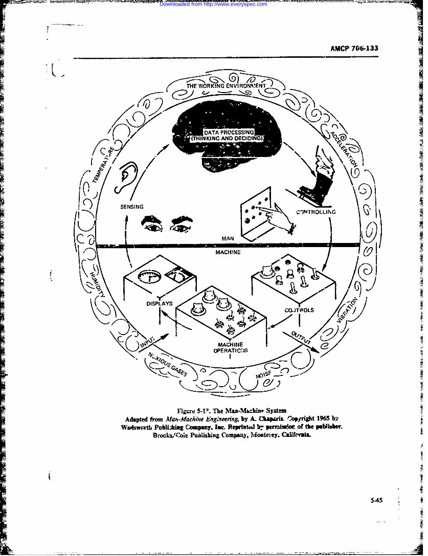
AMP 706.33
UHINKINC AN DECIDIG
I I
I ~CINTROLLING 40IzIt
'ASgOPERATIC 6Sv
Figue 5-11. The NMaa.Nfbchit4 SY~t=Adapted from M4ah-M4aciije Engneerng by A. CLapiari. Copyvright 1965 W~
Waswcrtai PubhiugCouipany. Imc ReprintW b.- pur~Au~ot of the publihher.Brocja,'C4Die Pualihig Compsay, Moiiteney. Calitcraia.
54A5
Downloaded from http://www.everyspec.com
AMCP 706-.33
The thir-d category treats inr, as ine component of strength. Certain of thuse are particukLly pertinen' forthe man-machine system. In effect, man is the sensor, the design of seating arrangements, workspac--i, co-n-data processor. and coiltroller in the man-machi'ne sys- trol- and displays, sizes -- access openings, and sizestemn (Fig. 1-l3). Finally, in the fourth category, the and weigh- of unit-- which can be lifted or carried bydesiene-r must consider those elements ad charac*.eris- one man, ectics which mnust be designed into the hardware/soft- Athiapometric data am~ j-ieu-1iy presented in uppf'$ware portions of the system (e-g., dislays, controls, and kerpercentiles. rangci-, and mediars (or- uieans).sersors, test points, operating and maintenance irfo.- With information of tis' yf-- jt ieg who usu-mation) and which will optimize the ma--machine aiy mill not be able to -ceornmodate al possible sizes,
corr,inaaion-the man-machine intcrfi'ces. can decide wJ'erc to makc the cintof.. He rnu,-, ofWhen the man and mac'uine are c'xnsidered in this course, design equipmzent so t%.at all members of the
fshi~nn it immediately becomes obvious that. to design popolzlion for which it is designed can operate andthe machinf- componeitt properly, the capabilities and maintain it; but at the same time, hec might have tolimnitations of the mait and his role in the system must inflict less efficient or less comfortable dircuX.2stanicesbe fully taken into account. Such consid-rrition of on a sm~all parcentage of the popziaition, i.e.. thoscman's abilities is the only way of acniev:irg insight into individ-zais having extreme measurements.the best wray-r in which he can be used .s 9 ccraporent MI-STD-t47). Hluman agieefing Desgn Crit-(Ref. 43). eric (Ref~ 50), states -esign s' all insure operability
It is the purpose of' this portion of the habookc in Lnd maintairabilit) oy at least 90 percent of the userdiscuss t: --se viil human factors considcrations and ptnulathiu. Tie design range shall includt at least thetheir impact on design for maintiinability. Detailed 5th arid 95th percertiles for design-crit'zal body dinien-huymn enin.ering considerations are given in "-e sions.- It further state. t.,at the us-, of aathropoinetricrnzny mod'k.;~ *ttx:bc&hs andi dii guides referenced dam shalk take the- following into consideration:and will not be ipeated here In paztictilzr, Refs. 43. 1. Nature frequency, and ,ifficuty of the related=4o, 48, and 49 are recommended as basic treatises on takhuman enginering. Refs. t,24, 2E., 30, 31, 32, 38,43, 2.Pstoofhebddrigpfrmnef48. 49, and 50 contain valuable detailed design griide- ths 23k
= line informnationi.3. Mlobility or flexibility requiremrents imposed by
5-8.4.1 Man and His Characteristics and the tasksCapabilities 4. Increments in the design-nutcal dinmensions im-
posed by the need to compensate for obstacles, proj-5-8.4.1.1 Human Body Measurement tiona, etc.
=(Anthropometry) 5. Increments in :Iik esign -i -tcar-!imensiorsin,-
The haman body, its stricture and mechanical func- posed by p.-ctctiv: Parents pkas fine ~ pa ngtion, c.ccupies a central plbc in' man-miachine design. etc.Faifure it; provide a fcw ircbes which mright b- criticalfor the operator car. jespard z- the performance arid Tables of Sth and 90th pticetetile body rieast~eenentssazety of both man and m:-nine. With proper fore including static, dyniamic, range X1 motion, and weightthought, these critical inches -sually -an b-- provided 3Td strength dita are included :n Res. 1M,43, 48, andwifthou con.promising the design (Ref. 43).so
'Ine importart ca-sideiation- ti.-Tefort. in designing 58.12 MasSeoyCpbityadfor mraintability is information en, body mcpsure- 5-...2 Ps Sno ryi Caailit-nents. Thii information is required it, the eariist cde- sc= alM -n
sign stagtes to er-su. & ̂!w~ equipme-nt will accommodate NMan as part ;of the man-machi~e system, contixusoperators and n'ainmenwrce ruen of vat ious sizes and many useful sensois. In additio-n to the five majorshapes. Anthropometry is co~cerned with human-body senses o. sight, hearing. tast-, sr-itel, an42 touch, manmeasurir-ent- Such measurement nor &,a~y includes can also sense temrpcratere. position. rota-tuon arid in-body diicnsions, rpnge of rnotion of bod:y members, =r motion, pressure, vibration, and ac--Jlei tionanid muscle strerigth. White most of ;- are firniliar witb (shock) Because man contains an information process-Uody dimensions that the tailor takes in altering or ing sy'stem and control systerl which is particularlyza:loring suits, !he =thvpornetrists usually mea:-.ire sersifive to sinall changes in these sertsatturis over aother body dimeatsions. as well as ranges of motwon and wide range. he can automatically recognize and react
5-46
Downloaded from http://www.everyspec.com
AMCP 70:5-433
-to such changes. Thus, nmn is often the best detector to syn-m perfarmance Us" the machine to releve theof change: i, performance or other system ,.onditions. man of as may routine jobs a possible, but use the
Men and machines have differ.nt capailites and man t oi supply the judgm2nts and flexibility of whichl-aitations. A.haug' they sometimes can do the same machines are incapab4e (Ref 4F).
thing e4ually well, more often one is better than the Severai hnmn factors expert; have prepred lists ofother. Men can do some things better than machines, tatement which com -e man to macl.ine- Ref 48and machines can do some ihings men cnnot. Such contains a composite of several such Iit-s.differeaces la cap~bilit- -mst be considered in detail
when designing s*sters--ey = important in decid- 5-P-4.2 Enwironental ConwidafioU1-,, whi::h jobs to 2sa tc men an which to asgh to
Conditions under which equipment-especially rwi'i-machiries. Diaferenas in capability also oft-n deter- Cniin ne hc qimn r~
aine how a machine s d be deigned to be used tar equipmet-must be supported vary Vd-iy, andi&IItomany instances are extrancly advmr.e. This
most cTectively by a human operator 'Rdf. 43). Rcfs. intto ayisacsreetelyd Ts
ois te whethe we speak of cndilion imposed by thephysica environment or tbm physical and psychologicalconditions resamting from strain, fatigue, or prolonged
5-8.4.1.3 Man as &n Informafion, P.,oc--, worry of the operator.I-emach ccnpcm :zz of man-machine systems-Man has =-un -dvantages and disadvantages as in
information pr,.xssot- a mpartl en .1 nr.-hine& TCe are normally designed to gihz ma.unum performancerapd dvaaces in nmchine infor .,.io~m processing within sptckified envirnmental limits; when these limitszapzd M aeinmine inandiadonanagesasng
cai..b2iies(cmpuer') n rcet yar W are emee, both performnc and reliabili..y %u-fc:.
the differences to scane extent. For ec.-mpte us e of Soe on reuednera cnti.adaptie nrol . pauter_ rcoition te:iniques ~chines oft= have faded to fulfil their .zissions,
hav alowe so € c~pt -s t hae a:,.red not oezcaue they were poorly designed or bady -
lewrn'rg capability- swtc but beause they demanded moir ofthe opx-
Map- "- od long-texm rmemo:y for g -id at" than was humnly possibe .iders the envi-
experince, ut rather poor imdiame memory for ronme.mostsenq~ny Fac~l. is som ao In oa tv' to equipmt, the jeg uf whikh can beF mst ewoy ftintzins-This i seilyoinatd-
tion. His acces time is slow, compared w--h t:-.at of & inbei -design" ch.-xacternbcs. Tle cnly aftesnktivecol puter, but he is able to fectil generatized patternsavasolve immediate probemis. A aalable is, wherever ass'je, the exercs, aC "nitrol
yet, - :omputer can do this. Man learns to do numeri- ovz environmental conditions to wov easonablycal compuions, but in the main. his time constanLs accptable working conditions (Ref 42 and 43).are such that heis arelaivdy poor nun-trical computer System and ,Vj@imwet dogners must be aware ofwhen under stres:. No computer can match him, hvw- the erT.cts of the environment and take thes into ac-ever, for the more qualiatave nonnumerical comp'a- co? -it in their desigm. There are se-ral types of envi-t:ins (Ref. 48). Ref. 48 cuntains data conctring man's rceiments of concern- Thesc iclude:inforinition procesing cspability. 1. The geographic or .,hysical environw-nmt
. The operational or w-rking environment5-8.4J .4 Man's Adaptability
Man is adaptabhe- He is abk to make use of liarningaad ex cr=c- to after his reactio s and behavviral 777 physical en7irofnmeM ncludes such fans aspa.-mns. Ws is truly an adaptitv conrol s, *iem. Man temperature, humidity, noise, vibrrtiom, shock (accel-reazu to psychological as w-ll a- physical n-tds. eration). radiation. ,ind, pressure. salty atmophere.Amoag these ps...ciogicra needs are comfort, toxic fums, san and dus: isects, fungi, e, and rain-seurity, safety. an tty, fatigue, bom.dcnm ,.ward, fdll Thie yx,-.ng ennhnsent includes the arrayse-
punishment, and motiation its effectivenss and effi- mert of opz adng and mainu.ince work spoon, oper-ciewy are a function of these ps-cholopcal factom ational or mission conditions. illmatio. accustics,They xaust be taker into acwount by the designer. ventlation, time ofday, dumtion ofwork. and numbert
Man is very flexible and =n peform well in many 3nad sOIE l eels of personnel involved- Ihe Aurtax eny-
- t t his timitsoos are not ignofd. As the mmm pertains !a phni. physiologicalm py-eu ts placed - him bc-ome more comp! c hlo4egical capabilitie and liniaons of the humar
lowevti, this sme 3 exibity may result in a decrement being. All of thev envircmmenis are of speciic comn
5.47
41
Downloaded from http://www.everyspec.com
AMCP 716-133
to human factors engineering, and thus to design for ieeling of warmth are given the sazme ET value" (tef.maintawhbility. 43). Fig. 5-14 aept, a famiy of ET curves.
Jmt as the reliability of equipment will te evartzd The optimum tempertu.c r-anx for personnel atif the desig-ter assumes that the equip-ment wll he wsed work obviously varies with the type of wo-k being doneat the extremes of the various environierial conditions and the conditioas uladr whicb it is being done. For-and proviaes, in his design, features which will allow mo geteral purposes, the tans, of 65' to 707 isthe equipment to work at these stress levels, the main- recommendee, even if tLe relative huminidy is rathertainability of equipment wil also be enhanced if the high. In order for maximum effik-ency to be obtained,designer analy2-s the .daintenswvce task, which must be air coditioning should be ;rovided ir the temperatureperformed under these environmental conditions and exceeds 9WF. The recommended range of 6F to 70"Ftakes th-se into account in his desig., may be muved upward if tk.e work to be done is light
Geographical-phical ie.onmnwtal conditions ae or downward, if heavy. (Se :ilso Fig. 10-5 in Re. 1).described in detail in Ret 11. In addition, environinen- Prolonged exposure to temperatures below optimumtal conditiowt in all three of the previously listed (6F) may adversely affect work performance. Ten-categwiec ere !escribed in the refermced human engi- peratures below 50YF frequently producz. a stiffening ifneering guides (Ref. 43 and 48-50). :he fingers and a consequent loss of full manual dexter-
Successf.i maintainability deign must incorporme ity. When a mpn has to vrk in heavy clothing andconsideration of the effects of the wir-dng environmeit wear lined gloves o; mitte-ts, his deitiency is reduced.on hurnan p. .rmance. The environment (both nttu- Relative humidity (Rh) afflects huran performancera'and induced) in which maintenance is to be accom- adrsey if combincd with temperetu__ that are beiowplish cnn have a pretb~ud effect on the efficiency or above the cptimum- The RH rmge from 30 to 70with % hich a technician can carry out his amigned percent is gewelly cceptable if optimum tempera-duti's. While the design ofA the physil environment tures for comfort are nzintained. At teipe.-aturesperse may not be a respotsibiiity of the desipn engineer, t.ove optimum, compar-ively small ris in RH usu-environmental factors must be considered in equipment ally have signficantly Lverse ifects on both comf'j.design for rapid, acmurate, and stfe nvintvrance. Fo" and performance.example, des;gn of prime anI support equipment for a Proper ventilation is essential to efficient perform-nuclear-powered system witho-t regard for the minte- ance over a period of timr in an enclosed work area. Annance environment would be obviously inappropriate aduli at work requires 1,000 fW of fresh air per hr.."ince radiation hazxrds may requize remote hzndling From 20 to 40 ft per min is the recommended rate of
which, in turn, may require the -esign of special fer- air circulation in enclosed work spaces in cold weather,tures into the equipmett (Ref. 30). it should be mensed slightly in hot weather.
Am-'ag the envi nmental items which have signifi- Whenever toxic materials in the air constitute a men-cant impact on maintainability zrc temperature, bu- ace, adeqtmte measures to protect persmnnel must bemidity, air circulation, Hghting, uo!se level. vibratiot, ,,_,. Ventilation alone is insufficin. Either theand work space arra-ngement. Some of th.-e a.e inter- source of contaminationt m-.- be cilc&d off. or the per-related, fo" example, temperature. humiait-, and a:r sonnet must be issued protecdv devices (Ref. 42)cirottzion. Addttionrl information with regard te the effects of
temperare, humidity, and air flow is given in Re&s- II5-8.4.2.1 Temperature, Humidity, r and and&
C;rcutation
Tenp..-atumrelative humidity, air circabtion, anW 5-8.4.2.2 Itlu-mination
a npurity of air all zflea human .imfo~mancc. For A techciian neds app ,Tminaion if he ispractical purpss temnperature, relative humidity, and to propeely perff;wm the t& as w to him-, ac-air movement are often: combined, and as suh are curacy. s.Ad andl W~dty sr 'er when he ctanot see
referred to as "Effective Temperature" or El. "This is c-art'y what he is to do. On the other hand, it must bean empirical index tf~a exprese the combir. l eff'cts rm&lizd that adequate illumination will not always beof these threxe characteiristics in terms ef the subjective availsbie Accodingly, the &-gnr of eqipmmtfeaLng or w, rmtl.. W~h,- the ambienit air is completdy should, as far" as is pow l develop their desi.gns to
saturated (100 perca-t relative humidity) and ff pmt m work to be performe eftivel,velocity is zero, the value of ET is that of thc air tern- under the pooret lighting conditii that are an-perature. Any combinations of teaperaturc, humidity. ti#*ted, t ths end, they sh,dd acquaint themselvesand air movena-.: that produce the same sut*efi*ve with all of the circumo= tht zay reduce tvailabk:
SAE
Downloaded from http://www.everyspec.com
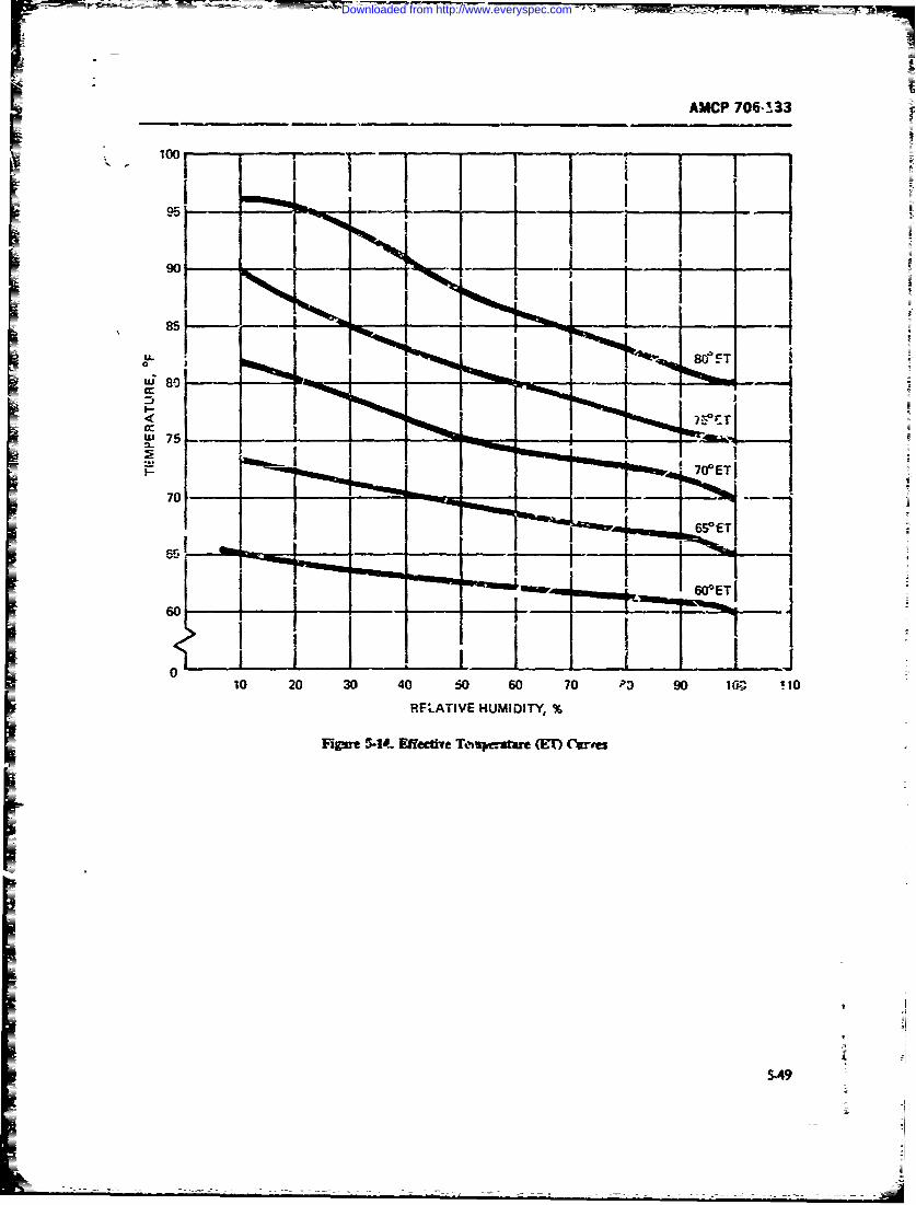
AMCP 706-133
100 - -
70 ..
10 20 30 40 60 60 70 P3) 90 1fz C9 tO
RIFLATIVE HUMIDITY, %
I.4* 5a"9
ziJ
)~tT4I
Downloaded from http://www.everyspec.com
AMC-P 706-133
i Ilumination. if only a flashlight is exp'cted to be avail- The intensity of -ound suall) measured in deci-able. the equipment to be developed should be designed Mts (dP), It is the prim& :Atc in the ensati of so that maintenance work on it can b: don-- with illUni- loudn-ss Table 5-9 listm th, inensity levels of somenatiL.. from a flashlight The employment of plug-i. common sounds.modules and readily accessible and easily replaceable Exposur to no:- cf m-: th-. 80 dB mr.Ay result snunits of light weight vill 4,- helpful in this respect (P.f. temporary or permanent kl , y hecm.t. -' extent -of42). damage being dtermined by the lengt-% C: -AFDS"e.
There are several impf-tant fuators that should be Excessive noise also affei.,spt-:!n-- psyhologicnsidered in the design of any lighting system: cally. O. exposure to it, fatigue occurs mme,' rapidly.
1. Suitable brightness for the task at hand ability z.) centate decreases and ,mmoyanoe in-
2. Uniform fighting on the task at hand cresses. As a resuit, .efficiency dwms Moise wndi-
3. Suitable brightess contrast 6, ew%-n task and tions in maintenance work are~as .t., be studied and.Suitable when necessary: rd d.cA. If reduction is not feasible,
background ".c workers should be iated protective devices (R.
4. Lack of glare from either the light source or the -.-2). Reis. I!, 30,4, 48. and 49 contain specific desipwork, surface Saidelines with 'spect to noise-
5. Suitable quality and color of illuminants andsurfaces. 5-8.4.2.4 Vibration
It s iffcut t srci' exctlev6-andliitatins Vibration i6 cmcerned with the eff, - on humar
for all the problems that may rise- in designing an peiomance of periodic mechaical forces impine-
efficient lighting rem tt nay si on body tissues. Of iateres; are vibratory forces theeffciet lghtngs:, a. A aly rcotmetdat0 effects of which dislace or damageb~ organs or
given in Table 5-8 sill undoubtedly serve n a safe
guide to bet'er eeing for most application. Design and tiss. other than tih.e involved in ordinary hearingplacement of all fighting elements shd facilitate and/or thos. that produce percpble feelings of pamin.
te nannoyance, or fatigue. In general, Jtese tre high-ampli-maintenance and cleaning in order to retain opiMum tude, low-fr cy vbrations generated by machinesillumnnation charaterstics (Rd 48). Specific desigr orecommendations with respect to illumination aregivnxt in Refs. :2, 43. anti 48. Te-eto i o h cydc&o h
physical parameters of the impingiag caey its direc-
5-8.4.2.3 Noise tion of applicatio with rfpec to the logitudim axis
of the body, and the mect iempa ,e and .bsorp-Note is deined as any undesirable sound, even tio coe'cient cfbzdy tissue, organs, and *-I' body n
dhough it might be a meaningful one. The criterin of a whole In additio-, because the matchint of .ipiedundcirabil.ty is based on ihe capacity of sound to dis- frequencies to the natnral firquency of the body art'orrupt canmunkcions. Excessh-e noise in a work area its parts wil produce rescranoes, resonant froceticsusually reauce the eiiemcy of the workers, and thus, of the body and its parts assume special imxn1aneindirectly, may reduce overall system readins if the (Ref 43).work performe4 is maintenance; exposure for iong pen- The human ody reacts to vihmtion and re.st.gods may result in loss of hearing. stimuli much t ume as does z -- echanic-al sy=s.sm of
Noise is most clearly described in terms of its two mases and spngs When the resona: stimulus ap-mrjor physical characeristics, frequency and intensity proxinutes the natural human-bAy rmont of aboutThe-- frequency of souad is asually msured in hertz 5Hz. the peron concerned finds this quite is4rcble
tz)--he prime firor of pitch. The 'iuman ear can (Re. 48)..4ect scunds of frr .encies from 20 to 2G,O00 H- The t e. ,,b-ion m-, amp -Marked individual diffe-eces exist, of course, and hude "displacerent), velucity. acce-o-n &am "*.changes come about with ane. Human engineering is Fo. a fixe -,flrq-y. the last three tems we -ses-concernad primarily with the frequencies to which the siit derivatives of amplitude with rmpect to iime.ear is most sensitive, namely, those between 60- And A detailed discussion of the eiects of vibr t-tRn on900 Hz. the body is givent in Rd. 43.
Personnel exposed for long pcriod to noih in :he The effe.t of T, rrion o the hum body depn&range of 4,000 to 6.000 Hz usually suffer major loss of upon the dLrectiom -n which &.ese vi-bratond forre& arehearing, applied. MItL-STD-1472 states that each directioa is to
5--.
Downloaded from http://www.everyspec.com
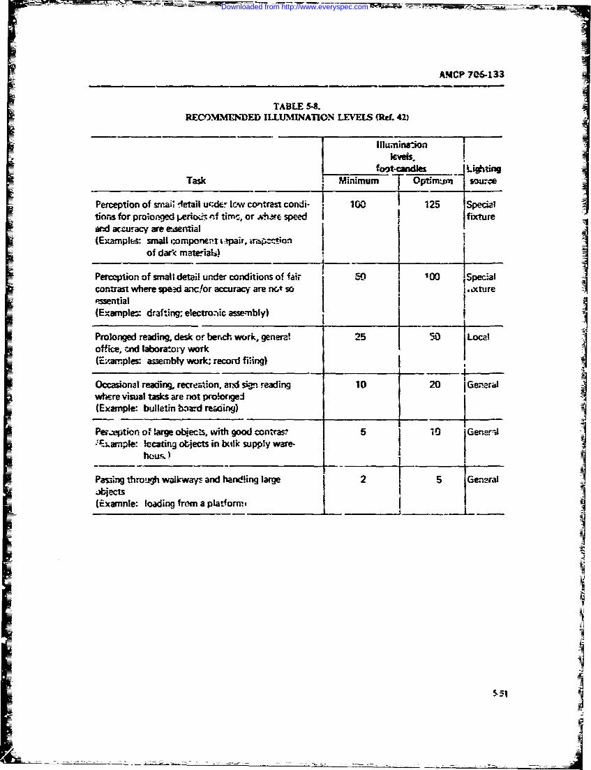
AMCP 706-133
TABLE 5-.REM N N C M I-ED ILLUMINATION LEVELS (qef. 42)
Illuminaionle'vels.
foot-candles "iCtinTask Minimum Opirj0SOu
Perception of sm-ai t etail ure& lew cowtrast condi- 100 125 Specialtinris for prolonged efiodst nf tirrc, or &t.Are speed fture
id acturacy are esential(Examples: small compornt i,.,pair, iri-.tion
of dark mat. ia6-), I
Perception of small detail under conditions of fai, 50 1 00 Specialcontrast where speed anclor accuracy are nt so I , .,xture,swential I(Examples draf.ng; electronic assembly)
Prolonged reading. desk or berch work, genera! 25 50 Local
office, cnd laboratory work(E;,.z.ples: assembly work; record firing)
Occasional reading. recreation, and siiq. reading 10 20 Gen ralwhere visual tasks are not pro.ergei(Example: bulletin board reading)
Per,ption o, large obiec-s, with good contras? 5 10 jGen._-J
'rarnple: !ccating otjects in balk supply ware-
Passing throuivh wa!k",ways, and handfing large 2 , 5 Gej.jects(Examnle: loading from a platform.,
_ _ _ _ __4
=1
MLI
Downloaded from http://www.everyspec.com
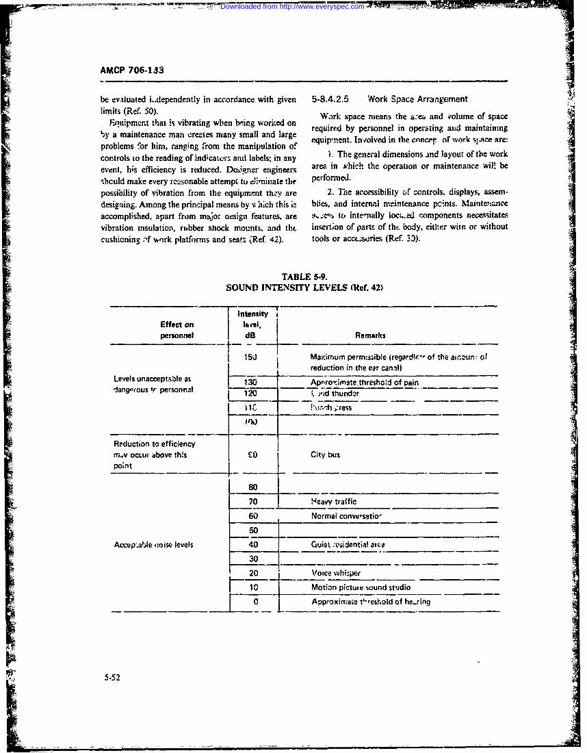
AMCP 706-133__ _ _ _ _ _ _ _-
be evtuated i..dependently in acrordance with given 5-8.4.2.5 Work Space Arrangementlelimits (Ref. 50). Wark space means the a:et and v'olume of space
Euipment that is vibrating when b.-.ing worked on b esne noentn n anann'.yamaintenance man creates many small and large requiret byneronel in oe nr!ating aord maitqae:
problems f'or him, ranging from the manipulation of eqi'n. hgnxol deion s a laynut of th~~j~e aore:controls io the reading of indcatcrs and labels: in any LTegnrldmnin idlyu ftewrevent, his effliciency is reduced. Deb,5gner engineers arm. in vhich the operation or maintenance wil! be
*hculd make every rc,_sonable attempt to ceiimiuate tire performed.
possibility of vibration from the equipment thzV are 2, T"he accessibility of controls, displays, assem-designing. Among the principal means by v hich this is blies, and internal maintenance pcnts. Maintenanoeaccomplished, apart from major- oesign features, are .%to inte-nally loc4,ed components necessitatesvibration insulation, riubber shock mounts, and tht. insertion of parts of thc. body, eitlker witfi or withoutI ~ Cushioning :'f work platforms and seats. (Ref. 42). tools or acaz.~ories (Ref. 33).
TABLE 5-9.SOUND INTENSITY LEVELS:9 (Ref. 42)
I i1ntensity 1Effect on lipersonnel dB Remarks
I 150j Maximum perms~ible iregardlp- of the ati'noun-. ofI reduction in the ear cann!)
Levels unacceptible asL53 Apr.ro%*6mate.threshod of pain _____
-iang.'rous r peronI1I 12 )-id thundar
Reduction to efficiency Im.1v ocLut above this co City buspoint - ---
80 _ _ _ _ _ _ _ _ _ _
70 H-eavy traffic
Accep.af.Je tioise levels 40 Quiet :osidentia! artea
30
5-52
Downloaded from http://www.everyspec.com
W-
AMCF 706-i 33
Many cietails affecting men -d oquipment must be with the servicing, irnspecti~r, diagnostic, and repaira-considered in the layout of worh apyAces, but it is seldom biliq characteristics of the system/equipment. Main-po*4i' le to provide optimum conditions throughout the tainability is dependent upon botfh the ope-rator anddesign. maintainer, and this invciv'tes the man-machine inter-I The desig-'er should obtain information about re- face~. An ouitstanding differ-nce between reliability andquirements before beginniu- to design the work space. maintainability, therefore, is the degree of dependenceUnless the following infirmation is available, the de- on human factors. Faikure to consider human factors insigne. might include undesirablt characteristics that the desirn will result in increastj inmpintenance prob-are nct dete -able until late in the development stage: lems as well as reduced efa.ctiveness nd readiness.
1. Purpose or mission of the. system it should zome as no suiprise, tlrtrefore, that all of2. Mission profile or dctailedsieps ir. conducting the maintainabibity design factors bsted in Table 5.5
typical and atypical misin concern human factors. They epitomize thk -nan-3. Tlernce alowale n th peforanc ofthe machine system. Therefore, it is -.o coincide-ice 'hat
3ye.--Toleracesalloedble it hepror ac.o h most of the maintainability design guides cited in Refs.systenr-acc...racI speet.1 and 24-321 were put together by human factors engi-
4. Effects an 5Ystemn performance when various neers. T'hey were the flyst to r-cognize the imlxortancetoleranceN. ga'e not met of tte man-machine nt .rfaces to maintainability and to
5. Specific tasks thzt the operator must per- give specific attention to them (par. 1- 1. 1). Accessibil-ft~m--fqunc o e anowd, rtie uionporach mfita h araybedssdste piad codn-.
eachrmc -l-ieiequenc obe nll d rtie uip orac of mtahne altrfadcen ircusd ishe primary mantask ~~~~~~~~~~~~Testpons otosdipas b'lnancdng
6. Inputs to the operator-infornitior. that fie manuals, checklists, and aids are all man-machn -in-nestacopihhsspecific tssterfaces concented with man's sensing, datu processing.I-operator to influenct the systen; system (Fig. 5-13). Tes-t equipment, tools, connectors.
3. Anticipated environmental cionditions--tern. cases, covers, doors, mtlunt'ng, fasten~ers, ha idles. andhumdit, nise ilumiatin, ibrtio, yn- handling are also part of the human fac'ors design
tiatr, raitoa~tdbd oiin ceeaie considerations to farilitate man's role in 1derformingtforcio, rit ioc.tdb d ostotclrtv maintencnce tasks. They sene no prime purpose in the
9. Specitic pieces of equipment alread. committed equipment other than assisting man.
~o tL desgn L is essential that design engineers ascertain the con-!o t_ deignditions under which the equipment they are designing
10. Miaitenance access and clearance requirements will be used and maintained. If these condi'ons w;' 1 be(Ref. 48). extreme, the design must be altered as n-uct. as is prac-
Thspcprvddfrmltnneino imry ticable in order to protect the equipment. RegardingI hespae povied or aintnane i no p!imaily suppor-t activities, such alterations would be made to-a conveience; it is a requirerncni to insure an accepta- reduce to a minimum the number of tasks to be per-ble level of operating efficiency. In laying out a work formed, and to provide that the tasks which could notEpace, consideration must be given to the methods by be eliminated can -.ow be performed witd: ease andwhich the eqcipment ir it wil' be maintained, especially raityudrthcoiinseptd.I njctn
if mre hana nrmalamont f sace illbe equred with such etforts, the system engineers should becometo perfurni maintenance. Maintenance access require- familiar with th~e necessary support equipment. such P.;rients are o. pyrnary importance in the location of mobile mainteanance facilities and cold we-athe-. cloth-equip' rient. . . ing a-ailabl (Ref. 42), and the constraints they impose.
Specific details regarding accessibility aite given in Regardless oi horoughness )f training and level ofpar. 5-8.2. 1. Specific te.rtails and guidelines regarding skills z~tained, a technician will and does make mis-the !ayou: of wor!: spaces ire giver in Refs. 43 and 48. taendscero fqutlcueeumetri-
5-84.3 Hua atr lmnsiofiinction, with varying consequences. A driver fails, t;)HumagniFactors Maintnbiity fill the radiatcr of his truck, with the result that the
Oesinin fo Mantaiabiityetg.ieoverheats and the truck stops on the road-in-The reliability of a system or equipment -. concerned convpenient but not serious. A te' ai'-ipt fails to put a
primarily with its inherent failu-e and lfe cliaracteris- cotter pin in a castellate nut in the fliglit-control link-tics. Maintainability, oin the other hand *:s concerned age of an aircraft, with the result that control of tl~e
5-53
Downloaded from http://www.everyspec.com
AMCP 706-133
plane is lost in flight, the plane crashes, and all aboard important objective of man-machine designers. Abso-are killed-very serious, Maintenance requitements are !ute safety is not attainable, firat, bca use not all haz-so demanding that all too often they !eave no room for ards can be dr.igned out of machines and, second,humar, error, yet, man being what he is, personnel because operators and technicians cannct be reliedfflure canno* be couptetely eliminated. For example, upon to obstrvesafety procedures at all times; Ps Mur-a reort by one of the military services revealed that inperi d of15 m nth , e ro rs m ad in the m l m e a c p y s Law " states, "If there is a w rong w ay to do
a period of 15 monchs, errors mnade in the maintenance smtig onro ae oen ildl htwyof aircraft contributed to 475 accidents and incidents in something, sooner or ter someone will do it that way"
fMight and ground operations, with 96 aircraft being (R. 42).seriously damaged or destroyed and :4 livc.; lost. A S'fety is one of the important parameters of system
study of these a.ccidents revealed ;hat many of the fail- design, along with pe-formance, packagin3, reliability,ures ahat produced them occurred shortly after comple- maintainability, and human factors (Fig. 1-1). Al-tion of periodic inbpections. It also showed that many though safety is often zhought of in terms of the preven-of the mistakes were repetitious. The conclusio,'s ar- tion of injury or death to ;ersonnel, it must also berived at with regards to the basic causi of these human considered w'ith respect to damage to or :oss of equip-faiiures were: ment, and the resultant effects upon cerational readi-
1. Inadequatt basic training in the relevant main- ness and s-stem effectiveness. Indeed, safety is d,-finedtenance practices, poiicies, and procedures as "freedom from tho'e conditions that can cause in-
2. Lack of training in !he mainterance of the types jury or death to persinnel, damage to or loss of equip-ard modides of the equipment being maintained ment or property" (Ref. 51).
3. Inadequate or Amproper supervision .vstem safrty engineering is an element of system.Inadequate oispcion sengineering involving the application of scientific and
4. Inadequate inspection. engineering principles for the timelv identification of
It follows from this that both operators and techni- hazards and initiation of those action necessa.-y toclans need oil the assistance the designers of equipment prevent or control haza=ds within th- system. It drawscan give them for the effective support of equipment. upon professional 'knowledge and specialized skills irThe principal go-is toward which the designers work the mathematical, physical, and related scientific disci-for this purp-se are: plires, together with the principles and methods of
1. Reducing to a minimum the number of support engineering design And analysis to srecify, predict. andtasks to be performed for each system evaluate the safety of the system (Ref. 51).
2. Designing equipnent so tha.t the support tasks Costs in time and dollars and the failure of designersrequired can be performed easily and simply by person- to give special attention to this aspect of tht'z work are
nel of specified s'ills working in specified environments reasons for the existence of hazards in equipment3e ,ch could haw been eliminated, had they been dealt3. Designing equipment with featres that make it wtih otherwise r-lht-i the equipment was n the design
difficult or impossible for a task to be performed im- stage Nevertiheless, the majority of accidents that oc-properly or incompletely (Ref. 42). cur are caused by the human compontnt of the man
Finally, safety as a design consideration is of impor- machine combination. The person at fauI, may be thetance to both man and machine with r'gard to protec- equipment operator or the technician charged with itstion of life and injury to the man md damage or de- mainte-ance. A designer who works succesfuliy tostruction of the equipment. Sfety is discussed in par. minimize hazards it, the equipment he is dcsipning can5-8.5. do mtuh to reduce the numher of accidents resulting
The maintainability cagineer atd system/equipment from its operation, but even by employing thc bestdesigner should become thorougly familiar with the design principles and test procedures, he cannot reducehandbooks and design guider rei'erenced in this chap- them to zero.ter, if a successful total man-machine sstem is to be Inasmuch = 1,azards cmaot be completely designedremized. out of systems, it is impera.tve that those that remain
be clearly recognized and that measeres be provided to
5-1.5 SAFETY protect againsi them. Guards are r "eded to p,otectoperators arJ technicians from moving parts, electrical
Safnty is a conditi:n created by either the nnnexist- charges, sharp edges and points, high temperatutesiunce i2f hazards or by fae ul.ilization of dev.es proided chemical contamination, etc.; in adJition, warningto gi ,e protection ayai: hazards. As such, it is an signs should be conspicuously placed near dangerous
5-5'4
Downloaded from http://www.everyspec.com
47
AMCP 706-133
items, and audible warning devices should ue added to 5-8.5.1 System Safety Analysisindicate -'erv dangerous conditions (Rcf. 42).
There are a number of analytic techniques which areSystem iafety requirements, though normall y con-sidered as being esscntially in the same geral ctegy used for system safety analysis. These include hazard
analysis, failure mode,, effects, and criticality arzysisand scope as re'iabihxty and nmintainability, may in (FMECA), and fault tree analysis. FMECA is .lso acertain cases be the antithesi4 of not only the reliability technique used for reliability analyses, and thus pro.but also of performance requirements. An oftm obvi- tides a close alliance between reliability and safety. Theous, but sometimes subtle, aspect of most hardware rcliability function is primarily ctoncerned with the as-systems is that for almost every energy-related 1'Uni surance that the hardware will accomplish its asignedtional requireme-it (propulsion, expiosive bolts, sepeara- function. The safety function is primarily concernedtion, iada- Imansmission, lifting, etc.) there is a corre- with the assurance that all safety-critical activities havesponding req|,.ircment to conrol t.he actul or potentbd bee, idenatified and arc -controlled-thus m,;dmizingenergy so that it is not inadverently expended in a the likelihood of cata3trophic events (such as explosionmriner wich resuits in an undesired, destructive, or or loss of life) (Ref. 53). Fault tree analysis is also a toolinjurious incident. This same control requirement con- of maintenance diagnostic analysis, and thus providescept exists for toxic and corrosive chemicals and mate- a close alliance with maintainability. Hazasd analysis isrials as welh (Ref. 52). similarly closely associated with human factors.
This innate safety requirement is also traditionally.-ecognized on such potentially ha.4-irdous materiel as 5-8.5.1.± Hazard Analysiseiectroexplosive devices tEED's), bombs, rocket mo-'ors, propellants, radiation sources, high voltage or A hazard is ary real or potential condition that canhigh presse* subsystems, and material handling equip- cause injury or death to personnel, or can result inment. Numerous safc.y regulations, specifications. con- damage to or loss of equipment or property. Hazardtract exhibits, and technical studies have been docu- analysis is performed in terms of hazard levels. Themented and published on methods to control the fol!owing hazard levels are dzin.d in MIL.STD-882:inheremn hazards of these items (Re!. 52). 1. Category I-Negligible. Conditions such that
The hazards associated with mtaintenance and other personnel error, environment, design characteristics.human tasks performed on equipment are n.t as well procedural deficiencies, or subsysmein or compomiltdocumented. They generally must be c asidered for failure or malfunction will not result in peisonnel in-each individual system and equipment by means ef the jury or system damage.performance of safety analyses. 2. Category II-Marginal. Conditions such that
System -afety management, as an element of system personnel error. entironrent, design characteristics,program management, is intended to insure that. procedural deficiencies, or .ubsystem or component
I. Safty consistent with mission requi-ements is lailure or malfunction car. be counteracted or con.designed into the system throriout all system plan- trolled without injury to personnel or major systemning and acquisition phases. damage.
2. Hazards associated with -ach system, subsys- 3. Category Ill--Critical. Conditions such thattem, and equipment are identified and evalua;ed, and personnel errot, environment, design characteristi.s,eliminated or controlled to an acceptable level, procedural deficiencies, or subsystem or component
3. Control over hazards that cannot be liminated failure or malfunction will cause personnel injury or3. ontol verhazrd. tht cnno beeliinaed major system damag4, or will requite immediate cor-;s established to protect personnel, equipment, andproperty. rective action for per nnel or system survival.
4. Minimum risk: is involved in the a,.eptane and 4. Category IV--Catastrophic. .onditiors suchuse of new mate-'ials and new production and testing that personnel error, environment, design characteris.techniques, tics, procedural deficiencies, or subsystem or compo-
nent failure or malfunction will cause death or zevere5. Retrofit actions required to iraprcve safety are injury to pcrsor-icl, or system !oss.
minimized through tbe timely inclusion of safety fac-to's during the acquisition of a system. Hazard analysis is concerned with identifying poter-
6. Historical safety data generated by similar sys- tial hazards, classifying them by level, tud highlightingtem programs are considered and used where appropri- those ar.¢z which require sperial design attention toate (Ref. 51). eliminate or minimize the identified potential hazards-
5.55
Downloaded from http://www.everyspec.com
AMCP 706-133
particularly in Categories III and I'd. Areas to be con- equipment design with safety requirements a~nd crit-sidered in hazard a.ay~ inlde ria.
1. Iolaion f eergysoucesA discussion of hazardi, their effects, and *afe liErii,%2. ~ ~ ~ ~ ~ ~ ~ a Fuels ans designs:tez ieitis ~ guidelines frir safety is given ir. Arous
a Fdleels and p;.ropellian:te cnsracitis, halng safety manuals and guideline handbooks (s(.-- for exam-storage, transportation safety fealtures, and compatibil- l'Rf1)ity fatr .8.5.1.2 Fa.lur Modes, Effe'.:ts, and
3. System environmental constraints Criticality Analysis (FMECA)4. Use of explosivJe 6devices ard their hazard con- FMECA is a systematic procedure for determning
stVaiflts the brsic causes of failiirc and defining actions to mini-5. Compatibility of materials mize their effects. It may be applied to any level of6. Effect of transi.nt current, electrostatic dis- assembly. lit each case,- the failure mode is described as
charges, electromagnetic radiation, and ionizing radia- the particular way in which the itemn flails to perorm itstion to or by the system. Design of citical contro.s to finiction, independent of the reas-m for failure--theIprevent inadvertent activation and employment of elec- how, not why. The fabilure efrfect describes the result oftrical inteflocks the failure for each possible failure mode-what hap-
7. Use of pressure vessels and~ associated plumb- pens. The criticalityestablishes the category of hazard.ing, fittings, mountirL-s, and hold-down devicesFalr"mdsicuescitsaslsofunin,
8. Crsh sfetyloss of output, reduced output. short or or~en circuit,and rupture. Failure effects include mission abort, in-
9. Training an1 certification pertaiaing to safe oj Ju ry or damage to personnel or equipment, loss of tar-L.~aionand naitena'~ ' th sytemget track, loss of communication, and reductd control.
t!10. E~ress, re-ue, survival, and salvage In addition, loss of functitn or lPssreduction of output11. ifesupprt equiemeltsand ~ei safty n- 'nay be a failure effect as well as a failure mode. Failure
plications in manned --)stems cause may be voltage surge, vibration, contamination,
12. Fi~e ignition and propagation sources and pro- overpressure, oierheat,g wear, or chemical reactioni.tection As part of IMECA, the rehiabihty engineer triL- to
13. Resistance to shock clanage determine the causes of failure aid the physical tncch-ani-ins which cause the failurt. He u..es stress-strain
14. Euvironmental 4ictors such as equipment lay- analysis and the physics of failure to impreve itemout and lightinZ requiremients and their safety implica- reliability and! to inhibit failure. The maintainal.ilityJons in manual systems -mginecr u,. FMECA to guide him -.n 'ieterminin;.
~ -Fail-safe design considerations pre .'entive and c-)rrective maintenance tasks to be per-16. safety from a vulnerability and survi-wability formed and the!, frequenz-y. The saf-tty engineer .ises,
standpoint; eg., application of various types of person- EMFCA a3 determine hazards to perf onnel and equip--c: arinur (nictals, ceramics, and glsbs), fire suppres- mert.sion systems, subsystemn protection, and bystem redun- Thu FMECA is a qu.alitative means of evaluatingdancy reliability. maintainability, and safety of a design by
17. Prottunive clow~ing, eauipment, or devices considering potential faures, the resulfirg effiects or a
18. Li-4 arning and elm-L.'-static protection system, and criticality of hese effitzts. Basically, the
19. Toxic fumes anaiy-is involves the identification and tabulati,;n ofthe ways (maodes) in which -% part, omponent, assemt-
20. Implosien biv. equipment, subsystem'. or system can fai!. For rm-21. Nuclear rtiia-tion and effetcts ampi -, a ball bearing mnay fail from normal weaout,22. Human error a.ialysis of operator functions, abnormal wearout- or brinelling. The eTct of eacai
tcsks, and requirememts (Ref. 51). m~ode is identified and th( criticality to system andmission operatiot. determined. For example, abnormal
Hazard analyses are used to deiermine safety re- ivearot will cause increased ne'se and vibration, withquirements for person- el, procedures, and equipnvxt rapid wearing of bearing parts and surfaces, apd even-used in the installation, o'ieration, test. maintenance tual destruction of hearing 2nd acizing of the itein.logistic support, transportation, storage, handling, and In usuing the analyris, the identified effiect may be
115itraining, and to evaluate ;he compliance of system and diflerent d-,xnding on the purpose for which the analy-
5-56
Downloaded from http://www.everyspec.com
4AMCP 706-133
sis is to be used. In reliability analysis, the elffect consid- the fault tirecs are dev'eloped usirg Boolean Aalgbra.ered .3 the eff-vt on the perfor-mance of the system or There expressions will be the mathematical stat~meritequipment function. In maintainability analysis, the of the AND/OR reLutinr.ship amJ can be siml~iifit.4.effects inzluue the symptom- by which failure can be 5. The ci-.cumsta!-nce. uni.ic- wbicii each of theidentified (!rich as temperature of tnc twaring or in- e'.en'.s in :ht fault tree could -,ccur are determnined.creased noise .2T -ibratiori), ant' it,. addit~ortai par',, TV,. consiists of e.-amining eacb component of the sub-
* r.Insft aa~is h ~inl i~scosrerd addeeinighwit aluewud otibt oneeding replacement U-5- . darnage becau.e o ' "he fail- sytten capablz of producing r-i event in the fult tree
would tie damage to adjacent ni-t -%I equipmrsnt, qnd mishapposibl dage topeionnl.6. An estimate is made of the p-robi'~ility of occur-The r~ior anceo FECAto afet a'W~t 'he rtnce of each event .r the fzilure rate of -tach ccompo-
identification of potential hazards and their zonse- -nt or si.osyftem. This may from kn-)-n filurequences. A well 7repared FMECA for reliability analy- rts .i~teAb ateprnc edr'ts aa
sis fte suflca fo saety s wll.compaison whsimilar equipment, or experimentaldhta obtained speciEfll-; for this equipsitent. -'aese
= 5-.5.1.3 Faut Tee nalsisprobabilities or failure rates 'rE -,ntert8 into the simpli-
17ault ire- anrlysis- is a techniqae to measure system fied Bocican exp-e.siors.safety by determining the probability that an undesira- 7. The probabil~ty of occurrence (adversity) of thetilc event, or fault, will occur. A typical fault tree is undesirable event being investigated is deter.ninedsho'-n in Fig. 5-IS, where the undesired event, "unsaife from -he probabilities of occurren-i- of the coratributei yfailure of protective systi, m". occurs if the systemn fads -vents. This -,goeedure will also identify the most Pinlu-
-= in a mode such thai S would rziain energized d--spite ertNa) iact~ rs, and any sensitive elements whose im-occurrew-e of th-e abnormal oaition. The fault tree provement wvould reduce the probavilit:! of a miishap.method may be sumimarized as follows (Ref'. 54): *
I. The undesirable event, or fault, whose possibi - Cetiasmpc's adcoerIz.thca-ity and probabuility are t- be investigated is selected- actAstics of the components ano their operations.This may be inadvertent or unauthorized isunch, i gni. These are:tion oi aai ordnaince device, failure of equipment -,j 1. Componerts and subsystecms -ither operteperform an operation, injury to rA-sonnei, cr any sini- satisfactorily or f.il. therc is no Ticr&t:on with partialtar mishap. S11CV
2. Ftunctional flow diagrams of the viopesed: s-. ptai- iiuesaei d =e! 'f each other.tern design are analyzed to. detcrmnine those combina 3. Each basic itein has a constant fathre ratttions of events and failures which could contributec or which confor. to an exponential distribuiou. Thiswould be necessary to an occurrence of the fault. assumption caa be modified to accommnodate v.ther dis-
3. Contributorfy events and failuc-es az'e dia- tributions.gr~mned systematically :v show their relation to each Fault tree analysis his two major dntadvhntaoes: it is
oThe n oteu dsrbeeeth n etgtd fault oriented and is linear. It is concerned only withithe process begins with the evints whch could directly those factors which may contribute to oc:currence ofcause the undesirable event (first level), and w-orkir3 that fault. Also, like failure effects analysii, it is !na .back step-by-step t)-rough tht system to deteimine cuate in its considerz:ion of wher. a fault m~ay occur. Itco~mbinations of events anti fidures which could bWing is an excellent proc;edur* within these limitationstrRef~atyout the end result. The diaginazns so prepared are U)called "fault tree3". When miore than one evcent is in- 5nrly al re ev he upssvol-ted, #he chat indicates whether they must all act in.
I. As a tool for accident analysis, a faul: tree aidscominatio (AR rlatioship) rwehrte a in efermining the possible causes cf ait accident. When
ac t sil Omeatheaia xrsionship).,rccn properly used, the fault tree often lea-is to disco~ver) of= 4.Suiablematematcalexpessins o r~preent failure combinations -h~ich otherwise would -"ot have
been recognized as causes oi the event being &nalyzed.'Adapted with permisson (.%-71 W. Hawnn'. "Numerical 2.Tefutresrvsaadipy fsl&Ith
Evaluation of Accident PotentiaWs. Annal; of ,teiabdiynd .Tefutte evsasadslyo eut.I~kAMafntinility, Vol. 5, 1966. Amri~ccan Institute of Atfornutics design is not adequ. the fault tree stwf what theand Mtronautics. New York, pp. 494-500. werk points are and how they lead to iL~e undesired
5-57
Downloaded from http://www.everyspec.com
AMCP 706-133
event. If the design is adequt , the fmt tree shtws 4. The fauls ?ree identities Ml external infLtZCCthat all conceivable causes have been cimsidered. which contribate to k.s--suc; as hurrn- errors, envi.
3. For reliability analyss tic fault tee provids a ronment, and test proedur__,--Jh1.rwas FMECA a -a_conveniet and efficient format for the probi,m de- ysis does not rqmi r investigation of as many emterra!
scription (Ref. 55). influencep, and !he associated data are not :quirdL5. The falt -tee has a restricted scowe with antly-
A fault trt is aki event-logic uaigram relating coni- sis in depth while FMECA analysis has a br-ader scoptponent failures to a particular system failure. An with .estliclea depth of analysis (Table 5-101."event-logic diagram" is a logical representation of theinterrelatiow-hip of various events ,c-uning within a 5-&5.2 Safety and Maintainability Desigtncompiex system, such us a missile ur L nuclear reactor. Safety and maimainibility are closely related. StieflyThe logic diagrani is coutructed using events inte-Con- i listed :is one of the most important maintainabil;ynteted by logic "gates". Each logfc Eate indicates the design factcrs (Table 5-5). Because tech-iciam mustrelation between a set of "input -vents" and an "output perform antenance I sks on equipment dtuing tte-ent". The input events are 'xmsidered to be causes J equipmeat on and off periods, they are expos-: to haz-the "output .vtrts". Output events frem most gates ares and a.e subject to accidents. Many of these bhz-serve as input events to other gates. An input event anis are created by careless design or histicent -ien-which i3 not the output of any ghte becomes a bJasic tion to hurr.an factors and safty features iiring design.input evert. Only a few types of logic gates are used and Some are created by environmental ondtiims. In addi-the logic of each is simpie art completely defined (Ref. tio the technician may create hazards to himself and55). otber personne or to equipment .if I a is arele; wie
C,'-tntruction " a fault tree begins with definition of performing maintenance tasks.the "top" utidcv. ,r event (th2 system failure interest). In additiun to the safety analyses described in theThe causes at- then indicated ad onmnected to the top preceding paragraphs, the process of maintenancr Mg-event by a logic gate. The irocedure is then repeitei, ieerng analysis (see Section I of this chaptezj deter-for each of the causes and th.- causes of causes, etc., mines mairte:anc tass ant: requirement whih af-uwf1 all events have been fiily developed. The events fect both design for m4intainabilit "M dedgn forare conidred ful411y devtjopd whn the causes have safty.been shc ".- for a;! events except indepetdent ,ompo. Some gei ral guidelines for the d- of equipmentnent failurs. Tae hti are considted basic input o or the safety of tecians and ^eatomevents. Ocasi-nally, subsystem o- equipment failures are.arc used b=ei input events if they are indpendent 1. Iteris and sabas,,nbfies that will neea mainte-of all otfer ba.ic input events (Re. 5:). nance s-o -Id be ka-ted Pnd mounted so that scces io
The sabiect of basic input eve;nt inde;>ndence wAr- then nat be Saied without danger to techriciansrants empbsis. AN basic input evenli, for a fault tree from elect rirm chari-, 'ea-. moving parts, toxic chemi-must be indepent-ent; Mlcss the failure can be cai-sed cals, and other hazards.by othn events, the causes mtu be explicitly shown. 2. Asccess arxm;,gs should be fitW~x "mi;i fillets gniSome of the relative iv tages of fault tree and Aes dge olbe fifoermit ets en-Some ~r~txneii edges, and la"ge enough to permit easy en-FMECA analy.is folw (Rd. 53): trance
I. *he fault tree is :he optimum t.chnique for i-, 3 f!l-Lfe devices sould ie provided so that atipi- failures, wherep.s Fl' 7 "A analysis ia the optimum malfuncti in one unit oi subaem-y ca-mot causetechnique for single fsiliu-s (Table 5-10). walfutictie-s in other units or sabassemblies, with re-
2. The fult tree does not require analycis of fail- sultant serious dariage to the system and possible in-ures which have no effect on operation under consider- jury to personIrel.ation. whereas FMECA analysis providcs docurnenta- 4. Potential sources of injury by eleArical shecktion tL insure that ev,,ry potential single failure has should be cretully studied. The effect of electricalbee-i cxamined. shoc t" dcpends or the resisance of the body, the cur-
3. 7,e fault tree is e',ent crienteu. It easily identi- rent path through the bodl., the duration of the shock,ies higher level events % r eventsu si+-equent to failure. the frequency of the c-urrent, the physical conditian ofThe FMECA analysis is hardnare oriented. at easily the individual, the amomnt of cutrent and voltage, andidentifies resrlts of falur: of an; comporent, subsys- the size of the contact area. A designer has some con-t.m, or system. trol ova, these last wo factors and should exerci~e it in
5-58
Downloaded from http://www.everyspec.com
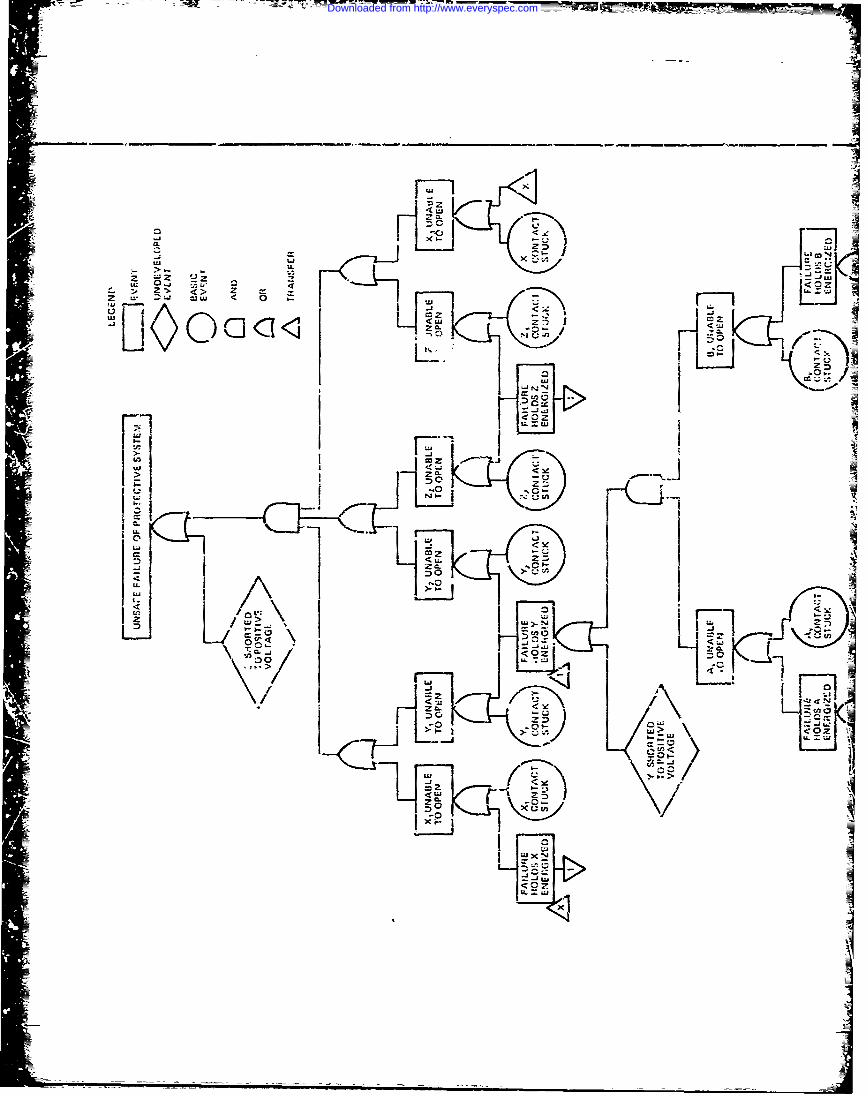
- - -=--=- ;- M--V M__
Z ___Z
ll0 0 -2<Z0.<u
51,1
0Ib-0
I~I I Iw I <I :)L-
L- cc-
-
'- tl
Downloaded from http://www.everyspec.com
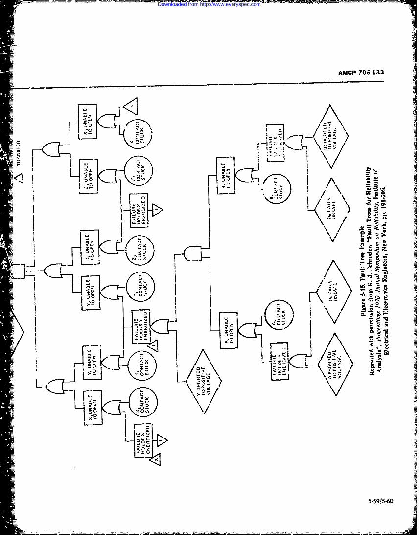
<-W I.
= I;
LiJ -5iXE~<1i I -' ~0a
40 -
- 1 ~~ 1 *j5-59!5-60-
Downloaded from http://www.everyspec.com
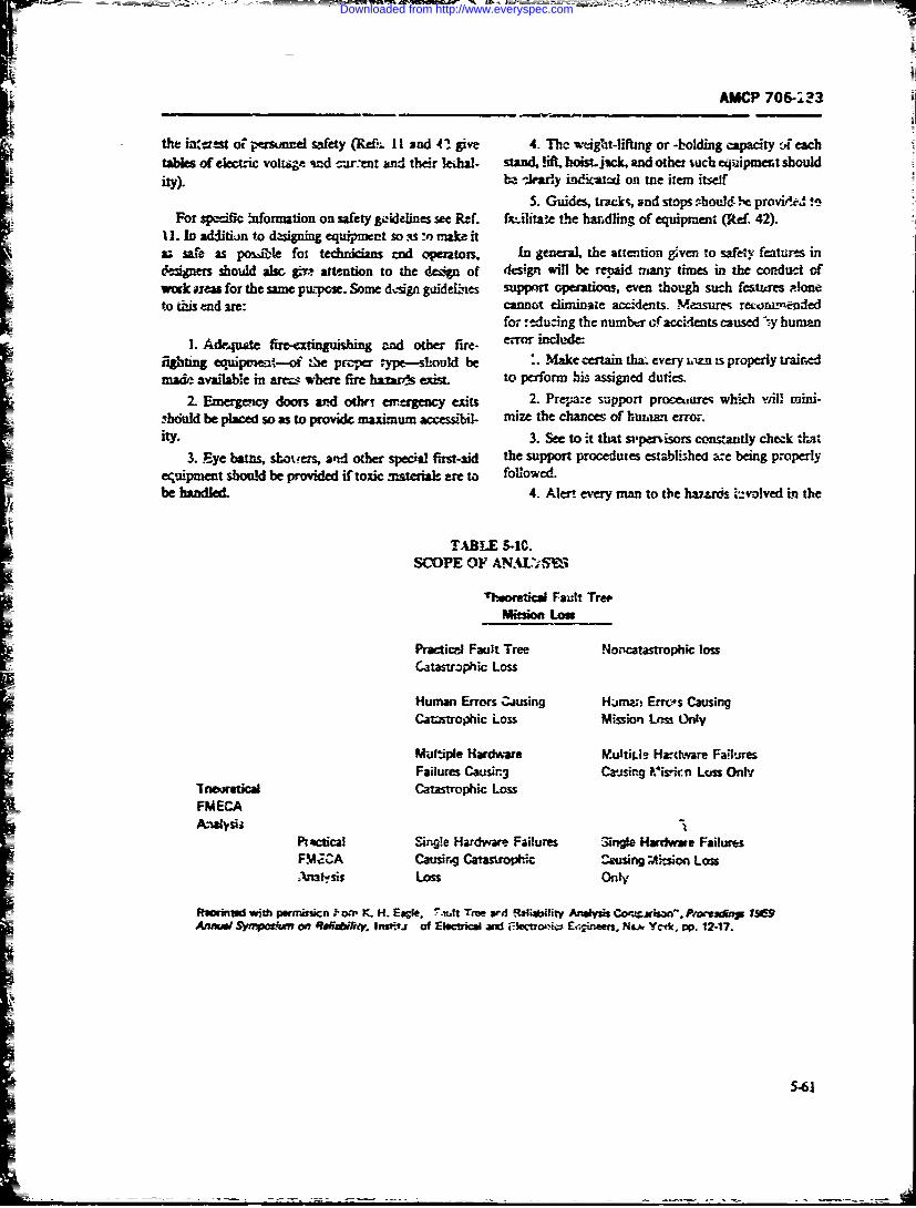
AMCP 706-113
J the intW st o perstonel safety (Re-. 11 sad 41 give 4. The wtight-liffing or -holding capacity co eachtables of electric voltige ad c.r.nt and their kJal- stand, !ift hoistjsck, and other 4uch equipment shouldity). ba >learly ini-atl on we item itself
5. Guides, trscks, and stops Aoud ' e provile.I vaFor sp=oc naformation on safety giddelines see Ref. fxilitate the handling of equipment (kef. 42).
11. In additiomn to dgsixning equipment so s :o nake ita; safe as pos"ible fot technicians rad -gerators, In general, the attention g ven to safeiy features indaiwrs should asc gi- attention to the de6gn of design will be repaid many times in the conduct cfwork a for the same pu-pose. Some dsign gaideui-es support operati , even though such features Ploneto this end are: cannot eliiinaze accidents. Measures reommended
for :educing the number of accdents caused 'y humn
1. Adequate firmexti in g end other fire- W" inclk-efighting equipumn,--ot :Ne proper ype-sould be . Make certain tha. every iitn is properly trainednu&e avu'lab~e in & where fire hazards e to perform his assigned duties.
2. Emergency doors and othr, erergency exits 2. Prepare support proceares which will mini-.bhculd be placed so as to provide maximum accessibil- mize the chances of huwa.'i error.ity. 3. See to it that si-penisors contantly check -that
3. Eye ba s, sbcers, ard other special fist-aid the support procedures establihea are being properlyecuipment shoulxd be provided if toxic material- are to followed.be handled. 4. Aleui every man to the hauzrds 1iv-olved in the
TABLE 5-10.SCOPE OF ANAL'S3
Tteoretl Fault TrepM i LoU
Practicni Fault Tree Norcatastrophic lossCatastrophic Loss
Human Errors musing Hinw, Erres CausingCatastrophic Loss Mission Ls OnLy
Multiple Hardware Multirle Hardware FailuresFailures Causir3 Casing Viskn Lcu Only
7nextic Catastrophic LossFMECAA.Wvsii "1
Practical Singe Hrdware. Failures 3irni Hardwwe FailuresFMJCA Catusirng Catarrophic Cusing Mrs4x Losnafsis Loss On,
Rumrintd with mopvicn i.-. K. H. Es, ie, t True ard R Mality Anay C, jrsop n," P,oteg 5 1.seAr f ecucal aribcta =tines. N&Ycd p.512-17.
5-61
Downloaded from http://www.everyspec.com
AMCP 706-1 33
work he is doing, and! to the possiblc consequence3 of OfMapecific imnortance to the test and ch-ckout prob-
bis failure to perfo-in his duwies :orrecily. temu is t&e state-of-the-art of both tl-e prime N-uipmant5. Design mrating pe(;s :., that they can only be design and test disciptn It is customary :'or prime
mated and assermbled n, :he correct configuration. system designers and 'Iesto want the C'-st equipmentC. dave all work property inspected. to be an order of magnitude ciore arzturate than the
7. Prvideprope toos, an adjstsae'ny.(a to be tested. This creates significant probezre,7en. Prvd rprtos n dutsft ~when the prime system and equipmrnet thesas~ivv are
8in general, make all workers safety conscgtious o hea , ~e rsgisicetn
(Ref~42).der-of-rnanwizLe and stale o-Y)--arn conditions, oa-Wherever safety is involved, r.3 one may assunie--ev- pled with the tend.nq n she poart of aquipc--mtery one must make certain. Ref. I I contains a safety designers toc' wacentrate en the prime equipmnent oe-checklist for maintoinability design. sA :0 the- exclusici. M: test comr'derntioas: til Wae
stagL-s of de-ign, make !he task of the test equipmentdesigncr extremely difficalt in the shortened tine frame
5-8.6 TEST AND CHECKOUT ncieans
!Te tesn and checkout features of a systemn or equip- Test equipme-t is required f~r inspecting systemsinent art an esseitial part of design for maintainability, and components, ; onitorfing syst pc. formianc, con-Three of the four orec .r in-aintemince downtime troffing quality of production, and facilitating mainte-categories mrt. concernet! with test Lie checkout. Ten riance. Test equipment is applied to oper-*ional systemsof the thirteen maintai-Whility design factors given in at all I -vels of assembly under b-tth act-il aad sitnu-
Table 5-5 are inG uenced to som: degree by the 3ystenl Wed opeatioWil -oiiditions. For each~ new we r ys-
T-stfeaure ina sste ppvid #.e mans or er- tes eqipmnt equredandthe level of assembly and
checkout. The test philosophy n:;ght be, at one ex aimed at achieving cost-eff'ctive ati: z-" of ex'xtingItreme, to have the equipment (,vraior be the only t~st and future test equipment. reducizg current ard. iutuzzmeans, ar, at te other extreme, to have a complex,. proliferation of test eqL-pmexrt, and elimiavng uin-coinplettly automatic test and checkoul s3 stem. in be- d4eriralble duplicktiom in development of new test equip-tween lie such concepts as manual testing'aided by the ment. Total test equipment programn management can-use of g alp-oeor special-purpo'.e tes! "quip- not. take place in a vacuum-it must tAe place innatnt, built-in test, seini-auiomatic test ind checkout, conjunction "ith. and ns an integrd pan of. waon
and fully automatic test . -, checkout. Which if the se systti desiglic rzd dvLament. production plannlng.cccicepts sh.Mud be used for sny partirular system deo. and sux iort plsanircg (Ref 57).peads upon t-&&e-off among many -texus. rhese irt- It is. i~~~essentiai that a purpeseful dialogueclude, be establish,-i between prime and suppov. systm de-
1. Technician skill ki-els :v.:ible sign personnO. early in the program. Test requirementsand equi-?mcnt feuu-es must influence prirme systeCa2. System effiectiveiien requirements Jni fa~'iettlsse eini ob
3. Mssio crticaity~ ~efor~anc feture ushieveri. Wjtl-owu, such a dialogue, design comridera-=4. Complexity oi the item to be tested tions; such as test points adjusrinents, sensors, diEplqys,=5. Accuracy and premision requircments and built-in test festures v ill be seriously compro-
6. Number of te.-ts which must be made mised, a:ither ;)y omissio i or by proliferation, either of7. Frequency with which tzsts must be xnaje wich will be deutimeni v'- ,wrstm efectiveness ByA. Maintenance level at w-hich tests are made vutblishing ane ealy dialc-cuc naaintinability ar-4e
equipment eaxgineers can determine the need x'orr test-9. Availability of general-purposc or -itandardized ing, th-t natut: of the tests to be performed, and du-wff*
te~tequimentri~ality and contrit..-rn to system effectivensr, as10. Nature of the system to be tested.--electronic, wtl as providing for the inclusion of proper tent Fes-
mechanical, hydraulic, pneumatic, optical, or combina- tucstions of these The test equipment ens-ineer, and indee the main-
11. CosL tainability enginerer. milst aizays question the need for
5-62
Downloaded from http://www.everyspec.com
AMCP /0~6-133
estL proposed test tcquire"ent an,' limit the amni The contrul mbsystem will ddrect the operation of the Zof ~itn and the numbei " test points to those which test in the proper "~ucnce set up the stimuli w'suiredare- essential at each appropriate maintenance 1leiPL te .xercise th- UIT, and command the caflction midThi6 requirts the earffl .zstblishment of a - iitible t --A processing of the test data- The cqerutio of directingand chee& vot philosophy is part of the overali Maitiae- th.- control subsystemt to puforix a test sequence isnance S'ipport :'Ian and rigid adherence to fls philisc- refzrrcd to as pregramming. Programming for humanIphy s3 'hat the exceptions do not beccme the rule. Tn, controi is by wor-4 of mivah, written routifies ctintair'edh-gh cost aad low effiectiveness of manysystemis icin be its test manuals, checkists, and visuai display-- Ma-
trcdto the over-complexity of both prime anz. sup- chine systemns recuire a program in a language formatport system resulting from the facr to tstabli h and that the mracum car~ decipher.
U~r oa fetv ulg- ewe rm r u- Tet- ta ethent of teg and checkout amc
planning pae.Te(au ratmfc ple hTherejcsvaIadtoa e nwh nesW aporeiptsiuutoteU I.I losks
maaz4emert ofte kelopment and use of test equip- the a"vopniate reacence standard. The output of t1%nient woik' fe fritfuL Farst, while Integrated Logs- UU ste e otecomparator where it Is conmtics Support (IL'T) chiectivms address tes! equipment as pared w-ith the stzad-rd and the result iiicated on the
=well as other support rsers. sccet expeiuencc with otu ispaidicato:.ILS planningindicates that detaited proew' u i~m d- nissmls form h prograrex is the equip-
ihave is ronre intlukecie of r t oe Mr heA '-.' e- itet oea hv~Ioror*Mteac eohniiatedfonn.%ppti Pelane frtve ytm nfaet ofepArIv enauysa s t e szim r may be a cm.spt pora tiat edhav ndiate thtwheres. qmzuay a mdc~ac te ei- hnL fre or dispaet a sigal rom l t oe s neu-eslfinote Secd th e mox 3!st prcdo iprt biltc (itora mai prsmul wil an ther be aubn fet ce. prhaout-ien temin or usefr aon-lin~e itmshn d bf-in e% iputs myithe agniudes and? or hratesiic reestor-port.iePla frIm~ th syse.in fatrw o rgnLto.#c Ws h programme tinky g bn aco put sinta teod
or dcp,&t levirs (P 1). tiri~uniLFinally, test ark.Xcku equipment may accunt The uquts from the UU-A are fed into a m-:-sure-
for t czmsidcrabje of syster nst it, has bee -ent section (comparator and d&play) where the-y xtiayestmated '.ha the inilitazy Vepartment spend more be further conditioned, compared against selectea ref-than SSWO million &uxiua!ly on the development and ereace stand'xds, and thkm in-:icate by the displayp: ocuenent of test equipc-ent in addition to those test unit. -b e display unit is a dc,, ice for presenting irfor-features which are desngned into the prime equipments. mation to the operator concerning the qtate or covtSpecial toOls and test equipmentii !he DoD ;uvetory tdon of the UUT or of the test. oquipraen ritself: Themay well exnce'nd $3 billit-. dslyunit may consist of warning lights. zudia s!.-
nals, video dis'jlays. or printed :nfornation- Tea t u-=5-8.6.1 Elemetnts of Test and Chetkoumt put may also be sto~ed on cards or tapes for fatu~i 4.-
at Iled into a data bank for statistical analysis.Certain basic functiozr. are associated with the test- ~ hTmyb n yrn r usse.asing pr(--ss regardless of the nature of the unit under l.sasebymouorc pontndrogtest (hUM). These functions can be identified in both y suasemby purp e- o r.' copoet uaydeo
manual ard automatic testing an amie ~ ~ uri ucioigwti1. test control (progrnaming) pefformance secifx-atis z-,in the case o~huilt-in w<s2t. Stimulation equipment (BITE). on-line test equipment. or scowne3. Mesra.t an riAny tyTpe of production test equimn~t: or th. purpcse may
b- t : acate the exac friult of a tUT that has ~ciul= Tet control can be idertL01W in either a rnatul or been dettermtnev t--% b in a tAiled cditioc, usi -g off-
autc-natic test systern. in the manual c:se. the control line dii~nonic i-st -quiament. In any event, thc hUUTfunction is the responsibility of tne human operator. must be designew #0 U*low3CX acs toVarious tc::t poin-,s
Downloaded from http://www.everyspec.com
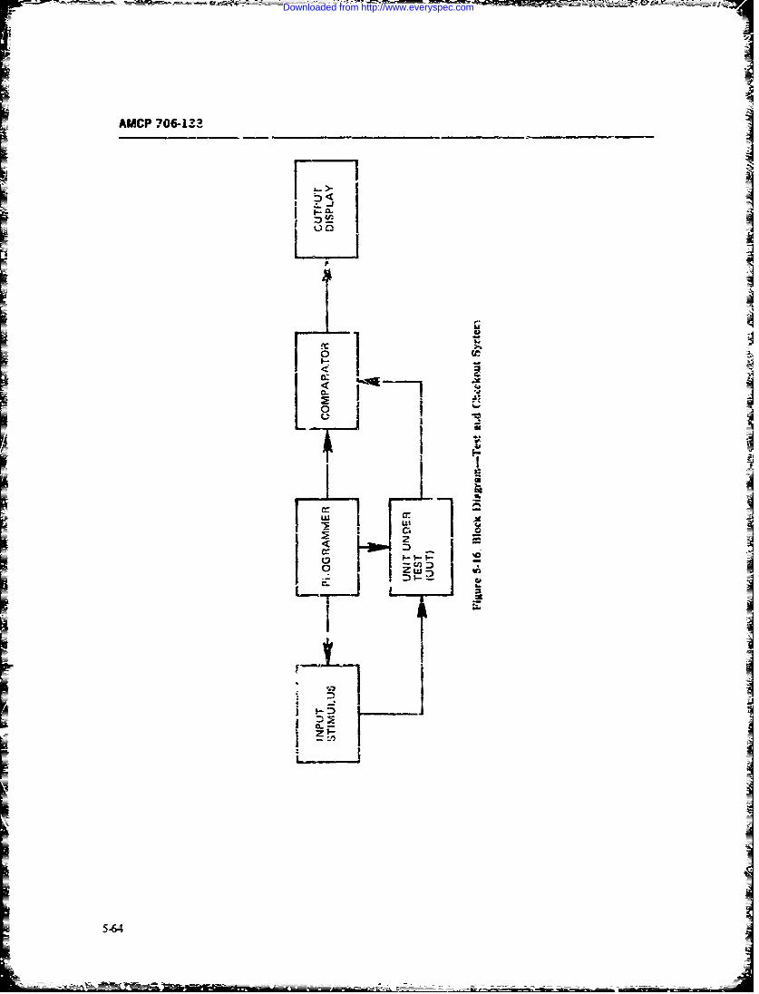
AMCP ?06-133
Lw
IU iinea(
5-L64
Downloaded from http://www.everyspec.com
wh-ich are -&rvibkc with the ten program andi, to Each of tisese-pro--myb sA-i5P by0one3o.so merl ei, th the prograxancr-coWparator (Ref o-e of the fdlk-iotzes smaith
57). 1. FunctiR-al (pef-.ormxncc! testing
R: shot:, b: notedi that an. automatic test system 2 Performance monrc- zng
impose :=ato.n -!sign reqlireinents or constraints oa 3M-j--I= ~the unizs to kL± tested, ich as accessibility to test. poinis. . JC*,ForNAa.ep.e the Navy hsdeveloped IMIL-ST-B '26 5 £4fIkest
(N.-.?- t T ? "izz Ts Porn'r £oJc-o.Lan fIver- 6. Diagnsic tsrfi' erdremensr £yinnrmt.ored by Spo-
boad c1-tte lurrnne h? Euipzen (Rt 5)~ Tyjs~s of test tedzniqvo i-4chait
In =a&;*;-n to test poinis 1ther amr g34jf cfrsig 1. DYIIIIQic imSai
feazum- zcdang procedsre. and n'tktamnEUity ze- 2- Open-lcz -rloedoopqui. cments ncessarily imaposed on tJ'Jrs tzc'ende&- for 3. On-iae--r off-lineE-sc v.hh %,eeral purpose auomti.; test systeca. All 4. -gj . quitivttew and cltckout systc-ns must c0Iit-i these lt-C 5 GO/NZOGE) or interpretive.features, Deonmding wpm- systemn wmr=4ny. the atbil-ity of the test systemn to zrswe ne than c ic prim Alli of the Hytd rrposeamtos n .x ttssr--zen c;.' equipment the sandarlzaion of equhxn-en! are cctarnd with rmaeneand znvi ltytoan4 UUT design. an-d the phase of the syste- life cycle some d t atcn or m of th dfaetziueUtwhich spponsstemnsidafin 2rabn. -d- ac res5.,
adapters which provide interface, between deUT are tes~s performedinaftzvo:dptadanc-ane the ;-s system. Adapters may be simple mecbsaxi- i.2rtied with the p;vductn-rentr -etnildiuy. or over-cai Fixtures an.d zest r-cnectors. They may also include haul-- usnten-ts and their copmis. These teats cr
Isources, signal conditio-ninz. and tes sequencev switches- thy) tray we-; dynamiz-cr autc r~Opt- -100j% or dow--OCwhich are not incorporated in the :cs sysort- A-!- loop tests: and they are- usualy cyanntanve ad inter-
thcao itwoul ap-ar hat i-Westadardzatin p- prtivv- C--thy ::s~w-ncedditi otz nallyv .y 3.qin-ntentizil ~ ~ ~ ~ ~ ~ ~ ~ ~ ~ 'fI exss-* ci-igcmo r udups hd d-.-e-a-r;;"' testingtprorrdue-
to .mke -;gr/ -vc- tadeofs %it rear -,3 e- aQIt-11-oi and ali--snetz ame e.rfrmed 4se features. of the $UM.l neav ocpt ob nyd-g md~o n ~&7t rr- eig
the method t,~v g. The cost associte -d with drvel- a =ii degrezs levea-- 1-as ~ls ain-iopnen-i. acqu, ition. storre.r ident~rca-tio ar.J zndifl- allinm: tess n pzr=fo;nied a-s pa: of cou"at amn of the .-dapter i-s bw- one of the factors that mainzzna-rze and as panr of sirnrflcux cf cr--
sho-uld &- consiered in ac h uesign/eamnomic trade- mize r.-znc.r: acvoa fbe 'nay c1LciEk reairction i.-seif Cur-ing the ciiegv-.csic
b.'nion and aiignnvuit testing infe Sd&zstMeh
=5-&6.2 Purpose and Typ-, c-1 Testo and technzmues as desrbed fcc wr.-.uan acr-3n-and csuaty =rance tcsftw.
Th-rc die a number of purposrs inwilve-d 23 testing- J7.uf dee ai m;!, dngnst- rniats. aci-
=These inciudez- iiwa-t.von -an cnment tts are conce.rn-ed int L-:1. Production a..teptanc-- and q'~hty assurwr= of tte~n corrective pcmyra cantin rt
2. Calibration and alignment g. rio-' can I-av a vgr ificant uv' C%- nm--
3. Fault ,etection iindwnteThyzlc lof'ecsmeis4. Fultdiwsisand zechn.qoes listed.
Coiple yse are frequetriy givt r.tes et5. Vai-fication by ax.t or both oftwn gnr imhodr, (1) funa-io'rai
6Propnss tests. Witch siin=-tc -,---al nc--2ratin aa~tins
Downloaded from http://www.everyspec.com
T ..... . . . .. .
AMCP :706-133
closely as possible; and (2) margina! tests, which at- components. A component is seeded so that when ittempt to isolate potential tru ,ble areas by simulation of wears beyond a certain limit an tabily deiectabk chemi-abnormal operating conditivns. ca.; substance is released (Ref. 59).
Functional tests are commonly used for mirsile One of the most promising approaches to predictingcheckout equipment; for example, a missilt is tested by impending mechanical failure is analysis of oil. Irnus-supplying typical guidance data to it and oberving the trial programs and the present U tri-service SOAPresponse of controls to computed erroi' signals. Such (? ectrometric Oil Antlys*s Pr-igram) operate by peri-tests are performed under norma! temperature, me- odical!y recording the percent con'entration of key ele-cbani-al, and electrical co,ditions. menis such as copper, ni.kel. iron, lead, and olgeri-a a functi-nal test, the test equipment simulates metzls found in oil taken from lubricating systemns,
,igi-ificant inputs to the syste-a being tested, evaluates comparing -;:is measurement with data compiled fromfinal nlitputs against a set of predetermined standards, tests which correlate actual wear of parts with thededuces the incidence of any probable faults, and indt- am, nt of metal in the )il. and evaluating the compcri-cates to the test equipment operator the system state sf son to predict failures of systemn parts. Abnormal ratesreadiness, of increase in these tiements are flagged anJ then cor-
Marginal tests, on the other hantd, supoly data about related witb historical data for final determination.a systeri while it is being subjecled to marginal and The instrumentation used is either a militarizedlimit signals anc severe environmental conditions, such emission spec:rometer or a commercial atomic absorp-as vibration, extreme heat, or lowered power. tvpp y tien spectrometer. Both types of inqtrurrent measurevoltages (Ref. 42). tie percent concentration of 'npurities in a batch test-
The system may be i sted at periodic intervals or just ing process on samples taken from engine oil, hydraulicprior to entering a mission state. This is callcd system lines, gearboxe-, and other oil reservoirs. This percent-checkout. Cieck,,r is A,.fined as "a sequence of func- age is converted to either Wear Metal Units (WMU) ortional. ' crationa_, and calibrational t-its to determine parts per million (ppm) by comparson with oil stand-th-. condition and status dra w. pon system or element ards having knownt amounts of contaminants (Ref S9).hereof." (AR 310-25). Syst.r-m monitoring and check- Spectrometric analysis utilized as a separate detec-
out are performed, thereforc, to detect aciual p.rform- !inn or diagnostic technique for wear metals or in con-ane- failures or to aleow the prediction of rr.-ipient junction wi,h physizal/chemical tests has proven effec-faiires. Chcckout is al,, perfort.ied during the verifi- tive in all military ci craft -ngines and gearboxes.cation period of corrn tive maiatenance downtime to Compatrisois and evaluations nf increases of cer.ainascertain that the repaired system is once again operat- elements in the il-v etted areas diagnosed categorizeing within acceptable limits, an impending failure of the 'omponent (component
Pregnostic tes.3 are use, for monitoring degradtion fabnca;,on already established). Physical and/or4 in system and component performance and for predict- chemical tests to supplement or confirm the failure are
ing when nonscheduled preventive and corrective -equired or occasion for support. Standardized tein-mainttnance should be performed in order to inhibit niques, training, and communication exchange- be-y:zin failure. During system operation, certain criti- tween military and i-dustry have stimuated wrddwide
cal performance functions may be continuously ." pen- nterest in maintenance efforts and ultimately in air-od~cally monitored in order to ascertain t.at they are crau safety and savingswithin aeceptMLle limits. If these tast data are recorded. Mil..ary agencies are now able to analyze as many as
the int'ormatior iotained may be used for degraoittmmt twelhe elements spectrcnietrical. wiith response timeanalysis and pron&ostic evaluation. Marginal testing reduced to several hours (,;, routine samples. Fre-has its greatest value when it is used in support of fault quency distributions t,;,tted with conf; med diagnosisprediction because it identifies many incipient failures (hits) are used to e tablish esaluation cri..ria for main-resulting from abnormal environmental and operating tenance recommendations. Wear trend daia compiledconditions. over a period of time demonstrate repair/replace/over-
Prognostic testing presents a great chall -age to the hadl type of maintenance.test equipment designer. There is no question of the The ,otential for spectrometric analysis has in-importance of being able to predict the time to failure ci eased, especially in areas of large equipment.for the main failure modes of a system. In automotive Performance checking is. in essence, a verificatiom, ofand aircraft vehicles, for example, the most piomising UUT operation against !ts performance specificationpossibilities appear to L,- through oil analysis, onboard and can be a go/no-go test in its simpnest form. Thisrecording, vi'ration analysis, and seeding of critical type of testing is usually associated with product ac-
5-66
Downloaded from http://www.everyspec.com
AMCP 706-133
-'eptance or prcxuct certifiation, and with system Component tests, by whih ievery in 'vidual subsys-
ch rckout am. mai.tenL.ice 1--r fault detection. "or ex- tern or component of a sys;tera is tested, are made on
ample, a determination of maximum engine horse- the assumption that if al1 ubsys~erns ,nd componentspower by a dynarrometer will reve.l quickly whether function satisfactorily, the system is ;n satisfactory op-or not the engiit is meeting the manufacturer's specifi- erating condition.cation. On the other hai.d, if the engine fails o deliv." The differences between these two types of zest canthe specified horsepower, the dyna'nometer test vill be illustrated by the e:mniple of a simple amplifier. Anot diagnose ur pinpoint the soc rcc of the problem system test oi'such an item would consist of providing(Ref. 5'). a representative signal as an input, and measuring the
Perhaps one of the most s&gnificart, as well as most response at the output for gain, phase shift, noise, tran-difficult, types of testing ;s diap'iostic iev:ing. Etudies sient response, etc. A component test, however, wouldhave shown that this downtime period is by far the measure pewer-supoiy vohages, resistances, capaci-largest contributor to corrective maintenance down- tances, ;ont .,u'ty. or some other performance charac-time. Th! purpose of diagnc: itic testing is tQ first local- itristic to find poteittial difficulties.ize the failure to a specific subsystem, equipment, or Usually, the system test is the more desirable of theassombly, and then ic isolate the replaceable or repaira- two types, because it is more comprehensive and repre-ble eid item which has failed. sents functioncl performance, and therefore is more
In many cases, fault detection tests are nim i? itially useful. No amount of component testing will definitelybut, instead of merely stopping or :ecording datm on an ensure, on the basis of test findings, that a system wi!lout-of-tcerance test, recoucse :o a fault isolation se- actually operate as specified.quence i. used to identify a specific maintenance acti)n. Component testing is sometimes used as an adjunctThe test sequence can be designed to prrvide fanl' iso- to system testing, to facilitate troubleshooting. It islatii. or ciagnosis to a predetermined iepth of detail, especially useful for isolated networks of passive Zore-The diagnostic and performance test- often overlap and ponents, cable ard harness assemblies, etc. It shoulda pertbr-nance test is frequent'y used together with rarely be used as a prime test technique (Ref. 42).another tes" to diagnose a paricular problem. For ex-ample, if a peak horsepower test shows .; low perfbrm 5-3.6.2.2.2 Static vs Dynamic Testsance, then a check of ignition timing against specified System tests may be run according to either static orlimits may pinpoint the cause of the problem as incor- dynamic prin:zples. The selection is d-termined by thermt timing.. On the oher hand, the success of the diag- type of system to be tested, which may dictate eithernostic analysis may rel) on the processing of a vibration one or a combination of both. Whichever technique iswaveform which has no connection with tL manufac- adopted, the ultimate aim is to exercise every subsys-turer3 specificai " ,Re. 59). Diagnostic testing is dis- tern as a means of determining the cumulative effect -)fcussed ir par. 5-3.6.5. all the subsystems on overall .ystem performance.
Regadless of the type of test equipment nee,'ed, a A static system test is one in which a series of steady-test should be suffic;ently comprehensive to determine state input signals is fed in, and the output indicationswhether or not a syteri is operating properly within its are monitored tc measure system operation. Altl.oughdesign specificationi. In the interests o -onomy. it this kind of test can provide information on the tran.may be nec.a%,,y to limit a test to the cot..ponents of sient behavior of a system through time synthesis, ina system that bave the most failures. Other principles practice the transient response is often ignored in favorof exclusio, specify components that are not really vital of the simpler steady-state response.to system operation, those that are "nly marginally In a dynamic system test, a transient or varying inputsignificant, com,,onents that cannot be tested, and sin- signal is applied to a system, and the output signals aregle-shot power sources (Ref. 42). noted and analyzed to determine whether or not system
requirements are being met. A test of this type more5-8.6.2.2 Types of Tests nearly simulates a typical mission of the sys',em being
tested; thus every major subsystem is checl.ed in this5-3.6,2.2.1 System v's Component Tests test.
System tests are performed on systems as single enti. A static test, of course, is the simpler nf the twoties; in each such test a set of stimuli is presented as types, and is therefore generally easier to perorm. Itsystem input;, and the responses are recorded. To the yields results that establish a confidence factor for ag'eatest possible extent, the test is performed as a con- system, but cannot go beyond this. A dynamic test, ontinuous series, !he other hand. produces much additional information,
5.67
Downloaded from http://www.everyspec.com
AMCP 706 -133
such as integration rates, phase ,rnd delay characteris- 5-8.6.2.2.5 Quanti.ative vs Qualitativetics, and frquency and transient resp..nse of a system Tests may be quantitative, i.e., the mee'surement ofto eithr typical or boundary-value inputs. For these a specific performance parameter within prescribed U-reasons, a dynamic test is recommended wherever it mits c'magnitude, tim#e, and/or shape;, or tests may becan be used (Ref. 42). qualitative, the indication of the presence or absence of
5-8.6.2.2.3 Open-loop vs Closed-loop Tests so,,ne system attribute. Quantitative and qualitativetests thus differ in their information content. Qualita-
A further refinement of either a static or a dynamic tive tests are usually simpler to make and to indicae,system test is tie application of opn-loop or closed- but do not permit prognostic evaluation. They are moreloop testing techniques. The open-loop test provides for desirable for organizational L.el and quick-check testszero intelligence ffedback to a system being tested. In than for diagnostic, det.iled testing.a test of this type, system r-ponse is evaluated as the Quantitative tests contain more information atoutsysteni end pr "-duct, and no adjustment of the stimulus the system or component and, therefore, can be usedis niade; i.e., a preset stimulus is fed into a systen and for more detailed examination of the performance ofthe response is independently evaluated. the UUT. Certain quantitative tests are difficult to
In a closed-loop test, input stimulus is continuously make in an operational environment and in an otr-lineadjusted as a function of the response. Adjustment is mode of test. For example, tests of high energy, highcomputed on the basis of system behavior under test frequency, electromagnetic emision, and armamentconditions; for exawn'le, in a guided missile test, the firing signals are difficult to perform in the operationalflight characteristics of the missile will control the in- system, or may not be permitted for safety or securityput stimulus at all times. reasons. However, quantitative tests rather than
Open-loop tests sometimes provide more useful qualitative tests at. required for calibration and align-mair.tenance information, because they make possible ment.direct observation of system transfer functions, free ofthe modifying influence of feedback; this makes possi- 5-8.6.2.2.6 Go/no-go vs Interpretiveble ready measurement of any degradation of system Go/no-go testing does not imply qualitative testingperformance. Closed-loop tests provide much informa- rather than quantitative. Go/no-go and interpretivetion for use in evaluation of system performance, .ffe- tests relate more to the method of display and thetiveness of design, adequacy of tolerances, and related degree of interpretation of results which is desired orcharacteristics (Ref. 42). needed by the operator or maintenance ;echnician.
5-8.6.2.2.4 On-line vs Off-line Go/no-go tests may ,& spemified because of limitationsas to technician skill-level or because the nature of the
On-line testing is performed on the UUT while it is test or operational situation is such that a noninterpre-installed as part of :he system in its ce+rating environ- tive type of readout is more effective. Go/no-go typement. It may consist of peiformance monitoring utiliz- displays are usually preferred for organizational leveling built-in test features or test points and connectors checkout tests.for the use of external test equipment. It may use the There are many instances, however, in which inter-normal operating signals and conditions of the system pretive displays are desirable. For example, a ,athode-rather than ex:enal stimuli. Or, it may consist of pen- ray tube display mpy give the technician informationodic checkout or fault diagnosis using internal or exter- about transients or the waveshape or marginal toler-nal test equipment and stanoardized stimuli. When ances which will allow him to take proper correctiveused, on-line testing is normally performed at organiza- measures. Interprttive displays are generally preferredtional and direct support maintenance levels, for diagnosis and adjustments at maintenance levels
Off-line testing is generally performed at direct sup- other than organizational.port, general support, and depot maintenance levels;occasionall;, it may also he performed al the organiza- 5-8.6.3 Classification of Test Equipmenttional level. Off-line twsting consists of removing the Test equipment may be classified in a number ofIJUT from its operational environment and testing iton a general-purpose or special-purpose tester. It al- ways (Ref. 57). .mong these are:lows tests to be pyrformed to greater depth and detail, 1. Method of operation (degree of automation)as well as to h-gher accuracy and precision. It also 2. Point of application (maintenance level, pro-generally requies higher skill levels than on-line test- duction)ing. 3. Design origin (military, commercial)
5-68
Downloaded from http://www.everyspec.com
=I
AMCP 706-133
4. Versatility (gencral-purpose, special-purpose) man errors, Oecreiased testing tire, decreased mainte-5. Interface with prime oquipment (buil:.in, or.- nance training time. and lower cost for testing and
line, off-line). naintenance !raining. While such advantages are nor-rpally associated with automatic testing, it does not
These categories of test equipment are discussed in the necessarly follow that all ATE is more cost effective toparagraphs that fallow, apply than manual test equipment. Development and
5-8.6.3.1 Method of Operation acquisition costs of ATE are high. The development ofATE test procedures also requires considerable invest-The method of operation of the test equipment is ameat. It has been estimated that the cost of software
fnction of the dxgree of automation. These range fo generally is three or four times that of the cost of thefully automatic to no test equipment as follows: ATE, itself. Moreover, there are numerous other de-1. Fully automatic sign and economic considerations which should be ad-2. -enfi-automatic (pre-programmed) dressed Zefore determining the most cost-effectivw test3. Semi-automati-, (manually programmed) equipment to utilize in a given situation (Ref. 57). Be-4. Manual cause ATE has become of increabing importance in5. No test equipment. system and equipment test and checkout in recent
years, a more detailed discussion of it is given in par.Automatic test equipment (ATE) may be defined as 5-8.6.4.
equipment designed to automatically test functional No test equipment In some cases, it has been shownparameters, to evaluate oegree of performance degra- that system effectiveness is optimizd by adopting thedatwoo, and to perform fault isolation to the replaceable test philosophy of no testing at the organizational level.or repairable end iinn. The decision-making, control, This has been applied to some small missiles, and isand evaluate functions are conducted without r:.liance called the "wooden round" concept.on human intervention. Nofully-utomatic test system,in the sense that a human operator is 5-8.6.3.. Point of Applicationeither to initiate the test sequence or to interrupt the Another way of classifying test equipment is by thetest, if necessary, exists today (Ref. 57). Some auto- pr.int or level at which the equipment is applied. ThIsmatic checkout equipments do exist which require only may be at the factory production line, at the depot oroperator initiation, particularly for on-line checkout repair facility, at general and direct support mainte-and diagnostic applications, or whirh instruct the oper- nance levels, or at the using organization.ator to perform certain other initiative, beit noninter- At the factory level, use is made of comme-cial testpretive, tasks during the test operation. equipment for production acceptance and quality as-
Semi-automatic test equipment is "any automatic surance, including calibration and alignment and envi-teating device which requires human participation in ronmenta tests, as described in par. 5-8.6.2. Similar orthe decision-making, control, or evaluation functions" identical equipment can b, used at the depot lt.el of(Rcf. 60). raainttznance. In addition, special- or general-purpocr
Semi-automatic test equipment may be either pre- test equipment car be utilized at the depot le-J (seeprogrammed with the ijechnician following prcviously par. 5-8.6.3.4).prepared and sequenced instructions, as directed by the At the general support and di-ect support levels, testtest equipment, or manually programmed in which the equipment may be diagnostic or checkout equipment,technician follows a printed test procedure or checklist and the requirements for the use of automatic test t-ch-and performs the control and switching function. niques increase (see par. 5-8.6.4). At the organizational
Manual test equiplmenris defined in MIL-STD-1 )9 l'.vel, test equipment requirements increasingly empha-as "test equipment that requires separae manipuia- 3ize checkout and built-in test for rapid test, fault detec-tions f-)r each task (e.g., connection to signal to be tion. and diagnosis down to the replaceable item level.measured, selection of suitable range, insertion of At this level, Jetailed quantitative, interpretive teststimuli, and measurement and evaluation of results)" equipment is less desirable than a quick, go/no-go(Ref. 60). checkont set.
Many of the advantages of automatic testing havebeen demonstrated time and again with regard to se- 5-8.5.3.3 Design Origincific test systems. Generally speakiiLg, -hey include Design origin, as a category of test equipment, ismc-e precise measurements, greater reliahi..y in test co.,.'enied with wnether military or commercially de-results, more continuous surveillanco, decreased hu- signed test equipment is wed. M;IItary designed :est
5-69
Downloaded from http://www.everyspec.com
AMCP 706-133
eq:,jipment does not necessari'y imply that the test which they a-ay be applied. A ,,ignificant number of"equipment is designed by a military activity but rather items listed in the Army Test, Measurement, and Diag-implies that the test equipment is designed to military nostic Equipment (TMDE) Register (Ref. 61) are ofspecifications an" fer use in military environ.aent. this category.Thus, the development cost .f mnilitary-designed testequipment is generally borne by the Government in its 5-8.6.3.3 Interface With Prime Equipmententirety or at least in part. Commerciaily &.-:igned testequipment is designed by industry gen rally to meet Test equipment can also be categorized accordng totesting requircm.cts for =iiimerc.al equipment. The its interface with the prime equipment being tested.development c-=t 'or commercially designed test equip- This categorization includes built-in test equitmentment is borne by industry (Ref. 57). (BITE), on-line test equipment, off-line test eq';ipment,
Commercial test equipment is used for factory test- and production test equipmen.ing and is usually well suited for depot testing as well. Buil-.n test equipment is defined in MIL-STD-I 3'9The acquisition cost for commercial test equipment is as "any device perimanettly mounted in the prime
well below thot of military test equipment (see par. equipmtmt. and used for the express purpose of testing5-6.8.4.6). Military test equipment, however, is more the prime equipment, either independently or in ,s-suitable for meeting the operating environment eut- sociatirn with external test equipment" (Ref. 60).
countered it. the field. BITE generally indicates a go/no-go sitration and canbe built into a small module or into an entire complex
5-8.6.3.4 Ve'sa',ility weapon system. BITE may provide continuous per-
The versatility of test equipment is a function of its formance monitoring or it may scan various test pntisability to test m.re than ome type of system or equip- periodically.ment. or to b readily modified to do so. It can be On-line test equipment is sn:, testing device which isclassified as either sprcial-ptrpose or general-purpose separate from the UUT bat which, when connected.test equipment. tests the UUT in its oprational environment. On-line
Special-purpose test equipment is designd to test a test equipment does not generally require the use ofspecific system, subsystem, or module. It is designed exte..lr stimuli. It normally measures or samples thefor applicat;on to a specific prime ,quipmnat where the actual operating stir.uli. Test equipment that is perma-design, operational, and environmental characteristics nently installed in the prime equipment and can testa Fe generally known before design of the test equip- various assemblies or subsystems through switching i-went. Special-purpcse test equipment thus performs a considered in the category of BITE and not on-!ine testmore efficient and effective test by prn.,id-.-g a better equipment. The basic difference is that a single unit ofinterface with the prime equipment for which it is de- on-line test equipmen. can be used to test multiplesigned as well as simpler operation and readout by copies of the U.T to which it is applicable, whereaslower skilled personnel. It is, therefure, less flexible and BITE is pbyvicaily constrained to test only one copy ofgenerally requires modification for use with otl'er the UUT for which it was designed (Ref. 57).equipments tha, that for which it was designed. Off-line :est eqvipment is any tcsting device which
As a result of the proliferation of complex, costly tests a UUT after it has been reni;ved from its opera-special test and checkout equipments and their lack of tional environment. Thus, off-line testing indicates thatflexibility, there has been a significant effort in recent some form of fault indication (perhaps resulting fromyet s to develop versatile test equipment utilizing the BITE or on-line test) bai already taken place since the"building block" concept and modern progr-mming UUT has been removed from it, parent operatingand digital computer techniques (see par. 5:4-.7). equipment. Since removal of the UUT is the only clitc.
On the other hand, general-purpose test equipment rion, off-line testing can occt'- at any level of checkoutis designed for application to a broad class or type of or maintenance, but is generally used at direct support,prime equipment, some of which may not yet ie de- general support. and depot levels rather that at thesigned when the test equipment is developed. Generat- organizational level.purpose test equipment cotsists of standard commer- Production test equipment is off-line test equipmentcial or military test equipmcnt-such as voltmeters, wherein the UUT is not ...sted in its operational envi-cathode-ray oscilloscopes, frequency and time measur- conment. Production test equipment is used primarilying devices, counters, pressure gages, and leak detec- to facilitate production 1ine testing and quality control.tors-which are designed for gene-ral parameter weas- Mn most cases, prodaction test equipment can performurement without regard to the system or equipment to tnc same test fun' _srms required by off-line test equip-
3-70
Downloaded from http://www.everyspec.com
AMCP 706-133
ment used for maintenance, as well as the More numer- 5.8.6.4.1 Rapidly Ad'vancing Technologyous, detailed tests itot required 1-' the field. Tcbna:ogical innovationis are occurring at a rapid
pace, both with respect to operating equipment and to5-8.6.4 Automatic Test anid Checkout automatic tt-t equipment. Most electronic equipmentIEquipment derfigned today is constructed of mrncr&.electronic cir-
Autoati tes an chekou equpmet wa ongi- cults and witt.. solid-state components. ATE not con-Autoati tet ad ceckut quimen wa orgi- structed to be capable of measuring performance
n -Aly developed in the early missile cra to check a sys-tem rio ~oopeatin rthertha tomontorit umb parameters asscciated wvith such d-esign characteristicsternprir o pertio rater han o mnitr itdurn'; is obsolete for miost fut~ure applici-.io"nS. Technological
operation. It was usu.y tiloredi for a particular sys advance ir. solid-state compon'mts is havinS a sigif-tern or equipmtait group. S;ince f hose days. automatic cant effect on the development of ATE. For example,test equipment (ATIE) has become more versatile and tercn 'eo il-fettas~u' rvdsahghis ben applied to on-lire performance monitoring, sh entty lo flodn apbltyf ~ el-fect traustespo ishig-off-line diagnosis, and Year echelon maintnance, in tarstifvsiny ATEw lallow forpabiiy naturlft se nsifuc-
th additn yspercalied i~cts alistcfvatile Eahtof tioii of parameter measuring tquipment and avoid thethemiltar sevics h~ is on lstsof erstil, ato- need for specially designed transistor circuits.
matic test equpnvxnt 1.Ref. 571). The technology with respect to UUT is changingEmplym~nt f atomic estandchekou eqip- sig.nificantly and th"s the design of ftiutre ATE mustRE ~ ment not only reducts tasting time and requirements change to keep pace with UTUT techno'cigy. RApidly
for skilled manpower. but also makes xessfo'se the es- idvancing technology in the field of electronics sug-tablishment of uniform, controiAe, anid reliable rn_-ck- gests that there is little to be gained by attempting toout ,rocedurts far dictermining operatifunal readine'ss. modify or standardize existing ATE, but much is to bela addition, such equipment is not re--tricted to t~ gainad by establishing more effective control and visi-checkoct of indivicsu.3 components, but can be. em.- bility over the development, acquisition, wit mse ofplayed effiriently for etirc systems and subsystems. future ATE.
For automatic test equipment to be effective it maust=have tne following charteristics: 5-8.6.4.2 2roader Scope of Application
1. Automatic sequencing of test operations Most ATE has been dleveloied to test electronic
2. Cortrol stimuli for the system to be tested, if modules and systems. However, technology now makessuch ctimuli are external to the system undergoing tes it possible to apply automaic testing techniques to me-
3.Cpbltofeautnsinlfrmasse chanical, hydraulic, and electro-optical areas hereto-Caabilit of ac eptalatring sigals foasytm fore precluded. N4ew measur.ag devices are being deve-
4. apaityof aki,-gdeccios (espnse) o a loped which will -llow mechanical, hydraulic, and4. apailiy f mki~g eciion (rspnse) o a electroopsica characteristcs to be translatedl into elec-
positive, obje'ztive basis tronic signals which can then be transnuttedl to a pro-5. Scif-checking of its cbeckou! features gramercomparator or a digital computer. The Ar-
*6 Monitoring displays for operator use, whce re- my's automotive diagnostic test equipmentquired development program is evidence of this trend-
7. Production of a permanent record of test re.. This broAder scope of application for ATE is notsults, where requi,,ed only significant with regard to off-line testing, but :s
8. Control, for rechecking sequences and tbypass- also significant when contsidering a built-in test semxing portionis of the test program Built-in test equipment with a broad scope of applica-
9. Aitoaticfaut iolaton o te :how-way tion has the advantage of utilizing a single. dedicated9.e o h sstm fut isltio otetwaa digital tmpute' to monitor an entire systes. For ex-
leve ofthe ystm uuer estample, the NMalfinction Detection. Analysis and Re-W0. Simplicity of operation and mainat-wiace comtling Sub-systemn (MAD)!kRS) installed oa thaa C5A
I1. Minimal .'alibration auid suppcr? requirements Aircraft monitors about 1800 line-Wpaeable units,
12. fail-safe circuitry (Ref. 42). including boto clect.-,nic &nd mechanical types.
In a recent rewort euititled Use of Automoatic Tes 5-8.6.4.3 Greater Emphasis on EquipmentEquipment for Mainrejace-A4 Reconnaiwsnce (Rdf erdto57), the Logi.4tics Maiagement Institute has noted the The development of ma-re sophisticated measuringtrend& that follow in he development and use of ATZ3 devices has cnabled test equipment designers to devwelop
5.71
Downloaded from http://www.everyspec.com
AMCP 706-133
test equipment whicL will indicatc. degradation trends 5 3.6.4.6 ATE Cost
of sys'em components in addidon to go/no-go tcst re- There ate indications that future ATE cost ier UUTsuit-.er This indications chat haver aT bcostn imper UoTsutL.. This capability can have a ignificant Iipact on tested can be significantly decreased A. - number ofmaintenance concepts for future equipmea iad on the reason;. irst, commercially developed A-E could bedesign of future ATE. Information regarding the deq iore widely used, particularly for oil-lin-e tesiing. Inradation )f system or component performance enables racent years commercial manufacturers have developeda scbeduled overiaul or remcve-and-replace iperation and built ATE systems for both coninercial andto take place prior to actual failure, and can be -H.fl. z!!.;,ary applieations. The result is that a great deal ofin determining the extent- f the repair operation aid .n commercia! off-the-shelf equipment is ctirrently availa-facilitating pie-entive maintenance. For example, the ble to satisfy many mili:ar needs wher- the opera-
Army 'has d .loped a need for Computer-controlled tional environment permits it. such as &t depots or
Automatii- Test Equipment (CATE) for use during the industrial facilities. T-.e acqui'tion costs of such corn-mcrcially available equipment are estimated to beC975-1990 time period. This requiremet describes somewhre between 10% and 20% ofth, acquisition
CA TE as a family of automatic test equipment,; that-, costs for ATE designed to military specifications.will provide all Its capability necessary for dirt, gen- A second factor which would reduce the cost ofeal: an ,' depot support of all US Army electrical, future ATE is the decreased cost of digital computerselectro-ic, elertro-mechanical, and electro-opical which affects built-in tesi equipment as well as off-linemateriel. A cvt-effectieness study compares the AT!_ Witi, lower cost digital comp wters becomingCATE concept with the use of present test equipment available, a broader applicatvn of BITT is economi-and methods and shows potential Life cycle savings of cilay jusfied Providing greater built-in test capabil-tyapproximately one billion dollars ove a S-ear period reduces the requirement fcr off-line testing.by applyiizi CATE in support of a two-cops field aniy A third reason for reducticn of future AE costs is(Ref. 62). the staiidardization of software. Much standardization
has already beei. achieved with respect to commercialCaMoea ie Sequipment; for example, most of the major ormnercialairlines tiave adopted a common c,,.nputer language for
The development of rPore complex AIE hws re- automatic test equipment applications. This allows testquired that a self-testing =apability be built into th,. test programs for common equipment to be shared by al!equipment itself. A number of improvments have been airlines. Standardization of test procedures and corn-made recently along those lines and inost current gm- puter programs has not yet met with vide success ineration ATE has self-testin? rapability. Future ATE military applications, but some efforts have been di-design vill automatically indicate to the operator when rected toward standardizing a commna computer !an-the test equipment is malfunctioning or requires cal,- -uage.bratic i. In fac. som~e designrs indicate that ATE ofthe futuru can be self-calibrating. In any event, ATE of 5-8.6.4.7 Standardization of ATEthe future should requre less maintenance and provide A numb-r of studies have been und-rtaken by thegreater con-Odence in the test results. military departments concerning the standardization of
5-8.6.4.5 A-,- Designs Compressed/ ATE ATF. There are two areas of standardization that5-8.6.n BerCoa eed, Awould contribute o the reduction of the number offuture ATE's. The first is the standardi7,tion of ATE,
Vhi!e the latest ATE is being designed for broader itself, and the second is :he standardization of the UUTtest appiications, the equipment itself is being corn- which the ATE is intendod to test. A recent Air Forcei,,ressed into smaller units. The decrease in test equip- study which examined 41 different ATE's for avionicsmeat size, weight, and power consumption is caused indicated that many test parameters buiit into a largeprimarily by the use of micro-electronic circuits arJ scale ATE are not bi'ng utilized at ali o- are utilizedtransistorizatit,tn of the test equipment, and by the use very little (Ref. 63). Th-s Air Force study proposes the,if smaller digital computrs as programmer-compara- design of 62 standard "building blocs" from whichtors. CQ-tair ATE under developmeni today is aimed most specific test requirements for avionics can be sat-at provicing testing capabilities for 85% to 95% of all isfied. The building block concept is to design the testequipment within broad categories, sucL as a,"onics system so that it consits of a number of functionaland co,-munications. modules, any of which, can be elimined when not
5-72
Downloaded from http://www.everyspec.com
AMCP 706-133
= required, without affecting the operation of the system Test, Measurement. a.nd Diagnosti Eqiuiipreotas a whole.11This concept alk-ws an automatic test sys- (TMDE) (Ref. 64). .estabashes broad policies covieringtern at any specific inst'Ilaticn to be con-Sigured to meet the development, purchas#e, acqjisition, and use of allthe unique requirements of that installation. As thr: test, measurement, diagnostic, prognostic, and calibra-state of the art advances, new modules can be designed tion tcquipment. In addition to prescribing policies, Ref.and incorperated -ithout redesigning the basic test sys- 64 estab~ishes objectives and priorides, and assigir re-tern. The builciing block mrinept has been applied to spon-sibilifies.7or life cycle management of TMDE. TheIsome e-tent by a1l three military departmeqts and to an scope of application is broad inasmuch as it spans allevcn greater extent ,y certain commercial inufactur- TMDEP all Army programs for maintewince. researchers. Standardizatioa potentials are aiso achievable for and developmne. procuretrent/production, invest-off-lint, spec-ial-purpose ATE. An example in this area ment, operating expense, and standardization.pis th-! standardization of "Spectrometric Oil Analysis The Army's TMDfE Registc- (Ref. 61) liss bothEquipment" used by all three military departments (see equipments which are operational andi those under de-I par. 'S .6.2). By standardization -)f cil analys eqi- velopment. Most of the equipmeums, both operationalinent, a reduction in the number of' oil analysis and uneer development, are manuali rather than ATE.liboratories, and the establishment of a new cii analysis In addition to the te~lt equipments documented in thr.program managernen, the Department ff Defense eti- Army's TMDE Register, there are a number of itemsmrates savings of some S5.3 million in planned equip- of ATE for which the Army has developed require-I nent costs and '$18.1 million a yez- in operanin costs. ments. An exam'ple of a multisystera application of
The Navy has made some significant progress with autmatic test tquipnient is the Land Combat Supportregard to the standardization of electronic circui, System (LCSS) (Ref's. 65 and 66). L.CSS is an Armymodliles. In was found that the incroasing use of micro- diagnostic field maintenance system designed to sup-c lectronc circuits inade it possible to develop basic, port the SHILLELAGH, TOW, LANCE. andfrunctiottally oriented circuits as zncdular assemblies rDRAGON 4-eapon systera?. The Army has also devel-wHch could be pluggcd in as needed to -itisfy a variety oped depot test cquipmeu:. for large failies of high
o f, t e q re nen ts fo r la g t- e le ctro n ic asse m b lies. T u s, p o p ula tio n c o m m u n ic a tio n e q u ip m e n t. 11h se e c un-,-%e Navy established the Standard Hardware Program ments. DEE (Digital Evaluation Equinent) and DI-I (SHP) to deveiop standard electronic modules at the MATE (Dept sAld Maintenance Automatic Testfunctional ci-.cuit iard level. There are approximately Equipment), (Ref's. 67 and 69). although designed for1*35 different standard modules in 19 general catego- ful! diagnostic capa'blity, are primnarily used for per-ries. In addition there zre- approximately 86 special formance testing because OF the high worklosd at themodules which could become cardidates for standard depots ard the dra-matic time savings and increasedI modules The SHP progrm is a dynamic owe, develop confidence in testing realized- Over 300 proS-us haveing new modules as the state of the art advances And been prepared for th=s equipments which have beendeleting those which become obsolete. The Navy re- used for tens of thousands of tests in depots and theports that there are over tairny systems which have field.ve-luntarily used SlIP modules in their design. The In addition to these Army programs, the US NavyPoseidon Fire Control System, for example, i. es up- and the US Air Foce havemdhaycomtnsproximately 10,000 SHP modules, 85% of which con- to their VAST (Versatile Avionic Shop Tester) andsist of only 12 different modules. GPATS (General Purpose Automatic Test System).
The interface betweea standardization of ATE ano The overall result of the military services automatedstandardization of prime equipment served by ATE is electronic test project has been 2 technolog) bWe whichimportant to recognize. This interface highlights th.- has not only gencrated intei est in industrial dctronics,need tc consider test eq-iipment requirements during butt in oiner commodity reac in the Goverwnment. Forthe design process of prime equi-pmerit, and converseiy example, all of the military set-vices currently ntave -k-to consider design features of prime equipment during velopment programs underway or under- consiiderationthe test equipment design process. for automatic test of gas turbine engines and turbine
5-8.5.4.8 ATE Policieseniecm"xaThez-e are currently no overall Department of De- 5_f. gnost Tecluikpas
fense policies aimed specifically at the development anduse of ATE. The Army's principal policyi, set forth in The teri- -dagnostics" refers to actions ~equitzod forAR 75&43, Maintenance of Sup-ilies and EqmdpmenL: actual location of a fault in an operatio.al suxtem it ts
5-73
Downloaded from http://www.everyspec.com
AMCP 70-133
better lwown as "troubleshooting." The primary objec- repair tine is usually spent in uetermining the causetivt of the maintainabity engineer in the field of diag- and location f a malfunctior (Ref. 69).nostics is an overall reduction f system downtin- by Examples of the application of diagnostic tchnitqiesproviding for the rapid location asd isolation of fuls. to Any systems an equip mets,. specifically of an-Different diagnostic techniques are available as follow3: tomotive diLgrowc eqipment, is given in Ref&. 69. 70.
and 71.1. Manual technigues (which are the type most The diagnostic equipment for the depot or factory
frequently referred to as troubleshooting) are bascally rebuild vehicle opertion is referred as the Jepottrial-and-error efforts by skilled technicians who usemeters, oscillo.scoe, and other devices, as well fs de- Mtailed prceedures ,and schematics, to isc. a mafuinc- terns (MAIDS). This equipment differs from thAi of theother maintenance levels previously described in that ittioning component by progressively testing all compo- s not used the complete vehicle. Its currentnents and elimin-.ling those that are still functioning. s to dos a dThese. techmques require that 'xternal test equipment which have been resoved from the vehie ard rebe used, and, in the great majority of instances, that thied oate dep roved ai. tie i.- and rc-
turned to the depot for overhaul. !t is i.,ed h-" cotijun-decisions be made by the t .chnicians. t ith conventional eng:e dynamoer ten fkcili-
2. Semiautomatic techniques, as tht. term sug- ties. The depot MAIDS represents a pioneering effortgests. represent one or more steps towari automation based on :he approach that diagnosing high cos en-of the isoladng of faults. In ali instances, -hey fall short gines and transmissiops before r and Le correct-of complete elimination of dependence on direct par- in& only those items needing repair is econcmi-AL De-• Vpation by techniciars. Techniques .f this type in- pot MAIDS identifies and isolates individual",ove -. sufficient number of internz! test ur.its and engine/transmission conditiois through a process ofindica:3rs to make any decision by the technician un- automatic analysis. Resultig c-zt aui work ' direc edn .-cer,'y Th'nl at' . Ih.- id-.e- - - : .- " to the correction of specific malfunctions with a ccnse-cabinet, chassis, or other componeit in which a mal- quent incrase in productivity and cost saving (Reft . 70function exists, or they direct the technician to the neit arA 71).action to be taken. A semi-eutomatic technique is
characterized by automated decision-making and by 5-8.6.6 Tst and Checkout Designpartial automation of test units :aid vrocedurem. Con lerations
3. Automadc techniqacs cyixpletely eliminate theneed for technician participadim in locIag a fzult. Maintainability design considerations with respect to
Upon failure of a comoonent. a 5)stem fitted with auo- test and checkout fall into two categories. The firsi 6mat.c techniques switches to a diagnostic mode, and by concerne,, with test philoscphy, the second with pe-means of internal circuitr. iso:at, and identifies the cific test zquipment design characteristics.
malfunctioning item to the repri-by-replacement level. 5-8.6.6.1 Tst Philosophy
Recent t s to d bt sta dization The considerations shat follow constitute the generalmodularization have aelerated the deielopment a'd philosophy of test and checkout. Th"ey should be keptemployment of automatic and semi-autona'ic diagnos- in mind by system designers, and maintainability andtic tchn;qus.- Inasmuch as both types are used to t equipment engineers as design guidelines.allow systems to be maintained by unskilled techni- I. At the onset of a program, the test phiosophycians, they mater;ally reduce overall system require should be to hold systmn checkout tests to a mi'urnum.ments (Ref. 42). preferably to test nothing. System parameters should be
In the absenca of automatic diagn= ! , carefully examained for criticality, and -. si.,ion forthe Atimy -,airtenacic ste. the practice of-diagno- cach test proposed shouid be required rather than thesis through par replacement" has becomea prblem. eady ado-*.*n of a poiicy to test everything uniess itThe result of thi: practice is a high rate of incorrect can later be shown which tests shoukl be eliminated.diagnoitis For example, an Army study in 1966 found t.e -later' seldom hap, and the .-sulting test!hat faulty engine diagnosis on .-3ckec! vehicles .c- equipment usualy turns out to be -- cunplex withcured 34% of the time. on wheeled vehicles 20% of consequent poor reliability and maintainability.de time. and on fuel and electrical compon.ents 47% 2 Test toleraces should get boader rs testingof the time. It has also been noted that with the present proceeds from rear areas to forward i,-sing artats (fac-raintmiance pools. 60 to 91'r of the mainternenc- tory to depot to field). If close test toleances are re-
5-74
Downloaded from http://www.everyspec.com
AMCP 70&133
quired 3t forward areas, then there iS a very strong in a oianner whkih reprecfmts as c;osely as possible its-'uplicafion that the system design is marginal and- that operational parameter values, ard the test outcomes
ine system will not achi-ve the required opea'tio-tal , w e more dicitive of true 'ysttm performance.availability. Althoagn this is often difficult to mplement. it should
3. In order to prevent the UUT iron, ,irculating be given consideration during the design of system testback and forth from using acti'ity to refair faci.ty and checkout. The use of substitute standard blackbacause the user test says th UUT is faulty and the boxes or simulators should be miaimtized.maintennce facility says that it is not. it is desirablethat each successive rear echelon, maint .ance level be 9. The confidence of the operator in the t.est equip-equipr.d to perform the seme tess to the same toler- ment cannot be wtr-looh.ed. If he has no confidence inancts and wi:h the sine test methods as its adjaccnt it, he will not usc it. If it turns out tha: indicar as ofi'orard level, preferably using the same test equip- failed performance are found to be due to the testment. If possible, this should be in addition to the more e.uipmnt rather than the UUT, he will not use it. Ifdetailed, tighter tolerance testing required at the rear the technicipn becomes the servant of th. ic equip-echelon concerned. ment rather than the test eqwptnent 'he tool of the
4. Ttsting at forward areas should be. imited to tec 'aic;an, he will avoid its use. Although often said inthose paraweters which are essential to checking overall jest, the question of wheter the tust equipment is test-system or equipment performance, preferably on a ing the s.ysem or %ice versa is vitally impo'iant.qu-ntitative, noninterpretive basis. This does not ne1es- e c equipment may beone compa-sa. ily mean the us, of go/no-go lights. If a different rabl e t o test e to e SystemtyFe of indication, such as L.O-l-q rete-s and CRT table witi: ur may even exceed the cost Ct the systemwith tolerance masts, gives both gE,/no-go indications which it is to trst, espeialy if ATE is usea. To justifyas well as indicating trend l,-els, it will assist the opera- such cost, ie opmtional av&lability of the syttemtor or maintenance techn;ci-n in monitoring system must be commensurately better.degradation or noting anomalies whi&h mignt help in i 1. A system which contains an undetected failurefault diagnosis. may be more harmful to mission success tha- one
5. To optimize test and maintenance, the s. tem which is down for maintenance.design shoula use "line replacv,ble units" (L s) 12. The ability of 'e prime system to -perform sec-which car be .eplaced at the orz-nizational and directmsupport levels using only udizr-ntary fault isolation on%_,ay or -txtive mignns th redu perform-techniques. An L'IU is a functional module or set of ance must be considered. The test philosophy and testfuncti-Al module* which, when replaced as an entity. equipment design should be able to give such stat.srequire no adjustment of ot.er systen modules, al- information to the optrrional camrander.thuo finc adjustment of the newly iserted LRU is 13. m-- : ability of the test and checkout equipment
to Qptimize iis performarc in the system. If to prt.vide feedback data for analysi. in order to allowoteK-r-nidulcs must bie ad-usted. they should be cotid- pr&izxt nmprovenent trend analysis. and improvedered as part of th LRU. mainteanc and iogistic planning should be consid-
5. To obtin the highest operational availability, ere.simplicity i- both pi.ne ;ystem and test equipment
decign and prformaw.ce mu t be onsidred as a gov- 14. The text ard checkout phitl.ophy must be cor-.ri._-g criterion, it is a fact that "simplicity means sistent with anti derived from ovall s-tem opera.reliability". tioral xad loistic policy and must be part o"the main-
7. ATE. shou!d not be used jut for sake cf auti.-a- tem-arice erncept. It must provide for fault isolation z ndtion. Its use must 'b- justified un system cost-effective- repair/re Place to the proper system level-ness c-nsuteranns only. Experience with eariy us. of 15, .h test equipmnt must not wen.- Ozi.
ATE .a sh ,in that, in a high percentage cf cases, finctional system.ATF is more complex and costly and is often unreliableand h--d to mainta.n, re-ulting in requirements for Oeckout of a system cnly indicates that the systemhi&g.y skilled personnel and lower system availability. was operating properly at the time the test was made.
8. For system checkout, it is desirable to let the It does vot guarantee that the system will operate im-system being tested introd.ce as many of its own t--t mediatqly thereafter rather it gives a degree of coil-.timuli as nossible. The system will then be exercised de.ce that the System will operate properly.
S-75
Downloaded from http://www.everyspec.com
AMCP 706-133
5-8.6.6.2 Test Equipment Casign block technique should be used where-ter possible, par-Cha-acteristics ficularly for ATE.
It -s ess ..,tial that extreme care be gv'in to the miain- 10. Particular attention should be paid to displays.
tnability design features in the aesign of both the Grl/no-c -, indicators should be used when noninterpre-
ptime system and its test an-I suppoit equipment, as tive -eadout is debired, as at the using level. Tem Ilates.
idicated in pir. 5-8.6. Such design coni~derations overlays, meters, CRT's, and other in!erpretiv-- is-ust~anas oonasthepri'.esysemdesgn s sartd. plays shaould be provided for maintenanice personnel
Ts-st philisophy considerations and *est equipmenst de. when determination of sysem degradation. margina
sgn po!.cies must t.- rigorously monitored and cn- performaince, and ;-rognostiz information is desired.
focdby Government technical and '-,ntract pesn- Adiditional de~sn infortnation and checalists appli-n-A It may well turn out that the systemn ovetall cable to test and checkout are given in Re-f. 11.
effectiveness will be influm~ced a much. and in somecsze oe by giin adeuat traenfsbbdedoqwtifaonanlto
tes: arid maintainability design features t'.an by im-provemlentincmoetadeupetrlblty
with respect to lest and checkout xrc in order to optimize some systemr parameter :hat is a
I. Use modular deigin. Design the prime equip- funt.ion of two or mere var-.bles which are being coan-ment and tes! P-quipmcnt using Liae Replaceable Units pared (traded off). Trade-off's involve perform-unce.(LRU4s) c ost. sche luIc, and risk. A trade-off may be quantita-
2. Use s-m'dard -.nd proven circuits and crimpo- *tve or ounditbtive. Insofar as possiole. it is desirablenents. taeof ebse nqatfalaa~io
3. Provide for built-in test points and test feattures, seriqal retativonmhds uhrs isnotna raningsorheincluding sclf-chec'z. to the greatest extent fe sible. .iqatttv ehd sn ria aknso
Self-check features should promrote a high degree I hord-f ocp s o e.Ec fu aecoi'.fence in the capability of the equipment to in'li- Tetacotcnet' o e.Ec fu aecate a fault in the system being tested, rather than in
the hecout quimentitslf.decision we make is based on judgment. which in itsturn represents the wcighing of known facts. The
4.prps rher thaint espile use tst eip entr treater it - number of -acts. provided they are dealtal-prpoe rthe thn s~aa-pupos tet euipent with rationally and svstematical'y, the greater is the
5. Require i; ically presented niaintemtancte in- probability of arriving at a correct decision.s,.ructions and di-. -5rms in tr-hniL--' manuals and Trade-off techniqu-,. by providing the objectivitymaintenaiice bar .ihoos. Use of techniques such 3s De- and systematic ap~proach required. contrbute greatlysign Disclos-ure Acrmat (DDF). logir diagramrs, fault to the validity of maintainability design decisions.I=tr#ees. and half-split should be investigated. Formally developed trade-off studies are needed at
6. Povie tst eatresand rocdur; wichare every stage of the design and development of new sys-
conmjtcat with the maintenance level arid environmcn- teins in the planning pawes, they determine the feasi-tal requirments. biliwv of a program. Miitary system requirements must
7. The man-machine ;elationship is important in be analyzed and weighed ir terms of such factors asthe esin ad uiliztio oftes andchekou eqip- sta-te of ilhe art. development time required. total cost.the esin ad uiliztio oftes andchekni e~ip- and extent tc which off-the-sheif hardware can be used;
ment. The man is par ofte op.fr civilian svst~ms. such factor- as potential consumer8. Safety precautions and safety desin features demnd. compiny capabilities, and profit margn are
must be emphasized. Fail-safe design should b~e c- analyzed and wieghed. After the feasibility study haspioyed. Adeuate prctection should be given to both produced a pes--t-ve finding and design work begins,operators and equipment; this should include shielded ttade-onfr it-hn.4 ues, art applied to such problems asintcrlecks at-,d properly pliced waffling s~gs determin:g the relative advAntage of various system
9. Test design should consider fiaxiblity in order concepts. throv'-away-at-failure vs iece-part repair,tu accommodat changes in the prime system andJ different packaging concepts, anS, at every level, vani-equipment design as well as the atelity to handle more ant specific design features. Trade-offs also play a pri-than one prime system 0i equipmuent- The buiduit mrary ro!z in decision making during design review.
5-76
Downloaded from http://www.everyspec.com
AMCP 706-133
.ihen the diverse interests of several project objectives the system level-.e g., equipment, unit, module. corn-must be reconciced (Ref 42). ponert. or part-at which rcpair or maintenance
The mctl~odology ror structuring and performinil, should be performed.
trade-off analyses is found in the system design decision 5. Corctv rs prw v ,ainienance. ThisIpr'ocess described ic par. _i-. The design decision trade-off is concerned with dhe decisioa as to whethermodel is shown~ F' ig. 5-5. The basic steps. summna- a particular failure should be ii~hibited by meana ctsized here, are preventive maintenance action or whether it shoIJ be
1. Detine the trade-off' pA*:em and establish the left as t. carrective maintenance action. upon failure.
tra-ofr cicria and cozrflrints. Among other considerations. this trade-off is a functionI2. Synt~ezize alterna tire desigp cimfigurations. of failutz modes, effects. and cricali:y. failurt Tre-3. Anlalyze thcsz alt.-rn-tive confrgiuiations. quency. tailure distribution, and mission and -.pcra-
4. EvAluate the results i-f tht: analyses with respect tiona! requirem'ents.to the criteria, elhirntin7 '.-lose vwhich violate con- 6. Lew of Tuoalmhis trade-off decision issiraint boundaries, one concernel with the level to whicn built-in and
S. elet he ltrnaiv whchbes m~et citeia automatic vs general-purpose and manual tet andand kctraithe bonarriternat e h e, des acrnra checkout fenetres should be incorporated into sysem
tands repeating St es itrg te te obtain imprved and equipmen, design in order it. meet system perform-Isolutions. h ooti mrvd aitce and effectiveness requirements. It concerns availa-bility, skill levels. cermplcxitv. criticality, monitoring,
Ths steps ane descriWe in mr-re detail in pars. 5-6 and number of tests. test time. and economiLcs. among oth-I 7-6.2.1. ers (see Ref. 11, Chapter 5).Trade-offs concerned with maintainability range 7 Packaging- This is c-ncerned with tLade-off, be-
from the relatively simple -eliabihitv-ma.i-itzinability- tween mstindardized and nonstandardized componentsavailability trade-off to complex issues which concern and modules and the extunt to which modularizationsuch items as the level of automation nf test and check- -!Il be utilized. It affects provisioning and repair partsout, selea~ion -)f module size, repair level analysis, and (see par. 5-8.1).trade-offis concerning skill level. perfan-mance and 8. Human Facsom' These are man vs machinepackaging requiremnents. hum-n factcrs. and the oper a- trade-offs dealing with which taiks would be bettertienal and support envirnnn'rent. pefre ytchicn n hc ymcie(e
Among the list of possible trade-off considerations parfr. e byic-8.4).n hhbymchn (e
which concern mintainabili~v are ,he folleuwing: p .5-8.4).aiiz hseae rdeof
I.cee weith~i whehe macnviabili thi tre-of is made among maintainability design factors r--hich willconcrne wih wethr ag~vn aailbilty e~ur~- allow the apportionnmnt of downtime to the various
= ~~merit can better bc t :hrsaegh increased o.mrphasis on ~i ieee -.t on a cost-ccti-re basis. Suchrliability features or un maintainability features, and traepairtae coernedwit m iaabltprdc
tors -8ta .1 a n ooefctv6.1ce bew en tem. tion and allocation as well as decisionts rep.rding thepars.5-8..1 ad 7-.1).various maintainability design facors.
2- Repair leweL This t-a&-off is conc-rned with 1.c l~altaeof r ae ~eothe determination of the cost-e11'ectivc allocation f OfL oi rtrAmin addio toperfrmn an rd efcie-
maintenance tasks to the various maintenlance levels- nomic istnia trad-on may befomae deee t isi-
-orgniztioal.dirct up~o. gnerl splxrt.and tion costs and operation and support costs as p-.. of
total system life-cycle costs. This may include trade-3. 2Zepair/replaceldiscarrt This trade-off is con- off's mnae during the eAly system life cycle planning
cerned with determining!iid zlpplying economic deci. and dev.elopment phases in determining maintenancesion critzria snd rules foe making decisions as to and support concepts, reliability and maintainabilitywhether a failed item should be repaired or dikcarded- features, and repair level and rerpair/disca' crireria. It
=It is also concerned with wh~ahcr. If repairable, the also includes trade -uffs made durngS the operation andfailed item should be w.paited in place at the cquipmcnt support phases as part of maintenance support deci-site or removed from the equipment. replaced by a gPod sions. such as whethe:r a normaily repairable item is stillitem. and then repaired at the same or a rear levelI (see wzarth repairing after sustaining damage or after a sing-pars 5-8.7.4 and 7-6.2.5). nificant part of its useful Ide has expired (see Chapter
4. System ievet This trade-off is concer"'ed with 7).5-77
Downloaded from http://www.everyspec.com
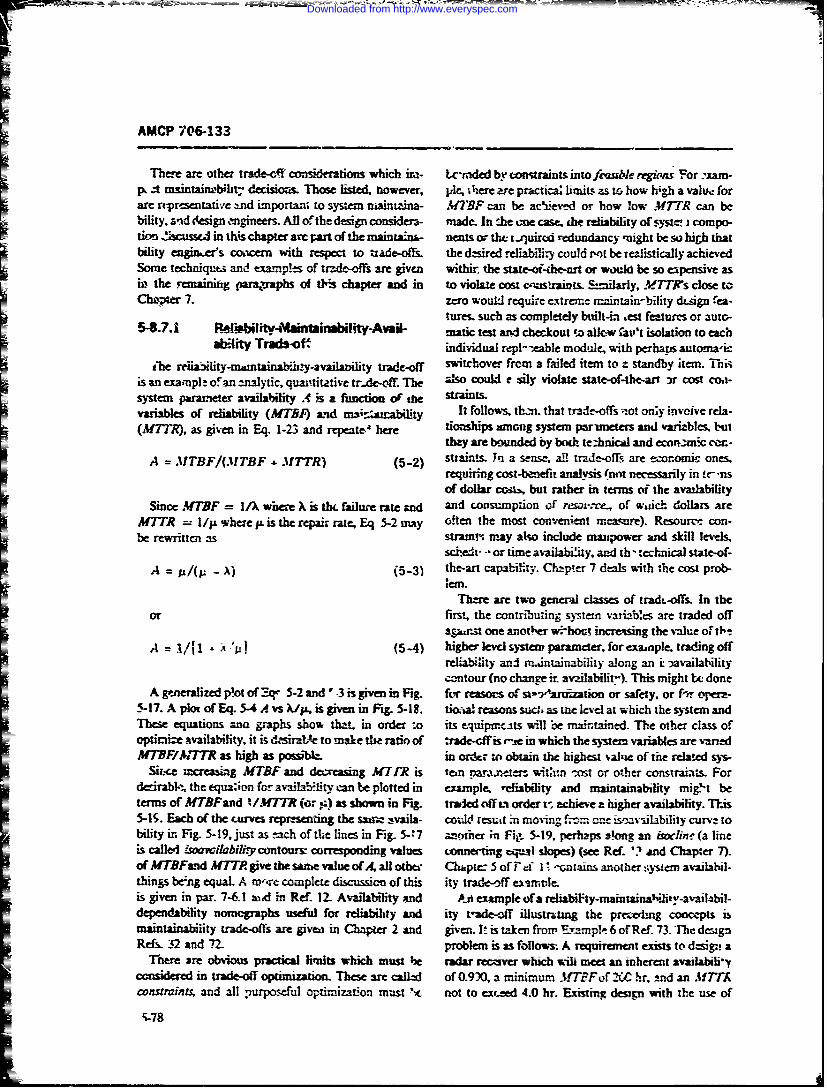
AMCP 706133
There are othe: trade-ef consideozwns which ir,,- Lc-rided by constraints into feable.regiozs For :xam-p zt maintaimbili:t decisimms Those listed, however, 1Ae, ere e pr'actica; limits zs to how high a val, forare reprasetative -nd important to system niain tna- 4M7-BF can be acyiievd or how lw MTR can b
blity, find de4sigl1,~inee- All Of the design consider- made. In :he cme case. the reliability of compo-tiOm ass in this chapter arc Part Of the mainwtanf- nents or the t ,quirod redundancy inight be so high that
bility engineers coacern with respect to tzadeo&fs the dcsmired relialit could "o be realistically achievedSome techniques and examples, of trd-of are given withir the , -ea.tor would be so expenive asw the reainiig paratraphs aff tl-:s chapter and in to violae cost c-.istramusy, .T s close tChip" 7. zero would require extreme maintain-bility dt-ign " ea-
tures. such as completely built-in ,est features or auto-5-8.7.1 Reliility-Mainiability-Awil- matic test and checkout ,z allow Cat,'t isolation to each
ality Traft-of. individual repl--eable module, with perhaps automaicihe reiaxliy-mdntainazbvhy-avaiIaz~ity t -off switchove from a failed item to z standby item. Thi
is an example ofan analytic, quantitatiie trde-off. The 2lso could r sily violate state-of-the-art )r cost coa-
system parameter availability .A is a function of me straintvariables of refabliy (47'5) L4 ms it It follows, thn that tirade-off --,ot only invove rel-
(M7TR , as given in Eq. 1-23 and rqeperem tionships among system primetes and variables, butthey are bomnded by boih te.hnical and ecormti cE-
A = MTBF/(MTBF . MT1TR) (5-2) suaints. In a sense a, trade-offls are economic ones,requiring cost-banefit analysis (nm necessarily in #- 'usof dollar cc., but rather in terms of the availability
Since MTBF = I/X where X is thL failure rate an and consumption of resov.-., of wadch dollars weMTTR = 1//I where p is the repair rate, Eq 5-2 may often the most convneniet mca re). Resourc. con-be rewrittcn as stramin may also include mnpower and skill lev-s,
schedr -or time availabiity, and th technical state-of-A = p/( -) (5-31 the-art capabilty. Chl- r 7 deals with the cost prob-
;Cm.Ther are two gener- classes of tradt-offs. In the
or first, the contributing system variabes are traded offagumn one another wrhout incrvesing the value o1 ib-
A = i/Il -A -'il (5-4) higher levd system parameter. forexanple. tradingoffreliability and mdntainability along an i iavailabuitycoantour (no change i. av-alabilit-). This might be- done
A generalized plot of Z. 5-2 and -3 is given in Fig. ft, reasons of st-w-1-artio or safety, or fne opera-5-17. A plot of Eq. 5-4 A vs /p, is given in Fig. 5-18. tioca! reasons sucti as the level at which the system andThese equations am graphs show that in order -o its equiptncits will be mamtained. The other class ofOptiraie availability, it is dsirzce to make the ratio of :rade-cff is -i in which the sstem variabies are varedMITBFMTTR as high as posswbL. in order to obtain the highest ,al'ie of the relaed sys-
Si.ce i .creasing MTBF and decreasing MTPR is ten pa.nters, witzm -t or other constrai.ts Fordedrabl--, the equaion for avaiLability can be plotted in exampe, rdliability and maintainability miget beterms of MTBFad /.fTTR (o ,) as shown in Fig. traded off mi order t- zchiee a hiLther availability. T-is5-4S. Each of the curves rep ting the saazz ivaila- coW result -n moving f.- a-- ismhvilability curv: tobility in Fig. 5-19, just as tach of the lines in Fig. 5-: 7 hani, ;nFi. 5-19, perhapsalongan isocline(alineis calle, ci abihy contours: corresponding values tcnneing voci! slopes) (see Ref. '? and Chapter 7).of MTBFarnd .M7T give the saime value of A. all other Ch&pte_ 5 of F16 1 !-.ntans another :y'str av-ailal-things berng equal. A m'wre complete discussion of this ity trade-off eLsniple.is given in par. 7-6.1 wed in Rf 12. Availability and A . example ofa reliabiFty-mamtzinaoh,-aAimhbil-dependability nomovaphs usef for reiabihlty and iry tde-off illustrting the precerng concepts ismaintainability trade-ofis are given in Chapter 2 and given. I. is taken from Exampe 6 of Ref. 73. The designRef- 32 and 2. problem is as follow. A requirewmt exists to d,.sigt a
There are obvious practical limits which must he radar reczver which wil meue an inherent avatlabiliyconsidered in trade-off optimization. These are calle of 0.9 M, a minimum MTBFof 2 hr. ind an f 7TAcO"UraiJt1 and all iurposefu optimization must N not to ez'.ed 4.0 hr. Existing desgn with the use of
5-78
Downloaded from http://www.everyspec.com
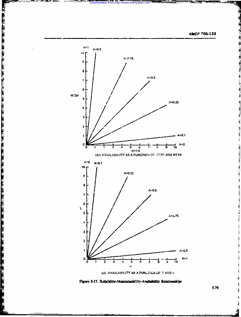
AMtCP 706-133
A-0.9
At C075
I A-0.25
31
1 A-Eli
0 A-_______
MTFR(A) AVAILABIL.ITY AS A FUNCTION 0- 1jT? AND) MTTR
10
I-
A-JJS
A-3
5-79
Downloaded from http://www.everyspec.com
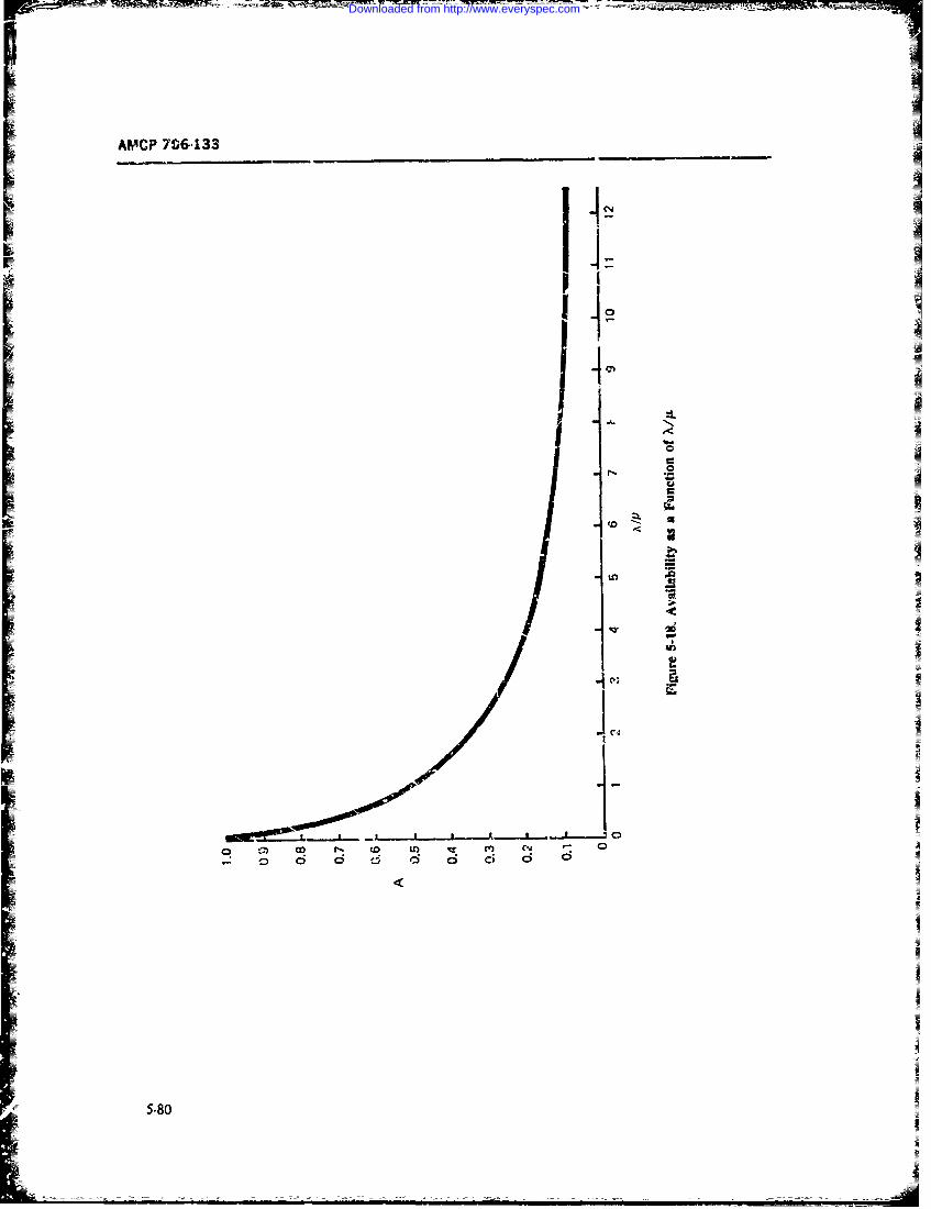
AMCP 706,133
1.4Z1 .j I,
co t , p m
0 6 6 6 6 6ci60
5.80
Downloaded from http://www.everyspec.com
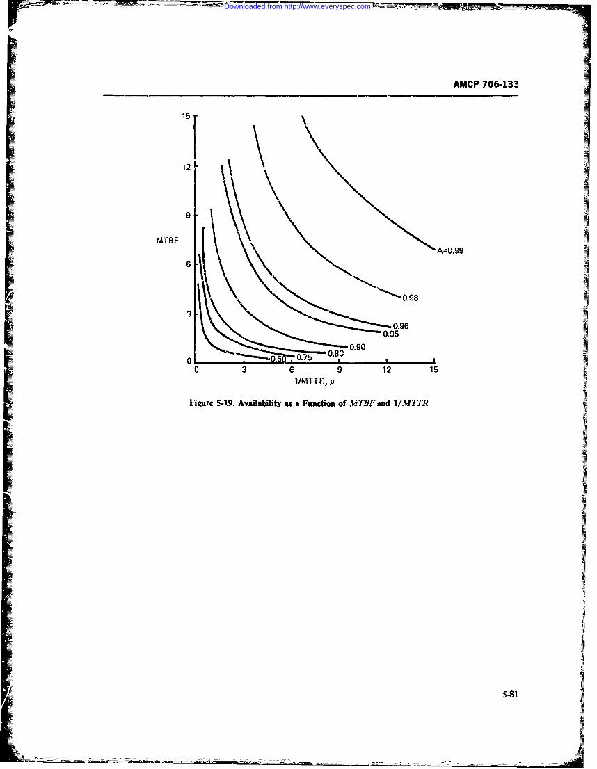
7-M -~ -
AMCP 706&133
MTBF(A=0.99
0.98
0.960.95
0.900.80
0 2 070 3 6 9 12 15
1/MTTF., p
Figur, 5-19. Availability as a Function of MTBFaand 1/M7TR
FML - - -I
Downloaded from http://www.everyspec.com
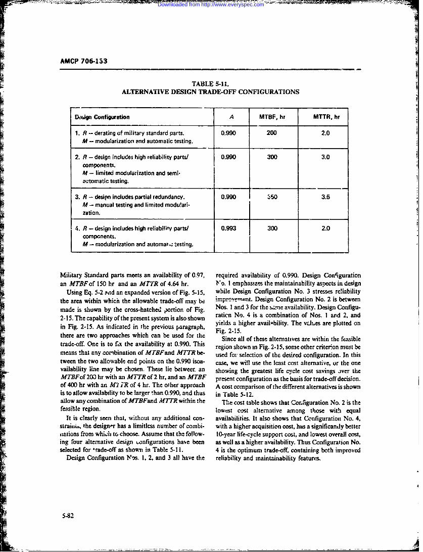
AMCP 706-133
TABLE 5-11.ALTERNATIVE DESIGN TRADE-OFF CONFIGURATIONS
D.gn Configuration A MTBF, hr MTTR, hr
1. R - derating of military standard parts. 0.990 200 2.0M - modularization and automatic testing.
2. R - design includes high reliability parts/ 0.990 300 3.0components.M - limited modulaization and semi-automatic testing.
3. R - design includes partial redundancy. 0.990 350 3.5M - manual testing and limited modu!ari-zationo
4. R - design includes high reliability parts/ 0.993 300 - .0 ]components.M - m odularization and automas,,: testing.
Military Standard parts meets an availability of 0.97, required availability of 0.990. Design Conligurationan MTBF of 150 hr and an MTR of 4.64 hr. No. I emphasizes the maintainability aspects in design
Using Eq. 5-2 odd an expanded version of Fig. 5-15, while Design Configuration No. 3 stresses rciabilitythe area within which the allowable trade-off may be imprevy-ment. Design Configuration No. 2 is betweenmade is shown by the cross-hatched portion of Fig. Nos. I and 3 for the szzne availability. Design Configu-
2-15. The capability of the present system is also shown ration No. 4 is a combination of Nos. I and 2. andin Fig. 2-15. As indicated in the previous paragraph, yields a higher availability. The vJes are plotted on
Fig. 2-15.there are two approaches which can be used for the Since all of these alternatives are within the feasibletrade-off. One is to fix the availability at 0.990. This region shown in Fig. 2-15, some other criterion must bemeans !hat any combination of MTBFand M7TR be- used for selection of the desired configuration. In thistween the two allowable end points on the 0.990 isoa- case, we will use the Icast cost alternative, or the onevailability line may be chosen. These lie betweer an showing the greatest life cycle cost savings over theMTBFof 203 hr with an M.1TR of 2 hr, and an MTBF present configuration as the basis for trade-off decision.of 400 hr with an M2 TR of 4 hr. The other approach A cost comparison of the different alternatives is shownis to allow availability to be larger !han 0.990, and thus in Table 5-12.allow any combination of MTBFand MTTR within the The cost table shows that Corfiguration No. 2 is thefeasible region. lowest cost alternative among those with equal
't is clearly seen that, without any additional con- availabilities. It also shows that Configuration No. 4,straiii, the designer has a limitlcss number of combi- with a higher acquisition cost, has a significantly bettersations from whiJi to choose. Assume that the follow- 10-year life-cycle support cost, and lowest overall cost,ing four alternative design wnfigurations have been as wcll as a higher availability. Thus Configuration No.selected for trade-off as shown in Table 5-11. 4 is the optimum trade-off, containing both improved
Design Configuration Nos. 1, 2, and 3 all have the reliability and maintainability features.
5-82
Downloaded from http://www.everyspec.com
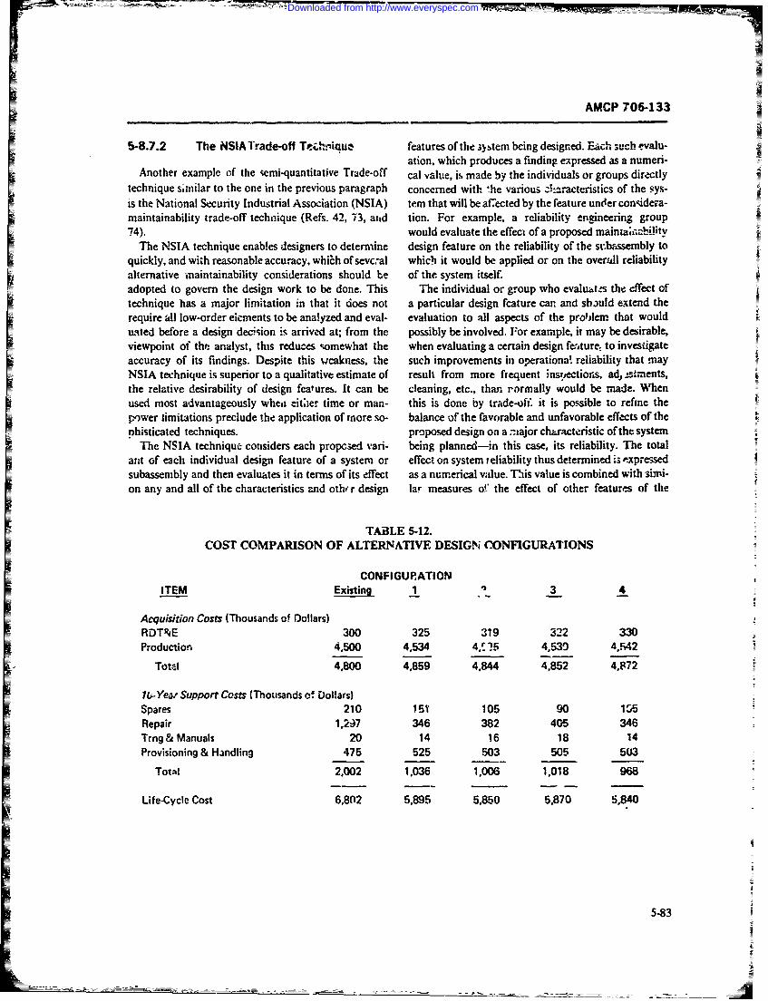
AMCP 706-133
5-8.7.2 The NSIA Trade-off Te..hL'iQue features of the ;y tem being designed. Each such evalu-ation, which produces a finding expressed as a numeri-
Another example of the semi-quantitative Trade-off cal alue, is, made by the individuals or groups directlytechnique similar to the one in the previous paragraph concerned with 'he various -k .acteristics of the sys-is the National Security Industrial Association (NSIA) tem that will be affected by the feature under con~idera-maintainability trade-off technique (Refs. 42, 73, atid tion. For example. a reliability engineering group74). would evaluate the effect of a proposed maintai;at-ci-ity
The NSIA technique enables designers to determine design feature on the reliability of the sutmbssembly toquickly, and with reasonable accuracy. which of sevc:al which it would be applied or on the overall reliabilityalternative maintainability considerations should be of the system itself.adopted to govern the design work to be done. This The individual or group who evalust the effect oftechnique has a major limitation in that it does not a particular design fcature can and should extend therequire all low-order eicments to be analyzed and eval- evaluation to all aspects of the problem that woulduated before a design decwision is arrived at; from the possibly be involved. For example, it may be desirable,viewpoint of the analyst, this reduces somewhat the when evaluating a certain design fi',ture, to investigateaccuracy of its findings. Despite this wcakness, the such improvements in operationa! reliability that mayNSIA technique is superior to a qualitative estimate of result from more frequent inst.ections, ad 2stmnents,the relative desirability of design features. It can be cleaning, etc., than rormally would be made. Whenused most advantageously wheii -itler time or man- this is done by trade-off. it is possible to refine thepower iimitations preclude the application of more so- balance of the favorable and unfavorable effects of thephisticated techniques. proposed design on a miajor cha_'act.ristic of the system
The NSIA technique considers each propc.ed vari- being planned-in this case, its reliability. The totalant of each individual design feature of a system or effect on system reliability thus determined is -xpressedsubassembly and then evaluates it in terms of its effect as a numerical vadue. This value is combined with simi-on any and all of the characteristics and otho r design lar measures o!" the effect of other features of the
TABLE 5-12.COST COMPARISON OF ALTERNATIVE DESIGN CONFIGURATIONS
CONFIGURATIONITEM Existing 1 3 4
Acquisition Costs (Thousands of Dollars)RDT&E 300 325 319 322 330Production 4,500 4,534 4,.5 5 4,530 4,F42
Total 4,800 4,859 4.844 4,852 4,872
lb-Year Support Costs (Thousands of Dollars)Spares 210 151 105 90 15Repair 1,237 346 382 405 346Trng & Manuals 20 14 16 18 14Provisioning & Handling 475 525 503 505 503
Total 2,002 1.036 1,006 1,018 968
Life-Cycle Cost 6,802 5,895 5,850 5,870 5,840
5-83
Downloaded from http://www.everyspec.com
AMCP 706-133
proposed design. The final result obtained becomes an other factors. It is necessary therefore that all possibleobjective basis for jadging the desirability of adopting armas of influen.e be listed as parameters for considera-*he desigi, fcu.e that has been so analyzed. tion and evaluation, and that each paiameter be evalu-
This technique obtains positive or negative numeti- ated with respect to all possible areas ,f influence tocal values for various paran.eters and aspects of in- maximize this tflec. (Ref. 11).fluence-based upon a detaminatien by a qualifiedindividual or a group-as to whether a particular de- It should b- noted ti-at the results of this type ofsign change under consideration shall have a favorable anatysis can usually be expected to give a reasonablyor unfavorable effect upon the total equipment or sys- clear and conclusive indication of which particular de-tem, as viewd from one particular area of interest. The
evauatr i alo rquied o ssoiat a umeica vaue sign feature of several under consideration is mostevaluator is alro required to associate a numerical value desirable, and to what degree. If the results of aoplyingbetween 0 and 100 denending upon the degree to whichit is considered favorable or unfavorable, indica'.ed by this technique do no. p,-ovide this clear indication, then
positive and negative values, respectively. The value of personal subjectivity may possibly be a significan: fac-
100 is applied when a change is considered corn- tor. In such cases, all valuis devloped during the ini-
pletely unacceptable, and + 100 is the value applied tial evaluation should be carefully reviewed beforewhen it i- considered absolutely necessary. Zero is the makir.g a final decision to he sure that it is based uponvalue apphed when it is considered that the advantages reasonable objectivity.
resulting from the change balaitce out the disadvan- One other aiea in which pcrsonal opinion c.,uld pos.tages. All other values fall somewhere between these sibly contribute to inaccuracy in the final result is in theextremes. The basic rating scale is shown in Fig. 5-20. determination of weighting factors. Here agin the
All evaluations are then combined algebraically to ar- opinion of a group of interested and informzd people ibrive at an overall value to be usew in making a final most desirable since it is less subject to personal bias
decision. than the opinion of a single individual. In general thisThere are certain areas that requife special consider- part of the technique should be approached with the
ation because of the fact that the numerical values es- same gene.al precautions recommended for the evalua-
tablished are based on personal opinion and judgment. tion of thc various aspects and parameters. it also
Any method or tec-hnique in whirh ly:ronal opinion or stands to reason that every effort should be made ioexperience is u .d in evaluating the relative merits or clearly dncribe "he change so ihat a uniform and accu-demerits of an item under consideation inh:rently in- rat! understanding is conveyed to all evaluators.
cludes the possibility of subjective bias being incur- In recent years, a number of studies have been mede
porated into the sinal decision. While this can be con- in the area of quantifying subjective judgment. Thesesidered as an inherent deficiency, it need not invalidaie studies have included the app' cation ofprobability and
the method if certain precautions are taken to minimize statistics, Bayesian analysis, psychophysics, and mod-
possible adver: effect-. ern decision and utility theoty. The Delphi techniqueTo reduce or minimize any bias that may be intro- developed by the k..&.ND Corporation :; one of these
duced through subjective evaluaion, the following who.- purpose is tv quantify expert judgment. It is aprecautions should be considered when making a rain- means of quantifying values obtained from gr(up opin-
tainability evaluation: ion (Refs. 75 and 76).Weighting schemes as discussed and as used in the
1. Evaluations should nly be made by individuals NSIA trade-off technique usually assume a linear rela-qualified to do so. i.e.. experts. tionship between some design or other system attribute
2. Evaluations of a single area of consideration and its val'te or contribution te system worth. In prac-should be made, whenever possible. by more than one tice. this is seldom linear. For example. the concept ofexpert on an independent basis, and the algebraic aver- diminishing marginal utilitt in economics indicatesage of all evaluations used. If evaluations cannot b, that the mere one has of a resource the less the nextmade independently, they should be made on a group increment is worth. More sophisticated weightingbsis The larger the number of qualified evaluators schemes are based on this concept. Ref. 77 describa'that ,omprise the group. the more accurate and how this can be applied to trade-off analysts. A step-by-unbiased the final evaluation should be. step dercription of the application of the NSIA trade-
1. Any bias that might be introduced by the opin- off technique is giveii in Ref. 42.ion if an individual, or a group, is modified in .ts effect The example of the NSIA trade-off technique, takenupon the final value because it is only one of severa' from Refs, 73 and 74, is presented.
5.84
Downloaded from http://www.everyspec.com
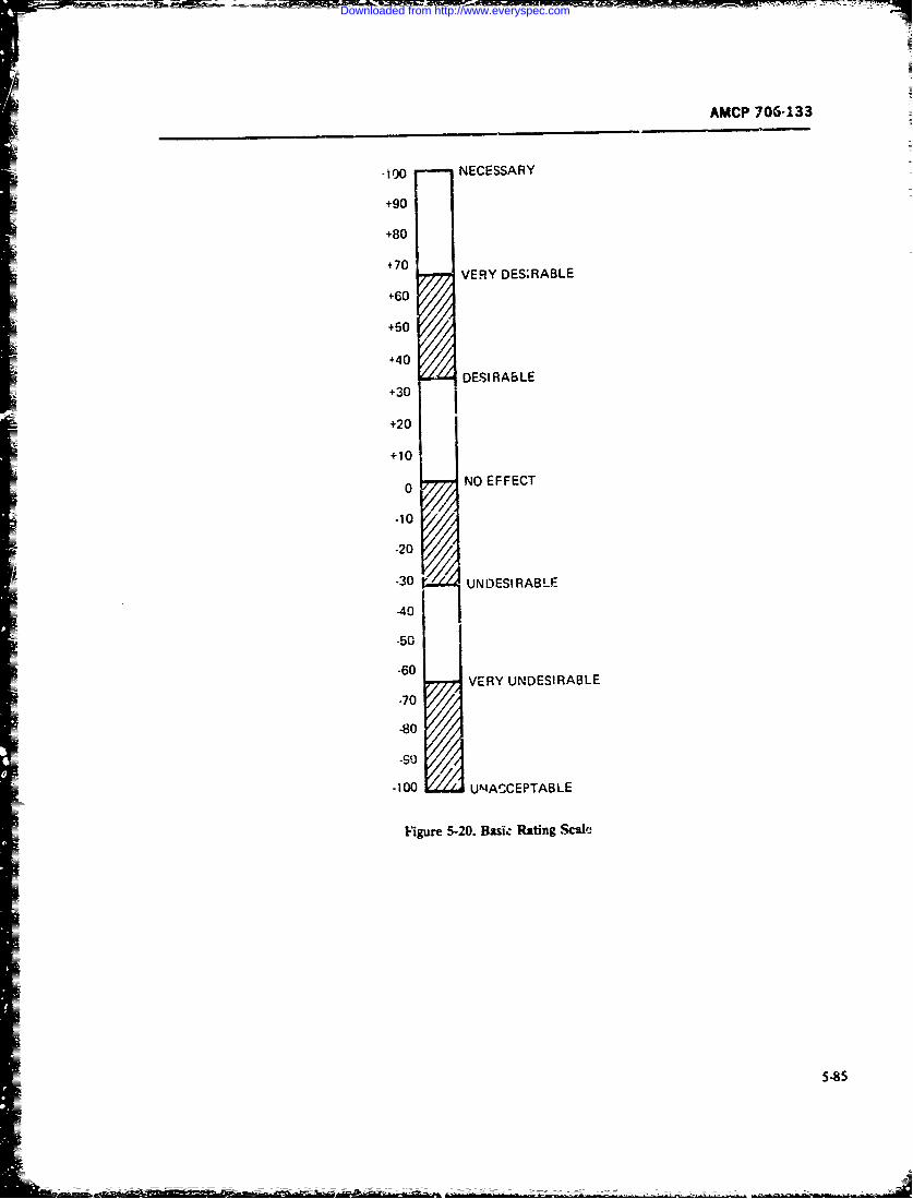
AMCP 706-133
-00o NECESSARY
+90
+80
+70 VERY DES:RABLE
60 11+50
+40 DE SIRA 6LE+30
+20
+10
o NO EFFECT0
-10/F
-20
-3 UNDESIRABLE
-50
-60VERY UNDESIRABLE
-70
.80
-90
-100 UNACCEPTABLE
Figure 5-20. Baskc Rating Sc
5-85
Downloaded from http://www.everyspec.com
AMCP 706-1 33
Disign Pr~oblem. An airborne nat'igation system re- of vacuum tubcs and discrete components mounted onqires precise voltage regulation in its power :,uppty -~of terminal boards. Printed circ-fit boards ind transistorssatisfactory operatio~t. Because of rigid wright and were just coming in'o use, and early development ver-space requiremenis placed upon tiv- designer, it is ner- sions of micro-electtonic packaging techniquts existed.essar to stress the power transfrmor teyond recoin- In more recen! years, with thc extensive oevelopmwnt
mendd lmit, terey icresin th falur'~ ate~4> of solid-state devices and integrated circuits which al-tential of the transformer. Replacement is anticipated lwhg akg esteteepai w hf:dtapproxiaiately every 500 I-r of one ation. Turn-around lmodhigh packagen dnims, ntenasis conas s antdttime otf the airplane is 18 min and cannot be increased,. oua akgn n ewmitnnecnet nReplacement of the power transformer in present de- techniqajes. These newer techniques have ofteni resultedsign will require approximately 35 min a,.- the average, in order-of-magnitude improverments ;n both reha.anity
Tht. question arises as to how the power supply and maintainability and, together with production ef-should be resesigned ;o meet aircraft turn-around time fiicies and quantity cost reduction, have i;ade dis-requirements most effectively. c~rd.?!-failu-re an economic reality today.
Possible Soltion. Two possible solutions are consid- RLpair/discard trade-off decisions may bc classifiedered for application: into two types The 'irst type is primarily a rmpair level
1. Re design the power supply as a completely re- decision, useful for developing maintenanc Eupport;;tacmble unit for rapid replacement of th~e ent:re as- coincepts during the system planning phases cr4d duringsembly. deployment phases after design has been completed.
2. Redesign the power tra;isfarmer as, aquick-dis- The decision to be made is concerned with optimizing=connect (plug-iai) part for rapi 3 replacernent of fatled the maintenance and support 1,vels at which repairs are
traissform er within ' e power supply assembly. most economical to effect: for example, whether it ismore ecOnomical to repair a rer-iraolc item at direct
The data. sheets fo: each of thecsc alternative solutiosis support or at general support. The second type of re-are given in Tables 5-13 and 5-14 :nd shown in the pair/discaid decisi on is design-oriptited for applicationgraphs of Figs. 5-21 and 5-22 F.oin thtse, it can Se during the late planning and the design phases of theseen that the replaceable power suppiy is the )refeired systemi life cycle. Some models can be used for designNsolution. and repair iewel decisions. A flow chart ofl the replace/
The NSIA Trade-off Technique was used in a main- repa discard ded-ion problem i; shown in Fig. 5-23.tainability :;tudy for an Army diesel-driven t-.actor per- In a study entitled Criteria for Repair vs Discardformed by the US Army Engineer Research and ip. 1,9ec.Wons(Ref. 79) the Logistics Management Instituteveloptnm Laboratories, Fcrt Belvoir. Va. (Ref. 78). (LMI) noted the high interactioij between repair/dis-71i'z results are described i-, Ref. 11. =ard decisions and other systtm design and support
eccmdmic (life-cycle cost) decisions. It identified five5-8.7.3 Repair/Discard Trade-off Decisions majpr decision points ;n the system life cy-Je where
repair/discard decisions might logically t i made (Fig-One of the important maii-tainability deign. trade- z)-24). The Frst of these decision po~nts, Dekelopmzant
off decisionst is whetl'er to design a perfeviar item for of Des;gn Snecificat-ens, occuirs during the Conceptrepair or discard at failure. This decision impacts sup- Formulation and System Definition P'hases. It dependsport resources (technician numbers and skill levels, re- upon ope'rational, maintenance, and logistic support ?pair parts, facilities, test and support equipment, and policies as well as cost-etiveness and othr ecr-.matintenance information). as well as thr, spTciic main- noinic criteria established dusrig concept and systemtenance actions to be taken andi the levels at which studies- At tifis lev'el, repair/discard decisious arerepairs are to be made. The decision also affects such primarily broad policy decisions which become part ofsystem and equipment design attributes a- safety. rplia- the overall mainter.ance and logistic support concept.bility, accessibility, test poin,_s, controls, displays. And Threy res-ult in the establishment of both qualitativos-_*~human factors. The repoir/discard trade-off decision is quzntitative critefia in system development ?pecifica-Driunarily an economic on-, and it significantly influ- ;ions to gui~*e systemn/equipment design engi iec.rs dur-ence . system life-cycle costs I'see Chap. 7). ing .he derelop en! and design phases.
A .'umber of repair/discard trade-off models have_ Thec second point i- the LMI model, Initial Demsignbeen d. velop-d since the mid- I 950's. primarily for edcc- or Ittem Selection. ocrcu.-s duriag full-scale develop-totic s -sterns and equipments. At the time of some of inent. the policies anti rcricea previously establisbedthe earlier studies, most electronic equipment consistzd are now cipplied to as.~emblims subassemiblies-. end ;
5-96
Downloaded from http://www.everyspec.com
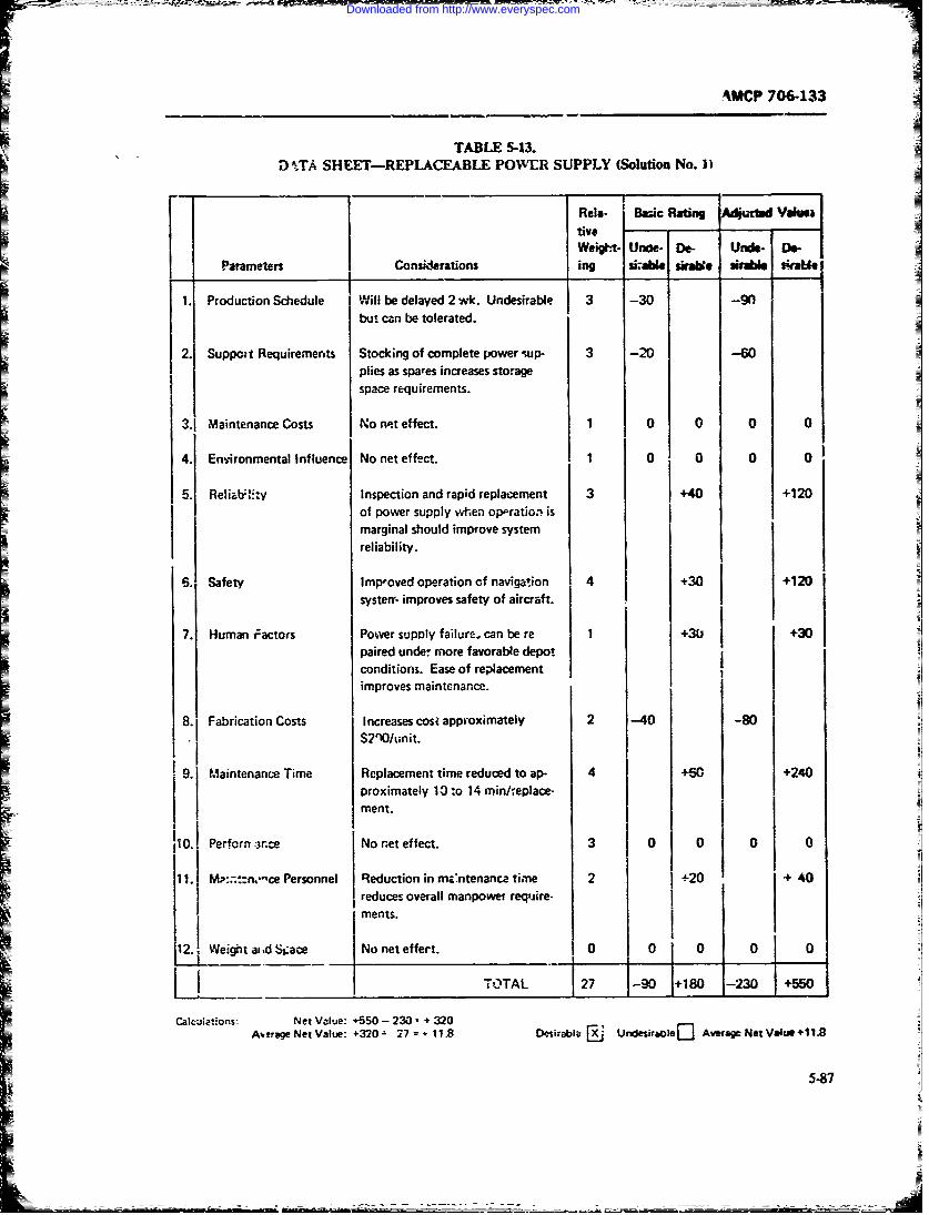
AMCP 7064133
TABLE 5-13.DMTA SHEET-REPLACEABLE POWER SUPPLY (Solution No. )
Rela- Basic Ratin Actiwrfd 'dsas
Weigtt. Unae- De- Uncle- Do-Poaaretrs Considerations ing si-abte *Wabe *tnI *latA
1. ProductinSchedule il Wbe delayed 2 wk. Undesrable 3 0-9
3,1 Mvaintenance Costs No neteffect. 1 0 0 0 0
4. Environmental Influence No net effect. 1 0 0 00
5. Reliabt.,y Inspection and rapid replacement 3 +40 +120of power supply when op'oratio~i isImarginal should improve systemreliability.I
6. Safety lmp-oved operation of navigation 4 j +30 +120systerr. improves safety of aircraft.I
7. Human ;actors Power supply failure. can be re 1 +3(jj +30paired under maore favorable depotconditions. Ease of replacementimproves maintenance.
8.j Fabrication Costs Increases cost approximately 2 -40 -80
S?'l/lunit.
9. Maintenance Time Replacement time reduced to ap- 4 +6r, +240proximately 10 to 14 minhfeplace-
ment.
110.1 Perforn arce No net effect. 3 0 0 01 0
11.1M::n"c Personnel Reduction in ma'ntenanca time& 2 +20) + +40
reduces overall manpowei require.ments. I
12.,. egtaidS~c No net effew-t. 0 0 0 0
Calci tions- Net Value: +550 -20 2
Ai~t'ag Net Value: +320- 27= + 18USial Urdesiraoe[]Aeaeeiou+1
5-87
Downloaded from http://www.everyspec.com
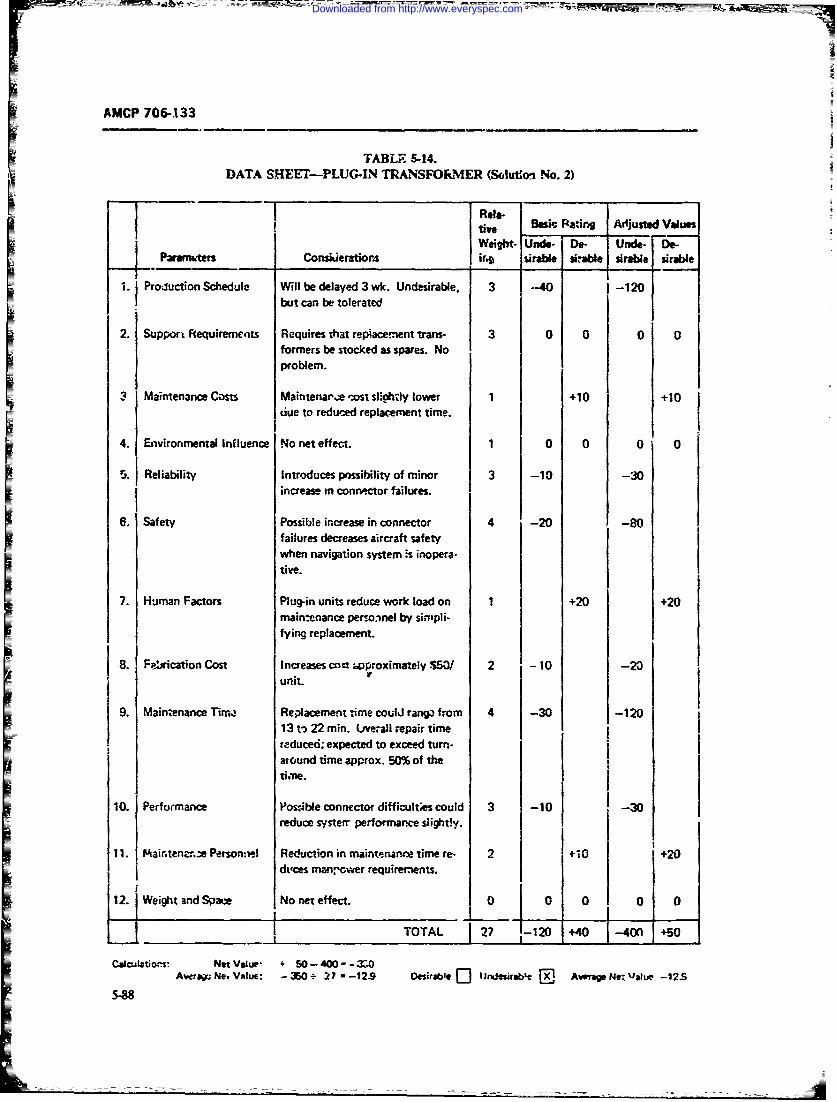
AMCP 706-133
TABLE S-14.DATA SHEET-PLUG-IN TRANSFO.MER (Solution No. 2)
Rela-tive B Rating Adjusted ValuesWeight- Und- Do- Uno- De-
Paranwters Cornklerations ir. sirabl siraile sirable sirable
. Prouction Schedule Will be delayed 3 wk. Undesirable. --40 i -120but can be toleratd1
2. Support R equirem ents R equires tat rep iace rent trans- 0 0 00
formers be stocked as spares. Noproblem.
3 Maintenance Costs Maintenar'.* -os slightiy lower 1 +10 +10due to reduced replacemnent time.
4. Environmental Influence No net effect. 1 0 0 0 0
5. Reliability Introduces possibility of minor 3 -10 -30increase in connector failures.
6. Safety Possible increase in connector 4 -20 -80failures decreases aircraft safetywhen navigation system is inopera-
tive.
7. Human Factors Plug-in units reduce work load on 1 +20 +20mainenance personnel by sirnpli-fying replacement.
8. Frcation Cost Increases coct wproximately.$50/ 2 -10 -20unit.
19. Maintenance Tim- Replacement time coulJ rang from 4 -30 -120
13 t-3 22 rain. Love.ali repair timereduced; expected to exceed turn-at ound time approx. 50% of the
timbe.
10. Performance Possible connector difficult;es could 3 -10 -30reduce systerr performatce e tight0y.
11. Maintenzn.e Person:-.I Reduction in maintenance time re- 2 +0 +20
Es LII - ZO 27-129
Cacdors: Net Vaklp + 50-400- -
A'ver Neg Value: -1350 2 -12- Deskrbe J] iJn rabLe AwrveNe: value -12S
5-88
Downloaded from http://www.everyspec.com
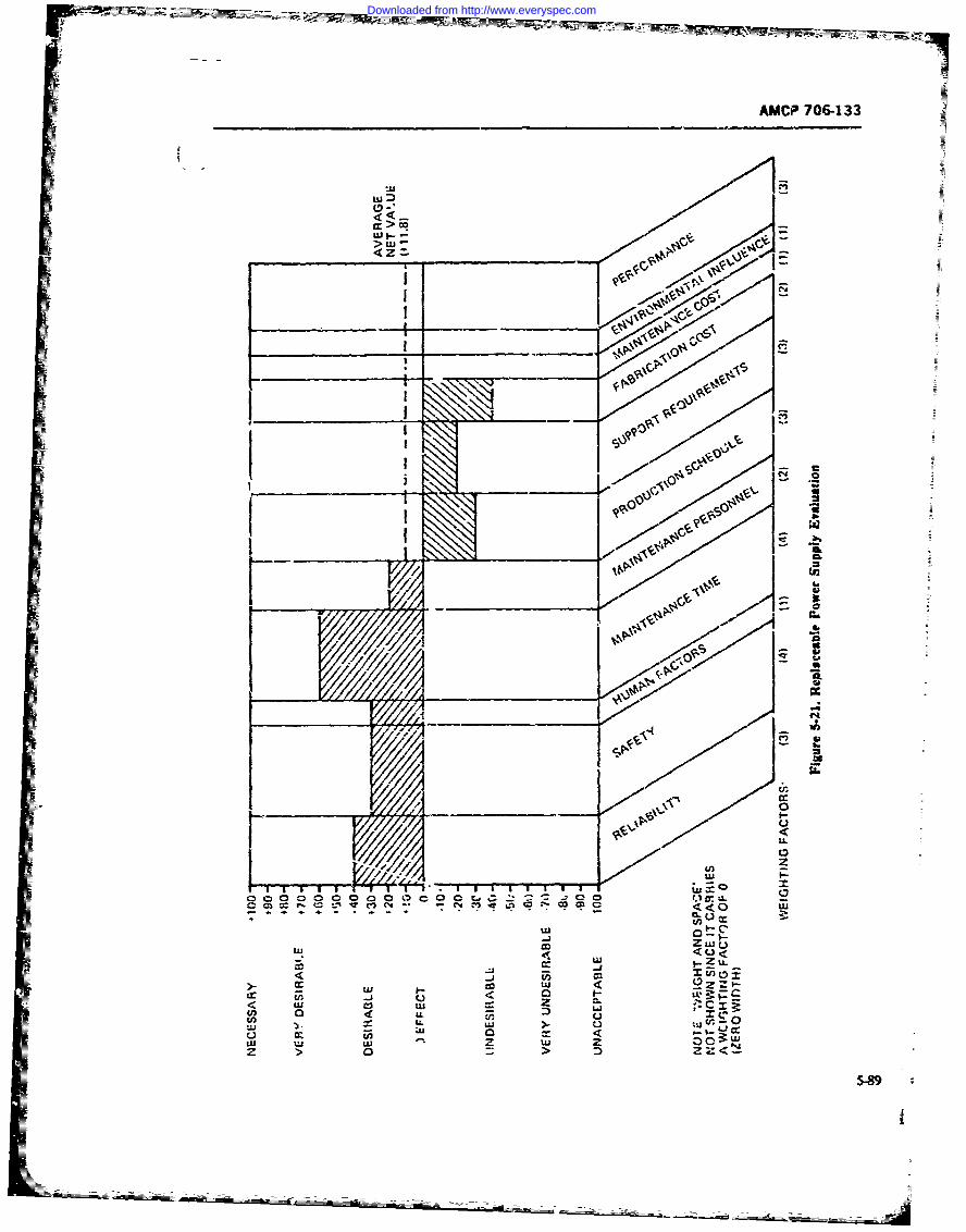
AMCP 706-133
I ot______ 'I 'IS
c o 0'0 0. 0
IL 0 I< U
0 U3 Z
U3 o
0 Z 0
5-9
Downloaded from http://www.everyspec.com
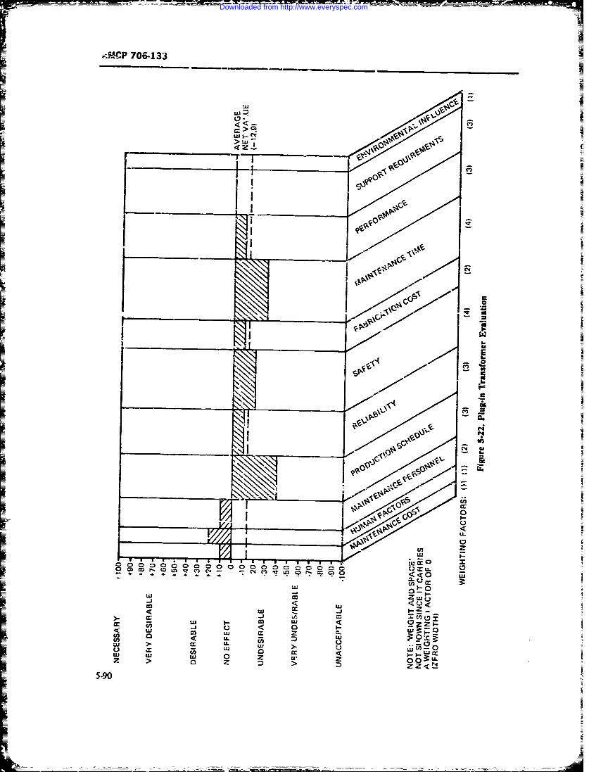
I-I
W-,P 706-133
ta.
ula
<4C.
>C
UI I C>. u
I'-lip
Oc)u
LiL)
0 C, us 2CD Ln v r) C. -.s .- . . . , -e<O L
0r -j oo x.zjL z z P
5 ;-90 aI.
Downloaded from http://www.everyspec.com
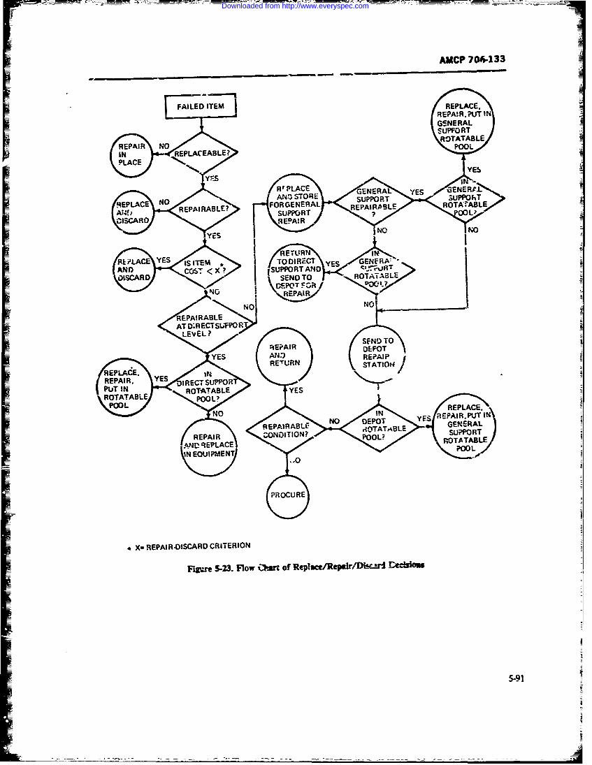
AMCP 706-133
R.EPLACCE.REPA"!R.?IT IGSNERALSUPPORT
REPAR NOROTATABLE
IN REPLACEABLE? POOL.
RLILAE ESISITM fORrA ES GENFRA ES
RACE COS4X ANO TORE SDUPPORT 3UPR
OARDSEDT RPI"S OTATABL>,ESUPOT f
CiSA* \$EPIWR
YE NO N
/REAIRN
RE PLACEREPLACE.
TO I RBL GEKEAAAND (UPPOT ANE04SU PPORTt
SEND TO OTATABLELG'EPOPOOL
SEAREISABLRIERO
Figu.RE 5-23. Fow R r fRpaeRe~rD~$tdl
LEVEL?
Downloaded from http://www.everyspec.com
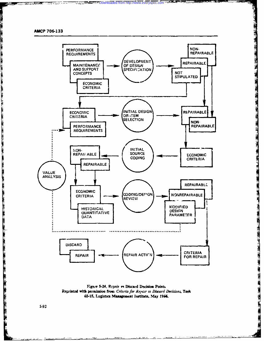
AMCP 706-133
PERFORIMANCE NON- -
REQUIREMENTS REPAIRABLE
MAINTENANCCDEVELOPMENT RPI~LMAINTENAN~t goo OF DESIGN ____ RPIALAND SUPPORT S?ECIFELATIONCONCEPTS NOTICNM.I STIPULATEDI
CRITERIA
REPAIRAAL
* ECECOMIC
CRERIRANC ~ OIGDPG REPAIRABLE
M SON-IITIAQEPUANTITATIVEE
REPAIABLECRITER IAREARl- REARAT]E~FRRPIIi BL
VALUE
("ANVAALYSI
_ _N O I _ _ ___ A- - -A
Downloaded from http://www.everyspec.com
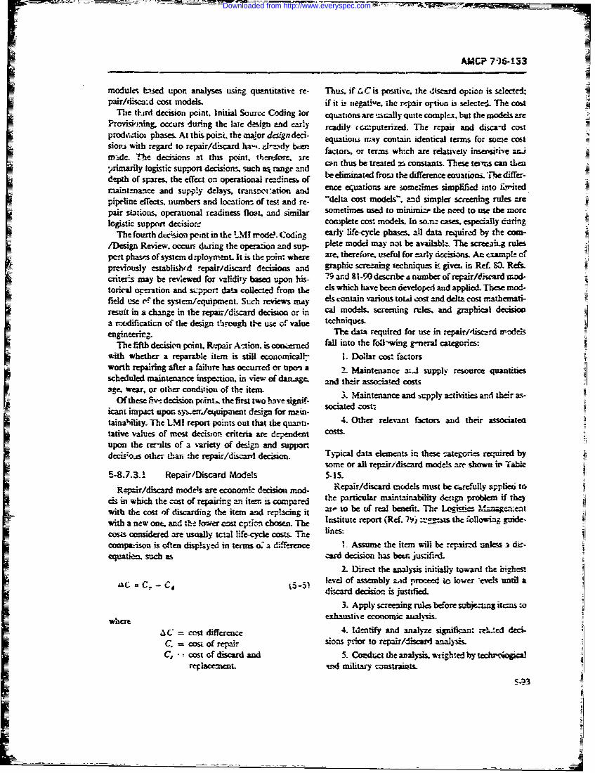
modlest-,sedupon analyses using quantitative re- Thus, If L Cis pwiitive- the d~iscard option is selected-
t tiurd decision point, Initial Source Coding 'Or eqations are t~ually quite complex, but the models arePro~vmng.occurs during the late design and cary readily (cAzputenized. The repair and disca-d cost
prodeztioi phases. At this poiri, the inaor design deci- qao'n oth.deiclersfrsieotsiot's with regard to repair/discard ha-~ --I"!dy b,-= atr~ rtri wihaereaieyasesteZ.
nvid. Te dcisins t tis pint tIersdre.~rc can thus be treated r. constants. These tcivns can then.irimarily logistic support decisiozis such mt range and
depth of spares, the effect on operational readinesu of beP elmntdfz h ifrneezainT e de-maintenance and supjzly delays, trnm-to and ence euatiors are some' imes simplified intoii"dpipeline effiects, numbers. and locations of test and re- detcotm el.a sm dsrengrlsaepair sitinS. operational readiness float. and similar s~ntne used to minimict the need to use the morelogistic support decisiovrf con-Tlete cost models. In so.=~ cases, especially durting
The fourth cc-sion point in the LMI rrode. Codin3 early lifre-cycle phases. ail data required by the aM-/Design Review. occur., during the operation and sup- plete modc] may not be av;:ibbhLa The scree:3iiL rulespcrt phases of systern d--ployinent- It is the p~iin; w~tere are thierefor. tisdul for zarl~ dccisizins AL- example oft
previously esaus' epair/discard decisoos and grphic scrteenig techniclum im give. in Re! M3 Re&scriter-s may be revewed for validity bae u*pon his - and 811-90 described number of mepair/dtutcrd mod-
toric-A ojeration and s;:pport. data collected fromi tf els which have been &-eveloped and applied. These mod-field use cf- the sytem/equipment. Sich revMis may els c%-ftan vartious totI cost and delta cost mnathemati-resit in a change in the repair/discarid decision or in Cl dI.5rein ueadgahcldcsoa r.-c4icaticni of the design throug~h tlec use of value techuniies.enginemzin. The dams ;equired for use in repair/'isard xr-ondds
T-he fith decisicn point. Repair Ati~on. is coorre fall into the follwing g-eral categories:with whether a repam-ble item is still ecoeniicallh I. Dollar cost factorsworth repairing after a failure has occurred or tzpo a 2 antance a:.4 supply resource quantiescheduled maintenance inspection, in view of dartAme and their associated costsSge, wear, or other condition of the item
Of these Flive decision poiint. , the first two have Csignif-kcant impact uporn sy,-eaJettuipment desizi for nin- scae otainahility. The LMI report points out that thbe quariti- 4. Other relevant factors and their associarctative values of most decisio criteria are depe&ndent costs.upon the rer-ilts of a variety of design and Supp4r1decisois othecr than :he repairfdiscardi decision. Tyia aaeeensmtee-ep'c eardb
58-.-. Repair/Discard Models caudmnsn atg ermiruo
Rcpzr/dicardmodes ar ecnomi decsica mod Rairddeiscasd btetl jmst b d.. , ppidt
cii Dinc thec thaesi nitial tofr theiin an i-heisPa~~'- level of sebl a b ronefit 7 tw Leilie Mev untaVoith ~ ~ ~ ~ ~ dscr decrio iss ofdustingteftmied.phcigit
cmuideredare usualexhaustive econoosts-c analinsis
__pais 4.- Ide ipae ntsito ite set e ited alze signlican: 3eie dei-C.ait suc os repair dois~on to s repardjiiscr ais
C,, ~ ~ ~ ~ ~ 2 .csofdsadad.CoDct the analysis. inighaled bywr te booiallevelnn of military zsai rcents.k~ -.csuni
aL C. - C
dscar_ Ieiini siid
Downloaded from http://www.everyspec.com

...-
AMCP 706-133
TABL~E 5-15.QUANTITATIVE !?ACTGRS IN R'l-PAIR/DISCARD MODIIS
1. Dollar Costs
A. Calculated Values1. Total Life Cycle Cost2. Discard Cost3. Repair Cost4. Cost Difference (A Cost,
B. Input Costs
1. Design CostI3. Procurement Costs4. L ,qistic Costs
5. Salvage Value6. Constants
11. Resources
A. PersonnelI
3. VrainingB. Equipment
1. Pritne EquipmnentI2. Support Equipm-nt3. Test Equipment4. Tools ard Fixtures
C. Materials1. Expendables
2?. Spares3. Rerjair Parts
D. Facii;ties1. Buldigs;
2. Mairterance A-easI
E. Iniormation1. Maintenance Manuals
2. Logistic DataI3. Provisionin.g Data4. Maintenance Engineering Analysis Data5. Drawings and Spe'..:fic,,tiorns6. Test Programs (Softwa.e)
Ill. Activities
A. Maintenancei Prevmntiv,! Mainteni'nceI
2 Corirective Maintenance
3. fiepai~r LevelsE. Supply
1 Inventory ard Inventory Centro:2. Entering and R9etaining New Line item3. I ooistic Pro .essing4. Procurement
5-94
Downloaded from http://www.everyspec.com
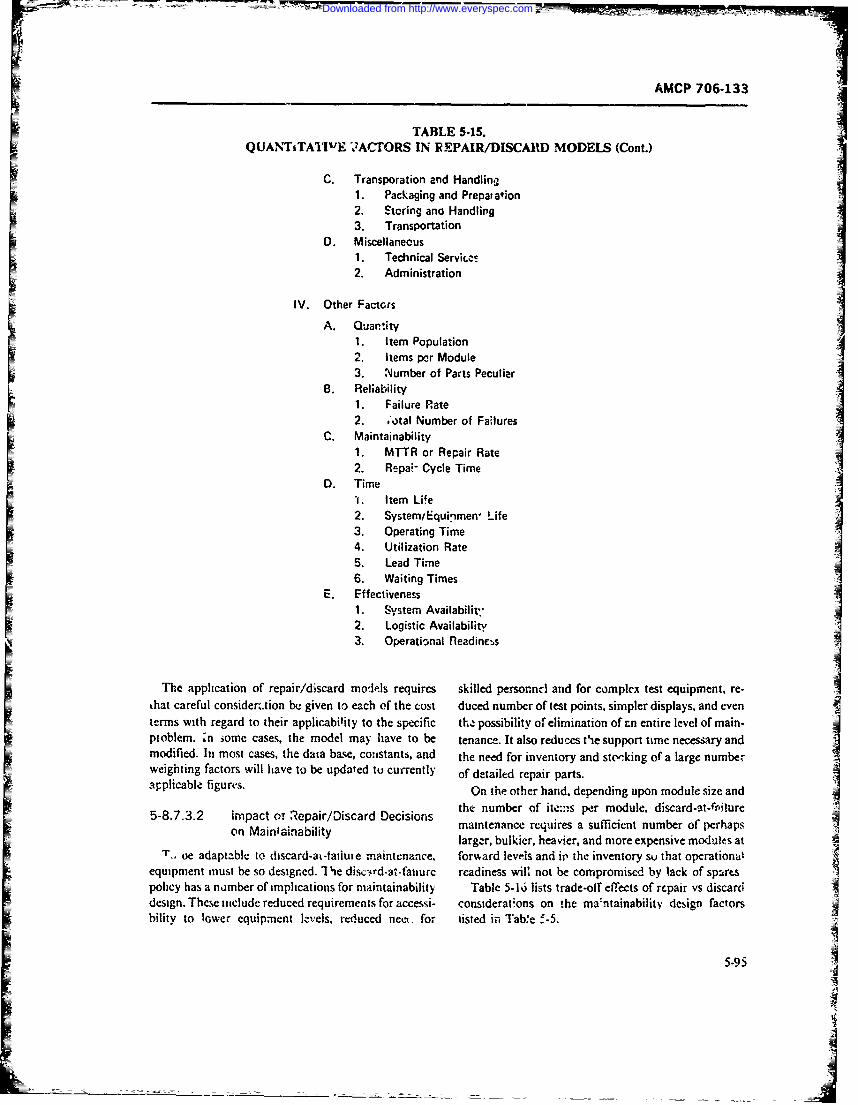
AMCP 706-133
TABLE 5.15.QUANTiTA1'iIE ".ACTORS IN PEPAIR/DISCARD MODELS (Cont.)
C. Transporation and Handling
1. Packaging and Prepaiation2. Storing and Handling3. Transportation
D. Miscellaneous1. Technical Servic.es2. Administration
IV. Other FactorsA. Quan.ity
1. Item Population2. Items per Module3. Number of Parts Peculiar
B. Reliability1. Failure Rate2. .'otal Number of Failures
C. Maintainability1. MTTR or Repair Rate2. R.pa - Cycle Time
D. Timel. Item Life2. System/Equinmen" Life3. Operating Time4. Utilization Rate5. Lead Time6. Waiting Times
E. Effectiveness1. System Availabilit'"2. Logistic Availability3. Operational Readinc,_s
The application of repair/discard models requires skilled persornncl and for complex test equipment, re-that careful consider .tion be given to each of the cost duced number of test points, simpler displays, and eventerms with regard to their applicability to the specific the possibility of elimination of an entire level of main-pioblem. :n some cases, the model may have to be tenance. It also reduces tie support time necessary andmodified. In most cases, the data base, constants, and the need for inventory and stoking of a large numberweighting factors will have to be updated tu currently of detailed repair parts.
ap~plicable figures. On the other hand. depending upon module size andthe number of ite:ns per module, discard-at-filure
5-8.7.3.2 on T i tainabilr/Discard Decisions maintenance requires a sufficient number of perhapslarger, bulkier, heavier, and more expensive moduies at
T_ oe adaptable to discard-at-tailute maintenance, formard levels and it' the inventory so that operationalequipment must be so designed. I lie disc-rd-at-faiiurc readiness wiUl not be compromised by tack of sparespolicy has a nuxmber of imphcations for maintainability Table 5-16 lists trade-off effects of repair vs discarddesign. These include reduced requirements for accessi- considerations on the ma:ntainability design factorsbility to lower equipment levels, reduced net. for listed in Tabre f -5.
5-95
Downloaded from http://www.everyspec.com
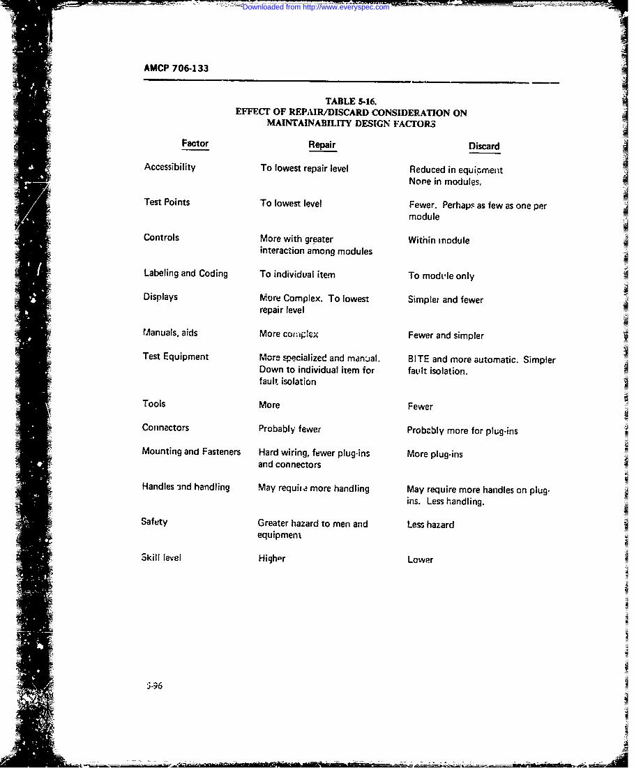
AMCP 706-133
TABLE 5-16.EFFECI' OF REPAIR/DISCARD CONSIDERATION ON
MAINTAINABILITY DESIGN FACFrORS
Factor Repair Discard
Accessibility To lowest repair level Reduced in equipment
None in modules,
Test Points To lowest level Fewer. Perhaps as few as one permodule
Controls More with greater Within moduleinteraction among modules
Labeling and Coding To individual item To mods-le only
Displays More Complex. To lowest Simplet and fewerrepair level
Manuals, aids More co;,ipeX Fewer and simpler
Test Equipment ore specialized and manjal. BITE and more automatic. SimplerDown to individual item for fault isolation.fault isolation
Tools More FewerConnectors Probably fewer Probably more for plug-ins
Mounting and Fasteners Hard wiring, fewer plug-ins More plug-insand connectors
Handles 3nd handling May requite more handling May require more handles on plug-
ins. Less handling.
Safety Greater hazard to men and Less hazardequipment
Skill level High-r Lower
i -96
Downloaded from http://www.everyspec.com
AMCP 706433
In addition to cost factors which es.ter the repair/- f. Logistic cost of discarded terns.discard decision, there are other factors which are not AFLCM/AFSCM 375-6 (Ref. 87) points out thatquantifiable or are intangible. Goldman and Slattery repair level decisions must be made as an integral part(Ref. 12) list some of these as follows: of system design, since the investment made during the
1. Factors favoring discard: acquisition phase precludes or seriously inhibits subse-quent reversal of repair level decisions during the oper-
a. Probable gain in equipment reliability through ational phase.eamilaation of repair; i.e., decrease the adverse effectsof technician; accidentally injuring equipment.
b. Probable saving in development cost and manu- 5-8.8 COST CONSIDERATIONSfacturing because of elimination of the need for accessi-bilitv within the throwaway module. It should be evident from the previous discussions in
c. Overall reduction in unit cost of module because this chapter that cost '. a major element in maintaina-of the manufacture of larger quantities. bility design. While the accomplishment of mission and
d. Compatibility of throwaway philosophy with operational objectives must be a prime consideration,pre.eat trend toward marginal testing and automatic many opportunities arise which allow for making thefailare isolation. The development effort required to necessa.'y cost- !ffectiveness trade-offs that provide theinclude marginal testing and automatic failure isolation proper balance between desired operational and sup-features in test equipment is often the same as required port features in a system and the economic use of re-to make the test equipment compatible with throwa- sources. Costs represent one of the constrairts withinway maintenance, which a system must be designed, produced, operated,
e. Simplification of fild modifications where plug- and supported.ins of a new unit will substitute for field rework. One of the purposes of this chaptei was to discuss the
f. Reduction in cost of training and supporting system approach to mainitainability design; the specific
maintenance technicians and the repair facilities and maintainability design factors which must be consid-performance aids they require. ered by system, design, and maintainability engineers-,
g. Release of repair facility floor space for other the interface relaionships which exist between main-
uses, for example, storage of spares. tainability and its related disciplines, including reliabil-h. Use of repair facilities for priority repairs rather ity, human factos, safety, standardization, autuma-
than indi3criminate queries for anany items. tion, and others, along with the trade-offs between2. Factors opposing discard: them. It has been pointed ou: that the competition for
scarce resources required that careful consideration bea. Emotion. feelings that discarding complex given to the economic and cost implications of main-
units is wasteful. (Salvaging of high value pans may tainability design decisions. !n particular, it has been
sometimes be a solution.) shown that an increased investment in acquisil ion costs"b. Loss of reliablity inform-itien when trouble- to improve system milintai.ability may return many
shooting of the component part is eliminated. times its amount in sv,,ings in opuraiion and supportc. Possible increased size and weight (and loss of costs, and thus may minimize system life-cycle costs in
reliability) because of the need for more connectors. terms of .avings in manpower costs, cost of repairs andd. Storage space requirements over and above repair parts, storage, trv'nsportation, handling costs,
what is required under a repair policy, and many others. For exa-mple, it has been estimatede. Loss of some of the capability of the forward that the reduction in .he need for one maintenance
echelon to react to emergcncy situations. Shortages of technician may bring savings of up to S300.000 in thespares become more critical unless emerg cy rcpair is life-cycle cost of a system.provided for (fcr example, by stocking emergency parts Cost considerations in maintainability are furtherkits). discussed in Chap.;.
595-97
Downloaded from http://www.everyspec.com
AMCP 706-133
REFERENCES
1. H. S. Dc'rdick, -Design Configuration", Chap- ;iondc Evaluation of Engineered System j. M.ter 4 in Maintainability Desig, F. L. Anken- English. Ed., John Wiley & Sons, 1968.brandt, Ed., Engineering Publisbem. Eliza- 18. M L-STD-47 1, Matintainability Demnm tiolbeth, N.J., 1963. 19. MIL-HDBK-472, Maintainability Prediction
2. H. S. Dordick, Maintainability- Prime nHnboDeinigor Prt RAND Corporation, Re- 20. TM 3&-70W-3, Maintenance Engineering Anal-
port P-2886, May 1964. ysir Data System.3. AR 750-1, Army Materiel Mfaintenance Con- 21. P. Sgouros, "Life Cycle and Impliczfions",
cepts and Policies. Proceedings of the NMSE Systems Perfobrm-4.AMCR 750-15, Integrated Logistic Support ance Effectiveness onference, (SPECON 1),
5. F. D. Mazzola, et a]., Mrintainobility Tech- US Naval Applitd Science Laboratory, 1965,nique Study, Fina' Report. Phase V. RADC- pp. 75-92.ITR-63-85, Vol. 1, RCA Se~ vice Company, 22. A. S. Goldman, et al., Economie; of the Traude-February 1963. Iff Among Reliabiit. Mvintainability cnd
6. F. D. Mazzola, et al., Maintainabitity Suppty G. E. TEMPO -.port RM62M-2IEngineering, RAD-TR-63-85, Vol. II, RCA June 1962.
Service Company, Feb. 1963. 23. 1. V. Sanderson, 'DDF for Design Review and7. DoD Directive 4100.35, Development of Inte- Maintanability". Proceedings of the Second
grated Logistic Support for Systems/Equip- System Perfonmance Effectiveness Confer-ment; October 1970. ence, (SPECON 2), US Naval Applied
8. TM 38-703, Integrated Logistic Support Man- Science Laboratory, April 1966, pp. 117-134.agement Guide. 24. J. M. McKendry, et al.. Maintainability Hand-
9. J. S. Foster, Jr. and D. J. Shillito, Memoran- book for Electronic Equipment Design. USIdum subject Reviiion of the Integrated Logistic Naval Training Device Center Technical Re-Support Planning Guide, 4100.235-G, Office of port NAVTRADEVCEN 330-1-4, Aprilihe Secretary of Defense, 25 March 1971. 1960.
=10. M. B. Kline, Maintainabl'ity Considerations in 25. .1. G. N. ohl, "Why Design for Maintainabil-Syvstem Design, Doctoral dissertation, Depart- ity?", IRE Transactions on Human Factors inment of Engineering, UCLA, 1966, University Electronics, Vol. HFE-2, Septemnber .961. pp.Microfilms, Inc., Ann Arbor, Michigan. 87-92.
11. AMCP 706-134, Engineering a-3ign Hand- 26. J. D. Folley and J. W. Altman, Guide to Designbook, Maintainability Guidt for Design. of Electronic Equipment for Maintainability
=12. A. S. Goldman and T. B. Slattery, Maintaina- US Air Force, Wright Air Develoapment Cen-biity: A Major Element of System Effective- ter, Dayton, Ohio, TR 56 218, April 1956.ness, John Wiley & Sons, 1964. 27. M. R. Wfumae and M. P. Willis, Development
3. H. H. Goode and R. E. Machol, System 9f an Index of Electronic ttaintainabiPty,Engineering, McGraw-Hill, 1957. American Institute for Research, Pittsburgh,
14. A. B. Rosenstein and J. M. English, "Design PA., Report AIR-59-PR-207 1959.as a Basis for a Unified Engineering Cur- 28. Weapons Requirementv Integrat-d Afainte-riculum", Proceedings ofteFrtCnrec nance Managemen-ttfo Aeronautical Weapons,on Engineering Design Education, Case Insti- Weapon Systems, Related Equipment, UStute of Technology, Cleveland, Ohio, Sepiern- Navy, Bureau of Nhvial Weapons, Specifica-ber 1960. tion WR-30, May 1963.
15. M. Asirnow. Introduction to Design, Prentice- 29) J. G. WohI, et al., An Analysis of the Mainte-Hall, 1962. nance Support System, US Naval Training
16. A. D. Hall, A Methodology fio Systems Engi- Devike Center, Tehnical Report NJAV-neering, Van Nostrand, 1962. TRADEVC2N 502-i. August 1961.
17. M B. Kline and M. W. Lifson, "Sys!:ms Engi- 30. 1. W. Altman, et al., Gu.*de to Design of Me-n?,rring", Chapter 2 in Cost-Effectvenes. Eco- chirmical Equipment for aintainability, US
5.98
Downloaded from http://www.everyspec.com
r AMCP 706-133
Aii Force. Aercrnautical Systems Division, Guide to Equipment Design, McGraw-Hill.Dayton, Ohio, Technical Report ASD-TR-6 1- 1963.381, August 1961. 44. R. DePaul, -Desi~n Disclosure Format". Pro-
ff31. L. V. Rigby, Jr.. et al., Guide to Integrated ceed*ngs of the NMSE Systems PerformanceSystem Deisg.. for Maintainability, US Air Effectiteness Conference, (SPECON 1), USForcre Aeron autical Systems Division, Day- Naval AppLd Science Laboratory, 1965, pp.ton, Ohio, Technical Report ASD-T.'1-6 1424, 137-165.October 1961. 45. T. G. Timnberake. "Hurnan Engireering in
32. Maintairability Dlesign Cuit. a Handbook, Corps of Engineers Equipment Design-. Con-US Navy, Bureau of Ships, NAVSHIPS ference Reprrt, Fourth Annual US Armay flu-94324, Change No 2, Mar--h 1965. man Factors Enginee, ing Confert ace. Sept'tn-
33. Guide for Measurement and Reporting of Elec- her 1958.ironic .Fquicient Maintainability Electronic 46. A. Chapanis, Man-Machine Engineering,1'-dustries Association, EIA Maintainability Wadsworth Publishing Company, Inc., Bel-Bulletin No. 2, Janutry 1961. mont, Calif. 1965.
34. N. J. Blichaca and J. lirinda, Jr., MaintainL )fl- 47. Col. K. H. Ewb,-nk, "The Application of Userity Simulation and Demonstration Equipment Guidance to Equipment Design". ConferenceI Description ;.nd Application, Technical Memo Report, Fourth Aninual USV Army HumanNo. 1, Philco Corporation, Western Develop- Factors J 'ngineering Confererce, Septemberment Laboratorics, Palo Alto. Calif. Decern- 1958.her 1962. 48. W. E. Wxodson and D. W. onover. Human
35. J. Cooper, **An integrated Approach to Sys- Engineering Guide for Equipment Designers.tern Maintainability", Chapter 14 in Electroric 2nd :dition, University of California Press-Maintainability, F. L Ankenbrand:,. Ed.. En- Berkcley, Caff., 1966.gineering Publishers, Elizabeth, N.J., 1960.49E.JMcomkH anEgeri,
36. Philco WDL Maintainability Program, WDL- M~a-il 97TR-1708B, P~ailco Corp., Western Develop- 0.MLST-42huaE:gnen Dsn
Criteria for Mili'ary Systems. Equipmnents. andment Labo~ratories, Palo Alto, Calif., April .aiii
19451. MIL-SfD-882. Rcquirements for Syse3 7. G. Bissell and G. M. Almeida. Jr., Maintaina- fePogmfrses.Axaedbs-
32,April !964. Annals of Reliability and Maintainability, Vol.3.;i'uma,: Fa..tors Design Standards for the Fleet 6, 190, Society of Automotive Engineers.
Ballistic Missile Weapon System, Vol. 2-De- New York, pp. 536-54).sinof Equipment, US Navy, Bureau of N2- 53. K. H. Eagle. "Fault Tree and Reliability Anal-v Weapons, NAVWEPS OD-M~i3A, Vol. ysis Comparison", Proceedings 1969 Annual1,August 1962.SypsuonRhbf.,IntteofEcri
3.BS.Blanchard and E. F. Lowety. Mlaintaina- cal and Electronics Engineers, NeV6 York, pp.blt.Principles and P.-actices, Mc~yraw-Hill. 12-17.
1969 54.W. amme, "umercalEvaluation of Acci-d.k in iability Engineering Handbook, US dent Potentials"~, Annals of Reliability and
Nv.Ordnance Systems Command, NA- Maintainability, Vol.. 5. 1966. American Insti-VORD OD-39223, February 1970. tute of Aeronautics and Astrorautics, New
4.R. E Redfern, "Design RvesChapter York, np. 494-5W0.ic. Maintainability Design, F. L. Ankenbiandt, 55. R. J. Schneider, "Fault Trees for ReliabilityEd., Engineering Publishers, OEizabeth, N.J., Anal~sis", Proceedings 1970 Annual Sym-1963. posium .7n Reliahility, Instituate of Electrical
4.DA Pamphlet 705-1, Maintanabiliry Ergi- and Electronics Engineers, New 'fork, pp.neering 198-205.
4.C. T. Morgan, eta.l , Ed-,_. Human Engireering 55. D. F. Haasl, "Advanccd Concepts in Fault
_ _ _ _ _ _ _ _ _ _ _ _ _ _ 9
Downloaded from http://www.everyspec.com
AMCP 706-133
7ree Analysis', System Safety Symposium Mid',., 20 Decemut~r 1969.Seattle. Wa.,hington, June. 1969. 70. 0. S. Sanxa. F Pra'dko, and D F. Aicona,
57. Use of Automatic Test Equipmeat foe' Main- Thagnosir Equtpnn, for Army Ve"- es, UStenan.e-a Reconnaissance, I ask 76-i- , Log- Army Tank- Autorinotie Command, Warrseu,istics Management Institute, Washington, Mich. (tindated)D.C. May 1971. 71. Mulfipuposc Automatic .*'npection Die gnostic
58. MIL-STD-,326(NAVY). Test Points, Test :'stenu (MAIDS) Opeiatin at a US ArmyIPoint Selev-tion. and Interface Reauirementsfor Lkp64 ESP 7101. Anmiitoia Standard Dlivi-Equipments Monitored by Shipboard On-Line sion. Un~ited Aircraft Corp~vation, WindsorAutomatic Test Equipment. rocks, Conn., March 197!.
59. L. R. Hulls and J. E. Lidiak. Vehicle Diagnos- 72. M. B. Kiine. "Applic~ation of t1ke Lognormualti- System,n Aerospace Systems Division. RCA Distribution to Maintaiaabli Dtsign". Log-T)-efense Electronic Product%, Burlington, istics Spectrum. Vol. 1, No. 2, WinL-z !967-68.Mus . (us-dated) 73. EJA Maintaina&bility!Trade-qff Thhniquex
60. MZIL-STD-1309, D.:finition of Terms for Auto- EIA Bulletin No. 3. Electionic Iniusuie; AM-matic Electronic Test and Checkoust. scciatic i, Washingeoe. D.C. July 94
61. Test, Measurement. ond Diagnostic quipment 74. Maintainability Trade-off Techniqi'. FinalRegister, US Army Weapons Commrand, Report of the T-rade-oITTasit Group, McionalJune 1971. Security Industria! Association. Federal M~ec-
62. Cost and Syvttn Effectiveness Analysis of the tric Corporation, Paramus, NJ., Report No.Computer-controlled Autornatic Test FAquip- 21 7-61A, March 1962.ment (CATE). Report No. ECOM-CATE-1, 75. T. I. Godon and 0. Helmer Re~port on aArospace Systems Division, IRCA Defense Long-Range Fc~reca stig Stud-, Report I.Electronic Products, Burlington, Mass.. July 2982, Th- RAND Co. poration. Santa Monica,1969. Calif., Scptemoer 1964.
6.4. Final R~eport on USAF Qualitativ Require- 76. N. Dalkey. The Delphi Method- An Expeni-= ments for Standardized Automatic Tet E"-i- mental Study )f Group Opinion, Report R-M-
ment, Standard ATE Siudy Goup, Director- 5888-PR, The RAND Crporation. Santaate of Materi1! Management. San Anwonio Monica, Calif.. June 1969.Materidl Area. Kelly AFB, Texas, June 1969. 77. M. W. Lifson, "Value Theory", Chapter 6 in
64. AR 750-43, Mainteno.-ce of Supplies and Cost-Effectivenes Ecamnic Evaluation ofEquipment. Test. Measurement and Diagnos- Engineered Sysem J. M. English. Ed., Johntic Equipment (ThfDE1). 'Wiiey & Sons, 1968.
65. W. E. Crunwald and 0. T. Cmier 78. Maintainabilty Engineering St.dy for Univer--LCSS-an ATE Case History". sal Enghneer Tractor Na 11I. - Rubber
66. E. M. Stockton and D. A. Douglas, "Auto- 77red UlS AryEngineer Research and De-matic Test Equipment for Army FiJd Use'. velopment Laboratories, Fort &lveir, Va.,Automated Support System. Aerospace Sys- 1963u-nms Division, RCA Defense Electrcuic Pro- 79. Criteria for Repair v-, Discard Deecisiis, Taskducts, Burlintion. Mass, 1968. 65-15, Logisxicm MAnar-ment Inst-Itute. May
L,. R. L. Mc"olor, "DIMATE-A Spa;>e-Age 19%(..Robot", Automated Support System-t Aeros- 80. J. K. Segar, "Repair or Ithuwaway- Graphicpace Systems Division, RCA Defense El-c- Screening Techniques Help Supply the An-ironic Products, Burlington, Mass., 1968. swer", Logivts Sp--., rm Vol. 5' No. 3, FAL,
68. R. N. K.-ox, "The DIAMATE System-Pro- i971.gramming and E-:prrience", Auto-izated Sup- 81. J. J. Andrea, An Evaluati.rn of 1m-wue Re-port Systeins, Aerospace Systems. Division, Placemnth and IY 7sa at Failure for Mainte-RCA Def~ense Eiectronic Products. Burl* ing- n-L-e of Grond Electronic EquomzaAntton, Mass.. 196E RADC-TR-60-5. CjUlins Radio Company, Ct-
69. F. Pr.adko. Autoiie Test Equipment, US dar Rapids, k,iva, Decemnber 1958.Aimy Taik-Atitomouive Command, Warren, 82. E. G. Wriclen, Criteria for Di'crd-at-Failure
5-100
Downloaded from http://www.everyspec.com
U-
AMCP 706-13?~
Maintenance- RAr ',C-TDR-63-140, IBM Cor- 87. Optimum Repair-Level Analysis. .AFLC-poration, Federal Svstems Division, Oswego, M/AFSCM 375.6, US Aik Farce, Mi-,y 1958.N.Y.. March 1963. 88. Levl qfRepairor Aerontrd.al~faterial, Gen-
83. R. E Pur-vis and R L. McLiaughlia. Valida- eral Program Requiremeni-. Nav~iI Air Sys-dion of Discard-ar-Falure Mainteniance Math- it--is Command AR-60. Junec 1970.ematical ModeL RADC.TR-65-214, RCA, 89. V. D. Harris, H. R. Gehie. and D. F. Meer.Febrray 1966. AMC Replacement Unit Repair Level 4nalysis
1.4. 0. E_ Davis, Economic Decision Criteria for Model, US Army Management LpineetingRepair versus Throwaway Maintenance, Vitro Training Agency. Decembher 1970.
Laboratories, Silver Spring, Md., Technical ' O. R. D. White and D. A. Tyburski. GeneraLzed
Report No. 01816.01-3, Septeinber 1964. Electronics Maintenance Model (GEMM).35. 0. Hoffman, Thrvoawy or Repair Implica- LIS Army Eiectron-cs Commaund, May. 197!.
tiorns on Maintenance Cost Program, Raytheon 91. AMCP 706-il 15, Enginenng Design Hand-Company, Report No. sR-4298, September 'bowk, Environmental Series. Part One, Basic
1967. Environmental Concepts86. &immaiy Dexription of COAMP-1i: Part I - 92. A Ceurseoflnstucsion in R~isk Analysis ALM-
Model Description, RCA, Report No. 67-526- 331 5-H. US Army Logistic ManagementMATE-5C. Rev. April 1'68. Center. Ft. Ltc. Va.
5 -10 6- 1I
Downloaded from http://www.everyspec.com
PiMCP 706-133
CHAPTER 6
MAINTAINABILITY TEST AND DEMONSTRATIONSECTION I
INTRODUCTION
6-1 GENERAL REQUIREMENTS reje. ev--auation n , nude concerning the main-tanaiy objctives.
Thz Maintainability Test and Demonstration tsk is In planning maint.mability tests and demoitstraionstass hoe pnay untio. s owhereaOd statistica athereec dess=.main ethtone of the twelve Maintainability Engineering Progmm where atatistic accp/rejet ecisienaking meth-tasks v hose piimary function, is to "verify mainuina- oi r mlyd hr r'he seta etrsta
biity" that has been "desiged-in and "bui-in" to must b. recSg:zed by both the developer and the user:the equipment (r&l. 1). Up to this point 'a the equip I. h*e quantitative parameters of time and mani-
nent development, the tasks of th, Maintainability hflu required to per orm a maintenance action in.Program have been analytical in tature, providing a clude administraive and logistic delay times beyondconfidence that both the quaatit, vive and qualitaive the control of the hardware designer. D rect nitinte-maintainability r"uire=ets would L-_ met. Thi. ronfi- nance tasks and sequence flow are controllable bydence h s been achievted in term3 of. building into designs the quaitat~ve cliaracteristics that
E. stabising desi criteria define the times to perform specific maintenance func-tions (Le.. preparation. access, diagnosis repk-.eienet,
2. Making alocation. aod pradicto", checkout). Delay times can be minimized fumi.r by3. Conducting designe- indoctripation and design using standardized or multi-use parts in thz design
wmonitoring therey improving the ability of the log IC sysev ,o
4. Participating in design reviews,, desip rnrlysis, respond. However. the type of administrati e and 'ogis-:rod design trade-c-fs dic delay factors ;ndirectly caused by the euipment5. Anadyzing the specific design configurations m desin characteristics are beyond the defipne s co.-
terms of the requirements for logistic fife cycle, mainte- troL This is especially true when the direct mainte-
nance support. nce steps, m tenaice Ccet- allocatn, predic-txms, and procedures during the d..ig, and
However. these evaluations do not reflect practical devoelment phases have been reiewed and acceptedexperience with the actual hlirdware. Therefre, it i by the producer and the consumer.'ssental to close the maintainability loop of analytical 2. The d-sign parame ers for maintenance time areconfidenc. evaluation and realisic ccnfidence e hlan- analyzed, scnuffed. and utablis-ed by considering thetion by exercising t1he hardware in an operationA envi- contrbution of the frequency of maintenace actionsronment and performing actual maintakability tcsts (fadu-e rates for ourrective maintenance and scheduledand demortrations inolving the primw equipment and mainteance rates for preventive mainteance). Orc
its awsociated life cycle logistic resouice (i.e., support these rates have been established during the ha-dwarre. ip en', technicians, technical date). desig and development phases, the requirements fo,
Due to costs and time schedules, it is not always !he design maitenance time paramete;s are be. if theprrLtsal to exercise the hardware through a total life failure rates in the hardware change from the originallyZ ,cle iseid toal population deployment under fludd envi- predicted vlws, the maintenance action times may notronment in order t arrive at an accept/reject decision- change accordingly. Therefore, in maintainability testFortunately, there are statistical methods using rela- design one utilizes random select,,n of maintmancetiedy small sample wiz by which a satisfactory accept! action tasks by an unbiased .andoin sampling method
6-1
Downloaded from http://www.everyspec.com
hMCP 706-133U
that is based upon the pre~dicted maintenance frequency cases where the use of simula!.on-type conditions anriWrates.hardware prootype models --r specified by contract,
3. The determinatiort of th~e producer risk -. tn one must try to achieve results upon which decisionsthe consimer risk 13. the test method to be used, and cani be made and inmerp.r,,ted to ascertain rcal-life ef-the selection of the sa.nplc size for maintainability deni- fectsonstrations must be negotiated early in the programwhen the mairstaiibility demonstration plan is estab- 6-1.1 PLANNING AND CONTROLlished and approved. The producer risk represents 'he REQUIREMENTSrrk that a product cenforming to specifications will berejected in the test. The consUMt.r risk reesnt. the The following are the minimum requircrn'mts forrisk that a product not cornform;-ig. to specification will planning and control in order to obtain the maximumbe accepted in the test. These factars must be conid- benefit from maintainability test5 and demonstrations:ered dung the piarning and accomplishment of thr 1. MIL-STD-(71 Requirements. The guides listed
maintainability program tasks of allocation and pedeeic- in NILSTD-471 (Ref. 2) and aMIL-STD-413 (Ref. )tion in order to avoid over- or under-design of the must z. responded to by the contractor. Eements fornuintainabilitv featuttes, and over- or underestimating the planning and control of the demonstravions are:the integrated life-cycle logstic requirements. a- Test conditions
The tests and dcmonstrations normally are per- c. Test support materialsformed in accordance wtith Wne rcquirements and proce- ~ P~~e~rto hsdures set forth in MIL-STD-471 Maiatainabiliy d- Frmademonstratio phase
Demciw trat~on (Ref. 2). and M IL-STD-473 Maitina- f. Rettst phasebl'try Venfication/~t -nonration/Evaucion fur g. Demonstration procedures
Aeronautical Systems (Ref. 3). These are guides for the It. Maintenance task scle.tirn and sampling
an tstevlutin.The planning and conduct of the k. Servicing and turn-arournd tasksforWaccept/recJt mait.t4Ihability demionstration 1. Mainterc task performanceplnsar ngoiaedfactors that must be ccrefully es? m. Maintainability data collectiontalihd ndaredupon pror to contract awards. nt Demonstration repcring. evaluation and
The details of the negotiated pkzns are updated as the aiA~is proceduresdesign and development progresses. Normally. for o.Dmntainamnistration and control
Army ~ ~ ~ ~ ~ ~ o contrstratso thaedisrnin r o.heetpsDevelopment Tests (DT), User Tests (UT). a-nd Main-tenwice E,.aluation-the extent of each de-pending These guides are basic to the success of a rnaintainabil.upon the contractual requiremenms For the "Fh' ity demonstration.Before Buy- type of procurement, the raintainabilit) 2. Den-onstratici Model (Refs. 4 and 5). For thedemonstrations are part of the program designed to formal test and demonstrm:on accept/reject decision.Ja.nrve at an accept/reject decision before commirit the pteferr i h!_dwr configuration is the -produc-to production. tion model- t' = will be used in ihe iffitary depk yed
There are usually no limits imposed for contractor environment. Quite often this is not feasible. For in-tests and demonstrations of the maiwitainabifity f=ct -s stance, in the '*Fly Before Buy- concept. the configura-
at various phase:- of the contract. These are conducted tion is either as similar as possible to the production
as the contractor deem, necessary to check ou! the model or is the prototype modQ developed to deroondesigns by such tests as proof of design. mock-up, strate the contractor's fulfillment of the customer's pez-breadboard. prot',type.- reliability mode, environmen- formna.-_ reontiremenis. In some cases, there is noteta!, quality cont.-ol, and productioc. than one prime contractor im a4n..4m there may be
The formal tests uf the accept/reject decision to de- two entirely different configurations to be deniot-termine contract omplian~e should l-e conducted in an struted. L.- Other i:stances, there may be engineeringoperational support environment or simulated eniviron- test configurations ane service test configirations,ment, using other operaiional-type mainteniance sot'- !hose being the same model in some cases and in otheraport re, ources anid produc-tior-type systems or nicdli causes vaiations of the prototype. as the contractas similar as possibl-: to those specified by contract. In schedule may dictate- If the design experiment requires
6-2
Downloaded from http://www.everyspec.com
AMCP 706-133
an early decision before the contract proceeds, th.: use equipment. tests are nat conducted under the opera-of breadboard, mock-up and/or pruotype models may tionsld environmert. Thus, the customer is usually facedbe required. An example is the case where the htead- with the need to simelat, these types of environments.board represents an operating iuiodel similar to the pro- Fortunately, the Army has developed seve:al provingduction model but does not reflect the simila-ity in size grounds and secruice test sities where the various opera-or pack'aging. Another case is where the mock-up tional environnumts can be simulated with a high de-model is not fuiy functioial becuse it allows only gi-ee of confidence - use in the formal demorstratiorsubstitution of alternate subassemblies or pans. reflect- of maintainability !u engineering test. service tes.ing sech maintainability characteristir- ais access, size, and rnaiatenarce tear-eown evaohmtiou. Therefore-packaging. A airtner example is the prototy'e mnodel duriiig the planning state the contractor should coordi-which is far !uperior to the b-eadboard and mtoc-i-p nate and kcelop plans for the use of these tess sites.models since it is more rel-esentative of *he mrouctionmodel. Prot, utype modeL are the most desirable to use Environmental ficiors must be condd-ered and deln-for formal maintainability demonstration because of ealed io as to include the test facilities; and SUpPO.:costs, scheduling, and improvements in design which resource req'tirenents; and Lmitation simulations. Thishave been icorporated o correct apparent deficiencies early demonstration and test planning must be coor-and safety hazards. The prime disadv-antage in proto- dinated with maintainability prediction and allocation
type mnxie"s is that they often have handcrafted pat uks. anti must be related iti terms of the operational
which necatly fit together. whereas miass-produced environnmnt effects on the consumer and p~roduceritems may present difficulttecs with tolerances and other risks.qualitty control problems. 4. Pemznnel (Refs. 2, 3. 4. and 5). Personnel used
to perform the maintainability demonstration task'-One of the nicass effective ways for demnonstrating should possess background, anc. skill levels similar toI
maintain~bility featues L a contractor-submitted titose imposed c-t ultimaie user maintenar-ce and oper-
mock-uip modei. Mock-up models serve two funda ating personn-J (peace time - war timi conditions).menta functions- (.,) they provide a basis for demnon- This factor is easy to d scribc but difficult to achieve,sttating the proposed maintainability quantitative especially when one considers the follow ing- (a) pat~on-parameters and qludtative design featuics of the ovecrall nel available for organizationai and intermediate train-equipment. and (b) they provide a designe-s to&, tenauce fluctuate f,-om thiL 95 percentile *.o the 5 per-for isibilit). packa ging limitatian and interface guides. ceothile man, and (b) maintenrance personnel seliomziperimentation, and planning prio, to final design or canduct the s~me maintenance action and/or functiondrawing release. The same considerations ?pply t(' in a routine iterative fashi-,n. Rather, thy perform.teadboard ind other p-teiminian design mnodels for multi'ile ;nain-enance actions heterogencousily dis-environmenal 3nd design proof tests used during the tributed over~ any one period of time.fdecifn pr---- Thougjh the tatter mrodels cannot be-uised !or fo~rmal design accept/reject cecision-nuking, Three guides to the selection of test pnrsnnel whichthey can be !sed to evaluate and confirm design dc-;- will assist in surmounting the difficulties described and
5~O~lS.will improve the confidence leve! of the test a.'e
3. Fjir ,en:-i(Res. 2.3.4, and 6'). Test -nviron- a. The use of enlited =iLitary personnel is theamtnt is important. Dfuwntimc vaies considerably be- most desirable. The producer (contr-actor) fum'ishes theA
=tween laboratory-controlled conditions Of '-ihmate and job description for the required tasks and the back-Z
tamperature. a-id up-r-wim-alI conditions (arctic. dese-rt. ground skills. Appropriate military pr.sonnel are lentsea, swamp. inountas-.s. tropics). For tns'ance, where to the test site and particivaic in a contractor traininglow tempei.:-mares requime the use of arct;c mittens to program which covern the specifics of the equipmentremiove mct! :tcrs, twe to five fiimes :Ls iL.uch techni- benno denxistrated. The ccntractor may reserve thecu, time is necessary Re~ replacemenct. and dovinimc right to scrern or inltetview !h-- selectees for back-is incre;-sed accordingldy. r-e same variation in down- groten~i and skils.tirnecper-airns to-agr.Witcs. vith theaduition of warm- 1' ic use of engincerin, ftchnician personnel unup and m-ndm:'ru'snz tirr~cs The variables arc an ;nte a loan basis by cthe-r the user or the contractor may begral rtm of and are- directly chargeable to the nceissary. Alt!hough sitch personnel arc not regularlycqir:pm~nt d -aign functions. However, A-i s unfortunate assigned to programs associated vaith the equipmentin oni program ptannaig that bemause of schedule, being tcsted, they may nonetheless in:roduce son'e dc-costs =;-&o- lack -f availability of the associated gree of bi;. into the demon'tration. Formalized train-
6.3
Downloaded from http://www.everyspec.com
AMCP 706-133
ing is conduc-ted covering specifics ofthe equipment that the planning has been done in an -ivory tower-,boting demonstftwd. and too littie time and effort it, the initial sikes of the
c. Selectior, of user and/or conti-Ador personndl life cycle have been devoted to the plapisijg of thefrom these currently assigned to the -.ame or simtilar demenrstratior design experiment. Since it is necessaryprogrrias involving the equiprnert bi'-ing demonstrated toi resort to statistical analyses and considerations in the(engineering aid -... maintenai;ce teehinici:%n) is le~At eapetimefltai design. the statistician is expected to con-desirable. The formal and on-the-it.! training achieved tribute to the decisico method. His co'itributzo" mnustby this type of personneld with equipment being demon- be based on the maintenance palicy, thc reasons for thestrated results insa significarn, bias. These must be comn- exprtliea.. and the measurable parameters. To makepensted for through the ust of known rel&-ti'cships of is, participation more valuable he m-atst require thepersonnel skill versus miatenance firc m~aintainabiitzy engineer to explain why hr is doing tlhe
experimcnt, justify the experiacntal trtainients lie pro-In the selection of personnel, d g-eat deal depends on poses to compnoaxe. cmd defind his Position that the
where the eemonstration is to take place. L~e., at &Ce completed t-xperi-mnt wil1 make a suitable 3cce-pticustomer's or the conttbctor's facility. For Army pur- 'eject deision omssible (Rrs. 5).poses -)f foinmal demonstration. Drgani-,tional Mainte- Thz awntenance policy is the e.-sen of maintc't#ancenan~e and at least Dimet Support Intermediate Nisinte- accoinished at eaelh level. es established by the main-nance are conducted at the user's sites ur facilities. terancr concept pln. along with tale time constraints.Mu~st General Supf.ort Intermediate Maintenance- and personnel skil' !evels required, ssppor equipmentDepot Maintenance are conaucted at the contractor's needs, fpcilities, environmental conditic~ns, etc. Thefaiqty. Therefore, the order of preference in pecrsonnel mnsnnnaltility demionstration is a method of vtrifyi..g
=seection will vary with the test facility and the pre- the effectiveniess; of the m~entenance policy: thtrefore.
5. Parameter Specifiction (Ref& I to 9). T'he for- demonstration plan (IRef-s. 2 and 3).mal maintainabi~ty demonstration process is tisically Prernquisite to the accoimplishment of the formal
z vt-rification of comnpliance with specifl'd measurable demonstration is the selectign of app-t-pt ate test crt-Iparameters. Such quantitative parameters must be dr.- ditions. Factors to be considered in this sele'ii are.fined in the negotiated demonstration p "mning docu- (1) Ma2intentance policy (including defintion of
-= ments. Qualitative fe..tuses may be prcsented, but :bey maintainability requirements)
are difficult (if not impossible) to quantify and are usu- (2) Demonstration test mo'ally meaningless in *.he conduct of a formal maintaina- (3) Maintenance test nataWiity demonstration to assist in arrivin?, -it an accept/ (4) Support material ard datla.
'*rct uecL-ion. IThe demonstrauio param'eter SDC3rsoddt ndti.I hsmn
specifications should be sxprez-,-d quantitatively; e-g.. In othe. words. the specifics of MIL-STD-471 or.%MIL-the parameters cemonstrated shall be the system Y)- STD U S? mmtbero netoi ta.Ithsm -min mean time to repair, at corganiz~Ationa' i,-eR, and I ner. adleuatc planning, budge.-ting. costit.;. and defini-
hr mean time to repair at the intermediate level, with tion Avil, assure a meaningful negotiated centrict sora maximum time at the 90 percentile of 1.5 hi: and 3 hr. the maintainability demonstration test. Mos; impor-respectrely. a producer risk of 205- anid ionsw'.rr risk tanfly. it tvill provide confidence that the maintawihz l-
=of 10%. ity objective is. in fact. achievable
T'here e :-various measurable time para meers. such b. Tert Planning (Rtfs. 2 arj 3).as the mean time to repair MT7TR riean downtime Administr.-tioni and control of thr demoristration is
=MDT mean corrective ti m Mfr mean preventive timte the key factor in accomplishing the demcmnstration on_41,media.i :ime .47, max~tnum time at givern Perceni- schedule, with';r the bix-geary aflowanccs. zird in an
tiles MM4Xat 90'%. and man -,nem~ kLT4e are effectivc, manner. The ess-ntial elements cf administra.measurable- specific quantita.ive parameters for tiit- ton and control are-:tainability demonstration. flI Organization aipproac,
6. Demonstration Plan (Refs. 2. 3. 5. and 6). (2) legree and respon-sibility of the conwractor
a. Tcest ConditioLis. and ccsit-.-er pa-tocipation(3) Test team appironch
Histo~rically. in the formal demonstration itsts of the (4) Organizational interfscesmnintaiigability paraintems documrentationi has si'own (5) Assignment of responsibtiw_
6-41
Downloaded from http://www.everyspec.com
AMC? 706-133
(6) Test event scheduling maintainability demnonstration requiremnts.m It ustilly(7) Test monitorh% is submitted wittain 30) days after completion of the(8) Cost control demonstrations (Ref's. 2 snd 3).
(9) Test data colleclion. reporting, and athalysis. d. Selection of the Test Sample (Ref 2. Appei-. IThe demonstration ttst planning. as prevously men- A. at.d R~efs. 3.4, 9. and 10):
tioned, is conceived, proposed. and negotiated during As mentioned ia par. 6-1- the selection of the testthe first phasc of contractor participation in a program. sapei an essetial feature of' the maintainabilitysuch -.s the validbtion phase. Because .he maz-ept/rejwi di nionstrations to assure the t te test accept/reject sta-decision affects thc -trodu-4r and customaer risks. and viva!ifteision is rerr .natiive and not biased. There-the planning of the demonstrations directly affects ale etets elcinsml sbae nternonrediction a-id cllocation tasks. thty should be cocr- eet~no aL hta'erpeettv fte'edmnated and iterfaced earls in the program phases f'- qec otibto fayon akt 'posbctic
equwr~nt eveoprent Asthepreramprcres~es that comprise the meanarereent set. The contribution ofthrogh he arios pa 5 thepla is~ipd:~- astite frequency cf'occurrentce of a maintenance action is
test schedules de.aonsiration model designation 'W.sod on the failure rate prediction snd mo on thetidentification of logistic support resource needs, and frqecofcufnmf!h atnil-ai d-personnel selection. The demionstraulozi plan should rqe oocrrneoftemateneato d-cove-r test conditions; test piannitIS. administratioll. ing any one type of' performance testing.
aiid control: p-c-da-monstration phase-- formnal demon- The size of 2 sample to be demonstrated is represen-strtio phse:retst has-, nd estdocmenatin, ative o-f the maintenance tasks based on the equipment
stration phased reotsihseng.es ouenain complexiiy and on the probability of test error- Theanalsm~,and eporingsample size must be deiermined independently of' theI
c- Test Documentation 'Ref's. 2 to 6). availability cf the prime equipment and support -_ I
Test documenta~ in varies according to the type and sources and of allotted program test time. It is desirable
complex-ity of tht: equipment being tested- T) pica doc- to select the sample size which s large ceough to "mcumentuon rquirc~entsare:riesentativL and yet aiwml enough to bc compatible
(1) Task selection work sheets with the totai pixogram costs and schedule require-(2) Demrmostration task data hieess ments. K larger sample will, of course. provide more(3) Denic-nstration work sheets definisive results, but tim-e anti cost of testung increase
(4) Demonstration am-thsis work sheets as testing continues. Hlowever, smzler %an.ple size in-
(5) Freqiiency/distribetion wort shet volves increasingly largrissad-y out ion(6) LOemonstration test dlata hist,rams and c lusivet test results- Corrective task sa.,le and preven-
cura u at-v d ka iltat on c artsprocedur te x e t h a preventive task rates are defi.ni-(7uraumltrve ditrbticas live she aple sad eation s rc thed -am(li) Inte-im results of demonstrationi reports and tv ceueirsadcre~'etssaebsdifia eot.faiure rates and can occur any time. Fortunately, the
demnonstratedi maintainability factors are based on sinDa~ta may b, iecorded by such mecans as tape !-ecardet-, 'ilation of the task occurrences, and rot on the rate dfcilart recorders. stop watch, time-lapse photography x,%currences during the test. Thi!s red--tear the maintain-ane, still photography. or simple data obse~rvation work ability dernonstraain cost and duraton of test. Same-sheems A principal point to keep in mind with regard time- the observations of maintenance task times areIto documnentation, is to use existing mihitary inainte- made during other equipment performance tests, when-
=nance data collction forms and formats. expanding ever cot. ective matntenanice :ud/er preventive mainte-thrse by supplemental page-, as the test needs dictate. nance becomne necessa.-%. The results may be used in the
= By using existing !'ortmats one is able to take advantage fornal naintainability demonstration test analysis inof establisnedA proc-:dures for collecting. storing, and order .0 reduce the mainten-ance simulations necessaryanalyzing the data. inciuding mxisting computerized :P meet the compvted sample sizc required. The samplei ystemns for drata collection. The maintability anaiv- size is det.-rmtnmed by the selected test method and thesis of the obser-ed data In s-ich an exercise is used to producer and ctosumer risks.evalu-.te the test results foi an accept/rejec decisian The task selection uses the following prociedueaccordinp to the s~atisiical methods applicable to the (1) List 3-id ca-egoize all significant assembles.Specific-dly pKined demonstration. The final reporl of modules. or parts that make up the item to be
the demow'stration is the- final offort in fflig tre tested. The iis iased on the- Tn='inte-
_ _ _6_J
Downloaded from http://www.everyspec.com
= AMCP 7O-133
r,==e ctions required to fw'flll the minne- an th-e &mnrinplan for customer renew WWdnance task necdeJ at the various levels or approval- On-c approved, the sclezz tasks sere as Atnsinten-mcz a.; designated in the ninnate- basis for the Owa accpt/ejec decision fOr die# main-
organizational level, the orWmfdveinaint T+blc1.Appendi A R.2 and TatwW141LRef.4.nanc s Wia storpae a.i majer as- p-29 eeapeIfte ylo sdt eemnsemnblies gmdisroups. et. nIi qi, ts eetc-7h atiait f~=m=kemeat list iscategorizedat:e1-do inmnth L-do aneatebngeintae freplaccment only. if at the &pot level, 'he the development of the tables (see p3-. ) a bov). The
forreachyt t totial fall tciems torpt ey isrte-nc to w ich a unssoc temniatiunabiitreplaceG ~ ~ ~ ~ ~~~pogn faldasrlr n qtietlss b asks oth eor and fthe the frmal main
(o) Wherapiaed ets oi a. gru oeh r es tan rvorzn eianostck6ishepntbwiatmnt th s a laetovelr.d~hh con- h tb Amintr-aive andEM-- logisti control ure
spc iied b the tityr) o-and asinm a otbu mtennc as o edeow.p=3 lion erienth fequ t thfu of th.j ne io-
midtean ecet or hibut inftoe ie i.6IadTal - watpca etfo igait) Apprmine the numb rer o as t m . h apoiizecrnloia reri
s5Dtrmdine prpt othe percent contrin mw- tes daaaIII iedfrdcso ian tciiaused inte mapornmets to tht wic -W ofa tnz requirtaiani bes, erie frc the oltiprposcitengintc speced fak. or .- v the ~ rai.;a emsts rati&- esm BTher ar tra dother usier (inmorehdyh pplid Woe arious posihit e s-e W IeII I~ 2m-e n t soitdmaznblt
PC st. a Qs~ if, rando nubr 16 ct-) tsrtc &tessa). Tese re apopriu enoe b
1. .nducingnkin pupoestulated heman.ents~isig an tem.~.r-ioi, eie tests are r conducted n by thacncor the use. uc
so thice key to tbhe saop seeo it rer aslth during z ET.ST o uatairc vauain ssthin'p nbae ueo the staisic oateger :hr.hic the formal ma gintbltacetee:d-
tiuwo in less staiticalr accpt/rejet de- L daitn,. do noet rqre aosnor my es d-tailedie plbyri tnd apprval aet fonhn in tiru chapterMILSTD41 (Ret:~ 2).a to MIL-TDm4o3 thefin,
= ~ ~ ~ ~ ~ ~ ~ ~ ~ ~ ~ ~~Fg The maneac task seetoTce~eec ci nyapable- show -r used a ee fo igatgmsionmetod nd smpl sie prces ax coigetd b t he mnnanahhta c chooloial and erains whih-A
: "n contratodng the erl pl anningo beJ p-fr- qrdt esteninanhygasadojcdeostrat n pse. io T the atin dt ar ide ties aaaerNte o eiinmkn tciia
th qi6n if -v-I os isaes
Downloaded from http://www.everyspec.com
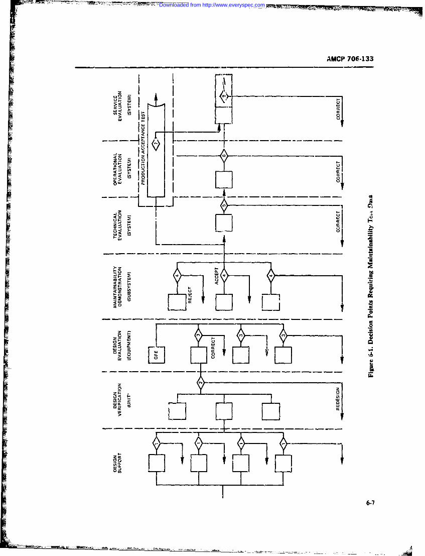
AMCP 706-133
z 2
LU IL __ _ _
L El
-C-
ui cc
w IF
I6-
Downloaded from http://www.everyspec.com
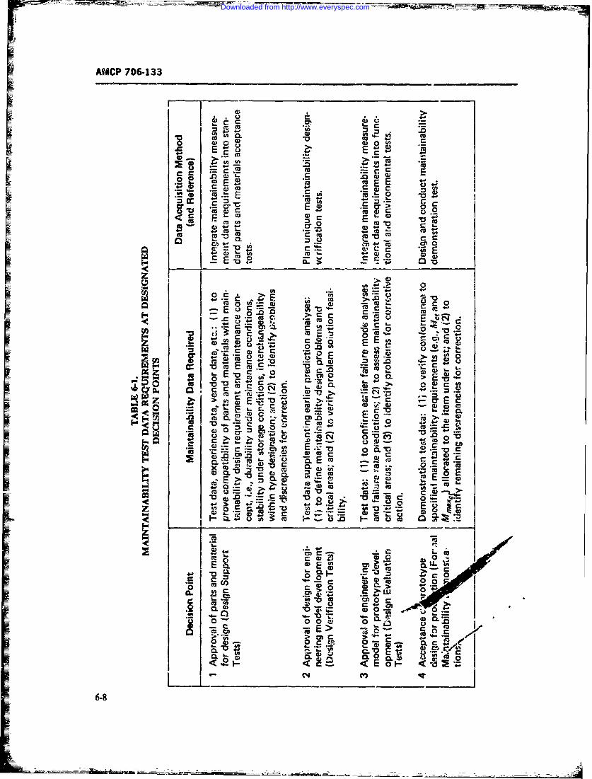
AMCP 706-133
S
E E
430
t o fA 0 o _
#-~ CO~ m
E > 0E v
+j .;; 9OE
0 0=Erioc-n c4r-C
C~O 00
0 .. 0
* ~E 00g 0
Ei C'dEv oI C
r+.0-L
Downloaded from http://www.everyspec.com
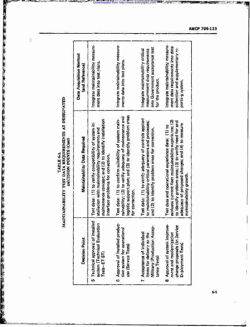
AMCP 706-133
4) CU (D 0 >
ka Ec-
r- a) Cu
c o, E g 0
E u E E m w E
CA- U. CD M
41-
StlE E; E cc
Cc 4-0. 2D '-
E~u 'c aw6 *
- o -. z U.
C .0 %M 0
c 0 x
%6- r -*- 4 &- (D-9
Downloaded from http://www.everyspec.com
F- _____
AMCP 706-133
The test approaches cited in this paragiaph a-e ma n- quirements, associated diagnostic support equipmcn.tainability design features that require consideratiion :a requirements, and higher downtime for maintenance,the maintainability alfocation and predictioi ta-ks.They are also of concern because of the effect3 and risks 6-2 1 TYPES OF TEST APPROACHESthey have on the maintena ce action times tv bedemonstrated during the forma marintainability dn.i- Funcriontl Tests These are tests that simulate nor-onstrations (early in the life-cycle development phaRs ). mal ooerating coiditions as closely as possible in orderThey affect the diagnostic times (fault isolation ar'd to establish the state of rcai'.-=;s of the equipment tolocation) which constitute the largest portion of th- perform its mission. The tet equipment simulates allmaintenance downtime. Effectiveness is evaluatzd dur- significant inputs, evaluates a;. final outpats against aing the first three types of test shown in Fig. 6. 1 (most set of predetermined standards, deduces the incidencedesirable if Type I test) in order to bring about any of aity probable faults, and indicates to the test equip-necessary design changes that can be made prior to the men' operator the system readipess state. Such tests areformal maintainability demonstration (Type 4 of Fig. performed under normal thermal, mechanical, and6-). electrical conditions. This type of test is usually the first
The primary objective in the use of any maintenarnce and last step in a maintenance action and i, calleddiagnostic technique is to obtain rapid and rpositive systen./equipnent check-out. It is used to verify thei.ientification of the equip.nent performance opera. condition of the equipment before turther maineniancetional readiness condition, or malfunction isolation in actions ate required and to verify that a correctivecases of failure of the equipment to meet the perform- action bAs been accomplished. Funciic nil ' == .bance specifications. This in turn contributes to reducing orientAd from P system level down to a replaceablesystem downtime for maintenance. Th-ere are th.,e subasembly level, depending upon the maintenancebasic diagnostic techniques avail-ole (Ref. 6. Chapter concept level LUing evaluated. Functional tess are op-5): plied and required during all evaluation points shown
1. ManuaL Basically a vrial-and-error effort re- in Fig. 6-.quiring 4echnician decision-maLng and using external Marginal Tess. Th-se tests attempt to isolate poten-meters, oscilloscopes, etc. tial problem areas by simulation of atnormal operatmon
2. 'Vemi-automaric. Repres'nting one or more conditiers. They are peformed by supplying unrelatedsteps toward automation of fault isolation and involv- stimuli to a system while it is subjected to severe en-ing sufficient internal test units and indications to assist ronmentrl conditions such as vibration, extreme heat,the technician's decision and to direct the next .ep to or lowered powtrsupply voltages. MP-ginal testing hmabe taken. Normally such systems fall short of complete its greate-t value- when it is ustd in support of faltelimination of dependence or the direct participation of preiiction, whern it identifies many incipient failurestechnicians in the diagnostic decision. resulting from abnorn.- environmental and operating
3. Automatic Eliminates the technician's partici- conditio. It is most us.eul when tlhe iten under testpaton in the fault lo-ation, and, upon failure, tl. s contains a number of idntical circuits or paralleltipaths, with only one or two exposed to severe condi-. tc~ is fitted with autoratic echniques and swichingto a diagnostic mode which, by means of irternal cir- " However, when ite-x.s tested follow complexcuitry, isolates and identifies the malfunctioning item paths, simple marginal testing does not. yield uisefulto a repair-by-replacement level, results both because (1) the com.p.exity of the paths or
circuits tends to mzsk tht. iest results ,nd (2) the varietyTrends during the late 1960's were toward both of circuits and paths requires simulation of many sets
standardizatior a-d .. modularization of equipment to of marginal .onditions. Therefore, funcional testing isaccelerate employment of autcmrtic and semi- most desirabl,: for checking equipment with minimalautomatic diagnostic techniques. This trend is essential test equipment, or for either manual or automatic!in order not to compromise mission availability while serni-automaic equipment. Mzginal testing is mostusing the available 95 nercentile-t)pe technician's skill desirable during ;he first three evaluation pointi shownto material'y reduce overall life-cy:le support resources in Fig. 6-1.and cost. Initial procurement and development costs Regarding the use of system versus component zest-may rise, but th. life-cycle support cost should de- ing (functional and/or marginal), a system test is mrercrease. Annual life-cycle support costs from 1956 to useful and comprehensive. No amount of component1970 rose by at least one order of magnitude over testing will ensur, defnitely that a system will actuas..the initial p.ocurement costs, due to higher skill re- perform as specified. System testing is required for this
6-10
Downloaded from http://www.everyspec.com
W_~
AMC,(J706-133
assurance. Cc-mponent testing usually is employed Only Closed-loop :rert& In this test, the sti.mulus is con-to verify that a replaceable coinponent is functioning :inuoutsly adjusted as a functi~', of the response. Ad-satisfa.-wrily before replacement! )r to verify that a justment is computed on the l-asis of en."pnient b~hav-replaced item is faulty. Component testing is rarely jar under the tes: conditions. CI&sed-loap tests provideused as a prime test technique and st oul i only be used engineering infortmation whicL is. use-Wl in evaluatingas an adjunct to system testing performance, efFectiveae of design. adequai-y of tolci-
Stafic Temt Tr this tizi. a series of intermittem . but ances, aud related characteristics. It is rarely usted fo~rsequenced input signals, is fed in and tbe output indica- field maintenanx excent fat research and deve~op-tions inre monitored to measure the operation of an ment. Cased-lrop cfr.-its or paths in equ'irment de-item. This test p-ovitis imfcrntion on the transient signing are the most difficult to maintain and diagnosabehavior of the itein although in practice, the transient whenever failuzres cccar in the loop. When a high de-response is often ignored in favor of a steady static gree of iaracy is required for a cemplea padrnanceresponse. A static test is siwpe and easy to perform. It and wnen t;:t points radiate noise L-vels which wouldusuWAy establishes a cc-tfidence factor !mi cannot go degrade tdie performance, clased-loop tests are verybeyond that, whereas a d:'iamic test yields much m~ore use1jL T-2e diagnostic rotines usua~y involve lengthyinfonnction. Static tests usually are applic. and evalu. functional test runs to verify performance. be. se ofater! turing the first thiee phase; shown in Fig. 6-1. inability to measure or stimulate input a" recive ade-
Dynamnic Test This involvLs application of a con- quate output iolerance responses. In uasny instammetinuous input signal, %here the output signals wre noted cemplex computer programmning of stimiulus prolblems;and a-ialyzed to determine whether the ilcin system have to be recogn;-e4 in order to verify the rerform-requicants are met. A test of ths type generally wirce state of readinees by test (either built-in or exter-simulates a typical mission of the systun be~ng tested; nal).thus every item or major subsystem is checked during In using various test approaches and techniqses allthis test. The dynamic test reveals such addtional in- maintainability qualitative chianacteristics are affec-formation as integration rates, phase claracteritics, ted--such as accessibility of test monts. optmmumand frequency responses; for either typical or b-ndary placemmzt of parts. tes. indceators, lbuilt-i tcs,. fea-inputs- Dynamic tests are preferabiiy used during fe- tures, technician sWl reqtarirmet ancillary suppormal masintainavility test (Phase 4, Fig. 6-1, as well as resource requiremnents, modular cc tucio,. stand-Phases 5 to 8). They also are applied during the first ardizaton, azA item throw away or d;Wpcai,! 'pon faii-three phame to verify te--t effectiveness of the design tire. Therdore, the maintainability eaigreer boustexperiment. ev-shmte he te7st in relation tn those q'ws'ita-
Open-lioop Tests. Open-loop (or closed-loop) tests are tivt chiaracteristics, and the assoriated effects oa thea further refin-iment of ,ttc and/or dynamic: tests. equipment design and trade-off aecisions i-, order toThe open-loop test provides a zero intelligemit feed-' optimize the maintainability goals and objectives.back to the item being tested. in this type, a sy-stemn For unsw"c, ready accestbiLity of sest points affectsresponse is etaluated as the item end-product. and no the test approaches. The effect depends upon the differ-adjustment c4 the stimli is made, i.e., a preet stimulus ent n--i at the various maintenance ccnscept levels ofis fed in, and the response is independently evaltzd actiom,. For example, functional tests at the organiza-Open-loop testing usually pro-ides moe u.cil tardnte- tional level require cnid-to-cirl input-output accessblnance informationi !haii closed-loop testing, because a teit points at the line replaceable subsyse-mnoduledirect Ov-vi~tion of the syvstm transfer funcdon is level (LRU) to reeasure the readiness status. This ismade, ftee the modiffy g influen-ce of feedheci:. Th1s especially true if ume of extetual test equipment is neces-St pacvides a ,ady measure of any degattation of item sary or builr-in test points interface to receivr, internalperfrmauce Also, the --proJ op test is simpler and stimuli and readouts for autoauitic test techakques. On
= cheaper than ckr-ed loop, becmuse it has wo require- the- other hant, if the replaceWl item repair is per-ments for an analog coinptie to supply intelligence formed at the intermzediate level, eater-iml test pointsfeedback. Because thert i no possibility of t~st instatil- mws be accessilki to diagnos rep!aeab~t- items up toity, it is the most desirable test for maintenance p'ir- the rqAacesble imit, using static or marginal teat tech-poses Its use is applied during Phase 4 testing (Rs. niqnms This in turn affects the optinuirn packaging of
= -1), as well as during other -tAses be-youd Phase 4. It replaceable itent- within the repit-ced unit.is used also in tize first three phases in connection with Closad-loop eircuift testing requifes niany dazig en-evaluation of the design experiments to verify or gather gineering decisi.-As regarding the circuit and test pointdatr for maintainability desirn purposes accewouhiy in a toduL-Ar design. so, as to make func-
Downloaded from http://www.everyspec.com
AMCP 706-133
tional static and dynamic testing possible on replacea- are usually more skiled and the support resorrCes arebWe i ens; open-loop testing requires accessible test lim'!ed due to *n nature of the test costs and szer.uAes.
pots for independent evaluation of the readiness st~ate tiprmilanegerngisgnrofs.
Reg;ardless of the test type used, the design decisien 2 Uer-ta Tniret s u sin ar e m e und eruatedsusermust assure that the comprehensive test ts adequate to oprinlevrnm tsuigseicoeatradverify whether a system is operating properly within as ~ Tr'epo h aoeac upr edesign specificatioit -nd whether the related intaina- sources (personflel, sup,,)rt equip'menlt. spmres, techni-bility clesign characteristcs 'zompro'u.-ise'the test tech- cal data, facilities. etc.) which have beer. ;c ieloptdL In
niques selected. such a situation, actual experience in the operationtalT7herefore, all maintainattity test and demonstra- environment can be observed, rectrded, anJ stubse-
dions in all phases shown in Fig. 6-1 must include evalu- quently analyzed to reflect the true approximate .epre-atio of the test techniques by' observation of the tech. sentation of the design in maintainability quantitativentin's procedures and proficiency These and qualiative requirenest. Usually the service tes-ts
observations of the time to perform check-out and diag- invlve only the organization level (opeuion/organ'-r ostic: mainitnanice tasks and the effects of built-in de- zation techn~iij") and the intermedifile level (directsign qualitafive characteristics provide a basis for mea- support and g-- eral support techniciats) mainter micesuring efctivers~ of the mabstentanct tasks &and for task.s. The depot level maintenance normally uses theI corrixti ie action to imrpevc cffectiveness. The diagnos- contractor %upport facilities, especially in the early de-tic time is a ke- factor in the achievement of maintaina- ployment phases; demonstrati-in involves maintenacebili objetives becruse, historically, such timesuar the repair tasks using contractor logistic support resources
FE largest single contributor to mintainability design 4r.- is performed at contractor facilitiesleading toward dyna-nir autoaic, and functional testI=techniqnies instead of static, manual and/or semi- Tzchnician training must be provided to ensure thatautomatic, and marlinal tes! techniques. the skills necessary to performn the maintenance tasks
durinr; tho service test demonstrations are adequate for
3. Thysical Tear Down is made by t-' customer to
The user-se-vice test is the most desirable type f --valuate the capability of equipment tear down :o 4%z-Iformal maintainability deamonstration on which !o bast lowest nelakceable item. Normally this test is done un-accept/reject decisiorrs 'Refs. 2-6). Such evaluations der controlled wonditions and tnvuionment using con-
Z ~ constitute a statistical approach to flit true erviron- tractor-customer production oi experimental techni-ment in whic-h &*upwent is operationally deployed arnd cians and the associated logistic support resource toolsto condition %where kf-gisti-, maitnenance support re- (custozr, designed or standard). The principal qurantita-sources are used. Although the statistical decision is tive parameter for maintainaiuty that can be ment-based on A Small sample of the equipment, the decision cured is the item replacement task time. Diagnosticis made in view of the specified risks. and confidence task times are not usually involved. This evaluation hasard accuracy limits e~ the maintenance task samp!e.It the additional advantage of observing such qualitativ
-.1ects, a closw simulation of the -ystem d-sign for maintainability design characterittics as accessibility,maintainability, ever. though it is not 100% reliable. packaging, or attachments. Also. messurement of theTiowever, the sampling processa of the simiilad main- test approaches can be included with little -!xtra cott.tenancc tasks I~c rep-n-sent randomt~. _5Of The test has the further advantage of evaluating depo;pecteil deployed use --nd provides an adequate simula- level m,intenance requirements as wel; as te other twotion wvithin the practical. life cycle program levels (orgaria~tional and intermediate lev-!s), becausedevclopsent, cost. scheduling. risks. onfidence, and complete tear dovun of the system/equ.-pient takesaccurat y limits. Pae
Curme.'t Army procedures require the following The hardware model- used for th--se three tests usu-phases of Lwe-service testing for mi ntri-7ability quan~- ally are engienna prototype models or tirly produc-i itatzve-qualic-tive accept/rcjct decisions- '- eazh tion itenm In the 'make before buy*" ("fly before buy-)pbast, the decist 'n-making evaluatic~n is tssed to estab- process, the models tested ar: proctypes t.ut simulatelish the design in Y.aintainabilitv goals and objectives: the prodtuction model as nearly as possibLL The same
1. Dei'elprent 7;-is(DP~ air made under simu- applims to other logistic mainenianic support items,Ilated operational enironnK'ts, except that technicians such as technical publications 2nd support Pquipaosit.
6-12
Downloaded from http://www.everyspec.com
-- -_I .. ..
AMCP 706133
IF 6-2.3 TASK SELECTION equpment failure. Thus the check-oit test must indi-cate that repair has been acco-,plished correctly. Simu-'e basic method of stratification and apportioi' lete. faults a.-e not to be inserted if they are potentially
ment of tasks to be demonstrated is presented in Jetail hazardous or may damage the equipm.nt. For exam-in the references cited in par. 6-1.1. In relation to che pie, a fault would not be sim-aulated in an airc-aft land-test techniques earlicr cited, par. 6-2. Test Approaches. ing gear ;f it would create s hazard in the landing of antests to be used must adhere to the principle that diag- aicr-Ai with potential damage to equipment and injurynosis and chck-out be capable of determining the to personnel.mairtenance functions required at the respective levels Careful attention shoidd also be given to choice ofof mxintt.narc. o, example, ira line replacement unit samples for the tests. This applie, especially to techni-is replaced at the organizational level, the diagtostic cizn skill levc&. Random selection .echniques should(fault isolation-location) test task must "troubleshoot" be ,tsed in chooesing the sample. The sample is chosenthe fault with sufficient confidence to assis! the techni- so that it correctly reflects the percentag, -iakeup (incians in determining that it is essential to replace the terms of skill levels) of tiue .i ginal population. Careutiit in order to correct the system malfunction. The must be taken when faiults are induced into the systemcheck-out task must indicate whether the equipment that the maintenance technician is not given informa-state of r':adinLss requires an item replacement due to tion that normally would not be available.
-
6-1316-14
Downloaded from http://www.everyspec.com
AMCP 706-133
SECTION4 11
METHODS OF TESTING
=6-3 TEST TECHNIQUES Fault sintulations are deterir ned during :he pre-denuiinstration phase in accordance with the plan for
Details tif the mnethods afetn fo mananblt selection of task and sanmplet Tie sample demonstra-geals vary Lue-ording to the desired obtives during tion data sheets must indicate the type of fzilu.-e to bethe: various phases of the systemn/equipment life cyl simulated. A technician (assignct! to assist the tt t di-
~1ios. n Fg. -Iandcitd i th tet aproche. ~ rector and maintainability test monitor) induces the6-2- failure ;-:o the equipment during the absence of theIThe maintainability design axzd quantitative gcds techntcian who will performn the 1taantriance. The
(time) rely on the reliability qwmnttative deternina- fault of the "bug" is checked to assure that it producestions of the need for maitenance (failure rates fe.- a malfunction ini the equipment- The technician who:orrective maintenance, and scheauled rates for pme- performs the maintenance action is tLen assigned to theventive maintevance). Unfortunately, due to costs, maintenance txiks. He preparts I'U the task-s by review-schedules and test times, it is not practical to test or ing the -eported symptom, usinf th! avaiLble technicaloperate equipmerit in a dep!Tizz! population under maua zn looking for approved alternate proce-cnmbat or peave-time environments or for th eipe dures. ie -onducts a visual inspecti-r. and sets up theuseful life. In some ilstances, the failui-e or wear-out oft qimn-isale upotts qimn n
co p n nsp rsf rsb seIas m ~ s m ele facility power input ann starts the maintenance actionsmy never Gccr.Irn so.me- cases, where the selectzi mainwenance tak required. He first performs a functional check-out test
for sm;.ll systems of less than 50 parts involve a limited an~d vef 1es the symptom. fie then performs the r-number of potentWa tasks ef simple diagnosis and re- quired maintentance tasks until he has completed the
placement, all maintenance tasks can be fault simu- action and the check-out functional tasks. This willlated, and the maintenance times ob-erved and prove !hat repair action has been ac'osnplished andweighted by ihle predicted failure rates, :o get the mean that the items =r ready for operational use- All actirvistime to repair the sys~em are timed and i ecorded on the .* ta worksfteets. In most
.r most case3, the potential maintenance actions are- cases the effects of the mainitainability features builtmanty, and simnulation sampling must be used. If. for into the equxipment are noted, e-specially where theeanple, over 6000 different efganizAional levPl t~iks times are excessive. In all case: where the predictedeist for the C5A aircrakt the sample suze for rnian. tie are exceeded, the reason must be recorded inability demonstration would be 228 (Ref. 10,. znd Sim- order to establish a basis for corrective action. The'vihtion ^f faults for the randomly selected ta ks would following ame typical fundamentA minntenance actiornbe necessary to be observed. monitored, and recorded, as a mini-
Also contributing to die mezhods3 of intirvg arm con- mrsiderations of thte comp~ex~ty of ilhe Ya -t z ies of wrequipment and associated technicizn skills 4Lai! mrechan-Iical, elerntro-mecharical, electrical. electcirmic, optic;-J. 1. Pir..praion and visual inspection timeor any combiriatkt, of types). The techniques are fur.- I. Funcional check-out time-darwitally the sam~e, varying only to the extenit of fault 3. iansi iesimulation. I ignsi ie
In all cases of fault simulation, the safety of person- b. 1731lt isolateredl and potential damage to systemn/equipment areconsidered. Safey fault tree analysis could be the basis 4. Repair time:for determining simulations. Also the Failure Modes- a. Glaill aCCessEtTects.Ctiticality-Analysis is wed to evaluate and b. Remove and replacedettcrne fault simulations c- Adjust. align, calibrate
6415
Downloaded from http://www.everyspec.com
AMCP 706-133
d. Close access time, or money and these -mnstraints must also enter5. Clean, lubricate, service time the selection process.
6. Functional check-out of ie repair action. To illustrate the latter point, suppose one %ishes toinfer the mean time to remove and replac- a ompo-
in order that the inference be valid o,' xhe entirethe following at-! typical -_xamples. population of repairmen, it is uecesary that th,: sample
I. Electrical-Electronic: include repairmen of varying, skill levels and ex-a. Opm or short circuits perience, i.e., be ,-eprebentative of the total population.
b. Insertion of failed components It would b- m ng to take &.I data on only onec. Msaligpmnt or misadjustment indivijdual, or sollely on indivi-luals- of one p.ticulacd. Insertion of broken connector pins or springs skill 1-v4. Informati M on the composition of the popu-
2- Mechz~ical-Electro Mechanical: lation of r,' -ain may be aviL-ble from personnela. insertion of bro~en springs records. If not. it may be nocessary 1a sample toe popu-b. Use :f worn-out bear gs, failed seasbroken latov of ,.Parmen to gain knowledge of its composi-
relays. or open-short coiR tomb. Misalignment or msaujustmets shotld they be collected, in any given situation? Thed. Insertion of failed iicats or worn aesies o the ;uestion quanon the segears, m~issig keys as' t hs m-in emdo h mtto
e. Use of failed sorsn compnents knowledge Whchepopulation, thedesired accuracy. and
3. Optical Syste to thre poitlation chardhtist s) we tih to infer. For
mechanical iret lecicl fexample, does one know the dist butional fom of the
o .eisaing n rc n inafws sthei -wreient random variable(;) and f s fi the value Lanyb isculitem or e aionst ands of the osmeterts oft,e distribution? ow lose shouldct Insertion of broken parts or comliments the estimates of the population quantities be to thesed. Use of faulty sensa faulty edicato n qnie ic h mout in c reto ieieg
Scesduld preventive acns are in accordance with esti vfated--,e m aan, the median, the varince -anubdished step-by-step proedres of rutine visual, (again) how accu tf y is it to esmatimaed?mandoihal mezskm t; eletrin, fspl tional check- If it were knoim that all e-ments of populationout; ceaning; and lud.caton. In a few cases they in- were idental then, clearly it would suffice to makevjolve scheduled item rep -looce actions and associ- only One observation in order to know al! about theated check-cut actions. reqfore faut simul n -is porpulation. The less homogeneous a iopultioi therather liimited because in mws =, scheduled mainte- mor: obsen-ations must ig made in order to achieve atiw= tasks are on a calendar, n'.ilag--, or rounds bwi certain level of :reformationi fii maences The infor-
anod 100% are demonstrable. For routine tear down teri n tmt of an estimate . (nry
and overhatil task selection, sampling usually is ema- in tern-& of its varianDe Var;.krxe_ in turn,. is wuna51y
ployed, inyer-.,ly p-oportionad to the size of the sample Thus.:,he irformatior content of an estne is directty pro-prtiona to the siz of the sample upon which it is
6-4 SAMPUNG AND SAMPLE SIZE basedSELECTION
".1 STATISTICAL MErHOS IN SAMPIUESampl'ng is the nrocess of gathering data about a SEECTON
population in order to infer some of its characteristics.Sampling is performed because it may b,- ;mpossible, In this paragraph, methods of determining minimum,oo expensive, or too time corsuming to ikserve the sam~lc sizes for estimating z proportion of successesentire population. and the mean cfa normal distribution will be discut,'.
In many cases considerable knowledge about a popu- as will sample size selecutc for the lognormal distrib-lation cin be inferred from a properiy choe sample tion. It will ,e seen tklt sample size determmntionof moderae size. Ii the t-pc'l situation, it is pcxsible requires th specificatin of a %i,-ed accuracy andto sample orly a small pan of the populitikA. Thus, it confidence. The relationship a tbm three quanti-is important to exercise care in the choice of the sample ties is suw.h that iE' two of these are gi,,-n, one can -Ivcto assure that i: is represmtative of the population. The for the third. Altemativel-, filing the vaue of only onesample size often will b- limited by lack of opportunity, of them entails a trade-ff beecr the -her two.
6-16
Downloaded from http://www.everyspec.com
J AMCP 706-133
1. Erimting a Proporti n of Succeze. b. If it is believed that p is les than ,7. substi-
First, considef sampling without .-eplacem'nt ;rom t the largest reasonabIl guess for p in Eq.
an inFnite population of items. Each item seected -,A for Ibejudged according to a dichotomous criterion and the C. If it is believed that p is greater than 1/2..it it eiv the maet pigret es forn 1/
two possibLe choies will be called "success" and -fa- in Eq. 64 for r.
ure", where succer or failure cousists of th- occur-
i'enice or ,voioccrrer-e, respectively, of t e event of The statemenu Ia. lb, and Ic follow directly frominterest. the fact tlu-t t, -- p) is a parabola taking the vale- 0
We cite the fotlwring flicts from statistics. Given a atp =0 and p = i, and at.aining its maximum of 1/4sample of size n in which s srzcesscs have been ob- at p = 1 ,2. The .A conservative rule to follow is Ia;served, the nmaximum liEelihood esti ,ate ofp the rules lb and Ic yield smaller values cf a than rule Ia."true" proportion -f successes in the population, is Example 6-1: Determine the sample siu n necessary
= s/n. For large values of n the distnoution of 6 is to assure that . is within 0.05 on either side of p withapproxim-tely normal with mean p and variance probtbility 090 if
r(1 - 7)/tL Using this %pproximation. deter- a. N-thing is known. about the true value ofmine fi-t the sample size n needed to assur- 'that 6 is Pwithin 8 on either s;de of A with probability1 - a. b. It is belie-ed that p < 0.40.(3bsequently nwillbe dewmined for/Pon oneside of, c. It is believed that p >_ 0.80.and within 8 of, Awith probability I - a). Solu:inm a = 0.10. 1 - arz = 0.95. tnd
It is required to determine !he sample size n so that 1.645; 6 = 0-05. Thus. rounding up to thenretintegenP [ - Pl _ < 6) -- I - cr (6-2) nearestinee:
-- 6-)a. a = (i.645Y.440.O5)'I = "71
b. n (1.645)V (0.4) (0.6)1,/(0.05)Y = 260c. = (1.645? 0.8) (0.2)/(OOy = 174.
This probaility staterrAnt is equivalent toNow determine th,. sample size n neee' to assure
i(p - p[ 6\ that P is wtbn .3 on one side of pwiti, probblity ipi - -, ;7= 15- (-3) - a.Therearetwocsesf6 >pandl <p WefirstO'i ir (6 derivethe result frP > A H=e %,. want to be asared
that we dont't overestimate r "!,3 much-, bunt are not
Invoking the approximate n'nrmility offiith mean conorned about an un2eresirwate. The derivation isio ad standar i- p) ana.-gou. andtheresultis identical, for p In that
quantity (/ - p) / is appfximately a scndar case we want to be protected i2ainst "too large" an
normal variate (ie., mean zero, variance one) The underestim of
probability statement can be portriyed as shown in Fig,. We want, for P > p,6-2_
This shows that o- is equal to z ,. th P (j-P < 6) 1- (6-C)100(l - a/2) percentge of the standard normzl bu-tion. Substituting /p(l - p)/n for a- in expressing thesequality and solving for n, we obtain This s eq ent to
n = (Z.f/z)p(1 - P)/l2 (6-4) P =k < L-- = I- (6-7)
Since the value ofpis not known, (elsc re wold norbe esfimzting it.), the following ilter.,fives ext for from which it follows that 6/0- is z, the 100 -a)estimating it percentile of the standid normal dis'.bution. SWtitut-
a. If nothing is known about zhe value of Ap or ing Np(l -p)In for into this ste'eztnt ofequalityif it is believed that p is riear 1/2, take anisolving fornyiel'is P
n = (z2..) /(4 62) (6-5) = (z,-. pt1 - p)/C (6-8)
6.17
Downloaded from http://www.everyspec.com
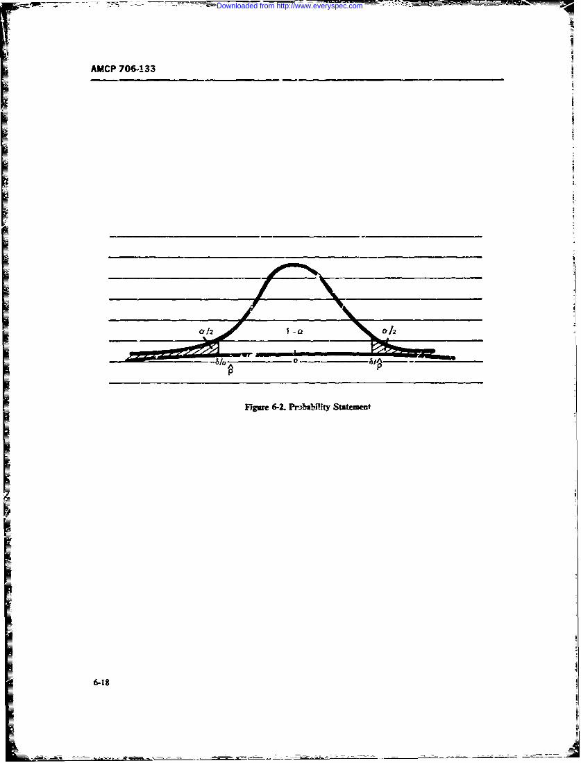
AMCP 706-133
Flgur 6-2. Pr-%babflty Stategiect
57-
Downloaded from http://www.everyspec.com
AJCP 706-133
Once again the ferr.atives a. b, and c pre.,iowsy set - a = 84L Simibzay a corSdence of I - a 95% wldown mu, be folowed The most consenai,'e choke provide an accuracy of 09.
The same kind;- zf tables and granha an be preparedis for Mtr san-.? sizes and :he other €ases.
nz= (4~l.jI(462j) (6-9) 2. -Pubrlariigthe Mew: of a I'frral Disrilutfi
6nsider sampling from a normal disvri with
Eample 6-2Deennmetheampeizenee y unown mean. Recall the followng fats from satis-
t- assure that A does not ov-resfimate p by more than tcs Given 2 sa''Ple of size a , x- ....x, o a0.05 v;tih probability G.O if neumal distribunon with -mn t Ld va.iante or:, the
a. Nothing is known about the true 'Aue of m um l estmat af a is A the smP&
me. The diswlatiao !dis normal with mean t and
b. It is believed that p S 0.40. vuiance &,lm These facts are now used to detcuinu
c. It is believed ,hat p : a.8o. the sample size n nedW to zasure thm xIs ccses" ".
S-?-~- t,, ik e can ask for the .3which'fiutiom a = 010, I - a = 0.90, and urn g tu ees x tswiis 8ion -. ersidof;Lwthprobe-
.2826 = 0.05. Ths, rondingu p to the nearest bf"iy I - :t. or x on on ide of. and within 8 o.integer MWith p " I --ia.lIf--itmkownthesi-
a. n = (1.282)2/[4(0._059,-] = 165 tion is somewhat more complkated. It his been shownb. n = (1.282) (0.4)(M) /(&0TYz 158 b.Dagt-g(Ref ll)thatitisnotposiewithasinglec. n = (1.282) (0-s) (0-) /(0.o 5 .= l& sample of fixe size to cnstrn a ccfidence interval
The sample sizes indicated in the ftcedinghe m -.n o aenldi. wh tev-may be quite e----st oc tie-c ing to obtain in ' h a a normal odis aipo whn thp varoe
some situatons. They are, how,er the smzlest sam- can achive this.) This mens thet, for o mknown, a
ple sizes that can be guaranteed to proide the specified diffeaent iterien is unccsaiy for detaining a. We
accurac1y -e., 8) anti confidence [i.e (1 -- a) or (I c i o f setnultnle
- w/NJ requirements. If the su .:ple t ! i, .y ce cnde in n shhat xpis-withsceof
of the preceding equations camnot be made avzilable, the p standard deviation a of 1- with prota-t i s an i ictic , th t n sic o , t I - - .Finally , w e presen t a m ethod tbr ti, e
sanindicat. that an uelisc (or, at least choce of n when the sample mn is to be within aun1-reilizable) specification of axuracy (a) and confi- given percent O t pesmianon mandence [(I - a) or (I - a/2)] has been made. f etuof th e o p.
Aralisic apprcach in this case is m codcm 0he Grm o- kn,,-mn !on eit side of
trale-off between ac.curacy and omfidence achievable i this cs w, that
for the largest sample size tha: car be male available.This trade-o is easily seefor example in Eq. 6-5, P(i-±i -)=1 -a (6-11)dealing with Example 6-Ia. Suppese one could makeaaIabie a sample of size n = 100. Suhituting "hi Ts probabi:ty satement is equivalent to
v-4e into Eq. 6-5 yields
40062 o = 4Z,.2r)1 2 0 (6-10) k 7 '':. N) =1- (6-12)
The relationsip can easily be tabulated (Tahe 6-2) And which c. be portrayed gr" a " as shown in Fig.
graph ol (Fig. 6-3). 6-4.
Fig. 6-3 shows. c- euxampie. that with a jmnpke of This shows that V 3-3lr is equl to .- thesize 1300 in Example 6-1a, if one wans an cz'racy of IO - a/2) pecentil of the sta-d r&dsri-6 = 0.07. he can achi e it with a cnfience of txdon- Expresir.gthisequalityano-- ngfornyieL
6-19
Downloaded from http://www.everyspec.com
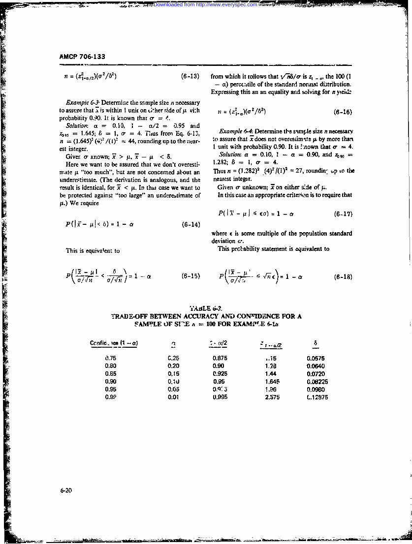
AMCP 706-133
n = (z, 12)(a 2/6 2) (6-13) from which it ollows that V//o" is z, - 0, the 100 (1- a) perwe-atile of the standard normat diitribution.
Expressing this an an equality and solving for n yieid:Example 6-3- Determine the ssrnple size n necessary
to asspre that 7'is within 1 unit on t.;*her ride of. pi:h n = (21.a)( /61) (6-16)probability 0.40. It is known that o - 4.
Solution. a - 0.10, 1 - a/2 = 0.95 artdzg, = 1.645; 8 1, a- = 4. Thus from Eq. 6-13, Example 64 Determine t)e sun tle size nnecessaryn = (1.645)2 (4); / (1)2 = 44, rounding up to the ctar- to assure that x does not overesdmn'mt, p. by more thanest integer. I unit with probability 0.90. It is -nown that a" = 4.
Giver o- nown; 7 > p,i-j <8 Solution: a = 0.10, 1 - a = 0.90, and z 0 =Here we want to be assured that we don't overesti- 1.232; 8 = 1, o- = 4.
mate It "too much", but are not concerned atout an Thus n = ( 282)2 (4)2'(i) 2 = 27, roundin- up to theunderc-timate. (The derivation is analogous, and the nearest integer.isult is identical, for 3 < fj. In that case we want to Given cr unknown; ! on either sd:e of I.be protected againsi "too large" an underettimate of In this case an appropriate crite'tn is to require thatp.) We require
P(I-i - C01 ) =1-a(6-17)
P(Ii - Pr< 6) 1 - a (6-14)where E is some multiple of the population standarddeviation c-.
This is equivalent to This prcbability statement is equivalent to
\ ,1(1 (6-18)
TiABLfE 4.
TRADE-OFF BETWEEN ACCURACY AND CONR'DJNCE FOR ASAMPLE OF ST.E h 100 FOR EXAMPLE 6-1a
Confi. ce (1 - a) (t2 .
0.75 C.25 0.875 ..i5 0.05750.80 0.20 0.90 1.28 0.06400.85 0.15 C.925 1.44 0.0720
S0.90 0,10 0.95 1.645 0.08225
0.95 0.65 0.q, 3 -. 46 0.09800.90 0.01 0.995 2.575 L.12875
6-20
- ,---- --
Downloaded from http://www.everyspec.com
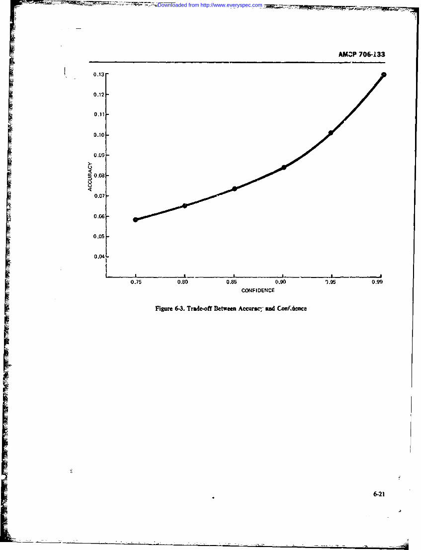
AM, P 706-133
0.13-
0.12
0.11
0.10
0.09 I-co 0.08-
0.07
0.06
0.05
0.04
Ii !p p pI
0.75 0.80 0.85 0.90 1.95 0.99
CONFIDENCE
Figure 6-3. Trade-off Between Accurac, ad Conf.a-e
6-21
Downloaded from http://www.everyspec.com
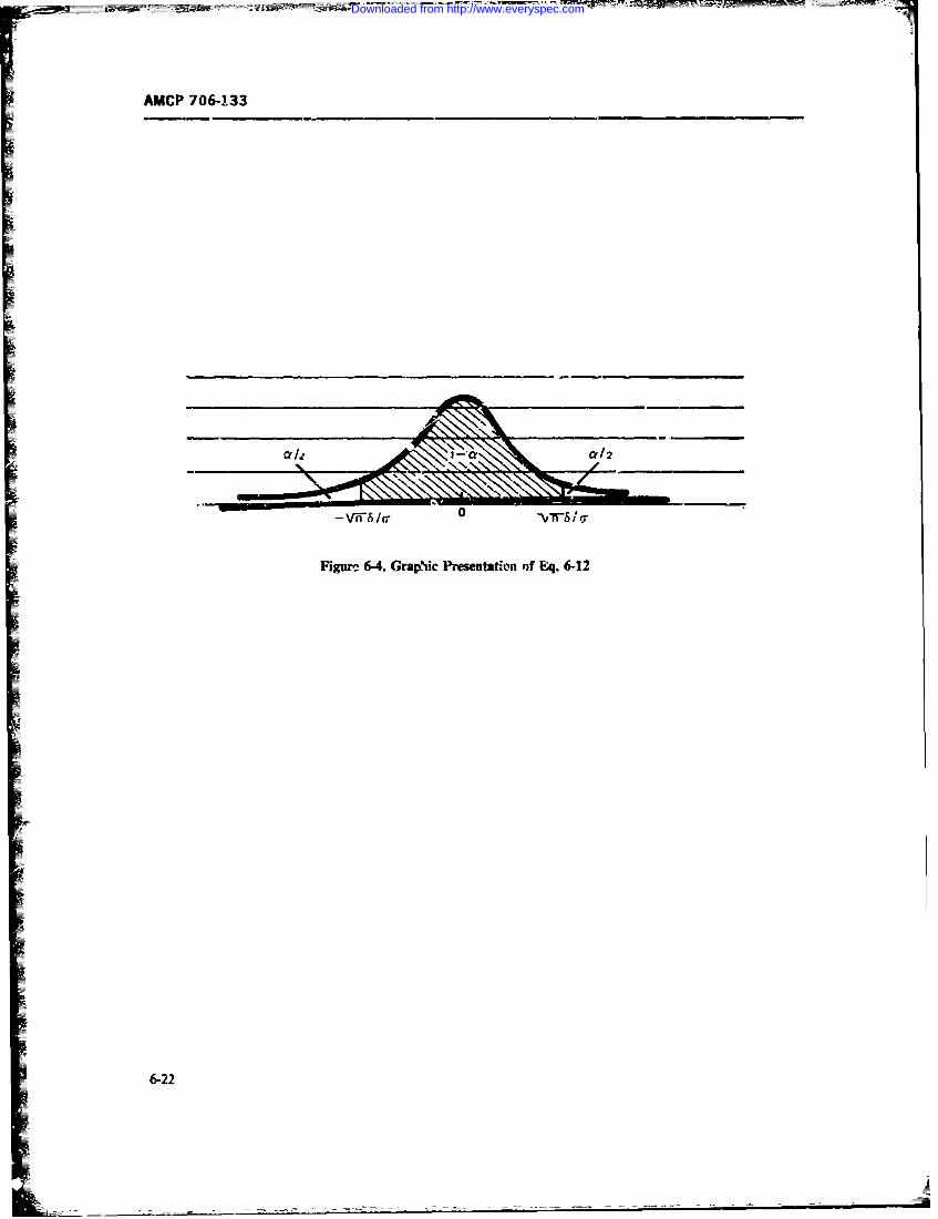
AMCP 706-133
Figure 6-4. Crap'uc Prmsetation of Eq. 6-12
6-22
Downloaded from http://www.everyspec.com
AMC P /16-i33
3othat V"eisequal to z, _,2, the 100(l -a/2) per- ( - 1 - (6-23)centilc of the standard normal ,itribution. Expressingthis equality and sol ;irg for n yielr.
in order that th mrot)ability satement be correct, :t ist = (z../,)/- 2 (6-19) neL-sary that
1 = ((6-24)Example 6-5 Determine the sample size n necessary
to assure that 7is within 0.25 o- or either side 0 :. withprobability 0.95. Solvin- for n yiclds
Solution: a 0.05, I - a/2 -= 0.975, %indz097., = 1.96; e = 0.25. Thus from Eq. 6-1q, n =(1.96)'/(0.25)' = 61, rounding up to the nearest inte- 1 = [(z,..a,2)a/(ku) (6-25)ger.Given or unknown; x > p., IL - < e(o.Our requti'ert is that While thi- m-.th',hd dces not require separate knowl-
edge of the popultion mean ad population..:ndard-eviation o', it does require knowledge of th, ratiov 6 o/. This quantity is called the population coeffiientof variation and is usualiy denoted by . (MIL-HDBK-472 denotes it Cx) It is claimed that certain classes of
Thisproabilty tatmentis quivlen toequipment have characteristic values of V To the ex-tent that this is true, the formula for ., which can be
p .- pI rewritten asP < 51,E(6-21)
n ( 1 ~)/1 (6-261so that V-e is equal to z , the 100 (1 -a) per-centile of the standard normal distribution. E.,.pres-ingthis equality and solving for n yields is usefu'. For example, MIHL-DBK-472 quots t,,-At
of V = 1.07 for ground electronic equipment. Ofn = (z',)!/," (6-22) course the formula will be useful in any situation in
which Vis known.
A normograph solving Eq. 6-26 for n for a range ofExample 6-6. )etermine the sa,-iple size n necessary values of Vand k, and for 90% confidence (i.e., I -
to assure that 7does not ove-estimate p by more than - = 0.90) is given is. Fig. 3-2, page 3-10 of MIL-0.25o- with probability 0.95. HDBK-472. (It should be noted that MIL-OBK-42
Solution a = 0.05, 1 - a = 0.95, z095 = 1.645; incorrectly states thi,.- nomograph is for 95% conti-e = 0.25. Thus from Eq. 6-22, n = dunce). However, the equation fo: n is easily solved(.645'/(0.25) = 44, rounding up to the next integer, without the nomograpI'.
Gi'ven or known. Estimating . to within a given F.za'.ple 6-7 It is known that the coefficient ofpercentage, variation Vfor a normal dbtribution is 0.5. Find the
This method is dese-bed in MIL-HDBK-472 (Ref. sarr.ple size necessary s that zhe absolute difference12). We follow our previous notation. between the sample mean and the population mean
The idea is to determine n so zhat for given probabi!- does not exceed 10% of the poputafiar mean withity I - a, and percentage k (expresed as a decimal) probability 0.95.of the population mean I. Solution: We must choose n so that
6-23°
Downloaded from http://www.everyspec.com
AMCP 766-133
rP(I - iL - 0. i0) = 0. 95 (6-27) e, = 1 In Xln
If w is known, then a sample size n car be determinedThe value of n from Eq. 6-26 is so that, for given values of 8 and a,
n = (zo. sV/k)2 = [(1. 95)(0. 5)0. 1OF = 96(6-28) P(V - < 6) = 1 - a (6-30)
3. Estimation For the 'Zognormal Disrribution asin Example 6-3. Specifically,
A positil random variable Xhas the !ognormal d:s-tribution with parameters v and c. if the naturt I loga- i .-(zIaZ /,•, ,z (6-31)rithm of X, i.e., lnX, has a normal distribution withmean v and standard deviation cu. The probability den-sity function, '~ of X is
The p:eceding probability statement. Eq. 6-30. can be
f(x - (c.x 227)0exp[- (lzx - '/,,2.1, (6-29) written as
P(' 6- < V< t,.6)= 1 -a (6-32)where
v = mean of the ratura' logarithms of XI
= "v12(lnX - D)t/(n-I) and a!%o, in terms of m - e", as
= estimatea value of vThe mean, medimi. aad variance of the iognormA] dis- o (r < P < ev* *) 1 (6-33)
tribution are:
mean: / v + o22 or
me~dian: mr = c='
variance: a" = e2 1 + - 2 (ew= -2 )F /""m.,;o=1-a(-4mean: uCF(?n/e- - C~ I-me (6-34)
The median is often used as a measure of central tend-ency for the iognormtal distribution because it does notinvolve w The 100pth percentile of the lognornal This interval for ctimating m does not have a fixeddi~tribution is giren by e' + P' where z_ i3 the !engh (indeed, its length is a random variable), but the
0OIpth peicentie of the standard normal distribution. ratit of the upper to the lower end of the interval is aMar.y rnintairuility demonstration plans nt-" constant e76. Note that it was necessary to assumni.
couiched 'n terms of the 90th or 95th per--ntile of the krowivege :;f oi in order to determine the sample size.lognormal distribution. See, in particular, MIL-STD- The point of this paragraph is to emphasize that one471 (Rnrf. 2). These plans are sequntial "n nature, not cannoi Cetermine a sample size that will allow con-of fixed sample size- (We descnbe them in par. 6-7.) strzction of a confidence iniervAl of predetermined
Suppose one wanted to estimate the median m of a cenffidence and length for the median of the lognormallognto-nalI random variable Xnn the basis of a sample distribution as we were able to do for the binomial andX, X ..... 3,_ Note that v = In ,n is the population normal distributions. What is true for the median, theinean of the normal random variab!r !- " so that an 50th percentile, is perforce true for other percentiles
wstimate of m is wii = ' where P is the sample mcan which involve o explicitly; hei,ze. the reason forof demonstration plans for the lognormnai distribution be-
In X, in X. I ... In X- ing sequential rather than of fixed sample size.
6-2-
~6-24
Downloaded from http://www.everyspec.com
AMCP 706-133
4. .Relation Among Accuracy, Confidence, and only maintainability but all other system effw.tivenessSample Size~ and operational design p~rmete-s. Therefor,- the
Under the subpars. 6-4.1(1) and 6-4.1(2) we have i iintainability engineer miust be prepared to particidiscussed the selection of a sample size .7 to mneet joint pate in all trade-offtstudies invo;ving reliability DuringIrequirements of aceracy ef an estimator and the corfi- the early design development phases--once the failuredence: robability I - a) w~ith which that rcurc is rates have been predicted --nd the equipniet.! reliabilityachieved. It should be clewr that in each C th moel design has been reviewed and approved-the rns-nair.-Idiscussed there is a relatton among the quantities o~f ability desigu palrameters are concurrently established,accracy, conlidence and sample size such that if any reviewAd and approved. At this point in tie equipment'wo of themn are specified, the third is dteld. cycle, the baseline for the demonstrable inaintain-bity
To illustrate this point it will auffice to consider Ex- factors is firmly established, and both the af?rnpriateamnple 6-1 in which we souqht n so th-0, for given 8and samplzs and statistical tests can be selected (see pars.I 6-4, 6-7, and 6-8). Therefo-e, any test conducted by the
relibility engineers. io evaluate reliability predictionsP( P < 6 (6-5) 'rstressing, increased quantity of er.~pment
USI tnvironmental testing, intemtnittent test results,
We found that (Eq. 6-9) rnin sons, wear-out failure rate, continuous operation
versus u'terrniiient operztion results, sample size vrfl= '4 2.ar,)/(4 62: (6 -36 sus time iequirod for adequate testing Jimiiation-inust
Had zn a eens:)cifd- wold e dterine by fect on the inantainability design pararneter must beHad cu a eens~eitid. wold e dterine by considc-ed a-.d incluided in the design for inaintzirtabil-
!eequation ity. Th1is task is part of the inaixwainzbility design su~-1"-.ilance, desigi' memniring. desini1 :evicw, raak
6 (z1.0. 2)I*2kJn) (637 ated trade :,udy tasks. The descrij~aoi of the variousreliability ertzineering methods, technique&. and statis-
E Had n and 8 been specified, we wculd solve fo- . by tics or reduircng test time for reliability demotq.trationfirst obtaining z, from c'Nhe frequency of maintenance actions is 4iain,-d in
vious reliability textbooks and sympose. mn hlerattu;:
Z 2 6 "-n (G 3 81 reports wtdi ot included to t~tsh nd o k
and then lead 1 - a/2 from tablcs of the cumulativenormal distributiou. C6~ ~ ~ hTO AT A
6-6.1 COLLECTION OF DEM0I4STPATION6-5 REDIJCTI'M OF TESTING DAT A
As stted p.zeviously, the equipment idep'ly wouldd _v The maintainability dz~a coliection systems oi mill-exercised and operated withi an actual operational tary vrocurernent agencies should be used to the maxi-t~ivronvmet and population using the estaLlished log- mum extent possible to recard data collected duringistic support resources' for the duration of the specified maintaiuiability den.on'trations. Supplemnentary oruseful lift. However, this is not practical because of cost unusual data collection systems may beLzrt- sand developr tat rcbedling. Fault simiulation there- necessary, if approved in the demonstration plan. Howfore should be itsed for stltsted tsks, based on statisti- ever. if such unusual data collection is necebary. itcal samplings, should be an addendumn to existing sy"em The pi-
Because frequenzy of maintenance action is r prime mary purpose in using existing systems is to speed upconsideration in determining thc dsigned-in maintain- eaius'itcl and analysis of the data, in most existingability quan-itative un~J the qualitrive dlesign features, data collection systems, pro'iisions are nomt made forthe maintainability engineer must be familiar with the recording detaed t;Tning of the individual mainte-method% and results used by reliability engineers or narlce tasks, bu ir-cinde only a prom suznination of thewith maintenance histo.ical eata on similar equipment. time *.o p=form the overall functin. 737h' datt collxc-Also, tie frequency of rnah; imance aetic-s affects not tion 6' the dencostration resulti. is not the same a.
Downloaded from http://www.everyspec.com
-~~~~~~~~ n I --==- ~=-_____=-
AMCP 7 0(j-13 3
gathering data for historical purpxiwes zs set forth in values, achieved values, and the accept/reject decisionCh'ipter 9. or evaluations. The format is tailored to the statistical
There are four formats fohr supplemental data collec- Semonstration methodA data used.iRon: The given formats and requirements apply to theK'I h ealdidvda etdt olcinb- formal maintainability demonstration. They are modi-mat must provide for recording, as a minimum the fled for other mrintainabilizy 'tests (Fig. 6-1 and Tablefollowing iividua4 taks 6-1) .~ reccessary. In all cases the' delay times not at-
a. Description of the test conducted--such as tributable to the intrinsic qui.'ithative design parime-number, corrective and/or preventive main- ~en are recorded in order to be used as basefine factorstenance, namr- of the recorder/61k-sc'der, in calculating a,, determining the overAll effects on totalname of the technician performing the task, claim time in the determination of system/equipmentdate. equipment identificAtion, and associ- -operatioa Wulbly.Alo t.to i nlddt
ated -esourcc equipment identificafron shov- ancillary aids used in recording observatiOns-b. Fault or schodulez action -simulation and/or such as tiine-lapre photography, still photography. ta7.
description of method of simulation-inclui- recordns, chart recorders, and stop watches.;r_- trw identification, failure -,ymptom de-scriptior, mode of detecion, etc. 6-6.2 REPORT.NG. STORAGE. ANID
c. Time daiz observcd for c)rti've mainte- EOEYO OS~.I~.aalce-s-.izh a-- preparation, inispectiont, func- REOERATAEONTATO
Ciona' checkout, diagnosis (fault location and DT
isoation). disasembly, remove and replacc- The prinary purpose of reporting ofimsint~nabilityvreassetrbly, align/adjust functional cherk- d5emtonstration data is to cport IN-onst.-at"o Re-out, setvice/cleaziflubricate-used to develop sr'and thcir asseciatec "Report Decisiot-"4-tngthe prediction t.-k step !hms . Findingp-. A secondary purpose is to ret. rt mai-'Ue-
d. Time data observedi for preventive mna-:. nanlce data results for historical purp/es in current= ~~te~nnc-sucl, as prctoArtiof., fzanictkyna maintentance dama systems. E-XiAt lrmat r sd
checut, adjust/align/calibrate,. overhaul. propedly ientified and coded to a-erbc the Tsults andscheduled ,*Ilacenients, =evicclcean/wbri- cvrluations .o be of value for historical pur-poses and to
czte.show trends in rxe% equipmnent. rae d~tails of the meli-
tsieddapedtinesobent-Jfo eement- of pa , tion evaluation time.I- d hcngts number, task descriptic;., numberoft c n c a s u e active m i t n cestart and s o T- E O S R T O E I Dtiim and admnistr- ie/Jistic start and r-4 times. 6- DE O SRT NMEH D3. The data analysis fornrats are adopted fo th rvefuamratiui- that contractually specifivd quantita-
recording ofe ove -and ao med coUIP-i- '-tve -naiitainaUtlty requirements have- been rret is anuw's, and for chArting resufts of the anal'- -,; rnf imnpoar,,, j~ it. ,iieprociawmni of maintainablehistopyatns and cumnulative distribution charts). The muilitary equiptaent. For this rezison, and to avoid thetable hirmats usaLey --how the dentraton number. confion arising froin c~ch set.-=c having its ownobserved ti-nes, frequency dist.bution pec-L l(W~- specications for mnaintainsb~ity dernmtratbon. a tri-riihmns of the times class interval freqt-ency distiibu. service Department of 1)efense Task Group issued aUUMis - Lierical vslucs of customer/producer 6s!,., Military bitandard on !his subject in February 1966.cwfhdw.e limits wnd zccuracy, mean time compvfa- This document MIL-STD-471. Ma in :ainabilytions, etc. as dictated by the statistical mneth-d used 12 Ewomion(Ref. 2) superseded a number of existingevaluate the obsezved data. requirement documents issued by the various ,crviceL
4. The summ.-ry sheet format of the test re'_its rz --olic is not limilttd to any clas.s of equiprset butconsists of demunsimuoi ariteu oft pecilieua predict.-d is intended, at least implicitly, to be uaniversally spplica-
6-26
Downloaded from http://www.everyspec.com
AMCP 706-133
ble. Section 1.2 states zhat "This standard is intended The ni.thod assumes that corre.tive rainterancefor us- in demonstration of maintainability a! any lcvel !ask times follow a lognormal distriuution. MIL-STD-isystern, subsystem, equipment, etc.) and at any level of 471 states that the level of risks of the ts is ,nlymaintenance under any defined set o maintenance con- slightly different if the corrective maintenance taskditions." time listribution is normal or exponential. "I.e method
In May 1971, the Department of Defcnse issued a is based on maximum level of rik for produccrnew Miitary Standard, MIL-S1D-473, %'.Wai'hil- "a" risk) and consum ("3" risk) of 16 percent. Con-
ity VerificationI/Demonstraionl lation for sraints on :ts use are: (a) the specified value of Me.
Aeronautical Systems (Ref. 3). It "is applicable to all may not be less thaw 10 min nor exceed 100 min (Le., 10Department of Defense procurements for aeronautical <Mct 4 10CJ; and (b) the ratio of specificd Mmxc,
systernr (aircraft and associated subsystems), and when !o specified Mct must not exceed 3:1. MIL.STD-471
srecified by the procuring activity is also applicable to asserts !hat deviation from these conditions (a) and (b)other procurements." For such procurenents only, is uncommon. To the extent that this assert,on !sMIL-STD-473 supersedes MIl.-STi)471. correct, constraints (a) and (b) will not seriously limit
As these two military standards are theap!iicable the applicat.cn of this test method.documents for maintainability demonstration, they will To apply Method I e MIL-STD-471 one mustbe described in this paragraph. The methods described specify values for both Met and 'Imaxe,. Then one
in these two military standards will be detailed here applies plan A, to determine co-fortince to the MetI according to whether !h. are se.uen:iai plans "par. specification and plan Y or plan $.2 to determine
6-7.1% plars rhich att. bead on an 2pplication of the confouance to the Mmaxc, specificution. Plan B, is
central linm: tiieorem (par. 6-7.2). techniques applica- dosen it' Mmcxct is deuned to b- tie 90th percentile;
ble when requirements tre stated in term- of equipment plart B if Vm xct is taken as the 95t percentile.
repair dine (par. 6-7.4.. or iechniques to be ,luJ when Th aoept/reject criteria for plans A,, tl,. and B: are
the undtrlying distributien of the data is unknowr de-dled in Tables 6-3. 6-4. e',d 6-5. .- spectively. When
(par. 6-7.4). In addition to the MIL-STIYs :thcmselve2, on- plan yi,,2ds an accept d..cision, attention to that
this paragraph draws on an antich. by Mazzola (RcE plan ceases 3nd the remaining plan is on.nued un,-;
131 which gives the background tc the prtaratiun of .. decision is reached for it. The equipment is -ejwcted
MIL-STD-471, as well as a summary of the si;: mreth- w!,en a decision to reject is reached on. -ther plan; in
oda therein. A Mainainabil'ty E.ngineedng iland, ok order to aocept the equipment, both plans must yield at.
(Rf. 14). isssued by the Naval Ordn.r-ce Systems Corr- .ccept decision.
mand, and Bird's article (Ref..J) z,iccrning MIL- I" no z.**t or rzject d.cisiccn has been made after
SD.471 were also ccosuited. 100 observations. the decision rhA- be made according
to the followinE ruits:
6-7.1 SEQUENTIAL TEST PLANS I. Plan A,: accept only if 29 ar fe'sr obset ations
exceed .A,,.Sequential test plans are plans in which the number 2. Plan B,: ac.--t only if 5 or fewer observations
of observations comprising th - test or the duration of exceed Mmxc,_the test iL ,o: specified in advan<s but is det.rminElAon the basis of the prcgress of the test as it proceeds. 3. Plan B,.acceptoniyrf2orfeweroserations
I !xaml.e., in testing whether the mean corrective exed .4maxc,.
d me for an item meets its specification, the test The ac-op'rerect criteria fur plans A,. F,. and , aswi,. ised ui,cly .f the bulk of cor'ective down- defined by Tables 6-3. 6-4, ana 6-5 a:0 the preceding
tiw.-s is less than the specified mean, will be fai.ed iules are grahicaly represened in Fig. 6-5.
quickly if the bulk of corrective dtwn imes exceeds the The risks associaed with plan A,, B,. and R: are
specified mean, atd will require a lnger time if the summarizea in Table 6-&mean corrective downtime is close to the specificeti-n.
Method I of MIL-STD-471 is a seque, tial procedurefor testing whether specifications of the mean c,rx- 6.7.2 TEST PLANS BASED ON THE
tive maintenance downtime M, and of the -aximurn CFANTRAL LIMIT THEOFMcorrective mni-tepance downtirm M,,,, ., are jointly
satisfied. This method permits a decision to :cczFt The central Eimit theorem, upon whicl all but one of
only wv1en an accert decision is nade for ootn it,, the tests described in this paragraph are based, states
and fmcxcf . that if X t ...... if. am identcally distributed, indeoend-
6-27
Downloaded from http://www.everyspec.com
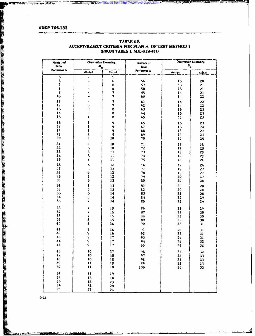
AMCP 706-133
TABLE 6-3.A( /aJE T CRnP.A FOR PLAN A, OF TESI MENIOD 1
(FROM TABLE I, MUS 71)
:umb .- of oi-rv~on Ex ~im Obvstion Excmd g
r l J 13dormd i
56 6 5 6 13 207 6 S7 ! 3 218 6 58 13 21
9 7 50, 14 21U. 7 2 1411 7 61 14 2212 0 7 62 14 Z213 8 63 15 2314 0 8 64 15 2315 i 8 65 :5 2316 1 9 . 16 2317 1 9 67 16 24
1 68 16 249 2 9 69 !7 24
21 0 70 17 -5
21 2 10 1 172z 10 72 r 17 25
23 3 1 73 1 8 252 4 1 i7 l e 25
4 7 18 2626 4 Iz 76 19 26
28 4 1 i b9229 ] 5 12 z -9 20 -T7
30 5 13 80 20 2831 5 13 82 2 '11 2832 6 13 82 20 2833 6 14 83 21 2834 6 4 84 21 2935 7 :4 85 21 2 "36 1 15 86 22 2937 7 15 87 22 3038 7 15 88 j 309 8 15 89 zz j 3040 8 16 90 23 31
41 8 16 -) I3 "I4-' 9 16 92 31
431 133143 9 17 93 24 3144 9 17 94 24 3245 24 32
46 10 17 96 ?5 3247 10 18 97 25 | 3348 10 1s 98 ?5 3359 11 18 99 25 33so 11 19 100 26 33
51 1i952 12 !9
53 1254 z 20
55 --2 2 _
Downloaded from http://www.everyspec.com
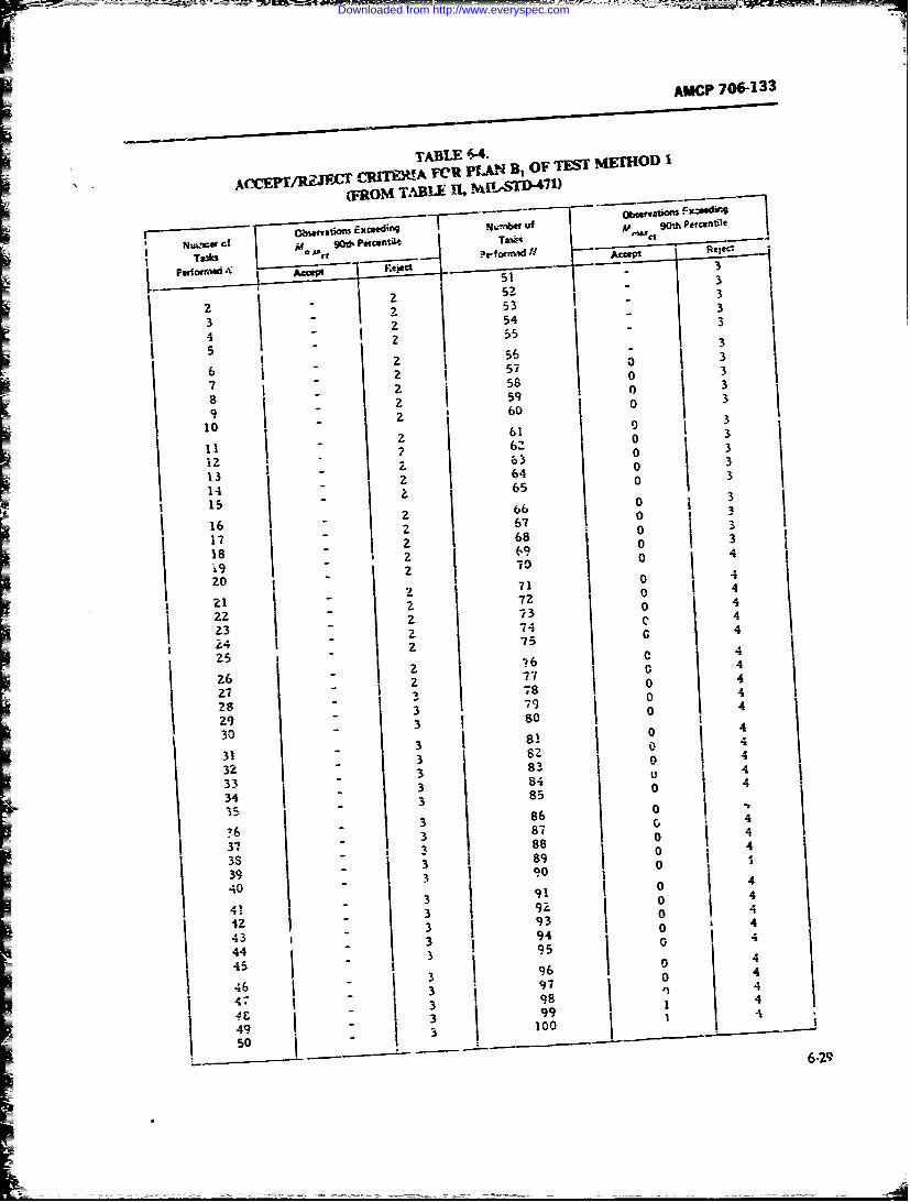
AMCP 706-133
TABLE 6-4-
Cr CRWOUA TClt PLAN B, OF TEST METHOD 1
(FROM TABL- i-SD 47 1)
Nuc Cn sn' 90 (t pvI,*a of 90th Petct --
-o " ' Al - R*- -1
5? 3
3 z 54 3
4 "555 56 - 3
2 0 3I 37 583
T= I -
? 6110
59 09 Z ' 60
2 3I I - 61 3
62 0 A4
013 2 64 0 314 Z6515 866 016 " 67 O
29 - 3
17- 2 68 0 3is 2 69 0 4
I f 9 2 7 04
20 - 02 0 4
I -83
2:1 - 8 6 0 4
3- 74 G 4Z 4; 755 6 4
390 426 4 77 0 4
91 7 04
28 _ 8 0 429 3 so I30 - 0 43182
4
3 "32 3 3 u 433 3 84 0 4
34 3 85
35 86 0
_ 3 87 4
63 0 4
37 1 3 8 8 o
38 3 890
39 1 - 9040 91 0
43 9 0
4! 3 9Z04Ig 3934
43 3 95 0
44 "3 945 9604
3 60 4
46 3 97 q 4
' 47 3 98 1 4
! 49 1 00
50
~6-29
Downloaded from http://www.everyspec.com
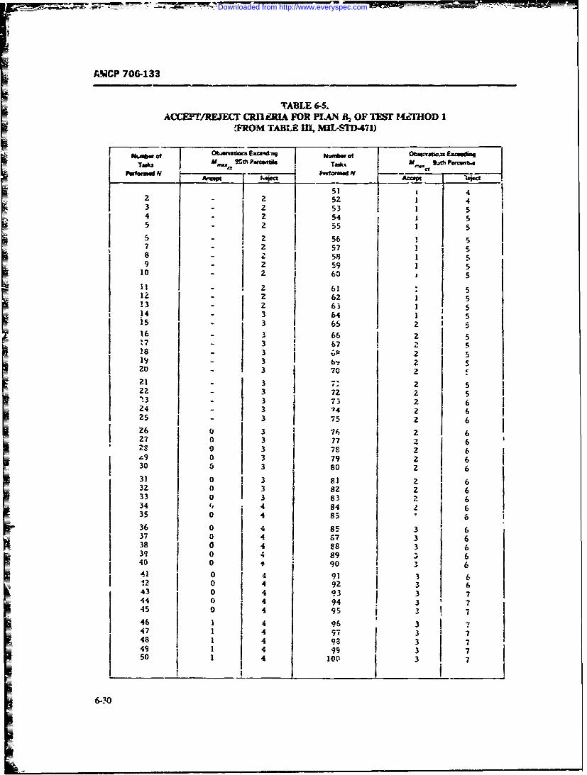
&MCP 706-133
TABLE 6-5.ACXEPT/RFJEC' CRFl A FOR PLAN i 2 OF TEST P4.FHOD I
FROM TABLE I MIL, SDI471)
fib Of 0bAunags EXCIng J Nurubw of j 0mvvaon EzcsnTeks I M - ism fi o Taks m , "i.Ah ParcenbA
P formW N - Pefotm d N
51 42 - 2 52 43 - 2 1 54 - 2 54 55 - 2 55 1 55 - 2 56 ! 57 - 1 5!
2 57-8 - 2 58 159 - 2 1 510 - 2 60 5
il - 2 61 * 512 2 62 1 5!3 - 63 1 514 -3 64 1 5
32 - 1 3 c16 - 3 2 517 - 3 67 2 528 - 3 75 2 6
26 3 70 2 621 3 7= 222 3 72 2 5- 3 3 73 2 6
24 3 74 2 625 3 75 2 626 0 3 76 z 1 627 0 3 87 2 62 O3 78 1 2 6
39 0 3 79 2 630 5 3 so 2 631 0 3 81 2 632 0 3 82 2 633 1 o 3 83 z 634 4 84 2 635 0 85 ' 636 0 4 85 3 637 0 1 4 87 3 638 0 4 88 i 3 639 0 4 89 3 640 0 90 _ 3 641 0 4 91 3 6= 0 4 92 3 643 0 4 93 ! 3 744 o 4 94 3 745 O 4 95 3 7
46 1 4 96 31 4 j47 1 73 7
48 1 4 98 3 7
49 1 4 99 3 751 4 100 3
6-.20
Downloaded from http://www.everyspec.com
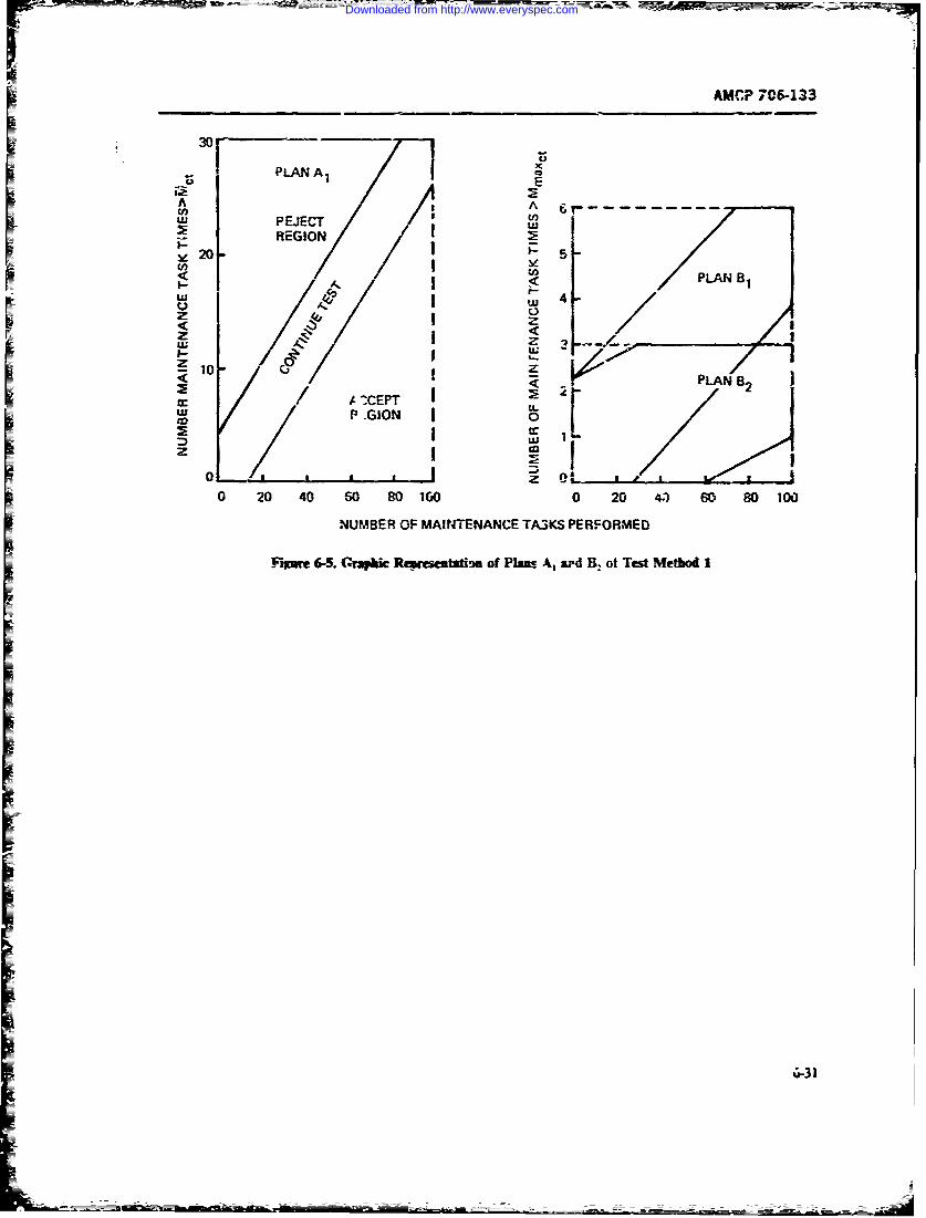
AM(P 7It06133
PLAN A Ex
A IsAwPEJECT I
REGION _
< PLAN B2
P eI0
z z .
z0o 204 2 Z 6 00
UMBER PLANS PE8RE
J~mM 2r~~cPa~A ~4Bo etMto
AIXPTLI IOI u
Downloaded from http://www.everyspec.com
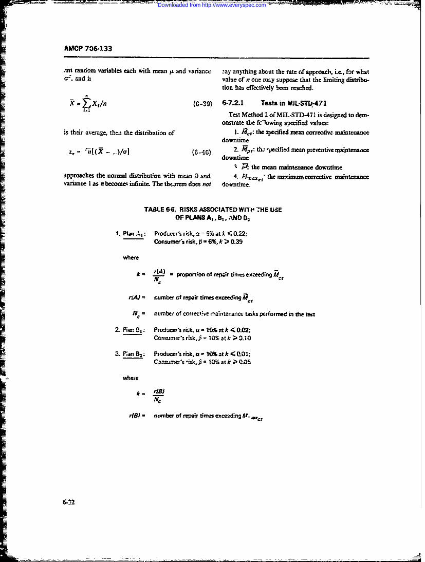
AMCP 706-133
.mt randorm variables each with mean iiL and v.ariance --ay anything about the rate o~f approach, .e., for whata,, and ai value of' n one muy suppose that the limiting distribii-
tion ha- cfkctfively been reicheui
X jIn (G-39) 6-7Z2. Tests in MIL-STU)471Test Method 2 of MIL-STD471 is designed to dem-
onstrate the fcowing s~xifled values:is their average, then the distribution of 1. Mt,: the secified mean corrective aitnac
downtime
Z, 4x.M(6-40) 2 Mp: t- -ecfidmean prevntiv aintenacedo-wntime
~ the mean maintenance downtimeipproaches the normal distribution with mean -3 aind 4. Umlr the maxinm corrective maintenancevariance I as n become- infinite. The th',rem does not do~tntine
TABLE 6-6. RISKS ASSOCIATED WIT" 7HE USEOFPANdSA,. 1, v;ND )
IPlan.;,: Producer's risk, -2 = 6& at k < 0.22;Consumeris risk. A = 6%. k>~ 0.39
where
k !IJ=proport~on of repair tirnks exceeding JtNC
n:A) =rnumber cf repair times exceeding Al
N, = number of correcte m~aintenance tasks Performed in tha test
2. Piar B%: Producer's rik. a =10%.vt k < 0.02;Consumer% risk, 10% at k > 3.10
3. P'an B2: Pdu's risk. Z 0% t k < 00' ;Canumersk 10% at k > 0.05
where
r(! number of repair times excanzfing U- hIC
Downloaded from http://www.everyspec.com
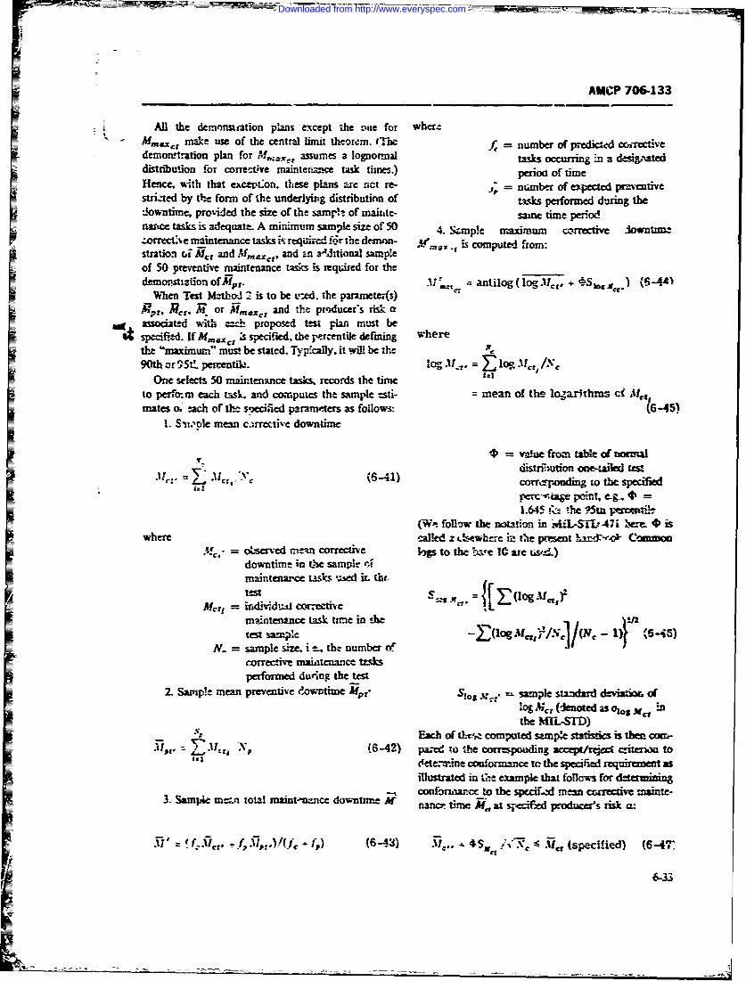
AMCP 706-133
All the demonsmation plans except the rue for wher-.Mm .ct make use of the central limit theorem. IThe number of prjij ccnr etiv
demortration plan for M,. assumes a lognormal ta occrng m a desi&-ateddisuution for correctve mainetance task times.) perioc of timeHence, with that except'on. these plans ae nct re- = ntmbr of expected preventivestriated by tt"e form of the underlying distributinn of tasks performed during thelowntimr- provided the size of the sam-in of maiute- same time period
nance tasks is adequate. A minimum sample size of 50 4. "S ple maximum corrective iow tmzofrect:e maintenance tasks i' re "& d ifr the dem m " A is computed from:stntio- , MoJA, and , and n aaJtional sampleof 50 preventive maintenance tasks is required for thedemonstiation of.e,. M . antilog (logMcg, +-S~ gj) (31-A
-When Teat M--thoW 2 is to be ined. the paramees)Mt. M,. or . and the prucers risk a
lg associat-d with =-I proposed test pla must bespIified. If MV.=€: ;s spe i ued, the p aracenik defining where
the "maximum- mus! be stated. Typically. it wil be the90th or 95tL perentle- log 31 .= Io 31I /.'
One selects 50 maintenance tasks, records the time f*
to per.bm each task. and computes the sample esti- = mean of the lo.,arihms cf Mtmates o. each of thl- so-xified paranviers as follows: (6-45)
1. S-,.te mean c.irrective downtime
40 = vwjne from table of wr'-W
distrFiition one-tOed test: .-. =: Mc,,-c (6-41)
(Wit follow the notation in 'iLSI,7 emi * iswhere called z 0-sewhere ie the present hadN ommoin
- - ,e corrective 9p to the bse 1e0 are nse)downtime in the sample r4maintenaxce tasks zscd it. th-test S=S = (log
mintenanct task time in the ,Utest Sam* - log Mf 'I (Nc-
N. = sample s i -. the numbercorrecte ma itenance tzsksperformed duing the test
2. Sample mean preventive dow M ' Sk... sample standard d-iat of
in A;, c(eted asoal,S jwithe MIL-STD)
Each of ttv. computed sample sta is then com-Ai,~ L.0.a d x\ (6-42) pared jo he coqrres;ponding accep/e~wc citemm to-4 ete.-ine conformance to the specified requir t as
illustrated in e example that follows for d.te n3. Sampe m-,n total mamt-mnnce downtume 2 o 'u'c to the spcif..xl ccmctive maiwe-
nanicr time M.at s-iflied produces risk a:
.*" G)._.,-., t.,.i/ , (-+_' .++, l.+- i (Sp fed) (6-A
j6-33
I --- - -"+ ... ..- -?
Downloaded from http://www.everyspec.com
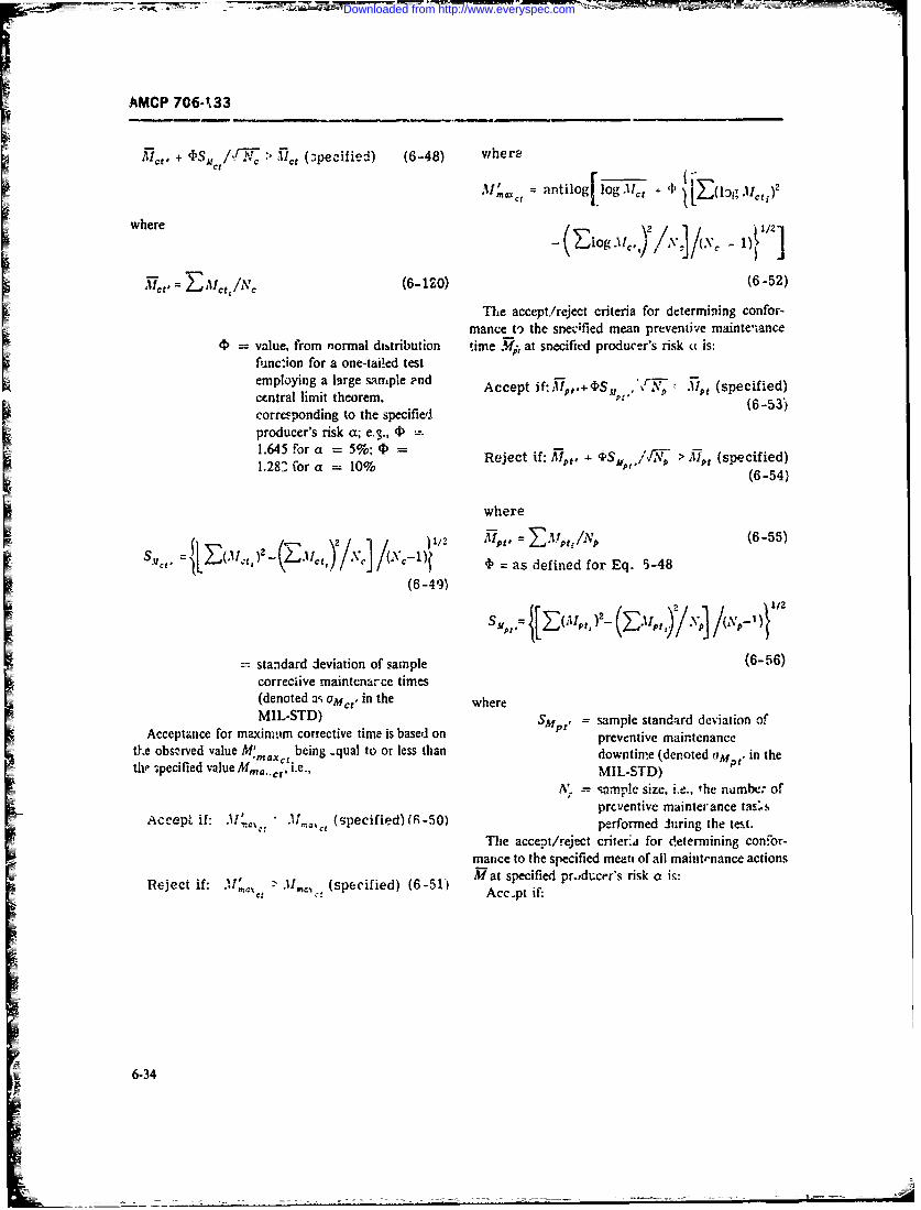
77- 7 =-
AMCP 7064733
T. + IDSM, /fkTI > 'I1 (z;pecified) (6.48) where
Mna antilog 1ogI~ . 'F;
= where 1(/ig.i.)2\](\ 4
=T~t ZMlct /NC (6-120) (6-52)
The accept/reject criteria for determining confor-mance o the sr&eu;fed mean preventive mainten~ance
4) value, from normal dittribution time M-i at snecified producer's risk u is:func'ion for a one-tailed testemploying a large sample -nd Acceptcified) t
central limit theorem. A c~4 (specified)+ DSv,,,,
corres-ponding to the specified (6-53)
producer's risk a; e.3., 4P
1.245 for a 10%P Reject if: TiM,. 'Ps 'fi. > M (specified)1.2C(or 10%(6-54)
where
(I ' /T , 2 /* . )1/2 -U1, E-IZfAV1/ (6-55)
mcf [ pLL3 ,)kJLc.Ic ,(ll)b' = as defined for Eq. 53-48
(6-49)
=standard deviation of sample (6-56)correciive maintenarce times(denoted a-; am,,,, in the whereMIL-STD) SUP,=smlesadr dvaino
Acceptance for maximvim corrective time is based on p prevesampe antevatnc ofth~e obsnrved value M'm being -qual to or less than dwtm dntd i h
the 3pecified vleM,.,ci.e., MIL-STD) P
A'. ,.samne size. i.e., the numIbc-. of
Ac~et i: W 50)prcu.entive mainterance tas.sAccepfid)L iffome .1!' ,., the tenst.
The accept/reject criter:4 for determnining cont-or-manc tothespecified mean of all maintrnance actions
Reec i:(specified) (6-51) M tspecified prodderr's risk a is:mat Acc.pt if:
w 6-34
Downloaded from http://www.everyspec.com
AMUF 706-133
Accept if: X, = the CMDT used after the 4h{1 flightL P n = number of flights
+ I/[NC NP1 f + fo)i tZ X = 'ican of sample of n CMDT's
M (speAfied) k6-57) = ( X i)/ni. I
S standard deviation of nCMDT's
Reject if:
=S
-. S E(X, -X (?( - 1)] (6-59)
> M (specified) (6-58) . i)(
z. = standard normal deviatewhere exceeded with probab'lity a.
S= mn ber of expected corrective Table 6-7 siLowing a ,s z,maintenance tasks occurring follows.during a representativ The test procedure of MIL-STD-473 tests the nulloperating time T hypothesis
4 = number of exp "ed oreentive Ho: M < Momainten-nce tasks occunins against th" alternative hypothesisdurii.R a representative H,: M > M,operating time T The sample siue n required to implement the test is
&nd all other symbols sre the same as previously de- given byfined.
6-71.2 The Test of MIL-STD-473 m (Z )- r (6-60)
Waile the test methods of MIL-ST-471 bas,.A on m . t - o/olzthe Central L;nit Theorem control on2j twe producer'srisk a the test method based on ihe Cent-'al LimitTheorem that is described in MIL-STD-473 controls Eq. 6-&) involves:the consumer's risk /3 as well. The methods of MI-hSTP-,71 specify a sample size of 50 fc: each procedure, . at , the producer's risk, which is the probabilitywhile the method of MIL-STD-473 has a minimnum th.t the null hypothesis will be rejected when, in fact,sample size of 50. it is true.
The notation that follows is needed to describe the 2. 13, the consumer's risk, which is the probabilityprocedure of MTIL-STD-473. The p.-ccedure is phrased that the null hypothesis wi., be accepted when M -in terms uf chargeable maintenance downtime M, has some positive value.(CMDT) per fight. 3. or, the population standard deviation of CMDT.
M true, unknown, mean CMDTper flight Generally, ,r will not be known, I ut will have to bespecified CMD r per flight determined on the basis of previov data, maintainabil-
,= true, unkno in, standard ity mathematical r- vels, or a specificatiot, t,..1uire-deviation of CMDT per flight m!n!.
6-35
Downloaded from http://www.everyspec.com
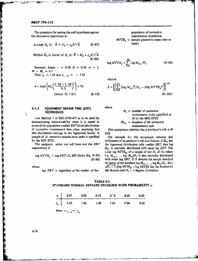
AMCP 706-133
The procedure for testing the null hypothesis against population of correcti'.ethe alternative hypothesis is: maintenance downtimes
M7TRg sample &,tometric mean timr- to
Accept Ho if: X -'11 + z.ln (6-61) repa'r
Reject Ho in favor of H, ii: X > M0 + Sln
(66) log MTTR,, g gM,,/ N, (6-65)
Example: Input- 0.10, /3 0.10. a* 1,M - M = 0. 3
Then z. 1:.28 and 2-.. -p1.28where
n max50,(L 8j2) + 73g~. 2 N - 61%
6-7.3 EQUIPMENT REPAIR TIME (ERT) whereTECHNIQUES N,= number of corrective
--';n-.enancc- #x-ks (Gpecificd as'iest Method 3 of MIIL-STD-471 is to be used for 20 in the MIL-STD)
dmntaigmitiaiiyweiisttd in The = duration of i&corrective ntem o h pplainindanE oftedistribution maintenance task.
of trrctie iaitenwz do%-,im, asumngthat Th1is accepance criterion has a producer's risk a ofthi dstrbuionbeong t th lgnonil fmiy.A 0.05.
sapeo 0-orciemit=.netssi specified Th rainlfutiscepne relo ad=by the MIL-STD). verification of its producer's risk is as follows. if J~ a
The equipnien under tebt will have met the ERT t he lognormal distribution with ~iedian ERT, then logrequirement if Af,, is noriiially distributed with mean log ERT. The
i..eani log MITRg, of asampie of size N, of the valueslog MTTRr -< logER T +0. 397 S(see Eq. 6- 65) l'jg Me,..' log MtlIN, is also normally distributed
(6-64) with mean log ERT. If S denotes the saniple standarddgriiation of the numbers log Mct,, . ., loj M.rAc theni
where v ,-1 I log M71'Rg - log ERTJ1S has the Studcnt's-ilog FR T = logarithm of the medial- of the dist -ibution with IV, - 1 degrees af freedom.
TABLE 6-7.STANDARD NOR.MAL DEVIATE EXCEE)J)F WITH PROBABILITY ce
a 0.01 0.05 0.10 0.',5 0.20 0.30
za 2.33 1.65 1.28 1.04 0,84 0.52
Note:Za a
6-36
Downloaded from http://www.everyspec.com
AMP 70& 133
Thus one rejects the h-,pothesis that mnedian correc- hypothesis holds.) Of course, one should generally us-tive maintenance downtime does nol. exceed a specified a distribution-free procedure when h,: had ao basis for
level ER Tin favor of the alternativu hypothesis that making specific distributional assumptions. Thi.- stzte-median correctivt maintenance dowitirne cks exceed ment is inade on the premise that a valid procedure:isERT based on a sainp!e of size A', and with a produ- preferable to an invalid one, even though the validcer's risk of a if procedure may involve a lerger sample size thani the
invalid one. One exc('3tion must be noted to this dic-N'1_q;=f (log MTTR, - log ER T)/S ctN.e1, turn. A number of statistical procedures &rc insensitive
(6-66) to certain departures from assumptions used in their
where t~ -1 .) is the value of a random variable topic is considerably advanced beyond this hand' )ok,
distrbuedas §tudent's-: with Nc - 1 degrees of however.freedom that is exceeded with probability ax. For N, = MIL 5-1D-473 gives one distribution-free procedure20 and a =0.05, we find from tables of percentage and MIL-STD-471 another. The latter also coi.tainspoints of the Student's-t distribution that t(4 9, 0.05) =two orher procedures that are not tests, per se All of1.729. Eq. 6-66 =7x be rearranged to read: these will be described in this paragraph.
Reject if: 6-7.4.1 Prc'cedtire o; i'AIL-ST)-73
logAIT TR, < logERTA + (i~. 2 )/I C Let The a critical mainteniancetime, i.e-. a maximum,(67 value for maintenance time (expressed either in elapsed
time or man hours) that is to be exceeded only infre-quently, say with probability 0.05 or 0. 0. If X'dentotes
Eq. 6-67 becomes Eq. 6-64 if one sets N, = 20 and the rand-un variable, maintenance time. then the proce-Ia =0.05. dure of MIT -STD-473 tests the null hypothesis:Finally, in order to have a consumners risk jS of 0.05 H.: i(X > TI = p,
associated with this procedure, the specified value of ;against the alternative hypoths.s
ER Tis determined by H,: I(X > 7) =p, > p0with p,. p, a (the producer's risk), and /3 (the con-
ERT speifie) 037 ET,~(6-8 -- :r's risk) given. Another way of stating the null ardalternative hypothesis is3 H0 : T =XA,, andH, :
LAE T = X,, where X is the 100(1 - p) percentile of thewhere 2SR T. is the largest value of ER Tthat should distribution of rnainteriancL time. I nis test proc Adure isbe accepted no rri.,rt than 10% of the time and where distribution free, however The form of the distributionthe -standard deviation of the logarithm of Yd, i- taker. need not be seied iorer t pl h etas 0.55. The test proced'ure is to te-ke a sample of size ni of
maintenance tasks. count :he number of these tasks6-7.4 TECHNIQUES WHEN UNDERLYING whose duration exceeds T(denote in~is number by ),
DISTRIBUTIONS OF DATA ARE accpt H. if r _< c and reject H,, if r > c Here cis anUNKNOWN appropriate acceptance number. The values of c and n
are obtained by Eqs. 6-69 through 6-72.The methods described in this para6raph are -tpplica- If 0.20 5 p. 0.80:
ble generally and do not requir. any assumptions con-cerning the statistical distiibution of the time to per-form a maintenance iask. They a-. called Ho: P(X > T) Prdistibution-free or nonparmeztric statistical m~ethods. H: (>T)pl>PThey have the advantage of b-ing valid no matter wl-at H ( lP o ___
the underlying population distribution; their chief n {z '5 _0 -0 - )Zxv~ 0 /ptjisadvantage is that *hey require larger sample sizes toachieve the same power than do procedures whicli (use next higher integer) (-9itiake specific distributional assumptions. (The powe:
_ka staitical test is the pr~bability that it will rejecta nill hypothesir when, in fact, somc fdaltrative anS
6-37
Downloaded from http://www.everyspec.com
AMCP 706-133
c= Czp1 1 ) describ , the procedure of MIL.-STD-4.3,'this method___1 -tests the hypothesis
+ z p po( 1 Z-Po70 z'SP( -P1) H.: fiX > 7) = p,
+ z 0 '1P0(l - P0 ]J against the altenativcH1 : (X > 7) > p.
(use next lower integer) (6-70) at a producers risk of a.MIL-STD-471 considers only p. = 0.95 and
If p. < 0.20, cand t. are the smallest integers satisfying po = 0.50, with a = 0.25 and a = 0.10. A simplesize of n = 50 is quoted for all procedres. 'Me num-ber r of maintenance times in the samp'se of 50 which
.e"eO(np 0)/j! >- - (6-71) -ceed the critical time T is determined. The nullLzo hypothesis Ho is accepted if r 4 c; Ho is rejected if .
c. he value of the acceptance number c appropriate tk.Po = 0.95 is for a test of a specified value T=M,.ncr
and orT= .Mmaxpt, the v.ue p, = 0.50 is for a test of themediars T=Mct or T=MP(.
e'nhYl .<. (6-72)Jzo 2. Method 5
Table 6-8 solves Fqs. 6-71 and 6-72, and provides the Method 5 of MILSTD471 describes a distribution-values of n and c for p. < 0.20; a = 0.05,0.1G, 0.20; fre tolerance interval based on the larg- and smallest3 - 0.05, 0.!0, 0.20; and k = P/po = 1.5, 2.0, 2.5, obseration :n a random sample. The numbers L and
3.0, 4 0, 3.0, 10.0. The valu of c is read directly fromTable 6-8 for the appropriate values ef k, a, andfl. To Uform lower and uppe tolerance limits with coverage
at least 100Zpe-.cent at probability Pif the probabilityobtain n. read off D from Tablc 6-8 for the appropriate is Pthat at least 1O0Zercent of a population lie in thevalue of k; a, and O; n Ls the greatest integer ises than interva from L to U The numbers L a d Uare batedD/p, For 0.20 :S & " 0.80 the values of n and c ca on a sample X ... .. Xfrom the popuition. A tolerancebe directly computed from Eqs. 6-71 and 6-72. Netc terval is distribution-free if the relatin among thethat the value of n must be otained first from Eq. 6-69; coverage Z the probability Pa and the sample size Nthe computation of c in Eq. 6-70 involves this va!ue of does not depend on the population distribution.a- In this method L is taken as the smallest olervationThis test procedure is based on the binomial distribu- In thi mehod Lis the larg st obse r/ation in the
tion. However, for computational convenience the s mple , and P in oh aues 0bs0r0tion0.99bdeternmination of n and cis based on the nrmal appro--- sasnple. For Z and P taking on: values 0.90, 0.95, 0.99,
etrmnation of ae c b ased! fo n h20a appp. 0.0.forop- Table 6-10 gives the appropriate value of N. Te valuesiai to2 the binormiao fo 0.20 < _ is 0ase for t of Nlited in Tabl. 6-10 are a solution of the equation:5 0.20 the dcten-nination of n mid c is based or. thePoisson approximation to the binomial. (Ref. 16, pp. 409-10)
6-7.4.2 Prucedures of MIL-STD-471
1. Method4:. HO: P(X > 2) = p0
Method 4 of MIL-STD-471 is a fixed sample size H: P(X > T) > Poproceduare which controls the prmucer's risk a, but 'c,the consumer s risk 6. In the terminology just used to 1 - P = Z'v1 (N(1 - Z) + ZI 6-73)
6-38
Downloaded from http://www.everyspec.com
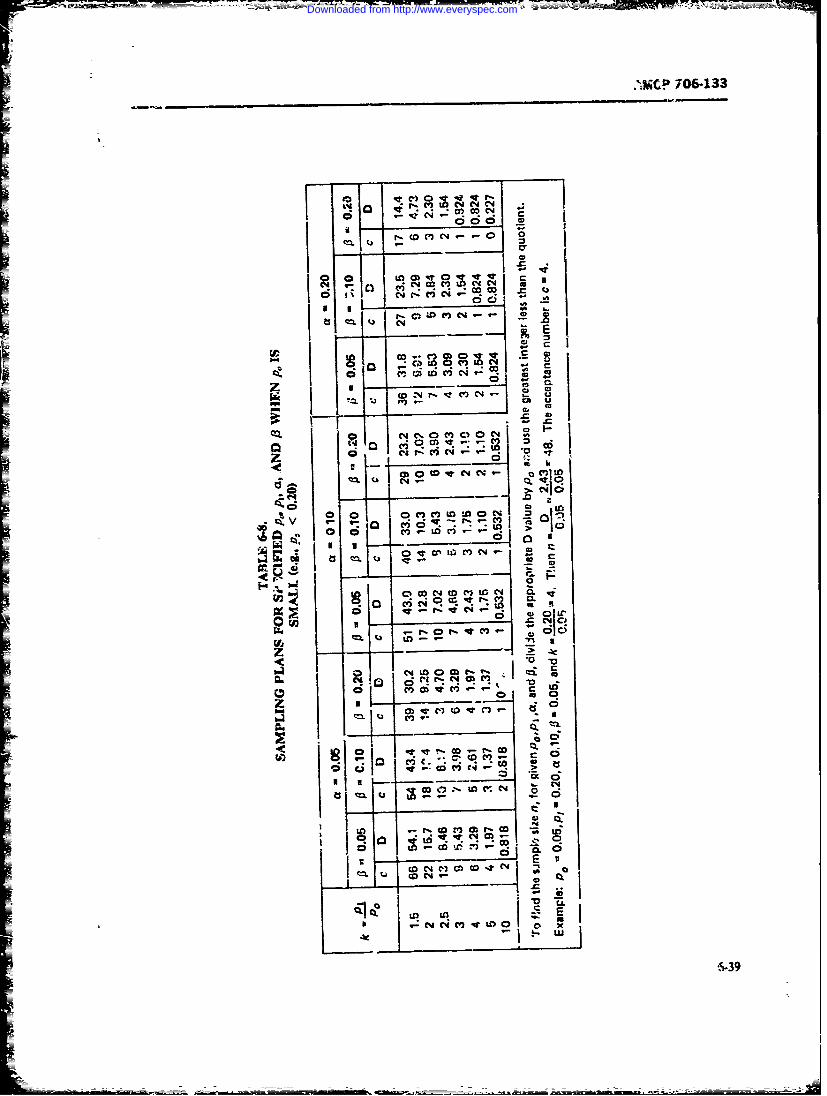
MC 06-133
QX~ u
N Clvt
S N -.. .. ci ci
ci o
CC
C, 0 m
000
d't- - -:Moo >
C4 r
_ -C4 0 o-. 0 r, - .
Qx u......
00Lo 0~2 .i~ C3 QC6 C- r. C Cb V
csr, 0I V)a 46_:3
UtcON,.azI
N~d~IDOI_________Ir: C. M 9
Downloaded from http://www.everyspec.com
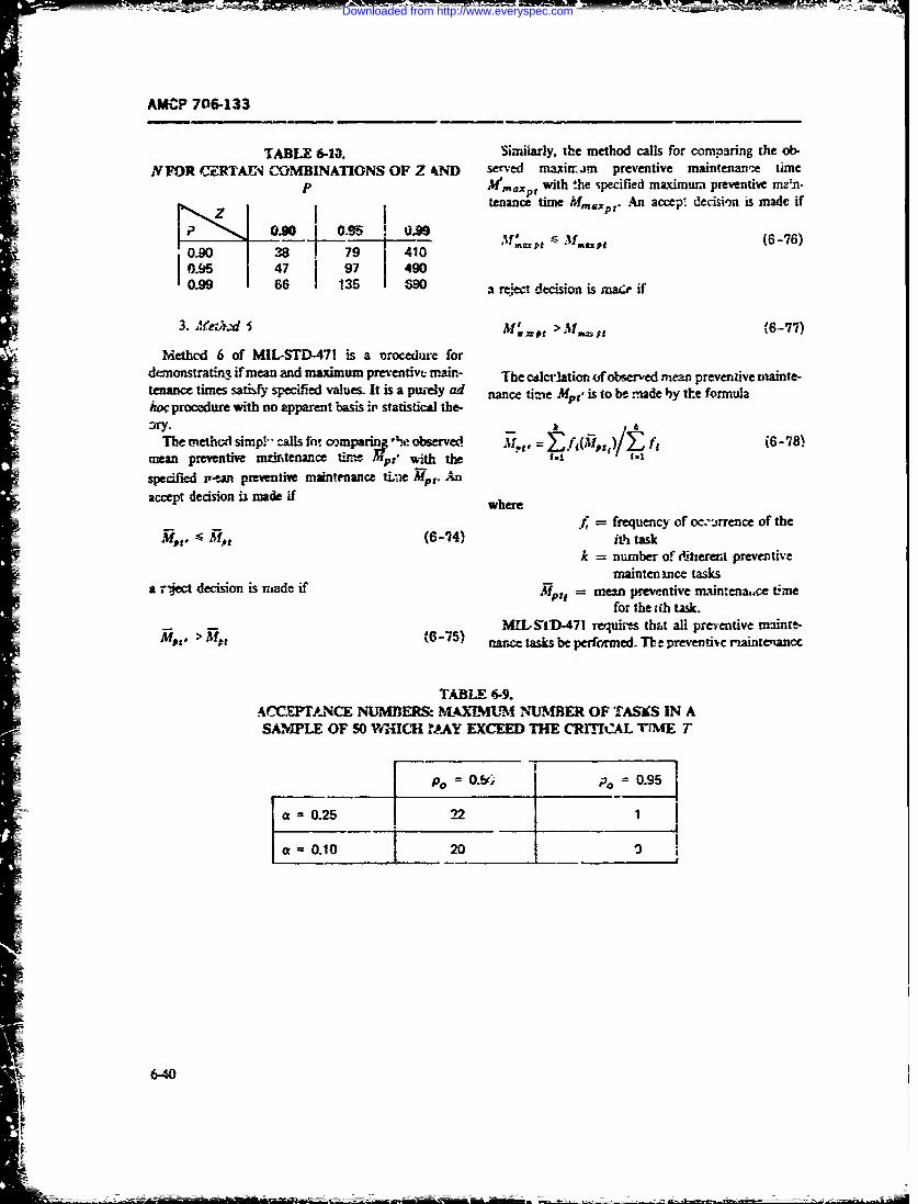
AMC*P 706-133
T iABLE 6-1. Similarly, the method calls for comprying the ob-NFOR C'ERAIN COMBINATIONS OF Z .ND served maxinam preventive maintenan,-e time
P M'maxp with the specified maxim,. preventive main-tenance time Mmaxp t . An accept decisin is made if
0.90 0.9 .96
0.90 38 79 4100.95 47 [ 97 49D
0.99 66 l M35 , a reject decision is made if
3. Mfea..d I M jI z t > M,, t (6-77)
Methcd 6 of MIL-STD-471 is a lorocedure fordenonstratini if mean and maximum preventive main- The caicr-ation of observed mean preventive nainte-tenance times satisf specified values. It is a puzely ad nance time Mpt is to be .ade by tLe formulahoc procedure with no apparent basis it statistical the-
hk
The method simp- calls fn! comparinf "N. observed 114t = f(,(' ), f' (6-78)mean preventive mnitenance t Mpt' with thespecified r,-van preventive maintenance tLe Mr. Anaccept decision ix made if where
= frequency of ocwirrence of the,<P(6-7.4) ith task
k = number of ditferent preventivemainten lnce tasks
a r.-Ject decision is made if Mp ea = men preventive maintena.ce timefor thea th task.
MtIS'ID-471 requh-s thit all preventive mainte-P > (6-5) nanc tasks be performed. Te z preventivc rnaintenan'c
TABLE 6-9.ACCEPTANCE NUMBERS: M-AXLMU NUMBER OF TASKS IN ASAMPLE OF 50 M'UICH ,AAY EXCEED THE CRITICAL TfME T
Po . ], 0.95
1a = 0.25 22j 1
a = 0.10 20 _ . .
6-40
Downloaded from http://www.everyspec.com
- - AMCP 704-133I
task with the longest de-ieoton it to be determined. Ths adi,.4 cy of a fit. T-he only coacisions possible fror..tstablishes a referenc,- period, and ail otier -p-eve:s'ive a test of gtodnes?-ofit are "the datz do not confbimmaintenance tarks Pre selected and apporticaed over it. to the modtl" or "the data do not &*ve oridIence ofNo sample size is specified, It isculd be poinited out nonconformity to the model". It is not possible to con-that no statemients moncernmng or con- chide the edequacy ofa fit, only that the inadequacy ofsu-1Lcrs tisk- u- be made concerning wis method. a Rt bas not been .'-wn. (This is analoous to the
In o-&-- to ca.7ulatc J~',,,one mut specify distinction betweent a -2dicial is-z 4g of -innocent" andwhich poircentle. defines lt mabinitim. Say it is the one of "not guilty').lOO~th percentile. ITha one orders *he r. observed A distinczion 'ietween two kinds of test of fit r;st=
Ptpresventive mainitentance times from shortest to longest also be nade. Given s set of data, cue c~i!testand takesJW ,,P = MUpipy 1 +j- HereMY-ptiis the fh whett !hese came ft-r a completely specified distri-orde-red pznzintiie maintenance time aad [n-yj is tie bution- (L~e, not only the form cr the distribution given.l3Tgest integer contained- in n-Y. For exampile, if n = 15 bat also the vulues of r* its parameters) or mrely fromand 7 0-90, then ivy 31.5 znd fniii = 3L. If, n- iS a given 'amily oniam oms Thus, for example, onle
an nteerth Y ... 1 n't uniquely defined, but could test that % samnle was draw-a from a normalnzay take on any value between M an Cdistr'outioqi with mean 10 and varianice 4, or one- culd(Ref. 16, p- l1O). On)adapl- j test that the sample camne fromn sme normal distrbu-
IkEL As ight b- expec~td, there is a relationship be-
point out where they ire similar and also where disriuc-
nubro the techniques dms~sed in the preced- tins must be ob.;erved.ing parAxmphs were anp!icable regardiess of the disuri- Our disctisao' wil feature a gena - fisession of
bution of the underlying randixn %-Ariable. Other tech- the chi-square and Kc~Imagcrov-Smiruov jproceduimsniquts did depentd on the distribution :)f the random -Ad specifi., discus~noos of tests luf fit for the normal,
' mnx~ sumet' a lognormal distribution for coneu-tiv- m-aintenance task times. Other -ttstca tec. 6-7.5-1 CMi-quare Proceduresiques involve the assumption of a normal distribution Supnwise a set of data is divided into k .ionoverlap-
or in expr-nentWa distribution, to give: biat two ping claisses or celk A,. A,,,.. .,A, such that, togethe-r,,Aexamples. they comprise all possible outcomies of the process
It a particuiar distributieni needs to be asmned in generating the data-, ie., each conceivable datur' wilordtr to -ms a prediction model, ther, scous error-2 fail into one and enly one clams These classes may be
important to have ~cereasonaible assurance thea dis- data are recorded. The idividual dat ieauresnentsn :ribtional assumptions ar- valid. For a treaet Of Deed rot be know3. only the tumber oi abserva~iorts
th s% sof--rosthat cn:sefrom mirpcfcdn Mn roec lm7Wifr pur-posesofa-dof the model, see, for ciamp.e, Barf'ow and Proschan square test, it is only nacessary to kriow a s-:t of k(Rif. 17). aurmbers, n,, r-2, (where n, z !e ntmiber of cbwe-
How can cue be sure that the distributional Is&-=p. vations in class, A), and not the total sample
tions necessary tc, m.plemcnt a t,!st or other statistical rx,procedure art jus~iflcd? On occu ic h mure of the (where N -- nj- - * . .. + ad.Iprocess generating the randmhsia rations is so well We first discs tae cbi-square test that the sampleunderstood that the- form of their probability distribu- comes from I comp&!tey specii-d distribution func-tion may oe taken as known. For cxamzple W &dwa tine f~xC). .er the fo . ofth siui'isk.nand Sltry (ReE 18, pagi. 46) discuss s-riations in and the. value of the I airetemr 0 is known as weil- 6
ki ~~wich the distribution of cetnr downtimes niay be may he a swar quaitu, a th-emrnen in the expooen-assumet I a priori to be exrionctial or lognouminaz (See ea! distributiort; v-- 0. may denote a pair c mn ?bems isalso par. 4-5.2) There are also statistical tests of th~t mean aad vaziance of a norm-i uhitxbutr c-r itwhether a given sample ir associated with a bl)Xiflcd my denote more than two itombems We use our
famly f istibtios.A discussion if some of these knowledge of the distribuqion to calculate p.. (a), th!
Acoit ithoaus be made at the onzset is that a test Suppoij that theupper t~d ower cnd point -if A, ale
Downloaded from http://www.everyspec.com
AMCP 706-133
p )= f(x, 0 dx chi-square minimum ctirnate of V.PThe foregoing often is :umm3rzed by saying that the
enly difference bcween the chi-square tct of a fullyspecifid hypothesis e:.d that of membership i.: family
tt et , (6) and of distributions is that in the atter, one first estxmte.With the knowledge of the pzobabil the parameters and tOen subtracts one degree Af free-observed frequencies ni for the k classes, one calcu- doam for each independent parameter estnated. Whatlates the test statistic A2 (6) given by is lost sight uf in tbis characterization is that the
method of estimation mus be chi-square minimization( {( which involves only the number of observations in :he
classes. If one uses, say, the maxirm likelihood est-mate 6 of the parameter(s), based on the individWaobservations x,, x.. x., the quantity X(0) cannot
.iti..l point of the chi-quare wibution with properly be compared with percentage po'fts of tb:
(k - 1) d:gret cf freedorm. Thus, if the test is to be chi-sqareditibutionwith(k - p -- )egrees of
St te Ma efreedom. (For further details on the correct distribution
hypt-eis that the dta .o fr,m the distribution o xO) iee Ref. 19.)
Kx, 8) is rejcted if Howcvci, for p ictical purposes. it is difficult to cal-
- -culate the miiimum valt of X2(8) without a computer,
and it becomLs a matter of convenience to substitutewhere the nai-m, ;u lkcihood estimate into X2(8) and com-
ist- 100(--o pare the rimulting value wit; t percentage point of !heE isthe 10(i -) perotile ofthe .hi-square ditbu- chi-square dis -oution with (k - p - 1) degrees cf
tion with (k - 1) degrees of freedom. ~ftedom. It is claimed that the result so obtained oftenWhen c-e has a choice of the number of clase-t-, does not differ greatly from the chi-square minimum
when ,he data do not come already groupec he should method.divide the &-;a into, as many classes -s possible, subct Before leaving the chi-square uthod we point outto ihe contraint tht the expe-ctd ithequecy, Npj O), some of its advantages and diadvantages. Its ,ked
tach cass shradbe t lastS. f tr frmig c -* vantage is that it can be applied to te.-t the fit of aan clclzir te M()t itmeb 4tad calculatirg the N 1(Oy's it may be necesaxy to sampe to any distribuion, faly specified or not. Itsomie r'nt to achieve this oncondition.ssan te oitonocmine icuss oa ts cchief disadvantage is its low powcr (..e.. poor ability wo.ME :_- discuss a modific.ation to the chi-square tzst re
of a fully specified hy-pothess neede to make it P_ ect th hypothesis of fit when there is actuully aof wbwther da,- come froai a particular distno=fimal si-;ificant departumt from the hypothesis) ard its d,.-
a ly e se o mependence on the m- o ass And the positonfamu.'. Th. we test, for exampk- whether a s'ample the boundaries between them-can Y'as=Way be suprrsed to come from ome lpo- With tbev genteraities out of the way, we t~w givenetial distribution. matwr than testing that that sam- the formuim for the probabiity conet of the classesple came from the -:jonentil distribution witL given f(" th ne nomal ad lagormual distribu-mean 6.
Nw ifthe parameter o the dist n is ticas, and the Kolmogorov-Smirnov test of goodner-
fled, we cannot calculate the pXO) and taiw not
X'(). The cor.,ect way to proceed is to choose O so isto minimize X.(8). Te resulting min~inum -,alue Last~re ch -square distribution with (k - p - i) degrets 6752 Eypomntial Distribution
of freedom, where p i- the number of iniuepmdent A radom varia31& distributed according to the ex-parametcr invol.ed. The -valIe of 8, say 8', witich ponntial distrbutian with mean 8 takes on all non-ykldthe.ruimumvue of (O ' .(O*) isaed th negazive vlues; iaus Z, = 0and U, =
6-42
I ____
Downloaded from http://www.everyspec.com
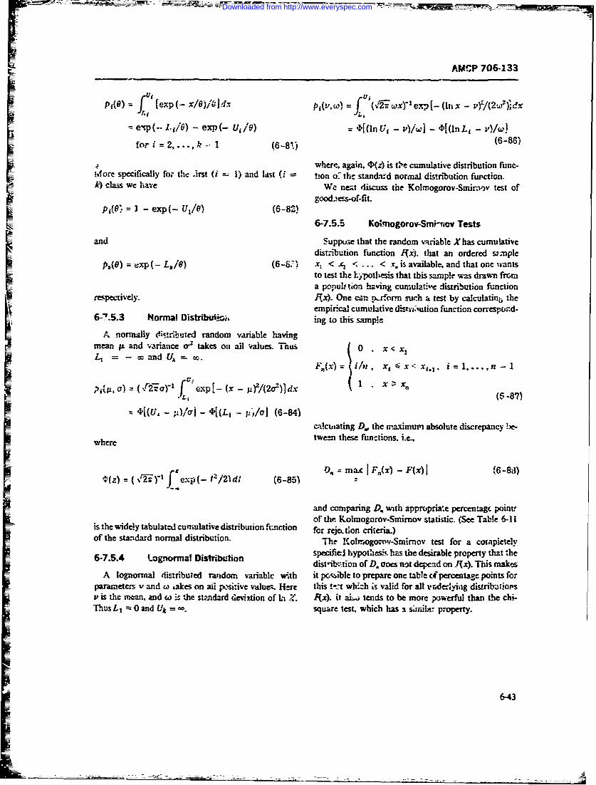
AMCP 706-133
fU'li
fU i
p1 (O) = [exp (- &/Y)]dx P(Mu.) = (-wx)- y exp (In x - vz/(2w5)idxt L1
e.p(-- I. i) - exp(- U, /) = q[(lnU' - v)l - 4[(lnL, -0,1W
2o , 2...., k --1 (6-81.) (-
wher-, again, 4)(z) is ti',e cumulative distribution fune-More specifically for the .irst (i 1) and last (i -on o the standard normal distribution fupction.k) class we have We nez discuss the Kolmogorov-Smirnov test of
goodess-of-fit.I I U1/) (6-8 2) 6-7.5.5 Ko.mogorov-Smihrv Tests
and Suppue that the random variable X has cumulativedistribution function ljxj. that an ordered s mple
pk(o) =--xp(- L,16) (6-S2' x < x< ... < r. is available, and that one wantsto test the I ypottesis that this sample was drawn frcma populiton having cumulative distribution function
respectively. R:x). One cs r!v-orn such a test by calculatinb theempirical cumulative di-strution function correspnd-6-7.5.3 Normal DistribWii ing to this sampie
A normally dis!ibuted random variable havingmean P and 'ariance o2 takes on al tAuhs. Thus 0 x < X aLccadU, *.F,.(x)= i/n , xi< x < xVi.l.i... n-
(st , o)- fve-Kp _ ( /x(r I v )d- 1 x X.• ".r. i(6-87)
4[(U, - v j- 4[(L, - p,/1 (6-84)cwlcutating D., the wmimum absolute discrepancT be-
tween these functions, i.e.,
P. = max I F(x) - F(s)I (6-83)$(z) = ( Jexp(- t2/21dt (6-85)
%
and comparing D. with appropaime percentage point,of the Kolmogorov-Smirnov statistic. (See Table 6-1 i
is the widely tabulated cumulative distribution frmction fer reje.tion criteria)of the standard normal distribution. The Erolmogorov-Smirnov test for a compietely
specifiel hypothesis has the desirable property that the6-7.5.4 'ognorrnal Distrib-?tion distib:xion of D. Oocs not depend on NKx). This makes
A lognormral distributed ratdom variable with it pcible to prepare one table cf percentage points forparameters v and w takes on aii psitive value. Here this t'"t whbiz is valid for all ,r-derlying distribatiopsv is the nxan, and co the stmdard de%!.iion ofL- (x). ita tends to be mote eoowerful than the h-Thus L 0 and Uk=oo. square test, which has s sim;ln property.
6-43
Downloaded from http://www.everyspec.com
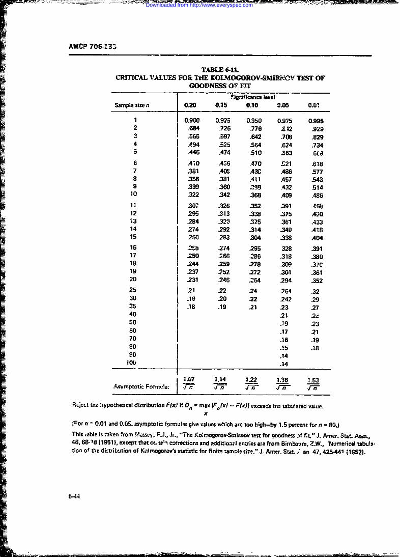
AMCP 706-133
TABLE 6-11lCRITCAL VALUES FOR Ti'E KOLMOGOROV-SMIJI_V TEST OF
GOODNESS O17 FFII Tr. icanne kwe
Sampe sizen 0.20 0.15 0.10 C.05 0.01
1 0.900 0.925 0.950 0.975 0.9952 .684 .726 .776 .42 .9293 .565 $:i97 .642 308 ,8294 A94 .525 564 .624 .7345 .446 .474 510 .63 .6C36 A;0 .436 A70 £21 .6187 .381 .405 A3C .486 .5778 .3.,8 .381 All A57 -5439 M .360 "M A32 .514
10 .322 .342 368 .409 .486
11 .307 .32 .352 .391 .46812 .295 .313 .338 .375 .430s3 .284 .320 .325 -361 .43314 .274 .292 .314 .349 A1815 .260 .283 34 .338 A0416 -.23 .274 295 328 .39117 .250 .266 .286 .318 38018 .244 .259 .278 309 .37C19 .237 .257 272 .301 .36120 .231 .246 264 294 .35225 .21 .22 24 .264 .3230 .19 .20 .22 .242 .2935 .18 .19 .21 .23 27
40 21 .,:50 .19 2360 .17 2170 .16 .19o .i5 .18
90 .1410E, .14
1.07 1.14 1.22 1.36 1.63.As-mptotic Formula: rn Zr r n r -
Reject the .ypothetical distribution F(z) if Dn = max IF(x) - Ffx)I exceeds me tabulated value.x
Cor a = 0.01 and 0.0S. asymptotic formulas give values which are too h;gh-by 1.5 percent forn 80.)
This table is t"aken from Massey, F., Jr., "The Kocrigorov-Smirnov test for goodness 3f It." J. Amer. S- t Awn.,46. 68-'8 (1951). except that ca- Wt corrections and akdditiVo,' emries ar from Birnbaum, Z.W., "urnerici tabul,-tion of the dit-trikention of Kclmogorov's statistic for finite swanple size," J. Amer. Stat. ;asn 47,425-441% 1952).
6-44
Downloaded from http://www.everyspec.com
I AMCP 706-133
A disadvantage of thr Kohno~orov-Smirr.ov test. tziba-i iein,; sampled. rThe latter dependence is note~ati-e to Se c6i-quare test, ia th-! it is rot as ea. presemt for diL':tritioa-fret confidence intervals. These
to mcify it to iest for fit to a family of distrilmion will be discr-.. in his paragraph.) Thus if 0 is thefurctions. T" wever. this defect h.'- bern remrneied for parametcr L the lower confid',nc limit. Uthc upperthe exponential and normal (and h.- sc s lognomAl) confidence limit, ai-d I - a tte confidence coefficient,distri' A-ns. Lil-hefors (Refs. 20 ad 21) has tzb-itrd one can w..tepercentage points of a Kalrmogoov-Smirn-- test forexponentiality arid normality where one su'situtes P(L - 0 - if) I . (6-89)maximum liktlihood estimnates for paramete-s. (To testfor lognormality of a sample x. x, one tests for A une-,sided conirience iatervAl m-t be of twonormality the values In x,.... ,r. x-.) We give Lilliefors" varieties, upper or lower. An upmr, one-sMdedtables of critical points in his Kolmogorov-Smirnov confidence interva: with ,o.I.,-dnce ccff:-i:nt I - atests for exponentiality and nefrnahliy in Tables 6-12 for the parmelc is deterrninei by the upperand 6-13, respectivdy. Lilliefors writes N for sample confidence limit U. These ouantitie are interrelated bysize and SJx) for the empirical cumulative distribution w einstead of the nand F.(x) tsed earlier in this pmragrzph.His P(x) is the cumulative distribution function cf the P(O z U 1 - (6-90)family under examination with maximum :keiood= -estiz rtes substituted for parameters.
We close this discussion by gvring some r'efrce. to Similarly a bowe-, one-sided confidence in.'.val withadditional tests offit as well as toadditional discus-: confidence coefficent I - a for the parwmeter 0 isconcerning me chi-square and Kolmogorov-Sminov dete-mi-,ed by the -ower confidence *ii L. withtests. They are Chapier 8 of Hahn and Shapiro (RE.22). and paper _y Epstein (Ref. 23). Chapter 4 of Aitch-ison and Brown (Ref. 24). and the references containted P(9 > L) = 1 - 5-9.)
therein
By ;he 00ttb perocntile ofa random variable Xw ,
6-8 CONFICENCE iNERiALS FOR .,can a number . zuch that J!X < ) -t q. ie..
DEMONSTRAT!ON METHODS :0Oq percent of the population lies below trWith th se defi-nions set aown. we ncw eJh'btt up-
Pmrameters describing a populatdot charmcristic, per and lower confide.e inter-'ls for tar,'neters of as mo ie number of ais-ibut;-n furctions. We ._ns,-- r the
suh psmea n o ad -. e maintenab doatimeakmi mean and percentilet of the normal, lo~xornl. ant:are t-Jdom known and are etiated by a corresp - exponential J.vributions, as well as the parameter ofing quat.ity in a samfe drawn from the popu!ation the binoin -. distnbution. Additionally. we introduce(Me, in the. case of .-. ). This yields a single number. t"caleda oin eftail- s n etiemef t---poplaio the concept of a tolrance ira l and rval-t- it t hit,called a point erti.ate as an estimate of the po?'.ion of a confidence interval for a percetiie Finally. we
disotv dist-ibuticn-free confidence anu tolerance in-To cite only a singie number a an estimate of a
populaticn parameter gives ro indication of the preci-sion of that estimate. Accordingly, atiktici:6ns havedevised the concept of a confiden- inte~re l to giv a 6-.1 NORMAL DISTRIBUTIONrange of values, not merely a sinile value, ta estimate Two cases must be distinguired .hee ie, thm popu-a population pammete.. Associated with each 'n-#hod i -rianc o'- known i-d o2 uniknown.of determining a confidence interval is a nmber calledthe confidence coefficient. ,-he confidence coeficient isthe probability that the method )iids an interval whichcover the parameter value. A two-sided confiderme interval with confit -ce co-
Confidtnce -tervals are of two kinds: two-sided, and efficient 1 - a fr the mcans t of a normal di.tri-tutkrnone-sid d. A two-sided confidence int-rval is de-Ined with known v.-.ri.:uce & 2 is given byby a lower conlid.-:ice limit Land an upper confidentcelimit U Both L and U depend on the .&mple valuedrawn, the desired confidence coefficient, and the dis- X. - ,Zaf < . . K nrGI/ %6-92)
6-45
- -=---.~ mak-
Downloaded from http://www.everyspec.com
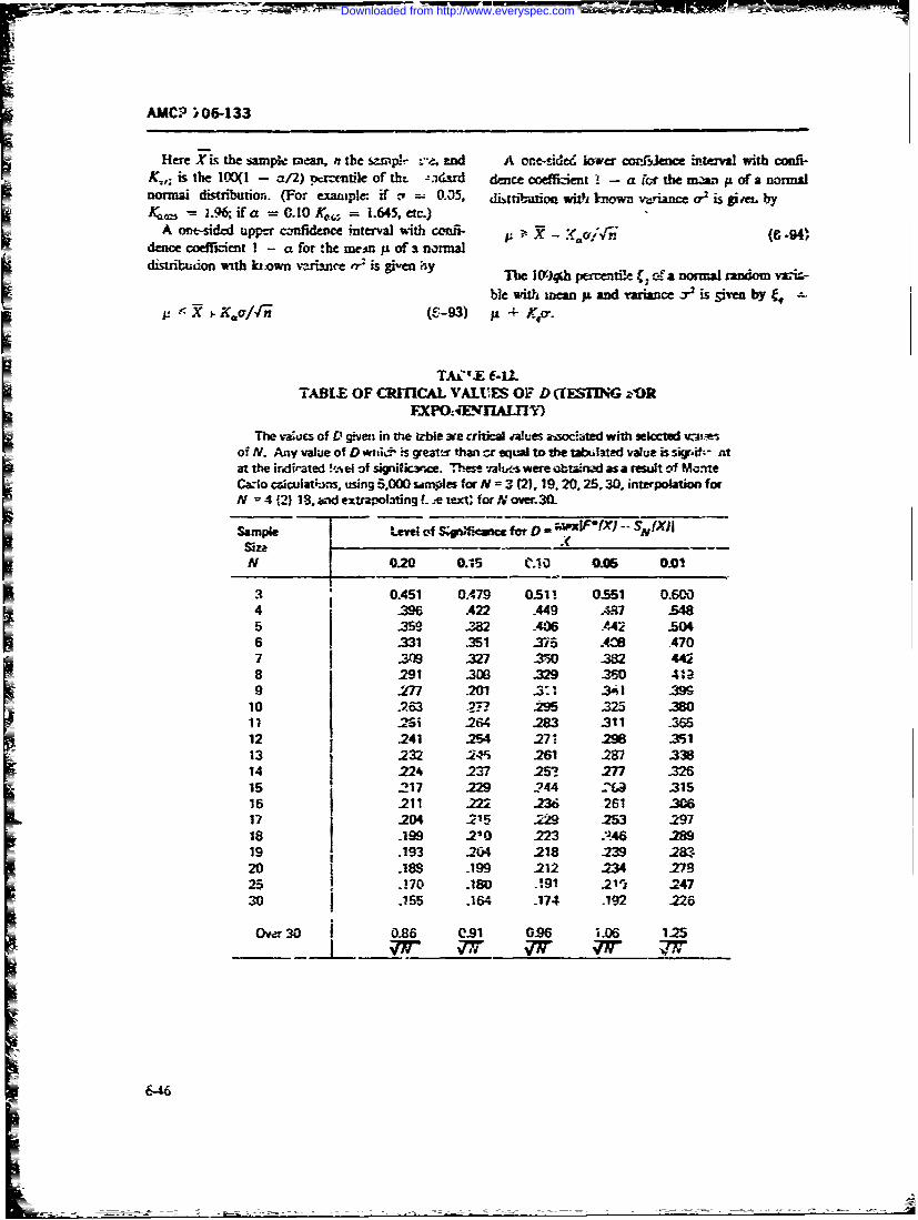
AMCP )06-133
Here Xis the sample men, n the sawp r -- , ed A one-ie lower corlrence it -val with confi-K,; is the l00( - al) pcnxnrile of tht -zadsrd dence coeffiztin - a for he m.i ofanormalnorm distribution. (For exanaple if .- - 0.35, LNtbutio with known variance o9 is give, byKoo, - 1.49, ifa = 0.10 40 = 1.645, etc.)
A o-sided upper czfldevce interval with COM.l X - (C -94)de coe-rint I - a for the me:n p of normal
TAC'.E f-12.TABLE OF CRITICAL VALUES OF D (fESUNG rOR
FXPOA4" M'AL17 IThe -iucs of D given in the title we crtial Mues asociated with se lcted wiz i
of N. Any value of D wtnoi is greatx than cr eqWal to the tabuaed value is si',if.- ntat the irndirated !,el of signific-re. Th es vabus were 63an ad as a result cf Mo-neCW-o ciculatkrns, using 5.000 samAes for N = 3 (2),19.20.25.30. interpolation forN =4 (2) 18. and extrapoating Le tei; forxover. 3
Sample tuveleM of ln;r for D -h I,.fx -- SN(X)Isize XN 020 0.15 tio 005 0.01i
120.451 0 79 051i 6151 04 .0 A22 .449 27W -U5 317 2 -406 .A2 .316 331 .351 35 .261 .3707 ---n -327 ...'k 3V2 442
8 .291 230 .329 260 4919 .27 2'0 .23. -4$ I ;
10 963 .274 .295 -25 8O20 1 1 i .264 212 311 3i 12 .241 25 .271 2W ,35113 .232 IN'S -261 M28 .338
14 .24 -237 -253 .27 -326is .217 .229 2'_44 -'ta .315
16 .211 M 236 .261 -3V0_17 .2M4 .215 .229 M25 .297
is .199 210 :223 M419 .193 20 4 -218 .239 320 .i8s .199 .212 23 725. 70 .180 .:91 211 .247
30 .155 .164 -174 .192 -226
Over30 0.86 0.91 0.96 1.06 125
&46
Downloaded from http://www.everyspec.com
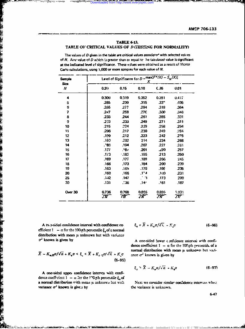
AMCP 706-133
TABLE 613.TABLE OF CRITICAL VALUES OF D CESfING FOR NOR-ALITY)
The values of D gven in the table are critical values associalt& with selected valuesof N. A-v value of D whi :4 greatt than ot equal to he tabJlated value is significaitat the indicated level cf sp.ifkaice. These vilues wore otLnwd as a reslit of Mcnte
Carlo ci!llttions. usng 1,000 or more sapes for each value of N.
Sample Lern of Sirinfa for D = !FiX-SnhXIsize - -
N OZ.) 0.15 0.10 C.35 ;&01
4 0-3DJ 0_319 0.352 0.31 OA4175 285 239 .315 -337 .405
S.65 .277 .294 -319 -3647 t.7 .58 _7r :90W048
8 233 .244 261 285 .3319 223 233 249 271 .311
10 215 -24 239 258 29411 .206 .217 230 .249 1Y8412 .1('9 .212 223 242 .27513 .':9 202 214 .234 26814 .183 .194 -207 .227 .261Is i!7s; -1.r -201 ,2 -25716 .113 ".18:2 .195 .213 .3.517 .169 .17i .189 206 245
18 .166 -173 -184 .2W -23919 .163 .16? .179 .19E 23520 .160 .166 .. 1!,V 231
25 142 147 "71 .173 20030 .131 .36 .14" .'61 .187
Over 30 0.736 0.768 0.8Z5 0S8fi 1.031
A m -sided confidence interval with confdene m- C 'uRK 8-6
dflct I - aforthe OD apercentiletofznomnKaI
distribion with mean p, unknown but with m-tiince-r known is gvn by A one-sided lower c ;nmfenc incr- ith confi-
dence coefficient I - a for the 100@ r-rccntik of arx-mal distribution with mean p unknown but tai-
X - K./r#if . K cr < It. < X + Kl/€ , .o nncecr known is gi-en b(6-95)
L~-Ko~~i K~a (6-97)A one-sided uppet confidence interva wi;h cfc -
dencecodciait I - aor the P - -.h pertilE,&fnormal fwlkdbtmonw rith mewAn n knowi; but wibh Next we consider sunmila- csni;c rcr-.t,-s wbc4
varbnce a? known is giwi by Lhe .rancr e is unknown.
6-47
Downloaded from http://www.everyspec.com
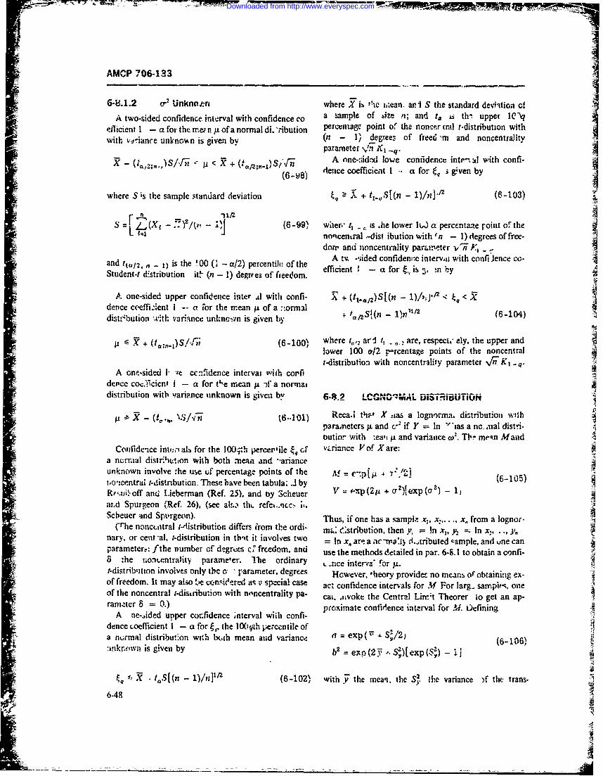
AMCP 706-133
6-8.1.2 C" Unknopri where X ie iaean. aniJ S the standard deylition ofA two-sided confidence interval with confidence co a sample of size n; and r. is th'. upper lQ'tq
ellicient I - a for the inef ii p of a normal dL 'ribution percentage point of the noncor tral t-distribution withwit vaiace nkn~nis ive(b - I' dego_,ee:, of freed -nm and noncentrality
parameter Vn 1 _q.
X -( ;AS/f < X_ 5 + A one-,,idod Iowe confidence inte- :l with confi-
(6.-A) detice coefficienit 1 -- a for t, s given by
where S is th~e sample standard deviation X + .i.~ '( - 1nP' (6-103)
s r 21, (6-9M he. t s .he lower Iu.W a percentae roint of theL. nocnta 4.is; ibution with (fl - 1) degrees of free-
dorn and noncentrality parin~eter v~i-n ,
and ~J2..~~ i the100(~ a/) pecenili ofthe A tv -sided confiden::c interv, with confi Jence co-Student-i d&stribution it (ni - 1) degrres of ftcedom. efcin -afo is n1'
A one-sided upper confidence inter Ai with co~nfl- X+ (t1.. ,2 )Sf(n < )~'dence ceeffi-lent I -- a tror the mrean iof a :-.ormail
= ~~~dist!bution with variance unkznc~rn is given by */t 2Sn L ) 1 1 614
SX + (t." 1 )S/f;?; (6-100N, where t,,, ar t1 , are, respect.- ely. the upper andVlower 100 a/12 p-rcentage points of the noncentralt-distribution with noncentrality parameter %f/W K, q
A one-sided I- ve ccnfidence intervai with co.'fidence co&.' cicnf I - a for t~e mean p± -)f a normaidistribution with varipnce unknown is given by 6.4.2 LCGNO" AL DiSThiELM~ON
I' X - (ta., vS.f6..1 01) Reca'. th-et X aias a logn'orma. distribution withparamreters pi and cr' if Y = In 'ias a nic.aial distri-outior wi.1th .ea't j± and variazice w2. TI"~ mrean Mand
Confidence intin.ialb for the 10.h percermile E ,T' vz iance V of X are:a ne-niatl distri~tion wiih both mean and -arianceunknown involve :he use uf percentage points of the Af = C71ji, 6-05t.o-!-.(ntra1 f-Jistribution. These bave been tabula. J3 byRf,.tniofl' and Lieberman (Ref. 25), and by Scheuer V = -- p ( 2
"L + or 2 fe~xp(02) - 1j
arAd Spurgeon (Ref. 26), (see al&,, thL- refe%..Acc! 11.Scbue an SA'reo).Thus, if one has a s amplz x1, x2, .. x. from a lognor-
(Trhe nonctatral i-istributor, differs f'rom the ordi- nit . :stribution, then y, = in x1, y, = In x,. ,nary, or cent -al, i-distribution in tb'it it involv'es two In x. are a acwI dI.tributed cample, and vne canparameter, : f the number of degrees c fircedom, and use the methods Meailed in par. 6-8.1 to obtain a conl-8 -he rnon,_entrality parameler. T he ordinary L.a-.ce interva* for ju.t-distrib'ition involves only tbc o, parameter, degrees However, 'heory provideE no means of obtaining ex-7of freedom. It may also te cconsieered aq v' special cas ac' confidence intervals for M For larg,. sampi-s. onleAof the nonceniral i-distribution with noncentrality pa- cat. ia~voke the Central Lirr.;t Theorer to get an ap-rarneter 8 prxmt cofdneinevlfr).Dfnn
A ne-A.ded upper con~fidence ;nterval wiih confi- primtcnianeitralfr.Leiindence oocfficient I - a for g, the lO0qth pt.-ccntile ofa normal distribut-on with bywh mean aiud variance C = exp ( S'/2) (68106%:inkriowii is given by b'exo (2i -* S.)exp (S2) -
s~ tA,(I - 1)/n]'/2 (6-10211 with y- the mean,. the S' the variance )f flu. trans-
6-48
Downloaded from http://www.everyspec.com
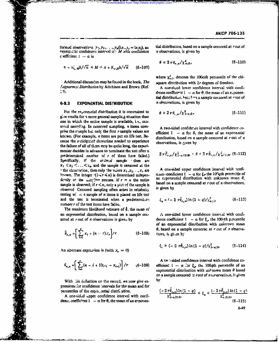
AMCP 706-133
formed ol.servati-'n, Y',Y2 .,Y(iL.,j = lax,), an tial distribution, based on a sample censored at rout of-symp'c'.ic confidence intetval ir M with confnlence n observations, is given byc-.effi:ient i -- a is
0 2 (6-110)z - .h, t4b/',f M 4 a + KR,t2blr (6-107)
where : denotes the 10Gath percentile of the chi-Additional discussion may be fowid in the book, The square dit,-ibation with 2r degrees of freedom.
Lognornni Distribution by Aitchison and Brown (Ref. A one-siued lower confidence interval with confi-dzace coeffici-it 1 - a for 0, the mean cfan e:.ponen-tial distributius% h.z- -- a sample censored at -out of
6-8.3 EXPONENTIAL DISrRIBUTIOR n observations, is given by
Foi the exponeitial distribution it is conveiient to 0 2 rO, ,N/Xs-a*, (6-111)g 'e rmsults for a more gereral samplit.g situation thanone in which the enire sample is available, i.e, cma-sori4 sanvlig. In ce~nsored s~anping, nt items5 corn- A two-sided confidt-,ce interval with confidence o-prise the t -nple bW; only the first rsampie values r efficient I - a for 0, the mean of an exponentialknown. (For example, .items are put on life test. e- distribution, based on a sample censored at rout of ncause the a-iticipa:ed downtime nmwed to experience observations, is iven bythe failure of all of thmn nmy be quite long, the expmri-menter decides in advance to trminate the tt after a (6-112)predetermined nuamber of Y of them have failed.) 2. ,,/X1 i. < <?rO,./X (Specifically, if thi orier4 saiple !iues arcX1 2 ...<,Xn and the sample is censored at the
the c.wrafion, then ordy the x1 ,X .... x, are A one-sided upper confidence interval with :onfi-known. Phe integer '(1-Z r 4 n) is determined indepen- 0aiiC4 coei icient I - a for ge the lCYlqth percentile of
dcztly o! the , proe=. if r = n the entire an e.ponentifd distribution with unknown mtan 0,
sairple is observed; if r <n, only a pFzt of the sample is bawed on a szmple censored at r out of n observations,
observed Censored sampling often arises in rehabuiifi 15 given bytesting wl t- a sample of n items it placed on life testand the test is terminattd when a predeterinL;ei t-2 r87 ,)In(1- q)/x2,;- (6-113)numoer r of the test items have failcu.
The maximum likelihood estimate of , .he mean ofan exponentital distributior, ba.d on a sample cen.- A one-sided lower confidence intenal with confi-sored at rout of n observations is givea by dence coefficient I - a for t,, the 100,h p.rcentile
of an exponential disLribution with unknown mean-D "] 6, based on a sample censored at rout of .z observa-
r,, =., xi + (n -. r)x /r (108i tions, is gi',em by
S- 2 rS,,)in (1 - q)!/x .e;, (6-114)An afvt inate exprc,,ion is (with x0 = 0)
A tw --sided confidence iterval with corifidence co-4 = 4 n - i + 1)(.-- - X5.] /7' 6-109) efficient 1 -- a Jf 4, tht, 100qth percentile of an
4 exponential distribution with uriinown mean 6 based[! or a sample censored it rout of n oa-ervatioats, iR given
With iis definition op the recotd, we uow give ex- pdvpreFsions vbr confidence ',tervals for the mean and for
ercentiles of the expx..mtiai distri ution. (-2 r In 1( - q) (-2 rO,,) In (1 - qIA one-sidmd upper confidence intervel with cor.fi- Xj;zr
denc. -oeffic;-nt 1 - a for 6, the mean ofan e.!vWen- (6-115)
6-49
Downloaded from http://www.everyspec.com
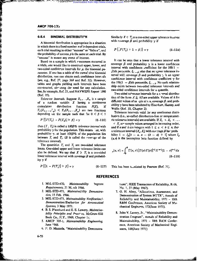
AMCP 706-13a
6-8.4 BINOMIAL DISTRIBUTI('N Similarly X i 7 is a one-sided upper .'o!erance intervai
A binomial distribution is appropriaie in a situation with %;verage,0 anl probability y if
in which there is a fixed number n of irdependent trials,each trial resulting in either "success" or "faii,-e", and P{ F(T2 ) 1 - ] } V (6-11)the probability of success p is the same at each trial. By"success" is meant any event of interest.
Based on a sample in which rsuccess;s occurred It can be seen that a lower tolerance interva n withn trials, one wold like to construct upper, lower, and coverage / and probability is a lower confidececonfde'~e inerias ~interval with confidence coefficient for the 106.1 -tw o -sid ed co n fid e nc inter vals fo r A t.h e bin om ial p a- j ) h p r t ii e l o t a n u r r t l r n e i irameter. If ouc: has a table of the cumu. ,tive binomial i3)th per~xntile. J, - ,; also that an uprr tolerance i'i-
ametr. I one hasa tble f th cum. .terval witd: coverage 3S and probability -. is an upperdistribution, one can obtain such confidence in!erals terral wit h cndence etic an ypforItconfidm~ce inter'al with confidence eneffice.nt y for
(seff. e.g., Ref. 27, page 369 and Ref. 32). However,table.; and graphs yielding such intervals have been the 100(1 - R)th percentile, No such relation-constructed, ob":',tng (he need for any calculation. ship exists between two-sided tolerance ;ntervals and
See, for example, Ref. 23, and NAVWEPS R.eport '. two-sided confidence intervals for a quantile.I(Ref. 79). Two-sided to'-rance intervals for a r, -rmal distribu-
Tolerace InterLs Suppose Xl,.. .,X, is a &le tioa of the form X ± kSare available. Values of k for
of a random variablie X having a continuous diffren values of sa iple si- n, coverage /3. and prob-cumulativ distribution function FM. If ability -y have been tabulated by Eisenhart, Hastay, and
T, (X ... ,"i) < T2 (Xi .... ,Xn ) are two functions Wallis (Ref. 30, Chapter 2).Tolerance intervals valid 'or any continuous distri-bution (i.e., so-called distribution-ftee or nonparamet-
P {['(T2 ) - F(TI) I -y (6-116) ric tolerarce intervals) are avaiable. IfX < X2 <...X, ar- sample values arranged in increasing order,
then (T, T) is called z 100/3% tolerance interml with and if a and bare integcrs with 1 < a < b : n, the,probability y foc the population. This means at, with a tolerance interval (X, Xj) with covn rage/3 Ia," probzprobabilU-ty y. at least 100/3% of the population lies bility I - J0b - a, P.- (b - a) -I- 1] where ,ebetween T, and T (/3 is called the rover2ge of the (uv) is the incomplete beta function dt.fined bytolerance interval).
The quantities T and T are two-sided tolerancelifits. One-sided upper and lower tolerance limits can v) 1r(, ) [r(, r(v*f 1X, 1(1 - xY- tdxalso be defined. We say that X _> T is a one-sided r(u, f ,lower tolerance interval with coverage /3 and probabil- (6-119)ity -Y if
P{[i - F(T)] - 01 = , (6-117) This has been tj.julated by Pearson (Ref. 31).
REFERENCES
1. MIL-STD-470, Maintainability 'rogram Icions". IEEE Transaction of Reliability, R-16,Requirements, 21 M. rch 1966. No. 1, 37 (May 1967).
2 MIL-STD-471, MaintainaWity Demunstra- 7. G. H. Almy, "Allo,-tions, Assessment, andtion, 15 Feb. 1966. Demonstration of Systern MTTR", Annals of
3. MIL-STD-473, Maintainability Verificationl- Reliabi.ity and Maintainability, 1971 - 10thDemonvtration/Evaluafion for Aeronautical R&M Conference, American Society of Me-Systems, 3 May 1971. chanical Engin.rs, 172(June 1971).
4. B. S. ElPanchard and E. E. Lowery, Maintaina-bility PHrinciples and Pract;-es; McGraw. Hill 8. John V. Lavery, Jr., "Maintainability Demon-Book Co., N.Y., 1969, Chapter *.A. stration rrogram", Annals of Reliability and
5. AMCP 705-1, Maintainability Engineering, Maintainability, 1971 - 10th R&M Confer-June '966. ence, American Society of Mechanical Engi-
6. F. D. Mazzola, "Maintainability Demonstra- neers, 168(June 1971)
6-50
IBM
Downloaded from http://www.everyspec.com
____________-__
AMC(P 706-133
9. Wayne Nelson, "'Producer Risk Tables for nov I -st fbi t*e Exponential Distribution withMethod 4 Maintainability Demonstration Mean Unknown", Journal of t. AericanPlan of MIL-STD-471", Annals of Reliability Statistical Asso.iatlou, 64, 387-89 ()969).and Maintainabi!ity, 1971 - 10th R&M Con- 21. H. W. Lilliefors, "Or t; c Kolmogorov-Smir-ference, American Society of Mechanical En- nov 'T.st for Normality with Mean and Vaxi-gineers, 188(June 1971). atce Unknown", Journal of the American Sa-0 ner tistical As.soc. tion, 62, 399-402 (1"7).10. Hunter M. Sohn, Lockheed-Georgia C..,m- 22. G. J. i-n and S. S. Shapiro. Stntistica, M-dels
pany, "Proven Techniques fo7 Maipain bi1y in Engineering, John Wity and Sons, Inc.,Predictions and Demonstrations", presented N.Y., 1c67.ht 10th Reliability and Meintnance Confer- 23. B. Epvten, "'Tests for the Validity of the As-enL.., Anaheim, California, J'jnt 1971 (unpub- sunption that the- Underlying Distribution o,fished). Liie is Exponential". Technometrics, ', 83-101
11. G. B. Dantzig, "On the Non-Existence of and 2, '67-183 (1960).Tests of "Student's" Hypothtsis Having 24. J. Aitchi-.n and J. A. C. Brown, The L gnor-Power Functions Indepenient of a", Annals maf Distribution, Cam..idge University Press,
of Mathe, a ical Statistics, 11, 186-192 (1940). 1957.12. MIL-,HDBK472, Maintainability Predic. 25. G. J. Resnikoff and G. J. Liberman, Tablk of
tion, 24 May 1966. the Noncentral t-Distribution, Stanford Upi-13. F. 0. Mazzola, 'Maint-unability Demonstra- versity Press, Staafoid, 1957.
tion", IEEE Thmsaction on Reliability, R-16, 26. E. M. Scheuer and R. A- Spurgeon. "Some37-42 (1967). Percentage Poins of the Noncentral !-Distri-
14. NAVORD OD 39223, Maintainabiliy Engi- bution", Journal .f the A.nericm:.,'Satisticalneering Handbook, Naval Ordnance Systems Associatiot., 5.. ,6 182.Command, I Feb. 1970. 2. S. S. Wilks, MfahemadcalStatistic" .1-ohn Wi-
15. G, T. Biud, "MIL-STD-471, Maintainability Icy and Sons, Inc.. N.Y. 1962.Demonstratior", Journal of Quality Tech- 28. C. . Clopper and E. S. Pearson, "Th.! Use Jfnology, I, 134-148 (1969). Cchfiderce or Fiducial Limits -llstr.-ted in
16. 3. W. Lindgren, Sta:istical Theory, 2nd Ed., the Ccse of the Pi'o-nial". MioIretrika, 26,MacMila, New York, 1968. 404-413.
17. R. E. Bariow and F. 1 roschan, "Exponential 29. NAVWEPS Report 8090, inomialReliablityLife Tesi Procedures When the Distribution Table (Lower Confidence Limits for theHs Monotone Failure Ratit". journal of the Binomial tiistribiez;on), US Naval OrdnanceAmerican Statistical Association, 62, 548-560 Test Staton. China Lake, California, Janumrv(1967). 1964.18. A. S. Goldman and T. B. Slattery, Maintaina- 30. C. Eisenhart. M. W. Hastay, W. A. Wallis,bility: A Maor Element of System Effective- Tecniques of Statistical Anaslysis, ?cGiaw-ness, John Wiley and Sons, Inc., N.Y., 1967. Hill Book Co., in,. NY. 1947.
19. H. Chernoff and E. L. Lehman, "The Us, of 31. K. Pearson, .The Table oftheinc.pee a
Maximum Likelihood Estimates in Chi- Function, Biometrika Pre-s, Londca, 93,.
Sqvare Tests for Goodness of!Fit", Annals of 32. AMCi .ii09 Engineering Design Hand-
Mathematical Statistics, 25, 579-586 (1954). book, Tables of m ive Binomil Pob-
20. E. W. Lilliefors, "On the Kolmogorov-Smir- ab es
6-5 1/6- 2
Downloaded from http://www.everyspec.com
AMCP 7064133
CHAPTER 7
ECONOMETRICSSECTIONI
t COST FACTORS AND ANALYSES
Ff7-1 iNTRODUCTION lation, and combination of cost equstions unto such amodel.
The urpse.of his haper s t destib th L~ of Pars. '_ 5 ',.r ,ugh 7-7 discuss the use of cogt modces
Thepuroseof hi chp~e isto esrib th ucof for system analysis, desigtn. and decision. Par. 7-5 be-econometriz techniiques in i-Aintainability (Mi; engi- gins the discusion with a treatmen-, of the tise of castneerirg. After this introduction, par. 7-2 disuses analysis for sy developmnt and decision at thedeveloping cost facto'rs to categorize existing system lelofntrsyem.Ti riinypheofs-c.,sts or predict new system costs, as they vary with tenil afnalyi cocsytse. 1h cr'hoing paof alte-
M-related variabl.!s. These factors are used to derive te sys'is fonrn- coishi6 hoin samroneg ar.
A.~r~atd csts andpreicthowth'5 cotS ill 7-6 discusses the economics of trade-off decisions.change with M-rclated design and performance varia- After 3 kiecision to begiv preliminary design of oe or'1es. An in'po'itant conir' 'ution to success in maintain- more syrtems, tht; int'-rnal coafiguration of each sys.mnAbility cost analysis is the development of a oia, must be specified. Economic trade-offs are an essentialordered, well-structured breakdown oi M-related cost part of this proces of selecting from arnqqg subsystemelements-a tree-like structure for planning, analysis, and component alternatives. Par 1-7 concludes thisiand design. Par. 7-2 concludes w-i a dscussion of chapter with a disaission of the rrnagcrnemt an.d or-breakdown techniques. Pr. 7-3 discuss--. :be concepts ganizational issues in performinit cest anaiyss, ant! theand use of cost analysis. After developing a cost ele- final "bili-of-,:osts' :or -~cquisition and operation of ament strurtare and list of elements for a Darticut1r sytmwhich is prepared at the conclusion of systemzy..tem, the analysis of s,'stem ceists requires prediction design This lif't.cycke coct analysic will -eflect die re-of the variation of irdividusl element cosms Historical sults of all cost ;rade-oTs pp'rformed di-ripg systemdata are 'eesirable for many systems; mai.y difficulties design. It cap be used to con.para competitive designsarise in coilt--tion and tonditioning of the data for use. for a system in order to select'the least-cost alternative:List as technical and peiiformancc variables affc*t to buy and operate.Mf-related costs, M-relate.i elements affe!ct system vani-ablbs like manpower. A ty;ica subanaiysis illustratesthis intv-vc:;. n. Another typical maintainablity cost 7-1.1 MAR.FrAlNA811.11Y CqSTSsubanrly.sis illuvorates the dLtciF'on between repair andihiow-raway modules. Seclmon I concludes wi'l' iso- One key econom i c issue in eq'.ipinen:. dct._er. is thelated, sing!'-subject subaralysis of particular total cost to the C 3vermtmentzif a particular etitipmen!Al-related issues The reality is much more complex, acquisition. Procurewi of rqpipment implics z comn--hianging one M-rolated v4-iable impacts others, often mitinen. to the! operating and support costs c-f thein a complicated way. To treat these ;ateractions, moice eq'uipment as well. Thu~s the relevant costs are those forcomplete model,. of the meiatainability process arc 'nec- devtski~ment. acquisition, operstion, and support. It is
c~sary.the total of these cws elements- which canjts-not th,-Sectien 11 of this chapter treats mathematical rmodes individual pieces. Tais total cost is affected by mainy
~n cost ansli.s. Par. 7-4 discusses lite development of factors, including mnawinability and reliability. Manysu~ch more complic mnodels for r redictibet annual sis operation and si-pport costs nni~ht be reduced if weof repair and support. it discuss-_ the structure, formu- could inu'-,a-e maintainiability. More mr intainable
7-I
Downloaded from http://www.everyspec.com
AMCP 706-133
.,uipmL'n.t reduces the, icchnician's main'enance time subelements (the most detailed breakdown) must pur-and hence its ope-ating cost. Fewer technician hours mut direct tstima' ion of costs. Thus diffret cost ele-imply fewer technicim's, reducing trainin~g costs Mov- inents may be broken .:own to different levels, as apro-rapid maintenance metans faster return to service, re- priate.during the size of the maintrnance float required. A gen-ral caution is usually applied to costing a3maller backlogs of cquipment awaiting maintenance sy stemn, as stated :n a Navy publication:., to in-Judecar. reduce the size of maintenance or overhaul facili- all co-sts incurred in estabiishing, operating, and main-
=ties ano the required amount of test equipm~ent. The tamning the ... System, and to exclude all costs whichkey comparison is the acquisition cost. for such im- woul Iccur whether the ... System existed or not"rjved maintainability or reliability, and !be resultant (Ret. 3).
savings in operating costs. Im[ roved maintainability 711m; purpose of thit cost analysis must be careflfycan be obtained i.n a number of sp~ecific ways; they cainsidred. If we wish to acmount for the cost: o01P
include (Ref. 1): peulcular equipment, a complete cate-crization is nec-a. Discard-at-failure mainiterance -nd 'nodule siz- essary. If we are comparing alternatives fcr the pMn owe
ing of -ectiza. cvbis which do nat vary awong alterna-
b. Easier access for mantenanze tiva, Pire often excluded. It is also nece-sar o cmisiderc. Design of bivilt-in te--t points !be point in equipment life when the analysis is being
d. Increased self-checking features performed. (Jr~ce a decisi- n has been made to proct'e
e. Grateruse f auomati tes equpmen :, articu! r type o& equipment, tarlier cocsts leadi:.Z upe. Geatr ue ofautmatc tet euipentto that dec-sion may become "sunk", and should be
fE Use of reduced-nantenaace cornponeus, e-g., ignored, excpt for accounting pqrpoes. Sunk costs areself-lubricating bearing; thos that have already been incured. "Relevant costs
g. More detailed .rcubleshoc.ing xanuals. lie :r tlte future, not in the past (Rr #' 4). In conten-Each approach can increase acquisition cost and de- plating a new system in advance, irwever, tie research
cosis.A seciic nalsis coparng ant.. development ccsts ze a lef-'tiate pert of the deci-crease operating coon to sproceed orlyis noondmutaeringre.
thes cots, s nededin ach ase IiRdy, existing .zouipmnt--e~g., test zxuipment-is
"free" except for h5s salvage value r r alternative use. In7-1. OWERSHP CSTSdeciding between new or exsf f: test equipmzni. the
Costs of ownership fall inte three major categories: original cost of the existing e,,iiprcea :s irrelevant toresearch apd development (R&D), acquisititm, and op. the analysis, providing enough sets of te:- equipmeteration &nd support. E. juipment acquisition cot a exist and are availat-lon the purpc-se zonsidered. Newaccount for half of defense costs for pirticular equip- test equipirent, not yet procured, must be coste at funlmeat. Operaton and support costs, accounting for tbe acquisition price for compariszsu. In develojng the costI othcr half. nclude m~anpower as their hlgest ele-nent. elements of an equipm ent itegratd cost structureIn one case th'e *Vrelated operation and support costb great care must be aker to include or exclude in-have exceeded acquisition costs by a factor of 1I00 divid-.-al elements as appropriate.(Ref, 2). As a resvIt, maintainability strategies whichreduce manpowt.- snould have high leverage. 7-2.1 1AIRD DUAL COST ELEMENTS
Integrated costs of ownership includ- many7-2 COST FACTORS OF EQUIPMENT *rdzated costs in each pb'a'- of equipinent life. Re-
search and developmnent costs include thsor feasriilWhen~ analyzing the total costs of owtue.'thip, it is ity studies and tests of equipmenmt and comixouents.
ncaessary to bemk cost categories into elemints and Many studies are' paper aimlyses" comparing differentsubelements which can then be estimated, analyzed, ,rnaitenence doctrin-s and performing many dlifferentbudgeted, reported. and controlled. The basic e!raent trade-offs to arrive at tl- -: preferred sysiem. The cost ofbreakdown is subdiivided by ccnsidering a number of these analyses and tests are a part of thc developmentbasic principles: (1) Each subelement must be a part of Current procurement policy includes "fly before youthe higher level eenient cos';; (2) subelemeats at any buy" in many cases; a pratotype zquipment ;-- produced
CK level must qdd to their suminaq elements; (3) subele- and carefully test-xd and evaluated before th- design L--meats must be uniquely defined at every level to avoid frozen. Many Mf-related design elements may b-- testeo,;enap and double ccunting;, (4) th.- lowest level for as a i...r of this process; again the costs must be cixisi-
7-2
Downloaded from http://www.everyspec.com
AMCP 706~-133
ered. Feas'iiity studie may extend to suppo,.. eqjuip. and the developmeet test of Eyst ~n* s zbaystein. or oom-mmnt, including automatic test eqtaipment and special pontent models or mock-ups ar. also included.tools, these costs voust also be iniclitied. New cone"tin Mrr -1 design may be developed a~s Cumpncents 7.2.: .1.5 Trainingor parts .~isolation during a researh stage. When
thee cstsareassociatedx with a particular sysiem or This cost element covers contractcr-furnished train-equipn:ent they must be included. nsevcsdvo ceoraiseLprntad
7-2.1.1 InveAtment rdcus a-iLitascoes3vnmt ss
Mrelated eleents of iinvestment cost include those to special traning not part of mnumI skiii-quaifi' a-for primie equ jxncnt, support, equipnitnt. system test tion trainink Persnnel, rGoverment tkiclities. i,and evaluation, sysc -P engineering niani, eient, train- structors, mointrinance trainers, Government-prepareding. data. new operational fau!.des, and ncjtair parts. training plans, course.-naterial:, training aids, and simi-
7-2 1.1.1 Prime Equipment aet lar rwoucr'- arn inclued.
It is often difficult to estimate the Al-related t.ves- 7 2.1.1.6 Data
zneit cstsforprie euipmnt iretiy Whn crn- This cwst element incliudes maintenance data. Tech-Pison of alternai-ives :rade-ofs) are invclved,, the nical Manuals c'-awings. plans, circuit diagrams. andmirgiaai cost (ccst difference) for equipmznt with par maintenance manuais 'xe some of the elements for con-ticular features compared to identical equipment with- sidcrtion.out these M-related fenitures often is us-A. M're con-varliently, all cos6 are summed for ercli alternative anA 722617 OeainlFcltethe totals (with operation and support costs properly 72117 OeainlFcltediscounitedj compared. This tpernits all cost-related For ma ' or sys-; ins, this cost element includes newdifferences to be considered nti balanced at one time. facili.it . For all systems, incr'1nental expansion ret ex-
7-2..1. EuportEqu'*pentisting facilities is also costed herc. When contractors7-2..1. SuportEqupmet tre- to perform maintenance anu overhaul. any charges
Special uto~s and test equipment a.-e included here. to the Government for ctitractor operational fac.-!ities=Often an item of support equ:.p.nent is used fur many would be included.
items of prime equipment. In such cases an all~atfijnof costs to each :tern of Dnme: equip.me-nt ir- sometimes 7-2.1.1.? Replacement C mptne-its andused when costs per piece of prime equip-rient are 6:!!-'g Repair Partscalculated. More cormonly, total system costs arn cal- Thscs lmn elcsteiiilprovisionjit ofMuated, base-r on an estimate of total ficid population Th's co-rist elmnt reaiects tohe el,- 4Y nof prime tt.'p-ment and 0" relevant support equip- rield stemeni aRepa pents or copoent.;' 1o aendment. Special anid common (already in DoD. inventory) fied scks.r Reatncrpcemfnsa e mpnt3 rp issen-Isupport eupetaeceor. fud-icaerm items of equipment. Repair parts are th- te '*:its and7-2.1.1.3 System Test and Evaiuation piece:,,", eg., individu--i parts or nomncpairable assem-
When acc-ptanre testing and inceiiivelpenalty blitz-, required for the rrpair of replacements or endmeasurements ,.&.e place or. equipmen. delvery, items. The cost J-emert does not .neludc costs for con-Mrelated test and evaluation measuremnnts are often %;umpt:ii of replacements or repair parts ditring the lifeincluded. 'These tests can cover preventive main'e- of the system; such costs are charged to operation ai-d.iance, simulated repair, simulated overhaul, and '.ul:Port costs-related matters. The cost of executing thz-.e tests ;,included :n this; cos! elements. 74~.1.2 Orpera'ions and Suppe.- Costs
7-2.1.1.4 System Engince.ing/Mariagem~n! Thec cost elements reflect ongoing costs of owner-Before and during prodckction. i-he Government aitd ship after a system is dtelivered and placed in servicz
the cortractor will pci form systemn engineering efforts They include operational end mainter~ance manningincluding opera-ion analysis, life-cycle costing, value suppo-it; such direct oper -iona! suppc -: as fuel .aidengi, eerinE. humani engineerin;,. rcliubility. and mazin- electricity; na~ntean-ce. repair. and alterations sup-tainability. Planning for system test and evaluation, port, material scoport, and related costs.
7-3
Downloaded from http://www.everyspec.com
r AMCP 7064337-2.1.2.1 Organizntione' iMaiitenance men!; and revisit,, of' technical data to reflectl wvrla-,I
Manpower actions.
This cost is sometimes diffic-lt to sepcrate frcin op- 741 1.2 3 Organizational Material Supporterationa! manpower without careful anatiyses. Particu- This element covers replenishment repair inns arlarly when crew members perform mny functions, as replacem ent items, and reair cSi-cplaceeent compot-in Uie cawe of first-linc maLitenance performed by oper nns eesr o ra ~nlmirnne tiating peronne1, appeal to rflalftenalec plants, uulysbdveditrei'.tchedules, and mean-tin :-to-repair data can be mis, repair parts. Rkeacem- r.mns-a euual slleading. A sys-tern cannot he mwan'id by a fractional dividL-* into replacemem: item-, ,nd repsir of !eplace-ecien.Sometimes a system which requires Sam,_- metiessnematnncdcrnefeclsfotnalyti nd when itms ofnc iatwccnocnet . salls for
hat higher maintenance man-hours can still be subsequent rcp-ar of the replaced -deictve' item.manned with a fixed personne' complement. Tbiv-' -. stelement is anotht: rcmindcr of the diffieren_% . :=
ing vstms.It iscustomary , &dstin3,uish between reduced total cost of owner-..ip 2n I the fragmentation
ing subelements of maintenance zranp~ower. Included o~t~7hp -a4bltondvdl
in the cost cf maintenance manw-wer is th cos of anayzed elemnts is di-ec:y arlml oidvda
replacement t.azining during the'life of a system, as p.-.o harwa e a. -ie'cssc het s t-- snposet
~wesonnel rotate estimuie fhie., : bown!es a inatter
z -2.1 .2.2 Maintensnrce, Repair, and matherna~ical 'alcui3isen 10 enpmnd the concept t -Modificalic-A Support subassemublies, set-systems. and co,~systems.This%.o;: lemnt s te oe mst ommnlyconie- When the building-biocl, elements (piec= ofh.,odwlare,-This~oi elmentis he ne mst ommnly onst'- have independent cexts (as, for examiple, for sertions of'
ered when designing for reliability and mantainai. ity. main:.ance rianuals dealing with each element), thry-=Because of its iniporta-ice, it it. further subdi-sided here are additive. Many costs involve joint economies and
into its comp,)nents: mnodifications, main'tenance and must be calculated more crrefully. A maintenancerepair (od'er than overiaal), and ove aul. maniual on a subsystem iequires only oty binding,
7-2.1.2.1 Mcriifications while individuiC manual1s on subassemiblies aire moreThisc-.t rfles iproemens o :eroftsincud- costly. Preventive maintenance tests or. systems can rseT~is c-:; rele~s mprvemntsor etofis. ncld- checking procedures which xercise major portions of
ing .nstaflation or next-generation equi..mein in a sys- a sx-tem, or the entre systetm, while separaite checkingtelr after it has been in he field. It can inclucie itr- ptecedures fo: subsystems or components wil! stuallyproved automated test equipment built into larger rectuire more time and effort. When a system i.s &i-systems. si'gned with high -redundancy, correctiv mainterance-
7-2-.2..2 M~ennce nd epai (Oher relatr4 mannower and material ;onsumption -nil often7-2.1.2.2 m Ovnehaul)n Rpi (t be reduced siace the systtm -an continue tt' operate
Than Ovrhaul)with partially degrad components (reducing the out-This element covcr-' labor, material, and overhead of-service zime, the number of iyste-m spar~i, and in-
for n'aintepancc and i epaxr, other than regularly sched- rreasing zhe nuisbcr of malfuncticti corrections whichuled overhauls, conductedt 1, personnel'of a n'ainie- caii be made a: one ;;izr.-e, with the resulting efficiencynance facility. It does not inclutie orgarizationa. msain- of naintenanix and repair).tenance an repair, which is cc%,-red uandrr Materi
=Support (for pat _s) and Maintentance Manpower (for 7-2.3 COST ELEMENT DRIEAKOOWNlabor). TECHINIQUES ANDI CODING SYSTEMS
7-2.1.2. 2.3 Overhaul FOR COST STRUCTURES
This element is uscd to accunidw!e depot overhaii Par. 7-2-1 discusses inditidual .oet elements impor-costs for ali labor, matterial. anC overhead required tant in maintainability, and introduces some piinciplerduring regularly scheduled ovetijauls far open-and- I.i dentifyng indviduJ- cost4 elements, with illustra-it,spect procedures; maintcrance, repair and refurbish- tions of principal V-related elcmenits. 'The bzasic bieak-
7-4
Downloaded from http://www.everyspec.com
W r
AKWCP 706-133
duwn sit ict-ire imrp'ied by these r'-erenLk incorporates system. Ithe dilffierent structures would be cnxeA to the~ev"r~ "-rher principles. similiir to those in work mos.vt d;!taid elemnts, whic oudtebea -
br-qm;~z structures used for progra monitorng Vited upward As des;ired. Thus a partisular cost ca-- beand -.- .-r.-71 The st'ucture can b- considered an in- for repir rarts. for part-, to be applied to a tank trans-
vert. tree-like arrazigement. beginning with -h~e corn- mission, for Goverm.%-ut-maniufactured parts. for 3r.I plete ..ystemn costs as the topmost elewent, branching ar~tic v,- sion of' the =an'\. 1his single com ca thn Zout to mnre and -n-ore levets of detAi. 'Iiach inv.Iease in accumulated upward thiro.uga- parts, to inatenials. tod.otad I hould retiect a consisent subdivision. if r. :ard operation arAd suirpr .i. --- ;till- for the- tank trans-ware rategoxy is, bmnng subdividci, 7fbdiisi"i -2 uld musioa fi,% Govcrotrit. i-'raufat.-ed pvst f , thebre coet-dcitu- ccizrpaziable. Subdivisi3ns of a tank arcici ver-jon. The cr,4: c,%n in-4cad be acuiul'edmight: iclude Lhe wea)on system. the. drive systc.n, the upw,-,d to Govcrnmcn!- anC naco-a'uacuegui- taace system, an;; the rrrsytmItwude repair parts '.) itt arcti- *nk transistsion: ac-I :approprimr. to abdivide a taank intz weapons, ecngine. cumulated to Crove-nmient-ianufacturzd :ank trans-wheels, r -trsaion, guidance :nd armiz, since the mission repair ritrts for a climates, and many othe.-
- transition from tank to engine, wheels, ated transmLi- sumnuziy categors.
sion omits a Ftvrl tf aggegeitkn otherwise included. Associuated with particular breaL-down techniques&qch iower-level subdivisioxi reflects fusrcti.-a sub- are numbring or coding s.ystenms which inplv thedivision in hardw-.re systems. MIL-STIJ-38 I edisi..os-es breakdown technique.Work Breakdown Stnictures Tablf- 7-1 shocws a simple breakdown for
' -i subdividing cost elements it is important Io use a PM1-eltaA cost elements. Each level of the structure isconsistent approach to subeivision. whern-ver possibt represented by a digit position in th co f morehn
Conf'p -s will oilen arise, znd must be thought through 9 subdivisions exist at any *^.vi. the digits may be spcarefully. For example ina~rd.'re subdivrisico_ fa.- piemented by letters of the Elphete.
system which includcs l-oth contractor- and Govern- Tabkc 7-2 shows a linear breakd& vn structu;e- withnm.it-urnished eqar.-cnt. it is often necessary te esti- an abrupt change in dimnensionality. Finer functionaltrava ow-riship costs separitely fnr contractor-pro- surVi o of operation aza support costs are brokenvided and L7overnmnent-nromick'd obD.Ccts and servicts -off ,, t hanigt !o a hard'are-asi. -- ted code for some(includin,, -ontractor-.-ided oper.I~v or and support. nv-t.0ls. Note the complexity of it coe o esuch as at a mn otfacturrotperated oj-:tiaui facilitylI introduce a hawsm- breakdown into teoperationShould there be two identic&!zatructures one fc- con- aid support st ucitem Note also tha: withetut an in-tractv.- costs and the other for Government costs, comn- plie inemeacri sirwcure, we .-annot presmnt the costing together at the top? If the Goveanent buys ser- all replacement con'ponents frT the Mark Z Gun.vices at diffie nt points in the program, the s:_ ctrre Above ,31 .111 in Ttbk -2 the gtin zosts arv. aggre-should re-flct thIs-perhaps through subdivision at the gated ir-to wvapon oytw, ruplAcemevt parts costs anduppropriate phasing point. Thus investirnent custs then spares coss To get gun spares %6. would have towt-'uld lie subdividJ into contracor and Government m'd 331.111 to othe gnreiatzd spar cossohnelemenL-, mannq costs woukl contain a few elements die such problems easily, we introduce the concept offor contr- -tor-ft. --shed sevcs at the propcr point ;-Z iniltipke coding structures, or -threaded iists-. Eachmanagemient integration in the syst~xtn. A hareware- characteristic of a cOst by which we imay wish to reCportrelated sub&.iv-sion of operating cost elements such v~ it is given a separate -_lig structu-e. Some of these-
r parpats whish shows the priir cquipmein ebd use structures are simpie disiios L uha nocnrcoof each category of repair parts pre-tents =-rain proti- cost-% and a3overnrrent cocts. Others may be more com-l'ems. Such a requirement can be met in a linear (tree- ple. like hardware breakdowns, functional break-like) structure only if the dim..zsionality changes down,or mission-related breakdowns. We then sefiect.ibnzprlY. Thus operation costs can be subdivdcd in-o thet appropriate code fro-ri erch struciure to categorizecategox.ies including materia: usage; materWa usage L~an a particular cost. Highly flexible aFgregation and re,be subdivided to include replacements and repair parts; porting then becomes po!~sble with a data pr-cr:essi4nj
=repair parts can be subdivided into classes by major system. Taking roe example of par. 7-2.3 we might=hardware use. Onccz the dimensionality changes, it is have a hariware coding systemn preceded by rie ier
difficult to return to the earlier principle of subdiision. "WA, a source code (C for coutractor G for Govern-A better- way of handling the situation is to mie a sepa- ment), a basic funct-mal cost breakdown with no pre-r.te structure for each mnajor dimeson when that di- fi:t, and a climiate 'ireakdown (whPre 3 = arctic)me,,sion is expect--d to apply to mrany elements -.n the Vveode-d by ttht letncr **It". The rearparts cost for the
7-5
Downloaded from http://www.everyspec.com
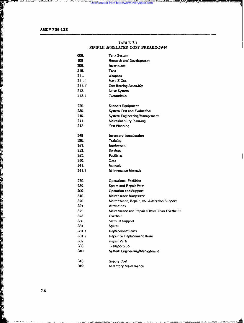
AMCP 706-133
TABLE 7-1.SIMPLF. *PREI.ATED) COSf BRE-AKDOWN
000. Tark Sysi--m100 Research~ and Developmenit200. Invertnient210. Tank211. Weapons21 .1 Mark Z Gum.201.111 Gun Bearing Aiasen.blly212. E)rive System
212.1 Transissiv..
2120. Support Equipment230. System Test and Evaluation240. Systern Engineering/tAanagrnent241. Maintainability Ptanrang242. Test Planinina
249 Inventory lntroduction250. Train;.ig251. Ecluipmnent252. Services257.. Facilities260. 3t261. Mar--jaIs261.1 Maintonanace Manuals
270. Operational Facilities2390. Spate-- and Repair Parts300. Operation and Support310. Mairte~ance Manpower320. Mairenance, Repair. anc Ateration Support
32-'. Maintenance and Pepeir (Other Than Overhaul)373. Overhau~l330. S-atem.al Support331. Spares
Z31 .~ Fe~acement Parts331.2 Repir 'iReplacement Items332. Repair Parts333. Transportatior.340. S-.-sterr Engineering/Management
348 SUP.IN cost349 Inventory Maintenance
Downloaded from http://www.everyspec.com
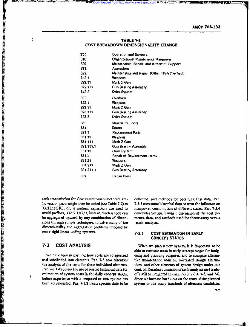
AMP 706-133
TABLE 7-2.C03 8FREAkDOWN DIMENSIONALITYL4HANGE
7. = Operation and ,Stknpo.-
310. Organiztional Maintenarcr Mnpower320. Maintenance, Repair, and Alteratiori Support321. Aiterations
322 Maintenance and Repair (Other i han Cl-ehaul)312.1 Weapons422.11 Mark ;_ GunS22.111 Gun Bearirg Assembly322.2 Driva System
S323 Overhaul
323. !Weapons
32311 Ma.K. Gun323.111 Sun Buarirg Assembly323.2 Drive System
332. Mayerial Support331. Spares331.1 Replacerment Parts331.11 Weapons331.111 Mark Z Gun33!.1!11.1 Gun Bearinn Assembly231.12 Drive System331.2 Repair of RelJacemnent Items331.21 Weapons
331.211 Mark Z Gun331-211.1 Gun Bearirj Asembly
332. Repair Parts
tank transmis-on for Gov.rnmen:-manufac ared, arc- collected, and mathods for obtairing that data. Pzr.tic versic" pa,-ts might then be coded (see Table 7-2) as 7-3.3 uses some hstorical data :o treat the influence on.332H.2.IGK3, or. if uniform separators are used to manpower consL-tnpticn at differeit stte. Par. 7-3.4avoid prefixes, 332,Ol/G/3. instead. Such a code can concludes Sec.io. . wii r discussion of -he cost -le-be agr e--gated upward by any combination of dimen- ments, data, and rosehods used for throw-away versgsions through simple techniqu.s, to solve many of tAe repair analyses.dimensitnality and aggregation problem imposed bymore rigid linear coing _ta-s. 7-3.1 COST ESTIMArION IN EARLY
CONCEPT STATES
7-3 COST ANALYSIS Whtm we plan a nenr system, it is important toabie to (stimate cos:s ia early concept stagts for budg-
We hare setm in par. "7-2 how costs an- categorized efing and plan-ing purposes, and to comri-re rdterna-arod subdividej into elements. Par. 7-3 now discusses tive maintenance policies, Y-r-iated design alterna-the analysis of the ";osts for these individual elements. fiies, and other elements of system design under ourPar. 7-3.1 discusses the use of relatd historical data fc conL ol. Detailed -i.Sisrson of such analyses and trade-e-,timation of system costs in tht daily con.ept sttges, offs will be - : pars. 7-3.3. 7-3.4. 7--. and 7-6.before experience with a proposed or new ?.'nt has Since we lavo rm, lud up'iA cmt he covas uf the plannedbeen accumuatd. Par. 7-3.2 treats specific data to be sysem or the many hundreds of alternate candic-tes
7-7
Downloaded from http://www.everyspec.com
AMCP 706-133
which may be considered aa, -.,-.cted to arrive at tue It remaim to determine what the degree of simiiarityselected systin, we must es.inate cos. through ,- is in e-ch source system, and which cost elements fredirect methods- Usint historical data and analogous of concern.
systetm, we can iake such tatim.tes of indilal ele- Suppose the Mark 2 Tank had an almost ;denticalaebt costs rd total them, or we can make direct eti- fra i w eight, propuon system (inrcluding tansmis-mates of te ".gem Wst sion, getsinge and tracking) and engine desia. We
7-3n1.1 Analoaindth Systis tiew! try that ansatog o the weootn stcm withoutfurthe mo fication. Suppt.hs that the f system e sdte
An analogou systm is one suffcit tily like :- ca.ti- for clhe e personnel carrier had on y reg peen tdate sltec in one or more respcs that it can pos id of the ca city of that of the derpon system, but asa basis f y g elem ent costs or total costs. We o idenfic design. Then thrg statistical or gi-will rt to the anAlogous system as the -source sys- nrerink- &--z)sis %e would deveiop Irc conve:sion
sour ad when system . dfactors or translahtg the costs of the soure fto cellsto" b'he procable ti ou ioves th s tem tutose of the weapon system V we la t eowiing steps: data or could get it. ce m aght perform regression anay
a. Selec one or e yste estimat- si on fue cell systems o severl differen sizes, toing .tartic-dar delnts of weapon s',-tem costs. relate number of cell-un~ts or capacity to maintenance
b. Identify similarities aud differer=-- between costs- Ifwre dk=erla stable re,---.'ship for aseries
source and wtaonk systems r of syeh..v vie ighn t inte- olat or r sl ate to t
c- Develop a meth.od for adjusting s .r system iaon s cr eaize in order to p ed it Altemna-vsc-h. wi- might dveop a cgi eng relationmhip
to be com parable with the wecot system costs. " bl estimer the anel o nte re
weac~ eatreanduseth~.A scon mtho wold sedo thmer field , gunaar wof continl torthe
d. d o required source sy stm cost da le and para-.), cell-unit TBF (ad lW eap would/TTe. Adhist for yste n cIr ey and othm t physical parameters to predict weapon ;)N-E. Develop weapon sy-ser ccsts, t-= cots Of course, realism mut apply to such xs
Co ider a new" k (call it the Mark Z). with a heavier w-rapaltiom by sit A hole in a simll tank cou d w
e djust a much to fix -s. a hole i a big oank. Par. 7 4
7-3.1.2a morle : ow ot~unine, Systn Well I wte u e ,.envom..t (icudn te i fferaanentgilefting
of new guida.n- elect,-oni- ad a new t-v of radar icssthdelomnaf.l-cladegnerggundircto. T be _ o:Jd ! afirt-ct eti- relationships as a mn of nodel development.
-.e "a - Suppose that hi.uek 3 Armored Person CarrierTate of 7 costs of this wsupc system. One e Ta. towe se tat many ccv-son facdr nee te
.oweapo st m dnestignalees of ere st tourisexm alwd fo i&ning comp for cst esimatnce sythey
plo.bta 7-3 san s ees t its th hek a 2e-t souck n- We would fikesy still need to develop converron :ela-terns, eac rm ong common s-atures to the weapon m fs - tilfahos ca s tad ifes domea t cndis,
systm. 114 he Mrk Artord ersnaiCarier nssion pecmeofitk ad if-ntrface ondeitonns.
tern s uch that toata all features of the ve pon sytm son factors fir.-luding operavrg profiles, en vron .-en-arelwxpesent, 4 3y analyziag historic-al data cn eachaa pa itz: dition. mion kngth, ad atress) to codveot tp-
sourt sys-n riFted to the weapon system fntures, it m n
The ark Tak a~aretly a; othig i comion rqures ap l o eson carrie udgen.-cots ~. inter st-
-ity be possible to se4Mam te out the cost datA for t d a d e .h tstica i nys i o ex rien da tat.
S featre and use them. A smond method wouldb e a st e t O . ,' e sy t m e o s n o r e t o s a e S u p p o se , th e fi ld g u n ra d a r w -re id e n tical to th e
thrcm te weapon system, complexity o- rag-rituide. An wxpns.tmgndelo aa.W ol tlexample will make bo-nb of these approaches cdcae', have to develop conv ---mikm mvtionships to the wepon
" -yt-'-a became- of the vibra~km OiaTernces between afixed and mob-L syste', &Av becaw. -of the cehfferent7-3.1.2 Exanmple: Sotime Systems W'ithmat te 'etrs teratxo environmensfimcluding the differenti-I ef, ectof the external vs fitel cell poutr supp lles .
Table 7-3 shows sev,,al source: systems and -he Thus we see that many ccnvs factrs need to bexeapon syste-m design elewmts ofintc--es to Ous exam- allowed for in using an.-!.-W for cost estimation. Teple. TrbL 7-3 shows (see t items) that thp Mark 2 Tank inct -e des:gn factors such as size and weight; z.nviron-has it frame arma engine of similar type to the weapon mental factors rich as hmd, &zm comot cni ossystem VW the Mark 3 Armorcd Personn-1 Carrer . miissio profile: and interace condtions. "I hehaz a siH ar power source and guiaic system. and identifrlicaticni ol conversion varibles and1 the develop-that the: Mari I lField Guri ,tma similar gun director. rw~t of conve-o zhtr is not -n exact science. buntThe Mark I Tank apparently .hai nothiig in comnio reuie app al to reason am tuadgment, even after sta-with the Mark Z Tar~c; its ccs dzta wo uld not be u-zd. tit; -ma7-:ysis of experience dama
Downloaded from http://www.everyspec.com

AMC,,* 2 -133
TA!%LE 7-&.
[7~UiV COSTDATA SOURCES Nr3 ! L r~
tfl ar ~ Armored~ k
ITrk Tank HitGa Peranar-W Tank
u :' _ {N/A Meiu _-
isual V isul J/A 1 Computer' CerqtG uidjnc A ssisted A sistedFire Control jisual 'f'sua! Rajdar ;N/ARar
*Weapon S'.'stein Features in Socuce % ttens
7-3.1.3 5-%kw Systtem Data vesztment costs are base. on d ntial acquisiuiot ofW~enallcc pn oa weponn'~e ~ ~ Orune mission eqri~ment with its *lrelated features.
the cur ansis pooblem is simplified. Came is M-ill o h custo frltdspotadtneupmNunir- to be sure that the source syste (i thi- cae u4ernt.date, training, on the coevoution. expansion orall or prit of the wnan system) is siilar. Often a orgaization of maintet ancefzie. and on she tiin-
w~.m 1 ystm i avilale wprootye o fild est tinl pipeline spans and rzrair part (whichi arr, 1-y con-fonT, or in a version designed for some inta missin on. Ato. assued to- be a smen: c ivestP-men costsConlrzrsicn olits crst datz before use will z-till be naesw- ta~e.o the ar.e Icsed assf a pr imra) pea missions.y if' mission profine or- 01- on differt b qi.-ir. vtheLeofapoga) A-eatdca
the ystm fom hic dra ar coc-id ad te xs- atfig -..x elemeats include mcn used over Line fcrxthLym mfo w ihdt r oeing andn-d the s- e rianc at zraiazati , direct sup;*rt,gnea
tanbeig iannd.. = -1,Po iee; mtra O4~iur)l1r C'fYml-
7-. R5CINADCS NLYI repairabtle ant.- i -arabe part at these samne leves and
74.2 PRE5CTIO ANDCOSTANALSIS relazed inrtrated loistic s-upport, dama and transpor-DATA tarioui cOsts.
Costs are predicted througih usr vC the results of cist Da-a fo~r iden..ifyng these costs ar- obtained fromanaysi. C~r nalsisisbas 4 O reo-n daa s~z con~ttal and -re rnz-r (experieniced) cvtsi, man-
anl-mCoaW-i sbs -1 ou rej-; ,-i- ic po descricns.m field data collaion systlems. pm-
over fine. Money is a cnvt izent. common, additive * * bide rrid i froueqpei
I b rn im o*designs. technica! repo"t and papers and budgets.parts, and fuel may all bmauCidolars. wndadded TDn-a are usr'tlly ccllean=d in resource units and 7± a ~Dtthen converted to dollars. Obftaindig and convertingGaza ofter. present difficulties -4 dii don, identifica- Ma' npouer data in ear-ly corrqn: design mayv be oh-don, capture. abd use. iained from similar svszewrs with similila intenanoe
!dentification of data prestnts another vi~ of pr&:- doctrines., through etarnir.-atwn of orjaziz-ional andL-an. W-hat data have been or can be colleced? Cam mainten..nce dccuinect.m Maintenance data systems-they be uneA to rr-asure r.eLe-at cosC *l.hted, which collect maupower coranptio d3.a can also be
Downloaded from http://www.everyspec.com
I The mosteffctive method for rnanpower J,a :i oqwtj!on V 74 is wtan nperig tice betweerdcveo ' isthrough dirtc arammton , T the can- mrns-tenance =10tion! beth co rztive and prevenime
cepuA rutrt f te sste beng esiaed by tha make a systm unavailable ADTis mean down-r=_t 'zcilation of likcely rnanpiwer nveeds giy-cn 3 main- time on account of faolre. pi-tventive ctanitec ortenance nolizv. and (whtre n-aintenance policy is a iogistiz delay. and R Tu- the system average ready timdesign variahle) by -Acuh.xin of nua pcete i'plica- it. t cycle of MfTBMI + R T +MD
wrch May be cqisidee in a searc C&i --h best al:cr-ME-ive- SO.Wh &dn 2nalys's Must cusde. Skill levels re- (P-ftMTcf)aTB3
c'mir frorma*,x-tenance as wj CTB L
r-ste ddnuc. t lim whd~ -time. isilbl mean anaaigi--btwey-deais.sl y s1-ed pato a t eti stae. Jre agreatedfai
c~s etmtng8a~2~fikrost eue.bs~ znd whichtx v-nis allmt-e ad JWFDT.4f mean -(ap cr:mnCU5- ic ande otati. 7;ro;cvd ro time, aewe fucoca otfa maiitennc ~eshn ndfc
(6- n eairl cWstr. andgn rnoe suitab;ec astii ezfiwrellil'y inisic nd z~iigproile ad oher oe. men nai ac im LI fratvt1"L(qepuen prna':dures fre use)jrc prventiv and thelak u-
--Stmini tic.th lmdatim avial ;o a te mmtnan'-
hiadwar.e anumberon of cos:-tsiv toawav traligu he MT (.!PCaMPTweon _system a4 soften a thiesStag Mone aregdoe JTP!~CI)IiMBucot-i profile: d a ;!ip mntes usste uvv basea -o whc sbeo fJFD .ma utctco
best a del s r - 4), thrug t e d s omption o i-! ana analaytcicaf fai ont igma o~ adosxirr orstewera sans. sWzs aut~! 3aut-f ireasd~laIiio tnbility, iso n ~r-i~ pric.a coterd qun-r th- me rnrtnne!xA-Tf ci
St s lpoeAt eres to~pmn similar e"-s--k susytes use prvnivncr
tive~~tne misc - -seiningo hi-herirelaita for reent souraarlliy Isnponwt ad- soubysvltedi cisall ilt -mpra otrs wca~shmar c~ atn Etng of cost e'pt i rusa toe t~el. a cip~da e ie s -at'
weaponas~ srepaaiem a.rc. Pui averreg n--6ca'nissm3r o*t.3.Z3fil dtaw ateow s'Ac ir.XS-C1 hav t tre 5j1TPJ).C1T 1TC
infern~~~11 s-tuu dat fwi~e tho that~ -novr ma-;niv bcit 1TPU A Inbe. forize riterough .then ; rtic- fan e -aatyzc nceaiostt Psa drwarique.
ofc-ro- var zabls enz a tabe aee wzfp operati-onal V jr CV aZn amJ 2s l-e~im prov7'i-ofavabiit r:a~ty m aintance t an s ootiefr soaena. oatnI cs~ne n aeunei iimpchnt metin appe gosiilr bystj ( usee tems.) taemr zpwat-s aaicn eance the Tair tsc&
carnedtive inheren avrad tevenygtr
were of ie= the or ar stn~,suivai-biby isfni
and~~~~~~~~~~~~~~I aefrmn itseyrdsssosadfntin.I ~n ter is ui'zrntd so that to thev tie dsrlbed7-0 o -t:tzac z--m;-Iciia e .,t , nnC cirstztc j-sse
Downloaded from http://www.everyspec.com
AMCP 706-133
we see the importance of time in economic a'alysis and calculate all costs for cf'ch alternative tbeing consiereddes;,n for maintzirnabifity (ie., meet;- n'issior an,' piformar.,erqieet
inciuding availability) and compare th ;-ults. Since
7-3.3 MAINTAINAS;LIrY AND MANPijWER each mic.-native admitted to the economic tra,*e-affCONSUMPTION meets noncost :-eqw'r-!-ents, the least-cost alternative
(after allowance for esti.nation c~rand uncertainty)In the process of resource consumnption, maintaina- bhould be selected. Suppose we wish to esutlisn when
bility determines the amount of in,- power needed to items are econonically thrown away and When ih'-yeffect repairs at cacti stage. The physical and policy should b repairej. We wish to pick the lower-cost
design for mt~intainability will influence the ability to .Aternative between throw-away and repair. What areperform maintenance at each level and the kinds o!~ some factor, to be c- -sideredl?mnaintenance possible. The maintaivia! ility parameters The following dit cussion is adaptel from Ref. I.determined by these physical and poiicy design deci- rttho'etnofdcsnpi.-iweaenasions will (through preventive maintenaice time and design state, we must address o. erall system econo-M7TR) influence directly irian'3wer consumption a! mies; if we are in a provisis.ing sage, the hai dware i!each stagt. If built-in test equii 'azent, for example, is a fixed and many costs cre sunk-a more !iwrited set ofrational part of the design for maintainability of a piece c-sts and ber its assoe-ated with sparing levels is ap-of equipme.-t, we would expect the time for fault detec. propriate; if we are at the Liioment of ir'th" when ation and isolation to be reduced, Lompare~d with that module %-os faile -i. we can consider the mosc-t limited setfor the same equipment without such features. Highcr of costs rtlatexi to current mission ce.nditions. resi~tplymaintainz'ility induce reduced time for mainteniance time ard. stock levels -is~ the system is operating (asand thus reduced marpower consumption (as,mirg distir -t lrom the the-re'tsal assumptions it, policy de-men Pe a scarcc rescurce and the man-hours saved in sign). We miust also conrsider the le~c) at which theniairtnrance time may be productively used else- Jecisi,.n is to be mnade, bearirg in mind multiphk optionswhere). Scveral alternative levels of built-in test equip- at the decision point: repair failed module, discerdment might !-- considered early in concept design. failed modi-le, re, -ace and/repjair faied module at or-Similar effects -an be expe.zted from ezsier access for gunizational or one of several higher levels.faster open-and-inspect procedures. Several alterna- The cost elements to be considered in "t most gen-tives -night be considered at hig..er maintenance organ- eral case (in. specific ca.'es, particular eiemn.ats may bitizationai stages; design alternatives can include dire-ct ignored) include:repair or repair by replacement to speed up - zpair. At 1. Cost of hardwar-, including alternative levelE ofstill higher leveic, a centralized, specialized module re- module complexity (measured, for example, in transis-naif ct euemnoe nog cnmepr acilitY ct euemnoe nog cnme tors o-* circuits per module)of scale. In eac-h case wht ri requiru availaibility can be 2. Cost of test equipment and toolsobtained without these procedures, an ec-iomic tradet-off is necessary to compare the savings from reduced Z. Cost of manpower by skill levtls, and cost ofmaupower (and other sources) with thie costs of design trainingfor higher maintainability. . .Cost of repa-ir parts
Once -- s! data and cost analysis have produced pre- 5. Cost of sup~ily. administration, and catalogingdiction metlic-1s for each element of CGSt, such costs 6. Cost of replacement partsmay be calculated for each alternative M-related policy 7. Cost of repair facilityand haroware design to be considered. The resultant 8 oto akgn n hpigcost analysis can be used to select from among th.Coeospeagn ndsipigalternatives. Such c-,mparisons (trade ')ffs) are dis-cussed in par. 7-6. To illustrate the cost elements to be In making the decision at the design level, a cost esti-cc-isidered, a brief discussion is presented in par. 7-3.4. mate is prepared for each alternative, showing the cost
of each appropriate element. The costs for each alterna-
)v-3.4 M~ETHODS FOR THROW-AWAY VERSUS tive (with operating and support costs over the litc of
REPAIR DESIGN rOECISIONS ti-c equipment suitably discounted) -re added znd thetotals compared in order to arrive at the design deci-
The basic principle of an economic: trade-off is to sion.
14l 1/7-12
Downloaded from http://www.everyspec.com
I' AMCP 706-233
SECTION 11
CGST ANALYSIS
This section discusses the development awid ust of ratio is the numbc-rr ef man-hours of corrective mainte-mathemalcal mr-lcls in cost analysis. It btfgns in par. nancc per failurt, of a given component, which may be7-4 with L treatmnent of life-cycle cost n--, Idel develop- obtained as a statistical avprage. An example of a policy
ment, froin the ba.-ic par-ameters &-d equations through parameter is the number of parts per module.- suchthe's combination into complete models of annt'.a (av- parameters enter into cost estimating relationships anderage) costs anid lift -cycle zoss. Thc exercise of such often Are compiled and piulished as planning factors.-nodels to proeuce the exrcted costs of a particularsystem, subsy~iem, or design alternative is discwsed 74.1.2 Vaiblesnixt, in par. 7-5, which also 4iscusses the use of models
E= ~ to consi&:-.- several alteratives, a range of output A variable in a CER characterizes r source con-parameters (avn'Wabifity, performance), and to p'..Aorrn surnption cver :ime. It may be a physicai or perform-sensitivity analysc.; .' cost versus riamower or skill ance *.easure. Variables generate costs. Examples of
utilzaton.Nex (pr. -6) a iscssin o fomal variables include faiure rate, preventive maint-iiancetrislc-ofs in which econorimc plals a key role in man-hours per unit of equipment, and hardware designM-related considerations. Thi- concludi-.g part of this characterisiis.c.hapter, par. 7-7, discusses life-L,clC --osting as a deci-sicn-, prcurcnrent-, and performance-monitoring tool. 7-4.1.3 Equatons
7-4 M DEL NELOMENTAn "enineerong" eq'iation, or "engineering" cost7-4 ODE DEVLOP ENTestimating relationidp, relects our belief in the under-
Cost models are made up of a collection of znations lyin- mechanism or relationship which generates costs.called~~~~~~ ~ ~~~ ~ Oftetmtngrlainhis(E')whc si en wihen a detailed theoretical relationship cannot
called~~. cos estimatin rcoisnhip aCRs which esu-mate individual element costs. Each CER contains bdeveloped,prtcularly foradaeot~saitvariables describing resource consumption, ai naram- cally derived empirical relationship is used. The statis-eters reflecting prices, conversion factors, or emnpirical tical CER is a simplification or "short cut", xad is notrelationships combined into an eqxiation. The equation, necess..rily a representatioci of a physical situation. An
in general form, is called the "structural form". Cos example will make the differerc ;lear. Suppose we-estimating relationships include those for direct calcu- wis~hed to estimate the ?4irnal shipment cost of & typelation, those using physical and engineering relation- of failed module to a fixed-site diepot. If we knew the
-=ships, and ttose derived through empirical statistica; weight per year of such module (say, If) and a ost permethods from historir-l cost data. T1his paragraph de- pound of packing and shipping for this module-typescribes the parts of eazt models, discusses specific (say, QF). then an enginem~ing retionship (reflectingM-relatel rost element parameters advariables, and the physical prices of shipment) for annual costs CApresents a number of CER exam;. might be
74.1 CCST ZSTIMATING RELATIONSHIPS CA = W(CP) (7-6)AND) BASIC 3UiiDING BLOCKS
7-4.1.1 Parameters and Planning Factors Suppose, instead, we had no way of obtaining a directA patrameter in a CER reflects a conversion factor variable such as weight to measure shipirt-,t cost. We
from kme system of units to anothert. It may be a price, might infe~r tl'st the cost varied with we number ofan empirically derived ratio, or a policy parameter. A units shipped, which in turn might reflect & laxed num-price like cost per n-hour, for cxample, converts bcr of failures per year, plus a variable numbe. depend-man-hours into dollars, An example of an empirical ent on missionr hours pa year. We could collect hisori-
7-13
Downloaded from http://www.everyspec.com
AMCP 706-1 33
cal data on annual shipment costs and nission hours defensible on rational, as well as statistical, grounds.for a number of years and attemp^ to fit ai equation to With the !xistence of rapid, economical, sophisticatedthose data through statistical methods. A reasonable computer programs for estimating the parameters ofequation might be CER's, it is of:en all too easy to produce statistical
relationships with attractive measures of fit which are
CA -z a b(MH) (7-6a) nonsense.The third step is to identify structural forms for the
CER's which also make sense. Simple linear relation-where a represents the fixed costs per year, b the ship- ships of the form:ping cost per mission hour per year, and MH is theannual mission hours. The parameters a and b would C = a (7-7)be estimated by the method of least squares (see Ref.4 for an excelsent treatment of statistical cost modelconstruction and estimation). If we thought, instead, a constarit, orthat the rate of increase in shipping costs decreased as[ mission ncurs increased, due to "burn-in" effects, we C = b.t (7-8)might add a parameter c to reflect this scale effect, andestimate the parameters of the equation
a linear homogeneous function, are often appropriateCA - a b(MH)c (7-6b) for fixed costs or costs which increase linearly with the
independent variable, respectively. Eq. 7-7 might re-flec: ta construction costs of a fixed-size depot: Eq. 7-8
through least squares. We might compare the fit" of is often used for pay and allowances as a function ofthese equations to zhe historical data through the use number of personnel, construction costs as a functionof measures of merit of each equation, such as the of square feet, or 'acilitis .nain:enaace cost as a func-st.'idard error of estimate, coefficient of variation, or tion of facilities iitial investment cost (Ref. 4). Coin-the coefficient of determination R2. bining ihe two we hare
7-4. 1.4 Engineering Cost EstimateC = a -bx (7-9)
Sometimes particular cost cements can be directlyestimated, particularly during middle and late designstages, by examining a system comionent-by-compo- a typical "fixed-plus-variable" cost estimating relation-nent. While this estimating method is the most con- ship.monly used one, based on detailed "pricing" wherever If we have reasop to believe that ecorornis orpossible, experience has shown it to be extremely inac- diseconomies of scale exist. we .ight considercurate and unreliable, despite the appearance of de-tailed analysis. Particularly ai early stages, for ctsting C . bxd i7-1O;large comp:.. zits, subsystems, and systenis, engineer-ing cost estimates tend to escalate radically over time.It may be thought of as a "legislated" cost, as in the where a. b, and dare constants to be determnined. In thiscase of a fixed price contract, but recent experience it. relationship. a is an estimated parameter representingmilitary procurement shows tl'at even these costs will fixed cost elements. b represents increasing or decreas-escalate. in: costs per unit over the range of in irest. and d
represents increasing or decreasing returns to scale. An7-4.2 STATISTICAL CER DEVELOPMENT economy of scalc occurs when the cost per unit de-
creases as the number of units increases. A large, speThe first szep in developing a st-tistical CER is to cialized repair fa.ility. fully loaded. usually has a lowe;
define the dependent variables to be sure that data cost per rep-.ir than several smaller fac'l'ties w.:tt thLcollected are consistent. same total capacity. The reasons for this include the
The second s:ep is to identify a list of possible in- ability to spread fixed costs (major equipment. land,dependent ,!predictor) variabls. Each candidate in- buildings) over a larger number of units (in th.s case.dependent variable must be reiated logically to thf. de- renairs). Diseconomies occur at still larger scales. Peo-pendent variable; the CER finally obtained must be pie get in each other's way, ovcrtime is r cess._ry after
7-14
Downloaded from http://www.everyspec.com
rAAMC 706-133
capacity has been reached, facilities are too large to costs, but correlated with some cost-generating varia-operate efficiently. Par. 7-6 discusses this topic further. ble. For example. -ubsistence costs will usually Le well
The reiltionship is estimated by a statistical fit to the correli ted with pay. But "explaining" pay using sub-data, but underlying physical interpretation oi the es- sisten;.e costs would be misleading. The correct ex-timated parameters adds confidence to the validity of planatory variables are n .ning and skill levels. Asthe CER which would be absent in the case of a pur,-,y subsistence costs changed over Lime, the first relation-
statistically derived relationship. ship would produce increasingly unreliable results.Multivariate statistical CER's are often used, of the In selecting from among alternative sets of independ-
form ent variables, care must be taken to avoid use of varia-bles which are themselves mutually correlated. This
C a + bx + dy + •-. (7-1.) "multicollinearity" may te redilced or avoided by per-
forming a principal components analysis on all varia-bles to select an uncorrelated subset for model building.
or The BMDO2R program (ef. 9) may then be used io
"build" a CER step-by-step, considering the varihblesC =ax"yd ... (7-12) in order of explanato.y pcwer. Ref. lu discusses this
process in detail, pointing out the many pitfalls anddangers along the way.
among others. The fifth step is to compare Itenative CER's andOften, i "'polynomial" formn is used (Rdf 6), subsum- select one for use. There are several statistical measures
ing many of the previously given forms as special cases: which can be used 4o evaluate each CER in absolute
and comparative terms (Refs. 6, 8,9, 10). They include:lx61 + a,.xb+ b . a. T-he standard error ofestimate, which indicates
(7-13) the magnitude of error in the CER's fit to each datapoint used to construct it. Assuming a normal distribu-
tion, two-thirds of the fitt-e, points lie within one stand-In the polynomial form, letting b, 0 sets the first ard error of the actuals, and 95% or the fitted pointsterm to a constant a,; leting b, = I prodL ces the lie within two standard errors of their actual points.product a, x,. Many physical situat'ons produce costreationships of polynomia form; a powerful optimiza- b. The coefficient of variation indicates the relativetion technique, geometric programming, has been standard errors (standard error of estimate divided bydeveloped for rapid solution of constrained design sample means of dependent variables).problems having polynomial cost functions (Ref. 6). c. The standard error of the regression coeffi-
The fourth step is to fit different structural relationships cients, which indicates the range around each estimated
to the data, with various combinations of relevant- regression coefficient where the true regression ccei-
seeming variables. Many curve.fitting methods exist for cient is likely to be. There is a chance of 0.67 that the
fitting s:atistical CER's to data. Christ 'Ref. 7) treats true coefficient is within plus or minus one standard
the subject in great detail from an economic point of error of the regression coefficient and a 0.95 chance
view. A more accessible treatment is contained in Kane that it i: v :thin two s.andard errors. A standard error(Ref. 8). Numerous compu!er programs exist for fitting. as large or lar;er than the coefficient being estimatedThe most commonly used (Ref. 9) is BMDO2R, a i: poor. If a fitted CER for C = a - bX had an
stepwise linear regression program. For a detailed estimated form C = 5 + 0.7Xand the standard error
treatment of the proper development of CER's and the of b was 0.7 this means chances are 0.67 to I that b is
use ( f this method, with examples derived directly from "really" somewhere between 0 and 1.4. Suppose, on the
commonly used computer programs, Draper and Smith other hand, that the standard error of b was 0.1. Then
(Ref. 10) cover the subject completely, a!'eit with a we areST percent sure that bisbetween 0.6and 0.8, and
,hysi.cal science o.ientation 95 percent sure hat b is between. (.5 and 0.9. A t-test
In atempting to identify appropriate sets of varia- (Refs. 7. 8, or 10) would confirm the significance of the
b!cs, it is often helpful to examine the corejation ma- estimate of b. If there were high probability that
tfx of the de,enden, and independent variabies, in b = 0, Xis not a significant explanatory variable for
order zo select meaningful combinations, and id: ,fy cost C
dangers. One common pitfall is the mistaken use of a d. The coi'tici nit of multiple determination R2
variable to explain costs which is not the generator of and multiple correlation R; R2 is #he pr .ortion of total
"1-15
Downloaded from http://www.everyspec.com
AMCP 706-133
variance we have explained b., :he cos estimating rela- 7-4.3 COST ESTIMATING RELATI3NSHIPStionship. This paragraph discusses examples cfcost estimating
e. The Theil U.stai:tics. which m---asure the pro- relationships at a highly aggregtecl implifts level forportions ofestimating error due to misestimation of the incremental full cost estimating (par. 74.3. 1), to set themean (estimates consistently high or low), of the vari- stage, desc.ibts tyical input CER parameters (pa.
ance (estimates consistentiy worse the larger. or 7-4.3.2), and presents ty',ical CER's using such paran-smaller, the value we are predicting). ard the covari- eters (par. 7-4.3.3)..nce (Ref. 11). 7-4.3.1 Generalized Estimation tor
f. The Durbin-Watson statistic, whici msures fludgeiary Purposes"runs" of error in our fit, and indicates a misestimatedox i~copleelyspecfie stucxralform ora volaion On set of generalized cos. estimating re.ationshipso r i tc o m p letel y sp ec ified st .-u c tu ral fi -iln , o r a v io la tio n ( R f 1 3 f o A r y p e a i w a n m i t n n c c s sof th,: basic least-square,, assuirpnions 'ehind the stts (Ref. 13) for Army operatiors and maintenance coststical it (Refs. 7 and t). is based on force levels, mat-riel to levels, personnellevels, and other factors. It is a highly aggregated set
A further check on different CER's is to use them for of relationships for costing ti-e implications of an incrc-
dati points withheld from the estimating data base, and mental force. Materiel costs used for estimation are at
see how well they predict. The CER estimates alsoan "standard cost" (current Army catJog cost) of initialbe plotted against the values of independent variables, issue materiel items (excluding replacement/consump-to see if they thive onsense curves or turning points. tion, maintenance float, and wartime stockage). TheThe sixth step is to report one's work. Fishnr pRef. force's material must be broken down into weap.ns,) scombat materiel items, tactical materiel items, support.4) suggests presenting a report on CER development as materiel items, electronic and communication items,fohiow :maeilieseetrncadom niaontes
missile ground support items, and ai-craft (fixe.1-winj.. A summa|ry of background research, including rotary-wing). Many of the relatianships ise average
information about trips to fic.d installations and initial costs derived from budget. zs margin (incremental)impression', about the hypothesis to be tested costs for the force increment. Table 1-4 shows some key
2. A complete presentation and description of the CER's. These may be useful for generalized budgetar.vraw dita base and the adjustments made to it estim:ticm. but must be av-ided fr M-ngineering
3. A description of the hypothesis that seemed analyses, since they esti-nate maintenance costs as aworhy of serious examination function of acquisition costs. Such an assumption is
4. A description --f the testing process itself, in- unwarianted for system and component design anidicating the tests used and the reasoni,'g 'eaing to the analysis-the implication that increased acquisition
acceptance of a particular hypothesis (CER) and the c'sts for automatic test equipment, for example, alsorejection of the lternatives increases maintenance costs is not borne out by experi-ence er logic.
5. A presentation of the complete se: of statisticalmeasures pertaining to the accepted regression oul- 7-4.3.2 Dettiled Cost Estimatingtion (all adjusted for degres of freedom). For example. Relationships-Parameters
a. Standard error of estimate In development of more detailed Mf-related cost es-b. Relative standard error of estimate (coeffi- timating relationships, one must consider design
cient of variation) related factors including AfTBFand MTTR, which willc. Standard errors of the regression ccocfcieats vary for different equipmet vihin a class, and be-d. The equation for the standard error of fore- t Yen equipment of the same type. This paragraph de-
cast (Ref. 12, pp. 568-571, 602, 629-630) sc.ibets some typical cost model input parameters.e. The coefficient of multiple determination and
the coefficint of multiple correlation 7-4 3.2.1 Annual Operating Hours fo:
6. A listing of special warning restrictions that Equipment (0)
should be observed by users of the regression equation. M-iclated costs are driven by the failure of equip-ment, itself a function of operating hours. A key
A good treatment of the estimating process, with paramt er--estimated from mission profles, sccaarios,detailed references hnd eramplm is contained in Ref. and otht-r data developed by mission analyst -- is the10, Chapter 6. operating schedule for the mission equipment. For an-7-16
Downloaded from http://www.everyspec.com
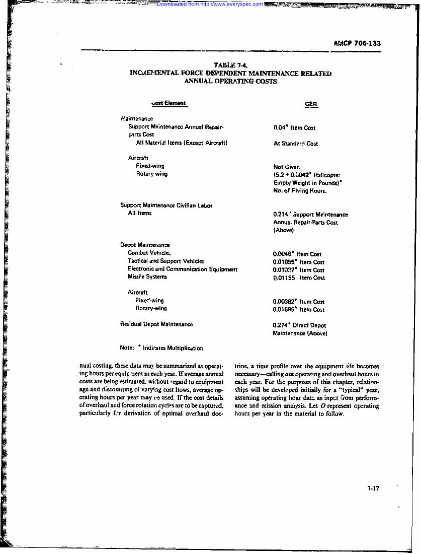
AMCP 706-133
TABIX 7-4.INCL4ENTAL FORCE DEPENDENT MAINTENANCE RELATED
ANNUAL OPERATING COSTS
-*it Elemenit CER
M~ainten~anceSupport Maintenance Annual Repair- 0.04' Item CostI Parts Cost
All %aterij! Itemns (Exceir Aircraft) At Standard Cost
AircraftFixfelwing Not GivenI Rotairy-wing (5.2 + O.(O04 H21icopte.-
Empty Weight in Pounds)*No. of Flying Hours.
Support Maintenaice Civilian LaboorAll Items 0.2 14' Support Maintenance
Annual Repair-Parts Cost(Above)
Depot Maintertam-eCombat Vehicle. 0.00460 Item CostTactical aind Support Vehiim, 0.01056. Item CostElectronic and Communication Equ~ipment 0.011,17* Item CostMissile Systemns 0.01155 Item Cost
A;rcraftFixee-wing 0.00382' lurn CostRotary-wing 0.oi 686' Item Cost
Res'dual Depot Maintenance 0.274* Direct DepotMaintenance (Atove)
Note: * lndii-ates Multiplicition
nuai costing, these data may be summarized as operat- trine, a time profile over the equipment life bezomesing hours per equip nent in eaich year. If average annual necessary-calling out operating and overhaul hours incosts are being estimated, wil:hout regard to equipment each year. For the purposes of this chapter relation-age and dscouniing of varying cost flows, average op- ships will be developed initially for a "typical" year,erating hours per year may (- used. If the cost details assuming operating licur dam. as input Cdril perform-of overhaul and force rotation cycl-s arc to be caotureil, ance and mission analyss. Let 0 represent operaingparticularly f.'r derivation of optimal overhaul doc- hours per year in the material to follow.
7-17
Downloaded from http://www.everyspec.com
r-7AMCP 706-133
7-4.3.2.2 Structural Cost of End 7-4.3.2.7 Size and Weight ofItem/Component (CAQ) Item,'Component (LOS, EIW)
This cost, which we shall call CAQ, represents those These physical data, perhaps summed over Al fai!-
cos oures per year, are important in calculating transporta-elements of acquis ed of the a-m or c ponent s ion and storage costs. In constrained inventory prob-to be supported represented by the hardware- It dcvs lems where space is limited they often play the role ofnot include Tc:hnical Manuals, :raining, initial repair a *side condition" on a least cost solution.parts, or cther acqui.ition cost elements separate fromthe cost of the physical s,." -ture of the end item or 7-4.3.2.8 Packaging and Transportation
Component. Costs (CTRI)
These one-way costs eflect the shipment of items to7-4.3.2.3 Manpower Per Repair Action (MR) or from level L The costs are usually expressed as costs
per pound or per cubic foot, and are partially depend-St ech level/of maintenance, a particular number nt on distance. They can have a significan: impact on
of man-hours is required to peform nmaintenance for system design analyses, where number and locati n ofeach repair action. This parameter may be dcvc!oped repair level facilities are being planned. They are also:hrough maintenance engineering analysis, prior expe- a contributor to the result of discard versus repair anal-rierce, or it may be prescribed by policy. yses, and of modulaiization studies.
7-4.3.2.4 Manpower Utilization Rate (UI) 7-4.3.2.9 Storage and Shop Space Costs(CSI. CSA)
Maintenance men are often assigned other tasks or Cost factors are important to inventory size analysesmili:ary duties. They are thus not fully utilized on and repair level studies. Jr. many such analyses, ;t is
maintenance. Sin c equipment maintenance require- important to estimate the fixed and variable componentments ar- usually expressed in man-hours, a manpower o':hese factor costs, and to capture any size effects thatutilization ra:, is needed to conven, from number of reduce cost per unit (per cubic foot in this case). Whenmaintenance men to maintenance man-hours available facility design studies are involved, it is important toat each level L make detailed space analyses rather than gross esti-
mates. These apparently straightforward costs can lead7-4.3.2.5 Incremental Cost of Manpower to quite complex analyses in the case of constrained
(CP; maintenance inventories-where space is limited, theSOne simplifying assumpti on sometimes made i "cost" reflects both the space taken up by parts and
maintenance zost analysis is that any "commodity" modules, and the 'availability value" of diherent partsreaching repair level Ihas the same cost per man-hour orimodlls havic t o r eigt. is theof repair. This assumption is based on the similarity o initial cost per cubic foot of space; CS. is the annualcorrective maintenance "style" at a pnrticular level. upkep cost per cubic foot.The differences in repair cost are captured in equip- 7-4.3.2.10 Training Costs (CTM, MHT)ment MTTR factors, which vary with repair com- Training costs include those fr facilities, instruc-
plexity. We denote repair cost cdr man-hour at level tor, materials, training aids, and trainees. Annuallas CRK. This cost does not irct.ude repair parts nor training includes that for replacements and for jetraire.their logistic support. ing or upgrading existing personnel. In manning analy-
ses and comparisnn of alternative maintenance plans,7arts (CHRI. CH) training alternativs may be assumed fixed throughderivation of a flat cost PC. man per year CTM and on
This cot rcflects ordering and other logistic cost estimate of man-hours per trainee per year MHT beelements. It is a factor in repair versus discard and usei in costing trainee pay and allovances. Initialstock level analyses. Its va;uc is usually minor com- training must be treated separately as part of the acqui-pareo with material and rnanpovcr costs, and. except sition cost of a system. Basic and recruit trainingfor special cases. may Le excluded from analyses. The should be excluded. Analyses comp.'ring alternativefactor may be important for repair-discaid analyses. training approaches cannot use such gross planningL.ct CHRI and CHT! be, respectively. repairable and factors as CTM and MHT. but must cost a detailedthrow-away costs at leve!. L training plan. course-by-course and item-by-itew.
7-18
Downloaded from http://www.everyspec.com
61 AMC? 79)6-133
7-4.3.2.1 1 Ao-qual Administrative Cost Per and throw-oaway units and repair parts, and deal with
Item (CIA) ..peculiar" support itemns (not yet in the Fa leral) SupplyThese costs are ofteni ircluded for completeniess, 1; it Sy-stemr) as well as "general" suDport iten s.
usually do not affect the outcome of MV-re-ated analyses TeTI E',hwvr r rai.db niand trade-offs, except in specir! cases. For example, ir necrinng concept rather dian cost anatyt is, concept.
a trade-off between a discard-at-failure module or Many CER's contain srveral cost elemens lumped
large-si:Jc integ~ated (LSI) circuit, and repair of in- together. A preferred procedurc is the devdlopment of'
dividual piece parts (soznmidres numbering iti the bun. CER's by cost element; th-- TRIM CER's a e modifiedI drds)tha cold mke p a eqivalnt et f eec- here for that purpose, an - a structure ba.d op A.ronc irus that cd p art ouvldt bethofvlyc 37- 18 (Ref. 15) is used. Estimating methods (or factorspenalized 5,y being charged .-vcrai hundred times the fo h RMmdl hc r ~Lsntv nyadm-Inistrative cost of the single module or L. circuit. follow each parameter or vuriabie name.
7-4.3.2.12 Cost of Entry of New Line Iter"-s in 7-4.3.3. 1 Related Cos' (0 00)
W).~ Oedera! Supply Systani (CII) (20. 00) C(2. OQ (.2. 051) ;.C(2. 052)This logistic rost for cftaloging is similar to C.A in
its ei'fect. Except as a penalty agains, many parts corn- -(C (2. 07) ('(O. 04) 4- C(4. 012)pared with a moduie, its effect is small. 024.021) - ((-. 022) C(4. 031)
7-4.3.3 Cost Estima~ing Relationship CO (24032) -&'(4. 05) C(0- 061Exampie:; (7-14)
This paragraph describes a number of Mf-relatedCER's using parameters discussed in par. 7-4.3.2. where
CERs must be developed for thm specific physical and Q2.04) = publicatior- costsorgantzhtinonal structures being analyzed or planned-, Q2.05 1) = bnilding coststhey must refiltct ciosu. inculT-ed at different levels of Q2_0521 = maintenance cquipment costsmaintenance, inclz-ding the mtiow of equipment to and CQ2.07)= logistic fint~ itcm caad ljingfrom these farilit-tes. CER's must reflect ILS doctrine osbeing planned u- analyzed, including provisionint, Q (3.04) = acq~iisition cost of itemnventory, and resupply considerations. They must allow Q(4.012) = repair cost-mainteriancefor repair policics (discard-at-failure, or repair, or Q(4.02!) = repair costs- -nosirepaira bleboth), and differernces caused by components, modules.and special design features (eg., built-in and automatic Q4$.022) =repair costs- - repaixcable a-tstest equi.pment). As a re-sult, CER'i and cost models _-~ re 4.03 11= logistic proccssiing costsoften -tailored" to tete particular case at, hand. Par. 7.6 (Q4.03211 = logistic catal~:.-g annua costsdiscusses this issue Yirther in connection with trrxle- Q(405) = transportation costsoffs. Q(4.06) = buildi:.g mainrnance costs
Since no simple stt of CER's can be usea in all 7-4.3.3.2 Publication Costs (:'.04)circumstances, thr remnainder. of this section will use anillustrative set largely derinved from the TRIM i. fhrow-away or Repair Implizations on Maintenance (.ost Pro- C2(2. 04) =K(L-1)(CAQ71 - (LR.)'CAQ1? - QR
grams; Raytheon Ce. for the Army) model, bat refltct- (7-15)
ing enough detail for somnewhat broaier ePr)licabiiity(Ref. 14). The TRIM model reflects a wca,)on support wneresystem composed of batte:r es, direct and gcneral sup- K = publicatior factor--throw-awe';port units, ownseas and CONRJS supply depots, and a (0.0056)factory. TRIM terminology is here ims': to allow the L 1* Initial inveriv:-y of tlirow-.wayreader to refer back to the original mel. The mainte- upit; ((erect est-mate)nance flow includes throw-away and repairable ele- cAQT = throw-E-ay uia~t cost (direc;ments; itemns of equipment are sent to p..ticular sup- estimate)- on units because of the natlur of the repair farn!'n.. JV = publicaoz Aictor-repirable
=The C'ER's assu-ne *'shrinkage*' !oss of replacement (0.0c40)
7.1
Downloaded from http://www.everyspec.com

AMCP 706-133
LR =initial inventory of repairable G =number of new line itemsunIts (direct estimnate) introduced i.r~o Federal Supply
CA QR = rqpairble unit cost (direct System (175S)esthtate) ofC11- cost of introducing a line itemn
mitnneequipment (dict(25 14-Huntsville)estitx) I G - thesum ofline items ina aie throw-away
R=maintance equipment unit mdls( ahrepairabie modules (number of newcost (direct estimate) itm nalmodules), and test equipment. If a paricL.-
1. K mnd N' Eiven w"ere derived empirically from lar uiew item occur more than once it ccun.., as oneDoD-wide budgetary ratios and publications ratio dif-. itzm.
ferences between throw-away and mepairmble unt. 7-4.3.3.6 Acquisition Cost of Item (3.04)2. Diroct estimation of niumber of pages o ehi
cal Manuals and cost per paiv may be preferred.
3. LT and LR, the initill inventcrics, may be Q(3. 04) = (CA QR)(PR) ,. (CAQ T) (7-19)derived through policy and stasuiard invettory calcula-tuns, including pipelin coasidt-zations. wm
7-4..3. Buidin Coss ("'.0 1)CIQR = acquisition cost. of each7-4..3.3 Builing osts(2.0i) =rcprAbl- item in the system',
C(2.051 = (S)(Z&')(7.6)learning (direct estimate)
CfQT =acquisition ccst for throw-away
where items (direct estimate)
SS = cubic feet required for PR =population of repdlrable items
maintenance builc~ings atal (direct estimate)
inaintanor levels (diirect PT= population of throw-away .terns
estimate) (direct estimate)
MS = initial cost per cubic fo (SI 7-4.3.3.7 Repair Cost; Miintenan~e (4.012)per cubic foot for new cementblock) C(4. 012) (FR)(1 - S11)(Wmf) (7-20)
7-4.3.3.4 Maintenance Equiprrk-nt Costs
(2.052) wher
C(2.52; C + R (-17)FR = number of repairable unitsC(2.52j + R (717)failing over the syteum life
SU = rpirable "shrinkag-c factordue to loss, damnagc. etc.
whereF/V =unit repair cost-mTanpowerC =R & Dcost ofnaitentnce These trcfacicts nir o'tained as follows:
equipnent (direct estimate) 1. The FR iictot' is given byR = unit acquisition cost of
m~aintenance equipment (direct F f(7-21)*1maite 4)X)RO
2 = nuinba of maiamenanceequipments; (direct .stimate)
where7-4-3.3.6 Logistic Caaoging Co.-ts (2.0 ) X =item failure rate (ditect
estimnate)Q(2. 07) =C(CII) 17 -8) PR =population of repairable iterts
(direct estimate)0 = cperr-ing hours pff year (direct
where estimate)
7-20
Downloaded from http://www.everyspec.com
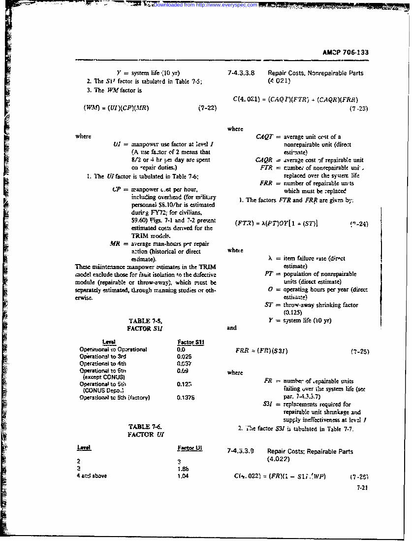
7777 _77
AMOP 706-133
Y = system life 'lO yr) 7-4.3.3.8 Repair Costs, Nonrepairable Parts2. The SI facto: is tabulated in Table 7-5; (4 021)3. The WM factor is
C(4. 0-1) = (CAQ T)(FTR) - (GAQR)(FRR)(WAM) = (UI)(CP)(MR) (7-22) (7.23)
wherewhere CAQT = average unit cest of a
Ui manpowt" use factor at *evel I nonrepairable unit (dirot(A tuse fztor of 2 means that esti-.'te)8-L or 4 hr etA day are ,pent CAQR = average cost -f repairable uniton "epair duties.) FR = rumbe- of nonrepairabc uzid.
1. The Ulfactor is tabulated in Table 7.6; replaced over the syten: lifeFRR = number of repairable units
C = ranpower L.,st per hour, which must be :eplaceincluding overhead (for mi!itiry 1. The factors FTR and FRR are given by:personnel S8.10/hr is estimateddurirg FY72; for civilians,S9.60) 'igs. 7-1 and 7-2 present (FT.) =X(P "iOY[1- (ST)l '-24)estimated costs dnved for theTRIM mod-A&
Mr = average man-hours per repaira:tion (historical or direct whereesirmate). X = item failure rate (d;roct
These trdint-nance manpower estimates in the TRIM estimate)model exclude those for iauit isolation to the &fective PT = population of nonrepairablemodule (repairable or throw-away), which must be units (direct estimate)separately estimated, tLrougb mnning studies or oth- 0 = operating hours per year (directerWISe, estituz-:)
O l!dST = throw-away shrinking factor
(F--R) (3.125)TABILE 7-5. Y =- systemn life (10 yr)
FACTOR SU/ and
Lewt Factor S1 IOpe¢kinai to Opwtionat 0.0 FRR z: (F IM(S3I) (,7 -25)r
OperatIons)to 3rd 0.025OpeCaticrmxi to 4th Q.L37Operatio=., to 5tri 0 .," where
(except CONUSI FR =umbt-" of epairble uisOperational to 5th 0.12o
{CONUS Depo., failing over :e system life (setOperastionl tc 5*h (factory) 0.1375 par. 7-A..3.7)
S31 replacements required forrepairable unit shnnkage andsupply ineffectiveness at leve l
TABLE 7-6. 2. ---te factor S3V is tabulated in Table 7-7.FAC-OR U1
IAII Factor Ui 7-4..3.9 Repair Costs; Repairable Parts
2 1 (4.022)3 1.8b4art'sbove 1.04 C(f,.022) = (FR)(* - S1i.'P) ,1 _2,
7-21
Downloaded from http://www.everyspec.com
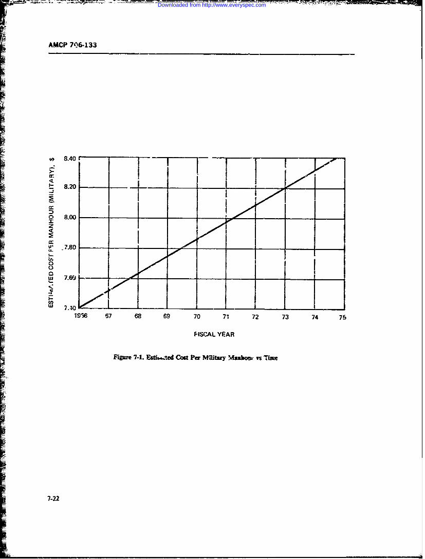
AMdCP 7e~6133
8.40 CI -t- 8.2o
o 8.00 -
9'. .7.80 - ___
0
.Li 7.6(1
196 67 68 69 70 71 72 73 74 75
FISCAL YEAR
Ftgnr 7-1. Dssted Cost Per Nf~fftzy Msabouir vs.,u ~e
7-22
Downloaded from http://www.everyspec.com
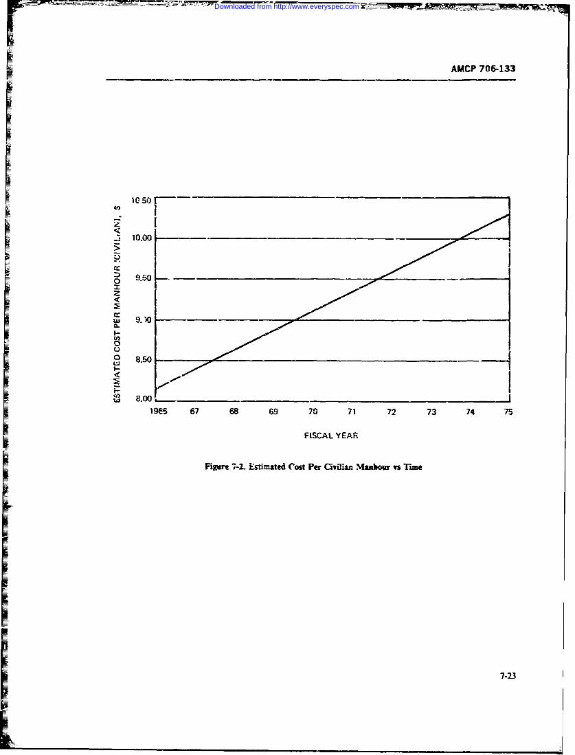
AMCP 706-133
M-K-
PH________________________
c7-2
Downloaded from http://www.everyspec.com
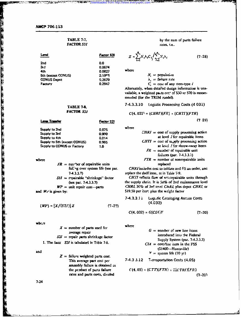
AMCP 706-133
TABLE 7-7. by the sum of plits failueFACTOR S31 rates. ie..
Z =Z NiiC *N€! N (7-28)
2nd 0.03rd 1.06744th 0.0827 where5th (excnt CONUS) 3.19=" N, = populati.mCONUS Depot 0%.2679 X, = failure rtteFactory 0.2947 C, = cot of any stem-type i
Alternately. when detaied dtsign information is .na-vailable, a weighted pats cx" of $30 to S70 is recom-mended (for the TRIM ,:odel).
TABLE74 7-4.3.3.10 Logistic Processing Costs (4 032)TALEO S21t
FACT"II 821 C(4.0311 = (CHRI)(FR) - (CHTI)(FTR)
Lem Tranfe Facto S21 (7 29)
Supply to 3rd 0.87yto&~ 3¢o. ,0 ZIRI = cosz of supply prcsig actio
Supply to 4t 0.914 at level " for repairable itemsSupply to 5th (except CONUS) 0.965 C(T! = cost oF supply processinj actionSupply to CONUS or Factory 1.0 at k'-- Pbf throw-Avway items
FR = nualbe of repairable unitfailures (par. 7-4.3.3.t)
where FTR = number of nonrepairable unitsFR = nuir-er of repairable units replaced
f-',g over system life (see par. CHRIincludes cost to in.tbte and fil an order, an-74.3.3.7) replace the shelf item, as in T;bit 7-9.
S SII= rpairabte -shrinkage" frctor CH7 reflects flaw of '-n-epairabe units through(see par. 74.3.3.7) the supply chain. It is 5j% of 2nd maintenance level
W m = unit repair cost-pants CHRl. 50% of 3r. revel ChIJ p!us depot CHRI orand Wr-'is giv by. $19.50 per itef, plus the weight facor
7-4.3.3.1 i Lt.Vtic Cataloging An.ujai Cost,
(WP) = rX/(S2,)] Z (7-27) (4.032)
C(4.032) = G(CIA',Y (7-30)
- X = number of parts used for whereaverage repair G = nun..ber of ne-w li.ne itcmas521 = repair pars shrinkg fator inmroduced into :he FederalSupply Systan (par. 74.3.3.5)
1. The faw SV is tabulated in Table 7-8. CIA = cost/inc item in the MSS
d($ 400-Huns'ill)and "= syste life (10 yr)
Z failure weighted parts cost.
This average par: cost per 7-4.3 3.12 T, nsportation Costs (4.05)assambly filur is obtained athe pzoduct of prt failure (4.05) (CTT)(FTR) 2(CTRI)(FR)rates and parts cwts, divrided (7-311
7-24
Downloaded from http://www.everyspec.com
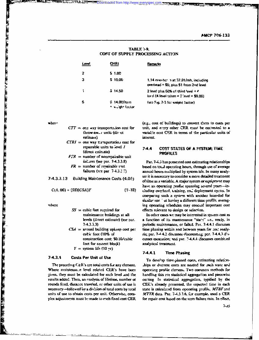
AMCP 7(M-133
TABLE -t-9.COST OF SUPPLY PROCXESSING ACHON
Level CHRI Renwrks
2 S1.003 S 10.00 1.14 m-h, 7s at -7-1I/mh. including
overhead = S9. lus S1 from 2nd level
3 14.50 2 level plus 5% cttirdev
lard4 (4 level takzen = *evel =$9.00)5 $14.00/item (sea Fvg. 7-S fo; weitut I-actor)
wher- (e.. cost of buildings) to convert them to custs perC7TT = or- way r .pton cost for unit. and tiny other CER mu:t be coc.vested to a
throw-aw-. unfl (dir -ct varia.e cct CPR in terms of the particular units oi
estiate) interest.C!RI = one way t:znsportatioa cost for
repairable units to ;evel I 7-4.4 CST STATES OF A SYSTM; TiME(direct estimate) PROFILES
F,-R = number of nonrepairable unitiai*cs (s, par. 7-4.3.3.8) Par. 7-4.3 has p.eseated cost estimating relationships
FR = numtber of rpairable t-t basea on t- hti aour throm use of averagfailures (se par 7-4.32 .anmn l hours muhipede by syscom acu In man acy-
7-4.3.3.13 Iuilding Maintenance Costs (4e06) s it is nesan to cosir a more dei d treatmntofmiene as a val.lno A m we m ryst m or einyect mayl .a n t opfrting atfis spmning sea year--iin
C34..06) 3SS)(CSA)Y (7-32 pic main ca. or fining .. .omn dicsss!nS a b ucomparmg sucth ,n'm with nyrears for
scilar me 1at nspr7nt4 a different time tc gpz-r 7 --3ag-w.here ;.ng opeating schedules may concea important cost
cs = cubic feet rioct for i -css rt-amnt to design or s cimafwfor celdin s at all In o r cas we may be tireeatme in ntn ow slcws (drcct estimate) (s7 m1r. a functi of its sing - -:" ,e. re cy, m774.3.3.3) periodic mai t--nanct - or faled . sm 74.4- iscras
The = apnue buldig upkeep ctl pcs time ps r g -wth cmt aeo=w years for ims aaly-cutk foot (10% of As; par. 7-,l 41 dis,-ussei 0isco unn p.ar- 7-4.4.3 -%
Wheetrutin n cost s.10/ebc cusses sato vid par. T4.4.4 mo n mbth edfoot for ceecht block) anal-inti trea stti
Y = syrstcm life (i0 1r)7-4.4.1 Tia trr si
7 -4 .3 . 4 C o s t s P e r U nfi t o f U se T e , - -pc s . , e t m t n e t -nThe precdig CR's z=eIoW cowsf15" any ceent .hips or dn.zrelc costs arm nwd for zac .itc arQ
Where r.=ntcn*-Ax: level related CER's have been opa-mung prfl c .r-%- Two conu mtthods forz nm the_" must be calculated f-r each leve ,and t!- - b.andlirig this rre statisti--Al a and piecmwisc
results adde Then, an :nalvsis of lifetime. number o cocting In statitical =gZre-ioo typified by therounds fit!. dita,-: traveled, or other units of use is CEK's ulready presented. the expt -e-7 time in eachnecessary-f4ol-ed by a div-sion of total costs by total state is calculated from operating profile. MTBF anunits of %e to dain costs per unit. Othace.ui com- .MTR data- Par. 74.3.3.6. 2z cxample, used s CERplex aajuszmonts must b-: made to c-tch fixed cost CER for repair cost based on the item failure rate. In ciec..
7.15
Downloaded from http://www.everyspec.com
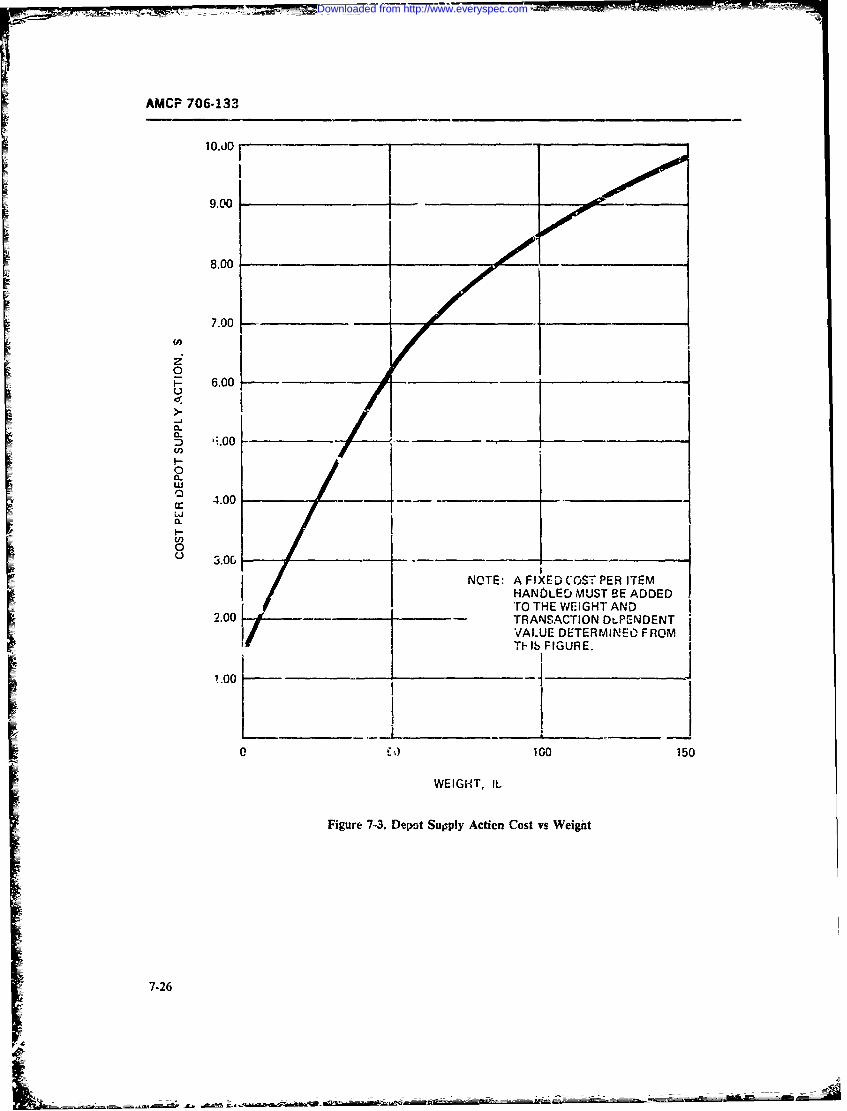
AMCP 706-133
10.JO
9.00
8.00 Z
7.00 -_ _ _ _ _ _
(0
6.0C.)
-
-
0
a 4.00 - ~____
Er -
0
C 3.0&- -__ NOTE: A F IXED COST PE R ITEMHANDOLED, MUST BE ADDED*ro THE WEIGHT AND
2.00__ I TRANSACTION DLPENDENTI VALUE DETERMINE-0 FROMF ______TF IS FIGURE.
I0 100 150
WEIGHT, IL
Figure 7-3. Depot Supply Action Cost vs Weight
7-26
Downloaded from http://www.everyspec.com
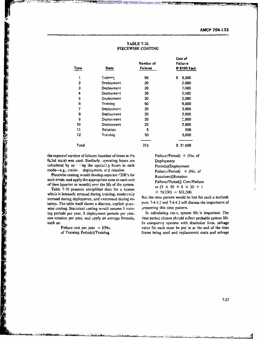
AMCP 706-133
TABLE 7-. PIECEWISE COSTING
Cost ofNumber of Failur-cs
Time State Failures @ $100 Each
1 Trainin-, 50 5,0002 Deployment 20 2,0003 Deployment 20 .7, 004 Deployment 20 2,0jOO5 Deployment 20 2,0006 Training 50 5,0007 Oeployriwnt 20 2,0008 Deployment 20 2,0009 Deployment 20 2.000
10 Deployment 20 2,00011 Rotation 5 50012 Training 50 5,000
Total 315 $ 31.500
the expecte- number of failures (number of times in the Failure/Period) + (No. offai!ed sta-e) was used. Similarly, operating hours are Deploymentcalculated by su , .ng the ope-i!-.e hours in each Periods)(DeploymentF'mode--e.g., trainiit deployment. a:-d rotation. Failurj-Pefiod) + (No. of
Piecewise costing would develop separate (CER's for Rotations)(Rotationeach mrode. and apply the appropriate ones to each unit Failure/Period)I Cost/Failureof time (quarter or month) over thc life of the system. or (3 X 50 + 8 X 20 + I
Table 7-10 presents sintiplified data for a system IY'0)=S150which is intensely stresbed during training, moden-.te*y - R0)=S150stressed during deployme'nt, and vnstressed during ro- Hu,, the time pattern would be lost for such a method;tation. The table itself shows a discrete, explicit pi.-e Pars. 7-4.4.2 and 7-4.4.3 will discuss the importance ofwise costing. Statistical costing would assume 3 train- presenting this time pattern.ing periods per year, 8 deployment periods per year. In calculating cos. s, system life is important. Theone rotation per year, and ipply an average formula, time period chosen shr'-uld reflect probable system life.such as: In compar'.re systems with dissimilar lives, salvage
Failure cost per year =[(No. value for each must be put in at the end of the time
of Training Periods)(Training fr-ame being used and replacement costs arid salvage
7-27
Downloaded from http://www.everyspec.com
AMCP 706-133
value must be included for elements whose life is maker can then decide wh,ber the appropriate dis-shorter than system life. count rate ir higher or lower than this "break iven"
rate. Since the rate is a measure of the opportunities7-4.4.2 Discounting foregone, one pe-suasive argument is that it should be
Relations among alternatives and calculation of the average long.term rate of return of the civilian
nomic impact involve flows of funds over time. When sector. In general, a rate of 6% is not unreasonable.Table 7-11 shows a typical calculation of discountedwe commit to a particular system, mainteaance doc- present value. The system shown has a discounted pre-
trine, level of modularization, or test ciuipment, wecommit operating costs over time. The flow of these sentvau ( at 0%) prewt a n of$ is-costs over time often varies betweer systems. A dollartoday is worth more than a dollar in ten years. The 74.4.3 Escalationcommitment of operating funds means giving up alter-native uses of these funds. D.scounting is used to add Just as discounting captures t,.e tine-effects of ex-costs in different years. The mechanism is simple. A penditures, escalation captures the chapge in price lev-dollar in the bank today at 6% interest is worth SI.79 els over time. To estimate costs in each future yea,"at the end of ten years (with interest) Alternatively, the based on current price is the equivalent of assuming nopresent value of $1.79 received ten years from now, at escalation. This "constant dolla," assmption is un-a discount rate of 6%, is Sl. In gereral, the present satisfactory for budgetary analysis (when we need tovalue PVof SK received N years from now, at a dis- know what funds must be requested in the future) andcount rate E is: for many kinds of trade-offs. if iwo al'-e. native ,ystems
are being ccmrared. one with automated test equip-ment and the otht: with manual diagnosis, we must
(PV') = K/(l * E)' (7-33) make ass,imptions about !he rise in the price of men(salaries and fringe bentefits) over the life of the systemin order to fully credit the autctrated alternative withall its savings, including those obtained by purchasing
now, at a 6% discount rate is (1/1.79) ar 0.558. This the automated equipment at tr--y's prices. Theis called the present value factor. Tables of present method :fcalculation is to Selarate costs that will esca-value factors are readily available (P -) for different late frum costs that will not escalate in each year, applydiscount rates and time periods. in 'Alculating dis- the correc! escalation faciors, total the escalated costscounted present value of a flow of funds, we multiply in each year, and then apply the d.scount factors. Tablethe cost in eacl', year by the present value (present 7-12 shows a pro-forma cost calculation form wb.chworth) factor for that year at the discount rate being includes a e e . orm a caesclation f c -
used and sum the total dixounted operating costs. To includes all E ffects. The formula for *he escalatio fac-
that total we add l:.e acquisition costs-which are not
discounted in the fist year-to ubtain the discountedpresent value if all costs. Repeating this process for (EF) = (1 - E)x (7-34)alternatives being considered, we may then comparethe dirterent present values to arrive at a decision. Notethat this process requires accurate time phasing of costsin each year rather than lifetime ceots averaged annu- 7-4.4.4 CER's with Escalating andally. Ref. 16 is a good introductory reference to dis- Discountingcounted cash flow analysis and many other engineer- It is often conven:ent to inclrde escelation and dis-ing-economic, decision-making tcchniques. counting in CER's particularly when they are to be
What should the discount rate be? Cost analysts do used in computerized cost models. If costs are constantnot agree on this question; but 6% to 10% rates are in each year, a CER such as Eq. 7-35 may be modifiedcommonly used for military trade-ots. In many cases to that of Eq. 7-36it makes no difference to the outcome. In other cases,the decision among alternative_, may change with a C = f(A. B) (7-35particular rate. A sensitivity analysis, assuming alter-nate rates, will quickly reveal when this is so, and theaiscount rate that equalizes the present value of alter-natives may be found by trial and error. The decision C = f(A. B)[(1 - E) (! D)I r (7-36)
1-28
Downloaded from http://www.everyspec.com
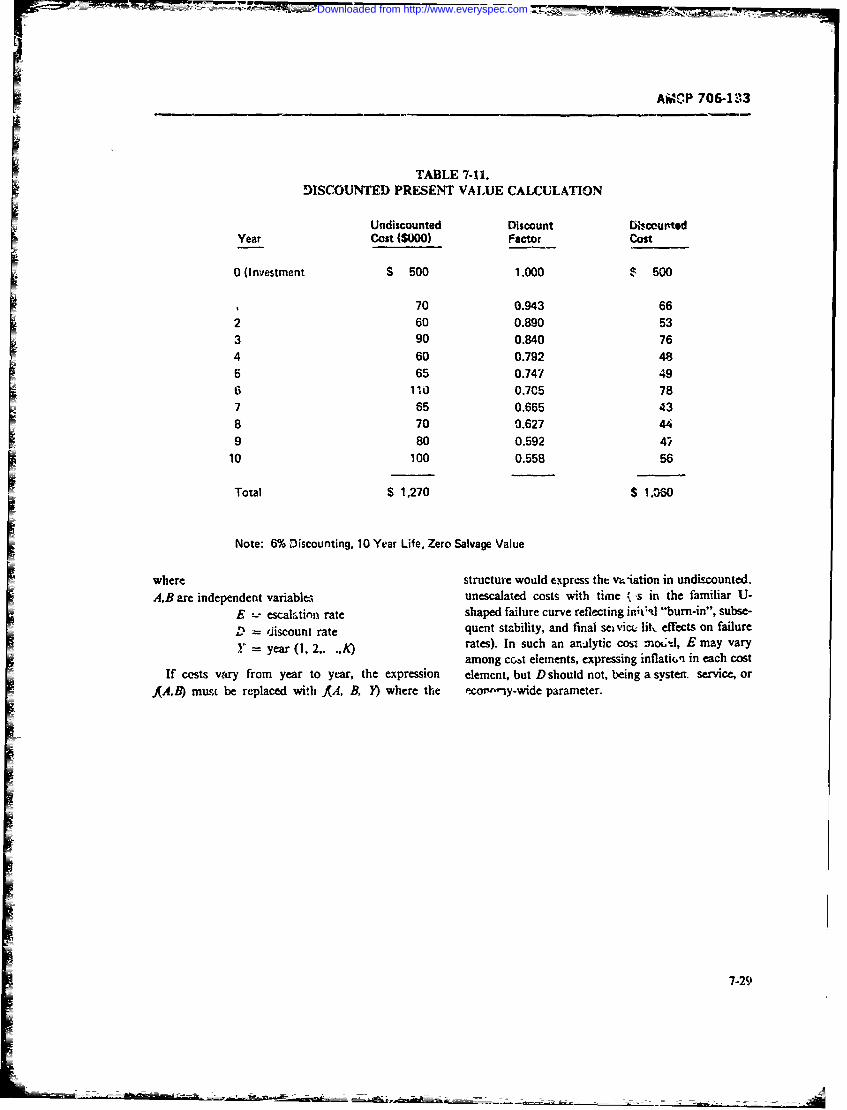
AMCP 706413
TABLE 7-11.M)SCOUNTED PRESENT VALUE CALCULATION
YerUndiscounted Discount W~coiwtodYerCost ($000) Factor cost
0 (Investment $ 500 1.000 $ 500
1 70 0.943 662 60 0.890 533 90 0.840 764 60 0.792 48
565 0.747 496 14.0 03C5 787 65 0.665 438 70 0.627 449 80 0.592 4
10 100 0.558 56
Total S 1,270 $ I'M6
Note: 6% Discounting, 10 Year Life, Zero Salvage Value
where structure would express the: v;_iation in undiscounted.A,B are independent variables, unescaated costs with timne s in the familiar U-
E escalati',n rate shaped failure curve reflecting inh*-d 'turn-in", subse-
D 'iscount rate quent stzbility, and final sei vice lih effecs on failure
Y'= year (1, 2,. ..K) rates). In such an armilyfic cos-, -noK;-, E may varyamong cc.,t elements, expressing inflatir,'i in each cost
If costs wary from year to ye-ar, the expression element, but D should not, being a system. service, orAB) mus be replaced with AA, B, }) where the 'ecor-ny-wide parameter.
7-29
Downloaded from http://www.everyspec.com
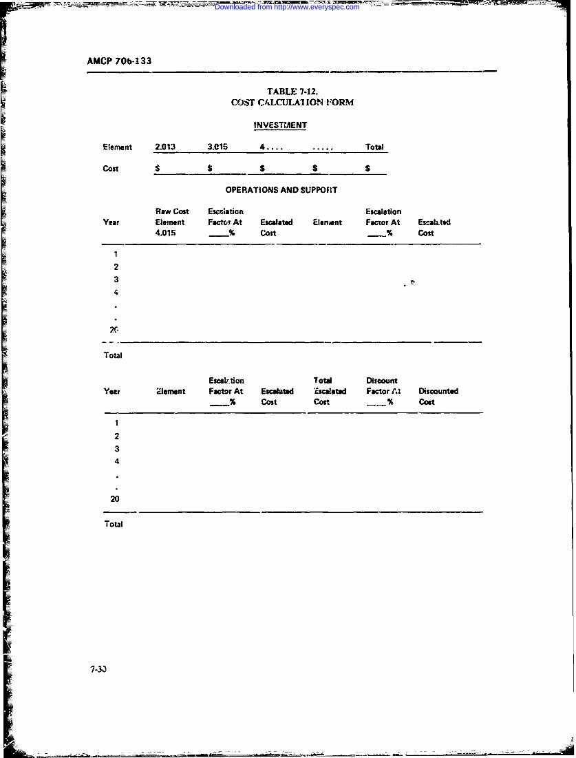
AMCP 70b-133
TABLE 7.12.CO.ST CALCULAI ION FORM
INVESTMENT
Element 2.013 3.016 4 .. .... Total
cost $ $ $$
OPERATIONS AND SUPPORT
Rawv Cost Esczation EscalationItYear Element Fact At Escalated Element Factr At Escalited
4.015 Cost __ Cost
2
34
Total
Escaktion Total Discountyear aiement Factor At Escalated 'Escalated Factor Al, Discounted
% Cost cost __ cost
234
20
Total
7-33
Downloaded from http://www.everyspec.com
AMCP 1064133
7-5 COST ANALYSIS UTILITY by decreasing the amount spent on any performancefactor and increasing the amount spent on another-
In pianniug system development w: need to deter- Ref. 17 c.)ntains a detailed discussion of this subjectmine pre---n*. and future financial implications of sys- with military examples, whl Ref. 18 presents the eco-tern decisions for bu~dgeting purposes. Budgets also act noriic theory in detail.Ein reverse,-as a constraint on design. The prircipal In the second case, (meeting fi~ed requirements withA--relpted system variable having overall design input the least life-cycle cost), availability, as one of the per-is availability. Par. 7-5.1 presents an overview of the formance p-, ame--ers, will be specified. The objective is
problenm of costing system availability, ith effect on to reach the t.arget availability at minsimum cost. WeM-related design, and utility calculations relating w',uid first fintl feasible kmeeting all rcquirements) sys-budget constraints to performance and availability. tems, and then search for least-cost alternatives be-
Par. 7-5.2 discusses the utility of analysis itself; given tweenl and with-n such feasible systems,, while continu-a herit.. of system design alternatives, how far should ing to meet target parameter values.each be carried in early feasibility studies before settling Developing a system availability- cost furction re-on a smaller nur-bff (perhaps one) of alternatives for quires the solution of three problItnms: finding the 1least-dietailed refinement? cost design and its cost for each i-eliability value over
Par. 7-5.3 utscusses the problem of maintenance the range of interest and leasibility, finding the least-planning under varying conditions of rnar~power or cost desgn and its cost for each maintainability valueskill utilization. o' er the range of int-erest and feasibility, ttnd finding
the'jeast-cost combination of reliability and maintaina-7-5.1 COS1'flG SYSTEM AVAILABILITY bility to achieve each kcvel of system availability over
the tange of interest and feasihility. Analy'ticafly, weIn gene-al, a system should be designed for maxi- can see that -.his is so since:
mum performance at specified cost, or for specifiedperfornrance st minimum ccest. In some special caes .11 MBF/3, TBF - 11TTR) 1 /'(1 - X)where thebuigetary outcome is known within a range 17-38)of uncertainiy for an-,- feasible system, design may bedirected to mahximize a cost-effectiveness measvi~ where(utily per dollar), subject to side constraints or. some A. availabilityperformance measures. In the first and third cases, MTBF mean-time-betwev- -failuresavailability can oe traded off ',or other performance M7TR inean-time-to-repaircharacteristirs if we know the -exchangc rate" between K mairstenanue time ratioa unit of availability and a i~nit of, say, speed. T'his (MY7TRAVMTBF)requires the establishment of "military) utility functions For a specified m~ailability. MT7TR and MiBFmust bewhich express such ratios ini ternis of an overall per- in n constant ratio. Inireasing one :equires increasingfornt ne measure El Suppose this is the case. Then we the other to mnaintaini a required avilabihity. If we as-can calculate the marginal exc~hange rate of contribu- stime that each level of M7TR has a particular costtion to U per dollar spent on arailabiliy versus contri- (more about this in a moment) and similarly fof MITBF,bution to U per dollar spent on speed. Provided weke
GG C + . M7T) + g(MTF)AUA A"CA .A Z !C. (7-37) wber--
%C, = cost of availaIhilitvC,= cost itf maintainability
th -extra benefit (marginal utility) per dollar spent, on C, = ow. u; reliabilityavailability is greate; than the extra benefit (marginai and we wish tc mainimize C, (find the least-cost systemutility) spent per dollar on speed, we would design for achieving specified availability) subject tan increment of availability rather than speed or, if wehad designed up to a budget limit. we would reduce K 3ITTR /.1TBF = (I - A)/A (7-39)speed and incre~se availability until the ratios wereequeal. M ore ger-rally, with severra variables we would a ablt we is tok hec tperturb all perforinanee-re!ated variables until their ex- For r. particular avalbltews okzwtecschange ratios were equalJ at the specitied system budget. of the least-cost syvtem. But C., and Ct are themselvesAt that point we wo-:1d not gain any total performance variable for a giver. M3'7R anid Af TBF Them lire mcny
1-31
Downloaded from http://www.everyspec.com
17 ACP 706-133
ways of acthieving a particular MfTB 7 includi-ig redun- performance having the highest marginal cost per uflitdlancy. Each MTBF and sirnilariy each MTR hzs a of utility. This often results in small reductions of the1frast-cost method of achievement (e g., chax:gL.g n.u.m- most essential military factor.i ber of technicians versus degree of automatic te! t). Par.7-6 discusses these trade-offs to achieve specifieu ma'n- 7-S.2 SYSTEM~tainability, as well as the relability-maintiwbility MEELOPMENT-ALTERNATIVESI trade-off to achieve specified availability. For no-.,, wepostpone the discussion of particular hardware trAe- During system development we often consider alter-
o ffs.natives-from Ln M-related pcint of view sach alterna-Let us suppose we wish to cost system availability irl tives might include similar hardware except for the
early cncept design. Then we nedA two stts of cct amount of built-in test eqipmeni, the same hardwarefunctiors, CRt a-ad C~l TI-se CER's must express sys- inspectee a' different intervids, the same hairdware ser-tem costs in terms of 4!TBFand MYTR, respectively. viced by different maintenance systems (numter andWe therefoim need a "prescriptive' cost model. T1he skill level min of technicians, different levels for check-maintainability cost model would require CER's that out, discard, or repair), or different amounts of redun-reflect the cost of the least-cnst systcm for anyhlTiTR. dancy. How long should sucl. alte-tative systems bp-Such expressions may be derivd from historical data, carried? How can we choose among them?statistically aggregated, or from preparation -if a de-tailed nm del specfying and costing the Irast-cost main- 7-5.2.1 The Vaiut_ ef Information
E_ ~~~teinance doctrine, amount of automated test equipment. sagnrlrle hnWentvessesaecn
re ~~numlere f Mona acee, an srstm-b-s d bails nor sidered they should be developed in paral2el providedanylevl o Mo a ystrnby- !,,cmbass. noter such development is nwcessary and sdvantageous as
approach% is to use state-of-the-art, military require- f olld be) Afrevque. ts intervals ay beelomn pero-mem~s 'and historical cost daao particlar sytm cesould a At frcevwd T intervals he beelo n pr-types and their availability to establish availability me- odic, or a review may be triggered by ni' elent such asquirements and targets. Reliability nd maintainability tecoieinfatrd-foraltc uy.(LAare next "allocated" at system. i~bsystern., rrnd compo- te dcinpitsthfrtqutonobeaked i,nent levelb based on statc-or-Ilhe-art, coxt. anid next- thDo wecso kno n enuhe fiow tio n choos eo alkedia-
level R and Ml requirements. Trade-offs arec next use "ivD? wf low te numbe no ocosimn alternatie s eue
to make tower-level decisions, and to rcallocate based iusall Io !on, umbg rer of corttst effeces
on excursions from baseline designs. For example, if We tsaltoneuigctraofotfetvns,ailocate availability to R and M portions. and diecve and perfbrmanct, &Wd mission requirements. If a choice
that the cost of increased R compared with thatal cannot be made cn these grounds, the second question
located is less than that of increased MA we would to be asked is, -D% the benefits of con tip uing the devJ-
deig I-itdirection of more Rand less A, achievinj, opment of alternatives oitweigh the cost of 'so cloi~g?'destn .f t~We comnare the value sf additional informnation with
L ~~~~a lower c'~st design for the specified availability. This tco.()ifAre wkisn jtfidnthe-marginal trade-off" me:thod (similar in ccpt to the iis ost. (c)lu nee t e re s jsfed n ollasemarginal utility trade-off discussed at the beginning of thoughntds healul toedo o), ne orxreued numbelrs
par. 7-5.1) is discussed in par. 7-6 tog alterais shpultdo e ) coe o reduced udmea
Costing systern availability is particdlarly important o lenaie hudb hsno ro4jdmna
under constraincd budgets. If the bud&et constraints -,r other ground and the work continued. Sometimes
are sufficiently low, we may not be able to achaieve a one alternative of high risk but extreme benefit is car-desired level of availability The lower availability can , 1ed along with t baseline a~entv.Often. a reduc-only be caused by reduced reliability or an intainabil- tion in the number. of alienzatives may 6e quickly
ity. Othcrwise, we must sacrifice some peemac achieved through trrade-*ffs and analytic studies. Par.paraete tagets) t -py fe' he eqw--,- avilail- 7-5.2.2 introduces selection concepts and pa:. 7-6 deals
ity. Reduced reliability may be due to lesA, cCSwlV coin- xeti!-w& Uecomcsftrdo.
rp sor reduced redunadzncy, for example. ReOduced 7-5422 Selection of ffai~ttenance Intervalmaintairdability n-ay be due to reduced test -,fuipmcnl and Mit npowei' Levelsar. I automatic checking, reduced maintenance mran-por. 'e, or reduced sparing and other logistic support, One method for &-tcrmunation of nmaintenance inter-for t- Arnple. In sacrificing pcrformance parameters we val anct manpower lcvels has been suggested in Ref 1,are li~lto be tempted to give up an ii-creniezt of Chapter 2. An item is assune3d to .e good, deteriorated.
7-32
Downloaded from http://www.everyspec.com
7- =7__ _
AMCP 706-133
or failed at the start o' any small inzrene: of time maintenance aiternaties and calculaig their come-
between inspections. (Probabilities are sr.cified for go- quences and costs. Par 1-6.7 dicnbes se examples
ing between any of these states during the calculation if these models an-' ohers.increment, chosen so that the probability of mc-e than Some of the resul:s of the model include:one transition between states is negligible, but the in- a. As the time between scheduled inspe ions in-creme-'! is long enough to permit repair of the failed creases, the number of prtventive repairs per year de-
item.) The resulting Markov process !eads to the calcu- creases, and the expected number of failures per yearttion of the probability of needing a preventive repair increases.P,at the end of some interval ibetween inspetctions, (the b. As the number of maintenance men increases,interval i is much longer than the calculation incre- the cost per year of unit preventive repair (excluding
: t.,ent) and to the calculation of!k,, the ex,,ected number set-up a.nd parts costs) decreases as does the marginal
of failures, at the end of that interval , between inspec- ost of inspection; the marginal cost of inspection istions. A simpie economiL model is then specified. The much less than that of preventive repair. With enoughrosts of inspectic-., r: of repair during an inspection, maintenance men, Ihe sum of the annual n-marginal ,osts
arc specified in terms of the average times for these ,.of failures, preventive repairs, End inspections in-actions, tLe number of men avadablz to ptrform them, creases cutting the number o'maintenance men causes
and the cost of downtime. The cost of corrective repair costs to have - minimum at a finite maintenance inter-is also calculated. Corrective repair costs can be large, val.particularly if we calculate the hourly economic oss c. After all costs are included, the annual mainte-
during downtime as the total system lifetime cost d:- nance cost is a double U-shaped curve of maintenancevided by lifetime expected operating hour. Ref. 1 next men. The result is shown in Table 7-13 (adapted fromcalculates the total cost as ; function of these individual Ref. 1).cost% the probability of a preventive repair, number ofcorrective repairs necdea, number of subsystems, and Many sophisticated techniques for scheduling main-
the set ip md manpower costs. The result is. a cost tenance actions have been developed. One survey of
function (presented in parts in Ref. t): 'hat literature ntry he found in Ref. 19. Re. 20 &s-cubses stochastic and deterministic maintenance poli-
cic including economic criteria (cxost per ;-r-nt of time)C, =
j1[XCD(W1 4 %1,Pj - VDjEj)/M, (SU)j and presents some illustrations, including product im-17- 40) proveinent.
where CTthe total cost, is to be minimized with respect 7-6 ECONOMICS CF TRADE-OFFto N the number of maintenance men M, and W the DECISIONS; APPLIED C-OSTinterval between inspections N Pand E. are !he proba- MODELSbility of a preventive repair during inspection and theexpected number of corrective repairs between inspec- This paragraph desc-bes the evonomc approach totions, respectively, and are functions of , the interval trade-off analysis. In conducting trade-off. ( ational
between inspections. CD is the :iourly cost of system comparison nf alternatives and selecton among them),downtime and is related to the system cost and value the economic, vhysical, performance, supply, logistic,D1, W,1, ani W21 are the average elapsed time for emer- development, and maintenance chaLacteristic ofgency diagnosis and repair, and the average manhours equipment in an operational environmcmt must be de-for preventive repair, respectively. SUIS set-up cost for scribed in a way permitting comparison and choice.preventive inspection, N, the number of subosystems, This requires descripdon and quantifization. (Qualita-and Cm the cost per maintenanc, man. Some of thee tive comparison is oten necessary for sr:ne factors;
elements may have to be calculated piecewise and here we n. gleft such factors, athoigh they mst cutersummed. For example, if the subsystemns are not all considem~don when they are ormajor significant-) TheidenticaL a series of P, E1, WIg, and N must be ccnsia- most common approach= to quantification is to buiid aeitml separately. Again, in - realistic case, a series of "model"--a representation of reality. Some modeLsmanning and skill combina, ions and their impact on have few equations and san be solved on inspection.D, W M. and C, will h.vaL to be calculatcd separately. More commonly, large numbers of equations and someAs a result, some c- !plex and sophisticated raintaina- ma:hermatical decsion rule are art of current main-bility/economic moqie have a. en, stepping through tainatility models.
7-33
Downloaded from http://www.everyspec.com
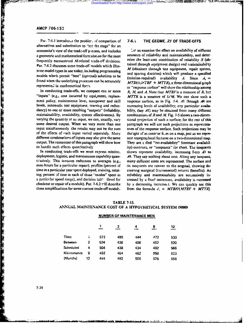
AMCP 706-133
Par. 7-6.1 introducs she probler. -)f comparison of 7-6. i THE GEOME. RY OF TRAOE-OFFSalternatives and substituiion to "'st !ht stage" for aneconomist's view of the trada-off p ozess, and includes -a' us examine the effect on availability of aifferenta geomeiric and mathematical fornulat'on for the most amounts of reliability and maintai-ability, and deter-frequently encountered M-related trade-otT dccisions. mine the least-cost combination of reliability R (oh-
tained through eq'uipment desiga) ;rid uiaintainabilityPar. 7-6.2 discusses some trade-of= models which illus- tae through equipment airte ,~M (obtaineo through test equipment, repair system,tra!e modJl-types in use today, including programming and sparing doctrine) which will produce a specifiedmodels which permit "best" (opimal) solutions to be (mission-required) availability A. Since A, =found when the underlying pxoce3:es can be accurately MT& F 1MTBF + MTTR). a three-dimensional graphreprenente. in mathematical forai. or "response surface" will show the relationship among
In conducting trade-offs, we compare tone or more R. M and A. Note that MTBFis a measure of R, '-."inputs" (e.g., cost incurred by equipment, replace- MTTR is a measure of /4. We can show such ameat policy, mainzennce levei, manpower and skill response surface, as in Fig 1-4. Al :hrough A4 arelevels, automatic. test equipment, tramir.g and redun- increasing levels of availability; any particular availa-dancy) to one or more resulting "outpu.s" (reliability. bility, (say Al' may be obtaned from many differentmaintainability, availability, system effectiveness). By combination of R and Af Fig. 7-5 shows a two-dimen-varying the quantity of an input, we can, usually, vary sional projection of such a surface; for the rest of thissome desired output. When we vary more than one paragra4ph we will use such projct-ons as reprecnta-input simultaneously the results may not be the sum tives of the response surface. Such projections may beof the eflects of vach input varied separately. Many the-ight of as contcur li..s on a map, just as we repre-different combinations of inputs may alsc give the same sent topographiczl fetures on a two-dim-sional map.output. The remainoer of this paragraph will show how They are c -iled ":so-availability" (constant availabil-to handle such dfects quantitatively ity) contours, or "soquants" 'or short- The isoquants
In conducting trad-offs we must express mission, shown represent availability, increasing fiom Al todeployment, legistic, and maintenznce capability quan- A4. They say nothing about cost. Along any isoquant,teatively. This invoives reduction to averages (e-g., many different costs are represented. The surface andman-hours for a particu!ar repair), profiles (percent of its isoquants are convex to the original, showing de-time in a particular year spent deployed, training, rozat- creasing marginal (incremental) returns (benefits). Asing; percent -f time in each of these "modes" spent int reliability and maintainabdiity are sucessively in-a partict-lar speed range), and decision tab' - - (level for creased by a fixec' incremen:, availability is increasedcheckout or repair of a module). Par. 7-6.2 "ill dtscribte by a decrtzsing incrememi. We can quickly see thisthese simplifications for some current trde-off modeL. from the formula -.7, IMTB/(MTBF + M7TR)
TABLE 7-13.ANNIUAL MAINTENANCE COST OF A HYPO'HETC4L SYSTEM (SWON)
NUMBER OF MAINTENANCE MEN
1 2 -4 8. 12
Tim2 i 572 496 444 J72 530Between 2 534 436 406 452 520Scheduled 4 504 433 434 492 566Maintenance 8 492 464 482 550 6z3(Months) 12 494 482 506 S78 656
7-34
Downloaded from http://www.everyspec.com
AMCP 706-13a
(Try assuming val-!tcs for either MTBFor MfTR, hold- irnterection of B v/ith the ),-axis; the price of R ising the other constant. Mere powet fully. calculate the BiigqRl.)partial derivative of A with respect tc, either.) The ir Fig. 7-7 combin, -s the isoquants of Fig. 7-5 with thedividual isoquants approach asymptotes to either aris isucot curves of Fig. 7-6. Let us plot the lowesibecause larger and larger amounts of R or M are r'e- j?-curve just tangent to each A-curve and dlenote thequired to produce a f' med A as M or R becomes small. parbthsmen ir(ABorCMor^J
R and Mf are "competitive substitutes" for each PaB3, tsae ontsmf'aer Al, PI toug P4. a2re3other, and the rate of such competitive substitution t3, letc . pointiis of R y and thro ha Pwilardiminishes as we mov'e aloaig any isoquant. Again, ref- thlescotAihaierofRn ltatwlerence to the formula shows the substitution effect. For ach w'e each level of avi."ability. Consider (Al, Bl). Ifa large, availability A and the rcsu.tant constant K. if Bl were any closer to rue origin (any lower budgezz), itIwe take partial derivatives in Eq. 7-39. reme mbering would not be tangent to AL. We could not buy availabil-that M77'R is proportional to) I/M. we atain: "ty Al for such a lower budget. Conversely, if BI were
further from the o-igin than shown, it would c--:rlapUM K A! in s-everal places;, we would, however, be spending
i" F (7-41) mare than necessary to achieve availability Al. Thus,BI is the least cost to achieve A I; the tangent point Plshows the combination .1I and P1 of Atand R that
where KI = A/(l - A). Thus, at any availability, as will achieve that availability Al.R increases M decreases proportionat-ly with R2. At ra2, _P3. and P4 ame the oplinial combination pointsvery large X. the slope of an isoquant is almnost zero, for R and M to achi.-ve availability A2, A3. 3fld A4 atwhile at very small R, the slope is almost infinite (the least cost. me curve connecting PI throtgh P4. curveisoquant becomes parallel to either axis as one goes out tN , is thc "expansion path" ;.nd shows the increasesfar enough). Note finally that the respc. surface ap- in RZ and M that must be obtained to increase A at leastproaches a point. AS. At some level of av-ailability we cost in? every care. Thi; is the economric mechanismhave approached the -state-c.7.the-art" Eli no higher behivid the trade-off bettveeni R and M to achieve .value ef R or (perhaps) M is possible: ..nd a single Note that at any tangent point (and only at su :h acombination cef Rand Mis the cinly way - t'chievc such p-Gint) the -'lepe of L-oth curves must be equal. Thus. to.a high A The isoquant has become a single point, a giv-zn availability curve, at the optimum the stope
Fig. 7-6 shows. a series of "budget" or -socc'sC- AR/ziMmust equal AC,/A C,. the slope of the budgetcurves. Any curve represeniz combination.; of R and curve. M.The marginal rate of substitution of R for M1Mthat can be purchascd for a particular budE t. Budg- must equal the in~erse cost iatio.)Iets incrvisc f-rm 3) to B$. The curves intersect the How should we search for an optimnum (tangent)axes a! a point where all of a particular budget is spent point? One way is to cxploi.t tht behavior of the avaiia-on R or zn M with rothini. spent on the other. The bility isoquant. Fig 7-9 reviews the cost behavior alongisocost c'.rrves say nothing aioul. avaiiability:. iany dif- such an isoqnan'.. Beginning at a high M1. low R combi-ferent values ce availability will likely i%-cur alcng a nation yielding !arget availat);iity Al. we move towardparticular isocost curve 'rlc isocost curves aze sorex- the low ML high R -nd of ther same isoquap t. As -we dowhat concave to tht origin. showin- increas~n mar- so wt pass through isocost curves representimg decreas-ginal costs. The last incremetit of R ar if is- usually ing cost from CS ifhrough C1 (the optimum) and thenmuch more costly than ear i:.r increments. Thus, as we through curve, of increasing c-ost C2 through C5. Sup-reduce the amount of R slighitly, we can "buy- substan- pose we sele ..t a rando'.n point (easign) on Al. By exarn-tial M. and- vice~ versa. This effect, diminishing returns ining the cost of that design. an.d *he cost of a mnoreto t:-Jle_ is a wedI known economic phenomenon at high reliable, less maintainable designi, we can tell whetheri vels of output i-or many kinds of process. In this case, we are moving awa-y from thIte opt im L i poir -t or toward
the highest increments o'reliability or maintainability it. If the costs incre.se. we are moving aw.i. from :herequire csxc-al. costly techniques (gold-plating or optimum. and we would reverse our strateg~y by reduc-redundancy. for exampi:). ing R anid incres~ing M to decrease costs. If. at scome
Note that ir Fig. 7- zny point (say. Q) on an isocost point, this stra.tegy caused costs to increase, we willcurve represe its the quantity (q.WL qR11 of M1 and R that have passed through the opti'ium anid must backtrack.can be purchased for the: fixed budget, (B1 in this case). On the othctr hand, if the trial design prodiced a lowerThe unit cost, or prict of Al whrn a-' sources are cost for morm R and less . we would be above anid tospent on Afis thus BI/.731 (whemeqx .:e pointJ~ the: left of te optimum and would contirue toin~rs
Downloaded from http://www.everyspec.com
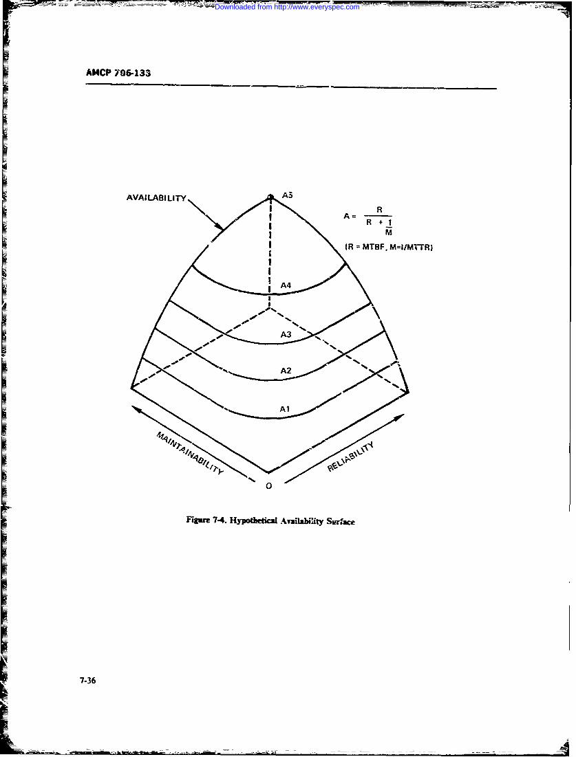
AMCP 706-133
AVAILABILITY A
R
( R MTBF. M=I/MTTR)
7-A3
Downloaded from http://www.everyspec.com
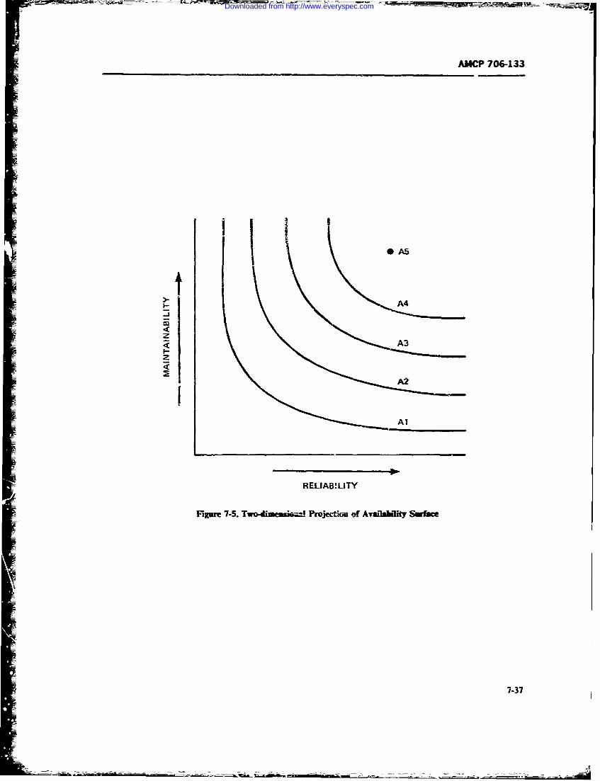
AMCP 706-133
4 'II A5
A4
I A2
Al
RELIABWLITY
Fgure 7-5. Two dask-' Projectim of Availabdkiy Swfoce
7-37
Downloaded from http://www.everyspec.com
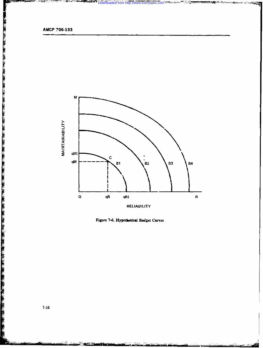
AMWCP 7064133
4m
7-3
zA
Downloaded from http://www.everyspec.com
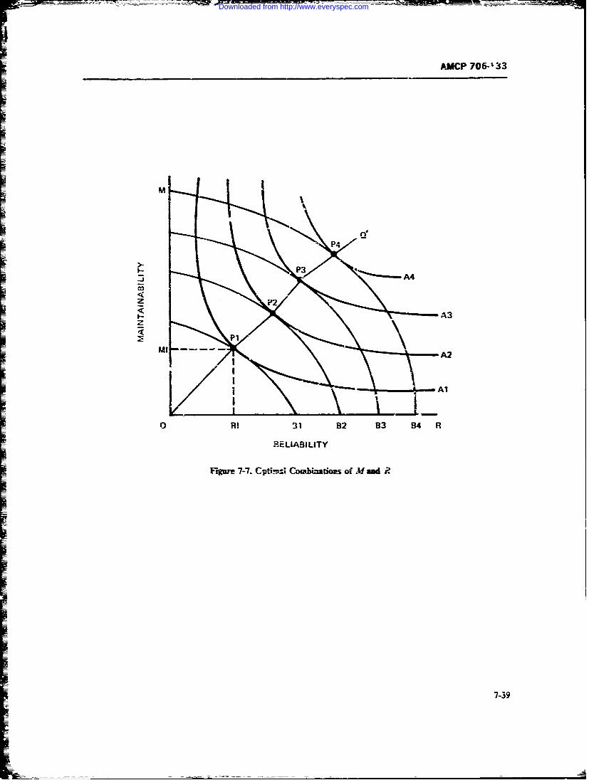
AMACP 706-' 33
I- A3
A2
0 RI 31 82 83 84 R
RELIABILITY
Fire 7-7. Cldti!-' Combimaioes of MA and P.
7-39
Downloaded from http://www.everyspec.com
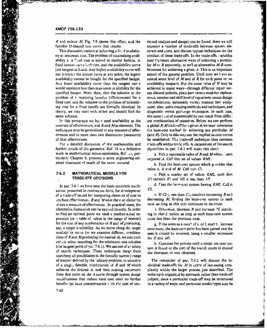
4 --EAMCP 706-133
R and red't:ce M. Fig. 7-9 shows this effect, a.id the tinued analysis and design) can be found. Hiere we willfamiliair U-shaped cost curve. th~at results. examiine a number of trade-offs between sysiei ele-
This discussion, centeics at achieving a fvi' d av~iilabii- rnents and co)sts, and discuss typical techniques !or theity at -ninmurr. cost. The problem of maximizing avail- conduct of these trade-offs. In the trade-offs, ariablesability 2 a F Aed cost is solvfd in similar fashion. A may r-present alternative ways of achieving a particu-fixed isocost -.- ! :s ch', sen, and the availability curve lar Mor R separately, as well as alternative M-R corn-jast tangent is fcurcd. Any hi-her av~ailability ctirve will binations for achieving a given A. This is oil importantnot itaersect the isocost curve at any point; the higher aspect of tihe general problem. Until novw we I avc as-availability cannot be bought for the specified budget. surned some level of M and of R for eazh point or 'qnAiny lower availability curve than the tangent cur aavailability isoquznit. But the same -a) ue od Ymay bewould represent less than mtxin' wvailability for the achieved in many ways-through different repair ver-specified buqget. Note, then, thpt the solution to the sus discard policies, piece part versv~s mod-lar replace-problem of r 2xitiz.-.g ltcnefiu, (cfLecttvenessl for a meist, number and skill level of repairmen versus designfixed cost. and thiL solution to the probiemn of riinimiz- ! crsiderations, automatic versu, manual test equip-in? cost for a fixed benefit are formally identical. In wient. alter -ative training methods and techntiques, andtheory, we may start with ei~her and should find the diagnostic ve.rsus go/zno-go teciniques. In each zase,same solution. the same 1l.-,el of n~aintainabi~ity can result from differ-
!r this paragraph we ha-/'- used availability as the ent combinations of resources. Befort we can performrzaaure of effecti'eriess, and R and Af as elements. The a global R-Mtrad,:-off for a given A, we muss detertninetecbf~iqucs may be generalized to any measure ofeffec- t'jo- least-cost nieth&~ fo-. achieving any particular Mtive!ness and to more thpii two dimensions (measures,) (and R). Only in this way can the implied ist/cost curvesof that effectiveness, be established. Thed tade-off technique thus contains
For a detailed discussion o"' the mathenmatics and t-ad-offs within trace ofs. A restatement ofthe searchfurthe!r dethils of th;- geometry, Ref. 18 is a definitive alooithms in par. 7-6.1 will make this clear:work in mathfrndticai micro-economics; Re-, .!, par- a. Pick a rea.sonable value of R and Mrwhici. 1ectstic'ilarly Chapter 9, presents a more ergiiieering-ori- required A. Cal! this set of value-, RW&lented treatment --f much of the same naterial b idtelatcs ytmwihpo'dsta
value o. R a-id of M_ Call tili-, Cl1.7-6.2 MATHEMATICAL MODELS FOR c. Pick a nearby set of values RM, euch thot
TRADE-OFF DECISIONS F"' excces R1 and A17 is less than iAln.
Irn par. 7-6.1 -we have seen the basic economic nie-.h- 2.d. Finci thc !a-t-cost system having RM2. Call itani~rn, presented in continu,)us form~, for drzvellopm.-rtof a t- ade-off mciel for comparing elemeats of cot to r. If (2 i,! ess than C1, continue increasing R andIjrcluce effectivenesi. R and 'Wwere the co)st eleme~ts; decreasing M, finding the lenst-cnsi system in eachA was a measare of efflectivenes., In practica! cases, the ca-,e, as long as this ccst continues to de--re.se.illustrative framework can te applied directly. In order S. Oth-arwise, decrease R and inc-ease .,f search-to find an optimal point we need a mather-adcal cx- ing in tha! d 7ection as long as ech least-cost systempression for t table of .'alues in the range of interest) ccosts 'ess thati the previous ones.for the cost of any comnbination of' Rand Mpcoclucing, g, If the costs as a rcsu"t of !. or f. start L crassay, a target av'ailability As wc move along the: target. once niore, the least-zo-ct point has been passed and theavaiiabi * ty cu-.-.e (zs we examine differen, crmbina- sear~h 0!ould be reversed, using a smaller increment'ions of R and Mproducing the desired A), we cost each for R? antid i,1.car .zi. ition, searching for the minimum-east solution h. Continue the process until a minir urn cost sys-(tdie taiigent point of par. 7-6. 1). We use one of a'i anieiy tern is founmd or the cos, of the search starts to exceedof search techniques. These techniques rang"' from the decreases in cost obtained.starching all possibilities in the (usually narrow:) raingeof intercei defined by the nilitary problem, to selfctio1 The remainder of par. 7-6.2 will discubs the in-cf a singl-, feasible, cormbinatior of R and M which dividual trade-offs for M in urd-tr of inca easing corn-achieves the dlesired A, and then making excurti''t exity with'in the larger process just described. The
- ~.from that point on ihe A curve through syste= dlesign write-up is organiz.4 by apnroach ather than trade-oilmoditfications that reduce total cost unt.d no further 'lbject, since a particular tra4de-off may be structured
Vbenefits (at le:,st commensurate~ 'th the cost of col. in a variety of ways, and particular modci~types m~ay be
7-40
Downloaded from http://www.everyspec.com
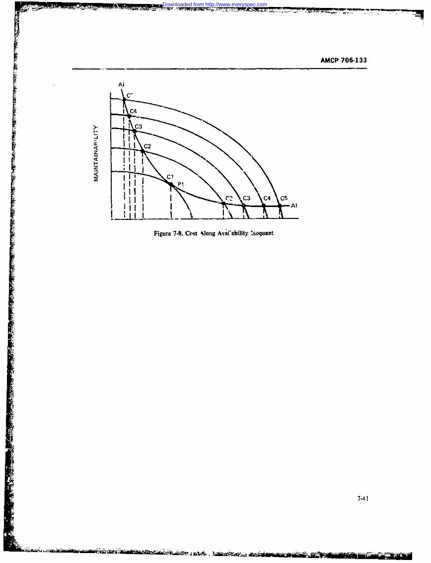
AMCP 706-133
Al
LC,
I C4
IC
Fiuet8 ot4og viaiiy~oun
r:
7-4
C2
Downloaded from http://www.everyspec.com
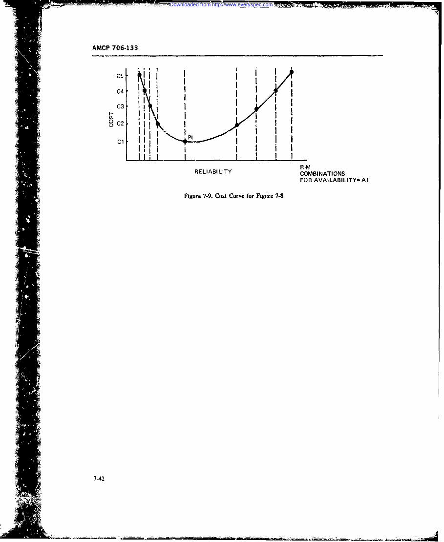
AMCP 706-133
I I •I "
0i !04 i I
03 II Ii I II
l I I I I ..
R-MRELIABILITY COMBINATIONS
FOR AVAILABILITY= Al
Figure 7-9. Cost Curve for Figme 7-8
7-42
Downloaded from http://www.everyspec.com
AMCP 706-133
used for a variety of applications. Par. 7-6.2.1 treats costs) or complex (maxurize the ratio or differenceformulation of the trade-o"t; par. 7-6.2.2 discusses the between a weighted sum or product of costs and of
point trade-off; par. 7-6.2.3 describes the simple de- benefits). Choosing appropriate criteria is fraught with= scriri.'e or "accounting" model. The descriptive pitfalhs: Ref. 17 contains a discussic. of appropriate
model with decisioi. is described in par. 7-6.2.4. Fi- and inappropriate criteria.nally, the prescriptive, or optimum seeking, model is The final element of a trade-of is a model relatingdescribed in par. 7.6.2.5. the criterion function to costs and benefits. In the re-
mainder of this paragaph we will discuss 'point trade-
7-6.2.1 Formulating the Trade-off offs" in which the model is a direct a ccounting com-
parison of specific alternatives (par. 7-6.. 2), the simpleThe first step in formulating a trade-off is tu clearly descriptive or accounting model (par. 7-6.2.3) into
state the objectives of the trade-off. Are they to find a whtich a vari-ty of different -tttratives may be
least-cost schedule of preventive maintenance meeting "plugged in" ir order to caicuiate thei, costs and bene-availability requirements, other things being equal? To fits, the descript, e model with decision (par. 7-6.2.4)find A preventive mainteniance schedule maximizing M, where suboptimizations are made within each alterud-at specified cost? To determine repair levels meeting tive (such as level oi maintenance) but where each al-required M at minimum cost? Specific objectives are ternative stil! produces a sp,,rate output for analysisnecaes-try to appropriately formulate the remaining ele- and comparison outside the model, and the prescriptivements of a trade-off. Carefully specified objectives are model (par. 7-6.2.5) in which alternatives are generatedneceszary to be sure we pose and solve the right prob- and compared accordirg to some predetermined se* oflm. rules, and thc. "best" solutio.t is found.
Once objective* have been specified, two or morealteenativesare desirned. W:thiout alternatives, there is 7-6,2.2 The Point Trade-,ffno problem of choice and no trade-off is necessary. A In the point tradc-off we compare several explicitrange of alternatives which reflect different approaches alternative, it is convenient to organize such trade-offsto the problem of choice (the objectives) is needed. according to a format, similar to that desciibd in par.They must be genuine alternatives, each of which 7-6.2.1:represenzs a legitimate. feas;ble, and des'rable choicefrom the decision-maker's point of view. Such "zooked a. Objertive The objective of the trade-iff arealternatives" as everything, nothing, and the oe-signers' stated in an introductory paragraph. Suppose we arefavorite compromise are not viable. Alternatives may selecting a subsystem design for testing. Suppose fur-Ent avote omprmis ar notviale.Altenatvesmay ther that the system already meets availability require-be discrete (two or three degrees of automatic testequipment) or semi-continuous (a finely divided con- ments; we seek the least-cost subsystem design for test-
tinuum of manning and skil! levels, or of MTTR). ing.'he third element of a traae-off is an explicit state- b. Alte-nativet Suppose the alternatives are built-
meat of costs All costs whicl vary among alternatives in test equipmen" which normally comes - ith themust be considered. Costs which would be incurred prime equipment, two types of senii-automatic faultwhether the system being cnsidered were produced or detection equipment, and one type of automatic faultPot should be ignored. A detailed discussion of costs, detction and isolation equipment. Each alternativecost elemen:s, and cost structures was presented in would be described in terms of its basic design andpars. 7-2, 7-3, and 7-4, and will not be repeated here. principal features. A requirements matrix would be
The fourth e!ement of a trade-off is an explicit state- presented, showing whether each alternative met tech-ment of beneitm These may be measured in dollars or nical requirements. including (for exampie) MTBF.;n units of effectiveness. A benefit struzture may consist MTTR, size, weigh!. technical risk, and any other non-of a sin, element (availability, say) or : a complex. cost criteria. Alternatives which failed to meet all re-tree-like structure similar to that of a cost structure. quirements would have tv, be redesigned or eliminated.
The fifth element of a trade-off is criteria or a crite- The remaining candidates would be admitted to therion function, the explicit, "mplementable rule for next step of the trade-off.choice among alternatives. A criterion is usually a c. Coszt The zost section should first defne eachmeasure of the combinaion of costs and benefits appli- element of deve'opment, investment, operating, andcable to the objectives of :ht particular trade-off. A support costs idplica le to the trade-off. After defini-criterion function may be simple (minimize costs for !ion of each elfment the method fot estim-tting the costfixed effectiveness; maximize effectiveness for specified of that elem,nt for each altcrnative in the trade-off
7-43
Downloaded from http://www.everyspec.com
AMCP 705-133
should be specified. Any cost estimating relationships. rciatiorships to the input data to produce costs didata or references should be presented at this point. rectly. Most accounting models are :.vitable for aNext, ie costs should be calculated for each eleme~nt .'quick look" at system costs, but are unsuitable forand each design miternative. Finally, a series of cLonven- detailed trade-off analysis since they reort to mnanyient. forms~, one set per alternative, should present costs oversimplifications.
by 1enient and year. One series of accounting models is presented in Ref.d. Benelts. Benefl's (eifeztiveness) should be cal- 22. A combat v.ehicle model for tanks uses simple
dated and presented for each alternati,.e. One coi CER's and adds them. One hundred equations includ-
mon case least cost for specified effectivene-ts, requires ing accounting identities (sums of lower level elerienrts)only a statement that each alternative meets the efrec- are presented. The model does scheduling and deploy-
ieness level specifitd at this point. (If any alternative merit, using average miles per year in CONUS and
exceeds the required effiectiveness in such a case, it overseas. Maint-mance costs are assumed to be given.should be redesitned until it just mcets required effL:- One average is used for worldwide maintenance depottiveness, if costs can b:e reduced by so doing.) shipment, one fur second destination transportation
e. Citeia.Thecrieri forcominig cstsand costs, etc. Most equations are simple sums and pro-
benefits and sele-ction of a 'winner" are specified next. dutofaegs.FrxmpcIThe specifications may !ange from complex weigbiting (Total depot maintenanceto a simple statement of least life-cycle cost for requir-.dsuprcat)=avageffetiveessannual civilian labor
maintenance support cost perI f~~~~~~1. Model. Costs and benefits are combined as specya)- a c-c anaitied by the criteria. Ir. a least-cost fixed-effectivenesscilanm -yrsncase, for example, the indivittual costs would be com-manencsupr)bined for the total procurement size and delivery Both terms on the right are input to the mod-,I. Theschedule, where applicable. The resultant system costs moepodcsancstabeutibsiilby year would next be discounted, and the total of cnein rtmn eieadrpr eeao sundiscounted initial costs (with irnestment discounted ing input data com~pletely specifying costs. Ref'. 22 con-for a multiyear procurement if appropriate) and dii- tisfu te oes iia otefrtbtwtcounted operating and support costs would be pre- fwreutos h atmdli ~t-qatn"uc
ser.ed or ach ltenatveand dirty" cost calculator, with a brief discussion ofIgSelection. Sensitivity Analysiv and Discussion. ".acrounting" sensiiit% n~t.Ti eitvt nl
The final section of the trade-off would use the model ysim. varies individual paranicters b% 5. 10. 15, and 20results to select the. preferred alternative using the pre- percent and plots the output ens: 'ariation Anotherspecified critcri 1 . Sensitivity analyses should be pt-e- accountin- model, for sirngle barrel automatic weapons.sented, varying costs which have significant impact on .sdcrbdnRe2.Suhm elaesilbigthe outcome. particular'.y when estimating uncertainty develoe. albeit for limited purposes.exists. A dscussion should follow, particularly whensensitivity analysis malkes the trade-off outcome incon- -
clusive. - .6.2.4 The Descriptive Trade-off ModelWith Decion
Table 7-12 shows on-- sketch~ of a cost calculationform. Individual fornis for point trade-offs, however. h etse nteeolto 1teofmdlmust he tailored tc the environment, Zotal procure- wsteadto fsbpi~ainaditra cinment. delivery schedule, anec discounting and cscaia- sinrlstderpte ol.Suhueswett-.ion rules applicable to the system being 'inalyzed. talyraedorepiprsprijnn. nntr
leve:.s. and selection of manlxmer levels for mainte-7.6..3 he Smpl Desripivenance activities imbedded within such models. The
(Accounting) Trade-off Model modeis produce a single "design" for each set of inputparameters, with certain featisrcs of thw iesign chiosen
l'he accounting trade-nfl model is a calculation coit- for "*best" performance. Often. incons-,tent rules wercveniencr f'or c'.A:ing one or more alternative systems. used to suboptimize different sections of such nidelsThe: model matkes no decisions, a system must be com- rur example, there are Lases of sparing for a guaranteedrpletel speified in input parameters. The model ap- probability of stockage and manning for least cost inpi~ce, _teraPe_. planning factor., and cost eslamatina the same model. Descrepi'e miodels with dccmsion arnc-
7-4J
Downloaded from http://www.everyspec.com
AMCF 706-1I';
usuay much more dettailed th.~xz simple descriptive wth the mair.enance action longes! overdue havingmodels and sometimes have elaborate deployment and the highest probabitity of selection for execution. Manyoperatdonal simulation sctionls. other aspects of M trade-off analysis are treaed in the
Ref. 24 describes a inodel for theeArmed Reconnais' model, which produce detailed reports ! Y cost edc-sance (SCOUT) Vehi-le Support phase. The m1odel ac nients, time, item, anti location. While the model 6;
cept-c a deployrotat schedule, standard costs for Army Wans data from TAERS (The Army Ez~uipment Acc~ordoperations, and maintenance c-ngineering analysis dat System)'. it uses 2, large number of distributions because
calcultes yar~ roup ncred byS ahes.semblies grnu of its detail. The deployment portion, for example. usescalclats yadyco-u, ncured y ie;Lsemly theu (2 + 2-K) d-,tributions for each location. 2 per vehicle(usig te Fnctona C-oup ode orFGQove ish category. showing the number entering or leaving over-
supprt has ofthe ystrn ifecyce lployment is time, and 2K(for K time periods) fcr each vehicle type.tetr Each pair shows (for a given tme period) the "qwlity"
characteristics as transit !lines and distances between (aeimls)ovhiesntrgadlaigalo-supply levels within a theater. Standard Army costs ar (aion mles ofpoe vehiclestrn ad leav locati- qie
usedforsuply nc~maitennceopeatins.Maite- further (I + K) distributions, on- showing ie numbe;nance planning data for an assembly group are taken ofvhcerquedorm.onvrteadK(nfrom a maintenance engineering analysis. The model f vehie eurod) foch showng usagtie. ind iK (nes
stores the costs developed in any run for a particular sion) eandim peri~tof) aahsialeaveimles p rienin(input-data specified) FG-C, so that subsequent runs thnat d pet faalbeveilseprecnmay include the FGC as a single part and the entire thtuaesystem mnay be built up through successive runs. Tinemodel siiboptimizes provisioning. supply stot-age, and 7-6.2.5 Prescriptive Trade-off Modelsdistribution through pnlicies ir. TM 38-7 15, TM 38-715-1, AR-710-2,and '.eplenisliment storage levels These models compare alternatives and select anthrough policies in AR 7 10- 1 . Like most detailed ..optimum" solution as defined by .he criterion func-models, failures and replacements are calculated from tion used in each miodel. These mode*s vary from sim-such fac'ors as5 usage, failure rate (in trus case based on ple screening rules, throu .gh full -search and compari-mies). and population. Maintenance factors are based son, to linear and dynamic programming modelson number of faluces per 103 end iten'- per 1000 miles Ref. 26 describes prescriptive criteria for repair ver-Age is considered. Preventive maintenance is specified sus discard decisions, and contains a useful approach toin matt-hours by level per 1000 miles; corrective main- low-cost seqiuential analysis of such decisions. an.] atenance is specified in man-hours by level per repair helpful bibliography of relIat:d models. The referenceaction. contains a s~-ies of simple sc-eening rules, applicable
Anol'.:-r descriptive decision model for vehicles is quickl . and at low cest, at each stage in the systemn lifed'.scribed in Ref. 245. T-his inodel performs an extremely (development of design s3pecificationis. initial design ordetailed veliicfe fleet simulation. Relidbilitv is a func- item selection.. initial !ource coding for provisioning.tion of the age distribution of the vehicles: mainiaina- coding/design review repair action). Starting %ith thebility is c,- Iculatec. in the model based on maintenarce earliest stage. screening rules define an item as discard.requirements fulfi~lled during the simulation. Availabil- repai.r, conduct a full economic analysis to decide. ority is a fuiaction of maintenance requirements and the postpone the derision until the next step. ['he basic.model exercise. anu is inherent (based on maintenance screening strategy ib to 5r.. assurne repair until discarddoctrine) and achievi-d (including: the effects-of preven- is justified and a.wxt analyze the highest 11evel of assem-
-=tive mairatcnance). Manpower is calculated within the bly. Titen, if a repair decision 4'. made. the next lowermodel a,; a -esult 3f maintenince requirements, and level of assembly is analyzed. The approaci: ad~o-le,repair parts provisioning is generated from parts uszge -ntrtrated decision anaivsis** since the repair versu,in the simula^tion. The mocll deploys vehicles a. a func- discard decision subsumes decisions about reliability vstion of age; usage of iehic ie is c-ontrolled by a mission- unit cost, standardization vs nonstandard1ization. typetype (miles to travel) destination. Maintenance require- of procurement and votumne ptirchased. coniractor vsmeoit% are gencrzt, from "incidenec rate" curves militaryv maintenance, preventive vs corrective riain~e-sbowing 'he relative freq,.cncy of occurrence. -;he i~ance, level of mairntenaaice. and czrnt-mlized v! decen-miodel schedules maintenance i n a fli-st-in, first-out traliz-td maintenance. A niumber oAl useful considers-bas;is unless manpower or -,s-rts are below requ re- tions are suggested:rnents. In s~uch a case, ran lom downtime is gen-:ra:ed, a. Standard costs are misleading. cost is related to
7.4-5
Downloaded from http://www.everyspec.com
AMCP 706-133
t'nc number of similar units ot' equipment subjected to out level is excluded from the dec-is.on process.) Th..the sam.e operation simultaneously. model compares alternatives for repair or discard at
=b. The economics are critically related to other different levels in sequence. to permit stepwise choicedecisions -ubject to change during the service life of of the least-cost doctrine (repair or discard) and level-equipment (e g.. varying parts cost over successive pro- Simplified spa-ing calci'lations are made. The model iscurements). valdated with a detailed applied cas',. the F105 bomb-
c. Some complex, detailed d.-ciskin models are toss computer Details or sparing, manning, aind othercostly to imple~ment and th.- return does~t always jus calculations are provided, as is a series of appendicestify the cost. prioiiding details of field survey questi.rinaires, data,
J. Current data systems don't al%-ys provide admdlcntnsqttantitative data in appropriate detail. After screening rules and t Nquential selection among
e. Time often prohib-its detailed analysis of all a limited nunibe-, of alternatives. the next !evel of so-item. Fo caes )ifid bythee cosidratins, phistication in prescriptive models is the pure searchitem. F~ cses'ypiiedby hes conideatins, algorithm. This process. "n archirig through the scilu-
scrtnerin,, rule-. can sometimes provide a solutior. insaei er'ee nR~.2:amdlfrtae
Thit next presc-iptive model, which slecifies repair off of repair levelIs. This -Integrated L:)gistics Supportlevel and mnaintenajnce doctrine (repair or discard) for Analyris Model (IL-SAM)" calculatms all possibilitiesmodular assemblies, is vdso orienited toward reruir/dis- asked for, and selects From among them it can handlerard !.ecisions (Ref. 27). This electronic model wtis constrained optimizaition problems through zdding tipdeveloped for discerd-al -failure analysis. based or an all irdiv~idhxal values in a feasible solution (of rnainte-earlier model containie 2 number of deficiencies. The nalnce cost or downtime or parts stocked), comparingreport points out come important considerations for' the result with the constraint, and (if the constraint ismodeling, not. met) successively adding to and dropping elements
a. Nnliearrelaionhip beweenmaitennce from the feasible solution having the least effect on theworkoad na sci ervies a inn~owr an te t ojwctive function, to bring the result closer to the con-
equipnent must be modelled accurately. straint value. if the objecive were minimum maint.b. Aquistio coss w'rh - *nance cost subject to a cor-straint ot, downtime, fin
naties ustbe nclded i. r wh dsig aler- example. -he model would first calculate the un'-in-naties ustbe iclued.strained 't-ast-cost solition (by trying all possibili:ies
c. Common dimension~s should be used. invest- n oiugtersl)adnxtnckhedwimment in greater .nanpower or more rpkhcement items to see if the cor raint was met. If nt, the model woui "should be considered ini terms of operatiocal readiness successively add .drerriatives to the unconstrained solu-return not, for exampe-. manpower in workload ter-is tion that would reduce downtime, adding them in orderam.- replacement items in terms of confid.-ne- against of !east ir :rease in, cost first. until the constraint wasoutage- satisfied. If the onstraint could not be satisfied, the
d. Unit cost differences may vary with absolute soluion closest to saiisfying the constraint would be%ost but total cost dilfiertrices unit diffe-retices X pres-:nted.populailion) are what count. The mocel of Ref. 2? de-termines r.s.policy. main-
e. Mlodule cost is a nonlineit function of number tenanic configuration. and pars s-Ocl. levels for aof parts. in addition. otner factcrs (standardizv:ion of weapon system, given ,he we-apon coinfl.,uratior., tacti-imndule type snd size, wzring techni'iuesl may have cal deployment, and system A. . and R. It can be use.'inore significant effect :)n cost. for re-pair/dicard analysis and to prmiride sensitivty
f. Main~tenance philosophy should I-- a function of analysis to failure rate, we~ght. and cost It car, be usedresullant support cost and not established independ- ior primary estimates ot'range and Oet, it of replarxe-
ently. ~~~ment parts. it is intedd f.,r ezrl) ,n.rastgso
g. Proration o ccsts is very dangerous. wepnsse ein. If f'ailure mode apnalysi~. is .o berun failure ratces for each mode mus; be provided. The
Kef. 27 speifies a cost model in detail; costs are a model wvill harndle tip to 130 assemblies of 500 pansfunction of location of maintcnance. 711- miod, is , un each, with a maximum of five levels rf mnaintenancefor alternative~ modutle designs until all but one module and 50 Iccat ions at the lowust level, 25. ! 5. 6. and 4 atis eliminated on a cost basis The mnode! consid.-rs 12 tht second thro gh iit'h k'ecl, reslwtctively. By codirmainitenance alternatives involving itpair or discard of the same 3sscmbly sev eral, different way-- diff..rent fail-modjie group an~d subunits at differcrnt levels. (Check ure modes. repair policies and deployments, for exam-
7-46
Downloaded from http://www.everyspec.com
AW-Z7 '06-133
pie. may be compartd. Ref. 28 provides a detailed dis- The GEMM process described is repeated to get thectassion of the analytic and constmied optimuto optinumrn aiienance puhilosophy specifying the levelcalculations, and should be referred to for such detail, at which eech module, component and part shouid beT1hree main issues arise for this model: it may not find repaired or thrown awav. It also determines the test
a feasible solution; it may not find an optimal solution; eyiipment, manpower, and 3tockage requirements for
IS ~~~~here for heuristic pose.sneteecn: r nlue ntem.e acltoRef. 29 describes the most recent prescriptive model process.
to be discussed here; it is representativc of rcent epti- The model uses the fundamental theorem of Dy-mizing models and is reconmended for consideration. naniic Programming for an optimum allocation poliscy:The optimiz~ng approach used is similar to that of Dy- whatever the initia; :!1-cation is- tht remaining alloca-I namiic Programming. The model is intended as a gener- tion must be optimal with regard to the total possiblealized electronic maintenance model ("GEMM"). It is allocation remainin~g after the first one has been. made.an a-nalytic model, not a simulation model, and consid- GEMM begins by assuming that a fault has beer. i"-ets 35 different maintenance allo-cat-on possibilities, us- lited to a module in the initial .Ilocajion, ard finds theing mean value-- for input data, and Poisson stockage optimal fault isolation to part strategy for eairh possiblerules (TM 38-715-1). Force st.-ucture data includc atutcomne of the initial FIM rllocation doing tlis for allnumbecr of equipmients; number of organizational, di- parts. This gives the optimal FIP strateg) 'cr any FlMrect. general, and depot suport shops. and di.tarmce and it 'must be the optimal strategy for the optimaLr- F!Mbetween shops. Life-cycle support costs and opera- (wvhicri we do not yet know). Now GEMM assumestional availability are calculated. Standard Army logis- that the initial sAllocm'tion has cstablished the optimaltic support rules are applied. The eliect of replacemienit FTC, and finds the optimal FIM (subsuming the opti-parts policy. manpowe =,and test eqnipment. for examn- mal FIC for each possible 9.M, already deter'ained)ple. on lift-cycle cost and availability can be calculated. for each possible FIC. GEMM vontinues this ).-ocessR and Mtrade-offs can be perform'ed through the effect at higher mid higher decision levels until the network
of desi~ii changes on R and M. Sensitivity analyses may has ben optimized1be preferred. The GEMM model, for speed of computation. imes
The GEMM model selects the least-cost ("op- P? and M inforrr-2 tion for ec-ch end iem, component.=timum"') maintenance philosophy. First. the least-cost and part-class. Par.s e as.-igned to classes containing.
FIP-fault isolation to part foi2anizational [FIPO], di- tcr e:xample, about 2_5 parts, each similar in sii.rect support IFIPDS]. general support [FII'GS], depot weight, and R and M parameters. (This assipniment is[FIr-DI. or thr..w-aw-ay module at organiration up to the user and is a function of the size of '.he[TAMOI) technique is selected for a part, assuming dimension statemnens his computer can -iccommnoeate.)fault isolation to module is performed at organizitional GEMM also contain- a subroutine tW apportion relia-level(FIMO). The model next calculates and cumns the "ility parameters to module-- components, find endleast-cost FIP strategy for every other part. derivee in items if parts reliability o,!y is known. It u.-cs missic'nthe same way. This sum is the total FIMO cist of profile dama including operational hours, mazintenianceleast-cost FIP or TAM strategies 2'Or each part. assum- shop av~ailable htuers, and forc.- structure data includ-ing FIMO. Next, the analysis "goe- up" orrc -level, and ing maint.nance shop network and distaucle, and num-cal~ulates transportation cost Fron FIC:O (fault isola- ber of equipment supported per shop. TYest equipmenttion to component-organizational) :0 FIMO. Next the requirements are quantified b,; type and %xist. mainte-leastn-cost FIP strategy for each pirt is calculated as- cance personnt4 are quantified by MOS type, pay. andsumn'iig FRADa. This proczss is rereatec' for P1MGS. allowance per year. Attrition fictors can reflect peace-FliV., and TftCO (ElM-gereral su1,tort. FlIM-depot. time ci' wartimie behavior. Stockage info=ation in-and thiow-away component at organizational level). cludes an arra) of confidence levels to be invest.gated,This entire process is next reper'ed for each co-npc- turnaround. order and shipping timnes, length of -.eplen-nent. The rzsult i-. the total -alt Isokion to ishment periods, cost of replacement items. and eco-Module" cost 3t any level, assuming least-cost "Fault nomnic life of -.quipment under study.Isolation to Iart" at thai level and above. From these GEMM mnodel outputs include op!ratienali availabil-costs, thc lcast-cnst FiM ;#.ate ',y is ;elected (along ity based an the optimum tor ..iv otherofl 35 possible)with~ its wsoiated FIP - ratcgy). FacE time (3EMM mai'tenance policies. GEMM producges life-cycle- sup.-cotupares ziturnatc costs at a particular level, it saves p~ort costs by catc-gory; maintenance all-,ation for re-the least -cost strategy only. pair of all moduiles, cornponents and the end item:
57-47
Downloaded from http://www.everyspec.com
AMCP 706-133
nrw-,dles or components for throw-away maintenance engineering cost estimates are used w es6mae many(and level of throw-away), stock (by level), test equip- element costs which, during design, were statisticallyment per shop (at each level), maintenance personnel costed or costed using aggregated techn q uc. Finalrequire:ments by MOS; and total force structure re- LCC analysis considers desised systems; ha-dwarequirements- The model also produces graphical out- and policies have beer, determined; sd maintenax.ceputs, inc'uding avaiLlity or support cost or coa- doctrine is spxcified in detail. supported by mainte-effectiveness versus sensitivity to change in one or a set nance engine-ring analysis or prior policy. Logisticof variables. dc4rine has been established-spport d by ILS. spar-
Ref. 30 is a recent book on aptimization and proba- ing and provisioning policy, and a logistiz system. Ability in system engineering. It presents a detailed but complete presentation of life-cycle costs for each alter-accessible mathematical trea.tment omethdology us. native system (ia a competitive environment), or for theful for system reliability maintainability, availability, selected se. results- If the finai LCC estimatcs aremnd dependability arlyss, including calculus, linear to be ued for selection. they must be car ully vali-programming. recursio,, Markov and quecing appro- dated by examinat. m of analy-.:s, assumptions, andaches, and is strongly recommend- _ vak--d data used to dcrive them. Otherwise, there is the danger J
text or reference *vf' for sysetem engLners and ar.- of competition by assertion-. (In a ,npemition a com-lysts. Ref. 31 dtsril. a usefu optimization tez&mue. mon basis for costing of Governinen controlled varia-
hies must be provided to co-mpetitors, or specifie i m auniform way =1 .. -,eiaed LCC annlysi
7-7 IlE CYCLE. C0-ING complete. When differing designs incur different Gov-ermnent-related costs, these conseqreuces mut be
In pr. 7.3 wt discussed the use of cost -uctures for made dear to designers in advance.)aaalysis, syntheis, and evduation of systems. In par. Once a single. va'dated set of LCC estimates has7-4 we discussed the development and use of cost es- 1.en derived for a systrm, it may be made the basis oftimating technicues nd relaticnships. In par. 7-6 we incentives. and penaltie". a-d ,sed to monitor -re-treated comparison odesign alternatives and selection turned" (eperienced) costs of the system as -!s life-between them to produce a desired sysiem. The conclt- cvcle proceeds. This puagraph describes life-cycle costsion of the process is to presenl: :he life-cycle cost management issues for the cowmpte process from ppra-(LCt) of the selected system. if" we have done the metric analysis through trade-offs, including irendorprcvious work properly, the sys'em life-cycle costs for procurements by system designe fi-, " life-cycledevelopment, ownership and operation will reflect costing. eval0uation, and validation. it i...-cludes with athose for a last life-cyc- cost system within perform- discussion of some su5dicinents of the life-cycle costingance and mission envelopes or, if the design task is so process which can be applied to small- and medium-specifled, the most cost-effective system. !n performing s.mie design and procurement issues.this "final" ifBe cycle costing we must -refuly'y applythe sa e grovmd rules applied to the earier trade-offs,so that the system -ye cost is assumed to be in the 7-7.1 UFE-CYCLE COSTING
environmcan we designed it for. Without such an inti-mate connection beiween trade-off ground rules and SSTEM EUMPLEfinal life-cyce ruLee we might des;gn a system using iteccle cost analyses and trade-offs have been pe-one set of crit~eria and evaluate: it using cottradictorr formed using many management structures. In one i]-ones. Particularly in a competitive denign environment, lustrating major .vstem design (Ref. 32). a single con-such consistency is not only desruible, but rnfir troing group of life-cyle cost anyts--charg, wth
Life-cycle costng may also be used to coumpre or explicit respobility for anastses. trade-offs. and finth
evaluate systems, however designed, for procurement life-cycle cots at tile conclusion of system desig, oper-
purpose-. Coniponeniz and item may niot be bubjected lf-yl ot ttecnlso fsse ein prpu Comonets nd ters my nt b : , ating through a working group stnscnure- proved ci'-to fr-,na' design L-ade-offis but may be "off-the-shell' fective
LCC comparsom a-.: be used to identily a preferred
system, after requr.d effectiveness has been -w 7-ed. 7 System Pammetric AnalsAlternatively, in cost-effectiveness comparisons, LCChould be used P- the rema cs measture Initially, sysem paramretric anatyzes wer per-
When perform.ing LCC analysis at the erd of a -le- formed, using a ccnnputer mode which contained mnis-ign proc--, or tor comnpari.son of existirg hardw-are sion and perormnc hardw-_ -c desi -n~. and life-cycle
7-48
Downloaded from http://www.everyspec.com
AMtCP 706-133
cost submoJds. Mean values were used for each mis- :ies. or tccanical risk, which ma.;e a few trade-off re-sion and perormCte tmodel, with tables of time per- su;ts ambiguous.centagc in each wod: (e.g.. dcpioyed). and within mode Some speial working g-o.ps were formed to dealin each submode (e g., at each speed). The model was "v.th i j$$U ("spe $ttdi ") that cut across
P used to step tfiromgn para-ne~ers w,,entiaFiy After hardware suMi'isions, including manning/automationinitial variatice of xcy parameter.%. a sequencing of &cisics. overall m tenance doctrine, traning plans.parameters was e ;ibfished which permitted step-tiy- hst--p aesign -Vtinizadon- Sensitivity analysis abo re- aditgae upo aitc.Sc o avepld tesign p aet ens ichivitydb slana ely alsop heavier participation from reliability, maintainability,
timized, xing unaffected by variation in other A logistic specialists, and subsyean engineers from
paramete s within the rages of itest. (Mos s)ge l many areas.
paramete s a e sharply constrained b nugion and
nnl-wod factors.) In tdis process. the ol-il rptw- 7-7.1..-3 Fg p wingal Licy Costng andsented a i'nrubber system" which could be pushed and p Aalysispulw, in differet directions to estabish a abestr base-
line deign. Detailed analyses and trade-offs of subs) s m During ti-l lf-cycl osting. trth d g altnea-
t-7s and policies (including mAinteaance and logistic uives e et, u conventional price timating group
pla-) could m consier v'ariationp on the baseline crlceuated acquis;bion costs for hardware and post-
de. neis pararectri-c. design stage used a single, delivery support ba i on en g design spcifi -
rirojeac-lvel working group inciping performanceand tion and ItS plas. OMhe, elneplts of acquisition andmission analysts. ife-cos in a, p if, ic rarca D gi- ogeratiow and support o) were cailated by theneing design ,xper and Ip anal;s One or two L"C group. working wiap ILS analystsp
inhid-l s i each area oo exprte were used, aided Extensive procurement analysis comparisons were
by two computer programmers, made mong vendors- At mael" component ev _ for-
eal amd detailee life-cyc le o ratg cost tof compe-
7-7.1.2 Subsystem Decsign as Spesyl r ive equipment. using :he fl working group approal
byudiea provided yccision a puts whicv wi e tracked to formal
price quothosan ns by these vendors. Intermediate cor-
The next step, s bsystem design tra--offs and de- ponmts were compared using a simified o.nputrtailed ei studwes, rc a larger number of working tabulation and comparison by vendor prices and sy t
groups, icgrut dagn diffnraen that could affect o ta gEawh working group was -e--pxmsible for life-Cyclc aos.s (e&., AMB.F UR re1T placemrent item require-
st analscs and raioffs in a specific area iaring merits, power consumption). Where designs were Simi-
dtign alyis, working groul were identified to sui- lar in te-nin. promtent and operating ost impira-systmis (c-.. propulsion. weapon control, ornriuni- tions. the "low bidaer" was selecd S-.mp -rule of
catio). Each working group ialuJW a subsyter de- th mb! were &-.'oped for .4ection of less o Stly
sigc easineer, a reliaility and ma.nainaiy analyst, item The diffcrence in lfe-.yle operating cost to odr-an intewated logitic support specialist. a system re- set - $I00 diffenc in p--curmt cost was cad-
quTre-'kt aseciahlst (where nde-)and was chaired Whe Such operating co gudelin e aided rapid
by a life-,c clne cos a lyst Th: LCC ar-aalesichairan comarson of alternatives having differen prices, for
coordinate the inputs of each membet and pva for- thousands a lower-lcvel procuteent utio( w(o zn'mlly rmponsibMc for prepar'ation of thre full analysiz, or forma.l trade-off's we-- not hmifi-cd.
trade-off. Hardware prie estinmtes wer-e otained from A final life-cycle cost packae. was prtwa-d by th%:
an internal tricithe group and fm-.gr. vendors. LCC S cttp, integrating the "price" paage othe pA particukit reliability and mabntaina ility special- curzaieit f, -y-s "-via the !govxrmeat ctas to be
ist, Irr anryst and LCC analyst often paricipated in worin grng procremn installtiocn, and opea-several such groups. The final anaysis required the tion of the system, providtd by ILS -.U-lyw. arid by theconcurrcnet of the design engineer. %-30'vtrnfL
The least-LCC alternative (in tr-ad--offis) wa-r toe s,- While the detais of the management mr".hanismlected one. Itf a higna..-os alternative was strongly may vary with the Poirt of -view (,,aners dadgner,
supported it-, selection required "the explicit approval, procurcms and opertmtc) and the institution (cor~trac-it) writing. of the progr-ln manlige. Such excepitions tot,. Government), the bai process, elments, andwere rr and resulted from design and cost uncertain- working group rmnagemenit strategy can be applied to
7-49
- ~ -S_
Downloaded from http://www.everyspec.com
= AMCP 706133
-most large- ana mcdium-sca'i. system planning and de- systeui proceeds th:oug-h its life cycle, time serves as
sign projects. the ultimate validator.The data produced through LCC performance meas-
urement should be entered inio an appropriate data7-7.1.4 Life-cycle~ Cost E% aluabon base :or future design use. Peiodically, such data
After -i design team (tr a group of con:.petitivc should be analyze d to provide LCC data by class c.-componert or equipment, and by element cost. incon-
tea.ms) :tas completed its work. the fina: life-cycle costs siecies or chainges in such aata can sometimes yieldpresented must be evaluated. An evaluation teaml system con dition er performance information whichmade up of Government engiiveers (reliability. main [n-ay be valuable for ongoing system evaluation, correc-tainability. ILS. and LC1Z artalysts, and coor:z-ed by ticn. and improvements.the LCC analysts). is r'-essary. Tihis team represents 7-7.2 LIECCE OTNthe procuremfmnt authoc..y slid mus,' establish the ..cr- MANAGENIENT-SUB ASKSreciness, reasonableness, and completk.-nts- cf the LCCestimate. The evaluation team relies ond'etailed exami- Par. 7-7.1 has sketched an integrated LCC process,nation of the cost analysis rationale, the appropriate- applicable to large-scate systems. The team approad-ness or the flnzncial data or other estimating basis used. my be avpied on a &,:Wiler scale using fewer working
the nature of those cast elements reflecting "prices- groups. LCC modieling, subsystem trade-offs. and spe-
(firm fixed pp .e, CPFF, or othe-r basis), and the result- cial studies may be conducind by individual specialists.
ant implied price guaranteed bi the offeror (if a pro- after appropriate training. At the comrpetitive prvqcure-cureent, te mthod usd ' trat ucenint ~d ment level, life- ycle "os considertions should betseestmatng rro. a--'th- dereeof xplcitin comparing Al costs to the Government fromt a par-
estmatng rro. a.,thedegee f epliitdetail pro- -icular procurcment action, even when historical designvided. Independent data available to the .;au:'t'on criteria have not yet been moxlif-ed to rcqutre formal
=team, consistency with appropriate historical data. and LCC 3asis in desig-a. W~hen offerors are told thatbasic reasonableness of estimates all will ve considered. they -will be judged on all costs of their product. corn-During this process insufficient or inadequate support- petitive forces will often produce lower tozal-cost de-mng rationale is often a cause for downgrading, and will signs over time-often lead to formal (.u,-stio-.s from the e, aluation team At the components and parts level, simple LCC coin-to !.he offerer. to clarify or support LCC estimates or narisonrs. perhaps using -"rules of thumrb", are also ztp-pfieoi-tions, propriate. The degree of formal analisis required or
uzted shoula reflect the total proc'rement. not the unitvaluie. nThus, careful study of LCC factors ;or standard
7-7.1.5 Life-cycle Cost V.al-'aton and electronic modules, for rifles, guns and vehicles, and;onitoringa for wany similar items should be made. Major oppo'-
tunitie. exist for large cost avoidances (theoretkaJ say-During and after LCC evaluation, validation stitdies ings thraugh selection of lowzr LCC alternatives-)
are ofteni required. Demonstration measuremeins. op. These c--st avaidances may be applied to loweringerzting data, and returrned cost measurements after budgets. increasing effectiv-ness. or improviag a force'delivciry muy be requirea. and may be assciated with mnix. The basic goal is--"Mre bang for a buck", andsignificant incentives and penalties. Such ciata also will A can be achieved through LCC analIysis at all levels ofserve to eszabiish capability for future programs. As a planning. desijgn, procurement. and outerations
REFERENCES
I . A. S. Gioldnm znd T. B. Slattery, Mininc- pariment of the Navy, Naval ShiD Systembilikt: A Majew Element of Syrsen Effecf.eness. Commuand, 2 - tember 1966.John Wiley & Sons, N.Y. .1964. 4. G. H. Fisher. (7os Conrsieratibn in Syswi-
2 DA PAM 705-1. Maitawbiy Engineri. Aa-ysiis Azmericai Eisevier, N.Y., 1971.5. D. R Laries, Integrm'ied Lpg Wcs Support "an
3.irir Deplcvmenz Logistic Ship System %rgram Life Ci~cle Cbsrinj Lecture N.-tes UCLABreckdown and Life Cce Cost S.-ructr., De- Course Engineering 885. 10 and Raythcon
7-5v
Downloaded from http://www.everyspec.com
AMCP 706-133
Company, Bedlore, Mass,, 1969. Engineein& D. Var. Nostrand Company. Inc.,& R. j. Duffin, E_ L Peterson, and C. Zener. N.Y., 1962.
Gen.mewn Programming John Wiley & Sons, 22. F. M. Chakhour, Automated Life Cycle CostInc.. N.Y.. 1967. Models for Army Weapon Sysiems. US Army
7. CF. Chirist, Econometric Models andMethods, WLapons Command. Technical Rep~ort CPDYaolui Wiley & Sons, Inc., N.Y., 1966. 69-11, May 1969 (1AD-688 599).
3. E. .J. K~ane, Eronomic Statistics and 23. Automated Life Cycle Cot Mode. for Single
Erivtometrics liarper & Row, N.Y.. 10" &rel Automatic Weapons, UIS Army Vleap-9. BMD9 Compueer Prograrx Univcsity of Cali- ots Command. Technical Report CPD 70-19.
fornir Press, Beizei-1ey. Cz!Lfi. 1970. Ociober 19"K (AD-? 14 223).10. . Dper nd . SithAppiedReg-ysin _4. Armed Recunnaisance Scow- "chicle Supporrt
10 N nyc Jo nd H.eya Sith, Apied N eg.. IW n Cost Model (3PIZ4) liandbook. Draft. USAnays..;Jon ile &Scs. ic. .Y. 16&Army Tarix-Autornotive Cnimmand.
I L H. Theil. Applied Economic Forecating. Rand AMCPM-RSV-SM, 3 August 1971.McNa1ty Co., Inc_, Chicago, Ill., 1966- 25. Allison Life Cycle Operating Gamt Mode,' Re-
= 1LI- V1. Ak Sp.!!r and C. P. Bonini, Statistical Anal- potNo. ED .97 Allison Div.ision. Generalysi for Ensiiiez Decion Irwin Publishing q'ors Corporation, March 1969.Co.. Horn-mtxd Ill., 1967. 24- (~ rteria for Repair Versus Discard Decisions.
1B. J. G. Philliqz., Cast of Operations and Main- Logistic Managemer., !rslitutc, Washington,nanre Actiidec (Army). Technquesfor Analy. D.C.. May 1966 (AD-484 603).sis and Estimaimn Research- Analysis Corpo- 27. R. E. Purvis and R. L McLaughlin, Validh-radion, McLean, V'irginia, January 1968. lion of Discard at Failure Maintenare Model.
14. D. Hodxanu, Thrmivawiy or Repair Jmplkco. Technical Report No. RADC-TR-6-14.dons on Maintenance Cost Prograim Report Rome Air Development Center. N.Y., Febru-No. BR-4298, Raytheon Company, Bedford. ary 1966 (AD-479 903).Mass, September 1967. 28. K. D. Hnis, H. R. Gehile, and D. F. Meer,
15. AR 37-18, Weapons/Suapport Systems Cost (SA.MC Replac mn-ent Unit Repair Level Anal-Categories and Elementcs ysis Model US Army Miazernent Fogineer-
16. N. I. Parish, Economic A'ialysis for Engineer- ing Training, Agenicy, Rock Island, Ill,ing and Mfanag_!?eP! Decision Afaking. December 1970.McGraw-Hill Book Company. N.Y.. 19-62- 29. R. D. White and D. A. 'I yburski, Generalized
17. C. Hitch and R. N. McKcar. The Bconor-;rs Mectronic Maintenance Model (GEMPI) USOf Defense in the Nuclear Agt' Harvard Uni- Army B "onks Commiand. Lay 1971.versity Press, Cambridge, 1963. 30. J. G. Rau. Optimrization and Probability it. Sys-
18. J. M. Henderson axca R. Z. Quandt. tems Eirgineering Van Nostrand Reinhold.
Microeconomic McGraw-Hill, N.Y., 1971. N.Y., 1970.I 19. J. J. McCi* -Maintemance Policies for Sto- 31. R. P. Mandel and Leopold, -OptimnizationchwAtically Failing Equipmarmt: A Survey'X Methods Applied to Ship DesignC', Trwns&.MNlwagetnent Science 11, No. 5 (1955,. tion Annual Meeting of Society of Naval Ar-
20. J. J. McWaL Some Receait Deveylop.'nent in chitectandMaine ngineers 74,30-35 (196 6).Maintenance Poicietr Report No. P- 3239. The 32- D. Stemlight. -Life Cyr~e Costing as an Bco-
RAND Corporation, Santa Monica, Cali.. nomic: Design and fleciin Toc]". Naval Re-October 1965 (AD-473 3311. search Logistics Quarterly 19. No. 4 (1971i
2 1. A- D). H~alt A Mfe *x-olg jor Systems
751/7-52
Downloaded from http://www.everyspec.com
AMCP 7064133
CHAPTER 8
STATISTICAL MAINTAINABILITYSECTION I
INTRODUCTION
3-1 GENERAL suring in~stnrnenmts tned in component t-sts have 'Prrorsin their readings, error anz'ysis tales specific account
841.1 US3E OF STATISTICS IN TECHNOLOGY of the-se in conjunction with the best-c errors caused by
Statstial nalyes re ery -seul n telanlog &t Other engireering disciplines which utilize statisticsdata analy-:is techniques for dectsion-making in design. aemxrzain eiblt.oeain eerh n
opeatin pannng.an' cotin4~c 5)31)t tOii gieering acceptance testing, wat ahouse and rwventoiIhe following important specific engineerigaesae ayirs nlsspluinroioigadcn
strongly influenced by statistics: rsar nyssrikailsi.pluontrioigado&n
I.oducdbhy St-tistics are very useful in maknu-
factuning analyses. With data analysis such quesuo.ns asthe following can be answered. C-ii the equipment be E-12 APPLYING STATISTICS TO
manufactured within specified toleranzim? What ame MAINTAINAIITYthe random factors affecting manufacturing vaiability, Saitc r ~csz ntemitiaiiytiiand can they be controlled sufficiently s- thtter- reitastis are ,.nvc;in themntatinaieldnpair/discard criterion for in-process items is kcotwwithin economical limits? What are the percentages of pe wo rmar.01 a-nIi-f-oetaw Izesfligsoto h i ul task and twreqencv ofarhet ta stablof the pramne-
lutefve l e raiie le s fligs or ftegie ult tapn itiy of a systemn are time tc. perform m znteriance1. Equipment Cafibraf. Due to drift of compo- tasks anfreubec of tatis- vaito Times1 aiane-
aents Ofremn ternoeratur, humidity, vibration, as well nance asuctito saisetcaa variable--since no oane -
as fom earut ffats) sh redin eror f teaszr- tion is repeatable without variance, and no addit-.veingmitrac hcou ttu combination of actions is repe-ata1le widhout vrriance-ments) tends to increase in time. What are the distribu- F ~ o aneac ~to - aibedet htions of thes-e errors; what are the drft rares; and wha pohiblistic nature of failuire ocur7.-nc. o-er a givenare the otmmiesat which iJ-1e instrument:. should span of' us-age. Therefore measures of central tendency
aczirance is required to attain some performarce Pa- design require ments have been achieved.rameter. For excample. one might want to design a The time to repair an equipment depends on such
ana.ysis would be important to determine how the er- 3. Fackaingtosin component perform ance combine into an over- 4. Labelling. marking. arid coding
all error for the exgine thrust prediction. Whe- inez- 5. Functional testin.g
Downloaded from http://www.everyspec.com
AMCP 706-I1" i
6. Work ens. protective deces,. and mro nne. ..mined in predicting the expected dosintime i% muchsafety lower. since the expected dowtime is very mucha
the same equipment aid same type of failure -sinc element is inherent in the expeated do-Antume cstinnte.thest actions ;ire not repeatablc without variance. tvcause the time to perform any specific L-sk by a
Mtainuaznabzlnq prediction in'n-'c s amt of technn is a raniom %ariable- Thr. prtially is ex-
system maintainability Chara,_c tstits frmthe main- planted b-. the fact that hurmn pc-rfonn-ancc %anecs ran-tainabilit'. chLAraaecristics, ofitN omponenits. Jhsri oinly an.d that sometime. one finds an appropritlayout dgerams..te and attachmentrs. functional sc-hemtatc diagram or achies a correct fix fai thantesting. diagnotstics aidJ ithc: design aspect!.. vne pre- at other times. Furthermore, different iredmiduals. vithdicis the svs.cem maint.-abIm' char-.-terist-. of ihe different ki~ds of Atcie- . . rform at diffe:t.t!system. speeds. Thnus. thc time mneasuremients of matitenanct
Mlaintainability d-:norstratioc n- he thec oe'map- effictency% .nd the analysis of maintainabi' have ;Ition of maintainability paameters fitm phyzaca! tests proced bi recogisiring h aiainoftmnon.
using statistical icchn'ques. and, once %ie right coridi- plete a mnaintenanice task. This is accomnplished by%tions have beer. set, it is tr-.entia!ly a pure g'sutcal means oa probability distributions,proble-m. That is- one fiat esigns miainhaniabdlitv tests A probabdlit: distribution is a funzton $4- which.and then analyzLes the test .esults to e-zn=re the for a giver, timc. 4 gives the paenentage of i-uiances-acntiejed maintatnability characxentstics of initerest. (trials or attempts-, in whiuch ihe maintenance task in
Field performance invol' -! the eutmtion of maimn- qLesuton is nefonned within a span of tunec no longertatnability chn-,ter:.saics of systems iperating in fitld than L Fit- &-I is an exani of a probability% distribu-envirwnmeats. The basic design ama perrhnance char- non for downtimes of a hypothetica system. Iti mdi-
*h fddorcrtin n gve gorahi ac;- ls tmez ,and tht1- ecn of the maintenanice
somewhat involved because of the man), random i-aria- 813 SAITCLANALYSIS OF
MAITANAILTYDATA
perforrawnce. For exameple. tE:z tru downtime of a Sys- Staistics is the science of'estimating paramecters andtern in the field is not only a nctn of 'iesign tut. also /o: tesring hypotheses conening a dis.ri!uticon based
afti-infheiisto" tirpr~rsRU_ _to. sat- pies, The reason for uin ig samples is -aAing of work loads at the in-mltttrance enels, and ;1C.ffir-';o sc aia scat ornrnttie n
cian etffiienctes Since mcsa of tecse logistic iupport =-io lc ~- a a.ineec ie nenc,~r. Howev-er. soineirmes this restrictio-n to samples
fictor arem in lyetradlvneo s t h etm ran d r s in the vry nature of the meiasurement -rnblen. Thismostly ~~~ ~cv-tl aduitrts dela tune notdirctl rlatd - when he only tests
:o 21 specific de ign feanxe. c. maintainabiity;cnpne_--r possible are assmuctuse tests (- us tcon=entrates his a'sention on. the prediction CAct ornne ul^ h dirdu
andww- their- ireuenri -rw.---. A.- of explosive proj-clitilemainteance mes - ~ ~ ar the numbei of v-raio -vcets which ain aircraft
r.aintentance task'4 still chkacteristicallv invver many wr anigta a uvv eo. alr)Iorandm iriabcs.ever, the use of samples is also necessarm% during the
For ex-a.'rpke. the amount of donrtime a systemn isexpected to require for ref a'r drpends on the type of -- adjrovetaeoprittea-maintri.-cc action izn be performed. If it is known tc Dsg.eiin a i ad nyfo itrclobe of a preventive type at a sptcific mintenance aevel exe-.? data not nt-an future dfa
ar4. at Iregular frequency. then- a . .ertain deegre ef 8-1.3.A Statistical Testcaccurac. car. be achieved- However. fic hnai-nnaiceaction is to a a btrm win~ch fails at nr~on T esis of siatistJzal_, hy-potheses wre wriy -nt~cul in.for different causes, -.en the amcc %aL-d can D-c Jecmisn maLinv, Esxa-mis of the tres .M- Azarsipn
8-2
Downloaded from http://www.everyspec.com
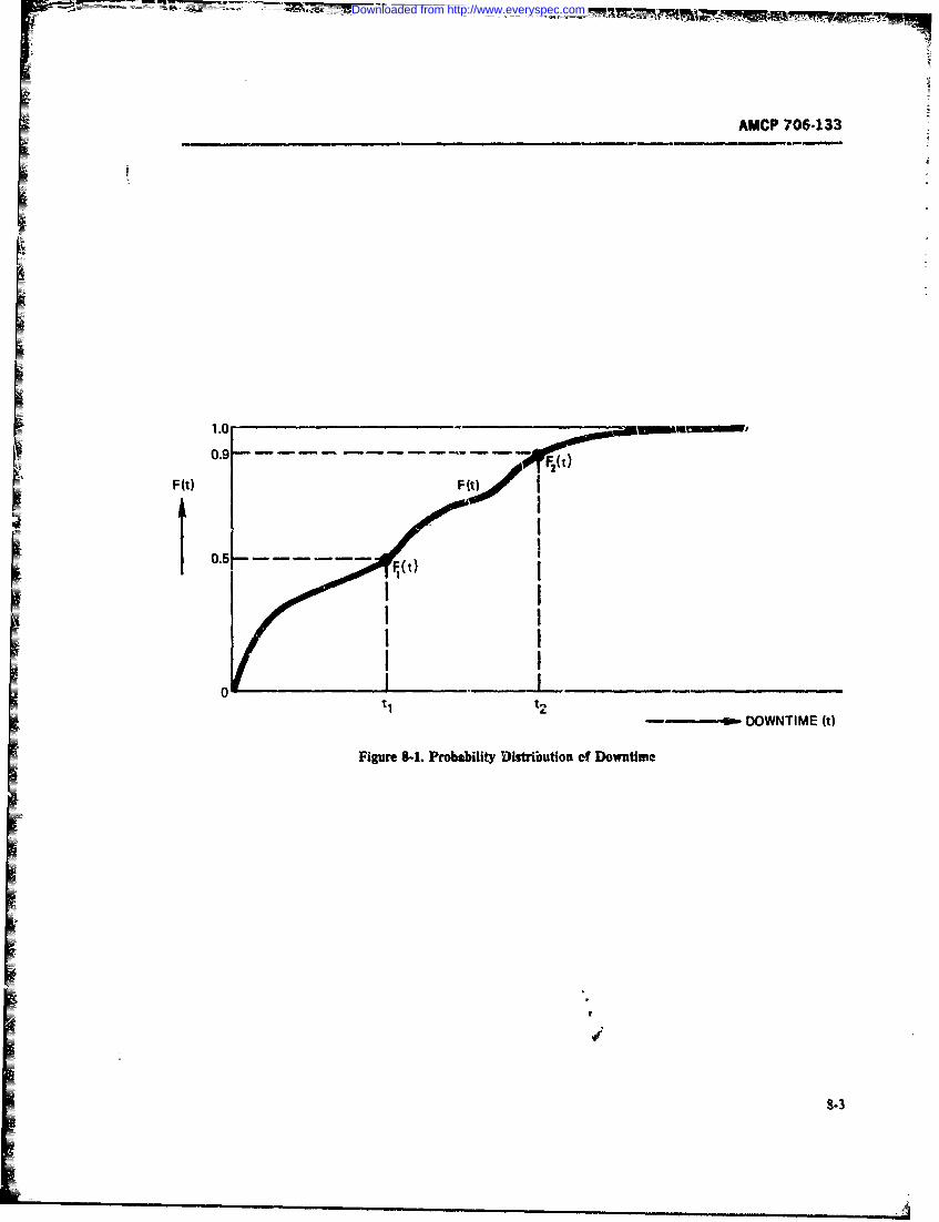
AMCP 706-133
1.0
F0 (t)t
FI~t)
------. DOWNTIME (t)
8-3
Downloaded from http://www.everyspec.com
AMCP 706-133
(hypotheses) for which ,pecial statistical fermulas or of an error of the first kind is usually denoted by a, thetheories have been developed are (Refs. 1 and 2): producer risk; and of the second kind by 0, the coii-
1. Does the average of a new product differ from sumer risk. The producer risk a is also called the sig-the standard, i.e., does the average downtime of a new nificance level Commonly used significance levels aredesign differ from the old one? 1% and 5%. In these cases, the decision-maker will
2. Is the average of a new product greater (less) reject a true hypothesis only 1% and 5% of the tinge.than the standard? Of course, the specific test used must be chosen so that
3. Do products A and B differ in average perform- the specified values of a and 13 are not exceeded.
ance, i.e., do they differ on the average? In simple cases, the choice of test is equivalent to the
4. Does the average of product A exceed that c. choice of the sample size to be ,ased. Importance of thesampve size is illustrated by the following case. Suppose
product 1. that the cost cf testing n units is nX This cost becomes5. Does the variability (standard deviation) of a large as n becotaes large. However, if n is too small, the
n-.w product differ from the standard? likelihood of ma'ing errors of the first or second kind6. Does the variability (standard deviation) of a will be large, ano this is also expensive. If the test
nev product exceed the standard? designer has a choice in the selection of the aE and .87. Do products A and B differ in per!'rnance risks, the type of analysis that follows rmay be ued to
variability (standard deviation)? determine an optimum~s cost-effective value of n.
8. Does the variability (standard deviatiun) of Suppose that the cost of making errors of the firsiproduct A exceed that of product 3? kind is C.. and that of making errors of the second kind
9. What is the correlation between two variables; is C,. Then the expected total cot (testing cost plus
i.e.,if the outcome or value ofone is known, how much decision cost) is Ca + Cfl + nX. If C, and C2 canmore certain are we of the other? be estimated, then the test designer has to select the
10. What is the statistical relationship betwen two triple (c, 0, n) so that the total cost is minimal. This
variables, e.g., between years of maintenance experi- leads to the followying procedure:
ence ant5 time to diagnose failures, or what is the effect .. Select a nurmber of different pairs (a,13) and forof alternative diagnosis procedures on the time to dimg- each fixed pair (ajl) determine the minimum samplenose? size h,(a,) wh:cl, gives a,13. Ref. 3 contains tabula-
tions of the common cases.8-1.3.2 Consumer and Producer Risks 2. If n,. must be an integer (which s not always the
The first eight questions of par. 8-1.3.1 arc zpecial caw because, for example. in reliability testing a single
examples of what can be answered by a very general unit may be tested for any iength of time and not just
statistical technique known as hypothesis testing. A for an integer multiple of itz MT!IFj, then a and flPOmust be re-evalwtted in terms of a(n-j and A3nJ,, todiscussion of the context in which this very general aut fo ee ed on te an integer.
technique is used follows. account to- the nee of n, to be an integer.
The generaii form of the probability distribution of 3. For each of the triples [a(n.,),i0(.,),nJ calcu-the items to bt tested is known (say, by experience). late the expected total cost Ca(n,) + Cfl(n) +However, some of the parameters of this distribution r.Xare not known (e.g., because they vary with the season. 4. Choose that triple [a(n,;,K(nJ,nJ which givesor from. batch to batch). A hypothesis, known as the the 5mallest total cost calculated b) the procedure innull hypothesis 1,, is asserted to be true; e.g., the mean Step 3.of the distribution is asserted to be a definite numberm. The results of a statistical test are used to detenmine The real nrobem in following this theoretically rig.whether the null hypothesis is true, or v ether another orous approt.Jh for determining the optimum samplehypothesis should be ac e teJ. The types of errors size i, is the estimation of the costs C and q. Thesewhich may result from this test (and which are inherent costs depend on the intended use of the equipmentin the very nature of' statistical tess) are of two types. being tested, on what will be Jane if" the equipment isEither the test can result in the rejectirn of the If( reject-d in the test, and on the consequences ofaccept-hypothesis when in fact it is true, or it can indicate that ing subs'.andard equipment. For instance, if the wholethe H hypothesis is correct when in fact it is false. batch is di-scarded when the test is not pas,.ed, ttio costThese two errors are called eriors of the first kind and of the error of the first kind C is the cost of thr batch.erro-. of the second kind respectively. The probability If the whole contract is lost. I- is the eapect-cd profit
8-4
Downloaded from http://www.everyspec.com
AMCP 706-133
IFwhich was not .'alized. If redesign and redevelopment long run, sequential tests are much more erznomicalere necessary to save the contract, C is the cost of such than fixed-length tests. Spccific details of sequential t.stredesign and redevelopment. The C, costs can often be design are discussed in par. 6-7.estimated it a way similar to estin.ating manufacturingane engivetering costs. 8-1.4 SAMPLING PROBLEMS IN
The wrination of the 4 costs is much more difficult. MAININAB!UTY OEMONSTRATIONIt is related to the setting of the original minimumacceptable standard, i.e., to the accept/reject criteria of Some of the sampling difficuliies in maintainabilitythe satistical test. Possibly, the activity which set this demonstration are:standard could help estimate C. To estimate C is actu- .The maintenance task population is highly
~~~uab~~~~~~~~ty~~I :The dosaoimettntenancea er~ra~e task onopuituha tion fiur raehillaiy equivalert to determining the cost of accepting heterogeneous and highly stratified. In each stratume4uipment which passes the test but in fact is of inferior the individuals are homogeneous. For example, a main-quality that does not meet thieconttractual performance tenance task on a unit with a Fgh failure rate will
requiremen. The cost ofthis error of the seaond kind probably occue relatively often in the system operationdepends on the length of time the equipment will be and will provide a relatively large segment (stratum) offielded and on the incurred dgaded performance. data with a specific homogeneity (Ref. 5).
if it wer known that the MTTR in- 2. The test results obtained from a test specimenstead of being m, hours was ra2 hour-, with i 2 >
can be highly misleading with respect to the aztualinn then in a (retm of mT) T wherating the ost maintenance times experienced during the operationalC, aol m ount to Cq = (in2 -- i) Aac where pla1b1h!yte Rt 4 o hi esn pca). is the failure rate of tne item, and ;. the average sampgof the system (Ref. 51. For this reason, special
maititenance labor cost per hour of item maintenane. sampling techniqut and tet precautions must be taken
A very good general discussion of error cost considera- (e.g., simulation of operating conditions).
tions is provided in Ref. 4, which also considers the 3. The maintenance tmks f'ali into various catego-actual probability density functions of the cost of er- ries which have different effects on downtime and onrors. the utilization of support equipment. These categories
urt:
8-1.3.3 Sequential Testing a. Preventive Maintenance Tasksb. Corrective Maintenare Tasks
Tl.- test design methodology developed from the the- c. Servicing Maintenance Tasks.ory of hypothesis testing for fired sample sizes is northe 4. The skill levels required to rerform the variousmost e:onomical available, since it does no; utilize all maintenance tasks vary considerably and require teci-tIf the data provided in the sample. For example, when nicians with different q,:alifications.the null hypothesis 110 is "the length of an item is 5. Thn statistical distribution of maintenance timern" but ..1ie Irst few items draw, at random from a for each of the given categories of maintenance tasks issample of size a have been found to have an average not only dependent on the MTTR's of each componentI !ength of 5 m, then the testing of the next item Of the type, but also on:sam~p! . will most probaoly not affect thte test result of a. The quantity of the components ofeach typerej .cting th null hypothesis. Hence, esting of the next The loation of the component oethn theejt. ~b. T11heloccation of the component within the sys-sonple is, in such a casi. a waste of cnctgy, time, ind rem. since location influences tht access timemcney, and the test can "at stopped before al! n items and thus will diffezentiate even oetween iden-uae Lested. The novel feature in this situation is an tical component types in differenZ iccations:4ementary use of the individual results immediately, f C. The frequency with which the maintenancesiviuence, as they ae obtained for each item of the actions become necessary, since this is di.sa;le being tested. These .eas have been thoroughly related to the reiabilityof each partcu.developed into sophisticated techniques of sequential iar component in its particular location (astest design, evaluation, and hypthsis acceptance or affet by ambient vibrations, temperature-.ejection. hurniKity, pressures, ctc.!.
A main characteristic of such tests is that the samolesize is not fixed in advance but, instead, a criterion is since theoretical prediction techniques for any rnain-used to decide whe.her to accept the sample, reject it. tenance category (corretive, preventive, or servicing)ur continue testing. Such ,.eisions caib be made con- can vary widely in accuracy, the sampling technmluetinuc.-sly, ite by item, or sample by sample. in the should ensure that represenradve samples from each
8-5
Downloaded from http://www.everyspec.com
AMCP 706-133
category are chosen according to an dccuate statistical nance time is a convolatioa of thre pdfv of perfoming
procedure. the subtasks. The mean times of these pdf'1 of course,Representative sampling is also important in the se- remin additive, per theorem of Eq. 8-26. If we define
lzction of different technician skill levels required, be- D, = mcan time to restore system tocause the theoretical predictions may be highly accu- o,erating condition
rate for some types of skill levels but not for others. A, = mean time to diagnose the faultFurthermore, estimation of the maintenance times 1z 3 = mean time to gain access towithin each of the strata (i.e., maintet.ne categorie faulty moduleand skiil levels) should take into account location D, = mean time to obtain rzpair partwithin the sy-nem ie, access time), and relative fre- D0 = mean time te replace faultyquency of occurence. module
D, = .nean time to checkout ifcorrect repirs and installation
8-2 MAINTAINABILITY FIGURES OF have been made•MERIT 0. = mean time to close up access
panels8-2.1 DOWNTIME then the mean downtime equals
The three basic types of maintainability figures of D = D? + D + D + Ds - D D7 (8-1)merit are those related to cost, manpower, and mainte-
'ance time. An ,xample of a cost-related figure of meritis maAntenance -;ost per year. Other figures of merit a; e The term downtir.e has different quantitative mear-.maintenance manhours per operating hour ings to the activities involved in a maintenance action.(YMMH/O1t), ,JMTR, ERT, M,,. etc. They are dis- As an example, cnnsider the scenario ;hat follows:cussed in Chapter 1. These figures of merit are inter- A helicopter has landed with its engine about to failrelated, and each is important in different phases of the due to excessive -ibration. Symptom analysis showslit cycle to different degrees. Of course, the most fun- that it will take about 8 hr to repair the :ngine in adamental aspect of maintainability design is that of wc rkshop. However, a spare -.nane is availabe and it
maintenance time. Of major importance, as a figure of takes i hr to repzace the faulty engine. What is themerit, is the amount of downtime spent performing a downtime caused by this failure? From the pilot's view-given maintenance task. point it is I hr at the organizational level. From that of
The downtime for a maintenance task is the amount the depot maintenance personnel administrator it is 9of fi-ne needed to complete the maintenance task. Dif- hr (I hr for organizttional replao-unent plus 8 hr forferent tasks will in general resutk ia di&ffrczit amounts depot repair). The actual calendar downtime of theofdowntime. Moreover, the downtime incurced for the removed taulty engine may 'e several days, due tosame maintenance action will "vary accordirg to the administrative delays or waiting for repair pars. Thetypes of tools and maintenance manuals used. the skill amount of time lost in performing a mis-ion may de-of maintenance technicians, and the environment. Fur- pend on otl,-r circumstances. For example, if the air-therinore, downti-.e for *-ic same maintenance action craft were scheJuled to be serviced aid the serviceperformed utder the same conditions by the same in- turnaround time were scheduled to *YAxed * h:. nodividua at different tirms will in general also be dif- mission time would necessarily be lest. But if the pilotferezzt--thus downtime is a random variable were forced to return because cf the faulty engine
Almost all m.intenance actions of inter;-.t can be before accomplishing his mission objective, consiedivided into smaller subtasks, the time of each of these ble loss of mission time may be involved. If the missionbeing a random variable- When tie subtasks of a main- objective was accomplished, little or no mission timetenance ation are pe.formed in serie then the sum of was lost. But if aircraft performan was so degraded
the tirom, to perform the subtasks is equal to the down- because of the excessive -ngiae vibration that enemytime of the composite maintenance action. However, damage was sustained requiring 12 hr of fuseage re-tte time to perform each subtask is a random variable pair. such .rnny-caused downTime could be attributedand, therefore, the time to perform the composite main- to the engine.tenance sction, being the sum of random variables, also Ref. 6 provides an excellert account of ho. main-will vary from case to case. This means that the proba- tainabi':ty requirements (both resource and operational)bility density frtuction (pdj) of tha composite mainte- r-in be used during the design of a major system. It
8-6
Downloaded from http://www.everyspec.com
AMCP 706-.133
shows that with proper analytical computer-oriented Other t-itinent things being equal, choose parts o-techr-ques, great depth and detail of investigation can components for a particelar 1location which have beenbe accomplished to pre-vide a basis for design decisions mn3st proven in other areas attd/or other equipment.at a system level. Commonality of parts wil! reduce- the tota! number of
Other aspects of downtime which are relevant to a different iep.,ir parts and will facilitate training. Frommaintninability anv'sis and 'nhich should be carefully the increased familiarity that will result, a higher levelconside-red are: of expertise will be maintained. Warehousing will be
1. Corrective maintenance does nat necessarily si-rplified, ;nd repair parts availability will be greatlycause system downtime, because the carrection may improved.
( x-ith proper design) be accomplished without any in- A disadvantage of using downtime as the only figureterription -*. system operation (eg.. if i..placement of merit is that a long downtime might be tolerated ifI pp.ts are carried in the system, or if st~adby czompo- it occurs very infrequently. But unless the desijnernertm are provided and repair provisions cvist in the knows the frequency of occurrence of long &dxlitntesvehicle), he would not be able to judge there impact on syslem
2. Pevenive r srvic ni-intzanc maycau efftectiveness. A means of circumventing this difficulty2. Pevetiv or ervce ~ai~nane my Cu~e is to use availa',ilitv a- a mea-ure of system effective-
unischeduled downtime if the servicing equipmtnt mau-functions during servicing, or if the servicing persnnel ns.Ser -. o icsino ~iaiiyfc
tors.make mistakes .im servicing. In the long run. inherent, steady-state availability A
3. A dminhstrative downtimuz (specifically down- is good design guidecline and is given bytimes caused by sickness or injury of personnel, or byhigher priority orders etc.) may increase the mainte-nance downtimie of equipment. Such do%.itiines siiould A = MTIJI/(MT7TR +. MUTBF) (8-2)I be recorded during demonstration tests but not in-cluded in the accept/reject decis.on of the equipment --'brmiltainability demnonstration tests. kTBF = mean time between failures
A! fTR = mebm time to topair8-2.2 SPECIFICATIONS !nherent availability is thus the pwallility that a sys-
teia i.s vot in a state of active repair af-i it has been inDow~ntime is a fundamental figure of it greatly uire for some time. Avail.ability reflects both reliability
impacts on equipment availability. "The soldier under and maintainability, It can be large (close to IAMl evenbattle conditions does not care how mouch a mainte- if the )M77'! is large, provid-.d the YTBF is -muchnance action costs (in terms of new parts, .pecia, t&--!& larger. However, even though the inherent av-ail a';tytraining level of mainatenance technicians or sophisti- crn be very ue!4l a.; an auxiliary desin guideline, thecation of diagnostic procedures), but h^ is very much -MM7 still needs to be specified since it is a funda-concerned with how qu-cily his equipment can be re-s- -mntal measure of system maintainabi'ity design char-toted to proper operatingt condition so that he can use acteri:;tc&. However. specifying availability and MTTRit !o carry r tit his mission. However since national by themnselvecs is not satisfactory. It is better tco specify-resources are not unlimited, costs always must bet con- iomec pits on ;he distributic m r-4azr times. Thus. oreAidered. could specify thpt !D& or 95% of the maintenance
Cost facteors of interest in the conteat ofplanning rnd actions be completed within a time 1 :5 MW,, whereaccountin3 are 1l:-bor, parts, tr-ain-.n;-, and power can- Mmr is the corrcspondint, percentile point (see par.sumption. Thc;, ftors are of specie! ierest to design 8-3.4.3) cf the distribution which has the JM17 as itsand ma~ntenar".ce prsonnel. Since downvine in th: metan, given by:fiald does ia fact ,-pend on the availability of repairparts, the logistic support procedures (e.g. types and TR f'Gtld(83amnetnts of repair parts stored at various maitenance TR G(dt8-3levels, :ypes and amounts of repair tools, etc.) do affectthe downtime of operational equipmnent. Thus, the log-istic support sopnistication should be considered azz wh~c CG6= I - Mo is the probability that repairleast generally, even during design. In fac-th 1 e guide- -will nwrbe completed in timre r. whikc Mo* is the proba-line that follows should be emplryed by every main- bility that repair .,'ill b-, accomplished by time r.tainability engineer during detip. Mi) is also calIled the Mainitainabifity Function andl
&-7
Downloaded from http://www.everyspec.com
NAMCF 706-133
may assume many differemt shap For instance, if bol U stan& for union of events, and n stands forrepair time is exponentially distribLted, i) 1 - intersecion of events (Ref. 2, pp. 10-13).exX - jut), where p is the repair rate. 2. If the two event! E and A are mutually exclu-Then sive, i.e., both cannot occur in a single experiment (they
do not intersect), the probability that either A or F
MTTR fexp(- pt)dt occurs is
- I'[exp(- gt)]0 P(EU E?) = P(E) + P(Ej) (8-5)
= -r0 - 1] = !/p (8-3a)
This is a special case c." the previous addition theorcm
8-3 PROBABILITY DISTRIBUTIORS IN :n that for mutually exclusive events P(E, n i 2 ) = 0.MAINTAINABILITY 3. If in addition to being mutu?Uy exclusive, the
two events are also complementary, i.e., oni of them
To develop ti-e theory of probability distrbutions in must occur in any experiment, the prebability that ei-Imaintainalility, iome basic rrobbilily concepts :m !h- A or A; occurs is unityfirst discu&vAd
P(E) + P(E z) = 1 (8-6)8-3.1 BASIC LAWS OF PROBABILITY
Consider the possibilit of occurrence of an event.The event might be onne whih is certain to occur, one For example, if the outcome -fan experiment can bewhich is impossible to occur, or one wh-ch has some only a success F, or a failure F., then the probability
poss'bility a' occurring. The degree of certainty, the that ei~ber event E, or event F2 occurs in that experi-likehhood or t ti the event wii occur is metmuul.Suchtwoevetsaresaidtobemeasurtci by its probability. Several alternadv: deni- Cople' 1~nttions and developments of this caej, _re possible. 4. If in an experimet two events F, and F canThe definition chosen here '- not the most rigor.ou occur, and it is known that ouae of the events (say,
iposble, but is vr-e--ited mirly because of its cloe- F) has already occurred, the probability of occurrenceness to the concepts of sta°s.vtics of the other event F, is
The probability of an event A, written as I A), is ameasure (W the frequency (petccntage) of the occur- P(E I E?) = P(ut n E,)/P(E.) tb-7)rence of the event out of a given number of pcssibLeexperiments or obser.'ations. Ti measure is normal-ized to eqai I when the evnt is certain to occur ineach experimcnt, and to equal 0 when tht event cannot This is called the contditionid probability o occrrenceoccur in any experiment. Thus, the probability of any of El, given that E2 has already occurred (writtene,,ait Eovcurring is a real number between 0 and 1, i.t, EIIE2). Eq. 8-7 may be rewritten as0 < 1(A) < 1. Note that IM ,(A) is qualt o thelong-rapz percentage of times that the event Eoccu.s P(E, j E,) = PiEI Ee)P(,) '8-8)out of all th2 possible chances it ad for ocnurring.
The basic laws which the probabilities of any set ofevents must satisfy are (Rets 2 and 7): Eq. 8-8 states that the probability of bat A; aF, F;
1. If in an experiment two even E; and P; can occurring is equal tc the conditional prol-ality *f theoccur either singly or together, then the pobabhty occurrence of event F,. given that E7 has aiready o,:-
that cher A, or F, or both F. and F, occur is carted, multipliedby the probtmility that event F- actu-ally occurs. Tais is sometimes caled the gem:mlized
P(EjUE. = P(EI) ---P(E2) - P(Ejf-E2) (8-4) product law of probabites.. Of course- the sequac ofEU ( ( -, -4Tee of and , may be reversed. i.-..
This is tbe udiion themem of pbabiliti. The sym- P(E:OEz) = P(E1 E)P(E1 ) (8-8a)
3-z8
Downloaded from http://www.everyspec.com
AMCP 706-133
As an example, one may ask what is the probability x < y, then Ax) < RJ (i.e., x) is a nndecreaingof drawing two aces in succession from a deck of 52 fnction of x). When Ix) is continuous, then Xis_ zudplayins cards, if the first card drawn is not implaced to, be a continuous random variable. When Ax) varies(Ref. 2, p. 47). Event E, is drawing an ace at the first. orly by jumps and is constant between jumps, then Xdraw, and event F. is drawing an ace at the seond is zaid to be a discete random variabe.draw. Thus, PIE, r E21 t-he probability that both E; An example of a discrete random variable occursand E2 will occu as specified is when the probability that Xwill be. equal to a. [we vTi.te
P!4X = a.)]isequal to Pand is0dwhere andP(EiflE2 ) = (3/51)(4/52)= 1/221 (8-8h) when (aj' - is a sequence of Nnumbers. In incre s-
ing order of their numerical values we have
where FF( I ) = 3/51 is the conditionl probabihty P ifX=aand where I n<-f drawing a ace on the second draw given that an ace P(X = x) =.,as drawn at the first draw (Le., 3/51 becaume ,rly 3 0, otherwiseaces are left at the second draw and the number of cards (8-10)is only 51) and (E ) = 4/52 is the probabili ofdrawing one ace out of four froto 52 cards at the fir Ntfdraw. More on condftional probabilities will be found v defintion of tla CDF,in par. 8-3.5.
5. If the evmts E and - are indr.pcndent of eachother. Le., J. , I E = *j) and -l n) = F(x)= P. (8-11I/ED, theri Eq. 8-0 assum= the form £
F(EJE z) = P(E1)P(E2) (8-9) where N is that unique integer which is the largeainthger mhat is not bigger than Since one of the rnctsmust O r (i.e., X must assume some value) condi-
&ed in or.% the( bi) that txwi dpendente ion of the values of the P. is that
<.t didinus wonte D froit anthr(eg. Ftw) Sined.
events , and pr ocbilt in i experiment is the productf ( aW) an att" of fact, two events c- . 2dfbe defined as irdependent of each other onlyr it Eq. 8-9 "--d 1(-
holds&In terms of the previous card example, thi zase
would wrise if oe would repiace the first drawn card -h rb b t m o f uI~ ; jtf() oInthat case HE) =- /52 and a-,o .5E,) = 4/52 random rable X is the pobabilit
because the card replaeaen makes the two ex-emtshueenet, and thpn !'(E, n E2) -,47(4/5,I2) =
1/19.fWx = limP[X in (x, x +. Aj')RAx)-* 1%8-13)
8-3.2. CUAiMIE ISTRIBUTION ANDPPOMILIT DE f FUNCH If the imit dkes not exist for anyX then the random
Asoiae with random variabiz- X is its cumukv variable X wilt not have a pdf A more intuitive ddefii-
daib~utnfuncin (CM). tRx) which is deie to be inoa f.4 isbt94~x = J*X: 4). Wen -sever feet randomv:.,i
Wbes (e..,. ) are being discuss4 asuffix is mic~hmi -!i) dx = PIX in (x, x + ax) (8-14)to distingWs ore CDFfrom another (e-g-., Fgx)). S.inceit is it probabiity,.,R,) ob~eys the laws of probablty.Thus 1K - o) 0 0and / + w)= 1. Ad if wb-e derW,,-"Aprxi e, eque, when&x is
3-9
Downloaded from http://www.everyspec.com
AMCP 706-i33
smA enough". By definition of the CDF this can also interval and n is the total number of Eiines X was ob-be. wir:en as rerved to occur (i.e,, sample size). Nr"e that f, is an
estirwte for the probability I{X ;'i (a, a . :)I-
f(x) dx F(x . dx) - F(x) (8-15) 5. A cumulatie frequency F, for the ckss interral(a,. a I) and for a given set of statistical data is equalto .N/n, whixe Vi is the number of times that X had a
since value less *han or equal to as.. ,, and n is as before.Note that F is an estimate for the probability I(X
F(x + dx) - F(x) (8-15a) a ). The nztaions of cumulative frequency and
,: -o dx relative frequency are related. In fact,
which results in F= N/n = .ri,/n (8-19)
f~)dF(xj.
dx and
ThusAx), when it exists, is a measure of how often the /, F - Fj. (820)random variable X will take on a value very close to.
Also, by Eq. 8-16, we have These relations correspond to those cited earlier be-
tween the CDFand the pdf One can prove that, unde-general conditions,
F(x) = ff(y)dy (8-17)
lim F,= F(a , (8-2,1
ane
andi1- Fix) = fl)dy 18-18)
lfm fs = F(a1 ) - F(aj) (8-22)
The CDFor plfof a random variable may be deter-mined by the ,onstruc.tion of histogramns. A hitga where the Ps on the right siJe denote the CDFvalu, Smine bythe omtuctin o hitogrrns A hstoram at their respective argum eni.s. This shows that the more
is a grzphical summiy of data arranged it. such a wayas to approximate either the CDFor the pdf. A more samples or trials one attemp-s, the more accurate will
form] definiti ~n is facilitated by !he following ter- be his predictions. However, cost and !im.: coinsidea-
mino;ogy: tions will limit the number of attelmpts. TLn- fators
1. The ra-ge of a random variable is the set of influencirg selection of an appropriate sample size n
values it can tak- are discussed in Chept 6 of this handbook.An example for constructing histograms is 'Jiven a
2- A parion " of the range is a sa of numuers, the end of this chapter. To conclude the discusi'i ona, < a, < a3 < ... , all ,thin the n-.x gee of the -random variable histograms, we may define the cumulative frequency
histogram as itte curve obtained when the cumul;%dve3. The class ,,;;erwls for the partition 7r are the fhequencies for a yiven id of class intervals gre pLtted
sets (a, a,, ,). For example, the th class interval is as a function of the range of a sample of independentthe set of all numbers between a, and a + from a par ob .vadons of the -a lo varial Ie ,f interest.tition ir.
4. A rekiiy' frequ-ncy for a given class interval 8-33 MEASURES OF CENTRAL TENDEtICY(ap aj + ,' and for a given set of statistical data for therandom variable X is the quantity f4 = n/n where Die cumulative distribution function It) com-n, is the total number of times X falls within the class pletely describs a -andem variable X, but thi infurma-
8-10
Downloaded from http://www.everyspec.com
I AMCP 706-133
tion is tofte too diffuse to be of direc use in determin- To prove Eq. 8-25. we shall integrate this impropering the distribution parameters. Data reduction integral by parts. First we integrate fromn 0 tc a thenterhniqaes can simplify this process. As a first example we take the limit a--:of such data reduction techniques, consider the meas-ures of central tendencyof the random variable X. Such rawmeasures are the mode, the median, and the a-n,. . x { fx)ax} - [ )
1. The mode of random variable Xis that value of ax at which.(x) is maximum (i.e., that value of Xwhich {-.x[l - F(x)j}*, + (I - F(x)]dxis more likely to e:ur than any othet single value). Not J-all distributions have a unique mode. In fact, for the1uni/orm distibution defined by (Ref. 2, p. 126) = -all -F(a)]+ 1-x
(8-25b)F(x) =11(b - a). for X ' (a, b) (8-23) Since in the limit the first te:m is
0 O, for X E (a. b)_ limoI - F(';) = 0 (8-25c)
each value of XE (a. b) is a mode G i; starA-d rWotaionfor "in" and 4 for "not in'% the resuh is Eq. 8-25.
2. The median of a random variable X is a vau Fora - .continuous random variable Xwith range fromsuch that - + cc. he mean i defined as
F(a= 1 -F(a) =1/2 (1s-24) E[X = xf(x)dx (8 -25d)
Stated in words. the probability that the value of X is The mean is !he most common measure of locationless thar, a is 0.5, and !he probability that X is greater (also called the average value). The mean is often de-than a is 0.3 also. The meian might not be. unique. As r oted by m or p, or by L[XJ.an example coiqider the discrete random vwiable with Two important theo,.ems en expected values are:CDF l. The expected value of the sum of independent
rapdom variables is the sum of their expected values,
F(x) =xfor 0 - : - 1(8-24a1 or
0. otherwise
E I X11 ZEIXi 1(8-26)In this case the median is unique, and n: equal to 0.5.However, the random .-. riable with P1() = 0.5,NI) = 0.5 dces not have a unique median bticause forrnyO < .x < 1, we have Rx) = 0.5 (see the case described hy Eq. 8-1).
3. The mean or the xpetaed value - JA) of a non- 2. r-T=rent on Total Expectation
negative random variable X is dkined as
EiXI { xtx)dx- 1- Fix)Idx (8-25)w1( vdere EjYYj iLs the expected v-Jue of X. given theactual value of Z. which is known to have occurred,and the su --ript Y in Er is i reminder thaa the cx-
when_,ever :he CD, Rx) ha such a form that pected 'alue is being ..er, with respect to Y (nozY).
iim xl - F(x)J 0 (8-25a) A- atrivialexampleofthistheorem cou--iderth casez- - of 3 system which has two components A and Ewithg-I1
Downloaded from http://www.everyspec.com
AMCP 706-133
expected system mean downtimes A(D) and E D), VARIX] = x xd -according to which component fails. Let :he condi- j jxJ dx -2n xftx)dx
tional probability of componen: A failure be (A), givwthat the system has failed. Then this theorem (Eq. 8-27) + m2 ff*x) dxsays that the expected system du'vntime, LID) is
=E[x'] - 2, + M2 = EX]- m2E[D = P(A)E(DA) ; (1 - P,)E(DB) (8-27a) (8-29)
8-3.4.1.2 Star-lard Deviationwhere we use the fac. that E(DLA failed)= !lD) and Ttc standard deviation of a random variable Xis theE(DIB failed) = EXDA), and twke Y to be the two- square root cf the variance of X The standard aevW-valued random variable tion Ls used frequently in the lite, ,tore and is d-moted
by a'. It is given by
P(Y = 9 = P(B). if r = b = a (8-27bo) a = qrVAR[X] = lijE X-7] -mz (8-30)
0 . otlTrwise
8-3.4-1.3 Coefficient of Variationwhere Y" a indicates A failed, and Y = b indicates The corcet oa variation Vis defned a
B failed. Then Eq. 8-27 givei Eq. 8-27c, sinc for anyfnction S(19J)=oi (8-31)
Eff.Y]= P(A)g(A) . P(B)g-b) (8-27c) generally expressed as a percentage. Because of thelinear relationship between a' and Y, V retimes re-places a in some textbooks.
8-3.4.2 CovartMaCe
-3.4 OTHER MEASdRES Whicn tw-, rahdo vr-riables am being considered in
1ra single context, a very i thxeunt concent is that of
8ively, is defined as
Another important itzm of information obtainablefrom the cumulative distribution function is the me- COV(X. Y) = E [(X -A)(Y - B-] (8-321ure of the dispersion of the random va.-iable (i.e., of itstendency to spread frrm its average value). The mostcommon treasure for the dispersion of X is the van-ance, denoted by VAR[AJ. VAR[A is defined as themvrage or mean of ihe square ofthe d-viation from themeanL m. When Xis nonnegative: COV(X, Y)=E[ -A)l.E[(Y B11
i.e., the covariance -f two random vaiables that areVAR[X] = (x - Yn). f(x)dx (8-28) independent of each other is O.
8-3.4.3 Percentile
The expressin (x - m)2 = 2 - 2xm + n?. so The ZO0pth perenle of *i ,ta is defnedasthethat value x. such that
8-12
Downloaded from http://www.everyspec.com
AMCP '706-133
F( 8F (X) ;P1., X -1 N P (1VN = nt) (8-39)
8-3.5 CONDITIONAL PROBABILITY AND Examinple. Consider a three-component system withI TOTAL PROBABILITYconditional downtimte CDFs-, fi:tx),. (x) arAs F'(x).
As rmiticned in par. 9-3. 1, the conditional probabil- FXx) is the CzD Fof dmwntimne when it is known that theity of a random event A, given V-.at a random event B Ah system fails first. Then the di's'retz version of thisIhas occuuzed, is denoted byP(A 1B). A heuristic explr.,e- thzeorem. by Eq 8-39 shows that the unconditional
rl ilon of the probability law of Eq. 8-7 is that if we know dm-ntitnc CDF is:K; that event 8 has occurred, we --n immediately restrict
our attention to the case when !he events A and Boc-urtogether. The probablitty of that event is denoted by F(X = P 1 F1 (xr) + P 2 F2.(X) P3 F3 (xV) (8-40)
V P(A f-IB) (read: Probability of A nd B). Now ji of -ifl
IKA), A given B occurs only when t'.fl both ocouran17(A IB) is measured in the limit by the -atio of the 84 LASSO POAiLTrelative occurrences of these two cases. Hence DISTRIBUTIONS
P(.A = Ip(AflB)/P(B) (8-35) 8-4-1 THE NORMAL CLASS OF FUNCTIONS
Th e normal pdjhas a vvry aistinguishecG place among
estm~t fr P B isnj- ndforF(A Ar,) is n/n. For with other exponential functions Thc main reason for
P() h mmt sr ,Hwvr hsas ste 5c tas tnis th unorahdiribuygtea whendt ti !hme
Thstmt fominel )F() bms siz of bol torg numt, fnda corrondin wrench,etc)xiBmae nofnl thesmtin rpisribute (eCntaLiniteCtrLmtTheorem, pa."2.The formaltainalty susied
P(A r)B) =PAI)()(8-36) oten inlarhe, samc pe vttistc3 The followin efni-tios aends topbe nres ofisoribute wheiins y berhu nine size tof both tte law. oin Eqe 8-repndn leadnch.
the ~ ~ ~ ~ ~ ~ t_ Theorem ofLtlPo~iiy1 eiitn Theom theI norma isbydfalsis uF(X'V.B P('A R) (x 37YvI Av fx '~Y'x[ x-m ~ tI(-1
Nowr m isn this varibte the law the Eeq an leissthe
For discrtte random variables this theorem reads standard devi-tion. The corresponding CDFis
Downloaded from http://www.everyspec.com
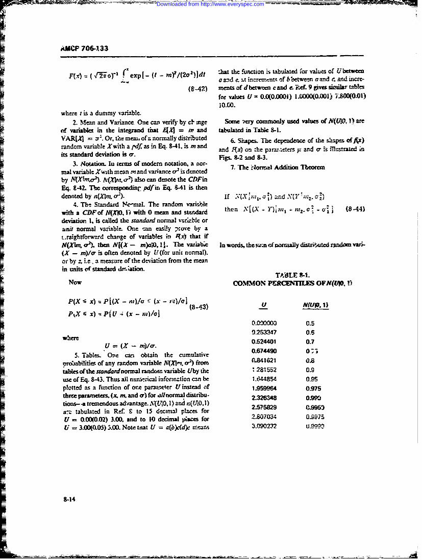
F(X) = (Vi---oy' zxl t m/22jt :a h uco Lul fraueoUbtwer'and e, t incremrwrns of between a and c r4 hn-
ig-2F zets -4 d t w-m c d - ef 9msi n abe
where t s a dumnmy vanable.
2.. Mean and Variane& One can verify by cF mge Some -ery commonly used ninesc- of NUAO. 1) are
r-T vaiablesi heitegrand that [ =ran tbuteinTle&VARJJ =zr-.Ot ~w mw. f anormllydisti-bted 6- Shapes& The dependence of the s~apes of Axk)
its sandad devatio is a andjFx) on ,he parar~ers 1K and cr ir. illustrated in
3.NttoIn term of modemn notation, a oor- Fis8-2M -3
7.The ?i~orrnnlI Addition Theoremn=1 vr~ak,'%lthmean.rnand variance ' is denoted
- by NV(X&n,). A{Xlm. a-) also car. denote the CDFinEq. 8-42- The correspoodinr pdf in, Eq. &-41 is thendened by .Xm or). .%i Mtx U 1= and X(Y no;
4. The Standard Nmal The random vari*.e 4=with a CDF of N(XIO, I, with 0 mean an tM.~r then Nj(XY Y)m -1 I..9 S rrj (84
deviation 1. is called the standard normal vafzble orunit normal variable. One -an easily ;nove by atsraightfcnrad change of variables in J(.x) that ifN(Xlrm4 a-21, then N[(X - m)c:O. 1]. The variabe In wordts, the sz-n d'nnrally distdtaAded rmndtxovn
orbjL a measure of the deviation from the mean.In units t standard &-r ation-
TA#BLE S-I.Now COMON PE-RCiTILE OFN(L/i, iI ~~~i x) -PI(XU4/ (x - (843/c NJI.1
0.00000 0.9253347 0.S
w mU = (X - M)/. 0.524.401 0-7
=5. Tables. One can obtain the cumulative 0-674.490 -j
orobabuilities of any randomn variable NAXmn or-) fromnO- 021621 0.8tables of the standasdnorwjal random variable (Thy the :.281552 0.9use of Eq. 8-43. Thus A nurrsnia infonna-tion can be 1.844854 0.95plotted as a ftmction of onte paraLmeter U instead af 1.596n0s7three paramneters (x. inL and a) for ailnorrnal distribu- 2-2:48 0S~tions- -a tremendous ad'antage- AqVUt0, 1) and nQAO. 1) 255 -9rt tabulated in Ref S to 15 6=cznai la fo 2.0378 0.95
= ~~~U = 0.00(0.02) 3.00, and to 10 decimal );;aces for2.004091= U = 3.00(0) 5.00. Note tnat U = gi~dd)e mnears 3.090232uS9
8-14
Downloaded from http://www.everyspec.com
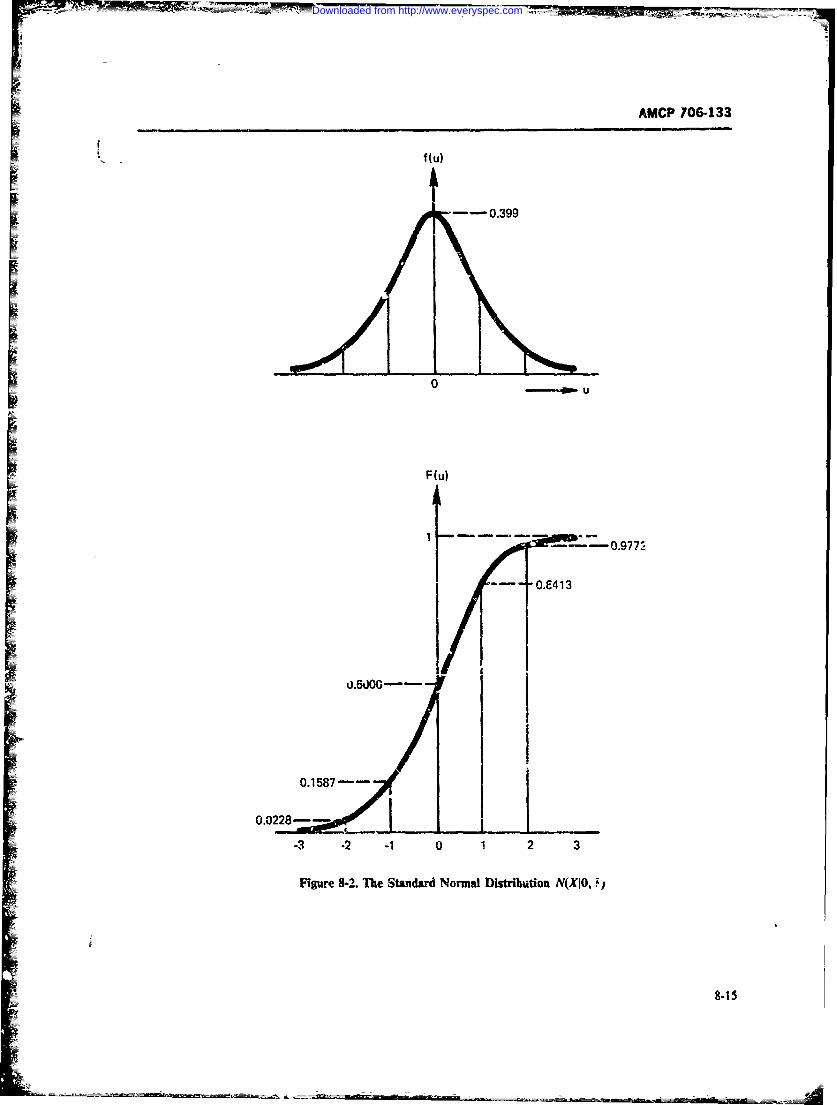
AMCP 706-133
I
0 - -am U
[ F (u)
[ --- 0.9772-- 01413
0.0228-- *VU-3 -2 -1 0 1 2 3
Figu." 8-2. The Standard Normal Distribution N(XIO, !I
Downloaded from http://www.everyspec.com
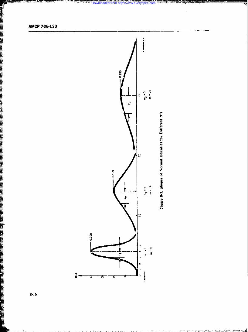
AMCP 706-133
M
is
I
C4
0I
I-i
b
K 2.00
0 oa I
°
8-16
Downloaded from http://www.everyspec.com
AMCP 706-133
ables is again normally distributed with a mean th'- um convntion (Ref. 131, as A (ZIp, 02, so thatof their respective means, and a varianze the su.n of A (ZIp, 02) = NMn Z 0 ). The corresponding pdfistheir respective variances. If the sum of two independ- dertotd as MkzIp, a2) = n(In zip, 02 ).
ent random variables (X, 7) is normally distibuted, 3. Mean, Variance, Median, and Mode. The meanther so are Xand Y, i.e., if AKX + Y)nt, 0.) then if and variance can be obtained easily once the kth mo-X, Yare independent, ment of Z is known. Tb:s kth moment is given by~~N(X'p, n
and
for some m1 , m2 so tl-atm, + rmh = M
and for some x exp L- (1/2)[(y - x)/Il2}dv (8-47)
so that S2 0h2a wherey = In zintegrating Eq. 8-47 (Ref. 13, Appendix A) gives
8-4.2 THE LOGNORMAL CLASS OF EZk exp (ki + k 2/z)FUNCTIONS (8-48)
The lognorm.al distribution frquently is applied inmaintainability, since the physical laws of search and Thus, the first moment (mean) isclassificatio-a oftcn obey the assuinptions leading to thelognormal distribution (Refs. 10, 11, 12). That is. the n: = E[Z= exp (p + 171/2) (d-49)time taken to find classified items (such as tool crib, amaintenance procedure in a ervice manual, or a docu-ment in a library) is rmore strongly dependent on the and the second moment (vzriance) isinformatioa stracture of the classification system andless so on user characteristics. Since the fault location VAR[..1 = E[Z ] - E[Z]and colr;.ction processes are classification processes -(e.g., classifying symptoms, responses to test signals, = M(8-50)selecting tools, or selecting repair parts), th y also willoften be logn.trmally distributed. A definition of the The median Y and the mode min are respectively:lognormal distribution and descriptions of its proper-ties follow: M = exp (W) (8-51)
1. Definition. A positive random variable Zis saidto be lognormraly distributed with parameters A and0. if Y7 = In Z is normally distributed with CDF 20 = exp (g - cr2) (8-52)N(li Zip, 0.2). where p. is the mzan and a-' is thevuiance of Y = In Z The logarithm is the naturallogarithm to the base e = 2718281828. 4. Tables. The CDFof A(Zip, a2) can bo read di-
The lognormal pdf is giver. by rty from the tables of the standard normal distribu-tion:
f(z) = (v7Faz)' exp{- (1/2)[(In z -i)/crj2} A(Z jg, 0.) = N(nZIJ40 2 )
(8-45) N[(InZ - i)l O0, 1 (8-53)
and the corresponding CDFis
F(7*1 exp {- (1/2)f(lnt - p),'a}dt 5. Rcprcductive Property. If Xis distributed as(0-e)A(,X\I , , )
and Yis distributed as2. Noti'ion. That a random variable Z is lognor- A(Yp , ')
many distributed with pararmetcrs p, a-' :s denoted, by then
8-17
Downloaded from http://www.everyspec.com
AM- CP 706-133
~ =ax~ pA(gIjn.rbj 1 +ci 2,ey+ ) p =ln .n-.-2/2 (8-60)
(8-54)
If m and zp ar o ie a legitimate normal distribu-This follows since In Z = In a + b(lIn X) + c(ln Y). tion, the two possible variances must be real and posi-
tive. First, the quantity within the square root must be6. Limiting Property. From the Central Limit non-negative. This requirement gives
Theorem (par. 8-8.2) and the reproductive property,when Z, is a sequence of ;andom variables and whenthe conditions for the Cental Limit Theorem are satis- z', = m exp (N../2)(-<1
fled by their logarithm. then the pdf of the productX# = N 11 1 Z, tends to the lognormal distribution.
7. Specification of the Lognormal Distribution. To To assure positiviiy of o, two cases occur:uniquely determine the lognorral, any one jf the fol- (1) Case .'. p < 1/2lowing four combinations can be used.
a. Specify ft and ar. This is tbe direct method. Then. NJ < 0 and z < mSubcase LA. If p _< 1/2 and z, < m, then there is
pbifd. Themn E and 8-ienble [ a tof one unique lognornl pdf which satisfies these values,specified. TIhen Eqs. 8-49 and 8-50 enable t and o" to anandbe determined as
04 = 9 n-UM2 + VAR[Z])/ " Z2] (8-55) ar1 = V, + ' -2 In(z;/2) (8-2,
n = nm - ln["?2 + VAR[Z]nz 2 ]/2 (8-56) Subrase I.B. If NP _ M, th,:n no lognormal distribu-
tion can satisfy the requirements.c. T- mean m and the 100pth percentile value (2) Case 2. p > 1/2. Then A > 0.
zare specified. Employing th,! definition of the lognor- Subcase 2A. If z e m, then one unique lognormal
mal and transforming to the normal, we obtain distribution exists that .itisfies the requirements.Subease 2Z&.
P(Z < z,) = P[(nZ - j)/c -< (Inz, - u)/crj' P
(8-57) "1 < z, * inexp(N 2/2) (8-(:,)
where
It.' = Pj + N Then two lognormal popolations exist satisfyingand ,is the 1-90ph percentile for the standard normal these values, and their standard deviations ate givet by
random variable Y = In Z Eqs. 8-58 and 8-59.Combining this with Eq. 8-49 and solving for o- gives Sub-=sv. 2C z8 -8 mexp( /21.
.hen no lognormal distribution can satisfy tae re-~l = N, .:- - 2 ln (z,7") (8-58) qu.remerfts m and zp simuaneoudY.
d. Two percentiit values z,, and 2,. for 100 p, and100 A'&: given.
q 2 = N, - 1N, - 2in(z,!-n_) (8-5) From Eq. 8-57:
S- = In z, (8-64)
Cnce a- is obtained, p. cars be oalculuted by i+ oQN2 = In z2
8-18
Downloaded from http://www.everyspec.com
AMCP 736-133
. Thus, f 3(t) = (cr3t N'2-n'Yexp{(- 1/2) [Int -I = (1.36 t 2N(2", exp f(- 1/2)
or (, - Y)' 1in (z,/z) (-5) X [(n I - 2.71)/1. 36 12 (8-69)
= (N - N) "' In (42/41) (8-66) From these equatiorts the three d-nsity curves of Fig.8-4(A) mn be plotted by .alculating A ) for variousvalues of . or by reading from normal trbles the tior-malized densities (u or z) corresponding to vanras v24-
8. Three-parameter Lognormal. A random varia- ues of , as shown lateT, and di~iding zby c-tto obtaiilble Z is said to have a three-param.ter lognormal eistri- AI) at L
bution when there exists a constant :: 5o that Y Mg. Sq..(B) shows the CDF, F(t), corresponding toZ - a :s . lognorr.al variate, i.e., A( Y - j,,). Z the three density r-arves. The ordinates of an g) curvecan e regarded as a displaced two-parameter lognor- are found from normid tables as follows. As statedMal variaOle_ before, we write:
To explore how the lognormal distribution behaves,let us consider the three lognormal curves of Fig. 8-4, F(t) f (o2- )- ' exp {.- (1/2)which may be tought of as representing the maintaina-bility of three Vystem designs, composed of line replace- (8-70)able undts for li-e mainta -nce. All three configura-(tons have the same median maintenance time but varygreatly ir the spread of duration of their maintenance which is the same asactions.
All three curves have a mdian maintwance time orgeometric mean Mof 15 min. This was purposely so F) = rchosen. A median of 15 min corresponds to a mean of Jg = In M = In 15 -- 2.71 log-minutesofthe-_ m.altransform. The three curves have different standarldeviztio,.s of the logarithms of £, i.e., o- = 0.g.L = where0.271 log-minutes, or, = 0.3; = 0.82 lo3-minutes, z = in t - t)lo" = (x - /z)/aand o3 = 0.5g. = 1.36 log-minutes. The equations of Say we want a point on go corresponding to a defi-th-i tnree density curves are: nite value of L Knowing A and o, we calculate :nr the
required t the numerical value of z = (In t - ,)/o"ana look up in standardized nonral tables the areafrom - co to z This gives us directly go at L For
f ( lt = .Yr 'I" exp ,- (1/2)f(nt - t±f 1 insta, taking thecurve F,(-, we find for t = 60 min= (0.2711 1i T, exp {- (1/2) with o = ).36 and it = 2.71, z = (4.095 - 2.71)/1.36
= + 1.02. )n Normal tables we find the area from - o tox[(ln t - A. 71)/0. 271 Z} (8-67) + 1.02 to be 0.85 or 85 percent, and ,'is is F3 (:) at t
60 min.It is interesting to note that with a median Mof 15
min and if maintenance times are spread i th o. -1.36 log-minutes, the probability of completing mainte-nance in 60 mir is only 0.85. The reason is obviously
f2 (1) = (c 2t -5"Y exp{- (I/2)[(! .i - )/%z72 } the excessive skewness off(0. Ifwe would like to find
=((0.821t 'exp - (1/2) the 90 percent point of F3(4, usualy refured to asexpj MN we find in normal tables that an area of 0.9
X [(lnt - 2. 71)/0. 82P21 (8-68) correspondsto z + 1.28. From this we get directly
8-19
Downloaded from http://www.everyspec.com
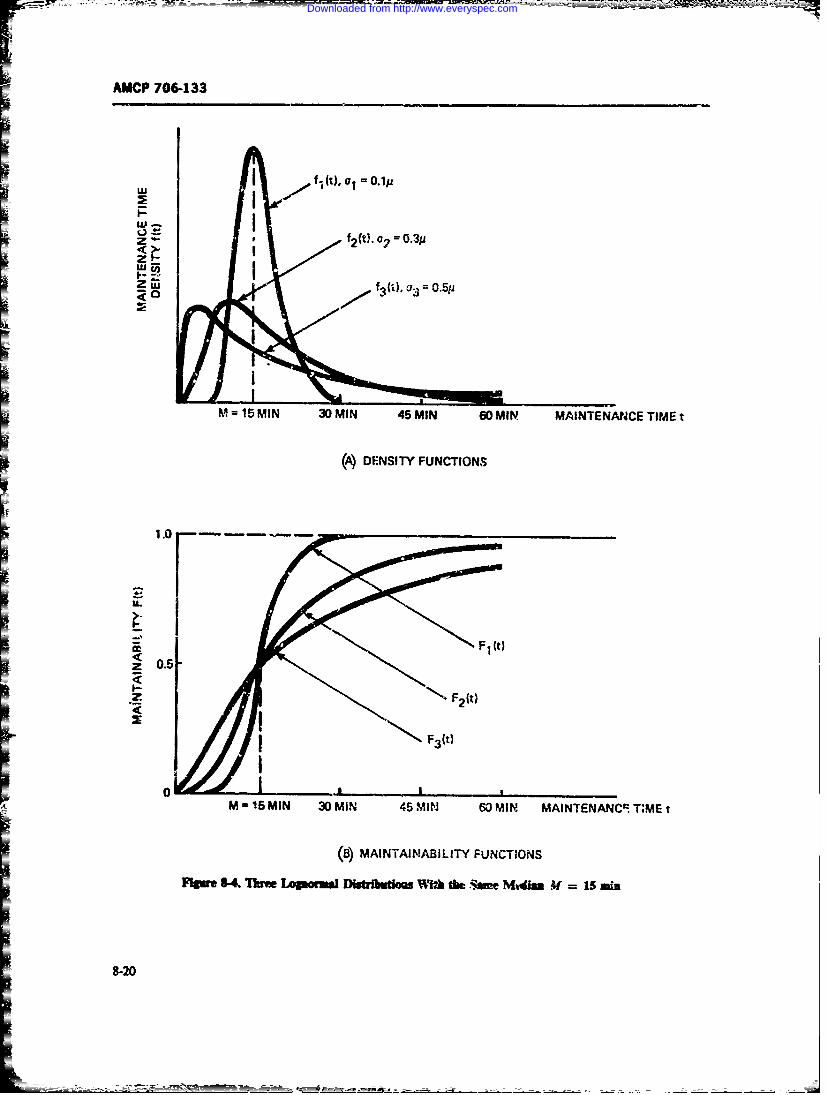
AMCP 706-133
"'i f (t). 01 0.1p
f2(t), 0?
2w
W
0 f
- " 2 (t 0 .3Pz
Z fj l3), as = 0.5y
M =15 MIN 30 MIN 45 MIN 60 MIN MAINTENANCE TIME t
(A) DENSITY FUNCTIONS
1.0
= F1 It}
I F3(t)
0 | LM-1 5 MIN 30 MlN 45 MIN 60 MIN MAINTENANCi T;ME t
(18) MAINTAINABILITY FUNCTIONS
Ftlawe kf i LlawmWm Dbtmdlto W'-Uh the im Mtiss Xf =in
Downloaded from http://www.everyspec.com
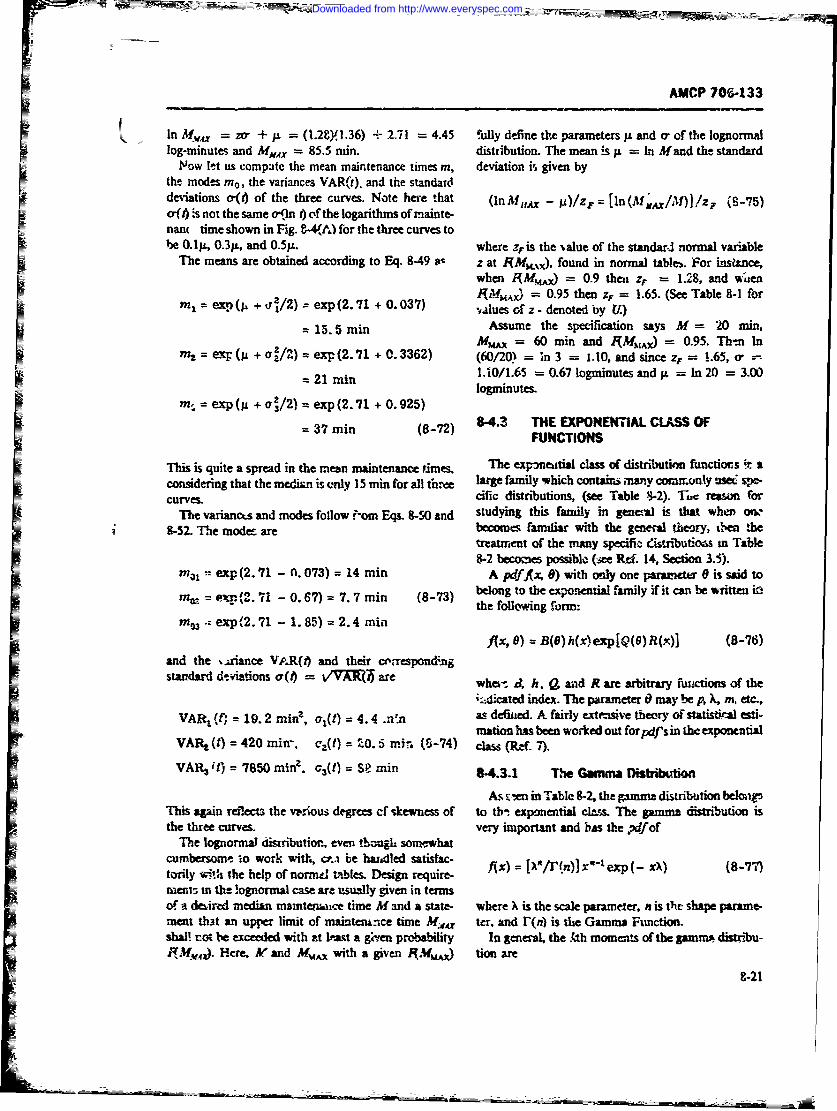
AMCP 70,-133I n M t = zo" + j = (1.2gY.36) + 2.71 = 4.45 fully define the parameters p and o, of the lognormallog-minutes and MUS = 85.5 nan. distribution. The mean s p = In Mand the standard
Now let us compate the mean maintenance times m, deviation is given bythe modes m, the variances VAR(t). and the standarddeviations o-(t) of the three curves. Note here that (In M AXx - A)/ZF = [n(M, /M)]!z. (8-75)
a( -s not the same o-4n 0 of the logarithms of maunte-
nan( time shown in Fig. 8-4(A) fbr the three curves tobe 0.1p, 0.3p., and 0.51L. where z4is the ,alue of the standard normal variable
The means are obtained according to Eq. 8-49 at z at (MK), found in normal tables. For instance,when iMMAX) = 0.9 then ZF = 1.28. and wiea( /MAX = 0.95 then z4 = 1.65. (See Table 8-1 forex( t + /2) exp(2.71 + 0.037) sfz- denoted by U.)
= 15.5 min Assume the specification says M = 20 min,(3Mm = 60 min and RMAx) = 0.95. Th-n In
= p(p.+a[/2) =exi(2.71 .3362) (60/20 = ;n3 = 1-IO, andsince zF = 1.65, o- == 21 rain 1.10/1.65 = 0.67 logminutes and p = In 20 = 3.00
logmunutes.m, exp (g + ar2/2) = exp(2.71 + 0.925)
= 37 min (8-72) 8-4.3 THE EXPONENTIAL CLASS OFFUNCTIONS
This is quite a spread in the mean maintenance times. The expneitial class of distribution functions iconsidering that the median is only 15 min for all th.iee large family which contains many commuily =6 spe-
curves- cific distributions, (see Table 8-2). ,- reason forThe variances and modes follow ;-om E(W &-Soand studying this family in general is that when onw-
8-52- The mode are become% familiar with the general theory, tsm !heuratment of the many specifit entributioas m Table8-2 becomes possible- (ee Rf. 14, Section 35).
ml = exp(2.71 - 0. 073) = 14 min A pdfAxz 8) with only one paramct is said to
71= e_ 7 - 0.67) = 7.7 min (8-73) bekong to the expontial family ifit can be written inthe following form:m93. exp(2.71 - 1.85) = 2.4 min
fix, 0) = B(6)h(x)exp[Q(G)R(x)] (8-76)and the ,A.riance Vo.R(i) and their cerespond;ngstandard dtia~tons a(s) = VAIQ' are whem A h, , and R are arbitrary fnctions of the
i:.!cated index. The parameter 0 may be p, X, m, etc.
VAR (f) = 19.2 miran2, o,(t) = 4.4 .n- as defied. A fairly exteusve theory OF stafisd! esti-mation has been worked out forpdffsin the expcoatial
VA L (t) = 420 miu, c',(t) = 20. 5 mi7, (6-74) class (Rf 7).
VAR3 it) = 7850 min. a3(t) = SP min 8-4.1 The Gaumna Disthlbution
As s:en in Table 8-2, the gamma distribution belongThis again refects the vweious degrces cf skewness of to th- exponential clam The gamma distribution isthe three curves. very important and bts the pdfof
The lognormal disiibution, even tlzugh somewhatcumbersome o work with, cr.a be hadled satistac-torily with the help of norm4 tables. Design require- fix) = ( /r~n)]x"t exp(- xX) (8-7)merit sn the lognormal case are usually given in termsof a deoired median matnte atce time M and a state- where X is the scale parameter, n is the shape parane-ment that an upper limit of main em-unce time M,,, ter, and r(n) is the Gamms Function-shall not be exceeded with zt Pa a g~i-en probability In general, the .(tb moments of the gamma distribu--ffA(4,). Here M and M, with a given RM.W ) tion are
8-21
Downloaded from http://www.everyspec.com
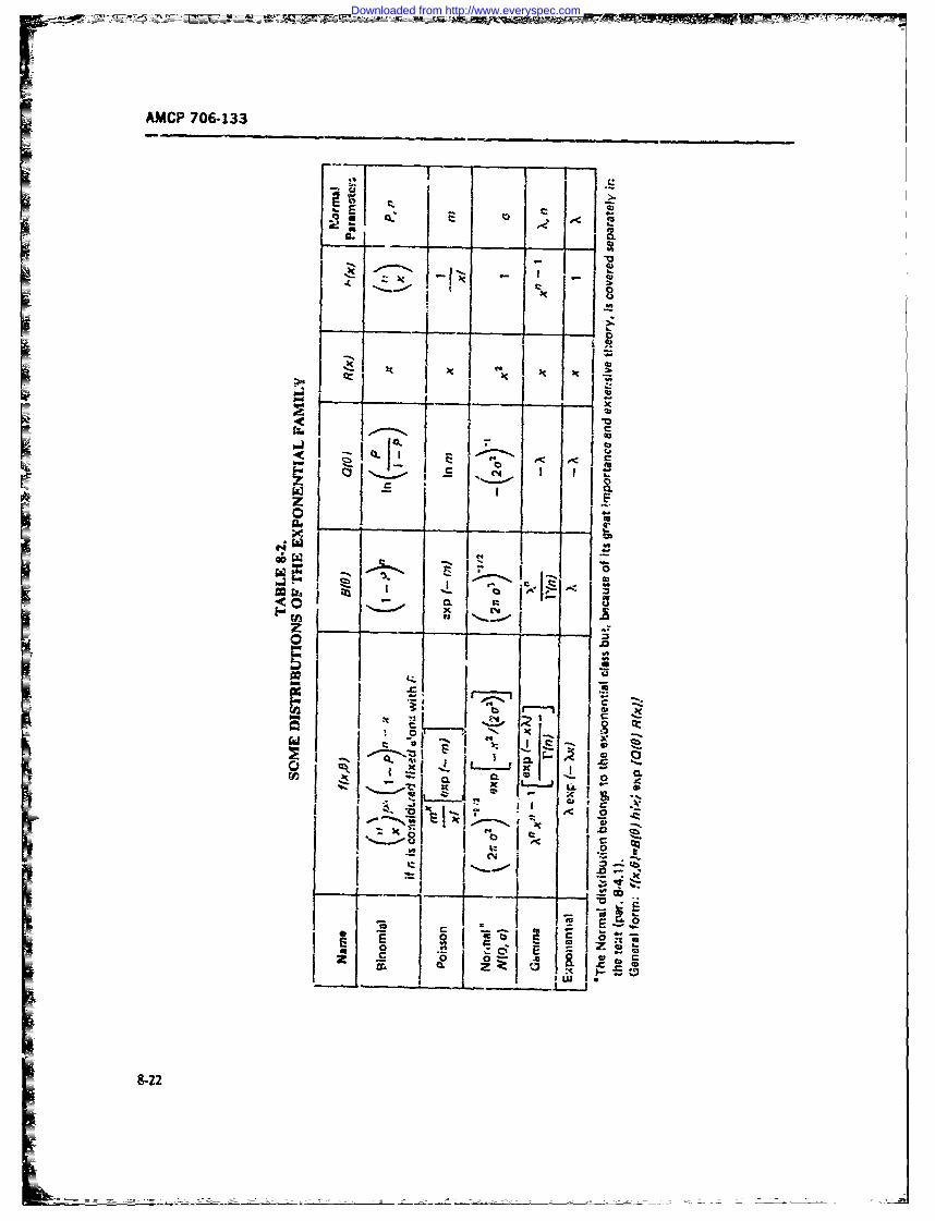
AMCP 706-133
EE
I' -
0 -b
.~if Qf
OL 0
I~~ ..'2-
~Ii~ 00'1 f -'XI 1 r-i j
8-22
Downloaded from http://www.everyspec.com
AMCP 7M6133
E[XA] [ r(n +k)l IVX 1'(n)J (8-78) of-fit Tests (par. 6.7.5). Ref. 16 tabulates tue X2 CDF
and its percentile points.
When n;-i an integer, this reduces to: &4.3.3 Exponential Distribution
E[X" = ( + k- 1)/[(z - ~i x) (679) A random variable X is said to b,- exponerially dis-4xaI (ii+ k- 1l/1n -1)~).~ (879) tributed if there is a num'her b Z-G, so that,
Then the mean and variance are r.- = nIX, and (1 -P x[ xv bx o if x --5VAR[Aj = l, P(X F( tc 0, ifx x
The gamma distribution satisfies the following addi- i ,ition theorem. If two gamm.a random variables X. and (8-81)X2 have pdfls with the samne X, but possible diflerentni parameters (say, it, and n,). then their sum Y = The pdf isX, + X, is again gamma 4istributed with pa.i.4metPrSA~ and n, = n,1 + r-. (U.. :.5). This theorem is usefulin problems uf summi~ng maintenance times for a fixed AX) exp X%'(x -b)I if x -b (tS-A2)rungber o'r repairs. 0 tews
Some shapes of th.t gammna pdfs (Eq. 8-77) areshown in Fig. 8-.%. Mary tables are avaikAble. Ref. 16gives standardized (X = 1) tables to nine decimal ot:hiisagnrapdwthaamesXadpiaces for n =- 0.5(0.5, 75(1) 162 at p = 0.0(0~.1 (oe)hi5saga0.d it aaetr nwhere n and ui ate definedi by the Incomiplete Gamma I
Funcion (it n),give byThe moments around zeo are
i(ti.n)I = lr(n)Iif t'l'exp(- tOdt (8-80) E[Xbl -- b~u! (8-83)0
A specia case of the gamma distribution occurs when and therefcre= the shape parameter n = 1. This respilts in the expo-
nential distribution Ax) = X exp ( )x), per Eq.
8-77. MNEAN = E[Xj 1,/ . (8-84)
8.4.312 the Chi-square Distribution V'11FY = EJX 21 - LIjXJ 1/"%' (8-85)1
T&ie chi-square distribution is also a special zase ofthe garna distribution. A random variable X is !.aid tobe chi-square (x') distributed witi' v degret:7. f freedom 8-5 ESTIMATIONwhen it is gamma dist-nbuted with scale parameter
X1 'and shape parameter ns = v/2. The useful- 8-5.1 PON UT ESTiMATION PROBLEMS INness of the X*' di,ributit.., arises from the fact that GENERAL%when X is normally distributed according to iVX!0.a'). then X' has the chi-square distribution with one Sampling is undertaken to estimate sourne parametersdegree of fr-tedom (Ref. 17). Als.o, the CDFof X: fol. of the population, e.g., the mean and .rsriance. Theselows the addition theorem peoperty of the gamma dis- parameters are to be estirru ted from the values of atributim... These two facts explain i'.s use in Goodness. sample of size n. Suppoc.e these are x, 4...A
9-23
Downloaded from http://www.everyspec.com
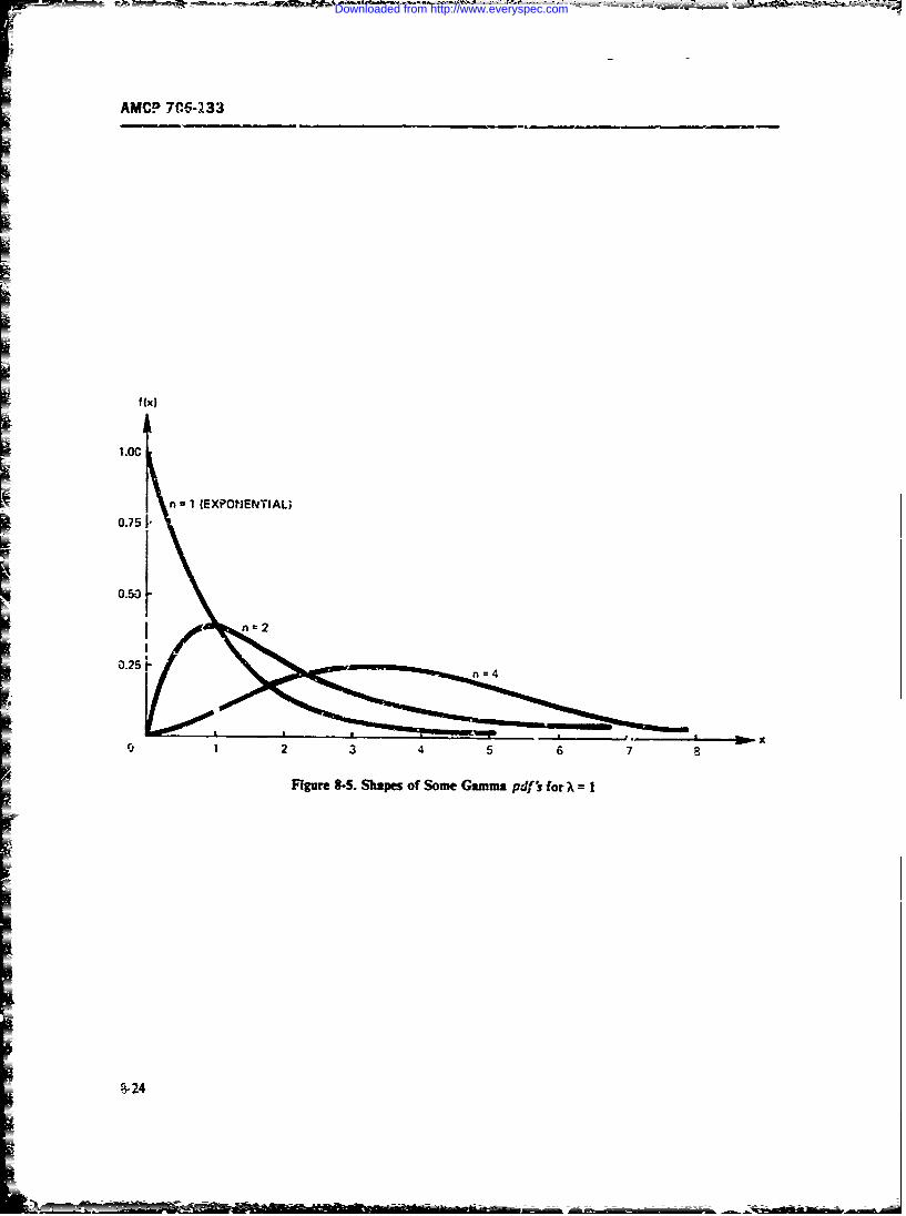
AMCP 7C6-233
f (x)
n I (EXPONENTIAL;0.75 I
_ 0.50
I n=2
0.25 i
1i 2 3 4 5 6 7a
Figure 8-5. Shapes of Some Gamum Pdf~ for A~ I
i
;-2
Downloaded from http://www.everyspec.com
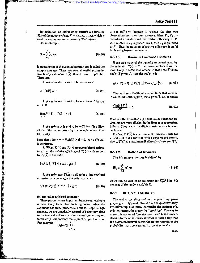
AMCP 706-133
By definition, an estimator or statistic is a function is not sufficint because it negec3s the first two70- of the sample values, 7 = (x., x ..... ,xj), which is observations and thus lose accuracy. When TI, T2 areused for estimating some quantity T of interest, consistent estimators and the relative efficiency of T,
As an example with respect to T2 is greater than 1, then T1 is preferredto T2. Thus the notation of relative efficiency is usefulin choosing between estimators.-i , /n (-86
i.t 8-5.1.1 Maximum Likelihood Estima4.es
If the true value of the quantity to be estimated byisanestimnator ofthe ppulation mean andiscalled the the estimator 7(x) is T, then scme vectos Xwill besample average. Thee are several iseful properties more likely to occur that others. In fact i.ff(xiT)!s thewhich any estimator T(x) should have. if possbk. pafof 3 given T, then the pdfor x isThese art:
1. An estimator is said to be urbiasedif g(F1T), = f(x iT)f( IT)--.f,(x ' (8-91)
El T)j = T (8-8VP The maximum likelihood method finds that value ofTwhiclb maJriz.s (x17")for a given iLe., it solves
2. An estimator is said to be censistent if for any
a> 0 d[g(ilt)i = 0 (8-1- )dT
limP IT - T(7i > aI (9-88)
te obtain the estimator T(x). Maximum likelihood es-timators ..e nrot dficient in the limit -s n appreaces
3. An estimator is said to be suficienw if it ut'liz,-. infiniy. They are abo sufficie-t estimators x neverall the ;ciformation given by the sample values V = uch exist.(x.....). Further. ;f T(x) is a mar.tmum likelih-ood -- imate forNote that if lira n-o VAR[T()] = 0. the T(x) so T. and if h(fl i; a function with a stnmIe-vnlaed in-rw. ,iNcoistenat, ithen .d~ -s)) ". a maxim=w tikelihood estimate for h.7i.
4. Wlien T ( ) atid T. (x) are two unbiased estima-toms then the relative effieJo, f T- O) with rt-peal 95.1.2 Wthd of Wmt.4
to T, 2) isthe rtioTIe lah sat;,ple riv--.-t is define by
[VAR rz(%3]I/[VA -. -&( )] (8-891 al 8-3
5. An estimator T(x) is said to be a best unbi"sedestimator .,r a muse effi..nt estimator when which can be used as an estimator for E'Xt I the kth
VAR[T(:)] --+ ,AR[T 1 (.' (8-90) moment of thte random variable X.
8-5.2 INTIEJVAL ESTIMATESfoi any o.he" unbiased estimator.
=Th.se properties are important because our estimate The estimat .- discussed in the preceding ara.is most likely to be close to being correct when the graphs giv. aiiy point estimates of the quantitie, theyestimator has these propertis. Thus for large enoijgb are estimating. Naturally. the smaller the variance of asampies. we are prctically assured of being very close pr+int estimator, the greater its -precision-. The way toto the true value if we are using3 a coisistent estimator. make this notion f -greater pcv iort " better under-Sufficiercy is important frc.in a practical poin. of view. stood is to use an inte. val estimator i such a way thatFor example n the estimated interval co -- s the largest amount of the
(lI(n-2)I % , probability mass co-cerning tit t oit estimator.if 3
8-25
Downloaded from http://www.everyspec.com
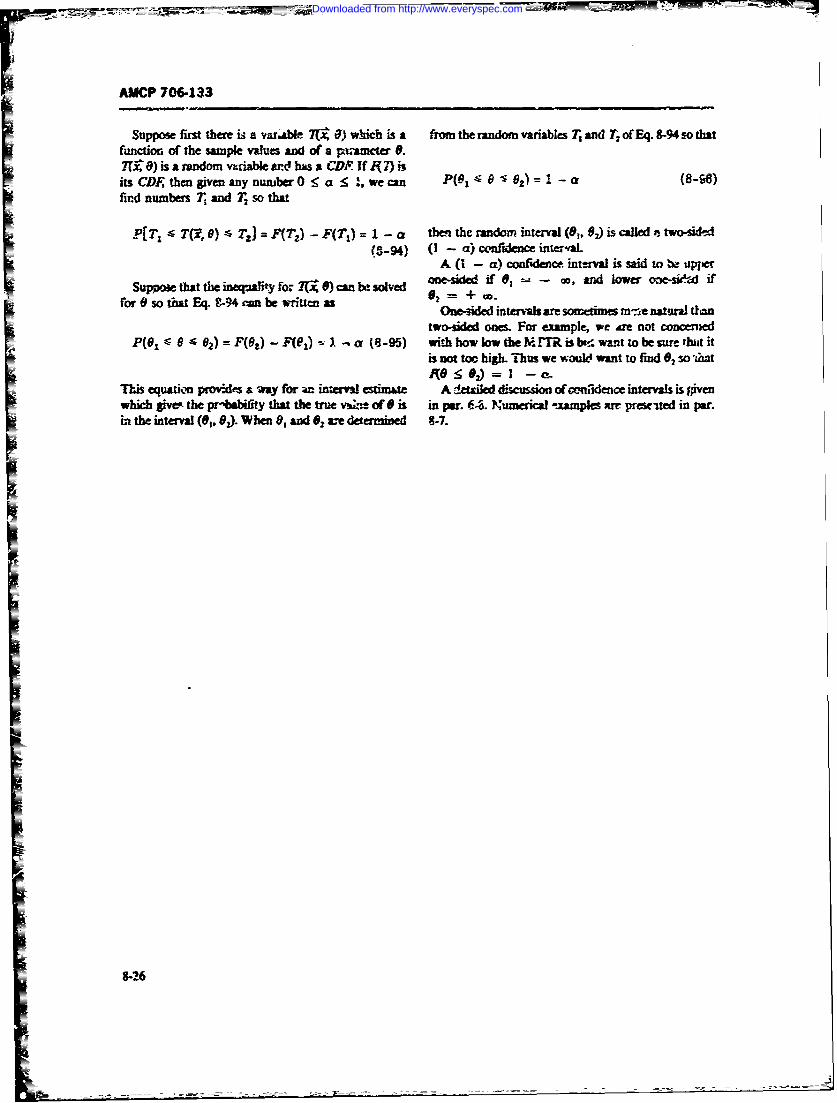
FAMCP 706-133
Suppose first there i a varabl 7(x 0) which is a from the random variables T and o Eq.8-94o thatfunction of the sample values and of a pxwancter 9.TUO 8) is a random vable a-d has a CDR If 97) iits CDF, then giveu any number 0 a :< .we can P(81 -
< )1 -. a (8-9)find numbers T and T so that
P[T- T(G, ) S T] = F(Tz) - F(TI)=1 - t n the random interval (8,, ) is called. tw4d A(3-94) (1 - a) confidence inerval.
A (I - a) co fencen-al is said to .
Sup ethat the ft for x-,) can be solved one-sided if ,-- nd lower one-s.iW if
for so that Eq. 9-94 can be written as 02 = + t.-One-ded intervals are someti mes mne natural t on
two-sided on. For example, we dre not concered0(1 8 2) =F(Gr) - FRI) - (8-95) with how lowtheM Mi bt!:wantto be ure tbjit it
is not too high. Thus we would want to find 0, so 'Lht:0<02) = I-o
Ths equation pmo:d' a way for an interml estimate A n'e discussion of cmnidence intervals is givenwhich givoee the Pr-biiit that the true w , of 0 is in par. 68. Numegical -. amples ar preseited in par.in the interval (0,, 02 When 0, and 19 a-e detwriW 8-7.
8-26
Downloaded from http://www.everyspec.com
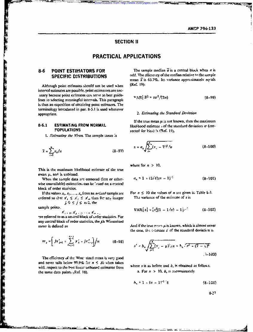
AMSP 706-133
SECTION Ii
PRACTICAL APPLICATIONS
8-6 POINT ESTIMATORS FOR The sample median j is a central block wh-n n is
SPECIFIC DISTRIBUTIONS odd. The ±fficic:.cy of the median relative to !hc samplemean i is 63.7%. Its variance approdmatelv eqr-als
Although point estimates should not be used % hen (Ref. 19):
interval estimates are possible point estimazors are nec-asary because point estmates car serve as best guide- VARj Ul za 'z/(2n) !8-99)
fines ;o selecting meaningful intcrval& This paragraphis thus an exposition of obtaining point estinmaes. Theterminology introduced in par. 8-5.1 is used wheneverappropriate 2. Estimating the Sandord Deviation
If the true mean .is not known, then the maximum8-6.1 ESTIMATiNG FROM NRMNAL likelihood estimate s of the standard dev.iation o- (zor-
P. OPULATIONS rected for bi&:-) is (Ref. 19'.1. Fstinating the MeatL The sample mean ;s
s = (,:,-i /n (8-100)-= Ext/n (8-97) us,
.41
wbcre for n > 10.This is the maximum likelihood estimatle of the truewean. p, and is unbiased.
When the sample data are censored (ost or other- a, = 1 ;- (3/40ln - 1 " (8-l0llwise unavailable) estimatio. can r& "nsed on a c-tmtrdblock of order statistics.
If the valum x., x:..... x. from an n-sized sample are For n < 0 the values of n are given in Table &-3ordered so btat xt < . A. then f6: an.y integer Th,- variance of the estimate 3f s is
.0 f- j nj. thesample point,., VARIsI = -1 - 1/n) - tI-- (8-102)
-A!q ='cl-10-I.(
Sxre referred to as a emaral block of trder statistics. Forany cen:ral block of order statistics. the ih Winsori redmen'. is defined as And if the r',e r- a. is known, which is aimo never
the case-. '. c<ir:ate Y of the standard devia.irn is
, - x - ' c8- 98) 5- = b - .r. _
,'-103)The efficiency of the Wam rizd m*an is very good
and nevet tials below 99.9% for n S r. when takenwitl. respect to the b-,t linear unLasc estimator from where s is as before and b. is obtained as folloms.
the same data points tRcf. 18). a. For n > 0 5. is a n oximely
5.. 1 - (xx - IS' A (8-04)
8-27
= = - -_- - _ _
Downloaded from http://www.everyspec.com
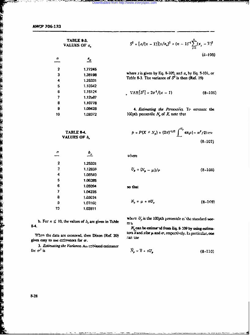
AMZP 706-133
TABLE 8-3.VALUES OF a. S= [41(n - 1)kslaf = (p - .""Y'(x, -,R);
I..
n
)
2 1.772453 1.7798 where sis em by Eq- -0 anJ a. by Eq. -101. or3 Im"98 T -,, 8-3. The va.,a, me of S2i t e (1 . 19)4 1.25331
5 1.139 426 "/.15124 4. VAR[, ] = 2C 4/(nZ - 1) (8-106)7 1.12bCV78 1.107789 1.09428 4. Euimadng the Pvw t Te estmuc the1o 1.08'72 100pth peentle N, of X. note t'bt
TABLE 8-4. p = P(X -N,) = (2.z") exp(- up!2)a
VALUES OF b. (8-107)
2 1-25331
2 1.12838 1, = U ,, - 14/c, (8-108)4 1.08W405 1.063856 1. so th
7 1.,42358 ~~ X...0324
9 1.0316 p' - + o7U, 8-1-9)10 1.02811
b. For n < 10, the ,,lues of .5, are given in Ti'e U i
-4. , caa beestim-Ad ftri Eq 8:0(9 by wing esixa-tors land sfor p and (r, rcgsp-tivjv. b paricukir. one
W~the data are censored. L%:= Damon j(Re 20)gives easy to ub %-----tms for a.
3. Eznitigdxh Vadarce Au.i %-tsdd saaz-fr a2 is + su-
8-28
Downloaded from http://www.everyspec.com
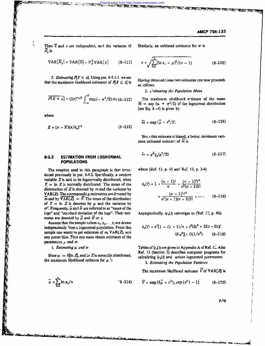
AMCP 70E-133
Then T and s are independent, ard the variance of Similarly, an unbiased estimator for o, is
VAR[RN.I VAR[3 ., U'VAR[s] (8-11)1- )/( ) (8-115)
5. Estimating 0,7 5 x]. Using par. 8-5. 1. 1. we see Haigotae ts wosimesneowpcedthat the maximum likelihood estimatorof I{X5 x] is ~ avin lobtieseew siae nenwpoed
2. .0climating the~ Population Mean
IX - xi MTV"1 fexp( u2/2)du 1(9-112) The maximnum ulkelihood e-simate of the meanR= exp (it + o 2/2) of the lognormal distribution
(see Eq. 8-4 is given by
where
Mz = exp (11 0 2 ) (8-116)
Sinc - this estimate is biased, a b',tcr, minimum vari-ance unbiased estimav of mWis
84.2 ES71MATION FROM LOGNORMAL = 817PoPuLATI
The notation used in this paragraph is thot in-ro. where (Ref. 12, p. 451 and Ref 13, p. 2-4)duced previously in par. 8-4.2. Spit-ificaily, a randomvariable Z is said to be lognormnally distributed, when ( )t ( )tY =In Z is normally distributed. The mean of the V),(t) =1 +.(i-11 ( )tdistnbution of Z is denoted by m and the vdriance by 1 ;( + 1)21VKAR(2). The correspondir g estimators are d-noted by + (11 - 1)5 f 3
m and by VAR(Z) =V The mean of the distribution ~ + n(n + 1)(r + 3)3! ~* 818of Y = In Z is denoted by jx and the vatince byor'. Freqil, Ai and Zr are referred to as "mean of thelogs5 and "stdard deviation of the togs". Their esti- Asymptotically, 41,,(4 converges to (R.ef. 1?, p. 46):mates are denoted by and F or &
Assume that the sampla ~sie z,, 7,,.. - z., are cirawnindependently f-rom n c ognormal popiulatiofl. From this k, (t) =e'[ 1 - f~ .1)/n + tz(312 + 22 t + 21Vsample one wants to get estimates of ,m VAR(Z), and (n)+01? 819any percen-titzs. First one must obtain estimates of the(6n)+01/) (81)parameters A~ and a-.
1. &dtmating p and a Tables of *(i) are given in Ap~pendix A of Ref. 1'-:. Also
Shie A= An Z, ad i Zs nrrrall dstrbutd, Ref. 13 (Section 3) describes computer programs forSihe xu lkioo ad esimat Zifor y disLibted calculating *4i,) avd arious lognormal parameters.
the aximm lieliood stimte fr ~3. Esdmatng the Population Varia."e
The maximuin likelihood estixhiate V of VAR[21 is
inL = zlnz~ '8 .114) V ~.exp (2i9 + a2)xp (sk)- (8-120)
Downloaded from http://www.everyspec.com
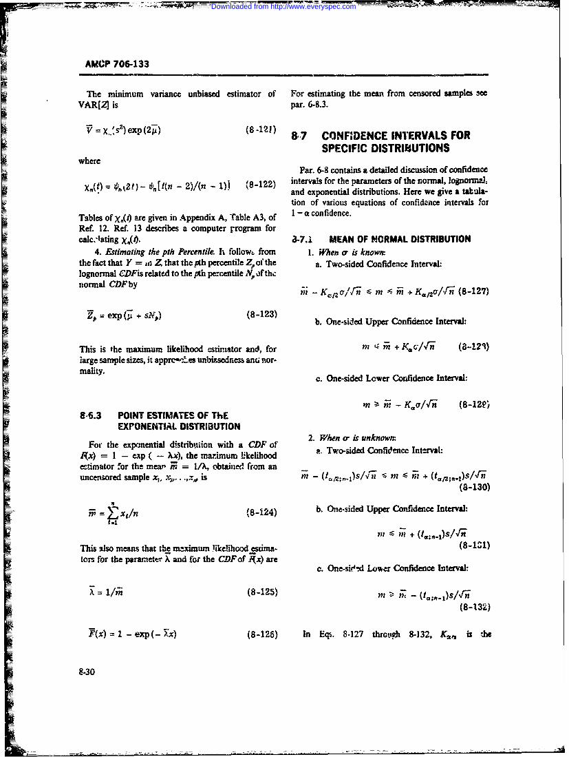
AMCP 706-133
The minimum variance unbiased estimator of For estimating the mean from censored samples meVAR[Z] is par. 6-8.3.
V = X..'s)exp(21) (8-121) 8-7 CONFIDENCE INTERVALS FOR
SPECIFIC DISTRIUUTIONSI wherePar. 6-8 contains a detailed discussion of confidence
X.(t) k2 t) - 0. [t(n - 2)/(n - 1)) '8-122) intervals for the parameters of the normal, lognorma-Lt " (- and exponential distributions. Here we give a tat-ala-
tion of various equations of confidence intervals for
Tables of X.(t) are given in Appendix A, Table A3, of I - a confidence.
Ref. 12. Ref. 13 describes a computer rrogram forcalc.-lating X(4). 3-7.1 MEAN OF NORMAL DISTRIBUTION
4. Estimating the pth Percentile It follow. from 1. hen or is known:the fact that Y = v Z that the oth percentile Z. of the a. Two-sided Confidence Interval:lognormal CDFis related to the pth pe-centile , of thenormal CDFby -T
n- - KCT/al - m i + K,/2orr, (8-127)
exp (g + s-N) (8-123) b. One-sided Upper Confidence Interval:
This is the maximum likelihood estimator and, for m Az m + Kf/i-n (8-123)iarge sample sizes, it apprct10M unli*,sednen anc; nor-mality. c. One-sided Lower Confidence Interval:
M > . - K c/,f (8-12P,8-6.3 POINT ESTIMATES OF ThE
EXPONENTIAL DISTRIBUTION2. When or is unknown:
For the exponential distribtion with a CDF of
gx) = I - exp ( - Xx), the marimurn lkelihood a. Two-sided Confidence Interval:
entimator for the mear X = I/, obtained from anuncenored sample x,, x.. .x, is n - (t/;,t)S/xfn - 1 - +
(8-130)
= (xn (8-124) b. One-sided Upper Confidence Interval:
n, < j + (t.;..OsldgThis also means that the maimum !ikelihood estima- (8-1Z1)tors for the parameter X and for the CDFof igx) are
c. One-sie-,d Lower Confidence Interval-
= (8-125) m - -; - (t,.;..)s/,/'
(8-132)
F(x) = -exp(- x) (8-126) In Eqs. 8-127 thrcl,.4 8-132, K,,, is the
8-30
Downloaded from http://www.everyspec.com
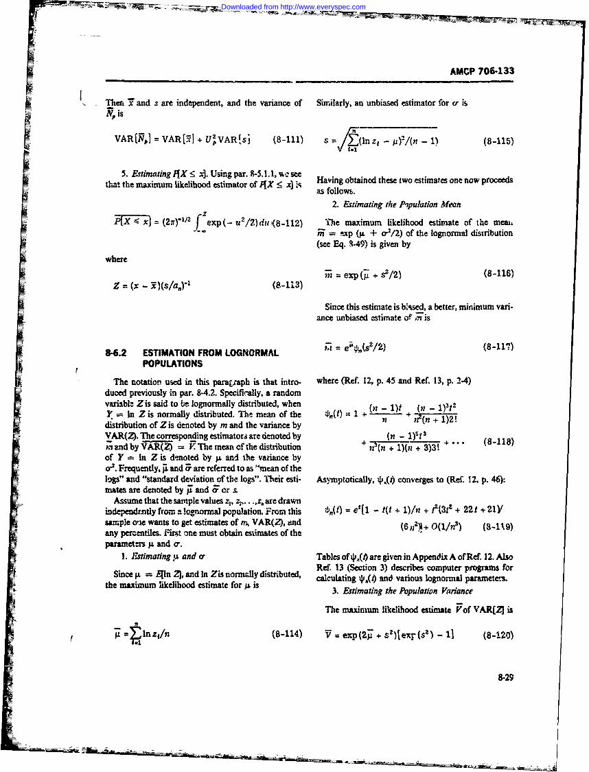
AMCP 706-133
Then 7" and s are independent, and the variance of Similarly, an unbiased estimator for or isN. is
VAR[N,] = VAR[5I + U2VAR~sj (8-111) s = / (nz, - l(n - 1) (8-115)
5. Estimating IfX S x]. Using par. 8-5.1.1, %-seetha~t the maximum likelihood estimator ofX < * Having obtained these two estimates one now proceedst mr -A as follows.
2. Estimating the Pipuladon Mean
P[X - x= (21r.1 2 fexp (-u/2)du (8-112) The maximum likelihood estimate of the meai,f F" = !-xp (p. + o-2/2) of the lognormal distribution
(see Eq. 8-49) is given by
where
n = exp (g + s2/2) (8-116)Z = (x - ")(s/a,5" (S-1.35
Since this estimate is bsed, a better, minimum vari-ance unbiased estimate of 7 is
8-6.2 ESTIMATION FROM LOGNORMAL ?d= e'O,(s/2) (8-117)
POPULATIONS
The notation used in this paratcaph is that intro- where (Ref. 12, p. 45 and Ref. 13, p. 24)duced previously in par. 8-4.2. Specifically, a randomvariable Zis said to bt lognormally distributed, when (n - 1)5 (n - 1)'tY = In Z is normally distributed. The mean of the 4"(t) 1 +distribution of Zis denoted by m and the variance byn _ + 1)VAR(. Theycorrespondingestimator aredenotedbyi and by VAR(Z) = V The mean of the distribution + n?(n + 1)(n + 3)3! + "of Y = In Z is d-noted by p. and the variance byo-. Frequently, A and F are referred to as "mean of thelop" and "standard deviation of the logs". Their esti- Asymptotically, 4s,(4 converges to (Re. 12, p. 46):mates are denoted by W and 5 or s.
Assume that the sample values z, z2,. .. are drawnindependently from a lognormal population. From this zb,(t) = et[l - t(t + 1)/n + t2(3tz + 22 t + 21Ysample oe wants to get estimates of m, VAR(Z), and (6 nV + 0(1/t?) (8-119)any perzentiles. isr.t one must obtain estimates of theparameters p. and 0.
1. , stimating p and a Tables of 4s (# are given in Appendix A of Ref. 12. AlsoRef. 13 (Section 3) describes computer programs for
Since p. = Eln 3, and in Zis normally distributed, calculating 4(4 and various lognormal parameters.the maximum likelihood estimate for A is 3. Estimating the Population Variance
The maximum likelihood estimate Vof VAR[2 is
p. =, .1 tnz,/n (8-114) V = exp(2 + s2)iexr(s 2 ) - 1] (8-.20)
8-29
Downloaded from http://www.everyspec.com
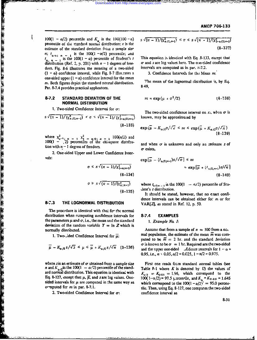
AMCP 706-133
100(l - a/2) percentile and K is the 100(,100 -ct) S - - s xFn---) /( ;,.)percentile of the tiandard norm.i distribution; s is theestimate of the standard deviation fron a sample size (8-137)n; n - I is the 100(1 -/2) percentie; and T
tis the 100(1 - a) percentile of Student's r This equation is identical with Eq. 8-133, except thatdistribution (Ref. 2, p. 201) with n - I degrees of free- a, and s are log values here. The ocie-sided confidencedorn. Fig. 8-6 illustrates the meaning of a two.sided intervals are computed as in par. ;-7.2.(1 - a) confidence interval, while Fig. 8-7 illus.rates a 3. Confidence Intervals for the Mean mnone-sided upper (1 - a) confid-nce interval for the meanm. Both figures depict dhe standard normal distribution. The mean of the lognormal distribution is, by Eq.
Par. 8-7.4 provides practical applhcatons. 8,49,
8-7.2 STANDARD DEVIATION OF THE in = exp(ji + cr-/2) (8-1.38)NORMAL DISTRIBUTION
1. Two-sided Confidence Interval for a-:1. ToieCndn InraThe two-sided confidence interval on r; when a- isS4F(-1 1 )/(XZ,/2;n-1) 5 J( - ' l(,- 1)a X----;V-n) known, may be approximnied by
(8-133) exp( - 'K=:r/,- -S ? - exp( + Ka/zo/f n)
(8-139)where X,, , _ I -_ . l00(a/2) and-~~~ ~ -2 cccta d2,100(l - .2) percentiles of t chi.square distribu- and when o is unknown and only an stimate s oftion with n - I degress of freedom. ad en s u
2. One-sided Upper and Lower Confidence Inter-vals: exp[ - (!/;t..i)s/'] I mi
a )/Xi.;.-i) -( exp[T + .
(8-134) (8-140)
LT S F(n - 1)/(Xa;n.i) where t.,:, - ,is the 100(1 - a/2) percentile of Stu-dent's t distribution.E (8-135) It should be stated, however, that no e.tact confi-dence intervals can be obtained either fo- m or for
8-7.3 THE LOGNORMAL DISTRIBUTION VAR[Z], as stated in Ref. 12, p. 50.
The procedure is identical with that fo- the normaldistribution when computing confidence intervals for 8-7.4 EXAMPLESthe parameters IL and a-, i.e., the mean and the standard 1. Exampe No. :
deviation of the random variable Y = In Z which isnormally distributed. Assume that from a sample of n = 100 from a no,
1. Two.rided Confidence Interval for _P: mal population, the estimate of the mean m was com-puted to be ir = 2 hr. and the standard deviation
_ + K, / (3-136) o' is known to be a- = I hr. Required are the two-sided- and the upper one-sided .,fidence intervals for I - a =
0.95, i.e., a -- 0.05, a/2 = 0.025, 1 - c/2 = 0.975.
where sis an eslimate of- obtained from a sample size First one reads f.rc~m standard aormal tables (seen and Ka,21s the 100(1 - a/2) percentile of the stand- Taile F-I where K is denoted by L) the values ofard normal distribution. This equation is identical with Yo:2 = K002S = 1.96, which correspond to theEq. 8-127, except that p, jr, and sare log values. One- 100(l--a/2) = 97.5 l.-rcentile, and Ka = Ko.os = 1.645sided intervals for / are computed in the same way as which correspond to the 100(1 - c/21' = 95.0 perceli-crinputed for m in par. 8-7. 1. tile. Then, using Eq. 8-127, one computes the two-sided
2. Two-sided Confidence Interval for a-: confidence interval as
8-31
Downloaded from http://www.everyspec.com
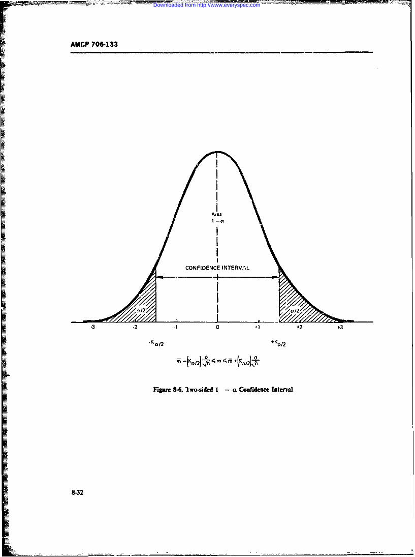
AMCP 706-133
Area
CONFIDENCE INTERVAL
/
- I , _ _ _ /
-3 -2 1 0 +1 +2 +3
• K 012 +KC! 2
Figure 84. Iwo-sided 1 - a C ofideuce Interal
8-32
Downloaded from http://www.everyspec.com
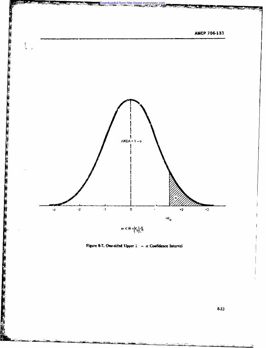
AMCP 706-133
I
AREA 1 -a
12-mi
*2 0 +
Fipmr 8-7. One-skt~d IUp-r -a Coafideace latenTi
9-33
Downloaded from http://www.everyspec.com
AMCP 70O6-133
[2 - 1.96(1/10)1 < [2 + 1.96(1/10)1 cr 1 X YT§Fi'9 =. 1.13 (8-145)
1. 804 -in 2.1i96 (8-141)
"The statement then reads "There is a (I - a) = 0.95probability that the calcuk~ted limits of !.804 hr and This reads, that with 95% confidence the true standard96 hr will include the true mean ". And using Eq. deviaticn is less than or equal to 1.13 hr. Attention is-2. 19wone comlutes the oe-me d u r E. drawn to the fact that some ch.-square tables g-ve the.nterval c u (1 - ) percentae points while others give the apercentage points.
Computati3ns of the confidence intervals for the log-m 2 + 1.645(1/10) = 2. 1645 (8-142) normal distribution are done in the same way as in the
preceding normal examples, except that the log valies
which reads: There is a (1 - a) = 0.95 probability must be Unsed.that he true m is less than or equ.-i to 2.165 hr. Cfcourse, in this examnple m could be the MTT R of asystem. 8-8 LIMIT THEOREMS
2. Example Na 2: Continuing with Example No.1. we assume that the standard deviation ar is not Limit theorems are widely used in statistics becauseknown, bu: an estimate of s = 1 hr was computed they give the approximate behavior of farge samples. Infrom thie samp!e of n = !00. What are the confidence fact, they form the basis of mr.ny statistical procedures.intervals? Using Eqs. 8-130 and 8-131, we first find the They serve a practical purpose because limiting behav-approximate values of t.:, = 1o0. = 1.971 ior is much simpler than ev.act analysis; the use of limitand t.., - = t = 1.664, from such table- as if' theorems simplifies !,isy requisite -nalysis. As an intro-Rei'. 3. Table A-4. Then we compute duction to thb- Central Limit Thetorem, the Law of
Large Numbers will be discus3ed.
[2 - 1.97(1/10)1 < ,n [24 1.97(1/10)1 b- .1 LAW OF LARGE NUMBERS1. 803 m m 2. 197 (8-143)
This states that if the mean or expected value m ..r
ard a random tariable is finite, then the probability that thearithmetic average of the sample will differ from m
r -< 2 * 1.66-(1/10) = 2. 156 approaches zero as n approaches infinity, or for anyE >0
(8-144)These results are almost identical with the previous (cnes except that the inmervals are a litt!z larger because iriin M - IX/j, = 0 (8-146)of the use of oercentiles of the tdistribution. The diffe- ... I I
ence would be significantly larger for small sample sizest where n is the number of observations in the sample,
- Example Noa3: Fort:esamecaseasin Example and Xi is the value of the ith observation. This law is ofNo. I, Let us c.;mpute the one-sided uppe confidence se in determining appropriate point estimates. Forinterv. fo: .r when the estimate ftom the sample of example, besides assuring us that
S--- 100 : s = I hr. From tables (R(. 3, Table A-3) nwe fir d rh c approximate value of the chi-square peicen, m = Z Xilntile ,. ., = xd, for n - I = 99 degrees of free- I =do;:t. This value is 77.9 and using Eq. 8-134, one ob- is a good estimator for the mean. :t .uso provides us withtains a good estimator fao the probibility of an event. Thus,
8-34
Downloaded from http://www.everyspec.com
AMCP 706-133
let A be an event and consider a sequence of k > 0. Note that the preceding est;tates the proltabil-inde,,endent t.ials bich athat P(A) is the same in each ity in thc tails ( - co, m - k) and (m + k, c). Thustrial. In order to get a probability estimate from it also estimates the probability concentrated symmet-
rically about the mean m, i.e.,
i= 1 P[X E(n? - k. m t k)]I > 1 - a' !,e- (8-151)
X, = 0. if ,A doe not occur .t the Ah From this follows
= 1, otherwisek1 /5
then P[I( Xi/-la o r/(na) (8-152)
wher Piaponurmbefr >.No thces e lwonumber of successes (3-147) for any a > 0, and any a _ 1.number of trials This gives us a gooI indication of how close our
estimate for m is when w.- know i. Conversely, it canwhere Pis a point estimate for I(A). Now the law of wnre as a means for choosing n when we want a certain
larg num-:mtell us hatconfidence in the estimate. For mnore sophisticated esti-
mation techniqies involving con-umer and producerlimP15 , PA~l 0 8-1811 risks, see par. 8-1.3.2.
limPP - P(A) = 0(8-148)"" 8-8.2: UE.TR.L LIMIT THEOREM
The reason (A) can be substituted for m is that. This states that under some commonly attained con-diti.os, tihe average of a sum of rando.,' varia;bles X.
EY'= = I[PO( ,. 011 - P'A)1 = P(4) becomes normally distributed as the number of stn-
(8-149, ma'--' becomes large. Since the normal distributinr, -Ieasy to use, and since for the cotditios of the theoremthe exact form a?" the pdffcr .he X is not needed, this
As an example. suppose we " ant to estimate th.- theorem is very us~fiJ in estimation. More specifically,
probability that a maintenance action will be completed let , be ident aly distributed t Mndon variables withi!hin a hours, i.e., we want to estimate the probability m e id staldr ditit a-lohn the with
1(1 5 a. Ten, y dfinng X 35in he peceing mean nn and standard deviatien o-. then the pdfofJi t < a). Then, by defining X, 3:, in the preceding
paragraph. we know that a good point estimatz of [Ax in]
P(i <a) is the mean, - a/i..7, ) (8-1c3)
tends to the n (XIO, I) pdf Equivalently, the pdf ofi=
Since a is azbttrary, this really says that the cumulative 1=histogram approaches the true distribution F(a) = P(t <2a) of maintenance time. tends to the n(Xlm, o2 /n)pdf.
To answer the question of how good such point esti-mates are, we need another limit theorem. lfhis limittheorem really follows directly from the more funda-mental result thai 8-9 HISTOGRAMS
8-9.1 USEP(IX - ni k) < a/k 2 (8-150)
In many instances ^he assumption that the repair
time of systems is distribc.ed according to some of thewhere m is the mean, cr the standard deviatior,, ant theoretical distributions (exponential. gamma. normal,
8-35
Downloaded from http://www.everyspec.com
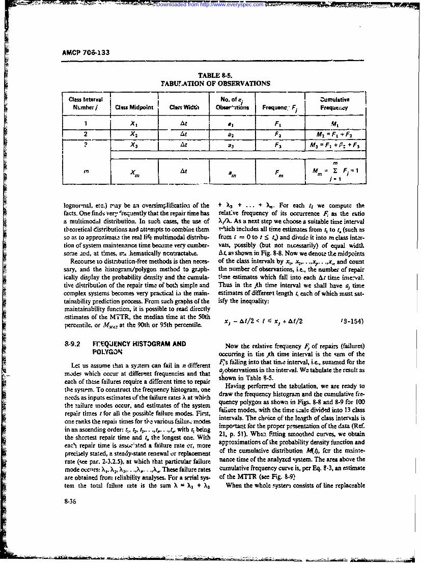
iA
AMCP 706-133
TABLE 8.5.TABUTATION OF OBSERVATIONS
Nmberj Cs Midpoint C W Ob 'tions Frequenc. F Fr@qWeecy
IX t At a F, M4f
2 X2 A t2 F2 M 2 = F+F 2
X3 At 3 F3 M3 F, + F: +_F3_
17T At i= F-
lognor'nd, etc.) may be an oversimjlificatioa of the + )3 + + 7.. For each lt we compute thefacts. One finds vety "requently that the repair time has relative frequency of its occurrence Fi as the rmtioa multimodal distribution. In such cases, the use of X/X. As a next step we choose a suitable time intervaltheoretical distributions and attempts to combine them .,hich includes all time estimates from t, to t. (such asso as to approximate the real life multimodal distrbu- from r = 0 to t : t,) and divide it into m class inter-tion of system maintenance time become very cumber- vais, possibly (but not ntcessarily) of equal widtl.some ard, at times, W, hematcally nc,'.ractabe. At. at; shown in Fig. 8-8. Now we denote t oe midpoints
Recourse to distributiGn-free methods is then neces- of the class intervals by x, x. ..,x,... ,x, and countsary, and the histogram/polygon method to graph- the number of observations, i.e., the numbe- of repairically display the probability density and the cumula- Dime estimates which fall into each At time ine-val.tive distribut;on of the repair time of both simple and Thus in the ith time interval we shall have a, timecomplex systems becomes very practical La the main- estimates of differept length , each of which must sat-tainability prediction process. From such graphs of the isfy the ineqludity:maintainability function, it is possible to read directlyestimates of the MIR, the median time at the 50tiipercentile, or M.,A: at the 90th or 95th percentile. xj - AI/2 < t - Xi + At/2 13-154)
8-9.2 FI.EQJENCY HISTOGRAM AND Now the relative freqdenicy F of repairs (failures)POLYGON occurring in tue !h time interval is the %im of the
Let us assume that a system can fail in n different Pis falling into that time interval, i.e., summed for the
moder which occur at differmt frequencies and that a observations in thz interva. We tabulate the result as
each of these failures require a different time to repair shown in Table 9-5.
the system. To construct the frequency histogram, one Having perfor-r-d the tabulation, we are ready to
neds as inputs estimates uf the failure rates X at which draw the frequency histogram and the cumulative fre-
the ailure modes occur, and estimates of the system quency polygon as shown in Figs. 8-8 and 8-9 for 100repair times t for all the ossibe failure modes. r failure modes, with the time sale divided into 13 classo -nthrepair times fororall the ris failur modesrs, intervas. The choice of the length of class intervals isone ranks the repait times for 1 c various failur. modes imoatfrtepoe rsetto-ftedt Rfin n aceningorer:tt t ,t .... t ... ,, ithrt ~ g important for the proper presentation of the data (Ref.in an ascending order: !I, t2, 13,. . .. r, ., 1, with r, being 21, p. 51). Wheiftigsote uvs eotithe shortest repair time and r, the longest one. With ape. fitting smoothed curves, we obtaineaci repair time is asso,-ated a failure rate or, more approximations of the probability density function andpreci3ely stated, a steady-state renewal or replacement of the cumulative distribution M(4, fcr the mainte-rate (see par. 2-3.2.5), at which that particular failure nance time of the analyzed qystem. The area above themode occurs: X. X. X)3 ... ., .... ,)- These failure rates cumulative frequency curve is, per Eq. 8-3, an estimateare obtained from reliability analyses. For a s-rial sys- of the MTTR (see Fig. 8-9)tern the total failure rate is the sum X 'A, + )2 When the whole systeri consists of line replac:able
8-36
Downloaded from http://www.everyspec.com
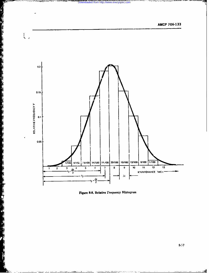
AMCP 706-133
0.2
0.15 F
I 0.1
1/100 VIC* t:IIOD 141100119,10 20!10- I 15/100 10i110016/100 1/100
2 3 4 5 7 10 1 12 13
S7" 2 dNTENAHCE "IME t
'7 2'
Figure 8-8. Relative Frequency Histogrium
8-.$-7
Downloaded from http://www.everyspec.com
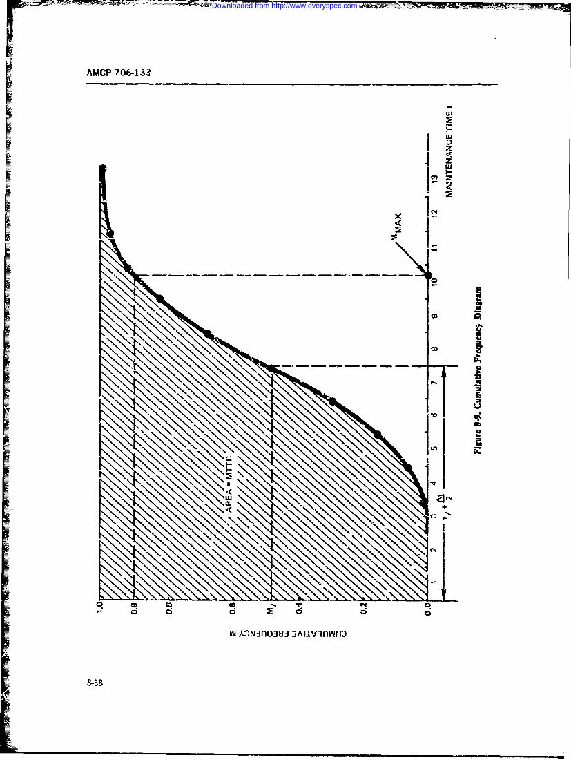
AMCP 706-133
w
I-
Z.)C
jt
SI*1i0n
co2
F6
Yi ADN~flD3UH HA.LI±VAmf
8-38
Downloaded from http://www.everyspec.com
AMCP 706-133
units (LRU's) arid there are only a few (A) of them (say, Usin? the ttatistical tools dveloped in thL- chapter
up to 20), we have Xsystem failure modes and Xassoci- will aid the maintainability engineer in performing theated system rerir times (b. LRU replacement). In tasksofnainairabiltypredictin, demnstraticansuch a cast. it is advisable to skip the grour ing into c!as estimafion The types ard sourtes of maintainabilityintervals and dcveop, directil the ct.muative frequency &%tz needed to perform these trsk; are discussed in thepolygon, as show-it in Ref. 21, p. 5-. following chapter
REFERENCES
1. AMCP 706-110 hrough -114, Ensineering 1.. Willian" 1. Hor.ath, "Appli a"bity of the Log-Design H&ndbo-_*, Expeimental Start normal ristributicr to $;ericing T:mes inSettions thrmugh 5. Congestion !uroblems". Opertions csarch,
2. John E. Freu.-d. MathematicalStatistid Pren- 7, No. 1, 116-12:' (Jan.-Feb. 1959).thc-Hall, inc., Englewood Cliffs , i52. 12. J. Aitchison and . A. Brown. Te Lognormal
3. Experimental Statisz oqp cit. Section 5 Ditibuon, .,-oj:dge Unirsy Press,(Tables)969
4. J. Denni- Aigner, Pinciples ofStaf i Dei. 196Ason Makin& Macmillan Decision Series, The 3 . n C. Aabadjio Th Lcg-Macmillan Cu, Canada. 1968. A'ormal Dirtribution General Elecric Cor--
5. Hunter M. Sohn, "Proven Techniques for party. Report No. R6SIPLI'2 April i,967.Maintainability Predictions and Deonstra- 14. Liu4grmn, oe cittion". presented at 10th Reliability and Main- 15. Freund, op. cit. Sections 7.3 -,nd 6-4.2-taiibbility Symposium, ASME. Anahcint, 16. H. L Harter, New Tables of the IncompieteCalif., 1971 (unpublished, availible from Gammo Functr Rcdo and Percentagz PontsLockheed-Georgia Company, M-ie-.a of the Chi-%, qarr and Yeta Dixtribution. U.S.Georgia). Government Prining Office, Washinion
6. Donald D. Gregor, Operational Capability D.C. 1964Analysis, Nov. 1970. Document NB .0--5i, 17. Freund, op. cit, Sectiots 5.4 and .Z2.Northrop C%,poraio. Aircraft Division. 13. A. E. Shrhan and G. B. Greenberg. "The Beq
7. B. W. l.indgil-. Stawzscal Theory, Macmil- Linear Estirnatcs for the Paramctes of the1an, C.n4da 196;. Normal Distribution", Contributions to Order
8. Ed. M. Abromowitz and 1. A. Stegun. Ha- Stotisti John Wiley and Sort- Inc., N.Y..book of Mc'rimaticd Functiob.s (p. 925- -- 5. 1962 (pD. 26-269).Probability Fc5..o"), US Depaxnent of 19. Norman L Johnson and Samuel Kotz. Con-
ComnBerce, !965. tinuous Univariate DsrrLbuio s- 1, Hou-htoya9. Nationl Bureau f Standards Tab, of Nor- ,ifflin Company. Boston, 1970. (pp. 59-62).
y-/ * -ctiorm. US r-p_,. nt of 20. W. J Dixon. -Simplified Estination fromCommerce, Aoplied Mat arld 2i3, CensorTed Normal Samples", Annals of Math-1953. ematical Statistics. 31. 385-391. 1963.
I0. R. L Bovatrd nd H. I. Zegor, "Lognorri! 21. A. Hald. Smad al Theory with Engineering1" -stribution and Maimviznab-hsty in %-ppmi of Application, John Wie'y and Sons. Inc N Y..Systems Research", Navd Lo.e- ic. QtAviwy, 1952.F, Nr,. 4, 343-356, %December 1961).
8-391$240
Downloaded from http://www.everyspec.com
AMCr 706-133
CHAPTER 9
MAINTAINABILITY DATASECTION I
LIFE CYCLE D)ATA
9-1 NTRODUCTIO. maintainablty designs throughout the iiHe cycle andproper performance of the maintenance function.
Bah the Military Standard& (ef. 1) and the ArmyEstablishment of the maintainability data collection, Regulotio (Ref 2) state tha. cr.sting data sources wili
analysis, and corrective action ssten. is oae of the be use4 to the mam um,.t extent possible, basing thetwelve essential tas:.s required in "he conduct of a well data system requirements only o'- essential data andorgnized Maintainability Engineering Pogram Plan specific plans. 0.- must therefore define exactly the(Ref I). Army Regulations (Re. 2) rcqu:'re suitable dta to be collected ar I the coritr to be exercised inplanning of mintanblty data collection to assure order to assure that all daa relevant t'e :he equiprrent
effectivt performanc.. of the maintamiability design under consideration are appropriately routed.function during the phases of the materiel hie cycle. analyzed, and acted upon in an effective and expedi-Therefore, it is stressed that a. effective and ewooini- tious maniter. ,i.itary data bcnks, e.g-, TAMMS.cWl maintaunbility data system should involve only make the data available to :.ny Government or indus-thse data essential to timely and intelligent -ssessment trial agency on a "ntm,-Lto-know" basis and subjec: toof the antr mnability design function and !ogistic sup- security lime.Ltions (Refs. i, 2).pon cost-. There are numerous maintainability data sources in
& Svr :he priacipal fiuctiou of th.i mafirainability the mlitary cSgencit, NASA, Bureau of Sta2dards,.
engineering discipline is to design mamridel so as to Energy Research and Development Administrauon,improv, availability for mission perf.xrmarnce and to and industrial agencies (Ref. 3). Hewevcr, die datare'-'c logistic support costs by revaci.g maintenance available from t.ee sorces are not always directlydowntime, tids fuction can be sttted in simplified applicable to a particilar rmteriel. ldtafly, the ne-form as: "Minimie main!e, nce downtime" and suy informadon would b, obtained by collecting and"MihiMize !oist.Uc suppOrt cC-t--. an..yzing all sources of data and observing th. perfor.
Thus, effectiveness of the mai-tensnce functions is mance of .=6ti materiel in current use. Since this isbased upon the abiiry of maintainability eginewing to n.t feasiole because of costs and time involved, thedesign equipment vnd develop maintenance plans current Army policy is to plan mid control limitedwl-.h will optimize the materiel uptime while miimiz- data collection (Refs. 4, 5). From the Various sourceing logistic support costs. The starting point for both of data available, mainminability engineers should ton-the theor and prtidcc of thc maintainabty engineer struct tre neces;ry maintainability data tables toivg discipline is to gather, validate, and e'a.mte exist- formulate baseline historical informaon applable toing mn.intain-bility data from similar eripment and the specific nateriel of comrn. This is a currentassociated maintenance concepts. This allows or to: practice in the airraft and electronc industrics (in-(1) tffectively develop the maintuinability design char- duding military aviation and cornmerciz airlines)actenstims required tolfill mission tobj ves, nd (2) wnere hist-ri6a data concerning existing materiel con-,wvelop and evaluate the life-cycle support roquir-. stimie the basi; of the -zintainability predictions andrnen-s WiJi-einabiliy data collectio must be ,rak- i ility design req-irements for view wtenelplumed, ,rintaiwdc, controlled. d .d evdu- (Ref. 6). V maintainability ". system thereforeated in order to assure continued a €prat of the entails the .o~lowing exsntial functons:
9-1
Downloaded from http://www.everyspec.com
AMCP 706-133
L. Observe,,_Alect-record-storc rnaintainabilit) generic rates, plus projec'ed development of- state-of-data h:at
2 Analyze-validate-ev.aluate Tnuitainability data 3. Scheduled maintenance replacement rates (31-
1 Retritte-utilize maintainability dat-t (for im- low-4ble and required rreventive replacement. actions;miediate product compliance are't cot rc-tive action, as scheduled servicing; etc.)well as for long range irnprovenerz of product design). 4. Rephacement anid repair times (mean time,
Yoedian time, maximum time. im ni-h.azrs per operatingMa:--taiability data colluctioi, evaluation, and hour. stendard dev'at'ons probabilities of rcpair rc-
tabulation sl'ould be a continuosts process during all complslunen')phases of *he equipment life -.ycle- There are no hand- 5. Maintenance oucepts (organizational inter-book sources of maintainability d-ua tabulatons availa- maediate, ands de'p(A levels at which maintetizzix G~ per-ble that are pertinent to a partiu!Lr equipment applIica- farned; effects of levels of maintenance on the equip-tici., such as is available to the reliabiity engineet in menit mssion availability, mairntenance skil! kiteWAIDWK-2l7 (Ref. 7) and !FARADA dxta- Thrre recvirenrents)
fore the maintainabiliyenieer is required to -valuate 6. Maintanabitity characteristics of the equip-svailat.lc data on the basis of simnhy to the- equip- merit (ease of mnaintenance. faalt isolation and locatiunmcnt of interst FortunwA~y over ihe past two decades, methods, 2ccess. ihem rerr.uve tnd replace. item service
soecontraz!Dr .rntaxznu zadvj1 ,e ability chedkout. throw-aw~ay -ersusear pectvhave been accumulating and evaluating data pawtai ng ~ mdfctos n vralto their sphere of inteiest (=o publishable because of 7. Equipment failure modes and their effec-s onproprietary inaresus), andi thetrety are able to 4-vs14f , iotheir partizcular usage in new eqtipmept designs. In a -;t miso eflAc
L-w instaces sxh as data furnished in MILvi-DBK- 8. Item criticality and higir risk (new or modj'iied472 (Ref. T3). data have been cited hised .m particular depmen)special applicatioas ns examples in exlinz th usencletigadaayzn aadr
of prd.zc tTherue but suc dacta in notetngn anayzngdatiaof pe&-tie tehniuesbutsuc daa 3- nt u.-Iaw -. g coniceiX deielopment is to obtain only those data= a rdbelae data source for new iqupment applications.
Thur. in the planning; for ccllecting and --valuating data tssertial to the fe=Wbiity sitdy. Therefora. op-. has to
for use at the v .:ioits tquipmnent lif-cydle phases, the Plan -4 procedure fcor data collection whid, will reveal
nriin-ainability engineer must define the need' ;)r and the citica; trend. Factckrs to be incindd o- rr -,jic tpe f dta equrte iarelzkmto he o~avalut sent reatist- and mreasurable requirement.,. For -xan-
bne ts t ape of da t a nteq ie r eain otece v pie. s study was recently mnaec for a mzilitary stip, tbeneitsandccntrant'. -rcraft wn which analysis of historical maiin~flit.
Maintainability dign requirements an wie date- for the exsting sysren (w~hich the projected air-nancc cor-cepts tie developed early i'r- the systen life craft vws to replace) re-vealed that four itaras re
ckc~ by ffeasibizhty studies. Such fezo-~ suiscn found to cause 40% of tle icracft mamneie &.n--sider maintainability dmnt and logistic support prob- trnze aniding grnt w+eels/brakes. windthieldcockpit
= k~~~~ns in. orde- to a~rrive at realistic asirnets of their -s rafih x-rl ign) enechhrpotential effect on the sup-port costs and availabity O itms an Mig t. anr te ri ing-n -e.nche or~
war s7 4Aid i etaJterslig4rahsOthe materiel.These consideratiorsin turn are derived .iitn ecci pdct 4 almtebyafto
i~nclnrrainlriltv ad lgistc ~of lour P.: a low cost J p. ocurement. The feamili tytorad-n fom imiar s) tem. Te dtaare validated
an~iealatdin orer o~ b h :bs ecnicap- studyo-fre onlythosL eerits whih caused ecsproachcs and to identify areas of iig twcnia andLs -a~eadotie
Usin opratonal aalyts ystm aalls. nd osa improvements rmeded. risks iaixJved. zod anticipa.:,dUsi ng op era htioa alss, yt e a alnds sep tbeneiis. In tis mmaner. the rnainlcmrivice concepis
pent requirern" appropnare to ti~e jp.. tvrutm vw- deind thi -cublt u rn-
of concern are selected.r~ ot e.rtrdadpe~ lmue s
fol lo i ty cond er nst nea flUu1 h In sixm zny. ct~aLur-tin, -alklatron, and evaluation offoflowiig ~data r e essentia in estabiig firmly and effect-imly
L Cost (both ir.3IZ Pr ~zictcnt inj !ife-41z thex reed and j-tsr'cati-I f".r !he design and pcoctre-SUPPOrt) men: of otintanable equiimt for military use, anti
2. Failizre rates (actual rates v--wjs MEAVKin the pre; =r apoblication of the tethmiqu of mantzin-
Downloaded from http://www.everyspec.com
AMCP 7C64!32
ability engineering. One mnust realize as a precaution in All aspe .ts of 1'he types of data sotzgnt and vsed bhould1c'anning and evaluating dita that a data syz,.em is only r-ate direc..y to thiese "actors, and cata coil-ctinas effective and valid as the individual involved is capa- categories she ild ',e constrained ac-,nrdinigly (Ref's. 9,ble of obse~rving and recor sIng the data. Constraints of 10). When ipecifying types of data collectioit, the keyE data colicc'ior,, skills, tine, environment, and CUSt objective is to assure that the ratioral - of the "need toever-present.knw:leryelandsthteroelIVve
Contractors or industrial agencies shnuld make use ino recr ing iexpand stat prorne ivoaed
of the available military maintainability o~ta syst-'ns as it endgi mauc-sn tzipoaeaear
a basis far evaluatin- of product improvement and for 'notivated v) record accurateiy. Two methods of ob-
mantainab' 'ity enT neering anolyces, predi,:tions, and aigdt r ~fua~loeations. Thes-, data systems also provide iaforma- 1. Standardized source cocumzent formqts, -'on-t.On concerning current -.Ase of thec~qaiozment. ('ontrac- taininr' basic dat.. rew..tred hy existing rmaintenancetor or industr.i agencies have access to st-.dard mil;- maniagemeait data collectie-. systems, re iire mainte-tar,, data colleting systemns, provided their "i'eeo to nance tec' n-ciatis to provwde the desired irforvnation a,know" is wvithin pioprietarv and security limitations, directed. TI'e raw data are col-cted iy a central proc-Some overall sum,.-aries include too miuch general data sigi-.andstbueora"cAt-kowbssand the cost of extracting thet essential dsta is c,,"ssive. esngiianidtruedoa edtokowbas
Thrfressential data shoul-d je speriFied so that it or upon sp.ecial -eques', for spicizic 'Aata availabic onTanhereree rmagnrlcmueie oas standard fo'-r ats (tLpe. decks of cards, microfilm, or
canbe etreve frnt geera covutrizd dta vs- otiter prir',jti-). Th-is process has te advantages oftem at reasonable cost, to fit ie need of' the user. 1 Jius, lower cost and the use of fewer piersonnel. "his source'he dat2 analyst who establishes the need for coatu ; is of considerable: value becaus- the standard i'ormas,key iink in the proper planning evaluation, use, and pitus n aecnb sdwt xsig tsradisstmi.ton ofinformation. He is the interpreter be- and rri::itary computer facilities to code and retrieve
Subeqen .aarpsii-i hpe uns h standard form~ats. Also, con: --ner programs canl printcliisconcerning t.,e development, acquisition, retrie-
val ard pocesin ofdaLas ellas he vp~~ dta out chart disp! -.,s of past !rends ane future predictinsandavalabe ('at baks.depending upon the staostical evalt' -tion methodsaridavalabl ~aa baksused. Fig. 9-1 is a typical conuter-printout display
c!..Ai showing the reliability (treqL'enz of nhainte-
9-2 D,.JA TYPES Pumice) achieve-newt ofar itemn This type of display canreveal fcr management the operationLl failure time re-
There exist many types of -iata irt' he fif- c -le of an sults.equipment. These data are collected in such format.s aserigineeiii~g design log books, equiprn it log books, A disa~ivarltugE of tne standa.dizerl forni is triat ex-analysis and evaluati . studies and --'ports, tes~t 13:.s isti-g ?ystems irvariably h-ve questionable accuracyand reAs handbooks, time -.nct motion tables, pro- and are irctccmplete in some of the specific details con-duction log reports, quality assuran.- rppot-ts, design cerning cause and frcquct:-~ of dA "'.ntirnes. In suchreview reports, military in-servie mnaintenant e data cases. us teof tht memc'd describea in the ;text para-formats-rertorts-summaries special data obseevations graph may be nec-ssary. I any c-ise, both methodsandt report,., pe-firmancz, reports, and scmi'ntif-c en6:- should be used to develop a file of special bacK.,rcundleering data banks (Ref. 3) ua~a and usable table as a baseline for the pr,~zieo
Therefore, in order lo-. the mairt'ainability engineer maintainability engineeringb.,o take advantage of the volumno.is data sou-ces avail- 2.SpeciA o.9servations and data collection sreab!2, the data program muct be organized And :on- moire i-astly and yet morr ac:..uate. This approach, intrelled in a basis tailored to solve the problems -nm- which technicA personnei zoncernec ,ith the spec&fvolved at the: activity level of .zoncern (Ref. 4). All evaua'.- o. -9equipment perfonmancs ob,-!rve! and re-maintainability data are cet.ctmed with the followinb; cordocrmtaiaci3rs; c-vi-cern;nS -ample equipmtit. ha.sffindaw'ntal factors: the following advantages.:
1. Time requ; .ed tor anc% f'-eqtiency of mainte- a. Pers.nnel have a more thornugh urtderstanding:.ancc action (task) of thme spv-ific objcc-ti%'es and the "need to know", and
2. Ce-t of life-cycle support (skills. -pares, equip. thus a hihe -A~s nt~suy n h elsa
ment, facilht, and procedu'-es). maintaired at the source 3f the (rata.
9-3
Downloaded from http://www.everyspec.com
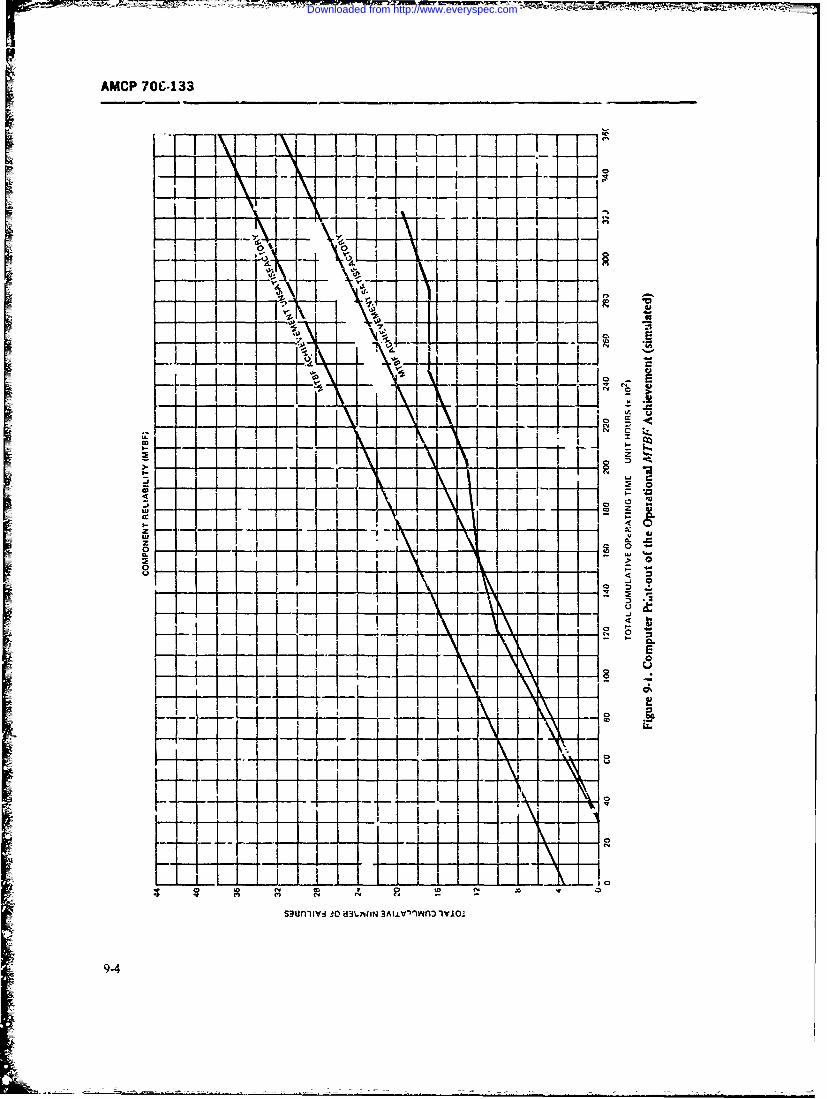
AMCP 70C. 133
I X
_ v
0_ 0
9-4I
Downloaded from http://www.everyspec.com
AMCP 706-133
b. Close daily contact with the syste. iser per,'..- bles. In addition, the military has banks )f data whichnc znd the evaluators keep the study oi: cout .. report the maintenance and logistic support expended
c. Data which are supplied under cloie monitoring over many decades for deployed equipment. The keep-
and recheck conditions require less interpretation ing of military use records started with individual
before final processing, equipment log books and has extended to sophisticated
d. Attention can be given to developing the re- computer prtce.,sing complex,-. This has been supple-
quired qualitative and quarititati-e detail-, trends, dnd mented by various industrial and scientific agencies,
human factor principles that are pertinent to the evalu- both under military contract and ip-'ouse efforts.
ation. Despite the fact that data are availr1e, adequate useInon s e has not been made of them, and evaluation has beene. Inconsistencies and erro."s in the aata cai. 1be neolected, invalid, or incomplete. Genert'.ly the data
detected through cursory checks and analysis with cor- that hae bnpulid r o o generic to e aarntins ppled a, o cl- to th tie ofoccrrece. that have been published are "oo generic to be appliza-
rctions applied at, or close, to, tihe time of ccurrence. ble to a newi "state-of-the-an" eqaipmen:. As ait ex m-f. Cause of maifunctions ct'n be analyzed in more pie, Tables 2 ard 3, Procedure ii, MIL-HDBK-472,detail at time of occurrence. show vacuum tL'be u bt not microcircuits, transistors,
g. Evaluations can be made with3 fewer samples. and diodes. ,The c an e me ithatsucha ewerd isapls. S"e'-eral of the large prime contractors and subcon-
The x isadvantage is tat such a method is relativply tractors daring the past d-. de have established datauxpensive. Howeer, considering the small sample collection-analysis-evaluatlon systems and arc usingused, thL. results are ost-effctive for dcisions regard- them for product improvement and for newly proposeding specific product improvement. Furthermore, logis- systems. in almost every instance, the evaluation istic support and deployment interruptions are mini- proprietary and unavailable for ge,erial use it. main-mized. Therefore. in applying this method, the tainability engineering. In a few ceses, natiorna sym-c:st-effectivaness of an organized and conirolled data posia disclose benefits in a fragmentary way, such ascolle.tion plan mst be considered (Refs. 4, 5, 9). Ref. 6. or data sources are disclosed by the miittary,
such as those listed in Ref. 11.
9-2.1 HISTORICAL 2 .TA The list of historical maintainability data regardingexisting parts ard components that may be incrr-
Historical maintainability data are used to establish porated in new systems is too voluminous and is ofthe maintainability requirements for newly proposed questionable rel;ability to b.- cited in this tet. Theseequipment. These deta should inclute considerations types of historical data generally apply to electric, elec.of both qualitative and quantitative factors. Without tronic, mechanical, and electromechanical izcms. It isthe knowledge of the maintenance downtimes, frequen- true, most available data apply to functional clectroniccies of their occurrence. anthropometric data, and op- systems used in various environments, while little haserational and logistic factors -f existing systems in an been pinpointed to mechanical systems. However, theoperational envir6nment, any requirements set forth kind of data conccning fundame.,tal maintainabilityfor improvement of proposed systems may result in characteristics remai.; ihe same.unrealistic constraints, high ri.ks, and costly life-cycle Te iflustrate the use of historical data, previous datasupport. fov an existing fighter aircraf landing gear brake and
The history of many new systems developed during wheel assembly indicated a 10 to 15 hr downtime tothe past two decades has revealed decreased reliability replace and repair. By analysis of the maintenanceand increased cost of maintenance and logistic sup port tasks involved, a new design concept evolvee wherebydue to the complexity of the systems, even though a a simple, strut jacking system allowed one nut to belarge portion of the systems used existing equipment removed and an entire wheel-drum assembly to be re-items. This was partially due to impt.,ler use and vali- placed, reducing the downtime to I to 2 hr. By design-dat;on of available data. ing the wheel drum assembly a . a one-part replacem-nt
Dunng the 1960's there were a number of contracts instead of 15, the cost of the design of the new assemblyto study and evaluate historical maintainabifity data for procurement was lower, yet perfcrmance remainedvarious typ s cf _quipment in order to arrive at a basik equal or better.for maintainability predictions for new equipment as Another case was an airborne computer for a 1970delineated in MIL-HDBK-472 (Ref. 8). Similarly, data design concept. High density chips were mounted onstudied dunng the late 1950's resulted in many human or:e printed circuitboard of throw-away dcsign in liet,factor handbook specifications and publication; of ta- of 1965-vintrge smell chips using 10 repairable printed
9-5
Downloaded from http://www.everyspec.com
AMCP 706-133
circuit cards. The downtime and frequency of replace- Actions, Technical Report NAVTRADEVCEN 330-ment decreased one order of magnitude and procure- 1.3, US Navy Trrining Device Center, 1960ment costs remained the same. Not only were the quan- 3. "Maintainability Engineering" Chap. 6, De-titati-e factc.s of maintenance downtime and partment of Arm Pamphlet 705-1, June 066.frequency considered, but the associated qualitative afactors of skills required and ease of maintenance were Anthropometric data are acquired by observationalsc included, and measurement of actual humar. fzctors relating to
Both of these cases result ed from product improve- tasks performed by maintenanc. technicians. Duringment and life-cycle -ost feasibility studies of the histori- the early development of equipment design, special ob-cal data collectcad and analyzed from previous syztems, servations are made by the maintainability engineer toBoth serve to emphasize the principle that when the verify and evaluate the quaiiiat.vc design features builtfact. are known, the evaluation of alternative- to ac- into the equipment. During the design prxess, thecomplish the same functions with equal or better per- maintainability engineer in his Maintainability Designformance at less cost is possible. Guide stipulates the human body constraints .hat are
Another example of the use of historical data is ilus- both pe,.u!iar and general to the items inuolved in thetrated by Fig. 9-1 at.d Fig. 9-2. These compare several desi2n proces. The end-item specifications shoulduser installations and an individual user's results. The designate these peculiar and general constraints. In thecollected data were programmed to allow retrieval of review and monitoring of the drawing bozrd designs,the essenial data to reveal details as well as to extrapo- sometimes paper, cardboard, or wooden mock-ups arelate trends. These are also examples of the use of data built for visual recognition of the constraints, especiallycollected from many sources to show the manufacturer for handling and accessibility factors. Mock-ups are thethe maintenance status of his equipment in an opetat- least costly method of insuring that designs meet lheing environment, human factor constraints. In the Army, the te:r-down
maintenrnce phase of system development is the f-cal9. Tpoint for assessment of the human factors constraints.
.Whenever special maintainability data are obtained forAnthropometric data are concrned with the geome- a sample of the deployed equipment, human anthro-Anyofthopometribdta ardeoncenecithtessr eor i pometric data are observed and reported in order Zo
try of the human body and ,lea..anes necessary for it evaluate the achievement3 or needs for product im-to function properly while performing a given task. provement. In studying, validating and evalating his-These types of data are essential qualitative factors in torical data and trends for new or proposed equipment,determining the ability of the technician to perform the it may be necessary to make special observaion or
maintenance tasks. The old cliche "if you can't get at obseve mock-up of the equipment . determine the
it, you can't fix it" is a primary element in the ease of obse s of he a i me nt im andtamin ct -
a maintenance function. The scoring criteria of Checkl- causes of excessive maintenance downtime and associ-
ist "C" Design Dictates, Maintenance Skills Prediction ated life-cycle support probeiis.Methd 3 MILHDB-472(Re. 8, funis thedefni- In all anthropometric observations, evaluations take- Method 3 MIL-HDBK-472 (Ref. 8). furnish the defini- into account the technician skill ard rating require-
tions of II anthropometric characteristics with espect ients that reorent the population (f the tehueicirs
to capabiliti- of an average technician. Although these a"ilb to t tr e ati tial methods-eiiursaparcmltoe*ia orfrt h availale to the military scrvices, rtatistica! methods
definit;ons uppear complete, one has to refer to the are used to dete:rnine the valid;.y of the evaluations instandard human engineering handbooks to obtain the terms of the various percentiles of maintenance typesdetails of the span of reach, height, length, and lifting available for the tasks ur.der observation. Any data
power for the minimum/naximum profiles for various without a suitable range of observatins are suspect.
human percentiles. It is interesting to note that the 11 Within th e range o. observations, one must evaluate
characteristics are directly related to the maintenance each of the various maintenance environments.
task times determinations.
Three of the many convenient references for mainte-nance technician anthropometric measurements are 9-2.3 OPERATIONAL REQUIREMENTSgiven in:
1. Guide to Design of Elctronic Equipment for The operational requirement for equipment, abilityMaintainability, WADC Technical Report 56-2i8, to perform its primary mission whciiever necessary, is196i the reason for the need to build maintainability into the
2. Anthropomeiry of One-Handed Maintenance equipment. The primary measure is maintenance
9-6
Downloaded from http://www.everyspec.com
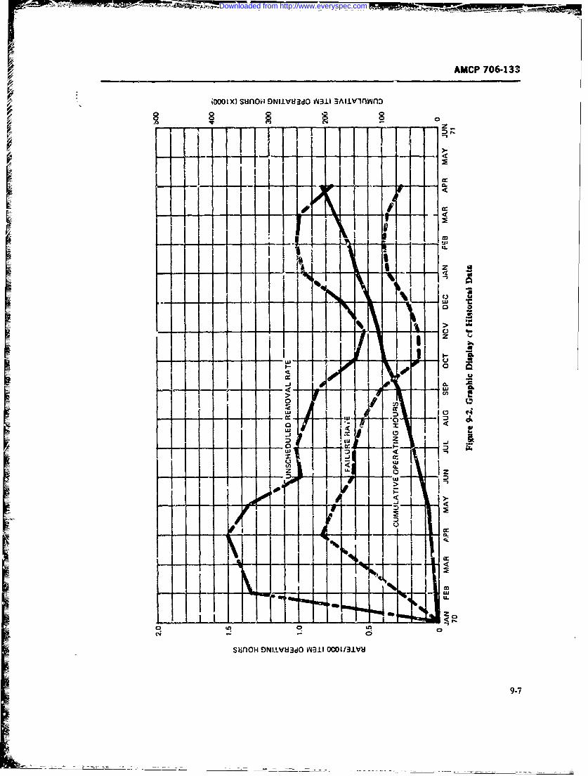
-OF*--'- AMCP 706-133
OWX sunoor E9NI1VHdO 0011. 3Aiiv-1ioyyn:
II
06
_ I- I_ _ _~ I _ LFE-**0 C Ci
us-.--I.------
0b o
s1iiloH E9NIl!Vd3dO WY311 OCOO/31VU
9-7
Downloaded from http://www.everyspec.com
- -- !0 ff-~- -
AMCP 706-133
downtime resulting from equipment failure. The funda- The chief parameter,.,, tuted previously, is availa-mental sources of data that define this measure are: bility far mission operation. This is the ratin of uptime
1. TIhe Failure Moies, Fiffects and Criticality to u-time plus downtime, with downtime for mainte-Analysis )f the equipment nance support as the principii parameter in-vestigated
2. The historical and/or selected data obtained '.Or establishing the raairitainabil~ty design pr-Inciples tofrom similar ecq'innient (maintenancc time frequency, be butilt into the system. The downtime impact on avail-levels o" maimnice, associated qualitative f atures, ability is measured in terms of frequency of failureand logistic sup;)ort). (need for corrective nRrintenance, frequency of a
Alsociaed n te oetaionl rquietrent anly- scheduled nmintcnancc (need for prtrientive matinte-
Si- are the secondary or ancillary missions of the equip-dtetiet pro.ritemaneaceatomentaddtheresectie aailbilty piortic. I co- (repair, replace, 'Adjust, service, inspect, iagistics delay,
sieng aa h pe tiea vapeforanceithe erorties ona etc.) in evaluating the availatility fa.-tor, it is essential
malifunction thr-t can be deferred and the related mis- ta aafo xsigado ro qimn ecnS.On degradations are establishzc!. To~ comp~lete the data sidered in order to arrive at rerlisic requirements A
analsisformaitaiabiity theetfctson he ost c~ functiunal flow diagram will facilitate consideration ofi e life-ylloitcrsucsaeeautante the specific operational dat*a elements. The functional
oinecnch logisncesores stabisedut.an h flow block diagramn uses a noan-verb description, andThe follewving are specif'c o)perational data elements shows the system mission (both primary and secor-d-
ilur are defined, analyzed, and eva'uated: ary) and the iaintenance aperatio.'u conz.vpL as well
IEqu:,ment operational availability as the effcts on the specific operadional elemer is. Thediagram thus puts consideration of all of the elements
2. Missiz'. goal tprirnary and secondary m'ssions iif their proper perspective. When trade-off drecisionsfor which equipment is designedl become necessary, the definitions and th.- respective
3 Mission duration pararneters (maximumn and elements of cost and nssion effectiveness are properlyavterage ider war-time and peace-time operational en- weighed to encourage effTive and realistic decisions.vronments) The functipral flow black diaram is discussed in par.
6. Fa~hire modes and effects of equipment failure A2Li
f -' quipment turn-a-ound time (maximumr, mean. In some complex zquipment, the need arises for com-and minimum) puterized mathematical models in order to arrive at
6. Maintenanc- fa'ec uency in the operfitional sideraotiun do s ll of h reeantlm daaeleents ipn on-~ronments (failure rates, scheduled maintenance rates) opetium decisiosf Theeaase daaepeens upn ron-
to shcw trends, assumptions. and proposed constraints7. Preventive maintenance time (scheduled peri- up., which trade-iffs and other decisions are mrade. A
ads, allo'wci-a.--rage, ani mnaximum) system effecdw'ness opratiorxi an-:Iysis depends upon8. Corrective maiuten-.ice downtime (aninimum, the rnaintaiirbiliky engineering finction ais the data
mean, and maximurn at specified percentilts) source for the required mainteniance and logistic sup-9. Standard deviations and confidenci.- levels e.v port information. 14ainta-iwtbility trngincring, in turn,
maintenance downtime in the operational environment derives its da~a from data bank sources which are eval-
10. Maintenance concept (operational levels of uated and validated according to the pertinent typts ofmainteniancz, repir levels, etc.) data.
11. Maintenince float requirements (peace-time! -Of special importance in, iiie determination of overa-war-imeenditens aftrzedforstc~ge t istala. tiunzal requirements are data affecting various design
wrtimes foendliemen afusorvie ae at whntae- parameters that influence downtime, i.e., the effects o~f
tirano far rpacmntliservwithenaleiied whenre-d detectng failures oy associated built-in test, auiliary
pa ir cannthbe accormplished with o intaseacifedero test, and check-out equipment. This feature has a directof tme y te iteredite lvelof ainenace) bearing on the eff,-ctiveniess of the opernaional require-
12. Int ;,Zrated logistic s~upport for the maintenance. ments as well as iu.irect rhec ndwtm aplan Gife-c:,cle costs, skills, training, technical proce- operational availability of the equipment. Validation ofdures, support equipment, facilities, and technical ser- the failurr modes and effec% data should include evalua-vices) tiot, of the method of faul! detection and ndequacy of
13. Maintenaince, logistics, stanaby :eadincss, &~no the equipment operational check-out in determiningother rnonoperational davn-rifimes. the time- parameters. Historically, fault detection time
9-8
Downloaded from http://www.everyspec.com
AMCP 706-133[has been one of the largest contributors to inaintennr-c. maintenance activity on standard source ooccmentsdowrtime. and summarized through the use of computer tvh-
niques; or specific cntrolled data collection systems
9-2.4 FAILURE RATES which o' serve only a limited sample of the deployedpopulation (Refs. 4, 5, 9).
Failure rates for corrective maintenawc, and fe-. In the first method, the validity depends upon thequency of preventive maintenance are esstmtial param- technicians' opinion as to cause of the failure and alsoeters in the determination of equipment maintenance upon the relative capabilities of the available techni-downtimes. Time required to perform a maintcance cian. The overall failure rate under an operational envi-task is not an uithmetic average of task times, but ronment gives a realistic use rate and therefore is arather is z sum of the individual task times multiplied valid rate for assessing the real life fac.tors. In someby their frequencies and divided by the sum of the deployed units where the rate is higher than in others.frequencies of all the related trsks. one is able to pinpoint unusual environments or man-
Frequency data are needed to assess all phases of agement controls, and determine where and 'tow themaintainability engineering analysis, and perform pre- use rates can be improved, or define areas for furtherdictions, and allocation. It is imortant to recognize special observation.and understand the types of failure rate data and sched- The sec-nd method of special )bservation and con-uied maintenance rate data in use, e.g., generic rates, trolled data c llection for a limited deployed sample ofgeneric usage rates under various operatiowl environ- the population is the most desirable for validatingments. and historical data based on actual use of similar equipment failure rates and making pinpoint determi-equipmeni Generic rates may be the only data availa- nations of the causes of failures. The selective metlh-ible for preliminary predictions and allocations. In some does provide detailed data showing th factorscases, it may be necessary to use multiplication factofs Affect the f~alure rates and the downtimes, and theto increase the generic rates to operational use rates. In knowledge of which is necessary to obtain design d"ci-others, overall use factors have been applied, based on sions that will ease maintenance and reduce the failurethe types of equipment. In still other cases generic use rates (Refs. 5, 18).factors have been applied to individual components and Both methods establish historical data upon whichtheir related operaviorad environment. The most useful to base operational derading factors over laboratoryand reliabka failure frequencies are based on historical testing conclusions. this is thl important factcr chatoperational data of similar equipment acttly operat- must b. considered by the maintainability engineer ining in the military combat enviromnent. order to develop designs or product irn -)rovements in
terms of the real life downtimes that itfect availability.9-2.4.1 Manufactter's Data Analysis and evaluations of the varie-us military, gov-
Fail re rates, use to show compliance with. ermnental, and industrial data bank information mustMTBF requirements, are usually iumffiient to estab- include the source of data, validity of the data, causes
lish failure data of an item sy:tem, or equimient to be of failure and use times in order to estabish Rf31den2used for maintainability analysis. Newly designed parts in fe failure rate data (Refs. 3, 12, 15).
mus' undergo life tests of sufficient sample size to bevalid. When tested under laboratory and simulated en-vironments, the aiues obtaim-d are generic rates. 9-3 EQUIPMENT VALIDATION DATAWhen related to field envirorment, operationl degra-dation factors must be used. Wheneve- manufacturers' 9-31 GENERALtest data are used, the test conditions must be known,and the rates extrapolated accordingl). efs. 3 and 12through 17 lit the current manufacturing sources of D aring equipment validation, data are coleted,data and data types available, as wll as the various analyzed, and evaluated to determine the quantitativegoverninga maintainability features and the assocted qualitative
design fcatures (Ref. 9). Early in the life-cycle of the
9-2.4.2 Operational Use Data equipment, decisions are made concerning the specificmaintenance level at which item replacemeit due !o
Operatinal use data are obtained either by general mv.1function will be made. Also in this phase, decisionsmainte-nance management data collection systems of are made regarding preventive maintenance whica willthe entire deployed population, as reported by the meet the requirements for equipment performance.
9-9
Downloaded from http://www.everyspec.com
r AMCP 7064133
The first type of data generate.1 consists of deta~led 3. M, an, median. andi -maximumn maintei~az eacmaintainability engineering a.,rxs' of the mauinte- tion timesnance tasks for each maintenanr. ievel function (opera- 4. Standard deviation )f malintenance task time.or maintenance, organizational maaintenance. direct distributionsupport rmaintenance, general support .naintenance, ' !"kill levels and ease of maintenance factorsand depot maintenanice). These data con.-ist of time 6.Ot-ioausg wktme(dint-tveestinmaics and predictions based on enginee-ing judg- 6.itis ec)p~toa sg 1:'vtms(diitaiment, historical data on simik,-r equipment. ttne-and- lgsis t.motion itudies, prelirninari design b-eadboard and 7. Equipment availabilitymock-up tests, environment-d tests, user-servict test 8. Failure mode.- and effects (fault detection andreports, arnd manufacturer parts list and specific.Liorn location element-).data.
The second type, of data generated are de"n, iistcatv'n Usually these types of operational data are limited toand test data observations and evaluations e. % n organizational and intermediate levels of maintenance.from prototype prr~uction items used for mainitiir. 1 Depot level measurcme'ts ere generally reported notity demonstrations, engineering prototype te' atpi4 as operating data btr in !eins of stimmaries affectinging giounds, maintenance evaluation, and other qualifi- th'e logistic p.-carneters for reconiitio-.d.,g of equip-
VI'cation testing. nent.In both data types, design reviews (in-house and cus- The key principle in the ana!;i r f operational data
tomer) are conducted .rsing the restilts of tests, des-ig is he evaluaticn of the equir~e~ parameters that af-trade-offs, analyses, evaluations, and draewings to de-n- fect nission availability. The e-quipment data generatedonst.ate that maintainability requirements established and analyzed must reSNect th e totz2l ,.quipment opera-fcr the and-item specifications hnave been achieved. The tion ai.e degradation ellwes.data so geuieratcd are used in the engineering analysis In mi ny cases the ope: ati 3nal &-va gener'ted fromof the dctailed maintenance tasks in order to~ define tbe tegni ltysofdaaxnsfcixtouewhintegrated logistic support resources for the equipment confidence but trend projec ions may shuw the needlife cycle (manpower skills and training, spzres and For the respoctive maintainability parametei to be dtmaintenance float, support equipment, technical pabli- igeinot'eqp n.Forctcaaesafcigcations P-id procedures, facilities and con1tract support availability th.' data mus'. b- obtairned and analyzed
servies).using specific o',servation of a selected sample of de-se~rrices).ployed eqipmen -.
9-3.2 OPERATIONAL EQUIPM4ENT DATA 9-L3. 3 DESIGN 'IATA
As previously state!d, historical data from deployed Design date aru obained bi- study, review, and eval-operational equipment consist of two types: uatior of equipment dra vings specifications, and parts
1. Gnerl oeraion manteanc dat coleced li .sts. Once the drawing has been approved, the de-by eneralopraio maintenance data collgemet !igrned-in maintainability featt res are fixed. Any subse-
policies quent changes are costly and ini some cases prohibited.2. Secil dta roma slectd smpl ofthede- Therefore, a day-by-day, wot-c-by-week review of de-
2.ye Sqpendta frnmalsee d salno the datraesei signer progress is made so thi~t the~ design data tnp'n-ployd euipent Inludd inthelater re pecfic tainabilitq parameters are e n~luated together with
manufacturers' data for equipment used in the military other design p'trameters. The mq~ntainability q~talita-operational environment; caution must be taken t in- live design datz are obtained f -om revie:w of the iraw-sure that the data are field operational eata ("is opposed in~s (ease ef maintenance). M msurements of the timneto laboratory test data). to perform a maintenance tasli are *~en analyzed. For
The ssetialmaitaiabilty atameasremnts instance, the feature of accLssil ility defines the time toa e es nil m iti a ilt aa m a ue e t gut at an itm for replacm ent, the attahment feature
are: defines the time to remove and replace; the tuct point1. Mean time between mainte-nance (hours, cycles, availability, identification and, or interface- with built-
miles, rounds, etc.) in test equipment defines the faiult location and detec2. Mani hours (per operating hour or operating tion time. The failure rate data or frequency of maintt
cycle) nhnce is used io analyze thi: mean dow-vimei for
9-10
Downloaded from http://www.everyspec.com
AMCP 706-133
maintenance. The parts lists and the associated failure 2. Hatrdling Featuresrates or preventive maintenance frequency rates are a. Weightt,'xl to define the need ior maintx _ance (generic failure b. Size
-1c is 'ncreased to determine the operational use rate). c. Huran factor capabilities and associated" h± specifkation data are used to obtain the qualitati-e supp'ort equipmentand quantitative constraints of maintainability imposed 3. Equipment Placement Featureson the design. a. Rac,.-'
b, A ,citssibili'y
9-3.4 PROPOSED PARTS AND C- k anid nwtchanical interconnetions
COMPONENTS TEST DATA d. Equ;,ment layouts4. P .-ka..;ng Features
Generation of test data for parts and contponents. ck. eib lity
nrovides the faiure rate data required to determine b. Modla ition
how frequently mainteranc will be iecessary which coSunarization
information in tu.ai iz used in the computation and d. Functional grouping
evaluation of the mean a.d maximum maintenance edterchangeabilitytimes. Such data are tied in the failure modes and f. Plug-in componentseffects analysis that also deines the maintepance necis. 5. Diag t Aids Factors
The data are generated in terms of failure rate,MTBF, degradation facors, opeational use factori, a. Built-in testand laboratory environmntal factors. The data are co. b. Test points ocation identificationlected from manufacturere parts test records nd c. Fanlt detector displaysspecifications which show the results of testing and in d. Ancillary test suppot equipmentspecial environment. The key factor in the use of such 6. Adjustment Requirem nts
data is to have a full understanding of the conditic'ns a. Accessibiliiy and quantity of adjustmentof the test and the relationship of the test to the equip- pointsment under consideration. Generally detailed inforraa- b. Interaction efiectstion on parts and component% involves proprietary 7. Displays and Control Featurcsrights, and the ?elatiorship to the specific application a. Panel lhyouts and illumintionmust be negotiated during ttLe proposal-to-buy transac- b. Seif-ir icating fuses and spare fusestion. c. Mete,*S
S. Labcli'g (extemUalinterrl) Adtcuacy9-3.5 KECORDS OF TRADE-OFF DECISIONS 9. Safet. Factors
a. P'sonnel safetyThese types of data are limited to a specific problem b. rasopmelt safety
concerning specific equipment being deve-loped zt a
particular thme. Usually the data thus collected tmd 1 Irtegrzted Ufe-Cyck= Support Requireni.s
used 2re lost fo~r historical purpo;es. a Tools/test equipment
Maintainability trade-off decisions require the ol- to. Technical data
lowing types of dita to Ie collected, analyzed, and c. Personnel skills, quantity, training
evaluated (Ref. 19)- d. Faciiites
1. Performance Factors e. Spares! 1. Schedules
a. MTBM (frequency of corrective and prev.n-
tive maintenance) a. RDT&E
b. Repair times (mean, median, maximum, and b. Production
associated .t;ndard deviations) 12. Cost (unit, system) Parameters
c. Equipment availability (uptime versus uj." a. Initial investment, development, and acquisi-time + downdme ratios) tion
d. Maintenance concepts (levels of mainte- b. Life-cycle suppo" costsnance) c. Effects of previous II factors on cost parame-
e. Utilization rates tersf. Failure modes, effects, and criticality analysis d. Throw-away versus repair costs
9-1
Downloaded from http://www.everyspec.com
AMCP 706-133
e. Functional vnd esthetic %alues. accessib~lity, d.-agr-'stic aids, and skills re-
Not all of :hese data items are considered in -vecy c. Qualitative features of initegrated' logistic sup-tradi-off stut'.7 and some thzt are unlsted naay anse inl port, such 3s n~eed for repair parts need forastudy and tired to be considered. Of paramount con- lvl fmitnne n ai:iscen in evaluairg item trade-off studies is the cestlelsomannncndfi:J.
effet in deermi wing the weighting factors assigned to At present these types of data at e rec-rded and avail-
eL Jemcnt. Of similar importance is ;he ezfeat of able through Army data banks anti caji be used aschange decisions on the socheduling parameters. The historcal data sourcts.
port) are also related to each of the weighting facteys COMFONENT * AND PARTSIestablished. In all maintainability trade-off studies. theeffx-ts on interrelated ;x rforinancc data param n These types of data are similar to the data cited -inmust be considereu, and similariy in all system analy' -xar. 9-3.2, Ope!rationzl Eqiipment Data. In the para-and effectiveness trade-eff studies. the maintainability ,:aph #4..d the essential data me-aurements are for andata paiatneters mtust te evaluated. equiptnent-level summary. if a breakdown on ade
tailed parts and componviis level is desired, a conl-trolled 4ata collection plan is devised to obtain such
9-3.6 ENGINEERING TEST AND SERVICE ndp xarmthdt bnsspeancoteT EST DATA sCiic typ of equipment of conceirn (Ref. 2).
Service These types of -data include the following dlementsAs stated prtviousl), Engineering Teits and Sc-ie for end item, componenis, and piece parts-
Tests (ET/ST) zre conducted t:D verify anu evaluate 1 eartmsb ee fmitra-cequipment adhere-nc( to the perormr*:e characteris- I eartmsb ee fmitn~cties and requiremants. During~ these tests, controlled 2. Mainlenance maii hours poer operating hou.,detailed data oservations are coilected. The evalue- -mile, or rrandltionts are usually statitically oriez'ted r.~ .etrnnine the 3. Skill le-vels usedperfornmrnce built into the desigits. to attermine trends, 4. Distribution of maintenance task-sto base modification for product improvemient. and to ~ .Failure rates for corrective naintenance ar-averify and establish the integrated life-cycle resaurcmt vniertsfr ceue aneacsupport requiremeit's. In som,! insta-ices, such as gun 6.vntv Tratesatfo timdued e tw enedtev-
teMs life tests to destruction. are mace. 6 rnp)tto iebtenue n h a;
The following are essential maintainability da -a to be ous supporting siops and supply facilities
obtained: 7. Adm~ntstrative delay times
I. Quanititative Perftrmance Elements 8. iport equipment data and operational facili-
r. MTDM (frequency of corrective and preven- te nontotivemainenane 'aks)9. Test instrumentation and test methods.
b. Mintnane mr hurs er pertirg hur, Generally, obtaining date from !he entire deployedroun, mie, cclepopulation is not economically feasible and is too un,-
c. Downtime for maintenancec (mean, median, wilyt- nlz n vlae Thei'efor annand/or maximum at speciidpretlsLh such data by selected controlled dat3 collection meth-associated standard deviaton bnd con~idence csi rfre Rf.4, 5). For exml.MIL-
l.equpve aalaiiylrtos)utmet p HDBK-A72. w-hich contakins data from specific studies= d.Equpm~.nt vai.ablity(raio )f utim toup- of special populations. may be tsed to make maintaina-
time + downtime) bility predictions (Ref. 8). In the past, n.ilitary activi-e. Quantitative factors of lif'e-cycle logistic su, tues have had to depend upon c,-tractor suppovt for
porl. such &irep.2ir pzrts aiminenc suh detailed evalain or rely ongrtss summaries oflontsthe deploy-d equipment pnpul-ton. Ref. I I lits ?a typi-
2. Qualizative Elements, Affecting the Quantiteitive cal example for Air Force ground electronic -end items.Elements Thnere is a trend to,,ard mliitary activities obtaining
-=&a Maintenance tear-down features such data -)n a speciaiizid controlle basis (R!!f is anb. Ease-of-maintenance design feawtrcs, such as example.)
9-12
Downloaded from http://www.everyspec.com
AMCP 706-133
SECT!ON 11
DATA ACQUISITION
9-4 PRINCIPLES OF DATA 6. Logistic supnort required. and iogistic de'lays
ACQUISITiION 7. Cause of malfunctioningQ. Time between failures.
As stated previously, a basi: principle in data acoci-sition is that data are only as reliable as ,he ohsei.-ver's The folloning objectives are essential to assembiingability to record the data. Also of importance is the data (Refs. 9. 10, 19):observer's u-derstanding if the need for recording the 1. All terms. cocs,, ,nd data elements shall Ledata. A third principle is the need for the data to be of clearly defined.sufficienit quantity and on a timely basis in order tc be. 2. The acquisition system shM! be based on a cor r-really useful. plete analysis of the euiprnent lperformance require-
ments.
9-4.1 METHODS OF ACQUIRING 3. Tre individual technician, operator. supervisor.
MAINTAINABILITY DATA or observer must understand the need for atd the typ,of data to b'e acquired.
The two fundamenta! methods ofaccumulating data 4. Acquisition of the required data must be timelyrdated to the maintainability chuacteristics of a prod- in order to be cffz. tive.uct are: .. Determination of data required must be in
1. Use of standardized reports of orirr-ctive an6 terms of he needs ot management, engineerire. andscheduled maintenance for the total depleyed equip logistics, and should be ,net in an economicazl manner.ment population. where the obserer is :he pch.-ician Visual charz- must shox the efferts, distribution. andor supervisor of the mainten-ance activity: treds of the data for management decisions.
2. Use of controlled special reports of maintenance 6. Quality ssurance procedures -rill be inco.--a.-tions for selected portions of the deployed equipment perated to make certain tha data collected is adequateon detailed fcrmat.s. where the observer is a specially for the intended purposes.trained technician. 7. Al; data must b: kept current to the extent re-
Deployed eqaiprient populat;on * equipment in quired by the system.lrvld use. It can also be considered. prior tc fide usie 8. Duplication of data should be przvented. Expe-as the popul.tion of equipment under dcelop,'ent rieuce ofindustr:al agencies has shown tiat many exist-andlor prduction where Engineering and St-ice in& gov-ernmental computerized data acqut iion sys-tests are used to ,btain performapce data. Althiough tems have adequate data availAble. With properno attempt is m.ade in this text to present an exhaustive evaluation of the pee(b, it has been found (hat extstingliv , of characteristics, the fo'!owing are essential generic tab rn.s can be ob:ained and coded to fit ind:%Idual tabd'Ata required for maintainability evaluation: run needs for evalu3tion (Ref. 61-
1. Frequtn-. and rtason for maintenance actioor+ No attem-.pt is made here t-j publish mjttenanc-2 Downtime required to perform the maintenance formats used to collect and acquire :ata. The refereces
action (minutes, hours. man-hours). cited in this section show .he mul:iplicity o formats
3. Manpower and skills required used (general and specifict. All of the formats contain
4. Spare pais certain data ss bas;;. -lements vlhs the individual ele-5. ! etification of equipment/systernsicompc- tments considered essential to the partic'xlar system
ntcn being ma;ntain.-,d used.
9-13
Downloaded from http://www.everyspec.com
AMAP 706-133
9-4.2 METHODS OF PROC1JBIW'. SWGU, quensc- cf repair is derwa-d front, failure n.te daa, iheI ACKAGE DATA .nainimaabilitv ei'gince.- must %. ;xh the condition un-
The design package data are obdained by the procur, derwk .daarediv sastvldtehem-
ing agency Ly negotiation at the time of the- contract o h a
award. This 6esi. n package cswitains dot: which %-- 9.5 GVRNE AT .LETVused to arsve at the desigi ;decisions made for th S GOVEM!ETtACO.LC1
equipmend cudo mamiaiiityp r ictimisa aa hcain.and task analyses. In some c thiese data Ile p.imary ;il~itary ,uu~ce, for inrtainabil;ty
the types of data listed irs par- 9-4.1. =mach of tht, lt e4 thei Ary maintepance d.ta colie-tmin systtms. In ad-information is available from deig oraiat* dition there are var' ous repur;t. iim the Armv. N!avy,
(ohindustrial and military laboratory). Therefcre it iw Air Force co--tring special and canirt'hled da-m- f~wa es-ential at contract negot-a~ion that the .ooole 4ape list&-v~t 'Iiplan to obtain such &~ z be developed in dtetail. defiring S. a al .ape aqrnte reoTI.I h ois.-i dnce
the i.ted, availai~ility. processing, and inrady reportng such details are ,ho-A-z sr. i the icferencesi citted ndnrM objectives stated in par- 9-4.1 mw_ beetails in tne respetive nutnazn- nunagemeni rcgatiocs
and adhered to- Fail ure to repcrty define the. pIrobc that ddinc: the procedures (Refs. i. 2. 4. 5).ha-- resulted in nnany contract cost escaLations.
~-4.6 Un~ST ThINK1(ING OP CONTROLLED9-4.3 DATA FROM MANUFACTURER'S DATA COtiECTtON
SPECIFICATIONS AND BROCHURESThe t-iio.-tion. storare. retrieval, analysis. and d;
Many of tbecx t,.pes if eat are 4f a geneic summary scrniatcUa of dati is a rrzitir ex-,endit ure for systemnature for specific end item and awe tiot in srfcin program nmaectMan% agencies throughoiut in-de-tail to. be usefal uecept f'or tid-itein purposc; eta. &- du-Irv ar. Ci,(.ernment (espvcisll) military) collectof the end item are proprieary, and the ontracor 'n rc.~ z aa a l namost A aesti aresenes the right toi ceatract for overhaul sxd/Cr war- don to;.,r prutilr mre'ments.rsnty repair. If the itemr procur- is off-the-shrMi undter Tlhe pres.-ri sv-tr . --the ar: data acquisition. arialy-Government contract, repair data are- usuiy availab'a i.a- resn osr'~~tmaueeto hfrom iitr oierhaul and reconditionine facill.Iti- efTecii~enes,. urorcn '-.e~po sserns. Hewever.The-Go%-fr-ni t anr-dsupply catalog is 34o usful d' th3 i , to h- atopst. xtn data m ust 1--In' addition, nmiltary hstorical data amt availzble from made a~aiLabk --o itat i'ne cxpxenence can be applie to
=repair reports 'or similar itemns- In srcmt cases, rr-4 the (.f rk (.f nc-&- Son -,ssnsin-de-pth data are available fimm proposal jut fearic4Ls Re 20 desrn the Air Forc:: Swstem E efor T_' .,-is so be procured. !r all cases, th- initzirutbi)- Ct-mrelation ad Analysrs Poea2 ,"SFCAPI'and tbrity crjint.r (both miiiza- and induastrizi) viust investi- Rdsabtiit Ana3-is Cenittal %4RAC) Syvizi used to il-gate and evaluate i;ie validity of the Jita especil) ;he lste ite lat". thinking on -ntegrwsre! sandard dataquwlitaive maintainability chararteristics aipon. which -y,. - -;s~ Arthe Air Fcrce. 7cf.21I des,.ibcs theffie quantitative paramctrms ar.- bzid \aticnal Bureau of Star-i- "ds R~eference V-atz !Zvstan.
The lntmductiern in Ref 9 cites ti.e -ced For and the9-4.4 INCiDENT STAT1STCQi REPORTING inter-t in et!ablishing an in rtddate. 'Syem_ R&'s
FAILLP5 .ES 12 through 14 and 15 1 heou;h 17 -Cite the Tri-Servkeintegration -4 RcIabitsiiv and Failuzze R~ate D'atsa
These *)ypes of data :;re ebt;u,4 from brs-ir-xd. (F.APRM)' and GIDEP).mnock-up, laboratory tests. environr-ntal iestin z. pro.tot-ype testi:ig. and fir'd sources-frow boh imiasirialand Gov-rmcntal agencies. Thaz IMQ?- i knci'int sta- 9-5 CENTWO:AL D)ATA BANKtistics mtm-: be evaluated to deemine If the tata arederived in tterms of gcanrc filure mtms of degradation Impr.enicent in the e~trem of the national sy-faidure rwes resulting from fa.esof erinronmve t.op- ten for scientifie and tinic"' intformatioai is a mattereiation-al degrading. or field deployment. Since i1re- of great popar rortxxz .n (R~efs- 20. :1) " Lxeciw.nd
Downloaded from http://www.everyspec.com
PMCP 7-133
-esults in mearemersts are the backbcm of pl.ysi. 1. A two-way flow of ;fo,naiiop between con-No theor, is acceptaLle unless it agrees with experi- trtc:ors, dciLmers. and maintainability engineLtrImnt.3l data. Cenversely. a systematic study of experi- 2. Standa-dization of methods of colection, analy-
- metal results can suggest new theoretical apvaches. sis, and valat1rTables and graprs c numerical data therefore play animportant rote in thc progrWss of scien, ce -. Thust u 3. Standardization of cod:g. procassiag, and dis-
obvious !hat d&ta compilations are of great importance seminafion of data.and sitould have :he full cocperation of those vroduc-ing dara. it is also clzar that modern cvrnputer tL~h- The b,-'%5ts to be derived when these factors areniques can handle -uch data more eficiert:y than old implcmentcu are:.tMbulations could, especiAly since thcir rnmberand 1. RedWictio of m -art-power r quirer-entsvartey ate growing more rapidly." Thes words otSamuel G-dsmiidt (Aysics ',oda. 19(9). 352) define 2. Reduction of training
the prob= ard =pIesie the importance oftl- avail- 3. Speed of obtaining and retrieving dataability ofdata. Such ccmpilatioms of data hve not betfn -;. Accurac A.- dataa- ailab:e tw the maintainability ergz~x',- due to propie-tary iactors, and he has had to rely on a snmall amoznt S..ta handling wonorry.
of data cbtained er..m liitd sources.Compilations of data are he basic tools of scientists Standardization of the present formats will lower
and ngineers. flandbooks contain'ng useful inf,,:ta- cost r.f data reductior. There will always be ur;qu-ior 4n the properties of substances ;nd system, are itens of vital concern to the individual agencies. bu;available and of invaluable assii -ice_ such as the these need not affect the standardization principle asSrardard Hadrbook for Mechanical Eginee' by can be noted 3y review of the various formats andBauneisur a-d Marks. Yet. for the r-ain-tainability procedures. Ref. 14 -h:ws the integration of !he Airengineer ro ,ich maint, nsbility data handbock has Fome 66-1 system ane SF.AP-RAC Central Systembeenope 6~h-l.systems ant'lityAp-aACiCentral Sritembeen publied. Nlainta iabdity practices and princi- to ifiustrate th. standardization principle.rzes fnr an,+atio' 'o product imr-roveaent of ,nti-¢ he teczhnolcgy of data communications in thesystems have evolved from small specially se, ztedsamp!s of limited validity. Unid s has be widely developed and used in
Tht problem of a Central Dat- Bank is recognized commercial appfications. One of the problems holding
by the Gov_- nment. The Naxionvrzde Nation:tl Stand- up implementation of this technolog" in th-e mii:ary
ard Reference Data Systeni (NSkDS) is a starting and other Gfvernment ep---.a ihc cost of installa-point. NSRDS is operated by the gurela of Standards tixn of communication terminals. Recent technologicaland caordinated by the Committee on Scientific and ;mprovements invoving lower costs will allod a datarechnical Iaformation (COS.-TI). which consist of accui-rion operator to use ielex o" similar machh.es torep. t,_wves from all G,.rnmnt departments and retrie 'e required data file- and associated printouts andindependent agencies .aving technical infiama:ion visual displav: from central catr banks. Time-sharingp-oqrarns. -is recognized in Ref 15, N.SRDS shoud .)stems will make it economically feasible to e.tendthen be regarded -s the painai y sac, of data ms- comtputer ,aility throughout the system complex Theurements by the techtical community of the United eninhasis in information storage an-d retrieval hasStates. SEC.P and RAC-Cntral are exarapLe- of the cblan--d from design of d&u'ment handling systeris tofe.-bibty and --sefulnss of sltch central data bank., design of handling s)scm& as ured for the Air ForceWhen A-l data from the NSRDS Pre availabLe in the Reliability Ardysis Central facility.central data bark. it will ha-re become a usdful tool. Until ret.r ral by telex or similar techniques is avpiUntil the central data b&rk can be used, maintainability able, mit.Mofdr or t pe can be used to collect dataengrcerin3 does have available existing rmilitatr) cen- furrds.Kd f)m cetral data banks. "ape is the pr-tral data hank -igencics. Expeiwenc has snow.- that ferred method where large amounts of d7!.a a;- neces-whenever thes- data banks ha,: been used, the basic sary. Such tape c-n b: coded- and local computer o>data this .nadt available to the maintainability engi- grams can be developzd for the print-out of the desiredniecning discipline has teslted in decided .,oduct/sy.- data and data dispays. Mict fil.m is uset- when. thetc-n/equipment improvement (Ref. 6). Esse=tial fac- amount of data is small, and hand analysis and evalua-tors mn the efficaent usc of central data bank information zion can be performed. The decsion as to which to use
is based on cost-effecti-cnes:.
9.15
Downloaded from http://www.everyspec.com
AMJT 70-133
9-6 DATARMEIVAL AND ing Ce d =bak files toserve astb tsse efPROESSNGthe desired output tReks 20. 21).PROCESSING '-he msinrainat ilkty data A-eieuts tv be retrieed
Good data I ink manageure'. r; prerequisite to &Ri- vnd orcmse ar-P, those zi0emenat related to maiste-cient data retnitval and prcaesang. Then! are two ha:c nhnc2 rion ('Oat, where, wiwn. how. ard wny anprinciple- the product is only as good as the accnracy iten wnj mairnaind oehr ihaintenance timeof the data input ands only that dstt for whieb there is and the rman-hours and skills eipendedlX am2 those
Suse should be stored. Thiercfore, the firs mmnhagemeni iwrnes; needed t3 n --iate ansd e~valuate the 1o~isuic sup-stq- is the establistiment of adequtate formats antd -4- pmtt requirements.
REFERECES
I. MIL-STD4?0. 11ainbahiwbility Pn~pcrn R.e- 15. GI DEP (Gc nnnwten.-lndustzy Data Ex-q.dnniengz 26 March 196, Par. 5.10. change hograw), In'orm Swers Hard-
2. AIR 702C-, Array tlfar~lReW Anrit- hook Nav=l Fkzes Misil Systr's Analysisabiliy.,tMl=bnainbff and Evjluation Group, Corona. Calif.. 6;:1 An-andt4 nual Wort- Shop Confevre nit Ange-les,
3. RdiYabihry and Mainrcdnabi .y Ana Snare Calif., Mi; 1-3. 1968.Guide LIS NanJ Applied Science Labor;- '&. Gi n)E? (Goverrsnent-lnduslry Data Ex-tory, Brooklyn. N.Y.. Janr, '967. c.hange Program), .tnge Nrognm Joint
4. A'JACR 75 -4j- Speela Or-erauional A=. Cot1 Arremen; Leter. Dept. of &V-ny 14- Naw!kSian, 22 April 19170. v$atrerip! Coe-ymand Armyv Materiel Con-
!H. H. Dobbs andi J. ru-omoson. rFid &EnZH mand. Chief N Mnarriat Comnx-arl Airmnen Controlled Data C7lerior 155 'EM S P Zorce Logiti Commnd!U Ai5t For*!r Sysarn
!bialrr. Report CWS 712002 115 Ai-, Command, MATX 03 RE, Nrual Fltd MissileVeaponts CoAnuusnd. tW)mr 1971. Systems Anait and £Ealutcn Group.
V taa rySeminar Los Angel_ Mati- Cormma. CaUl.. 21 Dec- 1970.
Ikiinabitlity &.sociation. 1 May :972, Sections 17. GV5EP (G~varmeat-Irtdusuyv Dra Ex-IV -%nd CT, AD-23 227. cha-.t,? ?lrograzn). Raw GI-DEP-Ji! Rr--
7-MIL-MDBK-2 17. iiabiiy Stez and FaXl senzatrez.Naa Ft:,r Mssilv SystemsqAnaly-urr ateDat b~ Ekronc Lu~mrzsis pnd Evaiuaticuz trvp. Corcrms. Calf..
9. W H.Wr.A~vn. E., ehki~t 18 D. W.Sharr. Data &Qrtt. ai'4
Cliffs NJ.. 1964, Chapter 1-Symposum 0.khbfv wqmt -*10a AIMCP W.; 1. Alaivainahiin &wbrin zfl trot. 1959, pagcei A .
June 1966. Chapt2r 12-. 19. 8 S. Blanchar-d and E_ F_ Lomwy .4Manair-11. VFSC DH-:-9. Mai mant Hlandbrnk (for bi&ix Ptincipes and Pranicc. McGrw>Mv.i
Gm±nd Eieafrorik 3}r 'is% 20 December Book Co., NY.. 0969. Chqner 71970. Design Notes 7.4-1 2A4. 'and 2.A5. 20. M. Hans. et ad.. Air Force Syran Cfficdree
12- FeRADA Failun- .'care Data w m aa and Re~irbiliry Data Tysr; Reliability andFleet Missile Systan Analysis aad Evaluation Maintxna'lity Confecnce, 6th Proct=dings,..Gonwp, Ccorona, California, April 1x569. Paper 67fl h'*1y 196'. pages 116-139.
13- FAPADA Proram ?ankcipxnt Nal ktca 21 S..i Brady arriM B. WalensteinTeNaMtssile_ System Analy%is and Evalutixon tional Stand&..t iReferezzat Dra Sj:stenf.
=Group. Corcnia. CLSli.. March 1971. Sciezrr.- 12 May 1967. Volume 156. No. 37776.14. Ary-Nary-Air Force-NAS FARADA h>- pages '154-762-
grm. 'Naval Flees M%,issile System Anialys~sand Evnn-non Group, Corona. Calif.. April!9910.
9-16
Downloaded from http://www.everyspec.com
AMCP 7(i6-133
CHAPTER 10
CONTRACTING RESPONSIBILITIESSECTION I
INTRODUCTION
10-1 GENERAL A-my reliability and maintainability pro:-rams "hisregulation estal-lishes reliability and maintaiutabiity
The u-,'-r-producer dialogue is discussed in par. 1-4. 1. characteristics which must b,. specified for the designThe Army as user repreerted to industry ov AMC, of tmteriel and must !e considered and asvessed coni-and industry, as producer, must enter into a contracc- currently througho-.t the life cycle. A R *;50-1 (Ref. 2)t.~al agreement with respect to, the systemr to 1,e devel- defines the matriel maintenjnce component of theoped and produced. Both partics, tlhercforz, have cer- Army Logistic System, including maintenaunce wpporttamn responsibilities for mutually establishing the rian. ;ng as an integral part of th acquisitior, processcontractuel requirements for maintainabilit). Chapter for Army systems or equipments. It also assigns func-3 describes in ietail the organiz-ition and management tional -. ponsibilities cr. the Government and the con-requirements fe. maintainability and how these re tractor, and prescribes policies for the mairntenancequirements are carried out throughout the system life function.cy-le.
To properly plan and imprimtt a mait,iainabilhyprogram, both the Government and the contractor 10-2 GOVERNIVIDT
=must carry out certain task- at certain times during the RESPONSIBILITIESlife cycle. These include:
1, Development of a maintenance upport plan Maintainability reco-gnized and acknowledged as one2. Performance of maintenance engineering analy- of the major system engieering disciplines and explic-
ses itly treated as part of the systctn/equpment contrac-3. Estailishment of man, ' inability design re- tual requirements. The Goverament has a rumber of
qtcmn- reflecting th- maintenance concept respo:nsibii~ties, such as:P. reparation of the maintainability program 1. Establishing maintenance support and main-
pla appzoorir e for the specific pro;7am tainability requirements5. Performanco. of maintainability anaiyses. pre- 2. Assuring that these requirements are ade-
dictions, allocations, and demonstrations quately specified in requirements documents asid in6. Participation in design reviews fo, n:aintainabil- system/equipment specificatioas
ity aind in change cointrol for mainthinability 3. Assuring that maintainability prog~am require-7. 1participatieti in "he performance oil maintaina- ments are rov-red in contractunl documents
bility trade-off's and trade-oil's of inaintainat'lity with 4. Mo Atoring, reviewiing, testing, and evaluitingother design d-sciplines the contractor's design effort for maiaitainm,%iv.
8 Preparation of necessary technical documentu- Teersosbltmrsd tdfeetlvl ntiora us it affects mnaintanxattililvTeersosblte esd tdfeetlvl n
among different organizations in the Airmny. For exam-S'.zme (,f these tasks -ire the responsibility of t*,e Gov- pie, the Deputy Chief of Staff fer Researeh, D rvelop-
erment (Army) and chers are the rt -ponsibil-ty of the men:, and Acquisition has primary Army G-r-icra Staffcontractor. AR 7O2- (Ref. 1) establishes corceots, responsibility f%-r the overall rzliat-ility and maintaina-objzct~ves, ics-ponsibilities. and genera, policies for the bility progn'im pertsining lo materict arid equipment..
Downloaded from http://www.everyspec.com
AMCF 706-133
He formulates, issu-', ano maintairs current Army the system description applicable to each development
policies on, and exercises Army General Staff superi- project, including the ma'ntenanc --once.sion over, reliability and rmaintainaoil.,y programs (AR 6. Implementing a maintenance engineering anal-702-2). ysis system in accor&2nce with TM 38-703-3
The Deputy Cnief of Staff for Logistics has primary 7. Assuring participation of appro,-riae personnel
Army Gerneal Staff responsioility for maintenance during the equipni..nt development cycle as required at
po!icy and support planning. He develops and coordi- bidder's conferences, contract negotiations, source se-
nates the Army General Staff position for mainteitance lection, and reviews made of contractor's plans, de-
ccazepts, conducts periodic reviews concerning status sigps, ; engineering change proposals (AR 702-3 and
or maintenance support planntag, and participates in AR 750-1).
support development and readiness planning (AR 75C. Specifi%. responsibilities with respect to the life-cycle1). management of US Army materiel are delinea,ed in
Using agencies hiave responsibility for establishing detail in DA Pamphlet 11.25 (Ref. 3). AMC, as theand maintaining controls at appropriate levels to assure pri,-_ary Army agency interface with contractors, j iusteffective coordinatior -f '-eliabi:ity and maintainability see to it that the various requirements are reflected inprogram functions and execution of t&'- policies set system development specifications and contractualforth by the Army General Staff. They also have re- documents.sponsibility for delineation of new materiel require- Army con:racting respor,3ibilities include specifica-mentz to include realistic reliabil'", maintainability, tion of the .ollowing, as required for the iteni underand avaihbility characterisitcs consistent with the goal contract:of integrating equipment into the Army ' realistic 1. Operatioaal requirements and constraintscosts in iesources (LR 702-3). 2. Loqt..-c support, maintenance policy, and
The 2'ommancking General, TRADOC, as .epresen- maintenance concept requirements or constraintstative of user agencies, is responsible for assuring that 3. Reliability, maintainability, and availability re-the maintenance concept-based on prescribed policy quirementsprovided in the requirements documents-is realistic quirementsand sufficiently definitive to furnish essentia! data rc- 4. irent mlmta biyrquired by, and reflects appropriate intputs from, the gram in accordance with MILSTD-470developing and other particip ing agencies, such as 5. Maintainability prediction requirements and
the Deputy Chief of Staff for Personnel, and the Com. method to be used per MIL-HDBK 472 or oth-rwise
manding General, US Army Forces Command (AR 6. Mintrtinability demonstration requirements
750-). and method(s) to be used per MIL-STD-471 or other-The Commanding General, US Army Materiel wise
Command, has responsibility for 7. Main:enance engineerit.g analysis requirements
1. Establishing and maintaining ir:egrated con- per TM 3h-703-3tro!s at appropriate levels to assure achievement of reli- 8. F !lattd human factorb, safety, standardization,ability, maintainability, a..d availability requirements and similar r-equireme"ntsand execution of the policies set forth by Army 9 Maintzinability design policies, criteria, andGeneral Staff constraints to the extent required by the particular de-
2. Validating the reliability, maintainability, or velopment program
avcilability requirements proposed for items that are 10. Other m intainahility-related requirements asunder his detelopmert responsibility applicable to the specific program, such as GFE, inter-
3 Pcpa.i-g, coordinating, and distributing to all face with other equ;pi ;ents or contractors which affect
participating agencies a maintenance support plan for the specific program but which are not a part of it
each end item I1. Contract data requirements per DD 1664. Data
4. Assuring that the devel-opment acceptance test Item Descriplions. and specified on DD 1423, Contract
of an item includes ih, testing of all elements of mainte- Data Requi.ements List.
,.znce support as weii as the denenstrmtion and evalua- 10-3 CONTRACTOR RESPONSIBILITIEStion of reliability, nai!ainabiiity, and availability
5. Preparing and quantifing descriptions of the The contractor's responsibilities with regard toelements of .naintnance support for incorporation in maintainability vary with the size of the program and
10-2
Downloaded from http://www.everyspec.com
AMCP 706-133
its contractual requirements. As a minimum, when including design reviews and maintainability demon-maintainability requirements ire not specifically called stration tectsout, he must provide those design features and charac- 9. Policy for monitoring and controlling subco,-teristics in his equipment which will promote ease of tractor/vendor maintainability programs.maintenance.
At the opposite extreme, the contractor must dem- The contractor must demonstrate that he has a
onstrate Fis capability to, perform a full-scale maintain- working knowledge of existing maintainability stand-
ability program effort in accordarce with MIL-STD- ards, specifications, analytical ,nethod,, and the pub-
470. He may have to demonstrate in his proposal, lish,'i literature.
prepared in response to an RFP, that he has an estab- Among the contractor's responsibilities, as specified
lished maintainability organization capable of prepar- in contract task statements, are to
ing the maintainability program plan aind conducting 1. Prepare the maintainability program planthe approved maintainability program. In addition, he 2. Perform maintenance engineering analysismay ha-e to supply information with regard to his 3. Establish maintainability design criteriamanagement policies and practices as they affect main- ,.. Perform maintainability analysestainability. This information might include: 5. Perform maintainability predictions and alloca-
1. A chart that shows the maintainability organi- ionszation and its relationship with other groups within the 6. Perform desgn trade-offs icluding interfacescompany organizat'on6.Promdsgtrd-fsicungnefascopn raia~nwith related disciplines
2. Responsibility ana authority of the niaintaina- 7 Per itainat
bility organization, specifically the organizational -le- 7
ment responsible for implementing the maintainabi.ity 8. Participate in design reviews
program and internal effor: planned in con-iection with 9. F.tablish data collection, analysis, and correc-the maintainability program ti.e action system, coordinated with otrer disciplines
3. Operational methods and procedures 10. Prepare maintainability status reports4. Identification of key personnel 11. Establish a maintainability assurance program
5. Methods for reporting maintainability status to 12. Incorporate and enforce maintainability re-program management quirements in subcontractor and vendor contract/pur-
6. Methods for program control of maintainability chese specifications.
I. Methods for eff..cting coordinatiop and l aison,
10-3/10-4
Downloaded from http://www.everyspec.com
AMCP 706-133
SECTION It
THE CONTRACTING CYCLE AND MAINTAINABILITYINPUTS TO CONTRACTING
10-4 GENERAL 10-5 MAINTAINABILITY INPUTS TOCONTRACTING
Maintafiability inputs to contracting are ieflected inthe system/equipment specificatio., and in maintaina- The eatablishment of an effective maintainabilitybility program requirements which are made part of the )rogram requires that the life cycle approach describedcontract. It is essential that the maintainability require- in Chapter 3 be applied to the contracting cycle, tail-merits be related to and dciived both from operational orcd as required by the nature, size, and complexity ofrequirements 'Plan for Use) and ,;ie maintenance con- the program. The logical development from opera-cept. This latter, in turn, is derived from the Integrated tional (mission) requirements to the ILS concept toLogistic Support concept (Plan for Support) and the maintenance support planning to maintenance engi-maintenance support plan, as described in Section I of neering analysis to maintrinability design predictionChapter 5, and as illustrated in Fig. 5-1. It is only and demonstration should be either an explicit or anthrough such an orderly procedure that effective and implicit part of every maintainability program. Omit-thorough nanagcrial direction, planning, program- ting or telescoping parts of these in order to meet un-ming, and resource allocation will be provided realistic time deadlines only serves to introduce seriousthroughout the life cycle, and cost-effective, design- proolems in meeting program objectives, resulting inoriented maintainability requirements will be clearly costly changes and compromising the program. It isspecified so as to enable the objective- of the reliability now recogi::zed that program progress should be tiedand mi" itainability programs to be arhieved for the to measurable event milestones rather than schedulesystem. deadlines.
This will help contract negotiations with respect to A number of regulations, policies, specifications,maintainability since it will allow maintainability re- standards, and handbooks exist on the subject of main-quirements to be stated in mission-oriented terms tainability which should be inteiiigently applied; tail-whose definition and meaning will be mutually under- cred, as appropriate. to the needs of each program; andstood and agreed upon by the Goverrr-.nt and 1he refererced in specifications, RFP's, contractors' re-contractor. It will also minimize design and contract sportsts to RFP's, and con:ractual documents. Thesech:ngcs resulting from ambiguity or improper plan- have been discusced in some detail in the precedingning and inadequate specification. One f the problems chapters of this handbook. Both technical and con-associated with contracting for and demonmtration of tracting personnel of the develooing agency shouldmaintainability is whether to specify an inherent or become familiar with the requirements of these do.u-operadonalavailability ,par. 1-7.3). While it is desirable merts insofar as they affect their respective areas ofto be able tW demonstrate that the system wi;l teet an concern and responsibility. it is not suffic-ent j".* toopcrational availability, the definition of operaticrial incorporate hese doctments in specification and con-availability includes supply and administrative delry tractual documents by reference.times and other operational factors over which the de- 'For e.,mp-, MIL-HDBK-472 contains four main-signer has no control. Thi, opens the door for later tainabity prediction methtds. The Government devel-disputes and involves the Government as part of the oper mu-t determine whether any of these methodsdemonstrati=n and guarantee of the achievement of can be used or modified in his program, or whethercontractual requirements. This is why inherent availa- some other prediction method would be moe suitable,bility, which is design controllable, is almost always as specified by the Government or recommended by theused as the basis of maintainability design and demon- contractor in his proposal or contract.stration.
10-5
Downloaded from http://www.everyspec.com
AMCP 706-133
Similarly, MIL-STD-471 contains six maintzinai'- b. Mean-time-to-repair (MTTR). This charac-
ity demonstration methods. The developing agency Zeristic wil apply to the prime item only and
must determine which of these should be used, or wiU nGt include repairs of components.
which combim-tion if more than one is to be called c. Maximurn-time-to-repair or mazimum cor-
out-for ezample, to demonstrate both corrective rective maintenance downtime.
maintenance and preventive maintenance downtimes. d Maintenance zran-hours by skill level/
A modified method or one r.oc included in the MIL- specific maintenance action.STD are still other possibilities, e. The conditional probab-lity that maintenance
at a level higher than organizational mainte-Of iignifzant importance also is the decision as to rtadce will be required before ihc systn or
which data items are to be furnished by the contractor equipment can be restored to service, givenas part of the contractual requirement, when these are that a malfunction ocurs.to be available for review or delivered, and if and when
they are to 1e updated. These requirements must be f Requirements for ease of maintenance, such
spelled out as part of the Centrat: Data Requirements as:
List (DD 1423) and supported by Data Item Des-rip- (1) The locatien of high mortality parts to pro-
tions kD3D 1664) for each data element required, all ef vide ready access when maintenance is re-
which must be included as Dart of the contract. A quired
sample specification of a maintainability program for a (2) The use of quick-release fasteners, wing
weapon system is given in Appendix A. nuts, and other features that will minimize
Availability, meliability, and maintainability require- requirements for special tools.
ments must be sta:ed in term- appropriate to the item 2. Frequency of Scheduld Maintenance Actionscomsidering its intended purpose, its complexity, and Minin um allowable time between scheduled mainte-the quantity expected to be produced. They must be nance ,ctions for each appficable maintenance levelclear quantitative where possible, and captble of being will be ;pecified.measured, tested far, or otherwise verified. Statistical 3. "e6t and Checkout Methods. The amount ofconfidence !.vs and risks associated with denionstfat- built-ir. t tst capability, and the degree of failure diagno-ing achievemeat of these requirnments must be stated sis and fa It location required without auxisiary equip-in documents deacribing test and evaluation require mert will be specified. Compatibility with multipur-meutl. Cont,-cts for materiel must include detailed pose, auto! iatic diagnostic test equipment, a,,ailable inteliability and mrintainability requirements as specific the field du ing the same time frame, will normally berequirements fo0" demonstrating achiemanent to the required. K eatlv in the life cycle ._s possible, arty
satisfaction of the Army. requirements for special, multipurpose, or aurcmaticSpecification of quantitative availability. reliability, test equipmer will be outlined, including require'rtepts
and maintainability requirements is discctsed in detail for test equipr. ent access points or connections, andin precvding chapters of this haadbook. Specifically, it built-in sensors or mea.uring devices. Elimination ofhas been pointed out that, wherever possible, it is pref- the need for checkout after issue (wooden round con-e table eo speciiy an availability wth a minimum a- cept) will be considered.eptable rtliabiity (Af TB!) and maximum acceptable 4. Time Between Overhauls (TBO). This will be
maintainability (.MT/TR) to give the designer as much specified for iterrs requiring pom.'.odic overhiu,. or red,:sign freedom as possible, rather than specifying L build. eg., engines, vehicles, and missile systems.specific MTBFand/or MTTR. Specification of system 5. Maintenamc¢Man-hours/Opffating Hour. P'hiseffectiveness requirements in mission-oriente termsalso is discussed is a comprehensive measure *hat depends on several
When the specification of specific maintainability performance aad maintenance char-teristics such as
parameters is desired by the nature of the equipment or M 'BF, MTR, and frequency of scheduled mainte-
program, the following considerations should be taken nance actions- It is sometimes r-cferred to as the Main-
into account (Ref. 1)- tenance Support Index.
I. Maintainability It must be emphasized that requirements which are
a. Probability og completing diag-osis, repair, specified for system effectiveness, including relhabilityahd verification (of successful correction) and ma;,tainab;lity, must be capable of being measuredwithin a specified time with specified person- or demonstrated within a realistic time frame Thisnel resources. requires careful consideration by the developing agency
= 10-6
Downloaded from http://www.everyspec.com
AMCP 706-133
before such requirements are pu' into specification and bility of t1.3se vans of the system under his designcont ictual documents. For example, an MTBF of control.
M000 hr may be desirable, but nay not be demonstrable Another is to use techniques such as redundzncy tobecause of lacL of sufficient test models and/or test achic e speciiied values. A third option is to turn t:.etime, yet it should be stated if it is a pzactical goal. probiem back to the Government by ipdicating thatSpecial testing techniques muy be used to venfy the imprcv nents must be made in the GFE or a relayationresults or the Gov-.rnment may have to rely on predic- of the system specification ma-e. Which of these a'trr-tions or incentive/penaity clauses based cn future oper- natives is the desir-.e one depenuds upni cost.-ffective-ation (se- Chapter 6). ness trade-offs which should be made.
By specifying the ase of GFE, ihe Government .'s-sumus part of the responsiblity for meeting syste.a ef-
10-6 GOVERNMENT FURNISHED fectiveness requiremenw. To help avoid later disput-s,
EQUbPMET the Government should furnish reliability and main-tainability data on GFE to piosp-ctive contractors as
When Government furni.hed equipment (GFE) is pat of the proposed package when the RFP is dis-part of the sysL.m and called out in the contract, the tributed. The contractors should be asked, as part ofGoernment assumes certain responsibilities to the their proposals, to comment on the given data or tocontractor in meeting system and contractual require- make a preliminary maintainabiity predictio. One ofments. Arnong these are assuring that the contractor the dangers in this, however, is that poor data may bereceives ciin required information and data about fuinished and contractor- will have a tendency to ac.the GEE, that it is --omplete and accurate, and that the cept such data and n-it take exceptions, or will indicatecontractor recesses it in a timely munner. that specified system effectiveitess requirements - -ot
With respect to maintainabitity, the following types be met, on the busis that this can be postponed untildf information about the GFE are required: after awaro of a contract and made the bu;,sis of a con-
1. Performance specifications tract change.
2. Operational data3. Environmental capabilities4. Test and evaluation data 10-7 DESIGN REVIIEWS5 Maintenance concept and the maintenance sup-
port lan Design review refers to informal and formal reviews
6. Maointainability design features of the development of the system/cquipment design
7. Maintenance engineering analysis data conducted at variou points throughout the planning
8. Reliability data, preferably operational from tie aid acquisition phases of a piogramn. Design review is
field, such as MTBF. utilization rates. and reliability intended to ensure that all facets of design (including
block diagrams maiataiaability) are bei'g incorporated or adequately
9. Maintainability data, such as MTTR aid considered. The subject of dccign review encompasss
MAXTR. a wide scope of in-erests and disciplines *.t is oasicallyagreed t!a hold:ng separate formal reviews for main-
Of particular importance is the effect of GFE relia- tainabilty. reliability, human factors, etc. would resultbility and maintainability data on system maintainabil- in confusion, waste of man-hours, extra expenseity predictio, and allocation. If the contractor must schedule d-.ys, and most likely would result in littlemeet some specified availability or maintainability re- or no accomplishment. Thus, the intent is to formallyquirement, then, as dicussed in Chapter 4, he must and logically review the proposed desicm from the total-
make maintainability allocations and predi.tionr. based system standpoint in the most effective and economicalupon the MTBFand MTTR data he has accumulated manner through a combined integrated 'eview effortor estimated. If GFE is part of the system, then the (Ref. 5).contractor must be furnished such data on the GFE. If As pointed out by Blanchard and Lo-ve- (Ref 4).the contractor's prediction and allocation, based upon "The formal design ,eview serves a number of pur-the furnished data, do not meet specification require- poses.ren~s for the system, he has one of ieveral options. On 1. It provides a formalized audii (check) ofis to change his allocations of reliability and maintaina- propo-cd system/equipment design with re-bIhity goals to improve the reliability and/or maintaina- spect -o contractual and specification require-
10-7
Downloaded from http://www.everyspec.com
AMCP 706-133
meliS. Major problem areas are discussed For a complex system which is subject to the corn-and corrective actio,, is taken. plete life cycle development process, starting with con-
2. L providei a common baseline for all project cept formulation and proceeing through acceptance ofperscnuel The designer is provided the op- the production design for production ard deployment,portunity to explain and justify his design ap- many design points are required. In fact, there should beproach, ar:d the va.-ious technical disciplines a program and/or design review at each major milestone(e.g., rnaintaikiability) are provided the op- prior to proceeding to the next phase, and at the end of
portunity to hear the de~ign engineer's preb- each design state discussed in Chapter 3.JenIs. This tends to faciLtate a better under-standing among design zund support Blanchard ard Lcwery (Ref. 4) describe conceptuelpersoanel. dcsign, system design, preliminary design, and critical
3. It provides a nc-ns of olving interfce prob- design review activities which correspond to some ofletr, ai.d promotes the assurance that the these design review points.system elements N,ll be compatible. For ex-ample, major interface problems btween en-gineuing and ianufacturing relativ, to zhe 1W-8 ESIGN CHANGESproducibility of the system being designed areoften ux:detected until design data ae One of the major concerns to both the system userreleased and production commences. The re- and th: system developer is the control of designsult of major problems discov,-d at that changes. This is particularly true once the design hr.stime are often quite costly. A. 'her example been approved and zxcmmitted to produ,.iion and de-includes the common ,nroblem of compatibil- ployment. it is also true, however, euring the do Yeop-ity, or lack :hereof b,.tween prime-equipment meat phase of the :ife cycle. Unles, closely controlled,and support-equipment design. Such inter- changes can and do have serious consequences. If de-*face pra)blem-s are ofter, unaetected at an -ar- sign changes are necessary during development, theiier point in tim- due to a wide variance u potential impact of cach change must be ascertainedorganizational interests and activity. A de- before it is approvee. This impact also depends uponsign review prevents these major problems. the stage in the development cycle in which it is
4. It p-oviaes a formalized rmxcord of what de- proposed. The later in the design an-d developmerl cy-sign dec.-isions were made and the reasons for cle in which a change oc.rs, the greater will be itsmaking them. Tradeoff study reports ar: impact on cost, b,'hedule, and redesign of associatednoted and are availablu to support de.ign items. For exampie. changes pr,.posed and made dur-decisions. Compromises to maintainability ing the detail or production design stages will haveare documented and included in the trade-off much greater impact than those made during prelimi-study reports. nary design oi engirering develcpment. Changes
5. It promotes a greater probability of mature made during production and deployment may havedesign as well as the incorporation of the lat- even more serious implications. The watchword of theest techniques. Group revi.-w may lead to new program manager, therefore, should be to resist desul-ideas. por:Aibly resulting in simplified pro- tory change and to institute adequate control overcesses and subsequent cost savings." change proposals and their evaluation and approval so
that indiscriminate changes are not permitted.There are a number of poiuts in time dlong the sys- The control of system/equipment design, and
tern life cycle at which review of the status of develop- changes to it, is generally called configuration manage-ment of a system/equipyment design is not only desira- meat (Ref. 6). Configuration management has manybl-, but necessary to the aciiev emnt of a cost-effictive facets, depending upon the phase of the life cycle tosyem. 7,e number of design reviews are a fincti , ; of w:ich it is applied. it can be overdone if irr,msed toothe sy- tem complexity ana th.- sta.e-of-ti,-a;'- uncr- early in the life cycle and can be abused and lead to la-:-tainty. DA ram 11-25 (Ref. 3) promulgates the Life of control if no rigorously enforced during later stages.Cycle System Managemen: ModJl (LCSMM) fol Army For example, there is no real need for imposing de-materiel systems. It details the process by whe Army tailed control procedures in thn preliminary design mndmateriel systems are initiated, validated, developed, engineering development stages during which variousdeployed, supp-.ted, and modhzed; and indicates where design alternatives are being explored. Change control,reviews are necessary. at these points, should be lim'ed to those changes re-
10-8
Downloaded from http://www.everyspec.com
J'MCP 706-133
suiting from study and design efforts which indicate a the system/equipment fielded.need for changing or waiving specification or other Ideally, forma configuration minagernent proce-cont-actual requirements and which require formaliza- dures, a3 spelled out in configuration managementtion. As the design develops in greater detail during the manuals, should not be impiemented until the completede-.led design, test and evaluation, and production desigp has been tested and approved and a first arnicledesign stages, certain elements of the design will configuration audit perfonr.ed. While this is feasible forbecome frczen. For example, repair/discard, module some individual equipments, the defign is ofter. ap-size, standardization, test philosophy, and othr design proved in parts for complex systems and equipments.decisions will fix or constrain the design alternplives. In these cases, formal change contiol must be initiatedDeviations from these design decisions must be con- as soon as oesign rcleases are made.trolled so that the design maintains I:s integrity. Such The mechanism for making and controlling designchanges must be proposed a.d documented so that the changes is the Engineering Change Proposal {ECP).trade-offs and reasons for the change can be evaluated The control of change is a mutual responsibility of bothand the appropriate decisions made. The interface im- the contractor and the Governmet. Jus, as for thepact of each proposed design change on the other de- other design disciplines, the rtvizw and approval ofsign disciplines must be evaluated as well as the impact ECP's with respect t' maintainability i:; a responsibilityon performance, cost, schedule, production, and :he of the maintainability engineer.possibifity of having a number of different versions of
REFERENCES
1. AR 702-3, Army Materiel Reliability, Avail- 4. B. S. Banchard and E. E. Lowcry, Maintaina-ability, Maintainability. bity:" Principles ond Practices McGraw-Hill
2. AR 750-1, Maintenance of Supplies and Book Company, New York. 1969.Equipment. 5. AR 70-37. CoafgLration Management.
3. DA Pam 11-25, Life Cycle Manageme-it Modelsfor Army Systems
1 i
IC)-91 10-10
Downloaded from http://www.everyspec.com
AMCP 70&.133
APPENDIX A
SPECIMEN FOR MAINTAiNABILITY PROGRAMREQUIREMENTS
MAITAIABIITYFIO RAMM[L-STD-721 Definition of EffectivenessREQUIREMENTS FOR THE XYZ Terms for Reliability,
WEAPON SYSTEM Maintainability, Human1.0 SCOPE Factors and Safety
1.1 COVERAGE This specification provides the ML-T78 eialty1rgafoSsemrequremntsfor he stalishentof maitaiabiitya..A. Eqiuipmenxtz (Development
roguramet for the etbiheto ananblt anz ProdL-tion)pormby the contractor frteXYZ Weapon Sys- N[L-STD-882 = Systonm Safet Program for
tem.StLsanA.ocae1.2 APPLICA4TICN The requirements of this spec- Eqimn an Reqocirede o
ifl-ition ns r~plicable to the XYZ system throughout MIL.STI)-1472 =Human Engineering Designits de- .n, development, and production phases. Its ap- Criteria for Military Systems,;;itcabiiity commences with Contract Definition, Equipments anid FacilitiesI weri he corutractor prepares a preliminary plan, Handooksufficiently in detail to permit evaluation for continuing MIL.HDBK-..72 = Maiaitainability Predictiondevelopment of the system. This plan shall describe theefforts to be experided during development aind produc- 30DFNT'Ntion to assure adequate niaintainabill*y of the XYZ 30DFNT'Nsystem, xnd which mneets the requirements of this specd- 3.1 The definitionn inchkded in MIL-SID-2M0fication. The preliminary proposal shall be updated and MILSTDA71, and MIL-STD.721 app'y. In addi.ion,approved by the Government prior to c-ntcring engi- the followaing definition appies:neering development. After approval the plani shad be Contac Dtfinition. That phas'p of devt opm ent dur-contractually binceing jipon the Government -nd con- n hc rlmnr eig n nieir r eitractor. 11e contractor's response to this specification fiend hicpliinrydes and cnranc nd ar yen.ihall have~ iieaeirgs in the samne sequence and title as fled an i a tcompli~ rmead.tecnrc n aaethose of section 5 *Deailed ftequireinent .* b-low. m4.t plaNing aRa EQURM1E. -r
2.0 REF'?RENCED DOC[JMVE.,7& The is-sues of 40GNRLRQIEE!the following documents i-;! effect an thc data of request .. xfaintainaLitry Progra-. The contraLtor shall
for piroposal, (ormn a part of this specification to the estaboiish and maintain an active and effiective m~aintain-= en~vt specificd herein: ality prog-rm. This program shall commence as a
preliminary progr cl'iring contiract definitio.:. up-=Spe.~ficaionf. Military date-d and approved by the Government. prior tu im-
MIL-V-38332 = Valuc Engineecring Program plementation. after which it bcomes a cortractualR'tquirc-nents documcnrt at th, beginning of engineering dei.ccpment
MIL-H-468:.5 =Human Engineering of the XYZ system. The program shalil inciude as aRequirements for Misitary ninimum, but not be limited to the following tasks:Systems. Equipment, and a. Prr-pare a -naintaina~ility program planFacilities b. Petrform maintainability analysis
Standai-d c- Prepare inpets to the detailed maintenanceMIL-STD-280 = Definitions of I erms for coi.cept and detailed maintenance Vlan
Equipment Divisions d. Establish maintaina;3lity Jtesign criteriaMIL-STD-A7Z = Maintainability Demonstration e. Pet-form design trade-oils
A-14
Downloaded from http://www.everyspec.com
AMCP 706-133
Vf. Predict maintainability paramtcr values show the organization of thtis activity with the variousg-Incorporate and enforce mnain t'i nability re- functions gnd responsibilities of each organizational
quirements in subconitractor, vendor, and grcup. incliding the tia:.itainability manager. Person-
suppliers* contract specifications nel shall be listed by name in conjuriciion w-itsh tI eIt .nme-rate other items as-i-ied responsibility.j. Participate in design reviews 5.1.2j- Establish data collection, analysis. and cor- Authority and Res;.onsibility The contractor
rec'ive action 'Lystem shall give a charter to his maintirbilitv ,rganization.
k Demonstrate achievemencrt ofatain~airlability This ci-,irter .hall be from top management. A copy ef thisreatiirer'ents charter ,hall be included in the mainta-nabiiity programPrepare manintain-,bility status report. plan. The charter shall clearly give necea;arv authority to
M. D)ETAILED) REQUIPEMENTS the main tainability o-ga1ni--atioti and its management t(Afalnaincblitvenforce its policies and actions. The contractor shall
5.1 Mamicbl- Plan. The contracc~r shall pre- identify specifically, and by organiationaI title, the-pare a preliminary plan for the development and con- idvda h hl ev stesnl-on otc o
duc ofa iminainbi'iy roramin is espnseto ne the Government in the area of maintainabl'ity. Th-isREP for conducting Corlract De.li: jtioi on the XYZ contact must be a member of the contractor *s maintain-system. Tlik plan shall ourtline how hi intendst do ei-op bltogaitinana conduct ,he vrogram to -neet the requi.-ement .s ablt 1.3 nztin
of pars. 5. 1.1 through 5.12 below and shall be in suffi- 5.3MagentTki heC trco'Mi-cient detail to permit evaluation of the proposal. The Man.i~lvPram n hall The Cntrantr' de ain-hprogram plan shall be continually updated and final- aiiyPormPa hl dniyaddfn h
izd hriz~Cotac Dfniio. h f.:lz. pa essential inks specified in pars. 5.2 thn 5.12 Weow,
shall be subaitted for review and anproval by the Gov- wihsalicueemrinenit along with the contractor's proposa' for engi- a. The work to be accomplished for each task,neering dev'elopmnent of tht XYZ System. Upon ap- including inputs and outputsprosal nf the plan and zontract, the plar shall be b. The time phasing of each taskcnntractuall% bindinp upon the contractor and the c. ThP- organ~z_.ienal element responsible forGovernmeint. implementing the task
5.1-1 d. Appropriate milestones for program review
Mainhtainahiiifyr Organization. The contractor by the Govezrnment and contractor
shall submi, ;n hi; init;i Tr.intainability prora I e. 'Ipecific technique(s) for allocating quintira-kind~~ u.at _as. reurdpnogaiainlc ar t ive rcquirements to lower level functional
and pdar a reuire. a oraniatioal har shw-elements such as sub-system. Pssembly.ing the various; management functions with soecific subassernty. accessory, part, or componentna~es f ni'.duas asinedeac reponibiity ~f. Spec~fic technique(s) for maintainability pine-
c-hart mnust cormei.ce with top mnagement and ex- dictions of tantitative requirements at lowertendl down jo a mana3gement Icycl at which the main- lvliseo~leeetsc ssfsseitainabilitl function f.~: the prcgram wi!l be 3dt-inis- leel itio sbseily, n c & componysen
tered. The rclation of the maintainability fun-ction to wsethmby whihebly matiailt c re.2uire-
reliabilil). logistic support. safety, ;ystem engineering g.Metho bre d imin iatet rode eqduire-
antl -arious other disciplinos Shali be ciearly delineated cite ero seon Hs orgaization chamt The contractor's inaintaina- h. ft ovisions for internal training and inocti-bilitt. shall not bse under :he control of e-niinering. ntrni on~inwt hspoetmanuffacturiur. marketing, or quality control functions 5'5-' shall have direc., acceis to the program mnanager. 5.1.4 Mair.%inabitry Intet'ace Compaibiin'. TheThe cortr-jctor*& orgathizafio:. char- shall make clearonlh direc, or indirtect ines :)f rety~rlinz. he they St maintainabi.lity programn shall be coordinated With
ot oheinwise. which apply I)teoratz other inte-aciaig efforts. such aq those cited Weow tom nu. re-,v ribl fir thensern orgaaniza-d n efciv onrcua :fott'o rsnibl ramiivrn the mainti:.-abhlvity r nhertdadefetv otata fot
PM roga effort. The co)ntract shml11 submith as a rbrt of a. Logisr.ic support a..-i Inputs to the Detailedthe maintainab:sty program Vian. a breakdowz of the Maintainability PL-
main~bih;~-organization identified as binng in 1. : laintenance requirements analysisclhirgc of the XYZ program. This breakdown shall 2. Maintc--tance task analyses
A-2
Downloaded from http://www.everyspec.com
AMCP 736-133
3. Tool and test equipmnt dezeiniations to prepare inputs to a detailed maintenarice concept forinclude calibration equipri-en' and calibra- the XI' Z system. The concept shall be L-sed upon thetion requirements operational and support concepts and rczpireaients es-
4. Manpower training and skill requirements tablished in the System Specification. A detailed main-.determination tt-nance plan, shal be vrtpared from b -.nc'.csd
5. Maintenance information systems: i.e., teco- oa cb planned oprional environment ol th XYznica!l data, training manuals, etc.
6. Support equipment/facilities determination. systen as described in the system specification. The
b. Reliability Programi (MIL-STO-795) Plr sha.ll include but not 1--. limited to:
c. Human resources (personnel subsystensl in- a. Dco.h and frequency of maintenance require-cldig utna egineiing (MlLH415 ments. at each level
anid MIL-SiD-1472) b. Facilities requiredd. System life cycle cost estimates and cot- c. Support equipmenmt and toots; required
effectiveness studies d. Skill levels and number of pcople required.e. System engineering and systemn effectiveness 5.4 Maintainability Design Criteria Vie contractet
analysis activities shall establish and periodically update detetd main-f. Design Engineering tainability design criteria, determinedt from the XYZ
g. V?.,ue Ergineering (MIL-V-38352) system Maintainability analysis. These crieria shal beh. Safety Enrgineering (MIL-STD-882N, implemented by maintainability guidelirres, techniques.,
5.2 Mfaintainability AnalyseK The contractor shall and procedurr, previously devloped arid iticorporatedperfo'rm a itaintainability analysis of the XYZ systemn intoi Military/industrial handbook&. Approprimt con-as an integral part of the ovetail XYZ system analysim sid~rtion of maintainability design criteria by the .con-Primary input to the analysis shall be data cbtained tiaWor shall be reflected in design concept reviews,from his studies and engineering reports and tae fol- item selection, design reiews, and dtsign trate-afl.
lowing anditional daza frem the Goernment Sy--tet Maintainability derign criteria shal include but not beSpeificati'mns -,r Descriptiori: restricted to:
a. Operational and support concepts and it a. Reduction of mnaintenance complexityquirement, in'luding en-viroilnwental condi- b. Reduction of need and frequency of design-tions; dictated maintenance activities
b. Overall quantitative maintainability require- c. Reduction of maintenance downtimements d. Reduction of design dictated taintenance
c- Person-.! subsystemT constraints support costsd. Projected facility, trainitig program, skills. t. Lim i:-on of maintenance personnel require-
quipment, and tool availability ments
e. Cost constraints fE Reduction of potential for maintenance errx.S:udies and engineering reports for the XYZ 5.5 Desigr Tradeqoff& The contractor's maintaina-system bility plan shall indicate ho'w maintainability is ccasid-
g. Lists of standard tools and equipment. ered in all dzsign trade-off analyser-. This shall includethe effects of niaintairzbility on relability, sslety, and
A-major rswik of the arsalysis. the contractor shall other disciplijes and constraints. Al! :nal-1w; shall beallocate quwntitativz- maintainability requirements to do _umen!ed and submitted a!. part of the tnaintainabil-all significant fv~.ctiora levels of the XYZ systtm. The ity status report, paragraph 5.12 below.analysis shall document trade-offs aid the quantitative 5.6 Mfaini dinsbilty Parameter Velues. The cr'ntzac-and qualitative requirer.ets. which then tecorie cle- tor shall predict Maintainability %alues for the XYZsign criteria and are incorporated into speLifications. system. The prediction techniqe shall be based or.The mintainability analysis shall aiso be used during Metod 2 of M1L-HD1_K-4;72 or a contractor for-design development and test to evalua'c the degret of mulated Method which can, piovide the samre vrlues. Inachievement of the maintainability design reqrire- llgae the technique use sall estimate quantita-ments. tively the XYZ system parameter values for the
5.5 Inputs to the Detailed Maintenance Concept and planned design configuratiun. The quantitative esti-Detailed Main :enatce Plan. The contractot shall, a5 a mates shal be used to evaluate the adequacy of therM! of the maintainability analysis ~pr. 5.2 above) proposed desig-a to ineet the maintainability cuantita-
A-3
Downloaded from http://www.everyspec.com
IM T
AMC 706-133
t-.vP requirements ariJ identify design features reqtiiring t:eved irto contract speciiicatteni. and as ;:ie haws forcorrective action. dvcterMinir.3 the con cA1.1r's compNance va quam1ita-I5.7 Jfainrainabilii", Requiremntsn in Suontaror live maintLnabili.y requircmzen s dwng the maintain-and Aendcw Specfcatoms The contnator shall irnclude ability de.nonstration.in his maintainability program plan, appropriate at.iaslle* heotrco salcodctitativc maintainabi Ly requirments in all spefi-I
tions or itms whch areintainabilomity design reviews. to assure the accom-
and vendors or suppliers. Tne requrem-nts sta b usxetonirzii rqiemnso h Ystiplatd i te~nswhih ~nbe :ostrted~ ~ systen- Reviews shall b= of two typ~es: forinaI and inforz-
comdanc-e with MIL-6-TD-47i. 71c meho *o be tii l, and ShAl be keyed to siiicezit design milestones.lectcti !ha1I take into coltsidtion risk, cos, tie =d The Formal desig.i revic-ws shall be indicated as mile-validity of underlying awsimpti~r&s The m--hod to be -.toaie -events on tbr n'ainiainatility program s~heduleuzied for detrnonsration shal be selected by the ontrac- sum~z to the Gcvernmcnt 11-x forimal reviews shall
tor and approved by ohz Girentm prior -a adoption. be conducted as an integral part of the contractor'sThe specifEi.ati-i sh-Jl irc!uase, but xtio: be tesiricted to ptr engin-eering t,.ie-w and e-,aiuation, and shall 1-c
the following: dwcuiented with copies fl'rnished to the Govertiment:L jSyvem,quipmenit constraints andt require- N.tice of the formal reviw shall be given to the Gov-
erment not ie thani :er (10) days in advance to per-ments - miz attendancc at these review-!. 'B e informal reviews
b. Mainte-ra-iut conce-pts and suppxn fequire- may consist of maintainability anid enginering person-.~fl~itSneA although more thatt likely they will include oIh--r
c. Standardization and iiterchngeability re- pvrsounw. also. A11 6dign changs shall be reviewedquirentents wni their effiects or. achievemnt of quantitative miin-
d. M~aintainability deinonstr~tici r-~quiremnts taiit reureet evzluated. A formal reviewand proo-Aures. shall be held prior to relase of drzwings/speifiatiens
PiTe program plan: sheall Also provide ins for zvalua- lor F.C-Auctioti.ing the subrtracior's Pnd %endlors nntainabllity 5-10 DOva Co11et ion. Ana~jiis. and Comctaire Actionprogram and miethods ;-. asu~e compiiance by the sub- Systiy_~ Tht. contra-ctor shall establisha a maintainability
-contractors a-id/or veneor oa A specific nmaintainabil- data co~mztion system for prediction during design and-ity requirements, incd~ing corrtetive action as re- far evauation of demonstration results. The sy..Tem- quired- sall be 4 cioscd loop stsle-i which is integrated uiol
5? F nkerahion qTf er lcami The contractaor diall o.ther activities such as ieh.-bility. I he contractor s ex-obtain mnaintanzability pamamcers for all -ubsystems, isting d&t sy-temi shall be utilizect with mmuimun,assemblies, parts. and zomixovs amnished by the changes necessary to meet the requirements thzt f-l-Government and all Fu'bcoatrs-tors and/or suoriuiers tow. The data collection system f--r rnaiiitainabili-ty pne-Pranieter values for C-mum'iitet Fun-.zshd Equip- diction shall be defined as early as posble but not later
- meat shall be 3btan-d frorp the - .et and val- than contract definition. and used during desgn. Thec- tues for rxher item shal be ibrnished by the respectivt data collection system for demonstration shall receive- su~bcontractors and/1or suppliers. If the rlinatinaatlity pre~iiinar-' planning dt.ring contrao definition aind- v-alues are uuavaiiable ot unknowrt,o. ormaor shal shall be finalized in the matainab.luy denmonst ration
cstiinale them. If the estimated or furnisited valuer are prior to testing- The contacto- Ehall evaluatc the data- ~ ~~~~~~~~~~~~~~~ inoptb-wth Y yteo fcav~ oi ~ ist maintainability quantitative and qua~litative re-
cates that thc XYZ syste-n aill not satra~t t-hz upe-a- quircments. identify problems, recommeno solutimnc--tional or mniltwinabi Nty requirtments when these v-.i docurmen--t corrective actions and include data co7-
uc3 arm usedi, the carcti-actor shal identi:fy 1-xoblem leeted which proves the effectivencss of' corrective ac-areas, propkt-e alternate courses of actzen or revised tion. The dama collection formats used s1all permiutstatenmnts of requiremets, and -sticiz-te values which detc-minahion of maintainability during e-,rly design
M-11ii alloer the maintainabflity or opernt!onal require- and mczintaznability demonstration. The system shall be-meats to be met Thex contractor shal: notify 4.ze Goy- coinpatil.-e with the Government Maintenance Data-ernmen; if the maizitainablity ialues for GFE are in- Collection Systemn s- that as the vehicle enters the oper-= c~~~ompatible writh maintrinability equ~zirements of the afioral& ;-hase-- trasito to in. evc e'tigcnb
system. Values appfwied by the Government shal be accoinplishea zri: minimum disturbarce and inaxi-used to determine quaantitative requirements to be en- mum continuity of diort.
Downloaded from http://www.everyspec.com
AMCP 706-133
5.11 Achievement of Maintainability 'piremensa 5.12 Maintainability Status Peportm The contractorThe contractor sl.ll demonstrate the whieved main- shall provide to the Government a Monthly Maintaina-trinability of the XYZ system. The demonstration shall bility Status Rep,,.-. This repor shall provide a currentbe based on a maintainability demcastration plan pre- accounting of required, ellocated, predicted, and ob-pared in accordance auth MZLSTD-471, and submit- served values for the XYZ system and its -ovmponets,ted to the Government for approval prior to tmpIemen- subassemblies, parts, and accessories. The report shalltation. A report shall be issued upon - =-pletio, of the include a narrative and graphical treatment of trends,formal demonstration. The demonstration plan shall be problem -eam, and actions taken ,r proposed and effez-remvosive to the program plan established by the re- tive date, both estimated and actual The reports mayquirements of this specification. The demonstration ef- Se combined with other ,eprts. provided the maintain-fort shall be integrated to the maximum extent possiblc ability information is stunmariLwd in a separate sectionwith other system test requircments ;sch 2; proof of and all supporting information is cross-referenlddesign. breadboard, prototype, environmental produc- 6.0 NOTEStion, and acceptatce. The contractor shzl update the 6.1 Data RequirementE The selected data whichmaintainability parameter valves obtained from main- shall be furnishe- by the contracto: for each phase oftainabiljty analyses and predictions with the values ob- the XYZ Sy-te Development Program are outlined intained during the demonstration All deisations the Contractor Data Requirement List Form DD 1423held for contract complianc- shall be conducted in the for each phase. The requiranents are attac-.d to theoperational environmemt qpled out in the system ze.- ,FP for this system and form an integral part thereof.ification.
A-1A-6
Downloaded from http://www.everyspec.com
_ _------ -- _
AMP9 7OV.33
j INDEX
A AV ilability, instxjnsic. See: Avai!3bfiity lin-
herent.ABM (Air Battic Model), 2-4 1, 2-42 AvailabilityAccepth-eJect criteria, 8-5 nomnograph. 1 -22Access 1- 8, 5-37, -40 factors, 8-7Access level, 4-1Adjustment See: CalibrationSAdministratite time, '7-6AFLCM/AFSCM 37~5-6; 5-97 Bahtub curve. !-35Air circulation, 5-48 Bernoulli tetals. 1-32tiert time, 2-6, 2-11 BITE (Bs-ilt-in -Test Equipment), 1-8, 1-9,Allocation, 248, 3-2, 3-5, 4-1, 4-5, 4-15, 5-77, 5-3 2, 5 -70, 7-. 1
6-1, 10-1 Block diagram, 4-4, 4-6, 4-7, 4-.'0, 4-! 2Alternative optima, 2-60 functional flow, 4-1, 4- 8, 4-11, 4-12, 4-2 7.Alternatives, 7-329ZAMC (Army Matexie, Command). 1-7, 5-3, BMOM (Base Maintenance and Operations
10-1,10-2 Model), 2-4i, 2-42, 2-43Army Materiel Command Pamphlets Boundary condition, 2-21
AMCP 706-l34; 1-3, 1-7, 1-8, 1-38, 2-2, Budgets- 3-15-37 Building block, 4-3. 4-6, 4-7, 4-15,7-4, 7-13
Army Materiel Commar-d RegulationsAIMCR I1-1 -12-li C.AMCR?750-!5;AMCR75G-42; i-7, 2-14 Cafibration.. 1-18,4-5,4-6
Army Regulations Capability. See: De-sign zapabilityAR 37-1-8; 7-19 Central-limit thceer, 6-27, 8-13, 8-18, 8-34,AR 70- 37;l10-9 8-35AR 702-3; -.!-6, 3-9. 3-JO, 3-15. 3-18, 9- i, Central tendency. 8-11I
10-1, 10-2 CER (cost estimating relationship). 7-13,AR 750-1: 5-1, 10-1. 10-2 7-16AR 750-43; 5-73 statistical. 7-14
Analysis, 3-2, 4- 1. 52 1 A-3 Checklists, 5-34Assessmnent 4-1 Checkout. 1- 18. 1-38, 4-5. 5-62. 5-74, i 0-6ARINC, See: Sys--m effectiveness, ARINC Chi-square test, 5-i
cc--ncept Co'dinig system, 7-4Avsilabilit-, 1-20, 2-1.2-2, 2-3,2-5,2-7,2-S, Commnonality, 4-I8
2-9, 2-10, 2-il1122-21, 2-30, 2-34, 2-3S, 2-36. Compatibility, 4-',3240. 2-44, 3-10, 414, 4-15, 4- 17, 5-10, 5-22 Concept deflnition See: Concept developm~ent.--22,7-10,1-31,&~7, 9-8 C:oncept development, 3-10, 3-1 1, 3-, 4-10,;xbieved, 1-' 1, 2-9, 2-14 5-3iaiherent, 1-20, 29r 2-4, 2-5, 2-33, 2-38, Confidence (statistical), 6-20, 6-211. 6-25,
=2-44, 10-5 6-45, 8-26, &-30. 8-32,9-SoptratiAnal. 1-10, 2-9,. 214, 1 G-5 Constraints. 2-48, 2-21. 4-13, 4-14, 4-17steady---,tate. 2-33 non-negativity. 2-48
W-
Downloaded from http://www.everyspec.com
AMCP 706-133
INDEX (Coat'd)
Consumer risk, 6-2, 8-4 Defense Standardization Program, 5-42Contracting, 10-1, 10-5, A-I Delay, 1-1:.3Corrective action, 4-1 Demand, operational, ? 11COSATI (Committee on Scientific and Tech- Deimunstration, 3-2, 3-13, 4-13, 5-22, 6-!,
nical Information), 9-15 8-, 10-1Cost, 4-16, 5-34, 5-77, 5-86, 7-1, 8-4, 8-6, 9-2, Demonstratior data, 6-25
9-3 collection. . 25life cycle, 7-2, 7-48, 7-50, 9-6 recovery, 6-26oper.ition, 7-3 reporting, 6-26support, 7-3 storage, 6-26
Cost analyses, 7-1, 7-7, 7-13, 7-31 Demonstration methods, 6-26, 10-6Cest data, 7-3, 7-22, 7-23, 7-26 Demonstration model, 6.2
manpower, 7-9 Demonstration plan. 6-4material, 7-10 Department of Army Pam.phletstime, 7-10 DA Pam 1 i-25; 13-2, 10-8
Cost effectiveness, 1-1, 1-4, '-36, 2-1, 2-20, DA Pam 705-12-14, 3-18, 5-1, 5-19, 7-31, 8-4, 9-5; 10-5 Dependability, 2-3, 2-7, 2-9. 2-10, 2-11, 2-21,
Cest elements Sce: Cost factors 2-40, 5-10, 5-22Cost estimation, 7-5, 7-13, 7-14, 8- Derating, 4-3
Co;t f tors, 7-1,7-2, 7-40, 8-7 Design, ! -1, 1-2, 1-3, 1-8, 1-20, 1-58, 2-44,Cost trodels, 7-13 3-2.3-3, .- 5, 3-9, 3-14, 4-1, 4-4, 4-10, 4-43,
applied, 7-33 4-14, 4-15, 4-17, 4-19, 5-1, 5-4, 3-10, 5-19,Cost prediction, 7-9 5-20, 5-21, 5-23, 5-24, 5-25, 5-27, 5-28,r"-st-tinie profiles, 7-2" 5-34, 5-37, 5-58, 5-74, 5-82, 5-86, 10-3Covariance, 8-12 Design adequacy, 2-3, "'--4, 2-5, 2-7, 2-10Cumulative distrib.ition tunctioa, 4-22, 4-31, Design analysis, 6-1
8-2, 8-3. 8-5 8-6 8-3, 8-9, 8-38 Design :aoabiliiy, 2-2, 2-7, 2-8, 2-10, 2-11,2-40
0 Design change, 10-8Design criteria, 5-I, 9-2, A-3
Data Design review, 3-2, 3-3. 3-5, 3-13, 6-1, 10-1,anthropometr,., 9-6 iO-3, 10-7, A4design, 9-10 Design techniques, 5-historical, 9-5, 9-7, 9-10, 9-12 Design trade-off:, 3-15, A-3life-cycle, 9-1 Detection time, 5-29test, 9-12 Diagnosis, 4-5, 5-73
Data banks, 3-2, 3-5, 9-,+ DIMATE (Depot I;i;tailed Maintenance Aut.-Data gatlering, 4- 16, 9-1, 9-13, 10-3 matic Tesi Equipment), 5-73Data types, 9-3 D.a'd-at-fai1ure, See: Pephceable throw-DD 1423 (Co.ntract data e _ st, away part, Repair/diszard
10-9!0-6, A-3 Discounting, 7-28DO 1664 (Data item description), 10-2, 10-6 Dispersion, 8-12Deactivation time, 2-14 Disposal, 3-18Decision, 5-22 Distribit.dcr, 4-2 1Decision points, 6-7, 6-8 binomial, 1-32, 6-50Decision variables, 2-48 chi-square, 8-23DEE (Digital Evaluation Equipmeni), 5-73 Erlanrg, )-2'4
1-2
Downloaded from http://www.everyspec.com
AMCP 706-133
INDEX (Co't'd)
Distribution (cont'd) Estimation (ccnt'd)Erlang, special, ;-29 population, 8-25, 8-30.exponential, 1-11, 1-12, 4-21, 6-42, 6-46, Estimator, 8-25
6-49, 8-23, 8-30 consistent, 8-25exponential class, 8-21 efficient, 8-25Gamma, 1-27, 4-21, 8-21 sufficient, P-25lognormal, 1-18, 1-23, 1-26, 1-28, 4-21, unbiased, 825
6-24, 6-43, 0-48, 8-17, 8-29, 8-31 Expected value, 8-11normal, 1-23, 1-24, 1-25, 6-19, 6-43, 6-45, Experimental design, 6-4
6-47, 8-13, 8-27, 8-30 Expoential smoothing, 4-20
Poisson, 1-29, 1-31 Ex .rapolation. 4-19Weibull, i-29, 1-36
Disribution function See: Cumulative dis- Ftribution function Failure mode, 9-2
Documentation, 3-2 Failure rate, 1-14, 1-35, 2-17, 2-18, 2-1 4-4,
DoD Directive 4100.35; 5-2Dormant, 2-27, 2-28 4-!0, 4-12, 4-13, 4-16, 4-17, 4-18, 6-1, 8-I,D 120230 9-2, 9-3, 9-9
ow,-0, Failure verification, 1-18Downti_e, 1-6, 1-14, 1-15, 2-6, 2-21,4-2, Fault correction, 1-18
4-12, 4-14, 4-15, 4-17, 4-19, 5-10, 5-37, Fault detection, 5-29,5-30, 5-31, 5-32, 9 85-38, C 8-6, 9-1, 9-6 Fault isolition, 1-18, 5-32active, 5 .5, 5-17, 5-23 Fault location, 1-18administrative, 8-7 Fault simulation, 6-15, C-16delay, 5-16 Fault tree, 5-57, 5-61, 6-15scheduled, 2-11 Feasible rgion, 2-48 2-57unscheduled, 2-14, 5-16 Feasible soluion, 2-48
Dynan'ic programming, 7-47ie ility studies, 3-10, 9-2
E Field data, 3-2Figure of raerit, 8-6
Econometrics, 7-1 Fly before buy, 6-2.6-12, 7-2FMECA (Failure made effects and criticality
ECF (Engineering Change Proposal), 10-9 analysis), 4-3, 4-7, 4-10,4-14,4-2'1, 5-55,Effe-tiv-ness See: System effectivenessElectrical-electronic systems, 1-35 5-5 6, 5-61, 6- i 5, 9-8, 9-10Free time, 2-6Electromechanical systems, 1-36Environment, 1-1, 2-3, 2-20, 4- 47 Functional breakdown levels, 4-6
Equipment diagram See: Block diagram GError
of first kind, See: Producer risk GEMM (generalized electronic maintenanceof second kind, See: Consumer risk model), 7-47
Escalation See: Inflation GFE (Government furnished equipment),ESM (Effectiveness Simulation Model), 2-41, 10-7
2-42. 2-43 Goals, 4-13, 4-27, 5-3, 5-8Estimation, 8-23 Goodness-of-fit tests, 6-41 See also: Chi-
cmi uative distribuJion function, 4-21 square, and Kolmogorov-Sinimovinterval, 8-25, 8-30 GPATS (General Purpose Automatic 1 estpoint, 8-23, 8-27 System), 5-73
1-3
Downloaded from http://www.everyspec.com
AMCP 706-133
INDEX Cont'd)
H LARM (Logistic Assets Requirements Models),2-41, 2-42, 2-43
Hazard analysis, 5-55 Law of large numbers, 8-34Hazard rate, See: Failure rate LCC (ife-cycle costing) See: Cost, life-cycleHistograms, 8-35 Leverage effect, 1-4, 1-5Human engineering, 5-44 Liason, subconiractor, 3-3Human factors, 1-1, 1-2, 1-3, 1-9, 2-2, 3-3, Life cycle, 1-4, 1-8, 1-9, 2-i1,3-1,3-9, 3-10,
3-9, 3-15, 3-18, 4-14, 4-16, 4-17, 4-27, 5-1, 3-11, 3-15, 4-7, 4-15, 4-18, 5-1,5-2, 5-3,5-3, 5-43, 5-53, 5-77 5-19, 5-22, 5-86, 6-1, 7-1, 7-28, 7-31, 7-47,
Human failures, 5-53 8-6, 9-i, 9-2, 9-3, 9-9, 10-1, 10-5, 10-8Humidity, 5-48 Linear prog-amming, 2-46, 2-57, 2-59, 2-e.1Hydraulic and pneumatic systems, 1-37 Linear regression, 7-15Hypothesis, 8-4 Logistic burden, 5-34
null, 8-4 Logistic endurance factors, 5-4Logistic suppo:t, 2-21, 2-38, 2-44, 3-2
1 llan, 5-2Logistic time, 2-6, 6-1
ICEM (Incremental Cost/EffectivenessModel), 2-41, 2-42 M
Idle time, 2-25Illumination, 5-48. 5-51 MM A X (maximum maintenance time), 1-13,ILS (integrated logistic support), 1-6, 1-9, !-i8, 1-19, 4-1, 4-15, 5-16, 6-4, 8-7
2-11. 3-3, 3-9, 3-13, 3-16, 4-14,4-17, 5-2, MAIDS (Multipurpose Automatic Inspection5-4, 7-46, 7-48, 9-8, 10-5 Diagnostic Equipment), 5-74
ILSAM (Integrated Logistic Support Analysis MaintaiiiabilityModel), 7-46 analysis, See: Analysis
Inactive period, 2-11 demonstration, See: DemonstrationIncentives, 3-13 coordination, See: CoordinationIndoctrination, 3-2, 3-3, 3-5 requirements, See: RequirementsInflation, 7-28 Maintainability definition, 1-1, 1-6, 1-7, 1-8,Integrated support planning, 5-1 1-11, 2-5, 5-1Interchangeability, 1-37, 5-41 Maintainability engineering, 1-7, 1-8, 109, 3-3.Interfaces, 5-1.5-3 3-4, 3-5, 3-6, 3-7, 3-9, 3-13, 3-15, 3-18,Investment, 7-3 4-10, 5-1, 5-10, 5-19, 5-23, 7-1, 9-1IPi i (Inventory Policy Model), 2-41, 2-42, progran, 6-1
2-43 Maintainability evaluation, 5-22Maintainability factors, 4-1, 4-10
K Maintainability function M(t), 1-13, 1-23,2-30. 8-7
Komogorov-Smirnov Maintainability improvement, 4-12statistic, 4-22, 4-24 Maintainability management, 3-1, 3-9, 3-15tables, 6-44, 6-46, 6-47 Maintainability measures, I- 11, 1-14. 2-)7,test, 6-41, 6-43 5-22
Maintainability, operational, 2-10, 4-27L Maintainability organization, 3-1, 3-3, 3-5, A-I
Maintainability program, 3-9,4-1, 10-3, A-1Laplace tranfforns, 2-31 plan, 3-1, 3-13, 3-i5, 9-1. 10-!, 10-3
1-4
Downloaded from http://www.everyspec.com
AMCP 706-133
iNDEX (Cont'd)
Maintenance, 1-7, 1-11, 2-21. 3-3, 3-6, 4-5, Mahitenanc--time distribution, 4-267-4, 9-6 Maintenance-time phases, 5-16active. 1-18 Maintenance-time predictioncorrective, 1-8, 1-9, 1-14. 1-16, 1-18, 1-35, ARINC method* 4-27
2-1 1, 2-38, 4-1, 4-5, 4-7, 4-10, 4-12, 4-17, ARINC symptom matrix, 4-395-4. 5-10, 5-15, 5-23, 5-34, 5-77, 7-1, ERPG symptom-hypothesis matiix, 4-397-10, 8-5, 8-7, 9-8. 9-9 expert judgement methcd, 4-38
preventive, 1-8, 1-9, 1-14, 1-16, 1-18, 1-2G, Federal Electric method, 4-271-35, 1-36, 2-! 1, 4-1, 4-5, 4-8, 4-10, Munger-Wilis method, 4-284-12, 4-14, 4-17, 4-18, 5-4, 5-10. 5-23, RCA method, 4-275-34, 5-77, 7-1, 7-10, 7-32, 8-5: 8-7, Republic Aviation/Fairchild Hiller method,9-8, 9-9 4-27
scheduled, See: Maintenance, preventive Maintenance-time ratio, 2-32, 2-33, 2-35,unscheduled, See: Maintenance, corrective 2-44
Maintenance activities, 5-14 Manpower, 8-6Maintenance burden, 4-27 MARM (Maintenance Analysis RequirementsMLintenance concept, 1-8, 1-9, 5-3, 5-4, 9-2, Model), 2-41, 2-43
9-8, 10-1 MART (Maintenance Analysis and ReviewMaintenance concept-plan, 4-27. 5-1, 6-4 Tech.iqueo), 2-41. 2-42, 2-43Maintenance cosi, 4-I 5 Materiel readiness, See: Operational readiressMaintenance engineering, 1-7, 1-8, j-2, 3-9, Mathematical models, 2-1 5, 2-20, 2-21, 2-38,
3-16, 5-22, i0-1 4-16, 4-31, 7-1, 7-33, -7-40Maintenance Engineering Analysis Data Maximum See: Optimization
Sheets, 5 3, 10-2 Maximum likelihood, 8-25Maintenance frequency, 4-1, 4-1. See also: Mean See: Expected value
Failure rate Mean of normal distribution, 6-19, 8-14, 8-27,Mainteiance functional breakdown, 4-27 8-30Maintenance level, 4-8, 4-9, 4-15, 4-16, 5-9, Mechanical sysiems, 1-36
5-25, 5-26, 5-29, 5-77, 746 Median, 8-11organizational, 4-5, 4-7, 4-8, 5-7 Milestones, 3-1, 3-15, 10-5direct support, 4-5, 4-7, 5-7 Military Handbooksgeneral support, 4-5, 4-7, 5-7 MIL-HDBK-217; 9-2depot, 4-6, 4-8, 5-7, 5-9 MIL-HDBK-472; 1-3, 1-14, 4-4, 4-27,4-28,
Main'eiiance lo .d See: Maintenance burden 4-29, 4-40, 5-22, 6-23, 9-2, 9-5, 9-6,Maintenance manhours, 1-20,4-15 9-12, 10-2, 10-5Maintenance policies, 5-8, 5-9, 5- 11 6-4 Military SpecificationMaintenance rate, See: Repair rate MIL-M-265 12 (USAF), 1-3Maintenance ratio, 2-35, 2-38 Military StandardsMaintenance support, 6-1 MIL-STD-470; 1-3,4-4, 9-1, 10-2, 10-3
plan, 5-1, 5-2, 10-1 M!L-STD-471; 1-3. 5-22, 6-2, 6-4, 6-6, 6-26,Maintenance task, 5-3, 5-9, 5-13, 5-25, 5-26, 6-27, 6-32, 6-35, 6-37, 6-A0, 10-2. 10-6
5-29 plan A, 6-28, 6-31, 6-32steps, 4-26 plan B1 , 6-29, 6-32time elcment, 4-15, 4-16 plan B2 , 6-30, 6-32
Maintenance time, 1-21,4-1. 4-15, 5-10, 8-1, test method 3, 6-368-6, 9-2, 9-3 test method 4, 6-38active corrective, 4-1, 4-2 MIL-STD-473, 6-2, 6-4, 6-6, 6-27, 6-35,active prcv-ntive, 4-1, 4-2, (-40 6-37, 6-38
I-5
Downloaded from http://www.everyspec.com
AMCP 706-133
INDEX (Cotd)
Military Standards (."opt'd) Operation, 3-10, 3-1 1, 3-15MIL-STD-721; 1-1 1, 2-! 1, 4-19 Operational readiness, -14. 1-6, i-8, 1-9, 2-1,MIL-STD-778; 1-3. 1-14 2-2, 2-3, 2-4, 2-5, 2-7, 2-8, 2-1 J, 2-21, 2-25,MIL-STD-881; 7-5 2-27. 2-28, 2-29MIL-STD-882; 5-55 Operational requirements, 3-13, 5-3, 9-6, 10-5MIL-STD-1309; 5-69, 5-70 Ope-rational states, 2-11MIL-STD-1326; 5-65 Optimal maintenance policies, 2-61
Minimum See: Optimization Optimization, 1-1, 2-15, 2-46, 2-52, 2-57,Mission P'nalysis, 5-4 5-22Mission definition, 2-21 constrained, 7-46Mission profile, 2-J 3, 2 38, 2-44, 5-4Mission time, 2-14 PMMH/OH (maintenance manhours per system
operating hour), 1-15, 1-20,4-12,4-15, Packaging, 1-1, 1-2, 5-37, 5-776-4, 7-11. 8-6, 10-6 Percentiles, 8-12
Mock-up model, 6-3 Performance, I-1, 1-2, 2-7. 2-8, 2-10, 2-20,Mode, 8-11 2-21, 2-38, 2-44, 3-1, 5-4, 8-1
L Modular, 1-37, 5-40 measures, 2-1 7Moments, 8.25 objectives, 3-13Monitoring, 5-32, 5-34 Physics of failure, See: Reliability PhysicsMore bang for a buck, 7-50 Plan for support, 5-3MTBF (Mean Time Between Failures), 1-20, Poisson process, 2-38
1-36, 2-1", 2-31, 2-33, 2-44, 2-47,4-14, P,.icies, 3-1
4-18, 5--8, 7-16, 7-25, 7-31, 7-49, 8-7, Prediction, 3-2. 4-1, 4-13, 4-15.4-20, 4-26,10-6, 10-7 5-22, 6-1, 8-1, 10-1, 10-5
NLITBPM (Mean Time Between Preventive Prediction index, 4- 6, 4-17, 4-19Maintenance), 4-18, 4-19 Preparation, 4-5
MTTR (Mean Time to Repair) 1-13, 2-1 7, Present value See: Discounting2-31, 2-33, 2-36, 2-44, 5-16, 5-78, 6-4, Probability, conditional, 8-8. 8-137-16, 7-25, 7-31, 7-49, 8-6, 8-7, 10-6, Probability density function (pdf), See:10-7 Cumulative distribution function
Probability listributin See: Cumulative dis-N tribution function
Probab'lity la1s, 8-8NAEM (Naval Air Effectiveness Model), 2-41, Procedures See: Policies
2-42 Process See: under the type of processNAM (Network Analysis Model), 2-41, 2-42, Procurement analysis, 7-49
2-43 Producer risk, 6-2, 4Noise, 5-50, 5-52 Preduct improvement, 9-6Nonparametric siatistics, 4-21,6-37 Production, 3-10, 3-11NSRDS (National Standard Reference Data Program management, 1-3
System), 9-15 Propirtion of successes, 6-17RAC (Rdiability Analysis Centear) 9-14
0 RAM (Reliability Availability, 9aintain-ability), 4-14, 5-78, 5-79, 5-80, 5-81, 7-34,
Obj,,tive function, 2-48, 2-57 10-1, I.-2, 10-6Operating time, 2-6, 2-25 Rando.n-number generation. 4-31
Downloaded from http://www.everyspec.com
AMCP 706-13:
iNDEX (Cont'd)
Random variables, 8-2, 8-9 Safety engineering, 5-54, 5-58Redundancy, parallel, 2-35 Sample size, 6-16, 6-25, 8-4, 8-5Regression analysis. 2-38 Sampling, 6-16, 8-2, 8-5
Reaction time, 2-6, 2-11 difficulties, 8-5Reassembly, 1-18 plans, 6-30Reliability, 1-1, 1-2, 1-9, l- 1, 1-35, 1-38, 2-, Schedule, 3-,
2-2, 2-5, 2-15, 2-20, 2-21, 2-30, 2-38, 2-44, SECAP (System Experience Correlation a:.d3-3, 3-10, 3-15, 3-18, 4-13, 4-14, 4-15, Analysis Program), 9-145-10, 5-77, 7-1: 7-34, 8-1. 8-5 Self-healing. 1-9mission, 1-4, 1-9, 1-37, 2-2, 2-3, 2-4, 2-5, Sensitiviy analysis, 2-20
27, 2-8, 2-10 Sequential test, 6-27.8-5
Reliability engineering, 3-6, 3-8, 5-1 Serviceability, 2-5Reliability measures, 2-17. 2-36 Servicing, 1-1 8, 4-5Reliability physics, 1-36 SHMM (Shop Maintenance Model), 2-41, 2-42,Renewal process, 2-38, 2-39 2-43Renewa.l rate, 2-18, 2-19, 2-30 S:gnificance (statistical), 8-4Repair See: Maintenance SimplexRepair frequency, 4-7 method. 2-52, 2-58Repair parts, 4-15 tableau. 2-53, 2-58Repair rate, 1-13, 9-2 Simulation, 4-30Repair tiane, 1-16, 1-17, 1-18,2-6, 2-17, 2-25, Siack variables, 2-52
2-31, 4-16, 4-19 SPA REM (Spares Provisioning and Require-equinment (ERT), -16 ments Effectiveness Model), 2-41. 2-42.
Repair/discard, 5-77, 5-86, 5-91, 5-92, 5-93, 2-435-94, 5 95, 5-96, 7-i 1, 7-"t6, 10-9 See also: Specification See: RequirementReplaceable throwaway part, and Replace- SSM (Subsystem Simulation Model), 2-41,abl2! units 2-42. 2-43
Repairability, 2-5 Standard de-vation See: Variance
Replaceable units, 5-77 Standaid error of estimate. 7-15line, 2-33 Standards See. Standardizationsystem. 2-33 Standardization. 1-37. 2-2, 4-6, 4-16, 541.
Replaceable throwaway part, 4-6, 5-77 9-3, 9-13Replacement. 4-5 Standby time. 2-1 1Replacement rate, 2- 18 Statisticai analysis, 8-1Req uirements, 3- 2, 4-1, 4-12, 4-I 15, --1, 5-9, Statistical .stimation, 6-16. 6-25
5-19, 5-22. 5-23, 8-6, 10-1.1G-5 Stoige time. 2-6Resource policies, 5-10 Subtasks. 8-6Responsibilities Supp,-ability. 1-1. i-2. 5-?
contracccr, I 0-1 Surviv..1.ihity. 2-20
Government. i0-1 Symbol. 4-7RRAM (Reliability 7,cquirements Analysis Synthesis, 4-12
Mde.), 2-41, 2-43 System breaKdown charts, functional level.S 4-27
System desc, iption, 2-21Safe;y, I i. 1-2. 109, 1-38. 2-2, 2-20. 3-3, System effectiveness. !-b. 1-8, 1-9. 2-1. 2-5.
3-9.3-i5.3-18. 5-1 . 5-54.-5 2-? .2 -I 2-0 2-.4!2-4.3-2.3-3.Safety analysis. 5-55 3-6. 3-7. 5-4. 5-21. 5-22. 8-7. 9-8
1-7
Downloaded from http://www.everyspec.com
AMCP 706-133
INDEX (Cont'd)
System effectiveness (cont'd) Tests (cont'd)ARINC concept, 2-2, 2-7, 2-9, 2-11 open loop, 6-11
measures, 2-36 physical tea:-down, 6-12Navy concept, 2-7, 2-8 static, 6-1 1WSEIAC concept, 1-4, 2-3, 2-7, 2-10, user, 6-2, 6-12
2-1 1, 2-20 Time between overhauls, 1-15System engineering, 2-1 1, 3-3, S-43, 7-3 Time summation scheme, See. Tune synthtsisSystem worti, 2-1 modeling
Time synthesis modelin7 4-26T TMDE (Test, Measurement, and Diagnostic
Equipment), 5-73TAGEM (Tactical Air-to-Ground Effective- Total package planning, 2-11
ness Model), 2-1, 2-42, 2-43 Trade-off, 1-1, 1-9, 2-20, 2-44, 2-47, 3-2, 3-3,TAMMS, 5-21 3-5, 3-13, 4-10, 4-17, 5-2, 5-4, 5-22, 5-76,Task times, elemental, 4-26 See aLso: Mainte- 5-78, 5-82, 5-86, 6-1, 7-1, 7-3, 7-11, 7-33,
nance tasks 7-34, 7-40, 7-49, 9- 1, 10-1, 10-8Technical Manuals NSIA technique, 5-83
TM 38-703-1; 2-1, 2-14 Trade-off models, 7-43TMi 38-703-3; See: Maintenanct Engineer- TRADO C (Training and Doctrine Command),
ing Analysis Data Sheets 1-7, 5-3, 10-2TM-38-715-1,7-t7 Training See: Indoctrination
Technician skPl, 4-14,4-16,4-17, 5-1, 5-9, Trouble shootng, 5-73, 5-747-32, 9-6, 9-.0 Turnaround, 1-18
Temperature, 5-48, 5-49 Turnamund time, 1-1 5, 1-18Termination point. 4-7
Test, 5-32, 5-62, 5-74, 10-6Test and demonstration See: DemorstrationTest conditions, 6-4Test data, 6-7, 6-8 Tinz-ailabiaity, See: Avai~ab--ity
Test equipment, 5-2, 5-32, 5-33, 5-62 Up, 20, 2-30Test parameter specifiction, &64 Utii, 7-311
Test personnel, 6-3 marginal, 7-31= Test planning and control. 6-2, 6-4
Test sample, electin, 6-5Test, task selection, 6-13 VTest techniques, 6-15Testing methods, 6-15 Validation, 3- 10, 3-11, 3t 3, 3-14, 3-17, 4-3 0,Testing, reduction, 6-25 5-3,9-9
Tests, user-service, See: specific kind of test Value engincering. 3-18Tests Value model, 5-21
closed-loop, 6-1l Value of infonrztion 7-32development, 6-2, 6-12 Variance, 8-12, 9-8functional, 6-10 VAST (Versatile Avionic Shop Tester), 5-73maintenance evaluation, 6-2 VtrificatianD 6-1marginal, 6-10 V! r-ton, 5-5,0
V
Downloaded from http://www.everyspec.com
AMCP 706-133
INDEX (Coat'd)
w
WBS (Work Breakdown Structure), 5-23, 7-5 Wooden round, 5-69WDM (wea-)on delivery model), 2-41, 2-42, WNork space, 5-52
2-43 WSEIAC, See: System effectiveness, WSEIACWear-out, 4-1 8 concept
1-9/1-10
Downloaded from http://www.everyspec.com
(AMCRD-TT) AMCP 706-133
FOR THE COHMANDER:
IROBERT L. KIRWAN'OFFICIAL: Bcigadier General, USA
j Chief of Staff
G. J. HAROLDLTC, GSAdjutant General
D)ISTRIBUTION:Special
*a$Ig~". ~rv M
Downloaded from http://www.everyspec.com