ksc-de-512-sm revision l - everyspec
TRANSCRIPT

KSC-DE-512-SMREVISION L
National Aeronautics andSpace Administration
John F. Kennedy Space Center
KSC FORM 16-12 (REV. 6/95) PREVIOUS EDITIONS ARE OBSOLETE (CG 11/95)
METRIC/INCH-POUND
FACILITY SYSTEMS, GROUND SUPPORT SYSTEMS,AND GROUND SUPPORT EQUIPMENTGENERAL DESIGN REQUIREMENTS
FEBRUARY 29, 2012
ENGINEERING AND TECHNOLOGY DIRECTORATE
Downloaded from http://www.everyspec.com

Downloaded from http://www.everyspec.com

KSC-DE-512-SMREVISION L
JOHN F. KENNEDY SPACE CENTER, NASAKSC-DE-512-SM_RevL_release copy.docx
FACILITY SYSTEMS, GROUND SUPPORT SYSTEMS,AND GROUND SUPPORT EQUIPMENTGENERAL DESIGN REQUIREMENTS
Approved by:
_____________________________________Patrick A.SimpkinsDirector, Engineering and Technology Directorate
This Revision Supersedes All Previous Editions of This Document
FEBRUARY 29, 2012
Downloaded from http://www.everyspec.com
KSC-DE-512-SMRevision L
ii
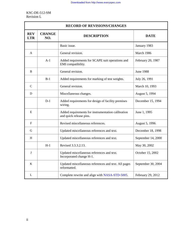
RECORD OF REVISIONS/CHANGES
REVLTR
CHANGENO.
DESCRIPTION DATE
Basic issue. January 1983
A General revision. March 1986
A-1 Added requirements for SCAPE suit operations andEMI compatibility.
February 20, 1987
B General revision. June 1988
B-1 Added requirements for marking of test weights. July 26, 1991
C General revision. March 10, 1993
D Miscellaneous changes. August 5, 1994
D-1 Added requirements for design of facility premiseswiring.
December 15, 1994
E Added requirements for instrumentation calibrationand quick release pins.
June 1, 1995
F Revised miscellaneous references. August 5, 1996
G Updated miscellaneous references and text. December 18, 1998
H Updated miscellaneous references and text. September 14, 2000
H-1 Revised 3.3.3.2.13. May 30, 2002
J Updated miscellaneous references and text.Incorporated change H-1.
October 15, 2002
K Updated miscellaneous references and text. All pagesreformatted.
September 30, 2004
L Complete rewrite and align with NASA-STD-5005. February 29, 2012
Downloaded from http://www.everyspec.com

KSC-DE-512-SMRevision L
iii
FOREWORD
KSC-DE-512-SM establishes overall requirements and best design practices to be used at theJohn F. Kennedy Space Center (KSC) for the development of ground systems (GS) in support ofoperations at launch, landing, and retrieval sites. These requirements apply to the design anddevelopment of hardware and software for ground support equipment (GSE), ground supportsystems (GSS), and facility ground support systems (F-GSS) used to support the KSC missionfor transportation, receiving, handling, assembly, test, checkout, servicing, and launch of spacevehicles and payloads and selected flight hardware items for retrieval.
During the 1950s and early 1960s, the Missile Firing Laboratory (later renamed to the LaunchOperations Directorate) was the launch operations arm of Redstone Arsenal and the ArmyBallistic Missile Agency. The Missile Firing Laboratory used Army specifications and standardsfor its design and development of ground systems. KSC’s effort to develop standards began withGP-863, General Criteria for Design of New Equipment and Facilities, which was released inJuly 1970 and updated three years later. GP-863 focused on operability, reliability,maintainability, useful life, environmental, transportability, human performance, safety, logistics,documentation, and quality assurance. KSC-DE-512-SM, Facility Systems, Ground SupportSystems, and Ground Support Equipment, General Design Requirements, replaced GP-863 in1983. The early revisions of KSC-DE-512-SM contained requirements, along with guidance foraccomplishing detailed designs. Later revisions became more formal and the “shall” statementbecame the phrase to identify each requirement.
This standards manual supplements NASA-STD-5005 by including KSC-site-specific and local-environment requirements. KSC-DE-512-SM is a single, complete document for design anddevelopment of KSC ground systems for use at launch, landing, and retrieval sites.
These requirements and practices are optional for equipment used at manufacturing,development, and test sites.
Downloaded from http://www.everyspec.com

KSC-DE-512-SMRevision L
iv
This page intentionally left blank.
Downloaded from http://www.everyspec.com
KSC-DE-512-SMRevision L
v
CONTENTS
1. SCOPE..............................................................................................................11.1 Purpose .............................................................................................................11.2 Applicability .....................................................................................................11.3 Tailoring and Waivers ......................................................................................3
2. APPLICABLE DOCUMENTS ........................................................................42.1 General..............................................................................................................42.2 Government Documents ...................................................................................42.3 Non-Government Documents .........................................................................102.4 Order of Precedence........................................................................................15
3. ACRONYMS, ABBREVIATIONS, AND DEFINITIONS............................163.1 Acronyms and Abbreviations .........................................................................163.2 Definitions ......................................................................................................18
4. GENERAL REQUIREMENTS ......................................................................234.1 General............................................................................................................234.2 Characteristics.................................................................................................234.2.1 Performance Characteristics ...........................................................................234.2.1.1 GS Designed to Meet Flight Hardware Requirements....................................234.2.1.2 Ground System Degradation and Contamination............................................244.2.1.3 GS Design for Access .....................................................................................244.2.1.4 Interfaces ........................................................................................................244.2.2 Physical Characteristics ..................................................................................254.2.2.1 Design Life Duration ......................................................................................254.2.2.2 Limited-Life Items..........................................................................................254.2.2.3 Colors..............................................................................................................254.2.3 Reliability .......................................................................................................264.2.3.1 Redundancy ....................................................................................................264.2.3.2 Failure Tolerance ............................................................................................264.2.3.3 Failure Propagation.........................................................................................274.2.3.4 System Safety and Reliability Analysis ..........................................................274.2.4 Environmental Conditions ..............................................................................294.2.4.1 Natural Environment.......................................................................................294.2.4.2 Launch-Induced Environment ........................................................................304.2.4.2.1 Launch-Induced Damage ................................................................................304.2.4.3 Controlled Interior Environment.....................................................................304.2.4.4 Controlled Clean Environment .......................................................................304.2.4.5 Uncontrolled Interior Environment.................................................................304.2.4.6 Fire/Explosion Hazardproofing ......................................................................304.2.4.7 Environmental Test Methods..........................................................................304.2.4.8 Seismic Environment......................................................................................314.3 Documentation................................................................................................31
Downloaded from http://www.everyspec.com

KSC-DE-512-SMRevision L
vi
4.3.1 Drawings and Specifications...........................................................................314.3.2 Technical Documentation ...............................................................................314.4 Logistics..........................................................................................................314.4.1 Limited-Life Item Tracking ............................................................................314.5 Qualification ...................................................................................................314.6 Quality Assurance...........................................................................................314.6.1 General............................................................................................................324.6.1.1 Definition of Quality Requirements................................................................324.6.1.2 Personnel Training..........................................................................................324.6.2 Testing ............................................................................................................324.6.2.1 Load Test ........................................................................................................324.6.2.2 Nondestructive Evaluation (NDE)..................................................................334.6.2.3 Metrology and Calibration..............................................................................334.6.3 Quality Conformance Verification..................................................................334.7 Packaging, Handling, and Transportation.......................................................334.7.1 Shipping and Storage Containers....................................................................334.7.2 Parts Protection...............................................................................................34
5. DESIGN AND CONSTRUCTION REQUIREMENTS.................................345.1 Structural Design ............................................................................................345.1.1 GS Structures and Equipment.........................................................................345.1.1.1 Steel Structures ...............................................................................................345.1.1.2 Aluminum Structures......................................................................................345.1.2 Safety Factor...................................................................................................345.1.2.1 Safety Factor for Cyclic Loading....................................................................355.1.3 Structural Design Loads..................................................................................355.2 Mechanical Design .........................................................................................365.2.1 Pneumatics......................................................................................................365.2.1.1 Breathing-Air Systems....................................................................................365.2.1.2 Vacuum and Compressed-Air Systems...........................................................365.2.2 Cryogenics ......................................................................................................365.2.3 Hypergols........................................................................................................365.2.4 Hydrocarbons..................................................................................................375.2.5 Hydraulics.......................................................................................................375.2.6 Environmental Control Systems (ECSs) and Environmental Control
and Life Support Systems (ECLSSs) ..............................................................375.2.7 Life Support ....................................................................................................375.2.8 Lifting Devices ...............................................................................................385.2.9 Torque for Threaded Fasteners .......................................................................385.2.10 Tethering Provisions .......................................................................................395.2.11 Jacks ...............................................................................................................395.2.12 Transportation Equipment ..............................................................................395.2.12.1 Towed GS.......................................................................................................395.2.12.2 Transportation Equipment Interface Loads.....................................................395.2.13 Pressure Vessels..............................................................................................395.2.13.1 Code-Stamped Vessel Registration.................................................................40
Downloaded from http://www.everyspec.com

KSC-DE-512-SMRevision L
vii
5.2.13.2 Pressure Vessels Used in Transporting Commodities.....................................405.2.14 Piping Systems................................................................................................405.2.15 Pressure Vessel/System Certification .............................................................405.2.16 Ground-to-Flight-Vehicle Umbilical Systems ................................................405.3 Electrical/Electronic Design ...........................................................................405.3.1 Electrical Control and Monitor Equipment.....................................................405.3.2 Electrical Design of Pneumatic and Hydraulic Components ..........................405.3.3 Pyrotechnic Systems .......................................................................................415.3.4 Electrical Power Systems................................................................................415.3.5 Bonding and Grounding..................................................................................415.3.6 Hazardproofing ...............................................................................................415.3.7 Software..........................................................................................................415.3.8 Firmware.........................................................................................................415.4 Parts ................................................................................................................415.4.1 Electrical, Electronic, and Electromechanical (EEE) Parts.............................415.4.1.1 Electrostatic-Discharge (ESD)-Sensitive Components and Assemblies .........425.4.2 Stainless-Steel Tubing ....................................................................................425.4.2.1 Superaustenitic Stainless-Steel Tubing...........................................................425.4.3 Pipe .................................................................................................................425.4.3.1 Aluminum Pipe...............................................................................................425.4.3.2 Expansion Joints .............................................................................................425.4.4 Metallic Fittings..............................................................................................425.4.5 Fluid System Protective Covers......................................................................425.4.6 Fluid System Components ..............................................................................435.4.6.1 Fluid System Component Acceptance Criteria ...............................................435.4.7 Electrical-Power Receptacles and Plugs .........................................................435.4.8 Electrical-Power Cable ...................................................................................435.4.9 Electrical Cable and Harnesses .......................................................................435.4.10 Fiber Optics ....................................................................................................435.4.11 Electrical Hookup Wire ..................................................................................445.4.12 Connectors ......................................................................................................445.4.13 Coaxial Radio Frequency (RF) Connectors ....................................................445.4.14 Protective Covers or Caps for Electrical Connectors......................................445.4.15 Optical Covers or Caps ...................................................................................445.4.16 Sensors and Transducers.................................................................................455.4.16.1 Sensor and Transducer Acceptance Criteria ...................................................455.4.17 Purged Electrical Enclosures ..........................................................................455.4.18 Racks, Panels, and Modular Enclosures .........................................................455.4.19 Printed Circuit Boards ....................................................................................455.4.19.1 Printed Circuit Board Design..........................................................................455.4.19.2 Printed Circuit Board Fabrication and Acceptance.........................................465.4.19.3 Printed Circuit Assembly Fabrication and Acceptance...................................465.4.20 Electric Motors and Generators ......................................................................465.4.20.1 Motor Starters and Controllers........................................................................465.4.21 GS Fasteners ...................................................................................................47
Downloaded from http://www.everyspec.com
KSC-DE-512-SMRevision L
viii
5.4.21.1 Reuse of Self-Locking Fasteners ....................................................................475.4.21.2 Liquid-Locking Compounds...........................................................................475.5 Electromagnetic Interference (EMI) ...............................................................475.6 Identification Markings and Labels ................................................................475.6.1 Systems and Equipment..................................................................................475.6.2 Load Test ........................................................................................................485.6.3 Piping Systems................................................................................................485.6.4 Compressed-Gas Cylinders.............................................................................485.6.5 Load Capacity.................................................................................................485.6.6 Electrical-Cable and Harness Assemblies.......................................................485.6.7 Serial Numbers ...............................................................................................485.7 Interchangeability ...........................................................................................495.8 Safety..............................................................................................................495.8.1 Hazard Analysis..............................................................................................495.8.2 Safety Requirements on KSC Property...........................................................495.8.3 Safety Requirements on Air Force Property ...................................................495.8.4 Safety Requirements on Other NASA Property..............................................495.8.5 Caution and Warning Indications ...................................................................495.9 Human Factors................................................................................................495.10 Security of Information Technology (IT) .......................................................50
6. MATERIALS AND PROCESSES REQUIREMENTS..................................506.1 Material Properties Design Data .....................................................................506.2 M&P Controls.................................................................................................516.3 Detailed Requirements....................................................................................516.3.1 Flammability and Compatibility Requirements ..............................................516.3.1.1 Flammability Control......................................................................................516.3.1.2 Electrical-Wire Insulation Materials ...............................................................526.3.1.3 Fluid Compatibility.........................................................................................526.3.1.3.1 Fluids Other than Oxygen...............................................................................536.3.1.3.2 Oxygen Systems .............................................................................................536.3.1.4 Metals .............................................................................................................546.3.1.4.1 Carbon and Low-Alloy Steel ..........................................................................546.3.1.4.2 Corrosion-Resistant Steel ...............................................................................546.3.1.4.3 Aluminum.......................................................................................................556.3.1.4.4 Nickel-Based Alloys .......................................................................................556.3.1.4.5 Titanium..........................................................................................................556.3.1.4.6 Copper Alloys.................................................................................................566.3.1.4.7 Beryllium and Beryllium Alloys.....................................................................566.3.1.4.8 Tin...................................................................................................................576.3.1.5 Nonmetals .......................................................................................................576.3.1.5.1 Elastomers ......................................................................................................576.3.1.5.2 Composite Materials .......................................................................................576.3.1.5.3 Refractory Concrete........................................................................................576.3.1.5.4 Lubricants .......................................................................................................576.3.1.5.5 Limited-Life Materials....................................................................................58
Downloaded from http://www.everyspec.com

KSC-DE-512-SMRevision L
ix
6.3.1.5.6 Plastic Film, Foam, and Adhesive Tape (PFA)...............................................586.3.1.5.7 Fungus Resistance ..........................................................................................586.4 Processes.........................................................................................................596.4.1 Welding ..........................................................................................................596.4.2 Brazing............................................................................................................596.4.3 Soldering.........................................................................................................606.4.4 Heat Treating and Plating ...............................................................................606.4.5 Forging............................................................................................................616.4.6 Casting ............................................................................................................616.4.7 Adhesive Bonding ..........................................................................................616.4.8 Fluid System Cleanliness................................................................................626.4.9 Riveting ..........................................................................................................626.4.10 Crimping.........................................................................................................626.4.11 Potting and Molding .......................................................................................626.4.12 Electrical-Cable Design and Fabrication ........................................................626.4.13 Conformal Coating .........................................................................................626.4.14 Corrosion Control ...........................................................................................636.4.14.1 Stress Corrosion Cracking (SCC) ...................................................................636.4.15 Nondestructive Evaluation..............................................................................636.4.16 Hydrogen Embrittlement ................................................................................646.4.17 Contamination Control ...................................................................................64
APPENDIX A. MATERIAL USAGE AGREEMENT ............................................................65
APPENDIX B. DELIVERABLES...........................................................................................67
APPENDIX C. REFERENCE DOCUMENTS........................................................................69
Downloaded from http://www.everyspec.com

KSC-DE-512-SMRevision L
x
This page intentionally left blank.
Downloaded from http://www.everyspec.com

KSC-DE-512-SMRevision L
1
FACILITY SYSTEMS, GROUND SUPPORT SYSTEMS, AND GROUND SUPPORTEQUIPMENT GENERAL DESIGN REQUIREMENTS
1. SCOPE
1.1 Purpose
KSC-DE-512-SM establishes requirements and guidance for design and fabrication of groundsystems (GS) that includes: ground support equipment (GSE), ground support systems (GSS),and facility ground support systems (F-GSS) to provide uniform methods and processes fordesign and development of robust, safe, reliable, maintainable, supportable, and cost-effectiveGS in support of space flight and institutional programs and projects. This standard is intended tosupplement the minimum requirements of NASA-STD-5005 by applying more stringent,restrictive, or demanding requirements applicable to the specific KSC environment. Thisstandard also provides requirements for GSS and F-GSS because these systems are not coveredin NASA-STD-5005.
1.2 Applicability
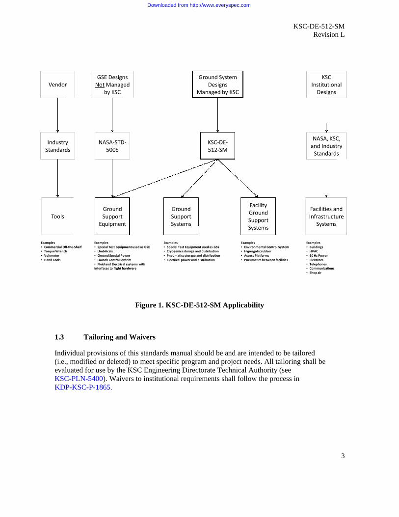
The applicability of KSC-DE-512-SM relative to other NASA and industry design standards isshown graphically in Figure 1.
a. This standards manual applies to all new GS for programs and projects assigned toKSC.
b. KSC-DE-512-SM establishes minimum design requirements for ground systems, asdefined herein, for NASA programs and projects assigned to KSC. This standardsmanual is intended to establish uniform engineering best practices and methods in thedesign, documentation, procurement, fabrication, assembly, test, and installation ofground systems to support KSC operations.
c. This standards manual is required for use by KSC design entities and their supportcontractors and may be cited in contracts, projects, and other documents as necessary toprovide a technical requirement.
d. Rationale and guidance are provided in italic text after the requirement where moredefinition is needed.
e. The requirements of this standard are optional for hardware used only atmanufacturing, development, or test sites but are required for hardware used at launch,landing, and retrieval sites.
f. A program may invoke additional requirements that differ from the requirements statedherein. These requirements will be evaluated and approved for use by the KSCEngineering and Technology Directorate Technical Authority. See KSC-PLN-5400 andparagraph 1.3.
Downloaded from http://www.everyspec.com

KSC-DE-512-SMRevision L
2
h. KSC Directorates are responsible to invoke this standards manual for design anddevelopment of ground systems. KSC Directorates have responsibilities described asfollows:
(1) Engineering and Safety and Mission Assurance (S&MA) have the responsibilityto determine categories or types of GS (e.g., critical vs. noncritical) and anyadditional requirements resulting from these categories or types.
(2) Center Operations, Protective Services Branch, Authority Having Jurisdiction,has the responsibility and authority to define hazardous areas and approvedesigns that provide equipment to these areas.
i. This standards manual applies to the following ground systems (see paragraph 3.2):
(1) ground support equipment,
(2) ground support systems,
(3) facility ground support systems,
(4) special test equipment, and
(5) modifications to commercial off-the-shelf (i.e., modified off-the-shelf [MOTS]).
j. NASA-STD-5005 applies to GSE provided by entities other than KSC.
k. This standards manual does not apply to the following:
(1) tools (standard shop),
(2) facilities and utilities (in-house and architect & engineering [A&E] firms), or
(3) commercial off-the-shelf (COTS) equipment.
KSC-DE-512-SM does not cover the design and fabrication of tools, facilities andutilities, and COTS equipment. However, other KSC standards and industry standardsmay apply to these designs.
l. The Technical Authority determines the classification of equipment listed in paragraphs1.2.i, 1.2.j, and 1.2.k.
Downloaded from http://www.everyspec.com
KSC-DE-512-SMRevision L
3
Vendor
IndustryStandards
Tools
GSE DesignsNot Managed
by KSC
KSCInstitutional
Designs
Ground SystemDesigns
Managed by KSC
NASA-STD-5005
KSC-DE-512-SM
NASA, KSC,and Industry
Standards
GroundSupport
Equipment
GroundSupportSystems
FacilityGroundSupportSystems
Facilities andInfrastructure
Systems
Examples• Commercial Off-the-Shelf• Torque Wrench• Voltmeter• Hand Tools
Examples• Special Test Equipment used as GSE• Umbilicals• Ground Special Power• Launch Control System• Fluid and Electrical systems withinterfaces to flight hardware
Examples• Special Test Equipment used as GSS• Cryogenics storage and distribution• Pneumatics storage and distribution• Electrical power and distribution
Examples• Environmental Control System• Hypergolscrubber• Access Platforms• Pneumatics between facilities
Examples• Buildings• HVAC• 60 Hz Power• Elevators• Telephones• Communications• Shop air
Figure 1. KSC-DE-512-SM Applicability
1.3 Tailoring and Waivers
Individual provisions of this standards manual should be and are intended to be tailored(i.e., modified or deleted) to meet specific program and project needs. All tailoring shall beevaluated for use by the KSC Engineering Directorate Technical Authority (seeKSC-PLN-5400). Waivers to institutional requirements shall follow the process inKDP-KSC-P-1865.
Downloaded from http://www.everyspec.com

KSC-DE-512-SMRevision L
4
2. APPLICABLE DOCUMENTS
2.1 General
The latest issuances of documents listed in this section contain provisions that constituterequirements of this standard as cited in the text.
The applicable documents are accessible via the NASA Standards and Technical AssistanceResource Tool at http://standards.nasa.gov or may be obtained directly from the standardsdeveloping organizations or other document distributors.
2.2 Government Documents
Department of Defense
AFSPCMAN 91-710 Range Safety User Requirements Manual,Volume 3, Launch Vehicles, Payloads, and GroundSupport Systems Requirements
MIL-DTL-16878 Wire, Electrical, Insulated, General Specificationfor
MIL-DTL-22992 Connectors, Plugs and Receptacles, Electrical,Waterproof, Quick Disconnect, Heavy Duty Type,General Specification for
MIL-DTL-24308 Connectors, Electric, Rectangular,Nonenvironmental, Miniature, Polarized Shell,Rack and Panel, General Specification for
MIL-DTL-38999 Connectors, Electrical, Circular, Miniature, HighDensity, Quick Disconnect (Bayonet, Threaded andBreech Coupling), Environment Resistant,Removable Crimp and Hermetic Solder Contacts,General Specification for
MIL-HDBK-17-1 Composite Materials Handbook, Volume 1,Polymer Matrix Composites Guidelines forCharacterization of Structural Materials
MIL-HDBK-17-2 Composite Materials Handbook, Volume 2,Polymer Matrix Composites Materials Properties
MIL-HDBK-17-3 Composite Materials Handbook, Volume 3,Polymer Matrix Composites Materials Usage,Design, and Analysis
Downloaded from http://www.everyspec.com
KSC-DE-512-SMRevision L
5
MIL-HDBK-17-4 Composite Materials Handbook, Volume 4, MetalMatrix Composites
MIL-HDBK-17-5 Composite Materials Handbook, Volume 5,Ceramic Matrix Composites
MIL-HDBK-149 Rubber
MIL-HDBK-263 Electrostatic Discharge Control Handbook forProtection of Electrical and Electronic Parts,Assemblies and Equipment (Excluding ElectricallyInitiated Explosive Devices) (Metric)
MIL-HDBK-700 Plastics
MIL-HDBK-6870 Inspection Program Requirements, Nondestructivefor Aircraft and Missile Materials and Parts
MIL-PRF-39012 Connectors, Coaxial, Radio Frequency, GeneralSpecification for
MIL-STD-202 Test Method Standard, Electronic and ElectricalComponent Parts
MIL-STD-461 Requirements for the Control of ElectromagneticInterference Characteristics of Subsystems andEquipment
MIL-STD-464 Electromagnetic Environmental EffectsRequirements for Systems
MIL-STD-810 Environmental Engineering Considerations andLaboratory Tests
MIL-STD-889 Dissimilar Metals
MIL-STD-1686 Electrostatic Discharge Control Program forProtection of Electrical and Electronic Parts,Assemblies and Equipment (Excluding ElectricallyInitiated Explosive Devices)
Federal (FED)
29 CFR 1910 Occupational Safety and Health Standards
29 CFR 1926 Safety and Health Regulations for Construction
Downloaded from http://www.everyspec.com
KSC-DE-512-SMRevision L
6
49 CFR 171 through 180 Hazardous Materials Regulations (Department ofTransportation)
FED-STD-595 Colors Used in Government Procurement
HF-STD-001 Human Factors Design Standard (Federal AviationAdministration)
DOT/FAA/AR-MMPDS Metallic Materials Properties Development andStandardization (MMPDS)
NASA
NASA-HDBK-1001 Terrestrial Environment (Climatic) CriteriaHandbook for Use in Aerospace VehicleDevelopment
NASA-SPEC-5004 Welding of Aerospace Ground Support Equipmentand Related Nonconventional Facilities
NASA-STD-4003 Electrical Bonding for NASA Launch Vehicles,Spacecraft, Payloads, and Flight Equipment
NASA-STD-5005 Standard for the Design and Fabrication of GroundSupport Equipment
NASA-STD-5008 Protective Coating of Carbon Steel, Stainless Steel,and Aluminum on Launch Structures, Facilities, andGround Support Equipment
NASA-STD-5009 Nondestructive Evaluation Requirements forFracture-Critical Metallic Components
NASA-STD-6001 Flammability, Offgassing, and CompatibilityRequirements and Test Procedures
NASA-STD-6002 Applying Data Matrix Identification Symbols onAerospace Parts
NASA-STD-8719.9 Standard for Lifting Devices and Equipment
NASA-STD-8719.12 Safety Standard for Explosives, Propellants, andPyrotechnics
NASA-STD-8719.17 NASA Requirements for Ground-Based PressureVessels and Pressurized Systems (PV/S)
Downloaded from http://www.everyspec.com

KSC-DE-512-SMRevision L
7
NASA-STD-8739.1 Workmanship Standard for Polymeric Applicationon Electronic Assemblies
NASA-STD-8739.2 Workmanship Standard for Surface MountTechnology
NASA-STD-8739.3 Soldered Electrical Connections
NASA-STD-8739.4 Crimping, Interconnecting Cables, Harnesses, andWiring
NASA-STD-8739.5 Fiber Optic Terminations, Cable Assemblies, andInstallation
NPR 2810.1 Security of Information Technology
NPR 6000.1 Requirements for Packaging, Handling, andTransportation for Aeronautical and Space Systems,Equipment, and Associated Components
NPR 7150.2 NASA Software Engineering Requirements
NPR 8705.2 Human-Rating Requirements for Space Systems
NPR 8715.3 NASA General Safety Program Requirements
George C. Marshall Space Flight Center (MSFC), NASA
MSFC-SPEC-445 Adhesive Bonding, Process and Inspection,Requirements for
MSFC-STD-486 Threaded Fasteners, Torque Limits, Standard for
MSFC-STD-3029 Guidelines for the Selection of Metallic Materialsfor Stress Corrosion Cracking Resistance in SodiumChloride Environments
John F. Kennedy Space Center (KSC), NASA
120E3100003 Electrical Cable Fabrication Requirements
79K07491 Installation of Purge Hardware
79K80000 Series Fluid Component Specification Drawings
KDP-KSC-P-1865 Institutional Requirement Deviation/Waiver Process
Downloaded from http://www.everyspec.com
KSC-DE-512-SMRevision L
8
KSC-PLN-5400 Technical Authority and Technical ExcellenceImplementation Plan
KNPR 8700.2 KSC System Safety and Reliability AnalysisMethodology Procedural Requirements
KNPR 8715.3 KSC Safety Practices Procedural Requirements
KNPR 8720.2 KSC Reliability and Maintainability ProceduralRequirements
KNPR 8730.1 KSC Metrology and Calibration ProceduralRequirements
KNPR 8730.2 Quality Assurance Procedural Requirement
KSC-C-123 Surface Cleanliness of Ground Support EquipmentFluid Systems, Specification for
KSC-DD-818-TR Summary of Measurements of KSC Launch-Induced Environmental Effects (STS-1 throughSTS-11)
KSC-DF-107 Technical Documentation Style Guide
KSC-E-165 Electrical Ground Support Equipment Fabrication,Specification For
KSC-E-166 Electrical Ground Support Equipment, Installationand Assembly, Specification for
KSC-GP-425 Fluid Fitting Engineering Standards
KSC-GP-435 Engineering Drawing Practices, Vol. 1: Aerospaceand Ground Support Equipment
KSC-GP-864 Electrical Ground Support Equipment CableHandbook
KSC-GP-986 Design Criteria for Reusable Space VehicleUmbilical Systems
KSC-NE-9187 Sensors, Transducers and Signal ConditioningSystems Selection Guidelines
KSC-SPEC-E-0002 Modular Electrical Enclosures, Racks, Consoles,and Accessories, Specification for
Downloaded from http://www.everyspec.com

KSC-DE-512-SMRevision L
9
KSC-SPEC-P-0012 Refractory Concrete, Specification for
KSC-SPEC-P-0027 Tubing, Steel, Superaustenitic, Corrosion Resistant,UNS N08367 and UNS S31245, Seamed, BrightAnnealed, Passivated, Specification for
KSC-SPEC-Z-0007 Tubing, Steel, Corrosion Resistant, Types 304 and316, Seamless, Annealed, Specification for
KSC-SPEC-Z-0008 Fabrication and Installation of Flared TubeAssemblies and Installation of Fittings and FittingAssemblies, Specification for
KSC-SPEC-Z-0009 Lubrication, Thread, Corrosion-Resistant Steel andAluminum Alloy Tube Fittings, Specification for
KSC-STD-132 Potting and Molding Electrical Cable AssemblyTerminations, Standard for
KSC-STD-141 Load Test Identification and Data Marking,Standard for
KSC-STD-164 Environmental Test Methods for Ground SupportEquipment, Standard for
KSC-STD-E-0001 Design of Electrical Control and MonitoringSystems, Equipment (GSE), and Panels, Standardfor
KSC-STD-E-0002 Hazardproofing of Electrically EnergizedEquipment, Standard for
KSC-STD-E-0004 Pneumatic and Hydraulic Mechanical Components,Electrical Design, Standard for
KSC-STD-E-0011 Electrical Power Receptacles and Plugs, Standardfor
KSC-STD-E-0012 Facility Grounding and Lightning Protection,Standard for
KSC-STD-E-0015 Standard for Marking of Ground SupportEquipment
KSC-STD-G-0003 Launch Support and Facility Components,Qualification of, Standard for
Downloaded from http://www.everyspec.com
KSC-DE-512-SMRevision L
10
KSC-STD-P-0006 Quick Release Pins and Pin Tethers, Standard for
KSC-STD-SF-0004 Ground Piping Systems Color Coding andIdentification, Safety Standard for
KSC-STD-Z-0005 Pneumatic Ground-Support Equipment, Design of,Standard for
KSC-STD-Z-0006 Hypergolic Propellants Ground Support Equipment,Design of, Standard for
KSC-STD-Z-0008 Ground Life Support Systems and Equipment,Design of, Standard for
KSC-STD-Z-0009 Cryogenic Ground Support Equipment, Design of,Standard for
KSC-STD-Z-0010 Environmental Control Systems, Ground CoolantSystems, Coolant Servicing Systems, and GroundSupport Equipment, Design of, Standard for
MMA-1985-79 Standard Test Method for Evaluating TriboelectricCharge Generation and Decay
2.3 Non-Government Documents
Aerospace Industries Association (AIA)/National Aerospace Standards (NAS)
AIA/NAS 410 NAS Certification and Qualification ofNondestructive Test Personnel
Aluminum Association (AA)
ADM Aluminum Design Manual
American Institute of Steel Construction (AISC)
AISC 325 Steel Construction Manual
American National Standards Institute (ANSI)
ANSI C18.2M Part 1 American National Standard for PortableRechargeable Cells and Batteries – General andSpecifications
ANSI C18.3M Part 1 American National Standard for Portable LithiumPrimary Cells and Batteries – General andSpecifications
Downloaded from http://www.everyspec.com

KSC-DE-512-SMRevision L
11
American Society for Testing and Materials (ASTM)
ASTM A123 Standard Specification for Zinc (Hot-DipGalvanized) Coatings on Iron and Steel Products
ASTM A153 Standard Specification for Zinc Coating (Hot-Dip)on Iron and Steel Hardware
ASTM A312 Standard Specification for Seamless, Welded, andHeavily Cold Worked Austenitic Stainless SteelPipes
ASTM A325 Standard Specification for Structural Bolts, Steel,Heat Treated, 120/105 ksi Minimum TensileStrength
ASTM A380 Standard Practice for Cleaning, Descaling, andPassivation of Stainless Steel Parts, Equipment, andSystems
ASTM A490 Standard Specification for Structural Bolts, AlloySteel, Heat Treated, 150 ksi Minimum TensileStrength
ASTM A653 Standard Specification for Steel Sheet, Zinc-Coated(Galvanized) or Zinc-Iron Alloy-Coated(Galvannealed) by the Hot-Dip Process
ASTM A780 Standard Practice for Repair of Damaged andUncoated Areas of Hot-Dip Galvanized Coatings
ASTM A967 Standard Specification for Chemical PassivationTreatments for Stainless Steel Parts
ASTM B241 Standard Specification for Aluminum andAluminum-Alloy Seamless Pipe and SeamlessExtruded Tube
ASTM D7194 Standard Specification for Aerospace PartsMachined from Polychlorotrifluoroethylene(PCTFE)
ASTM E1417 Standard Practice for Liquid Penetrant Testing
ASTM E1444 Standard Practice for Magnetic Particle Testing
Downloaded from http://www.everyspec.com

KSC-DE-512-SMRevision L
12
ASTM E1548 Standard Practice for Preparation of AerospaceContamination Control Plans
ASTM E1742 Standard Practice for Radiographic Examination
ASTM E2217 Standard Practice for Design and Construction ofAerospace Cleanrooms and ContaminationControlled Areas
ASTM E2375 Standard Practice for Ultrasonic Testing of WroughtProducts
ASTM MNL 36 Safe Use of Oxygen and Oxygen Systems:Handbook for Design, Operation, and Maintenance
American Society of Civil Engineers (ASCE)
ASCE-7 Minimum Design Loads for Buildings and OtherStructures
American Society of Mechanical Engineers (ASME)
ASME BPVC-VIII ASME Boiler & Pressure Vessel Code, SectionVIII, Division 1: Rules for Construction of PressureVessels, Division 2: Alternative Rules, Division 3:Alternative Rules
ASME BPVC-X ASME Boiler & Pressure Vessel Code, Section X,Fiber-Reinforced Plastic Pressure Vessels
ASME Y14.100 Engineering Drawing Practices
ASME B30.1 Jacks, Industrial Rollers, Air Casters, and HydraulicGantries
ASME B31.3 Process Piping
ASME B31.8 Gas Transmission and Distribution Piping Systems
ASME B31.9 Building Services Piping
American Welding Society (AWS)
AWS C3.2M/C3.2 Standard Method for Evaluating the Strength ofBrazed Joints
AWS C3.4M/C3.4 Specification for Torch Brazing
Downloaded from http://www.everyspec.com
KSC-DE-512-SMRevision L
13
AWS C3.5M/C3.5 Specification for Induction Brazing
AWS C3.6M/C3.6 Specification for Furnace Brazing
AWS C3.7M/C3.7 Specification for Aluminum Brazing
Compressed Gas Association (CGA)
CGA C-7 Guide to the Preparation of Precautionary Labelingand Marking of Compressed Gas Containers
ESD Association
ESD S20.20 For the Development of an Electrostatic DischargeControl Program for – Protection of Electrical andElectronic Parts, Assemblies and Equipment(Excluding Electrically Initiated Explosive Devices)
International Electrotechnical Commission
IEC 60807 Rectangular Connectors for Frequencies Below 3MHz
IPC – Association Connecting Electronics Industries
IPC-2221 Generic Standard on Printed Board Design
IPC-2222 Sectional Design Standard for Rigid OrganicPrinted Boards
IPC-2223 Sectional Design Standard for Flexible PrintedBoards
IPC-2252 Design Guide for RF/Microwave Circuit Boards
IPC-6011 Generic Performance Specification for PrintedBoards
IPC-6012 Qualification and Performance Specification forRigid Printed Boards
IPC-6013 Qualification and Performance Specification forFlexible Printed Boards
IPC-6018 Microwave End Product Board Inspection and Test
IPC J-STD-001 Requirements for Soldered Electrical and ElectronicAssemblies, Performance Class 3
Downloaded from http://www.everyspec.com

KSC-DE-512-SMRevision L
14
IPC J-STD-001ES Space Applications Electronic Hardware Addendumto IPC J-STD-001E Requirements for SolderedElectrical and Electronic Assemblies
National Fire Protection Association (NFPA)
NFPA 59A Standard for the Production, Storage, and Handlingof Liquefied Natural Gas (LNG)
NFPA 70 National Electrical Code
NFPA 70E Standard for Electrical Safety in the Workplace
NFPA 496 Standard for Purged and Pressurized Enclosures forElectrical Equipment
Sheet Metal and Air Conditioning Contractors’ National Association (SMACNA)
SMACNA 1958 HVAC Systems Duct Design
Society of Automotive Engineers (SAE)
SAE AMS-DTL-23053/5 Insulation Sleeving, Electrical, Heat Shrinkable,Polyolefin, Flexible, Crosslinked
SAE AMS 2175 Castings, Classification and Inspection of
SAE AMS 2403 Plating, Nickel, General Purpose
SAE AMS 2404 Plating, Electroless Nickel
SAE AMS 2423 Plating, Nickel Hard Deposit
SAE AMS 2460 Chromium Plating
SAE AMS 2488 Anodic Treatment – Titanium and Titanium AlloysSolution pH 13 or Higher
SAE AMS 2647 Fluorescent Penetrant Inspection Aircraft andEngine Component Maintenance
SAE AMS 2759 Heat Treatment of Steel Parts, GeneralRequirements
SAE AMS 2759/9 Hydrogen Embrittlement Relief (Baking) of SteelParts
SAE AMS 2770 Heat Treatment of Wrought Aluminum Alloy Parts
Downloaded from http://www.everyspec.com
KSC-DE-512-SMRevision L
15
SAE AMS 2771 Heat Treatment of Aluminum Alloy Castings
SAE AMS 2772 Heat Treatment of Aluminum Alloy Raw Materials
SAE AMS 2774 Heat Treatment Wrought Nickel Alloy and CobaltAlloy Parts
SAE AMS-H-6875 Heat Treatment of Steel Raw Materials
SAE AMS-H-81200 Heat Treatment of Titanium and Titanium Alloys
SAE AMS-QQ-P-416 Plating, Cadmium (Electrodeposited)
SAE AMS-STD-2154 Inspection, Ultrasonic, Wrought Metals, Process for
SAE ARP 1247 Aerospace Ground Support Equipment – GeneralRequirements
SAE ARP 4402 Eddy Current Inspection of Open Fastener Holes inAluminum Aircraft Structure
SAE AS 4787 Eddy Current Inspection of Circular Holes inNonferrous Metallic Aircraft Engine Hardware
SAE AS 5942 Marking of Electrical Insulating Materials
SAE AS 8090 Mobility, Towed Aerospace Ground Equipment,General Requirements for
SAE AS 22759 Wire, Electrical, Fluoropolymer-Insulated, Copperor Copper Alloy
SAE AS 50151 Connectors, Electrical, Circular Threaded, ANType, General Specification for
SAE AS 50861 Wire, Electric, Polyvinyl Chloride Insulated,Copper or Copper Alloy
2.4 Order of Precedence
This standard establishes requirements and guidance for design and fabrication of KSC groundsystems (GSE, GSS, and F-GSS), but does not supersede or waive established Agencyrequirements found in other documentation. Conflicts between this standard and applicabledocuments cited herein shall be resolved by the responsible Technical Authorities.
Downloaded from http://www.everyspec.com
KSC-DE-512-SMRevision L
16
3. ACRONYMS, ABBREVIATIONS, AND DEFINITIONS
3.1 Acronyms and Abbreviations
°C degrees Celsius°F degrees FahrenheitA-50 aerozine 50AA Aluminum AssociationAC alternating currentADM Aluminum Design ManualAFSPCMAN Air Force Space Command ManualAIA Aerospace Industries AssociationAIAA American Institute of Aeronautics and AstronauticsAISC American Institute of Steel ConstructionAMS Aerospace Material SpecificationANSI American National Standards InstituteARP Aerospace Recommended PracticeAS Aerospace StandardASCE American Society of Civil EngineersASME American Society of Mechanical EngineersASTM American Society for Testing and MaterialsAWS American Welding SocietyBPVC Boiler and Pressure Vessel CodeCFR Code of Federal RegulationsCGA Compressed Gas AssociationCIL Critical Items ListCOPV Composite Overwrapped Pressure VesselCOTS commercial off-the-shelfDE designDOT Department of TransportationDTL detailECS Environmental Control SystemECLSS Environmental Control and Life Support SystemECA Electronic Components, Assemblies & Materials AssociationECS Environmental Control SystemEEE electrical, electronic, and electromechanicale.g. for exampleEIA Electronic Industries AssociationEMC electromagnetic compatibilityEMI electromagnetic interferenceEPS Electrical Power SystemESD electrostatic dischargeETFE ethylene tetrafluoroethyleneFAA Federal Aviation AdministrationFED FederalF-GSS facility ground support system
Downloaded from http://www.everyspec.com

KSC-DE-512-SMRevision L
17
FMEA Failure Mode and Effects AnalysisFOD foreign-object debrisGO2 gaseous oxygenGP general publication (KSC)GS ground systemGSE ground support equipmentGSS ground support systemHDBK handbookHVAC heating, ventilation, and air conditioningHz hertzICD interface control documenti.e. that isIEC International Electrotechnical CommissionIEEE Institute of Electrical and Electronic Engineersin inchIPC Association Connecting Electronics IndustriesISO International Standardization Organization for StandardizationIT information technologyJSC Lyndon B. Johnson Space CenterkPa kilopascalKSC John F. Kennedy Space Centerksi one thousand pounds per square inchKTI Kennedy Technical InstructionLNG liquefied natural gasM&P materials and processesMAPTIS Materials and Processes Technical Information SystemMHz megahertzMIL militarymm millimeterMMA Malfunction/Materials AnalysisMMH monomethylhydrazineMMPDS Metallic Materials Properties Development and StandardizationMNL manualMPa megapascalMSFC George C. Marshall Space Flight CenterMUA Material Usage AgreementN4H4 hydrazineN2O4 nitrogen tetroxideNAS National Aerospace StandardsNASA National Aeronautics and Space AdministrationNDE nondestructive evaluationNEMA National Electrical Manufacturers AssociationNFPA National Fire Protection AssociationNPD NASA Policy DirectiveNPR NASA Procedural Requirements
Downloaded from http://www.everyspec.com

KSC-DE-512-SMRevision L
18
NSS NASA Safety StandardOSHA Occupational Safety and Health AdministrationPCTFE polychlorotrifluoroethylenePFA plastic film, foam, and adhesive tapepH potential of hydrogenPHE propellant handler’s ensemblePPE personal protective equipmentPRF performance specificationpsi pound per square inchpsia pound per square inch absolutePTFE polytetrafluoroethylenePV/S pressure vessels and pressurized systemsQD quick disconnectRF radio frequencyRH relative humidityRP reference publicationS&MA Safety and Mission AssuranceSAA Systems Assurance AnalysisSAE Society of Automotive EngineersSCC stress corrosion crackingSMACNA Sheet Metal and Air Conditioning Contractors’ National
AssociationSPEC specificationSSP Space Shuttle ProgramSTD standardTM technical memorandumTP technical procedureUDMH unsymmetrical dimethylhydrazineUNS Unified Numbering SystemUTS ultimate tensile strengthvs. versus
3.2 Definitions
analysis: use of calculations, numerical simulations, tools, techniques, and physics/engineering-based modeling to determine that the requirement is satisfied.
Rationale: Engineering analysis proceeds by separating the engineering design into thecomponents and disciplines, analyzing, or estimating each component of the operation orfailure mechanism separately, and recombining the components in accordance withphysics and engineering principles. The methods selected must be supported byappropriate technical rationale and be documented in detail.
catastrophic: a level beyond critical, resulting in loss of life, loss of flight vehicle, or loss of amajor ground asset.
Downloaded from http://www.everyspec.com
KSC-DE-512-SMRevision L
19
commercial off-the-shelf (COTS): equipment, including hardware and associatedsoftware/procedures, that is commercially available from the industrial inventory at the time ofpurchase.
Rationale: Commercial items or components should be used when they satisfy the groundsystems function and will not degrade the safety or reliability of the ground or flightsystem. Requirements should be specified in terms of functionality or performance ratherthan design. To qualify as COTS, equipment must not be modified (see modified off-the-shelf [MOTS]).
conventional structures: structures composed predominately of standard structural shapes andconnections typical of commercial or residential construction, such as office buildings,warehouses, machine shops, and other facilities whose structures are characterized by well-established design precedents and loading conditions.
corrosive environment: a marine (sea coast) or launch-induced environment that causesdegradation of materials due to oxidation or chemical reaction.
Rationale: In the corrosive marine (sea coast) environment at KSC, the most commonsources of corrosion are moisture and sodium chloride. The launch-induced environmentalso introduces hydrochloric acid, which exacerbates the corrosive effects of the marineenvironment.
critical ground system: a system whose loss of function or improper performance could resultin serious injury, damage to flight hardware, loss of mission, or major damage to a significantground asset.
critical: loss of function or improper performance could result in serious injury, damage to flighthardware, loss of mission, or major damage to a significant ground asset.
criticality: a program-defined measure of the consequences of a failure mode.
Rationale: Criticality of a ground system (GS) is determined by a Safety and MissionAssurance study analysis of the function and application of the equipment. Theclassifications assigned to the GS will guide the design team in determining whichspecifications and standards to apply, which materials to select, and how to document theGS.
demonstration: a verification method that determines the properties on an end item byobservation of its operation. This method is generally employed where qualitative operationalperformance is to be verified. A demonstration must be witnessed and documented.
design life: the operational life of equipment (to include storage life, installed life in anonoperating mode, and operational service life), after which the equipment will be replaced orrecertified. It is the responsibility of the program/project to determine recertificationrequirements, which may include refurbishment, analysis, or test.
Downloaded from http://www.everyspec.com

KSC-DE-512-SMRevision L
20
facility: land, buildings, structures, and other real property improvements, including facilitysystems (utility systems and collateral equipment). Facility systems include heating, ventilation,and air conditioning (HVAC); 60-hertz (Hz) power; potable water; elevators; lighting; shop air;etc. Facility systems may support or have interfaces with ground systems. The term facility doesnot include ground support equipment, ground support systems, facility ground support systems,tools, or special test equipment.
facility ground support system (F-GSS): fixed infrastructure and equipment (not includingutility systems and collateral equipment) that provides functional or physical support to GSS orGSE. F-GSS are specialized systems that are designed, built, and tested to more stringentrequirements than conventional facilities and their integral facility systems.
Rationale: F-GSS includes fixed environmental control systems (ECS), breathing airsystems, long-run piping systems, high-pressure gases, liquid hydrogen (LH2) and liquidoxygen (LO2) storage spheres, etc. The requirements for F-GSS and GSS are the same,and the distinction between the two is not always clear. The important distinction isbetween F-GSS and conventional facility systems. Conventional facility systems are notcovered by this standard.
flight hardware: hardware intended for launch into space, including boosters, engines,payloads, and manned or unmanned components.
fracture-critical: classification of hardware where a crack could lead to a failure that results inserious injury, damage to flight hardware, loss of mission, or major damage to a significantground asset.
ground support equipment (GSE): nonflight equipment, systems, or devices specificallydesigned and developed for a direct physical or functional interface with flight hardware.
Rationale: Equipment used during the manufacturing of flight hardware is notconsidered to be GSE. Each program defines when manufacturing ends and processingof the flight hardware begins. If manufacturing equipment is to be used after flighthardware processing begins, it must be designed to meet GSE requirements. GSE doesnot include tools that are designed for general use and not specifically for use on flighthardware.
ground support system (GSS): equipment or infrastructure (portable or fixed) that providesfunctional or physical support to GSE. It does not directly interface with flight hardware,although it may supply commodities, power, or data that eventually reaches the flight hardwareafter being conditioned or controlled by GSE.
Rationale: Design standards for GSS may be similar to or, at the discretion of theprogram/project, identical to the design standards for GSE. Protective features designedinto the GSE prevent failures from propagating to flight hardware.
ground systems (GS): ground support equipment, ground support systems, and facility groundsupport systems.
Downloaded from http://www.everyspec.com

KSC-DE-512-SMRevision L
21
inspection: measurement or examination of one or more characteristics of a product or serviceand comparison with specified requirements to determine conformity.
limited-life item: equipment or component that degrades due to operating time, cycling, ormaterial aging and that has a shorter lifetime than the system’s design life. Limited-life itemsrequire periodic replacement or refurbishment, which must be defined in design and maintenancedocuments.
modified off-the-shelf (MOTS): commercially available equipment, including hardware andassociated software and procedures, modified in accordance with this document for a specificapplication in GS.
Rationale: Modification of COTS voids the design intent of the original equipment andplaces responsibility for performance, functionality, and reliability on the designer.
nonconventional structures: structures that are experimental, specific to a space program, or ifany of the following apply:
1. Structural members and connections are predominately atypical to commercial orresidential construction.
2. The structure supports or provides direct access to flight hardware (e.g., test stands,launch complexes, access platforms in operational or research facilities, towers, andsimilar special-purpose facilities).
3. Structures are characterized by unusual or inadequately defined loading conditions(launch acoustics, vibration, rocket exhaust, etc.), a lack of established designprecedent, or frequent modifications to support changes in the operationalrequirements.
Rationale: The transition between conventional and nonconventional is the interfacebetween the structure specifically designed for processing and vehicle access and thegeneric building structure whose purpose is the physical support of the overall facility.The transition region between conventional and nonconventional structures should bedesigned to meet the criteria for both types of structure.
safe working load: the maximum assigned load the device or equipment can operationallyhandle and maintain. This value is marked on the device indicating maximum working capacity.This is also the load referred to as “rated load” or “working load limit.” If the device has neverbeen downrated or uprated, this also is the “manufacturer’s rated load.”
safety factor: a constant that has been defined for yield and ultimate design criteria and that isthe ratio of the yield or ultimate design loads to the limit load (the maximum allowable designload). If the safety factor is defined in terms of stress, it is the ratio of the ultimate or yield stressto the maximum design stress. In fatigue design, it is the ratio of the calculated fatigue life to theallowable design life. This standards manual specifies the minimum safety factor for GS for
Downloaded from http://www.everyspec.com

KSC-DE-512-SMRevision L
22
specific structural applications (e.g., pressure vessels, threaded fasteners, and aluminumstructures).
Rationale: This definition is consistent between ground and flight hardware. Thisdefinition is inherently load-based. It reduces to the traditional stress-based definition inthe simplest case.
special test equipment (STE): equipment designed for limited or one-time use in a variety ofapplications. STE is classified as GSE or GSS and designed to the requirements of this standardsmanual.
Rationale: Although its use is limited, STE has the potential to cause damage to flighthardware or injury to personnel. STE includes equipment traditionally known as shopaids.
testing: an activity that determines an item’s ability to meet specified requirements by subjectingthe item to a set of physical, chemical, environmental, or operating actions and conditions. Itincludes measurements taken with certified and calibrated tools in accordance with generallyaccepted scientific or engineering principles.
tools: equipment designed for general use in a variety of applications. Tools are calibrated, whennecessary, in accordance with industry standards.
Rationale: Tools are not designed to specifically interface with flight hardware, nor arethey designed to perform a function specific to flight hardware. Their design and generaluse in industry includes a variety of applications that may be required on flight hardwareor GSE. Tools are intended for use by trained technicians and facilitate manualoperations, such as torquing fasteners, cutting wire, checking electrical continuity, andverifying surface clearances. Examples of tools include torque wrenches, crow’s feet,voltmeters, go/no-go gages, screwdrivers, wire cutters, and pliers.
traceability: the data, reports, and records that document the history of a product or componentfrom the point of origin to final use.
Rationale: Documentation may include the origin of materials and parts and certificationof personnel and processes during fabrication, assembly, procurement, installation,activation, verification, and validation.
validation: a two-part process to confirm first that the design requirements comply with thestakeholders’ expectations and second that the final product complies with operationalrequirements.
Rationale: Validation answers the question, “Does it do what thestakeholders/users/customers want it to do?”
Downloaded from http://www.everyspec.com

KSC-DE-512-SMRevision L
23
verification: proof of compliance with design solution specifications and descriptive documents.Verification may be determined by a combination of test, analysis, demonstration, andinspection.
Rationale: Verification answers the question, “Is it built according to the design?”
4. GENERAL REQUIREMENTS
4.1 General
In order to meet customer requirements, individual system and equipment design projects mayneed criteria that are more stringent than those specified herein. In such cases, these criteriashould be determined by the responsible design organization in consultation with its customers(e.g., users and operators).
Each program/project has the responsibility to define its own policy for the acceptance ofcommercial-off-the shelf (COTS) equipment in ground systems (GS).
When a program/project approves the use of COTS equipment in GS, the following designrequirements apply:
a. COTS equipment shall be evaluated for acceptability from a materials and processes(M&P) standpoint (see 6).
b. Qualification tests and inspections shall be indicated in the engineering documentation.
c. Vendor documentation shall be provided as evidence that the requirements of thisstandards manual have been met.
d. Modifications to COTS shall be performed in accordance with this standards manual.
COTS equipment should be used to the maximum extent possible when (1) it satisfies theintended function, (2) it will not degrade the safety or reliability of the flight or ground system,and (3) it provides a cost savings that exceeds possible cost increases due to unique maintenanceor logistics requirements, modifications, or an increase in the complexity of the interfacingequipment. Vendor or contractor documentation and supporting test data should be incorporatedinto system control documents.
4.2 Characteristics
4.2.1 Performance Characteristics
4.2.1.1 GS Designed to Meet Flight Hardware Requirements
The GS design shall support the program/project-specific operational requirements of flighthardware.
Downloaded from http://www.everyspec.com
KSC-DE-512-SMRevision L
24
In addition to operational requirements, GS should be designed for ease of production,manufacturing, construction, and inspection. GS should be designed to minimize the complexityand frequency of maintenance. Close manufacturing tolerances should be avoided unlessrequired by design and performance.
4.2.1.2 Ground System Degradation and Contamination
GS shall not degrade or contaminate flight systems, other GS, subsystems, or experiments whileit is being used, checked out, serviced, or otherwise handled.
4.2.1.3 GS Design for Access
GS design shall include access provisions for handling, servicing, calibrating, maintaining, andreplacing components and limited-life items.
GS design should provide for ease of operation, maintenance, servicing, cleaning, and inspectionof hardware and software. GS fault detection and isolation should be considered based oncriticality and cost of failures.
4.2.1.4 Interfaces
a. GS shall meet the requirements of all interfaces with new or existing hardware orsoftware as documented in interface control documents (ICDs) or any otherdocumentation that controls interface requirements.
Interfaces should be verified by test and/or analysis. As a design goal, the number of connectionsat interfaces should be minimized.
b. Fluid, mechanical, or electrical connections in close proximity shall be designed toprevent cross-connections.
Unique design configurations and clear identification marking should both be used to minimizethe probability of incorrectly mating connections. Design configurations include threads,flanges, sizes, orientation (male/female, left-hand, right-hand), pins, and keys. Identificationmarking (see 5.6.1) should indicate function, commodities, pressure, reference designator, etc.
c. GS shall be compatible with all facility interfaces.
An assessment may be required to determine whether it is more cost-effective to modify thefacility interface or design the GS to meet the existing facility interface. Some GS interfacesdirectly to the facility; some GS interfaces to GSS or to facility ground support systems (F-GSS).
Downloaded from http://www.everyspec.com
KSC-DE-512-SMRevision L
25
4.2.2 Physical Characteristics
4.2.2.1 Design Life Duration
a. GS shall be designed for the operational life specified by program or missionrequirements and identified in design drawings and maintenance documents.
Engineering documentation should specify maintenance requirements to meet design life.
b. Existing GS that was verified to meet the GS requirements of a previous NASAprogram shall be considered acceptable for use without further verification to therequirements of this standards manual.
GSE requirements for previous NASA programs are defined in SW-E-0002, NASA-STD-5005,SSP 50004, or a previous version of this standards manual.
4.2.2.2 Limited-Life Items
Items with limited life shall be identified on design drawings and annotated with the specificlimitation to the life of the item.
Use of items with a projected lifetime that is less than the design life of the GS for which theitems are intended should be avoided whenever possible. Elapsed time or cycle indicators shouldbe employed to accumulate operational time or cycles for limited-life items. The age of items thatare installed in a nonoperating mode should also be tracked.
4.2.2.3 Colors
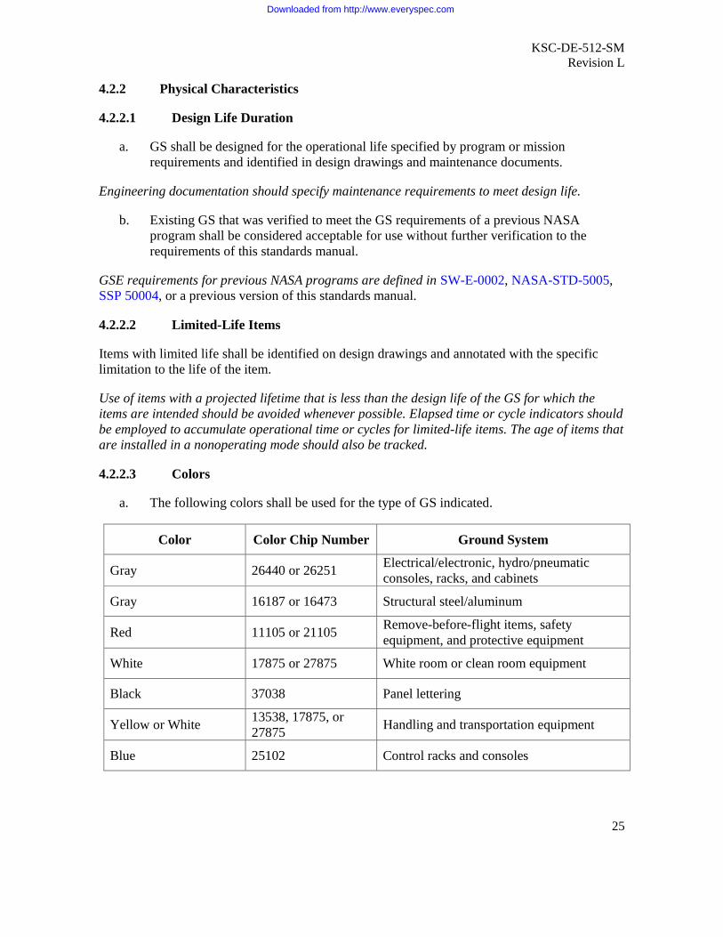
a. The following colors shall be used for the type of GS indicated.
Color Color Chip Number Ground System
Gray 26440 or 26251Electrical/electronic, hydro/pneumaticconsoles, racks, and cabinets
Gray 16187 or 16473 Structural steel/aluminum
Red 11105 or 21105Remove-before-flight items, safetyequipment, and protective equipment
White 17875 or 27875 White room or clean room equipment
Black 37038 Panel lettering
Yellow or White13538, 17875, or27875
Handling and transportation equipment
Blue 25102 Control racks and consoles
Downloaded from http://www.everyspec.com

KSC-DE-512-SMRevision L
26
Color Color Chip Number Ground System
YellowBrown Band (optional)
13655 (yellow)10080 (brown)
Connections and interfaces for hypergolicfuel servicing (see KSC-STD-SF-0004 forcolor coding of piping systems)
GreenBrown Band (optional)
14110 (green)10080 (brown)
Connections and interfaces for hypergolicoxidizer servicing (see KSC-STD-SF-0004for color coding of piping systems)
b. Colors shall be in accordance with FED-STD-595.
These colors apply to GS designed and painted for NASA/KSC. If the equipment is COTS, thesecolors should be used as guidance to make equipment consistent with other GS.
4.2.3 Reliability
GS should be designed to minimize the probability of system failure and reduce the severity ofthe failure effect of the system, including failures caused by operator errors and human-systeminteraction. Procedures and instructions to perform and document analyses (such as FailureMode and Effects Analysis [FMEA]/Critical Items List [CIL] or sneak circuit analysis), will bein accordance with KNPR 8720.2.
4.2.3.1 Redundancy
a. Redundant systems, subsystems, or components shall be physically oriented orseparated such that the failure of one will not prevent the other from performing itsintended function.
b. Redundant systems, subsystems, or components shall be designed such that common-cause failures (e.g., contamination) do not eliminate redundancy.
c. The design of redundant systems shall provide methods for verifying each redundantelement without compromising the reliability of the redundant system.
4.2.3.2 Failure Tolerance
a. GS, except primary structure and pressure vessels/piping/tubing in rupture mode, shallbe designed to sustain a failure without causing loss of life or damage to supportequipment, facilities, or flight hardware (fail-safe).
Failure tolerance is not possible for primary structure and pressure vessels/tubing in rupturemode. Safety of these systems is achieved by application of design requirements contained in thisstandards manual.
More stringent fault tolerance requirements (e.g., two-fault tolerant for loss of flight crew) maybe applicable depending on program requirements. GS should be designed such that no singlefailure/inadvertent operator action results in injury or in damage to or loss of ground equipment,
Downloaded from http://www.everyspec.com

KSC-DE-512-SMRevision L
27
flight equipment, or facilities. Failure modes/inadvertent operator actions are controlled using asystematic application of approved standards and design margins.
GS may be designed to terminate operations autonomously after the first failure or inadvertentoperator action and in time to preclude any scenario that results in loss of life. This approach isconsistent with the historical use of the term “fail-safe” in GS design.
b. GS shall be designed to sustain a failure and still perform its basic function (fail-operational) when necessary to meet safety or operational requirements.
Purges, ground special power, and launch release systems are examples of systems that interfacewith other systems whose loss would propagate failures. Requirements for availability of systemfunctions during launch processing may necessitate fail-operational design.
c. GS failure modes/inadvertent operator actions with the potential for loss of flight crewshall be addressed in accordance with NPR 8705.2.
4.2.3.3 Failure Propagation
GS shall be designed such that failures will not be propagated to the flight systems.
The design of GS should consider how flight hardware/software failures could propagatethrough the GS and affect other flight systems (vent systems, etc.).
4.2.3.4 System Safety and Reliability Analysis
a. A criticality assessment shall be performed early in the design phase to determine theneed for performing a reliability and/or safety analysis.
The criticality of a system failure mode will be assigned on the basis of worst-case crediblefailure effect, assuming the loss of all redundancy (where applicable). This will include possiblecatastrophic or critical effects of system failure, including the effects of loss of hardwarefunctions.
b. System inputs (including dependencies such as electrical power and pneumatic purges)and outputs (including all control and monitoring functions) that could fail withpotentially catastrophic or critical consequences shall be identified as reliability critical(FMEA is required).
System inputs and outputs can be obtained from a system requirements document if available.
c. Systems with hazards to personnel or equipment during normal or credible usescenarios shall be identified as critical (Hazard Analysis is required).
In addition, information obtained from criticality assessments is often used in determining how asystem will be designed, documented, fabricated, assembled, installed, and tested.
Downloaded from http://www.everyspec.com

KSC-DE-512-SMRevision L
28
Table 1. Criticality Categories
Criticality Criticality Definition
1 Single failure that could result in loss of life or vehicle.
1R Redundant hardware item, which if all failed, could cause loss of life or vehicle.
1S Single failure in a safety or hazard monitoring system that could cause thesystem to fail to detect, combat, or operate when needed during the existence ofa hazardous condition and could result in loss of life or vehicle.
2 Single failure that could result in loss of mission, damage to a vehicle system,or major damage to a significant ground asset.
2R Redundant hardware item, which if all failed, could cause a loss of mission,damage to a vehicle system, or major damage to a significant ground asset.
3 All other failures.
Guidelines in Determining Criticality
In determining the criticality of a subsystem, emergency systems or contingency andemergency operations (e.g., fire suppression, crew escape, and abort) will not beconsidered as a level of redundancy.
The criticality assignment for an item whose failure affects the loading or pressure onprimary structure, thermal protection, or pressure vessels will be based on the worst-casepotential effect of exceeding the maximum load that the structure can withstand withoutdeformation, rupture, or collapse.
In determining the classification of criticality categories, it will be assumed thatpersonnel actions will be performed to activate standby redundant items, as long asrequirements for detectability and time to effect are met. Manual standby redundancymust be activated by a trained operator in accordance with a preapproved writtenprocedure.
d. An FMEA shall be performed in accordance with program-defined methodology on thosesystems and subsystems identified by the criticality analysis as having the potential tocause a criticality 1, 1S, 1R, or 2 condition. Based on the results of the FMEA,components having failure modes that could cause an undesirable event (other thancriticality 3) shall be identified, categorized, and approved in accordance with theapplicable agency, program, or KSC requirements. In the absence of a programrequirement, the methodology of KNPR 8700.2 shall be used.
All components other than criticality 3 are included in a CIL report, where they are reviewed forcriteria such as qualification, failure history, tests, and verifications that will justify the design.
Downloaded from http://www.everyspec.com

KSC-DE-512-SMRevision L
29
e. The criticality categories shown in Table 1 shall be used when the program does notidentify categories.
f. Static components, such as pressure vessels, pressure lines, cables, connectors, andwiring, shall be considered only if failure can be attributed to an active componentfailure.
Analysis ground rules and exceptions to program methodology or related to the scope of analysisshould be clearly stated with justification.
g. A Hazard Analysis shall be performed on those systems and subsystems determined bythe criticality assessment to be a potential threat to flight systems, ground systems, orsafety.
h. Based on the results of the Hazard Analysis, those hazards that could not be eliminatedby design or mitigated to an acceptable level shall require a Hazard Report.
The Hazard Report summarizes all controls and verifications that would be used to mitigate thehazard. As with the FMEA, Hazard Analyses are performed and Hazard Reports are written inaccordance with the applicable program requirements. In the absence of a programrequirement, the methodology of KNRP 8700.2 applies.
i. FMEA and/or Hazard Analysis including the results of the analysis shall be combinedinto a Systems Assurance Analysis (SAA) to summarize the risks resulting from eachsystem/subsystem analysis.
j. CIL and Hazard Reports shall be approved and maintained as part of the designdocumentation.
4.2.4 Environmental Conditions
GS shall be designed to perform in the natural and induced environments to which it will besubjected during its life cycle.
4.2.4.1 Natural Environment
GS used or stored in an uncontrolled exterior environment shall be designed to function afterexposure to the natural environment at its respective geographical location as specified inNASA-HDBK-1001.
Specifications in NASA-HDBK-1001 may be tailored to reflect program-defined risk andexposure times, including operation within the launch commit criteria of the vehicle. Purging ofenclosures to protect GS components from the natural environment should be consideredessential, in addition to purging of enclosures in hazardous areas as required in 5.4.17.
Downloaded from http://www.everyspec.com
KSC-DE-512-SMRevision L
30
4.2.4.2 Launch-Induced Environment
a. GS required to function during or after exposure to the launch-induced environmentshall be designed to withstand the environment defined in program-specific documents.
b. Testing of GS for launch-induced environment shall be applied in accordance withKSC-STD-164.
4.2.4.2.1 Launch-Induced Damage
GS not required to function after exposure to the launch-induced environment shall not causedamage or create a hazard to flight hardware, facilities, other GS, personnel, or the environment.
4.2.4.3 Controlled Interior Environment
GS designed to function within a controlled interior environment shall be designed to thefollowing temperature and humidity requirements:
a. Temperature: +15 °C (60 °F) to +27 °C (80 °F) and within the extremes of +11 °C(52 °F) to +40 °C (104 °F) for a maximum of 1 hour.
b. Humidity: nominal 55%, within a range of 30% to 70%.
4.2.4.4 Controlled Clean Environment
a. GS shall be designed to meet the program/project contamination control requirements.
b. Clean rooms and associated controlled environments designated as GS shall bedesigned in accordance with ASTM E2217.
4.2.4.5 Uncontrolled Interior Environment
GS used in an uncontrolled interior environment shall be designed to meet the most severeexterior environmental conditions for humidity and temperature expected at the respectivegeographical locations, as defined in NASA-HDBK-1001.
Some uncontrolled interior environments can exceed the most severe exterior environment,e.g., an enclosed trailer in a hot (tropical or desert) exterior environment.
4.2.4.6 Fire/Explosion Hazardproofing
If GS will be operated in locations where fire or explosion hazards exist, as defined by NFPA 70,Article 500, it shall be hazardproofed in accordance with the requirements in KSC-STD-E-0002.
4.2.4.7 Environmental Test Methods
Environmental methods and conditions required for testing and qualification of GS componentsshall be in accordance with MIL-STD-810 and KSC-STD-164.
Downloaded from http://www.everyspec.com

KSC-DE-512-SMRevision L
31
4.2.4.8 Seismic Environment
GS used in Zones 3 or 4 as defined in NASA-HDBK-1001 shall be designed to resist the effectsof a seismic event using the criteria and guidelines in ASCE-7.
4.3 Documentation
Documentation in Appendix B should be released and made available to the user.
4.3.1 Drawings and Specifications
Drawings and specifications required for the fabrication, construction, installation, modification,test, operation, maintenance, sustaining, and use of GS shall be prepared in accordance withdrawing practices equal to or more stringent than the engineering drawing practices ofASME Y14.100 and KSC-GP-435, Vol. I.
4.3.2 Technical Documentation
Technical documentation (e.g., manuals and reports) shall be prepared in accordance withKSC-DF-107.
4.4 Logistics
GS design documentation shall identify spare parts, components, materials, and items necessaryto support construction, fabrication, installation, activation, test, verification, and operation.
4.4.1 Limited-Life Item Tracking
a. Limited-life items shall be controlled from the date of their manufacture through theirperiod of operational use, including the time they are in storage.
b. The status of limited-life items shall be documented.
c. GS design documentation shall identify limited-life items and provide instructions forreplacement of those parts, components, and materials.
4.5 Qualification
All components used in critical GS shall undergo qualification to verify performance in theirintended environment in accordance with KSC-STD-G-0003.
Qualification of components is guided by NPD 8730.2.
4.6 Quality Assurance
Quality assurance is the function that verifies the compliance of hardware and software tospecified requirements. Quality assurance includes quality engineering and quality inspection.KSC minimum requirements and best practices are given in KNPR 8730.2.
Downloaded from http://www.everyspec.com

KSC-DE-512-SMRevision L
32
4.6.1 General
GS design shall incorporate quality requirements in accordance with the program’s/project’sS&MA Plan.
Quality assurance best practices for applying program requirements at KSC are given inKSC-NE-9439, Section 5.4.
4.6.1.1 Definition of Quality Requirements
Quality requirements shall be defined on the engineering drawings or in other technicaldocuments that are included in the design, fabrication, or installation contract.
The design documentation should include special quality-related requirements, such as anyspecial processes, certification of personnel or special testing that should be conducted, and anyother special requirements that are necessary to produce a quality product.
4.6.1.2 Personnel Training
Certification documentation for required training of personnel performing processes duringfabrication, assembly, installation, and testing of GS shall be maintained in accordance withKNPR 8730.2.
4.6.2 Testing
a. Testing requirements shall be specified in engineering documentation.
b. Testing shall verify compliance with the applicable specifications and the ability of theGS to perform its required design functions.
c. Test documentation, data, and results shall be produced, maintained, and archived inaccordance with KNPR 8730.2 and program or project requirements.
4.6.2.1 Load Test
a. A load test shall be performed on all structural GSE (access platforms, workstands,etc.) and moveable or articulating GS structures except when the load test creates anunsafe condition or when analysis shows the load test will result in damage to thestructure.
Load testing of fixed GS structures may be accomplished using a representative section of thestructure.
b. The minimum test load shall be 125% of the design or working load for GS not usedfor lifting.
c. Lifting devices and equipment shall be proofload tested in accordance withNASA-STD-8719.9.
Downloaded from http://www.everyspec.com

KSC-DE-512-SMRevision L
33
d. In the absence of design analysis, a load test of 8 times the safe working load shallsatisfy the factor of safety requirements of this standards manual.
This load test is to eliminate the need for structural analysis. The 8-to-1 load test screens outflaws that could propagate to failure in a structure used at or below the design load. This optionshould only be used for ductile materials.
4.6.2.2 Nondestructive Evaluation (NDE)
NDE for components and materials shall be in accordance with 6.4.15.
4.6.2.3 Metrology and Calibration
Metrology and calibration of all test equipment and tools used in support of fabrication,assembly, installation, and test of GS shall be in accordance with KNPR 8730.1.
4.6.3 Quality Conformance Verification
Documentation shall be provided by the design organization to verify compliance with thisstandard in accordance with the program/project verification plan (see Appendix B).
Test, analysis, demonstration, and inspection (including similarity) are recommended methods toverify that each requirement of Sections 4 and 5 of this standard has been satisfied.
4.7 Packaging, Handling, and Transportation
Requirements for packaging, transporting, shipping, and handling shall be in accordance withNPR 6000.1.
GS should be designed so it can be transported by ground, air, or sea, using commerciallyavailable methods.
4.7.1 Shipping and Storage Containers
a. Containers shall be compatible with onsite transportation, handling, and storagemethods.
b. Container attachment points shall be provided for crane hoists and tie-downs.
c. Containers shall be designed so that indicators that require monitoring (e.g., desiccants,humidity monitors, shock meters, and tilt meters) can be monitored without opening theshipping container.
d. Containers shall be marked in accordance with NPR 6000.1 so that contents can beidentified without opening the container.
Containers having a gross weight of more than 65 kilograms (144 pounds) should be providedwith integral skids or pallets for shipment.
Downloaded from http://www.everyspec.com

KSC-DE-512-SMRevision L
34
4.7.2 Parts Protection
a. Procedures shall be employed to protect parts during manufacturing and in-planthandling and storage.
Any procedures, methods, materials, and devices (such as carts, boxes, containers, ortransportation vehicles) that are used to protect parts should be standardized to prevent damageto hardware.
b. Precision-cleaned parts shall be packaged in accordance with NPR 6000.1 and programcontamination control requirements.
5. DESIGN AND CONSTRUCTION REQUIREMENTS
5.1 Structural Design
5.1.1 GS Structures and Equipment
5.1.1.1 Steel Structures
a. The design of conventional steel structures shall be in accordance with AISC 325.
b. The design of nonconventional steel structures shall be in accordance with establisheddesign practices using the safety factors in 5.1.2.
Nonconventional steel structures may be designed using provisions of AISC 325, provided thatthe factors of safety are adjusted to be consistent with 5.1.2.
c. High-strength carbon steel fasteners such as ASTM A490 and SAE Grade 8 shall not beused in a corrosive environment.
Galvanizing and other zinc coatings may cause hydrogen embrittlement in high-strength carbonsteel fasteners that is difficult to detect. When possible, ASTM A325 or SAE Grade 5 fastenersshould be used instead.
5.1.1.2 Aluminum Structures
a. The design of conventional aluminum structures shall be in accordance with ADM.
b. The design of nonconventional aluminum structures shall be in accordance withestablished design practices using the safety factors in 5.1.2.
Nonconventional aluminum structures may be designed using provisions of ADM, provided thatthe factors of safety are adjusted to be consistent with 5.1.2.
5.1.2 Safety Factor
a. The safety factor shall not be used to justify exceeding the safe working load.
Downloaded from http://www.everyspec.com

KSC-DE-512-SMRevision L
35
b. The following minimum safety factors shall be used for support structures (excludinglifting devices, pressure vessels, threaded fasteners, and springs) when not otherwisespecified.
(1) GS structures shall be designed to a minimum safety factor of 2 againstdeformation or yielding that impairs the function of the part and a minimumsafety factor of 3 against collapsing, buckling, exceeding the ultimate load, orfailing to support the design load.
(2) For brittle metals (less than 5% elongation-to-failure), excluding castings, thefactor of safety shall be 5 against exceeding the ultimate tensile strength (UTS).
(3) For metal castings, the factor of safety shall be 10 against exceeding the UTS.
(4) For ductile-matrix composites with test data, the factor of safety shall be 5against exceeding the UTS; in the absence of test data, the factor of safety shallbe 10.
(5) For brittle-matrix composites, the factor of safety shall be 10 against exceedingthe UTS.
Due to the nature of their design, springs do not meet the factors of safety specified for otherengineering applications and should be designed in accordance with the Handbook of SpringDesign from the Spring Manufacturers Institute.
5.1.2.1 Safety Factor for Cyclic Loading
Structures exposed to cyclic loads shall be designed for a minimum safety factor of 4 against thedesign life.
The ratio of fatigue life to design life is 4 as a minimum. The designer/analyst has theresponsibility to determine when cyclic loads are significant in the design. The relationshipbetween stress/strength and fatigue life is highly nonlinear. Applying the safety factor to life isthe established engineering method to handle this nonlinearity. The structure is designed towithstand four times the number of load cycles expected during the design life.
5.1.3 Structural Design Loads
Structural design loads shall be specified in the design documentation.
The design should consider loads created by the assembly, lifting, handling, transportation,operations, wind conditions, launch-induced environments, and seismic events. For torque loadson threaded fasteners, see 5.2.9.
Downloaded from http://www.everyspec.com
KSC-DE-512-SMRevision L
36
5.2 Mechanical Design
5.2.1 Pneumatics
The design of GS used for pneumatic servicing shall be in accordance with KSC-STD-Z-0005.
Media includes but is not limited to nitrogen, helium, hydrogen, oxygen, methane, breathing air,and special mixtures of these gases.
5.2.1.1 Breathing-Air Systems
a. Breathing-air respirator systems shall conform to 29 CFR 1910.
b. Breathing-air storage and distribution systems shall be designed in accordance withKSC-STD-Z-0008.
5.2.1.2 Vacuum and Compressed-Air Systems
a. Vacuum systems shall be designed in accordance with ASME B31.9.
b. Compressed-air systems having an operating gage pressure up to 1.0 megapascals(MPa) (150 pounds per square inch [psi]) shall be designed in accordance withASME B31.9.
c. Compressed-air systems above 1.0 MPa (150 psi) shall be designed in accordance withASME B31.3 and KSC-STD-Z-0005.
ASME B31.1 meets or exceeds the requirements of ASME B31.3 and may be used as analternative.
5.2.2 Cryogenics
a. The design of GS used for cryogenic servicing with liquid hydrogen, liquid oxygen,and liquid nitrogen shall be in accordance with KSC-STD-Z-0009.
b. The design of GS used for cryogenic servicing with liquid methane shall be inaccordance with NFPA 59A.
The design of GS used for cryogenic servicing with liquid helium and cryogenic fluids should useKSC-STD-Z-0009 as a guide.
5.2.3 Hypergols
The design of GS used for hypergolic-fuel or oxidizer servicing with monomethylhydrazine(MMH), unsymmetrical dimethylhydrazine (UDMH), nitrogen tetroxide (N2O4), aerozine 50(A-50), or hydrazine (N2H4) shall be in accordance with KSC-STD-Z-0006.
Downloaded from http://www.everyspec.com

KSC-DE-512-SMRevision L
37
Hypergolic propellants are fuels and oxidizers or fuels and catalysts that, when combined,produce a violent, explosive, high-energy exothermic reaction, without any other ignition source.Hypergolic propellants are highly toxic, are very sensitive to material selection for containmentor sealing, and require the use of personal protective equipment (PPE) for operators of GS.
5.2.4 Hydrocarbons
The design of GS used for servicing with hydrocarbon fuels (JP-4, JP-5, RP-1, and ASTM jetfuels A and B) shall be in accordance with ASME B31.3.
ASME B31.1 meets or exceeds the requirements of ASME B31.3 and may be used as analternative.
5.2.5 Hydraulics
The design of GS used for servicing hydraulic systems shall be in accordance with ASME B31.3and with KSC-STD-Z-0005.
ASME B31.1 meets or exceeds the requirements of ASME B31.3 and may be used as analternative.
5.2.6 Environmental Control Systems (ECSs) and Environmental Control and LifeSupport Systems (ECLSSs)
a. The design of GS used for an ECS or ECLSS shall be in accordance withKSC-STD-Z-0010.
b. The design of ducting shall be in accordance with ASME B31.3 or SMACNA 1958.
ASME B31.1, Power Piping, meets or exceeds the requirements of ASME B31.3 and may be usedas an alternative.
5.2.7 Life Support
The design of GS used for life support systems shall be in accordance with KSC-STD-Z-0008.
GS intended for use by operators wearing propellant handler’s ensembles (PHEs) should bedesigned to meet the following criteria:
a. Items (valves, gages, levers, bolts, nuts, and any other items required to be moved,turned, manipulated, or monitored) should be located in a position that will make iteasier for a PHE-suited operator to access the item while standing.
b. Sufficient clearance should be provided to preclude the operator from brushing againstother surfaces.
Downloaded from http://www.everyspec.com

KSC-DE-512-SMRevision L
38
c. GS should be designed to avoid requirements for PHE-suited operators to reach intotight areas; stoop to avoid low overhead obstructions; mount supplementary ladders orstairs; touch rough surfaces; or sit, kneel, or lie on the floors or decks.
d. The design should include suitable provisions to prevent discomfort or fatigue for thePHE-suited personnel.
e. Use of expanded metal surfaces and other sharp edges should be avoided.
5.2.8 Lifting Devices
The design and certification of lifting devices (cranes, crane girders, hoists, lifting slings, jacks,etc.) shall be in accordance with NASA-STD-8719.9.
5.2.9 Torque for Threaded Fasteners
a. The combined stress from all applied loads (plus an uncertainty factor), including thepreload, shear, tension, and bending stress, shall not exceed the yield strength of thefastener material.
b. The torque limit for threaded fasteners that are less than or equal to 32 millimeters(mm) (1 1/4 inches) in diameter shall be in accordance with MSFC-STD-486 or thealternative limit identified on the drawing.
c. Threaded fasteners greater than 32 mm (1 1/4 inches) in diameter shall be designed fora maximum torque that results in a preload of 70% of the yield stress on the net crosssection.
d. The criteria for torquing structural bolts, such as specified in ASTM A325 andASTM A490 shall be in accordance with AISC 325.
ASTM A490 structural bolts should be avoided in a corrosive environment. Galvanizing andother zinc coatings may cause hydrogen embrittlement that is difficult to detect. When possible,ASTM A325 bolts should be used instead.
e. Torquing criteria shall be documented on the fabrication, assembly, or installationdrawing.
For nonstructural applications where a specific clamping force is not required, the designer mayspecify that fasteners be installed snug tight (tighten the fastener with standard tools, usingordinary force, until the assembly layers come into firm contact, determined visually and byfeel).
Downloaded from http://www.everyspec.com

KSC-DE-512-SMRevision L
39
5.2.10 Tethering Provisions
a. GS components that require temporary removal/installation during operations, such asquick-release pins and quick-disconnect (QD) caps, shall be tethered to or otherwiseheld captive by the equipment for which they are used.
b. GS intended for use near flight hardware or elevated above personnel or flighthardware shall be designed and constructed with provisions for tethering.
c. Quick-release pins and pin tethers shall be in accordance with KSC-STD-P-0006.
5.2.11 Jacks
The design of jacks shall be in accordance with ASME B30.1.
5.2.12 Transportation Equipment
GS used for transporting flight hardware shall be designed in accordance with SAE ARP 1247.
5.2.12.1 Towed GS
Towed GS shall be designed in accordance with SAE AS 8090.
5.2.12.2 Transportation Equipment Interface Loads
Transportation equipment shall be designed so that loads imparted to flight hardware do notexceed 80% of the flight limit loads.
Transportation loads should be evaluated early in the design cycle since they may be thegoverning design load case.
5.2.13 Pressure Vessels
a. Metallic pressure vessels for use in GS shall be designed, constructed, tested, andstamped in accordance with ASME BPVC-VIII, Division 1, 2, or 3.
Shops and welders repairing or altering code vessels require R stamp certification. For noncodevessels, R stamp certification is not required but is good practice.
b. Composite Overwrapped Pressure Vessels (COPVs) for use in GS shall be designed,constructed, tested, and marked in accordance with ASME BPVC-X.
COPVs should be used only when necessary because of weight constraints. Special training andcertification are required for personnel handling and repairing COPVs. Damage to COPVs canbe difficult to detect because reliable NDE methods have not been developed. COPV failuremodes can be catastrophic, requiring special safety clears during pressurization.
Downloaded from http://www.everyspec.com

KSC-DE-512-SMRevision L
40
5.2.13.1 Code-Stamped Vessel Registration
All ASME code-stamped vessels shall be registered with the National Board of Boiler andPressure Vessel Inspectors.
5.2.13.2 Pressure Vessels Used in Transporting Commodities
Pressure vessels used for transporting hazardous commodities shall meet the Department ofTransportation requirements in 49 CFR 171 through 180.
5.2.14 Piping Systems
Piping and support systems, except those in remote or “cross country” areas or where personneltraffic is low, shall be in accordance with ASME B31.3 the piping system may be designed toASME B31.8.
Examples include piping between facilities in low-traffic areas, buried pipelines, and long-runpiping between remote facilities. Where ASME B31.3 piping connects to ASME B31.8 pipinge.g., at facility interfaces), the design should consider the differences in internal diameters andhow the piping will be cleaned (via pipeline cleaning pigs). ASME B31.1 meets or exceeds therequirements of ASME B31.3 and may be used as an alternative.
5.2.15 Pressure Vessel/System Certification
The design of pressure systems, including pressure vessels, transmission lines, and GS, shallcomply with KNPR 8715.3, Section 13, which complies with NASA-STD-8719.17.
5.2.16 Ground-to-Flight-Vehicle Umbilical Systems
Reusable umbilicals shall be designed in accordance with KSC-GP-986.
5.3 Electrical/Electronic Design
5.3.1 Electrical Control and Monitor Equipment
The design of GS for electrical control and monitoring shall be in accordance withKSC-STD-E-0001.
AFSPCMAN 91-710 and MIL-HDBK-454 should be consulted for general guidance inelectrical/electronic design.
5.3.2 Electrical Design of Pneumatic and Hydraulic Components
The electrical design of pneumatic and hydraulic components shall be in accordance withKSC-STD-E-0004.
Downloaded from http://www.everyspec.com
KSC-DE-512-SMRevision L
41
5.3.3 Pyrotechnic Systems
The design of pyrotechnic GS shall be in accordance with NASA-STD-8719.12.
5.3.4 Electrical Power Systems
The design of electrical power systems covered by NFPA 70 shall be in accordance withNFPA 70 and NFPA 70E.
Incorporation of batteries in the design of GS should follow the recommended practices in thefollowing documents: IEEE 484, IEEE 1106, IEEE 1187, IEEE 446, ANSI C18.2M, Part 1, andANSI C18.3M, Part 1.
5.3.5 Bonding and Grounding
a. Bonding and grounding shall be provided in accordance with NFPA 70 andNASA-STD-4003.
b. GS shall be designed in accordance with KSC-STD-E-0012, KSC-E-165, andMIL-STD-464.
The designer should be aware whether the system being designed will be operated under alightning protection system or where induced static electricity is possible. For additionalinformation on lightning protection, refer to International Electrotechnical Commissionstandard IEC 62305, Parts 1 through 4.
5.3.6 Hazardproofing
The design of electronic equipment and wiring for all voltages in hazardous locations shall be inaccordance with NFPA 70, Article 500; and KSC-STD-E-0002.
5.3.7 Software
Software incorporated into the design of GS shall meet the requirements of NPR 7150.2.
This ensures that KSC-developed software meets the Agency requirements for softwareengineering practices, software assurance, and software safety. NPR 7150.2 contains provisionsapplicable to COTS software in NASA-developed systems.
5.3.8 Firmware
Firmware incorporated in the design of GS shall meet the requirements of NPR 7150.2.
5.4 Parts
5.4.1 Electrical, Electronic, and Electromechanical (EEE) Parts
EEE parts shall be selected in accordance with KNPR 8720.2.
Downloaded from http://www.everyspec.com

KSC-DE-512-SMRevision L
42
EEE parts may be selected using AIAA R-100 or NASA/TP-2003-212242.
5.4.1.1 Electrostatic-Discharge (ESD)-Sensitive Components and Assemblies
All ESD-sensitive components and assemblies shall be handled using practices in accordancewith ESD S20.20, MIL-STD-1686, and MIL-HDBK-263.
Insulator materials should not be used near ESD-sensitive components or assemblies.
5.4.2 Stainless-Steel Tubing
a. Austenitic stainless-steel tubing shall be in accordance with KSC-SPEC-Z-0007.
b. Stainless-steel tubing shall be fabricated, tested, and installed in accordance withKSC-SPEC-Z-0008.
5.4.2.1 Superaustenitic Stainless-Steel Tubing
a. When directly exposed to a corrosive environment, tubing shall consist of UnifiedNumbering System (UNS) N08367 or S31245 superaustenitic stainless steel (tradename AL6XN or 254SMO) in accordance with KSC-SPEC-P-0027.
b. Superaustenitic stainless-steel tubing shall be fabricated, tested, and installed inaccordance with KSC-SPEC-Z-0008.
5.4.3 Pipe
Stainless-steel pipe for fluid systems shall be in accordance with ASTM A312.
5.4.3.1 Aluminum Pipe
Aluminum pipe for fluid systems shall be in accordance with ASTM B241.
5.4.3.2 Expansion Joints
Expansion joints used in fluid systems in marine or launch-induced environments shall be madefrom UNS N06022 (Hastelloy C22) material.
5.4.4 Metallic Fittings
Flared tubing fittings, tube weld fittings, and pipe fittings shall be selected in accordance withKSC-GP-425.
5.4.5 Fluid System Protective Covers
Protective covers shall be provided for all hoses, ports, fittings, and other fluid-fittingconnections to GS to protect the threads, protect the sealing surface, and maintain the cleanliness
Downloaded from http://www.everyspec.com

KSC-DE-512-SMRevision L
43
of the system. Prior to installation, protective caps, plugs, and covers shall be maintained clean atthe same level or better than the system that they are protecting.
Caution should be used in selecting caps and plugs as covers due to the potential for generatingdebris during installation or removal, especially in oxygen systems. When possible, theprotective cover should be connected with a lanyard or the equipment should have a designatedstorage provision. Caps and plugs should be selected in accordance with KSC-C-123.
5.4.6 Fluid System Components
Fluid system components used in the design of liquid or gas systems shall be selected from the79K80000 series of specifications, unless the required part is not covered by this series.
5.4.6.1 Fluid System Component Acceptance Criteria
If a part is not covered by the 79K80000 series of specifications, it shall be documented with thefollowing minimum information: commodity, environment, performance, installed dimensions,connection interfaces, recommended vendor, materials, compatibility, qualification/acceptancecriteria, and recommended maintenance.
5.4.7 Electrical-Power Receptacles and Plugs
a. Alternating-current (AC) electrical-power receptacles and plugs that supply power toGS shall be in accordance with KSC-STD-E-0011.
b. Electrical-power receptacles and plugs within GS shall be in accordance withKSC-GP-864.
5.4.8 Electrical-Power Cable
Power cables shall be in accordance with NFPA 70.
5.4.9 Electrical Cable and Harnesses
Flexible, multiconductor, jacketed electrical cable and cable harnesses shall be in accordancewith KSC-GP-864.
5.4.10 Fiber Optics
a. Fiber-optic cable assemblies, installations, and terminations shall be in accordance withNASA-STD-8739.5 and KSC-GP-864.
b. Protective caps shall be provided for all fiber-optic connections to GS so that themating surface is protected.
Downloaded from http://www.everyspec.com

KSC-DE-512-SMRevision L
44
5.4.11 Electrical Hookup Wire
Electrical hookup wire shall be in accordance with SAE AS 50861, MIL-DTL-16878, orSAE AS 22759.
5.4.12 Connectors
a. Electrical multiconductor connectors for GS used for electrical control and monitoringshall be selected from the following documents: SAE AS 50151, MIL-DTL-22992,MIL-DTL-24308, MIL-DTL-38999, IEC 60807, or KSC-GP-864.
MIL-DTL-5015 was replaced with SAE AS 50151.
b. When multiconductor connectors must be used in hazardous locations, they shall bewaterproof and used with threaded connectors.
5.4.13 Coaxial Radio Frequency (RF) Connectors
Coaxial RF connectors shall be selected from MIL-PRF-39012.
5.4.14 Protective Covers or Caps for Electrical Connectors
Protective covers or caps shall be specified for use with electrical-connector plugs andreceptacles in accordance with KSC-GP-864 when they are not connected.
Metallic protection caps should be used during transportation or other potentially damaginghandling situations.
Protective covers or caps should
protect against moisture intrusion,
protect sealing surfaces, threads, and pins against damage,
resist abrasion, chipping, and flaking,
comply with cleanliness requirements for the plugs and receptacles on which they areused,
consist of material that is compatible with the connector materials,
connect to the cable with a suitable lanyard, chain, or hinge, and
not produce static.
5.4.15 Optical Covers or Caps
Covers/caps shall be provided to protect optics.
Downloaded from http://www.everyspec.com

KSC-DE-512-SMRevision L
45
Optical covers/caps should be easy to install and remove. The covers/caps should be connectedwith a lanyard, or the equipment should have a designated storage provision.
5.4.16 Sensors and Transducers
Sensors and transducers used in the design of GS systems shall be selected using KSC-NE-9187.
Measurement applications that provide visibility only and are not relied upon to control acondition that could potentially damage flight hardware or potentially create a safety hazardmay use COTS components.
5.4.16.1 Sensor and Transducer Acceptance Criteria
If a part is not covered by KSC-NE-9187, it shall be documented with the following minimuminformation included: commodity, environment, performance, recommended vendor, materials,compatibility, and qualification/acceptance criteria.
5.4.17 Purged Electrical Enclosures
Purged electrical enclosures in hazardous locations shall be in accordance with NFPA 496.Purged electrical enclosures in nonhazardous locations shall be outfitted with purge hardware inaccordance with 79K07491.
NFPA 496 contains requirements for the protection of electrical and electronic equipmentrecognized by NFPA 70 for installations in hazardous locations. Hardware required for purgingenclosures (to maintain low relative humidity and positive pressure) should be selected from79K07491.
5.4.18 Racks, Panels, and Modular Enclosures
Electronic racks, panels, and enclosures shall be in accordance with KSC-SPEC-E-0002.
Electronic racks, panels, and modular enclosures should conform to the configuration anddimensional requirements of ECA EIA/ECA 310-E.
5.4.19 Printed Circuit Boards
5.4.19.1 Printed Circuit Board Design
Rigid, flexible, and rigid-flex printed circuit boards (single, double, metal-core, or multilayerstructures) shall meet the design specifications of the following standards, as applicable:IPC-2221 (For critical applications, performance classification 3 shall be used.), IPC-2222,IPC-2223, and IPC-2252.
All board types within the IPC-2221 series standard documents are acceptable.
Downloaded from http://www.everyspec.com

KSC-DE-512-SMRevision L
46
5.4.19.2 Printed Circuit Board Fabrication and Acceptance
Rigid, flexible, and rigid-flex printed circuit boards (single, double, metal-core, or multilayerstructures) shall meet the qualification and performance specifications of the followingstandards, as applicable: IPC-6011, (For critical applications, performance classification 3 shallbe used.), IPC-6012, (For critical applications, performance classification 3 shall be used.),IPC-6013, and IPC-6018.
5.4.19.3 Printed Circuit Assembly Fabrication and Acceptance
a. Printed circuit assemblies that will not be exposed to vibration or thermal cycling atspace flight levels shall be fabricated in accordance with IPC J-STD-001.
NASA-STD-8739.2 and NASA-STD-8739.3 may be used in lieu of IPC J-STD-001.
b. Printed circuit assemblies that will be exposed to vibration or thermal cycling at spaceflight levels shall be fabricated in accordance with IPC J-STD-001ES.
NASA-STD-8739.2 and NASA-STD-8739.3 may be used in lieu of IPC J-STD-001ES.
5.4.20 Electric Motors and Generators
Motors and generators used in GS shall be selected in accordance with the system requirementsfor speed, torque, horsepower, and environment. Motors and generators shall meet the applicableNational Electrical Manufacturers Association (NEMA) standards and NFPA requirements thatgovern the classification and general application of motors and generators.
NEMA MG 1 is a comprehensive document that includes the classification, general standards,manufacturing, and test of motors and generators. This document should be used as a guide forspecification and selection of GS motors and generators. Another reference and guide isNEMA C50.41. NFPA 70 provides the size of wiring and conduit required for the motorconnections.
5.4.20.1 Motor Starters and Controllers
Motor starters and controllers shall be in accordance with the type of motor, performance ratings,and type of control required. Enclosures for motor starters and controllers shall meet theenvironmental requirements for their locations.
NEMA ICS 2, Parts 1 through 9, is a comprehensive document that provides practicalinformation concerning ratings, construction, test, performance, and manufacture of industrialcontrol equipment. NEMA ICS 61800-2 specifies ratings for low-voltage, adjustable-frequencyAC power drive systems. NFPA 70 provides the size of wiring and conduit required for thestarter/controller connections.
Downloaded from http://www.everyspec.com

KSC-DE-512-SMRevision L
47
5.4.21 GS Fasteners
GS fasteners used in critical applications shall have lot traceability from the manufacturer to finalinstallation.
NASA RP-1228 should be used for guidance in selecting and analyzing fasteners.
5.4.21.1 Reuse of Self-Locking Fasteners
a. The reuse of self-locking fasteners shall be permitted when the running torque beforeclamp-up remains between the maximum self-locking torque and the minimum break-away torque.
Self-locking fasteners should be used wherever possible. The use of star lock washers should beavoided.
b. Fasteners used in corrosive environments and applications where condensation canoccur shall be installed using a corrosion-resistant sealant while the sealant is still wet(wet installation).
5.4.21.2 Liquid-Locking Compounds
When liquid-locking compounds are used for fastener installation, engineering drawings shallspecify a validated process for application.
Liquid-locking compounds should be selected in accordance with ASTM D5363.
5.5 Electromagnetic Interference (EMI)
Electrical and electronic systems shall be designed to meet the EMI/electromagnetic-compatibility (EMC) requirements in MIL-STD-461.
The requirements of MIL-STD-461 may be tailored for use on NASA programs as indicated inMIL-STD-461, Sections 1.2, 1.2.1, and 1.2.3. The application of MIL-STD-461 to GS should bebased on an evaluation of the potential for flight hardware interaction and any existingcommercial standards to which the hardware is already certified.
5.6 Identification Markings and Labels
5.6.1 Systems and Equipment
a. GS shall be identified and marked in accordance with KSC-STD-E-0015.
b. When data matrix identification symbols are used to identify GS, they shall be appliedin accordance with NASA-STD-6002.
Downloaded from http://www.everyspec.com
KSC-DE-512-SMRevision L
48
5.6.2 Load Test
GS that have been load-tested shall be identified and marked in accordance with KSC-STD-141,and for lifting equipment, NASA-STD-8719.9.
5.6.3 Piping Systems
Ground piping systems shall be identified and color-coded in accordance withKSC-STD-SF-0004.
5.6.4 Compressed-Gas Cylinders
Compressed-gas cylinders shall be labeled in accordance with CGA C-7.
5.6.5 Load Capacity
GS used for transportation, handling, and personnel access shall be conspicuously marked toindicate the maximum safe working load in accordance with KSC-STD-E-0015, and for liftingequipment, NASA-STD-8719.9.
5.6.6 Electrical-Cable and Harness Assemblies
a. Electrical cable and harness assemblies shall be identified at each end of the cableand/or harness and labeled to show the assembly part number, cable or harnessreference designation number, and cable or harness end marking, in accordance withthe requirements provided on the cable assembly drawing and described in120E3100003.
b. Labels for cable assemblies shall comply with KSC-E-166.
c. Labels shall meet the requirements of KSC-STD-E-0015.
d. Labels for wire harnesses shall comply with KSC-E-166.
e. Labels shall be of heat-shrinkable sleeving that conforms to the requirements ofSAE AMS-DTL-23053/5, Class 1.
f. The heat-shrink labels shall be marked in accordance with SAE AS 5942 and shall meetthe testing requirements of MIL-STD-202, Method 215.
MIL-DTL-23053/5 was replaced by SAE AMS-DTL-23053/5. MIL-M-81531 was replaced bySAE AS 5942.
5.6.7 Serial Numbers
Serial numbers or other unique identifiers shall be marked on those parts, components, orassemblies that contain limited-life items (e.g., valves or regulators) or that require periodic
Downloaded from http://www.everyspec.com

KSC-DE-512-SMRevision L
49
inspection, checkout, repair, maintenance, servicing, or calibration (e.g., pressure transducers orgages).
Other unique identifiers include A-numbers and drawing dash numbers for end items.
5.7 Interchangeability
Hardware assemblies, components, and parts with the same part number shall be physically andfunctionally interchangeable.
5.8 Safety
All GS shall be designed and fabricated in accordance with 29 CFR 1910, 29 CFR 1926, andNPR 8715.3.
5.8.1 Hazard Analysis
A hazard analysis shall be conducted in accordance with program-defined methodology as partof the GS design process to identify, mitigate, and control hazards. In the absence of a program-defined methodology, KNPR 8700.2 shall be used.
5.8.2 Safety Requirements on KSC Property
GS to be used at KSC shall meet the safety requirements of KNPR 8715.3.
5.8.3 Safety Requirements on Air Force Property
GS to be used on Air Force property shall meet the requirements of AFSPCMAN 91-710,Volume 3.
5.8.4 Safety Requirements on Other NASA Property
GS to be used at other NASA facilities shall meet the safety requirements of those facilities.
5.8.5 Caution and Warning Indications
GS shall provide caution and warning indications to alert personnel of impending or existinghazards.
GS should be designed to allow efficient implementation of the applicable Occupational Safetyand Health Administration (OSHA) lockout/tagout requirements.
5.9 Human Factors
a. HF-STD-001 shall be used to establish human factors criteria for GS design.
b. GS shall comply with 29 CFR 1910.
Downloaded from http://www.everyspec.com

KSC-DE-512-SMRevision L
50
5.10 Security of Information Technology (IT)
The design of GS shall meet the IT security requirements in NPR 2810.1.
6. MATERIALS AND PROCESSES REQUIREMENTS
M&P used in the design and fabrication of GS shall be selected by considering the worst-caseoperational requirements for the particular application and the design engineering properties ofthe candidate materials.
For example, the operational requirements should consider operational temperature limits,loads, contamination, life expectancy, exposure to moisture or other fluids, corrosiveenvironments, and launch-induced and natural environments. Properties that should beconsidered in material selection include mechanical properties, fracture toughness, flammabilityand offgassing characteristics, corrosion and stress corrosion resistance, thermal- andmechanical-fatigue properties, glass-transition temperature, mismatches between coefficients ofthermal expansion, vacuum outgassing, fluid compatibility, microbial resistance, moistureresistance, fretting, galling, and susceptibility to ESD and contamination.
6.1 Material Properties Design Data
a. The following documents shall be used to establish materials properties for use insystem or component design: DOT/FAA/AR-MMPDS, MIL-HDBK-17-2,MIL-HDBK-17-4, MIL-HDBK-17-5, and voluntary-consensus standards or codes(e.g., ASME BPVC-VIII and ASME BPVC-X for pressure vessels, and AISC 325 forstructural steel).
The values listed in the codes or standards are minimum material properties. The use ofminimum material properties, as stated by the code, is intrinsic to the factor of safety, margin ofsafety, strength factor, etc., of the design.
b. Parts machined from polychlorotrifluoroethylene (PCTFE) shall comply withASTM D7194.
ASTM D7194 requires an annealing process for parts machined from PCTFE. Annealing resultsin dimensional stability, which minimizes the occurrence of flow friction in oxygen systemcomponents with PCTFE soft goods.
c. When mechanical properties of new or existing structural materials are not available,they shall be determined by the analytical methods described in the followingdocuments: MIL-HDBK-17-1, MIL-HDBK-17-3, MIL-HDBK-17-4,MIL-HDBK-17-5, MIL-HDBK-149, and MIL-HDBK-700.
If the material is not covered by a design code or one of these sources, the Aerospace StructuralMetals Database or other published industry sources should be used in accordance with the bestpractices for design. The properties listed in these documents are typical values, not minimumvalues; this must be considered when applying the factor of safety appropriate for the design.
Downloaded from http://www.everyspec.com

KSC-DE-512-SMRevision L
51
6.2 M&P Controls
M&P controls shall be as follows:
a. All M&P shall be defined by standards or specifications and shall be identified directlyon the appropriate engineering drawing.
(1) Engineering drawings shall be reviewed for compliance with all applicable M&Prequirements.
(2) An M&P assessment shall be done concurrently with the design.
b. The design drawings shall be signed by an authorized M&P engineer.
c. Composition and properties of all materials and parts shall be certified as required bythe procuring document.
d. The Materials and Processes Technical Information System (MAPTIS) shall beconsulted to obtain material codes and ratings for materials, standard and commercialparts, and components.
e. For critical GS, Material Usage Agreements (MUAs) shall be submitted for all M&Pthat are technically acceptable but do not meet the M&P requirements of this standard.
f. For noncritical GS, MUAs shall be submitted for M&P that are technically acceptablebut do not meet the requirements of this standard in regard to flammability,compatibility, or stress corrosion cracking (SCC).
For noncritical GS, the M&P organization’s approval on the engineering drawing approvesdeviations from other M&P requirements of this standard. The use of materials and processesthat do not comply with the requirements of this standard may still be acceptable in the actualhardware applications. MUAs are submitted using KSC Form 21-475. See Appendix A.
6.3 Detailed Requirements
6.3.1 Flammability and Compatibility Requirements
Materials shall be tested in accordance with NASA-STD-6001.
6.3.1.1 Flammability Control
a. Materials used for flammability control shall be nonflammable or self-extinguishing intheir use configuration as defined by NASA-STD-6001, Test 1 or Test 10.
Material flammability ratings and tests based on NASA-STD-6001 are available in the MAPTISdatabase for many materials.
b. The following materials or methods are also acceptable:
Downloaded from http://www.everyspec.com

KSC-DE-512-SMRevision L
52
(1) Ceramics, metal oxides, and inorganic glasses shall be acceptable without priortesting.
When a material is sufficiently similar (chemically and physically) to a material found to beacceptable by testing in accordance with NASA-STD-6001, this material may be used withoutadditional testing if its use is justified on an approved MUA.
(2) Materials whose flammability and self-extinguishing properties have been testedin accordance with NASA-STD-6001 under conditions more severe than thoseencountered in the use environment shall be acceptable without further testing, asin the following examples:
(a) Materials used in an environment with an oxygen concentration lower thanthe test level shall be accepted without further testing (provided that theoxygen partial pressure is not greater than the partial pressure at the testlevel).
(b) Materials used in an environment where the concentration is greater thanthe test level shall be retested or considered flammable.
(c) If a material passes the flammability test on a metal substrate, it shall beused on metal substrates of the same thickness or greater.
(d) If the material will be used on a thinner or non-heat-sinking substrate (oron no substrate at all), it shall be retested or considered flammable.
Many situations arise in which flammable materials are used in an acceptable manner withouttesting, but such uses require mitigation practices and MUA approval. Guidelines for assessmentand mitigation of hardware flammability characteristics can be found in JSC 29353.
6.3.1.2 Electrical-Wire Insulation Materials
a. Electrical-wire insulation materials shall be evaluated for flammability in accordancewith NASA-STD-6001, Test 4.
b. Arc tracking shall be evaluated in accordance with NASA-STD-6001, Test 18.
Arc tracking testing is not required for polytetrafluoroethylene (PTFE), PTFE laminate, ethylenetetrafluoroethlyene (ETFE), or silicone-insulated wires because the resistance of these materialsto arc tracking has already been established.
6.3.1.3 Fluid Compatibility
For the purposes of this standard, the definition of “hazardous fluids” includes gaseous oxygen,liquid oxygen, fuels, oxidizers, and other fluids that could cause corrosion, chemically orphysically degrade materials in the system, or cause an exothermic reaction.
Downloaded from http://www.everyspec.com

KSC-DE-512-SMRevision L
53
6.3.1.3.1 Fluids Other than Oxygen
a. Materials exposed to hazardous fluids other than oxygen shall be evaluated or tested forcompatibility.
NASA-STD-6001, Test 15, tests materials for short-term exposure to fuels and oxidizers.NASA-STD-6001, Test A.7, tests materials for incidental exposure, such as a splash, to fuels andoxidizers. For many materials, material compatibility ratings and test results based onNASA-STD-6001, Test 15, are available in the MAPTIS database.
b. Appropriate compatibility tests shall be conducted for materials that are subjected tolong-term exposure to fuels, oxidizers, or other hazardous fluids. The test conditionsare customer-specified and shall simulate the worst-case use environment that wouldenhance reactions or degradation of the material or fluid.
c. Material degradation in long-term tests shall be characterized by posttest analyses ofthe material and fluid to determine the extent of changes in chemical and physicalcharacteristics, including mechanical properties.
6.3.1.3.2 Oxygen Systems
a. Liquid oxygen and gaseous oxygen systems shall use materials that are nonflammablein their worst-case use configuration, as defined by NASA-STD-6001, Test 17, forupward flammability in GO2 (or Test 1 for materials used in oxygen pressures that areless than 350 kPa (50 psia).
Material flammability ratings and test results based on NASA-STD-6001 are available in theMAPTIS database for many materials. KTI-5210 may be consulted for a summary of oxygencompatibility test results for various materials used in liquid oxygen and gaseous oxygenapplications.
b. When a material in an oxygen system is determined to be flammable by Test 17, anoxygen compatibility assessment shall be conducted in accordance withNASA-STD-6001 and the system safety rationale documented in an MUA.
c. When the oxygen compatibility assessment shows the risk is above an acceptable level,configurational testing shall be conducted to support the oxygen compatibilityassessment.
d. Configurational testing shall exercise the ignition mechanisms identified by the oxygencompatibility assessment, using test methods described in ASTM MNL 36.
e. The configurational test method and acceptance criteria shall be reviewed and approvedas part of the MUA process described in 6.2.
Downloaded from http://www.everyspec.com
KSC-DE-512-SMRevision L
54
f. The as-built configuration shall be verified against the oxygen compatibility assessmentto ensure that mitigation methods identified in the report were incorporated into thedesign and construction of the hardware.
g. For compressed-air systems and oxygen-enriched systems, the need for an oxygencompatibility assessment shall be addressed on a case-by-case basis.
Compressed-air systems and oxygen-enriched systems are inherently less hazardous thansystems containing pure oxygen; the hazard increases with oxygen concentration and pressure.
Guidelines on the design of safe oxygen systems are contained in ASTM MNL 36, ASTM G88,ASTM G63, ASTM G94, and NASA/TM-2007-213740.
h. Oxygen, oxygen-enriched, and compressed-air system components that operate atpressures above 1.83 MPa (265 psia) shall undergo oxygen compatibility acceptancetesting at maximum design pressure for a minimum of 10 cycles before being placedinto service. Components shall be retested if the results are invalidated by actionsoccurring after the test (such as rework, repair, or interfacing with hardware for whichthe cleanliness level is unknown or uncontrolled).
6.3.1.4 Metals
6.3.1.4.1 Carbon and Low-Alloy Steel
Carbon and low-alloy steels heat-treated to strength levels at or above 1,240 MPa (180 ksi) UTSshall require an MUA due to sensitivity to SCC.
The ductile-to-brittle transition temperature exhibited in steels should be considered when usingcarbon and low-alloy steels in hardware operating in or exposed to low temperatures while inservice. For some alloys, the transition temperature may be as high as the ambient temperature.
6.3.1.4.2 Corrosion-Resistant Steel
a. Unstabilized austenitic steels shall not be used under conditions where the temperatureis above 371 °C (700 °F).
Welding should be performed only on low-carbon, stabilized grades, or superaustenitic grades(i.e., UNS S30403, UNS S31603, UNS S32100, UNS S34700, UNS N08367, and UNS S31254).Welding higher-carbon, unstabilized austenitic stainless steel can result in sensitization in theweld heat-affected zone. Sensitization occurs when carbon precipitates from the solid solution,mainly at the grain boundaries, depleting the chromium in the adjacent matrix, which results inlocalized intergranular attack when the material is exposed to corrosive service conditions.Caution should be exercised in using martensitic and ferritic stainless steels because these aresusceptible to hydrogen embrittlement, corrosion, and stress corrosion. Austenitic stainlesssteels are susceptible to pitting corrosion and crevice corrosion in a marine environment; someaustenitic stainless steels are susceptible to SCC in a marine environment.
Downloaded from http://www.everyspec.com

KSC-DE-512-SMRevision L
55
b. Free-machining alloys such as UNS S30300 (type 303 SST) and UNS S30323 (type303Se SST) shall not be used in corrosive environments.
c. UNS N08367 (trade name AL-6XN) or UNS S31254 (trade name 254 SMO) shall beused in pressure piping and tubing in lieu of 300-series stainless steel when the pipingor tubing is directly exposed to a corrosive environment.
d. Cleaning, descaling, and passivating of stainless-steel parts, assemblies, equipment, andinstalled systems shall be in accordance with ASTM A380 and ASTM A967.
e. When acid cleaning baths are used for steel parts, the parts shall be baked in accordancewith SAE AMS 2759/9 to alleviate potential hydrogen embrittlement problems.
Hardware should be designed to avoid fretting or wear of stainless-steel alloys. Lubricants andlubricated coatings should be considered for use with stainless-steel materials in applicationswhere they come into contact through a sliding movement. Stainless-steel alloys (such asNitronic 60) that resist galling should be considered as alternatives.
6.3.1.4.3 Aluminum
a. Aluminum alloys used in structural applications shall be resistant to general corrosion,pitting, intergranular corrosion, and SCC.
b. Alloys in the 5000-series containing more than 3% magnesium shall not be used inapplications where the temperature exceeds 66 °C (150 °F), because grain boundaryprecipitation above this temperature can create stress-corrosion sensitivity.
Hardware made with aluminum alloys should not be loaded through the short transverse graindirection because resistance to SCC is at a minimum in that direction.
6.3.1.4.4 Nickel-Based Alloys
Alloys with high nickel content are susceptible to sulfur embrittlement; therefore, any foreignmaterial that could contain sulfur, such as oils, grease, and cutting lubricants, shall be removedbefore heat treatment, welding, or high-temperature service.
Some of the precipitation-hardening superalloys are susceptible to depletion of the alloyingelement at the surface in a high-temperature, oxidizing environment. This effect should becarefully evaluated when a thin sheet is used, since a slight depletion could involve aconsiderable proportion of the cross section of the material.
6.3.1.4.5 Titanium
a. Areas subject to fretting or wear shall be anodized in accordance with SAE AMS 2488or hard-coated using a wear-resistant material such as a tungsten carbide/cobalt thermalspray.
Downloaded from http://www.everyspec.com
KSC-DE-512-SMRevision L
56
Titanium and its alloys exhibit very poor resistance to wear. Fretting may cause cracking,potentially leading to fatigue failure. The design should avoid fretting or wear in titanium and itsalloys.
b. Titanium alloys shall not be used with LO2 or GO2 at any pressure or with air at oxygenpartial pressures above 35 kPa (5 psia).
c. The surfaces of titanium and titanium alloy mill products shall be 100% machined,chemically milled, or pickled to a sufficient depth to remove all oxygen-contaminatedlayers (alpha case) formed as a result of mill processing, heat treating, and formingoperations at elevated temperatures.
d. All cleaning fluids and other chemicals used during manufacturing and processing oftitanium hardware shall be verified to be compatible with and not detrimental to thematerial’s performance.
The use of titanium in hydrochloric acid, chlorinated solvents, chlorinated cutting fluids,fluorinated hydrocarbons, and anhydrous methyl alcohol should be avoided due to titanium’ssusceptibility to SCC. Contact of titanium alloys with mercury, cadmium, silver, and gold shouldbe avoided at certain temperature ranges because of liquid-metal-induced embrittlement and/orsolid-metal-induced embrittlement.
6.3.1.4.6 Copper Alloys
a. Copper alloys, brasses, and bronzes that are resistant to general corrosion and pitting,and highly resistant to SCC in accordance with MSFC-STD-3029 shall be used in GS.
b. Copper alloys shall not be used in solutions with ammonium ions or in contact withammonia to prevent SCC.
GS should be designed so that copper is not exposed to hydrazine environments. Copper has thepotential for SCC when exposed to ammonia, which is a product of hydrazine decomposition.Beryllium copper (UNS C17200) is commonly used for high-strength, nonsparking structuralcomponents in applications where it is subject to contact and wear.
6.3.1.4.7 Beryllium and Beryllium Alloys
Beryllium particles, beryllium oxide, and other beryllium compounds are toxic when inhaled.Extreme caution must be exercised during fabrication to avoid exposing personnel to berylliumor beryllium compounds.
Machining, grinding, and finishing operations on beryllium and beryllium alloys shall beperformed either wet, using a liquid coolant with local ventilation, or dry, using high-velocity,close-capture ventilation.
Refer to the appropriate Material Safety Data Sheet for more detail.
Downloaded from http://www.everyspec.com

KSC-DE-512-SMRevision L
57
6.3.1.4.8 Tin
a. Tin solder and tin plating shall be alloyed with at least 3% lead to prevent the growth oftin whiskers.
b. For critical GS, lot sampling shall be used to verify the presence of at least 3% lead.
6.3.1.5 Nonmetals
6.3.1.5.1 Elastomers
a. Elastomers shall be in accordance with MIL-HDBK-149.
b. Elastomers shall operate within the parameters of a design service life, including thevendor-specified shelf life.
c. Elastomers shall be cure-dated for tracking purposes.
d. Elastomers shall not have a corrosive effect on other materials when exposed toconditions normally encountered in service.
Examples include one-part silicones that liberate acetic acid when they are cured.
e. When rubbers or elastomers are used at low temperatures, the ability of these materialsto maintain the required elastomeric properties shall be verified by testing them at orbelow use temperature.
6.3.1.5.2 Composite Materials
a. Composite materials used in GS shall be in accordance with MIL-HDBK-17,Volumes 1 through 5.
b. Defects resulting from manufacturing shall be assessed through NDE techniques tomeet the intent of 6.4.15.
6.3.1.5.3 Refractory Concrete
Refractory concrete used for heat and blast protection of flame deflectors and other areas of thelaunch pad shall be in accordance with KSC-SPEC-P-0012.
6.3.1.5.4 Lubricants
NASA-TM-86556, Parts A and B, should be used in evaluating and selecting solid and liquidlubricants for GS. Guidelines on additional lubricants are contained in NASA/CR–2005-213424.Long-life performance should be considered when selecting lubricants. Use of lubricants nearprecision-cleaned hardware or electrical connections should be minimized or tightly controlledto prevent cross-contamination.
Downloaded from http://www.everyspec.com

KSC-DE-512-SMRevision L
58
a. Lubricants containing chloro-fluoro compounds shall not be used with aluminum ormagnesium.
b. Lubricants containing chloro-fluoro compounds shall not be heated above theirmaximum temperature rating.
The decomposition/reaction products that result from overheating lubricants that contain chloro-fluoro compounds can attack metallic materials and can be toxic.
c. Lubrication of flared tube fittings shall be in accordance with KSC-SPEC-Z-0009.
6.3.1.5.5 Limited-Life Materials
Materials that are not expected to meet the design life requirements but must be used forfunctional reasons shall be identified as limited-life items in accordance with 4.2.2.2.
Materials should be selected to meet the useful life of the hardware without the need foradditional maintenance. Useful life includes storage life, installed life in a nonoperating mode,and operational service life.
6.3.1.5.6 Plastic Film, Foam, and Adhesive Tape (PFA)
Thin plastic films and tape materials used in GS shall be tested in accordance with and meet therequirements of the following for flammability, ESD, and hypergolic ignition/breakthroughcharacteristics, respectively, as appropriate for the application: NASA-STD-6001 (Test 1 andA.7) and MMA-1985-79.
Material flammability ratings and hypergol compatibility test results for many PFAs are found inthe MAPTIS database. KTI-5212 may be consulted for a summary of flammability, ESD, andhypergol compatibility test results for various PFAs.
6.3.1.5.7 Fungus Resistance
For GS used in a humid environment, materials shall meet one of the following criteria or beidentified in the design documentation along with any action required, such as periodicinspection, maintenance, or replacement of the material:
a. Materials are selected from fungus-inert materials (Group I) identified inMIL-STD-810. Fluorocarbon polymers (including ETFE) and silicones are consideredacceptable.
b. Materials are used under one of the following conditions:
(1) Materials are used inside environmentally sealed containers with less than 60%relative humidity (RH) at ambient conditions.
Downloaded from http://www.everyspec.com

KSC-DE-512-SMRevision L
59
(2) Materials are used inside electrical boxes where the temperature is always greaterthan or equal to the ambient cabin temperature.
(3) Only the edges of materials are exposed.
c. Materials are tested for fungus resistance in accordance with MIL-STD-810 and receivea rating of 0 or 1.
d. Materials are treated to prevent fungus growth in a manner that does not adverselyaffect the unit's performance or service life and are protected from environments thatwould leach out the protective agent.
6.4 Processes
6.4.1 Welding
Welding of GS shall be in accordance with NASA-SPEC-5004, with the exception of pressurevessels (see 5.2.13).
The selection of parent materials and weld methods for a design should consider the weldments,including adjacent heat-affected zones, because they affect the operational capability of the partsconcerned.
6.4.2 Brazing
Brazing should be conducted in accordance with AWS C3.3.
a. Brazing of aluminum alloys shall meet the requirements of AWS C3.7M/C3.7.
b. Torch, induction, and furnace brazing shall meet the requirements ofAWS C3.4M/C3.4, AWS C3.5M/C3.5, and AWS C3.6M/C3.6.
c. Subsequent fusion welding operations in the vicinity of brazed joints or otheroperations involving high temperatures that might affect the brazed joint shall beprohibited unless it can be demonstrated that the fixturing, processes, methods, and/orprocedures employed will preclude degradation of the brazed joint.
d. Brazed joints shall be designed for shear loading and, for structural parts, not be reliedupon for strength in axial loading.
e. The shear strength of brazed joints shall be evaluated in accordance withAWS C3.2M/C3.2.
f. For furnace brazing of complex configurations, such as heat exchangers and coldplates, destructive testing shall be conducted on preproduction brazed joints to verifythat the brazed layer that extends beyond the fillet area is continuous and forms auniform phase.
Downloaded from http://www.everyspec.com

KSC-DE-512-SMRevision L
60
g. Brazing of pressure vessels shall be in accordance with ASME BPVC VIII.
6.4.3 Soldering
a. Soldering of electrical connections for surface mount technology shall be in accordanceNASA-STD-8739.2.
b. Soldering of electrical connections shall be in accordance with NASA-STD-8739.3.
c. All solderable platings and protective finishes based on tin shall contain a minimumlead content of 3% by weight.
d. For critical GS, lot sampling shall be used to verify the presence of at least 3% lead.
e. Soldering shall not be used for structural applications.
6.4.4 Heat Treating and Plating
a. Heat treatment of aluminum alloy parts shall meet the requirements of SAE AMS 2770,SAE AMS 2771, or SAE AMS 2772, as appropriate.
b. Steel parts shall be heat-treated to meet the requirements of SAE AMS-H-6875 orSAE AMS 2759.
c. Heat treatment of titanium and titanium alloy parts shall meet the requirements ofSAE AMS-H-81200.
d. Heat treatment of nickel-based and cobalt-based alloy parts shall meet the requirementsof SAE AMS 2774.
e. Electrodeposited nickel plating shall be applied according to the requirements ofSAE AMS 2403 or SAE AMS 2423.
f. Electroless nickel plate shall be applied in accordance with SAE AMS 2404.
g. The nickel-aluminum interface in nickel-plated aluminum shall be protected fromexposure to corrosive environments.
Nickel and aluminum form a strong galvanic cell at the nickel-aluminum interface, and exposureof the aluminum alloy to a corrosive environment can rapidly debond the nickel plate.
h. Galvanized (zinc) coatings shall be applied in accordance with ASTM A123,ASTM A153, and ASTM A653.
i. All repairs to damaged galvanized coatings shall be in accordance with ASTM A780.
j. Chromium plating shall be in accordance with SAE AMS 2460.
Downloaded from http://www.everyspec.com

KSC-DE-512-SMRevision L
61
k. Cadmium plating shall be in accordance with SAE AMS-QQ-P-416.
6.4.5 Forging
For critical GS, after the forging technique (including degree of working) is established, the firstproduction forging shall be sectioned to show the grain-flow patterns and to verify mechanicalproperties.
a. The procedure shall be repeated after any change in the forging technique.
The information gained from this effort should be used to redesign the forging technique asnecessary.
b. The resulting data shall be retained and made available for review by the procuringactivity.
Forging techniques should produce an internal grain-flow pattern parallel to the principalstresses, because mechanical properties are optimum in the direction of material flow duringforging. The forging pattern should be free from reentrant and sharply folded flow lines.
6.4.6 Casting
Castings shall meet the requirements in SAE AMS 2175.
6.4.7 Adhesive Bonding
a. Structural adhesive bonding shall be in accordance with MSFC-SPEC-445, with theexception of retesting.
Retesting of adhesives used for production parts is not required if they are within themanufacturer’s recommended shelf life.
b. Structural adhesive bonding processes shall be controlled by a documented process toprevent contamination.
The sensitivity of structural adhesive bonds to contamination is of particular concern. In theabsence of relevant performance data, bond sensitivity studies should be conducted to verify thatthe required adhesive properties are maintained after exposure to the expected materials at theexpected concentrations, including ozone, ambient humidity, cleaning fluids, and lubricants.Adequate cleanliness inspections should be conducted during the fabrication part of the bondingprocess.
c. Bonded primary structural joints shall demonstrate cohesive failure modes in shear atambient temperature.
d. Adhesives shall not have a corrosive effect on other materials when exposed toconditions normally encountered in service.
Downloaded from http://www.everyspec.com
KSC-DE-512-SMRevision L
62
6.4.8 Fluid System Cleanliness
a. Surface cleanliness levels, test methods, cleaning and packaging requirements, andprotection and inspection procedures for piping, tubing, fittings, and other fluid systemcomponents shall be in accordance with KSC-C-123 or as specified in the programcontamination control requirements or fluid procurement and use control specification.
b. The cleanliness level and test method shall be specified in the design documentation.
c. For GS interfaces with precision-cleaned fluid systems for flight, the supplyinterface/final filters shall be located as close to the flight hardware interface aspossible.
d. Interface filters shall be used on outlet lines if it is determined that any operations, suchas the servicing or deservicing of fluids, could permit flow in a reverse direction.
e. Interfacing fluid system GS shall be cleaned to meet or exceed the cleanliness level ofthe flight hardware.
6.4.9 Riveting
Riveting should be in accordance with MSFC-STD-156, Riveting, Fabrication and Inspection,Standard for. Though MSFC-STD-156 is not current, it does contain the best practices forriveting.
6.4.10 Crimping
Crimping shall be in accordance with NASA-STD-8739.4.
6.4.11 Potting and Molding
Potting and molding of electrical connectors shall be in accordance with KSC-STD-132.
6.4.12 Electrical-Cable Design and Fabrication
Electrical cables shall be designed and fabricated in accordance with KSC-GP-864 as determinedby application, criticality, and operational environment.
6.4.13 Conformal Coating
Where electronic circuitry can be damaged or degraded by moisture, dust, chemicals,temperature extremes, mechanical stress, or vibration, conformal coating shall be required inaccordance with NASA-STD-8739.1.
When established, requirements for conformal coating should be stated in the designdocumentation.
Downloaded from http://www.everyspec.com
KSC-DE-512-SMRevision L
63
6.4.14 Corrosion Control
Protective coating of hardware should be appropriate to the condition, use, and environment towhich the hardware will be exposed during its life cycle. The coating should minimize corrosionand its color should indicate its use (see 4.2.2.3). Guidelines for corrosion control for facilities,systems, and equipment are given in TM-584.
a. Protective coating of hardware shall be in accordance with NASA-STD-5008.
b. Corrosion control of galvanic couples shall be in accordance with MIL-STD-889.
c. All contacts between graphite-based composites and metallic materials shall be treatedas dissimilar metal couples and sealed in accordance with NASA-STD-5008.
d. For critical GS, faying surfaces of metal alloys and electrical bonding connections,except for nickel-plated surfaces, shall be sealed in accordance with NASA-STD-5008,except for nickel-plated surfaces.
6.4.14.1 Stress Corrosion Cracking (SCC)
In critical applications, metals exposed to the KSC environment shall be selected from alloys thatare highly resistant to SCC as specified in MSFC-STD-3029.
In noncritical applications, the designer should select from alloys that are highly resistant toSCC as specified in MSFC-STD-3029. When COTS items are selected, the designer shouldattempt to identify the materials used and determine if an SCC failure would be critical.Materials protected from the environment, such as lubricated roller bearings and gears within asealed gearbox, are exempt from the above requirement. The M&P authority’s signature orelectronic approval of the design drawings constitutes approval to use the materials of thedesign in the intended application.
6.4.15 Nondestructive Evaluation
a. NDE for all components except fracture-critical metallic GS components shall beperformed in accordance with MIL-HDBK-6870.
b. NDE for all fracture-critical metallic GS components shall be performed in accordancewith NASA-STD-5009.
c. All NDE of welds shall be performed in accordance with the applicable weldingspecification.
d. NDE of non-fracture-critical base materials shall be in accordance with ASTM E1417,ASTM E1444, ASTM E1742, ASTM E2375, SAE AMS 2647, SAE AMS-STD-2154,SAE ARP 4402, and SAE AS 4787
Downloaded from http://www.everyspec.com

KSC-DE-512-SMRevision L
64
Typical NDE methods include penetrant, magnetic particle, radiographic, ultrasonic, and eddycurrent testing. NDE inspection is not limited to these methods and may include additionalmethods such as leak testing, and advanced methods such as shearography and thermography,as required.
f. Qualification and certification of personnel involved in NDE shall comply withAIA/NAS 410.
6.4.16 Hydrogen Embrittlement
The embrittlement of a metal or alloy by hydrogen involves the diffusion of atomic hydrogen intoa component subject to a manufacturing process or environmental event. The entrainedhydrogen reduces the ductility of the metal and load-bearing capacity, resulting in brittlefracture at stresses below the yield stress of susceptible materials.
Hydrogen can be introduced by processes such as electroplating, phosphating, pickling,passivation, and welding. Hydrogen can also be introduced as a by-product of a corrosionreaction in which some of the hydrogen enters the metal in atomic form.
a. Approval by the M&P organization, in the form of an MUA, or documented approvalof the design drawings is required for all metallic materials used in hydrogen systems incritical GS.
Test data may have to be generated in a simulated environment to support the approvalrationale. Guidelines for designing safe hydrogen systems are contained in ANSI/AIAA/G-095.
b. After electroplating, phosphating, pickling, passivation, or other processes that canintroduce hydrogen, materials that are susceptible to hydrogen embrittlement shallundergo a final baking heat treatment in accordance with SAE AMS 2759/9.
c. Corrosion protection shall be in accordance with NASA-STD-5008 to minimize therisk of hydrogen embrittlement due to corrosion.
d. Welding shall be in accordance with NASA-SPEC-5004 to minimize generation ofhydrogen during welding.
6.4.17 Contamination Control
a. When required by the program, a contamination control plan shall be generated inaccordance with ASTM E1548.
b. Engineering documentation shall specify internal and external surface cleanliness levelsfor all GS.
Downloaded from http://www.everyspec.com

KSC-DE-512-SMRevision L
65
APPENDIX A. MATERIAL USAGE AGREEMENT
KSC Form 21-475, Material Usage Agreement, can be accessed on the Internet athttp://kscforms.ksc.nasa.gov/KSCForms2/ref/KSC21-475.itr.
Figure 2 is an example of the first page of the agreement, which will open up in Form Fillerwhen you go to the Internet address noted above.
Figure 2. Sample Material Usage Agreement
Downloaded from http://www.everyspec.com

KSC-DE-512-SMRevision L
66
This page was intentionally left blank.
Downloaded from http://www.everyspec.com
KSC-DE-512-SMRevision L
67
APPENDIX B. DELIVERABLES
B.1 GS Documentation Deliverables
B.1.1 The GS provider is responsible for submitting documentation to verify that thehardware/software has been developed in accordance with this standard.
B.1.2 The GS provider is responsible for providing all the necessary documentation to theusing organization when the GS is delivered for use, regardless of who “owns” theGS at the time of delivery. Examples of this documentation include, but are notlimited to, the following:
Certification Approval Request (indicateshow the GS was certified as complyingwith this standard)
Design Verification Matrix (indicateswhich GS requirements were met and how)
Material Inspection and Receiving Report Software Version Description Document Validation and verification compliance
records Facility and flight vehicle interface
requirements Drawings with parts list or bills of material Firmware Version Description Document Maintenance manuals/procedures Material certifications and lot traceability Hazard Analyses or Ground Safety Data
Pack Failure Modes, Effects, and Criticality
Analysis Operating manuals/procedures Critical Items List
Intent/Rationale: The using organization requires documentation for safely operating,maintaining, and servicing the GS. To reduce risk to the mission, as well as to ground personneland flight crews, a Failure Modes and Effects Analysis should be completed and submitted inaccordance with the criticality assigned to the GS by the responsible program or project.KDP-P-2713 lists typical documentation requirements.
Downloaded from http://www.everyspec.com

KSC-DE-512-SMRevision L
68
This page was intentionally left blank.
Downloaded from http://www.everyspec.com

KSC-DE-512-SMRevision L
69
APPENDIX C. REFERENCE DOCUMENTS
AIAA R-100 Recommended Practice for Parts Management
ANSI/AIAA/G-095 Guide to Safety of Hydrogen and Hydrogen Systems
ASME B31.1 Power Piping
ASTM D5363 Standard Specification for Anaerobic Single-ComponentAdhesives (AN)
ASTM G63 Standard Guide for Evaluating Nonmetallic Materials forOxygen Service
ASTM G88 Standard Guide for Designing Systems for Oxygen Service
ASTM G94 Standard Guide for Evaluating Metals for Oxygen Service
AWS C3.3 Recommended Practices for Design, Manufacture, andExamination of Critical Brazed Components
ECA EIA/ECA 310-E Cabinets, Racks, Panels, and Associated Equipment
IEC 62305 Protection Against Lighting, Part 1: General Principles,Part 2: Risk Management, Part 3: Physical Damage and LifeHazards, and Part 4: Electrical and Electronic Systems withStructures
IEEE 446 Recommended Practice for Emergency and Standby PowerSystems for Industrial and Commercial Applications
IEEE 484 Recommended Practice for Installation Design and Installationof Vented Lead-Acid Batteries for Stationary Applications
IEEE 1106 Recommended Practice for Installation, Maintenance, Testing,and Replacement of Vented Nickel-Cadmium Batteries forStationary Applications
IEEE 1187 Recommended Practice for Installation Design and Installationof Valve-Regulated Lead-Acid Storage Batteries for StationaryApplications
JSC 29353 Flammability Configuration Analysis for SpacecraftApplications
KDP-P-2713 Technical Review Process
Downloaded from http://www.everyspec.com

KSC-DE-512-SMRevision L
70
KTI-5210 Material Selection List for All Oxygen and Air Services
KTI-5212 Material Selection List for Plastic Films, Foams, and AdhesiveTapes
MIL-HDBK-454 General Guidelines for Electronic Equipment
MSFC-STD-156 Riveting, Fabrication and Inspection, Standard for
NASA/CR-2005-213424 Lubrication for Space Applications
NASA RP-1228 Fastener Design Manual
NASA/TM-2007-213740 Guide for Oxygen Compatibility Assessments on OxygenComponents and Systems
NASA-TM-86556 Lubrication Handbook for the Space Industry, Part A: SolidLubricants, Part B: Liquid Lubricants
NASA/TP-2003-212242 EEE-INST-002: Instructions for EEE Parts Selection,Screening, Qualification, and Derating
NEMA C50.41 American National Standard for Polyphase Induction Motorsfor Power Generating Stations
NEMA ICS 2 Industrial Control and Systems Controllers, Contactors, andOverload Relays Rated 600 Volts
NEMA ICS 61800-2 Adjustable Speed Electrical Power Drive Systems, Part 2:General Requirements – Rating Specifications for Low VoltageAdjustable Frequency A.C. Power Drive Systems
NEMA MG 1 Motors and Generators
NPD 8730.2 NASA Parts Policy
SSP 50004 Ground Support Equipment Design Requirements:International Space Station
SW-E-0002 Ground Support Equipment General Design Requirements:Space Shuttle
TM-584 Corrosion Control and Treatment Manual
Downloaded from http://www.everyspec.com

STANDARDIZATION DOCUMENT IMPROVEMENT PROPOSAL
INSTRUCTIONS
1. The preparing activity must complete blocks 1, 2, 3, and 8. In block 1, both the document number and revision lettershould be given.
2. The submitter of this form must complete blocks 4, 5, 6, and 7.
3. The preparing activity must provide a reply within 30 days from receipt of the form.
NOTE: This form may not be used to request copies of documents, nor to request waivers or clarification ofrequirements on current contracts. Comments submitted on this form do not constitute or imply authorization towaive any portion of the referenced document or to amend contractual requirements.
I RECOMMEND A CHANGE:1. DOCUMENT NUMBER
KSC-DE-512-SM Revision L2. DOCUMENT DATE
February 29, 20123. DOCUMENT TITLE
Facility Systems, Ground Support Systems, and Ground Support Equipment General Design Requirements4. NATURE OF CHANGE (Identify paragraph number and include proposed rewrite, if possible. Attach extra sheets as needed.)
5. REASON FOR RECOMMENDATION
6. SUBMITTER
a. NAME (Last, First, Middle Initial) b. ORGANIZATION
c. ADDRESS (Include Zip Code) d. TELEPHONE (Include Area Code) 7. DATE SUBMITTED
8. PREPARING ACTIVITY
a. NAME
Engineering and Technology Directorate, (NE)
b. TELEPHONE (Include Area Code)
(321) 867-7770
c. ADDRESS (Include Zip Code)
John F. Kennedy Space CenterKennedy Space Center, Florida 32899
KSC FORM 21-610NS (2/94) (C/G 2/94)
Downloaded from http://www.everyspec.com