unclassified ad number limitation changes to
TRANSCRIPT

UNCLASSIFIED
AD NUMBER
LIMITATION CHANGESTO:
FROM:
AUTHORITY
THIS PAGE IS UNCLASSIFIED
AD840752
Approved for public release; distribution isunlimited.
Distribution authorized to U.S. Gov't. agenciesand their contractors;Administrative/Operational Use; AUG 1968. Otherrequests shall be referred to Air Force FlightDynamics Lab., Wright-Patterson AFB, OH 45433.
AFFDL ltr 25 Oct 1972
AFFDL-TR-68-90
iß
IN-FUOHT INVESTIGATION OF THE EFFECTS OF HIGHER-ORDER CONTROL SYSTEM DYNAMICS
ON LONGITUDINAL HANDLING QUALITIES
00 DANTE A. DI FRANCO
Cornell Aeronautical Laboratory, Inc.
■
I TECHNICAL REPORT AFFDL.TR-68-90
.1
AUGUST 1968 o
This document ii subject to special export controls and each tnnsmittal to foreign governments or foreign nationals may be made only with prior approval of the AF Flight Dynamics Laboratory (FDCC), Wright-Pat- terson AFB, Ohio 45433.
AIR FORCE FLIGHT DYNAMICS LABORATORY AIR FORCE SYSTEMS COMMAND
WRIGHT-PATTERSON AIR FORCE BASE, OHIO
I fl? I

IN-FLIGHT INVESTIGATION OF THE EFFECTS OF HIGHER-ORDER CONTROL SYSTEM DYNAMICS
ON LONGITUDINAL HANDLING QUALITIES
DANTE A. DI FRANCO
This document is subject to special export controls and each transmittal to foreign governments or foreign nationals may be made only with prior approval of the AF Flight Dynamics Laboratory (FDCC), Wright-Pat- terson AFB, Ohio 45433.
I

FOREWORD
This report was prepared for the United States Air Force by the Cornell Aeronautical Laboratory, Inc., Buffalo, New York, in partial fulfill- ment of Contract AF33(615)-3294.
The flight test program reported herein was performed by the Flight Research Department of Cornell Aeronautical Laboratory (CAL) under sponsorship of the Air Force Flight Dynamics Laboratory, Directorate of Laboratories, Wright-Patterson Air Force Base, Ohio, as Task No. 821905 of Project No. 8219. Major William Smith was project engineer for the Flight Dynamics Laboratory.
This report is also being published as Cornell Aeronautical Laboratory Report No. BM-2238-F-4.
The work reported in this document represents the combined efforts of a number of members of the CAL Flight Research Department. The CAL variable stability T-33 program manager was Mr. Robert C. Kidder. Mr. R. Huber is responsible for modifications, calibration, and maintenance of the T-33 vari- able stability system. Mr. James Meeker was project engineer and a safety pilot through the flight calibration phase of the program until his untimely death in June, 1967. Mr. G. Warren Hall assisted the new project engineer in analytic work during the transition phase, and also acted as one CAL evaluation pilot (Pilot H) during the evaluation phase of the program. A second CAL evaluation pilot (Pilot B) was Mr. Gifford Bull. Mr. N.L. Infanti and Mr. R.P. Harper acted as CAL safety pilots and in-flight test conductors during various phases of the program. Mr. Dennis Behm participated as a flight test engineer through most of the flight test phase of the program. Mr. James Lyons participated as a computing technician throughout the program.
This manuscript was released April 1968 for publication as an AFFDL Technical Report.
This technical report has been reviewed and is approved.
restoroo* Chief, Control Criteria Branch Air Force Flight Dynamics Laboratory
ii
.t

ABSTRACT
The results of a flight test program to investigate the effects of higher-order control system dynamics on the handling qualities of a fighter airplane are presented and discussed. This research was undertaken using the USAF/CAL variable stability T-33 airplane as an in-flight simulator. This in-flight investigation was based on a similar fixed-base ground simulator program. Higher-order response characteristics were obtained by altering the elevator stick feel system dynamics and elevator actuator dynamics in conjunc- tion with four different sets of longitudinal short period airplane dynamics. In the investigation, the dynamics of any of the thiee elements (feel system, actuator, and airplane) could be changed independently of the others. Three of the set of four airplane characteristics were investigated as a fighter in "up-and-away" flight, and the fourth was evaluated as a fighter during landing approach. Thirty-two different configurations were evaluated by one CAL evaluation pilot (Pilot B) and 35 configurations were evaluated by a second CAL evaluation pilot (Pilot H]. Essentially the same configurations were evaluated by both pilots and rated using a new pilot rating scale. Pilot H also rated the configurations for their pilot-induced oscillation (PIO) tend- encies using a PIO rating scale. Pilot comments were recorded in flight and the comments and ratings were related to various handling qualities parameters and response characteristics of the configurations. The results of the inves- tigation indicate that many of the higher-order control systems investigated produce very pronounced PIO tendencies and these tendencies can be related to the delay in the initial response of the airplane and to the stick force gradients (^. /» ). Configurations that were acceptable with conventional control system
dynamics were considered unflyable with certain higher-order characteristics.
iii
TABLE OF CONTENTS
Section Page
I INTRODUCTION 1
II HIGHER-ORDER CONTROL SYSTEM ELEMENTS 3
2.1 Higher-Order Control System Block Diagram 3
2.2 Feel System Dynamics 4
2.3 Elevator Actuator Dynamics 5
^.4 Airplane Longitudinal Dynamics 6
2.S Configuration Matrix as Planned 10
III IN-FLIGHT SIMULATION TECHNIQUES 12
3.1 Simulation of Feel System Dynamics 12
5.2 Simulation of Actuator Dynamics 14
3.3 Simulation of Airplane Longitudinal Dynamics 15
3.4 Configuration Matrix as Investigated 18
3.5 Simulation of Lateral-Directional Stability Parameters 19
IV IN-FLIGHT EVALUATIONS 20
4-1 General Discussion 20
4.2 Evaluation Tasks, Pilot Comments, and Pilot Rating Scales . 21
4.3 Altitude Tracking Task . 22
4.4 IFR Attitude Tracking Task 23
V ANALYSIS OF PILOT RATINGS AND COMMENTS 25
5.1 Delay Time, Delay Parameters, and Phase Shift 25
5.2 Analysis of Pilot Ratings and PIO Ratings 34
5.3 Comparison of Ground and In-Flight Simulation 38
5.4 PIO Tendencies, Tracking Performance, and Pilot Comments 39
5.5 Summary of Pilot Comments on Configurations with Higher-Order Control System Dynamics 41

TABLE OF CONTENTS (Cont.)
Section Page
VI CONCLUSIONS 46
APPENDIX - SUMMARIES OF PILOT COMMENTS AND RESPONSE CHARACTERISTICS OF EACH HIGHER-ORDER CONFIGURATION SIMULATED 99
REFERENCES 178
vi
,T
ILLUSTRATIONS
Figure Page
1 Block Diagram - In-Flight Pilot Longitudinal Control Loops With the Variable Stability T-33 Airplane 60
2 Response Characteristics of the Feel System to a Step Stick Force Input (Second-Order Feel Systems - No Notch Filter) . . 61
3 Response Characteristics of the Feel System to a Step Stick Force Input (Second-Order Feel System With Notch Filter) ... 62
4 Elevator Response to Step Stick Inputs for Various Actuators Simulated (Second-Order Actuators) 63
5 Elevator Response to Step Stick Inputs for Various Actuators Simulated (Fifth-Order Actuators) 64
6 Elevator Response to Step Stick Inputs for Various Actuators Simulated (Actuator Frequency 2.S cps) 65
7 Buttervorth Distribution of Actuator and Airplane Longitudinal Short Period Roots for Configuration C1(F)-S(.796) 66
8 In-Flight Measurements of Lateral-Directional Mode Characteristics Simulated (Up-and-Away Flight Condition) . . 67
9 In-Flight Measurements of Lateral-Directional Mode Characteristics Simulated (Landing Approach Flight Condition) 68
10 T-33 Panel Arrangement with VFR and IFR Tracking Task Display 69
11 Altitude Command Tracking Task 70
12 Representative Unfiltered Random Noise Signal 70
13 Random Noise Filter Frequency Response 71
14 Comparison of Higher-Order Longitudinal Responses With Second- Order Responses With Time Delay Following a Step Stick Force Input - Conf. A(F)-2(1) 72
15 Comparison of Higher-Order Longitudinal Responses With Second- Order Responses With Time Delay Following a Step Stick Force Input - Conf. A(F)-5(1) 73
16 Comparison of Higher-Order Longitudinal Responses With Second- Order Responses With Time Delay Following a Step Stick Force Input - Conf. A(M)-4(2.5) 74
vii
/
ILLUSTRATIONS (Cont.)
Piiur« Page
17 Coaparison of Higher-Order Longitudinal Responses With Second- Order Responses With Time Delay Following a Step Stick Force Input - Conf. A(S)-2(10) 75
18 Comparison of Higher-Order Longitudinal Responses With Second- Order Responses With Time Delay Following a Step Stick Force Input - Conf. B(F)-S(1) 76
19 Coaparison of Higher-Order Longitudinal Responses With Second- Order Responses With Tine Delay Following a Step Stick Force Input - Conf. C(F)-5(1) 77
20 Coaparison of the Various Delay Times for a Second-Order Match of the Higher-Order Responses 78
21 Coaparison of Delay Parameters Determined Using Various Methods 79
22 Variation of Pilot Rating and PIO Rating With Delay Parameter (Pilot H - Airplane Conf. A) 80
23 Variation of Pilot Rating and PIO Rating With Delay Paraaefer (Pilot H - Airplane Conf. B) 81
24 Variation of Pilot Rating and PIO Rating With Delay Parameter (Pilot H - Airplane Conf. C) 82
25 Variation of Pilot Rating and PIO Rating With Delay Parameter (Pilot H - Airplane Conf. LA) 83
26 Variation of Pilot Rating With Delay Parameter (Pilot B - Airplane Conf. A and B) 84
27 Variation of Pilot Rating With Delay Parameter (Pilot B - Airplane Conf. C and LA) 85
28 Effect of Stick Force Gradient (rfcf/», } on Pilot Rating and PIO Rating - Pilot H f 86
29 Correlation Between Pilot Ratings (PR) and PIO Ratings (PIOR) - Pilot H 87
30 Initial and Repeat Pilot Ratings and PIO Ratings - Pilot H . 88
31 Initial and Repeat Pilot Ratings - Pilot B 89
32 Comparison of Pilot Ratings of the Two Evaluation Pilots . . 90
33 Coaparison of Pilot Ratings in Flight and In a Fixed-Base Ground Simulator 91
viii
3
ILLUSTRATIONS (Cont.)
Figure Page
34 VFR Altitude Tracking Task Performance of Pilot H During Simulation of Configuration A(F)-5(1) on Flight 850 .... 92
35 IFR Pitch Attitude Tracking Task Performance of Pilot H During Simulation of Configuration A(F)-5(1) on Flight 850 ... 93
36 VFR Altitude Tracking Task Performance of Pilot H During Simulation of Configuration C(F)-5(2.5) on Flight 851 ... 94
37 IFR Pitch Attitude Tracking Task Performance of Pilot H During Simulation of Configuration C(F)-5(2.5) on Flight 851 ... 95
38 VFR Altitude Tracking Task Performance of Pilot H During Simulation of Configuration LA(F)-5(1) on Flight 846 ... 96
39 IFR Pitch Attitude Tracking Task Performance of Pilot H During Simulation of Configuration LA(F)-5(1) on Flight 846 ... 97
40 Performance of Pilot H During ILS Approach During Simulation of Configuration LA(F)-5(1) on Flight 846 98
ix

TABLES
Table Page
I Configuration Matrix Established for In-Flight Evaluation of Higher-Order Control System Dynamics 49
II Higher-Order Configuration Matrix Evaluation by Pilot B . . . 50
III Higher-Order Configuration Matrix Evaluation by Pilot H . . . 51
IV Configurations Evaluated and Longitudinal Parameters Simulated in Flight 52
V Configurations Evaluated and Handling Qualities Parameters Simulated in Flight 54
VI Pilot Evaluation Tasks (Fighter Mission - "Up-and-Away" Flight) 56
VII Pilot Evaluation Tasks (Fighter Miss ion-Landing Approach) . . 56
VIII Pilot Comnent Card - Fighter Mission 57
IX Pilot Rating Scale 58
X PIO Tendency Rating Scale 59
— .i

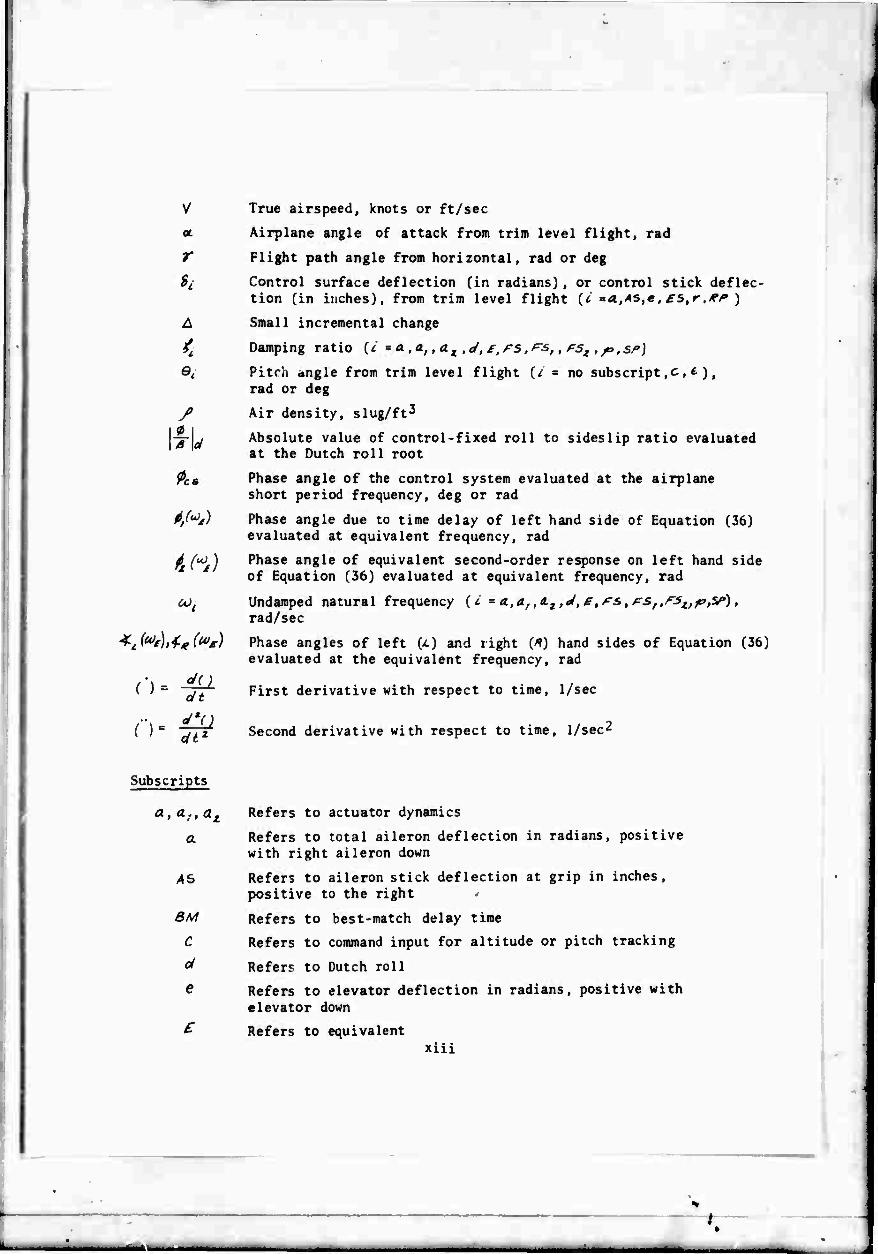
LIST OF SYMBOLS
b
c
'". \/<m*
c'*:
c ■ z. 4 .V^5
V d*.
s dcL
IC
c* A4
i/V*
s 9cm
^ = Urn.
da.
«•* '(ft) s . WC
c- V
//•;"«*
r.. dc„ '% *Sr
t Fc
System delay time (| *6M,*' , tr , t), sec
Wing span, ft
Wing Chord, ft
Airplane rolling moment coefficient
Nondimensional airplane rolling moment coefricient due to aileron deflection, l/rad
Airplane lift coefficient
Nondimensional airplane lift curve slope, l/rad
Nondimensional lift coefficient derivative due to elevator deflection, l/rad
Airplane pitching moment coefficient
Nondimensional pitching moment coefficient damping derivative with respect to angular pitching velocity, l/rad
Nondimensional airplane pitching moment curve slope, l/rad
Nondimensiorvil pitching moment coefficient damping derivative with respect to rate of change of angle of attack, l/rad
Nondimensional pitching moment coefficient derivative due to elevator deflection, l/rad
Airplane yawing moment coefficient
Nondimensional airplane yawing moment coefficient due to rudder deflection, l/rad
Frequency {*- **,(*, ,(il, ps,rsf,rst) cps
Control force of aileron stick, elevator, or rudder pedal
XI

I h
Acceleration of gravity, ft/sec
Altitude change, ft
Moments of inertia about airplane body Ar, ^ and ^ axes, respectively, slug-ft2
Characteristic equation constants, defined in Section 5.1
Airplane lift, lb
Airplane rolling moment, ft-lb
Dimensional lift force derivative with respect to angle of attack, 1/sec
Dimensional rolling moment derivative with respect to aileron stick deflection, l/ir-sec2
M
„.. A*'.
Mass of airplane, slugs
Airplane pitching moment, ft-lb
Dimensional pitching moment derivative with respect to angle of attack, l/sec2
Dimensional damping moment in pitch with respect to angle of attack rate, 1/sec
M. />V*'Sc
%-u * % Dimensional pitching moment derivative with respect to elevator deflection, l/sec2
%-4£CK Dimensional pitching moment derivative with respect to elevator stick deflection, l/in.-sec2
*l*'-4
A 5c2
Vt
A/
V iTt \är,r%
*
s
5
t
Dimensional damping moment in pitch due to angular pitch rate, 1/sec
Number of roots or order of characteristic equation
Normal acceleration, 9 's
Yawing moment, ft-lb
Dimensional yawing moment derivative with respect to rudder pedal deflection, l/in.-sec2
Equivalent period, 1/sec
Laplace operator
Wing area, ft2
Time, sec
Xll
.1
(
r
A
<
/ I ^ I
AS
alt
^l'
True airspeed, knots or ft/sec
Airplane angle of attack from trim level flight, rad
Flight path angle from horizontal, rad or deg
Control surface deflection (in radians), or control stick deflec- tion (in inches), from trim level flight (^ a«,4S,e, ^s,»-,^/» )
Small incremental change
Damping ratio {c = a. .a,, aj^ ,d, £,F5,rsf, f:5z , jo,s/>)
Pitch angle from trim level flight (/ = no subscript,c ,£), rad or deg
Air density, slug/ft3
Absolute value of control-fixed roll to sideslip ratio evaluated at the Dutch roll root
Phase angle of the control system evaluated at the airplane short period frequency, deg or rad
Phase angle due to time delay of left hand side of Equation (36) evaluated at equivalent frequency, rad
Phase angle of equivalent second-order response on left hand side of Equation (36) evaluated at equivalent frequency, rad
Undamped natural frequency (* = a.,af ,a.t ,J, e, rs, rSf.fS^f?^), rad/sec
Phase angles of left GO and right (^) hand sides of Equation (36) evaluated at the equivalent frequency, rad
First derivative with respect to time, 1/sec
Second derivative with respect to time, 1/sec2
Subscripts
a, a.,at
a
AS
3M
C
ol
e
Refers to actuator dynamics
Refers to total aileron deflection in radians, positive with right aileron down
Refers to aileron stick deflection at grip in inches, positive to the right <
Refers to best-match delay time
Refers to command input for altitude or pitch tracking
Refers to Dutch roll
Refers to elevator deflection in radians, positive with
elevator down
Refers to equivalent xiii
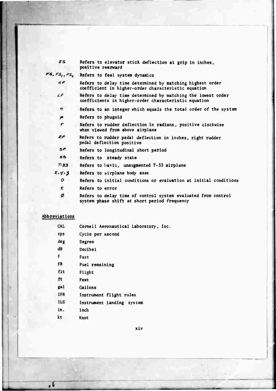
FS, FS, , PSi
HF
Iß
1
P r
er
SF
SS
r-33
o c
0
Abbreviations
Refers to elevator stick deflection at grip in inches, positive rearward
Refers to feel system dynamics
Refers to delay time determined by matching highest order coefficient in higher-order characteristic equation
Refers to delay time determined by matching the lowest order coefficients in higher-order characteristic equation
Refers to an integer which equals the total order of the system
Refers to phugoid
Refers to rudder deflection in radians, positive clockwise when viewed from above airplane
Refers to rudder peda) deflection in inches, right rudder pedal deflection positive
Refers to longitudinal short period
Refers to steady stale
Refers to ba'ic, unaugmented T-33 airplane
Refers to airplane body axes
Refers to initial conditions or evaluation at initial conditions
Refers to error
Refers to delay time of control system evaluated from control system phase shift at short period frequency
CAL Cornell Aeronautical Laboratory, Inc
cps Cycle per second
deg Degree
dB Decibel
F Fast
FR Fuel remaining
fit Flight
ft Feet
gal Gallons
IFR Instrument flight rules
ILS Instrument landing system
in. Inch
kt Knot
XIV
.1
I
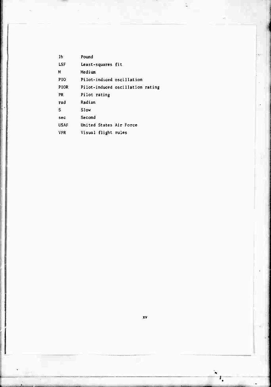
lb Pound
LSF Least-squares fit
M Medium
PIO Pilot-induced oscillation
PIOR Pilot-induced oscillation rating
PR Pilot rating
rad Radian
S Slow
sec Second
USAF United States Air Force
VFR Visual flight rules
xv
SECTION I
INTRODUCTION
It has been known for some time that control system dynamics, as well as open-loop airplane dynamics, affect the handling qualities of the closed- loop pilot and airplane combination. Most handling qualities investigations have been concerned with an investigation of the effects of variations in certain open-loop airplane parameters. The feel system and elevator actuator characteristics have in general been held constant. In some of these cases, the dynamic characteristics of the control system have not been adequately documented and their effect on the airplane response to pilot inputs has not been sufficiently investigated. By making the control system sufficiently "fast" compared to the open-loop airplane, it has been assumed that the han- dling qualities were a function of only open-loop airplane parameters.
The effect of control system dynamics is to raise the order of the airplane response to pilot control inputs. The airplane responses (©,«, ». , etc.) are fourth-order for elevator control inputs. The dynamics of the ele- vator response to control stick displacements and the response of stick displacements to stick forces will increase the order of the airplane response to pilot stick force inputs. In addition, the feel system and actuator roots may be near the airplane roots. Order, closeness of roots, etc. will alter the responses of the airplane to stick force inputs and make the responses very "non-airplane-like." These characteristics affect the pilot's closed- loop control significantly and alter the pilot's evaluation of particular airplane characteristics.
Control system dynamics have often not been properly accounted for in the evaluation of airplane handling qualities. CAL handling qualities research programs have generally tried to minimize the effects of control system dynam- ics through the use of a fast control system with reasonably large separation between the control system and airplane roots. With a trend to more complex flight control systems (adaptive, model-following, etc.), these higher-order effects may increase i'. significance.
The USAF and CAL undertook a systematic investigation to evaluate the effects of control system dynamics on handling qualities. The results of a ground simulator program are presented in Reference 2. The results of a flight test program based on this fixed-base ground simulator program are presented in this report. Both the order and location of the roots of the feel system and actuator were varied with four different sets of fixed short period air- plane dynamics.
This flight test program is considered to be only an introductory one in the in-flight investigation of handling qualities of airplanes with higher- order control systems. Modem high performance fighters do have flight control systems with higher-order characteristics that arise from control elements similar to those investigated. Other types of higher-order response character- istics, however, can arise from additional feedback loops, such as airplane
1
i i

responses that generate inputs to the elevator control actuator, a bobweight on the stick, etc. The latter were not part of the present flight program.
This flight investigation of the handling qualities of a fighter air- plane with higher-order control system dynamics was conducted using the USAF/ CAL variable stability T-33 as an in-flight simulator (Reference 1).
Three of the four sets of longitudinal short period dynamics were evaluated with higher-order control systems as a fighter in "up-and-away" flight. The last set of airplane dynamics was evaluated as a fighter during landing approach.
Thirty-one different configurations (different combinations of control system and airplane dynamics) were evaluated by one CAL evaluation pilot (Pilot B). Thirty-five different configurations were evaluated by a second CAL evaluation pilot (Pilot H). Twenty-nine of these configurations were coanon to both evaluation pilots except for some inadvertent differences in the stick force gradients (F'^/'t ) simulated. Twenty-three of these config- urations, with some differences, were essentially the same configurations evaluated in the fixed-base ground simulator program (Reference 2).
Pilot B evaluated 41 configurations during 18 evaluation flights; 10 of these were repeat evaluations of some of the configurations. Pilot B commented on each configuration evaluated and assigned to each configuration a pilot rating based on a new pilot rating scale (Reference 3).
Pilot H did his evaluations after Pilot B had finished. He evaluated 60 configurations during 29 evaluation flights. Fifteen of these were evaluations of certain configurations with different stick force gradients (FÄS A,) and 10 evaluations were repeats with essentially the same ^5/^, . This variation of ^gA* seemed desirable since many of the configurations, when evaluated by Pilot B, showed strong PIO tendencies. Other flight schedule coimnitments precluded a similar investigation with Pilot B. Because of the strong PIO tendencies of many of the configurations. Pilot H also rated each for their PIO tendencies using the PIO rating scale of Reference 4 (Table X).
The control system dynamics and airplane longitudinal dynamics actually simulated in flight were determined from ground and flight calibration records obtained before, during, and after the flight test program. Pilot comments, pilot ratings, and PIO ratings are correlated with certain handling qualities paraaeters that seemed appropriate to higher-order control system dynamics. Pilot comments and response characteristics simulated are summarized in the text and presented in greater detail for each configuration simulated in the Appendix.
* 71

SECTION II
HIGHER-ORDER CONTROL SYSTEM ELEMENTS
2.1 HIGHER-ORDER CONTROL SYSTEM BLOCK DIAGRAM
The in-flight investigation of higher-order longitudi dynamics was conducted in the USAF/CAL variable stability T- system of the T-33 consists of the elevator feel system and actuator. Higher-order control system dynamics were simulat characteristics of both of these control elements. Airplane simulated using the variable stability response-feedback sys A block diagram of pilot open-loop control through the feel and airplane combination that was the basis of the in-flight shown below.
nal control system 33. The control the elevator ed by altering the dynamics were
tern of the T-33. system, actuator, simulation is
SIMULATED
ELEVATOR
FEEL
SYSTEM
^5 SIMULATED
ACTUATOR
CONTROL SYSTEM
1 *, SIMULATED
AIRPLANE AIRPLANL
RESPONSES
Control is initiated by the pilot by applying a control force (Fg, ).
Through the dynamics of the simulated elevator feel system in the T-33, this force results in a stick displacement ^e6^ which is an input to the simulated
elevator actuator. The elevator response (<£. ) is a function of the simulated
actuator dynamics, and commands the response of the airplane as determined by the simulated airplane dynamics.
Higher-order response characteristics of modem high performance fighters do arise from the same control system elements. In addition, fighter control systems may have feedback loops such as airplane responses that gener- ate inputs to the elevator control system, bobweights, etc. which alter the control system characteristics. The higher-order systems investigated in this program do not cover all possible control systems by any means, but the present program is a fundamental and systematic one upon which future research can be built.
The pilot in-flight longitudinal control loops with the simulated control system and simulated airplane are shown as Figure 1.
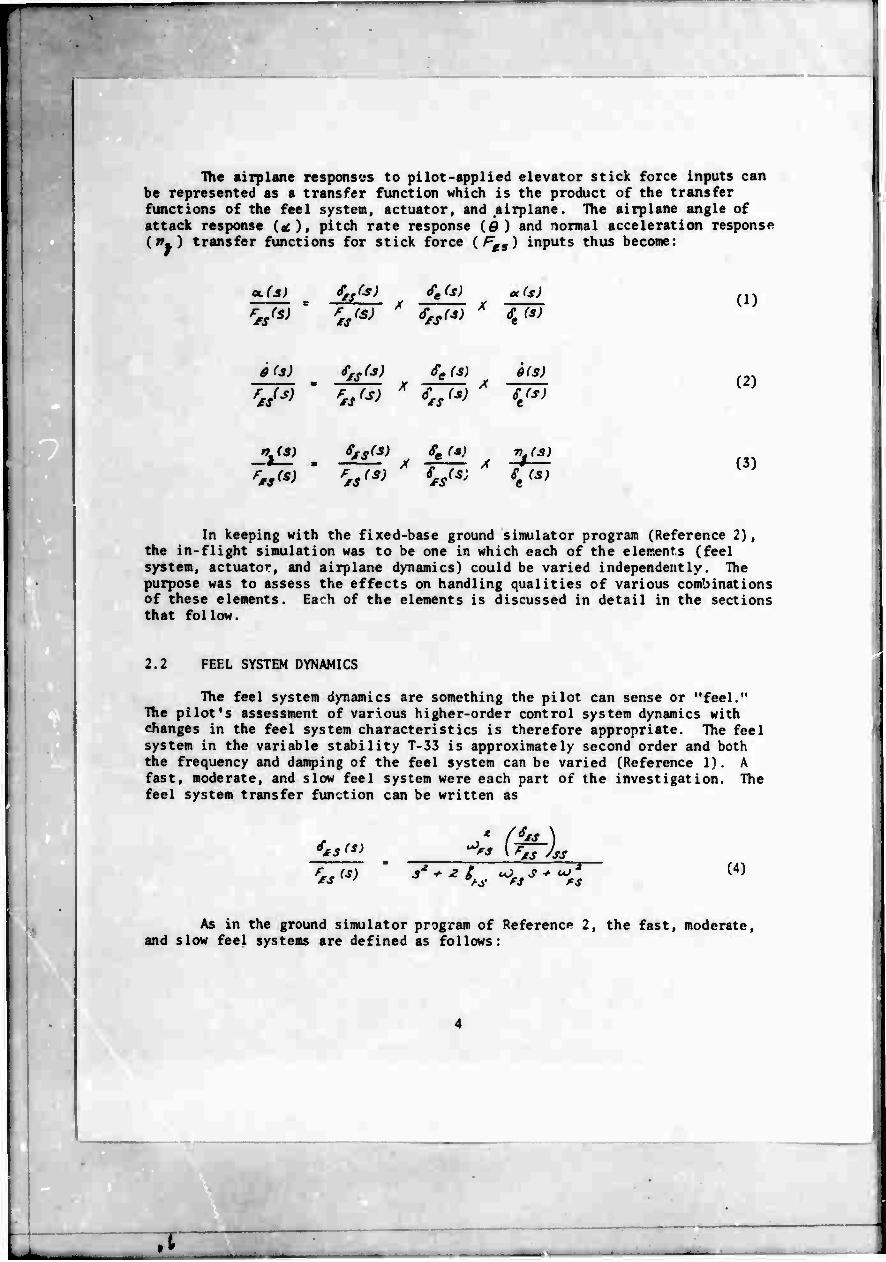
The airplane responses to pilot-applied elevator stick force inputs can be represented as a transfer function which is the product of the transfer functions of the feel system, actuator, and airplane. The airplane angle of attack response itc), pitch rate response (Ö) and normal acceleration response ("») transfer functions for stick force (^5) inputs thus become:
a. (3)
Vs X Se(s)
S,s(3) X St (s)
$(s) X
Se(s) A
6(S)
St(s)
^(S)
'**>
SfS(s) X
4 (*) X
r> (3)
(1)
(2)
(3)
In keeping with the fixed-base ground simulator program (Reference 2), the in-flight simulation was to be one in which each of the elements (feel system, actuator, and airplane dynamics) could be varied independently. The purpose was to assess the effects on handling qualities of various combinations of these elements. Each of the elements is discussed in detail in the sections that follow.
2.2 FEEL SYSTEM DYNAMICS
The feel system dynamics are something the pilot can sense or "feel." The pilot's assessment of various higher-order control system dynamics with changes in the feel system characteristics is therefore appropriate. The feel system in the variable stability T-33 is approximately second order and both the frequency and damping of the feel system can be varied (Reference 1). A fast, moderate, and slow feel system were each part of the investigation. The feel system transfer function can be written as
a£S (S)
'*,<*>
XS 'SS
*i. 'S (4)
As in the ground simulator program of Reference 2, the fast, moderate, and slow feel systems are defined as follows:
.1
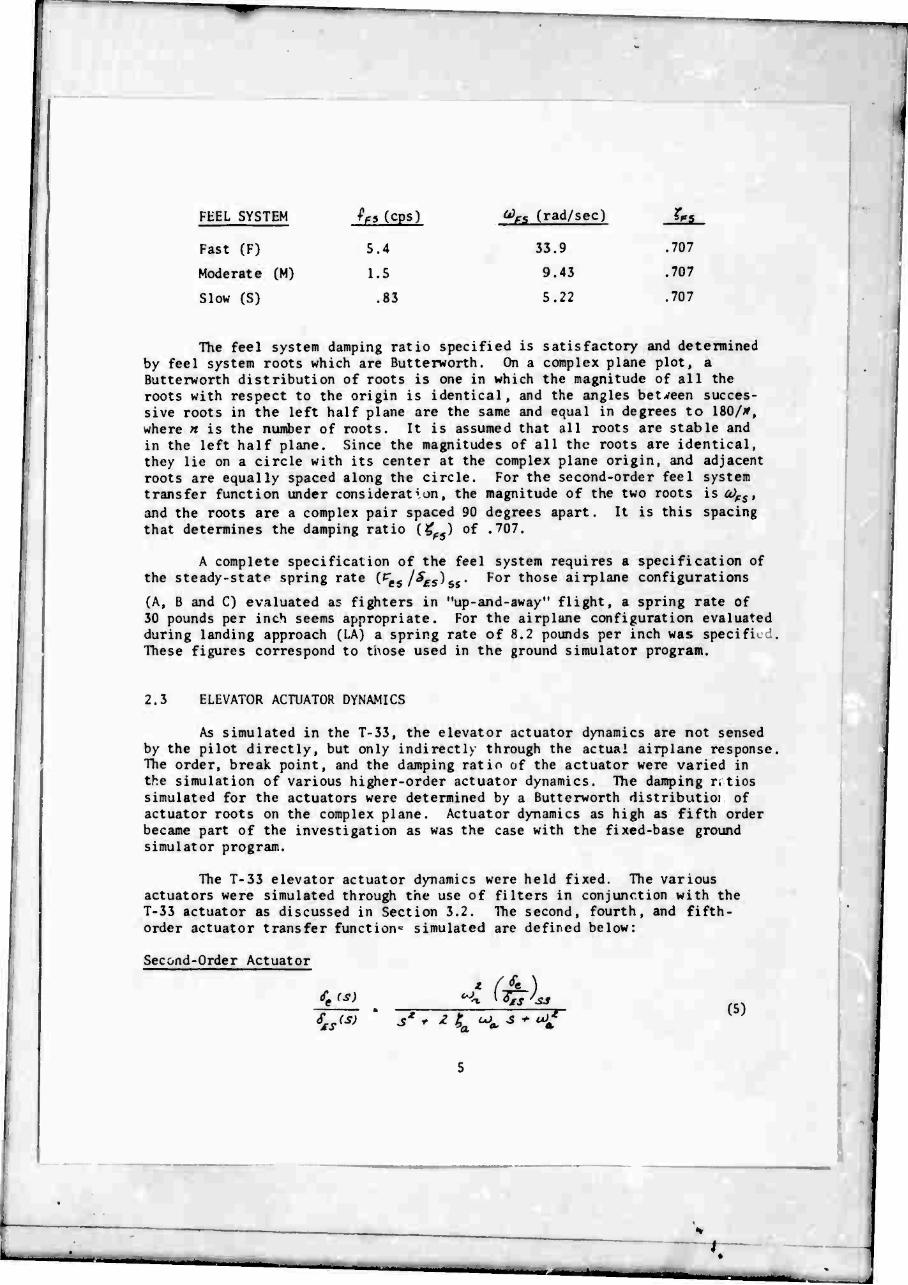
FEEL SYSTEM If» tCMl o)fs (rad/sec) b.
Fast (F) 5.4 33.9 .707
Moderate (M) 1.5 9.43 .707
Slow (S) .83 5.22 .707
The feel system damping ratio specified is satisfactory and determined by feel system roots which are Butterworth. On a complex plane plot, a Butterworth distribution of roots is one in which the magnitude of all the roots with respect to the origin is identical, and the angles between succes- sive roots in the left half plane are the same and equal in degrees to 180/*, where « is the number of roots. It is assumed that all roots are stable and in the left half plane. Since the magnitudes of all the roots are identical, they lie on a circle with its center at the complex plane origin, and adjacent roots are equally spaced along the circle. For the second-order feel system transfer function under consideration, the magnitude of the two roots is Ci)PS, and the roots are a complex pair spaced 90 degrees apart. It is this spacing that determines the damping ratio (^5) of .707.
A complete specification of the feel system requires a specification of the steady-state spring rate (^5/^fs^ss* foT t^ose airplane configurations
(A, B and C) evaluated as fighters in "up-and-away" flight, a spring rate of 30 pounds per inch seems appropriate. For the airplane configuration evaluated during landing approach (LA) a spring rate of 8.2 pounds per inch was specific .'-. These figures correspond to tnose used in the ground simulator program.
2.3 ELEVATOR ACTUATOR DYNAMICS
As simulated in the T-33, the elevator actuator dynamics are not sensed by the pilot directly, but only indirectly through the actual airplane response, The order, break point, and the damping ratio of the actuator were varied in the simulation of various higher-order actuator dynamics. The damping r.tios simulated for the actuators were determined by a Butterworth distributioi of actuator roots on the complex plane. Actuator dynamics as high as fifth order became part of the investigation as was the case with the fixed-base ground simulator program.
The T-33 elevator actuator dynamics were held fixed. The various actuators were simulated through the use of filters in conjunction with the T-33 actuator as discussed in Section 3.2. The second, fourth, and fifth- order actuator transfer function^ simulated are defined below:
Second-Order Actuator
Se (s)
^7 •%
3' * H. Sgs 'ss 3 *■ <Af
(5)
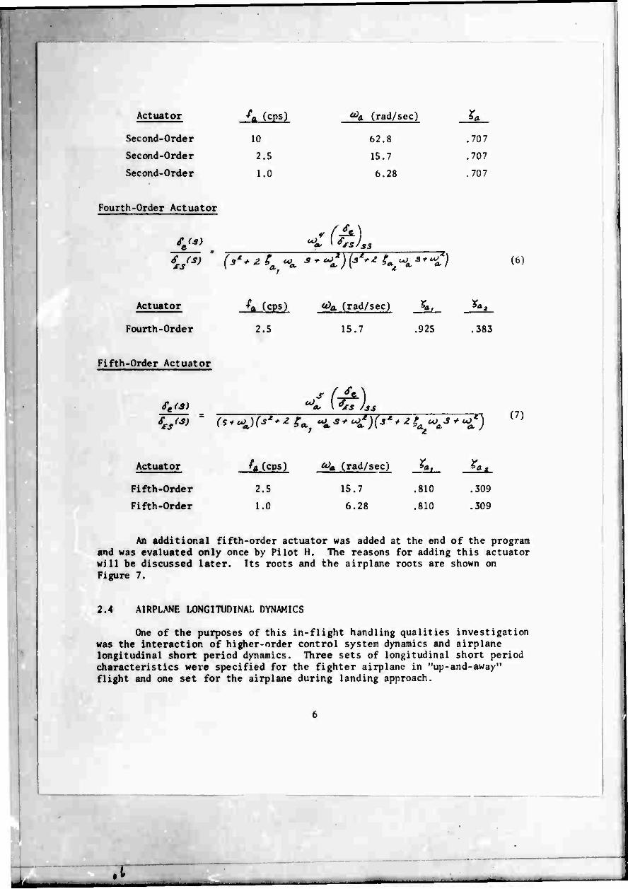
Actuator ^a (cps) ^a (rad/. ;ec 1 ra
Second-Order 10 62.8 .707
Second-Order 2.5 15.7 .707
Second-Order 1.0 6.28 .707
Fourth-Order Actuator
4L€s} ■
i/i P3 ***£){*•" i^ H. ^•fl It
Actuator ^a fcps) <*>a (rad/sec) IL ^
Fourth-Order
Fifth-Order Actuator
2.5 15.7 .925 383
C3^
Actuator
Fifth-Order
Fifth-Order
^T (^fL (7)
/a (cps) <^i (rad/sec)
2.5
1.0
15.7
6.28
.810
.810
,309
.309
An additional fifth-order actuator was added at the end of the program and was evaluated only once by Pilot H. The reasons for adding this actuator will be discussed later. Its roots and the airplane roots are shown on Figure 7.
2.4 AIRPLANE LONGITUDINAL DYNAMICS
One of the purposes of this in-flight handling qualities investigation was the interaction of higher-order control system dynamics and airplane longitudinal short period dynamics. Three sets of longitudinal short period characteristics were specified for the fighter airplane in "up-and-away" flight and one set for the airplane during landing approach.
.1

With negligible velocity changes and negligible elevator lift, the longitudinal, short period, small perturbation equations of motion can be written as
- A- - z oc * 0 m (8)
Ai. oc^Aloc-6fA4$ \ *l (9)
fi*-*) (10)
Equation (10) is not an independent equation of motion but merely a relation- ship between the variables in Equations (8) and (9), It is also easily determined from Equations (8) and (10) that
et ? « (ID
These equations are obtained from Reference 4 and are discussed in some detail there.
Using Equations (8), (9), and (10), it is possible to derive the following transfer functions for the « , Q and v responses of the airplane for elevator inputs.
ot(S)
St(s) ^fe,
0SP SP SP (12)
Se(s) S*' ^ SJP ^SP ***£
(13)
rUS) A A4
''e l* 9***1 'SP SP SP
(14)
where LÜ
SP * 0 ec
hSP SP JL -A4. -At.
*. 0 U

to st^^ir^h^e^Ä s st"d-5t>,e -*~ -p-=
(15)
(16)
(17)
Regardless of the feel system, actuator, or airplane specified, it can easilv be shown that these equations become:
3fi Oil- (ti m. %
^^
•fcp f^
(18)
(19)
(20)
Solving for Mg in Equation (20) and substituting in gives g in Equations (18) and (19)
m: (mu-' tmi ('*k (fj(f\
(21)
(22)
The level of angle of attack and pitch response to stick force inputs is thus specified once the stick force gradient i^/». ). and any two of the
three parameters ^ . ^Ä, and W,/<K of the airplane are specified. These three
parameters are related by Equation (11). Once the feel system and actuator
.1 - - ^
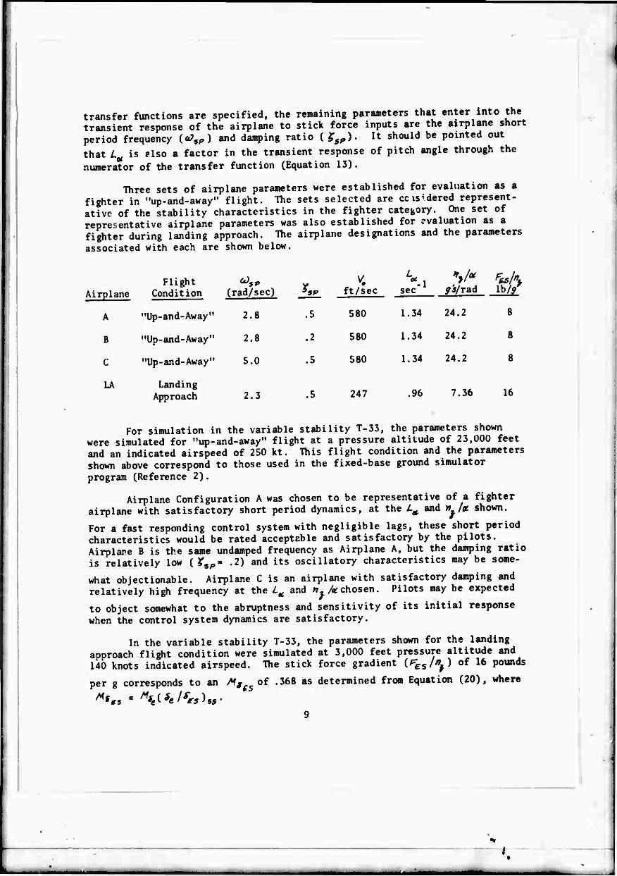
transfer functions are specified, the remaining parameters that enter into the transient response of the airplane to stick force inputs are the airplane short period frequency (ä74„) and damping ratio ( $sP). It should be pointed out
that L is ?lso a factor in the transient response of pitch angle through the
numerator of the transfer function (Equation 13).
Three sets of airplane parameters were established for evaluation as a fighter in "up-and-away" flight. The sets selected are ccis'dered represent- ative of the stability characteristics in the fighter category. One set of representative airplane parameters was also established for evaluation as a fighter during landing approach. The airplane designations and the parameters
associated with each are shown below.
Airplane Flight
Condition ^5P
(rad/sec) ^P ft/sec «:- V*
yj/rad lb//
A "Up-and-Away" 2.8 .5 580 1.34 24.2 8
B "Up-and-Away" 2.8 .2 580 1.34 24.2 8
C "Up-and-Away" 5.0 .5 580 1.34 24.2 8
LA Landing Approach 2.3 .5 247 .96 7.36 16
For simulation in the variable stability T-33, the parameters shown were simulated for "up-and-away" flight at a pressure altitude of 23,000 feet and an indicated airspeed of 250 kt. This flight condition and the parameters shown above correspond to those used in the fixed-base ground simulator
program (Reference 2).
Airplane Configuration A was chosen to be representative of a fighter airplane with satisfactory short period dynamics, at the l^ and » /ac shown.
For a fast responding control system with negligible lags, these short period characteristics would be rated acceptable and satisfactory by the pilots. Airplane B is the same undamped frequency as Airplane A, but the damping ratio is relatively low ( ?sp« .2) and its oscillatory characteristics may be some-
what objectionable. Airplane C is an airplane with satisfactory damping and relatively high frequency at the L^ and » /«chosen. Pilots may be expected
to object somewhat to the abruptness and sensitivity of its initial response when the control system dynamics are satisfactory.
In the variable stability T-33, the parameters shown for the landing approach flight condition were simulated at 3,000 feet pressure altitude and 140 knots indicated airspeed. The stick force gradient (^j/^) of 16 pounds
per g corresponds to an *,f^ of .368 as determined from Equation (20), where 'es
*

In the fixed-base ground simulator program, an indicated airspeed of 125 knots was used as a landing approach speed. An indicated airspeed of 140 knots was selected for the flight simulation because of the desirable margin of safety above stall speed during actual flight simulation of the landing approach with the variable stability T-33. Thur the La and ^,/« for
the flight program are somewhat higher than they were for the ground simulation. The ground simulation program used an Mf of .205 and a stick force gradient
of approximately 30 pounds per g. These values were based on the results of Reference 5. The ft9/». of 16 pounds per g and A^- of .368 are based on what
the evaluation pilot considered as an optimum control gain during some prelim- inary checks during the calibration phase of the flight program.
The frequency and damping of Airplane LA during landing approach repre- sents approximately the dynamics of the T-33 at landing approach and are considered representative of satisfactory dynamics for a fighter at this flight condition.
2.5 CONFIGURATION MATRIX AS PLANNED
With the three sets of feel system characteristics, six sets of actuator dynamics, and the four sets of longitudinal short period parameters specified, it is possible to obtain 72 different combinations of feel system, actuator, and airplane dynamics. Not all these configurations would differ significantly in their characteristics, therefore a matrix of 40 configurations was selected. Forty configurations is also a reasonable number upon which to base a handling qualities flight program.
The matrix of 40 configurations established for this flight program is shown as Table I. The matrix was based on the fixed-base ground simulator program, but does differ from it. The ground simulator results identified many of the configurations that seemed least interesting and fruitful in terms of handling qualities, and these were deleted from the flight program. This reduced the flight program to a manageable size. Also a few configurations were added to the flight program that looked promising which were not part of the ground program. The primary difference between the flight and ground program was that one set of airplane dynamics was deleted from the flight program in "up-and-away" flight, and one set was eliminated for landing approach simulation. In addition, during the flight program, only one value of Mf was
evaluated during landing approach simulations, and only one value of ^ei/r>^
was evaluated for the "up-and-away" configurations. Some inadvertent variations in fmmitk did occur during the flight simulation and some intentional variations
ynfgs/» were added later for specific configurations. These variations in
the flight program will be discussed later.
10
ü ; i ~
Configurations actually evaluated in the ground program that are part of Table I are designated with solid dots. It was the purpose of this flight program to evaluate these configurations and any others in the matrix that looked promising and could be evaluated within the flight time available.
Shown in Table I in each of the blocks is the configuration designation. The first letter or letters refer to the airplane dynamics simulated (A, B, C or LA). The letter in parentheses designates the feel system (Fast, Medium, or Slow). The numbers refer to the actuator dynamics. The first number is the actuator order and the second number in parentheses is the actuator
frequency in cycles per second.
The configurations actually investigated by each of the two CAL evaluation pilots are discussed in Section III and shown in Tables II and III. The actual configuration characteristics as determined from ground and in-flight calibration records aie also shown in these tables and discussed in Section III.
11
•
—
I

SECTION III
IN-FLIGHT SIMULATION TECHNIQUES
3.1 SIMULATION OF FEEL SYSTEM DYNAMICS
The ■variable stability T-33 has an independent feel system for the evaluation pilot in the front seat. The characteristics (a^5, £.-, ^^ ^s/^j)
of this second-order system can be varied independently of the airplane dynamics simulated. The feel system is discussed in some detail in Reference 1. Ex- tensive improvements have recently been made in the functioning and reliability of various components of the T-33 variable stability system since Reference 1 was written, but the basic variable stability system remains the same.
By varying the frequency and damping gains of the feel system, it was possible to simulate the fast, medium, and slow feel systems as described in Section 2.2. Responses of the -imulatea feel systems to step itick force inputs were obtained on the gn.'iid at the beginning and end of the flight test prograr.i. The feel system responi* characteristics to these inputs are shown as Figure 2. The desired responses are those of feel systems specified in Section 2.2. Some slight differences exist between the desired and measured responses. The measured responses were analyzed using the analog matching technique of Reference 6 to determine the actual frequency and damping ratio simulated for each of the feel systems. These measured characteristics are also shown on Figure 2.
Stick force inputs fJ^J enter the feel system through a strain gage
attached to the stick and result in stick deflections («5..). Because of
such things as structural noise, these strain gage signals are first filtered by a notch filter installed between the stick and the feel system. The filter notch is located at IS cps. Assuming that the notch has negligible effect on the feel system transfer function, <5_ f«)//1^ .'5,) , the result is the response
curves of Figure 2 which exclude any dynamics of the notch filter.
Post flight examination o* the notch filter frequency response did indicate a notch location at IS cps, and an amplitude ratio and phase shift that was not negligible. The feel system transfer function including the notch filter is of the following form:
(9t)
SZ*Z(.578)(<H)5+ (Uj*
z (4fL\
Mtttu FS *U ^ tint*
(23)
12
.t

This feel system transfer function is the standard second-order transfer function response multiplied by the transfer function of the notch filter. The notch filter transfer function was substantiated by actual frequency response data.
The feel system stick displacement response (££S) following a step stick
force input (^5) was computed with a digital computer for the fast, medium,
and slow feel systems with the notch filter dynamics included. These computed responses are shown as the solid curves of Figure 3 and were determined using the measured feel system characteristics of Figure 2. A few reasonably good manual records of step inputs were obtained from some ground calibration records and are also shown on Figure 3 as measured responses. The comparisons are reasonably good and indicate that responses determined from Equation 23 are substantiated by actual test data.
Comparing Figures 2 and 3 indicates that the notch filter effects are quite significant in the case of the fast feel system and do increase the initial delay or lag in the response of all the feel systems.
Attempts were made to define the feel system transfer function in a simpler form than that indicated by Equation (23). By the analog matching technique of Reference 6, it was found that the computed step responses indi- cated by the solid curves of Figure 3 could be very well matched by a fourth- order transfer function of the following form:
$£*<*)
V td «5 "fc* I'M*!* (%l
(s'"t "r *fcf* "%)F *i
** »*L* - "-I) (24)
One of the second-order transfer functions of Equation (24) was essentially the feel system without the notch filter, and the other second-order transfer function was of much higher frequency and introduced the added initial delay. The constants in the feel system transfer function as defined by Equation (24) that were simulated during the flight program are listed below.
w, Feel System
Fast
Medium
Slow
'5. Vs, (rad/sec) (cps)
30.7 4.88
9.71 1.55
5.70 .906
.833
.605
.620
•* W. >J. (rad/sec) (cps)
60.0 9.55
49.1 7.83
49.1 7.83
The values of /PS and ?„ should be comparable to the measured values for
the second-order feel system as shown on Figure 2.
13
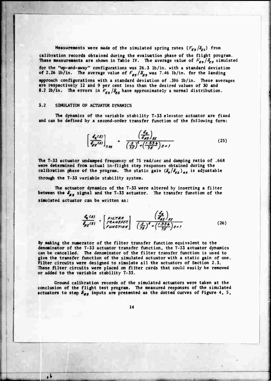
Measurements were made of the simulated spring rates (^j/^s) from
calibration records obtained during the evaluation phase of the flight program. These measurements are shown in Table IV. The average value of ^esl^e5 simulated for the "up-and-away" configurations was 26.3 lb/in. with a standard deviation of 2.26 lb/in. The average value of FgS/äBi*** 7.46 lb/in. for the landing
approach configurations with a standard deviation of .396 lb/in. These averages are respectively 12 and 9 per cent less than the desired values of 30 and 8.2 lb/in. The errors in F£s /SgS have approximately a normal distribution.
3.2 SIMULATION OF ACTUATOR DYNAMICS
The dynamics of the variable stability T-33 elevator actuator are fixed and can be defined by a second-order transfer function of the following form:
m. "'* (25) T-n
The T-33 actuator undamped frequency of 75 rad/sec and damping ratio of .668 were determined from actual in-flight step responses obtained during the calibration phase of the program. The static gain iSa/fes)ts is adjustable
through the T-33 variable stability system.
The actuator dynamics of the T-33 were altered by inserting a filter between the fg signal and the T-33 actuator. The transfer function of the
simulated actuator can be written as:
FO*CT/O»f
it) 'St'MS
By making the numerator of the filter transfer function equivalent to the denominator of the T-33 actuator transfer function, the T-33 actuator dynamics can be cancelled. The denominator of the filter transfer function is used to give the transfer function of the simulated actuator with a static gain of one. Filter circuits were designed to simulate all the actuators of Section 2.3. TTiese filter circuits were placed on filter cards that could easily be removed or added to the variable stability T-33.
Ground calibration records of the simulated actuators were taken at the conclusion of the flight test program. The measured responses of the simulated actuators to step SB9 inputs are presented as the dotted curves of Figure 4, 5,
.t
and 6. Digital computer responses to step inputs were also obtained based on the desired actuator transfer functions of Section 2.3. The comparisons are quite good and indicate that the actuator dynamics simulated can be assumed to be essentially equivalent to the desired actuator dynamics of Section 2.3.
The fifth-order actuator of Figure S(c) is not included in the planned actuators of Section 2.3. It was included near the end of the flight program and evaluated only once by one pilot, Pilot H. It was evaluated with the C airplane which has the same frequency as the actuator (5 rad/sec or .795 cps). The damping ratios of the actuator (.901 and .223) and the damping ratio of the airplane (.625) were chosen so that actuator roots and the airplane short period roots were Butterwcrth. ihis configuration is discussed in more detail in Section V.
Figure 6(a) is a repeat of Figure 4(b) and Figure 6(c) is a repeat of Figure S(a). The actuators of Figure 6 are shown together so that the effects of a change in order of the actuator at a fixed frequency can be easily visualized. Figure 4 is a comparison of second-order actuators of various frequencies.
3.3 SIMULATION OF AIRPLANE LONGITUDINAL DYNAMICS
Hie airplane longitudinal dynamics were simulated using the response feedback gains of the variable stability system of the T-33. The short period frequency was simulated primarily through the S /tt. gain. The short period
damping ratio was simulated using both Se/oi and Se/9 gains. Stick force per g
was simulated with the ^e IS gain of the airplane. The gains were varied as
a function of fuel remaining of the T-33 in an attempt to keep the simulated short period dynamics independent of moment of inertia and center of gravity variations of the T-33.
The "up-and-away" airplane configurations (Airplane A, B, and C) were simulated at 23,000 feet pressure altitude and 250 knots indicated airspeed. This flight condition is the same as that used for the fixed-base ground simu- lator program. The L^ and »_/* f imulated were thus determined by the flight
condition chosen. The simulated L and »./« also vary inversely as the gross
weight of the airplane. The gross weight varies during flight and therefore the simulated L and 77 /« also vary. It is not possible to control directly
the L^ and *-/« simulated since the variable stability T-33 has no independent
lift control. The variations in A,/a. and ^ were kept to a minimum by per-
forming the "up-and-away" simulation first in the flight and then the landing approach simulation last. On a few flights, however, only "up-and-away" configurations were simulated and therefore the variations in n./x and /Ä
were greater. In any case, the variations are not large and are not expected to affect the results significantly.
15

_
16
The landing approach simulation was performed between sea level and 3,000 feet pressure altitude at 140 knots indicated airspeed. For reasons of flight safety, the 125 knots simulation speed of the ground simulator program was increased to 140 knots in the flight program. The frequency, damping, and PP )fc ir/tp simulation for the landing approach conCiguration were performed
with the same response feedback gains of the T-33. For the landing approach configurations, the variations of * /« were quite small since the simulation
and evaluations always occurred with approximately 350 gallons of fuel remaining in the T-33.
The gains required to perform the simulation were determined during the calibration phase of the flight program. During the evaluation phase, calibra- tion records were also taken of the configurations evaluated by each of the evaluation pilots in order to identify the configuration characteristics actually evaluated.
From the oscillograph traces of the airplane's respr se to automatic elevator doublets and steps, it was possible to identify the short period frequency and damping of the airplane. The most reliable method found for identifying a? and f was to analog-match the airplane Ö response to an
elevator step by the method of Reference 6. The automatic step responses were also used to identify the w /« of the configurations
The responses of the airplane to manual stick force (r ) step inputs by
the evaluation pilot were also recorded for the configurations evaluated on each flight. The procedure was for the evaluation pilot first to hold the stick out of trim with the airplane in straight and level flight at constant speed. The stick was next released and the airplane responses recorded on an oscillograph. These records were used to identify {F,m/S ) <c and the {fL. V ),, simulated.
The airplane response to manual step stick force inputs also reflects the effects of both feel system and actuator dynamics and represents the airplane response as sensed by the pilot. The airplane angle of attack (or) and pitch rate (0) responses to stick force steps for each of the configurations simu- lated are presented and discussed in the light of the pilot ratings and comments in the Appendix.
The measured parameters for all the configurations evaluated by both pilots are listed in Table IV. Where blanks exist in the columns of measured parameters, no measurements were obtained beca'ise of a lack of adequate oscil- lograph records, atmospheric turbulence, etc. Also shown in Table IV are least-squares-fit (LSF) values of the simulated parameters. The LSF values of each of the parameters simulated were obtained from an appropriate analytic equation whose coefficients were determined by a LSF of all the measured values of the parameter to the equation. Each analytic equation contained the appro- priate variable stability gains and the fuel remaining of the T-33 as variables. This l.SF method is discussed in some detail in Appendix I of Reference 4.
.i

How well the measured data correlated with the variable stability gains is indicated by a comparison of the measured and LSF values of the parameters shown in Table IV. The correlation also made it vossible to detect significant discrepancies or errors in the gains or measured parameters. Because of the difference in flight condition of the "up-and-away" and landing approach configurations, the measured parameters for each of xhese flight conditions were fitted separately.
The comparisons between measured a.id LSF values of the parameters, with few exceptions, are reasonably good ami indicate that the simulated parameters are consistent with one another and the variable stability gains used in the simulation. Since the LSF value of a parameter is based on all the measured values of this parameter for all the flights, the LSF value is the best estimate of what was simulated in flight. The LSF values of all the parameters are used in any computations or analysis of the flight test results.
The average of the LSF values of a>gp, % , n./g. , and Ftt /SgS were
determined for each of the airplane configurations (A, B, C, C., and LA) simulated and are shown below.
Airplane ^5P
(rad/sec) ^ (g/rad) (lb/in.)
A 2.68 .546 22.5 26.3
B 2.67 .239 22.2 26.3
5.05 .432 22.7 26.3
Cl 5.25 .578 22.7 26.3
LA 1.96 .558 6.1 7.5
These should be compared to the desired parameters of Table I. Small differences are evident between the parameters actually simulated and the desired parameters. Airplane C was not part of the original matrix of configurations shown as
Table I. This configuration was added at the very end of the flight program and evaluated on only one flight. It was intended that the (09p be 5.0 rad/sec
and JT = .625 so that the short period roots and the actuator roots (Figure 7)
would be Butterworth.
An average value of P jn was not computed for each of the airplanes
simulated since some of the variations in both the least-tquares-fit and measured values are significant and would be reflected in the pilot comments and pilot ratings of the configurations. This is especially true of the configurations evaluated by Pilot B. In the case of Pilot H, some of the configurations were evaluated with the F In intentionally changed by large amounts so that th.
effects of stick force gradient on the handling qualities of these configurations could be assessed.
17

No attempt was made to alter the longitudinal phugoid characteristics of the variable stability T-J3 airplane. Thus the phugoid characteristics simulated were essentially those of the basic airplane as documented in Reference 2. For the "up-and-away" flight condition aL • .07 rad/sec and
Wj ■ .05. For the landing approach flight condition oJ« .2 rad/sec and
^, «.096.
3.4 CONFIGURATION MATRIX AS INVESTIGATED
The configuration matrix actually investigated and evaluated by each of the two pilots is shown as Tables II and III. Those configurations designated with a solid dot were evaluated in the fixed-base ground simulator program with the feel system, actuator and short period characteristics of Table I. In the case of Pilot B, configuration A(M)-4(2.5) was added to the matrix of Table I and evaluated. In the case of Pilot H, configurations A(S)-4{2.5) and C1(F)-5(.795) were added and evaluated.
Each evaluation of a particular configuration is designated in the configuration block as follows:
FJight / Pilot / PIO / (ib/gr No. Rating Rating
Pilot B was not provided with a PIO rating scale and therefore did not give the configurations a PIO rating. In the case of Pilot B, it was intended that Pgg/n, be a constant of 8 Ib/g. The variations shown are associated with
difficulties in establishing the correct «L /§ gain. These difficulties were
resolved reasonably well when Pilot H began evaluations. For those evaluations of Pilot H with significant differences in '>./" from 8 Ib/g, the stick force
Jt -i per g was changed intentionally to assess the effects of ^£s/\ on the pilot
9 rating, PIO rating, and pilot comments associated with a configuration. Some cf the configurations were evaluated a second time by the pilots with essen- tially the same ^ /n as a check on intra-pilot rating variability.
The values of airplane parameters shown in Tables II and III are the averages of the LSF values of Table IV as indicated in Section 3.3. The numerical values oi £ /n shown are ?;mply the LSF values of Table IV.
18
.1

3.5 SIMULATION OF LATERAL-DIRECTIONAL STABILITY PARAMETERS
No attempt was made to alter the basic lateral-directional dynamic stability characteristics of the T-33 during the simulation. The T-33 dynamic stability characteristics are satisfactory and representative of those of a fighter airplane and should in no way adversely influence the longitudinal investigation of higher-order control system dynamics. The fact that few, if any, adverse comments were made on lateral-directional dynamics during the evaluation of the longitudinal configurations substantiates this conclusion.
During the flight program, the airplane Dutch roll response to rudder doublets was recorded on some flights. From these records the Dutch roll undamped frequency (&^) , damping ratio (2^), and the magnitude of the roll
to sideslip ratio (/Ä/^/^y ) at the Dutch roll root were determined.
Plots of these lateral-directional parameters are shown as Figure 8 for the "up-and-away" evalucuion of airplane configurations A, B, C, and C.
performed at 23,000 feet and 250 kt. Phe parameters are a function of fuel remaining in the T-33 primarily since the I and I moments of inertia vary
quite significantly witn fuel consumption. These parameters are of course with the T-33 in the clean condition, gear up and flaps up. Similar plots are shown as Figure 9 for the T-33 when simulating the landing approach configurations. The landing approach simulation was performed at 140 kt indi- cated airspeed. For the landing approach, the T-53 gear was down, the T-33 flaps were deflected 25 degrees, and the speed brake was retracted.
The rudder feel system characteristics were the same for the two flight conditions. The rudder feel system undamped frequency was fixed at 4 cps and the damping ratio was set at .707. The rudder spring rate was set at 120 lb/in. For the "up-and-away" evaluations and "landing approach" evaluations the rudder control power was determined by an fff value of approximately .38
-2 -1 €P
and .22 sec x in. respectively.
The aileron feel system characteristics were the same for the two flight conditions. The aileron feel system frequency was fixed at 4 cps and a damping ratio of .707. The aileron spring rate was fixed at 4 lb/in. For "up-and-away" and landing approach evaluations, the aileron control power was determined by
an it of approximately 1.53 and .71 sec x in. respectively.
The rudder and aileron feel characteristics and control powers were selected and checked out in flight with one of the evaluation pilots during the calibration flights. They were considered satisfactory in all respects. The feel system characteristics and control powers actually simulated were verified by ground and in-flight calibration records.
19
SECTION IV
IN-FLIGHT EVALUATIONS
4.1 GENERAL DISCUSSION
In general, two configurations were evaluated per flight. The first evaluation was an "up-and-away" configuration with the dynamics of airplane A, B, or C, and was performed with the variable stability T-33 flying at 23,000 feet pressure altitude and 250 kt indicated airspeed. The second configuration was simulated and evaluated by descending to 3,000 feet pressure altitude, reducing the speed to 140 kt, extending the landing gear, and deflecting the flaps 25 degrees. The speed brake remained retracted. A configuration with landing approach airplane dynamics was simulated and evaluated. An ILS apprr^ch was then performed followed by a landing flare just above the runway. On some flights, only "up-and-away" configurations were simulated. On such flights, it was generally possible to evaluate three configurations at altitude because of the lower fuel consumption.
Each configuration was evaluated as an all-weather fighter under both VFR and IFR conditions. During the IFR evaluation, the pilot wore a cardboard hood which eliminated his outside view and made concentration on instruments easier. The ILS approach of t^~ landing approach configurations was an instrument approach down to tfu dddle marker at 300 feet above the runway. At the middle marker, the hood was removed and the approach wa.c continued visually down to a flare a few faet above the runway. At this point, a gu-around was initiated.
The simulated configurations were flown and evaluated by the pilot in the front seat of the USAF/CAL variable stability T-33 airplane. The evaluation pilot was not informed of the dynamic characteristics of the feel system, actuator, and airplane that were simulated. The feel system and airplane dynamics simulated were determined by variable stability gain settings in the rear cockpit. The gains required to simulate the configurations evaluated in any flight were supplied to the rear seat safety pilot. The simulated actuator dynamics were determined by an actuator filter card installed in the airplane prior to each flight. Each card could simulate two different actuators; the actuator selected was determined by a two-position switch set by the safety pilot.
Two CAL evaluation pilots were used in the flight test program. They are the same Pilot B and Pilot H who participated in the fixed-based ground simulator program (Reference 2). Pilot B has approximately 8,000 hours of flight time about evenly divided between single-engine and multi-engine aircraft of a very wide spectrum ranging from light airplanes and fighters to transports. Very little of his time has been in jet aircraft. His primary recent experience has been in the CAL variable stability B-26 airplane. Pilot H has had approximately 2,000 hours of flight time. Approximately 1,500 hours
20
.t J
have been in single-engine jet aircraft and 500 hours in multi-engine aircraft. He is a former Navy fighter pilot with F3B and F4B experience. His most recent experience has been in the USAF/CAL variable stability T-33 airplane.
Pilot B was the first evaluation pilot. During 18 flights he performed 4J evaluations, 10 of which were repeats. Pilot H performed 60 evaluations during 29 evaluation flights. Only 10 of these evaluations can be considered to be repeats. Fifteen evaluations were evaluations of some configurations with the stick force gradient (^/"J intentionally changed.
Pilot B's participation in the program was more limited than that of Pilot H because of other flight commitments. During Pilot B's participation in the flight program, some significant but unintentional variations in ^jn
from 8 Ib/g occurred for the configurations evaluated in "up-and-away" flight. This was due to difficulties in establishing the proper S&/§£S gain.
The difficulties experienced due to variations in Fetln were essentially
resolved before Pilot H began his evaluations. Because of the strong PIC tendencies experienced by Pilot B for some of the configurations evaluated, it seemed appropriate that Pilot H give each configuration a PIO rating as well as a pilot rating. He was therefore provided with a PIO rating scale.
Since Reference 4 indicates that PIO tendencies are related to ^g/", ,
it was decided to have Pilot H evaluate some of the configurations with the F In changed. This was an addition to the program as initially planned.
4.2 EVALUATION TASKS, PILOT COMMENTS, AND PILOT RATING SCALES
As part of the evaluation of each configuration simulated, the pilot was asked to perform a series of tasks. These tasks were presented to him on two flight cards and are shown as Tables VI and VII. The evaluation tasks were somewhat different for the "up-and-away" and the landing approach flight condition. The tasks were also separated into those performed for VFR and IFR flight. The cockpit instrument panel display is shown as Figure 10. During the IFR evaluation, the pilot wore a cardboard hood which restricted his outside view. The evaluation pilot was also free to perform any other tasks that he thought appropriate in the evaluation.
As part of the VFR evaluation, an altitude command tracking task was performed which is somewhat indicative of the precise altitude control required during VFR formation flying, in-flight refueling, and low level flying. In a strict sense this was not a VFR task since the pilot was asked to compensate for the altitude error displayed on the all-attitude indicator of Figure 10. The altitude error tracking task is discussed in greater detail in Section 4.3. As part of the IFR evaluation, a compensatory attitude tracking task was also performed. The attitude error was also displayed on the all-attitude indi- cator. This task is discussed in detail in Section 4.4. Each configuration was evaluated with random noise inputs to the controls as is discussed in Section 4.5.
21

The landing approach configurations were evaluated performing a standard ILS approach. The localizer was usually intercepted at 1200 feet above the runway. Azimuth error and glide slope error, a measure of ILS performance, were displayed by the ILS cross-pointer of Figure 10. The ILS part of the approach was discontinued at approximately 300 feet above the runway and the approach was completed VFR with a landing flare just over the runway.
The pilot was asked to comment on each configuration evaluated and these comments were recorded on a wire recorder during and following each evaluation. He was asked to make specific comments based on a pilot comment card supplied to him. This card is shown as Table VIII. The pilot was also free to make any additional comments he thought were appropriate to a proper evaluation of the handling qualities of the configurations simulated.
As part of the pilot comments, the evaluation pilot was asked to give each configuration a pilot rating and Pilot H also gave each configuration a PIG rating. The pilot rating was based on a new pilot rating scale shown as Table IX. The basis for this new rating scale is described in some detail in Reference 3. This scale was devised in an attempt to overcome the difficulties experienced with previous rating scales. The new scale is clearly mission oriented, that is, the rating is based on a configuration performance for a specific mission. In the present program, airplane configurations A, B, C, and C, are rated on the basis of a fighter airplane in "up-and-away" flight. It
was considered to be a general all-weather fighter with a primary air-to-air combat role, but also an air-to-ground capability. Airplane configurations LA are rated on the basis of the same single-pilot fighter during landing approach. The new rating scale is also arranged so the pilot can make a series of sequential decisions in arriving at a rating. First, is the airplane controllable or uncontrollable? If controllable, the next decision is whether the configuration is acceptable or unacceptable. If acceptable, is the air- plane satisfactory or unsatisfactory? The actual rating is made within the three categories by selecting one of three descriptions which best fits the evaluation. The new rating scale provides better word descriptions associated with each category to help the pilot in arriving at a rating.
Tlie PIG rating scale (Table X) was obtained from Reference 4 where it proved successful in PIG evaluations on another flight program. For reasons presented previously, only Pilot H gave the configurations evaluated a PIG
rating.
4.3 ALTITUDF TRACKING TASK
As part of the VFR evaluation, the pilot performed an altitude tracking task. Altitude tracking was evaluated in lieu of formation flying or low level flying for a fighter airplane. The task was a compensatory one in that only the altitude error ike ) was displayed by the horizontal needle on the all- attitude instrument (Figure 10). The needle was displaced by the difference between the altitude command (4# ) and the altitude change of the airplane (A) so that
22
.t
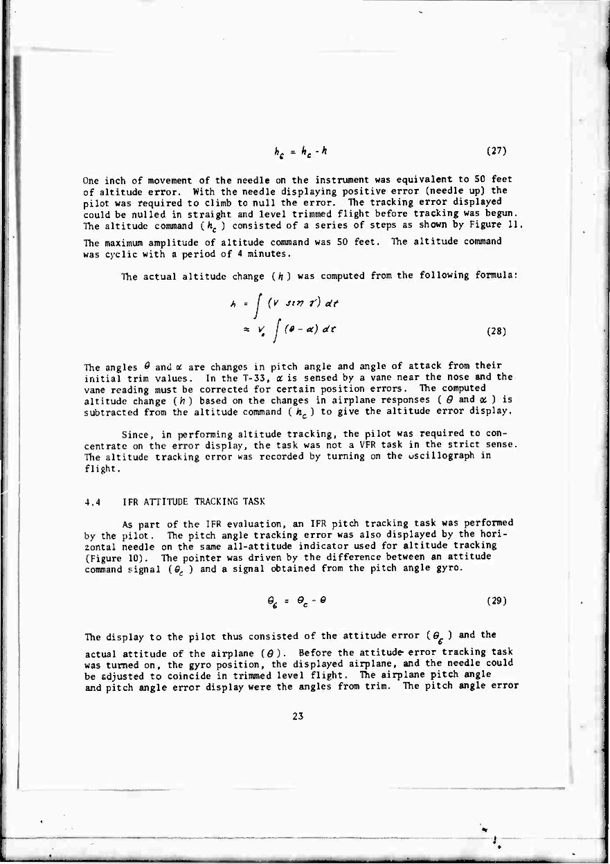
hc -hc-h (27)
One inch of movement of the needle on the instrument was equivalent to 50 feet of altitude error. With the needle displaying positive error (needle up) the pilot was required to climb to null the error. The tracking error displayed could be nulled in straight and level trimmed flight before tracking was begun. The altitude command ( hc ) consisted of a series of steps as shown by Figure 11
The maximum amplitude of altitude command was 50 feet. The altitude command was cyclic with a period of 4 minutes.
The actual altitude change (/?) was computed from the following formula:
h = {¥ sir? t) ät
* Vt j (fi - a) ät (28)
The angles Ö and (t are changes in pitch angle and angle of attack from their initial trim values. In the T-33, a is sensed by a vane near the nose and the vane reading must be corrected for certain position errors. The computed altitude change (h) based on the changes in airplane responses ( Q and ot ) is subtracted from the altitude command ( tec ) to give the altitude error display.
Since, in performing altitude tracking, the pilot was required to con- centrate on the error display, the task was not a VFR task in the strict sense. The altitude tracking error was recorded by turning on the uscillograph in flight.
4.4 IFR ATTITUDE TRACKING TASK
As part of the IFR evaluation, an IFR pitch tracking task was performed by the pilot. The pitch angle tracking error was also displayed by the hori- zontal needle on the same all-attitude indicator used for altitude tracking (Figure 10). The pointer was driven by the difference between an attitude command signal {Qc ) and a signal obtained from the pitch angle gyro.
%- Qc-G (29)
The display to the pilot thus consisted of the attitude error (0 ) and the
actual attitude of the airplane (g). Before the attitude error tracking task was turned on, the gyro position, the displayed airplane, and the needle could be adjusted to coincide in trimmed level flight. The airplane pitch angle and pitch angle error display were the angles from trim. The pitch angle error
23
displayed was magnified with respect to the actual airplane pitch angle indicated by the gyro. One inch of movement of the horizontal needle repre- sented 5 degrees of pitch angle error. One inch of movement of the gyro was equivalent to approximately 20 degrees of airplane pitch attitude change. The Signification of tracking error displayed was considered reasonable by the evaluation pilot for tracking purposes. During tracking, the pilot nulled the error by getting the displayed airplane and horizontal needle to coincide.
The command pitch angle ($ ) was obtained from a filtered random noise
source. Figure 12 shows a representative time history of the waveform of the unfiltered noise. The filtered noise was not recorded. This unfiltered noise source is not suitable as a pitch angle command primarily because the frequency content is too high. The noise source was filtered using a high pass filter with a comer at 0.1 rad/sec and a low pass filter with a comer at .786 rad/sec. Both the low and high frequency asymptotes attenuated the random noise at 12 dB per octave. The filter frequency response with both high and low pass filters is shown as Figure 13. The attitude tracking performance, including the attitude tracking error, was lecorded in flight by turning on the oscillograph.
24
.t
SECTION V
ANALYSIS OF PILOT RATINGS AND CXM1ENTS
5.1 DELAY TIME, DELAY PARAMETERS, AND PHASE SHIFT
In the simulation of the effects of airplane control system dynamics, the break-point frequency of the feei system and the break-point frequency and order of the actuator were control system variables. The interactions of these variables and the longitudinal airplane dynamics were the essential aspects of this handling qualities flight program.
One of the primary effects of higher-order contro to make the airplane response "nonairplane-like," that i airplane responses to elevator stick force inputs is inc flight program, airplane responses to stick force inputs order were evaluated. A fundamental aspect of higher-or dynamics is the initial delay or lag following an abrupt lag increases with an increase in order or a decrease in or both. This is true of both the feel system and the e Figures 2 through 6).
1 system dynamics is s, the order of the reased. In the present
as high as eleventh Jer control system control input. The break-point frequency
levator actuator (see
In terms of frequency response, an aspect of control system dynamics is the phase shift introduced by the control system. With an increase in order and a decrease in break-point frequency of the control system elements, the phase angle introduced by the control system increases. Increases in time delay and phase angle are related since they both arise from control system characteristics.
The delay or lag in the airplane response continual comment of both evaluation pilots. As complaints increased, and the handling qualities or "funny" feel of the stick as the feel system b reduced was also a very frequent comment. Pilot the closed-loop control problems to the combined by a rapid pitch response. The airplane response predict and control. Similar pilot comments were ground simulator program of Reference 2.
to control inputs was a the lag increased, the pilot deteriorated. The peculiar reak-point frequency was comments often attributed effects of the delay followed
was therefore difficult to evident in the fixed-base
A delay parameter that considers the initial delay time and the rapidity of the response that follows the delay is derived below. Pilot comments indicate that such a parameter will be useful in interpreting the comments and analyzing the pilot ratings. The importance of the phase shift introduced by the control systems and its effect on handling -qualities is also given seme consideration. The relationship between the delay parameter and the control system phase angles is analyzed.
25
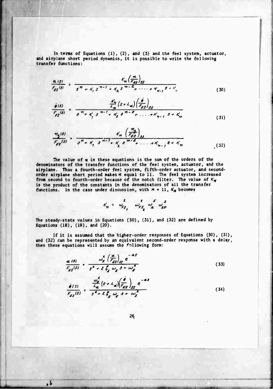
In terms of Equations (1), (2), and (3) and the feel system, actuator, and airplane short period dynamics, it is possible to write the following transfer functions:
a (SI
0(J)
V7'
**f*m'M $***,**-* rz7^% v-f * (30)
k(*^J-t) IS'SS
; ■ (31)
ri (J) LSL 1 t rt- / *f (32)
The value of n in these equations is the sum of the orders of the denominators of the transfer functions of the feel system, actuator, and the airplane. Thus a fourth-order feel system, fifth-order actuator, and second- order airplane short period makes »t equal to 11. The feel system increased from second to fourth-order because of the notch filter. The value of icn
is the product of the constants in the denominators of all the transfer functions. In the case under discussion, with « » 11, ^ becomes
t t 9 z <cL "J~. "J oJ
>*, '1 a. SP
The steady-state values in Equations (30), (31), and (32) are defined by Equations (18), (19), and (20).
If it is assumed that the higher-order responses of Equations (30), (31), and (32) can be represented by an equivalent second-order response with a delay, then these equations will assume the following form:
aL(S)
Z/7)
i /JL SS'SJ
as
o>J. ***L»,
£'"*-)(£) -as
fS 'ss
s' ■»■ * t u) -S + <*>,
(33)
(34)
J
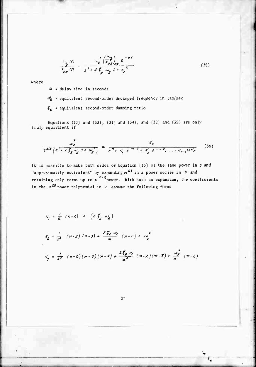
■r IS) - as
fS'ss
* + Z % oJc s (35)
* oO
where
4
delay time in seconds
equivalent second-order undamped frequency in rad/sec
equivalent second-order damping ratio
Equations (30) and (33), (31) and (34), and (32) and (35) are only truly equivalent if
uJ, 4 '■
esr(7r* tjpi s+ ^/) s** <t s *-' * TT ***.,****
(36)
It is possible to make both sides of Equation (36) of the same power in s and as
"approximately equivalent" by expanding e in a power series in s and n-Z
retaining only terms up to S power. With such an expansion, the coefficients
ft* in the n— power polynomial in S assume the following form:
.; = 1 ^-Z) + {Zfs uJ£)
Z- a. CL £
a' A'j - 7*- <*•*)(*•*)(*'*)* -^r* ('"*)<*■*)''' •? ("'*)
r
l
»#••
/ [tr-ig/ i^-^ r^-"?)/ N? fw-fy
a. n-i
'n-t iT*51 0/ »»-•V «/
»-/ ^^ H ^-^'
TTT 01
■4 r»^/ »r--? 0/
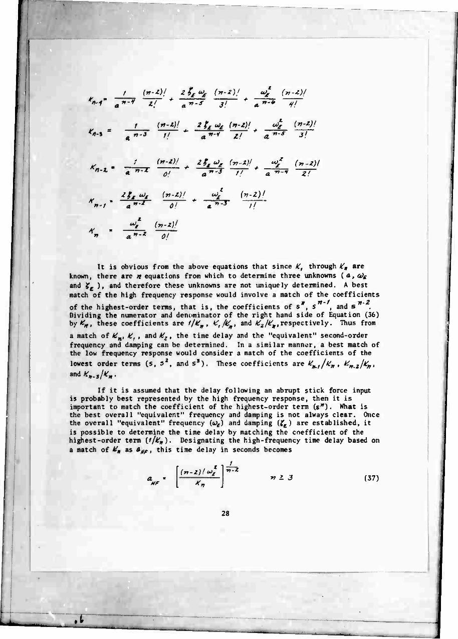
It is obvious from the above equations that since /ff through Kn are known, there are n equations from which to determine three unknowns (a,^ and Xc )» and therefore these unknowns are not uniquely determined. A best match of the high frequency response would involve a match of the coefficients
of the highest-order terms, that is, the coefficients of s , s , and s Dividing the numerator and denominator of the right hand side of Equation (36) by A^, these coefficients are '/*> . ^A*» and ^/^respectively. Thus from
a match of #_, It, , and A^ , the time delay and the "equivalent" second-order frequency and damping can be determined. In a similar manner, a best match of the low frequency response would consider a match of the coefficients of the lowest order terms (s, 5 , and ss). These coefficients are *'w.,/'fw , ^n.zl^n*
andW*- If it is assumed that the delay following an abrupt stick force input
is probably best represented by the high frequency response, then it is important to match the coefficient of the highest-order term U") • What is the best overall "equivalent" frequency and damping is not always clear. Once the overall "equivalent" frequency (o^l and damping (^c) are established, it is possible to determine the time delay by matching the coefficient of the highest-order term [l/Vn). Designating the high-frequency time delay based on a match of HQ as AMf , this time delay in seconds becomes
ln-Z)l (*>£
1 ■n-t
*r L 3 (37)
28
.t
The equivalent period (Pe) is related to the equivlent second-order frequency by the relationship
Zfr P * — g
(38)
The ratio of time delay in seconds to the equivalent second-order period in seconds is a nondimensional delay parameter defined as
anfr Hr p t
2fr (■n-z)! mfr
/ rr-Z
Tt > 3 (39)
The "equivalent, best match" overall frequency will be determined primarily by the slowest responding element ir the transfer function which is generally the airplane short period frequency (&}„). Assuming the airplane undamped short
period frequency to be the equivalent frequency leads to the following form for the d^'.ay time and nondimensional delay parameter, Equations (37) and (39).
>//■
MP
*s
(r,.t)l ml,* n-Z
zrr (n-Z)' u). SP
V.
/
n-Z
r, > 3
r? > 3
(40)
(41)
It is of interest to note that since ^w contains the factor ^5p , the delay
time is not a function of the airplane short period frequency but only the characteristics of the control system.
Since the "equivalent" overall frequency is determined primarily by the slowest responding elements in the transfer function, it is possible to deter- mine an "equivalent" frequency and damping, and a corresponding delay time, by matching the three coefficients K+f/** » ^n-zl^r* ■^ ^n-sl^n •
29

* a *n *
4- — \ r- £ + — a. ien co^ c*Jr2 I &>
These three equations in three unknowns (a, o^,^) can be manipulated to give Equations (42), (43), and (44) shown below. The delay time is now designated as ciif to indicate that this delay time is one that gives a best match of the low frequency response.
•kJ
Q,Lr (43)
(44)
By solving for the delay time using Equation (42), it is next possible to determine the equivalent frequency and damping using Equations (43) and (44) With this approach, it is not necessary to assume that the equivalent short period frequency and damping are equal to the airplane short period frequency and damping. Once the equivalent frequency (a?£) is determined, the equivalent
period is determined from Equation (38). The delay parameter based on a match of the coefficient of the lowest-order terms thus hecomes:
(45) ^ zrr
Another possible method of interpreting the effects of control system dynamics is in terms of the phase shift introduced by th" control system. Phase shift in the vicinity of the short period frequenc. should be important
50

in closed-loop tracking performance and PIO tendencies of the airplane. Based on pilot conunents and tracking records obtained in flight, many of the config- urations simulated had strong PIO tendencies.
If the phase shift in the region of control can account for the reduced closed-loop damping or PIO tendencies, then the time delay Q, in Equation (36) can be defined based on this phase shift. Since the phase shift of the delay
term e is linear with frequency and directly proportional to a-, the value of Q. will be chosen to match the phase shift on both sides of Equation (36) at the equivalent frequency (o^) . Designating the phase angle at <t>^ on the
left and right side of Equation (36) as4t (<«Jf) and4R (^) respectively, then
^(H) - ^i%) (46)
-45 The phase angle of the term e" evaluated at £*> is
where a^ is the designation for the delay time defined by the phase shift at at. The phase angle (öJ,) of the "equivalent" second-order term on the left side of Equation (36) is
We therefore have
fr 4 . . 2L P2 t
\ H) '',*'** % rr_ Z (47)
Substituting F -ation (47) in Equation (46) we have
a. cJ
(48)
In terms of the equivalent period, P6 = 2 V/^£ , a delay parameter based on a*
can be defined from Equation (48) as follows:
31
€M<*V-T (49) 2fr
Again, what the best overall "equivalent" frequency should be for evaluating the phase shift is not easy to define. Assuming the airplane undamped short period frequency to be the best equivalent frequency {<*>£'&!&>),
then Equations (48) and (49) define the delay time and delay parameter determined from the phas; angle match at <t>9P . The denominator of the right hand side of Equation (3j) does contain the airplane short period quadratic as a factor. What remains defines the control system dynamics. The phase shift of the right side of Equation (36) at o^p thus becomes
(uJ ) 4 - - (50)
<bc% is the phase shift of the control system at the short period frequency and-TT/^ is the phase shift of the short period quadratic. The time delay and delay parameters defined by the control system phase shift at u)sr are obtained by substituting Equation (50) in Equations (48) and (49).
•£ * Zfr
(51)
(52)
The delay time and delay parameter can thus be determined by three methods, Equations (40) and (41), Equations (42) and (45), and Equations (51) and (52). The first method matches the coefficient of the highest-order term in the characteristic equation and assumes the equivalent frequency to be the airplane short period frequency. The second method gives a delay time, an equivalent frequency and damping, and a delay parameter based on a match of the three lowest-order coefficients in the characteristic equation. The third method determines the delay time and delay parameter from the phase shift of the control system at the airplane short period frequency.
The delay time and delay parameters have been determined by all three methods for each of the configurations simulated and are shown in Table V. The feel system and actuator frequencies used to determine IL, 16. »» "'»-/ 'n-2 and Kn.i were obtained from calibration records of the feel system and actuator as discussed in Sections 3.1 and 3.2. The airplane short period frequencies used in the computations are the average least-squares-fit values obtained as discussed in Section 3.3. These values are also shown in the table in Section 3.3 and in .ables II and III.
32
Using the average LSF short period parameters of airplanes A, B, C, C. and LA, the airplane responses to step stick force inputs were computed
for all the configurations simulated using an IBM 360 computer and a program that gives time histories directly from transfer functions. The airplane longitudinal short period transfer functions for the various configurations simulate \ are of the form of Equations (30), (31), and (32). Each of the responses was normalized or ratioed to the steady-state values of the responses shown in these equations. It is obvious from the equations that, on this basis, the normalized oc and J? response per unit F'es are the same.
This is true when the elevator lift and speed changes of the airplane are assumed to be negligibly small.
These computed responses to step stick force inputs are shown in the Appendix and compared to the measured responses in flight. It is quite evident that both the computed and measured responses show pronounced lags or delay times in the initial response for some of the higher-order control systems simulated.
The computed higher-order responses based on Equations (30), (31), and (32) have been compared to the delayed second-order responses of Equations (33), (34), and (35). Each of the three methods previously discussed was used to compute the delayed second-order response. These comparisons are shown for a few of the configurations as Figures 14, 15, 16, 17, 18, and 19. Also shown on the figures is a comparison of responses • .r-\ the delay time (ä_M) is
chosen such that airplane short period resp i give a best match of the air- plane overall responses after the delay. Th.o is done by simply shifting the airplane short period responses along the time scale to give the best match. The delay times (Äa/If) and delay parameters (ä-^/^. ) determined using this
fourth method are shown in Table V for all the configurations simulated.
It is quite evident from the figures that, although the delay time is reasonably well estimated by Equation (40), the responses following this delay are evidently not second-order, at least not initially, because of the pro- nounced curvature of ths responses following the computed delay. This is especially evident from the •/^- response which should increase linearly for
a second-order response. With an increased time delay to give a best match id ), the airplane short period responses compare reasonably well with the
higher-order responses for most of the configurations. The initial curvature of the higher-order response is, of course, not matched. When the actuator frequency approaches the feel system frequency, Configuration C(F)-5(1), the match is poorest (.see Figure 19).
Generally, the best comparison of the higher-order response by a delay and second-order response is that obtained when the three lowest-order coefficients in the characteristic equation are matched to give a delay time (a. ), and an equivalent frequency and damping (co , ? ). Using the computed
equivalent frequency gives a somewhat better match of the overall responses.
33
especially the peak value of ö/^3 (Figure 19). This is especially the case
when the feel system or actuator frequency approaches the airplane short period frequency. In such cases, the equivalent frequency can deviate signif- icantly fron the airplane short period frequency. This is evident from a comparison of airplane short period frequencies and computed equivalent fre- quencies in Table V.
Figure 20 compares the delay times determined by the various methods discussed for all the configurations simulated. A similar comparison of delay parameters is made in Figure 21. Figures 20(a) and 21(a) indicate that the delay times and delay parameters tWy^/C) determined from a match of the
coefficient of the highest-order term in the characteristic equation are about half the values of these parameters Ql^, ^/^ ) computed from a match of the
coefficients of the lowest-order terms in the characteristic equation. The delay time and delay parameter computed from the control system phase shift
'^adtad/P€^ compare reasonably well with fl^ and ^/^. . The comparisons are
poorest for the C and Cj airplane configurations when the equivalent frequency
deviates significantly from the airplane short period frequency (Figures 2ü(b) and 21(b)). Similar conclusions can be drawn from a comparison of the best match delay time and delay parameter (äJ^I^/Z^ ) to a^. anda^/P^ (Figures 20(c) and 21(c)).
From Figures 20 and 21, it is possible to establish the following approximate relationships between the various delay times and delay parameters.
V • V * aBM * **m
s» —!— m —-— a Z
(53)
(54)
% ?!
5.2 ANALYSIS OF PILOT RATINGS AND PIO RATINGS
The pilot ratings for all the configurations evaluated by Pilot B are shown in Table II. The pilot ratings and PIO ratings of the configurations evaluated by Pilot H are shown in Table III. As stated previously, Pilot B did not give the configurations a PIO rating. Some difficulty was experienced in establishing an Fm%l*. of B.O Ib/g for Pilot B as is apparent from Table II
(see Section 3.4). Mucn better control oiFlsln occurred in the evaluations of Pilot H (Table III). Certain configurations were evaluated by Pilot H with significant changes in ^gs/ft. from 8 Ib/g, but these changes were intentional and added to the program to determine the effects of stick fc pilot ratings and PIO ratings.
force gradients on
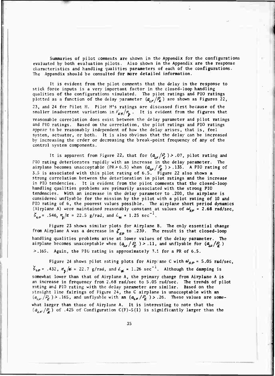
Summaries of pilot comments are shown in the Appendix for the configurations evaluated by both evaluation pilots. Also shown in the Appendix are the response characteristics and handling qualities parameters of each of the configurations. The Appendix should be consulted for more detailed information.
It is evident from the pilot comments that the delay in the response to stick force inputs is a very important factor in the closed-loop handling qualities of the configurations simulated. The pilot ratings and PIO ratings plotted as a function of the delay parameter (^^r/^) are shown as Figures 22,
23, and 24 for Pilot H. Pilot H's ratings are discussed first because of the smaller inadvertent variations mfggjn,. It is evident from the figures that
reasonable correlation does exist between the delay parameter and pilot ratings and PIO ratings. Based on the correlation, the pilot ratings and PIO ratings appear to be reasonably independent of how the delay arises, that is, feel system, actuator, or both. It is also obvious that the delay can be increased by increasing the order or decreasing the break-point frequency of any of the control system components.
It is apparent from Figure 22, that for (d^^ ) > .07, pilot rating and
PIO rating deteriorates rapidly with an increase in the delay parameter. The airplane becomes unacceptable (PR>6.5) when (^/^ )> .135. A PIO rating of
3.5 is associated with this pilot rating of 6.5. Figure 22 also shows a strong correlation between the deterioration in pilot ratings and the increase in PIO tendencies. It is evident from the pilot comments that the closed-loop handling qualities problems are primarily associated with the strong PIO tendencies. With an increase in the delay parameter to .200, the airplane is considerea unflyahle for the mission by the pilot with a pilot rating of 10 and PIO rating of 6, the poorest values possible. The airplane short period dynamics (Airplane A) were maintained reasonably constant at values of cJsp = 2,68 rad/sec,
*p ,546 , «t/« = 22.5 g/rad, and L^m 1.25 sec-1
Figure 23 shows similar plots for Airplane B. The only essential change from Airplane A was a decrease in £ to .239. The result is that closed-loop
handling qualities problems arise at lower values of the delay parameter. The airplane becomes unacceptable when (^ / P. )> .11, and unflyable for (^/^ )
>.165. Again, the PIO rating is approximately l.i for a PR of 6.5.
Figure 24 shows pilot rating plots for Airpane C with ^sf, = 5.05 rad/sec,
>5p = .432, n,/& m 22.7 g/rad, and Z^ = 1.26 sec" . Although the damping is
somewhat lower than that of Airplane A, the primary change from Airplane A is an increase in frequency from 2.68 rad/sec to 5.05 rad/sec. The trends of pilot rating and PIO rating with the delay parameter are similar. Based on the straight line fairings of Figure 24, the C airplane is unacceptable with an {<LLFlPa )> .165, and unflyable with an {d^ /pa )> .26. These values are some-
what larger than those of Airplane A. It is interesting to note that the (a^/^) of .425 of Configuration C(F)-5(1) is significantly larger than the
SS

{a.lF/Pg ) of .26 which results in an unflyable C airplane. The airplane would
probably also be unflyable for values of CL. /P£ between .26 and .425.
It is important to note that Figures 22 through 24 are results for stick force gradients between 6.8 and 10.5 Ib/g. It is difficult to make similar plots for Pilot B because of appreciable variations in the simulated stick force gradients. Figures 26(a), 26(b), and 27(a) are plots of Pilot B pilot ratings as a function of 4 jp for Airplanes A, B, and C. The numbers next to the
points designate the least-squares fit values of ^mm/IL • Also shown on the
figures are the straight line fairings obtained from the pilot rating data of Pilot H (Figures 22, 23, and 24). Generally more scatter exists in the pilot rating data of Pilot B, and some of this scatter can be attributed to the large variations in stick force gradients. The trend of pilot rating with äv-./A
shown by Pilot H is substantiated by Pilot B. No PIO ratings were obtained with Pilot B, therefore comparisons of PIO ratings of the two pilots are not possible.
Figure 25 is a plot of pilot ratings and PIO ratings for the landing approach configurations simulated for Pilot H. Although the trends are similar to those displayed for the "up-and-away" configurations, more scatter exists in the data at low values of the delay parameter. The degradation in pilot rating in this region is not due to an increase in PIO tendencies. The faired straight line of Figure 25(b) is also shown with the pilot ratings of Pilot B (Figure 27(b)). Although the data is somewhat limited, the comparisons of pilot ratings of the two pilots are good. Stick force gradients were maintained reasonably constant and were the same for both pilots during landing approach evaluations. It should be noted that »«/of was 6.06 during landing approach
simulations compared to approximately 22 for up-and-away flight. The corre- sponding L^ '5 were .806 and 1.25 respectively.
The effects of ^ I» on pilot rating and PIO rating were investigated
with Pilot H by intentionally varying the simulated stick force gradients. The pilot rating and PIO rating data obtained are plotted as Figure 28.
With a stick force gradient of 8 Ib/g, Configuration A(F) 2(10) has no PIO tendencies (Figure 28(a)). Increasing or decreasing the stick force gradient does not change the PIO rating, but the overall pilot rating improves with a decrease m F In and deteriorates with an increase in FeK/>79.
Obviously Pilot H likes a lower stick force gradient than 8 Ib/g if no PIO tendencies exist.
With a stick force gradient of 8 Ib/g, Configuration A(F)-5(1) is considered unflyable with the poorest pilot rating and PIO rating (Figure 28(b)). In this case, increasing ^s/tf, improves the pilot rating and diminishes, but
does not eliminate, the severity of the PIO tendencies. Similar effects are evident for Configurations C(F)-5(2.5), C(F)-5(1), and C (F)-5(.796). In the
36

case of Configuration A(S)-2(2.5), the stick force gradients were both increased and decreased from 8 Ib/g. Since this configuration had significant PIO tendencies with 8 Ib/g, decreasing the stick force gradient made both the pilot rating and PIO ratings worse. Configuration A(5)-2(2.5) actually became unflyable with 4 Ib/g. An increase in and PIO ratings of the configuration.
W'j improved the pilot rating
The effect of Feij*, on the landing approach configurations is less
clear (Figures 28(g) and 28(h)). For Configuration LA(F)-4(2.5), a decrease in F In to 8.5 Ib/g had little effect on either pilot rating or PIO
s r tendencies. Configuration LA(F)-5(1) was rated quite poorly from both the standpoint of PIO tendencies and overall pilot rating with 17.5 Ib/g. With an increase in stick force gradients to as high as 37.5 Ib/g, the improvement shown, if any, is less apparent.
Also shown in Figure 28 are the pilot ratings of Pilot B for the same configurations. The pilot ratings of Pilot B and Pilot H compare well when the effect of ^5/0, on the rating is properly accounted for.
Figure 29 is a plot of pilot rating versus PIO rating for Pilot H. The fact that a strong correlation does ex.st between PIO rating and pilot rating indicates that the primary effect of higher-order control system dynamics investigated in this flight program is to induce PIO tendencies. For Airplane A, the airplane becomes unacceptable (PR > 6.5) with a PI0R>ä.5. No apparent difference in the relationship between PR and PIOR exists for Airplane B with lower short period damping, ^ of .239, instead of .546 for Airplane A, This is
not to say that Airplane B is rated similarly to Airplane A, but only that the lower damping also accentuates PIO tendencies as do the higher-order control system characteristics. Figure 29(c) indicates that the faster and more abrupt responses of Airplanes C and Cj become unacceptable at the slightly lower PIO
rating of 3.0. In the case of Airplane LA evaluated during landing approach, pilot ratings and PIO ratings show a significantly different correlation. High-order control system lags with a jP < .10, Figure 25(a), result in a
degradation of closed-loop performance and a degradation in pilot rating, but the degradation is not associate! with PIO tendencies. For a IP >.10,
further degradation of handling qualities during the landing approach is associated with the PIO tendencies that result from the higher-order control system dynamics.
All the actuators simulated except one had a Butterworth distribution of roots. In the cass of Configuration C (F)-5(.796), the actuator and air-
plane short period roots together had a Butterworth distribution as shown in Figure 7. This configuration was evaluated by Pilot H on Flight 866 with three different values of f In . The pilot ratings and PIO ratings are shown
in the table of Figure 7, and trey are also plotted in Figure 28(f). The purpose of this configuration wis to determine any improvement that results from a Butterworth distribution of actuator and short period roots. If
37
;
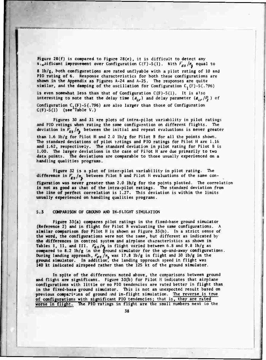
Figure 28(f) is compared to Figure 28(e), it is difficult to detect any s.^nificant improvement over Configuration C(F)-5(1). Kith ^gS/", equal to
8 Ib/g, both configurations are rated unflyable with a pilot rating of 10 and PIO rating of 6. Response characteristics for both these configurations are shown in the Appendix as Figures A-24 and A-25, The responses are quite similar, and the damping of the oscillation for Configuration C. (F)-5(.',9b)
is even somewhat less than that of Configuration C(F)-5(1). It is also interesting to note that the delay time (Ä,r) and delay parameter ^0-LFl
pE) of
Configuration C,(F)-5(.796) are also larger than those of Configuration C(F)-5(1) (see Table V.)
Figures 30 and 31 are plots of intra-pilot variability in pilot ratings and PIO ratings when rating the same configuration on different flights. The deviation in ^ /» between the initial and repeat evaluations is never greater
than 1.6 Ib/g for Pilot H and 2 ü lb/g for Pilot B for all the points shown. The standard deviations of pilot ratings and PIO ratings for Pilot H are 1.16 and 1.62, respectively. The standard deviation in pilot rating for Pilot B is 1.00. The larger deviations in the case of Pilot H are due primarily to two data points. The deviations are comparable to those usually experienced on a handling qualities programs.
Figure 32 is a plot of inter-pilot variability in pilot rating. The difference in F In between Pilot B and Pilot H evaluations of the same con- ts y figuration was never greater than 2.0 lb/g for the points plotted. The correlation is not as good as that of the intra-pilot ratings. The standard deviation from the line of perfect correlation is 1.27. This deviation is within the limits usually experienced on handling qualities programs.
5.3 COMPARISON OF GROUND AND IN-FLIGHT SIMULATION
Figure 33(a) compares pilot ratings in the fixed-base ground simulator (Reference 2) and in flight for Pilot B evaluating the same configurations. A similar comparison for Pilot H is shown as Figure 33(b). In a strict sense of the word, the configurations were not the same, but different as indicated by the differences in control system and airplane characteristics as shown in Tables I, II, and III. /^s/». in flight varied between 6.8 and 9.8 lb/g as compared to 8.2 lb/g \n the ground simulator for the up-and-away configurations, During landing approach, Fes/v, was 17.8 lb/g in flight and 30 lb/g in the ground simulator. In addition', the landing approach speed in flight was 140 kt indicated airspeed rather than the 125 kt of the ground simulator.
In spite of the differences noted above, the comparisons between ground and flight are significant. Figure 33(b) for Pilot H indicates that airplane configurations with little or no PIO tendencies are rated better in flight than in the fixed-base ground simulator. This is not an unexpected result based on previous comparicjns of ground md in-flight simulation. The reverse is true of configurations with significant PIO tendencies; that is, they are rcted worse in flight." The PIG ratings in flight are the small numbers next to the
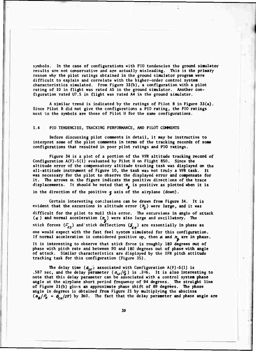
symbols. In the case of configurations with PIO tendencies the ground simulator results are not conservative and are actually misleading. This is the primary reason why the pilot ratings obtained in the ground simulator program were difficult to explain and correlate with the higher-order control system characteristics simulated. From Figure 33(b), a configuration with a pilot rating of 10 in flight was rated AS in the ground simulator. Another con- figuration rated U7.5 in flight was rated A4 in the ground simulator.
A similar trend is indicated by the ratings of Pilot B in Figure 33(a). Since Pilot B did not give the configurations a PIO rating, the PIO ratings next to the symbols are those of Pilot H for the same configurations.
5.4 PIO TENDENCIES, TRACKING PERFORMANCE, AND PILOT COWENTS
Before discussing pilot comments in detail, it may be instructive to interpret some of the pilot comments in terms of the tracking records of some configurations that resulted in poor pilot ratings and PIO ratings.
Figure 34 is a plot of a portion of the VFR altitude tracking record of Configuration A(F)-5(1) evaluated by Pilot H on Flight 850. Since the altitude error of the compensatory altitude tracking task was displayed on the all-attitude instrument of Figure 10, the task was not truly a VFR task. It was necessary for the pilot to observe the displayed error and compensate for it. The arrows oi. the figure indicate the positive directions of the trace displacements. It should be noted that v is positive as plotted when it Is
in the direction of the positive * axis of the airplane (down).
Certain interesting conclusions can be drawn from Figure 34. It is evident that the excursions in altitude error (/?.) were large, and it was
difficult for the pilot to null this error. The excursions in angle of attack {a. ) and normal acceleration (# ) were also large and oscillatory. The
stick forces C-—) and stick deflections (^" ) are essentially in phase as
one would expect with the fast feel system simulated for this configuration. If normal acceleration is considered positive up, then ac and » are in phase.
It is interesting to observe that stick force is roughly 180 degrees out of phase with pitch rate and between 90 and 180 degrees out of phase with angle of attack. Similar characteristics are displayed by the IFR pitch attitude tracking task for this configuration (Figure 35).
The delay time {d'j associated with Configuration A(F)-5(1) is .587 sec, and the delay parameter {<a^.//> ) is .2<l6. It is also interesting to note that this delay parameter can be associated with a control system phase angle at the airplane short period frequency of 94 degrees. The straight line of Figure 21(b) gives an approximate phase shift of 89 degrees. The phase angle in degrees is obtained from Figure 21 by multiplying the abscissa i^/Pe m $ jzif) by 360. The fact that the delay parameter and phase angle are
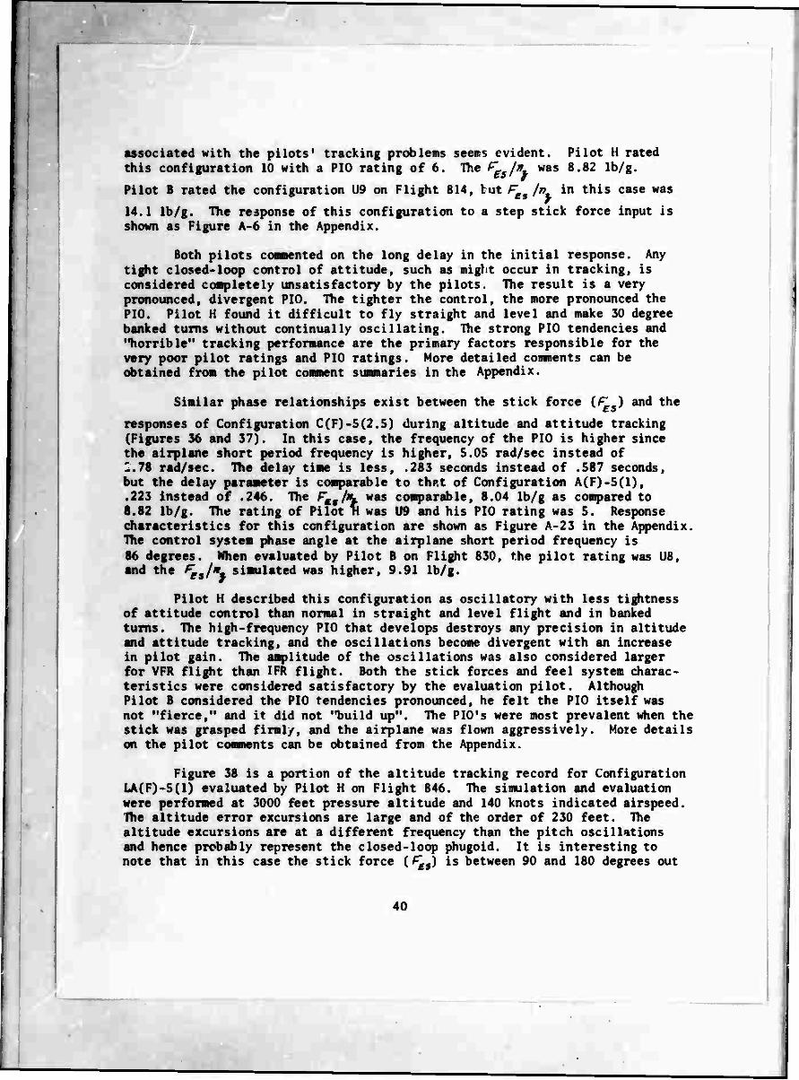
associated with the pilots' tracking problems seers evident. Pilot H rated this configuration 10 with a PIO rating of 6. The fgm/K was 8.82 Ib/g.
Pilot B rated the configuration U9 on Flight 814, tut ^es l\ in this case was
14.1 Ib/g. The response of this configuration to a step stick force input is shown as Figure A-6 in the Appendix.
Both pilots contented on the long delay in the initial response. Any tight closed-loop control of attitude, such as night occur in tracking, is considered completely unsatisfactory by the pilots. The result is a very pronounced, divergent P10. The tighter the control, the more pronounced the PIO. Pilot H found it difficult to fly straight and level and make 30 degree banked turns without continually oscillating. The strong PIG tendencies and "horrible" tracking performance are the primary factors responsible for the very poor pilot ratings and PIO ratings. More detailed comnents can be obtained from the pilot comment summaries in the Appendix.
Similar phase relationships exist between the stick force (^v-) and the
responses of Configuration C(F)-5(2.5) during altitude and attitude tracking (Figures 36 and 37), In this case, the frequency of the PIO is higher since the airplane short period frequency is higher, 5.05 rad/sec instead of 1.78 rad/sec. The delay time is less, .283 seconds instead of .587 seconds, but the delay parameter is comparable to thp.t of Configuration A(F)-5(1), .223 instead of .246. The Ftitln. was comparable, 8.04 Ib/g as compared to 8.82 Ib/g. The rating of Pilot n was U9 and his PIO rating was 5. Response characteristics for this configuration are shown as Figure A-23 in the Appendix. The control system phase angle at the airplane short period frequency is 86 degrees. When evaluated by Pilot B on Flight 830, the pilot rating was US, and the ^,/*. simulated was higher, 9.91 Ib/g.
Pilot H described this configuration as oscillatory with less tightness of attitude control than normal in straight and level flight and in banked turns. The high-frequency PIO that develops destroys any precision in altitude and attitude tracking, and the oscillations become divergent with an increase in pilot gain. The amplitude of the oscillations was also considered larger for VFR flight than IFR flight. Both the stick forces and feel system charac- teristics were considered satisfactory by the evaluation pilot. Although Pilot B considered the PIO tendencies pronounced, he felt the PIO itself was not "fierce," and it did not "build up". The PIO's were most prevalent when the stick was grasped firmly, and the airplane was flown aggressively. More details on the pilot comments can be obtained from the Appendix.
Figure 38 is a portion of the altitude tracking record for Configuration LA(F)-5(1) evaluated by Pilot H on Flight 846. The simulation and evaluation were performed at 3000 feet pressure altitude and 140 knots indicated airspeed. Ihe altitude error excursions are large and of the order of 230 feet. The altitude excursions are at a different frequency than the pitch oscillations and hence probably represent the closed-loop phugoid. It is interesting to note that in this case the stick force (^9) is between 90 and 180 degrees out

of phase with the pitch rate, and of the order of 90 degrees out of phase with the angle of attack. The computed delay time associated with this configuration is .613 sec and the delay parameter is .194. For this delay, the control system phase shift at the short period frequency is 68 degrees. Figure 39 is a record of pitch attitude tracking for this same configuration. The PIO tendencies are very evident here. The phase relationships between stick force, pitch rate, and angle of attack show similar characteristics. Figure 40 is a portion of the ILS approach record obtained for this configuration. The XLS azimuth errors were negligible but the ILS pitch angle excursions were excessive. The responses to a step stick force input for this configuration are shown as Figure A-33 in the Appendix.
Pilot H considered that the piimary problem of Configuration LA(F)-5(1) was the delay in the response following a stick force control input. This gave the airplane PIO tendencies. PID tendencies showed up with any tight closed- loop control in both VFR and IFR flight. These problems were especially evident with altitude and attitude tracking, and during the ILS approach. The pilot comments were that the feel system was "mushy," but it has no unusual charac- teristics and was what one wild expect at low altitudes and speeds during landing approach. The airplane was "approaching uncontrollable" with divergent PIO's occurring even during gentle turns and flying straight and level. It was felt that a landing flare and actual landing could not be successfully performed with the airplane. The pilot rating was 10 and the PIO rating was 6. This configuration was also evaluated on Flights 836 and 850 by Pilot H with somewhat different ratings and comments. These can be found in the Appendix. Pilot B evaluated this configuration only once on Flight 818 with similar comments on its handling qualities and also gave the configuration a pilot rating of 10.
5.5 SUWARY OF PILOT OMIENTS ON CONFIGURATIONS WITH HIGHER-ORDER CONTROL SYSTEM DYNAMICS
Detailed summaries of the pilot comments on specific configurations may be obtained from the Appendix. Along with the comments, the response charac- teristics simulated are also shown in the Appendix.
In general. Pilot B liked and was more tolerant of higher stick forces (r /* ) than was Pilot H. When the stick forces were higher than 8 Ib/g for £5/ j.
"up-and-away" flight. Pilot 3 was likely to comnent that the forces were a little high, but he liked them that way. This was sometimes true even when F /> was as high as 12 or 14 Ib/g. Pilot H was very sensitive to high stick
forces and liked forces less than 8 Ib/g if the configuration cloced-loop response characteristics were satisfactory with the lighter forces.
41
5.5.1 Suanary of Comnents with Airplane Configuration A
With a fast feel system and actuator, Configuration A(F)-2(10), this airplane was considered reasonably satisfactory. In fact, when ^5/». was
reduced to 4.19 Ib/g, the configuration was given a pilot rating of Al.S by Pilot H. As the order was increased and the break-point frequency reduced for the control systen elenents, the primary comment on the configuration chrrac- teristics was the amount of delay in the initial response following a it-ick input. The pilots often said that the closed-loop control problems were associated with this lag or pause between a stick input and the airplane response. Pilot H often described this characteristic as not being "directly connected to the airplane," or a lack of "one-to-one'' connection between a pilot input and the airplane response. The rapidity of the response after the delay was an important factor in closi -loop control. In some cases the response after the delay was described as "slow at first," and then it "builds up." With the delay, the airplane response was difficult to predict and there was also a tendency to overdrive the airplane or pump the stick to compensate for the delay.
As the ratio of delay time to airplane response time (airplane short period) increased, precise closed-loop control deteriorated. The pilots complained of "bobble" tendencies, overcontrol, and lack of precise attitude and g control. Tracking performance, both VFR and IFR, also became progressively poorer. As the delay increased further, PIO tendencies developed and then became divergent, and tracking became an impossible task. Establishing accurate trim also became difficult, and with sufficient delay, PIO's developed just flying the airplane straight and level. The PIO tendencies also became more severe with tighter closed-loop control. Those configurations with pronounced PIO tendencies could only be flown by putting in small step inputs and releasing the stick, that is, by essentially flying the airplane open loop. Closing the loop led to divergent PIO's.
As far as PIO tendencies, pilot ratings, and PIO ratings are con- cerned, it did not appear to make much difference whether the primary delay in the response was introduced by the feel system, actuator, or combinations of both. When the primary delay came from the higher-order characteristics of the actuator, both pilots usually commented that the airplane had greater PIO tendencies and was more difficult to control under VFR than IFR flying. This was attributed to the tighter control under VFR conditions.
When the frequency of the feel system was reduced, and the lag of the airplane response to stick force inputs was increased in this way, both pilots were aware of the changes in feel system characteristics. Pilots described the slow responding stick as "funny feeling," "high inertia," or "rate limited" stick. Pilot H often described the stick or feel system as "soft." With these slow feel system characteristics, the tendency was also to pump and overdrive the stick. When the delay originated primarily from the slow feel system, the configuration was generally more objectionable to the pilots under IFR conditions.
42
.r

The effects of fmmj1L on handling qualities of some configurations
were investigated systematically by Pilot H. The nominal stick force per g for configurations simulated in "up-and-away" flight was 8 Ib/g. If the airplane had no PIO tendencies, reducing the stick force improved the airplane by making the response "snappier." If a configuration had PIO tendencies, reducing the stick force increased the PIO tendencies and tended to make the PIO oscillations divergent. With an increase in stick forces, the PIO oscillations did not disappear, but they were often described by the pilot as of low magnitude and zero damped rather than divergent. The higher forces could make an uncontrollable airplane controllable (see Figure 28). Even though the pilot ratings and PIO ratings improved with these higher stick force gradients. Pilot H objected strongly to them for the fighter mission
5.5.2 Summary of Comments with Airplane Configuration B
When the damping of the airplane short period (£ ) was decreased.
Airplane Configuration B, there were more comments by the evaluation pilots on the bobble and overshoot tendencies of the configurations, even with the best feel system and actuator simulated. Configuration B(F)-2(10). The bobble and PIO tendencies increased at a more rapid rate with an increase in the delay parameter (see Figure 23). There were also some complaints, especially by Pilot H, to the larger ratio of pitch rate overshoot to steady-state response for the Airplane B configurations. This made the airplane appear "heavy" to Pilot H. The pilot was referring to the low ratio of steady-state to transient pitch rate response for a given stick force input. The pitch rate overshoot is apparent from the pitch rate responses shown in Figures A-13 through A-19 in the Appendix. Although it was evident to the pilots that the airplane was somewhat oscillatory open loop, the closed-loop damping was not too objectionable except when a configuration had sufficient delay to result in PIO tendencies.
5.5.3 Summary of Pilot Comments with Airplane Configurations C and C
When the longitudinal short period frequency of the airplane was increased (Airplane C), the airplane was described by the pilots as "quick re- sponding," "touchy," "snappy," and "bobbly." Pilot H also said that the rapid initial response compared to the low steady-state response made the airplane appear "heavy." These remarks were applied to Configuration C(F)-2(10) with the fast feel system and actuator. Pilot B also considered the "bobble" an annoying deficiency of the airplane. The "bobble" conment indicates a lighter damped closed-loop airplane even though the open-loop airplane is well damped.
As the lag in the initial response was increased by slowing up the feel system or actuator, or increasing the order of the.actuator, the handling qualities again deteriorated, and the PIO tendencies increased. The reasons are similar to those presented for Airplane Configuration A as is evident from Figures 24(b) and 27(a). The deterioration in handling qualities
43

^" !
is «gain associated with the delay parameter (^/^)- ^en the PIO tendencies
were pronounced, the pilots comented that they could be avoided by doing things "slowly/* or maneuvering "smoothly." When the PIO tendencies were small, there was a tendency again to pump the stick to compensate for the initial lag. Pilot H often complained about the "heaviness" of some of the configurations. He was referring to the low ratio of steady-state to transient pitch rate response of the airplane.
Configurations C(F)-5(1) and C.CFj-SC.TPö) both had very strong, large amplitude and divergent PIO tendencies. These PIO tendencies occurred even with normal airplane control and could only be avoided by freezing the stick or going open loop. If the stick force gradient (^5/9.) was increased, the PIO's did not disappear, but the amplitude of the closed-loop oscillations decreased and the oscillations could become zero damped. An uncontrollable configuration could again be made controllable.
When the frequency of the feel system was decreased, the pilots again complained of the "miserable" airplane, the stick with "high inertia," the "rate limit," or the "soft" feeling of the stick.
!'•
5.5.4 Summary of Pilot Comments With Airplane Configuration LA
Some of the persistent comments of Pilot B during the simulation of all the landing approach configurations were the "sloshy," "loose control," and "lot of stick travel" characteristics of the feel system. Pilot H categorized the stick as "soft" or "springy" with "too much travel." These comnents, especially with the simulation of the fast feel system, refer to the low value of spring rate (^5/^) simulated for the landing approach con-
figurations rather than the dynamics of the feel system. Although the pilots did not particularly like this low spring rate of 7.46 lb/in., they occasionally commented that such stick characteristics were typical for an airplane during the landing approach. Further comments indicated that these stick characteristics did not particularly interfere with landing approach handling qualities provided the actuator and short period dynamics of the airplane were satisfactory.
As the order of actuator was increased, or the frequency reduced, the pilots commented on the lag in the initial response, the lack of precision, the "bouncy" feeling, and the "indefinite" nature of the response. When the lag originated primarily from the slow feel system, pilot comments indicated concern with the "high inertia" or "rate limit" characteristics of the stick. With a "slow" stick, the handling qualities again were generally worse during IFR flight. When actuator lags and slow stick characteristics were simulated, the pilots had a tendency to pump the stick and overdrive the airplane to increase the response.
44
.r
IT
•
Most of the deterioration in handling qualities that occurred for the landing approach configurations was associated with a degradation of precise attitude and g control, poor tracking, or a dislike of the slow feel system characteristics, but was not generally associated with a development of PIO tendencies. Except for Configuration LA(F)-5(1), the ILS approach and the flare for the landing approach configurations were considered fairly good. Configuration LA(F)-5(1) was also the only configuration with pronounced PIO tendencies and a very poor ILS approach. Both pilots gave this configuration very poor pilot ratings and Pilot H gave it a poor PIO rating. The very poor ratings given by Pilot H could be improved somewhat by raising ? 3S.7 Ib/g, Figure 28(h).
is In- to
45
SECTION VI
CONCLUSIONS
As a result of this in-flight simulation and evaluation of higher-order control systems, the following conclusions can be drawn as to the effects of control system dynamics on the longitudinal handling qualities of a fighter airplane.
1. The predominant pilot comments on many of the control system configurations were concerned with the delay or lag in the response following a control input and the PIO tendencies of the configurations.
2. Some of the higher-order configurations simulated and evaluated were considered unflyable by the pilots and were given pilot ratings of 10 and PIO ratings of 6. These configurations usually had large amplitude and divergent pilot-induced oscillations (PIO) with any closed-loop control.
3. A strong correlation exists between the pilot ratings and PIO ratings of the configurations. The deterioration in handling qualities with degraded control system dynamics is therefore related to an increase in PIO tendencies.
4. With higher-order control system dynamics, the airplane short period response to step stick force inputs can be reasonably well represented by a time delay and an equivalent second-order response. The time delay and frequency and damping of the equivalent second-order response are determined by matching the lowest-order coefficients of the characteristic equation of the higher- order system. This simplified representation is poorest when the lowest frequency of the control system is near the airplane short period frequency. When the control system frequency is significantly higher than the airplane short period frequency, the equivalent second-order response is essentially the airplane short period response.
5. It is also possible to compute a delay time from a match of the highest-order coefficient in the characteristic equation of the higher-order system. This delay time is approximately half the delay time determined by matching the lowest-order coefficients. It is also possible to determine a delay time from the control system phase shift at the airplane short period frequency. The phase shift delay time is comparable to the delay time obtained from a match of the coefficients of the lowest-order terms.
46
• .r

I —,
(
6. Pilot ratings and PIO ratings for all the configurations simulated correlate reasonably well with a computed delay parameter (4,/£ )• ^ is the delay time and P£ is the
period of equivalent second-order response determined from a match of the coefficients of the lowest-order terms in the characteristic equation of the higher-order system.
7. The delay parameter is reasonably well correlated to control system phase angle evaluated at the airplane short period frequency. It is therefore also possible to correlate pilot ratings and PIO ratings to control system phase shift at the airplane short period frequency.
8. There is some indication from tracking records that tracking difficulties and PIO tendencies can be related to the phase angle of the control system at the airplane short period frequency.
9. The deterioration in pilot ratings with an increase in the delay parameter does not appear to be a function of whether the delay arises from the feel system, elevator actuator, or both. Pilot comments differ however, depending on the source of the delay.
10. It is evident from the pilot comments that pilots are very aware of poor feel system charjr.teristics when the feel system frequency is lowered and approaches the airplane short period frequency. Pilot complaints are then directed to the "high inertia," "rate limit," or "soft" characteristics of the stick. Pilots object to such stick characteristics even when they think they do not interfere with airplane control.
11. When the response delay arises primarily from the elevator actuator, the handling qualities are considered poorer by the pilots during VFR flight. When the response delay arises primarily from the slow elevator stick, the handling qualities appear to be poorer under IFR flight. In- sufficient data exists to completely substantiate the latter statement.
12. Pilot ratings and PIO ratings are related to the stick force gradients ('«•/*) of the configuration. A con-
figuration with significant PIO tendencies can be made unflyable by lowering the stick forces, and an unflyable airplane may be made flyable by raising the stick forces. Higher stick forces do not eliminate the PIO tendencies, but they do reduce the amplitude of the oscillations and can prevent them from being divergent.
47
-
1
13. The effect of reducing the airplane short period damping (Airplane B) is to degrade handling qualities at a higher rate with an increase in the delay parameter. The lower short period damping appears to accentuate PIO tendencies with the saae delay parameter.
14. Less correlation exists between the delay parameter and the PIO tendencies for the landing approach configurations simulated. Initially, an increase in the delay parameter appears to degrade handling qualities without an increase in PIO tendencies. The data, however, is not conclusive on this point.
15. General comparisons of fixed-base ground simulator versus flight evaluations indicate that configurations with significant PIO tendencies are rated poorer in flight, and configurations with little or no PIO tendencies are rated better in flight. In evaluating PIO tendencies, ground simulator results are not conservative and can be very misleading.
48
-t- •T

/
■
TABLE I
CONFIGURATION MATRIX ESTABLISHED FOR IN-FLIGHT EVALUATION OF HIGHER-ORDER CONTROL SYSTEM DYNAMICS
ll FEEL
SYSTEM DYNAMICS
AIRPLANE PYNAWIC8 _j ACTUATOR DYNAMICS
UF-AND-AWAY
CONFIGURATIONS LANDING j
APPROACH
FILTER CHARACTERISTICS
A 8 C LA |
FAST
^« - B.4 cpt
i^S - 0.707
ORDER *„ - 0.6
o;*.- 2.8 rad/MC r.p-02
Ait,* t.0 nöJmc
**, " 0.6
A4/. - 2.3 rad/MC <^ - 0.5 |
2
10.0 •A(F)-2<10» *B(F»-2I10» C(F)-2I10) LA(FI-2(10) j
2.6 •A(F»-2(2.6) B(F)-2(2.B) C(F)-2(2.6) LA<F)-2(2.6) |
1.0 •A(F)-2(1) •B(F)-2(1) •C(F)-2(1» *LA(F)-2(1)
4 2.5 •A(F»-4(2.6) #B(F»4(2.B) C(F)-4<2.6I LA(F).4<2.W |
5 2.5 •A(F)-6(2.6I
• B(F)-5(2.5) C(F)-5(2.5) LA|F)-6(2.6» j
1.0 A(F)-60) B(F)-6(1) C(F)-5(1| • i
LA(F).B(1) j
1 MEDIUM
K/* ■ 1.5 q» | in - 0.707
2
10.0 •A(M)-2(10I B(M 1-2(10» C(MI-2|10I *LA|M»-2(10» j
2.5 A(M)-2(2.5) B(M)-2(2.5) C(M)-2(2.BI #LA(M).2!2.B 1
SLOW As - 0.83 cp« ^s-0.707
2 10.0
• A(S)-2(10)
• B(S)2(10)
• C(SI2(10» LA(Si-2l10)
2.6 A(S)-2(2.6) B(S)2(2.5) C(S)2«2.6) • LA(S)-2I2.6I 1
NOTES: (11 UPAND-AWAY CONFIGURATIONS
V0 - 680 FT/SEC, im» \M SEC"1, «yt- 24.2 9'«/RAD
(21 LANDING APPROACH
V0 - 247 FT/SEC, i-« - 0.96 SEC'1, /»-/* - 7.36 gVRAD
,•2 />.s /Sri • 8.2 LB/IN.,Fet,/n.' 16 LB/9, Mg ■ 0.388 IN.'1 SEC
(3) 'CONFIGURATIONS EVALUATED IN FIXED-BASE GROUND SIMULATOR
14) NUMBERS AND LETTERS IN BLOCKS REFER TO CONFIGURATION DESIGNATIONS
49

£
I I >
< IT
II
i' i; n ■
ij
Iffi ml
ii
■ •
5?
'S
ii
11 II
!
dl ^
h //
Ii '11
I
Ml
f If ?j Is
B 8
I s
u Ii 8i 8 ,
C %> v* v»
50
H— .T

I
5 >- SD
< >
CD z
o
Q
I UJ
s z
i!
Si
is M
I
58 • ■
a *
V'
• I
-"«
ill
3 si
11
ii
i\i il
5;
Hi
Ii it
si
i
hiii
lii
i 9
ill
,1" I.
9|
i al a I i:. : .
II
lii
r. /^
ii
3 | I i » • " .1' I i i I ! 51'I
ill il!! : 6
i
ll »Is sit »5-
5
51

TABLE IV
CONFIGURATIONS EVALUATED AND LONGITUDINAL PARAMETERS
SIMULATED IN FLIGHT
FUU *W / VV v «•<■
m lEMIIIRi
mi CMFIWIITI« I'M/ MC)
• P ('»/») (1/ rM] _ ('»' '••1 . PI/PIO» P LOT
KM. IIF MM». LIF MU ml NU» l»F Mi». LIF
in tu L*(M)-2(2.») . 1.12 . I»»' . . 1.07 . 7.M *«/- 1 ii« SM »(F).»(l) 2.71 2.71 .SO« .in . U.I 11.10 21.IS . 21.» u»/-
711 U(f)-2(l) - I.IS - .ISO - . . S.IS . 7.«l u/- IIS «12 •(')-»( 1) 2.71 2.11 .220 .217 . 1».. 22 1 22.2 . M.» bl/-
»17 U(»)-2(I0) I.I« 1.12 .ISS ,1»« . . . 6.03 . 7.M *»/- in MO •(0-2(2.1) 2.12 2.7S .23» .2»« I«.0 17.» 11.2 21.M . M.) »»/-
IM U(I)-2(2.S) 2.13 2.M .SM .SI7 . . 7.SO • •17 . 7.«« *»/- •17 SM *(i)-J(io) 2.17 2.11 .S«» .S«l 12.« 13.0 . 22.1 »2.1 21.» «/- i
m l*(")-2(IO) 1.17 1.7» .635 .ISI I«.l 17.» . 1.»» (.»• 7.M »2/- III »71 e(f)-2(i) S.OI S.M .«10 .«22 «».« 3» 5 . 21.S 21.1 21.» U7/-
»1 U(f)-5(l) • 1.17 • .s«s . 17.» . 1.07 . 7.M 10/- III SM •(M-2(I0) 2.13 2.70 .til .211 • II.1 21.1 21.7 27.« 21.3 M/*
110 *(M-2(i) 2. SO 2.M ■*»2 .MO I.IS 1.71 . 2».« 2«.S 21.» U7/. 117 e(F)-2{i) S.I3 S.O« .«M .«»7 7.27 7.21 21.1 n.i 2«.2 21.» ml-
110 «7« C(F).«(2.S) S.02 S.OI .««2 .«»« '0.» 10.» 2S.« 22.« 27.S N.» U7/. l«S •(f)-»(2.») 2.71 2.S» .2«2 .Ml 11.7 10.7 . 2».S 27.» 21.3 M/-
1 *11 M2 C(F)-2(10) S.I3 S.O« .«57 .«»i 1.6 ».7» 2S.I 22.2 2«.» 21.» «/- «22 C(»)-2(I0) «.17 S.M • Ml .«M ».SS ».»» 21.2 22.» 2».» 21.» Ü7/. 2U »(n-»(io) 2.M 2.1« .SSS .SSI ».»« I.I» . 2«.» 2(.« M.) »«/-
122 »2 C(F)-I(I) S.M S.M .«70 .«2» ».^t ».»1 21.1 21.• 2S.0 21.» U7/- M7 L»(M-2(I0) - I.M - .»1» II.W 17.1 . 1.21 7.»2 7.M ktl-
123 SM »(")-»(10) 2.7» 2.71 .S»l .SIS II.1 12.S 2).l 21.1 21.1 21.» IS/- MS »(0-2(1) 2.7' 2.S7 .ss» .SS» II.» ».IS 2S.2 n.i B.I 21.» Ul- 12S C(F)-2(10) I.I« S.03 .«s« .«»7 I.M 1.17 25.J 2».7 2S.S 21.» »2/-
12« Sll »(0-»(2.S) 2.11 2.12 - .530 10.» 12.5 2)1 22.0 »1.» 21.9 i«/- «II »(f)-2(2.») 2.M 2.S2 .102 .SSS ».22 I.IS . 22.» 21.1 21.1 1»/- 2M C(F).«(2.») «.71 S.M .SM .«1« I.M ».17 2S.7 2«.0 23.5 21.1 U7/-
in IM »(F).8(2.S) 2.77 2.12 .IM .Sll ia.a l».S 21.1 21.2 M.I 21.1 »S/- IM U(M)-2(2.S) l.ll I.M .S20 .SI« )i.i 17.» - • .!• 7.3S 7,«« *«/-
12« SM C(F)-»(I) S.M S.M .»20 .«22 10.7 10.2 22.0 21.» 27.» 21.1 10/- «M C(F).2(I) S.2I S.OS .SM .MO 10.« ».7» 22 I 22.» »0.1 21.1 U7/- «2« U(F)-2(I) 2.2S I.M .s«s .SM IS.« 17.» 1.0 (.»» 7.M »«/-
127 «M •(0 2(2.») 2.11 2.70 .22» .217 . 10.1 20.1 22.» M.I 21.1 «/- 112 L*(I).2(2.S) 2.02 I.M .SM .SM II.» 17.1 S.I2 1.02 7.17 7.«« *«/-
121 «31 »(0-«(2.») 2.M 2.M .10« .SM 10.0 10.1 22.1 22.1 21.S 21.1 Ml- SM .»(0-«(2.S) 2.01 1.17 .«II .S»S 20.» 17.1 . I.M 7.IS 7.«» A»/-
121 SM »(»)-2(2.») - 2.70 - .S«2 . II.1 . 22.2 . 21.1 «/- MO »(l)-2(2.5) • 2.M • .MO - 1.70 . 2».« . 21.1 Ü7/- 2M »(")-«(2.») - 2.1« - S61 - 1.70 . 2«.» . 21.1 »«/-
IM SM e(F)-»(2.J) s.os S.OS .«7S .«21 ».»» ».»1 21.0 21.7 2«.2 N.I Ml- | 1 |
313 t»(n-*(2.S) I.IS 1.17 .SI2 .SM 11.» 17.» S.I« 1.02 7.SO 7.»« Ul- 1
52
.r
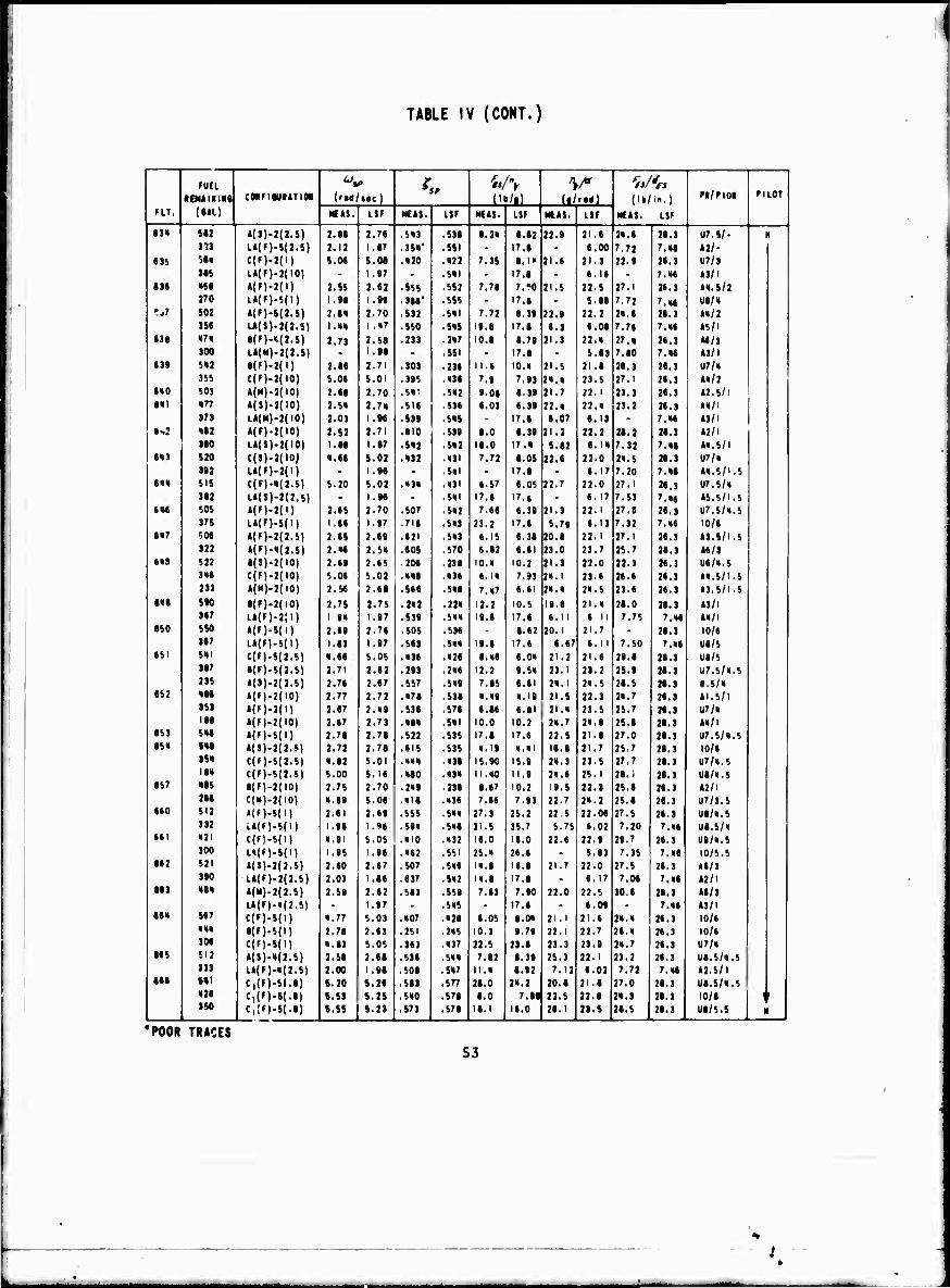
TABLE IV (COHT.)
FUEL ^V / tP w v W '«
FIT.
•EMtlliHQ
{MM
CMFIMMTIOi (rid tic) (18/61 (■/rail NUI.
L.)
LSF
FI/PIO* FILOT
«IS. L$F KM. LIF MCH. LSF MUS. LSF
13« Ml *(»)-2(J.8) 2.88 2.78 .S«3 538 8.2« 8.82 22.9 21.6 2«.6 26.3 UT.il- N 373 L»(f)-*(J.S) 2.12 i.r ^S«' .551 - I7.S - 6.00 7.72 7.«6 ill-
83i SS« e(F)-2(l) S.M S.08 .«20 .«22 7.3$ S.I» 21.6 21.3 22.9 26.3 U7/3 3SS U(F).2(I0) - 1.97 - .Ml " 17.8 - 6.16 - 7.«6 63/1
136 «SS A(f)-J(l) 2.SS 2.82 sss .552 7.78 7.»0 21.5 22.5 27.1 26.3 M.S/2 J70 L*(F).S(I) I.SS I.9S ■ 3M' .555 - 17.8 - S.M 7.72 7.«6 U8/«
r..7 S02 *(f)-»(2.5) 2.8« 2.70 .S32 .Ml 7.72 8.39 23.9 22.2 2«.6 26.3 »«/2 3SS l.»(8)-2(2.S) 1.«« l.«7 .SSO .S«S IS.8 17.8 8.3 6.OS 7.76 7.»6 65/1
138 «7« 8(F).«(2.8) 2.73 2.S8 .233 .2«7 10.6 8.79 21.3 22.« 27.» 26.3 66/3 300 U(M)-2(2.5) 1.98 - .SSI - 17.8 - 5.S3 7.80 7.»6 63/1
(3» S«J •(f)-»(l) 2.68 2.71 .303 236 II.I 10.» 21.5 21.8 29.3 26.3 U7/« 3SS C(F).2(I0) S.06 S.OI .395 .»38 7.9 7.93 2«.» 23.5 27.1 26.3 t«/2
810 S03 «(M)-2(10) 2.88 2.70 .5«! .5«2 9.06 8.38 21.7 22.1 23.3 26.3 «2.5/1 Ml «77 »(»)-2(10) 2.S« 2.7» .518 .536 S.03 6.39 22.» 32.« 23.2 26.3 ««/I
373 U(ll).t(IO| 2.03 I.M .539 .S«S - 17.8 6.07 8.13 - 7.»6 63/1 •si «92 »m-2(io) 2.S2 2.71 .810 .538 8.0 8.39 21.2 22.2 28.2 26.3 62/1
3W l*($)-2(10) I.N I.S7 .S«2 .S«2 18.0 17.« 5.82 8.1« 7.32 7.«6 6«.S/1 S«3 sn C(S)-2(IOj «.88 S.02 .«32 .«31 7.72 8.05 22.6 22.0 2».5 26.3 U7/«
3S2 LA(F)-2(I) - I.N - .Ml - 17.8 - 8.17 7.20 7.«6 »«,5/1.5 •«« SIS C(F).«(2.S) S.20 S.02 .«3« .«31 8.57 8.05 22.7 22.0 27.1 26.3 U7.5/«
3*2 L»(S)-2(2.S) - I.M - .Ml 17.8 17.8 • 8.17 7.53 7.»« 65.5/1.5 SM SOS »(f)-2(l) 2.6S 2.70 .507 .S«2 7.68 8.39 21.3 22.1 27.8 26.3 U7.5/«.5
375 U(f).S(l) 1.88 1.97 .718 .5«3 23.2 17.8 S.79 8.13 7.32 7.»6 10/6 in; r-OS Mf)-2(2.S) 2.6S 2.69 .621 .5«3 8.15 8.39 20.8 22.1 27.1 26.3 63.5/1.5
322 »(M-«(2.S) 2.«6 2.S« .60S .570 6.82 6.81 23.0 23.7 25.7 26.3 66/3 BXS S22 S(S)-2(I0) 2.69 2.6S .206 .238 10.« 10.2 21.1 22.0 22.3 26.3 US/«.5
3«S C(F)-2(I0) S.06 S.02 .««6 .»38 8.1« 7.93 2».l 23.6 26.6 26.3 6«.5/1.5 233 »(«y-i(io) 2.S6 2.68 .568 .IM 7.«7 6.61 2«.« 2«.5 23.6 26.3 63.5/1.5
«t» SM 8(F).2(I0) 2.7S 2.7S .2«2 .22« 12.2 10.5 19.8 21.« 26.0 26.3 63/1 367 U(F).2(I) 1 •« 1.97 .539 .5«» 19.6 17.8 6.11 6 II 7.75 7.«6 M/l
SSO SSO M')-»(il 2.68 2.78 .505 .536 - 8.82 20.1 21.7 - 26.3 10/6 367 L*(f)-5(l) 1.93 1.87 .563 .5»» 19.8 17.S 6.87 6.11 7.50 7.»6 U9/5
SSI HI C(F)-S(2.S) «.86 S.OS .«36 .»28 6.46 8.0» 21.2 21.8 29.8 26.3 US/S 3S7 8(F)-5(2.S) 2.71 2.82 .293 .2»6 12.2 9.5» 23.1 23.2 25.9 28.3 U7.5/6.5 23S M»)-2(2.S) 2.76 2.67 .557 .S»9 7.85 6.81 2«.l 2«.5 26.5 28.3 6.5/«
SS2 «M *(n-2(IO) 2.77 2.72 .«78 .538 ».»9 ».19 21.S 22.3 2«.7 26.3 61.5/1 3S3 Mf)-2(i) 2.67 2.«9 .536 .578 8.86 6.81 21.« 23.5 25.7 26.3 U7/« ISS «(F)-2(I0) 2.67 2.73 .«9« .Ml 10.0 10.2 2«.7 2«.8 25.6 26.3 M/l
SS3 s«s »(F)-S(l) 2.78 2.78 .522 .535 17.S 17.6 22.S 21.8 27.0 28.3 U7.5/«.S es» s«s *(S)-2(2.M 2.72 2.78 .615 .535 ».IS «.«1 IS.8 21.7 25.7 26.3 10/8
3S« C(F)-S(2.S) «.82 S.OI .««« .»38 15.90 IS.8 2«.3 73.5 27.7 36.3 U7/6.5 IS« C(f)-S(2.S) S.00 S.I6 .«SO .«3« II.»0 11.8 2«.8 2S.1 M.I 26.3 U8/6.5
SS7 «SS 8{F)-2(I0) 2.7S 2.70 .2«9 .238 8.87 10.2 19.5 22.3 25.8 28.3 62/1 266 C(N)-2(I0) «.88 S.OS .«IS .»36 7.66 7.93 22.7 2«.2 25.8 26.3 U7/3.5
S60 111 »(F)-S(l) 2.81 2.69 .555 .5»» 27.3 25.2 22 5 22.M 27.5 26.3 U8/6.5 332 ..»(F)-S(l) 1.98 I.M .59« .5»8 31.5 35.7 5.75 6.02 7.20 7.»6 US.5/»
SSI «21 C(f)-S(l) «.91 S.OS .«10 .»32 16.0 16.0 23.6 22.8 29.7 26.3 US/«.5 300 LMF)-S(I) I.SS 1.98 .»82 .551 25.» 26.6 - 5.93 7.35 7.»6 10/5.5
S62 S2I MS)-2(2.S) 2.60 2.67 ,507 .S»6 I».8 16.6 21.7 22.0 27.5 26.3 66/3 3S0 l.*(f!-2<2.S) 2.03 1.96 .637 ■ Ml l».8 17.8 - 6.17 7.M 7.»6 62/1
SS3 «6« «("1-2(2.8) 2.S9 2.62 .563 .559 7.83 7.90 22.0 22.5 30.6 26.3 66/3 Ul(f)-«(2.S) • 1.17 . .5»5 • 17.8 . 6.09 ■ 7.»6 63/1
SS« S67 e(»)-i(i) «.77 S.03 .«07 «29 8.05 8.0« 21.1 21.6 2«.» 26.3 10/6 ««« 8(F)-5(I) 2.76 2.63 .251 .2»5 10.3 9.79 22.1 22.7 28.» 26.3 10/6 306 C(F)-8(I) «.S3 S.OS .361 .»37 23.5 23.9 23.3 23.9 2«.7 26.3 U7/»
MS SI2 »(S)-«(2.S) 2.SS 2.69 .536 .5»» 7.82 8.39 25.3 22.1 23.2 26.3 U8.S/6.5 333 LA(F).«(2.S) 2.00 I.9S .SOS .S«7 II.» 8.82 7.12 6.02 7.72 7.»6 62.5/1
MS S«l C|{F)-8{.S) S.20 S.26 .563 .577 26.0 2«.2 20.9 21.S 27.0 26.3 US.5/«.5 «26 C,(F)-8(.8) S.SI S.2S .560 .578 8.0 7.St 22.5 22.8 2«.3 26.3 10/8 \ I
3 SO C,;FI.S(.S) 8.SS 1.11 .573 .S7S 18.1 18.0 26.1 23.S 26.5 _ 26.3 US/5.5 " 1
'POOR TRACES
53
.'

g
i U)
9i
2 og
si mi < > m
< C
O
i 1 « «
1 3 9StUI993l3Sta«9t5a3S85SS5tSSa9S9t99SI9aiaSl3iB3|] 1 *.•• >»
t •*
liüslüiüüilüsiüiiüssiiiSssüiilllssSHIÜüS s
,51 oooooooooocsoooocoooooooooooooooooooooooooooooooooool
9 — lsM>!!8i!3i!|l|8MiiEEE^gäl!S9lii>§l!!8^il!s9>8>«
OOOOOOOOOOOOOOOOOOOOOOOOOOOOOOOOOOOOOOOOOOOOOOOOOOO
8
•%1 ^ricfrioeiooooeodooooooötfeoödeöoöooooooöobocdöddoöädoeb
5
iiBB||S{in§H§iHSio8g8iliys§n!li8iiliiiiiiBBBiB ooooooooooooooooooooooooooooooooooooooooooooooooooo
5
;-i iiiliiiiiil!iiiiiiicsiiiii!iliilii!ilililiiiiliil!i 0300000000000000000000000000000000000000000000030 01
B s !ll!l!!!!!ni!!!!!l!!!!!!!n!!!!SnHiillHillin!!
S
•-) f,r>iNr»fsfNisf^»Nf>,(N^r>.r*f>,r«.r.f>.^.rf»«««««**»Wi«--------^^-iNr.rir.*«ir.f»f*(N^r»
™
«1
iilliii!iii'g8iiSII|nilini!^||nS8inB§S|ijilii§i ooooooooooooooooooooooooodoooodooooooooooooodoooooo
■
,SI iil8fil||li!l||f9Il|ilB9llfilSiB8lil|ll!il|||iBI8!l| OOOOO30O0O0OO0OOO0OOOOOOOÖOOOOOOOOO0OOO0OOOÖOO0O00O
<* iiiiiliiiiiiiiiiiiiiiliiiiiiiisnSssS!SsSs8ii8ii8iR
•ii !5S99S*55!55!9!59S!S5S8S5!SS!5§tf!iliII8lii!555!!5!S|
Ms
,»i ii8iSS3aS38ii!!SR^S$3S3S9995599iHni9S2rIS9i3äSSSs OOOOOOCOOOOOOOOOOOOÖOOOOOOOOOOOOOOOOOOOOOOOOOOOOOOO,
^5 ^ 8iESi8Ss5SSsSs§BsSs8SsS&98iBBgB2BBs8ssSsS82iiiB8lis
I
1
il
J >
• i i J ; a 8
| 1 i
M i ■ c
8 9
54
.1

o u
CD <
$1
,%i
■ i
-I
^?5
-a'ji
'j3
*i
rlS 3 S
S5523t33:2J5335J3S5JS5555«5S55SS55 33J33335555233355
MI§8^-5££f|H????ilS^-HH •Si8 22SSs!2!::8§8§§ 0000000000000000000000000000 OOOOOOOOOOOOÖÖÖOO
OOOOOOOOOOOOOOOOOÖOOOÖbOOOOOO OOOOOOOOOOOOOOOOOOO
in||!!lifii!liisi!||giii8S5§fff8e|i|||iSiiiiiiih5 OOOOOOOOOOOOOOOOOOOOOOOOOOOOOOOOOOOÖOOOOOOOOOOOÖOOO
s s ; ■! e S ^ ^ f : = S Ü H & 119 £ m i I i a ■ • e S § ^ U 2 R 9 8 S 9 9 m it ii ooooooooooooooooooooooooooooooooooobooooooooooooood
oooooooooooooooooöoooooöooooooooooobooöoodooooeoooo
000000000000000000000000000000000600000000000000000
oocooooooooooooooooooooooooooooooeooooooooooooooooo
SSS99i9iii83SS£i9s9^lilli^HSSSHii22iiiiitiin!2s
!^uSiHI§iii8llh!!2^sES!;Sniisl!niisriSnil9^ 000000000000000000000000000000000000000000000000000
|iiiin8ll!B|iS!li!t8BnMRJtRnM«88BB«!Mii|ih!ll 00000000000000000000000000000000000000000000000000
RRKKRRRRRieitRRKItRRItRRKRieRRRRRRRieie«« »*«««»»*»«»»««»»«
K;;BSRKXRR8RSS;(;;xRR&SU2R;;Sft;:88;;!;RXRS8Bs|8Ms8i£*lsi5 ----------^-------^------^^-------OOOOOOOOOOOOOOOOO
O in • n o • «
s r 9 R R'; = : = :
9 S H ! 9 9 9 9 S S H S S x H ! 9 ! S 3 S ! 3 S S B 2 S S ! ; s H H H H S s S S ü S i x OOOO - -> O O O t 0000000000000000*0000000000000000000000
l!Ste|3:RSR;|Ce:S83SS8888ö!888RR!388£IISSB;iSII.I«SSI
8ii99li9iili9iB8ii989Biiiiiiilii8i8ii9ii99iii9i928i ill 91 91 2 - • ! 8 a » 5 » _ i, 7 I ' 7 K K K K S S 91 Z X 31 7 9 ^ ^ K K R
*"*R!5?S555!!?»??! " ';":£:i555ti5ii11 5«8
i
1 1
i !
II
h !
I
i ^ I i c s ■ c
S i
seas
55
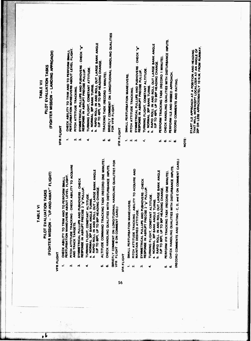
W) azS
^£
tS2
fit! f|t gga QCHO
X o 3
1 o u.
56
• t
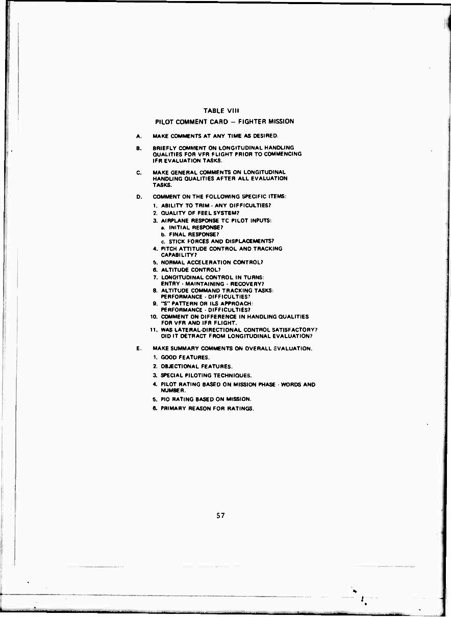
I
TABLE VIII
PILOT COMMENT CARD - FIGHTER MISSION
A. MAKE COMMENTS AT ANY TIME AS DESIRED.
B BRIEFLY COMMENT ON LONGITUDINAL HANDLING QUALITIES FOR VFR FLIGHT PRIOR TO COMMENCING IFR EVALUATION TASKS.
C. MAKE GENERAL COMMENTS ON LONGITUDINAL HANDLING DUALITIES AFTER ALL EVALUATION TASKS.
O. COMMENT ON THE FOLLOWING SPECIFIC ITEMS:
1. ABILITY TO TRIM ANY DIFFICULTIES? 2. QUALITY OF FEEL SYSTEM? 3. AIRPLANE RESPONSE TC PILOT INPUTS:
«. INITIAL RESPONSE? b. FINAL RESPONSE? c. STICK FORCES AND DISPLACEMENTS?
4. PITCH ATTITUDE CONTROL AND TRACKING CAPABILITY?
b NORMAL ACCELERATION CONTROL? 8. ALTITUDE CONTROL? 7. LONGITUDINAL CONTROL IN TURNS:
ENTRY - MAINTAINING - RECOVERY? 8. ALTITUDE COMMAND TRACKING TASKS:
PERFORMANCE ■ DIFFICULTIES7
9. "S" PATTERN OR ILS APPROACH: PERFORMANCE - DIFFICULTIES?
10. COMMENT ON DIFFERENCE IN HANDLING QUALITIES FOR VFR AND IFR FLIGHT.
11. WAS LATERAL-DIRECTIONAL CONTROL SATISFACTORY? DID IT DETRACT FROM LONGITUDINAL EVALUATION?
E. MAKE SUMMARY COMMENTS ON OVERALL EVALUATION
1. GOOD FEATURES.
2. OBJECTIONAL FEATURES.
3. SPECIAL PILOTING TECHNIQUES.
4. PILOT RATING BASED ON MISSION PHASE ■ WORDS AND NUMBER.
5. PID RATING BASED ON MISSION.
6. PRIMARY REASON FOR RATINGS.
57
MnMBMBMM
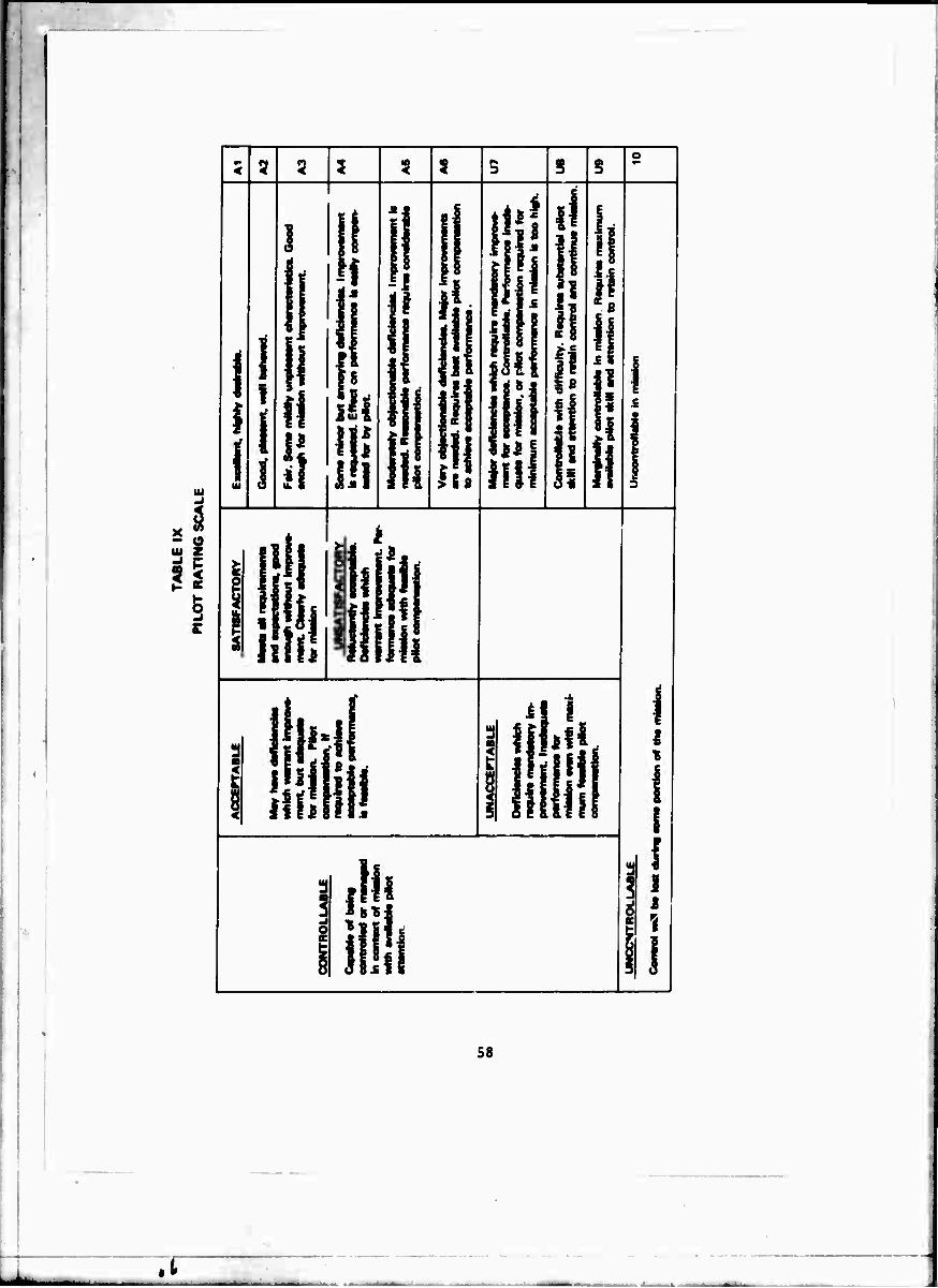
85 S OC
I
H
in ili
*!
i!
i1
Hi
!! > 6ß
Mt n
i\ l
I in
illill1 ll!
11
h^ ilflftl!
s o
fill ill1 Ulli
III
?
8
!
!1 ll
5
I? 5
:l
In llll 11
I I
1
58
.1
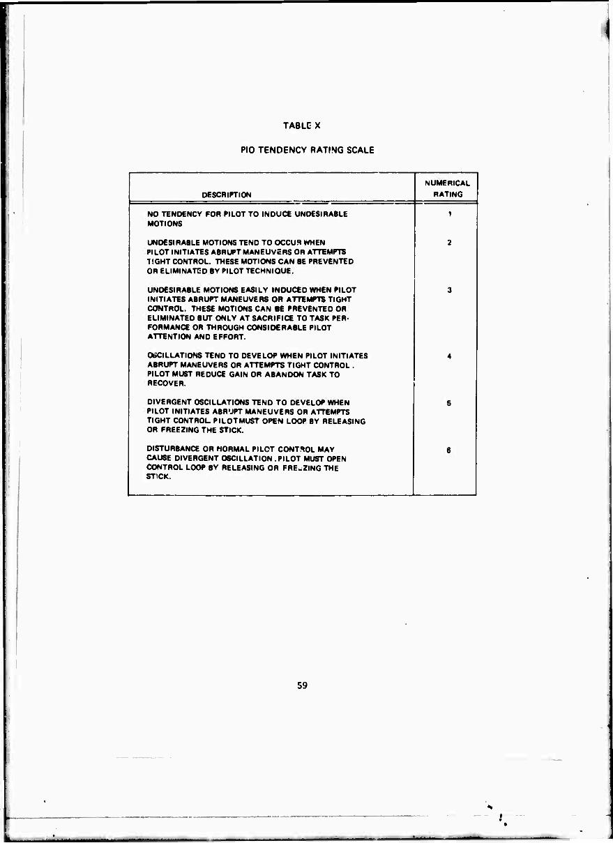
TABLE X
PIO TENDENCY RATING SCALE
DESCRIPTION
NUMERICAL
RATING
NO TENDENCY FOR PILOT TO INDUCE UNDESIRABLE MOTIONS
UNDESIRABLE MOTIONS TEND TO OCCUR WHEN PILOT INITIATES ABRUPT MANEUVERS OR ATTEMPTS TIGHT CONTROL. THESE MOTIONS CAN BE PREVENTED OR ELIMINATED BY PILOT TECHNIQUE.
UNDESIRABLE MOTIONS EASILY INDUCED WHEN PILOT INITIATES ABRUPT MANEUVERS OR ATTEMPTS TIGHT CONTROL. THESE MOTIONS CAN BE PREVENTED OR ELIMINATED BUT ONLY AT SACRIFICE TO TASK PER- FORMANCE OR THROUGH CONSIDERABLE PILOT ATTENTION AND EFFORT.
OäCILLATIONS TEND TO DEVELOP WHEN PILOT INITIATES ABRUPT MANEUVERS OR ATTEMPTS TIGHT CONTROL . PILOT MUST REDUCE GAIN OR ABANDON TASK TO RECOVER.
DIVERGENT OSCILLATIONS TEND TO DEVELOP WHEN PILOT INITIATES ABRUPT MANEUVERS OR ATTEMPTS TIGHT CONTROL PILOTMUST OPEN LOOP BY RELEASING OR FREEZING THE STICK.
DISTURBANCE OR NORMAL PILOT CONTROL MAY CAUSE DIVERGENT OSCILLATION . PILOT MUST OPEN CONTROL LOOP BY RELEASING OR FREEZING THE STICK.
59

(A
O DC I- z 8 < z
H §!
it IS Z ui
CD < oc < > Ui
60
.t
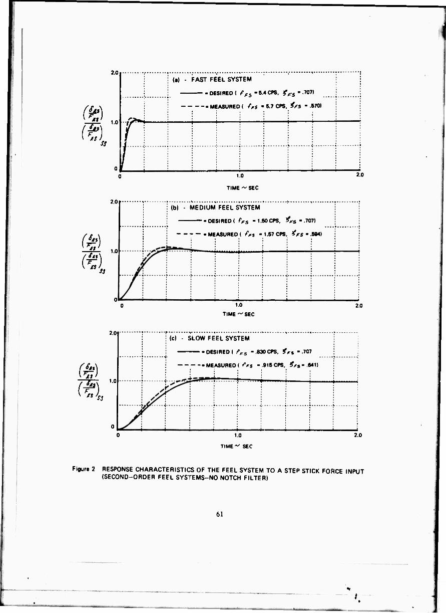
2.0
1.0
2.0
te)
77* 1.0
\ IS SJ
(•) - FAST FEEL SYSTEM
DESIRED ( />s - 5.4 CPS, ^s - 707)
-MEASURED ( /Vs " 6.7 CPS, ^5 " 6/0)
1.0
TIME ~ SEC
: (b) - MEDIUM FEEL SYSTEM
DESIRED ( />s -1.50 CPS, ^cs - .707)
MEASURED ( /Vs - 1.67 CPS, frs - .5M)
^■■■i
1.0
TIME ^ SEC
2.0
2.0
2.0
W). 1.0
|c) - SLOW FEEL SYSTEM
-DESIRED! i'Vs -.830CPS, ^s -.707
MEASURED (^s -.915 CPS, ^s-.*»1t
I 1.0
TIME-^ SEC
2.0
Figure 2 RESPONSE CHARACTERISTICS OF THE FEEL SVSTEM TO A STEP STICK FORCE INPUT (SECOND-ORDER FEEL SYSTEMS-NO NOTCH FILTER)
61
.'

2.0
(J)
a)
1.0
1 f T H PAST MiL SYSTEM | ! f 1
MEASURED \ 4 \ ■••••••"•T 1 *
11 . l. J
yi i 2.0
1.0
2.0
m m 1.0 -
1.0
TIME ~ SEC
1.0
TIME ~ SEC
(cl SLOW FEEL SYSTEM
COMPUTED MEASURED
MCU*.
1.0
TIME - SEC
2.0
I lb) MEDIUM FEEL SYSTEM
; ; ■. MEASURED
1/I i 1 | 1 j""\ 1 1 1 | : •< i
2.0
2.0
F gur« 3 RESPONSE CHARACTERISTICS OF THE FEEL SYSTEM TO A STEP STICK FORCE INPUT (SECOND-ORDER FEEL SYSTEM WITH NOTCH FILTER)
62
.1

20
(t) (1) ss
(•) ......"^*
2.0
(?) 1.0
£, -10.0CW, ^a -707) - DESIRED ( ra - i*v^.. ^a
. MEASURED (SAMP AS DESIRED)
Mb)-
- DESIRED ( /^ -2.60«. fa
-MEASURED
•.707)
(M
2.0 .,c).
DESIRED I /m -1.0CW, !<a -.
Figure 4 ELEVATOR RESPONSE TO STEP STICK INPUTS FOR VARIOUS ACTUATORS SIMULATED (SECOND-ORDER ACTUATORS)
63
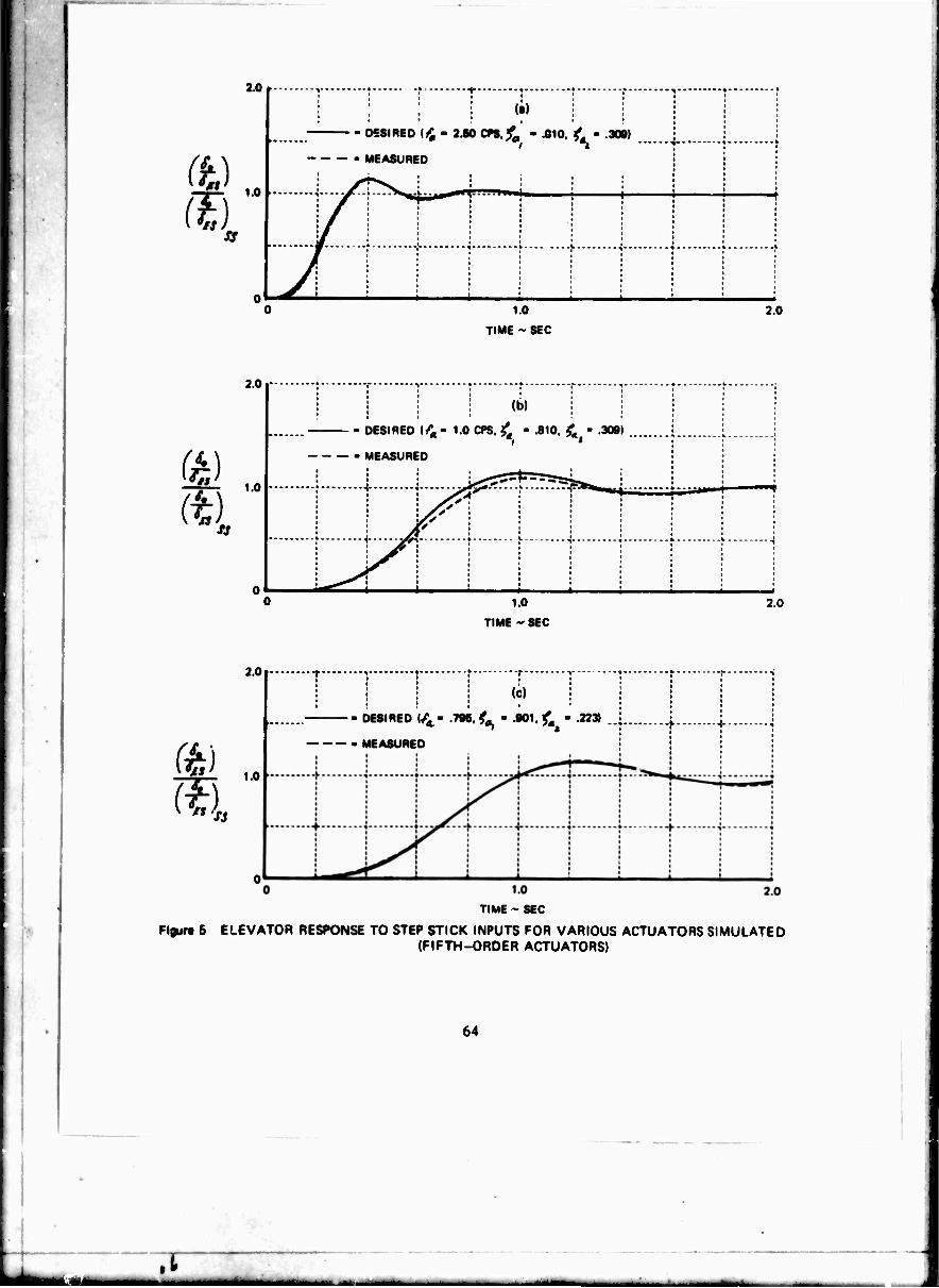
3.0
(t) (I)
1.0 ■
I ; 1 '1' xsmto {£'7Mcn.fa - .010,
,* --^-- -
<- - 3091 L ■ '
[
I MEASURED
/ 1.0
TIME ~ SEC
2.0
2.0
ft) 1.0
- i (i) j j
• DESIRED (A- 1.0 CPS. £ - .810 t. - .309) 1
- MEASURED '-J ; !■ •
1 t^5 ._ j J£Z. .
f
» ' * ' I : ' i i. !
„^ III^^ i
I • * * i
1.0
TIME - SEC
2.0
2.0
W) 1.0
;
--r-
(c)
- DESIRED </4- .796, t - .901, £ - .223»
- MEASURED
^ f
TIME - SEC
Figurt 5 ELEVATOR RESPONSE TO STEP STICK INPUTS FOR VARIOUS ACTUATORS SIMULATED (FIFTH-ORDER ACTUATORS)
64
kM .1

2.0
(t) ss
(a) - SECOND ORDER
DfSIREDC /" -2.5CPS, t^'fOJ) a. *
-MEASURED
1,0 TIME ~ SEC
» \ 2.0
2.0
(41
FOURTH ORDER i
DESIRED ( f -2 50CPS, i -.926. A -.383):
MEASURED
1.0
TIME - SEC 20
2.0
i Snl. Si
1 kiVVrFTH ORDER
'• '< ■810. t
1 \ -j - MEASURED
• i- -i » ^
1.0
TIME ~ SEC 2.0
Fisure 8 ELEVATOR RESPONSE TO STEP STICK «NPUTS FOR VARIOUS ORDER ACTUATORS SIMULATED (ACTUATOR FREQUENCY 2.5 CPS)
65

FLIGHT «LOT PR/PIOR RAD/SEC i*. RAD/SEC <*, «s Fes/** LB/Q'
DESIRED 6.00 0.626 5.00 0.901 .233 8.0
ne H 118.5/4.6 Ml 0.677 5.00 0.901 .233 24.2
M H 10/6 B.26 0.578 S.00 0.901 .223 8.0
866 H U8/6.B 6.33 0.678 6.00 0.901 .223 16.0 1
0 DESIRED AND SIMULATED FIFTH-ORDER ELEVATOR ACTUATOR ROOTS
O DESIRED AIRPLANE SHORT PERIOD ROOTS
" • SIMULATED AIRPLANE SHORT PERIOD ROOTS
Figur« 7 BUTTERWORTH DISTRIBUTION OF ACTUATOR AND AIRPLANE LONGITUDINAL SHORT PERIOD ROOTS FOR CONFIGURATION C^FI-SUM)
66
.1 \
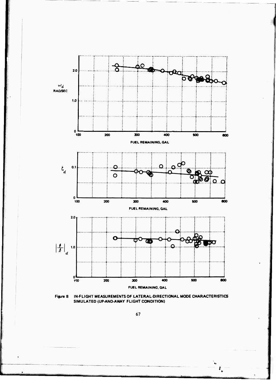
2.0
RAD/SEC
1.0
• , i * ' I * *
•» r * -I ■• • *- ■» * •
• * ■ * * * * *
• ■ • * • * *
• i * * i • *
. • • ; I ' • ; ! I • *!••' i * *
•> • r ■{ • • ,«• i i •
i % * i i * §
1 : : * * ' : ■ * '
100 200 300 400
FUEL REMAINING. GAL
BOO 000
d
100
300 400
FUEL REMAINING. GAL
200 300
FUEL REMAINING,
400
GAL
eoo
Figur« 8 IN-FLIGHT MEASUREMENTS OF LATERAL-DIRECTIONAL MODE CHARACTERISTICS SIMULATED tUP-AND AWAY FLIGHT CONDITION)
67

2.0
RAO/SEC
1.0
!• | r t i i r : ! : : j ■ i : |
1 ■> ', \ "j ■• r ^ ■i
-i • \ i- \ f f -i I i ! i i i : i * ■ ■ i * i • * i *
•» r ^ + ' • .'• ^
100 300 400
FUEL REMAINING, GAL
500 600
01
| i 1 | j o I
o, 100 200 300 400
FUEL REMAINING, GAL
500 600
2.0
^ I
1.0
; r T ■ r r * 1 , • ,
f 1 i J .[Q.J... k........j ! t 0: ^-"-i
• i i ; • i i j I • ; ;
\ i | • \ 1
l i i i i •
1 Mi 100 200 300 400
FUEL REMAINING, GAL
600 600
Figure 9 IN FLIGHT MEASUREMENTS OF LATERAL-DIRECTIONAL MODE CHARACTERISTICS SIMULATED (LANDING APPROACH FLIGHT CONDITION)
68
.1
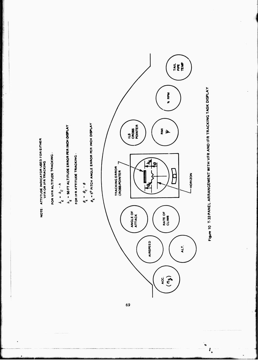
I I o
(9 Z
si
E <
z 2 o < K
I -J < u. > E O
>
5 5 z cc ü: or O oc K Ui
8
3
o z 5 o <
t s <
<
c o
I o I c K cc o cc ■ IH
a O z < I
? I %
i
o z < IX oc <
< a.
i
69
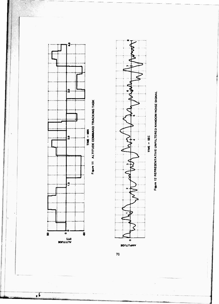
■s
, 1.
—(
.9
v ■.«
ft --a
aannnv
7C
.1
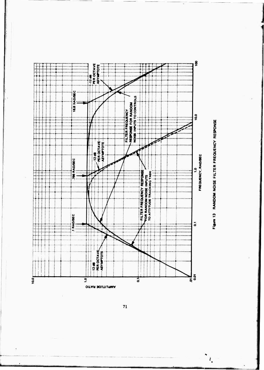
i
«
Ui
g z UJ
8 Ui c IL ac UJ
O z
i o z < ac
I
oiiv« 3am.iidMV
71

(t)
ör
- HlGMEROROeH RESPONSE
- TIMt DELAY («„ I ANDSECONO-OROEB AIRPLANE SHOUT PERIOD I l*g, • ?„ I
• TIM« DELAY I *t0 ) AND EQUIVALENT SECONDOHDEH RESPONSE i*»>t ,'Sf\
• TIME DELAY FOR BEST MATCH I ««* I AND SECONOORDEH AIRPLANE SHORT PERIOD ( W,^ , tSA I
TIME ~ SEC
TIME - SEC
Figur« 14 COMPARISON OF HIGHER-ORDER LONGITUDINAL RESPONSES WITH SECOND-ORDER RESPONSES WITH TIME DELAY FOLLOWING A STEP STICK FORCE INPUT CONF. A|F)-2(1)
72
.1
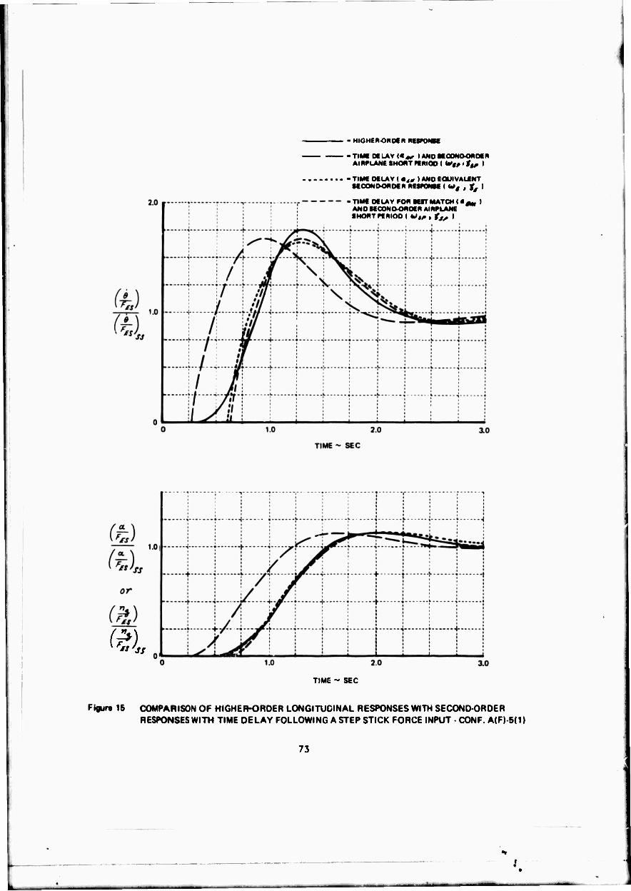
• HIGHER-OnOCR RESPONK
• TIMC DELAY |4«r I ANOMOOM&OMOCN Al RPLANE SHOHT ff RICO ( V$ß 11t, I
• TIME DELAY I »ä0 I AND f OUIVALCNT KCONOOROCN MWONM I W# , J^ I
• TIME DELAY FOR MtT MATCH I • 0m I ANOSEOONDOMOER AIRPLANE •HORT PERIOD I W,^ , f,, I
TIME " S€C
Figur« 15 COMPARISON OF HIGHER-ORDER LONGITUDINAL RESPONSES WITH SECOND-ORDER RESPONSES WITH TIME DELAY FOLLOWING A STEP STICK FORCE INPUT - CONF A(F) 5( 1)
73

• HIGHlROBOf R RESPONSE
-TIMiOfLAV«,, lANOKOONOOnOCR AIRPLANE SHOWT PCfllOO I i*i, • f,, I
- TIME Of LAV I m4, I AND EQUIVALENT •ECOMOOftDEM RttPONK ( W# , j^ I
■ TIME Of LAV PON MtT MATCH I « «* I AND SECONOORDtR AIRPLANE SMOÄT PERIOD I http , ts, |
TIME ~ SEC
TIME ^ sec
Figura 16 COMPARISON OF HIGHER-ORDER LONGITUDINAL RESPONSES WITH SECOND-ORDER RESPONSES WITH TIME DELAY FOLLOWING A STEP STICK FORCE INPUT CONF. A(M)-4(2.5)
74
.t • j
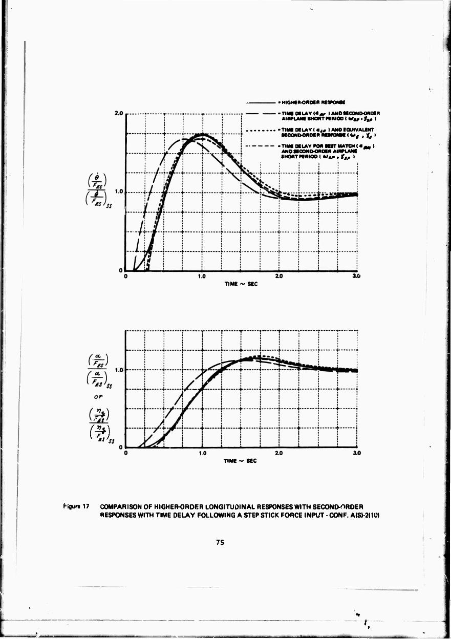
I
• HIGHf R-ONOf R Rt
•TIMt OtLAVKj^ lANDHCONOOMDCR AINPLAM SHORT HRIOO ( Vg, • 1l0 I
TIMf Of LAY I *t0 I AND lOUIVALiNT SfOONMMMR RUKMN I W# , J^ I
TIM Of LAY FOR MtT MATCH I «j^. > AN0flfC0NI>OR0tR AIRPLANf SHORT KRIOO ( hit* * XJS I
TIME ~ SEC
v «'s*
TIME ~ SEC
Figurt 17 COMPARISON OF HIGHEH-ORDF.R LONGITUDINAL RESPONSES WITH SECOND-ORDER RESPONSES WITH TIME DELAY FOLLOWING A STEP STICK FORCE INPUT - CONF. A(S)-2(1Ü)
75
t i

•HICHfR-OROCR RESPC»SE
-T Ml «LAY I«,, lANOKOOMOOnDEN AIRPLANC SHOnT KRIOO I <^t, • ttß I
• TIME Df LA V I m*» I AMD iOUIVAUNT SCCOMOOMDCn RESPONSE < w4 , ^ i
\!\,\ -TIME DELAY FOR MtT MATCH i «.., I h-\l—!• AWOitCOWtMMIOtH AlWLANi
TIME - SEC
or
1.0
(a) ts ss
TIME - SEC
Figure 18 COMPARISON OF HIGHER-ORDER LONGITUDINAL RESPONSES WITH SECOND OROER RESPONSES WITH TIME DELAY FOI ^WING A STEP STICK FORCE INPUT - CONF. B(F)-5( I I
76
.t
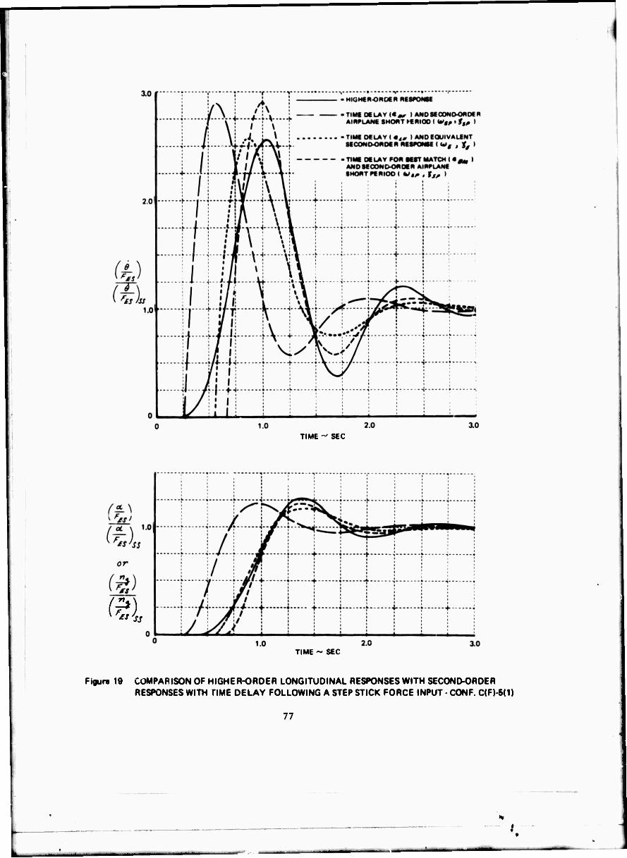
TIME - SEC
TIME ~ SEC
Figure 19 COMPARISON OF HIGHE R-ORDE R LONGITUDINAL RESPONSES WITH SECOND-ORDER RESPONSES WITH TIME DELAY FOLLOWING A STEP STICK FORCE INPUT CONF. C(F)-6(1)
77
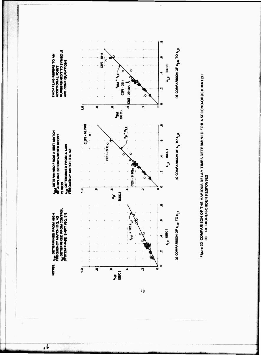
i
hfl set- ' _i HI (S o < z - 3JSg
11 5 < z <
«
li i
9 5 ä
li
>l
* - *
2
c <
cc <
^g
i cc
<
2 2 z i
i >-
<^
a. X
Ö o
8 I
78
• t

> z
s ui cc u. * o s o cc
i II #8
h 9 o
I o
8 uX Ui X 3
« 2 K
38 = 1 o
h I ^
I
/.u-
79

or
2 -
PIOR
4 -
; (a) P.O RATING •
± .7 .3
DELAY PARAMETER - i^/Fg
DC LA V PARAMETE R - »^tP-
Figur« 22 VARIATION OF PILOT RATING AND PIO RATING WITH DELAY PARAMETER (PILOT H - AIRPLANE CONF. A)
80
.t
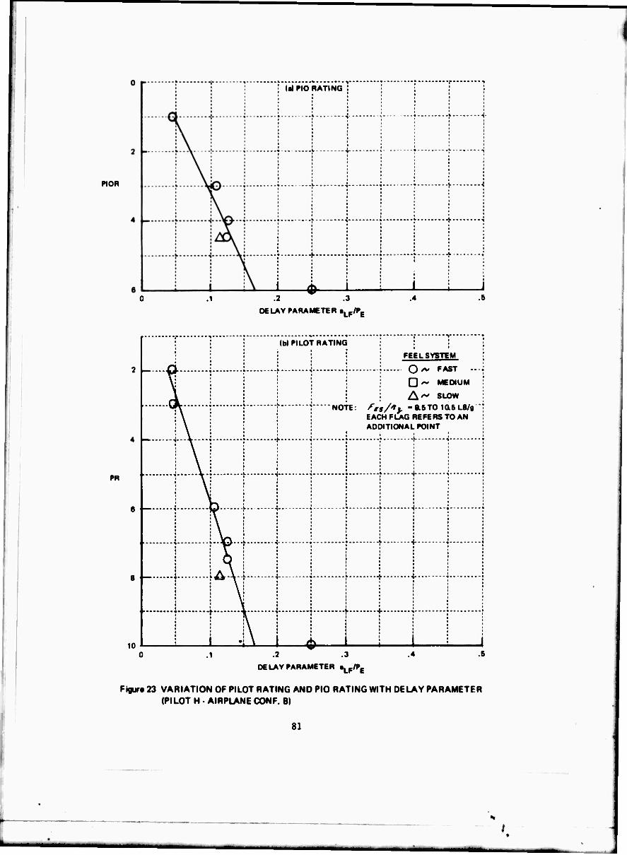
PIOR
; la) PIO RATING
-0- .2
DELAY PARAMETER »LfIPB
PR
• -r ^ • • • • lb> PILOT RATING
,• -•■>• ••
FEELSYSTEM
2 Q /v FAST ■ ■ 1
v i | j D ^ MEDIUM
1 ; 1 • A'*' SLO«
iK j" ] NOTE: fts/ly -a6TOia5LB/B •
EACH FLAG REFERS TO AN
4
i
"»■—
■
+ -j ••--
-j \ ♦-•• 1 j J
ADC »TIONAL POINT
-j-
' 4-
6 *
• • :
-4 1 •
■
..jp... -i \ r— « * J * I '
-j-
8 -—•— -i • • t
A\- -j \ \-- -j-
10
• :
" " * • •
i
H
• v i i r \ 1 i .1
\
i i .1
DELAY PARAMETER »Lp/Pg
Figurt 23 VARIATION OF PILOT RATING AND PIO RATING WITH DELAY PARAMETER (PILOT H • AIRPLANE CONF. B)
81

0|-
PlOfl
I DC LAV PARAMETER. •LF/PE
DELAY PARAMETER • »Lf/PB
Figur« 24 VARIATION OF PILOT RATING AND PIO RATING WITH DELAY PARAMETER (PILOT H - AIRPLANE CONF. O
82
.1 1

PIOR
6 L
UIPIO RATING ;
.4
DELAY PARAMETER - «^/Pg
FEEL SYSTEM
O *• FAST D ~ MEDIUM' ;
A*"- SLOW
NOTE: fts/*}. * 17.8 LB/g !
PR
DELAY PARAMETER «Lp/Pg
Ftgurt 26 VARIATION OF PILOT RATING AND PIO RATING WITH DELAY PARAMETER {PILOT H-AIRPLANE CONF. LAI
83

2»-
06LAY PARAMETER • »LF^E
2r-
PR
I lb» PILOT RATING FOR AIRPLANE B
FEEL SYSTEM
O—FAST
D —MEDIUM;
A —SLOW
NOTE: EACHFLAGREFERSTOAN ADDITIONAL POINT
NUMBERS NEXT TO SYMBOLS A«E ffs/*J "N LB/9
FAIRING FROM FIGURE 23(b»
-u
,1 2 .3 4
DELAY PARAMETER - \fn>t
Figure 26 VARIATION OF PILOT RATING WITH DELAY PARAMETER (PILOT B • AIRPLANE CONF. A AND 8)
84
.t

PR
10
(•I PILOT RATING FOR AIRPLANE C
FAIRING FROM FIGURE 24(b)
FEEL SYSTEM
O —FAST
A —MEDIUM
0 —SLOW
't* S NOTE:
9.2 TO ia9 LB/9
j EACH FLAG REFERS TO AN ■ ADDITIONAL POINT
.5
DELAY PARAMETER - 1^^
DELAY PARAMETER- \^^
Figure 27 VARIATION OF PILOT RATING WITH DELAY PARAMETER (PILOT B • AIRPLANE CONF. C A.\'0 LA)
85
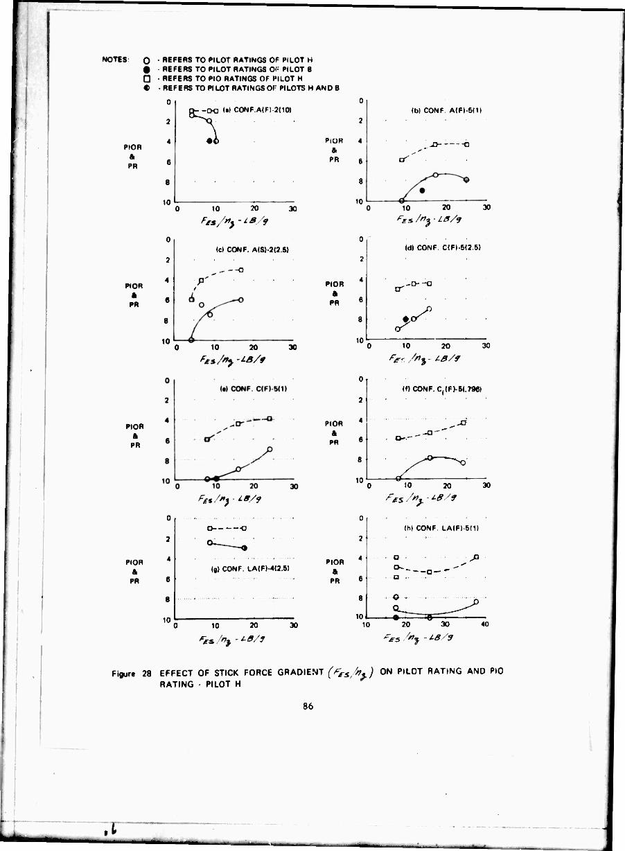
NOTES: O
D t
REFERS TO PILOT RATINGS OF PILOT H REFERS TO PILOT RATINGS 0'- PILOT B REFERS TO PIO RATINGS OF PILOT H REFERS TO PILOT RATINGS OF PILOTS H AND B
PIOR
a PH
PIOR
PR
PIOR
ft PR
PIOR
ft PR
2
4
6
8
10
0
2
4
6
S
10
c>--CK) !•» CONF.A(F) 2(10)
10 20 30
(c) CONF. A(S) 2(2 5)
10 20 30
"SS."} IB/f
0
2
4
6
8
10
O -O
(g| CONF. LA(F) 4(2 51
10 20 30
PiOR a PR
PIOR ft
PR
PIOR
ft PR
0
2
4
6
8
10
0
2
4
6
8
10L
0
2
4
6
8
10
PIOR ft
PR
10
(bl CONF A(F)-5(1)
-□ O
10 20 30
(d) CONF. C(F)-5(2.5)
,-o-o
y 10 20 30
(0 CONF. C^FJ-^.TSe)
,,--"
y~ ~^
10 20 30
^>s >t - W
0 (h| CONF. LA(F)-5(1)
2
4
6
O ^
. a .
8 . o ■
10 1 -• iO 20 30 40
PMS/** -16/9
Fijjur« 28 EFFECT OF STICK FORCE GRADIENT (^s,^%.) 0N P,L0T RATING AND PIO RATING PILOT H
8b
■
,1

1 i
:3. - : w t XA . cr
: <
\ | f 1 1 f f \ ; f
I I •
)0 | j ; i
is \ ■■^rt
E a.
■ «
* » r v 7 '
f -i \ + i \
1 -j j \ i 1
li-f o \ j I •UJ -- + -—\(- •• -j J
. a. —i. ;—-Jw.i 4. , .
•< \
; o : 1 Q-WJK>-|
j f -i- j !---0^----
■ «
I
O
o 5.
a
< cc
Q
\ c a. (A
i I cr
a. Z in tu
UJ 00
oc ac
8 R e I
E o I
87
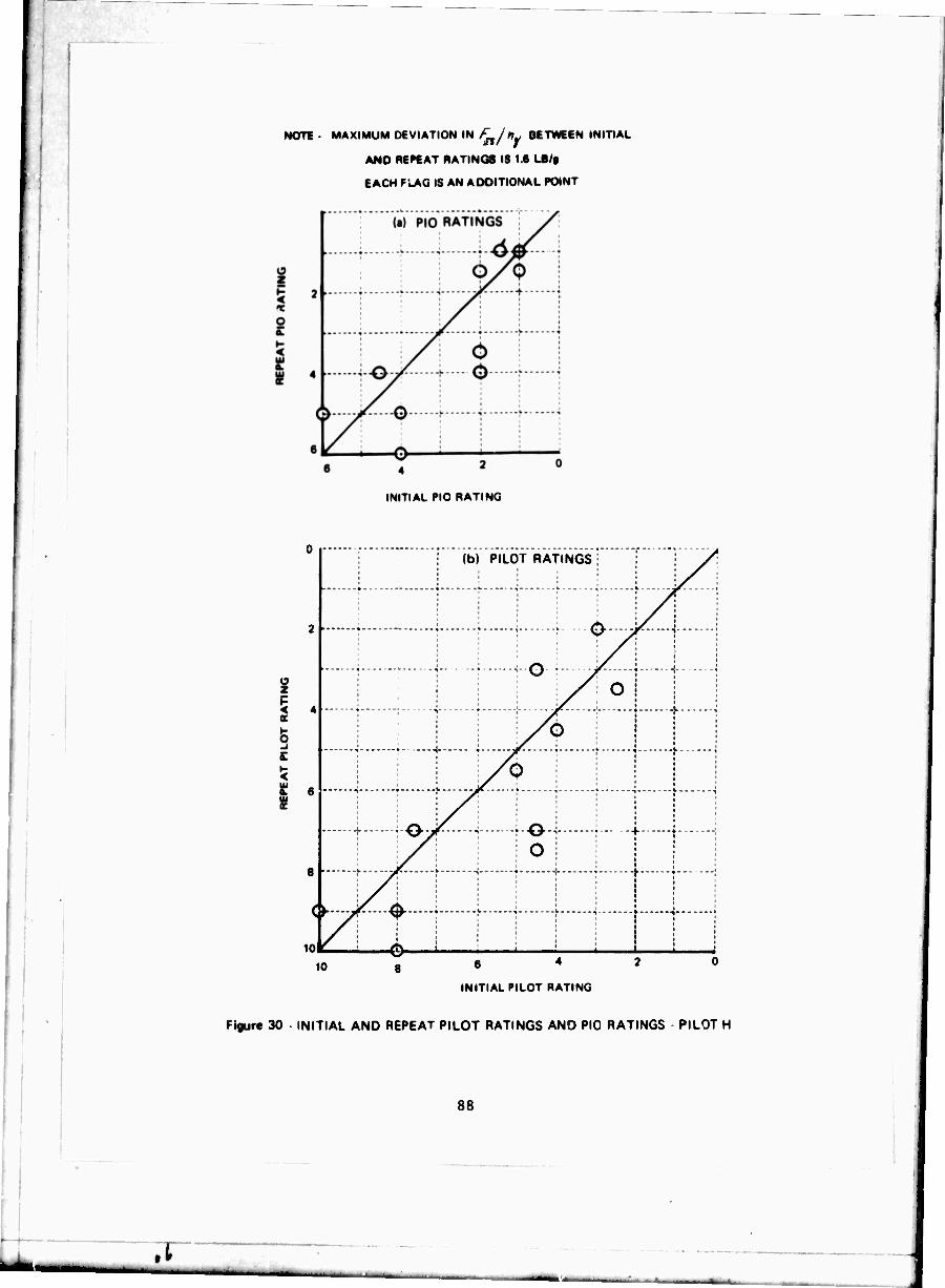
NOTE - MAXIMUM DEVIATION IN /£,/«,/ BETWEEN INITIAL
AND REPEAT RATINGS IS 1.6 LB/«
EACH FUKG IS AN ADDITIONAL POINT
INITIAL PIO RATING
5
5 i
u (b) PILOT RATINGST i y^
2
i j 1 i-O-f- -y^-i H j X o i
\ • -i \.....~j£.....\ \ \ ;. i
i- \&Y \
oO
8 |
L....J/..A. 1 1
IOI ^Lj—0—j 1—, 10 6 *
INITIAL PILOT RATING
Figure 30 INITIAL AND REPEAT PILOT RATINGS AND PIO RATINGS PILOT H
88
.1

NOTf • MAXIMUM D€VIATION IN ^//».BETWEEN INITIAL AND
REPEAT RATING IS 2.0 LB/g
EACH FLAG IS AN ADDITIONAL POINT
Cl
j ; j i
3
: : : O , :/^....\
i C 4
• • W V X ---y
j ; j /ir ^i i
§ c
i -i f -i- i y
■ ■-y}- ■ \? | + '
I [
81
■•j——-:- -^ -^
t-—-^ f -j-
i i j t \ « ' t ' ' ' ' I '
■If. 1 + • + • ; i ; i ! i 1 1 1 1 •
io|
^ i \ \ ; ■ * i *
10 6 4
INITIAL PILOT RATING
Figure 31. INITIAL AND REPEAT PILOT RATINGS • PILOT B
89
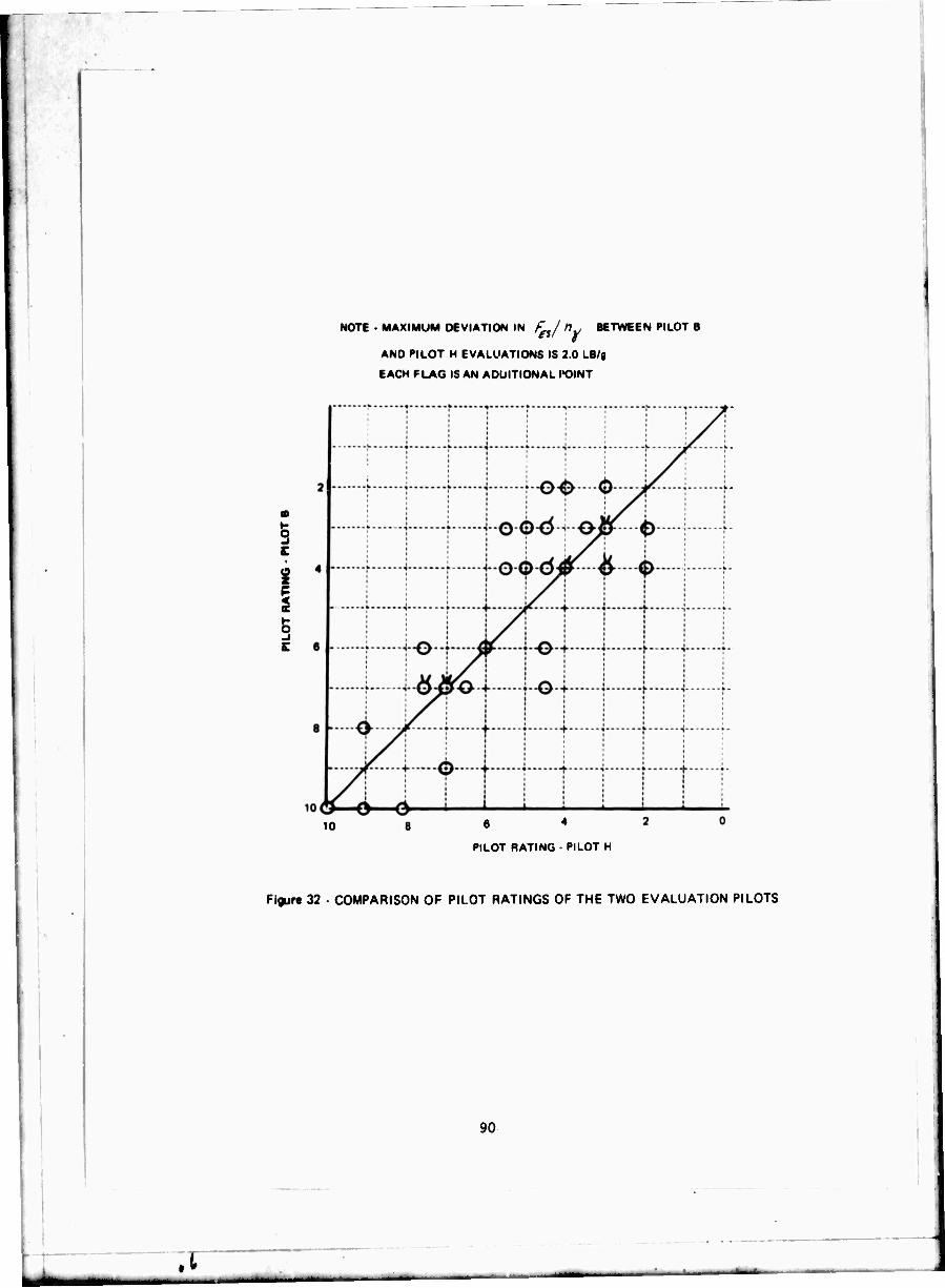
NOTE - MAXIMUM DEVIATION IN £_/ fly BETWEEN PILOT B
AND PILOT H EVALUATIONS IS 2.0 LB/g
EACH FLAG IS AN ADDITIONAL I'OINT
S
i I !
10 6 *
PILOT RATING • PILOT
Figur« 32 ■ COMPARISON OF PILOT RATINGS OF THE TWO EVALUATION PILOTS
90
,t

I
NOTE
UP ft AWAY CONFIGURATIONS ^s/*; ' 7.2 TO 9.8 LB/g
LANDING APPROACH fjn/*j* 17.8 LB/Q
NOS. NEXT TO PLOTTED POINTS REFER
TO PIO RATINGS FROM PILOT H SI^CE
NO PIO RATINGS EXIST FOR PILOT |
EACH FLAG IS AN ADDITIONAL POINT
6 4
PR (FLIGHT)
PR
(GROUND)
NOTE
UP ft AWAY CONFIGURATIONS ^/"j - 6 8 TO 94 LB/g
LANDING APPROACH ^s/i^- 17.8 LB/g
NOS. NEXT TO PLOTTED POINTS REFER TO PIO RATINGS EACH FLAG IS AN ADDITIONAL POINT
6 4 PR (FLIGHT)
Figure 33 - 0tM»ARI90N OF PILOT RATINGS IN FLIGHT AND IN A FIXED-BASE GROUND SIMULATOR
91

Ü z D D
O
u. U 0 3 tu u.
LU <
is
is li s°
_ i3 > «Ö
i
92
.1

s i ■
I v, C u y5 J
d a u. u. 0Z 0° Z ^
15 £< si
?z S8 K O ui Z Q O
Si
El
E I
93
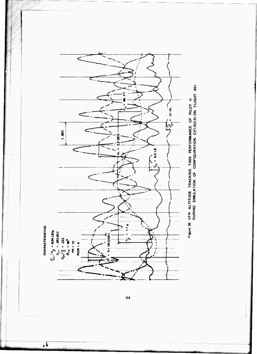
94
oo
Z
SS IU "?
< o
is o g a < Kg
^^ •- o u a Z u.
S 5
n u. Z> > D
i
.i
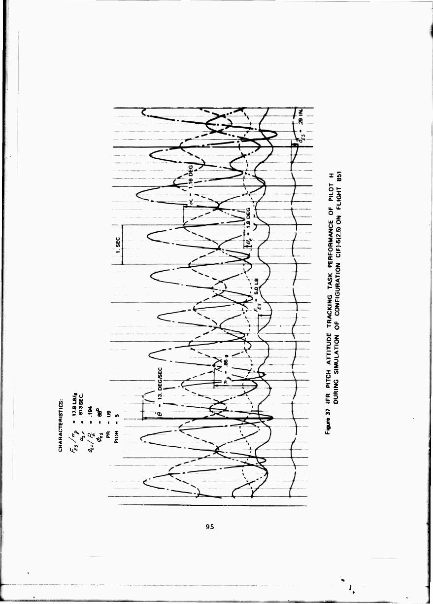
D
T W H.
Z tn oo
c S
o LU O O _, Z Mt < «N
So
o2 ?? ^ o
3 if K I-
ES «i I w 0 t o a. z
«I
95
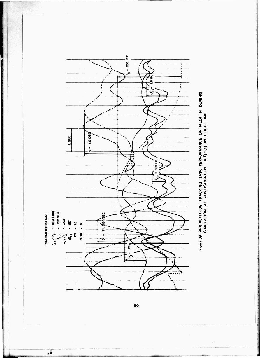
;
ä 0
Mal c tu r ■ ■ i ■ ■
5 k5 ^
o z er
i
(3
S5
I- 1 ■?
B <
z g
oi O Q D Z P g h- »-
^^
u. ■ > w
R
96
Lk .i
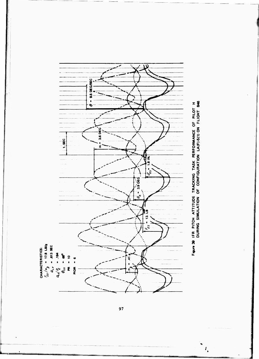
25 £2
o z
ui O o Z.
is DC U. 0 < K
IS Si z ^ 2 o ^o
5 S
M x 55 u t o a. Z
«I
e
97
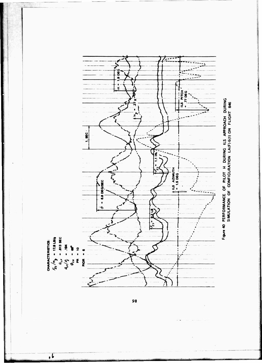
h z
9 3
< - (/) in
O < Z -J
? 2
Sg ^2 1- 3 -I u.
u. O
UJ O Q z z < o i E S3 -i LU 2 a. to
9 I
91
.t
APPENDIX
SUMMARIES OF PILOT COMMENTS \ND RESPONSE CHARACTERISTICS OF EACH HIGHER-ORDER CONFIGURATION SIMULATED
INTRODUCTION
Summaries of the pilot comments and the longitudinal short period responses are presented in this appendix for each of the higher-order control system configurations simulated, '.lie short period responses are those for a step stick force inpit and include the dynamics of the feel system and actuators simulated as well as the simulated airplane short period characteristics. The pilot comment summaries and the longitudinal responses of each configuration are presented on adjacent and facing pages so that it is easy to compare the comments and the response characteristics simulated.
The pilot comment summaries were prepared from transcripts of wire recordings for each configuration evaluated by Pilot B and Pilot H. The pilot comments are based on the Pilot Comment Card presented as Table VIII. The comment summaries were made in the light of the questions asked of the evaluation pilots as shown on the Pilot comment Card.
The longitudinal short period response curves shown for each configura- tion have been normalized or ratioed to the steady-state values of the responses. To obtain the actual magnitude of the pitch rate (0), angle of attack (ot),
and normal acceleration (77 ) responses as a function of time from these
normalized curves, it is necessary to know the magnitude of the steady-state responses and the actual stick force (^C ) • The required steady-state responses
are (0/^-5)5,. C«/^,) • and (»./^,)ss. The steady-state responses (ö/^),,
and («t/^g.,) are related to the simulated psrameters as indicated by Equations
21 and 22 in the text. The actual responses thus become
(*/ )
'fS
W) f 1*4
'Xf -«
(A-l)
*■< (A-2)
•j mr iS
99

r ("tl^ss ts ry^/) ^j
T*fiWjs\ {%)M ^-v
Measured and least-squares fit values of L , rr,/ot and {.feflrT )5J are
shown in Table IV for all the configurations simulated. The least-square fit values (LSF) alone are shown in Table V along with the delay time and delay parameters, and the pilot ratings and PIO ratings. As discussed in the ^ody of the report, the LSF values are the best estimate of the parameters actually simulated in flight. The average of the LSF values of the parameters o}.0, X » ("-/*). and Z^, for each of the airplanes (A, B, C, C., and LA) are
also shown in Tables II and III and Figure 7.
The computed responses shown on Figures A-l through A-37 are based on the average LSF values of the airplane ti)sp , ?jp , (/),/&), and /-^ . The
average LSF values of cüs/, and £ are also sl^own in the small table that
accompanies each figure. The average LSF values of all the airplane parameters required to obtain the computed responses are also shown in Section 3.3.
The computed time histories were obtained directly from the airplane total transfer functions (Equations 1, 2, and 3) using an IBM digital computer program. The feel system and actuator transfer functions appropriate to each configuration simulated were used in obtaining the time histories. The fourth-order form of the feel system transfer function used and the measured constants appropriate to each feel system ire presented and discussed In Section 3.1. Tne form of the actuator transfer function and the measured constants involved are presented and discussed In Sections 2.3 and 3.2,
In conjunction with the computed response, in-flight measured responses obtained from pilot step stick force inputs are also shown for most of the configurations simulated. An attempt was made to show one set of records for each pilot when the configuration was evaluated at least once by each pilot. In some cases no records are shown because none were obtained or the records were poor and questionable because of such things as turbulence. These in-flight measured responses were recorded on an oscillograph and then normalized bas^d on the steady-state responses for proper comparison to the computed responses. The actual LSF values of the measured a> , f , and ^,/»,
appropriate to each evaluation of a configuration are also shown in the small table that accompanies each figure.
The in-flight step stick force responses were obtained with the pilot holding the stick out of trim with the airplane flying in straight and level flight at constant indicated airspeed. The pilot next released the stick. The stick rapidly assumed its trim position and the airplane responded to this stick movement. In a true sense, the stick force after releasing the stick was not a pure step but a ramp determined by the dynamics of the stick
100
strain gage filter end stick inertia. The time interval of the ramp was small, of the order of .05 to 0.1 seconds. From computer studies it was determined that for these small time intervals the responses of the airplane to a ramp stick force input could not be distinguished from the responses to a step stick force input when the step occurred at the mid-point of the ramp time interval. This technique was used to establish zero time for the in-flight measured "step" responses.
In most cases, the in-flight measured » response was used rather than the ?7 response to obtain the plot shown in the bottom figure. The ec response
is generally a better response for establishing the steady-state value of {v./P' ) since it is less affected by small changes in airplane speed. In
some cases the oc response was poor and affected by such things as atmospheric turbulence. In such cases the rt response of the airplane was used instead
of the * response. The cases in which this was done are indicated by an asterisk on the flight number.
Also shown on the figures is the computed delay time obtained from Equations 40 and 42 (fly , a ). As explained in Section 5.1, a best second-
order match of the responses shown in Figures A-l to A-3 will be obtained if the computed delay time {a ) is obtained from Equation 42. Although the
computed delay time (a ) does indeed predict the initial delay in the response
quite well, the response immediately following this delay is still higher than second-order. This necessitates approximately doubling the delay time a to
obtain a. which gives a best overall time history match (Figures 14 through 19).
The delay parameter (a /£) associated with each of the configurations simulated
are listed in Table V.
The computed responses and measured responses in general compare quite well. All indications are that the higher-order control system dynamics, and their effects on t .e airplane responses wcie properly simulated. Generally the poorest comparisons between measured and comruted responses occurred for the landing approach (LA) configurations simulated. No completely satisfactory reason can be given to explain this. The flight records of landing approach configurations were obtained at 3000 feet pressure altitude and 140 knots IAS. Flight records were poorer and affecter* by the larger atmospheric turbulence at lower altitudes which makes establishment of the steady-state responses moie difficult. In addition, small changes in velocity at the lower indicated airspeed for simulation of landing approach configuration, 140 knots instead of 250 knots, also has a larger effect on the values of the steady-state response.
In the pilot comment suimT.aries, no mention is made of the lateral- directional characteristics of the configurations simulated. The evaluation pilots were askjd to comment on each configuration's lateral-directional
101

characteristics. The general comments were that the lateral-directional characteristics were satisfactory ai<d in no way detracted from or affected the longitudinal evaluation. There were occasional comments on the lack of control harmony and poor longitudinal control characteristics as compared to lateral-directional control when the £" In was high, and the elevator feel
system was slow. In such cases the lateral-directional response was considered "snappier" and superio" to the longitudinal response of the configuration. Some of the lateral-di cctional mode characteristics simulated are shown as Figures 8 and 9.
102

PILOT COMMENT SIMIARIES A. CONFIGURATION
LONGITUDINAL RESPONSE CHARACTERISTICS
103
I
CONFIGURATION A(F)-2(10)
Pilot B on Flight 821 found this configuration a little slow responding with a "digging in" tendency. Because of the slow response, he tended to over- drive the airplane which caused a noticeable overshoot in pulling g's and tracking. There was good altitude control, except when initiating a turn, and the airplane wavered somewhat in steady g's in the turn. These characteristics were worse in rough air or with random noise inputs. He said the response was somewhat indefinite and the airplane took a long time to settle on g or pitch angle. The airplane appeared to be well damped. No trouble finding trim, although trimming was slow. The quality of the control system was considered to be good. There was no friction and both the stick forces and stick travel were considered reasonable with no lag in response. The pilot ratirg of A4 was based primarily on the slow and indefinite response, and the tendency to overshoot noticeably when driving the airplane response.
Pilot H on Flight 842 found that there was no tendency to overshoot in g's, the initial response was smooth, the nose could be placed as desired. He found the airplane well damped, stable, and easy to trim, with no PIO tend- encies. He found control in turns to be good, and that the airplane had excellent altitude and attitude tracking. He found the feel system to be very good without lags between stick inputs and airplane response. His only adverse comments were that random noise inputs degraded the airplane performance slightly, and the stick force gradient (/" /»?-) was slightly high. The pilot rating was an A2 and the PIOR was 1. f *
Decreasing the ^»/»V from 8.39 to 4.19 Ib/g further improved the configuration for Pilot H (Flight 852). He was especially impressed with its "snappy" response and the fact that the airplane felt "fighter-like." Random noise had little effect on the airplane performance. He classified it as an excellent configuration and gave it a pilot rating of Al.5 and a PIOR of 1.0.
When the stick force gradient was increased to 10.2 Ib/g the pilot complained that the stick forces felt heavy and the initial and steady-state pitch rate responses were low. The configuration showed no PIO tendencies. The feel system response characteristics were considered good and it was felt that there was a "one-to-one" correspondence between pilot inputs and airplane response. All the other response characteristics were considered good. The pilot rating of A4 was determined primarily by the low initial and final pitch responses. The PIOR was 1.
104
•

"1
fe) m
U or
*s ss
FLT PILOT PR/PIOR A) SP <S, 5? DESIGNATION
1 COMPUTED RESPONSE 2.68 .646
•21* 8 A4/- 2.64 .663 %M 1 842 H A2/1 2.71 .630 8.38
| 882 H Al.6/1 2.72 .638 4.19
[ 882 H A4/1 2.73 .541 10 2
2.0 -r
1.5 -
1.0 -■
0.5 --
0.0
1.5 -.
1.0 --
0.5 -
0.0
O COMPUTED DELAY TIME. EQ. 40
D COMPUTED DELAY TIME. EQ. 42
0.0 1.0 2.0 TIME-SEC
3.0
Figure Al COMPUTED AND MEASURED LONGITUDINAL SHORT PERIOD RESPONSES FOR A STEP ELEVATOR STICK FORCE INPUT
CONF. /HF) 2(10)
105
CONFIGURATION A(F)-2(2.5)
This configuration was evaluated by Pilot B on Flight 824. The feel system was considered "all right" and the stick forces reasonable. Trim, initial response, altitude control, and«, control all seemed "pretty good." There was no lag in the airplane response but the response was a little slow and the tendency was to overdrive the airplane to increase the response. The steady-state response was fine and the airplane response with random noise was considered good. VFR altitude and IFR attitude tracking were described as "pretty good." Altitude control and g coordination in turns, turn entry and recovery were all considered "easy," and ability to trim was considered "all right." The configuration was considered controllable, acceptable, and satisfactory and given a pilot rating of A3. The pilot stated that it would be rated an A2 if it "moved quicker."
This configuration was rated A3.5 by Pilot H on Flight 847. The feel system was considered good, trim was excellent, altitude control was fair to good, and n, control was considered precise. The airplane response to pilot inputs was a slight delay followed by a fairly smooth "takeoff" of pitch rate. Although the configuration was fairly well behaved, the connection between pilot inputs and airplane response was not quite "one-to-one," there was a slight tendency to overshoot in tracking, and the airplane was not as "snappy" as desired. Altitude tracking was fairly good with a slight tendency to oscillate with high pilot gain. The airplane was quite smooth and easy to fly IFR even with random disturbances, and IFR attitude tracking was "especially good." The delay and slow response were not as noticeable IFR as VFR. There was a "very slight" PIO tendency with real tight tracking VFR. The airplane was considered acceptable with only very minor deficiencies. The airplane should be snappier and faster in the initial response flying VFR. The PIO rating was 1.5.
106

(- '*)
it) SJ
or
'»'*
FLT PILOT PR/PIOR *>*, ^ 5? DESIGNATION
COMPUTED RESPONSE 2.88 646
824* B A3/- 2.52 .566 9.86 1 847 H A3.B/1.6 2 88 .543 8.38
2.0 -r
1.5 -.
1.0 -■
0.5 -
0.0
1.5 -.
1.0 -
0.5 --
0.0
0.0
O COMPUTED DELAY TIME. EQ. 40
D COMPUTED DELAY TIME. EQ. 42
1.0 2.0 3.0 TIHE-SEC
Figure A 2 COMPUTED AND MEASURED LONGITUDINAL SHORT PERIOD RESPONSES FOR A STEP ELEVATOR STICK FORCE INPUT
CONF. A(F) 2(2.5)
107
CONFIGURATION A(F)-2(I)
This configuration was evaluated by Pilot B on Flight 813 and described as having a tendency to PIO. There was a slight lag or pause between a stick input and the nose movement of the airplane. The feel system characteristics and the stick forces were said to be satisfactory without any "funny feel" in the stick. The response lag is followed by rapid response. With moderate o,- tight control the result is overcontrol, and a bobble or PIO which degrades tracking. VFR flight is degraded more than IFR flight. Relaxing the stick and doing things slowly tends to eliminate PIO's and improve the final attitude and ", response. Longitudinal control in turns was considered satisfactory since the time required to roll into a turn compensates for the lag. The air- plane was considered unsuited to the mission and must be fixed and was rated U7 primarily because of its tendency to PIO.
On Flight 823 Pilot B fie* this configuration a second time. Comments about feel system characteristics, stick force, lag in the response, and over- control tendencies were similar. Although the airplane tended to "waver" with tight control there was no tendency to PIO. The airplane was considered controllable and only reluctantly acceptable because of its unpredictable response, and rated an A6.0.
On Flight 836 this configuration was flown by Pilot H. The primarily undesirable characteristic of the configuration was described as a tendency to over-control or "over-g" the airplane with tight control. When the airplane was flown "smoothly" and "easily," altitude, attitude, and w- control were satisfactory. The lag, followed by the rapid response, led to over-control tendencies which reduced altitude and attitude tracking precision significantly but did not result in oscillations. Over-control and "over-g" tendencies were especially evident with random noise inputs. Forces and stick displacements are considered comfortable, maybe a little heavy, based on the initial response. The configuration is considered acceptable but unsatisfactory and should be improved. Pilot H gave it a PIOR of 2 and a pilot rating of A4.5.
Pilot H flew the configuration a second and third time on Flights 846 and 8S2 and for both flights the ratings were significantly poorer. The PIO ratings and pilot ratings were 4.5 and U7.5, arA 4.0 and U7, respectively. On both these flights the pilot described the delay in airplane response as "noticeable" or "significant." He also stated that there was a definite tendency toward a "mild" and a "little" divergent PIO with tight control. Tracking both VFR and IFR was considered poor with oscillatory and PIO ten- dencies. Random noise also degrades performance significantly because it leads to divergent closed-loop oscillations. The pilot had a tendency to pump the stick which resulted in oscillations and PIO tendencies. The airplane does not "get away from you." It was considered controllable but unacceptable and it must be improved.
Pilot »I'j ratings and comments on Flights 846 and 852 agree well with those of Pilot B on Flight 819. The lack of any significant PIO tendencies for this configuration when flown by Pilot B in Flight 823 and Pilot H on Flight 836 cannot be explained, but is the primary reason for the better ratings on these flights.
108

" S3
or
(a) **'ss
1- PILOT Pfl/PIOR ^ ^ ^ DESIGNATION
COMPUTED RESPONSE 2 68 .646
819 B U7/- 2 48 .680 9.78
833 8 A6/- 2.67 568 9.6b
836 H A4.6/2 2.62 .662 7.90
84« H U7.6/4.6 2.70 .642 839
862 H U7/4 2.49 .578 6.81
2.0
1.5
1.0 -■
0.5 --
0.0
1.5 -.
1.0 -
0.5 -
i
h L
1 J
^ ■^
{ H>i , „L. -
f: i% J d
■—-1*—-j-3**
j ' ,
1—4-— ■ i
i j i i i ^— H 1 i —H
i i • •
\JL 1 ' 1 1 —r—l—r
—T — 1 ,
—'—i—' —i O COMPUTED DELAY TIME. EQ. 40
D COMPUTED DELAY TIME. EQ. 42
0.0 0.0 1.0 2.0 3.0
TIME-SEC
Figure A3 COMPUTED AND MEASURED LONGITUDINAL SHORT PERIOD RESPONSES FOR A STEP ELEVATOR STICK FORCE INPUT
CONF. A(F)-2(1)
109
CONFIGURATION A(F)-4(2.5)
Pilot B evaluated this configuration on Flight 824 and Flight 828. In both cases the pilot rating was A4, The feel system was described as pretty good and the stick forces as reasonable on the first flight. In the initial response there is a slight delay, followed by a response that is more rapid than anticipated and difficult to predict. There is a tendency to over-drive the airplane, but attitude control, *;, control and trim are all considered
reasonable. Altitude tracking is considered a bit "wobbly" with care required not to overshoot pitch angle. The entry and recovery from turns is considered all right, but the airplane is a little indefinite in steady steep turns. Characteristics are similar IFR and get worse with random inputs. There are no PIO tendencies, and the airplane is considered controllable, acceptable, and only slightly unsatisfactory. The primary objections are the overshoot and bobble tendencies with abrupt inputs.
On Flight 828 the control forces felt heavy even though the ^x/,'<.was
not high. The forces felt high when moving the stick rapidly, even though the feel syste» characteristics were considered satisfactory. In the initial response the stick requires quite a force, then the nose gets underway slowly without an initial delay. Trim is considered satisfactory, but there was a lack of precision in pitch attitude control and w- control which also degraded
the tracking capability. It was difficult to force the airplane to move quickly without a bobble. The bobble and indecision in response made altitude tracking and control with random noise difficult. The airplane was easy to fly for normal IFR conditions and IFR attitude tracking was surprisingly easier than VFR altitude tracking. In general IFR and VFR showed the same difficulties. Altitude control in steep turns was "not so good," but recovery was easy. The airplane response when pushing on the stick was difficult to predict, but it was difficult to say what the exact trouble was. The pilot rating was A4
Pilot H evaluated the configuration on Flight 847 with fjfj/*}** 6.81 Ib/g,
When evaluated twice by Pilot B, the stick forces were 12.5 and 10.6 Ib/g. Pilot H considered the feel system as satisfactory, and considered the problem to be the very definite time delay following a pilot input. Following the delay, the response is slow and then "takes off" rapidly. The result is a tendency to "over g" the airplane, difficulty in establishing pitch attitude, and a tendency to develop PIO oscillations. There is some difficulty in trimming, reduced precision in level turns, tendency toward PIO with high gain tracking, and the airplane is oscillatory with random noise inputs with tend- ency to speed up and slow down in pitch. In tracking, the oscillation or PIO tends to be zero damped with tight control and it is necessary to reduce the pilot gain. The steady-state pitch response is a little lower than desiiable and makes the airplane feel "heavy." Since a nondivergent PIO is relatively easy to attain, the configuration is considered acceptable but unsatisfactory and needs major improvement. The pilot rating is A6 and the PiO rating is 3.
110
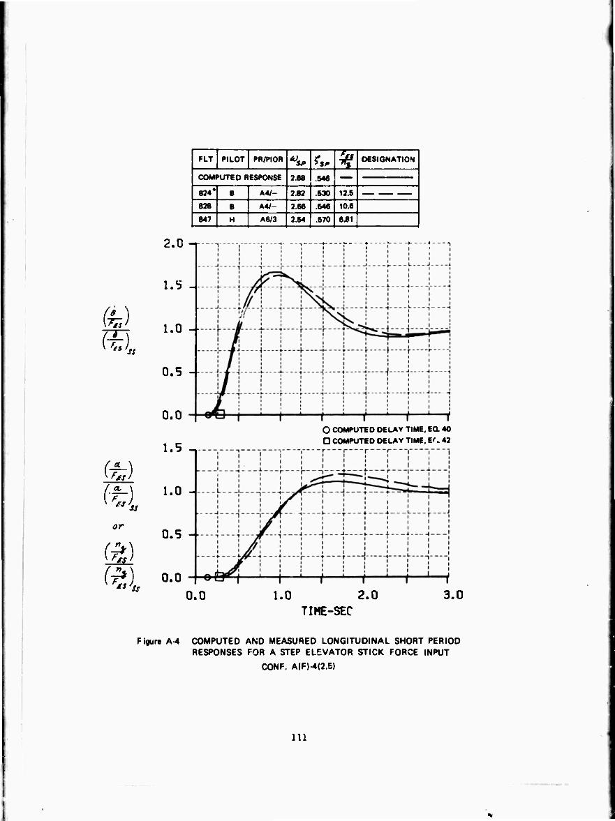
or
" ss
FLT PILOT PR/PIOR *» ^ DESIGNATION
COMPUTED RESPONSE 2 68 .546
824* B A4/- 3.82 530 12.6
828 8 A4/- 2.66 .546 10.6
847 H A6/3 2.54 .570 6.81
2.0 -r
1.5 -
1.0 -
0.5 --
0.0
1.5 -.
1.0 -
0.5 -
O COMPUTED DELAY TIME. EQ. 40
O COMPUTED DELAY TIME, If. 42
0.0 0.0 1.0 2.0
TIME-SEC 3.0
Figure A4 COMPUTED AND MEASURED LONGITUDINAL SHORT PERIOD RESPONSES FOR A STEP ELEVATOR STICK FORCE INPUT
CONF. A|F)-4(2.6)
111
CONFIGURATION A(F)-5(2.5)
This configuration was evaluated by Pilot B on Flight 82S. The stick exhibited no rate limit or high inertia but it felt "pretty funny" to the pilot. The stick felt heavy and slow, it moved easily and smoothly, but nothing happened to the airplane initially because of a lag. Attitude control was all right and *|, control was "not very good," but there was not much over- shoot. Trying to force the airplane increased the overshoot and bobble. These characteristics degraded the tracking performance both VFR and IFR. Pitch control centering and re overing from a turn, and altitude control in turns were not considered bad. The pilot technique was to overdrive tho air- plane and then open the loop to eliminate the bobble. Trim was described as "all right." The airplane was considered controllable, acceptable, "wishy- washy" overall, and rated an AS.
Pilot H flew this configuration on Flight 837. His ^w/n was 8.39 instead of the 13.5 Ib/g for Pilot B. The stick was described as "heavy" with inadequate initial response for a given input. There is a delay in the initial response, but the final response is considered good, and the steady-state stick forces are described as satisfactory. Because of lag in the response, the tendency is to be abrupt with the airplane which results in overshoot in pitch attitude and «u and overcontrol in tracking. If the airplane is controlled smoothly without abrupt inputs, the airplane is much more precise.
The airplane was classified as "not too bad," it trimmed nicely, it had no real tendency to PIG, tracking was not bad but uncomfortable because of a tendency to overcontrol. Overcontrol tendencies were also evident with random noise disturbances. The airplane open loop was considered satisfactory with a fast, well damped short period. Because of the delay, the pilot did not feel directly connected to the airplane, and he tended to "over-g." The airplane was considered acceptable, but annoying and uncomfortable, and rated an A4. The PIOR was 2.
112
•
•r

rtr PILOT PR/PIOR ^ ?,. % DESIGNATION 1
1 COMTUTEO RESPONSE 2.68 .846
•26* ■ AW- 3J2 .631 1X8 1 837 H A4/2 2.70 .841 8.38
(h) m
0.0
1.5 ^ O COMPUTED DELAY TIME, Ea 40
D COMPUTED DELAY TIME. Ea 42
or
0.0 1.0 2.0 3.0 TIME-SEC
Figura A-B COMPUTED AND MEASURED LONGITUDINAL SHORT PERIOD RESPONSES FOR A STEP ELEVATOR STICK FORCE INPUT
CONF. A(F»-5(2.5)
113
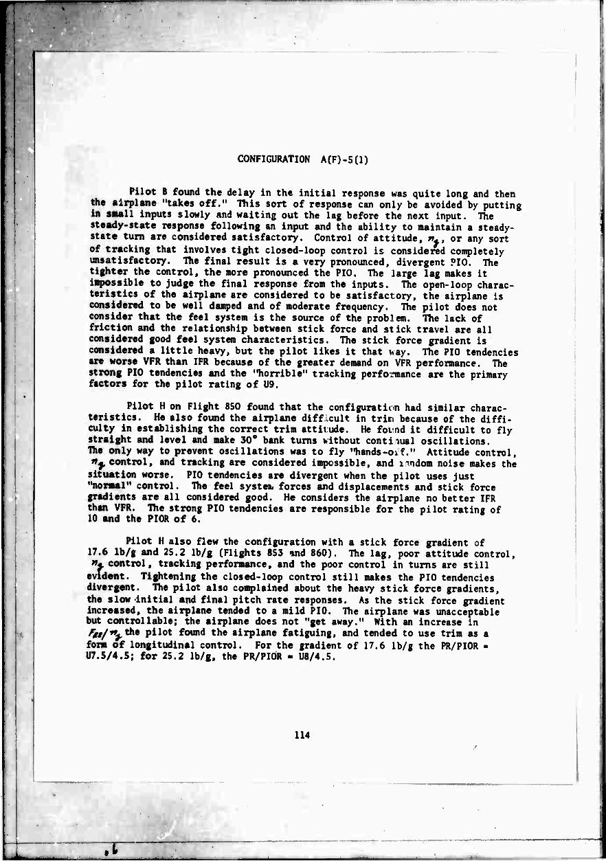
CONFIGURATION A(F)-5(1)
Pilot B found the delay in the initial response was quite long and then the airplane "takes off." This sort of response can only be avoided by putting in small inputs slowly and waiting out the lag before the next input. The steady-state response following an input and the ability to maintain a steady- state turn are considered satisfactory. Control of attitude, n*, or any sort of tracking that involves tight closed-loop control is considered completely unsatisfactory. The final result is a very pronounced, divergent PIO. The tighter the control, the more pronounced the PIO. The large lag makes it impossible to judge the final response from the inputs. The open-loop charac- teristics of the airplane are considered to be satisfactory, the airplane is considered to be well damped and of moderate frequency. The pilot does not consider that the feel system is the source of the problem. The lack of friction and the relationship between stick force and stick travel are all considered good feel system characteristics. The stick force gradient is considered a little heavy, but the pilot likes it that >«ay. The PIO tendencies are worse VFR than IFR because of the greater demand on VFR performance. The strong PIO tendencies and the "horrible" tracking performance are the primary factors for the pilot rating of U9.
Pilot H on Flight 850 found that the configuration had similar charac- teristics. He also found the airplane difficult in trim because of the diffi- culty in establishing the correct trim attitude. He found it difficult to fly straight and level and make 30° bank turns without continual oscillations. The only way to prevent oscillations was to fly "hands-oif." Attitude control, >»^, control, and tracking are considered impossible, and i^ndom noise makes the
situation worse. PIO tendencies are divergent when the pilot uses just "normal" control. The feel systen. forces and displacements and stick force gradients are all considered good. He considers the airplane no better IFR than VFR. The strong PIO tendencies are responsible for the pilot rating of 10 and the PIOR of 6.
Pilot H also flew the configuration with a stick force gradient of 17.6 Ib/g and 25.2 Ib/g (Flights 853 and 860). The lag, poor attitude control, w- control, tracking performance, and the poor control in turns are still
evident. Tightening the closed-loop control still makes the PIO tendencies divergent. The pilot also complained about the heavy stick force gradients, the slow initial and final pitch rate responses. As the stick force gradient increased, the airplane tended to a mild PIO. The airplane was unacceptable but controllable; the airplane does not "get away." With an increase in ^//^the pilot found the airplane fatiguing, and tended to use trim as a form of longitudinal control. For the gradient of 17.6 Ib/g the PR/PIOR - U7.S/4.5; for 25.2 Ib/g, the PR/PIOR - U8/4.5.
114
;r
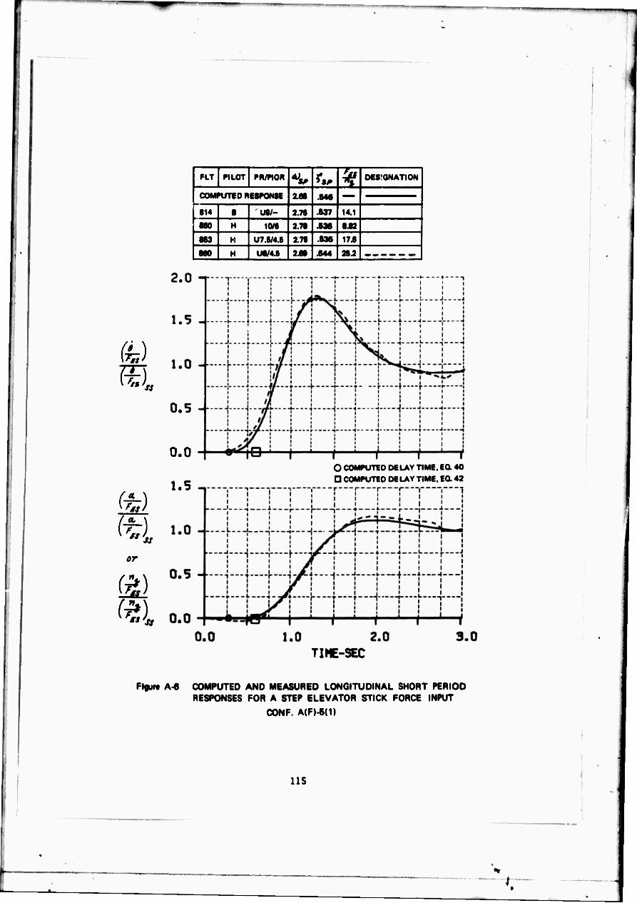
fe)
IE). 1
or
(a)
I
FLT PILOT PR/PIOR at) *S, ^
DESIGNATION
| COMPUTED RESPONSE 3.88 .846
| 814 8 UB/- 2.78 .637 14.1
880 H 10/8 2.78 .636 8.82
863 H U7.B/4.B 2.78 .636 17.8
880 H U8/4.6 2.68 .644 26.2
0.5 4
0.0
1.5 O COMPUTED DELAY TIME, EG. 40 D COMPUTED DELAY TIME. EQ. 42
TIME-SEC
Figur« A-« COMPUTED AND MEASURED LONGITUDINAL SHORT PERIOD RESPONSES FOR A STEP ELEVATOR STICK FORCE INPUT
CONF. A(F).5(1)
115
I :

CONFIGURATION A(M)-2(10)
Pilot B flew this configuration once (Flight 823). His predominant connents were concerned with the "funny feeling" stick. The stick felt like it had "high inertia" and was "rate limited" which he did not like. The stick characteristics made it difficult to define trim sharply, and hampered the initial response by requiring a lot of time to get the stick and airplane moving. The magnitude of the forces for steady-state response was considered satisfactory. The stick characteristics also interfered quite a bit with VFR and IFR tracking. The airplane was considered more difficult to fly IFR than VFR, which is not usually the case. The tendencies were to overdrive the stick with a resulting overshoot of the response. If flown gently and with care, pitch control was considered pretty good. There were no tendencies to PIO, and the airplane itself was considered to be of medium frequency and well damped. Considering IFR tracking an important airplane requirement, the air- plane was considered to be moderately objectionable, required improvement, and it was rated an AS.
Pilot H flew the configuration twice, on Flights 840 and 848. On Flight 840 he commented that there was a very slight delay in the response following a control input, but the stick forces, stick displacements and feel system characteristics were all considered to be good. The pilot stated that he did not feel "directly connected" to the pitch response because of the delay. These complaints were only minor. He considered the airplane to be good, pleasant, and well behaved. Initial and final response to control inputs, and trim were considered good. There were no PIO tendencies and the airplane tracked well both VFR and IFR. Longitudinal control in turns was also considered good, and random noise had little effect on the handling qualities. The configuration was only degraded slightly by the tiny delay and given a pilot rating of A2.5. The PIOR was 1.
On Flight 848 the pilot rated the configuration more severely. He rated the feel system as somewhat poor with a "softer" feeling and with less than a "one-to-one" relationship between inputs and airplane response. He said that there was some difficulty in establishing trim, there was a tendency to "over-g" the airplane a little bit, and a tendency to "dig in" because of the slow initial response followed by a rapid "takeoff." He had a tendency to "pump the stick" which he objected to. He said that he had good control of everything, control in turns was not bad, but the tracking was a little dis- appointing. The bad features, although they did not affect his performance too much, he thought should be improved. He gave the configuration a pilot rating of A3.5 and a PIOR of l.S.
Pilot B's comments and Pilot H's comments on Flight 848 agree reasonably well. Pilot B was more critical of the feel system and the poor IFR tracking and gave a pilot rating of AS rather than A3 5. Pilot B's stick force gradient of 12.S Ib/g was significantly higher than the 6.81 Ib/g of Pilot H, although Pilot B said the forces were all right. No explanation can be offered for the relatively good comments and ratings of Pilot H on F'ight 840.
116
^L
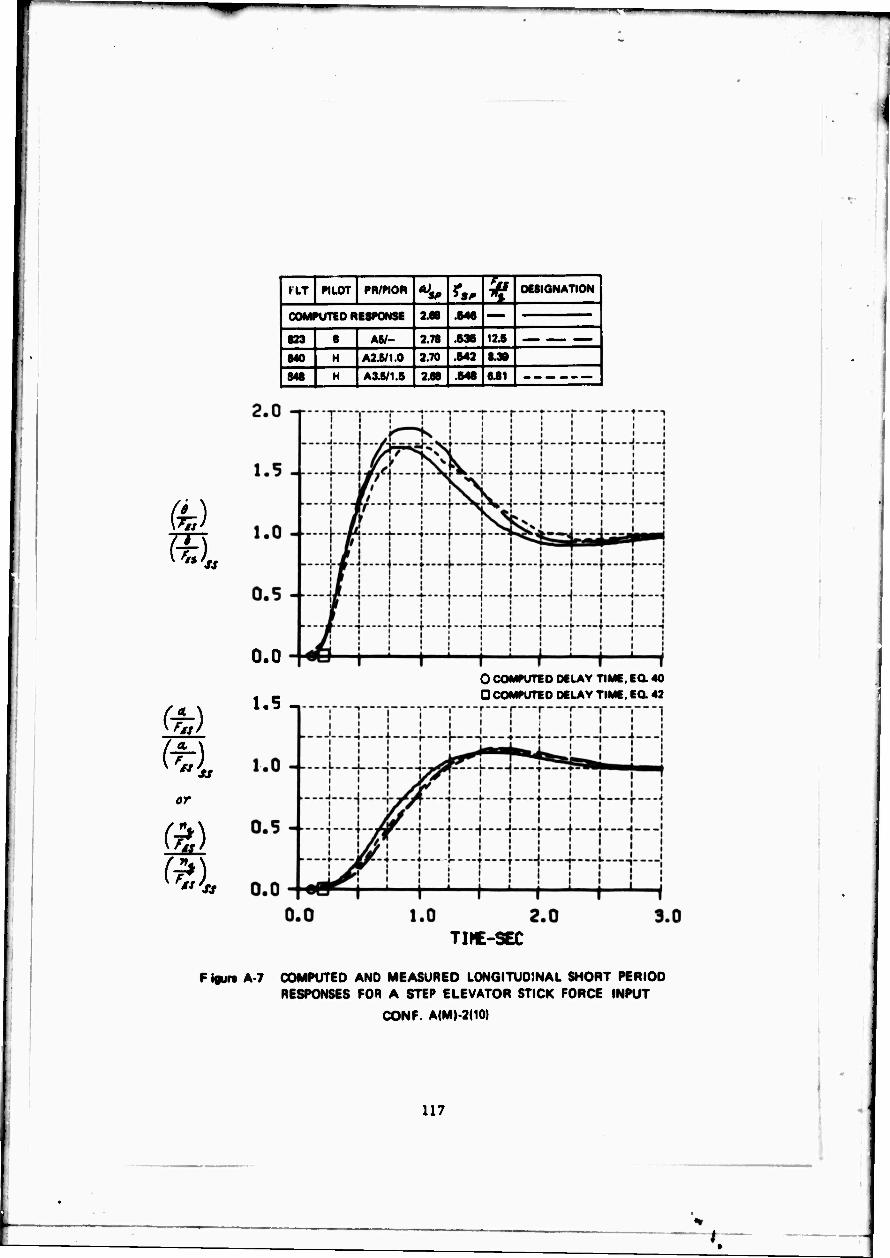
I
m
fS \ F-) S3
or
(a)
{
HT PILOT PR/PIOR **, k DESIGNATION j
| COMPUTED RESPONSE 2.88 .646
1 823 8 AW- 2.78 .636 12.6 1 840 H A2.6/1 0 2.70 .642 8.30
848 H A3.5/1 6 288 .648 6.81
0.0
1.5 -, 0 COMPUTED DELAY TIME, EQ. 40 O COMPUTED DELAY TIME. EQ. 42
TIME-SEC
F igurt A-7 COMPUTED AND MEASURED LONGITUDINAL SHORT PERIOD RESPONSES FOR A STEP ELEVATOR STICK FORCE INPUT
CONF. A(M)-2(10)
117

»I CONFIGURATION ACM)-2C2.5)
■•t
Pilot B evaluated this configuration on Flight 829 with a stick force gradient (^/»^) of 11.6 Ib/g. The pilot found something in the control systea objectionable. The stick did not move fast enough, it felt like a high inertia stick. Steady-state stick forces were reasonable but the initial stick forces were considered high. There was no pronounced lag in the initial response; it started slowly and then Increased. The tendency was to overdrive the airplane. The VFR altitude tracking performance was not very good, and the attitude tracking task IFR was easier. Pitch attitude control was not bad but it interfered with tracking sometifces. The performance with random noise inputs was not particularly damaging. Although the airplane was reasonably "well behaved," it was not "very good." In steep turns, holding altitude was not easy; the nose tended to wander. There was no tendency to PIG. The air- plane was controllable, reluctantly acceptable, and unsatisfactory with a pilot rating of AS. The airplane was "unpleasant to fly" even though the pilot felt he could do a "pretty good job."
This configuration was evaluated by Pilot H on Flight 863 with fss/^ym
7.9 Ib/g. The stick forces and stick displacements were considered good, 'me forces were considered light and comfortable and the airplane was quite naneuverable. With a pilot input the airplane responded without delay, but did not respond smoothly. Flying the airplane aggressively under VFR conditions leads to "over g's." There was a tendency to set up a PIO in tracking depending on how much the airplane was forced. VFR attitude tracking precision was con- sidered p^or. With a series of pulse type inputs the accuracy of tracking could be improved. The problems IFR were similar to those VFR. The airplane handled badly in the presence of random noise, it oscillated with attitude corrections, it felt nonlinear, and the IFR attitude tracking was poor. The airplane tended to oscillate in pitch in level flight turns, and the tendency was to pulse or pump the stick for control. The airplane was considered acceptable but un- satisfactory with very objectionable deficiencies. The pilot rating was A6 and the PIO rating was 3.
118
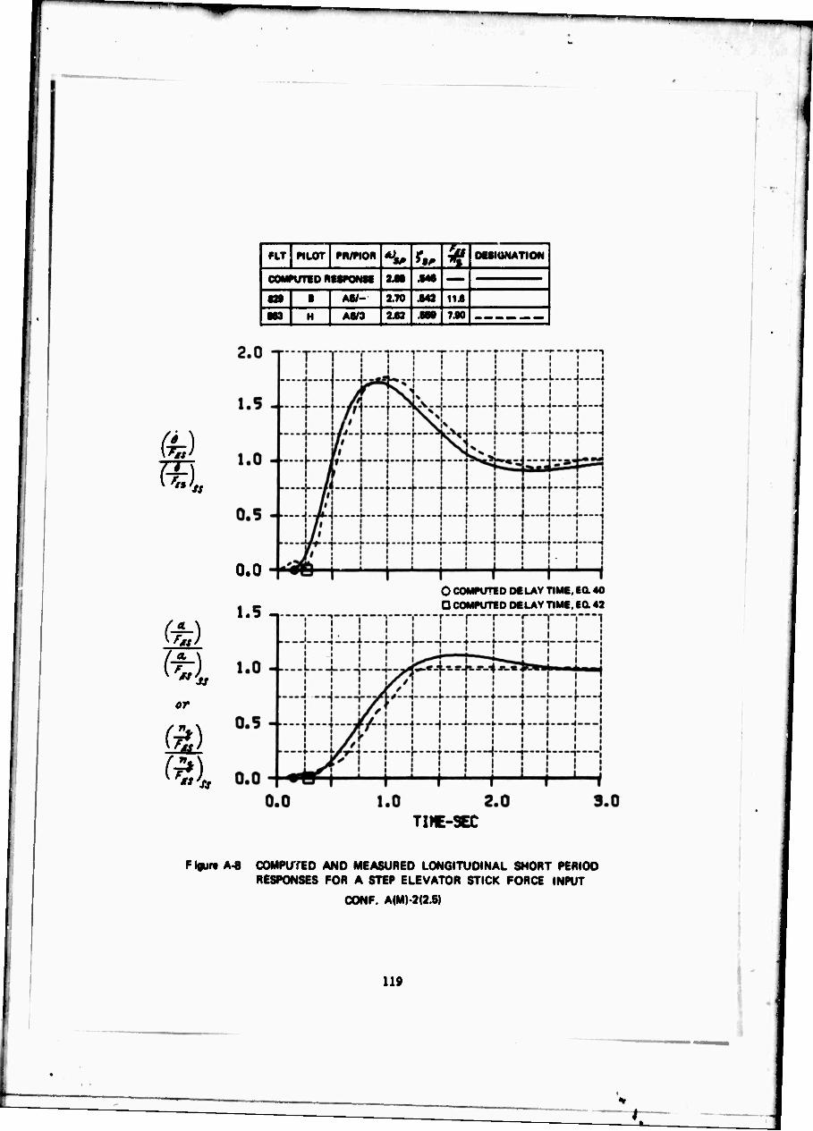
1 FLT PILOT PR/PtOR ^ ft. ¥ OeSIUNATION
1 COMPUTED ntSKMM 2.61 JM
B» 1 AW- 2.70 Ma 11.6
M3 H A«/3 242 .888 7.90
(-
0.0
1.5 - O COMPUTED DELAY TIME, EQ. 40 Q COMPUTED DELAY TIME, EQ. 42
or
(?)
TIME-SEC
F igur« A-8 COMPUTED AND MEASURED LONGITUDINAL SHORT PERIOD RESPONSES FOR A STEP ELEVATOR STICK FORCE INPUT
CONF. A(M)-2(2.6)
119
• ■
CONFIGURATION A(M)-4(2.5)
Ulis configuration was evaluated only once, by Pilot B on Flight 829. The initial response following an input was not considered good. The ju^h response had a Jlight pause followed by a sudden ji«p **ich made fraction of desired response difficult. Stick forces were not considered too bad. Sere wL a little bit of "feel" to the stick like "high inertia/' but the feel syste« was not considered to be peculiar or rate limited. The tendency was to overdrive the s ick. Tbt stick gets "underway" but the airplane does not. •n.e pause, followed by a rapid response, degraded altitude tracking and ^liinri's. but none of thise effects are considered serious enough to "hurt" the airplane. It is possible to move moderately rapidly in pitch without overshoot, the final response is considered "pretty good" and there is no tendency to PIO. Altitude and longitudinal control in turns are considered "pretty good." It was difficult, for the pilot to distinguish what is feel system" and what is "airplane" in the response characteristics. Hie UIMM requires care to avoid bobble and overshoot. It was considered controllable, acceptable, but unsatisfactory with minor but annoying deficiencies and it was rated an A4.
120
• ■
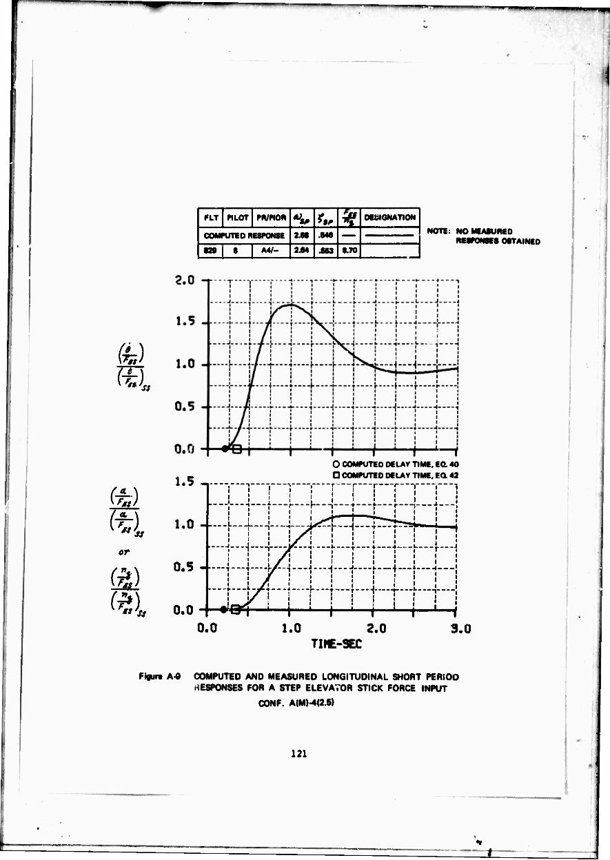
W.T «LOT PR/picm *W ^ ^ OEtilGNATION j
j COMPUTED RESPONSE 2.68 .646
1 829 i B A4/- 244 .863 870
NOTE: NO MEASURED RESPONSES OBTAINED
(■
or
(?) SI
1.5 -.
1.0 --
0.5 -
O COMPUTED DELAY TIME, EQ. 40 D COMPUTED DELAY TIME, EQ. 42
0.0
L I , i i 1 1 1 I 1 i ! ! I i
—-
i 1
, ! i i A \ \ \ \ \ \ \ \
_...L^.-J J . .. J J ._L i..._l J 1
—j.— y5.-. ....|..^...L..i_.|... ..^.„J
W\3\ 1 1 i ' i 1 1 0.0 1.0 2.0
TIME-SEC 3.0
Figur« A-9 COMPUTED AND MEASURED LONGITUDINAL SHORT PERIOD HESPONSES FOR A STEP ELEVATOR STICK FORCE INPUT
CONF. A(MM(2.5)
121

CONFIGURATION A(S)-2(10)
Pilot B's comments on this configuration were concerned with the slow stick which made the stick feel like it had "high inertia*' and was "rate liaited." These stick characteristics hampered the pilot's ability to make small rapid corrections and predict the airplane response from the corrections. The initial response was such that the tendency wa» to overshoot. Thece characteristics also hampered the entry into turns and made changes in the turn imprecise. The feel system characteristics interfered with quick tracking of moving or fixed targets, but trim and altitude control were judged to be "all right." With smooth and relatively slow inputs the response was more controllable and reasonable. Airplane response open loop was considered f) be reasonable without oscillation or bobble, but the stick forces in maneuver! were judged to be a little heavy. The airplane was judged to be only reluc- tantly acceptable and reasonably objectionable because of the stick and its effects on the airplane response and the pilot rating was an AS.
Pilot H judged the feel system to be poor. He described the quality of the feel system as "soft." He said the stick characteristics "detracted some- what" from trim, and the very slight delay in the airplane response following an input caused a slight tendency to "over-g" the airplane. Pitch attitude con- trol was judged not excellent but good, and altitude control was thought to be less precise than desired. The "funny feeling" stick felt lighter damped than desired and the tendency was to pump the stick in turns to impart damping and to maintain altitude. The stick forces were judged to be satisfactory and the airplane itself was considered well damped. The stick characteristics were objected to more under IFR than VFR conditions. Ther* were no PIO tendencies, and the PIOR was 1. The airplane was judged acceptable, but because of these "annoying" features was rated an A4.
122
.T
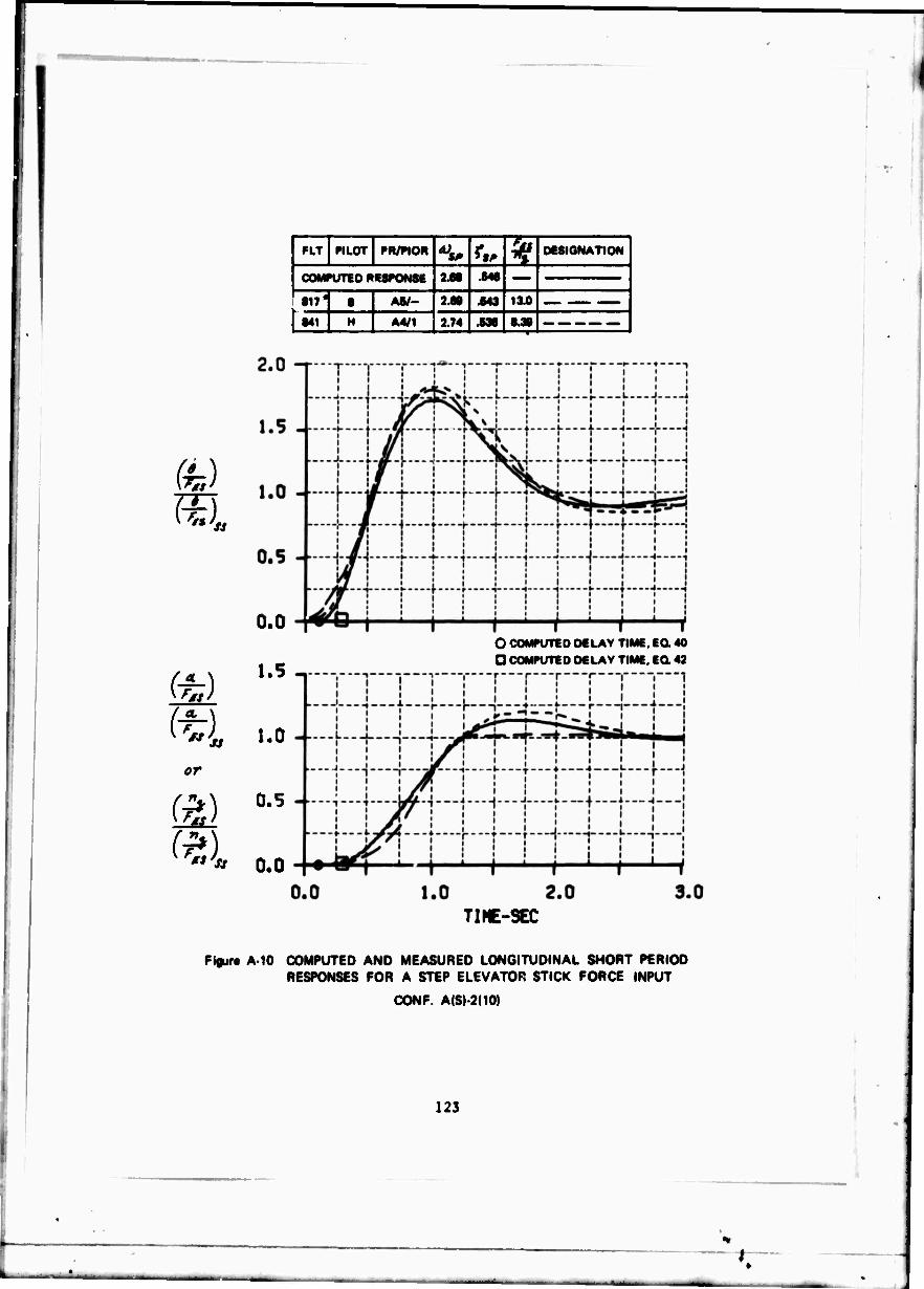
.
PIT «LOT PR/PIOR <4J V ^ 06SIGNATION
1 COMPUTED P6SPONSE 2.68 .648
! §17 • ■ AS/- 2.80 .643 13.0 1 I"' H A4/1 3.74 338 8.38
(h) }
0.0
1.5
1.0
or
fr») 0.5
0.0
O COMPUTED DELAY TIME. EG. 40 D COMPUTED DELAY TIME. EO 42
TIME-SEC
Figur« A 10 COMPUTED AND MEASURED LONGITUDINAL SHORT PERIOD RESPONSES FOR A STEP ELEVATOR STICK FORCE INPUT
CONF. A(S)-2(10)
123

CONFIGURATION A(S)-2(2.5)
The feel system or control system of this configuration was described as "lousy" by Pilot B with a feeling of "high inertia" or "rate limit." The stick forces were high initially, but "all right" steady state. There is no pronounced delay in the airplane response after the stick finally moves. The initial pitch response is indefinite and bad. The nose moves slowly, then rapidly, and the result is poor attitude and n* control and similar problems under both VFR and IFR flight. The poor stick'interferes with tracking. VFR altitude tracking is worse than IFR attitude tracking. The airplane does not PIO, and by maneuvering gently no "bobble" occurs. The tendency to force the response does not work. The airplane is controllable but unacceptable and rated a U7.
On Flight 834, Pilot H described the stick characteristics as "not very good." He did not feel "directly connected" to the airplane. The stick felt "heavy" even though the steady-state forces were "O.K." The tendency was to "pump" the stick to force the airplane response. The result was an oscillation with poor attitude, n« , and tracking control. With a rapid stick forte input there is a "kind of delay," a "pick-up" in response, and then an overshoot and "bobble." The oscillation is rapid, damped, and "not a classic PIO." There are no trim difficulties. Precise control is a function of how "smooth" and slow the inputs are. With random noise inputs, the pilot "has his hands full." la% airplane is controllable but unacceptable and rated a U7.5.
This configuration was evaluated again by Pilot H on Flights 851, 854, and 862. On Flight 851 with ^/»r-equal to 6.81 Ib/g the pilot comments were similar, but he also commentea on PIO tendencies, said trim was "not the best," and the airplane was difficult to handle in turbulence. The pilot rating was 6.5 and the PIO rating was 4.
On Flight 854, with 4.41 Ib/g, trim was difficult, the airplane approached the limits of controllability, and divergent PIO's occurred with attitude control, tracking, banked turns, and normal control in level flight. The airplane could only be flown by small inputs followed by a release of the stick. The PIO rating was 6 and the pilot rating a 10.
With 16.8 Ib/g on Flight 862, the PIO rating became 3 and the pilot rating improved to A6. The feel system was described as slightly "soft," the stick forces were objectionably heavy, the airplane was slow responding, but the airplane was also easy to trim, "very stable," fair in tracking, and had only a slight tendency to PIO. The PIO could be stopped by "easing up" on the tight control. The pilot objected to the slow initial response, the fatiguing stick forces, and the PIO tendencies with high gain tracking. The PIO rating was 3 and the airplane was reluctantly acceptable with a pilot rating of A6.0.
124
•T
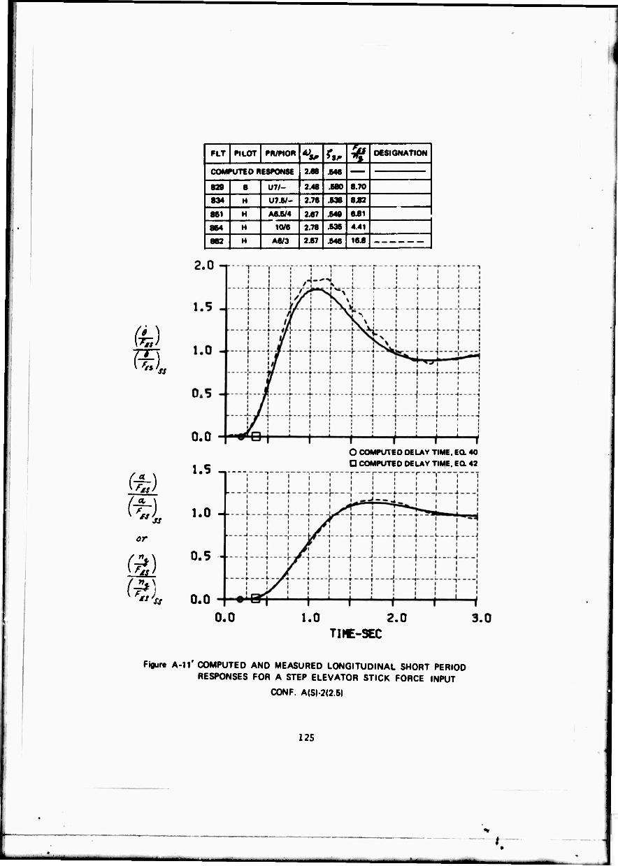
m
or
(%)
( 7*)
FLT PILOT PR/PIOR ** r,. % DESIGNATION
| COMPUTED RESPONSE 2.68 .646
| 829 8 U7/- 2.48 .680 8.70
834 H U7.6/- 2.76 .638 8.82
86 H A6.5/4 2.67 .648 6.81
864 H 10/6 2.78 .636 4.41
[ 863 H A6/3 2.67 .646 16 8
0.0
1.5 -.
1.0 -
0.5 -
0.0
O COMPU1 ED DELAY TIME, EG. 40
D COMPUTED DELAY TIME. EO 42
0. 1.0 2.0 TINE-SEC
Figure A-ll' COMPUTED AND MEASURED LONGITUDINAL SHORT PERIOD RESPONSES FOR A STEP ELEVATOR STICK FORCE INPUT
CONF. A(S)-2|2.5)
12S
.
CONFIGURATION A(S)-4(2.5)
This configuration was flown only by Pilot H on Flight 865. He considered the configuration uncomfortable, easy to over-g in both the plus and minus direction. The response was considered to be one with a significant time delay followed by a high pitch acceleration or pitch rate. Tracking performance was considered quite poor with oscillations of plus or minus one g. Tight closed-loop gain led to a PIO with divergent oscillations. The divergent oscillations can be prevented by reducing the pilot gain. IFR flight is a little better than VFR flight because with "smoother" inputs it is possible to control attitude and **, better. Altitude control is considered "all right" with "smooth" inputs, out with small bank angles and small precise pitch corrections there is a tendency to set up continuous PIO's of small amplitude. The airplane is not considered extremely oscillatory for normal flying straight and level and with gentle turns. The pilot liked the light stick forces and considers the feel system as satisfactory. He considers the stick displacements as fine, with no weird or funny movements in the stick. The configuration is considered controllable with difficulty and given a pilot rating of U8.5 and a PIO rating of 4.5 because of the divergent PIO tendencies with high pilot gain.
The lack of objections to the slow feel system cannot be explained.
126
—,^—
.T

fe) m
or
(a)
«LT PILOT PR/WOR A) *» %
DESIGNAT! "»N!
| COMPUTED RESPONSE 2.68 .546
- H U8.5/4.5 2.69 .544 8.39
2.0 -r
1.5 -
1.0 --
0.5 --
0.0
1.5 -.
1.0 --
0.5 -■
O COMPUTED DELAY TIME. EQ. 40 D COMPUTED DELAY TIME. EC 43
0.0 0.0 1.0 2.0
TIME-SEC 3.0
Figur« A-12 COMPUTED AND MEASURED LONGITUDINAL SHORT PERIOD RESPONSES FOR A STEP ELEVATOR STICK FORCE INPUT
CONF. A(S)-4(2.5)
127
i
CONFIGURATION B(F)-2(10)
Pilot B's primary coaplaints against this configuration on Flight 819 were the "bobbl;" and overshoot tendencies. The airplane frequency was not considered particularly high, but it was considered to be oscillatory open loop. The initial response was good, but the final response and precise tracking characteristics are adversely affected by the bobble and overshoot tendencies. Trim, altitude control, and control in turns were all "pretty good." The feel system, stick forces and displacements were considered satisfactory. The stick force gradient of 16.6 Ib/g was on the heavy side but the pilot liked it that way. The bobble effects were more severe with random noise and VFR as compared to IFR flying. The overshoot tendencies could be avoided by using slow inputs and applying pilot damping. The airplane was considered unsatisfactory and given a pilot rating of AS because of its oscillatory characteristics.
On Flight 849, Pilot H said that the configuration had a tendency to bobble and oscillate slightly in tracking and making attitude changes. The overshoot was greater with more "aggressive" inputs. The one-to-one relation- ship between stick inputs and airplane response was good. The initial pitch response to stick force inputs was good, but the final response was considered to be a little low. Trim, initial response, and attitude and altitude tracking both IFR and VFR were all good. Longitudinal control in turns was considered good, and in general the airplane was well behaved and pleasant to fly. The airplane was satisfactory and good enough for the mission without improvements and given a PIOR of 1 and a pilot rating of A3.
Pilot H flew this configuration again on Flight 857. The comments improved somewhat. He now made no mention of a bobble or overshoot tendency. In fact, he said the airplane was well damped, and showed no tendency to oscillate. He did mention that the stick felt "softer" than he would desire, but said that stick inputs and airplane response had close to a "one-to-one" relationship. The PIOR was 1 and the overall pilot rating improved to an A2.
Measured and LSF values of the airplane stability parameters are similar except for the high stick force gradient, 16.6 Ib/g, flown by Pilot B. It could be that Pilot B's poor rating of AS was influenced significantly by the high stick force even though his comments tend to contradict such a conclusion. The sUght difference in comments and ratings for the twc evaluations of Pilot H cannot be explained.
128
.1" AMBM.«^_
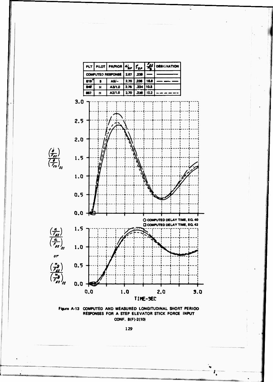
(h)
'*>*
or
l»LT PILOT PN/PIOR •W *„ k OESI MTIOW
| OOMniTED RESPONSE 2.67 .238
SIS* 8 Khl- J.TO .238 18.8
1 S4S H A3/1.0 2.78 .224 10.B
887 H A2/1.0 2.70 .238 .'0.2
0.0
1.5 n
O COMPUTED DELAY TIME. EG. 40 0 COMPUTED DELAY TIME. EQ. 42
0.0 I.0 2.0 3.0 TIME-3EC
Figur« A 13 COMPUTED AND MEASURED LONGITUDINAL SHORT PERIOD RESPONSES FOR A STEP ELEVATOR STICK FORCE INPUT
CONF. B(F)-2(10)
129
'
'
CONFIGURATION B(F)-2(2.5)
This configuration was evaluated by Pilot B with two different stick force gradients. On Flight 816 the stick force gradient was 17.3 Ib/g and the pilot rating was A3. On Flight 827 the gradient was 10.1 Ib/g and the pilot rating was poor, an AS.
On Flight 816 the pilot said the stick forces were "nice and high," but he did not mind the "little high" stick forces. He considered the feel system as "smooth and good." The initial response was prompt and the final response was considered predictable with not too much overshoot in g. Acquiring and maintaining g was considered "pretty easy" except that the forces did get "kind of high." Trim, entry into turns and maintaining altitude and g's in turns were considered good although the forces in steep turns were considered high. IFR flying was not significantly different from VFR. The airplane had a little oscillation and significant bobble open-loop, but the bobble did not interfere much and could be compensated for. There was no tendency to PIO even with tight control. The configuration was considered controllable, acceptable, and satisfactory with mildly unpleasant charac- teristics. The pilot said the configuration would have been rated better except for the bobble and would have been rated poor if stick forces were lower.
When the pilot flew this configuration with 10.1 Ib/g on Flight 827, he again said the feel system was good and the stick forces were "nice." The initial response is described as "pretty good" but "rather slow" in the end, with a tendency to overshoot in g. There was a substantial overshoot open-loop, and the airplane is considered quite oscillatory if nothing is done to control it. The airplane is considered not very difficult to fly and has no tendency to PIO. IFR characteristics were similar to VFR. Altitude tracking was only fair and IFR attitude tracking was only fair because of the difficulty in holding exact pitch angle. Coordination in steep turns is not as good as it should be, although altitude control in turns is considered "pretty good." The airplane is considered not much worse in rough air. Because of its characteristics, the tendency is to fly the airplane somewhat open-loop and trying to predict the final response. The airplane is considered controllable, acceptable, but unsatisfactory. Improvement is really necessary since the airplane requires considerable compensation because of the bobble and not being sure "what it will do."
130
.1
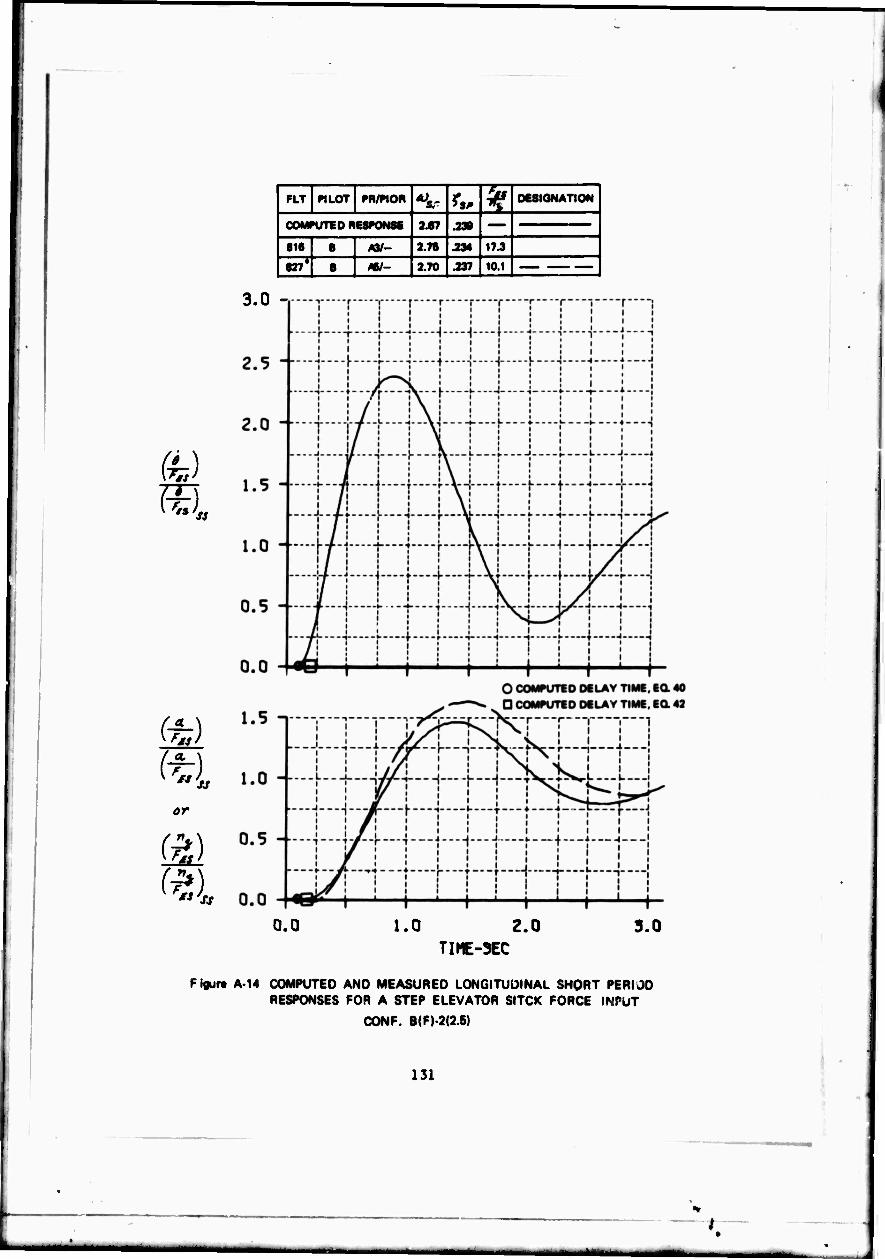
I
(M (■
or
FLT «LOT PH/PIOR *>*.- r«. 5" DESIGNATION 1
| COMPUTED RESPONSB 2.87 .230
816 B m- 2.7B .234 17 3
827* B m~ 2.70 .237 101 |
3.0 -
0.0 1.0 z.o 3.0 TIME-3EC
Figure A 14 COMPUTED AND MEASURED LONGITUDINAL SHORT PERIOD RESPONSES FOR A STEP ELEVATOR SITCK FORCE INPUT
CONF. B(F)-2<2.6)
131
»
CONFIGURATION B(F)-2(1)
Pilot B flew this configuration on Flight 815. Although the feel system characteristics vere considered satisfactory, the stick forces were described as pretty heavy, especially in steady-state turns. The airplane response was described as slow with an initial slight pause followed by an airplane response which led to an overshoot. Steady-state response was also not considered good because of the high stick forces. Attempting to control attitude and ** led quickly to a bobble. This was also true in turns. By flying the airplane tight'y there was a noticeable PIO. The airplane was worse under VFR as compared to IFR flying. Trim was con- sidered satisfactory. The bobble, PIO tendencies and high stick forces were bad features. The airplane was considered controllable but un- acceptable and rated a U8.
Pilot H flew this configuration on Flight 839. He considered the stick forces "about right." There was some difficulty in establishing nose attitude and trimming because of a slight tendency to a small amplitude PIO. There were very definite PIO tendencies only with precise high gain tracking. With control inputs the response was a noticeable delay, a rapid "pitch-up," and a tendency to "over-g" and settle at a lower steady state g than expected. With random noise inputs the tendency was for continuous oscillations to develop. The airplane open-loop was described as perhaps lighter damped than desirable. The airplane pitch rat ' appeared to increase and decrease continuously in a level flight turn which made control feel "heavier" than it really was. The best piloting technique was to fly the airplane "slowly" and "smoothly." The airplane was considered to be "not much different" VFR than IFR except that the airplane oscillated more with random noise inputs IFR. Because of the lightly damped PIO with tight control, the PIOR was 4 and the overall pilot rating was a U7.
132
.1" — . -—

te)
FLT PILOT PH/PIOR •>*, ^ k DESIGNATION
| COMPUTED RESPONSE 2.87 .238
815 1 U8/- 2.88 2S1 ISA
839 H U7/4 2.71 2» 10.4 |
3.0 -,
2.5 "
2.0 "
1.5
1.0
0.5
0.0
1.5 n
O COMPUTED DELAY T G COMPUTED DELAY T
^l 1.0
or
W 0.5
KF**'ss 0.0
ME, 60 40 ME. 60 42
0.0 1.0 z.o TinE-3EC
3.0
Figure A 15 COMPUTED AND MEASURED LONGITUDINAL SHORT PERIOD RESPONSES FOR A STEP ELEVATOR STICK FORCE INPUT
CONF. B<F)-2(1)
133

CONFIGURATION B(F)-4(2.5)
Pilot B evaluated this configuration on Flight 820. He described the feel systea as "all right" with reasonable stick forces and stick displaceaent, and no peculiar stick characteristics. The airplane is not quick responding and has a substantial overshoot open loop. It is hard to establish g's without an overshoot. Although the initial response is "all right," it is difficult to know what to expect for the final or steady-state g and attitude response. It is necessary to estimate what the overshoot will be. Altitude control in turns and in turn recovery is considered not as "good as usual" because of the overshoot. Trim and "smooth" tracking are considered relatively easy, but the overshoot tendencies interfere with altitude and attitude tracking and the per- formance with random noise inputs. The configuration has no PIO tendencies. It is considered just barely acceptable and unsatisfactory. The airplane is very objectionable, needs major improvement, and is rated an A6 with an inclination in the U7 direction.
Pilot H evaluated this configuration on Flight 838. He considered the feel system satisfactory. To get the desired pitch response required ■ore force than desirable although the steady-state stick force per g was satisfactory. The result was that the airplane felt "heavier" than it should. In response to pilot inputs, there did appear to be a delay, an overshoot and lower steady-state response which made the initial response poor. It was a "smooth" configuration if flown gently with "even" inputs and also in straight and level flight. With abrupt inputs for tight tracking there was a tendency to "over-g" the airplane and oscillate with PIO tendencies. The airplane itself is considered lightly damped. A small PIO occurs in holding constant altitude in turns and the PIO tendencies and "over-g" tendencies are evident with random noise inputs in turns. There was more of a tendency to bobble and oscillate IFR than VFR when holding altitude in turns. Altitude and attitude command tracking were not very good. The airplane is considered unsatisfactory and rated an A6. The PIO rating is 3.
134
.t

- PILOT PR/PIOR *^ <*, ^
DESIGNATION
1 COMPUTED RESPONSE i67 X»
820 8 A6/- 2.6B 761 10.7 — |
831 H Ae/3 2J8 J47 0.78 |
or
(a)
0.0
1.5 n
1.0 --
0.5 -
O COMPUTED DC LAY TIME. EQ. 40 D COMPUTED DELAY TIME. EO 42
0.0
0.0 1.0 2.0 3.0 TIME-5EC
F igurt A 16 COMPUTED AND MEASURED LONGITUDINAL SHORT PERIOD RESPONSES FOR A STEP ELEVATOR STICK FORCE INPUT
CONF. B|F)-4<2.5)
135
L.

CONFIGURATION B(F)-5(2.5)
This configuration was evaluated by Pilot B on Flight 813. The feel system itself was described as "pretty good"; it did not contribute to any of the difficulties. The stick forces were considered "OK" but "fairly high". UOT fast stick inputs the response was a "pause" followed by a fast response and a "bobble". The steady-state response was considered steady and smooth. For slow inputs, the initial response, attitude and "- control, and control in turns were considered satisfactory. Trim was also considered satisfactory. Altitude control was "all right" because the pilot integrated the oscillations, but altitude tracking perfoxsance was not good because of the tendency to use slow inputs. There was more tendency to bobble VFR then IFR because of the tighter control. The airplane had a pronounced oscillation open-loop, but the pilot could add damping by doing things slowly. The configuration was controllable but inadequate for the mission. Tracking was poor, and the bobble and low damping required high compensation. The pilot rating was a U7.
This configuration was flown by Pilot H on Flight 851. The feel system was classified as satisfactory but the forces felt heavy because of the low steady-state response and a not very rapid initial response. The response was considered poor with an initial time delay, followed by a rapid transient response and a low steady-state value. Pitch attitude and T- control, and tracking were all considered poor because of the definite tendency toward PIO's with even moderately tight closed-loop flying. PIG tendencies were also evident with trieming straight and level, and with random noise inputs. Tracking was poor VFR and quite poor IFR. Oscillations were also pronounced in the negative g direction. The open-loop aiiplane was considered lightly damped. With real tight control for any length of time, the PIG oscillations will go divergent. VFR and IFR flights were not too different, but the oscil- lations with TFR attitude tracking were greater than those with VFR altitude tracking. The airplane was controllable but unacceptable with a PIOR of 4.5 and a pilot rating of U 7.5.
136
.1

or
m
\
FLT «LOT PR/P10R ^ r«. ^ DESIGNATION
1 COMPUTED RESPONSE 2.67 .236
813 ■ U7/- 2.76 .234 17.3
861 H U7.B/4.6 2.62 .246 9.64
3.0 -,
0.0
1.5 n
O COMPUTED DELAY TIME. EQ. 40 Q COMPUTED DELAY TIME. EQ. 42
0.0 1.0 2.0 TIME-3EC
3.0
Figur« A-17 COMPUTED AND MEASURED LONGITUDINAL SHORT PERIOD RESPONSES FOR A STEP ELEVATOR STICK FORCE INPUT
CONF. B(F)-5(2.5)
137
/
CONFIGURATION B(F)-5(1)
Pilot H flew this configuration. He classified the airplane as quite poor with divergent PIO tendencies, even when flying in straight and level flight. Any attempt to establish pitch attitude, control v* , track, and roll out of turns both VFR and IPR results in a PIO. The aiVplane also oscillates continuously in a turn. Random noise deteriorates performance further. A very significant time delay is apparent between a control input and the response of the airplane, which is then followed by a rapid "takeoff" of the response. The quality of the feel system and the stick force gradients are considered satisfactory. The only technique for trimming is to use small inputs, a little trim, small inputs, etc. If the pilot takes his hand iff the stick and gets out of the loop, the PIO oscillations will damp out. The amplitude of oscillations seems to be greater in the negative g direction. Putting a control input in, holding it, and accepting the response does not lead to oscillations or a PIO. The airplane is considered uncontrollable in the mission with divergent t'IO tendencies. The pilot gave the airplane a PIOR of 6 and an overall rating of 10.
138
^. .t
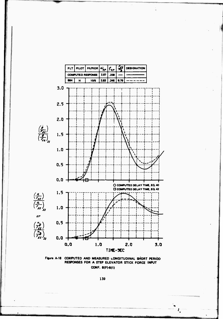
FU «LOT PR/PIOR *i. ^5^ ^ DCSIGNATION
1 COMPUTED RESfONSE 2.67 .230
1 864 H 1(V6 2 63 .246 9.79 |
3.0 -i—r
or
O COMf UTED DELAY TIME, Ea 40 D COMPUTED DELAY TIME. Ea 42
0.0 1.0 2.0 3.0 TIHE-3EC
Figurt A 18 COMPUTED AND MEASURED LONGITUDINAL SHORT PERIOD RESPONSES FOR A STEP ELEVATOR STICK FORCE INPUT
CONF. B|F)-6(1)
139
CONFIGURATION B(S)-2(10)
This configuration was evaluated only by Pilot H on Flight 848. He described the configuration as uncomfortable to fly and "almost in continuous oscillation" even when flying straight and level. He described the pitch response following a control input as quite slow initially f 'lowed by a "speed up" and a fairly light damped oscillation. The steady-state pitch rate response is considered significantly less than the peak value which makes the airplane feel somewhat heavy. Elevator Jtick forces are considered correct or adequate, but the feel system is described as "soft" or "mushy" feeling which results in a tendency to pump the stick considerably. The connection between an input and the airplane response is considered poor. Tracking ability with even mild closed-loop control is considered nil because of the PIO's. Depending on the pilot gain, the oscillations can be divergent. Attitude control is poor under both VFR and IFR flight. It is easy to overshoot and "over g" the airplane. The airplane is also oscillatory with random noise inputs. With a 30 degree banked turn it is easy to incur jL.8g fluctuations, particularly in the negative direction. The configuration is considered not uncontrollable but certainly unacceptable and difficult to fly, with PIO's that can be divergent with high gain tracking. By continuously releasing the stick, the configuration can be made more flyable. The PIO rating is 4.5 and the overall rating is U8.
140
.1
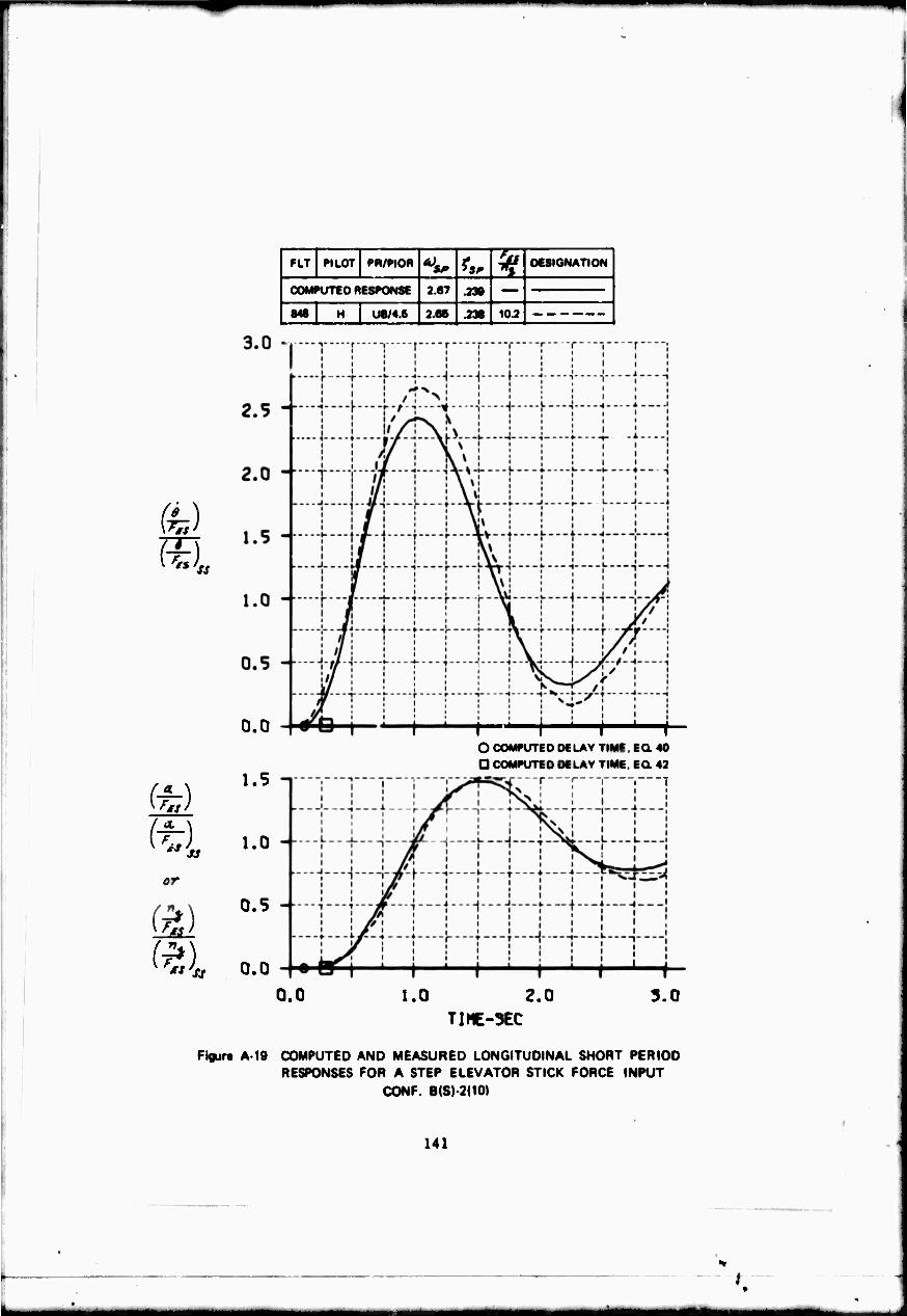
fe)
I-
FLT PILOT PR/PIOR SP *5, ? DESIGNATION
COMPUTED RESPONSE 2.67 .238
848 H U8/4.6 2.66 .238 10.2
0.0
%)
1.5
/''t 1 ('«i 1.0
0"
^)
0.5
fr») 0.0
1——I—^-i—'—h O COMPUTED DELAY TIME, EQ. 40
Q COMPUTED DELAY TIME. EQ. 42
r---r-"i 1—"
0.0 1.0 2.0 TIHE-3EC
3.0
Fioure A 19 COMPUTED AND MEASURED LONGITUDINAL SHORT PERIOD RESPONSES FOR A STEP ELEVATOR STICK FORCE INPUT
CONF. B(S)-2(101
141
/

CONFIGURATION C(F)-2(10)
Pilot B described the airplane as a quick responding, high frequency airplane with a slight bobble on Flight 821. Because of these characteristics the airplane was a little "touchy," although it was possible to minimize the bobble through piloting technique. Trim, attitude and g control, and tracking were all considered "pretty good." There were no significant differences flying VFR or IFR. There were no PIO tendencies. It was a reasonably good airplane to control in turns. The feel system was considered satisfactory. There was no friction, stick deflections were small and satisfactory, but the stick forces were considered somewhat light. Random noise did not affect the pilot's opinion of the configuration. The airplane was considered unsatisfac- tory with adnor but annoying deficiencies because of the "little" bobble. The pilot therefore rated the configuration as A4. On Flight 823, Pilot B evalu- ated essentially the same configuration a second time. The comments were very similar. Although he said the airplane was quick responding and slightly "jerky" or "jumpy," he said there was no overshoot and never commented on a bobble. He liked the airplane and now considered it acceptable and satisfactory and rated it an A2.
Pilot H flew the configuration twice. Flights 839 and 848. His comments were similar to those of the first evaluation of Pilot B. He also was bothered by the slight bobble. The airplane was considered to be "snappy" and attitude and tracking were considered to be "fair" or "pretty fair" and degraded some- what by the bobble tendencies. Control of g was a function of how "aggressive" the pilot was in flying the configuration; there was more bobble when flown aggressively. Although the feel system and stick forces were good, the pilot felt there was a very slight delay in the airplane response following a control input. The pilot felt there was no PIO tendency on Flight 848, and only a very, very small oscillation in tight tracking in Flight 839. He felt that the initial pitch response was rapid, and the steady-state response was slightly lower, which made the airplane appear somewhat "heavy." Although VFR and IFR flying were not considered too different, the tendency was to be "smoother" IFR which resulted in less tendency to "bobble." On Flight 839 the pilot rating was A4 and the PIO rating was 2. On Flight 848 the pilot rating was A4.5 and PIO rating was 1.5.
142
.1

fe)
SI (
or
(£1 *t'ss
FLT PILOT PR/PIOR r^ ^ DESIGNATION 1
COMPUTED RESPONSE 5.06 .433
831 I A4/- 6.04 .431 8.73 |
833 8 A2/- 6.03 .437 9.17
830 H A4/3 B.01 .438 7 93
848 H A4.5/1.6 6.03 .438 7.93
3.0
2.5
2.0
1.5
1.0 -■
0.5 --
Ü.0
1.5
■"■T"JJ"*'T""P'T""r i "[■"T""!
----l7---rt---j--""|----|--"f--H j-—f—-i
—J 1 X.L..-J—\ ! L — ;—l 1
E i lii! I ! J L L
^
|i ! 1 i i i i i ! ""'I i * "l""1 ! r 1 ! "'"1 i """1
1 j' i\I lAiTii* ..fj i ! i_ ..J i j J j j
noj
r1 "j p T 1—"j 1—<—i—i— I 1 i 1 j i i ! 1 1 j / 1 : i : ! ! 1 ! ! ;
—j
^-J 1 1 { i i ■ O COMPUTED DELAY TIME, EC 40
D COMPUTED DELAY TIME, EQ. 43
0.0 1.0 2.0 TIME-SEC
3.0
Figure A 20 COMPUTED AND MEASURED LONGITUDINAL SHORT PERIOD RESPONSES FOR A STEP ELEVATOR STICK FORCE INPUT
CONF. C(F)-2(10I
143
t
■■i
CONFIGURATION C(F)-2(1)
This configuration was evaluated by Pilot B on Flight 818. The stick displacements were described as small and prompt, and the stick forces were "fairly high" but reasonable. It was not a good airplane because of the bobble and PIO tendencies when flown tightly in rough air, during tracking, and when making quick corrections to hold the nose in a turn and entering and recovering quickly from a turn. The PIO tendencies were not "fierce." By doing things gently or relaxing the stick, the bobble and PIO tendencies could be prevented or stopped. Attitude and ft» control in turns were not bad. IFR flight was significantly easier than VFR flight. The trouble was the initial lag in the response followed by a response more rapid than anticipated. The primary reason for the U7 rating was the tendency to PIO.
On Flight 819, Pilot B rated the configuration as poor, "extreicdly touch/," and easy to PIO. The quick response is preceded by a slight pause. PIO's develop with ordinary manuevering. The pitch response per unit stick force input is considered large and abrupt with a tendency to PIO during the steady-state response. VFR altitude tracking was considered most difficult, but IFR attitude tracking was also touchy. The airplane could be flown without PIO's by flying slowly and gently with the "fingertips." The airplane was marginally controllable and rated a U9.
On Flights 822 and 826 Pilot B flew the configuration with stick force gradients of 9.9 and 9.7 Ib/g, respectively. The forces were on the heavy side, but the pilot liked them. The airplane was "touchy," abrupt in response, with "bobbles" and overshoots in desired attitude and g's. It was possible to get a "small limit cycle going" which did not grow or "get away" like a PID. These characteristics were true IFR, worse VFR, and occurred during altitude and attitude tracking. With slow, smooth inputs, control was better. The airplane was controllable, but unacceptable because of the bobble and rated U7 on both flights.
This configuration was also evaluated by Pilot H on Flight 835 with a stick force gradient of 8.14 Ib/g. The feel system characteristics were considered "OK" and the sti " forces were thought to be "pretty good." Pilot H's comments were similar to those of Pilot B on Flights 822 and 826. With "smooth" inputs, the airplane is well behaved in holding altitude and attaining a given attitude or g. With abrupt or tight control, the airplane becomes oscillatory, and the oscillations can be eliminated by reducing the pilot gain. The tendency was to overcontrol and set up a zero damped PIO with random noise inputs. This was true of both VFR and IFR tracking. The airplane was control- lable but unacceptable with a PIO rating of 3 and a pilot rating of U7.
144
.t
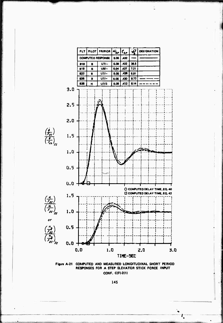
««
or
FLT PILOT PR/PIOR *^ ?,,. ^ DESIGNATION 1
| COMPUTED RESPONSE 6.06 432
818 8 U7/- 6.08 .422 30.6
819 8 U8/- 6.04 .437 7.21
822 8 071- 6.06 .428 9.91
828 8 011- 6.06 .430 9.73
836 H U7/3 6.06 .4M 8.14
3.0
2.5
2.0
1.5
1.0 -
0.5 -
0.0
1.5
1.0 -I—
0.5
0.0 0.0
-
---■j r i f r r r ["' r "i
j- --|----f----;-----j-----i- - j—--j - .!-.--[---- i t?$ : ! 1 i 1 1
" —!—-j'f"!"""'""!""""''" 1 -i --;■-- -;---
j L ,L -V-j ■! • }--■-♦ — • 1
i Jj '._jL' \ L -► i i- L
r —;
ill ' ■*
i -X * i 8 .1 4 L-.-l .4.--.
J..I 1 ...!... jll..L L J l-.-J U
i A ' "^^ji^ i. ' 1 'I
. . -II. .l----b---.a--.-«... 1 . . ) J----M
!
m , i 1 , [ ., ^ -j 1 ,
# ! '. - i I i i 1 ; ■ •' l ! i i
"""/!—1 t"—\ — r'""""!—1 ! I" —! ' /1 i ■ ' i i • . j i . i i i . i i i '
-# r-i. ! : : : ! i : l • «J l i i i i i
O COMPUTED DELAY TIME, EU. 40
D COMPUTED DELAY TIME, EC 42
r ■ ! i ! r r r r j ; j | i ; j 1 ; | 1
—!
- -|---t#-4—I" ■}----|----| }.—+—*.—^ : / : i l ; : i ;
j
a^j ( | ( ' r f i
1.0 2.0 3.0 TIME-SEC
Figure A-21 COMPUTED AND MEASURED LONGITUDINAL SHORT PERIOD RESPONSES FOR A STEP ELEVATOR STICK FORCE INPUT
CONF. C(F)-20)
145

CONFIGURATION C(F)-4(2.5)
.
This configuration was evaluate by Pilot B on Flights 820 and 824. In both cases the pilot rating was U7. For both evaluations the feel system characteristics were considered "all right" with small stick travel, no friction, and no "high inertia" or "rate limit" characteristics. The stick forces were also considered reasonable. The response following a control input was possibly a very slight delay, a "prompt" or abrupt pitch response, followed by a bobble in stopping on a particular steady-state response. On Flight 824, the config- uration was considered junpy with a tendency to bobble which interferes with pitch attitude control and VFR tracking, but the configuration was not consi- dered to have PIO tendencies unless the pilot tried "real hard." On Flight 820 attitude control and tracking suffered because of the tendency to get a small PIO going. The PIO could be avoided by doing things a "little bit slower." Control of attitude in steep turns was "touchy" with bobble tendencies on Flight 824. On Flight 820 the airplane tended to bobble on entering a turn, but altitude control in the turn was considered "pretty easy." Trim charac- teristics were considered satisfactory on both flights. Command tracking was considered to be fair on both flights, but ordinary VFR tracking was considered unacceptable on Flight 824. The final response following a control input was considered difficult to predict on both flights. The rating on Flight 820 was based primarily on the PIO and limit cycle tendencies of the configuration. On Flight 824, the same rating was based primarily on the tendency to bobble the configuration.
This same configuration was evaluated by Pilot H on Flight 844. The pilot rating was 1/7.5 and the PIO rating was 4. The feel systeik was considered satisfactory, and the steady-state stick forces were rated "about right." The configuration was considered "quite oscillatory" and of high frequency. With tight control in tracking and controlling attitude the tendency was to get a Zitro damped PIO of moderate amplitude. The pilot felt the connection between an input and the airplane response was poor because of the delay. The response to a control input was described as a noticeable delay followed by a quick initial response and a relatively low steady-state pitch rate which made the airplane feel "heavy." The overshoot in g was as high as .4. By maneuvering "smoo'vhly" the overshoot and PIO tendencies can be prevented. Altitude and attitude tracking were both considered "quite poor" because of the zero damped PIO. Altitude control and longitudinal control in level flight turns were also considered poor because of the oscillations. The pilot rating was based primarily on the fact that oscillations and a zero damped PIO developed, but the airplane still "never gets away."
146
nr

or
FLT PILOT PR/PtOR A) SP **, ^ DESIGNATION
COMPUTED RESPONSE 6.06 .432
8W B U7/- 5.01 .434 108
824 ■ U7/- £.06 .436 8.17
844 H U7.6/4 6.02 .431 8.06 .
0.0 1.0 ^.0 TIHE-SEC
i.O
riflur- A 22 COMPUTED AND MEASURED LONGITUDINAL SHORT PERIOD RESPONSES FOR A SIcP ELEVATOR STICK FORCE INPUT
CONF. C(F;-.1(2.5)
147
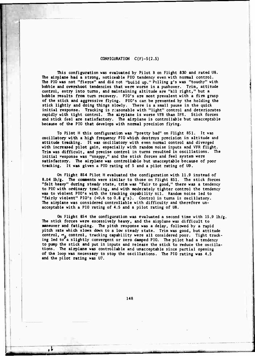
CONFIGURATION C(F)-5(2.5)
This configuration was evaluated by Pilot B on Flight 830 and rated U8. The airplane had a strong, noticeable PIO tendency even with normal control. The PIO was not "fierce" and did not "build up." Pulling g's was "touchy" with bobble and overshoot tendencies that were worse in a pushover. Trim, attitude control, entry into turns, and maintaining altitude are "all right," but a bobble results from turn recovery. PIO's are most prevalent with a firm grasp of the stick and aggressive flying. PIO's can be prevented by the holding the stick lightly and doing things slowly. There is a small pause in the quick initial response. Tracking is reasonable with "light" control and deteriorates rapidly with tight control. The airplane is worse VFR than IFR. Stick forces and stick feel are satisfactory. The airplane is controllable but unacceptable because of the PIO that develops with normal precision flying.
To Pilot H this configuration was "pretty bad" on Flight 851. It was oscillatory with a high frequency PIO which destroys precision in altitude and attitude tracking. It was oscillatory with even normal control and diverged with increased pilot gain, especially with random noise inputs and VFR flight. Trim was difficult, and precise control in turns resulted in oscillations. The initial response was "snappy," and the stick forces and feel system were satisfactory. The airplane was controllable but unacceptable because of poor tracking. It was given a PIO rating of 5 and a pilot rating of U9.
On Flight 854 Pilot H evaluated the configuration with 11.9 instead of 8.04 Ib/g. The comments were similar to those on Flight 851. The stick forces "felt heavy" during steady state, trim was "fair to good," there was a tendency to PIC with ordinary tracking, and with moderately tighter control the tendency was to violent PIO's with the tracking capability nil. Random noise led to "fairly violent" PIO's (+0.6 to 0.8 g's). Control in turns is oscillatory. The airplane was considered controllable with difficulty and therefore un- acceptable with a PIO rating of 4.5 and a pilot rating of U8.
On Flight 854 the configuration was evaluated a second time with 15.9 Ib/g, TTie stick forces were excessively heavy, and the airplane was difficult to maneuver and fatiguing. The pitch response was a delay, followed by a rapid pitch rate which slows down to a low steady state. Trim was good, but attitude control, rr control, tracking capability were all considered poor. Tight track- ing led to a slightly convergent or zero damped PIO. The pilot had a tendency to pump the stick and put in inputs and release the stick to reduce the oscilla- tions. The airplane was controllable and unacceptable since partial opening of the loop was necessary to stop the oscillations. The PIO rating was 4.5 and the pilot rating was U7.
148
.1
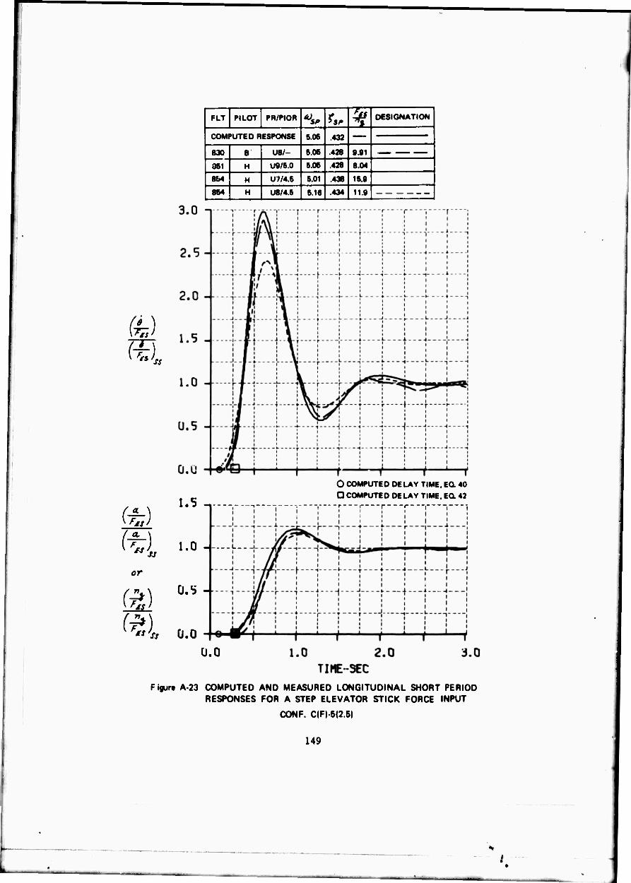
(• \
or
(a)
FLT PILOT PR/PIOR to *„ ^ DESIGNATION
COMPUTED RESPONSE 6.06 .432
830 B U8/- 6.06 .428 9.91
061 H U9/5.0 6.06 .428 8.04
I 8M H U7/4.6 6.01 438 16.9
| 864 H U8/4.6 6.16 .434 11.9
1.5 -.
1.0 L..
O COMPUTED DELAY T D COMPUTED DELAY T
■r i r
0.5 -
«<» 0.0
ME, £0 40 ME.EQ *2
0.0
F igura A 23 COMPUTED AND MEASURED LONGITUDINAL SHORT PERIOD RESPONSES FOR A STEP ELEVATOR STICK FORCE INPUT
CONF. C(F) 5(2.5)
149

CONFIGURATION C(F)-5(1)
Pilot B's predominant comment on this configuration was its strong PIO tendencies. As soon as the pilot tries any sort of accurate control of the airplane, the result is a severe PIO. PIO's are severe and easy to excite when trying to trim, controlling pitch attitude, tracking, and recovering from a turn and pushing the nose down. The PIO is not as strong entering a turn and main- taining attitude in a turn. PIO tendencies are not as bad if the airplane is controlled slowly and very gently. The only way to stop the PIO is to release the stick, and then it does not stop right away. The PIO's are worse in rough air, and much worse during VFR than IFR flying. The pilot commented on a pronounced lag between the pilot input and the time the airplane responds. The feel system was judged satisfactory. The airplane was judged to be uncontroll- able for the mission because of the strong PIO tendencies and it was rated a 10.
Pilot H flew the configuration with similar comments. He also commented on the significant time delay in the airplane response following a control input The delay was followed by a rapid pitch rate response. Attempting to control pitch then led to a phasing problem and a PIO. The airplane could be trimmed only by using small "pulse" type inputs and releasing the stick to allow the oscillation to die out. Using small, easy inputs and releasing the stick after each input was the only technique that worked for controlling the airplane. Flying the airplane even straight and level with any attitude correction led to a high frequency, large amplitude divergent PIO. The airplane was considered uncontrollable in the mission and given a PIOR of 6 and a pilot rating of 10.
Pilot H also flew the configuration on Flight 861 with 16 rather than 8.04 Ib/g. He comnented that the stick forces felt heavy, and the tendency was to maneuver the airplane less abruptly than one would like. Although the comments on PIO tendencies were similar to those with the stick force gradient of 8.04 Ib/g, the magnitude of the PIO tendencies was not as pronounced. The pilot felt that there were no tendencies toward fast divergent oscillations. In fact, the oscillations were probably slightly damped and tended to be zero damped with an increase in gain. The stick forces and PIO tendencies resulted in a PIOR of 4.5 and a pilot rating of U9.
The configuration was flow by Pilot H with 23.8 Ib/g on Flight 864. The pilot complained that the stick forces were too heavy and physically tiring, and the initial and steady-state pitch responses were too low for a fighter. Trim and tracking were considered poor. PIO tendencies were still there with tight high gain tracking, but it could be flown in straight and level flight "quite comfortably." The heavy stick forces, slow response, and PIO tendencies resulted in a PIOR of 4 and an overall rating of U7.
150
.1

fe)
or
(a) *s'ss 0.0
FLT PILOT PR/PIOR * ^
DESIGNATION
1 COMPUTED RESPONSE 6.06 .4 32
8261 1 1<V- 6.06 .4 22 10.2
861 H U9/4.5 6.06 .4.12 16.0
864 H U7/4.0 6.06 .♦n 23.8
| 864 H 10/6 6.03 .4» 8.04
0.0
1.5
1.0 --
0.5 -
O COMPUTED DELAY Tl
Q COMPUTED DELAY Tl
ME.Ea40 ME. ECl 42
0.0 1.0 2.0 TIME-3EC
Figure A 24 COMPUTED AND MEASURED LONGITUDINAL SHORT PERIOD RESPONSES FOR A STEP ELEVATOR STICK FORCE INPUT
CONF. C(F)-5(1»
151
I

CONFIGURATION C (F)-5(0.796)
On Flight 866 Pilot H evaluated this configuration three times with three different stick force gradients, 24.2, 7.99 and 16.0 Ib/g.
With the 16.0 Ib/g the stick forces were considered a little heavier than desired but might be considered acceptable. The quality of the feel system was considered satisfactory and the stick displacements were considered small and good. The configuration was considered unacceptable both IFR and VFR flying because of its strong PIO tendencies. The oscillatory tendencies made control of attitude and n, veiy poor. It was therefore quite difficult to trim the airplane. There was a tendency to mild PlO's even flying straight and level and in gentle banked turns. With moderate to high pilot gain, the oscillation tended to go divergent. Attitude control and tracking capability were very, very poor. Neither the VFR nor IFR trarking tasks could be performed. Tracking led to divergent PIO's. The PIO's couh be stopped by reducing the pilot gain; it was not necessary to go open-loop. V?.e connection between stick inputs and airplane response was considered extremely poor because of the significant time delay in the response. The configuration was considered unacceptable and controllable with difficulty and required substantial pilot skill. The PIO rating was 5.5 and the pilot rating was U8.
With a stick force gradient of 7.99 Ib/g, the pilot rating degraded to a 10 and the PIO rating to 6. Now even normal control resulted in divergent PIO's. Attitude control, n- control, and tracking were equally impossible. It was impossible to make level flight turns without oscillations that tend to go divergent. The airplane could only be flown by putting an input in and holding it and accepting the response. Freeing the stick and going open loop was the only way the airplane could be flown.
With a stick force gradient of 24.2 Ib/g the airplane was considered so heavy that for normal inputs the response was very slow. With such high stick forces the airplane was not considered in the realm of a fighter. With one hand, it was possible to pull only 1.5 incremental g's. Attitude control and rtj control were considered quite poor. Random noise had no significant effect on control. Trim was considered easy. With higher pilot gain in tracking, there was almost a continuous PIO, but the oscillation was not divergent and of moderate amplitude. For small bank angle turns there was a mild, continuous PIO with pitch angle corrections. Tlie tendency was to go to two hands to control pitch attitude in banked turns greater than 30 degrees. The best piloting technique was to put in inputs and then let go of the stick. There was no desire to maneuver the airplane because of the high stick forces. The airplane is considered unacceptable and controllable only with difficulty. The pilot rating wasU8.5 and the PIO rating 4.5.
152
.1
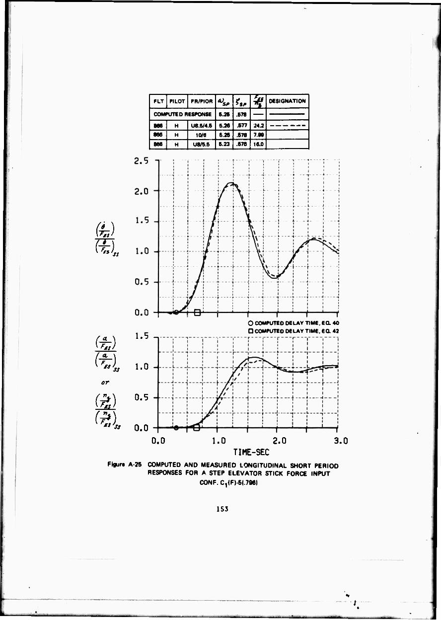
m fe 'A
(a)
FLT PILOT PR/PIOR *„ % DESIGNATION ]
| COMPUTE D RESTONSE 6.36 .678
866 H U8.6/4.5 6.26 .677 J4.2
|886_ H 10/6 6.26 .678 7.86
866 H U8/5.5 6.23 .678 16.0
1.5 -,
1.0 -
0.5 --
O COMPUTED DELAY TIME. EG. 40
D COMPUTED DELAY TIME. EG. 42
0.0 0.0 1.0 2.0 3.0
TIME-SEC Fjgurt A-26 COMPUTED AND MEASURED LONGITUDINAL SHORT PERIOD
RESPONSES FOR A STEP ELEVATOR STICK FORCE INPUT CONF.C^FJ-S«.?«)
153

CONFIGURATION C(M)-2(10)
Pilot H found this configuration disappointing primarily because of its tendencies toward PIO's coupled with its poor tracking capabilities. Ability to trim was considered only fair because attempts at precise positioning of the nose set up an oscillation. Trim position could better be established by re- leasing the stick. With tight closed-loop control there was a tendency to "over g" in attitude, pitch attitude tracking was poor, altitude tracking was only fair and PIO tendencies developed. PIO tendencies could be reduced and control improved by the pilot reducing his gain, especially as the airplane attitude is attained. Random noise also had considerable detrimental effect, and caused the airplane to "bobble." The pilot liked the high frequency, rapid response, and good damping of the airplane open-loop. He liked the light stick forces and the ability to maneuver rapidly. He felt the feel system characteristics were good with pretty close to a "one-to-one" relationship between the stick and the airplane response. The airplane was considered unacceptable for the fighter mission primarily because of the inability to track without PIO developing with any reasonable pilot gain. The PIOR was 3.5 and the pilot rating was U7.
154
.k

fe)
or
" ss
FLT PILOT PR/PIOR ^ **, ^ DESIGNATION
COMPUTED RESPONSE 5.06 .433
867 H U7/3.6 6.08 .436 7.96
3.0 n
2.5 --
2.0
1.5
1.0 -
U.5 --
Ü.0
1.5
1.0 --
Ü.5 --
—
—-■«"—U—-j p---j.--.j.----,. r..-.r...^ r ,
----|-i[--U-"-5!--"j--"-j-"H |.--|-.J--.:—J
—-j-/,--•{—-jU--!----:—i----f—1—\—\—\—i
fr-"!—■! V't—r—•—^—i----i----;—\--—\
- .„Jj—\—v...iSJ(....\—\—j—.|—J—\—\
UU | | < ' f ' f ' I1
O COMPUTED DELAY TIME, EQ. 40 D COMPUTED DELAY TIME. EQ. 43
0.0
0.0 1.0 2.0 TIME-3EC
3.0
Figure A 2b COMPUTED AND MEASURED LONGITUDINAL SHORT PERIOD RESPONSES FOR A STEP ELEVATOR STICK FORtE INPUT
CONF. C(M)2;i0)
1S5

CONFIGURATION C(S)-2(10)
This configuration was categorized as a "miserable" airplane by Pilot B because of the "high inertia" stick. There was "not much" correlation between stick inputs and motion of the airplane. The poor stick dynamics result in a lag in the airplane response which results in poor trim, attitude control, and n control with overshoot and a "bobble." Tracking performance was poor IFR
ami worse VFR. The steady-state response to slow inputs and the control in steady-state turns were considered satisfactory. Control during entry and recovery from rapid turns was degraded. Although steady-state forces and stick displacements were satisfactory, the stick felt heavy and poorly damped under "dynamic" conditions. The open-loop airplane was considered -ood. There was not much in the way of a PIO, but the peculiar feeling stick made the airplane unpleasant, bad, controllable but unacceptable. The pilot rating was a U7.
Pilot H flew this configuration on Flight 843, and described the feel system as only fair with a tendency for a delay between an input and the airplane response so that the pilot did not feel "directly connected" to the airplane. Stick forces were considered satisfactory as were stick displacements. The response delay followed by a rapid response tended to result in oscillations and a PIO that is somewhat damped. The oscillations and PIO tendencies made trim a little difficult and precise control of attitude and n. impossible. Both altitude and attitude tracking were considered unacceptable both VFR and IFR. The airplane was considered controllable but unacceptable because of the PIO tendencies and the inadequate tracking characteristics and given a PIOR of 4 and an overall rating of Ü7.
The comments and ratings of the two pilots are similar except that Pilot B did not sense much in the way of a PIO. The higher stick force gradient, 9.36 as compared to 8.OS Ib/g, may have inhibited PIO tendencies somewhat.
156
* 3
^M
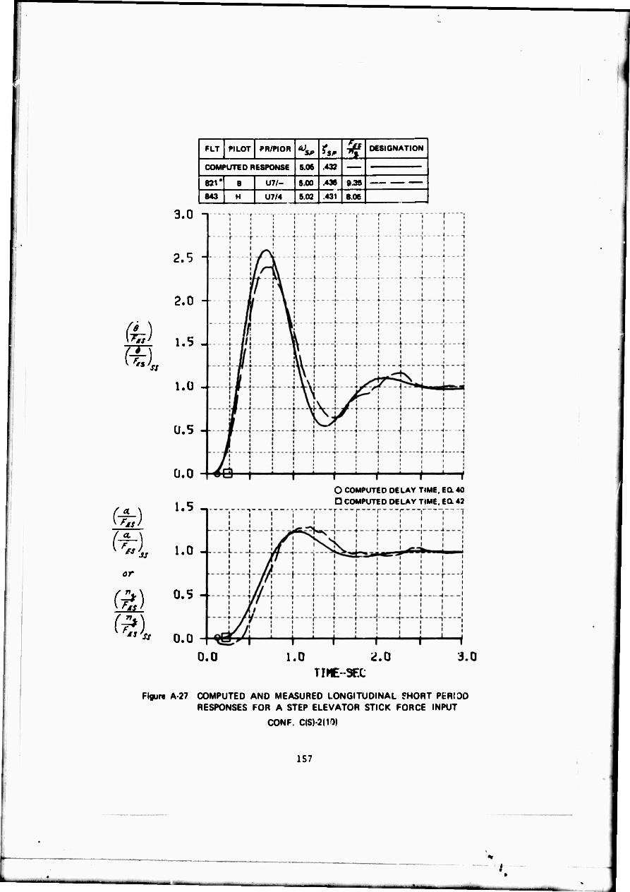
fe) m
or
ts'ss
FLT PILOT PR/PIOR ^ ^ ^ DESIGNATION
COMPUTED RESPONSE 5.06 .432
821* B U7/- 600 .436 9.36 |
843 H U7/4 502 .431 8.06
3.0 n
2.5 -
2.0 -
1.5 -
l.Q -
U.5 -
Ü.0
1.5 -.
1.0 --
0.5 -
0.0
O COMPUTED DELAY TIME. EG. 40
O COMPUTED DELAY TIME. EG. 43 -r i 1 ( 1-
0.0 1.0 ^.0 TIME-SEC
Figure A 27 COMPUTED AND MEASURED LONGITUDINAL THORT PER! 3D RESPONSES FOR A STEP ELEVATOR STICK FORCE INPUT
CONF. C(S)-2(10)
157
;

CONFIGURATION LA(F)-2(10)
Pilot B evaluated this configuration on Flight 822. His primary objec- tion to the configuration was that it was slow responding, "sloshy," with "loose" control. The airplane was considered quite flyable and certainly acceptable. The tttl system was described as good with a lot of stick travel, but "all right" in the approach. The forces were considered a little light. Trim, initial response, attitude control and ** control were all satisfactory with no overshoot. The nose responded to stick movement immediately, but it was not possible to do anything quickly; the airplane was a little imprecise. Altitude control was good. IFR attitude tracking was "not difficult," the ILS approach "seemed good," and control in turns was good. The pilot rating was A3 and would have been A2 if the airplane had responded raster.
Pilot H flew this configuration on Flight 835 and gave the configuration a PIOR of 1 and the same pilot rating as Pilot B, a rating of A3. His coaments were similar to those of Pilot B. The airplane was well behaved, but he objected slightly to the "springiness" or "softness" of the feel system and the fact that the airplane response felt a "shade behind" the control input. The ILS approach was considered "pretty good" and the airplane easy to handle with large corrections. The airplane was considered acceptable and satisfactory. The "soft and spongy" feel system and the slight "hesitation in the nose" pre- vented it from being rated an A2.
158
.(.

FLT PILOT PR/PIOH A) ?s^ ¥ DESIGNATION]
i COMPUTED RESPON&fc 1.96 .668
822 1 A3/- 1.90 .63» 17.8
t* H Am 1.97 Ml 17A
NOTE: NO MEASURED RESTONSES OBTAINED
or
m "'» 0.0
O COMPUTED DELAY TIME, Ed 40 D COMPUTED DELAY TIME, Ed 42
1.0 2.0 TIME-SEC
Figur« A 28 COMPUTED AND MEASURED LONGITUDINAL SHORT PERIOD RESPONSES FOR A STEP ELEVATOR STICK FORCE INPUT
CONF. LA(F)-2(10)
159
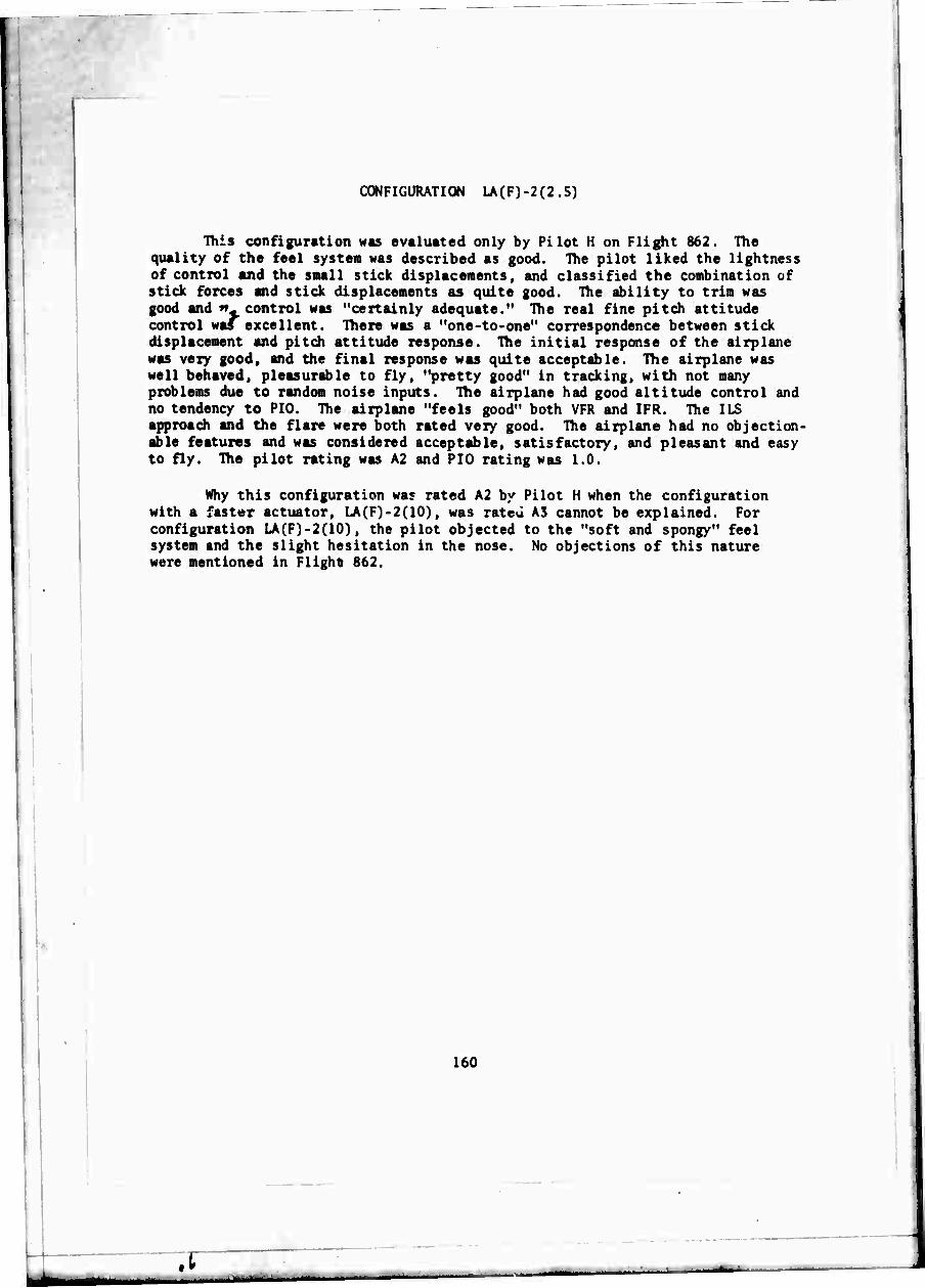
CONFIGURATION LA(F)-2(2.5)
This configuration was evaluated only by Pilot H on Flight 862. The quality of the feel system was described as good. The pilot liked the lightness of control and the small stick displacements, and classified the combination of stick forces and stick displacements as quite good. The ability to trim was good and *% control was "certainly adequate." The real fine pitch attitude control was excellent. There was a "one-to-one" correspondence between stick displacement and pitch attitude response. The initial response of the airplane was very good, and the final response was quite acceptable. The airplane was well behaved, pleasurable to fly, "pretty good" in tracking, with not many problems due to random noise inputs. The airplane had good altitude control and no tendency to PIO. The airplane "feels good" both VFR and IFR. The ILS approach and the flare were both rated very good. The airplane had no objection- able features and was considered acceptable, satisfactory, and pleasant and easy to fly. The pilot rating was A2 and PIO rating was 1.0.
Why this configuration was rated A2 by Pilot H when the configuration with a faster actuator, LA(F)-2(10), was rateü A3 cannot be explained. For configuration LA(F)-2(10), the pilot objected to the "soft and spongy" feel system and the slight hesitation in the nose. No objections of this nature were mentioned in Flight 862.
160
.i ___—
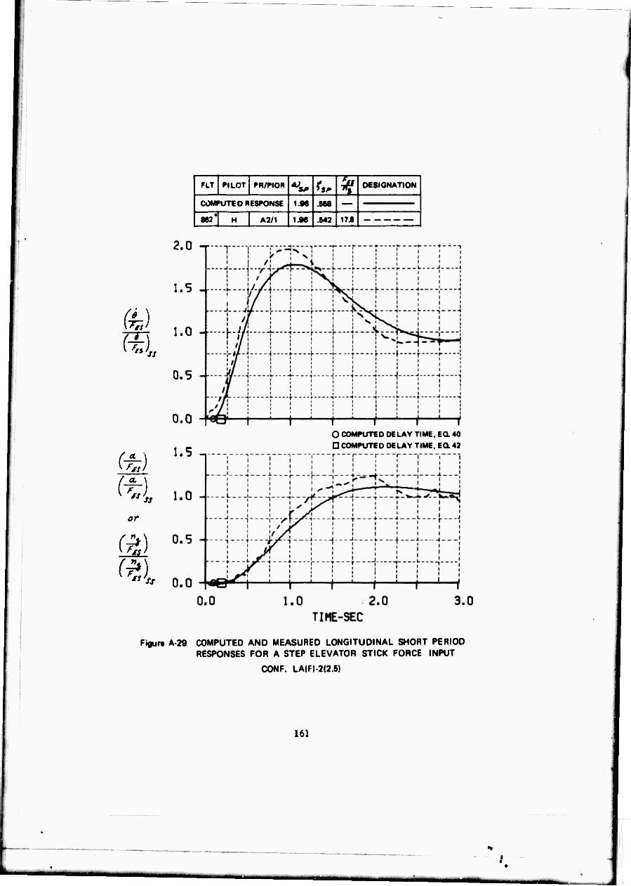
fe)
or
** ss
FLT PILOT PR/PIOR ^ ^M ^ DESIGNATION
1 COMPUTED RESPONSE 1.96 .668
\m' H A2/1 1.96 .543 17 J |
2.0 -r
1.5 -
1.0 - hi
0.5 --
0.0
1.5 -. O COMPUTED DELAY TIME. EQ. 40
D COMPUTED DELAY TIME. EG- 43
Figure A 29 COMPUTED AND MEASURED LONGITUDINAL SHORT PERIOD RESPONSES FOR A STEP ELEVATOR STICK FORCE INPUT
CONF. LA|F|-2(2.6)
161
CONFIGURATION LA(F)-2())
This configuration was evaluated by Pilot B on two occasions. Flight 826 and Flight 814. On Flight 826 the feel systen and stick forces were considered satisfactory. If anything, the stick forces were somewhat light. The stick was considered soft with too auch travel, but not bad and what would be expected during the approach. The initial response shows little lag. The airplane responds slowly but proaptly, then the response builds up in a "smooth" way. Trim, »u , and attitude control are considered satisfactory, but the "soft" feeling the airplane has makes the final response indefinite. For quicker response the tendency is to overdrive the airplane which leads to a small bobble or overshoot. Because of the "loose, soft, or indefinite" response, altitude tracking and pitch attitude tracking were "not the best." Altitude control in turns was "all right" but the indefinite response was really objec- tionable. The ILS approach was considered satisfactory, easy to do, and natural. The airplane was considered controllable, acceptable, but unsatisfac- tory because of the "soft" or indefinite response and rated an A4.
On Flight 814 the evaluation and comments were somewhat limited but certainly similar to those of Flight 826. On this occasion the pilot rating was AS.
:
Pilot H evaluated the configuration the first time on Flight 843. The feel system was considered only fair since it felt "real soft." The stick forces were considered "OK." The initial response to a control input was a "quite noticeable" delay followed by a satisfactory initial pitch rate and a steady-state value that is low. The airplane therefore tends to feel a "little heavy." The pilot had the feeling of not being "directly connected" to the airplane. The result was a loss of precision of control which was "disconcerting" in tracking with the result that the pilot puaped the stick considerably to get the airplane to respond. In altitude and attitude tracking the pilot was "well behind." Trim was not difficult, attitude control in general was good, but the delay did affect altitude control in turns. The ILS approech was "pretty fair," and there was some learning involved because of the delay, The pilot rating was A4.5 and the PIO rating was 1.5.
Pilot H re-evaluated this configuration on Flight 849. The comments on feel system, stick forces, delay, trim, stick pumping, tracking precision, and the ILS approach were similar. Altitude control and flying was considered better VFR than IFR. There was a tendency to pump the stick on the ILS approach and again on the VFR portion of the approach before the flare. In the flare the pilot had real good control. There were no PIO tendencies. The PIO rating was 1.0. The airplane was considered acceptable, but unsatisfactory because of the delay and rated A4.
162
.t

FLT PILOT PR/PtOR *^ ts. * DESIGNATION
1 COMPUTE 0 RESPONSE IM .086
[ 814 8 MJ- 166 .680
836 6 AAI- 168 348 176
843 H A4.5/1.6 166 .641 176
846* H A4/1.0 167 .644 176
2.0
1.5
1.0 -
0.5 --
0.0
(■*)
1.5
1.0
or
0.5
n.n
4
III i iii
—-^-|-—j-—-1.—f—-j—--I—-j |.....;—.-j-.-j
^U 1 1 / I ^ I O COMPUTED DELAY TIME. EO 40
D COMPUTED DELAY TIME, EQ. 42
0.0 TIME-SEC
Figure A 30 COMPUTED AND MEASURED LONGITUDINAL SHORT PERIOD RESPONSES FOR A STEP ELEVATOR STICK FORCE INPUT
CONF. LA(F) 2(1)
163

CONFIGURATION LA(F)-4(2.5)
This configuration was evaluated by Pilot B on one occasion, Flight 828. The feel system characteristics, stick forces and stick displacements were all considered reasonable, pleasant, and good. The airplane was considered "soft," not very precise, but not a bad airplane for the landing approach. The airplane is slow getting underway, there is no detectable lag, but the initial response is slow, and then builds up faster in a smooth fashion. The final response is well damped but a little indefinite or unpredictable. The tendency is to drive the airplane to increase the response and this technique works. Trim is "all right," attitude control is good, and tt* control is reasonable for landing approach. It is difficult to do a precise job of altitude and attitude tracking because of the "soft" or indefinite response, but the airplane is "still pretty good." Entry into turn, control in turns, and turn recovery were all considered "pretty good." Maintaining altitude in turns did require some attention. The ILS approach was "pretty good," pitch control was adequate, it was also "pretty good" in the flare close to the runway. Characteristics with I PR and VFR flying are similar. The airplane is considered controllable, acceptable, satisfactory, and a fair airplane and rated A3. If the airplane were a little more precise and faster responding it would be rated an A2.
On Flight 863, Pilot H also considered the feel system, stick forces, and stick displacements as good. A very minor and insignificant delay in the pitch attitude response causes a small degree of imprecision which is more noticeable VFR t'.an IFR. The configuration was considered "pretty good." Attitude control and ^control were considered fair to good. Ability to trim and altitude control in turns were both considered very good. Altitude track- ing and IFR attitude tracking were both considered fair. The effects of random noise were hardly noticeable, and there were no differences VFR or IFR. The ILS approach was considered quite good, and the ILS corrections worked out well. The configuration was considered acceptable and satisfactory with only mild objections and it was rated an A3. The PIO rating was 1.0.
The evaluation of this configuration was repeated on Plight 865 with a pilot rating of A2.5 and a PIO rating of 1.0. The stick force per g was now 8.68 instead of 17.4 Ib/g. The pilot liked the "lightness" of the feel system and the stick displacements. He thought the combination was good for the landing approach. The comments were similar, but in general more laudatory than those of Plight 863. Altitude and attitude command tracking were considered good. Altitude and longitudinal control in turns and trim were considered very good. The ILS approach and flare were both pretty good, and random noise had little effect on the handling qualities. The airplane was controlled some- what by a series of pulse type inputs which come very naturally. It was a pleasant, well behaved airplane requiring a little different control technique.
164
.t

fe)
a \ f ̂ J
or
FLT PILOT PR/PIOR ?M ^ DESIGNATION
COMPUTED RESPONSE 1.S6 .668 •
828 B A3/- 1.97 .646 17.8 1 863 H A3/1 1.97 .646 17.8
866 H A2.B/1 1.98 .547 8.92
2.5 -,
2.0
1.5
1.0 -
0.5
0.0
1.5
1.0 -
0.5 -
L..J
1 . —.. :
— - - J
/i >^Ni
Si
1
—
\?- kw j r i ; : [ . i sr- *aq
1 > i i
_. _j j i
"^
».-,_-»- , ^ i 11 i t i i
i4 3-t —'—i—''—i—' —i—i—i —i O COMPUTED DELAY TIME. EO 40
O COMPUTED DELAY TIME. EQ 42
0.0 0.0 1.0 2.0 3.0
TIME-SEC
Figure A 31 COMPUTED AND MEASURED LONGITUDINAL SHORT PERIOD RESPONSES FOR A STEP ELEVATOR STICK FORCE INPUT
CONF. LA<F)-4(2.5)
165
_

CONFIGURATION LA(F)-5(2.5)
This configuration was evaluated by Pilot B on Flight 830. The quality of the feel system was good, stick forces and stick displacements were both satisfactory. With a stick input the airplane responds "smoothly" and "nicely," but slowly to an indefinite steady-state condition which makes the configuration "soft feeling." The airplane is easy to fly, but a littlr "loose" and "bouncy feeling." The performance of both the altitude and attitude tracking tasks is "surprisingly poor" because of these characteristics. The ILS approach, trim, and attitude control in the pattern is "very nice," but the airplane is "bouncy," "spongy" and "not good" close to the ground and with disturbances during the flare. The airplane is controllable, acceptable, and "pretty good" except for the "soft feeling" and rated A3. The tendency is to lean in the direction of an A4 rating rather than an A2.
This configuration was evaluated by Pilot H on Flight 834. The quality of the feel system was considered excellent with the right amount of stick motion and stick displacement. The airplane's initial and final response, longitudinal control and altitude control in turn, and trim were all excellent. The pilot liked the "one-to-one" relationship between control input and airplane response, the precise control of nose attitude, and the good control with real turbulence and random noise inputs. The altitude control tracking task was performed with fair precision. The airplane could be flown abruptly and aggressively. The ILS and visual approach were quite comfortable with excellent control of attitude and altitude. Turning flight was "real good" even up to 45 degree banked turns. The airplane was considered good, pleasant, and well behaved and rated an A2.
166
* .t
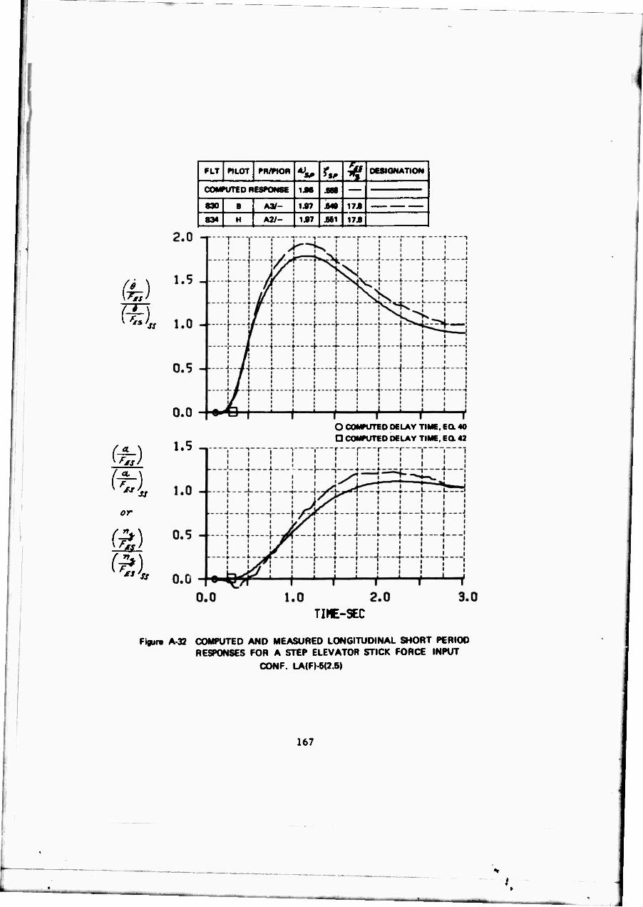
or
(a)
FLT «LOT PH/PIOR *>*> ^ ^ DESIGNATION
COMPUTED RESPONSE IM .860
830 I A»- 1.97 .649 17A
1 834 H A2I- 1A7 .661 17.8
0.0
1.5
O COMPUTED DELAY TIME, EG. 40 O COMPUTED DELAY TIME. EQ. 42
TINE-SEC
Figur« A 32 COMPUTED AND MEASURED LONGITUDINAL SHORT PERIOD RESPONSES FOR A STEP ELEVATOR STICK FORCE INPUT
CONF. LA(F) 5(2.5)
167
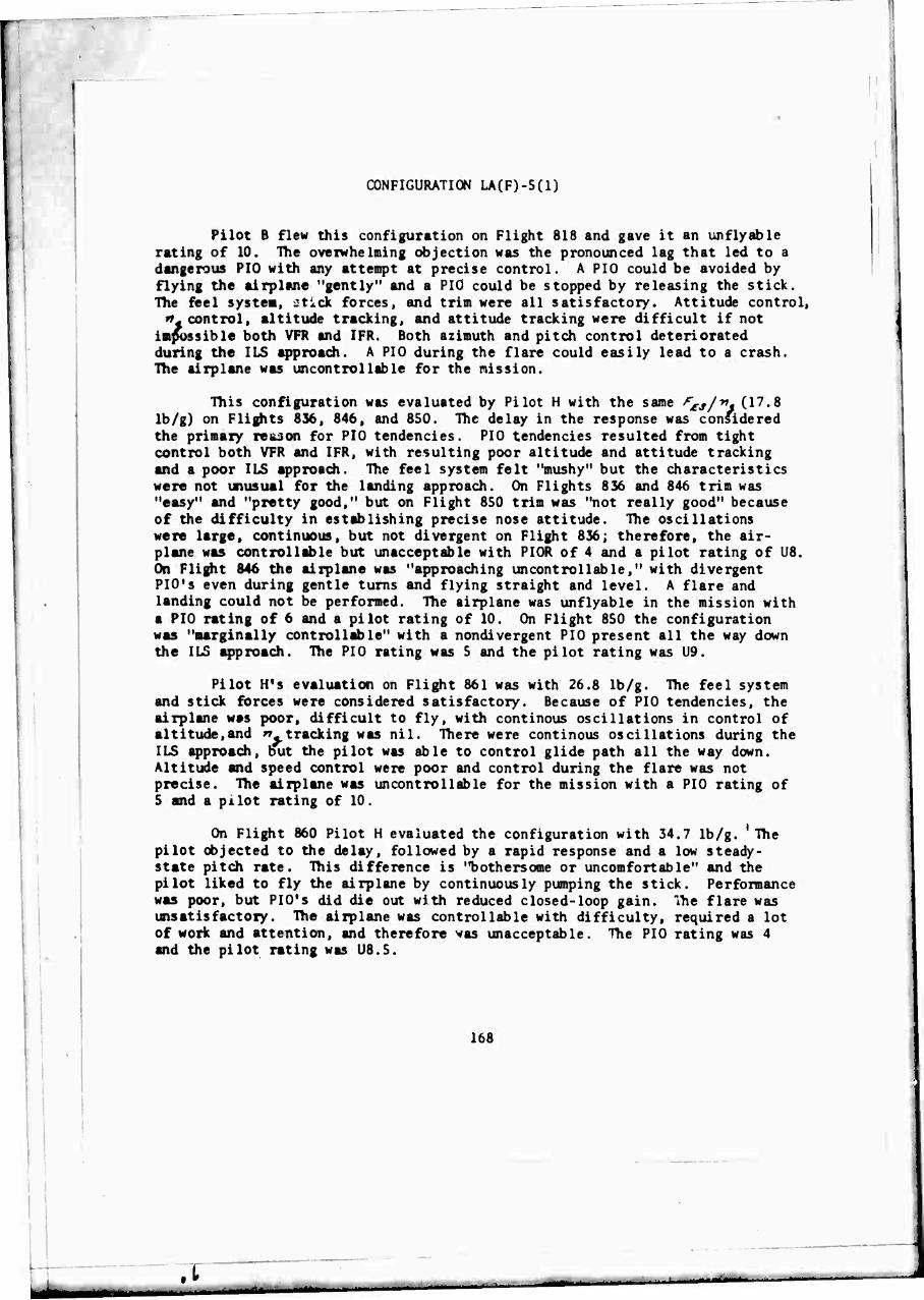
CONFIGURATION LA(F)-5(1)
Pilot B flew this configuration on Flight 818 and gave it an unflyable rating of 10. The overwhelming objection was the pronounced lag that led to a dangerous PIO with any attempt at precise control. A PIO could be avoided by flying the airplane "gently" and a PIO could be stopped by releasing the stick. The feel system, ctick forces, and trim were all satisfactory. Attitude control,
»»-control, altitude tracking, and attitude tracking were difficult if not impossible both VFR and IFR. Both azimuth and pitch control deteriorated during the ILS approach. A PIO during the flare could easily lead to a crash. The airplane was uncontrollable for the mission.
This configuration was evaluated by Pilot H with the same fr£s/yi, (17.8
Ib/g) on Flights 836, 846, and 850. The delay in the response was considered the primary reason for PIO tendencies. PIO tendencies resulted from tight control both VFR and IFR, with resulting poor altitude and attitude tracking and a poor ILS approach. The feel system felt "mushy" but the characteristics were not unusual for the landing approach. On Flights 836 and 846 trim was "easy" and "pretty good," but on Flight 850 trim was "not really good" because of the difficulty in establishing precise nose attitude. The oscillations were large, continuous, but not divergent on Flight 836; therefore, the air- plane was controllable but unacceptable with PIOR of 4 and a pilot rating of U8. On Flight 846 the airplane was "approaching uncontrollable," with divergent PIO's even during gentle turns and flying straight and level. A flare and landing could not be performed. The airplane was unflyable in the mission with a PIO rating of 6 and a pilot rating of 10. On Flight 850 the configuration was "marginally controllable" with a nondivergent PIO present all the way down the ILS approach. The PIO rating was 5 and the pilot rating was U9.
Pilot H's evaluation on Flight 861 was with 26.8 Ib/g. The feel system and stick forces were considered satisfactory. Because of PIO tendencies, the airplane was poor, difficult to fly, with continous oscillations in control of altitude,and ".tracking was nil. There were continous oscillations during the ILS approach, but the pilot was able to control glide path all the way down. Altitude and speed control were poor and control during the flare was not precise. The airplane was uncontrollable for the mission with a PIO rating of 5 and a pilot rating of 10.
On Flight 860 Pilot H evaluated the configuration with 34.7 Ib/g. 'The pilot objected to the delay, followed by a rapid response and a low steady- state pitch rate. This difference is "bothersome or uncomfortable" and the pilot liked to fly the airplane by continuously pumping the stick. Performance was poor, but PIO's did die out with reduced closed-loop gain. The flare was unsatisfactory. The airplane was controllable with difficulty, required a lot of work and attention, and therefore was unacceptable. The PIO rating was 4 and the pilot rating was US.5.
168
,t
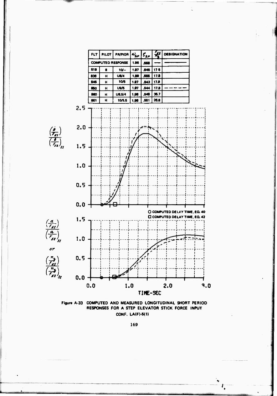
FLT PILOT PR/WOR fs. 5? DESIGNATION
COMPUTED RESPONSE 1.86 .568
1 818 8 1<V- 1A7 .646 17 8
i 836 H U8/4 1.98 .866 173
846 H 10/6 1.97 .643 17.8
860 H U9/B 1.97 .644 173
860 H U8.K/4 1.98 .648 387
861 H 10/56 1.98 .661 263
0.0
r* ] 1.5
(U 1.0
or
yF*'Jss
0.5
0.0
O COMPUTED DELAY TIME. EQ. 40
D COMPUTED DELAY TIME, EQ. 43
0.0 1.0 2.0 ^.0 TIME-SEC
Figur« A-33 COMPUTED AND MEASURED LONGITUDINAL SHORT PERIOD RESPONSES FOR A STEP ELEVATOR STICK FORCE INPUT
CONF. LA(F)-5(1)
169
K
»-—
CONFIGURATION LA(M)-2(10)
This configuration was flown by Pilot B on Flight 817. The pilot stated that the feel system 'seems pretty good." The stick travel was satisfactory, if anything, a little on the large side. The stick forces were smooth and reason- able. The initial response was prompt, the airplane got underway without a pause. Pitch attitude control and n« control were "pretty good." It was easy to predict the final response from tne initial response. The tendency was to overdrive the airplane, but the response was still controllable and predictable. The pilot felt that with the airplane he could do anything that was reasonably expected in the approach. Altitude command tracking was "not outstanding." Longitudinal control and altitude control in turns and during the ILS approach were considered "pretty good." The airplane was considered controllable, acceptable, and satisfactory, with no unpleasant characteristics and rated an A2.
This configuration was evaluated by Pilot H on Flight 841. He considered the feel system a little softer than desired and felt the quality could have been a little better. A couple of times the pilot found himself getting into stick oscillations, but this was no real problem. The airplane's initial response could be a little faster following an input. The final response was satisfactory, but the steady-state response was a little lower than expected for a given input. Pitch attitude control, T, control, and trim were rated good. Altitude control and altitude command tracking performance were considered good. Altitude could be controlled in 30 and 45 degree banked turns "fairly well," but the pilot woula have liked a little finer control of nose attitude. VFR and IFR flying, the ILS approach, and the flare were rated good. There were minor objections to the "softness" uf the feel system and the fact that the steady-state response was lower than expected. The mildly unpleasant, but not annoying characteristics were responsible for a pilot rating of A3 and a PIO rating of 1.0.
170
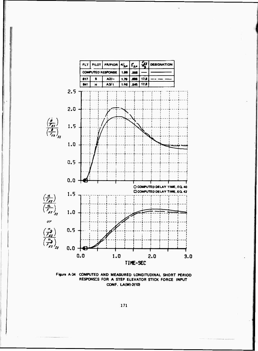
fe) T ^l
m m or
(%)
^ ss
PLT PILOT PR/PIOR ^ r*. 5? DESIGNATION
COMPUTED heSPONSE 1.96 .568
817 1 A2/- 1.7» .666 176 |
841 H A3/1 1«« .646 17J
2.5 -■
2.0 -
1.5 --
1.0 -
0.5 -■-
0.0
1.5 O COMPUTED DELAY TIME. EQ. 40
D COMPUTED DELAY TIME. EO 42
TIME-SEC
Fiflure A 34 COMPUTED AND MEASURED LONGITUDINAL SHORT PERIOD RESPONSES FOR A STEP ELEVATOR STICK FORCE INPUT
CONF LA(M) 2(10»
171
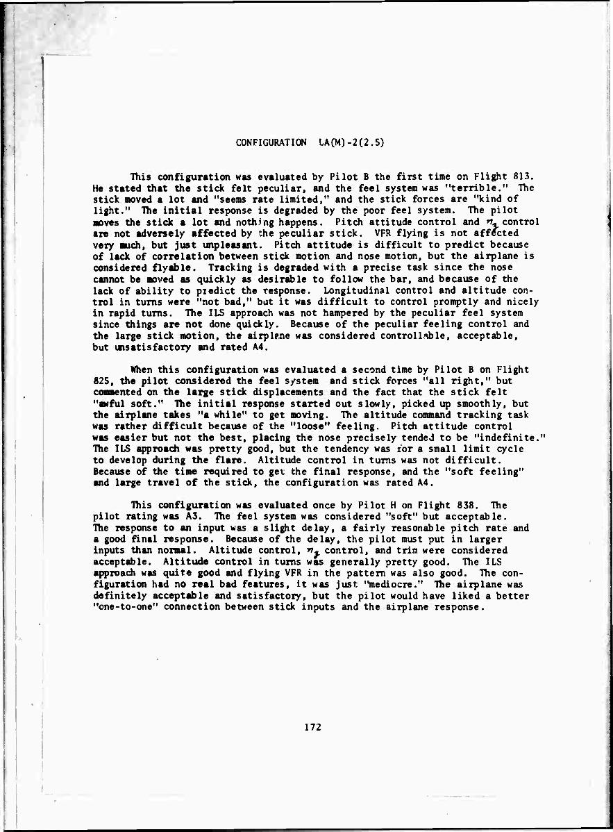
CONFIGURATION LA(M)-2(2.5)
This configuration was evaluated by Pilot B the first time on Flight 813. He stated that the stick felt peculiar, and the feel system was "terrible." The stick moved a lot and "seems rate limited," and the stick forces are "kind of light." The initial response is degraded by the poor feel system. The pilot moves the stick a lot and nothing happens. Pitch attitude control and »v control are not adversely affected by :he peculiar stick. VFR flying is not affected very much, but just unpleasant. Pitch attitude is difficult to predict because of lack of correlation between stick motion and nose motion, but the airplane is considered flyable. Tracking is degraded with a precise task since the nose cannot be moved as quickly as desirable to follow the bar, and because of the lack of ability to pi edict the response. Longitudinal control and altitude con- trol in turns were "not bad," but it was difficult to control promptly and nicely in rapid turns. The ILS approach was not hampered by the peculiar feel system since things are not done quickly. Because of the peculiar feeling control and the large stick motion, the airplrne was considered controllable, acceptable, but unsatisfactory and rated A4.
When this configuration was evaluated a second time by Pilot B on Flight 825, the pilot considered the feel system and stick forces "all right," but contented on the large stick displacements and the fact that the stick felt "awful soft." The initial response started out slowly, picked up smoothly, but the airplane takes "a while" to get moving. The altitude command tracking task was rather difficult because of the "loose" feeling. Pitch attitude control was easier but not the best, placing the nose precisely tended to be "indefinite." The ILS approach was pretty good, but the tendency was tor a small limit cycle to develop during the flare. Altitude control in turns was not difficult. Because of the time required to get the final response, and the "soft feeling" and large travel of the stick, the configuration was rated A4.
This configuration was evaluated once by Pilot H on Flight 838. The pilot rating was A3. The feel system was considered "soft" but acceptable. The response to an input was a slight delay, a fairly reasonable pitch rate and a good final response. Because of the delay, the pilot must put in larger inputs than normal. Altitude control, T« control, and trim were considered acceptable. Altitude control in turns was generally pretty good. The ILS approach was quite good and flying VFR in the pattern was also good. The con- figuration had no real bad features, it was just "mediocre." The airplane was definitely acceptable and satisfactory, but the pilot would have liked a better "one-to-one" connection between stick inputs and the airplane response.
172
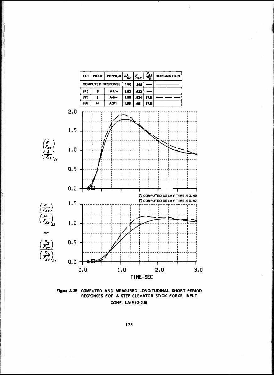
or
(ft
FLT PILOT PR/PIOR A) SP fs. ^ DESIGNATION
COMPUTED RESPONSE 1.86 .666
813 B A4/- 1.92 .633 826 B A4/- 1.96 .634 MA
838 H A3/1 1.98 .661 17.8
0.0
1.5 -,
1.0 -
0.5 --
0.0
O COMPUTED UELAY TIME. EQ. 40
D COMPUTED DELAY TIME, EQ 42
0.0 1.0 2.0 3.0 TIME-SEC
Figure A 35 COMPUTED AND MEASURED LONGITUDINAL SHORT PERIOD RESPONSES FOR A STEP ELEVATOR STICK FORCE INPUT
CONF. LA(M) 2(2.5)
173
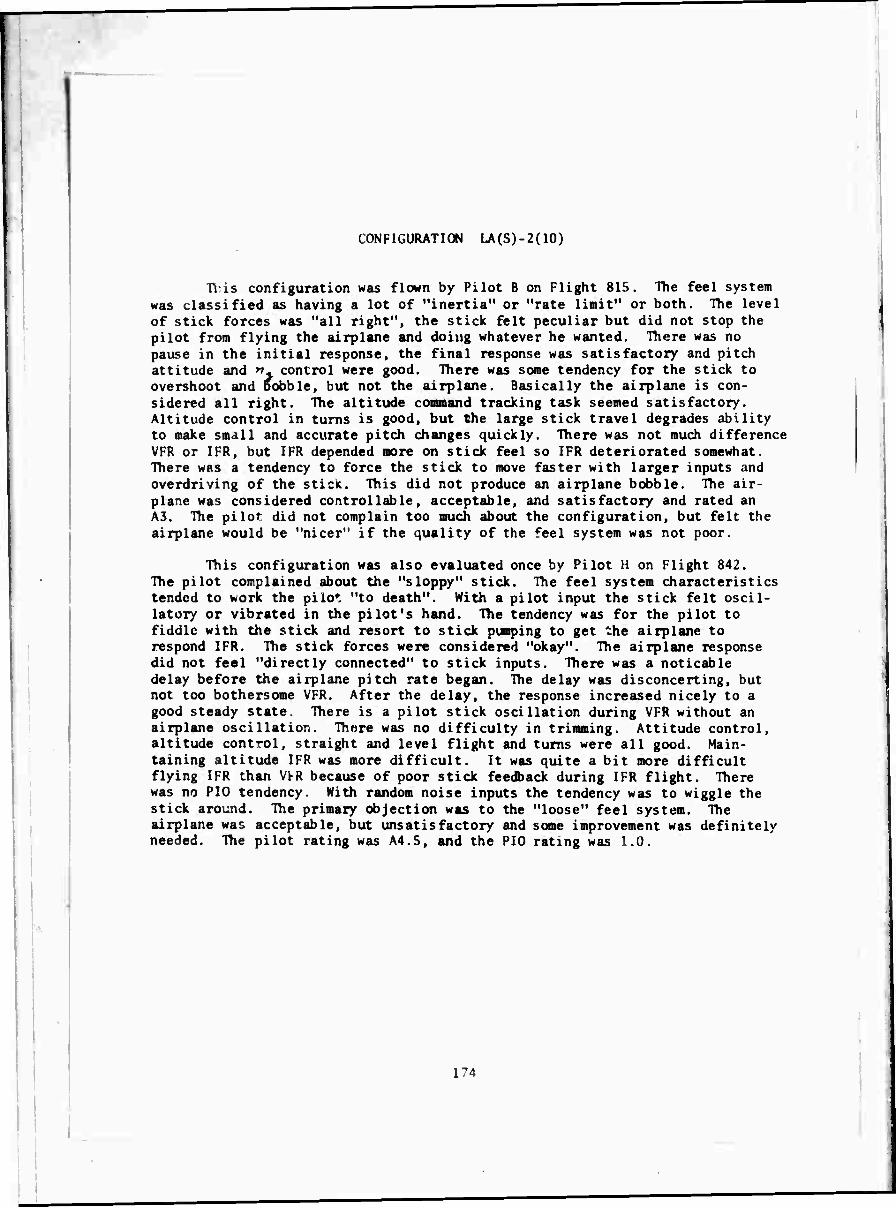
CONFIGURATION LA(S)-2(10)
Tl is configuration was flown by Pilot B on Flight 815. The feel system was classified as having a lot of "inertia" or "rate limit" or both. The level of stick forces was "all right", the stick felt peculiar but did not stop the pilot from flying the airplane and doing whatever he wanted. There was no pause in the initial response, the final response was satisfactory and pitch attitude and ". control were good. There was some tendency for the stick to overshoot and Bobble, but not the airplane. Basically the airplane is con- sidered all right. The altitude command tracking task seemed satisfactory. Altitude control in turns is good, but the large stick travel degrades ability to make small and accurate pitch changes quickly. There was not much difference VFR or IFR, but IFR depended more on stick feel so IFR deteriorated somewhat. There was a tendency to force the stick to move faster with larger inputs and overdriving of the stick. This did not produce an airplane bobble. The air- plane was considered controllable, acceptable, and satisfactory and rated an A3. The pilot did not complain too much about the configuration, but felt the airplane would be "nicer" if the quality of the feel system was not poor.
This configuration was also evaluated once by Pilot H on Flight 842. The pilot complained about the "sloppy" stick. The feel system characteristics tended to work the pilot "to death". With a pilot input the stick felt oscil- latory or vibrated in the pilot's hand. The tendency was for the pilot to fiddle with the stick and resort to stick pumping to get the airplane to respond IFR. The stick forces were considered "okay". The airplane response did not feel "directly connected" to stick inputs. There was a noticable delay before the airplane pitch rate began. The delay was disconcerting, but not too bothersome VFR. After the delay, the response increased nicely to a good steady state. There is a pilot stick oscillation during VFR without an airplane oscillation. Thare was no difficulty in trimming. Attitude control, altitude control, straight and level flight and turns were all good. Main- taining altitude IFR was more difficult. It was quite a bit more difficult flying IFR than V^R because of poor stick feedback during IFR flight, liiere was no PIO tendency. With random noise inputs the tendency was to wiggle the stick around. The primary objection was to the "loose" feel system. The airplane was acceptable, but unsatisfactory and some improvement was definitely needed. The pilot rating was A4.5, and the PIO rating was 1.0.
174
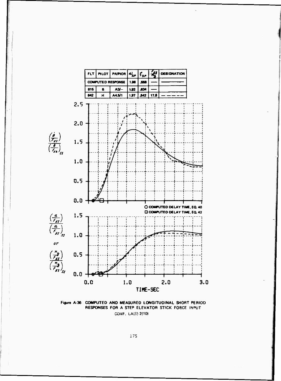
fe) m
^l
FLT PILOT PR/PIO« ^ fM ^ DESIGNAT ON
1 COMPUTED RESPONSE IM JM
1 816 B L A3/_ 1S2 .•34
843 H A4.6/1 1Ä7 .642 17.8
0.0
ft) 1.5
(U 1.0 ör
^) 0.5
1—'—(—'—I—'—I O COMPUTED DELAY TIME. EO 40 D COMPUTED DELAY TIME. Ed 42
0.0 1.0 2.0 3.0 TIHE-SEC
Figure A 36 COMPUTED AND MEASURED LONGITUDINAL SHORT PERIOD RESPONSES FOR A STEP ELEVATOR STICK FORCE IN«»UT
CONF. LA;S)-2(10|
175
CONFIGURATION LA(S)-2(2.5)
Pilot B evaluated this configuration on two flights, Flights 816 and 827, and the pilot ratings were A3 and A4 respectively. On both flights the pilot objected to the unpleasant stick characteristics. The stick had "high inertia" and felt "rate limited." The airplane was not considered very fast responding but it did follow the stick once the stick moved. There was no lag in airplane response. The final response and the stick forces were con- sidered reasonable. The airplane was less precise IFR than VFR. Pitch atti- tude and ».control and tracking performance were "fair," or "OK," or "all right." Tne ILS approach was considered "OK," the pilot could make the nose go where he wanted. On Flight 816 the pilot considered the feel system as terrible but the airplane as acceptable and satisfactory with some unpleasant characteristics. On Flight 827 he considered the airplane "not too bad", acceptable but unsatisfactory because of the difficulty in predicting the airplane response and lowered the rating to A4.
Pilot K flew this configuration on both Flights 837 and 844. The PIGR's were 1 and 1.5 respectively and the pilot ratings were A5 and AS.5 respectively. Pilot H objected also to the peculiar and very poor quality of the feel system. He described it at various times as "soft," "sluggish," or "loose feeling" with a tendency for the stick to "oscillate in the hand" with inputs. The tendency was for the pilot to work and "pump the stick" for control. Altitude tracking and IFR attitude tracking were poor because of the sluggish initial response. Control of the airplane during ILS was considered "surprisingly good" on Flight 837 and required quite a bit of work to keep speed and maintain attitude on Flight 844. On Flight 837 the airplane was considered acceptable and able to perform all the landing approach mission, but unsatisfactory because of the feel system. On Flight 844 the airplane was acceptable and unsatisfactory because it felt heavy, sluggish, and imprecise.
176
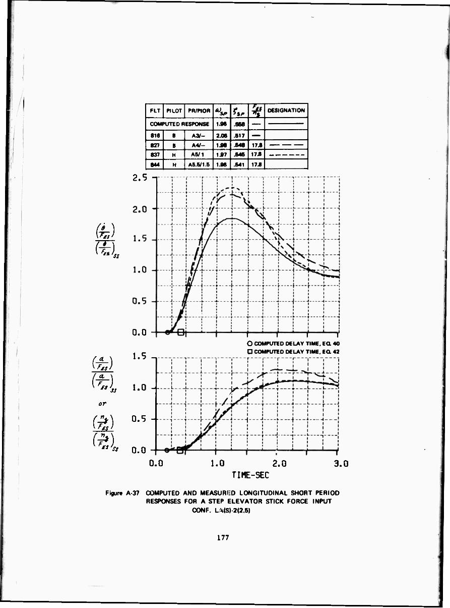
fe)
or
FLT PILOT PH/PJOR SP *S, ^ DESIGNATION
COMPUTED RESPONSE 1.96 .868
8 6 8 A3/- 2.06 .817 — 827 8 A4/- 1J86 .848 17.8 1 837 H A5/1 1.97 .846 17.8
1 844 H A6.V1.5 1.96 .641 176
2.5 -i
0.0
1.5
1.0 --
0.5 -
O COMPUTED DELAY TIME, EQ. 40 D COMPUTED DELAY TIME. EQ. 42
0.0
0.0 1.0 2.0 3.0 TIHE-SEC
Figure A 37 COMPUTED AND MEASURED LONGITUDINAL SHORT PERIOD RESPONSES FOR A STEP ELEVATOR STICK FORCE INPUT
CONF. L MS) 2(2.5)
177

REFERENCES
1.
2.
3.
4.
5.
6.
Key, D.L.: A Functional Description and Working Data for the Variable Stability System T-33 Airplane. Cornell Aeronautical Laboratory, Inc., Report No. TC-1921-F-2, October 1965.
Parrag, M.L.: Pilot Evaluations in a Ground Simulator of the Effects of Elevator Control System Dynamics in Fighter Aircraft. AFFDL-TR-67-19, Septeidber 1967.
Harper, R.P., Jr., and Cooper, G.E.: A Revised Pilot Rating Scale for the Evaluation of Handling Qualities. Presented at AGARD Specialists' Meeting on Stability and Control; Cambridge, England, 20-23 September 1966. Cornell Aeronautical Laboratory, Inc., Report No. CAL 153.
DiFranco, D.A.: Flight Investigation of longitudinal Short Period Frequency Requirements and PIO Tendencies. AFFDL-TR-66-163, Aprfl 19S7.
cs at Chalk, C.R.: Fli^vt Evaluation of Various Short Period PgMgi Four Drag Configurations for the Landing Approach Task. AFFDL- TR-64-60T April 1964.
Behm, D.D.: Analog Matching Technique for Longitudinal Responses Cornell Aeronautical Laboratory, Inc., Report FRM No. 409, October 1967.
178
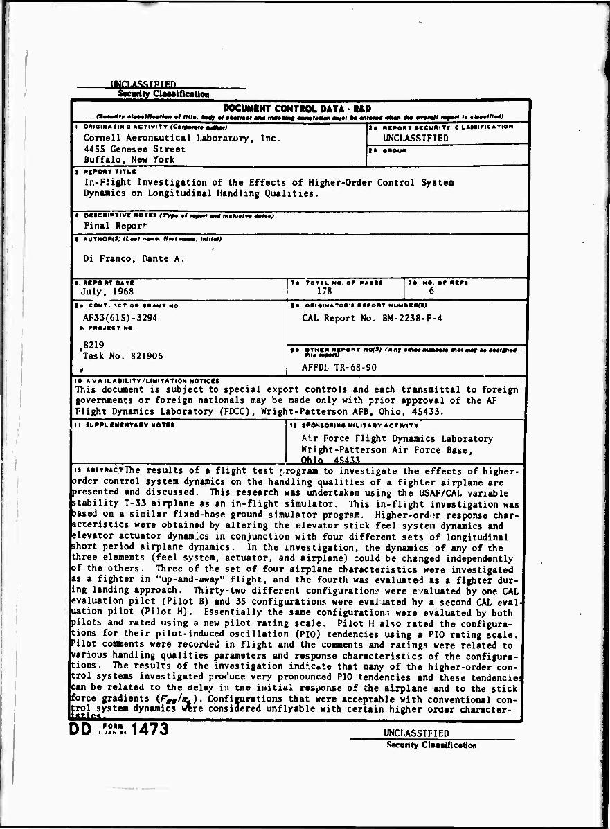
IMCUaMlIM S«curity Ogwitottoa
n—ufilr cl*«««ft««ll«n •« H(l*. DOCUMENT CONTROL DATA - R&D
' W •*••!•» I I tlWalln« i •laMOT ■«•( to mtffä «*•" Ma •«•«II rmß^i Im c*ttlli»*) I 0«IOt»ATINO ÄCTIWI»V fC»f|
Cornell Aeronautical Laboratory, Inc. 445S Genesee Street Buffalo, New York
UNCLASSIFIED t» «NOU»
I NI^ONT TITLC
In-Flight Investigation of the Effects of Higher-Order Control System Dynamics on Longitudinal Handling Qualities.
4 OttCNI^TIVI NOTIt (Typu •! mpof an« inchitm 4mf)
Final Report I AUTMONf»'LMI nan«. Mm nww. Initial;
Di Franco, Dante A.
• miPom OATI July, 1968 178
ta COMT. \CT on «HAMT MO.
AF33(615)-3294 b »«OJtCT NO
e8219 Task No. 821905
inr«; CAL Report No. BM-2238-F-4
tb QTMin «■•OUT NO<*; (Af»r»»ft
AFFDL TR-68-90
—tw Aal atay ka aaal#iatf
10 AVAILAeiLITV/LIMITATION MOTICfl This document is subject to special export controls and each transmittal to foreign governments or foreign nationals may be made only with prior approval of the AF Flight Dynamics Laboratory (FDCC), Wright-Patterson AFB, Ohio, 45433. it tut >TIi It SPOMOftlNO MILITARY ACTIVITY
Air Force Flight Dynamics Laboratory Wright-Patterson Air Force Base, Ohio i&taa
ii AMTRAcrThe results of a flight test r rogram to investigate the effects of higher- order control system dynamics on the handling qualities of a fighter airplane are presented and discussed. This research was undertaken using the USAF/CAL variable stability T-33 airplane as an in-flight simulator. This in-flight investigation was )ased on a similar fixed-base ground simulator program. Higher-ord-ir response char- acteristics were obtained by altering the elevator stick feel system dynamics and elevator actuator dynamics in conjunction with four different sets of longitudinal short period airplane dynamics. In the investigation, the dynamics of any of the three elements (feel system, actuator, and airplane) could be changed independently of the others. Three of the set of four airplane characteristics were investigated as a fighter in "up-and-away" flight, and the fourth was evaluated as a fighter dur- ing landing approach. Thirty-two different configuration»: were evaluated by one CAL evaluation pilot (Pilot B) and 35 configurations were evaliated by a second CAL eval- uation pilot (Pilot H). Essentially the same configuration,-, were evaluated by both pilots and rated using a new pilot rating scale. Pilot H also rated the configura- tions for their pilot-induced oscillation (PIG) tendencies using a PIO rating scale. Pilot comments were recorded in flight and the comments and ratings were related to various handling qualities parameters and response characteristics of the configura- tions. The results of the investigation indicate that many of the higher-order con- trol systems investigated produce very pronounced PIO tendencies and these tendencies can be related to the delay in tne initial response of die airplane and to the stick force gradients (r„/«L). Configurations that were acceptable with conventional con- trol system dynamics «rere considered unfly&ble with certain higher order character- <t4r« "^ lOL
DD /?!-.. 1473 UNCLASSIFIED Security Claaaificatton
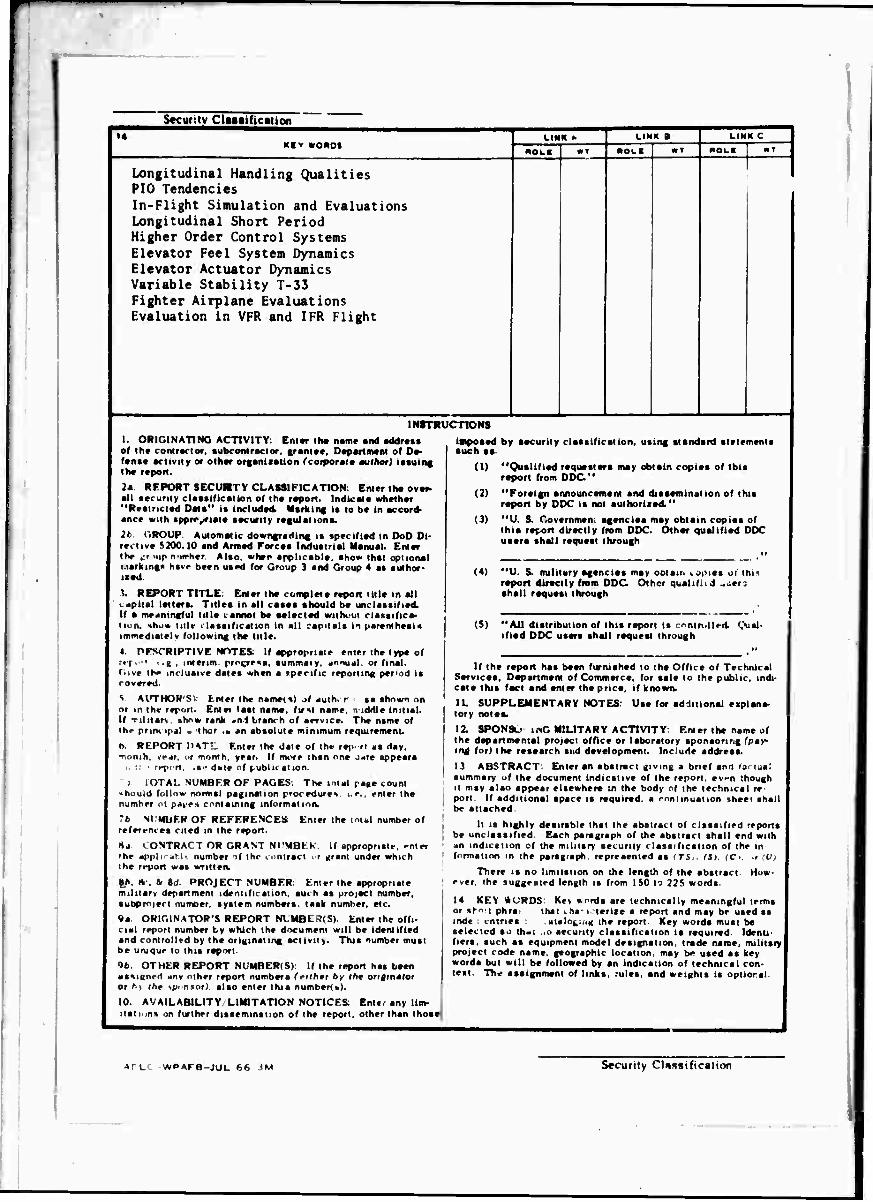
Security Clutification i«
KCv «OMOI
Longitudinal Handling Qualities PIO Tendencies In-Flight Simulation and Evaluations Longitudinal Short Period Higher Order Control Systems Elevator Feel System Dynamics Elevator Actuator Dynamics Variable Stability T-33 Fighter Airplane Evaluations Evaluation in VFR and IFR Flight
LINK >■
"OH
LINK a LINK C
«OL*
INSTRUCTIONS
I. ORIGINATING ACTIVITY: Eniar It» n.m« and «ddraat of th» conlraclor, •ubconlraclor. grant««, Department o( D«- («na« arlivity or other organnation (corporatt milhor) iaauing th« report.
2a REPORT SECUMTY CLASSIFICATION: Enter UM over- all ««curtly claaaification of the report. Indicate whether "Rettnrted Data" ta included Markin« ta to b« in accord- anrr with appropriate aacurity r«gulation».
.'' CiROUP. Automatic downgrading ta «perifiad in DoD Di- r«v'tive S200.10 and Armed Forte« Induatrial Manual. Entar the (•? xip n'iirher Also, whan applirabla, »ho* that optional Marking« have been uand (or Group 3 and Group 4 a« aulhor- it«d
ti REPORT TITLE: Enl«r th« cuft^l«!« report Mil« in all • apital letten. Titlra in all caaaa ahould be unclaatiliad. U a meaningful till« i-antiot be «elected wilhi'Ut claiiaifira- tiun, Hho* title claaaification in all capnata in parantheai« immediately following th« till«.
« nrSCRIPTIVE NOTES If appropriate enter th« typ« of r«f.-' ■ .g , interim progre««, aummaiy. «nnual. or (mal. (•ive the mtluaiva dale« when a «pacific reporting p«r<od i« rovared.
S AUTHOR'S) fcnter the natnet«) at aulh. r as «hown on or in the terurt. Entei laat name, fuil name, 'iiddle initial. If Tiliiarv »how rank .-nl branch of aervice. The name of the print ip<il ■ thor .• an abaotute minimum requirement.
t>. REPORT DAT!, Enter the date of the rej^ rl as day, •nonih, \f*r. or month, year. If rune than one jme appeara i.:: ■ repcn, .s-dale of (.ublu alion.
I. IOTA!. NUMBER OF PAGES: The total ra«e count >houid follow normal pagination procedutev i.e., enter the number ol p«i'e» containing informalma
7* NI'MbF.R OF REFERENCES Enter the inlal number of referi-m es cited in the report.
HJ I ONTRACT OR GRAM NI'MBKK 11 appropriate, ^nter 'he appli' abl« number of the contract > r urant under which the report was writtea
|(t. tk , &r 6,1 PROJECT NUMBER: Enter the appropriate miluarv department identification, such as projacl number, subproiert numoer. system numbers, task number, «Ic.
«a ORIGINATOR'S REPORT Nl MBl .'. S) Entar the offi- cial report number by which the d>->cum«ni will b« id«nlifi«d and controlled by the originating activity. This number muat b« unique to this raport.
tb OTHER REPORT NUMBER(S): If the report has been assiKned any other report numbers (nlhrni by th» originator or h| the sponsor), alao enter this numberts).
10. AVAILABILITY/LIMITATION NOTICES: Enter any lim- itations on further dissemination of th« report, other than thoa«
impoaed by secuniy claaaification, auch aa
using standard alatements
(I)
(2)
(3)
(4)
(5)
"(^islified requesters may obtain ropiea of this raport from DDC "
"Foreign announcamant and dissemination of this raport by DDC is not authorized."
"U S Covarnman. agencies may obtain copies of this raport directly from DDC. Other qualified DDC users shall request through
"U. S. military agencies may ootam copies ol this raport directly from DDC Other qualifiid ^atM shall request through
"All distribution of this repon is ntr.llt-.l (.Xial- ified DDC users shall request through
If th« report has been furnished to th« Offic« of TechniesI Service». Department of Commarc«, lor aala to the public, indi- cate this fact and enter the prtc«, if known.
U. SUPPLEMENTARY NOTES: Us« for additional explana- tory notes.
12. SPONSu inG MILITARY ACTIVITY: Enter the name of th« departmernal project offlc« or laboratory aponsonng (pay- ing for) th« r«8««rch and development. Include address.
13 ABSTRACT: Enter sn sbstract giving a brief and farmai summary uf the document indicative of the report, even though it may alao appear elsewhere ;n the body of the technical re- port. If additional space la required, a continuation sheet shall be attached
It is highly desirsble that the abstract of cliasified reports be unclaaaifiad Each paragraph of the abstract shall end with •tn indication cf the military security classrfication of the in formation in the paragraph, represented as fTli. CSj (Ci, i (V)
There is no limitation on the length of the abstrsct How- ever the suggested length is from ISO to 22S words
14 KEY MORDS: Key »ords are technically meaningful terms or sho-i phra: that cha-i-lenxe a report and may be used ss inde entries . .ataleging the raport Key words must be selected so thai ,o security classification is required Identi- fiers, such as equipment model designation, trade name, military project code name, gaographic location, may br> uaed as key words but will be followed by sn indicstion of technical con- test. The aastgnment of links, rules, snd weights is optiorsl
*FLC WPAFB-JUL 66 JM Security Clussification