new limitation change to
TRANSCRIPT
UNCLASSIFIED
AD NUMBER
ADB031768
NEW LIMITATION CHANGE
TOApproved for public release, distributionunlimited
FROMDistribution authorized to U.S. Gov't.agencies only; Test Evalution; 10 Jul1978. Other requests shall be referred toAir Force Flight Dynamics Laboratory Att:AFFDC/FXB; Wright-Patterson Air ForceBase, OH 45433.
AUTHORITY
AFWAL ltr, 11 feb 1980
THIS PAGE IS UNCLASSIFIED
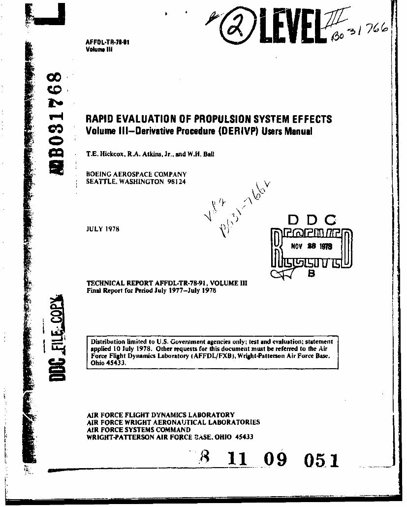
AFFDL-TR-71-91 /EV E j;1• Volume III
S r-o RAPID EVALUATION OF PROPULSION SYSTEM EFFECTSCO• Volume Ill-Derivative Procedure (DERIVP) Users Manual
T.E. Hickcox, RA. Atkins, Jr., and W.H. Ball
BOEING AEROSPACE COMPANYSEATTLE. WASHINGTON 98124
JULY 1978 ronp
1}. TECHNICAL REPORT AFFDL-TR-78-91, VOLUME IIIFinal Report for Period July 1977-July 1978
Distribution limited to U.S. Government agencies only, test and evaluation; statementI applied 10 July 1978. Other requests for this document must be referred to the Air
Force Flight Dynamics Laboratory (AFFDL/FXB). Wright-Patterson Air Force Base.•! Ohio 45433.
AIR FORCE FLIGHT DYNAMICS LABORATORYAIR FORCE WRIGHT AERONAUTICAL LABORATORIES
[ AIR FORCE SYSTEMS COMMAND_ WRIGHT-PATTERSON AIR FORCE UASE. OHIO 45433
WNW . --.
4I
NOTYCE
When Goverment drawings, specifications, or other data are used for anypurpose other than in coni.ection with a definitely related Governmentprocurement operation, the United States Government thereby incurs noresponsibility nor any obligation whatsoever; and the fact that thegovernment may have formulated, furnished, or in any way supplied thesaid drawings, specifications, or other data, is not to be regarded byimplication or otherwise as in any manner licensing the holder or anyother person or corporation, or conveying any rights or permission tomanufacture, use, or sell any patented invention that may in any way berelated thereto.
This technical report has been reviewed and is approved for publication.
GORDON C. TAMPI IN RAYMOND L. HAASProject Engineer Chief, Vehicle Synthesis BranchVehicle Synthesis Bvranch AF Flight Dynamics Laboratory
FOR THE COMMANDER
MELVt-.BCActing ChiefAeromechanics Division
"If your address has changed, if you wish to be removed from our mailinglist, or if the addressee is no longer employed by your organization,please notify AFFDL/FXE, W-PAFB, OH 45433 to help us maintain a currentmailing list."
Copies of this report should not be returned unless return is required bysecurity considerations, contractual obligations, or notice on a specificdocument.
AIR FORCdiV6760/I November 1071-so 4
I Inc I asq-i fipdSECURITY C.6 IFICATION OF' TmiS PAGC 1"o Date Eniotectj
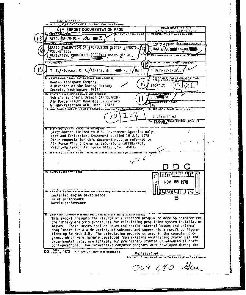
0 9 EPORT DOCUMENTATION PAGE READ NSTUCTONS
Rate R2. GOVT ACCESSiON NO. I. flECIPIENT'S CATALOG NJUMERf
iceAC AFFD RRN 91MSERdL)
PIS. OISTRIUTINATEMEN (OF PROPU ReIONrYSEt)FCS
DE OSRIVATIVEOMTAEMUEN (of IVP) VSERSe~ ?nNUAL V-EInMN Block REPORT7en te P
_:ýý ;NU
Boingtle Aenginae pCrormpanceO NT i R
Ane perfsormno te BoigCmay "- ,-4' -Noattle. persormncen982
11. AONTRALLIN OFCEntsu NAM ANDrc AlDDRESS o dntf y lc meh
Tehisl repothpesens trnhe resuDltsX ofareerh rgamt dvlpopteie
li orses Tlihes losseis nLudeornltor an oze nenlossandetratrioghtuPatteron MAFhB.5. Theo calulaio pro .dure usdI h optrpo
1D. MOIORIN G AG473 O INAM O DRE1NV 1 diffrn IfUEOLSTE . 1 SECURITY CLASh IAINO HSPOEWe. (.1 this rered
Cr ~
Unclassified _
SECURtI•Y CLASSIFICAT-ION OF THIS PAGE(Wheou Does Entered)
contract: (1) A propulsion installation effects program that calculatesinstalled performance, using input maps of inlet and nozzle/aftbody charac-teristics for specific configurations, and (2) A derivative program thatallows the user to generate new sets of input maps by perturbations to thegeometries of the basic input maps. The work accomplished during the con-tract is documented in thrse separate volumes. Volume I is a Final Reportdiscussing the analysis methods and data used to develop the programs, andmajor technical observations from the study. Volume II is a PIPSI UsersManual, containtng documentation of the interactive propulsion installationprogram. Volume III is the Derivative Procedure Users Manual, documentingthe methods and usage of the derivative procedure. Volume IV is a libraryof input maps.
[t U
,9CURITY CL.ASSICATON OF THS,,,.. Wonm Does ,.,.., --
FOREWORD
This report documents the work accomplished during USAF Contract No.F33615-77-C-3085. The work consisted of developing an interactive PIPSI
computer program, developing an interactive derivative computer program,
and developing and documenting supporting data libraries. The work was
accomplished in three phases. As part of the work accomplished in Phase
I of the contract, the interactive PIPSI program was completed and
delivered to the Air Force. As part of Phase II work, derivative param-
eters were selected and development work was completed on the derivative
program. During Phase III a library of inlet and nozzle/aftbody charac-j
teristics was prepared, test cases were completed, documentation was
accomplished, and final programs were delivered to the Air Force. The
program was cenducted under the direction of the Vehicle Synthesis
Branch, Air Force Flight Dynamics Laboratory, Air Force Systems Command.Mr. Gordon Tamplin was the Air Force Program Monitor.
The program was initiated on 17 July 1977 and draft copies of the final
reports were submitted for approval on 15 May 1978.
Mr. W. H. Ball was Program Manager for The Boeing Company. The following
individuals contributed significantly to the work accomplished during
this contract: R. A. Atkins, Jr., computer programming; T. E. Hlckcox,inlet derivative procedure development; E. J. Kowalski, inlet configura-
tions and performance; and J. E. Petit and R. M. Trayler, nozzle/aftbody
procedure and configurations.
11 0 0
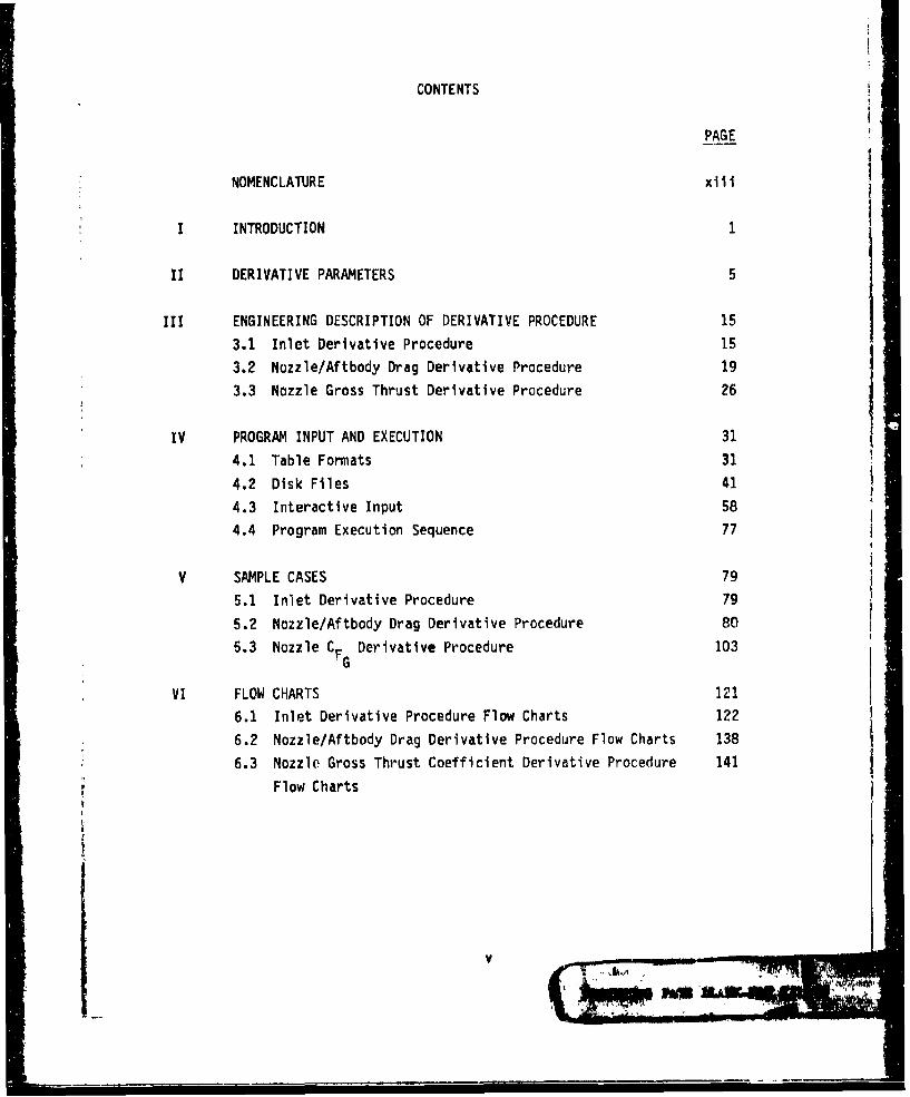
CONTENTS
PAGE
NOMENCLATURE xiii
INTRODUCTION 1
II DERIVATIVE PARAMETERS 5
III ENGINEERING DESCRIPTION OF DERIVATIVE PROCEDURE 15
3.1 Inlet Derivative Procedure 15 i3.2 Nozzle/Aftbody Drag Derivative Procedure 19
3.3 Nozzle Gross Thrust Derivative Procedure 26
IV PROGRAM INPUT AND EXECUTION 31
4.1 Table Formats 31
4.2 Disk Files 41
4.3 Interactive Input 58
4.4 Program Execution Sequence 77
V SAMPLE CASES 79
5.1 Inlet Derivative Procedure 79
5.2 Nozzle/Aftbody Drag Derivative Procedure 80
5.3 Nozzle CF Derivative Procedure 103
VI FLOW CHARTS 121
6.1 Inlet Derivative Procedure Flow Charts 122
6.2 Nozzle/Aftbody Drag Derivative Procedure Flow Charts 138
6.3 Nozzle Gross Thrust Coefficient Derivative Procedure 141
Flow Charts
V-I.-
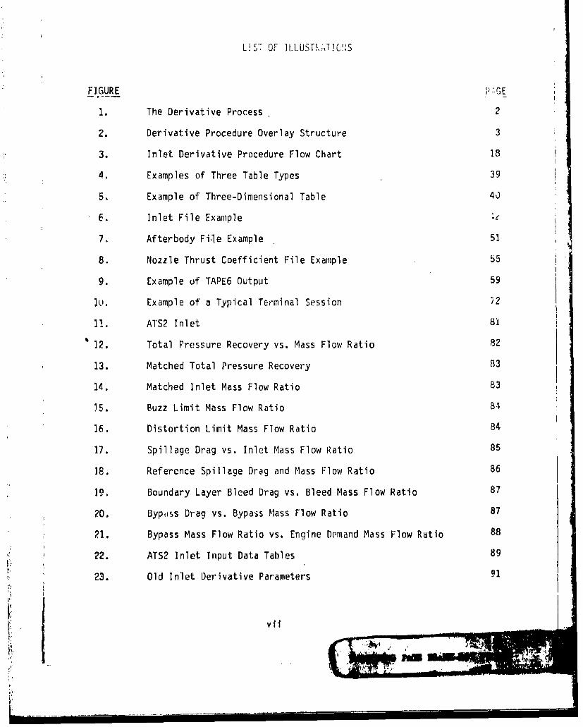
LST OF ]LLUST J,',T]O!'S
F]GURE GE
1. The Derivative Process 2
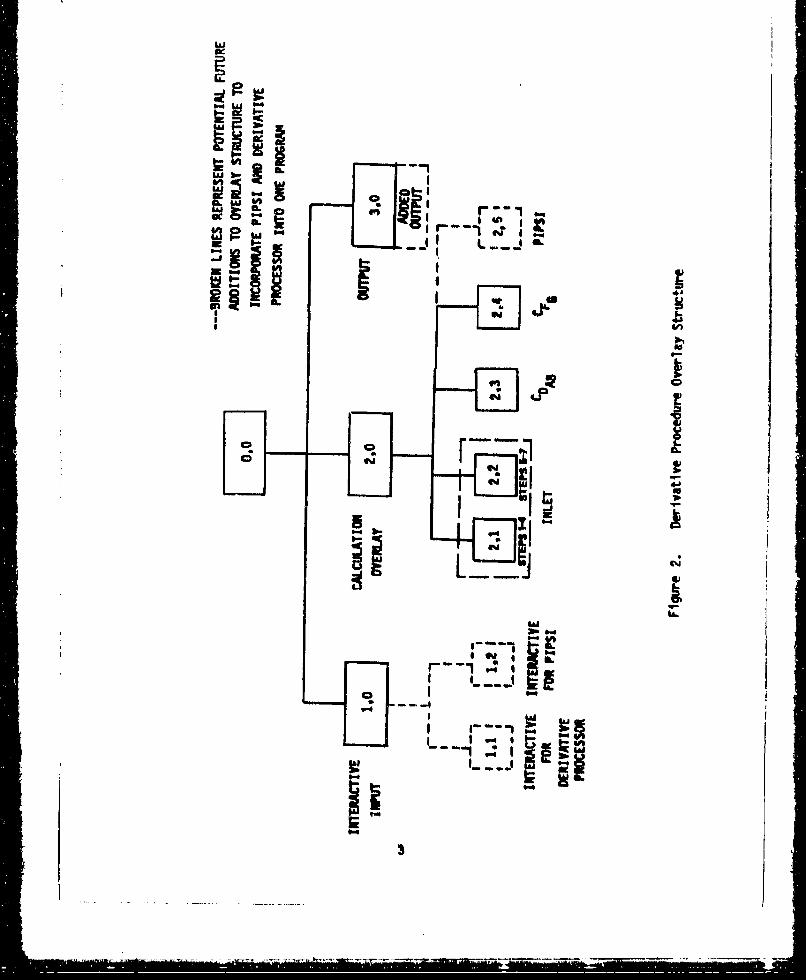
2. Derivative Procedure Overlay Structure 3
3. Inlet Derivative Procedure Flow Chart 18
4. Examples of Three Table Types 39
5. Example of Three-Dimensional Table 4J
6. Inlet File Example
7. Afterbody File Example 51
8. Nozzle Thrust Coefficient File Example 55
9. Example uf TAPE6 Output 59
1u. Example of a Typical Terminal Session ?2
11. ATS2 Inlet 81
12. Total Pressure Recovery vs. Mass Flow Ratio 82
13. Matched Total Pressure Recovery 83
14. Matched Inlet Mass Flow Ratio 83
i5. Buzz Limit Mass Flow Ratio 84
16. Distortion Limit Mass Flow Ratio 84
17. Spillage Drag vs. Inlet Mass Flow Ratio 85
18. Reference Spillage Drag and Mass Flow Ratio 86
19. Boundary Layer Bleed Drag vs. Bleed Mass Flow Ratio 87
20. Byposs Drag vs. Bypass Mass Flow Ratio 87
21. Bypass Mass Flow Ratio vs. Engine Demand Mass Flow Ratio 88
22. ATS2 Inlet Input Data Tables 89
23. Old Inlet Derivative Parameters 91
vii
I .. .. .... .... .. 4-I I
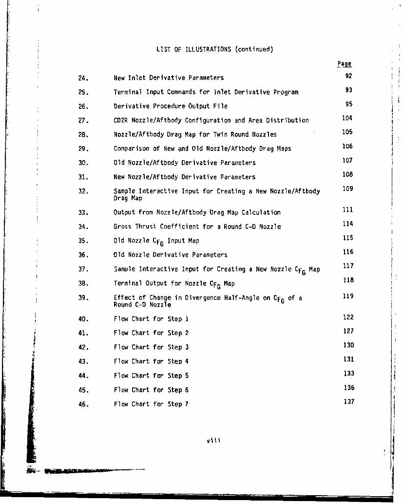
LIST OF ILLUSTRATIONS (continued)
24. New Inlet Derivative Parameters 92
25. Terminal Input Conmands for Inlet Derivative Program 93
26. Derivative Procedure Output File 95
27. CD2R Nozzle/Aftbody Configuration and Area Distribution 104
28. Nozzle/Aftbody Drag Map for Twin Round Nozzles 105
29. Comparison of New and Old Nozzle/Aftbody Drag Maps 106
30. Old Nozzle/Aftbody Derivative Parameters10731. New Nozzle/Aftbody Derivative Parameters 108
32. Sample Interactive Input for Creating a New Nozzle/Aftbody 109
Drag Map
33. Output from Nozzle/Aftbody Drag Map Calculation 111
34. Gross Thrust Coefficient for a Round C-D Nozzle 114
35. Old Nozzle CFG Input Map 115
36. Old Nozzle Derivative Parameters 116
37. Sample Interactive Input for Creating a New Nozzle CFG Map 117
38. Terminal Output for Nozzle CFG Map 118
39. Effect of Change in Divergence Half-Angle on CFG of a 119Round C-D Nozzle
40. Flow Chart for Step 1 122
41. Flow Chart for Step 2 127
42. Flow Chart for Step 3 130
r 43. Flow Chart for Step 4 131
44. Flow Chart for Step 5 133
45. Flow Chart for Step 6 136
46. Flow Chart for Step 7 137
viii
• i mm I im "
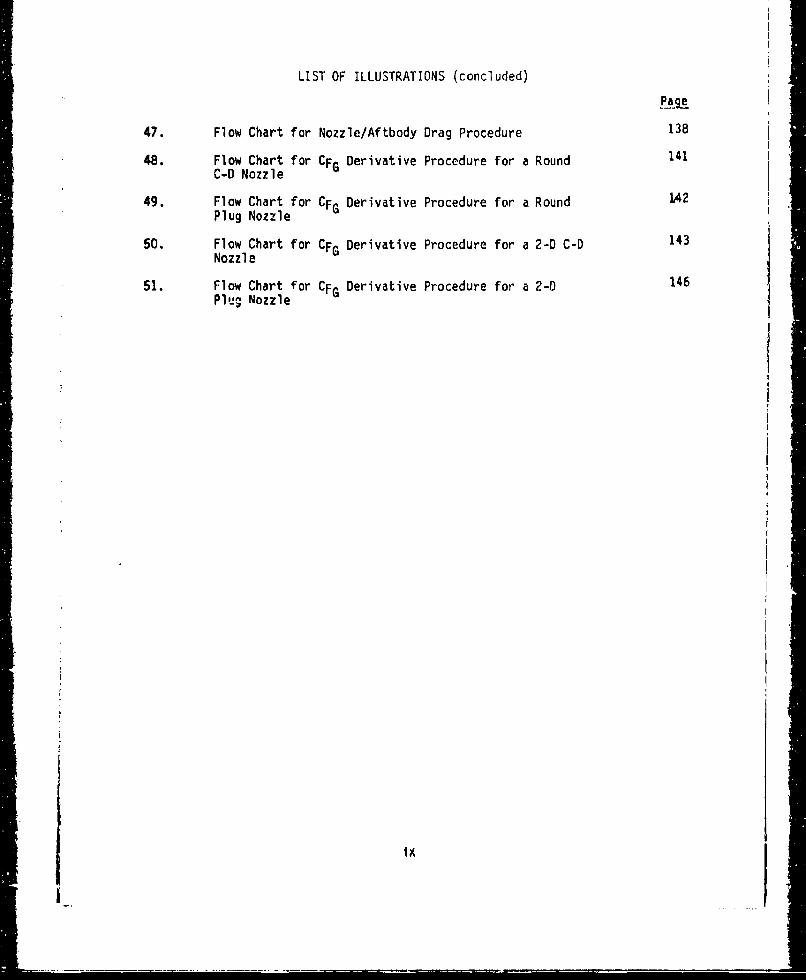
LIST OF ILLUSTRATIONS (concluded)
47. Flow Chart for Nozzle/Aftbody Drag Procedure 138
48. Flow Chart for CFG Derivative Procedure for a Round 141C-D Nozzle Dra
49. Flow Chart for CFG Derivative Procedure for a RoundPlug Nozzle
50. Flow Chart for CFG Derivative Procedure for a 2-D C-D 143Nozzle
51. Flow Chart for CFG Derivative Procedure for a 2-D 146Plu- Nozzle
ii
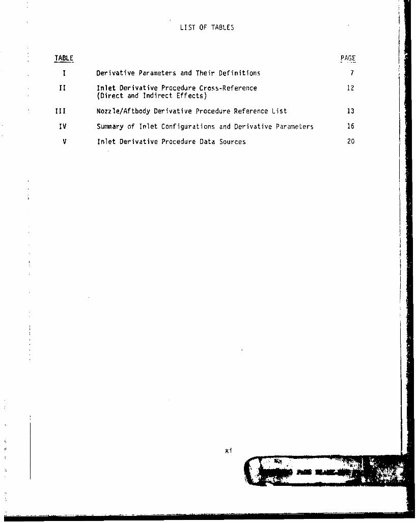
LIST OF TABLES
TABLE PAGE
I Derivative Parameters and Their Definitions 7
II Inlet Derivative Procedure Cross-Reference 12(Direct and Indirect Effects)
III Nozzle/Aftbody Derivative Procedure Reference List 13
IV Summary of Inlet Configurations and Derivative Parameters 16
V Inlet Derivative Procedure Data Sources 20
xi
104i
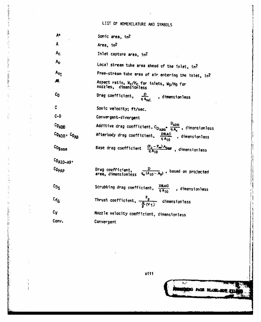
LIST OF NOMENCLATURE AND SYMBOLS
A* Sonic area, in 2
A Area, In2
Ac Inlet capture area. in 2
A° Local stream tube area ahead of the inlet, in2
A01 Free-stream tube area of air entering the Inlet, in2
AR Aspect ratio, Wc/Hc for inlets, Wg/Hg fornozzles, dimensionless
CD Drag coefficient, D * dimensionless
C Sonic velocity; ft/sec.
C-D Cqnvergent-divergent D/mbCDAo0 Additive drag coefficient, CDAJ. , dimensionlessCD C Afterbody drag coefficient, DRAG dimensionless
CA10 CD q AdOs s
CDEase Base drag coefficient (Pb-P.m)Abm , dimensionless•qA 1 odmnsols
CDA1o-A9,
CDPAP Drag coefficient,'S Dbsdo r~cearea, dimensionless %A 10 - ) ' based on projected
C!JS Scrubbing drag coefficient, * , dimensionless
FCfG Thrust coefficient, dimensionless
CV Nozzle velocity coefficient, dimensionless
Cony. Convergent
xlii

LIST OF NOMENCLATURE AND SYMBOLS (Continued)
D Drag, lb.; Hydraulic Diameter, -4 A in., diameter,in. P
F Thrust, lb.
FN Net thrust, lb.
FNA Installed net thrust, lb.
Fgi Ideal gross thrust (fully expanded), lb.
f/a Fuel/air ratio, dimensionless
g Gravitational constant, ft/sec2
h Enthalpy per unit mass, BTU/Ib.; height, in.
hfan Enthalpy of fan discharge flow, BTU/lb
hpri Enthalpy of primary exhaust flow after heat addition,BTU/lb
ht Throat height, in 2
IMST Integral mean slope parameter, truncated
IMT~U (I - Aq/A10) f d( d (A1 10q1o
L Length, in. AIO
M Mach number, dimensionless
P Static pressure, lb/in2 , perimeter, in.
Pr Relative pressure,; the ratio Of the pressures Paand Pb corresponding to the temperatures Ta andTýj, respectively, along a given isentrope, dimen-sionless
P.S. Power setting
SPT Total pressure, lb/in2
Q Effective heating value of fuel, BTU/Ib.
xlv

LIS, OF NOMENCLATURE AND SYMBOLS (Continued)
q Dynamic pressure, lb/In2
R Gas constant
R, r Radius, in.
RF Total pressure recovery
SFC Specific fuel conswuption
SFCA Installed specific fuel consumption
T Temperature, OR
V Velocity, ft/sec
W Mass flow, lb/sec
WBX Bleed air removed from engine, lb/sec.
WC, Corrected airflow, lb/sec. ./"-'
)Jf Weight flow rate of fuel, lb/sec.
W2 Weight flow rate of air, primary plus secondary,
lb/sec.
W8 Primary nozzle airflow rate, lb/sec.
x Length, in.
Angle of attack; convergence angle of nozzle, degrees
y Ratio of specific heats, dimensionless
6T, Pressure correction factor, "T2/Ps.
Diffuser loss coefficient, qPT dimensionless
OTI Temperature correction factor, TTrrSTo
xv
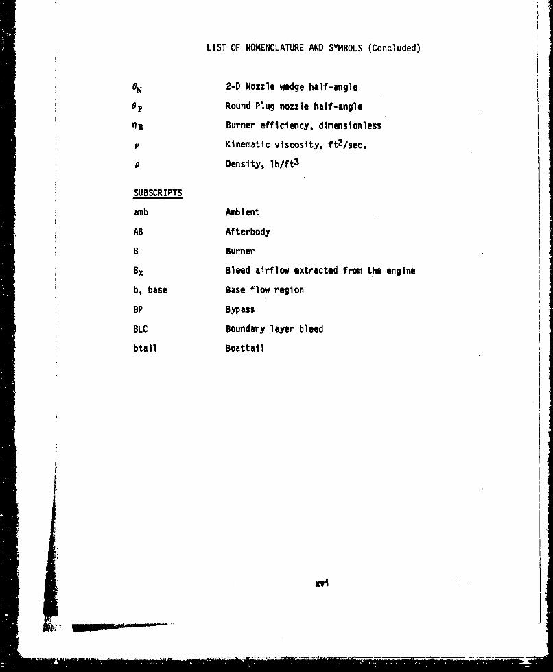
LIST OF NOMENCLATURE AND SYMBOLS (Concluded)
2-D Nozzle wedge half-angle
0I, Round Plug nozzle half-angle
Burner efficiency, dimensionless
- Kinematic viscosity, ft 2/sec.
P Density, lb/ft 3
SUBSCRIPTS
amb Ambient
AB Afterbody
B Burner
Bx Bleed airflow extracted from the engine
b, base Base flow region
BP Bypass
BLC Boundary layer bleed
btail Boattail
f
"Xvl
-- ~ ~ ~ ~ ~ ~ z -•=L _.MON=..... 2-' •....
SECTION 1
INTRODUCTION
The purpose of ,the derivative procedure is to provide a first-orderanalytical method to determine the effects on inlet and nozzle perfor-
mance of configuration differences from the nearest configuration repre-
sented In the library of stored maps (which are built-up for specific
configurations). The derivative process Is illustrated in Figure 1.
The derivative procedure utilizes analytical and experimental data in
determining changes in the stored performance maps that result from
geometric changes in the inlet and nozzle/aftbody configurations. Theanalytical procedures and experimental data have been used to develop an
interactive computer program that allows the user to interactivelyaccount for changes to the configurations in the library. The program
then generates new input data maps in the PIPSI format that represent theperformance characteristics of the, perturbed configuration. An overlay
structure was used to construct the program as shown in Figure 2.
L M"]•.I
SI- .. .I I . L - - ... • j . . . • . -

Zm
404
WZV
ILw9
4-4
-- "
, L
p..
ILI
L-- V
V4--• Sri
I_..I
g3
"•"•' • ' " •-- •: • • •'• • -• •-''•" '•' '- ' '•" i••''•'•-'- ---"•- I . ... -- -- ' • --• .. ... -•" = " '-: "
SECTION IIDERIVATIVE PARAMETERS
The first step in the development of the derivative procedure was the
selection of the derivative parameters. The derivative parameters are
those parameters that will be perturbed to produce a new set of perfor-
mance characteristics from an existing (or "baseline") set of maps.
The criteria used to select the derivative parameters were:
1) Variations in the parameter must have a significant effect onthe content of the maps used to describe inlet or nozzle/aftbody
performance. The derivative procedure will be used as part of
an overall preliminary analysis procedure for calculating first-
order propulsion system installation effects. It should not be
used for detailed design studies because the methodology em-
ployed in developing the input data for the inlet and nozzle
maps, of necessity, requires using a variety of engineering
analyses, test data and assumptions based on experience and
Judgment. The methods employed are believed to be reasonable;
however, the procedure may not be sensitive to the effects of
mall variations in some design variables. The user should
ascertain whether or not the procedure will properly evaluatethe desired parameter before using the procedure. The deriva-
tive parameters selected for the present procedure are those
which have been clearly identified by test or analysis as having
"first-order" effects on installed performance.
2) To the maxitmum extent possible, an attempt was made to define
the derivative parameters in terms of geometric variables thatcan be easily related to the airplane configuration. This was
"done to help In evaluating the effects of configuration changes
on installed performance.
6
3) Derivative parameters had to represent trends that were strong
enough to be clearly evident in spite of the scatter in test
data obtained from typical inlet and nozzle tests.
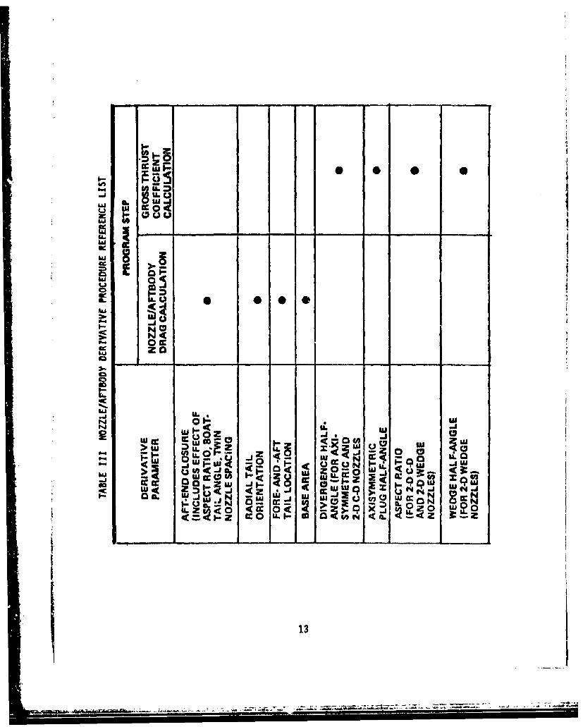
Table I presents a list of the derivative parameters that have beenselected for use in the derivative procedures. The definition of each of
these parameters is included. Tables IT and III present the derivdtiveparameters and the performance map variables that they affect, either
directly or indirectly.
I
,,,d6

TABLE I
DERIVATIVE PARAMETERS ANO THEIR DEFINITIONS
1) Aspect Ratio - Applicable to two-dimensional inlets only(AR)
- Defined as inlet width divided by inlet lip
height (relative to tip position).
2) Sideplate Cutback - Applicable to two-dimensional inlets only
(SPC)
- Defined as the percent of a full sldeplate
area that is removed to define a partial
sideplate.
The upper edge of a full sideplate extendsfrom the ramp tip to the cowl lip.
3) First Ramp or Cone - Applicable to two-dimensional and
Angle axisymmetric inlets
- Defined as surface ramp angle, in degrees,
relative to horizontal reference line for
two-dimensional inlets
Defined as cone surface angle, in degrees,
relative to Inlet centerline for axisym-metric inlets (cone half-angle)
7
--. -. - --- "

TABLE I (Continued)
4) Design Mach Number Applicable to all inlets
(Mo Design)Defined as the maximum Mach number at which
the inlet is designed to operate
5) Cowl Lip Bluntness Applicable to all inlets
Defined as the inlet lip surface radiusdivided by the lip height.
6) Takeoff Door Area Applicable to all inlets
Defined as the total door throat area forthe takeoff auxiliary air system divided by
the inlet capture area
7) External Cowl Angle Applicable to all inlets
Defined as external cowl surface angle, in
degrees, relative to inlet horizontal
reference line
8) Exit Nozzle Type - Applicable to two-dimensional and
for Bleed axisymmetric inlets
- Defines whether bleed exit nozzle is
convergent or convergent-divergent
9) Exit Nozzle Angle Applicable to two-dimensional and
for Bleed axisymmetric inlets
- Defined as bleed exit nozzle angle, In
degrees, relative to inlet horizontal
reference line
8WON
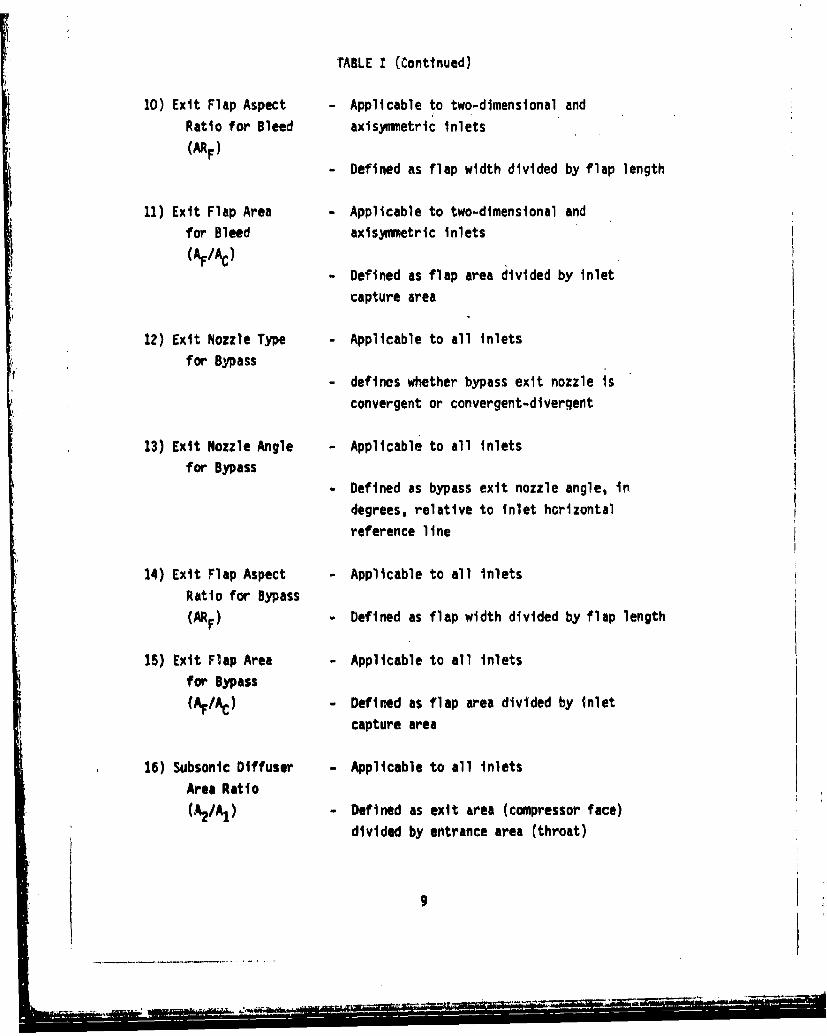
TABLE I (Continued)
10) Exit Flap Aspect - Applicable to two-dimensional andRatio for Bleed axisymmetric inlets
- Defined as flap width divided by flap length
11) Exit Flap Area - Applicable to two-dimensional and
for Bleed axisymmetric inlets
(AF/Ac)- Defined as flap area divided by Inlet
capture area
12) Exit Nozzle Type - Applicable to all inlets
for Bypassdefines whether bypass exit nozzle is
convergent or convergent-divergent
13) Exit Nozzle Angle - Applicable to all inlets
for Bypass- Defined as bypass exit nozzle angle, in
degrees, relative to inlet horizontal
reference line
14) Exit Flap Aspect - Applicable to all Inlets
Ratio for Bypass
(ARF) - Defined as flap width divided by flap length
15) Exit Flap Area - Applicable to all inlets
for Bypass
(Ar /AC) - Defined as flap area divided by inlet
capture area
16) Subsonic Diffuser - Applicable to all Inlets
Area Ratio
(%/A1 ) - Defined as exit area (compressor face)
divided by entrance area (throat)
9
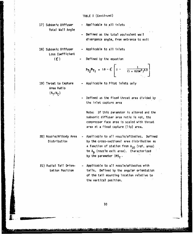
TABLE I (Continued)
17) Subsonic Diffuser - Applicable to all inlets
Total Wall Angle- Defined as the total equivalent wall
divergence angle, from entrance to exit
18) Subsonic Diffuser Applicable to all inlets
Loss Coefficient(•) - Defined by the equation
P PT 1.0T2 (I + .2M1 N')-"
19) Throat to Capture - Applicable to Pitot inlets only
Area Ratio
(AT/Ac)
- Defined as the fixed throat area divided by
the inlet capture area
Note: If this parameter is altered and the
subsonic diffuser area ratio is not, the
compressor face area is scaled with throat
area at a fixed capture (lip) area.
20) Nozzle/Aftbody Area Applicable to all nozzle/aftbodies. Defined
Distribution by the cross-sectional area distribution asa function of station from A10 (ref. area)
to A9 (nozzle exit area). Characterized
by the parameter IMST.
21) Radial Tail Orien- Applicable to all nozzle/aftbodies with
tation Position tails. Defined by the angular orientation
of the tail mounting location relative to
the vertical position,
10
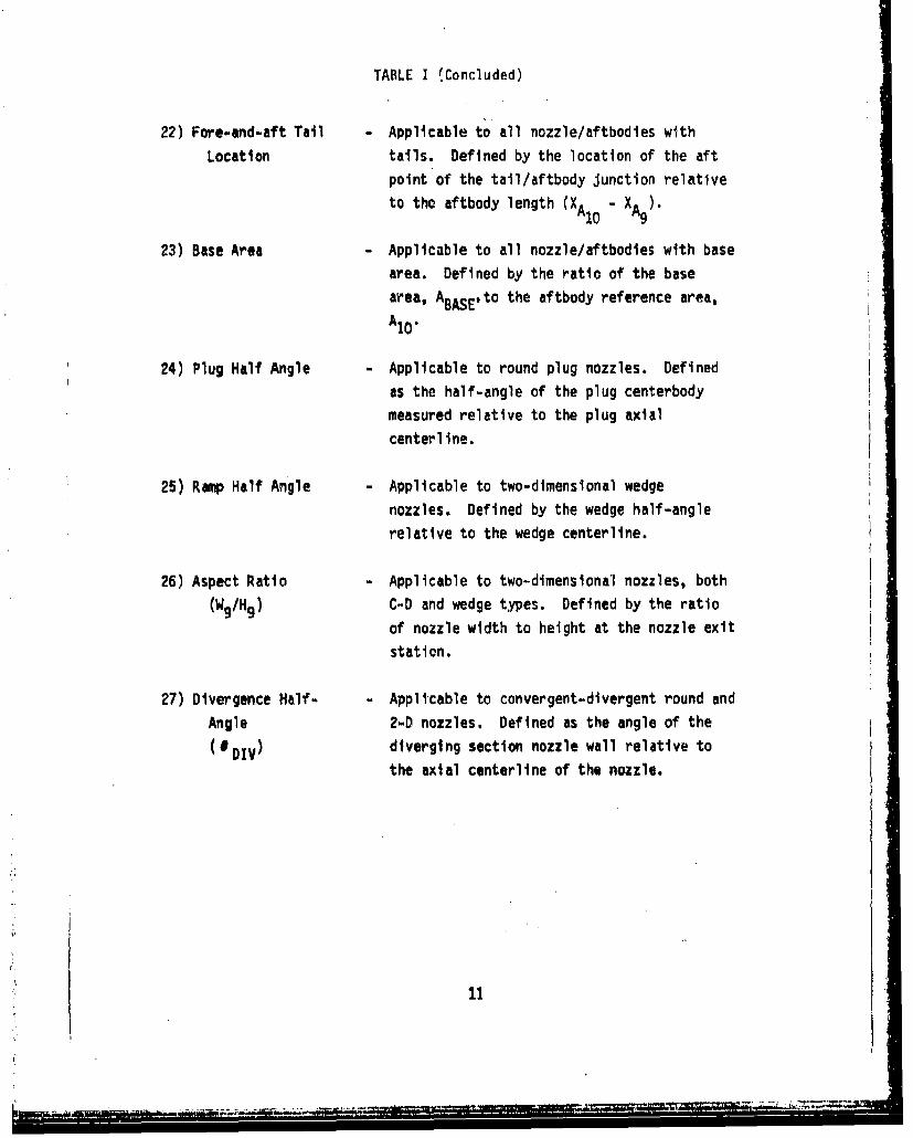
TABLE I (Concluded)
22) Fore-and-aft Tall Applicable to all nozzle/aftbodies with
Location tails. Defined by the location of the aftpoint of the tail/aftbody Junction relativeto the aftbody length (XA10 - XA9).
23) Base Area Applicable to all nozzle/aftbodles with base
area. Defined by the ratio of the base
area, ABASE' to the aftbody reference area,AIOA10.
24) Plug Half Angle Applicable to round plug nozzles. Defined
as the half-angle of the plug centerbodymeasured relative to the plug axial
centerline.
25) Rmp Half Angle Applicable to two-dimensional wedge
nozzles. Defined by the wedge half-angle
relative to the wedge centerline.
26) Aspect Ratio Applicable to two-dimensional nozzles, both
(W9/H9 ) C-D and wedge types. Defined by the ratio
of nozzle width to height at the nozzle exit
station.
27) Divergence Half- Applicable to convergent-divergent round and
Angle 2-D nozzles. Defined as the angle of the
(0 DIV) diverging section nozzle wall relative to
the axial centerline of the nozzle.
11
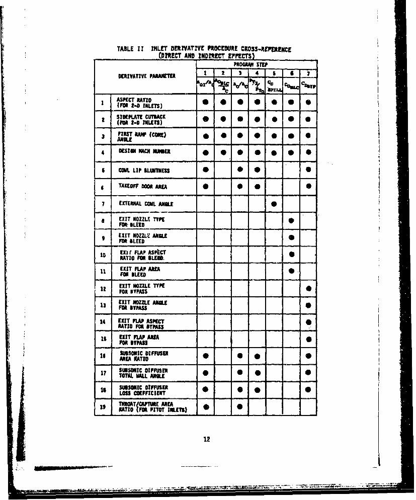
TABLE 11 INLT DERIVATIVE PROCEDURE CROSS-REIERENCE(DIRECT AND INDIRECT EFPECTS)
PROMAN STEP
DERIVATIVE PARAIETER 1 2 $ 4 6 1 -
aX/A AI
S ASPECT RATIO 0 0 1(FR2-0 INLM1)00 0
2 SRIOMATECUMCK
1 (MR 2-0 toutrs)
3 FIRT AP (CORE) . . . .ANILE
4 DESIGN RACKNUMBER* * 0 0 0 *
. COW. LiPmLthESS L * S 0
6 TAKEOFF DOOR AREA * *
7 EXTERNAL COWL ANILE 0
a EXIT NOZZLT TYPE 9FOR--BLEED
EXIT NOZZLW ANGLE SFOR BLEED10 EXW FLAP Aspt•C
RATIO FOR ALEN,--
EXIT FLAP AREA •FOR BLEED
EXIT NOZZLE TYPE 0FOR BYPASS
EXIT NOZZLE ANGLE -13 FOR BYPASS
14 EXIT FLAP ASPECT •RATIO FOR MYPASS
16 EXIT FLAP AREAFOR BYPASSSUBSONIC 0I FFIMEN • 0AREA KATIO
17 0TOTN WALL ANL
SUBSONIC DIFFUSER- 0 * - - 0LOSS COEFFICIENT
1. ... JATICAPTRE AREA ERATIO (FOR PITOT IMLS)
12
.....- .. .--.
-IL
* 05
E @00
'-4
C-
IiJ
*. U . 5114 0-u
N o- i<u-J 0( 0- Wq~~
CC g> Lu LW, .9 zLI13
Pt -.--. *-"-..--*-. 0
SECTION III
ENGINEERING DESCRIPTION OF DERIVATIVE PROCEDURE
3.1 INLET DERIVATIVE PROCEDURE
The purpose of the inlet derivative procedure is to analytically modify a
baseline inlet configuration and define the resulting performance charac-
teristics in a format that can be used as direct input to the PIPSI
program. Baseline inlet geometry and performance characteristics willbe represented by elements of a set of inlet geometries and performance
characteristics contained in the library of map files. The inlet geomet-
ric characteristics represented by the inlet configurations contained in
the basic library of inlet maps are shown in Table IV. The derivative
procedure provides a first-order prediction of the new inlet performance
based on the baseline map file and changes in derivative parameters from
those of the baseline inlet.
This procedure is based on two key assumptions:
(1) Generally applicable functions exist which relate changes In
inlet performance characteristics to changes in inlet design
parameters; and
(2) The derivative procedure will not alter the sophistication,
technnlogy, design philosophy, or mission related design trades
that are represented by the baseline inlet. As a result, the
inlet level of technology, type of application, complexity anddesign philosophy are removed as variables in the derivative
procedure. It is important to note that as a result of thisapproach 6a new inlet with given design variables will not have
completely unique performance characteristics if it is generatedby perturbations from different baseline map files. Each result
will reflect the design of the chosen baseline inlet.
15 X

W. : 1 2:l! T
14 1, 'itR ,
C31
-I 1
a F.
4 .4 F4 P, .
EEX~~~3Zg zug ..1q

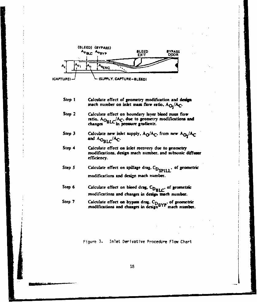
Simplified flow charts are included that provide a basic outline of the
procedure and each of its steps. The seven basic steps in the procedure
(Figure 3) are ordered in a manner which provides a sequential definition
of the new performance maps without the requirement of iteration between
later and early steps. A summary of these steps is as follows:
STEP 1
The effect of geometry modification on inlet capture is determined for
two-dimensional inlets from the Petersen-Tamplin analysis using a single
ramp inlet approximation. For axisymmetric inlets the effects of inlet
modification are determined from a single cone analysis. The effect of
design Mach number for both these inlet types alters the Mach 1.0 inlet
captured mass flow ratio, Ao /AC, and provides a correction over
the supersonic and subsonic Aach number range. For supersonic pitot type
inlets, the effect of a change in design Mach number on inlet captured
mass flow ratio is calculated using the assumption of fixed throat to lip
area ratio.
STEP 2
Changes in bleed mass flow caused by design modifications are calculated
by accounting for the effects of altered geometry on surface wetted-area
ratio and changes in inlet pressure gradient.
STEP 3
"Engine-plus-bypassw supply mass flow ratio, Ao/AC, is determined
simply by reducing the inlet captured mass flow ratio, A0 /AC, by
the required bleed mass flow ratio, AoBLC/Ac.
STEP 4
Changes In inlet recovery due to geumetry modifications are determined
from changes in shock losses and subsonic diffuser recovery. The effect
of design Mach number change on recovery is determined from the use of
the loss coefficient,-, at equivalent Mach numbers.
17
(BLEED) (BYPASS)AoS0 X AOBfP BLEED BYPASSEXIT DOOR
(C AP TU R qJ:)I(SUPPLY, CAPTURE-BLEED)
Step I Calculate effect of geometry modification and deupImuch number on inlet mn flow-ato. Ato /AC.
Step 2 Calculate effect on boundary layer bleed mass flowratio, AN. /AC, due to geometry modifications andchanges in premure gradientr.
Step 3 Calculate new inlet supply, AO/AC. from new AoI/ACand AOL/c
Step 4 Calculate effect on inlet recovery due to geometrymodifications, design mach number, and subsonic diffuserefficiency.
Step S Calculate effect on spillage drag. CDSPILL. of gomsetic
modifications and desin mach number.
Step 6 Calculate effect on bleed drag, CD,,.c. of eometric
modifications and changes in desip mech number.
Step 7 Calculate effect on bypass drag, CD Y. of geometric
modifications and changes in design mach number.
Figure 3. Inlet Derivative Procedure Flow Chart
18
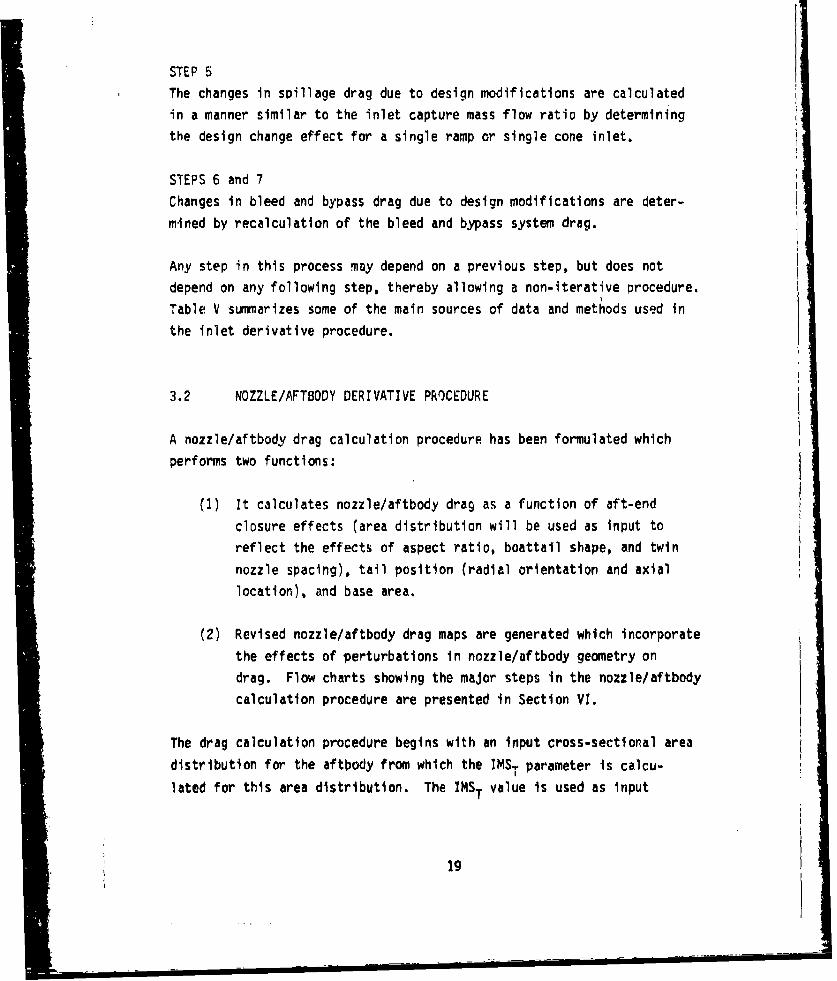
STEP 5
The changes in spillage drag due to design modifications are calculated
in a manner similar to the inlet capture mass flow ratio by determiningthe design change effect for a single ramp or single cone inlet.
STEPS 6 and 7
Changes in bleed and bypass drag due to design modifications are deter-
mined by recalculation of the bleed and bypass system drag.
Any step in this process may depend on a previous step, but does not
depend on any following step, thereby allowing a non-iterative procedure.
Table V summarizes some of the main sources of data and methods used in
the inlet derivative procedure.
3.2 NOZZLE/AFTBODY DERIVATIVE PROCEDURE
A nozzle/aftbody drag calculation procedure has been formulated which
performs two functions:
(1) It calculates nozzle/aftbody drag as a function of aft-end
closure effects (area distribution will be used as input toreflect the effects of aspect ratio, boattail shape, and twin
nozzle spacing), tail position (radial orientation and axial
location), and base area.
(2) Revised nozzle/aftbody drag maps are generated which incorporate
the effects of perturbations in nozzle/aftbody geometry on
drag. Flow charts showing the major steps in the nozzle/aftbody
calculation procedure are presented in Section VI.
The drag calculation procedure begins with an input cross-sectional area
distribution for the aftbody from which the IMST parameter is calcu-
lated for this area distribution. The IMST value is used as input
19-----------------------
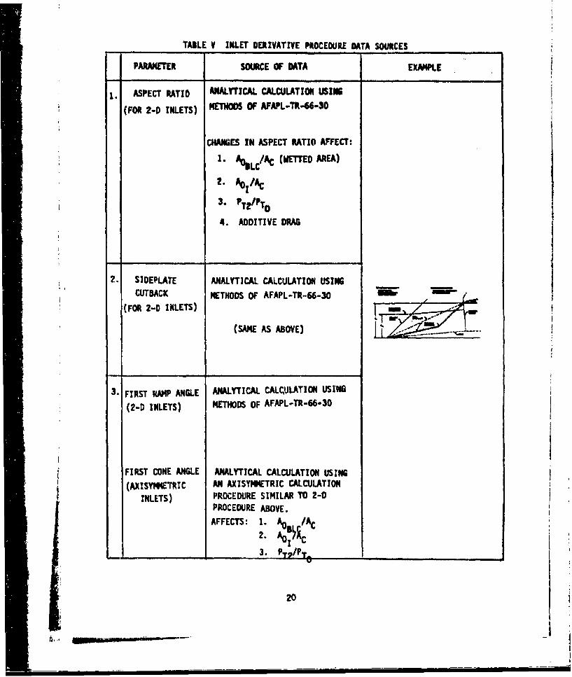
TABLE V INLET DERIVATIVE PROCEDURE DATA SOURCES
PARAMETER SOURCE OF DATA EXAMPLE
S. ASPECT RATIO ANALYTICAL CALCULATION USINGS(FOR 2-0 INLETS) METNOOS OF AFAPL-TR-66-30
CHANGES IN ASPECT RATIO AFFECT:
I. ,LC/AC (WETDo AREA)
2. AoI/A
3. PT2/pTO
4. ADDITIVE DRAG
2. SIDEPLATE ANALYTICAL CALCULATION USING
CUTBACK METHODS OF AFAPL-TR-66-30 -
(FOR 2-D INLETS)
(SAME AS ABOVE)
3. FIRST RAMP ANGLE ANALYTICAL CALOLATION USING
(2-D INLETS) METHODS OF AFAPL.TR-66,30
FIRST CONE ANGLE ANALYTICAL CALCULATION USING
(AXISYMMETRIC AN AXISYMMETRIC CALCULATIONINLETS) PROCEDURE SIMILAR TO 2-D
PROCEDURE ABOVE.
AFFECTS: 1.2. A
________ _______3. P V/P _ _ _ _ __ _ _ _ __ _ _ _ _
20
, U,,, n .... . iu-i . . .
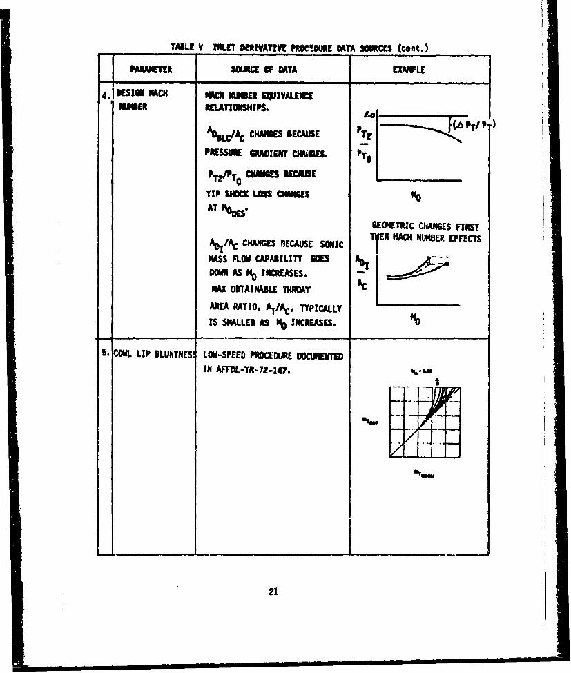
- TABLE V MNLET MRIVATVt PRTO.URE D•TA SOURCES (cent.)
PARAMETER SOURCE OF MTA EXAlPLE
4. DESIGN MVA MACH MIWBER EQUIVALENCEIMUER RELATIONSHIPS.
%L/CCHANGES BECAUSE T
PRESSURE GRADIENT CNAI5ES.
PTZTo CHANGES BECAUSE
TIP SHOCK LOSS CHANGES
AT 1OSGEOMETRIC CHANGES FIRST
AO1/AC CHANGES MECAUSE SONIC EN MACH NUMBER EFFECTS
MASS FLOW CAPABILITY WOES A01
DON AS N INCREASES.
MAX OBTAINABLE THROT AC
AREA RATIO, AI.AC. TYPICALLY
IS SMALLER AS % INCREASES. NO
5. COWL LIP BLUNTNES LOW-SPEED PROCEDURE DOCUMENTEDIN AFFDL-TR-72-147.
21

TABLE V INLET DERIVATIVE PROCEDURE DATA SOURCES (cont.)
PARAMETER SOURCE OF DATA EXAMfPLE
6. TAKEOFF DOOR AREA LOW-SPEED PROCEDURE DOCUMENTED .iIN AFFDL-TR-72-147
T2......... ... ...PT¶
7.EXTERNAL COWL CORRELATION DEVELOPED FROMANGLE EXPERIMENTAL DATA
THAT RELATE EXTERNAL COWL
eEXT
8.EXIT NOZZLE TYPE NOZZLE CAN BE EITHER CONVERGENT R(FOR BLEED) CONVERGENT/DIVERGENT
USED IN MOMENTUM DRAG CALCULATIO PTE'I ToANALYTICAL METHODS DOCUMENTEDE-ELOPD FRO
IN AFFDL-TR-72.147 AND €PITAP BLEED RECOVERYDAT
THAT RLATE XTERNLCCOW
8. EXIT NOZZLE ANGLE USER CAN SELECT NOZZLE EXIT ANGL VERGT) NOZFOR BLEED FOR MOMENTUM DRAG CALCULATIOý T NOZ
ANALYTICAL METHODS DOCUMENTED IN
NAFFDL-TR-72-147
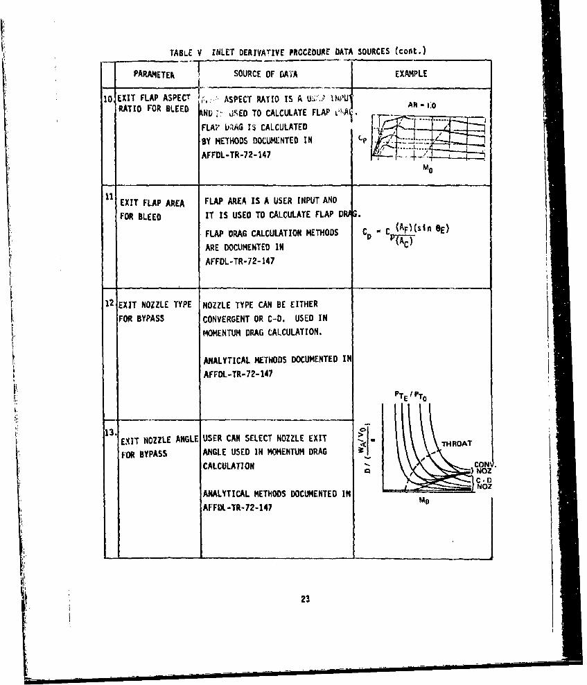
TABLE V INLET DERIVATIVE PROCEDURE DATA SOURCES (cont..)
PAR C F E
IOEXIT FLAP ASPECT ASPECT RATIO IS A INU t ANDRATIO FOR BLEED IN IS' UED TO CALCULATE FLAP V4 AR" 1.0" "T+"• ,• ''" " " J -.... ..... ..
FLAP ,tAG I' CALCULATED C--C.(A.-( __. _E)
BY A ETHODS DOCUMENTED I N - A -... .......AFFDL-TR-72-147
MID
11EXIT FLAP AREA FLAP AREA IS A USER INPUT AND
FOR BLEED IT IS USED TO CALCULATE FLAP DIN G,
FLAP DRAG CALCULATION METHODS .C _ AE)
AREN AETH DOCUMENTED IN
AFFDL-TR-72-147
12 EXIT NOZZLE TYPE NOZZLE TYPE CAN BE EITHER
FOR BYPASS CONVERGENT OR C-D. USED ]IN
CMOMENTU DRAG CALCULATION.
ANALYTICAL METHODS DOCUMENTED IN
AFFDL-TR-72-147
PTE 1 PTO
132.
- I . ', .. . . .
SEXIT NOZZLE ANGLE USER CAN SELECT NOZZLE EXIT TRA
FOR BYPASS ANGLE USED IN MOMENTUM DRAG
CALCULATION "CONW .
ANALYT]ICAL METHODS DOCUMENTED ]IN -- ' NOZ
AFFDL,-TR-72-147 M
23
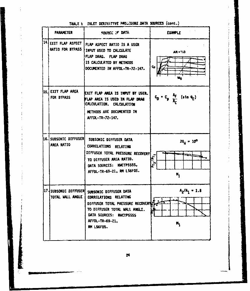
TAKE V INLET DERIVATIVE P0ZZURE -DATA SOURCES (cont.)
PARAMETER 5OURCE VF DATA EXAMPLE
14 EXIT FLAP ASPECT FLAP ASPECT RATIO IS A USER
RATIO FOR BYPASS INPUT USED TO CALCULATE AR-',
FLAP DRAG. FLAP DRAG or-.-4,1
IS CALCULATED BY METHODS - .
DOCUMENTED IN AFFL-R-72-147. -
15. EXIT FLAP AREA EXIT FLAP AREA IS INPUT BY USER.FOR BYPASS AREA IS USED IN FLAP OhD C0 Cp 9•)(sI 9
CALCULATION. CALCULATION
METHODS ARE DOCUMENTED IN
AFFDL-TR-72-147.
i --
16. SUBSONIC DIFFUSER SUBSONIC DIFFUSER DATA 2ew io0AREA RATIO CORRELATIONS RELATING
DIFFUSER TOTAL PRESSURE RECOVERY
TO DIFFUSER AREA RATIO.
DATA SOURCES: NWCTP5S5,AFFDL-TR-69-21, RM L56FO0.
17 SUBSONIC DIFFUSER SUBSONIC DIFFUSER DATA A2ITOTAL WALL ANGLE CORRELATIONS RELATING
DIFFUSER TOTAL PRESSURE RECOVERITO DIFFUSER TOTAL WALL ANGLE.DATA SOURCES: NWCTP5555
AFFDL-TR-69-21, HRt L56FOS.
24
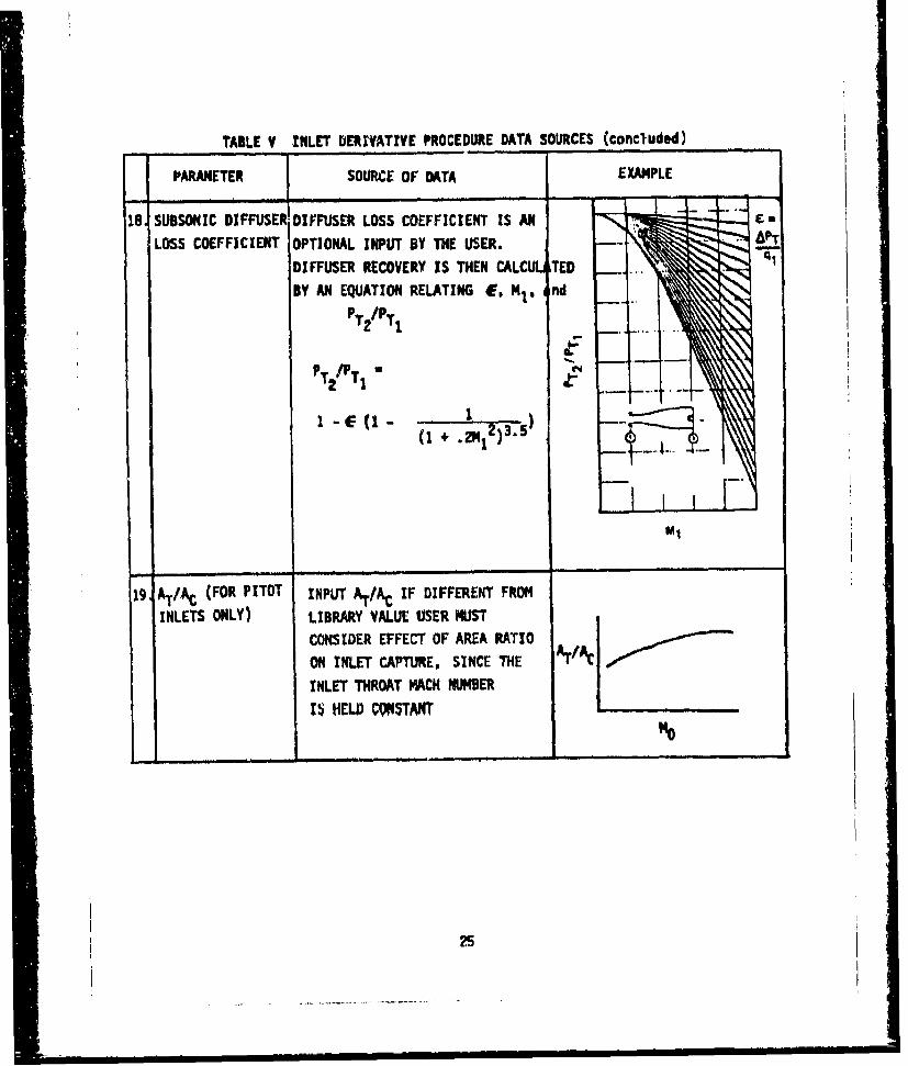
TABLE V INLET DERIVATIVE PROCEDURE DATA SOURCES (concluded)
PARAMETER SOURCE OF DATA EXAMPLE
16 SUBSONIC DIFFUSER DIFFUSER LOSS COEFFICIENT IS AN
LOSS COEFFICIENT OPTIONAL INPUT BY THE USER.
DIFFUSER RECOVERY IS THEN CALC TED _. .
BY AN EQUATION RELATING 4E. Mi. nd
P 'PS~~~PT/PI •[
T2I
(I ....
"19, AT/AC (FOR PITOT INPUT AT//AC IF DIFFERENT FROM
INLETS ONLY) LIBRARY VALUE USER MUST
CONSIDER EFFECT OF AREA RATIO
ON INLET CAPTURE. SINCE THE AT/AC
INLET THROAT MACH NUMBER
15i HELD CONSTANT "o25
- ~- -
to data correlations which provide nozzle/aftbody drag as a function of
IMST, Mach number, and exhaust nozzle exit static pressure ratio. Datacorrelations based on IMST parameters are available for certain classes
of installations, namely:
(1) Single, isolated axisymmetric configurations
(2) Twin axisymmetric configurations
(3) Siigle 2-D wedge nozzle configurations
(4) Twin 2-D wedge nozzle configurations
The data correlations listed above are used to predict drag of similar
configurations within the limitations of the data correlations. Inputrequirements must be fairly detailed because an accurate cross-sectional
area distribution must be available as input to compute the IMST param-
eter.
After.obtairlng the basic nozzle/aftbody drag from the IMST correla-tions, drag corrections are added to account for the radial orientation
of tails, longitudinal location of tails, and base drag. The total dragis then calculated as the sum of the individual drag contributions. The
drag calculation process is repeated for both the old (baseline) config-
uration and the new (perturbed) configuration. The incremental dragdifference is then added to the old (baseline) drag map to produce a new
drag map for the new (perturbed) configuration.
3.3 NOZZLE GROSS THRUST COEFFICIENT DERIVATIVE PROCEDURE
Using the calculation procedure built into this program, incrementalchanges in nozzle geometric variables are made by the user and the re-sulting changes in CF are calculated. The program then adds the
incremental changes A• nozzle CF to the old (baseline) CF map
to obtain the CF map for the new configuration. G
26
The calculation methods used to determine the effects on nozzle gross
thrust coefficient (CF ) of changes in nozzle geometric variables
depend greatly on the type of nozzle being used. Separate calculation
flow paths were constructed to handle each of the following nozzle types:
(1) Axls)ymetric Convergent-Divergent
(2) Axisymetric Plug
(3) Two-Dimensional Convergent-Divergent
(4) Two-Dimensional Plug (Wedge)
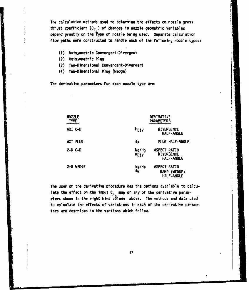
The derivative parameters for each nozzle type are:
NOZZLE DERIVATIVETYPE PARAMETERS
AXI C-D #DIV DIVERGENCEHALF-ANGLE
AXI PLUG Op PLUG HALF-ANGLE
2-D C-D Wg/H9 ASPECT RATIOODIV DIVERGENCE
HALF-ANGLE
2-D WEDGE W9/Hg ASPECT RATIOON RAMP (WEDGE)
HALF-ANGLE
The user of the derivative procedure has the options available to calcu-late the effect on the Input CF map of any of the derivative param-
eters shown in the right hand c•lumn above. The methods and data used
to calculate the effects of variations in each of the derivative parame-
ters are described in the sections which follow.
27

3.3.1 Effect of Divergence Half-Angle on CF for a Round C-D
Nozzle
The input map format for round C-D nozzles used by the PIPSI program is
illustrated in Figure 34. This map provides CF as a function ofnozzle pressure ratio, PT8/pop for various nozzie expansion ratios, ,
AB/A 8 . To provide a method whereby the effect of aD1V could be
related to area ratio, a typical round C-D nozzle oIV variation as a
function of A9 /A8 was adopted for programming into the procedure.
With a knowledge of Ag/A 8 and aDIV, it is possible to determine the
angularity loss, using the experimental angularity loss coefficient data
shown in Volume I.
3.3.2 Effect of Plug Half-Angle on CFG for a Round Plug Nozzle
The input map format for an axisymnmetric plug nozzle provides nozzle
grosýs thrust coefficient, CF I as a function of nozzle pressure
ratio PTB/Po for various areý ratios, Ag/A 8 . To obtain therelationship of Ag/A 8 and plug half angle, a two-dimenqional table
look-up set of data was prepared that represents the geometric relation-ships between lip angle, oplug half angle, Op, and area ratio,Ag/As, for a typical plug nozzle configuration. These data were
programmed into the code to provide data necessary to calculate the
parameter (o - Gp) used in the data correlation that provides the plugnozzle performance loss. This correlation, documented in Volume I, is
based on experimental data.
3.3.3 Effect of Aspect Ratio and Divergence Half-Angle on CF for
a Two-Dimensional Convergent-Divergent Nozzle G
The methods used in developing the computer code for the 2-D C-D nozzle
'internal performance calculations are based primarily on the experimental
data gathered during the AFAPL Installed Turbine Engine Survivability
Criteria contract. These tests prov.ided data on a variety uf 2-D nozzles
of various aspect ratios and divergence angles.
28
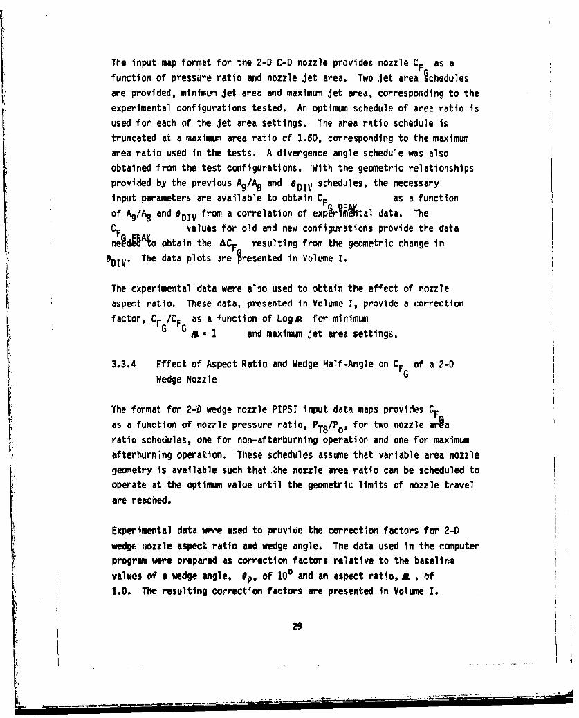
The input map format for the 2-D C-D nozzle provides nozzle CF as a
function of pressure ratio and nozzle jet area. Two jet area hchedules
are provided, minimum jet area and maximum jet area, corresponding to the
experimental configurations tested. An optimum schedule of area ratio is
used for each of the jet area settings. The area ratio schedule is
truncated at a maximum area ratio of 1.60, corresponding to the maximum
area ratio used in the tests. A divergence angle schedule was also
obtained from the test configurations. With the geometric relationships
provided by the previous A9/A8 and *DIV schedules, the necessary
input parameters are available to obtain CF as a function
of %q/A8 and ODIV from a correlation of exp~rIgAital data. The
CF values for old and new configurations provide the data
negdgA*o obtain the ACF resulting from the geometric change in
*DiV. The data plots are Oresented in Volume I.
The experimental data were also used to obtain the effect of nozzle
aspect ratio. These data, presented in Volume I, provide a correction
factor, C. /CF as a function of Logst for minimumG G 1 and maximum jet area settings.
3.3.4 Effect of Aspect Ratio and Wedge Half-Angle on CF of a 2-D
Wedge Nozzle G
The format for 2-0 wedge nozzle PIPSI input data maps provides CF
as a function of nozzle pressure ratio, PT8/Po, for two nozzle ariaratio schedules, one for non-afterburning operation and one for maximum
afterhurning operation. These schedules assume that variable area nozzle
geometry is available such that the nozzle area ratio can be scheduled to
operate at the optimum value until the geometric limits of nozzle travel
are reached.
Experimeptal data w.r'e used to provide the correction factors for 2-D
wedge niozzle aspect ratio and wedge angle. Tne data used in the computerprogram were prepared as correction factors relative to the baseline
values of a wedge angle, #,, of 100 and an aspect ratio, A , of
1.0. The resulting correction factors are presented in Volume I.
29
Flow charts are presented In Section VI which show the calculation pro-
cedure used to calculate the new nozzle CFG maps.
0
I
- I
I:
' i30
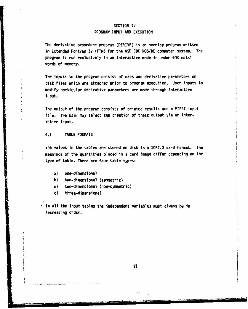
SECTION IV
PROGRAM INPUT AND EXECUTION
The derivative procedure program (DERIVP) is an overlay program written
in Extended Fortran IV (FTN) for the ASD CDC NOS/BE computer system. The
program is run exclusively in an interactive mode in under 60K octal
words of memory.
The inputs to the program consist of maps and derivative parameters on
disk files which are attached prior to program execution. User inputs to
modify particular derivative parameters are made through interactive
ii~put.
The output of the program consists of printed results and a PIPSI input
file. The user may select the creation of these output via an inter-
active input.
4.1 TABLE FORMATS
the values in the tables are stored on disk in a 10F7.0 card format. The
meanings of the quantities placed in a card image 4iffer depending on the
type of table. There are four table types:
a) one-dimensionalb) two-dimensional (symmetric)
c) two-dimensional (non-symmetric)
d) three-dimensional
In all the input tables the independent variablhs must always be in
Increasing order.
31
_ _ _ _ _ _ _ , -- --

4.1.1 One-Dimensional Table Definition
Card I Table Definition Card Format
Cols.
1-7 Table Name A7
8-14 Number of X Values F7.0
Card 2 X Values
Cols.
1-7 X1 F7 .0
8-14 X2 F7.0
64-70 X F7.0
Card 3 Table Values
Cols.
1-7 f(xl) F7.O
8-14 f(x 2 ) F7.0
64-70 f(Xlo) F7.0
4.1.2 Two-Dimensional Table Definition (Symmetric)
Card 1 Table definition Card Format
Cols.
1-7 Table Title A7
8-14 Number of X Values F7.0
15-21 Number of Y Values F7.O
32

Ci-rd 2. Y ValuesCo ls.1-71
F7.0S-14 Y2 F7.0
64-70 YF7.0
Card 3 X Values
Cols.1-7 Xl F7.0B-14 X1 F7.0
64-7010 F7.0
L.ard 4 Table values for YI, and
Cols. all X values1-7 f(xl,yl) F7.08-14 f(x 2,yl) F7.0
64-70 f(Xo0 9 Y1 ) F7.0
Card 5 Table Values for Y2 andCols. all X Values1-7 f~x1 Y2 ) F7.08-14 f(x 2 ,y 2 ) F7.0
64-70 f( 10 ,y 2 ) F7.0Etc. for additional Y values
33

I
4.1.3 Two-Dimensional Table (Non-Symmetrlc)
Card 1 Table Definition Card Format
Cols.1-7 Table Name A7
8-14 Number of Y Values F7.0
Card 2 Number of X Values for
Cols. A Particular Y Value1-7 NX (Y1 ) F7.0
8-14 NX (Y2) F7.0
64-70 NX (Y10 ) F7.0
Card 3 Y Values
Cols.1-7 Y1 F7.0
8-14 Y2 F7.0
64-70 YIO F7.0
Card 4 X Values for Y1
Cols.
1-7 XI(Y 1 ) F7.0
8-14 X2 (y1 ) F7.0
64-70 X 10 (y1 ) F7.0
34
...---.- - -- -- * -= - ~ -'-- _
Card 5 Table Values for (XI-X 10 ,Y1 )
Cols.1-7 f(X],Y1 ) F7.08-14 f(X2 ,Y1 ) F7.0
64-70 f(X10 ,Y1 ) F7.0
Card 6 X Values for Y2
(see Card 4)
Card 7 Table Values for (XI-X 10 ,Y2 )
(see Card 5)
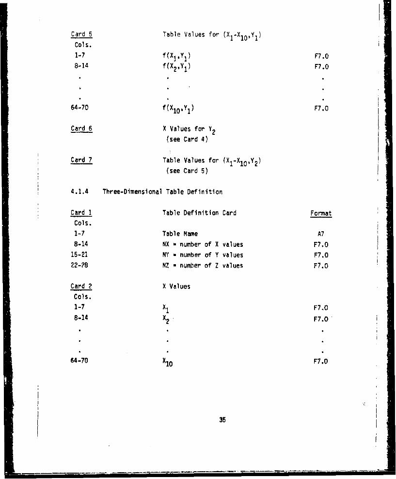
4.1A4 Three-Dimensional Table Definition
Card 1 Table Definition Card Format
Cols.
1-7 Table Name A7
8-14 NX a number of X values F7.015-21 NY w number of Y values F7.0
22-?8 NZ - number of Z values F7.0
Card 2 X Values
Cols.
1-7 F7.0
B-14 X2 F7.0
64-70 X10 F7.0
35
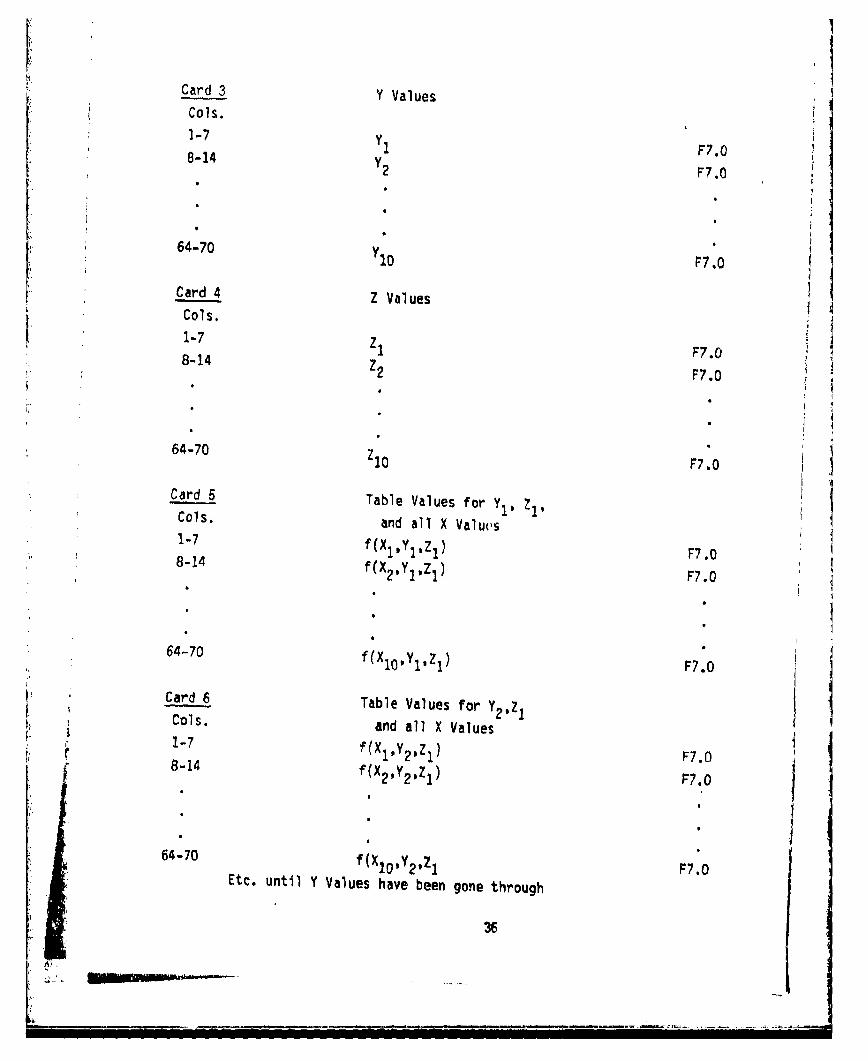
Card 3 Y Values
F7.0
64-70 P:
Card 4 ZVle
Cols.1-7 z78-14 1 F7.0
64-70 P7.0
Card 5 Table Values for Y1, Z1,Cols. and all X Valucs1-7 f(Xz1 y11 z1 ) F7.08-14
F7.0f(X 21 Y,z1) F.
64-70 f (X 0
Z10, ,j F7.0
Card 6 Table Values for Y ZCols. and all X Values1-7 f(Xl,Y1,Zl) F7.08-14 f(X 2 ,Y1,Z 1 ) FT.0
64-0 fX2oYI0,l) F7.0
os. an alX ale
64-70 f(X 1O,y2,z 1 F7.0Etc. until Y Values have been gone through
36
" 8-14f(X2 y2,Zl F7.
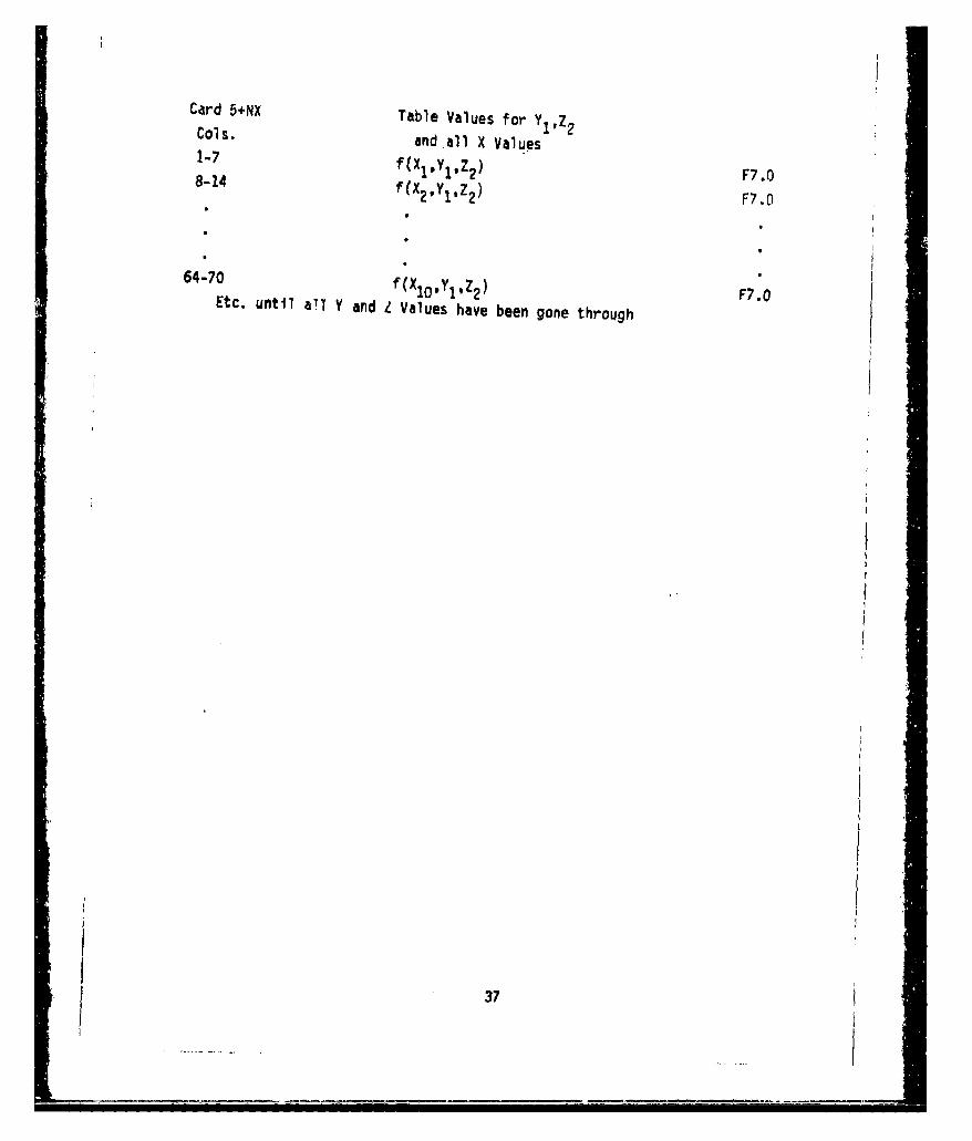
Card 5+NX Table Values for YZCols. and all X Values1-7 f(XlYl,Z 2 ) F7.O8-14 f(X2 ,Y1 ,Z2 ) F7.0
64-70 f(Xlo,Yl,Z 2 ) F7.0Etc. until all Y and L Values have been gone through
37
4.1.5 Table ExaMnDles
Examples of tables in each of the first 3 formats are shown in Figure 4,
and an example of the three-dimensional table format is shown in Figure 5.
S3W3
W- -
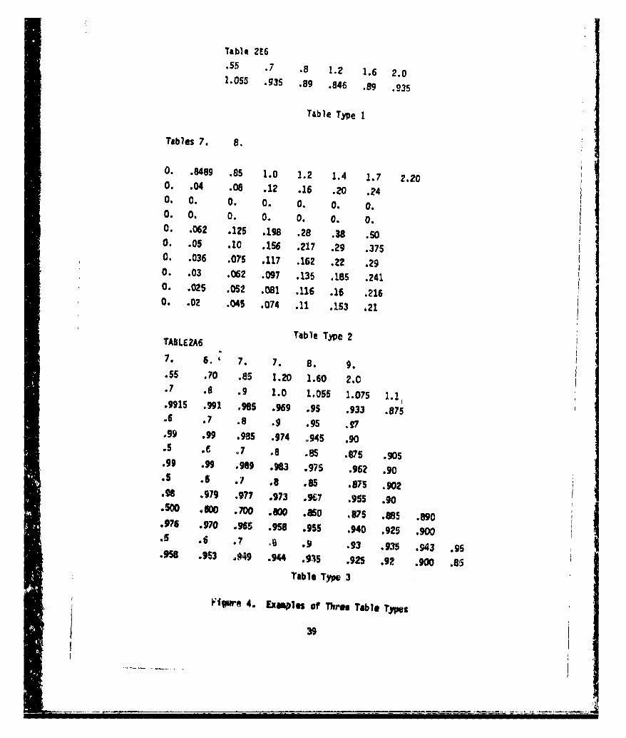
Table ZE6.55 .7 .8 1.2 1.6 2.01.055 .935 ,89 .846 .89 .935
Table Type 1
Tables 7. 8.
0. .8489 .85 1.0 1.2 1.4 1.7 2.200. .04 .08 .12 .16 .20 .240. 0. 0. 0. 0. 0. 0.0. 0. 0. 0 . 0. 0.0. .062 .125 .198 .28 .38 .So0. .05 .10 .156 .217 .29 .3750. .036 .075 .117 .162 .22 .290. .03 .062 .097 .135 .185 .2410. .025 .052 .081 .116 .16 .2160. .02 .045 .074 .11 .153 .21
Table Type 2TABLEMA
7. 6.' 7. 7. 8. 9,.55 .70 .85 1.20 1.60 2.0.7 .8 .9 1.0 1.055 1.075 1.1.•915 .991 985 .9g .95 .933 .875.6 .7 .8 .9 .95 X.99 .99 .985 .974 .945 .90.5 .E o7 .8 .85 .875 .905.99 .99 .989 .983 .975 .962 .90.5 .6 .7 .8 .85 .875 .902.g8 .979 .977 .973 .9g7 .955 .90.500 .W M . -o w600 .a5o 875 .885 .890.97S .970 .965 .958 .955 .940 .925 .900
.,6 .7 .8 .9 .93 .935 .943 .95.958 .953 J949 .944 .915 .925 .92 .900 .85
Table Type 3
ilgwe 4. Exwles of Three Table TypeS
39
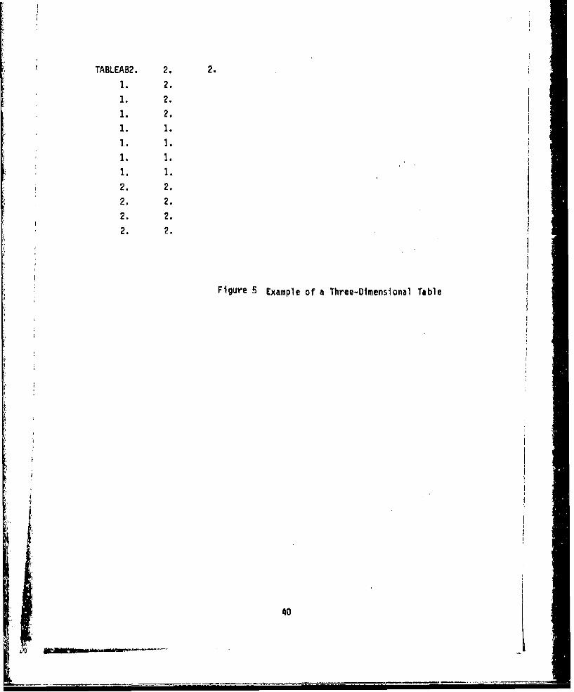
TABLEAB2. 2. 2.
1. 2.
1. 2.1. 2.
1. 1.].1.
1. 1.
1. 1.
2. 2.2. 2.2. 2.
2. 2.
Figure 5 Example of a Three-Dimensional Table
40

4.2 DISK FILES
The derivative procedure program utilizes three input disk files and two
output disk files for program data communication. The user governs the
usage of these disk files by responding to prompts when executing the
program.
4.2.1 Input Disk Files
Three disk files must be attached prior to program execution. in order to
run all maps necessary for a PIPSI execution. These files are as follows:
TAPE 51 - Inlet maps and Inlet Derivative Parameters
TAPE 52 - Afterbody Drag Map and Derivative ParametersTAPE 53 - Nozzle Thrust Coefficient (CF ) Map and
Derivative Parameters G
Only the disk files needed to run the desired maps need to be attached
before executing the program.
4.2.1.1 Inlet File APE 51)
This disk file consists of four separable sections of input:
1) Inlet Title Card
2) Inlet Derivative Parameters
3) Non-changeable Inlet Parameters
4) Inlet Tables
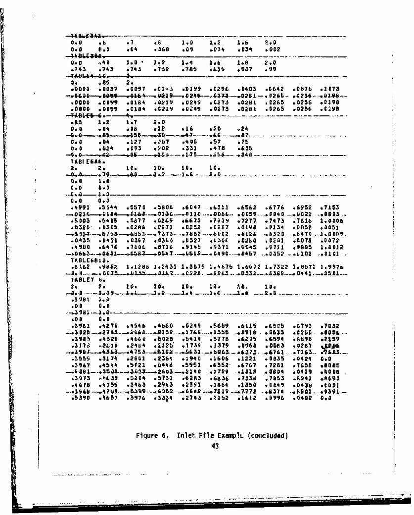
Figure 6 shows an example of a typical inlet file
4.2.1.1.1 Inlet Title Card
An 80-character title card must be the first card of the inlet file. It
is read with an A format and is printed as a heading on the output data.
41
• | -iii "5 -i¥ ... i-------------

NVSTO INLE7Do Do 22. 2. .015 046 19. 1.@ 20a le0
0. 1.3 5.30 .75 0.7ABLE1 Be
TA I, EMlAe
.60 SO 1.0 104 1.6 1.b It.1.5*10 e&696 .*749 .7906 .5236 .*460 o85568 .SAM SAM @,1696
*-vw9-- 4-v46b-94--f -99647---.4SAS 9 6". 9 10-4)4--aft i -S.b#9 5352 .5959 o6641 .7106 .7294* 1443 P7550 .7066 .7088 .1559*9879- w983% .90754 e9655 e9595 .9852 .9415* .9423 *9359 *8673W610 k1161 &5-64-.1.-.J4-..L&-. 3--014190-14-14--@911*0 w9805 c9751 e96437 .9545 .*9531 a9455 99430 e9333 A666**6462 96663 .6621 07132 .*159 .1757 0Mli .7845 .9873 .1882
M979 .6466 *6980 .7*98 .1113 *7927 .8545 94266.1b 2 ell? &33.9693 o9684 s9666 *9692 .9610 .9575 e9536 o9490 .9925 .5694
--.W" a 0--.6v _;;M 772 - 30-.51-.---*68 "feS864 -- e*9*S§-. wag67--v 89 TV--.9640 e9620 .9579 .9535 o9477 .*940 o9409 99353 ;9277 .86*9o6965 97617 .5227 *6833 .9225 .9465 s9621 .9126 *9771 AM75
---* 54 al-o S8A4--.. 94 63-.A34--o. 93 23 a 3331 89u-.ej--..s -.4404 -TABLE28109.5003 o2566 .4305 #WPSO .6951 01*86 1.1317 3.47*6 1.7112 1.9913
-.00*4&-.060 191k Afi17 91b4--..96G i *96-1S-- ..9963 1 9583---o95 10 -. 9360.-TASLEMCO.**477 .5319 .6523 .7361 .7100 .596k 1.0380 1.,212* 108534 1.9122
TABLE2010o1.5795 1.3982 1.4354 1.4715 1.5510 1.55*4 109701 1.7904 1.6735 1.9976
.5356 .6779g m6576 *9311 e9959 I*C9B2 1&2955 le5k67 1.6995 1.9835~9 9904&9 s~ 4...749-15 -.. 8&. 4.&.-.- *0ISSLE3 10oýIts 2o 10O 10o 10. lii. to* 10. 10.1 10.
s30 1.0
10.0 GOO
s35 .362 s417 9449 .479 sb03 .5*5 .565 .556 IS$-#5--.~6--.3*--lI5-- -.0 11--.-. --*011-A.-..... 00*a..-. 001.- .. 1 0 --as--.Sea-
.355 .363 .*16 6*s 0*9 .582 .606 .639 .671 1.0el1& .1 .003 .066 005 .636 .013 S905 ag0 .o0
.,119 .145 6119 .096 sell 9.051 .035 agog *Do 100
.3*17 e39* .**2 0*58 s531 .519 .521 .063 .7*5 1.0-,642-9.48 of.4.--.4-- .93 --.*86----. 7 .--. ,014..4---0.325 .39 o443 .81 .S664 .617 .116 .75* .767 1.0s326 0215 .2*2 .195 .156 .1 .535 5121 0.481 Sol
0615 .515 .431 o397 .25 .12 .094 .*Ci 0.0 gooo443 .50* .563 .61* *673 .725 .706 0876 .91 .00
.1509 05I6* .6*6 .702 @753 OM8 .905 6951 .99 10.00799 0672 .511 .*79 *392 .223 .*14 096* 0.0 0.0
Figure 6. Inlet File Example
42
0.) 6,6 e7 08 1*0 1*2 106 :_le
0.c 0.0 .04 .068 009 .074 .034 e002
0.0 ,40 1,,0 1.2 1.4 1.6 1.8 2.00743 .743 .7143 .752 .785 ,639 .907 .99
a. s85 2.•0000 .0037 .0097 .0'i: .0W99 .0296 ,0403 .0642 .0876 .1073
-.- 0-....a---,4 l --- w 0 249-,,4273---.,,28.1 -. 0 265 - *.1236 -. v&144-...v0000 0099 .0184 .0219 .0249 .027, *0281 .1265 .0236 .0198
-- *A r". ...0000 o0099 .0184 .0219 .U.49 .0273 a0281 .0265 *0216 OEM98.8B5 1.2 1.7 2.0
0.0 .004 *, .12 .16 .20 .24
-4-.-- ,0-,5 -. 8 7. -. ... -
0.0 .04 .127 .9:7 .405 .57 .7S0.0 e024 0193 e'02 .331 .478 .635
-4-9.0-- 96 e44 .I)•- o ... •0,7 ... o; 8- '.,3440,
2. 2. l10. 10. s0 10.
0.0 1.10
0.•0 0.0
.499 o53544 .5b70 .580A .6047 .*6311 .6562 .6776 .6952 .7153-- 43,,, 214,6- m-0,,• 184,,--, , ,-,,.- .13 1-. 13.0 .... e,0086-- *6,059 --. 1* 0040 -- ,. *,122,..0 0 .- ,G
a5.003 .5485 5•577 .6269 e6673 .7039 e7277 0?473 .7616 1.0006
S 0320' s0365 .02R6 &0271 .0252 .0227 .0198 .0134 ,0052 .0051
.0435 .04•21 .M37 .03LC .0327 .*Ii0( .e210 .0201 ,0073 .0072
.4980 .6476 .760L .6716 .914b .*371 .954a5 .97•1 .9885 I.8012-*0£6b-..-0,65,1--•,%,3--..~4--.b54:.-7 ... 51.g--..c.90).....D,057 ... 035? - ,,102 -. 03.101...
TABLI6010..B162 .9b12 1.121b 1"2431 1.3675 1.4b7b 1.6072 1.7322 2.8577 1.9976
•--.---.,0,-5--- S.a,5---.n--....422a.. .- 0 ... 03 .....-. 38 0441 •1._TABLE7 8.2. 2•o 0. 10c 10. 10. ýG) 1.
.3':,8lt 1o14.00 0,
*00 0.0.3981 1270 .5i546 .4860 o5249 .5609 .6115 51CS 906793 .7032-,.JTO25--.-27U1.-~-.-A.6.0k~----..2152.-.,17&& .... .1365 .40918 • .1•533 .0250 16006DS...
.3983 .o321 4b6•0 .5025 .5414 .5778 *.205 .6594 .e6695 e..159vW, .2CA8 .24b4 9.22b .1739 ,1379 .0968 .0563 s028157 ,P
... :•11L.-,4.65 .- AT• -- ,• S2 .. ,.+& .1--ebV&3-_.a&372, .,T 3.*..7163...-61/&,A3.•
.3559 .3174 .v2802 2361 .1940 .1606 .1221 .0835 .0424 0.0*3947 .4544 .5021 .a t44d .5951 o6352- .67(7 .7281 .7658 .8085
--. 14O81---.3b,#2---.-A.2-.--.*2603--,2140 - *1729 •1318 &0804 .0419 I00011.3973 ,At639 .5204 .5731 .6283 e6836 075338 .753 .R241 ,(693.4678 o§335 .3463 .2943 o2391 .1864 .1350 90849 •043b .0::01
.5690 .4657 .3976 o33;4 o2743 *3152 .1612 .0996 .0482 0.0
Figure 6. Inlet File Exwmplc (concluded)
43
S.... ... .... .. .'. .. -. . . - - .-. --- -. - -- - - -- -- -- -- fl - a
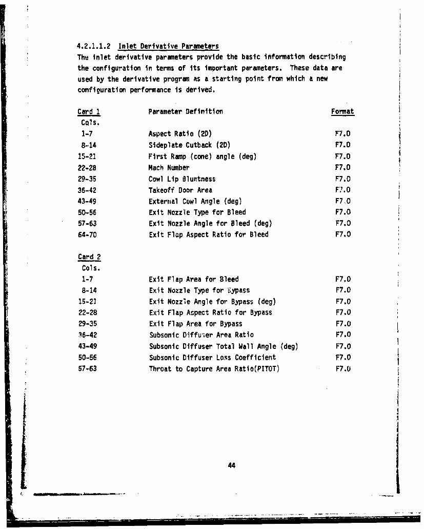
4.2.1.1.2 Inlet Derivative Parameters
The inlet derivative parameters provide the basic information describing
the configuration in terms of its important parameters. These data are
used by the derivative program as a starting point from which a new
configuration performance is derived.
Card 1 Parameter Definition Format
CQIs.
1-7 Aspect Ratio (2D) F7.0
8-14 Sideplate Cutback (2D) F7.0
15-21 First Ramp (cone) angle (deg) F7.0
22-28 Mach Number F7.0
29-35 Cowl Lip Bluntness F7.0
36-42 Takeoff Door Area F7.0
43-49 Externlal Cowl Angle (deg) F7,0
50-56 Exit Nozzle Type for Bleed F7.0
57-63 Exit Nozzle Angle for Bleed (deg) F7.0
64-70 Exit Flop Aspect Ratio for Bleed F7.0
Card 2
Cols.
1-7 Exit Flap Area for Bleed F7.0
8-14 Exit Nozzle Type for bypass F7.0
15-21 Exit Nozzle Angle for Bypass (deg) F7.0
22-28 Exit Flap Aspect Ratio for Bypass F7.0
29-35 Exit Flap Area for Bypass F7.0
36-42 Subsonic Diffuw;er Area Ratio F7.0
43-49 Subsonic Diffuser Total Wall Angle (deg) F7.0
50-56 Subsonic Diffuser Loss Coefficient F7.0
57-63 Throat to Capture Area Ratio(PITOT) F7.0
I
44I
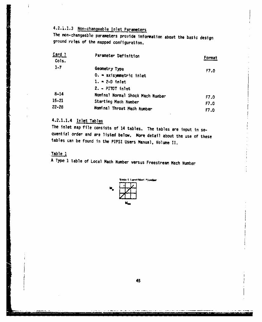
4.2.1.1,3 Non-changeable Inlet ParametersThe non-changeable parameters provide information about the basic designground rt-les of the mapped configuration.
Card I Parameter Definition FormatCols.
1-7 Geometry Type F7.0
0. - •axis.uetr!c inlet1. - 2-D inlet2. - PITOT inlet
8-14 Nominal Normal Shock Mach Nwnber F7.015-21 Starting Mach Number F7.022-28 Nominal Throat Mach Number F7.0
4.2.1.1.4 Inlet TablesThe inlet map file consists of 14 tables. The tables are input in se-quential order and are listed below. More detail about the use of thesetables can be found in the PIPSI Users Manual, Volume II.
Table 1A Type 1 table of Local Mach Number versus Freestream Mach Number
i4I4
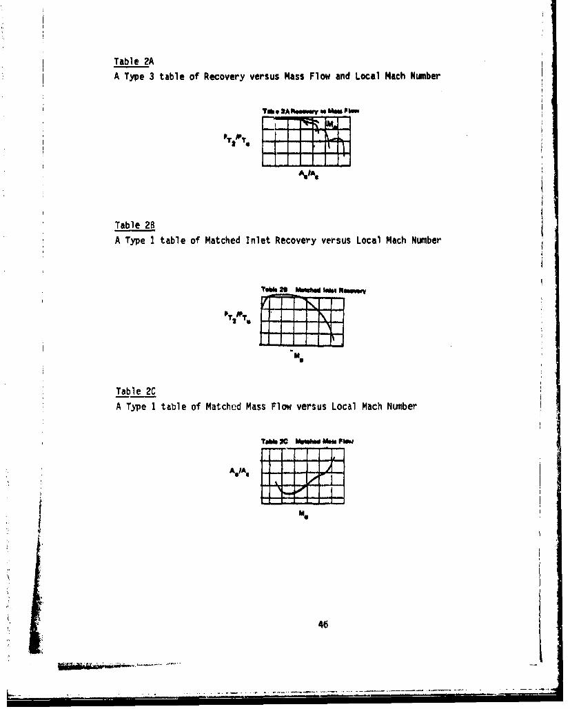
Table 2A
A Type 3 table of Recovery versus Mass Flow and Local Mach Number
Tb 2Aft.wew w MW Pli
PT 2T PI I I' i
A,
Table 2B
A Type I table of Matched Inlet Recovery versus Local Mach Number
TN23 MweN iN4 Mewmmy
Table 2C
A Type 1 table of Matched Mass Flow versus Local Mach Number
Tebb X MiW" V" FNW
Me
46
.. -- -- .-

Table 2DA Type 1 table of Buzz Limit versus Local Mach Number
T"i 10 auua-LMbIk
-1-1A I T-1-i
MO
Table 2E
A Type I table of Distortion Limit versus Local Mach Number
rlo to o5wmDk wsm LUmh
A IA
Me
Table 3
A Type 3 table of Spillage Drag versus Inlet Supply ratio and Local Mach
number
/ IA*
Table 3A
A Type 1 table of Reference Spillage Drag versus Local Mach Number
Til IA RuiW til 01wi
U II
M7
• 47
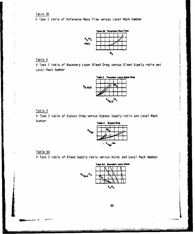
Table 3B
A Type I table of Reference Mass Flow versus Local Mach Number
'rbe~bw Oli telerm0 MWIFIow
AV M IS /Avu 4a h
A*IAOIJt11
Table 4
A Type 2 table of Boundary Layer Bleed Drag versus Bleed Supply ratio and
Local Mach Number
TOW 4 fteyndery Laym Blee OM
ACI~uAIc
A IAOBLC
Table 5A Type 2 table of Bypass Drag versus Bypass Supply ratio and Local Mach
N u m b e r T abl 1 6 " 0 0 b r
CO ~ I MI I
C091
*A OWAm
Table 6A
A Type 3 table of Bleed Supply ratio versus Ao/Ac and Local Mach Number
Table $A louaroYLOyWlBMWAOBLC /A a lw
A 0 AVIA-
48

Table 6B
A Type 1 table of Hatched Boundary Layer Bleed ratio versus Local Mach
NumberT?1 m "O"W feuwyev Low Owd
Table 7
A Type 3 table of Bypass ratio versus Engine Supply ratio and Local Mach
NumberTak r*ONm MM Fbw
Table 8
This is an optional type 1 table of reference recovery factor versus free
streat Mach number.1ab" I R~ftwwn Pe~ moa"eV
The derivative procedure program does not perform any oper'ations on this
table. It just transfers it along to the TAPEI output file for PIPSI
us age.
49
................
4.2.1.2 Afterbody file (TAPE 52)
This disk file consists of five separate sections
(2) Afterbody Title Card atr
(2) Afterbody Derivative Parameteds
(3) Afterbody Location versus Area Curves
(4) Non-changeable Afterbody Parameters
(5) Afterbody Drag Table
Figure 7 is an example of a typical afterbody file.
4.2.1.2.1 Afterbody Title Card
An 80-character title card must be the first card of the afterbody file.It is read with an A format and is printed as a heading on the output
data.
4.2.1.2.2 Afterbody Derivative Parameters
The afterbody derivative parameters provide the basic information de-
scribing the configuration in terms of Its important parameters. Thesedata are used by the derivative program as a starting point from which a
new configuration performance is derived.
Card I Parameter Definition Format
Cols.
1-7 Nozzle Static Pressure Ratio F7.0
8-14 Tail Fin Configurations (0., 1. or 2) F7.015-21 Tail Fin Angle (deg) F7.0
22-28 Tail Fin Fore-and-Aft Location Ratio F7.0
29-35 Base Area Ratio F7.0
4.2.1.2.3 Afterbody Location Versus Area Curves
The area curves are used to calculate the IMST parameter which is the.
basic afterbody drag correlation parameter. For each A1O/A9 curve iiD the
C0 table, there corresponds a nozzle aftblody area versus location
ditribution.
50
m~iwAN~m•-•S...... . . ... . -_L•,,•__. . .' -• •

CD2R INPUT MAP1.0 2.0 0. .1736 Do
7o 7. 7. 7, 7.b37. 700. 760. Ev•. 920o 0,. 676.-44-.5-"15 .... 36-- .. 31-..25- 2 0 20.5637a 7C00. 760. 80C. S20. 830. 876."44.5 41,5 36, 31. 2. 20, 1J'F,.4
44 .5 41.5 36. 31. 25. 20.5 13,39637. 70r. 760. 600. b20. L30. 876.
---44 .5-----4 1.5--.36., -.... 31 -. 25.. .,20.5 6,92637. 700. 760. e 0. 0 0. r ,"30. 876.4ý ,5 41,5 36 a •1, 25, 2 L.5 fie
* .... I. •--'2.. ....-.- - . ..--..... .. ..
TABLEABB. 5.2.18 2.50 3.33 5,. 7 o 43. 4 -. 9 - ... ,13 . - 1.4 1.6 2.0 2.3.037 .E37 .096 ,04 .065 .L .D45 .wD42.04 O .P48 .107 .09,5 .C72 .063 .C53 .CA 8-.... ---. 0(.C -4 .1 . ... 1,*. .j,4 .(81 .066 .06
S075 .075 .i 1 .I•c .12 .103 C.L45 ."77s08B3 OOB• *226- *20 014E, W2 012 .1LO OC09
Figure 7,. Afterbody File Exwple
51
Card 1 Format
Cols.1-7 Number of Curves F7.0
Card 2 Number of Points/Curve FormatCols.1-7 No. Points for Curve 1 F7.0B-14 No. Points for Curve 2 F7.0
64-70 No. Points for Curve 10 F7.0
Card 3 Curve 1 Location Values (in) Format
Cols.1-7 X F7.08-14 x2 F7.0
64-70 X10 F7.0
Card 4 Curve 2 Area Values (Sq. Ft.)Cols.1-7 A1 F7.0
8-14 A2 F7.0
64-70 A10 F7.0
Etc. for the rest of the Area Ratios in CD TableS. AS
4.2.1.2.4 Non-changeable Afterbody ParametersThe non-changeable afterbody parameters provide additional basic informa-.tion describing the configuration and its Important parameters.
"52

Card 1 Other Parameters FormatCols.1-7 Geometry Type F7.0
0. axis3ymetric1. 2-D
8-14 Afterbody Type F7.0 *
1. - CD Axlsummetric Single Nozzle2. - CD Axisymetric Dual Nozzle
3. a CD 2-0 Single Nozzle4. a CD 2-D Dual NozzleS. - Plug Axli.,,mietric Single Nozzle6. v Plug Axtsymmetrtc Dual Nozzle7. - Wedge 2-D Single Nozzle
8. w Wedge 2-0 Dual Nozzle
4.2.1.2.5 Afterbodi Drag TableThe afterbody drag table is a Type 2 table of Afterbody Drag versus
A1O/A9 and local Mach Number
The same table format Is used for both ound ad two-dinsional nozzles;
however, the afterbody drag coefficient in the input table for the two-dimensional nozzle is defined differently from that for the round nozzleinput. These coefficients are defined as follows:
S3
T • TT
•'i-T•'i 7K mAi• -- • T9m mm%
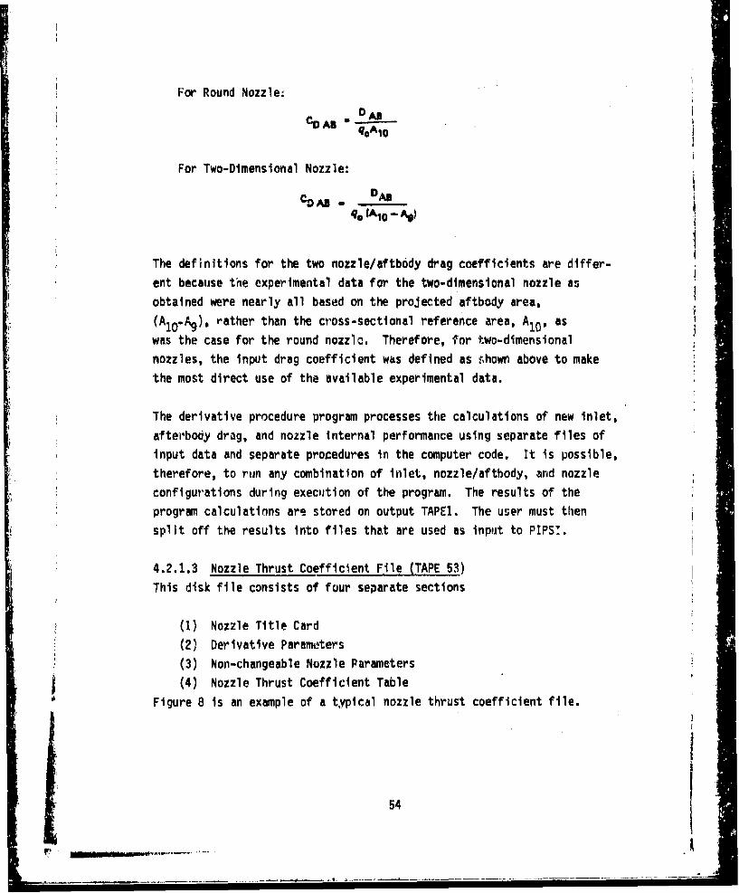
For Round Nozzle:
%AB
For Two-Dimensional Nozzle:
90 1Ao - AS)
The definitions for the two nozzle/aftbody drag coefficients are differ-
ent because the experimental data for the two-dimensional nozzle as
obtained were nearly all based on the projected aftbody area,(A1o-Ag), rather than the cross-sectional reference area, A10, as
was the case for the round nozzle. Therefore, for two-dimensional
nozzles, the input drag coefficient was defined as shown above to make
the most direct use of the available experimental data.
The derivative procedure program processes the calculations of new inlet,
afterbody drag, and nozzle internal performance using separate files ofinput data and separate procedures in the computer code. It is possible,
therefore, to run any combination of inlet, nozzle/aftbody, and nozzle
configurations during execuition of the program. The results of the
program calculations are stored on output TAPEl. The user must then
split off the results into files that are used as input to PIPS1.
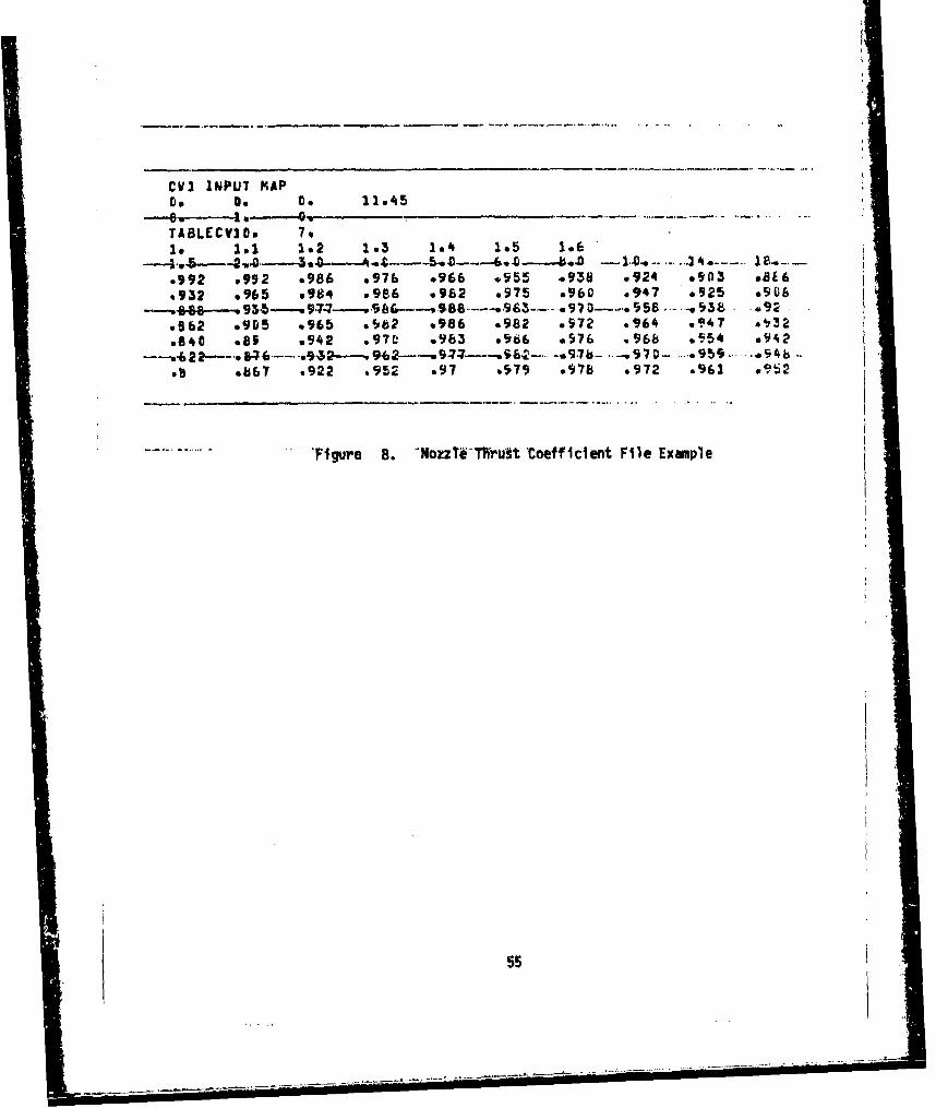
4.2.1.3 Nozzle Thrust Coefficient File (TAPE 53)This disk file consists of four separate sections
(1) Nozzle Title Card
(2) Derivative Parameters
(3) Non-changeable Nozzle Parameters(4) Nozzle Thrust Coefficient Table
Figure 8 is an example of a typical nozzle thrust coefficient file.
54
- ~ --
____* ~ -- - - - ___-- ----
CVI INPUT MAPto on to 22,45
TABLECVI1o 7.1@ 1.1 1.2 1.3 1.4 1.5 1.6
.992 ,992 ,986 o976 0966 .0955 -938 .924 ,903 ,816•932 .965 98w4 v986 .962 s975 *960 *947 .925 ,906
see 970 - $5 -039 .92.562 .905 ,965 .982 .986 .982 w972 ,964 0.?'7 *t32v840 .65 .942 .97L' .963 0966 o976 .968 .,'54 o942i ---,'6 ;•"-'-' IF; ..... '• • 962• -" 9 -7 -- --, 5 .... * 9.7b- .. -,970- ...... 959 ..... *94b• .
b .5867 .922 .952 .97 .979 .978 .972 .961 0952
T . gure B. -NozzTeT1Vust 'Coefficient File Example
55i
----
4.2.1.3.1 Nozzle Title CardAn 80 character title card mu3t be the first card of the nozzle file. It
is read with an A format and is printed &s a heading on the output data.
4.2.1.3.2 Derivative ParametersThe nozzle/aftbody derivative parameters provide the basic information
* describing the configuration in terms of Its important parmeters. Thesedata are used-by the derivative program as a starting point from which a
new configuration performance is derived.
Card 1 Parameter Definition Format
Cols.
1-7 Plug Half Anghe (deg) F7.0
8-14 Wedge Half Angle (deg) F7.0
* 15-21 Aspect Ratio F7.0
22-28 Divergence Half Angle (deg) F7.0
4.2.1.3.3 Non-changeable Nozzle Parameters
The non-changeable parameters provide information describing the config-
uration in terms of-important basic parameters that were used to derive
the performance maps. They describe the configuration but are not usedin the interactive sessions.
Caro I Parameter Definition Format
Cols.
1-7 Nozzle Type F7.0
I - Round Convergent-Divergent
2 - 2-D Wedge3 w Round Plug4 - 2-D Convergent-Divergent
4.2.1.3.4 Nozzle Thrust Coefficient TableThe format of the table varies depending on whether the user has selected
a round or 2-dimensional nozzle.
56
S• .l,• -•ww•.,,-' " "• _ -• ; : . . • . .. ½ W•m mm mm
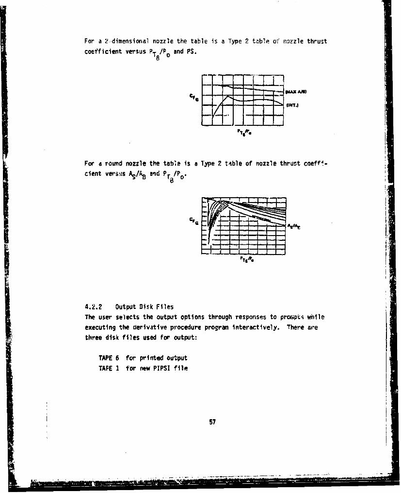
For a 2.dimensional nozzle the table is a Type 2 table of no.zle thrust
coefficient versus PT 8/P and PS.
For a round nozzle the table Is a 1ype 2 t4ble of nozzle thrust coeff.-
dient versues A,/.and P /P
4.2.2 Output Disk Files
The user selects the output options through responses to procapti whileexecuting the derivative procedure program interactively. There are
three disk files used for output:
TAPE 6 for printed output
TAPE 1 for new PIPSI file
57
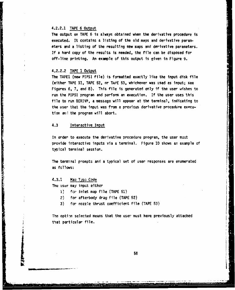
4.2.2.1 TAPE 6 Output
The output on TAPE 6 is always obtained when the derivative procedure is
executed. It contains a listing of the old maps and derivative param-eters and a listing of the resulting new maps and derivative parameters.
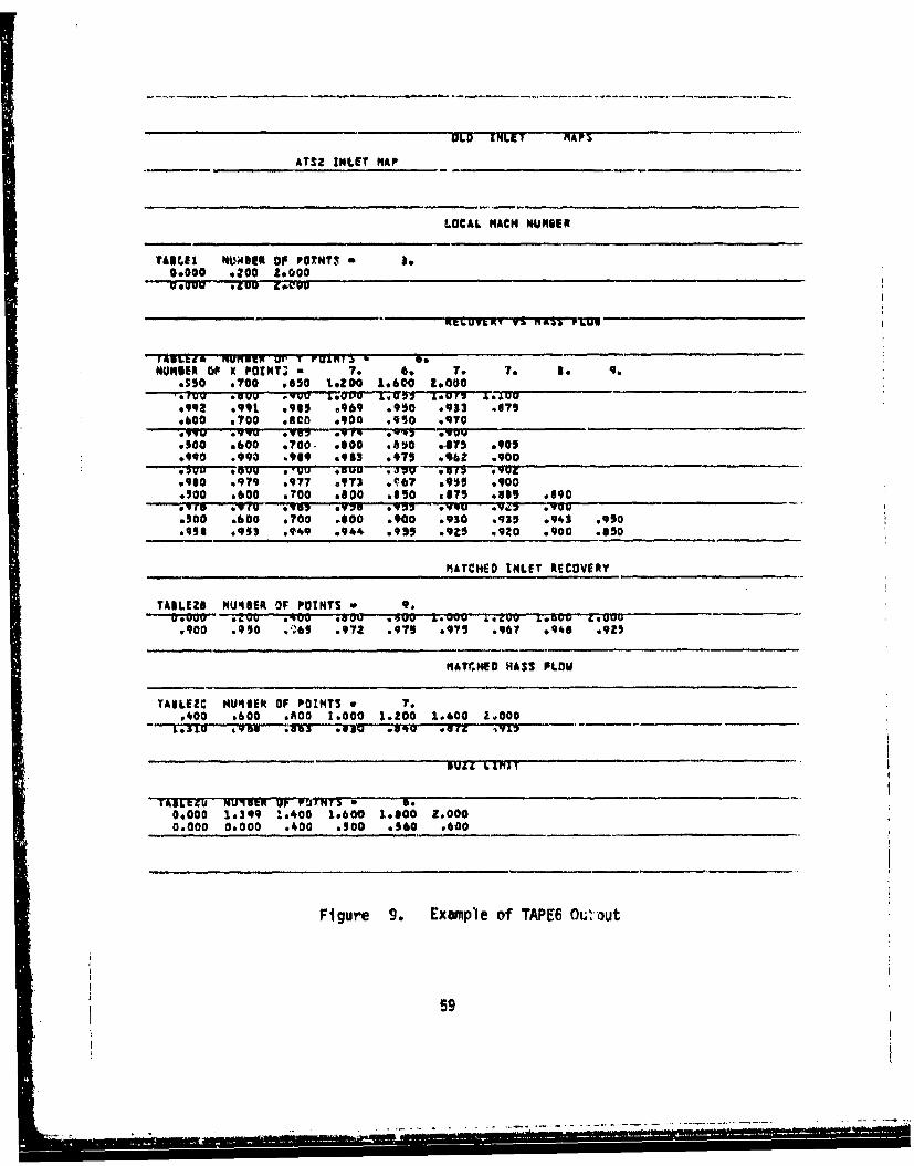
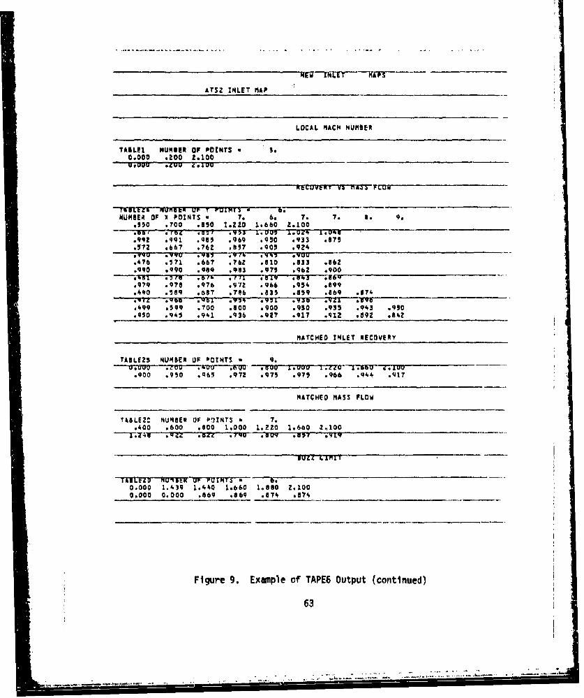
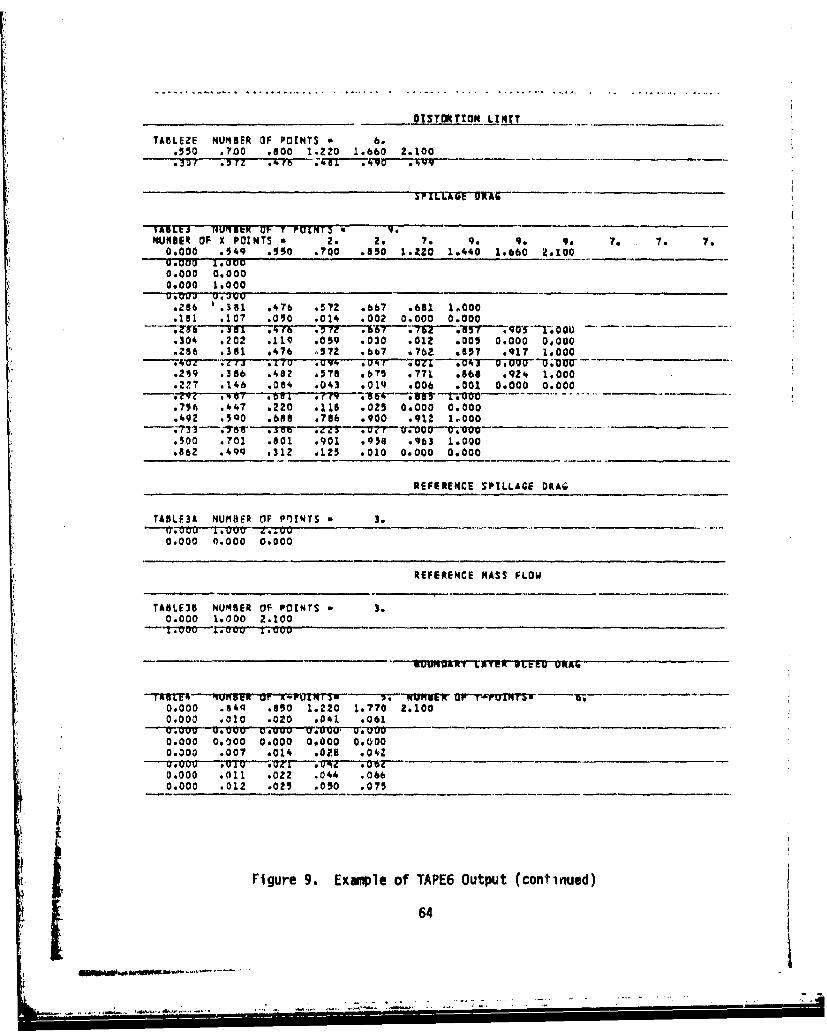
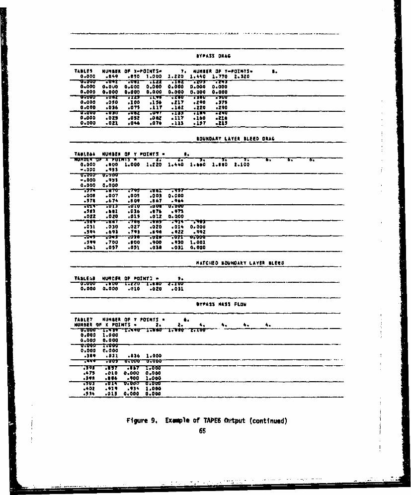
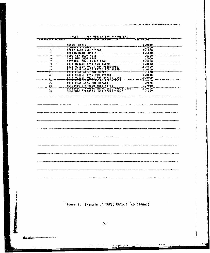
If a hard copy of the results is needed, the file can be disposed foroff-line printing. An example of this output is given in Figure 9.
4.2.2.2 TAPE 1 Output
The TAPE1 (new PIPSI file) is formatted exactly like the input disk file
(either TAPE 51, TAPE 52, or TAPE 53, whichever was used as input; seeFigures 6, 7, and 8). This file is generated only if the user wishes to
run the PIPSI program and perform an execution. If the user uses thisfile to run DERIVP, a message will appear at the terminal, indicating to
the user that the input was from a previous derivative procedure execuw
tion an'! the program will abort.
4.3 Interactive Input
In order to execute the derivative procedure program, the user must
provide interactive inputs via a terminal. Figure 10 shows an example oftypical terminal session.
The terminal prompts and a typical set of user responses are enumerated
as follows:
4.3.1 MaLiYE Ci'dThe user may input either
iV for inlet map file (TAPE 51)
2) for afterbody drag file (TAPE 52)
3) for nozzle thrust coefficient file (TAPE 53)
S"he optiin selected means that the user must have previously attached
that particular file.
5
Ii ,5
iS
OLD INLET MAP'S
£TSZ INLET NAP
LOCAL MACH NUMBER
TAIL11 NUW4SI OF POINTI b e.0.000 ,200 2.000
- oeVU -. IUU •.UU
NUIRER OF X POZNT3 * . 7. 7q..950 7oO0 .650 1.200 1.600 2.000-tYJV SOW~ .VYU 1.000 L. U 7 1.100
•992 .991 .965 .969 .950 0933 .879.600 .700 .800 .900 ,90 .970
.500 .600 0700. .*00 0810 .875 .9059900 .990 .969 .953 .975 .962 .900100U *GOO OO #0 .r ~ 3-50 -73~ 13f .'UL
.960 .979 .977 s9T3 6ý67 0905 .9000900 .600 0700 .00 .850 9875 .886 .090pvto 0970 *Vol .'U15 .972 0,YU *Vzv .900
.500 e600 ,700 .$00 .900 .930 ,915 .943 ,950
.956 .9$3 .949 0944 .99 ,9z5 4920 .900 .650
MATCHED INLET RECOVERY
TABLE28 NU46ER 0O POINTS w 9
.900 .990 w;6) .971 .975 0975 .967 9486 .925
MATCHED HASS FLOW
TAILEZC HU46ER OF POINTS * 7..400 .600 .00 1.000 1.200 1.600 2.0000
1.3111 VON .653 .wUw IWOg 00g tic 79
IABLtZU NUI3R9 OF PDANIT U
0.000 1,399 1.400 1,600 1.000 Z,0000,000 0.000 .400 .900 .560 .600
Figure 9. Example of TAPE6 OutlOut
59
IzST7ION LIhIT .....
TABLEZE NUMBER OF POINTS * 6.0950 .700 .800 1.200 1.600 2.000
-"'5L7 -u9T5 '• v'u a4 .9•7. 3
NUMBER OF X POINTS 2 2. 2. 7. 90 . . 7. o. 7.0.000 a949 4390 .000 .*s0 1.200 1*400 16600 29000
'0ou00" 140500.000 0.0000.000 1.000VawU9 U ogu
. 300 :400 -..500 .600 .700 .'r19 1.000
. .1 ,110 .01Z so0s .002 00000 0.000
..sUi .400 0509 Gob' .-rag .500 .11CO .y"V 17m,
.310 .207 612 e062 .032 .015 .005 0.000 0.000
.300 s400 .500 .600 .700 .800 .900 .963 1.000
.4LU . *.u .rD- .U'8 . .020 . 11''O.0UU ".U'o
.300 .400 .500 .600 ..00 .100 .900 .91$ 1.000
.300 .360 .240 .10 .006 608S .014 0.000 00000
.30,U .vu .fu7 48u0 -beer "'Q . I a IOoN,730 *437 0110 .110 .022 0.000 0.000
.500 .00 .700 .600 OV15 .920 1.0000
.500 .?00 .800 *900 .957 .962 1.000
.640 .460 .296 .11 ,010 0.000 0.000
REFERENCE SPILLAGE ORAG
TAILE3A NUMBER OF POINTS a 3.
0.000 0.000 0.000
REFERENCE MASS FLOW
TAILE13 NUNIER OF POINTS I*0*000 1.000 2.000
X a O0 .100v .A0 U .0 DO00P.0 UUJJNIST tAT9K BLEED 1P&Ar
Tr4511% HIunuq OF r-POuLuIVIS go 'iUNWE up vrUTHISM *a0,000 8*94 .850 1.200 1.700 7.0000.000 .010 0020 .040 .060u.SuuU U.vw uwuuu VOuuu' uuuu0.000 0.000 0.000 0.000 0.0000.000 .007 .014 .OZ5 .042
0,000 .011 .022 .044 .0660.000 .013 .026 .032 .076
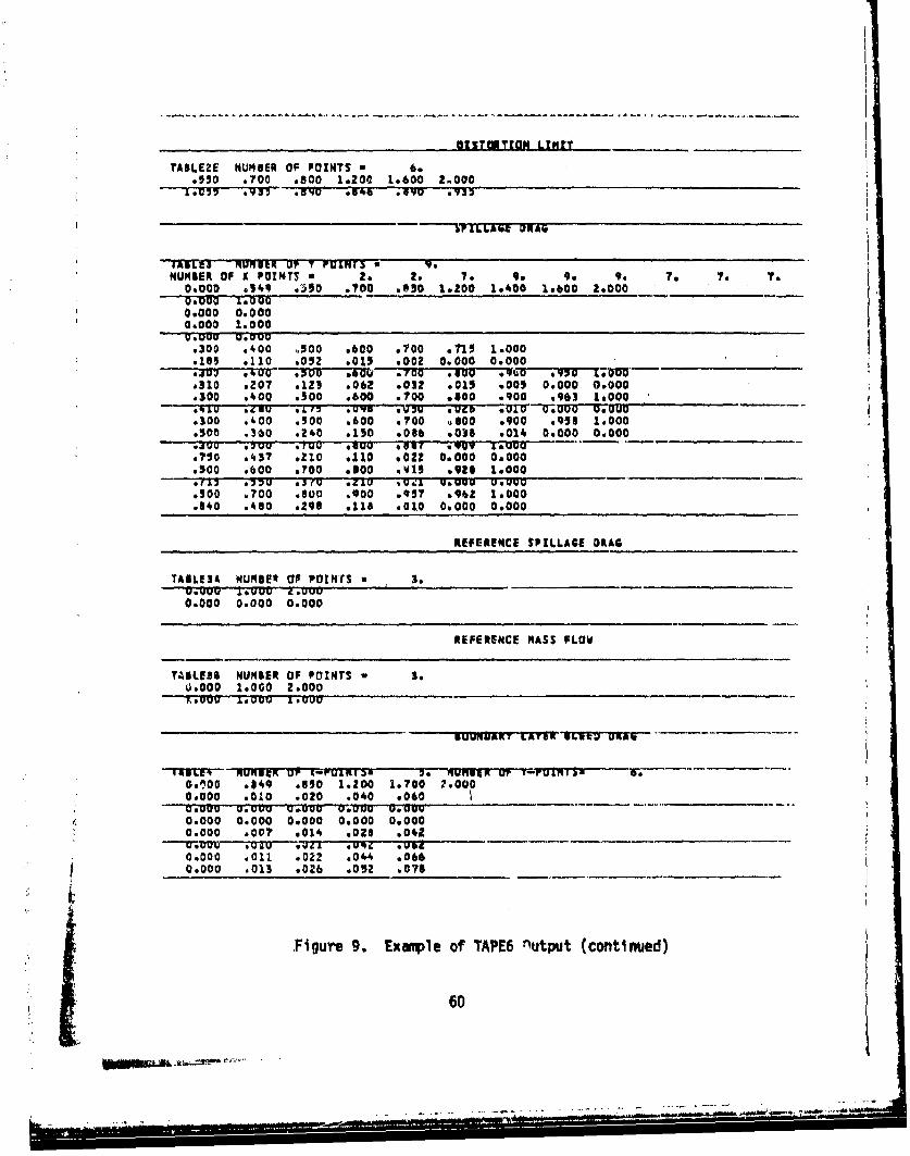
.Figure 9. Example of TAPE6 nutput (continued)
60iU

BYPASS ORAG
TABLES NUMBER OF I-POWNTSw 7. NUMBER or Y-POIwYIs ,.0.000 .849 .O50 1.000 1.200 1.400 1.?00 .O200gt--Uug Ov•v UOOU" Me *Lou'J 410 O•.'op
0.000 0.000 0o000 0.000 0.000 0.600 000000.000 0.000 0.000 0.000 0.000 0.000 0.000
• ,•6• * ~.~ ,• . ,'.u •u .u
D0O00 .050 .100 .156 .21? *.ZqO ,3?!0.000 .036 e071 .117 .162 .220 .290
0.000 .025 .052 .DO1 0116 .160 .2160.000 .020 .045 .074 .110 .153 .210
BOUNDARY LAYER BLEED DRAG
TABLEbA NUMBER OF Y POINTS s o.
0.000 .OO 1.000 1.1200 1.400 1.600 1.300 2.0000.000 1.000
0.000 1.0000,000 0.000
sawu .70u .83A 09100 16000
.O00 .00? .005 .003 0.000
.600 .700 .840 .900 10000
.600 @'P00 ,59 .900 1.0000
.022 .020 .015 .012 0.000
.030 .029 .026 .020 4014 0.000
.603 .o00 .800 .906 .930 1.0000"0044''•. -;O'Z Vr U.03 ."w zlJ-.-0--V-'T-'Vot'3
.600 .700 .o00 4900 .930 1*000
.060 .016 .000 .017 .030 0.0000 _-
MATCHED BOUNDARY LAYER BLEED
YTALE6B NUIBER OF POINTS 5.O
0.000 0.000 .010 .020 .030
Figure 9. Example of TAPE6 Output (continued)
61
- ...w /' '
BYPASS MASS FLOW
TABLE? NUMBER OF Y PaZNTS * 6NUMBER OF X POINTS - Z. Z. 4, 4, 4. 4.
V. U12 O. Prv I.V I.Quv Leai &*UUU0.000 1.0000.000 0.000
00000 0.000.400 *.654 085q 1.000
.;8l U2 V.Uuu U*UUU
--- '?J)d---;'i•z '-.sez i;o~o.483 .010 0.000 0.000.400 *aqZ .906 19000
.400 4915 .930 1.000
.522 .315 0.000 0.000
INLET MAP OERrVATIVE PARAMETERS,AAR-V-ItK qur tA'R UR ttIK VrFTIN-rTTO ULU VALUU
1 ASPECT RATIO 1.00005~L~tFLAit (;UTISAV. -Kz
3 FIRST RAM,ý ANGLE(OEG) 7.20004 DESIGN NACNH NUMBR 2.0000
13 COWL LIF ?UNT'Fl. .UUU6 TAKE OFF OOOR AREA .20007 EXTERNAL COWL ANGLE(OEG) .17.o000
I F T FIUMLE liPtr PUS mLE'f,'r. IiAimU9 FXII NOZZLE ANGLE FOR ILEGEDIOUG 13.0000
10 EXIT FLAP ASPECT RATIO FOR %LEED 2.0000-EXIT t=J'I PL&P AFel PUXF lt:ttV :&UU
12 EXIT NOZZLE TYPE FORb.YPASS 1.000013 EXIT NOZZLE ANGLE FOR BYPASS(BEG) 1000M40
is EXIT FLAP AREA FOR IYPASS .300016 SUBSONIC DIFFUSER AReA RATIO 1.9000if 5• s SUMq"-' U' I. I.. P U'S t F9 1 A L" VjT,'-"AN'V1L-E rt M9'T '10 ,0000
le SUBSONIC DIFFUSER LOSS COEFFICIENT .1000
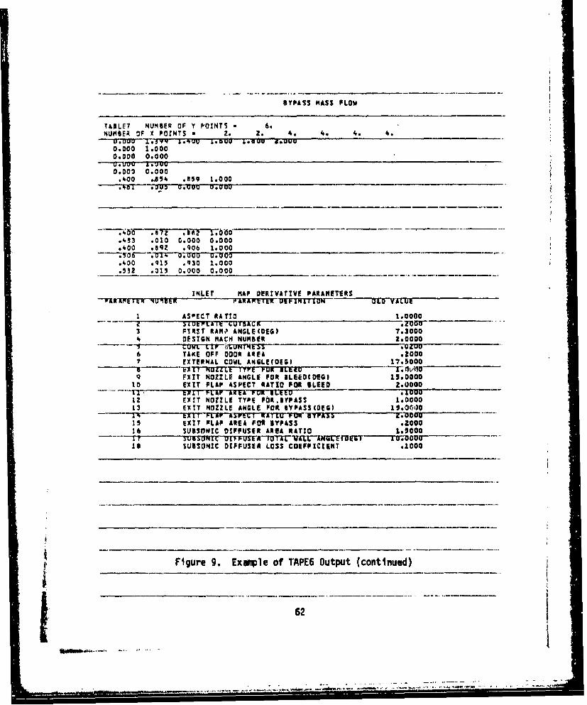
Figure 9. Example of TAPE6 Output (continued)
62
ATSZ INLET MAP
LOCAL MACH NUMBER
TAILEI NUMBER OF POINTS * 3.
0.000 .200 2.100_____________Mawp .200 2.400
CI.UEVKT VS nAS rC•ui
%RCCi A RUM,, sOtRlC UP T K•]rURTS 6- J
MUMBER OF X POINTS , 7. 6. 7. 7. 8. 9..050 0700 .50 1.220 1.660 2.100
.992 .991 .900 ,969 .950 .933 ,675
.57Z .667 676t all? ,OJ90 .924
.476 .571 .667 .76Z .510 a833 .86z
.990 ,090 .989 0903 .979 096Z .900g "' *.7re 0rp" b 0 .(7 1 .519 .oUl.3 -.- 6'979 .97? .976 .972 .966 .954 .699o490 .599 .087 .746 .835 .859 .869 .$174
o499 .599 .700 .600 0900 o930 .935 .943 .990.950 0945 .941 .936 .927 .917 .912 .89z .942
MATCHED INLET RECOVERY
TABLE25 NUMBER OF POTNTS * 9.MUDDu ..u IVV .E0O~*; .000 &.VD0u L. .6 Z .0 I76U at).900 .950 Qqb6 .972 .975 .97T .966 .944 .917
MATCHED MASS PLOW
TA&LE2t NUMBER OF POINTS 7..400 .600 .800 1,000 1,220 1.660 2.100
0.000 1.4]q 1.440 Lob&0 1.860 2.1000.000 0.000 .869 .069 .674 .874
Figure 9. Example of TAPE6 Output (continued)
63
-". . .. ........ .. .. ."...,.. . -...-.- - .. .• ••, ".;
DISYTORTION LZIMT_
TABLEZE NUMBER OF POINTS * 6..550 .700 .000 1.220 1.660 2.100
TIALts NUM¶BER U(t T VULNTI RNUMBER OF X POINTS w 2. 2. 7. 9* 9. 9. 7. 7. 7.
0.000 .149 0550 .700 .8so IZ.O 1.440 1.660 *1O00U. 000 1'vo0.000 0.0000.000 1.0000
s286 .381 .476 .572 9b67 .681 1.000.151 .107 .010 .014 .002 0.000 0.000
-ýL5v * .30 rii7b T7 .67 767-3.57; 0 T o,304 .202 .110• 059 .030 .012 .005 0.000 0#000.286 .181 ,476 p572 .667 076Z .857 .917 1,000
.249 .386 o48? ,57 0.675 .771 .868 v924 1.000
.227 ,146 .004 a043 .019 .006 .001 0.000 0.00002 ..... .00 a '" ,'V¥ ,1.76•4-'--ý311V-+'0"0......
s756 .447 .220 .11l ,025 0.000 0.000.492 .500 .688 ,786 .900 ,91z 1.000
-.-T31 '76e .33B .4Z3 M -V.Ooo-o0-~- v 0-- 000-.500 .701 .601 0901 .956 .963 1.000.862 .494 0312 .12$ • 010 0.000 0.000
REFERENCE SPILLAGE DRKA _
TABLE3A NUMBER OF P'NTS - 3.
0.000 0.000 0.000
REFERENCE MASS FLOW
TASLE36 NUMBER OF POINTS 3.0.000 1.000 2.100
-- :i.O 0 +i,• 1.000&
-rTXVM4 'qu nnw ur-""Z 114!U 1- . WUnWVEW U7.SITTWTSTN10.000 .84q .0ý0 1.220 1*770 Z*1000.000 .010 .020 .041 .061
0.000 0,000 0.000 0.000 0.0000.000 .007 .014 ,028 .042u.Ou 'u "" ,ucI" .0• .t -
0.000 .011 .022 .044 .0660.000 .012 .025 .050 .075
Figure 9. Example of TAPE6 Output (continued)
64
I-II I I --.- -.
BYPASS DRAG
TABLES NUNIBER OF X-POINTS. T7 NUMBER OF Y-POINTS. so0.000 .849 .850 1.000 1.20 1.440 1.770 2,5200.u00 .04L .uu0 E&Z .IUCz o'L11 *LOs0.000 0.OUO 00000 0.000 00.000 0.0000.000 0.000 0.000 0.000 0.000 0.000 0.000
0.000 *050 .100 .15• .21? .290 .3750.000 .006 ,075 .117 .162 .220 .290
0.000 .025 052 .012 .217 .160 .2100.000 .0.1 .046 .07 .113 Olt? .Ot1s
1OUNDLRY LAYER ILEED DRAG
TA&LE0A NUMSER OF Y POINTS 8 6.NON51c1 ur A POIWIS V go go is 26 GO* 0 W
0.000 .100 1.000 1.ZZO 1.440 1.000 1.ll0 2,100-. 000 .953
-. 000 .9530.000 0.000
0~j .uru5 .197 lotl vm#,.008 .007 .009 .003 0.000.573 .674 .809 .867 ,964
.583 .611 .036 o176 .973
.022 .020 .015 .012 0.4009269 .$or revU .107 *.91- OT8.011 .030 .027 ,020 a014 09000.594 0693 7,73 .698 .922 .992Owww ,014 .0V2 0040 sud4 06000V
0599 0700 .300 .900 .930 16001•001 .05?• 051 *034 .031 0.000
MATC490 IOUNOARY LAYER ILEE"
TASLE.IS NUMCIA OF POINT - 5. So-. 9.000 VOVI L.Zza 1%.6501 2.1100
0.000 0.000 .010 .020 .031
DYPASS MASS FLOW
TABLE? NUMBER OF y POINTS 6 0.NURSER OF x POINTS 2 2. 2. 4. 4. 4. 4e
W.uuV &.Nov 1"q+' *,C. AL.UV D.OU.0.000 1.0000.000 0.000
0.000 0.000.36* .631 .136 1.000
" .44 o~u;• Uu.uu u .O u U@O~
S... .157 .867 1#000.475 .010 0.000 0.0001.98 .*6f .900 1.0000
.402 .4419 034 1.000"*534 sol 0.000 0.0000
Figure 9. Exalm e of TAPE6 Watput (continued)65
INLET NAP DERIVATIVE PARAMETERS"A•kAR RNv• R lUPrix KAeIe at,•ntH NItPITIIOEIW-vAru!-
ASPECT RATIO _1.00000
3 FIRST RAMP ANGLE(PEG) 7o10004 DESIGN MACH NUMBER 2.1000
LUWL CZ L ORT" .0200~L6 TAKE OFF DOOR AREA .20CO7 EXTERNAL COWL ANGLECIEGI I7.5O00
tAAT 1TW 0•7Zt-TW ID-BLE"D 10,0000EXIT NOZZLE ANGLE FOR IBLEDIDEG) 1.5*0000
10 EXIT FLAP ASPECT RATIO FOR BLEED 2.0000- -TI' t;Xrr-TI F* I. APIWT]FO tTL . r.a0o12 EXIT NOZZLE TYPE FOR BYPASS 1.000011 EXIT NOZZLE ATGLE FOR BYPASS(DEG 15.0000
~~~ -T~TW W~TOIW S - 2.0000-ii EXIT FLAP AREA FOR BYPASS .2000)16 SUBSONIC DIFFUSER AREA RATIO 1.7000
3T0TC'-'7TMF STYR T TrAL- WA CV-k &K ET. Fl; I ;T o00O1.9 SUBSONIC DIFFUSER LOSS COEFFICIENT .1'17
"Figure 9. Example of TAPE6 Output (continued)
66
................................ :,.--
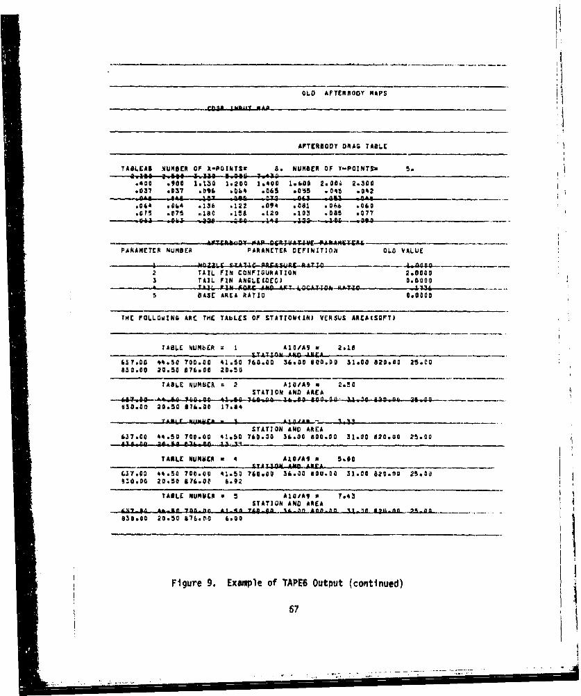
OLD AFTERBODY MAPS
AFTERIODY DRAG TABLE
TABLEAU NMBNER OF X-POINTSX 8. NUMBER OF Y-POINTSM 5.
.400 *900 1%1.30 1.200 1.400 1.600 2.00w 2.300.3,7 .037 .096 vDb4 e065 .845 .045 .042
-10.. _;4v -.. P732 063 W n44-.04 .064 .136 .122 .094 6081 .06.b .060
so?% .075 .180 .1!6 .120 *103 .085 .077
rTCRABQ9* MAP 06AUPXTE INCA~AM6'906I
PAAMAETER NUMBER PARAMETER DEINITION OLO VALUE
v v. - .,,T - rCS41SRf RATIO 400
2 TAIL FIN CONFIGURATION 2.00003 TAIL FIN ANGLECOEG) 000
5 BASE AREA RATIO 000
THE FOLLOWING ARE THIE TAbLES OF STATIOWN(d) VERSUS AREAISQFYI
TABLE NUMbER I AICIA9 w 2.18- IATrI Awfl Iffia
657.00 44*50 700.00 41.50 760.00 36.00 800.00 31.00 820.00 25.00830.00 20.50 876.00 20.50
TABLE NUMSCR =2 AlOiA9 2.50STATION AND AREA
-. 8I:w ei I a 7-6 00 0. am l 7S(6 6600 6JP -t f 0.4-4--l-4. 20 21O27f fl 00930.00 20.50 07&.00 17.84
STATION AND AREA637.00 14450 700.00 41.50 760.00 36.00 800.00 31.00 820.00 25.00
TABLE RUMVER a 4 A101AW 5---.-.LAZA LI JLDA. A irA-
631.00 44.50 700.00 41.501760.00 36.00 800.00 31.00 820.00n 25.00930.00 20.50 676.0v 6.92
TABLE NURSERM a 5 A10IA9 74STATION AND AREA "n
830.00 20.30 576.D0 6.00
Figure 9. Example of TAPE6 Output (continued)
67
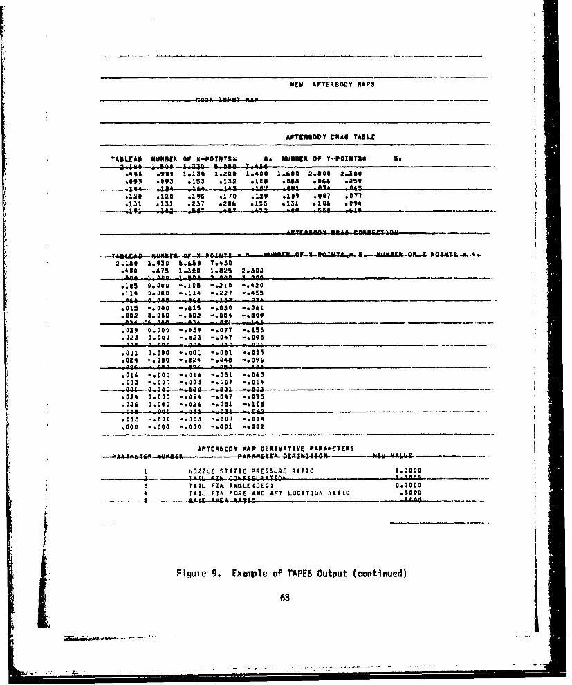
wgw ArTERBODY NAPS
AFTCUBODY DRfAG TABLE
TASLEA8 NUMBER OF X-FOINTSX 8. NUMBER OF V-POINTS8 5.
1.400 .900 1.130 1.200 1.400 1.600 2.000 20300.093 .093 .153 .132 *too .003 .066 0059
9120 .120 .195 .170 .129 .109 .0417 60177
AEI~ NUMltrft or x POINXS- HlUUX -Qlr-9P0WT4.,L~a5..USE.O RG"T.&m-X6.4.2.150 30930 5.1MBg 7.430.400 .675 1.350 1.585 2.300~I a 1.1009 1,A q900 f 2 woo*11(1
.105 0.000 -. 105 -. 210 -. 420
.114 0.000 -. 114 -. 227 -s4!50ndI a-Don .D4 1
6015 -. 000 -. 015 -. 030 -. 061.002 0.000 -. 002 -v004 -w009o"0I "OonalOl -04ie - 14
.039 0.000 -. 039 -. 077 -. 155
.023 0.000 -. 023 -. 047 -e093005w A An. - An& - -j,
.091 0.000 -. 001 -. 001 -. 003&024 -. 000 -. 024 -. 048 -. 096
-12 -. AAA - -2 -*D 05 - 11.Oj-.000 -. 018 -. 031 -. 063
.003 -. 0011 -. 003 .. UQ7 -. 014-----.44 gg --sof 000 Q, -*goo-
.024 0.000 -&024 -. 047 -. 095
.026 0.010 -.026 -*003 -*103 ___
.003 -. 000 -. 003 -. 007 -. 014
.000 -*000 -. 000 -. 001 -. 002
AFTE~bODY NAP DERtIVATIVE PARADNtTCRS________________________________________ ________________vzv liWr~ -N
I NOZZLE STATIC PRESSURE RATIO 1.00(00----------4---1 h N....4~--~- tIF! A0 A N
3 TAIL FIN ANGLECOEG) 0.00004 TAIL FIN FORE AND AFT LOCATION RATIO .3000
Figure g. Example of TAPE6 Output (continued)
68
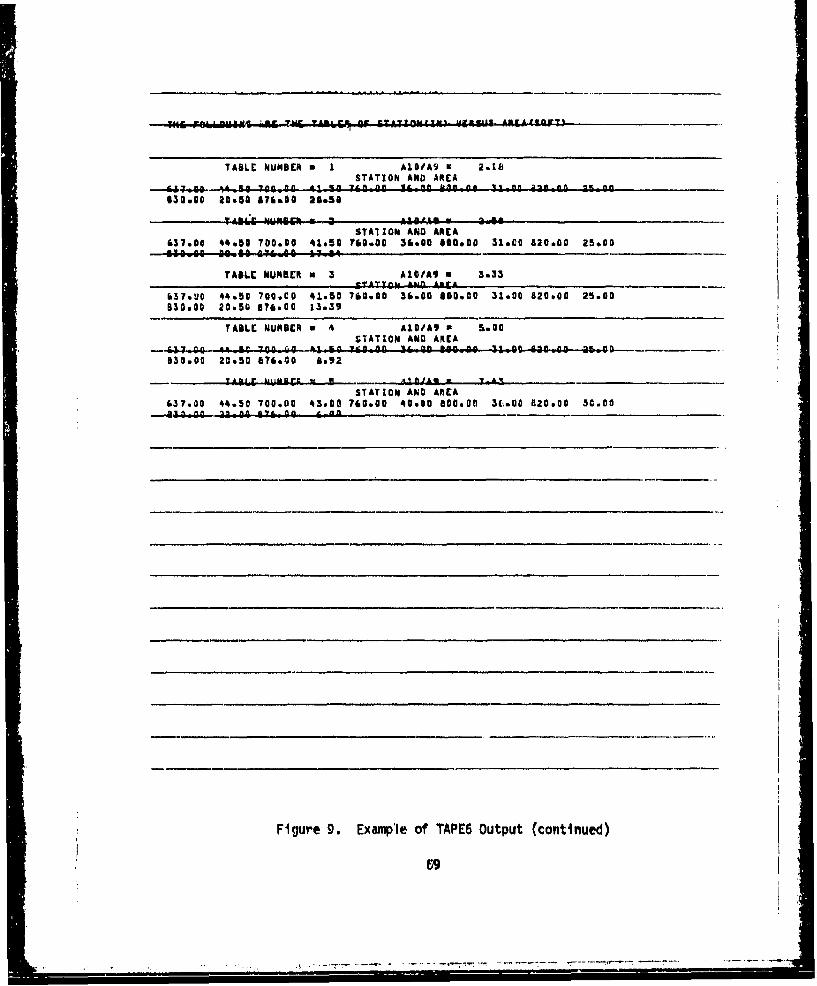
TABLE NUMBER a • A1S/A9 a 2.18STATION AND AREA
Lt•~L- V Ai ••• • n ALM~n I&_-f Kf~n A.A •~ABIT0ig 0 3O0E 700.00 1 "70 01 0 l C-1 Y li O~030.60 20450 &76&00 20&351
STA71ON AND AREA
637.00 44.56 700.00 41.50 780.00 36.00 8000.0 31*00 820.00 25.00
TABLE NUMBER m 3 A1OIA9 a 3.33
837.UO 44.50 700.00 ti.50 780.00 36.00 800.00 31.00 820.00 25.00830.00 20.50 a?6800 13.39
TABLC NUMBER U 4 A1G/A9 1.00STATION AND AREA
- ID 017 KC 3¶I~700 0064Nf flf 1 0 %&MOO too Go 3404 a_,_G 35 08-930•00 20.50 676.00 8692
yA0I lr j A ftJA@ 7 ? __
STATION AND AtEA637.00 44*50 700.00 43.00 760.00 40.00 800.00 U(.00 820.00 30.00
Figure 9. Example of TAPE6 Output (continued)
69
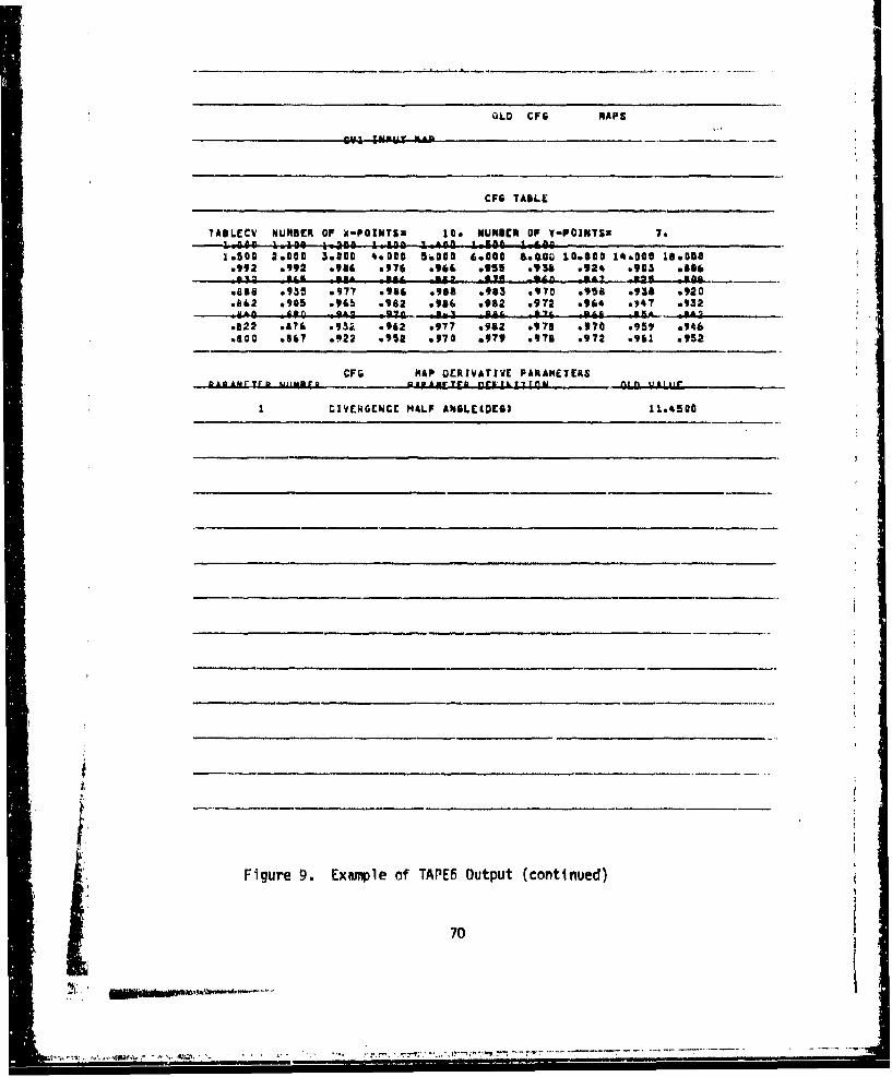
OLO CFG MAPS
CFG TABLE
TABLECV NUMBER OF X-PORNTSm 10. NUMIBE OF V-POINTS" 7.1 saC !oleo 1ýG 300 . 1 1 4It" Sa ,0 o go1.500 2.000 350O 4e8000 5.000 6.000 &a.0It 160000 14.000 18.550
.992 .992 .916 .976 .964 *955 *93S .924 .903 0686-In Kl. A. IS& _am bs9 -84A / SA2- -25 a
.%Gs .935 .977 .946 .,90 .983 .970 .958 .938 .920.h812 .905 .965 .982 .986 e982 .972 .914 v•47 o932
a~ Afth 830 07 -. It CL ftd TL -64----SL. n
.1122 .176 .932 .962 .977 .982 .978 .970 .959 .946
.800 .567 .922 .952 .970 .979 .976 .972 .961 .952
CFG HAP DERIVATIVE PARAMETERSDk.nAM-Trb UiympD .. 418 mrYA _ r ' _ l. ft uIAIr
I DIVERGENCE HALF ANGLE(DOE) 11.8500
i.
Figure 9. Example of TAPE6 Output (continued)
70
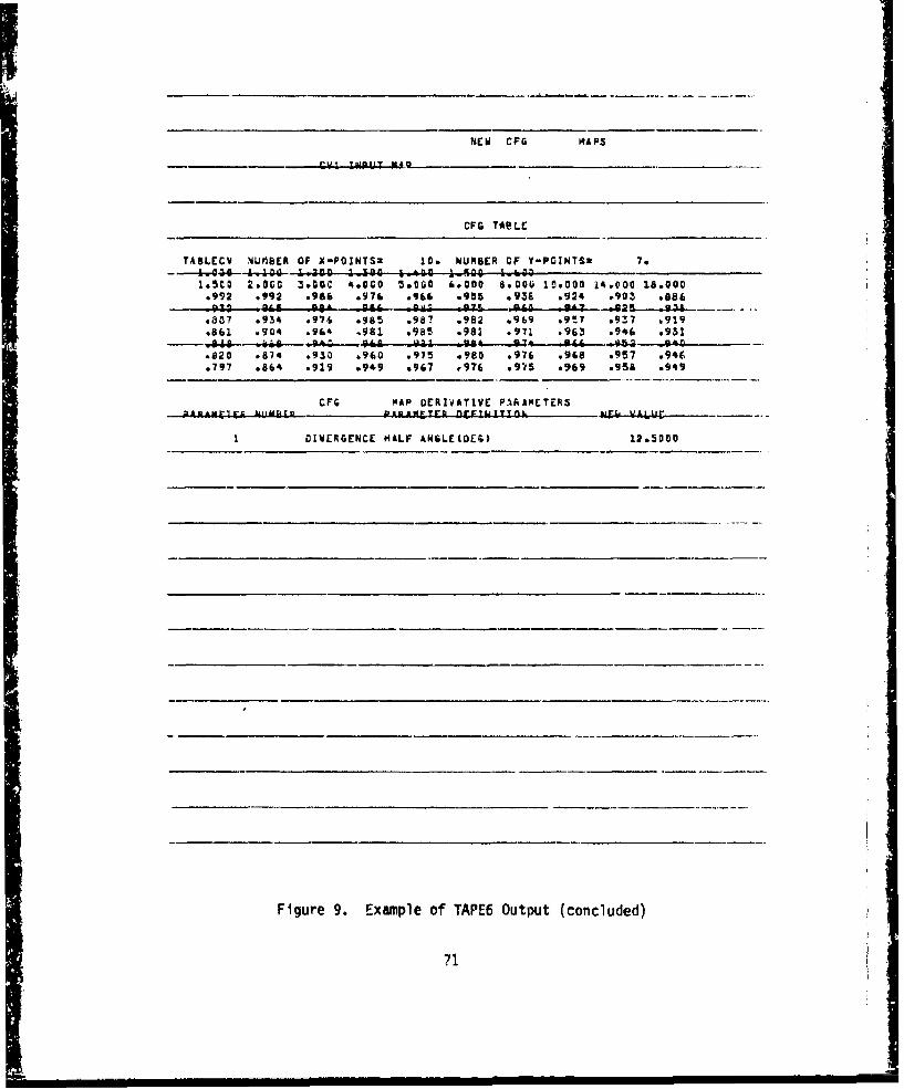
NEW CFG MAPS
CFG TOPLE
TAaLECV SiUfl6R OF X-PO1NTSZ ID& NUMBER OF Y-POINTSz 7.-.--... 44-4-aO I. 30 no0 i ,n i0gg 0 150 wsgv
i05co 20060 3-40C 4.000 5.000 600oo 9*00U ID.000 24.000 18.000.992 .992 .986 .97& .966 .955 .936 .924 *903 .88691 Q-' S46--4A -011 -6.8n L-4GZ.--- .0
.307 .934 0976 .965 .987 .982 .9b9 .9!7 .937 0919
.861 .904 .96' .991 .9815 .981 .971 .963 .946 .931uia6 0. a 8-.83 - .J-.4----------.820 .874 .930 .960 .975 .980 .976 .968 .957 .946.797 .864 .919 .949 s967 r976 .975 .969 .95A .949
CFG MAP DERIVATIVE P~AAMCTERSADANFClr 1U K&A- R1ANANIEND~FINIJTION &NrL UkI-1I1r
I DIWERGENCE MALF ANGLECOMG 12.3000
Figure 9. Example of TAPE6 Output (concluded)
71
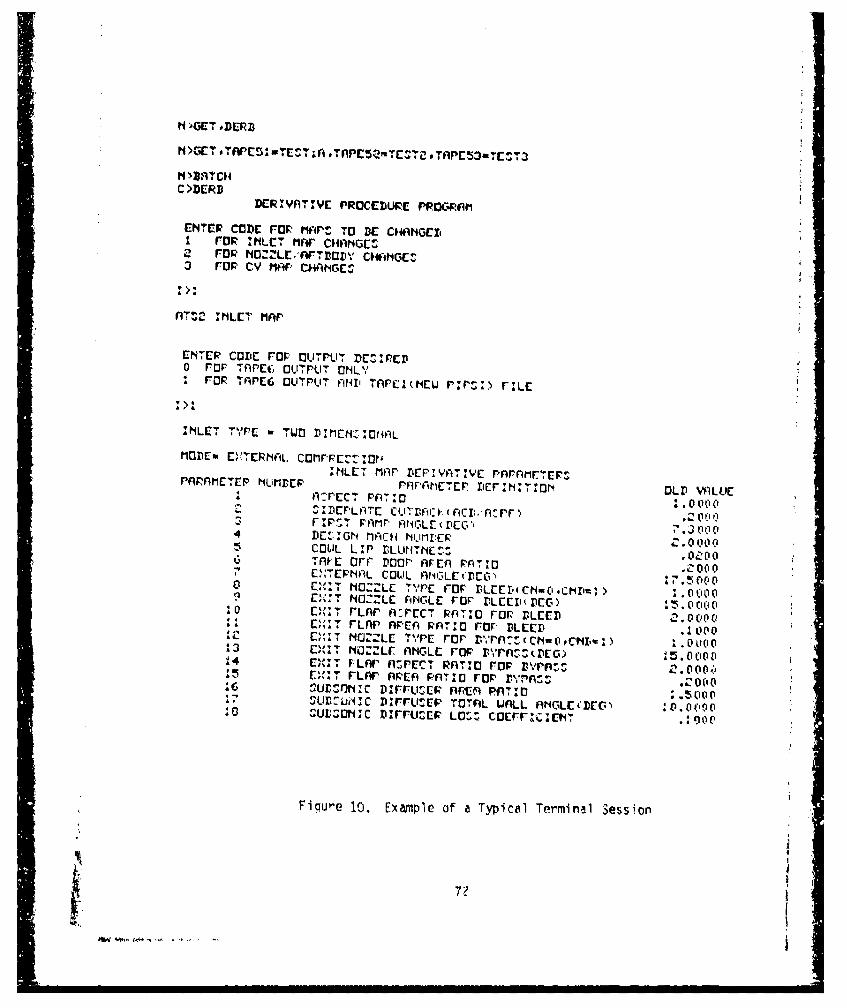
H>GC-ToDCRPZ CT TAC3mET
DCRIYATIVE PROCEDBURE PROPOM~f#ENTCP CODE FOP t1V4P TO BE cI*~IhGCDII rap 'HLETi fir c,4lj;r1Gt2 FOR t1O:ZLC,AnrTDIvY cowimmC'3 rap Cv MArP C1*HAGC-E
nAT, c INLET MAP
ENTET CODE For, ayTPUT DE".PCDo ror TAPEt; OLITPUT DNLY
r oRz TAPrECLOTIPUT AND' TnPC1(tIEw rv: rI
AINLET TI'PE a TIWO flIrENZAIDNAh
lOflEm E,*TERr1-L. CIOMPF.?'I"Z10INLET MiAP r'EP:YAT:VE r'n~rAMCrprPAAMET [P HUriDEP rPrAMETEP IrNIToN OLD IvALLIE
SIflEPLAT c y vcfrv ( riZI: r; ýrrr . 00' Q4D DE:Gh lFlI:H NUrlIEP L0 (I,WsC041L LIP r3LUNTNEZ: .0c0ý0TAnvc Orr~ poor, nFin PTIO .~01 00I ý.;ETPN~inL COU1L ANGLEx(DCG) CP0 C " T NOZZLE Tr'PE FOF' flLCEri'cN-c'.ct~rI. > 00OL'09 C,'I 'T NOcrZLE ANCILE FOP r.LEEI"DEG) 0((10 ~ rLAF' n.:PccT.P'v FAOP BaLEED 2.0C000
I II'&T rLAPnF AEA RATIO Fror BLEED .000C, T NC ZLE T~PE For 00 0~IEllT NO NL -P srlDG1444t E1T. VLfw" nrZPcT RnATo rpO rvrii:zI a115EX: - rLWr AREA, PSATO rcw, rl'nri-.2(
..UDtI1NZC DIFFIURE AREA PfI7AI Q0I.L uD~ui~ic DI-rU:CF TOTnL WALL ANCLUCiDcO:)oo:0 ~ Ur.;ONIC tirrUZEsz LO6: caErrI~c;[NT
Fig~ure 10. Example of a Typical Termiinal Session
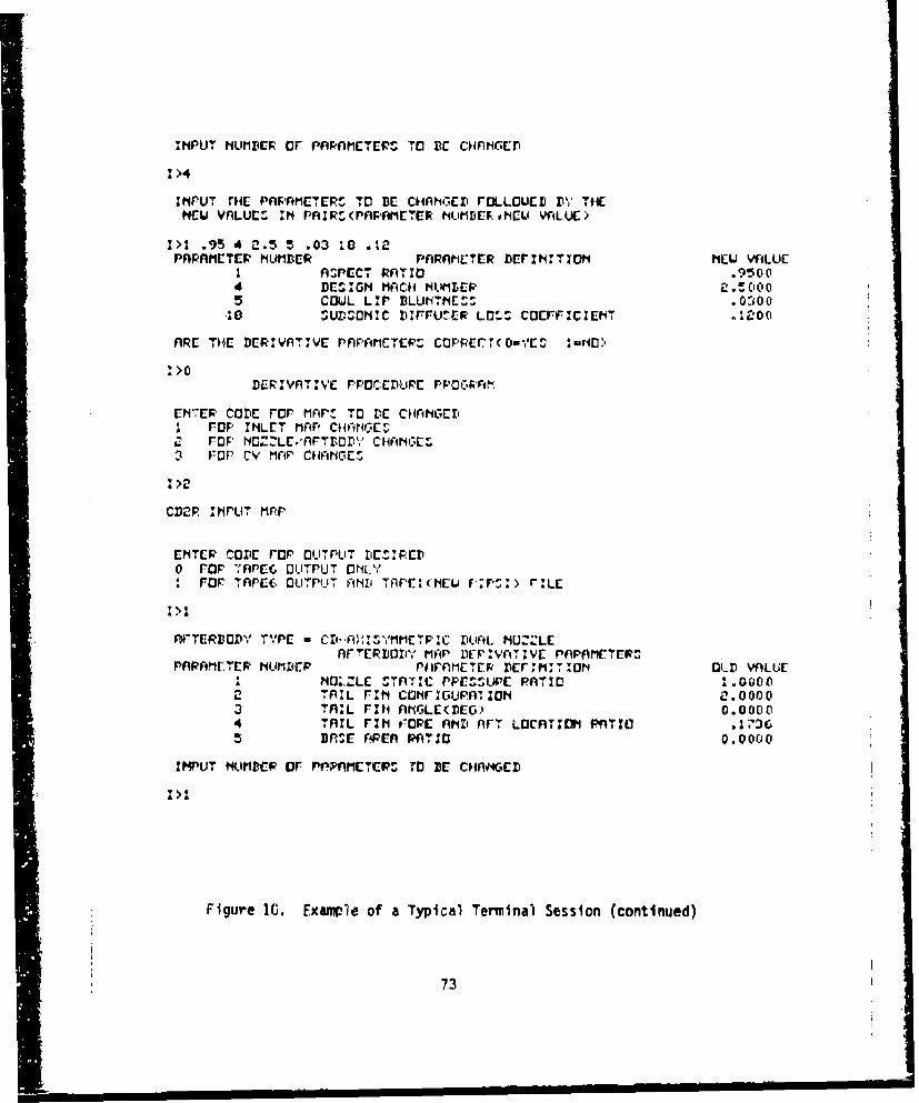
INPUT NU'MBER Or ~~PnHMECTER "1' BE CH4vNcc
1>4
ThPUT T&E PnPAMETERS TO BE CH4ANGED rOLLOUCL D"~ THENIEW YnLUC-S M PýFUF (PAPAMfETCP tIUMD EE~tCL VAILU')'
14>i .95 4 2.5 5 .03 i0 .%zPnPAMIETCF NUMBIER pnRnt#ILtR bDrjlj"ITXOt NLU VA4LUE
I A:;PEC7 RATIO .91-;(104 DMIGt MACH4 HNMLER 2 . 1. (C, 0
5COWL LF' BLLINTHE." .0 0 0*10 ~ SUflOI91C NF'FtER LO1- cocrF.ICIEK ~
ARE ITHE flERIVATIVE PAF'AMETCR. CPPECT(0uVES %"NMD
1>0DERIVAT lYE rpocDtI'UE rP'OCPA
ENT7ER CODE For mnrPl TO DE 01riNGE1'I FOP IN~'LET Mnr' CHANGES
C FOP NO.ZE.'AFr.DBrI',- CHAI.AIiES3 rup CY MnP ClinNES
CD2P AtIPLIT mAp
CNTCR coDE rap OUTýPUIT rIEt.'PCD0 rap -Apcc oUTPUTý ONL'/
PO APCE6 OUTPUTI ANDi (NEitlU rr:r
nFTEPBDYZ T,,r w Cl'-.A I~.I'.IMMETF.C ZIU*.01. N1UZZLEAFr~EPLOri' MAP DVP:VATVE PnPAMrTEFS
PAP(AMFER' riUfDEP PhrF'METEP DOrIiI T:ON OLD VALUEIA NMZLC STnTIC PPEMUPIE PATID1 01.0000
2 -TAIL FIN co~rirGu~mioa L1.00003 TAIL rzti AriGLEDPEG& 0.00004 TAIL r,.ti oPtOP Anii nrT LOCnfl~vOH PqTIIO5 BASE PAREA PATIP 0.00(00
IMPUT t4UMBCP OF NPnME41CTPS TO VE CHAnvOED
I >1
Figure 10. Fxample of a Typical Terminal Session (continued)
73
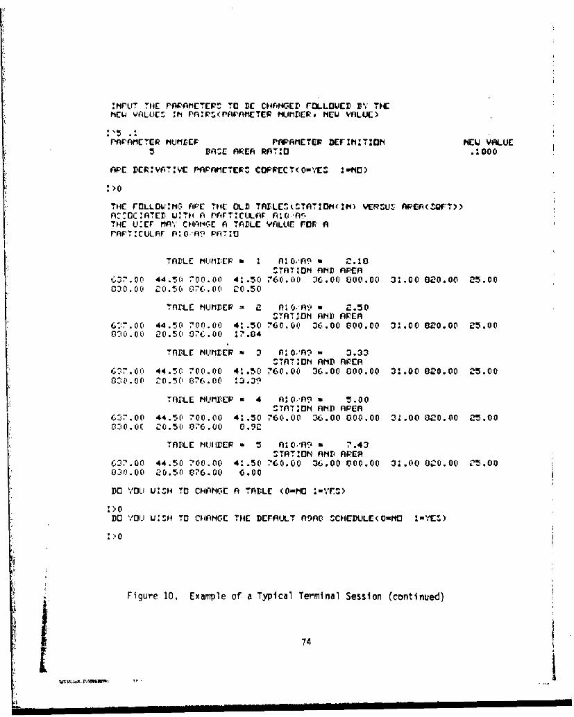
: rLIT H AFMT TO BEr C&HvHtGc FOLLOWED D'.- TMCNEWJ VALLICE :h PMI-.(PAFAIPETE•U M.IER, MELD VALUE)
:'5 .1
PnPAMflETER 4IMLEF PAFAMETCP DcrINtlTIOtl NEW VALUE*.5 DArE AREA RAITO .000
M'E DERV T:YIE PA• AMETER' CCP'PECT(001CS •I&tO)
1>0
THE rOLLO v INO APE THE OL D T K.,LCE,•TATAT' M 'ZIt4 VCER'UZ IEA <(=CFT)>A: ̂ -OCITCED UITH ol rfirTACLLFqr A: 0.A.nTHE u:'r Mn',' 00H-01E A TADLE VAL.IE FOr nPAF•T:C'UL'r n*:O,.*A9 P•4TI'O
STAT ION ANP nFEA.. ,' .Q044.50 700.C01) 4'.5( .6(. 70(. 3x.0 000.00 3...00 020.00 25.00
G30.0 •...• 0 76,•(.00 C0.50,
TADLE HLUMPEP - 2 AA0.A9 u 2.50,MTRTMI9 ANP APEA
6:7.00 4 4 .50 700.60 41.50 760.01. X.00 000.00 31.00 020.00
Z.5.0003.C0'.0 , 20.50 07C.00 41.04
TADLr MI.JMI:EF i 3 n,0'n? 3.33STn'TION AMD AIFER
6t7.Ci0 44.50' 700.00 41.50 76o0.QC, 36.00 000.00 3:.00 020.00 25.0003Cv.0C' 20.65C, 876.00 13.39
TAnLE NI.IMI:EP a 4 nI o0.'A9nq * !5.00..rvInv,:oN AINDI nPEnI
6-1.00 44.50 -.00.00 41.50 760.00 3•1.00 000.00 31.00 020.00 25".00030. C.C 20.5(, 076.00 0.9C
TABLE UII.E - 5 '. IO.'P9 7 ,.43STATION AMD A•E•
637.O0 44.50 700.0C 4C.50 760.00 36.00 000.00 3:00 020.00 P5.000.10,00 20.50 01"6.00 6.00
SDO Y'OLI UISH TO CHONGE A TABLE (0MO "-Vm)
.>0DO ",Di! LI IH TO CHAN•GE THE DEFAqULT AgflO ,•CHED$JLE (0,,OUMO~E
Figure 10. Example of a Typical Terminal Session (continued)
74.,, 74;1N44*
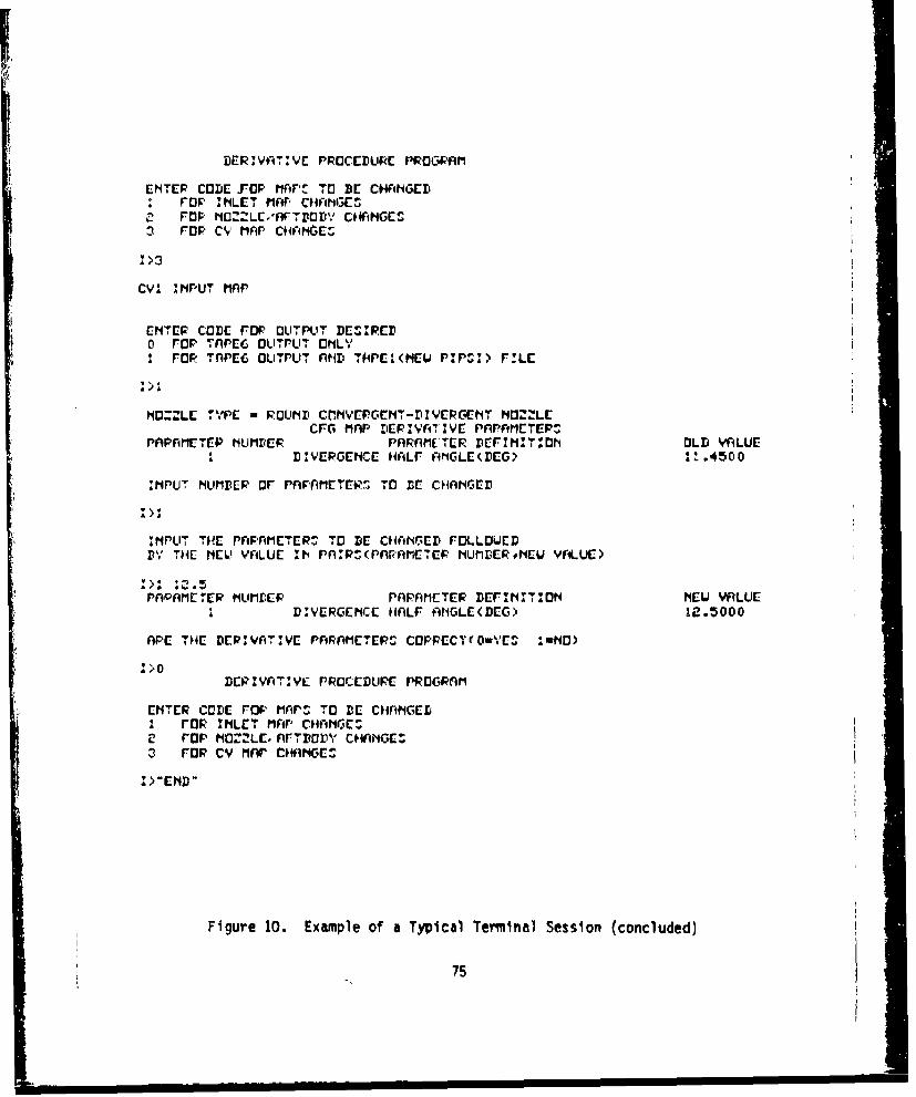
DRIVAT.:VC PROCEDURPE PRaC4ýAM~
ENTER CODE[ r'OF wit~f m BE cHwimGcD: rap 'HIET MAP CHANGE"
e FOP AC-LEA-i BOD~Y CHAN1GESIn rap C'Yv MAP CHFIHOCI
CV! rINPUT MAP~
ENTER CODE FOP OUTPUT DCEIREIDo rap TAPE6 OLIT UT, 6NL',
rap IOnPE6 OUITPUT nNDt TW4EI(HEW P:'PISIA FVLE
NlOZZLE 'TYPE w FOUNDlI CflMVE CEMTv-PIYIEPcGEIT NOZZLECFG MAP DER:YATI7 E PAT'APETEP",
PAPFIMETEP NUMBER PARAMETER DEFI'M:'ITIO OLD VAiLUEIa DVERENC HAF RNLCýIEG It4500
M1PUT NULMB.ER OF PnPnMETERý T13 BE CHANGEDr
*ZHPUT TvE rPAM~tETER^ TO BE CHANrED FOLLOWED
D, . THE N1EW YAILUE IN4 rPARs(PnrAI1ETEF NMBmERtrIEU VALUC)
PnrAME1Erp I'ILIML:EFP rAPAMETER DEr,,,T4:Tot4 NEW VALUEII DV.ERc.EMCE HALF AtIGLE(DEG> 12.5000
APE TH4E DEPIVATZVE PARAMETEPS COPRECTI(O-YES I NO)
:>0DEcZvATV,,Y PROcuuED Ppmcwnmr
ENTER CODE FOP' MAPS TO BE CHANG~EDFI ra MLE" MAP CHCAIE'
2 rap No.Z&E. Ar -,ow,, cf'sAGC3 FOP CY MAr CHAN1GES
Figure 10. Example of a Typical Terminal Session (concluded)
75

If the user does not wish to continue, at this point a response of "END"will discontinue execution of the program.
When the option is selected, the name of the file which is the first card
on the disk file is printed to Inform the user of the type of file being
used.
4.3.2 Output Code Type
The user at this time selects the type of output desired from the pro-
gram. The options are:
0 TAPE 6 output only
1 TAPE 6 plus TAPEI (a new PIPSI file)
Once the output code has been selected, the derivative parameters are
listed at the terminal. Only the derivative parameters actually required
for this input map file are listed and are modifiable.
4.3.3 Number of Parameters to be ChangedThe user looks at the list of derivative parameters and decides how many
are to be changed. That number is entered in response to the prompt.
4.3.4 Input of New Parameter Values
The user inputs the parameter number and parameter value in pairs for the
parameters to be changed. The results are itsted on the terminal for the
user to review to see if they are correct.
4.3.5 Is Input Correct Code
If the above input has been correct, the user will enter a zero; if not
the user will enter a one and the sequence of prompts and responses will
be repeated. At this point, also, the user may enter "END" and the
program will be terminated. After a zero has been entered for this
prompt, the program executes and the next prompt will be the map type
code prompt discussed in 4.3.1, at which time the user may executeanother case or terminate execution.
76
4.4 Program Execution Sequence
In order to execute the Derivative Processor, the user must attach all
disk files which are expected to be used to specific file names recog-
nized by the program. These are:
TAPE 51 a Inlet file name.TAPE 52 - Nozzle/afterbody drag file narme.TAPE 53 w Nozzle thrust coefficient file name.
A typical set of control cards is shown below:
ATTACH, TAPE 51 - ATS2DP2.ATTACH, TAPE 52 - CD2R.
ATTACH, TAPE 53 - CV1.
where ATS2DP2, CD2R and CVM are previously constructed files existing on
the user permanent files.
The user then attaches the Derivative Processor program,
ATTACH, DERIVP a existing permanent file name of an absolute binaryfile of the program.
It should be noted here that a pre-existing absolute file must have beengenerated and saved from a compilation and load of the program. This Is
necessary in order that the program be able to run in less than 60K octalwords in an interactive environment.
DERIVP
This executes the program and is the absolute overlay file name and must
be used when executing the absolute file. The user then responds toprompts once the program is executing. After an "END" is entered, the
program terminates execution. At this time the user may elect to performdifferent types of outfile manipulations, such as saving, listing, dis-
posing, or merging.
77
SECTION V
SAMPLE CASES
The purpose of the sample cases for the derivative procedure is to demon-
strate the major flow paths in the program used to produce new inlet and
nozzle/aftbody maps. Three sample sets are provided for the derivative
procedure program. One set will be used to demonstrate the major flow
paths used to produce a new inlet map, the second sample set will be used
to demonstrate the flow paths used to produce a new nozzle/aftbody drag
map, and the third set will be used to demonstrate the flow paths used to
produce a new nozzle internal performance (CFG) map.
Each of the sample cases is described separately in the sections which
follow. For each of the sample cases, the following information is
provided:
(1) Old (baseline) input data tables and baseline derivative param-
eters for which the data tables correspond.
(2) A list of new derivative parameters for which a new (perturbed)
map is to be produced.
(3) a set of terminal input commands used to interactively generate
the new set of input data tables.
(4) A new set of input tables produced by the derivative procedure
program.
5.1 INLET DERIVATIVE PROCEDURE SAMPLE CASE
The baseline inlet used to demonstrate the inlet derivative proce.dure is
Configuration #8, File Name ATS2. The inlet is an external compression,
four-shack inlet designed for a free-stream Mach number of 2.0. The
inlet has two movable external ramps, a 7.30 initial ramp angle, a
79
"it I i P A 1APDKI JIU 11

boundary layer control bleed system consisting of porous bleed on the
second and third ramp surfaces and sideplates; and a throat bleed slot
located aft of the normal shock. The throat slot also acts as a bypass
to remove excess inlet airflow for matching engine airflow demand with
inlet supply. The inlet characteristics were built up from engineering
analyses and available data from similar configurations and components.
A sketch of the configuration is shown in Figure 11.
The predicted inlet performance characteristics for the ATS2 inlet are
shown plotted in figures 12 through 21. These performance characteris-
tics are entered as old (baseline) data tables (Figure 22).
Each set of inlet input tables in the library is accompanied by a set of
derivative parameters that describe the configuration in terms of its
important variables. An example showing the derivative parameters for
the ATS2 inlet is presented in Figure 23. In addition to the complete
set of derivative parameters for the library inlet configuration, a new
set of inlet derivative parameters must be input by the user to specify
the new values of the parameters that are to be used in the new configur-
ation calculations. The new derivative parameters for the ATS2 inlet
test case are shown in Figure 24.
The set of interactive terminal commands input by the user to run the
inlet derivative procedure program is presented in Figure 25.
The output file obtained as a result of the ATS2 inlet sample case run is
presented in Figure 26. The old (original library configuration) inlet
maps are printed out first together with the original derivative param-
eters. Next, the new set of inlet maps is printed out, with the new set
of derivative parameters shown for reference.
5.2 NOZZLE/AFTBODY DRAG DERIVATIVE PROGRAM SAMPLE CASE
The baseline nozzle/aftbody configuration used to demonstrate the opera-
tion of the nozzle/aftbody drag map derivative procedure is the twin,
I °
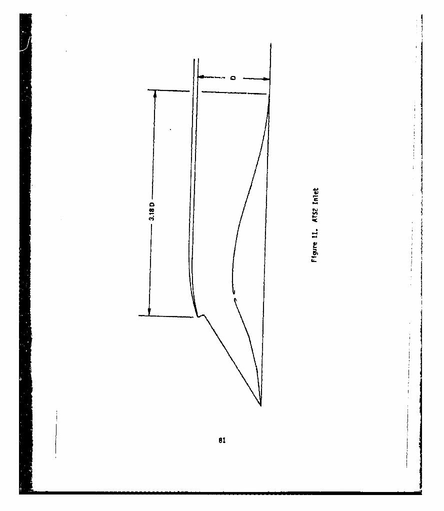
I
-i- 0
6JS.,
p.-
0
9-
'-4'-4
a.'-
II
81
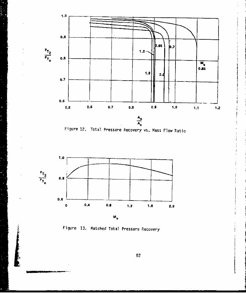
1.0
:0.9 - -SeT.2
1.2 -
MoT o 0 . 80 .I S 6
1.6 2.j
o.7
0.6
0.5 0.6 0.7 0.8 0.9 1.0 1.1 1.2
Ao
ACFigure 12. Total Pressure Recovery vs. Mass Flow Ratio
PT2
0 .
0.8____ _
S 0.4 0.8 1.2 1.6 2.0
__ M0
Figure 13. Matched Total Pressure Recovery
82

1.3
AD
1.2
0.S
S~0.3
0.7 .. . .... _
0 0.4 0.1 1.2 1.6 2.0
Mo
Figure 14. Matched Inlet Mass Flow Ratio
83
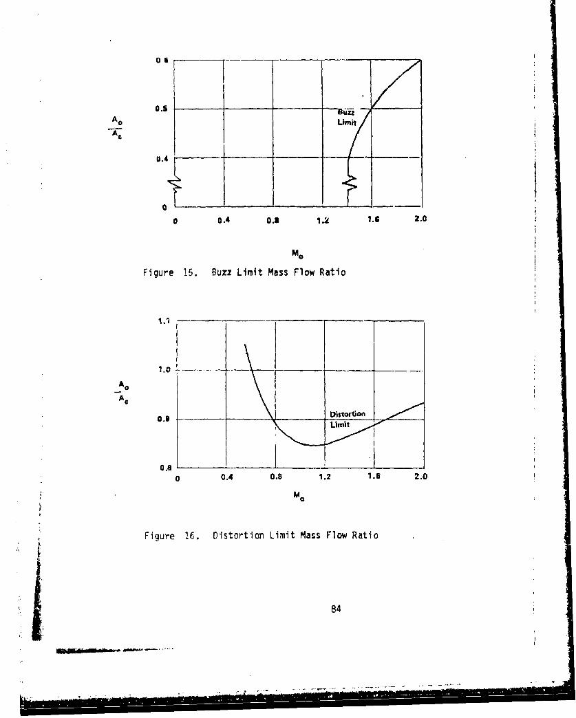
0.5,
Ao Umnit
0.4
0 0.4 0.3 1.2 1.6 2.0
Mo
Figure 15. Buzz Limit Mass Flow Ratio
1oI.0 -- -____1
Ac
0.9 Distortion______
0.8 -
0 0.4 0.8 1.2 1.6 2.00.08
Figure 16. Distortion Limit Mass Flow Ratio
84
•" •• . ....... 4

2.0
0.7
e~g 1.6
1.4
c0.4 ____
o.2
0.3 .5____
0.1
0.4 0.5 0.6 0.7 0.5 o.9 1.0
Figure 17. Spillage Drag vs. Inlet mass nlow Ratio
85

2.0
A~L 0.04
OvLC
04 0 . A.00 .
0.035
A~At
(b) ~athed A./At ~
0.86
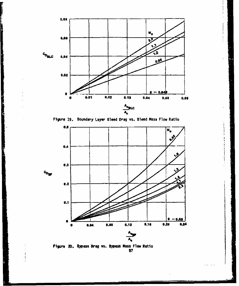
Cm 0.04
0.02
0 0 .01 0.02 4412 0.04 0.06 0.06
-SLC
Figure 19. Boundary Layer Bleed Drag vs. Bleed Mass Flow Ratio
0.5
0.2
0.1
0.04. 0.03 0.12 0.16 C.26 534
As
Figur go. Bypass Drag vs. Bypass Mass Flow Ratio
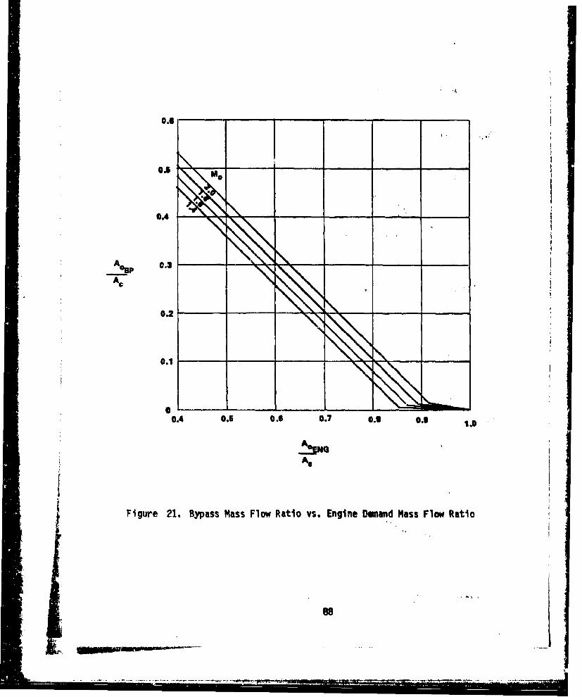
O.6*
0.4
A ¢ 0.2
0.2
: ~ 0.1 -
00.4 0.5 0.6 0.7 0. i 0.9 1.0
As
Figure 21. Bypass Mass Flow Ratio vs. Engine Demand Mass Flow Ratio
." 88

LTS2 IOlET PAP.95 *?0 7.30 2.50 .03 .i0 17.50 1.00 I5.00 2.000
.10 1.09 00 ?se.0 .20. .0.00* 0.00 .12 0.900
- IL'0o 1.25' 3.000 . 1.00TAILEl 3.
0.000 .200 2.5000.000 .200 2.500 -
TA91f?A 6.7.000 6.000 7.000 7.000 89000 9.000.550, .100 $so0 19100 1.900 2.50005!.9 .639 .719 '790Q .R43 lf89 .379
0090 0. 990 *9q4 '9#-8 .99 .93E .8474
41.0 *56 *.0619 .719 '759 *77q
:~ 969 '009 046 4073 044 pot).399 0479 a 549 .639 .679 .700 .721
--. 0988 .989 sloe? .981 97 .060 " Sof
.416 e500 45M4 80$6 .710 .737 0755
.960 *959 *957 0953 .0047 0935 a P ti
-- 453 0545 .637 .730 .776 0 ROO .'009 41%14
0938 '43-P .0?7 .*O .62 917 01402 .PP7 .86?
0493 o594 o6q4 *704 0096 .926 q32 . .940 .947
OCR Opel 0 1 P .'64 *q7q .865 .860 .010 0740
*TAILM? 9.0.000 .200 *43)0 .600 0100 1.0000 1.300 1*900 7.500
.90-9 040 006i Oq71 .q75 09610 0047 .910 .865
TAOLF?C 7.
:400 .600 **00 1.000 1.300 1.q00 2.510
-'A 1040, *774 fl%0 .664 .70'y q75 .1STABLE?0 f%.
0.000 1.590 1.600 1.000 2.700 2.00O-06000 0.000 .755 .755 61114 0014
-TAILF?E 6..550 .700 0"30 1.300 .1.900 ?.50o
2p? 07 41t0 .100 m416 o4%1 .493
T&B;E3- 9.3.000 30COO 70000 90000 0,Q '000 7.0000 70000 7 .000 6O
0.000 e549 .550 *'T0o OM0 1.300 1.00lo 3.900 7.500
0.1000 *70F 1.0000.000 0.000 0.00000000 s798 1.0000.00L, 0.000 0.000.740 .120 61109 *470 01559 6572 1.000
0 .57 .096 .04* .011 .000? 0.000 06000
0240 03?0 .400 *41O 05f,3 .0'9 .719 0759 1.0000
.255 .171 .103 .051 OOZA .014 .0001 0.0000 0.0000
.0240 .320 o4'30 .1.60 .560 .640 ?POQ .770 1.000
.336 OM3 .145 .087 .843 40?3 0000 0.000 06000
OM5 .335 *41w .503 .1507 9671 0755 .0904 16000
-. 41.? - 320 .2154 .135 .071 .035 .01' O.000 0,000
.264 *439 .615 0701p .779 .79P 1.0000764 .0456 '725 0190 .075 0.000 00000
.459 .51;1 .613 07ý4 .543 052 1.000C
*.766 0.593 *402 .230 .023 0.000 0.000.500 e669 0701 *Oq9 o956 .061 1.000
*975 .535 411 .137 .010 0.000 0.000
Figure 2-L. ATS2 Inlet Input Data Tables
89

TAUL! IA so0.000 1.000 Z.530*.000 60.000 0.0000
0.000 1.OCO 2040o.999 000. *999
Y40LE4 1. 6
69000 .S*, OPSO 1.100 2,050 P.5000.000 oeII act? .044 0@A&46000 0.000 60030 09000 090000.000 0.000 0.000 0.000 0.0000.000 e007 .014 .0?4 .84P$*too 4010 .021 .04? .0%?0.000 .011 q0?' 6044 .06660.000 .011 .023 -0016 .044
TAILES T. to$.000 *049 .550 1.000 1.300 1.600 2.050 Z.6600.000 .042 *643 OM2 .16th *too .249a 0000 0.0006 00000 60000 0.000 0.000 0.0000:000 6.000 0.000 0.000 0.000 0.000 0.000
_66000 .062 SIPS .l9FI .260 .160 .50006000 .050 *100 0156 01P 1 0290 a.SIP
0.000 *030 .0 OR .00M .113 0181 .230,9~0 0?6 .005 .0@4 otro .144 *220.-
TALr6A F,--2.000 1.000 5.000 .(0 5*000 4.000 64 000 *6 .900-too
0.000 *MOO l.0DO 210O' 10600 1.900 2.200 to$"0-.0000 .747
-0.000 0.000-OC01 ofto00.000 00000
-. .'.6 oq' .674 0731 **it0009 *004 .005 .003 0.000.500 .544 70 T . 751 .111.015 0014 .011 .f00% 0.00005?? .AH1 .751 , ?pit .7.024 OC2! .0115 9011 0.000
- .545 .617 .710 00os *0; .917.033 .Ci 00!4 077 0015 0.0000.570 0(66 .742 0'#5 *.Pg 0051!Ar4m o04A .0041 .077 .0?3 690000594 .0-04 .704 9*0' 00?6 0099
a.066 604A1 .055 .041 .003 GO00T AILFFA9 so
0.000 .',00 1.100 1.900 26,40060000 04000 .011 .00? .013
2.000 2.000 4.000 4.000 4.900 4.0000.000 1.05,0 10610 1.900 ?POO0 2.500
*0.000 1.0000.000 0.0000.1000 1.0000.000 0.000*350 .74A 975t 1.000'404 .004 09000 0.000.366 71*6 *a"l? 1.000f,44? 0009 0.000 0.000eIV3 *051 OP61 1.0000
- .413 0011 0.000 0.000.400 .*1l5 .030 1.000.532 .015 0.000 0.000
Figure 22. ATS2 Inlet Inpuit Data Tables (concluded)
90
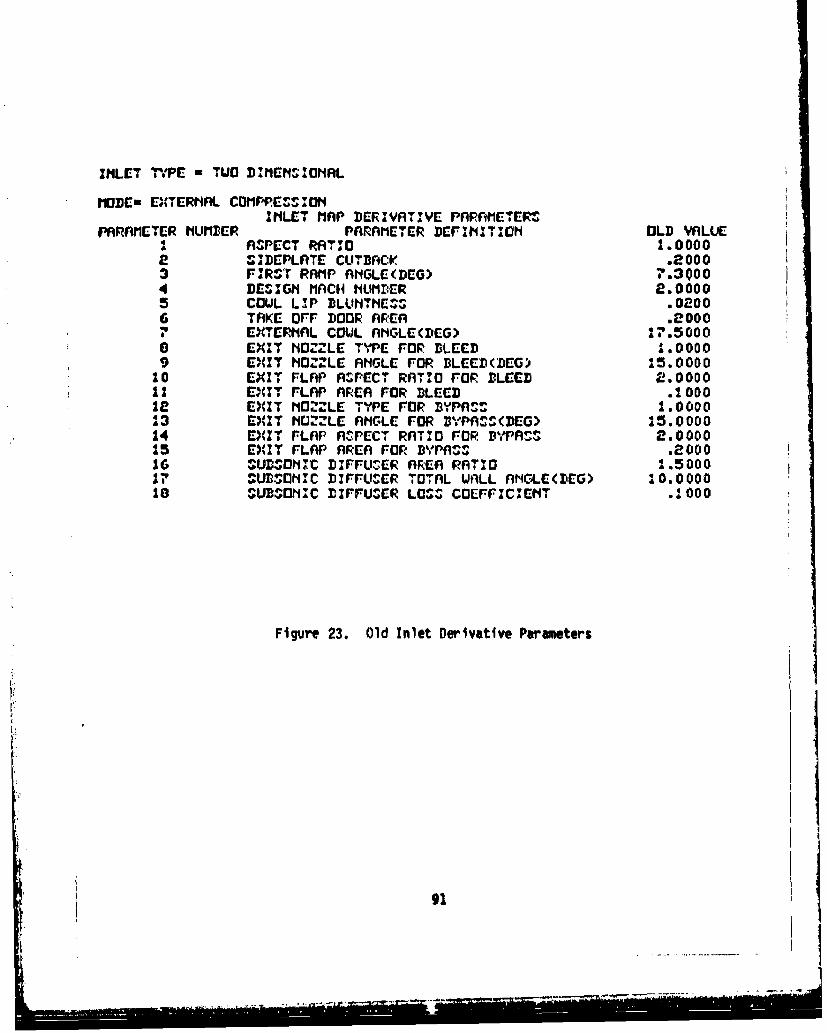
INLET TmPE - TUD DAKSMEt•-I0HNL.
IIODE- EXTER, AL COMPPE4 tIWINLET MAP DERIVATIVE PARnMEETERt
PARAMETER tIUMBlER PARAMETER DEFINI TION OLD VALUEA RnPECT RATIO 1 00002 ,• !DEPLATE CUTBACK .20003 FIRST RAMP ANGLE(DEG) 7.30004 DEVZGI MACHI HUMBER 2.00005 COUL LIP DLUNTHEC4S .02006 TAKE OFF DOOR AFEA .0000
EXTERNAL COUL AhGLE(DEG) 17.50000 E;(IT NOZZLE TYPE FOR BLEED 1.00009 EXIT NOZZLE ANGLE FOR BLEED(BEG) 15.0000
10 EXIAT FLAP ASPECT RATIO FOR BLEED 2.000011 EXIT FLAP AREA FOR BLEED .100012 EXIT MN02LE TYPE FOR DBPA, 1.0000"23 E04IT HCOLE ANGLE FOR rDVPA 4(DEG> 15.000014 EITr FLAP AnPECT RATIO FOR DBPR• 2.000015 EXIT FLAP AREA FOR D%,PA#% .200016 SUD,-HOIC DIFFUSER AnREA RATIO 1.500017 SUDI]ONC DIFFUSER TOTAL UALL ANMLE(DEG) 10.000010 SUBSOMIC BIFFUSER LOSS COEFFIC,'EHT ,1000
Figure 23. Old Inlet Derivative Parameters
II
-9

PARRAMETER NUMBER PARAMETER DEFINITION HEW VRLUE1 ASPECT RATIO .95004 DESIGN MACH NUMBER 2.50005 COWL LIP BLUNTNESS .030018 SUBSONIC DIFFUSER LOSS COEFFICIENT .1200
Figure 24. New Inlet Derivative Parameters
92
92

14 >GC-T oDERD
M>GE-T eT PEW-TESTIA #T APE-520TEST2 @TAPE-530PTEST3
INXITCHC >bC RD
SCRIVATIYC PROCEDUMt PPOMFAI1
ENTER CODE FOR WIPC TO BE Ct*VIGC-DI FOR INLET mAP CHVwiGio
re FORNO2LE.-AFTUDY coortwGCCa FOR CV "W" CIVOMGE,
A T S2 INLET flAP
ENTER CODE FOR COUTPUTr DE"1PED0 FOP. TAPEG OUTPUT ONLY: OR TAPE6 OUTPUT AND TAPEI(NEU PA'PSI) FILE
~1>
INLET TYPE a TWO DIMNSMM~.$L
INLET MAP DERIVATI:VE PAPAMETERMPARAME TER hUMIDER PWArA1E-TR DEFINIITIONI OLD VALUE
I ASPECT RATIO 1.00002 SOMEPLATE CUTBACK (nC.b.,A'1F'V .410003 r RSOT RIAMP ANGLE(CG) "9.30004 DESIGN1 MACH N4UMBER 2.*0000
5 OU LIP DLLW4TME-- .02006 Aix.E OFF DOOR. APEA PATIO .2000
7 0ETE-RhAL COUL AhaC-(Dr-G> *1*.50000 VEi T NO 26LE TYPE FOP DLEED(CN~oeCIIDw:) 1.80009 DCXIT NOZZLE ANGLE FOP DLEED(DC-G 15.000010 Epc- rLAP ASPECT RATIO FOP BLEED 2.0000it ocziT FLAP AREA P ATIO Ora sAiEs .100012 EXI T N1O" LE TYPE Ora Dv'PnAs(cmo4.0ct1 ) 1.000013 EXI T MUZLE nNGLE POP MYPAS.MG) 15.000014 EXCI T FLA'P n'. PECT RATIO FOR MYPA'S 2.000015 01, 1T FLAP AREA RATIO FOR BUM" 0 .200016 SOUD"50IIC DIFFUSEIR AREA RATIO 1.50001? SUBSONIIC DZPPUSER TOTAL UALL AtIGLE(IE) 20.0O00010 SIUBOh1IC DIFFUSER LOSS COEFFICIENT .:000
Figure 25. Tevmlnal Input Commiands for Inlet Derivative Program
93
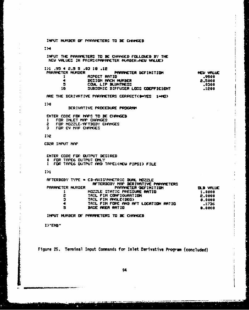
INPUT WIUDER Or PfWWIETERS TO SE CW#4GEI
INPUT TIE PARAIiETERS TO BE CH*IG*ED FLLO1UED IVB THENEU VALUE" IN PnIZR(PAPAFMiTER N.411iEIR tEU WLUC)
1>1 .95 4 2.5 5 .03 10 .12PARAMETER tNUIER PARAMETER DEFINIT:ON WEU WVLUE
I ASPECT RATIO .95004 DE!SIGNt fAMC Mul•FR 2,50005 COUL LIP 3LUtIT1"C• .0300
10 JUBSOMIC ]DIFFUmER LOS.', COEFVFICIENT .:200
ARE THE DERIVATIVE PARAMIETERS CORPECT(OYEZO 1.9PC)
1>0DERITIVE PROCEDURE PROGRAM1
ENTER CODE FOR FO PS TO DE C1*WGEDi FOR ItLET finp CI4ANGE•2 FOP NOV"LE.'nFTBQDOLD CHNGEC3 FOR CV MAR O$ GAGE#
1>2
CD2R INPUT MAP
ENTER CODE FOR OUTPUT DESIRED0 FOR TnPE6 OUTPUT OMLYI FOR TPEG OUTPUT IAMD TAPEZI(MEU PIP-V; FILE
Z>1
AFTERNODY TYPE a C]D--AISYlMETRIC DUA. LOZZLEAFTERDODY flAP DERIVRTIVE PARfMCTERT.P#
PARAMC, TER NUMBDER PARAHER 'DEFINITION OLmD VALUEI HNOZZLE STATIC PRESURE RATIO 1.00002 TAIL FIN CONWFIGURATION e.00003 TNIL FIN A.IGLE(DEG) 0.00004 TAIL FIN FORE AND AFT LOCAITION RATIO .11,36S BASE, AREA RATIO 0.0000
INPUT NUMDER OF PARRMIETERS TO IE C1ANhGED
W>"END"
Figure 25. Terminal Input Commands for Inlet Derivative Program (concluded)
94
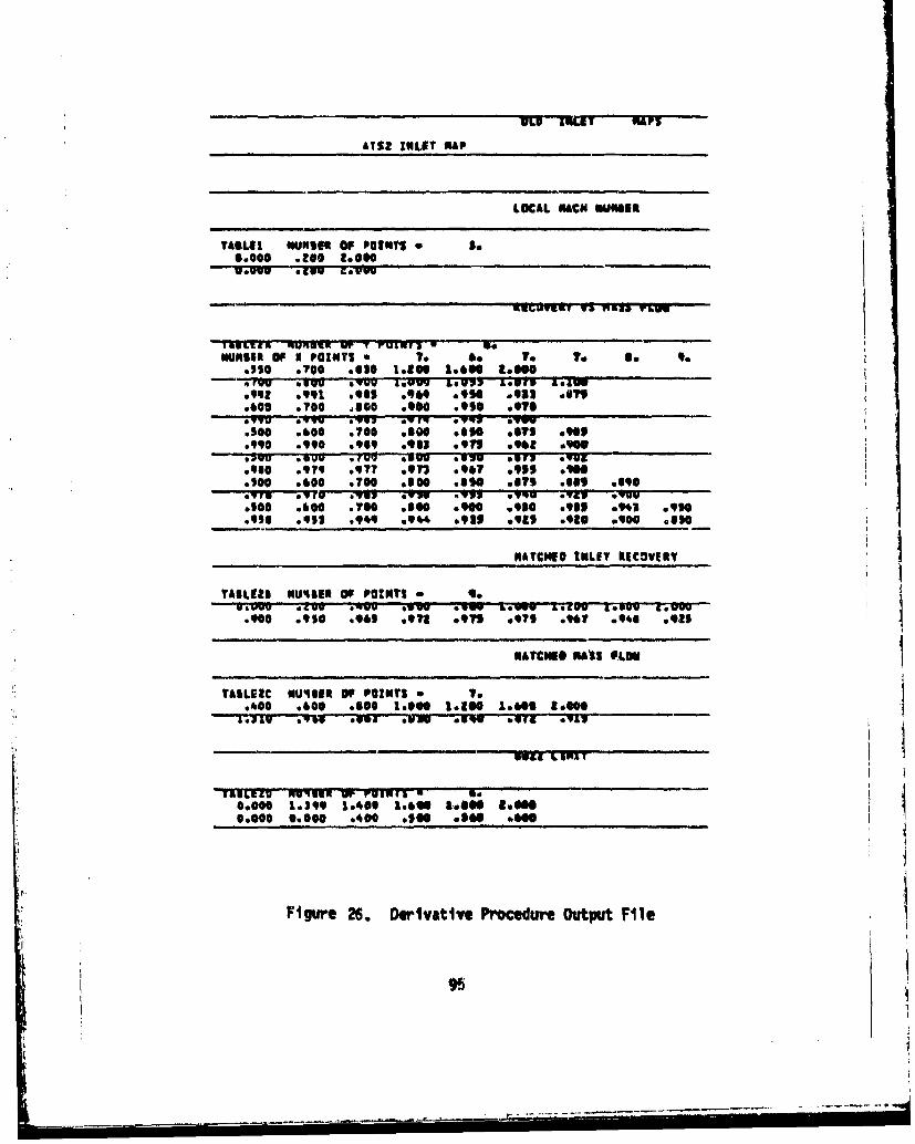
1001 INLT 101
£TS2 INLET NAP
LOCAL CUACN UM46U
TIBAGI "UNSIR OF POINT$ So36.000 .200 too"0
05~MVu 1413 riPg vO
TRCZ UdRUIW up - rVINTYNUSAO P04T a Touv 60 T oee 9
.110 .700 also 191041 1.06" 3.014 raw MCIu wvvU &SUw7&UM&G 60.949 .991 8.901 .96409 .9 0933 91.000 .700 ,$Go .900 .990 0970a~Y 9,70 Go *VMS * yg F.vw9u11 o.10o06.00 .700 .606 *$go of61i 0909*990 .990 .094 .903 .971 .962 .90v;PvU .000 Two11 ovUU Oulu ov7v Myg
.960 .979 .977 .973 .967 .915 09600
.S0o .000 *T00 .o00 .650 ways wool .690
6500 .60007 .7f0 6 0.910 lose0.931 .943 .910*999 .91 .999 .944 .90 91 1ga .919 .900 also
- - NACNEOINLIT kECOVIA?
TASLEIS Nuquum Of POINTS -*
.900 .910 .94 91 *ol .975 .979 .961 .9*6e 0981
HATCHES MASS FLOW
TAILGIC VU46ER of polaTS To1
.0*00 0.006 .66 1.400 logf 1.0604 too"
0.0000 13.00 10400 .1660 .910e too"0.0000 1.009 1.*00 a.06 .0960 a&"0
Figure 26. Derivatlve Procedure Output File
95
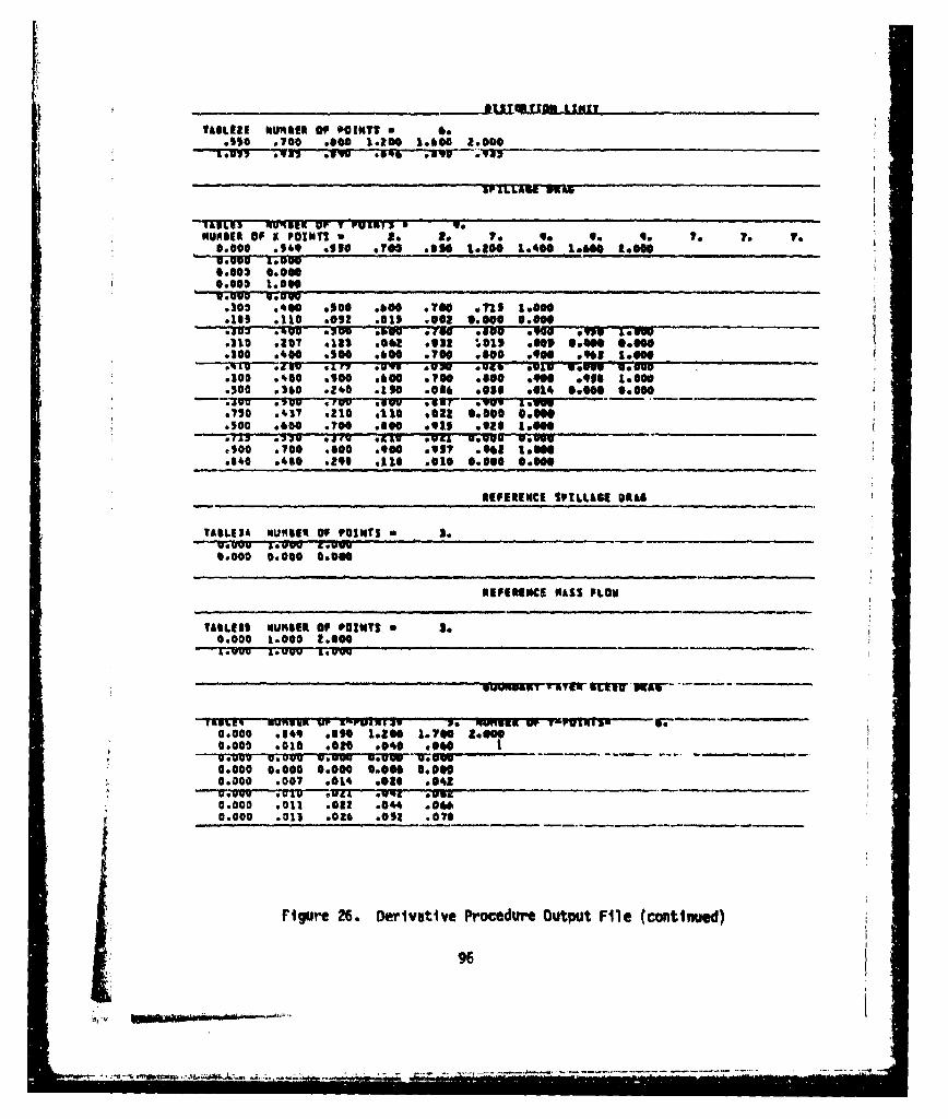
ta~IL2 NURSER Of POINTSIs mAso 07.00 .000 1.200 1.6000 2.0000
'I&UL93 MfewUP UV FOaRM 0. 1.002.0
0.0 :109 of$* $Too .010 I.800 L*40 9.60 2 .0700
40003 0.00000.0011 1.500
.303 .000 .100 .000 .700 an* I.wonoil$ *Ile .012 eels .002 10.009 0.ee"0303 .~u .AO 2Uu .5010 .790 . IN *g "is I.w
0100 .000 .100 .000 .700 *goo0.900 09S 1.000
.300 .360 .240 .1 SO .016 .038 .014 66660 0.000.sVw .VUv 0,i 300 .u.V---~ r 0901 a.750 .437 %216 e1 10 .022 @.000 coo"5
*500 .700 *too .800 .917 .*W 1.06"
CIO0 .000 **Do 60410 0950 0.800 0.00
AffEREWCE SPILLASI OMA
TASW.EA NUMSIR of POINTS so
0.0000 04000 GOODS
*IIRIMECS MASS PLON
TASLE21 NURSER Of POINTS So50.000 1.000 2.000
AMCwau &*U .YrStem31
1116M~ *UNPRX WY AMUAMIX. No qjmnuu Wr T 7ylg17a-0.0000 .09 .0690 1.208 1.700 too0"0.000 %CIO0 020 .000 .000 1 _
MC0C 0.000 0.000 0.00 0000.000 600? .010 sea$ 001.2
0.000 .012 0862 .004 .0o"0.000 .013 .026 .002 a0To
Figure 26. Derivative Procedure Output File (continued)
96
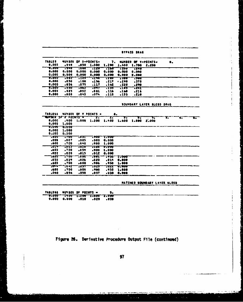
BYPASS DRAG
TABLES eguiqmft Of t-P01NYSS 1. NUMBER 0F Y-POtNTS. 60.0000 .349 Osl0 1.000 1.200 10400 1.700 Z0200
W-u .7109 -. wag .1ZU .1aw Z09 0*9~46600 0.000 0.000 0.000 0.000 0.600 .00040.0060 0.000 0.000 . 0.000 0 .000 0 .0000 90%P VUW ;052 .127 .19o 0muU .15 3 -. N U0.000 .050 .100 *1 ft .21? -. 290 .1750.000 .036 .079 .117 .161 0220 OR"0
0.000 .0m .052 .031 .116 .16'a .2100.000 .020 .045 .074 .110 *115 .110 ____
BOUNDARY LATER BLEED 01A6
TASLEOb NUnIER Of T POINTS * 6
09000 .100 1.000 1.200 1.400 1.000 &.goo [email protected] 10000
0.000 1.00000400 0.a00.VOO Oriau i.U1-Tyuu IOUVu.0005 .007 co0l .003 0.000.000 .700 .640 .900 1.000
.000 .700 9899 *900 -1.0000GORR .020 .015 .012 0.0GOO"_ ____
.030 .019 .0260.020 6014 010900
.000 .7,00 .000 .906 .930 1.0006qw.1 .04 O UJ OW .04 0A .000
.000 .700 sloe0.900 O9I0 1.00.00 050 .050 .057 .610 S.O.S
HATCHED GOWNGARY LATER %Lfff
TAOLEOB NU49IR VP POINTS so.___
0.000 0.000 .010 .010 lose
Figure 26. Derivative Procedure Output File (continued)
97

BYPASS "ASS FLOW
TAILEY NUMBER 0, V POINTS 6 6.NUMIER OF X POINTS s A. 3. .. 4* 6
U.UUV L.2'rv 1.UV .uU01. g LoU0.000 1.000.000 03000
0.O00 a.D00.400 J54 .959 1.00.el Uuw" vUUUU W
I --• 01rTI2 16-m
.413 .010 0.000 0.000
.400 .892 .906 1,600-- "'•.OK--%ul u uuuo 6-.o
.400 .915 .930 1.000
.532 .315 0.000 0.000
INLET NAP DERIVATIVE PARAMETERS--TIrawETEI1 u•iJ,•!ptu t wA rr •ruFFk LurI O-VALUE-
I ASPECT RATIO 1.00009 m "T OE 'l t G 'u isa, -3 FIRST RARP ANCLEIDE61 ?.30004 DESIGN RACH MUNGER 2.0000
COuL CrI uTuniq$ST .'Dz0U4 TAKE OFF DOOR AREA .2000? EXTEANAL COWL ANGLE(OEGI 17?5000
A ~Ip NUZLE. STPL-rITE -f 0066f. 0O09 fXIT NOZZLE ANGLE FOR GLEEDOIOEI 15.0000
10 EXIT FLAP ASPECT RATIO POO ILEEO 2.00001 tAI u-LAFr AKtM FUR e §tU .010
13 EXIT NOZZLE TYPE FOR BYPASS 1.0000Is EXIT NOZZLE ANGLE flOR BYPAS(S(DEl 15.0000
is EXIT FLAP AREA FOR BYPASS .ZQ014 SUISONIC ODIFUSER AREA RATIO .S6000
is SUISONIC O[WFUSEIR LOSS COEFFICIENT .1000
"Figure 26. DerIvative Procedure Output File (continued)
98
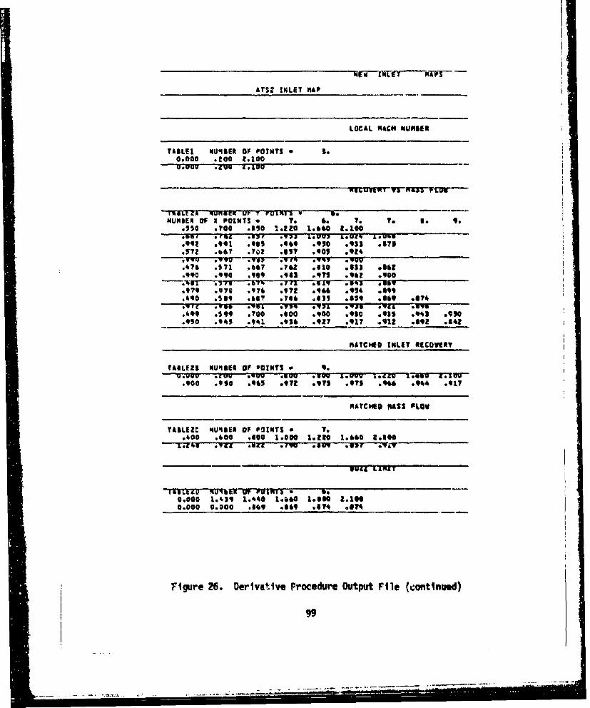
ATS2 INLET MfAP
LOCAL MACH NUMIBE
TAILI, NU'4IER OF POINTS to0.000 .100 2.100.0uu .*lug M.pUu
IULtCI C UFIUiltK UP T VU11NI * S.
NUNDER OF I POINTS *r7 0. TO 7. TO 9..is0 .?00 .l0 14.220 1.060 1.100' .+ .mL .IM" Nor V7 L.UU7 Leo.[Ll- U-U
.92 .z 991 .9$ .909 .910 9 93ei ,I735"72 .b6? .?%) *B5I .901 .924
.4?6 .571 .667 .762 .610 .033 .i6Z
.990 .990 .0969 .93 ,91 .962 .*goo
.979 .976 .7 992 .046 *69;4 *099.490 .599 ,l? .676 ,633 9619 .1069 #674.''-w I ,S C W .S-L. .Vi MAL ' "IU .'V& .119.499 0599 .700 .600 .900 .910 *935 .941 9910.950 .940 *.941 .93 .927 .917 .912 .892 .962
MATCOED INLET OtCOVI6r
TAILEZI 1U48EQ OF POINTS gou.U0u .Z'V ."Um fawu V .UU'.VVU 1.2CO1.50- -
.900 .90 096! .971 6171, ,7s .0*6 .9#44 ,.17
"OLYC1O "A&s$ FLOW
TAILEZ. NU46E6 OF POINTS 7 1..400 .000 .100 1.000 1410 1.060 1.100
"-T7; .... .Y1 *iLL . " .UV .51 .Y
049L LIMIT
IIS1E&S 7 ExE IN PO7INTS oil.0.000 1.419 1.440 1.oOO 1.660 1.1000.000 0.000 .I09 .009 V ? .074
Figure 26. Derivative Procedure Output File (continued)
99
S.. ..... i.,+,+.i, . <.... .
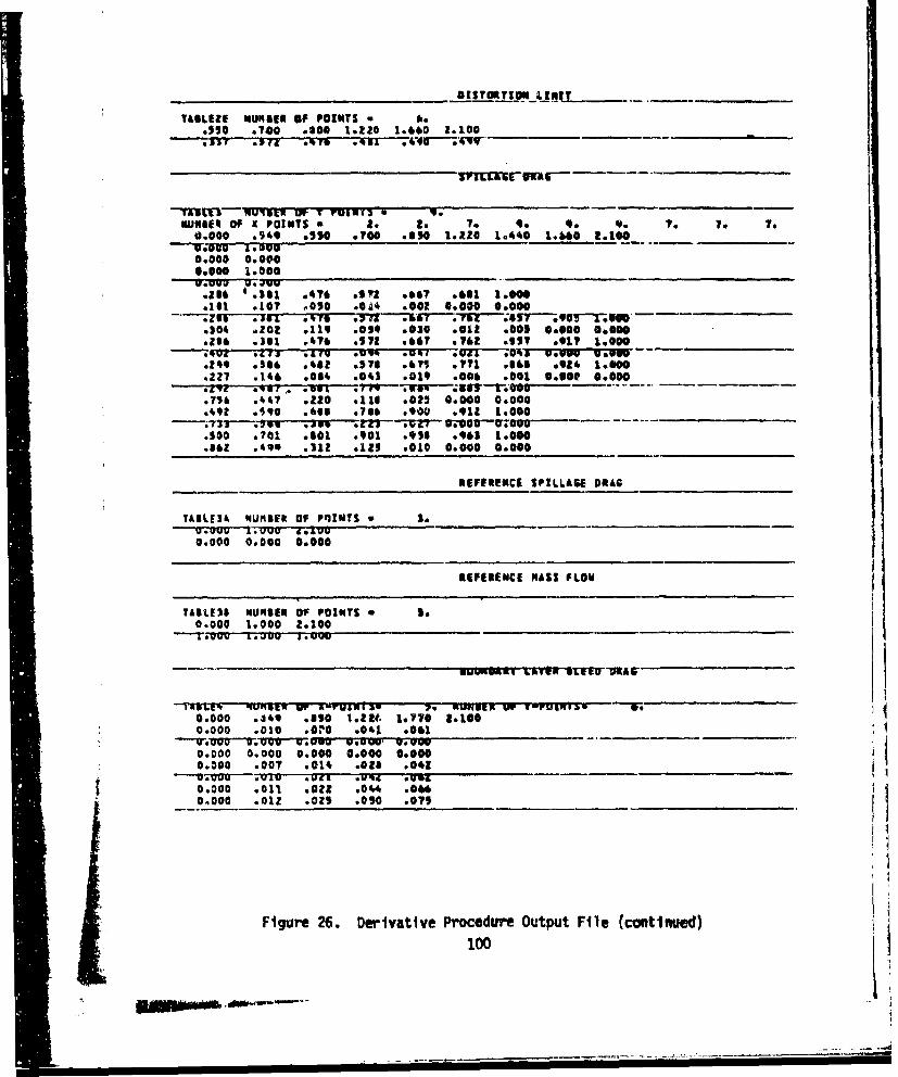
TasLtZE NUIUSt OF POINTS * A..a50 .7?0 .000 1.220 1.660 2.100.337 - rz' .475, .71 3v.•O--'4V9
IIUCFIUVIVt OF T VU99NI31 9muffaft F X POINTS. a 3. 2. 7. 9. 9. 9. 7. To To
0.000 .949 .05 .?0 .e50 1.120 1.**0 1.bo0 .100
0.000 0o0000,000 1.0000
-" uo.F u.'JvO
as* . I1 470 .0670.67 0681 1.000.181 .10? .050 .0O4 .002 0.000 0.000- .1JuTo' . re .T7Z 10 ;air-. qo--0--j fe-.104 .202 .119 .019 .030 .012 .00s 0.000 6.000O2 .l .181 4?6 .572 .66? .71 a .l57 .017 &.000.*02 .411 A AfU .01" .9%r *0T0a a~w VW U go.2-" .S66 .042 .u78 .871 .7'71 Sl .924 1.600.227 .146 .064 .043 0019 .000 .001 0.004 0.000*o'l over *8s '00.756 .440 .120 .116 .0*! 0.000 0.000.492 .50 .666 .716 .900 .911 1.000- .--3,3 .7015 Jug+ .ZZ; "T-q -'l+'OOO-"•;+@b
.500 .701 .601 4901 .936 .961 1.0t 0
.•62 .490 .312 .121 .010 00000 0.000
REFERENCE SPILLAGE DRAG
TAILEI3 NUMIEt OF PqINTS * S.
0.000 0.000 0*000
REFmERECE MASS FLOW
TAILE1s NURSER Of POINTS % 1.0.000 1.000 2.100"-t~vuv Ljuu £.+
06000 .14, .*10 .22f. toy?@ 1.100e
0.000 .010 .010 .041 .0061"--Tub +00 u~u vu . u ug v,'yu
0.000 0.000 0.000 0c000 0.0000.300 .007 .014 .0*6 .041
0.000 .011 .002 .044 .0000.000 .012 .0z9 .090 .075
Figure 26. Derivative Procedure Output File (continued)100

TABLES NUMBER Of %-POINTS* is NHUNIER OF V-POINTS. so0.000 .849 .950 19660 1.120 1.000 10770 2.80________
.1010 0036 *a$ el I2#Z s
GUWNSAIY LATER BLESS .01
TAGL16A MNUREN OF Y POINTS * asFOMwf upr 4 VORISI 1 9* 7. We V.U. e
coc0a *to0 1.000 1.220 1.040 1.660 L.ss* sale00.~00 Volvo
-. 000 .913cocoa 0.000 ____
.0003 *007 .0059 *001 cocoaiM7 .067 .009 .007 .1900_____
*502 .031 .8320 .70 .
TASLEO MUoE row MOiNT 91 983
0*00l 0I00a .020 .008 .0514 0
TAlL15 44U4614 OF VPOINTS so0
0.0000 0.000 __010__0____fall
OgPI MAS FLOW
0.0000 0.0 a.15 coo______M
1.0W ___.000_0.00_
J91U 367 1ST.5 1.075s .010 0.000 0.000.393 .000 .900 16000 ____ _________
G002 .919 W914 1.000013'. A0il 66000 0.000
Figure 26. Derivative Procedure Output File (ccotirnud)
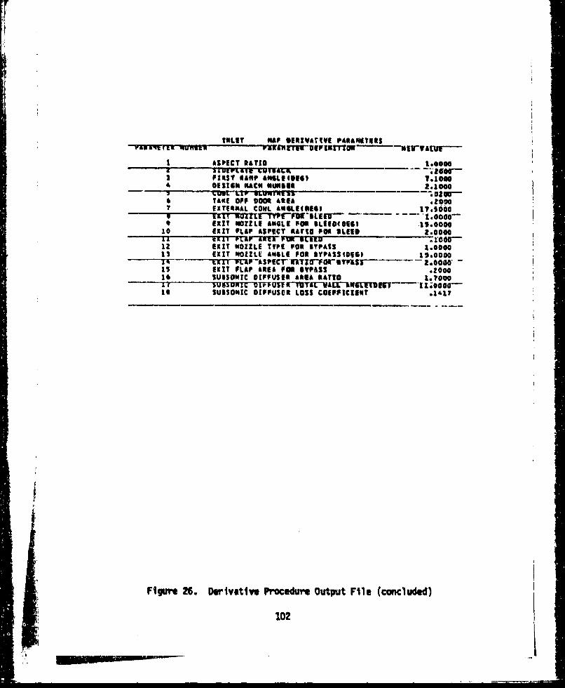
INLET NAP 1RImVrIViE PAAMITIRESva'n ai t. v un"... ra- en ETWT"UEFIEITTTW - NTVCT'-
I ASPECT RATYIO _ _N000
SLIt7LS1g ]COIShR - .-- 50a0...3 FIRST RANP AMSLE(OISI *1.000DESIGN NACH HUNEUR 2.1000
* TAKE OFF 0000 1AA Ze007 EXTERNAL COWL V N. AEII EGI IT.s000
tlT NTOoL7-TYPr-PU't SLE"D 1.0000-* EXIT NOZZLE ANGLE FOR 0LIE1I0E16 .11.0000
10 EXIT PLAP ASPECT RAIKO POe SL119 2.0000& A t AM r &NMUL-WI~ 'P.UN EEMau
12 EXIT NOZZLE TYPE FOE BYPASS 1.0000"11 EXIT NOZZLE ANGLE FOR YPAIS1OSP 19.00001 - (99VTY -L1-PEASPf rMrr TF"FO- S --- 5 - 2. 0000 -
L5 EXIT FLAP AREA 0Oil 8YPASS .000016 SUO$Isic DIPFUSRE AREA *ATrO .000
If iUXNMTr"TwFUSYWTUOTatAV- 1W"-RgTrMs - I1 .@0000Is SUBSONIC DIFFUSER LOSS COEFFICIENT ,.Lr
-i Figue 26. Derivstiwe Procedure Output File (concluded)
102
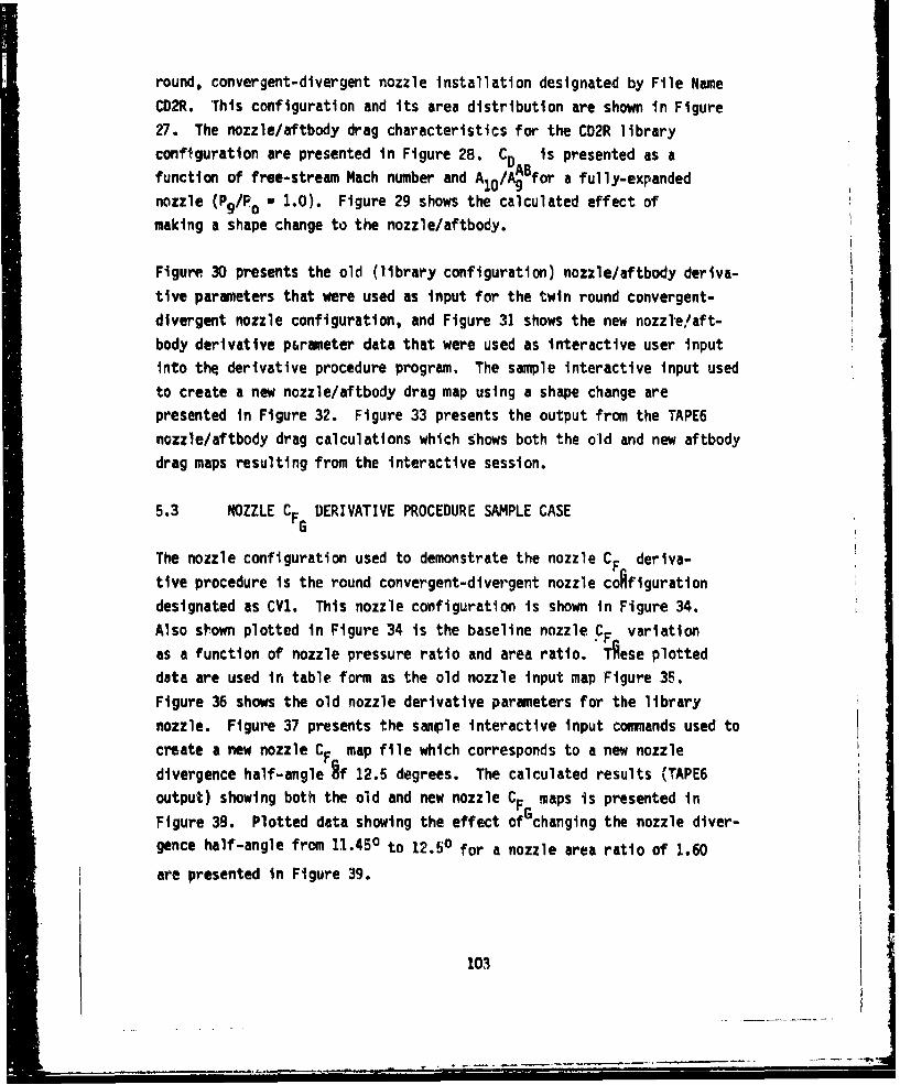
round, convergent-divergent nozzle installation designated by File Name
CD2R. This configuration and its area distribution are shown in Figure
27. The nozzle/aftbody drag characteristics for the CD2R library
configuration are presented in Figure 28. CD is presented as afunction of free-stream Mach number and AloABf or a fully-expanded
nozzle (P9/Po - 1.0). Figure 29 shows the calculated effect of
making a shape change to the nozzle/aftbody.
Figure 30 presents the old (library configuration) nozzle/aftbody deriva-
tive parameters that were used as input for the twin round convergent-
divergent nozzle configuration, and Figure 31 shows the new nozzl-elaft-
body derivative p~rameter data that were used as interactive user input
into the derivative procedure program, The sample interactive input used
to create a new nozzle/aftbody drag map using a shape change arepresented in Figure 32. Figure 33 presents the output from the TAPE6
nozzle/aftbody drag calculations which shows both the old and new aftbody
drag maps resulting from the interactive session.
5.3 NOZZLE CF DERIVATIVE PROCEDURE SAMPLE CASE
G
The nozzle configuration used to demonstrate the nozzle CF deriva-
tive procedure is the round convergent-divergent nozzle coAfiguration
designated as CV1. This nozzle configuration is shown in Figure 34.
Also shown plotted in Figure 34 is the baseline nozzle CF variation
as a function of nozzle pressure ratio and area ratio. "Aese plotted
data are used in table form as the old nozzle input map Figure 35.
Figure 36 shows the old nozzle derivative parameters for the library
nozzle. Figure 37 presents the sample interactive input commands used to
create a new nozzle CF map file which corresponds to a new nozzle
divergence half-angle Ff 12.5 degrees. The calculated results (TAPE6
output) showing both the old and new nozzle CF maps is presented in
Figure 38. Plotted data showing the effect of changing the nozzle diver-gence half-angle from 11.450 to 12.50 for a nozzle area ratio of 1.60
are presented in Figure 39.
103
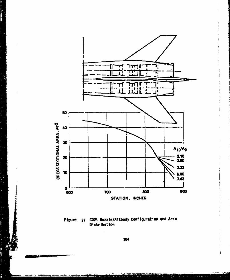
50r
w
- • JC440
--- 7.43
30
6.00O 700 -0 -O
S~STATION, INCHES
F~gure 27 CD• Nozzle/A? tbody Conftguration and AreaDistribu'tion
010i
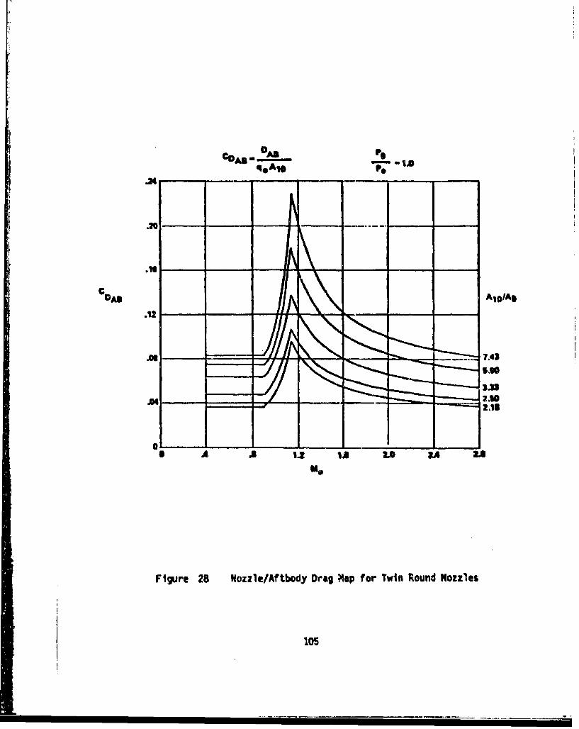
OAS IN
.24 -SA-
c DANAID/Ag
.12
.0
• A 1. IA LO IA Z.4Me
Figure 28 Nozzle/Aftbody Drag Map for Twin Round Nozzles
105
so-REVISED AFTBODYAREA DTS*RIBUTION
40
BASEUINE AMT DY- ~AREA DrSTRIBUMrN
STATION M"
6.82
MJI
CDM'
6.120
S EL INE_______ _______NFIGURtATION
OA 9.3 1 1.4 2A6 VA
Figurt 29. Comparison oF Now and Old Nozzle/Aftbody Drag Mlaps106
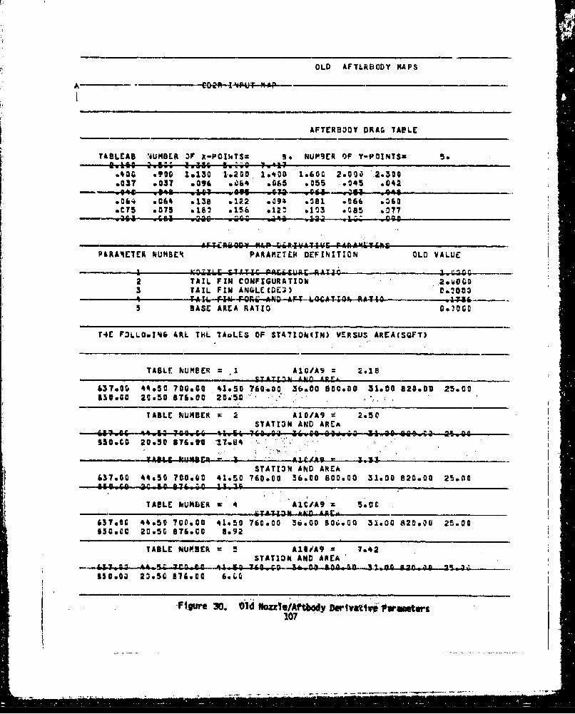
OLD AFTERBODY MAPS
- - AFTrRHODY DRAG TAPLE
TABLEAU r4UMBEK OF X-POINTSm Be NUPSrR OF Y-POINTSZ 5.
*436 a?20 1.130 '19200. 19400 1.60C 2.000 .2.300.037 .037 .096 .004 .065 .055 .045 .002
- 946 0S14 0C 11 Q.--goes 0----.,.044- 353. -0480064 .01* s138 .122 6094 .081. .066 .'60
a C75 .075 0183 .156 *124, .103 6085 .077
ArFT=Rp0DY MAPr rirR4-VA44-;6 r-AAA9';TihP4RA4ETER NUMBER PA RAMETER DEFI NITION OLD VALUE
I.~ ~ Z C 6TI;TI P~rZitl2fg RATIO I~2D -m
2 TAIL FIN CONFIGURATION .Q'3 TAIL FIN ANGLEC(DE 0.0
4 TAd..F4IN FOR: AND AF4-l_=CAYIO#6 MATIO5 BASE AREA RATIO co.~oc
t4E F3LL0.Id& 4RL THL TADLES OF ST471OW~N) VERSUS AREA(SQF1)
TABLE NUMOER .1 Ala/AS 2.18- SAZTI: AljIn Amo r
£37.00. **.5C 700.00 41.50 760.00o 36.00 800.00 31.00 820.00 25.00l55.00 20w50 976&00 20.59
TABLE NU14BER = 2Al0/A9 2.50STATION AND AREA
(W;..I 06 ktI 1""W66O iLEi 7Cioli &'vi 6W ao a: '40,0 s~ias a.oo%30vCO 20.50 876o~ '17%84 . *.
T'A3'C ?~Vrl - 3 ACAA9 - -4--a
STAY13N AND AREA437.00 44&50 700.00 41.50 760.00 36.00O 800.00 31.00 820.00 25.80
TABLE %U~bER K4 A1CIA9 z 5*5C
637eOG 4*.50 700.00 4*150 760.00 36.00 604GOD 31.00 820.00 25.0063090C 20.50 676.00 8.92
TABLE NURSER = AlOA9 = 7e42STATION AND AREA I
- W fJ'in 54 3Cd0 Q_5 7 1 .. 3- 0 gpo mo-k 3 3 44440. 2!0.4-4.-.-£[email protected] 23w56 316.00 6sLD
* . F i gr" 3 0 . 6 1 d Ho zzl eiMA t boy D eriv atfv * ' 1# srmw e tv rs

STATION AND AREA637.C q50 700,00 43,UC 760aOgO 4t,. &OGUOO 36900 82G0 -oo-4.o., e- w? 06.40 6 w-6-. C
Figure 31. New Nozzle/Aftbody Derivative Parameters
toe
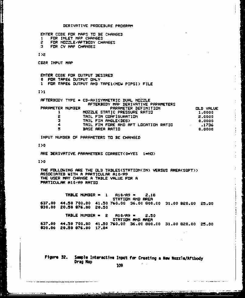
DERIVATIVE PROCEDURE PROGRAM
ENTER CODE FOR MAPS TO BE CHANGED1 FOR INLET MAP CHANGES2 FOR NOZZLE/AFT3DDY CHANGES3 FOR CV MAP CHANGES
CD2R INPUT MRP
ENTER CODE FOR OUTPUT DESIRED0 FOR TAPE6 OUTPUT ONLY1 FOR TAPE6 OUTPUT AND TRPEI(MEW PIPSI) FILE
I>1
AFTERBODY TYPE a CD-AXISYMMETRIC DURL NOZZLEAFTERBDODY MAP DERIVATIVE PARAMETERS
PARAMETER NUMBER PARAMETER DEFINITION OLD VALUE1 M[IZZLE STATIC PRESSURE RATIO 1.00002 TAIL FIN CDNFIGURATION 2.00003 TAIL FIN RAGLE(DEG) 0.00004 TRIL FIN FORE AND RFT LOCATION RATIO .17365 BASE AREA RATIO 0.0000
INPUT NUMBER OF PARAMETERS TO BE CHANGED
1>0
ARE DERIVATIVE PARAMETERS CORRECT(O=YES I-NO)
1>0
THE FOLLOWING ARE THE OLD TABLES(STATION(IN) VERSUS AREA(SQFT))ASSOCIRT"ED WITH A PARTICULAR RIO/A9THE USER MAY CHANGE A TABLE VALUE FOR APRRTICULAR R10,09 RRTD
TABLE HUMBER - I AIO/R9 m 2.18STATION AMD AREA
637.00 44.50 700.00 41.50 760.00 36.00 800.00 31.00 880.00 25,00830.00 20.50 876..00 20.50
TABLE NUMBER w 2 RIl0/R9 - 2.50STATION AND AREA
637.00 44.50 700.00 41.50 760.00 36.00 800.00 31.00 820.00 25.00830.00 20.50 876.00 17.84
Fig",e 32. Staple Interactive InpUt fom Creating a Now Nozzle/Aftbody
Drag Nap
¾0
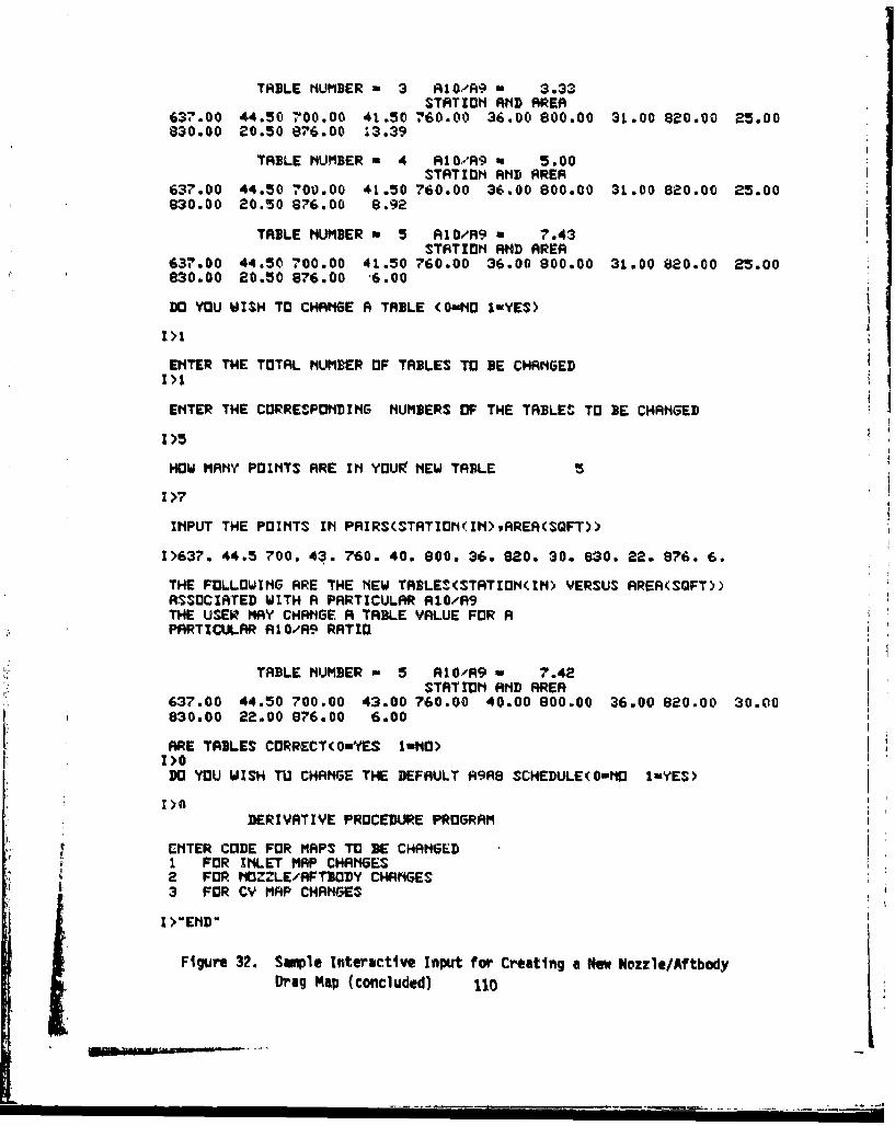
TABLE NUMBER a 3 RIO'R9 * 3.33STATION RND AREA
637.00 44.50 700.00 41.50 760.00 36.00 800.00 31.00 820.00 25.00830.00 20.50 876.00 13.39
TABLE NUMBER a 4 RIO,.'A9 - 5.00STATION AMD AREA
637.00 44.50 7"00.00 41.50 760.00 36.00 800.00 31.00 820.00 25.00830.00 20.50 876.00 8.92
TABLE HUMBER w 5 RIO/R9 7 7.43STATION ARD AREA
637.00 44.50 700.00 41.50 760.00 36.00 800.00 31.00 820.00 25.00830.00 20.50 876.00 6.00
DO YOU WISH TO CHANGE A TABLE (0-MO 1'YES)
I1>
ENTER THE TOTAL NUMBER OF TABLES TO BE CHRNGED1>1
ENTER THE CORRESPONDING NUMBERS OF THE TABLES TO BE CHANGED
1 >5
HOW RANY POINTS ARE IN YOU9 NEW TABLE 5
1>7
IHPUT THE POINTS INI PRIRS(STATIOn(IN)PRREA(SQFT))
1>637. 44.5 700. 43. 760. 40. 800. 36. 820. 30. 830. 22. 876. 6.
THE FOLLOWING ARE THE NEW TABLES(STATION(IN) VERSUS AREA(SQFT))ASSOCIATED WITH A PARTICULAR AI0/09THE USER MAY CHANGE A TABLE VALUE FOR APARTICULAR AIO/A9 RATIO
TABLE NUMBER - 5 A1O/A9 - 7.42STATION AMD AREA
637.00 44.50 700.00 43.00 760.00 40.00 800.00 36.00 820.00 30.00830.00 22.00 876.00 6.00
FARE TABLES CORRECT(O-YES IMNO)1>0DO0 YOU WISH TU CHANGE THE DEFAULT A9R8 SCHEDULE(O-NO 1,YES)
I>;
DERIVATIVE PROCEDURE PROGRAM
EHTER CODE FOR MAPS TO BE CHHNGED1 FOR INLET MAP CHANGES2 FOR NOZZLE/AFT3ODY CHANGES3 FOR CV MAP CHANGES
I >"END"
Figure 32. Sample Interactive Input for Creating 4 New Nozzle/AftbodyDrag Map (concluded) 110
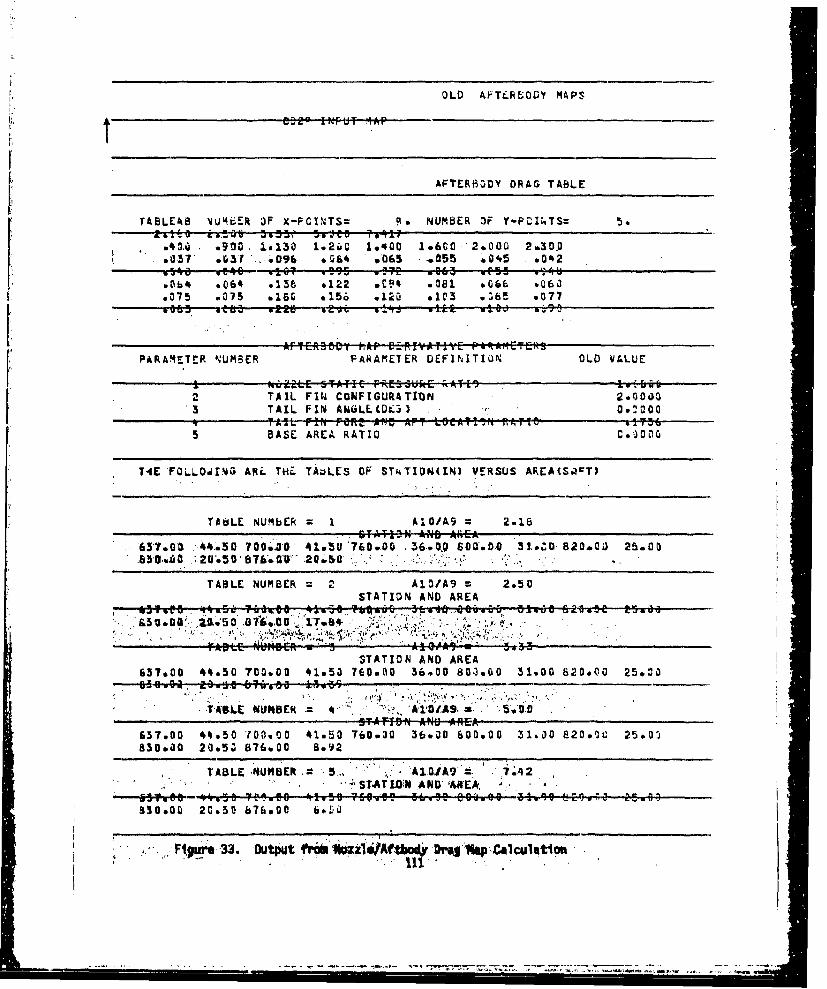
OLD AFTC.RE;OD MAPS
AF~TRHRiDY DRAG TABLE
TABLEkB N~UM6.ER OF X-POINTS= 0, NUMBER 3F Y-POINITS: 5
04 e910. 1.130 1.2ujC 1.Q0O 1.600 2&00UO 2.30.0.037 003? :..096 jb64 6,0th5 .0055 o045 *042
o0b4 6064 .136 .122 .CIP .081 ,*66 006a.075 .075 .160 6.156 0125 6103 0565 .T77
PARAMETER NUMBER PARAMETER DEFINITIO.N OLD WALUE
2 TAIL FIN CONFIGURATI'ON 2*00033 TAIL FIN ANiLLCD~ Wtý50
ofTA2L mNT FaRt An~ App LocDTmti .TAria 2 P365 BASE AREA RATIO 630
TAE 'FOLLO0Y.1G ARE. THL TADLES OF ST"kTIOt4(IN) VERSUS AREACSOOT)
T~dLE NUMbER = I A1"OI'A9 * 2.18STA~TIDt4 AND AREA
65.T ~5 0.041*5U 76.DwO .36-9.0 60aebO 33.*ZCD820.0ai) 25.00
TABLE NUMBER 2 AlO/A9 2.50STATION AND AREA
STATION AND AREA637.00 44s50 700.00 41853 760.00 36*00 803.00 31.00 820.00 25.02
.a9-0 a .5. -?68 kivai
*T-4LE tdiNBEk 41,1O(A9 .0TAi0 ANO AREA
657.00 44v50 1700.00 41.50 760.;0-36.30 600.00 31,00 PS20ole 2509300010 20s5Z 876.00O 8.92
TABLE. NUMBER . 5:.,ý 42. O1A9 = 7.42STAT LWN AND' *KEA '.
930.00 2C650 b67900 6o.,
Figre -33. Output fr6l Wozz1VAf-tAo -DM'. lisp-Calculation
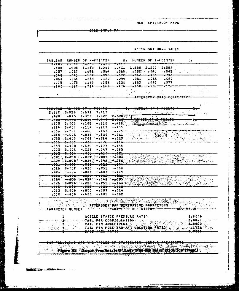
NJEW AFTEREVODY MAPS
ebiR 14rul MAI'
AFTERB30Y k)R4k TABLE
TABLEAS N~UMBER OF X-POINTS= 6. WIMEZR OF Y-PO1NTS= 5
40O0 *SfLD- 1.a1"30 1&200 1*m. -fD ,.0 .2.&DUG .2&302~: 037. *C17 wOfi s0& %35 ..a055>: v04,5 .042
.6105 P. CPs I -. 10 -. 91 -. 20 eb 1-15.
.114 9.Ora -2.11 .122? -ý9 gol5;65O
0105 ik: k! .015 t..V? -.061 3?.13 ft .
.023V.0C -.. 23 -U' ~ A-.09
6.003-0C . -. 2c0 -.-;01.
.114 -. 090 .- ol24 .-.. 048 -eA.5 5
at02 'C00CD05 -C C -&t1. -0061..0 tM .
*02 woo vC .2iT -wL4 ".0
.0039 G.G0G -.6t39 -. 07 -. 015
s016 -0*00 -. 000 -. 031 -*062
*3 *c .003-*OCUT flP-O RY'TV 1RI4TR
rX.Of1tE p~nE rýl1~Tf D=ILTIt IC~
603 -:0 T .007 -.0UIA14~ 0
NOZZLAE, STATICPRSUEATO100
HEI 196L.80.4 ARE- Vivi. TOEt R r E5 T.(N -FJ A4~cr~
Ijb

tTA3LE NUP¶ECI R. I A1li/Aý 2,b1a
STA~TIýN ANC APEA
b3QwCv 2ý%54 Es76*00 20.o5t
STATIýN ANDO AREA637*ýC 446S 72C.CD di1.5 760*ýC- 369Or 80eO.J- 31.OC 82*C 25eGO
0350C. ttst3! .AO/9
TABLE NUMBER 3 ALO/Ai9 3 5.O5VTfHiN ANDL AREA
We~ 76iV 36b.C 3040.91s0
TASLE NUMBER 4 A16/0A IL '0 a PSTATION AND AREA
637a " 1 4465C, 7fl.C 3*3CC '76O0e0 43v,30-800~.00 36, 01. 820.0A) 30048858v~d 9266 67fiv.6 .d
Figure 33. Output from Nozzle/Aftbody Drag Map Calculation (concluded)
113'.
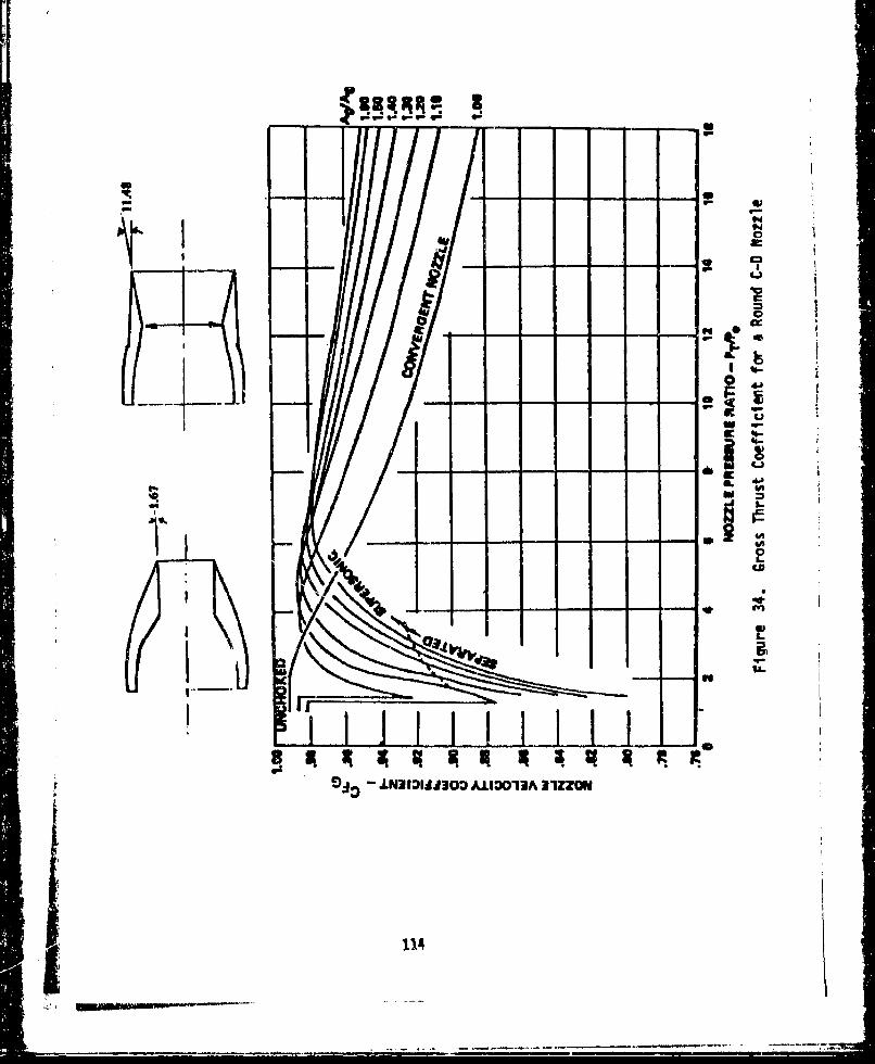
CM
I lipcoJ
t-AI'91 -. N1130 -- - -3 - -ZZ -
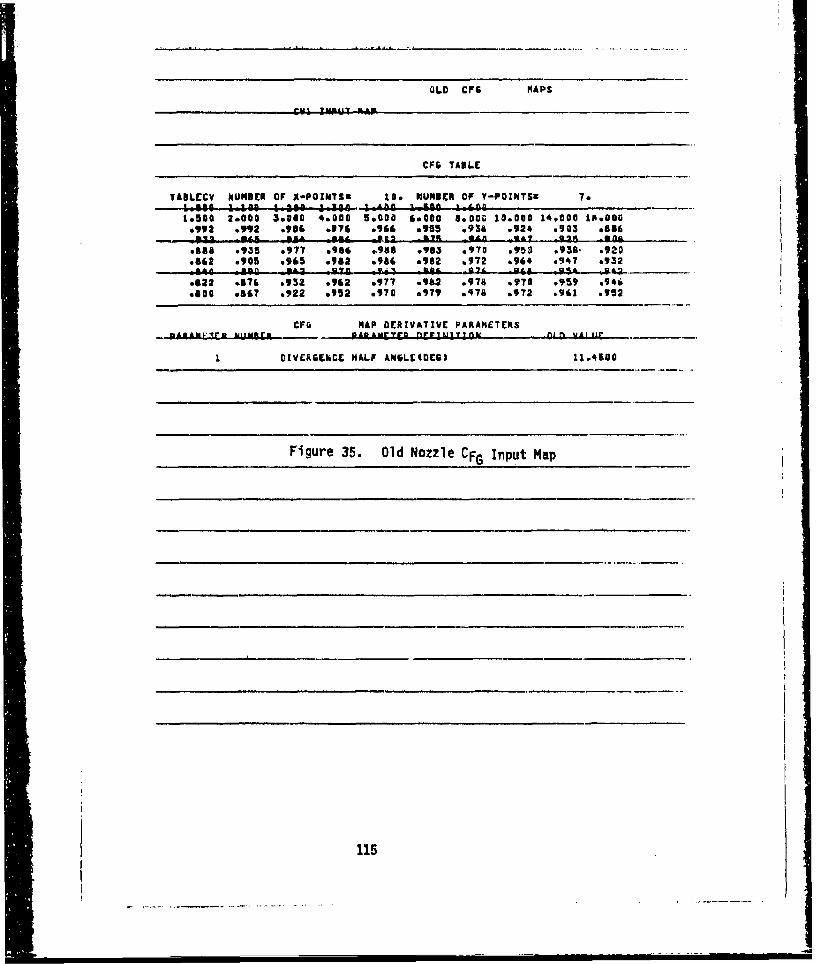
OLD0 CFG MAPS
CF6 TABLE
TABLECY NUMBER OF X-POJJGTSK Ice NUMBER OF Y-POXNTSZ 7a " 1.13 n ft 0 1 110 1n ft. ! K11 fit
1.502 2.000 3.04C 460a0 5*0oo 6.060 &.DOG 10-000 14.000 189060.992 *992 0986 0976 .966 0955 .93# .924 .903 .856_.v .&A *mA -so *- 2 p _5g5s& .935 .977 .986 o9985 .9u3 4970 095 .93s. .920.662 .905 .965 .952 .956 .982 0172 0964 e947 *932
.522 05761 .932 o962 .977 .962 .978 *970 .959 69416
.500 096? .922 .952 .970 .979 .476 *972 .961 .952
CFG MAP DERIVATIVE PARtAMETERS_uA.AXrLZELN_ o Iiur I L.AXFYRD K 1 to1 1 1 A Aim UAIUFIr
I DIVERG~kCE HALF ANGLECOE61 11.4580
Figure 35. Old Nozzle CFG Input Map
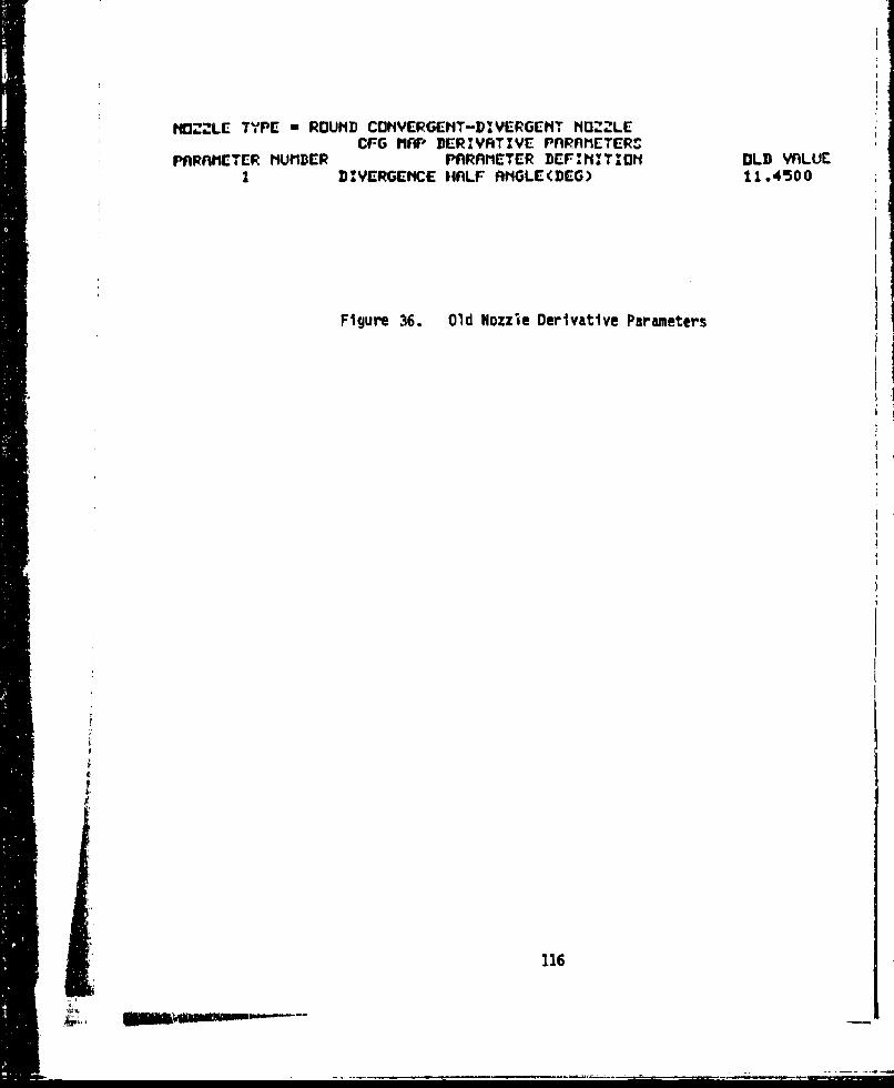
HN"&LE TYPE -ROUNID CcINVERGENT-DI&VERGENTO HUZLE
CFG MAF' DERIVATIVYE PnRAME'TERS"PARAMETER NMBflER PARAMETER DEF'flITION OLD VALUE
I DIVERGENCE H4ALF AýGLE(DEG') 11.4500
Figure 36. Old Nozzle Derivative Parameters
116
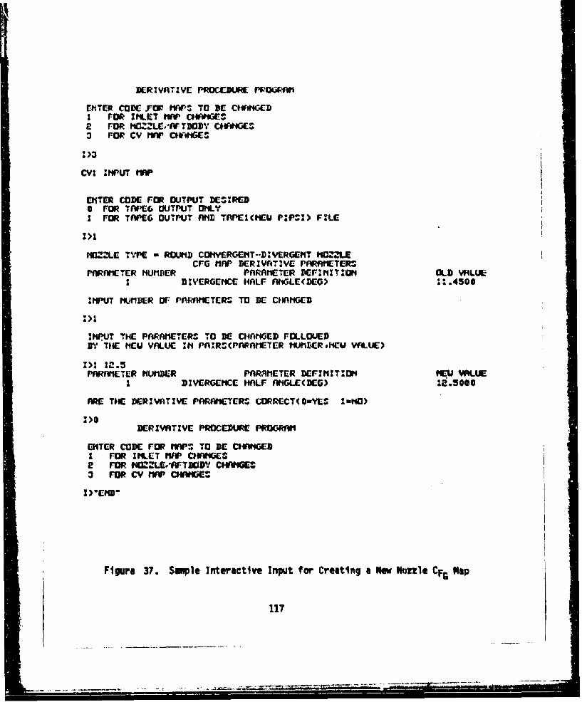
DERWVATIVE PROCEDURE PPOG1Wi
EIITER CODE FOP "W"P TO DE C0V*#GD1 FOR INLET NAP 0OWIGES,2 FOR I1OZZLE.'Ar TWDV CIV*"GE9*3 Ora cv mAp CW*ois.
CYI I PUT MAP
ENTER CODE FOR OUJTPUT DESIRED0 FOR TVV'E6 OUTPUT ONLYI FOR TAPE-6 OUTPUT MVID TnPEItCAMU PZPI) FXLE-
MIZ2'LE TY.PE- m ROUNHD COtIVERGCNT-DVICRGEI'IT HIOILECFG MnP DERIVATIVE PAAINETEro
PARAMIETER hUMPER PARAIITER Dr:N',:T;OFI OLD. WRLUEI DIYERGNCME HALF RIIGLE(DEG) 161.4500
INPUT NIUMBER OF- PnRAI1$ETEr* To BE CHANGED
INPUT THEC PnRAI1ETER.S TO KC CHANGED FOLLOUEDirt THE. #Eu VALUE. IN PnIRS(PARAI1ETER tIAtIDERshEW VfdLUE-
1>1 22.5PnRMUE TER NUMBER PARM1tETCR DE-INIT.'ON tiE-U WLUME
I ~~DIVERGENCE HALF RtIGLE-(DC-G) .5O
MRE THC BE-RIVATIVE- PARAflETER~o CORRCCT( D-YES lwNO)
I1>0DERIVATIVE- PROCEDURE PROGRWW
ENTER coDE FRm MM.". TO BRE CWWIEI1 FOR INLET "APC*WGe FOR MO2:LE.I*W-TWi5 CIWI$KoE3 FOR CV rlWC*WG
Figure 37. Smiple Interactive Input for Creating a New Nmlue CFG Nap
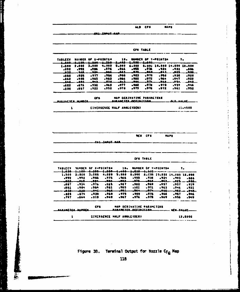
fte CFO NAPS
CFO TABLE
TAILECY N4JOSEA OF X-POINTS& If. U4NSSC OF I-PUINTS* 1.0
19591 l.se$ Sells 40966 Sem G.63 ease; &lose$ II*66 1..66zes*tog .9992 6196 9976 .966 MISS *936 6924 .943 me"6~.y .a 3. ~ ae -ago m
.66 .951 .977 so"4 6966 so"3 .971 0955 .956 ooze
.6461 .9965 .965 .962 .946 but1 OV92 6966 .941 .913-.. a~~~~~---. SAL -e -*&I--qp n" y* *u
sets .576 09"1 .962 .971 Son .976 MITI .959 .946,0891 .616 .933 09131 .916 .979 .916 .911 .961 0912
CIFS NAP DERIVATIVE PARAMETERS
C IVCIBCNCC HALF ANOLCODEI 1164510
Neu CFS NA PS
CfU TABLE
TSSLECV UINNES Of X-POINTSE Is* Nufteck OF V-POINTS. T.- .634-a4-.a446-4.344e-4.1305 4.449 log%@4.--
%*see 2.666 3.064 4.#66 S.lls &also 46916 ]loss$ 14.001 16.898.991 ,993 .go" *IT& 0144, else .96 0924 .993 .866
.of? .054 0976 .961 .967 .968 .969 a9ly 0357 *giggoal .904 .964 .901 .935 ow81 .911 .963 .946 09513
coal .74 .953 .964 .9"5 .909 .976 S966 *917 .9066717 .064 0911 4.949 .967 .974 Otis goal 6956 0949
CFS NAP DCRIVATIVC VARSNCICRU
I DIVROCISCE H*LIF A64.C3@C68 tresses
Figurm 38. Terminal OutPut fer IWozzle CFG Ralie
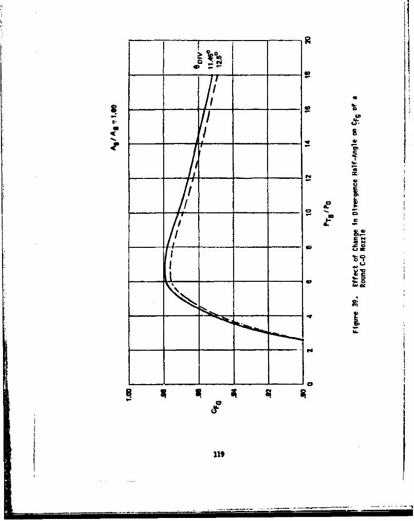
_________ _________ _________
I.._____ _____ 0
I
-- I aI 0
IL
0 £II- U-
- _______ a,E
S tU-
a,/ U
__ / __
IaN
0 £0
I 4-)-t�I
0uJu
S
_ _ _ 9,
Ii.
______________________________________ ______________________________________ _____________________________________ _________________________________
aa
119
SECTION VI
FLOWI CHARTS
Tkli' soction presents 4&tn ~incering flow charts used to develop thederivative procedure camputw program. Section 6.1 presents the inletderivative procedure flow charts, Section 6.2 presents the nozzle/aftbodydrag derivativ4 procedure flow chattt. nwid Section 6.3 presents thenozzle gross thrust coefficient derivative procedure flow charts.
121NW
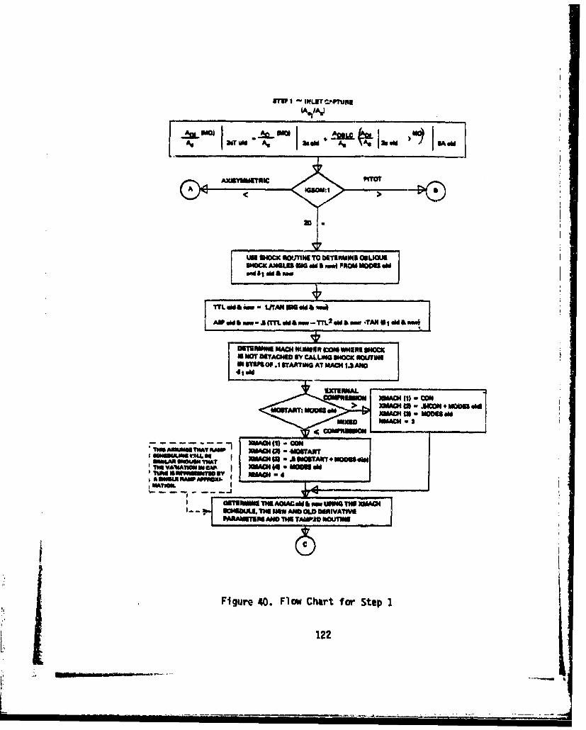
amITU - INLET C.O.Mas
[~~L~iIOjhdi±U PO Aga i M Mdi
36Y~T N __A@_9id A
A 'C IAGM IO Pila
LO SHOCK ROUTINE TO OETEMINE SUJDOCK ANGLES M0Gd ai A a PROM MOE
M sA iw -SAA 06OW b-
ASPS mid&I Tý -jUT ~ M fw - T ~ w --X I O~~ F
UI0A UWO4JS OP1gARW T A41.TNIS VNAII M S ~ @I~4- am d
PAKNEU> MAC TH wAJ NWNU+MOMN
Figure IT 40m FAow ChOr -Step 1
122 MAH
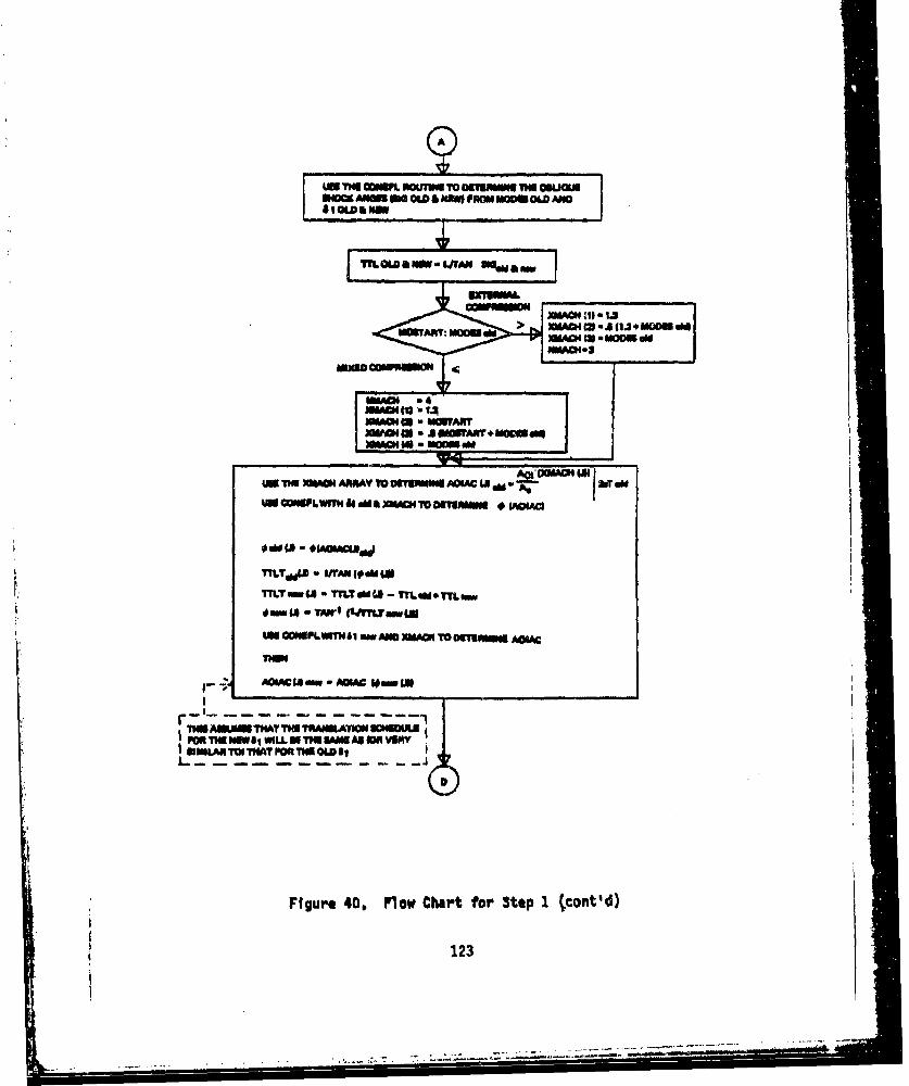
AWA
AWO mo4W
mo toS - T
us~~~XMC aouiwg c 90 mrvam *=TART
X*MI SMlWAR*MMI
OddT1. CA I 0AM iAU d
TILTE.8 - MAN~(. -OS UP~T~~
0im -4aTAWI o%~Lu nw mt
Wm GOIPLTN~i m*OMA Np4 TO OSTMuW AOUC
I~~~OU mwIIUSWIWLLTHMMAC lNVUNY
Figure 40. Flow Chart for Step I tcont'd)
123

AC IMI* I)TM TAMM
MOOR ~ 2rdlTABU TNUNATUD
FOPO ALLH MACH'ML NUMMAI MOZT
.JJMUN FlBRUMN CX~AL20 bTMXOIMWM SCSUO3rmM RUAVBft CRWT
RIUNMa ING ESOOWNY qFROM EAHIbe= NmE POhN~ THI MCj I.4.T4. 3 L
F PA.MAXO"
TI4IAYWT1H FEIOIMMIM M RACH
FLOW THAT MI*M IUR O' LL MAWI TMU SMM
figure 403, plow Chart for 3tso 1 (cont'd)
124
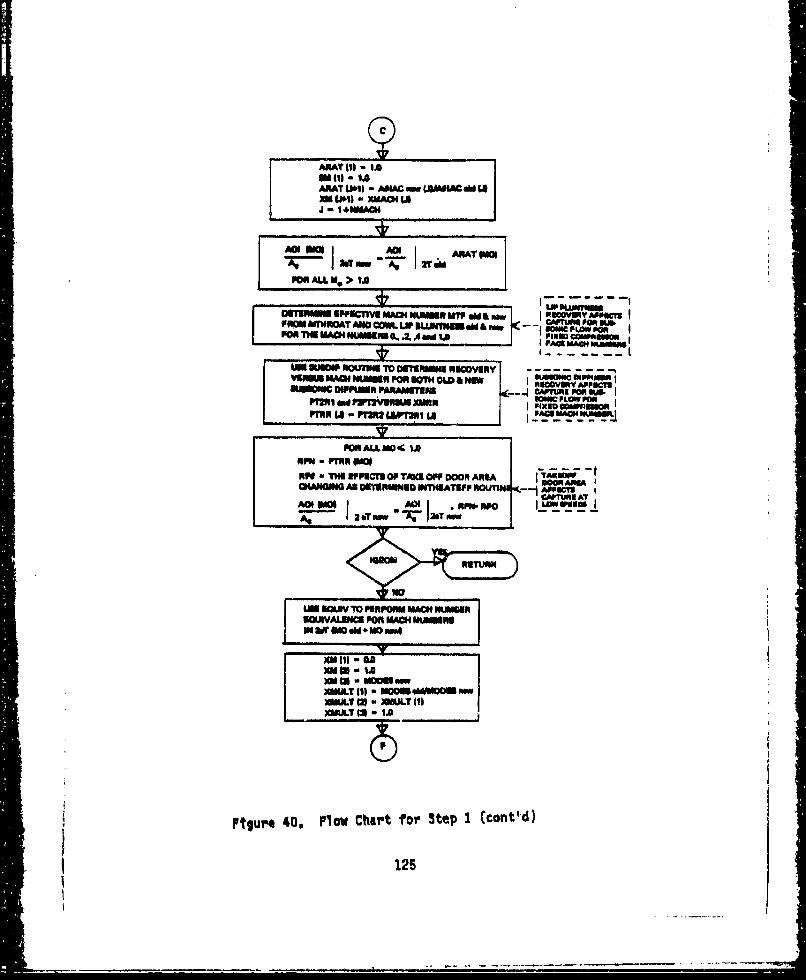
ARA141 u IAa III - 1.0ANAl OKnI - MIAC - (JMOLOW mM 14
M LI01) a XMACM I$J I +WAACN
~ 2T maw W I2T~ am AWPOP ALL H, > ?A0
aUKRmnMIS IPPICTII MACH NUMIEN WM @M & I~cvYwwPOWM WDTWOAT AID O ML LIP MuAMeuusi & ?h6PW aPON ~~~I~A PLM MAHNMII SA4WL
9WSZ MACH NIUMURP010 01. 9M OW a MW4'~ 1FfiosApm
"P"A I Prm LWFAI la
POR ALL~ NO 0 1IRN~~~~~~~ DOM~UPU10T~IP DO M
CHWOOIN AS OIEMIWUD WHILATUPF ROU'TIN -A ppomP01 J 21 IWW JaTrww AT
: LM NOW TO PIRPORM MACHSM MI
NUWJSALIU PMR MACH MUMMUIS
XMIII - GA0XM to Ix" t 0 MOM a..
1LMT III * MOMN 4CM mwUL"T W1 - UL"T (1)
Ptgre 0.Flow Chart for Step I(cont'd)
125

AOI (M01 AO (MOI
AG acT now At 24T mW XMULT (MO)
CAPTURE SCALINGWITH hiM *UONASMo0sm IS
INCREASED THEI T1qOAT AREAI BECOMES SMALLER
Figure 4a, Flow Chart for Step 1 (concluded)
126
S. • .. ... . . _2. .. _ a. ... ._ "_•'_222:'_- " •- --... '...:--•__--'-__-_ .............
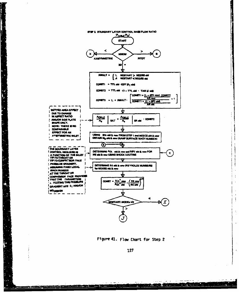
VVE I. BOLIDARY LAYER OONTRO0L MAIII FLOW RATIO
S ~TART Mr
XWATC C.N~i vma 1on
COMMIhP 1 ~- t. *4 I*- cow +IAPT=o
N AMNPU RAI ATANDOf SIDEM PLMg eNS - IURAs E MIAC oW 'COM
IINAPumK oft rr I~OU N RMSE I iMO5eNIW
AINVAUI IqOrg~NLET: DEUNMIN'4 vb MnFOSTmwmPRIamwFORZod
MAO4 NUNSERV AE
ATNTHE I40OAT OR
* ~~NTHATT PrAAhUMGRM NfTARI 41 ANO~jWdg
Figure 41. Flow Chart for Step 2
127
Ai.-
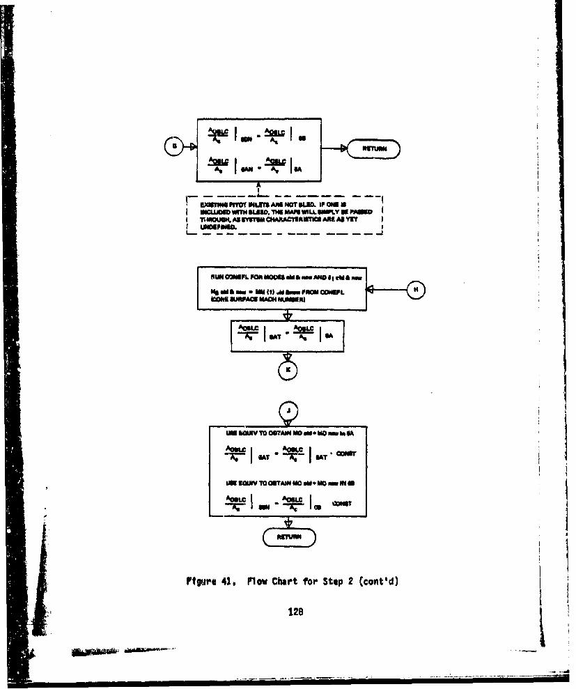
AmA
---- ---w
uxapum~~~~~I auo u unN~ 41.wm a
R UN OUIAFL FOR MOM CHARa oUwwI APO alE I adm
UN I@JSV TO OBTAIN M0 006 VA) wI
OIAj T jSA *
rtgtue 41, Flow Chart for Stop 2 (otd
128d

( In
unE~I Twwo OSTAIN mom MOu., in
AOOkLC. AOU@f COI
PON MOaM 49 MOSTART
- -~ -~-- -- OU~bdd - f[!2!I iLFOR MIXED COMPRESSION tNLETS THE1 ACt" IJA7/
*S ULED 13 SPLIT INTO FORWARD (LOW AO F0 - ( AOBLPCed AO LP )-ISPRESSURE) BLEED AN4D THROAT (HKH OLMW -( ALk
PRESSPM BLED -1NEW TABLEU M
FOR ALL MOold > MOSTART
AA:C I GAT -12 I -COS
PON MOdA C moumw
USE EGJW TO OBTAIN 100 dd-eMOs,
AOSLC CON A VLC. AOSLC PO 19 AOULC anAC SAT ( AC IA -72 AC
FOR oad> ~
USE EOUMV. TO OBTAIN M*do M0, 1
figure 41. Flow Chart for Step 2 (concluded)
129
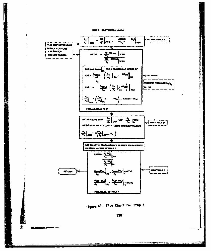
UTP 3 INLET PJPPLY 4A.4"
.lupmAOII I
noUL MI) I#J RAM lowSI XA UN
PON ALLAGA POOR A PAWrKXP.AN MOMU OF
VAL- -A" ( I I' aeoGj
AsPW W RIW UALU
~+ VAL)*AN-YL
POR ALL M~si N 2A
AN UOMIAL~IM CALED it. IUN T-m -n 0-mVAENU *MM
umWSW JTO PUPPOIAN ACNUMN l OMJALuIMION MACH VAL WM LI J AN
PIATW-!~PO
MRW ALL MM IN TAULI I
Figure 42. Flow Chart fort Step 3
130
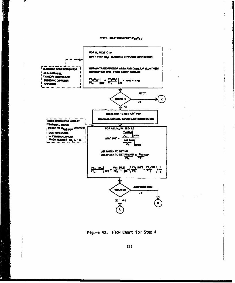
ON PO ONTM TAMOPF DOOR AREA AMD COWL LIP DMwNUI
LP BITN owRcION amO PROM ATIPP ROT imTAICOPP DOORILAMOIUNlIDWPFuI% I *A RPI R*
"TOT
iGO02 >
Un Pon" To UT RA40 Fom- -- -- - -, NOMINAL NORMAL. SHOC MACHN UMDEf WEB
rIMIRMUAL 3ON=PRYO"TMeggmpjown"hIU FOR ALL Me, k =;I, .
I OR TDO CHAGE IAqI 'IRMIMALOC ofA A4 IUW
WANWI mumm Ai*01 AMV
T~~ Tm G0T 20'
EmwIOcxTOVN
"I.
Fiur 43 Fo JhatfrStep 4"
131f~

Fm
:1__
P" a I ToI I.U CA
-m L.."Le rtI
FO AL ORE .moo >1.6
IT ~ ~ ~ ~ -~- IITULR e pvwcmtco msis
POALLM,0111 IN 11MAOI OUTIN ----------
UT. _ I I~
Po p ALL i 1 M'WIIM W-o
Fr, NMNTAROS Ioii
.e~~um~ia PrV~,.i iu SwM AXU OF - - - - -- _
F~~~~~guv~~Ef!ýM 43 lwCarMo tp4 cnldd
UO6 WW TOADAWALL t, W132
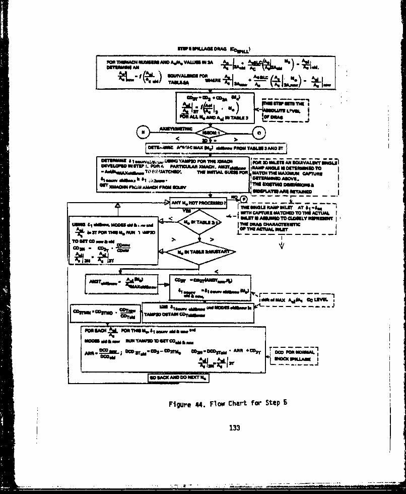
PWThUMACHN USJMADA~,AVALAIUS Ni 2ANDITUIMIWI AN Ac
mmAL romv)Aa aAv &J3 OftAow
NJhI W~AC MAX %J d*- FROM TA"L 3 AND 3T
OMOMOI"s ARTWCULAR H,.AWWM~rjw 1 IRA'D.WU#J MMorusiMToAdA*,%m7 " AACW TM WbAL GUM POPN MAM~ THU MAXNALR CAMflIN
somvAUIM TOm 6WL $1 4NUIIIIWNMDM
IiEANN AjAODLVI
<M %NTIN M&e
[0"c mw4o >OIM.Ium >a
A a Iw k4 Tmu w&
Fiur NJ. cowCar o Se
133fuxA4%GcW
-grdTOWO fls
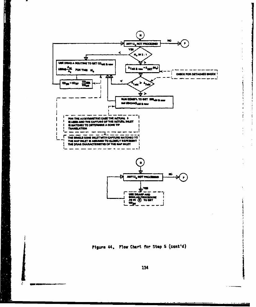
UN~~ DM*AMUO T pCWm
A ml P " T H I A
1
PME TIN "ThEMI CAN~3U TIN ACTUAL Sil
IW SNThOU CW O VRhNA-FTUI MTWW T
0
70"-r
figure 44. Flow Chart for StUP 5 (cont'd)
134
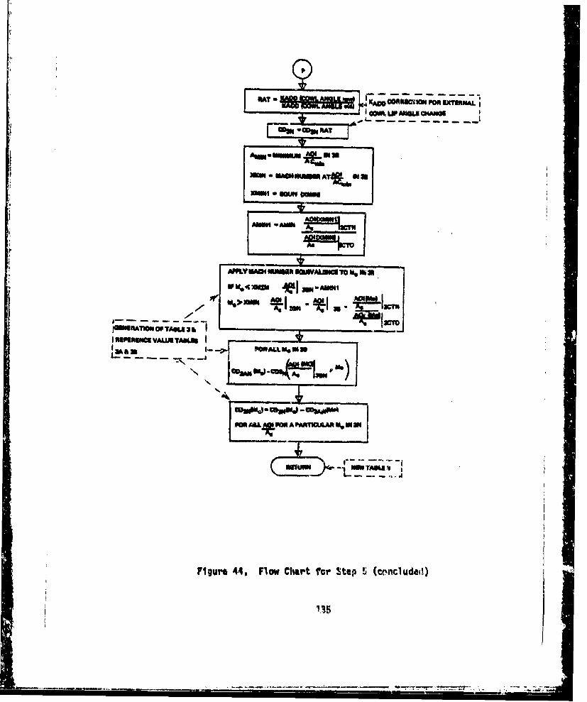
.,rKADSONNc"Amm Pon EXT1RMALj
AMI-WAN INEIR USJAL~A , Mb Maw W4.tm *I nAMI4
rMWhRATMOS OP TANS 3~ 1-NI RIUMUO VALIM TALU
&a-.> PCALL M*1,
PM9A*POWA Poinu1AARM 0 3H
figui'e 44. Flow Chart ftr Step 'i (econcluded)
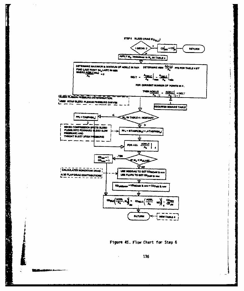
A"Ly e "W-w- M.N TANI 4
DITEMUNO MAXWLI & MIMVAUM OF AMLC IN lA&M DTEMINt MEW PIEPO TIL 4PONO LAWT PowI vIMLAII1 em so
FOR CORMTm NUMm OFP OeWy IN 4.
TNVN AONLC- #DE_
PWP n ruwmpnawltg omv,uw Knmao PUNU muw uaiv
r >WUON 30-FLOM MTO PORWAND I ow L190 -MOW PP- WTA1PIJ +U'TMWWe
THROA BENAIL 4 JI
PONur ".L FAt,(hrtf' te
136
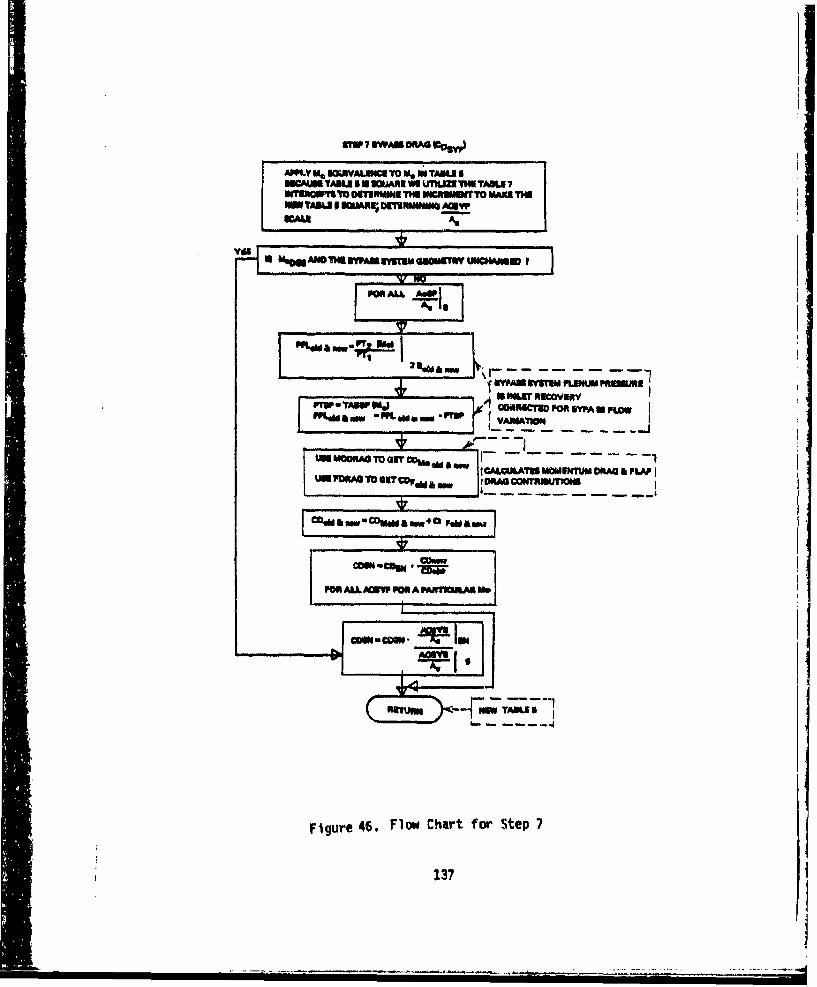
27W 7 SWAIS OR"AG s"
APPL U0 UKXYALUNC TO W6 NO TABUSSWCAUU TABLEm 5 4 ANE WI LUMIZ TMU TAOU 7
WAU
4 Ma~o=u ADM rfAN EUM Gicucim UNW*ISW y
PVSP.TSW ML (GSMCTSD 5O San FLOW
4k mw~SA '"L GETU.d a i OP-1
tCALPA.AT GETWU CRAG am a
IAWi~~ "LDRAI TOM) DRAG FLAPAlRS1IW
-7 -__ --- - ,--I
FRALL AGMW FR A FAWflORIA Ift
cow - UKN -fWTI
figure 46. Flow Chart for Step 7
137
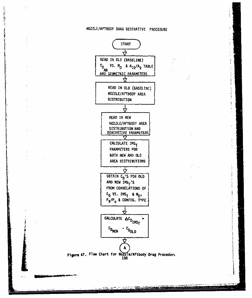
NOZZLE/AFTBODY DRAG DERIVATIVE PROCEDURE
READ IN OLD (BASELINE)CD VS. M0 & AIo/A9 TABLE'AS
AND GEOMETRIC PARAMETERS
READ IN OLD (BASELINE)NOZZLE/AFTBODY AREADISTRIBUTION
READ IN NEW
NOZZLE/AFTBODY AREADISTRIBUTION AND
DERIVATIVE PARAMETERS.
CALCULATE IMST
PARAMETERS FOR
BOTH NEW AND OLD
AREA DISTRIBUTIONS
"OBTAIN CD"S FOR OLD
AND NEW IMST.S
FROM CORRELATIONS OF
C0 VS. INSr I No.
P9/Po I CONFIG. TYPE
• ~ ~~CALCULATE &•COsT'
SCDNEW- CDoLD
Figure 47. Flow Chart for Noz */Aftbody Drag .Procedurc138
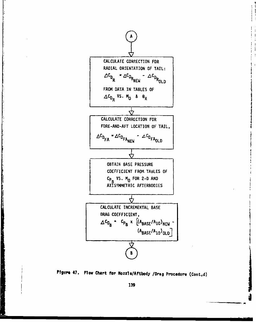
CALCULATE CORRECTION FORRADIAL ORIENTATION OF TAIL:
LDCDR /CDRNEW - '6CDROLD
FROM DATA IN TABLES OFACDR VS. MO & OR
CALCULATE CORRECTION FOR
FORE-AND-AFT LOCATION OF TAIL.
6£CDFA "ACDFANE 6CDFAoLD
mII
OBTAIN BASE PRESSURECOEFFICIENT FROM TABLES OFCPB VS. MO FOR 2-D AND
AXISYMM4ETRIC AFTERBODIES
CALCULATE INCREMENTAL BASEDRAG COEFFICIENT,
ACDB Ca B x LABASE/A1O)NEW -
(ABASE/AlO)OLD]
Ptgur. 47. Flow Chart for Nozzle/Aftbody /Drag Procedure (Contd)
139
dl•Ip
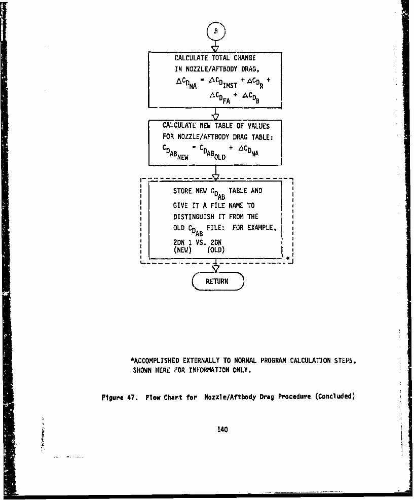
CALCULATE TOTAL CHANGE
IN NOZZLE/AFTBODY DRAG,
CDNA CDIMST ACDR +
ACD + ACDFA B
CALCULATE NEW TABLE OF VALUES
FOR NOZZLE/AFTBODY DRAG TABLE:
CDABNEW CDABOLD + CDNA
STORE NEW C TABLE ANDGDABGIVE IT A FILE NAME TO
DISTINGUISH IT FROM THE
OLD CD FILE: FOR EXAMPLE,AB
2DN 1 VS. 2DN(NEW) (OLD)
RETURN
*ACCOMPLISHED EXTERNALLY TO NORMAL PROGRAM CALCULATION STEPS.SHOWN HERE FOR rNFORMATION ONLY.
Figure 47. Flow Chart for Nozzle/Aftbody Drag Procedure (Concluded)
140
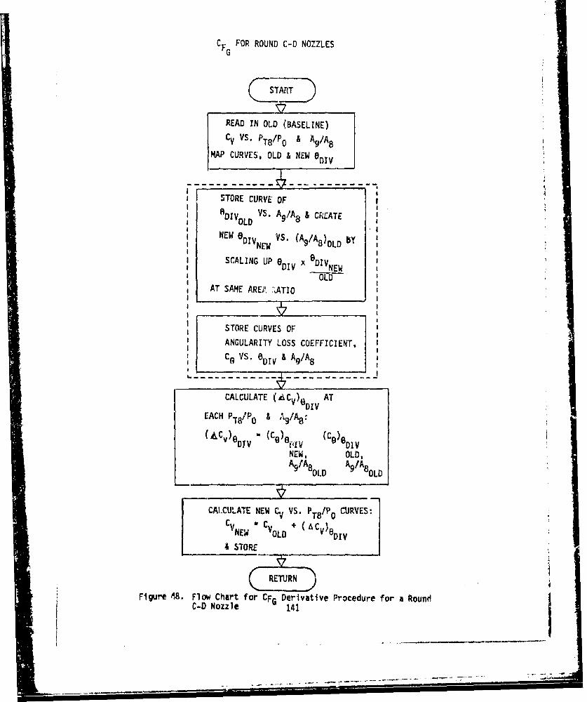
CFG FOR ROUND C-D NOZZLES
S READ IN OLD (BASELINE)
CV vs. PT8/Po A Ag/AB
MAP CURVES, OLD & NEW eOiv
STORE CURVE OF
DIVoLD VS. Ag/A 8 & CREATEOLD
NEW aDIVNEw VS. (Ag/A8)OLD by
SCALING UP 6 DIV x DIV
AT SAME AREA' :..ATIO
STORE CURVES OF
ANGULARITY LOSS COEFFICIENT,
C9 VS. 8DIV & Aq/A8
CALCULATE (ACV)6 ATDIV
EACH PT8/PO & ,•/A8
(C~) (C9) ( CeDTV 01) V DIV
NEW, OLD,A91A8 0LD A9 /A8 OLD
CALCULATE NEW C VS. PT8o/P CURVES:C V T8i CV~NEW "COLD + C)DIV
& STORE
Figure 68. Flow Chart for CFG Derivative Procedure for a RoundC-D Nozzle 141
I I I I I I I I. . .- -.- - -- -- - --
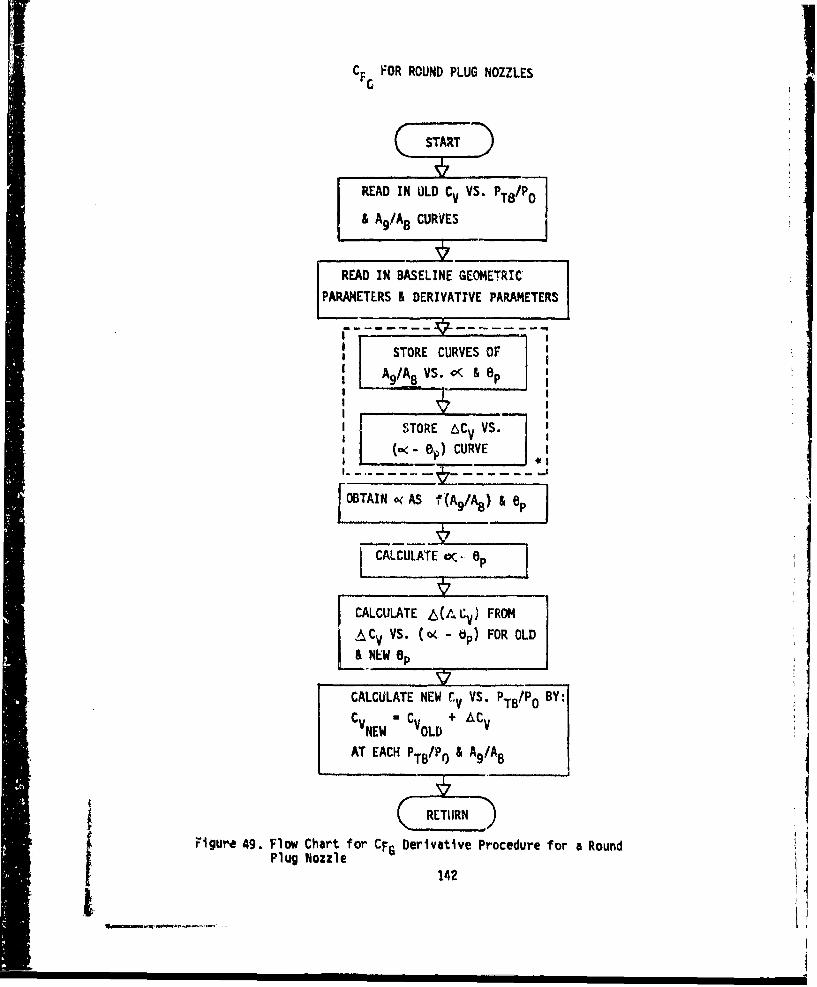
CF FOR ROUND PLUG NOZZLES
READ IN ULD Cv VS. PT8/Po0
& A9/A8 CURVES
READ IN BASELINE GEOMETRIC
PARAMETERS & DERIVATIVE PARAMETERS
STORE CURVES OF i-A 9 /A8 VS. c< & Op
STORE 6CV VS.
(o e O.) CURVE J
[OBTAIN o< AS f(A 9/As) & BpJ
LALCULATE oC, Op
CALCULATE 6tCV) FROM
CV (. - ip) FOR OLD- & NEW ep
CALCULATE NEW CV VS. PTs/Po BY:C C + ACv
NEW OLDAT EACH PTB/P & A9 /A8
Figure 49. Flow Chart for CFG Derivative Procedure for a RoundPlug Nozzle
142
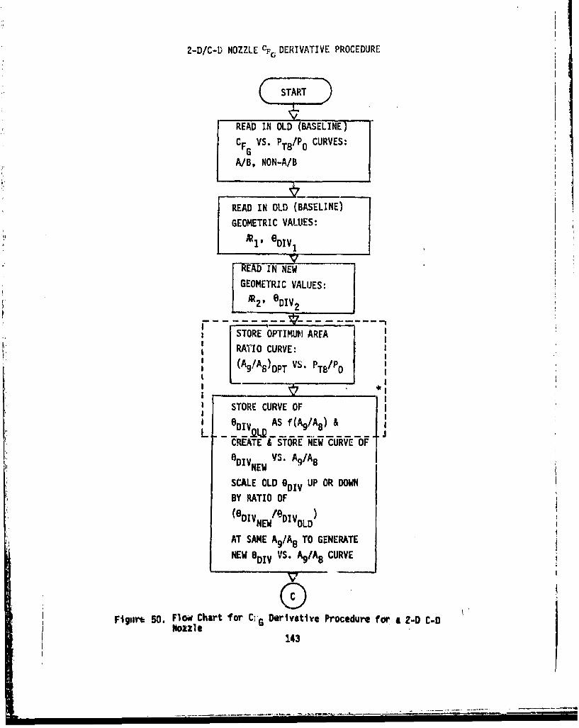
2-D/C-D NOZZLE CF. DERIVATIVE PROCEDURE
READ IN OLD (BASELINE)
CFG VS. PT8/P CURVES:
A/B, NON-A/B
READ IN OLD (BASELINE)
GEOMETRIC VALUES:
A~1 , 6 DIV
"REW-D IN NEWGEOMETRIC VALUES:
R2, eDIV2
STORE OPTIMUM AREA
RATIO CURVE:
(A9!A8)oPT VS. PT/Po
STORE CURVE OF
_ DIV- AS f(Ag/A8 ) &
CREATE & STORE NEW CURVE OFeDIVNEW VS. Ag/A8
SCALE OLD 0 DIV UP OR DOWN
BY RATIO OF
(8 DIV /eDIVNEW OLD
AT SAME A9 /A8 TO GENERATE
NEW eDiv VS. A%/A8 CURVE
V
Figiur 50. Flow Chart for C;'G Derivative Procedure for a 2-D C-DNozzle -143
,--
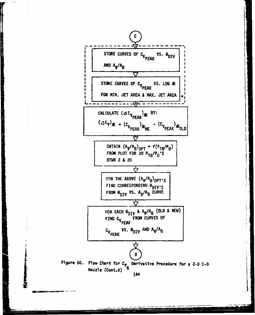
STORE CURVES OF CV VS. Div
AND %/A
STORE CURVES OF CV VS. LOG AtPEAK
FOR MIN. JET AREA & MAX. JET AREAJ,
CALCULATE (4 CVpK BY:VPEAK
(dCV)M * (CV ~At - (CV AlPEAK NE PEAK OLD
OBTAIN (Ag/A 8 )oPT -)T8'Po'
FROM PLOT FOR 10 PTB/PO'SBTWN 2 & 20
ý7 i
FOR THE ABOVE (Ag/A8)OPTS-
FIND CORRESPONDING 0DIV'S
FROM 80DV VS. Ag/A 8 CURVE
FOR EACH 9 DIV & Ag/A 8 (OLD A NEW)
FIND CV FROM CURVES OFPEAK
CVPEAK VS. 9DIV AND A9 /A8
Figure 50. Flow Chart for c Derivative Procedure for a 2-D C-Dji [ Nozzle (Contd) 4.- • 144,
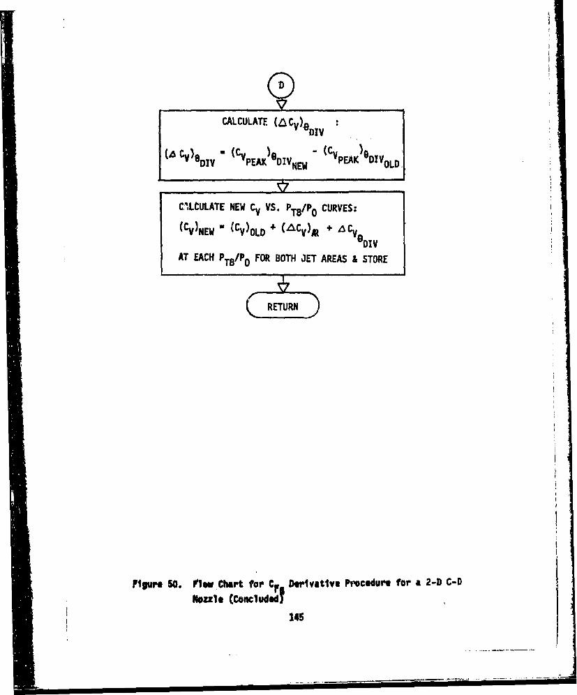
CALCULATE (aCV)e"("( )e - (Cv )D
('6 CvDIV PEAK l DIVNE # PEAK DIeoLD
CILCULATE NEW CV VS. PT8'Po CURVES:
(CV)NEW ' (CV)OLD + (L&Cv) 4 t ACVI TV
eDIVAT EACH PT8/PO FOR BOTH JET AREAS & STORE
ilgure 50. iew Chart for CF_ Dsgljvtjlv Procedure for a 2-D C-D
Noule (Concluded?145
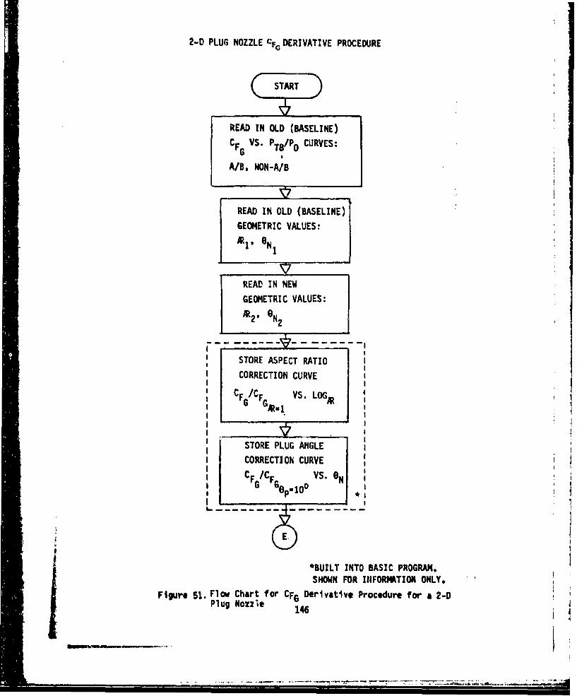
2-D PLUG NOZZLE CFG DERIVATIVE PROCEDURE
READ IN OLD (BASELINE)
CF VS. PT8 /Po CURVES:G
A/B, NON-A/B
READ IN OLD (BASELINE)
GEOMETRIC VALUES:
t1' 8 N1
SREAD IN NEW
GEOMETRIC VALUES:
At 2* N2
STORE ASPECT RATIOI CORRECTION CURVE
CF /CF VS. LOG,G G•, 1
STORE PLUG ANGLECORRECTION CURVE
CF /CF VS. 0 NG GelO 0
II
*BUILT INTO BASIC PROGRAM.
SHOWN FOR I1FORMATION ONLY.
Figure 51. Flow Chart for CFG Derivative Procedure for a 2-DPlug Nozzle 146
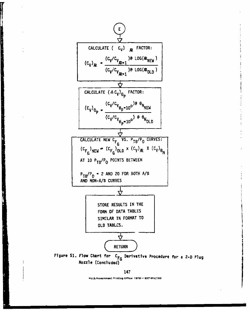
CALCULATE C CV) R FACTOR:
(Cv) - (Cv/CV )@ LOG(tNEW)
(CviCV )@ LOG(RtoLD)
CALCULATE (A CV)ep FACTOR:
p (Cv/CV 0 ON-I
(Cv/CV o @ 6oGl0 U0 OLDL
CALCULATE NEW CFG VS. PT8/Po CURVES:
(CFG)NEWg (CF )OLD x (Cv)O X (CV)eG ~ GN
AT 10 PT8/Po POINTS BETWEEN
PT8O/P - 2 AND 20 FOR BOTH A/B
AND NON-A/B CURVES
STORE RESULTS IN THE
FORM OF DATA TABLES
SIMILAR IN FORMAT TO
OLD TABLES.
G RETURNFigure 51. Flow Chart for CFG Derivative Procedure for a 2-D Plug
Nozzle (Concluded)
147
*U,$.Qovernmmnt Printing Officet 19781 - 657*-0021O2