unclassified ad number classification changes to
TRANSCRIPT

UNCLASSIFIED
AD NUMBER
CLASSIFICATION CHANGESTO:FROM:
LIMITATION CHANGESTO:
FROM:
AUTHORITY
THIS PAGE IS UNCLASSIFIED
ADB805966
unclassified
restricted
Approved for public release; distribution isunlimited.
Distribution authorized to DoD only;Administrative/Operational Use; FEB 1942. Otherrequests shall be referred to NationalAeronautics and Space Administration,Washington, DC. Pre-dates formal DoDdistribution statements. Treat as DoD only.
NACA list dtd 28 Sep 1945; NASA TR Serverwebsite

""(f* document contain« daaamed information mSmdSmg \hc "- ation&I Defence* ot tk* Unitwv States within thä m«r-nine of the Espionage li.- hvtnsmission or the rev« any manner to an unauthorized lew. Information ao claaaifiVd to p.-rnom in the military and VJn'»r«d Sta'es, appropriate civilian ] "• 'He Federal Government wf di - rein, sad to United Steten citizen« on d'f-.retion who of necea«»ty nn*S f»e informed thereat
»>--
;i -.;
22CHHICAL BT0T3S
7A7?I01TAL ADVISORY 00HHIT3JBZ FOR AERONAUTICS
No. 841
THE PHOTOVISCOUS PR0P3RTI3S OP FLUIDS
By R. Weiler, D. J. Hiddlehurst, and R. Steine* State College of Washington
k ..
7 ••• ~ • .-~^-:/-~
I - • .
I
...-••• t • -.-
.••;ay- ... -.-=•-*=
Washington February 1942 FOR REFBRENCE
^ 7Ö ^ ^*^ nat'wcs axa

NATIONAL ADVISORY COMMITTEE TOS AERONAUTICS
TECHNICAL NOTE 110. 841
THE PHOTOYISCOUS PROPERTIES OP FLUIDS _
3y R. Weiler, D. J. Middlehurst, and R. Steiner
A method has "bee sion of the methods o measurement of Teloci The method is "based o i<ain liquids gives ri linearly related to t sitivity of numerous calibrating apparatus system was constructe studied around certai cate that the method problems in fluid flo
SUMMARY
n developed that permits f photoelasticity to inc ty distribution in a mov n the fact that viscous se to double refraction, he shear stresses. ~TTTe liquids has been measure
Subsequently a closed" d and the velocity distr n simple shapes. 'The ye may be profitably used^_t w not easily attacked in
the exten- lude the' ing fluid~T^~ shear _in cer— which may be optical sen- d in suitable c £ rcüTa ting
ibution was suits indi~~ b inveslTxgate ö t her~ways 7
INTRODUCTION -"r
The development of double refraction in a liquid ^.s a result of viscous shear will be termed "pholfovlscosity." The degree to which a liquid develops photoviscosity for" a given rate of shear will be called its photo'vtscoiis"sea-" sitivity. This property has been studied from time to " time since it was reported by I-Iaxwell (reference l) in 1874 although this report does not seem to have~^been the first record of its existence. Most of these studies have been concerned with the measurement of photoviscous sen~ sitivity for a given group of liquids, and a literature of " the effect has been built up. A large number "of rejfer-^ ences on the subject are included in the bibliography at the end of this report. A very complete bibliography oh the subject of phot oelasticity is included in reference "IST. A few of the observers have attempted to explain the ~~ef —" feet in terms of assumed optical and mechanical anisotr'o- pies present in the mediums. -Raman and £r*ischnan (refer- ence S) in 1928 published the most elaborate of the T;heorJ.e in this direct-ion. The first at.tempts to apply the phenom- enon to the solution of engineering problems seem to have
-t—=^--..-J
s

2 NACA Technical Hot« So. 841 r
be«n reported by Sadron and Alcock (references 4 and 5) .
A great number of organic compounds having unusual op- tical properties have been developed within recent years. It seemed probable that some of these might have a higher photoviscous sensitivity than the liquids previously in- vestigated. For example, whereas cellulose nitrate 10 years ago was themost satisfactory material for photoelas- tic analysis.of solid models, the development of tho phonol- formaldehyde ^and similar plastics .made possible a now and improvod photoolastie technique. The present paper covors an investigation of several of those newer compounds as well as certain other materials not previously reported. The investigation was undertaken primarily to discover a suitable liquid for optical fluid-flow determinations and not for the purpose of accurately measuring the photo- viscous sensitivity of a large number of liquids. The ap- paratus and the method employed wore such as to.yield vory little data regarding materials of low sensitivity, which were discarded without much attention. Emphasis was laid on tho convenient measurement—of large effocirs.
The assistance of tho following—organizations is gratefully acknowledged in providing materials for this work and information concerning these materials; Eastman Kodak Company, Bakelite Corporation, E. I. duPont do ITemours & Company, Monsanto Chemical Company, The B. T. Goodrich Company, and Research Foundation of the Armour Institute of Technology.
PHOTOTISCOSITY
Tho phenomenon of photoviscosity involves the develop- ment of directional optical properties in a liquid in which a velocity gradient is present. Such a velocity gradient sets up stresses in the liquid as a result of viscous shear. These shearing stresses are proportional to the gradient and.to the viscosity (absolute). By analogy with the photo- elastic effect, a tension and a compression at^ right an- gles to each other and at 45° on either side of the shears may be substituted for these shearing strosses. (See fig. 1.) These may be taken as the "principle stress direc- t-ions" in the liquid. Jn many liquids the dir-ections of the minimum and maximum refraction indices are found to lie along these principal stress directions. Where those directions do not coincide, the theory will probably re-

1TACA Technical ITote Ho. 841
quire rather specific assumptions as to the character of the liquid.
A liquid which develops birefringence in such a way that the index of refraction is reduced for light in which the electric vector vibrates in the direction of "princi- pal tension" and is increased in the direction of "princi- pal compression" is said to be positively bir'efringeht and vice versa. Both positive and negative liquids have been observed. In some cases the sign of the birefringence reverses as the rate of shearing increases. (See refer- ence 6. ) • • -
METHODS OE MEASUREMENT • -.
Maxwell (reference l) suggested that photoviscous bi- refringence be measured by placing the liquid betweon an outer stationary hollow cylinder and a cohcöhtric inner rotating cylinder. This apparatus was to be placed in a polariscope and the interference patternW wore to be ob- served. Eigure 2 shows such an arrangoment schematically. Here the velocity of the liquid at a given radius R vHF- ies according to the relationship T'~~~ ~
V = V, log0
a3 - loSe R
lQSQ Hs - l0ge R1
in which Vx is the peripheral velocity of the innor cyl- inder, Rx is the radius of the inner cylinder, and R3 the inner radius of the outer cylinder. The accompanying velocity gradient on which the optical effect depends is found by differentiation to bo
dr R doge Rs - log0 Rx) ' R
where
A = loSn Ha - logD R
'o
It will be observed that this gradient is not constant over the -gap between the two cylinders and therefor"eT/ä reference point must be.chosen in the gap at which measurements are to be made. It is convenient to measure the velocity gradi-

4 NACA technical Böte ffo.' 841
ent at; the midpoint of the 'gap between' the two cylinders, this point being very olose to the average value.
The method by which the calibration is made depends on the sensitivity of the liquid being tested. : One way is simply to count the fringes that pass the center of the gap as' the speed -of the inner cylinder is slowly increased. If the order of interference is more than' three or four, monochromatic light must be used 'in order to maintain sharply defined fringes. The effect is also proportional to the length of light path through the liquid; the num- ber of fringes may be- doubled by doubling tho length of the path. The sensitivity of the apparatus therefore de- pend-s- on this dimension.
Inasmuch, as counting fringes is an inaccurate process, it is better to introduce a Babinot Soloil compensator at the point indicated in figure 2. With the polarizer and the analyzer crossed and.the componsator set at zero, the field will be dark when the innor cylinder is stationary. If the inaor cylinder is now rotated,light will be re- stored and the compensator may be employed to return the field to blackness. Tho amount of birefringenco may then bo road directly on the compensator scale. It is better tier use whit.e light because in this instance the zero-order fringe is the only one thefcappears black; all others are colored and confusion, therefore, does not exist as to the degree of compensation obtained.
Two types of gg^rn-a£»gSttäffi£££_ compensatur-s are availa- ble. If the ordinary compensator is used, a series of parallel fringes appe ar in the field, the center one boing black when compensation is complete. If tho Babinet Soliel type of compensator is used, the entire field is - compensated by a constant amount, any variation ovor the field boing duo to tho variation in the velocity gradient of the liquid. The Babinet Soleil type of compensator was employed in the present investigation.
When the effect is small, as it has been in all pre- .x viously r-eported data, spectroscopic methods may be used." Here the light emerging from the polariscope is projected into a spectrometer. As 'the birefringence of tho fluid increases, certain of the spectral colors will be restored and will be visible in the spectrometer. If additional birofringent material is introduced into tho polariscopo (such as a mica plate about 0.01 cm thick), there will be several dark bands in the spectral field. The motion of

HACA Technical IToto ffo. 841
these "bands as the "birefringence is varied is a rather sensitive test for double refraction.
The photoviscou's sensitivity of a given material may- he measured in terms of the Maxwell constant (reference 3). This constant is defined "by the equation '. .
n, - nx = H* g
in which nx is the refractive index in the direction of the principal tension, n3 is the refractive index in the direction of compression, H is the Maxwell cons^anr, u- is the viscosity of the liquid, and dV/ds is the velocity gradient. When the value of the Maxwell constant is computed for known liquids, it is found t.o contain a factor of the order of lO"11, which renders it inconven- ient to handle. In the present report this sensitivity is discussed in torms of (a) the fringe value and (h) the specific fringe value. The first of these values is de- fined as the velocity gradiont that will produce a rola- tivo retardation of one wave length of light in a unit thickness of the liquid. The valuo of this constant will dopond on the units used Pjid on the wave length of the light selected, no significance being attached tq. this constant for white light. The specific fringo value is defined as the fringo valuo multiplied hy the absolute viscosity (in.poisos).
CALIBPATIITÖ APPARATUS
The various types of apparatus employed hy other ex- perimenters in this- field were considered and equipment of the same general nature was constructed. This appara- tus is shown in figures'3 and 4 and was used to measure the photoviscous sensitivity of the liquids tested. Tho inner diamotor of the outer fixed cylinder was 6.988 cen- tiaotors and that of the inner rotating cylinder"5.956 centimeters. Tho gap between tho two cylindors was there- fore 0.516 centimctor. Tho inner cylinder was 9~.60~con- timeters long, and a clearance of 0.05 centimeter was al- lowed at the top and the bottom.
The range of speed for the inner cylinder extended from approximately 100 rpm to 2000 rpm, marring possible velocity gradients of from 30 centimeters per second per centimeter to 600 centimeters per second per centimeter.

6 ITACA Technical Hoto ITo. 841 .
A Babinot Soleil compensator was! introduced "between the two sheets of Polaroid in the polarizer and analyzer. Forty-five degree reflecting prisms were added trr direct the light "beam. Light was supplied by a 21-candle-power automobile headlight bulb; this light-was diffused by a sheet of opal glass preceding the polarizer.
There are two techniques possible for the measurement- of birefringence with this apparatus. Since on© is '. using white light, tho entire field will bo black with the polarizer and the analyzor crossed, the liquid station- ary, and the compensator sot at zero. Tho innor cylinder can be sot in motion and th.o doublo refraction neutralized with tho compensator. This procoss involvos an estimate on the part" of thoobsorver as to the 'degree of—compensa- tion obtained, and various observers do not always exactly agree, A second possibility involves the introduction of birefringence before the liquid is set in motion. Tho bi- refringence in this case may be obtained by varying-the compensator setting until the so-called sensitive tint is obtained. This tint represents tho transition of tho in- terference color from red to blue, which takos placo quito suddonly on a small motion of. tho componsator. Whon tho liquid is set in motion, its birofringoncc may bo moas- urod by restoring tho sensitive tint. . Observations tond t"o agrco Tioro closely whon this procoduro .is usod.
The noro sonsitivo liquids then woro t-pstod by tho following nothod* Tho liquid was placod in tho cali- brator and readings" woro taken at various spoods so that a curve of doublo refraction against volocity gradiont could bo plotted. Tho viscosity of tho liquid was approxi- mately noasurod by the falling-ball method, Whoro donsi- tios wore not availablo in handbooks, thoy woro measured,
SENSITIVE IIATEBIALS
Previous investigators have discovered in.studying photovis'cous sensitivity that liquids nay bo divided ac- cording, to two general clasaos of behavior. In one of these classes the amount of birofringoncc produced is *• closely proportional to the rate, of shear. Liquids re- ported in this class include many oils such as olive oil, cotton-seed oil, sesame, oil, etc.. The second class of * liquids contains the liquids that tend to saturate quite rapidly as the rate of shear increases, that is, the curve
v

ITACA Technical Hote Ho. 841
In which rate of shear is plotted on the-abscissa scale and sensitivity on the ordinate scale is convex upward and is nowhere a straight line. In this class "belong such materials as the vanadium pentoxide sols, tobacco mosaic virus» and other suspensions that are probably'long thin particles. Ordinary gelatin was investigated (refer- ence 6) and was found to reverse the sign of "it s" "birefrin- gence "beyond a certain rate of shear so that, while it is relatively very sensitive, the relation "between "birefrin- gence and rate of shear is quite complex. The variation in photoviscous sensitivity with temperature has also ~b~een studied. It is found that, in general, this sensitivity decreases with a decrease in temperature and the ^resulting reduction in the viscosity and in the magnitude of~the shearing stresses. It is, of course, desirable, if photo- viscous phenomena are to be used as the basis of engineer- ing measurements, to have a liquid In which the rate of shear and birefringence are linearly related.
It seemed desirable first to investigate those mate- rials related to photoelastically sensitive solids. These materials included the phenol formaldehydes, "cellulose ni- trate and acetate» the vinyl resins, such as vinyl" acetate, polyvinyl butyral, polystyrene, etc. Many of these prod- ucts are liquids in the pr-imary stages. ,of manufacture . Some are of the polymerizing type and the possibility ex- isted of Investigating various degrees of polymerization. Various plastic manufacturers were asked to contribute samples of materials that seemed promising. To these sam- ples were added a group of oils and various random naterl--
als that occurred to the experimenters from time to "time.
SESUITS
The results of this investigation are shown in table I and figures 5 and 6. Table I lists materials tested. The optical response is indicated in figures 5 and 6 in terms of the motion of the Babinet Soliel compensator. Approximately 540 divisions is the equivalent of 1 wave length of green light. The speed of the inner "cylinder Is given in revolutions per minute but may be converteST^Tö other units by considering the diameter of the cylinder, which is 5.956 centimeters. The curves show the variation in double refraction with the speed of rotation of the in- ner cylinder. Tor each liquid for vrhich a curve was drawn, the fringe value is listed with the curve"." The fringe

8 KACA Technical Note Ho. 841
value is given by
TI .?•. „r, inner-cylinder speed, rpn Jo = OX/dU :
compensator shift
Hone of the desirable liquids maintained a straight- line relationship betxvecn the rat^o öf shear and tho amount of double rofraction as tho rate of—shear increased. This rosult is largely due to tho rise in temperature accompany- ing viscous shear. This riso in tomperaturo could havo boon prevented by the use of a water jacket on the calibrator. In many cases additional data indicate that a straight- line relationship can be maintained if the temperature is hold constant. Various investigators have measured the relationship between temperature and phot-oviscous sensitiv- ity and have found that it~varies in a complicated way» The complexity is probably chiefly due to the relation be- tween temperature and viscosity rather than to the rela- tion between viscosity and optical response. It is natural to expect a reduction in optical response with a reduction in viscosity if the stress is directly involved because tho stross is diroctly proportional to tho viscosity. Re- frigeration may therefore bo employed in photoviscous experiments or tho experiments, nay be hold up until tom- peraturo. equilibrium is established. In any event a cali- bration of the sensitive medium should be made at the working temperature.
In certain cases .the liquids were diluted with appro- priate solvents and the sensitivity was found to decrease by an amount proportional to the viscosity change for small amounts of solvent.
The liquids that are considered useful in engineer- ing applications of photoviscosity are given in tablo II in order of increasing fringe value (decreasing sensitiv- ity) . Tablo II indicatos the best fringe value for mate- rial 50 as woll as tho best spocific fringe valuo. In addition, tho offoct of the incroaso in temperature as tho apparatus was operatod scons loss for this liquid. Reduc- tion in viscosity by the addition of diluents is oasily accomplished.

NACA Technical IToto . 3Jo. 841
T'UEBULBITCS
When the photoviscous .effects in liquids Qf low vis- cosity were observed, a new phenomenon appeared, which consisted of the d-evelopment of a dark hand in•the center of the gap between the cylinders when the speed of the cylinders was increased ahove a certain amount. Tho ap— poaranco of-the dark-"band was interpreted- as due to the presence of turbulence In this region. The liquid betwoon the dark band and the cylinder walls retained its birefring- ence, but the birefringence was not of the same order as would bo expected in tho absence' of turbulence. As the speed was slowly increased, tho point at which turbulence appeared could be determined with reasonable accuracy. Values of the order ..of 40 wero obtained for Reynolds numbor at the- onset -'of . turbulence. The linear dimonsion'-was taken to bo the gap between.tho cylinders and the velocity was taken as half the peripheral volocity of .the inner cylin- der» In order to establish clearly tho argument that tho dark band was duo to turbulence,- tho viscosity of tho fluid was changod by tho addition of a .diluting agent and the-Hoynolds numbor was found to bo substantially constant.
- - * It therefore appears that the methods of this report
may be useful in studies of fluid- flow which' are. not en*-". - tirely' laminar, the boundaries at turbulent regions being easily established.
Some of the liquids measured are far more sensitive than, any previously reported*.' and there are a number thffc might be chosen for use in engineering applications.. It is felt that these working mediums now make it pra~ctl'cable to employ the fringe-counting technique of the photoelas— tic method..in tho determination of velocity distributions in flowing fluids, whereas previously it was necessary to employ, spectro.'scopic analysis in order to obtain results*
THE EXPERIIffiHTAL' LIQUID TUNITEL
The limitations of the project made-, it necessary to construct a rather small experimental flow.system and for
* Ho liquid previously reported in tho litoraturo on the subjoct of photoviscous sensitivity would have given- ä noasurablo indication of sensitivity with tho present appa» ratus except gelatin.

10 ffACA technical Note No. 841
this reason couples: shapes could not "be treated. The fol- lowing cases will now "be discussed:
(1) Floxv in a rectangular channel
(2) Flow around a cylindrical obstruction in the channel
(3) Flow around a streamlined strut section in the channel
The methods applied to these cases are quite general and nay be used in connection with any two-dimensional-flow system.
The apparatus consisted of? a~ closed liquid system having a circulating pump and a test .section through which observations were made-. This equipment is shown schemat—* ically in figure.7. Figure 8 shows the equipment proper, and figure 9 shows a detail of the test section. The tun- nel was constructed of ,4—inch pipe, having a cross- sectional area of 12.7 square inches, or 82 square centi- meters. Circulation in figure 7 is to be t~s:ken as clock- wise, the liq.uid discharging directly from the test sec- tion intrs-the pump and thence around the cir-cuit before again entering the test section. It- was thought that this type'of circulation would eliminate any disturbances in the fluid due t~ö~ the action of the pump but it is now con- sidered that these precautions were no't necessary.
The pump was of the positive-displacement typo mado by-the Kinney Manufacturing Company. It operatos by the rotation of an eccentric roller against a sealing vane. Tho rated capacity at 600 rpm is 60 gallons por minute or 227 liters por minutx?-;- This type of pump construction results in a slightly pulsating discharge that is undesir- able because the pulsations appoar in the optical obser- vations .
Tho pump was driven by a diroct-curre"nt motor that— was capable of a variation in speod up to double the rated speed of tho pump. The motor was rated at 12 horsepower at 1200 rpm, but for most runs less than 1 horsepower was consumed. Pressure measurements made on oppositre sides of the pump indicated that a differential of up to 0.2 kilo- gram per square centimeter was sufficient--to circulate the fluid.

17ACA Technical ITote iTo. 841 11
The pipe system was first placed horizontally» hut the removal of air after opening the ^system was difficult and the vertical position was adopted*. The vortical posi- tion possesses the advantage of a horizontal light beam" and consequently greater ease of observation.
In order to maintain the liquid in the system at a prossuro above atmospheric at all' times, it bocamo nocos— sary to provide a etandpipe, at the top of which was placed an air valve through which compressed air could he intro_~_ duced. Leakage of fluid from the system was negligible but air intake at the pump packing and around joints~"be~ came objectionable unless the air pressure was maintained at about 5 pounds. As will be noted later, this air tend- ed.to collect on the downstream side of certain test spec- imens and disturbed the flow pattern in the neighborhood.
Inasmuch as the fluid employed.is an excellent sol- vent for many materials, it was necessary to take precau- tions to prevent contamination. Paint presents a hazard in this connection as does graphited packing in the pump bearings. When contamination results, it is necessary to resort to distillation because filtration is not adequate. Purification therefore results in the loss of the solute and a significant amo-ant of solvent.
A detail of the tost section is shown in figure 9. It consisted of a channel 1 inch wido and 5 inches deep, having quadrant-shaped entrance walls. The channel main- tains its width for a space of about 3 inches and^ then slowly diverges. The observation windows on opposite sides of the section are made of ^-inch glass cemented in place with. Sauereisen cement. The various models were supported by spring-loaded pins that seated in holes drilled part way through the glass. This procedure olim- ._ inated the necessity "of removing the windows when it be- " came necessary to change models, access to the tost sec- tion being obtained by removing the adjacent pipe elbow.
The glass windows exhibited a slight double refrac- tion aftor drilling, which was evident as a slight light- ening of the field in the neighborhood of the holes when the tost fluid was at rest. Tho effect was not sufficient to cau'se appreciable distortion in the fringe patterns.
The optical arrangement, which is the conventional layout for two-dimensional photoolastic analysis, i-s shown schematically in figure TO. It involved a 100-watt, high-

12 17ACA Technical IToto Ho. 841
intensity nercury vapor-lamp, the light boam fron which was collinatod by a 10—inch-diameter condonsing Ions. Tho light passed through a polarizer consisting of a disk of Polaroid and -a quarter-wave plate, each 8-§ inches in diam- eter. The energent circularly polarized light then trav- ersed the test section and was subsequently analysed and projected into a canera. The problem of-photography dif- fers fron that encountered in stress analysis in that a thicker layer of sensitive material is being observed. This fact renders difficult the use of an optical system having a large numerical aperture with the accompanying shallowness of field; for axanple, the best fringe photo- graphs wore taken with tho system focused on tho median plane of the test section. For this setting, howovor, tho boundarios of both channel and model woro blurred. When the sido of the tost section noarost tho camera was in focusi the fringes woro not cloar. This condition is illustrated in figure 11. Tho remedy is obviously a field lens of very long focal length. Such a lens must be made to order and was not available. In tire- present report a compromise was adopted; in most cases the sharpness in the fringes was obtained at the expense of-wo11—defined bound- aries.
THE FLUID
As proviously mentioned, tho fluid employed was a so- lution of ethyl cellulose (Ethooel from Tho Dow Chemical Company) in othylono glycol methyl -ether acetate (Methyl Cellosolve Acetate from the Carbide & Carbon Chem. Corp.). In quantities such as those employed (15 gal or 45 liters) the cost approximated 50 cents per liter. An amount of the solute necessary to raise the viscosity at room tem- perature to about 30 poises was added. The significant properties of the fluid as actually used arc as follows:
Concentration, grams, per liter 60
Specific gravity 1.019
Absolute viscosity at 19° C, poises 30
Kinematic viscosity 29.4
Fringe value 1*200
Specific fringe value . 36,000

FACA Tochnical lToto tfo. 841 13
The heat generated "by stirring action did not notice- ably increase the tenperature of the fluid during oper- ation, The roon-tenperature fringe value (1200).is there- fore given. Because the sensitivity depends on.. th~e vis- cosity, it decreases rapidly with rising tenperature and at 60° C is approxinately one-half its value at 20° 0.
A significant feature of this fluid is that it .does not develop its principal axes of birofr_ingenco_at 45 to the direction of flow. (.See fig. 1.) lor infinitesihal defoliations the principal tension and principal conpros- sion directions nake angles of 45 to the diroction of flow, This condition would DO expected because such direc- tions lie at 45° to tho diroction of riaxinun shear, which is tho direction of flow. Tho tost fluid did not develop its principa.1 axes of birefringence in these directions but in directions corresponding to.a rotation of approxi- mately 12° in the diroction indicated by the shearing- force voctors.
? Tho diroction of t onsion therefore nake s an angle of ,—^ 33° to tho direction of flow and the diroction of connres- ^ sion nakes an angle of 57° to tho direction of_flow. Ref- ' oronco to this effoct will be nade lator in connection with sono of the interference patterns.
THE RECTAUGTTLAE. CHA1T17EL
Measurerients were first nade using the test section alone. Fringe patterns of this condition are shown in figures 12 to 14, Figure 12 represents the flow at a punp speed of 165 rpn, the flow being at the rate of 62,5 liters per ninute. Figures 13 and 14 were taken at the rate of 142 and 234 liters per ninute, respectively. It will be observed that the fringes tend to becone equally spaced a short distance down the channel. This spacing indicates a uniforn rate of variation in tho velocity gradient and henco a uniforn acceleration of the velocity fron the con- tor of tho channel to the walls, which is the well-known parabolic velocity distribution. Since tho naxinun velacr* ity is 1,5 tines tho average velocity, it is easy to con— pute tho sensitivity of tho fluid as a chock against the original calibrator data; for oxanplo,
Lot W bo tho dischargo in cubic continetcrs per second

14 NACA Technical Kote No. 841
L.et a "be the half «Width of'the channel in centimeters
Let t lie the channel depth in centineters
Then the average velocity will be
VaT .= W/2at
The maximum velocity will then "be
Vmax = 3W/4at
The equation representing the velocity distribution can be written
V = 3W/4at ~ 3Wx2/4a3t
The maximum velocity gradient will occur at the boundary where x = a and is given by
dv/dx = -3W/2as t
Tho basic equation of tho photoviscous effect is
dv/dx = CH/t
whore 0 is the photoviscous sonsitivity and N is the fringo order. Hence at the boundaries
3tf/2a3t = Clf/t
or
C = 3W/2a3lT
lor example, in figure 14 the value of V is 4860 cubic centineters per second, the value of a is 1.27 centineters, and tho value of N appears to be approxi- mately 3.75. As a result 0 has a value of 1200. A nore accurate determination nay-be made by subjecti-ng the neg- ative to examination in a nicrophotometer, which accurate- ly measures the position of the fringes. Such a record is shown in figure 15. Fringe positions_from this record are shown in figure 16. Calculations based on this spac- ing indicate a value of 1180 for 0.
The open channel illustrates the anomalous behavior

KACA Technical Koto Ho. 841 15
of the test medium with, regard to the direction of polariz- ation. If the principal axes of polarization developed within the fluid lie at 45° to the direction of flow, then no light would be expected to "be transmitted if the plane" polarizer and the plane analyzer are placed in correTsjpo'ncf^ ing positions. Figure 17 shows the fringe pattern for this case, it "being evident that light is transmitted. If the polarizers are rotated so that one or the other lies at 33° to the direction of flow, however, the condition for extinction is satisfactory for a part of the flow. Figure 18 shows this situation. It is impossible to ex- tinguish both sides of the channel ät'orice because oppo- site rotations are necessary. A rotation of IS from the 45° position in the opposite direction would have caused extinction over the other half of the channel."-
THE CYLINDER
Figures 19 to 21 show the pattern resulting from the presence of a cylindrical obstruction to the flow. ~~Theso photographs were taken with circularly polarized light, the rate of flow being 60.5, 91, and 147 liters per "min- ute, respectively. The compromise between sharp fringes" and sharp boundaries is hero quite evident", sharp bound- aries having been sacrificed to obtain sharp fringes.
Figure 22 shows a tracing of figure 20 in whichtho fringe order is Indicated. It will be observed that a zero fringe occurs at five points within the pattern. The region of highest fringo order is, of course, that where the viscous drag is highest; these regions are nat- urally found on the sides of the cylinder and on the walls •ppositc the cylinder. It is interesting to notice that the effect extends over a length of the" channel wftll equal to approximately twice the cylinder diameter.
With this cylindrical model there was a_tendency for air circulating in the system as bubbles to become at- tached to the trailing edge of the cylinder. The tiny black space having the shape of an arrowhead is this" 'ac- cretion of air. After prolonged operation at high speeds the size of the air space approached tha't of the model itself. The effect could have bo'en avoided by the' elimi- nation of air from the system; but the elimination of air would have required bettor methods of sealing than wore employed. The flow pattern around the cylinder is, of course, affected by this factor.
16 1TACA Technical .Note "No.. 841
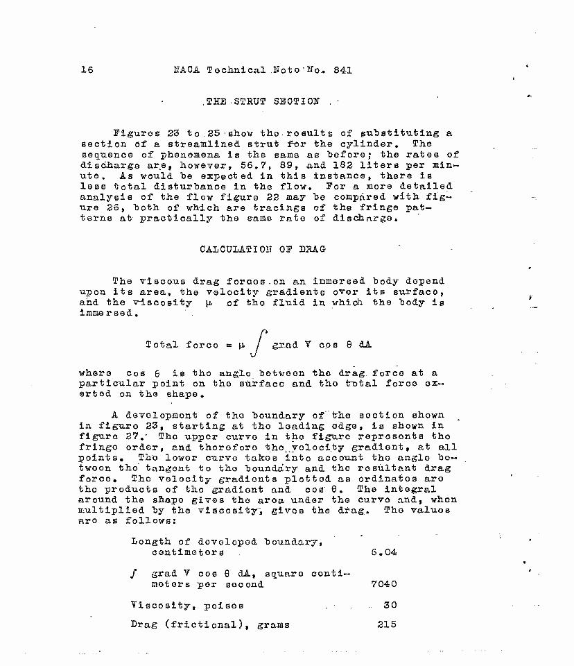
.THE -STRUT SECT I OK .
Figures 23 to. 25 show the results of substituting a section of a streamlined strut for the cylinder. The sequence of phenomena is the same as before; the rates of discharge are, however, 56.7, 89, and 182 liters per min- ute. As would be expected in this instance, there is less total disturbance in the flow. For a more detailed analysis of the flow figure 22 may be compared with fig- ure 26, both of which are tracings of the fringe pat- terns at practically the same rate of discharge»
CALCULATI01T OF DRAG
The viscous drag forces.on an immersed body depend upon its area, the velocity gradients over its surface, and the viscosity p. of the fluid in which the body is immersed.
Total forco = \J> I grad V cos 8 dA
where cos G is the anglo between the drag, force at a particular point on the sürfaco and tho t"otal force ex- erted on the shape.
A development of tho boundary of" the section shown in figure 23, starting at tho loading edge, is shown in figure 27." Tho upper curvo in the figure reprosonts tho fringo order, and thoroforo tho velocity gradient, at all points. Tho lower curvo takes into account the angle bc- twoon tho' tangent to tho boundary and tho resultant drag force» The velocity gradionts plotted as ordinatos are tho products of tho gradient and cos 8. The integral around the shape gives tho aroa under the curvo and, whon multiplied by the viscosity, gives the drag. Tho valuos aro as follows:
Longth of developed boundary, contimetors 6.04
/ grad V cos 9 dA, square centi- meters per second 7040
Viscosity, poises 30
Drag (frictional), grams 215

1TACA Technical ITo"to No. 841. 1?
The gradient is obtained simply as the product, of. the fringe order at each point and the fringe const ant of the fluid for the thickness employed. ' In this case a .veloc- ity gradient of 93 centimeters per second per centimeter" corresponds to a fringe order of unity.
TELOCITY .CALCULATIONS
In order to determine the actual velocities present in various parts of the flow, the following procedure may be adopted. Consider figure 16, which represents^the fringes in the central, part of the channel for the situa- tion of figure 14. Assume that the velocity is zerö~at all boundaries. Choose a path along which to integrate, such as A-33. Divide this path into sections represented by the intersections with the fringes. The velocity gradi- ent at the boundary is 371 centimeters per second per cen- timeter. At the first intersection with an inner fringe, the velocity gradient becomes 279 centimeters per second per centimeter. Over the first section of the path It has an average value, therefore, of 325 centimeters per"second per centimeter» If this average value is multiplied by the length of the section, the result is the change in ve- locity over the section. Since the velocity at the bound- ary is zero, this change (added to zero) gives the veloc- ity at the end of the first section. By taking the aver- age gradient over the second section, multiplying by the length of the section, and adding the result to the first velocity, the velocity at the end of tho second section Is obtained. Table III shows tho values obtained in this way. A check is provided by the requirement that, when the opposite boundary is reachod, the velocity must return to zero. Such integrations may be performed oVer any curved line in the velocity field. If a closod curve i~s selected that encloses the model, the result will be tho circulation around tho model, an important factor dynam- ically.
CORRECTION FACTORS
Aside from the causes of error usually associated with photoelastic experiments, there aro certain effects peculiar to the use öf fluid mediums of tho typo employed. Whether these corrections aro largo or small depends on the particular case under discussion. It might bo

18 HACA Tochnical"Note No. 841.
suggostod, however, that ono souroo of difficulty oncoun- tored in olastic systoms is absent in fluid—flow measure— montss namely, the oxistonco of initial stresses. liThorca-s these initial stresses oxist to a certain extent in ail photoolastic modols., thero is no birofringenco in a fluid at rest.
The anomaly in the polarization' directions associated with the use of certain test fluids.has already been aoted, This irregularity actually introduces two types of correc- tion. The first—is the simple rotation of polarization axes, which makes it necessary to add 33 t~u or subtract 57 from the polarizer directions instead of the expected 45 in order to obtain the directions of flow. This rota^ tion of axes is not a significant feature and the anglos that must be used are always obvious.
The second correction arises from the same source but must be considered more carefully. With solid photoelas- tic models it~~is common to assume that the double refrac- tion observed along any particular direction of observa- tion arises solely from stresses lying in planes normal to this direction. The same is not true of fluids as the following example will illustrate.. It is obvious that, in the channel employed in these tests, the velocity is not constant throughout the depth of the section-but must become zero at the inner surface of tho glass windows. Since the channel is deep as compared with iirs width, it is probable .that variations of velocity with depth are confined to regions•near tho windows. Consider figure 28. Here tho flow is s ho vrn from the side and an element of tho fluid is shown lying in tho region wherein such a velocity variation is taking place. This elemont deforms into tho shape shown by the dotted-lines in the figure and tho re- sulting directions of polarization are indicatod. Be- cause this is a pure shoar., tho tonsion and the compres- sion are numerically equal; and, if the tonsion and com- pression directions wore at 45° to the direction of flow, thoir projections normal to tho light beam would cancel each other. Inasmuch as tho compression will actually project shorter than the tension, the projections do not cancel and a rosidual tension remains. This residual ten- sion introduces an additional double refraction, which is added to that produced by the volocity gradionts normal to the light direction. This effect is illustrated in figure 29, which shows the factors producing double re- fraction along tho light beam.

EACA Technical Koto Ho. 841 19
This correction will alter the interpretation of the fringe patterns to a certain- oxtont. lor oxanple, in tho caso of tho cylinder and strut when photographed with cir- cularly polarized light, the channel nay "be crossed with- out encountering a zero fringe, This condition is in- possible for obvious reasons. If proper correction is • made, the zoro fringe should extend throughout tho chan- nel, dividing to pass the obstruction. Shis situatTon has been found to be truo.
Several methods nay be used to overcone the difficulty mentioned. Two fluid systens having the aane velocities and shapes but different depths night be superinposed. If the two flows are in opposite directions the end. effects will cancel, leaving a single effect due to a channel of a depth equal to the difference of the two. Probably the best solution is to utilize the scattering nethod of analy- sis. (See reference 7.) Here it seens nost convenient to introduce a source of polarized light within" the nodel. This source nay be obtained by projecting a bean o"f un- polarized light through a slit into the test section so as to illuninato a piano section normal to the direction of observation. If this plane section were" so" chosen" that it lay above the region in which the difficulty arises, a part of tho disturbance would be ronovod.
COUCLUSIOHS
The investigations carried out on tho photoviscous properties of fluids soen to indicate that it is ontiroly"" practicable to carry over into fluid-flow studies the techniques of phot oolast icity . " Tho nost satisfactory flu- ids found to date are solutions of cor"tain organic nato— rials. Those materials soon to bo thoso characterized by a complex molecular structure, which is not rigid but which is capable of considerable distortion in viscous shear. The high viscosity of tho present fluids loads to abnornally low values of Reynolds number for models of reasonable size, but this difficulty can be corrected if bettor working nediuns aro found. Work is being continued in this direction.
The noasuronent of velocity gradients is_carriod out by precisely the sane techniques as aro employed in the photoelastic procoduro. Tho development of poXarTzing axes at anglos other than 45° to the direction of flow

20 NACA Technical Note No. 841
introduces end corrections that are reduced as the aspect ratio of the test channel is increased. It is provable that these end corrections can be completely evaluated by the use of . scattered-light sources..
The investigation of three-dimensional-flow problems apparently offers no special difficulties and will be studied at rf.n early date.
State College of Washington, Pullman, Wash., Apriü " Q41 .
REFERENCES
1. Maxwell., J. C. : On Double Refraction in a "Viscous Fluid in Motion. ProuC. Roy. Soc, vol. 22, 1873-74, pp. 46-47.
2. Coker, E. G. , and Pi Ion, L. N. G-.: A Treatise on Photo-Elasticity. The University Press, Cambridge, (England), 1931.
3. Raman, C. Y., and Erischnan, K. S.: A Theory of the Birefringence Induced "by Plow in Liquids. Phil. Mag., ser. 7, vol. 5, no. 30, April 1928, pp. 769- 783.
4. Sadron, C. L., and Al.cock, E. D.: An Optical Method for Measuring.the Distribution of Telocity Gradi- ents in a Two-Dimensional Plow. Paper presented at Aerodynamics and Hydrodynamics Summer Meeting of the A.S.M.E., June 19-21, 1934.
5. Alcock, E. D., and Sadron, C. L.: An Optical Method for Measuring the Distribution of Velocity Gradients in a Two-Dimensional Plow. Physics, vol. 6, March 1935, pp. 92-95.
6. Hill, B. 7.: On Accidental Double Refraction in Liq- uids. Phil. Mag., vol. 48, 1899, pp. 485-498.
7. Weiler, R., and Bussey, J. K.: Photoelastic Analysis of—Three-Dimensional Stress Systems Using Scat- tered Light. T.N. Ho. 737, NAOA, 1939.

Tf
NACA Technical Note No. 841 21
BIBLIOGRAPHY
resnel, A.: Memoirs sur les couleurs deVelopp&es dans des fluides homogenes par la lumiere polarisee. Ann.
. de Chem. et. Phys. (Ill), vol. 17, 1846, pp. 172-19~8~.
Maxwell, J. G.: Über Doppelbrechung in einer bewegten zähen Flüssigkeit. Ann.-der Phys. (II)t Bd. 151, 1874, p. 154.
Kundt i A.: Über die Doppelbrechung des Lichtes in be- wegten reibenden Flüssigkeiten. Ann. der Phys. (Ill), Bd. 13, 1881, pp. 110-133.
deMetz, &.: Über die temporare Doppelbrechung des Lichtes in rotirenden Flüssigkeiten. Ann. der Phys. (Ill), Bd. 35, 1888, pp. 497-507.
Umlauf, K..: Über Doppelbrechung in rotirenden Flüssig- keiten. Ann. der Phys. (Hl), Bd. 45, 1892,' pp."~3"Ö4~ 315.
Schwedoff, "T.: Sur uno anomalie dans la refraction double des liquides. Jour, d© Phys. (ill), vol. 1, 1892, pp. 49-53. -.-- .__ _ _.
Almy, J. E.: Concerning Accidental Double Refraction in Liauids. Phil. Mag., ser. 5, vol. 44, 1897, pp. 49Ö- 503".
Reiger, R.: Innere Riebung elastischer und fester Körper. Phys. Zeitschr., vol. 2, 1900-1901, pp. 213-217'.
Hill, B. V.: ifote on Accidental Double Refraction in Solu- tions of Colloids. Phil. Mag., ser. 6, vol. 2, KOT. 1901, pp. 524-527.
Hatanson, L.: Über die temporäre Doppelbrechung dos Lichtes in bewogten reibenden Flüssigkeiten. Zeitschr". f, Phys. Chem., vol. 39, 1901, pp. 355-363. '_
Natanson, L. : On Double Refraction in Moving Viscous Liq- uids. Phil. Hag., ser. 6, vol. 2, Oct..1901, pp. 342- 356. '- • :"
deMetz, G-. : Double r6fraction accidontelle des; liquides mecaniquement diSformös. Comptes Rondus, t. 134, June 9, 1902, pp. 1353-56- ..

22 HACA Technical Hot© Ho. 841
Zaremba, S.: Note sur la double röfraction accidcntello de la lumiSre dans les liquides. Jour, do Fhys. (IT)! vol. 3, 1904, pp. 606-611; vol. 4, 1905, p-p. 514-516.«
Natanson, !.: Sur una particular it 6" do la double refrac- tion accidentolle dans les liquides. Jour, de Phys. (IV), vol. 4, 1905, pp. 183-190.
Zakrzcwski, C, and Kraft, C: Directions principales dans los liquides bire*f ringent s par l'offet du mouvemont. Bull. Acad. Sei. (Oracovio), Ho. 7, July 1905, pp. 506- 520.
deMotz, G.: La doublo refraction accidentelle dans les liquides. Collection "Scientia" , Ho. 26, Gautier- Villars (Paris), 1906.
Diesselhorst, H., and Freundlich, H.: über die Doppel- brechung des Vanadin-pentoxyd Sols, Phys. Zeitschr., 16 Jahrg., Hov. 15, 1915, pp. 419-435.
Pontremoli, A.: La doppia rifrazione accidentale meccanica nei liquidi,. Mem. R. Accad., Cl . Sei. Pis. Mat. e Hat«, vol. L3, 1921, pp. 594-616.
Humphrey, R. H.: Demonstration of the Double Refraction Due to Motion of a Vanadium Pentoxide Solution and Some Applications. Proc. Phys. Soc. (London), vol. 35, June 1923, pp. 217-218. -
Krüger, 3.: Versuche zur Kenntniss der Doppelbrechung in strömenden Flüssigkeiten. Zeit-schr. f. Phys. Chom. , vol. 109, 1924, pp. 438-452.
Vorländer, D., and Walter, R.; Die erzwungene Doppel-.. brechung der amprphen Flüssigkeiten im Zusammenhange mit der molekularen Gestalt. Phys. Zeitschr. 25 Jahrg., 1924, pp. 571-573.
Vorlander, D.,- and Walter, R.: Die mechanisch orzwungene Doppelbrechung .der amorphen Flüssigkeiten im Zusammen- hange mit der molekularen Gosalt. Zeitschr. f. Fhys. Chem., vol. 118, Oct. 25, 1925, pp. 1-3T).
Graffi, D.: Riccrche sulla birifrangonza accidentale doi colloidi in movimento. Atti. R. Accad. Haz. Lincoi, ser. 6, vol. 3, June 3, 1926, pp. 28-31.

HACA Technical Hoto Ho. 841 23
Pontrcmoli, A.: Circa alcuno EUOVO rioerche sulla "bl- rifrangenza accidentale doi colloidi in movimento. Atti E. Accad. Haz. Lincoi f sor. S, vol. 3, Jan. 17, 1926, pp. 75-77.
Boodor, P.: ITber Stromungsdoppolbrechung, Zoltschr. f, Phys., Bd. 75, no. 3/4, March 31, 1931, pp. 258-281.
Sadron, Charles: Sur une nouvelle methode optiquo d1 exploration d'un champ do Titossos hidimonsionol. Comptes Eenduo, t. 197, ITov. 27, 1933, pp. 1293-96.
Mamul: Die Verwendung der doppelten Strahlenbrechung zur TTnt or suchung von Strömungen hoi Flüssigkeiten. Zeitschr. f. Tech. Phys. (Leningrad), Bd. 6, 1936,.pp. 2016-2028.
Sadron, C: Sur los propri6*tds dynamo-optiques des lia— uidos purs et des solution colloidalos. Schwelsor Archiv, vol. 3, no. 1, Jan. 1937, pp. 8-21.

TABLE I
MATERIALS TESTED FOB PHOTOVISCOUS SENSITIVITY
I
I 9
10 11 12
S 15
3 19 20 21 22 23
2, 2?
29 50 51 52
S 55
36
Material
Cottonseed oil Halowax oil Gelatin (Knox) 0.035 gram/cc Gelatin (Knox) 0.07 gram/oc Egg albumen Sodium silicate Gum acacia In water Oil of sassafras Oil of citronella Oil of anise Oil of eucalyptus Oil of ember Oil of pine Sperm oil Oil of cedar Oil of Juniper Oil of almonds Neat18-foot oil Cod-liver oil Oil of balsam Pish oil Resin BV-10360 (Bakelite) Resin BR-lj.500 {Bakelite) Resin BR-lf8-306 (Bakelite) Resin BR-^l-00i (Bakelite) Resin B-ij. (XR-7l|28) (Bakelite) Beta glucose penta-acetäte Vinyl acetate polymer in monomer Poor Styrene polymer in monomer Good Resin L-llll-59 (XR-13936) Neg- Acrawax B in mineral turpentine Reg. Diglycol laurate (Glycol) Reg. Mglycol otearate In ethanxl. (Glycol) Reg. Abopon (Glycol) Reg. Polyvynal butyral resin in
etbanol (duPont) Fair Polyvynal butyral sheeting in
ethanol (duPont) Fair
Sensitivity Negligible Reg. Good Good Reg. Reg. Reg. Neg. Reg. Heg, Neg, Neg. Reg. Reg, Reg. Neg. Reg, Reg, Neg. Keg. Reg. Cloudy Fair Not tested Reg. Fair Reg
8 la
IS
lj.6
kl
hs
50
51
52 53 5^ 55 56
11 59
Material Sensitivity Vinyl acetate in ethanol(duPont) Negligible Methyl methaorylate in ethanol
(duPont) KdyvinylakdholSn water (duPont) Resin R-3525 (duPont.) Zein in carbitol Korolac (Goodrich) Sesame oil Methyl cellosolve acetate with
cellulose acetate and butyr- ate 160 (Kodak)
Methyl cellosolve acetate with cellulose acetate and butyr- ate 381 (Kodak)
Methyl cellosolve acetate with cellulose acetate (Kodak)
Dimethyl phthalate with oellulose acetate (Kodak)
Dimethyl phthalate with cellu- lose acetate and butyrate 160 (Kodak)
Dimethyl phthalate with cellu- lose acetate and butyrate 381 (Kodak)
Methyl cellosolve acetate with cellulose ether (Kodak)
Dimethyl phthalate with cellulose ether (Kodak)
Polyvinyl acetate (Monsanto) Polyvinyl formal (Monsanto) Polyvinyl butyral (Monsanto) Cellulose acetate (Monsanto) Cellulose citrate (Monsanto) Polystyrene (Monaanto) Phenol-formaldehyde syrup
(Monsanto) Ethyl cellulose (Monsanto)
Poor Reg. Reg. Reg. Fair Reg.
Fair
Good
Good
Good
Good
Good
Good
Good Good Poor Good Good Good Good
Fair Good
&
m
o
I o t w tH- O
O
00
•3
& H <D

TABLE II FRINGE VALUES OP LIQUIDS USEFUL IK ENGINEERED
APPLICATIONS OP PBOTOVISCOSITY
Material
50 oil methyl cello solve acetatewith) 5$G cellulose ether (Kodak)
51 16:1 dimethyl phthalate with cellulose ether (Kodak)
14.7 12:1 dimethyl phthalate with cellulose acetate (Kodak)
• 4 4-V, MA. bU
14.8 34:1 dimethyl phthalate/cellulose acetate butyrate l60 (Kodak)
29 Polystyrene in styrene monomer (Bakelite)
value
56O
1500
2700
room temperature . (poises)
w 71
79
254
• Ji±.! fan -— • apeciixc fringe value
36,800
]+0,OQO
118,000
118,000
10l|.,000
a
&
&
eh
5
I
TABLE III VELOCITY CALCULATIONS
1 2 3 1».
!
Average fringe order over section
5.5 2.5 1.5
•5 •5
1.5 2.5 3.25
Average velocity gradient
^cm/sec/om) 325 232 159.5
jJ-6.5 -lj-6.5
-139.5 -232 -302
Length of IAA -H * >DV UJLl
(cm) m ^4 /•*% .
Velocity
(cm/sec)
109 77.9 1*2.7 15.6
-I5.6 -k9.il. -80.3 -56.7
Velocity at end
(cm/sec)
109 I86.9 229.6 21+5.2 229.6 180.2
?9.9 1-5.2 3
£ 5

• T * I < f
g
"> T,
Moving wall Velocity = Vi
//////////////////////// ////////.
Liquid
/////1 ////)/11 /) 1////////////
1-3 O O
fed o cr <E
O
8 ' H
irixoa wan 4 J- • • rt voioci-cy = u
Figura 1.- Eorces in a shearing liquid. An element such as the solid square deforms with time into the dotted figure.
(Jtj
i 1 I I

NACA Technical Kote So. 841 Mg. 2
Light source
i
«d Outers Inner l fl fixed ä rotating «H
cyl- •H r-l
cylinder cd inder o
+= u a> <H
E-l
.
o a>
3
Compensator position
Analyzer
Polarizer
To observer Mirror
Figure 2.- Device for measuring photoviscous "birefringence. , Windows in the outer cylinder permit the light
to pass through.

NACA Technical Kote No. 841 Fig. 3

NACA Technical Note No. 841 Fig. 4
Figure 4.- Apparatus for measuring the photoviscous sensitivity of liquids and liquids tested.

KACA Technical Note Ho. 841 Fig. 5
A High, percentage of polymer B Intermediate amount of polymer C Small amount of polymer
•1200
1000
800
? u o CO W
CD
o o
600
400
300
400 800 1200 1600 Inner-cylinder speed, rpm
2000
figure 5.- Photoviscous sensitivity of polystyrene.

NACA Technical Note No. 841 Fig. 6
A Methyl cellosolve acetate cellulose ether
B Dimethyl phthalate cellulose ether
C Dimethyl phthalate cellulose acetate
D Dimethyl phthalate cellulose acetate "butyrate 160
E Dimethyl phthalate cellulose acetate butyrate 160
2400
2000
1600 4-» «H •H
•s u o
cd CO Ö (D
O o
1200
800
400
800 1200 1600 Inner-cylinder speed, rpm
2000
Figure 6.- Photoviscous sensitivity of materials related to photoelastically sensitive solids.

Stwulplpe
Klguia 7.- Bcheaatio diagram of photoTiaoouB test equipMnt. Oircrolation of the fluid la olookwlae.
Light öouroe
Conäeiißlng leas
Polaroid
Quarter-wove plat«
TOBT section
(taarter-^were plate
* Polaroid
Project Ion. lens
Ganara
E ? tr
a I 5 ct-
g to *-
Plgnre 10.- Schematic dlagx«*» ofi tbo optical systen.
-a •
s

o
t4 o
CD
Figure 8.- General Yiew of apparatus.
Figure 9.- Tie« of test section in which models were placed« the strut model is In
the channel.
tu m
at

Figure 11.- Fringe photograph taken witn the camera focused on the
near side of the teat lection showing "blurred fringe pattern.
o
O
Figure 12.- Flow pattern in the unobstructed channel. Discharge rate, 62.5
liters per minute.
fti •»I n
H H
CO

Figur« 13.- Flow pattern In tii« unobstructed channel. Discharge rat«, 142 liters per minute*
Figure 14.- Flow pattern in the unobstructed 'channel* Discharge rate, ao* xiicrs per minute.
&
j?
tzt o
09
Q

m i •
• I-
til I
IF
Iff Pi
lulls F'li.B
,
W I
! !
II !WT!
1 I !• V'i
-. | • i ': • , • i' ( I ••
I' J
!! • i : i
• : IJ ...
:i!t ?;; ! I i. ;r 11
i'ft'i
I . I I
T ;. Hr:'r;:|i! iVf-,
r : i i'l I'lfiTtt'?;;'^!'! Mr- ;, '»«fljry'n t f jilt
.ME • • f* St. •If. i : &•:»••
•ft-;)
J . ilJkL ..I
;1
:il
pt •- *• '»]> n*t i I'L '.: jMt ü! ! : Ml! Ill !
„lUJ t;Jj;Ll.,i
•V •-• •• •: :, i I1!
•i'j i,-.» iji !'
A
A i • i i ,
! V
; i: P
i: , 9
i-
£ er •
\ 9 • 00
.:!
d. J, b( i, i:.L
I Igor« 15.- Photomlcrographle trace of the negative of fig. .14, which represents the variations in the density of the image across
the unifonn portion of the flow» Increasing ordinates represent Increasing transmission, that is, dark fringes in the channel.
*4
H

NA.CA Technical Note No.. 841 Jig. 16
3 2 1 0 1 2 3
Figure 16.- A tracing of the center lines of the fringes of fig. 14, showing nearly -uniform spacing
resulting from a parabolic velocity distribution.

rigor« 17.- fringes In the unobstructed channel taken with plans-polarized light, The polarizer and the analyser are placed with their axes at 45 to the direction of flow.
Jigure 18.- Darkening of half the channel, resulting from placing the polarizer at 33° to the vertical and the analyser at 33° to the horizontal.
K o
s 00
m *
3

Figur« 19*- Triage pattern resulting from the placing of a cylindrical obstruction
In the channel. Discharge rate, 60.5 liters per minute«
Tigore 30,- Iringe pattern resulting from the placing of a cylindrical obstruction
in the channel. Discharge rate, 91 liters per minute.
•3 a
$
9
S «
CD
m CO « a
t-» to
8

Figure 33.- Jringe pattern (torn to the streamlined strut section. Discharge rate, 56.7 liters per mlnute.
figure 21.- fringe pattern resulting from the placing of a cylindrical
obstruction in the channel« Discharge rate» 147 liters per minute.
I
s
o
•4
*
8

» »
2
a •a

# •*
tfigure 24.- Eringa pattern due to the streamlined strut flection. Discharge- rate, 89 liters per minute.
Figure 25.- Pringe pat i#sm due to the streamlined strut Baction. Discbarge rate, 182 liters per minute.
a
o •
s
0>J
to

p 4 (—
3 -
Li
o 2 ID
•H
1 -
0 Developed contour
Figure 37.- Development of the "boundary of the strut section shown in fig. 23.
-4

• 1
Top window
Bottom window
Compression Tension
Figure £j8»- Telocity distribution through the depth of the channol showing
the cLqctrease to zero at the windows.
1 1-3
a P
8?
in
CD

NACA Technical Note ffo. 840. Iig. 29
>r >'
Compression
Residual tension
Tension
figure 29.- Sources of double refraction in the channel.

I -ae«(MCW& TITLE: The Photovlscous Properties of Fluids
AUTHOR(S): Weiler, R.; Middlehurst, D. and others ORIGINATING AGENCY: National Advisory Committee for Aeronautics, Washington, D. C. PUBLISHED BY: (Same)
ATP- 8813
(None)
njaBMNO AOCNCY
Feb '42 Restr. U. S. 1ANOUAOI E°g-
MOB
45 musnATiONt photos, diagrs, graphs oo£®>
AD- Extension of methods of photoelasticity to include the measurement of velocity distribution in ajnoving fluid. Most satisfactory are solutions of certain organic
r^V ?F$\ /7^\ Y^ tr¥\ fr^ 17^ BOlecular structure capable of considerable ^< vr/ I [ 11 u-?\ \ü ) [r^\f r\\ adients are measured by same technique Q) \Q) \JJ *2^s ^J v^x v>' corrections may be completely evaluated
jiiv/tt.-Kequest copies ol tilts' report only lrom unginatlng Agency DIVISION: Aerodynamics (2) SECTION: Fluid Mechanics and Aerodynamic
Theory (9)
ATI SHEET NO.: R-2-9 -37
SUBJECT HEADjySS: Fluids -^fcosiro- Measurement (51510)
fC-i^fy Wty Air Docvraontt Division, Intotlifjonco Dcpartmonl
Air Material Command AIR TECHNICAL INDIA
-R£«ftr6JfiD Wrieht-Pattoreon Air Force Bat«
Dayton, Ohio fj ^Jlff'

C2.asQif£eati@a «saacollo^l pa:? authority