tech tip-013 - narhams
TRANSCRIPT

Tech Tip-013 Cluster Altitude Competition design & Construction:
Dedicated to the dissemination of detailed model building methods and techniques.
Materials and methods presented here are not intended as the best or only solutions to the modeling challenge(s)
discussed, rather as methods and procedures which have a proven record of success in actual use. Please keep
experimenting with new materials and techniques as this is the only way to expand the fields of knowledge.
Written by: John E. McCoy Sr. - NAR-15731 – 04-30-2016 This Tech Tip will look at each NAR Cluster Altitude Contest event by motor thrust level 2x1/8A thru 6C. We will explore
these clusters by event impulse rather than by when the event was actually flown over more than a 13year time span. On the following pages a bit of Narhams History will aid in the attempt to give the reader an over view of the processes
involved in designing and building competitive multi-motor cluster altitude model rockets. Some will appear weird, others sleek and
streamlined. Every effort will be used to explore various motor configurations with some of the many concepts designed over the last
13 years by the author and others. While it may not be possible within the limited space of this Tech-Tip to look at every design
concept created for each of the 6 motor class events. It is hoped there will be enough detail included that the reader will gain greater
insight into what can be expected from a set of motors for the thrust level of interest.
Two of the most important things to keep in mind while designing Cluster Altitude models: A: Minimal Frontal Area: The Plan View of our models plays a vital but under appreciated roll in overall performance.
B: Optimal Mass: Each model will have a specific “Best Mass” or (Throw Weight) for the selected motor class.
With these few guidelines in mind let us begin with the smallest but not necessarily easiest motor group and model size:
2x1/8A Cluster Altitude: (Micro Maxx motor Powered): 08-2004 to 09-2005 While we are only going to need two 1/8A.5-1 MMX-II motors or one MMX-II and one MMX-II-NE too power this impulse class.
These tiny rockets can require a good bit of ingenuity to get a model that will fly on two MMX motors with minimum Frontal Area
we spoke of and Optimum Mass to obtain the highest possible coasting altitude. There is also the challenge of visibility for such
small, very fast moving rockets over a given baseline. Over time it has been determined a 300ft baseline is preferred over the normal
1000ft baseline for tracking 2x1/8A Cluster Altitude events. It was observed that even at this shorter distance if tracking powder was
not used or used properly the rocket would almost certainly receive a TRACK LOST report for the flight. We’ll look a little deeper
into the tracking powder problem shortly. For now let’s get back to the basics design phase of our two motor clusters.
Side by side is of course the preferred configuration of this rocket. But that means we have a couple choices to make. Do we
want to enter a Qualifier type model that will almost certainly be large and easy to track or some form where our side by side motors
or motor tubes vent into a minimum diameter or smaller body tube? More bizarre could we build a stacked in-line 2 motor cluster?
Materials are also something to be considered. Standard Craft tubes with .013” wall are fairly easy to find but considered on the
heavy side at this model size, Tracing Vellum or single wrap .5oz fiberglass cloth could be considered if we have the talent, mandrel
and time. There is also the possibility of combining a couple or all the above materials to create our vision of the most aerodynamic
slippery rocket. Looking at the minimum diameter standard motor tube for MMX motors one can see the T2+ (.281”OD) side by side
will just fit with a little distortion into a BT-5 Standard .013” wall body tube. With a little nudging our two 1” long motor tubes can
be fitting into the BT-5 and sealed with a bit of white glue soaked tissue. Add a light weight Pratt Hobbies 2pc vacuum formed
styrene nose cone and some light 3/64th 3ply plywood fins, 30” of 50 to 70lb Kevlar shock line and a ½” x 9” Teflon tape streamer-
wadding I think we have a Qualifier.
Do we want something that has a chance to make it to the podium? Then we will have to do some serious streamlining to
reduce the frontal area and overall mass. This will mean mounting two T2+ motor tubes side by side and notching them into a single
T2+ main body tube. Our motor tubes will then be plugged to ensure all the ejection gas is channeled into the main body tube.
Plugging can be done with small pieces of 1/8” epoxy coated balsa or white glue soaked tissue, whichever is lighter. My choice was
the 1/8” balsa bulkheads. The next step will be to streamline the transition from a single T2+ to the dual motor tubes. We have a few
possible choices to do this either turn a balsa transition hollowed out to slide over the main tube down over the motor tube joint, or
build a cardstock oval transition, or the root I took creating a ultra light tracing vellum overlapping cone with a .281” apex and large
enough base to deform into an oval capping our dual motor tubes. After CA fixing the transition in place over the motor tubes the
entire transition is carefully trimmed as close as possible to the top of the motor tubes then Medium CA is paper towel mopped over
the entire transition to harden our transition shell.
To form our shock-line 50lb x 30” Kevlar is attached directly to a small hole drilled between the center point between the
motor tubes in the epoxy fillet. Our nosecone is a simple parabolic home made basswood turning, center drilled just enough to epoxy
in a 50lb Kevlar attachment loop. To this shock-line we attach a 1/2” x 9” yellow military grade PTFE Teflon streamer/wadding.
3 fins for the streamlined bird will be 1/64” 3ply plywood in a dual tapered profile. Attaching these 120 degrees apart will be a little
tricky on this oval section. Fins are attached with spot CA and very fine 5-minute epoxy fillets. This model will be tower launched,
so no launch lug will be added. It is now time to start smoothing the model surface after application of 3 coats of grey primer.
Sanding and smoothing any and all joints to create as smooth a transitions as possible. Two coats of Dark Red enamel complete the
model painting. Paint is not the end of our finishing effort. It is now time to use Finessit-II polishing medium to polish the dry color
coat to a babies butt smooth over-all finish. Finally a coat of Nu-Finish polymer is applied to the entire rocket. 1)
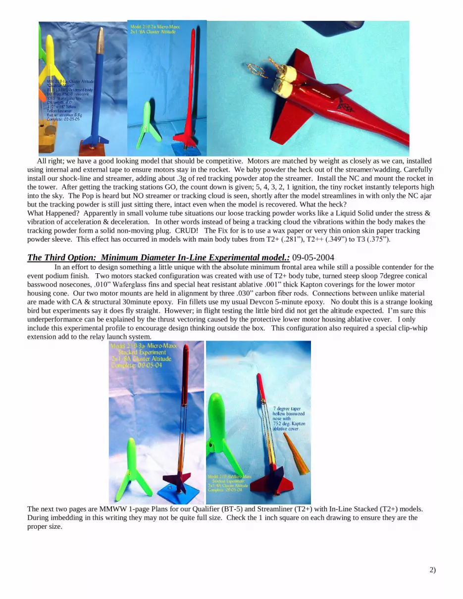
All right; we have a good looking model that should be competitive. Motors are matched by weight as closely as we can, installed
using internal and external tape to ensure motors stay in the rocket. We baby powder the heck out of the streamer/wadding. Carefully
install our shock-line and streamer, adding about .3g of red tracking powder atop the streamer. Install the NC and mount the rocket in
the tower. After getting the tracking stations GO, the count down is given; 5, 4, 3, 2, 1 ignition, the tiny rocket instantly teleports high
into the sky. The Pop is heard but NO streamer or tracking cloud is seen, shortly after the model streamlines in with only the NC ajar
but the tracking powder is still just sitting there, intact even when the model is recovered. What the heck?
What Happened? Apparently in small volume tube situations our loose tracking powder works like a Liquid Solid under the stress &
vibration of acceleration & deceleration. In other words instead of being a tracking cloud the vibrations within the body makes the
tracking powder form a solid non-moving plug. CRUD! The Fix for is to use a wax paper or very thin onion skin paper tracking
powder sleeve. This effect has occurred in models with main body tubes from T2+ (.281”), T2++ (.349”) to T3 (.375”).
The Third Option: Minimum Diameter In-Line Experimental model.: 09-05-2004
In an effort to design something a little unique with the absolute minimum frontal area while still a possible contender for the
event podium finish. Two motors stacked configuration was created with use of T2+ body tube, turned steep sloop 7degree conical
basswood nosecones, .010” Waferglass fins and special heat resistant ablative .001” thick Kapton coverings for the lower motor
housing cone. Our two motor mounts are held in alignment by three .030” carbon fiber rods. Connections between unlike material
are made with CA & structural 30minute epoxy. Fin fillets use my usual Devcon 5-minute epoxy. No doubt this is a strange looking
bird but experiments say it does fly straight. However; in flight testing the little bird did not get the altitude expected. I’m sure this
underperformance can be explained by the thrust vectoring caused by the protective lower motor housing ablative cover. I only
include this experimental profile to encourage design thinking outside the box. This configuration also required a special clip-whip
extension add to the relay launch system.
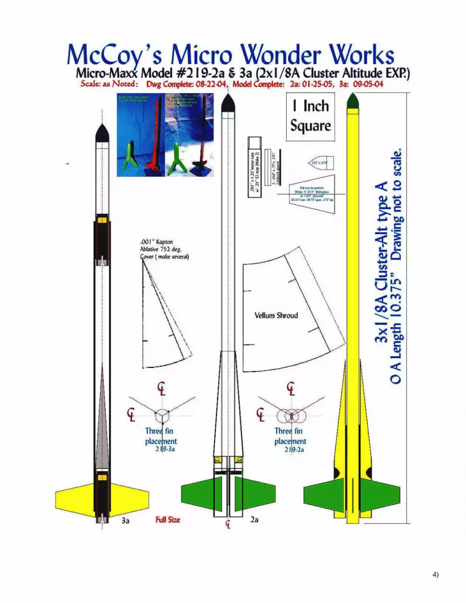
The next two pages are MMWW 1-page Plans for our Qualifier (BT-5) and Streamliner (T2+) with In-Line Stacked (T2+) models.
During imbedding in this writing they may not be quite full size. Check the 1 inch square on each drawing to ensure they are the
proper size.
2)

3)
4)

2x1/4A cluster Altitude: 13mm 1/4A motors – (10-1998 – 05-1999) BT-5 & BT-4 bodies for these two models seem to share the same building and finishing techniques as the 2x1/8A models
discussed above, even though they were designed almost 6years earlier. With that in mind, I’ll simply show the designs flown and
you folks can go from there.
Two different body tube sizes were used for these 2-motor cluster models. The first 13mm version produced 10-10-1998 and
a smaller second model 10.5mm version finished 05-08-1999 produced specifically for ECRM-26. Both were flown at that Contest
with outstanding flight results.
Both are standard .013” wall 10.5(BT-4) and 13mm (BT-5) Brown craft tubing. The 10.5mm later model was designed around the
newly available Apogee Components A2 10.5mm High Performance BP motors. Same basic side by side design as our 2x1/8A
configuration using slightly larger 1/32” basswood fins on the BT-5 model and .015” waferglass fins for the 10.5mm model. Pratt
vacuum formed styrene nosecones and Tracing vellum oval transitions for both. Transitions are CA soaked and sanded to smooth out
joints to as uniform slippery air flow as possible. Both variations used 60” of 70lb Kevlar shock-lines with 3” x 30” Mylar streamers.
Both use standard wadding. Both were flown at ECRM-26 from a competition Tower resulting in outstanding flights.
5)

6)

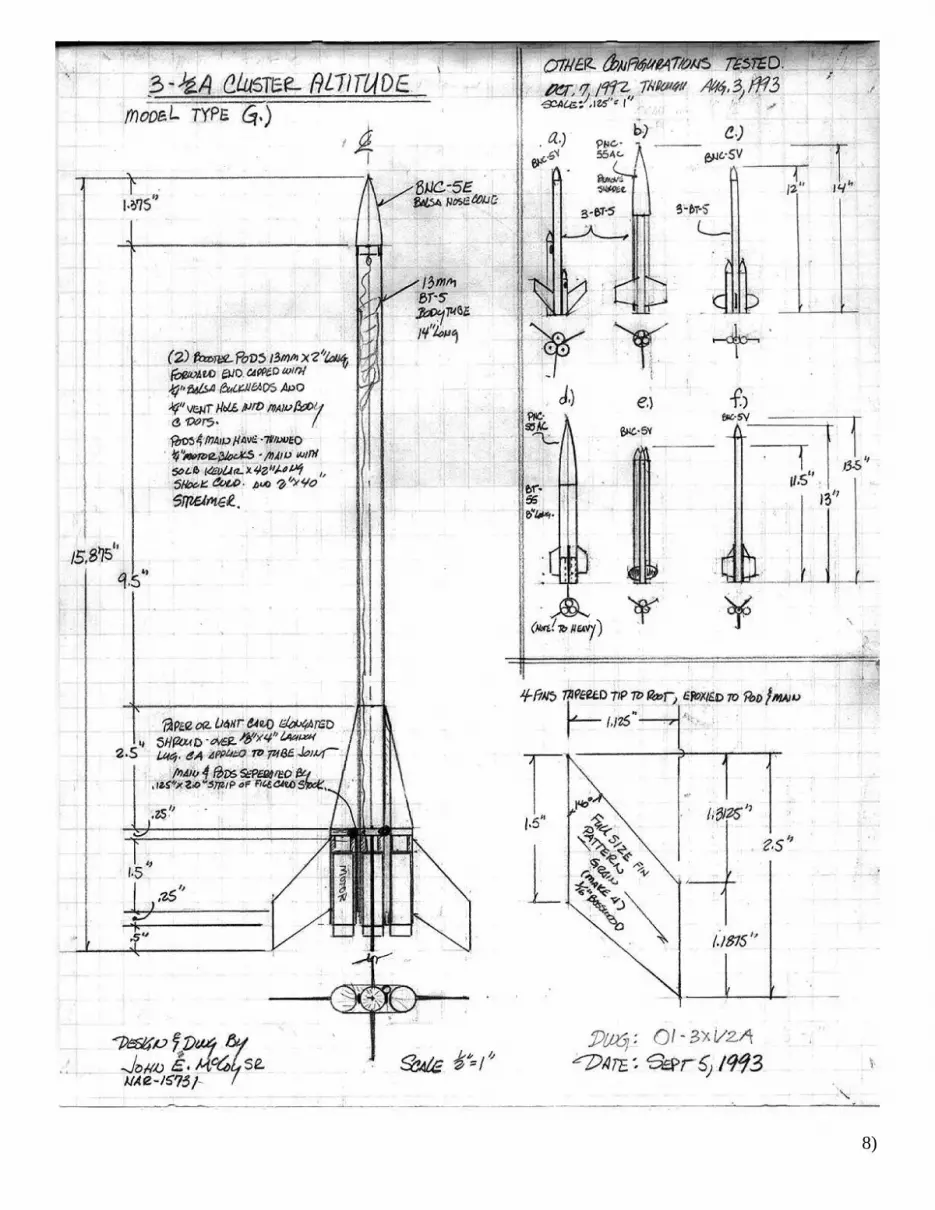
3x1/2A Cluster Altitude: 13mm 3 motor cluster; THE BEGINNING: (05-1992 – 08-1993)
Around May of 1992, Narhams decided to put in our bid to host NARAM-35 slated for August of 1993. One of the proposed
events caught my eye. 3x1/2A Cluster Altitude initiated my fascination with Cluster Altitude competition model design. I had
already been tagged by then Section President Tom Lyon as “MrCluster” since I’d been cluster converting everything that looked like
it would take more than a single BP motor. Mostly a sport flyer, I had never considered clustered motor competition models.
3x1/2A Cluster Altitude was actually my first dabbling into competition clusters. As a first attempt this particular motor
selection presents some very interesting flying event options that challenge both design and construction techniques. Almost
immediately the experimenting with design & construction started producing some wild, weird and wonderful 3 motor configurations
eventually numbering 10+ designs. Not all these designs made the transition from drawing to flying model but the majority did. In
the beginning there was no inkling of what would eventually evolve into a competitive, buildable design. One of the event rules at
the time dictated all 3 motors had to ignite or the flight would be considered NO flight. Add to this all motor ignition issue various
tracking problems either not closing within 10% or track lost, the NARAM-35 Staff were surprised at the number of contestants who
never got a good flight tracked and closed during the meet. While each contestant had the ability to re-fly their model with a new set
of motors, the time constraint would prove to be a major contributing issue especially when some had to re-fly as many as 4 or 5
times. My particular 10th design (Model G) ended up flying 4 flights without ever getting a closed track. Very nice altitude but just
couldn’t get the tracking closed. If memory serves Dr. Bob Kreutz won the event with a single wrap epoxy-.5oz fiberglass model
making an amazingly high flight. Unfortunately, I could not find the exact altitude but it was nearly double that of every other
contestant. All this NARAM-35 History has been included as an example of what can be learned and accomplished, beginning in a
new event or technique starting with absolute zero information or experience.
Looking at construction materials for these 3x1/2A models they begin with our standard Estes BT-5 .013” wall body tubing.
With this motor configuration we have all kinds of options. The main concern in my mind was reliability of ignition and deployment.
Authors note: In the early stages I was not aware that the burn through gas build-up was enough to eject tightly fraction
fitted motor casings from the rocket.
As time and flying went on it was discovered there had to be a way to either vent ejection gases into the core tube or using
A10-0 booster motors in the outer pods, find another manor to relieve the burn through internal gas pressure within the very short
strap-on tubes. In a couple designs the model used 3 individual body tubes. But over the year of research an inline 3 motor
configuration reduced to a single core 13mm tube proved to be the best performing design.
All the remaining parts and components were standard model rocket vendor available materials. One thing to always keep in
mind is finding that optimum mass without adding a bunch of altitude killing nose weight. It was discovered lengthening the core
body tube reduced or eliminated the need for nose weight. Fin materials varied from .032” to .063” basswood. Slightly heavier then
Balsa but the fine straight grain filled and smoothed to a finer, slicker finish with minimal extra weight added. As a first look at
competition clusters we were still using light coating fluorescent orange paint with and without fillers on these models. Yes; today I’d
change base fin materials, CA fill the nosecone and tracing vellum transitions so I could use either tissue or magic marker fluorescent
colors. Live and learn we say
None of the above models were heavily primed but didn’t have the CA soaked tracing paper shrouds that later motor class models
received. I’m sure if 3x1/2A were to be flown again today, design G would be altered making it much more aerodynamically slippery
by increasing the shroud taper to 7 degrees of CA soaked tracing vellum which would greatly decrease the drag and mass allowing it
to be nearly as competitive as Dr. Bob’s .5oz Fiberglass BTC model was in 1993. 7)
8)
4xA Cluster Altitude: 10.5mm(T4), 13mm (BT-5), 13/ 18mm(BT-20) models: 1995-96, 1999-2000
4xA impulse motors gives quite a number of interesting configuration options. During the early 90’s 4xA Clu-Alt designs
were limited for the most part to Estes 13mm mini brute motors. These motors had at best a 4second delay giving many designers fits,
as we knew the designs would be ejecting long before the model coasted to apogee. With this fact in mind a large number of
competitors looked at a combined 18mm core with 13mm booster pods. Within this 18mm/13mm configuration we had the option of
using 18mm A8-5 certified motors.
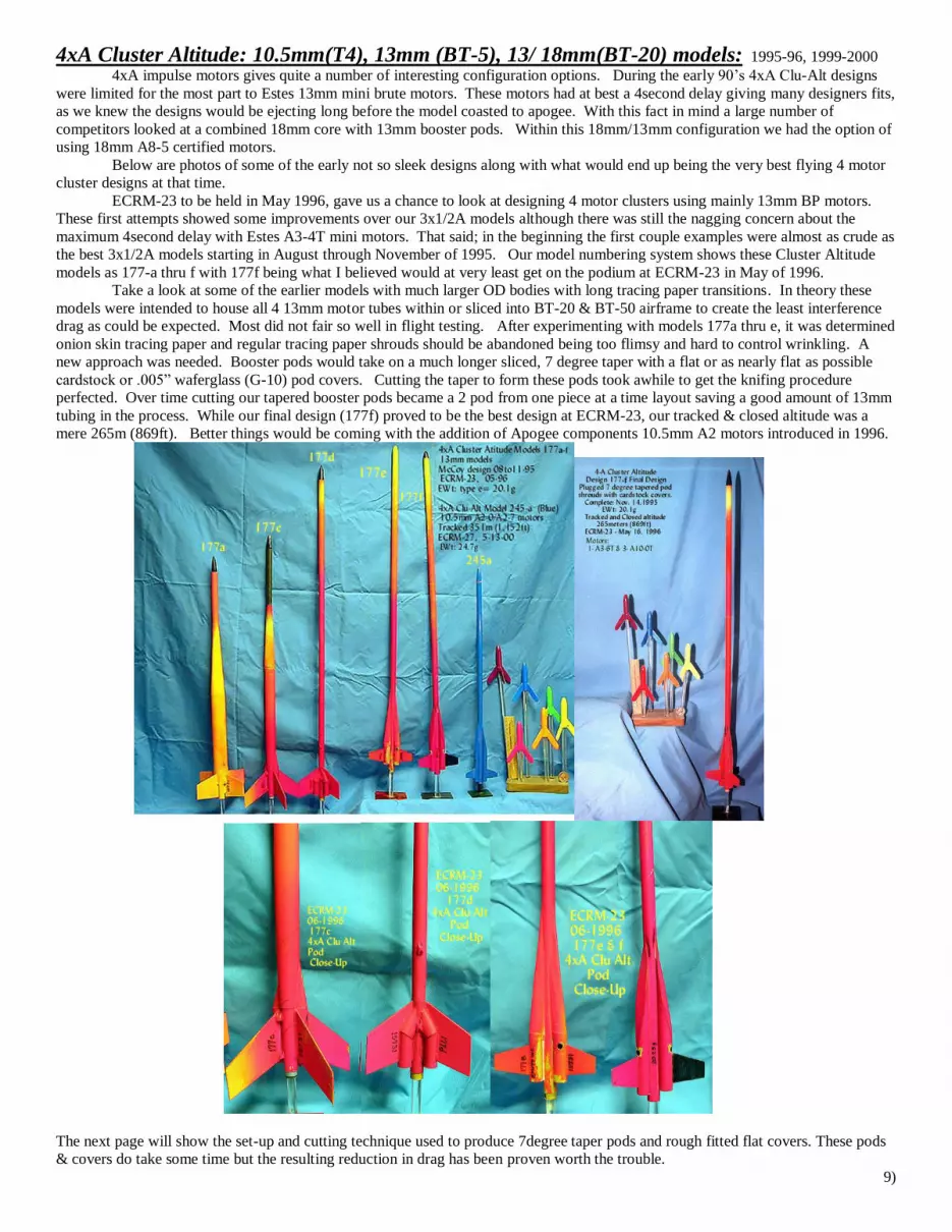
Below are photos of some of the early not so sleek designs along with what would end up being the very best flying 4 motor
cluster designs at that time.
ECRM-23 to be held in May 1996, gave us a chance to look at designing 4 motor clusters using mainly 13mm BP motors.
These first attempts showed some improvements over our 3x1/2A models although there was still the nagging concern about the
maximum 4second delay with Estes A3-4T mini motors. That said; in the beginning the first couple examples were almost as crude as
the best 3x1/2A models starting in August through November of 1995. Our model numbering system shows these Cluster Altitude
models as 177-a thru f with 177f being what I believed would at very least get on the podium at ECRM-23 in May of 1996.
Take a look at some of the earlier models with much larger OD bodies with long tracing paper transitions. In theory these
models were intended to house all 4 13mm motor tubes within or sliced into BT-20 & BT-50 airframe to create the least interference
drag as could be expected. Most did not fair so well in flight testing. After experimenting with models 177a thru e, it was determined
onion skin tracing paper and regular tracing paper shrouds should be abandoned being too flimsy and hard to control wrinkling. A
new approach was needed. Booster pods would take on a much longer sliced, 7 degree taper with a flat or as nearly flat as possible
cardstock or .005” waferglass (G-10) pod covers. Cutting the taper to form these pods took awhile to get the knifing procedure
perfected. Over time cutting our tapered booster pods became a 2 pod from one piece at a time layout saving a good amount of 13mm
tubing in the process. While our final design (177f) proved to be the best design at ECRM-23, our tracked & closed altitude was a
mere 265m (869ft). Better things would be coming with the addition of Apogee components 10.5mm A2 motors introduced in 1996.
The next page will show the set-up and cutting technique used to produce 7degree taper pods and rough fitted flat covers. These pods
& covers do take some time but the resulting reduction in drag has been proven worth the trouble.
9)

10)

later 4xA 10.5mm design: (11-04-99 – 08-01-2000)
Early in 1996 Apogee introduced their 10.5mm BP high performance contest certified motors. With these 10.5 mm motors
certified ECRM-27 and NARAM-42 out west in Canon City, Colorado would again test the bounds of 4xA cluster altitude
competition. The A2 10.5mm mini diameter motors opened an entire new level of competition design concepts which immediately
went into high gear. 10.5mm motors are housed in T4 (.448”) diameter body tubes allowed for some very sleek and slippery
streamlined designs. During early 1999 and 2000 creations for ECRM-27 & NARAM-42 design phase had many cluster altitude
modelers, attempting uncounted cluster configurations before zeroing in on our best guess at the highest performing design(s).
Concentrating hard on keeping model mass and frontal area to a minimum, conventional “stock” building materials were
chosen over other more exotic materials such as Fiberglass & Carbon fiber. Over the last decade or so conventional, easy to obtain
model rocket materials had performed well for cluster altitude events. Preparing for one of NARHAMS Pre-ECRM-27 design
discussion meetings, the hope was to give the members easy to obtain building materials for this 4xA event along with a fairly simple
to follow building plan. At the time, Grumpy Old Men partner Paul Miller and I were flying as a team so our discussion would also
be pointed to individual a, b & c division building efforts.
It was also around this time in 1999 we were testing a lot of A2 high performance motors from Apogee components for the
purpose of reducing the frontal area and overall mass of 4xA Cluster Altitude models for ECRM-27 and upcoming NARAM-42.
Working from the last successful 4xA Cluster Altitude design the 10.5mm model seems very aerodynamically slippery indeed. At
ECRM-27 the 10.5mm “Blue Streak” set a new NAR Team division National Altitude record at 371m (1,217ft) as well as taking 1st
place in the Division. Knowing that the Colorado launch site would be at a much higher ASL elevation I was sure our design was
going to be very competitive. Middletown Park, Md. elevation is only 269ft ASL, where Canon City, Colorado elevation is 4,724ft
ASL. Competitors at NARAM-42 could pretty much bank on having considerably lower humidity in the high dry air in which to fly.
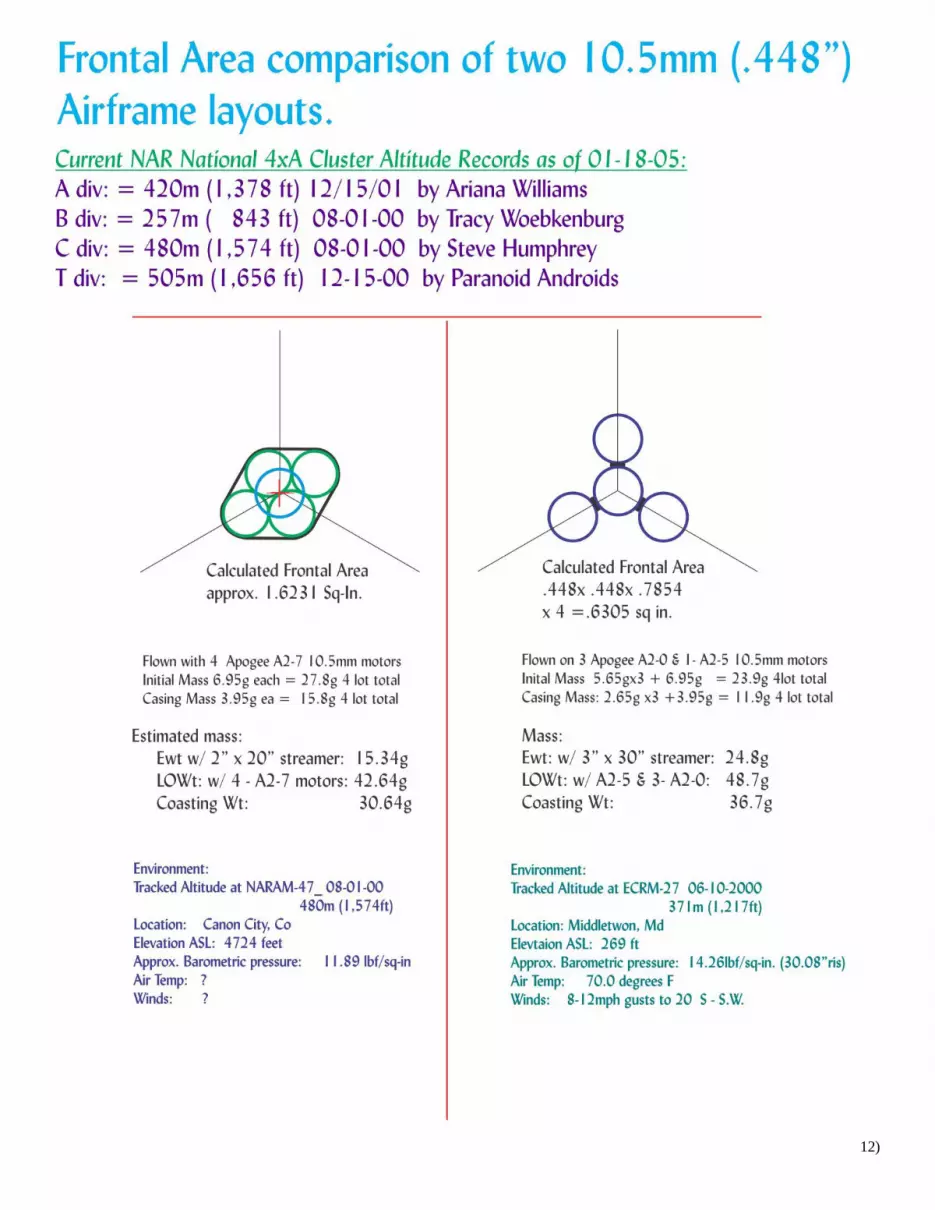
After ECRM-27 one of NARHAMS extended NJ family members Steve Humphrey decided to go with a more exotic model
body of fiberglass lay-up with a short aft transition to an open motor shell designed that just fit 4 squeezed together 10.5mm motors.
To this day I’m not quite sure how Steve lariat loop retained the motors but they did in fact stay with the model post ing an outstanding
480m (1574ft) flight taking 1st place in C div at NARAM-42. Unfortunately; Paul & I did not attended NARAM-42 but we did do a
side by side comparison of the two designs frontal area and optimum mass just for fun. Below you compare the designs and examine
the interesting findings.
11)
12)

13)

Another 4xA Cluster Altitude Combination: 18mm core with 13mm pods: (01-05-2005 – 06-2005) Another 5 years pasted before 4xA cluster altitude would be back on ECRM-32 and NARAM-47 event lists slated for April
and July of 2005. Unfortunately during those intervening years a couple motor limiting events occurred. First in 2001, Apogee
discontinued production of their 10.5 A2 high performance motors. Then around the same time Estes stopped production of the A10-0
booster motors due to a huge backlog of inventoried motors. Because these booster motors were out of active production for more
than three years, the NAR dropped them from the certified contest motors list. This mistake by the NAR really hurt Cluster Altitude
potential as we were left with only Estes A10-PT Heavy plugged booster motor.
While our choice of core motors in 13mm were still limited to Estes A3-4T or A10-3T mini brutes. There was always Estes
18mm A8-5 or Quest Aerospace 18mm A6-4 which actually has a higher initial thrust then the A8 motor.
Being forced to go with either 4 motors with ejection charges or choosing the HEAVY A10-PT adding .6g per motor too the liftoff
mass and .3g pre motor during coasting phase left much to be desired.
All these altitude limiting concerns only made the new design phase a bit more nerve wracking. After doing a bunch of early
altitude calculations it seems obvious the best chance for decent altitude would be a combination 18mm core vehicle with 3- 13mm
7degree taper pods. Designing with standard BT-20 tubing for the model core and BT-5 for the 3 Pods the calculated frontal area
worked out to 1.13 sq-in. An Apogee black styrene competition nose cone was chosen which would be highly polished without paint.
The pod covers are CA soaked file folder. While the pods themselves would be spaced off the last couple inches of the main on two
stacked paper 1/8” wide spacers to allow full diameter external taping of the booster and core motors. Fins are .015” Waferglass with
light epoxy fillets. Shock-cord is a combination of 36” 70lb Kevlar knotted to a 24” piece of 1/8” oval elastic. Intended as a
streamer recovery model, a 4” x 40” 1mil Mylar accordion folded streamer was prepared. I decided this one would be primed and
paint while trying to keep the additional mass down to a minimum. After filling all pod to main joints with Micro Balloon filled
epoxy all joints were smoothed and rounded down to 400 girt sandpaper. A single coat of grey auto primer was applied, allowed to
dry then sanded almost completely off, leaving only a very small amount in areas that needed a bit of filling. After about a week dry
time, two coats of Krylon (Old Formula) 1501 gloss white was applied. Giving the model another week to cure, the entire white
surface was first 1000 grit wet sanded then Finessit-II worked until the entire surface was as blemish free as practical. Thinking back
on this process I recall spending several hours longer polishing the surfaces then it took to build the entire model. Once satisfied with
the surface finish a couple simple decals & NAR numbers were applied. Than the entire vehicle was Nu-Finish polymer applied and
buffed to a very high Gloss. A really good looking rocket if I do say so. That and a couple Weird options would be presented to the
NARHAM membership in our usual Pre-ECRM event discussion meeting. We’ll look a bit more at that option shortly.
14)

15)

16)

17)

The 4xA Cluster Altitude 18-13mm Option: Odd looking stacked in-line 4 motor design – (08-2004 - 02-2005)
If you’ll recall our 2x1/8A Cluster Alt builds we discussed a stacked in-line 2 motor option. Apparently
another well known micro and all around decent NAR model designer Jeff Vincent expanded on that micro
rocket option to build a 4xA in-line stacked cluster altitude model which he tested in August of 2004.
Around the same time in preparation for our Feb 2005 NARHAMS pre-ECRM build discussion meeting
I also put together a 4 motor in-line stacked contraption based on the earlier micro stacked rocket. Jeff’s and
my designs are somewhat similar though I didn’t learn of Jeff’s design until some time later. This does show
that thinking outside the box does often lead to nearly simultaneous invention of some rather strange flying
machines.
Using an 18mm forward pod to contain the recovery system, nosecone and A8-5 motor the lower 13mm
short pods we stacked leaving as much room between as practical without turning the model into a super-roc.
Tying all 4 motor pods together were 3- 1/8” square Spruce dowels with basswood spacers as needed to keep
everything aligned. For this model 3- 3/32” Basswood fins were chosen. Over all the thing ends up being 39-
1/4” long.
There are two main draw backs to the In-line stacked configuration, needing two somewhat specific
accessory elements. First the 3 lower motor housing will need some form of nose cone with ablative or
protective material covering the forward section of each lower booster to prevent the lower motors from being
back burned by the exhaust of the motor ahead of it. In my design I used sharply turned long Basswood
nosecones with .001” Kapton covers rolled to snuggly fit in an attempt help protect the wood cones and motors
below.
Second these very long models also require a special set of extended micro clips with ohm matched
lengths to eliminate any slight hesitation in amp delivery to the ignitions for this weird set-up. Another
consideration is to have an add-on fall away tether rod to pull the clips away from the model as it begins to rise.
In flight testing I was surprised this configuration 177k3, didn’t get higher altitudes then the standard
side pod cluster as the unfinished model is considerably lighter then 18-13mm design 177i described earlier.
I’m sure the open areas and thrust vectoring account for most of the reduced altitude achieved.
Now that Estes has returned the A10-0 to contest certified production, it may be worth another look as these
strange looking cluster altitude models.
18)

A couple looks at NARHAMS Cluster Altitude presentation 02-05-2005 preparing for ECRM-32 04-16/17-05
and NARAM-47 07-29-2005.
19)

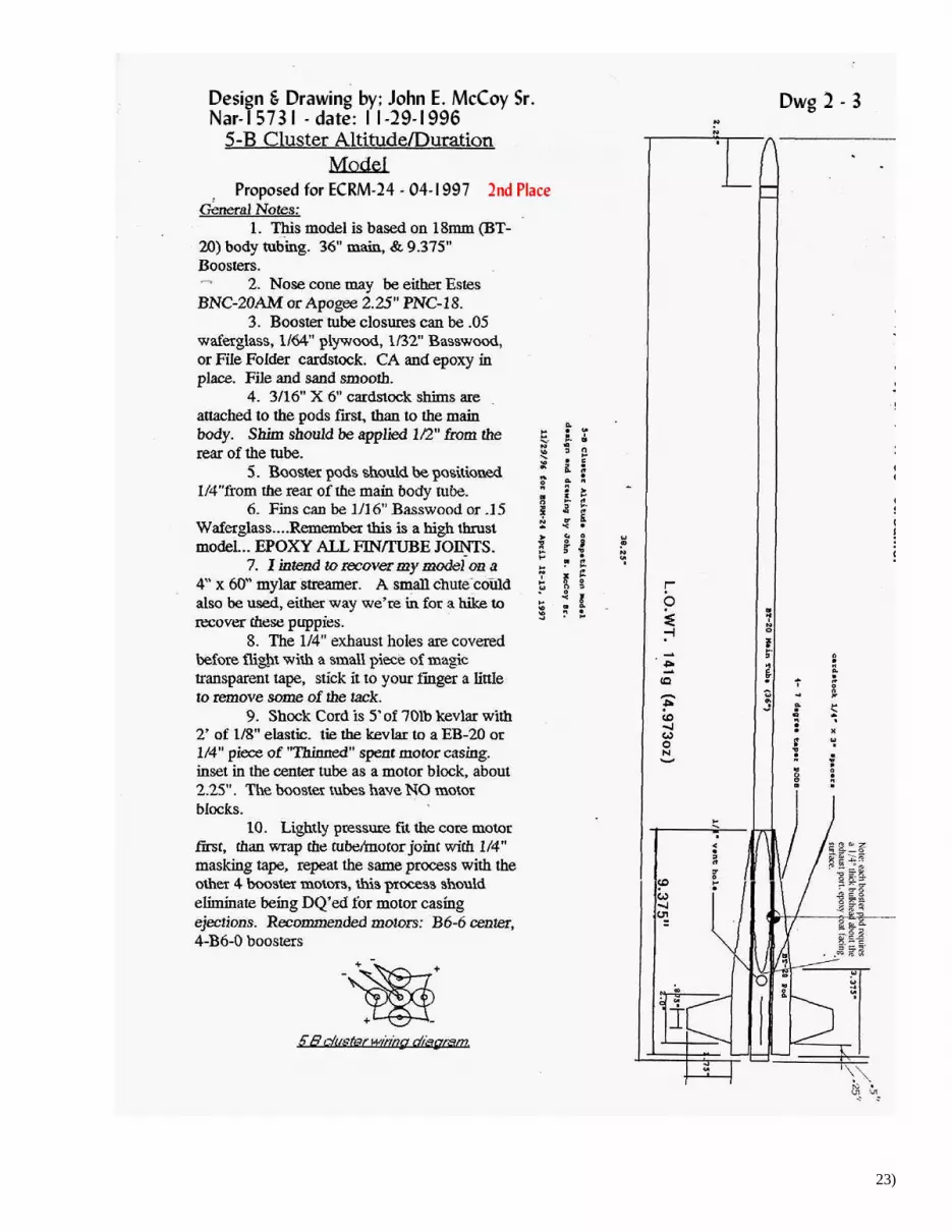
5xB Cluster Altitude: 18mm long vehicles. (08-16-1996 – 04-1997) Now this even gets really interesting. Five B Cluster Altitude events require a good bit more length to offset the mass in the
aft end. As it turns out an 18mm BT-20 x 36” long worked out just about right. Having 36” long “stock” tubes has been a blessing
ever since a few of us in the club went in on a truck load of all Estes size .013” wall craft tubes from BT-5 through BT-101, all one
piece 36” long. To this day I’m still using the tubes purchase in the early 1990’s at fantastically low prices.
To cover 5xB Cluster Altitude flown at ECRM-24 April 1997, we will have to regress just a bit. After NARAM-35,
NARHAMS decided during our yearly planning sessions for the next few years to work our way through all 5-6 motor class events
progressing one motor class a year at our ECRM contests with or without a matching Cluster-Altitude event at the Nationals.
Building on what had been learned with last years 4xA rockets. A few sketches were prepared and shared with the
membership for comment. Our basic model would be a long core BT-20 with 4 Short motor pods with parabolic balsa nosecone, 5-
double taper Balsa fins, having the usual internal parts made up of the usually Kevlar/Elastic/Mylar Streamer recovery system. While
this particular set up would certainly get each builder a qualified flight, it would not likely earn a spot on the podium. Back to the
drawing board: Below are the drawings which are more or less a take off on the previous years 7deg. tapered pod model. Increasing
the body tube to BT-20 and increasing the length of both core and the tapered pod tubes. Our streamlined model has an Apogee
components black plastic high polished nosecone. Still learning, the first prototype model #191a did not have solid Bulkheads above
the ¼” exhaust ports. During test flying the CA hardened file card pod covers held up fine during booster motor burn through.
However: when finished and flown at ECRM-24 I blow off 3 of the 4 covers at burn thru which I’m sure cost several hundred feet
landing my flight in second place. My only solace in the fact the Jim Filler took first place flying the same design.
20)

5xB Cluster Altitude 10.5mm: 5- B2 BP T4 Airframe Model – (09-1996 – 06-14-1997) While working on the standard design for the club using BT-20 size body. I decided to create a 10.5mm (.448”) OD design set-up to
use Apogee B2 high performance BP motors.
Building and finishing this sleek little T4 body rocket as smooth and sleek as I could I decided to fly it at ECRM-24 as a
sport flight using a core B2-7 and 4 B2-0 motors. Setting up this model for the “Demonstration Flight” most of us expected the model
to get a couple thousand feet but I had no idea just how high it would actually fly.
At ignition, the B2 powered rocket teleported out of sight in an instant still under thrust. The tracking teams reported “Track Lost”
saying they never saw anything but did hear a faint pop very high in the sky. No sign of the 4” x 40” Mylar streamer. The model
simply disappeared never to be seen again. It was a fantastic flight that I will be happy do again. I still have a stash of the sweet little
10.5 mm B2 motors.
21)

22)
23)

24)

6xC Cluster-Altitude: Very High Performance flying: (02-1997 – 05-17-1998) Last up on NARHAMS Cluster Altitude ECRM events roster was 6xC, slated for ECRM-25, May 17, 1998. I do not recall
how we got out of sequence with the Cluster-Altitude events at NARAM but according to the records somehow we did.
NARAM-39 held in August of 1997 out west in Tucson, AZ. (Elevation 2,346ft) with 6xC Clu-Alt as one of the events.
Earlier in 1997 Tim Van Milligan created an Apogee components paper “6 Cluster motor model general construction notes.”
published on their web page with an interesting set of short cardstock pod shroud patterns. Unfortunately this very nicely done write-
up was completely missed until doing research for our NARHAMS ECRM model design around June of 1997. While working on
model 607a 6xC design prototype, the decision was made to give Mr. Van Milligan’s design a try along with the fresh off the drawing
board 6xC Cluster ECRM-25 design. Building both models with an eye on the club meeting cluster altitude discussion coming up in
April of 1998 made perfect sense. Having two different designs to actually test fly should make for some interesting data points. I
did get both models built and flown in July of 1997, recovering both but having to rebuild the aft section of the Van Milligan model
which crumpled badly on landing causing the entire aft motor pod section to need replacement. Neither flight was tracked beyond the
many sport launch spectators watching. The general consensus gathered after the test flights by those watching was unanimous,
giving #607a “much higher flight” over Tim’s suggested design. After crude repairs to the Van Milligan model for use at the
upcoming club discussion, that rocket has not flown again.
Showing up shortly after our April club presentation Dan Wolf had an article published in the May/June 1997 Sport Rocketry
giving plans for two contest qualifier type 6xC cluster altitude models. The first design was a BT-20 core with 5- BT-20 short pods
with balsa nose cones and 5- 1/8” balsa pod mounted fins. The second design centered on a BT-60 core with Big Bertha plastic nose
cone with 3- internal BT-20 motor mount tubes and 3- BT-20 external booster pods with balsa nose cones, spaced between 3 large
1/8” balsa fins. While both designs are interesting the larger frontal area and use of standard Balsa full nose cones on the pods seemed
to suggest these would be pretty drag prone rockets. It is my understanding ECRM-25 had at least one or two of each design flown by
contest competitors. However I do not recall these designs performance.
Somewhere along the line, the fact that 6xC had already been flown at the Nationals August of 1997, came to light.
Searching for info we found C division, 1st place winner was Wally Etzel. He posted a winning flight topping out at 716m (2,349ft) on
08-1997. Still later in Sport Rocketry Jan/Feb issue 1998 published his 6xC 2- page plan. Wally’s design is a very interesting but far
more complex design then 607a. After much concentrated pondering, a model built from these plans was not included in the club
presentation beyond referencing the Sport Rocketry article and NARAM-39 6xC Cluster Altitude results. It was also noted that the
Tucson, AZ launch site elevation, 2,346ft ASL was certain to have played a role in the extraordinary altitude achieved. During the
club discussion centered on Launch Site ASL level effect on model rocket achieved altitude, many long time NARAM competition
flying members adding that “Out west” flights always seemed to fly higher. For some reason Wally’s 716m flight was retired from
the record books with no explanation.
ECRM-25; 05-17-1998, Model 607a, designed as an all 18mm model, flying on 1-C6-7 & 5-C6-0 motors set a new National
record from our East Coast Middletown, Md. Launch site elevation 269ft ASL with a closed track of 666m (2,185ft) ASL. This
record was also retired in 2000 again with no explanation? A look at NAR National records as of 2016 lists the current 6xC Cluster
Altitude records still show; Mike Fillers A-div. record @ 657m, At ECRM-25 06-16-98 using the same design as my C Div. 666m
flight flown on the same day. While C-div. Cluster altitude is shown as 513m flown on 04-17-11. There are no current records for
either B or Team divisions. Go figure.
After flying all 6 of these Cluster-Altitude events there are a few conclusions I’d like to pass on to
the next generation of Cluster flyers.
As stated at the beginning of this article the two most important elements in gaining the very most out of our clustered BP
motors require:
1) Reduce overall Frontal Area as much as possible. In that respect it is my opinion Wally Etzel was on the right track,
imbedding some of the booster tubes in the main could work if the overall frontal area were reduced to say BT-20 rather then BT-50.
2) Find by calculation and/or flight testing the Optimum Mass for the particular Rocket & Motor combination.
Followed by several other things the Cluster Altitude Builder should look for;
* Purchase and Weigh several packs of motors to be used, picking the heaviest individual motors of each cluster group
* Continuity Test All Igniter/Starters to be used, Before, During and AFTER installation in the motors to ensure all motors
have a Good igniter.
* Limit the use of “Clip Whips” to those that are no more the 16ga stranded copper and no longer then 22”.
* Clip whips should be Mechanically Fastened directly to both +/- sides of our RELAY not added to an existing control wire
circuit.
* If at all possible Always Fly Clustered models using a Relay Launch System with a HD 12V battery at the launcher.
* Cluster-Altitude rockets should be Tower Launched, or Rail launched with minimal size rail buttons or fly away shoes.
On the next several pages are presented as many of the drawings, instructions and photos of as many of the above described
6xC designs as could be gathered. From these pages and the previous impulse events models shown: I am certain those interested in
flying any of the 6 impulse classes of Cluster-Altitude competition should have a pretty good starting point on which to build.
We have covered a lot of ground in over a decades worth of flying different cluster impulse events. Keep in mind that some
of the motor choices will or have changed as time goes on. Select the “Best Matched” sets of motors for your Cluster Flying.
I have to say as a former competition flyer; Cluster Altitude has always been in the top 4 of my favorite contest events: Sport Scale,
PMC, Cluster-Alt. & HD. Hope readers have as much fun with this or those events in the future as I’ve enjoyed over the years.
25)

Instruction & Plan from J.EM Club Discussion Handout (09-1997)
26)

27)

Instruction and Plan from Apogee components 02-1997
28)

Plan from Apogee Components 02-1997
29)
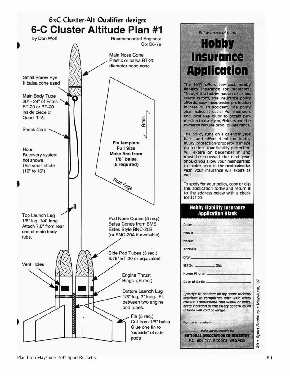
Plan from May/June 1997 Sport Rocketry: 30)

Plan from May/June 1997 Sport Rocketry.
31)

Plan from Jan/Feb 1998 Sport Rocketry.
32)

Plan from Jan/Feb 1998 Sport Rocketry.
33)