aerodynamics of wing tip sails
TRANSCRIPT

Journal of Engineering Science and Technology Vol. 1, No. 1 (2006) 89-98 © School of Engineering, Taylor’s College
AERODYNAMICS OF WING TIP SAILS
MUSHTAK AL-ATABI School of Engineering, Taylor’s College
No 1 Jalan SS15/8, 47500 Selangor, Malaysia Email: [email protected]
Abstract Observers have always been fascinated by soaring birds. An interesting feature of these birds is the existence of few feathers extending from the tip of the wing. In this paper, small lifting surfaces were fitted to the tip of a NACA0012 wing in a fashion similar to that of wing tip feathers. Experimental measurements of induced drag, longitudinal static stability and trailing vortex structure were obtained. The tests showed that adding wing tip surfaces (sails) decreased the induced drag factor and increased the longitudinal static stability. Results identified two discrete appositely rotated tip vortices and showed the ability of wing tip surfaces to break them down and to diffuse them. Keywords: Wing tip sails, Induced drag, Wing tip vortices.
1. Introduction Studies made of the flow about the wing tip of a wind tunnel model showed that the vortex-type flow generally associated with the rolled-up vortex sheet well behind the wing tip existed just behind the trailing edge and seemed to be forming over the top of the wing tip itself [1]. Since lift generated by a finite wing could be explained only by a circulatory flow generated by the proper vortex strength, a properly placed vortex filament could simulate the wing. Prandtl called this vortex a lifting line. It is also known as the bound vortex [2]. The bound vortex could not just disappear when the
89
90 M. Al-Atabi
Nomenclatures A Aspect ratio CD Drag coefficient
CL Lift coefficient CM1/4C Pitching moment coefficient measured about quarter the chord KS Induced drag factor for separated conditions KU Induced drag factor for unseparated conditions k Yawmeter calibration factor p Pressure [N/m2] u,v,w Local velocity components in x,y,z directions respectively [m/s] U Free stream velocity [m/s] X A distance parallel to the flow [m] Y A distance along the model span [m] Z A distance along the tunnel height [m] Greek Symbols α Angle of attack of the wing [deg] β Local angle of attack of the sail [deg] δ Radius of the vorticity probe [m] ζ Vorticity [1/s] ρ
Density of Air [kg/m3]
lift dropped to zero at the wings’ tips but it would continue into the fluid and produce actual free vortex in the fluid at the tips of the wing. These tip vortices trailing behind present day’s aircraft are of great concern to the aviation community because they may be hazardous to a trailing aircraft and they are responsible for creating a drag component known as induced drag or lift dependent drag [3]. For most transport aircraft, induced drag is approximately 30% of total drag in cruise and more at lower speeds [4]. Wing tip sails are small lifting surfaces fitted to the wing in such a way that they use the local air flows about the wing tip to produce a thrust. They act in a manner similar to that of the sail of a yacht when it is sailing close to the wind, hence their name [5] and they are inspired by the birds’ wing tip feathers as those shown in Fig.1. 2. Experimental Procedure In this research the effectiveness of wing tip sails was investigated through wind tunnel measurements of aerodynamic forces and moments and through the study of flow structure behind the wing tip using the vorticity probe described firstly by Freestone [6]. The tunnel used was of the closed working section, open return
Journal of Engineering Science and Technology JUNE 2006, Vol. 1(1)

Aerodynamics of Wing Tip Sails 91
type, with a working section of 457mm×457mm and with a maximum air speed of 33m/s.
Fig.1. Soaring bird with wing tip feathers.
The wing model used in this study had a symmetric NACA0012 profile, with a
chord of 200mm and a semispan of 300mm corresponding to a constant aspect ratio of 3. The wing was an untapered and untwisted one. It was mounted in the horizontal mid-plane of the test section, allowing it to pitch about its quarter-chord pivot line. Figure 2 shows the wing with three sails fitted to its tip. The positions of the sails are at 30%, 52.5%, and 75% of the chord from the leading edge. Sails were made of cambered galvanized plate of 1mm thickness with 26mm root chord and 13mm tip chords.
Fig.2. NACA0012 wing fitted with three wing tip sails.
Journal of Engineering Science and Technology JUNE 2006, Vol. 1(1)

92 M. Al-Atabi
The profile of each sail changes in the spanwise direction as its camber decreases gradually from a part of the circumference of a circle of radius 38mm at the root of the sail to simply a straight line at its tip. The gradual change in camber was according to reference [4] In order to reduce the interference between successive sails, different angles of dihedral with respect to the plane of the wing were chosen for each sail. If three sails were used, the angles of dihedral were +15, 0, -15 deg from the forward to the rearward sail. If two sails were used the angles were + 15m and 0 deg., while if only one sail was used, its angle was zero. In all figures of results described below, the numbers denoted by β will be given representing the local angles of attack of the sails. The numbers from left to right to indicate the front, middle, and rear sails respectively. The measuring of aerodynamic forces and moments acting on the model was done using a three component balance at a tunnel speed of 25m/s corresponding to Reynolds number of 3.4×10⁵ based on wing’s chord. In order to study the flow structure downstream of the wing, to account for the effect of wing tip sails on tip vortices, the vorticity probe described by Freestone [6] was constructed and calibrated. This probe consists of four yawmeters and is shown schematically in Fig. 3.
Fig.3. The arrangement of four yawmeters to produce a vorticity probe.
Journal of Engineering Science and Technology JUNE 2006, Vol. 1(1)

Aerodynamics of Wing Tip Sails 93
Freestone [6] related the sum of pressure differences produced by the yawmeter pairs to the vorticity by the relation
ζρδUpk
j,ij,i
=∆∑ 1 (1)
zv
yw
∂∂
−∂∂
=ζ (2)
The flow structure study was done by measuring the vorticity at every point in grids downstream of the wing at x/c=0.5 and x/c= 1.0, then plotting the vorticity contours. The effect of a number of wing tip sails parameters on the performance of the sails was experimentally investigated. These included the angle of attack of the wing, the number of sails, the local angle of attack of the sails and the position of the tip sail relative to the wing tip chord.
3. Results and Discussion
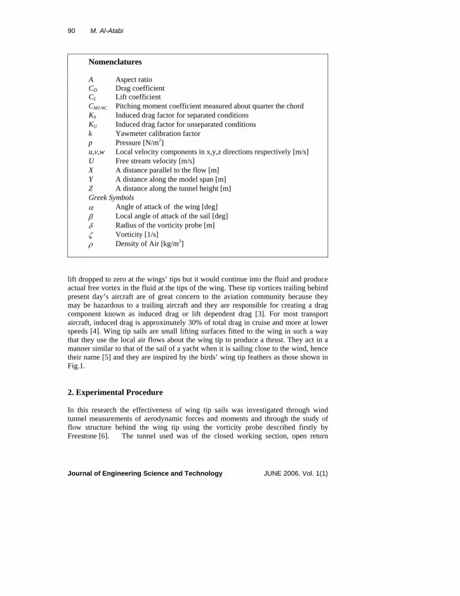
3.1 Drag Results The test results showed that all the configurations of wing with sails had greater drag coefficients compared to wing without sails at lift coefficients below 0.4. This, however, was not the case at higher lift coefficients where lower drag coefficients were recorded for the wings with tip sails. These results are expected, as the plan area of the wing with sails is greater than that of the wing without sails. Greater plan area increases the skin friction drag that was more significant at low lift coefficients [5] and this explains the drag reduction at the higher lift coefficients. It is also noted that a sail with a significant camber at the root is likely to have root separations from the undersurface of very small wing incidences because the angle between the local flow direction and the chord of the sails can be too large and negative. In this case the drag of the sail would be significantly increased. As wing incidence increased the root flow would attach to the undersurface and the drag would decrease. This behavior is clear in Fig. 4 which shows the effect of the number of sails on the drag reduction. It’s obvious that after recovery from sails’ undersurface separation addition of more sails reduces the drag coefficient. 3.2 Induced Drag Results To study the effect of sails on induced drag reduction, the square of lift coefficient was plotted against the drag coefficient. The rate of change of drag coefficient of this curve gives an indication of the amount of induced drag, where the induced drag factor K is defined as
Journal of Engineering Science and Technology JUNE 2006, Vol. 1(1)
94 M. Al-Atabi
AdC
dCK
L
D ××= π2 (3)
No Sails
Fig.4. The effect of sails’ number on CD increment relative to wing with no sails.
The general behavior of this curve is to remain linear until separation occurs, where the behavior becomes nonlinear. The case of a wing with no sails is represented by a curve which has a linear part and then becomes nonlinear, while in the case of a wing with sails fitted to its tip, the curve consists of three zones, the first is a nonlinear one, extending from CL
2=0 to CL2≈0.2. The reason of this nonlinearity is
the separation undersurface of the sails. This zone is followed by another linear one extending to about CL
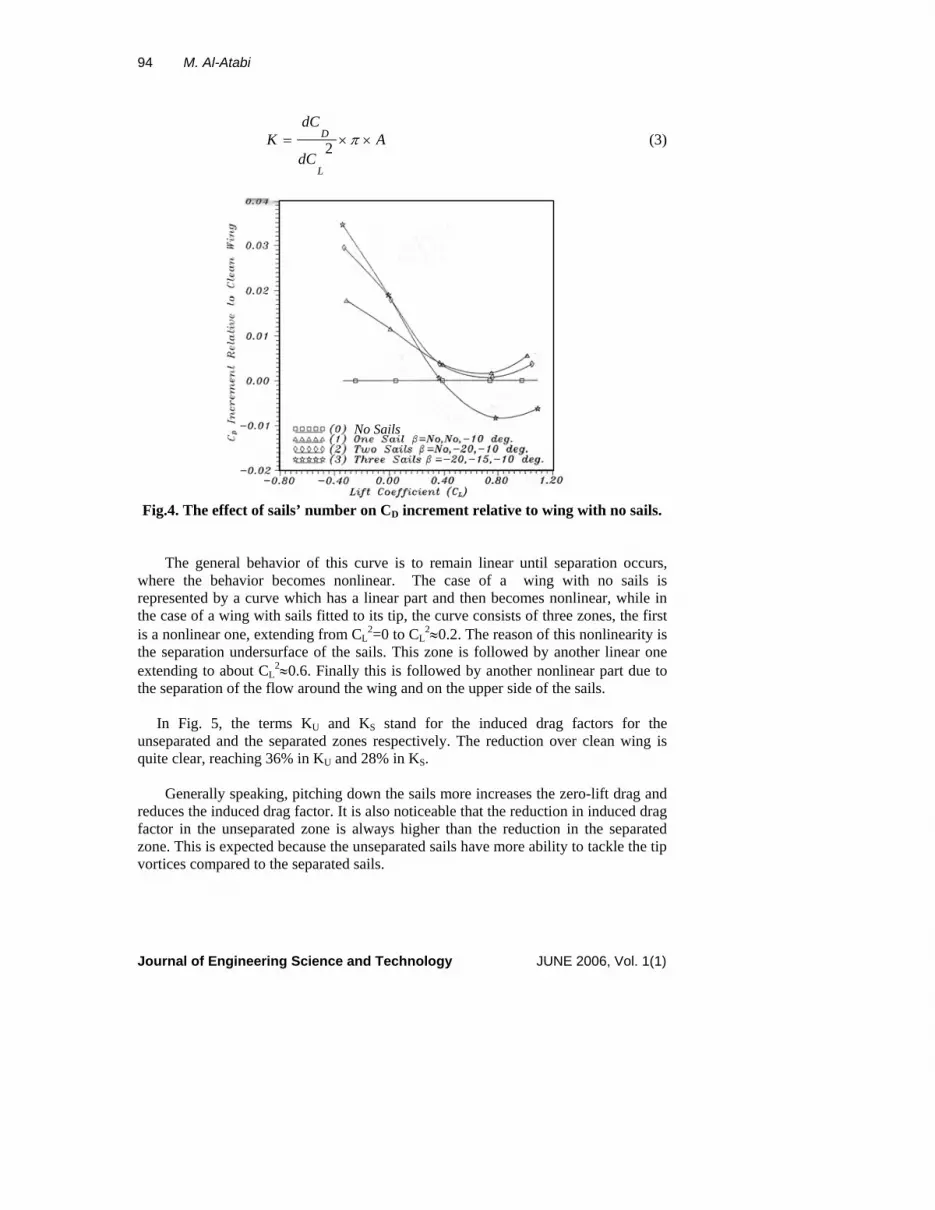
2≈0.6. Finally this is followed by another nonlinear part due to the separation of the flow around the wing and on the upper side of the sails. In Fig. 5, the terms KU and KS stand for the induced drag factors for the unseparated and the separated zones respectively. The reduction over clean wing is quite clear, reaching 36% in KU and 28% in KS. Generally speaking, pitching down the sails more increases the zero-lift drag and reduces the induced drag factor. It is also noticeable that the reduction in induced drag factor in the unseparated zone is always higher than the reduction in the separated zone. This is expected because the unseparated sails have more ability to tackle the tip vortices compared to the separated sails.
Journal of Engineering Science and Technology JUNE 2006, Vol. 1(1)
Aerodynamics of Wing Tip Sails 95
Other results showed that the addition of more sails reduces the induced drag further. In fact two sails more than doubled the reduction in KU and reduced KS by slightly less than this. However a third sail reduced these factors only slightly. Similar results were reported by Spillman [5]. He used a set of sails to be fitted to a one-seventh scale of a Paris aircraft with tip tanks. These tests were not extended to the separated wing zone. However, the sails caused a reduction in the lift dependent drag by 12% for one or two sail and by 28% for three sails.
s
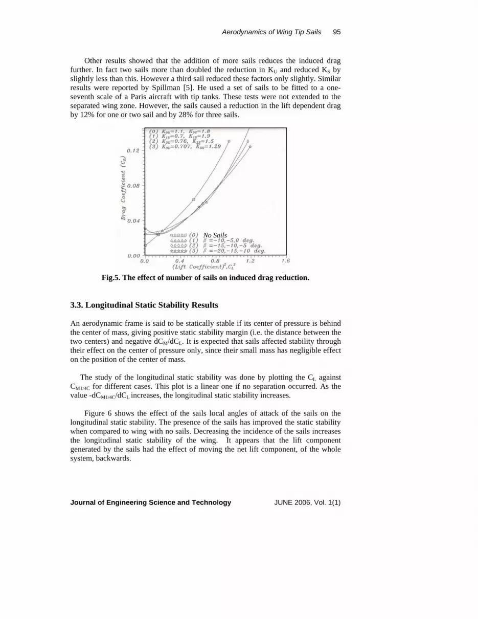
Fig.5. The effect of number of 3.3. Longitudinal Static Stability Res An aerodynamic frame is said to be staticthe center of mass, giving positive static stwo centers) and negative dCM/dCL. It is etheir effect on the center of pressure only,on the position of the center of mass. The study of the longitudinal static stCM1/4C for different cases. This plot is a lvalue -dCM1/4C/dCL increases, the longitudi Figure 6 shows the effect of the saillongitudinal static stability. The presence when compared to wing with no sails. Dethe longitudinal static stability of the wgenerated by the sails had the effect of msystem, backwards. Journal of Engineering Science and Tec
No Sail
sails on induced drag reduction.
ults
ally stable if its center of pressure is behind tability margin (i.e. the distance between the xpected that sails affected stability through since their small mass has negligible effect
ability was done by plotting the CL against inear one if no separation occurred. As the nal static stability increases.
s local angles of attack of the sails on the of the sails has improved the static stability creasing the incidence of the sails increases ing. It appears that the lift component oving the net lift component, of the whole
hnology JUNE 2006, Vol. 1(1)
96 M. Al-Atabi
s
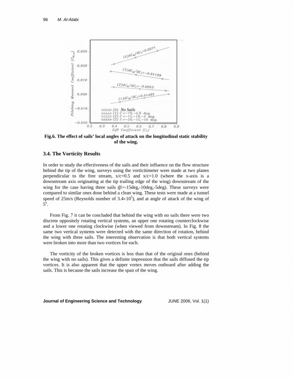
Fig.6. The effect of sails’ local angles of t
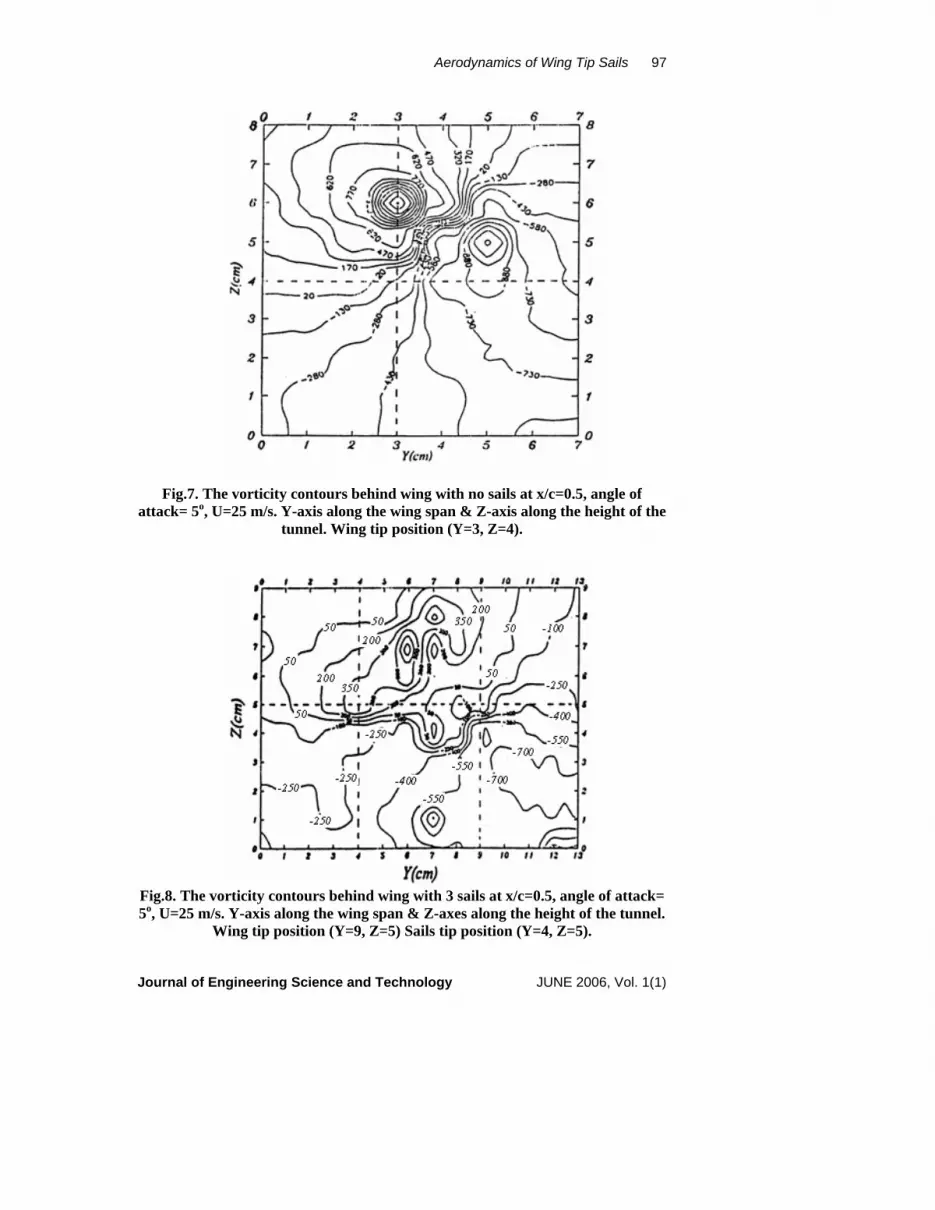
3.4. The Vorticity Results In order to study the effectiveness of thebehind the tip of the wing, surveys usinperpendicular to the free stream, x/cdownstream axis originating at the tip wing for the case having three sails (βcompared to similar ones done behind aspeed of 25m/s (Reynolds number of 35o. From Fig. 7 it can be concluded thatdiscrete oppositely rotating vertical sysand a lower one rotating clockwise (wsame two vertical systems were detectethe wing with three sails. The interestwere broken into more than two vortices The vorticity of the broken vorticesthe wing with no sails). This gives a devortices. It is also apparent that the upsails. This is because the sails increase th
Journal of Engineering Science and T
No Sail
of attack on the longitudinal static stability he wing.
sails and their influence on the flow structure g the vorticitimeter were made at two planes =0.5 and x/c=1.0 (where the x-axis is a
trailing edge of the wing) downstream of the =-15deg,-10deg,-5deg). These surveys were
clean wing. These tests were made at a tunnel .4×105), and at angle of attack of the wing of
behind the wing with no sails there were two tems, an upper one rotating counterclockwise hen viewed from downstream). In Fig. 8 the d with the same direction of rotation, behind ing observation is that both vertical systems for each.
is less than that of the original ones (behind finite impression that the sails diffused the tip per vortex moves outboard after adding the e span of the wing.
echnology JUNE 2006, Vol. 1(1)
Aerodynamics of Wing Tip Sails 97
Fig.7. The vorticity contours behind wing with no sails at x/c=0.5, angle of attack= 5o, U=25 m/s. Y-axis along the wing span & Z-axis along the height of the
tunnel. Wing tip position (Y=3, Z=4).
Fig.8. The vorticity contours behind wing with 3 sails at x/c=0.5, angle of attack= 5o, U=25 m/s. Y-axis along the wing span & Z-axes along the height of the tunnel.
Wing tip position (Y=9, Z=5) Sails tip position (Y=4, Z=5). Journal of Engineering Science and Technology JUNE 2006, Vol. 1(1)

98 M. Al-Atabi
5. Conclusions Wind tunnel tests have shown that the drag of a wing can be reduced over a considerable lift range if wing tip sails are fitted to the tip of a planar wing. Sails fitted to the wing tip can reduce its lift dependent drag by up to 35%. An increase in local angle of attack of the sails, and also an increase in the number of sails decreases the lift dependent drag, while the increase of number of sails decreases it also. Longitudinal static stability of the wing was significantly improved after adding the sails. The amount of longitudinal static stability was increased by decreasing the local angle of attack of the sails, increasing the number of sails and moving a sail backward toward the wing’s trailing edge. There were two discrete tip vortices behind the wing with and without sails for x/c=0.5 and x/c=1.0. The wing tip sails showed their ability to break down and reduce the tip vorticity behind the wing they are fitted to its tip. References 1. Spillman, J.J., Ratcliffe, H.Y., and McVitie, A. (1979). Flight Experiments to
Evaluate the Effect of Wing-Tip Sails on Fuel Consumption and Handling Characteristics. Aeronautical Journal. 83, 279-281.
2. Hoerner, S.F. (1965). Fluid Dynamic Drag. Published by the author. 3. Ciffone, D.L., and Orloff K.L. (1975) Far-Field Wake-Vortex Characteristics of
Wings. J. Aircraft.12 (5), 464-470. 4. Spillman, J.J. (1978). The Use of Wing Tip Sails to Reduce Vortex Drag.
Aeronautical Journal. 82, 387-395. 5. Spillman,J.J., and McVitie, A.M. (1978). Wing Tip Sails which Give Lower
Drag at all Normal Flight Speeds. Aeronautical Journal. 88, No. 878, 362-369. 6. Freestone, M.M. (1985). Approximate Measurement of Streamwise Vorticity in
Aeronautical Flows by Simple Pressure Probe. In Proceedings of Hatfield Polytechnic Conference.
Journal of Engineering Science and Technology JUNE 2006, Vol. 1(1)