unsteady aerodynamics of rotorcraft in ground effect
TRANSCRIPT

- 1 - American Institute of Aeronautics and Astronautics
AIAA Paper 2004-2431, Fluid Dynamics Meeting, Portland, OR, June 2004
Unsteady Aerodynamics of Rotorcraft in Ground Effect
Balakrishnan Ganesh1, Narayanan Komerath2. School of Aerospace Engineering, Georgia Institute of Technology, Atlanta, GA 30332-0150
The aerodynamic characteristics of rotorcraft flight close to the ground are studied. Flow visualization was done to identify the flow structure in ground effect, and compare it with the out of ground effect flow structure. Hotwire measurements were done to quantify time scales of fluctuations. Six component force measurements were done to measure the loads at various advance ratios and yaw angles.
Nomenclature µ = Advance Ratio
I. Introduction The fundamental fluid dynamics problem here is one where large fluctuations are observed under nominally
quasi-steady flight conditions, separated by seemingly random intervals. The application interest is described below, and the approach taken to sort out the different phenomena, are described in the rest of this extended abstract. This approach takes us into challenges in prediction techniques as well as in qualitative and quantitative visualization, force measurement and other forms of uncertainty reduction.
In ground effect (IGE) conditions, the wake of a helicopter rotor interacts with the ground and causes significant perturbation to the flow near the rotor blades, as well as the rest of the craft. Interactions between the main rotor wake and the ground have been associated with the formation and passage of a ground vortex in transitional flight. These interactions have substantial effects on the handling qualities, power requirements and stability of the craft. Large transients including asymmetric loads and moments have been reported from flight tests of new craft. Differences have also been observed between the performance of helicopters hovering close to the ground with ambient wind and helicopters during low speed flight close to the ground.
One of the basic questions that arise from the reported flight test results, is whether the unsteadiness arises from the craft interacting with different regions of an otherwise quasi-steady flowfield, due to changes in wind direction, ground clearance or aircraft speed – or whether long-period fluctuations are generated in an otherwise periodic flowfield under fixed flight conditions.
Detailed studies of the rotor wake and ground vortex was performed with an isolated model rotor above a static ground plane at low advance ratio, and various ground heights. This study aims to quantify time scales of unsteadiness by bringing together results from pulsed laser sheet flow visualization, hotwire anemometry, and fuselage force measurement. In previous work with this experimental set-up, it was shown that the wake was steady enough in the absence of ground effect, to enable clear quantification of the unsteadiness caused by ground effect. This unsteadiness was quantified using laser sheet imaging of vortex dynamics. It was then shown that large transient velocity fluctuations occurred with long intervals, in the ground-vortex and in the rotor inflow regions.
Subsequent work investigated whether long-interval transients were also seen in the yawing moments experienced on generic fuselage models placed in the wake in ground effect. The present paper investigates a decision point in the investigation of unsteady ground effect. It is argued that transients could occur due to two basically different situations, or a combination of these situations:
1 PhD Candidate, School of Aerospace Engineering. Student Member, AIAA 2 Professor, School of Aerospace Engineering. Associate Fellow, AIAA.

- 2 - American Institute of Aeronautics and Astronautics
a) Due to wind direction and advance ratio change, so that the fuselage/ tail rotor interacts with different parts of the rotor wake. However, the rotor wake for a given flight condition is perfectly periodic. This situation can be modeled analytically through quasi-steady methods.
b) Even thought the flight condition remains identical, interactions between vortices, the ground and the vehicle surfaces, generate transient spikes in the forces and moments, with large intervals possible between such occurrences. This situation is fundamentally unsteady, and requires long-period unsteady simulation methods with high accuracy.
In real flight tests, these situations may be indistinguishable, and may both occur simultaneously. In wind tunnel tests, the latter situation corresponds to what we had tested so far. The former is the primary subject of the tests conducted, and the data presented in this paper.
II. Background The interaction of a rotorcraft wake with the ground during low speed flight close to the ground involves two
distinct flow regimes: 1. Recirculation of the wake ahead of the rotor at very low advance ratios, causing additional inflow through
the forward part of the rotor.1 (Recirculation Regime) 2. Formation of a horseshoe ground vortex under the rotor at higher advance ratios with its associated
interactions.1 (Ground Vortex Regime) Studies have found irregular changes in hub moment for a helicopter flying close to the ground2. Reference 1
noted that the flow fluctuates at a low frequency in the recirculation regime. The authors in Reference 2 found that in the recirculation flow regime, there is very little lateral flow and moderate level of unsteadiness in the flow field. The unsteady phenomena have been attributed to the periodic interference fluctuation between downwash and upwash in the recirculation regime3.
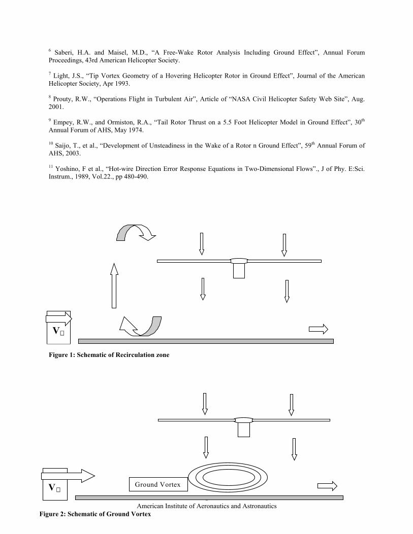
When rotors are operating near the ground at low advanced ratios, the forward part of rotor wake, after impinging on the ground plane, flows forward and then rolls up, forming a recirculation zone around the rotors (Fig.1). For a single rotor, the ground vortex center in the longitudinal symmetric plane is a little upstream of rotor leading edge4.
Above a critical advance ratio, which depends upon collective pitch and height-to-diameter ratio, a well-defined concentrated horseshoe vortex is formed under the rotor, and significant lateral flow is present (Fig.2). The flow field becomes quite steady. The vortex becomes smaller, and eventually vanished as the advance ratio is increased. The ground vortex also alters the helicopter yaw control effectiveness in sideway and rearward flights near the ground.
The ground vortex itself is quite unsteady, both in size and shape, and also in location5. The ground vortex has a large-scale low-frequency pulsating behavior, which is referred to as puffing of the ground vortex. The sequence of this puffing behavior is as follows. First the ground vortex is very small, but growing. For slow forward speed or for hover in light winds, the ground vortex would stay upstream. As the wind velocity increases, the ground vortex moves closer to the rotor. Interaction between the old vortices and new vortices increases as forward airspeed increases. As the ground vortex continues to grow, it eventually becomes too large for the flow field to sustain. At this point the entire flow field breaks up violently, and the large ground vortex is swept downstream. Immediately a new small ground vortex begins to grow upstream, and the cyclic process repeats itself6.
Tip vortex geometry is changed close to the ground since the wake contracts and then expands after impinging on the ground, leading to change in radial trajectory of the tip vortex when compared to flight away from the ground7. The unsteadiness is also more in the radial direction.
For a helicopter going into forward flight, the required power increases in the 5~20kt speed regime. The change in inflow through the rotor not only affects the required power but the lateral trim as well. Under OGE conditions at low speed the down flow through the front part of the rotor is lower than that through the rear part. This phenomenon makes the rotor tend to flap with the retreating side up. The effect of the ground vortex is to increase the down flow through the front part of the rotor disc, making the flow more uniform and reducing the requirement for left stick. After the ground vortex is overrun, left stick is required suddenly8.
When a helicopter is in rearward or sideward flight, the ground vortex may occur behind or on the side of the vehicle and may affect the tail rotor. In some helicopter development, the ground vortex causes the loss of tail rotor thrust9.

- 3 - American Institute of Aeronautics and Astronautics
III. Experiment description The experiments were conducted in the John J. Harper Low Speed Wind Tunnel of Georgia Institute of
Technology. This facility is a closed-circuit wind tunnel with a 7ft × 9ft test section. The rotor and test section is shown in Fig.3. A DC motor is used to drive the rotor shaft at speeds between 0 and 2100 rpm. The specifications of the test rotor are shown in table 1.
Table 1: Test Rotor Specifications.
Diameter (ft) 3 Chord length (in) 3.37 Airfoil NACA0015 Number of blades 2
(Teetering) Collective pitch angle(deg)
10 (fixed)
Twist angle(deg) 0 Rotor shaft tilt angle (deg) 6 Solidity 0.1193 A ground plate was installed in the test section to simulate the ground as shown in Fig.4. The flow visualization and the hot-wire measurements were initially done without the presence of a fuselage below the rotor. Laser sheet optics were placed downstream of the test section, and the images were captured by a camera placed perpendicular to the plane of the laser sheet. Flow seeding was generated by fog machines placed upstream of the rotor. Fluctuation frequencies were studied using hot-wire probes (TSI 120-120).
A. Test Conditions and Relation to Full-Scale Flight Conditions Test conditions are shown below. Rotor coordinates are illustrated in Fig.5.
• µ = 0.0, 0.03, 0.04, 0.05, 0.06, 0.07,0.08 • Rotor speed: 2100rpm • IGE (h/D = 0.36) , OGE • Laser sheet location: y/r = 0, -1/3, -2/3
These conditions are roughly equivalent to those of a UH-1B helicopter hovering at a skid altitude of 4ft and 0 to 38kt headwind. It should be noted here that the shaft tilt and tip path plane angle are not matched to such flight conditions. To attempt such matching would be to create needless complications, preventing systematic examination of the basic flow phenomena, and their separation into constituent phenomena.
IV. Results A. Flow Visualization
The preliminary results of the Flow Visualization done were presented in an earlier paper10. It was seen that at low advance ratios between 0.03 and 0.04, the rotor tip vortices move forward and upward, recirculating through the rotor disk (Fig.6). 7 or 8 vortices were tracked in the loop. The timescale of recirculation is approximately 0.11secs (approximately 9Hz) in this case 1. Evolution of Ground Vortex
In order to understand the evolution of the ground vortex, flow visualization images with gradually accelerating freestream flow (from µ=0.058 to 0.067 in 45 secs) were captured. Locations of separation points for each µ are summarized in Fig.7. At µ=0.056, separation occurred but a ground vortex was not formed yet. At µ-=0.058, the separated flow rolled and formed a ground vortex. In the range of µ=0.060 to 0.067, the ground vortex moves downstream as the advance ratio increased. It was observed that the separation point was moving back and forth intermittently at a fixed advance ratio. As the advance ratio increased, the mean location of the separation point moved downstream and the amplitude of the oscillatory movement became smaller. 2. Flow Visualization (OGE)
Flow visualization out of ground effect was done to compare the flow features with flow in ground effect. Recirculation was not observed even at low advance ratio in the OGE case. The fluctuation of the tip vortex position was found to be more stable than the IGE case.

- 4 - American Institute of Aeronautics and Astronautics
3. Unsteadiness Seen in Flow Visualization In order to compare the unsteadiness of IGE case and that of OGE case, movements of tip vortices were
analyzed by looking at the tip vortex location variation at different times captured by using a video camera. The results are summarized in Table 2. From the table, it can be seen that the IGE case is much more unsteady than the OGE case. The peak-to-peak jitter for the IGE case is almost double that of the OGE case. However, the difference in standard deviation is negligible, implying that the jitter in both cases is similar except for the occasional sharp change in tip vortex position in the IGE case. Table 2: Tip vortex location variation (IGE/OGE, y/r = 0, µ=0.03)
IGE OGE x z x z
Max peak to peak variation 0.048r 0.034r 0.032r 0.019r Standard deviation 0.012r 0.011r 0.011r 0.008r
Measurement uncertainty 0.010r 0.010r 0.006r 0.006r x: Horizontal direction z: Vertical direction r: Rotor radius
B. Hot-wire Measurement (IGE/OGE) The most notable result was the difference in the fluctuations in the inflow velocities obtained from the
hotwire measurements. As was expected, the inflow magnitude was lesser for the IGE case. However, the magnitude of fluctuations was negligible in the OGE case, while it was about 5 to 10 % in the IGE case, and is shown in Fig. 8. The upper and lower bounds are marked in red and green respectively, and represent twice the standard deviation. Also it has to be noted that the IGE case appears to have spikes that seem to re-occur every second. This appears to be the effect of the recirculation of the tip vortices.
To get a better idea of the frequency of these fluctuations, a Fourier analysis was done to the velocity time trace. The results are shown in Fig. 9. It can be seen that the 2 per rev component dominates the flow out of ground effect. However, with the ground plane, the spectrum is dominated by low frequency components. It can be seen that there is a distinct difference between the low frequency components in the IGE and the OGE case. In fact, the peak frequency in the IGE case occurs at about 1 Hz, even overshadowing the 2 per rev spike, which is dominant in the OGE case. This difference can be seen in Fig.9, which shows the Fourier coefficients for the two cases at advance ratios of 0.03, 0.04 and 0.05.
The results of the hotwire measurements close to the ground vortex are plotted in Fig. 10. It can be seen that at point A, a velocity fluctuation at low frequency (1 to 2 Hz) occurs and appears to be related to the movement of the flow separation point ahead of the nascent ground vortex. This correlates with the flow visualization results at an advance ratio of 0.05 where the flow appeared to switch between recirculation and the preliminary stage of formation of a ground vortex. At both points C and E, the frequency of the velocity fluctuation became relatively broad-band (between 0 and 50Hz). The mean flow velocities at these points were higher than free stream speed, which is approximately 16.5fps at an advance ratio of 0.05. At point G, a low frequency velocity fluctuation occurs. However, it is not similar to the large velocity separation-like change that occurs at point A, and appears to be induced by the passage of the tip vortex.
The isolated-rotor experiments above served to establish that
1. we could indeed achieve clean periodic flow conditions in the absence of ground effect 2. that the rise in unsteadiness due to ground effect was clearly perceptible and quantifiable 3. that wake interaction with the ground does cause unsteadiness in the ground vortex. 4. that recirculation of vortices does cause fluctuations in the rotor inflow plane. 5. long-period unsteadiness is indeed seen in the flowfield
The new work for this paper focused on observations with a fuselage present in the flowfield. This is essential
to (eventually) relate flowfield observations with pilot experience of stick forces and moments. These measurements would help in quantifying the fuselage loads decoupled from the rotor hub moments.
C. Fuselage Side Force Measurements

- 5 - American Institute of Aeronautics and Astronautics
1. Experiment Setup The fuselage was mounted through a hole in the ground plane, and was set up to yaw about an axis that was
perpendicular to the ground. The experimental setup is shown in Fig.11. The fuselage is a fiberglass cylinder 34” long, with a hemispherical nose with a radius of 5.5”. A picture of the setup is shown in Fig.12. The directional convention of the forces measured are shown in Fig.13. 2. Experimental Results
The side force on the fuselage was first measured with the yaw angle fixed at 0°. Analogous to the hotwire experiments, there is a significant low frequency component in the IGE case at low advance ratios that reduces with advance ratio increase. This trend can be seen in Fig.14. The Fourier components of side force at advance ratios of 0.03 and 0.08 are plotted for the IGE and OGE cases. Out of ground effect, the 1 and 2 per rev components dominates the spectrum. In ground effect, however, there seems to considerable low frequency components in the side force. A similar trend was seen in all the forces measured. At an advance ratio of 0.03 in ground effect, the two main frequencies are 7 Hz and 14 Hz. At an advance ratio of 0.08 in ground effect, the 7 Hz component has almost completely disappeared, and is dominated by the 14 Hz component. The response of the force balance to a step disturbance was investigated to understand these frequency components. This is plotted in Fig.15, and shows that the natural frequency of the balance is at 7 and 14 Hz. Therefore; we can conclude that in ground effect the natural frequency vibration of the fuselage is of the same order of magnitude of the 1 and 2 per rev components. Outside ground effect, however, the 1 and 2 per rev components are much bigger than the natural frequency vibration of the balance. Also, the low frequency fluctuations seen in hotwire measurements are not discernible in the fuselage force measurements. This is to be expected, because the hotwire fluctuations seen in the inflow and ground vortex are localized fluctuations and their effects tend to be smoothed out when integrated over the entire fuselage. A more detailed analysis of the Fourier coefficients of the side force in ground effect at various advance ratios is shown in Fig.16. All of them are plotted to the same scale. It can be seen that it is the 7 Hz component reduces in value with increasing advance ratio, indicating that the lower frequency excitation of the balance reduces with advance ratio. But it can be seen that there is no clear 1 Hz component as was seen in the hotwire measurements. This indicates that the unsteadiness seen in ground effect can be tackled on two fronts.
a) Long time scale fluctuations seen in the inflow and around the ground vortex, leading to thrust and power variation. This would imply that unsteadiness exists even in a trimmed condition in ground effect at low advance ratios.
b) Change in the forces felt on the fuselage due to the wake structure in ground effect. The rotorcraft would handle quite differently when compared to its handling out of ground effect at the same regime of flight. However, this change is a quasi-steady variation that can be trimmed off, if the changes are anticipated.
Another interesting phenomenon that was noticed is a change in side force from positive to negative at an advance ratio of about 0.06. This is shown in Fig.17. Interestingly, this change in the direction of the side force occurs at the advance ratio when there is a change from the recirculation regime resulting in the formation of the ground vortex. Furthermore, this change is associated with a change in slope of the curve, with a distinct kink at the zero side force advance ratio. The sideward center of pressure, where the side force acts on the fuselage is also plotted in Fig.17. These values were obtained by dividing the yawing moment by the side force, with the zero value being the center of the load cell as shown in Fig.11. It can be seen that the change in the direction of the side force is accompanied by a rearward shift of the side force moment arm. It can also be seen that after that the IGE values start tending towards the OGE values, indicating that the ground vortex has now been swept behind the fuselage, and its effect on the fuselage is now negligible. This is an indicator that it is at this advance ratio that the wake interacts with the tail rotor causing a sudden change in tail rotor effectiveness as measured in Ref.9.
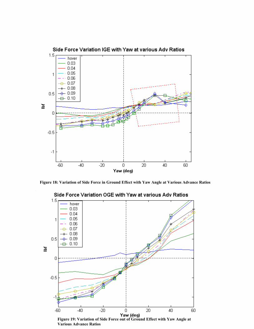
An investigation into the variation of side-force at various yaw angles was carried out. It can be seen from Fig.18 that the yaw angle for zero side force changes with advance ratios. The vertical dotted black line represents zero degrees yaw, and the horizontal dotted black line represents zero side force. To visualize the same phenomena mentioned in the previous paragraph, one has to start at the point of intersection of the hover line and the vertical zero degree yaw line, and move downward with advance ratio along the zero degree yaw line. It can be seen that there is a switch in the direction of the side force at an advance ratio of about 0.05. This seems to suggest that it is a function of the flow interaction rather than the effect of a flaw in cylinder shape. Similarly, if one were to move to the right along the zero sideforce line, it is seen that the zero side force at higher advance ratios occurs at higher positive yaw angles. A similar result was obtained when the sideforce is measured with the fuselage being yawed dynamically at 3 RPM. The side force results out of ground effect can be seen in Fig.19. Several interesting differences can be seen between the results of Figs.18 and 19.

- 6 - American Institute of Aeronautics and Astronautics
a) The force vs. yaw angle plot out of ground effect is symmetric about the zero degree yaw angle line. It can be seen from Fig.19 that at zero degree yaw, the side force changes to a negative value as soon as the regime of flight changes from hover to forward flight, and thereafter stays fairly constant with increasing advance ratio. In ground effect, however, it can be seen from Fig.18 that the side force variation is gradual and progressive at zero degree yaw with increasing advance ratio. This can be seen by moving down the vertical dotted black line in Figs. 18 and 19, and the resulting data would be the plot in Fig.17.
b) The magnitude of the side force at higher yaw angles out of ground effect is more than the magnitude in ground effect.
c) An interesting phenomenon observed in ground effect is shown marked in the red dotted box in Fig.18. At advance ratios above 0.06, there is a sudden increase in the side force at yaw angles between 20° and 60°. This appears to be a lift production phenomenon with a sudden increase in side force followed by a stall. This conclusion is buttressed by plotting the center of pressure of the side force in Fig.20. These values were obtained by dividing the yawing moment by the side force, as explained in the previous paragraph. It can be seen there is a forward moment of the yawing moment arm at the same advance ratio-yaw angle combination, which supports the conclusion of the observed phenomenon being a lift production phenomenon. This can be correlated with inputs obtained from various helicopter operators in the industry, who note that there is a considerable difference in the side forces produced in ground effect by fuselages of various cross sections. We can anticipate that this force would be higher in a sideward-contoured fuselage, like the hemisphere nose cylindrical fuselage used in this experiment. Experiments on a sideward-flattened fuselage will be carried out to test this hypothesis.
The comparison of the fuselage lift in and out of ground effect is seen in Fig.21. It can be seen that there is a considerable reduction in the fuselage lift produced in ground effect, and this is due to the change in the wake structure due to the presence of the ground. The presence of the ground cuts of the spiral wake structure, and this coupled with the mirror image vorticity causes a reduction in the upward force on the fuselage.
V. Conclusions 1. Flow Visualization of a rotor in ground effect was able to capture two regimes of flight, with a recirculating
flow pattern at an advance ratio less than 0.05, and a ground vortex regime between advance ratios of 0.05 to 0.08. Tip vortices were tracked, and it was found that the time scale of recirculation was about 0.11 seconds.
2. This was correlated with the blips seen in the hotwire measurements in ground effect, which seem to be dependent on the recirculated vortex passage.
3. A peak frequency component of 1 Hz was seen in the IGE hotwire data – with the fundamental blade passage frequency being 35Hz.
4. These are presumably accessible by quasi-steady-state prediction methods. Preliminary results from the fuselage side force measurements indicate that there is a switch in the direction of the sideforce as the helicopter accelerates in ground effect, and this switch seems to occur at the advance ratio where the ground vortex formation occurs.
5. The following flow phenomena in helicopter flight close to ground that have been identified. • Inherent unsteadiness in the flow pattern due to a rotor in ground
effect without a fuselage, which has been investigated and found in flow visualization and hotwire anemometry. This situation is fundamentally unsteady, and requires long-period unsteady simulation methods with high accuracy. These long time scales pose a major challenge for numerical predictions, but appear to be due to vortex interactions which can be modeled by inviscid methods.
• Unsteadiness IGE due to interaction of the wake with the fuselage and ground- comprising of two subdivisions.
a) The wind direction and advance ratio change, so that the fuselage/ tail rotor interact with different parts of the rotor wake. However, the rotor wake for a given flight condition is perfectly periodic. This situation can be modeled analytically through quasi-steady methods.
b) Even thought the flight condition remains identical, interactions between vortices, the ground and the vehicle surfaces, generate transient spikes in the forces and

- 7 - American Institute of Aeronautics and Astronautics
moments, with large intervals possible between such occurrences. This situation is fundamentally unsteady, and requires long-period unsteady simulation methods with high accuracy.
• Control changes due to ingestion of the main rotor wake into the tail rotor causing loss in tail rotor thrust, as studied in Ref.9.
• A sudden increase at positive yaw angles that seems to be dependent on fuselage cross section. • Considerable reduction in the fuselage lift in ground effect, due to change in wake structure.
Experimental Uncertainty One of the major achievements in this experiment is that the flow in the OGE case has been captured with so little uncertainty that the IGE fluctuations can be properly quantified. This issue is examined using flow visualization, hot-wire measurements, and now using straingage / load cell measurements of fuselage loads. 1) Flow Visualization: Error in quantifying ground vortex position with respect to advance ratio is examined below. The position was plotted by digitizing video images, and marking the edge of the void area that was formed due to lack of seed particles in the vortex. The coverage area of the image was 60 inches by 25 inches. The image was digitized into a 1280 by 768 pixels bitmap. Since the edge of the void area cannot be resolved under one pixel, the error probability of the position is approximately 0.04 in. The resulting uncertainty is examined in Table 2. 2) Hotwire Measurements: The main reason for errors in Hotwire measurements is the wire orientation of the Hotwire, after the calibration has been done and checked with test runs11. Alignment for this experiment was checked with a laser alignment tool, with a beam diameter of 0.1 in. This beam was aligned with a mark on the wall, 4.5 ft away. Assuming the worst-case error was one diameter of the laser beam, this works out to a maximum error of 0.1°. 3) Force Measurements: The force balance was calibrated with precision weights, and the response was found to be linear. Five sets of check runs were done with precision weights, both in the negative and positive side force direction. The error was found to be less than 1% for the side force. The 6 d.o.f load cell being used has an error less than 0.5% of full load.
References 1 Curtiss, H.C. Jr., Sun, M., Putman, W.F., Hanker, E.J. Jr., “ Rotor Aerodynamics in Ground Effect at Low Advance Ratios”, Journal AHS, Jan. 1984. 2 Curtiss Jr., H.C., Erdman, W., and Sun, M., “Ground Effect Aerodynamics”, International Conference on Rotorcraft Basic Research, 1985. 3 Xin, H., “Development and Validation of a Generalized Ground Effect Model for Lifting Rotors”, PhD Thesis, Georgia Tech, 1999. 4 Hanker, E.J. Jr. and Smith, R.P., “Parameters Affecting Helicopter Interactional Aerodynamics in Ground Effect”, Journal AHS, Jan 1985. 5 Cimbala, J.M., Billet, M.L., Gaublomme, D.P., and Oefelein, “Experiments on the Unsteadiness Associated with a Ground Vortex”, Journal of Aircraft, Apr. 1991.
- 8 - American Institute of Aeronautics and Astronautics
6 Saberi, H.A. and Maisel, M.D., “A Free-Wake Rotor Analysis Including Ground Effect”, Annual Forum Proceedings, 43rd American Helicopter Society. 7 Light, J.S., “Tip Vortex Geometry of a Hovering Helicopter Rotor in Ground Effect”, Journal of the American Helicopter Society, Apr 1993. 8 Prouty, R.W., “Operations Flight in Turbulent Air”, Article of “NASA Civil Helicopter Safety Web Site”, Aug. 2001. 9 Empey, R.W., and Ormiston, R.A., “Tail Rotor Thrust on a 5.5 Foot Helicopter Model in Ground Effect”, 30th Annual Forum of AHS, May 1974. 10 Saijo, T., et al., “Development of Unsteadiness in the Wake of a Rotor n Ground Effect”, 59th Annual Forum of AHS, 2003. 11 Yoshino, F et al., “Hot-wire Direction Error Response Equations in Two-Dimensional Flows”., J of Phy. E:Sci. Instrum., 1989, Vol.22., pp 480-490.
V∝
Figure 1: Schematic of Recirculation zone
V ∝
Ground Vortex
Figure 2: Schematic of Ground Vortex

- 9 - American Institute of Aeronautics and Astronautics
Figure 3: Rotor and Test Section
Figure 4: Rotor with Ground Plane.

- 10 - American Institute of Aeronautics and Astronautics
Figure 5: Coordinate System of the Rotor.
Figure 6: Recirculation (IGE, y/r = 0, µ=0.03)
Note: Inflow fluctuations IGE ~ 5-10%
Figure 8: Hot-wire Velocity time history. (OGE/IGE, y/r = 0)

- 11 - American Institute of Aeronautics and Astronautics
0 10 20 30 40 50 60 70 800
1
2
3
4
5
6
x 106 Hotwire IGE Adv 0.03 Peak freq =70.0
Four
ier P
ower
Spe
ctra
l Den
sity
Frequency0 10 20 30 40 50 60 70 80
0
2
4
6
8
10
12x 106 Hotwire IGE Adv 0.04. Peak freq =1.7
Four
ier P
ower
Spe
ctra
l Den
sity
Frequency
0 10 20 30 40 50 60 70 800
1
2
3
4
5
6
7
8
9x 10⁶
Frequency
Four
ier P
ower
Spe
ctra
l Den
sity
Hotwire- IGE Adv 0.05. Peak freq= 1.1
0 10 20 30 40 50 60 70 800
0.5
1
1.5
2
2.5
3
3.5
4
x 104 Hotwire OGE Adv 0.03 Peak freq =70.0
Four
ier P
ower
Spe
ctra
l Den
sity
Frequency
0 10 20 30 40 50 60 70 800
0.5
1
1.5
2
2.5
3
3.5
4
x 104 Hotwire OGE Adv 0.04 Peak freq =70.0
Four
ier P
ower
Spe
ctra
l Den
sity
Frequency0 10 20 30 40 50 60 70 80
0
1
2
3
4
5
6x 10⁴ Hotwire OGE Adv 0.05 Maxfreq 70.0
Four
ier P
ower
Spe
ctra
l Den
sity
Frequency
Figure 9: Comparison of Hotwire Frequencies. IGE vs OGE. Advance Ratios 0.03, 0.04, and 0.05

- 12 - American Institute of Aeronautics and Astronautics
Ground Normal
Tunnel Floor
Stepper Motor
Simulated Ground Plane
Load Cells
Rotor Radius ‘r’
Rotor Shaft Axis
0.5 r0.72 r
0.4 r
1.9 r
18”
0
20
40
60
80
100
0 2 4 6 8 10
Vel
ocity
(fps)
Time(sec)0
20
40
60
80
100
0 2 4 6 8 10V
eloc
ity(fp
s)
Time(sec)
0
20
40
60
80
100
0 2 4 6 8 10
Vel
ocity
(fps)
Time(sec)0
20
40
60
80
100
0 2 4 6 8 10
Vel
ocity
(fps)
Time(sec)
0
20
40
60
80
100
0 2 4 6 8 10
Vel
ocity
(fps)
Time(sec)
a c e hg
(a) (c)
(e) (g)
(h)Figure 10: Ground Vortex Velocity Measurements
Advance Ratio 0.05

- 13 - American Institute of Aeronautics and Astronautics
Figure 12: Experimental Setup: Fuselage Force Measurement
Figure 13: Directional Convention of Forces and Moments
Direction of rotor rotation

- 14 - American Institute of Aeronautics and Astronautics
Figure 14: Difference in Low Frequency Components of Side Force at Advance Ratios 0.03 and 0.08
Figure 15: Natural Frequency of Load Cell Side Force to a step disturbance.

- 15 - American Institute of Aeronautics and Astronautics
Figure 16: Variation of Frequency Components with increasing Advance Ratios IGE.
Figure 17: Variation of Side Force and Sideward Center of Pressure with Advance Ratio IGE vs. OGE, 0° Yaw.
- 16 - American Institute of Aeronautics and Astronautics
Figure 18: Variation of Side Force in Ground Effect with Yaw Angle at Various Advance Ratios
Figure 19: Variation of Side Force out of Ground Effect with Yaw Angle at Various Advance Ratios

- 17 - American Institute of Aeronautics and Astronautics
Figure 20: Variation of Side Force Center of Pressure in Ground Effect with YawAngle at Various Advance Ratios
Figure 21: Comparison of Fuselage lift IGE vs. OGE

- 18 - American Institute of Aeronautics and Astronautics