guidelines for the installation of steel frames
TRANSCRIPT

Best Of Steel | 1
ww
w.tt
z-on
line.
de
GUIDELINES FOR THE INSTALLATION OF STEEL FRAMES
Contents Page
1 Intent and purpose of the guidelines 22 Areas of application 23 General information before installation 33.1 Steel frames 33.2 Building site / place of installation 34 Installation 64.1 General requirements 64.2 Type-specific requirements 84.2.1 1 part steel frames in brickwork/ concrete/solid walls 84.2.2 1 part steel frames in stud or mounting walls 114.2.3 2 part split steel frames in different wall types 134.2.4 Non standard frames 135 Dimensional check of installed steel frames 146 Recommendations / Notes 14
An electronic version of the current Guidelines for the installation of steel frames is also available.
The electronic version of the Guidelines for the installation of steel frames can be downloaded directly from our website at www.ttz-online.de
Installation Guidelines
German Industrial Associationfor doors and frames
2 | Best Of Steel
Installation Guidelines
1. Intent and purpose of the guidelines
The guidelines from the German Industrial Association for doors and frames are intended to provide planning security for the quality of installation of steel frames.
The information in these guidelines is based on the experience and skill of member companies of the Industrial Association and imparts assistance for architects, planners and installers of steel frames.
The installation instructions from the manufacturer should be followed, the guidelines for installing steel frames is a supplement to the aforementioned documents. For door systems with special properties, the installation specifications of the door leaf manufacturer are decisive.
2. Areas of application
These guidelines are applicable for the installation of frames for brick work, stud walls and for non standard frames.
They do not replace the series of standards DIN 18111.
The steel frame designs are described in the standards DIN 18111: October 2018, Parts 1 and 2. Part 3 of DIN 18111 determines the basics for installation (assembly) of steel frames:
DIN 18111 Part 1 – standard frames (1 part and 2 part split) for rebated doors in brick and stud walls
DIN 18111 Part 2 – non standard frames (1 part and 2 part split) for rebated and flush doors in brick and stud walls
DIN 18111 Part 3 – installation of steel frames according to DIN 18111-1 and DIN 18111-2
These guidelines are not applicable for steel frames for fire and smoke protection elements, for burglar resistant or sound protection elements, air raid protection doors, frames for container construction, for sandwich walls and timber-frame construction or for steel frames in concrete walls using pouring methods.
In these cases the applicable standards or regulations should be followed.
Best Of Steel | 3
ww
w.tt
z-on
line.
de
Installation Guidelines
3. General information before installation
The person entrusted with the assembly should have suitable training, practical experience and qualified knowledge in order to be able to assemble steel frames properly and expertly. This is the only way to ensure that the high quality of the steel frame is transferred to later use.
The solid and stud walls or their profiles must be designed in such a way that they can reliably and sustainably absorb the static and dynamic forces resulting from the strain of use from the door element used. Solid walls must be constructed in accordance with the relevant standards. In the case of stud walls, the requirements of the system manufacturers with regard to the design of the wall openings, particularly with regard to the maximum permissible door leaf weights, must be observed.
3.1 Steel frames
Before installation the order and state on delivery should be checked, in particular the following points:
The design of the steel frame in relation to the planning specifications regarding profiling and anchoring, width and height measurements, hinge positions, cut-outs etc.
The construction characteristics of the steel frame – this “identity check” ensures that the “right” steel frame is used.
The labelling of the steel frame (according to DIN 18111) – the details stated on the delivery note can be used for checking.
The completeness of the frame – pay special attention to the accessories, seals etc.
3.2 Building site/Place of Installation
Before starting installation, the state of the wall, wall opening, wall construction and materials used and the general situation on site should be inspected, special emphasis should be placed amongst others on:
Metre mark
Wall opening measurements
Wall thickness
4 | Best Of Steel
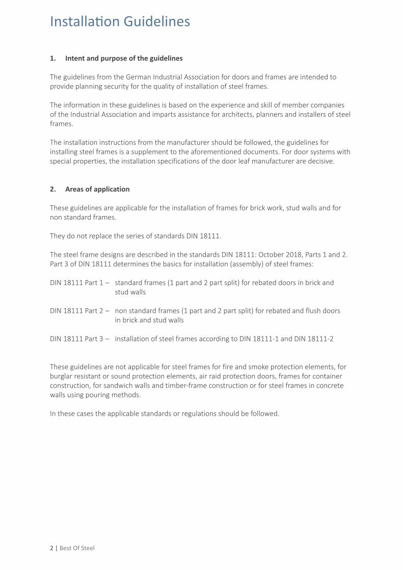
Picture 1 – Important terms of a steel frame according to DIN 18111-1
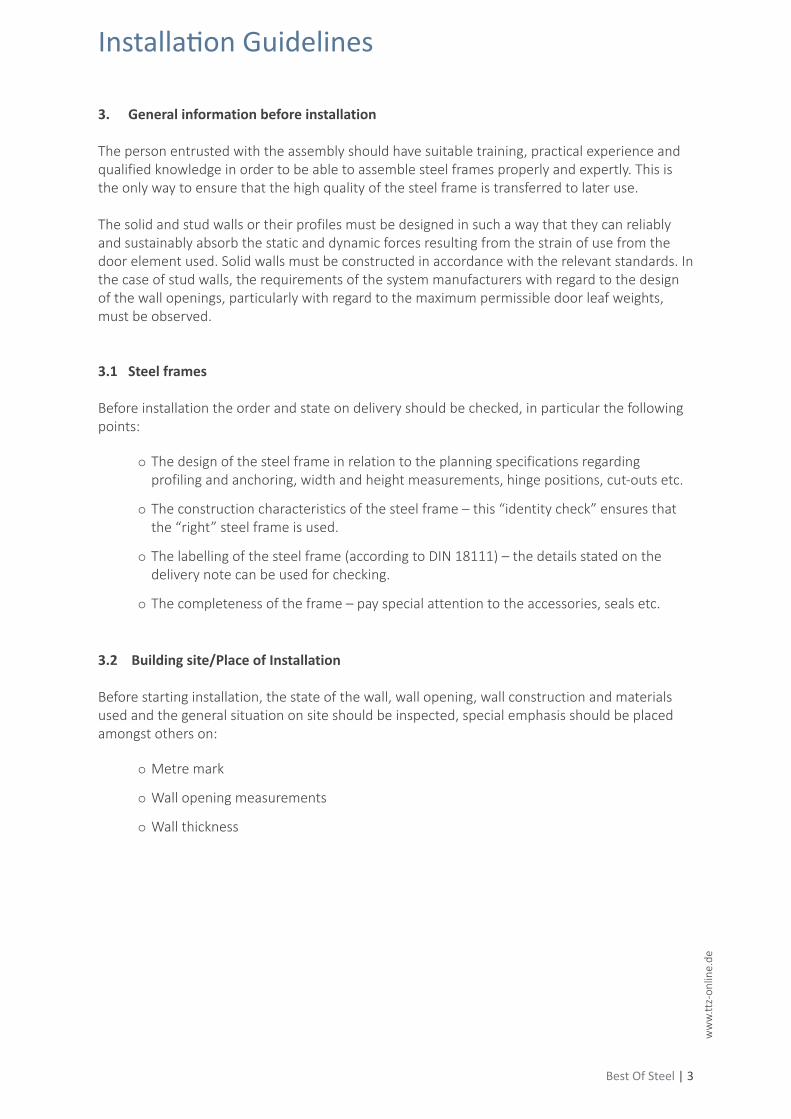
Picture 2 – Section A-A
Installation Guidelines
Fram
e re
bate
hei
ght
Dist
ance
bet
wee
n hi
nges
Met
re m
ark
from
top
leve
l of
fini
shed
floo
rFo
unda
tion
bedd
ing =
Han
dle
heig
ht fr
om to
p le
vel o
f fin
ished
floo
r
Foundation bedding (FBE) (not for all frames)
Bolt/latch cut-out (pre-punched on both sides)
Frame rebate width
Hinge position(DIN 18268)
= Top level of finished floor
= Top level of finished floor
Spacer rails/transport aids
Seal
Best Of Steel | 5
ww
w.tt
z-on
line.
de
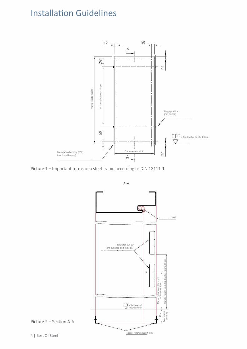
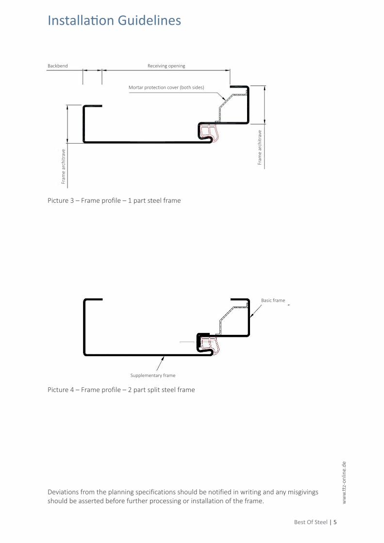
Picture 3 – Frame profile – 1 part steel frame
Picture 4 – Frame profile – 2 part split steel frame
Deviations from the planning specifications should be notified in writing and any misgivings should be asserted before further processing or installation of the frame.
Installation Guidelines
Backbend Receiving opening
Basic frame
Supplementary frame
Fram
e ar
chitr
ave
Fram
e ar
chitr
ave
Mortar protection cover (both sides)
Blickrichtung
90°
6 | Best Of Steel
Picture 6a – Perpendicular installation of steel frames
4. Installation
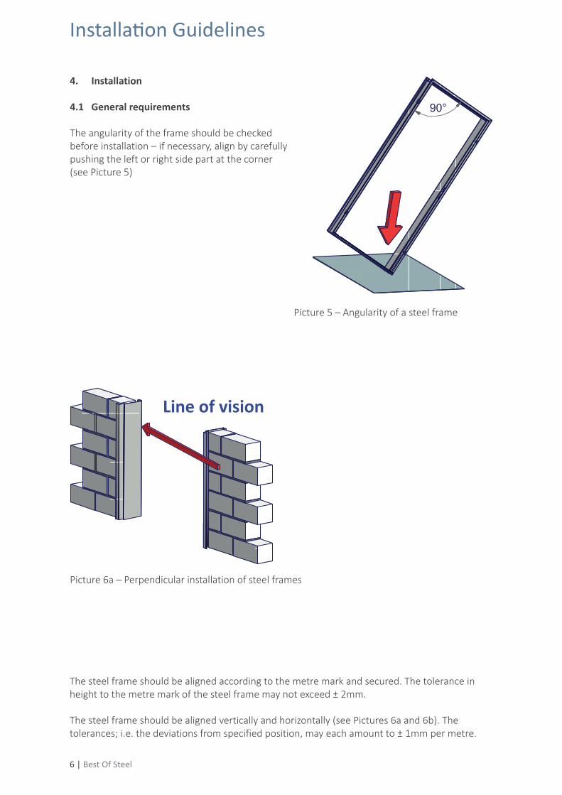
4.1 General requirements
The angularity of the frame should be checked before installation – if necessary, align by carefully pushing the left or right side part at the corner (see Picture 5)
Picture 5 – Angularity of a steel frame
Line of vision
The steel frame should be aligned according to the metre mark and secured. The tolerance in height to the metre mark of the steel frame may not exceed ± 2mm.
The steel frame should be aligned vertically and horizontally (see Pictures 6a and 6b). The tolerances; i.e. the deviations from specified position, may each amount to ± 1mm per metre.
Installation Guidelines
richtig falsch
Mauerwerk Ständerwerk
Best Of Steel | 7
ww
w.tt
z-on
line.
de
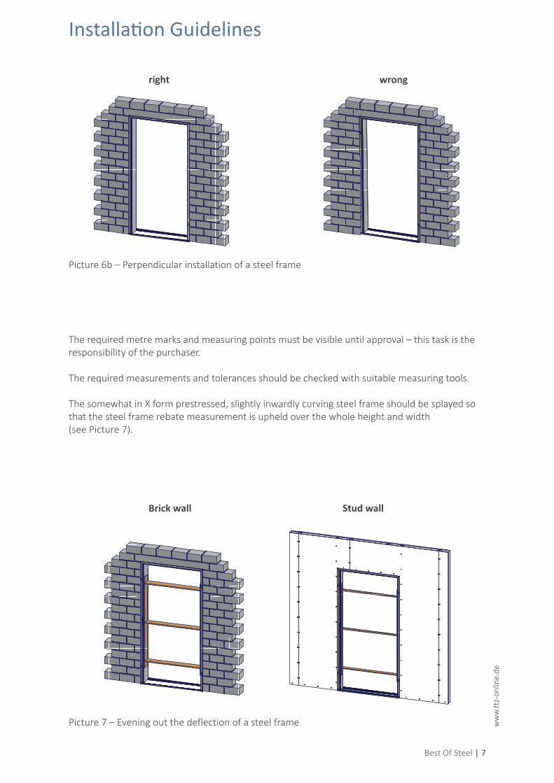
The required metre marks and measuring points must be visible until approval – this task is the responsibility of the purchaser.
The required measurements and tolerances should be checked with suitable measuring tools.
The somewhat in X form prestressed, slightly inwardly curving steel frame should be splayed so that the steel frame rebate measurement is upheld over the whole height and width (see Picture 7).
Picture 6b – Perpendicular installation of a steel frame
right
Brick wall
wrong
Stud wall
Picture 7 – Evening out the deflection of a steel frame
Installation Guidelines
8 | Best Of Steel
4.2 Type-specific requirements
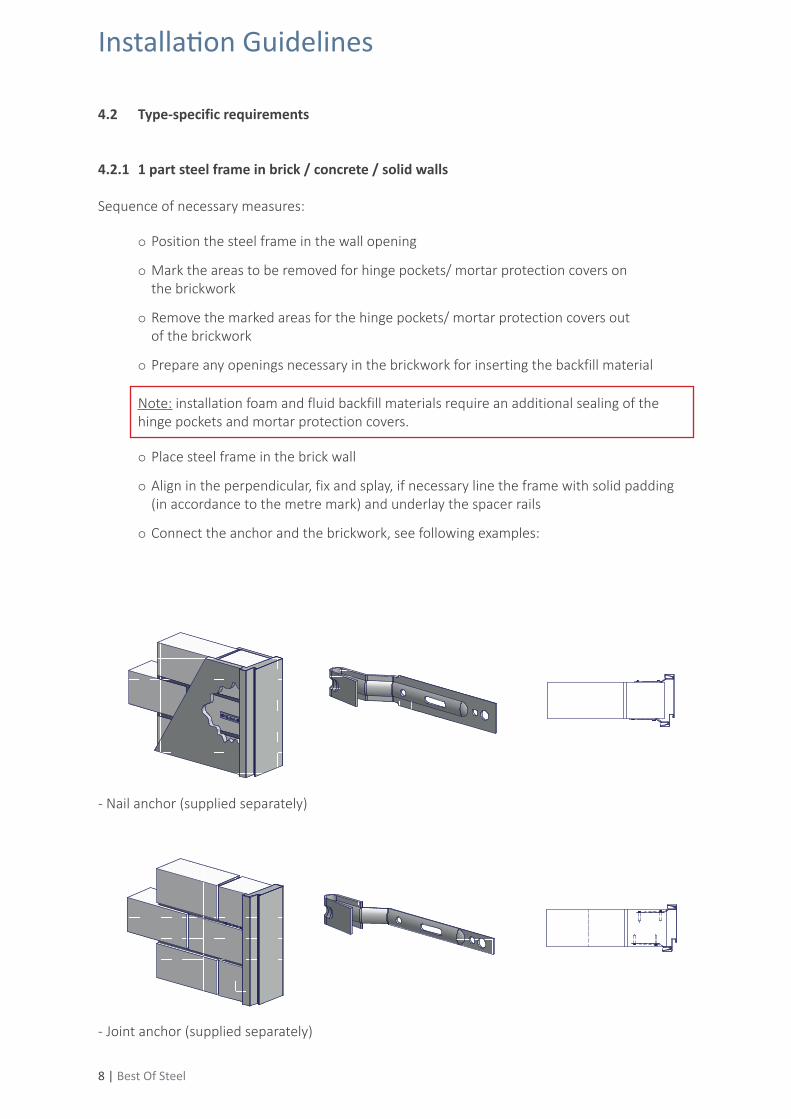
4.2.1 1 part steel frame in brick / concrete / solid walls
Sequence of necessary measures:
Position the steel frame in the wall opening
Mark the areas to be removed for hinge pockets/ mortar protection covers on the brickwork
Remove the marked areas for the hinge pockets/ mortar protection covers out of the brickwork
Prepare any openings necessary in the brickwork for inserting the backfill material
Note: installation foam and fluid backfill materials require an additional sealing of the hinge pockets and mortar protection covers.
Place steel frame in the brick wall
Align in the perpendicular, fix and splay, if necessary line the frame with solid padding (in accordance to the metre mark) and underlay the spacer rails
Connect the anchor and the brickwork, see following examples:
- Nail anchor (supplied separately)
- Joint anchor (supplied separately)
Installation Guidelines
Best Of Steel | 9
ww
w.tt
z-on
line.
de
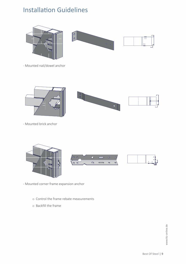
- Mounted nail/dowel anchor
- Mounted brick anchor
Control the frame rebate measurements
Backfill the frame
- Mounted corner frame expansion anchor
Installation Guidelines
10 | Best Of Steel
The materials to be used for backfilling are to be stated by the purchaser:
Suitable backfilling materials are:
• standard mortar 4:1, earth-moist (DIN 1053-1)• steel frame grouting compound• 2 component installation foam (expansion adhesives, stable in shape)
The following may NOT be used:
• back filling materials which coalesce with other materials or which could lead to corrosion or other chemical reactions (e.g. antifreeze)
• 1 component installation foams • pure gypsum mortar
- Mortaring When inserting the mortar the following points should be heeded:
• The cavity between the steel frame and the wall should be completely filled.• Material-locking to the wall, not to the steel frame.• Due to the residual stress of the cold formed sheet and the shrinkage process of the
mortar, a separation between the sheet surface and mortar can occur in the area of the soffit. An installation fault cannot be derived as a consequence.
- Foaming When foaming the following points should be heeded:
• The adherent surfaces should be clean and free of dust. The application instructions of the foam manufacturer should be followed.
• The cavity between the steel frame and the wall should be completely filled.
On arrangement between client and contractor, a partial backfilling of at least 50% of the cavity between wall and steel frame can be agreed upon.
Installation Guidelines
Best Of Steel | 11
ww
w.tt
z-on
line.
de
Verschäumung
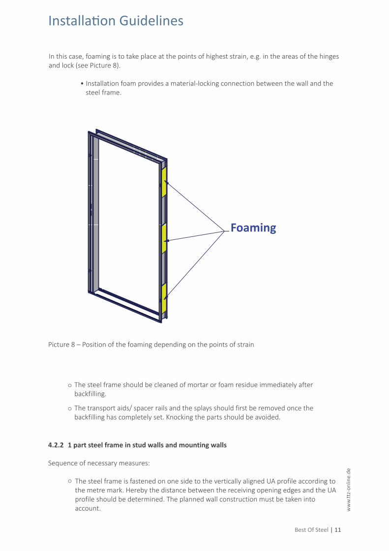
In this case, foaming is to take place at the points of highest strain, e.g. in the areas of the hinges and lock (see Picture 8).
• Installation foam provides a material-locking connection between the wall and the steel frame.
The steel frame should be cleaned of mortar or foam residue immediately after backfilling.
The transport aids/ spacer rails and the splays should first be removed once the backfilling has completely set. Knocking the parts should be avoided.
4.2.2 1 part steel frame in stud walls and mounting walls
Sequence of necessary measures:
The steel frame is fastened on one side to the vertically aligned UA profile according to the metre mark. Hereby the distance between the receiving opening edges and the UA profile should be determined. The planned wall construction must be taken into account.
Picture 8 – Position of the foaming depending on the points of strain
Installation Guidelines
Foaming
12 | Best Of Steel
The steel frame should be aligned vertically and horizontally and supported with splays (see Pictures 6a, 6b and 7) Finally, fasten the steel frame to the second UA profile.
Note: Self-drilling screws of a sufficient size must be used for the installation in order to ensure a permanent and secure join. Two screws per anchor must be used, diagonally positioned.
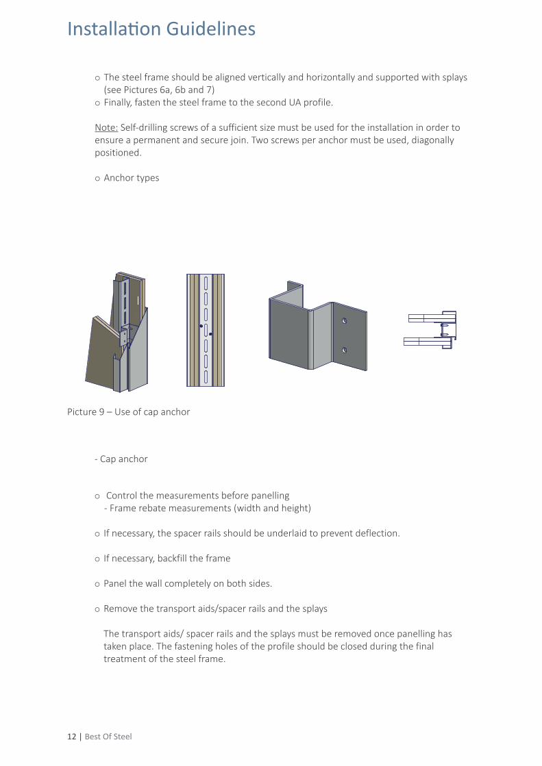
Anchor types
Picture 9 – Use of cap anchor
- Cap anchor
Control the measurements before panelling - Frame rebate measurements (width and height)
If necessary, the spacer rails should be underlaid to prevent deflection.
If necessary, backfill the frame
Panel the wall completely on both sides.
Remove the transport aids/spacer rails and the splays
The transport aids/ spacer rails and the splays must be removed once panelling has taken place. The fastening holes of the profile should be closed during the final treatment of the steel frame.
Installation Guidelines
Best Of Steel | 13
ww
w.tt
z-on
line.
de
4.2.3 2 part split steel frames in different wall types
Before beginning installation, check the existing wall thickness and compare it to the receiving opening of the frame. The wall thickness should not be larger than the receiving opening.
Sequence of necessary measures:
Separate the front and back parts of the frame by completely loosening the screw connection in the mounting groove of the seal.
Note: due to the surface treatment of the frame, the joint between the front and back part of the frame can be partially stuck together. Usually, light blows with a plastic hammer against the inside of the frame architrave are enough to loosen this bonding.
Align the front part of the frame vertically and horizontally and fix in the wall opening according to the metre mark. Determine the distances between the receiving opening edges and if necessary, chase out the wall in the areas of the hinge pockets and mortar protection covers.
Ensure the parallelism of the anchors to the frame soffit through all-over, solid padding to the wall jamb.
Fasten the anchors of the front part of the frame securely with at least one fastening suitable for the wall construction present.
In stud walls, self-drilling screws of a sufficient size must be used for the installation in order to ensure a permanent and secure join. Two screws per anchor must be used, diagonally positioned.
Push the back part of the frame onto the front part and join together again in the mounting groove of the seal.
4.2.4 Non-standard steel frames
The above stated installation requirements apply to non-standard steel frames according to DIN 18111-2.
For non-standard steel frames which do not fall under the area of validity of DIN 18111 Part 2, the instructions given by the frame and/or door system manufacturer and the planning specifications should be followed. This is particularly applicable for installation due to the different designs of the steel frames.
Installation Guidelines
14 | Best Of Steel
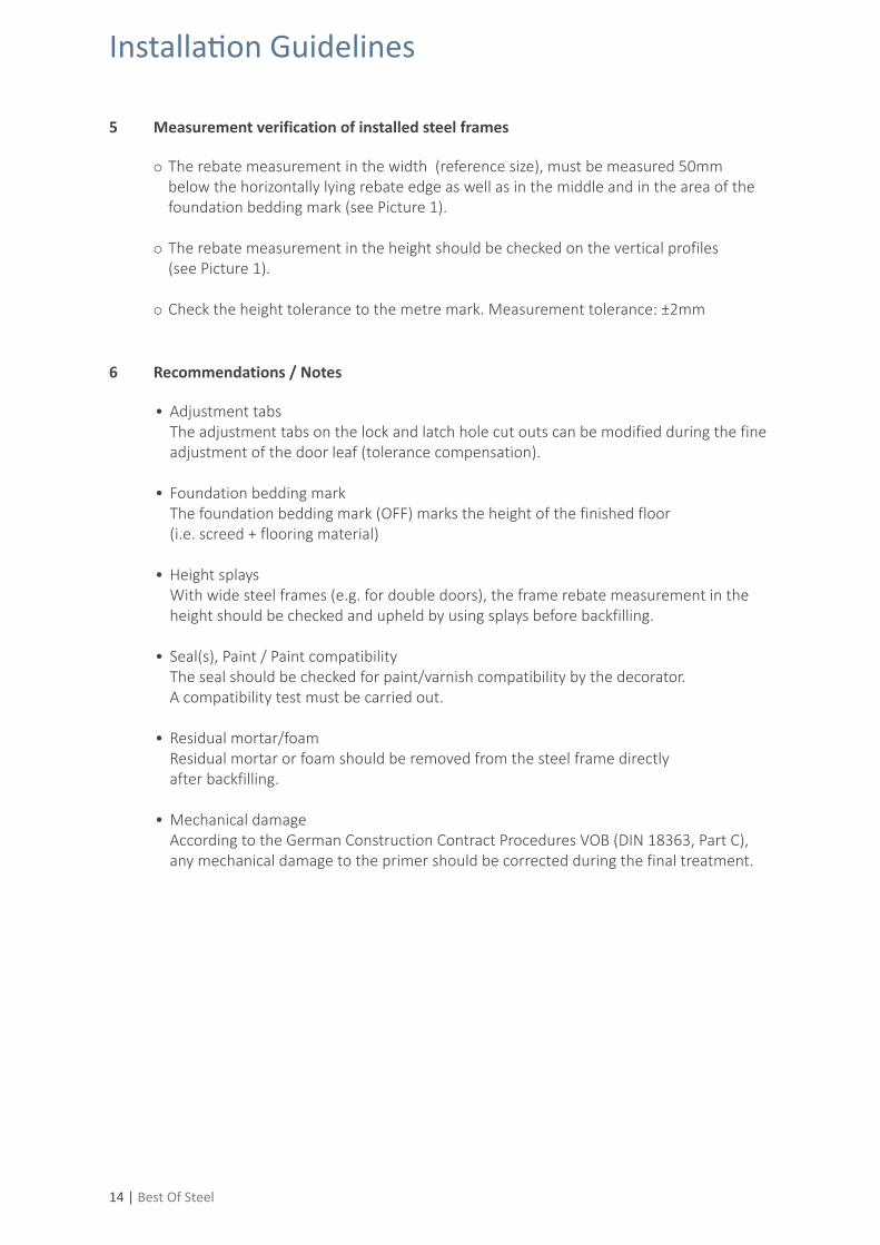
5 Measurement verification of installed steel frames
The rebate measurement in the width (reference size), must be measured 50mm below the horizontally lying rebate edge as well as in the middle and in the area of the foundation bedding mark (see Picture 1). The rebate measurement in the height should be checked on the vertical profiles (see Picture 1).
Check the height tolerance to the metre mark. Measurement tolerance: ±2mm
6 Recommendations / Notes
• Adjustment tabs The adjustment tabs on the lock and latch hole cut outs can be modified during the fine adjustment of the door leaf (tolerance compensation).
• Foundation bedding mark The foundation bedding mark (OFF) marks the height of the finished floor (i.e. screed + flooring material)
• Height splays With wide steel frames (e.g. for double doors), the frame rebate measurement in the height should be checked and upheld by using splays before backfilling.
• Seal(s), Paint / Paint compatibility The seal should be checked for paint/varnish compatibility by the decorator. A compatibility test must be carried out.
• Residual mortar/foam Residual mortar or foam should be removed from the steel frame directly after backfilling.
• Mechanical damage According to the German Construction Contract Procedures VOB (DIN 18363, Part C), any mechanical damage to the primer should be corrected during the final treatment.
Installation Guidelines
Best Of Steel | 15
ww
w.tt
z-on
line.
de
Guidelines for the installation of steel framesSecond Edition September 2018
Publisher:Industrieverband Tore Türen Zargen e. V. (ttz) in derWIB Wirtschaftsvereinigung Industrie- und Bau-Systeme e. V.Neumarktstr. 2 b, D-58095 HagenTel: +49 2331 2008-0, Fax: +49 2331 2008-40www.ttz-online.de, E-Mail: [email protected]
Text/Editing:Arbeitskreis Technik ttz-ZargenGraduate Engineer Nicolas Geitmann
The information provided in this publication has been carefully researched and edited. A liability is excluded.
A reprint – even in extracts – is only allowed with written permission of the publisher and with clear reference to source.