cyclic loading behavior of steel chevron braced frames with
TRANSCRIPT
CYCLIC LOADING BEHAVIOR OF STEEL CHEVRON BRACED FRAMES WITH ROUND-HOLLOW-SECTION
OR I-SECTION BRACES
Taichiro OKAZAKI1, Akiri SEKI2, Hayato ASADA3
ABSTRACT Six large-scale specimens were tested at Hokkaido University to examine the seismic behavior of chevron steel concentrically braced frames (CBFs) designed and constructed according to current practice in Japan. The specimens placed a pair of braces in a single-bay, single-story moment-resisting frame. Three specimens used round-HSS braces while three specimens used I-section braces. The specimens differed in the design and fabrication of the bracing connections: Four specimens adopted bolted connections that are widely used in Japan, while two specimens adopted a field-welded connection detail following US recommendations. The specimens were subjected to a cyclic loading protocol that is similar in severity to protocols specified for steel moment-resisting frames. The test results suggest that chevron CBFs with compact braces and using moment-resisting beam-to-column connections can safely develop large story drifts exceeding 0.03 radians. The force unbalance between the tension and compression braces led to severe yielding and torsion of the beam, and therefore, forced the braces to deform primarily in contraction. Consequently, the tensile force imposed on the bracing connections were smaller than the tensile yield strength of the braces. Except for a specimen with I-section braces oriented to buckle in plane, whose brace fractured along the first bolt line, no bolt slippage was observed in the bolted bracing connections. A specimen with stiffened gusset plate connection developed cracks at locations of strain concentration. The bracing connections in the other four specimens showed little sign of damage at the end of the test. Keywords: steel building systems; concentrically braced frames; bracing connections; chevron arrangement; cyclic loading tests 1. INTRODUCTION The paper describes an experimental study on the seismic performance of steel concentrically braced frames (CBFs). In Japan, the most common CBF systems place diagonal braces in a chevron (or inverted “V”) arrangement. Round hollow steel section (HSS) braces are popular due to their artistic appeal, while I-section braces are favored for their mechanical properties. While CBFs are widely used in various building types such as commercial buildings, factories, and parking ramps, limited guidance is available in the current code provisions or guidelines. Lack of design guidance has allowed engineers to use a wide range of different bracing connections, although reconnaissance from past earthquakes suggests that CBFs are prone to seismic damage particularly in the bracing connections. It is well known from past studies (Wakabayashi et al. 1981; Muto et al. 1981) that the seismic behavior of chevron CBFs is significantly affected by force unbalance between the tension brace and buckled compression brace. If the beam intersecting the braces is unable to sustain this vertical component of the unbalanced force, a plastic hinge will form in the beam before the tension brace can develop its yield strength. Consequently, modern seismic code provisions in Japan (AIJ 2010) and the US (AISC 2010) among other countries require the beams in chevron CBFs to be designed for the
1Professor, Hokkaido University, Sapporo, Japan, [email protected] 2Graduate student, Hokkaido University, Sapporo, Japan, [email protected] 3Assistant Professor, Kobe University, Kobe, Japan, [email protected]
2
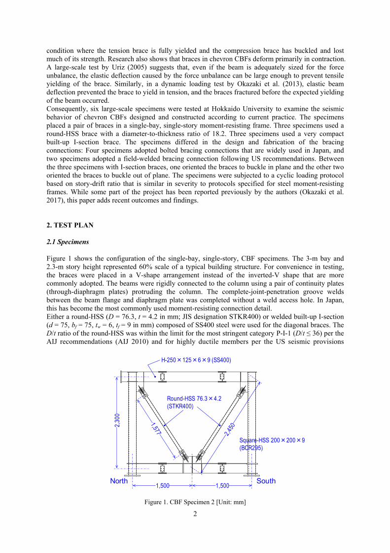
condition where the tension brace is fully yielded and the compression brace has buckled and lost much of its strength. Research also shows that braces in chevron CBFs deform primarily in contraction. A large-scale test by Uriz (2005) suggests that, even if the beam is adequately sized for the force unbalance, the elastic deflection caused by the force unbalance can be large enough to prevent tensile yielding of the brace. Similarly, in a dynamic loading test by Okazaki et al. (2013), elastic beam deflection prevented the brace to yield in tension, and the braces fractured before the expected yielding of the beam occurred. Consequently, six large-scale specimens were tested at Hokkaido University to examine the seismic behavior of chevron CBFs designed and constructed according to current practice. The specimens placed a pair of braces in a single-bay, single-story moment-resisting frame. Three specimens used a round-HSS brace with a diameter-to-thickness ratio of 18.2. Three specimens used a very compact built-up I-section brace. The specimens differed in the design and fabrication of the bracing connections: Four specimens adopted bolted bracing connections that are widely used in Japan, and two specimens adopted a field-welded bracing connection following US recommendations. Between the three specimens with I-section braces, one oriented the braces to buckle in plane and the other two oriented the braces to buckle out of plane. The specimens were subjected to a cyclic loading protocol based on story-drift ratio that is similar in severity to protocols specified for steel moment-resisting frames. While some part of the project has been reported previously by the authors (Okazaki et al. 2017), this paper adds recent outcomes and findings. 2. TEST PLAN 2.1 Specimens Figure 1 shows the configuration of the single-bay, single-story, CBF specimens. The 3-m bay and 2.3-m story height represented 60% scale of a typical building structure. For convenience in testing, the braces were placed in a V-shape arrangement instead of the inverted-V shape that are more commonly adopted. The beams were rigidly connected to the column using a pair of continuity plates (through-diaphragm plates) protruding the column. The complete-joint-penetration groove welds between the beam flange and diaphragm plate was completed without a weld access hole. In Japan, this has become the most commonly used moment-resisting connection detail. Either a round-HSS (D = 76.3, t = 4.2 in mm; JIS designation STKR400) or welded built-up I-section (d = 75, bf = 75, tw = 6, tf = 9 in mm) composed of SS400 steel were used for the diagonal braces. The D/t ratio of the round-HSS was within the limit for the most stringent category P-I-1 (D/t ≤ 36) per the AIJ recommendations (AIJ 2010) and for highly ductile members per the US seismic provisions
Figure 1. CBF Specimen 2 [Unit: mm]
H-250×125×6×9 (SS400)
Round-HSS 76.3×4.2(STKR400)
SouthNorth
2,30
0
1,500 1,500
Square-HSS 200×200×9(BCR295)
3
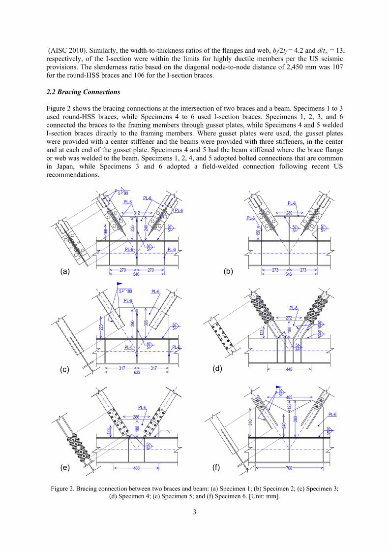
(AISC 2010). Similarly, the width-to-thickness ratios of the flanges and web, bf/2tf = 4.2 and d/tw = 13, respectively, of the I-section were within the limits for highly ductile members per the US seismic provisions. The slenderness ratio based on the diagonal node-to-node distance of 2,450 mm was 107 for the round-HSS braces and 106 for the I-section braces. 2.2 Bracing Connections Figure 2 shows the bracing connections at the intersection of two braces and a beam. Specimens 1 to 3 used round-HSS braces, while Specimens 4 to 6 used I-section braces. Specimens 1, 2, 3, and 6 connected the braces to the framing members through gusset plates, while Specimens 4 and 5 welded I-section braces directly to the framing members. Where gusset plates were used, the gusset plates were provided with a center stiffener and the beams were provided with three stiffeners, in the center and at each end of the gusset plate. Specimens 4 and 5 had the beam stiffened where the brace flange or web was welded to the beam. Specimens 1, 2, 4, and 5 adopted bolted connections that are common in Japan, while Specimens 3 and 6 adopted a field-welded connection following recent US recommendations.
Figure 2. Bracing connection between two braces and beam: (a) Specimen 1; (b) Specimen 2; (c) Specimen 3;
(d) Specimen 4; (e) Specimen 5; and (f) Specimen 6. [Unit: mm].
PL-6
PL-6PL-6
55
5 90
312
255
166 24
0
270 270540
55PL-6
PL-6
55
5 180
290
223 30
5
317 317633
55PL-6
(a)
(c)
PL-6
PL-6
PL-6
(e)
180
286
123
460
PL-6
55
280
150
273 273546
55
55
PL-6
PL-6
(b)
(d)
5272
123 18
0 5
448
PL-6
55
55
(f)
485
310 38
0
55
55
PL-6
700
240
125
4
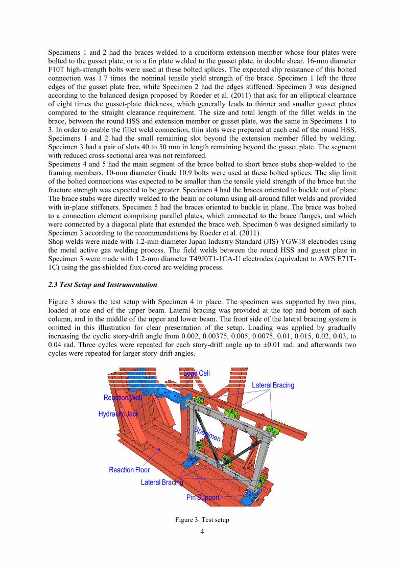
Specimens 1 and 2 had the braces welded to a cruciform extension member whose four plates were bolted to the gusset plate, or to a fin plate welded to the gusset plate, in double shear. 16-mm diameter F10T high-strength bolts were used at these bolted splices. The expected slip resistance of this bolted connection was 1.7 times the nominal tensile yield strength of the brace. Specimen 1 left the three edges of the gusset plate free, while Specimen 2 had the edges stiffened. Specimen 3 was designed according to the balanced design proposed by Roeder et al. (2011) that ask for an elliptical clearance of eight times the gusset-plate thickness, which generally leads to thinner and smaller gusset plates compared to the straight clearance requirement. The size and total length of the fillet welds in the brace, between the round HSS and extension member or gusset plate, was the same in Specimens 1 to 3. In order to enable the fillet weld connection, thin slots were prepared at each end of the round HSS. Specimens 1 and 2 had the small remaining slot beyond the extension member filled by welding. Specimen 3 had a pair of slots 40 to 50 mm in length remaining beyond the gusset plate. The segment with reduced cross-sectional area was not reinforced. Specimens 4 and 5 had the main segment of the brace bolted to short brace stubs shop-welded to the framing members. 10-mm diameter Grade 10.9 bolts were used at these bolted splices. The slip limit of the bolted connections was expected to be smaller than the tensile yield strength of the brace but the fracture strength was expected to be greater. Specimen 4 had the braces oriented to buckle out of plane. The brace stubs were directly welded to the beam or column using all-around fillet welds and provided with in-plane stiffeners. Specimen 5 had the braces oriented to buckle in plane. The brace was bolted to a connection element comprising parallel plates, which connected to the brace flanges, and which were connected by a diagonal plate that extended the brace web. Specimen 6 was designed similarly to Specimen 3 according to the recommendations by Roeder et al. (2011). Shop welds were made with 1.2-mm diameter Japan Industry Standard (JIS) YGW18 electrodes using the metal active gas welding process. The field welds between the round HSS and gusset plate in Specimen 3 were made with 1.2-mm diameter T49J0T1-1CA-U electrodes (equivalent to AWS E71T-1C) using the gas-shielded flux-cored arc welding process. 2.3 Test Setup and Instrumentation Figure 3 shows the test setup with Specimen 4 in place. The specimen was supported by two pins, loaded at one end of the upper beam. Lateral bracing was provided at the top and bottom of each column, and in the middle of the upper and lower beam. The front side of the lateral bracing system is omitted in this illustration for clear presentation of the setup. Loading was applied by gradually increasing the cyclic story-drift angle from 0.002, 0.00375, 0.005, 0.0075, 0.01, 0.015, 0.02, 0.03, to 0.04 rad. Three cycles were repeated for each story-drift angle up to ±0.01 rad. and afterwards two cycles were repeated for larger story-drift angles.
Figure 3. Test setup
Pin Support
Load Cell
Reaction Floor
Reaction Wall
Lateral Bracing
Hydraulic Jack
Lateral Bracing
5
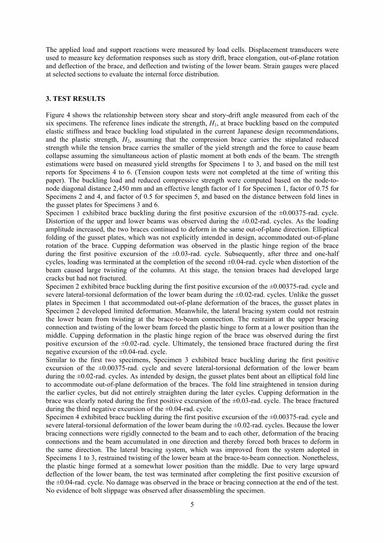
The applied load and support reactions were measured by load cells. Displacement transducers were used to measure key deformation responses such as story drift, brace elongation, out-of-plane rotation and deflection of the brace, and deflection and twisting of the lower beam. Strain gauges were placed at selected sections to evaluate the internal force distribution. 3. TEST RESULTS Figure 4 shows the relationship between story shear and story-drift angle measured from each of the six specimens. The reference lines indicate the strength, H1, at brace buckling based on the computed elastic stiffness and brace buckling load stipulated in the current Japanese design recommendations, and the plastic strength, H2, assuming that the compression brace carries the stipulated reduced strength while the tension brace carries the smaller of the yield strength and the force to cause beam collapse assuming the simultaneous action of plastic moment at both ends of the beam. The strength estimations were based on measured yield strengths for Specimens 1 to 3, and based on the mill test reports for Specimens 4 to 6. (Tension coupon tests were not completed at the time of writing this paper). The buckling load and reduced compressive strength were computed based on the node-to-node diagonal distance 2,450 mm and an effective length factor of 1 for Specimen 1, factor of 0.75 for Specimens 2 and 4, and factor of 0.5 for specimen 5, and based on the distance between fold lines in the gusset plates for Specimens 3 and 6. Specimen 1 exhibited brace buckling during the first positive excursion of the ±0.00375-rad. cycle. Distortion of the upper and lower beams was observed during the ±0.02-rad. cycles. As the loading amplitude increased, the two braces continued to deform in the same out-of-plane direction. Elliptical folding of the gusset plates, which was not explicitly intended in design, accommodated out-of-plane rotation of the brace. Cupping deformation was observed in the plastic hinge region of the brace during the first positive excursion of the ±0.03-rad. cycle. Subsequently, after three and one-half cycles, loading was terminated at the completion of the second ±0.04-rad. cycle when distortion of the beam caused large twisting of the columns. At this stage, the tension braces had developed large cracks but had not fractured. Specimen 2 exhibited brace buckling during the first positive excursion of the ±0.00375-rad. cycle and severe lateral-torsional deformation of the lower beam during the ±0.02-rad. cycles. Unlike the gusset plates in Specimen 1 that accommodated out-of-plane deformation of the braces, the gusset plates in Specimen 2 developed limited deformation. Meanwhile, the lateral bracing system could not restrain the lower beam from twisting at the brace-to-beam connection. The restraint at the upper bracing connection and twisting of the lower beam forced the plastic hinge to form at a lower position than the middle. Cupping deformation in the plastic hinge region of the brace was observed during the first positive excursion of the ±0.02-rad. cycle. Ultimately, the tensioned brace fractured during the first negative excursion of the ±0.04-rad. cycle. Similar to the first two specimens, Specimen 3 exhibited brace buckling during the first positive excursion of the ±0.00375-rad. cycle and severe lateral-torsional deformation of the lower beam during the ±0.02-rad. cycles. As intended by design, the gusset plates bent about an elliptical fold line to accommodate out-of-plane deformation of the braces. The fold line straightened in tension during the earlier cycles, but did not entirely straighten during the later cycles. Cupping deformation in the brace was clearly noted during the first positive excursion of the ±0.03-rad. cycle. The brace fractured during the third negative excursion of the ±0.04-rad. cycle. Specimen 4 exhibited brace buckling during the first positive excursion of the ±0.00375-rad. cycle and severe lateral-torsional deformation of the lower beam during the ±0.02-rad. cycles. Because the lower bracing connections were rigidly connected to the beam and to each other, deformation of the bracing connections and the beam accumulated in one direction and thereby forced both braces to deform in the same direction. The lateral bracing system, which was improved from the system adopted in Specimens 1 to 3, restrained twisting of the lower beam at the brace-to-beam connection. Nonetheless, the plastic hinge formed at a somewhat lower position than the middle. Due to very large upward deflection of the lower beam, the test was terminated after completing the first positive excursion of the ±0.04-rad. cycle. No damage was observed in the brace or bracing connection at the end of the test. No evidence of bolt slippage was observed after disassembling the specimen.
6
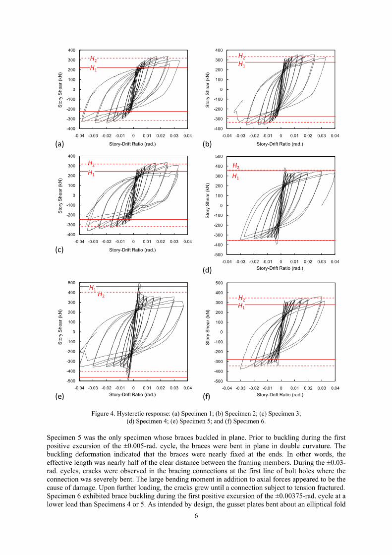
Figure 4. Hysteretic response: (a) Specimen 1; (b) Specimen 2; (c) Specimen 3;
(d) Specimen 4; (e) Specimen 5; and (f) Specimen 6. Specimen 5 was the only specimen whose braces buckled in plane. Prior to buckling during the first positive excursion of the ±0.005-rad. cycle, the braces were bent in plane in double curvature. The buckling deformation indicated that the braces were nearly fixed at the ends. In other words, the effective length was nearly half of the clear distance between the framing members. During the ±0.03-rad. cycles, cracks were observed in the bracing connections at the first line of bolt holes where the connection was severely bent. The large bending moment in addition to axial forces appeared to be the cause of damage. Upon further loading, the cracks grew until a connection subject to tension fractured. Specimen 6 exhibited brace buckling during the first positive excursion of the ±0.00375-rad. cycle at a lower load than Specimens 4 or 5. As intended by design, the gusset plates bent about an elliptical fold
-400
-300
-200
-100
0
100
200
300
400
-0.04 -0.03 -0.02 -0.01 0 0.01 0.02 0.03 0.04
Stor
y Sh
ear (
kN)
Story-Drift Ratio (rad.)
H1
H2
(a)
-400
-300
-200
-100
0
100
200
300
400
-0.04 -0.03 -0.02 -0.01 0 0.01 0.02 0.03 0.04
Stor
y Sh
ear (
kN)
Story-Drift Ratio (rad.)
H1
H2
(b)
-400
-300
-200
-100
0
100
200
300
400
-0.04 -0.03 -0.02 -0.01 0 0.01 0.02 0.03 0.04
Stor
y Sh
ear (
kN)
Story-Drift Ratio (rad.)
H1
H2
(c)
-500
-400
-300
-200
-100
0
100
200
300
400
500
-0.04 -0.03 -0.02 -0.01 0 0.01 0.02 0.03 0.04
Stor
y Sh
ear (
kN)
Story-Drift Ratio (rad.)(f)
H1
H2
-500
-400
-300
-200
-100
0
100
200
300
400
500
-0.04 -0.03 -0.02 -0.01 0 0.01 0.02 0.03 0.04
Stor
y Sh
ear (
kN)
Story-Drift Ratio (rad.)(d)
H1
H2
-500
-400
-300
-200
-100
0
100
200
300
400
500
-0.04 -0.03 -0.02 -0.01 0 0.01 0.02 0.03 0.04
Stor
y Sh
ear (
kN)
Story-Drift Ratio (rad.)(e)
H2
H1
7
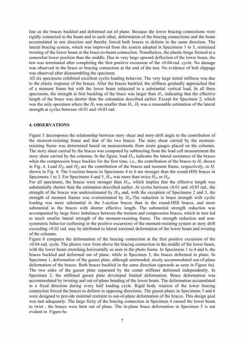
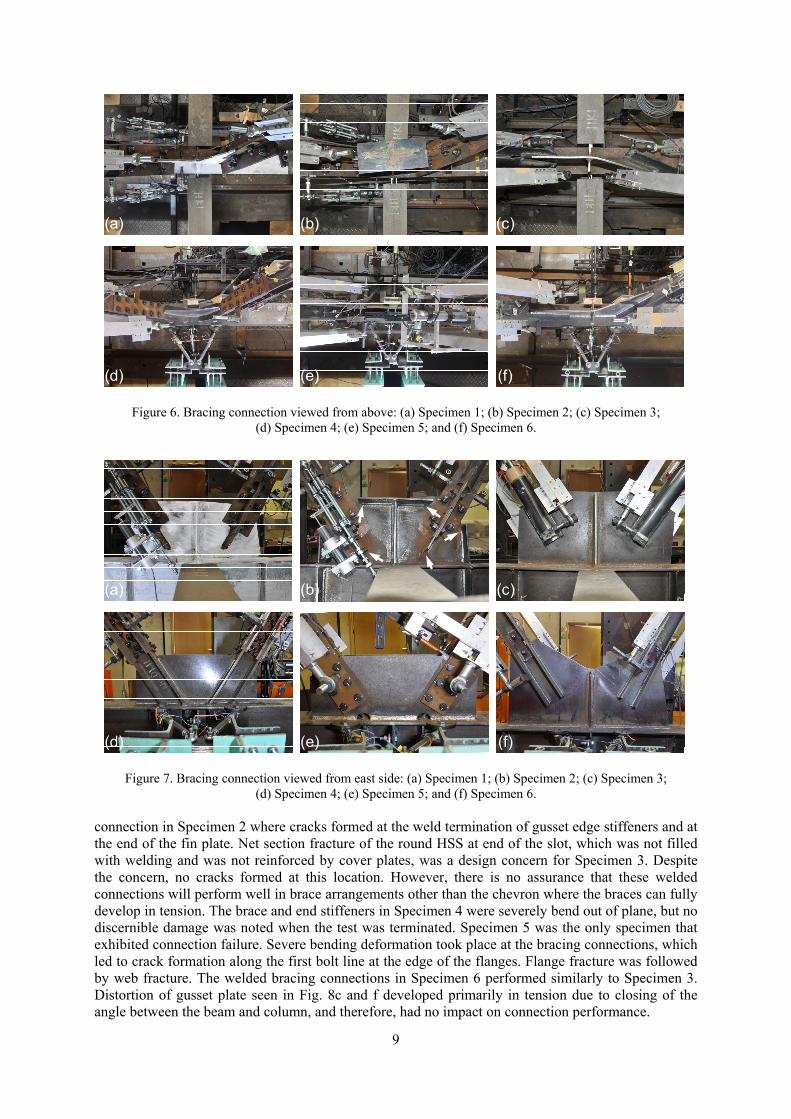
line as the braces buckled and deformed out of plane. Because the lower bracing connections were rigidly connected to the beam and to each other, deformation of the bracing connections and the beam accumulated in one direction and thereby forced both braces to deform in the same direction. The lateral bracing system, which was improved from the system adopted in Specimens 1 to 3, restrained twisting of the lower beam at the brace-to-beam connection. Nonetheless, the plastic hinge formed at a somewhat lower position than the middle. Due to very large upward deflection of the lower beam, the test was terminated after completing the first positive excursion of the ±0.04-rad. cycle. No damage was observed in the brace or bracing connection at the end of the test. No evidence of bolt slippage was observed after disassembling the specimen. All six specimens exhibited excellent cyclic-loading behavior. The very large initial stiffness was due to the elastic response of the braces. After the braces buckled, the stiffness gradually approached that of a moment frame but with the lower beam subjected to a substantial vertical load. In all three specimens, the strength at first buckling of the brace was larger than H1, indicating that the effective length of the brace was shorter than the estimation described earlier. Except for Specimen 2, which was the only specimen where the H2 was smaller than H1, H2 was a reasonable estimation of the lateral strength at cycles between ±0.01 and ±0.03 rad. 4. OBSERVATIONS Figure 5 decomposes the relationship between story shear and story-drift angle to the contribution of the moment-resisting frame and that of the two braces. The story shear carried by the moment-resisting frame was determined based on measurements from strain gauges placed on the columns. The story shear carried by the braces was computed by subtracting from the load cell measurement the story shear carried by the columns. In the figure, load H1b indicates the lateral resistance of the braces when the compression brace buckles for the first time, i.e., the contribution of the braces to H1 shown in Fig. 4. Load H2b and H2f are the contribution of the braces and moment frame, respectively, to H1 shown in Fig. 4. The I-section braces in Specimens 4 to 6 are stronger than the round-HSS braces in Specimens 1 to 3. For Specimens 4 and 5, H1b was more than twice H2b or H2f. For all specimens, the braces were stronger than H1b, which implies that the effective length was substantially shorter than the estimation described earlier. At cycles between ±0.01 and ±0.03 rad., the strength of the braces was underestimated by H2b and, with the exception of Specimens 2 and 3, the strength of moment frames was overestimated by H2b.The reduction in brace strength with cyclic loading was more substantial in the I-section braces than in the round-HSS braces, and more substantial in the braces with shorter effective length. The substantial strength reduction was accompanied by large force imbalance between the tension and compression braces, which in turn led to much smaller lateral strength of the moment-resisting frame. The strength reduction and non-symmetric behavior (softening in the positive excursion) of the moment-resisting system at story drift exceeding ±0.02 rad. may be attributed to lateral torsional deformation of the lower beam and twisting of the columns. Figure 6 compares the deformation of the bracing connection at the first positive excursion of the ±0.04-rad. cycle. The photos view from above the bracing connection in the middle of the lower beam, with the lower beam stretching horizontally as seen in the photo frame. In Specimens 1 to 4 and 6, the braces buckled and deformed out of plane, while in Specimen 5, the braces deformed in plane. In Specimen 1, deformation of the gusset plate, although unintended, nicely accommodated out-of-plane deformation of the braces. Both braces buckled in the same direction (upwards as seen in Figure 6a). The two sides of the gusset plate separated by the center stiffener deformed independently. In Specimen 2, the stiffened gusset plate developed limited deformation. Brace deformation was accommodated by twisting and out-of-plane bending of the lower beam. The deformation accumulated in a fixed direction during every half loading cycle. Rigid body rotation of the lower bracing connection forced the braces to deform in opposing directions. The gusset plates in Specimens 3 and 6 were designed to provide minimal restraint to out-of-plane deformation of the braces. This design goal was met adequately. The large fixity of the bracing connection in Specimen 4 caused the lower beam to twist , the braces were bent out of plane. The in-plane brace deformation in Specimen 5 is not evident in Figure 6e.
8
Figure 5. Hysteretic response of chevron braces and moment frame viewed separately: (a) Specimen 1;
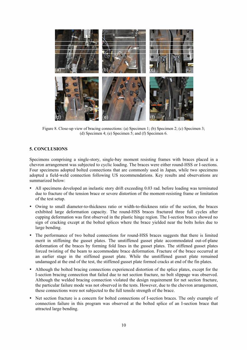
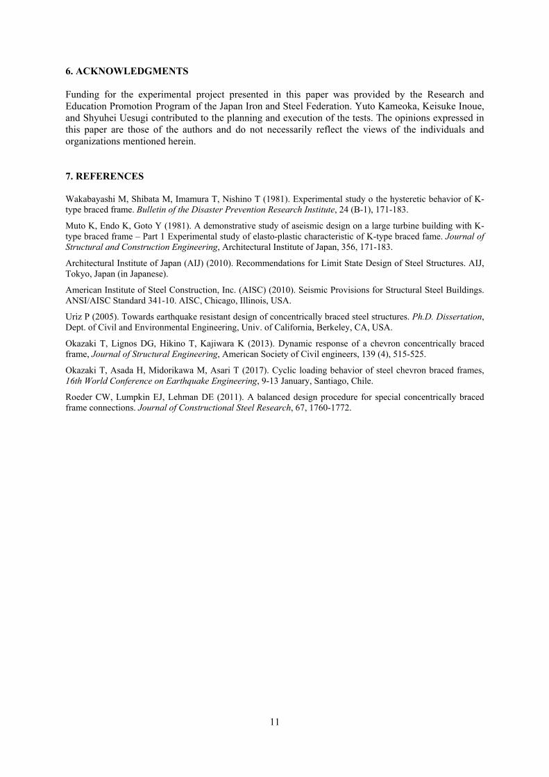
(b) Specimen 2; (c) Specimen 3; (d) Specimen 4; (e) Specimen 5; and (f) Specimen 6. Figure 7 views the bracing connection at the same stage from the east side. In Specimens 1, 3, 4, and 6, no discernible damage in the bracing connections was observed at the end of the test. In Specimen 2, at the end of both braces, small cracks were developing at the weld termination of the gusset edge stiffeners and at the end of the fin plates, at locations indicated in Figure 7b with arrows. In Specimen 5, cracks were forming in the brace along the first line of bolts although no damage had occurred in the plates visible in Figure 7e. Figure 8 shows key locations of the bracing connections near the end of the test. Regardless of the large bending deformation and gap opening between plates seen in Figure 8a, the bracing connections of Specimens 1 and 2 did not slip in the bolted connection. Figure 8b shows an upper bracing
-500
-400
-300
-200
-100
0
100
200
300
400
500
-0.04 -0.03 -0.02 -0.01 0 0.01 0.02 0.03 0.04
Stor
y Sh
ear (
kN)
Story-Drift Ratio (rad.)(d)
-400
-300
-200
-100
0
100
200
300
400
-0.04 -0.03 -0.02 -0.01 0 0.01 0.02 0.03 0.04 0.05
Stor
y Sh
ear (
kN)
Story-Drift Ratio (rad.)
MRFBraces
-400
-300
-200
-100
0
100
200
300
400
-0.04 -0.03 -0.02 -0.01 0 0.01 0.02 0.03 0.04
Stor
y Sh
ear (
kN)
Story-Drift Ratio (rad.)
-400
-300
-200
-100
0
100
200
300
400
-0.04 -0.03 -0.02 -0.01 0 0.01 0.02 0.03 0.04
Stor
y Sh
ear (
kN)
Story-Drift Ratio (rad.)
H1bH2f
(a) (b)
(c)
H2b
-500
-400
-300
-200
-100
0
100
200
300
400
500
-0.04 -0.03 -0.02 -0.01 0 0.01 0.02 0.03 0.04
Stor
y Sh
ear (
kN)
Story-Drift Ratio (rad.)(e)
-500
-400
-300
-200
-100
0
100
200
300
400
500
-0.04 -0.03 -0.02 -0.01 0 0.01 0.02 0.03 0.04
Stor
y Sh
ear (
kN)
Story-Drift Ratio (rad.)(f)
H1b
H2f , H2b
H1b
H2fH2b
H1b
H2fH2b
H1b
H2f
H2b
H1b
H2fH2b
9
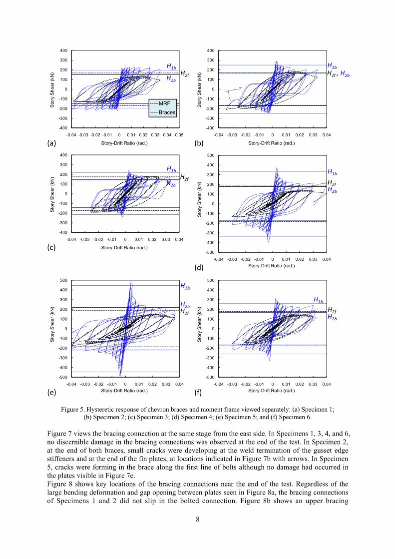
Figure 6. Bracing connection viewed from above: (a) Specimen 1; (b) Specimen 2; (c) Specimen 3;
(d) Specimen 4; (e) Specimen 5; and (f) Specimen 6.
Figure 7. Bracing connection viewed from east side: (a) Specimen 1; (b) Specimen 2; (c) Specimen 3;
(d) Specimen 4; (e) Specimen 5; and (f) Specimen 6. connection in Specimen 2 where cracks formed at the weld termination of gusset edge stiffeners and at the end of the fin plate. Net section fracture of the round HSS at end of the slot, which was not filled with welding and was not reinforced by cover plates, was a design concern for Specimen 3. Despite the concern, no cracks formed at this location. However, there is no assurance that these welded connections will perform well in brace arrangements other than the chevron where the braces can fully develop in tension. The brace and end stiffeners in Specimen 4 were severely bend out of plane, but no discernible damage was noted when the test was terminated. Specimen 5 was the only specimen that exhibited connection failure. Severe bending deformation took place at the bracing connections, which led to crack formation along the first bolt line at the edge of the flanges. Flange fracture was followed by web fracture. The welded bracing connections in Specimen 6 performed similarly to Specimen 3. Distortion of gusset plate seen in Fig. 8c and f developed primarily in tension due to closing of the angle between the beam and column, and therefore, had no impact on connection performance.
(a) (b) (c)
(d) (e) (f)
(d) (e)
(a) (b) (c)
(f)
10
Figure 8. Close-up view of bracing connections: (a) Specimen 1; (b) Specimen 2; (c) Specimen 3; (d) Specimen 4; (e) Specimen 5; and (f) Specimen 6.
5. CONCLUSIONS Specimens comprising a single-story, single-bay moment resisting frames with braces placed in a chevron arrangement was subjected to cyclic loading. The braces were either round-HSS or I-sections. Four specimens adopted bolted connections that are commonly used in Japan, while two specimens adopted a field-weld connection following US recommendations. Key results and observations are summarized below:
All specimens developed an inelastic story drift exceeding 0.03 rad. before loading was terminated due to fracture of the tension brace or severe distortion of the moment-resisting frame or limitation of the test setup.
Owing to small diameter-to-thickness ratio or width-to-thickness ratio of the section, the braces exhibited large deformation capacity. The round-HSS braces fractured three full cycles after cupping deformation was first observed in the plastic hinge region. The I-section braces showed no sign of cracking except at the bolted splices where the brace yielded near the bolts holes due to large bending.
The performance of two bolted connections for round-HSS braces suggests that there is limited merit in stiffening the gusset plates. The unstiffened gusset plate accommodated out-of-plane deformation of the braces by forming fold lines in the gusset plates. The stiffened gusset plates forced twisting of the beam to accommodate brace deformation. Fracture of the brace occurred at an earlier stage in the stiffened gusset plate. While the unstiffened gusset plate remained undamaged at the end of the test, the stiffened gusset plate formed cracks at end of the fin plates.
Although the bolted bracing connections experienced distortion of the splice plates, except for the I-section bracing connection that failed due to net section fracture, no bolt slippage was observed. Although the welded bracing connection violated the design requirement for net section fracture, the particular failure mode was not observed in the tests. However, due to the chevron arrangement, these connections were not subjected to the full tensile strength of the brace.
Net section fracture is a concern for bolted connections of I-section braces. The only example of connection failure in this program was observed at the bolted splice of an I-section brace that attracted large bending.
(a) (b) (c)
(d) (e) (f)
11
6. ACKNOWLEDGMENTS Funding for the experimental project presented in this paper was provided by the Research and Education Promotion Program of the Japan Iron and Steel Federation. Yuto Kameoka, Keisuke Inoue, and Shyuhei Uesugi contributed to the planning and execution of the tests. The opinions expressed in this paper are those of the authors and do not necessarily reflect the views of the individuals and organizations mentioned herein. 7. REFERENCES Wakabayashi M, Shibata M, Imamura T, Nishino T (1981). Experimental study o the hysteretic behavior of K-type braced frame. Bulletin of the Disaster Prevention Research Institute, 24 (B-1), 171-183.
Muto K, Endo K, Goto Y (1981). A demonstrative study of aseismic design on a large turbine building with K-type braced frame – Part 1 Experimental study of elasto-plastic characteristic of K-type braced fame. Journal of Structural and Construction Engineering, Architectural Institute of Japan, 356, 171-183.
Architectural Institute of Japan (AIJ) (2010). Recommendations for Limit State Design of Steel Structures. AIJ, Tokyo, Japan (in Japanese).
American Institute of Steel Construction, Inc. (AISC) (2010). Seismic Provisions for Structural Steel Buildings. ANSI/AISC Standard 341-10. AISC, Chicago, Illinois, USA.
Uriz P (2005). Towards earthquake resistant design of concentrically braced steel structures. Ph.D. Dissertation, Dept. of Civil and Environmental Engineering, Univ. of California, Berkeley, CA, USA.
Okazaki T, Lignos DG, Hikino T, Kajiwara K (2013). Dynamic response of a chevron concentrically braced frame, Journal of Structural Engineering, American Society of Civil engineers, 139 (4), 515-525.
Okazaki T, Asada H, Midorikawa M, Asari T (2017). Cyclic loading behavior of steel chevron braced frames, 16th World Conference on Earthquake Engineering, 9-13 January, Santiago, Chile.
Roeder CW, Lumpkin EJ, Lehman DE (2011). A balanced design procedure for special concentrically braced frame connections. Journal of Constructional Steel Research, 67, 1760-1772.