dynamic response of a chevron concentrically braced frame
TRANSCRIPT

Dynamic Response of a Chevron ConcentricallyBraced Frame
Taichiro Okazaki, A.M.ASCE1; Dimitrios G. Lignos, A.M.ASCE2; Tsuyoshi Hikino3; and Koichi Kajiwara4
Abstract: Large-scale shake table tests were conducted at E-Defense, Japan, to examine the dynamic response of a steel concentrically bracedframe. The specimenwas a single-bay, single-story framewith a pair of square hollow structural section braces placed in a chevron arrangement.The gusset plates connecting the brace to the framing elements were provided with an elliptic fold line to accommodate out-of-plane rotation ofthe brace in compression. The specimen was subjected repeatedly to a unidirectional ground motion with increasing magnitude until the bracesbuckled and eventually fractured. The bracing connections performed as intended; the gusset plates folded out of plane, and no crack wasobserved in the gusset plate or in the critical welds. Consequently, the test results demonstrated excellent performance of the bracingconnections. Elastic deformation of the beamprevented the braces fromdeveloping their full tensile strength.Yielding in themiddle of the beam,which was predicted by monotonic loading analysis, did not occur. The specimen response was reproduced by a numerical model using fiberelements. This model was able to predict the occurrence of brace buckling and fracture and thereby accurately trace the dynamic behavior of theframe. DOI: 10.1061/(ASCE)ST.1943-541X.0000679. © 2013 American Society of Civil Engineers.
CE Database subject headings: Shake table tests; Steel frames; Seismic design; Bracing; Connections; Nonlinear analysis; Dynamicresponse.
Author keywords: Shake table tests; Steel frames; Seismic design; Bracing; Connections; Nonlinear analysis.
Introduction
Concentrically braced frames (CBFs) are a widely used structuralsystem to achieve the lateral stiffness and strength required bymodern seismic design provisions. The design rules in the AISCseismic provisions for structural steel buildings (AISC 2005a),hereinafter referred to as the 2005 AISC Seismic Provisions, arebased on extensive research conducted since the 1970s (Popov et al.1976; Astaneh-Asl et al. 1986; Nakashima and Wakabayashi 1992;Tremblay 2001, 2002), which suggests that the seismic performanceof CBFs is controlled by the width-to-thickness ratio and slender-ness of the braces. Recent tests byUriz (2005), Lehman et al. (2008),and Roeder and Lehman (2009) indicate that secondary bending inthe framing members can significantly affect bracing connections.The current provisions can lead to large and thick gusset plates,
which restrain the framing members and thereby draw significantstresses to the gusset plate welds. Laboratory tests indicate that CBFswith such bracing connections can fail in the gusset plates or at thewelds before the deformation capacity of the braces are exploited. Onthe basis of such observations, Lehman et al. (2008) and Roeder et al.(2011b) developed a designprocedure that promotes compact and thingusset plates and thereby leads to increased drift capacity of CBFs.
CBFs with braces arranged in a chevron (or an inverted-V) pat-tern are frequently used because of their architectural advantages.Chevron CBFs require special considerations that are not requiredfor other CBF configurations. Early experiments by Shibata andWakabayashi (1983), Yamanouchi et al. (1989), and Fukuta et al.(1989) suggest that the seismic behavior of chevron CBFs is sig-nificantly affected by force unbalance between the tension braceand buckled compression brace. If the beam intersecting the braces isunable to sustain this downward force, a plastic hinge will form inthe beam before the tension brace can develop its yield strength.Studies by Khatib et al. (1988) and Tremblay and Robert (2001)warn that this mechanism is undesirable for CBFs. Consequently,the 2005 AISC Seismic Provisions (AISC 2005a) require the beamsin chevron CBFs to be designed for the condition where the tensionbrace is fully yielded and the compression brace has buckled and lostmuch of its strength. In addition, braces in chevron CBFs areexpected to develop inelastic deformation primarily in contraction.For example, a large-scale test by Uriz (2005) suggests that, even ifthe beam is designed for the force unbalance per the 2005 AISCSeismic Provisions, the elastic deflection caused by the force un-balance can be large enough to prevent tensile yielding of the brace.
This paper describes a shake table test program of a large-scalechevron CBF specimen. The objective of the program was to con-firm the available knowledge of CBFs including cyclic brace be-havior, the effect of framing action on bracing connections, andcharacteristics of chevron systems, which is based mostly on staticloading tests. The specimen is one of few large-scale chevron CBFstested to date and one of few large-scale CBFs tested dynamically.
1Associate Professor, Graduate School of Engineering, Hokkaido Univ.,Sapporo, Hokkaido 060-8628, Japan; formerly, Researcher, National Re-search Institute for Earth Science andDisaster Prevention,Miki, Hyogo 673-0515 Japan (corresponding author). E-mail: [email protected]
2Assistant Professor, Dept. of Civil and Applied Mechanics, McGillUniv., Montreal, QC, Canada H3A 2K6. E-mail: [email protected]
3Manager, Nippon Steel Engineering Co. Ltd., Shinagawa, Tokyo 141-8604, Japan; formerly, Researcher, National Research Institute for EarthScience and Disaster Prevention, Miki, Hyogo 673-0515 Japan. E-mail:[email protected]
4Director of Hyogo Earthquake Engineering Center (E-Defense),National Research Institute for Earth Science and Disaster Prevention,Miki, Hyogo 673-0515, Japan. E-mail: [email protected]
Note. This manuscript was submitted on December 28, 2011; approvedon July 20, 2012; published online on August 11, 2012. Discussion periodopen until September 1, 2013; separate discussions must be submitted forindividual papers. This paper is part of the Journal of Structural Engi-neering, Vol. 139, No. 4, April 1, 2013. ©ASCE, ISSN 0733-9445/2013/4-515–525/$25.00.
JOURNAL OF STRUCTURAL ENGINEERING © ASCE / APRIL 2013 / 515
J. Struct. Eng. 2013.139:515-525.
Dow
nloa
ded
from
asc
elib
rary
.org
by
MC
GIL
L U
NIV
ER
SIT
Y o
n 04
/10/
13. C
opyr
ight
ASC
E. F
or p
erso
nal u
se o
nly;
all
righ
ts r
eser
ved.

In addition, the test results are used to demonstrate that numericalmodels can be calibrated to simulate inelastic buckling and fractureinitiation caused by low cycle fatigue.
Test Plan
A single-story, single-span, chevron CBF specimen was sub-jected to a series of strong earthquake ground motions. The testswere conducted at E-Defense, which is a three-dimensional (3D),large-scale earthquake testing facility operated by the NationalResearch Institute for Earth Science and Disaster Prevention ofJapan.
Specimen
Fig. 1 shows an elevation of the CBF specimen. The 4.15-m spanand 2.25-m height correspond to 70% scale of typical buildingstructures. The specimen may represent the bottom story of a 3- to5-story building in Japan. The frame comprised a built-up wide-flange beam (d5 300, bf 5 150, tw 5 6:5, tf 5 9 mmÞ, two cold-formed square hollow structural section (HSS) columns (d5 b5 200,t5 9 mm), andapair of squareHSSbraces (d5 b5 75, t5 3:2 mm).The braces connected to the beam and columns through 4.5-mmgusset plates. The standard through-diaphragmdetail (Nakashima et al.1998) was used to achieve rigid beam-to-column connections.
For each material comprising the specimen, Table 1 lists the ma-terial designation, either by the Japanese IndustryStandards (JIS) or bythe Japan Iron and Steel Federation. The specified minimum yieldstrength is 245, 235, 295, and 245 MPa, respectively, for STKR400,SN400, BCR295, and SS400 steel. BothHSSmaterials, BCR295 andSTKR400, were formed from a flat plate and completed with onelongitudinal seam weld. Although BCR295 steel is commonly usedfor columns subjected to biaxial bending, STKR400 steel is a typicalmaterial for bracing. The STKR400 standard lacks the minimumCharpy V-Notch toughness, chemical control for weldability, andyield-to-tensile strength ratio requirements, which are specified forBCR295. Table 1 indicates that the measured yield strength for thebeam, columns, andHSS braces was 50% stronger than the respective
specified minimum value. Similarly large measured-to-nominal yieldstrength ratios have been reported by Lehman et al. (2008), Roederet al. (2011b), and Fell et al. (2009) for ASTM A500 material. In-terestingly, the measured yield strength for the gusset plate, 204MPa,did not meet the specified minimum value of 245 MPa.
The bracing connections shown in Fig. 2 did not represent typicalJapanese design. The three gusset plates were designed according tothe balanced design proposed by Lehman et al. (2008); by adoptingan elliptic clearance distance of eight times the thickness of thegusset plate, the unsupported segment between the brace and thebeam and column flanges was shortened, thereby enabling relativelythin, compact gusset plates. The gusset plate at the top end of thebraces, connecting the braces to the beam at its midspan, wasprovidedwith a pair of vertical stiffener plates. As indicated in Fig. 2,each end of the brace was welded to a gusset plate along the slottededges of the brace and clipped portion of the gusset plate. Netsection reinforcement is not needed for this detail. The welds be-tween the brace and gusset plate and between the gusset plate andbeam and column flanges were placed with the specimen standing inthe upright position and made by a shielded metal arc weldingprocess using a 3.2-mm-diameter JIS Z 3211 electrode. The weldswere sized to develop the full strength of the base material.
Prior to the tests described in this paper, the beam and columnsof the specimen were used for a different test, where a pair ofdampers was placed in the same chevron arrangement and where theframe developed drifts near but smaller than 0.01 rad. After this priortest was completed, the dampers were removed, the 16-mm gussetplates were removed by arc gouging and grinding, and the smaller4.5-mmgusset plates shown in Fig. 2 were welded over the removedgusset plates. Because the frame was designed to remain elastic fordrifts less than 0.01 rad, minimum damage occurred in the reusedbeam and columns. However, because the old gusset plates and filletwelds could not be ground flush to the base material, the new gussetplates were welded over 30-mm-wide and 5- to 10-mm-thick left-over material. Consequently, where the gusset plate was welded to abeam or column, the clearance distance for elliptic folding of thegusset plate was reduced by up to twice the plate thickness.
The columns were rigidly connected to heavy base beams, whichin turn were rigidly connected to the shake table. At the top side of the
Fig. 1. Test specimen and out-of-plane bracing points (mm)
516 / JOURNAL OF STRUCTURAL ENGINEERING © ASCE / APRIL 2013
J. Struct. Eng. 2013.139:515-525.
Dow
nloa
ded
from
asc
elib
rary
.org
by
MC
GIL
L U
NIV
ER
SIT
Y o
n 04
/10/
13. C
opyr
ight
ASC
E. F
or p
erso
nal u
se o
nly;
all
righ
ts r
eser
ved.

specimen, each end of the beamwas connected to the test-bed systemdescribed later. The specimen was laterally braced along the columnsand beam at discrete locations indicated in Fig. 1 by 3 marks.
Compliance to Code Requirements
The square HSS braces had a width-to-thickness ratio of b/t5 20:4and a member slenderness ratio of KL/r5 82:5, where K is theeffective length factor taken equal to unity, and the member lengthL is measured between the elliptic fold lines. The b/t ratio slightlyviolated the seismically compact limit of 0:64ðE/FyÞ1=2 5 18:5,whereas the KL/r ratio was within the limit of 4:0ðE/FyÞ1=2 5 116specified in the 2005 AISC Seismic Provisions to develop mean-ingful compressive strength. These limiting values are computedbased on the specified minimum yield strength Fy 5 245 MPa. Thenominal compressive strength, Pcr, based on the AISC Specificationfor Structural Steel Buildings (AISC 2005b) and the specifiedminimum yield strength, Fy 5 245 MPa, was 134 kN, whereas thestrength based on the measured strength, Fy 5 383 MPa, was213 kN. The tensile yield strength, Py, was 342 kN based onFy 5 245 MPa and 342 kN based on Fy 5 383 MPa.
The bracing connection shown in Fig. 2 was designed to developthe required tensile and compressive strength of the HSS bracesusing the procedure by Roeder et al. (2011b). Although Roeder et al.(2011b) suggests selectively relaxing the resistance factors in theAISC specification, the designs shown in Fig. 2 fully meet the 2005AISC specification requirements. However, on the basis of themeasured yield strength values shown in Table 1, the tensile yieldstrength of the brace was nearly 10% larger than the yield strengthof the Whitmore section of the gusset plates.
The 2005 AISC Seismic Provisions (AISC 2005a) and Japaneserecommendations [Architectural Institute of Japan (AIJ) 2002] re-quire the beams in chevron CBFs to be designed for the forceunbalance between the tension and compression braces. Because thebeam in the specimen is part of a rigid frame, the available strength ofthe beam to carry a midspan load is a function of the momentdistribution produced by moment-frame action. Fig. 3(a) showsa static pushover response obtained from the modeling proceduredescribed later and where gravity load is neglected. The same figureshows the story shear developed in the columns by moment frameaction. Fig. 3(b) plots the axial force in the two braces as the storydrift increased, along with key strength values specified in the 2005AISC Seismic Provisions. Before buckling of the compression brace,the braces account for 84% of the frame strength. This ratio reducesto 73% after the compression brace buckles [Stage A indicated inFig. 3(a)] and to 54%when the tensioned brace yields (Stage B). Thecompressed brace buckles at a story drift ratio of 0.0022 rad, thetension brace yields at 0.0095 rad, and at 0.01 rad., a plastic hingeforms at the end of the rigid offset near the center of the beam (StageC). The force in the compressed brace reduces to less than 0:3Pcr,which is the strength used to evaluate the beam midspan load inchevron CBFs. Even after a beam mechanism is formed, the frame
Table 1. Material Properties
Material DesignationFy
(MPa)Fu
(MPa)Elongation
(%)
Brace STKR400 383 452 36Beam flange (9 mm) SN400B 327 456 27Beam web (6 mm) SN400B 376 472 29Column BCR295 434 518 19Gusset plate (4.5 mm) SS400 204 291 54
Fig. 2. Details of bracing connections
JOURNAL OF STRUCTURAL ENGINEERING © ASCE / APRIL 2013 / 517
J. Struct. Eng. 2013.139:515-525.
Dow
nloa
ded
from
asc
elib
rary
.org
by
MC
GIL
L U
NIV
ER
SIT
Y o
n 04
/10/
13. C
opyr
ight
ASC
E. F
or p
erso
nal u
se o
nly;
all
righ
ts r
eser
ved.

strength continues to increase. It is cautioned that deterioration ofbeam strength at the beam-to-column connection is notmodeled, andbecause gravity load is not accounted for, the model is not affectedby P-D effects.
Test Bed
The specimens were subjected to ground shaking at the E-Defensefacility using the test-bed system developed by Takeuchi et al.(2008). The test beds aremultipurpose devices that supply horizontalmass to the specimen while adding minimal lateral force resistance.As shown in Fig. 4, a pair of test beds was used for this program, oneat each side of the specimen. The figure shows a 3D view of the testsetup, with the test bed on the left side partly transparent. At the base,the test bed was connected to the shake table through a set of linearbearings that produced minimal friction for motion in the loadingplane and that restrained out-of-plane and vertical motion. Thedynamic friction coefficient was evaluated as 0.0033 by Takeuchiet al. (2008). At the top, the test bedwas connected to each end of thespecimen, with a load cell placed in the load path. The two test bedsand additional test rigs supplied a combined 69.4-t mass to the
specimen. The test bed was also used to anchor the out-of-planebracing indicated in Fig. 1. The test-bed system has previouslybeen used in a similar fashion for two experimental programs(Takeuchi et al. 2008; Ma et al. 2010).
Test Procedure
The scaling rules for the shake table test are summarized inTable 2, where l indicates the scaling factor for length. In this case,l5 0:7. Time and stress were not scaled in the test.
The east-west (EW) component of the JR Takatori motion(Nakamura et al. 1996) was introduced in the direction parallel to theloading plane. The JR Takatori motion is a strong motion recordfrom the 1995 Kobe earthquake, measured immediately adjacent tothe fault. The EW component is characterized by a peak accelerationof 6.6 m/s2 and strong velocity pulses. Fig. 5(a) shows the accel-eration history of the motion, whereas Fig. 5(b) shows the responseacceleration spectrum obtained for a damping ratio of z5 0:02. Theshake table tests were conducted by introducing the Takatori EWmotion seven times, with the target amplification level increas-ing from 10, 12, 14, 28, 28 (second time), to 42, and finally, 70%.Fig. 5(b) also shows the acceleration response spectra constructedfrom the measured table motion and for z5 0:02. The targetedmotion was achieved over a wide range of periods between 0.1 and3 s, although the 70%motion exceeded the target in the short periodrange between 0.1 and 0.5 s.
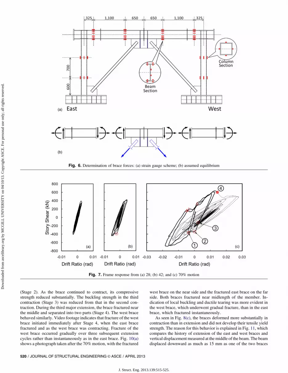
The load cells mentioned previously were used to evaluate thestory shear force. Displacement transducers were used to monitorstory drift and out-of-plane deformation of the beam and braces. Asshown in Fig. 6(a), strain gauges were placed at selected sectionsof the beam and columns. The section forces estimated from strain
Fig. 3.Monotonic loading response of specimen: (a) pushover curves;(b) brace axial forces Fig. 4. Specimen and test-bed system
Table 2. Scaling Rule
Parameters Scaling factor
Length l 0.7Mass l 0.7Acceleration l 0.7Time 1 1Force l2 0.5Velocity l 0.7Stress 1 1
518 / JOURNAL OF STRUCTURAL ENGINEERING © ASCE / APRIL 2013
J. Struct. Eng. 2013.139:515-525.
Dow
nloa
ded
from
asc
elib
rary
.org
by
MC
GIL
L U
NIV
ER
SIT
Y o
n 04
/10/
13. C
opyr
ight
ASC
E. F
or p
erso
nal u
se o
nly;
all
righ
ts r
eser
ved.

gauge readings were combined with the equilibrium conditionsindicated in Fig. 6(b) to compute the axial force in the braces.Elongation of the brace was measured from the change in length ofthe HSS member. Data were collected at a rate of 1,000 Hz. Alldata were passed through a low-pass filter to eliminate frequencycontent greater than 50 Hz.
Test Results
Frame Behavior
Based on unidirectional white noise excitation, the natural vibrationperiod was determined as 0.21 s, which is equivalent to that ofa single- or 2-story building.
Fig. 7 shows the story shear versus story drift response measuredfor the three tests using the 28, 42, and 70% motions. The figureindicates that the structure responded linearly during the 28%motion, but some nonlinearity occurred during the 42%motion. Theresponse from the 70% motion plotted in Fig. 7(c) suggests that thesystem was affected by buckling and yielding of the braces during2.5 drift cycles of –0.015 to10.01 rad. The circles and triangles inthe figure correspond to the time instants when key phenomenawere observed in the east andwest braces, respectively. The numbers1–4 in Fig. 7(c) correlate with buckling and fracture of the east braceindicated in later figures. The braces buckled and fractured withinthree negative to positive drift excursions between –0.015 and 0.01rad. Each occurrence of brace buckling caused a reduction instiffness and drop in story shear, although the frame was able toregain strength as the drift increased further. Near the instant
when the east brace fractured at Stage 4, the west brace started tofracture under large contraction. The response after Stage 4 is in-dicated by a dotted line. After both braces fractured, the specimenacted as a moment resisting frame, developing a large deformationbetween –0.018 and 1 0.028 rad without any strength loss. Fig.7(c) clearly indicates the reduction in stiffness after the bracedframe reduced to a moment resisting frame. At the end of the 70%motion, a residual drift of 10.007 rad remained.
The largest story shear developed by the specimenwas1635 and–690 kN in the positive and negative directions, respectively. Theshear strength was somewhat larger than the estimation of thepushover analysis, which, as shown in Fig. 3, developed a story shearof 634 kN at a story drift of 0.02 rad. The largest story shear de-veloped after Stage 4, during which the specimen acted as a mo-ment resisting frame, was 1515 and –550 kN in the positive andnegative directions, respectively. Therefore, for this specimen, thestrength of the underlying moment resisting frame was 80% of themaximum strength provided by the two braces.
After the test was completed, flaking of white wash indicatedthat the column had yielded near the bases, although no residualdeformation of the column was visible. Similarly, the white washindicated that no yielding occurred in the beam near the brace-to-beam connections.
Brace Performance
Fig. 8 shows the axial force (tension taken as positive) versuselongation relationship measured from the east brace for the 28, 42,and 70% motions. Fig. 9 shows the rotation of the top and bottomends of the east brace measured from the same motions. The re-sponse of the west brace was similar to that of the east brace. InFigs. 8 and 9, the horizontal lines indicate the tensile yield strengthPy and compressive strength Pcr of the brace member computedbased on the measured yield strength and a slenderness ratio ofKL/r5 82:5.
During the 28% motion, the braces exceeded the estimatedbuckling load, and Fig. 9(a) indicates a small out-of-plane de-formation that followed brace buckling. However, the occurrenceof buckling is not obvious from the axial response in Fig. 8(a). Atthe end of the 28% motion, a residual out-of-plane displacement of6 mm, not accounting for initial imperfection, was measured in themiddle of the brace. Therefore, the braces had an out-of-straightnessof 1/400 before being subjected to the 42%motion. During the 42%motion shown in Fig. 8(b), the braces buckled under a compressionclose to the estimated buckling load. After occurrence of the firstbuckling, the compressive strength of the brace reduced. It is notedthat, although the specimen developed similar drifts in both loadingdirections, the braces developed larger contraction than extension,and the braces did not develop their yield strength in tension. At theend of the 42% motion, a residual out-of-plane displacement of 17mm was measured in the middle of the east brace, which corres-ponds to an out-of-straightness of 1/133.
During the 70% motion, as the story drift ratio exceeded 0.01rad, the beam yielded near the connections to the column face wheresome of the strain gauges were placed. Beyond this stage, the braceforces were estimated using a reduced number of strain gauges, andtherefore, the brace forces were not estimated as accurately as in thesmaller motions. Nonetheless, Fig. 8 clearly illustrates the keycharacteristics of buckling brace behavior. During the first majorcontraction, the east brace buckled at a smaller force than themaximum compression reached during the 28 and 42% motions[Stage 1 indicated in Fig. 8(c)]. However, after experiencing ten-sion, presumably because the out-of-straightness was corrected, thebrace recovered its compressive strength in the next contraction
Fig. 5. Ground motion: (a) JR Takatori EW acceleration history; (b)response spectra for h5 0:02
JOURNAL OF STRUCTURAL ENGINEERING © ASCE / APRIL 2013 / 519
J. Struct. Eng. 2013.139:515-525.
Dow
nloa
ded
from
asc
elib
rary
.org
by
MC
GIL
L U
NIV
ER
SIT
Y o
n 04
/10/
13. C
opyr
ight
ASC
E. F
or p
erso
nal u
se o
nly;
all
righ
ts r
eser
ved.
(Stage 2). As the brace continued to contract, its compressivestrength reduced substantially. The buckling strength in the thirdcontraction (Stage 3) was reduced from that in the second con-traction. During the third major extension, the brace fractured nearthe middle and separated into two parts (Stage 4). The west bracebehaved similarly. Video footage indicates that fracture of the westbrace initiated immediately after Stage 4, when the east bracefractured and as the west brace was contracting. Fracture of thewest brace occurred gradually over three subsequent extensioncycles rather than instantaneously as in the east brace. Fig. 10(a)shows a photograph taken after the 70%motion, with the fractured
west brace on the near side and the fractured east brace on the farside. Both braces fractured near midlength of the member. In-dication of local buckling and ductile tearing was more evident inthe west brace, which underwent gradual fracture, than in the eastbrace, which fractured instantaneously.
As seen in Fig. 8(c), the braces deformed more substantially incontraction than in extension and did not develop their tensile yieldstrength. The reason for this behavior is explained in Fig. 11, whichcompares the history of extension of the east and west braces andvertical displacement measured at the middle of the beam. The beamdisplaced downward as much as 15 mm as one of the two braces
Fig. 6. Determination of brace forces: (a) strain gauge scheme; (b) assumed equilibrium
Fig. 7. Frame response from (a) 28; (b) 42; and (c) 70% motion
520 / JOURNAL OF STRUCTURAL ENGINEERING © ASCE / APRIL 2013
J. Struct. Eng. 2013.139:515-525.
Dow
nloa
ded
from
asc
elib
rary
.org
by
MC
GIL
L U
NIV
ER
SIT
Y o
n 04
/10/
13. C
opyr
ight
ASC
E. F
or p
erso
nal u
se o
nly;
all
righ
ts r
eser
ved.

contracted and the other extended to produce force unbalance. Thefigure indicates how the vertical displacement added to bracecontraction and reduced brace extension. After the east bracefailed in tension [Stage 4 in Fig. 8(c)] and the west brace beganto fracture, the beam was no longer subjected to substantialdownward forces.
Contrary to the prediction by monotonic loading analysis, theforce unbalance between the tension and compression braces didnot cause plastic hinge formation in the beam. Nonetheless, theforce unbalance influenced the behavior of the braces by de-forming the beam to increase contraction and limit elongation ofthe brace.
Fig. 8. Axial response of east brace from (a) 28; (b) 42; and (c) 70% motion
Fig. 9. End rotation of east brace from (a) 28; (b) 42; and (c) 70% motion
Fig. 10. Specimen after 70% motion: (a) fractured west brace; (b) gusset plate at the east column base; (c) gusset plate connecting braces to beam
JOURNAL OF STRUCTURAL ENGINEERING © ASCE / APRIL 2013 / 521
J. Struct. Eng. 2013.139:515-525.
Dow
nloa
ded
from
asc
elib
rary
.org
by
MC
GIL
L U
NIV
ER
SIT
Y o
n 04
/10/
13. C
opyr
ight
ASC
E. F
or p
erso
nal u
se o
nly;
all
righ
ts r
eser
ved.

Bracing Connection
Fig. 9 shows how the top and bottom ends of the east brace rotated inopposite directions as the brace deformed out of plane. The sym-metric hysteresis indicates that the top and bottom bracing con-nections performed equally well. The ends rotated 0.03 rad duringthe 28% motion and 0.08 rad during the 42% motion. The endsrotated by as much as 0.18 rad during the 70% motion as the braceunderwent large out-of-plane deformation. The photographs inFigs. 10(b and c) show that the gusset plates, either at the columnbase or at the midspan of the beam, folded nicely along the ellipticclearance to accommodate brace-end rotation in compression. Nodiscernible damagewas observed in the gusset plates, the brace ends,or in the critical welds, suggesting that the performance of thebracing connections was excellent. However, while the bracingconnections achieved all the design goals for braces in compression,it is suspected that the connections were not subjected to the mostsevere conditions expected for braces in tension. The connectionswere not subjected to very severe secondary bending effects. In otherwords, had the braces exhibited longer fatigue life as expected forsections with smaller b/t ratios, the frame would have developedlarger drifts and thereby imposed larger secondary bending effectson the connections.
Numerical Simulation
Modeling
Fig. 12(a) shows the numerical model constructed in the OpenSeessimulation platform (McKenna 1997). The model included panelzones modeled according to Gupta and Krawinkler (1999) anda 300-mm-long rigid segment in themiddle of the beam.The test-bedsystem was modeled by connecting each end of the beam to a lean-ing column that support half of the test-bed mass. Nonlinear geometrywas considered with corotational transformation. The members weremodeled with a displacement-based fiber element that uses the Gauss-
Lobatto quadrature rule. Five integration points were used along theirlengths including the two placed at the ends. A 163 4 mesh was usedfor the flange and web of the beam and columns, and a 103 4 meshwas used for each wall of the braces. Material nonlinearity wasmodeled using the Giuffre-Menegotto-Pinto model with isotropicstrain hardening and themeasuredmaterial properties listed in Table 1.Three percent mass proportional damping was assumed at the firstvibration period of the numerical model (0.20 s) to represent friction inthe test bed.
The braces were modeled using a technique similar to the tech-nique developed byUriz et al. (2008) and described in NIST (2011).Each brace was split into two fiber elements and provided with aninitial imperfection equal to 0.1% of the brace length. The gussetplates were modeled by a fiber element with a length equal to twicethe gusset plate thickness and with two integration points. Fracturein the critical section was considered by tracking the strain history ineach fiber and assigning zero stiffness to any fiber that has exceededthe low-cycle fatigue limit defined by a rain-flow-count rule. Thelow-cycle fatigue limit was calibrated against quasi-static tests onsquare HSS braces by Fell et al. (2009) and Black et al. (1980) thathad similar geometric properties (L=ry 5 80, b=t5 16) as the bracesin the shake table tests (L=ry 5 82:5, b=t5 20:4). Fig. 13 shows anexample where the calibrated brace model captured the buckling,yielding, postbuckling hysteresis, and fracture observed in a cyclicloading test by Fell et al (2009).
Simulated versus Experimental Results
The measured motions of the shake table were applied to the nu-merical models in sequential order to consider the cumulativedamage effects on the nonlinear response from phase to phase.Fig. 14 compares the simulated versus experimental hysteresis ofthe east brace for the 42 and 70%motions. The figure shows that thesimulation traced the experimental response fairly accurately forthe 42% motion, including buckling and postbuckling response,although larger tensile force was developed in simulation. For the70% motion, the simulation did not see substantial recovery ofcompression strength after undergoing tension, which was observedin the experiment. The simulated brace fractured before completingthe second major tension excursion, whereas fracture in the ex-periment occurred during the third major tension excursion. Asdescribed previously, the fracture limit in the numerical model wascalibrated against available test data on braces similar to the braces inthe shake table specimen. Although the timing of the fracture could
Fig. 11. Brace elongation and beam deflection: (a) brace elongation;(b) vertical displacement (upward positive) of beam Fig. 12. Numerical model (mm)
522 / JOURNAL OF STRUCTURAL ENGINEERING © ASCE / APRIL 2013
J. Struct. Eng. 2013.139:515-525.
Dow
nloa
ded
from
asc
elib
rary
.org
by
MC
GIL
L U
NIV
ER
SIT
Y o
n 04
/10/
13. C
opyr
ight
ASC
E. F
or p
erso
nal u
se o
nly;
all
righ
ts r
eser
ved.

be matched by adjusting the fracture limit, the difference in thetiming of the fracture seen in Fig. 14(c) indicates the difficulty ofpredicting fracture based on a priori information and also indicatesthe sensitivity of how the fracture model affects the simulated be-havior of braces.
Fig. 14 shows the story shear versus story drift response for the42 and 70% motions. The figure shows that the simulation tracedthe experimental response fairly accurately for both motions. Thediscrepancy between experimental and simulated response forthe 70% motion is primarily caused by the difference in timing ofthe brace fracture. As in the experimental response, the simulationacted as a moment resisting frame after both braces fractured. As inthe experimental response, the simulation did not form a plastichinge in the beam. This observation is contrary to the prediction fromthe monotonic loading response shown in Fig. 3 and that wasobtained from the same model.
Design Implications
Loading Rate
The peak loading rate of the braces was 30, 60, 120, and 500 mm/s,respectively, for the 14, 28, 42, and 70% motions. The peak strainrate, obtained by dividing the loading rate by the brace length of2,300 mm, was 0.015, 0.03, 0.06, and 0.2/s, respectively, for thefourmotions. Fell et al. (2009) compared a dynamically loaded HSSbrace specimen with a peak rate of 150 mm/s (peak strain rate of0.05/s) and an identical, quasi-statically loaded specimen and ob-served little influence of the loading rate. The loading rate achievedin this project was four times that reported by Fell et al (2009).Considering the short fundamental period of the specimen (0.21 s),this loading rate may represent an upper bound for strain ratesexperienced by braces in a reasonably designed CBF. Comparedwith the braces used to calibrate the rain-flow-count fracture model,the braces in this program were expected to exhibit a shorter fatiguelife because of the slightly larger b/t ratio. However, Figs. 14 and 15show that the braces survived one more inelastic cycle than thesimulated braces. Therefore, although no conclusive statement canbe made, Figs. 14 and 15 suggest that the loading rate produced bysevere earthquake ground motions do not cause negative effects onthe performance of CBFs.
Behavior
The dynamic response of the specimen was quite different fromthe response predicted by monotonic loading analysis. Although themonotonic analysis in Fig. 3 suggests the likelihood of forminga plastic hinge at midspan of the beam, no sign of yielding was ob-served at this location in the shake table test or in the numericalsimulation of the specimen. Although Fig. 3 suggests that the tensionbrace can develop substantial yielding, the braces in the shake tabletest and numerical simulation developed limited tension. The dis-crepancies are caused by the strong dependency of brace behavior tothe loading history and by the limitation of the pushover analysisprocedure to account for cyclic loading effects (Krawinkler andSeneviratna 1998).
Drift Capacity
TheCBF frame underwent 2.5 drift cycles between –0.015 and10.01rad before the braces fractured. This drift range is similar to the driftrange reported by Uriz (2005) but is smaller than what is reportedby Lehman et al. (2008) and Roeder et al. (2011a). The limited driftcapacity may be attributed to the violation of b/t limit by the braces.The b/t ratio of the two braces was 20.4 against the seismicallycompact limit of 18.5 based on the nominal yield strengthFy 5 245 MPa and 14.8 based on the measured yield strengthFy 5 383 MPa. In comparison, theHSSbraces tested byLehman et al.(2008) and Roeder et al. (2011a) had a b/t ratio of 11.3 against theseismically compact limit of 16.3 based on the nominal yield strengthand between 13.0 and 14.0 based on the measured yield strength. TheHSS braces tested by Uriz (2005) may have been negatively affectedby the thicker gusset plates compared with those recommended byLehman et al. (2008), which caused larger plastic curvature at theplastic hinge.
Conclusions
A series of large-scale shake table tests were conducted to examinethe dynamic response of CBFs. The tests used a 70%-scale, single-bay, single-story moment resisting frame specimen with a pair ofsquare HSS braces placed in a chevron arrangement. The braceshad a width-to-thickness ratio of 20.4 and a member slendernessratio of 82.5. Because the width-to-thickness ratio was greater than
Fig. 13. Validation of brace hysteresis and calibrated fracture model using test by Fell et al. (2009)
JOURNAL OF STRUCTURAL ENGINEERING © ASCE / APRIL 2013 / 523
J. Struct. Eng. 2013.139:515-525.
Dow
nloa
ded
from
asc
elib
rary
.org
by
MC
GIL
L U
NIV
ER
SIT
Y o
n 04
/10/
13. C
opyr
ight
ASC
E. F
or p
erso
nal u
se o
nly;
all
righ
ts r
eser
ved.

the seismically compact limit of 18.5, the specimen did not qualify asa special CBF per the 2005 AISC Seismic Provisions (AISC 2005a).Themeasured yield strength of the bracematerialwas 56% larger thanits nominal yield strength. This measured-to-nominal yield strengthratio is similar to what is reported by Lehman et al. (2008) and Roederet al. (2011b) for ASTM A500 Grade B material. The gusset plateconnectionswere designed according to the balanceddesign proposedby Lehman et al. (2008). The specimen was subjected to a number ofunidirectional ground motions with increasing intensity. During thefinal excitation, both braces experienced buckling, inelastic de-formation, and ultimately fracture. Prior to brace fracture, the frameunderwent 2.5 drift cycles between –0.015 and10.01 rad, or a totaldrift range of 0.025 rad. After the braces fractured, the underlyingmoment framedeveloped a story drift between–0.018and10.028 radwithout any strength loss. After all tests were completed, no dis-cernible damagewas observed at the bracing connections. No fracturewas observed in thewelds between the brace and gusset plate or in thewelds connecting thegusset plate to framingelements.Although staticpushover analysis predicts plastic hinge formation in the beambecause
of the forceunbalancebetween the tension and compressionbraces, thespecimen did not form this plastic hinge. Elastic deformation of thebeam increased brace contraction and limited brace extension, andtherefore, the force unbalance was smaller than expected from thepushover analysis. The rather limited fatigue life of the braces may beattributed to the b/t ratio of the HSS section violating the seismicallycompact limit. A numerical model was constructed using fiber ele-ments and incorporating fracture that can initiate according to a cali-brated rain-flow-count rule. The story drift, story shear, braceelongation, and force distribution recorded from the shake table testswere traced fairly accurately by the numerical model. The model wasable to predict the occurrence of brace fracture and subsequent be-havior of the frame, although the timing of fracture was not captured.
Acknowledgments
This project was funded by the National Research Institute forEarth Science and Disaster Prevention of Japan. Ms. Sachi
Fig. 14. Simulated versus experimental east brace response for (a) 42 and (b) 70% motion
Fig. 15. Simulated versus experimental frame response for (a) 42 and (b) 70% motion
524 / JOURNAL OF STRUCTURAL ENGINEERING © ASCE / APRIL 2013
J. Struct. Eng. 2013.139:515-525.
Dow
nloa
ded
from
asc
elib
rary
.org
by
MC
GIL
L U
NIV
ER
SIT
Y o
n 04
/10/
13. C
opyr
ight
ASC
E. F
or p
erso
nal u
se o
nly;
all
righ
ts r
eser
ved.

Furukawa, Mr. Ryo Umehara, and Mr. Xuchuan Lin helped processthe data. The authors thank the administrative and technical staff atE-Defense, officially named the Hyogo Earthquake Engineering Re-search Center. Mr. Chui-Hsin Chen and Professor Steve Mahin atthe University of California (Berkeley, CA) kindly shared informa-tion on their numerical models. The opinions expressed in this paperare those of the authors and do not necessarily reflect the views of theindividuals and organizations mentioned herein.
References
AISC. (2005a). “Seismic provisions for structural steel buildings.” ANSI/AISC Standard 341-05, Chicago.
AISC. (2005b). “Specification for structural steel buildings.” ANSI/AISCStandard 360-05, Chicago.
Architectural Institute of Japan (AIJ). (2002). Recommendations for limitstate design of steel structures, AIJ, Tokyo (in Japanese).
Astaneh-Asl, A., Goel, S. C., and Hanson, R. D. (1986). “Earthquake-resistant design of double angle bracing.” Eng. J., 23(4), 133–147.
Black, R. G., Wenger, W. A., and Popov, E. P. (1980). “Inelastic bucklingof steel struts under cyclic load reversals.” Rep. No. UCB/EERC-80-40,EarthquakeEngineeringResearchCenter,Univ. ofCalifornia,Berkeley,CA.
Fell, B. V., Kanvinde, A. M., Deierlein, G. G., and Myers, A. T. (2009).“Experimental investigation of inelastic cyclic buckling and fracture ofsteel braces.” J. Struct. Eng., 135(1), 19–32.
Fukuta, T., Nishiyama, I., Yamanouchi, H., and Kato, B. (1989). “Seismicperformance of steel frames with inverted V braces.” J. Struct. Eng.,115(8), 2016–2028.
Gupta, A., and Krawinkler, H. (1999). “Seismic demands for performanceevaluation of steel moment resisting frame structures.” John A. BlumeEarthquake Engineering Center Rep. No. 132, Dept. of Civil and En-vironmental Engineering, Stanford Univ., Stanford, CA.
Khatib, I. F., Mahin, S. A., and Pister, K. S. (1988). “Seismic behavior ofconcentrically braced steel frames.”Rep.UCB/EERC-88/01, EarthquakeEngineering Research Center, Univ. of California, Berkeley, CA.
Krawinkler,H., andSeneviratna,P. (1998). “Pros andconsof a pushover analysisfor seismic performance evaluation.” Eng. Struct., 20(4–6), 452–464.
Lehman, D. E., Roeder, C. W., Herman, D., Johnson, S., and Kotulka, B.(2008). “Improved seismic performance of gusset plate connections.”J. Struct. Eng., 134(6), 890–901.
Ma, X., et al. (2010). “Large-scale shaking table tests of steel braced framewith controlled rocking and energy dissipating fuses.” Proc., 9th U.S.National and 10th Canadian Conf. on Earthquake Engineering, Tor-onto, ON, Canada.
McKenna, F. (1997). “Object oriented finite element programmingframeworks for analysis, algorithms and parallel computing.” Ph.D.dissertation, Univ. of California, Berkeley, CA.
Nakamura, Y., Uehan, F., and Inoue, H. (1996). “Waveform and itsanalysis of the 1995 Hyogo-ken-Nanubu earthquake II.” JR EarthquakeInformation No. 23d, UrEDAS R&D Promotion Dept., RailwayTechnical Research Institute, Tokyo.
Nakashima, M., Suita, K., Morisako, K., and Maruoka, Y. (1998). “Tests ofwelded beam-column subassemblies. I: Global behavior.” J. Struct.Eng., 124(11), 1236–1244.
Nakashima, M., and Wakabayashi, M. (1992). “Analysis and design ofsteel braces and braced frames in building structures.” Stability andductility of steel structures under cyclic loading, Y. Fukumoto and G.Lee, eds., CRC Press, Boca Raton, FL.
NIST. (2010). “Evaluation of the FEMA P-695 methodology forquantification of building seismic performance factors.” GCR 10-917-8, NEHRP Consultants Joint Venture for NIST, Gaithersburg,MD.
Popov, E. P., Takanashi, K., and Roeder, C. W. (1976). “Structural steelbracing systems: Behavior under cyclic loading.” Rep. No. EERC 76-17,Earthquake Engineering Research Center, Univ. of California,Berkeley, CA.
Roeder, C. W., and Lehman, D. E. (2009). “Performance and behavior ofgusset plate connections.” Proc., North American Steel ConstructionConf., AISC, Chicago.
Roeder, C. W., et al. (2011a). “Influence of gusset plate connections andbraces on the seismic performance of X-braced frames.” EarthquakeEng. Struct. Dynam., 40(4), 355–374.
Roeder, C. W., Lumpkin, E. J., and Lehman, D. E. (2011b). “A balanceddesign procedure for special concentrically braced frame connections.”J. Constr. Steel Res., 67(11), 1760–1772.
Shibata, M., and Wakabayashi, M. (1983). “Experimental study on thehysteretic behavior of K-type braced frame subjected to repeated load.”Trans. Arch. Inst. Jap., 326, 10–16.
Takeuchi, T., et al. (2008). “Shaking table test using E-Defense multipur-pose test bed.” Proc., 14th World Conf. on Earthquake Engineering,Int. Association for Earthquake Engineering, Tokyo.
Tremblay, R. (2001). “Seismic behavior and design of concentricallybraced steel frames.” Eng. J., 38(3), 148–166.
Tremblay, R. (2002). “Inelastic seismic response of steel bracing members.”J. Constr. Steel Res., 58(5–8), 665–701.
Tremblay, R., and Robert, N. (2001). “Seismic performance of low- andmedium-rise chevron braced steel frames.”Can. J.Civ. Eng., 28(4), 699–714.
Uriz, P. (2005). “Towards earthquake resistant design of concentricallybraced steel structures.” Ph.D. dissertation, Dept. of Civil and Envi-ronmental Engineering, Univ. of California, Berkeley, CA.
Uriz, P., Filippou, F. C., and Mahin, S. A. (2008). “Model for cyclicinelastic buckling of steel braces.” J. Struct. Eng., 134(4), 619–628.
Yamanouchi, H., Midorikawa, M., Nishiyama, I., and Watabe, M. (1989).“Seismic behavior of full-scale concentrically braced steel buildingstructure.” J. Struct. Eng., 115(8), 1917–1929.
JOURNAL OF STRUCTURAL ENGINEERING © ASCE / APRIL 2013 / 525
J. Struct. Eng. 2013.139:515-525.
Dow
nloa
ded
from
asc
elib
rary
.org
by
MC
GIL
L U
NIV
ER
SIT
Y o
n 04
/10/
13. C
opyr
ight
ASC
E. F
or p
erso
nal u
se o
nly;
all
righ
ts r
eser
ved.