lateral stability of imperfect discretely braced steel beams
TRANSCRIPT
Accep
ted M
anus
cript
Not Cop
yedit
ed
Lateral stability of imperfect discretely-braced steel beams
Finian McCann∗, M. Ahmer Wadee†and Leroy Gardner‡
December 13, 2012
Abstract
The lateral stability of imperfect discretely-braced steel beams is analyzed using Rayleigh–
Ritz approximations for the lateral deflection and the angle of twist. Initially, it is assumed
that these degrees-of-freedom can be represented by functions comprising only single harmon-
ics; this is then compared to the more accurate representation of the displacement functions by
full Fourier series. It is confirmed by linear eigenvalue analysis that the beam can realistically
buckle into two separate classes of modes: a finite number of node-displacing modes, equal to
the number of restraints provided, and an infinite number of single harmonic buckling modes
where the restraint nodes remain undeflected. Closed-form analytical relations are derived for
the elastic critical moment of the beam, the forces induced in the restraints and the minimum
stiffness required to enforce the first internodal buckling mode. The position of the restraint
above or below the shear center is shown to influence the overall buckling behavior of the
beam. The analytical results for the critical moment of the beam are validated by the finite
element program LTBeam, while the results for the deflected shape of the beam are validated
by the numerical continuation software Auto-07p, with very close agreement between the
analytical and numerical results.
∗Research student, Department of Civil and Environmental Engineering, Imperial College London, London SW7
2AZ, UK†Reader in Nonlinear Mechanics, Department of Civil and Environmental Engineering, Imperial College London,
London SW7 2AZ, UK‡Reader in Structural Engineering, Department of Civil and Environmental Engineering, Imperial College Lon-
don, London SW7 2AZ, UK
1
Journal of Engineering Mechanics. Submitted February 8, 2012; accepted December 18, 2012; posted ahead of print December 21, 2012. doi:10.1061/(ASCE)EM.1943-7889.0000586
Copyright 2012 by the American Society of Civil Engineers
J. Eng. Mech.
Dow
nloa
ded
from
asc
elib
rary
.org
by
IMPE
RIA
L C
OL
LE
GE
LO
ND
ON
on
01/1
0/13
. Cop
yrig
ht A
SCE
. For
per
sona
l use
onl
y; a
ll ri
ghts
res
erve
d.
Accep
ted M
anus
cript
Not Cop
yedit
ed
1 Introduction
Slender beams are susceptible to failure through lateral-torsional buckling, an instability phe-
nomenon involving both lateral deflection and twist of the cross-section of the beam. The stability
of a beam can be enhanced through the provision of restraints that inhibit either one, or both,
of these forms of displacement, thus increasing the overall load that the beam can safely support.
Restraints can be continuous, like profiled metal sheeting, or discrete, like roof purlins. If they
inhibit the amount of twist at a particular cross-section then they are described as torsional re-
straints; if they inhibit the lateral deflection of the section, they are described as lateral restraints.
The current work focuses on beams with discrete lateral restraints.
The classical result for the critical lateral-torsional buckling moment of a beam simply-supported
in and out of plane without intermediate restraint under constant bending moment, as given by
Timoshenko & Gere (1961), is:
Mob =π2EIzL2
√IwIz
+L2GItπ2EIw
, (1)
where the material properties E and G are the Young’s modulus and elastic shear modulus,
respectively, of steel; the cross-sectional properties Iz, Iw and It are the minor-axis second moment
of area, the warping stiffness and the St. Venant’s torsional constant, respectively.
Flint (1951) was the first to examine analytically the beneficial effect of providing beams with
lateral restraints, making use of variational methods to derive expressions for the critical moment
of a beam with a single central elastic restraint. A limiting restraint stiffness was found at which
the beam would buckle without displacing the restraint node, in contrast with the node-displacing
buckling shape that occurred for less stiff restraints. Subsequent work by Zuk (1956), Winter
(1960) and Taylor & Ojalvo (1966) expanded on the work of Flint to examine forces transmitted
to the restraints and the influence of various types of restraint. In these works, it was again
assumed that the buckling shape was a single harmonic wave; it is shown in the current work
that such an assumption leads to erroneous predictions of key features such as critical moment,
required brace stiffness and displaced shape. Finite element analyses, such as those performed
2
Journal of Engineering Mechanics. Submitted February 8, 2012; accepted December 18, 2012; posted ahead of print December 21, 2012. doi:10.1061/(ASCE)EM.1943-7889.0000586
Copyright 2012 by the American Society of Civil Engineers
J. Eng. Mech.
Dow
nloa
ded
from
asc
elib
rary
.org
by
IMPE
RIA
L C
OL
LE
GE
LO
ND
ON
on
01/1
0/13
. Cop
yrig
ht A
SCE
. For
per
sona
l use
onl
y; a
ll ri
ghts
res
erve
d.
Accep
ted M
anus
cript
Not Cop
yedit
ed
by Nethercot & Rockey (1971) and Mutton & Trahair (1973), circumvented such assumptions,
providing more accurate results for the critical moment and the required brace stiffness.
Trahair & Nethercot (1984) presented specific results for beam-columns with continuous restraint
and outlined how the stiffness matrix could be adapted for discrete braces. The critical moment
of a beam with multiple discrete rigid (infinitely stiff) lateral braces was provided; for elastic
restraints, the work of Medland (1980) was referenced, but no explicit expressions were given.
Trahair (1993) suggested to represent the system of braces as an equivalent continuous restraint
of stiffness, a procedure referred to currently as smearing; this is also shown in the current work
to lead to erroneous predictions.
Yura (2001) confirmed that compression flange braces are the most efficient and that when web
distortion was accounted for, there was a loss of efficiency for braces positioned at the shear center.
It is assumed in the current work that webs are adequately stiffened at bracing nodes.
Thus, it is the aim of the current work to determine key features of a laterally-braced beam system
by analytical, rather than numerical, means, for an arbitrary number of restraints positioned at
an arbitrary height above the shear center.
2 Model under investigation
The model under investigation (see Figure 1) is that of a simply-supported doubly-symmetric I-
beam of span L with nb discrete linearly elastic restraints located regularly along the span, so that
the restraint spacing s = L/(nb + 1). Equal but opposite end moments create a constant bending
moment of magnitude M throughout the beam. The restraints are linearly elastic and each one
is of stiffness K. They are positioned at a height a above the shear center, with a > 0 denoting
compression side restraints. The rigid cross-section condition of Vlasov (1961) is assumed and so
there are two degrees-of-freedom: the lateral deflection of the shear center of the cross-section of
the beam, u, and the angle of twist of the cross-section about the longitudinal x axis, φ.
An expression for the total potential energy, V , of the system is obtained by modifying that of Pi
3
Journal of Engineering Mechanics. Submitted February 8, 2012; accepted December 18, 2012; posted ahead of print December 21, 2012. doi:10.1061/(ASCE)EM.1943-7889.0000586
Copyright 2012 by the American Society of Civil Engineers
J. Eng. Mech.
Dow
nloa
ded
from
asc
elib
rary
.org
by
IMPE
RIA
L C
OL
LE
GE
LO
ND
ON
on
01/1
0/13
. Cop
yrig
ht A
SCE
. For
per
sona
l use
onl
y; a
ll ri
ghts
res
erve
d.
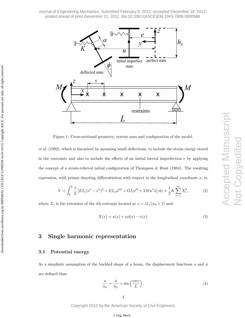
Figure 1: Cross-sectional geometry, system axes and configuration of the model.
et al. (1992), which is linearized by assuming small deflections, to include the strain energy stored
in the restraints and also to include the effects of an initial lateral imperfection e by applying
the concept of a strain-relieved initial configuration of Thompson & Hunt (1984). The resulting
expression, with primes denoting differentiation with respect to the longitudinal coordinate x, is:
V =
∫ L
0
1
2
[EIz(u
′′ − e′′)2 + EIwφ′′2 +GItφ
′2 + 2Mu′′φ]dx+
1
2K
nb∑i=1
X2i , (2)
where Xi is the extension of the ith restraint located at x = iL/(nb + 1) and:
X(x) = u(x) + aφ(x)− e(x). (3)
3 Single harmonic representation
3.1 Potential energy
As a simplistic assumption of the buckled shape of a beam, the displacement functions u and φ
are defined thus:
u
un=
φ
φn= sin
(nπxL
), (4)
4
Acc
epte
d M
anus
crip
t N
ot C
opye
dite
d
Journal of Engineering Mechanics. Submitted February 8, 2012; accepted December 18, 2012; posted ahead of print December 21, 2012. doi:10.1061/(ASCE)EM.1943-7889.0000586
Copyright 2012 by the American Society of Civil Engineers
J. Eng. Mech.
Dow
nloa
ded
from
asc
elib
rary
.org
by
IMPE
RIA
L C
OL
LE
GE
LO
ND
ON
on
01/1
0/13
. Cop
yrig
ht A
SCE
. For
per
sona
l use
onl
y; a
ll ri
ghts
res
erve
d.
Accep
ted M
anus
cript
Not Cop
yedit
ed
where un and φn are the maximum amplitudes of u and φ, respectively and are the generalized
coordinates of the system; in the current section, only critical equilibrium is of interest and so the
form of the imperfection may be ignored.
3.1.1 Node-displacing harmonics
Harmonic numbers n where n mod (nb +1) �= 0, are termed node-displacing harmonics. Owing to
the orthogonality of the sine function, upon integration, V reduces to:
V =L
4
[EIz
(nπL
)4
(un − e)2 + EIw
(nπL
)4
φ2n +GIt
(nπL
)2
φ2 − 2M(nπL
)2
unφn
](5)
+1
2K
(nb + 1
2
)(un + aφn − en)
2,
since periodic functions in the restraint energy term outside the integral are replaced by:
nb∑i=1
sin2(
inπ
nb + 1
)=
nb + 1
2, (6)
a relationship that can be proven using difference calculus (McCann, 2012).
3.1.2 Internodal harmonics
For n mod (nb+1) = 0, termed internodal harmonics, the restraint spacing s is an integer multiple
of the wavelength of the harmonic displacement function and thus there is no displacement of the
restraint nodes. This, in turn, implies that there is no strain energy stored in the restraints. The
associated total potential energy, Vi, reduces to:
Vi =L
4
[EIz
(nπL
)4
(un − e)2 + EIw
(nπL
)4
φ2n +GIt
(nπL
)2
φ2 − 2M(nπL
)2
unφn
]. (7)
3.2 Linear eigenvalue analysis
The critical moment of the system is found by solving det (H) = 0 for M , where H is the Hessian
matrix of the system, i.e. the matrix of second derivatives of V (or Vi for internodal harmonics)
with respect to the generalized coordinates; it is assumed for the linear eigenvalue analysis that
e = 0. For internodal harmonic numbers of the form q(nb+1), the nondimensional critical moment
5
Journal of Engineering Mechanics. Submitted February 8, 2012; accepted December 18, 2012; posted ahead of print December 21, 2012. doi:10.1061/(ASCE)EM.1943-7889.0000586
Copyright 2012 by the American Society of Civil Engineers
J. Eng. Mech.
Dow
nloa
ded
from
asc
elib
rary
.org
by
IMPE
RIA
L C
OL
LE
GE
LO
ND
ON
on
01/1
0/13
. Cop
yrig
ht A
SCE
. For
per
sona
l use
onl
y; a
ll ri
ghts
res
erve
d.
Accep
ted M
anus
cript
Not Cop
yedit
ed
is:
Mcr,q(nb+1) = q2(nb + 1)2√
1 +κ
q2 (nb + 1)2 , (8)
where q ∈ N and M = 2M/PEhs, PE = π2EIz/L2, κ = L2GIt/π
2EIw and Iw = Izh2s/4 for
I-sections, and hs is the depth between the shear centers of the flanges. The lowest possible
internodal critical moment of course occurs for q = 1; this value of the critical moment is known
as the threshold moment, MT , and corresponds to a beam buckling in between the restraint nodes
i.e. when the harmonic number n = nb + 1:
MT = (nb + 1)2√
1 +κ
(nb + 1)2 . (9)
For node-displacing harmonics, the nondimensional critical moment, found by solving det(H) = 0
for the expression of V in Equation (5), is given by:
Mcr,n =
√[n2 +
(nb + 1
n2
)γ
] [n2 + κ+ a2
(nb + 1
n2
)γ
]+ a
(nb + 1
n2
)γ, (10)
where γ = KL/π2PE and a = 2a/hs. The value of the critical moment for node-displacing
modes is clearly dependent upon the magnitude of the restraint stiffness, and increases as the
restraint stiffness is increased. For K = 0, i.e. an unrestrained beam, Mcr,n+1 > Mcr,n; however,
as shown in Figure 2, once a relevant transition stiffness is exceeded, Mcr,n+1 < Mcr,n, and
the mode corresponding to the higher harmonic is now in fact the critical mode. At a certain
threshold stiffness, KT , all the critical moments associated with the node-displacing modes exceed
the threshold moment, and the internodal buckling mode is the critical mode; this level of restraint
is referred to as “full bracing”. Since full bracing corresponds to a buckled shape with a harmonic
number nb+1, there can be a maximum of nb possible critical node-displacing modes for K < KT ;
however, this does not necessarily imply that the mode number nT at which the transition from
node-displacing to internodal buckling occurs is necessarily equal to nb. The nondimensional
threshold stiffness γT,n corresponding to the nth node-displacing mode is found by equating Mcr,n
with MT and solving for γ:
γT,n =
(n2
nb + 1
) [(nb + 1)2 − n2
] [(nb + 1)2 + n2 + κ
]n2(1 + a2) + κ+ 2a(nb + 1)2
√1 + κ
(nb+1)2
. (11)
6
Journal of Engineering Mechanics. Submitted February 8, 2012; accepted December 18, 2012; posted ahead of print December 21, 2012. doi:10.1061/(ASCE)EM.1943-7889.0000586
Copyright 2012 by the American Society of Civil Engineers
J. Eng. Mech.
Dow
nloa
ded
from
asc
elib
rary
.org
by
IMPE
RIA
L C
OL
LE
GE
LO
ND
ON
on
01/1
0/13
. Cop
yrig
ht A
SCE
. For
per
sona
l use
onl
y; a
ll ri
ghts
res
erve
d.
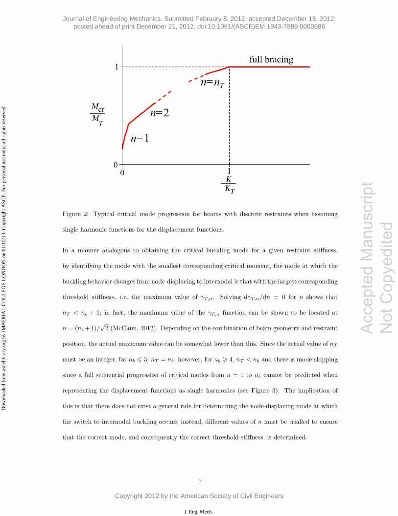
Figure 2: Typical critical mode progression for beams with discrete restraints when assuming
single harmonic functions for the displacement functions.
In a manner analogous to obtaining the critical buckling mode for a given restraint stiffness,
by identifying the mode with the smallest corresponding critical moment, the mode at which the
buckling behavior changes from node-displacing to internodal is that with the largest corresponding
threshold stiffness, i.e. the maximum value of γT,n. Solving dγT,n/dn = 0 for n shows that
nT < nb + 1; in fact, the maximum value of the γT,n function can be shown to be located at
n = (nb+1)/√2 (McCann, 2012). Depending on the combination of beam geometry and restraint
position, the actual maximum value can be somewhat lower than this. Since the actual value of nT
must be an integer, for nb � 3, nT = nb; however, for nb � 4, nT < nb and there is mode-skipping
since a full sequential progression of critical modes from n = 1 to nb cannot be predicted when
representing the displacement functions as single harmonics (see Figure 3). The implication of
this is that there does not exist a general rule for determining the node-displacing mode at which
the switch to internodal buckling occurs; instead, different values of n must be trialled to ensure
that the correct mode, and consequently the correct threshold stiffness, is determined.
7
Acc
epte
d M
anus
crip
t N
ot C
opye
dite
d
Journal of Engineering Mechanics. Submitted February 8, 2012; accepted December 18, 2012; posted ahead of print December 21, 2012. doi:10.1061/(ASCE)EM.1943-7889.0000586
Copyright 2012 by the American Society of Civil Engineers
J. Eng. Mech.
Dow
nloa
ded
from
asc
elib
rary
.org
by
IMPE
RIA
L C
OL
LE
GE
LO
ND
ON
on
01/1
0/13
. Cop
yrig
ht A
SCE
. For
per
sona
l use
onl
y; a
ll ri
ghts
res
erve
d.
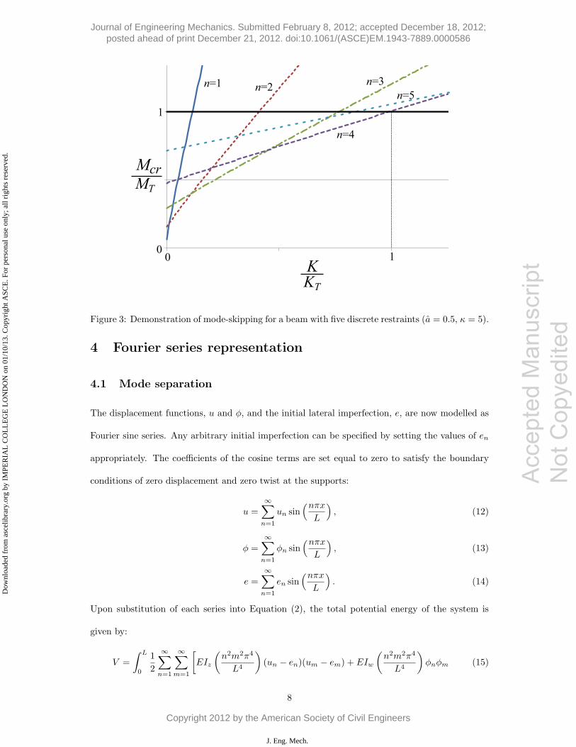
Figure 3: Demonstration of mode-skipping for a beam with five discrete restraints (a = 0.5, κ = 5).
4 Fourier series representation
4.1 Mode separation
The displacement functions, u and φ, and the initial lateral imperfection, e, are now modelled as
Fourier sine series. Any arbitrary initial imperfection can be specified by setting the values of en
appropriately. The coefficients of the cosine terms are set equal to zero to satisfy the boundary
conditions of zero displacement and zero twist at the supports:
u =
∞∑n=1
un sin(nπx
L
), (12)
φ =
∞∑n=1
φn sin(nπx
L
), (13)
e =
∞∑n=1
en sin(nπx
L
). (14)
Upon substitution of each series into Equation (2), the total potential energy of the system is
given by:
V =
∫ L
0
1
2
∞∑n=1
∞∑m=1
[EIz
(n2m2π4
L4
)(un − en)(um − em) + EIw
(n2m2π4
L4
)φnφm (15)
8
Acc
epte
d M
anus
crip
t N
ot C
opye
dite
d
Journal of Engineering Mechanics. Submitted February 8, 2012; accepted December 18, 2012; posted ahead of print December 21, 2012. doi:10.1061/(ASCE)EM.1943-7889.0000586
Copyright 2012 by the American Society of Civil Engineers
J. Eng. Mech.
Dow
nloa
ded
from
asc
elib
rary
.org
by
IMPE
RIA
L C
OL
LE
GE
LO
ND
ON
on
01/1
0/13
. Cop
yrig
ht A
SCE
. For
per
sona
l use
onl
y; a
ll ri
ghts
res
erve
d.
Accep
ted M
anus
cript
Not Cop
yedit
ed
+GIt
(nmπ2
L2
)φnφm − 2M
(n2π2
L2
)unφm
]sin
(nπxL
)sin
(mπx
L
)dx
+1
2K
nb∑i=1
∞∑n=1
∞∑m=1
(un + aφn − en)(um + aφm − em) sin
(inπ
nb + 1
)sin
(imπ
nb + 1
).
Upon evaluation of the integral, terms containing sin(nπx/L) sin(mπx/L) where n �= m vanish
due to the orthogonality of the sine function. However, this does not occur for terms outside the
integral, i.e. in the restraint strain energy term; instead, there is interaction between harmonics
with numbers n and m that obey (n±m) mod 2(nb + 1) = 0, while all other terms vanish, since:
nb∑i=1
sin
(inπ
nb + 1
)sin
(imπ
nb + 1
)= 0∀ (n±m) mod 2(nb + 1) �= 0, (16)
a relationship that can be proven using difference calculus (McCann, 2012). Thus, the following
potential energy functional is obtained:
V =L
4
∞∑n=1
[EIz
(nπL
)4
(un − en)2 + EIw
(nπL
)4
φ2n +GIt
(nπL
)2
φ2n − 2M
(nπL
)2
unφn
]
+nb + 1
4K
∞∑n=1
∑m∈Hn
δn,m(un + aφn − en)(um + aφm − em) . (17)
The sign operator function, δn,m = ±1 if (n ∓m) mod 2(nb + 1) = 0 (otherwise δn,m = 0). The
set Hn is the set of harmonic numbers m that interact in the manner described above with n, or
Hn = {m : (n±m) mod 2(nb+1) = 0,m > 0}; the modularity involved in this definition makes it
sufficient to define nb different sets of interacting harmonics, i.e. H1, H2, ..., Hnb. A crucial point
to note is that the elements of each of these sets are uniquely their own, i.e. Hi ∩Hj = ∅.
Since the coordinates separate into distinct sets, the linear system of equations represented by
the Hessian matrix H separates into distinct separate systems: a finite number nb of modes that
each relate to a particular harmonic set Hn, and an infinite number of modes relating to harmonic
numbers of the form q(nb + 1), which are not included in any set Hn. These two different classes
of deflection modes are node-displacing and internodal modes, respectively, and are analogous
to those mentioned in the previous section concerning single harmonic representations of the
displacement functions.
9
Journal of Engineering Mechanics. Submitted February 8, 2012; accepted December 18, 2012; posted ahead of print December 21, 2012. doi:10.1061/(ASCE)EM.1943-7889.0000586
Copyright 2012 by the American Society of Civil Engineers
J. Eng. Mech.
Dow
nloa
ded
from
asc
elib
rary
.org
by
IMPE
RIA
L C
OL
LE
GE
LO
ND
ON
on
01/1
0/13
. Cop
yrig
ht A
SCE
. For
per
sona
l use
onl
y; a
ll ri
ghts
res
erve
d.
Accep
ted M
anus
cript
Not Cop
yedit
ed
4.2 Deflected shape and restraint forces
For the mth node-displacing mode, a system of linear equilibrium equations in un and φn is con-
structed from ∂V/∂un = 0 and ∂V/∂φn = 0; of course, since only one particular mode is being
considered, not all harmonics are involved and so a wave number wi,j is defined whereby, if the
elements of Hi are ordered by increasing magnitude, then wi,j is the jth element of Hi. Simulta-
neous solution of the system of equations for all values of uwm,nand φwm,n
leads to the following
closed-form expressions for the harmonic amplitudes in terms of the imperfection amplitudes:
uwm,n =Bn + M2
Bnewm,n +
(−1)nMAn
w2m,nBn
S11
(nb+1)γ + S2
, (18)
φwm,n=
2
hs
[w2
m,nM
Bnewm,n
+(−1)nM(w2
m,na+ M)
w2m,nBn
S11
(nb+1)γ + S2
], (19)
where:
S1 =
∞∑i
(−1)i+1w2
m,ia+ M
Biewm,i
, (20)
S2 =
∞∑i
Ci
w2m,iBi
, (21)
An = w2m,n + κ+ aM , (22)
Bn = w4m,n + w2
m,nκ− M2, (23)
Cn = w2m,n(1 + a2) + κ+ 2aM . (24)
Now, considering the contribution of all the node-displacing deflection modes, an expression for
the force induced in the ith restraint, Fi, as a proportion of the maximum compressive force in
the beam, P = M/hs, can be obtained by substituting Equations (18) and (19) into Equation (3),
and noting that the restraints are linearly elastic, Fi = KXi, the ratio FI/P is obtained:
Fi
P=
2π2γ
L
nb∑m=1
S1
1 + (nb + 1)γS2sin
imπ
nb + 1. (25)
If the mth mode is isolated, it can be seen that the deflected positions of the restraint nodes
follow a locus of m half-sine waves. If it is assumed that the imperfection is in the form of a
single half-sine wave, as also assumed by Steel Construction Institute (2009), Al-Shawi (2001) and
10
Journal of Engineering Mechanics. Submitted February 8, 2012; accepted December 18, 2012; posted ahead of print December 21, 2012. doi:10.1061/(ASCE)EM.1943-7889.0000586
Copyright 2012 by the American Society of Civil Engineers
J. Eng. Mech.
Dow
nloa
ded
from
asc
elib
rary
.org
by
IMPE
RIA
L C
OL
LE
GE
LO
ND
ON
on
01/1
0/13
. Cop
yrig
ht A
SCE
. For
per
sona
l use
onl
y; a
ll ri
ghts
res
erve
d.
Accep
ted M
anus
cript
Not Cop
yedit
ed
Trahair et al. (2008), i.e. e = e1 sin(πx/L), then for all node-displacing modes other than the first,
the theory does not predict any pre-buckling deflections, and likewise for the internodal modes.
The expression for the restraint force ratio Fi/P becomes:
Fi
P= 2π2γ sin
iπ
nb + 1
(a+ M
1 + κ− M2
)(1
1 + (nb + 1)γS2
)e1L. (26)
4.3 Critical moment
An implicit load–deflection relationship can be inferred from Equations (18) and (19). Since
the system is linear, a state of critical equilibrium is associated with a hypothetical deflection
of arbitrary magnitude and a fixed critical load (or, in the current case, moment) and so the
equilibrium path approaches a flat critical state asymptotically. Thus, conversely, a solution for
the critical moment of the system can be obtained by determining the asymptote of a graph of un
against M ; this relationship is independent of the initial imperfection. The equation for such an
asymptote is found by setting the common denominator of Equations (18) and (19) equal to zero:
1 + γsSs,2 = 0 , (27)
where Ss,2 = (nb + 1)4S2 and γs = γ/(nb + 1)3; the lowest positive solution for M of Equation
(27) is the critical moment for the mth node-displacing mode. An equivalent finite-termed form
of the infinite series Ss,2 is given by:
Ss,2 = − 1√2r0
⎡⎣( rar+
2μ2(1 + κs)+ 1 + a2
)π sinπ
√r−/2
√r−
(cosπ
√r−/2− cosπη
)
+
(rar−
2μ2(1 + κs)− (1 + a2)
)π sinhπ
√r+/2
√r+
(coshπ
√r+/2− cosπη
)⎤⎦
+raπ
2
2μ2(1 + κs) (1− cosπη), (28)
the derivation of which can be found in McCann (2012), where:
ra = κs + 2aμ√1 + κs, (29)
r0 =√κ2s + 4μ2(1 + κs), (30)
11
Journal of Engineering Mechanics. Submitted February 8, 2012; accepted December 18, 2012; posted ahead of print December 21, 2012. doi:10.1061/(ASCE)EM.1943-7889.0000586
Copyright 2012 by the American Society of Civil Engineers
J. Eng. Mech.
Dow
nloa
ded
from
asc
elib
rary
.org
by
IMPE
RIA
L C
OL
LE
GE
LO
ND
ON
on
01/1
0/13
. Cop
yrig
ht A
SCE
. For
per
sona
l use
onl
y; a
ll ri
ghts
res
erve
d.
Accep
ted M
anus
cript
Not Cop
yedit
ed
r+ = r0 + κs, (31)
r− = r0 − κs, (32)
η = m/(nb + 1), (33)
κs = κ/(nb + 1)2. (34)
The moment factor μ = M/MT is introduced here. The nondimensional threshold stiffness relating
to the mth non-displacing mode γs,T,m is found by setting μ = 1 and solving Equation (27) for
γs:
γs,T,m =
[π2(κs + 2a
√1 + κs)
2(1 + κs)(1− cosπη)+
π sinhπ√1 + κs
(1− a
√1 + κs
)22(2 + κs)(1 + κs)3/2
(coshπ
√1 + κs − cosπη
)]−1
. (35)
4.4 Mode progression
Examination of dγs,T,m/dη provides information about the critical mode progression behavior of
the system as the restraint stiffness is increased. Upon inspection, it is found that, for a > alim,
where alim = −hsκs/4√1 + κs, the derivative is positive. This implies that if the restraints
are positioned above a point, located |alim| from the shear center on the tension side of the
cross-section, then, as the restraint stiffness is increased, there is a full sequential critical mode
progression from m = 1 up to m = nb, as shown in Figure 4. This is in contrast to the truncated
mode progression predicted by the single harmonic representation. This, in turn, implies that
the overall threshold stiffness KT of the beam corresponds to the nbth node-displacing mode and,
when correctly rescaled, can be obtained from:
γs,T =
⎡⎣ π2(κs + 2a
√1 + κs)
2(1 + κs)(1 + cos πnb+1 )
+π sinhπ
√1 + κs
(1− a
√1 + κs
)22(2 + κs)(1 + κs)3/2
(coshπ
√1 + κs + cos π
nb+1
)⎤⎦−1
. (36)
When a � alim, the derivative is not necessarily negative, but its sign now depends on the
value of η. However, at a distance only slightly below alim, the derivative is negative and thus
the threshold stiffness of the system is that corresponding to the first node-displacing mode i.e.
m = 1. Hence it can be assumed without being overly conservative that if a < alim then sequential
12
Journal of Engineering Mechanics. Submitted February 8, 2012; accepted December 18, 2012; posted ahead of print December 21, 2012. doi:10.1061/(ASCE)EM.1943-7889.0000586
Copyright 2012 by the American Society of Civil Engineers
J. Eng. Mech.
Dow
nloa
ded
from
asc
elib
rary
.org
by
IMPE
RIA
L C
OL
LE
GE
LO
ND
ON
on
01/1
0/13
. Cop
yrig
ht A
SCE
. For
per
sona
l use
onl
y; a
ll ri
ghts
res
erve
d.
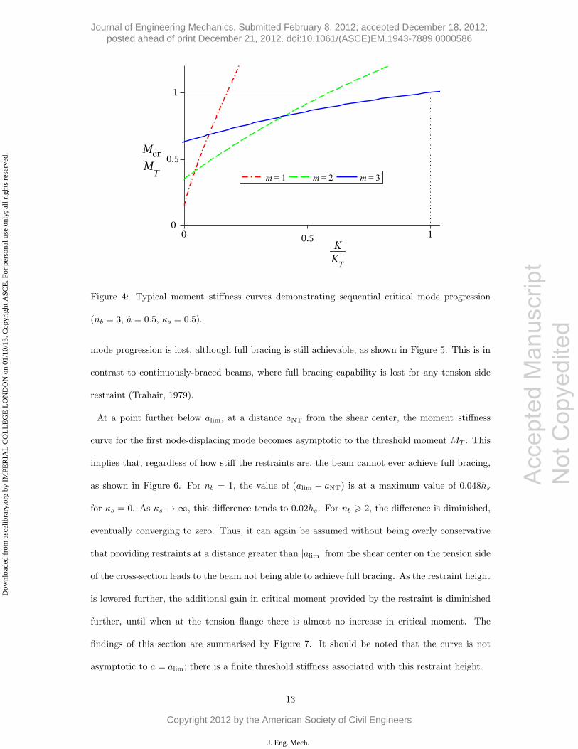
Figure 4: Typical moment–stiffness curves demonstrating sequential critical mode progression
(nb = 3, a = 0.5, κs = 0.5).
mode progression is lost, although full bracing is still achievable, as shown in Figure 5. This is in
contrast to continuously-braced beams, where full bracing capability is lost for any tension side
restraint (Trahair, 1979).
At a point further below alim, at a distance aNT from the shear center, the moment–stiffness
curve for the first node-displacing mode becomes asymptotic to the threshold moment MT . This
implies that, regardless of how stiff the restraints are, the beam cannot ever achieve full bracing,
as shown in Figure 6. For nb = 1, the value of (alim − aNT) is at a maximum value of 0.048hs
for κs = 0. As κs → ∞, this difference tends to 0.02hs. For nb � 2, the difference is diminished,
eventually converging to zero. Thus, it can again be assumed without being overly conservative
that providing restraints at a distance greater than |alim| from the shear center on the tension side
of the cross-section leads to the beam not being able to achieve full bracing. As the restraint height
is lowered further, the additional gain in critical moment provided by the restraint is diminished
further, until when at the tension flange there is almost no increase in critical moment. The
findings of this section are summarised by Figure 7. It should be noted that the curve is not
asymptotic to a = alim; there is a finite threshold stiffness associated with this restraint height.
13
Acc
epte
d M
anus
crip
t N
ot C
opye
dite
d
Journal of Engineering Mechanics. Submitted February 8, 2012; accepted December 18, 2012; posted ahead of print December 21, 2012. doi:10.1061/(ASCE)EM.1943-7889.0000586
Copyright 2012 by the American Society of Civil Engineers
J. Eng. Mech.
Dow
nloa
ded
from
asc
elib
rary
.org
by
IMPE
RIA
L C
OL
LE
GE
LO
ND
ON
on
01/1
0/13
. Cop
yrig
ht A
SCE
. For
per
sona
l use
onl
y; a
ll ri
ghts
res
erve
d.
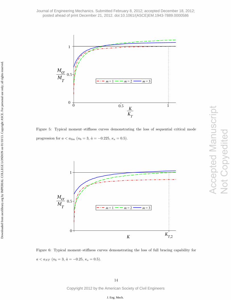
Figure 5: Typical moment–stiffness curves demonstrating the loss of sequential critical mode
progression for a < alim (nb = 3, a = −0.225, κs = 0.5).
Figure 6: Typical moment–stiffness curves demonstrating the loss of full bracing capability for
a < aNT (nb = 3, a = −0.25, κs = 0.5).
14
Acc
epte
d M
anus
crip
t N
ot C
opye
dite
d
Journal of Engineering Mechanics. Submitted February 8, 2012; accepted December 18, 2012; posted ahead of print December 21, 2012. doi:10.1061/(ASCE)EM.1943-7889.0000586
Copyright 2012 by the American Society of Civil Engineers
J. Eng. Mech.
Dow
nloa
ded
from
asc
elib
rary
.org
by
IMPE
RIA
L C
OL
LE
GE
LO
ND
ON
on
01/1
0/13
. Cop
yrig
ht A
SCE
. For
per
sona
l use
onl
y; a
ll ri
ghts
res
erve
d.
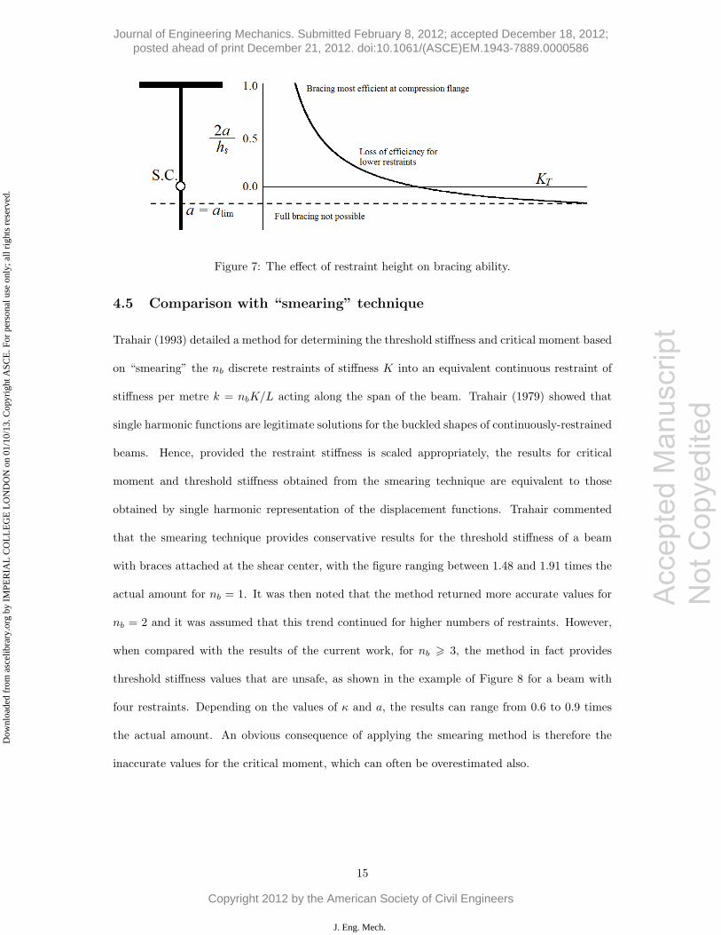
Figure 7: The effect of restraint height on bracing ability.
4.5 Comparison with “smearing” technique
Trahair (1993) detailed a method for determining the threshold stiffness and critical moment based
on “smearing” the nb discrete restraints of stiffness K into an equivalent continuous restraint of
stiffness per metre k = nbK/L acting along the span of the beam. Trahair (1979) showed that
single harmonic functions are legitimate solutions for the buckled shapes of continuously-restrained
beams. Hence, provided the restraint stiffness is scaled appropriately, the results for critical
moment and threshold stiffness obtained from the smearing technique are equivalent to those
obtained by single harmonic representation of the displacement functions. Trahair commented
that the smearing technique provides conservative results for the threshold stiffness of a beam
with braces attached at the shear center, with the figure ranging between 1.48 and 1.91 times the
actual amount for nb = 1. It was then noted that the method returned more accurate values for
nb = 2 and it was assumed that this trend continued for higher numbers of restraints. However,
when compared with the results of the current work, for nb � 3, the method in fact provides
threshold stiffness values that are unsafe, as shown in the example of Figure 8 for a beam with
four restraints. Depending on the values of κ and a, the results can range from 0.6 to 0.9 times
the actual amount. An obvious consequence of applying the smearing method is therefore the
inaccurate values for the critical moment, which can often be overestimated also.
15
Acc
epte
d M
anus
crip
t N
ot C
opye
dite
d
Journal of Engineering Mechanics. Submitted February 8, 2012; accepted December 18, 2012; posted ahead of print December 21, 2012. doi:10.1061/(ASCE)EM.1943-7889.0000586
Copyright 2012 by the American Society of Civil Engineers
J. Eng. Mech.
Dow
nloa
ded
from
asc
elib
rary
.org
by
IMPE
RIA
L C
OL
LE
GE
LO
ND
ON
on
01/1
0/13
. Cop
yrig
ht A
SCE
. For
per
sona
l use
onl
y; a
ll ri
ghts
res
erve
d.
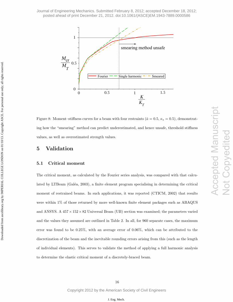
Figure 8: Moment–stiffness curves for a beam with four restraints (a = 0.5, κs = 0.5), demonstrat-
ing how the “smearing” method can predict underestimated, and hence unsafe, threshold stiffness
values, as well as overestimated strength values.
5 Validation
5.1 Critical moment
The critical moment, as calculated by the Fourier series analysis, was compared with that calcu-
lated by LTBeam (Galea, 2003), a finite element program specialising in determining the critical
moment of restrained beams. In such applications, it was reported (CTICM, 2002) that results
were within 1% of those returned by more well-known finite element packages such as ABAQUS
and ANSYS. A 457× 152× 82 Universal Beam (UB) section was examined; the parameters varied
and the values they assumed are outlined in Table 2. In all, for 960 separate cases, the maximum
error was found to be 0.25%, with an average error of 0.06%, which can be attributed to the
discretization of the beam and the inevitable rounding errors arising from this (such as the length
of individual elements). This serves to validate the method of applying a full harmonic analysis
to determine the elastic critical moment of a discretely-braced beam.
16
Acc
epte
d M
anus
crip
t N
ot C
opye
dite
d
Journal of Engineering Mechanics. Submitted February 8, 2012; accepted December 18, 2012; posted ahead of print December 21, 2012. doi:10.1061/(ASCE)EM.1943-7889.0000586
Copyright 2012 by the American Society of Civil Engineers
J. Eng. Mech.
Dow
nloa
ded
from
asc
elib
rary
.org
by
IMPE
RIA
L C
OL
LE
GE
LO
ND
ON
on
01/1
0/13
. Cop
yrig
ht A
SCE
. For
per
sona
l use
onl
y; a
ll ri
ghts
res
erve
d.
457× 152× 82
hs 446.9 mm
Iz 1185 cm4
Iw 0.591 dm6
It 89.2 cm4
Table 1: Relevant section properties of 457× 152× 82 UB section.
Parameter Values assumed
nb 1, 2, 3, 4, 5, 6
a alim, 0, 0.5, 1
L (m) 7, 8.75, 10.5, 12.25, 14
Table 2: Values assumed for the parameters in the validation using LTBeam.
5.2 Deflected shape
The deflected shape of the beam was solved for by the numerical continuation software Auto-07p
(Doedel & Oldeman, 2009). The governing differential equations of the system are obtained by
performing the calculus of variations (Hunt &Wadee (1998) provided an example of the procedure)
on the total potential energy, V . To be suitable for use byAuto, it is required to nondimensionalize
and rescale the variables: u = u/L; e = e/L; φ = φ; x = x/L. The initial imperfection was
e = (L/500) sin(πx/L). The differential equations solved by Auto were:
u′′′′ − e′′′′ +ML
EIzφ′′ + kf
(kL4
EIz
)(u+
a
Lφ− e
)= 0, (37)
φ′′′′ +ML3
EIwu′′ − L2GIt
EIwφ′′ + akf
(akL6
EIw
)(u+
a
Lφ− e
)= 0, (38)
subject to the boundary conditions u(0) = u(1) = 0, φ(0) = φ(1) = 0, u′′(0) = u′′(1) = 0,
φ′′(0) = φ′′(1) = 0, where primes denote differentiation with respect to x, rather than x. In order
to model the discrete restraint stiffness distribution, a piecewise-linear distribution kf was used,
with spikes possessing a base width of 2b and height 1/b centered at the restraint nodes, as shown
in Figure 9. This guarantees that, upon integration, the area underneath a spike is equal to unity,
17
Acc
epte
d M
anus
crip
t N
ot C
opye
dite
d
Journal of Engineering Mechanics. Submitted February 8, 2012; accepted December 18, 2012; posted ahead of print December 21, 2012. doi:10.1061/(ASCE)EM.1943-7889.0000586
Copyright 2012 by the American Society of Civil Engineers
J. Eng. Mech.
Dow
nloa
ded
from
asc
elib
rary
.org
by
IMPE
RIA
L C
OL
LE
GE
LO
ND
ON
on
01/1
0/13
. Cop
yrig
ht A
SCE
. For
per
sona
l use
onl
y; a
ll ri
ghts
res
erve
d.
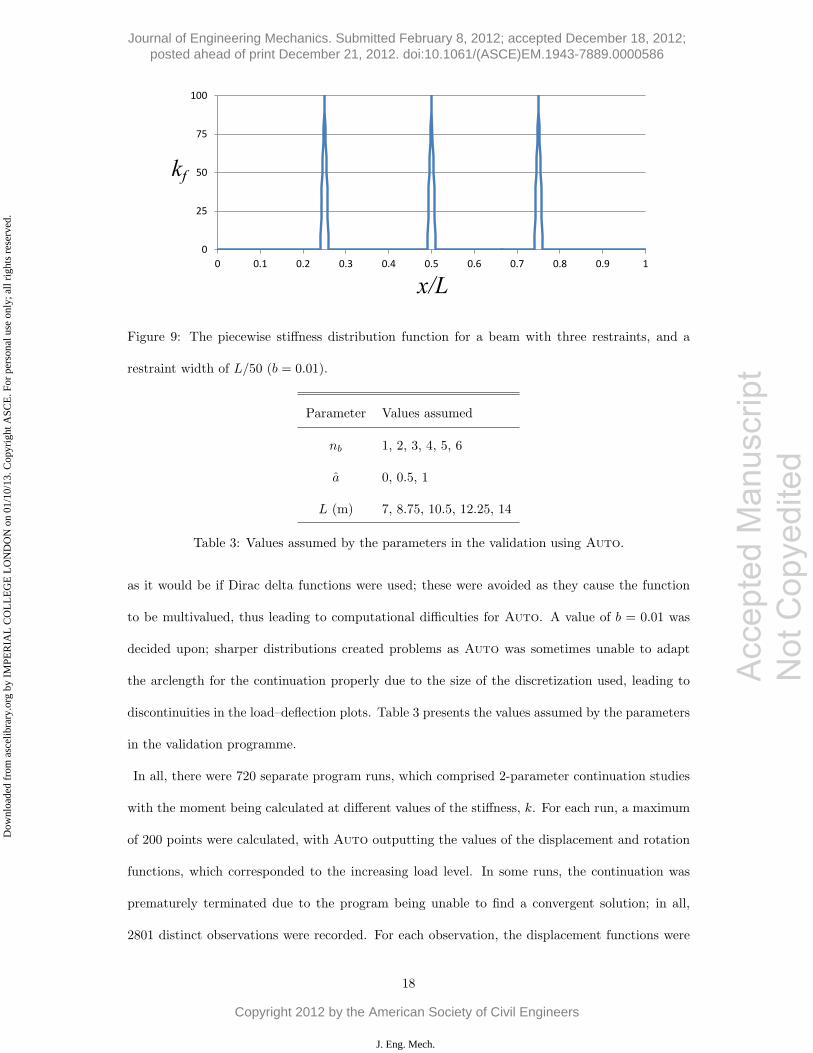
Figure 9: The piecewise stiffness distribution function for a beam with three restraints, and a
restraint width of L/50 (b = 0.01).
Parameter Values assumed
nb 1, 2, 3, 4, 5, 6
a 0, 0.5, 1
L (m) 7, 8.75, 10.5, 12.25, 14
Table 3: Values assumed by the parameters in the validation using Auto.
as it would be if Dirac delta functions were used; these were avoided as they cause the function
to be multivalued, thus leading to computational difficulties for Auto. A value of b = 0.01 was
decided upon; sharper distributions created problems as Auto was sometimes unable to adapt
the arclength for the continuation properly due to the size of the discretization used, leading to
discontinuities in the load–deflection plots. Table 3 presents the values assumed by the parameters
in the validation programme.
In all, there were 720 separate program runs, which comprised 2-parameter continuation studies
with the moment being calculated at different values of the stiffness, k. For each run, a maximum
of 200 points were calculated, with Auto outputting the values of the displacement and rotation
functions, which corresponded to the increasing load level. In some runs, the continuation was
prematurely terminated due to the program being unable to find a convergent solution; in all,
2801 distinct observations were recorded. For each observation, the displacement functions were
18
Acc
epte
d M
anus
crip
t N
ot C
opye
dite
d
Journal of Engineering Mechanics. Submitted February 8, 2012; accepted December 18, 2012; posted ahead of print December 21, 2012. doi:10.1061/(ASCE)EM.1943-7889.0000586
Copyright 2012 by the American Society of Civil Engineers
J. Eng. Mech.
Dow
nloa
ded
from
asc
elib
rary
.org
by
IMPE
RIA
L C
OL
LE
GE
LO
ND
ON
on
01/1
0/13
. Cop
yrig
ht A
SCE
. For
per
sona
l use
onl
y; a
ll ri
ghts
res
erve
d.
Value of R2 Observations Percentage of total
> 0.999 1936 69.1
0.99− 0.999 446 15.9
0.98− 0.99 81 2.9
0.96− 0.98 64 2.3
0.90− 0.96 70 2.5
< 0.90 204 7.3
Table 4: Distribution of the coefficient of determination (R2) values between the analytical and
Auto results for the lateral deflection, u.
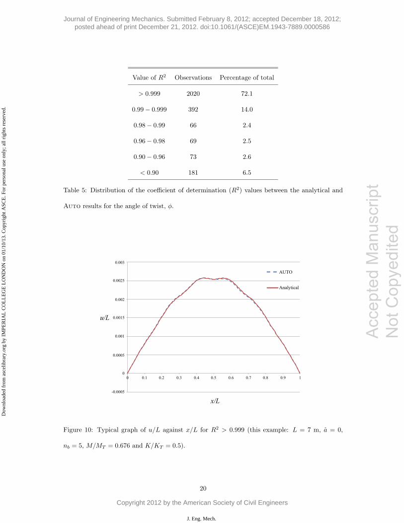
evaluated at 150 points along the span of the beam. In order to make a comparison with the
deflected shape as calculated using the analytical methods of the current work, the coefficient of
determination (R2) was calculated to provide a quantitative measure of the goodness-of-fit between
the analytical and numerical results. Tables 4 and 5 present the results of the analysis. As can
be seen, the majority of the results are almost identical, indicating the accuracy of the analytical
results. Figure 10 provides an appreciation of the level of goodness-of-fit implied by R2 > 0.999;
it can also be seen how a single harmonic function is not capable of modelling the deflected shape
accurately, due to the inflection points.
6 Concluding remarks
A Rayleigh–Ritz analysis of the lateral buckling response of a beam with an arbitrary number
of linearly elastic restraints located at regular intervals, positioned at an arbitrary point on its
cross-section, has been successfully conducted.
Representing the DOFs as single harmonic functions can be unsafe, since a full sequential mode
progression cannot be predicted. This, in turn, can lead to overestimated predictions of the
value of the critical moment and creates difficulty in determining the threshold stiffness of the
restraints accurately. Fourier series representations of the displacement functions leads to finite-
19
Acc
epte
d M
anus
crip
t N
ot C
opye
dite
d
Journal of Engineering Mechanics. Submitted February 8, 2012; accepted December 18, 2012; posted ahead of print December 21, 2012. doi:10.1061/(ASCE)EM.1943-7889.0000586
Copyright 2012 by the American Society of Civil Engineers
J. Eng. Mech.
Dow
nloa
ded
from
asc
elib
rary
.org
by
IMPE
RIA
L C
OL
LE
GE
LO
ND
ON
on
01/1
0/13
. Cop
yrig
ht A
SCE
. For
per
sona
l use
onl
y; a
ll ri
ghts
res
erve
d.
Value of R2 Observations Percentage of total
> 0.999 2020 72.1
0.99− 0.999 392 14.0
0.98− 0.99 66 2.4
0.96− 0.98 69 2.5
0.90− 0.96 73 2.6
< 0.90 181 6.5
Table 5: Distribution of the coefficient of determination (R2) values between the analytical and
Auto results for the angle of twist, φ.
Figure 10: Typical graph of u/L against x/L for R2 > 0.999 (this example: L = 7 m, a = 0,
nb = 5, M/MT = 0.676 and K/KT = 0.5).
20
Acc
epte
d M
anus
crip
t N
ot C
opye
dite
d
Journal of Engineering Mechanics. Submitted February 8, 2012; accepted December 18, 2012; posted ahead of print December 21, 2012. doi:10.1061/(ASCE)EM.1943-7889.0000586
Copyright 2012 by the American Society of Civil Engineers
J. Eng. Mech.
Dow
nloa
ded
from
asc
elib
rary
.org
by
IMPE
RIA
L C
OL
LE
GE
LO
ND
ON
on
01/1
0/13
. Cop
yrig
ht A
SCE
. For
per
sona
l use
onl
y; a
ll ri
ghts
res
erve
d.
Accep
ted M
anus
cript
Not Cop
yedit
ed
termed closed-form solutions for the threshold stiffness and the force induced in the restraints.
An implicit relationship between restraint stiffness and critical moment has also been found. An
expression has been found for the limiting distance from the shear center to the position of the
restraints that allows the beam to develop its full bracing capacity.
The results obtained from the full harmonic analysis of the beam were successfully validated by
comparing against results obtained by two independent numerical methods. Very close agreement
between the analytical and numerical results was found. Since expressions for both threshold
stiffness and restraint force have been found, an approach where restraints are designed to possess
both adequate stiffness and strength can be formulated.
There is scope for further development of the current work, in particular with regard to nonlinear
studies into the postbuckling behavior of discretely-braced beams. The current work assumes small
deflections and that the restraints can be modelled as linearly-elastic springs; with relaxation of
these assumptions localizations would be expected to occur at the restraint nodes, analogous to
the cellular postbuckling behavior as seen in nonlinear analyses of the stability of a strut on an
elastic foundation (Hunt et al., 2000) and in beams suffering from mode interaction (Wadee &
Gardner, 2012).
Acknowledgements
The work was partially funded by the UK Engineering and Physical Sciences Research Council
through project grant: EP/F022182/1, and also by the Department of Civil and Environmental
Engineering at Imperial College London.
References
Al-Shawi, F. A. N. 2001. Stiffness of restraint for steel struts with elastic end supports. Proceedings
of the Institution of Civil Engineers - Structures and Buildings, 146(2), 153–159.
21
Journal of Engineering Mechanics. Submitted February 8, 2012; accepted December 18, 2012; posted ahead of print December 21, 2012. doi:10.1061/(ASCE)EM.1943-7889.0000586
Copyright 2012 by the American Society of Civil Engineers
J. Eng. Mech.
Dow
nloa
ded
from
asc
elib
rary
.org
by
IMPE
RIA
L C
OL
LE
GE
LO
ND
ON
on
01/1
0/13
. Cop
yrig
ht A
SCE
. For
per
sona
l use
onl
y; a
ll ri
ghts
res
erve
d.
Accep
ted M
anus
cript
Not Cop
yedit
ed
CTICM. 2002 (July). LTBeam – Report on validation tests. Tech. rept. (available with LTBeam
package).
Doedel, E. J., & Oldeman, B. E. 2009. Auto-07p: Continuation and bifurcation software for ordi-
nary differential equations. Tech. rept. Department of Computer Science, Concordia University,
Montreal, Canada. Available from http://indy.cs.concordia.ca/auto.
Flint, A. R. 1951. The influence of restraint on the stability of beams. The Structural Engineer,
29(9), 235–246.
Galea, Y. 2003. Moment critique de deversement elastique de poutre flechies – Presentation
du logiciel LTBeam. Revue Construction Metallique – CTICM. available to download at:
www.steelbizfrance.com/telechargement/desclog.aspx?idrub=1&lng=2.
Hunt, G. W., & Wadee, M. A. 1998. Localization and mode interaction in sandwich structures.
Proceedings of the Royal Society A, 454, 1197–1216.
Hunt, G. W., Peletier, M. A., Champneys, A. R., Woods, P. D., Wadee, M. A., Budd, C. J., &
Lord, G. J. 2000. Cellular buckling in long structures. Nonlinear Dynamics, 21(1), 3–29.
McCann, F. 2012. Stability of beams with discrete lateral restraints. Ph.D. thesis, Imperial College
London.
Medland, I. C. 1980. Buckling of interbraced beam systems. Engineering Structures, 2(2), 90–96.
Mutton, B. R., & Trahair, N. S. 1973. Stiffness requirements for lateral bracing. Journal of the
Structural Division, ASCE, 99(10), 2167–2182.
Nethercot, D. A., & Rockey, K. C. 1971. Finite element solutions for the buckling of columns and
beams. International Journal of Mechanical Sciences, 13(11), 945–949.
Pi, Y. L., Trahair, N. S., & Rajasekaran, S. 1992. Energy equation for beam lateral buckling.
Journal of Structural Engineering, ASCE, 118(6), 1462–1479.
22
Journal of Engineering Mechanics. Submitted February 8, 2012; accepted December 18, 2012; posted ahead of print December 21, 2012. doi:10.1061/(ASCE)EM.1943-7889.0000586
Copyright 2012 by the American Society of Civil Engineers
J. Eng. Mech.
Dow
nloa
ded
from
asc
elib
rary
.org
by
IMPE
RIA
L C
OL
LE
GE
LO
ND
ON
on
01/1
0/13
. Cop
yrig
ht A
SCE
. For
per
sona
l use
onl
y; a
ll ri
ghts
res
erve
d.
Accep
ted M
anus
cript
Not Cop
yedit
ed
Steel Construction Institute. 2009. Steel building design: Design data – in accordance with Eu-
rocodes and the UK National Annexes. Ascot, UK: Steel Construction Institute. SCI Publication
P363.
Taylor, A. C., & Ojalvo, M. 1966. Torsional restraint of lateral buckling. Journal of the Structural
Division, ASCE, 92(2), 115–129.
Thompson, J. M. T., & Hunt, G. W. 1984. Elastic instability phenomena. New York: John Wiley
and Sons.
Timoshenko, S. P., & Gere, J. M. 1961. Theory of elastic stability. 2nd edn. New York: McGraw-
Hill.
Trahair, N. S. 1979. Elastic lateral buckling of continuously restrained beam columns. Pages 61–
73 of: Campbell-Allen, D., & Davis, E. H. (eds), The Profession of a Civil Engineer. Sydney
University Press.
Trahair, N. S., & Nethercot, D. A. 1984. Bracing requirements in thin-walled structures. Chap. 3,
pages 93–130 of: Rhodes, J., & Walker, A. C. (eds), Developments in Thin-Walled Structures
Volume 2. London: Elsevier Applied Science Publishers.
Trahair, N. S., Bradford, M. A., Nethercot, D. A., & Gardner, L. 2008. The Behaviour and Design
of Steel Structures to EC3. 4th edn. London: Taylor and Francis.
Trahair, N.S. 1993. Flexural-torsional buckling of structures. London: E & FN SPON.
Vlasov, V. Z. 1961. Thin-walled elastic beams. 2nd edn. Jerusalem, Israel: Israel Program for
Scientific Translations.
Wadee, M. A., & Gardner, L. 2012. Cellular buckling from mode interaction in I-beams under
uniform bending. Proceedings of the Royal Society A, 468(2137), 245–268.
Winter, G. 1960. Lateral bracing of columns and beams. ASCE Transactions, 125, 807–826.
23
Journal of Engineering Mechanics. Submitted February 8, 2012; accepted December 18, 2012; posted ahead of print December 21, 2012. doi:10.1061/(ASCE)EM.1943-7889.0000586
Copyright 2012 by the American Society of Civil Engineers
J. Eng. Mech.
Dow
nloa
ded
from
asc
elib
rary
.org
by
IMPE
RIA
L C
OL
LE
GE
LO
ND
ON
on
01/1
0/13
. Cop
yrig
ht A
SCE
. For
per
sona
l use
onl
y; a
ll ri
ghts
res
erve
d.
Accep
ted M
anus
cript
Not Cop
yedit
ed
Yura, J. A. 2001. Fundamentals of beam bracing. Engineering Journal, American Institute of
Steel Construction, 38(1), 11–26.
Zuk, W. 1956. Lateral bracing forces on beams and columns. Journal of the Engineering Mechanics
Division, ASCE, 82(3), 1032–1 – 1032–16.
24
Journal of Engineering Mechanics. Submitted February 8, 2012; accepted December 18, 2012; posted ahead of print December 21, 2012. doi:10.1061/(ASCE)EM.1943-7889.0000586
Copyright 2012 by the American Society of Civil Engineers
J. Eng. Mech.
Dow
nloa
ded
from
asc
elib
rary
.org
by
IMPE
RIA
L C
OL
LE
GE
LO
ND
ON
on
01/1
0/13
. Cop
yrig
ht A
SCE
. For
per
sona
l use
onl
y; a
ll ri
ghts
res
erve
d.