modeling of different bracing configurations in multi-storey concentrically braced frames using a...
TRANSCRIPT
Journal of Constructional Steel Research 101 (2014) 426–436
Contents lists available at ScienceDirect
Journal of Constructional Steel Research
Modeling of different bracing configurations in multi-storeyconcentrically braced frames using a fiber-beam based approach
K.K. Wijesundara a, R. Nascimbene b,⁎, G.A. Rassati c
a SAITM, Faculty of Engineering Malabe, Sri Lankab European Centre for Training and Research in Earthquake Engineering (EUCENTRE), Via Ferrata 1, 27100 Pavia, Italyc Department of Civil and Architectural Engineering, University of Cincinnati, Cincinnati, OH, USA
⁎ Corresponding author.E-mail address: [email protected] (R. N
http://dx.doi.org/10.1016/j.jcsr.2014.06.0090143-974X/© 2014 Elsevier Ltd. All rights reserved.
a b s t r a c t
a r t i c l e i n f oArticle history:Received 17 August 2013Accepted 16 June 2014Available online 5 July 2014
Keywords:Inelastic force-based beam-column elementsGlobal bucklingSlendernessLocal buckling
This study presents a modeling approach for concentrically braced frames to be used in multi-storey buildings.The model for an inelastic beam-column brace consists of two inelastic force-based beam-column elements,each of which having five integration points and a discretized fiber section. The hysteretic response of suchelements can be derived by integration of uniaxial stress-strain relations.To capture the effects of gusset end restraint, in addition to the two inelastic beam-column elements, this studyuses an additional inelastic force-based beam-column element of length 2 t (where t is the thickness ofthe gusset plate) at each end of the brace. This study presents the correlation of the axial force–axial displacementand the axial force–lateral displacement responses obtained from the brace model with the availableexperimental results.Based on the comparison of numerical hysteretic responses with the experimental results, it can be concludedthat the brace model which includes two additional force-based beam-column elements at the ends ofthe brace can capture the hysteretic responses of axial force–axial displacement and axial force–lateraldisplacement more accurately. Finally, this study sets the limits of slenderness and the width-to-thicknessratio in which inelastic beam-column brace model can predict the hysteretic responses of a brace memberwith adequately accuracy.
© 2014 Elsevier Ltd. All rights reserved.
1. Introduction
Concentrically braced frames are commonly used for seismic designin high seismic areas due to their high stiffness and strengthwhen com-pared to moment resisting frames (Nascimbene et al. [23]). In currentdesign practice, CBFs are designed and detailed to dissipate energythrough brace yielding in tension and inelastic buckling in compressionunder the strong shaking of an earthquake. Therefore, the inelasticbehavior of braces has been extensively studied in the past by a num-ber of experimental programs (Black et al. [3], Lee and Goel [21],Archambault et al. [2], Walpole [35], Shaback [28]). These studieshave identified the main influencing parameters for the hystereticresponse of a bracing member as slenderness, which is a functionof end conditions and section shapes, and width-to-thickness ratio,which governs the local buckling of a brace.
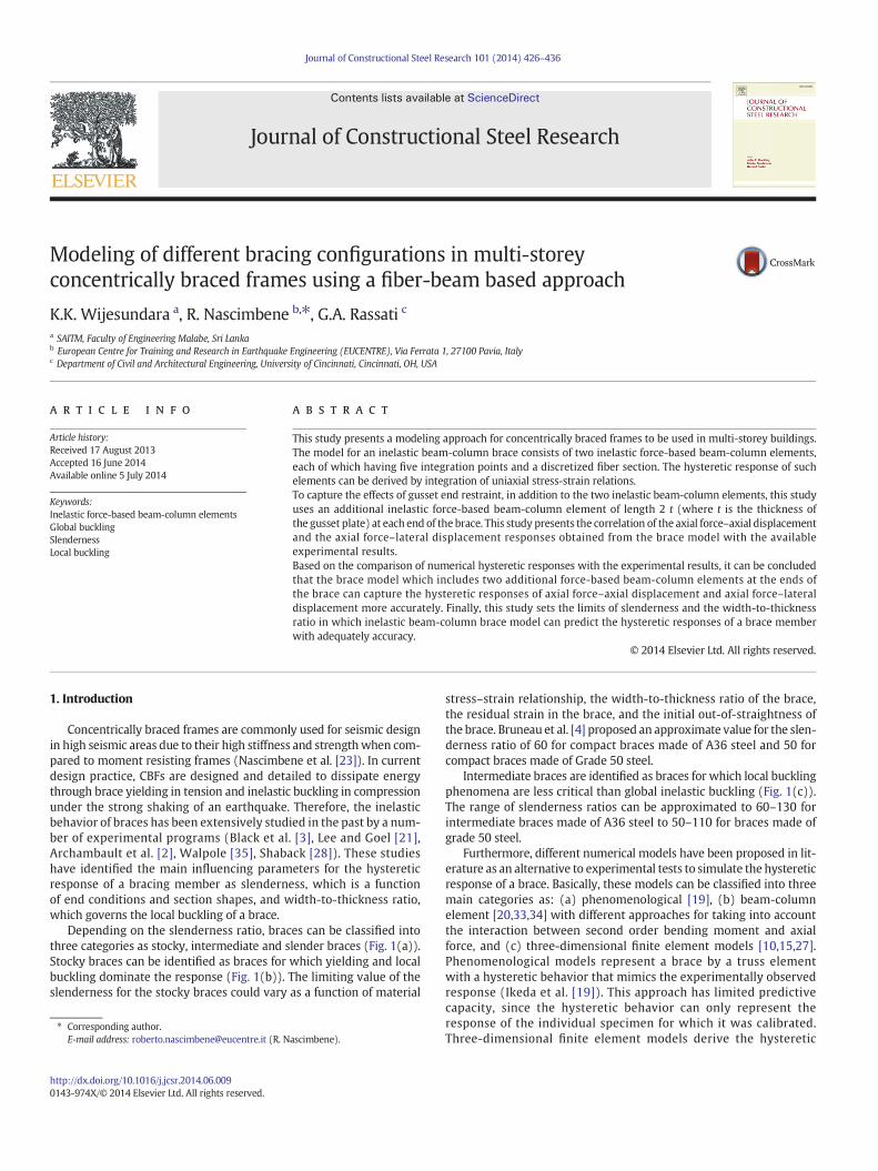
Depending on the slenderness ratio, braces can be classified intothree categories as stocky, intermediate and slender braces (Fig. 1(a)).Stocky braces can be identified as braces for which yielding and localbuckling dominate the response (Fig. 1(b)). The limiting value of theslenderness for the stocky braces could vary as a function of material
ascimbene).
stress–strain relationship, the width-to-thickness ratio of the brace,the residual strain in the brace, and the initial out-of-straightness ofthe brace. Bruneau et al. [4] proposed an approximate value for the slen-derness ratio of 60 for compact braces made of A36 steel and 50 forcompact braces made of Grade 50 steel.
Intermediate braces are identified as braces for which local bucklingphenomena are less critical than global inelastic buckling (Fig. 1(c)).The range of slenderness ratios can be approximated to 60–130 forintermediate braces made of A36 steel to 50–110 for braces made ofgrade 50 steel.
Furthermore, different numerical models have been proposed in lit-erature as an alternative to experimental tests to simulate the hystereticresponse of a brace. Basically, these models can be classified into threemain categories as: (a) phenomenological [19], (b) beam-columnelement [20,33,34] with different approaches for taking into accountthe interaction between second order bending moment and axialforce, and (c) three-dimensional finite element models [10,15,27].Phenomenological models represent a brace by a truss elementwith a hysteretic behavior that mimics the experimentally observedresponse (Ikeda et al. [19]). This approach has limited predictivecapacity, since the hysteretic behavior can only represent theresponse of the individual specimen for which it was calibrated.Three-dimensional finite element models derive the hysteretic
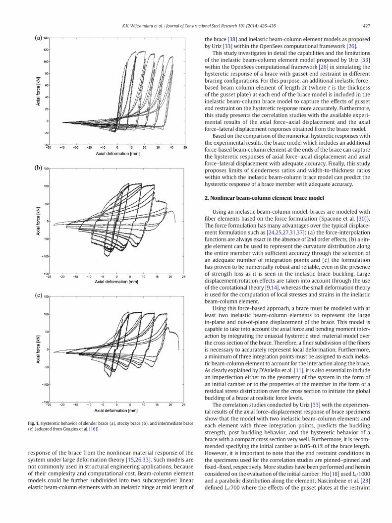
Fig. 1. Hysteretic behavior of slender brace (a), stocky brace (b), and intermediate brace(c) (adopted from Goggins et al. [16]).
427K.K. Wijesundara et al. / Journal of Constructional Steel Research 101 (2014) 426–436
response of the brace from the nonlinear material response of thesystem under large deformation theory [15,26,33]. Such models arenot commonly used in structural engineering applications, becauseof their complexity and computational cost. Beam-column elementmodels could be further subdivided into two subcategories: linearelastic beam-column elements with an inelastic hinge at mid length of
the brace [38] and inelastic beam-column element models as proposedby Uriz [33] within the OpenSees computational framework [26].
This study investigates in detail the capabilities and the limitationsof the inelastic beam-column element model proposed by Uriz [33]within the OpenSees computational framework [26] in simulating thehysteretic response of a brace with gusset end restraint in differentbracing configurations. For this purpose, an additional inelastic force-based beam-column element of length 2t (where t is the thicknessof the gusset plate) at each end of the brace model is included in theinelastic beam-column brace model to capture the effects of gussetend restraint on the hysteretic response more accurately. Furthermore,this study presents the correlation studies with the available experi-mental results of the axial force–axial displacement and the axialforce–lateral displacement responses obtained from the brace model.
Based on the comparison of the numerical hysteretic responses withthe experimental results, the brace model which includes an additionalforce-based beam-column element at the ends of the brace can capturethe hysteretic responses of axial force–axial displacement and axialforce–lateral displacement with adequate accuracy. Finally, this studyproposes limits of slenderness ratios and width-to-thickness ratioswithin which the inelastic beam-column brace model can predict thehysteretic response of a brace member with adequate accuracy.
2. Nonlinear beam-column element brace model
Using an inelastic beam-column model, braces are modeled withfiber elements based on the force formulation (Spacone et al. [30]).The force formulation has many advantages over the typical displace-ment formulation such as [24,25,27,31,37]: (a) the force-interpolationfunctions are always exact in the absence of 2nd order effects, (b) a sin-gle element can be used to represent the curvature distribution alongthe entire member with sufficient accuracy through the selection ofan adequate number of integration points and (c) the formulationhas proven to be numerically robust and reliable, even in the presenceof strength loss as it is seen in the inelastic brace buckling. Largedisplacement/rotation effects are taken into account through the useof the corotational theory [9,14], whereas the small deformation theoryis used for the computation of local stresses and strains in the inelasticbeam-column element.
Using this force-based approach, a brace must be modeled with atleast two inelastic beam-column elements to represent the largein-plane and out-of-plane displacement of the brace. This model iscapable to take into account the axial force and bending moment inter-action by integrating the uniaxial hysteretic steel material model overthe cross section of the brace. Therefore, a finer subdivision of the fibersis necessary to accurately represent local deformation. Furthermore,a minimum of three integration points must be assigned to each inelas-tic beam-column element to account for the interaction along the brace.As clearly explained by D'Aniello et al. [11], it is also essential to includean imperfection either to the geometry of the system in the form ofan initial camber or to the properties of the member in the form of aresidual stress distribution over the cross section to initiate the globalbuckling of a brace at realistic force levels.
The correlation studies conducted by Uriz [33] with the experimen-tal results of the axial force–displacement response of brace specimensshow that the model with two inelastic beam-column elements andeach element with three integration points, predicts the bucklingstrength, post buckling behavior, and the hysteretic behavior of abrace with a compact cross section very well. Furthermore, it is recom-mended specifying the initial camber as 0.05–0.1% of the brace length.However, it is important to note that the end restraint conditions inthe specimens used for the correlation studies are pinned–pinned andfixed–fixed, respectively. More studies have been performed and hereinconsidered on the evaluation of the initial camber: Hu [18] used Ls/1000and a parabolic distribution along the element; Nascimbene et al. [23]defined Ls/700 where the effects of the gusset plates at the restraint

Table 1Main characteristics of the specimens: 1 is from Shaback [28], 2 from Black et al. [3], 3 from Lee and Goel [21], 4 from Archambault et al. [2] and 5 fromWalpole [35] (GE stands for gusset plate; S, NS, HUS stands for symmetrical displacement history,nearly symmetrical displacement shape, and highly unsymmetrical displacement history respectively; (c/t)Limit is defined as specified in EC3 [8] for the section class 1 as (c/t)Limit = 33(235/Fy)0.5).
Study Test ID Size Buckling L (m) Ls (m) Ls/L KL/r (c/t)/(c/t) Limit A (mm2) Fy (MPa) E (MPa) Nb (kW) λ δy (mm) End restraint Cross section Dis. history
1 IB 127 × 127 × 8.0 Out 3.401 3.050 0.90 53.9 0.54 3620 421 191 1156 0.805 7.4 GE (3) Class 1 NS2A 152 × 152 × 8.0 Out 3.995 3.600 0.90 53.3 0.68 4430 442 202 1507 0.794 8.6 GE (3) Class 1 NS2B 152 × 152 × 9.5 Out 3.989 3.600 0.90 52.4 0.56 5210 442 196 1721 0.792 8.9 GE (3) Class 1 NS3A 127 × 127 × 6.4 Out 4.403 4.050 0.92 64.8 0.72 2960 461 196 864 1.000 10.2 GE (3) Class 1 NS3B 127 × 127 × 8.0 Out 4.398 4.050 0.92 65.8 0.54 3620 421 191 952 0.983 9.6 GE (3) Class 1 NS3C 127 × 127 × 9.5 Out 4.382 4.050 0.92 61.6 0.46 4240 461 202 1011 0.937 9.9 GE (3) Class 1 NS4A 152 × 152 × 8.0 Out 4.897 4.500 0.92 63.5 0.68 4430 442 202 1381 0.945 10.6 GE (3) Class 1 NS4B 152 × 152 × 9.5 Out 4.882 4.500 0.92 59.7 0.56 5210 442 196 1435 0.902 10.9 GE (3) Class 1 NS
2 St rut 17 101 × 101 × 6.4 Out 3.050 2.638 0.86 80.0 0.51 2316 394 200 547 1.122 5.2 Pin-Pin Class 1 SSt rut 18 101 × 101 × 13 Out 2.760 2.348 0.85 80.0 0.26 4516 566 200 1210 1.322 6.6 Pin-Pin Class 1 sSt rut 2 2 101 × 101 × 13 Out 3.950 3.744 0.95 80.0 0.26 4516 566 200 1069 1.327 10.6 Fix-Pin Class 1 s
3 1 127 × 127 × 4.8 Out 3.429 2.946 0.86 58.0 0.96 2271 426 200 801 0.852 6.3 GE (1) Class 1 HUS2 127 × 127 × 4.8 Out 3.429 3.200 0.93 35.0 0.96 2271 430 200 881 0.517 6.9 GE (1) Class 1 HUS4 101 × 101 × 3.2 Out 3.480 3.099 0.89 43.0 1.11 1226 400 200 423 0.612 6.2 GE (1) Non Class 1 HUS5 101 × 101 × 6.4 Out 3.454 3.099 0.90 77.0 0.58 2316 510 200 690 1.238 7.9 GE (1) Class 1 HUS6 101 × 101 × 6.4 Out 3.480 3.300 0.95 45.0 0.58 2316 510 200 939 0.723 8.4 Fix-Fix (1) Class 1 HUS7 101 × 101 × 6.4 Out 3.480 3.300 0.95 45.0 0.58 2316 510 200 952 0.723 8.4 Fix-Fix (1) Class 1 HUS
4 SI-A 127 × 76 × 4.8 Out 4.614 4.009 0.87 92.7 0.92 1790 395 198 475 1.319 8.0 GE (2) Class 1 SS'l-B 127 × 76 × 4.8 Out 4.614 4.009 0.87 93.0 0.92 1790 395 198 405 1.323 8.0 GE (2) Class 1 SSl-QA 127 × 76 × 4.8 Out 4.614 4.009 0.87 92.8 0.92 1790 395 198 459 1.320 8.0 GE (2) Class 1 SSl-QB 127 × 76 × 4.8 Out 4.614 4.009 0.87 93.2 0.92 1790 395 198 453 1.326 8.0 GE (2) Class 1 SS2-A 102 × 76 × 4.8 Out 4.614 4.089 0.89 108.0 0.70 1550 381 185 268 1.561 8.4 GE (2) Class 1 sS2-B 102 × 76 × 4.8 Out 4.614 4.089 0.89 108.4 0.70 1550 381 185 325 1.567 8.4 GE (2) Class 1 sS3-A 76 × 76 × 4.8 Out 4.619 4.179 0.90 143.5 0.50 1310 389 187 143 2.084 8.7 GE (2) Class 1 sS3-B 76 × 76 × 4.8 Out 4.619 4.179 0.90 141.8 0.50 1310 389 187 165 2.060 8.7 GE (2) Class 1 sS4-A 127 × 64 × 6.4 Out 4.614 4.049 0.88 97.7 0.66 1670 385 194 295 1.385 8.0 GE (2) Class 1 sS4-B 127 × 64 × 6.4 Out 4.614 4.049 0.88 97.7 0.66 1670 385 194 325 1.385 8.0 GE (2) Class 1 sS4-QA 127 × 64 × 4.8 Out 4.614 4.049 0.88 97.6 0.89 1670 372 188 258 1.381 8.0 GE (2) Class 1 sS4-QB 127 × 64 × 4.8 Out 4.614 4.049 0.88 97.5 0.89 1670 372 188 343 1.379 8.0 GE (2) Class 1 sS5-A 102 × 76 × 4.8 Out 4.614 4.089 0.89 112.5 0.74 1990 422 183 313 1.719 9.4 GE (2) Class 1 sS5-B 102 × 76 × 4.8 Out 4.614 4.089 0.89 113.4 0.74 1990 422 183 373 1.733 9.4 GE (2) Class 1 s
5 RHS'l 150 × 100 × 6.0 Out 2.704 2.064 0.76 80.0 0.93 2730 449 200 945 1.207 4.6 Pin-Pin Class 1 sRHS2 150 × 100 × 6.0 Out 2.028 1.388 0.68 60.0 0.93 2730 449 200 1050 0.905 3.1 Pin-Pin Class 1 sRHS3 150 × 100 × 6.0 Out 2.704 2.704 1.00 40.0 0.93 2730 449 200 1032 0.603 6.1 Fix-Fix Class 1 s
428K.K.W
ijesundaraetal./JournalofConstructionalSteelResearch
101(2014)
426–436
Z
X
Gusset plate elements
Brace elements
(a) (b) (c)
Fig. 2. Cross fiber section of (a) brace, (b) gusset plate and (c) single brace specimen using equivalent brace model with gusset end restraint condition.
429K.K. Wijesundara et al. / Journal of Constructional Steel Research 101 (2014) 426–436
end have been taken into account; Wijesundara et al. [36] calibrated asinusoidal deformed shape using Ls/350. The initial camber selected inthis paper has been calibrated comparing the numerical model withfive experimental programmes from Shaback [28], Black et al. [3],Lee and Goel [21], Archambault et al. [2] and Walpole [35].
3. Correlation studies with experimental results:single brace specimens
The parametric study conducted by Uriz et. al. [33,34] illustrates thecapabilities and the limitations of an inelastic beam-column elementapplied to single brace members with two main restraint conditions:pinned–pinned and fixed–fixed. However, actual end restraint conditionsof a single brace in a CBF are realistically in between the pinned–pinnedand fixed–fixed end conditions.
This part of the correlation study performed by the authorsillustrates how to incorporate the gusset end restraint into thenonlinearbeam-column brace model to simulate the response of a single bracespecimen connected to end-gusset plates with an unrestrained spaceprovided in the gusset plate to make the brace prone to buckling inthe out-of-plane direction. This will illustrate the effect of more realisticgusset end restraints onto the brace hysteretic response.
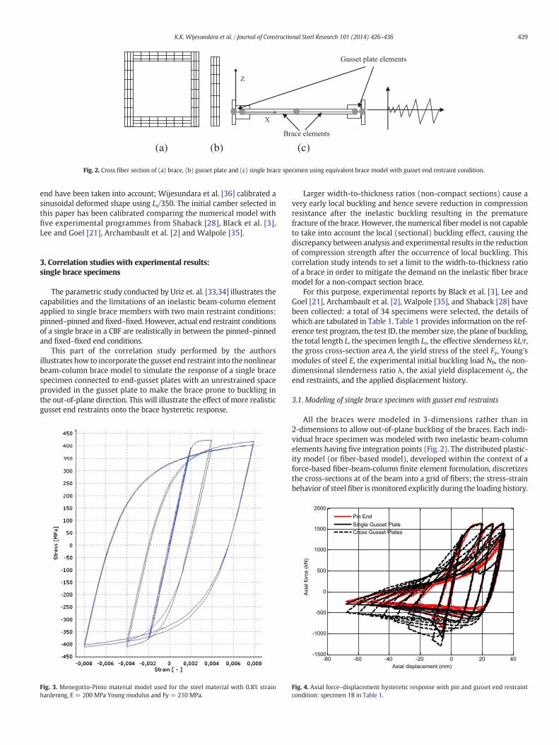
Fig. 3. Menegotto-Pinto material model used for the steel material with 0.8% strainhardening, E = 200 MPa Young modulus and Fy = 210 MPa.
Larger width-to-thickness ratios (non-compact sections) cause avery early local buckling and hence severe reduction in compressionresistance after the inelastic buckling resulting in the prematurefracture of the brace. However, the numerical fiber model is not capableto take into account the local (sectional) buckling effect, causing thediscrepancy between analysis and experimental results in the reductionof compression strength after the occurrence of local buckling. Thiscorrelation study intends to set a limit to the width-to-thickness ratioof a brace in order to mitigate the demand on the inelastic fiber bracemodel for a non-compact section brace.
For this purpose, experimental reports by Black et al. [3], Lee andGoel [21], Archambault et al. [2], Walpole [35], and Shaback [28] havebeen collected: a total of 34 specimens were selected, the details ofwhich are tabulated in Table 1. Table 1 provides information on the ref-erence test program, the test ID, themember size, the plane of buckling,the total length L, the specimen length Ls, the effective slenderness kL/r,the gross cross-section area A, the yield stress of the steel Fy, Young'smodules of steel E, the experimental initial buckling load Nb, the non-dimensional slenderness ratio λ, the axial yield displacement δy, theend restraints, and the applied displacement history.
3.1. Modeling of single brace specimen with gusset end restraints
All the braces were modeled in 3-dimensions rather than in2-dimensions to allow out-of-plane buckling of the braces. Each indi-vidual brace specimen was modeled with two inelastic beam-columnelements having five integration points (Fig. 2). The distributed plastic-ity model (or fiber-based model), developed within the context of aforce-based fiber-beam-column finite element formulation, discretizesthe cross-sections at of the beam into a grid of fibers; the stress-strainbehavior of steel fiber ismonitored explicitly during the loading history.
-80 -60 -40 -20 0 20 40-1500
-1000
-500
0
500
1000
1500
2000
Axial displacement (mm)
Axi
al fo
rce
(kN
)
Pin EndSingle Gusset PlateCross Gusset Plates
Fig. 4. Axial force–displacement hysteretic response with pin and gusset end restraintcondition: specimen 1B in Table 1.
-100 -80 -60 -40 -20 0 20 40-2000
-1500
-1000
-500
0
500
1000
1500
2000
Axial displacement (mm)
Axi
al fo
rce
(kN
)
OpenSees-L/1000
Exp
-100 -80 -60 -40 -20 0 20 40-2000
-1500
-1000
-500
0
500
1000
1500
2000
Axial displacement (mm)
Axi
al fo
rce
(kN
)
OpenSees-L/700
Exp
-100 -80 -60 -40 -20 0 20 40-2000
-1500
-1000
-500
0
500
1000
1500
2000
Axial displacement (mm)
Axi
al fo
rce
(kN
)
OpenSees-L/500
Exp
-100 -80 -60 -40 -20 0 20 40-2000
-1500
-1000
-500
0
500
1000
1500
2000
Axial displacement (mm)
Axi
al fo
rce
(kN
)
OpenSees-L/200
Exp
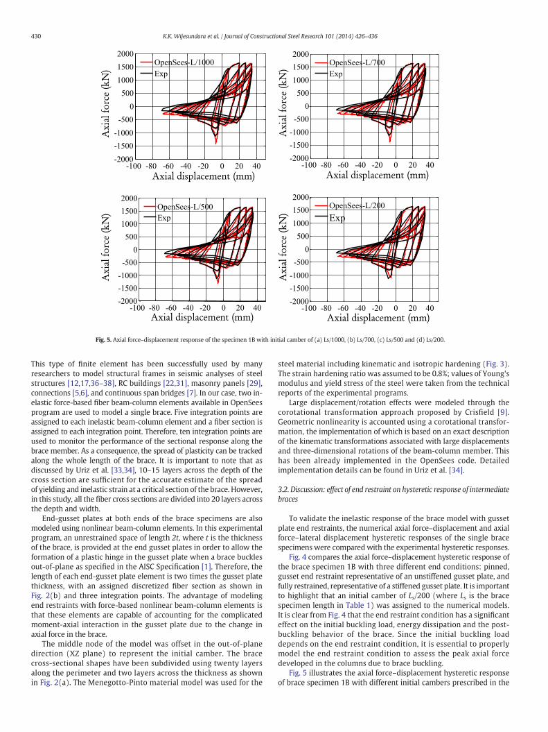
Fig. 5. Axial force–displacement response of the specimen 1B with initial camber of (a) Ls/1000, (b) Ls/700, (c) Ls/500 and (d) Ls/200.
430 K.K. Wijesundara et al. / Journal of Constructional Steel Research 101 (2014) 426–436
This type of finite element has been successfully used by manyresearchers to model structural frames in seismic analyses of steelstructures [12,17,36–38], RC buildings [22,31], masonry panels [29],connections [5,6], and continuous span bridges [7]. In our case, two in-elastic force-based fiber beam-column elements available in OpenSeesprogram are used to model a single brace. Five integration points areassigned to each inelastic beam-column element and a fiber section isassigned to each integration point. Therefore, ten integration points areused to monitor the performance of the sectional response along thebrace member. As a consequence, the spread of plasticity can be trackedalong the whole length of the brace. It is important to note that asdiscussed by Uriz et al. [33,34], 10–15 layers across the depth of thecross section are sufficient for the accurate estimate of the spreadof yielding and inelastic strain at a critical section of the brace. However,in this study, all the fiber cross sections are divided into 20 layers acrossthe depth and width.
End-gusset plates at both ends of the brace specimens are alsomodeled using nonlinear beam-column elements. In this experimentalprogram, an unrestrained space of length 2t, where t is the thicknessof the brace, is provided at the end gusset plates in order to allow theformation of a plastic hinge in the gusset plate when a brace bucklesout-of-plane as specified in the AISC Specification [1]. Therefore, thelength of each end-gusset plate element is two times the gusset platethickness, with an assigned discretized fiber section as shown inFig. 2(b) and three integration points. The advantage of modelingend restraints with force-based nonlinear beam-column elements isthat these elements are capable of accounting for the complicatedmoment-axial interaction in the gusset plate due to the change inaxial force in the brace.
The middle node of the model was offset in the out-of-planedirection (XZ plane) to represent the initial camber. The bracecross-sectional shapes have been subdivided using twenty layersalong the perimeter and two layers across the thickness as shownin Fig. 2(a). The Menegotto-Pinto material model was used for the
steel material including kinematic and isotropic hardening (Fig. 3).The strain hardening ratio was assumed to be 0.8%; values of Young'smodulus and yield stress of the steel were taken from the technicalreports of the experimental programs.
Large displacement/rotation effects were modeled through thecorotational transformation approach proposed by Crisfield [9].Geometric nonlinearity is accounted using a corotational transfor-mation, the implementation of which is based on an exact descriptionof the kinematic transformations associated with large displacementsand three-dimensional rotations of the beam-column member. Thishas been already implemented in the OpenSees code. Detailedimplementation details can be found in Uriz et al. [34].
3.2. Discussion: effect of end restraint on hysteretic response of intermediatebraces
To validate the inelastic response of the brace model with gussetplate end restraints, the numerical axial force–displacement and axialforce–lateral displacement hysteretic responses of the single bracespecimens were compared with the experimental hysteretic responses.
Fig. 4 compares the axial force–displacement hysteretic response ofthe brace specimen 1B with three different end conditions: pinned,gusset end restraint representative of an unstiffened gusset plate, andfully restrained, representative of a stiffened gusset plate. It is importantto highlight that an initial camber of Ls/200 (where Ls is the bracespecimen length in Table 1) was assigned to the numerical models.It is clear from Fig. 4 that the end restraint condition has a significanteffect on the initial buckling load, energy dissipation and the post-buckling behavior of the brace. Since the initial buckling loaddepends on the end restraint condition, it is essential to properlymodel the end restraint condition to assess the peak axial forcedeveloped in the columns due to brace buckling.
Fig. 5 illustrates the axial force–displacement hysteretic responseof brace specimen 1B with different initial cambers prescribed in the
(a)
(b)
-80 -70 -60 -50 -40 -30 -20 -10 0 10 20 30 40-1000
-500
0
500
1000
1500
Axial displacement (mm)
Ax
ial
forc
e(k
N)
OpenSeesExp
-80 -70 -60 -50 -40 -30 -20 -10 0 10 20 30 40-1000
-500
0
500
1000
1500
2000
Axial displacement (mm)
Ax
ial
forc
e(k
N)
OpenSeesExp
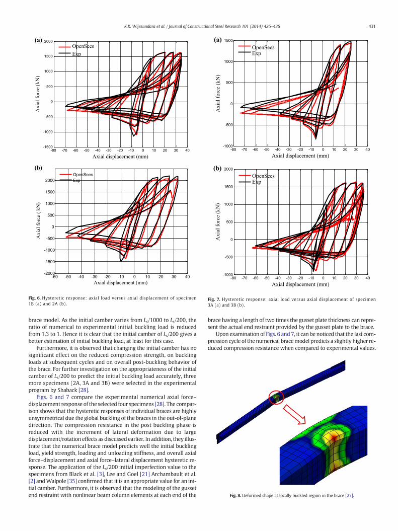
Fig. 7. Hysteretic response: axial load versus axial displacement of specimen3A (a) and 3B (b).
Fig. 8. Deformed shape at locally buckled region in the brace [27].
(a)
(b)
-80 -70 -60 -50 -40 -30 -20 -10 0 10 20 30 40-1500
-1000
-500
0
500
1000
1500
2000
Axial displacement (mm)
Ax
ial
forc
e (k
N)
OpenSees
Exp
-60 -50 -40 -30 -20 -10 0 10 20 30 40-2000
-1500
-1000
-500
0
500
1000
1500
2000
Axial displacement (mm)
Ax
ial
forc
e (
kN
)
OpenSeesExp
Fig. 6. Hysteretic response: axial load versus axial displacement of specimen1B (a) and 2A (b).
431K.K. Wijesundara et al. / Journal of Constructional Steel Research 101 (2014) 426–436
brace model. As the initial camber varies from Ls/1000 to Ls/200, theratio of numerical to experimental initial buckling load is reducedfrom 1.3 to 1. Hence it is clear that the initial camber of Ls/200 gives abetter estimation of initial buckling load, at least for this case.
Furthermore, it is observed that changing the initial camber has nosignificant effect on the reduced compression strength, on bucklingloads at subsequent cycles and on overall post-buckling behavior ofthe brace. For further investigation on the appropriateness of the initialcamber of Ls/200 to predict the initial buckling load accurately, threemore specimens (2A, 3A and 3B) were selected in the experimentalprogram by Shaback [28].
Figs. 6 and 7 compare the experimental numerical axial force–displacement response of the selected four specimens [28]. The compar-ison shows that the hysteretic responses of individual braces are highlyunsymmetrical due the global buckling of the braces in the out-of-planedirection. The compression resistance in the post buckling phase isreduced with the increment of lateral deformation due to largedisplacement/rotation effects as discussed earlier. In addition, they illus-trate that the numerical brace model predicts well the initial bucklingload, yield strength, loading and unloading stiffness, and overall axialforce–displacement and axial force–lateral displacement hysteretic re-sponse. The application of the Ls/200 initial imperfection value to thespecimens from Black et al. [3], Lee and Goel [21] Archambault et al.[2] andWalpole [35] confirmed that it is an appropriate value for an ini-tial camber. Furthermore, it is observed that the modeling of the gussetend restraint with nonlinear beam column elements at each end of the
brace having a length of two times the gusset plate thickness can repre-sent the actual end restraint provided by the gusset plate to the brace.
Upon examination of Figs. 6 and7, it can be noticed that the last com-pression cycle of thenumerical bracemodel predicts a slightly higher re-duced compression resistance when compared to experimental values.
(a)
(b)
-350 -300 -250 -200 -150 -100 -50 0 50 100-2500
-2000
-1500
-1000
-500
0
500
1000
1500
2000
2500
Lateral displacement (mm)
Axia
l fo
rce
(kN
)
OpenSeesExp
-400 -300 -200 -100 0-1500
-1000
-500
0
500
1000
1500
2000
Lateral displacement (mm)
Axia
l fo
rce
(kN
)
OpenSeesExp
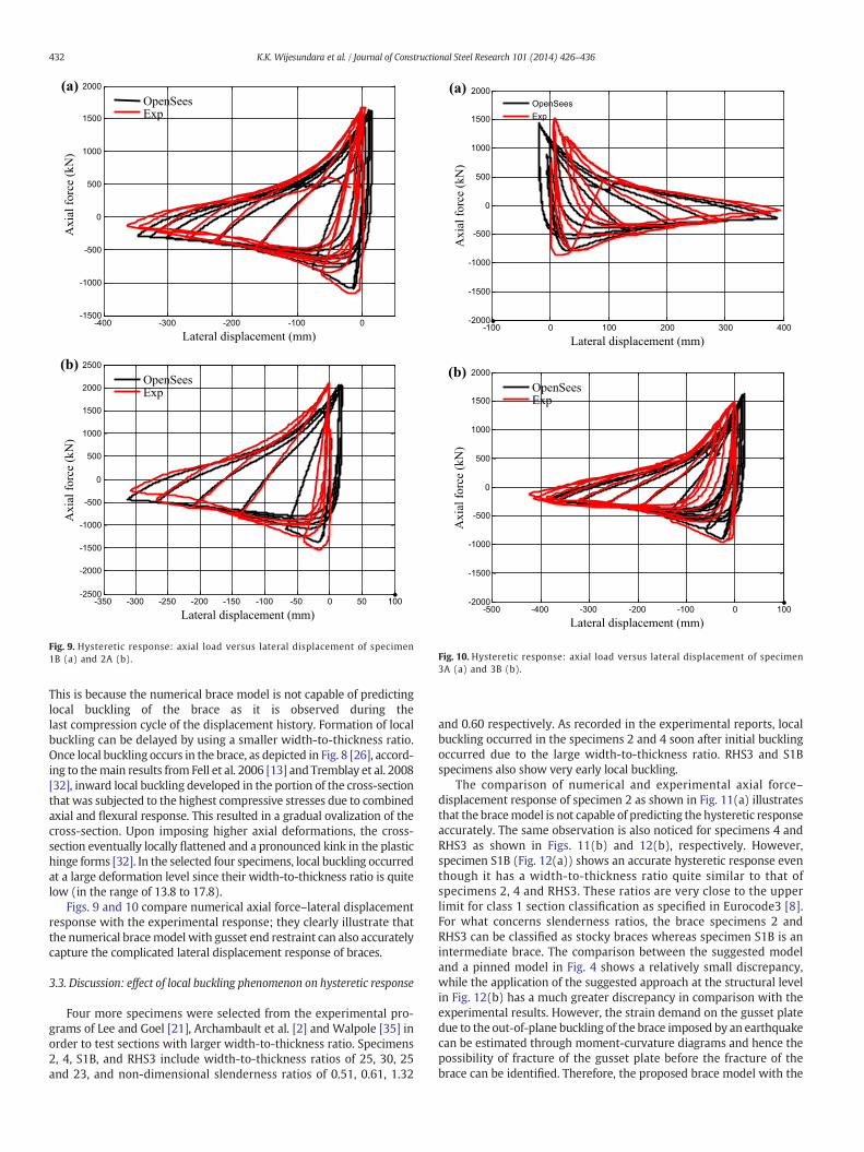
Fig. 9. Hysteretic response: axial load versus lateral displacement of specimen1B (a) and 2A (b).
(a)
(b)
-500 -400 -300 -200 -100 0 100-2000
-1500
-1000
-500
0
500
1000
1500
2000
Lateral displacement (mm)
Axia
l fo
rce
(kN
)
OpenSeesExp
-100 0 100 200 300 400-2000
-1500
-1000
-500
0
500
1000
1500
2000
Lateral displacement (mm)
Axia
l fo
rce
(kN
)
OpenSeesExp
Fig. 10. Hysteretic response: axial load versus lateral displacement of specimen3A (a) and 3B (b).
432 K.K. Wijesundara et al. / Journal of Constructional Steel Research 101 (2014) 426–436
This is because the numerical brace model is not capable of predictinglocal buckling of the brace as it is observed during thelast compression cycle of the displacement history. Formation of localbuckling can be delayed by using a smaller width-to-thickness ratio.Once local buckling occurs in the brace, as depicted in Fig. 8 [26], accord-ing to themain results from Fell et al. 2006 [13] and Tremblay et al. 2008[32], inward local buckling developed in the portion of the cross-sectionthat was subjected to the highest compressive stresses due to combinedaxial and flexural response. This resulted in a gradual ovalization of thecross-section. Upon imposing higher axial deformations, the cross-section eventually locally flattened and a pronounced kink in the plastichinge forms [32]. In the selected four specimens, local buckling occurredat a large deformation level since their width-to-thickness ratio is quitelow (in the range of 13.8 to 17.8).
Figs. 9 and 10 compare numerical axial force–lateral displacementresponse with the experimental response; they clearly illustrate thatthe numerical bracemodel with gusset end restraint can also accuratelycapture the complicated lateral displacement response of braces.
3.3. Discussion: effect of local buckling phenomenon on hysteretic response
Four more specimens were selected from the experimental pro-grams of Lee and Goel [21], Archambault et al. [2] and Walpole [35] inorder to test sections with larger width-to-thickness ratio. Specimens2, 4, S1B, and RHS3 include width-to-thickness ratios of 25, 30, 25and 23, and non-dimensional slenderness ratios of 0.51, 0.61, 1.32
and 0.60 respectively. As recorded in the experimental reports, localbuckling occurred in the specimens 2 and 4 soon after initial bucklingoccurred due to the large width-to-thickness ratio. RHS3 and S1Bspecimens also show very early local buckling.
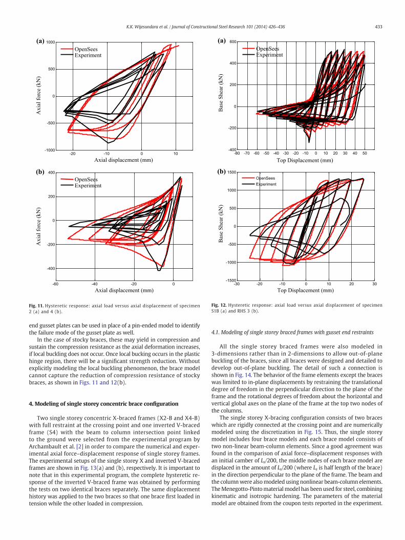
The comparison of numerical and experimental axial force–displacement response of specimen 2 as shown in Fig. 11(a) illustratesthat the bracemodel is not capable of predicting the hysteretic responseaccurately. The same observation is also noticed for specimens 4 andRHS3 as shown in Figs. 11(b) and 12(b), respectively. However,specimen S1B (Fig. 12(a)) shows an accurate hysteretic response eventhough it has a width-to-thickness ratio quite similar to that ofspecimens 2, 4 and RHS3. These ratios are very close to the upperlimit for class 1 section classification as specified in Eurocode3 [8].For what concerns slenderness ratios, the brace specimens 2 andRHS3 can be classified as stocky braces whereas specimen S1B is anintermediate brace. The comparison between the suggested modeland a pinned model in Fig. 4 shows a relatively small discrepancy,while the application of the suggested approach at the structural levelin Fig. 12(b) has a much greater discrepancy in comparison with theexperimental results. However, the strain demand on the gusset platedue to the out-of-plane buckling of the brace imposed by an earthquakecan be estimated through moment-curvature diagrams and hence thepossibility of fracture of the gusset plate before the fracture of thebrace can be identified. Therefore, the proposed brace model with the
(a)
(b)
-20 -10 0 10-1000
-500
0
500
1000
Axial displacement (mm)
Ax
ial
forc
e (k
N)
OpenSeesExperiment
-60 -40 -20 0
-400
-200
0
200
400
Axial displacement (mm)
Ax
ial
forc
e (k
N)
OpenSeesExperiment
Fig. 11. Hysteretic response: axial load versus axial displacement of specimen2 (a) and 4 (b).
(a)
(b)
-80 -70 -60 -50 -40 -30 -20 -10 0 10 20 30 40 50-400
-200
0
200
400
600
Top Displacement (mm)
Bas
e S
hea
r (k
N)
OpenSeesExperiment
-30 -20 -10 0 10 20 30-1500
-1000
-500
0
500
1000
1500
Top Displacement (mm)
Bas
e S
hea
r (k
N)
OpenSeesExperiment
Fig. 12. Hysteretic response: axial load versus axial displacement of specimenS1B (a) and RHS 3 (b).
433K.K. Wijesundara et al. / Journal of Constructional Steel Research 101 (2014) 426–436
end gusset plates can be used in place of a pin-ended model to identifythe failure mode of the gusset plate as well.
In the case of stocky braces, these may yield in compression andsustain the compression resistance as the axial deformation increases,if local buckling does not occur. Once local bucking occurs in the plastichinge region, there will be a significant strength reduction. Withoutexplicitly modeling the local buckling phenomenon, the brace modelcannot capture the reduction of compression resistance of stockybraces, as shown in Figs. 11 and 12(b).
4. Modeling of single storey concentric brace configuration
Two single storey concentric X-braced frames (X2-B and X4-B)with full restraint at the crossing point and one inverted V-bracedframe (S4) with the beam to column intersection point linkedto the ground were selected from the experimental program byArchambault et al. [2] in order to compare the numerical and exper-imental axial force–displacement response of single storey frames.The experimental setups of the single storey X and inverted V-bracedframes are shown in Fig. 13(a) and (b), respectively. It is important tonote that in this experimental program, the complete hysteretic re-sponse of the inverted V-braced frame was obtained by performingthe tests on two identical braces separately. The same displacementhistory was applied to the two braces so that one brace first loaded intension while the other loaded in compression.
4.1. Modeling of single storey braced frames with gusset end restraints
All the single storey braced frames were also modeled in3-dimensions rather than in 2-dimensions to allow out-of-planebuckling of the braces, since all braces were designed and detailed todevelop out-of-plane buckling. The detail of such a connection isshown in Fig. 14. The behavior of the frame elements except the braceswas limited to in-plane displacements by restraining the translationaldegree of freedom in the perpendicular direction to the plane of theframe and the rotational degrees of freedom about the horizontal andvertical global axes on the plane of the frame at the top two nodes ofthe columns.
The single storey X-bracing configuration consists of two braceswhich are rigidly connected at the crossing point and are numericallymodeled using the discretization in Fig. 15. Thus, the single storeymodel includes four brace models and each brace model consists oftwo non-linear beam-column elements. Since a good agreement wasfound in the comparison of axial force–displacement responses withan initial camber of Ls/200, the middle nodes of each brace model aredisplaced in the amount of Ls/200 (where Ls is half length of the brace)in the direction perpendicular to the plane of the frame. The beam andthe columnwere alsomodeled using nonlinear beam-columnelements.TheMenegotto-Pintomaterialmodel has been used for steel, combiningkinematic and isotropic hardening. The parameters of the materialmodel are obtained from the coupon tests reported in the experiment.
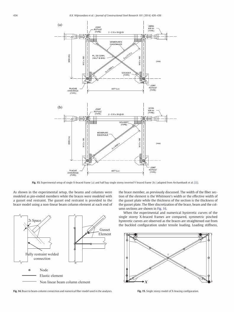
Fig. 13. Experimental setup of single X-braced frame (a) and half bay single storey inverted V braced frame (b) (adapted from Archambault et al. [2]).
434 K.K. Wijesundara et al. / Journal of Constructional Steel Research 101 (2014) 426–436
As shown in the experimental setup, the beams and columns weremodeled as pin-ended members while the braces were modeled witha gusset end restraint. The gusset end restraint is provided to thebrace model using a non-linear beam column element at each end of
Gusset
Element
2t Space
Fully restraint welded
connection
Elastic element
Non linear beam column element
Node
Fig. 14.Brace to beam-column connection and numerical fibermodel used in the analyses.
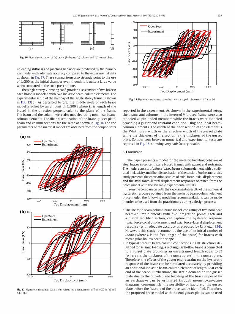
the brace member, as previously discussed. The width of the fiber sec-tion of the element is the Whitmore's width or the effective width ofthe gusset plate while the thickness of the section is the thickness ofthe gusset plate. The fiber discretization of the brace, beam and the col-umn sections are shown in Fig. 16.
When the experimental and numerical hysteretic curves of thesingle storey X-braced frames are compared, symmetric pinchedhysteretic curves are observed as the braces are straightened out fromthe buckled configuration under tensile loading. Loading stiffness,
1
2 3
4X
5
Fig. 15. Single storey model of X-bracing configuration.
(a) (b) (c) (d)
Fig. 16. Fiber discretization of (a) brace, (b) beam, (c) column and (d) gusset plate.
-0.04 -0.02 0 0.02 0.04-800
-600
-400
-200
0
200
400
600
800
Top Displacement (mm)
Bas
e S
hea
r (k
N)
OpenSees
Experiment
Fig. 18. Hysteretic response: base shear versus top displacement of frame S4.
435K.K. Wijesundara et al. / Journal of Constructional Steel Research 101 (2014) 426–436
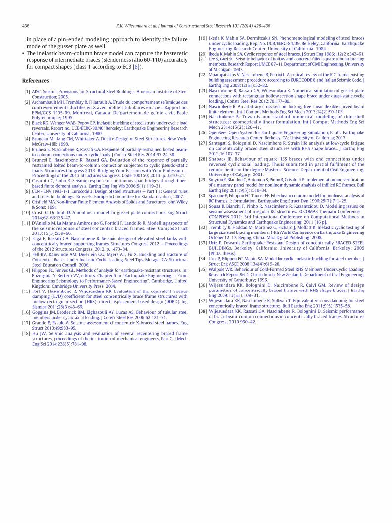
unloading stiffness and pinching behavior are predicted by the numer-ical model with adequate accuracy compared to the experimental dataas shown in Fig. 17. These comparisons also strongly point to the useof Ls/200 as the initial chamber even though it is quite a large valuewhen compared to the code prescriptions.
The single storeyV-bracing configuration also consists of two braces;each brace is modeled with two inelastic beam-column elements. Theexperimental setup of the half bay of the single storey frame is shownin Fig. 13(b). As described before, the middle node of each bracemodel is offset by an amount of Ls/200 (where Ls is length of thebrace) in the direction perpendicular to the plane of the frame.The beam and the column were also modeled using nonlinear beam-column elements. The fiber discretization of the brace, gusset plate,beam and column sections are the same as shown in Fig. 16 and theparameters of the material model are obtained from the coupon tests
(a)
(b)
-0.04 -0.02 0 0.02 0.04-800
-600
-400
-200
0
200
400
600
800
Top Displacement (mm)
OpenSeesExperiment
Bas
e S
hea
r (k
N)
-0.04 -0.02 0 0.02 0.04-400
-200
0
200
400
Top Displacement (mm)
Bas
e S
hea
r (k
N)
OpenSeesExperiment
Fig. 17. Hysteretic response: base shear versus top displacement of frame X2-B (a) andX4-B (b).
reported in the experiment. As shown in the experimental setup,the beams and columns in the inverted V-braced frame were alsomodeled as pin-ended members while the braces were modeledproviding a gusset end restraint condition using nonlinear beam-column elements. The width of the fiber section of the element isthe Whitmore's width or the effective width of the gusset platewhile the thickness of the section is the thickness of the gussetplate. Comparisons between numerical and experimental tests arereported in Fig. 18, showing very satisfactory results.
5. Conclusion
The paper presents a model for the inelastic buckling behavior ofsteel braces in concentrically braced frames with gusset end restraints.Themodel consists of a force-based beam-column elementwith distrib-uted inelasticity andfiber discretization of the section. Furthermore, thisstudy presents the correlation studies of axial force–axial displacementand the axial force–lateral displacement responses obtained from thebrace model with the available experimental results.
From the comparisonwith the experimental results of the numericalhysteretic response obtained from the inelastic beam-column elementbrace model, the following modeling recommendations can be madein order to be used from the practitioners during a design process:
• The inelastic beam-column brace model, consisting of two nonlinearbeam-column elements with five integration points each anda discretized fiber section, can capture the hysteretic response(axial force–axial displacement and axial force–lateral displacementresponse) with adequate accuracy as proposed by Urix et.al. [34].However, this study recommends the use of an initial camber ofL/200 (where L is the free length of the brace) for braces withrectangular hollow section shape.
• In typical brace to beam-column connections in CBF structures de-signed for seismic loading, a rectangular hollow brace is connectedto a gusset plate providing an unrestrained length equal to 2t(where t is the thickness of the gusset plate) in the gusset plate.Therefore, the effects of the gusset end restraint on the hystereticresponse of the brace can be simulated accurately by providingan additional inelastic beam-column element of length 2t at eachend of the brace. Furthermore, the strain demand on the gussetplate due to the out-of-plane buckling of the brace imposed byan earthquake can be estimated through moment-curvaturediagrams: consequently, the possibility of fracture of the gussetplate before the fracture of the brace can be identified. Therefore,the proposed brace model with the end gusset plates can be used
436 K.K. Wijesundara et al. / Journal of Constructional Steel Research 101 (2014) 426–436
in place of a pin-ended modeling approach to identify the failuremode of the gusset plate as well.
• The inelastic beam-column brace model can capture the hystereticresponse of intermediate braces (slenderness ratio 60-110) accuratelyfor compact shapes (class 1 according to EC3 [8]).
References
[1] AISC. Seismic Provisions for Structural Steel Buildings. American Institute of SteelConstruction; 2005.
[2] Archambault MH, Tremblay R, Filiatrault A. E´tude du comportement se´ismique descontreventements ductiles en X avec profile´s tubulaires en acier. Rapport no.EPM/GCS 1995-09. Montreal, Canada: De´partement de ge´nie civil, EcolePolytechnique; 1995.
[3] Black RG, Wenger WAB, Popov EP. Inelastic buckling of steel struts under cyclic loadreversals. Report no. UCB/EERC-80/40. Berkeley: Earthquake Engineering ResearchCenter, University of California; 1980.
[4] Bruneau M, Uang CM, Whittaker A. Ductile Design of Steel Structures. New York:McGraw-Hill; 1998.
[5] Brunesi E, Nascimbene R, Rassati GA. Response of partially-restrained bolted beam-to-column connections under cyclic loads. J Constr Steel Res 2014;97:24–38.
[6] Brunesi E, Nascimbene R, Rassati GA. Evaluation of the response of partiallyrestrained bolted beam-to-column connection subjected to cyclic pseudo-staticloads. Structures Congress 2013: Bridging Your Passion with Your Profession —
Proceedings of the 2013 Structures Congress, Code 100150; 2013. p. 2310–21.[7] Casarotti C, Pinho R. Seismic response of continuous span bridges through fiber-
based finite element analysis. Earthq Eng Eng Vib 2006;5(1):119–31.[8] CEN - ENV 1993-1-1. Eurocode 3: Design of steel structures— Part 1.1: General rules
and rules for buildings. Brussels: European Committee for Standardization; 2007.[9] Crisfield MA. Non-linear Finite Element Analysis of Solids and Structures. JohnWiley
& Sons; 1991.[10] Crosti C, Duthinh D. A nonlinear model for gusset plate connections. Eng Struct
2014;62–63:135–47.[11] D'Aniello M, La Manna Ambrosino G, Portioli F, Landolfo R. Modelling aspects of
the seismic response of steel concentric braced frames. Steel Compos Struct2013;15(5):539–66.
[12] Fagà E, Rassati GA, Nascimbene R. Seismic design of elevated steel tanks withconcentrically braced supporting frames. Structures Congress 2012 — Proceedingsof the 2012 Structures Congress; 2012. p. 1473–84.
[13] Fell BV, Kanwinde AM, Deierlein GG, Myers AT, Fu X. Buckling and Fracture ofConcentric Braces Under Inelastic Cyclic Loading. Steel Tips. Moraga, CA: StructuralSteel Education Council; 2006.
[14] Filippou FC, Fenves GL. Methods of analysis for earthquake-resistant structures. In:Bozorgnia Y, Bertero VV, editors. Chapter 6 in “Earthquake Engineering — FromEngineering Seismology to Performance-Based Engineering”. Cambridge, UnitedKingdom: Cambridge University Press; 2004.
[15] Fort V, Nascimbene R, Wijesundara KK. Evaluation of the equivalent viscousdamping (EVD) coefficient for steel concentrically brace frame structures withhollow rectangular section (HRS): direct displacement based design (DDBD). IngSismica 2011;28(3):43–66.
[16] Goggins JM, Broderick BM, Elghazouli AY, Lucas AS. Behaviour of tubular steelmembers under cyclic axial loading. J Constr Steel Res 2006;62:121–31.
[17] Grande E, Rasulo A. Seismic assessment of concentric X-braced steel frames. EngStruct 2013;49:983–95.
[18] Hu JW. Seismic analysis and evaluation of several recentering braced framestructures, proceedings of the institution of mechanical engineers, Part C. J MechEng Sci 2014;228(5):781–98.
[19] Ikeda K, Mahin SA, Dermitzakis SN. Phenomenological modeling of steel bracesunder cyclic loading. Rep. No. UCB/EERC-84/09. Berkeley, California: EarthquakeEngineering Research Center, University of California; 1984.
[20] Ikeda K, Mahin SA. Cyclic response of steel braces. J Struct Eng 1986;112(2):342–61.[21] Lee S, Goel SC. Seismic behavior of hollow and concrete-filled square tubular bracing
members. Research Report UMCE87–11. Department of Civil Engineering, Universityof Michigan; 1987.
[22] Mpampatsikos V, Nascimbene R, Petrini L. A critical review of the R.C. frame existingbuilding assessment procedure according to EUROCODE 8 and Italian Seismic Code. JEarthq Eng 2008;12(S1):52–82.
[23] Nascimbene R, Rassati GA, Wijesundara K. Numerical simulation of gusset plateconnections with rectangular hollow section shape brace under quasi-static cyclicloading. J Constr Steel Res 2012;70:177–89.
[24] Nascimbene R. An arbitrary cross section, locking free shear-flexible curved beamfinite element. Int J Comput Methods Eng Sci Mech 2013;14(2):90–103.
[25] Nascimbene R. Towards non-standard numerical modeling of thin-shellstructures: geometrically linear formulation. Int J Comput Methods Eng SciMech 2014;15(2):126–41.
[26] OpenSees. Open System for Earthquake Engineering Simulation, Pacific EarthquakeEngineering Research Center. Berkeley, CA: University of California; 2013.
[27] Santagati S, Bolognini D, Nascimbene R. Strain life analysis at low-cycle fatigueon concentrically braced steel structures with RHS shape braces. J Earthq Eng2012;16:107–37.
[28] Shaback JB. Behaviour of square HSS braces with end connections underreversed cyclic axial loading. Thesis submitted in partial fulfilment of therequirements for the degree Master of Science. Department of Civil Engineering,University of Calgary; 2001.
[29] Smyrou E, Blandon C, Antoniou S, Pinho R, Crisafulli F. Implementation and verificationof a masonry panel model for nonlinear dynamic analysis of infilled RC frames. BullEarthq Eng 2011;9(5):1519–34.
[30] Spacone E, Filippou FC, Taucer FF. Fiber beam columnmodel for nonlinear analysis ofRC frames. I: formulation. Earthquake Eng Struct Dyn 1996;25(7):711–25.
[31] Sousa R, Bianchi F, Pinho R, Nascimbene R, Kazantzidou D. Modelling issues onseismic assessment of irregular RC structures. ECCOMAS Thematic Conference —
COMPDYN 2011: 3rd International Conference on Computational Methods inStructural Dynamics and Earthquake Engineering; 2011 [16 p].
[32] Tremblay R, Haddad M, Martinez G, Richard J, Moffatt K. Inelastic cyclic testing oflarge size steel bracingmembers. 14thWorld Conference onEarthquake EngineeringOctober 12–17. Beijing, China: Mira Digital Publishing; 2008.
[33] Uriz P. Towards Earthquake Resistant Design of concentrically BRACED STEELBUILDINGs. Berkeley, California: University of California, Berkeley; 2005[Ph.D. Thesis].
[34] Uriz P, Filippou FC, Mahin SA. Model for cyclic inelastic buckling for steel member. JStruct Eng ASCE 2008;134(4):619–28.
[35] Walpole WR. Behaviour of Cold-Formed Steel RHS Members Under Cyclic Loading.Research Report 96-4. Christchurch, New Zealand: Department of Civil Engineering,University of Canterbury; 1996.
[36] Wijesundara KK, Bolognini D, Nascimbene R, Calvi GM. Review of designparameters of concentrically braced frames with RHS shape braces. J EarthqEng 2009;13(S1):109–31.
[37] Wijesundara KK, Nascimbene R, Sullivan T. Equivalent viscous damping for steelconcentrically braced frame structures. Bull Earthq Eng 2011;9(5):1535–58.
[38] Wijesundara KK, Rassati GA, Nascimbene R, Bolognini D. Seismic performanceof brace-beam-column connections in concentrically braced frames. StructuresCongress; 2010 930–42.