bracing, tie-down and other issues - building inspections
TRANSCRIPT
1
qbcc queensland building and construction commission
A guide to the construction of buildings in cyclonic regions
Bracing, tie-down and other issues
Produced in conjunction with:
21/05/2014
1
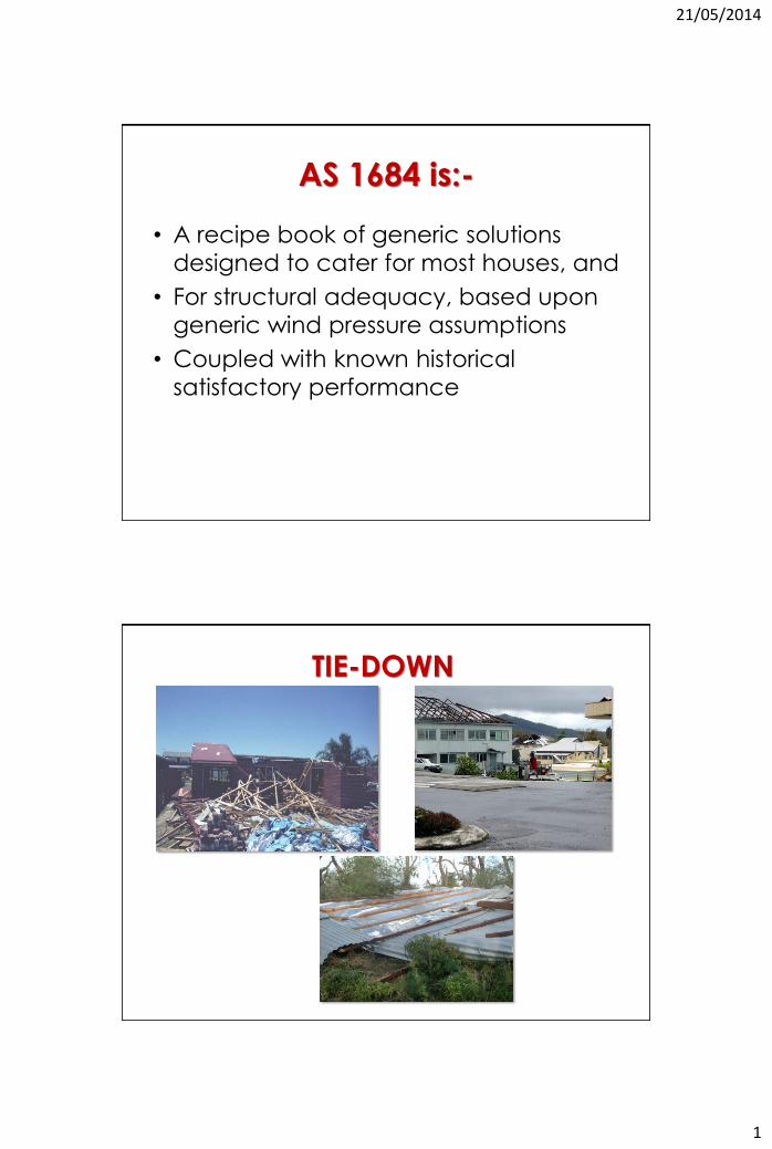
AS 1684 is:-
• A recipe book of generic solutions
designed to cater for most houses, and
• For structural adequacy, based upon
generic wind pressure assumptions
• Coupled with known historical
satisfactory performance
TIE-DOWN
21/05/2014
2
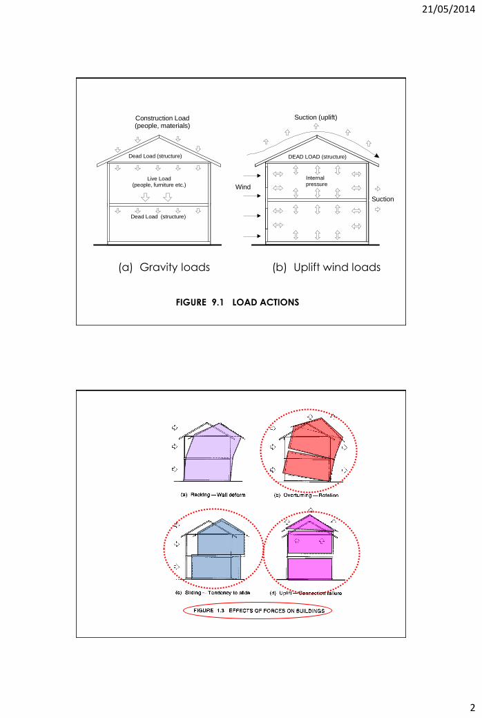
Live Load (people, furniture etc.)
Suction
Internal pressure
Suction (uplift)
Wind
Dead Load (structure)
Construction Load (people, materials)
DEAD LOAD (structure)
Dead Load (structure)
(a) Gravity loads (b) Uplift wind loads
FIGURE 9.1 LOAD ACTIONS
21/05/2014
3
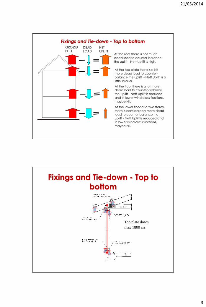
GROSSUPLIFT
DEAD LOAD
NET UPLIFT
At the roof there is not much dead load to counter-balance the uplift - Nett Uplift is high.
At the top plate there is a bit more dead load to counter-balance the uplift - Nett Uplift is a little smaller.
At the floor there is a lot more dead load to counter-balance the uplift - Nett Uplift is reduced and in lower wind classifications, maybe Nil.
At the lower floor of a two storey, there is considerably more dead load to counter-balance the uplift - Nett Uplift is reduced and in lower wind classifications, maybe Nil.
Fixings and Tie-down - Top to bottom
Fixings and Tie-down - Top to
bottom
Top plate down
max 1800 crs
21/05/2014
4
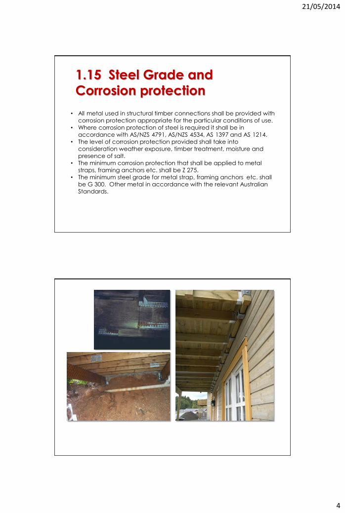
1.15 Steel Grade and
Corrosion protection
• All metal used in structural timber connections shall be provided with
corrosion protection appropriate for the particular conditions of use.
• Where corrosion protection of steel is required it shall be in
accordance with AS/NZS 4791, AS/NZS 4534, AS 1397 and AS 1214.
• The level of corrosion protection provided shall take into
consideration weather exposure, timber treatment, moisture and
presence of salt.
• The minimum corrosion protection that shall be applied to metal
straps, framing anchors etc. shall be Z 275.
• The minimum steel grade for metal strap, framing anchors etc. shall
be G 300. Other metal in accordance with the relevant Australian
Standards.
21/05/2014
5
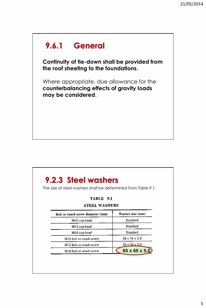
Continuity of tie-down shall be provided from the roof sheeting to the foundations. Where appropriate, due allowance for the
counterbalancing effects of gravity loads may be considered.
9.6.1 General
The size of steel washers shall be determined from Table 9.1.
9.2.3 Steel washers
65 x 65 x 5.0
21/05/2014
6
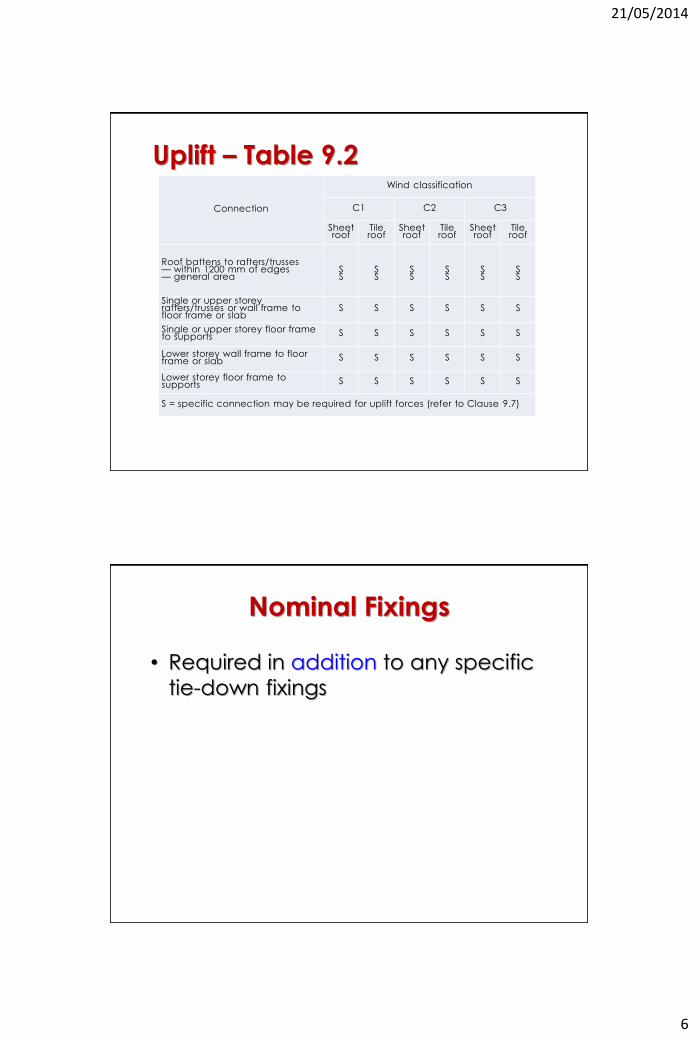
Connection
Wind classification
C1 C2 C3
Sheet roof
Tile roof
Sheet roof
Tile roof
Sheet roof
Tile roof
Roof battens to rafters/trusses — within 1200 mm of edges — general area
S S
S S
S S
S S
S S
S S
Single or upper storey rafters/trusses or wall frame to floor frame or slab
S S S S S S
Single or upper storey floor frame to supports S S S S S S
Lower storey wall frame to floor frame or slab S S S S S S
Lower storey floor frame to supports S S S S S S
S = specific connection may be required for uplift forces (refer to Clause 9.7)
Uplift – Table 9.2
Nominal Fixings
• Required in addition to any specific
tie-down fixings
21/05/2014
7
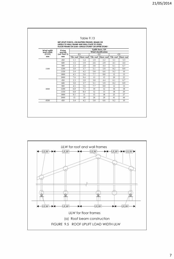
Wind uplift load width
(ULW)
mm
Fixing spacing
(see Note 2)
mm
Uplift force, kN
Wind classification
C1 C2 C3
Tile roof Sheet roof Tile roof Sheet roof Tile roof Sheet roof
1500
450 1.1 1.4 1.9 2.2 3.1 3.3
600 1.5 1.9 2.6 2.9 4.1 4.4
900 2.3 2.8 3.8 4.4 6.1 6.7
1200 3.0 3.7 5.1 5.9 8.2 8.9
1350 3.4 4.2 5.8 6.6 9.2 10
1800 4.5 5.6 7.7 8.8 12 13
3000 7.6 9.4 13 15 20 22
3000
450 2.3 2.8 3.8 4.4 6.1 6.7
600 3.0 3.7 5.1 5.9 8.2 8.9
900 4.5 5.6 7.7 8.8 12 13
1200 6.0 7.5 10 12 16 18
1350 6.8 8.4 12 13 18 20
1800 9.1 11 15 18 25 27
3000 15 19 26 29 41 44
4500 450 3.4 4.2 5.8 6.6 9.2 10
NET UPLIFT FORCE—ON RAFTERS/TRUSSES, BEAMS OR LINTELS TO WALL FRAME AND WALL PLATE TO STUDS, FLOOR FRAME OR SLAB—SINGLE STOREY OR UPPER STOREY
Table 9.13
ULW
ULW
ULW
ULW
ULW
ULW
ULW
ULW
ULW
FIGURE 9.5 ROOF UPLIFT LOAD WIDTH ULW
(a) Roof beam construction
ULW for roof and wall frames
ULW for floor frames
21/05/2014
8
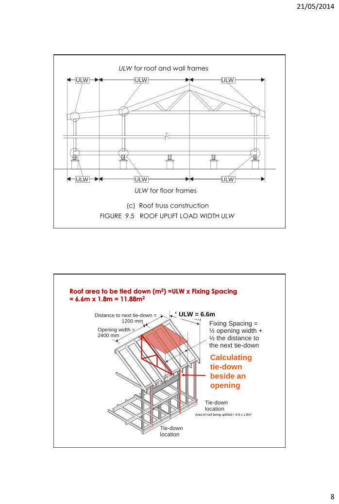
FIGURE 9.5 ROOF UPLIFT LOAD WIDTH ULW
ULW
ULW
ULW
ULW
ULW
ULW
(c) Roof truss construction
ULW for roof and wall frames
ULW for floor frames
ULW =4000 mm
Tie-downlocation
Tie-downlocation
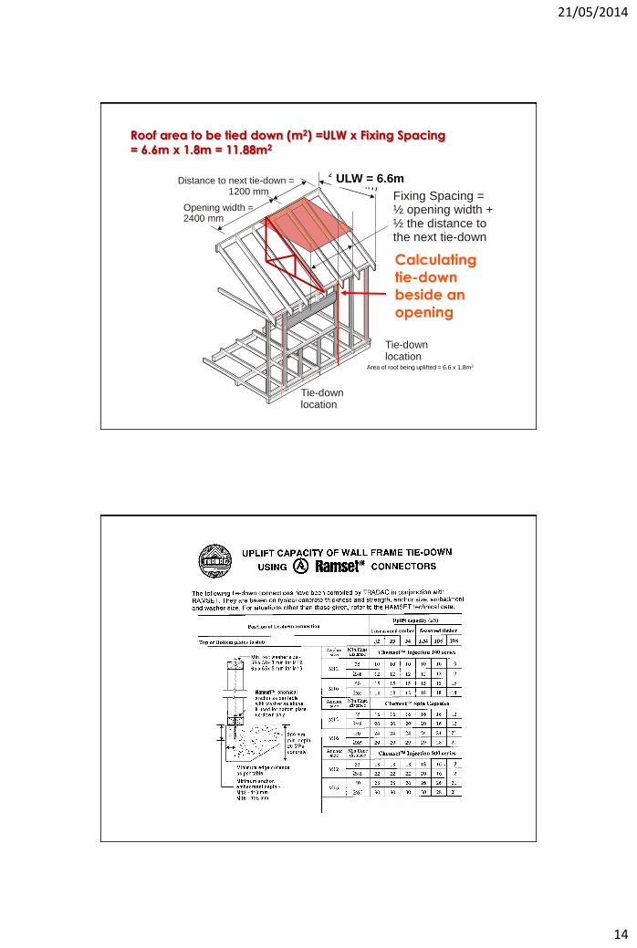
Fixing Spacing =½ opening width +½ the distance tothe next tie-down
Opening width =2400 mm
Distance to next tie-down = 1200 mm
Roof area to be tied down (m2) =ULW x Fixing Spacing
= 6.6m x 1.8m = 11.88m2
Calculating
tie-down
beside an
opening
ULW = 6.6m
Area of roof being uplifted = 6.6 x 1.8m2
21/05/2014
9
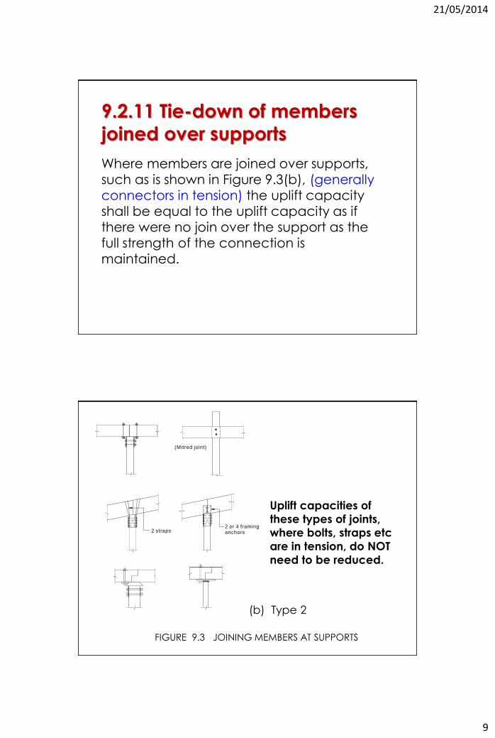
Where members are joined over supports,
such as is shown in Figure 9.3(b), (generally connectors in tension) the uplift capacity shall be equal to the uplift capacity as if there were no join over the support as the full strength of the connection is maintained.
9.2.11 Tie-down of members
joined over supports
(Mitred joint)
2 straps2 or 4 framing anchors
Uplift capacities of
these types of joints,
where bolts, straps etc
are in tension, do NOT
need to be reduced.
FIGURE 9.3 JOINING MEMBERS AT SUPPORTS
(b) Type 2
21/05/2014
10
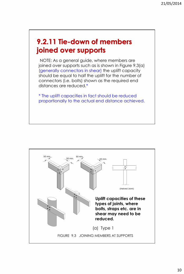
NOTE: As a general guide, where members are
joined over supports such as is shown in Figure 9.3(a)
(generally connectors in shear) the uplift capacity
should be equal to half the uplift for the number of
connectors (i.e. bolts) shown as the required end
distances are reduced.*
* The uplift capacities in fact should be reduced
proportionally to the actual end distance achieved.
9.2.11 Tie-down of members
joined over supports
50 min. 50 min.50 min. 50 min.
(Halved Joint)
FIGURE 9.3 JOINING MEMBERS AT SUPPORTS
(a) Type 1
Uplift capacities of these
types of joints, where
bolts, straps etc. are in
shear may need to be
reduced.
21/05/2014
11
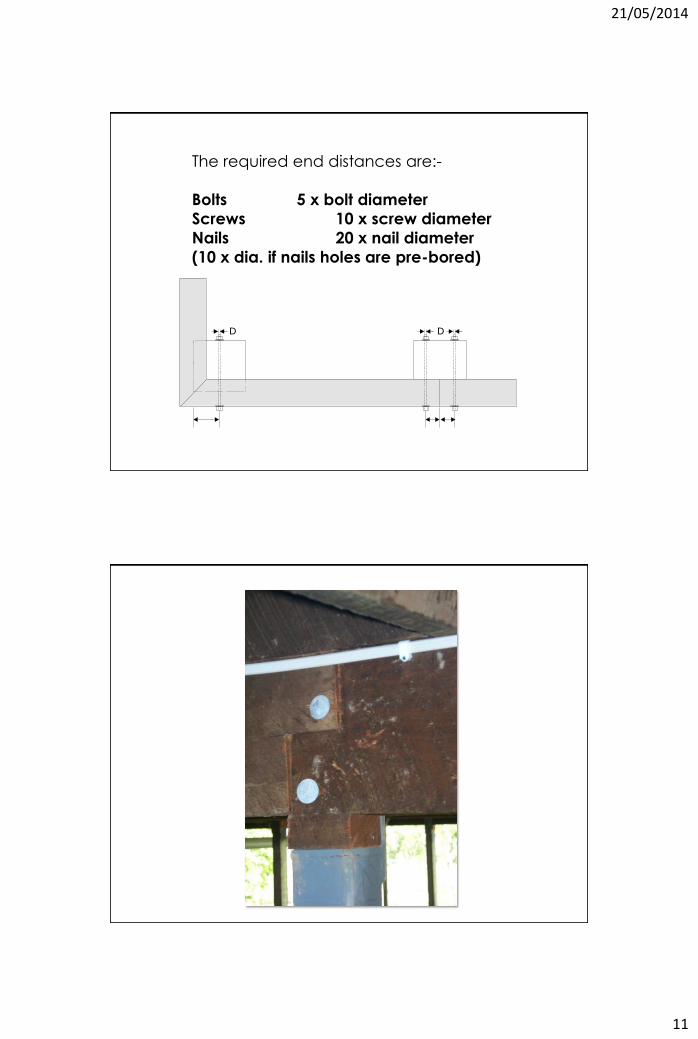
The required end distances are:-
Bolts 5 x bolt diameter
Screws 10 x screw diameter
Nails 20 x nail diameter
(10 x dia. if nails holes are pre-bored)
D D
21/05/2014
12
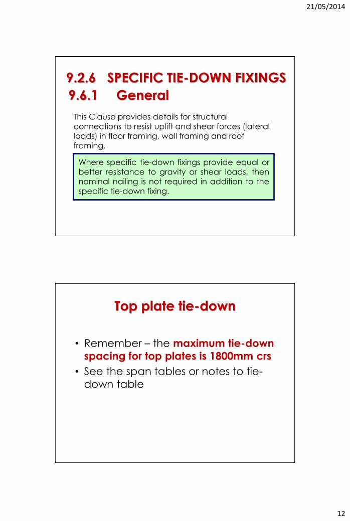
This Clause provides details for structural
connections to resist uplift and shear forces (lateral
loads) in floor framing, wall framing and roof
framing.
Unless otherwise specified, the details provided are
in addition to nominal nailing
(see Clause 9.5).
9.2.6 SPECIFIC TIE-DOWN FIXINGS
9.6.1 General
Where specific tie-down fixings provide equal or
better resistance to gravity or shear loads, then
nominal nailing is not required in addition to the
specific tie-down fixing.
Top plate tie-down
• Remember – the maximum tie-down
spacing for top plates is 1800mm crs
• See the span tables or notes to tie-
down table
21/05/2014
13
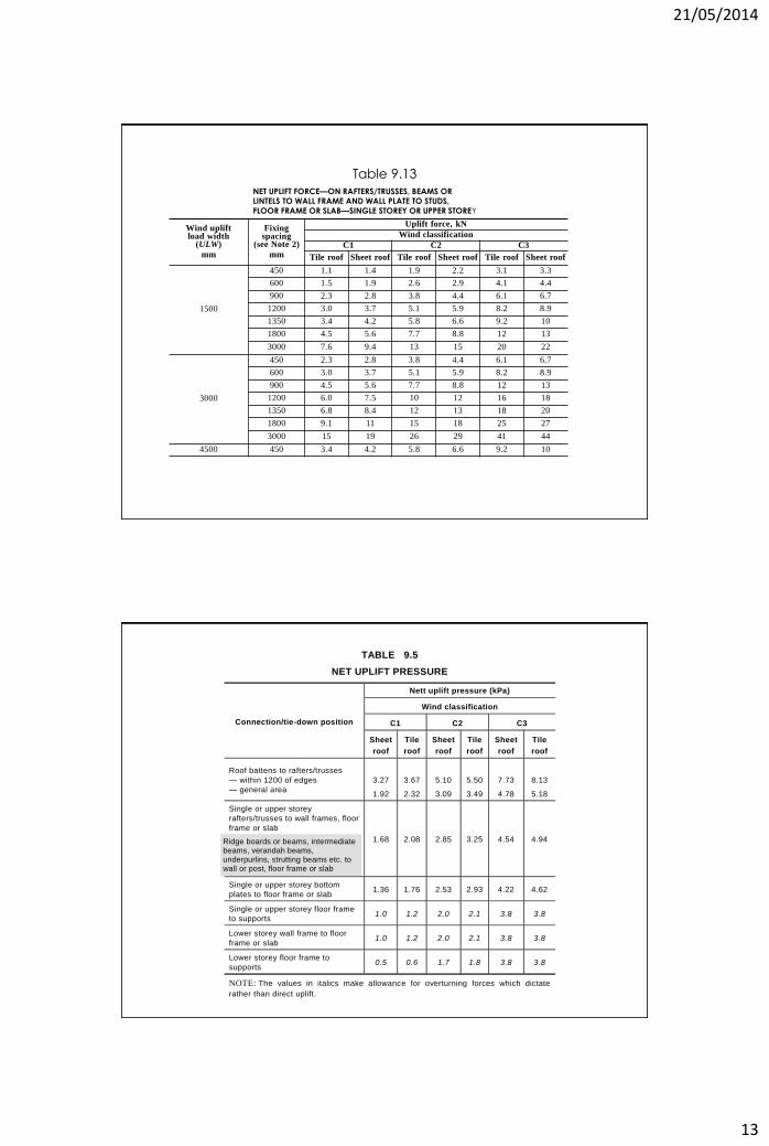
Wind uplift load width
(ULW)
mm
Fixing spacing
(see Note 2)
mm
Uplift force, kN
Wind classification
C1 C2 C3
Tile roof Sheet roof Tile roof Sheet roof Tile roof Sheet roof
1500
450 1.1 1.4 1.9 2.2 3.1 3.3
600 1.5 1.9 2.6 2.9 4.1 4.4
900 2.3 2.8 3.8 4.4 6.1 6.7
1200 3.0 3.7 5.1 5.9 8.2 8.9
1350 3.4 4.2 5.8 6.6 9.2 10
1800 4.5 5.6 7.7 8.8 12 13
3000 7.6 9.4 13 15 20 22
3000
450 2.3 2.8 3.8 4.4 6.1 6.7
600 3.0 3.7 5.1 5.9 8.2 8.9
900 4.5 5.6 7.7 8.8 12 13
1200 6.0 7.5 10 12 16 18
1350 6.8 8.4 12 13 18 20
1800 9.1 11 15 18 25 27
3000 15 19 26 29 41 44
4500 450 3.4 4.2 5.8 6.6 9.2 10
NET UPLIFT FORCE—ON RAFTERS/TRUSSES, BEAMS OR LINTELS TO WALL FRAME AND WALL PLATE TO STUDS,
FLOOR FRAME OR SLAB—SINGLE STOREY OR UPPER STOREY
Table 9.13
TABLE 9.5
NET UPLIFT PRESSURE
Connection/tie-down position
Nett uplift pressure (kPa)
Wind classification
C1 C2 C3
Sheet
roof
Tile
roof
Sheet
roof
Tile
roof
Sheet
roof
Tile
roof
Roof battens to rafters/trusses
— within 1200 of edges
— general area
3.27
1.92
3.67
2.32
5.10
3.09
5.50
3.49
7.73
4.78
8.13
5.18
Single or upper storey
rafters/trusses to wall frames, floor
frame or slab
1.68 2.08 2.85 3.25 4.54 4.94
Single or upper storey bottom
plates to floor frame or slab 1.36 1.76 2.53 2.93 4.22 4.62
Single or upper storey floor frame
to supports 1.0 1.2 2.0 2.1 3.8 3.8
Lower storey wall frame to floor
frame or slab 1.0 1.2 2.0 2.1 3.8 3.8
Lower storey floor frame to
supports 0.5 0.6 1.7 1.8 3.8 3.8
NOTE: The values in italics make allowance for overturning forces which dictate
rather than direct uplift.
Ridge boards or beams, intermediate beams, verandah beams, underpurlins, strutting beams etc. to wall or post, floor frame or slab
21/05/2014
14
ULW =4000 mm
Tie-downlocation
Tie-downlocation
Fixing Spacing =½ opening width +½ the distance tothe next tie-down
Opening width =2400 mm
Distance to next tie-down = 1200 mm
Roof area to be tied down (m2) =ULW x Fixing Spacing
= 6.6m x 1.8m = 11.88m2
Calculating
tie-down
beside an
opening
ULW = 6.6m
Area of roof being uplifted = 6.6 x 1.8m2
21/05/2014
15
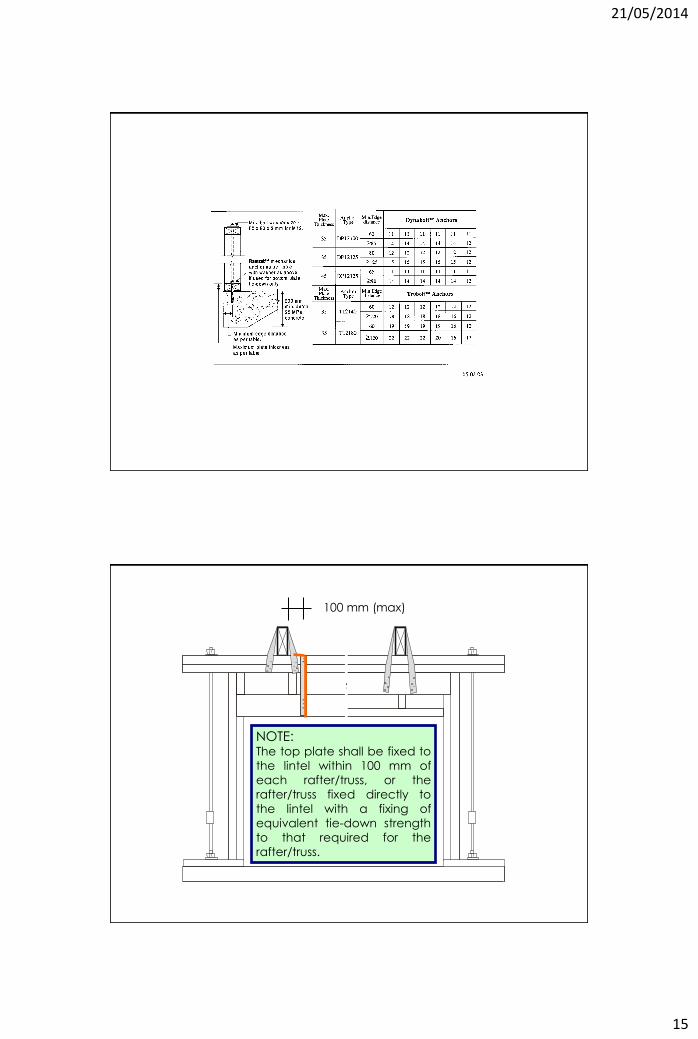
NOTE: The top plate shall be fixed to
the lintel within 100 mm of
each rafter/truss, or the
rafter/truss fixed directly to
the lintel with a fixing of
equivalent tie-down strength
to that required for the
rafter/truss.
100 mm (max)
21/05/2014
16
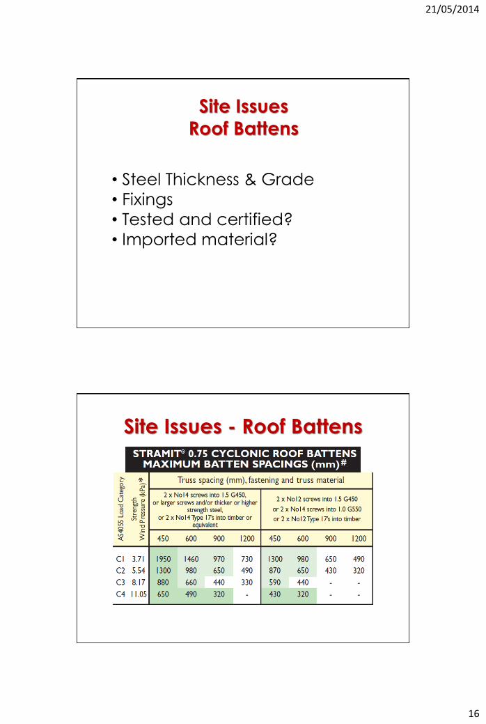
Site Issues
Roof Battens
• Steel Thickness & Grade
• Fixings
• Tested and certified?
• Imported material?
Site Issues - Roof Battens

21/05/2014
17
Site Issues
Truss Installation
Install Trusses Plumb and Straight
21/05/2014
18
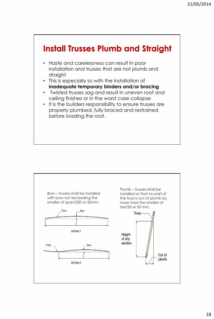
Install Trusses Plumb and Straight
• Haste and carelessness can result in poor
installation and trusses that are not plumb and
straight
• This is especially so with the installation of
inadequate temporary binders and/or bracing
• Twisted trusses sag and result in uneven roof and
ceiling finishes or in the worst case collapse
• It is the builders responsibility to ensure trusses are
properly plumbed, fully braced and restrained
before loading the roof.
Plumb – trusses shall be
installed so that no part of
the truss is out of plumb by
more than the smaller of
rise/50 or 50 mm.
Bow – trusses shall be installed
with bow not exceeding the
smaller of span/200 or 50mm.
21/05/2014
19
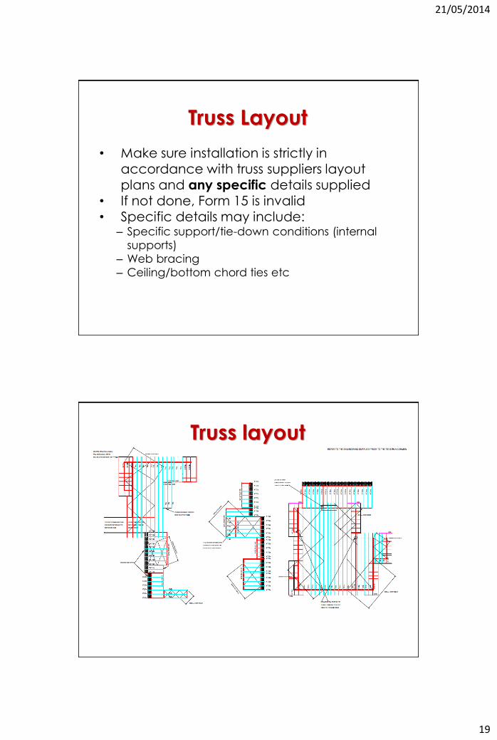
Truss Layout
• Make sure installation is strictly in accordance with truss suppliers layout plans and any specific details supplied
• If not done, Form 15 is invalid • Specific details may include:
– Specific support/tie-down conditions (internal
supports)
– Web bracing
– Ceiling/bottom chord ties etc
Truss layout
21/05/2014
20
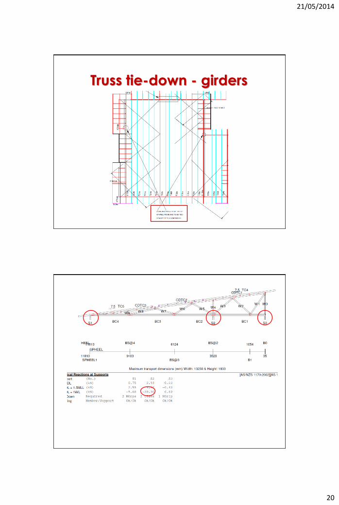
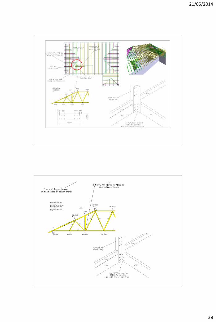
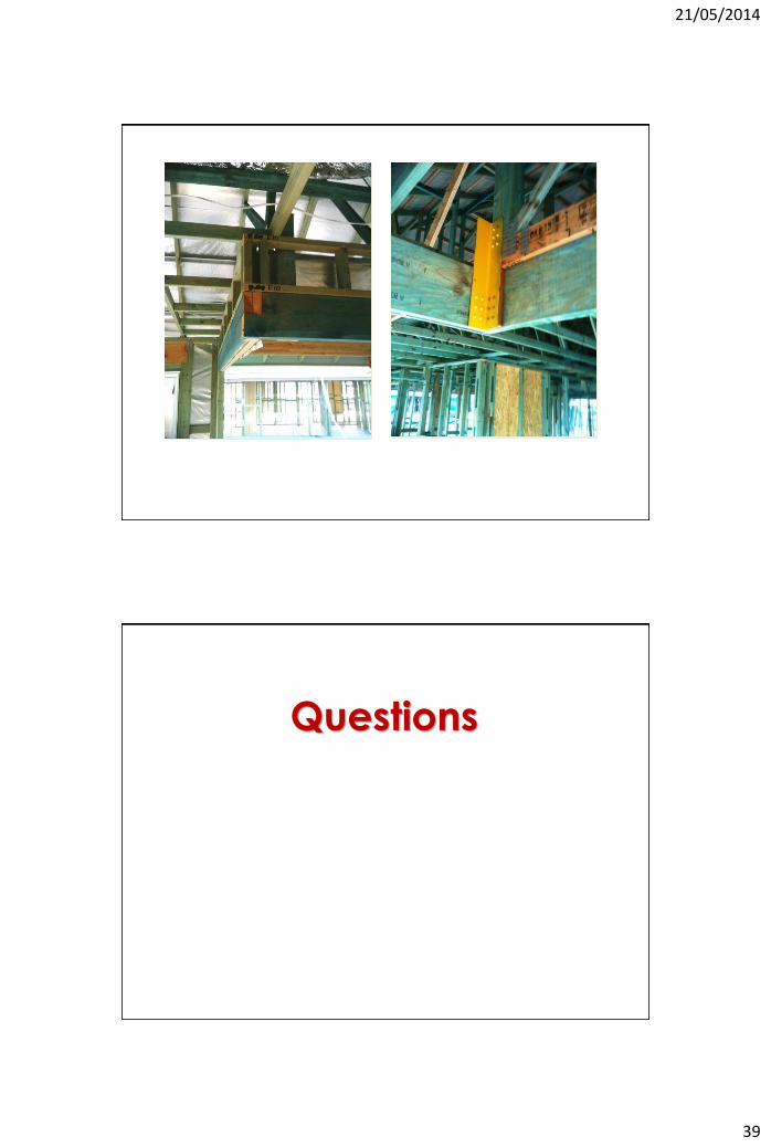
Truss tie-down - girders
21/05/2014
21
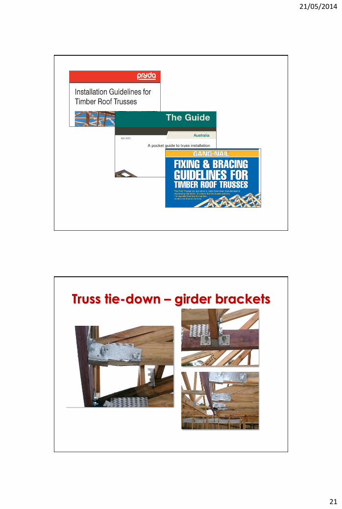
Truss tie-down – girder brackets
21/05/2014
22
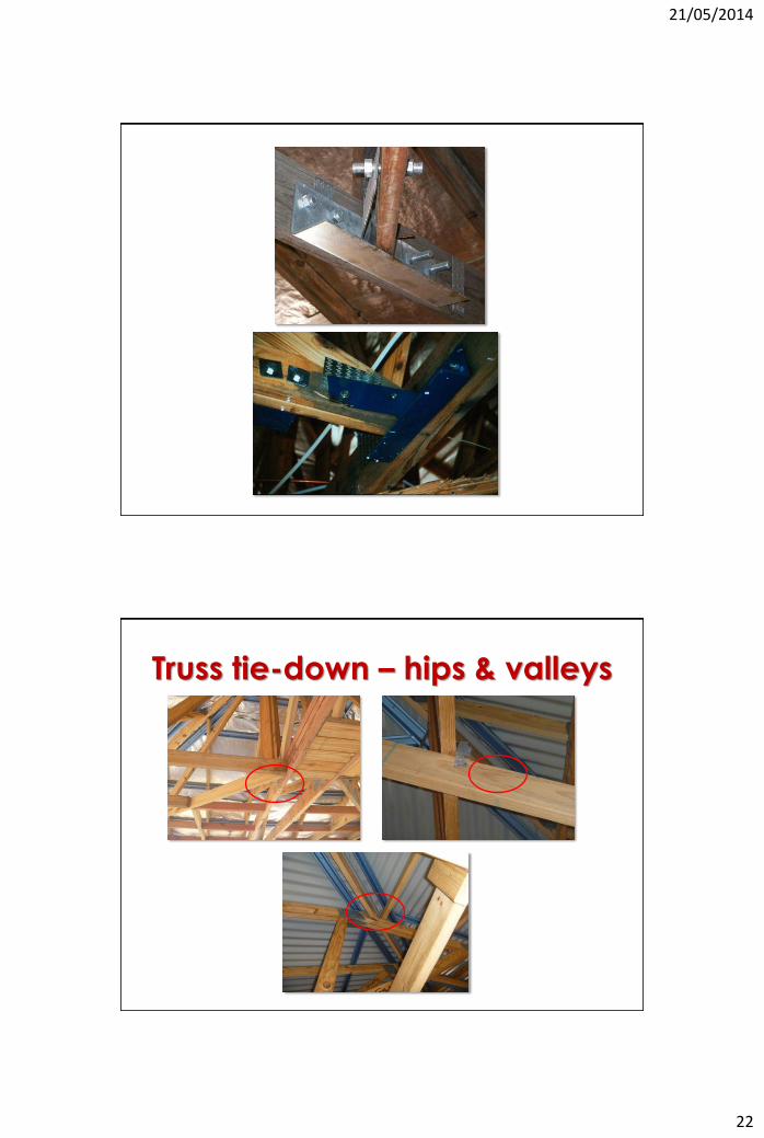
Truss tie-down – hips & valleys
21/05/2014
23
21/05/2014
24
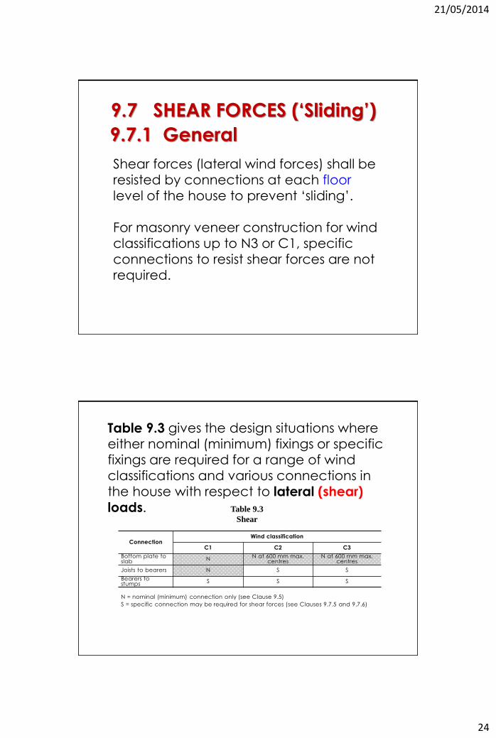
9.7 SHEAR FORCES (‘Sliding’)
9.7.1 General
Shear forces (lateral wind forces) shall be resisted by connections at each floor level of the house to prevent ‘sliding’.
For masonry veneer construction for wind classifications up to N3 or C1, specific connections to resist shear forces are not required.
Table 9.3 gives the design situations where either nominal (minimum) fixings or specific fixings are required for a range of wind classifications and various connections in the house with respect to lateral (shear)
loads.
Connection Wind classification
C1 C2 C3
Bottom plate to slab N N at 600 mm max.
centres N at 600 mm max.
centres
Joists to bearers N S S
Bearers to stumps S S S
N = nominal (minimum) connection only (see Clause 9.5)
S = specific connection may be required for shear forces (see Clauses 9.7.5 and 9.7.6)
Table 9.3
Shear
21/05/2014
25
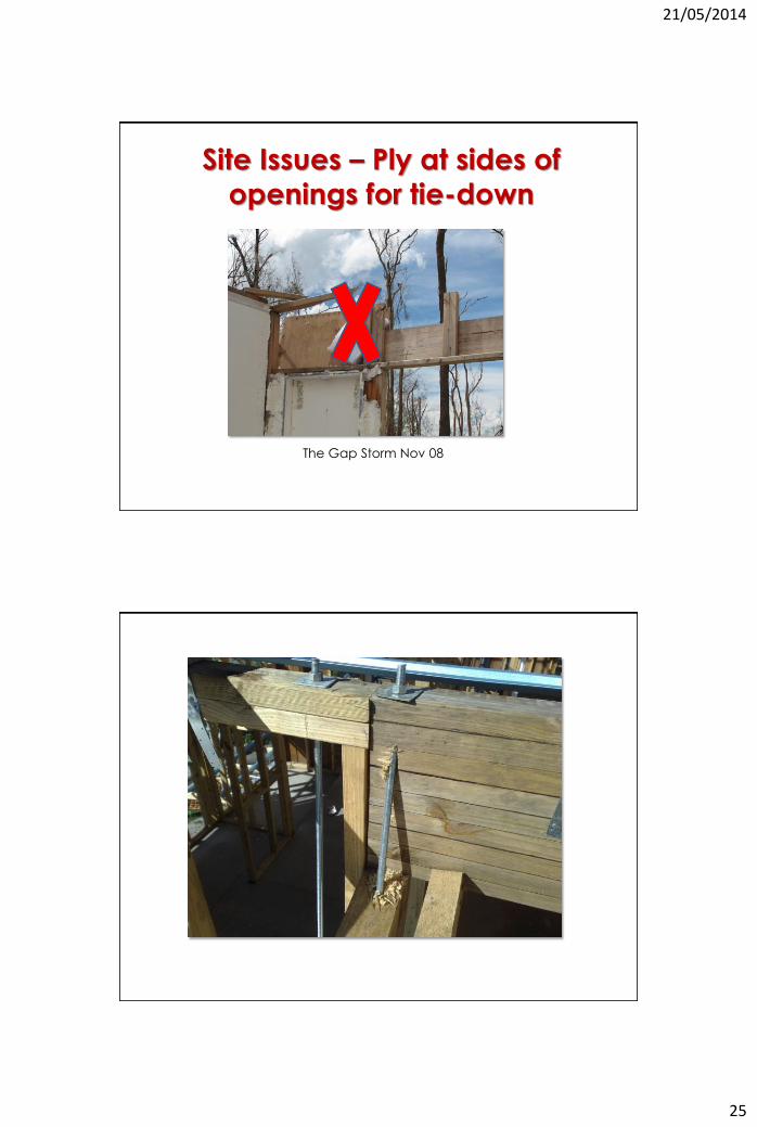
The Gap Storm Nov 08
Site Issues – Ply at sides of
openings for tie-down
21/05/2014
26
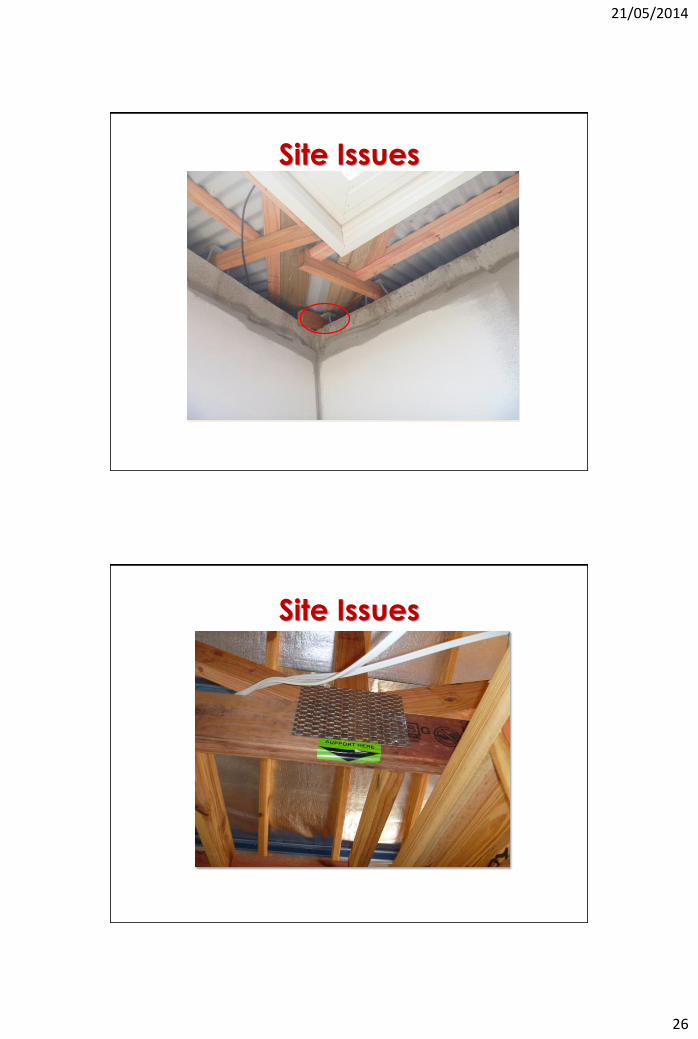
Site Issues
Site Issues
21/05/2014
27
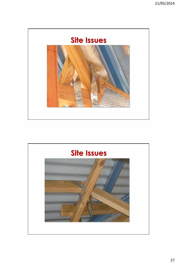
Site Issues
Site Issues
21/05/2014
28
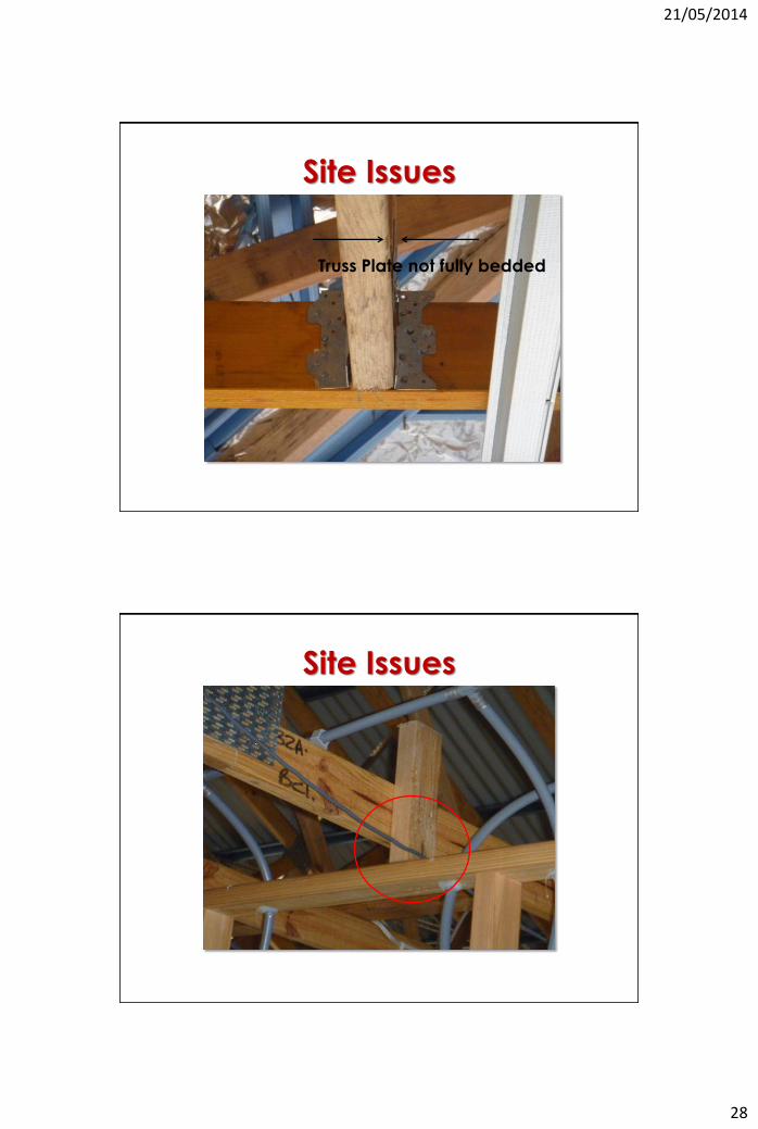
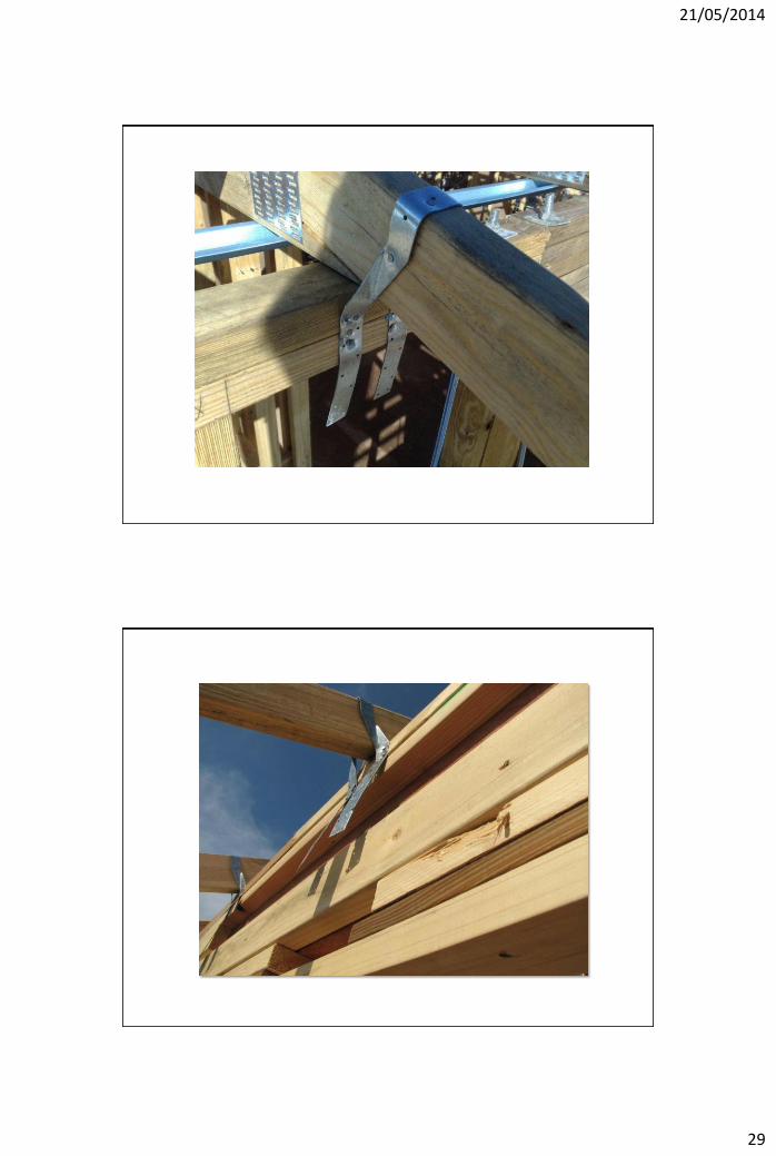
Site Issues
Truss Plate not fully bedded
Site Issues
21/05/2014
29
21/05/2014
30
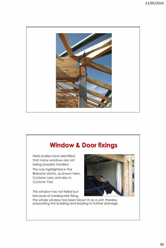
Window & Door fixings
Field studies have identified
that many windows are not
being properly installed.
This was highlighted in the
Brisbane storms, as shown here,
Cyclone Larry and also in
Cyclone Yasi.
This window has not failed but
because of inadequate fixing,
the whole window has been blown in as a unit, thereby pressurising the building and leading to further damage.
21/05/2014
31
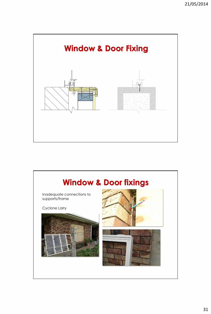
Window & Door Fixing
Gap
Cyclone Larry
Inadequate connections to
supports/frame
Window & Door fixings
21/05/2014
32
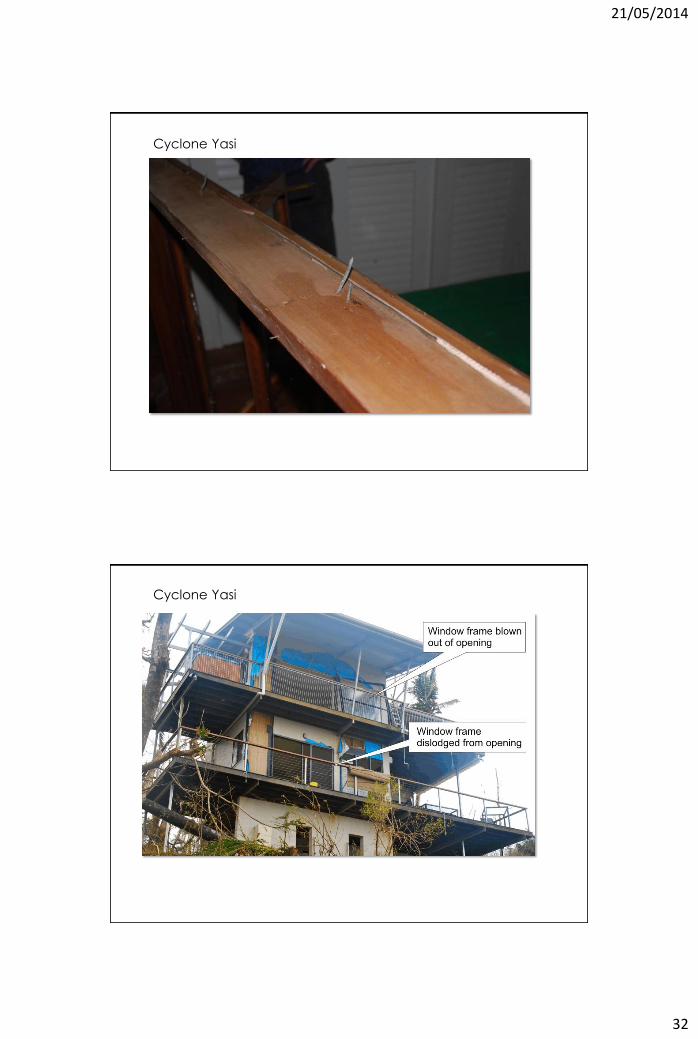
Cyclone Yasi
Cyclone Yasi
21/05/2014
33
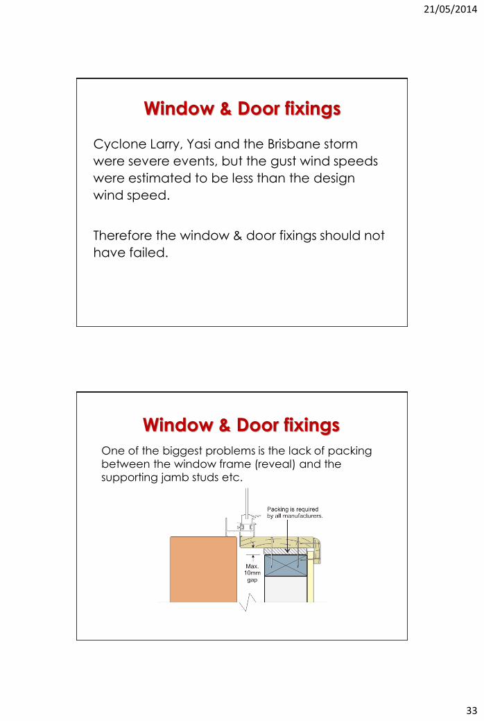
Cyclone Larry, Yasi and the Brisbane storm
were severe events, but the gust wind speeds
were estimated to be less than the design
wind speed.
Therefore the window & door fixings should not
have failed.
Window & Door fixings
Window & Door fixings
One of the biggest problems is the lack of packing
between the window frame (reveal) and the
supporting jamb studs etc.
21/05/2014
34
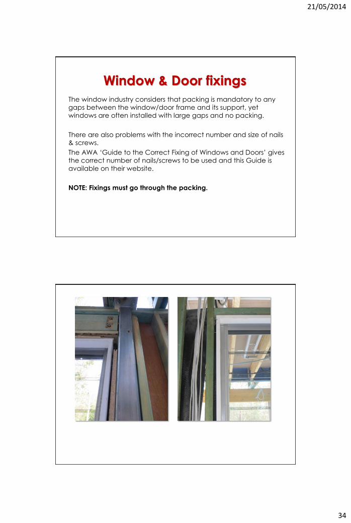
The window industry considers that packing is mandatory to any
gaps between the window/door frame and its support, yet
windows are often installed with large gaps and no packing.
There are also problems with the incorrect number and size of nails
& screws.
The AWA ‘Guide to the Correct Fixing of Windows and Doors’ gives
the correct number of nails/screws to be used and this Guide is
available on their website.
NOTE: Fixings must go through the packing.
Window & Door fixings

21/05/2014
35
Window & Door fixings
Window & Door fixings
21/05/2014
36
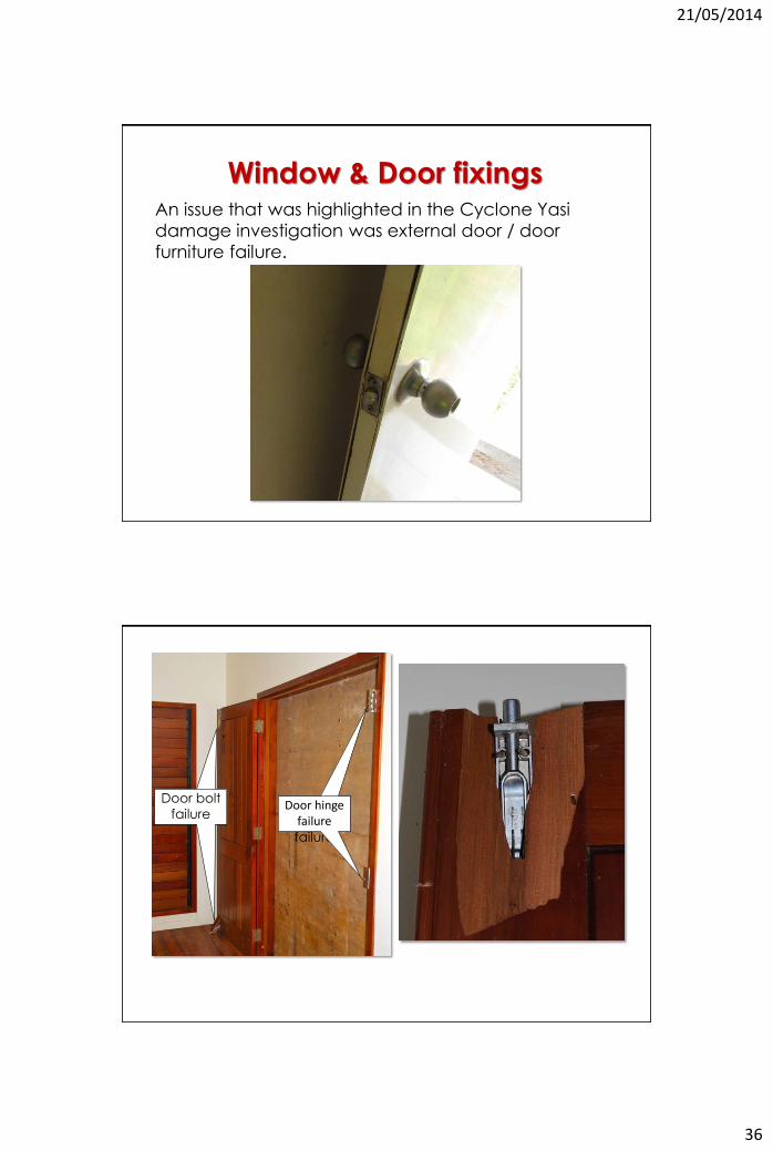
An issue that was highlighted in the Cyclone Yasi
damage investigation was external door / door
furniture failure.
Window & Door fixings
Door bolt failure
Door
hinge
failure
Door hinge failure
Door bolt
failure
21/05/2014
37
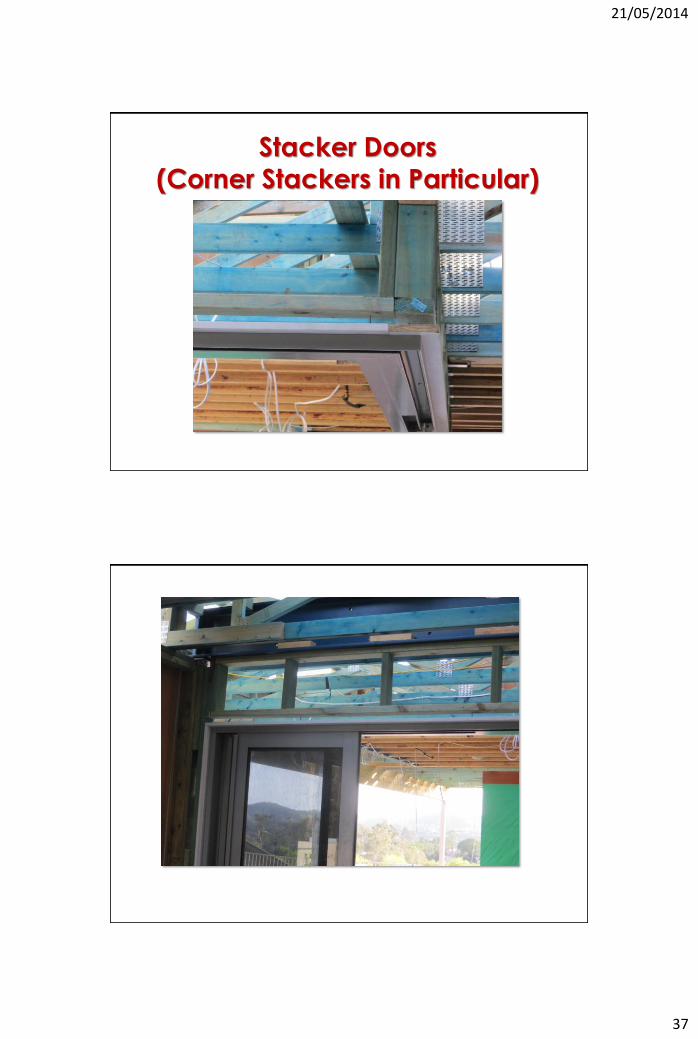
Stacker Doors
(Corner Stackers in Particular)
21/05/2014
38
21/05/2014
39
Questions
21/05/2014
40
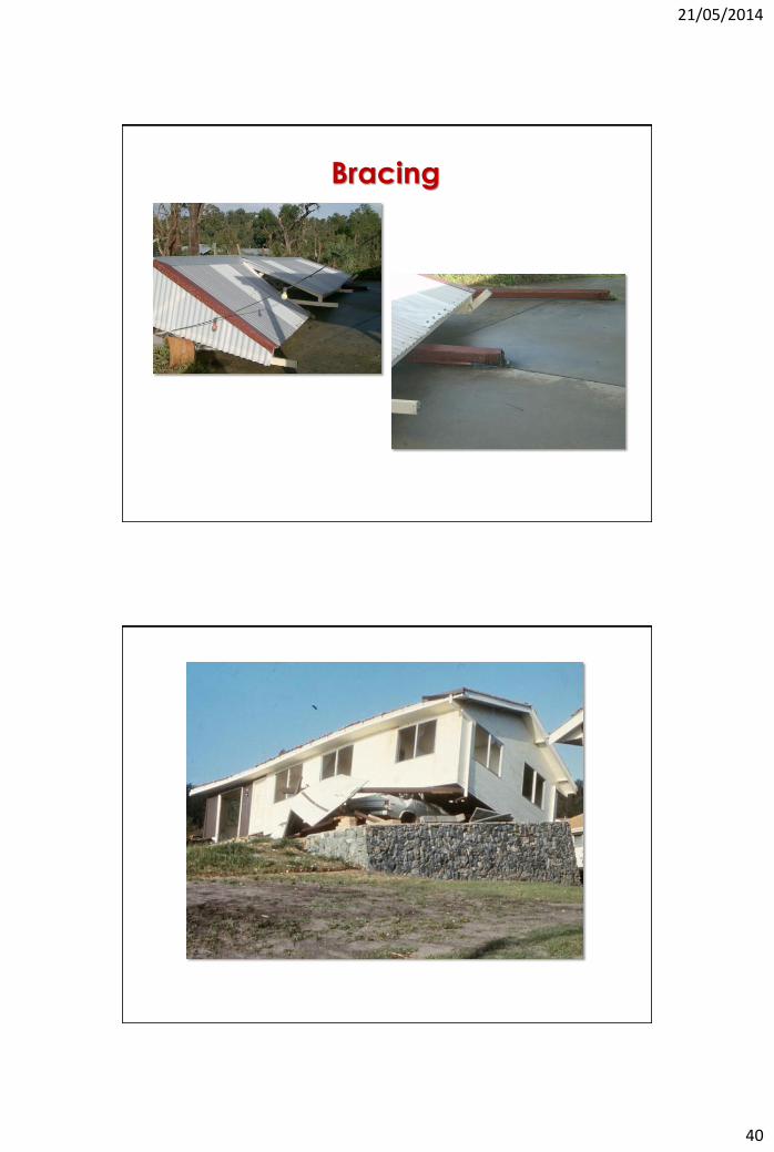
Bracing
21/05/2014
41
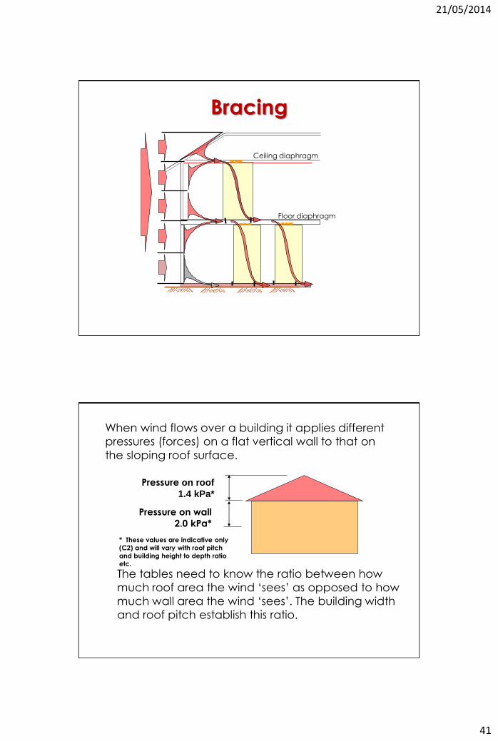
Bracing
Ceiling diaphragm
Floor diaphragm
When wind flows over a building it applies different
pressures (forces) on a flat vertical wall to that on
the sloping roof surface.
* These values are indicative only
(C2) and will vary with roof pitch
and building height to depth ratio
etc.
Pressure on roof
1.4 kPa*
Pressure on wall
2.0 kPa*
The tables need to know the ratio between how
much roof area the wind ‘sees’ as opposed to how
much wall area the wind ‘sees’. The building width
and roof pitch establish this ratio.
21/05/2014
42
10000 mm
30 O
10000 mm
20 O
SAME WIDTH DIFFERENT PITCH
10000 mm
30 O
6000 mm
30 O
SAME PITCH DIFFERENT WIDTH
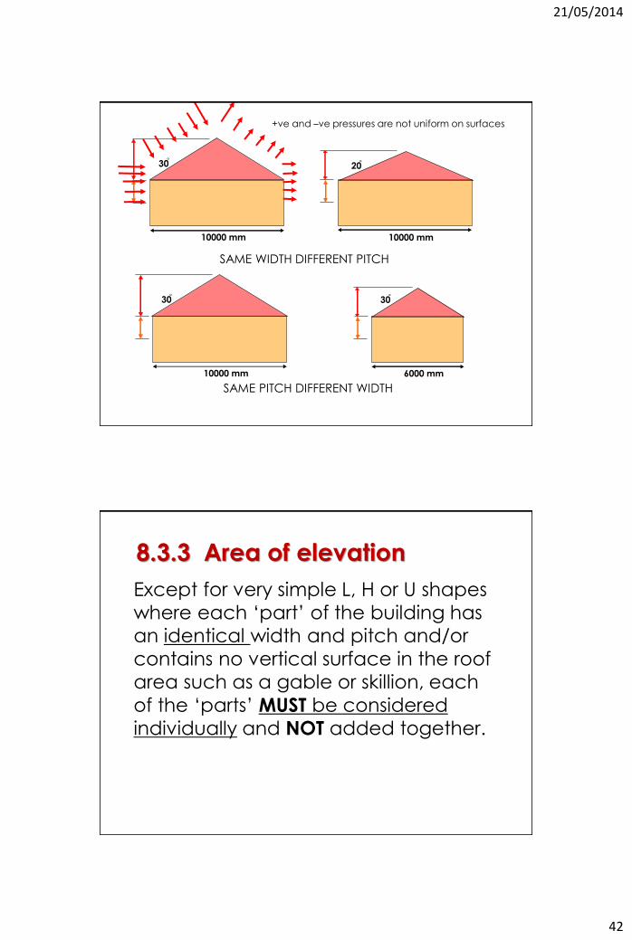
+ve and –ve pressures are not uniform on surfaces
8.3.3 Area of elevation
Except for very simple L, H or U shapes
where each ‘part’ of the building has
an identical width and pitch and/or
contains no vertical surface in the roof
area such as a gable or skillion, each
of the ‘parts’ MUST be considered
individually and NOT added together.
21/05/2014
43
8.3.3 Area of elevation
bracing......, shall be distributed
throughout the house approximately
in proportion to the forces (or areas)
relevant to each shape
(see Clause 8.3.6.6 Location and
distribution of bracing walls).
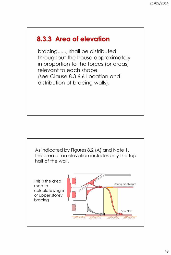
As indicated by Figures 8.2 (A) and Note 1, the area of an elevation includes only the top half of the wall.
Ceiling diaphragm
Floor Slab
This is the area
used to
calculate single
or upper storey
bracing
21/05/2014
44
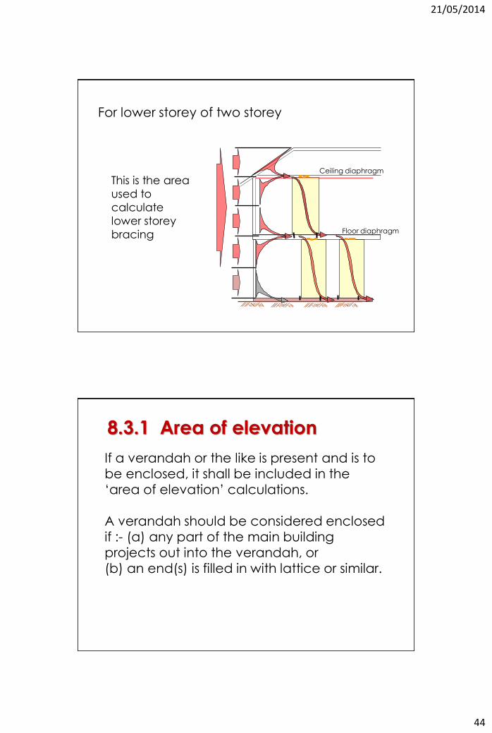
This is the area
used to
calculate
lower storey
bracing
Ceiling diaphragm
Floor diaphragm
For lower storey of two storey
8.3.1 Area of elevation
If a verandah or the like is present and is to be enclosed, it shall be included in the
‘area of elevation’ calculations. A verandah should be considered enclosed if :- (a) any part of the main building projects out into the verandah, or (b) an end(s) is filled in with lattice or similar.
21/05/2014
45
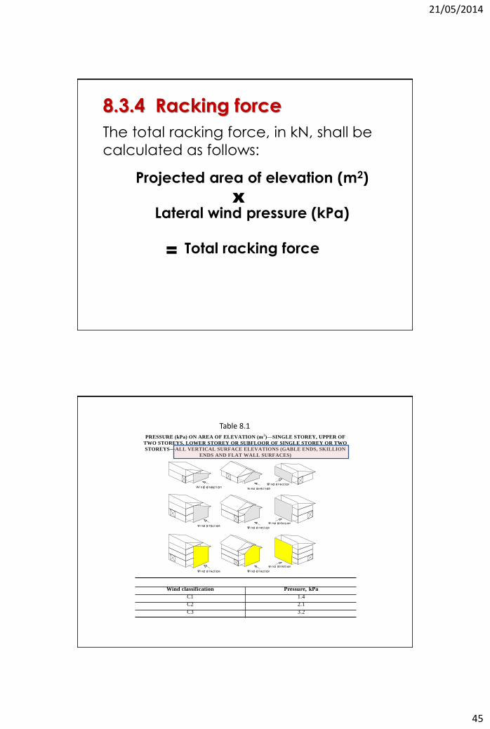
8.3.4 Racking force
The total racking force, in kN, shall be
calculated as follows:
Projected area of elevation (m2)
Lateral wind pressure (kPa)
Total racking force
x
=
PRESSURE (kPa) ON AREA OF ELEVATION (m2)—SINGLE STOREY, UPPER OF
TWO STOREYS, LOWER STOREY OR SUBFLOOR OF SINGLE STOREY OR TWO
STOREYS—ALL VERTICAL SURFACE ELEVATIONS (GABLE ENDS, SKILLION
ENDS AND FLAT WALL SURFACES)
Wind classification Pressure, kPa
C1 1.4
C2 2.1
C3 3.2
Table 8.1
21/05/2014
46
C2
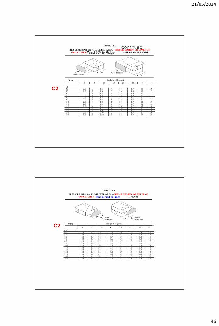
continued TABLE 8.2
PRESSURE (kPa) ON PROJECTED AREA—SINGLE STOREY OR UPPER OF
TWO STOREY—LONG LENGTH OF BUILDING—HIP OR GABLE ENDS
W
W
Wind directionWind direction
W (m) Roof pitch (degrees)
Wind 90O to Ridge
C2 4.0 2.0 1.7 1.6 1.4 1.4 1.7 1.8 1.8
5.0 2.0 1.7 1.5 1.3 1.3 1.6 1.8 1.7 6.0 2.0 1.6 1.4 1.3 1.4 1.6 1.7 1.7
7.0 2.0 1.6 1.4 1.2 1.4 1.6 1.7 1.7 8.0 2.0 1.5 1.3 1.2 1.4 1.6 1.7 1.7 9.0 2.0 1.5 1.3 1.1 1.4 1.7 1.7 1.7 10.0 2.0 1.4 1.2 1.1 1.4 1.7 1.6 1.7
11.0 2.0 1.4 1.2 1.1 1.4 1.7 1.6 1.8 12.0 2.0 1.4 1.1 1.1 1.5 1.7 1.7 1.8
13.0 2.0 1.3 1.1 1.1 1.5 1.7 1.7 1.8 14.0 2.0 1.3 1.0 1.2 1.5 1.7 1.7 1.8 15.0 2.0 1.3 0.97 1.2 1.5 1.7 1.7 1.8 16.0 2.0 1.2 0.93 1.2 1.5 1.7 1.7 1.8
0 5 10 15 20 25 30 35
C2
TABLE 8.4
PRESSURE (kPa) ON PROJECTED AREA—SINGLE STOREY OR UPPER OF
TWO-STOREY—SHORT END OF BUILDING—HIP ENDS
W Wind direction
W Wind direction
W (m) Roof pitch (degrees)
Wind parallel to Ridge
C2
4.0 2.1 2.0 1.9 1.8 1.8 1.8 1.9 1.9 5.0 2.1 2.0 1.8 1.7 1.7 1.8 1.9 1.8
6.0 2.1 1.9 1.8 1.7 1.7 1.8 1.8 1.8 7.0 2.1 1.9 1.7 1.6 1.7 1.8 1.8 1.8 8.0 2.1 1.9 1.7 1.6 1.7 1.8 1.8 1.8 9.0 2.1 1.8 1.7 1.5 1.7 1.8 1.8 1.8
10.0 2.1 1.8 1.6 1.5 1.7 1.8 1.8 1.8 11.0 2.1 1.8 1.6 1.5 1.7 1.8 1.8 1.8
12.0 2.1 1.8 1.5 1.5 1.7 1.8 1.8 1.8 13.0 2.1 1.7 1.5 1.5 1.7 1.8 1.8 1.8 14.0 2.1 1.7 1.4 1.5 1.7 1.8 1.8 1.8
15.0 2.1 1.7 1.4 1.5 1.7 1.8 1.8 1.9 16.0 2.1 1.7 1.4 1.5 1.7 1.8 1.8 1.9
0 5 10 15 20 25 30 35
21/05/2014
47
8.3.6 Wall bracing
Walls shall be permanently braced to resist
horizontal racking forces applied to the building.
Wall bracing shall be designed to resist racking
forces equal to or greater than the forces
calculated from Clause 8.3.4.
The total capacity of bracing walls shall be the
sum of the bracing capacities of individual walls.
See Table 8.18 for the capacity of structural
bracing walls.
8.3.6.1 General
AS 1684 USER GUIDE
Temporary Bracing 2 G U I D E T O T H E U S E O F AS 1684
AS 1684 only requires temporary bracing to
be 60% of the permanent bracing and this reflects the lower probability of a building being subjected to its long term maximum design gust wind speed event, during the relatively short period of construction.
21/05/2014
48
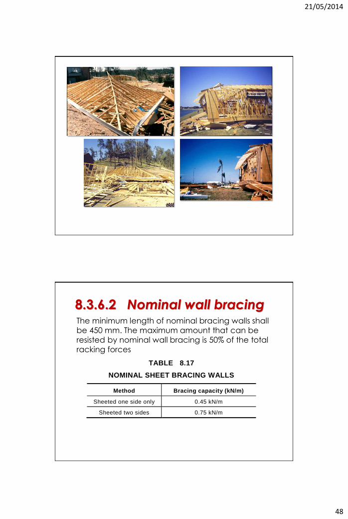
The minimum length of nominal bracing walls shall
be 450 mm. The maximum amount that can be
resisted by nominal wall bracing is 50% of the total
racking forces
8.3.6.2 Nominal wall bracing
TABLE 8.17
NOMINAL SHEET BRACING WALLS
Method Bracing capacity (kN/m)
Sheeted one side only 0.45 kN/m
Sheeted two sides 0.75 kN/m
21/05/2014
49
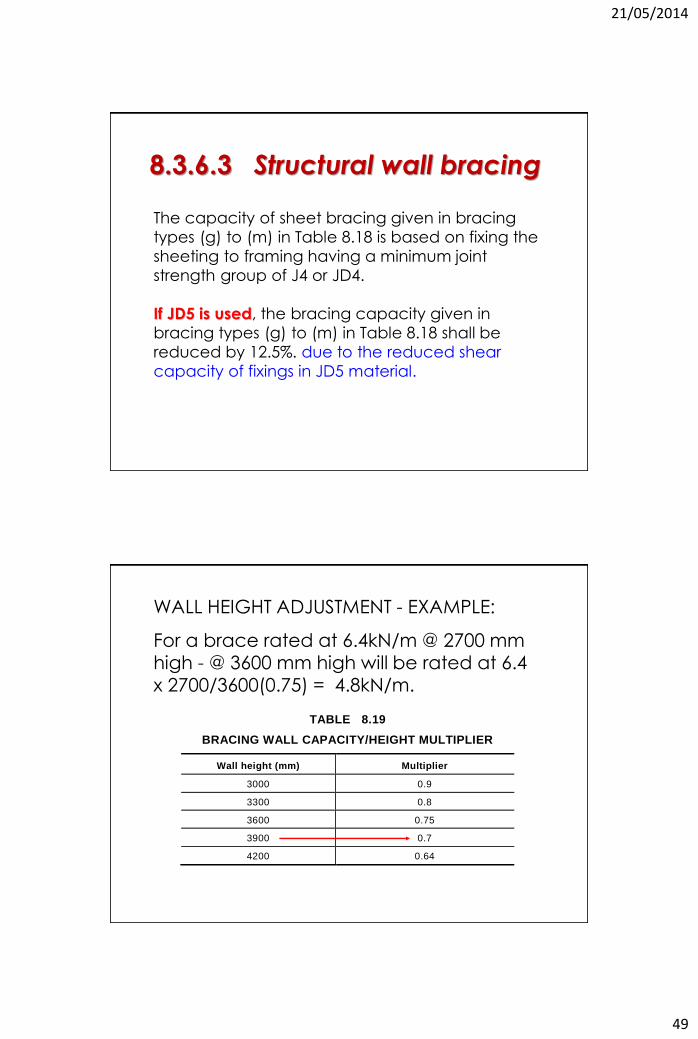
The capacity of sheet bracing given in bracing
types (g) to (m) in Table 8.18 is based on fixing the
sheeting to framing having a minimum joint
strength group of J4 or JD4.
If JD5 is used, the bracing capacity given in
bracing types (g) to (m) in Table 8.18 shall be
reduced by 12.5%. due to the reduced shear
capacity of fixings in JD5 material.
8.3.6.3 Structural wall bracing
TABLE 8.19
BRACING WALL CAPACITY/HEIGHT MULTIPLIER
Wall height (mm) Multiplier
3000 0.9
3300 0.8
3600 0.75
3900 0.7
4200 0.64
WALL HEIGHT ADJUSTMENT - EXAMPLE:
For a brace rated at 6.4kN/m @ 2700 mm high - @ 3600 mm high will be rated at 6.4 x 2700/3600(0.75) = 4.8kN/m.
21/05/2014
50
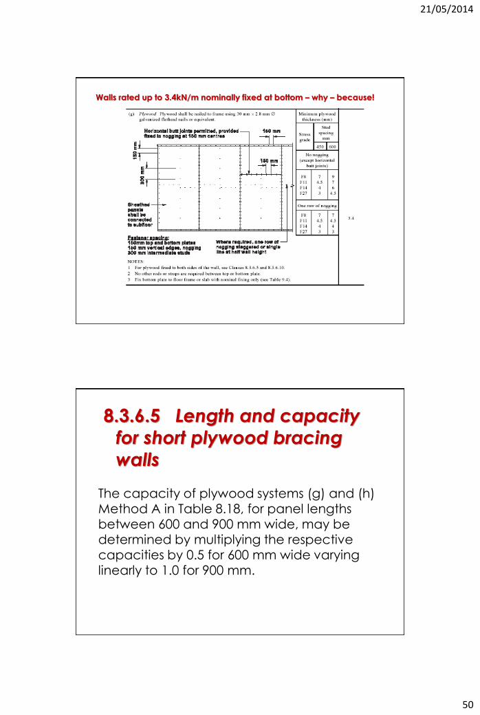
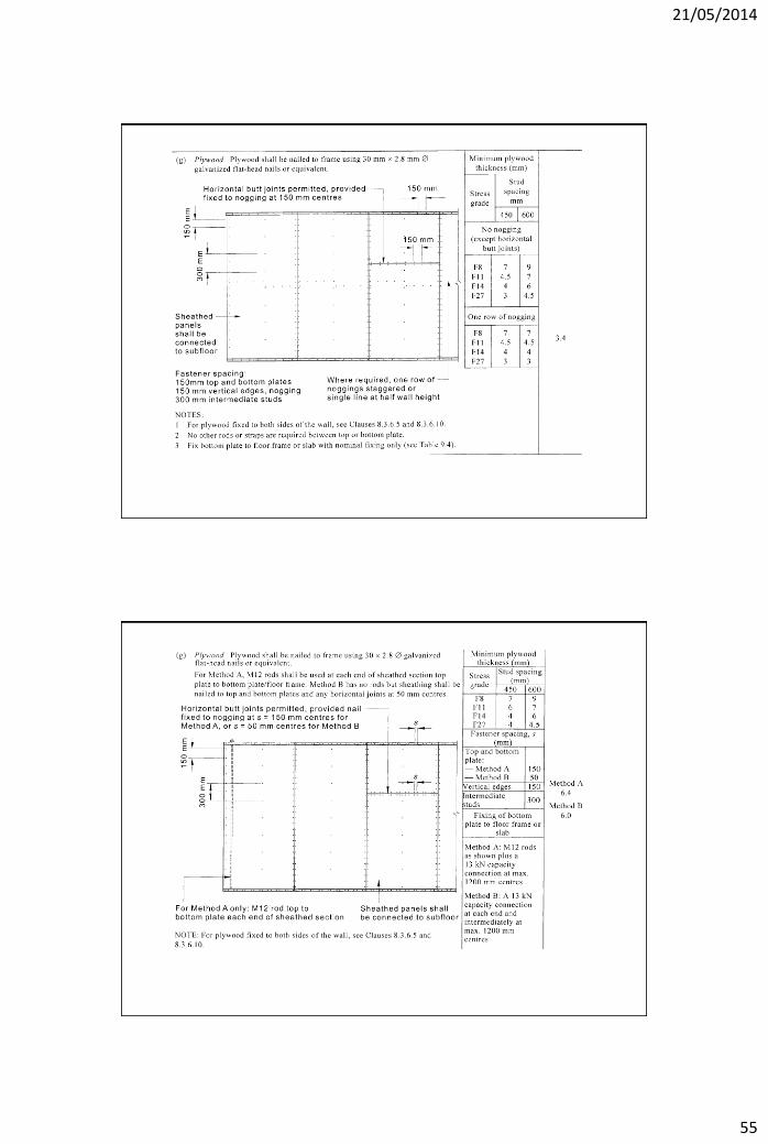
Walls rated up to 3.4kN/m nominally fixed at bottom – why – because!
The capacity of plywood systems (g) and (h) Method A in Table 8.18, for panel lengths between 600 and 900 mm wide, may be determined by multiplying the respective capacities by 0.5 for 600 mm wide varying linearly to 1.0 for 900 mm.
8.3.6.5 Length and capacity
for short plywood bracing
walls
21/05/2014
51
All internal bracing walls shall be fixed to —
(a) the floor for lower storey bracing walls;
(b) the ceiling or roof frame; and/or
(c) the external wall frame,
with structural connections of equivalent shear
capacity to the bracing capacity of that particular
bracing wall.
Nominal and other bracing walls with bracing
capacity up to 1.5 kN/m require nominal
fixing only, i.e. no additional fixing requirements.
8.3.6.9 Fixing of top of bracing walls
Internal bracing walls can be connected to the floor/ceiling/roof diaphragm either directly (a connection at the actual position of the bracing wall) or at some other position in the same wall but away from the actual brace.
AS 1684USER GUIDE 5
G U I D E T O T H E U S E O F AS 1684
Fixing of Top of Bracing Walls
21/05/2014
52
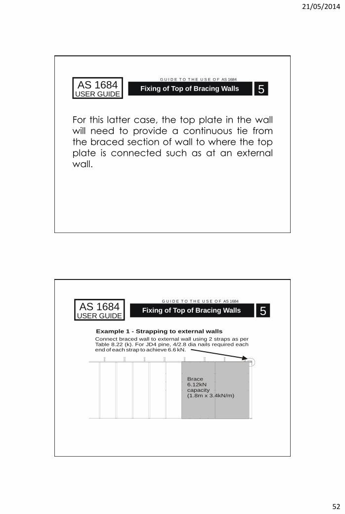
For this latter case, the top plate in the wall will need to provide a continuous tie from
the braced section of wall to where the top plate is connected such as at an external wall.
AS 1684USER GUIDE 5
G U I D E T O T H E U S E O F AS 1684
Fixing of Top of Bracing Walls
Connect braced wall to external wall using 2 straps as perTable 8.22 (k). For JD4 pine, 4/2.8 dia nails required each end of each strap to achieve 6.6 kN.
Example 1 - Strapping to external walls
Brace6.12kNcapacity(1.8m x 3.4kN/m)
AS 1684USER GUIDE 5
G U I D E T O T H E U S E O F AS 1684
Fixing of Top of Bracing Walls
21/05/2014
53
AS 1684USER GUIDE 5
G U I D E T O T H E U S E O F AS 1684
Fixing of Top of Bracing Walls
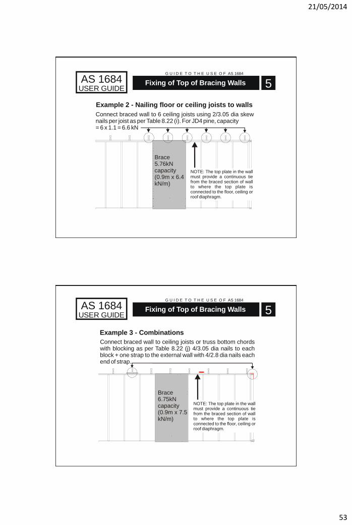
Brace5.76kNcapacity(0.9m x 6.4kN/m)
Connect braced wall to 6 ceiling joists using 2/3.05 dia skew nails per joist as per Table 8.22 (i). For JD4 pine, capacity = 6 x 1.1 = 6.6 kN
Example 2 - Nailing floor or ceiling joists to walls
NOTE: The top plate in the wall must provide a continuous tie from the braced section of wall to where the top plate is connected to the floor, ceiling or roof diaphragm.
AS 1684USER GUIDE 5
G U I D E T O T H E U S E O F AS 1684
Fixing of Top of Bracing Walls
Connect braced wall to ceiling joists or truss bottom chords with blocking as per Table 8.22 (j) 4/3.05 dia nails to each block + one strap to the external wall with 4/2.8 dia nails each end of strap.
Example 3 - Combinations
Brace6.75kNcapacity(0.9m x 7.5kN/m)
NOTE: The top plate in the wall must provide a continuous tie from the braced section of wall to where the top plate is connected to the floor, ceiling or roof diaphragm.
21/05/2014
54
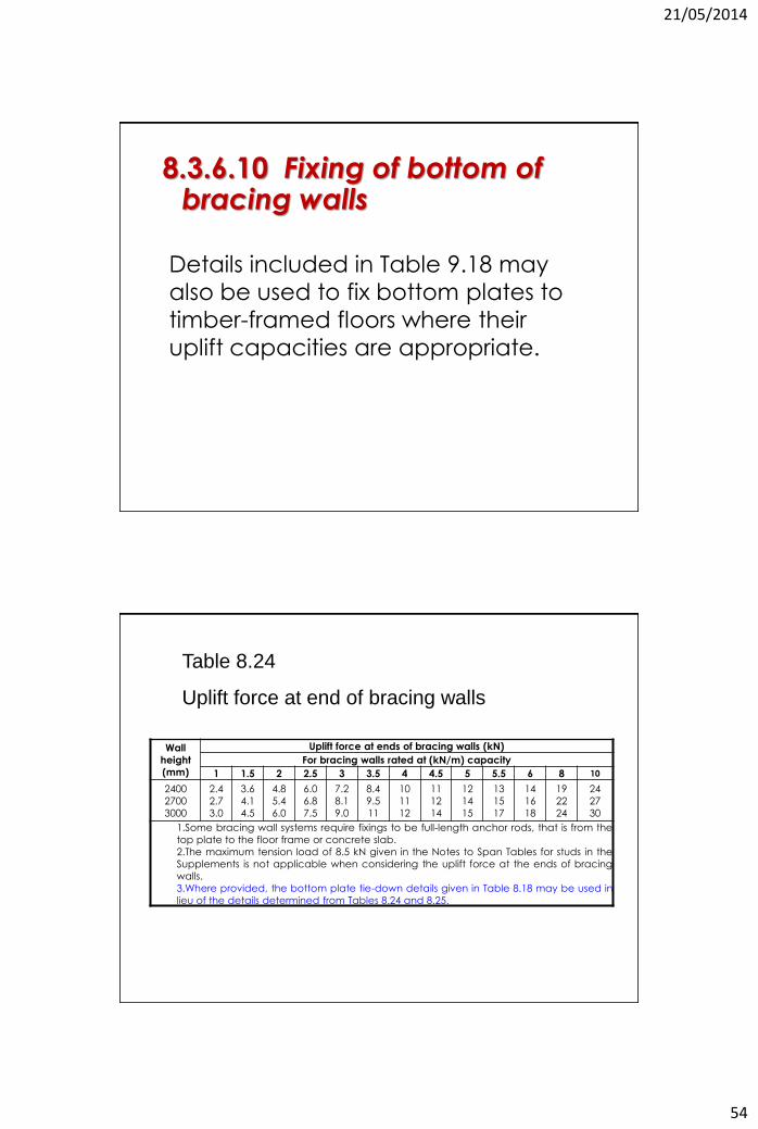
Details included in Table 9.18 may
also be used to fix bottom plates to
timber-framed floors where their
uplift capacities are appropriate.
8.3.6.10 Fixing of bottom of bracing walls
Wall
height
(mm)
Uplift force at ends of bracing walls (kN)
For bracing walls rated at (kN/m) capacity
1 1.5 2 2.5 3 3.5 4 4.5 5 5.5 6 8 10
2400
2700
3000
2.4
2.7
3.0
3.6
4.1
4.5
4.8
5.4
6.0
6.0
6.8
7.5
7.2
8.1
9.0
8.4
9.5
11
10
11
12
11
12
14
12
14
15
13
15
17
14
16
18
19
22
24
24
27
30
1.Some bracing wall systems require fixings to be full-length anchor rods, that is from the
top plate to the floor frame or concrete slab.
2.The maximum tension load of 8.5 kN given in the Notes to Span Tables for studs in the
Supplements is not applicable when considering the uplift force at the ends of bracing
walls.
3.Where provided, the bottom plate tie-down details given in Table 8.18 may be used in
lieu of the details determined from Tables 8.24 and 8.25.
Table 8.24
Uplift force at end of bracing walls
21/05/2014
55
21/05/2014
56
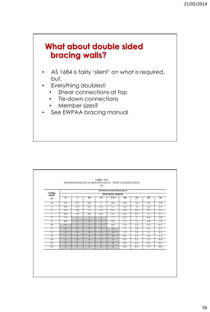
What about double sided bracing walls?
• AS 1684 is fairly ‘silent’ on what is required,
but, • Everything doubles!!
• Shear connections at top • Tie-down connections • Member sizes?
• See EWPAA bracing manual
Ceiling depth
m
Maximum bracing wall spacing, m
Roof pitch, degrees
0 5 10 15 17.5 20 25 30 35
4 3.9 4.3 4.9 5 4.6 4.2 3.4 2.9 2.8
5 4.9 5.4 6.1 6.2 5.7 5.2 4 3.3 3.1
6 5.9 6.6 7.3 7.4 6.5 5.8 4.4 3.7 3.4
7 6.9 7.9 8.6 8.3 7.2 6.3 4.7 4 3.7
8 7.9 9 9 9 7.7 6.7 5 4.4 3.8
9 8.8 9 9 9 8.4 7.1 5.2 4.8 3.9
10 9 9 9 9 8.9 7.4 5.5 5.2 4.1
11 9 9 9 9 9 7.7 5.8 5.2 4.2
12 9 9 9 9 9 7.9 5.9 5.2 4.3
13 9 9 9 9 9 8.1 6.1 5.3 4.3
14 9 9 9 9 9 8.2 6.1 5.5 4.4
15 9 9 9 9 9 8.5 6.3 5.5 4.5
16 9 9 9 9 9 8.6 6.5 5.7 4.6
TABLE 8.21
MAXIMUM SPACING OF BRACING WALLS—WIND CLASSIFICATION
C2
21/05/2014
57
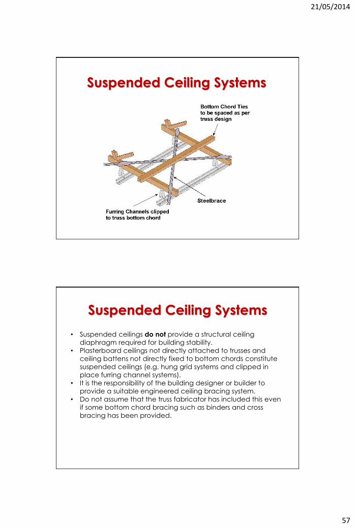
Suspended Ceiling Systems
Suspended Ceiling Systems
• Suspended ceilings do not provide a structural ceiling
diaphragm required for building stability.
• Plasterboard ceilings not directly attached to trusses and
ceiling battens not directly fixed to bottom chords constitute
suspended ceilings (e.g. hung grid systems and clipped in
place furring channel systems).
• It is the responsibility of the building designer or builder to
provide a suitable engineered ceiling bracing system.
• Do not assume that the truss fabricator has included this even
if some bottom chord bracing such as binders and cross
bracing has been provided.
21/05/2014
58
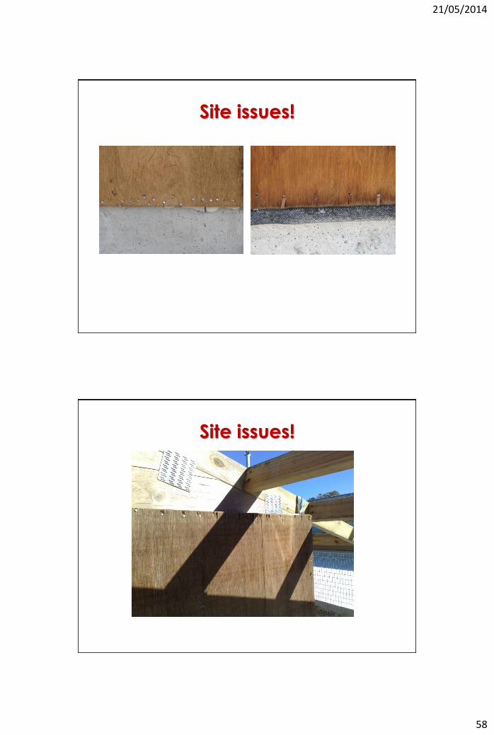
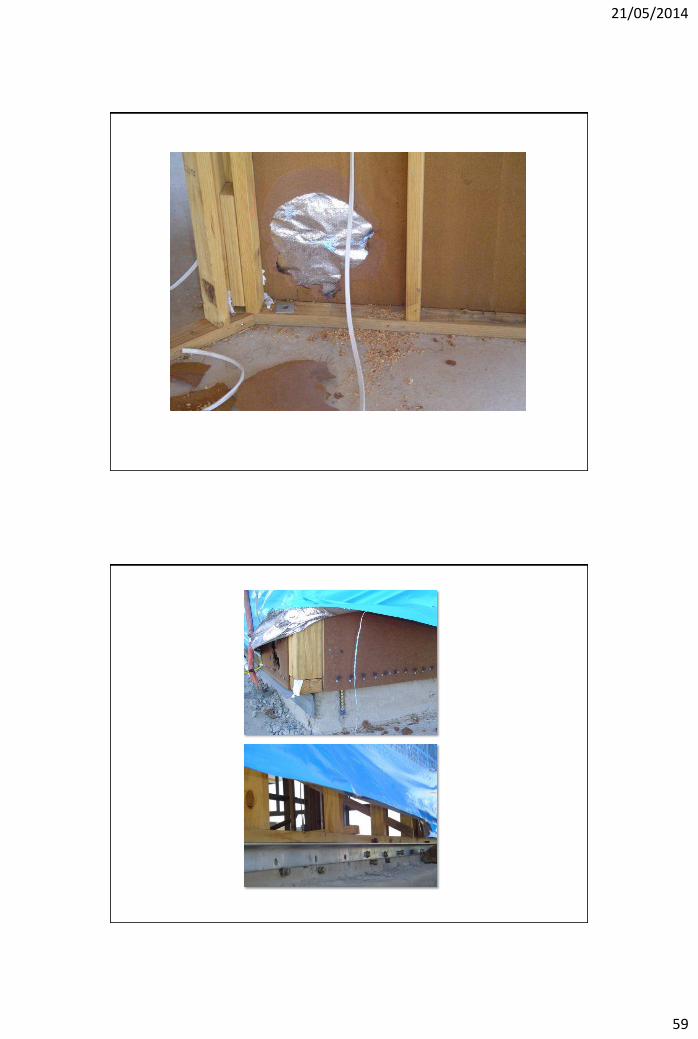
Site issues!
Site issues!
21/05/2014
59
21/05/2014
60
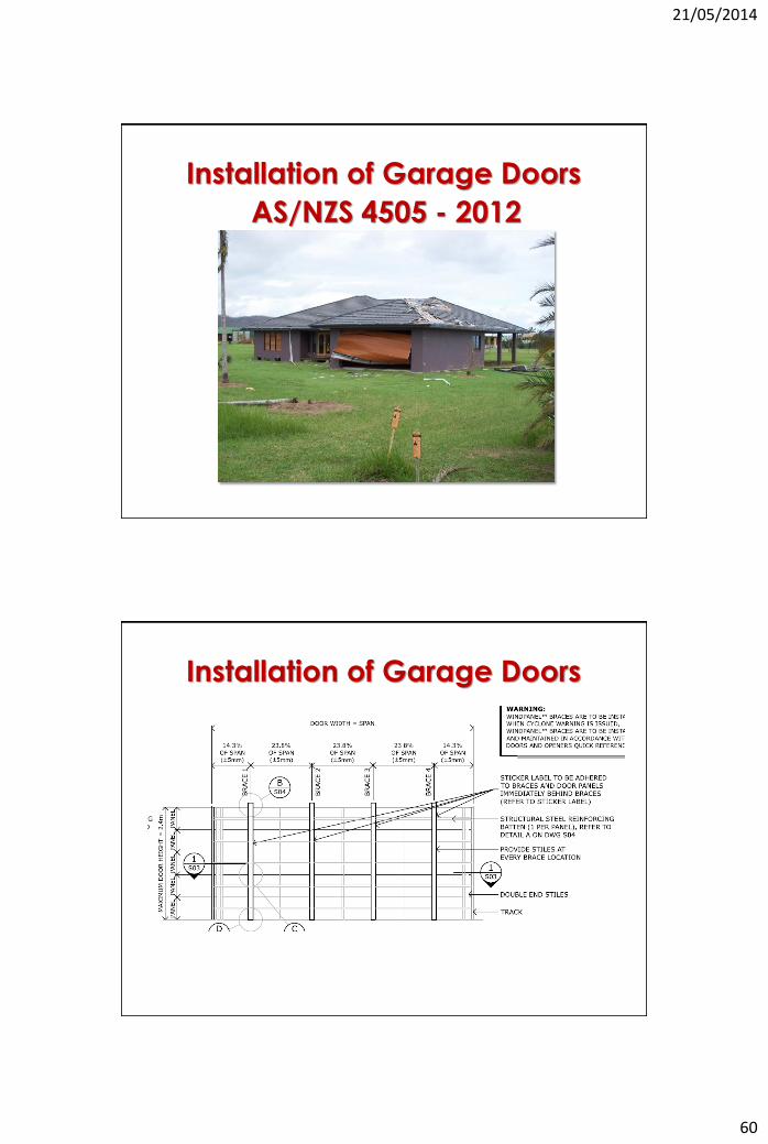
Installation of Garage Doors
AS/NZS 4505 - 2012
Installation of Garage Doors
21/05/2014
61
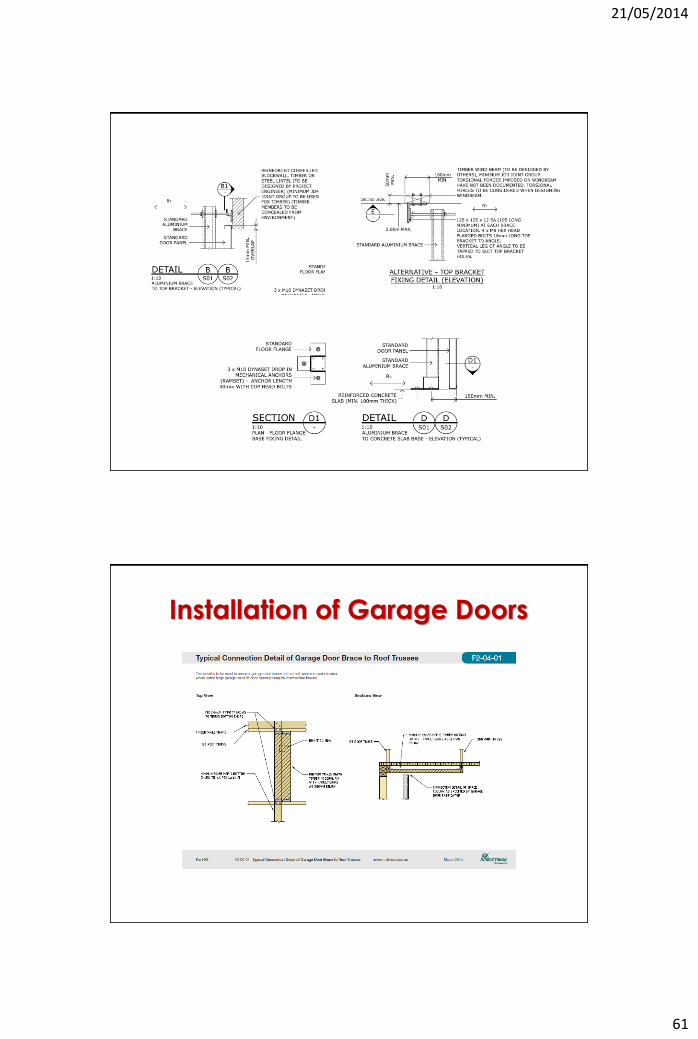
Installation of Garage Doors
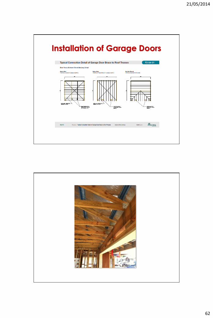
21/05/2014
62
Installation of Garage Doors
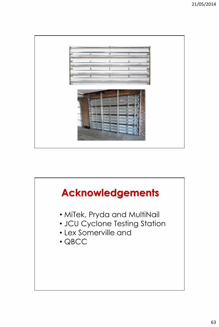
21/05/2014
63
Acknowledgements
• MiTek, Pryda and MultiNail
• JCU Cyclone Testing Station
• Lex Somerville and
• QBCC