braced frames - steelconstruction
TRANSCRIPT
Home
Print PDF
SteelConstruction.info
The free encyclopedia for UK steel construction information
BCSA TATA Steel SCI Steel Knowledge
Log in / create account
Search
Views
Braced frames
From Steelconstruction.info
Braced frames are a very common form of construction, being economic to construct and simple to analyse.
Economy comes from the inexpensive, nominally pinned connections between beams and columns. Bracing,
which provides stability and resists lateral loads, may be from diagonal steel members or, from a concrete
'core'. In braced construction, beams and columns are designed under vertical load only, assuming the bracing
system carries all lateral loads.
Contents
1 Bracing systems
1.1 Location of planes of vertical bracing
2 Vertical bracing
3 Horizontal bracing
3.1 Horizontal diaphragms
3.2 Discrete triangulated bracing
4 The effects of imperfections
4.1 Imperfections for global analysis of braced frames
4.1.1 Equivalent horizontal forces
5 Additional design cases for bracing systems
5.1 Imperfection for analysis of bracing systems
6 Second order effects
6.1 Determination of second order effects
6.2 Second-order analysis
Braced frames - Steelconstruction.info http://www.steelconstruction.info/Braced_frames
1 of 11 7/30/2014 1:38 PM
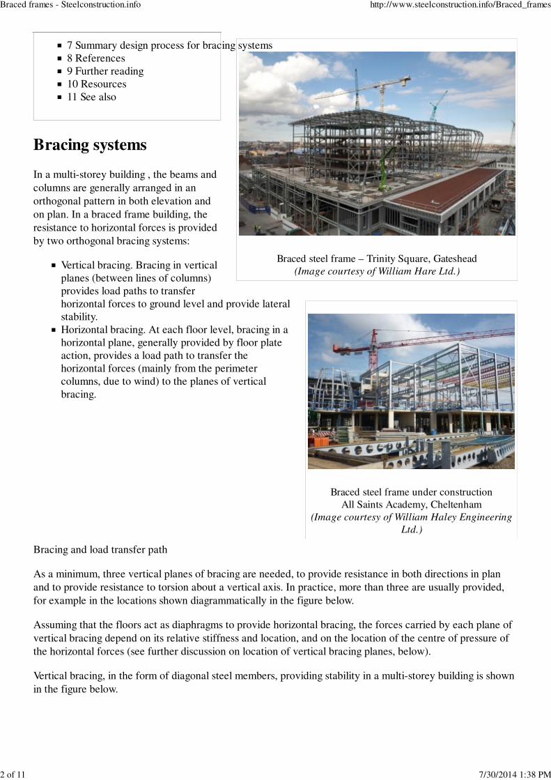
Braced steel frame – Trinity Square, Gateshead
(Image courtesy of William Hare Ltd.)
Braced steel frame under construction
All Saints Academy, Cheltenham
(Image courtesy of William Haley Engineering
Ltd.)
7 Summary design process for bracing systems
8 References
9 Further reading
10 Resources
11 See also
Bracing systems
In a multi-storey building , the beams and
columns are generally arranged in an
orthogonal pattern in both elevation and
on plan. In a braced frame building, the
resistance to horizontal forces is provided
by two orthogonal bracing systems:
Vertical bracing. Bracing in vertical
planes (between lines of columns)
provides load paths to transfer
horizontal forces to ground level and provide lateral
stability.
Horizontal bracing. At each floor level, bracing in a
horizontal plane, generally provided by floor plate
action, provides a load path to transfer the
horizontal forces (mainly from the perimeter
columns, due to wind) to the planes of vertical
bracing.
Bracing and load transfer path
As a minimum, three vertical planes of bracing are needed, to provide resistance in both directions in plan
and to provide resistance to torsion about a vertical axis. In practice, more than three are usually provided,
for example in the locations shown diagrammatically in the figure below.
Assuming that the floors act as diaphragms to provide horizontal bracing, the forces carried by each plane of
vertical bracing depend on its relative stiffness and location, and on the location of the centre of pressure of
the horizontal forces (see further discussion on location of vertical bracing planes, below).
Vertical bracing, in the form of diagonal steel members, providing stability in a multi-storey building is shown
in the figure below.
Braced frames - Steelconstruction.info http://www.steelconstruction.info/Braced_frames
2 of 11 7/30/2014 1:38 PM

Typical arrangement of vertical bracing
Vertical bracing in a multi-storey building
Stability to a building can also be provided partially or entirely
by one or more reinforced concrete cores.
Location of planes of vertical bracing
It is preferable to locate bracing at or near the extremities
of the structure, in order to resist any torsional effects.
See figure on the right.
Where the sets of bracing are identical or similar, it is
sufficient to assume that the horizontal forces (wind loads
and equivalent horizontal forces, each magnified for
second order effects if necessary, see discussion below)
are shared equally between the bracing systems in the
orthogonal direction under consideration.
Where the stiffnesses of the vertical bracing systems
differ or the bracing systems are located asymmetrically
on plan, as shown in the figure below, equal sharing of
forces should not be assumed. The forces carried by each
bracing system can be calculated by assuming the floor is
a stiff beam and the bracing systems are spring supports,
as shown in the figure below.
Braced frames - Steelconstruction.info http://www.steelconstruction.info/Braced_frames
3 of 11 7/30/2014 1:38 PM

Determination of bracing forces for asymmetric
arrangement of bracing
Cantilever truss
The stiffness of each bracing system should be calculated by applying horizontal forces to each bracing
system and calculating the deflection. The spring stiffness (typically in mm/kN) can then be used to calculate
the distribution of force to each bracing system.
Vertical bracing
In a braced multi-storey building , the planes of vertical bracing are usually provided by diagonal bracing
between two lines of columns, as shown in the figure below. Either single diagonals are provided, as shown,
in which case they must be designed for either tension or compression, or crossed diagonals are provided, in
which case slender bracing members carrying only tension may be provided.
Note that when crossed diagonals are used and it is assumed
that only the tensile diagonals provide resistance, the floor
beams participate as part of the bracing system (in effect a
vertical Pratt truss is created, with diagonals in tension and
posts (the floor beams) in compression).
The vertical bracing must be designed to resist the forces due
to the following:
Wind loads
Equivalent horizontal forces, representing the effect of
initial imperfections
Second order effects due to sway (if the frame is
sensitive to second order effects).
Guidance on the determination of equivalent horizontal forces
and on the consideration of second order effects in discussed
in the sections below.
Forces in the individual members of the bracing system must
be determined for the appropriate combinations of actions. For
bracing members, design forces at ULS due to the combination where wind load is the leading action are
likely to be the most onerous.
Where possible, bracing members inclined at approximately 45° are recommended. This provides an efficient
Braced frames - Steelconstruction.info http://www.steelconstruction.info/Braced_frames
4 of 11 7/30/2014 1:38 PM

Horizontal bracing (in the roof) in a single storey
building
system with relatively modest member forces compared to other arrangements, and means that the
connection details where the bracing meets the beam/column junctions are compact. Narrow bracing systems
with steeply inclined internal members will increase the sway sensitivity of the structure. Wide bracing
systems will result in more stable structures.
The table below gives an indication of how maximum deflection varies with bracing layout, for a constant
size of bracing cross section.
Bracing efficiency
Storey
height
Bracing
width
Angle from
horizontal
Ratio of maximum
deflection (compared to
bracing at 34°)
h 2h 26° 0.9
h 1.5h 34° 1.0
h h 45° 1.5
h 0.75h 53° 2.2
h 0.5h 63° 4.5
Horizontal bracing
A horizontal bracing system is needed at each floor
level, to transfer horizontal forces (chiefly the forces
transferred from the perimeter columns) to the
planes of vertical bracing that provide resistance to
horizontal forces.
There are two types of horizontal bracing system that
are used in multi-storey braced frames:
Diaphragms
Discrete triangulated bracing.
Usually, the floor system will be sufficient to act as a
diaphragm without the need for additional steel
bracing. At roof level, bracing, often known as a
wind girder, may be required to carry the horizontal
forces at the top of the columns, if there is no
diaphragm. See figure on the right.
Horizontal diaphragms
All floor solutions involving permanent formwork such as metal decking fixed by through-deck stud welding
to the beams, with in-situ concrete infill, provide an excellent rigid diaphragm to carry horizontal forces to
the bracing system.
Floor systems involving precast concrete planks require proper consideration to ensure adequate transfer of
forces if they are to act as a diaphragm. The coefficient of friction between planks and steelwork may be as
low as 0.1, and even lower if the steel is painted. This will allow the slabs to move relative to each other, and
to slide over the steelwork. Grouting between the slabs will only partially overcome this problem, and for
large shears, a more positive tying system will be required between the slabs and from the slabs to the
steelwork.
Braced frames - Steelconstruction.info http://www.steelconstruction.info/Braced_frames
5 of 11 7/30/2014 1:38 PM
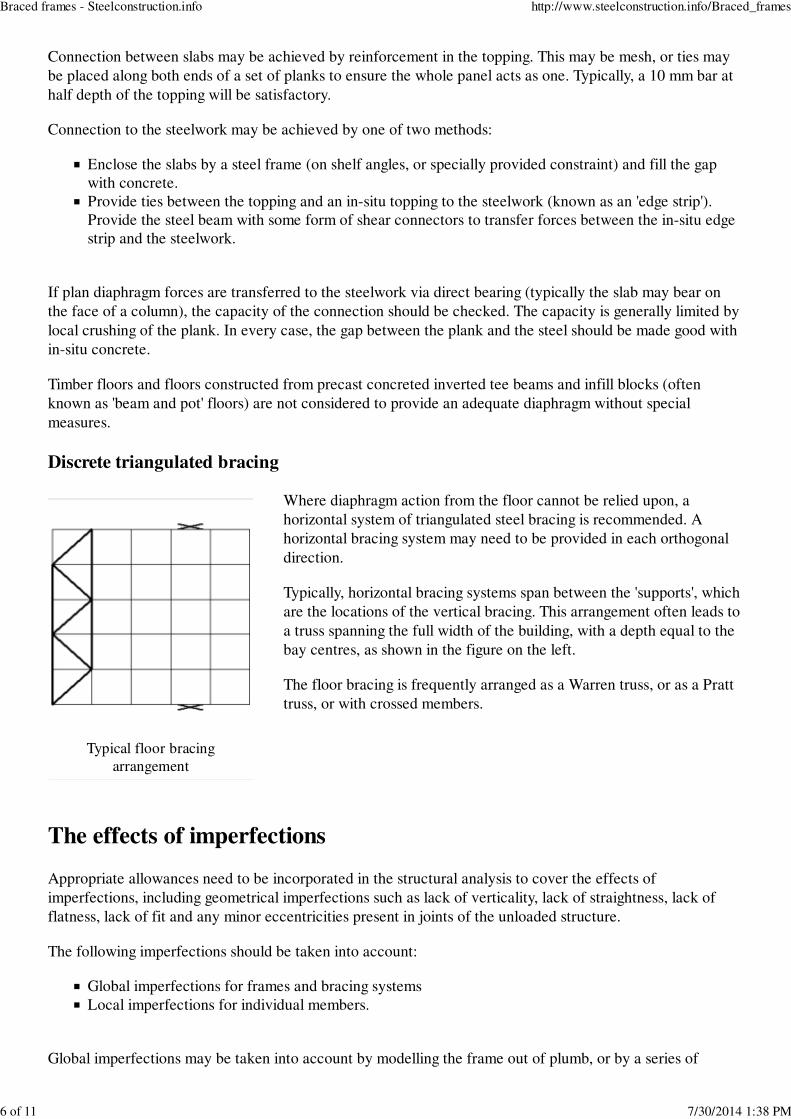
Typical floor bracing
arrangement
Connection between slabs may be achieved by reinforcement in the topping. This may be mesh, or ties may
be placed along both ends of a set of planks to ensure the whole panel acts as one. Typically, a 10 mm bar at
half depth of the topping will be satisfactory.
Connection to the steelwork may be achieved by one of two methods:
Enclose the slabs by a steel frame (on shelf angles, or specially provided constraint) and fill the gap
with concrete.
Provide ties between the topping and an in-situ topping to the steelwork (known as an 'edge strip').
Provide the steel beam with some form of shear connectors to transfer forces between the in-situ edge
strip and the steelwork.
If plan diaphragm forces are transferred to the steelwork via direct bearing (typically the slab may bear on
the face of a column), the capacity of the connection should be checked. The capacity is generally limited by
local crushing of the plank. In every case, the gap between the plank and the steel should be made good with
in-situ concrete.
Timber floors and floors constructed from precast concreted inverted tee beams and infill blocks (often
known as 'beam and pot' floors) are not considered to provide an adequate diaphragm without special
measures.
Discrete triangulated bracing
Where diaphragm action from the floor cannot be relied upon, a
horizontal system of triangulated steel bracing is recommended. A
horizontal bracing system may need to be provided in each orthogonal
direction.
Typically, horizontal bracing systems span between the 'supports', which
are the locations of the vertical bracing. This arrangement often leads to
a truss spanning the full width of the building, with a depth equal to the
bay centres, as shown in the figure on the left.
The floor bracing is frequently arranged as a Warren truss, or as a Pratt
truss, or with crossed members.
The effects of imperfections
Appropriate allowances need to be incorporated in the structural analysis to cover the effects of
imperfections, including geometrical imperfections such as lack of verticality, lack of straightness, lack of
flatness, lack of fit and any minor eccentricities present in joints of the unloaded structure.
The following imperfections should be taken into account:
Global imperfections for frames and bracing systems
Local imperfections for individual members.
Global imperfections may be taken into account by modelling the frame out of plumb, or by a series of
Braced frames - Steelconstruction.info http://www.steelconstruction.info/Braced_frames
6 of 11 7/30/2014 1:38 PM
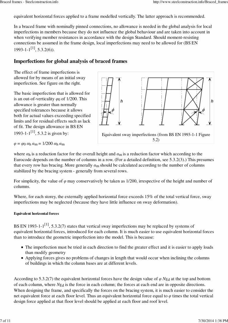
Equivalent sway imperfections (from BS EN 1993-1-1 Figure
5.2)
equivalent horizontal forces applied to a frame modelled vertically. The latter approach is recommended.
In a braced frame with nominally pinned connections, no allowance is needed in the global analysis for local
imperfections in members because they do not influence the global behaviour and are taken into account in
when verifying member resistances in accordance with the design Standard. Should moment-resisting
connections be assumed in the frame design, local imperfections may need to be allowed for (BS EN
1993-1-1[1]
, 5.3.2(6)).
Imperfections for global analysis of braced frames
The effect of frame imperfections is
allowed for by means of an initial sway
imperfection. See figure on the right.
The basic imperfection that is allowed for
is an out-of-verticality φ0 of 1/200. This
allowance is greater than normally
specified tolerances because it allows
both for actual values exceeding specified
limits and for residual effects such as lack
of fit. The design allowance in BS EN
1993-1-1[1]
, 5.3.2 is given by:
φ = φ0 αh αm = 1/200 αh αm
where αh is a reduction factor for the overall height and αm is a reduction factor which according to the
Eurocode depends on the number of columns in a row. (For a detailed definition, see 5.3.2(3).) This presumes
that every row has bracing. More generally αm should be calculated according to the number of columns
stabilized by the bracing system - generally from several rows.
For simplicity, the value of φ may conservatively be taken as 1/200, irrespective of the height and number of
columns.
Where, for each storey, the externally applied horizontal force exceeds 15% of the total vertical force, sway
imperfections may be neglected (because they have little influence on sway deformation).
Equivalent horizontal forces
BS EN 1993-1-1[1]
, 5.3.2(7) states that vertical sway imperfections may be replaced by systems of
equivalent horizontal forces, introduced for each column. It is much easier to use equivalent horizontal forces
than to introduce the geometric imperfection into the model. This is because:
The imperfection must be tried in each direction to find the greater effect and it is easier to apply loads
than modify geometry
Applying forces gives no problems of changes in length that would occur when inclining the columns
of buildings in which the column bases are at different levels.
According to 5.3.2(7) the equivalent horizontal forces have the design value of φ NEd at the top and bottom
of each column, where NEd is the force in each column; the forces at each end are in opposite directions.
When designing the frame, and specifically the forces on the bracing system, it is much easier to consider the
net equivalent force at each floor level. Thus an equivalent horizontal force equal to φ times the total vertical
design force applied at that floor level should be applied at each floor and roof level.
Braced frames - Steelconstruction.info http://www.steelconstruction.info/Braced_frames
7 of 11 7/30/2014 1:38 PM
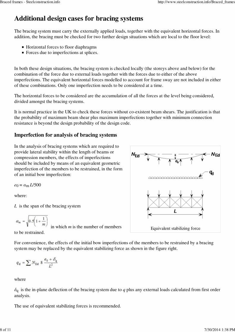
Equivalent stabilizing force
Additional design cases for bracing systems
The bracing system must carry the externally applied loads, together with the equivalent horizontal forces. In
addition, the bracing must be checked for two further design situations which are local to the floor level:
Horizontal forces to floor diaphragms
Forces due to imperfections at splices.
In both these design situations, the bracing system is checked locally (the storeys above and below) for the
combination of the force due to external loads together with the forces due to either of the above
imperfections. The equivalent horizontal forces modelled to account for frame sway are not included in either
of these combinations. Only one imperfection needs to be considered at a time.
The horizontal forces to be considered are the accumulation of all the forces at the level being considered,
divided amongst the bracing systems.
It is normal practice in the UK to check these forces without co-existent beam shears. The justification is that
the probability of maximum beam shear plus maximum imperfections together with minimum connection
resistance is beyond the design probability of the design code.
Imperfection for analysis of bracing systems
In the analysis of bracing systems which are required to
provide lateral stability within the length of beams or
compression members, the effects of imperfections
should be included by means of an equivalent geometric
imperfection of the members to be restrained, in the form
of an initial bow imperfection:
e0 = αm L/500
where:
L is the span of the bracing system
in which m is the number of members
to be restrained.
For convenience, the effects of the initial bow imperfections of the members to be restrained by a bracing
system may be replaced by the equivalent stabilizing force as shown in the figure right.
where
δq is the in-plane deflection of the bracing system due to q plus any external loads calculated from first order
analysis.
The use of equivalent stabilizing forces is recommended.
Braced frames - Steelconstruction.info http://www.steelconstruction.info/Braced_frames
8 of 11 7/30/2014 1:38 PM

Horizontal forces applied to the bracing system
Second order effects
The effects of the deformed geometry of the structure (second order effects) need to be considered if the
deformations significantly increase the forces in the structure or if the deformations significantly modify
structural behaviour. For elastic global analysis, second order effects are significant if αcr is less than 10.
The criterion should be applied separately for each storey, for the condition where the full frame is loaded, as
shown in the figure below. In most cases, the lowest storey will give the lowest value of αcr.
Determination of second order effects
Where second order effects need to be evaluated, the most common method used is by amplification of an
elastic first order analysis using the initial geometry of the structure. The use of this method is subject to the
limitation that αcr > 3. If αcr is less than 3, second order analysis must be used.
In a braced frame, where the beam to column connections are nominally pinned and thus do not contribute to
lateral stiffness, the only effects to be amplified are the axial forces in the bracing members and the forces in
columns that are due to their function as part of the bracing system
The amplification factor is given in BS EN 1993-1-1[1]
, 5.2.2(5)B as:
Only the effects due to the horizontal forces (including the equivalent horizontal forces) need to be amplified.
Second-order analysis
A range of second order analysis software is available. Use of any software will give results that are to some
extent approximate, depending on the solution method employed, the types of second-order effects
considered and the modelling assumptions. Generally, second-order software will automatically allow for
frame imperfections, so the designer will not need to calculate and apply the equivalent horizontal forces.
The effects of deformed geometry (second-order effects) will be allowed for in the analysis.
Summary design process for bracing systems
Braced frames - Steelconstruction.info http://www.steelconstruction.info/Braced_frames
9 of 11 7/30/2014 1:38 PM
The following simple design process is recommended for a typical medium rise building utilizing braced
frames.
Choose appropriate section sizes for the beams.1.
Choose appropriate section sizes for the columns (which may be designed initially for axial force alone,
leaving some nominal provision for bending moments, to be determined at a later stage).
2.
Calculate the equivalent horizontal forces (EHF), floor by floor, and the wind loads.3.
Calculate the total shear at the base of the bracing, by adding the total wind load to the total EHF, and
sharing this appropriately amongst the bracing systems.
4.
Size the bracing members. The lowest bracing member (with the greatest design force) can be sized,
based on the shear determined in Step 4. A smaller section size may be used higher up the structure
(where the bracing is subject to lesser forces) or the same size may be used for all members.
5.
Evaluate the frame stability, in terms of the parameter αcr, using the combination of the EHF and wind
loads as the horizontal forces on the frame, in conjunction with the vertical loads.
6.
Determine an amplifier, if required (i.e. if αcr < 10). If the frame is sensitive to second order effects, all
the lateral forces must be amplified. If this is the case, the bracing members may need to be re-checked
for increased forces (step 5).
7.
At each floor level, check that the connection to the diaphragm can carry 1% of the axial force in the
column at that point (clearly, the most onerous design force is at the lowest suspended floor).
8.
Verify that the floor diaphragms are effective in distributing all forces to the bracing systems.9.
At splice levels, determine the total force to be resisted by the bracing locally (which will usually be
the summation from several columns). Verify that the bracing local to the splice can carry these forces
in addition to the forces due to external loads (EHF are not included when making this check).
10.
Verify that the bracing local to each floor can carry the restraint forces from that floor, in addition to
the forces due to external loads (EHF are not included when making this check).
11.
If designing manually, the design data in SCI P363 , may be used to choose appropriate section sizes.
References
1.0
1.1
1.2
1.3
BS EN 1993-1-1:2005. Eurocode 3: Design of steel structures General rules and rules
for buildings, BSI
1.
Further reading
Steel Designers' Manual 7th Edition. (http://shop.steel-sci.com/products/231-steel-designers-manual-
7th-edition.aspx) Editors B Davison & G W Owens. The Steel Construction Institute 2012, Chapter 5
Architectural Design in Steel, Lawson M & Trebilcock P, SCI and Spon. Chapter 3.
Resources
SCI P365 Steel Building Design: Medium Rise Braced Frames, 2009
SCI P363 Steel Building Design: Design Data, 2013.
An interactive online version, or eBlue Book (http://tsbluebook.steel-sci.org/) , is also available.
Steel Buildings, 2003, (Publication No 35/03), BCSA, Chapter 4
See also
Multi-storey office buildings
Trusses
Floor systems
Braced frames - Steelconstruction.info http://www.steelconstruction.info/Braced_frames
10 of 11 7/30/2014 1:38 PM
Modelling and analysis
Allowing for the effects of deformed frame geometry
Simple connections
Retrieved from "http://www.steelconstruction.info/Braced_frames"
Category: Design
Sitemap
Contact
Cookies
Braced frames - Steelconstruction.info http://www.steelconstruction.info/Braced_frames
11 of 11 7/30/2014 1:38 PM