finite element analysis of the buckling critical loads in un-braced steel frames with multiple...
TRANSCRIPT
International Journal Of Civil And Structural Engineering Research (IJCSER) Vol. 1, Issue 1, pp: (1-13), Month: October-December 2013, Available at: www.researchpublish.com
Page | 1 Research Publish Journals
Finite Element Analysis of the Buckling Critical
Loads in Un-Braced Steel Frames with Multiple
Slenderness Ratio Configurations
Nazim Abdul Nariman 1, Mohammed A. Msekh
2
PhD candidate - Institute of Structural Mechanics
Bauhaus Universitat Weimar – Germany
Abstract: In this paper, two types of steel frames, steel frame without side sway permission and another with
side sway permission are created in Abaqus with 10 multiple slenderness ratio of the columns by changing the
length every time starting from 1 M and ending with 10 M length of the columns, Twenty models of steel frames
with single story and single bay were created, the models are with the same 2D dimensions and material
properties, the cross section of the steel is (0.5*0.5) M ,and the supports are fixed, two equal forces P= 1000 N are
exerted on the frames in the position mentioned in fig 6, a beam section was defined for the frame integrated
before analysis with Young modulus of elasticity E=1*107 N/M
2 , and shear modulus G = 3.8*106 N/M2 and
poisons ratio ν = 0.3. A linear perturbation step is created for buckling and 10 eigenvalues are requested for
analysis, a standard quadratic beam element type is generated with global seeding of 0.6, and 20 Jobs are created
for every situation and conclusions have been obtained, the critical buckling loads of the frames fall in the ranges
between the Euler loads forms which has been proved for each type of frames and this scientific approach was
verified in this research, in addition to that the relation between the length of the column and the eigenvalues that
represent the critical loads of buckling verified, and the simulations of the mode shapes of buckling of the steel
frames were identified adopting finite element analysis which shows the amount of loads necessary to reach each
mode shape of buckling for each type of steel frames mentioned before .
Keywords: Euler column, stiffness matrix, critical buckling load, eigen values and eigenvectors
I. Introduction
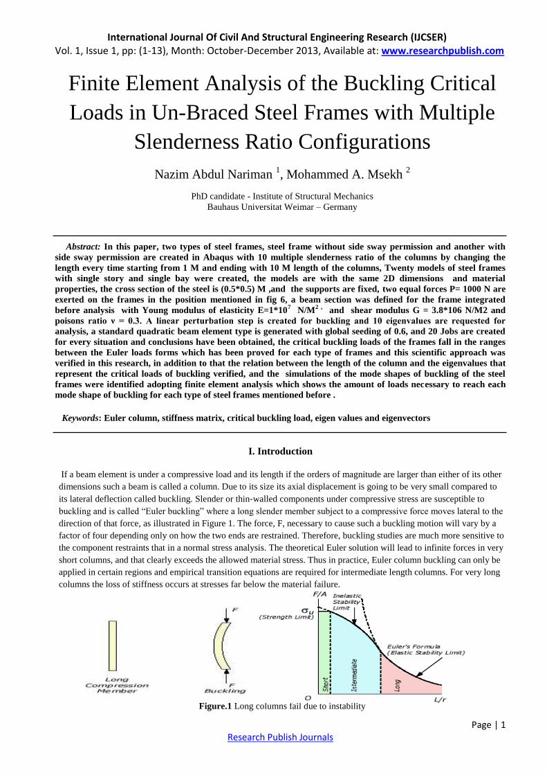
If a beam element is under a compressive load and its length if the orders of magnitude are larger than either of its other
dimensions such a beam is called a column. Due to its size its axial displacement is going to be very small compared to
its lateral deflection called buckling. Slender or thin‐walled components under compressive stress are susceptible to
buckling and is called ―Euler buckling‖ where a long slender member subject to a compressive force moves lateral to the
direction of that force, as illustrated in Figure 1. The force, F, necessary to cause such a buckling motion will vary by a
factor of four depending only on how the two ends are restrained. Therefore, buckling studies are much more sensitive to
the component restraints that in a normal stress analysis. The theoretical Euler solution will lead to infinite forces in very
short columns, and that clearly exceeds the allowed material stress. Thus in practice, Euler column buckling can only be
applied in certain regions and empirical transition equations are required for intermediate length columns. For very long
columns the loss of stiffness occurs at stresses far below the material failure.
Figure.1 Long columns fail due to instability
International Journal Of Civil And Structural Engineering Research (IJCSER) Vol. 1, Issue 1, pp: (1-13), Month: October-December 2013, Available at: www.researchpublish.com
Page | 2 Research Publish Journals
Quite often the buckling of column can lead to sudden and dramatic failure. And as a result, special attention must be
given to design of column so that they can safely support the loads.
Buckling can be related to the singularity of the tangent stiffness matrix, which in turn consists of two parts. The first
part is the material stiffness matrix which is related to the deformational stiffness of the components, taking into account
the connectivity of components in the current geometric configuration of the structure. For linear elastic components, the
material stiffness is identical to the linear elastic stiffness, but updating the structural geometry to include the effect of
any displacements. The second part is the geometric stiffness matrix, which is related to the component forces, and in
some cases to the applied loading, taking into account the effect of a change in geometry from the current configuration.
For typical structures, the material stiffness is positive for all deformation modes, mathematically referred to as positive-
definite, whereas the geometric stiffness can admit negative values for certain modes, depending on the component
forces and applied loading. It is therefore the effect of a negative geometric stiffness that can lead to a singular overall
tangent stiffness matrix, and hence buckling.
II. Stability concept
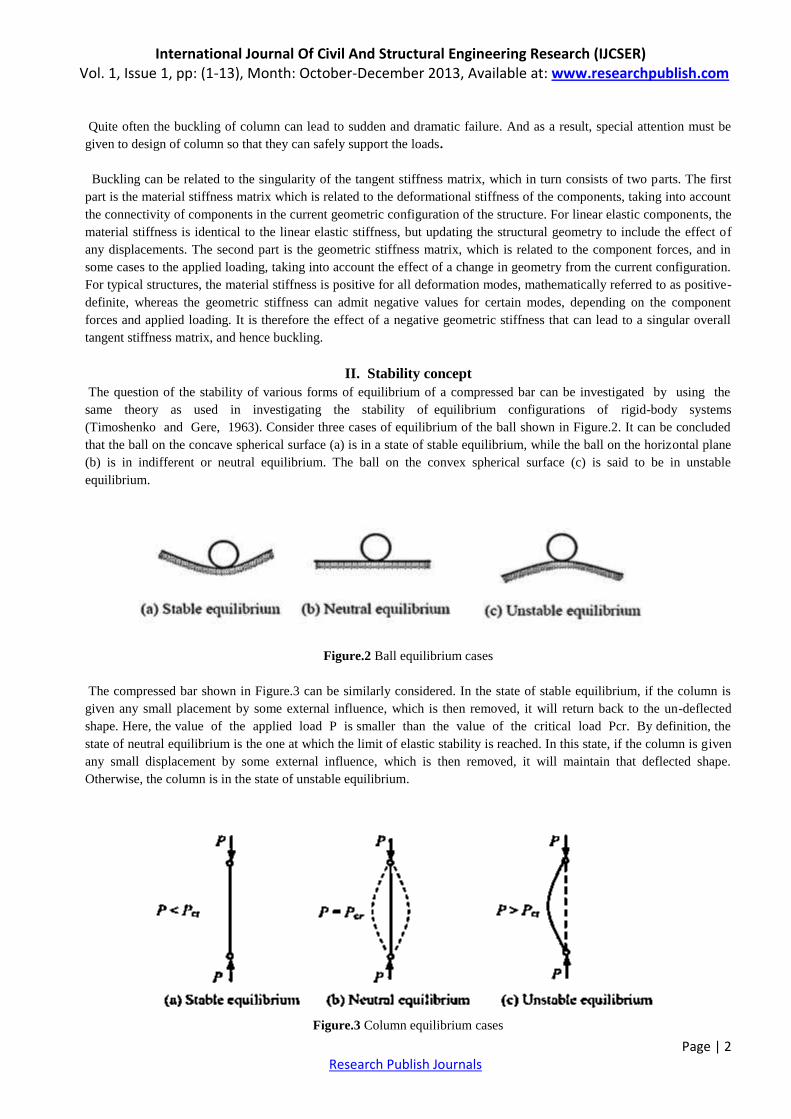
The question of the stability of various forms of equilibrium of a compressed bar can be investigated by using the
same theory as used in investigating the stability of equilibrium configurations of rigid-body systems
(Timoshenko and Gere, 1963). Consider three cases of equilibrium of the ball shown in Figure.2. It can be concluded
that the ball on the concave spherical surface (a) is in a state of stable equilibrium, while the ball on the horizontal plane
(b) is in indifferent or neutral equilibrium. The ball on the convex spherical surface (c) is said to be in unstable
equilibrium.
Figure.2 Ball equilibrium cases
The compressed bar shown in Figure.3 can be similarly considered. In the state of stable equilibrium, if the column is
given any small placement by some external influence, which is then removed, it will return back to the un-deflected
shape. Here, the value of the applied load P is smaller than the value of the critical load Pcr. By definition, the
state of neutral equilibrium is the one at which the limit of elastic stability is reached. In this state, if the column is given
any small displacement by some external influence, which is then removed, it will maintain that deflected shape.
Otherwise, the column is in the state of unstable equilibrium.
Figure.3 Column equilibrium cases
International Journal Of Civil And Structural Engineering Research (IJCSER) Vol. 1, Issue 1, pp: (1-13), Month: October-December 2013, Available at: www.researchpublish.com
Page | 3 Research Publish Journals
III. Euler Column
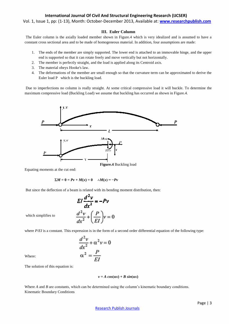
The Euler column is the axially loaded member shown in Figure.4 which is very idealized and is assumed to have a
constant cross sectional area and to be made of homogeneous material. In addition, four assumptions are made:
1. The ends of the member are simply supported. The lower end is attached to an immovable hinge, and the upper
end is supported so that it can rotate freely and move vertically but not horizontally.
2. The member is perfectly straight, and the load is applied along its Centroid axis.
3. The material obeys Hooke's law.
4. The deformations of the member are small enough so that the curvature term can be approximated to derive the
Euler load P which is the buckling load.
Due to imperfections no column is really straight. At some critical compressive load it will buckle. To determine the
maximum compressive load (Buckling Load) we assume that buckling has occurred as shown in Figure.4.
Figure.4 Buckling load
Equating moments at the cut end:
ΣM = 0 = Pv + M(x) = 0 ∴M(x) = −Pv
But since the deflection of a beam is related with its bending moment distribution, then:
which simplifies to
where P/EI is a constant. This expression is in the form of a second order differential equation of the following type:
Where:
The solution of this equation is:
v = A cos(αx) + B sin(αx)
Where A and B are constants, which can be determined using the column’s kinematic boundary conditions.
Kinematic Boundary Conditions
International Journal Of Civil And Structural Engineering Research (IJCSER) Vol. 1, Issue 1, pp: (1-13), Month: October-December 2013, Available at: www.researchpublish.com
Page | 4 Research Publish Journals
at x = 0, v = 0: 0 = A + 0, giving that A = 0
at x = L , v = 0, then: 0 = B sin(αL)
If B = 0, No bending moment exists, so the only logical solution is for: sin(αL)=0 and the only way that this can happen
is if :
αL = nπ, where n = integer
But since:
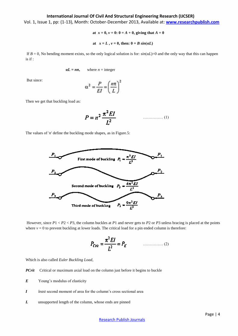
Then we get that buckling load as:
…………… (1)
The values of 'n' define the buckling mode shapes, as in Figure.5:
Figure.5 Buckling modes
However, since P1 < P2 < P3, the column buckles at P1 and never gets to P2 or P3 unless bracing is placed at the points
where v = 0 to prevent buckling at lower loads. The critical load for a pin ended column is therefore:
…………… (2)
Which is also called Euler Buckling Load,
PCrit Critical or maximum axial load on the column just before it begins to buckle
E Young’s modulus of elasticity
I least second moment of area for the column’s cross sectional area
L unsupported length of the column, whose ends are pinned
International Journal Of Civil And Structural Engineering Research (IJCSER) Vol. 1, Issue 1, pp: (1-13), Month: October-December 2013, Available at: www.researchpublish.com
Page | 5 Research Publish Journals
IV. Critical Buckling Load
Buckling is that mode of failure when the structure experiences sudden failure when subjected to compressive stress.
When a slender structure is loaded in compression, for small loads it deforms with hardly any noticeable change in the
geometry and load carrying capacity.
At the point of critical load value, the structure suddenly experiences a large deformation and may lose its ability to
carry load. This stage is the buckling stage.
The critical buckling load for a pin-pinned column (which is called the Euler buckling load) is given by the formula:
n = 1,2,3 integer which is representing the mode of buckling for the simply supported columns.
Where n=1 for the lowest critical buckling load so the formula would be:
So the critical loads at which nonzero deflections are possible are the eigenvalues, and the deflected shapes that can
exist at these loads are the eigenvectors. The smallest eigenvalue is the critical load and the corresponding eigenvector is
the buckling mode shape.
V. Buckling of frames
By considering a single story frame with a single bay, and for the buckling study we assume the external loads P to act
directly over the columns so that there is no bending moment in any member of the frame prior to buckling, and the
frame is categorized to two types: frames where side sway prevented and frames with side sway permitted.
We consider the first type of frames in which side sway is prevented. At the critical load the frame buckles as it
mentioned in the figure. The buckling takes place when the applied load P is equal to the critical load of the columns, the
upper end of each column is elastically restrained by the beam to which the column is rigidly connected, and that the
critical load of the column therefore depends not only on the column stiffness, but also on the stiffness of the beam. We
when we assume that the beam is infinitely flexible, the beam then is unable to offer any rotational restraint to the upper
ends of the columns as shown in Figure.6.
In this case the columns behave as if they were fixed at one end and hinged at the other, and the critical load of the
frame is approximately equal to twice the Euler load of the columns.
For an actual frame the critical load in which side sway is prevented, can be bracketed as follows:
2Pɛ < Pcr < 4Pɛ ……………… (3)
When we consider the second types of frames in which side sway is permitted, and the base is fixed and it is assumed
that the frame's material behaves according to Hooke's law, that the deformations remain small, and that there is no
primary bending present in the frame prior to buckling, and the shear forces that arise from the bending of the horizontal
member are neglected, and if we assume the beam to be infinitely flexible, the upper ends of the columns are free to both
rotate and translate as shown in Figure.11.
In this case the columns act like to be fixed at the base and free at the top, and the critical load of the frame is equal to
one fourth the Euler Load of the columns.
International Journal Of Civil And Structural Engineering Research (IJCSER) Vol. 1, Issue 1, pp: (1-13), Month: October-December 2013, Available at: www.researchpublish.com
Page | 6 Research Publish Journals
The critical load of the frame whose upper joints are free to translate laterally must therefore lie between Pɛ and 1/4 Pɛ.
That is:
1/4 Pɛ < Pcr < Pɛ ……………… (4)
VI. Buckling strength
Designs based on the alignment chart are reasonably accurate only when all the individual columns in a story buckle
simultaneously under their individual proportionate share of the total gravity load. The columns cannot brace each other
in this situation — their total strength is required to support their own gravity loads, leaving no reserve which might be
counted upon to provide a bracing force for other columns.
There are situations in which the individual columns have excessive buckling strengths. If the two exterior columns
contain axial loads such that the buckling load of these columns is not reached when the interior columns reach their
independent buckling loads, the system will not buckle. This may occur when different loading conditions govern the
design of various columns in a story. Shear resistance will be developed in the exterior columns which counteracts the
side sway tendency. (If all columns want to buckle simultaneously, there will be no shear resistance available. the
stabilizing effect of the lightly loaded exterior columns buckling will occur. The critical load for the interior columns is
increased and their effective length is decreased. The stabilizing effect can be such that the effective length of some of
the columns could be reduced to 1.0, even though there is no apparent bracing system.
It is safe to treat separately each column to which beams are rigidly attached and to use the alignment chart to get the
individual strengths. However, in some instances this usual approach may be unduly conservative. Side sway buckling is
a total story phenomenon. A single individual column cannot fail by side sway without all the columns in the same story
also buckling in a sway mode. On the other hand, buckling in a non-sway mode is an individual phenomenon. Each
column's non-sway buckling load is reasonably independent of the buckling load of the other columns.
VII. Buckling modes of frames
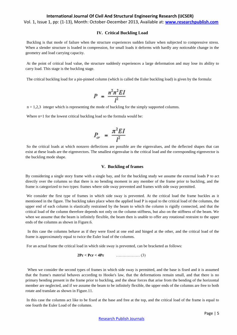
A. Symmetric buckling: If the frame is prevented from translating laterally at the top, buckling will occur in the
symmetric mode, as indicated in Figure.6 .The critical load for a fixed base portal frame whose beam has the same
stiffness as the columns and that is laterally restrained is:
……………… (5)
Figure.6 Symmetric buckling
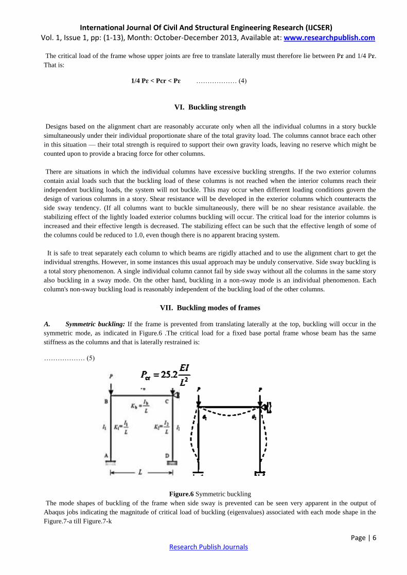
The mode shapes of buckling of the frame when side sway is prevented can be seen very apparent in the output of
Abaqus jobs indicating the magnitude of critical load of buckling (eigenvalues) associated with each mode shape in the
Figure.7-a till Figure.7-k
International Journal Of Civil And Structural Engineering Research (IJCSER) Vol. 1, Issue 1, pp: (1-13), Month: October-December 2013, Available at: www.researchpublish.com
Page | 7 Research Publish Journals
.
Figure.7- a Un-deformed shape
Figure.7- b Mode shape 1 Figure.7- c Mode shape 2
Figure.7- d Mode shape 3 Figure.7- e Mode shape 4
Figure.7- f Mode shape 5 Figure.7- g Mode shape 6
Figure.7- h Mode shape 7 Figure.7- i Mode shape 8
Figue.7- j Mode shape 9 Figure.7- k Mode shape 10
International Journal Of Civil And Structural Engineering Research (IJCSER) Vol. 1, Issue 1, pp: (1-13), Month: October-December 2013, Available at: www.researchpublish.com
Page | 8 Research Publish Journals
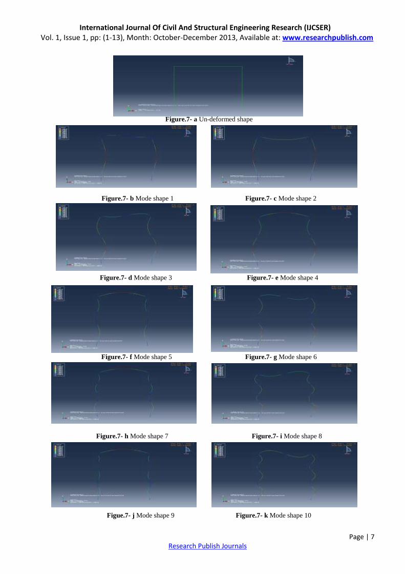
Table -1 is the results of Euler loads and Critical buckling loads for 10 situations of column length for the frame with
side sway prevented.
Table – 1 Euler Loads and Critical Loads
Figure.8 represents the relation between the Euler Loads and the column lengths in the same time between the Critical
Loads of Buckling and the column lengths when side sway is prevented in the frame due to the loads P.
Figure.8 Euler Loads and Critical buckling loads
In Table-2, the eigenvalues of 10 mode shapes of buckling for 10 multiple column lengths of the frame are stated that
are indications of the critical loads of buckling for each mode shape with respect of slenderness ratio.
Table – 2 Eigenvalues and mode shapes
π2 E N/M2 I M4 L M PE N Pcr N
9.877 10000000 0.0052 1 513604 1310400
9.877 10000000 0.0052 2 128401 327600
9.877 10000000 0.0052 3 57067.11111 145600
9.877 10000000 0.0052 4 32100.25 81900
9.877 10000000 0.0052 5 20544.16 52416
9.877 10000000 0.0052 6 14266.77778 36400
9.877 10000000 0.0052 7 10481.71429 26742.85714
9.877 10000000 0.0052 8 8025.0625 20475
9.877 10000000 0.0052 9 6340.790123 16177.77778
9.877 10000000 0.0052 10 5136.04 13104
0
200000
400000
600000
800000
1000000
1200000
1400000
0 2 4 6 8 10 12
Load
N
Column length M
Euler Loads
Critical Loads
International Journal Of Civil And Structural Engineering Research (IJCSER) Vol. 1, Issue 1, pp: (1-13), Month: October-December 2013, Available at: www.researchpublish.com
Page | 9 Research Publish Journals
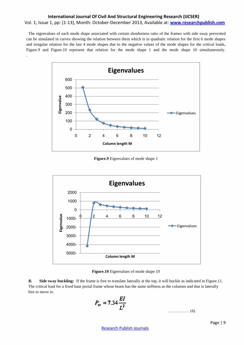
The eigenvalues of each mode shape associated with certain slenderness ratio of the frames with side sway prevented
can be simulated in curves showing the relation between them which is in quadratic relation for the first 6 mode shapes
and irregular relation for the last 4 mode shapes due to the negative values of the mode shapes for the critical loads,
Figure.9 and Figure.10 represent that relation for the mode shape 1 and the mode shape 10 simultaneously.
.
Figure.9 Eigenvalues of mode shape 1
Figure.10 Eigenvalues of mode shape 10
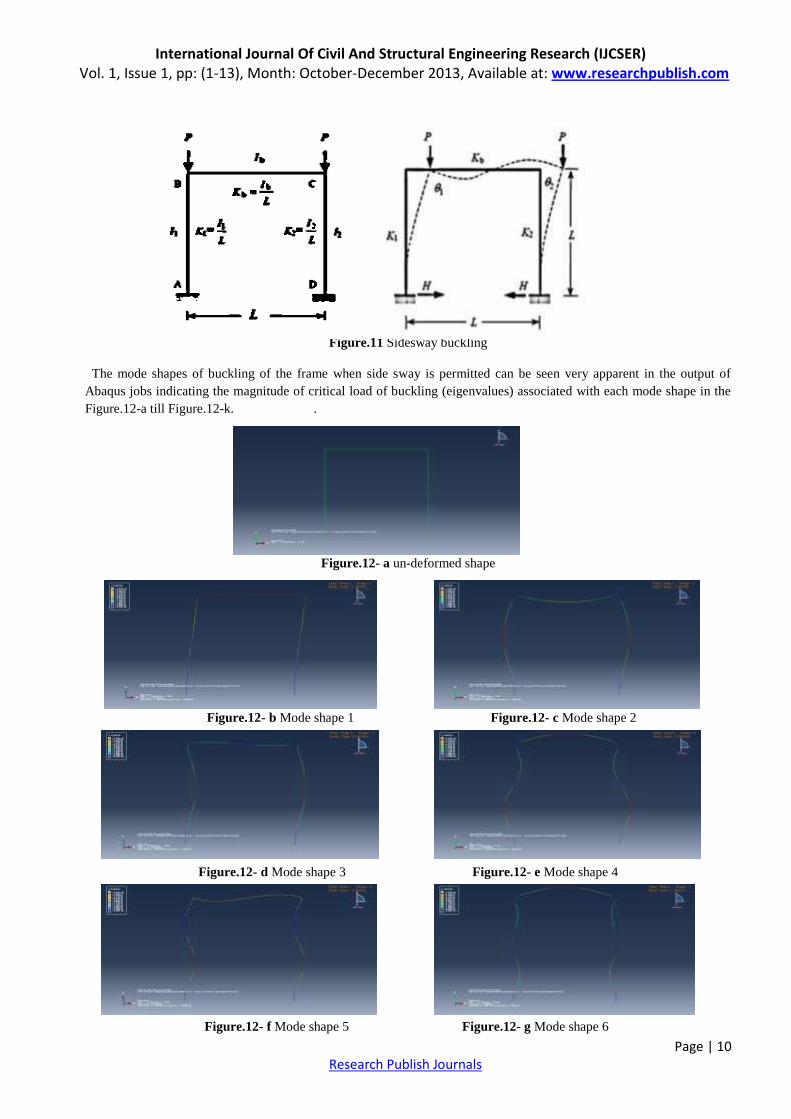
B. Side sway buckling: If the frame is free to translate laterally at the top, it will buckle as indicated in Figure.11.
The critical load for a fixed base portal frame whose beam has the same stiffness as the columns and that is laterally
free to move is:
…………… (6)
0
100
200
300
400
500
600
0 2 4 6 8 10 12
Eige
nva
lue
Column length M
Eigenvalues
Eigenvalues
-5000
-4000
-3000
-2000
-1000
0
1000
2000
0 2 4 6 8 10 12
Eige
nva
lue
Column length M
Eigenvalues
Eigenvalues
International Journal Of Civil And Structural Engineering Research (IJCSER) Vol. 1, Issue 1, pp: (1-13), Month: October-December 2013, Available at: www.researchpublish.com
Page | 10 Research Publish Journals
Figure.11 Sidesway buckling
The mode shapes of buckling of the frame when side sway is permitted can be seen very apparent in the output of
Abaqus jobs indicating the magnitude of critical load of buckling (eigenvalues) associated with each mode shape in the
Figure.12-a till Figure.12-k. .
Figure.12- a un-deformed shape
Figure.12- b Mode shape 1 Figure.12- c Mode shape 2
Figure.12- d Mode shape 3 Figure.12- e Mode shape 4
Figure.12- f Mode shape 5 Figure.12- g Mode shape 6
International Journal Of Civil And Structural Engineering Research (IJCSER) Vol. 1, Issue 1, pp: (1-13), Month: October-December 2013, Available at: www.researchpublish.com
Page | 11 Research Publish Journals
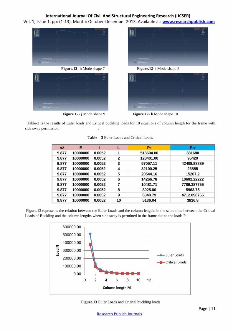
Figure.12- h Mode shape 7 Figure.12- i Mode shape 8
Figure.12- j Mode shape 9 Figure.12- k Mode shape 10
Table-3 is the results of Euler loads and Critical buckling loads for 10 situations of column length for the frame with
side sway permission. .
Table – 3 Euler Loads and Critical Loads
Figure.13 represents the relation between the Euler Loads and the column lengths in the same time between the Critical
Loads of Buckling and the column lengths when side sway is permitted in the frame due to the loads P.
Figure.13 Euler Loads and Critical buckling loads
π2 E I L PE Pcr
9.877 10000000 0.0052 1 513604.00 381680
9.877 10000000 0.0052 2 128401.00 95420
9.877 10000000 0.0052 3 57067.11 42408.88889
9.877 10000000 0.0052 4 32100.25 23855
9.877 10000000 0.0052 5 20544.16 15267.2
9.877 10000000 0.0052 6 14266.78 10602.22222
9.877 10000000 0.0052 7 10481.71 7789.387755
9.877 10000000 0.0052 8 8025.06 5963.75
9.877 10000000 0.0052 9 6340.79 4712.098765
9.877 10000000 0.0052 10 5136.04 3816.8
0.00
100000.00
200000.00
300000.00
400000.00
500000.00
600000.00
0 2 4 6 8 10 12
Load
N
Column length M
Euler Loads
Critical Loads
International Journal Of Civil And Structural Engineering Research (IJCSER) Vol. 1, Issue 1, pp: (1-13), Month: October-December 2013, Available at: www.researchpublish.com
Page | 12 Research Publish Journals
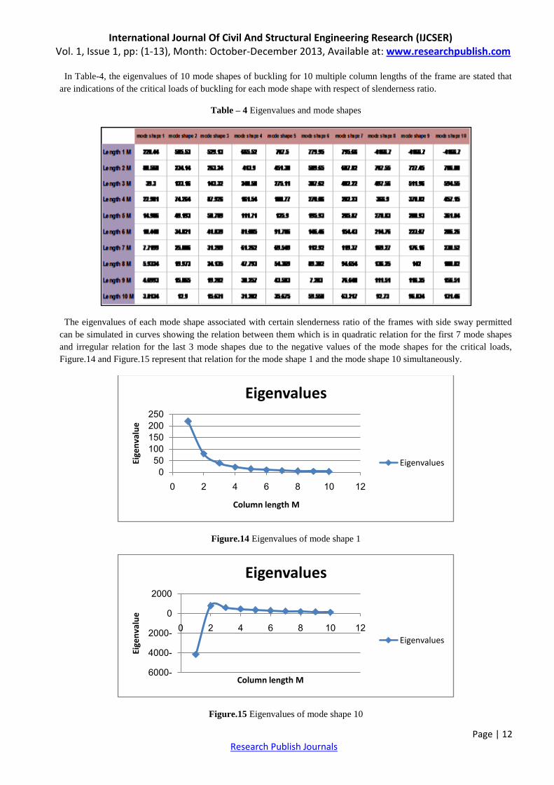
In Table-4, the eigenvalues of 10 mode shapes of buckling for 10 multiple column lengths of the frame are stated that
are indications of the critical loads of buckling for each mode shape with respect of slenderness ratio.
Table – 4 Eigenvalues and mode shapes
The eigenvalues of each mode shape associated with certain slenderness ratio of the frames with side sway permitted
can be simulated in curves showing the relation between them which is in quadratic relation for the first 7 mode shapes
and irregular relation for the last 3 mode shapes due to the negative values of the mode shapes for the critical loads,
Figure.14 and Figure.15 represent that relation for the mode shape 1 and the mode shape 10 simultaneously.
Figure.14 Eigenvalues of mode shape 1
Figure.15 Eigenvalues of mode shape 10
0
50
100
150
200
250
0 2 4 6 8 10 12
Eige
nva
lue
Column length M
Eigenvalues
Eigenvalues
-6000
-4000
-2000
0
2000
0 2 4 6 8 10 12
Eige
nva
lue
Column length M
Eigenvalues
Eigenvalues
International Journal Of Civil And Structural Engineering Research (IJCSER) Vol. 1, Issue 1, pp: (1-13), Month: October-December 2013, Available at: www.researchpublish.com
Page | 13 Research Publish Journals
VIII. Conclusions and recommendations
In this paper the results of the buckling analysis drawn from Abaqus jobs for the steel frames with side sway prevented
and the others permitted associate with 10 multiple configuration of slenderness ratio of the columns are shown below:
1- The basic results of buckling analysis are critical coefficients (eigenvalues) and buckling mode shapes
(eigenvectors) corresponding to these critical coefficients. Each critical coefficient is the factor by which the loads
of appropriate load case should be multiplied to obtain appropriate loss of stability which is the buckling mode
shape.
2- Negative critical coefficient (eigenvalues) for some buckling mode means that the loads of appropriate load case
should have opposite direction to result in such buckling mode shape. In practice buckling mode shapes with
negative critical coefficients (eigenvalues) should be neglected.
3- The theoretical values of buckling critical loads for each frame type are approximately the same value of drawn
values of the critical loads obtained from buckling analysis of Abaqus jobs that are equal to multiplying the
magnitude of the P applied on the frame by the eigenvalue of each buckling mode shape, and the deference between
the two values could be narrowed by making mesh refinement in each seeding step in Abaqus jobs until reaching the
designated theoretical value.
4- Changing the slenderness ratio of the columns to higher values by shortening the columns length every time , leads
to higher values of eigenvalues for each buckling mode shape and as a result to get higher values of critical loads
needed to create buckling in each type of frames especially in the steel frames that are prevented from side sway
buckling.
I recommend the following points for the future works in this area which have been arisen during my research work and
need more details and analysis:
1- Studying steel frames with more than one story and one bay to search the results and compare them to relevant
results.
2- Mesh refinement of the models to investigate the efficiency of the results and control the output of the parameters
of buckling analysis.
3- Creating steel frames models in 3D forms, and application of the same analysis steps, and drawing conclusions
about the effects of this change on the analysis.
Acknowledgements
First, thank to my God(Allah) for granting me the power and faith to proceed with this research work, and special
thanks to my former supervisor, Associated Professor Dr. Choong Kok Keong from the University Sains Malaysia who
taught me the theoretical background of this subject during my master study.
References
1. Shruti Deshpande, Buckling and Post buckling of structural components, M.Sc. thesis, University of Texas,chap.3, 2010.
2. Paul A. Lagace, The Column and Buckling, Massachusetts Institute of Technology, 2009.
3. The University of Sydney, Buckling of Columns, Lecture Notes of Mechanics of Solids, Chap.13, 2012.
4. Sameh Mahfouz, Design Optimization of Structural Steel work, PhD thesis, University of Bradford, chap.3,1999.
5. John E. Akin, Buckling Analysis, Rice University, chap.12, 2009.
6. B.A. Izzuddin, Simplified Buckling Analysis of Skeletal Structures, Structures & Buildings 159 Issue SB4, 2006.
7. Joseph A. Yura, The Effective Length of Columns in Un braced Frames, AISC Engineering Journal, 2003.
8. Alexander Chajes, Principles Of Structural Stability Theory, Prentice Hall, New Jersey, 1974