hybrid steel frames
TRANSCRIPT
Hybrid Steel Frames
O. Atlayan & F.A. Charney Virginia Tech, Blacksburg, Virginia, U.S.A. SUMMARY: Performance Based Earthquake Engineering requires various limit states to be satisfied at different seismic hazard levels. The optimum seismic structural performance depends on the ability of stable hysteretic energy dissipation of ductile systems. In this paper, two new structural steel systems, which are intended to perform better than the similar existing systems, are presented: Hybrid Buckling Restrained Braced Frames (BRBF) and hybrid steel Moment Frames (MF). The hybridity of the frames comes from the use of different steel material including carbon steel, structural steel, high-performance steel (HPS) and low yield point (LYP) steel. The Hybrid BRBF includes a multi-material brace core which is made of a combination of carbon steel, HPS, and LYP steel. The Hybrid MF contains connections made of LYP steel and reinforced sections. Nonlinear Static Pushover (NSP) and Incremental Dynamic Analysis (IDA) using P-695 methodology are conducted and comparisons between the hybrid and the regular BRBFs and MFs are made. Conclusions regarding the advantages of the hybrid systems are presented. Keywords: Seismic design, buckling restrained braced frames, moment resisting frames, low strength steel 1. INTRODUCTION The main objective of the hybrid frames is to have controlled yielding in the selected members of the structure. In hybrid BRBF, the LYP component of the BRB core yields earlier than the carbon steel and the energy dissipation due to early yielding helps the hybrid BRBF to perform better than the regular BRBF under low to mid-level earthquakes. The HPS provides strength and counteracts the low post-yield stiffness of the regular BRBFs (with the help of high strain hardening of LYP steel), and thus increases the performance of the frame and reduces the likelihood of dynamic instability under high intensity ground motions. A similar idea is implemented on steel moment frames. A hybrid moment frame with LYP steel plate connections and reinforced sections is studied. 1.1. Objective Structural systems in current design practice are calibrated for good performance at Design Basis Earthquake (DBE) and Maximum Considered Earthquake (MCE) level limit states, and performance at other limit states (generally less severe shaking) is uncertain. The objectives of the hybrid frames are to have better performance at previously neglected limit states, to have reduced residual displacements and reduced likelihood of dynamic instability at DBE/MCE level limit states, to obtain more reliable performance across all limit states, to reduce probability of collapse, and to reduce dispersion in nonlinear analyses. While improving the performance, it is important to have a minimal economic impact on the system. 1.2. Background The hysteretic behaviour of BRBs made of low strength steel (LYP100) was tested by Chen et al.
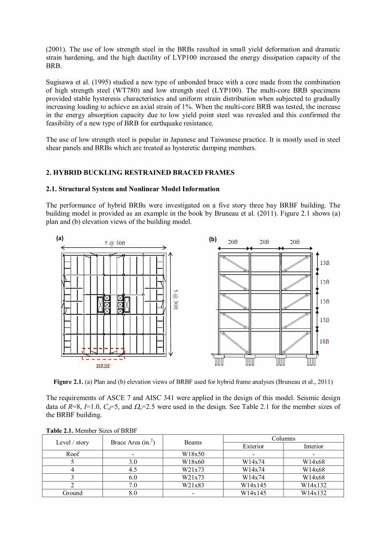
(2001). The use of low strength steel in the BRBs resulted in small yield deformation and dramatic strain hardening, and the high ductility of LYP100 increased the energy dissipation capacity of the BRB. Sugisawa et al. (1995) studied a new type of unbonded brace with a core made from the combination of high strength steel (WT780) and low strength steel (LYP100). The multi-core BRB specimens provided stable hysteresis characteristics and uniform strain distribution when subjected to gradually increasing loading to achieve an axial strain of 1%. When the multi-core BRB was tested, the increase in the energy absorption capacity due to low yield point steel was revealed and this confirmed the feasibility of a new type of BRB for earthquake resistance. The use of low strength steel is popular in Japanese and Taiwanese practice. It is mostly used in steel shear panels and BRBs which are treated as hysteretic damping members. 2. HYBRID BUCKLING RESTRAINED BRACED FRAMES 2.1. Structural System and Nonlinear Model Information The performance of hybrid BRBs were investigated on a five story three bay BRBF building. The building model is provided as an example in the book by Bruneau et al. (2011). Figure 2.1 shows (a) plan and (b) elevation views of the building model.
Figure 2.1. (a) Plan and (b) elevation views of BRBF used for hybrid frame analyses (Bruneau et al., 2011) The requirements of ASCE 7 and AISC 341 were applied in the design of this model. Seismic design data of R=8, I=1.0, Cd=5, and Ωo=2.5 were used in the design. See Table 2.1 for the member sizes of the BRBF building. Table 2.1. Member Sizes of BRBF
Level / story Brace Area (in.2) Beams Columns Exterior Interior
Roof - W18x50 - - 5 3.0 W18x60 W14x74 W14x68 4 4.5 W21x73 W14x74 W14x68 3 6.0 W21x73 W14x74 W14x68 2 7.0 W21x83 W14x145 W14x132
Ground 8.0 - W14x145 W14x132
(a) (b)
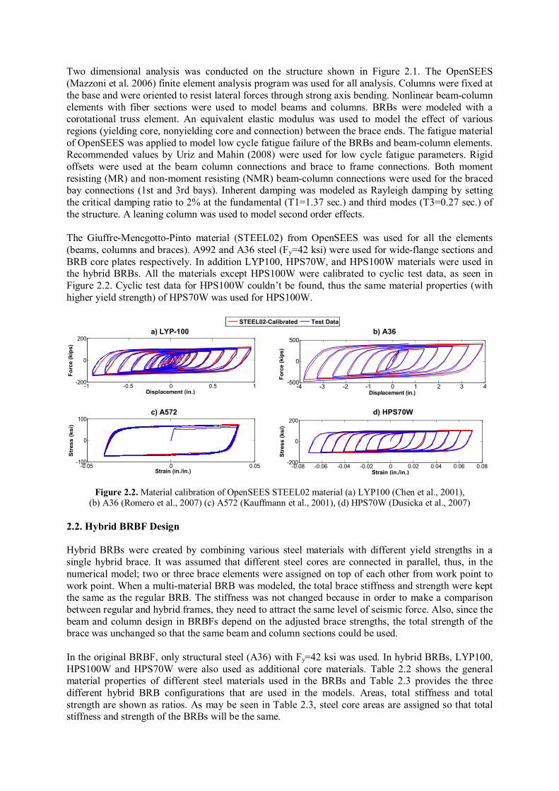
Two dimensional analysis was conducted on the structure shown in Figure 2.1. The OpenSEES (Mazzoni et al. 2006) finite element analysis program was used for all analysis. Columns were fixed at the base and were oriented to resist lateral forces through strong axis bending. Nonlinear beam-column elements with fiber sections were used to model beams and columns. BRBs were modeled with a corotational truss element. An equivalent elastic modulus was used to model the effect of various regions (yielding core, nonyielding core and connection) between the brace ends. The fatigue material of OpenSEES was applied to model low cycle fatigue failure of the BRBs and beam-column elements. Recommended values by Uriz and Mahin (2008) were used for low cycle fatigue parameters. Rigid offsets were used at the beam column connections and brace to frame connections. Both moment resisting (MR) and non-moment resisting (NMR) beam-column connections were used for the braced bay connections (1st and 3rd bays). Inherent damping was modeled as Rayleigh damping by setting the critical damping ratio to 2% at the fundamental (T1=1.37 sec.) and third modes (T3=0.27 sec.) of the structure. A leaning column was used to model second order effects. The Giuffre-Menegotto-Pinto material (STEEL02) from OpenSEES was used for all the elements (beams, columns and braces). A992 and A36 steel (Fy=42 ksi) were used for wide-flange sections and BRB core plates respectively. In addition LYP100, HPS70W, and HPS100W materials were used in the hybrid BRBs. All the materials except HPS100W were calibrated to cyclic test data, as seen in Figure 2.2. Cyclic test data for HPS100W couldn’t be found, thus the same material properties (with higher yield strength) of HPS70W was used for HPS100W.
00
STEEL02-Calibrated Test Data
a) LYP-100 b) A36
-1 -0.5 0 0.5 1-200
0
200
Displacement (in.)
Forc
e (k
ips)
Forc
e (k
ips)
-4 -3 -2 -1 0 1 2 3 4-500
0
500
Displacement (in.)
5000
c) A572 d) HPS70W
-0.05 0 0.05-100
0
100
Strain (in./in.)
Str
ess
(ksi
)
-0.08 -0.06 -0.04 -0.02 0 0.02 0.04 0.06 0.08-200
0
200
Strain (in./in.)
Stre
ss (k
si)
Figure 2.2. Material calibration of OpenSEES STEEL02 material (a) LYP100 (Chen et al., 2001), (b) A36 (Romero et al., 2007) (c) A572 (Kauffmann et al., 2001), (d) HPS70W (Dusicka et al., 2007)
2.2. Hybrid BRBF Design Hybrid BRBs were created by combining various steel materials with different yield strengths in a single hybrid brace. It was assumed that different steel cores are connected in parallel, thus, in the numerical model; two or three brace elements were assigned on top of each other from work point to work point. When a multi-material BRB was modeled, the total brace stiffness and strength were kept the same as the regular BRB. The stiffness was not changed because in order to make a comparison between regular and hybrid frames, they need to attract the same level of seismic force. Also, since the beam and column design in BRBFs depend on the adjusted brace strengths, the total strength of the brace was unchanged so that the same beam and column sections could be used. In the original BRBF, only structural steel (A36) with Fy=42 ksi was used. In hybrid BRBs, LYP100, HPS100W and HPS70W were also used as additional core materials. Table 2.2 shows the general material properties of different steel materials used in the BRBs and Table 2.3 provides the three different hybrid BRB configurations that are used in the models. Areas, total stiffness and total strength are shown as ratios. As may be seen in Table 2.3, steel core areas are assigned so that total stiffness and strength of the BRBs will be the same.
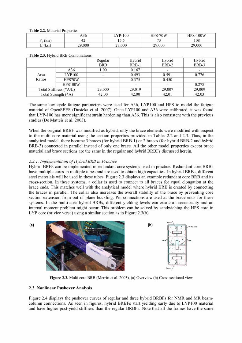
Table 2.2. Material Properties A36 LYP-100 HPS-70W HPS-100W
Fy (ksi) 42 15.5 73 108 E (ksi) 29,000 27,000 29,000 29,000
Table 2.3. Hybrid BRB Combinations
Regular BRB
Hybrid BRB-1
Hybrid BRB-2
Hybrid BRB-3
Area
Ratios
A36 1.00 0.167 - - LYP100 - 0.493 0.591 0.776 HPS70W - 0.375 0.450 -
HPS100W - - - 0.278 Total Stiffness (*A/L) 29,000 29,019 29,007 29,009 Total Strength (*A) 42.00 42.00 42.01 42.03
The same low cycle fatigue parameters were used for A36, LYP100 and HPS to model the fatigue material of OpenSEES (Dusicka et al. 2007). Once LYP100 and A36 were calibrated, it was found that LYP-100 has more significant strain hardening than A36. This is also consistent with the previous studies (De Matteis et al. 2003). When the original BRBF was modified as hybrid, only the brace elements were modified with respect to the multi core material using the section properties provided in Tables 2.2 and 2.3. Thus, in the analytical model, there became 3 braces (for hybrid BRB-1) or 2 braces (for hybrid BRB-2 and hybrid BRB-3) connected in parallel instead of only one brace. All the other model properties except brace material and brace sections are the same in the regular and hybrid BRBFs discussed herein. 2.2.1. Implementation of Hybrid BRB in Practice Hybrid BRBs can be implemented in redundant core systems used in practice. Redundant core BRBs have multiple cores in multiple tubes and are used to obtain high capacities. In hybrid BRBs, different steel materials will be used in these tubes. Figure 2.3 displays an example redundant core BRB and its cross-section. In these systems, a collar is used to connect to all braces for equal elongation at the brace ends. This matches well with the analytical model where hybrid BRB is created by connecting the braces in parallel. The collar also increases the overall stability of the brace by preventing core section extension from out of plane buckling. Pin connections are used at the brace ends for these systems. In the multi-core hybrid BRBs, different yielding levels can create an eccentricity and an internal moment problem might occur. This problem can be solved by sandwiching the HPS core in LYP core (or vice versa) using a similar section as in Figure 2.3(b).
Figure 2.3. Multi core BRB (Merritt et al. 2003), (a) Overview (b) Cross sectional view 2.3. Nonlinear Pushover Analysis Figure 2.4 displays the pushover curves of regular and three hybrid BRBFs for NMR and MR beam-column connections. As seen in figures, hybrid BRBFs start yielding early due to LYP100 material and have higher post-yield stiffness than the regular BRBFs. Note that all the frames have the same
(a) (b)
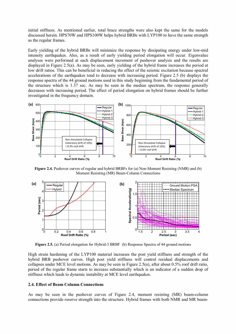
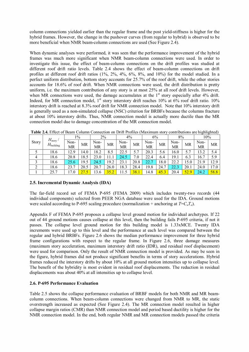
initial stiffness. As mentioned earlier, total brace strengths were also kept the same for the models discussed herein. HPS70W and HPS100W helps hybrid BRBs with LYP100 to have the same strength as the regular frames. Early yielding of the hybrid BRBs will minimize the response by dissipating energy under low-mid intensity earthquakes. Also, as a result of early yielding period elongation will occur. Eigenvalue analyses were performed at each displacement increment of pushover analysis and the results are displayed in Figure 2.5(a). As may be seen, early yielding of the hybrid frame increases the period at low drift ratios. This can be beneficial in reducing the effect of the seismic excitation because spectral accelerations of the earthquakes tend to decrease with increasing period. Figure 2.5 (b) displays the response spectra of the 44 ground motions used in this study beginning from the fundamental period of the structure which is 1.37 sec. As may be seen in the median spectrum, the response generally decreases with increasing period. The effect of period elongation on hybrid frames should be further investigated in the frequency domain.
0 2 4 6 8 100
100
200
300
400
500
600
Roof Drift Ratio (%)
Bas
e Sh
ear (
kips
)
RegularHybrid-1Hybrid-2Hybrid-3
0 2 4 6 8 10
0
200
400
600
800
1000
Roof Drift Ratio (%)
Bas
e Sh
ear (
kips
)
RegularHybrid-1Hybrid-2Hybrid-3
Figure 2.4. Pushover curves of regular and hybrid BRBFs for (a) Non-Moment Resisting (NMR) and (b) Moment Resisting (MR) Beam-Column Connections
0 0.2 0.4 0.6 0.8 10
1
2
3
4
5
Roof Drift Ratio (%)
Perio
d (s
ec)
RegularHybrid
1.5 2 2.5 3 3.5 4
0
0.5
1
1.5
2
Period (sec)
Spec
tral
Acc
eler
atio
n(g)
Ground Motion PSAMedian Spectrum
Figure 2.5. (a) Period elongation for Hybrid-3 BRBF (b) Response Spectra of 44 ground motions High strain hardening of the LYP100 material increases the post yield stiffness and strength of the hybrid BRB pushover curves. High post yield stiffness will control residual displacements and collapses under MCE level motions. As may be seen in Figure 2.5(a), after about 0.5% roof drift ratio, period of the regular frame starts to increase substantially which is an indicator of a sudden drop of stiffness which leads to dynamic instability at MCE level earthquakes. 2.4. Effect of Beam Column Connections As may be seen in the pushover curves of Figure 2.4, moment resisting (MR) beam-column connections provide reserve strength into the structure. Hybrid frames with both NMR and MR beam-
Non-Simulated Collapse (Interstory drift of 10%) = 8.3% roof drift
Non-Simulated Collapse (Interstory drift of 10%) = 6.0% roof drift
(a) (b)
(a) (b)
column connections yielded earlier than the regular frame and the post yield-stiffness is higher for the hybrid frames. However, the change in the pushover curves (from regular to hybrid) is observed to be more beneficial when NMR beam-column connections are used (See Figure 2.4). When dynamic analyses were performed, it was seen that the performance improvement of the hybrid frames was much more significant when NMR beam-column connections were used. In order to investigate this issue, the effect of beam-column connections on the drift profiles was studied at different roof drift ratio levels. Table 2.4 shows the effect of beam-column connections on drift profiles at different roof drift ratios (1%, 2%, 4%, 6%, 8%, and 10%) for the model studied. In a perfect uniform distribution, bottom story accounts for 25.7% of the roof drift, while the other stories accounts for 18.6% of roof drift. When NMR connections were used, the drift distribution is pretty uniform, i.e. the maximum contribution of any story is at most 25% at all roof drift levels. However, when MR connections were used, the damage accumulates at the 1st story especially after 4% drift. Indeed, for MR connection model, 1st story interstory drift reaches 10% at 6% roof drift ratio. 10% interstory drift is reached at 8.3% roof drift for NMR connection model. Note that 10% interstory drift is generally used as a non-simulated collapse (NSC) criterion for BRBFs because the columns fracture at about 10% interstory drifts. Thus, NMR connection model is actually more ductile than the MR connection model due to damage concentration of the MR connection model. Table 2.4. Effect of Beam Column Connection on Drift Profiles (Maximum story contributions are highlighted)
Story Hstory / Hbuilding
1% 2% 4% 6% 8% 10% Non- MR MR Non-
MR MR Non-MR MR Non-
MR MR Non-MR MR Non-
MR MR
5 18.6 12.9 14.0 18.2 8.5 22.5 5.7 20.3 5.6 16.0 5.7 13.2 5.4 4 18.6 20.8 18.5 23.0 11.1 24.5 7.0 22.4 6.4 19.1 6.3 16.7 5.9 3 18.6 25.6 19.5 24.5 19.2 23.1 20.8 22.7 18.0 22.2 15.0 21.9 12.9 2 18.6 23.7 20.5 20.7 26.0 18.3 28.4 19.8 24.7 22.3 20.1 24.0 17.0 1 25.7 17.0 27.5 13.6 35.2 11.5 38.1 14.8 45.3 20.4 52.9 24.2 58.8
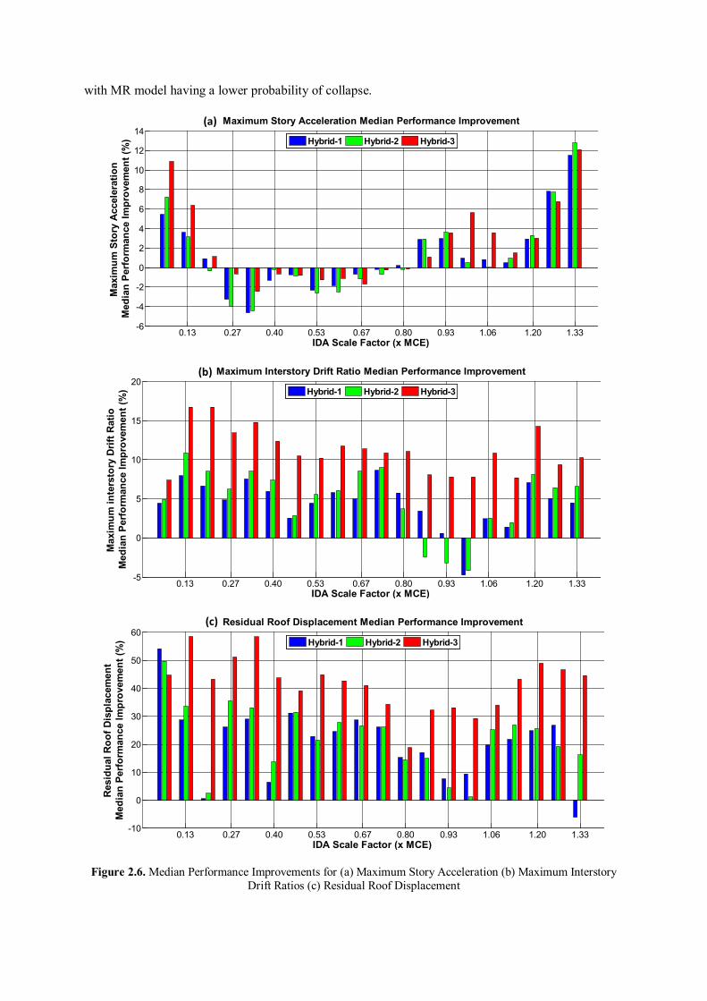
2.5. Incremental Dynamic Analysis (IDA) The far-field record set of FEMA P-695 (FEMA 2009) which includes twenty-two records (44 individual components) selected from PEER NGA database were used for the IDA. Ground motions were scaled according to P-695 scaling procedure (normalization + anchoring at T=CuTa). Appendix F of FEMA P-695 proposes a collapse level ground motion for individual archetypes. If 22 out of 44 ground motions causes collapse at this level, then the building fails P-695 criteria, if not it passes. The collapse level ground motion for this building model is 1.33xMCE. Twenty IDA increments were used up to this level and the performance at each level was compared between the regular and hybrid BRBFs. Figure 2.6 shows the median performance improvement for three hybrid frame configurations with respect to the regular frame. In Figure 2.6, three damage measures (maximum story acceleration, maximum interstory drift ratio (IDR), and residual roof displacement) were used for comparison. Only the result of NMR connection model is provided. As may be seen in the figure, hybrid frames did not produce significant benefits in terms of story accelerations. Hybrid frames reduced the interstory drifts by about 10% at all ground motion intensities up to collapse level. The benefit of the hybridity is most evident in residual roof displacements. The reduction in residual displacements was about 40% at all intensities up to collapse level. 2.6. P-695 Performance Evaluation Table 2.5 shows the collapse performance evaluation of BRBF models for both NMR and MR beam-column connections. When beam-column connections were changed from NMR to MR, the static overstrength increased as expected (See Figure 2.4). The MR connection model resulted in higher collapse margin ratios (CMR) than NMR connection model and period based ductility is higher for the NMR connection model. In the end, both regular NMR and MR connection models passed the criteria
with MR model having a lower probability of collapse.
0.13 0.27 0.40 0.53 0.67 0.80 0.93 1.06 1.20 1.33-6
-4
-2
0
2
4
6
8
10
12
14Maximum Story Acceleration Median Performance Improvement
IDA Scale Factor (x MCE)
Max
imum
Sto
ry A
ccel
erat
ion
Med
ian
Perf
orm
ance
Impr
ovem
ent (
%)
Hybrid-1 Hybrid-2 Hybrid-3
0.13 0.27 0.40 0.53 0.67 0.80 0.93 1.06 1.20 1.33-5
0
5
10
15
20Maximum Interstory Drift Ratio Median Performance Improvement
IDA Scale Factor (x MCE)
Max
imum
inte
rsto
ry D
rift R
atio
Med
ian
Perf
orm
ance
Impr
ovem
ent (
%)
Hybrid-1 Hybrid-2 Hybrid-3
0.13 0.27 0.40 0.53 0.67 0.80 0.93 1.06 1.20 1.33-10
0
10
20
30
40
50
60Residual Roof Displacement Median Performance Improvement
IDA Scale Factor (x MCE)
Res
idua
l Roo
f Dis
plac
emen
tM
edia
n Pe
rfor
man
ce Im
prov
emen
t (%
)
Hybrid-1 Hybrid-2 Hybrid-3
Figure 2.6. Median Performance Improvements for (a) Maximum Story Acceleration (b) Maximum Interstory Drift Ratios (c) Residual Roof Displacement
(c)
(b)
(a)
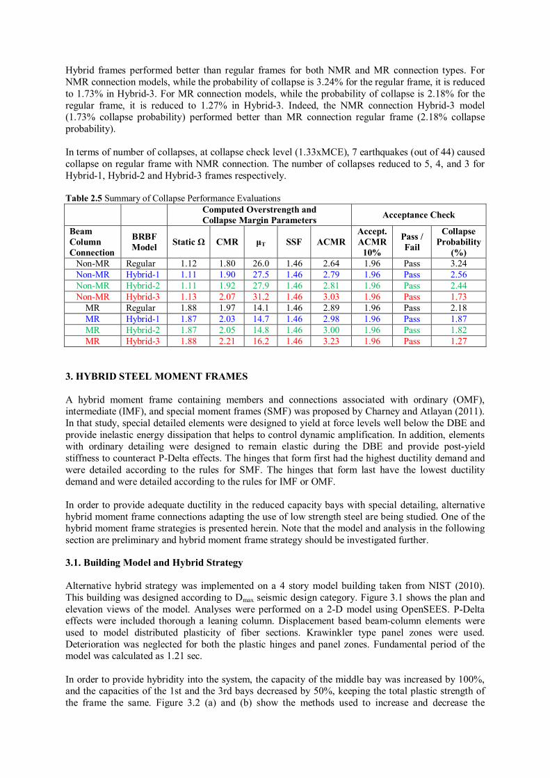
Hybrid frames performed better than regular frames for both NMR and MR connection types. For NMR connection models, while the probability of collapse is 3.24% for the regular frame, it is reduced to 1.73% in Hybrid-3. For MR connection models, while the probability of collapse is 2.18% for the regular frame, it is reduced to 1.27% in Hybrid-3. Indeed, the NMR connection Hybrid-3 model (1.73% collapse probability) performed better than MR connection regular frame (2.18% collapse probability). In terms of number of collapses, at collapse check level (1.33xMCE), 7 earthquakes (out of 44) caused collapse on regular frame with NMR connection. The number of collapses reduced to 5, 4, and 3 for Hybrid-1, Hybrid-2 and Hybrid-3 frames respectively. Table 2.5 Summary of Collapse Performance Evaluations Computed Overstrength and
Collapse Margin Parameters Acceptance Check
Beam Column Connection
BRBF Model Static Ω CMR μT SSF ACMR
Accept. ACMR
10%
Pass / Fail
Collapse Probability
(%) Non-MR Regular 1.12 1.80 26.0 1.46 2.64 1.96 Pass 3.24 Non-MR Hybrid-1 1.11 1.90 27.5 1.46 2.79 1.96 Pass 2.56 Non-MR Hybrid-2 1.11 1.92 27.9 1.46 2.81 1.96 Pass 2.44 Non-MR Hybrid-3 1.13 2.07 31.2 1.46 3.03 1.96 Pass 1.73
MR Regular 1.88 1.97 14.1 1.46 2.89 1.96 Pass 2.18 MR Hybrid-1 1.87 2.03 14.7 1.46 2.98 1.96 Pass 1.87 MR Hybrid-2 1.87 2.05 14.8 1.46 3.00 1.96 Pass 1.82 MR Hybrid-3 1.88 2.21 16.2 1.46 3.23 1.96 Pass 1.27
3. HYBRID STEEL MOMENT FRAMES A hybrid moment frame containing members and connections associated with ordinary (OMF), intermediate (IMF), and special moment frames (SMF) was proposed by Charney and Atlayan (2011). In that study, special detailed elements were designed to yield at force levels well below the DBE and provide inelastic energy dissipation that helps to control dynamic amplification. In addition, elements with ordinary detailing were designed to remain elastic during the DBE and provide post-yield stiffness to counteract P-Delta effects. The hinges that form first had the highest ductility demand and were detailed according to the rules for SMF. The hinges that form last have the lowest ductility demand and were detailed according to the rules for IMF or OMF. In order to provide adequate ductility in the reduced capacity bays with special detailing, alternative hybrid moment frame connections adapting the use of low strength steel are being studied. One of the hybrid moment frame strategies is presented herein. Note that the model and analysis in the following section are preliminary and hybrid moment frame strategy should be investigated further. 3.1. Building Model and Hybrid Strategy Alternative hybrid strategy was implemented on a 4 story model building taken from NIST (2010). This building was designed according to Dmax seismic design category. Figure 3.1 shows the plan and elevation views of the model. Analyses were performed on a 2-D model using OpenSEES. P-Delta effects were included thorough a leaning column. Displacement based beam-column elements were used to model distributed plasticity of fiber sections. Krawinkler type panel zones were used. Deterioration was neglected for both the plastic hinges and panel zones. Fundamental period of the model was calculated as 1.21 sec. In order to provide hybridity into the system, the capacity of the middle bay was increased by 100%, and the capacities of the 1st and the 3rd bays decreased by 50%, keeping the total plastic strength of the frame the same. Figure 3.2 (a) and (b) show the methods used to increase and decrease the
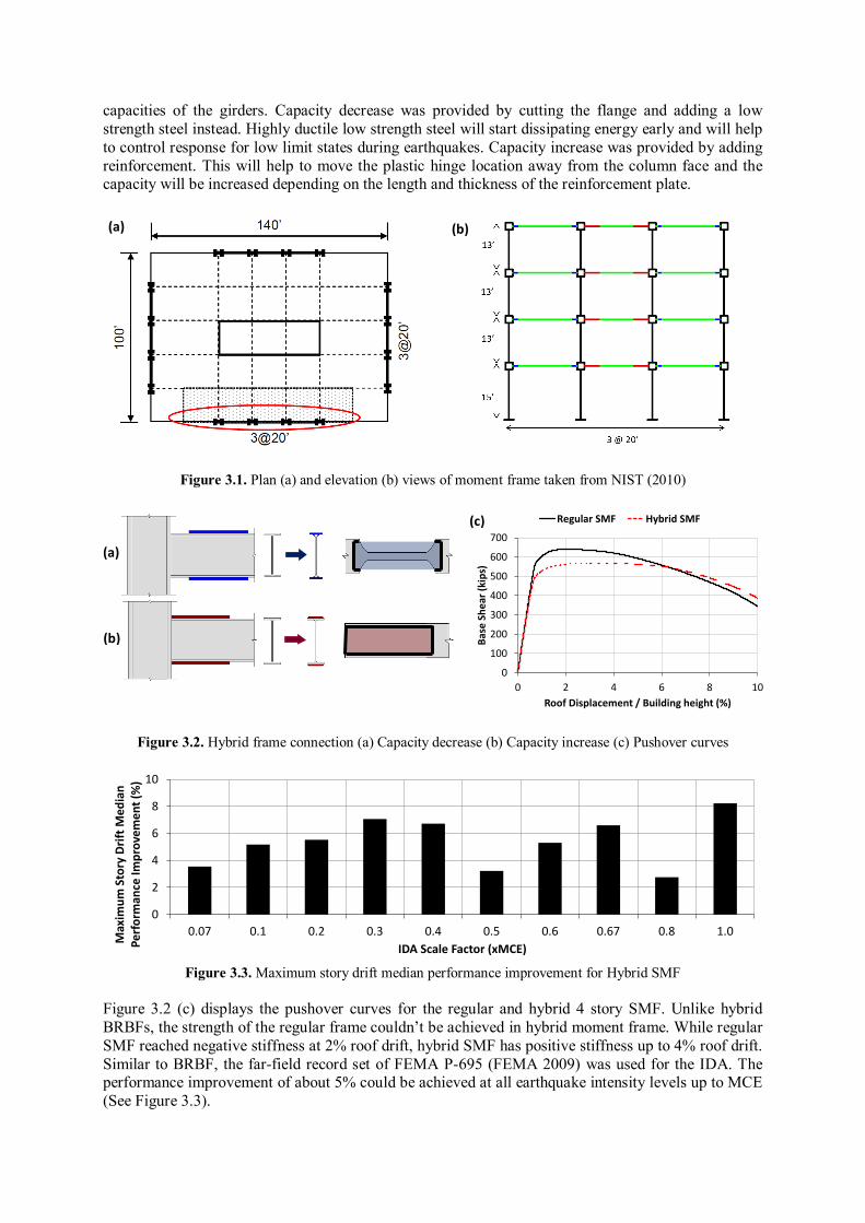
capacities of the girders. Capacity decrease was provided by cutting the flange and adding a low strength steel instead. Highly ductile low strength steel will start dissipating energy early and will help to control response for low limit states during earthquakes. Capacity increase was provided by adding reinforcement. This will help to move the plastic hinge location away from the column face and the capacity will be increased depending on the length and thickness of the reinforcement plate.
Figure 3.1. Plan (a) and elevation (b) views of moment frame taken from NIST (2010)
0
100
200
300
400
500
600
700
0 2 4 6 8 10
Base
She
ar (k
ips)
Roof Displacement / Building height (%)
Regular SMF Hybrid SMF
Figure 3.2. Hybrid frame connection (a) Capacity decrease (b) Capacity increase (c) Pushover curves
0
2
4
6
8
10
0.07 0.1 0.2 0.3 0.4 0.5 0.6 0.67 0.8 1.0
Max
imum
Sto
ry D
rift M
edia
n Pe
rfor
man
ce Im
prov
emen
t (%
)
IDA Scale Factor (xMCE)
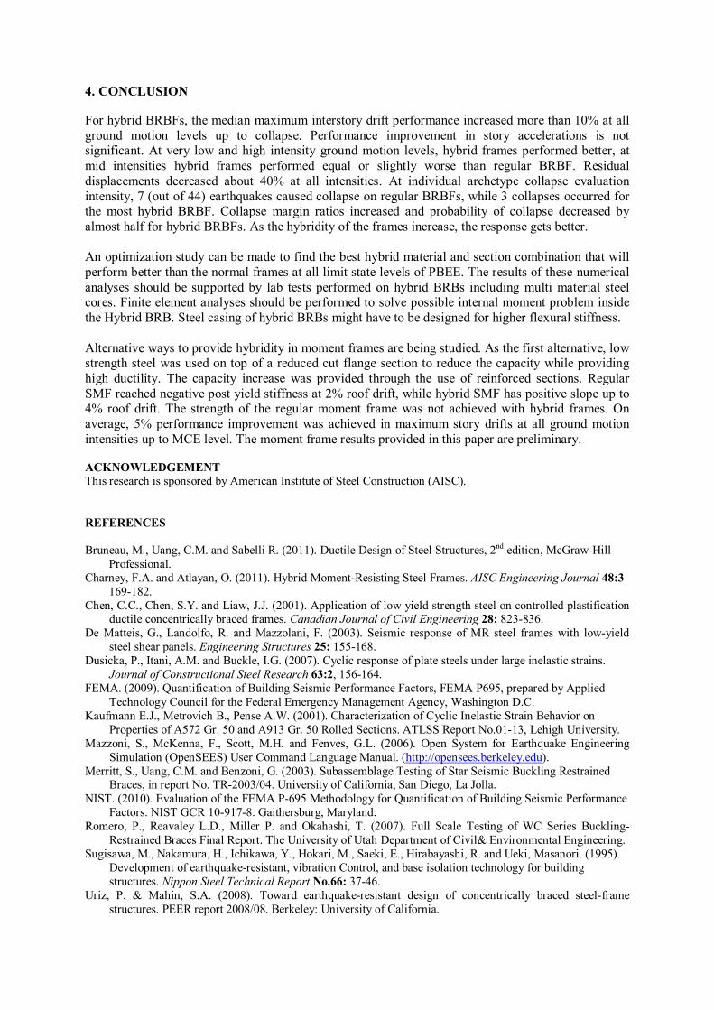
Figure 3.3. Maximum story drift median performance improvement for Hybrid SMF
Figure 3.2 (c) displays the pushover curves for the regular and hybrid 4 story SMF. Unlike hybrid BRBFs, the strength of the regular frame couldn’t be achieved in hybrid moment frame. While regular SMF reached negative stiffness at 2% roof drift, hybrid SMF has positive stiffness up to 4% roof drift. Similar to BRBF, the far-field record set of FEMA P-695 (FEMA 2009) was used for the IDA. The performance improvement of about 5% could be achieved at all earthquake intensity levels up to MCE (See Figure 3.3).
(a)
(b)
(c)
(b) (a)
4. CONCLUSION For hybrid BRBFs, the median maximum interstory drift performance increased more than 10% at all ground motion levels up to collapse. Performance improvement in story accelerations is not significant. At very low and high intensity ground motion levels, hybrid frames performed better, at mid intensities hybrid frames performed equal or slightly worse than regular BRBF. Residual displacements decreased about 40% at all intensities. At individual archetype collapse evaluation intensity, 7 (out of 44) earthquakes caused collapse on regular BRBFs, while 3 collapses occurred for the most hybrid BRBF. Collapse margin ratios increased and probability of collapse decreased by almost half for hybrid BRBFs. As the hybridity of the frames increase, the response gets better. An optimization study can be made to find the best hybrid material and section combination that will perform better than the normal frames at all limit state levels of PBEE. The results of these numerical analyses should be supported by lab tests performed on hybrid BRBs including multi material steel cores. Finite element analyses should be performed to solve possible internal moment problem inside the Hybrid BRB. Steel casing of hybrid BRBs might have to be designed for higher flexural stiffness. Alternative ways to provide hybridity in moment frames are being studied. As the first alternative, low strength steel was used on top of a reduced cut flange section to reduce the capacity while providing high ductility. The capacity increase was provided through the use of reinforced sections. Regular SMF reached negative post yield stiffness at 2% roof drift, while hybrid SMF has positive slope up to 4% roof drift. The strength of the regular moment frame was not achieved with hybrid frames. On average, 5% performance improvement was achieved in maximum story drifts at all ground motion intensities up to MCE level. The moment frame results provided in this paper are preliminary. ACKNOWLEDGEMENT This research is sponsored by American Institute of Steel Construction (AISC). REFERENCES Bruneau, M., Uang, C.M. and Sabelli R. (2011). Ductile Design of Steel Structures, 2nd edition, McGraw-Hill
Professional. Charney, F.A. and Atlayan, O. (2011). Hybrid Moment-Resisting Steel Frames. AISC Engineering Journal 48:3
169-182. Chen, C.C., Chen, S.Y. and Liaw, J.J. (2001). Application of low yield strength steel on controlled plastification
ductile concentrically braced frames. Canadian Journal of Civil Engineering 28: 823-836. De Matteis, G., Landolfo, R. and Mazzolani, F. (2003). Seismic response of MR steel frames with low-yield
steel shear panels. Engineering Structures 25: 155-168. Dusicka, P., Itani, A.M. and Buckle, I.G. (2007). Cyclic response of plate steels under large inelastic strains.
Journal of Constructional Steel Research 63:2, 156-164. FEMA. (2009). Quantification of Building Seismic Performance Factors, FEMA P695, prepared by Applied
Technology Council for the Federal Emergency Management Agency, Washington D.C. Kaufmann E.J., Metrovich B., Pense A.W. (2001). Characterization of Cyclic Inelastic Strain Behavior on
Properties of A572 Gr. 50 and A913 Gr. 50 Rolled Sections. ATLSS Report No.01-13, Lehigh University. Mazzoni, S., McKenna, F., Scott, M.H. and Fenves, G.L. (2006). Open System for Earthquake Engineering
Simulation (OpenSEES) User Command Language Manual. (http://opensees.berkeley.edu). Merritt, S., Uang, C.M. and Benzoni, G. (2003). Subassemblage Testing of Star Seismic Buckling Restrained
Braces, in report No. TR-2003/04. University of California, San Diego, La Jolla. NIST. (2010). Evaluation of the FEMA P-695 Methodology for Quantification of Building Seismic Performance
Factors. NIST GCR 10-917-8. Gaithersburg, Maryland. Romero, P., Reavaley L.D., Miller P. and Okahashi, T. (2007). Full Scale Testing of WC Series Buckling-
Restrained Braces Final Report. The University of Utah Department of Civil& Environmental Engineering. Sugisawa, M., Nakamura, H., Ichikawa, Y., Hokari, M., Saeki, E., Hirabayashi, R. and Ueki, Masanori. (1995).
Development of earthquake-resistant, vibration Control, and base isolation technology for building structures. Nippon Steel Technical Report No.66: 37-46.
Uriz, P. & Mahin, S.A. (2008). Toward earthquake-resistant design of concentrically braced steel-frame structures. PEER report 2008/08. Berkeley: University of California.