seismic performance evaluation of steel moment resisting frames through incremental dynamic analysis
TRANSCRIPT

143
SEISMIC PERFORMANCE EVALUATION OF STEEL MOMENT RESISTING FRAMES WITH CONCRETE FILLED TUBE COLUMNS
Ricardo HERRERA1, James M. RICLES2, Richard SAUSE2, Brian LEWIS1
SUMMARY
In conjunction with the U.S.–Japan Cooperative Research Program on Composite and Hybrid Structures, analytical and experimental studies on the seismic behavior of steel moment resisting frames (MRFs) with concrete filled steel tubular (CFT) columns are being conducted at Lehigh University. The objectives of these studies are to investigate the seismic performance of this type of frame, to evaluate existing design criteria, and to calibrate analytical models. The MRF, extracted from a four-story prototype building designed using current U.S. seismic provisions, is composed of CFT columns and steel wide-flange beams. The moment connections between the beams and the column are split-tee connections. For the analytical study, a fiber-element based model of the four-story, four-bay MRF was developed. Included in the model are the effects of local buckling in the steel tube and cracking and confinement of the concrete in the CFT, local buckling in the beams, flexibility and inelastic behavior of the connections and panel zones, and geometric nonlinearities. Two-dimensional nonlinear time-history analyses were performed, using ground motion records scaled to match two levels of seismic hazard: the Design Basis Earthquake (DBE) and the Maximum Considered Earthquake (MCE). A post-earthquake frame stability analysis was also performed to determine a stability index representing the load factor applied to the dead load to cause frame collapse. It was found that, when subjected to earthquake excitation, the prototype frame performs adequately when designed in accordance with current U.S. seismic provisions. The test structure for the experimental study is a three-fifths scale model of an MRF extracted from the above prototype building. The test structure consists of four-stories and two bays. The experimental program is currently in progress, and involves a series of tests, which will result in the structure being subjected to different levels of seismic hazard, including the Design Basis Earthquake (DBE) and the Maximum Considered Earthquake (MCE). Keywords: composite construction, structural response, buildings, experimental testing, structural system.
INTRODUCTION In conjunction with the U.S.–Japan Cooperative Research Program on Composite and Hybrid Structures, analytical and experimental studies on the seismic behavior of steel moment resisting frames (MRFs) with concrete filled steel tubular (CFT) columns are being conducted at the ATLSS Engineering Research Center located at Lehigh University. The objectives of these studies are to investigate the seismic performance of these types of frames and to evaluate existing design criteria. This paper describes the first phase of work related to the analytical studies performed as part of the design of the test structure. In addition, a description of the test structure to be tested next, as part of the experimental phase of the program, is included.
1 Graduate Research Assistant, Dept. of Civil Eng., Lehigh Univ., Bethlehem, Pennsylvania. email: [email protected], [email protected] 2 Professor, Dept. of Civil Eng., Lehigh University, Bethlehem, Pennsylvania. email: [email protected], [email protected].
144
DESCRIPTION AND DESIGN OF PROTOTYPE BUILDING A prototype building was designed according to the International Building Code (IBC) 2000 provisions (International 2000). A typical floor plan is shown in Figure 1, where the MRFs are located around the perimeter of the building. The building is intended for office use, and assumed to be located in Los Angeles, in soil type D. The equivalent static lateral load procedure outlined in IBC 2000 was used to design the building, where drift was found to control the design. The fundamental period of the structure is T1 = 1.4 seconds.
Figure 1. Prototype Building Floor Plan. The design objectives were related to two levels of earthquake hazard: the Maximum Considered Earthquake (MCE), associated with a probability of exceedance of 2% in 50 years; and the Design Basis Earthquake (DBE), defined as two-thirds the intensity of the MCE, with a probability of exceedance of about 10% in 50 years. When subjected to a DBE level earthquake, the building was expected to achieve the life safety level, while staying under or at the collapse prevention level when subjected to a MCE level ground motion. Table 1 summarizes the limit states consistent with these performance objectives.
Table 1. Limit States and Expected Occurrence. Component Limit State DBE MCE
Strength degradation due to local buckling of steel No Yes Column Flange fracture No No Strength degradation due to local buckling No Yes Lateral-torsional buckling No No Beam Fracture No No T-stem yielding Yes Yes T-stem fracture No No T-stem welds fracture No No Tension bolt fracture No No T-flange shear yielding No Yes
Connection
T-flange yielding No Yes Concrete cracking Yes Yes P-Z steel yielding Yes Yes P-Z concrete crushing No Yes Panel Zone
P-Z fracture No No The CFT columns consisted of high strength square, steel tubes (552 MPa nominal yield strength) filled with normal strength concrete (55 MPa nominal compressive strength), designed using ACI 318 (1998) provisions. The beams were A992 steel wide flange sections (345 MPa nominal yield strength), designed according to AISC (1993, 1997). The moment connections between the beams and columns in the perimeter MRFs consisted of split tee connections, where the tee stems are fillet welded to the beam flange and the tee flanges are post-tensioned to the CFT column by passing high strength rods through it (see Figure 2). The material for the tees was also A992 steel. Peng et al. (2001) developed and tested this connection detail in prior studies. The connections were
145
designed to reach yield on the tee stem when the beam develops the maximum expected moment capacity calculated using FEMA 350 (FEMA, 2000), so that fracture would not occur, even under the most severe ground motion. The members of the MRFs were proportioned to satisfy a weak beam-strong column design, according to FEMA (2000) provisions, to avoid the formation of soft story mechanisms that could cause collapse of the structure. The required column moment and tee stem capacities were based on the expected plastic beam moment occurring at the end of the tee stem. For the former, the inflection points in the columns were assumed to be located at the far end of the columns framing into the joint. The panel zone strength was checked against the demand calculated using the assumptions considered when evaluating weak beam-strong column conditions.
Figure 2. First Floor Connection Detail. The prototype building had four floors plus a basement. Several issues contributed in selecting this configuration. The basement was included considering that a fixed base at the bottom of the first floor columns would not be representative of the actual end conditions in a real building at that level, yielding excessively unrealistic demands at the base of the columns. Height constraints in the laboratory limited the test structure to a 3 to 4-story frame, depending on the scale chosen. Having a prototype with the same number of floors as the test structure eliminated the problem of reproducing the variation of axial load on the columns due to the overturning effect of the upper floors not present on the test frame.
ANALYTICAL STUDIES Modeling details The prototype frame consisted of one of the perimeter MRFs from the prototype building. As shown in Figure 3, the frame had 4 bays and 5 floor levels, with the lower level being the basement of the prototype building. The member sizes are also shown in Figure 3.
Figure 3. Prototype Perimeter Moment Resisting Frame.

146
The computer program DRAIN-2DX (Prakash et al. 1993) was used to develop a model of the prototype frame with material and geometric non-linearities (See Figure 4). Fiber elements were used to model the inelastic regions of the CFT columns and WF beams. The inelastic regions in the columns, where local buckling was expected to occur, were modeled using a special steel fiber that allowed modeling of post-buckling strength degradation (Herrera et al. 2001). The fiber element model was calibrated to experimental data from component tests (Fujimoto et al. 1996, Varma et al. 2001). The stress-strain curves for steel and concrete in the CFT, considering the effects of local buckling in the steel tube, and cracking and confinement of the concrete, were obtained using nonlinear continuum finite element models developed using ABAQUS (1998) and concepts formulated by Varma et al. (2001). Preliminary analysis results showed that the plastic deformation in the columns was concentrated at the base of the first floor columns, therefore, only a segment at the base of each first floor column was modeled with fibers that included special steel fibers (see Figure 5). These fibers were also used to model the local buckling behavior of the wide flange steel beams in their plastic zone region. The stress-strain curves for the WF beam fibers were determined using calibrated experimental curves, in terms of a generalized slenderness ratio (Muhummud, 2003). Outside of the plastic zone region, elastic beam elements were used.
Figure 4. Prototype Frame Model.
Figure 5. First Floor Column Model.
The panel zones and connection components (i.e., tees and bolts) were modeled using inelastic springs (see Figure 6) calibrated to experimental data from previous U.S.-Japan studies (Peng et al. 2001, Koester 2000). Second-order effects were considered through the geometric stiffness of the elements, based on the displacement of the chord. Several calibration analyses showed that this is the dominant effect on the overall second-order effects. P-delta effects caused by the interaction of the perimeter MRF with the interior gravity frames were accounted for by using a leaning column as shown in Figure 4. This column had the geometric properties and weight corresponding to the sum of the gravity columns that were tributary to the perimeter MRF.

147
Figure 6. Panel Zone and Connection Model. The gravity load was applied to girders and columns as shown in Figure 4. The model considered the mass of the structure lumped at each joint, and no rigid diaphragm was modeled. The frame model was used to perform nonlinear static pushover and time-history analyses. For the static analyses, two cases were considered: a uniform lateral load profile and a lateral load profile in accordance with the IBC 2000 provisions (International, 2000). For each case, the frame was displaced to a 5% global roof drift using displacement control. For the time-history analyses, the model was subjected to 16 ground motion acceleration records. The records are listed in Table 2 and the response spectra of selected records are shown in Figure 7 scaled to the MCE spectrum recommended by the IBC code (International, 2000). The ground motions that were considered included a subset of the ground motions proposed for the SAC Steel Project (Somerville et al. 1997) and natural records from the Pacific Earthquake Engineering Research Center database. Each horizontal component of these records was scaled using the procedure outlined by Somerville (Somerville et al. 1997) to the two levels of earthquake hazard, namely, the Design Basis Earthquake (DBE) and Maximum Considered Earthquake (MCE). Only one horizontal component of each record, the one that yielded the smaller scale factor, was subsequently used in the time history analysis.
Table 2. Selected Ground Motion Records.
Earthquake Station Magnitude R Km
PGA g
1995 Kobe, Japan* JMA 6.9 3.4 0.921 1974 Tabas, Iran* Tabas 7.4 1.2 0.992 1985 Valparaiso, Chile* Llolleo 8.0 42 1.575 1978 Miyagi-Oki, Japan* Ofuna 7.4 66 0.784 1940 Imperial Valley* El Centro 6.9 10 0.676 1999 Duzce, Turkey Bolu 7.1 17.6 0.728 1999 Kocaeli, Turkey Iznik 7.4 31.8 0.136 1992 Landers Yermo 7.3 24.9 0.245 1989 Loma Prieta 1 Gilroy #3 7.0 28.8 0.209 1989 Loma Prieta 2 Hollister diff#1 7.0 14.4 0.367 1989 Loma Prieta 3 Hollister S&P 7.0 25.8 0.269 1989 Loma Prieta 4 Sunnyvale 7.0 28.8 0.371 1994 Northridge 1 Canyon Co. 6.7 13 0.410 1994 Northridge 2 Canoga Park 6.7 15.8 0.420 1994 Northridge 3 Saticoy 6.7 13.3 0.477 1987 Superstition Hills Westmoreland 6.6 13.3 0.211 * Ground motions from the SAC Steel Project.

148
T1
0
0.5
1
1.5
2
2.5
3
3.5
4
0 0.5 1 1.5 2 2.5 3 3.5 4
T (sec)
Sa (g
)
IBC MCEDuzceLandersLoma Prieta 4Loma Prieta 1Loma Prieta 2Loma Prieta 3Northridge 1Northridge 2Northridge 3Superstition Hills
Figure 7. Response Spectrum of Selected Records Scaled to MCE Level.
Pushover analysis results Figure 8 shows the relationship between the normalized base shear and the roof drift index (RDI). The normalized base shear is defined as the base shear divided by the seismic dead weight tributary to the MRF, W, while the RDI is the roof displacement divided by the building height. For the IBC lateral load profile, the frame first yielded at a base shear of 0.2W at the first floor beams; for the uniform lateral load case, first yielding occurred at 0.21W also at the first floor beams. The maximum overstrength of the MRF relative to its design base shear was 3.0 (0.27W) for the IBC profile, and 3.4 (0.31W) for the uniform profile. For both cases, the inelastic deformations were concentrated at the base of the first floor columns and at the ends of the floor beams. Only the first and second floor panel zones developed minor inelastic response, with a maximum shear deformation of 0.004 rad, verifying that they are sufficiently strong in shear compared with the demand imposed on them.
IBC 2000 design base shear
0.00
0.05
0.10
0.15
0.20
0.25
0.30
0.35
0% 1% 2% 3% 4% 5%
Roof Drift
Nor
mal
ized
bas
e sh
ear
IBC 2000
Uniform
Figure 8. Static Pushover Results.
Time-history analysis results Results from the non-linear time history analyses for selected DBE and MCE scaled records are presented in Tables 3 and 4, respectively. Tables 3 and 4 include the maximum values of story drift (θmax), base shear (Vbase), beam plastic rotation (θp,bm max), column plastic rotation (θp,col max), and plastic shear deformation in the panel zone (γp,max). Following the completion of each time history analysis a post-earthquake frame stability analysis was performed to determine how much gravity load the frame could sustain. The post-earthquake analysis accounted for the damaged state in the frame (residual drift, deteriorated member strength and stiffness). A stability index λ was then computed, which represented the load factor applied to the dead load to cause frame collapse.

149
From Table 3, it can be seen that the maximum base shear exceeds the value for the static analysis using the IBC 2000 profile and is closer to the value for the uniform profile. This phenomenon is attributed to the participation of higher vibration modes in the response to the earthquake excitation.
Table 3. Analysis Results for Selected Ground Motions. DBE Level.
Record θmax %
Vbase %W
θp,bm max %
θp,col max %
γp,max % λ
Imperial Valley 2.8 30 1.9 0.2 0.2 16 Duzce 2.1 35 1.2 0.5 0.3 15.8 Kocaeli 3.0 30 2.4 1.4 0.4 14.5 Landers 3.9 31 3.3 2.4 0.4 10.8 Loma Prieta 1 4.1 33 3.5 2.7 0.4 10.2 Loma Prieta 2 2.2 29 1.4 0.6 0.3 14.1 Loma Prieta 3 2.4 31 1.4 0.7 0.3 14.6 Loma Prieta 4 2.0 29 1.1 0.3 0.3 14.9 Northridge 1 2.5 35 1.5 0.9 0.4 14.7 Northridge 2 2.9 33 1.9 1.1 0.4 14.1 Northridge 3 2.4 36 1.2 0.9 0.3 16.6 Superstition Hills 2.3 33 1.5 0.8 0.3 15.5
Table 4. Analysis Results for Selected Ground Motions. MCE Level.
Record θmax %
Vbase %W
θp,bm max %
θp,col max %
γp,max % λ
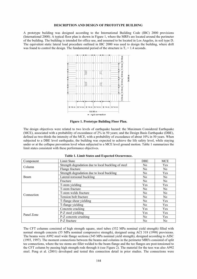
Kobe 3.0 34 2.2 0.9 0.3 12.7 Tabas 3.4 40 2.2 2.0 0.3 13.7 Valparaiso 4.2 39 8.0 2.1 0.4 11.7 Miyagi-Oki 5.4 33 5.2 3.7 0.5 8.1 Imperial Valley 4.3 36 3.4 1.6 0.4 10.1 Duzce 3.4 38 2.8 2.0 0.4 11.8 Landers 5.4 31 5.1 3.9 0.4 8.1 Loma Prieta 1 5.8 35 5.3 1.8 0.4 8.5 Loma Prieta 2 3.1 35 2.4 1.5 0.4 15.2 Loma Prieta 3 3.3 33 2.5 1.7 0.4 11.1 Loma Prieta 4 3.1 35 2.3 1.5 0.4 13.2 Northridge 1 4.4 40 4.0 3.8 0.4 9.2 Northridge 2 4.4 36 4.0 3.6 0.4 8.5 Northridge 3 3.8 36 3.3 2.9 0.4 9.8 Superstition Hills 3.9 32 3.4 2.6 0.4 11.4 The data in Tables 3 and 4 are plotted in Figures 9 to 11, together with the mean and the mean plus one standard deviation of the data at each floor. Assuming that the distribution of the data follows a lognormal distribution, data values that are one standard deviation above the mean correspond to the 84th percentile of the data. Figure 9 shows the maximum story drift for the DBE and MCE levels. A fairly uniform story drift can be observed for both levels of earthquake hazard, with the maximum values occurring at the first floor. The mean and one standard deviation above the mean values for this floor are 2.6% and 3.3%, respectively, for the DBE, and 3.9% and 4.8%, respectively, for the MCE. Although some DBE values exceeded the 2.5% drift limit of the IBC 2000 (International, 2000), the stability index indicated that the structure was not on the verge of collapse, the plastic rotation demand on the members was not excessive, and no strength degradation was observed. In the case of the MCE values, the stability indices were lower, indicating deterioration of the gravity load carrying capacity of the frame. However, only minor strength degradation was observed to have occurred in the members.
150
IBC 20000
1
2
3
4
0.00 0.02 0.04 0.06 0.08Story Drift, rad
Floo
rMeanMean+Std.Dev.
0
1
2
3
4
0.00 0.02 0.04 0.06 0.08Story Drift, rad
Floo
r
MeanMean+Std.Dev.
(a) DBE Level (b) MCE Level
Figure 9. Story Drift Results.
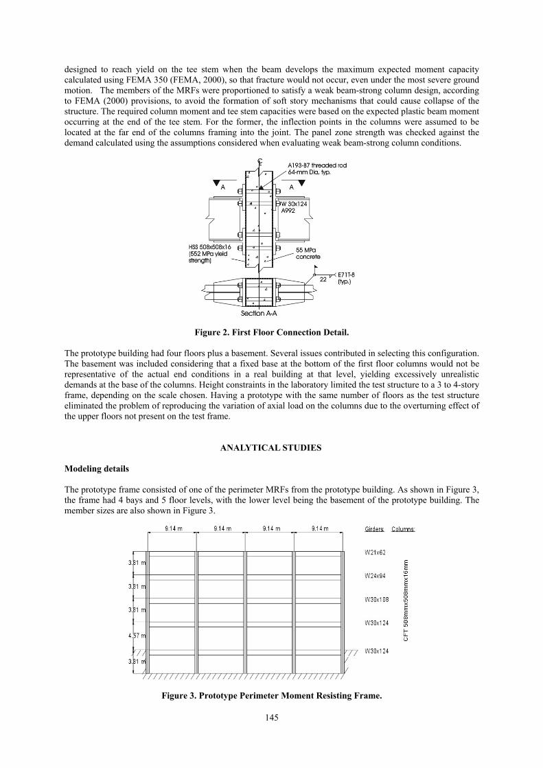
The maximum beam plastic rotation is presented in Figure 10. For the DBE records the maximum values of the mean and the mean plus one standard deviation occurred at the second floor, 1.8% and 3.1% respectively. For the MCE, both maxima occurred at the first floor, 3.3% for the mean and 4.4%, for the mean plus one standard deviation. No appreciable strength degradation due to beam local buckling was observed, except for the 4th floor beams during the Valparaiso MCE record. Comparing the values of accumulated plastic rotation capacity from component tests with the values obtained from the analyses, it was determined that fracture was not likely to occur under the MCE level.
0
1
2
3
4
0.00 0.02 0.04 0.06 0.08Beam Plastic Rotation, rad
Floo
r
MeanMean+Std.Dev.
0
1
2
3
4
0.00 0.02 0.04 0.06 0.08Beam Plastic Rotation, rad
Floo
r
MeanMean+Std.Dev.
(a) DBE Level (b) MCE Level
Figure 10. Beam Plastic Rotation Results.
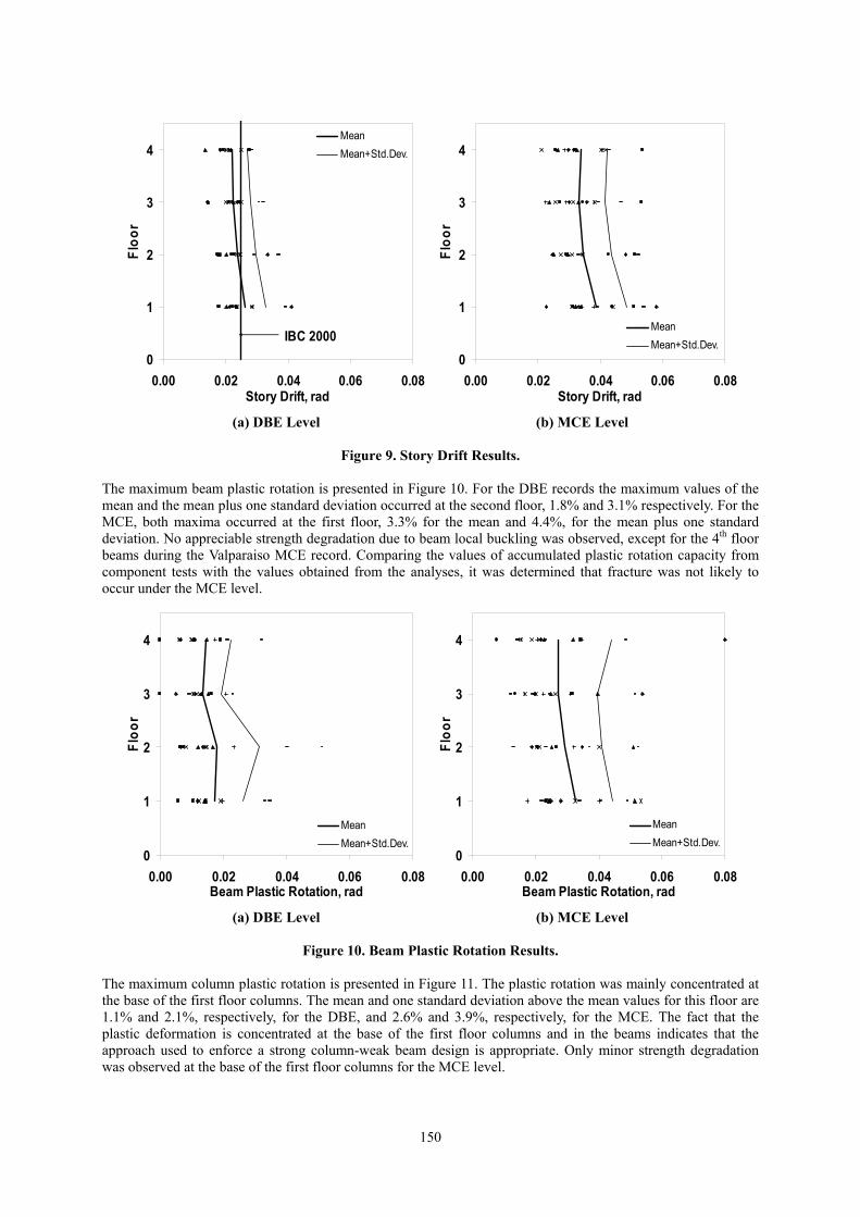
The maximum column plastic rotation is presented in Figure 11. The plastic rotation was mainly concentrated at the base of the first floor columns. The mean and one standard deviation above the mean values for this floor are 1.1% and 2.1%, respectively, for the DBE, and 2.6% and 3.9%, respectively, for the MCE. The fact that the plastic deformation is concentrated at the base of the first floor columns and in the beams indicates that the approach used to enforce a strong column-weak beam design is appropriate. Only minor strength degradation was observed at the base of the first floor columns for the MCE level.
151
0
1
2
3
4
0.00 0.02 0.04 0.06 0.08Column Plastic Rotation, rad
Floo
r
MeanMean+Std.Dev.
0
1
2
3
4
0.00 0.02 0.04 0.06 0.08Column Plastic Rotation, rad
Floo
r
MeanMean+Std.Dev.
(a) DBE Level (b) MCE Level
Figure 11. Column Plastic Rotation Results.
The panel zone plastic deformation was not significant and it was concentrated at the bottom two floors. The maximum shear deformation was 75% of the shear deformation corresponding to the shear strength of the panel zone, indicating that the panel zones have a large reserve of capacity. The connection components remained nearly elastic for all the time history analyses. Therefore, no failure is expected to occur in any of these elements. Based on the component tests by Peng et al. (2001), Varma et al. (2001), and Fujimoto et al. (1996), the connections, beams, and CFT columns have sufficient strength and ductility capacity to resist the demand, implying that the frames would survive DBE earthquakes without loss of strength and MCE earthquakes without collapsing. The design procedure appears to be adequate in enforcing the performance objectives given in Table 1.
DESCRIPTION OF THE TEST FRAME Having verified that the design of the prototype building was adequate, the test structure was selected as two bays of the prototype frame. The scale of the test structure was constrained by the maximum height of the reaction wall. The final scale factor was selected as three-fifths (0.6). The CFT columns scaled exactly to an available size of high strength hollow structural section (HSS). To determine the appropriate scaled sizes for the beams, a close match in strength and stiffness of the section, together with the plastic hinge distribution and maximum plastic deformation among the beams were the defining factors. To evaluate the last two factors, a model of the test structure was constructed and subjected to displacement inputs from selected ground motion records. The response was then compared with the response of the prototype and modifications on the beam sizes made if needed. The final design is shown in Figure 12.
SUMMARY AND CONCLUSIONS The results of the analyses imply that MRFs with CFT columns designed in accordance with current U.S. seismic provisions are likely to perform adequately during an earthquake. The experimental study that is to follow will involve constructing and testing a three-fifths scale model of the prototype frame. Analyses are being performed on a model of the test frame in order to simulate the response during the test. The results from the experiments will be used to refine design criteria and calibrate the analytical models.

152
ACKNOWLEDGMENTS The research reported herein was supported by the National Science Foundation (Dr. Shih-Chiu Liu cognizant program official), and by a grant from the Pennsylvania D.C.E.D. through the PITA program. The opinions expressed in this paper are those of the authors and do not necessarily reflect the views of the sponsors.
All Columns HSS 305x305x9.5
Figure 12. Test Frame.
REFERENCES ABAQUS 1998. ABAQUS/Standard User’s Manual, Version 5.8. Hibbitt, Karlsson and Sorensen, Inc.
Pawtucket, RI, USA. ACI 1999. Building Code Requirements for Structural Concrete (318-99). American Concrete Institute.
Farmington Hills, MI, USA. AISC 1993. Manual of Steel Construction. Load and Resistance Factor Design. American Institute of Steel
Construction. Chicago, IL, USA. AISC 1997. Seismic Provisions for Structural Steel Buildings. American Institute of Steel Construction. Chicago,
IL, USA. FEMA 2000. Recommended Seismic Design Criteria for New Steel Moment-Frame Buildings. Report No.
FEMA 350, Federal Emergency Management Agency, Washington, D.C., USA. Fujimoto, T., Nishiyama, I., Mukai, A., and T. Baba 1996. “Test Results of Concrete Filled Steel Tubular
Beam-Columns.” Proceedings of the 3rd JTCC on Composite and Hybrid Structures, Hong Kong. Herrera, R., Sause, R., and J. Ricles 2001. “Refined Connection Element (Type 05) for DRAIN-2DX: Element
Description and User Guide.” ATLSS Engineering Research Center, Report No. 01-08. Lehigh University, Bethlehem, PA, USA.
International Code Council 2000. International Building Code 2000. Falls Church, Virginia, USA. Koester, B. 2000. “Panel Zone Behavior of Moment Connections Between Rectangular Concrete-Filled Steel
Tubes and WF Beams.” Ph.D. Dissertation. Depart. of Civil and Envir. Eng., Univ. Texas, Austin, TX, USA. Muhummud, T. 2003. “Seismic Design and Behavior of Composite Moment Resisting Frame Constructed of
CFT Columns and WF Beams.” Ph.D. Dissertation. Department of Civil and Environmental Engineering. Lehigh University, Bethlehem, PA, USA. To be published.
Peng, S.W., Ricles, J.M., and Lu, L.W. 2001. “Seismic Resistant Connections for Concrete Filled Column-to-WF Beam MRFs.” ATLSS Engineering Research Center, Report No. 01-08. Lehigh University, Bethlehem, PA, USA.
Prakash, V., Powell, G.H., and Campbell, S. 1993, “DRAIN-2DX Base Program Description and User Guide,” Report No. UCB/SEMM-93/17&18. University of California, Berkeley, CA, USA.
Somerville, P., Smith, N., Punyamurthula, S., and Sun, J. 1997. “Development of Ground Motion Time Histories for Phase 2 of the FEMA/SAC Steel Project.” Report No. SAC/BD-97/04. Sacramento, CA, USA.
Varma, A., Ricles, J.M., Sause, R., and Lu, L.W. 2001. “Seismic Behavior, Analysis, and Design of High Strength Square Concrete Filled Steel Tube (CFT) Columns.” ATLSS Engineering Research Center, Report No. 01-01. Lehigh University, Bethlehem, PA, USA.