global seismic performance of steel moment resisting frames
TRANSCRIPT
16th World Conference on Earthquake, 16WCEE 2017
Santiago Chile, January 9th to 13th 2017
Paper N° 3319
Registration Code: S-Z1461781018
Global seismic performance of steel moment resisting frames with different connection details
P. Steneker(1), L. Wiebe(2)
(1) Graduate Student Researcher, Department of Civil Engineering, McMaster University, [email protected] (2) Assistant Professor, Department of Civil Engineering, McMaster University, [email protected]
Abstract The 1994 Northridge Earthquake highlighted the unacceptable performance of common connection details for moment resisting frames and led to many new details being developed. These include connections that have now been recommended by codes worldwide because of their demonstrated ductility capacity. The performance of these connections have been verified by researchers in component tests; however, these tests have also demonstrated differing hysteretic behavior for each detail. There is relatively little information available on how these differences affect the global response. Considering that the cost in material, labour, and erection time may vary for these connections, it is important to understand the impact that the choice of connection detail has on the overall system performance.
This paper examines the influence of four different connection details on the global performance of an eight-storey moment resisting frame. Each connection is modeled in OpenSees using nonlinear elements that capture cyclic deterioration, and is calibrated using available experimental data. The global performance of the steel frame using each connection is evaluated under seven ground motions at incremental amplifications above and below the design basis earthquake, using the peak interstorey drifts and connection rotation demands as the primary engineering design parameters for evaluating the frame performance. During the majority of ground motions, the difference in performance between connections is small. Column hinging is observed in most frames, resulting in failures that are independent of the beam connection type. However, beam connections with a more pinched hysteretic response lead to a reduction in collapse performance for certain ground motions. Keywords: Steel Moment Resting Frames, prequalified connection details, nonlinear time history analysis, global behaviour
1. Introduction The Northridge Earthquake had far reaching impacts on the design of moment resisting steel frames in seismic areas [1]. The resulting investigation highlighted the poor performance of the beam-to-column connections, due to fractures in and around the weld connecting the beam flanges to the column [2]. To address these problems with pre-Northridge connections, the SAC research program developed seven prequalified connections that have demonstrated adequate performance during cyclic component testing. Such connections are currently approved for use in seismic areas of the United States without further investigation [3].
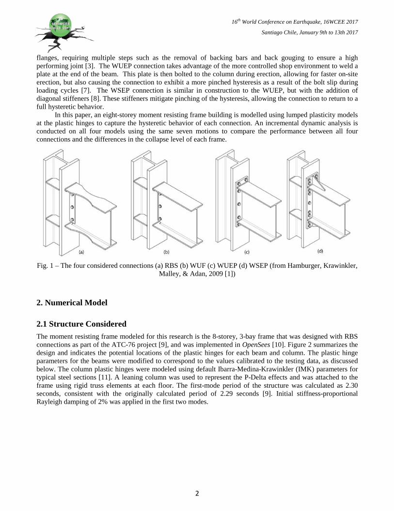
Each connection has demonstrated its own hysteretic behavior during component testing [4, 5, 6, 7, 8], but no guidelines have been provided to aid the designer in distinguishing the performance of one particular connection compared to others. The fabrication and erection process for each connection varies and may also affect the global performance of a frame. Figure 1 shows four connections that are the focus of this paper: the Reduced Beam Section (RBS), the Welded Unreinforced Flange with Welded Web (WUF), the Welded Unstiffened End Plate (WUEP) and the Welded Stiffened End Plate (WSEP) connections. These were chosen because they have undergone the most component testing, therefore producing the most available test data for calibration [9]. Each connection uses a different method to avoid the brittle fracture of the beam-to-column weld observed in past research. The RBS connection reduces the moment capacity of the beam at a distance from the column face, thereby causing the plastic hinge to develop away from the column [3]. The WUF connection focuses on the proper implementation of a meticulous field welding procedure between the beam and column
16th World Conference on Earthquake, 16WCEE 2017
Santiago Chile, January 9th to 13th 2017
flanges, requiring multiple steps such as the removal of backing bars and back gouging to ensure a high performing joint [3]. The WUEP connection takes advantage of the more controlled shop environment to weld a plate at the end of the beam. This plate is then bolted to the column during erection, allowing for faster on-site erection, but also causing the connection to exhibit a more pinched hysteresis as a result of the bolt slip during loading cycles [7]. The WSEP connection is similar in construction to the WUEP, but with the addition of diagonal stiffeners [8]. These stiffeners mitigate pinching of the hysteresis, allowing the connection to return to a full hysteretic behavior.
In this paper, an eight-storey moment resisting frame building is modelled using lumped plasticity models at the plastic hinges to capture the hysteretic behavior of each connection. An incremental dynamic analysis is conducted on all four models using the same seven motions to compare the performance between all four connections and the differences in the collapse level of each frame.
Fig. 1 – The four considered connections (a) RBS (b) WUF (c) WUEP (d) WSEP (from Hamburger, Krawinkler,
Malley, & Adan, 2009 [1])
2. Numerical Model
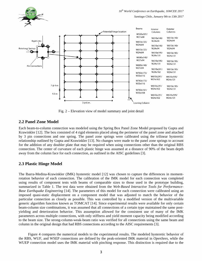
2.1 Structure Considered The moment resisting frame modeled for this research is the 8-storey, 3-bay frame that was designed with RBS connections as part of the ATC-76 project [9], and was implemented in OpenSees [10]. Figure 2 summarizes the design and indicates the potential locations of the plastic hinges for each beam and column. The plastic hinge parameters for the beams were modified to correspond to the values calibrated to the testing data, as discussed below. The column plastic hinges were modeled using default Ibarra-Medina-Krawinkler (IMK) parameters for typical steel sections [11]. A leaning column was used to represent the P-Delta effects and was attached to the frame using rigid truss elements at each floor. The first-mode period of the structure was calculated as 2.30 seconds, consistent with the originally calculated period of 2.29 seconds [9]. Initial stiffness-proportional Rayleigh damping of 2% was applied in the first two modes.
2
16th World Conference on Earthquake, 16WCEE 2017
Santiago Chile, January 9th to 13th 2017
Fig. 2 – Elevation view of model summary and joint detail
2.2 Panel Zone Model Each beam-to-column connection was modeled using the Spring Box Panel Zone Model proposed by Gupta and Krawinkler [12]. The box consisted of 4 rigid elements placed along the perimeter of the panel zone and attached by 3 pin connections and one spring. The panel zone springs were calibrated using the trilinear hysteretic relationship outlined by Gupta and Krawinkler [13]. No changes were made to the panel zone springs to account for the addition of any doubler plate that may be required when using connections other than the original RBS connection. The center of curvature of each plastic hinge was assumed at a distance of 90% of the beam depth away from the column face for each connection, as outlined in the AISC guidelines [3].
2.3 Plastic Hinge Model
The Ibarra-Medina-Krawinkler (IMK) hysteretic model [12] was chosen to capture the differences in moment-rotation behavior of each connection. The calibration of the IMK model for each connection was completed using results of component tests with beams of comparable sizes to those used in the prototype building, summarized in Table 1. The test data were obtained from the Web-Based Interactive Tools for Performance-Base Earthquake Engineering [14]. The parameters of this model for each connection were calibrated using an imposed quasi-static displacement on a component model that was adjusted to match the behavior of the particular connection as closely as possible. This was controlled by a modified version of the multivariable generic algorithm function known as TOMCAT [14]. Since experimental results were available for only certain beam-column size combinations, it was assumed that all connections of a certain type maintained the same post-yielding and deterioration behavior. This assumption allowed for the consistent use of many of the IMK parameters across multiple connections, with only stiffness and yield moment capacity being modified according to the beam size. The strong-column-weak-beam ratio was verified for all connections using the same beam and column in the original design that had RBS connections according to the AISC requirements [3].
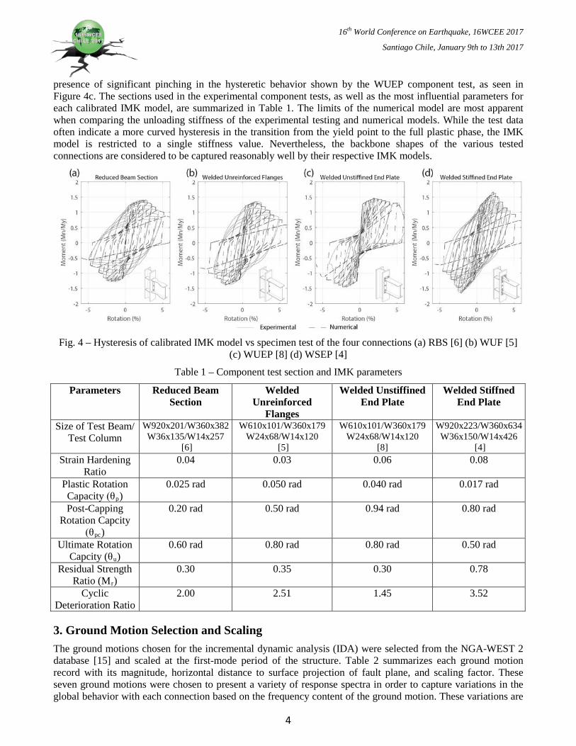
Figure 4 compares the numerical models to the experimental results. The modeled hysteretic behavior of the RBS, WUF, and WSEP connections are defined by the peak-oriented IMK material in OpenSees, while the WUEP connection model uses the IMK material with pinching response. This distinction is required due to the
3
16th World Conference on Earthquake, 16WCEE 2017
Santiago Chile, January 9th to 13th 2017
presence of significant pinching in the hysteretic behavior shown by the WUEP component test, as seen in Figure 4c. The sections used in the experimental component tests, as well as the most influential parameters for each calibrated IMK model, are summarized in Table 1. The limits of the numerical model are most apparent when comparing the unloading stiffness of the experimental testing and numerical models. While the test data often indicate a more curved hysteresis in the transition from the yield point to the full plastic phase, the IMK model is restricted to a single stiffness value. Nevertheless, the backbone shapes of the various tested connections are considered to be captured reasonably well by their respective IMK models.
Fig. 4 – Hysteresis of calibrated IMK model vs specimen test of the four connections (a) RBS [6] (b) WUF [5]
(c) WUEP [8] (d) WSEP [4]
Table 1 – Component test section and IMK parameters
Parameters Reduced Beam Section
Welded Unreinforced
Flanges
Welded Unstiffined End Plate
Welded Stiffned End Plate
Size of Test Beam/ Test Column
W920x201/W360x382 W36x135/W14x257
[6]
W610x101/W360x179 W24x68/W14x120
[5]
W610x101/W360x179 W24x68/W14x120
[8]
W920x223/W360x634 W36x150/W14x426
[4] Strain Hardening
Ratio 0.04 0.03 0.06 0.08
Plastic Rotation Capacity (θp)
0.025 rad 0.050 rad 0.040 rad 0.017 rad
Post-Capping Rotation Capcity
(θpc)
0.20 rad 0.50 rad 0.94 rad 0.80 rad
Ultimate Rotation Capcity (θu)
0.60 rad 0.80 rad 0.80 rad 0.50 rad
Residual Strength Ratio (Mr)
0.30 0.35 0.30 0.78
Cyclic Deterioration Ratio
2.00 2.51 1.45 3.52
3. Ground Motion Selection and Scaling The ground motions chosen for the incremental dynamic analysis (IDA) were selected from the NGA-WEST 2 database [15] and scaled at the first-mode period of the structure. Table 2 summarizes each ground motion record with its magnitude, horizontal distance to surface projection of fault plane, and scaling factor. These seven ground motions were chosen to present a variety of response spectra in order to capture variations in the global behavior with each connection based on the frequency content of the ground motion. These variations are
4

16th World Conference on Earthquake, 16WCEE 2017
Santiago Chile, January 9th to 13th 2017
observed in the acceleration and displacement spectra, shown in Figure 5 (a) and (b), respectively. The mean of the spectra overshoots the design spectrum at periods shorter than 2.3 seconds and undershoots at longer periods. The Kern and Tabas ground motions are identified as they are discussed in more detail later.
Table 2 – Summary of ground motions used in IDA
Ground Motion Location (Year) Magnitude Distance (km) Scaling Factor at Design Level Kern Kern County, Cal (1952) 7.4 114.6 2.39
San Fernando San Fernando Valley, Cal (1971) 6.6 22.8 1.20 Point Mugu Point Mugu, Cal (1973) 5.7 15.5 2.02
Gazli Gazli, USSR (1984) 6.8 3.9 0.55 Tabas Tabas, Iran (1978) 7.4 24.1 1.78
Taiwan_13 Hualien, Taiwan (2013) 5.9 25.5 2.86 Lazio-Abruzzo Basilicata, Italy (1990) 5.8 49.3 3.02
Fig. 5 – (a) Acceleration spectrum, (b) Displacement spectrum
4. Results and Discussion
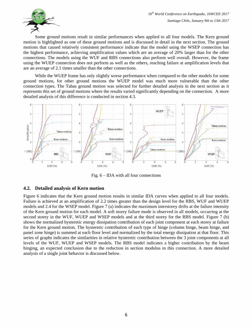
4.1 Incremental Dynamic Analysis (IDA) A series of incremental dynamic analyses were conducted on all four models using increments of 0.1 amplification relative to the design level. These ground motions were amplified until the maximum interstorey drift during the time history analysis reached a value larger than 8%, which was considered collapse for this analysis. The relationship between the amplification factor and the maximum interstorey drift for each ground motion using all 4 individual models is shown in Figure 6. Using this method, the design level event is at an amplification of 1 for each motion on the IDA plots. All ground motions applied to each frame design using the different connections pass the design level magnitude, usually by a significant margin, a result which is expected by the AISC guidelines when selecting prequalified connections [3].
5
16th World Conference on Earthquake, 16WCEE 2017
Santiago Chile, January 9th to 13th 2017
Some ground motions result in similar performances when applied to all four models. The Kern ground motion is highlighted as one of these ground motions and is discussed in detail in the next section. The ground motions that caused relatively consistent performance indicate that the model using the WSEP connection has the highest performance, achieving amplification values which are an average of 20% larger than for the other connections. The models using the WUF and RBS connections also perform well overall. However, the frame using the WUEP connection does not perform as well as the others, reaching failure at amplification levels that are an average of 2.1 times smaller than the other connections.
While the WUEP frame has only slightly worse performance when compared to the other models for some ground motions, for other ground motions the WUEP model was much more vulnerable than the other connection types. The Tabas ground motion was selected for further detailed analysis in the next section as it represents this set of ground motions where the results varied significantly depending on the connection. A more detailed analysis of this difference is conducted in section 4.3.
Fig. 6 – IDA with all four connections
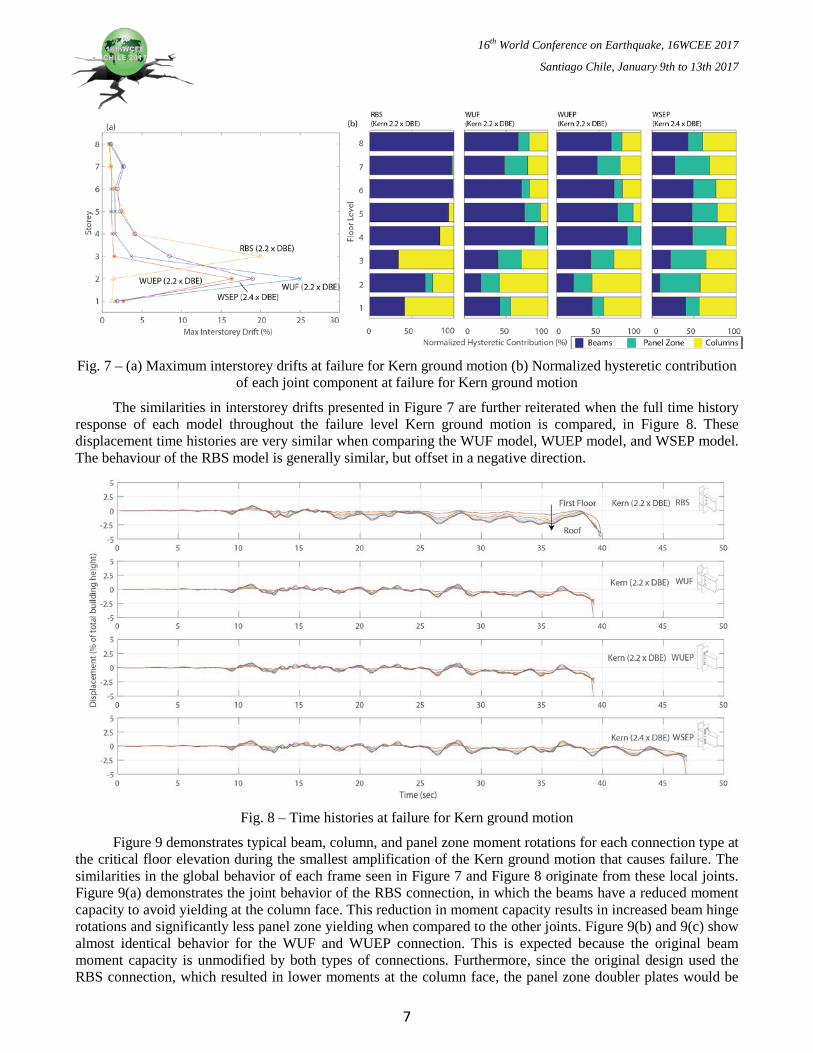
4.2. Detailed analysis of Kern motion Figure 6 indicates that the Kern ground motion results in similar IDA curves when applied to all four models. Failure is achieved at an amplification of 2.2 times greater than the design level for the RBS, WUF and WUEP models and 2.4 for the WSEP model. Figure 7 (a) indicates the maximum interstorey drifts at the failure intensity of the Kern ground motion for each model. A soft storey failure mode is observed in all models, occurring at the second storey in the WUF, WUEP and WSEP models and at the third storey for the RBS model. Figure 7 (b) shows the normalized hysteretic energy dissipation contribution of each joint component at each storey at failure for the Kern ground motion. The hysteretic contribution of each type of hinge (column hinge, beam hinge, and panel zone hinge) is summed at each floor level and normalized by the total energy dissipation at that floor. This series of graphs indicates the similarities in relative hysteretic contribution between the 3 joint components at all levels of the WUF, WUEP and WSEP models. The RBS model indicates a higher contribution by the beam hinging, an expected conclusion due to the reduction in section modulus in this connection. A more detailed analysis of a single joint behavior is discussed below.
6
16th World Conference on Earthquake, 16WCEE 2017
Santiago Chile, January 9th to 13th 2017
Fig. 7 – (a) Maximum interstorey drifts at failure for Kern ground motion (b) Normalized hysteretic contribution
of each joint component at failure for Kern ground motion
The similarities in interstorey drifts presented in Figure 7 are further reiterated when the full time history response of each model throughout the failure level Kern ground motion is compared, in Figure 8. These displacement time histories are very similar when comparing the WUF model, WUEP model, and WSEP model. The behaviour of the RBS model is generally similar, but offset in a negative direction.
Fig. 8 – Time histories at failure for Kern ground motion
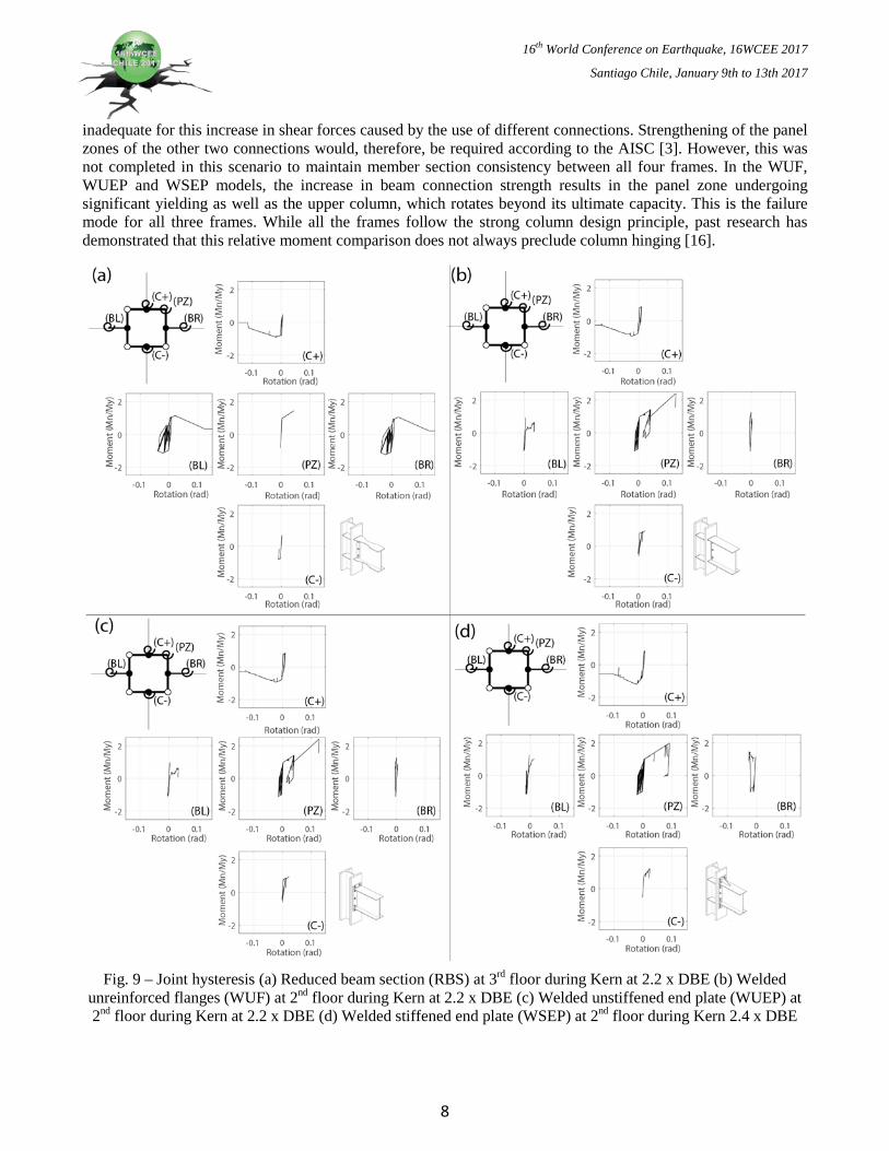
Figure 9 demonstrates typical beam, column, and panel zone moment rotations for each connection type at the critical floor elevation during the smallest amplification of the Kern ground motion that causes failure. The similarities in the global behavior of each frame seen in Figure 7 and Figure 8 originate from these local joints. Figure 9(a) demonstrates the joint behavior of the RBS connection, in which the beams have a reduced moment capacity to avoid yielding at the column face. This reduction in moment capacity results in increased beam hinge rotations and significantly less panel zone yielding when compared to the other joints. Figure 9(b) and 9(c) show almost identical behavior for the WUF and WUEP connection. This is expected because the original beam moment capacity is unmodified by both types of connections. Furthermore, since the original design used the RBS connection, which resulted in lower moments at the column face, the panel zone doubler plates would be
7
16th World Conference on Earthquake, 16WCEE 2017
Santiago Chile, January 9th to 13th 2017
inadequate for this increase in shear forces caused by the use of different connections. Strengthening of the panel zones of the other two connections would, therefore, be required according to the AISC [3]. However, this was not completed in this scenario to maintain member section consistency between all four frames. In the WUF, WUEP and WSEP models, the increase in beam connection strength results in the panel zone undergoing significant yielding as well as the upper column, which rotates beyond its ultimate capacity. This is the failure mode for all three frames. While all the frames follow the strong column design principle, past research has demonstrated that this relative moment comparison does not always preclude column hinging [16].
Fig. 9 – Joint hysteresis (a) Reduced beam section (RBS) at 3rd floor during Kern at 2.2 x DBE (b) Welded
unreinforced flanges (WUF) at 2nd floor during Kern at 2.2 x DBE (c) Welded unstiffened end plate (WUEP) at 2nd floor during Kern at 2.2 x DBE (d) Welded stiffened end plate (WSEP) at 2nd floor during Kern 2.4 x DBE
8
16th World Conference on Earthquake, 16WCEE 2017
Santiago Chile, January 9th to 13th 2017
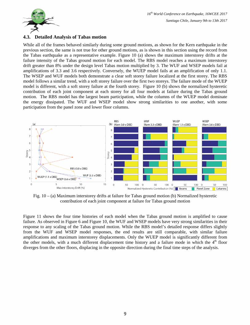
4.3. Detailed Analysis of Tabas motion While all of the frames behaved similarly during some ground motions, as shown for the Kern earthquake in the previous section, the same is not true for other ground motions, as is shown in this section using the record from the Tabas earthquake as a representative example. Figure 10 (a) shows the maximum interstorey drifts at the failure intensity of the Tabas ground motion for each model. The RBS model reaches a maximum interstorey drift greater than 8% under the design level Tabas motion multiplied by 3. The WUF and WSEP models fail at amplifications of 3.3 and 3.6 respectively. Conversely, the WUEP model fails at an amplification of only 1.1. The WSEP and WUF models both demonstrate a clear soft storey failure localized at the first storey. The RBS model follows a similar trend, with a soft storey failure over the first two storeys. The failure mode of the WUEP model is different, with a soft storey failure at the fourth storey. Figure 10 (b) shows the normalized hysteretic contribution of each joint component at each storey for all four models at failure during the Tabas ground motion. The RBS model has the largest beam participation, while the columns of the WUEP model dominate the energy dissipated. The WUF and WSEP model show strong similarities to one another, with some participation from the panel zone and lower floor columns.
Fig. 10 – (a) Maximum interstorey drifts at failure for Tabas ground motion (b) Normalized hysteretic
contribution of each joint component at failure for Tabas ground motion
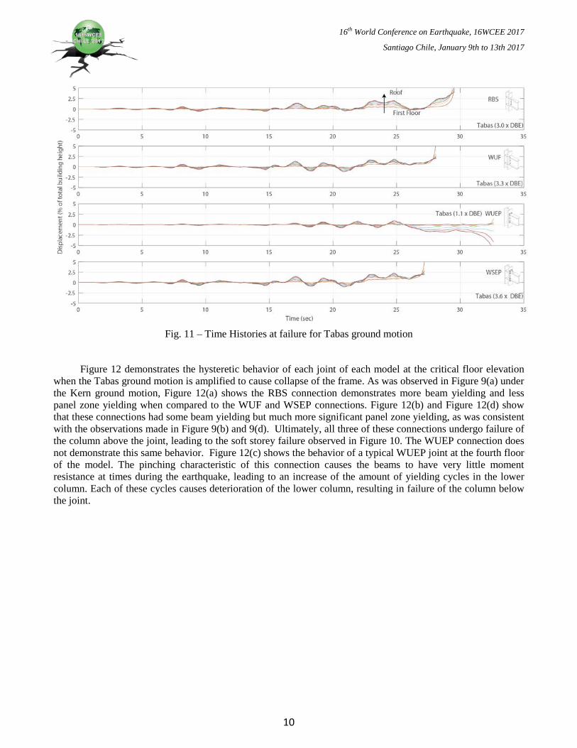
Figure 11 shows the four time histories of each model when the Tabas ground motion is amplified to cause failure. As observed in Figure 6 and Figure 10, the WUF and WSEP models have very strong similarities in their response to any scaling of the Tabas ground motion. While the RBS model’s detailed response differs slightly from the WUF and WSEP model responses, the end results are still comparable, with similar failure amplifications and maximum interstorey displacements. Only the WUEP model is significantly different from the other models, with a much different displacement time history and a failure mode in which the 4th floor diverges from the other floors, displacing in the opposite direction during the final time steps of the analysis.
9
16th World Conference on Earthquake, 16WCEE 2017
Santiago Chile, January 9th to 13th 2017
Fig. 11 – Time Histories at failure for Tabas ground motion
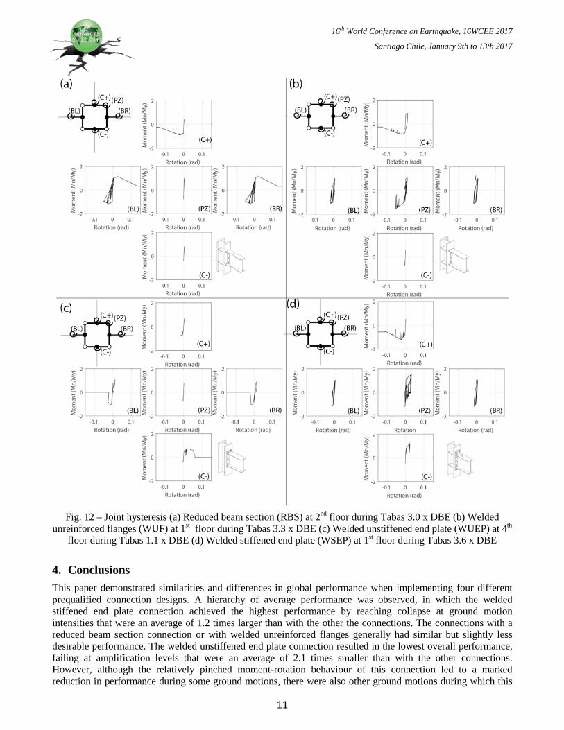
Figure 12 demonstrates the hysteretic behavior of each joint of each model at the critical floor elevation when the Tabas ground motion is amplified to cause collapse of the frame. As was observed in Figure 9(a) under the Kern ground motion, Figure 12(a) shows the RBS connection demonstrates more beam yielding and less panel zone yielding when compared to the WUF and WSEP connections. Figure 12(b) and Figure 12(d) show that these connections had some beam yielding but much more significant panel zone yielding, as was consistent with the observations made in Figure 9(b) and 9(d). Ultimately, all three of these connections undergo failure of the column above the joint, leading to the soft storey failure observed in Figure 10. The WUEP connection does not demonstrate this same behavior. Figure 12(c) shows the behavior of a typical WUEP joint at the fourth floor of the model. The pinching characteristic of this connection causes the beams to have very little moment resistance at times during the earthquake, leading to an increase of the amount of yielding cycles in the lower column. Each of these cycles causes deterioration of the lower column, resulting in failure of the column below the joint.
10
16th World Conference on Earthquake, 16WCEE 2017
Santiago Chile, January 9th to 13th 2017
Fig. 12 – Joint hysteresis (a) Reduced beam section (RBS) at 2nd floor during Tabas 3.0 x DBE (b) Welded
unreinforced flanges (WUF) at 1st floor during Tabas 3.3 x DBE (c) Welded unstiffened end plate (WUEP) at 4th floor during Tabas 1.1 x DBE (d) Welded stiffened end plate (WSEP) at 1st floor during Tabas 3.6 x DBE
4. Conclusions This paper demonstrated similarities and differences in global performance when implementing four different prequalified connection designs. A hierarchy of average performance was observed, in which the welded stiffened end plate connection achieved the highest performance by reaching collapse at ground motion intensities that were an average of 1.2 times larger than with the other the connections. The connections with a reduced beam section connection or with welded unreinforced flanges generally had similar but slightly less desirable performance. The welded unstiffened end plate connection resulted in the lowest overall performance, failing at amplification levels that were an average of 2.1 times smaller than with the other connections. However, although the relatively pinched moment-rotation behaviour of this connection led to a marked reduction in performance during some ground motions, there were also other ground motions during which this
11
16th World Conference on Earthquake, 16WCEE 2017
Santiago Chile, January 9th to 13th 2017
connection did not have a significant negative effect on the global seismic performance. Further study would be needed to identify the characteristics of ground motions that lead to each kind of performance.
The available numerical models that were used to model the plastic hinges do not perfectly capture all aspects of the connection behavior, and future research using improved modeling techniques may lead to modified conclusions. In addition, a more detailed analysis of the local performance of the joints should also be undertaken to better understand the local impacts of each particular connection. Finally, the AISC has prequalified three other connections for use in special moment resisting frames; further component testing is recommended in order to provide the necessary data to calibrate numerical models of these connections.
5. Acknowledgements This research was conducted as part of a research partnership with Arup through the NSERC Engage program.
6. References [1] FEMA. (2000). FEMA 355 State of the Art Report on Systems Performance of Steel Moment Frames Subject to
Earthquake Ground Shaking. 8-2.
[2] Ramirez, C., Lignos, D., Miranda, E., Kolios, D., (2012). Fragility functions for pre-Northridge welded steel moment-resisting beam-to-column connections. Engineering Structures, 45, 574-584
[3] AISC 358-10. (2014). Prequalified Connections for Special and Intermediate Steel Moment Frames for Seismic Applications. AISC.
[4] Engelhardt, M., & Sabol, T. (1994). Testing of welded steel moment connections in response to the Northridge earthquake. Chicago: AISC.
[5] Choi, J., Stojadinovic, B., & Goel, S. (2002). Development of free flange moment connection. University of Michigan, Department of Civil and Environmental Engineering, Ann Arbor.
[6] Popov, E., Balan, T., & Yang, T. (1998). Post‐Northridge Earthquake Seismic Steel Moment Connections. Earthquake Spectra, 14(4), 659-677.
[7] Dessouki, A., Youssef, A., & Ibrahim, M. (2013). Behavior of I-beam bolted extended end-plate moment connections. Ain Shams Engineering Journal, 685-698.
[8] Sumner, W., & Murray, T. (2002). Behavior of Extended End-Plate Moment Connections Subject to Cyclic Loading. Journal of Structural Engineering, 128(4), 501-508.
[9] NEHRP Consultants Joint Venture. (2010). Evaluation of the FEMA P-695 Methodology for Quantification of Building Seismic Performance Factors. U.S. Department of Commerce.
[10] McKenna, F., Scott, M.H., and Fenves, G.L. (2010). Nonlinear Finite Element Analysis Software Architecture Using Object Composition. Journal of Computing in Civil Engineering. 24, 95-107.
[11] Lignos, D., & Al-Shawwa, N. (2010). Steel W-Shape Database. Web-Based Interactice Tools for Performance-Based Earthquake Eningeering: http://dimitrios-lignos.research.mcgill.ca/databases/index.php
[12] Ibarra, L., Medina, R., Krawinkler, H., (2005) Hysteretic models that incorporate strength and stiffness deterioration. Earthquake Engineering and Structural Dynamics, 34, 1489-1511
[13] Gupta, A., & Krawinkler, H. (1999). Seismic Demands for Performance Evaluation of Steel Moment Resisting Frame Structures. Stanford University, Department of Civil and Environmental Engineering, Stanford.
[14] Dazykowski, M., Serneels, S., Kaczmarek, K., Van Espen, P., Croux, C., Walczak B., TOMCAT: A MATLAB toolbox for multivariate calibration techniques, Chemometrics and Intelligent Laboratory Systems, 85, 269-277
[15] Bozorgnia, A., Ancheta, T.D., Silva, W.J., Darragh, R., Chiou, B., Stweart, J.P., Boore, D.M., Graves, R., Abrahamson, N.A., Campbell, K.W., Idriss, I.M., Youngs, R.R., Atkinson, G.M. (2012). PEER NRA-West2 Database: A Database of Ground Motions Recorded in Shallow Crustal Earthquakes in Active Tectonic Regions. 15 WCEE, Lisbon.
[16] Medina, R., Krawinkler, H., (2005) Strength Demand Issues Relevant for the Seismic Design of Moment-Resisting Frames, Earthquake Spectra, 21, 415-439
12