seismic performance of a 3d full-scale high-ductility steel-concrete composite moment-resisting...
TRANSCRIPT
EARTHQUAKE ENGINEERING AND STRUCTURAL DYNAMICSEarthquake Engng Struct. Dyn. (2008)Published online in Wiley InterScience (www.interscience.wiley.com). DOI: 10.1002/eqe.829
Seismic performance of a 3D full-scale high-ductilitysteel–concrete composite moment-resisting structure—Part I:
Design and testing procedure
A. Braconi1,‡, O. S. Bursi2,§ , G. Fabbrocino3,¶ , W. Salvatore4,∗,†,‖ and R. Tremblay5,§
1Corporate Research Policies of Riva Group S.p.A. ILVA Works, Genova, Italy2Department of Structural and Mechanical Engineering, University of Trento, Trento, Italy
3Department of SAVA Engineering & Environment Division, University of Molise, Termoli (CB), Italy4Department of Structural Engineering, University of Pisa, Pisa, Italy
5Group for Research in Structural Engineering, Ecole Polytechnique, Montreal, Canada H3C3A7
SUMMARY
A multi-level pseudo-dynamic (PSD) seismic test programme was performed on a full-scale three-bay two-storey steel–concrete composite moment-resisting frame built with partially encased composite columnsand partial-strength connections. The system was designed to provide strength and ductility for earthquakeresistance with energy dissipation located in ductile components of beam-to-column joints includingflexural yielding of beam end-plates and shear yielding of the column web panel zone. In addition, theresponse of the frame depending on the column base yielding was analysed. Firstly, the design of the teststructure is presented in the paper, with particular emphasis on the ductile detailing of beam-to-columnjoints. Details of the construction of the test structure and the test set-up are also given. The paper thenprovides a description of the non-linear static and dynamic analytical studies that were carried out topreliminary assess the seismic performance of the test structure and establish a comprehensive multi-levelPSD seismic test programme. The resulting test protocol included the application of a spectrum-compatibleearthquake ground motion scaled to four different peak ground acceleration levels to reproduce an elasticresponse as well as serviceability, ultimate, and collapse limit state conditions, respectively. Severe damageto the building was finally induced by a cyclic test with stepwise increasing displacement amplitudes.Copyright q 2008 John Wiley & Sons, Ltd.
Received 14 March 2007; Revised 16 April 2008; Accepted 1 May 2008
∗Correspondence to: W. Salvatore, Department of Structural Engineering, University of Pisa, Pisa, Italy.†E-mail: [email protected]‡Research Engineer.§Professor.¶Associate Professor.‖Assistant Professor.
Contract/grant sponsor: Joint Research Centre at IspraContract/grant sponsor: Ecole Polytechnique of Montreal; contract/grant number: 19851-2002-09 P1VS3 ISP ITContract/grant sponsor: Natural Sciences and Engineering Research Council of Canada
Copyright q 2008 John Wiley & Sons, Ltd.
A. BRACONI ET AL.
KEY WORDS: seismic design; ductility; steel–concrete composite frames; partial-strength beam-to-column joints; composite members; pseudo-dynamic testing
1. INTRODUCTION
Steel–concrete composite moment-resisting frames represent an attractive alternative to their baresteel counterparts in view of their inherent fire resistance and their relatively higher lateral stiffnesscompared with steel only framing constructions. In addition, beam-to-column joints can generallybe obtained at a lower cost in composite structures by taking advantage of the concrete slab todevelop the required flexural stiffness and strength under gravity and lateral loads [1]. However,common layouts of composite flexural members lead to an asymmetrical response to bending. Infact, hogging bending can lead to extensive use of reinforcement in the concrete components [2].Therefore, ductility of members and design requirements for connections can be critical. In addi-tion, with regard to seismic design, beam and column sizes are controlled by lateral drift limits,so that an interesting design option is represented by partial-strength (PS) beam-to-column jointsdetailed to accommodate relevant inelastic rotations through ductile inelastic connection compo-nents’ response. These components are designed to bear forces associated with all prescribed loadcombinations, taking advantage of the moment redistribution owing to the inelastic connectionresponse. Global beam hinging mechanisms for earthquake resistance can be achieved at a reducedcost as the force demand on joints and columns is governed by the expected capacity of theductile connection components rather than by the beam flexural capacity. The behaviour of sucha framing system heavily depends on the joint response and a significant part of past research onsteel–concrete composite PS frames was devoted to the development of connection details ableto behave in a ductile manner under cyclic inelastic loading [3–10]. Numerical studies were alsoperformed to verify the global seismic performance of partially restrained (PR) composite framestructures [11–13]. This data set is still limited and exhaustive design guidelines to ensure a properductile seismic performance of this system are still missing in current building codes.
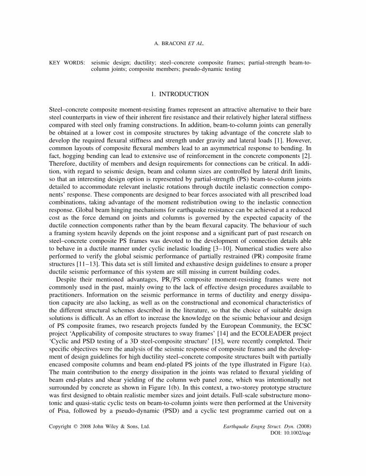
Despite their mentioned advantages, PR/PS composite moment-resisting frames were notcommonly used in the past, mainly owing to the lack of effective design procedures available topractitioners. Information on the seismic performance in terms of ductility and energy dissipa-tion capacity are also lacking, as well as on the constructional and economical characteristics ofthe different structural schemes described in the literature, so that the choice of suitable designsolutions is difficult. As an effort to increase the knowledge on the seismic behaviour and designof PS composite frames, two research projects funded by the European Community, the ECSCproject ‘Applicability of composite structures to sway frames’ [14] and the ECOLEADER project‘Cyclic and PSD testing of a 3D steel-composite structure’ [15], were recently completed. Theirspecific objectives were the analysis of the seismic response of composite frames and the develop-ment of design guidelines for high ductility steel–concrete composite structures built with partiallyencased composite columns and beam end-plated PS joints of the type illustrated in Figure 1(a).The main contribution to the energy dissipation in the joints was related to flexural yielding ofbeam end-plates and shear yielding of the column web panel zone, which was intentionally notsurrounded by concrete as shown in Figure 1(b). In this context, a two-storey prototype structurewas first designed to obtain realistic member sizes and joint details. Full-scale substructure mono-tonic and quasi-static cyclic tests on beam-to-column joints were then performed at the Universityof Pisa, followed by a pseudo-dynamic (PSD) and a cyclic test programme carried out on a
Copyright q 2008 John Wiley & Sons, Ltd. Earthquake Engng Struct. Dyn. (2008)DOI: 10.1002/eqe
STEEL–CONCRETE COMPOSITE MOMENT-RESISTING STRUCTURE
(a)
(b)
Re-bars in tension(ductile component)
Concrete slab in compression(brittle component)
Column web panel in shear(ductile component)
Column web in tension(ductile component)
Column web in compression(brittle component)
Bolt in tension(brittle component)
End-plate and column flange in bending (ductile component)
Beam flange in compression(brittle component)
Beam flange and web in tension(ductile component)
MRD,PL hogging
MRD,PL sagging
Figure 1. Proposed PS composite joint solution: (a) undeformed configuration of a joint and (b) jointcomponents subdivided as ductile and brittle for capacity design.
full-scale 3D two-storey frame at the European Laboratory for Structural Assessment (ELSA) ofthe Joint Research Centre at Ispra, Italy. These tests were complemented with tests on columnbase components and joints performed at the University of Naples and at the University of Trento.The projects also offered the opportunity to examine the viability of the proposed constructionalmethods, to calibrate and validate numerical analysis models, and to evaluate the EC8 behaviourfactor [16] for the specific structural system, including assessment of the ductility capacity andstructural overstrength. The present paper deals with the development of the PSD and cyclic testprogramme on a full-scale steel–concrete composite-framed building. In detail, the attention isprimarily focussed on the analysis of available design procedures suggested by relevant codes andon the efficiency of some critical issues of the design process taking into consideration nationaland international (basically European and U.S. perspectives) design code backgrounds.
Copyright q 2008 John Wiley & Sons, Ltd. Earthquake Engng Struct. Dyn. (2008)DOI: 10.1002/eqe
A. BRACONI ET AL.
Therefore, a comparative analysis of easy-to-manage design procedures proposed by availableseismic codes versus more refined non-linear response evolution of the structures is issued andreported herein. Design requirements of the composite framed structure and specific design proce-dures adopted to implement innovative structural options are reported. Details of the erection phaseand the testing protocol preformed at the ELSA are discussed in order to point out relevant aspectsof the experimental campaign and a detailed report and critical review of experimental results arereported in a companion paper [17].
2. CURRENT CODE PROVISIONS FOR SEISMIC DESIGN OF COMPOSITE FRAMES
EC8 permits the design of composite frames according to different design concepts basedon different levels of expected yielding (e.g. ductility demand) in structural elements (lowdissipation—ductility class low, DCL; medium dissipation—ductility class medium, DCM; andhigh dissipation—ductility class high, DCH) [16]. Different design concepts assign differentdissipative behaviours to the structures. The dissipation induced by plastic deformations can belocated, for DCM and DCH structures, in composite or bare steel parts as beam ends, PR/PSbeam-to-column joint or bracing systems, leading to different dissipative structural types. EC8does not limit the height of all of these types of structures. Similarly, U.S. AISC seismic codes[18] suggest three different structural concepts, namely, ordinary, intermediate, and specialmoment-resisting composite and bare steel frames, depending on the yielding level, which variesfrom very low to high values. AISC provisions consider particular design/detailing rules forconcentrically (C-CBF) and eccentrically braced (C-EBF) and partially restrained compositeframes (C-PRMF) typologies, as the EC8. The ASCE 7-05 code [19] assigns height limitationsto each structural type, differently from EC8; in particular, C-PRMFs are not permitted for highseismic applications (Seismic Design Categories D and E) and stringent height limits are imposedfor other applications, i.e. 30m for Seismic Design Category C and 49 m for Seismic DesignCategories A and B. Correspondingly, special steel moment-resisting frames (S-SMRF) have noheight limitation.
2.1. Behaviour factor
Non-linear structural response under seismic loads can be considered elastic by analyses usinga reduced response spectrum if energy dissipation of the structure is ensured through a ductilebehaviour of members and/or other deformation mechanisms. EC8 [16] allows this reduction bythe behaviour factor q; for DCH class steel, the q of composite moment-resisting frames andPS composite frames is equal to 5�u/�1. The ratio �u/�1 is typically determined by a pushoveranalysis and corresponds to the ratio between the lateral loads required to reach the near collapsecondition (global mechanism) and the lateral load at a first significant yielding. A default value of�u/�1=1.2 is suggested in EC8 [16] for the framed structures; hence, a behaviour factor q equalto 6.0 is assumed. In the ASCE 7-05 [19], the elastic design spectrum is modified by the responsemodification factor R, which is set to 6.0 for C-PRMF and to 8.0 for steel frames. Numericalstudies by Ciutina et al. [12] and Bursi et al. [3] confirm a good performance of multi-storey PSframes; hence, a design value q=6.0 was adopted. The particular structure, herein studied, and thedifferences between examined codes about height limitations and behaviour factor imply that an
Copyright q 2008 John Wiley & Sons, Ltd. Earthquake Engng Struct. Dyn. (2008)DOI: 10.1002/eqe
STEEL–CONCRETE COMPOSITE MOMENT-RESISTING STRUCTURE
experimental assessment of seismic performance of the composite PR-PS MRF should be carriedout to investigate the actual behaviour factor and other structural properties.
2.2. Capacity design
EC8 and AISC provisions adopt ‘capacity design’ procedures for the final design of structuralelements in dissipative seismic-resistant systems. According to this methodology, some structuralelements are chosen and suitably designed to dissipate energy through severe inelastic deformations.Other elements not devoted to energy dissipation are elastically designed taking into account theexpected capacity of dissipative elements framing to them. Therefore, the ductility demand isconfined in members designed with specific requirements [16, 18]. To develop a global hingingcomposite frame mechanism, a strong column–weak beam or PS connection strategy is proposed.This aim is differently reached by EC8 and AISC. The former imposes that the sum of resistingbending moments of columns framing into a joint has to be higher than 1.3 times the design valuesof resisting moments of beams or design values of resisting moments of PS connections. The latterimposes that the sum of expected resisting moments of columns has to be higher than the expectedresisting moments of beams or resisting moments of PS connections. In detail, a factor Ry for asteel grade that takes into account the ratio of the expected yield value to the nominal yield valuemust be used, for both columns and beams/connections, and the maximum expected value forthe compressive strength of the concrete is upper limited to 1.2 times f ′
c [18]. In any case the PSconnections shall exhibit a ductile failure mode for energy dissipation accommodating a rotationcapacity consistent with the global deformations expected from the frame. For this reason plasticdeformation must be essentially localized in ductile components of PS/PR composite joints.
2.3. Connection design
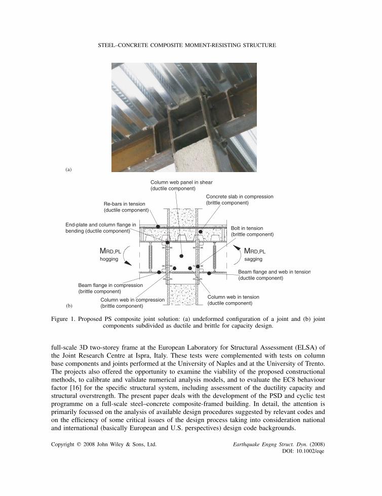
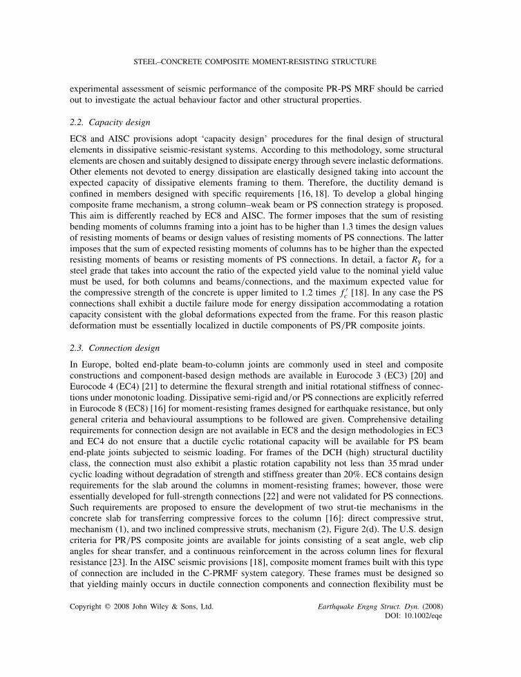
In Europe, bolted end-plate beam-to-column joints are commonly used in steel and compositeconstructions and component-based design methods are available in Eurocode 3 (EC3) [20] andEurocode 4 (EC4) [21] to determine the flexural strength and initial rotational stiffness of connec-tions under monotonic loading. Dissipative semi-rigid and/or PS connections are explicitly referredin Eurocode 8 (EC8) [16] for moment-resisting frames designed for earthquake resistance, but onlygeneral criteria and behavioural assumptions to be followed are given. Comprehensive detailingrequirements for connection design are not available in EC8 and the design methodologies in EC3and EC4 do not ensure that a ductile cyclic rotational capacity will be available for PS beamend-plate joints subjected to seismic loading. For frames of the DCH (high) structural ductilityclass, the connection must also exhibit a plastic rotation capability not less than 35mrad undercyclic loading without degradation of strength and stiffness greater than 20%. EC8 contains designrequirements for the slab around the columns in moment-resisting frames; however, those wereessentially developed for full-strength connections [22] and were not validated for PS connections.Such requirements are proposed to ensure the development of two strut-tie mechanisms in theconcrete slab for transferring compressive forces to the column [16]: direct compressive strut,mechanism (1), and two inclined compressive struts, mechanism (2), Figure 2(d). The U.S. designcriteria for PR/PS composite joints are available for joints consisting of a seat angle, web clipangles for shear transfer, and a continuous reinforcement in the across column lines for flexuralresistance [23]. In the AISC seismic provisions [18], composite moment frames built with this typeof connection are included in the C-PRMF system category. These frames must be designed sothat yielding mainly occurs in ductile connection components and connection flexibility must be
Copyright q 2008 John Wiley & Sons, Ltd. Earthquake Engng Struct. Dyn. (2008)DOI: 10.1002/eqe
A. BRACONI ET AL.
(a)
Crit
ical
Len
gth
Seismic steel rebars
Main beam
Seismic steelrebars
Secondary beam
Steel Column
A-AA-A
(b)
Seismic steel rebars
Main beam
Seismic steelrebars
Steel Column
Crit
ical
Len
gth
(c)
seismic transverse re-bars
Mechanism 1Mechanism 2
(d)
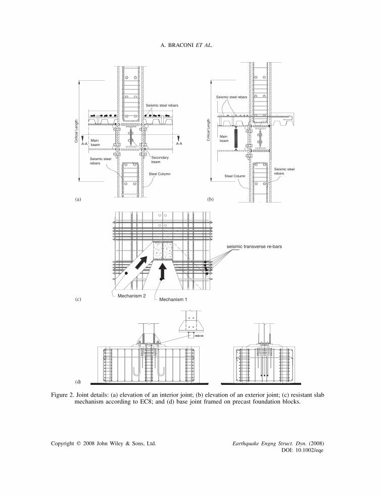
Figure 2. Joint details: (a) elevation of an interior joint; (b) elevation of an exterior joint; (c) resistant slabmechanism according to EC8; and (d) base joint framed on precast foundation blocks.
Copyright q 2008 John Wiley & Sons, Ltd. Earthquake Engng Struct. Dyn. (2008)DOI: 10.1002/eqe
STEEL–CONCRETE COMPOSITE MOMENT-RESISTING STRUCTURE
taken into account in the analysis. The provisions are, however, limited to frames with structuralsteel columns, not to composite columns. Selected connections must have a total interstorey driftcapacity of 40mrad as demonstrated by physical qualification cyclic testing. The AISC recom-mendation to provide full slab depth at the column was not met in the structure studied herein asonly the portion of the slab located above the steel deck profile was in contact against the columnflange in both the interior and exterior joints [18]. In addition, compressive force transferring fromthe concrete slab to the column imposes the installation of transverse reinforcing bars to act as atie in the spreading zone of the compressive strut against the column.
2.4. Research significance
Previous research projects have been carried out for assessing the seismic performance of thesteel–concrete composite frames. The ICONS (Intelligent CONtent management Systems) projectdeeply investigated the definition of behaviour factor, the effective width of composite beamsin the earthquake-resistant frames, and the design methodology for concrete slab in rigid full-strength composite beam-to-column joint [24]. In 2004 another research project was carried outat the University of Taiwan with the aim of assessing the seismic performance of a full-scaleplane composite frame realized with composite columns and steel beams [25, 26]. The finalgoal of this research was to examine an innovative pre-cast structural typology and to show theviability of reinforced concrete-steel beam-to-column connections to provide strength and ductilityto an earthquake-resistant frame. Regardless of the importance and the usefulness of the resultsobtained from these previous projects, the knowledge about the seismic performance about PS/PRcomposite beam-to-column joint is still limited to experimental results coming from tests onsubassemblages.
Another relevant aspect is related to the study of the seismic design and the inelastic response ofcomposite column bases. In fact, their details generally fit specifications of bare steel structures evenif the interaction between steel and concrete can activate beneficial effects and energy dissipation.This is why a test programme performed on a 3D full-scale prototype equipped by PR/PS compositejoints appeared necessary to enhance seismic design rules for this specific structural type until nownot extensively used. As far as column bases are concerned, traditional end-plate connections wereused, but comparative experimental tests with innovative socket-type connections were carried outat the Laboratory of the University of Naples Federico II in collaboration with the University ofSannio and the University of Molise [27].
3. DESIGN
3.1. Gravity load resistance
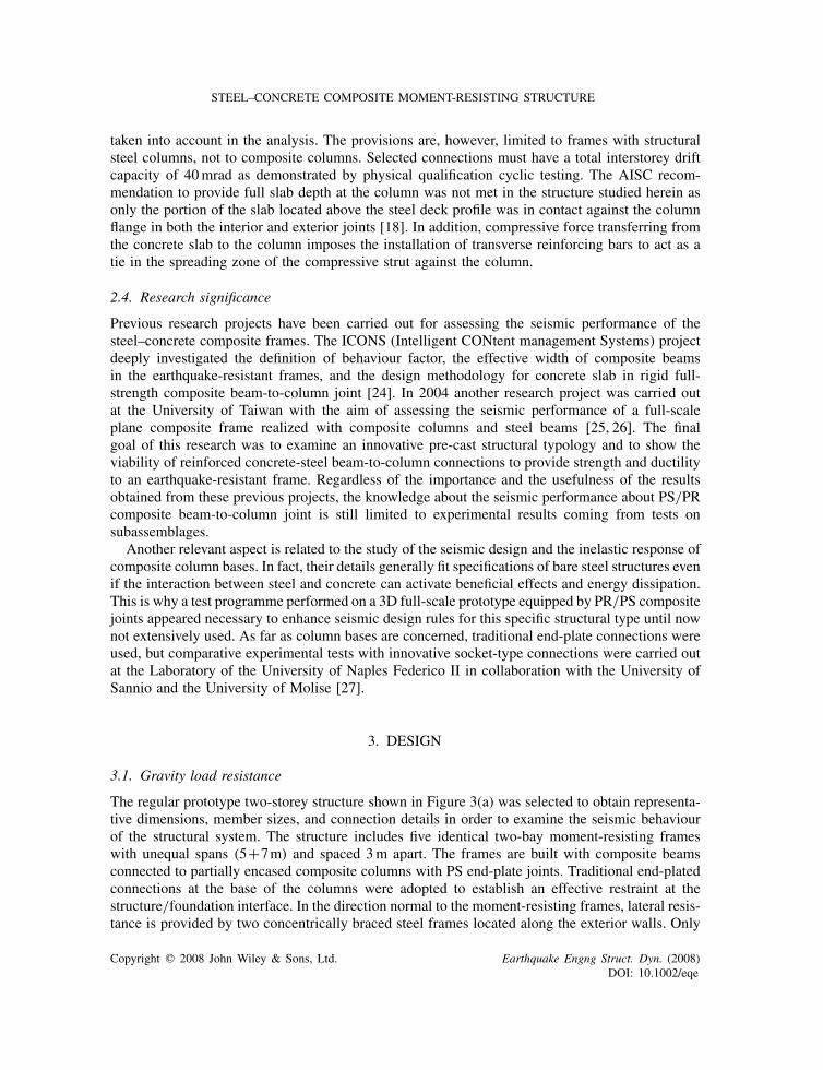
The regular prototype two-storey structure shown in Figure 3(a) was selected to obtain representa-tive dimensions, member sizes, and connection details in order to examine the seismic behaviourof the structural system. The structure includes five identical two-bay moment-resisting frameswith unequal spans (5+7m) and spaced 3m apart. The frames are built with composite beamsconnected to partially encased composite columns with PS end-plate joints. Traditional end-platedconnections at the base of the columns were adopted to establish an effective restraint at thestructure/foundation interface. In the direction normal to the moment-resisting frames, lateral resis-tance is provided by two concentrically braced steel frames located along the exterior walls. Only
Copyright q 2008 John Wiley & Sons, Ltd. Earthquake Engng Struct. Dyn. (2008)DOI: 10.1002/eqe
A. BRACONI ET AL.
(a)
(b)
(c)
260189
26097
18
18
Composite beam
IPE 300
Composite columns
55 95 150
TRANSVERSE REBARS3Ø16/100cm
WIRE FABRICS Ø6/150
STUDS NELSON3/4" x 5"-3/16"
STEEL SHEETING Brollo EGB 210
TRANSVERSEREBARS3Ø16/100cm
WIRE FABRICS Ø6/150
150
20
91
20 20
280
280
208
107
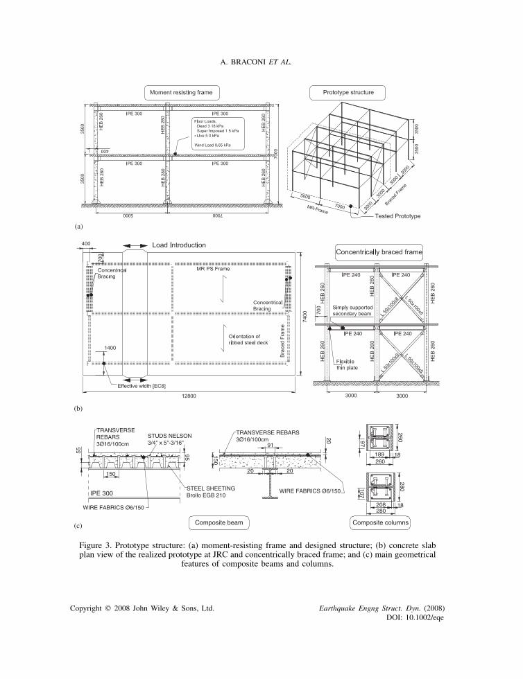
Figure 3. Prototype structure: (a) moment-resisting frame and designed structure; (b) concrete slabplan view of the realized prototype at JRC and concentrically braced frame; and (c) main geometrical
features of composite beams and columns.
Copyright q 2008 John Wiley & Sons, Ltd. Earthquake Engng Struct. Dyn. (2008)DOI: 10.1002/eqe
STEEL–CONCRETE COMPOSITE MOMENT-RESISTING STRUCTURE
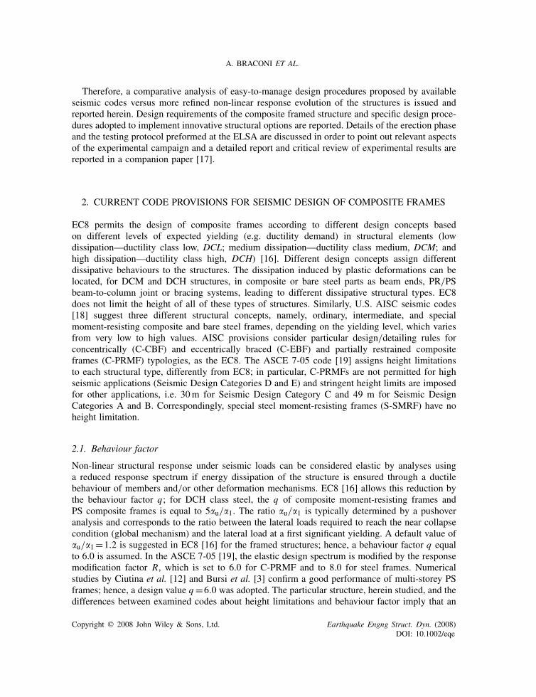
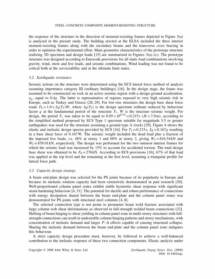
the response of the structure in the direction of moment-resisting frames depicted in Figure 3(a)is analysed in the present study. The building erected at the ELSA included the three interiormoment-resisting frames along with the secondary beams and the transverse cross bracing inorder to optimize the experimental effort. Main geometric characteristics of the prototype structurerealizing 3D specimen and design loads [15] are summarized in Figures 3(a)–(c). The prototypestructure was designed according to Eurocode provisions for all static load combinations involvinggravity, wind, snow and live loads, and seismic combinations. Wind loading was not found to becritical both at the serviceability and at the ultimate limit states.
3.2. Earthquake resistance
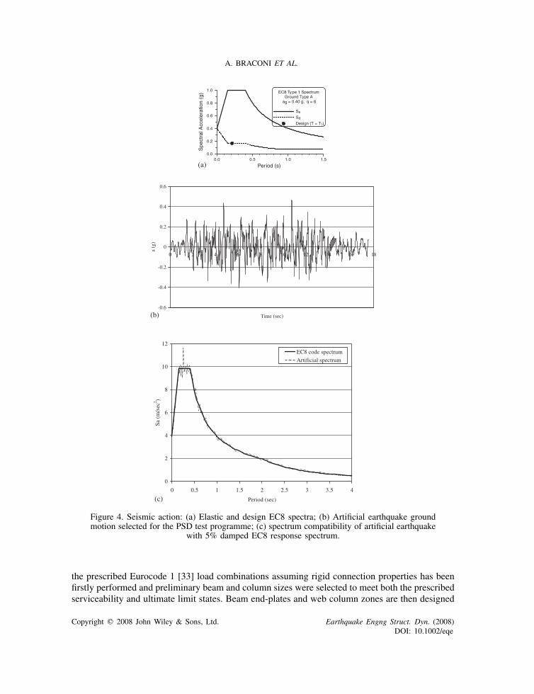
Seismic actions on the structure were determined using the EC8 lateral force method of analysisassuming importance category III (ordinary buildings) [16]. In the design stage, the frame wasassumed to be constructed on rock in an active seismic region with a design ground acceleration,ag , equal to 0.4g. The latter is representative of regions exposed to very high seismic risk inEurope, such as Turkey and Greece [28, 29]. For low-rise structures the design base shear forcereads Fb=1.0×Sd(T1)W , where Sd(T1) is the design spectrum ordinate reduced by behaviourfactor q at the fundamental period of the structure T1. W is the structure seismic weight. Fordesign, the period T1 was taken to be equal to 0.05×H0.75=0.215s (H =7.0m), according tothe simplified method proposed by EC8 Type 1 spectrum suitable for magnitude 5.5 or greaterearthquakes was used for the structure assuming a ground type A (rock) [29]. Figure 4 shows theelastic and inelastic design spectra provided by EC8 [16]. For T1=0.215s, Sd=0.167g resultingin a base shear force of 0.167W. The seismic weight included the dead load plus a fraction ofthe imposed live loads, i.e. 48% at storey 1 and 60% at storey 2, giving W1=816.54kN andW2=839.01kN, respectively. The design was performed for the two outmost interior frames forwhich the seismic load was increased by 15% to account for accidental torsion. The total designbase shear was obtained to be Fb=276kN. According to EC8 provisions [16], 67% of that loadwas applied at the top level and the remaining at the first level, assuming a triangular profile forlateral force path.
3.3. Capacity design strategy
A beam end-plate design was selected for the PS joints because of its popularity in Europe andbecause its inelastic rotation capacity had been extensively demonstrated in past research [30].Well-proportioned column panel zones exhibit stable hysteretic shear response with significantstrain hardening behaviour [4, 31]. The potential for ductile and robust performance of connectionswith energy dissipation shared between the beam end-plate and the column panel zones wasdemonstrated for PS joints with structural steel columns [4, 8].
The selected connection type is not prone to premature beam weld fracture associated withlarge column web shear deformations as observed in full-strength welded beam connections [32].Shifting of beam hinging to shear yielding in column panel zone in multi-storey structures with full-strength connections can result in undesirable column hinging patterns and storey mechanisms, withconcentration of inelastic demand and larger P–� effects capable of causing structural collapse.Sharing the inelastic demand between the beam end-plate and the column panel zone mitigatesthis behaviour.
A strict capacity design procedure must, however, be followed to achieve a well-balancedcontribution to the inelastic response of these two connection components. Elastic analysis under
Copyright q 2008 John Wiley & Sons, Ltd. Earthquake Engng Struct. Dyn. (2008)DOI: 10.1002/eqe
A. BRACONI ET AL.
(a) Period (s)
0.00.0 0.5 1.0 1.5
0.2
0.4
0.6
0.8
1.0
Spe
ctra
l Acc
eler
atio
n (g
)
(b)-0.6
-0.4
-0.2
0
0.2
0.4
0.6
0 2 4 6 8 10 12 14 16 18
Time (sec)
a (g
)
(c)
0
2
4
6
8
10
12
0 0.5 1 1.5 2 2.5 3 3.5 4
Period (sec)
Sa (
m/s
ec2 )
EC8 code spectrum
Artificial spectrum
Figure 4. Seismic action: (a) Elastic and design EC8 spectra; (b) Artificial earthquake groundmotion selected for the PSD test programme; (c) spectrum compatibility of artificial earthquake
with 5% damped EC8 response spectrum.
the prescribed Eurocode 1 [33] load combinations assuming rigid connection properties has beenfirstly performed and preliminary beam and column sizes were selected to meet both the prescribedserviceability and ultimate limit states. Beam end-plates and web column zones are then designed
Copyright q 2008 John Wiley & Sons, Ltd. Earthquake Engng Struct. Dyn. (2008)DOI: 10.1002/eqe
STEEL–CONCRETE COMPOSITE MOMENT-RESISTING STRUCTURE
to also resist the actions obtained from the same elastic analysis. Their strength should be kept closeso that yielding will develop simultaneously in both components. In order to ensure an effectivehierarchy of yielding under strong ground motion shaking, beams, columns, and components haveto be checked against design forces compared with those that lead to yield dissipative mechanismsin the end-plates and column web panels. The expected capacity of these ductile components wasdetermined with assumed steel yield strength equal to 1.3 times the nominal value for the checkof the members or connection components against brittle failure mode, such a flexural failure ofthe columns or compression failure of the concrete slab bearing against the column face. Thevarious connection components are illustrated in Figure 1(b) with the indication of the failure mode(brittle or ductile) considered. For end-plate bolts, premature failure of the bolts prior to flexuralyielding of the end-plates was prevented, satisfying the following conditions: t�0.36d
√fub/ fy
[4, 5], where d and fub are the diameter and nominal tensile stress of bolts, and t and fy are thethickness and the nominal yield strength of the end-plate, respectively.
Once the capacity check is completed for all members and connection components, the connec-tion stiffness properties can be determined and the process must be repeated taking into consider-ation the connection flexibility. Since beam end-plates and column web panels play a key role onthe connection stiffness and drift limits often govern the member sizes in moment frames, theseparts should be proportioned at this stage such that code drift limits can be met without furtherincrease in member sizes. The design of the shear connectors and the final layout of reinforcingsteel in the concrete slab are completed at the end of the design process.
3.4. The prototype structure
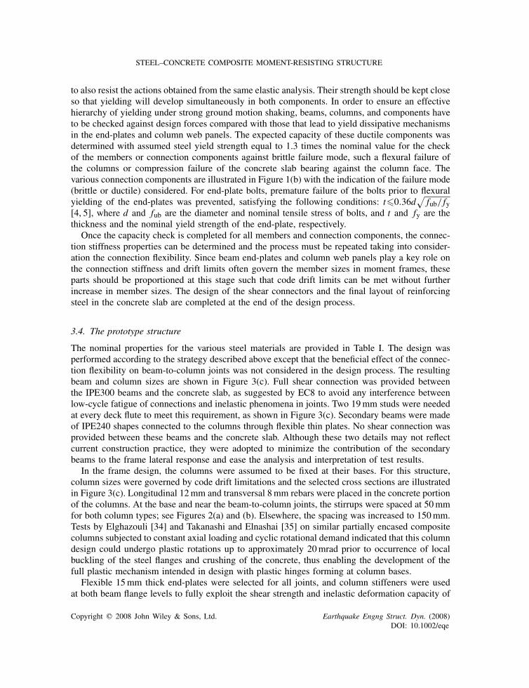
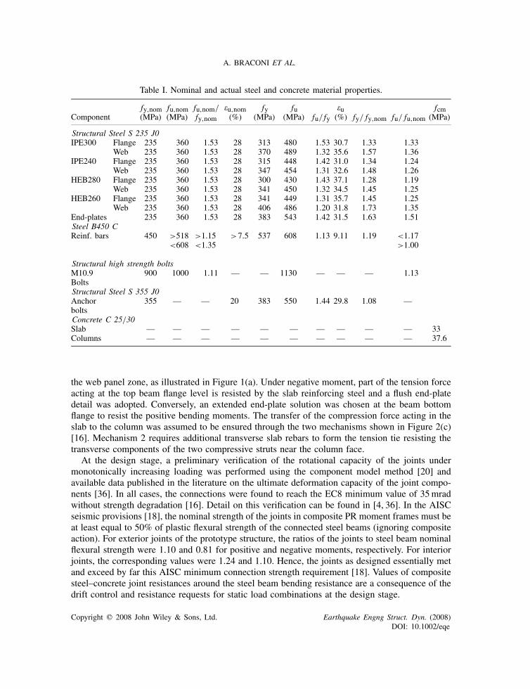
The nominal properties for the various steel materials are provided in Table I. The design wasperformed according to the strategy described above except that the beneficial effect of the connec-tion flexibility on beam-to-column joints was not considered in the design process. The resultingbeam and column sizes are shown in Figure 3(c). Full shear connection was provided betweenthe IPE300 beams and the concrete slab, as suggested by EC8 to avoid any interference betweenlow-cycle fatigue of connections and inelastic phenomena in joints. Two 19mm studs were neededat every deck flute to meet this requirement, as shown in Figure 3(c). Secondary beams were madeof IPE240 shapes connected to the columns through flexible thin plates. No shear connection wasprovided between these beams and the concrete slab. Although these two details may not reflectcurrent construction practice, they were adopted to minimize the contribution of the secondarybeams to the frame lateral response and ease the analysis and interpretation of test results.
In the frame design, the columns were assumed to be fixed at their bases. For this structure,column sizes were governed by code drift limitations and the selected cross sections are illustratedin Figure 3(c). Longitudinal 12mm and transversal 8mm rebars were placed in the concrete portionof the columns. At the base and near the beam-to-column joints, the stirrups were spaced at 50mmfor both column types; see Figures 2(a) and (b). Elsewhere, the spacing was increased to 150mm.Tests by Elghazouli [34] and Takanashi and Elnashai [35] on similar partially encased compositecolumns subjected to constant axial loading and cyclic rotational demand indicated that this columndesign could undergo plastic rotations up to approximately 20mrad prior to occurrence of localbuckling of the steel flanges and crushing of the concrete, thus enabling the development of thefull plastic mechanism intended in design with plastic hinges forming at column bases.
Flexible 15mm thick end-plates were selected for all joints, and column stiffeners were usedat both beam flange levels to fully exploit the shear strength and inelastic deformation capacity of
Copyright q 2008 John Wiley & Sons, Ltd. Earthquake Engng Struct. Dyn. (2008)DOI: 10.1002/eqe
A. BRACONI ET AL.
Table I. Nominal and actual steel and concrete material properties.
fy,nom fu,nom fu,nom/ �u,nom fy fu �u fcmComponent (MPa) (MPa) fy,nom (%) (MPa) (MPa) fu/ fy (%) fy/ fy,nom fu/ fu,nom (MPa)
Structural Steel S 235 J0IPE300 Flange 235 360 1.53 28 313 480 1.53 30.7 1.33 1.33
Web 235 360 1.53 28 370 489 1.32 35.6 1.57 1.36IPE240 Flange 235 360 1.53 28 315 448 1.42 31.0 1.34 1.24
Web 235 360 1.53 28 347 454 1.31 32.6 1.48 1.26HEB280 Flange 235 360 1.53 28 300 430 1.43 37.1 1.28 1.19
Web 235 360 1.53 28 341 450 1.32 34.5 1.45 1.25HEB260 Flange 235 360 1.53 28 341 449 1.31 35.7 1.45 1.25
Web 235 360 1.53 28 406 486 1.20 31.8 1.73 1.35End-plates 235 360 1.53 28 383 543 1.42 31.5 1.63 1.51Steel B450 CReinf. bars 450 >518 >1.15 >7.5 537 608 1.13 9.11 1.19 <1.17
<608 <1.35 >1.00
Structural high strength boltsM10.9 900 1000 1.11 — — 1130 — — — 1.13BoltsStructural Steel S 355 J0Anchor 355 — — 20 383 550 1.44 29.8 1.08 —boltsConcrete C 25/30Slab — — — — — — — — — — 33Columns — — — — — — — — — — 37.6
the web panel zone, as illustrated in Figure 1(a). Under negative moment, part of the tension forceacting at the top beam flange level is resisted by the slab reinforcing steel and a flush end-platedetail was adopted. Conversely, an extended end-plate solution was chosen at the beam bottomflange to resist the positive bending moments. The transfer of the compression force acting in theslab to the column was assumed to be ensured through the two mechanisms shown in Figure 2(c)[16]. Mechanism 2 requires additional transverse slab rebars to form the tension tie resisting thetransverse components of the two compressive struts near the column face.
At the design stage, a preliminary verification of the rotational capacity of the joints undermonotonically increasing loading was performed using the component model method [20] andavailable data published in the literature on the ultimate deformation capacity of the joint compo-nents [36]. In all cases, the connections were found to reach the EC8 minimum value of 35mradwithout strength degradation [16]. Detail on this verification can be found in [4, 36]. In the AISCseismic provisions [18], the nominal strength of the joints in composite PR moment frames must beat least equal to 50% of plastic flexural strength of the connected steel beams (ignoring compositeaction). For exterior joints of the prototype structure, the ratios of the joints to steel beam nominalflexural strength were 1.10 and 0.81 for positive and negative moments, respectively. For interiorjoints, the corresponding values were 1.24 and 1.10. Hence, the joints as designed essentially metand exceed by far this AISC minimum connection strength requirement [18]. Values of compositesteel–concrete joint resistances around the steel beam bending resistance are a consequence of thedrift control and resistance requests for static load combinations at the design stage.
Copyright q 2008 John Wiley & Sons, Ltd. Earthquake Engng Struct. Dyn. (2008)DOI: 10.1002/eqe
STEEL–CONCRETE COMPOSITE MOMENT-RESISTING STRUCTURE
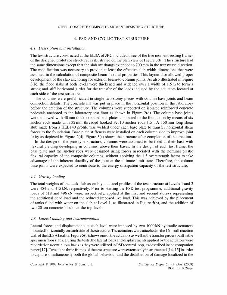
4. PSD AND CYCLIC TEST STRUCTURE
4.1. Description and installation
The test structure constructed at the ELSA of JRC included three of the five moment-resting framesof the designed prototype structure, as illustrated on the plan view of Figure 3(b). The structure hadthe same dimensions except that the slab overhangs extended to 700mm in the transverse direction.The modification was necessary to provide at least the effective slab width dimensions that wereassumed in the calculation of composite beam flexural properties. This layout also allowed properdevelopment of the slab anchoring for exterior beam-to-column joints. As also illustrated in Figure3(b), the floor slabs at both levels were thickened and widened over a width of 1.5m to form astrong and stiff horizontal girder for the transfer of the loads induced by the actuators located ateach side of the test structure.
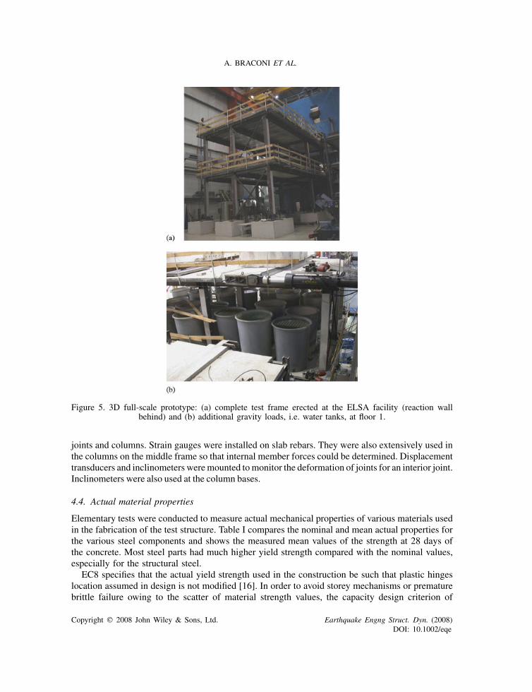
The columns were prefabricated in single two-storey pieces with column base joints and beamconnection details. The concrete fill was put in place in the horizontal position in the laboratorybefore the erection of the structure. The columns were supported on isolated reinforced concretepedestals anchored to the laboratory test floor as shown in Figure 2(d). The column base jointswere endowed with 40mm thick extended end-plates connected to the foundation by means of sixanchor rods made with 32mm threaded hooked Fe510 anchor rods [15]. A 150mm long shearstub made from a HEB140 profile was welded under each base plate to transfer horizontal shearforces to the foundation. Base plate stiffeners were installed on each column side to improve jointfixity as depicted in Figure 2(d). Figure 5(a) shows the structure after completion of the erection.
In the design of the prototype structure, columns were assumed to be fixed at their base withflexural yielding developing in columns, above their bases. In the design of each test frame, thebase plate and the anchor rods were designed using forces associated with the nominal plasticflexural capacity of the composite columns, without applying the 1.3 overstrength factor to takeadvantage of the inherent ductility of the joint at the ultimate limit state. Therefore, the columnbase joints were expected to contribute to the energy dissipation capacity of the test structure.
4.2. Gravity loading
The total weights of the deck-slab assembly and steel profiles of the test structure at Levels 1 and 2were 454 and 415 kN, respectively. Prior to starting the PSD test programme, additional gravityloads of 518 and 496 kN were, respectively, applied at the first and second storeys representingthe additional dead load and the reduced imposed live load. This was achieved by the placementof tanks filled with water on the slab at Level 1, as illustrated in Figure 5(b), and the addition oftwo 20 ton concrete blocks at the top level.
4.3. Lateral loading and instrumentation
Lateral forces and displacements at each level were imposed by two 1000 kN hydraulic actuatorsmountedhorizontallyoneach sideof the structure.Theactuatorswere attached to the16mtall reactionwallof theELSAfacility.Figure5(b)showsoneof theactuatorsaswellas the transfergirdersbuilt in thespecimenfloor slabs.During the tests, the lateral loadsanddisplacements appliedby theactuatorswererecordedonacontinuousbasis as theywereutilized inPSDcontrol loop, asdescribed in thecompanionpaper [17]. Twoof the three frames of the test structurewere extensively instrumented [14, 15] in orderto capture simultaneously both the global behaviour and the distribution of damage localized in the
Copyright q 2008 John Wiley & Sons, Ltd. Earthquake Engng Struct. Dyn. (2008)DOI: 10.1002/eqe
A. BRACONI ET AL.
Figure 5. 3D full-scale prototype: (a) complete test frame erected at the ELSA facility (reaction wallbehind) and (b) additional gravity loads, i.e. water tanks, at floor 1.
joints and columns. Strain gauges were installed on slab rebars. They were also extensively used inthe columns on the middle frame so that internal member forces could be determined. Displacementtransducers and inclinometers weremounted tomonitor the deformation of joints for an interior joint.Inclinometers were also used at the column bases.
4.4. Actual material properties
Elementary tests were conducted to measure actual mechanical properties of various materials usedin the fabrication of the test structure. Table I compares the nominal and mean actual properties forthe various steel components and shows the measured mean values of the strength at 28 days ofthe concrete. Most steel parts had much higher yield strength compared with the nominal values,especially for the structural steel.
EC8 specifies that the actual yield strength used in the construction be such that plastic hingeslocation assumed in design is not modified [16]. In order to avoid storey mechanisms or prematurebrittle failure owing to the scatter of material strength values, the capacity design criterion of
Copyright q 2008 John Wiley & Sons, Ltd. Earthquake Engng Struct. Dyn. (2008)DOI: 10.1002/eqe
STEEL–CONCRETE COMPOSITE MOMENT-RESISTING STRUCTURE
members and components of PS joints was checked using the measured material properties and itwas found that the intended yielding mechanism could be maintained.
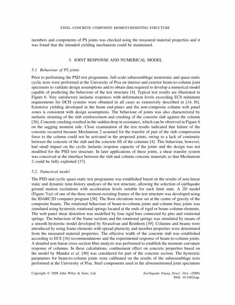
5. JOINT RESPONSE AND NUMERICAL MODEL
5.1. Behaviour of PS joints
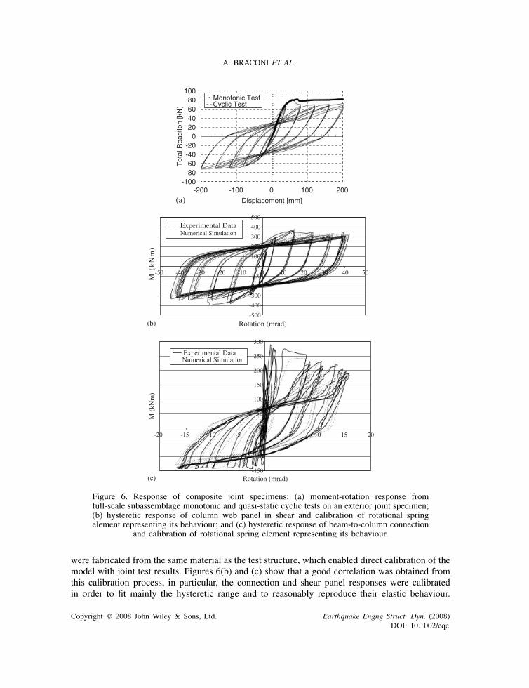
Prior to performing the PSD test programme, full-scale subassemblage monotonic and quasi-staticcyclic tests were performed at the University of Pisa on interior and exterior beam-to-column jointspecimens to validate design assumptions and to obtain data required to develop a numerical modelcapable of predicting the behaviour of the test structure [4]. Typical test results are illustrated inFigure 6. Very satisfactory inelastic responses with deformation levels exceeding EC8 minimumrequirements for DCH systems were obtained in all cases as extensively described in [14, 36].Extensive yielding developed in the beam end-plates and the non-composite column web panelzones is consistent with design assumptions. The behaviour of joints was also characterized byinelastic straining of the slab reinforcement and crushing of the concrete slab against the column[36]. Concrete crushing resulted in the sudden drop in resistance, which can be observed in Figure 6on the sagging moment side. Close examination of the test results indicated that failure of theconcrete occurred because Mechanism 2 assumed for the transfer of part of the slab compressionforce to the column could not be activated in the proposed joints, owing to a lack of continuitybetween the concrete of the slab and the concrete fill of the columns [4]. This behaviour, however,had small impact on the cyclic inelastic response capacity of the joints and the design was notmodified for the PSD test structure. In later applications of these joints, a shear transfer systemwas conceived at the interface between the slab and column concrete materials so that Mechanism2 could be fully exploited [37].
5.2. Numerical model
The PSD and cyclic quasi-static test programme was established based on the results of non-linearstatic and dynamic time-history analyses of the test structure, allowing the selection of earthquakeground motion excitations with acceleration levels suitable for each limit state. A 2D model(Figure 7(a)) of one of the three moment-resisting frames of the test structure was developed usingthe IDARC2D computer program [38]. The floor elevations were set at the centre of gravity of thecomposite beams. The rotational behaviour of beam-to-column joints and column base joints wassimulated using hysteretic rotational springs located at the ends of rigid or beam–column elements.The web panel shear distortion was modelled by four rigid bars connected by pins and rotationalsprings. The behaviour of the frame sections and the rotational springs was simulated by means ofa smooth hysteretic model developed by Sivaselvan and Reinhorn [39]. Columns and beams wereintroduced by using frame elements with spread plasticity and member properties were determinedfrom the measured material properties. The effective width of the concrete slab was establishedaccording to EC8 [16] recommendations and the experimental response of beam-to-column joints.A detailed non-linear cross-section fibre analysis was performed to establish the moment–curvatureresponse of columns. In these calculations, confinement effect on concrete properties based onthe model by Mander et al. [40] was considered for part of the concrete section. The hystereticparameters for beam-to-column joints were calibrated on the results of the subassemblage testsperformed at the University of Pisa. Steel components used in the aforementioned joint specimens
Copyright q 2008 John Wiley & Sons, Ltd. Earthquake Engng Struct. Dyn. (2008)DOI: 10.1002/eqe
A. BRACONI ET AL.
(a)
-100-80-60-40-20
020406080
100
-200 -100 0 100 200
Displacement [mm]
Tot
al R
eact
ion
[kN
]
Monotonic TestCyclic Test
(b)-500
-400
-300
-200
-100
0
100
200
300
400
500
-50
Rotation (mrad)
M (
kN
m)
(c)-150
-100
0
50
100
150
200
250
300
-20
Rotation (mrad)
M (
kNm
)
-40 -30 -20 -10 0 10 20 30 40 50
-15 -10 -5 0 5 10 15 20
Experimental DataNumerical Simulation
Experimental DataNumerical Simulation
Figure 6. Response of composite joint specimens: (a) moment-rotation response fromfull-scale subassemblage monotonic and quasi-static cyclic tests on an exterior joint specimen;(b) hysteretic response of column web panel in shear and calibration of rotational springelement representing its behaviour; and (c) hysteretic response of beam-to-column connection
and calibration of rotational spring element representing its behaviour.
were fabricated from the same material as the test structure, which enabled direct calibration of themodel with joint test results. Figures 6(b) and (c) show that a good correlation was obtained fromthis calibration process, in particular, the connection and shear panel responses were calibratedin order to fit mainly the hysteretic range and to reasonably reproduce their elastic behaviour.
Copyright q 2008 John Wiley & Sons, Ltd. Earthquake Engng Struct. Dyn. (2008)DOI: 10.1002/eqe
STEEL–CONCRETE COMPOSITE MOMENT-RESISTING STRUCTURE
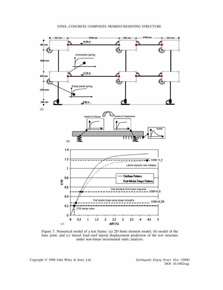
Figure 7. Numerical model of a test frame: (a) 2D finite element model; (b) model of thebase joint; and (c) lateral load–roof lateral displacement prediction of the test structure
under non-linear incremental static analysis.
Copyright q 2008 John Wiley & Sons, Ltd. Earthquake Engng Struct. Dyn. (2008)DOI: 10.1002/eqe
A. BRACONI ET AL.
The rotational spring used in correspondence to the column base plate account represents theinelastic behaviour of the anchor rods in tension and the grout in compression as depicted in Figure7(b). As described also in the companion paper [17], the base plate representation was modifiedto better capture the observed response of the as-built base plates.
5.3. Column bases
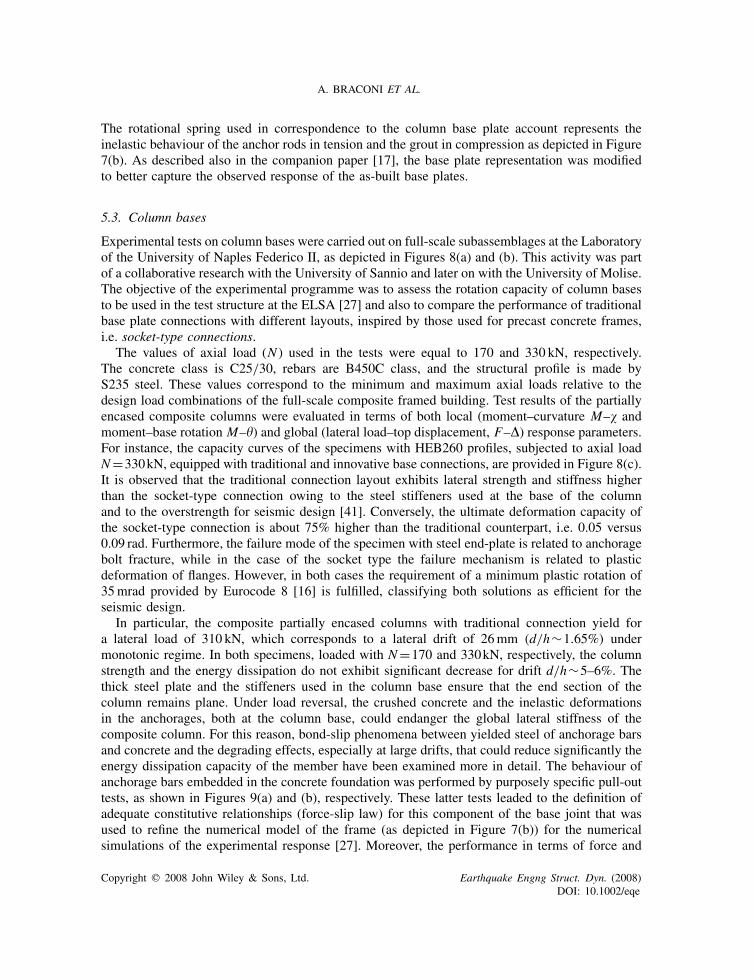
Experimental tests on column bases were carried out on full-scale subassemblages at the Laboratoryof the University of Naples Federico II, as depicted in Figures 8(a) and (b). This activity was partof a collaborative research with the University of Sannio and later on with the University of Molise.The objective of the experimental programme was to assess the rotation capacity of column basesto be used in the test structure at the ELSA [27] and also to compare the performance of traditionalbase plate connections with different layouts, inspired by those used for precast concrete frames,i.e. socket-type connections.
The values of axial load (N ) used in the tests were equal to 170 and 330 kN, respectively.The concrete class is C25/30, rebars are B450C class, and the structural profile is made byS235 steel. These values correspond to the minimum and maximum axial loads relative to thedesign load combinations of the full-scale composite framed building. Test results of the partiallyencased composite columns were evaluated in terms of both local (moment–curvature M–� andmoment–base rotation M–�) and global (lateral load–top displacement, F–�) response parameters.For instance, the capacity curves of the specimens with HEB260 profiles, subjected to axial loadN=330kN, equipped with traditional and innovative base connections, are provided in Figure 8(c).It is observed that the traditional connection layout exhibits lateral strength and stiffness higherthan the socket-type connection owing to the steel stiffeners used at the base of the columnand to the overstrength for seismic design [41]. Conversely, the ultimate deformation capacity ofthe socket-type connection is about 75% higher than the traditional counterpart, i.e. 0.05 versus0.09 rad. Furthermore, the failure mode of the specimen with steel end-plate is related to anchoragebolt fracture, while in the case of the socket type the failure mechanism is related to plasticdeformation of flanges. However, in both cases the requirement of a minimum plastic rotation of35mrad provided by Eurocode 8 [16] is fulfilled, classifying both solutions as efficient for theseismic design.
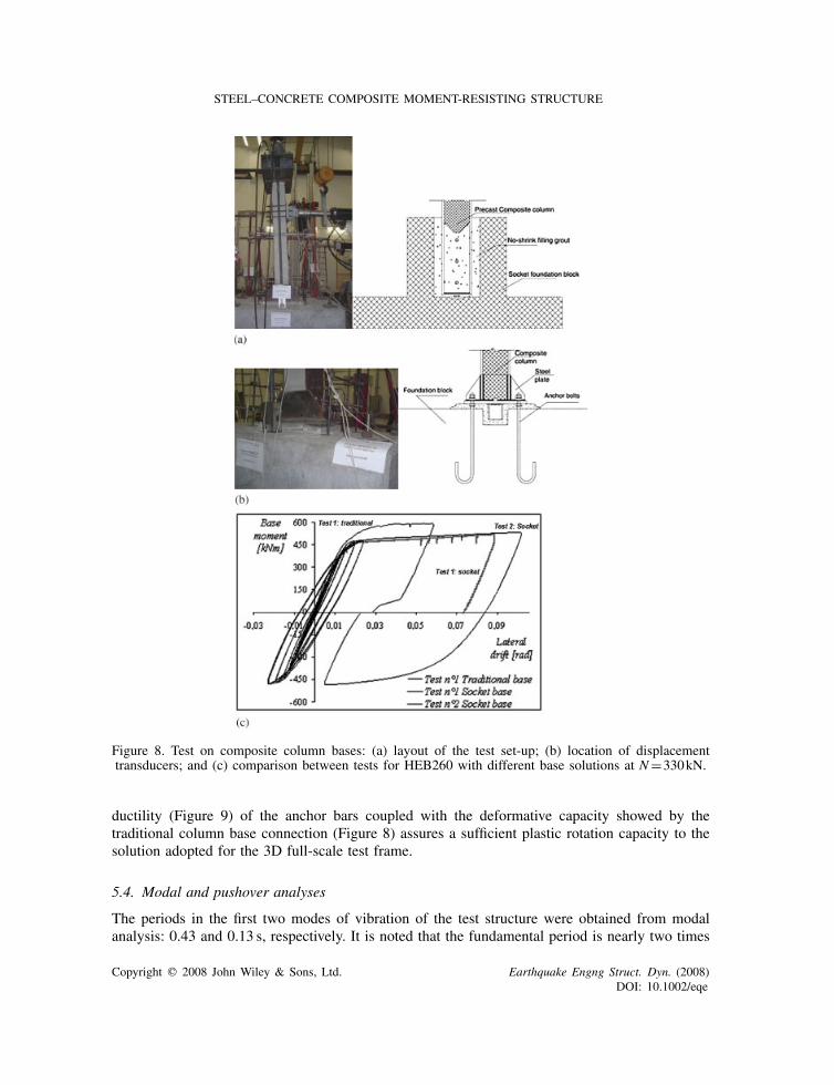
In particular, the composite partially encased columns with traditional connection yield fora lateral load of 310 kN, which corresponds to a lateral drift of 26mm (d/h∼1.65%) undermonotonic regime. In both specimens, loaded with N=170 and 330kN, respectively, the columnstrength and the energy dissipation do not exhibit significant decrease for drift d/h∼5–6%. Thethick steel plate and the stiffeners used in the column base ensure that the end section of thecolumn remains plane. Under load reversal, the crushed concrete and the inelastic deformationsin the anchorages, both at the column base, could endanger the global lateral stiffness of thecomposite column. For this reason, bond-slip phenomena between yielded steel of anchorage barsand concrete and the degrading effects, especially at large drifts, that could reduce significantly theenergy dissipation capacity of the member have been examined more in detail. The behaviour ofanchorage bars embedded in the concrete foundation was performed by purposely specific pull-outtests, as shown in Figures 9(a) and (b), respectively. These latter tests leaded to the definition ofadequate constitutive relationships (force-slip law) for this component of the base joint that wasused to refine the numerical model of the frame (as depicted in Figure 7(b)) for the numericalsimulations of the experimental response [27]. Moreover, the performance in terms of force and
Copyright q 2008 John Wiley & Sons, Ltd. Earthquake Engng Struct. Dyn. (2008)DOI: 10.1002/eqe
STEEL–CONCRETE COMPOSITE MOMENT-RESISTING STRUCTURE
Figure 8. Test on composite column bases: (a) layout of the test set-up; (b) location of displacementtransducers; and (c) comparison between tests for HEB260 with different base solutions at N=330kN.
ductility (Figure 9) of the anchor bars coupled with the deformative capacity showed by thetraditional column base connection (Figure 8) assures a sufficient plastic rotation capacity to thesolution adopted for the 3D full-scale test frame.
5.4. Modal and pushover analyses
The periods in the first two modes of vibration of the test structure were obtained from modalanalysis: 0.43 and 0.13 s, respectively. It is noted that the fundamental period is nearly two times
Copyright q 2008 John Wiley & Sons, Ltd. Earthquake Engng Struct. Dyn. (2008)DOI: 10.1002/eqe
A. BRACONI ET AL.
(a)
(b)
0
100
200
300
400
0 5 10 15 20 25
Slip (mm)
Forc
e (k
N)
Test #1 Test #2
Figure 9. Pull-out test for anchorage bolts for traditional base connections:(a) set-up of the test and (b) test results.
longer than the value of T1 used in design (0.22 s), due to the simplified formula proposed byEC8 for the fundamental period estimation that overestimates the lateral stiffness of the building.Incremental static (pushover) analysis was then carried out to assess the as-built lateral capacity ofthe test structure and to evaluate overstrength phenomena, using the model calibrated on the cyclictests made on sub-structures (joints and column bases); the adopted material resistances were thosecoming from qualification tests executed on profile specimens and concrete. The model was alsoused for more extensive static and dynamic studies performed to provide a more detailed assessment
Copyright q 2008 John Wiley & Sons, Ltd. Earthquake Engng Struct. Dyn. (2008)DOI: 10.1002/eqe
STEEL–CONCRETE COMPOSITE MOMENT-RESISTING STRUCTURE
of the expected frame seismic performance [17] on the basis also of executed PSD programme.In this first analysis, the gravity loading corresponding to Eurocode 1 [33] load combinationswas first applied to the structure and two lateral load conditions were considered, according toEC8 suggestions [16] for structural assessment: uniform pattern and first mode shape distribution.Computed normalized lateral load, V/W , versus normalized lateral roof displacement, �/H , isplotted in Figure 7(c). The two curves are quite similar, though they reflect the influence of largerlateral forces applied at the top of the building with the first mode shape distribution. In both cases,the first significant deviation from a linear response occurs at V/W =0.5, which is approximately2.5 times the EC8 design seismic loads, which corresponds to V/W =0.206.
The first yielding is related to two factors: (i) the selection of members and drift limitationsunder the serviceability load conditions and (ii) the scatter between nominal and actual yieldingstresses of steel profiles. These facts are confirmed by results of elastic analyses carried outto assess the first yielding of the structure: design strengths of materials lead to V/W =0.29;the average yielding stresses for steel and compressive strength for concrete components lead toa V/W =0.50, calculated from pushover curves (Figure 7(c)). The latter show that the lateralcapacity near collapse reaches on average V/W =1.2; hence, it can be argued that strain hardeningcontributes significantly to the response of the structure and ensures a relevant overstrength ratio,quite larger than the valued assumed for design (approximately estimated as �u/�1�2). However,strain hardening and scattering of material properties are not the only causes of overstrengthphenomena. An interesting aspect is related to the drift limit checks, EC8 [16], with reference tojoint flexibility. From Figure 7(c), the computed drift angle under the design seismic load is 0.20%.In EC8 [16], this deformation must be amplified by the q factor (6.0) and multiplied by the returnperiod reduction factor �=0.4 (Importance Classes III and IV), thus providing a value of ∼0.50%.This value is equal to the EC8 limit for structures including brittle non-structural components.Such a drift imposes a demanding checking of the limit state of damage (serviceability limit state,SLS) that can lead to members oversized for dissipation purposes at limit state of safety (ultimatelimit state, ULS). A more harmonized definition of the suggested drift limits associated with theexpected performance as indicated in [16] could lead to an effective optimization of the membersizes for the two considered limit states.
6. PSD AND CYCLIC TEST PROGRAMMES
6.1. Ground motion selection and dynamic analysis
In order to evaluate the response of the test structure under code compatible seismic demand atall natural frequencies, a suite of artificial accelerograms were generated to match the EC8 Type 1elastic response spectrum [42], i.e. Se. The ground motions were generated using the techniquedescribed in Clough and Penzien [43]. The accelerogram that was selected for the PSD tests isillustrated in Figure 4(b) and its 5% damped response spectrum is compared with the code spectrumin Figure 4(c). This time history was selected, between all those generated, because it caused thehighest level of damage in beam-to-column joints and limited damage induced in columns of theIDARC model. The ground motion time history has a peak ground acceleration (pga) of 0.46g.It is characterized by 10 s strong motion duration, as prescribed in EC8 [16], with rise and decayperiods of 2.5 and 5.0 s, respectively. Trial non-linear time step analyses of the test structure wereperformed using the IDARC frame model [38] to establish ground amplitudes required to reach
Copyright q 2008 John Wiley & Sons, Ltd. Earthquake Engng Struct. Dyn. (2008)DOI: 10.1002/eqe
A. BRACONI ET AL.
a set of predetermined limit states. The analyses were performed using the trapezoidal rule inthe implicit �-Newmark time-stepping scheme [44], with a single correction. Time steps were setequal to 0.001 and 0.0001 s used for the elastic and inelastic analyses, respectively; the Rayleighdamping was set to 5% of critical damping in the first two modes of vibration. More details aboutthe whole test programme are reported in the following section, while main results coming fromnumerical simulations and tests are reported in the companion paper [17].
6.2. PSD and cyclic test programme
In accordance with the performance-based earthquake engineering approach, it was decided tocarry out a series of four PSD tests at increasing ground motion amplitudes to examine the responseof the structure corresponding to various limit states or anticipated performance levels. The chosentest programme is reported hereafter with the performance objective (PO) foreseen:
• PSD test 1—pga set equal to 0.10g; PO: elastic response;• PSD test 2—pga set equal to 0.25g; PO: no structural damage;• PSD test 3—pga set equal to 1.40g; PO: joint plastic rotation near 35mrad with less than20% of strength degradation;
• PSD test 4—pga set equal to 1.80g; PO: joint plastic rotation beyond 35mrad.
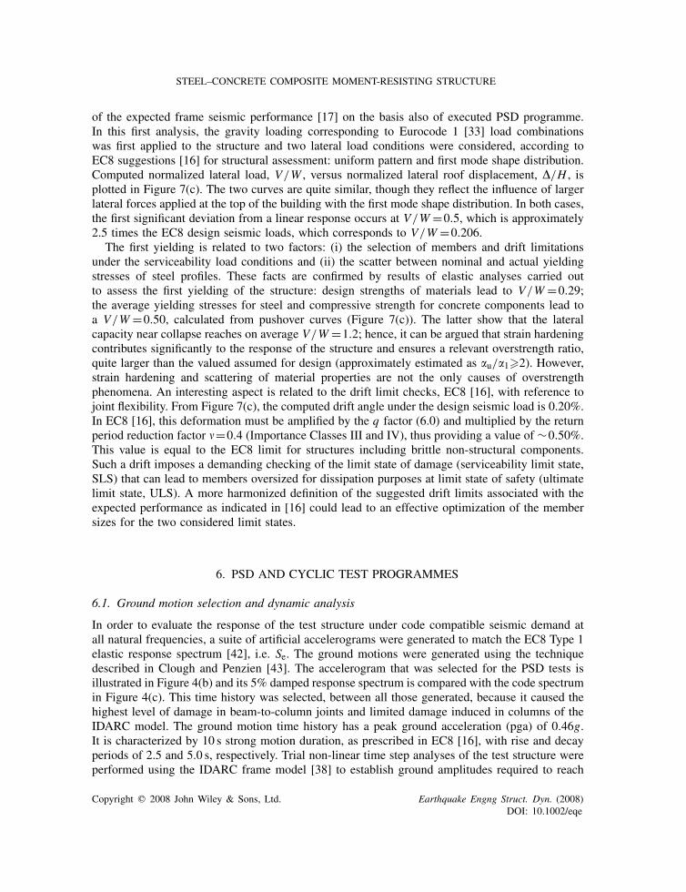
A final cyclic quasi-static test with stepwise increasing large amplitudes was then added toinduce severe damage to the structure and allow failure mechanisms of the structure components tobe examined. The analyses indicated a nearly elastic structural response without concrete crackingunder the ground motion time history scaled to 0.10g pga. A PSD test was therefore proposed atthis amplitude to evaluate the dynamic elastic uncracked properties of the structure, including itsnatural frequencies, associated mode shapes, and damping levels. This test was also carried outto verify the adequacy of both the test set-up and PSD algorithm without damaging the structure.An SLS was established at a 0.25g pga, a ground motion level that brings the structure near firstsignificant yielding with peak storey drift angles reaching approximately 1%. Such a ground motionamplitude is associated with a probability of exceedance of 10% in 10 years in high seismic sites.In order to reach rotational demand in joints up to or close to the EC8 requirement of 35mrad [16],the accelerogram amplitude had to be increased such that its pga reached 1.40g. This correspondsto 3.5 times the design acceleration level of 0.40g, a difference consistent with the results of thestatic incremental analysis. The PSD Test No. 3 performed at this amplitude therefore aims atexamining the global performance of the structure at the ULS, with specific interest in the responseof the PS beam-to-column joints at levels corresponding to the EC8 prescribed rotation limit [16].The anticipated peak storey drift angles under this ground motion level are equal to 2.5%, thus 2.5times the values expected at the SLS. Figure 10(a) shows the predicted top storey displacement atthis earthquake level. The PSD Test No. 4 is performed to observe the behaviour of the frame fortotal rotation just beyond the 35mrad inelastic rotation requirement of EC8 and a pga value of 1.8gwas selected to impose such a demand to the structure. Under such a ground motion amplitude,the analysis predicted plastic rotation of up to 40mrad in the joints and interstorey drift anglesof 4.5%, thus close to the 0.04 rad specified in the AISC seismic provisions for composite PRmoment-resisting frames. The final quasi-static cyclic test was developed according to the ECCS 45procedure [45] with stepwise increasing amplitude cyclic displacements in order to induce a severeamount of damage in beam-to-column joints, column base joints, and columns in a controlledand systematic manner. The imposed roof displacement history is illustrated in Figure 10(b).
Copyright q 2008 John Wiley & Sons, Ltd. Earthquake Engng Struct. Dyn. (2008)DOI: 10.1002/eqe
STEEL–CONCRETE COMPOSITE MOMENT-RESISTING STRUCTURE
-3-2.5
-2-1.5
-1-0.5
00.5
11.5
2
0
Time (sec)(a)-400
-300
-200
-100
0
100
200
300
400Top Storey
(b)
-0.8
-0.6
-0.4
-0.2
0
0.2
0.4
0.6
0.8
0
Time (sec)
Experimental DataNumerical Simulation
(c)
-4
-3
-2
-1-1
0
1
2
3
Time (sec)
Experimental DataNumerical Simulation
(d)
2.5 5 7.5 10 12.5 15 17.5
0 -12.5 5 7.5 10 12.5 15 17.5
2 4 6 8 10 12 14 16 18
Figure 10. Predicted response of the roof displacement: (a) time history under ground motion scaled at1.4g pga and (b) history developed for the cyclic quasi-static test. Measured and predicted top storey
displacement time histories: PSD Test No. 2 pga=0.25g(c); PSD Test No. 3 pga=1.40g(d).
A total of six displacement increments with two cycles per increment were applied for a total of12 cycles. The maximum displacement amplitude was equal to 300mm, with predicted interstoreydrift angles of 4.6%. During this test, the first to the second floor lateral load ratio is maintainedequal to 0.97. This ratio was determined from modal shapes obtained in the PSD Test No. 4.
7. CONCLUSIONS
A comprehensive design procedure, applied to a prototype structure, was proposed for steel–concrete composite moment-resisting structure endowed with PS beam-to-column joints designedto dissipate seismic energy through bending of the beam end-plates and shear yielding of columnweb panel zones. The performance of joints was verified through subassemblage quasi-static cyclictests. The results were used to calibrate a numerical model developed to predict the seismicbehaviour of a full-scale structure specimen to be used in a PSD test programme. The frame wasfound to exhibit significant extra lateral capacity compared with the value expected in design. Theresults of the analysis and the calibrated numerical model were used to develop a comprehensivemulti-level PSD programme targeted to analyse the response of the structure at various limit statesor anticipated performance levels. A final quasi-static cyclic test programme was also included inthe test programme to induce severe damage to the structure components. The calibrated model of
Copyright q 2008 John Wiley & Sons, Ltd. Earthquake Engng Struct. Dyn. (2008)DOI: 10.1002/eqe
A. BRACONI ET AL.
the test structures adopted for the PSD test programme definition also demonstrated good agreementwith the experimental results (Figures 10(c) and (d)). The results coming from 3D full-scale testare further discussed in the companion paper [17].
ACKNOWLEDGEMENTS
The results presented in this work were obtained in the framework of the ECOLEADER HPR-CT-1999-00059 and the ECSC 7210-PR-250 European research projects, for which the authors are grateful. Thelast author collaborated to this study as a Visiting Scientist at the Joint Research Centre at Ispra duringa sabbatical leave from Ecole Polytechnique of Montreal (Contract No. 19851-2002-09 P1VS3 ISP IT).The financial support from both institutions and the Natural Sciences and Engineering Research Councilof Canada is acknowledged. Nevertheless, opinions expressed in this paper are those of the authors anddo not necessarily reflect those of the sponsors.
REFERENCES
1. Leon RT, Hoffman JJ, Staeger T. Partially Restrained Composite Connections. Steel Design Guide Series, vol.8. American Institute of Steel Construction: Chicago, IL, 1996.
2. Fabbrocino G, Manfredi G, Cosenza E. Ductility of composite beams under negative bending: an equivalentindex for reinforcing steel classification. Journal of Constructional Steel Research 2001; 57:185–202.
3. Bursi OS, Sun F-F, Postal S. Non-linear analysis of steel–concrete composite frames with full and partial shearconnection subjected to seismic loads. Journal of Constructional Steel Research 2005; 61:67–92.
4. Braconi A, Salvatore W, Tremblay R, Bursi OS. Behaviour and modelling of partial-strength beam-to-columncomposite joints for seismic applications. Earthquake Engineering and Structural Dynamics 2007; 36:142–161.
5. Braconi A, Salvatore W, Bursi OS, Ferrario F. Seismic design of beam-to-column connections for steel–concretecomposite moment resisting frames. In Proceedings of the STESSA 2003 Conference, Naples, Italy, June 2003.Behaviour of Steel Structures in Seismic Area, Mazzolani F (ed.). Lisse: Balkema, 2003; 253–260.
6. Green PT, Leon RT, Rassati GA. Bidirectional tests on partially restrained, composite beam-to-column connections.Journal of Structural Engineering (ASCE) 2004; 130(2):320–327.
7. Lachal A, Aribert J-M, Ciutina A. Seismic performance of end-plate moment resisting composite joints.Proceedings of the Fifth Conference on Composite Construction in Steel and Concrete (ASCE): Kruger NationalPark, South Africa, July 2004. 2005.
8. Leon RT, Ammerman DJ, Lin J, McCauley RD. Semi-rigid composite steel frames. Engineering Journal (AISC)1987; 24(4):147–155.
9. Mander JB, Chen SS, Pekcan G. Low-cycle fatigue behaviour of semi-rigid top-and-seat angle connections.Engineering Journal (AISC) 1994; 31(3):111–122.
10. Swanson JA, Leon RT. Bolted steel connections: tests on T-stub components. Journal of Structural Engineering(ASCE) 2000; 126(1):50–56.
11. Aribert JM, Ciutina A, Dubina D. Seismic response of composite structures including actual behaviour ofbeam-to-column joints. Proceedings of the Fifth Conference on Composite Construction in Steel and Concrete.(ASCE): Kruger National Park, South Africa, July 2004. 2005.
12. Ciutina AL, Dubina D, Aribert JM. Dissipative seismic performance of composite moment resisting framesincluding realistic behaviour of joints. In Proceedings of the STESSA Conference, Naples, Italy, June 2003.Behaviour of Steel Structures in Seismic Area, Mazzolani F (ed.). Lisse: Balkema, 2003; 503–509.
13. Salazar AR, Haldar A. Energy dissipation at PR frames under seismic loading. Journal of Structural Engineering(ASCE) 2001; 127(5):588–592.
14. ECSC. Steel RTD programme—applicability of composite structures to sway frames. ECSC Contract No. 7210-PR-250, edited by Stangenberg H, European Commission, Brussels, Belgium, 2002.
15. Bursi OS, Caramelli S, Fabbrocino G, Molina J, Salvatore W, Taucer F. 3-D full-scale seismic testing of a steel–concrete composite building at ELSA. Contract No. HPR-CT-1999-00059, Eur Report, European Community,Brussels, Belgium, 2004.
16. CEN. Eurocode 8: design of structures for earthquake resistance. Part 1: general rules, seismic actions and rulesfor buildings. prEN 1998-1, European Committee for Standardization, Brussels, Belgium, Draft December 2003.
Copyright q 2008 John Wiley & Sons, Ltd. Earthquake Engng Struct. Dyn. (2008)DOI: 10.1002/eqe
STEEL–CONCRETE COMPOSITE MOMENT-RESISTING STRUCTURE
17. Bursi O, Braconi A, Fabbrocino G, Salvatore, Taucer F, Tremblay R. Seismic performance of a 3D full-scalehigh-ductile steel–concrete composite moment-resisting frame—part II: test results and analytical validation.Earthquake Engineering and Structural Dynamics 2008; submitted.
18. AISC. Seismic provisions for structural steel buildings. ANSI/AISC 341-05, American Institute of SteelConstruction, Inc., Chicago, IL, 2005.
19. ASCE. Minimum design loads for buildings and other structures. ASCE/SEI Standard No. 7-05 (includesSupplement No. 1), ASCE, Reston, VA, 2005.
20. CEN. Eurocode 3: design of steel structures. Part 1-1: general rules. prEN 1993-1-1, European Committee forStandardization, Brussels, Belgium, Draft December 2003.
21. CEN. Eurocode 4: design of composite steel and concrete structures. Part 1.1: general rules and rules forbuildings. prEN 1994-1-1, European Committee for Standardization, Brussels, Belgium, Draft January 2004.
22. Doneux C. Etude du mecanisme de transfert des flexions a la jonction poutre-poteau dans les structures enportiques mixtes soumises a une action sismique. Ph.D. Thesis, Faculty of Applied Sciences, Universite deLieges, Lieges, Belgium, 2002 (in French).
23. ASCE. Design guide for partially restrained composite connections. Journal of Structural Engineering (ASCE)1998; 124(10):1099–1114.
24. Plumier A, Doneux C. ICONS-ECOEST Project ‘Seismic Behaviour and Design of Composite Steel ConcreteStructures.’ LNEC—Laboratorio Nacional de Ingenharia Civil, Lisboa, Portugal, 2001.
25. Chen CH, Lai WC, Cordova P, Deierlein GG, Tsai KC. Pseudo-dynamic test of full-scale RCS frame: partI—design, construction, testing. Proceedings of Structures 2004—Building on the Past: Securing the Future,Nashville, Tennessee, 22–26 May 2004. ASCE: Reston, VA, 2004.
26. Cordova P, Chen CH, Lai WC, Tsai KC. Pseudo-dynamic test on full-scale RCS frame: part II—analysis anddesign implications. Proceedings of Structures 2004—Building on the Past: Securing the Future, Nashville,Tennessee, 22–26 May 2004. ASCE: Reston, VA, 2004.
27. Di Sarno L, Pecce MR, Fabbrocino G. Inelastic response of composite steel and concrete base column connections.Journal of Constructional Steel Research 2006. DOI:10.1016/j.jcsr.2006.08.007.
28. Altnyollar A, Gulkan P. Re-assessment of seismic safety of TR-2 research reactor building. Proceedings ofWorkshop on the Seismic Re-evaluation of all Nuclear Facilities, Ispra, Italy, 26–27 March 2001.
29. Tsapanos TM, Mantyniemi P, Kijko A. A probabilistic seismic hazard assessment for Greece and the surroundingregion including site-specific considerations. Annals of Geophysics 2004; 47(6):253–270.
30. Bursi OS, Ferrario F, Fontanari V. Non-linear analysis of the low-cycle fracture behaviour of isolated Tee Stubconnections. Computers and Structures 2002; 80:2333–2360.
31. Krawinkler H. Shear in beam-column joints in seismic design of steel frames. Engineering Journal (AISC) 1978;15(3):82–89.
32. Nakashima M, Roeder CW. Steel moment frames for earthquakes in the United States and Japan. Journal ofStructural Engineering (ASCE) 2000; 126(9):861–868.
33. CEN. Eurocode 1: actions of structures. Part 1-1: densities, self-weight and imposed loads for buildings. prEN1991-1-1, European Committee for Standardization, Brussels, Belgium, Draft July 2001.
34. Elghazouli AY. Earthquake resistance of composite beam-columns. Ph.D. Thesis, Civil Engineering Department,Imperial College of Science, Technology and Medicine, University of London, U.K., 1992.
35. Takanashi K, Elnashai AS. Experiments on partially encased composite columns. In Stability and Ductility ofSteel Structures under Cyclic Loading, Fukumoto Y, Lee GC (eds). CRC Press: Boca Raton, FL, 1992; 175–186.
36. Salvatore W, Bursi OS, Lucchesi D. Design, testing and analysis of high ductile partial-strength steel–concretecomposite beam-to-column joints. Computers and Structures 2005; 83(28–30):2334–2352.
37. Bursi OS, Colombo A (eds). Prefabricated composite beam-to-column filled tube or partially reinforced-concreteencased column connections for severe seismic and fire loadings. Mid-Term Report, Contr. No: RFS-CR-03034,PRECIOUS Project, Research Fund for Coal and Steel, 2006.
38. Valles RE, Reinhorn AM, Kunnath SK, Madan A. IDARC2D Version 4.0: a program for the inelastic damageanalysis of buildings. Technical Report NCEER-96-0010, National Center for Earthquake Engineering Research,State University of New York at Buffalo, Red Jacket Quadrangle, Buffalo, NY, 1996.
39. Sivaselvan MV, Reinhorn AM. Hysteretic model for cyclic behaviour of deteriorating inelastic structures. TechnicalReport MCEER-99-0018, Multi-Disciplinary Center for Earthquake Engineering Research, SUNY Buffalo, Buffalo,NY, 1999.
40. Mander JB, Priestley MJN, Park R. Theoretical stress–strain model for confined concrete. Journal of StructuralEngineering (ASCE) 1988; 114(8):1804–1826.
Copyright q 2008 John Wiley & Sons, Ltd. Earthquake Engng Struct. Dyn. (2008)DOI: 10.1002/eqe
A. BRACONI ET AL.
41. Fabbrocino G, Pecce MR, Di Sarno L. Inelastic response of steel and concrete columns. Proceedings of theFourth International Conference on Advances in Steel Structures (ICASS 05) ICSCS ’04, Seoul, Korea, 2004.
42. Rey J, Faccioli E, Bommer JJ. Derivation of design soil coefficients (S) and response spectral shapes forEurocode 8 using the European strong-motion database. Journal of Seismology 2002; 6:547–555.
43. Clough RW, Penzien J. Dynamics of Structures. McGraw-Hill: New York, NY, 1993.44. Erlicher S, Bonaventura L, Bursi OS. The analysis of the generalized—a method for non-linear dynamic problems.
Computational Mechanics 2002; 28:83–104.45. ECCS. Recommended testing procedures for assessing the behaviour of structural steel elements under cyclic
loads. Report No. ECCS 45, Technical Committee 1, Technical Working Group 1.3, European Convention forConstructional Steelwork, Brussels, Belgium, 1986.
Copyright q 2008 John Wiley & Sons, Ltd. Earthquake Engng Struct. Dyn. (2008)DOI: 10.1002/eqe