implications of design philosophies for seismic response of steel moment frames
TRANSCRIPT
EARTHQUAKE ENGINEERING AND STRUCTURAL DYNAMICS, VOL. 24, 127-143 (1995)
IMPLICATIONS OF DESIGN PHILOSOPHIES FOR SEISMIC RESPONSE OF STEEL MOMENT FRAMES
ASHRAF OSMAN* Civil Engineering Department. Faculty of Engineering, Cairo University, Giza, Egypt
A N D
A. GHOBARAH' A N D R. M. KOROL' Department of Civil Engineering, McMaster University. Hamilton, Ontario, Canada L 8 S 4L7
SUMMARY During a severe earthquake, steel moment resisting frames are expected to experience significant inelastic deformation in their members and joints. This behaviour is dependent upon several design parameters such as member sizes, frame's overstrength, member deformation capacities and the detailing of components. In this study, the influence of such aspects on the inelastic response of frames is investigated. Inelastic static and dynamic analyses were performed on four frames of different designs for a typical six-storey building. The frames were designed and detailed in accordance with current North American code requirements. The computed response of each frame was compared with the behaviour expected by the codes. Recommendations for a design procedure are suggested for improving the structural performance of low- rise steel frames subjected to strong earthquake excitation.
INTRODUCTION
In regions of high seismicity, moment resisting frames (MRFs) are widely used as lateral force resisting systems for low-rise steel structures. Their stable hysteretic behaviour and superior ability to dissipate earthquake input energy have tended to favour them by designers over other structural systems. Good performance of MRFs was observed during past major earthquakes. The widely accepted design philosophy for MRFs is that of strong column-weak beam (SCWB). According to this philosophy, the columns are detailed to be stronger than the adjoining beams. Consequently, the inelastic action is forced to take place in the beams which, if compact and adequately laterally braced, are excellent energy dissipators.
In the past two decades, several studies were conducted to investigate the cyclic response of other components of the MRFs such as columns and joint panel zones. It was concluded that these elements can participate efficiently in dissipating the earthquake input energy with only minimal signs of deterioration or distress, provided certain design requirements have been satisfied. For instance, Popov et al.' investigated the cyclic response of beam-to-column subassemblages with weak columns. They demonstrated that columns can perform satisfactorily under cyclic loading conditions, provided they experience axial force less than 50 per cent of the column yield force. Bertero et ~ l . , ~ Tsai and Popov3 and Ghobarah et al.* examined the cyclic behaviour of joint panel zones. They concluded that panel zones possess stable restoring force characteristics and superior ability to dissipate the earthquake energy.
Influenced by these research findings, new seismic design philosophies for MRFs have evolved and have been implemented by some of the current seismic steel design specifications such as the Canadian steel
*Assistant Professor. 'Professor and Chairman. Professor.
CCC OO98-8847/95/0 10 127- 17 0 1995 by John Wiley & Sons, Ltd.
Received I 1 August 1992 Revised 23 August 1993
128 A. OSMAN, A. GHOBARAH A N D R. M. KOROL
standard (CAN3-S16.1-M89)5 and the Uniform Building Code (UBC).6 According to these standards, the earthquake input energy is allowed to be dissipated in MRFs through inelastic deformation in one or more of the three elements meeting at the beam-to-column joint, i.e. in girders, columns or joint panel zones. Consequently, in addition to the conventional design concept of SCWB, other design philosophies such as weak column-strong beam (WCSB) and weak panel zone-strong column (WPSC) may also be considered acceptable in certain situations. This raises several interesting questions regarding how these frames, which are detailed in accordance with these different design philosophies, will behave during severe earthquakes. Will their behaviour coincide with the response envisioned by the codes? In addition, will these frames be able to deliver the required strength, stiffness and ductility?
The objective of this study is to evaluate the implications of different design philosophies, SCWB, WCSB, and WPSC, on the seismic performance of low-rise steel moment frames.
REVIEW OF THE DESIGN PHILOSOPHIES
Application of the current code requirements to low-rise steel MRFs may result in designs that belong to the SCWB, WCSB or WPSC design categories.
Strong column-weak beam design (SC WB) In this design philosophy, the beams are detailed to be weaker than the adjoining columns and are
designed to be the critical elements that undergo inelastic deformations. In the Canadian steel design ~ tanda rd ,~ which is based on limit state design, this criterion is satisfied by ensuring that the strength of the columns at each joint is higher than the overstrength of the adjoining beams using the relationship
where 1.2 is the overstrength factor, M,, and MPb are the plastic moment capacities of the columns and the beams, respectively, while C , and C , are the specified gravity load and column yield axial load values. The factor 0.85 is the inverse of 1.18 which is an empirical curve fitting parameter for the ultimate strength interaction relationship for the case of no instability.
In the UBC,6 which is based on allowable stress design, SCWB can be achieved by
xZ,(a,, - a a ) / x z b a y b > 1.0 where an > 0 (2)
in which Z , and are the plastic section moduli for the columns and the beams framing into the joint, respectively, ayc and Oyb are the column and the beam yield stresses and a, is the column axial stress due to a factored load combination.
Since the beams are considered the main energy dissipators in the SCWB design, they are selected to conform to class 1 sections (compact) designed to delay the onset of local buckling.
Weak column-strong beam design ( WCSB) In this design philosophy, the columns are considered the critical elements that dissipate the earthquake
input energy. This situation normally arises in low-rise buildings, where the beam’s design is dominated by gravity loads and drift requirements due to wind load, while that of the column is governed by earthquake forces. Recent studies by Popov et al.’ illustrated the ability of the columns with small axial forces to deliver the required ductility. Akiyama7 suggested that a 60 per cent increase in the columns’ strength is required to force the WCSB design to be SCWB, which is considered uneconomical.
the design according to the WCSB philosophy is allowed provided that the columns conform to class 1 sections (compact) and that, under any load combination, their axial forces are less than approximately 0.5Cy (in CAN3-S16.1-M895 the column axial forces should be less than 0.6$Cy, where 4 is the performance factor of 0.9, while in UBC the axial forces should be less than 0*4Cy).
In the current
STEEL MOMENT FRAMES 129
Weak panel zone-strong column design (WPSC) This design philosophy was first suggested for low-rise MRFs by Kawano.* Panel zones are designed to be
the weakest elements in the frame. Most of the inelastic action is expected to be confined to the joint panel zones which have stable and ductile restoring force characteristics. In current codes, the factored shear force, V,, resulting from gravity loads combined with extreme seismic forces should not exceed the panel shear resistance, V,, given by
V, = 0 ~ 5 5 ~ d , w , a y , (1 + --) 3bAf dcdbwc
(3)
where d, and d , are the depths of the column and the beam, b, and t,, are the column flange’s width and thickness and wc is the column web thickness. The performance factor 4 is equal to 0.9 in CAN3-S16.1-M895 while in the UBC6 its value is unity.
Equation (3) represents a lower bound for the joint panel strength to ensure that the inelastic action within the panels is controlled and to guard against severe potential strain. Only the UBC6 suggests an upper bound to the joint panel strength by mentioning that it need not exceed that required to develop 043CZ,oyb of the girders framing into the column flanges. Since no upper bound to the panel zone strength is suggested by the Canadian design specification^,^ application of this code does not guarantee the participation of the joint panels in dissipating the earthquake energy. Meanwhile, following the UBC6 proposed limit only ensures that the joint panels will yield prior to the yielding of the beams framing into them. However, in low-rise frames where the columns are generally weaker than the beams, column yielding may occur first and participation of the panel in the inelastic action may be questionable. Efficient participation of the joint panel zone in dissipating the earthquake energy in this case can only be ensured if the panel zone-column yield strength ratio, a, is maintained less than 1.0:
a = - < MPP 1.0 MI,
(4)
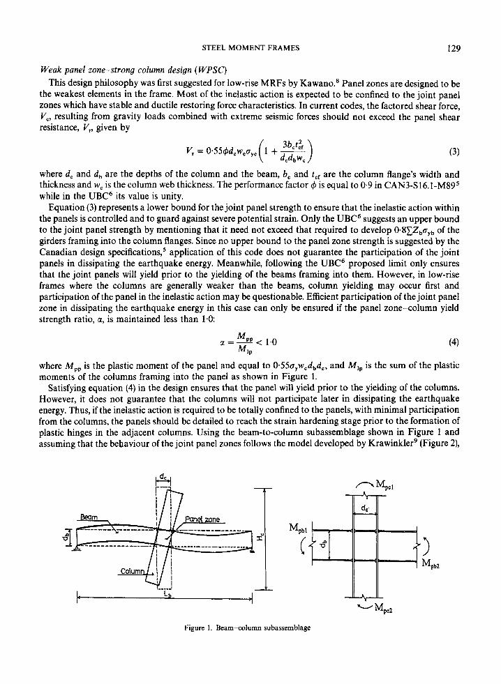
where Mpp is the plastic moment of the panel and equal to 0 ~ ~ ~ ~ , w , d , d , , and M,, is the sum of the plastic moments of the columns framing into the panel as shown in Figure 1.
Satisfying equation (4) in the design ensures that the panel will yield prior to the yielding of the columns. However, it does not guarantee that the columns will not participate later in dissipating the earthquake energy. Thus, if the inelastic action is required to be totally confined to the panels, with minimal participation from the columns, the panels should be detailed to reach the strain hardening stage prior to the formation of plastic hinges in the adjacent columns. Using the beam-to-column subassemblage shown in Figure 1 and assuming that the bebaviour of the joint panel zones follows the model developed by Krawinklerg (Figure 2),
Mpbl
Mpb2
- MpcZ
Figure 1. Beam-column subassemblage
130
Moment
1 A. OSMAN, A. GHOBARAH AND R. M. KOROL
I i I I
"/r 4% Shear strain (y) %
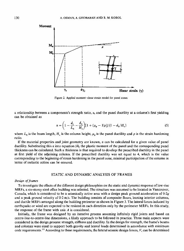
Figure 2. Applied moment-shear strain model for panel zones
a relationship between a components's strength ratio, a, and the panel ductility at a column's first yielding can be obtained as
where L b is the beam length, H, is the column height, pp is the panel ductility and p is the strain hardening ratio.
If the material properties and joint geometry are known, a can be calculated for a given value of panel ductility. Substituting this a into equation (4), the plastic moment of the panel and the corresponding panel thickness can be calculated. Such a thickness is that required to develop the prescribed ductility in the panel at first yield of the adjoining column. If the prescribed ductility was set equal to 4, which is the value corresponding to the beginning of strain hardening in the panel zone, minimal participation of the column in terms of inelastic action can be ensured.
STATIC AND DYNAMIC ANALYSIS OF FRAMES
Design of frames To investigate the effects of the different design philosophies on the static and dynamic response of low-rise
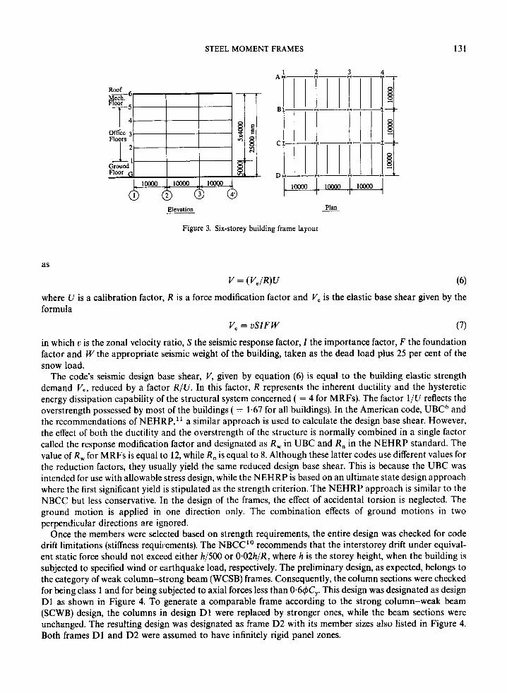
MRFs, a six-storey steel office building was selected. The structure was assumed to be located in Vancouver, Canada, which is considered to be a seismically active area with a design peak ground acceleration of 0.29 and a peak ground velocity of 0.2 m/s. The building consists of composite floors, leaning interior columns, and ductile MRFs arranged along the building perimeter as shown in Figure 3. The lateral forces induced by earthquake or wind are expected to be resisted in each direction only by the perimeter MRFs. In this study, the response of the frame with axis A is considered.
Initially, the frame was designed by an iterative process assuming infinitely rigid joints and based on centre-line-to-centre-line dimensions, a likely approach to be followed in practice. Three main aspects were considered in the design process: strength, stiffness and ductility. In the design for strength, the frame's beams and columns were sized to support both gravity and lateral loads determined in accordance with minimum code requirements." According to these requirements, the lateral seismic design forces, V, can be determined
STEEL MOMENT FRAMES 131
Elevation Plan
Figure 3. Six-storey building frame layout
as
V = ( V,/R)U
where U is a calibration factor, R is a force modification factor and V, is the elastic base shear given by the formula
V, = USIF W (7)
in which u is the zonal velocity ratio, S the seismic response factor, I the importance factor, F the foundation factor and W the appropriate seismic weight of the building, taken as the dead load plus 25 per cent of the snow load.
The code's seismic design base shear, V, given by equation (6) is equal to the building elastic strength demand V,, reduced by a factor R / U . In this factor, R represents the inherent ductility and the hysteretic energy dissipation capability of the structural system concerned ( = 4 for MRFs). The factor 1/U reflects the overstrength possessed by most of the buildings ( = 1.67 for all buildings). In the American code, UBC6 and the recommendations of NEHRP,l' a similar approach is used to calculate the design base shear. However, the effect of both the ductility and the overstrength of the structure is normally combined in a single factor called the response modification factor and designated as R, in UBC and R , in the NEHRP standard. The value of R, for MRFs is equal to 12, while R, is equal to 8. Although these latter codes use different values for the reduction factors, they usually yield the same reduced design base shear. This is because the UBC was intended for use with allowable stress design, while the NEHRP is based on an ultimate state design approach where the first significant yield is stipulated as the strength criterion. The NEHRP approach is similar to the NBCC but less conservative. In the design of the frames, the effect of accidental torsion is neglected. The ground motion is applied in one direction only. The combination effects of ground motions in two perpendicular directions are ignored.
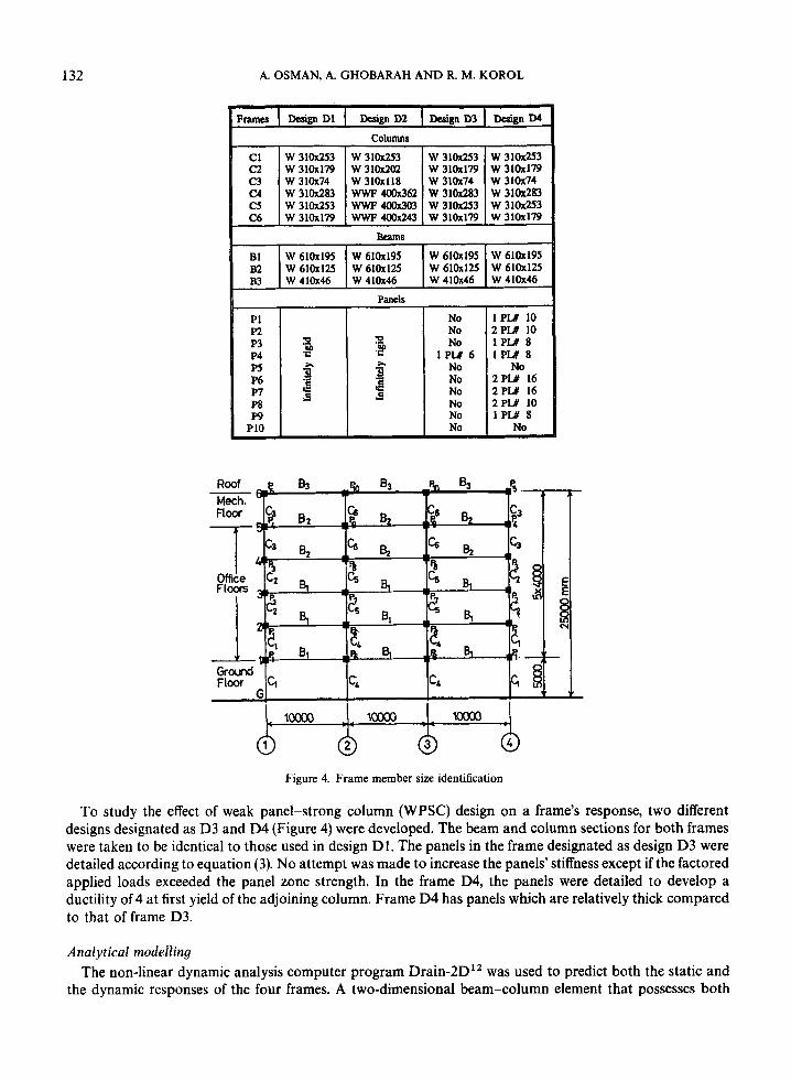
Once the members were selected based on strength requirements, the entire design was checked for code drift limitations (stiffness requirements). The NBCC?' recommends that the interstorey drift under equival- ent static force should not exceed either h/500 or 0.02h/R, where h is the storey height, when the building is subjected to specified wind or earthquake load, respectively. The preliminary design, as expected, belongs to the category of weak column-strong beam (WCSB) frames. Consequently, the column sections were checked for being class 1 and for being subjected to axial forces less than 0.61#K,. This design was designated as design D1 as shown in Figure 4. To generate a comparable frame according to the strong column-weak beam (SCWB) design, the columns in design D1 were replaced by stronger ones, while the beam sections were unchanged. The resulting design was designated as frame D 2 with its member sizes also listed in Figure 4. Both frames D1 and D 2 were assumed to have infinitely rigid panel zones.
132 A. OSMAN, A. GHOBARAH A N D R. M. KOROL
Columns
BcamS
B1 W 610x195 W 610x195 W 610x195 W 610x195 B2 W610x125 W610x125 W610x125 W610~125 B3 W410x46 W410x46 W41Ox46 W410x46
pancls
P1 No 1 PLY 10 P2 No 2PW 10
P4 PS P6 1 w P8 P9 No I P W 8
P10 No No
a No lPW 8 2 l P U 6 1 P U 8
P3 B .e No No No 2PW 16 No 2 P U 16
5 5 No 2PLY 10
x
Figure 4. Frame member size identification
To study the effect of weak panel-strong column (WPSC) design on a frame’s response, two different designs designated as D3 and D4 (Figure 4) were developed. The beam and column sections for both frames were taken to be identical to those used in design D1. The panels in the frame designated as design D3 were detailed according to equation (3). No attempt was made to increase the panels’ stiffness except if the factored applied loads exceeded the panel zone strength. In the frame D4, the panels were detailed to develop a ductility of 4 at first yield of the adjoining column. Frame D4 has panels which are relatively thick compared to that of frame D3.
Analytical modelling The non-linear dynamic analysis computer program Drain-2DI2 was used to predict both the static and
the dynamic responses of the four frames. A two-dimensional beam-column element that possesses both
133 STEEL MOMENT FRAMES
flexural and axial stiffness was used to model the beams and the columns. This element allows the formation of plastic hinges at concentrated points near its ends. The beams’ yield strength was limited to Za,, where Z is the plastic modulus of the beam section and ay is the yield stress. For the columns, a yield interaction relationship involving both axial force and bending moment was prescribed by the expression C,/Cy + 0.85 M,,/M,, < 1.0. Here C, and M,, are the axial load and the bending moment about the major axis due to gravity and lateral loads, while C, and M,, are the axial yield resistance and the moment yield resistance of the column section. The joint’s panel zone response was simulated by a trilinear spring modeL9
In the dynamic analysis, damping was taken to be proportional to both mass and initial stiffness with a damping ratio of 3 per cent. For both static and dynamic analyses, lateral sway effects (P-delta) were included while member stability considerations were excluded.
Non-linear static analysis The four frames were subjected to monotonically increasing base shear distributed along the height
according to the shape of the first vibration mode. The objective was to estimate the yield resistance, ultimate resistance, overall displacement ductility, storey displacement ductility, rotation requirements of individual elements, and ultimate interstorey drift.
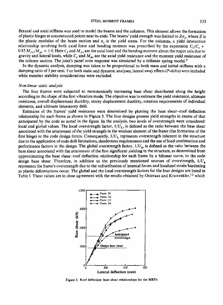
Estimates of the frames’ yield resistance were determined by plotting the base shear-roof deflection relationship for each frame as shown in Figure 5. The four designs possess yield strengths in excess of that anticipated by the code as noted in the figure. In the analysis, two levels of overstrength were considered: local and global values. The local overstrength factor, l/UL, is defined as the ratio between the base shear associated with the attainment of the yield strength in the weakest element of the frame (the formation of the first hinge) to the code design forces. Consequently, l/UL represents overstrength inherent in the structure due to the application of code drift limitations, slenderness requirements and the use of load combination and performance factors in the design. The global overstrength factor, l/Ug: is defined as the ratio between the base shear associated with the attainment of the first significant yielding in the structure, as determined from approximating the base shear-roof deflection relationship for each frame by a bilinear curve, to the code design base shear. Therefore, in addition to the previously mentioned sources of overstrength, l/Ug represents the frame’s overstrength due to the redistribution of internal forces and localized strain hardening as plastic deformations occur. The global and the local overstrength factors for the four designs are listed in Table I. These values are in close agreement with the results obtained by Osteraas and Kra~inkler , ‘~ which
- Frame D2 - Frame D3 t--t Frame D4
Lateral deflection (mm)
Figure 5. Roof deflection-base shear relationships for the MRFs
134 A. OSMAN, A. GHOBARAH A N D R. M. KOROL
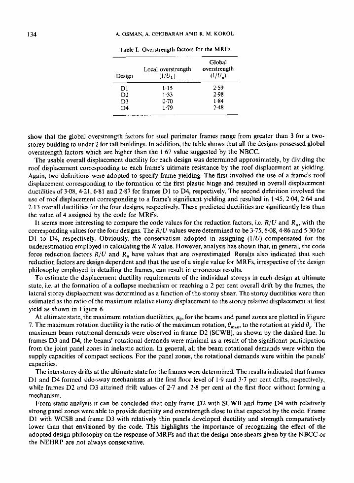
Table I. Overstrength factors for the MRFs
Global Local overstrength overstrength
Design W J L ) WJJ D1 1.15 2.59 D2 1.33 2.98 D3 0.70 1.84 D4 1.79 2.48
show that the global overstrength factors for steel perimeter frames range from greater than 3 for a two- storey building to under 2 for tall buildings. In addition, the table shows that all the designs possessed global overstrength factors which are higher than the 1.67 value suggested by the NBCC.
The usable overall displacement ductility for each design was determined approximately, by dividing the roof displacement corresponding to each frame’s ultimate resistance by the roof displacement at yielding. Again, two definitions were adopted to specify frame yielding. The first involved the use of a frame’s roof displacement corresponding to the formation of the first plastic hinge and resulted in overall displacement ductilities of 3.08,4.21, 6.81 and 2-87 for frames D1 to D4, respectively. The second definition involved the use of roof displacement corresponding to a frame’s significant yielding and resulted in 1.45, 2.04, 2.64 and 2.13 overall ductilities for the four designs, respectively. These predicted ductilities are significantly less than the value of 4 assigned by the code for MRFs.
It seems more interesting to compare the code values for the reduction factors, i.e. R/U and R,, with the corresponding values for the four designs. The R/U values were determined to be 3.75,6.08,4.86 and 5.30 for D1 to D4, respectively. Obviously, the conservatism adopted in assigning (l/U) compensated for the underestimation employed in calculating the R value. However, analysis has shown that, in general, the code force reduction factors R/U and R, have values that are overestimated. Results also indicated that such reduction factors are design dependent and that the use of a single value for MRFs, irrespective of the design philosophy employed in detailing the frames, can result in erroneous results.
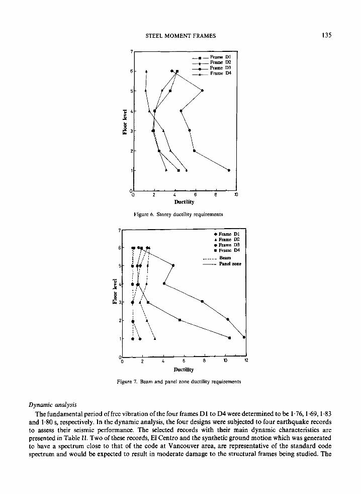
To estimate the displacement ductility requirements of the individual storeys in each design at ultimate state, i.e. at the formation of a collapse mechanism or reaching a 2 per cent overall drift by the frames, the lateral storey displacement was determined as a function of the storey shear. The storey ductilities were then estimated as the ratio of the maximum relative storey displacement to the storey relative displacement at first yield as shown in Figure 6.
At ultimate state, the maximum rotation ductilities, pe, for the beams and panel zones are plotted in Figure 7. The maximum rotation ductility is the ratio of the maximum rotation, Om,,, to the rotation at yield Oy. The maximum beam rotational demands were observed in frame D2 (SCWB), as shown by the dashed line. In frames D3 and D4, the beams’ rotational demands were minimal as a result of the significant participation from the joint panel zones in inelastic action. In general, all the beam rotational demands were within the supply capacities of compact sections. For the panel zones, the rotational demands were within the panels’ capacities.
The interstorey drifts at the ultimate state for the frames were determined. The results indicated that frames D1 and D4 formed side-sway mechanisms at the first floor level of 1.9 and 3.7 per cent drifts, respectively, while frames D2 and D3 attained drift values of 2.7 and 2.8 per cent at the first floor without forming a mechanism.
From static analysis it can be concluded that only frame D2 with SCWB and frame D4 with relatively strong panel zones were able to provide ductility and overstrength close to that expected by the code. Frame D1 with WCSB and frame D3 with relatively thin panels developed ductility and strength comparatively lower than that envisioned by the code. This highlights the importance of recognizing the effect of the adopted design philosophy on the response of MRFs and that the design base shears given by the NBCC or the NEHRP are not always conservative.
STEEL MOMENT FRAMES 135
Figure 6. Storey ductility requirements
*Frame D1 A Frame D2 .Frame D3 m Frame D4
___- -_ Beam - Panel zone
Ductility
Figure 7. Beam and panel zone ductility requirements
2
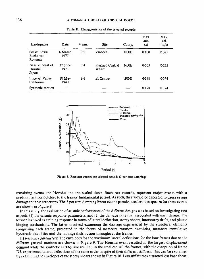
Dynamic analysis The fundamental period offree vibration of the four frames D1 to D4 were determined to be 1-76,1.69,1.83
and 1.80 s, respectively. In the dynamic analysis, the four designs were subjected to four earthquake records to assess their seismic performance. The selected records with their main dynamic characteristics are presented in Table 11. Two of these records, El Centro and the synthetic ground motion which was generated to have a spectrum close to that of the code at Vancouver area, are representative of the standard code spectrum and would be expected to result in moderate damage to the structural frames being studied. The
136 A. OSMAN, A. GHOBARAH AND R. M. KOROL
Table 11. Characteristics of the selected records
Max. Max. am. vel.
Earthquake Date Magn. Site Comp. (9) (m/s)
Scaled down 4 March 7.2 Vrancea NOOE 0.100 0.375 Bucharest, 1977 Romania
Near E. coast of 17 June 7.4 Kushiro Central NOOE 0.205 0.275 Honshu, 1973 Wharf Japan
Imperial Valley, 18 May 6.6 El Centro SOOE 0-348 0.334 California 1940
Synthetic motion - - - 0.178 0.174 -
Bucharest 1-21
1.0 C h 0.8 MI n
Honshu El Centro _ _ - _ _ - - Synthetic earthquake - Code
_ _ _ _ -
<'.. '-
0 1 2 3 4 5
Period (s)
Figure 8. Response spectra for selected records (3 per cent damping)
remaining events, the Honshu and the scaled down Bucharest records, represent major events with a predominant period close to the frames' fundamental period. As such, they would be expected to cause severe damage to these structures. The 3 per cent damping linear elastic pseudo-acceleration spectra for these events are shown in Figure 8.
In this study, the evaluation of seismic performance of the different designs was based on investigating two aspects: (1) the seismic response parameters, and (2) the damage potential associated with each design. The former involved examining response in terms of lateral deflection, storey shears, interstorey drifts, and plastic hinging mechanisms. The latter involved examining the damage experienced by the structural elements comprising each frame, presented in the forms of members rotation ductilities, members cumulative hysteretic ductilities and the damage distribution throughout the frames.
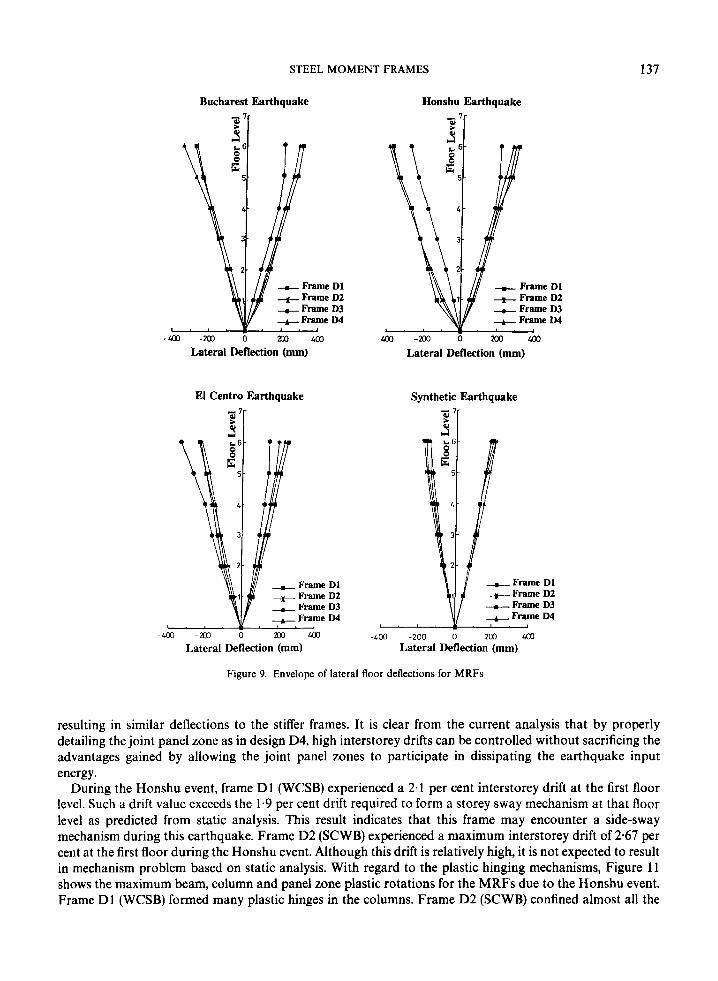
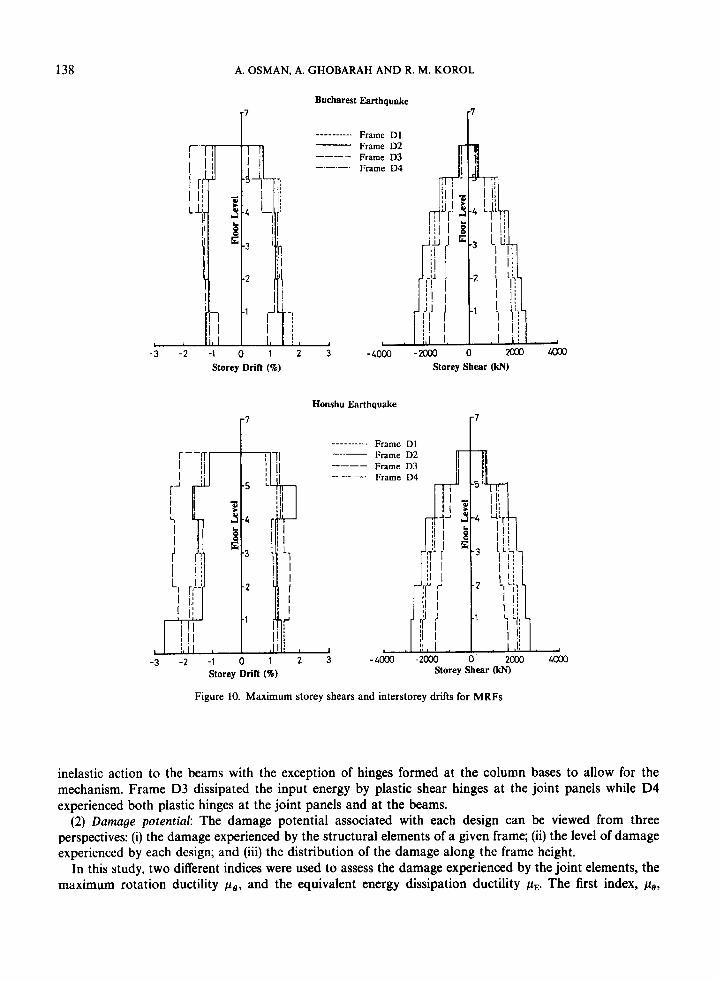
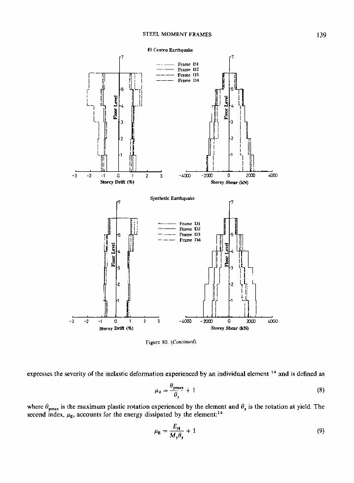
(1) Response parameters: The envelopes for the maximum lateral deflections for the four frames due to the different ground motions are shown in Figure 9. The Honshu event resulted in the largest displacement demand while the synthetic earthquake resulted in the smallest. All the frames, with the exception of frame D3, experienced lateral deflections of the same order in spite of their different stiffness. This can be explained by examining the envelopes of the storey shears shown in Figure 10. Less stiff frames attracted less base shear,
STEEL MOMENT FRAMES 137
Bucharest Earthquake
Lateral Deflection (mm)
Lateral Deflection (mm)
Honshu Earthquake
Q
D1 D2 D3 LM
Lateral Deflection (mm)
Synthetic Earthquake
-400 -200 0 203 403 Lateral Deflection (mm)
Figure 9. Envelope of lateral floor deflections for MRFs
resulting in similar deflections to the stiffer frames. It is clear from the current analysis that by properly detailing the joint panel zone as in design D4, high interstorey drifts can be controlled without sacrificing the advantages gained by allowing the joint panel zones to participate in dissipating the earthquake input energy.
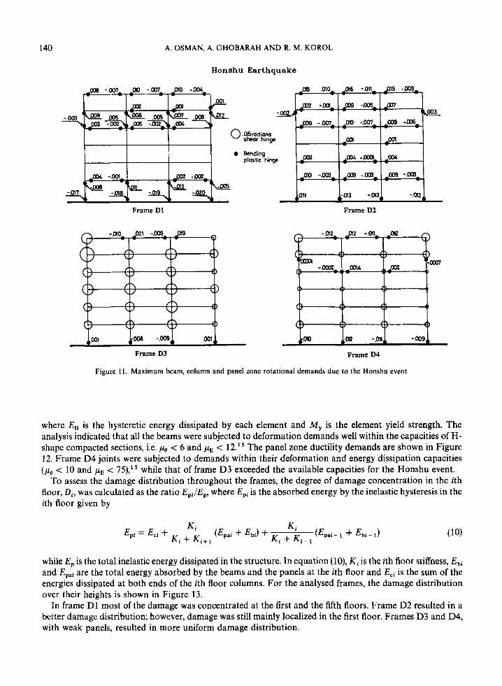
During the Honshu event, frame D1 (WCSB) experienced a 2.1 per cent interstorey drift at the first floor level. Such a drift value exceeds the 1.9 per cent drift required to form a storey sway mechanism at that floor level as predicted from static analysis. This result indicates that this frame may encounter a side-sway mechanism during this earthquake. Frame D2 (SCWB) experienced a maximum interstorey drift of 2.67 per cent at the first floor during the Honshu event. Although this drift is relatively high, it is not expected to result in mechanism problem based on static analysis. With regard to the plastic hinging mechanisms, Figure 11 shows the maximum beam, column and panel zone plastic rotations for the MRFs due to the Honshu event. Frame D1 (WCSB) formed many plastic hinges in the columns. Frame D2 (SCWB) confined almost all the
138
r-1 j
A. OSMAN. A. GHOBARAH AND R. M. KOROL
I I :
iJ LI'
3
Bucharest Earthquake
= t r - i E
"
-3 -2 -I 0 1 2 Storey Dritt (Ti)
! I 1 I I I .
I -3 -2 -1
Frame D1 Frame D2 Frame D3 Frame D4
3 -4000 - Storey Shear (W
1, , 4003
Honshu Earthquake 7
Frame D1 Frame D2
-___ Frame D3 Frame D4
-_______. ~ I'
Storey Shear 0 Storey Dritt (%)
Figure 10. Maximum storey shears and interstorey drifts for MRFs
inelastic action to the beams with the exception of hinges formed at the column bases to allow for the mechanism. Frame D3 dissipated the input energy by plastic shear hinges at the joint panels while D4 experienced both plastic hinges at the joint panels and at the beams.
(2) Damage potential: The damage potential associated with each design can be viewed from three perspectives: (i) the damage experienced by the structural elements of a given frame; (ii) the level of damage experienced by each design; and (iii) the distribution of the damage along the frame height.
In this study, two different indices were used to assess the damage experienced by the joint elements, the maximum rotation ductility pa, and the equivalent energy dissipation ductility pE. The first index, p,,,
STEEL MOMENT FRAMES
Frame D1 Frame D2
_ _ _ _ - - - - -.
139
-3 -2 -1 0 1 Storey Dritt (%)
-3 -2
7
2 3 -4m -2m 0 m 4 0 Storey Shear (kN)
Synthetic Earthquake " Frame D1 Frame D2 Frame D3 Frame D4
--- -__-___ --__
- 1 0 1 2 3 Storey Dritt (40)
Figure 10. (Continued).
expresses the severity of the inelastic deformation experienced by an individual element l 4 and is defined as
where Opmax is the maximum plastic rotation experienced by the element and 8, is the rotation at yield. The second index, pE, accounts for the energy dissipated by the element:I4
140 A. OSMAN, A. GHOBARAH AND R. M. KOROL
Honshu Earthquake
Bending plaslic hinge
Frame D1 Frame D2
Frame D3 Frame D4
Figure 11. Maximum beam, column and panel zone rotational demands due to the Honshu event
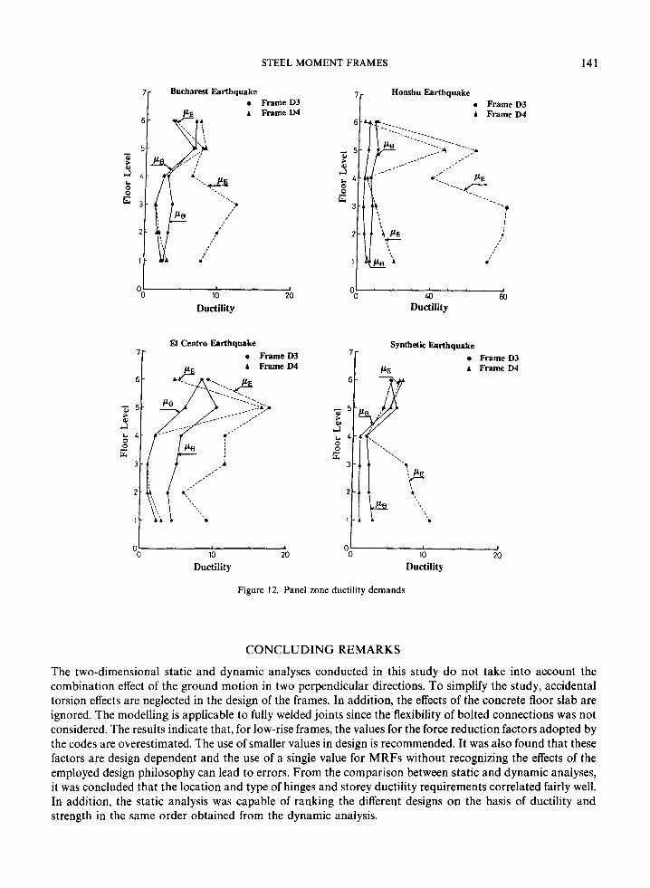
where E , is the hysteretic energy dissipated by each element and M y is the element yield strength. The analysis indicated that all the beams were subjected to deformation demands well within the capacities of H- shape compacted sections, i.e. pce < 6 and pE < 12.15 The panel zone ductility demands are shown in Figure 12. Frame D4 joints were subjected to demands within their deformation and energy dissipation capacities (pee < 10 and pE < 75),15 while that of frame D3 exceeded the available capacities for the Honshu event.
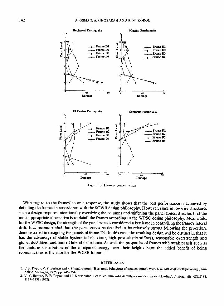
To assess the damage distribution throughout the frames, the degree of damage concentration in the ith floor, Di, was calculated as the ratio Epi/Ep, where Epi is the absorbed energy by the inelastic hysteresis in the ith floor given by
while E, is the total inelastic energy dissipated in the structure. In equation (lo), Ki is the ith floor stiffness, Ebi and Epai are the total energy absorbed by the beams and the panels at the ith floor and E,, is the sum of the energies dissipated at both ends of the ith floor columns. For the analysed frames, the damage distribution over their heights is shown in Figure 13.
In frame D1 most of the damage was concentrated at the first and the fifth floors. Frame D2 resulted in a better damage distribution; however, damage was still mainly localized in the first floor. Frames D3 and D4, with weak panels, resulted in more uniform damage distribution.
STEEL MOMENT FRAMES 141
Bucharest Earthquake FrameD3
A FrameD4
I 0 10 M
Ductility
D3 D4
D3 D4
Synthetic Earthquake
7r
- 5
E 3 - '1
2 -
1 - b
A Frame D3 Frame D4
0- O@ 10 20 0 10 20 \
Ductility Ductility
Figure 12. Panel zone ductility demands
CONCLUDING REMARKS
The two-dimensional static and dynamic analyses conducted in this study do not take into account the combination effect of the ground motion in two perpendicular directions. To simplify the study, accidental torsion effects are neglected in the design of the frames. In addition, the effects of the concrete floor slab are ignored. The modelling is applicable to fully welded joints since the flexibility of bolted connections was not considered. The results indicate that, for low-rise frames, the values for the force reduction factors adopted by the codes are overestimated. The use of smaller values in design is recommended. It was also found that these factors are design dependent and the use of a single value for MRFs without recognizing the effects of the employed design philosophy can lead to errors. From the comparison between static and dynamic analyses, it was concluded that the location and type of hinges and storey ductility requirements correlated fairly well. In addition, the static analysis was capable of ranking the different designs on the basis of ductility and strength in the same order obtained from the dynamic analysis.
142 A. OSMAN, A. GHOBARAH AND R. M. KOROL
Bucharest Earthquake Honshu Earthquake
+ Frame D1 + Frame D2 + Frame D3 - Frame D4
1 OO (15 1.0
Damage
El Centro Earthquake 7r
Frame D1 Frame D2 Frame D3 Frame D4
0 as 11)
Damage
- Frame D1 - Frame D2 - Frame D3 - Frame D4
0.5 1.0 Damage
Synthetic Earthquake
Figure 13. Damage concentration
With regard to the frames’ seismic response, the study shows that the best performance is achieved by detailing the frames in accordance with the SCWB design philosophy. However, since in low-rise structures such a design requires intentionally oversizing the columns and stiffening the panel zones, it seems that the most appropriate alternative is to detail the frames according to the WPSC design philosophy. Meanwhile, for the WPSC design, the strength of the panel zone is considered a key issue in controlling the frame’s lateral drift. It is recommended that the panel zones be detailed to be relatively strong following the procedure demonstrated in designing the panels of frame D4. In this case, the resulting design will be distinct in that it has the advantage of stable hysteretic behaviour, high post-elastic stiffness, reasonable overstrength and global ductilities, and limited lateral deflections. As well, the properties of frames with weak panels such as the uniform distribution of the dissipated energy over their heights have the added benefit of being economical as is the case for the WCSB frames.
REFERENCES 1 . E. P. Popov, V. V. Bertero and S. Chandramouli, ‘Hysteretic behaviour of steel columns’, Proc. US. natl. con$ earthquake eng., Ann
2. V. V. Bertero, E. P. Popov and H. Krawinkler, ‘Beam-column subassemblages under repeated loading’, J . struct. diu ASCE 98, Arbor, Michigan, 1975, pp. 245-254.
1137-1159 (1972).
STEEL MOMENT FRAMES 143
3. K. Tsai and E. P. Popov, ‘Steel beam-column joints in seismic moment resisting frames’, Report No. EERC 88-19, Earthquake Eng.
4. A. Ghobarah, R. M. Korol and A. Osman, ‘Cyclic behaviour of extended end-plate joints’, J . struct. eng. ASCE 118, 1333-1353
5. CAN3-Sl6.1-MS9, ‘Steel structures for buildings-limit state design’, Canadian Standards Association, Rexdale, Ontario, Canada,
6. UBC, ‘Uniform building code’, Int. conf. of building officials, Whittier, CA, 1988. 7. H. Akiyama, Earthquake-Resistant Limit-State Design For Buildings, University of Tokyo Press, Japan, 1985. 8. A. Kawano, ‘Inelastic behaviour of low-rise steel frames based on a weak beam-column connection philosophy to earthquake
9. H. Krawinkler, ‘Shear in beam-column joints in seismic design of steel frames’, Eng. j . AISC 3, 82-90 (1978). 10. NBCC, ‘National building code of Canada’, National Research Council, Ottawa, Canada, 1990. 1 1 . NEHRP, ‘Recommended provisions for the development of seismic regulation for new buildings (Parts 1 and 2)’. Federal Emergency
12. A. E. Kannan and G. H. Powell, ‘Drain-2D, a general purpose computer program for dynamic analysis of inelastic plane structures’,
13. J. Osteraas and H. Krawinkler, ‘Seismic design based on strength of structures’, Proc. 4th U.S. natl. conj on earthquake eng., Palm
14. A. Vulcano, ‘Comparison between ductility requirements based on different criteria’, Proc. VII symp. on earthquake eng., University
15. T. Hasegama, H. Yamanouchi and H. Akiyama, ‘Seismic damage concentration in steel building structures with weak beam-to-
Res. Center, University of California, Berkeley, CA, 1988.
(1992).
1989.
motion’, Proc. 8th WCEE, San Francisco, CA, Vol. IV, 1984, pp. 519-526.
Management Agency (FEMA), Building Seismic Safety Council, Washington, DC, 1988.
Reporr No. EERC 73-6, Earthquake Eng. Res. Center, University of California, Berkeley CA, 1973.
Springs, CA, Vol. 2, 1990, pp. 955-964.
of Roorkee, 1982, pp. 209-214.
column joint panels’, Proc 6th Canadian earthquake eng. con$, Toronto, 1991, pp. 117-122.