drilled displacement piles – current practice and design
TRANSCRIPT

DFI JOURNAL Vol. 4 No. 1 August 2010 [3]
Drilled Displacement Piles – Current Practice and DesignPrasenjit Basu, Assistant Professor, Department of Civil and Environmental Engineering, Pennsylvania
State University, University Park, PA 16802, USA, Ph: 1-863-814-4010, e-mail: [email protected]
Monica Prezzi, Associate Professor, School of Civil Engineering, Purdue University, West Lafayette,
IN 47907, USA, Ph: 1-765-494-5034, Fax: 1-765-494-0395, e-mail: [email protected]
Dipanjan Basu, Assistant Professor, Department of Civil Engineering, University of Connecticut, CT
06269-2037, USA, Ph: 1-860-486-5023, e-mail: [email protected]
ABSTRACTDrilled displacement piles are being increasingly used as foundation elements, particularly in projects requiring fast construction. Different types of drilled displacement (DD) piles are available in practice. DD piles are classified according to the drilling tool design and installation method. The capacity of a DD pile, depending on its type, is between the capacities of geometrically similar nondisplacement and full-displacement piles installed in the same soil profile. This paper provides an overview of the different types of DD piles and their installation techniques and describes three design methods used in practice. It also compares DD pile capacities obtained with these design methods for two different sites.
INTRODUCTION
A wide variety of pile types are currently available for use in geotechnical engineering practice. The response of these piles to loading varies greatly depending on the installation or construction methods employed. On one end of the pile behavior spectrum are the nondisplacement piles (e.g., bored piles or drilled shafts) and, on the other end, are the full-displacement piles (e.g., closed-ended pipe piles or precast reinforced concrete piles). Nondisplacement piles are constructed by removing a cylinder of soil from the ground and replacing the void created with concrete and reinforcement. Full-displacement piles, on the other hand, are driven or jacked into the ground. During the installation of full-displacement piles, significant changes in the void ratio and stress state of the in situ soil take place because the soil surrounding the pile shaft is displaced mainly in the lateral direction and the soil below the base of the pile is preloaded. These changes produce a stiffer load-displacement response for the displacement piles than that of the nondisplacement piles, particularly in the case of sandy soils which gain additional strength through densification.
There are other types of piles (e.g., open-ended pipe piles) that show behavior intermediate between nondisplacement and full-displacement piles. These piles are often called partial-
displacement piles. Many auger piles, which are installed by drilling a continuous-, segmented- or partial-flight auger into the ground, fall under this category. A variety of auger piling equipment is available in the market; each one is associated with a certain degree of soil displacement during installation. The commonly used terminologies used for auger piles in North America and Europe are presented in Fig. 1.
A special class of auger piles was created as a result of advances in auger piling technology; these are commonly known as “screw piles” in Europe, and “drilled displacement” or “augered displacement” piles in the USA (Brown and Drew 2000; Brown 2005; Prezzi and Basu 2005). These piles have been used in Europe over the last few decades and are becoming popular in the U.S. Drilled displacement (DD) piles are rotary displacement piles installed by inserting a specially designed helical auger segment into the ground with both a vertical force and a torque. Soil is displaced laterally within the ground (with minimal spoil generated), and the void created is filled with grout or concrete. The installation of DD piles produces greater soil displacement than that produced by continuous-flight-auger (CFA) or auger cast-in-place (ACIP) piles (these piles are generally associated with small soil displacement). The axial capacity of the different types of DD piles depends on the radial soil displacement

[4] DFI JOURNAL Vol. 4 No. 1 August 2010
caused by their installation (the radial soil displacement depends on the soil type and state, the design of the DD pile drilling tool, and
the drilling rig technology).
From a design point of view, full-displacement piles are preferable because they are capable of carrying larger loads than partial- or nondisplacement piles of similar geometry. However, pile driving may cause excessive vibration to neighboring structures or create excessive noise that may be unacceptable under certain conditions. Additionally, in some soil profiles, the use of driven piles may not be advisable. DD piles often offer a viable alternative in cases where the installation of driven full-displacement piles is not advisable. The advantages of DD piles are (i) the ease and fast rate of construction with minimal vibration or noise, and minimal spoil (important for contaminated sites), (ii) the high load-carrying capacity due to partial or full displacement of the soil surrounding the pile, and (iii) the associated savings that result when they are installed in the right soil conditions.
This paper presents a review of the current DD pile practice, including DD pile installation methods, quality control procedures, and three design methods. The ultimate capacities of five different types of DD piles are calculated with the design methods used in practice and compared with those obtained from pile load test results reported in the literature. Additionally, in a separate design example, the capacities of a DD pile, a full-displacement pile and a nondisplacement pile in a residual soil profile are compared.
OVERVIEW OF DD PILING TECHNOLOGYThe development of DD piling technology evolved from the continuous-flight auger (CFA) piling technology. The remarkable progress in piling
rig capabilities over the past few decades and the improvement of the auger pile drilling tools and installation techniques helped speed up the installation process and resulted in larger lateral soil displacement. The piles that ensued because of these developments were called DD piles. However, DD piles are not just limited to those that are variations of the CFA or ACIP piles. A variety of other piles that have significantly different installation (drilling) tools are also included in this broad pile classification: Atlas, De Waal, Fundex, Olivier, Omega, Pressure-Grouted Displacement (PGD), and SVV piles (see Fig. 2). In general, the drilling tool of a DD pile contains one or more of the following components: a) a soil displacement body (an enlarged-diameter section which facilitates lateral soil movement), b) a helical, partial-flight auger segment, and c) a specially designed sacrificial tip, which is attached to the bottom of the drilling tool. The shape of the displacement body varies from one pile type to another; broadly, it consists of a cylindrical body that, in some cases, also contains single or multiple helices (Fig. 2). A casing (mandrel) of diameter smaller than or equal to the diameter of the pile is connected to the drilling tool.
Auger Piles
European Nomenclature North-American Nomenclature
Continuous -Flight -Auger
(CFA)
Screw Piles Auger Cast In-Place (ACIP)
Augercast or Auger Pressure -Grouted (APG)
Drilled-Displacement (DD)/ Augered -Displacement
Partial -Displacement
Continuous -Flight -Auger
(CFA)
Full-Displacement
Auger Piles
European Nomenclature North-American Nomenclature
Continuous -Flight -Auger
(CFA)
Screw Piles Auger Cast -In-Place (ACIP)
Augercast or Auger Pressure -Grouted (APG)
Drilled-Displacement (DD)/ Augered -Displacement
Partial -Displacement
Continuous -Flight -Auger
(CFA)
Full-Displacement
[FIG. 1] Nomenclature used for auger piles in Europe and the U.S. (modifi ed after Prezzi and Basu 2005)
[FIG. 2] Drilling tools for installation of drilled displacement piles.
Atlas DeWaal Fundex Olivier Omega PGD SVV

DFI JOURNAL Vol. 4 No. 1 August 2010 [5]
Piling rigs with high torque capacities (150 kN-m to 500 kN-m or more) (110 kip ft to 370 kip ft) that provide vertical thrust during the drilling process are required for installation of DD piles [drilling proceeds as a result of both the rotation of the drilling tool and the crowd (axial) force typically applied by hydraulic rams]. Once the drilling tool reaches the desired depth, the sacrificial tip (if used) is released from the casing or displacement body. Concrete or grout is then placed through the casing as the drilling tool and the casing are extracted from the ground. The reinforcement is inserted either before or after concrete placement. The drilling tool and casing can be withdrawn from the ground with or without rotation (the rotation may be clockwise or counter-clockwise). A nearly smooth pile shaft is obtained if the casing is withdrawn with alternating 180° clockwise and counter-clockwise rotations (as in the case of the Fundex pile). A nearly smooth shaft also results if the drilling tool is rotated clockwise as it is withdrawn from the ground (e.g., De Waal, PGD, and Omega piles). However, if the displacement body is rotated counter-clockwise (e.g., Atlas and Olivier piles) during withdrawal, then a screw-shaped shaft is obtained.
Proper knowledge of the subsurface profile is required for selecting the most efficient pile type for a given site. For a number of sites in the U.S., Siegel et al. (2007) reported an increase in cone penetration test (CPT) resistance q
c due
to the installation of DD piles. The maximum increase in q
c was observed in the case of loose
sand with normalized value of CPT resistance q
c1 less than 50 [q
c1 = (q
c/p
a)(p
a/σ′
v0)0.5; where
pa = atmospheric pressure = 100 kPa and σ′
v0
= in situ vertical effective stress; Siegel et al. 2007]. However, according to Bustamante and Gianeselli (1998), the performance of DD piles may be compromised because of possible difficulties encountered during installation in very loose sandy soils or very soft clayey soils (characterized by SPT blow count N < 5 or q
c < 1
MPa or 145 psi). In the case of very dense sandy soils or thick alluvium layers, a drastic drop in the penetration rate may be observed and premature wear of the screw head (drilling tool) may result (Bustamante and Gianeselli 1998). According to NeSmith (2002), the installation of auger pressure-grouted displacement (APGD) piles (which can more generally be called PGD piles) becomes difficult in dense sand layers with q
c > 14 MPa (2,030 psi). In the case of
thick clay deposits, the excess pore pressure generated during installation of DD piles may cause bleeding of fresh concrete and loss of pile integrity (NeSmith 2002). However, an assessment of the potential problems that may occur during the installation of DD piles can only be made after full consideration of specific site conditions and equipment capabilities (piling rig and drilling tool).
INSTALLATION TECHNIQUES FOR DIFFERENT DD PILES
Atlas Pile
The Atlas pile is a drilled, dual-displacement, cast-in-place concrete pile (De Cock and Imbo 1994). Lateral displacement of soil occurs both during drilling and extraction of the auger (this is the reason why it is called a dual-displacement pile). The Atlas pile is installed using a purpose-built drilling rig with a base rotary drive (Bottiau 2006). The Atlas pile rig has two hydraulic rams that can work independently (one ram taking over from the other after its full stroke is achieved) to allow a continuous drilling operation. In the case of hard soils, the two hydraulic rams can be used simultaneously. The rig can be operated at dual rotational speeds. This helps control the drilling tool penetration rate in different soil types.
A sacrificial tip (a lost pile shoe) is attached to a displacement body, which, in turn, is attached to a steel casing or mandrel (Fig. 3). The displacement body consists of a cast-iron dismountable helical head with an enlarged helical flange. The joint between the displacement body and the sacrificial tip is made watertight. The combined action of the torque and the vertical thrust forces the casing down into the ground with a continuous, clockwise, helical penetrating movement. After the desired depth is reached, the steel shoe is detached from the casing by rotating the casing counter-clockwise (thereby opening the connection between the steel shoe and the casing). Subsequently, the steel reinforcing cage is inserted into the casing, and high-slump concrete is poured through a hopper placed on top of the casing to cast the pile shaft. As the casing and the displacement body are extracted by a vertical pulling force and counter-clockwise rotation, concrete completely fills the helical bore formed by the upward-moving displacement screw. This way, a screw-shaped shaft is formed. The flange thickness of the screw-shaped shaft varies

[6] DFI JOURNAL Vol. 4 No. 1 August 2010
depending on the extraction procedure (i.e., the ratio of rotational to translational speeds during extraction) (De Cock and Imbo 1994; Geoforum 2008). After concrete placement is complete, it is possible to push a supplementary reinforcing cage into the concrete.
The diameter of the displacement body (which is the same as the minimum diameter of the pile shaft) typically ranges from 0.31 m to 0.56 m (1.00 ft to 1.84 ft), while that of the enlarged helical flange ranges from 0.45 m to 0.81 m (1.48 ft to 2.66 ft) (Bustamante and Gianeselli 1998; De Cock and Imbo 1994). The Atlas pile length can reach up to 22-25 m (72-82 ft). In highly compressible soils or in soils with large cavities or voids, a thin-walled casing is often attached to the screw head of the Atlas piles (Bustamante and Gianeselli 1998). The casing is left in the ground with the sacrificial tip.
De Waal Pile
The drilling tool used to install the De Waal pile consists of a sacrificial tip, a partial-flight auger and a displacement body (Fig. 4). The tool is attached to a casing. The partial-flight auger is closed at the bottom with the sacrificial tip. To install the De Waal pile, the drilling tool is rotated clockwise to the required depth with a torque and a vertical force. After reaching the desired depth, concrete is placed into the casing to a level above the ground level, the sacrificial tip is released, and the tool is extracted using clockwise rotation and a vertical force. Upward transport of soil during extraction is restricted due to the presence of reverse auger flights above the displacement body. The concrete level within the casing is maintained above the ground level during extraction. A reinforcement cage is typically installed after concrete placement. Unlike the Atlas pile, installation of the De Waal pile creates a nearly smooth shaft.
Fundex Pile
In the Fundex pile installation, a casing/tube with a conical auger tip attached to its end is rotated clockwise and pushed down into the soil (Fig. 5). The joint between the casing and the conical tip is made watertight. As the casing penetrates into the ground, soil is displaced laterally. In dense or hard layers, drilling can be combined with grout injection or water jetting through the conical tip. After the desired depth is reached, the sacrificial conical tip, which forms an enlarged pile base, is released. The reinforcement cage is then inserted into
the casing, and concrete is placed. As the concrete is placed, the casing is extracted in an oscillating upward and downward motion with alternate 180° clockwise and counter-clockwise rotations. The withdrawal of the casing with both clockwise and counter-clockwise rotations produces a nearly smooth shaft.
The diameter of the conical tip ranges from 0.45 m to 0.67 m (1.5 ft to 2.2 ft), while that of the casing ranges from 0.38 m to 0.52 m (15 in to 20 in) (American Pile Driving Inc. 2007; Geoforum 2008). The length of the Fundex pile can reach up to 25-35 m (82-115 ft).
Olivier Pile
The installation of the Olivier pile is similar to that of the Atlas pile (Fig. 6). However, the drilling rigs used to install the Olivier piles are different from those of the Atlas piles (the rotary drives are different; the Atlas pile rig has a bottom-type rotary drive with a fixed rate of penetration, while the Olivier pile rig uses a top-type rotary drive with variable rate of penetration). A lost tip is attached to a partial-flight auger which, in turn, is attached to a casing. The casing, which is rotated clockwise continuously, penetrates into the ground by the action of a torque and a vertical force. At the desired installation depth, the lost tip is released, and the reinforcing cage is inserted into the casing. Concrete is then placed inside the casing through a funnel. The casing and the partial-flight auger are extracted by counter-clockwise rotation. Similar to the Atlas pile, the shaft of the Olivier pile has the shape of a screw.
Omega Pile
In the case of the Omega pile, drilling is done by a displacement auger (with varying flange diameter), which is closed at the bottom with a sacrificial tip (Fig. 7). The flange diameter of the auger segments increases gradually from both ends and becomes equal to the diameter of the central displacement body. A casing is attached to the upper end of the displacement auger. After reaching the required depth, concrete is injected under pressure, and the sacrificial tip is released. The auger is slowly rotated clockwise and pulled up to produce a nearly smooth shaft. The reinforcement cage is then vibrated down into the fresh concrete. For some Omega piles, it is possible to place the reinforcement cage (or bar) into the drilling stem (casing) even before concrete is placed (Bottiau et al. 1998).

DFI JOURNAL Vol. 4 No. 1 August 2010 [7]
2: Insertion of reinforcing cage at end of drilling
3: Extraction of the casing with counter-clockwise rotation and
vertical force
4: Insertion of supplementary
reinforcement: completed Atlas pile with screw-
shaped shaftHydraulic Ram
Displacement Body
Sacrificial Tip
Casing
1: Drilling with clockwise auger rotation and
vertical force
2: Extraction of casing with clockwise rotation and
vertical force
3: Concrete injection and release of sacrificial tip at
the desired depth
4: Insertion of reinforcing cage
and completed De Waal pile
Displacement Body
Sacrificial Tip
Partial Auger
Casing
1: Drilling with clockwise auger rotation and
vertical force
[FIG. 3] Installation stages for the Atlas pile.
[FIG. 4] Installation stages for the DeWaal pile.

[8] DFI JOURNAL Vol. 4 No. 1 August 2010
2: At the desired depth, insertion of reinforcing cage, release of sacrificial tip and placement of concrete into
the casing
3: Extraction of casing with an oscillating upward and
downward motion and alternating 180° clockwise
and counter-clockwise rotations
4: Completed Fundex pile
Casing
Sacrificial Conical Tip
1: Drilling with clockwise auger rotation and
vertical force
2: Insertion of reinforcing cage and release of sacrificial
tip at the desired depth
3: Concrete pumping and extraction of casing with
counter-clockwise rotation
4: Completed Olivier pile with screw-shaped shaft
Casing
Sacrificial Tip
Partial Auger
1: Drilling with clockwise auger rotation and
vertical force
[FIG. 5] Installation stages for the Fundex pile.
[FIG. 6] Installation stages for the Olivier pile.
DFI JOURNAL Vol. 4 No. 1 August 2010 [9]
PGD Pile
The PGD piling technology is a modification of the Auger Pressure-Grouted (APG) piling system (Brettmann and NeSmith 2005). The APG pile is a type of CFA pile which is constructed by pumping fluid grout under pressure during the withdrawal of the continuous-flight auger. During the installation of a PGD pile (Fig. 8), the surrounding soil is displaced laterally as the drilling tool is advanced into the ground. There are basically two types of PGD piles: 1) pressure-grouted with partial soil displacement and 2) pressure-grouted with full soil displacement. The PGD pile rigs are capable of producing both a torque and a downward crowd force, facilitating the drilling operations. Once the desired depth is reached, high-strength grout is pumped under pressure through the drill stem and the drilling tool is withdrawn as it rotates clockwise. The reinforcement cage is inserted into the grout column to complete the pile installation process. Note that the term Auger Pressure-Grouted Displacement (APGD) is also used in practice to refer to this type of DD pile (NeSmith 2002; Brettmann and NeSmith 2005).
The full-displacement PGD piles, which are typically installed in loose to medium dense sands (corresponding to SPT blow count N < 25), can be 0.3-0.45 m (12-18 in) in diameter and up to 24 m (79 ft) in length (NeSmith 2002; Brettmann and NeSmith 2005). The diameter of the partial-displacement PGD pile ranges from 0.3-0.5 m (12-20 in). These piles reach up to 17 m (79 ft) in length and are used in loose to dense sands with N < 50 (NeSmith 2002; Brettmann and NeSmith 2005).
SVV Pile
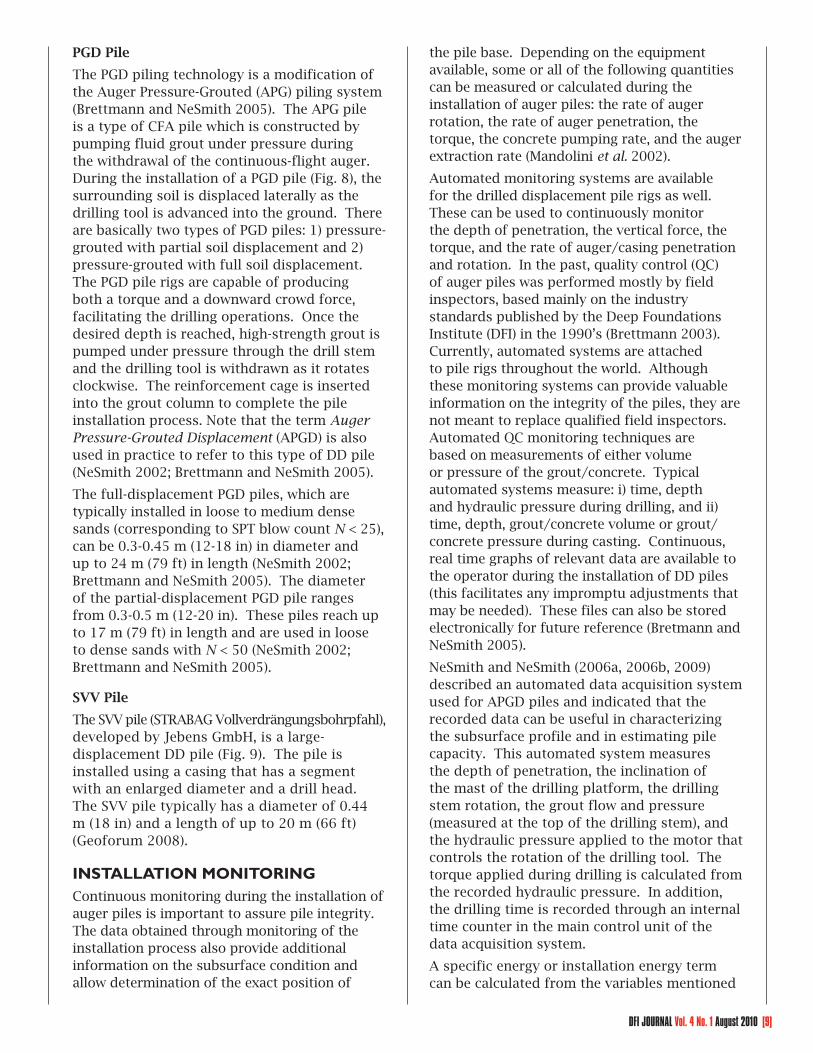
The SVV pile (STRABAG Vollverdrängungsbohrpfahl), developed by Jebens GmbH, is a large-displacement DD pile (Fig. 9). The pile is installed using a casing that has a segment with an enlarged diameter and a drill head. The SVV pile typically has a diameter of 0.44 m (18 in) and a length of up to 20 m (66 ft) (Geoforum 2008).
INSTALLATION MONITORINGContinuous monitoring during the installation of auger piles is important to assure pile integrity. The data obtained through monitoring of the installation process also provide additional information on the subsurface condition and allow determination of the exact position of
the pile base. Depending on the equipment available, some or all of the following quantities can be measured or calculated during the installation of auger piles: the rate of auger rotation, the rate of auger penetration, the torque, the concrete pumping rate, and the auger extraction rate (Mandolini et al. 2002).
Automated monitoring systems are available for the drilled displacement pile rigs as well. These can be used to continuously monitor the depth of penetration, the vertical force, the torque, and the rate of auger/casing penetration and rotation. In the past, quality control (QC) of auger piles was performed mostly by field inspectors, based mainly on the industry standards published by the Deep Foundations Institute (DFI) in the 1990’s (Brettmann 2003). Currently, automated systems are attached to pile rigs throughout the world. Although these monitoring systems can provide valuable information on the integrity of the piles, they are not meant to replace qualified field inspectors. Automated QC monitoring techniques are based on measurements of either volume or pressure of the grout/concrete. Typical automated systems measure: i) time, depth and hydraulic pressure during drilling, and ii) time, depth, grout/concrete volume or grout/concrete pressure during casting. Continuous, real time graphs of relevant data are available to the operator during the installation of DD piles (this facilitates any impromptu adjustments that may be needed). These files can also be stored electronically for future reference (Bretmann and NeSmith 2005).
NeSmith and NeSmith (2006a, 2006b, 2009) described an automated data acquisition system used for APGD piles and indicated that the recorded data can be useful in characterizing the subsurface profile and in estimating pile capacity. This automated system measures the depth of penetration, the inclination of the mast of the drilling platform, the drilling stem rotation, the grout flow and pressure (measured at the top of the drilling stem), and the hydraulic pressure applied to the motor that controls the rotation of the drilling tool. The torque applied during drilling is calculated from the recorded hydraulic pressure. In addition, the drilling time is recorded through an internal time counter in the main control unit of the data acquisition system.
A specific energy or installation energy term can be calculated from the variables mentioned

[10] DFI JOURNAL Vol. 4 No. 1 August 2010
3: Pressure injection of concrete into the casing and release of sacrificial
tip at desired depth
4: Extraction of drilling tool with clockwise rotation and
concrete placement
5: Insertion of reinforcement:
completed Omega pile
Displacement Auger
Sacrificial Conical Tip
1: Drilling with clockwise auger rotation
and vertical force
2: Pressure injection of grout after reaching the desired depth
3: Extraction of drilling tool with clockwise rotation
4: Insertion of reinforcement:
completed PGD pile
Drilling Tool
1: Drilling with clockwise auger rotation and
vertical force
Drill Stem
[FIG. 7] Installation stages for the Omega pile.
[FIG. 8] Installation stages for the PGD pile.
DFI JOURNAL Vol. 4 No. 1 August 2010 [11]
above and other machine-specific installation parameters (Bottiau et al. 1998). The specific energy along the depth of the pile can be correlated with in situ test results; it can potentially be used to interpret the effects of pile installation and to help predict pile load capacity (De Cock and Imbo 1994). NeSmith (2003) also proposed that an installation effort parameter (IE; defined as the product of normalized values of torque and drilling tool penetration rate) be used as an indicator of the capacity of DD piles. However, research on this topic is very limited and caution is necessary when using these methodologies.
DESIGN METHODS
General Framework
The ultimate pile capacity Qult
can be expressed as:
Qult
= Qb,ult
+ QsL
(1)
where Qb,ult
and QsL
are the ultimate base and limit shaft capacities. These quantities are
calculated from:
Qb,ult
= qbA
b (2)
n
iQ sL=A s∑q sih si (3)
where the subscript i represents a given soil layer (i = 1, 2, 3, …) for which shaft capacity is calculated; n is the total number of layers crossed by the pile; q
b and q
si are the unit base
and shaft resistances; Ab (= π D
b2/4) is the
representative pile base area; As (= π D
s) is the
pile shaft perimeter; Db and D
s are the nominal
diameters of the pile base and shaft respectively; and h
si is the thickness of the ith soil layer.
According to the guidelines provided by Huybrechts and Whenham (2003), the nominal shaft and base diameters depend on the drilling tool geometry. For the Atlas and Olivier piles, D
b
and Ds are assumed to be equal to the measured
maximum diameter Df of the drilling auger screw
blade (see Fig. 10). Bustamante and Gianeselli (1993, 1998), however, suggested that the nominal diameter of the Atlas pile is equal to 0.9D
f, except
for the thick-flanged Atlas piles, for which they suggested a nominal diameter equal to D
f. For
the Fundex pile, Db is equal to the measured
maximum diameter of the conical auger tip, and D
s is equal to the measured maximum diameter
of the casing/tube (Huybrechts and Whenham 2003). For other DD piles that also have a nearly smooth shaft, such as the De Waal and Omega piles, both D
s and D
b are taken as the diameter
of the soil displacement body (which is equal
2: Insertion of reinforcing cage after reaching the
desired depth
3: Pumping concrete and extraction of casing with clockwise rotation
and vertical force
4: Completed SVV pile
1: Clockwise drilling using torque and
vertical force
Drill Head
2: Insertion of reinforcing cage after reaching the
desired depth
3: Pumping concrete and extraction of casing with clockwise rotation
and vertical force
4: Completed SVV pile
1: Clockwise drilling using torque and
vertical force
Drill Head
[FIG. 9] Installation stages for the SVV pile.

[12] DFI JOURNAL Vol. 4 No. 1 August 2010
to the maximum diameter of the screw blade; Huybrechts and Whenham 2003). Since the nominal pile diameter depends on the drilling tool geometry, the different coefficients proposed (in different design methods) for pile capacity calculations reflect the way in which they were determined, including the nominal dimensions of the pile. No specific guidelines are given in the literature on nominal diameter values for use in the design of other types of DD piles.
Df
Atlas OlivierDb
Ds
Fundex
Db = sDf
Omega
Db s
De Waal
DfDf
Atlas OlivierDb
Ds
Db
Ds
Fundex
Db sDb sDfDf
Omega
Db = s
De Waal
D D
[FIG. 10] Design dimensions for some DD piles.
Calculation of unit base and shaft resistances
Available design methods for DD piles are mostly based on in situ test results. The unit base and shaft resistances of piles are typically related to the cone penetration test (CPT) tip resistance q
c, the standard penetration test
(SPT) blow count N and the pressuremeter test (PMT) limit pressure p
l.
Method A
This design methodology was developed in the U.S. based on load tests performed on 28 APGD piles (NeSmith 2002; Brettmann and NeSmith 2005). The Geotechnical Engineering Circular No. 8 (published by Federal Highway Administration) recommends this method for the calculation of the axial capacity of DD piles in the U.S. (Brown et al. 2007). The ultimate load (defined as the ‘interpreted failure load’ by NeSmith 2002) was defined as the minimum of the loads corresponding to (i) a pile head settlement of 25.4 mm (1 in) or (ii) a pile displacement rate of 0.057 mm/kN (0.02 inch/ton). The specified value of the pile head settlement (i.e., 25.4 mm = 1 inch) is equal to about 6% of the diameter of the piles tested [pile diameters ranged from 0.36 m to 0.46 m (14-18 in), with 80% of the piles having a diameter equal to 0.41 m (16 in). According to NeSmith (2002), the settlement-based criterion (pile head settlement equal to 25.4 mm or 1 in) controlled the determination of the ultimate load (or the ‘interpreted failure load’). Therefore, in this
design method, the ultimate pile load capacity is based on a relative settlement of 6% (i.e., the load corresponding to a pile head settlement equal to 6% of the pile diameter). The unit base resistance q
b is given by:
qb (MPa) = 0.4 q
cm + w
b for q
cm ≤ 19 MPa (4a)
or
qb (MPa) = 0.19 N
m + w
b for N
m ≤ 50 (4b)
where qcm
and Nm are representative values of
qc and uncorrected SPT blow count N in the
vicinity of the pile base, and wb is a constant
that depends on soil gradation and angularity. For soils containing uniform, rounded particles with up to 40% fines, w
b = 0 and the upper
limit of qb is 7.2 MPa (1,044 psi). For soils
with well-graded, angular particles having less than 10% fines, w
b = 1.34 MPa (195 psi) and
the upper limit for qb is 8.62 MPa (1,250 psi).
Interpolation (based on percentage of fines) is suggested to determine the values of w
b for
other types of soils (NeSmith 2002). qcm
and Nm
are determined from the following equations (Fleming and Thorburn 1983):
qcm
= 0.25qc0
+ 0.25qc1
+ 0.5qc2
(5a)
Nm = 0.25N
0 + 0.25N
1 + 0.5N
2 (5b)
where qc0
and qc1
are the average and minimum cone resistances over a length of 4D
b below the
pile base, respectively, and qc2
is the average cone resistance over a length of 4D
b above
the pile base after eliminating values greater than q
c1 (NeSmith 2002). N
0, N
1 and N
2 refer
to the corresponding uncorrected SPT values (equivalent to q
c0, q
c1, and q
c2).
The unit shaft resistance for any soil layer i is given by:
qsi (MPa) = 0.01 q
ci + w
s for q
ci ≤ 19 MPa (6a)
or
qsi (MPa) = 0.005 N
i + w
s for N
i ≤ 50 (6b)
where ws is a constant similar to w
b, q
ci is
the CPT cone resistance for soil layer i, and N
i is the uncorrected SPT blow count for soil
layer i. For soils containing uniform, rounded particles with up to 40 % fines, w
s = 0 and the
limiting value of qsi is 0.16 MPa (23 psi). For
soils with well-graded, angular particles having less than 10 % fines, w
s = 0.05 MPa (7 psi) and
the limiting value of qsi is 0.21 MPa (30 psi).
Interpolation of ws is suggested for intermediate

DFI JOURNAL Vol. 4 No. 1 August 2010 [13]
soils. This shaft capacity calculation method is recommended only for sandy soils, where pile installation results in soil densification. Brettmann and NeSmith (2005) recommended the use in Eqs. (5b) and (6b) of energy-corrected SPT blow count N
60 values.
Method B
Bustamante and Gianeselli (1993, 1998) developed a design method based on the results of 24 load tests on Atlas piles. They defined the ultimate pile load capacity as the load corresponding to 10% relative settlement (i.e., the load corresponding to a pile head settlement equal to 10% of the pile diameter).
According to this method, the unit base resistance is given by:
qb = Kα (7)
where K is a coefficient that depends on the soil type (Table 1), and α represents an average of the in situ test results within an influence zone extending from a distance a above to a below the pile base (Table 2). For the SPT-based design, the parameter α is the average (geometric mean) of N
1, N
2 and N
3 (see Table 2).
For the PMT-based design, the parameter α is the average (geometric mean) of p
l1, p
l2 and p
l3
(see Table 2). To obtain α from a CPT profile, the in situ q
c profile is modified within the
influence zone. This is done in four successive stages: (i) the in situ q
c profile is smoothened to
remove local irregularities within the influence zone, (ii) an arithmetic mean q
ca is calculated
within the influence zone, (iii) a qce profile is
obtained within the influence zone by applying bounds to the minimum and maximum resistances in the q
c profile: for the zone above
the pile base, the resistance values are clipped
between 0.7qca
and 1.3qca
, and for the zone below the pile base, an upper bound of 1.3q
ca is
applied, and (iv) the arithmetic mean qce value is
calculated from the qce profile obtained in (iii).
To estimate the unit shaft resistance qsi, a
design curve (Q1, Q
2, Q
3, Q
4 or Q
5) is first
selected depending on the soil type and the guidelines given in Table 3. Fig. 11 is then used to estimate q
si from the design curve selected.
[TABLE 2] Values of α and a for different in situ tests (Bustamante and Gianeselli 1998).
aThe factor 1000 is used to maintain consistency between units.
The qc value used to develop this method
was obtained from penetration tests using an M1-type mechanical cone. When an electrical CPT cone is used, a correction factor β was recommended:
qc,mech
= β qc,elec
(8)
where qc,mech
is the cone resistance measured with a mechanical cone, and q
c,elec is the cone
resistance measured with an electrical cone. The coefficient β is in the 1.4-1.7 range for clayey soils and is equal to 1.3 for saturated sands (Bustamante and Gianeselli 1993).
[TABLE 3] Guidelines for selection of a design curve to estimate q
s from Fig. 11 (Bustamante
and Gianeselli 1998).
Soil TypeLimit pressure
from PMT (MPa)
Cone Resistance
(MPa)
Curves
C MClay
/Clayey Silt
/Sandy Clay
< 0.3> 0.5≥ 1.0
< 1.0> 1.5≥ 3.0
Q1
Q3
Q4
Q1
Q2
Q2
Sand /Gravel
< 0.3> 0.5≥ 1.2
< 1.0> 3.5> 8.0
Q1Q4Q5
Q1Q2Q2
Marl< 1.2≥ 1.5
< 4.0≥ 5.0
Q4Q5
Q2Q2
Chalk> 0.5≥ 1.2
> 1.5> 4.5
Q4Q5
Q2Q2
C = Cast-in-place screw piles, M = Screw piles with lost casing
[TABLE 1] Values of K for different soil types (Bustamante and Gianeselli 1998).
Soil TypeIn situ Tests
PMT CPT SPT
Clay 1.6-1.8 0.55-0.65 0.9-1.2
Sand 3.6-4.2 0.50-0.75 1.8-2.1
1Gravel ≥ 3.6 ≥ 0.5 –
1Marl 2.0-2.6 ≥ 0.7 ≥ 1.2
1Chalk ≥ 2.6 ≥ 0.6 ≥ 2.6
1Conservative values are reported due to inadequacy of test results

[14] DFI JOURNAL Vol. 4 No. 1 August 2010
[FIG. 11] Values of unit shaft resistance qs as a function of pl, qc or N (Bustamante and Gianeselli 1993, 1998).
Method C
In the Belgian pile design practice, the capacity of DD piles is calculated using empirical expressions that were developed based mainly on CPT and pile load test results (Van Impe 1986, 1988, 2004; Bauduin 2001; Holeyman et al. 2001; De Vos et al. 2003; Maertens and Huybrechts 2003a). The design practice for DD piles was strongly influenced by the results of the pile load tests performed at the Sint-Katelijne-Waver and Limelette test sites (Holeyman 2001; Maertens and Huybrechts 2003b; Van Impe 2004); these load tests were supported by the Belgian Building Research Institute (BBRI). This method is applicable to all types of DD piles. The current Belgian practice follows the guidelines developed for the implementation of Eurocode 7 (Application de l’Eurocode 7 en Belgique 2008). The ultimate unit base resistance corresponding to 10% relative settlement is given by:
qb = λα
bε
bq
b,CPT (9)
where λ is a reduction factor accounting for what was referred to as the “soil relaxation” that may take place around the shaft during the drilling process due to the presence of an enlarged base, α
b is an empirical factor that
accounts for the pile installation technique and soil type, ε
b is a scaling coefficient (accounting
for fissuring of the soil) expressed as a function of the ratio of the diameter of the pile base D
b
to that of the standard electrical CPT cone dCPT
(= 35.7 mm), and q
b,CPT is the representative base
resistance calculated from a CPT resistance q
c profile obtained according to the method
proposed by De Beer (De Beer 1971; Van Impe 1986; Van Impe et al. 1988).
According to the recent guidelines presented in the Application of Eurocode 7 in the Belgian practice (Application de l’Eurocode 7 en Belgique, 2008), the factor λ = 1 for all the DD piles considered in this paper, except for the Fundex pile. For the Fundex pile, the value of λ is obtained from :
2
b
s
22
bb
ss
2
b
s
5.1;0.1
1 0.429 1 ; 1.5 1.7
7.1;7.0
⎧ ⎛ ⎞⎪ ≤= ⎜ ⎟⎪ ⎝ ⎠⎪
⎡ ⎤⎛ ⎞ ⎛ ⎞⎪⎢ ⎥= − − < <⎨ ⎜ ⎟ ⎜ ⎟⎢ ⎥⎝ ⎠ ⎝ ⎠⎪ ⎣ ⎦
⎪⎛ ⎞⎪
≥= ⎜ ⎟⎪⎝ ⎠⎩
DD
D DD D
DD
λ
(10)
The factor αb varies between 0.7 and 0.8 (see
Table 4). The coefficient εb = max [1.0–0.01(D
b/
dCPT
–1); 0.476] for stiff, fissured tertiary clay, while, for all other soil types, ε
b = 1.0.
The unit shaft resistance qsi for the ith soil layer
is related to the average cone resistance qci
(obtained using a standard electrical cone) of that layer by:
qsi = α
siη
p*q
ci (11)
where αsi and η
p* are empirical factors. α
si
depends on the method of installation in a particular soil and the roughness of the pile shaft (see Table 4). Table 5 shows the values of η
p*, which are a function of soil type and
qci. Beyond a certain value of q
ci, a maximum
design value is prescribed for qsi (Table 5). Note
that, in the shaft capacity calculations, the
[TABLE 4] Values of αb and α
si for use in Eqs. (9)
and (11) (Application de l’Eurocode 7 en Belgique 2008).
Pile Types
αb
αsi
Tertiary Clay
Other Soils
Tertiary Clay
Other Soils
Piles cast in situ using concrete
0.8 0.7 0.9 1.0
Piles cast using lost
casing0.8 0.8 0.6 0.6

DFI JOURNAL Vol. 4 No. 1 August 2010 [15]
Test site at Limelette, Belgium
The pile load test site at Limelette, Belgium, consists of a silty and sandy clay layer down to a depth of 8.2 m (27 ft); this layer is underlain by a clayey sand layer (Van Alboom and Whenham 2003). The water table at the site is located at a depth well below the base of the test piles. Five different types of DD piles were installed and subjected to static load tests (SLTs). The pile geometries, (D
b, D
s and
length Lp), as obtained from Huybrechts and
Whenham (2003), are given in Table 7. All the test piles, except the Fundex piles, have the same nominal shaft and base diameters (D
s and
Db) for calculation of base and shaft resistances
(the nominal design diameters were selected following the guidelines described previously).
We used the average cone resistance profiles [obtained from CPTs done with an electrical cone (for use in Methods A and C) and a mechanical M1-type cone (for use in Method B)], reproduced in Fig. 12, to calculate the ultimate pile capacities. Fig. 12 also shows the q
b,CPT
profile (calculated using De Beer’s Method) for use in design method C. The calculated ultimate capacities of the test piles are given in Table 8, which also includes the reported ultimate capacities of the piles obtained from the SLTs (Maertens and Huybrechts 2003a). For piles A2, B3, B4, C1 and C2, the SLTs could not be continued up to a pile head settlement of 10% of the pile diameter. For these piles, Chin’s method of extrapolation (Chin 1970) was used to extend the load-settlement curves; the ultimate capacities of these piles were
contributions of soil layers with qci
< 1MPa (145 psi) are neglected.
The Belgian practice for DD piles, as described above, relies on q
c values obtained using
an electrical cone. A reduction factor ω is suggested (see Table 6) for q
c values obtained
from CPTs performed in tertiary clay using a mechanical cone (i.e., q
c,elec = q
c,mech/ω).
[TABLE 5] Values of ηp* for use in Eq. 11
(modifi ed after Application de l’Eurocode 7 en Belgique 2008).
Soil Type
Average Cone
Resistance q
ci (MPa)
ηp* Maximum
qsi (MPa)
Clay 1-4.5 0.03330.150 for q
ci > 4.5 MPa
Silt 1-6 0.01670.100 for
qci > 6 MPa
Sandy Silt/Clay
or
Clayey Silt/Sand
1-10 0.01250.125 for
qci > 10 MPa
Sand
1-10 0.0111 -
10-200.110 + 0.004
(qci – 10)
> 20 - 0.150
[TABLE 6] Reduction factor ω (Application de l’Eurocode 7 en Belgique 2008).
Type of Mechanical Cone
Tertiary Clay
Other Types of Soil
M1 1.3 1.0
M2 1.3 1.0
M4 1.15 1.0
CAPACITY CALCULATIONS USING THE DIFFERENT DESIGN METHODSWe selected the soil profiles of two well documented pile load test sites to evaluate the different methods of pile capacity calculation described above. The first test site is at Limelette, Belgium; this site was used for the load test program supported by the BBRI. The second test site is located at the Georgia Institute of Technology campus; this test site was used for a load test program on drilled shafts.
[TABLE 7] Pile geometries (Huybrechts and Whenham 2003).
Pile Tag Pile TypeD
sD
bL
p
(m) (m) (m)
B3Atlas 0.51 0.51 9.43
B4
A4DeWaal 0.41 0.41 9.53
C4
A1Fundex 0.39 0.45
9.59
C1 9.65
A2Olivier 0.55 0.55
9.20
C2 9.13
A3Omega 0.41 0.41 9.45
C3

[16] DFI JOURNAL Vol. 4 No. 1 August 2010
obtained from the extrapolated curves as the loads corresponding to a pile head settlement equal to 10% of the pile diameter (Maertens and Huybrechts 2003a).
As can be seen in Table 8, the smallest base capacity estimates were obtained with Method A (originally developed for APGD piles). Note that method A could not be used for shaft capacity calculations at this site because the test piles were installed mostly in clayey soils, for which method A is not applicable. Base capacity estimates obtained with method B, (originally developed for the Atlas pile) were larger (by 26-38%) than those calculated using method C. However, the shaft capacity estimates of methods B and C were in good agreement (within 3%).
The total ultimate capacities calculated using method B are consistently higher than the capacities obtained from the SLTs; the maximum difference was obtained for the DeWaal and Olivier piles (for these two pile types, the total ultimate capacities estimated using method B were larger than the SLT capacities by 17% and 20%, respectively). For the Olivier pile A2, the total ultimate capacity calculated using method C is in good agreement (the difference is ~1%) with the ultimate capacity obtained from the extrapolated load-
settlement curve. For the Atlas, Omega and Fundex A1 piles, the total ultimate capacities estimated using method C were smaller (by 11%, 13% and 14%, respectively) than the SLT capacities. For the DeWaal piles, the total ultimate capacities obtained with method C were larger (by 5%) than the SLT capacities.
Test site at Georgia Institute of Technology
We used the residual soil profile at the Georgia Institute of Technology test site to calculate and compare the capacities of a DD pile (using design methods A, B and C), a full-displacement pile and a nondisplacement pile. Subsurface information for this site is available from the results of in situ and laboratory tests performed to characterize the test site (FHWA Technical Report 1993). The subsurface at this site consists of a silty sand (SM) layer extending down to depths ranging from 15.8 m to 19.7 m (52 to 65 ft); this silty sand layer is underlain by a partially weathered rock bed. A fill layer 0.6-3.7 m (2-12 ft) thick comprised mostly of silt and sand, is present above the silty sand layer. The ground water table was recorded (at the time of site characterization) at depths ranging from 16.7 m to 19.1 m (55.0 to 62.7 ft) from the ground surface. Particle size analysis of the collected samples revealed that the site consists
[TABLE 8] Ultimate capacities of different drilled displacement piles at the Limelette test site, Belgium.
Pile Tag
Pile Type
Calculated Base Capacity (kN)
Calculated Shaft Capacity (kN)
Calculated Total Capacity (kN) Capacity
Obtained from SLTs (kN)Different Design Methods
A B C B C B C
B3Atlas 1220 2160 1460 1648 1671 3808 3131
a3528
B4 a3454
A4DeWaal 832 1456 1079 1351 1363 2807 2442
2400
C4 2248
A1Fundex 992
1776 1312 1300 1309 3076 2621 2988
C1 1808 1344 1313 1318 3121 2662 a, b1778
A2Olivier
1440 2496 1560 1714 1757 4210 3317 a3354
C2 1416 2400 1488 1694 1742 4094 3230 a, b2908
A3Omega 806 1456 1079 1333 1350 2789 2429
2786
C3 2723
a Values (corresponding to a pile head settlement equal to 10% of the pile diameter) were obtained from extrapolated load-settlement curves (Maertens and Huybrechts 2003a)b Low ultimate capacities of C1 and C2 are attributed to the segregation of concrete and structural rupture (Maertens and Huybrechts 2003a)
DFI JOURNAL Vol. 4 No. 1 August 2010 [17]
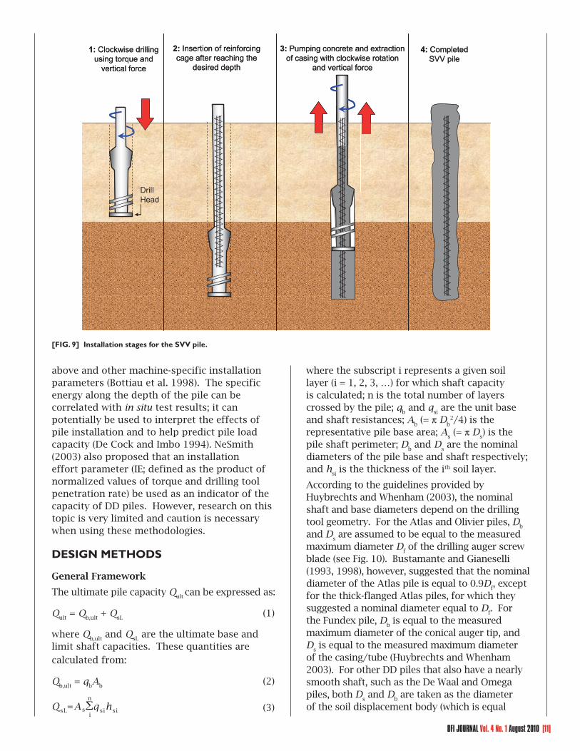
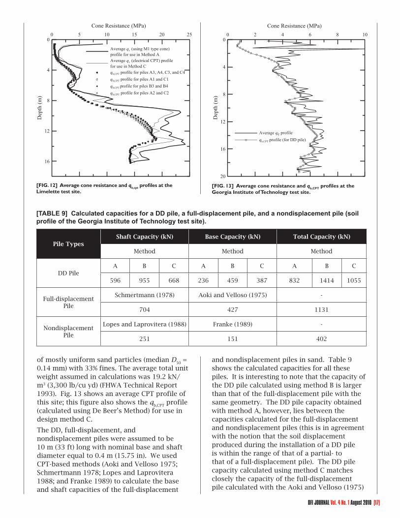
of mostly uniform sand particles (median D50
= 0.14 mm) with 33% fines. The average total unit weight assumed in calculations was 19.2 kN/m3 (3,300 lb/cu yd) (FHWA Technical Report 1993). Fig. 13 shows an average CPT profile of this site; this figure also shows the q
b,CPT profile
(calculated using De Beer’s Method) for use in design method C.
The DD, full-displacement, and nondisplacement piles were assumed to be 10 m (33 ft) long with nominal base and shaft diameter equal to 0.4 m (15.75 in). We used CPT-based methods (Aoki and Velloso 1975; Schmertmann 1978; Lopes and Laprovitera 1988; and Franke 1989) to calculate the base and shaft capacities of the full-displacement
and nondisplacement piles in sand. Table 9 shows the calculated capacities for all these piles. It is interesting to note that the capacity of the DD pile calculated using method B is larger than that of the full-displacement pile with the same geometry. The DD pile capacity obtained with method A, however, lies between the capacities calculated for the full-displacement and nondisplacement piles (this is in agreement with the notion that the soil displacement produced during the installation of a DD pile is within the range of that of a partial- to that of a full-displacement pile). The DD pile capacity calculated using method C matches closely the capacity of the full-displacement pile calculated with the Aoki and Velloso (1975)
[TABLE 9] Calculated capacities for a DD pile, a full-displacement pile, and a nondisplacement pile (soil profi le of the Georgia Institute of Technology test site).
Pile TypesShaft Capacity (kN) Base Capacity (kN) Total Capacity (kN)
Method Method Method
DD PileA B C A B C A B C
596 955 668 236 459 387 832 1414 1055
Full-displacement Pile
Schmertmann (1978) Aoki and Velloso (1975) -
704 427 1131
Nondisplacement Pile
Lopes and Laprovitera (1988) Franke (1989) -
251 151 402
[FIG. 12] Average cone resistance and qb,cpt profi les at the Limelette test site.
16
12
8
4
0D
epth
(m)
0 5 10 15 20 25
Cone Resistance (MPa)
Average qc (using M1 type cone)profile for use in Method AAverage qc (electrical CPT) profile for use in Method Cqb,CPT profile for piles A3, A4, C3, and C4qb,CPT profile for piles A1 and C1qb,CPT profile for piles B3 and B4qb,CPT profile for piles A2 and C2
20
16
12
8
4
0
Dep
th (m
)
0 2 4 6 8 10
Cone Resistance (MPa)
Average qc profileqb,CPT profile (for DD pile)
[FIG. 13] Average cone resistance and qb,CPT profi les at the Georgia Institute of Technology test site.

[18] DFI JOURNAL Vol. 4 No. 1 August 2010
and Schmertmann (1978) methods. Note that general conclusions can not be reached based on the calculations presented in Table 9; they provide only a site-specific comparison of predicted capacities.
SUMMARY AND CONCLUSIONSDrilled displacement piles are increasingly used in geotechnical practice. The advantages of these piles are that their construction is fast, economical and environmentally friendly. Depending on the method of installation, DD piles can be classified as partial-displacement piles, with capacities sometimes approaching that of full-displacement piles.
Pile capacity calculation methods do not always predict field capacities with acceptable accuracy. One of the reasons for the difficulty in making good predictions is that the degree of soil disturbance caused by pile installation cannot be assessed properly in the field. Different DD pile installation methods (with different drilling tools) change the soil state differently, leading to different pile load-carrying capacities. Additionally, for the same degree of soil disturbance, a screw-shaped shaft may develop a larger shaft capacity than a smooth shaft. The design methods described in this paper were developed based on pile load tests performed at particular test sites. Consequently, these methods have biases and may not be applicable to other sites without proper calibration. There is also the need for the design methods to be more precise, going beyond just textbook soils (sand and clay).
In order to illustrate the capabilities of currently available design methods, we used these methods to estimate the capacities of the DD piles load-tested at the Limelette test site in Belgium. Additionally, we compared the capacities of DD, full-displacement and nondisplacement piles for a residual soil profile of granite. The comparisons of the calculated and measured pile capacities show that improvements in the design methods are necessary. In particular, future improvement of DD pile design methods should include (1) parameters that reflect the pile installation method and their impact on the state of the soil around the pile; (2) interaction of the pile and soil in a way that reflects the stress-strain response of the soil; (3) limit states that must be prevented. Development of a database containing in situ test results (performed before and after pile installation) and pile load
test results can help improve the prediction capability and consistency of design methods for DD piles. These load tests should be extended to large pile settlements (certainly in excess of 10% of the pile diameter), the piles should preferably be instrumented (so that, at a minimum, base and shaft resistances may be separated) and the test sites must be well characterized. Modeling of the pile installation process in conjunction with well designed field load tests and systematic monitoring of pile installation is needed for meaningful advances in the analysis and design of DD piles.
ACKNOWLEDGMENTSDr. Irem Zeynep Yildirim assisted with the drafting of some of the figures presented in this paper. The authors greatly appreciate her helpful efforts. The authors also thank the reviewers for their valuable comments.
REFERENCES1. American Pile Driving, Inc.
<americanpiledriving.com > as seen on March 2, 2007.
2. Aoki, N., and Velloso, D. A. 1975. An Approximate Method to Estimate the Bearing Capacity of Piles. Proceedings of the 5th Pan-American Conference of Soil Mechanics and Foundation Engineering, Buenos Aires, Vol. 1, pp. 367–376.
3. Application de l’Eurocode 7 en Belgique : Directives pour le dimensionnement en ELU de pieux sous charge axiale en compression, Version de mars 2008.
4. Bauduin, C. 2001. Design procedure according to Eurocode 7 and analysis of the test results. Screw Piles – Installation and Design in Stiff Clay, Holeyman (ed.), Swets and Zeitlinger, Lisse, pp. 275 – 303.
5. Bottiau, M., 2006. Recent evolutions in deep foundation technologies. Proceedings of the DFI/EFFC 10th International Conference on Piling and Deep Foundations, 2006, Amsterdam, The Netherlands.
6. Bottiau, M., Meyus, I. and Callens, S. 2008. Screw-in energy measurement for on-site control of the bearing capacity of Omega piles. Proceedings of the 7th International Conference and Exhibition on Piling and Deep Foundations, 2008, Vienna, Austria.
7. Brettmann, T. and NeSmith, W., 2005. Advances in auger pressure grouted piles:

DFI JOURNAL Vol. 4 No. 1 August 2010 [19]
design, construction and testing. Advances in Designing and Testing Deep Foundations. Geotechnical Special Publication No. 129, ASCE, pp. 262-274.
8. Brettmann, T., 2003. Constructibility of augured cast-in-place piles. Geo-Strata, 8 – 11.
9. Brown, D. A., 2005. Practical considerations in the selection and use of continuous flight auger and drilled displacement piles. Advances in auger pressure grouted piles: design, construction and testing. Advances in Designing and Testing Deep Foundations. Geotechnical Special Publication No. 129, ASCE, pp. 251-261.
10. Brown, D. A., Dapp, S. D., Thompson, W. R. and Lazarte, C.A. 2007. Design and construction of continuous flight auger piles. FHWA Geotechnical Engineering Circular No. 8. FHWA.
11. Brown, D. and Drew, C., 2000. Axial capacity of augured displacement piles at Auburn University, New Technological and Design Developments in Deep Foundations, Proceedings of sessions of Geo- Denver 2000, Geotechnical Special Publication No. 100, ASCE, pp. 397-403.
12. Bustamante, M. and Gianeselli, L., 1993. Design of auger displacement piles from in-situ tests. Deep Foundations on Bored and Auger Piles, BAP II, Balkema, Rotterdam, pp. 21-34.
13. Bustamante, M. and Gianeselli, L., 1998. Installation parameters and capacity of screwed piles. Deep Foundations on Bored and Auger Piles, BAP III, Balkema, Rotterdam, pp. 95-108.
14. Chin, F. V. 1970. Estimation of ultimate load of piles not carried to failure. Proc. 2nd Southeast Asian Conference on Soil Engineering, 81-90.
15. De Beer, E. Méthodes de déduction de la capacité portante d’un pieu à partir des résultats des essais de pénétration. Bruxelles, Journal des Travaux publics de Belgique, volume 72, no 4 (p. 191-268), no 5 (p. 321-353) & no 6 (p. 351-405), 1971-1972.
16. De Vos, M., Bauduin, C. and Maertens, J. 2003. The current draft of the application rules of Eurocode 7 in Belgium for the design of pile foundations. Belgian Screw Pile Technology – Design and Developments, Maertens and HuyBrechts (eds.), Swets and Zeitlinger, Lisse, pp. 303 – 325.
17. De Cock, F. and Imbo, R., 1994. Atlas screw pile: a vibration-free, full displacement, cast-in-place pile. Transportation Research Record 1447, pp 49-62.
18. FHWA Technical Report No. 41-30-2175. 1993. Axial load-displacement behavior of drilled shaft foundations in piedmont residuum.
19. Fleming, W. G. K. and Thorburn, S., 1983. Recent piling advances, state of the art report. Proceedings of the International Conference on Advances in Piling and Ground Treatment for Foundations, ICE, London, pp 1-16.
20. Franke, E. 1989. Co-report to discussion, session 13: large-diameter piles. 12th International Conference on Soil Mechanics and Foundation Engineering, Rio de Janeiro.
21. Geoforum <http://www.geoforum.com/info/pileinfo/class_list.asp?Method=4> as seen on November 25, 2008.
22. Holeyman, A. E. 2001. Screw piles – installation and design in stiff clay. Proceedings of the Symposium on Screw Piles, Brussels, Belgium. Swets and Zeitlinger B. V., Lisse, The Netherlands.
23. Holeyman, A., Bauduin, C., Bottiau, M., Debacker, P., De Cock, F. A., Dupont, E., Hilde, J. L., Legrand, C., Huybrechts, N., Mengé, P., Miller, J. P., and Simon., G. 2001. Design of axially loaded piles – 1997 Belgian practice. Screw Piles – Installation and Design in Stiff Clay, Holeyman (ed.), Swets and Zeitlinger, Lisse, pp. 63 – 88.
24. HuyBrechts, N. and Whenham V., 2003. Pile testing campaign on the Limelette test site and installation techniques of screw piles. Belgian Screw Pile Technology – Design and Developments, Maertens and HuyBrechts (eds.), Swets and Zeitlinger, Lisse, pp. 71 – 130.
25. Lopes, F. R., and Laprovitera, H. (1988). On the Prediction of the Bearing Capacity of Bored Piles from Dynamic Penetration Tests. Deep Foundations on Bored and Auger Piles, W. Van Impe (ed.), Balkema, Rotterdam, pp. 537–540.
26. Maertens, J. and Huybrechts, N., 2003a. Results of the static pile load tests at the Limelette test site. Belgian Screw Pile Technology – Design and Developments, Maertens and HuyBrechts (eds.), Swets and Zeitlinger, Lisse, pp. 167 – 214.

[20] DFI JOURNAL Vol. 4 No. 1 August 2010
27. Maertens, J., and Huybrechts, N. 2003b. Belgian screw pile technology design and recent developments. Proceedings of the 2nd Symposium on Screw Piles, Brussels, Belgium. Swets and Zeitlinger B. V., Lisse, The Netherlands.
28. Mandolini, A., Ramodini, M., Russo, G. and Viggiani, C., 2002. Full scale loading tests on instrumented CFA piles. Proceedings of the International Deep Foundations Congress 2002, Geotechnical Special Publication No. 116, Vol. 2, ASCE, pp. 1088-1097.
29. NeSmith, W. M., 2002. Static capacity analysis of augured, pressure-injected displacement piles. Proceedings of the International Deep Foundations Congress 2002, Geotechnical Special Publication No. 116, Vol. 2, ASCE, pp. 1174-1186.
30. NeSmith, W. M., 2003. Installation effort as an indicator of screw pile capacity. Proceedings of Deep Foundations on Bored and Augered Piles (BAPIV), Van Impe (ed.), Rotterdam: Millpress, pp. 177-181.
31. NeSmith, W. M., and NeSmith, W. M. 2006a. Anatomy of a data acquisition system for drilled displacement piles. Proceedings of the GeoConGress 2006: Geotechnical engineering in the information technology age, ASCE, pp. 1-6.
32. NeSmith, W. M., and NeSmith, W. M. 2006b. Application of data acquired during drilled displacement pile installation. Proceedings of the GeoConGress 2006: Geotechnical engineering in the information technology age, ASCE.
33. NeSmith, W. M., 2003. Advancements in data acquisition based design for drilled displacement piles. Contemporary Topics in Deep Foundations: Geotechnical Special Publication No. 185, ASCE, pp. 447-455.
34. Prezzi, M. and Basu, P. 2005. Overview of construction and design of auger cast-in-place and drilled displacement piles. Proceedings of DFI’s 30th annual conference on deep foundations, Chicago, U.S.A., pp. 497 – 512.
35. Siegel, T. C., NeSmith, W. M., NeSmith, W. M., and Cargill, P. E. 2007. Ground improvement resulting from installation of drilled displacement piles. Proceedings of DFI’s 32nd annual conference on deep foundations, Colorado Springs, U.S.A., pp. 129-138.
36. Schmertmann, J.H. 1978. Guidelines for Cone Penetration Test, Performance and Design. U.S. Department of Transportation, FHWA-TS-78-209.
37. Van Alboom, G. and Whenham, V., 2003. Soil investigation campaign at Limelette (Belgium): results, Belgian Screw Pile Technology – Design and Recent Developments, Maertens and HuyBrechts (eds.), Swets and Zeitlinger, Lisse, pp. 21 – 70.
38. Van Impe, W. F. (1986). Evaluation of deformation and bearing capacity parameters of foundations, from static CPT-results. Proceedings of the Fourth International Geotechnical Seminar: Field Instrumentation and In Situ Measurements, NTI, Singapore, pp 51-70.
39. Van Impe, W. F. (1988). Considerations in the auger pile design. Proceedings of the 1st International Geotechnical Seminar on Deep Foundations on Bored and Auger Piles, BAP I, Balkema, Rotterdam, pp. 193-217.
40. Van Impe, W. F. (2004). Two decades of full scale research on screw piles : An overview. Published by The Laboratory of Soil Mechanics, Ghent University, Belgium.
41. Van Impe, W. F., De Beer, E., and Lousberg, E. (1988). Prediction of the single pile bearing capacity in granular soils out of CPT results. Proceedings of the International Symposium on Penetration Testing (ISOPT I), Speciality Session, Orlando, pp 1-34.