mechanisms of setup of displacement piles in sand: laboratory creep tests
TRANSCRIPT
Mechanisms of setup of displacement piles insand: laboratory creep tests
Elisabeth T. Bowman and Kenichi Soga
Abstract: A series of triaxial creep tests is described, with the aim of shedding light on the mechanisms behind dis-placement pile setup in granular soils. The stress path leading to the creep stages has been designed to mimic, as far aspossible, the installation of a pile adjacent to an element of soil. A complex strain response is found with creep indense sands at high stress ratio, with rotation of the creep strain vector over time. A new hypothesis, involving kine-matically restrained dilation of the soil close to the pile shaft and soil ageing, is proposed to explain pile setup. Influ-ences on the creep behaviour, and hence degree of setup, are found to be particle shape and strength, relative density,and rate of loading. The application of small cyclic perturbations during creep is found to accelerate the onset of volu-metric dilation and hence is proposed to accelerate setup.
Key words: creep, setup, displacement piles, laboratory testing, sands.
Résumé : On décrit une série d’essais triaxiaux réalisés dans le but d’apporter un certain éclairage sur le mécanismequi sous-tend la mise en place d’un pieu à déplacement dans des sols granulaires. Le chemin des contraintes condui-sant aux stades de fluage a été conçu pour imiter autant que possible l’installation d’un pieu adjacent à un élément desol. On trouve une réponse complexe à la déformation avec du fluage dans les sables denses sous un haut rapport decontrainte, avec une rotation en fonction du temps du vecteur de déformation en fluage. Une nouvelle hypothèse estproposée pour expliquer la mise en place du pieu, et qui implique une dilatation restreinte en terme cinématique du solprès du fût du pieu et le vieillissement du sol. On trouve que les influences sur le comportement en fluage, et parconséquent sur le degré de mise en place sont la forme et la résistance des particules, la densité relative, et la vitessede chargement. On trouve que l’application de faibles perturbations cycliques durant le fluage accélère l’apparition dela dilatation volumétrique, et par conséquent, on propose d’accélérer la mise en place.
Mots clés : fluage, mise en place, pieux à déplacement, essai de laboratoire, sables.
[Traduit par la Rédaction] Bowman and Soga 1407
Introduction
Soil “ageing” is a process whereby recently disturbed ordeposited granular soils gain stiffness and strength over timeat constant effective stress. The ageing phenomenon is oftenmanifested as an increase in the resistance of granular fills(Mitchell and Solymar 1984; Thomann and Hryciw 1992;Ng et al. 1998). There are also cited cases of granular soilslosing strength as a result of disturbance, even when the resultis a denser soil. In these cases, the soil is sometimes termedsensitive (Mitchell and Solymar 1984; York et al. 1994).
A phenomenon linked to ageing is the observed increasein displacement pile capacity over time in granular soils. Ca-pacities have been found to typically double over 6 months(Chow 1997; Jardine and Standing 1999), although this ef-fect is highly variable (from 20% to 170%/log cycle of time).This process is known as pile setup and has been found tocontinue for up to 5 years, long after pore pressures have
dissipated. Various cases are reported in the literature, andthese cases have been comprehensively reviewed by Chowet al. (1998) and Axelsson (2000).
Key field observationsBelow is listed a number of key observations that have
been made on setup:(i) Setup has been reported in strong silica sands but not in
weaker calcareous sands (e.g., Mello and Galgoul 1992),suggesting that particle strength is a major factor in pilesetup.
(ii) Piles in denser, finer sands and silts set up more thanthose in looser, coarser sands and gravels (York et al.1994). This tendency may be due to a greater number ofinterparticle contacts or to the greater strength ofsmaller particles, which possess fewer flaws (McDowelland Bolton 1998). In this way, the effect of particle sizeis inherently linked to that of particle strength.
Can. Geotech. J. 42: 1391–1407 (2005) doi: 10.1139/T05-063 © 2005 NRC Canada
1391
Received 14 November 2004. Accepted 22 June 2005. Published on the NRC Research Press Web site at http://cgj.nrc.ca on7 October 2005.
E.T. Bowman1,2 and K. Soga. The Schofield Centre, Cambridge University Engineering Department, Trumpington Street,Cambridge CB2 1PZ, UK.
1Corresponding author (e-mail: [email protected]).2Present address: Department of Civil Engineering, Canterbury University, Private Bag 4800, Christchurch, New Zealand.
(iii) Piles have been found to set up both above and belowthe water line, with concrete, steel, and timber piles allproducing time-dependent gains in capacity (e.g.,Tavernas and Audy 1972; Chow et al. 1998). This find-ing suggests that water, acting as either a chemical re-agent or a lubricant, has little influence on pile setup.
(iv) There is sometimes a delay observed in the commence-ment of setup, beyond a period when pore pressureswould be expected to dissipate (Axelsson 2000).
(v) Setup tends not to occur in the top 3 m of ground (e.g.,Samson and Authier 1986).
MechanismsWhen a pile is loaded to failure, the radial stress on the
pile at failure, σf, can be written as
[1] σ f = σr + δσr
where σr is the at-rest radial stress acting on the pile beforepile loading; and δσr is the change in radial stress acting onthe pile during pile reloading after installation. Furthermore,δσr has been found to be largely due to dilation during pileloading.
Using cavity expansion theory, Lehane and Jardine (1994)showed that
[2] δσr = 2δhG/R
where δh is the radial displacement during loading; G is thesoil shear modulus; and R is the pile radius.
Setup may be considered the summation of two processesrelated to the above equations. The first directly involves soilcreep under at-rest conditions, resulting in an increase in ra-dial stress, σr(t), around the pile with time. The second in-volves soil ageing, which is manifested as an increase in soilstiffness with time, G(t), greater than that accounted for by adecrease in soil volume (e.g., Anderson and Stokoe 1978),resulting in an increase in the change of radial stress duringloading, δσr(t).
Axelsson (2000) and Chow et al. (1998) attributed pilesetup to both soil stiffness change, resulting in a change in σrwith time (i.e., creep mechanism), and a change in δσr withtime (i.e., ageing mechanism), but they disagree on which isdominant.
Ageing mechanismOn the basis of the results of direct shear tests on aged
sand samples, Chow et al. (1998) stated that ageing couldonly account for 30% of setup. However, the ageing of sam-ples in those tests was undertaken at the K0 condition with-out additional shear, and it has been found that theapplication of shear stress is necessary for a soil to exhibit“sensitivity” (i.e., a loss of strength, followed by recoverywith time) or slow strengthening (Thomann and Hryciw1992; Losert et al. 2000). In contrast, following tests on full-scale instrumented piles, Axelsson (2000) found a greater in-crease in δσr during reloading (contributing to 65% of setup)of piles than of the at-rest radial stress, σr (contributing to35% of setup) with time.
Although the authors of this paper believe that ageing sig-nificantly contributes to pile setup, this topic was discussedin a previous paper that dealt with the micromechanics be-
hind soil ageing (Bowman and Soga 2003). Hence, theageing process is not discussed in detail here.
Creep mechanismMeasurements made during model pile-jacking investiga-
tions have shown that the radial stress, σr, increases around apile for some time after pile installation (Ng et al. 1988;Axelsson 2000). Åstedt et al. (1992) and Chow et al. (1998)postulated that the breakdown with time of hoop stressesgenerated via a loosening of soil around the pile during theinstallation process is responsible for the increase in σr.
This mechanism is plausible. Calibration chamber tests onmodel piles conducted by White and Bolton (2004) sug-gested that radial stress caused by cavity collapse due tofriction fatigue may indeed cause a lower radial stress closeto the pile than farther out, which may then equalize overtime. However, their results also suggest that this tendencyshould lead to greater pile setup at the top of the pile (wheremore cavity collapse has occurred) than at the base. This re-sult is not seen in field studies (Samson and Authier 1986;Chow et al. 1998).
The hoop stress breakdown hypothesis also suggests thatsetup should commence immediately after pore pressureshave dissipated. This is not borne out by field or model testdata (Tomlinson 1996; Zhao 2002), which suggest there isoften a delay before setup commences.
Tests undertaken by Axelsson (2000) on torsionallyloaded, driven instrumented rods in sand suggest an alterna-tive mechanism. He found an increasing maximum torquewith time that contrasts with typical pile setup under verticalload, which tends to level off with time. This suggests that ahoop stress is not the required precursor to setup, but that,instead, a form of disturbance coupled with shear stress ap-plication in the direction of subsequent loading is moreimportant. A more complex helical transmission of load be-tween particles in the torsional case may result in a differentsetup rate with time than in vertically loaded piles.
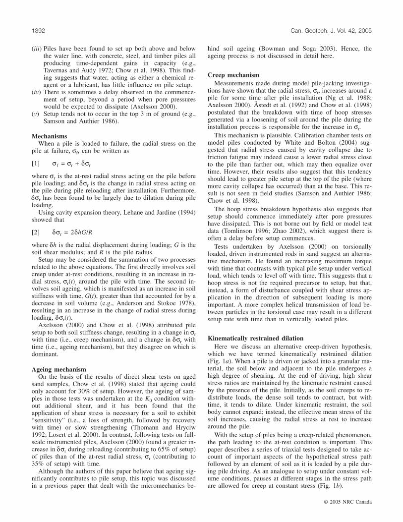
Kinematically restrained dilationHere we discuss an alternative creep-driven hypothesis,
which we have termed kinematically restrained dilation(Fig. 1a). When a pile is driven or jacked into a granular ma-terial, the soil below and adjacent to the pile undergoes ahigh degree of shearing. At the end of driving, high shearstress ratios are maintained by the kinematic restraint causedby the presence of the pile. Initially, as the soil creeps to re-distribute loads, the dense soil tends to contract, but withtime, it tends to dilate. Under kinematic restraint, the soilbody cannot expand; instead, the effective mean stress of thesoil increases, causing the radial stress at rest to increasearound the pile.
With the setup of piles being a creep-related phenomenon,the path leading to the at-rest condition is important. Thispaper describes a series of triaxial tests designed to take ac-count of important aspects of the hypothetical stress pathfollowed by an element of soil as it is loaded by a pile dur-ing pile driving. As an analogue to setup under constant vol-ume conditions, pauses at different stages in the stress pathare allowed for creep at constant stress (Fig. 1b).
© 2005 NRC Canada
1392 Can. Geotech. J. Vol. 42, 2005
Stress path during displacement pileinstallation
BackgroundThe stress path for pile installation via the displacement
method is a particularly challenging one to quantify. How-ever, to investigate post-installation creep in the laboratory, itis necessary to attempt to mimic that stress path as far aspossible. To this end, finite-element analyses, distinct-element method analyses, and physical model tests on deeppenetration mechanisms conducted by Baligh (1985), Huanget al. (1993), and White and Bolton (2004) were examined(see Bowman (2002), for details).
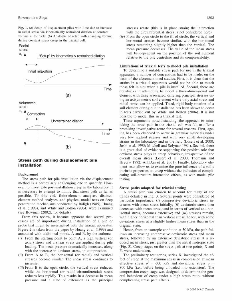
From this review, it became apparent that several pro-cesses are of importance during installation of a pile orprobe that might be investigated with the triaxial apparatus.Figure 2 is taken from the paper by Huang et al. (1993) andannotated with additional points, A and B, by the authors:(i) From the starting point to point A, a high vertical (or
axial) stress and a shear stress are applied during pileloading. The mean pressure dramatically increases, alongwith the increase in deviator stress, in compression.
(ii) From A to B, the horizontal (or radial) and verticalstresses become similar. The shear stress continues toincrease.
(iii) From B to the open circle, the vertical stress reduces,while the horizontal (or radial–circumferential) stressreduces less rapidly. This results in a decrease in meanpressure and a state of extension as the principal
stresses rotate (this is in plane strain; the interactionwith the circumferential stress is not considered here).
(iv) From the open circle to the filled circle, the vertical andhorizontal stresses become similar, with the horizontalstress remaining slightly higher than the vertical. Themean pressure decreases. The value of the mean stresswill be dependent on the position of the soil elementrelative to the pile centreline and its compressibility.
Limitations of triaxial tests to model pile installationTo determine a suitable stress path for use in the triaxial
apparatus, a number of concessions had to be made, on thebasis of the aforementioned studies. First, it is clear that thestrains in a triaxial apparatus would not be able to matchthose felt in situ when a pile is installed. Second, there aredrawbacks in attempting to model a three-dimensional soilelement with three associated, differing principal stresses us-ing an axisymmetric soil element where only axial stress andradial stress can be applied. Third, rigid body rotation of asoil element during pile installation has been shown to occurin tests carried out by White and Bolton (2004). It is notpossible to model this in a triaxial test.
These arguments notwithstanding, the approach to mim-icking the stress path in the triaxial cell was felt to offer apromising investigative route for several reasons. First, age-ing has been observed to occur in granular materials undervery low applied stresses and with very small developingstrains in the laboratory and in the field (Losert et al. 2000;Joshi et al. 1995; Mitchell and Solymar 1984). Second, thereis a great deal of evidence supporting the positive role thatdeviator stress plays in creep behaviour, irrespective of theoverall mean stress (Losert et al. 2000; Thomann andHryciw 1992; AnhDan et al. 2001). Finally, laboratory ele-ment tests allow us to examine the pure influence of a soil’sintrinsic properties on creep without the inclusion of compli-cating soil–structure interaction effects, as with model piletesting.
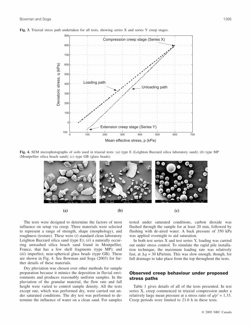
Stress paths adopted for triaxial testingA stress path was chosen to account for many of the
trends detailed in Fig. 3. Several points were considered ofparticular importance: (i) compressive deviatoric stress in-creases with mean stress initially; (ii) deviatoric stress thendecreases with mean stress, and in terms of vertical and hor-izontal stress, becomes extensive; and (iii) stresses remain,with higher horizontal than vertical stress, hence, with somedeviatoric stress at a slightly higher mean stress than in theoriginal state.
Hence, from an isotropic condition at 50 kPa, the path fol-lows an increasing compressive deviatoric stress and meanstress, followed by an extensive deviatoric stress at a re-duced mean stress, just greater than the initial isotropic state(Fig. 3). Creep stages on the stress path at two points, X andY, were undertaken.
The preliminary test series, series X, investigated the ef-fect of creep at the maximum stress in compression at meaneffective stress p′ = 600 kPa and deviatoric stress q =800 kPa (i.e., before being unloaded into extension). Thecompression creep stage was designed to determine the gen-eral behaviour of creep under a high stress ratio, withoutcomplicating stress path effects.
© 2005 NRC Canada
Bowman and Soga 1393
Fig. 1. (a) Setup of displacement piles with time due to increasein radial stress via kinematically restrained dilation at constantvolume in the field. (b) Analogue of setup with changing volumeduring constant stress creep in the triaxial cell.
The main test series, series Y, investigated long-termcreep in extension at p′ = 100 kPa and q = –75 kPa, after theloading and unloading stress path. This test series was tosimulate an element of soil being loaded and sheared by theapproach of the pile, before being unloaded and sheared intoa state of extension as the pile tip passed. The creep stagesimulated an element of soil close to the shaft of the pileover time.
Test procedure and materials
The triaxial system uses a hydraulic Bishop and Wesleystress path cell connected to three GDS digital pressure con-trollers (DPCs) (GDS Instruments, UK), linked to a personalcomputer. The DPCs include an axial load or displacementcontroller, a cell pressure controller, and a back pressurecontroller. The pressure controllers regulate pressure withfeedback from the axial load, displacement, and pore pres-sure transducers; these also provide data logging. The porepressure transducer is situated in the base pedestal. Drainageis via the top cap.
The apparatus can perform tests in both triaxial compres-sion and extension, using an extension cap and sleeve.Strains to the sample were measured locally. Two submers-ible linear variable displacement transducers (LVDTs) werelocated within the cell, on either side of the sample, to mea-sure axial strains. The LVDTs (model RDP-DW5, RDPElectronics, UK) had been modified for use in the triaxialcell, as described by Cuccovillo and Coop (1997). EachLVDT had an internal, free-moving reaction pin and wasmounted on the sample via a holder glued to the membrane.
To measure local radial strains, proximity (PX) sensorswere used. The PX sensors were placed within the cell 0.5–1.5 mm from each side of the sample, facing a metal (brassor aluminium) target attached to the sample. Each sensorwas calibrated against the specific target to be used. The twoPX sensor – and amplifier systems used in this study wereAS-440 (Keyence Corp.) and KD-2300–2UB1 (Kaman In-strumentation). Cell pressure sensitivity of the PX sensordata was found to be repeatable and was corrected for in theloading and unloading stages by calibrating against the pres-sure.
© 2005 NRC Canada
1394 Can. Geotech. J. Vol. 42, 2005
Fig. 2. Penetrating induced stress paths at 1.5 diameters (No. 1) and 2.5 diameters (No. 2) from probe centreline for a simulated conepenetration test in uncrushable granular material (after Huang et al. 1993). Note: dy /R is horizontal displacement normalized by proberadius; dz /R is vertical displacement normalized by probe radius; σvc is vertical consolidation stress under K0 conditions; σyy is hori-zontal stress; σyz is shear stress; and σzz is vertical stress.
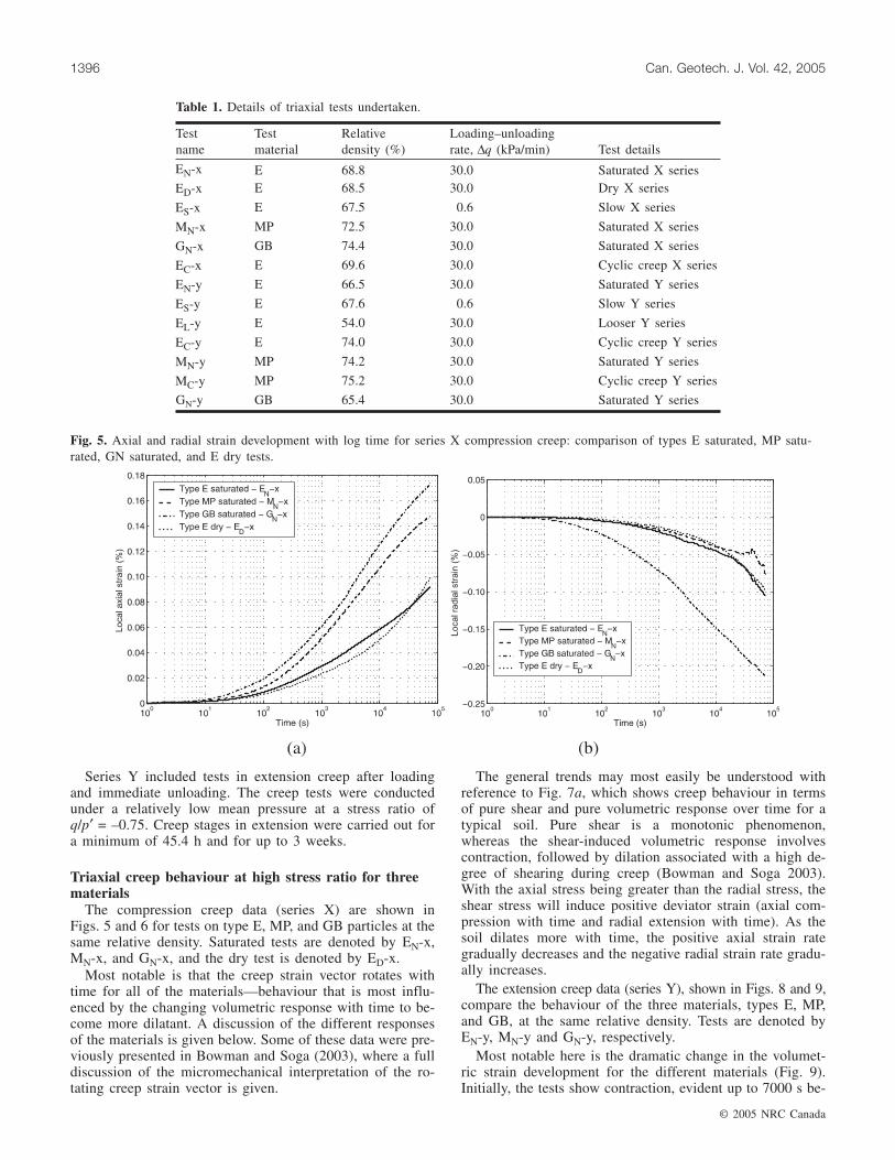
The tests were designed to determine the factors of mostinfluence on setup via creep. Three materials were selectedto represent a range of strength, shape (morphology), androughness (texture). These were (i) standard clean laboratoryLeighton Buzzard silica sand (type E); (ii) a naturally occur-ring unwashed silica beach sand found in Montpellier,France, that has a few shell fragments (type MP); and(iii) imperfect, near-spherical glass beads (type GB). Theseare shown in Fig. 4. See Bowman and Soga (2003) for fur-ther details of these materials.
Dry pluviation was chosen over other methods for samplepreparation because it mimics the deposition in fluvial envi-ronments and produces reasonably uniform samples. In thepluviation of the granular material, the flow rate and fallheight were varied to control sample density. All the testsexcept one, which was performed dry, were carried out un-der saturated conditions. The dry test was performed to de-termine the influence of water on a clean sand. For samples
tested under saturated conditions, carbon dioxide wasflushed through the sample for at least 20 min, followed byflushing with de-aired water. A back pressure of 350 kPawas applied overnight to aid saturation.
In both test series X and test series Y, loading was carriedout under stress control. To simulate the rapid pile installa-tion technique, the maximum loading rate was relativelyfast, at ∆q = 30 kPa/min. This was slow enough, though, forfull drainage to take place from the top throughout the tests.
Observed creep behaviour under proposedstress paths
Table 1 gives details of all of the tests presented. In testseries X, creep commenced in triaxial compression under arelatively large mean pressure at a stress ratio of q/p′ = 1.33.Creep periods were limited to 21.6 h in these tests.
© 2005 NRC Canada
Bowman and Soga 1395
Fig. 3. Triaxial stress path undertaken for all tests, showing series X and series Y creep stages.
Fig. 4. SEM microphotographs of soils used in triaxial tests: (a) type E (Leighton Buzzard silica laboratory sand); (b) type MP(Montpellier silica beach sand); (c) type GB (glass beads).
Series Y included tests in extension creep after loadingand immediate unloading. The creep tests were conductedunder a relatively low mean pressure at a stress ratio ofq/p′ = –0.75. Creep stages in extension were carried out fora minimum of 45.4 h and for up to 3 weeks.
Triaxial creep behaviour at high stress ratio for threematerials
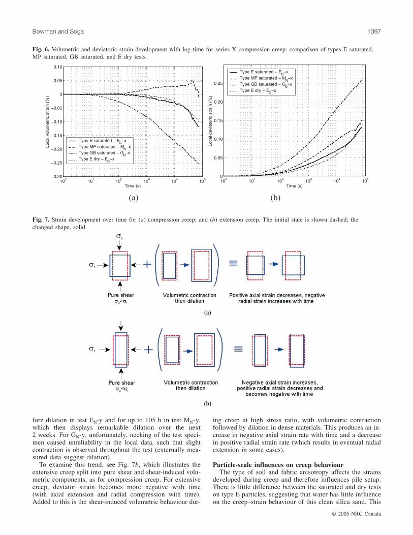
The compression creep data (series X) are shown inFigs. 5 and 6 for tests on type E, MP, and GB particles at thesame relative density. Saturated tests are denoted by EN-x,MN-x, and GN-x, and the dry test is denoted by ED-x.
Most notable is that the creep strain vector rotates withtime for all of the materials—behaviour that is most influ-enced by the changing volumetric response with time to be-come more dilatant. A discussion of the different responsesof the materials is given below. Some of these data were pre-viously presented in Bowman and Soga (2003), where a fulldiscussion of the micromechanical interpretation of the ro-tating creep strain vector is given.
The general trends may most easily be understood withreference to Fig. 7a, which shows creep behaviour in termsof pure shear and pure volumetric response over time for atypical soil. Pure shear is a monotonic phenomenon,whereas the shear-induced volumetric response involvescontraction, followed by dilation associated with a high de-gree of shearing during creep (Bowman and Soga 2003).With the axial stress being greater than the radial stress, theshear stress will induce positive deviator strain (axial com-pression with time and radial extension with time). As thesoil dilates more with time, the positive axial strain rategradually decreases and the negative radial strain rate gradu-ally increases.
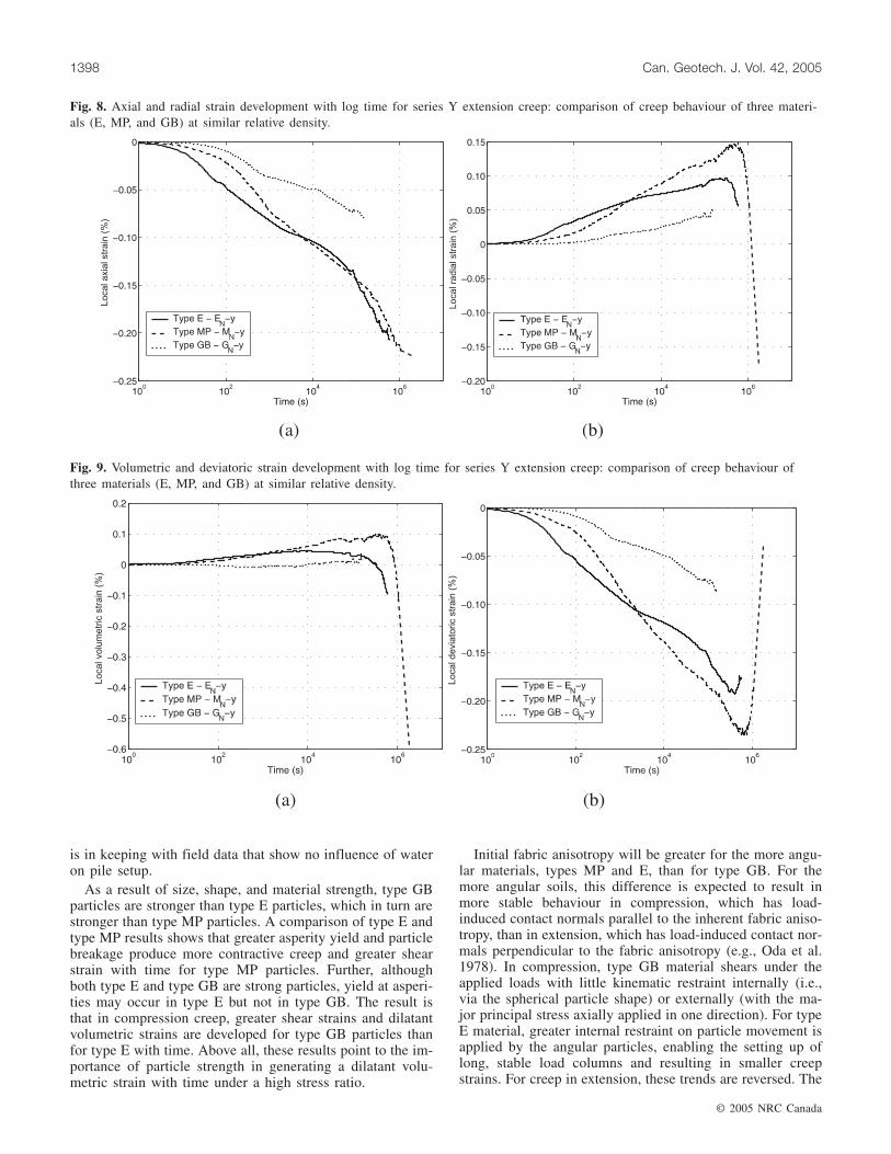
The extension creep data (series Y), shown in Figs. 8 and 9,compare the behaviour of the three materials, types E, MP,and GB, at the same relative density. Tests are denoted byEN-y, MN-y and GN-y, respectively.
Most notable here is the dramatic change in the volumet-ric strain development for the different materials (Fig. 9).Initially, the tests show contraction, evident up to 7000 s be-
© 2005 NRC Canada
1396 Can. Geotech. J. Vol. 42, 2005
Testname
Testmaterial
Relativedensity (%)
Loading–unloadingrate, ∆q (kPa/min) Test details
EN-x E 68.8 30.0 Saturated X seriesED-x E 68.5 30.0 Dry X series
ES-x E 67.5 0.6 Slow X series
MN-x MP 72.5 30.0 Saturated X series
GN-x GB 74.4 30.0 Saturated X series
EC-x E 69.6 30.0 Cyclic creep X series
EN-y E 66.5 30.0 Saturated Y series
ES-y E 67.6 0.6 Slow Y series
EL-y E 54.0 30.0 Looser Y series
EC-y E 74.0 30.0 Cyclic creep Y series
MN-y MP 74.2 30.0 Saturated Y series
MC-y MP 75.2 30.0 Cyclic creep Y series
GN-y GB 65.4 30.0 Saturated Y series
Table 1. Details of triaxial tests undertaken.
Fig. 5. Axial and radial strain development with log time for series X compression creep: comparison of types E saturated, MP satu-rated, GN saturated, and E dry tests.
fore dilation in test EN-y and for up to 105 h in test MN-y,which then displays remarkable dilation over the next2 weeks. For GN-y, unfortunately, necking of the test speci-men caused unreliability in the local data, such that slightcontraction is observed throughout the test (externally mea-sured data suggest dilation).
To examine this trend, see Fig. 7b, which illustrates theextensive creep split into pure shear and shear-induced volu-metric components, as for compression creep. For extensivecreep, deviator strain becomes more negative with time(with axial extension and radial compression with time).Added to this is the shear-induced volumetric behaviour dur-
ing creep at high stress ratio, with volumetric contractionfollowed by dilation in dense materials. This produces an in-crease in negative axial strain rate with time and a decreasein positive radial strain rate (which results in eventual radialextension in some cases).
Particle-scale influences on creep behaviourThe type of soil and fabric anisotropy affects the strains
developed during creep and therefore influences pile setup.There is little difference between the saturated and dry testson type E particles, suggesting that water has little influenceon the creep–strain behaviour of this clean silica sand. This
© 2005 NRC Canada
Bowman and Soga 1397
Fig. 6. Volumetric and deviatoric strain development with log time for series X compression creep: comparison of types E saturated,MP saturated, GB saturated, and E dry tests.
Fig. 7. Strain development over time for (a) compression creep; and (b) extension creep. The initial state is shown dashed; thechanged shape, solid.
is in keeping with field data that show no influence of wateron pile setup.
As a result of size, shape, and material strength, type GBparticles are stronger than type E particles, which in turn arestronger than type MP particles. A comparison of type E andtype MP results shows that greater asperity yield and particlebreakage produce more contractive creep and greater shearstrain with time for type MP particles. Further, althoughboth type E and type GB are strong particles, yield at asperi-ties may occur in type E but not in type GB. The result isthat in compression creep, greater shear strains and dilatantvolumetric strains are developed for type GB particles thanfor type E with time. Above all, these results point to the im-portance of particle strength in generating a dilatant volu-metric strain with time under a high stress ratio.
Initial fabric anisotropy will be greater for the more angu-lar materials, types MP and E, than for type GB. For themore angular soils, this difference is expected to result inmore stable behaviour in compression, which has load-induced contact normals parallel to the inherent fabric aniso-tropy, than in extension, which has load-induced contact nor-mals perpendicular to the fabric anisotropy (e.g., Oda et al.1978). In compression, type GB material shears under theapplied loads with little kinematic restraint internally (i.e.,via the spherical particle shape) or externally (with the ma-jor principal stress axially applied in one direction). For typeE material, greater internal restraint on particle movement isapplied by the angular particles, enabling the setting up oflong, stable load columns and resulting in smaller creepstrains. For creep in extension, these trends are reversed. The
© 2005 NRC Canada
1398 Can. Geotech. J. Vol. 42, 2005
Fig. 8. Axial and radial strain development with log time for series Y extension creep: comparison of creep behaviour of three materi-als (E, MP, and GB) at similar relative density.
Fig. 9. Volumetric and deviatoric strain development with log time for series Y extension creep: comparison of creep behaviour ofthree materials (E, MP, and GB) at similar relative density.
soil samples are more kinematically restrained externally, asa result of the major principal stress being applied in two di-rections radially (Santamarina 2003). The spherical shape ofthe type GB particles does not offer many options for shear-ing without dilation, whereas for type E material, the angu-lar shape of the particles allows continued movementbecause of asperity yield and void collapse. In addition, thegreater initial fabric anisotropy of type E material (due topluviation), which gave greater resistance to change in com-pression creep, now gives less resistance in extension creep.The result is greater deviatoric strain development with timein extension for type E material than for type GB. This re-sult suggests that the angularity of soil particles is importantin relieving kinematic restraint. Hence, following the re-strained dilation setup hypothesis, it might be expected thatstrong, angular particles would produce a faster rate of pilesetup than strong, rounded particles. It should be noted,however, that the pile installation process may modify theparticle shape extensively, making this hypothesis hard toverify.
The results show the complexities in creep behaviour gen-erated by different particle shapes and strengths. It is clearthat small, strong particles result in greater dilatant volumet-ric creep, which via kinematically restrained dilation wouldlead to greater setup. Dilatant creep is generally preceded,however, by a period of contractive creep, the length ofwhich is dependent on particle-scale characteristics, as wellas relative density. These findings are in agreement withfield and model test data on setup of piles in dense sands,where greater setup is found in finer grained soils consistingof stronger materials and where sometimes a delay or even areduction in pile capacity is seen in the first few days beforesetup commences (Tomlinson 1996; Axelsson 2000; Zhao2002).
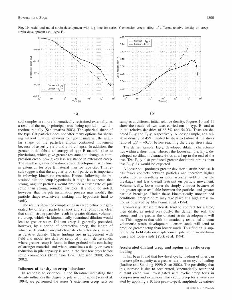
Influence of density on creep behaviourIn response to evidence in the literature indicating that
density influences the degree of pile setup in sands (York et al.1994), we performed the series Y extension creep tests on
samples at different initial relative density. Figures 10 and 11show the results of two tests carried out on type E sand atinitial relative densities of 66.5% and 54.0%. Tests are de-noted EN-y and EL-y, respectively. A looser sample, at a rel-ative density of 45%, tended to shear to failure at the stressratio of q/p′ = –0.75, before reaching the creep stress state.
The denser sample, EN-y, developed dilatant characteris-tics within a short time, whereas the looser sample, EL-y, de-veloped no dilatant characteristics at all up to the end of thetest. Test EL-y also produced greater deviatoric strains thantest EN-y, as would be expected.
A looser soil produces greater deviatoric strain because ithas fewer contacts between particles and therefore highercontact forces (resulting in more asperity yield or particlebreakage) and less overall restraint on particle movement.Volumetrically, loose materials simply contract because ofthe greater space available between the particles and greaterparticle breakage. Under these kinematically unrestrainedconditions, creep rupture may take place at a high stress ra-tio, as observed by Murayama et al. (1984).
Conversely, denser materials tend to contract for a time,then dilate, as noted previously: the denser the soil, thesooner and the greater the dilatant strain development willbe. This suggests that with kinematically restrained dilatantvolumetric strain development, denser sands will tend toproduce greater setup than looser sands. This finding is sup-ported by field data on displacement pile setup in medium-dense and loose sands (York et al. 1994).
Accelerated dilatant creep and ageing via cyclic creeploading
It has been found that low-level cyclic loading of piles canincrease pile capacity at a greater rate than no cyclic loading(Jardine and Standing 1999; Zhao 2002). The possibility thatthis increase is due to accelerated, kinematically restraineddilatant creep was investigated with cyclic creep tests incompression and extension. The cyclic creep tests were cre-ated by applying a 10 kPa peak-to-peak amplitude deviatoric
© 2005 NRC Canada
Bowman and Soga 1399
Fig. 10. Axial and radial strain development with log time for series Y extension creep: effect of different relative density on creepstrain development (soil type E).
© 2005 NRC Canada
1400 Can. Geotech. J. Vol. 42, 2005
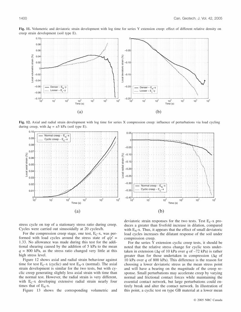
stress cycle on top of a stationary stress ratio during creep.Cycles were carried out sinusoidally at 20 cycles/h.
For the compression creep stage, one test, EC-x, was per-formed with load cycles around the stress state of q/p′ =1.33. No allowance was made during this test for the addi-tional shearing caused by the addition of 5 kPa to the meanq = 800 kPa, as the stress ratio changed very little at thishigh stress level.
Figure 12 shows axial and radial strain behaviour againsttime for test EC-x (cyclic) and test EN-x (normal). The axialstrain development is similar for the two tests, but with cy-clic creep generating slightly less axial strain with time thanthe normal test. However, the radial strain is very different,with EC-x developing extensive radial strain nearly fourtimes that of EN-x.
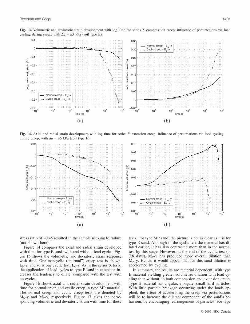
Figure 13 shows the corresponding volumetric and
deviatoric strain responses for the two tests. Test EC-x pro-duces a greater than fivefold increase in dilation, comparedwith EN-x. Thus, it appears that the effect of small deviatoricload cycles increases the dilatant response of the soil undercompression creep.
For the series Y extension cyclic creep tests, it should benoted that the relative stress change for cyclic tests under-taken in extension (∆q of 10 kPa over q of –72 kPa) is rathergreater than for those undertaken in compression (∆q of10 kPa over q of 800 kPa). This difference is the reason forchoosing a lower deviatoric stress as the mean stress pointand will have a bearing on the magnitude of the creep re-sponse. Small perturbations may accelerate creep by varyingnormal and frictional contact forces while maintaining theessential contact network, but large perturbations could en-tirely break and alter the contact network. In illustration ofthis point, a cyclic test on type GB material at a lower mean
Fig. 12. Axial and radial strain development with log time for series X compression creep: influence of perturbations via load cyclingduring creep, with ∆q = ±5 kPa (soil type E).
Fig. 11. Volumetric and deviatoric strain development with log time for series Y extension creep: effect of different relative density oncreep strain development (soil type E).
stress ratio of –0.45 resulted in the sample necking to failure(not shown here).
Figure 14 compares the axial and radial strain developedwith time for type E sand, with and without load cycles. Fig-ure 15 shows the volumetric and deviatoric strain responsewith time. One noncyclic (“normal”) creep test is shown,EN-y, and so is one cyclic test, EC-y. As in the series X tests,the application of load cycles to type E sand in extension in-creases the tendency to dilate, compared with the test withno cycles.
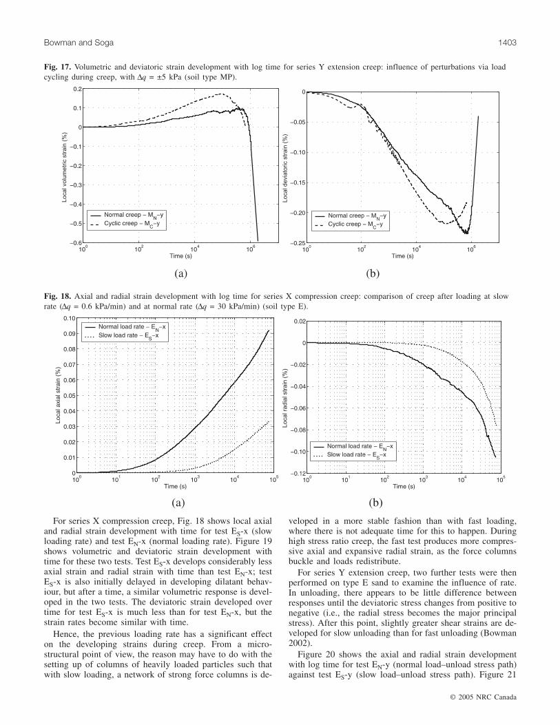
Figure 16 shows axial and radial strain development withtime for normal creep and cyclic creep in type MP material.The normal creep and cyclic creep tests are denoted byMN-y and MC-y, respectively. Figure 17 gives the corre-sponding volumetric and deviatoric strain with time for these
tests. For type MP sand, the picture is not as clear as it is fortype E sand. Although in the cyclic test the material has di-lated earlier, it has also contracted more than in the normaltest by this stage. However, at the end of the cyclic test (at7.8 days), MC-y has produced more overall dilation thanMN-y. Hence, it would appear that for this sand dilation isaccelerated by cycling.
In summary, the results are material dependent, with typeE material yielding greater volumetric dilation with load cy-cling than without, in both compression and extension creep.Type E material has angular, elongate, small hard particles.With little particle breakage occurring under the loads ap-plied, the effect of accelerating the creep via perturbationswill be to increase the dilatant component of the sand’s be-haviour, by encouraging rearrangement of particles. For type
© 2005 NRC Canada
Bowman and Soga 1401
Fig. 13. Volumetric and deviatoric strain development with log time for series X compression creep: influence of perturbations via loadcycling during creep, with ∆q = ±5 kPa (soil type E).
Fig. 14. Axial and radial strain development with log time for series Y extension creep: influence of perturbations via load cyclingduring creep, with ∆q = ±5 kPa (soil type E).
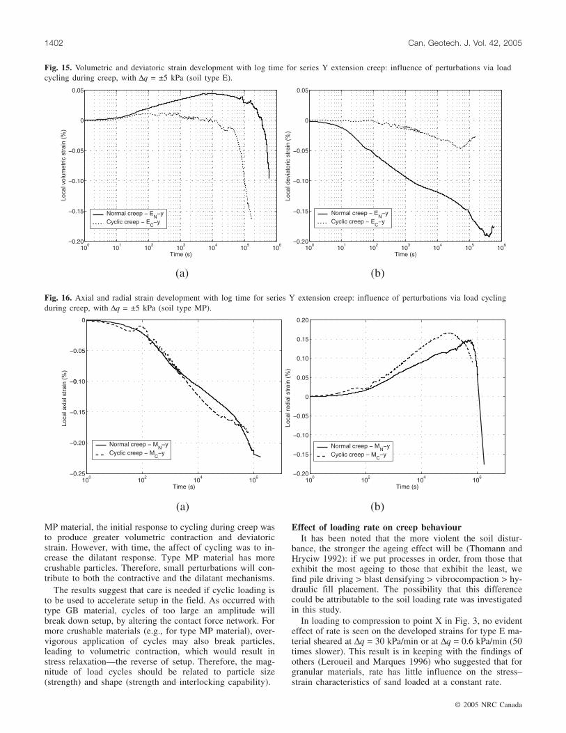
MP material, the initial response to cycling during creep wasto produce greater volumetric contraction and deviatoricstrain. However, with time, the affect of cycling was to in-crease the dilatant response. Type MP material has morecrushable particles. Therefore, small perturbations will con-tribute to both the contractive and the dilatant mechanisms.
The results suggest that care is needed if cyclic loading isto be used to accelerate setup in the field. As occurred withtype GB material, cycles of too large an amplitude willbreak down setup, by altering the contact force network. Formore crushable materials (e.g., for type MP material), over-vigorous application of cycles may also break particles,leading to volumetric contraction, which would result instress relaxation—the reverse of setup. Therefore, the mag-nitude of load cycles should be related to particle size(strength) and shape (strength and interlocking capability).
Effect of loading rate on creep behaviourIt has been noted that the more violent the soil distur-
bance, the stronger the ageing effect will be (Thomann andHryciw 1992): if we put processes in order, from those thatexhibit the most ageing to those that exhibit the least, wefind pile driving > blast densifying > vibrocompaction > hy-draulic fill placement. The possibility that this differencecould be attributable to the soil loading rate was investigatedin this study.
In loading to compression to point X in Fig. 3, no evidenteffect of rate is seen on the developed strains for type E ma-terial sheared at ∆q = 30 kPa/min or at ∆q = 0.6 kPa/min (50times slower). This result is in keeping with the findings ofothers (Leroueil and Marques 1996) who suggested that forgranular materials, rate has little influence on the stress–strain characteristics of sand loaded at a constant rate.
© 2005 NRC Canada
1402 Can. Geotech. J. Vol. 42, 2005
Fig. 15. Volumetric and deviatoric strain development with log time for series Y extension creep: influence of perturbations via loadcycling during creep, with ∆q = ±5 kPa (soil type E).
Fig. 16. Axial and radial strain development with log time for series Y extension creep: influence of perturbations via load cyclingduring creep, with ∆q = ±5 kPa (soil type MP).
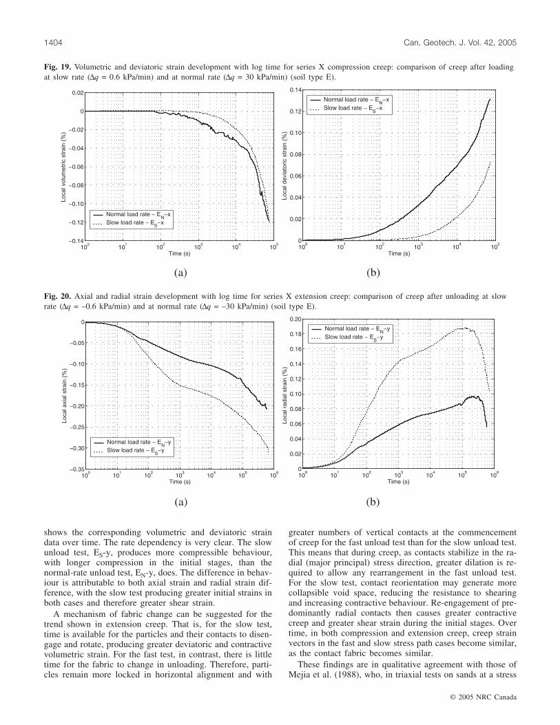
For series X compression creep, Fig. 18 shows local axialand radial strain development with time for test ES-x (slowloading rate) and test EN-x (normal loading rate). Figure 19shows volumetric and deviatoric strain development withtime for these two tests. Test ES-x develops considerably lessaxial strain and radial strain with time than test EN-x; testES-x is also initially delayed in developing dilatant behav-iour, but after a time, a similar volumetric response is devel-oped in the two tests. The deviatoric strain developed overtime for test ES-x is much less than for test EN-x, but thestrain rates become similar with time.
Hence, the previous loading rate has a significant effecton the developing strains during creep. From a micro-structural point of view, the reason may have to do with thesetting up of columns of heavily loaded particles such thatwith slow loading, a network of strong force columns is de-
veloped in a more stable fashion than with fast loading,where there is not adequate time for this to happen. Duringhigh stress ratio creep, the fast test produces more compres-sive axial and expansive radial strain, as the force columnsbuckle and loads redistribute.
For series Y extension creep, two further tests were thenperformed on type E sand to examine the influence of rate.In unloading, there appears to be little difference betweenresponses until the deviatoric stress changes from positive tonegative (i.e., the radial stress becomes the major principalstress). After this point, slightly greater shear strains are de-veloped for slow unloading than for fast unloading (Bowman2002).
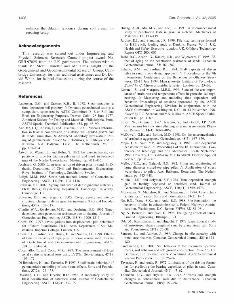
Figure 20 shows the axial and radial strain developmentwith log time for test EN-y (normal load–unload stress path)against test ES-y (slow load–unload stress path). Figure 21
© 2005 NRC Canada
Bowman and Soga 1403
Fig. 17. Volumetric and deviatoric strain development with log time for series Y extension creep: influence of perturbations via loadcycling during creep, with ∆q = ±5 kPa (soil type MP).
Fig. 18. Axial and radial strain development with log time for series X compression creep: comparison of creep after loading at slowrate (∆q = 0.6 kPa/min) and at normal rate (∆q = 30 kPa/min) (soil type E).
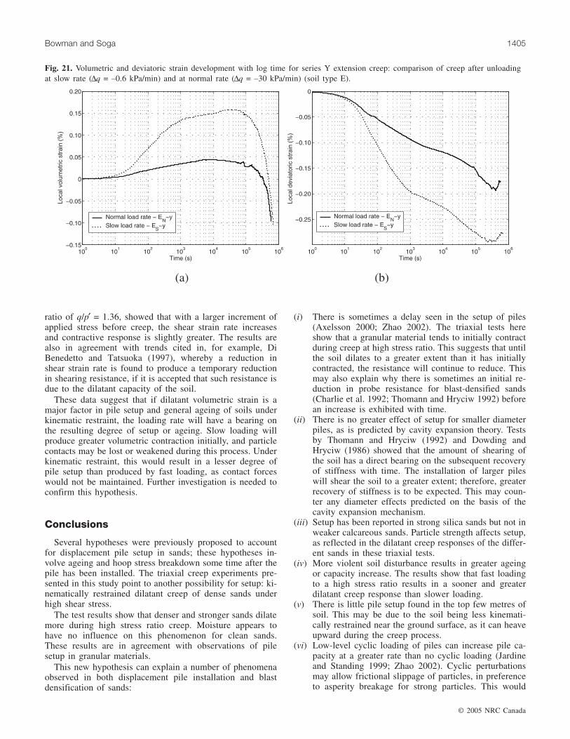
shows the corresponding volumetric and deviatoric straindata over time. The rate dependency is very clear. The slowunload test, ES-y, produces more compressible behaviour,with longer compression in the initial stages, than thenormal-rate unload test, EN-y, does. The difference in behav-iour is attributable to both axial strain and radial strain dif-ference, with the slow test producing greater initial strains inboth cases and therefore greater shear strain.
A mechanism of fabric change can be suggested for thetrend shown in extension creep. That is, for the slow test,time is available for the particles and their contacts to disen-gage and rotate, producing greater deviatoric and contractivevolumetric strain. For the fast test, in contrast, there is littletime for the fabric to change in unloading. Therefore, parti-cles remain more locked in horizontal alignment and with
greater numbers of vertical contacts at the commencementof creep for the fast unload test than for the slow unload test.This means that during creep, as contacts stabilize in the ra-dial (major principal) stress direction, greater dilation is re-quired to allow any rearrangement in the fast unload test.For the slow test, contact reorientation may generate morecollapsible void space, reducing the resistance to shearingand increasing contractive behaviour. Re-engagement of pre-dominantly radial contacts then causes greater contractivecreep and greater shear strain during the initial stages. Overtime, in both compression and extension creep, creep strainvectors in the fast and slow stress path cases become similar,as the contact fabric becomes similar.
These findings are in qualitative agreement with those ofMejia et al. (1988), who, in triaxial tests on sands at a stress
© 2005 NRC Canada
1404 Can. Geotech. J. Vol. 42, 2005
Fig. 19. Volumetric and deviatoric strain development with log time for series X compression creep: comparison of creep after loadingat slow rate (∆q = 0.6 kPa/min) and at normal rate (∆q = 30 kPa/min) (soil type E).
Fig. 20. Axial and radial strain development with log time for series X extension creep: comparison of creep after unloading at slowrate (∆q = –0.6 kPa/min) and at normal rate (∆q = –30 kPa/min) (soil type E).
ratio of q/p′ = 1.36, showed that with a larger increment ofapplied stress before creep, the shear strain rate increasesand contractive response is slightly greater. The results arealso in agreement with trends cited in, for example, DiBenedetto and Tatsuoka (1997), whereby a reduction inshear strain rate is found to produce a temporary reductionin shearing resistance, if it is accepted that such resistance isdue to the dilatant capacity of the soil.
These data suggest that if dilatant volumetric strain is amajor factor in pile setup and general ageing of soils underkinematic restraint, the loading rate will have a bearing onthe resulting degree of setup or ageing. Slow loading willproduce greater volumetric contraction initially, and particlecontacts may be lost or weakened during this process. Underkinematic restraint, this would result in a lesser degree ofpile setup than produced by fast loading, as contact forceswould not be maintained. Further investigation is needed toconfirm this hypothesis.
Conclusions
Several hypotheses were previously proposed to accountfor displacement pile setup in sands; these hypotheses in-volve ageing and hoop stress breakdown some time after thepile has been installed. The triaxial creep experiments pre-sented in this study point to another possibility for setup: ki-nematically restrained dilatant creep of dense sands underhigh shear stress.
The test results show that denser and stronger sands dilatemore during high stress ratio creep. Moisture appears tohave no influence on this phenomenon for clean sands.These results are in agreement with observations of pilesetup in granular materials.
This new hypothesis can explain a number of phenomenaobserved in both displacement pile installation and blastdensification of sands:
(i) There is sometimes a delay seen in the setup of piles(Axelsson 2000; Zhao 2002). The triaxial tests hereshow that a granular material tends to initially contractduring creep at high stress ratio. This suggests that untilthe soil dilates to a greater extent than it has initiallycontracted, the resistance will continue to reduce. Thismay also explain why there is sometimes an initial re-duction in probe resistance for blast-densified sands(Charlie et al. 1992; Thomann and Hryciw 1992) beforean increase is exhibited with time.
(ii) There is no greater effect of setup for smaller diameterpiles, as is predicted by cavity expansion theory. Testsby Thomann and Hryciw (1992) and Dowding andHryciw (1986) showed that the amount of shearing ofthe soil has a direct bearing on the subsequent recoveryof stiffness with time. The installation of larger pileswill shear the soil to a greater extent; therefore, greaterrecovery of stiffness is to be expected. This may coun-ter any diameter effects predicted on the basis of thecavity expansion mechanism.
(iii) Setup has been reported in strong silica sands but not inweaker calcareous sands. Particle strength affects setup,as reflected in the dilatant creep responses of the differ-ent sands in these triaxial tests.
(iv) More violent soil disturbance results in greater ageingor capacity increase. The results show that fast loadingto a high stress ratio results in a sooner and greaterdilatant creep response than slower loading.
(v) There is little pile setup found in the top few metres ofsoil. This may be due to the soil being less kinemati-cally restrained near the ground surface, as it can heaveupward during the creep process.
(vi) Low-level cyclic loading of piles can increase pile ca-pacity at a greater rate than no cyclic loading (Jardineand Standing 1999; Zhao 2002). Cyclic perturbationsmay allow frictional slippage of particles, in preferenceto asperity breakage for strong particles. This would
© 2005 NRC Canada
Bowman and Soga 1405
Fig. 21. Volumetric and deviatoric strain development with log time for series Y extension creep: comparison of creep after unloadingat slow rate (∆q = –0.6 kPa/min) and at normal rate (∆q = –30 kPa/min) (soil type E).
enhance the dilatant tendency during soil creep, in-creasing setup.
Acknowledgements
This research was carried out under Engineering andPhysical Sciences Research Council project award No.GR/L97025, from the U.K. government. The authors wish tothank Mr. Steve Chandler and Mr. Chris Knight of theGeotechnical and Geoenvironmental Research Group, Cam-bridge University, for their technical assistance; and Dr. Da-vid White, for helpful discussions during the course of theresearch.
References
Anderson, D.G., and Stokoe, K.H., II. 1978. Shear modulus, atime-dependent soil property. In Dynamic geotechnical testing: asymposium, sponsored by ASTM Committee D-18 on Soil andRock for Engineering Purposes, Denver, Colo., 28 June 1977.American Society for Testing and Materials, Philadelphia, Penn.ASTM Special Technical Publication 654, pp. 66–90.
AnhDan, L.Q., Koseki, J., and Tatsuoka, F. 2001. Viscous deforma-tion in triaxial compression of a dense well-graded gravel andits model simulation. In Advanced laboratory stress–strain test-ing of geomaterials. Edited by F. Tatsuoka, S. Shibuya, and R.Kuwano. A.A. Balkema, Lisse, The Netherlands. Vol. 1,pp. 187–194.
Åstedt, B., Weiner, L., and Holm, G. 1992. Increase in bearing ca-pacity with time for friction piles in silt and sand. In Proceed-ings of the Nordic Geotechnical Meeting, pp. 411–416.
Axelsson, G. 2000. Long-term set-up of driven piles in sand. Ph.D.thesis, Department of Civil and Environmental Engineering.Royal Institute of Technology, Stockholm, Sweden.
Baligh, M.M. 1985. Strain path method. Journal of GeotechnicalEngineering, ASCE, 111(9): 1108–1138.
Bowman, E.T. 2002. Ageing and creep of dense granular materials.Ph.D. thesis, Engineering Department, Cambridge University,Cambridge, UK.
Bowman, E.T., and Soga, K. 2003. Creep, ageing and micro-structural change in dense granular materials. Soils and Founda-tions, 43(4): 107–117.
Charlie, W.A., Rwebyogo, M.F.J., and Doehring, D.O. 1992. Time-dependent cone penetration resistance due to blasting. Journal ofGeotechnical Engineering, ASCE, 118(8): 1200–1215.
Chow, F.C. 1997. Investigations into displacement pile behaviourfor offshore foundations. Ph.D. thesis, Department of Soil Me-chanics, Imperial College, London, UK.
Chow, F.C., Jardine, R.J., Brucy, F., and Nauroy, J.F. 1998. Effectsof time on capacity of pipe piles in dense marine sand. Journalof Geotechnical and Geoenvironmental Engineering, ASCE,124(3): 254–264.
Cuccovillo, T., and Coop, M.R. 1997. The measurement of localaxial strains in triaxial tests using LVDTs. Géotechnique, 47(1):167–172.
Di Benedetto, H., and Tatsuoka, F. 1997. Small strain behaviour ofgeomaterials: modelling of strain rate effects. Soils and Founda-tions, 37(2): 127–138.
Dowding, C.H., and Hryciw, R.D. 1986. A laboratory study ofblast densification of saturated sand. Journal of GeotechnicalEngineering, ASCE, 112(2): 187–199.
Huang, A.-B., Ma, M.Y., and Lee, J.S. 1993. A micromechanicalstudy of penetration tests in granular material. Mechanics ofMaterials, 16: 133–139.
Jardine, R.J., and Standing, J.R. 1999. Pile load testing performedfor HSE cyclic loading study at Dunkirk, France. Vol. 1. UK.Health and Safety Executive, London, UK. Offshore TechnologyReport OTO 2000 007.
Joshi, R.C., Acahri, G., Kaniraj, S.R., and Wijeweera, H. 1995. Ef-fect of aging on the penetration resistance of sands. CanadianGeotechnical Journal, 32: 767–782.
Lehane, B.M., and Jardine, R.J. 1994. Shaft capacity of drivenpiles in sand: a new design approach. In Proceedings of the 7thInternational Conference on the Behaviour of Offshore Struc-tures, 12–15 July 1994, Massachusetts Institute of Technology.Edited by C. Chryssostomidis. Elsevier, London. pp. 23–36.
Leroueil, S., and Marques, M.E.S. 1996. State of the art: impor-tance of strain rate and temperature effects in geotechnical engi-neering. In Measuring and modeling time dependent soilbehavior. Proceedings of sessions sponsored by the ASCEGeotechnical Engineering Division in conjunction with theASCE Convention in Washington, D.C., 10–14 November 1996.Edited by T.C. Sheahan and V.N. Kaliakin. ASCE Special Publi-cation 61, pp. 1–60.
Losert, W., Geminard, J.-C., Nasuno, S., and Gollub, J.P. 2000.Mechanisms for slow strengthening in granular materials. Physi-cal Review E, 61(4): 4060–4068.
McDowell, G.R., and Bolton, M.D. 1998. On the micromechanicsof crushable aggregates. Géotechnique, 48(5): 667–679.
Mejia, C.A., Vaid, Y.P., and Negussey, D. 1988. Time dependentbehaviour of sand. In Proceedings of the lst International Con-ference on Rheology and Soil Mechanics, 12–16 September1988, Coventry, UK. Edited by M.J. Keedwell. Elsevier AppliedScience, pp. 312–326.
Mello, J.R.C., and Galgoul, N.S. 1992. Piling and monitoring oflarge diameter closed-toe pipe piles. In Application of stresswave theory to piles. A.A. Balkema, Rotterdam, The Nether-lands. pp. 443–448.
Mitchell, J.K., and Solymar, Z.V. 1984. Time-dependent strengthgain in freshly deposited or densified sand. Journal ofGeotechnical Engineering, ASCE, 110(11): 1559–1576.
Murayama, S., Michihro, K., and Sakagami, T. 1984. Creep char-acteristics of sands. Soils and Foundations, 24(2): 1–15.
Ng, E.S., Tsang, S.K., and Auld, B.C. 1988. Pile foundation: thebehavior of piles in cohesionless soils. Federal Highway Admin-istration, Washington, D.C. Report FHWA-RD-88–081.
Ng, N., Berner, P., and Covil, C. 1998. The ageing effects of sands.Ground Engineering, 10(Suppl.): 21.
Oda, M., Koishikawa, I., and Higuchi, T. 1978. Experimental studyof anisotropic shear strength of sand by plane strain test. Soilsand Foundations, 18(1): 25–38.
Samson, L., and Authier, J. 1986. Change in pile capacity withtime: case histories. Canadian Geotechnical Journal, 23(1): 174–180.
Santamarina, J.C. 2003. Soil behavior at the microscale: particleforces, soil behavior and soft ground construction. Edited by J.T.Germaine, T.C. Sheahan, and R.V. Whitman. ASCE GeotechnicalSpecial Publication 119, pp. 25–56.
Tavernas, F., and Audy, R. 1972. Limitations of the driving formu-las for predicting the bearing capacities of piles in sand. Cana-dian Geotechnical Journal, 47(9): 47–62.
Thomann, T.G., and Hryciw, R.D. 1992. Stiffness and strengthchanges in cohesionless soils due to disturbance. CanadianGeotechnical Journal, 29(5): 853–861.
© 2005 NRC Canada
1406 Can. Geotech. J. Vol. 42, 2005
Tomlinson, M. 1996. BGS/Offshore Engineering Society meetingreport: Recent advances in driven pile design. Ground Engi-neering, pp. 31–33.
White, D.J., and Bolton, M.D. 2004. Displacement and strain pathsduring plane–strain model pile installation in sand.Géotechnique, 54(6): 375–397.
York, D.L., Brusey, W.G., Clemente, F.M., and Law, S.K. 1994.Setup and relaxation in glacial sand. Journal of GeotechnicalEngineering, ASCE, 120(9): 1498–1513.
Zhao, Y. 2002. Pile set-up in sand. M.Eng. thesis, Engineering De-partment, Cambridge University, Cambridge, UK.
© 2005 NRC Canada
Bowman and Soga 1407