modelling of friction piles in consolidating soils
TRANSCRIPT
Modelling of Friction Piles in Consolidating Soils
Gabriel Auvinet* and Juan Frlix Rodriguez**
*Research Professor, Institute of Engineering, National University of Mexico, AP 70-472, Coyoac~in, CP 04510, Mrxico D.F.; PH (52)56223500; [email protected] **Research Assistant, Institute of Engineering, National University of Mexico, AP 70-472, Coyoacfin, CP 04510, M6xico D.F., PH (52)56223500; [email protected]
Abstract
This paper presents a quantitative analysis of the interaction between soil, structure and friction piles located in a consolidating clayey soil using the Finite Element Method (FEM). The consolidation process due to the weight of the structure and to a pumping-induced decrease in pore water pressure is simulated. The stresses developed within the soil and at the interface between pile and soil are evaluated. Progressive increase of soil strength due to consolidation is taken into account. The analysis performed provides a valuable insight into the complex interaction between soil, piles and structure and suggests some important new elements to be taken into account in the design of friction piles.
Introduction
Friction piles are seldom used in Mexico City lacustrine clays since the 1985 earthquakes. The unsatisfactory behavior of several structures with this type of foundation contributed to generalize the idea that this system is unreliable. It can be shown, however, that friction piles are still attractive and secure when properly designed. It is particularly important that the interaction between soil, piles and structure due to both structural loading and pumping induced regional subsidence affecting the lacustrine area of the city be properly accounted for. A useful insight into this problem can be obtained by simulating the working conditions of friction piles in these complex conditions using the Finite Element Method (FEM).
Foundations on friction piles
Friction piles transfer most of their load to the soil through skin friction. In Mexico City's soft soil, they have been mainly used as a complement to box-type, partially compensated foundations aimed at reducing settlement (design for deformations). Not so frequently, they have been used to carry the total weight of the structure and ensure the overall stability of the foundation (design for bearing capacity).
In both cases, a complex interaction develops between the soil, the piles and the structure. This is due to the fact that the soil is submitted to a double process of consolidation: first, due to the load of the structure and, second, variations in the pore pressure conditions in the soil associated to the intense pumping of water from the subsoil in the urban area.
In such conditions, when not properly designed, friction pile foundations can settle excessively or, on the contrary, they can protrude from the subsiding surrounding soil.
224
Dee
p Fo
unda
tions
200
2 D
ownl
oade
d fr
om a
scel
ibra
ry.o
rg b
y U
NIV
ER
SID
AD
E D
E B
RA
SIL
IA o
n 07
/13/
12. F
or p
erso
nal u
se o
nly.
No
othe
r us
es w
ithou
t per
mis
sion
. Cop
yrig
ht (
c) 2
012.
Am
eric
an S
ocie
ty o
f C
ivil
Eng
inee
rs. A
ll ri
ghts
res
erve
d.
DEEP FOUNDATIONS 2002 225
Design of foundations on friction piles must therefore be based on a careful evaluation of the stresses developed near the point and along the shaft of the piles and of the resulting strains and displacements. Those stresses are a function of the geometrical characteristics of the foundation, the stiffness and spacing of the piles, the mechanical properties of the soil, the magnitude of structural loading, and the development of pore water pressure.
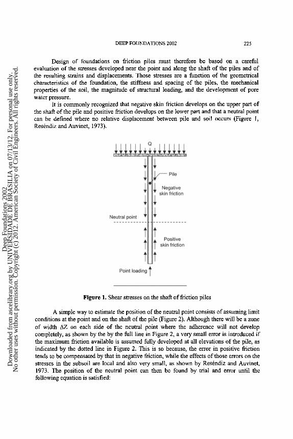
It is commonly recognized that negative skin friction develops on the upper part of the shaft of the pile and positive friction develops on the lower part and that a neutral point can be defined where no relative displacement between pile and soil occurs (Figure 1, Res6ndiz and Auvinet, 1973).
Figure 1, Shear stresses on the shaft of friction piles
A simple way to estimate the position of the neutral point consists of assuming limit conditions at the point and on the shaft of the pile (Figure 2). Although there will be a zone of width AZ on each side of the neutral point where the adherence will not develop completely, as shown by the by the full line in Figure 2, a very small error is introduced if the maximum friction available is assumed fully developed at all elevations of the pile, as indicated by the dotted line in Figure 2. This is so because, the error in positive friction tends to be compensated by that in negative friction, while the effects of those errors on the stresses in the subsoil are local and also very small, as shown by Res6ndiz and Auvinet, 1973. The position of the neutral point can then be found by trial and error until the following equation is satisfied:
Dee
p Fo
unda
tions
200
2 D
ownl
oade
d fr
om a
scel
ibra
ry.o
rg b
y U
NIV
ER
SID
AD
E D
E B
RA
SIL
IA o
n 07
/13/
12. F
or p
erso
nal u
se o
nly.
No
othe
r us
es w
ithou
t per
mis
sion
. Cop
yrig
ht (
c) 2
012.
Am
eric
an S
ocie
ty o
f C
ivil
Eng
inee
rs. A
ll ri
ghts
res
erve
d.

226 DEEP FOUNDATIONS 2002
- - F Zo
where Q is the load applied to pile; c? is the point bearing capacity of pile; Zo is the depth
of neutral point; Ze is the depth of pile point; Dr is the depth of foundation raft; c § z, is F Zo
_ Zo is the limit adhesion the limit adhesion along the pile shaft between Zo and Zp and ICF I DF
along the pile shaft between DF and Zo.
Figure 2. Stresses at the point and along the shaft ofa fiiction pile for limit conditions
Taking into account that hypotheses implicit in Eq. 1 can probably be unrealistic in certain conditions, it was considered necessary to evaluate their validity for different geometric and loading conditions, using the FEM.
Numerical model
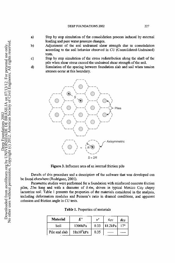
A group of friction piles connected to a rigid slab and arranged according to a regular pattern is considered (Figure 3). The study presented in this paper refers only to the behavior of the internal piles within this pile group. The tributary area or influence cell (Schlosser et al., 1984) of each internal pile is hexagonal but it can be considered as approximately circular. The radius R of this area is then approximately equal to half the spacing S between piles (S z2R). The problem can then be considered as axisymmetric.
A standard finite element software developed by the authors was adapted to perform the following operations:
Dee
p Fo
unda
tions
200
2 D
ownl
oade
d fr
om a
scel
ibra
ry.o
rg b
y U
NIV
ER
SID
AD
E D
E B
RA
SIL
IA o
n 07
/13/
12. F
or p
erso
nal u
se o
nly.
No
othe
r us
es w
ithou
t per
mis
sion
. Cop
yrig
ht (
c) 2
012.
Am
eric
an S
ocie
ty o
f C
ivil
Eng
inee
rs. A
ll ri
ghts
res
erve
d.
DEEP FOUNDATIONS 2002 227
a)
b)
c)
d)
Step by step simulation of the consolidation process induced by external loading and pore water pressure changes. Adjustment of the soil undrained shear strength due to consolidation according to the soil behavior observed in CU (Consolidated-Undrained) tests. Step by step simulation of the stress redistribution along the shaft of the pile when shear stress exceed the undrained shear strength of the soil. Simulation of the spacing between foundation slab and soil when tension stresses occur at this boundary.
Figure 3. Influence area of an internal friction pile
Details of this procedure and a description of the software that was developed can be found elsewhere (Rodriguez, 2001).
Parametric studies were performed for a foundation with reinforced concrete friction piles, 25m long and with a diameter of 0.4m, driven in typical Mexico City clayey lacustrine soil. Table 1 presents the properties of the materials considered in the analysis, including deformation modulus and Poisson's ratio in drained conditions, and apparent cohesion and friction angle in CUtests.
Table 1. Properties of materials
Material E'
Soil 1300kPa
Pile and slab 18xl06kPa
V ~ CCU ~CU
0.33 18.2kPa 17 ~
0.35
Dee
p Fo
unda
tions
200
2 D
ownl
oade
d fr
om a
scel
ibra
ry.o
rg b
y U
NIV
ER
SID
AD
E D
E B
RA
SIL
IA o
n 07
/13/
12. F
or p
erso
nal u
se o
nly.
No
othe
r us
es w
ithou
t per
mis
sion
. Cop
yrig
ht (
c) 2
012.
Am
eric
an S
ocie
ty o
f C
ivil
Eng
inee
rs. A
ll ri
ghts
res
erve
d.
228 DEEP FOUNDATIONS 2002
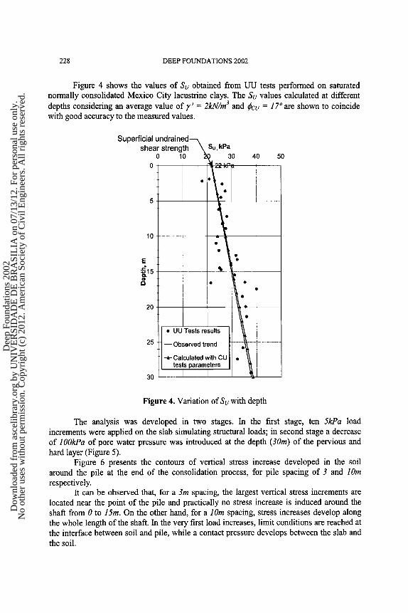
Figure 4 shows the values of Su obtained from UU tests performed on saturated normally consolidated Mexico City lacustrine clays. The Su values calculated at different depths considering an average value of y ' = 2kN/m 3 and qkcu = 17 ~ are shown to coincide with good accuracy to the measured values.
Su
30
shea r s t reng th Su, kPa 0 10 30 40
0 I
0 ~
10 -
-,t- ~ �9 o
20 * I
�9 I
�9 UU Tests results
25 - - Observed trend �9
�9 -~--CalculatedwithCU �9 \\ I tests parameters
I I
50
Figure 4. Variation of Su with depth
The analysis was developed in two stages. In the first stage, ten 5kPa load increments were applied on the slab simulating structural loads; in second stage a decrease of lOOkPa of pore water pressure was introduced at the depth (3Ore) of the pervious and hard layer (Figure 5).
Figure 6 presents the contours of vertical stress increase developed in the soil around the pile at the end of the consolidation process, for pile spacing of 3 and lOm
respectively. It can be observed that, for a 3m spacing, the largest vertical stress increments are
located near the point of the pile and practically no stress increase is induced around the shaft from 0 to 15m. On the other hand, for a lOm spacing, stress increases develop along the whole length of the shaft. In the very first load increases, limit conditions are reached at the interface between soil and pile, while a contact pressure develops between the slab and the soil.
Dee
p Fo
unda
tions
200
2 D
ownl
oade
d fr
om a
scel
ibra
ry.o
rg b
y U
NIV
ER
SID
AD
E D
E B
RA
SIL
IA o
n 07
/13/
12. F
or p
erso
nal u
se o
nly.
No
othe
r us
es w
ithou
t per
mis
sion
. Cop
yrig
ht (
c) 2
012.
Am
eric
an S
ocie
ty o
f C
ivil
Eng
inee
rs. A
ll ri
ghts
res
erve
d.
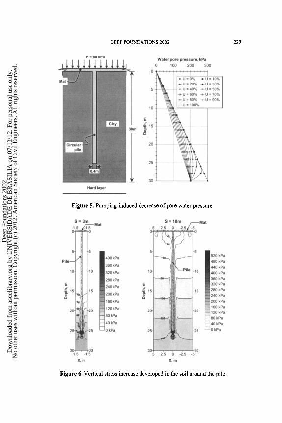
DEEP FOUNDATIONS 2002 229
Figure 5. Pumping-induced decrease of pore water pressure
Figure 6. Vertical stress increase developed in the soil around the pile
Dee
p Fo
unda
tions
200
2 D
ownl
oade
d fr
om a
scel
ibra
ry.o
rg b
y U
NIV
ER
SID
AD
E D
E B
RA
SIL
IA o
n 07
/13/
12. F
or p
erso
nal u
se o
nly.
No
othe
r us
es w
ithou
t per
mis
sion
. Cop
yrig
ht (
c) 2
012.
Am
eric
an S
ocie
ty o
f C
ivil
Eng
inee
rs. A
ll ri
ghts
res
erve
d.
230 DEEP FOUNDATIONS 2002
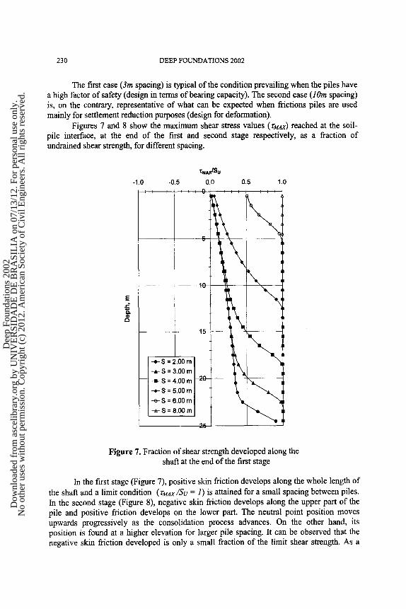
The first case (3m spacing) is typical of the condition prevailing when the piles have a high factor of safety (design in terms of bearing capacity). The second case (lOm spacing) is, on the contrary, representative of what can be expected when frictions piles are used mainly for settlement reduction purposes (design for deformation).
Figures 7 and 8 show the maximum shear stress values (rMAx) reached at the soil- pile interface, at the end of the first and second stage respectively, as a fraction of undrained shear strength, for different spacing.
E
t ' , ,
X.AxlSo -1.0 -0.5 0.0 0.5 1.0
, 0 i\ ! i
t5-
-o-S = 6.00 m -n-S = 8"00 m I
Figure 7. Fraction of shear strength developed along the shaft at the end of the first stage
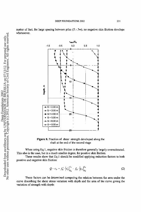
In the first stage (Figure 7), positive skin friction develops along the whole length of the shaft and a limit condition (ruAx/Sv = 1) is attained for a small spacing between piles. In the second stage (Figure 8), negative skin friction develops along the upper part of the pile and positive friction develops on the lower part. The neutral point position moves upwards progressively as the consolidation process advances. On the other hand, its position is found at a higher elevation for larger pile spacing. It can be observed that the negative skin friction developed is only a small fraction of the limit shear strength. As a
Dee
p Fo
unda
tions
200
2 D
ownl
oade
d fr
om a
scel
ibra
ry.o
rg b
y U
NIV
ER
SID
AD
E D
E B
RA
SIL
IA o
n 07
/13/
12. F
or p
erso
nal u
se o
nly.
No
othe
r us
es w
ithou
t per
mis
sion
. Cop
yrig
ht (
c) 2
012.
Am
eric
an S
ocie
ty o
f C
ivil
Eng
inee
rs. A
ll ri
ghts
res
erve
d.
DEEP FOUNDATIONS 2002 231
matter of fact, for large spacing between piles (S ~ 5m), no negative skin friction develops whatsoever.
xM~lSu
-1.0 -0.5 0.0 0.5 1.0
, , , u
, ~ - -
E
�9 - e - S = 2 .00 rn
--=-S 3 .00 rn
,-,B-S = 4 .00 rn
- ~ - S = 5 .00 m
- e - S = 6 .00 m
- ~ - S = 8 .00 m
Figure 8. Fraction of shear strength developed along the shaft at the end of the second stage
When using Eq.1, negative skin friction is therefore generally largely overestimated. This also is the case, but in a much smaller degree, for positive skin friction.
These results show that Eq. 1 should be modified applying reduction factors to both positive and negative skin friction:
�9 C + Z P _ _ Z o . : ; - :; I c & (2)
These factors can be determined computing the relation between the area under the curve describing the shear stress variation with depth and the area of the curve giving the variation of strength with depth:
Dee
p Fo
unda
tions
200
2 D
ownl
oade
d fr
om a
scel
ibra
ry.o
rg b
y U
NIV
ER
SID
AD
E D
E B
RA
SIL
IA o
n 07
/13/
12. F
or p
erso
nal u
se o
nly.
No
othe
r us
es w
ithou
t per
mis
sion
. Cop
yrig
ht (
c) 2
012.
Am
eric
an S
ocie
ty o
f C
ivil
Eng
inee
rs. A
ll ri
ghts
res
erve
d.

232 DEEP FOUNDATIONS 2002
Z=Zo
'T,.~ �9 dz
+ _ z=Di for positive skin friction UR Z=Zo ~S u " dz Z=Df
~S U .dz Z=Zo
, for negative skin friction
The calculated factors for the conditions prevailing in the analysis are presented in Figure 9.
1.0
0.9
0.8
0.7
0.6
0.5
0.4 I- 0.3
0.2
0.1
0.0 0.0
f �9 Pos i t ive friction
i P i P r l l
2.0
Ultimate load ""=-'~1 �9 carried by
)ositive friction
•'•L_• N o development -- ~ " of negat ive friction
�9 N tN
4.0 6.0 8.0
Sp m
Figure 9. Reduction factors for positive and negative skin friction
For different loading and subsidence conditions, these coefficients should be re- evaluated but the values presented in Figure 9 can be considered as typical. Eq.2 should lead to a more realistic position of the neutral point. Moreover, the reduced values of positive and negative skin friction can be introduced in analytical models that have been developed for computing settlement of friction pile foundations, (Auvinet and Rodriguez, 2000). The Finite Element model developed is however simple enough to be used directly for design.
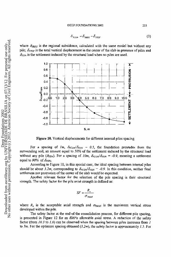
In Figure 10, the relation (6rcoJ6rslN) is presented for different internal pile spacing, where 6rcou is the vertical displacement of the center of the foundation with respect to the surrounding surface, i.e. (Figure l 1):
Dee
p Fo
unda
tions
200
2 D
ownl
oade
d fr
om a
scel
ibra
ry.o
rg b
y U
NIV
ER
SID
AD
E D
E B
RA
SIL
IA o
n 07
/13/
12. F
or p
erso
nal u
se o
nly.
No
othe
r us
es w
ithou
t per
mis
sion
. Cop
yrig
ht (
c) 2
012.
Am
eric
an S
ocie
ty o
f C
ivil
Eng
inee
rs. A
ll ri
ghts
res
erve
d.
DEEP FOUNDATIONS 2002 233
8rcoN = #rRe~ - 8trot (3)
where firRe6 is the regional subsidence, calculated with the same model but without any pile; ~ o r is the total vertical displacement in the center of the slab in presence of piles and firsm is the settlement induced by the structural load when no piles are used.
1.0
0.8
0.6
0.4
z 0.2
~ 0.0
~.~ -0.2 (
-0.4
-0.6
-0.8
-1.0
: i
\ 20
g
1 o a.
3o so 60 7o 80 so l c . IU
Sl m
Figure I0. Vertical displacements for different intemal piles spacing
For a spacing of lm, ~cou/~sm = 0.5, the foundation protrudes from the surrounding soil, an amount equal to 50% of the settlement induced by the structural load without any pile (firsm). For a spacing of lOre, &CON/6rSm = -0.9, meaning a settlement equal to 90% of fiYSlN.
According to Figure 10, in this special case, the ideal spacing between internal piles should be about 3.2m, corresponding to 'Y'rCON/firSlN = -0.9. In this condition, neither final settlement nor protrusion of the center of the slab would be expected.
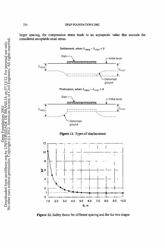
Another relevant factor for the selection of the pile spacing is their structural strength. The safety factor for the pile axial strength is defined as:
SF= Ro O" YMAX
where Ra is the acceptable axial strength and r is the maximum vertical stress developed within the pile.
The safety factor at the end of the consolidation process, for different pile spacing, is presented in Figure 12 for an 8MPa allowable axial stress. A reduction of the safety factor (from 10.3 to 1.6) can be observed when the spacing between piles increases from 1 to 3m. For the optimum spacing obtained (3.2m), the safety factor is approximately 1.5. For
Dee
p Fo
unda
tions
200
2 D
ownl
oade
d fr
om a
scel
ibra
ry.o
rg b
y U
NIV
ER
SID
AD
E D
E B
RA
SIL
IA o
n 07
/13/
12. F
or p
erso
nal u
se o
nly.
No
othe
r us
es w
ithou
t per
mis
sion
. Cop
yrig
ht (
c) 2
012.
Am
eric
an S
ocie
ty o
f C
ivil
Eng
inee
rs. A
ll ri
ghts
res
erve
d.
234 DEEP FOUNDATIONS 2002
larger spacing, the compression stress tends to an asymptotic value that exceeds the considered acceptable axial stress.
Figure 11. Types of displacement
12
10
8
4
2
1
0 1.0
, , , , , , , , i , l , , T
2.0 3.0 4.0 5.0
i i , , i l l l , i l k i ~ l l
6.0 7.0 8.0 9.0 10.0
S ~ m
Figure 12. Safety factor for different spacing and for the two stages
Dee
p Fo
unda
tions
200
2 D
ownl
oade
d fr
om a
scel
ibra
ry.o
rg b
y U
NIV
ER
SID
AD
E D
E B
RA
SIL
IA o
n 07
/13/
12. F
or p
erso
nal u
se o
nly.
No
othe
r us
es w
ithou
t per
mis
sion
. Cop
yrig
ht (
c) 2
012.
Am
eric
an S
ocie
ty o
f C
ivil
Eng
inee
rs. A
ll ri
ghts
res
erve
d.
DEEP FOUNDATIONS 2002 235
Conclusions
Design of friction pile foundations in consolidating soils must be based on a detailed assessment of the complex interaction between soil, slab and piles. This interaction depends on the geometrical conditions, including the spacing of piles, and on the stiffness of the piles, the mechanical properties of the soil, the magnitude of the structural loading, and the pore water pressure development.
The simple Finite Element model presented in this paper provides a valuable insight into the stress, strain, and displacement fields that develop in the soil and along the pile shaft in these complex conditions. The results obtained using this model clarify some important aspects of the development of positive and negative skin friction on the piles that will have to be taken into account in the design of friction pile foundations.
A truly three-dimensional model is presently being developed, that will allow extending the results of the present analysis, limited to internal piles, to piles located near the edge of the pile group.
References
Auvinet, G., and Rodriguez J.F. (2000). "Program MICRA2000 for design of friction pile foundations." Institute of Engineering, National University of Mexico, Mexico.
Res6ndiz D., and Auvinet G. (1973). "Analysis of pile foundations in consolidating soil. Proceedings." VIIIth International Conference on Soil Mechanics and Foundation Engineering, Moscow. Russia, 211-218.
Rodriguez J.F. (2001). "Use of inclusions for control of settlement in soft soils." Master Degree Thesis, Postgraduate Division, Engineering Faculty, National University of Mexico.
Schlosser F., Jacobsen H. M., and Juran I. (1984). "Le renforcement des sols (1)." Revue Frangaise de G6otechnique, No. 29, France, 7-32.
Dee
p Fo
unda
tions
200
2 D
ownl
oade
d fr
om a
scel
ibra
ry.o
rg b
y U
NIV
ER
SID
AD
E D
E B
RA
SIL
IA o
n 07
/13/
12. F
or p
erso
nal u
se o
nly.
No
othe
r us
es w
ithou
t per
mis
sion
. Cop
yrig
ht (
c) 2
012.
Am
eric
an S
ocie
ty o
f C
ivil
Eng
inee
rs. A
ll ri
ghts
res
erve
d.