compressed facade displacement maps
TRANSCRIPT

Compressed Facade Displacement MapsSaif Ali, Jieping Ye, Member, IEEE, Anshuman Razdan, Member, IEEE, and
Peter Wonka, Member, IEEE
Abstract—We describe an approach to render massive urban models. To prevent a memory transfer bottleneck, we propose to render
the models from a compressed representation directly. Our solution is based on rendering crude building outlines as polygons and
generating details by ray-tracing displacement maps in the fragment shader. We demonstrate how to compress a displacement map
so that a decompression algorithm can selectively and quickly access individual entries in a fragment shader. Our prototype
implementation shows how a massive urban model can be compressed by a factor of 85 and outperform a basic geometry-based
renderer by a factor of 40 to 80 in rendering speed.
Index Terms—Massive urban models, displacement mapping, real-time rendering, compression.
Ç
1 INTRODUCTION
IN this paper, we describe an approach to rendermassive urban models requiring several gigabytes of
data. It is especially difficult to render fly overs, wherealmost the complete model is visible, and the visualportion of the scene requires more memory than isavailable on the graphics card and in the main memory.As a solution, we present a framework that renders froma compressed representation directly and avoids slowmemory transfers from the disk to the main memory andGPU at every frame.
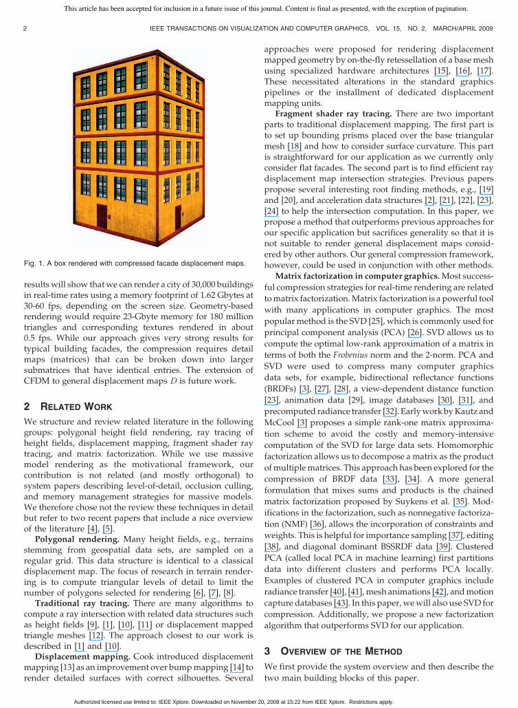
We assume that building facades are stored as largepolygons and facade details are stored as displacementmaps and material index maps. A displacement map is amatrix D 2 Rm�n, where each entry represents a displace-ment from a reference plane, and a material index map is amatrixM 2 Nm�n, where each entry references a texture in atexture library. To render this representation, the largefacade polygons are rasterized to initialize a fragmentshader that computes an exact ray-surface intersection (seeFig. 1) using ray casting. The idea of the fragment shader raycaster is to march a ray over the displacement map until asurface intersection is found. While a naive algorithm uses alarge number of very small steps, it is often beneficial to useacceleration data structures to allow the ray to jump largerdistances in regions of free space. Two prominent examplesof acceleration data structures are cones [1] or spheres [2] offree space. These acceleration data structures are stored as
an additional matrix A (or several additional matrices). Wecall the matrices D, M, and A the detail maps of a facade.
In this paper, we will present a rendering frameworkthat precomputes compressed detail maps and decom-presses individual matrix entries in the fragment shader.We need to tackle two challenges. First, we have to find asuitable compression algorithm. Second, we have to adaptcurrent fragment shader ray-tracing algorithms. The solu-tions to these two problems are the major contributions ofthis paper:
. We present a novel lossless compression algorithmfor facade detail maps. While the combination ofcompression and fragment shader ray tracing is anovel approach by itself, we additionally improve thebest previously used algorithm, the singular valuedecomposition (SVD). The SVD was used in differentcontexts, for example, to compress BRDFs [3]. Ourresults show that our representation is 2.5 to 8.6 timessmaller and takes a shorter time to decompress(resulting in faster rendering speed). The main ideaof our approach is to factor a matrix using binaryvalues instead of floating-point values.
. We analyze existing fragment ray-tracing techniquesand propose a new acceleration data structure A: westore indices of boxes of free space for each entry inD.We need to adapt previous work 1) because of visualquality and efficiency issues connected with render-ing discontinuities and 2) because previous accelera-tion data structures do not compress well andtherefore do not fit into our framework. While ournew data structure and the rendering algorithm arenot very sophisticated, the explanation of algorithmdetails and the connection between acceleration datastructure design and compression ratios is importantfor understanding the overall framework. We willshow that our rendering times are a factor of three toseven faster than a naive combination of previouswork in displacement mapping (relief mapping) andcompression (SVD).
We call our new representation CFDM for CompressedFacade Displacement Map. For massive model rendering, our
IEEE TRANSACTIONS ON VISUALIZATION AND COMPUTER GRAPHICS, VOL. 15, NO. 2, MARCH/APRIL 2009 1
. S. Ali is with AMD, 2145 3rd street, Santa Clara, CA 95054.E-mail: [email protected].
. J. Ye is with the Department of Computer Science and Engineering,Arizona State University, Box 878809, Tempe, AZ 85287-8809.E-mail: [email protected].
. A. Razdan is with the Division of Computing Studies, Arizona StateUniversity, Mail Code 0180, Tempe, AZ 85287-5906.E-mail: [email protected].
. P.Wonka is with Arizona State University, 342 Byeng, Brickyard Building,3rd Floor, 699 S. Mill Avenue, Tempe, AZ 85281.E-mail: [email protected].
Manuscript received 8 Sept. 2007; revised 6 May 2008; accepted 2 July 2008;published online 17 July 2008.Recommended for acceptance by P. Dutre.For information on obtaining reprints of this article, please send e-mail to:[email protected], and reference IEEECS Log Number TVCG-2007-09-0135.Digital Object Identifier no. 10.1109/TVCG.2008.98.
1077-2626/09/$25.00 � 2009 IEEE Published by the IEEE Computer Society
This article has been accepted for inclusion in a future issue of this journal. Content is final as presented, with the exception of pagination.
Authorized licensed use limited to: IEEE Xplore. Downloaded on November 20, 2008 at 15:22 from IEEE Xplore. Restrictions apply.
results will show thatwe can render a city of 30,000 buildingsin real-time rates using a memory footprint of 1.62 Gbytes at30-60 fps, depending on the screen size. Geometry-basedrendering would require 23-Gbyte memory for 180 milliontriangles and corresponding textures rendered in about0.5 fps. While our approach gives very strong results fortypical building facades, the compression requires detailmaps (matrices) that can be broken down into largersubmatrices that have identical entries. The extension ofCFDM to general displacement maps D is future work.
2 RELATED WORK
We structure and review related literature in the followinggroups: polygonal height field rendering, ray tracing ofheight fields, displacement mapping, fragment shader raytracing, and matrix factorization. While we use massivemodel rendering as the motivational framework, ourcontribution is not related (and mostly orthogonal) tosystem papers describing level-of-detail, occlusion culling,and memory management strategies for massive models.We therefore chose not the review these techniques in detailbut refer to two recent papers that include a nice overviewof the literature [4], [5].
Polygonal rendering. Many height fields, e.g., terrainsstemming from geospatial data sets, are sampled on aregular grid. This data structure is identical to a classicaldisplacement map. The focus of research in terrain render-ing is to compute triangular levels of detail to limit thenumber of polygons selected for rendering [6], [7], [8].
Traditional ray tracing. There are many algorithms tocompute a ray intersection with related data structures suchas height fields [9], [1], [10], [11] or displacement mappedtriangle meshes [12]. The approach closest to our work isdescribed in [1] and [10].
Displacement mapping. Cook introduced displacementmapping [13] as an improvement over bumpmapping [14] torender detailed surfaces with correct silhouettes. Several
approaches were proposed for rendering displacementmapped geometry by on-the-fly retessellation of a base meshusing specialized hardware architectures [15], [16], [17].These necessitated alterations in the standard graphicspipelines or the installment of dedicated displacementmapping units.
Fragment shader ray tracing. There are two importantparts to traditional displacement mapping. The first part isto set up bounding prisms placed over the base triangularmesh [18] and how to consider surface curvature. This partis straightforward for our application as we currently onlyconsider flat facades. The second part is to find efficient raydisplacement map intersection strategies. Previous paperspropose several interesting root finding methods, e.g., [19]and [20], and acceleration data structures [2], [21], [22], [23],[24] to help the intersection computation. In this paper, wepropose a method that outperforms previous approaches forour specific application but sacrifices generality so that it isnot suitable to render general displacement maps consid-ered by other authors. Our general compression framework,however, could be used in conjunction with other methods.
Matrix factorization in computer graphics.Most success-
ful compression strategies for real-time rendering are related
tomatrix factorization.Matrix factorization is a powerful tool
with many applications in computer graphics. The most
popularmethod is the SVD [25], which is commonly used for
principal component analysis (PCA) [26]. SVD allows us to
compute the optimal low-rank approximation of a matrix in
terms of both the Frobenius norm and the 2-norm. PCA and
SVD were used to compress many computer graphics
data sets, for example, bidirectional reflectance functions
(BRDFs) [3], [27], [28], a view-dependent distance function
[23], animation data [29], image databases [30], [31], and
precomputed radiance transfer [32]. EarlyworkbyKautz and
McCool [3] proposes a simple rank-one matrix approxima-
tion scheme to avoid the costly and memory-intensive
computation of the SVD for large data sets. Homomorphic
factorization allows us to decompose amatrix as the product
ofmultiplematrices. This approach has been explored for the
compression of BRDF data [33], [34]. A more general
formulation that mixes sums and products is the chained
matrix factorization proposed by Suykens et al. [35]. Mod-
ifications in the factorization, such as nonnegative factoriza-
tion (NMF) [36], allows the incorporation of constraints and
weights. This is helpful for importance sampling [37], editing
[38], and diagonal dominant BSSRDF data [39]. Clustered
PCA (called local PCA in machine learning) first partitions
data into different clusters and performs PCA locally.
Examples of clustered PCA in computer graphics include
radiance transfer [40], [41],mesh animations [42], andmotion
capture databases [43]. In this paper, wewill also use SVD for
compression. Additionally, we propose a new factorization
algorithm that outperforms SVD for our application.
3 OVERVIEW OF THE METHOD
We first provide the system overview and then describe the
two main building blocks of this paper.
2 IEEE TRANSACTIONS ON VISUALIZATION AND COMPUTER GRAPHICS, VOL. 15, NO. 2, MARCH/APRIL 2009
Fig. 1. A box rendered with compressed facade displacement maps.
This article has been accepted for inclusion in a future issue of this journal. Content is final as presented, with the exception of pagination.
Authorized licensed use limited to: IEEE Xplore. Downloaded on November 20, 2008 at 15:22 from IEEE Xplore. Restrictions apply.

System overview. Before a massive model can berendered, it has to be created. Recent work in industry[44] and academia [45] shows how building textures can beanalyzed and segmented so that displacement maps D 2Rm�n and material index maps M 2 Nm�n can be created.As it will take a few more years until these models arecreated in a large scale, we use Photoshop to model a fewexample facades and replicate them to create a massivemodel. We use a material library of several wall, glass, andwood materials stored in a texture array. We assume thatthe facades are characterized by regular, repetitive, andboxlike patterns. The question that we address in this paperis the following: how can we render these building modelsas efficiently as possible from a compressed representationso that we have high compression rates with only a modestimpact on rendering performance?
Facade ray tracing. We investigated several existingfragment shader ray-tracing algorithms and propose a newmodification. Instead of storing cones or spheres of freespace for each texel in a displacement map, we store indicesto boxes of free space. In Section 4, we will explain thedetails of this acceleration data structure A and thefragment shader ray tracer. We also discuss severalalternative design choices that we experimented with andthe reasons they were not as successful.
Map compression. The amount of memory required to
store the detail mapsD,M, and A even for a single facade issignificant. Therefore, we propose a solution that interprets
all maps as matrices and factors them into the product ofthree matrices (X, S, and Y ). The reconstruction of the
original matrices can be computed in the fragment shader
for each matrix entry individually. In Section 5, we providedetails about the factorization algorithm, the representation,
the reconstruction in the fragment shader, and integrationwith the ray tracer.
4 FACADE RAY TRACING
This section describes a new acceleration data structure andthe corresponding ray tracing algorithm for facade displace-
ment maps. Our compression and decompression frame-work can be easily integrated into this fragment shader ray-
tracing algorithm, by substituting lookup functions in2D textures by compressed lookup functions. The key to
designing a successful algorithm is to find an acceleration
data structure that leads to very few search steps and that issimple enough so that it compresses well. The short
explanation of our solution is that we extend the idea ofthe cone data structure proposed by Paglieroni [1], [10] from
cones of free space to indices of boxes of free space. We firstanalyze previous work in the context of facade displacement
maps and then give the details of our algorithm.The displacement map D is a sampled representation of
a discontinuous function fðu; vÞ ! height over a rectangu-lar domain ½0; 1� � ½0; 1� that is stored in a matrix. In contrast
to displacement maps for continuous functions, we are notinterested in a smooth reconstruction, as we need to retain
the sharp edges prominent in building facades. Therefore,the reconstruction of choice is the box filter. See Fig. 2a for a
2D example displacement map.
4.1 Analysis of Previous Work
A very simple method to compute the intersection of adisplacement map and a ray is to use a large number oflinear search steps. On a 1,000 � 1,000 map, this wouldrequire at least 1,000 steps. While huge accelerations arepossible by using fewer search steps, this strategy simplyignores most of the data. A good optimization in practice isto use a linear search with larger search steps to get anestimate of the location of the intersection point and thenuse a binary search to compute a more exact intersection.This algorithm was proposed by Policarpo et al. [19] and isshown in Fig. 2. The strength of this algorithm is itssimplicity and the fact that the algorithm does not need tostore an acceleration data structure. We will use thisalgorithm for comparison. The main challenge of thisalgorithm is that it uses unnecessary search steps if usedwith facade displacement maps. This is especially aproblem in compressed rendering where search steps aregetting more expensive.
Therefore, we experimented with acceleration datastructures to accelerate rendering by space leaping. Thegeneral idea of space leaping is to store a boundingprimitive of free space for each texel in the displacementmap. In recent papers, spheres and cones were proposed asacceleration data structures (see Fig. 4). We experimentedwith both data structures but dismissed spheres becausethey require a 3D rather than 2D data structure. Cones needless memory, but we encountered three problems: 1) Near adiscontinuity (and we have many), the cones will get verynarrow, and the intersection routine becomes inefficient.We found that the intersection computation typicallyrequires 3 to 10 times more steps than our proposedmethod (please note that this is only true for facadedisplacement maps and not the general case). 2) Disconti-nuities cannot be handled well by cone step mapping (andalso other previous methods), because the discontinuitiesare not appropriately textured. A simple solution is totexture discontinuities with the texture of the highersurface. This gives correct results in almost all cases forarchitectural models, but this modification is difficult tointegrate in previous work. Fig. 3 illustrates the importanceof discontinuity handling. A related problem is that the allthe discussed methods need a separate normal map N tostore normals at discontinuities that would require addi-tional memory. 3) The acceleration data structure has littlecoherence between neighboring texels. This leads to lowcompression rates and slow decompression times. Theoverall rendering times of compressed cone step mapping istherefore often slower than compressed relief mapping,because the slow decompression of the acceleration datastructure negates the performance gain of space leaping. In
ALI ET AL.: COMPRESSED FACADE DISPLACEMENT MAPS 3
Fig. 2. (a) A sampled facade displacement map is reconstructed with abox filter. Please note the resulting discontinuities. (b) An intersectionalgorithm can use a combination of linear and binary search to find theintersection of a ray and a facade displacement map. The first foursamples in the sequence are linear search steps, and the last threesamples result from a binary search.
This article has been accepted for inclusion in a future issue of this journal. Content is final as presented, with the exception of pagination.
Authorized licensed use limited to: IEEE Xplore. Downloaded on November 20, 2008 at 15:22 from IEEE Xplore. Restrictions apply.
the next section, we explain how to modify the ideas fromprevious work to adapt them to compressed facadedisplacement mapping.
4.2 Facade Displacement Mapping
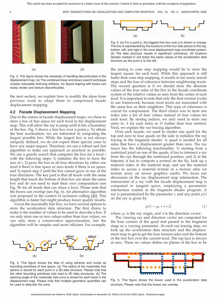
Due to the nature of facade displacement maps, we chose tostore a box of free space for each texel in the displacementmap. This will allow the ray to jump until it hits a boundaryof the box. Fig. 5 shows a free box over a point p. To obtainthe best acceleration, we are interested in computing thelargest possible box. While the largest box is not alwaysuniquely defined, we do not expect these special cases tohave any major impact. Therefore, we use a robust and fastalgorithm to make our approach as practical as possible.We use a greedy search that computes the box for a texel twith the following steps: 1) initialize the box to have thesize of t, 2) grow the box in all four directions by either onetexel if there is free space or zero texels if there is no space,and 3) repeat step 2 until the box cannot grow in any of thefour directions. The key part is that all texels with the sameheight that touch the bottom of that box can share the samebox and do not need to start their own computation (seeFig. 5b for all texels that can share a box). Please note thatthe boxes can overlap (see Fig. 6). An alternative algorithmwas proposed in the context of occlusion culling [46]. Thisalgorithm is faster but might produce lower quality results.
Given the maximally free box, we have several options tostore the acceleration data structure. The first choice tomake is the number of values to be used to describe a box. Ifwe only store one or two values rather than four values, wecan only store a conservative approximation, but thealgorithm will be simpler and more efficient. For example,
the analog to cone step mapping would be to store thelargest square for each texel. While this approach is stillfaster than cone step mapping, it results in too many searchsteps and the loss of coherence between neighboring texels.The second question is if we should store the absolutevalues of the four sides of the box in the facade coordinatesystem or the relative values as seen from the center of eachtexel. It is important to note that only the first version worksin our framework, because most texels are associated withthe same box as their neighbors. This type of coherence iscrucial for compression. The third choice was to store oneindex into a list of four values instead of four values foreach texel. By storing indices, we only need to store oneentry in A for each entry in D (rather than four entries).Next, we explain the ray-tracing algorithm.
Over each facade, we need to render one quad for thetop and zero to four quads on the side to initialize the raytracing in the fragment shader. A quad is needed for allsides that have a displacement greater than zero. The raytracer has the following functionality: 1) starting from arasterized pixel on one of the quads, it has to intersect a rayfrom the eye through the rasterized position, and 2) at thehitpoint, it has to compute a normal on the fly, look up amaterial index in the material map, and use the materialindex to access a material texture in a texture atlas (ortexture array on newer graphics cards). We focus ourdiscussion on the ray displacement map intersection. Theintersection of a ray with the facade displacement map iscomputed in tangent space, employing a parametricintersection routine in the fragment shader program. Aray is parameterized by the parameter t, and any point pðtÞon the ray is given by
pðtÞ ¼ p0 þ t � ~d; ð1Þwhere p0 is the ray origin, and d is the direction vector.
The viewing ray and direction vector are computed forthe four corners of the quad and passed to the fragmentstage as a varying parameter. At each ray-tracing step, welook up the acceleration data structure and the displace-ment map to get to get the four nearest sides and the bottomof the free box over the current texel. The top face is alwaysat zero. These six values define six planes of the box to be
4 IEEE TRANSACTIONS ON VISUALIZATION AND COMPUTER GRAPHICS, VOL. 15, NO. 2, MARCH/APRIL 2009
Fig. 4. This figure shows the idea of using spheres and cones asbounding primitives of free space. (a) The radius of the maximally freesphere is stored for each point in a 3D data structure. Please note thatthe other bounding primitives only lead to 2D data structures. (b) Theopening angle of the maximally free cone is stored for each texel in thedisplacement map. Please note that multiple geometric quantities canbe used to describe the cone.
Fig. 3. This figure shows the necessity of handling discontinuities in the
displacement map. (a) The combined linear and binary search technique
creates noticeable texturing artifacts. (b) Space leaping with boxes can
nicely render and texture discontinuities.
Fig. 5. (a) For a point p, the biggest free box over p is shown in orange.The box is represented by the locations of the four side planes to the top,bottom, left, and right in the local displacement map coordinate system.(b) The data structure results in significant coherence. All locations(texels) marked in red share the same values of the acceleration datastructure as the point p to the left.
Fig. 6. This figure shows the boxes used in the acceleration data
structure. Please note that the boxes can overlap.
This article has been accepted for inclusion in a future issue of this journal. Content is final as presented, with the exception of pagination.
Authorized licensed use limited to: IEEE Xplore. Downloaded on November 20, 2008 at 15:22 from IEEE Xplore. Restrictions apply.
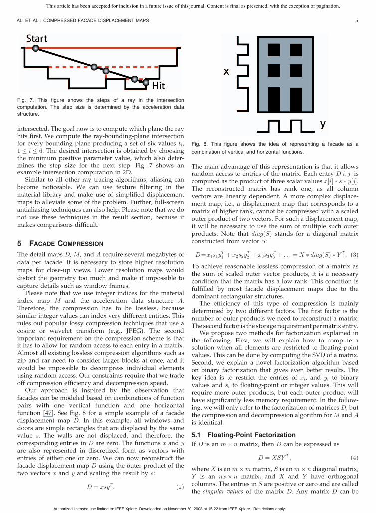
intersected. The goal now is to compute which plane the rayhits first. We compute the ray-bounding-plane intersectionfor every bounding plane producing a set of six values ti,1 � i � 6. The desired intersection is obtained by choosingthe minimum positive parameter value, which also deter-mines the step size for the next step. Fig. 7 shows anexample intersection computation in 2D.
Similar to all other ray tracing algorithms, aliasing canbecome noticeable. We can use texture filtering in thematerial library and make use of simplified displacementmaps to alleviate some of the problem. Further, full-screenantialiasing techniques can also help. Please note that we donot use these techniques in the result section, because itmakes comparisons difficult.
5 FACADE COMPRESSION
The detail maps D, M, and A require several megabytes ofdata per facade. It is necessary to store higher resolutionmaps for close-up views. Lower resolution maps woulddistort the geometry too much and make it impossible tocapture details such as window frames.
Please note that we use integer indices for the materialindex map M and the acceleration data structure A.Therefore, the compression has to be lossless, becausesimilar integer values can index very different entities. Thisrules out popular lossy compression techniques that use acosine or wavelet transform (e.g., JPEG). The secondimportant requirement on the compression scheme is thatit has to allow for random access to each entry in a matrix.Almost all existing lossless compression algorithms such aszip and rar need to consider larger blocks at once, and itwould be impossible to decompress individual elementsusing random access. Our constraints require that we tradeoff compression efficiency and decompression speed.
Our approach is inspired by the observation thatfacades can be modeled based on combinations of functionpairs with one vertical function and one horizontalfunction [47]. See Fig. 8 for a simple example of a facadedisplacement map D. In this example, all windows anddoors are simple rectangles that are displaced by the samevalue s. The walls are not displaced, and therefore, thecorresponding entries in D are zero. The functions x and yare also represented in discretized form as vectors withentries of either one or zero. We can now reconstruct thefacade displacement map D using the outer product of thetwo vectors x and y and scaling the result by s:
D ¼ xsyT : ð2Þ
The main advantage of this representation is that it allowsrandom access to entries of the matrix. Each entry D½i; j� iscomputed as the product of three scalar values x½i� � s � y½j�.The reconstructed matrix has rank one, as all columnvectors are linearly dependent. A more complex displace-ment map, i.e., a displacement map that corresponds to amatrix of higher rank, cannot be compressed with a scaledouter product of two vectors. For such a displacement map,it will be necessary to use the sum of multiple such outerproducts. Note that diagðSÞ stands for a diagonal matrixconstructed from vector S:
D¼x1s1yT1 þ x2s2y
T2 þ x3s3y
T3 þ . . . ¼ X � diagðSÞ � Y T : ð3Þ
To achieve reasonable lossless compression of a matrix asthe sum of scaled outer vector products, it is a necessarycondition that the matrix has a low rank. This condition isfulfilled by most facade displacement maps due to thedominant rectangular structures.
The efficiency of this type of compression is mainlydetermined by two different factors. The first factor is thenumber of outer products we need to reconstruct a matrix.The second factor is the storage requirement permatrix entry.
We propose two methods for factorization explained inthe following. First, we will explain how to compute asolution when all elements are restricted to floating-pointvalues. This can be done by computing the SVD of a matrix.Second, we explain a novel factorization algorithm basedon binary factorization that gives even better results. Thekey idea is to restrict the entries of xi, and yi to binaryvalues and si to floating-point or integer values. This willrequire more outer products, but each outer product willhave significantly less memory requirement. In the follow-ing, we will only refer to the factorization of matrices D, butthe compression and decompression algorithm for M and Ais identical.
5.1 Floating-Point Factorization
If D is an m� n matrix, then D can be expressed as
D ¼ XSY T ; ð4Þwhere X is an m�m matrix, S is an m� n diagonal matrix,Y is an nx� n matrix, and X and Y have orthogonalcolumns. The entries in S are positive or zero and are calledthe singular values of the matrix D. Any matrix D can be
ALI ET AL.: COMPRESSED FACADE DISPLACEMENT MAPS 5
Fig. 7. This figure shows the steps of a ray in the intersection
computation. The step size is determined by the acceleration data
structure.
Fig. 8. This figure shows the idea of representing a facade as a
combination of vertical and horizontal functions.
This article has been accepted for inclusion in a future issue of this journal. Content is final as presented, with the exception of pagination.
Authorized licensed use limited to: IEEE Xplore. Downloaded on November 20, 2008 at 15:22 from IEEE Xplore. Restrictions apply.

written as a weighted sum of outer products of columns ofX and Y , where the weights are the singular values sj [48]:
Dij ¼XN�1
k¼0
skXikYjk: ð5Þ
The singular values appear along the diagonal in thematrix S in descending order. We can safely discard thesingular values that are zero because the terms in the aboveouter product corresponding to these singular values willvanish. In our application, we can expect the singularvalues to go quickly toward zero. To reconstruct theelement Dði; jÞp, we use the following formula (here, thesubscript p indicates the number of singular valuesretained):
Dði; jÞp ¼Xp�1
k¼0
XikSkkYjk: ð6Þ
To guarantee lossless compression for integer entries inM and A, we use as many singular values as are required toguarantee that the rounded reconstructed values areidentical to the original values. For D, we keep all singularvalues that are nonzero. Due to the regularity of facades,there is a clear jump from nonzero to zero singular values.
5.2 Binary Factorization
The idea for the binary factorization is to factor an arbitrarymatrix D into the product of three matrices D ¼ XSY T ,similar to SVD. However, we want to restrict the entries inX and Y to binary values while allowing floating-pointvalues for the entries in the diagonal matrix S. Allpreviously described factorization methods produce sin-gular values and singular vectors with continuous entries.There are only few exceptions of discrete factorization, e.g.,[49] and [50], but previous papers impose restrictions onthe matrices that are not useful for the given application.We therefore propose a new numerical algorithm based ontwo building blocks: First, we want to find the approxima-tion of a matrix as a scaled outer product of two binaryvectors x and y. Second, we describe how to use thisbuilding block for a complete algorithm.
Rank-one approximation. We first consider the rank-one binary matrix factorization, where for a given matrixD 2 Rm�n, we find the optimal x 2 f0; 1gm, y 2 f0; 1gn, and� such that �xyT approximates the matrix D. In ourapplications, the entries in D consist of a small set ofpositive integers. Let dD � maxijfDijg be the maximuminteger in D. We simply set � ¼ dD. The concept can best
be visualized by a binary matrix with entries 2 f0; 1g,where all entries that are equal to the highest entry areone, and all others are zero. See Fig. 9 for an example. Wethen build a bipartite graph G ¼ ðE; Vx [ VyÞ, where eachentry in x corresponds to a node in graph Vx, each entry iny corresponds to a node in the other graph Vy, and E is theset of edges between Vx and Vy. There is an edge betweenthe ith entry in x and the jth entry in y if and only ifDij ¼ dD. For the example in Fig. 9, we show the resultinggraph in Fig. 10a. Next, we look for a subset of nodes in Vx
and a subset of nodes in Vy so that the subgraph inducedby these two subsets forms a maximum complete bipartitesubgraph. This is an NP-hard problem [51]. We apply agreedy heuristic for the computation as follows:
Among all the vertices of Vx, we find a vertex u such thatthe total number of neighbors in Vy (v 2 Vy is a neighbor of uif there is an edge between these two nodes) ismaximum.Weadd u to an initially empty setLx and add all the neighbors ofu to another empty setLy. It is clear that these two setsLx andLy form a clique, as all vertices in Lx are connected to allvertices in Ly. Denote jLx � Lyj ¼ jLxkLyj as the size of theclique formed by Lx and Ly, where jLxj and jLyj denote thenumber of vertices in Lx and Ly, respectively.
We then repeat the above step on the subgraph ~G of Ginduced by the neighbors Ly of u, where the vertices of ~Gconsist of the ones from both Vx and the current Ly. That is,among the vertices Vx not in the currentLx, we find a vertex ~usuch that the total numberofneighbors inLy ismaximumandadd ~u to Lx. The set Ly will also be updated by removing allvertices that are not neighbors of ~u. And so on, until at somepoint the current setLy becomes empty.At this point,weget asequence of cliques formed by different sets Lx and Ly. Wefind the onewith themaximum size jLx � Lyj and output thevector x from Lx and the vector y from Ly. See Figs. 10b and10c for an example.
Rank-p approximation. The idea of the complete algo-rithm is the following iterative algorithm: 1) compute arank-one binary factorization, 2) subtract the rank-onesolution from the matrix, and 3) if the algorithm is notconverged go to step 1. The formula for a rank-p binarymatrix factorization is given by
Dp ¼Xp
i¼1
�ixiyTi ; ð7Þ
where ðxk; yk; �kÞ can be obtained by computing the rank-one binary factorization of the residue matrix:
D�Xk�1
i¼1
�ixiyTi ¼ D�Dk�1: ð8Þ
6 IEEE TRANSACTIONS ON VISUALIZATION AND COMPUTER GRAPHICS, VOL. 15, NO. 2, MARCH/APRIL 2009
Fig. 9. Left: Input matrix. Right: The binary matrix of the maximum
values.
Fig. 10. (a) Bipartite graph corresponding to entries in x and y.(b) Subset of nodes that form a complete subgraph. (c) Therank-one approximation.
This article has been accepted for inclusion in a future issue of this journal. Content is final as presented, with the exception of pagination.
Authorized licensed use limited to: IEEE Xplore. Downloaded on November 20, 2008 at 15:22 from IEEE Xplore. Restrictions apply.
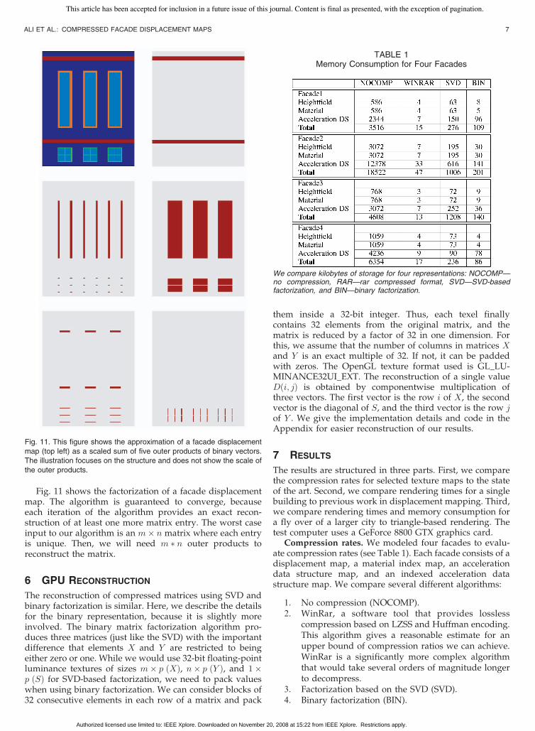
Fig. 11 shows the factorization of a facade displacementmap. The algorithm is guaranteed to converge, becauseeach iteration of the algorithm provides an exact recon-struction of at least one more matrix entry. The worst caseinput to our algorithm is an m� n matrix where each entryis unique. Then, we will need m � n outer products toreconstruct the matrix.
6 GPU RECONSTRUCTION
The reconstruction of compressed matrices using SVD andbinary factorization is similar. Here, we describe the detailsfor the binary representation, because it is slightly moreinvolved. The binary matrix factorization algorithm pro-duces three matrices (just like the SVD) with the importantdifference that elements X and Y are restricted to beingeither zero or one. While we would use 32-bit floating-pointluminance textures of sizes m� p ðXÞ, n� p ðY Þ, and 1�p ðSÞ for SVD-based factorization, we need to pack valueswhen using binary factorization. We can consider blocks of32 consecutive elements in each row of a matrix and pack
them inside a 32-bit integer. Thus, each texel finallycontains 32 elements from the original matrix, and thematrix is reduced by a factor of 32 in one dimension. Forthis, we assume that the number of columns in matrices Xand Y is an exact multiple of 32. If not, it can be paddedwith zeros. The OpenGL texture format used is GL_LU-MINANCE32UI_EXT. The reconstruction of a single valueDði; jÞ is obtained by componentwise multiplication ofthree vectors. The first vector is the row i of X, the secondvector is the diagonal of S, and the third vector is the row jof Y . We give the implementation details and code in theAppendix for easier reconstruction of our results.
7 RESULTS
The results are structured in three parts. First, we comparethe compression rates for selected texture maps to the stateof the art. Second, we compare rendering times for a singlebuilding to previous work in displacement mapping. Third,we compare rendering times and memory consumption fora fly over of a larger city to triangle-based rendering. Thetest computer uses a GeForce 8800 GTX graphics card.
Compression rates. We modeled four facades to evalu-ate compression rates (see Table 1). Each facade consists of adisplacement map, a material index map, an accelerationdata structure map, and an indexed acceleration datastructure map. We compare several different algorithms:
1. No compression (NOCOMP).2. WinRar, a software tool that provides lossless
compression based on LZSS and Huffman encoding.This algorithm gives a reasonable estimate for anupper bound of compression ratios we can achieve.WinRar is a significantly more complex algorithmthat would take several orders of magnitude longerto decompress.
3. Factorization based on the SVD (SVD).4. Binary factorization (BIN).
ALI ET AL.: COMPRESSED FACADE DISPLACEMENT MAPS 7
Fig. 11. This figure shows the approximation of a facade displacement
map (top left) as a scaled sum of five outer products of binary vectors.
The illustration focuses on the structure and does not show the scale of
the outer products.
TABLE 1Memory Consumption for Four Facades
We compare kilobytes of storage for four representations: NOCOMP—no compression, RAR—rar compressed format, SVD—SVD-basedfactorization, and BIN—binary factorization.
This article has been accepted for inclusion in a future issue of this journal. Content is final as presented, with the exception of pagination.
Authorized licensed use limited to: IEEE Xplore. Downloaded on November 20, 2008 at 15:22 from IEEE Xplore. Restrictions apply.
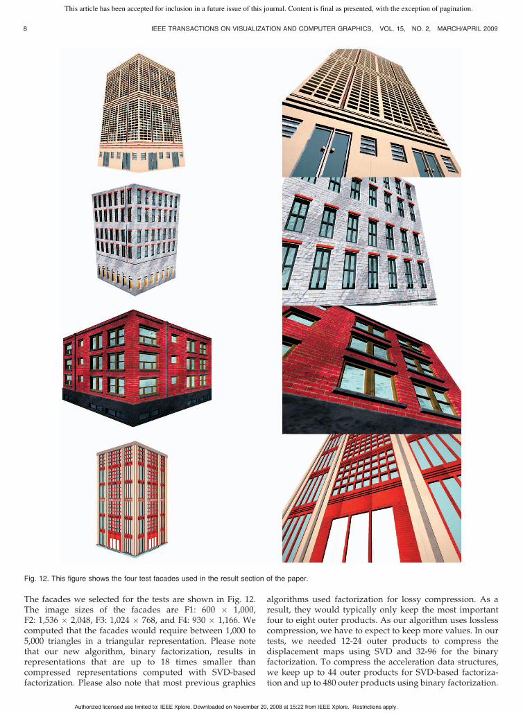
The facades we selected for the tests are shown in Fig. 12.The image sizes of the facades are F1: 600 � 1,000,F2: 1,536 � 2,048, F3: 1,024 � 768, and F4: 930 � 1,166. Wecomputed that the facades would require between 1,000 to5,000 triangles in a triangular representation. Please notethat our new algorithm, binary factorization, results inrepresentations that are up to 18 times smaller thancompressed representations computed with SVD-basedfactorization. Please also note that most previous graphics
algorithms used factorization for lossy compression. As aresult, they would typically only keep the most importantfour to eight outer products. As our algorithm uses losslesscompression, we have to expect to keep more values. In ourtests, we needed 12-24 outer products to compress thedisplacement maps using SVD and 32-96 for the binaryfactorization. To compress the acceleration data structures,we keep up to 44 outer products for SVD-based factoriza-tion and up to 480 outer products using binary factorization.
8 IEEE TRANSACTIONS ON VISUALIZATION AND COMPUTER GRAPHICS, VOL. 15, NO. 2, MARCH/APRIL 2009
Fig. 12. This figure shows the four test facades used in the result section of the paper.
This article has been accepted for inclusion in a future issue of this journal. Content is final as presented, with the exception of pagination.
Authorized licensed use limited to: IEEE Xplore. Downloaded on November 20, 2008 at 15:22 from IEEE Xplore. Restrictions apply.
The compression algorithm works better for the height fieldand material information than for the acceleration datastructure. The acceleration data structure contains a type ofcoherence that is not a very good match for the binaryfactorization. For example, consider a simple model withrectangular facade elements having identical displacements(see Fig. 8). The displacements and material information canbe encoded in a single term using binary factorization.However, the values in the acceleration data structure haveonly some coherence in the vertical and horizontal directionso that multiple terms are needed.
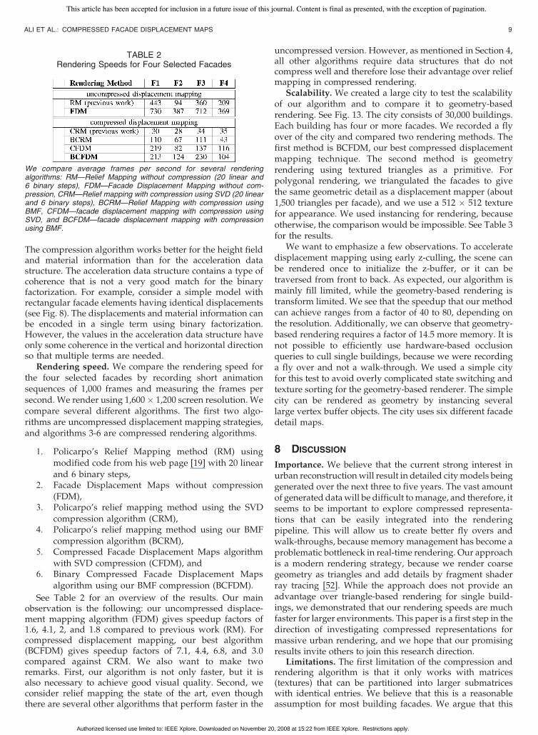
Rendering speed. We compare the rendering speed forthe four selected facades by recording short animationsequences of 1,000 frames and measuring the frames persecond. We render using 1,600� 1,200 screen resolution. Wecompare several different algorithms. The first two algo-rithms are uncompressed displacement mapping strategies,and algorithms 3-6 are compressed rendering algorithms.
1. Policarpo’s Relief Mapping method (RM) using
modified code from his web page [19] with 20 linearand 6 binary steps,
2. Facade Displacement Maps without compression(FDM),
3. Policarpo’s relief mapping method using the SVD
compression algorithm (CRM),4. Policarpo’s relief mapping method using our BMF
compression algorithm (BCRM),5. Compressed Facade Displacement Maps algorithm
with SVD compression (CFDM), and6. Binary Compressed Facade Displacement Maps
algorithm using our BMF compression (BCFDM).
See Table 2 for an overview of the results. Our mainobservation is the following: our uncompressed displace-ment mapping algorithm (FDM) gives speedup factors of1.6, 4.1, 2, and 1.8 compared to previous work (RM). Forcompressed displacement mapping, our best algorithm(BCFDM) gives speedup factors of 7.1, 4.4, 6.8, and 3.0compared against CRM. We also want to make tworemarks. First, our algorithm is not only faster, but it isalso necessary to achieve good visual quality. Second, weconsider relief mapping the state of the art, even thoughthere are several other algorithms that perform faster in the
uncompressed version. However, as mentioned in Section 4,all other algorithms require data structures that do notcompress well and therefore lose their advantage over reliefmapping in compressed rendering.
Scalability. We created a large city to test the scalabilityof our algorithm and to compare it to geometry-basedrendering. See Fig. 13. The city consists of 30,000 buildings.Each building has four or more facades. We recorded a flyover of the city and compared two rendering methods. Thefirst method is BCFDM, our best compressed displacementmapping technique. The second method is geometryrendering using textured triangles as a primitive. Forpolygonal rendering, we triangulated the facades to givethe same geometric detail as a displacement mapper (about1,500 triangles per facade), and we use a 512 � 512 texturefor appearance. We used instancing for rendering, becauseotherwise, the comparison would be impossible. See Table 3for the results.
We want to emphasize a few observations. To acceleratedisplacement mapping using early z-culling, the scene canbe rendered once to initialize the z-buffer, or it can betraversed from front to back. As expected, our algorithm ismainly fill limited, while the geometry-based rendering istransform limited. We see that the speedup that our methodcan achieve ranges from a factor of 40 to 80, depending onthe resolution. Additionally, we can observe that geometry-based rendering requires a factor of 14.5 more memory. It isnot possible to efficiently use hardware-based occlusionqueries to cull single buildings, because we were recordinga fly over and not a walk-through. We used a simple cityfor this test to avoid overly complicated state switching andtexture sorting for the geometry-based renderer. The simplecity can be rendered as geometry by instancing severallarge vertex buffer objects. The city uses six different facadedetail maps.
8 DISCUSSION
Importance. We believe that the current strong interest inurban reconstructionwill result in detailed citymodels beinggenerated over the next three to five years. The vast amountof generated datawill be difficult tomanage, and therefore, itseems to be important to explore compressed representa-tions that can be easily integrated into the renderingpipeline. This will allow us to create better fly overs andwalk-throughs, because memory management has become aproblematic bottleneck in real-time rendering. Our approachis a modern rendering strategy, because we render coarsegeometry as triangles and add details by fragment shaderray tracing [52]. While the approach does not provide anadvantage over triangle-based rendering for single build-ings, we demonstrated that our rendering speeds are muchfaster for larger environments. This paper is a first step in thedirection of investigating compressed representations formassive urban rendering, and we hope that our promisingresults invite others to join this research direction.
Limitations. The first limitation of the compression andrendering algorithm is that it only works with matrices(textures) that can be partitioned into larger submatriceswith identical entries. We believe that this is a reasonableassumption for most building facades. We argue that this
ALI ET AL.: COMPRESSED FACADE DISPLACEMENT MAPS 9
TABLE 2Rendering Speeds for Four Selected Facades
We compare average frames per second for several renderingalgorithms: RM—Relief Mapping without compression (20 linear and6 binary steps), FDM—Facade Displacement Mapping without com-pression, CRM—Relief mapping with compression using SVD (20 linearand 6 binary steps), BCRM—Relief Mapping with compression usingBMF, CFDM—facade displacement mapping with compression usingSVD, and BCFDM—facade displacement mapping with compressionusing BMF.
This article has been accepted for inclusion in a future issue of this journal. Content is final as presented, with the exception of pagination.
Authorized licensed use limited to: IEEE Xplore. Downloaded on November 20, 2008 at 15:22 from IEEE Xplore. Restrictions apply.

class of matrices is important enough so that it warrants aseparate solution for rendering and compression. In futurework, we plan to address the compression of generaldisplacement maps to complement our compression algo-rithm for facade displacement maps. We intend to useconstrained matrix factorization algorithms to cull thecomputation of outer products.
Comparison to other compression algorithms. It isdifficult to make a formal comparison of compressionalgorithms, because we focus on a special class of matrices(textures), and we require very fast decompression. We didnot expect to outperform strong algorithms such as rar withour compression technique, but we were surprised to see asignificant improvement over SVD. We believe that matrixfactorization is a great tool for compression in the context ofreal-time rendering, because it allows random access bydecompressing any entry in thematrix separately.During thecourse of this research project, we also experimented withother techniques such as the wavelet transform and tensorfactorization, but the decompression is much more sophis-ticated and cannot easily be integrated into a shaderprogram.
9 CONCLUSIONS
This paper presents a method to efficiently render massiveurban models. Our main idea is to model the city usingdisplacement maps and to render from a compressedrepresentation directly. We demonstrated that our render-ing framework outperforms existing displacement mappingtechniques and geometry-based rendering for large models.We believe that texture compression will be a crucial aspect
of the future development of real-time rendering, and we
are interested to pursue related avenues of research.
APPENDIX
SOURCE CODE
We briefly discuss the implementation of the reconstruction
of binary factorizedmatrices. Let us look at the code Listing 1.
We take as input three sampler variables containing theX, Y ,
and Smatrices, input texture coordinates, and the number of
iterations required for reconstruction. We start a loop that
performs the reconstruction. There are a couple of important
things to note. Recall that when the original matrices are
encoded in textures every 32-bit texel contains 32 elements of
the original matrix. Thus, in one lookup, we have access to
32matrix elements. For us, the value of the integer looked up
from the texture has no meaning; we treat it like a binary
10 IEEE TRANSACTIONS ON VISUALIZATION AND COMPUTER GRAPHICS, VOL. 15, NO. 2, MARCH/APRIL 2009
TABLE 3This Table Compares the Rendering Speed and Memory
Consumption of Our Algorithm againstGeometry-Based Rendering
Fig. 13. A complete city rendered with Compressed Facade Displacement Maps. The city consists of 30,000 buildings.
This article has been accepted for inclusion in a future issue of this journal. Content is final as presented, with the exception of pagination.
Authorized licensed use limited to: IEEE Xplore. Downloaded on November 20, 2008 at 15:22 from IEEE Xplore. Restrictions apply.
string because we are interested in individual bits. The
simple way to reconstruct would be to knock out 1 bit at a
time using bitwise mask and multiply. This has complexity
OðnÞ, where n is the length of the binary string. We observe
that thematrices obtained by BMF are sparse, andmost of the
elements are zeros. These do not contribute to the reconstruc-
tion, and it is inefficient to perform bitwise shifts and
multiplications for each zero encountered. We use a method
based on discrete logarithms [53] to efficiently find the
rightmost one in a binary string. Inside the loop, we find the
position of the rightmost one and right shift the string so that
this one is shifted out. We then look up the matrix S in the
appropriately shifted location and simply add the looked up
value to our partial sum. The loop terminates when all the
ones have been shifted out at which point the value of the
integer becomes zero.
Listing 1 bmflookup_grayscale: Lookup routine for gray-scale images factorized with BMFfloat bmflookup_grayscale(
uniform isamplerRECT X,
uniform samplerRECT S,
uniform isamplerRECT Y,
float2 texCoords,
int recon)
{
float4 sk ¼ float4ð0; 0; 0; 0Þ;float c ¼ 0:0;int4 xk, yk, x_vec, y_vec;int xk and yk ¼ 0, position ¼ 0, i ¼ 0;
for (int k ¼ 0; k < recon; k þ¼ 32){
xk ¼ texRECTðX;float2 (float(k/32), texCoords.y));
yk ¼ texRECTðY;float2(float(k/32),texCoords.x));
xk and yk ¼ xk:x & yk:x;
for ðint j ¼ 0; xk and yk !¼ 0; jþþÞ{
position ¼ discrete logs [(xk_and_yk & (-xk_and_yk)) % 37];
xk and yk ¼ xk and yk >>ðpositionþ 1Þ;
i ¼ iþ positionþ signðjÞ;sk ¼ texRECTðS; float2ðkþ i; 0:0ÞÞ : x;c þ¼ sk:x;
}
}
return c;}
ACKNOWLEDGMENTS
The authors thank Pushpak Karnick for code reviews andfacade modeling, John Owens for paper review andfeedback, and all reviewers for their helpful comments.The authors would like to acknowledge the support of USNational Science Foundation (NSF) Contracts IIS 0612269,CCF 0811790, and IIS 0757623 and NGA Contract HM1582-05-1-2004.
REFERENCES
[1] D.W. Paglieroni and S.M. Petersen, “Height DistributionalDistance Transform Methods for Height Field Ray Tracing,”ACM Trans. Graphics, vol. 13, no. 4, pp. 376-399, 1994.
[2] W. Donnelly, “Per-Pixel Displacement Mapping with DistanceFunctions,” GPU Gems 2, 2005.
[3] J. Kautz and M.D. McCool, “Interactive Rendering with ArbitraryBRDFs Using Separable Approximations,” Proc. EurographicsWorkshop Rendering Techniques, 253-253, 1999.
[4] L. Borgeat, G. Godin, F. Blais, P. Massicotte, and C. Lahanier,“GoLD: Interactive Display of Huge Colored and TexturedModels,” ACM Trans. Graphics, vol. 26, no. 3, pp. 869-877,July 2005.
[5] E. Gobbetti and F. Marton, “Far Voxels: A MultiresolutionFramework for interactive Rendering of Huge Complex 3DModels on Commodity Graphics Platforms,” ACM Trans. Graphics,vol. 24, no. 3, pp. 878-885, July 2005.
[6] P. Lindstrom, D. Koller, W. Ribarsky, L.F. Hodges, N. Faust, andG.A. Turner, “Real-Time, Continuous Level of Detail Rendering ofHeight Fields,” Proc. ACM SIGGRAPH ’96, vol. 30, no. Ann. Conf.Series, pp. 109-118, 1996.
[7] F. Losasso and H. Hoppe, “Geometry Clipmaps: Terrain Render-ing Using Nested Regular Grids,” ACM Trans. Graphics, vol. 23,no. 3, pp. 769-776, Aug. 2004.
[8] E. Gobbetti, F. Marton, P. Cignoni, M.D. Benedetto, andF. Ganovelli, “C-BDAM—Compressed Batched Dynamic Adap-tive Meshes for Terrain Rendering,” Computer Graphics Forum,vol. 25, no. 3, Sept. 2006.
[9] F. Musgrave, “Grid Tracing: Fast Ray Tracing for Height Fields,”technical report, 1988.
[10] D.W. Paglieroni, “The Directional Parameter Plane Transform of aHeight Field,” ACM Trans. Graphics, vol. 17, no. 1, pp. 50-70, 1998.
[11] C.-H. Lee and Y.-G. Shin, “A Terrain Rendering Method UsingVertical Ray Coherence,” J. Visualization and Computer Animation,vol. 8, no. 2, pp. 97-114, 1997.
[12] B.E. Smits, P. Shirley, and M.M. Stark, “Direct Ray Tracing ofDisplacement Mapped Triangles,” Proc. Eurographics WorkshopRendering Techniques, pp. 307-318, 2000.
[13] R.L. Cook, “Shade Trees,” Proc. ACM SIGGRAPH ’84, pp. 223-231,1984.
[14] J.F. Blinn, “Simulation of Wrinkled Surfaces,” Proc. ACMSIGGRAPH ’78, pp. 286-292, 1978.
[15] S. Gumhold and T. Huettner, “Multiresolution Rendering withDisplacement Mapping,” Proc. ACM SIGGRAPH/EurographicsWorkshop Graphics Hardware (HWWS ’99), pp. 55-66, 1999.
[16] M. Doggett and J. Hirche, “Adaptive View Dependent Tessellationof Displacement Maps,” Proc. ACM SIGGRAPH/EurographicsWorkshop Graphics Hardware (HWWS ’00), pp. 59-66, 2000.
[17] K. Moule and M.D. McCool, “Efficient Bounded AdaptiveTessellation of Displacement Maps,” Proc. Conf. Graphics Interface(GI ’02), pp. 171-180, May 2002.
[18] J. Hirche, A. Ehlert, S. Guthe, and M. Doggett, “HardwareAccelerated Per-Pixel Displacement Mapping,” Proc. Conf. Gra-phics Interface (GI ’04), pp. 153-158, 2004.
[19] F. Policarpo, M.M. Oliveira, and A.L.D.C. Jo, “Real-Time ReliefMapping on Arbitrary Polygonal Surfaces,” Proc. ACMSIGGRAPH Symp. Interactive 3D Graphics and Games (I3D ’05),pp. 155-162, 2005.
[20] E.A. Risser, M.A. Shah, and S. Pattanaik, “Interval Mapping,”technical report, School of Eng. and Computer Science, Univ. ofCentral Florida, 2006.
[21] L. Baboud and X. Decoret, “Rendering Geometry with ReliefTextures,” Proc. Conf. Graphics Interface (GI ’06), pp. 195-201, 2006.
[22] J. Dummer, “Cone Step Mapping: An Iterative Ray-HeightfieldIntersection Algorithm,” technical report, http://www.lonesock.net/files/ConeStepMapping.pdf, 2006.
[23] L. Wang, X. Wang, X. Tong, S. Lin, S. Hu, B. Guo, and H.-Y. Shum,“View-Dependent Displacement Mapping,” ACM Trans. Graphics,vol. 22, no. 3, pp. 334-339, 2003.
[24] N. Tatarchuk, “Dynamic Parallax Occlusion Mapping withApproximate Soft Shadows,” Proc. ACM SIGGRAPH Symp.Interactive 3D Graphics and Games (I3D ’06), pp. 63-69, 2006.
[25] G.H. Golub and C.F. Van Loan, Matrix Computations, third ed.Johns Hopkins Univ. Press, 1996.
[26] I.T. Jolliffe, Principal Component Analysis. Springer, 1986.
ALI ET AL.: COMPRESSED FACADE DISPLACEMENT MAPS 11
This article has been accepted for inclusion in a future issue of this journal. Content is final as presented, with the exception of pagination.
Authorized licensed use limited to: IEEE Xplore. Downloaded on November 20, 2008 at 15:22 from IEEE Xplore. Restrictions apply.

[27] A. Fournier, “Separating Reflection Functions for LinearRadiosity,” Proc. Eurographics Workshop Rendering Techniques,pp. 296-305, 1995.
[28] R. Wang, J. Tran, and D.P. Luebke, “All-Frequency Relightingof Non-Diffuse Objects Using Separable BRDF Approxima-tion,” Proc. 15th Eurographics Workshop Rendering Techniques,pp. 345-354, 2004.
[29] M. Alexa and W. Muller, “Representing Animations by PrincipalComponents,” Computer Graphics Forum, vol. 19, no. 3, 2000.
[30] K. Nishino, Y. Sato, and K. Ikeuchi, “Eigen-Texture Method:Appearance Compression Based on 3D Model,” Proc. IEEE Conf.Computer Vision and Pattern Recognition (CVPR ’99), pp. 618-624,1999.
[31] M. Turk and A. Pentland, “Eigenfaces for Recognition,” J. CognitiveNeuroscience, vol. 3, no. 1, pp. 71-86, 1991.
[32] J. Lehtinen and J. Kautz, “Matrix Radiance Transfer,” Proc. ACMSIGGRAPH Symp. Interactive 3D Graphics (I3D ’03), pp. 59-64,Apr. 2003.
[33] L. Latta and A. Kolb, “Homomorphic Factorization of BRDF-Based Lighting Computation,” Proc. ACM SIGGRAPH ’02,pp. 509-516, 2002.
[34] M.D. McCool, J. Ang, and A. Ahmad, “Homomorphic Factoriza-tion of BRDFs for High-Performance Rendering,” Proc. ACMSIGGRAPH ’01, pp. 171-178, 2001.
[35] F. Suykens, K. vom Berge, A. Lagae, and P. Dutre, “InteractiveRendering with Bidirectional Texture Functions,” ComputerGraphics Forum, vol. 22, no. 3, pp. 463-472, Sept. 2003.
[36] D.D. Lee and H.S. Seung, Algorithms for Non-Negative MatrixFactorization. MIT Press, pp. 556-562, 2000.
[37] J. Lawrence, S. Rusinkiewicz, and R. Ramamoorthi, “EfficientBRDF Importance Sampling Using a Factored Representation,”ACM Trans. Graphics, vol. 23, no. 3, pp. 496-505, 2004.
[38] J. Lawrence, A. Ben-Artzi, C. DeCoro, W. Matusik, H. Pfister,R. Ramamoorthi, and S. Rusinkiewicz, “Inverse Shade Treesfor Non-Parametric Material Representation and Editing,” ACMTrans. Graphics, vol. 25, no. 3, pp. 735-745, 2006.
[39] P. Peers, K. vom Berge, W. Matusik, R. Ramamoorthi, J. Lawrence,S. Rusinkiewicz, and P. Dutre, “A Compact Factored Representa-tion of Heterogeneous Subsurface Scattering,” ACM Trans.Graphics, vol. 25, no. 3, pp. 746-753, 2006.
[40] P.-P.J. Sloan, J. Hall, J.C. Hart, and J. Snyder, “Clustered PrincipalComponents for Precomputed Radiance Transfer,” ACM Trans.Graphics, vol. 22, no. 3, pp. 382-391, 2003.
[41] A.W. Kristensen, T. Akenine-Moller, and H.W. Jensen, “Precom-puted Local Radiance Transfer for Real-Time Lighting Design,”ACM Trans. Graphics, vol. 24, no. 3, pp. 1208-1215, 2005.
[42] M. Sattler, R. Sarlette, and R. Klein, “Simple and EfficientCompression of Animation Sequences,” Proc. ACM SIGGRAPH/Eurographics Symp. Computer Animation (SCA ’05), pp. 209-218,2005.
[43] O. Arikan, “Compression of Motion Capture Databases,” ACMTrans. Graphics, vol. 25, no. 3, pp. 890-897, http://doi.acm.org/10.1145/1141911.1141971, 2006.
[44] J. Ricard, J. Royan, and O. Aubault, “From Photographs toProcedural Facade Models,” ACM SIGGRAPH ’07, p. 75, 2007.
[45] P. Muller, G. Zeng, P. Wonka, and L.V. Gool, “Image-BasedProcedural Modeling of Facades,” ACM Trans. Graphics, vol. 24,no. 3, p. 85, 2007.
[46] G. Schaufler, J. Dorsey, X. Decoret, and F. Sillion, “Conserva-tive Volumetric Visibility with Occluder Fusion,” Proc. ACMSIGGRAPH ’00, pp. 229-238, 2000.
[47] Y.I.H. Parish and P. Muller, “Procedural Modeling of Cities,” Proc.ACM SIGGRAPH ’01, E. Fiume, ed., pp. 301-308, 2001.
[48] W.H. Press, W.T. Vetterling, S.A. Teukolsky, and B.P. Flannery,Numerical Recipes in C++: The Art of Scientific Computing, 2002.
[49] M. Koyuturk and A. Grama, “PROXIMUS: A Framework forAnalyzing Very High Dimensional Discrete-Attributed Datasets,”Proc. ACM SIGKDD ’03, pp. 147-156, 2003.
[50] T. Kolda and D. O’Leary, “A Semidiscrete Matrix Decompositionfor Latent Semantic Indexing Information Retrieval,” ACM Trans.Information Systems, vol. 16, no. 4, pp. 322-346, 1998.
[51] M.R. Garey and D.S. Johnson, Computers and Intractability: A Guideto the Theory of NP-Completeness. W.H. Freeman, 1979.
[52] D. Blythe, “The Direct3d 10 System,” ACM Trans. Graphics, vol. 25,no. 3, pp. 724-734, 2006.
[53] C. Sturtivant, Finding the Right One, http://blog.lib.umn.edu/sturt001/sturtivant/2006/12/finding_the_right_one.html, 2008.
Saif Ali received the BS degree in computerengineering from Jamia Millia Islamia, NewDelhi, India, and the MS degree in computerscience and a concentration in arts, media, andengineering from Arizona State University inSeptember 2007. He is a member of the StreamComputing SDK team at AMD, where he writescode for GPGPU on next-generation graphicshardware. He cultivates a parallel interest inphotography.
Jieping Ye received the PhD degree in compu-ter science from the University of Minnesota-Twin Cities in 2005. He is currently an assistantprofessor in the Department of ComputerScience and Engineering, Arizona State Uni-versity. He has been a core faculty member ofthe Center for Evolutionary Functional Geno-mics, Bio-design Institute, Arizona State Uni-versity, since August 2005. His researchinterests include machine learning, data mining,
and bioinformatics. He has published extensively in these areas. Hereceived the Guidant Fellowship in 2004 and 2005. In 2004, his paper ongeneralized low-rank approximations of matrices won the outstandingstudent paper award at the 21st International Conference on MachineLearning. He is a member of the IEEE and the ACM.
Anshuman Razdan received the BS and MSdegrees in mechanical engineering and the PhDdegree in computer science. He is an associateprofessor in the Division of Computing Studiesand the Director of Advanced TechnologyInnovation Collaboratory (ATIC) and theI3DEA Laboratory (i3deas.asu.edu) at ArizonaState University (ASU), Polytechnic campus. Hehas been a pioneer in computing-based inter-disciplinary collaboration and research at ASU.
His research interests include geometric design, computer graphics,document exploitation, and geospatial visualization and analysis. He isthe principal investigator and a collaborator on several federal grantsfrom agencies, including the US National Science Foundation (NSF),NGA, and NIH. He is a member of the IEEE.
Peter Wonka received the MS degree in urbanplanning and the doctorate in computer sciencefrom the Technical University of Vienna. He iscurrently with Arizona State University (ASU).Prior to coming to ASU, he was a postdoctorateresearcher at the Georgia Institute of Technol-ogy for two years. His research interests includevarious topics in computer graphics, visualiza-tion, and image processing. He is a member ofthe IEEE.
. For more information on this or any other computing topic,please visit our Digital Library at www.computer.org/publications/dlib.
12 IEEE TRANSACTIONS ON VISUALIZATION AND COMPUTER GRAPHICS, VOL. 15, NO. 2, MARCH/APRIL 2009
This article has been accepted for inclusion in a future issue of this journal. Content is final as presented, with the exception of pagination.
Authorized licensed use limited to: IEEE Xplore. Downloaded on November 20, 2008 at 15:22 from IEEE Xplore. Restrictions apply.