stresses around horizontal boreholes drilled in sedimentary rocks
TRANSCRIPT
Journal o[ Petroleum Science and Engineering, 2 (1989) 349-360 349 Elsevier Science Publishers B.V., Amsterdam -- Printed in The Netherlands
STRESSES AROUND HORIZONTAL BOREHOLES DRILLED IN SEDIMENTARY ROCKS
B E R N T SIGVE AADNOY
Rogaland University, P.O. Box 2557, Ullandhaug, N-4004 Stavanger (Norway)
(Received July 8, 1988; revised and accepted October 20, 1988)
Abstract
Aadnoy, B.S., 1989. Stresses around horizontal boreholes drilled in sedimentary rocks. J. Pet. Sci. Eng., 2: 349-360.
The main purpose of this paper is to present the anisotropic stress equations that can be used to analyze fracturing or collapse problems for horizontal boreholes, and to show how anisotropy in the elastic properties of the rock affects the stress field around a horizontal borehole.
This paper gives the complete equations to determine stresses around boreholes in transverse isotropic, but linear elastic sedimentary rocks. The equations to determine the effective stresses are also given. It is shown that the stress fields and their direction is affected by the anisotropic material properties of the rock. Also shown is the deformation pattern of the borehole, which for anisotropic rocks is elliptical rather than cylindrical. Finally, a hydraulic fracturing example is given to show the effect of elastic anisotropy on the fracturing pressure.
Introduct ion
An increasingly number of horizontal wells is drilled today. Despite the economic potent ial offered by these wells, the industry has realized tha t highly inclined boreholes also pose prob- lems. One of the problem areas is wellbore sta- bility. This paper is an a t tempt to analyze the stress field around a horizontal wellbore in a flat sedimentary rock, as a tool for borehole stability analysis.
The presence of a borehole creates a stress concentra t ion in the rock. The equations for stresses around a borehole were initially de- rived by Kirsch (1898). These equations are virtually exclusively used in the petroleum in- dustry. A complete summary of these equations and the stress t ransformat ion equations to use for inclined boreholes are listed in the publi- cation by Aadnoy and Chenevert (1987).
The Kirsch equations are based on linear elasticity and assume isotropic rock properties. It is well known tha t most rocks are anisotropic to some extent, and therefore the isotropic equations are idealized.
This paper is based on the stress equations for orthotropic but linear elastic materials. Typically, nine independent elastic constants are needed to describe such a material. Sedi- menta ry rocks, however, can typically be de- scribed in a simpler way, as t ransverse iso- tropic. One example is shale, which often has equal elastic properties in all directions in the bedding plane, but different elastic properties across the bedding plane. Five independent elastic constants are required to describe a t ransverse isotropic rock, but in this paper we will use a simplified model proposed by Van Cauwelaert (1977), which uses only three elas- tic constants. This paper therefore results in
0920-4105/89/$03.50 © 1989 Elsevier Science Publishers B.V.
350
simplified equations to determine the stress field around a borehole drilled in a sedimentary rock. One condition for the stress equations given in this paper is tha t the hole axis must extend along the bedding plane. For more de- tails on the constitutive relations, see Amadei (1983) and Aadnoy (1987).
Both the plane strain and the plane stress solution are given in this paper. The plane strain case is typically used for deeper bore- holes (see Aadnoy and Chenevert, 1987). How- ever, there exists, to the author 's knowledge, not a simple physical argument for choosing one solution over the other. For many applications, the difference between the plane stress and the plane strain cases is small.
M a t e r i a l properties
In the following section the expressions for the stresses around boreholes located in ortho- tropic materials will be given. The general method is developed by Lekhnitskii (1968), but the specific application is derived in this paper.
Nomenclature
E P
x , y , z
x ' , y ' , z
r,O,z k 2
n
a
a~, ay,a~z,#zz a~ Pw Po c7~ , Cro,ff z
B'
aq
Modulus of elasticity Poisson ratio Reference frame for bedding plane Reference frame for in-situ stresses Polar reference frame Ex/Ey, anisotropy coefficient Material constant Borehole radius In-situ stresses Axial load at the borehole wall Borehole pressure Pore pressure Stresses at the borehole wall Effective stresses Einterpore/Ex, elastic modulus ratio for the interpore material over the porous material Complex parameters of a stress function Angle between the reference frames for the bedding plane and the in-situ stresses Elastic constants (i,j= 1, 2, 3, 4, 5, 6,)
: ~ ! ( / 9 / /
Q
~×
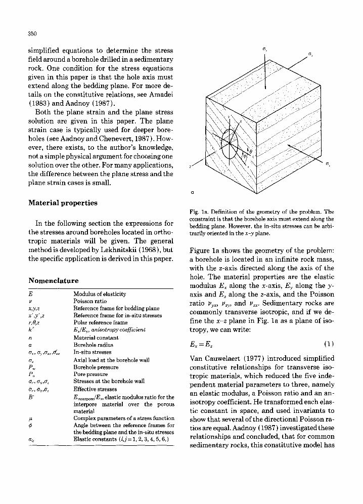
Fig. la. Definition of the geometry of the problem. The constraint is that the borehole axis must extend along the bedding plane. However, the in-situ stresses can be arbi- trarily oriented in the x-y plane.
Figure l a shows the geometry of the problem: a borehole is located in an infinite rock mass, with the z-axis directed along the axis of the hole. The material properties are the elastic modulus Ex along the x-axis, Ey along the y- axis and Ez along the z-axis, and the Poisson ratio vyx, vzy, and v~x. Sedimentary rocks are commonly transverse isotropic, and if we de- fine the x - z plane in Fig. l a as a plane of iso- tropy, we can write:
E~ =E~ (i)
Van Cauwelaert (1977) introduced simplified constitutive relationships for transverse iso- tropic materials, which reduced the five inde- pendent material parameters to three, namely an elastic modulus, a Poisson ratio and an an- isotropy coefficient. He transformed each elas- tic constant in space, and used invariants to show tha t several of the directional Poisson ra- tios are equal. Aadnoy (1987) investigated these relationships and concluded, tha t for common sedimentary rocks, this constitutive model has
reasonable accuracy. The results, as applied to this analysis, are given below:
u = Uyx = Uzx = Uzy (2)
1 2 ~=E--~(I+ p) (3)
M a t h e m a t i c a l m o d e l
In the following a complete mathematical model will be given for stresses at the borehole wall. The basic method is derived by Lekhnit- skii (1968) using complex stress functions. The reader is referred to Lekhnitskii for the com- plete derivations of these equations. The as- sumptions are: linear elastic orthotropic ma- terial, cont inuum mechanics and plane strain or plane stress conditions. We will in the fol- lowing reduce each element of this orthotropic model to the transverse isotropic case, which is chosen as a good description for common sedi- mentary rocks. The borehole is assumed infi- nitely long (to neglect end effects), and the outer radius of the rock mass is infinite. In the application of the method, a characteristic equation must first be solved. The rocks of this equation reflect the degree of anisotropy of the material. This equation looks as follows:
al lo t 4 -}- (2a12 +a66)tt2+a22 = 0 (4)
The parameters all , a12, a22 and a66 are the elastic constants for the rock. Lekhnitskii (1968) defines # as a set of complex parame- ters of a stress function. This equation is valid both for the plane stress and the plane strain cases. The only difference is the material con- stants, which are defined in Table I. The roots are either complex or purely imaginary, they are never real. For the transverse isotropic model, the roots are complex and appear in conjugate pairs as Pl,/~2 and PT, P~.
For a transverse isotropic rock, the parame- ters of Table I can be further simplified. Defin- ing the x - z plane as a plane of isotropy, and using Eqs. 1-3, Table II is obtained. This is a
351
TABLE I
Material constants in the characteristic equation (Eq. 4 ) The plane stress and the plane strain conditions apply par- allel to the x - y plane; the x - z plane is the plane of trans- verse isotropy
Material Plane stress Plane strain constants condition condition
1 a,, E--~
1 a22 Ey
_ Py__ x a12 Ey
1 a66
1 u~x E~ Ez
1 p2 z y
E> Ez
Pyx Pzx Pzy E~ E~
1
TABLE II
Simplified material constants for transverse isotropy (Eq. 4) The plane stress and the plane strain conditions apply par- allel to the x - y plane; the x - z plane is the plane of trans- verse isotropy
Material Plane stress Plane strain constants condition condition
a l , E x 1 1 - u 2
a22Ex k 2 k 2- u 2 a12E~ - u - u(l+ u) a66Ex 2(1+ u) 2(1+ u)
useful model of a horizontal borehole located in a laminated sedimentary rock. The only con- straint is, however, tha t the borehole extends along the bedding plane. It can also be used to model boreholes at other inclinations located in dipping formations, provided the hole ex- tends along the bedding plane.
Now introducing the following notation (Lekhnitskii , (1968):
, ,1 /2
n = - i (~1-{-~2)
(5)
(6)
352
When Eq. 4 is solved with the material con- stants for plane stress condition (in the x-y plane) from Table II, Eq. 6 becomes:
n2=2+2k (7)
Performing the same operation for the plane strain case defined in Table II, results in the following:
n 2 = 2 + 2 k { ( 1 - v 2 / k 2 ) / ( 1 - v 2 ) } 1/2 (8)
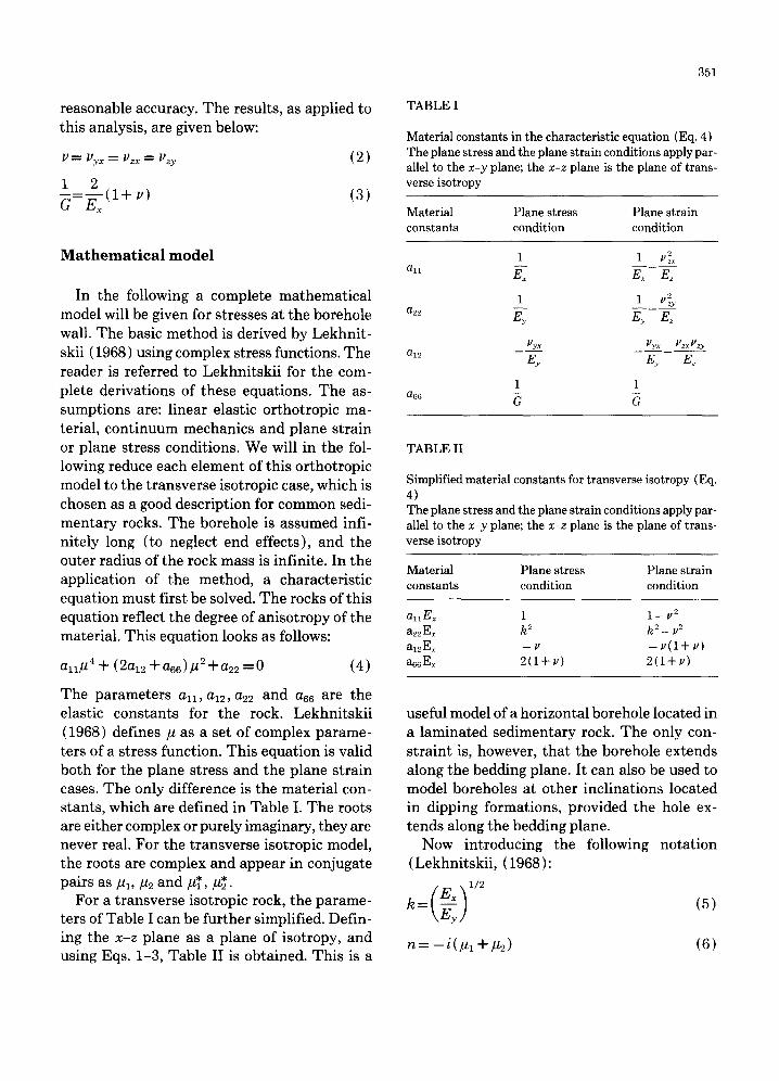
Defining 0 as the polar angle about the z-axis, measured from the x-axis as shown in Fig. lb, and E6 as the Young modulus in compression in the direction tangent to the opening contour, the modulus of elasticity is given by the for- mula (Lekhnitskii, 1968):
1 sin40 ( 1 2 v ~ \ 2 cos40 E o - E ~ Jr ~ )s in 0 cos20+ E~--
(9)
Imposing the conditions for transverse iso- tropy from Eqs. 2, 3 and 5, we obtain:
Sx 4 ~--=sin 0+2 sin20 cos20+k2cos40 (10) Co
Fig. lb. The radial and tangential stress components around the wall of the hole. The radial stress component is con- stant around the hole and is given by the borehole pressure. The tangential component, on the other hand, varies around the hole depending on the material properties and the in- situ stresses.
In all cases we will show the expressions for the circumferential stress ao acting on the bore- hole, and also formulas for go at individual con- tour points.
E q u a t i o n s for the s tresses
Radial stress on the borehole wall
The radial stress is simply equal to the inner boundary condition, which is a hydrostatic pressure:
ar=Pw (11)
Axial stress
Here the plane strain and plane stress cases must be distinguished. The simplest is the plane stress case, which is written:
az = az~ = constant ( 12 )
The plane strain case yields an axial stress as follows:
az=a;z+ V(ar+ae) (13)
Tangential stresses
These are the most significant stress com- ponents around the borehole, and the most complex. Figure lb shows the tangential stress at the borehole wall at an arbitrary angle 0 from the x-axis. The tangential, or the hoop stress, is a result of several effects, namely the bore- hole pressure and the outer boundary stresses on the rock. In the following, we will define each component that contributes to the total tan- gential stress. First let us define the component caused by the inner boundary condition, the borehole pressure:
Eo 2 2 ael =Pw-~--[k-n(sin 0+kcos 0)
- ( l + / h 2) (1 + ~t2)sin20cos20] (14)
where #1 and #2 are the roots of Eq. 4. Again introducing the transverse isotropic model as described earlier, Eq. 14 becomes:
Eo 2 2 0.ol = Pw~-[ k -n(s in 0+kcos 0)
+ ( 1 -- k 2 ) sin20cos20] (15) For an isotropic plate ael = - P w . In a trans- verse isotropic plate the stress O'Ol is distributed non-uniformly along the contour, according to a complicated law. The difference between its maximum and minimum values can be very large. Across the x-axis for 0= 0 °:
1 - n 0-ol = Pw --k (16)
and across the y-axis at 0= 90 °:
0-01 = P w ( k - n ) (17)
A circular opening subjected to deformation becomes elliptical and its semi-axes a' (across the x-axis) and b' (across the y-axis) are equal to:
1 a '=a[1-Pw(~xx~Eyy
, 1 - n b =a[X-Pw( ~=---~
[_ \x /Exi lE,
n + ~yx
E~JJ (18)
where a is the borehole radius. For the trans- verse isotropic model described earlier (Eqs. 2 and 5), Eq. 18 simplifies to:
a ' = a I l - ~ ( k - n - v ) 1
b'=a[1--P~xx(k-nk-~) 1 (19)
Equations 18 and 19 give the borehole radii in the x- and y-directions only. Equations for other directions are cumbersome, and are therefore not given.
The outer boundary condition must be de- fined. Refer to Fig. 1, where two stresses act on the rock, 0-x along the x'-axis and a~ along the
353
y' -axis in addition to the axial stress az. Impos- ing this boundary condition (in the x'-y' plane), the tangential component due to the outer boundary stresses is:
E6 a~ = aXE-~{ [ - cos20+ (k+ n)sin2¢] kcos20
+ [ (l+n)cos2O-ksin2O]sin20
- n ( 1 + k + n) sin¢ cos0 sin0 cos0}
Ee + a y e { [ - s i n 2 0 + (k+n)cos20]kcos20
+ [ (1+n)sin20-kcos20]sin20
+n(l +k+n)sin¢cos¢sinOcosO} (20)
Here 0 is defined as the angle between the bed- ding plane and the in-situ stresses (Fig. la ). The stress distribution will be symmetrical with re- spect to both principal directions x and y. Across the x-axis for 0=0=0°:
0.0~=-~aax+ 1+~ 0-, (21)
and across the y-axis, 0 = 0 °, 0=90°:
0-o2 = ( l + n )0-x -k0.y (22)
The general case assumes that the two stresses at the outer boundary 0.x and 0. s have different values. Therefore, a shear stress will arise. This will give a contribution to the tangential stress as follows:
Eo 0-oa = "Cxy~-~- ( 1 + k + n){ - n cos (20)sin (20)
+ [(l+k)cos(20)+k-1]sin(2¢)} (23)
where the shear stress component zxs can be ex- pressed as:
z~y = ½ ( 0., -0.x) (24)
Finally the total tangential stress at the bore- hole wall (see Fig. lb) can by the principle of superposition be expressed as the sum of each component:
0"0=O"01 +O'G, 2 +0"03 (25)
354
In the application of the mathematical method, frequent comparison to the isotropic stress equations will be made. From Eqs. 5 and 7 the isotropic case yields: k = 1 and n = 2. The corresponding isotropic equations then become for 0 = 0 ° : O'r = g w
aol = - P w ao,~= ax+ ~, + 2 ( ~ - a~)cos20 ao:~ = - 4r~.sin20 a~ = az~ (plane stress condition) a. = a~.+ 2v(cr,.-a~)cos20-4vr~ysin20
(26)
Where: ~ z = & z z + v ( a x + a y ) (plane strain condition). Equation 26 is identical to the equations ini- tially derived by Kirsch (1898).
Study o f the mathemat ica l model
Material properties
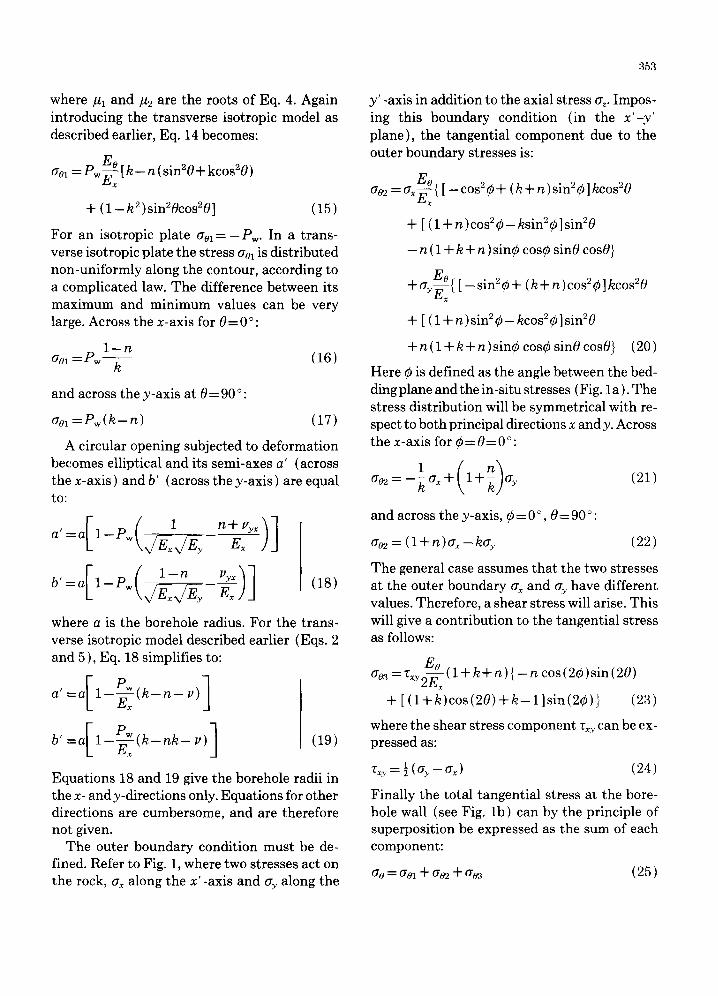
First we will study the stress coefficients that enter the stress equations. They are defined in Eqs. 5, 7 and 8. The simplified concept of trans- verse isotropy as illustrated in Fig. la and given by Table II was used. The result is shown in Fig. 2 where n is plotted vs. k. Several interesting conclusions came out of these simulations. Firstly, for our transverse isotropic model, Fig. 2 yields approximately the same curve regard- less of the Poisson ratio. (for k > 1). That is, the solution is essentially independent of the Poisson ratio. Secondly, both plane stress con- dition (Eq. 7), and the plane strain condition (Eq. 8), gave also nearly the same curve, the difference being small. The factor k defines the degree of anisotropy. The conclusion is there- fore that the only factor that governs this par- ticular transverse isotropic solution is the ratio of the elastic moduli. In the following we will use Eq. 7 and study each of the tangential stress components, and compare them to the corre- sponding isotropic stress components.
Tangential stress due to the borehole pressure
The following case is constructed and will be used to study the effect of transverse isotropy: ¢ = 30 ° (angle between the bedding plane
k = 2 n = 2.45 v =0 .2 (~x = 2
a s, = 3 P w = l
and the applied stress, see Fig. la ) (k = 1 for isotropic case ) ( n = 2 for isotropic case)
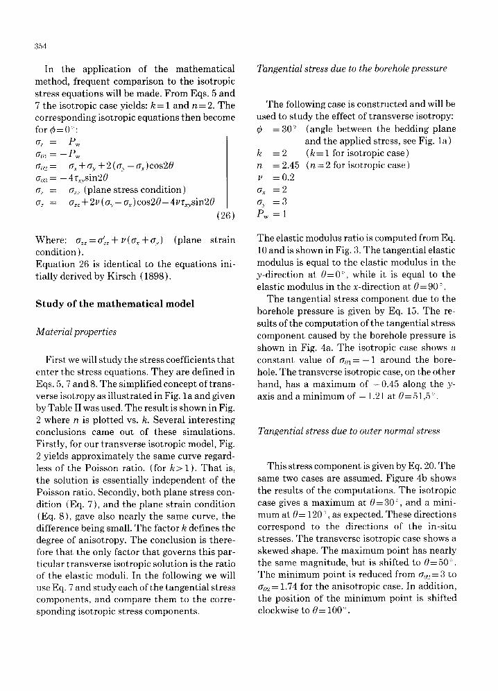
The elastic modulus ratio is computed from Eq. 10 and is shown in Fig. 3. The tangential elastic modulus is equal to the elastic modulus in the y-direction at 0 = 0 °, while it is equal to the elastic modulus in the x-direction at 0= 90 °.
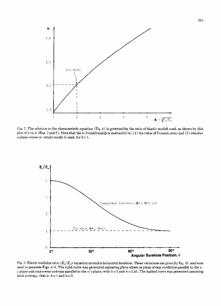
The tangential stress component due to the borehole pressure is given by Eq. 15. The re- sults of the computation of the tangential stress component caused by the borehole pressure is shown in Fig. 4a. The isotropic case shows a constant value of a o l = - 1 around the bore- hole. The transverse isotropic case, on the other hand, has a maximum of - 0 . 4 5 along the y- axis and a minimum of - 1.21 at 0=51,5 °.
Tangential stress due to outer normal stress
This stress component is given by Eq. 20. The same two cases are assumed. Figure 4b shows the results of the computations. The isotropic case gives a maximum at 0= 30 °, and a mini- mum at 0= 120 °, as expected. These directions correspond to the directions of the in-situ stresses. The transverse isotropic case shows a skewed shape. The maximum point has nearly the same magnitude, but is shifted to 0 = 50°. The minimum point is reduced from ~2 = 3 to a~ = 1.74 for the anisotropic case. In addition, the position of the minimum point is shifted clockwise to O= 100 °
355
n
3.0
2.5
2.0
1.5
ISOT~iYIC
I I I J 1 2 3 4
|
Fig. 2. The solution to the characteris t ic equat ion (Eq. 4) is governed by the ratio of elastic moduli used, as shown by th is plot of n vs. k (Eqs. 7 and 5 ). Note t h a t the n-k relat ionship is insensit ive to: ( 1 ) the value of Poisson ratio, and (2) whether a plane-stress or -strain model is used, for k > 1.
EJE~ ~
45)
ISOTROPIC(k=I, n=2)
l J I I l I i I I •
0 o 30 ° 60 ° 90 ° Angu la r Borehole Posit ion, 0
Fig. 3. Elastic modulus ratio (Ex/Eo) var ia t ion around a horizontal borehole. These var ia t ions are given by Eq. 10, and were used to generate Figs. 4-6. The solid curve was generated assuming plane stress or plane s t ra in condi t ion parallel to the x- y plane and t ransverse isotropy parallel to the x-z plane, wi th k - 2 and n = 2.45. The dashed curve was generated assuming total isotropy, t ha t is: k = 1 and n -- 2.
356
---Transverse Isotropi£ - - -Isotropic
/ i I
51.5 °
i i
a) Tangential Stress Contribution from %1 (Equation 15)
- -T ransverse Isotropic 1 0 0 ° . . . . Isotropic
/
i I /
- -T ransverse Isotropic ~ , o - - I --Isotropic
/
l /
........ ~ . . ~ / / _ . . . ~ _ 345 °
" ~ ~ 328 °
c) Tangential Stress Contribution from o83 (Equation 23)
(~y
\ 50 °
/ 30 o /
\ \I} II I/ I I X I
\\\
- -Transverse Isotropic - - -Isotropin
Y 94° o o i I 3 4 / 0
~ 7.5 °
b) Tangential Stress Contribution from %2 d) Total Tangential Stress % (Equation 20) (Equation 25)
Fig. 4. Anisotropic, in this case transverse isotropic, material properties will affect the stress distribution about a horizontal borehole. In each case, the dashed lines give the stress distribution assuming total isotropic material properties. The solid curves containing the arrow heads give the stress distributions assuming a transverse isotropic material {see Fig. 3 ). In both cases the external stresses are the same. Therefore, the deviation of the solid curves from the dashed curves shows the incremental effect of rock anisotropy on the stress distribution about a horizontal borehole.
Tangential stress due to outer shear stress
This stress component is defined by Eq. 23. The same cases as before are assumed with the shear stress at infinity given by Eq. 24. The re- sults are shown in Fig. 4c. The isotropic case shows maximum and minimum values at
0 = 3 4 5 ° and 0--75 ° respectively. The trans- verse isotropic case again has a distorted shape. The maximum and minimum stress levels are approximately the same for the isotropic and the anisotropic cases, however, for the aniso- tropic case the maximum is observed at 0 = 328 °, while the minimum is seen at 0 = 81 °
357
Figures 4a, 4b and 4c show the variations in each tangential stress component around the borehole. Using Eq. 25 the same case was used to determine the total tangential stress around the borehole. The total tangential stress curves are shown in Fig. 4d. The isotropic case has a maximum at 0=7 .5 ° and a minimum at 0 = 97.5 °. The transverse isotropic case reaches a maximum at 0 = 3 4 ° , and a minimum at 0=94 ° . Although the maximum stresses ob- served for the two cases are similar, the mini- mum values differ considerably. For the iso- tropic case the minimum is a s = 1.17, while the transverse isotropic case reaches a minimum of a s = -0 .62 . The conclusions are that the ani- sotropic material properties shift the direc- tions of the principal values, and significantly affect the magnitude of the minimum tangen- tial stress.
Borehole deformation due to changing borehole pressure
Equation 19 was used to compute the relative deformation in the x- and y-directions of the borehole due to a change in the borehole pressure.
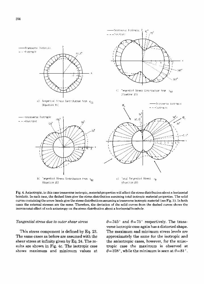
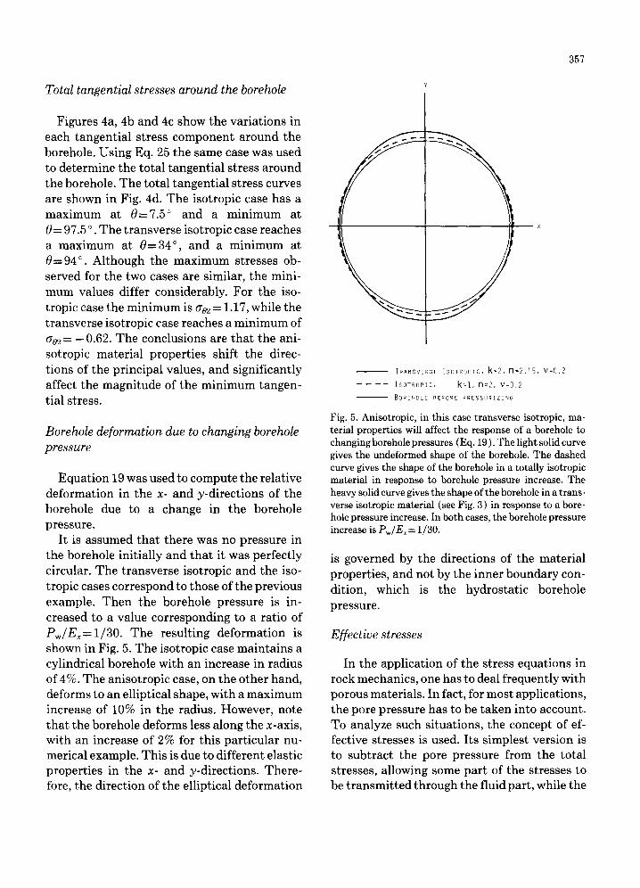
It is assumed that there was no pressure in the borehole initially and that it was perfectly circular. The transverse isotropic and the iso- tropic cases correspond to those of the previous example. Then the borehole pressure is in- creased to a value corresponding to a ratio of P w / E x = l / 3 0 . The resulting deformation is shown in Fig. 5. The isotropic case maintains a cylindrical borehole with an increase in radius of 4%. The anisotropic case, on the other hand, deforms to an elliptical shape, with a maximum increase of 10% in the radius. However, note that the borehole deforms less along the x-axis, with an increase of 2% for this particular nu- merical example. This is due to different elastic properties in the x- and y-directions. There- fore, the direction of the elliptical deformation
|
Total tangential stresses around the borehole
- - TRANSVERSE [SOTROPIC, k = 2 , n = 2 . q s , v = 0 . 2
. . . . ISOTROPIC, k=t, n=2, v:0.2
- - BORENOLE BEFORE PRESSURIZING
Fig. 5. Anisotropic, in this case transverse isotropic, ma- terial properties will affect the response of a borehole to changing borehole pressures (Eq. 19). The light solid curve gives the undeformed shape of the borehole. The dashed curve gives the shape of the borehole in a totally isotropic material in response to borehole pressure increase. The heavy solid curve gives the shape of the borehole in a trans- verse isotropic material (see Fig. 3 ) in response to a bore- hole pressure increase. In both cases, the borehole pressure increase is Pw/Ex= 1/30.
is governed by the directions of the material properties, and not by the inner boundary con- dition, which is the hydrostatic borehole pressure.
Effective stresses
In the application of the stress equations in rock mechanics, one has to deal frequently with porous materials. In fact, for most applications, the pore pressure has to be taken into account. To analyze such situations, the concept of ef- fective stresses is used. Its simplest version is to subtract the pore pressure from the total stresses, allowing some part of the stresses to be t ransmit ted through the fluid part, while the
358
rest (the effective) stress is taken up by the rock matrix.
For isotropic elastic materials, Nur and Byerlee (1971) derived an effective stress law. Carroll (1979) derived an effective stress law for anisotropic materials. This is cumbersome and will not be shown in detail here. However, based on Carroll's (1979) law, with results taken from Aadnoy (1987), the effective stress law for our transverse isotropic material can be shown to become:
~T r ---- O" r -- [1 + ~{ ~ + k2cos20+ sin20} ]Po ~o = ao - [ 1 + ~x { v + kZsin20 + cosZO} ] Po
( v 2 + ~ ( l + k 2 ) +k2)po &~=a~-- 1+o~- l + v
(27)
where:
1 - 2 v 1 ~ = 2 v Z + k 2 ( v _ 1 ) ~-7
B' = Einterpore/ Ex
A number of assumptions are used in arriving at Eq. 27. Firstly, it is assumed tha t the Poisson ratio is equal for the porous material and inter- pore (grain matrix) material. Secondly, Pois- son ratio is assumed equal in all directions. Thirdly, the rock is assumed to have structural anisotropy, which implies tha t it is the pore ge- ometry that causes the rock to behave trans- verse isotropic. The interpore material (the grains), or the intrinsic material is assumed to behave isotropically.
By inserting the condition for an isotropic material, k-- 1, Eq. 27 reduces to:
(28)
Equation 28 is similar to the isotropic effective
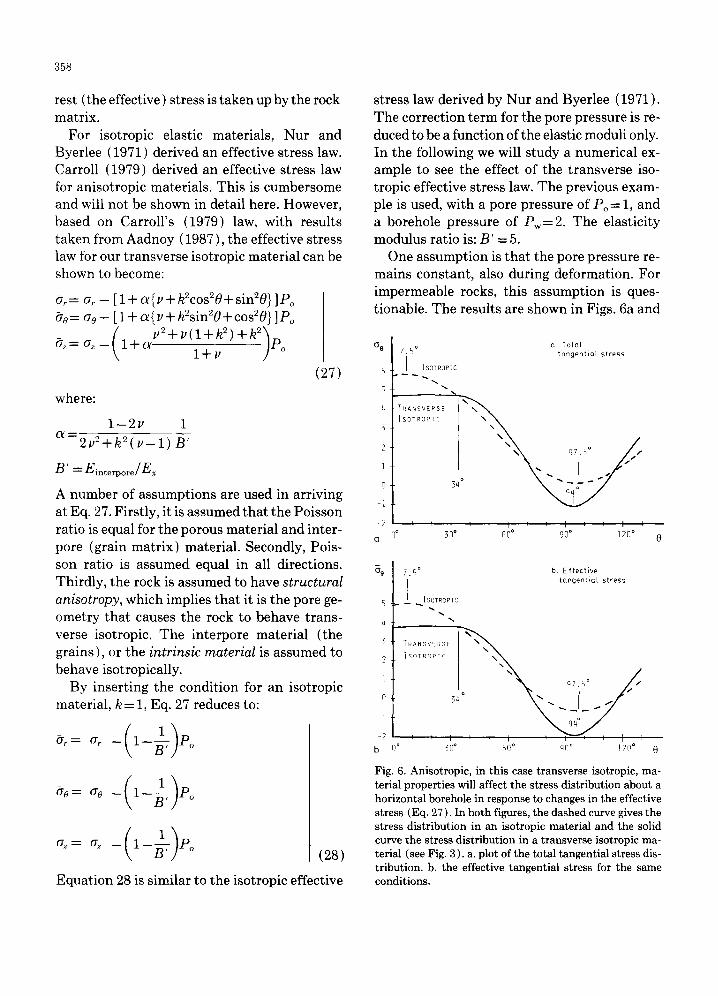
stress law derived by Nur and Byerlee (1971). The correction term for the pore pressure is re- duced to be a function of the elastic moduli only. In the following we will study a numerical ex- ample to see the effect of the transverse iso- tropic effective stress law. The previous exam- ple is used, with a pore pressure of Po = 1, and a borehole pressure of Pw = 2. The elasticity modulus ratio is: B' = 5.
One assumption is that the pore pressure re- mains constant, also during deformation. For impermeable rocks, this assumption is ques- tionable. The results are shown in Figs. 6a and
OQ
5
t;
2
1
0
-2
Cl
o Total 7.5 ° tcmgentiat st ress
I [SOTROPIC
TRANSVERSE
ISOTROPIC % \ \ \
/ . "
I , I q ' I ' ' I ' ' I
n ° 311 ° 60 ° 911 ° 12fl °
~9
5
L~
3
2
I
0
-1
-2
b
[SOTROPIC
"%
TRANSVERSE \ ~ \~,
ISOTROPIC
a 7 ' 5 ° //
34
q 4 °
I I I i L I q I i " ~ " ~ ' ' I I O° ]O° ~0° qfl° ]? f i ° 0
b Effective tangential stress
Fig. 6. Anisotropic, in th is case t ransverse isotropic, ma- terial propert ies will affect the stress dis t r ibut ion about a hor izontal borehole in response to changes in the effective stress (Eq. 27 ). In bo th figures, the dashed curve gives the stress d is t r ibut ion in an isotropic material and the solid curve the stress dis t r ibut ion in a t ransverse isotropic ma- terial (see Fig. 3 ). a. plot of the total tangent ia l stress dis- t r ibut ion, b. the effective tangent ia l stress for the same conditions.
6b. Due to symmetry, only one part containing the maxima and minima is shown. In Fig. 6a the tangential stresses are shown. Here the ef- fect of anisotropy is clearly seen. Both the max- imum and the minimum stress level are lower for the transverse isotropic case, with the min- imum value deviating most. Also note that the curve shapes are different for the transverse isotropic cases. In Fig. 6b the effective tangen- tial stresses are shown. These look very similar to the curves of Fig. 6a, but smaller in magni- tude. The isotropic curve in Fig. 6b is shifted down 0.8 units compared to the isotropic case in Fig. 6a.
In Figs. 4-6, deviations by the anisotropic material property curves (solid) from the iso- tropic material property curves (dashed) illus- trate the incremental effect of rock anisotropy on the stresses acting at the borehole wall, over and above those resulting from the differential stress field.
Applications to the petroleum industry
The stress equations can be applied to sur- face tunnelling work, and to deeper boreholes, the constraint being that the rock must extend along the bedding plane.
In borehole stability work, the virgin in-situ stresses are of primary concern. It has been shown that both the magnitude and the direc- tions of the stresses around the borehole are af- fected by the degree of anisotropy. Thus, by back-calculating the in-situ stresses, erroneous results will be obtained if the isotropic material properties are used for an anisotropic rock. By the same token, by using borehole fractures or borehole collapse positions to estimate the di- rections of the in-situ stresses, the full aniso- tropic solution must be used to arrive at correct directions.
Primarily the application is in the drilling phase of a well, but the stress fields are also important during the production phase. For ex- ample, sand production is sensitive to the local shear stress fields around the borehole. These
359
are clearly different for anisotropic and iso- tropic rocks.
Hydraulic fracturing example
To demonstrate the application of the equa- tions we will define a simplified case. A hori- zontal borehole is drilled in sedimentary rock with the following characteristics: % =1 G = 0.8 ¢ = 0 ° 1 /B' = o
Po -- 0.5
(dimensionless overburden stress) (dimensionless horizontal stress ) (horizontal bedding plane )
(dimensionless pore pressure)
In the example above, the in-situ stresses are assumed to act parallel and normal to the bed- ding plane. More extreme results can be ob- tained if the in-situ stresses and the bedding planes have different directions (0 ° < O < 90 ° ). We will now compute the wellbore pressure re- quired to initiate fracture at the wellbore wall. The condition is (Aadnoy and Chenevert, 1987) that a fracture initiates when the effective tan- gential stress becomes zero. The minimum tan- gential stress occurs at 0=90 ° (for ay>ax). Equation 25 reduces to:
ao = (1 + n)ax - kay - ( n - k )Pw (29)
Imposing the fracture initiation condition:
ao - P o = 0
the result is the following expression:
1 Pw - n _ k [ (1+ n )G - kay +Po ] (30)
Inserting the numbers given above, Eq. 30 becomes:
Pw= ( 1 . 3 + 0 . 8 n - k ) / ( n - k ) (31)
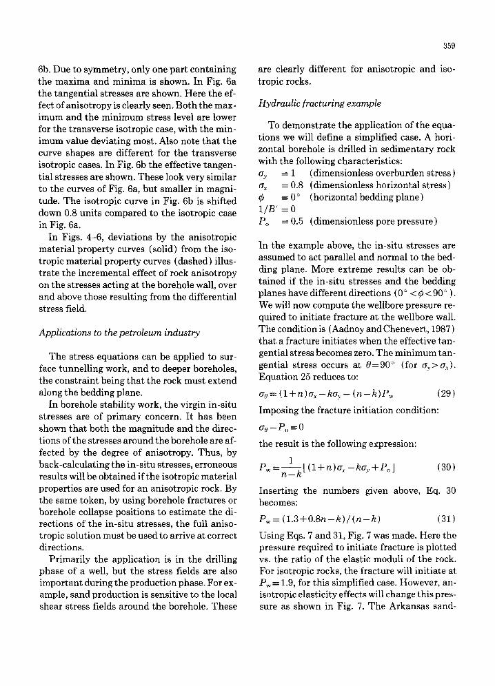
Using Eqs. 7 and 31, Fig. 7 was made. Here the pressure required to initiate fracture is plotted vs. the ratio of the elastic moduli of the rock. For isotropic rocks, the fracture will initiate at Pw = 1.9, for this simplified case. However, an- isotropic elasticity effects will change this pres- sure as shown in Fig. 7. The Arkansas sand-
360
Pw
3 LEUDERS LIMES~
GREEN RIVER SHALE
PERMIAN SHALE
I I D
2 3 k2= Ex/Ey
Fig. 7. The predicted fracturing pressure as a function of the anisotropic elastic properties. Also shown are the esti- mated fracturing pressures for some sedimentary rocks. The elastic modulus ratio are taken from Chenevert and Gatlin (1965). Note that increasing the elastic modulus ratio from 1 to 2, results in a 11% increase in the predicted fracture pressure.
stone has a predicted fracture pressure of 2.02, an increase of 6.3% over the isotropic Leuders limestone. For higher degrees of anisotropy, this effect increases. At k 2 = 2, the difference in pre- dicted fracture pressure is 11% compared to isotropic rock conditions.
Conclusions
A mathematical model for stresses around boreholes in transverse isotropic materials is given. The particular solutions for a transverse isotropic material, with the borehole axis ex- tending along the plane of isotropy, are also given. Each stress component is defined, with the tangential stress resolved to study the ef- fect of each component. It was found that for the transverse isotropic case the solution to the characteristic equation was independent of the
Poisson ratio, and the same solution was appli- cable to both plane strain and plane stress equations. The anisotropic stress distributions in general differed from the isotropic stress dis- tributions. The magnitude was different, but also significant was the location of the maxi- mum and minimum tangential stresses. An an- isotropic effective stress law was defined to take into account the pore pressure. When subjected to varying borehole pressures, the hole would deform in an elliptical fashion. The direction of the ellipse is determined by the direction of the elastic properties. The mathematical solu- tion given is useful in determining the stresses around boreholes in sedimentary rocks, which are typically transverse isotropic. A hydraulic fracturing example was also given to demon- strate the effect of anisotropy in the elasticity moduli.
References
Aadnoy, B.S., 1987. Continuum mechanics analysis of the stability of inclined boreholes in anisotropic rock for- mations. Dr. Ing. thesis. Norw. Inst. Technol. 240 pp.
Aadnoy, B.S. and Chenevert, M.E., 1987. Stability of highly inclined boreholes. S.P.E. Drilling Eng. (Dec.): 364- 374.
Amadei, B., 1983. Rock anisotropy and the theory of stress measurements. Lecture Notes in Engineering, 2. Sprin- ger, Berlin, 478 pp.
Carroll, M.M., 1979. An effective stress law for anisotropic elastic deformation. J. Geophys. Res., 84(B13): 7510- 7512.
Chenevert, M.E. and Gatlin, C., 1965. Mechanical aniso- tropies of laminated sedimentary rocks. Soc. Pet. Eng. J., (Mar.): 67-77.
Kirsch, G., 1898. Z. Vet. dent. Ing., Vol. 42. Lekhnitskii, S.G., 1968. Anisotropic plates. Gordon and
Breach, New York, N.Y., 594 pp. Nur, A. and Byerlee, J.D., 1971. An exact effective stress
law for elastic deformation of rocks with fluids. J. Geo- phys. Res., 76(26): 6414-6419.
Van Cauwelaert, F., 1977. Coefficients of deformation of an anisotropic body. J. Mech. Eng. Div., Proc. ASCE; 103(EM5): 823-835.