damage evaluation of drilled carbon/epoxy laminates based on area assessment methods
TRANSCRIPT

DAMAGE EVALUATION OF DRILLED CARBON/EPOXY
LAMINATES BASED ON AREA ASSESSMENT METHODS
Luís Miguel P. Durão*, João Manuel R. S. Tavares†, Victor Hugo C. de Albuquerque‡,
Daniel J. S. Gonçalves†
* ISEP/CIDEM, Instituto Superior de Engenharia do Porto
Centro de Investigação e Desenvolvimento em Engenharia Mecânica
Rua Dr. António Bernardino de Almeida, 431, 4200-072 Porto, Portugal
e-mail: [email protected], webpage: http://www.isep.ipp.pt
† Instituto de Engenharia Mecânica e Gestão Industrial, Departamento de Engenharia Mecânica,
Faculdade de Engenharia, Universidade do Porto
Rua Dr. Roberto Frias, 4200-465 Porto, Portugal
e-mail: [email protected], webpage: http://www.fe.up.pt/~tavares
‡ Graduate Program in Applied Informatics, Center of Technological
Sciences, University of Fortaleza, Av. Washington Soares, 1321/J30,
60811-905 Fortaleza, CE, Brazil
email: [email protected]
Key words: Carbon fibre, Machining, Radiography, Damage Assessment, Testing.

2
Summary. The characteristics of carbon fibre reinforced laminates had widened their use,
from aerospace to domestic appliances. A common characteristic is the need of drilling for
assembly purposes. It is known that a drilling process that reduces the drill thrust force can
decrease the risk of delamination. In this work, delamination assessment methods based on
radiographic data are compared and correlated with mechanical test results (Bearing test).
1 INTRODUCTION
The extensive use of composites, from aircrafts to sporting goods, increases the demand
for optimized solutions considering production at reasonable costs and high level of quality.
Advantages in their use are related with their lightweight characteristics combined with good
mechanical properties. The importance and usage of composite materials have been growing
in latest years, which can be confirmed by their intensive use in the new Airbus A380 or
Boeing 787 airplanes. In the latter, 50% of the weight of its primary aircraft structure will be
made of composite materials [1]. One can now find composite materials not only in the
aeronautical field, but also in other industries like automotive, railway, marine or of sport
goods.
As parts in composite materials are to be usually assembled in complex structures, joining
of these parts is always needed. Drilling is the most common machining operation in industry.
Drilling is a complex process, characterized by the existence of extrusion and cut
mechanisms. The former is performed by the drill chisel edge that has null or negligible linear
speed and the latter by the existence of rotating cutting lips at a certain speed. The most
common drill is the conventional conical point drill. The cutting process is unique and can be

3
divided into two distinct regions: chisel edge and cutting lips. In a common drill, there is a
small region around the centre of the chisel edge, called the indentation zone, where the tool
does not cut the material, but extrudes it instead. At the region outside the indentation zone,
called the secondary cutting edge area, the rake angle is highly negative. As fibre reinforced
plastics are more brittle than metals, it is unlikely that extrusion really takes place and
orthogonal cutting could be assumed for the entire chisel edge. However, model predictions
based on this assumption do not agree with the experimental data. Along the cutting lips,
cutting action of a drill is a three-dimensional oblique cutting process. The cutting speed, rake
angles and other geometrical parameters vary along the cutting lips with the radial distance
from the centre. The cutting action is more efficient at the outer regions of the cutting lips
than near the drill’s centre [2]. When considering the drilling of a composite part, good results
are mainly fibre related and less dependent on the matrix material [3].
Due to the high abrasive nature of carbon fibers, combined with the laminar nature of
parts, several damages are due to occur during drilling operations, like push-down
delamination, fiber pull-out or thermal damages [4]. The most frequent and noticeable
evidence of these damages is the existence of an edge around the machined hole, namely at
the exit side of the drill, as a consequence of the drilling process. In this region, it is possible
to observe, by visual or enhanced inspection, the separation of adjacent plies of the laminate.
This damage is known as delamination.
Delamination is considered as one of the most critical damages that can occur as it can
contribute to a decrease in the mechanical strength of the part. These damages can affect not
only the load carrying capacity of laminated parts but also strength and stiffness, thus

4
reliability [5]. Rapid tool wear, due to material abrasiveness and matrix softening, due to heat
buildup, can also be an important factor in damage occurrence [6]. Another consequence is
the need of frequent tool changes that affects the production cycle and raises the final cost.
Therefore, the reduction of this damage is of capital importance to the industry of composites.
The importance of tool geometry in delamination reduction is evidenced by several
published works on the subject. For example, Piquet et al. [7] suggested the use of a greater
number of cutting edges, from three to six, in order to increase the contact length between tool
and part, a point angle of 118º and a small rake angle. Chisel edge should be as reduced as
possible. Park et al. [8] applied the helical-feed method to avoid fuzzing and delamination.
The use of helical feed allows for an efficient completion of the drilling operation avoiding
depth limitation. Stone and Krishnamurthy [9] studied the implementation of a neural network
thrust force controller. The control scheme can minimize delamination by varying feed rate in
order to control thrust force. Persson et al. [5] presented an orbital drilling method, in which
the hole is machined simultaneously axially and radially. This method eliminates the
stationary tool centre, thus reducing the axial force, reduces the risk of tool clogging and
allows for the use of one tool diameter to machine several hole diameters. Davim and Reis
[10] studied the effect of cutting parameters on specific cutting pressure, delamination and
cutting power in carbon fibre reinforced plastics. These authors concluded that the feed rate
has greater influence on thrust force, so damage increases with feed. Tsao and Hocheng [11]
analyzed the effect of a backup plate on delamination, in order to understand and explain the
advantage of its use in composite laminate drilling. Experimental findings revealed that the
use of a backup plate causes an increase in the critical thrust force, allowing for higher feed

5
rates. The possibility of actual use of this plate can be an issue in the construction and
maintenance of structures. In another work [12], Hocheng and Tsao conducted several
practical experiences to prove the benefit of using a special drill when compared to
commercially available tools, like twist drill. The effect of their use on delamination was
evaluated. Delamination extent was determined with the help of ultrasonic C-Scan. At the
end, it was possible to conclude that thrust force varies with drill geometry and with feed rate.
That enables for the use of higher feed rates if adequate drill geometry is selected. More
recently, Tsao and Hocheng [13] have presented the advantages of a core drill. The influence
of spindle speed was relatively insignificant. Fernandes and Cook [14] investigated the thrust
force during drilling with “one shot” drill bit. Their objective was to extend tool life and
improve hole quality. For that, a mathematical model leading to the calculation of feed in
order to keep the thrust force under a critical threshold was developed. Finally, Tsao [15, 16]
evaluated the importance of pilot hole on delamination reduction when using core drills and
saw drills. Pilot hole eliminates the chisel edge effect, reducing delamination hazard. The
ratio of pre-drilled hole to drill diameter must be controlled in order to drill with higher feed
rate without delamination. In his experimental work, Tsao has found an optimal ratio of 0.85
for the use of the largest feed rate – 0.012 mm/rev. Dharan and Won [17] conducted a series
of machining experiments in order to propose an intelligent machining system that avoids
delamination by peel-up at entrance and by push-down at exit. Such a system should be able
to limit feeds when the tool contacts the plate and before drill breakthrough, avoiding
delamination onset.
As carbon fibre/epoxy laminates are opaque some of these damages are not visible in a

6
visual inspection, so it is needed to establish non-destructive testing (NDT) in order to
determine the extension of internal damages, such as delamination. Digital images are also
used to assess this type of damage after drilling [18].
Enhanced radiography, a non-destructive inspection method, can help on the identification
and measurement of the delaminated area or diameter around the hole (Figure 1).
Delamination assessment can be attained with the help of existing models that combine the
delaminated diameter or damaged area with hole nominal diameter or area [18-19] or even by
the rounding of the cutting edge [20].
In this work, a batch of carbon/epoxy plates was drilled with different drills and the
resultant delamination extensions were measured from digital enhanced radiographies that
were evaluated using computational techniques of image processing and analysis [21, 22].
Afterwards, the measurement results were used to correlate two traditional damage models
[18-19] and compare them to a new model that takes into account the shape of the damage
areas agreed by a circularity index. Finally, the results of the three damage models were
correlated with the bearing test, ASTM D-5961-07 [23].
Experimental findings confirmed that the damage models used are useful to evaluate the
drilling process of composite laminates in complex structures and suitable to assist on
delamination reduction objectives.
2 DELAMINATION IN POLYMERIC MATRIX COMPOSITES
2.1 Delamination mechanism

7
When delamination is concerned, it is necessary to consider two types of damage that are
different in causes and effects: peel-up delamination and push-down delamination, Figure 2.
Peel-up delamination, Figure 2a), is a consequence of the cutting force pushing the abraded
and cut materials to the flute surface. The material spirals up the drill flute before it is
completely machined. A peeling force pointing upwards is introduced that tend to separate the
upper lamina of the uncut portion held by the downward acting thrust force. Normally, a
reduction in feed rate can reduce this delamination type.
Push-down delamination, Figure 2b), is a damage that occurs in interlaminar regions, so it
depends not only on fibre nature, but also on resin type and respective properties. This
damage is a consequence of the compressive thrust force that the drill chisel edge always
exerts on the uncut laminate plies. There is a certain point at which the loading exceeds the
interlaminar bond strength and delamination occurs. The reduction of this delamination type
is the main focus of this work.
Analysis of delamination mechanisms during drilling using Linear Elastic Fracture
Mechanics (LEFM) based approach have been developed and different models presented. The
one most referred to is the Hocheng-Dharan [24] delamination model. In this model, the
critical thrust force for the onset of delamination, Fcrit, is related with properties of the
unidirectional laminate, such as the elastic modulus, E1, the Poisson ratio, ν12, the interlaminar
fracture toughness in mode I, GIc, and the uncut plate thickness (h):
21
212
31
)1(38
−=
υπ
hEGF Ic
crit
(1).

8
A comprehensive summary of the steps towards free-delamination holes can be found in
[25].
2.2 Delamination Assessment
After laminate holes are drilled, it is important to establish criteria that can easily compare
the delamination extension caused by different machining processes. Damage extension can
be evaluated through NDT. Some examples are the use of a tool maker’s microscope [10; 26-
28], ultrasound techniques [29], acoustic emission [30], enhanced radiography [31, 32] –
Figure 3a), C-Scan [33] – Figure 3b) or Computerized Tomography (CT) [34, 35] – Figure
3c). In all these methods, the main goal is to obtain images representing the hole surrounding
areas that can be further analyzed and measured, mainly for diameters and areas.
Then, it is possible to carry out the quantification of the damaged region in order to
calculate a factor that numerically expresses the damaged region extension and shape, Figure
3. Chen [19] presented a comparing factor that enables the evaluation and analysis of
delamination extent in laminated composites. That ratio was called the Delamination Factor,
Fd, and it was defined as the quotient between the maximum delaminated diameter, Dmax, see
Figure 4, and the hole nominal diameter, D:
DDFd max= (2).
In the experimental work presented in [19], the author examined the effects of tool
geometry and cutting parameters as well as tool wear on the delamination factor. Two types
of drills were used: a carbide drill and a HSS drill with 5 mm diameter. Damage zone was

9
evaluated by using radiographic non-destructive inspection. Results showed a near-linear
relationship between the delamination factor and average thrust forces for both drill materials.
The author also concluded that thrust force increased when drill point angle increases and that
helix angle did not have a significant effect on this force. Tool flank wear causes an increase
of the delamination factor, as thrust force increases with tool wear.
Although the feed rate has a strong influence on the thrust force, the cutting speed has not
shown a significant effect on that force. Finally, the author has noticed the absence of built up
edge during carbon/epoxy machining.
Mehta et al. [36] have suggested a different ratio with the same purpose, named Damage
Ratio, DRAT, defined as the ratio of Hole Peripheral Damage Area, DMAR, to Nominal Drilled
Hole Area, AAVG, i.e.:
AVGMARRAT ADD = (3).
This hole damage evaluation method is based on the existence of damage images from C-
Scan and pixel counting of the digitized damage area, as described in [36], or from digitized
radiographs [37].
One limitation of Chen’s criterion is related with situations when the delamination
involved is not circular, but presents breaks and cracks. In such cases, the values of the
delaminated area are more appropriated for the damage quantification. Based on this, Davim
et al. [18] presented a novel approach known as the Adjusted Delamination Factor, Fda,
AA
DD
Fdamaxmax βα +=
, (4),

10
where Amax is the area corresponding to the maximum delaminated diameter, Dmax, and A is
the nominal hole area. In this new criterion, the first term is the conventional delamination
factor and a second term is added, taking into account the damaged area contribution, and the
parameters α and β are used as weights, being their sum always equal to 1 (one).
In this work, we suggest that the shape of the damaged area should be taken into account.
That shape can be related with circularity, defined as a function of the perimeter, P, and the
area, A, of the damaged area around the machined hole as f:
24PAf π=
(5).
The value of circularity equals 1 (one) for a perfect circle and much lower for distended
shapes, as is demonstrated by Figure 5, for three different shapes: a circle, a square and a
diamond-shaped quadrangle.
The final goal in this work was to find a correlation between mechanical resistance and
damage extension, combining a delamination criterion with the circularity value.
3 MATERIALS AND METHODS
3.1 Composite Plates Production and Drilling
For the experimental work, a batch of unidirectional carbon/epoxy plates using prepreg
CC160 ET 443 with 24 layers and a final thickness of 4 mm were produced. The plates were
then cured for one hour under 300 kPa pressure and 130 ºC, followed by cooling. Then, the

11
plates were cut into test coupons of 135x36 mm2 for the drilling experiments according to the
bearing test specifications.
The experimental work was divided in drilling of the laminate plates, delamination
measurement by enhanced radiography and computational algorithms of computational vision
and mechanical tests. Composite coupons were tested according to ASTM D5961 – Bearing
test. The results of delamination damage assessment and bearing stress were compared and
correlated in order to enable the conclusions of this work.
The drilling operation was carried out in a 3.7 kW DENFORD Triac Centre CNC machine.
As it has been previously identified the main importance of feed rate when compared with
spindle speed in thrust forces development [31], the cutting speed was kept constant and equal
to 2800 rpm and the feed rate had three levels: low feed rate of 0.03 mm/rev, intermediate
feed rate equal to 0.10 mm/rev and high feed rate of 0.20 mm/rev. These cutting parameters
were selected according to previous published works [21, 22, 31, 37] as well as tool
manufacturer’s recommendation. A tool diameter of 6 mm was used combined with three drill
geometries: twist, Brad and bidiametral, see figure 6. Details on the drills can be found in
[21].
3.2 Delamination Assessment
After the drilling process, the delaminated region around the drilled hole was evaluated
using enhanced digital radiography. In order to generate a contrast, the plates were first
immersed in di-iodomethane for approximately fifteen to twenty minutes. Then the
12
radiographic images were acquired using a 60 kV, 300 kHz Kodak 2100 X-Ray system
associated with a Kodak RVG 5100 digital acquisition system. Exposition time was set to
0.125 seconds.
Each radiographic image was computationally processed in order to identify and
characterize the regions of interest: hole region, delaminated and non-delaminated regions.
The hole region corresponds to the central area, the delaminated region consists on a dark
border around the machined hole, and the non-delaminated regions are lighter areas located
outside the damaged region, Figure 7a) and 7c) [31]. Figure 7b) is a negative image, hence
lighter area is the delaminated region around the hole.
The final objective of the image processing and analysis performed was to measure the
damaged diameters and areas in each radiographic image. This was achieved by using in the
image segmentation step a neuronal network built with 1 input layer with 3 neurons, 1 hidden
layer with 7 neurons [38], 1 output layer with 3 neurons, and the logistic function [39] as the
neurons activation function, which was trained using the backpropagation learning algorithm
[40]. The inputs of the network were each image pixel’s value, and the output was the
correspondent segmentation region. Further details of the neuronal network used can be found
in [41]. After the identification of the three regions presented in the input image, the diameter
and area values were computed: the diameters by searching for the longest diagonal within the
delaminated region, and the areas by summing up the pixels within the associated regions.
The values obtained from the radiography images were used to determine the delamination
factor, Fd, [19], the adjusted delamination factor, Fda, [18] and the circularity factor, according
to Equations 2, 4 and 5 (see section 2.2).

13
So, taking advantage of the computational techniques of imaging processing and analysis,
the adjusted delamination factor was the criterion used in this work for damage assessment.
3.3 Mechanical Testing
The mechanical test carried out was the “Bearing test” according to ASTM D5961M-10
[23]. This test was used to assess the effect of the delamination extension on the mechanical
properties of the drilled plates in the joint area. Procedure A – double-shear – was used. This
procedure uses a single fastener and is recommended for material evaluation and comparison.
The tests were performed in a Shimadzu AG-X/100 kN Universal Testing machine
equipped with the necessary accessories to run the different tests and connected to a computer
for machine control and data acquisition. The head displacement speed was set to 2 mm/min.
The purpose of this mechanical test was to establish a comparison between the results
obtained for plates drilled under different conditions regarding tool geometry or feed rate.
4 RESULTS AND DISCUSSION
The results of maximum thrust force variation according to drill geometry and feed rate
were largely published and discussed, see for example [10, 12, 13, 17, 21, 22 24, 27, 43]; so,
in this work, no data is added to the existing information. According to that extensive
published work, it is possible to say that higher feeds result in higher thrust forces. It is also
possible to say that different geometries cause a variation in the thrust force evolution during
drilling and, consequently, on the values of the maximum force obtained during drilling, all
the other factors remaining constant: plate characteristics and drill diameter. It is also known

14
that higher diameters cause larger thrust forces. However, the main focus in this work was on
the damage assessment and mechanical consequences in terms of bearing resistance, so this
issue is not discussed hereby.
4.1 Delamination assessment
Delamination assessment was carried out according to the procedure described in section
3.2. The average results concerning all the combinations of drills and feed rates are presented
in Tables 1 and 2 and in Figure 9a) and 9b). From these results, it is possible to conclude that,
as expected, the increase in the feed rate had a direct effect in the delamination extension, for
both assessment criteria. Based on these results and on the previous works referred above, a
clear connection between the thrust force results and the delamination extension can be
established. The drilling conditions with less damage corresponded to the coupons associated
to the lowest feed rate, as a consequence of lower thrust forces during drilling.
An interesting result is the evolution of the circularity of the damaged area with feed rate,
as this value decreased while the feed rate increased, see Table 1 and Figure 9c). This
outcome suggests that for higher feed rates the damaged area, besides its greater extension,
has an extended shape, far from the circumferential reference shape (IC=1). This can be the
consequence of the higher energy transferred from the tool to the composite coupon when
feed rate is higher. As the drill chisel edge acts more like a punch, higher feed rate
corresponds to a higher linear extrusion speed, thus more energy is transmitted to the uncut
plies. So, this result confirms the known recommendation of using feed rates as low as
possible when drilling composite plates.

15
The results from the damage extension and circularity related with tool geometry are
presented in Table 2 and in Figure 9d). As the effect of the feed rate was discussed in the
precedent paragraph, only the effect of the tool is discussed here. So, the table presents
average values for the three feed rates used in the experimental work in order to reduce the
amount of data presented.
Analysing the results presented in Table 2 and in Figure 9, the tool influence is clear,
although not very different from any geometry to any other. Damage in unidirectional drilled
plates differs according to the tool geometry and material, under the experimental conditions
described. Considering the tool geometry influence, the lowest values of damage extension
were those obtained for the plates drilled with carbide twist drill. Damage from Brad drills
was 2% higher when considering the adjusted delamination factor and for bidiametral drills
was approximately 3% higher. Finally, confirming the fact that HSS drills should not be used
for drilling carbon/epoxy composites, damage extension was always the highest,
approximately 24% on the average.
From these results, it is possible to state that, more than the tool influence is the selection
of an appropriate combination of tool geometry considering the stacking sequence of the plate
that must be always in mind when defining the drilling conditions. Naturally, the feed rate has
to be kept as low as possible, in order to minimize damage extension. The limit on this
condition is to be given by the need to avoid unwanted thermal damages that result from the
matrix softening and the need, in industrial terms, to ensure a reasonable number of hourly
productions.
Finally, analysing the results of circularity of the damaged region, the holes machined with

16
HSS drills were those with higher result of this value, so closer to a perfect round shape,
suggesting that the tool geometry and material have a strong influence on this effect. This
outcome can be a consequence of the larger area of the delaminated region for plates drilled
with HSS drills, causing an increase in the IC factor, see Eq. (5). As for all the plates the
perimeter is higher, due to its irregular contour, the final result of IC is small and a difference
in the area can turn out in results as those presented in table 2. For the carbide tools’ geometry
the circularity values were always lower and it seems that there is some influence of the tool
geometry, as plates with less delamination extension also have lower values of IC, opposite to
the observed effects for the feed rate.
4.2 Mechanical testing
The results of the bearing test for the different combinations of tool geometry and feed rate
are presented in Tables 1 and 2 and in Figures 9e) and f). Observing these results it is evident
that there is some influence of the feed rate on the bearing resistance of the plates, as plate
strength lowers with increasing feed rate. According to expectations, higher feed rates had
caused a greater loss of mechanical properties of the plate. The difference from the values
obtained with plates drilled with 0.03 mm/rev feed rate from those drilled with a feed rate of
0.20 mm/rev was about 13%. This result means that higher feed rates are to be avoided when
drilling composite plates.
Table 2 and Figure 9f) present the average results for bearing test considering drill
geometry or material. In this case, the importance of drill geometry is easily evidenced. The
highest results of bearing strength were obtained with tungsten carbide Brad drill machined

17
plates, although the final result is almost equal to those for plates drilled with tungsten carbide
twist drill. For the bidiametral geometry, the final result is lower but only for 3%. The greater
difference is related with tool material. Considering the twist drill geometry, there is a drop of
strength of 16% just by changing from tungsten carbide to high speed steel. So, it is possible
to conclude that tool material plays a more important role in this property than the drill
geometry. This outcome has to be seen as a key factor in damage onset and propagation.
Hence, a good selection of the tool, combined with a proper feed rate can reduce damage
extension.
Correlations for damage extension to bearing resistance, using either one of the methods of
Equation 2 and 3, did not return any valid result. More data will be needed in order to confirm
this assumption.
The influence of the circularity on the mechanisms of damage propagation during bearing
test could not be established. The importance of circularity on the mechanical resistance of the
plate, as an outcome of the bearing test result, has to be further investigated.
5. CONCLUSIONS
In this work, unidirectional carbon fibre/epoxy laminates plates were drilled with the
objective of comparing the performance of three different tool geometries, combined with
three feed rates. One of the drills – twist drill – had two distinct materials. Relevant results
considered for assessment were the delamination extension by the Delamination factor and by
the Adusted delamination factor, circularity of the damaged area by the Circularity Index and

18
the mechanical strength by the Bearing stress test. According to the results of the
experimental work presented in the precedent sections, the following conclusions were
possible.
The feed rate influence on damage onset and propagation is well known and the results
confirmed that higher feed rates correspond to higher delamination extension, whatever the
criterion that was used. So, feed rates should be kept as conservative as possible, in order to
avoid large delamination around the drilled hole.
When considering the machining of composite plates, particularly drilling, a good
combination of tool geometry combined with an adequate feed rate for the stacking sequence
of the plate is essential in order to have worthy results for minimum delamination.
Circularity of the damaged region was higher – closer to circular shape – for holes
obtained with HSS drills. For carbide drills, no influence of tool geometry on this shape
parameter was recognized. No correlation between circularity and damage extension or
bearing strength was found.
The mechanical tests showed the influence of both drill geometry and feed rate. Higher
strength was found for plates drilled with carbide twist drill and lower feed rate.
The present experimental work shows the importance of a careful planning of drilling
operations in composite plates, by selecting appropriate machining conditions keeping in
mind the plate stacking sequence, in order to reduce delamination damage.
19
AKNOWLEDGEMENTS
This work was supported by FCT (Fundação para a Ciência e a Tecnologia) – Portugal, in
the scope of the strategic funding project PEst-OE/EME/UI0615/2011.
The third author thanks to National Council for Research and Development (CNPq) and
Cearense Foundation for the Support of Scientific and Technological Development
(FUNCAP) for providing financial support through a DCR grant (project number
35.0053/2011.1) to UNIFOR.
The authors would like to express their recognition to the mechanical workshop of ISEP,
particularly to Eng. Victor Ribeiro and Eng. Ricardo Chita for their contribution to the
completion of this work.
REFERENCES
[1] A. Gilpin, “Tools solutions for machining composites”, Reinforced Plastics, Aug/Sept,
30-34 (2009).
[2] V. Chandrasekharan, S. G. Kapoor and R. E. DeVor, “A mechanistic approach to
predicting the cutting forces in drilling: with application to fibre-reinforced composite
materials”, J. Engineering for Industry, 117, 559-570 (1995).
[3] J. A. Boldt and J. P. Chanani, “Solid-tool machining and drilling”, Engineered Materials
Handbook, ASM International Handbook Committee, Vol.1, 667-672 (1987).
[4] C. W. Wern, M. Ramulu and A. Schukla, “Investigation of Stresses in the Orthogonal
Cutting of Fiber-Reinforced Plastics”, Experimental Mechanics, 33-41 (1994).

20
[5] E. Persson, I. Eriksson and L. Zackrisson, “Effects of hole machining defects on strength
and fatigue life of composite laminates”, Composites A, 28, 141-151 (1997).
[6] S. Abrate, “Machining of Composite Materials”, Composites Engineering Handbook, P.
K. Mallick, Marcel Dekker, New York, 777-809 (1997).
[7] R. Piquet, B. Ferret, F. Lachaud and P. Swider, “Experimental analysis of drilling
damage in thin carbon/epoxy plate using special drills” Composites A, 31, 1107-1115
(2000).
[8] K.Y. Park, J.H. Choi and D.G. Lee, “Delamination-free and high efficiency drilling of
carbon fibre reinforced plastics”, J. Composite Materials, 29, 1988-2002 (1995).
[9] R. Stone and K. Krishnamurthy, “A Neural Network Thrust Force Controller to Minimize
Delamination During Drilling of Graphite-Epoxy Composites”, Int. J. Machine Tools &
Manufacture, 36, 985-1003 (1996).
[10] J.P. Davim and P. Reis, “Drilling carbon fibre reinforced plastics manufactured by
autoclave – experimental and statistical study”, Materials & Design, 24, 315-324 (2003).
[11] C.C. Tsao and H. Hocheng, “Effects of exit back-up on delamination in drilling
composite materials using a saw drill and a core drill”, Int. J. Machine Tools &
Manufacture, 45, 1261-1270 (2005).
[12] H. Hocheng H and C.C. Tsao, “Effects of special drill bits on drilling-induced
delamination of composite materials”, Int. J. Machine Tools & Manufacture, 46, 1403-
1416 (2006).
[13] C.C. Tsao and H. Hocheng, “Parametric study on thrust force of core drill”, J. Materials
Processing Technology, 192-193, 37-40 (2007).

21
[14] M. Fernandes and C. Cook, “Drilling of carbon composites using a one shot drill bit. Part
II: empirical modelling of maximum thrust force”, Int. J. Machine Tools & Manufacture,
46, 76-79 (2006).
[15] C.C. Tsao, “The effect of pilot hole on delamination when core drilling composite
materials”, Int. J. Machine Tools & Manufacture, 46, 1653-1661 (2006).
[16] C.C. Tsao, “Effect of pilot hole on thrust force by saw drill”, Int. J. Machine Tools &
Manufacture, 47, 2172-2176 (2007).
[17] C.H.K. Dharan and M.S. Won, “Machining parameters for an intelligent machining
system for composite laminates”, Int. J. Machine Tools & Manufacture, 39, 415-426
(2000).
[18] J. P. Davim, J. C. Campos Rubio and A. M. Abrão, “A novel approach based on digital
image analysis to evaluate the delamination factor after drilling composite laminates”,
Composites Science & Technology, 67, 9, 1939-1945 (2007).
[19] W. C. Chen, “Some Experimental Investigations in the Drilling of Carbon Fibre-
Reinforced Plastic (CFRP) Composite Laminates”, Int. J. Machine Tools & Manufacture,
37, 1097-1108 (1997).
[20] A. Faraz, D. Biermann, K. Weinert, “Cutting edge rounding: An innovative tool wear
criterion in drilling CFRP composite laminates”, Int. J Machine Tools & Manufacture,
49, 1185-1196 (2009).
[21] Luís M. P. Durão, Daniel J. S. Gonçalves, João M. R. S. Tavares, Victor H. C. de
Albuquerque, A. A. Vieira and A. T. Marques, “Drilling tool geometry evaluation for
reinforced composite laminates”, Composite Structures, 92, 1545-1550 (2010).

22
[22] Luís M. P. Durão, João M. R. S. Tavares, A. T. Marques, A. M. Baptista, A. G.
Magalhães, “Damage analysis of carbon/epoxy plates after drilling”, Int. Journal
Materials & Product Technology, 32, nº 2/3, 226-242 (2008).
[23] ASTM D5961 / D5961M - 10 “Standard Test Method for Bearing Response of Polymer
Matrix Composite Laminates”, ASTM International (2010).
[24] H. Hocheng and C. K. H. Dharan “Delamination during drilling in composite laminates”
Journal of Engineering for Industry, 112, 236-239 (1990).
[25] H. Hocheng and C.C. Tsao, “The path towards delamination-free drilling of composite
materials”, J. of Materials Processing Technology, 167, 251-264 (2005).
[26] K. Palanikumar, J. Campos Rubio, A. Abrão, A. Esteves and J.P. Davim, “Statistical
Analysis of Delamination in Drilling Glass Fiber-Reinforced Plastics (GFRP)”, J
Reinforced Plastics Composites, 27, 1615-1623 (2008).
[27] J. Campos Rubio, A.M. Abrão, P.E. Faria, A. Esteves Correia and J.P. Davim, “Effects of
high speed in the drilling of glass fibre reinforced plastic: Evaluation of the delamination
factor”, Int J Machine Tools Manufacture, 48, 715-720 (2008).
[28] J.C. Campos Rubio, A.M. Abrão, P.E. Faria, A.E. Correia, and J.P. Davim,
“Delamination in High Speed Drilling of Carbon Fiber Reinforced Plastic (CFRP)”, J
Composite Materials, 42, 1523-1532 (2008).
[29] M.V. Hosur, F. Chowdhury and S. Jeelani “Low-Velocity Impact Response and
Ultrasonic NDE of Woven Carbon/ Epoxy—Nanoclay Nanocomposites”, J Composite
Materials, 41, pp 2195-2212 (2007).
[30] H.J. Jong, “Transverse Cracking in a Cross-ply Composite Laminate - Detection in

23
Acoustic Emission and Source Characterization”, J Composite Materials, 40, 37-69
(2006).
[31] V.H.C. de Albuquerque, J.M.R.S. Tavares and Luís M.P. Durão, “Evaluation of
delamination damages on composite plates from radiographic image processing using an
artificial neural network”, J Composite Materials, 44, 1139-1159 (2010).
[32] W.S. Johnson, P. Treasurer and G.W. Woodruff, “Radiographic Investigation of the
Effects of Ply Modification on Damage Development in Laminates Containing Circular
Holes”, J Composite Materials 42, 2143-2161 (2008).
[33] C.C. Tsao and H. Hocheng, “Computerized tomography and C-Scan for measuring
delamination in the drilling of composite materials using various drills”, Int J Machine
Tools Manufacture, 45, 1282-1287 (2005).
[34] L.B. Wang, J.D. Frost, G.Z. Voyiadjis and T.P. Harman, “Quantification of damage
parameters using X-ray tomography images”, Mechanics Materials 35, 777-790 (2003).
[35] P.J. Schilling, B.P.R. Karedla, A.K. Tatiparthi, M.A. Verges and P.D. Herrington, “X-ray
computed microtomography of internal damage in fiber reinforced polymer matrix
composites”, Composites Science Technology, 65, 2071-2078 (2005).
[36] M. Mehta, T.J. Reinhart and A.H. Soni, “Effect of fastener hole drilling anomalies on
structural integrity of PMR-15/Gr composite laminates”, Proc. of the Machining
Composite Materials Symposium, ASM Materials Week, 113-126 (1992).
[37] Luís M.P. Durão, A.G. Magalhães, J.M.R.S. Tavares, and A.T. Marques, “Analyzing
objects in images for estimating the delamination influence on load carrying capacity of
composite laminates”, Electronic Letters Computer Vision Image Analysis, 7(2), 11-21

24
(2008).
[38] Y. Bodyanskiy, V. Kolodyazhniy and P. Otto, “Neuro-fuzzy Kolmogorov’s network for
time series prediction and pattern classification”, Springer LNCS 3698:91-202 (2005).
[39] D. L. Elliott and A. Better, Activation function for artificial neuronal network, ISR
Technical Report TR 93-8, Institute for Systems Research, University of Maryland
(1993).
[40] V. Singh and S. M. Rao, “Application of image processing and radial basis neuronal
network techniques for ore sorting and ore classification”, Minerals Engineering, 18,
1412-1420 (2005).
[41] V. H. C. de Albuquerque, C. C. Silva, T. I. S. Menezes, J. P. Farias and J. M. R. S.
Tavares, “Automatic evaluation of nickel alloy secondary phases from SEM images”,
Microscopy Research and Technique, 74, 1, 36-46 (2011).
[42] S.D. Thoppul, J. Finegan and R.F. Gibson, “Mechanics of mechanically fastened joints in
polymer–matrix composite structures – A review”, Composites Science Technology, 69,
301-329 (2009).
[43] Luís M. P. Durão, António T. Marques, A. G. Magalhães, J. F. Silva, João Manuel R. S
Tavares, “Delamination analysis of carbon fibre reinforced laminates: evaluation of a
special step drill”, Composites Science & Technology, 69, 2376-2382 (2009).

25
TABLE CAPTIONS
Table 1 – Results of delamination criteria, circularity and bearing test for the three feed rates studied.
Table 2 – Results of delamination criteria, circularity and bearing test for tool geometries and tool materials.
26
FIGURE CAPTIONS
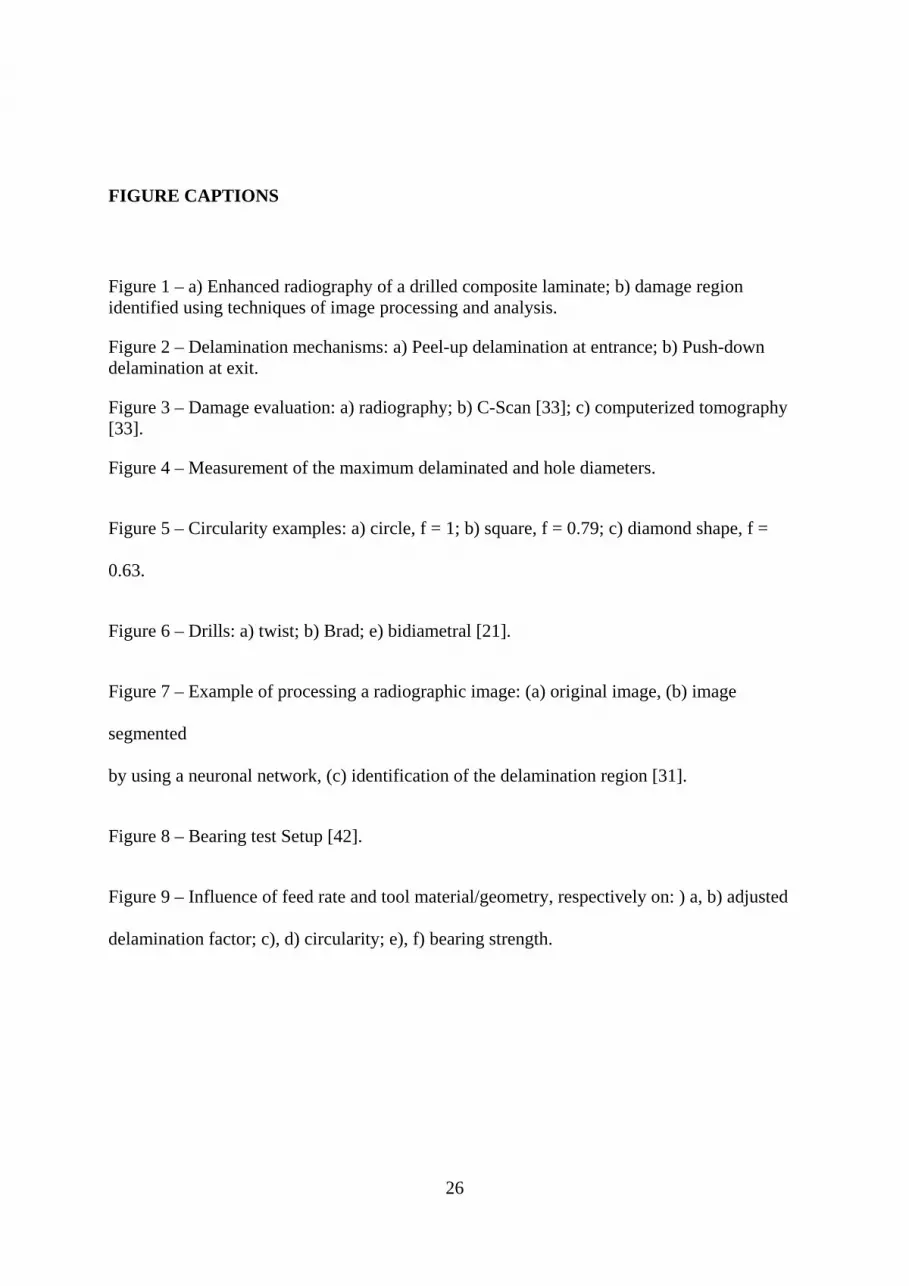
Figure 1 – a) Enhanced radiography of a drilled composite laminate; b) damage region identified using techniques of image processing and analysis.
Figure 2 – Delamination mechanisms: a) Peel-up delamination at entrance; b) Push-down delamination at exit.
Figure 3 – Damage evaluation: a) radiography; b) C-Scan [33]; c) computerized tomography [33].
Figure 4 – Measurement of the maximum delaminated and hole diameters.
Figure 5 – Circularity examples: a) circle, f = 1; b) square, f = 0.79; c) diamond shape, f =
0.63.
Figure 6 – Drills: a) twist; b) Brad; e) bidiametral [21].
Figure 7 – Example of processing a radiographic image: (a) original image, (b) image
segmented
by using a neuronal network, (c) identification of the delamination region [31].
Figure 8 – Bearing test Setup [42].
Figure 9 – Influence of feed rate and tool material/geometry, respectively on: ) a, b) adjusted
delamination factor; c), d) circularity; e), f) bearing strength.

27
TABLES
Feed rate [mm/rev]
Delamination factor, Fd
Adjust delam factor, Fda
Circularity, f Bearing test, MPa
0.03 1.29 1.47 0.14 203 0.10 1.61 1.81 0.10 195 0.20 2.04 2.33 0.08 178
Table 1
Mat /geometry Delamination factor, Fd
Adjusted Delamination
factor, Fda
Circularity, f Bearing test, MPa
HSS / twist 1.76 2.16 0.14 172 WC / twist 1.60 1.74 0.08 205 WC / brad 1.60 1.78 0.09 207
WC / bidiametral 1.64 1.80 0.11 201
Table 2

28
FIGURES
a) b)
Figure 1
a) b)
Figure 2

29
a) b) c)
Figure 3
Figure 4
Figure 5

30
a) b) c)
Figure 6
a) b) c)
Figure 7

31
Figure 8

32
a) b)
c) d)
e) f)
Figure 9