multiscale modeling of heat conduction in graphene laminates
TRANSCRIPT

1
Multiscale modeling of heat conduction in graphene laminates
Bohayra Mortazavi* and Timon Rabczuk
Institute of Structural Mechanics, Bauhaus-Universität Weimar, Marienstr. 15, D-99423
Weimar, Germany
Abstract
We developed a combined atomistic-continuum hierarchical multiscale approach to explore
the effective thermal conductivity of graphene laminates. To this aim, we first performed
molecular dynamics simulations in order to study the heat conduction at atomistic level.
Using the non-equilibrium molecular dynamics method, we evaluated the length dependent
thermal conductivity of graphene as well as the thermal contact conductance between two
individual graphene sheets. In the next step, based on the results provided by the molecular
dynamics simulations, we constructed finite element models of graphene laminates to probe
the effective thermal conductivity at macroscopic level. A similar methodology was also
developed to study the thermal conductivity of laminates made from hexagonal boron-nitride
(h-BN) films. In agreement with recent experimental observations, our multiscale modeling
confirms that the flake size is the main factor that affects the thermal conductivity of
graphene and h-BN laminates. Provided information by the proposed multiscale approach
could be used to guide experimental studies to fabricate laminates with tunable thermal
conduction properties.
*Corresponding author (Bohayra Mortazavi): [email protected]
Tel: +49 176 68195567
Fax: +49 364 358 4511

2
1. Introduction
Great success of graphene [1-3] with unique combination of exceptionally high thermal [4],
mechanical [5] and electrical properties [6] has raised an ongoing attention toward two-
dimensional (2D) materials as a new class of materials suitable for a wide variety of
applications from nanoelectronics to aerospace industry. Micro-raman spectroscopy
experiments [4] confirmed that single-layer graphene can present a thermal conductivity of
4100±500 W/mK at room temperature which outperforms all known materials. Presenting a
remarkably high thermal conductivity proposes the graphene as an excellent candidate in
response to heat management concerns in numerous applications such as nanoelectronics and
li-ion batteries. It should be taken into account that due to the small thickness of graphene
sheets, application of graphene as an isolated material is complicated and limited as well. One
common approach is to disperse graphene sheets inside polymeric materials to fabricate
nanocomposite materials with enhanced thermal and mechanical properties [7-9]. In this
regard, it is worthy to note that because of planar structure of graphene membranes,
experimental tests [8] and finite element modeling [10] confirm the superiority of graphene
nanosheets than carbon nanotubes in reinforcement of thermal conductivity of random
nanocomposite materials.
Latest experimental study [11] however suggests a new route to reach a highly thermal
conductive material through fabrication of graphene laminates. In this scenario, produced
graphene flakes are closely packed and stacked to form an overlapping structure.
Nevertheless, because of random nature of graphene flakes overlapping regions the physics
of heat conduction in graphene laminates is non-trivial [11]. Due to difficulties of
experimental studies along with complex nature of the problem, numerical and theoretical
methods could be considered as promising approaches to provide a general viewpoint.
Because of statistical nature of heat conduction through van-der Waals contact interfaces

3
between individual graphene plates, application of numerical methods is more convincing
and justifiable in comparison with theoretical procedures.
The objective of this work is to provide a general viewpoint concerning the heat transfer
along the laminates made from 2D materials by developing a hierarchical multiscale
approach. In the proposed approach, we developed a combination of atomistic and continuum
methods by using molecular dynamics (MD) and finite element (FE) methods, respectively.
In this regard, MD simulations were used to obtain the thermal conductivity of graphene as a
function of flakes length. In addition, MD modeling was utilized to evaluate interfacial
contact conductance between two separate graphene layers. Molecular dynamics simulation
is a powerful tool for studying the structures response at atomistic level, however because of
its high computational costs, MD turns to be an unfeasible method to study the samples with
macroscopic sizes. To pass this limitation, we construct continuum models of graphene
laminates by using the finite element approach. In agreement with experimental samples, we
assumed that graphene flakes were randomly distributed and staked to form a representative
volume element of graphene laminate. In our FE modeling, information provided by MD
simulations were used to introduce flakes thermal conductivity as well as interfacial
conductance between contacting sheets. It is worthy to mention that graphene is an
electrically conductive material. This way, fabricated graphene laminates would be also
electrically conductive due to the existence of percolation path for electrons through the
contacting flakes. This issue limits the use of graphene for the applications in which the
building blocks are preferred to be electrically insulating. To the best of our knowledge,
hexagonal boron-nitride (h-BN) presents the highest thermal conductivity among all
experimentally fabricated 2D electrically insulating materials. Consequently, the same
multiscale scenario was also developed to study the heat conduction through h-BN laminates
and the obtained results were compared with those of laminates made from graphene flakes.
4
2. Molecular dynamics modeling
We used classical molecular dynamics simulations in order to evaluate length dependent
thermal conductivity of suspended sheets as well as thermal contact conductance between
two individual flakes at room temperature (300 K). To this aim, we constructed molecular
models of graphene and h-BN films. Molecular dynamics calculations in this study were
performed using LAMMPS (Large-scale Atomic/Molecular Massively Parallel Simulator)
[12] package. It is worthy to note that the accuracy of predicted properties by molecular
dynamics simulations is strongly dependents on the use of appropriate potential functions for
introducing the atomic interactions. In this work, we used optimized Tersoff potentials
developed by Lindsay and Broido for graphene [13] and h-BN [14] atoms. The Tersoff
potentials [15, 16] parameters proposed by Lindsay and Broido [13, 14] could predict the
phonon dispersion curves of graphite and bulk h-BN in close agreements with experimental
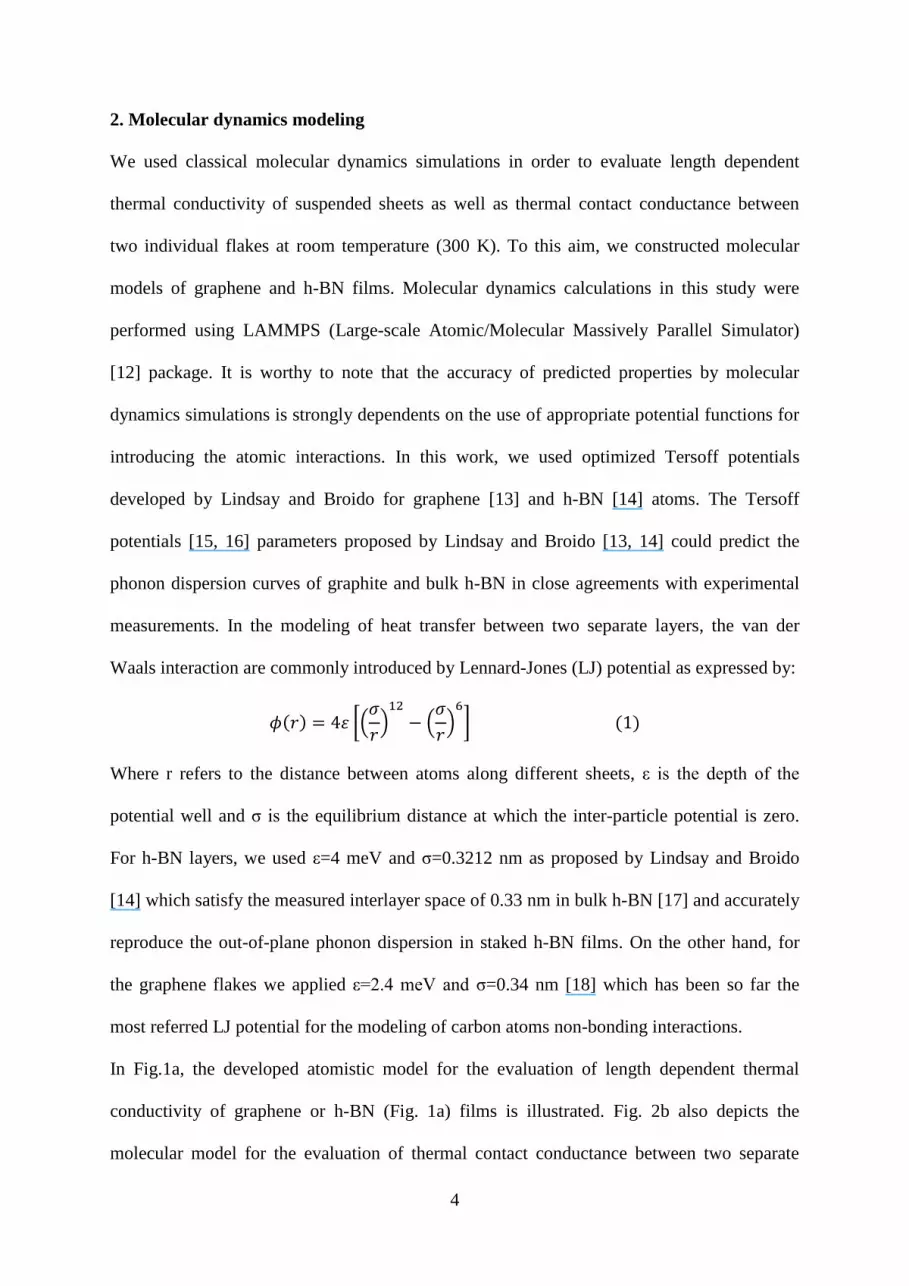
measurements. In the modeling of heat transfer between two separate layers, the van der
Waals interaction are commonly introduced by Lennard-Jones (LJ) potential as expressed by:
Where r refers to the distance between atoms along different sheets, ε is the depth of the
potential well and σ is the equilibrium distance at which the inter-particle potential is zero.
For h-BN layers, we used ε=4 meV and σ=0.3212 nm as proposed by Lindsay and Broido
[14] which satisfy the measured interlayer space of 0.33 nm in bulk h-BN [17] and accurately
reproduce the out-of-plane phonon dispersion in staked h-BN films. On the other hand, for
the graphene flakes we applied ε=2.4 meV and σ=0.34 nm [18] which has been so far the
most referred LJ potential for the modeling of carbon atoms non-bonding interactions.
In Fig.1a, the developed atomistic model for the evaluation of length dependent thermal
conductivity of graphene or h-BN (Fig. 1a) films is illustrated. Fig. 2b also depicts the
molecular model for the evaluation of thermal contact conductance between two separate

5
graphene or h-BN layers. In this case, we assumed that one tenth of the sheets lengths are
overlapping up-together to conduct the interfacial heat. In the molecular dynamics modeling
performed in this work, we applied periodic boundary condition along the width of the
samples in order to remove the effects of free atoms on the edge. These molecular models
were also developed for different sheet lengths to investigate length effect on the acquired
properties. We note that the time increment of all calculations was set to 1 fs.
In this work, thermal properties were evaluated using non-equilibrium molecular dynamics
(NEMD) method. In this approach, we fixed atoms at the two ends of the structure to prevent
atoms from sublimating (as shown in Fig. 1a with black atoms). Then, we divided the
simulation box (excluding the fixed atoms at the two ends) along the longitudinal direction
into several slabs. The temperature at each slab was then computed using the following
relation:
Where Ti (slab) is the temperature of ith
slab, Ni is the number of atoms in ith
slab, kB is the
Boltzmann’s constant, mj and pj are atomic mass and momentum of atom j, respectively. In
the NEMD method, specimen was first relaxed at room temperature using Nosé-Hoover
thermostat (NVT) method for 100 ps. In the next step, a temperature difference was applied
between the first and last slabs using the NVT method, while the remaining slabs were under
constant energy (NVE) simulations. In this study, the first and last slabs were assigned to be
hot and cold reservoir, respectively (as shown in Fig. 1). To keep the applied temperature
differences at the two slabs at the ends, at every simulation time step an amount of energy is
added to the atoms in hot reservoir and at the same time another amount of energy is removed
from the atoms in the cold reservoir by the NVT method. Instantly after the application of
temperature difference, the system would be at transient condition. However, after 300 ps of

6
the exchanging process, the system reaches to a steady-state heat transfer condition in which
a temperature gradient is established along the sample longitudinal direction. At this stage,
simulations were performed for longer time and averaged temperatures at each slab were
computed (as shown in Fig. 2a and Fig. 2b). To ensure the accurate application of NEMD
method after reaching the steady-state heat transfer condition, the net amount of energy added
to the hot reservoir must be equal to that removed from the cold reservoir. This means that
the total energy of the system is conserved. In addition, the slopes of energy curves must
follow linear patterns to ensure that the energy is added or removed with a constant rate. In
Fig. 2c and Fig. 2d, we plot the energy curves for the evaluation of length dependent thermal
conductivity of pristine sheets as well as those for studying the thermal contact conductance,
respectively. As it can be observed, in both cases the slopes of energy curves are considerably
close and they follow linear patterns. These observations imply that the energy of the
simulation box remains constant and a constant heat flow is applied throughout the sample
(Fig. 1).The applied heat flux through the sample is calculated based on the slope of
these energy curves which is accurately the same if one calculates it from the hot or cold
atoms energy curves.
Based on the established temperature profiles along the samples and calculated heat fluxes,
we then evaluated the thermal conductivity and contact conductance. The thermal
conductivity, k, was calculated using the one-dimensional form of the Fourier law:
Here,
is the established temperature gradient along the sample (as shown in Fig. 2a with
dashed line) and Across is the cross sectional area of graphene or h-BN flakes. In the
calculation of cross section area, we assumed thickness of 0.34 nm [18] and 0.33 nm [17] for
graphene and h-BN sheets, respectively. On another hand, thermal contact conductance, C,
was also evaluated using the following relation:

7
Here, ∆T is the formed temperature difference at the interface of two membranes (as depicted
in Fig. 2b) and Acontact is the overlapping area of two contacting films.
3. Finite element modeling
In the multiscale scheme developed in this work, we used finite element method to evaluate
the effective thermal conductivity of graphene and h-BN laminates. We note that
computational limitation of finite element method impose limits on the size of studied
systems. Therefore, commonly the simulations are limited only to the modeling of a
representative volume element (RVEs), consisting of a limited number of particles. Finite
element modeling in this study was performed using the Abaqus/Standard (Version 6.10)
commercial package. As a common assumption, graphene and h-BN sheets were modeled
using the disc geometry. In this case, the diameter of the disc is considered as the flakes
length. Fig. 3a illustrates a sample of developed RVE of graphene laminate that is consisting
of 800 individual flakes staked in 12 layers up together. In agreement with experimental
samples, the flakes were randomly distributed in each layer. The constructed models were
periodic in loading direction (y direction in this case). These models were constructed in
Abaqus by python scripting. We remind that the acquired results by MD modeling were used
to introduce flakes thermal conductivity as well as contact conductance interaction properties.
For the evaluation of laminates effective thermal conductivity, we included two highly
conductive strips at the two ends of the structure. These two auxiliary parts had the same
cross section as that of the laminate and they were thermally tied (zero contact resistance) to
the contacting flakes at the two ends. The thermal conductivity of these thin strips was chosen
to be one million to have negligible resistance. For the loading conditions, a constant inward

8
surface heat flux (+qy) was applied on the external surface of a strip (hot surface) while on the
outer surface of the opposite strip (cold surface) the same magnitude outward surface heat
flux (-qy) was applied. As the initial value for the problem, we set the temperature of outer
surface of cold strip to zero. As a result of applied loading condition, a steady-state
temperature profile form along the RVE length (Fig. 3b). We note that heat percolates in
laminate only through the contacting surfaces. To this purpose, we introduced contact
elements between every two contacting sheets. In this case, the master surface was chosen to
be the one that is closer to the hot strip and then the other contacting surface (closer to the
cold strip) was selected to be the slave surface. The established temperature difference along
the laminate, ∆Tl, is therefore the computed temperature on the outer surface of hot strip.
Finally, the laminate effective thermal conductivity, keff, was obtained using one-dimensional
form of the Fourier law:
Here, qy is the applied surface heat flux and Ll is the laminate length (without the strips).
4. Results and discussions
In Fig. 4, the calculated thermal contact conductance for graphene and h-BN flakes are
plotted for different sheets lengths. As it can be observed, the obtained results are
independent of flake length. On the other hand, as we assumed that one tenth of sheets
lengths are overlapping, the contacting area increases by increasing the sheet length.
Accordingly, the acquired contact conductance values are also independent of contacting
area. To summarize, using the NEMD method we found the conduct conductance of 0.1±0.01
GW/m2K and 0.053±0.005 GW/m
2K for h-BN and graphene flakes, respectively. These
values were then used in our finite element modeling to introduce contact interaction
properties between the flakes, independent of flakes length. We note that among the different

9
methods available for the modeling of interfacial contact conductance, the NEMD approach
is the most convincing approach that could simulate the nature of heat conduction in
graphene and h-BN laminates.
We performed NEMD simulations for samples with different lengths up to 300 nm. As
illustrated in Fig. 5, MD results for graphene and h-BN sheets show that the thermal
conductivity increases by increasing the length (L). As a common approach, the thermal
conductivity of sheets with infinite length was obtained by extrapolation of results for finite
lengths. To this aim, a simple approach is to define an effective phonon mean free path ( )
as
. Since the thermal conductivity is proportional to , the thermal
conductivity of the infinite system can be obtained by extrapolating to 1/L=0 [20].
Accordingly, the thermal conductivity of graphene and h-BN at room temperature are
calculated to be 3050±100 W/mK and 600±20 W/mK, respectively. The NEMD result for
thermal conductivity of single-layer h-BN at room temperature is in an excellent agreement
with theoretical prediction of 600 W/mK by Lindsay and Broido [14]. We note that using the
Tersoff potential parameters proposed by Matsunaga et al. [21], thermal conductivity of
pristine h-BN was predicted to be 80 W/mK [22]. On the other hand, the calculated value for
graphene is below the experimental measurements of 4100±500 W/mK [4] for pristine and
single-later graphene. The obtained relations for thermal conductivity as a function of flakes
length were then used to introduce the intrinsic thermal conductivity of particles in our finite
element modeling.
In Fig. 6, we compared the multiscale results for effective thermal conductivity of graphene
and h-BN laminates for different flake sizes. We note that we constructed finite element
models for different number of layers and we found that when the numbers of laminate layers
are higher than eight, the predicted properties are well-converged. However, in the final
calculation in this work, we set the laminate layers to twelve. Our multiscale results confirm

10
that by increasing the flake size, the effective conductivity increases for both graphene and h-
BN laminates. This observation is in agreement with recent experimental results [11] in
which it was observed that the flakes size presents remarkable effects on thermal conductivity
of graphene laminates. This enhancement trend in thermal conductivity is not only because of
the increasing of flakes thermal conductivity for the larger flakes but it is strongly due the
increasing of contacting area for heat percolation. In Fig. 6, the multiscale results are also
compared with experimental measurements for graphene laminates [11]. Interestingly, the
averaged thermal conductivity of three experimental points is only within 2% difference with
the multiscale prediction for the same averaged flake size. This confirms remarkable validity
of the developed hierarchical multiscale method in this study. However, experimental results
show sharper effects on the laminate thermal conductivity as the flake size increases. In the
reported experiments only about 20% increase in the flake size resulted in a two times higher
thermal conductivity of graphene laminate. This considerable increase could not be due to the
changes in the intrinsic thermal conductivity of the flakes [23-25]. However, one must take
into account that in experiments it is not possible to change the average flake size while
keeping all other parameters of the composite exactly the same. This means that variations in
the flake overlap or the strength of their attachment, which define the interfacial conductance
between the flakes, can account for some discrepancy between the experimental and
numerical results.
Surprisingly, our multiscale results suggest that for the flakes sizes lower than 1μm, the h-BN
laminates present higher thermal conductivity than graphene laminates. This observation is
interesting since the intrinsic thermal conductivities of h-BN films are by several times lower
than that for graphene sheets (as compared in Fig. 5). We remind that our MD results show
that interfacial contact conductance between h-BN films are almost double of that for
graphene sheets. Therefore, superior thermal conductivity of h-BN laminates for small flake

11
sizes is principally due to the lower interfacial resistance between the h-BN particles. In this
case, for the small flake sizes the interfacial resistance is the main factor that does contribute
to the effective thermal conductivity of laminate and the particles thermal conductivity plays
the minor part. However, by increasing the flake size, effect of interfacial resistance is
weakened and on the other hand influence of particles intrinsic conductivity is enhanced. Our
results suggest that a laminate made by graphene flakes with size of 10 μm could yield a
thermal conductivity by around 2.5 times higher than a laminate formed from same sized h-
BN films. In addition, our multiscale results predict that a graphene laminate formed by
millimeter sized graphene sheets can exhibit a remarkably high thermal conductivity of
around 900 W/mK. This thermal conductivity is by around thirteen times higher than that of
the sample with the flake size of 1μm. Such an observation clearly shows the remarkable
importance of flake size effects. We note that the intrinsic thermal conductivity of flakes with
length of 1μm is only 25% below the one with 1 mm length. On the other hand, h-BN films
could be also considered as an excellent candidate to fabricate highly conductive laminates.
Owing to their low interfacial thermal resistance, h-BN laminates are best suited when the
flake sizes are small.
From experimental point of view, fabrication of graphene or h-BN films with large sizes has
been among the most challenging barriers front to their applications performance.
Nevertheless, our simulation results recommend that for the small flakes sizes, improvement
of interfacial conductance could be taken into consideration as a promising approach to
enhance the effective thermal conductivity of laminates. In this regard, the common route is
to form covalent bonds between the graphene flakes through chemical functionalization or
ion irradiation. However, it should be taken into account that these chemical modifications
also decrease the intrinsic thermal conductivity of graphene sheets. Our recent MD study [10]
predicts that formation of 5% covalent bonds between graphene and epoxy enhances the

12
thermal contact conductance by around 3 times and reduce the intrinsic thermal conductivity
of pristine films by around 60%. As an example and based on these estimates, our multiscale
modeling reveals that a graphene laminate with flake size of 1μm and incorporation of 5%
covalent bonds could yield a thermal conductivity by around 70% higher than the same
sample made only from pristine sheets. Because of the fact that contact resistance between
the particles is understood to be the main factor in determining the overall effective thermal
conductivity for smaller flake sizes, effect of interlayer covalent bonding intensifies more as
the film sizes are smaller.
Presented multiscale results suggest the possibility of tuning the thermal conductivity of
graphene laminates by almost two orders of magnitude through controlling the flakes size.
Therefore, studying the electrical conductivity of graphene laminates could be also
interesting. This is due to the fact that fabrication of graphene laminates with low thermal and
high electrical conductivities could enhance the thermoelectric figure of merit in favor to
reach a high efficiency carbon-based thermoelectric material.
5. Conclusion
First multiscale modeling was conducted to systematically study the effective thermal
conductivity of graphene and h-BN laminates. The proposed approach is a hierarchical
combination of atomistic and continuum modeling. We performed molecular dynamics
simulations for the evaluation of length dependent thermal conductivity of particles and
thermal contact conductance between two individual flakes. Then, we constructed continuum
models of graphene and h-BN laminates using the finite element approach. In our finite
element modeling, we used the information provided by atomistic simulations to introduce
particles as well as interfacial conductance thermal properties. Comparison with experimental
results for graphene laminates confirms the considerable validity of the proposed approach.

13
Our modeling results suggest the possibility of tuning the graphene laminates thermal
conductivity by almost two orders of magnitude through controlling the flakes size. We found
that for the small flake sizes, the inter-flake contact resistance presents the major contribution
toward the effective thermal resistance of the sample. Unexpectedly, we found that for the
flake sizes smaller than 1μm, h-BN laminates owing to their high interfacial conductance
could yield thermal conductivity higher than the laminates made form graphene sheets. Our
study recommends that forming the covalent bonds between the graphene flakes could be
considered as an efficient approach to considerably enhance the thermal conductivity of
laminates, especially when the flake size is small. Nevertheless, by increasing the flake size,
the intrinsic thermal conductivity of particles start to play the key role in the heat conduction,
in which we found superiority of graphene than h-BN laminates for the flake sizes larger than
1μm. The proposed multiscale approach in this study could be considered as an efficient
modeling methodology to design laminates with tunable thermal conduction properties.
Acknowledgment
Financial support by European Union through ERC grant for COMBAT project is greatly
acknowledged.
References
[1] Novoselov KS, Geim AK, Morozov SV, Jiang D, Zhang Y, Dubonos SV, et al. Electric
field effect in atomically thin carbon films. Science 2004; 306(5659):666–9.
[2] Novoselov KS, Jiang D, Schedin F, Booth TJ, Khotkevich VV, Morozov SV, et al. Two-
dimensional atomic crystals. Proc Nat Acad Sci 2005; 102(30):10451–3.
[3] Geim AK, Novoselov KS. The rise of graphene. Nat Mater 2007; 6:183–91.
[4] Ghosh S, Bao W, Nika DL, Subrina S, Pokatilov EP, Lau CN, et al. Dimensional
crossover of thermal transport in few-layer graphene. Nat Mater 2010; 9: 555-8.

14
[5] Lee C, Wei X, Kysar JW, Hone J. Measurement of the elastic properties and intrinsic
strength of monolayer graphene. Science 2008; 321: 385–8.
[6] Williams JR, DiCarlo L, Marcus CM. Quantum Hall effect in a gate-controlled pn
junction of graphene. Science 2007; 317: 638-41.
[7] Wu H, Drzal LT. Graphene nanoplatelet paper as a light-weight composite with excellent
electrical and thermal conductivity and good gas barrier properties. Carbon 2012; 50: 1135-
45.
[8] Shahil KMF, Balandin AA. Graphene–multilayer graphene nanocomposites as highly
efficient thermal interface materials. Nano Lett 2012; 12: 861-7.
[9] Mortazavi B, Hassouna F, Laachachi A, Rajabpour A, Ahzi S, Chapron D, et al.,
Experimental and multiscale modeling of thermal conductivity and elastic properties of
PLA/expanded graphite polymer nanocomposites, Thermochimica Acta 2013; 552: 106-13.
[10] Mortazavi B, Benzerara O, Meyer H, Bardon J, Ahzi S. Combined molecular dynamics-
finite element multiscale modeling of thermal conduction in graphene epoxy nanocomposites.
Carbon 2013; 60: 356–65.
[11] Malekpour H, Chang KH, Chen JC, Lu CY, Nika D, Novoselov KS, Balandin AA.
Thermal Conductivity of Graphene Laminate. Nano Lett 2014; 14: 5155–61.
[12] Plimpton S. Fast parallel algorithms for short-range molecular dynamics. J Comp Phys
1995 ; 117: 1-19.
[13] Lindsay L, Broido DA. Optimized Tersoff and Brenner empirical potential parameters
for lattice dynamics and phonon thermal transport in carbon nanotubes and graphene. Phys
Rev B 2010; 82: 205441.
[14] Lindsay L, Broido DA. Enhanced thermal conductivity and isotope effect in single-layer
hexagonal boron nitride. Phys Rev B 2011; 84: 155421.

15
[15] Tersoff J. New empirical approach for the structure and energy of covalent systems.
Phys Rev B 1988; 37: 6991-7000.
[16] Tersoff J. Empirical interatomic potential for carbon, with applications to amorphous
carbon. Phys Rev Lett 1988; 61: 2879-82.
[17] Warner JH, Rummeli MH, Bachmatiuk A, Buchner B. Atomic resolution imaging and
topography of boron nitride sheets produced by chemical exfoliation. ACS nano 2010; 4:
1299-1304.
[18] Girifalco LA, Hodak M, Lee RS. Carbon nanotubes, buckyballs, ropes, and a universal
graphitic potential. Phys Rev B 2000; 62: 13104-10.
[19] Humphrey W, Dalke A, Schulten K, VMD - Visual Molecular Dynamics, J. Molec.
Graphics 1996; 14: 33-8.
[20] Schelling PK, Phillpot SR, Keblinski P. Comparison of atomic-level simulation methods
for computing thermal conductivity. Phys Rev B 2002; 65: 144306.
[21] Matsunaga K, Fisher C, Matsubara H. Tersoff potential parameters for simulating cubic
boron carbonitrides. Jpn J Appl Phys 2000; 39: 48-51.
[22] Mortazavi B, Remond Y, Investigation of tensile response and thermal conductivity of
boron-nitride nanosheets using molecular dynamics simulations, Physica E 2012; 44: 1846-
52.
[23] Xu X, Pereira LFC, Wang Y, Wu J, Zhang K, Zhao X, et al. Length-dependent thermal
conductivity in suspended single-layer graphene, Nature Communications 2014; 5: 3689.
[24] Balandin AA. Thermal properties of graphene and nanostructured carbon materials.
Nature Mater 2011; 10: 569-81.
[25] Nika DL, Balandin AA. Two-dimensional phonon transport in graphene. J Phys
Condens Matter 2012; 24: 233203.

16
Fig. 1- Constructed molecular models for the valuation of (a) length dependent thermal
conductivity and (b) thermal contact conductance between two individual flakes. Modelings
were performed for defect-free graphene and h-BN films. For the modeling of thermal
contact conductance, one tenth of sheets lengths are overlapped to simulate interfacial heat
conductance. VMD software [19] is used for graphical presentation of structures.

17
Fig. 2- (a and b) Established steady-state temperature profile along the samples by application
of non-equilibrium molecular dynamics method. (a) In the modeling of length dependent
thermal conductivity, by neglecting the initial jumps at two ends, a linear relation (dT/dx) is
formed along the sample length that is shown by a dashed line. (b) For the modeling of
thermal contact conductance, a temperature jump (∆T) occurs at the interface of two
individual flakes. Samples of energy values added to the atoms in hot reservoir and removed
from the atoms in cold reservoir by the NVT method for the modeling of (c) length dependent
thermal conductivity and (d) contact conductance. The depicted results (a and c) belong for
the thermal conductivity modeling of a graphene sheet with the length of 200 nm and (b and
d) are for the modeling of contact conductance between two individual h-BN films, each with
the length of 100 nm.

18
Fig. 3- A typical developed 3D representative volume element of graphene laminate
constructed in Abaqus/Standard. (a) For the loading condition, we applied inward and
outward surface heat fluxes on the outer surfaces of highly conductive strips. (b) Established
steady-state temperature profile along the sample.

19
Fig. 4- Calculated thermal contact conductance between individual graphene or h-BN sheets
for different sheet lengths.

20
Fig. 5- Calculated length dependent thermal conductivity of pristine graphene and h-BN
sheets. We plot the inverse of thermal conductivity as a function of length inverse to
extrapolate the thermal conductivity of films with infinite lengths. The fitted lines to the
NEMD results (shown by dashed lines) are also used to determine length dependent thermal
conductivity functions for graphene and h-BN films.

21
Fig. 6- Multiscale results for effective thermal conductivity of graphene and h-BN laminates
as a function of flake size. Modeling results are compared with recent experimental
measurements [11] for graphene laminates.