dog-leg control in directionally drilled wells - onepetro
TRANSCRIPT
Dog-Leg “Control in Directionally Drilled Wells
G. J. WILSON I CONTINENTAL 011 CO.
MEMBER AIME HARVEY, LA.
ABS I KACT
Review oj difficulties experienced in drilling directionalwells in the offshore Grand Isle Hock 43 field showed,.most failures of drill pipe, drill collars and c&ring to havebeen associated with excessive dog-legs, Alleviation of di/-/icul[ies was approached by synthesizing theoretical andpractical concepts in a planned dog-leg control program.Preventive measures necessary (o control dog-leg severityand corrective measures used to reduce unacceptable dog-legs are discussed. When other meas,ures fail, deliberativemeasui.es as outlined can be employed after the probablecumulative fatigue darnage to be sustained by the dri[lpipe has been determined. Restdts of a program success-ful in virtually eliminating problems stemming from ex-cessive dog-legs indicate that control of dog-leg severity indirectional wells is feasibte and will cause fio decrease inIhe over-all drilling rate.
INTRODUCTION
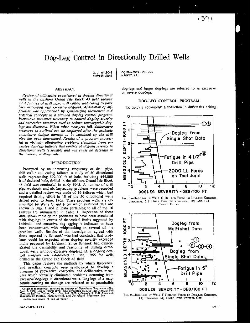
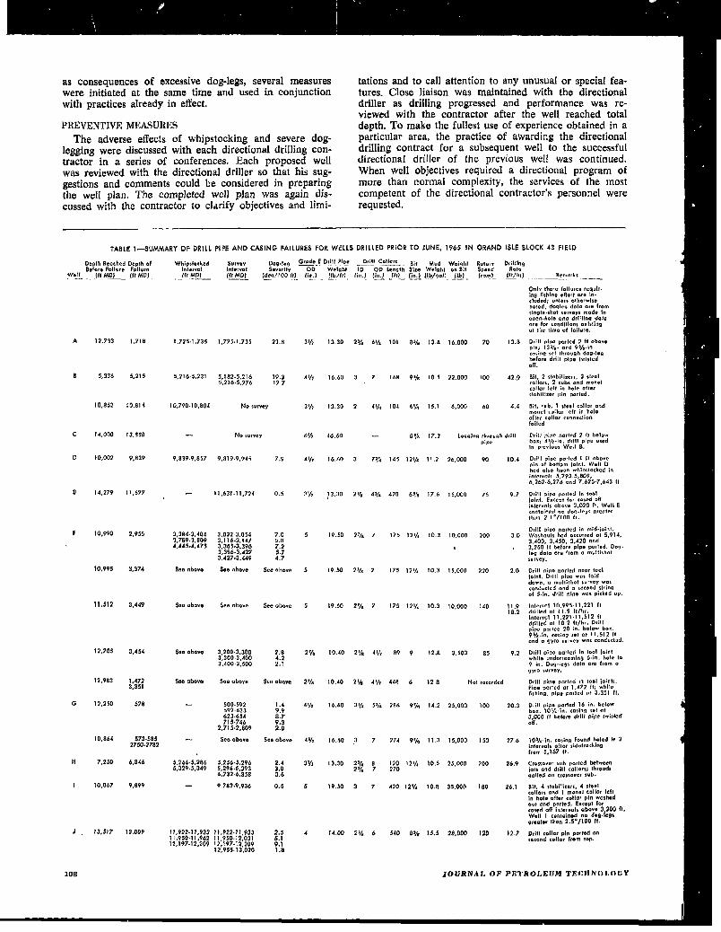
Prompted by an increasing frequency of drill pipe,drjll collar and casing failures, a study of 50 directionalwells representing 592,000 ft of hole, inchding 444,000ft of deviated hole, drilled in the offshore Grand Isle Block43 field was conducted in early 1965. A number of drillpipe washouts and six keyseating problems were recordedand a detailed review was made of 16 failures which hadrequired fishing effort in 10 of the 50 directional wellsdrilled prior to June, 1965, These problem wells are ex-emplified by Wells G and F for which pertinent data areshown in Figs. 1 and 2. Data pertaining to all of the 16failures are summarized in Table 1. Inspection of thesedata shows most of the problems to have been associatedwith dog-legs in excess of theoretical limits suggested byLubinski’ and excessive dog-legging is indicated to havebeen concomitant with whipstocking in several of the
problem wells. Results of the investigation agreed withthose reported by Schenck’ who had concluded that prob-lems could be expected when dog-leg severity exceededlimits proposed by Lubinski, Since Schenck had demon-strated the desirability and feasibility of drilling direc-tional wells without excessive dog-legging, a dog-leg con-trol program was established in June, 1965 for wellsdrilled in the Grand Isle Block43 field.
This paper reviews the methods by which theoreticaland practical concepts were synthesized to develop aprogram of preventive, corrective and deliberative meas-ures which virtually eliminated problems stemming fromexcessive”dog-legs in directional wells. Dog-legs of a mag-nitude causirm no damage are referred to as permissible
Original manuscript recuived in Society of Petroleum Engineers of?keAug. 5, 1966. Paper (SPE 1571) W8S pwsented at SPE41st Annutd FallMeeting held in Dallas, Tex., Oct. 2-s, 1966, c opyright 1!Is7 American
PInstitute of Mining, Metnllurzicrd, and Petroeum Enxinem’s Inc.Preferences given e.t end of Paper.
dog-legs and larger dog-legs are referred to as excessiveor severe dog-legs,
DOG-LEG CONTROL PROGRAM
To quickly accomplish a reduction in ditlicukiesa rising
:1 -.
) * A1
g I Dogleg from
! Single Shot Data;2 _+ e 1&LUa
tigue in 41/2,*
LLsK Drill Pipe3< 2000 Lb ForceIuz
on Tool JointI I I
50 2 4 6 8 10 ’12
DOGLEG SEVERITY -DEG/100 FT
10c. l—I)oc.LJ:tis1N WKLL G DRILLKD PRIOR’TO lh~G-Lix CONTROLpfKICl{AM.(]) [)RILI.~’lPE‘t’WISTIWoFF; (2) AND (3)
C.*S[NGHOLED.
)-Sk l\ Dogleg from
:2 rM,ultishot Data
DOGLEG SEVER ITY-DEG/100 FT
l% 2—I)cw-r.lxxINWLL F J)RII.I.I;IJPRIOR TO DOG.LWCONTROI.,(1) THROUGH (4) DRILL PIPI+TWSTED OFF.
JANUARY, 1967 107
Dow
nloaded from http://onepetro.org/jpt/article-pdf/19/01/107/2220859/spe-1571-pa.pdf by guest on 14 July 2022
as consequences of excessive dog-legs, several measures tations and to call attention to any unusual or special fea-were initiated at the same time and used in conjunction tures. Close liaison was maintained with the dhectionalwith practices already in effect. driller as drilling progressed and performance was re-
PREVENTIVEMEASURESviewed with the contractor after the well reached totaldepth. TO make the fullest use of experience obtained in a
The adverse effects of whipstocking and severe dog- particular area, the practice of awarding the directionallegging were discussed with each directional drilling con- drilfing contract for a subsequent well to the successfultractor in a series of conferences. Each proposed well directional driller of the previous well was continued,was reviewed with the directional driller so that his sug- When well objectives required a directional program ofgestions and comments could be considered in preparing more than normal complexity, the services of the mostthe well plan. The completed well plan was again dis- competent of the directional contractor’s personnel werecussed with the contractor to clarify objectives and limi- requested,
—
TABLEI—SUMMARYOF DRILL PIPE AND CASING FAILURES FOR WELLS DRILLED PRIOR TO JUNE, 1965 IN CJRAND ISLE BLOCK43 FIELD
DeDlh Reoched Deplh.fBef.re F.llvre Feilwe
well (fl Mol (ftd401
Whi@~cked S“wef’ Dog.feg Grode ED,ilf Pipe Drill CO1l.arS—.. Bity;;; I“tewel Severity
.— . Mud Weight R&qti~qh~ ID
Dcilli.gOD Lsngfh Size Weight ontiil
/d,g/ 100 (t] (:!)Rolq
(,b/ft), (;”, } {In. ) fft)_ f~O~ f~~/9011 ~lk,.(f~ __ . - _ _..-— (rPm) ~ty) Reme<k,_.—-. .—
OrilTthwef.iluce, re,qulr.I.g I%hlng cflert we in.c!vded: unless e*herwlso“Mod, d.qlq dol. ate fromd.g!e.sh.t wrveys mod. 1.men.h.in ma drilllrw datuMO for C.andilic.n$cxlsli.n.1 lhe lime ef fcdl. re.
A
B
c
D
E
F
G
H
I
J
108
12,733
5,336
! 0,8A2
14.000
10,003
14,379
10.990
10,99s
11,512
12,785
12,983
1?,250
10,864
7,250
10,067
)3.s17
1,718
5,215
:2.OIA
13.850
9,839
11,677
2,955
3,374
3.449
3,454
1,4723,351
578
573.58537S0.3782
4,846
9,899
13,009
1,725.1,735 1,725.1.735 23.8
5,216.5,231 5,1 S3.5,216 19.35,216.5.276 13.7
10,79 O.1O,8O4 ND ,vrvey
No ,.,VCY
9.839.9,057 9.8199,945 7.9
I 1,631 .11,73.4 0,5
3,384.3,4043,769.3,8094.445.4,415
SC* -hove
S.. above
See above
See above
—
—
$,266.5,2865,X39.5.349
3,D32 3.054 7,03,116.3.147 5.83.365-3,396 7,23,396.3.427 5.73,427.3,449 4,7
See above s.e oh...
see “ha”” See rim..
3,200.3,300 2.83,300.3.4003,400.3,500 ;:?
See above S00 above
500.592 1.4592.633 9.9623.654 8,771 S.746 9.3
2,715.2,809 2.8
See obeve see above
5,256.5,296 2,45,296+,393 2.06,732.6,858 0.6
9,782.9.936 0.s
1t,922 .)1,933 II,?22 .11,932 2.s11,950.11,962 11,950.12,031 5.112,197.12,209 ,?,197.12 ,209 9.1
12,9SS.1 3.020 1.8
3 s~
4 !/,
3 yt
41~
, 1/,
? 1/,
5
5
5
2:1,
27A
4 ~j,
4 8/,
31/,
5
A
13.30 23A 6,/. 10 I 85A 13.8 16.000 70 13.8
16.60 3 7 168 9% 105 ‘42.000 t 00 42.0
f3.20 2 4ye T04 6*IM 15.1 6.000 60 4.4
16.60 — 8% 17.2 l.xginq lh,eughdzillpipe
16.60 3 79A 145 131[, !1.2 26,000 90
13.30 z~h 4% 420 65,5 176 15.000 75
19.50 27h 7 175 121A 10.2 10’000 200
19.5U ?V* 7 175 izlh 10.3 15.000 230
19,50 2% 7 f75 121A 10.3 10,000 ! 40
to.40 21/a 4% 89 9 12.8 3.500 85
10,4
9.7
3.0
‘4.0
11.918.2
9,2
10,40 2!Ys 4YI 448 6 128 N.! ,e,e,dcd
16.60 31~ 5S), 286 WA !4.2 35,000 I 00 20.3
16.60 37 274 9% 11.3 15,000 150 276
13.30 21A a 120 1274 10.5 2s.000 200 26,92,h 7 270
19.50 3 7 420 12% 10.8 S5,000 180 26.1
14,00 23,2 6 540 8% 13.5 28,000 I 20 12.7
0.111 d.e patted ? #l .bo,ep!.; 13%. cmd 9%.3.<.,;.s ,,1 Ihmwzh dm!.legbefora drill ~ic.e fwis!edon.
%!, 2 s!. bi!izer,, 3 sleet.911., $, 2 sub, or,d mo”elcollar left in hem after!I. bilizer pi. cmrled.
Ml, cub, 1 Neel collar andmend collar Iefl In h.luof fe< colt., . ..nedi.nf. iled
Dcill Pine nncled 3 II belowb.,; 4,/,.1., drill D:nc u,edI. mevi,w Well B.
0,01 pic.e P.adc’d 1 II abovepi. of bot!em i.inl. Wall Ohod also been whln$!acked in;.terv.1, 5,793.5,809,6.362.6,278 and 7,625,7,642 fl
0,111 P:DO P.md :. Ioofi.lnt. E.<. *I for <smd Mlin ferval, above 2,020 It, Well E<*dlotnod “o doq.lew gr,oterlhm 3 !“/100 fl.
Drill cd~e wa,led i. mid.i.iol.Wmh.wl, hod eccwmd .1 S,914,3,400. 3,450, 3,420 and3,260 fl bef.rc pip. !mrted. Dog.leg dol. . . . f,om a mu[li. hotsurvey.
D,ill I+PO nwtcd neor ladi.aint. Drill DI.C -m I.idd.w”, o m.lli$h.t Wrv.y was,o.d. ded ond a %C<end.%td.uof S.1.. drill Pipe “IO, m<k, d .0.
Inlew.f 10,99511.221 Itdrilled al )1.9 fl/hrI“terv.1 11.22 f.11,512 Itdr$llw! al 1S2 It/hr. DI;IIpi.. pnr,cd ?0 ;.. b~l~~ b...95,$.;”. <.,;”0 ,.1.} 11,512 ftond a gyro survey w.% <.nduded.
Drill niP. marled in leaf i.inlwhile under reom;nq 6.:”, he!e 109 in. Dq.leg$ d.a~ are f:.m a9Yr. wrw.
Drill PiP. narl.d m 1..1 ioln!$.9iw P.CM or 1,472 ff, whilefish!ng, tine oarled Ot 3.351 ft.
0,;11 r,ioa pled 16 !n. belowbe.. 10%, Tn. <odn!I WI at3,000 ff before drill Pit,e twistedon.
10Vin, cmiw f.w.d h.hdIn 2;.!.,..1s .f!.a sidetrackingfrom 5,157 ft.
s+, 4 slabillzers, 4 steelc. flo,, c.nd I me”.] <01[0, leftin hole aft., collar pi. washedcwt and rmrfed. EKceDt forcased OR intervals ob.vo 3,204ft,well I c.ntained no dea-fa$~,c.atw lhon 2. S”/100 If.
D,;II coil.rph $.mted . .second collar fmm tap.
JOSJRNAL OF P31TRs31.EIJM TECHNOLOGY
Dow
nloaded from http://onepetro.org/jpt/article-pdf/19/01/107/2220859/spe-1571-pa.pdf by guest on 14 July 2022
.—
Limits of permissible dog-leg severity were calculated forthe entire well using Schenck’s assumptions. Schenckassumed the radius of hole curvature to be constant forall points between two adjacent survey stations regardlessof the distance between stations. He also assumed that Lu-binski’s calculations could be employed with dog-leg sever-itystated in degrees per 100 ft. Dog-leg limits for drillpipewere calculated for wells in the Grand Isle Block 43 fieldby applying a conversion factor to expressions derived
—~ by Lubinski.
, (2)
(1)
. . . (3)
where a, = dog-leg angle to which drill pipe can be sub-jected without failure occurring as a result offatigue due to stress reversa[, degrees/100 ft
w =dog-leg angle to which dril! pipe can be sub-jected without failure occurring as a resultof horizontal thrust, degrees/100 ft
au =dog-leg angle at which driI1 pipe can be ex-pected to fail immediately as a result of theyield strength being exceeded, degrees/100 ft
S, = reversed bending stress in drill pipe, lb/sq in.
S, =tensile stress indrill pipe, lb/sqin. S, =T/Awhere A = cross-sectional area of drill pipe,sq in.
S. = minimum yield strength of the drill pipe nla-terial, lb/sq in.
F= horizontal force exerted by drill pipe againstside of the hole or casing, lb
E= Young’s modulus of the driIl pipe material,lb/sq in.
D = outside diameter of drill pipe, in.
2’= weight, in the well control fluid, of the por-tion of the drill string below the point atwhich a is determined, lb
I = moment of inertia of drill pipe cross-sectionwith respect to a diameter, in.’
764= conversion factor equal to2X(100ft/15ft)X (1800/7 radians),
The allowable reversed bending stress can be readfrom a Goodman diagram as modified by Lubinski.’ Inmaking a large number of computations, it wits foundconvenient to further modify the Goodman dtagram sothat the straight-line relationship So = 20,000 -0.185S,could be used for Grade Edrill pipe with S, not to exceed67,500 lb/sq in. In preparing permissible dog-leg sever-ity curves for Grand Isle Block 43 wells, weight carriedon the bit is not deducted in calculating T since off-bottom rotation is required at times,
Permissible dog-leg severity in the upper part of thewellbore was at first based on a maximum horizontalthrust of 2,000 lb. However, permissible dog-leg valuesthus calculated approached the desired rate of inclinationbuildup in deeper wells and would have demanded an es-
IANUARY, 1967
sentially ideal wellbore to be drilled. Furthermore, direc..tional surveys made before and after setting casing indi-cated cased-hole dog-legs to be usually smaller than open-hole dog-legs. After considering these facts, the decisionwas made to use the drill pipe fatigue curve as the per-missible limit from the surface to the depth at whichdrill collar fatigue became the controlling limit, Thus, itwas assumed that a welt drilled within the drill pipe fa-tigue limits would not develop horizontal thrust forcessufficient to cause appreciable drill pipe or casing wear.The net effect of the assumption wsx to increase the per-missible thrust to about 2,900 lb,
Permissible dog-leg severity for drill collars was ob-tained by applying a 100/30 factor to curves presented inRef. 1, interpolating for collar sizes not shown,
In accordance with the principles and assumptions justoutlined, dog-leg severity was calculated for conditionsexpected to exist at total depth in each proposed well.Dog-1eg severity causing immediate yielding of drill pipewas also calculated as an aid in qualitatively estimating theetiect of an actual dog-leg on drill pipe life. Permissibledog-leg severity was plotted vs measured depth and copiesof the plot were submitted to personnel concerned withdrilling the well.
Contractors were instructed to calculate dog-leg severityat the well site for each single-shot survey according tothe method prescribed in API Bulletin D8. The informa-tion was reported with other directional survey data eachmorning. Data were then checked and actual dog-legvalues were plotted on the permissible dog-leg severity vsmeasured depth plot previously prepared. This procedurefacilitated requests for resurveys and made feasible themonitoring of several directional wells drilling at the sametime.
Limits 10 the amount of hole drilled between single-shot survey stations were also established. The buildupportion, the first 650 ft of the slant portion and the re-turn to vertical portion of the hole were to be surveyedat intervals not exceeding 93 ft or the length of one standof drill pipe, and the remainder of the deviated hole wasto be surveyed at intervals not exceeding 280 ft or thelength of three stands, Surveys made on these spacingsproved to be adequate when directional control problemswere largely absent. In practice, surveys were usuaflymade on shorter course lengths when difficulties were ex-perienced. Intervals surveyed on a course length longerthan about 50 ft which exhibited a dog-leg greater than75 per cent of the permissible value were resurveyed at31-ft intervals. The resurvey was conducted soon after theinitial survey so that corrective measures could be con-sidered before the well had progressed far beyond thedog-legged interval. Figs. 1 and 2 demonstrate the needfor resurveying with either single shots or multishots on31-ft spacing. Well G (Fig. 1) was not resurveyed. Thecasing failed opposite a dog-leg indicated by single-shotdata to be smaller than a dog-leg opposite which no faihsreoccurred. Data for Well F (Fig. 2) shows differences be-tween mt.dtishot data from a 3I-ft survey and single-shotdata from a survey made on random spacing longerthan 31 ft.
Since permissible dog-leg limits increase with depth,kickoff points were planned at the maximum depth permit-ted by well objectives and established practices regardingdirectional drilling in general. Although the deviated por-tion of the wellbore — over which most of the severe dog-legs occur — decreases as the inclination angle increases,the advantages of a deeper kickoff point and a largerinclination angle must be weighed against the cost of sur-
169
Dow
nloaded from http://onepetro.org/jpt/article-pdf/19/01/107/2220859/spe-1571-pa.pdf by guest on 14 July 2022
face casing, the location of the return to vertical point,relative to casing points and to total depth and other fac-tors not directly affecting dog-leg control.
Prior to initiation of the dog-leg control program, mostwells were planned with rates of inclination angle buildupand return to vertical of 2.0°/ 100 ft of measured depth,After the program was established, the buildup rate wasusually limited to 1.0 or 1.SO/100 ft for wells deeperthan about 10,000 ft. Shallower wells could tolerate build-ups of 2.0 to 2.5°/ 100 ft without complicating dog-legcontrol. Wells were returned to vertical at rates rangingfrom 1.0 to 2.5°/ 100 ft.
The importance attached to an imaginary 100-ft radiuscylinder surrounding the axis of the proposed wellbore wasrepudiated, In the past some directional contractors con-sidered any wellbore d:illed within the cylinder to repre-sent an optimum effort. A brief inspection of data record-ed for Well F in Table 1 and Fig. 2 demonstrates the fal-lacy of this assumption. At WeR F, preoccupation withthe cylinder and overzealous attempts made to maintainthe wellbore within the cylinder required several whipstockruns which resulted in severe multiple dog-legs and re-peated drill pipe failures. By directing more attention toreaching the bottom-hole target at the proposed locationand relaxing the presumed requirements regarding a cyl-inder, the normal tendency of the bit to drift could beutilized in reaching the target. Much of the time andcost former] y expended in resisting the tendency of thebit to move in a curved path was eliminated.
When corrections in direction or inclination were re-quired, alternately drilling a few feet and jetting a fewfeet was first attempted, with whipstocking reserved as afinal resort. In a few cases for which position of the wellon structure and-well spacing requirements were not criti-cal, the bottom-hole target area was expanded to precludewhipstocking. In this regard, it is imperative that thelargest acceptable area be defined immediately upon en-countering a directional control problem since Iittie is tobe gained by expending several days in a futile attempt toreach an unnecessarily restricted target. On the ofher hand,target areas drastically reduced in size were sometimesnecessary. These targets were carefully defined prior tostarting the well and the restricted target areas werereached without undue delay.
At initiation of the dog-leg control program, it hadbeen anticipated that whipstocking could not be com-pletely precluded. Whipstocks were used to sidetrack onenew well out of an abandoned borehole and to correct di-rection in one well. In the first well, dog-leg severity atthe point of sidetrack was acceptable but corrective meas-ures were later required, A whipstock was set in the sec-ond well at 10,311 ft in a hole inclined at 38” and the di-rection was changed by 2° with 0.50 change in the in-clination angle. A dog-leg of only 1.78°/ 100 ft was creat-ed, indicating that excessive dog-legging was not necessar-ily adjunctive to judicious use of whipstocks.
Multishot surveys were conducted over the openholeinterval at each successively deeper casing point. Surveyswere made on 93-ft spacing unless single-shot data hadshown the existence of dog-legs larger than 75 per centof the permissible value, in which case multishot surveyswere made on 3I-ft spacing. Dog-leg severity was cal-culated from multishot data. Multishot values larger thanpermissible values and multishot values opposite any inter-vals which had been indicated by single-shot data to con-tain severe dog-legs were entered on the plot of permiss-ible dog-leg severity vs measured depth, Comparisons ofsingle-shot and muhishot data often showed dog-leg se-
110
verity to change as drilling progressed, Usually, but notnecessarily, dog-leg severity increased in the upper part ofthe hole and decreased at deeper depths. A series of com-parative surveys run before and after reaming surfaceholes to a size required to accommodate surface casingindicated dog-leg severity to be reduced by reaming inmost cases. The few data available indicated cased-holedog-legs to be smaller than the original openhole dog-legs.It was nevertheless anticipated that gyro surveys insidecasing suspected of containing severe dog-iegs would berequired at times.
The practice of setting heavier weight casing throughthe buildup portion of the hole was continued. While theheavier weight casing was not expected to prevent failuresresulting from very severe dog-legs, the greater wall thick-ness did provide slightly higher wear resistance. When di-rectional surveys indicate the casing to contain doglegs ofa magnitude sutlcient to damage drill pipe or casing, anattempt should be made to reduce horizontal thrust of thedrill pipe by carrying out deliberative measures discussedlater. However, casing should not be set across dog-legsgreater than the maximum tolerable listed in API BulletinRP 5C1. Due to the higher drilling rate achieved in theupper portion of the hole as compared to the rate atdeeper depths, setting surfttce casing at depths much deep-er than required by pressurv considerations has oniy asmall effect in obviating failures stemming from excessivedog-legs. Setting surface casing 200 to 300 ft into theslant portion of the hole has proved to be helpful in pre-venting severe dog-legs frequently encountered below sur-face casing set before the n~aximunl inclination angle hadbeen attained.
The general use of nonhard-btmded or fine mesh hard-banded drill pipe contributed to success of the dog-legcontrol program. Higher grade drill pipe, used in the topof the drill string when well depth requirements exceededthe strength of the pipe normally used, increased to someextent the permissible limit of dog-leg severity. Double-wall drill pipe, used above the drill collars in attempts toincrease the drilling rate in two wells, also effectively re-duced fatigue in critical joints. Although inspection of drillpipe and drill collars could be considered as a preventivemeasure, inspection practices are discussed later.
(:ORRIKTIYE hll;ASURESThe continued practice of drilling the deviated surface
hole and then reaming with a hole opener to the diameterrequired for surface casing was etlective in reducingsevere dog-legs to permissible limits in all but two of thefew wells exhibhing excessive dog-legs in the surfacehole.
Corrective measures were carried out below surface cas-ing in two wells. The first well, sidetracked from a dryhole by whipstocking opposite a window at 2,910 ft, con-tained no severe dog-legs at the point of sidetrack butreached a depth of 5,244 ft with a 5.0°/ 100 ft dog-legin the interval 5,170 to 5,234 ft and with the direction 5“off the desired course, To return the well to a more opti-mum direction without creating a greater dog-leg, the in-terval from 5,050 to 5,244 ft was rc .lriIIed in about 16hours, No severe dog-legs were present in the redrilledhole and the well was continued to the programmed totaldepth without further incidents. The second well reacheda depth of 4,500 ft with 5.25 and 5.48°/ 100 ft dog-legsin the intervals 3,059 to 3,112 ft and 3,143 to 3,206 ft.Calculations made with the procedure presented by Hans-ford and Lubinsk~ indicated that, at a depth of 7,360 fi,the drill pipe would be subjected to stresses resulting infatigue failure before the well objectives had been attained.
JOURNALOF PE’rROL~oM‘lECH~OLO~Y
Dow
nloaded from http://onepetro.org/jpt/article-pdf/19/01/107/2220859/spe-1571-pa.pdf by guest on 14 July 2022
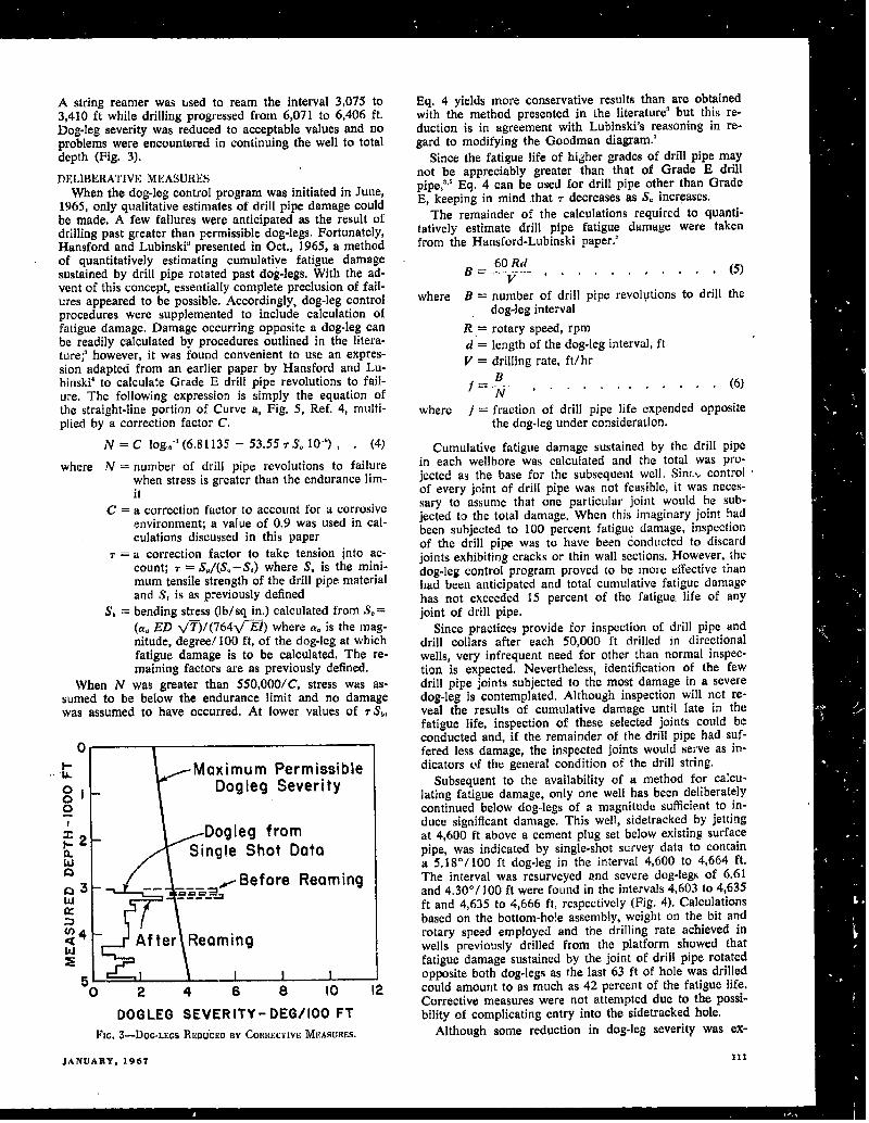
A string reamer was used to ream the interval 3,075 to3,410 ft while drilling progressed from 6,071 to 6,406 ft.Dog-leg severity was reduced to acceptable values and noproblems were encountered in continuing the well to totaldepth (Fig. 3).
DELIBERATIVEMEASURESWhen thedog-leg control program wasinitiated in June,
1965, only qualitative estimates of drill pipe damage couldbe made. A few failures were anticipated as the result ofdrilling past greater than permissible dog-legs. Fortunately,Hansford and Lubinsk~presented in Oct., 1965, a methodof quantitatively estimating cumulative fatigue damagesustained by drill pipe rotated past dog-legs. With the ad-vent of this concept, essentially complete preclusion of fail-ures appeared to be possible. Accordingly, dog-leg controlprocedures were supplemented to include calculation offatigue damage. Damage occurring opposite adog-leg canbe readily calculated by procedures outlined in the litera-ttire~ however, it was found convenient to use an expres-sion adapted from an earlier paper by Hansford and Lu-binski’ to calculate Grade E drill pipe revolutions to fail-ure. The following expression is simply the equation ofthe straight-line portion of Curve a, Fig. 5, Ref. 4, multi-plied by a correction factor C.
N=C log..,”’(6.81 135 -53.55 rSti 10-”), . (4)
where N =msmber of drill pipe revolutions to failurewhen stress is greater than the endurance lim-it
C= a correction tldctor 10 account for acorrosivcenvironment; a value of 0.9 was used in cal-culations discussed in this paper
r =a correction factor to take tension into ac-count; 7 =S,/(S. –S,) where S. is the mini-mum tensile strength of the drill pipe materialand S, is as previously defined
S, = bending stress (lb/ sq in.) calculated from S,=(a. ED V~)/(764ti~) where a.isthemag-nitude, degree/100 ft, of the dog-leg at whichfatigue damage is to be calculated, The re-maining factors are as previously defined.
When N was greater than 550,000/C, stress was as-sumed to be below the endurance limit and no damagewas assumed to have occurred. At lower values of rS~,
~~E.1 rMaximum Permissible0[ Dogleg Severityo0
;2M Dogleg from1-LM
Single Shot DataQ-x — -- —--- ~Before Reaming
{q ~~ After \Reaming
\~ &sLdt__~2
024 6
DOGLEG SEVERITY- DEG/100 FT
llc. 3—DOG.LEGSREDUCEDBY Corm&crxvEMIZASUMS.
Eq. 4 yields more conservative results than are obtainedwith the method presented in the literature’ but this re-
1duction is in agreement with Lubinski’s reasoning in re-gard to modifying the Goodman diagram,’
Since the fatigue life of higher grades of drill pipe maynot be appreciably greater than that of Grade E drillpipe~” Eq. 4 can be used for drill pipe other than GradeE, keeping in mind that T decreases as S. increases.
The remainder of the calculations required to quanti-tatively estimate drill pipe fatigue damage were takenfrom the Hansford-Lubinski paper.:’
where B = number of drill pipe revolutions to drill thedog-leg interval
R,= rotary speed, rpmd = length of the dog-leg interval, ftV = drilling rate, ft/hr
where / = fraction of drill pipe life expended oppositethe dog-leg under consideratiorr.
Cumulative fatigue damage sustained by tbe drill pipein each wellbore was calculated and the total was pro-jected as the base for the subsequent. well. Sinr.s controlof every joint of drill pipe was not feasible, it was neces-sary to assume that one particular joint would be sub-jected to the total damage, When this imaginary joint hadbeen subjected to 100 percent fatigue damage, inspectionof the drill pipe was to have been conducted to discardjoints exhibiting cracks or thin wail sections, However, thedog-leg control program proved to be more effective thanhad been anticipated and total cumulative fatigue damagehas not exceeded 15 percent of the fati6ue. life of anYjoint of drill pipe.
Since practices provide for inspection of drill pipe anddrill collars after each 50,000 ft drilled in directionalwells, very infrequent need for other than normal inspec-tion is expected. Nevertheless, identification of the fewdrill pipe joints subjected to the most damage in a severedog-leg is contemplated. Although inspection will not re-veal the results of cumulative damage until late in thefatigue life, inspection of these selected joints could beconducted and, if the remainder of the drili pipe had suf-fered less damage, the inspected joints would serve as in-dicators of the general condition of the drill st]
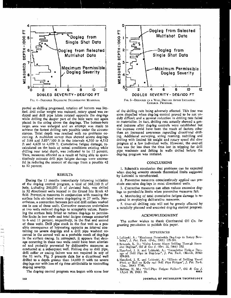
Subsequent to the availability of a method for calcu-lating fatigue damage, only one well has been deliberatelycontinued below dog-legs of a magnitude sufficient to in-duce significant damage. This well, sidetracked by jettingat 4,600 ft above a cement plug set below existing surfacepipe, was indicated by single-shot survey data to containa 5.18°/ 100 ft dog-leg in the interval 4,600 to 4,664 ft.The interval was resurveyed and severe dog-legs of 6.61and 4.30°/ 100 ft were found in the intervals 4,603 to 4,635ft and 4,635 to 4,666 ft, respectively (Fig. 4). Calculationsbased on the bottom-ho!e assembly, weight on the bit androtary speed employed and the drilling rate achieved inwells previously drilled from the platform showed thatfatigue damage sustained by the joint of drill pipe rotatedopposite both dog-legs as the last 63 ft of hole was drilledcould amount to as much as 42 percent of the fi “ ““-Corrective measures were not attempted due to the possi-bility of complicating entry into the sidetracked hole.
Although some reduction in dog-leg severity was ex-
JANUARY. 1967 111
Dow
nloaded from http://onepetro.org/jpt/article-pdf/19/01/107/2220859/spe-1571-pa.pdf by guest on 14 July 2022
~
050
R.
Dogleg fromg ● Single Shot Data
&~ Dogleg from Selectedm Multishot Datctc)
t’>~‘/*7’ ●
td”K Maximum Permissible@- Dogleg Severity
~ ~’;a I 1 1‘O 2 4 6 8 10 12
DOGLEG SEVER ITY-DEG/100FT
lh~. 4--DOC.LI;CSRIXIUIIHNCI)t;LIHI:RASWI~MKASUtiU.S.
petted as drilling progressed, rotation off bottom waslim-ited, drill collar weight was reduced, rotary speed was re-duced and drill pipe joints rotated opposite the dog-legswhile drilling the deeper part of the hole were not againplaced in the string above the dog-Iegs, The bottom-holetarget area was enlarged and an attempt was made toachieve the fastest drilling rate possible under the circum-stances. Total depth was reached with no problems oc-curring. A multishot survey then showed severe dog-legsof 3.98 and 5,03 °;100 ft in the intervals 4,500 to 4,532ft and 4,628 to 4,659 ft. Cumulative fatigue damage, re-calculated on the basis of actual conditions existing whiledrilling near total depth, was indicated to be 12 percent.Thus, measures effected as a result of being able to quan-titatively estimate drill pipe fatigue damage were success-fulinreducingthe amount of daiaage from a possible 42to 12 percent.
RESULTS
During the 13 months immediately following initiationof the dog-leg control program, a total of 368,!)00 ft ofhole, i,~chrding 260,000 ft of deviated hole, was drilledin 32 directional wells located in the Grand Isle Block 43field. Prevent; remeasures in conjunction with reaming thesurface hoIe obtiated severe dog-Iegging in 27 wells. Nev-ertheless, a connection between jars and drill collars washedout in one of these well~, Corrective measures undertakenat two wells reduced dog-legs to acceptable values. Ream-ing the surface hole feiled to reduce dog-legs to permiss-ible limits in two wells and total faligue damage amountedto 6 and 11 percent, respectively, in the first and secondof these wells. Drill pipe stuck in the first well as a pos-
— sible consequence of keyseating opposite an interval con— taining no severe dog-legs and a drill pipe washout oc-
curred in the second well as a probable result of dog-legsin the surface casing. In retrospect, it appears that dam-age occurring in these two wells could have been alleviat-ed and probabIy prevented by deliberative measures as
—: conducted at a subsequent well, Fishing due to drill pipe,drill collar or casing failure was not required in any of
I
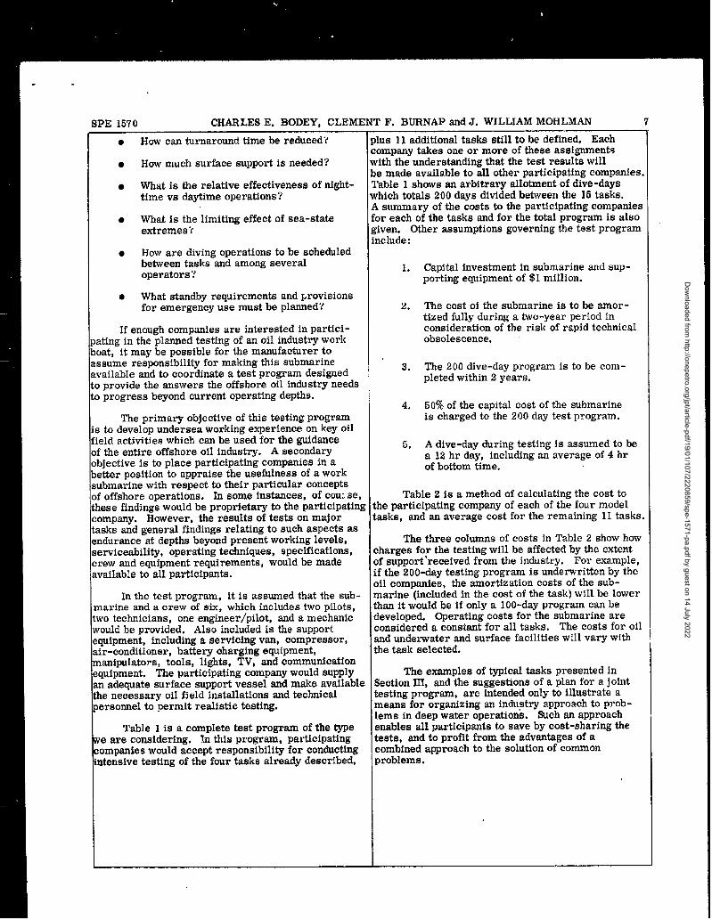
the 32 wells. Fig. 5 presents data for a directional welldrilled to a depth greater than 14,fJO0 ft with no severedog-legs nor with loss of rig time attributable to controllingdog-leg severity.
Thedog-leg control program was begun with some fear
$Dogleg from Selected
Multishot Data
●●
Dogleg from
● Single Shot Data
T~b Maximum PermissibleDogleg Severity
L●
I L 1 t f
2 4 6 8 10
DOGLEG SEVERITY -DEG/100 FT
FIG.5–DOC.J,KCSIN A \VI:LLDRILLKU AP!I~R IN[rINtYXG
CON’WJJ, ]’ROCliAM.
of the drilling rate being adversely affected. This fear wassoon dispelled when dog-leg control proved to be not un-duly difficult and a general reduction in drilling rate failedto materialize. In fact, drilling rate actualIy showed agen-eral increase after dog-leg controls were established butthe increase could have been the result of factors otherthan an increased awareness regarding direct?mal drill-ing. Additional surveying, string reaming, redrilling anddrilling with limited bit weight and rotary speed did S1OWprogress at a few individual wells. However, the over-allloss was far less than the time lost in tripping for drillpipe washouts and fishing in wells drilled before thedog-leg, program was initiated.
CONCLUSIONS
1. Schenck’s concision that problems can be expectedwhen dog-leg severity exceeds theoretical limits suggestedby Lubinski is corroborated.
2. Preventive measures conscientiously applied can pre-clude excessive dog-legs in most directional wells.
3. Corrective measures can often reduce excessive dog-legs topermissible limits when preventive measures fail.
4. Monitoring of total cumulative fatigue damage is re-quired in employing deliberative measures.
5. Over-all drilling rate will not be greatly affected bya ~arefu[~y p]annedand executed dog-leg control program.
ACKNOWLEDGMENT
The author wishes to thank Continental Oil Co. forgranting permission to publish this paper.
REFERENCES
l.1.nhinski. A.: “Muxinnlm Pe.rmissiblc f)og-l,eg+in Rn(nry JkIrv.holes”,J. ht. Tech. (Feb., 1961) 175.194.
2. Sc]wsck, K, D.: “Cahm harm Ahn,t Drilling Tl,rough I;xccs-sive Doglegs”,Or? &. Gas j. (M. 12, 1964) 132.
3. Hmw%rd, J. E. and Lubiwki. A.: “Cunullntivc Fatignc Dsm.age of Drill l’ipe in f)og.Legs”, J. Pet. Tech, (March, 1966)359.3s33.
4, Hmrsford, J. R ml I.tdinski A.: “Effects of Drilling VesselI)i[cll or Roll “1, Kelly ml Drill Pipe Fatigue”, ~. Pet. 7’e~~l.(fan., 1964) 7736.
5. Rollins, H. M.: “Dtiil.Pipe Fi,tjguc IJuilurr.”, Oil & Cm J.(April 18, 1966) 98.
JOURNALOF PETROLEUM TECIINOLOCY
Dow
nloaded from http://onepetro.org/jpt/article-pdf/19/01/107/2220859/spe-1571-pa.pdf by guest on 14 July 2022
SPE 1570 CHARLES E. BODEY, CLEMENT F. BURNAP and J. WILLIAM MOHLMAN 7
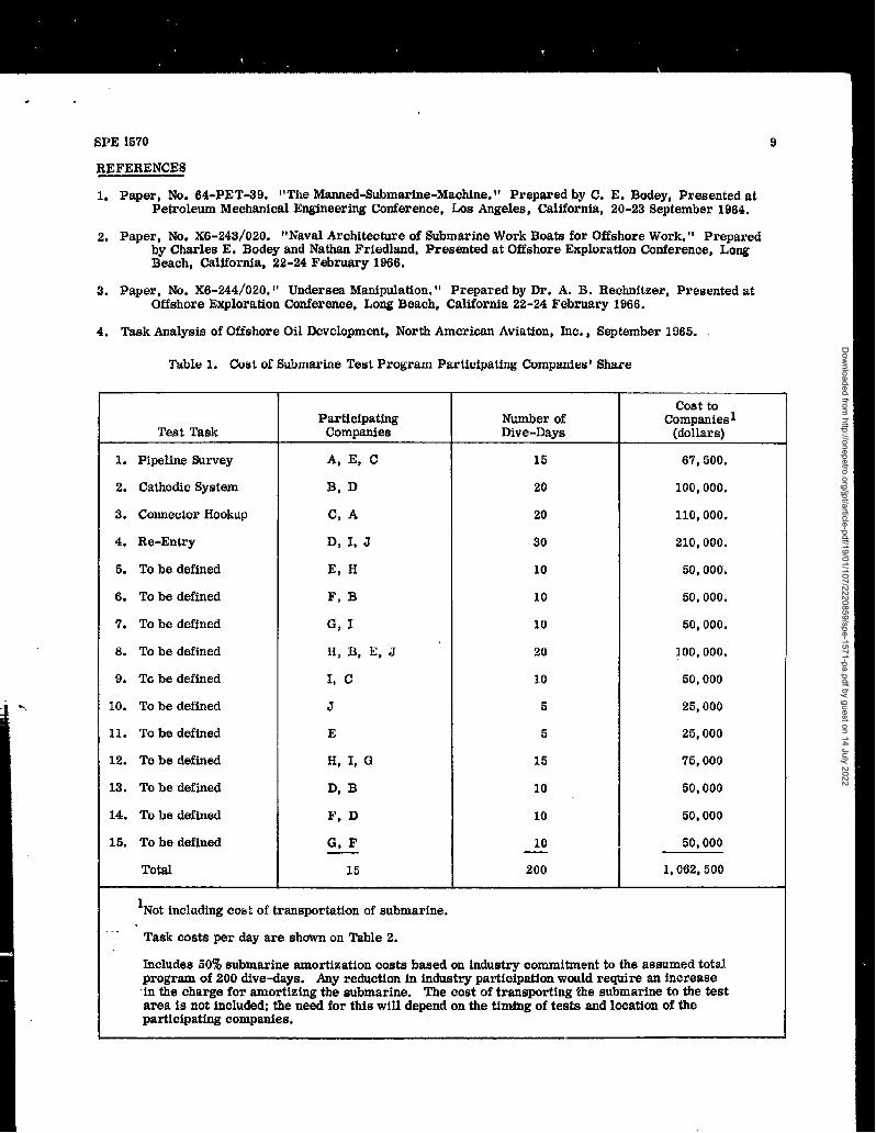
● How can turnaround time be reduced”{ plus 11 additional tasks still to be defined. Eachcompany takes one or more of these assignments
● How much surface support is needed? with the understanding that the test results willbe made available to all other participating companies.
● What is the relative effectiveness of night- Table 1 shows an arbitrary allotment of dive-daystime vs daytime operations? which totals 200 days divided between the 15 tasks.
A summary of the costs to the participating companies● What is the limiting effect of sea-state for each of the tasks and for the total program is also
extremes”( given. Other assumptions governing the test programinclude:
● How are diving operations to be scheduledbetween tasks and among severaloperators ? 1. Capital investment in submarine and sup-
porting equipment of $1 million.
● What standby requirements and provisionsfor emergency use must be planned? 2. The cost of the submarine is to be smor -
tized fully during a two-year period inIf enough companies are interested in partici- consideration of the risk of rapid technical
sting in the planned testing of an oil industry work obsolescence.oat, it may be possible for the manufacturer tossume responsibility for making this submarine 3..vailable and to coordinate a test program designed
The 200 dive-day program is to be com -
D provide the answers the offshore oil industry needspleted within 2 years.
s progress beyond current operating depths.4. 50% of the capital cost of the submarine
The primary objective of this testing program is charged to the 200 day test program.s to develop undersea working experience on key oilield activities which can be used for the guidance 5. A dive-day during testing is assumed to belf the entire offshore oil industry. A secondarylbjective is to place participating companies in a
a 12 hr day, including an average of 4 hr
letter position to appraise the usefulness of a workof bottom time.
:ubmarine with respect to their particular concepts~foffshore operations. In some instances, of COU:se, Table 2 is a method of calculating the cost tohese findings would be proprietary to the participating the participating company of each of the four model:ompany. However, the results of tests on major tasks, and an average cost for the remaining 11 tasks.asks and general findings relating to such aspects asmdursnce a.t depths beyond present working levels, The three columns of costs in Table 2 show howServiceability, operating techniques, specifications, charges for the testing will be affected by the extent)rew and equipment requirements, would be made of eupport ‘received from the industry. For example,wailable to adI participants. if the 200-day testing program is underwritten by the
oil companies, the amortization costs of the sub-In the test program, it is assumed that the sub- marine (included in the cost of the task) will be lower
marine and a crew of six, which includes two pilots, than it would be if only a 100-day program can bewo technicians, one engineer/pilot, and a mechanic developed. Operating costs for the submarine arevould be provided, Also included is the support considered a constant for all tasks. The costs for oilquipment, including a servicing van, compressor, and underwater and surface facilities will vary withLir-conditioner, battery charging equipment, the task selected.manipulators, tools, lights, TV, and communication?quipment. The participating company would supply The examples of typical tasks presented inm adequate surface support vessel and make available Section III, and the suggestions of a plan for a jointhe necessary oil field installations and technical testing program, are intended only to illustrate aIersonnel to permit realistic testing. means for organizing an industry approach to prob-
lems in deep water operations. fMch an approachTable 1 is a complete test program of the type enables all participants to save by cost-sharing the
re are considering. Sn this program, participating tests, and to profit from the advantages of a:ompanies would accept responsibility for conducting combined approach to the solution of commonntensive testing of the four tasks already described, problems.
Dow
nloaded from http://onepetro.org/jpt/article-pdf/19/01/107/2220859/spe-1571-pa.pdf by guest on 14 July 2022
8 A PROJECTED OFFSHORE SERVICE OPERATION WITH SUBMARINE WORK BOATS SPE 1670
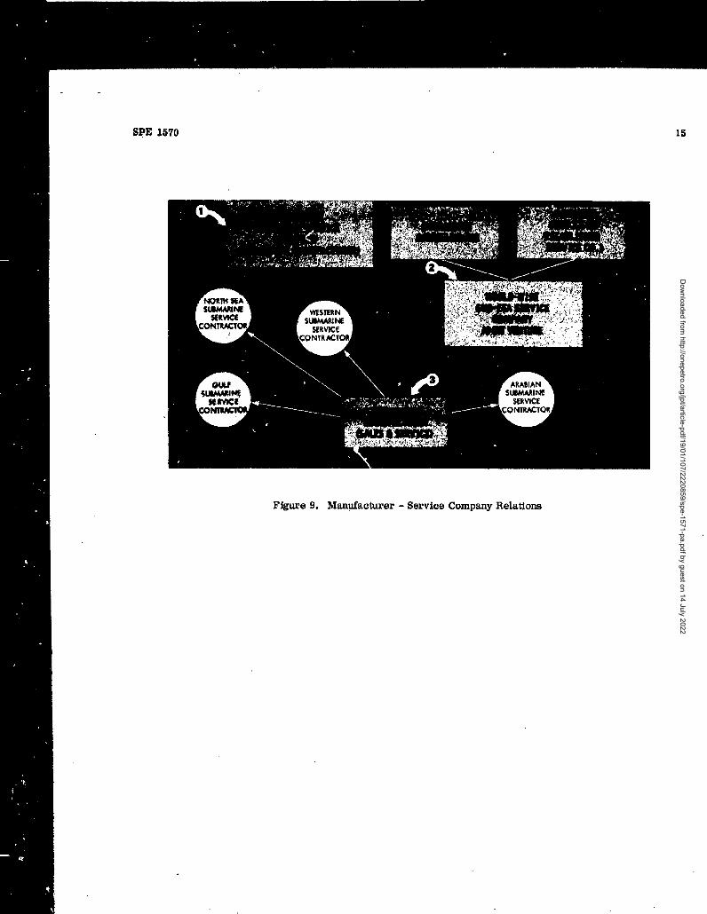
‘I. SERVICE COMPANY ORGANIZATION The second case considers a joint venturebetween the submarine builder and an established
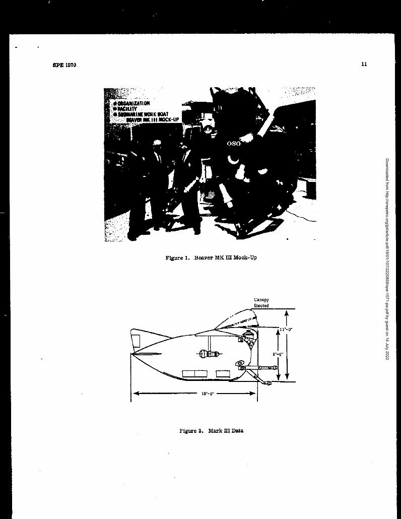
tice developed, the Beaver Mark III eubmarine contractor to the industry. me partner in the ven-rork boat will be made available to operating oil ture might be a work-over contractor, a drilling or~mpaniesandotherh&Str~~and governmental pipeline contractor, or a mud service company, Therganizations. The authors are convinced, however, use of an established partner accepted by the industryhat the nature of the submersible and its applications should assure good business acceptance. Hisictate that most customers will prefer its use on a experience should assist a submarine manufacturerBase basis rather than individual ownership. in recognizing industry methods and requirements.
The ability to support the work with existing serviceOptimum use of such complex and specialized boats, work-over rigs, docks, and crews should
quipment - together with its tools and adapters, provide economy.Iectronic gear, and various items of rigging andehicIe support - calls for experienced operating A third relationship is that where the submarinerews. Many tasks will involve a high order of builder provides vehicle sales plus crew training, andSSM work between surface and underwater crew technical and maintenance support to several estab-~embers to operate the combination of lights, TV lished service contractors and consortiums. l%isquipment, communications, and navigating equip- presumes that the contractors have established rela-lent. Proficiency with the manipulator in approach- tions with the industry, and this approach willmga wide gamut of oil field tasks can probably best provide many features of case 2. In addition, theome from the kind of experience developed in third relationship probably would encourage earlierleeting the varied demands of many clients. and wider geographical distribution of submarines,
Until large offshore oil fields with bottom com- Obviously, there are forme other than thoseIetion become an actuality, full use of the submarine described above and in Figure 9 which the organiza-~ay require careful scheduling of its services among tion of a service company might take. These pos -umy operators. Experience in handling the logistics sibilities have been discussed with industry repre-nd preparation for dives, estimating time require- sentatives, and the authors welcome the opportunity~ents, and anticipating needs would enable trained to carry on further discussions with any otherervice company crews to make better use of equip- interested groups.lent. Finally, where individual operating oil com-anies might have but one submarine, a service Upon completion of the operational tf;stpro-ompany may operate several, plus surface support gram described, the offshore industry will have aessels, and thereby provide needed backup when fuller understanding of the part the submarine willmergencies and overloads arise. Keeping the aub- play in oil operations and its required performance~arine small and adaptable to transportation by specifications.and, sea, and air is an initial basic requirement toacilitate widespread use. The authors appreciate this opportunity to reviel
these subjects of mutual interest with the oil industry.A service company organizational structure We believe that the manned submarine work boat,
ould follow several patterns. Three of these are with its related equipment, will play a major role inhewn in Figure 9. The first relationship is a simple the exploitation of offshore gas and oil resources.,ne where the eubmarine builder would provide We welco~e your continuing assistance in making it aubmarine work boat systems on a contract basis. more effective operating tool for your industry.
Dow
nloaded from http://onepetro.org/jpt/article-pdf/19/01/107/2220859/spe-1571-pa.pdf by guest on 14 July 2022
SPE 1570
REFERENCES
9
la p~p~~,NO.64.pET-3g, !!The Manned-Submarine-Machine.” Prepared by C. E. Bodey, Presented atPetroleum Mechanical Engineering Conference, Los Angeles, CaHfOrnia, 20-23 September 1964.
2. Paper, No. X6-243/020. ~tNaval ArcMtecture of ~bmartie Work Boats fOr Offshore Work. ” Preparedby Charles E. Bodey and Nathan Friedland, Presented at Offshore Exploration Conference, LongBeach, California, 22-24 February 1966.
3. Paper, No. X6-244/020. ” Undersea Manipulation. t! prePared by Dro A. B. Rechnitzer, presented at
Offshore Exploration Conference, Long Beach, California 22-24 February 1966.
4. Task Analysis of Offshore Oil Development, North American Aviation, Inc., September 1965.
Table 1. Cost of Submarine Test Program Participating Companies’ Share
Test Task
1. Pipeline Survey
2. Cathodic System
3. Connector Hookup
4, Re-Entry
5. To be defined
6. To be defined
7. To be defined
8. To be defined
9. Tci be defined
10. To be defined
11. To be defined
12. To be defined
13. To be defined
14. To be defined
15. To be defined
Total
ParticipatingComrmuies
A, E, C
B, D
C, A
D, I, J
E, H
F, B
G, I
H, B, E, J
L C
J
E
H, I, G
D, B
F, D
G, F
15
Number ofDive-Davs
15
20
20
30
10
10
10
20
10
5
5
15
10
10
10
200
cost toCompanies 1
(dollars)
67,500.
100,000.
110,000.
210,000.
50,000.
50,000.
50,000.
100,000.
50,000
25,000
25,000
75,000
50,000
50,000
50,000
1,062,500
1Not including COS: of transportation of submarine..
Task costs per day are shown on Table 2.
Includes 50% submarine amortization costs based on industry commitment to the assumed totalprogram of 200 dive-days. Any reduction in industry participation would require an increasein the charge for amortizing the submarine. The cost of transporting the submarine to the testarea is not included; the need for this will depend on the timing of tests and location of theparticipating companies.
Dow
nloaded from http://onepetro.org/jpt/article-pdf/19/01/107/2220859/spe-1571-pa.pdf by guest on 14 July 2022
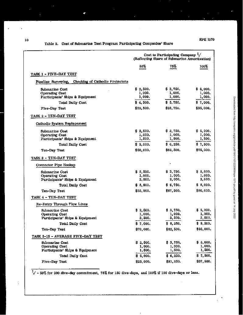
Table 2. Cost of Submarine Test Program Participating Companies! Share
Cost to Participating Company Id(Reflecting Share of Submarine Amortization)
60% ’75% 100%
TASK 1- FIVE-DAY TEST
Pipeline Surveying, Checking of Cathodic Protectors
Submarine CostOperating CostParticipants? Ships & Equipment
Total Daily Cost
Five-Day Test
TASK 2- TEN-DAY TEST
Cathodic System Replacement
Submarine CostOperating CostParticipants’ Ships & Equipment
Total Daily Cost
Ten-Day Test
TASK 3- TEN-DAY TEST
Connector Pipe Hookup
Submarine CostOperating CostParticipants? Ships & Equipment
Total Daily Cost
Ten-Day Test
TASK 4- TEN-DAY TEST
Re-Entry Through Flow Liues
Submarine CostOperating costParticipants~ Ships & Equipment
Total Daily Cost
Ten-Day Test
TASK 5-15- AVERAGE FIV~-DAY TEST
Submarine C4wtOperating CostParticipants~ Ships & Equipment
Total Daily Cost
Five-Day Test
!$ :,50;. $3,750. $! 5,000.1,000. 1,000.
1:000: 1,000. 1,000.
$4,500. $5,750. $7,000.
$22,500. $28,750. $35,000.
$2,500.1,000.1,500.
$5,000.
$50,000.
$2,500.1,000.2,000.
$! 5,500.
$55,000.
$2,500.1,000.3,500.
* 7,000.
$’70,000.
$2,500.1,000.1.500.
$25,000.
$3,750.1,000.1,500.
$6,250.
$62,500.
$5,000.1,000.1,500.
$7,500.
$76,000.
$3,750.1,000.2,0000
$6,750.
$67,500.
$3,750.1,000.3,500.
$8,250.
$82,500.
$3,750.1,000.1,500.
$6,250.
$31,250.
$! 5,000.1,000.2,000.
$8,000.
$80,000.
$ 5,000,1,000.3,500.
$9,500.
$95,0000
$5,000.1,000.1,500.
$ 7,500.
$37,500.
li - 50% for 200 dive-day commitment, 75% for 15G dive-days, and 100% if 100 dive-days or less.
Dow
nloaded from http://onepetro.org/jpt/article-pdf/19/01/107/2220859/spe-1571-pa.pdf by guest on 14 July 2022
11
,,.,,,!. ; * . .,.?-.,.,.,. .:>;
.“- .. :,:,+, .,, ,. , ~,.,. . .
.
SEW 1570
Figure 1. Beaver MK III Mock-Up
canopyErected
- /-”, A.-
Figure 2. Mark III Data
Dow
nloaded from http://onepetro.org/jpt/article-pdf/19/01/107/2220859/spe-1571-pa.pdf by guest on 14 July 2022
12 SPE 1570
OFFSHORE INDUSTRY ““\ SUBMARINE WORK BOAT PROGRAM
REQUIREMENTS AMALYSI S MARKET ANALYSIS
DISCLOSURE OF REQUIREMENTDISCLOSURE OF CONCEPTS
REVIEW OF CONCEPTS,TRANSMISSION OF SUGGESTIONS
REPORT ON R&D RESULTS
COOPERATION IN PLANNINGMANIPULATOR TANK TASKS
EXPERIMENTAL WORK IN TANKS
-TODAY - ,,
AGREEMENT TO USE BUILD PROTOTYPE
COOPERATIVE PLANS ANDEXPERIMENTS AT SEA
COOPERATIVE PLANS &EXPERINIWTS M SEA
SUBMARINE RESEARCH CONTRACT EKPERI MENTAL
AREA OF SUPPORTMUTUAL OPERATION
iNVESTMENT
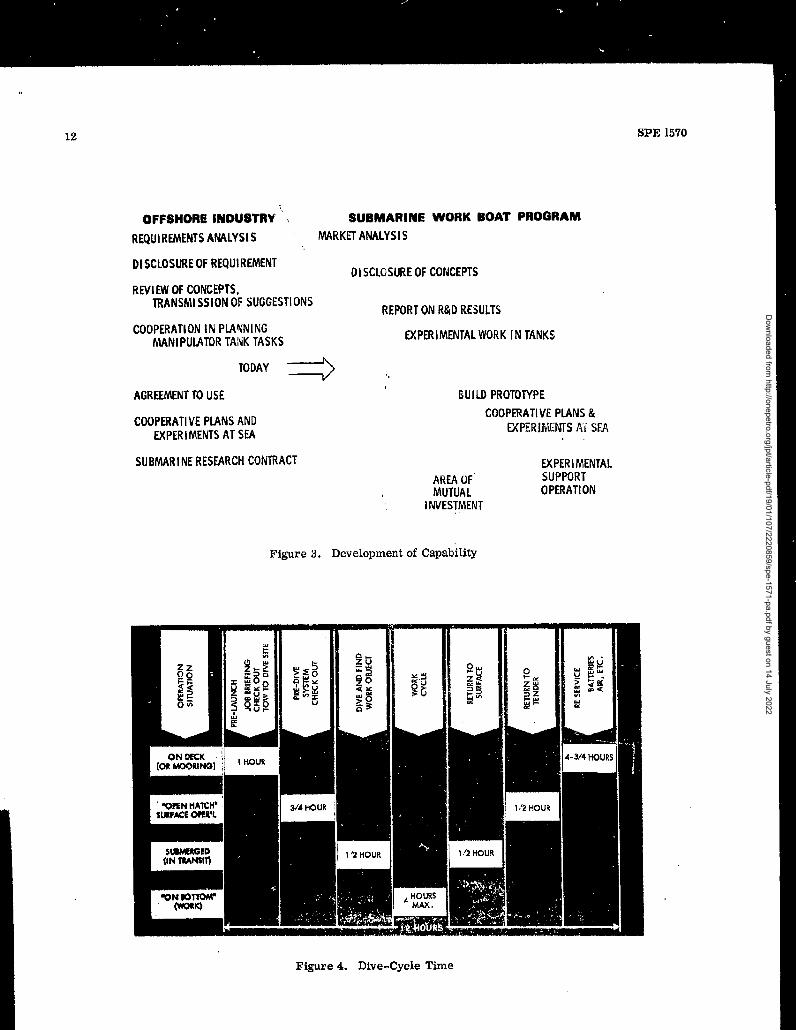
Figure 3. Development of Capability
Figure 4. Dive-Cycle Time
Dow
nloaded from http://onepetro.org/jpt/article-pdf/19/01/107/2220859/spe-1571-pa.pdf by guest on 14 July 2022
‘.
SPE 1570 13
. I I I I I I
e. Wsud Inswdion !1OI,OI,8O
~i
P,ricdk hpecu.n of Corr,pletedPipalinm
Iksdacc & Ir,sped C,thdic P,.kcumSF ill,. Viwal lnspecuon
b, Rerm”e C.lkdh Matei+nl Iww”c Rqalm. NW C,lhdk Natcrhl 10 16 ! ?0Posltlon t’lmvllne Templates i 1
a Ram”. Dcbrls 10 30 ‘ 180
b, W TmPhte in Plain 5 10 180
c. se! P@ b Pk., ; ,0 ,80
d, EM 10 Place 5 10 180
. .—
-1+.PQN—
+
15(3’3
1,5 1. J
1.69,3
1.5 3 !3.—
13
1,5
1,5.
1,5
0.6
05
0,5
1sjs1.5 , 1.5
1,5 / 1.5
-
1
.33
1,5 3
0,5 3
1,5 3
0.5
0.2:
0.s
0.25
0,25
0.25—
0,5
0.23
0.25
0,23
27
68>
27—
:,9
59
69
37,7
37.7
27
27
—
885
35.5
35.3
3J,5
35,5
35.5
8,85
8.85
8,85
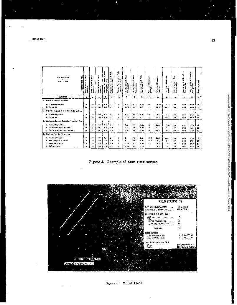
Figure 5. ExampIe of Task Time Studies
IrL B1’N—.
500 6000 : 270C
!500 6000 270C—.. --.——.
8.85
35.5
8.s5
8.85
8.s5
35.5
8,85
6.85
8.83
.No 6000
500 , Gooo
T$00 ‘O”rl
300 woo
600 3000
T
—
;00 6000
250 2000
2.50 2000
,50 ] ,00,
1
2700 ‘Ml
I?;00
150”
2700
2700
2;00
2700
NUMBER OF WELI&GM .,)................ 4OIL:IilGflPRESSURE,..... 21LOWEN PRESSUNE.... 18
—T~AL 39
DISTANCESGAS MUNCHES: 2.4NAUT MIOIL BNANCNES: 5.1NAUT MI
10
n
~
25
10
25
-1
25
’10
Figure 6. Model Field
Dow
nloaded from http://onepetro.org/jpt/article-pdf/19/01/107/2220859/spe-1571-pa.pdf by guest on 14 July 2022
SPE 1570
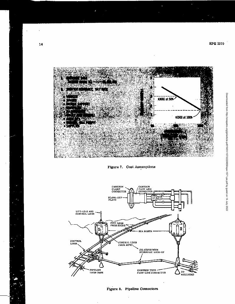
Figure 7. Cost Ass~ptions
F~re 8. Pipeline Connectors
Dow
nloaded from http://onepetro.org/jpt/article-pdf/19/01/107/2220859/spe-1571-pa.pdf by guest on 14 July 2022
SPE 1670 15
F@re 9. Wu@acturer - Service Company Relations
Dow
nloaded from http://onepetro.org/jpt/article-pdf/19/01/107/2220859/spe-1571-pa.pdf by guest on 14 July 2022