ventilation shafts | bbugs
TRANSCRIPT

BBUGSMARCH 2020
VENTILATIONSHAFTS PROJECT GUIDE
IN-DEPTHENGINEERING
ABOUT US
2
§ Focused on innovation and optimisation with the purpose of improving safetyand output for our clients.
§ Our expertise is the result of over 60 years combined experience on both theconsultancy and client side of industry.
§ Our team understands your operational needs and constraint.
§ Offices in QLD, NSW and NZ with our lab based in Wollongong.
IN-DEPTHENGINEERING
Getting Started
Methods
Data
Stability
Contracts
3
IN-DEPTHENGINEERING
GETTING STARTEDCONCEPT
4
• Go / no-go
• Make a plan
• Scope of works
• Investigation
• How is it going to happen?
IN-DEPTHENGINEERING
GETTING STARTEDINVESTIGATION
5
• Takes a while to get the ball rolling, decision making processalone can take months
• Engage professional services, the speed of this is dependent onquality of scope
• Allow plenty of time for drilling and data gathering
• Turn around time on lab tests usually at least a month
• Don’t rush this part or you end up with plenty of limitations
IN-DEPTHENGINEERING
GETTING STARTEDRISKS
6
• Is it going to rain?
• Tender process can take verylong, how good was yourinvestigation?
• Availability
• Can you afford standby
• Development rate
• Competitive market, understand thequotes
• Price and timeline rarely align
• Beware of shortcuts
• Liability
IN-DEPTHENGINEERING
GETTING STARTEDMITIGATION
7
• Parallel task
• Identify critical path early and frequently, engage the schedular asearly as possible
• Wishful thinking is your worst enemy
• Contingency planning is key
• Update your scope
IN-DEPTHENGINEERING
METHODSRAISE BORE
8
• Faster
• Pilot hole
• Special support required UG
• Possible limitations on size
• Material needs removal
• Water and gas
IN-DEPTHENGINEERING
METHODSBLIND BORE
9
• More stable
• Can be done ahead of time
• Liner installation is simpler
• Isolated activity
• Holing in requires some consideration
IN-DEPTHENGINEERING
METHODSLINER SELECTION
10
• Steel
• Concrete
• Shotcrete
IN-DEPTHENGINEERING
DATAGENERAL
11
• Layout
• Infrastructure
• Foundation
• Nearby workings
• Water sources
IN-DEPTHENGINEERING
DATASOILS
12
• How deep
• Granular or cohesive
• Reactive materials
• Collar construction / reinstatement
IN-DEPTHENGINEERING
DATAROCK
13
• Strength – Lab UCS and PLT
• Defects – Geology logging and core photos
• Material type – Geology logs and geophysics
• Slaking potential - Buddery and Oldroyd (1992)
IN-DEPTHENGINEERING
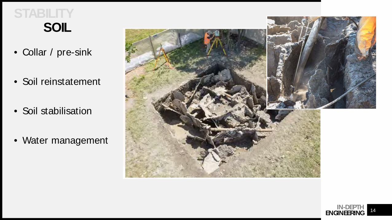
STABILITYSOIL
14
• Collar / pre-sink
• Soil reinstatement
• Soil stabilisation
• Water management
IN-DEPTHENGINEERING
STABILITYSOIL
15
IN-DEPTHENGINEERING
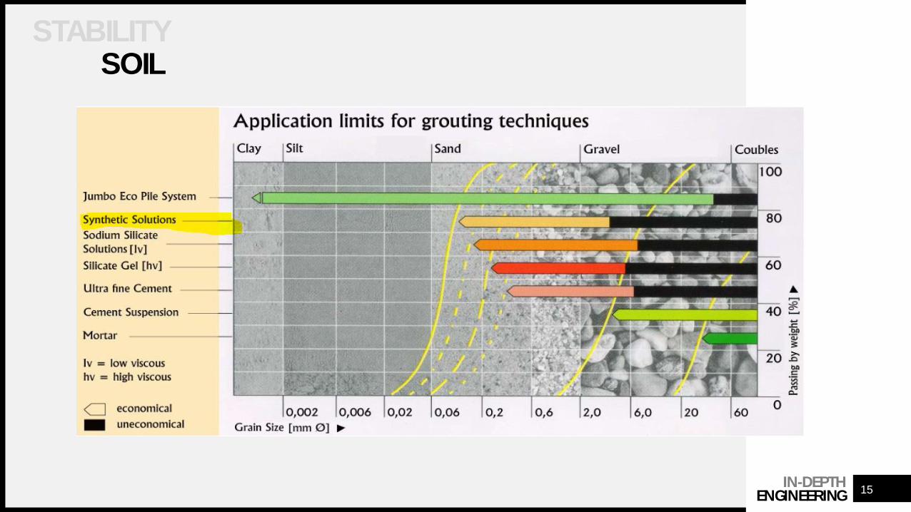
STABILITYSOIL
16
• Often where things go wrong
• Multiple components interacting
• Easy to cut corners
• Can be particularly dangerous due to undermining
• Weathering horizon

IN-DEPTHENGINEERING
STABILITYROCK
17
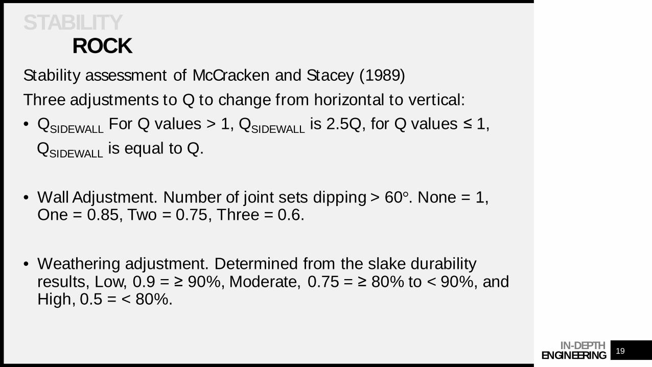
Stability assessment of McCracken and Stacey (1989)
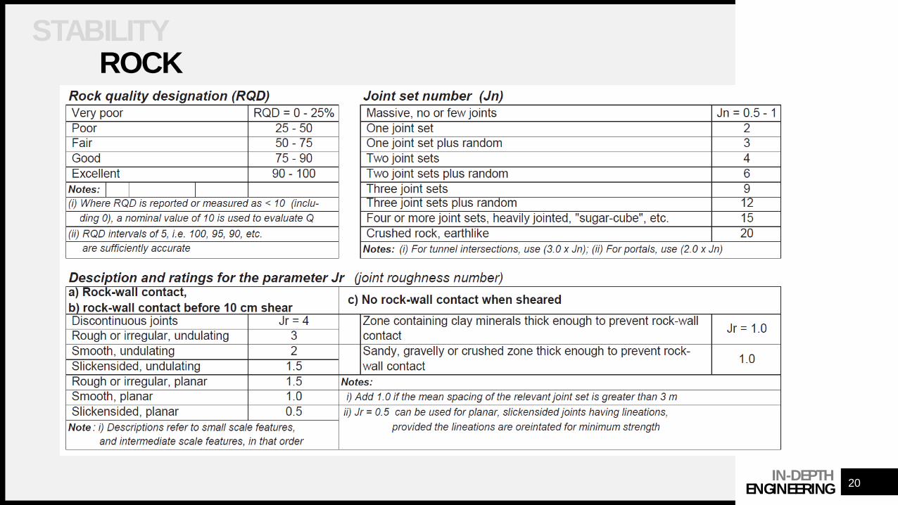
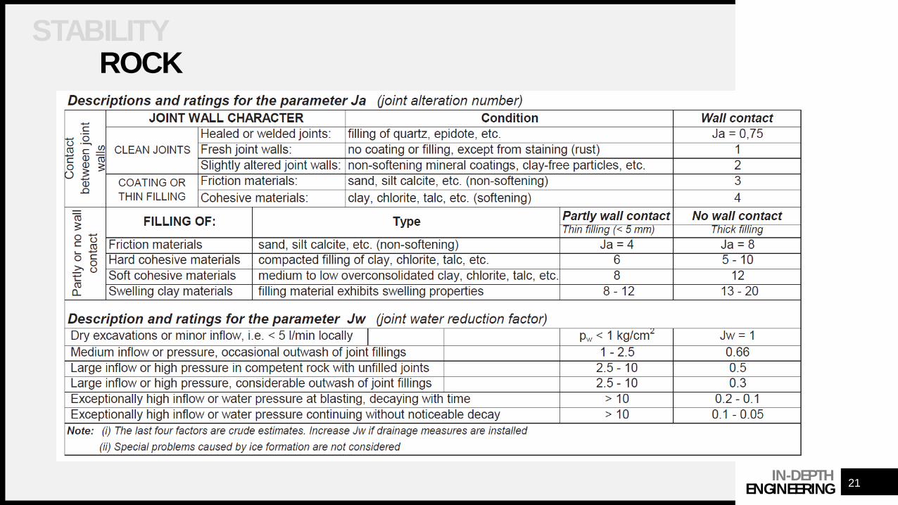
• Uses the Q System (Bieniawski, 1989)
• Methodology is intended for raise bores but is useful for blindboring
=ܦܬ
.ݎܬݏܬ
.ݓܬܨ
IN-DEPTHENGINEERING
STABILITYROCK
18
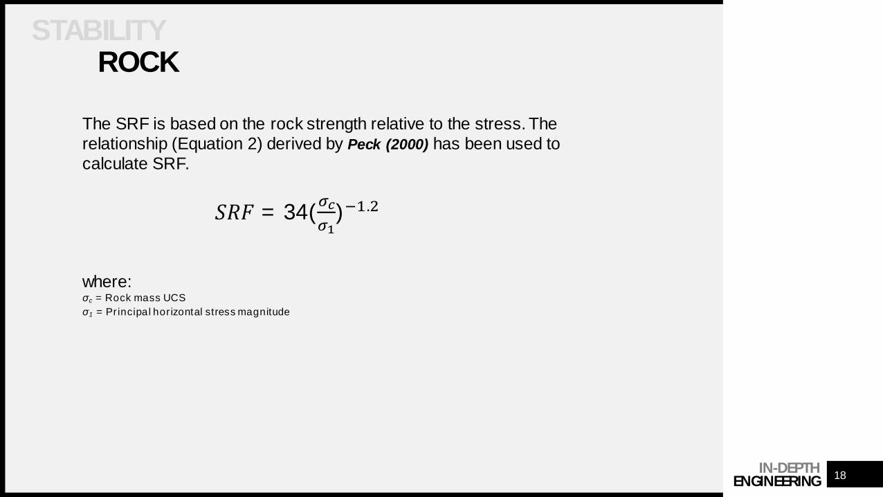
The SRF is based on the rock strength relative to the stress. Therelationship (Equation 2) derived by Peck (2000) has been used tocalculate SRF.
ܨ = 34(ఙఙభ
)ଵ.ଶ
where:σc = Rock mass UCSσ1 = Principal horizontal stress magnitude
IN-DEPTHENGINEERING
STABILITYROCK
19
Stability assessment of McCracken and Stacey (1989)Three adjustments to Q to change from horizontal to vertical:• QSIDEWALL For Q values > 1, QSIDEWALL is 2.5Q, for Q values ≤ 1,
QSIDEWALL is equal to Q.
• Wall Adjustment. Number of joint sets dipping > 60°. None = 1,One = 0.85, Two = 0.75, Three = 0.6.
• Weathering adjustment. Determined from the slake durabilityresults, Low, 0.9 = ≥ 90%, Moderate, 0.75 = ≥ 80% to < 90%, andHigh, 0.5 = < 80%.
IN-DEPTHENGINEERING
STABILITYROCK
20
IN-DEPTHENGINEERING
STABILITYROCK
21
IN-DEPTHENGINEERING
STABILITYROCK
22
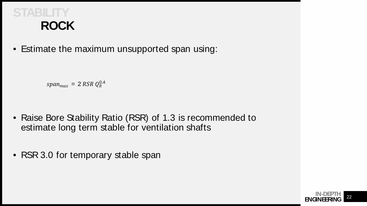
• Estimate the maximum unsupported span using:
• Raise Bore Stability Ratio (RSR) of 1.3 is recommended toestimate long term stable for ventilation shafts
• RSR 3.0 for temporary stable span
ݔݏ = 2 0.4
IN-DEPTHENGINEERING
STABILITYROCK
23
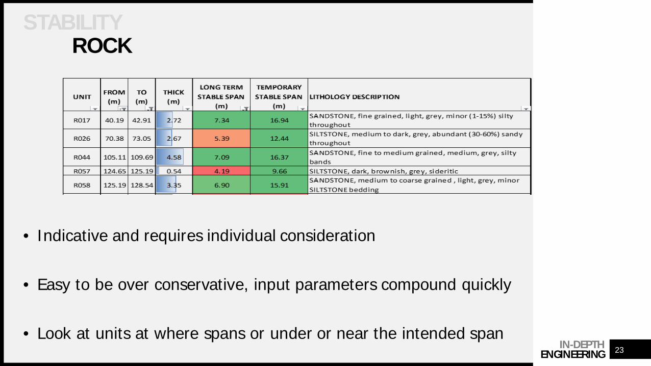
• Indicative and requires individual consideration
• Easy to be over conservative, input parameters compound quickly
• Look at units at where spans or under or near the intended span
IN-DEPTHENGINEERING
STABILITYROCK
24
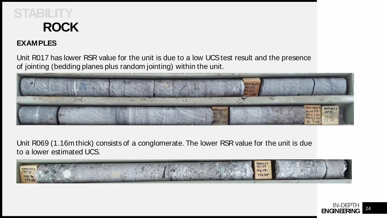
EXAMPLES
Unit R017 has lower RSR value for the unit is due to a low UCS test result and the presenceof jointing (bedding planes plus random jointing) within the unit.
Unit R069 (1.16m thick) consists of a conglomerate. The lower RSR value for the unit is dueto a lower estimated UCS.
IN-DEPTHENGINEERING
STABILITYROCK
25
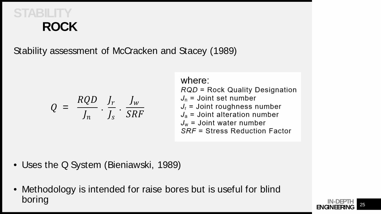
Stability assessment of McCracken and Stacey (1989)
• Uses the Q System (Bieniawski, 1989)
• Methodology is intended for raise bores but is useful for blindboring
=ܦܬ
.ݎܬݏܬ
.ݓܬܨ
IN-DEPTHENGINEERING 26
SOME TIPS
• Contract management courses available
• If it feels ambiguous it probably is, ask forclarification
• Good faith lasts only as long as the moneydoes
• Know what you are in for
IN-DEPTHENGINEERING
27
Bieniawski, Z. T. (1989). Engineering Rock Mass Classifications. John Wiley &Sons, ISBN: 0471601721.
Buddery, P. S. and Oldroyd, D. C. (1992). Development of a Roof and FloorClassification Applicable to Collieries. Proc. Eurock ’92 Conference. London:Thomas Telford, pp. 197–202.
Kazemian, S, Huat, B & Prasad, A, & Barghchi, M. (2010). A review ofstabilization of soft soils by injection of chemical grouting. Australian Journalof Basic and Applied Sciences. 4
McCracken, A. and Stacey, T.R. (1989). Geotechnical Risk Assessment of LargeDiameter Raisebored Shafts. Shaft Engineering, Inst Min Met, pp 309 – 316.
Peck, W. (2000). Determining the stress reduction factor in highly stressedjointed rock. Aust Geomech 35(2)
THANK YOU
Christian Mans +64 21 980 853
IN-DEPTHENGINEERING
28
Paul Buddery +61 447 034 383
i-denginering.com