ventilation in mines - survivor library
TRANSCRIPT


Vfimnjr dart.


VENTILATION IN MINES


VENTILATIONIN MINES
BY
ROBERT WABNERn
MINING ENGINEER
TRANSLATED FROM THE GERMANBY
CHARLES SALTER
WITH THIRTY PLATES AND TWENTY-TWO ILLUSTRATIONS
LONDON
SCOTT, GREENWOOD & SON8 BROADWAY, LUDGATE HILL, E.G.
CANADA: THE COPP CLARK co. LTD., TORONTO
UNITED STATES: D. VAN NOSTRAND co., NEW YORK
1903
{The sole right of Translation into English rests with Scott, Greenwood & Son]

|M> . * t

PREFACE.
THE high importance of a uniform and sufficient supply of fresh air for
the life and health of the workers in mines, and indeed for the perform-
ance of the various operations therein, would seem to justify special treat-
ment of this branch of the art of mining.
The Author's first idea was to undertake a translation of Theophil
Guibal's work on Ventilation;but more than twenty years have elapsed
since the death of that authority, during which period great progress has
been made in the ventilation of mines; and, especially as opinions and
knowledge have undergone considerable modification with regard to the
dangerous gases occurring in mines, it proved necessary to amplify
Guibal's work and bring it up to date. One point that required intro-
duction was the matter of respiration and rescue apparatus. Another
was the cooling of the workings, surrounding rock, and the air of the
mine, this question having been brought to the front of late, in conse-
quence of the ever-increasing depth of mining operations, and the accom-
panying rise in the rock temperature ;to which must be added, in the
case of coal mines, the increase in temperature due to the absorption of
oxygen by coal at the ordinary temperature.
As is well known, continued exposure to high temperature is injurious
to health, and, since the working efficiency of the miners is reduced in
proportion as the pit temperature is increased, it is necessary to take
steps to combat this unfavourable influence. Now the only way to do
this effectually is to replace the usual, simple air ways by driving three,
four, and more intake and return air ways in setting out the mine, thus
considerably increasing the surface of contact between the air current and
the gallery walls, reducing the velocity of the current, and prolonging the
period of contact.
The individual ventilating and working sections must also be reduced
in size, and the excessive length of the air ways avoided.
It will be evident that, in future, just as much care must be bestowed
337520

vi PREFACE
on the provision of an ample supply of motive power for the efficient
ventilation of a mine as has to be done in connection with the establish-
ment of the necessary powerful engines for pumping and winding.
In this respect typical examples are afforded by existing installations
at well-ventilated fiery pits such, for instance, as that at the Hibernia
pit, Gelsenkirchen, described by Behrens in his work on the Firedamp
Problem.
The Author is only too conscious that the present work is lacking in
completeness, and would be grateful for any corrections and supple-
mentary information from experts interested in the matter, for insertion
in a subsequent edition.
TAKNOWITZ, December 1901.

CONTENTS.
PAGE
PREFACE . . . . . . . . . vINTRODUCTION* ... 1
CHAPTEE I.
THE CAUSES OF THE CONTAMINATION OF PIT AIR ..... 3
Composition of the Air .... ... .3The Oxygen of the Air ........ 3
Nitrogen .......... 5
Other Contaminating Gases present in Pit Air ..... 6
Carbon Dioxide . . . . . . . . .6Carbon Monoxide ......... 8
Means of Detecting CO in Air . . . . . . .13Spectroscopic Examination of CO in the Blood . . . . .14Colorimetric Examination of the Blood for CO . . . . .14Treatment of Victims of CO Poisoning . . . , . .15Hydrogen . . . . . . . . . .16Sulphuretted Hydrogen . . . . . . . .16Water Vapour . . . . . . . .17Sulphurous Acid . . . . . . . . .18Occurrence of Firedamp in Nature ....... 19
Blowers .......... 20
Sudden Outbursts of Gas ........ 20
Physical and Chemical Properties of Firedamp . . .22Methane ........ .22Inflammability of Firedamp...... .23Pressure under which Firedamp is imprisoned in Coal . 25
Influence of Atmospheric Pressure on the Liberation of Firedamp . . .27
CHAPTER II.
THE MEANS OF PREVENTING THE DANGERS RESULTING FROM THE CONTAMINATION
OF PIT AIR ... . .31Determining the Percentage of Methane in Pit Air Testing Firedamp Firedamp
Indicators ...... 31
Readily inflammable, explosive Coal Dust ...... 34
Method of rendering Coal Dust Innocuous ... .35Conveying the Water for Sprinkling the Coal and Coal Dust . 36
Wetting the Coal Face ....Cost of Setting up and Working Installations for Sprinkling . 39
Advantages and Disadvantages of Sprinkling Coal Dust . .39Other Precautions for Preventing Explosions in Fiery and Dusty Mines .
t40
vii

i CONTENTS
PAGE
Dangers of Blasting in Fiery Mines ....... 41
Shot Firing without Danger in Fiery Mines . . . .
'
. .43Electrical Ignition ......... 43
Explosions of Gas and Firedamp caused by Shaft and Pit Fires in Fiery Mines
and in Mines working Anthracitic and Sintering Coal . . . .43Precautions for Obviating and Repairing the Injurious Effects of Firedamp
Explosions ......... 45
The Chemical Composition of Afterdamp . . . . . .46Behaviour of the Miners in Afterdamp ...... 47
Means for bringing Help from Outside to the Imprisoned Miners after a Firedamp
Explosion ......... 48
Respiration and Rescue Apparatus for entering Workings laden with InjuriousGases .......... 50
The Robert Respiration Apparatus ....... 52
Fixed Respiration Apparatus . . . . . . . .53The von Bremen Smoke Helmet, with Pipe and Jacket . . . .54The Mueller Smoke Helmet . . . . . . .55Electric Lamps for use in Dangerous Gases . . . . . .55Portable (Knapsack) Rescue Apparatus . . . . . .56The 0. Neupert's Nachfolger Respiration Apparatus . . . .59The Contamination of Pit Air from other Causes than Injurious Gases . . 61
Accessions of Temperature in the Pit . . . . . . . 62
Moisture in Pit Air . . . . . . . . .63Mechanical Causes of Contamination in Pit Air 63
CHAPTEE III.
CALCULATING THE VOLUME OF VENTILATING CURRENT NECESSARY TO FBEE PIT AmFROM CONTAMINATION ........ 64
Replenishing Pit Air by Fresh Air from Abovegroimd . . . .64General Remarks on the Flow of Gases ...... 67
Atmospheric Pressure ........ 67
The De Vaux Pressure Gauge........ 68
Fluctuations of Pressure in Pressure Gauges...... 69
The Guibal Pressure Gauge . . . . . . . .69The Maess Vacuum Meter, with Floating Scale . . . . .70Multiplication Pressure Gauge . . . . . . .70Points to be noted in Working with the Pressure Gauge . . . .70Moisture Content in Pit Air, and Specific Gravity Determinations ... 71
Measuring the Ventilating Current ....... 74
Measuring the Velocity of the Ventilating Current ..... 74
Measuring the Velocity of the Air Current in a given spot by the Anemometer . 76
The Casella Anemometer . . . . . . . .77The Maess Clockwork Anemometer . . . . . 78
The Robinson Cup Anemometer ....... 79
Whim for Testing the Anemometer . . . . . . .81The Krell Anemometer ........ 82
Standardising the Krell Anemometer....... 84
Method of using Vane Anemometers....... 85
CHAPTER IV.
DETERMINATION OF THE RESISTANCE OPPOSED TO THE PASSAGE OF AIR THROUGHTHE PIT LAWS OF RESISTANCE AND FORMULAE THEREFOR . . .88
Resistance to the Passage of Air in Galleries...... 89
Determining the Coefficient of Resistance K of the Mine . . . .91The Coefficient of Resistance K 1 in Shafts 94

CONTENTS ix
PAGE
Comparison of the Temperament of various Pits ..... 97Motive Power required for Ventilation . . . . . .100Equivalent Volumes of Air ........ 101
Loss of Motive Power through the Velocity of the Discharged Air from the Upcast . 101
FLUCTUATIONS IN THE TEMPERAMENT OR SPECIFIC RESISTANCE OF A PIT . . 102
Variability of Pit Temperament . . . . . . .102
CHAPTER V.
MEANS FOR PROVIDING A VENTILATING CURRENT IN THE PIT . . .103Natural and Artificial Ventilating Currents . . . . .103Air Currents in Shafts . . . . . . . . 103
Ventilating Currents in Headings . . . . -. .105Ventilating Currents in Underground Chambers with Two Exits . . .105Natural Ventilation .
,. . ... . . . .105Theory of Natural Draught . . ... . . . . 107
Producing an Artificial Ventilating Current . . . . . .108Fire Baskets . . . ... . . . . 108
Warming the Column of Air in the Shaft by means of Steam Pipes . . .109Cooling the Descending Column of Air in the Intake Shaft . . . .109Ventilating Furnaces or Fires . . . . . . .110Ventilating Furnaces Aboveground . . . . . . .110Underground Ventilating Furnaces . ... . . . . Ill
Theory of Furnace Ventilation . , . . . . .112The Depression (Attenuation) produced in the Shaft by a Ventilating Furnace . 112
Economic Results of Furnace Ventilation . . . . . .115Practical Application of Ventilation Furnaces . . . . .116Amount of Heat utilised in Ventilation Furnaces ..... 118
Theoretical Consumption of Fuel ....... 118
Ratio between the Heat present in Pit Air and that produced in the Ventilating
Furnace . . . .
'
. . . . . .120Work done by a Ventilating Furnace . . . . . .121The Practical Effects of Ventilating Furnaces in Belgium and England . .121
CHAPTEE VI.
MECHANICAL VENTILATION.
. , . . . . . 123
Ventilation by Injected Steam . . . . . . .123The Koerting Injector . . . . . . . .125Ventilation by Natural Pressure with Air Cowl . . . . .127Ventilation with Compressed Air Air Compressors . . . .127Dry Compressors ....... .127Semi-Wet or Spray Compressors .....Wet Compressors .... .129Compressors with Valve Gear
Compound Compressors .....Dimensions of Air Mains .
Efficiency of Compressed Air as a Motive Force . .131Utilising Compressed Air for Ventilation
Separate Ventilation by Compressed Air Motors and Fans ,
Hydraulic Separate Ventilation
Working Expenses of Separate Ventilation . 137
Result of Observations at the Heinrich Shaft
Separate Ventilation by a Direct Fall of Water Water Drums
Electricity as a Motive Power in Mine Ventilation .
Motor-driven Ventilating Appliances generating an Air Current in the Pit . . 141

x CONTENTS
CHAPTER VII.PAGE
VENTILATORS AND FANS......... 143
The Harz Ventilator . . . . . . . .143Other Forms of Plunger and Bell Apparatus...... 144
Rotary Ventilators with variable Internal Capacity..... 144
The Fabry Fan ......... 144
Calculating the Volume of Air propelled by the Fabry Fan . . . .145Defects of the Fabry Fan ........ 146
The Roots Blower . . . . . . . .147The Lemielle Ventilator ..... 150
Fans of the Screw-propeller Type ....... 151
Centrifugal Fans . ... 151
Hand-power Ventilating Fan ...... 152
The Letoret Fan . ..'.'.. . . . . . .152Combes' Fan.......... 153
The Cabany Fan ......... 154
The Biram Fan ......... 154
Brunton's Fan ......... 154
The Waddle Fan ......... 154
The Rammel Fan . . . . . . . . . 155
The Rittinger Fan . . . . . . . . .155The Kraft Turbine Fan . . . . . . . .156The Lambert Fan ......... 157
The Guibal Fan . . 157
Casing the Guibal Fan . . . . . . . .158Flared Upcast Flue for the Guibal Fan . . . . . .158Details of Large (22 feet) Guibal Fan . . . . . .159Determining the Useful Dynamic Effect of the Guibal Fan . . . .161Guibal's Analytical Theory of Centrifugal Fans . . . . . 162
The Depression produced by the Guibal Fan . . . . . .165Setting the Damper Slide of the Guibal Fan . . . . . .167Calculating the Adjustment of the Damper Slide ..... 168
Calculating the relative Dimensions of the Guibal Fan, as Function of Pit
Temperament ......... 169
Applications . . . . . . . . . 170
Useful Effect of the Guibal Fan ....... 172
Deductions .......... 174
Apparent and Real Depression . . . . . . .175Defects and Imperfections of the Improved Guibal Fan .... 176
CHAPTER VIII.
DETERMINING THE THEORETICAL, INITIAL, AND TRITE (EFFECTIVE) DEPRESSION OF
THE CENTRIFUGAL FAN . . . . . . . .178Theoretical Depression ..... .178Initial Depression ....... .179Effective Depression....... .179Prime Cost of Installing a Guibal Fan . .180Modifications of the Guibal Fan . 181
The Dinnendahl Fan......... 181
TheKleyFan. . . . 181
NEW TYPES OF CENTRIFUGAL FAN OF SMALL DIAMETER AND HIGH WORKING SPEED . 183
ThePelzerFan ......... 183
Cost of Pelzer Fans ... .184The Geisler Fan . . .184The Capell Centrifugal Fan ........ 187
TheSerFan 189

CONTENTS xi
PAGK
The Rateau Fan ......... 190
The Hanarte Fan ... .... 194
The Mortier Fan ......... 196
Main Ventilation by Exhaust versus Compression . . . . .199Installing a Guibal Fan for Ventilating by either Suction or Blowing . . 199
Tandem Fans . 200
CHAPTER IX.
UTILISING THE VENTILATING CURRENT TO THE UTMOST ADVANTAGE AND DISTRI-
BUTING THE SAME THROUGH THE WORKINGS ..... 202
Introducing the Main Air Current into and Distributing it through the Workings
Splitting the Main Current; Reuniting the Split Currents and Conducting
them to Bank ......... 205
ARTIFICIALLY RETARDING THE VENTILATING CURRENT . ... . 208
Air Dams .......... 208
Dams of Hay and Straw ... 208
Dams of Pit Timbers..... 209
Obstructions for Regulating the Flow of Air . . . ... . 209
Rescue or Safety Air Doors ..... .211Theory of the Modulus, or Individual Temperament, of different Portions of a Pit . 212
Calculating the Orifice of the Air Slide in Brattices . . . . .219
CHAPTER X.
VENTILATING PRELIMINARY WORKINGS BLIND HEADINGS SEPARATE VENTILA-
TION SUPERVISION OF VENTILATION . . . 222
Brattices ..... .222Parallel Headings ......... 224
Air Tubbing ... . 225
Ventilation by Tubbings Blowing versus Suction . . . . . 225
Calculating the Modulus of Air Tubbings . . . . . .227The Supervision of Ventilation . . . . . . . 232
The Guibal Air Controller ........ 233
Recording Pressure Gauge ... . 233
Air Register and Ventilating Plans .... . 234
Arranging an Upcast Air Shaft for use as a Winding Shaft.... 234
INDEX . .237


VENTILATION IN MINES.
INTRODUCTION.
1. MINES are artificial subterranean cavities made for the purpose of
recovering minerals, and as a rule their communication with the outer
air is merely by means of a few narrow orifices, the consequence being
that, where the underground workings are extensive, difficulties arise in
connection with the introduction of fresh air and the removal of con-
taminated air.
The atmospheric air is of almost invariable composition everywhere,
and contains 20'93 parts by volume of oxygen, 78'10 of nitrogen, 0'94
of argon, and 0'03 of carbon dioxide, small quantities of water vapour
being always present up to saturation point. In the course of its
ceaseless movement around the globe, the air carries on its waves a
number of light, minute bodies, germs of plants and animals, mineral
dust, gases resulting from the decomposition of plants and animals, or
from combustion and respiration, smoke, and, in the vicinity of large
towns, factories, and smelting works, various impurities, such as sulphur
dioxide, metallic vapours, and the like;
the amount and character of
these extraneous admixtures influencing the suitability of the air for
human respiration.
So far, however, as the ventilation of mines is concerned, these
atmospheric impurities are devoid of importance, since, just in the same
manner as river water laden with the refuse matters of large towns and
certain factories quickly purifies itself, so these contaminating ingredients
of the air are soon eliminated therefrom. Eain and dew carry down
the floating solid particles and many gases, whilst the excess of carbon
dioxide is removed by plants, especially extensive forests, with the collabo-
ration of light, the carbon being retained and the oxygen liberated into
the air again.
2. Consequently, though the air is exposed to various local modi-
fications, its general composition will be found fairly constant, provided

I IN
the samples examined have not been drawn too near a source of con-
tamination. It may therefore be concluded that, in the case of pit air,
we have not to trouble ourselves with the question of how to restore
the contaminated air of the mine to its original good condition, but
all that has to be considered is how the same can be returned into the
general mass of the atmosphere and replaced by pure air, in order to
keep the pit air healthy and respirable. This object is effected with the
aid of a ventilating current.
To produce such a current entails the exertion of force, or an
expenditure of energy in overcoming resistances opposing the movement
of the ventilating current. This must, however, be accomplished in such
a manner as to ensure that all the spaces in the mine are traversed by
this current, without injury to the health of the miners; moreover, an
endeavour must be made to carry out the plan in the most economical
manner, by suitably arranging the underground workings, diminishing the
resistances, and suitably selecting the ventilating appliances.
3. The science of mine ventilation, which deals with the ways and
means of providing a supply of fresh air to the pit, may be divided into
the following five sections for treatment :
I. The causes of the contamination of pit air, and the means of pre-
venting the resulting dangers to the life and health of the miners.
II. The calculation of the amount of ventilating required to counter-
act the contamination.
III. The determination of the resistances opposing the flow of the
ventilating current.
IV. The means of providing the necessary current of air.
V. The ways and means of utilising the air current to the utmost
advantage and distributing it throughout the workings.

CHAPTER I.
CAUSES OF THE CONTAMINATION OF PIT AIR.
1. The causes of contamination in pit air are partly natural and
spontaneous, partly artificial and due to the conditions of working.In the first place, the air may be fouled by the exhaustion or con-
sumption of the oxygen necessary to respiration ; secondly, by the
liberation or production of injurious gases ;and thirdly, by the presence
ol finely divided particles of solid matter, such as coal dust, soot, and
smoke.
The health of the miners is also prejudiced by an excessively high
temperature in the pit air, especially when the same is saturated with
water vapour and the current moves with such velocity as to produce an
excessive draught.
COMPOSITION OF THE Am.
2. As already mentioned, atmospheric air contains 20 '9 3 (21) parts
by volume of oxygen and 79 parts of nitrogen (with 0*94 of argon).
One cubic metre of air weighs 1*2936 kilogrammes at C. and 760
millimetres pressure.
THE OXYGEN OF THE AIR.
3. The life-maintaining constituent, oxygen, the chemical symbol for
which is 0, has the specific gravity 11056 compared with air; 1 cubic
metre weighs 1*430 kilogrammes.
OXYGEN is a colourless, odourless, and tasteless gas, which enters into
combination with all the elements except fluorine, and also combines with
many compound bodies. Hence a considerable amount of oxygen is con-
sumed in mines. According to the researches of Dr. Schondorf, in the
mines at Saarbruecken, the consumption of oxygen by the miners, the
horses, and the lamps in a pit amounts to only about one-seventeenth of
the total consumption therein, the remainder being used up in the oxida-
tion of coal and pyrites, by absorption into the rock, and by the putre-
faction of the pit timbers.

4 VENTILATION IN MINES
The combination of oxygen with other substances is known as oxida-
tion, and if the operation be accompanied by evolution of heat and light
it is termed combustion.
Luminous combustion proceeds only in the case of gaseous bodies, or
such solid or liquid bodies as are gasified by the heat generated during
combustion;or again in the case of gaseous, combustible decomposition
products. Other substances, e.g. carbon (coke), burn without flame, merely
becoming incandescent on combining with oxygen.
Oxidation also occurs during respiration. Here the oxygen comes
into contact with venous blood in the lungs, whereupon the carbon in the
blood is oxidised into carbon dioxide (carbonic acid, CO2), which is then
exhaled.
Of late, oxygen has been prepared artificially, and is sold in the
condensed form, which is administered for artificial respiration in manycases of disease, as also in the event of carbon monoxide (CO) poisoning.
In the condensed state it is also used for charging the respiratory and
rescue appliances employed when spaces filled with irrespirable gases
have to be entered.
Until recently it was believed that suffocation necessarily ensued in
the human subject on exposure to an atmosphere so poor in oxygen as to
be incapable of supporting combustion in the ordinary sense. This has
been shown to be incorrect by Dr. Haldane of Oxford, who was entrusted
by the Home Office with the investigation of the causes and results of
the colliery explosions at Tylerstown, Brancepeth, and Micklefield. His
researches have thrown a great deal of new light on the effects of air poor
in oxygen, and of the poisonous gases present in the afterdamp succeed-
ing explosions of firedamp, as well as those in the fumes generated by
pit fires.
4. When the oxygen content of inhaled air is gradually reduced, the
respiration of the human subject is found to slightly decrease in depth
on the percentage of oxygen falling to 12 per cent. At 10 per cent.
of oxygen, breathing is accelerated, the respirations are deeper, and the
lips turn pale blue. At 8 per cent, the face assumes a bluish-grey tinge,
although no great uneasiness is so far manifested. Laboured panting
first appears at 5 to 6 per cent., and is succeeded by unconsciousness,
death finally occurring after a shorter or longer interval. When the
inhaled air contains less than 1 to 2 per cent, of oxygen, unconsciousness
supervenes after 40 to 50 seconds, without previous panting. Conscious-
ness vanishes more rapidly than it does under water or in strangling,
since not only is the patient deprived of a supply of oxygen, but that
already in the lungs is immediately expelled by the violent breathing.

CAUSES OF THE CONTAMINATION OF PIT AIR 5
Loss of consciousness is followed by cramp, and respiration ceases. In
the case of dogs or cats, the heart of the subject continues to beat for 2
to 8 minutes;but in the case of man this period would be of longer
duration, it being apparently a general rule that the resistance to suffoca-
tion increases with the size of the organism. Dr. Haldane himself continued
to inhale air containing only 0*7 per cent, of oxygen for half a minute
without losing consciousness, whereas a mouse under the same conditions
was seized with convulsions in 15 seconds, respiration ceasing almost
entirely. So long as the beating of the heart continued, it was found
easy to resuscitate the affected animal by means of artificial respiration.
Sometimes this artificial respiration must be prolonged for a considerable
time, since the injuries may be grave, in which case recovery is a slow
process. It also happens that consciousness is not restored for some
hours after the resumption of respiration, and in such event there is
danger of a fatal result unless the patient be treated with extreme
care and skill.
Great exertion in an atmosphere impoverished of oxygen to a certain
extent may produce unconsciousness. Consequently such exertion must
be avoided in the pit when the impoverishment of the air is manifested
by the extinction of the lights. The flame of the miner's lamp goes out
when the oxygen content of the pit air has receded to 17'6-17T per
cent. The first quoted figure, 17'6 per cent., refers to a candle held
upright, whereas when held horizontally it is not extinguished until the
percentage has fallen to 17T.
From the foregoing it follows that the extinction of lights in conse-
quence of a lack of oxygen in the air does not imply danger to human
life by suffocation, this danger not arising until the percentage of oxygen
is much lower (below 7 per cent.).
NITROGEN.
5. NITROGEN (symbol N), the second chief constituent of the air, has
no chemical action on mankind or animals. It is an inert gas, devoid of
colour, smell, or taste; the specific gravity is '9 7 31, and 1 cubic metre
weighs 1*2553 kilogrammes.
The argon recently discovered in air by Lord Kayleigh and Professor
Eamsay seems to resemble nitrogen in its properties, but it is still
imperfectly known. The amount present in air is stated to be about
0'94 per cent.

6 VENTILATION IN MINES
OTHER CONTAMINATING GASES PRESENT IN PIT AIR.
6. The following gases escape in smaller or larger quantities from the
fissures and pores in the rock, or are liberated in consequence of atmos-
pheric influences, warmth, or mining operations :
(a) Carbon dioxide, C02 ; density, 1-5240. A cubic metre weighs 1-9714 kilos,
(ft)Carbon monoxide, CO ; density, 0-968. 1-252
(c) Methane, or pit gas, CH4 ; density, 0-558. 0'7218
(d) Pure hydrogen, H; density, 0-0693. 0'0896
(e) Sulphuretted hydrogen, H2S
; density, 1 '191. 1-5407 ,,
(/) Sulphurous acid, H2S03 ; density, 2-21. 2'859
(#) Water vapour; density, 0-624. 0'8072
(h) Various miasmatic gases resulting from the decomposition of organic matter;
also certain metallic vapours, especially mercury.
7. With regard to the appearance, properties, and influence of these
gases and vapours on animals and the human organism and on pit lights,
the following observations may be made.
8. CARBON DIOXIDE is a colourless gas, with a prickling, faintly acid
taste and smell, and is met with very extensively, both free and combined,
in nature. In the vicinity of volcanic rocks it is often found issuing in
abundance from the ground, e.g. at the so-called Dog's Grotto near Naples,
the Dunsthoehle near Pyrmont, at the Bromthale in the Ehineland district,
etc. As already mentioned, atmospheric air contains usually 0'03 to
0*04 per cent, of this gas; pit air generally a somewhat larger proportion.
Small quantities are also found in all well and spring waters, and larger
amounts in many mineral springs. Some coal seams contain carbon
dioxide, e.g. those in the Haenichen Colliery near Dresden. On the other
hand, firedamp is encountered in the same seam in the adjoining colliery
belonging to Baron von Burgk, which is situated farther within the limits
of the small Dresden coal basin;whereas the seam found in the Govern-
ment colliery at Zankeroda, which is situated in the other wing of the
basin, again contains carbon dioxide. Consequently, both here and in the
Haenichen pit it is impossible, on account of the escape of carbon dioxide
(chokedamp), to cut on the bottom of the seam;neither can the miners
be allowed to remain singly in the working places, on account of the
danger of stupefaction by the gas, which would be infallibly attended with
fatal results.
In addition to that present, either free or combined with minerals,
in nature, carbon dioxide is continually being produced from organic
substances at the ordinary temperature by fermentation, respiration,
decomposition, or putrefaction ;in the first and last cases with the

CAUSES OF THE CONTAMINATION OF PIT AIR 7
collaboration of micro-organisms. It is also formed at higher tempera-
tures by combustion.
Many kinds of coal and lignite, when brought into contact with
air, undergo gradual oxidation, whereby carbon dioxide is formed in
large quantities. The temperature of the coal slowly rises, and this
may proceed so far that spontaneous ignition ensues. This gradual
accession of temperature is also noticeable in working seams that are
rich in pyrites and of considerable thickness, more especially when the
pillars suffer compression and the coal is converted into dust, so that
it presents a large surface to the air. On this account, large volumes
of carbon dioxide are formed in old workings (goaf) of such seams, owingto the large quantity of coal dust left behind there.
Other sources of carbon dioxide in the pit are the miners' lamps,
and the respiration of the men and any animals there. The amount
produced in this way is, however, comparatively unimportant ;so that
a slight ventilating current would suffice to carry it away as soon as
formed.
Another important source of carbon dioxide in the pit is the ignition
of firedamp a matter to which we shall revert later on. As carbon
dioxide does not enter into any chemical combination with the blood,
it cannot be regarded as a poisonous gas, though irrespirable and incap-
able of supporting life. Dr. Haldane, it is true, looks on C02 as exerting
a poisonous action, because when present to the extent of 5 per cent,
in inhaled air it rapidly causes death by suffocation, whereas a similar
proportion of a natural gas, such as hydrogen or nitrogen, does not
produce this result. This fact, which has been demonstrated by experi-
ments with animals, is, however, explainable by the greater density of
carbon dioxide, and by the circumstance that this gas is constantly
produced in the lungs. Man is also suffocated when submerged in
water, without any assumption being urged that this liquid is
poisonous.
In any event, the action of carbon dioxide on the human organism
is less injurious than it is generally assumed to be, the evil reputation
it enjoys among miners being really due to the action of the hitherto
insufficiently recognised carbon monoxide.
The first effects of the presence of carbon dioxide in air begin to
manifest themselves when the proportion of this gas attains 3 to 4
per cent. At this stage the depth of the respirations is slightly
increased, though without any resulting disturbance or injury to the
organism; and animals that are kept for several weeks in such an
atmosphere exhibit no unusual phenomena. The depth and frequency

8 VENTILATION IN MINES
of the respirations increase with the percentage of the gas ;at 6 per
cent, decided gasping occurs, accompanied by a slight pain in the fore-
head, this usually becoming somewhat worse on a return to a purer
atmosphere. At 7 to 8 per cent, the oppression and panting become
very painful, especially at the outset;but it is only when 1 per cent,
is reached that the difficulty becomes severe. At a slight increase
beyond this stage suffocation ensues, and the subject of the experiment
loses consciousness, without as tests on animals have demonstrated
there being any actual danger to life.
The effect of carbon dioxide on the light of lamps or candles seems
to increase regularly in proportion as the amount of oxygen in the air
decreases. According to Professor Clowes, the presence of 15 per cent,
of carbon dioxide in the air causes the extinction of the flame;and
the same result ensues when the air is mixed with 17 per cent, of
nitrogen.
Dr. Haldane has demonstrated that a candle will continue to burn
in a mixture containing 75 per cent, of carbon dioxide, provided the
remaining 25 per cent, consists of oxygen. Since carbon dioxide, though
not poisonous, is irrespirable, care is always necessary on entering a
place where its presence is suspected ;and such places should 011 no
account be entered without a light. Owing to its greater density, this
gas does not readily mix with air, but often collects, in a fairly pure
state, in considerable quantity in low-lying spots, such as the bottom
of shafts and wells and the floor of pit headings. If the lamp is
suddenly extinguished on being gradually lowered from above to the
gallery floor, a dangerous accumulation of carbon dioxide may be con-
cluded, and caution is necessary. Shafts of wells may often be entered
after water has been run in for some time, since this liquid carries
air down with it, and displaces the carbon dioxide; or, again, the air
may be set in action by quickly raising and lowering a bundle of
brushwood or straw suspended by a rope. However imperfect these
methods may appear, they are nevertheless able to do good service
when it is a question of saving the life of some one who has been
overtaken by the gas and has lost consciousness. Another plan recom-
mended is to pour in milk of lime, since this absorbs the C02. If,
however, these means should prove ineffectual, then attempts must be
made to induce a ventilating current, as will be described later on.
9. CARBON MONOXIDE is a colourless, tasteless, and inodorous, but
combustible gas, and therefore extremely poisonous, even in small quan-
tities. It is produced only at high temperatures, whereas the dioxide
is formed at ordinary temperatures as well. When carbon dioxide is

CAUSES OF THE CONTAMINATION OF PIT AIR 9
passed over glowing charcoal it is reduced to CO, which latter burns
with a blue flame on contact with the air, and is reconverted into carbon
dioxide.
Many metallic oxides also suffer reduction when heated to incan-
descence with carbon, CO being formed. Consequently large volumes
of this gas are produced in certain metallurgical processes, e.g. in blast
furnaces. It is customary to say that carbon monoxide is formed
by incomplete combustion, when the amount of oxygen present is
insufficient to entirely consume a fuel to C02 .
Somewhat large amounts of CO are also formed when gunpowderis exploded this powder being, as is well known, a mixture of finely
pulverised charcoal, sulphur, and saltpetre especially when the powderis damp, or contains too small a proportion of saltpetre (below 78 per
cent.), since in such event the amount of oxygen in this latter is
insufficient for the complete combustion of the sulphur and carbon
present. Consequently in such cases the poisonous CO and the still
more poisonous sulphuretted hydrogen are formed. A considerable
amount of carbon monoxide is associated with the dioxide in after-
damp : the dangerous mixture of gases resulting from the explosion
of firedamp, and the gasification and combustion of fine coal dust.
It is also present in dangerous quantities (up to 2 '7 5 per cent. 1) in
the fumes generated during the progress of pit fires.
A larger proportion of carbon monoxide is furnished by the com-
bustion of coal than is the case with wood;this result being apparently
due to the circumstance that with the former there is always a certain
amount of glowing carbon, which presents an opportunity for the carbon
dioxide to become reduced to monoxide. Illuminating gas, resulting
from the distillation of coal, contains about 5 per cent, of the monoxide,
and is therefore highly poisonous.
10. The reason for the poisonous action of carbon dioxide when
breathed will now be more closely explained. When respiration is
conducted in ordinary air the oxygen is absorbed through the lungs
into the blood, and forms with the red blood corpuscles (hemoglobin)
an unstable chemical compound : this is conveyed by the circulation
into the parts of the body where it can be utilised for the needs of
the latter, namely, into the tissues. However, as was shown by Claude
Bertrand, the haemoglobin of the blood has a far (about 250 times)
greater chemical affinity for carbon monoxide than for oxygen ; and,
so soon as it is saturated with CO to form carboxyglobin, it ceases to
1 The characteristic smell of these fumes is due, not to the presence of carbon monoxide,
but to smoke and distillation products (hydrocarbons, ammonia, etc.).

io VENTILATION IN MINES
take up any further oxygen from the air. Consequently no oxygen
finds its way into the tissues, and a fatal termination results, just as
though the inhaled air contained little or no oxygen at all. It is thus
evident that the disturbances produced in the organism by CO do not
appreciably differ from those resulting from a deprivation of oxygen.
If one remained for some time in an atmosphere containing OT per
cent, of CO, the blood would finally be equally saturated with CO and
0. On returning to pure air a gradual elimination of CO from the
blood ensues, inasmuch as it is probably converted into carbon dioxide.
In pure oxygen the elimination proceeds five times as rapidly as in
atmospheric air. So soon as the blood is saturated with 50 per cent,
of CO all control over the limbs is lost, the sufferer is unable to move,
and finally becomes unconscious. When the proportion of CO in the
air reaches O'l per cent., then the blood cannot become saturated to
a greater extent than 50 per cent., and no immediate danger to life
ensues;but with 0*2 per cent, of CO in the air the saturation limit
of the blood is increased to 67 per cent., the sufferer becomes unconscious,
and death supervenes. The presence of 0*3 per cent, of CO is exceed-
ingly momentous and dangerous.
It is also a matter of some importance to ascertain the interval
elapsing between poisoning with CO and loss of consciousness there-
through. In order to approximately estimate this interval, it may be
taken for granted that the blood of a full-grown man can absorb about
1*1 litre of CO and before saturation. On the other hand, a man
when at rest will inhale and exhale from 5 '5 to 6'6 litres of air per
minute. Furthermore, it has been shown by experiment that only 60
per cent, of inhaled CO is actually absorbed into the blood.
Now, if we assume the air to contain 0*1 per cent, of CO, the
amount of this gas absorbed will average about 0*00396 litre per
minute, and thus 4 hours and 36 minutes will elapse before 1*1 litre
of CO is taken up into the blood. When the proportion of CO is
0'2 per cent, the time will be reduced to one-half, with 0'3 per cent,
to one-third, and so on. The period will, however, be still further
shortened when the individual has already spent some time in an
injurious atmosphere, and has not since fully recovered. Moreover,
when at work or in motion, a man inhales about three times as muchair as when at rest, and in such case only about one-third the usual
time will be required for the absorption of a given quantity of COinto the blood. With air containing 0*3 per cent, of CO the blood
will be saturated with this gas in half an hour, and consciousness will
be lost in quarter of an hour (semi-saturation). With 1 per cent, of

CAUSES OF THE CONTAMINATION OF PIT AIR n
CO this will not take longer than 5 to 6 minutes, even supposing that
the ill-ventilated place does not already contain other injurious gases or
impoverished air, which will generally be the case in the pit.
11. The danger of entering headings laden with afterdamp containing
CO, smoke, or products of combustion, must therefore be regarded as con-
siderable, owing to the possibility of traversing a good distance therein
before the action of the injurious gases becomes apparent, and that when
this does occur the power to gain safety by retracing one's steps is lost.
Hence, when the necessity arises for penetrating an atmosphere laden with
carbon monoxide or smoke fumes, it is strongly advisable to keep a number
of men in the rear, in a pure atmosphere, as a reserve for rendering
immediate aid in case of need. Many lives have been saved in English
collieries by the adoption of this precaution.
Again, before entering an ill-ventilated place, filled with smoke, the
mouth and nose should always be covered with a damp cloth, to prevent,
at any rate, the penetration of dust and smoke into the air passages and
lungs, and the consequent hindrance to recovery.
12. When sojourning in air containing carbon monoxide, the condition
of total helplessness is preceded by phenomena which should be very
carefully observed, namely, giddiness, swelling of the veins in the fore-
head, a feeling of dulness in the limbs, weakening of the sight, and
palpitation of the heart under the slightest exertion. These indications
are very decided when the saturation of the blood has attained 25 to 30
per cent., and increase therewith. At 5 per cent, the limbs become very
feeble and refuse their office, unconsciousness rapidly supervening. Whenthe saturation by carbon monoxide reaches 79 per cent., death is inevitable.
Moreover, the above indications are accompanied by very painful sensa-
tions. The crippling of the limbs is followed by a weakening of the
senses, as under the influence of gradual suffocation.
When the percentage of CO attains 1 to 2 per cent., unconsciousness
is quickly followed by cramp, just as in cases of suffocation through lack
of oxygen. With a little under 1 per cent, of CO in the air, death
approaches very quietly : this is evidenced by the condition observed in
individuals who have been suffocated by a low percentage of carbon
monoxide in pit air.
Those who have partly lost consciousness through the influence of
CO, experience, for several days or even weeks after recovery, disturbances
in health which may be very severe. Should the action of the poisonous
gases have been more prolonged, recovery is doubtful, whatever the
remedies applied. In any case it would be very protracted, and accom-
panied by pains demonstrating the great extent to which the blood has

12 VENTILATION IN MINES
been injuriously affected by the carbon monoxide, and how greatly the
nervous system has suffered. The breathing and pulse are irregular ;the
temperature of the body rises to 39 C. and over. Every attempt to move
the arms and limbs gives rise to muscular spasms and epileptic cramp.
Even if the result is not fatal, prolonged illness is certain.
If, on the contrary, the period of unconsciousness has been merely of
short duration, and the sufferer has been quickly brought into a pure
atmosphere, recovery will generally ensue within a few hours. It is
accompanied by violent headache, and also by nausea and vomiting. The
disturbing effects will be greater in proportion as the sojourn in the
poisonous atmosphere was prolonged.
Dr. Haldane ascertained, by personal experience, that exposure to an
atmosphere containing even only 0'07 per cent, of CO was sufficient not
merely to produce vertigo on the slightest exertion, but also to cause
headache lasting for over 12 hours.
He also demonstrated by experiment that, after a strong poisoning
with CO, it takes about 6 hours to free the blood from the poison ;
whereas, on the other hand, it has been determined that the combination
between the red blood corpuscles and CO is so stable in the case of persons
who have died from this cause, that the presence of CO can be proved by
spectrum analysis after the body has lain twelve months in the grave.
This proves that the living organism alone is in a position to eliminate
the carbon monoxide absorbed during respiration. The means by which
this is accomplished is, as already indicated, by conversion of the CO in
the blood into carbon dioxide.
13. Carbon monoxide gains access to the blood solely in the breath,
and not by absorption through the skin. The dark red colour of the
blood is changed by the absorbed gas into a highly characteristic pale to
rose-red shade. Those parts of the body where the colour of the blood
can be observed through the skin, e.g. the lips, also assume a decidedly
pale" red coloration in cases of fatal poisoning by this gas, whereas in the
event of death from other causes they turn a leaden grey or have a pallid
look. By reason of this rose colour, the bodies of persons who have died
from carbon monoxide poisoning look as though still in life.
The same pale red coloration due to CO poisoning is very decidedly
apparent when the muscles are dissected. It may, however, happen that
this coloration has again disappeared, if the sufferer remained unconscious
for some time after inhaling the poisonous gas, instead of dying im-
mediately. If in the interim the ventilating current has been restored
and has carried away the poisonous gases, then the absorbed CO may have
been eliminated from the blood, though the case terminated fatally all the

CAUSES OF THE CONTAMINATION OF PIT AIR 13
same. Instances of this kind have been frequently noted in English
collieries.
The small proportions of CO required to produce a fatal result cannot
be detected, either by the lamp flame or otherwise, since this gas does not
form a flame cap unless present to the extent of at least 1 per cent, in
the air. Chokedamp from fires, which also contains up to 3 per cent, of
CO, usually exhibits, it is true, a peculiar burning smell;but this, as
already mentioned, arises not from CO but from certain hydrocarbons,
ammonia, etc.
A point that should be particularly borne in mind is that, CO
being an inflammable gas, lamps are not extinguished by an atmosphere
containing a fatal dose of this component. Such a gaseous mix-
ture is not explosive until the proportion of CO attains over 15 per
cent.
MEANS OF DETECTING CO IN AIR.
14. It is also a matter of great importance to have some means of
reliably detecting the presence of CO in the air. It is already known
that the blood of small animals is more quickly saturated with CO than
is the case with man. It therefore follows that a mouse, for example,
will more quickly exhibit the effects of carbon monoxide than a human
subject ; or, in other words, the condition of a mouse after a brief
sojourn in an atmosphere containing a dangerous proportion of CO will
be the same as that of a man after a longer exposure therein. The
coefficient is about 20 for a man at rest.
Thus Dr. Haldane found that, with 0*4 per cent, of CO in the air,
a mouse gave symptoms of illness after a sojourn of 1J minutes, and
became unconscious in 3 minutes;whereas the experimenter himself did
not feel serious discomfort until half an hour had elapsed. This propor-
tion of CO is present in the afterdamp succeeding firedamp explosions,
and is frequently injurious to rescue-parties.
When one desires to enter a part of the pit laden with afterdamp or
chokedamp, the mouse can be carried in a small cage, or inside a gauze
from a safety lamp. For this purpose, a few mice should be kept in
readiness in the engine-house or other suitable place.
On entering such contaminated air, the latter may be regarded as
really dangerous from the moment when the test-mouse becomes incapable
of motion and falls down unconscious.
15. So far as concerns the detection of CO in the blood of living
human beings and corpses, this can be effected in the first place by
spectrum analysis, and secondly by the difference between the colour

14 VENTILATION IN MINES
(dark red) of pure blood and the rose-red shade of blood containingthis gas.
SPECTROSCOPIC EXAMINATION OF CO IN THE BLOOD.
1 6. If a drop of the blood under examination be diluted with water,
so that the two absorption bands of CO are perfectly visible in the
spectroscope, the two bands will remain almost as decidedly visible after
an addition of ammonium sulphide and gentle warming, if CO be present
and the blood is saturated therewith. According to Dr. Haldane, how-
ever, this test gives unreliable results when the degree of saturation byCO in the blood is only 40 per cent, or less.
COLORIMETRIC EXAMINATION OF THE BLOOD FOR CO.
The same authority states that better results are furnished by the
second method, namely, the colorimetric test, which also enables the degree
of saturation to be approximately gauged at the same time. The method
of applying the test is as follows :
As already mentioned, the blood of living mammals exhibits a more
or less decided pale to rose-red colour when partly or completely saturated
with CO. The only means of changing the dark red colour of pure blood
into this paler tint is by the addition of a definite quantity of a 1 per
cent, aqueous solution of carmine, which forms the reagent employed in
the present test. A standard solution for comparison is prepared by
making a 1 per cent, aqueous solution of pure blood, and saturating
the same with CO by means of coal gas (which contains about 5 per
cent.).
The blood under examination for CO is converted into a 1 per cent,
aqueous solution and placed in a test-glass. To this solution is now
added the 1 per cent, solution of carmine, run in drop by drop from a
burette, whereupon it will .gradually assume the rose-red tint of the
standard check solution. The carmine solution having previously been
standardised on a 1 per cent, solution of pure blood, so as to ascertain
the quantity required to bring the latter to the same shade as the check
solution, it is then possible to calculate the percentage of CO in the blood
under examination. It is evident that, the larger the percentage of COin the solution under examination, the smaller will be the amount of
carmine solution required to bring it to the standard colour. If no
addition is needed, and the test solution is already of the same shade as
the check solution, then the blood in question is evidently saturated with
CO. If;on the other hand, one-half the predetermined quantity of car-

CAUSES OF THE CONTAMINATION OF PIT AIR 15
mine solution is needed to bring the solution to standard, the saturation
with CO is only 50 per cent., and so on.
TREATMENT OF VICTIMS OF CO POISONING.
17. It is clear that, in cases of CO poisoning, the main essential for
securing the elimination of the CO from the blood is the administration
of oxygen, and that consequently the victims must be carried into a pure
atmosphere. If respiration has ceased, it must be restored by artificial
means.
When the pulse is weak, it becomes necessary to administer stimulants
acting on the heart and stomach. Good results in such cases have been
obtained by Dr. Morris with hypodermic injections of ether.
The first effect of fresh air on a victim of CO poisoning seems to be
attended with a certain danger. On the occasion of a firedamp explosion
at the Albion Colliery it was found that several of the miners suffering
from CO poisoning first lost consciousness on being brought to bank.
This unfavourable symptom has also been observed in other cases of pit
accidents, and no satisfactory explanation has yet been afforded. Possibly
the reduction of pressure on ascending to the pit mouth diminishes the
flow of blood to the brain, and thus causes loss of consciousness.
In cases of CO poisoning among small animals, a considerable diminu-
tion in the generation of heat is observed;but this is perfectly natural,
in view of the fact that the absorption of oxygen into the blood is
retarded. Kecovery in pure air is considerably accelerated by warmingthe animal under experiment. The application of artificial heat seems
therefore indicated in such cases of poisoning, and it is advisable to apply
hot-water bottles to the sufferer and wrap him in woollen blankets.
Exceedingly favourable results attended the exhibition of pure oxygen,
by inhalation, in restoring consciousness to the victims of CO poisoning
at the Micklefield Colliery explosion. This explosion took place on 30th
April 1896, and resulted in a loss of 60 lives. The pit is not a gassy
one, but is very dusty. In the opinion of the Committee of Inquiry, 46
of the victims were killed by the action of CO in the afterdamp. Anumber of the rescuers were made seriously ill from the same cause, and
had to be sent up as quickly as possible, the CO being evidently to blame,
since the lamps continued to burn regularly, and therefore the symptomscould not be attributed to a lack of oxygen in the pit air. A supply of
condensed oxygen was readily available, and proved highly useful in
restoring the sufferers to consciousness.
True, as the following example will show, one must not expect too

16 VENTILATION IN MINES
much from the employment of condensed oxygen. One of the Micklefield
miners was discovered, still alive but senseless, among a number of the dead,
56 hours after the explosion. A little farther on, it may be remarked in
passing, a pony was found in a healthy condition. Dr. Haldane was in
the pit at the time this man was discovered, and immediately proceeded
to administer oxygen. Breathing and pulse were both regular, but the
members were cold. After wrapping up the victim as warmly as possible,
he was caused to inhale pure oxygen for 20 minutes, the gas being
supplied through a tube placed in the mouth, with the precaution that
the nostrils were compressed at each breath. He was then sent up to
bank in a litter as quickly as possible, laid in front of a good fire, and
surrounded with warm-water bottles until the members attained a sufficient
temperature. The blood of this patient was found to be saturated to the
extent of 20 per cent, of CO after half an hour's sojourn above ground.
The temperature was normal, and his condition seemed to have improved ;
nevertheless he remained unconscious and died the following day, the
exposure to the poisonous gas having been too protracted to admit of
recovery.
18. HYDROGEN (H) is also a colourless, inodorous, and tasteless gas,
which burns in air with a somewhat reddish, faintly luminous, though
extremely hot flame. Although not poisonous, the gas is incapable of
supporting life. In the coal pit it is liberated in cases of fire, along with
other unconsumed gases, from the distillation of the coal, on the explosion
of blasting charges of inferior powder, and also in smaller amount in fire-
damp explosions and coal-dust explosions. By reason of its affinity for
oxygen, it increases the explosive and combustible character of inflammable
gaseous mixtures to a very considerable extent, even though present only
jn minute quantities.
19. SULPHURETTED HYDROGEN (H2S) is a colourless gas, with a dis-
agreeable smell of rotten eggs and a sweetish taste. It burns with a
bluish flame, sulphurous acid and water being formed. When inhaled it
is exceedingly poisonous, more so indeed than carbon monoxide. Birds
will die when placed in an atmosphere containing 0*07 per cent. (1 part
in 1500) of this gas; dogs when the percentage reaches 0'125 per cent.,
or 1 part in 800. The presence of 0*1 per cent, is sufficient to
produce unconsciousness in man within a short time, and finally lead to
fatal results.
Sulphuretted hydrogen occurs in many natural mineral waters;
it is
also formed during the putrefaction of sulphurous organic matter and in
the decomposition of metallic sulphides. In mines this gas frequently
appears in small quantities associated with firedamp, and is also liberated

CAUSES OF THE CONTAMINATION OF PIT AIR 17
to a very troublesome extent in blasting, especially in the case of damp
charges, and black powder deficient in saltpetre.
20. WATER VAPOUR.
Like the majority of gases, atmospheric air absorbs a larger or smaller
proportion of water vapour according to the temperature and pressure
in all degrees up to saturation point. Pit air is for the most part
completely saturated with water vapour, or nearly so, since nearly every-
where underground water escapes from the rock and is vaporised. Anunfavourable effect on human health is produced by an insufficiency as
well as by an excess of moisture in the air. As the proportion of
moisture present modifies the specific gravity of the air, the amount
may be ascertained by a specific gravity instrument or hygrometer,
the usual form being that invented by Daniel
(Kg- 1).
Two hollow glass bulbs, A and B, are con-
nected by a bent glass tube. The bulb A is fitted
with an external annular covering of gold, on which
the deposition of dew can be observed. This bulb
is charged with ether, into which dips the bulb
of an enclosed thermometer t. The second bulb Bis surrounded with gauze. The interior of the
apparatus is exhausted of air, and a second thermo-
meter T, for recording the temperature of the
surrounding air, is mounted on the stand of the
mFIG. 1. Daniel
hygrometer.
hygrometer. On
pouring a few drops of ether on the bulb B, the latter is rapidly cooled
down by the evaporation of the ether, whereupon the ether in A is
volatilised and passes over for condensation into B. This causes A to
cool down, the result being a deposition of moisture (dew) from the
surrounding air upon the gold ring A. The temperature at which this
occurs is known as the dew-point, i.e. the air surrounding A is now so
far cooled as to be saturated with the contained water vapour. The
temperature of this dew-point is indicated by the interior thermometer;
but, as this thermometer is necessarily somewhat cooler than the sur-
rounding air, the temperature it records is lower than the truth. For
this reason the observer waits until the dew disappears again from the
gold ring, then takes a second reading, and sets down the mean T^ of
the two. The temperature Ta of the outer thermometer T is also noted
clown. The degree of saturation E of the external air is equivalent to
the tension / of water vapour at the dew temperature T^, divided by

1 8 VENTILATION IN MINES
the tension F of water vapour at the outer temperature Ta. Conse-
quently E = ^. The respective tension (/ and F) of water vapour atr
the internal and exterior temperatures is found in Table (p. 37), when
it is a question of determining the weight of a cubic metre of pit air.
TABLE OF AIR TEMPERATURES, WITH TENSION F OF THE CONTAINED WATERVAPOUR AT COMPLETE SATURATION. THE TENSION is EXPRESSED IN MILLIMETRES
OF MERCURY.
(For Calculation in Metres divide by 1000.)
Temperature.

CAUSES OF THE CONTAMINATION OF PIT AIR 19
This gas causes the decomposition of the red blood corpuscles, and
thus renders the two absorption lines exhibited by dissolved blood less
clearly visible than is otherwise the case.
METHANE, pit gas, marsh gas (firedamp), CH4 ,has the specific gravity
0'55S;
1 cubic metre weighs 0'7218 kilogramme.
22. OCCURRENCE OF FIREDAMP IN NATURE.
In certain collieries the mining operations pursued in winning the
coal cause the liberation of a larger or smaller volume of a light hydro-
carbon gas, methane, which when mixed with atmospheric air is termed
firedamp by the miners, on account of its inflammable character and
its property of exploding with violence under certain circumstances.
This firedamp plays an important part in the working of such gassy
seams, on account of the dangers to which it gives rise, the difficulties
it produces in coal getting, and the arrangements and precautions that
have to be devised on this score. Nevertheless, despite all precautions,
firedamp explosions still occur, and are attended with very injurious
consequences to both the health and the life of the miner. Firedamp
is also encountered in salt mines, in variegated sandstones and clays
where saline deposits are found, and also wherever petroleum is discovered;
and.it often escapes in large quantities from the ground, either associated
with this oil or alone.
Methane is also known as marsh gas, because it is formed in abundance
from putrefying vegetable matter in the mud of peat mosses, and escapes
in the form of large bubbles on this mud being stirred. Since coal
seams were undoubtedly formed by the decomposition of vegetable matter,
under the conjoint action of moisture and heat generated by pressure, in
the absence of air, it is evident that hydrocarbons must also have been
produced at the same time. These have either been dissipated, owing to
the absence of an hermetical cover rock of sufficient thickness and close-
ness of texture, or else have remained behind, wholly or in part, on the
deposition of impermeable strata above the coal seams.
Since certain coal seams, are even now undergoing a slow process of
decomposition, or dry distillation, and owing to the inequality prevailing
in respect to the extent with which decomposition has proceeded contain
unequal percentages of volatile constituents, it is probable that, under
certain circumstances, the formation of methane is still going on.
Though firedamp is usually only met with in bituminous coal seams,
yet there are some seams of this kind that are free from gas ; conversely,
it may happen, though rarely, that gas is met with in anthracitic coal

20 VENTILATION IN MINES
seams, e.g. those at Charleroi Irregularity also prevails with regard to
the appearance of inflammable gases in different parts of one and the
same seam or group of seams. When the adjacent rock is porous, this
also may become impregnated with firedamp. The most gas is generally
found in disturbances and fissures, containing cavities or disintegrated
rock affording space for the accumulation of the gas. Moreover, hori-
zontal portions of a seam as is, for instance, the case in the Hibernia
pit at Gelsenkirchen usually contain more gas than the inclined por-
tions, apparently because the gas has greater opportunities for escaping
from the inclined seams, in the direction of stratification, than it has for
passing transversely through the strata in the other case. On account of
the greater pressure, the accumulation and density of the gas increase with
the depth, and consequently the danger of firedamp explosions increases
in a corresponding manner. At the same time, since the rock temperature
increases with the depth, a more extensive liberation of gas occurs.
As a general rule, the pit gas is intimately combined with the coal,
and occupies all the cavities therein. In such event, it escapes from
the exposed wall of coal in proportion as the work of coal getting pro-
ceeds and the seams are traversed by headings, the escape being fre-
quently accompanied by a peculiar noise resembling the sound produced
by rubbing crab shells together, or like the patter of fine rain on foliage.
This noise is observed where the gas is being liberated in quantity from
damp coal and under pressure. It may be remarked, in passing, that a
similar noise is made by carbon dioxide in escaping under analogous con-
ditions from the coal;
this has been noticed at the Haenichen Colliery
near Dresden.
23. BLOWERS. Firedamp sometimes occurs in so-called blowers,
which greatly resemble water springs, issuing from fissures in the rock.
These blowers often continue to discharge gas for weeks and months in
succession, in which event they must communicate with extensive reservoirs
in the adjacent rock, partly filled with dust or loose rock, or with faults,
some of which latter may traverse several seams.
24. SUDDEN OUTBURSTS OF GAS (D^GAGEMEMTS INSTANTANES). In
contrast to the above-mentioned occurrence of methane, wherein the gas
uniformly permeates the entire mass of the coal, or issues from cracks
and fissures in the rock, another method of occurrence is known, peculiar
to Belgian coal basins, the gas being found in large volumes and under a
high pressure, accompanied by a certain kind of very porous coal dust
(houille daloide), imprisoned in large underground chambers. When a
reservoir of this kind is accidentally tapped in driving a heading, an
irruption of large volumes of gas and coal dust occurs with great

CAUSES OF THE CONTAMINATION OF PIT AIR 21
suddenness, tilling up the workings immediately and causing enormous
devastation.
These occurrences seem to have a very intimate connection with
local geoguostic conditions, and are caused by the extensive dynamic dis-
turbances in the Belgian coal measures, as may be gathered from the
plans and profiles of such pits. At some time or other the Belgian coal
measures have been subjected to an extremely heavy horizontal pressure,
in consequence of the shrinkage of the earth and the subsidence of its
solid crust. This has caused extensive lateral thrust, tilting, folding,
buckling, and overthrow, the result being that some of the formations,
instead of being thrust under, above, or side by side with one another,
have been telescoped one into the other with enormous force. The
natural consequence of this is that certain parts of the rock, and
especially the less solid coal seams, must have been ground down and
disintegrated in places, and this rock, interspersed with cavities, has then
absorbed gas liberated by the coal, the gas itself being greatly compressed
by the heavy rock pressure.
It is also quite natural that such disintegrated masses of rock should
only be encountered at great depths, since rocks near the surface would,
on being exposed to such unusual horizontal pressure, be more easily
deflected upwards and so escape disintegration.
The extensive and sudden irruptions of gas and coal dust in the pits
at Gard, Midi de Dour, and Agrappe (Belgium) are well known. At the
last-named colliery about 500,000 cubic metres of gas and a great mass of
coal dust broke out into a heading at a depth of 610 metres (2000 feet),
blocking up all the workings and the shafts, and taking fire at the pit
mouth, all the head gear, buildings, etc. being thereby entirely destroyed.
When the liberation of gas subsided a little, violent explosions occurred in
the workings, and the shaft openings were rendered quite inaccessible.
This accident involved the sacrifice of one hundred and one lives, in
addition to eleven men injured.
Where such sudden and enormous outbreaks are caused by the
conditions of deposition, it is almost impossible to guard against their
occurrence;whilst otherwise firedamp explosions in mines can best be
hindered by preventing any accumulation of the gas, and by removing
the liberated gas, where it occurs continuously from the coal, rock, or
blowers, by the aid of a powerful ventilating current, and finally diluting
it to such an extent that ignition or explosion is no longer possible.
To prevent one or all of the seams in a section of the workings
from getting overwhelmed with firedamp when the same is uniformly
distributed, it is furthermore advisable to subdivide the section into

22 VENTILATION IN MINES
smaller working fields as quickly as possible, by driving the drainage
galleries, middle galleries, and air ways, and then the inclines, as far as
the boundary, or to the natural limit of the mine (fault), and in this
manner tap the seams to some extent before commencing the work of
coal getting, which will expose every day a large surface of gas-exhaling
coal.
Of course it will be necessary in this preparatory work to have a
good system of mechanical ventilation already installed, of the kind that
will be referred to later on;
the same is also indispensable for the
subsequent coal getting.
PHYSICAL AND CHEMICAL PROPERTIES OF FIREDAMP.
25. In many cases firedamp does not exclusively consist of pure
methane, and it is frequently a mixture of olefiant gas (C2H4), nitrogen,
oxygen, carbon dioxide, hydrogen, and occasionally small quantities of
sulphuretted hydrogen. In Belgian pits the admixture reaches as high
a figure as 30 per cent., but generally is only about 10 to 15 per cent.
According to the tests made at the Hibernia pit (Westphalia) in 1894
and 1895, the firedamp at this colliery contained methane, 95 to 99*5
per cent.; C02 ,0*44 to 1/6 per cent.; and nitrogen, to 4'5 per cent.
By reason of the presence of other gases, the specific gravity of firedamp
is higher than that of pure methane, and reaches about 0*7.
26. METHANE is colourless, inodorous, and tasteless. Some miners,
however, profess themselves able to see firedamp, the appearance being
said to resemble that of a spider's web. According to Dumas, the ex-
planation of this assumption is as follows : By reason of its lower
density, the methane accumulates near the roof of the headings, and, as
the rays of light in passing through air strata of different density are
refracted differently, the phenomenon becomes visible. Among English
miners this appearance is termed silver gas.
A person accustomed to sojourning in firedamp experiences a peculiar
sensation on entering an atmosphere highly charged with this gas. Thoughthe latter should be tasteless and inodorous, it is credited with possessing
a flavour similar to that of apples, and a curious smell that is difficult
to describe but is very well known to the miner. When taken into the
lungs, firedamp is not poisonous ; nevertheless, like nitrogen and hydrogen,
it is incapable of replacing oxygen as a supporter of life, and therefore
produces suffocation when in the pure state or present to the extent of
50 per cent, in the inhaled air.
According to Guibal, even 3 3 per cent, of firedamp in air will produce

CAUSES OF THE CONTAMINATION OF PIT AIR 23
suffocation, whilst 5 per cent, will extinguish the flaine of a safety lamp.
Hence, apart from the risk of ignition, care is necessary in entering an
atmosphere laden with firedamp for example, in ascending a pit incline
for the purpose of rectifying the ventilation at the upper end, the danger
being intensified by the fact that the percentage of gas increases very
rapidly in the higher levels, so that one might suddenly find himself in
an atmosphere containing too little oxygen to maintain life. With a
view to obviating this risk, the advance should be gradual, and the
explorer should be followed by one or two men a short distance in
the rear.
It is also necessary, in traversing fiery mines, to hold the lamp low
down, the dangerous gas, as has been said, accumulating at the top and
diffusing but imperfectly. On the other hand, when it is desired to test
the condition of the atmosphere by means of the lamp flame, the lampshould be raised and the test applied near the roof.
Even where galleries and working places are traversed by a ventilating
current, accumulations of firedamp will often remain obstinately in
cavities in the roof, and resist diffusion. However, once the gas has
become mixed with the air, it will not separate again.
INFLAMMABILITY OF FIKEDAMP.
27. Firedamp is ignited by a flame, since the two constituent elements
C and H are able to combine with 0, a lambent bluish flame .being
generally produced. Water and carbon dioxide are the products of com-
bustion. When ignited in a current of pure air, pure methane burns
with a white flame, the reaction proceeding in accordance with the
equation
CH4 +202 =2(H20) + C02 .
Owing to the fact that the water vapour produced by the reaction is
almost instantaneously cooled and condensed, two shocks, the shock proper
and the counter-shock, are produced in quick succession when an ex-
plosion of firedamp occurs. The former results from the sudden expansion
of the hot gases at a pressure of 4 to 6 atmospheres ;whilst the weaker
counter-shock is caused by the inrush of air to occupy the vacuum
formed by the condensation of the resulting water vapour. The ignition
temperature of firedamp is 650 C. according to Demanet, or 780 C.
according to Koehler. The only way to produce ignition is by contact
with a flame or an electric spark. As a rule, no ignition is produced by
glowing iron, glowing tinder, or by the spark formed by the impact of a
steel tool on a hard object (rock, etc.) ; though instances have been

24 VENTILATION IN MINES
reported where ignition of firedamp has been alleged to have ensued from
the sparks produced by a drill working in hard sandstone. In a Galician
petroleum shaft, where a hewer was working without a light on account
of the shallow depth of the pit, an explosion was caused by the stroke
of a pick. The circumstance that glowing iron does not usually cause
the ignition of firedamp is explained by the so-called retardation of
ignition. The inflammable gaseous mixture requires a certain time to
attain the ignition temperature, but as the particles of gas in contact
with the hot metal become lighter than the rest as they are warmed, and
therefore ascend, they cannot become heated to the requisite point for
ignition to ensue. The case is different when their ascent is retarded by
any obstacle, such as an inverted bucket, etc., above the glowing metal;and
in such event an ignition of the inflammable mixture might easily occur.
The ignition of firedamp during shot firing will be dealt with later
in the chapter on Coal Dust.
The inflammability and explosibility of firedamp vary in accordance
with the proportions of the mixture with air. In the event of the fire-
damp consisting of pure methane, and the air containing 23*1 parts by
weight of oxygen and 76*9 parts, of nitrogen, the most violent explosion
would occur in the case of a mixture containing l-7-7<4 = 13'5 per cent,
by volume of methane. Owing, however, to the fact, as already stated,
that pit gas also contains other gases, the maximum explosibility is
exhibited when the proportion of firedamp is about one-eighth to one-
ninth the entire mixture, i.e. 12'5 to 11*1 per cent. When the propor-
tion of gas is as low as one-thirtieth to one-fifteenth (3*33 to 6*66 per
cent.) of the total volume, the ignition of the mixture is confined to such
portions as are immediately in contact with the igniting flame. The
resulting combustion does not spread over the whole mass, but the flame
becomes elongated and broader in proportion as the gas content increases,
and is surrounded by a lambent aureole, or flame cap, which diminishes
in proportion as the percentage of the mixture approximates to one-
thirtieth, at which point it disappears. When the gas content rises to
one-fourteenth (7'1 per cent.), ignition extends throughout the entire
volume of the mixture, and a slight explosion occurs. The more the
percentage of gas increases the more decided is the ignition, and conse-
quently the more violent the explosion, the maximum being attained at one-
eighth. Beyond this point the violence of the explosion again diminishes,
the amount of oxygen present being then more and more insufficient to
permit complete combustion of the carbon and hydrogen to C02and H
20.
The detonations therefore gradually decrease in intensity, and cease
entirely when the proportion of gas has reached one-third of the total

CAUSES OF THE CONTAMINATION OF PIT AIR 25
volume of the mixture, at which point simple ignition occurs. The final
limit of inflammability is reached at 50 per cent., beyond which point the
mixture will not burn at all, and in fact simply extinguishes an introduced
flame. The above particulars have been collected into the table now given.
Ratio of CH4 to Air (by Volume).

26 VENTILATION IN MINES
be accepted as a rule that the greater the depth of a seam below the
surface, and the more effectually it is shut off by impenetrable cover rock,
the higher will be the pressure of the imprisoned gas, and consequently
the more violent the outrush of gas when the seam is tapped. On the
other hand, the longer the seam is worked and the greater the number
of galleries and other openings made therein, the more will the initial
pressure and outflow diminish in course of time, until finally the latter
ceases altogether or diminishes to an imperceptible quantity. From this
it follows that a larger amount of gas will be met with in opening out
a new section than when the same is being worked and has long been
traversed by headings. There is thus evidently a certain analogy between
the occurrence of firedamp and pit water, inasmuch as in both cases the
initial outflow is the greatest, diminishing in a short time as drying
progresses.
Some relation must undoubtedly exist between the pressure under
which gas is imprisoned in the coal and the volume escaping therefrom,
this being a natural law. Nevertheless, thefe is no practical advantage
to be derived from expressing the relation between gas pressure and
volume liberated by mathematical formulae, such, for instance, as the
formula for the equivalent orifice, according to which Q = pa V2gh,
wherein Q indicates the volume of the outflow in cubic metres per
second, /JLthe coefficient of contraction, a the equivalent orifice in square
metres, g = 9*81, and h the pressure in millimetres of the water gauge.
(This formula will be referred to later on.)
No serviceable value or regularity can be laid down for the dimension
a of the effluent orifice from the solid coal;and besides, these orifices are
numerous and not confined to a single one. Moreover, since the pressure
h has no constant value in the present case capable of being accurately
determined beforehand for even a small portion of the area, and since
this pressure diminishes in an uncontrollable degree as the liberation of
gas proceeds, it is evident that a mathematical treatment of the question
will lead to no practically useful result. If no further production of
gas occurs in the coal, under the conditions of temperature prevailing in
the rock, then the escape of gas must cease at some time or other after
the section of the field has been tapped. Of course the total amount
of gas escaping from the pit will not suffer diminution (and may even
increase), so long as fresh gassy portions of the field continue to be opened
up and placed in communication with the existing workings ;and this is
a contingency that must be borne in mind when planning out the workingand ventilation of a mine. The outflow of gas can be to some extent
kept under control, inasmuch as it is possible to reduce the volume of

CAUSES OF THE CONTAMINATION OF PIT AIR 27
gas that has to be daily or hourly removed by the ventilating current,
by limiting the output of coal, and more especially by regulating the
preliminary work of opening up new sections of the pit.
29. Since, under ordinary conditions, the gas intimately permeatesthe coal and fills its pores at a higher or lower pressure, the gas also
influences the coherence and firmness of the seam, and, under certain
circumstances, may make the coal friable and brittle. Tor this reason,
fiery bituminous coal seams frequently yield nothing but small coal;and
occasionally this factor becomes so prominent as to make coal getting
dangerous, especially in sloping seams. This evil can be counteracted by
tapping the seam with boreholes before commencing to win coal from
the face : in this way the coal is rendered more solid and resistant.
More especially has this contingency to be taken into consideration
when two gassy seams are situated in close juxtaposition. In such
event the coal could undoubtedly be more easily won by working both
seams simultaneously, but only small coal would be obtained; whereas,
by working one seam before the other, an opportunity is afforded for the
gas in the second one to escape, and the coal won from this will then be
more solid and furnish a larger proportion of lumps.
INFLUENCE OF ATMOSPHERIC PRESSURE ON THE LIBERATION OF
FIREDAMP.
30. The escape of firedamp is influenced by another important
factor, namely, the pressure of the atmosphere. It frequently happensthat a condition of high or low atmospheric pressure prevails for manydays in succession
; but, on the other hand and especially at certain
times of the year considerable changes in pressure may occur within
twenty-four hours, or even a shorter time. It is assumed that such
fluctuations of pressure have a by no means inconsiderable influence on
the outflow of certain springs ;so much the more should they have an
effect on the outflow of firedamp, a substance of such tenuity and
elasticity that its volume is affected by the slightest alteration of
pressure. As the barometer falls, so the firedamp escapes in larger
amount, the converse occurring when the glass rises;and an increase is
noticeable in stormy weather. This will be easily understood when it
is remembered how greatly gusts of wind affect the escape of smoke
from the chimney stacks of factories, dwellings, etc. On the other
hand, it is freely admitted, and regarded as a happy circumstance, that
the ventilation of a large mine, when carefully planned, supervised, and
carried out by the aid of powerful fans but in such event only is not

28 VENTILATION IN MINES
so readily subject to disturbance from this cause; but, as we shall see
later on, this influence of so-called natural ventilation still makes itself
felt even in the case of artificial ventilating currents, and consequently
any change in the atmospheric temperature or pressure will have some
effect on the liberation of firedamp.
If we regard the gas pressure existing in the coal of a fiery pit as
representing one limb of two vertical tubes, filled with liquid and con-
nected at their lower extremities, the second limb being formed by the
atmosphere, it will be evident that any alteration of pressure, or anymovement in the one limb, cannot remain without influence on the
condition of the other limb.
Also subject to the influence of atmospheric pressure are anyaccumulations of gas in the cavities of the worked-out portions of
the pit (goaf) and in the interstices of the packing; expanding when
the pressure diminishes, and escaping into such portions of the workings
as are traversed by the ventilating current, and thus raising the
percentage of gas therein beyond its normal level.
The influence of atmospheric fluctuations on the liberation of fire-
damp from coal has been set beyond doubt by the observations made
in the collieries of the Archduke Albrecht at Karwin (Moravia), the
aforesaid Hibernia pit in Westphalia, and at other collieries in different
countries.
In a communication dealing with the firedamp question, Behrends
reviews the observations made by himself and W. Koehler in this
connection, as follows :
(1) Increasing atmospheric pressure retards the escape of firedamp,
whilst diminishing pressure accelerates it.
(2) The greater the increase in atmospheric pressure per unit time,
so much the more is the liberation of gas diminished;the more the
pressure falls per unit time, the larger is the escape of the gas.
(3) If the barometric pressure, having attained a certain height
the result of which has been to diminish the escape of firedamp remains
at that level for some time or permanently, the percentage of gas
gradually increases again, though without attaining the original figure,
so long as the increased pressure continues. The diminution in the
outflow, induced by a permanent increase in the atmospheric pressure,
is smaller when the gas pressure in the coal is high, and greater when
the gas pressure is low. Conversely, when the atmospheric pressure
falls which condition is accompanied by an increase in the escape of
gas and then remains at this point, either for some time or permanently,
the percentage of gas gradually decreases again, though it does not recede

CAUSES OF THE CONTAMINATION OF PIT AIR 29
as low as the original level, so long as the pressure remains constant;
the increased outflow of gas, due to the permanent fall in the pressure, is
smaller when the gas pressure in the coal is high, and greater when the
gas pressure is low.
(4) Should a sudden rise of atmospheric pressure be succeeded by a
more gradual increase, a slow acceleration of the gas outflow ensues;
on the other hand, when a rapid fall in the barometer is followed by a
more gradual one, the retardation of the gas outflow proceeds slowly.
In no case, however, do the maxima or minima of the barometric curves
correspond to maximum or minimum rates of outflow of the gas.
In England special attention is paid to barometric observations in the
case of fiery mines, the state of the glass being examined several times
a day by the officials, and the readings entered in the journal. This
procedure has its justification in the circumstance that, in consequence
of the stratigraphical condition of the seams and the methods of working
pursued, large empty chambers are frequently left in the goaf, which
spaces fill up with firedamp. Falls of roof or sudden barometric
depressions may force this gas into the workings, and give rise to
explosions. There is no doubt that great explosions of firedamp often
coincide with falls in the atmospheric pressure, and that consequently
attention must be paid to the latter. Again, accessions of temperature
and fluctuations in the percentage of moisture in the air, especially in the
warmer seasons of the year, are not without influence on the escape of
firedamp.
The following short table gives a review of the firedamp explosions
occurring in English collieries from 1868 to 1872, and shows that one-
half of these coincided with fluctuations of atmospheric pressure :

30 VENTILATION IN MINES
Since, as we have seen, fluctuations of atmospheric pressure have
certainly an influence on the liberation, of firedamp, meteorological
stations should be provided at all fiery pits, and daily observations of
the barometer and thermometer should be made and entered in the
journal. On days when a heavy fall in the barometer is noticed, special
care should be bestowed on the possibility of accumulations of firedamp,
and great precaution observed in shot firing.

CHAPTER II.
PREVENTING THE DANGERS RESULTING FROM CONTAMINATIONOF PIT AIR.
DETERMINING THE PERCENTAGE OF METHANE IN PIT AIR TESTING
FIREDAMP FIREDAMP INDICATORS.
31. The percentage of methane in pit air can be accurately deter-
mined by chemical analysis. For this purpose, samples of air must be
taken at the places where a knowledge of the composition is desirable,
and these samples submitted to examination in the laboratory. In this
connection reference may be made to Winkler's Technical Analysis of
Gases, and to Dr. Schondorf's paper on the Laboratory Apparatus of the
Prussian Firedamp Commission, in Zeitsclirift filr das Berg-, Hutten-, und
Salinenwesen, 1887.
For the estimation of carbon dioxide, carbon monoxide, and oxygen the
Schwackhoefer apparatus may be used;and all gases, methane included,
may be determined by the Orsat apparatus. The Bunte burette can also be
employed for this purpose ;whilst the Coquillon
" Grisoumetre"
(firedamp
tester) is intended for estimating the percentage of firedamp exclusively.
By means of such gas analyses the composition of the air in the
upcast ventilating shaft can be ascertained, and, when the volume of the
effluent air has been determined by measurement (an operation which
will be described later on), the total amount of firedamp discharged from
the pit will be revealed. The same can also be done in the case of split
air currents, and will permit of measures being taken to diminish the
percentage of gas in the main current or in a branch of same. This
estimation of methane by analysis is indispensable in all fiery pits ;
though such analysis will not preclude the risk and possibility of firedamp
explosions in portions of the pit where inflammable gaseous mixtures can
be formed.
For this reason it is desirable, and even necessary, that one should be
able to ascertain, in situ, the percentage of firedamp in the pit air where-
ever firedamp makes its appearance, even in minute quantities.31

32 VENTILATION IN MINES
It has already been stated that methane is considerably lighter than
ordinary air, and that consequently it preferably accumulates against the
roof or in cavities therein, and will obstinately remain there unless
directly encountered and driven away by the ventilating current. Hence
we may always expect to find a larger percentage of firedamp near the
roof than elsewhere. It was also mentioned that this gas in burning
exhibits a flame by which its presence is revealed; and, in fact, the flame
of the miner's lamp is the only known means whereby the occurrence of
this gas in any place can be detected. Of course, when a flame is used
for ascertaining the presence of firedamp, the experiment must not be
made with a naked light, but with the flame of the safety lamp. And,
as every miner in the pit should be in a position to detect the presence
of firedamp, up to a certain extent, in his working place by means of his
lamp, it follows that safety lamps alone should be allowed in any fiery
pit as is indeed made obligatory by legislative or other administrative
enactments.
The first Davy safety lamp (Figs. 2 and 3, Plate I.) afforded, as is
well known, but little protection and security against the penetration of
the lamp flame through the gauze, or against the ignition of inflammable
gaseous mixtures, and therefore urgently needed improving. Neverthe-
less, on account of its simplicity and convenience, it still remained in use
for testing the presence of firedamp, even after the introduction of
improved lamps. According to Davy's own observations, the flame in his
lamp underwent a decided elongation in presence of 3 '3 3 per cent, of
gas. According to Koehler, the shortened flame of the Davy lamp,
burning rape oil, in presence of
2 per cent, of gas, is elongated by an aureole of 7 mm.
%2 " " "
3 55 5) 55^O
,,
3f 55 55 55 35,,
4 55 55 55 60
When the percentage of gas reaches 4J per cent, the apex of the
flame touches the top of the gauze cylinder.
According to Lamprecht, it is possible with a little skill to detect
2 per cent, of gas by means of the Mueseler oil safety lamp, though the
lowest limit of definite indication is afforded by 3 per cent.
In making the test the lamp should be raised very slowly from the
gallery floor to the roof, and then lowered again in the same manner.
Early in the 'eighties a proposal was made by Pieler, of Ruda (Upper
Silesia), to feed the Davy lamp, for testing purposes, with%
pure spirit,
absorbed by cotton-wool, instead of with rape oil. The spirit flame,

PREVENTING DANGERS FROM CONTAMINATION 33
though intensely hot, has but little illuminating power, but, in presence
of an inflammable gas in the atmosphere, elongates and surrounds itself
with a bluish aureole (flame cap) ; consequently, by suitably shortening
the wick, the presence of-]-
to -i- per cent, of methane can be detected bythis means. When the gas content attains 1| per cent, the flame
reaches to the top of the gauze cylinder, so that no larger percentage can
be detected. In using a spirit lamp for testing purposes it is necessary
to also have an ordinary safety lamp at hand to give light, since the
illuminating power of the former is practically nil. Furthermore, the
lamp is a source of danger when the gas content reaches 2J to 3 per
cent., and therefore some means must be employed for instantly extin-
guishing the flame when necessary.
Superiority in this respect is exhibited by the Clowes lamp for
testing firedamp (Fig. 4), this being fed with pure hydrogen. It was
based on the construction of the Gray oil safety lamp, and will reveal, bythe flame cap, from 0'2 to 6 per cent, of methane, and can also be used
for ordinary lighting purposes.
Fig. 5 illustrates the Chesneau test lamp, which is similar to the
Pieler-Davy lamp, and is fed with methylated spirit, containing a little
ethylene chloride and copper nitrate, this admixture giving the flame a
greenish tinge, and therefore rendering it more visible.
The Frieniann and Wolf (Zwickau) spirit-fed testing lamps, illustrated
in Figs. 2 and 3, are graduated on the outside to indicate the length
attained by the flame in presence of different percentages of methane in
the air. Absolute alcohol is the fuel used. Before applying the test, it
is advisable to regulate the flame in pure air in such a manner that the
tip of the flame cone is flush with the upper rim of the small sheet-metal
chimney.
On account of the great advantages exhibited by benzine safety
lamps in comparison with those fed with rape oil, they have rightly
almost entirely replaced the latter for pit use. These advantages
also comprise superior capacity for indicating the presence of firedamp
mixtures.
According to the makers' catalogue, the benzine lamp, with inside
lighter and bottom draught, shown in Figs. 6 and 6 a, is capable, with a
little practice on the part of the user, of indicating as little as f per
cent, of methane, and 1J per cent, with perfect certainty.
Figs. 7 and 8 illustrate the appearance of the flame given by the
lamp Fig. 6, the former figure showing the normal flame, and Fig. 6a
the appearance of the flame when shortened by turning down the
wick.
3

34 VENTILATION IN MINES
KEADILY INFLAMMABLE EXPLOSIVE COAL DUST.
32. A second source of the origin and liberation of inflammable gases
in coal mines is formed by a certain kind of fine coal dust inevitably
produced in coal winning, and distributed throughout the workings
which conies into play so soon as, from any cause, it is acted upon and
gasified by a high temperature.1
Certain sintering (clod) coals and non-caking coals in many districts,
and especially when present in thick seams, have long been known to
possess the dangerous property of occluding and condensing oxygen, and
then gradually entering into combination therewith to form carbon
dioxide, the heat thus generated producing spontaneous ignition and pit
fires, frequently attended with disastrous consequences.
The dusty state of these coals greatly facilitates the absorption of
oxygen, and spontaneous heating. Moreover, it has now been indubitably
demonstrated that the almost exclusive cause of serious explosions of coal
dust in well-ventilated coal mines is the coal dust partly floating about in
the pit air and partly deposited on the walls, floor, and timbering of the
galleries, which dust may also have been the initial cause of the ignition.
In the majority of instances this ignition is brought about by shot firing.
It has been experimentally demonstrated that the dust of certain kinds
of true coal is not only capable of producing explosion, even in the
absence of firedamp, but inspection of the underground workings after
an explosion has clearly shown that the explosion flame almost exclu-
sively traverses the drainage galleries and main haulage and air ways,
where also most of the victims of afterdamp are found, and that these
galleries, though in general containing very little firedamp, exhibit quan-
tities of coal dust, which is found, after an explosion, on the bodies of
the victims, the timberings, and the floors, in the form of a degasified,
coky incrustation. Apparently these particles of dust have been deprived,
by dry distillation, of the bulk of their volatile constituents, which have
then become ignited and fed the flame of the explosion, leaving the coky
residue behind as a deposit.
As we know, the various kinds of coal contain very unequal per-
centages of volatile matters;and the volatilisation of these constituents
also seems to be effected at different temperatures. This circumstance
is the chief cause of the susceptibility of certain classes of coal dust to
explosion. It may also be assumed that the physical condition of the
1 Those acquainted with even the rudiments of chemistry will be aware that it is not the
solid substance, in any case, that ignites direct and burns with a flame, but the gas in the
case of coal dust, combustible hydrocarbon driven out from the solid body by any source of
heat whatsoever.

PREVENTING DANGERS FROM CONTAMINATION 35
coal hardness, solidity, porosity, and friability is not without influence
on this susceptibility, or tendency to liberate methane when heated. At
any rate, it is certain that the gas driven out of the coal dust by heat
is what burns in the event of an explosion, and not the coal dust
itself.
The gas first disengaged in considerable amount when coal dust is
heated is undoubtedly methane, since, as we know, this gas is the first
to pass over in any quantity in the production of coal gas by distillation.
Methane is therefore revealed as the cause of firedamp explosions, no
matter whether it is liberated from the coal at ordinary temperature or
driven out by higher temperatures from the coal dust floating in the air
of the pit or deposited anywhere therein. It is urgently desirable that
this susceptibility of certain kinds of coal dust should be made the
subject of a more thorough chemical investigation, and that it should be
determined at what temperatures the liberation of methane from coal
dust begins and reaches a maximum. It should also be borne in mind
that the afterdamp following coal dust explosions (to retain this term
for the sake of brevity, though admitting methane as the real cause of
same) must invariably contain considerable quantities of carbon monoxide*
since this afterdamp has proved itself so highly poisonous. Now, Dr.
Brookmann of Bochum has shown that the product of the imperfect
combustion of methane is ethylene (olefiant gas), and not carbon monoxide.
Consequently the coal dust is the sole cause of the formation of CO,
and of the poisonous and dangerous character of the afterdamp.
Experience has proved the great danger attending the presence of
certain kinds of coal dust in mines;and it has furthermore been demon-
strated that neither the provision of a powerful ventilating current, nor
the division of extensive workings into smaller areas of ventilation,
affords the least protection against the occurrence of explosions of firedamp
and coal dust;but that, on the contrary, the dust is carried in larger
quantities and to a farther distance from the centre of production the
stronger the ventilating current traversing the mine. It thus became
evident that the prevention of such catastrophes in future entailed the
adoption of one of two courses, either suppressing the formation and
distribution of fine coal dust altogether, or, should this prove impossible,
the employment of means to render the dust innocuous.
METHOD OF RENDERING COAL DUST INNOCUOUS.
33. The only means found capable of counteracting the excessive
production of coal dust in the pit, and of rendering any existing dust

36 VENTILATION IN MINES
innocuous, is by thoroughly moistening and wetting the face to be next
worked, and the coal won therefrom (this being the chief source of the
dust), as well as to thoroughly saturate any dust that may have been
formed despite the earlier precautions adopted. The various galleries,
headings, etc. must be kept constantly wet for a distance of at least
3 feet from the working face, and all inclines in work must be wetted
throughout their entire length. The same precaution must be adopted
in the main haulage ways and drainage galleries, whilst, according to the
experience gained in the Saarbruecken district, galleries connecting
adjacent divided-current air ways are sufficiently protected by sprinkling
in belts at intervals in their length.
CONVEYING THE WATER FOR SPRINKLING THE COAL AND
COAL DUST.
34. As a general thing, it may be taken for granted that every coal
pit contains, in daily influx of pit water that has to be raised through
the shafts, a sufficient quantity at the rate of about 3000 to 3300
gallons per 100 tons of coal raised per diem of water for the work of
sprinkling. Should, in exceptional cases, the pit be free from water,
or the influx be insufficient, then water must be led into the mine from
the surface. In order to prevent clogging of the upcast pipes, the pit
water is clarified before arriving at the pumps, by allowing it to pass
through several broad settling basins, and finally through a sieve;and
the water for sprinkling is delivered from the pumps or special down-
pipes, when these are required into the different working levels, bymeans of pipes provided for that purpose.
As a working pressure in the delivery pipes, 5 to 10 atmos-
pheres will be more than sufficient;
and higher pressures will be
required only in cases where the sprinkling mains have also to con-
vey water for the transmission of power, and for driving underground
machinery a condition probably obtaining in the majority of mines.
It must, however, be borne in mind that, in order to stand heavy
pressure, the pipes will then have to be of more than the usual
thickness a circumstance that considerably increases the cost of
installation.
The diameter of the pipes should be so chosen that the rate of flow
will not much exceed 40 inches, even in the event of the network of
pipes having to be subsequently extended in consequence of the working
area of the pit being enlarged. As a rule, a diameter of 3J to 4J inches

PREVENTING DANGERS FROM CONTAMINATION 37
-*->

38 VENTILATION IN MINES
will be sufficient for the shaft mains, and the following dimensions for
the various branches :
In cross drivages and drainage galleries . . 3 inches.
In winzes and inclines . . . 2
In working galleries . . . . 4 to 1 inch.
Only in the event of the sprinkling mains being used for the transmission
of power are larger sizes up to about 10 inches necessary.
The usual material for the smaller pipes is wrought-iron, and for the
larger ones steel (Mannesmann tubes, spiral-welded, and patent-welded
wrought-iron gaspipe).
The pipe joints consist of loose flanges.
Cast-iron pipes, which are less liable to rust than those of steel or
wrought-iron, are seldom used, and then only for the larger sizes (over
1 inches). In this case the flanges at the joints are fixed. The pipes
are in lengths of 12 to 16 feet.
It is advisable to coat the pipes inside and out with red-lead paint,
hot linseed oil, or asphaltum. Galvanising also helps to. prevent rusting.
In galleries the pipes are laid close up against the roof, and are sup-
ported by wooden pegs or iron hooks;those of smaller diameter may
also be suspended from the timbering by wire loops. In laying the pipes
a level must be constantly employed, so as to keep them horizontal or
at an almost uniform slope throughout the gallery.
To prevent breakages of the pipes in galleries where the rock is not
of a firm character, short lengths of rubber piping lined with coiled wire
are inserted at intervals.
It is a bad practice to bend the pipes cold for passing round curves,
a better plan being to fill them with sand and then apply heat. Where
a right-angle turn has to be made, junctions of cast or wrought-iron are
best;and 3-way (T-piece) or 4-way connections should be inserted for
branches, and attachments for valves, hose lengths, etc. Valves are
preferable to taps for cutting off the supply, in order to diminish the
suddenness of the cut-off and the attendant risk of shock and breakage.
These valves cost from 10s. to 26s. apiece, according to the diameter
(1 to 3J inches).
Eubber hose, J inch in internal diameter, J inch thick, and in
lengths up to about 60 feet (costing Is. to Is. 9d. per yard run), is
used for sprinkling. This hose is permanently attached to the supply-
pipe in working places, and is connected to hydrants in the headings
wherever required.
35. WETTING THE COAL FACE. The Meissner system of wetting the

PREVENTING DANGERS FROM CONTAMINATION 39
coal face consists in drilling one to three holes to a depth of 40 inches
in the coal during the shift preceding that in which the coal is to be
worked. A J-inch iron pipe is then fitted into each hole by the aid
of a wooden washer, and connected up with the supply-pipe, the water
pressure being then allowed to act on the coal for eight hours. In this
manner the coal is so completely permeated with moisture that the
formation of dust in winning is precluded. This method, however, does
not act in the case of very hard or fissured coal, in which event the
working face and the won coal must be the more frequently and
thoroughly sprinkled with the hose.
In inclines, haulage ways, etc. hydrants are attached to the supply-
pipe at intervals of about 50 to 80 yards. To these hydrants are
connected lengths of hose sufficient to reach half-way along, and bymeans of these latter the men charged with the sprinkling wet the walls,
floor, etc., and swill away any accumulations of coal dust. This operation
is repeated every two to three days, a longer interval (a week) being
permissible only in special cases.
In headings connecting two adjacent working sections, wet zones, 50
to 80 yards in length, are provided every 70 to 100 yards, in order
to restrict any explosion of firedamp or coal dust to the originating
centre. The efficacy and utility of such wet zones has been amplyconfirmed by experience.
COST OF SETTING UP AND WORKING INSTALLATIONS FOR
SPRINKLING.
36. The cost of installation of a system of sprinkling pipes amounts
to 2s. 3d. to 3s. per yard run;or up to 4s. where larger pipes are used
for transmitting power.
According to Droege, the working expenses of such installations in
the Saarbruecken district (1895-1896) ranged from 6s. 6d. to 13s. 4d.
per 100 tons of coal raised, and were highest where the action of heavy
rock pressure necessitated frequent repairs.
ADVANTAGES AND DISADVANTAGES OF SPRINKLING COAL DUST.
37. In addition to preventing explosions, the sprinkling of the
working face and the wetting of coal dust in the galleries is also
attended with other considerable advantages in the working of the pit.
In the first place, shot firing, which in many places would otherwise
be dangerous and prohibited, can be resumed without objection when

40 VENTILATION IN MINES
sprinkling is practised. The removal of coal dust from the air of the
mine makes the latter far healthier for the miners, and the disease known
as"coal lung
"disappears. Sprinkling also considerably reduces the
very high temperature usually prevailing in deep pits a result that is
not only agreeable but also conducive to health. The sprinkling pipes
can also be used for transmitting power for the purposes of separate
ventilation, etc.; and, furthermore, extensive and thorough sprinkling
diminishes the frequency of pit fires, whether arising from spontaneous
ignition, malice, or negligence. At the same time, should a conflagration
break out, the water and means for its prompt extinction are ready to
hand.
Nevertheless, sprinkling has also certain disadvantages. Where the
rock is clayey in character, swelling of the floor and its attendant
inconveniences are caused or furthered;the coal is also often made dirty
and unsightly, and in winter is rendered liable to freeze in the haulage
tubs, storage towers, and railway trucks, by reason of the large amount
of water present. These disadvantages, however, are not very weighty,
and must be put up with.
OTHER PRECAUTIONS FOR PREVENTING EXPLOSIONS IN FIERY
AND DUSTY MINES.
38. In the same manner that a barrel full of powder will not
explode unless admission is gained by an igniting spark, so also is an
explosion of firedamp or coal dust impossible without ignition.
Up to now we have considered the means whereby firedamp can
be removed from the pit without injury, and the accumulation of
inflammable coal dust prevented ; nevertheless, in order to prevent
the unforeseen failure of these precautions, it is essential that there
should be no chance of the dangerous substances in question being
ignited.
It has been already stated that the ordinary open miners' lamps
must be replaced by safety lamps in fiery mines. In this latter class
of lamp the flame is surrounded by a strong and well-cooled glass
chimney (cylinder), in order to facilitate the transmission of light to
the outside. Of course the oxygen necessary to support combustion
is derived from the outer air, but the admission and discharge passages
are interrupted by fine wire gauze, which is doubled in the newer forms
of safety lamp. By this means the flame is prevented from deflection
by strong draughts, and at the same time is incapable of producing
ignition of inflammable gases in the outer air. Furthermore, even

PREVENTING DANGERS FROM CONTAMINATION 41
though these gases penetrate with the air into the interior of the lamp,
and there become ignited, the ignition cannot be transmitted to the
outside, since the burning gases are so far cooled in passing through
the double gauze as to be incapable of communicating the ignition to
the outer air and thus inducing an explosion.
At the present time the greatest amount of safety against the ignition
of firedamp mixtures is afforded by the Friemann and Wolf benzine
lamp, with inside lighting device and double gauze cylinder (shown in
Figs. 6 and 6 a), and consequently this lamp is more and more replacing
the rape (colza) oil lamp. Such benzine lamps give a better light than
rape oil, and a flame perfectly free from smoke and soot;
the light
is cheaper ;the lamp when extinguished can be immediately and safely
relighted without opening ;the wick does not require cleaning ;
the
presence of 1 per cent, of methane in the air can be readily detected;
the lamp flame does not strike through, nor will it ignite a 9 per
cent, firedamp mixture in the most powerful draught (air velocity 60
feet per second).
DANGERS OF BLASTING IN FIERY MINES.
39. A great source of danger in fiery and dusty mines resides in
the operation of blasting ;and a careful investigation of the causes of
firedamp explosions in various countries has shown that shot firing is
the usual cause of ignition in such accidents.
Ordinary black powder has proved especially dangerous in this
connection. Although this powder explodes at a far lower temperature
than the so-called high explosives, which are prepared by nitrating
organic substances, it generates such a large volume of inflammable
and also very poisonous gases that the absolute prohibition of this
powder in its present form is highly necessary, not only in fiery pits,
but for all underground work whatever, unless an addition of at least
78 per cent, of saltpetre be made to the charge. According to Demanet
(Traite, d'Exploitation des Mines de Houille, 2nd ed. vol. ii. p. 61), the
gases liberated by the combustion of black powder low in saltpetre
consist of
32-13 per cent. C02
.
33-75 CO.'
19-03 JST
.
7-01 H2S.
5-24 H.
2-75 CEL
100-00 per cent.

42 VENTILATION IN MINES
Of these gases 48*84 per cent, are combustible, and 40*76 per cent,
exceedingly poisonous.
Since the combustion of 1 gramme of such powder furnishes over
300 cubic centimetres of gas, 1 pound of the powder will contaminate
36 cubic metres of pit air with CO and H2S to such an extent that the
mixture will quickly prove fatal to human life.
It is further evident that an explosive generating such a large volume
of combustible gas cannot contain nearly sufficient oxygen to oxidise
this gas, and therefore urgently requires the addition of a carrier of
oxygen. Moreover, the introduction of combustible gas from powderinto a pit air containing an insufficient amount of firedamp to be inflam-
mable may easily render the latter explosive.
Powder with a deficient proportion of saltpetre or oxygen is unsuitable
for the preparation of fuses.
However, even the high explosives made from nitroglycerin do not
afford sufficient protection against the ignition of firedamp and coal
dust, especially when the shot holes are overloaded or give blown-'
out shots, or in the event of accidental explosion of the explosives in
the mine. Pictures taken at the instant of shot firing with these high
explosives show a decided external flame, from which it may be concluded
that firedamp mixtures and coal dust could be ignited thereby under
certain circumstances. On this account the practice has arisen of tampingthe shot holes with water cartridges, or of mixing crystalline salts with
the explosives themselves, in order to cool down the ejected combustible
gases formed by the firing of the charge, and thus prevent the formation
of a flame. In addition, there have been introduced, for use in fiery
mines, so-called safety explosives (free from nitroglycerin), which explode
at relatively low temperatures (1500 to 1800 C., and exceptionally upto 2000 C.), consist mainly of ammonium nitrate and aromatic hydro-
carbons (benzol, naphtha, aniline, resins, fats, etc.), and can only be fired
by very powerful detonating caps, but not by direct flame or red-hot
iron. The conveyance, handling, and storage of these explosives are
free from danger. The larger the proportion of hydrocarbons used in
their manufacture, the more powerful the explosives ;hence the more
readily do they produce an external flame when fired, and therefore
the lower the degree of safety afforded. On the other hand, the safety
is increased by additions of ammonium oxalate, or salts of chlorine,
bromine, and iodine, which at the same time diminish the explosive
power.
In Saarbruecken the best results have been obtained with the safety
blasting powder of the Koeln-Eottweiler Pulverfabrik, dahmenite and

PREVENTING DANGERS FROM CONTAMINATION 43
new westphalite coming next;
in the Maehrisch-Ostrau district, pro-
gressite has proved the best. Demanet gives the following list of safety
explosives : Eoburite, ammonite, bellite, securite, westphalite, antigrisou
Favier;
none of which, however, afford absolute safety against the
ignition of firedamp mixtures. They can only be regarded as relatively
safe, provided the amount of the charge in each borehole does not
exceed 250 grammes (9 ounces).
When the safety-lamp test reveals the presence of firedamp at a
working place, shot firing should be unconditionally prohibited there. In
all the mining districts of Germany this question is dealt with minutely
by the regulations of the mining police.
SHOT FIRING WITHOUT DANGER IN FIERY MINES.
40. It would naturally be useless to prescribe the exclusive use of
safety lamps and safety explosives in fiery mines were permission given
to fire the shots by means of a naked light, ordinary fuse, or burning
straw. No sufficient degree of safety would either be assured by lighting
the fuse with tinder kindled with flint and steel, since the fuse itself
throws off sparks of flame in burning, and is therefore capable of
igniting firedamp. Moreover, the so-called safety lighters, enclosed in
incombustible wrappers, cannot be classed as absolutely safe when
they contain a powder core.
ELECTRICAL IGNITION.
41. In any case the best method of firing the blasting charge is
by electricity, the safest being the so-called incandescent (or glow) lighter,
actuated by an induction machine (Siemens & Halske type, for instance).
In Maehrisch-Ostrau permission is granted to fire shots in gassy mines
with Lauer's friction igniter or Tirmann's percussion igniter, which method
is said to be quite innocuous (Koehler).
The central igniter of Jarolimek, consisting of a detonating cap fired
by means of compressed quicklime and water, is also characterised as safe.
EXPLOSIONS OF GAS AND FIREDAMP CAUSED BY SHAFT AND PIT FIRES
IN FIERY MINES AND IN MINES WORKING ANTHRACITIC AND
SINTERING COAL.
42. Pit fires are in themselves a very dangerous foe to the miner.
They are liable to break out in shafts and underground workings, and

44 VENTILATION IN MINES
may be started as a result of carelessness or malice. As already men-
tioned, pit fires also occur as a result of spontaneous ignition of the
coal, and are unfortunately of very frequent occurrence in mines with
thick seams of clod coal, e.g. those of Upper Silesia. Seams of gassy
long-flame coal are less liable to spontaneous ignition, since here the
pores of the coal are filled with methane, which retards the absorption
of oxygen from the air, and consequent oxidation. On the other hand,
fires due to carelessness or malice are just as readily caused, as in other
pits, with non-caking coal; or, finally, may result from explosions of gas
or coal dust.
The condition into which such a pit then falls is one of extreme
danger, since it is almost impossible to barricade the fire in the immediate
vicinity of its seat by means of dams of masonry, etc., as this would
entail a cessation of the ventilating current, leaving the disengagementof gas unrestricted, or even increased, as a result of the fire. The con-
sequence would be the production of secondary explosions, attended with
the gravest danger to the men engaged in dam building. In such
cases the only thing that can generally be done is to submerge the
seat of the fire for some time, which usually means the flooding of the
whole pit ;or the shafts may be hermetically closed and working
discontinued until the fire has been suppressed, and the seat of same
sufficiently cooled down. This cooling, however, cannot be successfully
effected so long as the internal pressure, recorded by a pressure gauge,
considerably exceeds that of the atmosphere. For the. same reason,
the burning section cannot be reopened until the excess pressure has
disappeared.
If a revival of the fire be feared, in reopening a gassy pit that
has been closed on account of fire, as was the case, for example, at
the Wilhelm shaft of the Kaiser Ferdinands - Nordbahn Colliery at
Polnisch-Ostrau in 1884, the sole way to carry on the recovery work
is by the aid of the Von Bremen rescue apparatus, the ventilation of
the pit being stopped, and the air supplied to the workmen through
pipes and hose.
In pits working anthracite and caking coal seams no inflammable
gas is liberated at the ordinary temperature ;but at higher temperatures,
i.e. in the case of a pit fire, this liberation may easily occur, and in
such event gas explosions may result, even though merely in a lesser
degree. As a matter of fact, such explosions have been observed in
Upper Silesian pits.
Special caution is necessary in visiting the headings in the vicinity
of masonry dams erected to isolate a burning section, since in these

PREVENTING DANGERS FROM CONTAMINATION 45
localities accumulations of inflammable gas are particularly liable to
occur, especially against the roof, owing to the escape of gas through
cracks in the dams, coal, or surrounding rock. For this reason, such
spaces near dams should not be visited with naked lights, but should
be tested with safety lamps. The chemical composition of the gas
escaping from burning sections of pits working sintering coal is analo-
gous to that of crude coal gas, and in any event contains a large amount
of methane, this being lighter than ordinary air, and collecting, as has
been said, near the roof of the adjacent galleries. Owing to the presence
of carbon monoxide, the gas escaping from the seat of a pit fire is
exceedingly poisonous. It should not, however, be assumed that such
gas owes its explosive character to carbon monoxide, the density of
this latter being very little greater than that of the air, whereas the
fire gas is apparently much lighter. To render fire gases inflammable
or explosive from CO, they must contain over 12 to 15 per cent, of
this constituent;
at least, such is found to be the case in the gases
from blast furnaces. As CO is of nearly the same density as atmos-
pheric air, and therefore readily diffusible therein, it follows that such
a high percentage would prove fatal to all life in the vicinity of
the burning section, since we have seen that even 0'3 per cent, of
this gas is fatal to the human organism. On the other hand, the
largest proportion of CO that has ever yet been detected in fire gases
is less than 3 per cent. (See Lamprecht's Recovery Work after Pit
Fires. 1)
PRECAUTIONS FOR OBVIATING AND REPAIRING THE INJURIOUS EFFECTS
OF FIREDAMP EXPLOSIONS.
44. Properly speaking, all workers in fiery mines should be obliged
to protect the nose and mouth with respirators of fine metal gauze,
like the wire gauze of safety lamps, in order to prevent, in case of
an explosion, the inhalation of the fiery gases into the air passages
and lungs, and guard against the grave internal injuries inevitable
thereon. This inhalation frequently occurs in cases of firedamp explo-
sions, and is known among English and Belgian miners as"swallowing
the fire." At all events, every one who is obliged to remain any time
in a fiery pit should be provided with a wet cloth, so that he can
protect his mouth and nose when an explosion is feared (e.g. in shot
firing), or when the approach of a fire is observed. This wet cloth
will play the same part as the gauze of a safety lamp, and prevent1 Published by Scott, Greenwood & Co. London, 1901.

46 VENTILATION IN MINES
the flame penetrating the mouth and air passages, or keep these organsfrom being obstructed by smoke and dust.
Firedamp explosions are attended with injurious and destructive
consequences
(1) Owing to the resulting dangerous gases (afterdamp), and the
excessive consumption of the atmospheric oxygen, whereby the miners
are liable to be poisoned and suffocated.
(2) Through the high temperature following on the combustion of
firedamp and coal dust, whereby the miners may be burned and injured,
and pit fires caused;and
(3) Owing to the mechanical force, exerted by the explosion, injuring
or killing the miners and any animals engaged in the pit, as well as
destroying and throwing down the pit timbering, causing falls in the
headings and other spaces, damage to the ventilating appliances, especially
the air doors, brattices, air crossings, and finally also to the shaft appli-
ances, the ventilating machinery, the air conduits, and the shaft doors.
THE CHEMICAL COMPOSITION OF AFTERDAMP.
44&. The chemical composition of afterdamp the presence of which
is generally revealed by the dense smoke and dust following an
explosion has not yet been accurately determined by analysis, it being
extremely difficult, if not impossible, to obtain samples of the same
immediately after an explosion, by reason of the exceedingly poisonous
nature of this gas. This composition is sure to be very irregular, owing
to the fact that the amount of the firedamp and coal dust burned during
an explosion fluctuates from place to place.
In any given locality in the pit, however, there will always be
more firedamp near the roof than near the floor. Moreover, the firedamp
will at one time be predominant, so that the atmospheric oxygen present
will be insufficient for the complete combustion of the methane, whilst
at another time the latter will be lacking, and the oxygen therefore in
excess. Again, owing to the specifically lighter nature of the firedamp,
the gas and air are never, or very seldom, thoroughly mixed.
It may, nevertheless, be accepted as a fact that undiluted afterdamp
invariably contains a considerable amount of carbon monoxide, and is
therefore quickly fatal to animal life. Even when diluted and mixed
with the air, which rushes in from adjacent headings (unaffected by the
explosion) in consequence of the condensation of the water vapour produced
by the explosive reaction, the afterdamp is always still sufficiently poisonous
to generally cause the death of any person coming within its influence.

PREVENTING DANGERS FROM CONTAMINATION 47
According to Dr. Haldane, afterdamp may be assumed to contain
about 80 to 85 per cent, of nitrogen, 12 to 14 per cent, of oxygen,
4 to 6 per cent, of CO2 ,0'6 to 1'5 per cent, of CO, together with small
quantities of sulphurous acid, sulphuretted hydrogen, and unconsumed
methane. The percentage of oxygen, however, must often exceed 17 '6
per cent., since, in many cases of explosions where miners have been
found overcome by afterdamp, their lamps have been discovered either
still alight or else with the entire supply of oil consumed.
BEHAVIOUR OF THE MINERS IN AFTERDAMP.
45. The first problem now arising is in what manner and by what
line of conduct it is possible for miners overtaken by an explosion to
best make their escape and preserve their lives. Certain experiences
made in this connection tend to show that persons unfortunate enoughto be so overtaken are able, by calm consideration and procedure and
provided they are not exposed to the first effects of the accident to
do much more for their own preservation than can be effected by the
rescue-parties which for the most part too late hasten to their
assistance. Now, careful investigations and observations into the great
firedamp accidents which have occurred principally in England
during the past few years, show that only a small proportion of
the total fatalities are due to the primary destructive action of the
explosion, the greater part from 75 to 90 per cent. succumbingafterwards to the effects of afterdamp, mostly during the flight towards
the shaft.
On this account, the men should be urgently recommended to throw
themselves flat on the floor on the approach of the explosion flame;
and, provided they are not directly in the midst of the smoke and
fumes at the site of the explosion itself, they should remain in that
attitude, in the first place to avoid injury from flying objects, but mainlyin order that they may be able to breathe the air near the floor, because
at the outset, after an explosion, the poisonous gases are sfcill warm, and
therefore collect near the roof, whereas the air against the floor is still
cool and fresh.
The following instance bespeaks the accuracy of this advice :
On the occasion of an explosion in No. 8 pit at the Tylorstown
Colliery, the rescue-party found a number of mice still alive and running
about in a part of the pit where the whole of the miners had been
killed by poisonous gas (carbon monoxide). These mice had escaped
the injurious influence of the afterdamp through being naturally on the

48 VENTILATION IN MINES
floor, though, as we know, such small animals are more susceptible to
poisonous gases than man.
It must also be remembered that men breathe much less when
at rest than when in active motion, and can therefore exist longer in
foul air by remaining quiet than by a hasty flight. In many instances
the men in a working place that has not been reached by the flame
of the explosion could save themselves by setting up a brattice to close
the heading leading to the portions of the workings laden with afterdamp,
and in this manner remain until reached by the rescue-party after
ventilation has been re-started;whereas by running away immediately
they would certainly encounter and be overcome by afterdamp. For
it is certain that, in the case of an explosion extending throughout an
entire section of the pit, the flame will traverse the main haulage waysand drainage galleries through which the men would have to pass on
their way to the shaft;and that consequently these ways will be laden
with afterdamp until such time as the latter is removed by the restored
ventilating current. Whilst it is true that, with the recently introduced
safety lamps with internal lighting devices, it is easy to relight the
lamps after they have been extinguished by an explosion (provided,
of course, the atmosphere is not of such a character as to preclude
all combustion), nevertheless this should not mislead the men into
making a heedless flight towards the shaft along a way where deatli
is surely waiting them. Furthermore, it should be remembered that
an explosion can be and very often is followed by the appearance
of gaseous mixtures, which contain carbon monoxide in fatal amount,
though they will still support the combustion of the lamp. As already
stated, the presence of the smoke generated by the explosion affords
the sole means of ascertaining whether one is in the midst of a fatal
gaseous mixture, or near same. When this is the case it may be possible
to find safety in a side gallery, out of the path of the explosion.
MEANS OF BRINGING HELP FROM OUTSIDE TO THE IMPRISONED
MINERS AFTER A FIREDAMP EXPLOSION.
46. To ensure that the aid sent to the imprisoned miners from
outside after an explosion will be effectual, the first thing to be done
is to restore if possible in an increased degree the ventilation that
has been interrupted by the mechanical effects of the explosion ;this
with the object of driving the afterdamp out of the underground work-
ings in the shortest possible time. Unless the rescue-parties are to be
sacrificed uselessly, they must not enter and traverse the pit except

PREVENTING DANGERS FROM CONTAMINATION 49
along with the fresh air current, or after they have been provided with
respiratory (rescue) apparatus. Should the pit be provided with a spare
ventilating fan, this must be set to work as well, in order to strengthen
the current. As a rule, the only part of the pithead gear damaged
by a powerful explosion is the cover of the upcast shaft, and for this
reason a supply of suitable materials should always be kept at hand
for repairing the same immediately. Movable caps, resembling the bell
of a gasometer, and guided in the same way, will probably be lifted by
the force of the explosion, and then automatically reclose when the
force has spent itself.
It is also advisable to provide several large flap valves in the culvert
leading from the upcast shaft to the fan, which flaps will open outwards
when an explosion occurs, and then close again of themselves as soon as
the pressure of air from the shaft ceases to act.
The next step (one of special importance) is to send the rescue-party
down as quickly as possible, and to provide for the immediate repair
of the damaged ventilation appliances in the pit, especially the brattices,
air doors, and air crossings, since, until this is done, the ventilating
current will traverse the shortest way from the intake to the upcast
shaft, leaving all the other workings untouched. It may also happenthat the winding shaft or the cage has suffered damage, thus greatly
retarding the descent of the rescue-party. In order to reduce the
possibility of this accident to a minimum, the shaft and the surrounding
headings and pass-byes, for a distance of at least 100 yards, must be
kept constantly free from accumulations of coal dust and thoroughly
wetted. Sprinkling the shaft affords at the same time an effectual
and highly necessary protection against the dangerous and injurious
outbreak of shaft fires.
When the intake and upcast shafts are situated very close together,
any headings leading from one to the other must be made narrow, and
provided with very strong air doors.
All points respecting the fitting out and performance of rescue work
must be accurately defined and practised beforehand, and be properly
made known to the officials of the mine. The men of the rescue-parties
should also be made familiar in advance with the dangers attending
exposure to the influence of afterdamp, and should be acquainted with
the indications which the safety lamps are capable of furnishing.
Safety lamps are extinguished by the presence of 3 to 4 per cent.
(5 per cent, at the most) of methane in the air, or by 15 per cent.
and over of carbon dioxide;
as also when the percentage of oxygen
falls below 18 per cent. (17'6 per cent.). If a mouse or two be taken
4

50 VENTILATION IN MINES
along with the party, the latter will then be in a position to detect
the presence of a dangerous proportion of carbon monoxide in the pit
air, or afterdamp, as already described. In the case of oil-burning
safety lamps, the presence of 1 per cent, of CO will be revealed bythe appearance of an aureole round the flame
;but this seems to be
less reliably shown by benzine lamps. Moreover, as already stated,
1 per cent, of CO in the air will prove fatal to human life in a veryfew minutes.
The rescuers should take good note of places where the timberinghas been dislodged, and where roof falls have occurred or are imminent
;
and under certain circumstances these defects should be temporarily
repaired as well as possible, or the places of their occurrence avoided.
It is also important that the rescue brigade should take with it the
necessary implements and materials for repairing damaged air doors, air
crossings, etc.
The care of the sick and wounded found in the mine should, as
far as possible, be left to the charge of persons having special knowledgein such matters
;of course they must have at disposal a supply of
medicaments and restoratives, as well as a sufficient number of bearers,
litters, etc., in order to usefully render Samaritan service.
RESPIRATION AND RESCUE APPARATUS FOR ENTERING WORKINGS
LADEN WITH INJURIOUS GASES.
47. Respiration and rescue apparatus are employed in certain manu-
facturing industries and by fire brigades ;but mainly in mining, for the pur-
pose of effecting an entrance into workings, etc. filled with an irrespirable
atmosphere, so as to perform work therein for a longer or shorter period,
or to rescue miners who have fallen unconscious and are endangered by
poisonous gases there. Almost without exception, miners are brought into
this unfortunate condition as a result of explosions of firedamp or coal
dust, or fires in the shaft or the pit.
The oxygen necessary for respiration may then be derived
(a) Either from the surrounding atmosphere, or
(b) From a distance.
If the oxygen be taken from the surrounding air, which at the
same time contains irrespirable gases, it is above all essential that
the oxygen itself is present in sufficient quantity therein, the next
indispensable condition being the possibility of preventing the simul-
taneous entry of the injurious gases into the lungs of the person breathing
this air.

PREVENTING DANGERS FROM CONTAMINATION 51
If, however, the oxygen needed for respiration in an ill-ventilated
place has to be brought from elsewhere, this can be done in two ways,
namely, by either supplying the pure air through a pipe or tube, or else
providing the user with a vessel charged with compressed air, or, better
still, oxygen.
The apparatus in the former case consists of fixed pipes an arrange-
ment well adapted for use in cases where prolonged work has to be
performed in an irrespirable atmosphere at a given spot. Though in
such event there is no limit to the time the apparatus can be used,
"the user is restricted in his movements by the length of piping provided.
The other kind of apparatus (the portable) is best adapted for rescue
work in case of pit accidents, since the user is allowed perfect freedom of
movement to great distances, though the time limit is fixed by the amount
of the oxygen contained in the apparatus.
The fixed-pipe apparatus can be supplied with air by suction or
by a force-pump. In the former case the air is drawn by the user
through a length of pipe not exceeding 50 yards at the most, and usually
measuring half that distance. This pipe is about 1 inch in diameter,
and connects the mouth of the user with the place whence the supply
of air is to be drawn.
When pumps are used to force the air through the pipe, the above
distance can be increased to 100 yards, the pump supplying air being
situated in a place where the air is fresh. Compressed air may also
be used, and in such event the pipe may extend for distances up to about
200 yards, and be fitted with connections for the attachment of branch
hose at suitable intervals.
Whatever apparatus be used, it is indispensably necessary that
measures be taken to prevent the entry of the surrounding impure
atmosphere into the wearer's lungs. In the apparatus now in use this
end is attained by the user breathing through a mouthpiece at the end
of the tube, the nose being kept shut by a clamp ;or else the face is
entirely covered by a mask, which keeps out the foul air and is provided
with a glass window in front. In the newer forms of apparatus the
face mask is provided with a helmet resembling that of a diver, covering
the entire head, and affording protection against the influence of heated
air and the like.
The nose clamp and the goggles, also necessary to protect the eyes
when working in smoke fumes, are very inconvenient, and are easily
displaced when the wearer is at work or afflicted with copious perspira-
tion; and, moreover, the mouthpiece impedes speech, and may easily be
dislodged during work or as a result of coughing, thus endangering the

52 VENTILATION IN MINES
wearer, on which account it will be evident that the use of such
apparatus as are provided with a mask, which obviates all these risks,
is to be preferred.
The remark made under A, to the effect that oxygen may be
derived from the surrounding air when breathing in dangerous gases,
does not imply that the rescuers, hastening bravely to the succour of
imprisoned comrades, should enter an atmosphere of poisonous gases
without any protection and with uncovered mouth and nostrils, but has
reference to the provision of appliances to be interposed between the
organs of respiration and the foul atmosphere, in order to keep the
injurious gases away from the lungs. It has been already mentioned
that in such cases the mouth and nose should at least be covered with
a damp cloth, to keep out smoke and dust, and thus prevent mechanical
obstruction of the air passages.
THE EGBERT RESPIRATION APPARATUS.
48. Very little superior to a wet cloth in point of efficacy is the
oldest form of respiration apparatus that of Robert. This consists of
a perforated sheet-metal cylindrical vessel, carried in front of the wearer
by means of a belt, and containing a sponge saturated with milk of lime.
A pipe leads from the interior of the vessel to the mouth of the wearer,
so that, in the act of inhalation, the outer air is drawn through the
sponge, the carbon dioxide being absorbed and retained by the milk
of lime.
As will be gathered from what has been already stated, the amount
of carbon dioxide present in afterdamp from explosions of firedamp
or coal dust, or in the products of combustion of pit fires, is rarely so
extensive as to cause suffocation, even on prolonged exposure thereto,
the greatest risk being due to the presence of the still smaller propor-
tion of carbon monoxide in the air. Now, milk of lime has not the
slightest retentive affinity for carbon monoxide, so that in such cases the
Robert apparatus is incapable of affording more than a slight degree
of protection, if any at all.
It has been averred and this opinion is shared by Dr. Haldane
that no substance is known to be capable of absorbing and fixing CO.
This, however, is incorrect, a solution of cuprous chloride (Cu2Cl2) in
hydrochloric acid taking up this gas readily and in large amount
(Lohrscheid). It would therefore be worth while to test this property
by means of an apparatus similar to that of Robert, but using cuprous
chloride to saturate the sponge.

PREVENTING DANGERS FROM CONTAMINATION 53
FIXED INSPIRATION APPARATUS.
49. The respiration apparatus of L. von Bremen (Kiel) is shown in
Figs. 9, 9^, and 9&. It chiefly consists of a metal case A, weighingabout 1 pound, and suspended on the wearer's back by means of a shoulder
strap and a belt. The case contains two rubber valves, a and b (Fig. 9&),
the former being the inlet valve, and the latter the discharge valve.
Both are made of the finest soft caoutchouc, so that the two plates of
which they are composed fit easily together in an air-tight manner.
Each of the rubber valves is slipped over the end of a correspondingtubular attachment fitted to the metal case. The slightest pressure on
the elastic valve plates causes them to separate,
so that the air can pass between them, whereas
the gentlest excess of external pressure immedi-
ately causes them to reclose.
In the act of inhalation through the tube
C the valve a allows the fresh air to enter the
case A and flow into the wearer's mouth, whilst
the valve b opens during the exhalation of air
and allows the expelled gases to escape into the
outer air, whereupon the valve itself immediately
recloses.
By means of a 1-inch pipe attached to the
lower end of the case A the wearer of this
apparatus is enabled to breathe at dis-
tances up to about 50 yards from the
source of fresh air.FIG
Fig. 9c shows a pair of goggles, which
also act as a nose clamp, and are used when the wearer has to enter
an atmosphere of pungent smoke fumes, an ordinary nose clamp
being sufficient in other cases. The body of the goggles consists of
a rubber bag, which can be inflated by means of a small tube s,
and tap v, after the apparatus has been fastened round the head
by the small strap shown in the drawing, whereupon it fits
tightly against the face. Small slides are provided for cleaning the
glasses.
The complete apparatus consists of an intake tube C, with mouth-
piece, a case A, with two rubber valves a and &, a nose clamp K, or
goggles, a shoulder strap, and a waist belt. Two extra mouthpieces,
two rubber valves, and two simple nose clamps are included in the set.
The cost is 50s. without the goggles, or 72s. 6d. with the latter.

54 VENTILATION IN MINES
The ordinary piping costs about 4s. 6d. per yard run, or 8s. if covered
with pure rubber.
THE VON BREMEN SMOKE HELMET, WITH PIPE AND JACKET.
(Fig. 10, Plate IV.).
50. This apparatus, which has proved highly useful for prolonged
work in irrespirable gases at a fixed station in the mine, consists of a
FIG. 9. FIG. Qb.
FIG. 9c.
light leather jacket attached to a wicker helmet stiffened with Spanish
cane, and provided in front with a glass plate which opens like a window.
After the jacket has been put on, it is fastened in an air-tight manner
by means of a waist belt and straps on the sleeves, so as to prevent the
entrance of dangerous gases. The pure air is introduced, under a pres-
sure of about 0*2 atmosphere (1*2 atmospheres absolute pressure), through
a ^-inch pipe deboaching at the back of the head, from an available
source, and is carried through the helmet in three air passages, which

PREVENTING DANGERS FROM CONTAMINATION 55
open in the form of slits in front of the mouth. The discharged air makes
its escape partly through leakages in the jacket, partly through a gauze
sieve in the helmet. A slight excess pressure must always he maintained
inside the jacket and the helmet, to prevent an inrush of poisonous gases
from outside. The air supply is delivered through piping by means of a
double-action lever air-pump (B, Fig. 10), or, better still, by a double-
cylinder air-pump of the kind used with diving gear (Figs. 11 and 12).
The admission pipe may also be connected with a compressed-air
supply, when such is available in the pit, the air in this case being
delivered by a compressor. An arrangement of this kind was used in
the recovery work at the Wilhelrn shaft of the Kaiser Ferdinands-
Nordbahn Colliery (Polnisch-Ostrau) in 1884, and described by Meyer in
the esterreichische Zeitschrift fur Berg- und Hiittenwcsen, 1887.
This apparatus also proved useful at Count Larisch's colliery,
Karwin (compare above journal, 1895).
51. In place of a helmet entirely covering the head, the same maker
supplies the apparatus illustrated in Fig. 12. In this case the wearer's
nose is simply closed with a clamp, and respiration is performed through
a case mounted on his back, similar to that described in Fig. 10. This
type, however, has not met with any extensive application in practice.
There is not very much difference between the Bremen apparatus and
the Stolz rescue mask (Fig. 13), or the Mueller smoke helmet (Fig. 14).
The Stolz mask is made of brass, and fits close against the face by
means of a pad of rubber placed round the edge. Two openings,
covered with fine wire gauze, are provided for the eyes, and through
these apertures the expelled air makes its escape along with any excess
of air from the supply-pipe. This pipe is divided, at the back of the
wearer, into two branches, which are attached to the sides of the mask.
52. The Mueller smoke helmet (Fig. 14; see also Lamprecht's
Recovery Work after Pit Fires) is manufactured by the firm Neupert's
Nachfolger, Vienna. It is made of deerskin, and the opening in front
of the face is covered with a double layer of wire gauze, through which
the discharged air escapes. The lower edges of the mask are drawn
tight, by chains passing under the wearer's arms, to prevent any influx
of foul gases from the outside. The complete mask, with chains, spiral
spring, and 40 yards of rubber pipe, costs 6, 10s.
ELECTRIC LAMPS FOR USE IN DANGEROUS GASES.
53. Portable electric lamps, deriving their current from batteries or
accumulators, are now generally and successfully used for lighting in

56 VENTILATION IN MINES
irrespirable gases. A very useful type of electric accumulator lamp is
the Bristol, or that of the Berlin Akkumulatorenfabrik employed in the
Shamrock Pit (Westphalia).
PORTABLE (KNAPSACK) EESCUE APPARATUS.
54. As far back as 1876 a rescue apparatus of the knapsack type,
fed with compressed air, was introduced by L. von Bremen. The time
limit (25 minutes) was, however, too short for the successful perform-ance of rescue work in irrespirable gases.
Subsequently compressed oxygen was employed for the same purpose,
with better results;well-known specimens of this type being the oxygen
apparatus of Schwann (Liege) and Fleuss (London). Though successfully
used for rescue work in English collieries on various occasions, the
original Fleuss pattern did not altogether answer
in the Saarbruecken district, and had to be modi-
fied. In Maehrisch-Ostrau, also, according to a
report by J. Mayer, it was found, in the course
of tests with the Fleuss apparatus, that the same
could only be worn for about 10 minutes, before
considerable oppression supervened. Recently the
Fleuss apparatus has been considerably improved
by Winstanley, so that its future now seems assured,
the more so because of the greater ease with which
a supply of compressed oxygen can now be obtained.
FIG. 15. The QQ&t, however, is rather high, namely, 13.
The Giersberg portable rescue apparatus (1901 pattern), Figs. 15
and 15&, for use in irrespirable atmospheres, represents a distinct advance
in the designing of this class of apparatus, inasmuch as the oxygen
supply is uniformly regulated and the purification and return flow of the
exhaled air are effected by the power stored up in the compressed oxygen.
It is well known that even men who are skilled in the use of oxygen
respiration apparatus are only too prone to open the oxygen valve
unduly wide, thus inducing too high a pressure within the mask or air
bag, and thereby increasing the difficulty of breathing and unnecessarily
shortening the working period of the apparatus.
In the Giersberg apparatus a similar mask to that of the Neupert
apparatus (Figs. 19 19a c, Plate VI.) is used, the illustration in Fig. 15
being a mere outline sketch. The mask M is made to fit air-tight
against the face by means of a pneumatic rubber tube g, and is
held fast by a strap r passing round the back of the head. The

PREVENTING DANGERS FROM CONTAMINATION 57
wearer has no difficulty in hearing and communicating with persons
near by.
The lower part of the mask is widened below the chin into a
leather-covered pouch B, into which the exhaled air sinks, and which
also contains the mouth of the supply and discharge tubes a and c
(Figs. 15a and 15&).
All the rest of the apparatus is enclosed in a knapsack, and carried
on the wearer's back. The two oxygen bottles SS are fastened together
and are connected by the metal pipe a with the wearer's mouth. The
pipe a is fitted with a pressure- re-
ducing valve and a pressure gauge.
The pressure gauge would seem to
be out of the wearer's sight a defect,
however, easily rectified by providing a
flexible metallic gauge pipe, which could
be attached to a, and would enable the
gauge to be carried in the pocket. The
tube c debouching at the other side of
the mask conveys the exhaled air and
carbon dioxide to the absorption vessel
0, whence, after purification, it is re-
turned to a through the pipe I, being
drawn therethrough by the injective
action of the oxygen flowing from
bottle S into the mask. Solid soda-lime
is the absorbent used in the vessel C.
This material allows the air to filter
through, and is easily replaced when
exhausted. The apparatus being auto-
matic, can be relied on to work for
a given period (2 hours) when once
charged.
FIG 156.
The cost is 175s. (Berlin), fitted with two oxygen bottles.
55. In Austria two useful and not too expensive systems of portable
oxygen apparatus for rescue work have been introduced of late, and
have already been largely tested. These are the Walcher-Gaertner
pneumatophor, made and sold by Waldeck, Wagner & Benda, of Vienna;
and the apparatus made by Neupert's Nachfolger, also of Vienna, after
the designs of J. Mayer and Pilar.
The original pattern of pneumatophor consists of a flat, rectangular
bag, carried on the chest, and measuring 22 inches in length and 18
inches in width. This bag (A, Fig. 15) is of close rubber, and contains

58 VENTILATION IN MINES
a steel bottle S2 (charged with compressed oxygen), and a second bottle
L, the latter being of glass, charged with a 40 per cent, solution of
caustic soda for the absorption of the exhaled carbon dioxide, and
surrounded by a perforated jacket of sheet-metal. From the bag A a
30 -millimetre (1J inch) valveless pipe E leads direct to the wearer's
mouth, and is held fast between the lips by the mouthpiece M. The nose
is closed by a clamp N ;whilst in an atmosphere charged with pungent
gases the eyes must be protected by goggles. In breathing with this
apparatus the wearer admits oxygen from the steel bottle S2 into the
bag A, as required, by means of the valve and hand-wheel r, the soda
iiask having first been broken by the pressure of a screw s, so that the
lye can saturate the woollen lining of the bag A, and thus be in a position
to absorb the exhaled carbon dioxide. As the soda solution tends to
run down and accumulate at the bottom of the bag A, the latter must
be reversed and shaken up from time to time to redistribute the liquid on
the lining. In this operation care is, however, necessary to see that the bag
does not get into such a position that the soda runs out into the mouthpiece,
otherwise the caustic action of the lye would be attended with very dis-
agreeable results. The original model having been found burdened with
certain other defects, apart from the absence of a protective mask, it
was modified and improved by Behrens for use at the Hibernia Colliery,
(Westphalia).
In the new apparatus (Figs. 16, 17, and 18) the rectangular bag
has been retained, but the alkali flask is no longer used, the liquid being
poured direct into the bag A. Furthermore, the woollen lining of the
latter has been replaced by a pad of loofah fibre to absorb the alkali;
and, in order to ensure a better distribution of the weight, the oxygen
bottle or, rather, two bottles each containing 0*6 litre, and fitted with
a valve is carried in a bag resembling a cartridge pouch (Fig. 17).
The oxygen is compressed to 100 atmospheres, and the bottles are con-
nected with the bag A by means of a tube passing over the shoulder.
Since the average consumption of the oxygen is at the rate of 1 litre
per minute, the supply is sufficient for a couple of hours. The total
weight of the apparatus, filled and ready for use, is 19 J pounds.
The tests made with this improved model at the Hibernia Colliery
show that it is suitable not only for rescuing miners from remote parts
of the workings in an atmosphere of irrespirable gases, but also for use
in prolonged dangerous work in the pit, such as erecting, opening, and
closing fire dams, putting up timbers, etc. in spaces filled with carbon
monoxide.
Behrens gives the following particulars respecting the prime cost and

PREVENTING DANGERS FROM CONTAMINATION 59
yearly upkeep (including instruction to the miners) of ten sets of the
improved apparatus, each with two oxygen bottles :
I. Prime cost
1. One Stolimann charging apparatus for oxygen . 137 shillings.
2. Five steel cylinders, of 10 litres capacity, at 45s. . 225 ,,
3. Ten sets of respiration apparatus, at 127s. 6d. . 1275 ,,
4. Keys, carriage, etc. . / . . . . 63,,
Total . 1700
or 170s. a piece.
II. Expense of upkeep, when ten men are exercised with the
apparatus eight times a year
(a) Cost of charging with caustic soda, 0'39s. a time . 31*2 shillings.
oxygen, 12 litres per time and man, at 1 '7 2s. 137 '6
(b) Men's wages, 0'75s. per hour = 2'25s. per three hours ISO'O
Total . . 348-8
or 3 4 '8 8s. per set per annum.
As a rule, each rescue-party includes four men well skilled in the
use of the apparatus ;and in large pits ten sets of apparatus should be
kept in good >order, charged with the necessary oxygen, ready for
emergencies.
Compressed oxygen can be obtained in commerce. It is, however,
better to send the small bottles to be filled at the works than to charge
them from storage cylinders at the pit, since, in the latter event, it is
apparently impossible to obtain the necessary pressure of 100 atmos-
pheres, even when an apparatus of the Stohmann type is used, unless
the pressure in the storage cylinders is higher than the figure quoted
above.
THE 0. NEUPEKT'S NACHFOLGER RESPIRATION APPARATUS.
56. This useful apparatus, shown in Figs. 19, 19a, 196, 19c, and 20,
consists of a bag AA (Fig. 195), which is divided in the middle and is
worn on the shoulders like a fur collar, the smoke helmet H, with the
face mask M, being fitted over the open space. The mask is provided
with a hollow rubber ring W, which fits tightly against the face when
strapped on by means of the head and neck straps RR', thus preventing
any access of outside air to the face as soon as the pane of glass in front
is closed. This window is protected from breakage by iron arches, and
can be cleaned from deposited moisture by a wiper actuated from the
outside. When the mask has been strapped on, the smoke helmet is
placed over the head, one part of the bag AA fitting on the chest and

60 VENTILATION IN MINES
the other on the wearer's back. The oxygen necessary for breathing is
contained in a steel bottle B (Fig. 19 a), which is carried in a pouch on the
left side, suspended from a strap. The bottle is connected with the air
bag by a flexible tube, usually attached to the latter. When the apparatus
is in position this tube is attached by a screw connection to the oxygen
bottle, whereupon oxygen can be admitted to A by easing the valve as
required. From A the air is drawn into the lungs through two metal
tubes, a and 6, connecting the bag with the space between the mask and
the face.
The tubes a and b are fitted with valves of mica (Fig. 20), openingin opposite directions, in order to regulate inhalation and expiration and
control the admission of oxygen to the nose and mouth of the wrearer.
At the same time, these valves prevent the immediate return of the
expelled carbon dioxide to the lungs.
The steel bottle usually holds 1J litres of oxygen, compressed to 100
atmospheres, though bottles holding 1 or 2 litres can also be used.
When empty, the bottles can be easily disconnected and replaced by full
ones during use in irrespirable gases, the tube being kept closed by the
finger until attached to the fresh bottle.
In this case, unlike the Walcher-Gaertner apparatus, the exhaled
carbon dioxide is absorbed, not by liquid caustic soda, but by solid sticks
of caustic potash, introduced into the bag A through an aperture closed
by a simple clamp. The caustic potash also absorbs the exhaled water
vapour, and entirely prevents facial perspiration a great advantage.
The bag may also be emptied and cleaned through the aperture men-
tioned above.
A man consumes, when at rest, 20 -8 litres or 29*5 grins, of oxygen per hour.
at work, 27-9 39'8
And produces, when at rest, . 19'4 litres of C02or 3S'0
at work, . 27'2 53'5
Consequently the maximum hourly consumption of KHO would be 136
grammes. The Neupert apparatus, however, is charged with 500 grammesof KHO, or more than sufficient for two hours' use.
The store of oxygen in a 1J litre bottle is about 2^- times the(
quantity theoretically required ;but since there is always a loss of oxygen
through leakage, and a certain excess of pressure must be constantly
maintained within the mask, the supply of oxygen only lasts two
hours.
The weight of the apparatus when fully charged is 15 J Ibs.
As a rule, four men are associated with each rescue-party, the fourth
carrying a couple of full oxygen bottles to act as reserve store, and also

PREVENTING DANGERS FROM CONTAMINATION 61
for use in resuscitating any sufferers discovered in an unconscious
condition.
The complete set of apparatus costs, with one oxygen bottle, 140s.
ex-makers' works, Vienna, ten sets being supplied for 1225s. The com-
pressed oxygen costs about ^d. to Jd. per litre.
According to experiments carried out by Dr. Heller, the wearers of
the Walchef-Gaertner apparatus suffer considerably from perspiration
during prolonged use; furthermore, the percentage of C02 in the air bag
increased from 3*2 per cent, to 8*2 per cent., and a considerable accelera-
tion in the number of pulsations and respirations was recorded. On
the other hand, with the Neupert apparatus these inconveniences were
not apparent, and the wearer experienced no oppression. These oxygen
apparatus, however, still suffer from one defect, namely, that the supply
of oxygen must be adjusted by the wearer. Now, as a rule, in conse-
quence of insufficient experience, far too much oxygen is admitted to the
air bag, the result being an excess of pressure, which retards exhalation
and is thereby injurious. For this reason, frequent exercise with the
apparatus is indispensable in order to prevent waste of oxygen in time
of need, and thus uselessly shorten the length of time the apparatus can
be used, and even perhaps cause the wearer to run into danger through
remaining too long in the irrespirable atmosphere.
Recently the makers of this apparatus have introduced a machine
for filling the oxygen bottles from the large (10-litre) gas cylinders.
This pump costs 40, can be worked by two men, and will charge the
bottles up to a pressure of 100 atmospheres in a short time.
THE CONTAMINATION OF PIT AIR FROM OTHER CAUSES THAN
INJURIOUS GASES.
57. It will be apparent from what has already been stated that the
gases escaping from the rock at ordinary temperature, liberated from the
coal at higher temperature, or disengaged by shot firing, and capable of
dangerously contaminating the air of the pit, are few in number.
Many pits are almost or entirely free from such gases. Nevertheless,
other causes of air contamination, which in time may injure the health
of the miners, are present in all pits. These causes are partly physical
partly mechanical in character, the former including excessively high
temperature and moisture in the pit air, whilst the second category com-
X>rises the dust from rock and coal, and lamp smoke. An excessive
draught is also injurious to the health of the men.
It is certain that in fiery pits, where there is urgent necessity for

62 VENTILATION IN MINES
driving out the pit gases by a strong ventilating current, the air is
generally far better and purer than in pits where firedamp is absent and
where ventilation is often neglected, the health of the miners suffering
in consequence, as may be seen by a single glance at the appearance of
the older men. These show the characteristic signs of deep suffering,
namely, anremia and bronchial emphysis, the face being pale, somewhat
bluish and wrinkled, and the neck stooping forward when in motion : at
the least strain the men become exhausted and prematurely invalid.
Such contaminations of the air must be regarded as equally dangerous
with explosive gases ;and here also the ventilating current should be
powerful and well distributed in the workings, in order to keep the
latter in a healthy condition.
ACCESSIONS OF TEMPERATURE IN THE PIT.
58. The temperature of pit air is an important matter, both as con-
cerns the health and working efficiency of the men. Miners who labour
in hot atmospheres exhibit oppression, stagnated circulation in consequence
of excessive perspiration, and short, quick breathing. Their capacity for
work diminishes as the heat increases; and pit temperatures of 27 to
30 C. are quite unbearable.
One of the prime causes of heated pit air is the depth of the
workings below ground. It is well known that, up to a depth of
20 to 25 yards from the surface, the rock temperature is invariable all
the year round, and corresponds to the mean annual temperature of the
locality (10 to 12 C.). Lower down, the temperature rises in propor-
tion to the depth, the average rate being 1 C. for every 35 to 40 yards.
The figures are not the same everywhere, but fluctuate a little in
accordance with the geognostic character of the rock. At some places,
again, high temperatures obtain close to the surface for instance, where
hot springs ascend from the depths and warm the surrounding rock, or
where volcanic activity has not yet entirely become extinct. Thus at
Teplitz (Bohemia) the sinking of shafts at the springs had to be quickly
abandoned, owing to the high rock temperature, and recourse had to deep
boring, when the thermal springs had to be deepened in consequence of
the loss by drainage into adjacent pit workings. The air in coal pits is
almost invariably warmer than the adjacent rock, owing to the liberation
of heat by the oxidation of the exposed coal. Heat is also generated
by the presence of men and animals, burning lights, shot firing, decaying
wood, etc. However, by passing a continuous air current of sufficient
strength through the pit, the temperature of the surrounding rock is

PREVENTING DANGERS FROM CONTAMINATION 63
gradually reduced, and as the other sources of heat lose their action the
air is brought into a bearable condition.
MOISTURE IN PIT AIR.
59. Owing to the previously mentioned faculty of air to greedily
absorb moisture, and since water usually exudes from the gallery walls,
pit air is generally saturated with water vapour. Now, very.damp air
is just as bad for the human organism as very dry, since it retards
evaporation from the skin and diminishes the amount of oxygen inhaled.
On strong constitutions, however, the moisture in pit air has but very
little effect.
MECHANICAL CAUSES OF CONTAMINATION IN PIT AIR.
5 9 . In dry pits the working operations result in the production of
rock dust and coal dust, which spread through and are deposited in all
parts ;hence the stronger the air current the farther is the dust carried.
Now, as already stated, the only way to nullify the dangerous tendencies
of coal dust is by a thorough wetting. This is an instance where it is
necessary to choose the lesser of two evils.
Certain kinds of metallic dust, such as that from arsenic, cinnabar,
copper, lead ores, etc., are also injurious to respiration.
Lamp smoke is most frequently generated in lamps fed with colza
oil, and is very troublesome to the lungs ;tallow gives less smoke than
colza oil;and it has already been mentioned that benzine safety lamps
are free from smoke or fumes, on which account alone they would be
preferable to colza oil lamps. Excessive draughts, especially in narrow
headings, are a frequent cause of colds in miners, and therefore it is
necessary, from hygienic considerations, to avoid a higher velocity than
5 to 6 yards per second for the air currents Other reasons favour the
same course;but this is a matter that will be discussed later on.

CHAPTER III.
CALCULATING THE VOLUME OF VENTILATING CURRENTNECESSARY TO FREE PIT AIR FROM CONTAMINATION.
60. EEPLENISHING PIT AIR BY FRESH AIR FROM ABOVEGROUND.
It is evident from the foregoing that pit air gets foul in a very short
time, and to remedy this state of things the air must be continually
renewed an object effected by forcing through the underground workings
a current of fresh air, which takes up the injurious gases and carries
them away uninterruptedly. The question then arises as to how much
fresh air must be passed through the pit in a given time, in any particular
instance, in order to keep the atmosphere in a fit state for respiration,
preserve the health of the miners, and prevent the occurrence of fire-
damp explosions. Some of the factors influencing this calculation are :
the number of men and animals employed, but more particularly the
volume, admittedly great, of noxious gases liberated by the decom-
position of the blasting explosives used;then the extent of the workings
or the quantity of the diurnal output of minerals therefrom; and, finally,
the presence or absence of firedamp since, as we have seen, the only
means for obviating the dangers from firedamp is by sufficiently diluting
the pit gas with air and then carrying it away out of the mine.
Again, it has already been mentioned that pit air can be contaminated
either by the abstraction and consumption of the contained oxygen, or
by the admixture of irrespirable gases. As the following calculation will
show, the former of these causes is of comparatively minor importance,
whether in the air of ore mines, safe coal mines, or fiery pits.
A man at rest consumes 20*8 litres of oxygen per hour and 27*2
litres when at work, i.e. a mean consumption of 24*35 litres. Now,
pure air contains about 21 per cent, by volume of oxygen and 79 per
cent, of hydrogen, so that if we assume as may safely be done in view
of what has been stated above with regard to oxygen that 2 per cent,
of the atmospheric oxygen can be abstracted during respiration, without

CALCULATING THE VENTILATING CURRENT 65
injury to health, then the requirement x of the human organism in
x 2
respect of air will amount to 24*35 =,OT x= 1/2 18 cubic metres
(43 cubic feet).
Allowing an equal quantity for the miner's lamp, then one man with
a lamp will consume 2*436 cubic metres (86 cubic feet) of air per hour.
Moreover, if we accept Dr. Schondorf's assumption that the oxygen
so consumed hourly by a man and lamp is only one-seventeenth of the
total oxygen consumption in the pit, then each man would require
17 + 2-436 = 41-412 cubic metres (1460 cubic feet) per hour, or 0'7
cubic metre (24J cubic feet) per minute. This, however, is far from
sufficient, especially when a deal of shot firing is in progress.
According to Demanet, the following gases are liberated by the
explosion of blasting powder :
C02
. . . \, -. 32-13 per cent.
CO* . . . '. .,. 33-75
N . . . , . 19-03
H S . . . 7-10
H" . . . . 5-24
CH4. 2-75
100-00
The whole of these gases are irrespirable, and 40 '8 5 per cent, of
them are even highly dangerous.
Theoretically, 1 gramme of powder liberates 331 cubic centimetres of
gas at C. Consequently 1 kilogramme of powder liberates, on ex-
plosive decomposition, 3 '31 cubic metres of gas, which at 20 C. occupies
a space of 3'31 (1 + 20 x 0*003665) = 3'35 cubic metres.
Thus if one kilogramme of powder be consumed per minute in the
pit, and furnish 3 '3 5 cubic metres of injurious gas, then, assuming that
the outflowing air may contain 0'06 per cent, of such gas without injury,
the volume of pure air introduced into the mine per minute must be
1667 X 3 -3 5 = 5584-5 cubic metres, or 93 cubic metres per second.
According to a report by Mining Inspector Nimptsch, the amount of
blasting material consumed at the Deutschland pit, Schwientochlowitz,
near Koenigshuette, Upper Silesia, per eight hours' shift, is : 342 kilo-
grammes (powder, 328 kilogrammes ; dynamite, 13 -5 kilogrammes, and 118
rings of fuse), or 07 kilogramme per minute. The amount of gas thereby
liberated, on the basis of 3'35 cubic metres per kilogramme at 20 C.,
would therefore be 2 '3 4 5 cubic metres; and therefore, to ensure reduc-
tion of the gas content to 0*06 per cent., or 1667-fold dilution, the
volume of air necessary per minute would be 2'345 x 1667 = 3909 cubic
5

66 VENTILATION IN MINES
metres, or 65 cubic metres per second. As a matter of fact, however,
the air supply in this pit is only 3200 cubic metres per minute, or 53 J
metres per second.
Such an amount of ventilation just about reaches the necessary limit,
without, however, enabling one to say that the condition of the air is
very good.
Since the amount of coal raised at the pit in question is 2360 tons
per shift of 680 men, the volume of air supplied per ton of coal raised
is 1'35 cubic metres, or 4 '7 cubic metre per man.
In the construction work of the Mont Cenis Tunnel it was found that
the amount of fresh air required was 10 cubic metres per man and 7
cubic metres per lamp an hour, and 250 cubic metres for removing the
gas liberated by each 1 kilogramme of explosive in blasting. Now, these
quantities are evidently insufficient, it being well known that the whole
of the working staff in the Mont Cenis Tunnel is affected with tunnel
sickness;and though this complaint is immediately caused by an intes-
tinal worm (Anchylostomum duodcnale), yet the circumstance that this
worm is able to thrive in the viscera of the workmen must be mainly
attributed to imperfect ventilation.
Experiments on the amount of air necessary in the pit have also been
carried out in Westphalia, with the following results :
Air required per hectare (2J acres) of pit area . 6*120 cubic metres.
,,ton of coal raised . . 1*034
man at work . . .1*712 ,,
per minute.
These figures seem rather low, but apply solely to the actual working
places.
It is highly desirable that further observations should be made and
published with reference to the amount of explosives consumed in non-
fiery mines, the resulting volume of irrespirable gases, and the condition
of the effluent pit air, the state of our knowledge in this respect being
still very imperfect.
Fiery mines naturally require a larger volume of air in order to
reduce the percentage of firedamp in the effluent air to 0'5-0 '6 per
cent., or 1 per cent, at the maximum, always premising that any dangerous
coal dust must have first been thoroughly sprinkled in the manner already
described.
In reality, a larger proportion of methane is often found in the up-
cast air current. Thus Dr. Haldane gives the following figures at several
English collieries: Podmore Hall, 11 per cent.; Talk o' th' Hill, West

CALCULATING THE VENTILATING CURRENT 67
Bullhurst, 0'88 per cent; Tylorstown, T87 per cent. The last-named
figure is indeed far too high, and indicates imminent risk of a firedamp
explosion in the event of any check in the ventilation. For the same
reason, all fiery pits are compelled to have a large reserve of ventilating
machinery so as to be able to increase the current in the event of an
emergency, such as a local ignition of firedamp, a sudden inrush of gas,
etc., and thus restore the pit to its normal condition in the shortest
possible time.
GENERAL REMARKS ON THE FLOW OF GASES.
61. In order to deal with the flow of gases and gaseous mixtures
arithmetically, it is necessary to first know their density ;and this
property is influenced by the chemical composition, warmth, atmospheric
pressure, and the percentage of moisture present. As a rule, the chemical
examination can be dispensed with in the case of air, since any other
than the ordinary gases present will usually be so in such minute pro-
portion as to leave the specific gravity practically unaffected.
Temperature is measured with the mercury thermometer, in using
which the following precautions should be borne in mind :
(1) When the bulb of the thermometer has become covered with
drops of moisture, these should be carefully wiped off before taking the
reading, otherwise the water in evaporating will lower the temperature.
(2) The reading must be commenced after a short rest, and then
repeated several times, since individual gusts of air may give a tempera-
ture that is not the true mean.
(3) The readings must be repeated, because the temperature of the
pit may momentarily alter. For reading off temperatures in the shaft,
the latter is divided into three equal sections or levels, the mean tem-
perature is ascertained in each, and from these results the density of
the whole column of air is deduced. Occasionally the temperature of
the surrounding rock will have to be determined as well. With this
object, a hole is drilled not less than 1 foot deep into the rock, an
interval of one quarter-hour being then allowed to elapse before inserting
the thermometer : this is because the sides of the hole may have become
somewhat heated in drilling. When the thermometer is in position the
hole is plastered up with clay, and the temperature is read off after a
short interval.
62. ATMOSPHERIC PRESSURE. This pressure is measured with the
barometer, and all readings that are taken at any other temperature than
zero Centigrade must be calculated to that standard.

68 VENTILATION IN MINES
The formula for pressure is P = h x p (height x weight) kilogrammes,and it is on this principle that the mercury barometer and the pressure
gauge (manometer) have been constructed. The mercury barometer
records the pressure of the atmospheric column. In this case P =li X 13598 kilogrammes, the last figure indicating the density or weightof a cubic metre of mercury at C. Under the influence of heat this
metal expands -g-tW of its volume for each 1 C. traversed. Therefore,
by including the factor of temperature, the above pressure formula will
assume the following form : P = kx 13598 x,wherein t ex-
5550 + Z
presses the temperature in degrees C.
Assuming the height of the mercury column to be li = 0*7 5 metre
and the temperature t = 0, then P=10198'5 kilogrammes per square
metre. When t = 1 6 C., P = 1 1 6 1 "7.
Hence temperature cannot be neglected in barometric readings.
Aneroid barometers are not instruments of precision, and therefore cannot
give accurate readings.
63. The object of the manometer or pressure gauge is to record
the difference of pressure of two media or in two separate spaces.
The simplest form, and the one mostly used for measuring the pressure
of air in mines, is the water gauge (Fig. 21). This consists of a bent
glass tube with two limbs a and 5, the bent end of b projecting through
a partition separating the chamber M from M', the former of which
exhibits a higher atmospheric pressure than the latter. The bent portion
of the tube is filled with water. The difference between the pressures
obtaining in M and Mxis recorded by the difference h in the water level
in a and &, measured in millimetres on the graduated scale. When, as is
customary, distilled water is employed, P = 7^x 1000; and for h = 1 milli-
metre, P = O'OOl x 1000 = 1 kilogramme. Consequently every millimetre
difference between the two water levels corresponds to 1 kilogramme extra
pressure per 1 square metre. True, water expands slightly when heated
(Wuir per 1 C.) ;but this slight error can be generally neglected. It
is necessary to have gauge tubes of somewhat large diameter, in order
to counteract the meniscus forming at the planes of contact with the
water.
64. THE DE VAUX PRESSUKE GAUGE (Fig. 22) consists of a cylin-
drical vessel A, partly filled with water and provided with a central
cylindrical orifice B, the walls of which do not reach quite to the bottom
of A. A float / rests on the water surface 0, and is balanced by a
weight q. The fluctuations in the water level are communicated to the
indicator a? by means of a cord attached to the float /, and passing

CALCULATING THE VENTILATING CURRENT 69
round a pulley n. Communication with the outer air and the interior
of the vessel A is established by turning a tap r, whilst a tap / enables
the space C to be put in communication with M, the pressure wherein
is to be measured.
The instrument is so arranged that a slight fluctuation of the water
level causes a wide sweep of the indicator x. Though the cord passing
over the pulley n, and actuating the indicator x, may slip over the
said pulley, it is nevertheless easy to test the instrument by the aid of
the taps r and ?', and set the instrument to the zero point on the scale.
65. FLUCTUATIONS OF PRESSUKE IN PRESSURE GAUGES.
These pressure gauges are attended with the defect that the surface
of the water is subject to continual fluctuation while the measurements
are being taken, the consequences of this irregularity being more par-
ticularly noticeable in the case of ventilating fans that exhibit variable
efficiency, in which cases it is difficult to obtain accurate measurements.
As a rule, in such event the mean of the maximum and lowest readings
is taken f - -j.
Occasionally, however, this furnishes inaccurate re-
sults;and therefore, in order that the reading shall correspond exactly
with the truth, the time factor of the highest and lowest readings must
be taken into consideration. The fluctuations in the water level are
due to the momentary displacement of the mass of water by the variable
pressure to which it is exposed. To make allowance for the time factor,
it is sufficient to interpose a resistance in the tube connecting the two
limbs of the gauge. This can be done by constricting the connecting
tube (Fig. 23), or by dropping some shot into the bottom of same.
Nevertheless, these artifices are not entirely reliable, since the connecting
tube may thereby become choked up completely.
66. THE GUIBAL PRESSURE GAUGE (Fig. 24).
This instrument contains two wide glass tubes A and B, which are
provided with metal covers and tubular connections, and are joined
together below by a narrow tube, fitted with a tap r, that can be
opened or closed to any desired extent. The tube A is opened at the
top, and is in direct communication with the outer air, whilst B is con-
nected by means of a rubber tube with the space wherein obtains the
pressure to be measured. Between the two is mounted a vertically
adjustable scale. The rapid fluctuation of level in the tubes can be
retarded by adjusting the tap r.

70 VENTILATION IN MINES
67. THE MAESS VACUUM METER WITH FLOATING SCALE (Fig. 25).
This instrument, the invention of W. Maess, of Dortmund, consists
of a glass a, of oval cross section, containing water in which floats the
scale &. At the upper end this vessel is connected by a tube e with
the space to be tested for the degree of attenuation (vacuum) of the
contained air, etc. At the same time a is connected at the bottom
with a narrow tube c, the water level in which recedes in proportion as
the pressure above the surface of the water in A is reduced. The in-
strument is attached to a board d, for convenience in hanging up. Nofresh water need be poured into the wide vessel a until the loss by
evaporation is such that the float of the scale touches bottom.
6 7 a. MULTIPLICATION PRESSURE GAUGE (Fig. 26).
When great accuracy is required with tubular gauges, use is made of
the so-called multiplication pressure gauge (Fig. 26), wherein the two
parallel tubes are set on a slope. The most suitable gradient is 1:5,
in which case the length measured on the slope will be five times the ver-
tical length. The two limbs, which are connected below, terminate at the
upper portion in vertical ends, to which are attached the rubber tubes con-
necting the instrument with the space under examination. For measuring
pressures this space is placed in communication with the upper limb of
the gauge, whilst for vacuum measurements the lower limb is "used.
The gauge glass and scale are mounted on a vertical board, which
is attached to a horizontal board fitted with set screws to ensure
perfect levelling.
68. A very useful pressure gauge, which automatically records the
pressure for twenty-four hours at a time, on a strip of paper mounted
on a drum, and also marks the hours thereon, is that of Ochwaldt
(Koehler).
POINTS TO BE NOTED WHEN WORKING WITH THE
PRESSURE GAUGE.
69. In using the pressure gauge, attention should be bestowed on
the following points : First is the method of placing the instrument in
connection with the space or chamber under examination. If the air
in this space were stationary, the pressure could be measured without
difficulty. As a rule, however, such is not the case, the air being
generally in motion. According to the law of hydraulics, the
pressure exerted by a fluid in motion on the walls of the conduit

CALCULATING THE VENTILATING CURRENT 71
through which it flows is diminished by that portion of the pressure
by which the effluent velocity is produced.
Now, there are three ways of passing the gauge tubes through the
wall of the air conduit (see Fig. 27). In the first position the bent
end of the tube is parallel to the direction of the air current, and turned
in the opposite direction thereto. Assume the air velocity to be v.
When P = the pressure indicated by the gauge, and h the total pressure
inherent in the air current, then P = h.
If, as in No. 2, the air passes by the straight extremity of the gaugeV% V2
tube, then P = li . Consequently, in order to keep li right, must2#
I v2
be added to the pressure P.(
Ji = P-f
Thirdly, if the bent end of the tube, though parallel with the air
current, be turned in the same direction as the flow, then we have
72v* . &
P = k = h -.
%g g
It is always advisable to make use of the position No. 1.
If the opening in the wall of the air way be too large for the gauge
tube, the free space must be well plastered up with clay, tallow, or the
like.
MOISTURE CONTENT IN PIT AIR, AND SPECIFIC GRAVITY
DETERMINATIONS.
70. When pure water is allowed to evaporate in air, it is gradually
and completely converted into water vapour. On the other hand, when
a certain quantity of water is placed in an enclosed space, e.g. under a
bell glass, only a portion will evaporate in any case, owing to the fact
that the space cannot absorb more than a definite quantity of water vapour
constant with the temperature which is then termed the saturation
limit of this space at the prevailing temperature. This limit rises with the
temperature : if that increases, then a larger amount of the water evaporates ;
if, on the other hand, the temperature falls, a portion of the water vapour
will be deposited in the form of water drops on the walls of the glass.
Dalton, in 1801, found that the capacity of a space for absorbing
the vapour of any liquid is independent of the presence of any other
gases in this space, and that consequently a space measuring, for example,
1 cubic metre will at any given temperature always absorb the same
amount of water vapour, immaterial whether the same be devoid of air
or filled with atmospheric air, oxygen, hydrogen, or any other gas.
On account of its elasticity, the vapour confined in any space exerts

72 VENTILATION IN MINES
a certain pressure on the surrounding walls of the vessel, etc. This
pressure, or the tension of the gas, increases with the temperature, as also
with the amount of water itself. Each temperature therefore corresponds
with a certain limit of saturation and a given tension. Consequently,
in calculating the weight of a volume of air containing water vapour,
the tension of the latter may be taken as a basis instead of the amount
of water, since it follows, from Mariotte's law, that at a given temperature
and given volume the weight of the water vapour, even below the
saturation limit, increases like the tension.
If / be taken to represent the tension of the water vapour in the
imperfectly saturated air, and F the tension in saturated air at the same
temperature, we then have ---- == and /100 F 100
The tension of water vapour at any given temperature can be found
in the table already given (p. 18), or may be calculated by means of
tthe Magnus formula, i.e. F = a x ---
5 , wherein F represents the tension
of water vapour at saturation point (air), t the temperature in degrees C.,
a = 4-525, ff= 10 7 - 4475,and 7=234'69.
Thus if t=3'2 C., F then = 4-5 25 x 10 7 - 4475 x- or234-69+ 9-2
= 8-64. (According to the table, F = 8'69.)
The weight P of 1 cubic metre of pit air is equal to the sum of the
weight of 1 cubic metre of pure dry air and 1 cubic metre of water vapour
at t, and with the tension/. We thus have P = 1'29344 - -/X0-76
Here B refers to the height of the barometer at the site of the
observation, f the air temperature, a the coefficient of expansion of
gases = 0-003665, and 1*29344 is the weight of 1 cubic metre of
dry air at C. and 760 millimetres barometric pressure. Since
the weight of water vapour is only f that of dry air, the weightof 1 cubic metre of water vapour 1\, at the temperature t and the
tension /, is
P!= f X 1-29344 ^ x1
0-760 l + a
The weight of the mixture P2 is therefore
B _/ 1 5 xl-29344^ JP2= P + P
1= 1-29344 J
x - 4-_0-76 1+ar 0'7t
p _ 1-29344 /B / f/ \ 1-29344 B-f/0-760
+07~60/ l+af"' 0-760*

CALCULATING THE VENTILATING CURRENT 73
On replacing / by its value,we have
100
"R 3n
1-29344* W
"l+ af~X
Q-760' kll grammes -
If, in addition to water vapour, the pit air also contains other gases,
the value 1*29344 will have to be replaced by the weight pQ of the
dry gaseous mixture. In such case p is equal to a per cent, air + b per
cent. H + c per cent. N + d per cent. + e per cent. CH4 +/ per cent. CO
+ g per cent. C02 .
On posing a + b + c + d + e +/+ # = 1,we obtain
pQ =l xa + bx 0-0896 +cx 1-2553 + dx 1-430 + ex 07218
+/x 1-252 +#x 1-9714.
71. Example I
Assume the gaseous mixture to have the following composition
Weight of 1 cubic metre at 1 C.
and 760 millimetres.
Air =0-90 .... =1-29344 kilogrammes.
Firedamp = 0-09 .... -07218C02
=0-01 .... =1-9714
1-00
The first thing is to determine the weight of this mixture at C.
and 760 millimetres. In this case p = 0'90 x 1'29344 + 0'09 x
0-7218 + 0-01 x 1-9714=1-248772 kilogrammes.
If now we have to ascertain the weight P3 of the mixture when the
local barometric pressure is B = 0755 metre, the temperature t = 1 6
C., and the saturation ratio = f, then, according to the table on
p. 18, F - -0 1 3 5 3 6. Consequently P3=^
t of
P1=
0-76 (1 + at)
Furthermore, the weight of 1 cubic metre of water vapour is
fx 1-29344/Q (l + at)'
and the weight of the mixture P4= P3 + 1\ ;
therefore
B- *_xl;293_44/"_4 776 (1 + at) 076 (1 + af
)
Now, since /= f F, and F at 16 G. = 0-0135636, we have
p _^ (B- j x 0-0135(536) + j X 1*29344 x j- x Q-Q1356364
"076(1

74 VENTILATION IN MINES
On substituting the values, we obtain
p = 1_ [1-248772 (0-755 x 0'8 x 0-0135636)
0-76 (1 + 16x0-003665)L
+ 0-5 x 1-29344 x 0-013636], i.e. = 1-1671 kilogrammes.
Since the weight of pit air mainly depends on the atmospheric
pressure, temperature, and degree of saturation, these factors alone are
generally taken into calculation. In such event the formula for the
weight of 1 cubic metre is
1-29344 x(B- | -F)
72. Example II.
If the temperature of the pit air be 9 -2 C., -.;-
= 0'5, and the local
barometric pressure B = 0"7472 metre, then
P2= 1-29344 .
-... kilogrammes.
0-760 (1 + 0-003665 x 9-2)
P2= 1-227496 kilogrammes.
MEASURING THE VENTILATING CURRENT.
73. Fundamental formula for measuring the ventilating current.
If Q be taken to express the volume of air passing through a
heading per second, v the velocity of same per second, and S the
sectional area of the heading, then Q = S x v cubic metres per second.
74. MEASURING THE VELOCITY OF THE VENTILATING CURRENT.
A. Measurement by the aid of readily transportable bodies.
B. Measurement of the air velocity at a given spot.
A. When the velocity of the ventilating current is to be measured
by the aid of light substances, it is an essential preliminary that the
sectional area of the heading to be measured must be of constant
uniformity ;in the alternative case; it is merely necessary to deter-
mine the sectional area at the spot where the measurements are
made.
Measurement by the first method is rather unreliable when the
heading in which the measurements are made is greater in some parts
and smaller in others. Headings or cross drivages lined with masonryare best for this purpose. The operation is performed by determining
with a seconds watch the time occupied by the ventilating current in

CALCULATING THE VENTILATING CURRENT 75
travelling a certain distance. If this distance be represented by W and
Wthe time by T, then the velocity v = . If the volume W of the air
is to be determined at the same time, the mean sectional area S of the
gallery must be measured and calculated.
(1) Measuring the Velocity of the Ventilating Current "by the Aid of
Light Substances.
The substances chiefly employed for this purpose are down and downy
feathers, which are readily transported by the current and are visible to
the eye, the assumption being that these substances move at the same
rate as the air itself. To perform the operation, two observers are
stationed from 100 to 200 metres apart in the heading. They must
be furnished with watches recording seconds, or else set up a standard
second pendulum (length 0'9938 metre). The observer nearest the
intake shaft throws a handful of down into the air, and calls to his
companion, who then counts the seconds until the feathers reach his
station. At first a few come in sight, then the bulk, and finally a few
stragglers to finish off. This implies that the air waves in the heading
are not all endowed with the same velocity ;and in such event the
mean of the readings given by the first and last feathers, i.e. the quickest
and slowest air waves, is taken. However, as it is rather difficult to
ascertain when the last feathers pass the observer, and as the first are
always seen a little too late, the resulting value for the velocity is more
likely to be below than above the truth.
(2) The Powder Smoke Test.
Somewhat similar results are obtained by burning a little gunpowder
in the measuring section of the gallery. This method has the advantage
that the powder smoke is both seen and smelt, and that it does not hang
to the walls of the heading. The first observer may also fire a pistol
(on giving the word "One, two, three ") to produce the smoke. However,
as the shot may easily cause a disturbance in the velocity of the air
current, it should be fired transversely, and not along the heading in
either direction.
(3) The Ether Test.
To measure the velocity of the air current by means of ether, the
first observer is provided with a thin glass bottle filled with that liquid.
At the word of command this bottle is smashed.' As in the feathers

76 VENTILATION IN MINES
test, both observers must have come to a definite understanding over the
moment of commencing the experiment. The test is not very accurate,
owing to the difficulty of grasping the right moment that the light
ethereal vapours arrive at the second station.
(4) Measurements with the Open Miners Lamp.
A simple means of measuring currents of moderate velocity consists
in carrying an open miner's lamp for a distance of 100 to 150 yards
along a heading of large and uniform sectional area, the pace being so
regulated that the lamp flame remains vertical throughout. In such case
the bearer is evidently moving at the same speed as the air. In this
case, also, the time must be measured with a seconds watch;the mean
of three observations will give an approximately correct result. When it
is merely a question of ascertaining, in slow currents, whether any flow
of air is taking place at all, the best and simplest plan is by blowinga thick cloud of tobacco smoke into the air. For instance, when it is
desired to find out whether a shaft is acting as an intake, it is easy to
observe, with tobacco or cigar smoke, whether a cloud blown at the pit
mouth is drawn down into the shaft or not.
75. B. Measuring the velocity of the air current in a given spot
by the anemometer. The foregoing methods furnish results that have
not much claim to accuracy. For this reason it is found preferable
to perform the measurements at a given point in the mine, all that is
further necessary being to determine the sectional area of the headingat that point. In these cases the instrument known as the anemometer
is usually employed. Though greatly improved, so that their errors have
been minimised and can readily be controlled, these instruments are not
perfectly infallible, and therefore it is necessary to guard against the
erroneous idea that absolutely accurate measurements are obtainable bytheir aid.
The anemometers used at first were similar to the instruments
employed for measuring the flow of water in rivers such, for example,as Pitot's tubes, the anemometers of Lind and Brunig, the pendulumanemometers of Devillez, Henault, and Dickinson, the vane anemo-
meter of Combes and Biram. As all these instruments have gone out
of use for pit work, and moreover are fully described in text-books on
mining, they need not be dealt with any further here.
The newer types of vane anemometers of Neumann, Casella, Eecke,
and Maess are all based on the same principle as that of Combes and
Biram, the air velocity being determined by the revolutions of a fan
connected with a train of counting gear.

CALCULATING THE VENTILATING CURRENT 77
76. THE CASELLA ANEMOMETER (Fig. 28).
This instrument presents the advantage of enabling the velocity of
the air current to be read off direct on the dial plate, thus saving the
trouble of calculating by means of a formula. The eight vanes of the
fan are made of aluminium, and are mounted at an angle of 30 degrees
to the vertical plane, which is normal to the axis of the fan. The shaft
is connected, by means of a worm screw, with the counting mechanism,
which is mounted in a horizontal case. The pointers revolving on the
dial plate indicate the number of revolutions made by the shaft, this
figure being identical with the velocity of the air current in units of
length (in this case metres) per second. All that is necessary before
commencing the observation is to note down the index of the large
pointer, and, in the case of
prolonged observations, the
position of the pointers re-
cording hundreds, thousands,
etc. To start the instrument,
the stop-rod is released, this
allowing the counting mechan-
ism to come into action. At
intervals of 60 seconds the
counting mechanism is stopped
by pressing the stop- rod,
leaving the fan to run free.
The index is finally read off',
giving the number of revolu-
tions made by the fan, each
movement of the large pointer through one division on the dial
plate corresponding to a distance of one metre traversed by the air
current. To the resulting figure must be added a constant (usually ten
per minute), to allow for the effects of friction;and "by dividing the
velocity per minute by sixty the value per second is obtained. Whenthe instrument is in such a position that it cannot easily be reached bythe hand, the stop-rod can be actuated by means of two cords. This is
in so far an advantage, in that it obviates the necessity for the observer
to obstruct the air way with his body and thereby retard the free passage
of the current.
The anemometer can also be fitted with a sleeve for mounting on a
rod; or, again, it can be attached to the board e of a telescopic stand
(Figs. 29 and 29a), which can be fixed up in a heading by means of
FIG. 28.

VENTILATION IN MINES
spikes at the top and bottom. The board e is adjustable on the outer
tube a of the stand, and is fixed in any position by a screw-clamp i.
FIG. 30. FIG. 31.
The iron rod & slides in and out of the tube a, according to the height
of the gallery, and is also fixed in
position by a clamp k. When fully
extended, the stand measures about 8
feet in height. When several observa-
tions have to be made in the same
heading at different levels in close prox-
imity, the best thing to do is to drive
a few props slantwise in the gallery, and
hang the anemometer on these.
The Casella anemometer, shown in
Fig. 28, is 75 shillings (W. Maess,
Dortmund) ;the smaller models, shown in
Figs. 30, 31, and 32, for smaller read-
ings, up to 1000 metres and 100 metres
FIGi 32. respectively, costing 54 and 36 shillings.
THE MAESS CLOCKWORK ANEMOMETER (Fig. 33).
77. A clockwork anemometer for pit use has recently been intro-
duced by W. Maess, of Dortmund. In this instrument a train of clock-
work is connected with the counting mechanism in such a manner as to
throw the latter into and out of gear, so that the instrument gives in
each case the exact results of one minute's observation. The clockwork
is wound up by means of the stem winder a (one winding being sum-

CALCULATING THE VENTILATING CURRENT 79
cient for about twenty observations). Then the hand is set to zero point,
by pressing a small knob I and turning the winder. The difference
between the zero point on the dial and the large for setting the hand,
serves to replace in this instrument the
correction usually made. Like other vane
anemometers, the instrument is placed in
position with the vanes facing the current,
and the clockwork is started by pushing
the projecting lever c towards the centre
for a moment. After about three-quarters
of a minute the clockwork sets the count-
ing mechanism in action, and this latter
runs for exactly a minute, to be then
stopped by the clockwork again. The clock-
work itself is also brought to a standstill,
and the figures marked by the hand on
the dial plate show the true velocity of
the air current without any calculation
being required.FIG. 33.
78. THE ROBINSON CUP ANEMOMETER (Figs. 34a and 346).
In fiery mines it is advisable to measure the velocity of the air
current and the amount of air drawn through the pit, somewhere above-
ground, say, in the manager's office, and so provide some check on the
regularity of the ventilation. With this object a testing station is provided
in the main air way, and the continuous anemometers therein situated
are connected with an electric counting apparatus above bank. The
best instrument of this type is the Robinson anemometer, improved by
Dr. Schondorff. Four hemispherical cups a, mounted on a rectangular
cross 1) b, are caused to revolve in the horizontal direction shown by the
arrow (Fig. 3 4&), because the air pressure on the concave sides of the
cups is greater than on the convex surface. The vertical shaft c,
supporting the cross I I, carries at its upper end a worm d, which drives
a small wheel e. As the wheel revolves, a pin / thereon presses on a
spring g, which in turn acts on a second spring g, and thus completes an
electrical circuit. The electric current is conveyed into the anemometer
by means of two wires h, h and the clamping screws n, n. These wires
are led up to bank, and there attached to a counting mechanism in a
suitable position. When the contact of the two springs g, g closes the
circuit, an armature aboveground is released, and thereby the counting

So VENTILATION IN MINES
mechanism is enabled to move forward by one tooth. The velocity of
the air current can be read off direct on the dial attached to the counting
apparatus, or by means of tables provided for that purpose, or the same
may be recorded graphically by a special appliance.
The mechanism in the underground station is protected by a glass
cylinder Jc, which re-
volves with the arms
b b, and dips into an oil
bath i in the lower part
of the frame, and thus
prevents the incursion
of dust and dirt.
As the cups of this
apparatus rotate, a cer-
tain amount of air is
carried round as well,
and this must be taken
into account in calcu-
lating the air velocity.
According to Grashof,
the air velocity w =
3-23^: if v be taken to
indicate the difference
between the peripheral
velocity, VQ of the cup
centre, and v the velo-
city of the accompany-
ing air, ?j_should be
set down as equal to
0-02377^.
If, for instance, the
peripheral velocity v of
the cup centre is foundFIG. 34&.FIG. 34a.
to be 2 metres per second, then
^=3-23^, and v = 2 - 0'02377w.
w=3-23 (2-0-02377^), or
Consequently
= 6-46-0'076777w; therefore w =6-46 = 5 (in
1-07677
round numbers, 6 metres per second).
79. Standardising the anemometer is ascertaining the relation between
the velocity of the air and the number of revolutions made by the vane wheel.

CALCULATING THE VENTILATING CURRENT 81
Whatever instrument be used, this relation must be determined
beforehand. As a rule, the operation is performed by the maker, in
which event the accuracy of the anemometer can be relied on, with
careful treatment, for a considerable time, since, like a watch, it is fitted
with jewelled bearings. Nevertheless, it is a standing complaint against
anemometers of the fan type that they register from 8 to 13 per cent.
higher than the truth. This, however, will be referred to again later on.
The instrument may be tested in the following manner :
Between the velocity v of the air and the number of revolutions Nof the fan there exists the ratio v = a + &N. Here a and b are invari-
able values, which, however, differ with the delicacy of the instrument.
a represents the minimum air velocity at which the fan will move at all;
whilst 6 is a second constant relating to the same pace and the velocity
of the instrument. In order to determine the value of a and &, two
equations are necessary, owing to the presence of two unknown quantities.
For this reason, two tests must be performed with different but known
velocities. If v = a -f &N, and v1 = a + &N 1,then we have
v1 v. (A).
To apply the test, the observer carries the instrument through a
closed room of large dimensions, at a uniform pace, noting down the
time occupied and the number of revolutions made by the fan. It is
important that the air should be perfectly still. Two tests made in
this manner, at two different rates of speed, will give the values for
a and &. If no large chamber is available, the test may be performed
in the open air on a perfectly still day. A post is set up in the centre
of an open space, and round this post is loosely slung one end of a stout
cord about 5 or 6 yards in length. The free end of the cord is carried
in the observer's hand, together with the anemometer, fan foremost, and
he then walks round the circle described. By going twice round at
different paces, the values for a and b will be furnished.
80. WHIM FOE TESTING THE ANEMOMETER.
A better method, perhaps, for testing the anemometer is by means
of the same kind of whim (Fig. 35) as is used by the makers of these
instruments.
The anemometer a is fixed on the end of the horizontal arm, at an
accurately measured distance R from the centre of the whim shaft. The
greater the value of E the better, and in no case should it be less than
4 metres. The arm of the whim can be set in motion either by the
6

82 VENTILATION IN MINES
observer or by a train of gear. As soon as the arm commences to move,
the fan begins to rotate. In order to be able to start and stop the
counting mechanism at any moment during the observation, the arm of
the whim is provided with a double lever, actuated by cords and pivoted
on x, by means of which the observer can do the needful at any point.
To this testing instrument the objection has been raised that the air
is at rest and the anemometer is in motion, whereas
the converse is the case in actual practice ;further-
more, that the air waves encounter the vanes slant-
wise; also, that a vortex is produced by the movement
of the whim in an enclosed space, i.e. that the air
in the testing room is not really quiescent, but moves
in the same direction as the arm of the whim, the
result being to influence the number of revolutions
made by the fan.
81. THE KKELL ANEMOMETEE.
The defects inherent in fan anemometers are
claimed to be obviated in the instrument designed by
Krell, and manufactured by G. A. Schultze, No. 4
Schoenebergerstrasse, Berlin;and this apparatus can
also be employed to test the accuracy of anemo-
meters of the fan type. The measurement of the
velocity of air currents in the Krell apparatus is
effected by determining the effort exerted by the air
on the surface of a disc set up in a direction normal
to that of the current.
The total effect of the air is composed of the
pressure exerted on that side of the disc that receives
the direct impact of the current, and of the effort
of suction exerted on the rear face of the disc. That
the current produces an effect of attenuation at the
rear face of the disc, or sets up an exhaust action there, is evident
from the fact that, when the funnel - shaped orifice of an air cowl
is turned away from the ventilating current, it draws air from the
shaft.
The excess pressure pQ on the windward side of the disc amounts to
V2S
pQ=
,wherein v represents the velocity of the air, s the weight of 1
cubic metre of air, and g 9*808 the acceleration of gravitation.
FIG. 36.

CALCULATING THE VENTILATING CURRENT 83
The effort of suction pl on the rearward face of the disc has been
1) S
determined by numerous experiments to be ^ = 0*372 . The total
effect of the current is therefore
The apparatus is shown in Figs. 36 and 37. The circular disc a
(Fig. 36) consists of two flat chambers separated by a metal partition, the
two compartments being connected below to the tubes b and c respectively.
A small orifice a is pierced in the centre of each external face of the
disc. On the side marked +, which is nearest the current, the latter
exerts a force of pressure on the central partition through the orifice a (+),
FIG. 37.
whilst on the rear face an effort of suction is exerted through the orifice
(-
a). The tubes a and b are attached at their lower ends to rubber
pipes leading to the + and - terminals of the anemometer proper (Fig.
37). This latter consists of a round metal box a, measuring 100 milli-
metres in internal diameter, and forming one limb of the gauge. The
second limb, in the form of a glass tube c, is connected with a by means
of a stuffing box b. At the upper end the two limbs a and c are
connected by tubes % and n with the + and tubes leading to the
disc. By simultaneously turning the (suitably bored) taps k and /, by
means of the handle bar m, the box a and tube c may be put in com-
munication either with the tubes b and c, or with the chambers of the
disc a (Fig. 36), or with the open air. In the former case the pressure

84 VENTILATION IN MINES
and suction of the air current are indicated on the scale attached to the
tube c (Fig. 37), and in the second case the level of the liquid in the
tube c sinks to zero. For the purpose of horizontal adjustment the
apparatus is fitted with two spirit levels g, gl set at right angles, and
with three set screws, only two of which (/ and /x) are shown in the
drawing. As a rule, the instrument is charged with alcohol of specific
gravity 0'8 instead of water.
The following table gives the vertical heights of the column of water
corresponding to given velocities of the air current, the calculation being
1 3720s*based on the formula p = - -
:
2-7
Velocity, v, of AirCurrent.

CALCULATING THE VENTILATING CURRENT 85
graduations of the scale will be ascertained. For instance, the graduation
for v = 5 metres per second will be found by placing 78'5397x2'675 =21*009 cubic centimetres of alcohol in the box a. The intermediate
graduations are obtained by dividing the interval between each pair into
5 equal parts ; and, by again dividing each of these, tenths of a degree are
obtained.
When the disc of this apparatus is set up in a suitable manner in an
air way, or the air conduit of a ventilating fan, the gauge itself can be put
FIG. 38.
in position aboveground and connected with the disc by a pipe. More-
over, since the diameter of the air way is constant, the velocity scale of
the gauge may be supplemented by a second scale indicating the cubic
volume of air passing through the air way per second (see Fig. 38).
82. METHOD OF USING VANE ANEMOMETERS.
Not all positions in the pit, shaft, cross drivage, drainage gallery, or
air way are equally suitable for measuring the air current;
for just as in
a river there may be rapids, dead water, vortices, damming-up, and back-
water currents, all of which aggravate the difficulties of measuring the
flow, so also in the pit there are places where the accurate measurement
of the air current is wellnigh impossible, and therefore must, as far as
possible, be avoided in the performance of that task.
Errors in measurement are particularly liable to occur in and adjoining
curves and at air doors. A straight portion of the heading should be
selected, where the walls are smooth and the way clear, and, under certain
circumstances, it is necessary to line the roof, walls, and floor with
boarding1 for a distance of 4 to 8 yards, to facilitate the parallel and
uniform flow of the air;and a small recess is hewn in one of the walls at
the end of this lined section, so that the observer may take his measure-
ments without himself- obstructing the current. It must also be borne
in mind that the velocity of the air is not the same in all parts of the
1 Translator's Note. In some of the pits in the Dortmund district, oiled or tarred canvas,
mounted on a wooden frame, is used in lining the galleries at certain places where the velocity
of the air current is to be measured.

86 VENTILATION IN MINES
sectional area of a shaft or heading, some exhibiting a maximum rate of
flow, others a minimum. The maximum, too, is not always found in the
centre of the passage, though as a rule the velocity diminishes in the
vicinity of the walls and floor, owing to the frictional resistance there.
The time at which the measurements are made is by no means immaterial.
Where traffic is brisk in the shaft and haulage ways it is scarcely possible
to take accurate measurements, since, when the winding shaft is utilised
as an intake or upcast for air, the movement of the current is disturbed
by the ascent and descent of the cages ; and, again, the moving trains of
trucks in the haulage ways produce occasional obstructions, thus damming
up the air current and causing an irregular, pulsating flow. These
pulsations are also a source of danger, since they not only stir up
deposited coal dust far more than shot firing, but tend to force the lampflames through the gauze, in fiery pits.
The measurement of the ventilating current can be performed in two
different ways with the anemometer. In the first method (that of
Combes) the instrument is set up in a fixed position. In a gallery of
large section (see Fig. 39) two horizontal laths are fixed up one at two-
thirds and the other at one-third the vertical height of the heading. The
anemometer is then placed successively at three equidistant points on
each lath, and the mean of the six results is taken. A surprising differ-
ence is often found in the individual measurements at the different points.
Particulars of the observations conducted in a heading 1*8 metres (6 feet)
high and the same width (see Fig. 39), the superficial area being 3*24
square metres, are given below :
No. 1 = 1576 revolutions. No. 2 - 1602. No. 3 = 1625.
No. 4 = 1557 revolutions. No. 5 = 1383 revolutions.
2:3133 2:2985
1566 1492
No. 6 = 1410 revolutions.
2:3035
1517
Mean of 1, 2, 3 = i =1601.
Mean of 2, 3, 4 = = 14503
2:3051
1525 revolutions, or 1525 metres in 5
minutes (300 seconds). Hence the mean velocity per second is
1525_ = 5 -08 metres.300

CALCULATING THE VENTILATING CURRENT 87
In this instance the maximum velocity was near the roof, the
minimum near the floor;but this is not always the case.
Example II. (Fig. 40)
In galleries of small diameter, four observations, as in Fig. 40, are
considered sufficient. The following values are obtained, for instance :
No. 1 = 2990 revolutions. No. 2 = 4295. Mean =3642 revolutions.
No. 3 = 3695 No. 4 = 4300 =3997276685 2:8595 2:7639
3342 4287 "1*819"
oo 1 Q3819 revolutions in 10 minutes (600 seconds) give
- = 6*3 metres
as the mean velocity of the air current per second.
Another method of using the anemometer owes its origin to the
ingenuity of an Englishman. In this case the instrument is held in the
hand with the vanes pointing towards the advancing current, and is then
moved to and fro for some time in a sinuous line across the heading, as
shown in Fig. 41. The operation requires a little skill, which, however,
can soon be acquired by practice. Two observers are desirable one to
carry the anemometer, and the other to look at the watch, start the
counting apparatus, and stop same after the lapse of a given interval
(one minute). A single observation taken in this manner is worth more
than six on the other plan. By repeating the operation several times and
taking the mean of the results, errors are almost entirely precluded.
A superficial and approximate estimation of the ventilating current
can be made, in passing through the pit, by making a few observations
here and there with the anemometer, at apparently suitable places, where
the current is presumably strongest. To obtain therefrom the mean air
velocity, the results are multiplied by 0'75 for timbered headings, 0'8 for
unlined galleries, and 0'S5 for galleries lined with masonry. These
measurements are naturally only of value for comparison with others
previously made, and can be dispensed with by those accustomed to the
work, experience in gauging the velocity of the current being quickly
acquired.
When the velocity is too slight to overcome the frictional resistance
offered by every vane anemometer, recourse must be had to the methods
described under A.

CHAPTER IV.
DETERMINATION OF THE RESISTANCE OPPOSED TO THE PAS-
SAGE OF AIR THROUGH THE PIT LAWS OF RESISTANCE ANDFORMULA THEREFOR.
FLUCTUATIONS IN THE TEMPERATURE OF A PIT.
83. When the volume and pressure of the ventilating current have
been determined, there still remains for estimation the resistance which
the pit workings oppose to the passage of any given amount of air. It
is in accordance with the laws of nature that air, in passing through
a conduit, has to overcome a certain resistance, no matter of what
material the walls of the conduit may consist. Consideration indicates,
and experiment confirms, that the velocity attained by a current of air
flowing under pressure through a conduit is not entirely dependent on
the pressure employed. The loss of a portion of the velocity may be
referred to a partial loss of pressure, which can only be due to a
resistance to be overcome. Daubisson has offered the following explana-
tion : Since the resistance originates in friction against the walls, it is
also proportional to the extent of those walls, i.e. their length and
dimensions. On the other hand, the larger the diameter of the heading
the smaller will be the number of molecules concerned in the resist-
ance and friction produced by contact with the sides, and consequently
the less will each molecule and the entire mass of flowing air be
retarded. Hence the resistance will be in inverse ratio to the number
of molecules and the sectional area of the gallery. Finally, also, as
numerous experiments have shown, the resistance is directly proportional
to the square of the velocity.
If, therefore, B be employed to indicate the length of the conduit or
gallery, S the diameter, P the circumferential measurement of same, and
v the velocity of the air current, the formula for the resistance will be
LPxv*as follows : E = . (1)
O
This equation expresses, perhaps, the aforesaid relation between the

RESISTANCE OPPOSED TO PASSAGE OF AIR 89
individual factors, but not their actual value, and the latter must be
ascertained by direct experiment. All the tests that have been
made on this point show that the resistance of air in a pipe is
directly proportional to the length and other dimensions of the
pipe and the square of the velocity, but inversely proportional to the
section.
In addition to the length, shape, and dimensions of a conduit, the
natural conditions of the walls thereof (inequalities, roughness, etc.)
must be taken into consideration. If one merely had to do with actual
mains of iron, earthenware, cement, or the like, all that would be
necessary in testing would be to mount a pressure gauge at either end,
the difference between the initial and final pressure then indicating
whether any loss had occurred in traversing the conduit. The difference
in pressure h between the two ends of the conduit being known, the
following equation can be set up :
K - - In the case of smooth iron pipes, K has been found.hi V
constant at 0'0037, h being expressed in millimetres of water gauge.
The other values are also metric.
Now, since the shafts, galleries, cross drivages, etc. going to make upa pit are really nothing but a more or less regular succession of pipes,
the air passing through them is also subject to the same laws as in
pipes, and consequently the resistance opposed to the passage of the air
will be
Air T> / f)\= &. X It = \*)
We shall see how this value K has been determined.
84. RESISTANCE TO THE PASSAGE OF AIR IN GALLERIES.
When, for two different cases, we presuppose in the above formula
No. 1 ( K = ~)
one and the same length of gallery and the same air
pvelocity, it will be recognised that the ratio - is a weighty factor in
P P1
the resistance. The relation of the resistances is R : R! = :
'
IfO O
now the gallery be of square section, the periphery P will be four
times the length of one side, and the sectional area S will be equal to
P 4c 4the square of the side, i.e.
- = =

90 VENTILATION IN MINES
If the section be a circle, then the circumference is = irD, and the
77 P 7TD 4area I>. Hence, then, - = -
8 TT D
pThe ratio is therefore the same for a square or circle, provided the
O
latter be inscribed in the former (Fig. 42).
Mining galleries are usually rectangular. If, then, the height be
represented by h, the width by b, we have - = --. Assuming
73, P 56 0-333
li = -b, then - = - - =-.
2 S 1-562 b
If we now suppose a circle the diameter of which is equal to the
height of a rectangular gallery, i.e. D = - - -,we then have
2
l + h-r> 7T X-
P 3*2Taking A= 1/5&, as above, then - =
:. The ratio of the rectangle
S b
3-33to the circle is therefore - = 1-0415.
o 'A
Under the above presumptions for a rectangle, we may also assume
a circle the diameter of which is equal to the mean of the height and
width of the gallery.
Frequently A = 1/2 56. On using the same calculation as above, it
P Pwill be found that for the rectangle behaves towards Q for the circle
k5 O
as 3'6 : 3*55 = 1-044. Here also we may therefore substitute the circle
for the rectangle. The diameter of a circle that can be substituted as
equal to the mean of the height and width of a rectangular mine gallery
varies from about 2 metres downwards to 0'75 metre. Within these
Plimits the values for ~- are as follows :
o
pD = 2 metres ..... ^ = 2-000o
,,= 1'75 . . .
. ;. ,,=2-287,,-l'50 . . U ,,=2-666
,,= 1'25 . . . . . ,,=3-236= 1'00 . ,,=4-000
,,= 0-75 ... ,,=5-315

RESISTANCE OPPOSED TO PASSAGE OF AIR 91
The resistance of the mine, which is also proportional to,is like-
S
wise in proportion to the above values. Therefore, in the case of a gallery
of circular section with a diameter = 1, the resistance would be twice as
great as for one with a diameter = 2.
When similar galleries, but of different dimensions, have to be com-
pared, the ratios, in view of the fact that the circumferences are
proportional to the homologous sides, and the sectional areas to the
squares of these sides, would be
P aP P PE : Rl=
Q:
-Ir E : E
l=
o:
a'3 &2S 3 aS
If only the sides of the square a = 2, 3, 4 be taken, then the
presistance will be J, J, J. The ratio - is therefore very important.
DETERMINING THE COEFFICIENT OF RESISTANCE K OF THE MINE.
85. In the foregoing formula (2) for the resistance : A = -,the
o
value corresponding to the truth for K must be known; and we shall
see that it is not difficult to ascertain this value by certain observations,
the results of which will be given.
A direct relation exists between the air pressure, or rather between
the diminution of tension produced by the passage of air through the
mine, and the resistance. This diminution of tension (which is often
termed depression) can be expressed in millimetres of the water gauge.
The equation (2) for li then assumes the following form :
millimetres water gauge.
Hence- K =L1
(3)
By determining the values for 7i, S, L, P, and vz,for a certain air way
in the pit, the value of K would then become known. The headings
and air ways in mines, however, are never of so uniform a character as
the walls of a smooth pipe. As a rule, though the galleries alter both
in their character and dimensions, these modifications retain a certain
regularity for a definite distance;and this is sufficiently the case to enable
K to be determined. Ordinarily, the ventilation in the pit proceeds in
the following manner : The current descends through a shaft, traverses
the workings in a series of galleries of divergent length, section, and
circumferential dimensions, until at length it is discharged into the open

92 VENTILATION IN MINES
air through a second shaft. To carry out the tests for determining the
value of K, it is' necessary to have a series of galleries and working
places of different sectional areas, connected in succession and in such a
manner that the differences in the tension of the air current can be
determined with a pressure gauge at both ends of the series. It is also
advisable that the series of galleries should be all in the same horizontal
plane, so as to be able to disregard the influence, on the movement of
the air current, of the differences in density between two columns of
air at different levels. These two air columns of different density are
constituted by parts of the general ventilating current situated between
the deepest point of the intake shaft and the highest point of the upcast
shaft, i.e. between the points a and & of Fig. 43, Plate VIII.
In many pits with a so-called central arrangement of the shafts,
where the intake shaft P (Figs. 44 and 45) and the upcast P1 are
separated by only a short distance, about 30 to 50 yards, and are
connected by cross drivages with the other parts of the workings, the
drainage galleries, inclines, air ways, etc., the shafts themselves are con-
nected at the deepest point by a short straight heading, which is kept
tightly closed by means of air doors q. It is evident that by means of
a pressure gauge set up at q, in one of the short connecting galleries P P,
the total diminution of pressure H, sustained by the air current in
passing from the foot of the intake shaft P through the whole of the
workings up to the upcast shaft P1,can be measured in millimetres of
the water gauge. This diminution of pressure is equal to the sum of all
the resistances arising in the long path P, a, b, cy d, P1.
These resistances are as follows :
(1) From P to a = li =
(2) aiob = hi
(3) Jto C = A,=
,etc.
O2
Finally, therefore, we have h + 7^+ h2
. . .= H, i.e. the air pressure,
indicated by the pressure gauge set up at q. Consequently we have
T)K =
We can now determine K in each heading by measuring the length,
circumference, and area; and, with the aid of an anemometer, the velocity,
or rate of ventilation per second, can be ascertained as well.

RESISTANCE OPPOSED TO PASSAGE OF AIR 93
The air velocity cannot, however, be at once assumed as v, v1}
v2 , etc.,
owing to the fact that losses of air may be sustained on the way by the
packing, air doors, etc.
Experiments for ascertaining the value of K have been performed
with great care in different countries and districts. According to Raux,
the following results have been obtained :
1. In the Crache-Pisquery pit, in a 1600-metre gallery . K = 0*001819.
2. Grand Buisson . . 1680 . 0*001656.
3. Torchies . 2695 . 0-001600.
4. 3200 . 0-001830.
In any event these values come very near the truth, the difference
between the highest and lowest (0-00183 and 0*001600) being only
'00 02 3, and therefore very small.
Similar values for K have been found in other experiments in France
and England.
Devillez gives the following values, for instance :
For a whole pit . . ,' * . the value of K was found = 0*0018.
For the working places' '. / 0-0027.
For galleries and air tubbings . ,, ,, 0*0004.
In English pits Elwen found
1. For untimbered headings in the coal, of uniform section K = 0*00055.
2. of irregular section 0-00069.
3.,, ,,
with very irregular walls 0*00081.
4. For timbered headings 0*00092.
5. For shafts with winding compartments . . . .,, 0*00071.
6. For very irregular, untimbered headings in the coal . . ,, 0*00106.
7. timbered 0*00108.
8. Timbered way, with numerous turnings, through a pillar stall 0*00263.
On the basis of his numerous researches, this observer proposed to
apply the following values to K :
For shafts . . . . . K = 0*00071.
Intake headings, drainage galleries, etc. . ,, 0*00081.
For working places . . . . .,, 0*00261.
For upcast ventilating galleries . . . 0*00107.
Murgue reports as follows on the value of K :
Small Section. Normal Section.
For masonry-lined headings . . . K = 0*00055 0*00033
unlined headings . 0*00122 0*00094
,, headings with doorpost linings . 0*00238 0*00156
perfectly straight, arched headings 0*00033
somewhat crooked, arched headings 0*00051
very crooked headings . . ,, 0*00062

94 VENTILATION IN MINES
Although considerable divergences as regards curvature, fluctuations
in diameter, and the rough character of the gallery walls exist in different
pits, it is evident from the foregoing that the corresponding values of Kremain fairly constant. The explanation of this is . found in the circum-
stance that, whereas the tests for determining the resistance in pipes of
small diameter (20 to 40 millimetres) were made with comparatively short
lengths of pipe (100 to 120 metres) and with high velocity currents
(20 to 60 metres per second), the .conditions in the pit are altogether
different. In the latter case we have to deal with wide galleries bearing
no comparison at all to narrow pipes, but with low velocities and long
lengths of gallery. Consequently in the pit the normal resistances, caused
by the circumference and section of the galleries and the velocity of the
current itself, predominate, and outweigh the abnormal resistances due
to roughness of walls, sharp ]turns, etc., and throw them quite into the
background ;the result being that the resistance does not differ greatly in
various pits, despite the divergent character of the galleries therein.
One is therefore in a position to calculate the resistance with sufficient
accuracy by the aid of the formula given above, in conjunction with the
values found for K. It is nevertheless an undoubted fact that irregu-
larities in the air ways influence the resistance, and that there is every
reason why these irregularities should be avoided as far as possible in
practice. On this account, masonry-lined galleries are preferable to all
others as air ways, in virtue of their smoother walls.
86. THE COEFFICIENT OF EESISTANCE KxIN SHAFTS.
The values given above for K apply to galleries ;but it is by no means
less useful to determine the same for shafts, the resistance to be attributed
to the latter being found by deducting the resistance in the galleries from
the total resistance in the pit.
The values for K in shafts also fluctuate considerably, owing to the
frequency with which the aperture of the shaft is more or less obstructed.
Many shafts contain passage ways and platforms with apertures for the
ascent and descent of the miners, the air being also obstructed by
traverses, pipes, etc. in the shaft. Moreover, the cages pass up and
down the compartment allotted to them, and thus exert a disturbing in-
fluence on the regularity of the ventilating current. Guibal gives O'OOl
as the general coefficient of K in shafts;
but for brick-lined shafts,
perfectly free from any obstruction, it may be set down as 0'0004.
According to Deville, the coefficient K for the entire pit (galleries
and shafts included) is now generally assumed as 0*0018.

RESISTANCE OPPOSED TO PASSAGE OF AIR 95
87. EXAMPLES OF THE COEFFICIENTS OF RESISTANCE.
We have already seen that the pressure necessary to overcome
the resistance to the passage of air through the pit amounts, according
70-0018IJV
to equation (2), to li = -- --- - millimetres of water gauge.k5
If the velocity v be replaced by the volume Q of air passing per
second, expressed in cubic metres, we have
Q2
7 0-0018LPQ2 .,since Q = t3 and v2
,/?,= - L millimetres. (4)
S2 S3
According to this equation, the cube of the sectional area of the
gallery is in inverse ratio to the resistance li, whereas the length of
the air way, the circumferential measurement of same, and the square of
distance traversed per second, are in direct relation thereto. The im-
portance of this equation for practical pit management is shown below.
Say that the resistance li is to be determined for a case where 4 cubic
metres of air per second are required to traverse a gallery or series
of galleries 2000 metres in length and of the dimensions shown in
Fig. 46-P = 1-5 + 1 + 2 x 1-62 = 5-74 metres.
S = 1'6( - = 2 square metres;therefore
, 0-0018 X2000 x 5-74x16h = =41 '3 millimetres.
It is evident that, if the length to be traversed is doubled, the
resistance will also be doubled.
If it were desired to pass 8 cubic metres instead of 4 cubic metres
of air per second through a gallery like that in Fig. 46, the resistance
0-0018 x 2000 x 5-74 x 8 2
h = - SB 1 6.5 '2 millimetres8
would be fourfold.
Assuming, further, that the dimensions S of the gallery were some-
thing like those in Fig. 47, the volume of air, however, remaining 8 cubic
metres per second, then the following result would be obtained :
P would be = 7 "60 metres.
S = 3 "4 6 5 square metres.
0-0018 x7'6x 2000 x 8 2
li = = 4:2 millimetres, which is only a trine41"60
more than in a gallery of 2 square metres section;but in the latter case,
with an air velocity of 8 metres per second, the resistance is fourfold,
though the ratio between the areas of the two is only 2 : 3*465, or

96 VENTILATION IN MINES
1 : 1'732. This ratio is graphically shown and expressed in figures in
Fig. 48.
This shows at a glance the great advantage to ventilation ensuing
from an increase of the sectional area of the air wT
ays. Another point
of superiority of wider air ways may also be mentioned. The losses of
air by escape through packing, through the goaf, timbering, brattices, and
air doors, increase in direct ratio to the difference of pressure existing
between two adjacent air currents, and may reach such an extent that it
becomes impossible to carry a supply of air to distant working places.
This circumstance becomes particularly and unpleasantly apparent in
the ventilation of long blind galleries, where the tubbings used to convey
the air to and fro offer an excessive resistance on account of their small
diameter, quite apart from the consideration that an insufficient diameter
for the tubbings causes an abnormal increase in the consumption of
motive power. This question will be reverted to later on.
THE TEMPERAMENT T = -- RESISTANCE E = - AND THE
/ 0'38Q\EQUIVALENT ORIFICE a =--=2 F THE PIT.
\ . V li 1
88. THE TEMPERAMENT.
0-0018PLQ2 KPLQ24In the foregoing equation No. 4, h = -- or ----
,the
values for K, P, L, and S3 are invariable so long as no alteration occurs
TCI I3
in the condition of the pit. For this reason the factor - - may be
replaced by a constant E, and the equation written
7i = EQ2. (5)
When any change occurs in the pressure li producing the air current,
then a corresponding alteration occurs in Q2 or Q, and this applies,
naturally, whether the ventilation be due to suction or compression. In
the former event an attenuation (depression) of the air will be set up in
or above the upcast shaft of the value h, whereas the ordinary atmosphere
prevails in the intake shaft;in the second case a compression h ex-
ceeding the atmospheric pressure is produced in the intake shaft, whilst
the ordinary pressure obtains in the upcast shaft. In any case the
motive power for producing the ventilating current resides in the
pressure k, and on this, in conjunction with the subsidiary hindrances,
depends the value of Q2 or Q, the volume of the air.
If now li be changed into h^ then RQ2changes into EQj
2. If the

RESISTANCE OPPOSED TO PASSAGE OF AIR 97
h Q2
equation li = KQ2 be divided by 7^ = EQX2
,then =
; furthermore,"i Qi
li Q2 Q 2
= . That is to say, the value of - is unalterable so long as thei Qr h
condition of the pit remains unchanged.
Q2
This unalterable value of has been termed by Guibal the tempera-i\i
Q2ment T of the pit; so that T also- (No. 7).
1
ii>
The expression temperament implies the greater or smaller resistance
encountered by the ventilating current in its passage through the
workings, which resistance naturally varies in different pits.
COMPARISON OF THE TEMPERAMENT OF VARIOUS PITS.
89. The smaller the power required to force the ventilating
current through a pit the better the temperament of that pit, and vice
versd.
In comparing the temperament of different pits, let us assume that
Q2 Q 2
in one T =, therefore Q = \/Th ;
whilst for a second pit Tx=
-p-, and
Qi = A/T^. By dividing the first equation by the second, we obtain :
Q /ThQi
V TA'T Q2 Qand if h be assumed = h
ltthen = - or = ^_.
The volumes of air passing through the two pits therefore stand in
direct relation to the square root of their temperaments. If the volumes
Ji T1
Q and Qx be assumed as equal, then =. The temperaments are
/i-^J-
therefore inversely proportional to the resistances, or the pressures
required to overcome them.
In coal pits the chief factor influencing a good or bad pit tempera-
ment is the thicknesses of the seams. Where the seams are thick the
galleries are naturally high and wide. Parallel headings, i.e. duplicate
air ways, are here abundant, since the driving of these headings is
profitable ; consequently the temperament is usually good. True, on
account of the large number and width of the galleries, the temptation
exists here to unduly extend the field of ventilation, and thus unfavour-
ably affect the temperament ;but this error can be easily guarded
1 Demanet erroneously gives j= as the expression for the temperament, his formula being\Jh
the root of the true one.
7

98 VENTILATION IN MINES
against by the calculations given later on. In pits with thin seams it
is difficult to obtain a good temperament, especially when the bad con-
dition of the hanging and lower walls prevents the making of wide
galleries ;and in such cases the extent of the fields of ventilation must
be considerably restricted. Long cross drivages must be made as wide
as possible and brick-lined, in order to diminish the resistance due to
friction.
In the coal pits of Belgium and the north of France the tempera-
ment is usually bad, on account of the thin and often highly distorted
seams. Consequently, since firedamp is also present here, very great care
has had to be devoted to improving the ventilating appliances. Necessity
is an excellent teacher. On the other hand, the rate of improvement has
been very great in districts where thick seams prevail.
/QS\Previous to 1845, temperaments ( )
of 1, 2, and 3 were often
\hjmet with in the older French and Belgian pits. Afterwards they were
gradually raised to 20, 30, and 40, the motive air pressure li being
40 to 80, and in exceptional cases even 127, millimetres water gauge.
In England, where the seams are for the most part of medium thickness
and fairly horizontal, temperaments of 70 to 85, and even 100, are byno means rare. In the main district of Upper Silesia, where the worked
seams are all from about 8 to 30 feet thick, the pit temperaments
should also be consequently good ;but here the error has been committed
of unduly increasing the horizontal length of the working and ventilation
sections, 5000 to 6000 yards being no unusual length for the ventilating
current to traverse.
According to Steinhoff, the temperaments observed at the Deutsch-
land pit (Schwientochlowitz) and the Schlesien pit (Chropatschow) do
not exceed 15, 20, and 26. Here the mean length of the air ways is
2200 to 5000 yards. It will be apparent that the belauded system of
central arrangement for the shafts is not very favourable for the pro-
duction of a good temperament, the intake and upcast being very close
together, whilst the working field extends several thousand yards side-
ways therefrom, so that the air current has to make its way through an
extensive area of workings and then return. A decidedly better arrange-
ment is to have the main portion of the working field situated between
the two shafts, so that the ventilating current has only to traverse the
distance once, and then ascends through an upcast shaft at the other
extremity of the field.

RESISTANCE OPPOSED TO PASSAGE OF AIR 99
SPECIFIC RESISTANCE R = -..
Q2
90. If in the above equation, No. 5 : h = RQ2,the constant factor R
be set down first, we have R = . (6)
In this case R expresses the specific resistance of the pit, and refers
to the pressure of air necessary to force 1 cubic metre of air through the
pit per second.
If, for instance, we take the air pressure h as 40 millimetres water
gauge, and the volume of air passing through the pit as 20 cubic metres
40per second, then R = - = O'Ol millimetre is the pressure needed to
drive 1 cubic metre of air through per second.
If the pressure h pass over into hltand the volume of air Q into
Q 1? to correspond, then K =,and since R is also =
,it follows that
Q Qi2
h h1
= -. Hence the air pressures or pit resistances vary as the squaresQ Qi
of the air volumes passing through the pit.
THE EQUIVALENT ORIFICE OF A PIT.
91. Equivalent orifice is the term applied by Murgue to express the
resistance opposing the passage of an air current through the pit, in
comparison with the resistance the same volume would encounter in
traversing the orifice in a thin partition. The dimensions of the
equivalent orifice are calculated from the formula
a = == square metres.
Q, as before, expresses the volume of air per second;K the co-
efficients of contraction and friction of the passing air current = '59;
g = 9 '8 08 the acceleration of gravitation; and li the excess pressure on
one side of the partition in millimetres water gauge. Consequently
0-38Qa = _ 2 square metres. (8)
vhPits with an equivalent orifice inferior to 1 square metre were
termed narrow by Murgue, those with an equivalent orifice of 1 square
metre being classed as medium, and those above this figure as wide.
This classification, however, is not very appropriate, since in very fiery
pits equivalent orifices of 3 to 5 square metres have proved necessary,

ioo VENTILATION IN MINES
and even in large non-fiery pits equivalent orifices of 1/5 to 2 '2 square
metres have been recognised as barely sufficient.
In all three of the foregoing expressions, both those relating to the
temperament, resistance, and equivalent orifice respectively, it is implied
that the air pressure h necessary to force a given volume of air through
the pit is proportional to the square of the volume of air to be moved.
From a mechanical standpoint it is desirable that the temperament and
equivalent orifice a should be as large, but the pit resistance E as
small, as possible.
MOTIVE POWER REQUIRED FOR VENTILATION.
92. To determine the amount of motive power required by the ven-
tilating machinery, we must take the velocity of the air current per
second = v metres, the volume of air = Q cubic metres, and the weight
of a cubic metre of air 7 ;then the amount of air moved in unit time
will be = Q X 7, the mass =,and the inertia therein = Q x 7 . As
9 %9
the initial velocity of the air is nil, the necessary power L for moving
the air will also be = -;
vz
If we insert = h,the height or pressure of the column of air
effecting the movement, we then obtain L = Q x h x 7.
As a rule, the height of a column of air is measured with a mano-
meter (Fig. 14), the result h being expressed in millimetres of the water
,, . h 2fy
gauge : this
Since 7 is the weight of a cubic metre of water, 1000 kilogrammes,
we then have = -> and L = = Q x li kilogrammetres per second.2g 7 7
On dividing the last expression by 75, the result gives, in horse-power,
the motive force required to move a given quantity of air.
Consequently : L = horse-power. (9)75
In the event of its being desired to double the volume of air forced
through a pit (the temperature remaining unchanged), the air pressure h
must.be quadrupled, since h increases as the square of Q. The work
would then be: L= 2Q x 4k = 8Q x h. It is thus evident that, the
condition of the pit being unchanged, in doubling the amount of ventilat-
ing air the consumption of motive power increases in cubical proportion.

RESISTANCE OPPOSED TO PASSAGE '?'AIR' 101
Hence, in such cases, there is every inducement to increase the tempera-
ment of the pit, i.e. diminish the resistance. This result is best effected
by increasing the area of the air ways, as shown in the case illustrated
in Fig. 48, Plate VIII.,where the sectional area of the gallery has
been increased in the ratio 1 : 1'7 3. In such event L will be only
= 2Q x h, i.e. merely doubled.
EQUIVALENT VOLUMES OF Am.
93. The formula L= ----horse-power, for determining the useful
7o
effort necessary in the production of the ventilating current, has been
applied by Durand for the purposes of another comparison that of the
equivalent volume. If 1 be substituted for L in equation No. 9, we
have 1 = _, or Q = . If now it be found in a given case that the75 h
air pressure must be Ji>75 millimetres, and that consequently Q<_1,
then there is every inducement to attempt an improvement in the pit
temperament or a diminution in the resistance, either by widening the
main air ways, driving parallel headings thereto, splitting the air current,
or finally by shortening the total length to be traversed by the air.
Loss OF MOTIVE POWER THROUGH THE VELOCITY OF THE
DISCHARGED AIR FROM THE UPCAST.
. 94. Formula No. 9 expresses only the motive power consumed in
overcoming the resistance of the pit, whereas, as a matter of fact, the
air issuing from the upcast shaft invariably does so at some velocity,
which corresponds to a certain amount of wasted motive power. For
instance, if the effluent air current, to the extent of 25 cubic metres
per second, be travelling at the rate of 5 metres per second on
leaving the upcast, the amount of power thus wasted is equivalent to
Qry-L<y2 25 X 1'2 X 5 2
Lrt= = - = 0'05 horse-power, and this amount must
2g 2 x 9-80
be added to the power required of the fan engine. In most cases, however,
this slight extra output of the ventilating engine is disregarded.

".:' V : if*H
102 VE^TltATION IN MINES
FLUCTUATIONS IN THE TEMPERAMENT OR SPECIFIC
RESISTANCE OF A PIT.
95. VARIABILITY OF PIT TEMPERAMENT.
The pit temperament or resistance remains unchanged only so long
as the character of the workings continues unaltered. This character,
however, is subjected to very many changes. . In the first place, the
progressive extension of the workings causes a continual increase in the
dimensions and condition of the underground cavities. True, these
changes proceed but slowly ; but, on the other hand, there are changes
which one might term diurnal, and which are the result of alterations
in the sectional area of the workings, whereas the first-named are the
consequence of longitudinal extensions of the galleries.
Now, the diurnal alterations are direct or indirect.
(1) During the hours of work in the pit there are times when the
free passage of the headings and working places is more or less obstructed
by the won coal, etc.
(2) Indirect obstruction of the headings and retardation of the air
current may be caused by the presence of the miners, animals, haulage
tubs, electric and other locomotives, etc.
(3) Finally, the movement of the winding cages continually alters the
temperament of the pit, so that measurements of air current performed
during the busy periods of work give results that are seldom uniform,
and often unfavourable. In coal pits the busiest time in the shaft
(winding) is also coteniporaneous with the busiest coal getting, and
therefore with the largest consumption of explosives and (in fiery pits)
the most voluminous liberation of firedamp, all of which operations are
inevitably attended with serious contamination of the air. If, in addition,
the sectional area of any of the headings becomes partly or entirely
obstructed at such times, it will be far from surprising to find in many
parts unlooked-for accumulations of firedamp, or thick clouds of powder
smoke in which it is impossible to see farther than a couple of yards.
Such conditions, when arising, must be unconditionally remedied without
delay.

CHAPTER V.
MEANS FOR PROVIDING A VENTILATING CURRENT IN
THE PIT.
.96. NATURAL AND ARTIFICIAL VENTILATING CURRENTS.
The establishment of a ventilating current in the pit presupposes the
existence of some motive power for that purpose. In many cases this
power is terrestrial gravitation.
When two liquids of different densities are present in a vessel, either
in the liquid or gaseous condition, the heavier of the two will settle
down to the bottom, whilst the lighter will suffer displacement ;the result
is the production of motion. Now, in connection with pit air and
atmospheric air, we have seen that the chief causes of fluctuations of
density are changes of temperature and the presence of admixtures of
other gases. Under certain circumstances the influence of heat, the
percentage of moisture, the liberation of lighter gases, and so forth,
produce a movement of the air without any artificial cause, the result
being a natural draught. Even in the open air the natural wind often
produces motion in localities where the air is quiescent. In investigating
the natural phenomena of pit ventilation, one must begin with the most
simple instances first. Such a one is afforded by the case of a shaft or
a depression in the earth's surface, where only one avenue of communi-
cation with the atmosphere exists. Now, experience teaches that the air
in such a depression is automatically and uninterruptedly renewed an
operation that necessitates the presence of a current, be this never so
slight. These natural currents can only originate through the influence
of fluctuations of temperature or density.
AIR CURRENTS IN SHAFTS.
97. On examining a shaft in course of sinking, it will be noticed
that, so long as no great depth has been attained, the air in the shaft
will have for the most part the same composition as that of the103

104 VENTILATION IN MINES
atmosphere aboveground. The deeper, however, the sinking progresses,
the more apparent will become the altered condition of the air, especially
at the shaft floor. Here three eventualities may arise : the air near the
shaft sole is either of the same density as the upper (atmospheric) air, or
it may be denser or lighter than the latter.
In the first-named case equilibrium is established, and there will be
no movement, there being no present cause for the shaft air to be dis-
placed and replaced by air from above. In the second case, the quies-
cence is absolute, permanent, and static. In the third eventuality the
equilibrium is unstable, and the shaft air suffers displacement by air
from the outside. In practice all three contingencies are encountered.
Quiescence in consequence of static equilibrium often results when the
surrounding walls discharge carbon dioxide, this gas collecting at the
bottom, owing to its density, and forming a motionless mass. Such
accumulations may prove a source of danger, to prevent which certain
precautions should be adopted. For instance, the presence of carbon
dioxide may be revealed by the fact that a light slowly lowered from
above is immediately extinguished on reaching the gas. True, carbon
dioxide is also generated by the presence of the workmen, the burning
of lights, etc., but, as all these causes also produce heat, the two act
in opposition, so that motion is set up.
The air in shafts is usually lighter than that of the atmosphere, for
the following reasons: (1) The terrestrial temperature, and therefore
that of the earth, increases with the depth. (2) Saturation with water
vapour lessens the density of the air. (3) Lighter gases (firedamp) are
occasionally disengaged from the surrounding rock, and mingle, by
diffusion, with the shaft air, which they consequently lighten. In such
cases, the lower, lighter portions of the shaft air exhibit a tendency to
ascend, whilst the heavier atmospheric air sinks downwards, the result
being a current, though of course only a very slight one generally.
When the temperature of the surrounding rock is high the air warmed
by contact with the shaft walls ascends, whilst the cooler air in the
centre of the shaft sinks. These phenomena do not exhibit any great
regularity, and are easily disturbed by chance circumstances. The further
the sinking of the shaft progresses, the less is an automatic ventilation
of the same to be depended upon ; hence, when any brisk activity is
displayed in a shaft in course of sinking, especially blasting operations,
whereby a large quantity of irrespirable gases is produced, the natural
ventilation proves insufficient, and must be supplemented by artificial
means.
Nevertheless, even in this case the circulation of air may be pro-

PROVIDING A VENTILATING CURRENT 105
moted by various favourable circumstances, e.g. by a copious flow of
water trickling down the sides of the shaft. The same object can also
be furthered by setting up a brattice to divide the shaft into two air
ways one for the descending air current, the other serving as an upcast
(see Fig. 49).
98. VENTILATING CURRENTS IN HEADINGS. The same causes that
disturb the equilibrium of the air in shafts also operate in headings,
though only to a relatively feeble extent, since the masses of air reside
in the same plane, so that differences of density only become apparent
in the higher parts of the galleries. Assuming that the air in a heading
is lighter than the external atmosphere, then the latter the pressure of
fluids being transmitted in all directions descends to the bottom, whilst
the lighter internal air flows along the roof (see Fig. 50). When the
air in the heading is colder, and therefore heavier, the phenomenon is
reversed. In either case the movements will be very slight, owing to
the mutual retardation of the currents.
As in shafts, the effect may be increased by separating the two
currents with a brattice (see Figs. 51 and 52). This partition may be
placed either vertically or horizontally, and must be arranged in such a
manner as to present a minimum of obstruction to the traffic of the
heading, namely, at the side or near the floor.
In sloping galleries the conditions are similar to those in shafts.
VENTILATING CURRENTS IN UNDERGROUND CHAMBERS
WITH TWO EXITS.
NATURAL VENTILATION.
99. No great result attends endeavours to produce a circulation of
air in underground chambers (pit workings) that have only a single exit.
The case is, however, different when there are two exits and two separate
paths for the admission and removal of the air (Fig. 53).
In this case a brisk movement, a natural circulation, occurs when the
two columns of air ac and ef, situated between the horizontal levels a b
and cd, and connected by a gallery below, are of different temperature,
and therefore different density. Under these circumstances, as will
usually be the case in winter, a current will flow, in the direction of
the arrow, from the mouth of the stope towards the shaft and up
the latter, the external column ac, which is colder and therefore
heavier, driving out the warmer and lighter column of air fe in the
shaft. In summer the conditions are reversed, and on this account

io6 VENTILATION IN MINES
we hear miners speak of the summer and winter ventilating current
of the mine.
The air in a pit is almost invariably of uniform temperature, whereas
that of the outer air changes both in the succession of day and night,
as also with the time of year, so that the direction of the flow also varies,
though the reversal is not by any means so regular as one might sup-
pose. For example; in the case of Fig. 53, when the current has been
flowing for some time in the direction shown by the arrows, from the
mouth of the stope to the shaft, and the air has become warmed through
contact with the walls, reversal does not readily occur, even though the
external temperature rises.
100. We will now examine a different arrangement (Fig. 54).
This is a case of two shafts, P and Px ,connected below by a gallery,
but opening into the air at different levels. When the air in both
shafts is of uniform temperature or density, the equally heavy columns
ad and be will remain in equilibrium and no current will flow, though
motion may ensue from the influence of the column licit when a difference
exists in the temperature of the atmosphere and the pit air. Since,
mostly, the columns of air in the two shafts are not of equal density, the
column of free air above P being the colder and heavier, the air usually
descends the shaft P and cools this latter down. The air in the pit tends
to become continually warmer and lighter, by prolonged contact with the
warmer rock, by friction against the walls, by heat from shot firing, bythe presence of men and animals, by the absorption of moisture up to
saturation point, etc., so that the column of air in Px becomes warmer
and produces a stronger draught. Only in summer, when the air above
the shaft P becomes much warmer than the column cb in the shaft I\,
does a partial reversal of the current ensue and a down draught is pro-
duced in Pr In former days, before the artificial ventilation of mines
had attained its present high state of perfection, attempts were made
to increase this natural circulation by erecting a chimney stack to a
height of as much as 150 feet above the upcast shaft, and of the same
diameter as the latter. However, this method would hardly be employed
nowadays in the case of pits of any size, owing to the great expense and
imperfect action, especially in the summer. In many cases the gallery
connecting two shafts at the bottom is on the slope, as shown in Fig. 55,
instead of horizontal. In respect of the circulation of air, such shafts
behave in the same manner as though of equal depth and connected
as indicated by the dotted lines.

PROVIDING A VENTILATING CURRENT 107
101. THEORY OF NATURAL DRAUGHT.
Take the case, illustrated in Fig. 56, of two shafts connected by a
bottom gallery and opening at different levels into the upper air. The
atmospheric influence is the same at a as at b, the difference of atmos-
pheric pressure at these two points being usually disregarded as insig-
nificant. Draw the two horizontal lines mb and an. The solution of
the problem consists in determining the weight of the column of air in
each shaft, and multiplying the same with the vertical height, so as to
obtain the pressure exerted on the shaft sole. As we know, the specific
gravity of gases is determined by various circumstances, such as atmos-
pheric pressure, warmth, degree of saturation with moisture, and chemical
composition. In ordinary cases the specific gravity of pit air is so little
changed by the admixture of extraneous gases that the density of
atmospheric air can be employed as the basis of calculation of natural
ventilation. In the absence of special determinations on the point, the
upcast air current may be assumed as saturated with moisture (m = 1),
whilst 50 per cent, saturation (m=0*5) may be assumed as correct for
the intake air.
The weight 1\ of a cubic metre of the ingoing air can be calculated
f ^(Pi I x 0'5 x F) , .,
from the formula : I\ = - - kilogrammes, wherein P =
1*29344 kilogrammes, the weight of 1 cubic metre of atmospheric air
at C. and 760 millimetres pressure; pl the local barometer pressure
on the day of the observation;F the tension of the saturated water
vapour at the temperature t;and ^=0*003665. (For the value
of F consult the table on p. 18.) For the upcast shaft the same
formula is used, with the insertion of m (the degree of saturation with
moisture) = 1.
Let us assume the depth of the shaft ac (Fig. 56) to be 100 metres,
and the difference of level nb between the mouths of the two shafts
as = 50 metres, the temperature of the atmospheric air as 5 C., that of
the intake current being 10 C., and of the upcast current 18 C., the
degree of saturation of the external air m= 0*5, and that of the upcast
air as m= 1 . Then the weight of 1 cubic metre of atmospheric air is
1*2464 kilogrammes, that of the intake air is 1*2231 kilogrammes, and
that of the upcast air 1*1835 kilogrammes.
The weight of the column of atmospheric air ma is therefore =50X 1*2464 = 62*3 kilogrammes, that of the descending column ac= 100
X 1*2 23 = 122*3 kilogrammes; the entire descending column am -f ac
therefore weighs 62*3 + 122*3 = 184*6 kilogrammes.

loS VENTILATION IN MINES
The ascending column db weighs 150xl'1835 = l77-5 kilogrammes.
Consequently the difference in pressure between the two columns
amounts to 184'6 177'5 = 7'1 kilogrammes per square metre of
superficial area. This gives a motive power of 7T millimetres water
gauge.
If the air way cd between the two shafts (Fig. 56) be closed by an
air dam d, the difference in pressure between the two columns can be
measured by a tubular pressure gauge. The volume Q of air flowing
per second having been determined beforehand, the temperament T,
resistance K, and equivalent orifice a, of the pit can be easily ascertained.
102. PRODUCING AN ARTIFICIAL VENTILATING CURRENT.
As may be gathered from the foregoing, and as experience teaches,
the influence of natural ventilation is limited, and this system is only
applicable in pits of small size, with shafts and galleries of large diameter
and insignificant traffic, so that the temperament is high and the resist-
ance low. In fiery coal pits, and where pit fires are liable to occur, natural
ventilation is inapplicable for continuous use, since it entails contingen-
cies (e.g. unforeseen or unexpected reversals of the air current, etc.) which
may lead to the most serious accidents. The first idea would be to
supplement the natural circulation by warming the column of air in the
upcast shaft and thus making it lighter.
103. FIRE BASKETS.
Formerly the warming of the upcast shaft was effected on the small
scale by suspending a fire basket in the shaft by means of a winch and
chain. This plan, however, has rightly been prohibited, owing to its
attendant dangers, since the basket might easily set fire to wooden ladders,
platforms, and traverses in timbered shafts, and on the other hand the
health and life of the miners might be endangered by unskilful hand-
ling ^of the baskets and the considerable quantities of poisonous carbon
monoxide produced by the imperfect combustion of the contained fuel.
Thus it may happen and the author has actually known a case of this
kind that the rapid introduction of a fire basket into a shaft during a
stagnation of the air current resulted in the column of air in the shaft
being insufficiently heated, the consequence being that the poisonous
gases from the fire were drawn into the workings and rendered manyof the miners unconscious.

PROVIDING A VENTILATING CURRENT 109
104. WARMING THE COLUMN OF AIR IN THE SHAFT BY MEANS
OF STEAM PIPES.
A very usual method now employed for warming the shafts is by
means of the pipes conveying steam from a boiler at bank to underground
engines. However well insulated these pipes may be, a considerable
loss of heat therefrom is inevitable, and is attended by a warming of the
shaft and the air therein. Furthermore, it is impossible to entirely
prevent leakage of hot steam from the flange connections of the pipes.
Though it cannot be denied that these steam pipes in the shaft
form a cheap means of promoting an active circulation of the pit air,
one must not underestimate the resulting danger that the shaft timber-
ing may be rendered extremely dry, and therefore inflammable even to
the verge of explosibility. Should, therefore, shafts traversed by steam
pipes be also used for purposes of ventilation, it becomes at least necessary
to prescribe that they be either brick-lined or tubbed with iron throughout,
or, if timbered, kept thoroughly wetted, though this latter plan entails
a partial cooling of the ascending air. Furthermore, it is found by ex-
perience that, even when sprinkling appliances are provided in such shafts,
the performance of this task is frequently interrupted by obstructed
pipes, etc., so that disastrous shaft fires and accidents are not precluded.
For these reasons, it is impossible to speak generally in favour of the
use of steam-heated shafts for ventilating purposes. Wherever possible,
it is preferable not to employ them for the conveyance of main venti-
lating currents, and to isolate them from such currents by means of iron
air doors.
105. The calculation of the mechanical effect of a shaft warmed bysteam pipes may be performed by means of the formulae and rules
already given. All that is necessary is to determine the mean tem-
perature of the shaft by thermometer readings taken at different levels,
and to compare the weight of the air column presumably fully saturated
with water vapour with that of the descending column.
106. COOLING THE DESCENDING COLUMN OF AIR IN THE
INTAKE SHAFT.
In many cases it is possible to cool down and render heavier the
descending column of air in the intake shaft, by means of a fine spray of
water evenly distributed over the entire sectional area of the shaft, the
descending water at the same time carrying air down with it mechanically.
Apart, however, from the fact that this arrangement renders the shaft

no VENTILATION IN MINES
unfit for certain other uses, e.g. as a winding shaft for the men, the effects
produced on the ventilation of the pit are neither considerable nor last-
ing ;in fact, the method can only be resorted to as a temporary expedient,
e.g. during shaft sinking, working preliminary headings, etc. In the case
of shaft fires, an urgent warning must be uttered against sprinkling the
shaft so long as any miners remain in the affected portion of the pit ;
since it will be evident that the greatest danger will result to the lives
of such miners, through the descending water carrying down with it the
large volumes of smoke and poisonous carbon monoxide gas invariably
generated in these fires.
107. VENTILATING FURNACES OR FIRES.
Ventilation by the aid of fire was very popular until recently in the
case of ore mines, and also in non-fiery coal pits, on account of its cheap-
ness. On the other hand, the method has long been prohibited in fiery
mines on account of the danger of explosion, despite all precautions.
More recent experience tends to show that the system in question should
be abolished even in non-fiery pits, since, in the event of an outbreak of
fire in the main intake shaft, or in adjoining shafts used for other pur-
poses, there is imminent danger of the miners being suffocated by smoke
and carbon monoxide. In such event the main air current may either
continue to flow in its original direction towards the upcast shaft, or maybe reversed by the stronger heating effect of the conflagration the
result in both cases being that the workings fill with poisonous gases
and the rescue of the miners is rendered well-nigh impossible. As an
examination of the following theory of ventilation by fire heat will show,
the attenuating action of the furnace seldom exceeds 2 to 25 millimetres
water gauge, and is therefore insufficient when the resistance of the pit
is higher than this figure, whether from the extent of the workings or
any other cause. Thus, in any event, one is compelled to resort to
mechanical ventilation, apart from the consideration of the dangers
already mentioned in connection with ventilation by fire heat.
Nevertheless, in order to place the reader in a position to decide for
himself on the advisability of ventilating a pit by warming the upcast
shaft, we will now describe the theory and working of the fire-heat method.
VENTILATING FURNACES ABOVEGROUND.
108. The original plan was to erect the heating furnace aboveground
at the foot of the chimney stack surmounting the upcast shaft (Fig. 57),

PROVIDING A VENTILATING CURRENT in
the fireplace being mounted on one side in a short arched gallery, and
connected by an arched passage-way with the stack, whilst a second,
somewhat longer, passage connected the covered top of the upcast shaft
with the foot of the chimney. It is evident that the effect of suction
thus produced on the air in the upcast shaft was limited to the difference
in weight between the heated air in the stack and that of the external
atmosphere. The action could not be more than slight, the exact degree
being readily calculated; furthermore, the furnace might easily be the
cause of firedamp explosions in fiery pits.
UNDERGROUND VENTILATING FURNACES.
109. A far stronger effect was naturally obtainable by the use of
furnaces situated underground, either at the foot of the upcast shaft or
at a higher level, since in such case the whole column of air above the
fire came under the heating influence of the latter.
In order to ensure complete combustion of the fuel in such a fire,
and the conversion of the same entirely into carbon dioxide, it is essential
that the air supply should be neither insufficient nor excessive. Pro-
vision must be made for regulating the admission of air by flaps or
dampers (s, s, Fig. 55), and, on the other hand, the escape of the pro-
ducts of combustion must not be hindered in any way unnecessarily.
The best plan is to set up the furnace in a pass-by near the upcast shaft
(as shown in ground plan in Fig. 58), and at a distance of 20 to 40
yards from the latter.
By means of a double wall of masonry, with an intermediate insulating
air space (see Fig. 59), it is possible to prevent undue heating of the
surrounding rock, or to keep the coal from getting ignited should the
furnace be located in or near a seam. The front wall of the fireplace
is shut off by a strong iron plate, fitted with suitable doors, to prevent
the escape of radiant heat into the stokehole;otherwise the fireman
would be unable to remain there on account of the great heat.
Fig. 60 illustrates a ventilating surface of the English type, with a
heating surface of about 4 square metres (43 square feet), and capable
of burning about 2 cwt. of coal per hour. The circular ventilating
shaft is divided into two unequal compartments by a brattice, the smaller
one p serving for the conveyance of the waste air and the gases of
combustion. The hearth F is surrounded by insulating chambers on
both sides and at the top. The lateral chambers R and Rx communicate
below with the compartment p, and are fitted with two or three air doors,
which can be opened as required for the admission of air through the

H2 VENTILATION IN MINES
fire bars. The upper conduit A can be closed when necessary by rneJins
of a double door.
The larger compartment P of the shaft may be used for other pur-
poses, e.g. as an intake air shaft.
110. The furnaces sketched above would be far too small for very
lar^e coal pits, the furnaces for the latter requiring to have a heating
surface of 6, 8, or .10 square metres (65, 85, or 108 square feet), or even
more. As the limit of length of a hearth, for convenience in stoking,
may be fixed at about 7 feet, it follows that in large furnaces the hearths
must be arranged side by side as shown in Fig. 61. In this case the
ventilating shaft Sch is connected by a rising bricked gallery m with
the also brick-lined furnace chamber, which is fitted with several hearths,
set side by side and closed in front by doors. To keep the temperature
of the stokehole C within bearable limits, a number of rectangular holes
x, x are provided above the doors, and communicate with a conduit y
(Fig. 61c), which discharges into the rising flue m (Fig. 6 la). The holes
'x may be partly or entirely closed as required.
THEORY OF FURNACE VENTILATION.
111. As we have seen, the warming of the pit air can only be
effected in the upcast shaft through which it is discharged into the
upper air. About the only change produced in the pit air by this
method of warming is that due to the resulting heightened temperature ;
and consequently the latter factor alone need be taken into calculation.
The method of computation is simple, but needs some care in appli-
cation. When air is heated, it expands by 0*003665 of its original
volume for each degree Centigrade ; and, when the air in question is
contained in a cylindrical vessel of constant sectional area but variable
cubical capacity, it follows that the expansion must proceed longitudi-
nally, ;ind that the relation between the longitudinal dimensions before
and jifter wanning must bo similar to tho volume before and afterwards.
Tin-: DEPRESSION (ATTENUATION) PRODUCED IN THE SHAFT BY A
VENTILATING FURNACE.
112. Take the case of two shafts, communicating at the bottom
(Fig. 62) and debouching into the upper air at the same level one
nerving as intake, tho other as upcast shaft. Let II indicate the depth
of tho shaft., or the height of the columns of air at different tempera-
tures, t and t^.

PROVIDING A VENTILATING CURRENT 113
In order to ascertain the effect of the ventilating furnace, the two
columns of air are brought to the higher temperature t-f of the
upcast shaft, so that both have the same specific gravity ; whereupon
the increased height of the column of air in the intake shaft will
be a measure of the motive power of the furnace. The height of
the upcast air column being H, the height h of the intake
i _i_ /
column at the higher temperature t- will be : h = II I- >
since := -
The difference ha between H and h is: ha = H -^- -H,or:
(t-t)ha = ILa
, o The height ka forms a measure of the pressure setJL ~T~ at i
up by the escaping air at the mouth of the upcast shaft.
Leaving aside the subsidiary retarding influences, the effluent
velocity v would be
Iii the event of the mouths of the two shafts not being in the same
plane, and assuming the ascending column to have the temperature
t-f and measure the height H^ (Fig. 63), which is greater than the
height H of the intake shaft with the mean temperature t, then the
difference ha, would be
' l+aThe difference can also be expressed in millimetres of the water
gauge, in which case it is sufficient to multiply the result with the
weight of 1 cubic metre of air at the temperature tf. If, therefore, the
weight of 1 cubic metre of air at the temperature t be expressed by p,
then the weight of the air at the temperature t will be
XI + at)
Consequently the degree of attenuation or depression he will be
l +af (t-f) l +In the former event: h,
= hap -o.. Ha x p
7, _ _/. /T)\
1 +<p
In the second case : h
From this we can also determine values for ^, and therefore the
8

i
114 VENTILATION IN MINES
temperature to which the air in the shaft must be warmed in order to
produce a given depression (in millimetres water gauge).
In the first case it is found that : t = -; TT^ -L xmillimetres. (C)
In the second, that : t? = --Z ^- millimetres. (C^ti
e )
From the formulae B and Bxit follows that, whilst every increase in
the temperature in the upcast shaft is accompanied by an increased
depression, this latter increase is a progressively diminishing one.
Consequently it is disadvantageous to raise the temperature to any con-
siderable extent in the upcast shaft in order to increase the volume of air
drawn through the pit. This circumstance causes the practical limits
of utility of ventilating fires to be soon reached, and prevents their
application for overcoming high resistances.
113. Example. Given 10 C. as the mean temperature t in an
intake shaft 150 metres deep, and assuming the degree of saturation
of the descending air to be 0'5, then the weight of a cubic metre of
such air will be (formula, sec. 70)
l-29344(B-f x 0-5F)P*=0-76x(l+10)
Then, assuming the local barometric pressure to be 0'744, we
have
1-29344(0-744 X fV X Q'054906)p*=
-(mVTo366^= 1-2045 kil g es .
If the air in the ventilating shaft be warmed up to 40 C., then the
depression hein the upcast will be
P2 x 150 x 0-003665(40-10)-,or h
e= 1 / '3 3 millimetres water
gauge.
For a large coal pit such a depression would be manifestly
insufficient.
If it has been found that a depression of 30 millimetres would
suffice to draw the requisite amount of air Q through the pit, then the
question arises to what extent the air in the upcast will need warmingin order to produce this result. The problem is therefore to find the
value of t (in formula (C)) corresponding to h = 30 millimetres
water gauge.
. 30+P2 x 150 x 0-003665x10The answer will be : t,
=
Q -003665(P2 x 150 -^0)"= 66 '67 '
Should a depression of 50 millimetres water gauge be necessary to
effect the requisite ventilation, then the air in the upcast shaft would
require heating up to 118-2 C:

PROVIDING A VENTILATING CURRENT 115
ECONOMIC RESULTS OF FURNACE VENTILATION.
114. If we take the case of two shafts (Fig. 64) debouching in the
same horizontal level, and let H represent the height of the warmedcolumn of air, t the temperature of the intake shaft and outer air,
and ^ the mean temperature in the upcast, then the volume of air
forced through the pit by the difference of temperature t-f 1 is
Q = vS per second, that is to say, equal to the sectional area S of the
shaft multiplied by the velocity v of the air current.
According to the foregoing formula (A)
= 4-429x/aH(<1 "f)
,aDd therefore Q = S x1 + at 1 + at
Now, the values S, 4'429, a, and H are invariable, and therefore the
/% _
volume of air Q is proportional to the expression \/ -5 . (D)
1 + at
If the temperature of the outer air and that of the intake shaft is
10 C., and the air current in the upcast shaft be warmed successively
up to ^=30 40 50 60 100 C., then t -t = 20 -30
40 50 90 C. The proportional velocities or volumes of air Qwill then be: Q = 4-392 5'37 6'21 6'93 9'32.
The amount of heat consumed is also proportional to the product
of the volume of air per second (Q) and the accession of temperature
(10 C.).
Hence the amount of heat consumed in the foregoing cases is: 43 '9
-107*4 186'3 277'2 745'6 respectively, which figures in turn
must be proportional to the amount of fuel consumed, and thus
demonstrate the rapid increase of the consumption of the latter in
relation to the corresponding volumes of air Q.
It should further be noted that, in order to force a given amount of
air through the pit, a certain amount of work must be performed, and
that this is proportional to the third power of the volume of air. For
each of the cases under consideration the work Lr, or Q3 = 4"39 3, 5'37 3
,
6-21 3, 6*93 3 9*32 3
,or Q3 = 84'6, 154-85, 239'48, 332-81 809*56.
The ratio between the volume of air Q and the amount of heat
Q _^ j5^7 6
'21 6-93 9-321
Heat consumed=43^' fOT7^ 186-3' 27772"~745'6
= 01, 0'05, 0-0333, 0-025, 0'0125;and the ratio between the work
done and the fuel consumed will be: - * W--
1= 0'9, 1'44,
Heat or luel consumed
1-29, 1-201-08.It is thus evident that the ventilating efficiency of fuel consumed in

n6 VENTILATION IN MINES
a ventilation furnace varies inversely as the temperature of the air in
the upcast shaft.
PRACTICAL APPLICATION OF VENTILATION FURNACES.
115. The following example has been arranged in such a manner as
to first illustrate the effect of natural ventilation in a pit, and after-
wards that of an underground ventilating furnace.
In this case also (Fig. 65) there are two shafts opening into the
upper air at the same level, and connected below by a rising gallery a l>.
The local barometric pressure is taken as B = 7 5 5 millimetres. The air
enters through the shaft P and escapes through P1. The temperature at
a (the foot of the shaft P) is t' = 8 C., the degree of saturation n' =%,the temperature t" at I (the foot of shaft P') is 16 C., and the degree of
saturation n" = i.
The mean temperature t in the shaft P being 6*5 C., and the mean
degree of saturation n= 0'5, then the weight p of a cubic metre of air
in the intake shaft P will be
1-29344(0755 - f x 0-5 x 0-0074)V=~0-76(1 + 0-008666 x 6-6)
^27 Mogrammes.
In the shaft P1 the mean temperature t" is also 16 C., and the
saturation n" = i. Under these circumstances the weight p' of a cubic
metre of air will be
1-29344(0-755 -f x i x 0*01536)
?0-76(1 + 0-003665x16)
J = 1^63 kilogrammes.
The mean temperature in the connecting gallery a I is 12 C., and
2_j_
4.
the saturation - = 0*733.
Consequently the weight of a cubic metre of air will be
1-29344(0-755 - f x 0*733 x 0-01046)p" L =1-2298 kilogrammes.
0*76(1 + 0*003665 x 12)
The column of air in the shaft P weighs 1-2527x200 = 250-54
kilogrammes, and that in Pr =1*2063 x 150 = 180*945 kilogrammes.
To the latter must be added the weight of the air in the gallery al,
namely, 1*2298 x 50 = 6 1*9 4 kilogrammes. The weight of the column
of intake air is thus 250'54 kilogrammes, whilst that of the upcast
column is 180'945 + 61'94 = 242-885 kilogrammes, an excess of 7*655
kilogrammes on the intake side. Accordingly h =7*6 5 5 millimetres
water gauge is the cause of the natural ventilation.
7-655The height of the corresponding column of air H will be
.9 Q (;>'

PROVIDING A VENTILATING CURRENT 117
6*346 metres, and this will produce a pressure generating a theoretical
velocity v = V~tyR = A/2 x 9 *S: ~8x^fr3A6 = 11157 metres. Assumingthat in reality the velocity of the air escaping from the upcast shaft is
only 0*5 metre, and that the sectional area of the shaft is 5 square
metres, then the volume of air passing through the mine will be
Q = 5 x 0*5 = 2*5 cubic metres per second. The effluent velocity
2/2 0*5 2
v' = 0*5 metre will produce a pressure H' = =777^7^
= 0*013 metre.^Q J_ y 'o J. o
The tension corresponding to this pressure or weight is 0*013x1*2063 =
0*015 kilogramme, or 0*015 millimetre water gauge. The total
pressure li was =7 '6 5 5 millimetres water gauge; the pressure absorbed
by supplementary obstacles is = 7*655 - 0*015 = 7*640 millimetres =
H"; and therefore 7*64 -*- 7*655 = 0*998 of the total pressure. The
Q2 2'5 2
temperament T is : -fF=
7."^"40= ^'82
'' ver^ sma^*
If it be further assumed that a ventilation furnace is erected at &, at
the foot of the upcast shaft P1,and that by this means the temperature
in the shaft is raised by 44 C., i.e. to 60 C., then the weight of a cubic
metre of the air in such case will be
-,1-2063
A =1 + 0-003665x44
=Fl6l26
= 1>0387 kil gra"At a depth of 150 metres the weight of the column of air is 1-0387
x 150 = 155*805 kilogrammes. On adding to this the weight of the
air in ab, namely, 61 '9 4 kilogrammes, we have the total weight of the
upcast column, 155*805 + 61*94 = 217'745 kilogrammes, the difference
in weight between the two columns being thus 250*54 217*745 =
32*795 kilogrammes. This corresponds to the pressure of a column of
air h = 32*795 -7- 1*0387 = 31*572 metres in height, and generating a
theoretical velocity of 4-429^31-572 = 24*886. The greater part of
this pressure is absorbed by supplementary obstacles, the minor por-
tion being manifested in the form of effluent velocity. The proportion
consumed by the supplementary obstacles is given above as 0*998 of
the total pressure in the case of natural ventilation; consequently in
the present case these supplementary obstacles absorb a pressure of
31*572x0*998 = 31*5= h millimetres water gauge. Under the pressure
necessary to overcome this, the true pit resistance, the following volume
of air will flow through a pit having the temperament T = 0*82,
namely, Q = yT x/i = A/0*82x31*5 = 5'08 cubic metres per second.
If the sectional area of the upcast shaft be 5 square metres, the
effluent velocity will be 5-08-^5 = 1*016 metres per second.
The total work done in the ventilation is Qx/i =5-08x31'572 =

n8 VENTILATION IN MINES
160-386 kilogrammetres per second, manifested as energy in the
effluent velocity. That is to say, ---, wherein P = Qxjo3 =5-08xl'038
= 5-273, and 0=1-016 metres, i.e. tf> = 1-032. Hence =2/7
5-273 x 1-032 A _ , .,
=0'277 kilogrammetre.19x62
Secondly, the supplementary obstacles also absorb work. Q x li =
31-5 x 5-08 = 160-02 kilogrammetres.
This gives together 160'02-f-0'277 = 160'297 kilogrammetres, where-
as the total work found above was 160*386 kilogrammetres. The
difference is insignificant.
The energy developed by warming the upcast shaft is equal to
the total energy, less that produced by natural ventilation, namely,
160*297 - 2-5 x 7'655 = 160-297 - 19-137 = 141-16 kilogrammetres.
AMOUNT OF HEAT UTILISED IN VENTILATION FURNACES.
116. The temperature of the pit air was raised by 44 C. through
the action of the furnace. This means that 5'08x1 '0387 = 5*2 766
kilogrammes of air were heated through 44. Now, in order to raise
1 kilogramme of air through 1, 0*237 calory is required. Hence in
the present instance 0*237x5-2766x44 = 55 calories are consumed
per second, or 198,000 per hour.
THEORETICAL CONSUMPTION OF FUEL.
116$. Taking the calorific power of 1 kilogramme of coal as 6900
calories, of which only 6500 can be brought into calculation, allowance
having to be made for waste in falling through the firebars, then the
consumption of coal in the above case would be 198,000-f6500 =30'46 kilogrammes per hour. As 25 kilogrammes (roughly, J cwt.) of
coal can be advantageously consumed per square metre of grate surface
per hour, the furnace must have a grate surface = 1-2 square metres, or
1J square metres, on allowing the necessary margin for contingencies.
The energy generated by the combustion has been already given as
141'16 kilogrammetres per second, or 14 1*
1 6 ~ 75 = 1 *S8 horse-power.
Hence the consumption of coal per horse-power-hour amounts to 30 -4 6
-*rl-88 = 16'15 kilogrammes.
Now, in the event of an increased temperature of 100 being found
necessary in order to induce the requisite volume of air to flow

PROVIDING A VENTILATING CURRENT 119
qj
through the pit, then 1 cubic metre of such air p would weigh - =
= 0'8S3 kilogramme, arid the pressure of a column1 + 0*003665 x 100
of air, 150 metres high, per unit of ground surface, would be 0*883 x
150 = 132 '4 5 kilogrammes. On adding to this the 61 '9 4 kilogrammes
corresponding to the column of air in the gallery ab, we have together
194-39 kilogrammes. The weight in the intake shaft remains 250'54
kilogrammes as before, so that the difference in the weight of the
incoming and effluent columns of air will be = 250*54 194*39 = 56T 5
kilogrammes. This motive pressure corresponds to a column of air
56*15-f-0-883 = 67"407 metres high, and this height in turn cor-
responds to a theoretical velocity v = 4'429\/67'407 = 36*362 metres.
If the supplementary obstacles (pit resistance), again, account for
0'998 of the total resistance, then the pressure thereby consumed will
be 7^= 56'15 x 0"998 = 56*0 millimetres water gauge. At this pressure
the volume of air passing through the pit per second would be
Q l= VTV= VO-82 x 56T 5 = 6'78 cubic metres: and the effluent
velocity 6"78-f5 = r356 metres per second.
The corresponding pressure would be: 7^2= 'i;
2-*r2#=l-356
2 -f-19-616
= 0*0937 metre, or 0'094 millimetre water gauge. On adding the
pressure consumed by the pit resistance, we have the total pressure
56-0 + 0-094 = 56-094 millimetre water gauge.
The total pressure found above was 56*15, and on deducting 56*094
we have, as the difference, 0*056 millimetre.
In this case the total energy of ventilation would be Qx x Ax= 6*78
x56T5 = 3 80*697; or, deducting the figures for natural ventilation,
namely, 19*137, a total of 361*560 kilogrammetres, to express the
energy developed by the furnace warmth. This value corresponds to
0-237 x 6-78 x Q'883 x 100 = 141-886 calories per second, or 510,789
per hour.
Taking, as before, the calorific power of coal as 6500 calories per
kilogramme, then the consumption of coal would amount to 510,789
-{-6500 = 78-57 kilogrammes. This would require a grate surface of 3'1,
or better 3 '5, square metres area.
The energy developed being 361*56^75 = 4*82 horse-power, the
consumption of coal would amount to 16*3 kilogrammes per horse-power-
hour.
The results obtained by the foregoing calculations are theoretical,
and are never arrived at in practice, since it often happens, especially in
wet upcast shafts, that the ascending air is so far cooled down by

120 VENTILATION IN MINES
contact with the shaft walls that the flow is suspended and the action
becomes nil.
Even in the case of perfectly dry shafts, the theoretical consumption
of coal in the ventilation furnace is exceeded by J ;and in wet shafts
this consumption may become two-, three-, and even four-fold the
calculated quantity. There is also, then, a danger of the ventilating
current becoming suddenly reversed, in which event the carbon monoxide
formed in the furnace would penetrate the workings and prove extremely
injurious to the miners there engaged. In the most favourable cases it is
hardly possible to employ ventilating furnaces at a greater depth than
300 to 350 metres (1000-1100 feet) below bank, on account of the
cooling of the gases in the upcast shaft. At the Pluto pit (Westphalia)
the use of a ventilating furnace at a depth of 330 metres had to be
discontinued, owing to the shaft water cooling down the air to such an
extent that the updraught was entirely suspended. This shaft was
lined with iron tubbings, wedged with wood, but the wedges took lire
and caused a deal of damage, and finally mechanical ventilation had to
be employed.
BETWEEN THE HEAT PRESENT IN PlT AlR AND THAT
PRODUCED IN THE VENTILATING FURNACE.
117. In every case it is possible to calculate the ratio between the
warmth present in the pit air and that supplied by the fuel consumed
in the furnace.
If Q, again, represent the volume of air passing through the pit per
second, t the temperature of this air, and t' the temperature of the air
after passing by the furnace, then we know that the number of heat
units required to raise the weight of air pQ, from the temperature t
to Tis 0-237 pQ, (t'-t).The weight of 1 cubic metre of air at C. and 760 millimetres
pressure is 1*239 kilogrammes ;the weight p at temperature t and the
1-293Bpressure L * : p =^^^
By replacing the value of p in the above equation, we obtain
Q can be determined by the anemometer, and the other values can
also be determined direct.
The heat disengaged by the fuel is = G x N, wherein G represents

PROVIDING A VENTILATING CURRENT 121
the weight of the fuel (in kilogrammes), and N the number of heat units
furnished per kilogramme. Hence the output is
E = 0-237 xQx 1-293 - (E)0-76(1 + 06500
118. WORK DONE BY A VENTILATING FURNACE.
The ventilative effect is expressed by the formula A = Q.x h kilo-
grammetres. As function of the temperament we have A = v T x A3.
The difference between the pressure of the air at the intake and
upcast shafts, or the air pressure produced by the difference in
temperature t and t',which pressure is also dependent on the height H
of the column of air in the shafts, is expressed by
.1Vh = - millimetres.l + at
On substituting the value of h in the equation A =
/ rHa(r-O1 8ihave A
/y/ T kilogrammetres per second.
L 1 + at J
From this it is evident that the work done by the warming of the
air in ventilating shafts varies as the square root of the pit tempera-
ment and the root of the cubed height of the column of warmed air
H, as also with the cube of the difference of temperature t' t. The
influence of this difference of temperature is the more favourable the
lower the temperature of the pit air.
Other conditions being equal, an increased temperature not only
reduces the efficiency of the ventilating furnace, but, when a given
temperature is exceeded (the limit being 315 C., according to Atkin-
son), the strength of the ventilating current becomes progressively less,
owing to the fact that, on account of its greater density, the external
air descends against the sides of the ventilating shaft (see Fig. 66),
especially when the shaft is comparatively wide. For this reason, upcast
shafts are narrowed at the mouth.
THE PRACTICAL EFFECTS OF VENTILATING FURNACES IN BELGIUM
AND ENGLAND.
119. Experiments carried out by Glepin with ventilating furnaces at
the Grand Hornu Colliery, Belgium, showed that in deep, dry shafts the
loss of heat amounted to 20 per cent., and that consequently 80 per
cent, of the fuel was utilised. In narrow and wet shafts, on the other
hand, the loss of heat rose to 80 per cent.

122 VENTILATION IN MINES
In England, where ventilating furnaces were in use to a very large
extent for a long period, numerous experiments have also been per-
formed. In one furnace, 213 metres below bank, the consumption of
coal averaged 18*26 kilogrammes (40'17 Ibs.) per horse-power-hour,
i.e. only a little higher than previous calculation had indicated. Nearly
all English collieries have a high temperament or a low pit resistance.
The following table gives three experiments performed at the Hetton,
Elmore, and Eppleton Collieries.
EFFICIENCY OF VENTILATION FURNACES IN ENGLISH PITS.

CHAPTER VI.
INJECTED STEAM COMPRESSED AIR SEPARATE VENTILATION-ELECTRICITY IN VENTILATION.
MECHANICAL VENTILATION.
120. In the mechanical ventilation of mines the ventilating current is
generated by machines driven by power. These machines may be divided
into two main groups
A. Those employed for ventilating only portions of the workings,
single shafts, cross drivages, galleries, etc., and therefore having merely to
produce the circulation of small volumes of air;and
B. Machines for efficiently ventilating an entire pit or section
of a pit, and therefore capable of setting in motion large volumes
of air.
Another method of classification is according as
(a) The power steam, wind pressure, compressed air, or hydraulic
power employed to move the air acts direct on the ventilating machine,
without the intervention of a motor;or
(b) The machine generating the current is actuated by a motor.
Generally speaking, it may be said that all the appliances coming
under the heading (a) are more suitable for ventilating isolated portions
of a mine (separate ventilation), whilst those driven by a motor (b) can be
more advantageously employed for ventilating the mine as a whole.
VENTILATION BY INJECTED STEAM.
121. Mention has already been made of the fact that the column of
air in the upcast shaft of a mine can be warmed and caused to ascend by
the warmth of a steam pipe placed in the shaft. These steam pipes,
however, are primarily intended for the transmission of power, their
ventilative action being merely a supplementary feature.
Attempts have, however, been made to warm the shaft air direct, or
to set it in motion by an injected current of steam, in the same manner123

124 VENTILATION IN MINES
as, in firing locomotives, a jet of steam (either direct from the boiler or
waste steam) blown into the short smoke-stack causes a strong draughtof air to flow through the firebars and fuel, and thus powerfully assists
combustion.
On the advice of Gunot, jets of steani were used in Belgium for
ventilating purposes as far back as 1841, though with little success. In
1852-53 attempts were also made in England, but also with little success.
122. Mention may here be made of a method of ventilation bydirect steam, introduced by Mehu at the Grand Hornu Colliery, Belgium
(Fig. 67, Plate XL).
Steam, at a pressure of 5 to 6 atmospheres, is led through a pipe Ainto an arched chamber B, communicating with the ventilating shaft.
The steam issues from the pipe through six jets s, debouching under an
equal number of short, vertical pipes C. The air in the chamber Bis carried away by the steam flowing through the pipes C, and is dis-
charged into the open air above. The capacity of the installation is only
1*616 cubic metres of air per second when the pressure of the effluent
air measures 16 '5 millimetres water gauge.
Pelletan, under similar circumstances, used only a single jet of steam,
and obtained a flow of 3*285 cubic metres of air under a pressure of
57'5 millimetres. At the No. 2 shaft of the L'Agrappe and Grisoeuil
Colliery, in 1841, the steam from a boiler was conveyed a distance of
120 metres, and blown vertically upwards. The effect was very small,
though greater than in the case just mentioned.
123. At the Ardenoises Colliery, near Gilly, the waste steam from
the winding engine and the hot gases from a furnace were conducted
into a ventilating stack 27 metres high and 2*4 metres diameter inside.
Despite the shortness of the distance, the only ventilative effect produced
amounted to 3 '5 6 5 cubic metres of air, under a pressure of 1*5 milli-
metres water gauge.
Finally, at the Grand Hornu Colliery, the steam from a boiler,
developing a pressure of 2f atmospheres, was conducted into a chimneystack 39 metres high and 1'19 metres diameter. The effective force
of this steam is equal to 75 kilograrnmetres per second. The boiler
firing alone would furnish 1*228 cubic metres of air under a pressure
of 13 millimetres water gauge, corresponding to a force of 19 '8 12
kilogrammetres. Consequently the steam jet furnished only 19 '8 12
14*756 = 5*016 kilograrnmetres. The consumption of steam amounted'
to 7 '5 cubic metres, the useful effect being therefore only 5*076
-T- -7-5 = 0-67.
124. Extensive experiments have also been made with steam jet

INJECTED STEAM, COMPRESSED AIR, ETC. 125
ventilation in England. At the Hetton pit, for example, where there is
only one upcast shaft to several winding shafts, the following arrangement
has been adopted (Fig. 68, Plate XL).
The waste air current ascends to the upcast shaft P through the
rising galleries G and G1. Simple ventilating furnaces F and F 1 are
situated at the foot of these galleries, and two large Cornish boilers, for
the haulage, are in position at the foot of the upcast P. A steam pipe
t delivers steam from the one boiler into a multiple jet a, placed in the
centre of the upcast shaft. There are thus several influences combined
to affect the up draught in the shaft P, namely: (1) the natural draught,
(2) the radiant heat from the boilers, (3) the ventilating furnaces, and
(4) the steam jet a.
The experiments made with the steam jet showed that the effect of
the jet with an increased pressure of steam varies inversely with the
diameter of the jet orifice.
The ventilative effect of the furnaces was ascertained to be equivalent
to 328*6 cubic metres of air per Ib. of coal consumed; that of the steam
jet, only 181*5 cubic metres.
125. Similar unfavourable results were obtained with steam jets at
the Tyne Main and Tern Collieries. At the former the furnace gave
results equal to 172'2 cubic metres of air per Ib. of coal; the steam jet
only 6 '3 cubic metres; whilst at the second pit the results were 278 and
5 cubic metres respectively.
THE KOERTING INJECTOR (Figs. 69 and 70, Plate XL).
126. The steam injector manufactured by the firm of Gebrueder
Koerting, of Koertingsdorf near Hanover, is used for ventilating entire
pits as well as for separate ventilation. The maximum capacity of the
largest of these injectors (Fig. 69) is 12 to 13 cubic metres of air per
second. Steam is supplied to the apparatus through the pipe r, and is
discharged through a small orifice into a larger jet surrounding same.
The air over the steam outlet is thereby highly rarefied, and more is
therefore drawn in from the sides, e.g. the air conduit S. The jets, which
are 6 to 8 in number in the larger injectors, increase in diameter in their
upward serial order. The outflowing steam draws in air through the
lateral orifices, and discharges the same through the flared tube at the
top. This flared tube fits, by means of a bottom flange, on to a cast-iron
plate, built air-tight into the brickwork lining of the air way.
The subjoined tables furnish particulars of the efficiency, etc. of a
Koerting injector, erected at the Jacob shaft of the Nordbahn Colliery at

126 VENTILATION IN MINES
Maehrisch-Ostrau, to act as a reserve in the event of a breakdown of
the fan.
Observation.

INJECTED STEAM, COMPRESSED AIR, ETC. 127
VENTILATION BY NATURAL PRESSURE, WITH AIR COWL.
127. An old device, and one still used in mining practice, is the so-
called air cowl, by means of which the natural pressure of the wind is
utilised for ventilation (see Fig. 71). According as the effect is to be
one of pressure or suction, the horizontal funnel on the cowl is turned
towards or away from the direction of the wind. The narrow end of the
funnel is bent round at right angles, and debouches into a vertical tubbing
forming the air conduit. The cowl is mounted so as to be capable of
rotation on the shaft tubbing, and may be fitted with vanes so as to turn
automatically with every change of the wind. It is still largely used
in the sinking of small shafts, and is cheap and easily made, but un-
fortunately suffers from the drawback of being almost entirely inoperative
during a calm, its action then being confined to the effect resulting from
the possible prevalence of a higher temperature within the cowl than in
the rest of the shaft.
VENTILATION WITH COMPRESSED AIR AIR COMPRESSORS.
128. Many pits, especially those of large size, are fitted with in-
stallations for compressing air, for the transmission of power to the
underground workings, compressed air being well adapted for such trans-
mission of power to great distances. Its principal application is for
driving rock drills, winches, and small pumps ;but may also be usefully
employed for ventilation purposes, especially separate ventilation.
The compression is effected in air compressors, which are usually
driven by steam power. A good compressor should fulfil the following
requirements :
(1) Occupy little space ;
(2) Hun at a high speed, in order to supply a large volume of air
from cylinders of small diameter;and
(3) Furnish the air as dry as possible, and compressed to a tension of
4 to 5 atmospheres.
There are several types of air compressors, namely, dry-, semi-wet-, wet
compressors ; compressors with valve motion, and compound compressors.
DRY COMPRESSORS.
These are usually employed at collieries, because the air to be com-
pressed does not come in contact with water, and therefore remains dry,
so that when discharged from the pipes there is no formation of ice on

128 VENTILATION IN MINES
expansion, nor are the inner parts of the machines so liable to rust.
In these compressors the cooling must be effected by water applied
externally, and this at least prevents decomposition of the lubricants in
the air cylinder.
The piston velocity must not be very high, since the air is only cooled
down at the cylinder walls, and not in the interior.
Dry compressors may be fitted either with valves or slides;and those
with valves may be single- or double-acting.
Single-acting compressors are those of Davy, Kilbourn, Wilkinson, and
Gray ; they are fitted with water jackets, and the compressor cylinders
have double walls. Dry double-action compressors are constructed by
E. W. Blanke & Co., of Merseburg, and by the Braunschweigische
Maschinenbau Anstalt. A Colladon air compressor was used in con-
structing the St. Gothard Tunnel.
Slide-valve compressors, with pressure compensators, are made by
C. W. Allen, of New York; Burkhard & Weiss, of Basle; and Klein,
-Schanzlin & Becker, of Frankenthal.
The advantages of these compressors include
. (1) Higher piston velocity than in valve compressors.
(2) Higher volumetric working efficiency.
(3) Smaller cylinders for an equal output.
(4) Eeduced friction.
(5) Low weight and prime cost.
(6) Less expense for repairs, owing to the smaller wear and
tear.
(7) Less leakage than with valves.
(8) Noiseless working.
On the other hand, the disadvantages are
(1) Higher consumption of motive power.
(2) More extensive heating of the air.
However, efficient lubrication with good oil renders these defects
insignificant.
The Weiss compressor furnishes perfectly dry air, so that the
formation of ice is precluded.
SEMI-WET OR SPRAY COMPRESSORS.
129. These are cooled by means of water jackets and by the intro-
duction of a cold water spray, partly during the suction period, partly
during compression, and in some cases during both. The small orifices
used for spraying are easily choked. In order to re-dry the compressed

INJECTED STEAM, COMPRESSED AIR, ETC. 129
air, especially for use in rock drills, large air chests must be provided in
connection with the air pipes.
Compressors of this type are made by Burleigh, Cornet, Dubois-
Fran^ois (used at Blanzy), the Humboldt Co., of Kalk (Cologne), Haertel-
Meyer, Mueller, Revollier of Blanzy, and Roy of Vevey.
WET COMPRESSORS.
130. The first compressor of this class was constructed by Som-
meillier, for driving the rock drills in making the Mont Cenis Tunnel, a
layer of cooling water being interposed between the water and air in the
cylinder.
Advantages
(1) More effective cooling than with water jackets.
(2) Greater volumetric efficiency.
(3) Simplicity of construction.
Defects
(1) Low piston velocity, otherwise water knocks and priming occur.
(2) Greater dimensions and weight.
(3) Larger consumption of water.
(4) Higher consumption of motive power.
(5) Liability to formation of ice in the driven machinery, in the
absence of a special furnace or stove for heating the com-
pressed air before its discharge into the open.
Machines of this type are also made by the Humboldt Co., and byDanek of Prague. Another useful form is the vertical compressor of
Hanarte (Mons).
COMPRESSORS WITH VALVE GEAR.
131. Riedler was the first to construct air compressors with valves
kept open by springs, and closed by the action of special valve gear.
Similar compressors are also made by Ehrhardt & Sehmer of Schleif-
muehle; Breitfeld, Danek & Co. of Prague ;
and Dr. Broell of Dresden.
COMPOUND COMPRESSORS.
132. The clearances in the cylinder prevent the air being compressed
beyond a certain stage, the expansion of the air in the clearance retarding
suction on the retreat of the piston. Since, however, a very high degree
of compression is required for certain purposes, the practice has arisen of
effecting the compression by stages, in two or three successive cylinders,
the air compressed in the one being delivered into the next for further
9

130 VENTILATION IN MINES
compression. Thus, to compress air to 125 atmospheres in a three-
cylinder machine, it is compressed to 5 atmospheres in the first cylinder,
then to 5 x 5 = 25 atmospheres in the second, and finally to 25x5 = 125
atmospheres in the third. To obtain this result, the air is either passed
direct from the first large cylinder into the second and smaller one, or, in
order to secure more efficient cooling, is made to traverse an intermediate
chamber. This method of compression by stages was first employed by
Colladon in the construction works at the Mont Cenis Tunnel, for driving
the compressed-air haulage locomotives at a working pressure of 16
atmospheres.
Eiedler was the first to apply the system to the transmission of
power. Air compressors without an intermediate chamber are made by
Brotherhood of London (for torpedoes), Whitehead, Sergeant (New York),
Elythe (London), and others. Those of Hunarte, Kaselowsky (Berlin),
and Biedler are fitted with intermediate chambers for cooling.
The Eiedler machine is well adapted for pit work. The one in use
at the Dieplinchen pit, near Stolberg, has two single-acting cylinders
fitted with geared clack valves, and has a capacity of 6 cubic metres
of air per minute under an absolute pressure of 6 atmospheres. The
dimensions are as follows :
High-pressure steam cylinder, diameter . . 350 millimetres.
Low- . 500
Low-pressure air cylinder, diameter . . . 530
High- . . 340
Stroke, 500 millimetres; Speed, 60 revolutions per minute.
Boiler, pressure 5J to 6 atmospheres.Steam consumption per horse-power-hour, 9 kilogrammes.
Capacity of steam engine, 43 horse-power.
In the improved Eiedler compound compressor the output is 10 '4
cubic metres of air under a pressure of 6 atmospheres per horse-power-
hour; in the others, only 7*5 to 8 '5 cubic metres.
DIMENSIONS OF AIR MAINS.
133. As compared with an equal volume of distilled water, the weight
of dry atmospheric air at C. and 760 millimetres pressure is -.
77o
Under the same conditions of temperature and pressure, the weight of
1 cubic metre of dry air is 1*29381 kilogrammes ;but at the temperature
and the pressure B it amounts to
1-293B5 kilogrammes.
(1 + 0-003665* )0760

INJECTED STEAM, COMPRESSED AIR, ETC. 131
The mains used for compressed air are usually made of cast-iron, the
branches of wrought-iron. The cast-iron pipes are in lengths of 3 metres
(10 feet), 180, 140, or 120 millimetres wide (7, 5J, or 4f inches), with
flanged connections, fitted with springs, grooves, and rubber washers.
The wrought-iron pipes are in lengths of 5 to 6 metres (16 to 20 feet), and
100, 88, 60, 40, and 20 millimetres (3J, 2f, 2, If, and f inches) in
diameter, with loose flange joints, the smaller sizes screwing together.
When the joints are well made the loss of pressure amounts to 0'25 to 0'2
kilogramme per 1000 metres of- pipe, or 5 to 6 per cent, at an initial
pressure of 4-J atmospheres. According to Stockalper and Schmidt, the
loss of pressure in the pipes may be calculated by the formula
785 L
wherein L represents the length of pipe,
d the diameter of pipe,
v the velocity of air per second,
p the weight of unit volume of air at the pressure B and
temperature tn
t
z the loss of pressure, expressed in degrees water gauge.
The air velocity in the pipes should not exceed 10 metres per second.
If V be employed to express the volume of air that will pass throughthe pipes per second at the ordinary atmospheric pressure and at C.
;
V the volume passing through at the temperature t and the pressure B,
then we have: V = V (l + 0-0036650 andBV . V 1-293B
* =_ = 1-274-. also = -0-003665*
EFFICIENCY OF COMPRESSED Am AS A MOTIVE FORCE.
134. If A be taken to express the work in horse-power done by a
motor, then the efficiency of the air compressor is 0'75 A, less 6 per
cent, for loss of pressure per 1000 metres of piping. Owing, however,
to fluctuations of pressure, etc., the power generated in machines driven
by compressed air is only about 42 per cent, of that furnished by the
motor.
The cost of compressed air at 4J atmospheres pressure is about \ of
a penny per cubic metre. At Saarbruecken the cost of compressingto 5 J atmospheres works out as low as 0*36 pfennig (0*0432 of a penny)
per cubic metre.

1 3 2 VENTILATION IN MINES
UTILISING COMPKESSED AIR FOR VENTILATION.
135. The employment of compressed air for driving fans erected
aboveground for the purpose of ventilating an entire pit or section of the
workings is out of the question, it being undoubtedly far more economical
to drive by steam engines direct. And even where there are several
upcasts, situated at some distance apart and each provided with a fan, it
is usually the practice to employ electricity in preference to compressed
air as motive power, where there is a central boiler installation for
generating power. On the other hand, compressed air is extremely useful
in all cases of separate ventilation underground, the air being either used
for actuating a motor or else direct on the ventilator. The former of
these two systems is in general use in the Saarbruecken pits, the other
in the Zwickau district of Saxony. In both centres it is a question
of expelling firedamp from the working places ;and consequently the
ventilating current must act by pressure, in order to set up a vertical
draught and properly mix and carry away with the fresh air, furnished
through the tubbings, the firedamp which escapes from the face and
collects more particularly at the roof.
When it is a question of affording separate ventilation to spots more
than 200 metres away, a better plan is to erect special fans, com-
municating with the main ventilating current, and to blow air derived
from the latter through tubbings into the place needing ventilation. If,
however, separate ventilation is required -in. nearly all the preliminary
works of an extensive pit, as was the case at the Wilhelm shafts of the
Oberhohndorf Colliery, the erection of a large number of special fans
and motors would be attended with considerable inconvenience and
expense, since they would require to be continually shifted and re-erected
as the work progressed. All this is obviated by adopting the method in
use at Zwickau.
Experiments have been made on the possibility of ventilating by
allowing the compressed air to escape from the pipe, through a small jet,
discharging into the space to be ventilated. It is, however, clear that
not only is there an entire loss of the work done in effecting the
compression of the air, but also that the volume of air delivered in this
manner is too small to be of use. According to measurements taken
by von Steindel, the amount of air escaping through a circular orifice
1J millimetres in diameter, under a pressure of 3 atmospheres, is only
0'216 cubic metre per minute (at atmospheric pressure), and only 1'224
cubic metres through an orifice 5 millimetres in diameter;that is to say,
a greatly insufficient amount in presence of firedamp.

INJECTED STEAM, COMPRESSED AIR, ETC. 133
136. A far better method of utilising compressed air is to allow it to
escape through a Koerting injector, mounted in communication with the
main ventilating current, and connected by tubbings with the spot to be
ventilated. Such an injector, with an effluent orifice 1^ millimetres in
diameter, and working under an air pressure of 3 atmospheres, will
deliver 3 '8 cubic metres of air per minute through a round tubbing,
1 metres in length and 1 5 centimetres in diameter, at a velocity of 2 1 7
metres. The injector thus increases 167 -fold the amount of air con-
veyed to the face by the compressed-air pipe.
137. A still simpler and better method exists of utilising compressed
air for separate ventilation. By fitting a small branch tube to the air
main and allowing the compressed air to escape through a 1J millimetre
jet direct into the 2 -inch tubbing, the delivery, at a working pressure of
3 atmospheres, is increased to 6*1 cubic metres at a velocity of 351
metres, i.e. 28*5 times as much as would be supplied by the compressed-
air pipe itself. According as the diameter of the 10 metres of tubbing
is varied between 15 and 31 centimetres (6 and 12 inches), and the jet
between 1J and 5 millimetres, so the spot to be ventilated can be sup-
plied with 6*1 to 41 '2 cubic metres of air, at a velocity of 351 to
550 metres. Under the same conditions, but with a tubbing 80 metres
in length, the volume of air supplied would vary between 3 '6 and
22 cubic metres at a velocity of 204 to 294 metres; with a 120-
metre length of tubbing we should have 3 '2 to 17 '3 cubic metres of
air at the velocity of 182 to 231 metres;and with 200 metres of
tubbing, 2 '2 to 13 '7 cubic metres of air at an effluent velocity of 124
to 182 metres.
The arrangement of separate ventilation in a working section ap-
proached by an incline, and having to deal with a fiery seam, is shown
in Fig. 72. Here the main air current is indicated by the arrows
( >>), the compressed-air pipes by broken and dotted lines (' '
'),
and the separate ventilating current set up in the tubbings by the
aid of compressed air is shown by a broken line and small circle
(Q ^
As will be seen from the Figure, the main current from the drainage
gallery is led through rising drives into the workings, and passes from
the No. 6 gallery into the air way. The compressed-air pipes extend as
far as the last upward drive in each working gallery, and at each of these
spots is provided a compressed-air jet, which sets up a separate venti-
lating current that is led to the working place through a sheet-metal
tubbing, and dissipates any firedamp found there. Given wide enough jets
for the compressed air, and tubbings of sufficient size, it is possible in

134 VENTILATION IN MINES
certain cases to split a separate ventilating current and employ the
same for ventilating two or more working places. See Figs. 7 3a
and 73&.
Here two working galleries one east, the other west have been
driven from the head of a double incline;and a separate ventilator for
the incline has been set up in the drainage gallery. In the incline the
round tinplate tubbing has a diameter of 31 centimetres (12 inches), and
in each of the branching galleries it measures 21 centimetres (8J inches)
(Fig. 73a). Then, according as the orifice of the jet at a measures 1J
to 5 millimetres, so the eastern gallery, which is 39 metres long, will re-
ceive 5*1 to 9*5 cubic metres of air at a velocity of 147 to 270 metres;
whilst the western gallery, which is 20 metres long, receives 2 '2 to 9*9
cubic metres at a velocity of 62 to 285 metres. The two galleries
were afterwards extended and a rising drive made from each, so that four
working places had to be ventilated. The tubbings were divided at the
corners of the rising drives c and d, the air being conveyed to each of
the working places through a length of 15 -centimetre (6 -inch) tubbing.
With the lengths of gallery indicated in Fig. 735, the amount of air
delivered to the eastern rise (with the aforesaid jet orifices) ranged
from 1*9 to 3 '6 cubic metres, and in the gallery 2'1 to 3*7;
in the
western rise, 1'3 to 4'1 cubic metres, and in the gallery 0'9 to 3*8
cubic metres, at the velocities 111 to 204, 120 to 209, 73 to 233,
and 53 to 216 metres respectively, measured on issuing from the
tubbings.
138. It will be evident from these figures that the effluent velocity
of the air at the end of the tubbings is still very considerable in part, and
that consequently a good deal of the tension of the air is wasted even in
this method of ventilation. On the other hand, it is alleged by von
Steindel as an advantage that the method can also be usefully employedon the occurrence of an outbreak of fire in the pit. To prevent hindrance
arising from the presence of smoke and poisonous gases when workingnear the seat of a pit fire, it is necessary to have a supply of fresh air
coming from the rear, without this supply being so great as to fan the
conflagration. If it be feasible to advance the tubbings as far as the seat
of the fire, and then set up a back draught with compressed air in a
tubbing, so as to produce an effect of suction in the latter, there is then a
possibility of removing large volumes of foul air from the locality of the
fire, whilst the fresh air extends slowly back along the gallery. The
degree of ventilation can be suitably regulated by using larger or
smaller jets.

INJECTED STEAM, COMPRESSED AIR, ETC. 135
SEPARATE VENTILATION BY COMPRESSED AIR MOTORS AND FANS.
139. According to Uthemann, the ventilation of blind headings, such
as incomplete cross drivages, drainage galleries, air ways, inclines, etc.,
which are only in communication with the main ventilating current at
one end, is effected in the Saarbruecken district, chiefly by means of
motors worked by compressed air or hydraulic power, which motors drive
small Ser fans deriving air from the main current and forcing it through
tinplate tubbings to the working places. As already mentioned, this
method is found necessary to ensure the thorough admixture of the air
and firedamp. In the district in question the practice of ventilating with
parallel air ways or brattices has been entirely abandoned for such blind
galleries, having been found more expensive than the compressed-air method.
Uthemann starts with the generally applicable assumption that, in
order to ascertain the power required to keep the total air current in
motion, the necessary depression hlt
for securing the ventilation of the
blind heading, must be added to that needed to move the main air
current. Thus, for example, if it be considered undesirable to charge the
main current with the task of moving a split current, a separate source
of power must be provided for the latter purpose. The question as to
whether, in any special case, the ventilation of a portion of the pit is best
effected from the main current or by separate means, will be discussed
later on in dealing with the theory of individual temperament (modulus)
of various sections of the workings. At the Eeden pit, Saarbruecken,
Ser fans, with a diameter of 20 to 27 inches (made by Gl. Pinette of
Chalons), have been found to answer very well. (A larger fan of this
type will be described later on.) The fan is driven by a small vertical
engine, with 3 J -inch cylinder and 3 J -inch stroke, and the belt pulley
gear is speeded up so that the fan makes four times as many revolutions
as the engine. The speed of the fan can also be easily changed from 200
to 1000 revolutions per minute. An apparatus of this kind, which does
not occupy more than 4 feet of space in any direction, can be run con-
tinuously for years, without any great outlay for repairs, and only costs
about 45 in the first place.
We shall revert to the technical results obtained by this method, after
dealing with hydraulic arrangements for separate ventilation. Mention
has already been made of the provision of hydraulic mains in the work-
ings of pits suffering from firedamp and large accumulations of inflam-
mable coal dust. In these places occasion is therefore afforded for
employing the water for the purposes of separate ventilation, as has been
done, for instance, at the Koenig pit, Saarbruecken.

136 VENTILATION IN MINES
HYDRAULIC SEPARATE VENTILATION.
140. Fig. 74 represents a Koerting jet, with inside screw joint, for
spraying water from hydraulic mains, for the purpose of drawing air from
the main current and forcing the same through the tubbing L (Fig. 75).
In this latter illustration S represents the suction pipe, which takes air
from the main current;J is the branch from the hydraulic main, and H
the tap for closing same. Inside the tubbing, and below H, is the jet
which forces the sprayed water and indrawn air through the tubbing L.
The widened pipe V, between the jet and the tubbing L, serves for the
separation and collection of the water spray, which is then run off through
a syphon without any waste of air.
The following table gives particulars of different sizes of Koerting
spray jets, with their capacity :
No. of Jet.

INJECTED STEAM, COMPRESSED AIR, ETC. 137
tubbing with Wirtz patent connections, will suffice. The Wirtz joint
consists of an elastic iron band, which is lined with canvas, and is fastened
with a wedge round the flush-butted ends of the pipe. It enables the
tubbing to be assembled and taken down quickly, facilitates rounding
curves, and makes a tighter joint than sockets. With tubbing of this
kind, 15 cubic metres of air can be delivered to a working place a
distance of 300 metres. The loss of air amounts to 25 per cent, in a
distance of 100 metres, 65 per cent, in 300 metres, 74 per cent, in 400
metres, and 76 per cent, in 500 metres.
Where the galleries are over 300 metres long, it is advisable to use
15|-inch tubbings with flange joints. These pipes are fitted at the ends
with turned and riveted flanges, like those on wrought-iron steam pipes,
and are tightened up by bolting loose outer flanges after the insertion of
rubber washers. In this case the loss of air is small, and does not attain
10 per cent, in a distance of 565 metres.
For passing round curves, special pieces bent to the sector of a circle
should be used not angle pieces !
At the E-eden Colliery 18 fans, worked by compressed air, are in
use for the separate ventilation of 23 working places ;and at the
Koenig pit 30 working places are separately ventilated by means
of 14 hydraulic fans and 12 water-jets. The fans are run at an
average speed of 375 revolutions per minute, and the average length
of the tubbings is 165 metres. The highest speed is 820 revolutions.
The mean air supply at the face is 17 '5 cubic metres per minute, or
4 '2 cubic centimetres per man.
WORKING EXPENSES OF SEPARATE VENTILATION.
141. The annual cost of compressing the air (to 5J atmospheres
pressure) for driving a Ser fan delivering 17 '5 cubic metres of air
to the working place, at the Eeden pit, is 34, 10s. (1 cubic metre
costs, in fuel, wages, and upkeep, 0'0324d., plus 10 per cent, of
the cost price of the compressor, 90s., and 5 for maintenance, lubri-
cation, and attendance, making altogether 44).
If the annual rate of advance in the working places be taken as
200 to 600 metres, then separate ventilation costs l'5s. to 4*4s. per
metre. To this must be added 20 per cent, written off the prime
cost of the patent tubbings, lid. per metre, thus bringing up the cost
to 2-
4s. to 5 '3s. per metre an average of 4s. (Bratticing would cost 10s.,
and parallel headings 10s. to 30s. per metre.) The annual working
expenses per Ser wheel, driven by a Pelton water-wheel, at the Koenig

VENTILATION IN MINES
pit, amount to 92s., which, together with 10 per cent, for depreciation
(120s.), and 100s. for upkeep, makes a total of 312s.
The water-jet apparatus costs 110s. per annum for upkeep, the cost
of 1 cubic metre of water under a pressure of 11 to 18 atmospheres
being taken as 0'216d. To this must be added 10s. for wear and tear
of the tubbing, making together 120s. The hydraulic system is therefore
the cheaper, the cost per running metre of heading being only 2s.,
including an allowance for the wear and tear of the tubbings.
The following results were furnished by a Ser fan, used in conjunction
with 12 -inch iron tubbings :
Length of Tubbing.

INJECTED STEAM, COMPRESSED AIR, ETC. 139
The fan actually ran at an initial speed of 400 to 500 revolutions,
afterwards 800 to 1000, and finally 1100 revolutions per minute.
The expenses were high, and repairs frequent. A jet with 3 milli-
metres orifice was employed in aid, but the efficiency was 20 per cent,
lower, and the consumption of air greater, than with the fan. The
observer in this case apparently did not regard separate ventilation by
compressed air with such favourable eyes as the recorder of the Saar-
bruecken experiments.
SEPARATE VENTILATION BY A DIRECT FALL OF WATER WATER DRUMS.
142. A ventilating apparatus long used in mining is the water drum
(Fig. 76), wherein the force of falling water is utilised direct for the com-
pression of air. The air drawn downwards by the water passes through
a descending pipe c into a compression chamber a, and discharges
through a conduit b. The compression chamber a, which is open at the
bottom, stands in a larger and higher water chest d, which is open at the
top, over the edge of which flows the water delivered through the intake
pipe c. The difference of level of the water in the inner and outer
vessels a and d is a measure of the pressure produced in the vessel a.
As the water descends the intake pipe c, it draws air in through the
orifices xx. As, however, only about 8 to 15 per cent, of the total force
developed by the water is utilised in this apparatus, it follows that the
same is only suitable for temporary use in the ventilation of a shaft or
heading, any form of motor (Pelton wheel) and fan being otherwise
preferable.
ELECTRICITY AS A MOTIVE POWER IN VENTILATION.
143. Mention has already been made of the feasibility of employing
electricity, generated at a central station above bank, for driving fans in
shafts at a distance. With equal ease the same power can be employedfor driving underground fans from dynamos situated at the surface,
electricity constituting the most convenient and best means of trans-
mitting power to great distances without much loss. When, as is
frequently the case in hilly mining districts, a natural fall of water is
available in the vicinity of the mine, the same can be utilised for
the purposes of ventilation. The theoretical energy N, furnished by
falling water, can be expressed by the formula N 13*33 QH horse-
power, wherein Q represents the volume of falling water in cubic metres
per second, and H the height of fall in metres.

140 VENTILATION IN MINES
The mean volume of water must be determined from the maximumand minimum quantities, and, in addition, it is necessary to ascertain the
height of fall, the length and width of the supply conduit or pipe, and
the maximum output required from the dynamo machine.
For a height of fall up to 25 to 30 metres, turbines may be used;
beyond these distances the Pelton wheel will be found best, being
specially adapted for driving dynamos by reason of its high speed. The
following data are applicable to Pelton wheels :
Height of Fall.

INJECTED STEAM, COMPRESSED AIR, ETC. 141
One electrical horse-power is equivalent of 736 watts, and 1 watt is
1 volt multiplied by 1 ampere (V x A).
V being the loss of tension in the line wire, the resistance of which
is expressed by K, we then have V = EJ volts, wherein J expresses the
intensity of the current in amperes.
To ascertain the value of E, use is made of the formula R"mS
'
wherein m is the resistance of a copper wire 1 metre in length and 1
square millimetre in sectional area. For copper, the value of m is givenas 0-017.
Then, in order to ascertain the sectional area of the conducting wire
for a new installation, the following formula is called in aid
25-024 xNxZS = square millimetres.
E x a x v
Example. Supposing the problem to be the sectional area of a
copper wire S for conveying 10 horse-power in such a manner that the
effective energy of 10 horse-power shall be developed in an electro-
motor driving a fan situated at a distance of 1500 metres from the primemotor. The tension of the current is assumed as 400 volts, the loss of
tension in the line wire not to exceed 10 per cent., and the mechanical
efficiency of the electro-motor as 90 per cent.
In this case N = 1 horse-power.
1= 1500 metres.
E = 400 volts.
a =0-9.
V = volts.
25-024x10x1500Consequently S = - = 26'066 square millimetres.
400x0-9x40Hence the diameter of the line wire d will be
/26-066d= \/ - - = 5'7 millimetres.0-785
Therefore, given an efficiency of 75 per cent., the prime motor must
develop a useful effect of TO -r 0*75 =.13*33 horse-power.
MOTOK-DEIVEN VENTILATING APPLIANCES GENERATING AN AlR CURRENT
IN THE PlT.
144. The mechanical appliances for producing a ventilating current
may be divided into two main classes. The first of these is characterised
by the formation of an enclosed hollow space, which increases in dimen-
sions at first and then decreases, air being drawn in during the first stage,

142 VENTILATION IN MINES
and then compressed and expelled during the second stage. This class
of apparatus evidently resembles a pump, and is adapted for dealing with
small definite volumes of air under high tension. This latter feature,
however, is by no means a desirable or favourable circumstance in pit
ventilation, the matter in hand being rather the propulsion of a large
volume of air.
The appliances of the second class comprise fans of the screw type
and centrifugal fans. The former act by the rotation of certain slant or
screw-like surfaces, which propel the air in the same manner as sub-
stances are transported by a worm conveyor ;whereas the centrifugal
fans are fitted with vanes, by means of which the air is drawn in at the
axis of the fan and expelled at the periphery. Both kinds furnish a
continuous current of air, and are distinguished by the peculiarity that
the working parts do not separate those parts of the pit whence the air is
drawn, from the atmospheric air into which the air current is discharged.
This is, of course, an advantage, from the fact that, in the event of the
stoppage of the fan, the air current, though weakened, is not entirely
interrupted.
The ventilating appliances of the first-named class are, fundamentally,
apparatus for measuring ,the air to be propelled ; they work intermit-
tently, do not produce any continuous uniform air current, and, further-
more, they entirely close the communication between the pit workings
and the outer air, so long as they are at a standstill. Their dimensions
must be selected in accordance with the purpose in view and the effect
to be produced, and may therefore occasionally have to be projected on
gigantic lines. For this reason, it is a matter of small wonder that the
use of such appliances has entirely lost its popularity, and that only a
few, already existing, are now in work.
On- the other hand, in the case of fans, there is no strict relation
between their dimensions and the volume of air to be propelled, the ratio
being capable of modification within wide limits;and small fans may be
used to deal with large volumes of air, by running them at high speed
or velocity. This forms another advantage of this class of ventilator ;
nevertheless, no definite decision has yet been formed by practical men
as to whether it is preferable to work with large heavy fans run at slow
speeds, or with quick-running fans of smaller dimensions and less weight.
In the meantime, it is therefore advisable to adopt a medium course. It
may, however, be mentioned that the attempts to employ'
fans of the
screw-propeller type in place of centrifugal fans have not proved success-
ful, their inferior efficiency having led to their being discarded.

CHAPTEK VII.
VENTILATORS AND FANS.
VENTILATING machines with variable internal capacity, and working by
the rectilinear movement of a bell or plunger.
145. THE HARZ VENTILATOR (Fig. 77).
The Harz ventilator is a machine that has long been used in the
Harz mountain ore mines. It consists of a fixed chest K of circular
section (seldom rectangular), open at the top, and traversed at the
bottom by an air pipe t, communicating with the workings to be venti-
lated. The mouth of the pipe t is fitted with a suction valve c, opening
upwards. The vessel P is partly filled with water to form a seal, and
into this dips a bell B which can be raised and Jowered by a piece
of mechanism T, which is usually a pump rod. The bell is open below,
and is provided in the top with a second valve c1
,also opening upwards.
When the bell is raised the rarefaction of the air inside causes the valve
c to open, c1remaining closed, and air flows upwards through the pipe t.
On the descent of the bell the air underneath is compressed, closing
the valve c, whilst c1
is forced open and allows the imprisoned air to
escape. In the position shown in Fig. 77 the arrangement of the valves
is such that the apparatus acts by suction, but it may be easily modified
so as to work by propulsion. Fairly high pressures can be obtained
with this apparatus, and a considerable pit resistance can be overcome;
consequently it may be used for ventilating long cross drivages, drainage
galleries, etc. a circumstance indicating its employment in cases where
compressed air, hydraulic power, or some other cheap source of motive
power, is not available. However, the volume of air supplied by this
apparatus is somewhat limited, since the bell can scarcely exceed 40
inches in diameter, the stroke 80 inches, or the speed 5 to 6 strokes
per minute.143

144 VENTILATION IN MINES
OTHER FORMS OF PLUNGER AND BELL APPARATUS.
146. All other forms of similar ventilators such as were chiefly
used in English and Belgian mines are now merely of historical interest,
it being improbable that the principles on which they were based will
be utilised again in connection with mine ventilation. These apparatus
resembled the blowers used in blast furnace work, or the Harz ventilator
described above.
Fig. 78 (Plate XII.) represents the old vertical plunger ventilator,
formerly used at the Bonne Esperance Pit, Seraing.
Fig. 79 is a horizontal Mahaut ventilator, such as was formerly in
use at a Charleroi colliery.
Fig. 80 is a vertical ventilator at Grand Buisson.
Fig. 81 is a Deschamps plunger ventilator.
Fig. 82 is a Nixon ventilator.
Fig. 83 is a Struve bell ventilator, and Fig. 84 a De Vaux machine.
(These illustrations are taken partly from von Hauer's work on mine
ventilation, and partly from Guibal's treatise on the same subject.)
KOTARY VENTILATORS WITH VARIABLE INTERNAL CAPACITY.
THE FABRY FAN.
147. Among apparatus of this type, the Fabry fan was at one time
extensively used in Westphalian and Belgian pits, but is hardly to be
found in work anywhere at
present. It was constructed on
the basis of the pump invented
by Murdoch (foreman in Watt's
works). See Fig. 85.
The mechanism consists of
two 6 -toothed wheels of equal
dimensions, arranged side by side
in a closed case. The teeth
engaged with one another, and
their extremities also came into
contact with the inner walls of
the case, which latter was pro-
vided with an intake and outlet,
situated above and below respectively. The wheels were set in rotation
from outside the case, and, in revolving, air was drawn into the spaces

VENTILATORS AND FANS 145
between the teeth, and expelled on the farther side. The action could
be reversed by turning the wheels backwards. The efficiency of the
apparatus as a ventilator was, however, low, owing to the fact that no
air-tight contact was secured between the two sets of teeth or between
the latter and the walls of the case, and also on account of the great
friction. In the Fabry fan the corresponding wheels had only three
teeth each, and the clearances were not increased in proportion to the
larger dimensions of the apparatus. This fan, which is illustrated in
Fig. 86 (Plate XIV), consisted of two wheels, each carrying three
epicycloidal cross-shaped teeth or arms, so arranged that one tooth of
the one wheel made contact with two teeth on the other, and prevented
any escape of air between them. The teeth also fitted air-tight against
the sides of the case. Air was drawn in through a suction pipe s,
connected with the case, and was discharged into the open air at the
top. Usually the case consisted of a cast-iron top resting on a lower
part of masonry, or else entirely made of brickwork.
CALCULATING THE VOLUME OF AIR PROPELLED BY THE FABRY FAN.
In calculating the volume of air propelled by a single revolution of
this fan, we must commence at the position shown in Fig. 87, where
the tooth of the left-hand wheel Ol is
horizontal, and the cross qp is just makingcontact with the top of tooth B at c, whilst
contact is ceasing between the lower arm of
the cross and the tooth C at d.
The space enclosed by the three teeth0,0-
B, A, and C is the air chamber, the charge
of air in which is returned to the suction
chamber, and consequently must be deducted
from the total capacity of the fan. The
capacity of the space OBAC has thereforeFIG g?
to be determined. By connecting c with d,
p with q, and c and d with 0, we have the angle cOA= 30, since the
angle AOB = 60 = 2cOA.
The space OcpqdO consists of the triangle Ocd and the rectangle cpqd.
Om is = r cos 30 = r0'866 Am = rxr cos 30 = r (1-
0'866) = rO'134.
7 cxdxOm rxrxOx866 <>* A <>v ,The triangle Ocd = - = r20'433. The
rectangle cpqd = r x Am = r x r0134 = 0'134r2. Consequently the tri-
angle cd+ cp qd = r2 '4 3 3 + *
1 3 4r2 = *
5 6 7r2 . For an entire revolution
10

146 VENTILATION IN MINES
of the wheel, the capacity of the space OcpqdO must be multiplied by6 = 6xO'567r2
. The capacity of the space discharging the air into
the atmosphere is equivalent to K23T415, multiplied by the breadth
L of the wheel (E representing the radius of the toothed wheel). Hence,
there being two wheels, the theoretical volume of air discharged at each
revolution is = 2L(3T415R2 - 3'402r2
).
The usual distance between centres of the wheels of the Fabry fan
was 2 metres (80 inches), the radius of the circle of contact 1 metre,
and the radius of the case 1*7 metre. In such event, the volume of air
expelled at each revolution = 22*6 cubic metres.
A fan of this kind, to discharge 20 cubic metres of air per second,
must be run at a speed of 6 revolutions per minute;but the practical
limit of speed was found to be 30 revolutions. Attempts were made to
construct fans of larger size, but the maximum output attained never
exceeded 35 cubic metres per revolution, or 10 to 11 cubic metres per
second. A fan of this capacity consumed 12 to 15 horse-power, and
cost 700 to 800, including motor and enclosure, but exclusive of
boiler.
DEFECTS OF THE FABRY FAN.
It was found impossible to increase the dimensions of the Fabry fan
beyond the above limits, owing to the difficulty of securing effectual
contact between the two wheels and proper air-tight connection of the
parts. The excessive superficial dimensions of larger wheels also induced
bending and distortion, owing to the excessive difference of density
between the inner and outer air, the consequence being either too much
or too little play for the surfaces of the teeth, resulting in mutual
pressure and breakages.
It was, moreover, found impossible to increase the volume of air
in case of need, by running at higher speed, since the difference in the
pressure of the inner and outer air then set up vibration in the arms
and induced breakages. The Fabry fan is reversible, i.e. may work by
suction or propulsion. Experience shows that, under certain circum-
stances, this is a valuable property ; nevertheless, this reversal was
found impossible in practice, being beyond the strength of the machine.
Attempts made to improve the fitting of the contact surfaces, by the
aid of leather, rubber, etc., proved a failure, it being quickly found that
the same resulted in excessive friction and loss of power. A by no
means inconsiderable loss of power also resulted from the high effluent
velocity of the discharged air. Again, inconvenience arose through the
necessary play of the outside driving cogs failing to properly correspond

VENTILATORS AND FANS 147
with the movement of the interior arms. Finally, as in all similar
appliances, the Fabry fan was attended by the defect that, in the event
of a stoppage, the communication between the pit and the outer air
was entirely interrupted, and ventilation completely prevented.
Superficially examined, the Fabry fan would appear to be a remarkable
invention, but its numerous defects made it a very imperfect ventilator,
and an improved form of construction therefore became indispensable,
more particularly in view of the increasing necessity for the provision of
larger volumes of air for the ventilation of the pit.
THE EOOTS BLOWER.
148. Another enclosed blower, which came into the field towards the
end of the 'sixties, was that of Eoots (Fig. 88, Plate XIV.).
This consists of two arms shaped like the figure 8, covered with
soft wood, and mounted on two parallel shafts in a cast-iron case, which
arms rotated in the direction of the arrow (see Fig. 88) and drew in
air through the lower aperture, to expel it at the top. The shafts are
fitted, outside the case, with cog-wheels of equal size, driven by belt
pulleys. The surfaces of contact between the periphery and ends of
the arms and the case must be coated with a semi-solid lubricant of
tallow and wax, partly to reduce friction and partly to prevent excessive
back flow of air.
Eoots blowers were first used in smelting works, for supplying air
to forges, cupola furnaces, Bessemer converters, etc., afterwards also for
separate ventilation in mines, and finally for ventilating the entire work-
ings in many collieries, especially in America and England. One instance
of their use for this purpose is also afforded at Mansfeld (Germany).
By means of this class of blower it is easy to overcome resistances of
200 to 300 millimetres water gauge. As, however, 80 to 100 milli-
metres are already a high figure for pit resistances, it may be concluded
that Eoots blowers are not specially adapted for the main ventilation
of mines. Difficulties are also encountered in connection with the lubri-
cation and close fitting of the vanes, both with regard to one another
and the sides of the case, in large blowers, temperature also constituting
a factor here. The replenishing of the lubricant also gives rise to
stoppages, etc.;
so that, all things taken into consideration, the Eoots
blower is hardly able to compete with the centrifugal fan as a means
of effecting the main ventilation of pits, especially as the stoppage of
the blower entails an entire cessation of ventilation. The blower is
more likely to be useful for separate ventilation in cases where high

148 VENTILATION IN MINES'
resistance has to be overcome, such as in long cross drivages, drainage
galleries, etc.
The following particulars may be given of the most important
constructive details of the Eoots blower. If the longer axis A/ of
one of the vanes (Fig. 88) be taken as 7, then the radius at the
centre CO will be = . The radius E of a contact circle T or T1?
14
and the outer toothed wheels, may be set down as 2, and the radius r
of the periphery of the head and the recessed circle will be 1*5 (or,
more accurately, T52). A right angle is enclosed by the lines Oal and
Od, as also by O 1^ and O1^ = E. The radius E of a vane AO or BO1
is 3'5.
The theoretical volume of air expelled by a single revolution of this
fan may be expressed by q, which is found by quadrupling the product
of the shaded area Fx (Fig. 88), multiplied on the axial length Z of the
vane. Hence q = 4F x 1 cubic metre.
F = E2- - 2 -5 7 lr2 - E2. Consequently-
If the values r and h be substituted for E and E, wherein E = -,r
h h ,/ TT 2-57U2 h2 \_, and E-_, then: q =4^A
2 -- ^^ -Jl,
and, assummg
Z= 2k, q = Sh( ?-*}= h{ TT-S-\ or h='J^j = 0-366 \fq
\ O O / \ / 1 O*i
cubic metres.
/ 1 7\The entire breadth, I = A/, of the case is : I = ( 7+ + -
\li, or I =
22^h. To this must be added the necessary free space for play between14
the teeth of the wheels, and between the latter and the case, an allowance
of 2 to 5 millimetres being made for each of these three contingencies,
according to the size of the blower.
The speed of the Eoots blower is 250 to 500 revolutions per minute,
according to the size, the larger machines of course running more slowly
than the smaller ones.
Example. Take the case where 20 cubic metres of air per minute
are to be supplied to a separately ventilated working place by means of a
Eoots blower running at 300 revolutions per minute, the efficiency of the
blower being assumed as 85 per cent. The problem is to determine the

VENTILATORS AND FANS 149
size of the fans and the strength of the motor when the pit resistance is
17 millimetres water gauge.
If Qx= 2 cubic metres per minute, then the volume of air per
second will be Q = 2 -r- 6 = - cubic metre.
The speed of the blower is 300 revolutions per minute, i.e. 5 revolu-
tions per second. Hence the volume of air to be supplied by the blower
1
"g
per second will be : a = = 0*07843 cubic metre.0-85x5
Consequently: h = 0'866VO'07843 = 370'7, or, in round numbers,
371 millimetres.
09The breadth will be: b = x371 + 3x2 millimetres =583 mffli-'
14
metres.
The length I of the case will be =2x371 = 742 millimetres, to
which must be added 2 millimetres for play on either side.
The motive power required to propel 5 X '07 843 = 0'39215, or, in
round numbers, 0'4 cubic metre of air per second, at 17 millimetres
water gauge pressure, will be
, T Q xh 0-4 x 17 A An ,N = = = 0'09 horse-power, i.e. insignificantly small.75 75
Of course, no allowance has been made in this calculation for the
friction in the journals, the contact of the two vanes with each other or
the case, or for the friction of the outer cogs and the belting.
In comparison with the air resistance, however, these resistances
must be somewhat high, since, according to Uhland's Engineers' Calendar,
3 horse-power is required to drive a Eoots blower to furnish 21 cubic
metres of air per minute for a smithy forge. Since, for this class of fire,
an air pressure of 250 millimetres water gauge should be more than
sufficient, the propulsion of 0'4 cubic metre of air per second would
require N" = - - 1-33 horse-power. Hence 3 - 1*33 = 1'66 horse-75
power will be required to overcome the resistance due to friction.
This amount will, however, be only slightly lower in the case now
under consideration (air resistance =17 millimetres water gauge), and
may therefore be set down as 1'5 horse-power, hardly less.
This example shows the great waste of power involved in the use of
the Eoots blower for separate ventilation, and the superiority of centri-
fugal fans (Ser, Pinette fans) for this purpose, as was proved by the
experience gained in Saarbruecken.

ISO VENTILATION IN MINES
THE LEMIELLE VENTILATOR (Figs. 89a and S9&-, Plate XIV).
149. About the middle of last century the Lemielle ventilator was
in very extensive use for main ventilation in Belgian collieries, owing
to the absence of better appliances at that time. Various modifications
were made from time to time, but in the main the apparatus consisted,
as shown in Figs. 89& and 89&, of a hexagonal or cylindrical drum tt
mounted on vertical journals a, n, and revolving within a brickwork
enclosure B. Equidistant on the drum t were mounted three vanes,
/, y1
, y2, hinged at both ends, which by opening and closing made
contact with the inner surface of B, and thus divided the chamber
into three compartments, 7, //, 777, during the rotation of the drum.
. The continual pressure of the outer ends of the vanes against the wall
of B was secured by connecting rods I, llt
lz ,
articulated both to the
vanes themselves and to a crank shaft C. Two apertures S and T,
equal in height to the drum t, were provided in the walls of B, the
one, S, communicating with the pit by a conduit, and serving as
intake, whilst the other, T, conducted the expelled air into the external
atmosphere.
The chamber B was closed top and bottom by plane surfaces.
The drum t was set in rotation by a steam engine, mounted above
the chamber B, the upper rosette A of the drum being keyed on to
the upper journal n, whilst the lower one, A1,ran loose on a.
For the reception of the connecting rods I, llt
12 ,
slots are cut in the
cover of the drum, and are packed with split strips of leather, between
which the rods move to and fro without allowing any escape of air.
According to the ground plan (Fig. 89&), three compartments, /, //, and
777, are formed in the chamber during the rotation of the drum t.
The air in // is forced out through the aperture T, whilst that in the
compartment 777 is conducted to the intake.
In English pits the Lemielle ventilator was constructed of very large
dimensions, the chamber B measuring up to 11 J feet radius and 33 feet
in height. The ventilating efficiency is stated to be 0'7 to 0*84 of the
theoretical value, and the mechanical efficiency 0'5 to 0'6; nevertheless,
the apparatus is hampered by such serious defects that nowadays no
one would think of using it. The upkeep and lubrication are trouble-
some and expensive. Owing to the fact that the crank axle C could
only be properly supported at the bottom, and was merely guided in
an imperfect manner by the shaft n of the crank at the top, lateral
displacements resulted, the consequence being elongation of the rods I,
jamming of the vanes /, and breakages of the whole apparatus. These

VENTILATORS AND FANS 151
dangers became more imminent the larger the machine and the higher
the working speed.
Numerous other ventilators belonging to the same main type have
been constructed and tried; but, as they are mostly still less satisfactory
than those described, they need not be further considered here.
FANS OF THE SCREW-PROPELLER TYPE.
150. There is another class of fan that has proved unable to make
headway in practical mine ventilation, namely, fans of the screw-propeller
type. (See Figs. 92a and 926.) Though the friction of the working
parts and internal resistance of the air in these are very small, and their
capacity is large, a favourable circumstance for mine ventilation, never-
theless, like the ventilating furnace, they are unable to produce more
than a slight degree of depression, and cannot overcome pit resistances
exceeding 20 to 25 millimetres water gauge. Such fans are suitable for
the ventilation of rooms, factories, etc. (because in these cases there is
no great resistance to overcome), but not for pit work. Moreover, their
useful effect is very low, scarcely attaining 20 to 25 per cent., and
declining very rapidly on an increase in the resistance.
Mention may be made here of the fans of Lesoinne (Figs. 90& and
90&), Motte (Fig. 91), and Pasquet, which is very similar to that of
Motte.
According to Ponson, a Lesoinne fan was set up at the Grand Bac
pit, Liege, in 1845. It consisted of six flat vanes, 2-66 metres in
diameter, set aslant on a vertical axis, and overlapping near the centre,
but leaving a certain free space between each pair at the periphery.
The fan was run at a speed of 200 revolutions per minute, produced
a depression of 13 millimetres, and delivered 9*12 cubic metres of air
per second. The cost was 140.
The Motte fan at Sauwartan-sur-Dour measured 1*4 metres in
diameter, ran at a speed of 400 to 500 revolutions per minute, pro-
duced a depression of 20 to 25 millimetres, furnished 3 to 4 cubic
metres of air per second, and cost about 240.
Just as insufficient for meeting present-day requirements as the two
foregoing was the Pasquet fan erected at the Ardinoise pit.
CENTRIFUGAL FANS.
151. The employment in mines of small centrifugal fans, of the kind
shown in Figs. 9 3a and 93&, is an old practice, Agricola having referred

152 VENTILATION IN MINES
to their frequent use in the Freiburg ore mines early in the seventeenth
century. Similar fans of wood have also long been used by agricultur-
ists, under the name of winnowing fans, for cleaning corn.
HAND-POWER VENTILATING FAN.
In its oldest and simplest form the centrifugal fan consisted of a
horizontal shaft carrying four straight vanes, and set in motion by a
hand crank. The vanes were enclosed in a circular case with flat
sides, and an effluent orifice at the periphery. The air was drawn in
through lateral apertures surrounding the shaft, and was expelled
through the peripheral orifice by the centrifugal force generated by
the rotation of the fan;hence the name centrifugal fan. From this
hand fan have been evolved the various fans now used in mine
ventilation, whether for supplying air to a portion or the whole of
the workings.
The principal part in the introduction of the centrifugal fan, both
as regards the development of the fundamental principles and their
practical application, has been played by Belgium, for the simple reason
that the abundance of firedamp in Belgian mines, and the progressive
extension of mining operations to continually increasing depths, rendered
the perfection of the ventilating appliances an indispensable necessity.
It should also be mentioned that, thanks to the forethought of the
State, technical education and engineering have been very thoroughly
fostered in that country.
THE LETOEET FAN (Figs. 94a and 94Z>, Plate XV).
152. Letoret, formerly principal of the Mons School of Mines, was
the first to recommend the application of centrifugal fans for mine
ventilation, at the time when Combes published his researches on venti-
lating appliances. The Letoret fan was installed at the St. Victoire
pit, Agrappe. It consisted of four vanes m (Figs. 94a and 946), mounted
at right angles on the horizontal shaft a. The fan was enclosed between
two vertical brick walls, and set in position directly over the upcast
shaft. The air current ascending from the latter divided into two, and
entered the fan through the orifices t, tl
. Motion was imparted to the
fan by a pulley actuated by a belt. By reason of its simplicity and
regularity in work, this very practical ventilator met with a ready
extension. At first the dimensions were modest, owing to the smallness

VENTILATORS AND FANS 153
of the requirements in respect of ventilation then prevailing, the particu-
lars being as follows :
Diameter of vanes . . . . . 1*5 metres.
Length of vanes . . . . . . 1 '0 metre.
Eadius of intake orifice . . . . 0'4 to 0'5 metre.
Speed . . . 150 to 200 revolutions per minute.
The depression produced amounted to 18 to 20 millimetres water
gauge, and the volume of air delivered to 3 to 5 cubic metres per second.
The useful effect was observed to be small, but the power required was
also low, being only 3 to 4 horse-power.
COMBES FAN (Figs. 95a and 956, Plate XV.).
153. Contemporaneously with the appearance of the Letoret fan, the
management of the Grand Cornu mine carried into practical application
the idea of Combes with regard to centrifugal fans.
The resulting fan resembled a turbine with curved blades, and was
also mounted directly above the upcast shaft. A hole, corresponding to
the intake orifice of the fan, was practised in the arched cover, and on
this hole was mounted a cast-iron ring c, upon which rotated the turbine
wheel D. The fan was provided with six curved full blades and an
equal number of alternating short blades, attached at the upper side to
a disc d, and underneath to a flat ring e. The disc c was fastened
to a vertical axis. To make an air-tight joint between the flat ring e
and the ring c, a water seal was formed in the trough r, into which
dipped an /-iron fastened to the under side of the flat ring e. The
shaft of the fan was prolonged both ways, and mounted on iron girders
above and below, motion being imparted by a belt acting on a stepped
pulley.
The blades were curved in such a manner that the air entered the
fan without any shock, and was intended to be expelled with a very low
velocity. This object, however, was not attained in practice.
The dimensions of the fan were as follows : Diameter of fan to
the commencement of the blades, 1*36 metres, to the termination of
the latter, 1'7 metres; height of blades, 0*274 metre. The intended
speed was 600 to 700 revolutions per minute; depression, 3 to 35
millimetres water gauge ;volume of air delivered, 3 to 4 cubic metres
per second.
The arrangement of the Combes fan is not simple ;the efficiency
was low and did not come up to expectation, being only 0'2 to 0'22.

154 VENTILATION IN MINES
THE CABANY FAN (Fig. 96, Plate XV.).
154. The arms of the Cabany fan were hinged as shown in the
drawing, the flat vanes being adjustable. Experiment showed that the
most effective angle for the vanes was one of 45 degrees to the plane of
prolongation of the arms, the motion of the fan being in the direction
indicated by the arrow.
Attention was also bestowed on the centrifugal fan in England, the
same theories and experiences being applied there as in Belgium ;where-
upon the dimensions of the fans were soon increased in conformity with
the need for larger volumes of air.
THE BIKAM FAN (Figs. 97a and 97&, Plate XVL).
155. The first fan of this class to be used in English mines was that
of Biram (Figs. 97& and 97). This also was set in position directly
over the upcast shaft P, and was provided with eight vanes curved back-
wards. Communication with the upcast shaft was established by means
of apertures on either side of the fan.
Dimensions.
Diameter of fan . . . 6 '86 metres (22J feet).
Diameter of intake orifice . . 5*5 (18 feet).
Width of vanes . . . 1 -2 to 1'5 (4 to 5 feet).
BRUNTON'S FAN (Figs. 98a and 985, Plate XVL).
156. The arrangement of the Brunton fan recalls that of Combes.
It has a vertical axis, and is driven by a horizontal steam engine. The
vanes are flat, forty-eight in number, of three different lengths, and
arranged vertically. The cover a and bottom plate b are attached to
the vanes, and turn with the latter. The diameter of the fan measures
19| feet.
THE WADDLE FAN (Figs. 99a and 995, Plate XVI.).
157. The Waddle fan was introduced into many English pits. It
has a horizontal axis A B, the one bearing being situated in the intake
aperture/; the other, carrying the driving pulley, on the foundation wall
C outside the fan. The vanes are placed between two curved metal
casings p and pl,which are attached to a cast-iron piece m, mounted on
the axis, and connected with the suction neck / by means of a stuffing

VENTILATORS AND FANS 155
box. The vanes are alternately long and short, the longer ones beginning
at a 1), a1 I1,and terminating at the periphery a1 &1
. The discharged air
escapes direct into the atmosphere.
One fan of this make measured 39 feet in diameter, and was run at
a speed of 6 to 7 revolutions per minute;but others used in English
mines measured 40 to 43 feet in diameter. The efficiency (ratio of actual
to nominal output) is given as 0*5.
THE EAMMEL FAN (Figs. lOOa and 100&, Plate XVI.).
158. The Eammel fan was first used in connection with the London
pneumatic post, to exhaust the air from the conduit pipe (between
Battersea and London), and was afterwards employed for purposes of
main ventilation in mines. It has thirty-two radial vanes, sixteen of
which commence at the periphery of the intake aperture and extend to
the outer circumference of the fan, whilst the rest are only half the
length of the others, but also reach to the outer surface of the fan. At
the central portion the vanes are separated, at right angles to the axis,
by a partition which, however, extends only as far as the shorter vanes
a1. The vanes become progressively narrower as the outer extremity is
approached, the width at the outer ends being only yV that at the centre.
The shape of the vanes is calculated on such a basis that the passage
for the escaping air diminishes in the same proportion as the velocity
increases.
Diameter of vanes . ... . . . 27 feet.
Diameter of intake orifice . . . 4JBreadth of vanes at the intake orifice . . 30 inches.
Breadth of vanes at the periphery . . 8|
Speed ..... 110 revolutions per minute.
THE EITTINGER FAN (Figs. 10 la and 101&, Plate XVI.).
159. A noteworthy, if not very successful, attempt to improve the
capacity and efficiency of ventilating fans is manifested in the one intro-
duced by P. Eittinger.
This fan, which is mounted on a horizontal shaft, is fitted with a
cast-iron intake cone a, keyed on to the shaft, and serving to deflect the
air entering through the intake orifice s into a vertical direction, parallel
to the plane of the fan. The vanes c c are enclosed between two
annular sheet-metal plates d and g, one of wT
hich, g, is riveted on to
the plate of the intake cone a. The vanes are numerous 24 in the
specimen illustrated (Fig. 10 la) and are curved backwards.

156 VENTILATION IN MINES
Extending beyond, and in the same plane as the plates d and g, but
separated therefrom by a small intervening space, are mounted board
partitions t and tlf
to which device the inventor gave the name "diffusor,"
the idea being that the air expelled by the vanes spreads out in the space
between the partitions ^ t, and progressively diminishes in velocity as it
approaches the outer edges of same. This device is intended to prevent
the unfavourable influence of the higher tension external atmosphere on
the low tension air expelled by the fan, and to keep the latter air from
flowing back into the fan itself.
The diameter of the intake orifice in Figs. lOla and 1016 is 1 metre (40
inches).
That of the fan, to the commencement of the vanes, is also 1 metre.
That of the whole fan to the ends of the vanes is 1700 millimetres (67
inches).
Axial breadth of fan, 250 millimetres (9 inches).
At the Maehrisch-Ostrau pits Kittinger fans measuring up to 4
metres (13 feet) in diameter were in use, but their capacity was dis-
appointing, being inferior in every respect to the Guibal fan. The
mechanical efficiency did not exceed 0'2 to 0'3, and the manometric
efficiency was not more than 0'5. Only in a very imperfect manner did
the so-called diffusor fulfil its intended purpose of preventing the forma-
tion of a vortex between the vanes, preventing a back draught into the
fan, and diminishing the effluent velocity of the escaping air;conse-
quently the total effect was far from satisfactory. In fact, these objects
were first perfectly attained by enclosing the Guibal fan and widening
the effluent shoot of this fan. The efficiency of the Rittinger fan was
not appreciably improved, even by the modifications introduced by the
inventor during the making of the Mont Cenis Tunnel (see Figs. 102
and 102&), or by the attachments fitted to this fan by Harze.
The fan used in ventilating the Mont Cenis Tunnel is horizontal, and
mounted on a vertical axis. The diffusor is of annular shape, as shown
in the Figure.
160. In the Harze fan the diffusor was constructed with a number
of guide blades, such as are used in the turbine, in which latter apparatus
it fulfils its object better, owing to the greater density of water. Subse-
quently Harze modified his fan in the direction shown in Fig. 100.
THE KRAFT TURBINE FAN (Figs. 104& and 1045, Plate XVIL).
161. The fan constructed by Kraft, of the Cockerill Company, for
use in the St. Marie shaft at Seraing, corresponds perfectly with the
Fourneyron turbine, fitted with internal, fixed guide blades c (Figs.

VENTILATORS AND FANS 157
and 104&); except that it was provided with aii annular diffusor
D, surrounding the fan. The fan itself measures 3 metres in internal
diameter, 7*5 metres outside diameter, and 55 centimetres in height. At
a speed of 90 revolutions per minute, and a depression of 62 millimetres
water gauge, it furnishes 2 5 '83 cubic metres per second.
The manometric efficiency is, however, small, and attains only
62-M50 = 0'41.
Only one specimen of the Kraft turbine fan has been constructed and
used, being complicated and costly, and inferior in efficiency to the Guibal
fan.
Finally, reference may be made to the unsuccessful attempts, of
Lambert and Aland to improve the centrifugal fan so as to attain the
same effects as are furnished by that of Guibal.
162. THE LAMBERT FAN (Fig. 105, Plate XVII.), which measures
13 to 33 feet in diameter, is fitted with eight vanes, and, like other centri-
fugal fans, a central suction aperture, but is covered by a sheet-metal
casing extending over the sides and periphery. Opposite each vane,
however, in the peripheral casing, is a slit a for the escape of the expelled
air. The dimensions of each slit must be in proportion to the volume
of air expelled. Though the formation of vortical currents between the
vanes, as also the back flow of air into the fan, is prevented, there is an
unavoidable loss of energy owing to the high velocity with which the air
leaves the fan. The friction is also greater than in other fans;conse-
quently the efficiency is low, and does not exceed 0'36. For this reason,
the use of this fan has been discontinued.
THE GUIBAL FAN.
163. The Guibal fan is superior in efficiency to all its predecessors,
and to most of them in simplicity of construction and security in working.
Since this fan is either coupled direct on to the crank shaft of the driving
engine or is driven by belting without any speeding up, it has to be made
of large size in order to comply with present-day requirements as regards
ventilation. This results in an increased weight, greater difficulty in
producing the necessary rigidity of the vanes, and consequently a greater
liability of the latter to breakage at high speed. A considerable increase
of friction in the bearings is also an accompaniment of augmenteddimensions.
It is well known that motors of high power must be made of great
size and weight when intended to run at low speed ;and this applies
equally to fans. On this account many have recently turned attention

158 VENTILATION IN MINES
to the construction of quick-running fans, with Guibal's improvements,
but of smaller diameter. Nevertheless, the Guibal fan represents such
an important advance in the construction and efficiency of the centrifugal
fan, and is moreover still used in so many large collieries, as to justify
an exhaustive theoretical treatment, and complete description of the
details. On examining an unenclosed fan, situated between parallel
walls, a considerable vortical effect will be observed at the periphery
when the fan is running. On standing in front of the fan, and throwing
a handful of scraps of paper into the vortex, a portion of these light
bodies will be found to be carried out by the air current, whilst another
portion will first be drawn in between the vanes and then expelled. This
procedure is repeated as often as a fresh lot of paper is thrown in: It
is quite evident that the volume of air expelled by the fan is unable
to produce a continuous outflow all round. Whilst the vanes produce a
compression of the air in front, and drive it outwards, a rarefaction takes
place at the rear face of the vanes, thus setting up, simultaneously, a back
flow of air as well. This double current explains the low efficiency of
the old unenclosed fans. Theoretically it appeared feasible that the back
draught could be counteracted by increasing the number of the vanes and
curving them towards the rear, as in the Combes fan;but the reverse
proved to be the case in practice. The next idea was therefore to enclose
the fan in a casing extending nearly all the way round, as in winnowing
machines; and this experiment was made in 1855 by Guibal and his
pupil Delsaux, at the Escouffiaux pit, Belgium.
CASING THE GUIBAL FAN
164. A fan at the above-mentioned pit, with four flat vanes, was
cased as represented in Fig. 106, Plate XVII. On working this fan,
however, a strong reflux of air was observed to occur at the point a, and
therefore the casing was tentatively lengthened by degrees above a, until
the back flow ceased, the test thus demonstrating the most favourable
sectional area for the outlet orifice. It was also recognised that, by
suitably regulating the dimensions of the effluent orifice in relation to the
Q2pit temperament -
, by means of a sliding damper, the depression couldh
be increased by one-third for any given rate of speed.
FLARED UPCAST FLUE FOR THE GUIBAL FAN.
165. The air expelled at a given velocity from a ventilating fan
still contains a certain kinetic energy, which is usually lost. In order to

VENTILATORS AND FANS 159
reduce this loss to a minimum, Guibal conducted the effluent air into a
Hue shaped like an inverted pyramid, so that the sectional area, which at
the bottom is about the same as that of the air issuing from the fan, is
much larger at the mouth. The favourable influence of this flue can be
demonstrated arithmetically, and has also been confirmed by numerous
experiments.
The flue is most easily constructed of the vertical type ; moreover,
with this form the air outflow is less liable to be affected by changes of
wind, and there is less likelihood of admixed firedamp and coal dust
becoming ignited by contact with an adjacent fire than in the horizontal
type of flue.
Peclet's experiments have shown that the optimum angle for the
discharge of the air into the flue should not exceed 8 or 10 degrees.
The lower end of the flared flue should be fitted with a regulating
damper.
DETAILS OF LARGE (22 FEET) GUIBAL FAN (Figs. 109&, &, c, d, e,f,
Plate XVIII.).
166. The movable part of the Guibal fan consists of a wrought-iron
or steel shaft, 10 to 12 J inches in diameter, according to the size and
weight of the fan. At one end the shaft carries a crank m (Fig. 109&),
for attachment to the connecting rod of the engine, or is fitted with a
pulley for belt or rope driving. The other end of the shaft rests in a
bearing p, reposing on a cast-iron girder, which in turn is supported bya cast-iron chair. The shaft also carries two octagonal rosette plates,
and O x
,which are perforated as much as possible in order to prevent
the undue reduction of the intake orifice. The prolongations of the
rosette arms form eight horns, to which are bolted D-iron rods, which
are slightly bent and bolted together at the point of intersection (Fig.
109/7). F r the attachment of the vane boards, angle-irons are fixed on
the arms (Fig. 109dT), to which they are fastened by screws and support-
ing plates. To prevent warping and distortion, each adjoining pair of the
wooden strips are connected at the edges by inset tongues or feathers of
cast-iron (Fig. 109/). Originally the vanes of the Guibal were made
quite flat, thus forming an acute angle with the tangents at the periphery
of the fan. The result of this arrangement, however, was to force the
air against the casing and the concave side of the flue (nearest the fan),
thus robbing the escaping air current of uniformity of movement, and
retarding the recovery of energy from the velocity of the escaping air.
For this reason, the iron rods supporting the wooden vanes were

160 VENTILATION IN MINES
afterwards slightly curved in the direction of rotation, so as to make the
outermost portion of the vanes perpendicular to the casing. This enables
the air to be gradually diverted into the plane of the flue, and distributed
uniformly over the whole area of the latter. Furthermore, in order to
ensure the air entering the fan without shock, the inner ends of the
vanes are set in a position nearly tangential to the circumference of the
intake.
Fans measuring 22 to 30 feet in diameter are fitted with eight vanes,
those of larger dimensions being provided with ten, in order to keep the
intervening distance and the aperture of the compartments of the fan
within bounds. When the breadth of the fan exceeds 8 feet, an extra
rosette plate is provided.
The cylindrical brickwork casing is 1 1 inches thick at the top (one
brick thick, plus a facing and lining of cement).
The abutment for the dome of the casing is formed by a cast-iron
traverse g on the side nearest the nue. The attachment of the nue to
the casing usually commences at the point a, Fig. 107, on a line Oawhich makes an angle of 45 degrees with the horizontal plane Oe. The
distance 0' varies with the size of the fan, and is also dependent on
the distance dc, which in turn bears a certain relation to the dimensions
of the intake aperture. The height of the flue is from 22 to 30 feet
above the axis of the fan, according as the peripheral velocity u is greater
or less. P (Fig. 109a) is a strong door, provided for convenience in
inspecting the interior of the fan;
i is an air chamber, communicating
with the intake on the one hand, and with the air conduit on the other.
By means of a dam s, fitted with several doors, this chamber can be
entered without interfering with the working of the fan. The damper d
is made of oak planking, 4 to 4J inches wide and about 1 inch thick,
fastened by screws on to flexible iron bands 2 inches wide and yV inch
thick. The lower end of the damper is formed of an iron plate bevelled
off at the bottom. The whole is held in position by means of two strong
eyes at the top, which are connected by chains with a ring attached to a
wire rope. This rope passes over two rollers at the mouth of the flue,
and thence downwards to a small winch for raising and lowering. The
damper edges slide in curved grooves lined with cast-iron (Fig. 109eT).
In order to prevent the shocks otherwise occurring each time one of the
vanes passes by the edge of the damper, the lower end of the latter is
fitted with an iron plate, of the shape indicated in Fig. 108, so that the
vanes do not approach the damper uniformly over the entire breadth.
The foregoing fan is simple, of high efficiency, and very reliable in
action, all of which are certainly very valuable properties.

VENTILATORS AND FANS 161
As shown in Fig. 109&, the fan intake is on one side only.
167. A Guibal fan, also 22 feet in diameter and 80 inches wide, in
use at Fuenfkirchen, in Hungary, is shown in vertical section in Fig. 1 1 Oa,
Plate XIX., and in ground plan in Fig. 110&, details of the arms being
given in, Figs. llOc and IlOd. This fan is driven by a steam engine,
the cylinder of which is 18 inches in diameter and the stroke 33J inches,
the steam having an admission pressure of 4|- atmospheres, and working
with quadruple expansion. At a working speed of 60 revolutions per
minute the engine develops a force of 30 horse-power, only 24 of which,
however, are transmitted to the fan. Consequently, as the fan delivers
16 '6 6 cubic metres of air per second, at a depression of 40 milli-
metres water gauge, the actual efficiency is N =:
= 8*8 8^8 '9
75
horse-power, and the mechanical efficiency E of the whole installation,
"-m
DETERMINING THE USEFUL DYNAMIC EFFECT OF THE GUIBAL FAN.
168. The coefficient of useful effect expresses the ratio between the
useful work done and the motive power consumed. If L^ be taken to
indicate the useful work, and Lm the motive power (the indicated energy
exerted on the piston by the steam in the cylinder of the motor), then
the useful effect will be E = . In the case of ventilating fans the term
useful work implies the overcoming of the supplementary hindrances in
the production of a ventilating current. As already stated in section 92,
this work is expressed by Ln = - horse-power, wherein Q is the number
of cubic metres of air per second, and h the depression in millimetres of
the water gauge.
As regards the denominator Lm ,or the motive force, opinions fre-
quently differ, so that reports on the efficiency of fans cannot always be
employed for comparison without some investigation. Thus some think
that the basis of calculation for determining Lm should be the force (Lt)
transmitted by the shaft of the motor to that of the driven machine, and
measured by the Prony dynamometer, and that consequently E = -.
This, however, is inaccurate, inasmuch as, in the expression for L^, no
allowance is made for the supplementary resistances present in the motor.
In order to determine Lm properly, one should rather measure the
1 1

162 VENTILATION IN MINES
force transmitted by the steam to the piston ;and this can only be done
by means of the indicator. With double-acting steam engines, the taking
of indicator diagrams on both sides of the piston is essential. And since,
considered from an industrial standpoint, the motor and the driven
mechanism form a whole, therefore E = '- =
,wherein Lw expresses the
Mm -km
indicated horse-power of the steam engine.
GUIBAL'S ANALYTICAL THEORY OF CENTRIFUGAL FANS.
169. There is no need to discuss the theory laid down by Guibal
with regard to ventilators with variable internal capacity, because, as
already mentioned, these machines have now gone entirely out of use.
The compartments formed by the vanes of an unenclosed centrifugal
fan may be regarded as a succession of tubes a &, Fig. Ill, rotating about
an axial point x. The air contained in these channels issues therefrom
with two velocities opposed in direction. The one velocity u, in the
.. direction of the radius H,q,_g
*<L_________J(^+"
T^.____if, -# is the result of centrifugal
I'
force; the other, v, is caused
& *_1 by the rotation of the tubes,FlGt m ' and is tangential to the peri-
phery of the fan. If w be taken to express the angular velocity, and r and Ethe inner and outer radii of the vanes, then, in accordance with the laws
of mechanics, the velocities u and v have the following values :
f2,and v
These velocities correspond to the air pressures
?/2 1
k = = -w2(R
2 - r2) = 0-05 lw2(R
2 - r2),and
=0-05 1^2R2.
2<7 2g
If the weight of air expelled per second is = P, then the power con-
sumed in the operation will be: L=PxA=Px 0'051w2(B
2 r2) along
the radius.
Equally, we have in the tangential direction, I/ = P// = P x 0'05 lw2B2,
and the total work : L + I/ = P x 0'051a2(2B
2 - r2).
The work consumed in the radial direction, however, is all that is
exerted usefully, and therefore (frictional resistances apart) the output
E =P 0-05 1w2
(K2 - r2) E2 - r2
L + I/ P

VENTILATORS AND FANS 163
E2
If r is assumed = o, then E = - = 0'5.
Theory therefore shows the impossibility of utilising more than half
the power expended in driving an unenclosed fan. In practice it is usual
to take E= 3r in the case of Guibal fans, and -it therefore follows that
E = lnl-l-0-4T.18-1 17
This is consequently the highest theoretical effect of the unenclosed
fan. Hitherto we have assumed the tubes to be of equal diameter
throughout their entire length : this is, however, not the case with the
spaces between the vanes of a centrifugal fan, the sectional area increasing
towards the periphery. In the case of straight vaned fans, the air issuing
with increasing velocity through the widening channels does not fully
occupy same, and therefore we have two zones, as shown in Fig. 1 1 2 an
outer zone of compressed and effluent air waves s, s, and an adjacent zone
Z, with expanding air, in which vortical
currents are set up, and where the ex-
ternal air flows back in between the
vanes.
This naturally results in a loss of
power, since energy is transmitted to the
indrawn external air as well;and the fol-
lowing unfavourable consequences ensue.
The useful effect was expressed by E = -,
in which it
FIG. 112.
2E2 -
assumed that only the air drawn through the intake of the fan has to be
propelled. If, however, the weight P' of external air drawn into the
vortex has to be taken into consideration, the expression will assume the
P2E2 - r2
form : E1 = X
= IP, then
If now we further assume that
1
P +FIf P' = JP
F_Pr
1+0-251
-
= 0-8, and E' = 0-47x0-8 =0'376.
E' = 0-47x 0-66 = 0-31.
E' = 0-47x0-5 =0-235.
E' = 0-47x0-33 = 0-156.
E' = 0-47x0-25 = 0-117.
E' = 0-47x0-2 =0-094.
=0-5,
-0-33,
-0-25,
-0-20,
Numerous experiments have proved that the amount P-f P' of air
discharged by a fan is a constant, that is to say, the smaller the quantitydrawn from the external air the more air will be sucked in from the pit.

164 VENTILATION IN MINES
Hence, if the value of P' attained 0*5 or 0*75 in the older unenclosed
fans, their low capacity is not surprising, the greater part of their activity
being consumed in drawing atmospheric air in at the periphery instead of
from the pit. The diminution of this back draught, by enclosing the fan
and providing a damper for regulating the dimensions of the effluent
orifice according to requirements, was therefore a great advance. This
modification changed the effect E to E', namely 0'47, however great the
volume of air propelled by the apparatus. It is, however, evident that
the loss of energy still remained very high, one source of this loss being
the velocity at which the air left the fan and entered the surrounding
atmosphere. Combes attempted to counteract this defect by giving the
vanes a backward curvature. He imagined the amount of air to be dis-
charged as being under a given pressure, assumed the pit temperature to
Q2
be T =,and determined the effluent
li
-S-
area of the fan compartments accordingly.
However, the only occasions on
which the desired effect was obtained
were those in which the pit tempera-
ment was exactly as assumed;
not
otherwise. Hence any change in the
temperament was accompanied by a
considerable deterioration in the effici-
ency of the fan as was confirmed by
Glepin's experiments at the Grand
Hornu pit.
Guibal then discovered a better means of utilising the kinetic energy
of the air discharged from the fan, with which object he surmounted the
enclosed fan with a flared flue. If s be taken to represent the area at
the lower end of the flue, by the damper, and S the area at the mouth (Fig.
113), then the energy present in the velocity of the air current will be
L' = PxO-051(>2B2
).
The velocity will be less at the widened mouth of the flue than lower
down, in inverse ratio to the sectional area; i.e., if the air enters the flue
through the damper, with a peripheral velocity w~R, it will leave the
FIG. 113.
mouth of the flue at a velocity -.
oThis lowered velocity induces an
increase in tension, which has a favourable effect on the exhaustion of air
from the pit.
The increased pressure is h" = 0'051f w2E2 -w2K2
2The useful

VENTILATORS AND FANS 165
tension acting on the suction of air from the pit is compounded of
h'+Ji" = IP. The utilised proportion of the tangential velocity of the
fan (which is equivalent to the velocity of expulsion of air by the fan),
recovered by means of the flue, is ascertained by the formula
and the total useful work is expressed by
2E2 / 2E2 E2
whence the useful effect attains the value
E" = If s -, r =,and r = 1, then we have
2E2 - r2 3
_ 2x9-9x 0011 + 1 16_18x1 17
The final results are therefore
(1) An unenclosed fan in which the amount of air P, flowing back at
the periphery, is equal to the quantity drawn from the pit, exhibits the
efficiency E' = 0'47 x 0'5 - 0'235.
(2) An enclosed fan, with damper, has the efficiency Er =0'47 x 1
- 0-47.
(3) An enclosed fan, with regulating damper, and flue has when
Ss = the efficiency E" = 0'94.
Hence, theoretically, the provision of a flue doubles the capacity of an
enclosed fan.
THE DEPRESSION PRODUCED BY THE GUIBAL FAN.
170. We know that the depression produced by centrifugal force = li,
and that the value of this has been found = 0'051 (w2E2 - w2r2
).
Furthermore, the depression h" produced by the flue
\
Hence the total useful tension, or depression, as the effect of centri-
fugal force and the flue, will be
The depression is here expressed by the height of a column of air.
It being inconvenient to employ angular velocities in calculation, the
substitution of revolutions per minute (N) is perferable. Then, since
and w2 = --,we have
60 60 2

166 VENTILATION IN MINES
Furthermore, by substituting the diameters D and d for the radii Eand r, there ensues
f2D2 -(v*^
L \ 3sHa
= 0-000139638N
The depression expressed by the height (in metres) of a column of
air can be converted into millimetres of water gauge. Taking TLw as the
height of the column of water, and 1*133 kilogrammes as the weight of
1 cubic metre of pit air, we then have
Ha : Hw = 1 : 1 -1 3 3, and Hw = 3* -* 3
,or in millimetres
Hw = Ha x 1 -1 3 3 millimetres. Hence
millimetres, and
|~2D2 - /D^+d
2 \\ milli= 0-000 158N2 2D2 - D+d2 millimetres.
This is the depression theoretically corresponding with the effect of the
centrifugal fan.
Now, to ascertain the ratio between the values of the theoretical formula
and the practical value of the head of pressure, experiments are necessary.
Numerous trials made with the Guibal fan at different pits have
shown that the actual depression attained in practice, He= 0"837 of the
theoretical value Hw . By inserting this correction we have
H = 0-00015SN2
H =0-000132N2 2D2 - D2 -
0-837, or
A.S2
/J
The formula may be simplified by assuming, as is usual in practice,
D Sthat = 3, and that - = 3 also. We then obtain
d s
,or
He=0-000234N2D2 millimetres . . . B.
By means of this latter equation it is possible to determine either the
diameter D of a fan, or the depression, or the number of revolutions to
be made by a fan, provided that in each case the other two factors are
of known value.
The value of D being given below, the following values for Heare
deduced for practical use

VENTILATORS AND FANS 167
When D = 5 metres (16'4 feet) He= 0'00585 N2
= 7 (23 ) =0-011466 N2
= 9 (291 j? ) t)= Q-018954 N2
-12 (36 ) -0-0336696N2
-14 (46 ) -0-045864 N2.
Similarly, to attain a depression He== 6 millimetres water gauge, we
have 1ST = 101, 72, 56, and 42 respectively, on the basis of the diameters
given above. The formulae A and B give surprisingly accurate results.
171. Example. The Crachet-Picquery Guibal fan measures 7 metres
(23 feet) in diameter, D2being therefore = 49. The diameter of the
intake is d = 3 metres, hence d2 = 9 . The area of the effluent orifice s,
under the damper slide, is 1 square metre, and S 3 '2 8 square metres.
Consequently | =(-I-Y
= 0'093.b \O AO/
According to equation A, the depression produced by the fan is
He= 0-000132N2
[2 x 7 2 -(7
2 x 0-093 + 3 2)], or
He= 0'01114N2 millimetre water gauge.
When the fan is run at the following speeds the results are
Revolutions perMinute.

1 68 VENTILATION IN MINES
by the formulae A and B, it is essential that the aperture of the dampershould be increased in proportion to the amount of air drawn from the
pit at any given depression. The aperture must also be adjusted in con-
formity with the temperament or the equivalent orifice of the pit.
The optimum setting of the damper may be experimentally deter-
mined by opening it wider, until the maximum of depression per given
speed of fan is obtained. This plan, however, is attended with incon-
veniences : for instance, the maximum depression does not invariably
coincide with the maximum intake of air into the fan.
On this account, the damper is often tentatively adjusted in the
following manner : The volume of air traversing the pit is measured, and
the result is divided by the speed of the fan in revolutions per second.
The maximum amount of air per revolution will then be gt=
.
One can easily understand that it is better to base on the maximum out-
flow of air than on the maximum depression. In these trials the speed
of the motor may be varied in order to determine the most favourable
setting of the damper. When once the latter is accurately adjusted, it
will be found that the ratio may be modified within fairly wide limitsN
without disadvantage.
CALCULATING THE ADJUSTMENT OF THE DAMPER SLIDE.
172. It is also useful to ascertain the dimensions of the effluent orifice
by calculation.
If the area of the damper orifice s be multiplied by a coefficient k
(fixed by experiment) and the peripheral velocity p of the fan, then Qwill be the volume of air expelled per second. Hence : sk x
/u,= Q cubic
,metres, and therefore
//,= -
60
The value of k is found by observations taken with properly adjusted
centrifugal fans. At the Staveley Colliery, & was found =0*454; and
may usually be taken as = 0*5.
,
Hence sxO">x - = Q = _.
60 120
Since Q is also = VTH^ then *-"
1 ZO
Furthermore, since He= 0'000234N2D2
,
-._ orN-D 0-000234' Dx 0-0153 D

VENTILATORS AND FANS 169
On substituting this value for N in the above equation (a) we have_
s=0-535\/T.
In this formula the value s of the damper orifice depends solely on
the pit temperament T. The breadth of the fan being known, the height
to which the damper should be lifted is then easily calculated.
If L = the breadth of the fan, and I = the lift of the damper, then
LFor instance, if L = 2 metres, and the pit temperament T = 4, then
0-585^4- = 0'5 80 metre.
CALCULATING THE RELATIVE DIMENSIONS OF THE GUIBAL FAN, AS
FUNCTION OF PIT TEMPERAMENT.
173. In the expression He= 0'000234N2D2
,the depression He may
be maintained constant by modifying the speed N and diameter D;that
is to say, the value Hc may be maintained by a certain number of
revolutions (or peripheral velocity /-t)when the diameter D is modified,
or vice v&rsd. The diameter D, however, is also dependent on the tempera-
ment T, and must be determined in accordance therewith.
The damper orifice, dependent on the temperament T, is
s=0-58oA/T-/x L.
Hence there is also a certain relation between the lift of the damper and
the diameter D of the fan;and the optimum relation in this connection
has been shown by observation to be as follows :
Let 1= O'OSD, and L= 0*25D (which values, though not compulsory,
afford a medium basis for calculation), then
/:L=0'08D : 0'25D = 0'02D2 =,
and therefore
0-02D2
0-585VT, D2 = T - 29'25VT, and
. . . (1)
If the values I and L be replaced by O'lD and 0'25D, we have
ZxL = 01D x
Hence 0'025D2 = 0'585A/T. and D2 = \/T ;and hence

1 70 VENTILATION IN MINES
APPLICATIONS.
174. If T be taken = 4, then -y/T = 1*414.
If now I = 0-08D, and L = 0*25D, then-
D = 5-408 x 1-414 = 7*65 metres,
1 = 0-08 x 7-65 = 0-612 metres, and
L= 0-25 x 7-65 = 1-91 metres.
If T = 30, then \/30 - 2*34, and therefore D - 12-65 metres,
/-= 0*08 x 12-65 = 1-01 metres, and L= 0*25 X 12-65 = 316 metres.
A fan of the first-named diameter, if erected at a pit requiring 60
millimetres depression, would discharge
Q = A/THg = A/4 x 60 = 15 "5 cubic metres of air per second.
In the second case, with 120 millimetres depression, the current
would be A/30 x 120 = 60 cubic metres per second.
To produce a 60 millimetres depression with a fan 7 '6 5 metres in
diameter, the speed required will be N = - - revolutions per
minute.
This value for N is deduced from the formula He= 0*000234N2D2
.
-=6618 revolutions per minute, the volume of air dis-7*65
charged being 15 "5 cubic metres per second.
The volume of air discharged in one revolution of the fan will be
15-50x60qt= - ---- = 14*0o cubic metres.
6618
The cubical capacity of the fan, including the intake, is xD2 x 0'25D.4
If the breadth of the fan ~b =,then the cubical capacity of the
fan = 0-785 x 7*65 2 x 0'25 x 7*65 - 86-143 cubic metres.
The ratio between the volume of air expelled per revolution and the
cubical capacity of the fan is - - = 0*163.86*143
On applying the same calculation to the second fan, wherein
D= 12 "6 5 metres, it will be found that a speed of 56*65 revolutions per
minute is required; 6 3 '5 48 cubic metres of air will be expelled per
revolution; and that, the cubical capacity being 019625D3 =0*19625
X 12'65 3 = 397*46 cubic metres, the ratio of air expelled per revolution
to this cubical capacity is = 0*160.

VENTILATORS AND FANS 171
This ratio is invariable, irrespective of the speed. If, for instance,
in the same fan (diameter 12*65 metres), N = 80, then the volume of air
QxN'expelled per second will be r
,since Q : Q' = VH '
*JIL'. Again, since
A/5T: A/H7- N : N', then Q : $ = N : N', and therefore
-, 60 x 80 K0Q = - __ = 84*/3 cubic metres.56*65
The volume of air expelled per second is qt=- =63*247
cubic metres, and the ratio
80
- 0-160.cubic capacity 397*461
175. Example 2. Calculation of the dimensions of a Guibal
fan (for the Gneisenau Colliery, Dortmund) as function of the pit
temperament
| =1^ = 26.67.
If the breadth of the fan be taken
as L,and the height of the damper
4
orifice =,then (according to formula
(2), 173)-D = 4*875^T,or D - 4*875^/26-66
= 11 metres.
N= 65*36 ,_.,
65*36
D- 46
revolutions per minute. FIG. 114.
Q = VTH = \/1600x60 = 40 cubic metres per second.
s = Lx/=0*585\/Q = 0*585 x 5*164 = 3*092 square metres.
L = = r = 2*75 metres;
1 = = =1*1 metres.44 10 10
s = L x Z=2*75 x 1*1 -3*025.
K' = K + J=6R.
5
The point 0' (Fig. 114) is found by drawing the line cf from the
point c, at right angles to the line dc (angle dcf= 90), the point of in-
tersection between cf and e~b then giving 0'. The line el makes an angleof 45 with the vertical or horizontal radius R

VENTILATION IN MINES
USEFUL EFFECT OF THE GUIBAL FAN.
176. The useful effect of the Guibal fan is calculated by the formula
E == ~ =--, wherein Ln = QH ; Q, again, implies the volume of air
L>m Ln + L,.
expelled, and H the actual depression recorded.
Lr comprises both the supplementary resistances in the motor and
those of the fan (friction in the motor and fan bearings, vortical currents
in the fan, etc.).
These supplementary resistances increase very considerably with the
speed. On the basis of experimental results, Guibal assumes that Lr is propor-
tional to the square of the fan speed, and therefore gives Lr= KN2
,wherein
'
K implies a coefficient depending on the size and character of the fan.
We thus have for E
-QH + KN 2
'
In every fan the value H of the depression varies as the square of the
peripheral velocity, or the square of the speed N ;so that we may state
TT
H = aN 2,or a = = constant.
TT
Hence N2 =,and
a
QH + KaHSince the volume of air Q expelled by a fan is a function of the pit
temperament (Q = A/TH), we have
E= ^
A/HFrom this last formula one can determine the useful effect of E of the
fan, provided the values K and a be known.
When a is a known value, K can be determined from formula (1).
The value of a depends on the mass of the fan.
Since in the Guibal fan the ratio r : E is usually = 1 : 3, we then
have : H = 0'000234IST2D2,whence
H 1
0-0002341)2 0-000234D2
N2 1=-- = a = constant.H 0-000234D2
H or

VENTILATORS AND FANS 173
For D= 5 metres, the value of a=--p ri^ ^ = 170 '9 4.
0-000234x49
0-000234x81
- 30 -00 -"0-000234X144
For the purposes of determining the value of K (formula 2) numerous
experiments have been carried out.
At the Crachet-Picquery Colliery the value E was found = 0'6 11 for
a fan 7 metres in diameter, the value of Q being = 2 3 '74 cubic metres.
Since, for a fan of these dimensions, the value a = 8 7 '20, it follows that
Ka= 0175x87-2 -15-42.
The pit temperament at Crachet-Picquery was 6 '4 3, and the depres-
sion = 85 millimetres water gauge ;so that
A/T A/6-43E = =r- = - - - = 0-602.Ka .-- 15-42
A/T + -- A/6-43+-
Accordingly the useful effect of a fan depends on the pit tempera-
ment, the depression H, and the coefficient K. When the value of Hrises, the denominator in the fraction for E is reduced, and the useful
effect consequently greater. The same thing happens when the tempera-
ment rises, i.e. the resistance of the pit is diminished.
Example 2. The Guibal fan at the Staveley Colliery measures 9
metres (29J feet) in diameter. For a depression H = 54*61 millimetres
water gauge, Q = 40 cubic metres per second (1412*66 cubic feet), the
value of E being found = 0*61. Hence
= A/29-29 = 5-415.
According to the formula, therefore
E = __5-415~'~
A/54-61

174 VENTILATION IN MINES
In the case of a Guibal fan 9 metres in diameter, at the Sacre-
Madarne pit, the value of Ka was found = 2 8 '4 5.
DEDUCTIONS.
177. From the foregoing it may be concluded that enclosed Guibal
fans, fitted with widened flues, furnish degrees of useful effect far sur-
passing those of older centrifugal fans.
Numerous experiments have also been carried out by Gille and
Franeau with the fan at Crachet-Picquery. At first, in order to deter-
mine the supplementary resistances in the steam engine and fan, the latter
was run without vanes;and in this manner it was found that, at a speed
of 18 '7 5 revolutions the supplementary resistances consumed a force of
1*4 horse-power, which increased to 24*8 horse-power on the speed being
raised to 75 revolutions. That is to say, these resistances increased
1S-75 2 1-40almost precisely as the square of the speed, since - = 2 2 '40
75" x
horse-power, instead of the 24'80 horse-power found.
On attaching the vanes, and gradually adding the casing, damper, and
flue, the following values were obtained for the useful effect :

VENTILATORS AND FANS 175
(3) A properly adjusted damper increases the useful effect of the fan
in all cases.
According to the experiments of Gille and Franeau, the average
useful effect of the Guibal fan may be set down as 0'50.
APPARENT AND KEAL DEPRESSION.
173. The engine room of every power fan installation must be fitted
with a pressure gauge to record the depression produced in the air
conduit in front of the fan. In the Breslau mining district the provision
of an automatic pressure recorder e.g. the Ochwadt pressure gauge is
compulsory in all fiery pits, and the diagrams drawn by the instrument
must be retained for at least two months.
It should here be remarked that the depression Hl5 produced by the
fan, does not comprise or indicate the rarefaction H", arising from
natural causes in the pic. Various causes unite to produce a natural
ventilating current in most pits, as may be easily noticed from the fact
that, on stopping the ventilating fan, a current, of diminished intensity it
is true, still continues to escape from the flue of the fan. This current is
due to the effect of differences in temperature in the intake and upcast
shafts. It is, however, impossible to measure the tension of this natural
current by means of the gauge at the mouth of the upcast shaft, since
this gauge immediately sinks to the zero point when the fan is stopped.
This is explained by the fact that the pressure necessary to the inception
of a natural ventilating current is consumed in overcoming the resist-
ances encountered in the pit, and therefore cannot be measured by the
gauge in the upcast. Hence it is necessary to perform the measurement
in another way.
The actual and true air tension H to be determined in working a
fan is H = H 7~{-H". In this equation it is necessary to write H~H", since
it may happen that the natural air current acts in opposition to the
artificial one, and therefore hinders instead of facilitating it. True, this
is a rare eventuality, being usually due to an unskilful selection of the
upcast shaft; nevertheless, it is always possible, and in some cases even
inevitable. The plus sign applies to cases where the natural current
assists the artificial one, the minus sign to the converse eventuality.
Hence, in the foregoing equation the value H, the real tension in the
mouth of the upcast, must remain an unknown quantity until the value
H" of the natural current has been determined;whereas H' can be read
off on the pressure gauge of the fan. The value of H", however, may be
simply ascertained by making two observations with the fan running at

1 76 VENTILATION IN MINES
different speeds, and reading off' the corresponding volumes of air Qland
Q2 , together with the pressures Hxand H2. Then, since the actual
tensions vary as the squares of the corresponding volumes of air, we
have
H1+a;:H2+^ = Q1
2 :Q22
.
Here x indicates the tension of the natural air current, Hxand H2
the apparent depressions read off on the gauge.
Q 2H Q92H
This equation gives us x =-~~-f ^
2
2
-- millimetres water gauge. A.V2
~~Ql
Example
179. Suppose the value Q x to be = 18 '33 cubic metres in the first
test, and Q2= 24 in the second
;H
x= 30 millimetres gauge, and H2
= 60
millimetres, the natural current in this instance assisting the artificial
18-33 2 x 60-242+30current, then the natural air pressure will be : x = -
0.002Zi 4: J_ O O O
= 12 millimetres.
Hence the actual depression in the first instance is H = 30 + 12
= 42 millimetres;in the second, 60 + 12 = 72 millimetres. The amount
of air drawn through the pit in the first case is Q 1=18'33 cubic
metres; and, in the second case, Q2
= 24 cubic metres.
According to the first experiment, the real temperament is
Q2 18'33 2 24 2
Tr = = - = 8; and, according to the second, also Tr = = 8.
The true specific resistance and the true equivalent orifice can be
determined in the same way, the apparent depression being replaced bythe true depression as a basis for the calculations.
DEFECTS AND IMPERFECTIONS OF THE IMPROVED GUIBAL FAN.
180. Although the improved Guibal fan is far superior in efficiency
to the older types, and is scarcely inferior to the newer small quick-
running fans, besides being quite as reliable in working as fans of any
other type whatsoever, it is nevertheless still attended with certain
features to which objections can be urged.
The Guibal fan is primarily intended to be coupled direct with the
driving motor, without the interposition of any speeding gear, so that the
speed of tne fan is the same as that of the motor. Consequently, when
a higher depression is to be produced, and a greater volume of air pro-
pelled, the diameter of the fan must be increased, in order to furnish the
necessary peripheral velocity a product of the radius and the angular
velocity.

VENTILATORS AND FANS 177
Guibal avoided high speeds, for the reason that the supplementary
resistances increase as the square of the speed. On the other hand, very
large fans are of great weight, and consequently involve a deal of loss by
friction, besides taking up a deal of room a particularly inconvenient
quality in underground chambers; moreover, the prime cost is high, the
expense of foundations and mounting is considerable, and, finally, they are
less suitable than smaller fans for use in pits with small equivalent
orifice, low temperament, or high specific resistance. Again, since the
fan is enclosed about three-quarters of the way round, the air can only
escape from about one-fourth of the periphery, the result being com-
pression in the remitting portions, and shocks which, in the case of very
large fans especially, may set up vibration in the arms and vanes.
Now, vibration is not very far removed from breakage. To prevent
this, and its characteristic humming noise, Guibal, as already mentioned,
shaped the lower edge of the damper slide like a swallow's tail;never-
theless, it is still indispensable to make the arms of large fans very
strong, and to stay the vanes effectually which, however, is frequently
omitted in practice.
If these hints be adopted, the Guibal fan will be found to fulfil its
purpose very well, and capable of running at a somewhat higher speed
than usual when occasion arises.

CHAPTER VIII.
DETERMINING THE THEORETICAL, INITIAL, AND TRUE (EFFECTIVE)
DEPRESSION OF THE CENTRIFUGAL FAN NEW TYPES OF
CENTRIFUGAL FAN.
THEORETICAL DEPRESSION.
181. As already mentioned, the rarefaction or depression produced
by the centrifugal force of a fan is h = (w2R? w2r2
),wherein E and r
%g
denote the internal and outer radii of the fan.
The rarefactive action of the flared flue attached to the fan has also
1 /' s2 \
been determined as': li" = ( w2R2 - w2B2
j,
wherein s and S denote the
sectional area of the lower orifices of the flue. Hence the total rare-
factive action Ha is
Ha = h+li" = -1-O2K2 - wM^rl/iW = tt-*R
2
% 2A S2
If now, in the equation for A, the internal radius be regarded as
zero, or of so small a value as to be practically negligible, then we have
li = i6'2K2
,or if w2B2 be taken as equal to the square of the peripheral
a2
>k)city, i.e./u,
2,h = .
If s \ s2
[n the second equation : li ={ w2E2 w2R2
), the value w2B2is
2ff\ S2/ S2
*alsb equal to zero if it be assumed that the upper sectional area of the
flue is infinitely great, so that the effluent velocity of the escaping air = 0.
We then have li" = ^-. Hence h+h" = Ha = ^- + ^ =~.
Expressed in millimetres of water gauge, when 1 cubic metre of pit air
weighs 1133 kilogrammes, we have Ha = ^ X 1'1332ilg^ = il^L
9 1000 ff
millimetres. . . . (A)178

DEPRESSION OF THE CENTRIFUGAL FAN 179
This result is the theoretical depression of a fan, in the absence of
any supplementary resistance (friction, vortices, etc.) to the passage of air
therethrough, and with an effluent velocity = on the part of the air
issuing from the flue. In reality, these values are of course unobtainable
from any fan, however well designed ; nevertheless, it is evident that the
effect of the fan must be the greater the closer the resulting depression
approaches the theoretical value Ha. By this means we have a method
for comparing fans of different construction, and of determining which
produces the best manonietric effect, i.e. which gives the greatest depres-
sion for any given peripheral velocity. Furthermore, since the tempera-'
Q2ment T =
,and therefore Q, the output of air from the fan, is a function
h
of the air tension li, a higher tension will generally correspond with the
passage of a larger volume of air through the fan.
INITIAL DEPRESSION.
182. From the foregoing it will be evident that the theoretical
depression can only be determined by calculation, and not by observation.
On the other hand, the initial depression can be ascertained when the
fan is running, by entirely closing the intake orifice, whereupon, of course,
110 air can flow through the fan, and therefore the depression in front of
the fan must be at a maximum.
The initial depression can be rendered visible to the eye by closing
the intake. We have here a new means of comparing the initial depres-
sion produced by different fans at an equal peripheral velocity /A.
EFFECTIVE DEPRESSION.
183. If any fan be allowed to run at any given peripheral velocity,
then, for any given temperament, there will result a certain depression,
which is termed the effective or actual depression. Generally speaking,
fans of different construction will give different results (other conditions
being equal), since divergent supplementary resistances within the fans
themselves will have to be overcome, and consequently they are not all
able to utilise the same peripheral velocity to an equal extent.
The higher the depression produced in any fan at a given peripheral
velocity, the better will the fan fulfil its purpose ; consequently the
smaller will be the inherent supplementary resistances, and the greater
the output of air.
On dividing the effective depression by the theoretical one,

i8o VENTILATION IN MINES
(S= 1*133), the manometric efficiency is obtained;and this enables
g
one to ascertain which type of a fan under comparison offers the smallest
amount of supplementary resistance to the passage of a given volume of air.
In the case of Guibal fans, the mean manometric efficiency is 0'53.
PRIME COST OF INSTALLING A GUIBAL FAN.
184. (1) The cost of a Guibal fan, measuring 7 metres (23 feet) in
diameter, 2'1 metres (83 inches) broad, and weighing 310 cwt.,
plus cost of setting, is . .8,400 shillings
The casing, flue, and air conduit cost . 3,000
The 30 to 35 horse-power engine, for
driving same, with boiler and engine
house, etc., costs . . .15,000
(2)
Total . 26,400 (1320).A Guibal fan, 9 metres (29J feet) in
diameter, 3 metres wide (10 feet),
erected at the Von der Heydt pit, Saar-
bruecken, cost . . .13,500
Buildings, conduits, foundations, etc. . 18,600
Total . . . 32,100 (1605).
(3) A Guibal fan, 9 metres in diameter,
and 2J metres (29J feet) wide, at the
Julie pit, Westphalia, cost, with engine 12,300
Condenser, feed-pump . . .3,150Two boilers, pipes, etc. . . . 6,000
Total . . .22,500 (1102).An average estimate for a 9-metre (29J feet) Guibal fan, installed
with engine, boilers, and buildings, amounts to 1750 to 2000.
According to the report of the Prussian Firedamp Commission, the
average cost of the seventy-eight Guibal fans in use in Prussian pits
amounts to 30,407 marks (1520), without reckoning the air shaft and
boilers. The most expensive fan of this type mentioned in the above
report is the one (9 metres in diameter) at the Wilhelm shaft of the
Koenigin Elisabeth pit, in the Kuhr district, the cost of which was
72,810 marks (3640), the next dearest being a 10-metre fan at the
Friedrichsthal pit, which cost 50,500 marks (2525). The cheapest

DEPRESSION OF THE CENTRIFUGAL FAN 181
Guibal fan cited was one of 9 metres diameter, at the Schlaegal und Eisen
pit, costing 8880 marks (444). The engine for this fan cost 339.
A Guibal fan, 7 metres in diameter, installed underground, cost 34,672
marks (1733), including 7721 marks (376) for constructing the under-
ground chamber. (The fan,engine,and pipes alone cost 20,526 marks (1026)).The working expenses and depreciation of a Guibal fan are set down
at 9046 marks (452).
MODIFICATIONS OF THE GUIBAL FAN.
THE DINNENDAHL FAN (Figs. 115a and 1156, Plate XX.).
185. The Dinnendahl fan belongs to the class of large-diameter fans
similar to that of Guibal, and, like the latter, is coupled direct on to the
shaft of the motor. The Guibal improvements are adopted, and the
vanes are of the same shape and number; but, instead of the casing
fitting close to the rim of the fan, it gradually recedes from the latter
spirally, commencing from the abutment on the flue wall, and gradually
merges into the opposite sloping wall of the flue. In consequence of this
arrangement the damper is dispensed with, there is no compression of
the air within the vane compartments as in the Guibal fan, the air issues
continuously and without shock over the entire periphery of the fan, and
there is no longer any tendency to vibration in the vanes. Nevertheless,
the air in the spiral chamber tends to flow back between the vanes and
thus set up vortical currents. True, the inventor endeavoured to obviate
this defect by making the fan narrower than the corresponding Guibal
fans, the vanes of an 8 -metre fan measuring only 2 metres (80 inches)
across : it would, however, have been better to taper the vanes towards
the outer end, as was done in the Eammel fan (Figs. 100& and &), the
Waddle fan (99a and &), and that of Brunton (Figs. 98a and &).
Furthermore, Dinnendahl provides an intake orifice of correspondingly
smaller diameter at each side of the fan, fits intake cones on the fan
shaft, and divides the fan space into two compartments by means of a
partition extending half-way up the vanes. The arms and vanes are
entirely constructed of wrought-iron, and are stiffened by wrought-iron
bars, angle irons and plates. The domed cover of the casing is also of
iron, only the under portion and the flue being df brickwork.
THE KLEY FAN.
186. Kley, of Bonn, attempted to further improve the construction
and efficiency of the Guibal fan. At first his fans were also coupled

1 82 VENTILATION IN MINES
direct to the shaft of the motor, and had a diameter of 8 to 9 metres
(26 to 29 feet). Afterwards he built smaller fans, 4 to 5 metres (13 to
16 feet) in diameter, driven by ropes, the speed being geared up as 1:3,
so as to work at about 150 revolutions per minute. Finally, however,
he reverted to large direct-coupled fans. The vanes are up to 16 in
number. A peculiar feature of the Kley fan is the spiral intake, which
was first applied to a fan constructed for the Schmidtmann shaft,
Aschersleben (Figs. 116&, &, and c). This spiral chamber, which was
afterwards provided on each side of the fan (Fig. HQd), causes the air
to enter the fan with a movement corresponding in direction with that
of the fan itself, the idea being to economise motive power. However,
the entire fan space is wide, complicated, and .difficult to arch over. It
is probable that the favourable effect of the spiral intake is nullified by
the consequent double bend at right angles necessarily made by the
incoming air.
The arch of the fan casing is given a spiral shape, commencing from
the inner wall of the fine, and, in the later models, a diffusion chamber
is also provided ;and on this account the vanes are tapered towards the
outer extremity, to prevent an increase in the velocity of the air traversing
the cells of the fan, and also to avoid back draught and vortical currents.
The last-named tendency is furthermore counteracted by the increased
number of vanes and the resulting reduction in the size of the individual
cells.
In the newer patterns of the Kley fan the fan chamber is surrounded
by an annular diffusion chamber, which is widened towards the outer
side, and is in turn surrounded by the spiral effluent chamber. This
reduces the effluent velocity even before the air enters the flue. The
shape of the vanes also differs from the theoretical form, inasmuch as the
outer ends are curved forwards, so as to form an angle of 2 degrees with
the tangents, whilst the inner ends enclose a forward acute angle, so that
the air may enter the fan without shock.
The vanes are made of sheet-iron, and are curved in a circular form
(see Figs. 117a and b, representing the Kley fan at the Osterfeld pit,
and Figs. 118& and &, showing the one at the Bismarck pit).
The working effect of the Kley fans, especially the newer patterns
(see Figs. 118&, &, and c, Plate XXIV.), where excessively constricted
intakes have been avoided, is said to be as much as 0'71, and therefore
higher than that of the Guibal fan; but, on the other hand, their
arrangement is less simple, and the cost of installation is consequently
greater. The manometric effect is also said to be higher than that of
the Guibal fans.

DEPRESSION OF THE CENTRIFUGAL FAN 183
NEW TYPES OF CENTRIFUGAL FAN OF SMALL DIAMETER ANDHIGH WORKING SPEED.
187. Owing to the high friction, heavy prime cost, and large space
occupied by direct-coupled fans, like those of Guibal and others, attempts
have been made to construct fans to be driven by ropes or belting,
smaller in size, lighter and cheaper, but capable of approaching, and even
surpassing, the larger fans in volume of air propelled, as well as in point
of mechanical and manometric efficiency. Of course, in small fans there
is the difficulty that, where a large volume of air has ta traverse a com-
paratively narrow fan space, it must do so at an increased velocity, and
that the resistance increases as the square of the velocity.
Consequently, in constructing such small fans, care has to be taken
to reduce the absolute dimensions of the resistance to a minimum, by
making the conduits as smooth internally as possible, avoiding dead
angles, sudden changes of sectional area, and sudden and acute curves.
It will be readily apparent that the reduction in diameter of these fans
has often been carried to extremes, just as the proper dimensions have
occasionally been exceeded in the construction of large fans.
These small quick-running fans usually have twice or three times as
many vanes as the large fans.
THE PELZER FAN (Figs. 119, b, c, d, e,f).
188. The Pelzer fan is made in a variety of sizes, ranging from
small hand fans, for separate ventilation, to those of 4 metres (13 feet)
diameter for the ventilation of an entire pit. A special feature is the
lateral air intake, parallel to the axis of the fan (see Fig. 1 1 9 a), wherein
the air encounters the straight conical surface k of the fan. The vanes
zz 8 to 16 in number, according to the size of the fan are attached
in a normal manner to the conical bottom k of the fan, and radiate
from the shaft, forming plane surfaces, between which the air enters
in a straight line, and is diverted towards, and is expelled from, the
periphery of the fan by the deflecting effect produced by the conical
bottom. In the newer and larger patterns of this fan the outer edges of
the straight vanes are fitted with exhaust paddles ss (Figs. 119&, b, c),
which are curved forwards and serve to draw the air into the fan
without shock.
The newer Pelzer fans, for main ventilation, are surrounded by a
spiral casing, which discharges into a flared flue (see Fig. 119e).
The fan illustrated in Fig. 119 measures 4 metres (13 feet) in
diameter, 800 millimetres (31 inches) in width, and was constructed for

1 84 VENTILATION IN MINES
the Friedrichsthal pit, Saarbruecken. The mechanical efficiency of these
fans is stated to be 0'54 to 0'62;the speed, 90 to 150 revolutions per
minute. Smaller patterns are run at speeds of 200 to 300, and even
more, revolutions per minute.
COST OF PELZER FANS.
The cost of installing a small Pelzer fan, 1*6 metres (5J feet) in
diameter, set up underground at the Heilbrun salt mine, was as follows :
Fan, including freight . . 1500*00 shillings
Excavating and masonry . . 572'36
Guide pulleys, girders, bolts, driving
rope, etc. . . . 327'64
Total . 2400-00 (120).
The working expenses, with a consumption of 18 horse-power and a
delivery of 1200 cubic metres of air per minute, amounted to 2 '8
shillings per diem.
According to, the report of the Prussian Firedamp Commission, the
average cost of the 22 Pelzer fans at work in Prussian mines amounted
to 9939 marks (497), of which sum 7128 marks (356, 9s.) falls to
the account of the motor engines. The most expensive of these fans
that at the Maybach shaft, Saarbruecken (a 4-metre fan) was 30,630
marks (1531, 10s.), including 2560 marks (125) for the engine.
THE GEISLER FAN (Figs. 120a, I, c, d).
The Geisler fan is probably one of the best and most skilfully
designed of the quick-running fans, comprising both the improvements
introduced into the Guibal fan, with low intake and internal resistances.
Excessive velocity is obviated by a correspondingly large diameter (up
to 4 J metres) ;and there is nothing in the way of constructing these
fans of still larger diameter when required by the volume of air to be
propelled.
As a rule this fan is fitted with a single intake and an intake
cone. To prevent vortical currents, the fan is provided with a large
number of vanes (48 in a fan of 3J metres lOf feet diameter), taper-
ing towards the outer end. As in the Guibal fan, the vanes are arranged
radially at the periphery, but are curved forwards at the intake, in order
to avoid concussion. Furthermore, they are fastened on one side to the
flat bottom plate of the fan, and are covered on the other by a ring of
sheet-metal so as to form cells enclosed on four sides.

DEPRESSION OF THE CENTRIFUGAL FAN 185
The end of the intake conduit nearest the fan is widened, in conoidal
form, to do away with sharp corners at this part.
The casing fits close against the fan in one place only, on the side of
the flue, from which point onwards it tapers spirally to the outer wall of
the flue. It also widens gradually in a transverse direction from the
ends of the vanes (see Fig. 120c), the side walls becoming parallel only
after a certain interval therefrom. The necessary diminution in the
velocity of the effluent air is completed in the tapered flue.
Motion is generally transmitted from the engine by hempen ropes.
The fan projects free on the end of the driving shaft, and can be re-
moved, on the side opposite the intake, when the bearing frame is dis-
mounted. In order to set the fan exactly in the proper position in the
casing, and fix it there, an adjusting device is attached to the outer ex-
tremity of the shaft, which is capable of a slight lateral movement in
the bearings. The shaft itself is mounted in Sellers' ball bearings.
A Geisler fan, 4J metres (14J feet) in diameter, has been installed
at the fiery Hibernia Colliery, Gelsenkirchen, for ventilating the entire
workings. Particulars of the results obtained with this fan have been
published by Bergrath Behrens in his monograph Beitrage zur Schlag-
wetterfrage (" The Firedamp Problem "). The fan was designed by its
inventor and constructor to furnish 5000 cubic metres of air per minute
(8 3 '3 3 per second), at a working speed of 160 revolutions, with a de-
pression of 100 millimetres water gauge, and an equivalent pit orifice a,
3*2 square metres. In practice, however, this output has been exceeded.
Tlie following tabular results with the above fan are taken from
Behrens' work already referred to :

1 86 VENTILATION IN MINES
As will be seen from the table, the manometric efficiency differed only
slightly from the mechanical efficiency. Only in experiment No. 16,
with artificially diminished equivalent orifice, did the mechanical efficiency
come out higher, whilst both were very large. Experiments Nos. 13, 14,
and 15, which were performed with the large equivalent orifice 5 "6 4 to
6 '02, show that with the reduction of the pit resistance and the increased
sectional area of the galleries the efficiency of the Geisler fan is reduced
in no inconsiderable degree. Behrens rightly concludes that the selected
fan diameter, 4| metres, is still too low for such conditions. Probably
the width of the fan is also insufficient. The dimensions are given in
Fig. 121, Plate XXVI.
The superficial area of the narrowest part of the intake conduit
/1 =5'72 square metres; at the commencement of the inner ends
of the vanes F2 it is 5'0, and the same at F3 ,
so that this figure
must be taken as the average for the interior of the fan. This
was the basis employed in the calculations detailed in the foregoing
table.
From the experiments in question, it must be concluded that the
height of the actual depression produced by the fan at the intake conduit
and which at the same time also expresses the dimensions of the pit
resistance (or, really, the ratio of the equivalent orifice to the transverse
sectional area of the fan) determines the manometric and mechanical
efficiency of the fan, since both the volume of air delivered and the
velocity of transit through the fan varied but slightly in all five tests,
and therefore could not so differently affect the efficiency. According
to the experiments, the optimum ratio between the equivalent orifice of
the pit and the width of the fan would be 3 '61 : 5, or 1 : 1'4.
An underground Geisler fan (diameter, 3J metres 10 J feet), at the
Shamrock pit, Westphalia, was designed to furnish 50 cubic metres
per second. It cost 68,000 marks (3400), of which sum, however,
30,000 marks (1500) represented the outlay in making the underground
chamber and connections.
Although of medium or small diameter, Geisler fans are scarcely less
expensive than large Guibal fans, especially when the flared upcast flue
is made, as is customary, of sheet-iron.
The annual working expenses of the Geisler fan at(
the Shamrock
pit are stated to amount to 15,600 marks (780).In exceptional cases Geisler fans are provided with a double intake,
and are therefore double fans, as shown in Figs. 122 and b.
The following table, giving the cost, weight, and output of Geisler
fans of different sizes, is taken from Hoefer's Pocket-Book :

DEPRESSION OF THE CENTRIFUGAL FAN 187
WEIGHT, DIAMETER, SPEED, AND PRICE OF GEISLER FANS(AFTER HOEFER).
Diameter of fan, metres .

188 VENTILATION IN MINES
.^s

DEPRESSION OF THE CENTRIFUGAL FAN
Hoefer's Mining Engineers' Pocket-Book gives the following particulars
respecting Capell fans :
SIZE, WEIGHT, PRICE, ETC. OF CAPELL FANS (HOEFER).

190 VENTILATION IN MINES
The angle made by the ends of the vanes with the peripheral
tangents is 135, whilst the angle at the base of the vanes (at the
intake) is 45.
According to P. Chalon, the details of the Ser fan are as follows :

DEPRESSION OF THE CENTRIFUGAL FAN 191
the intake it is prolonged into a conical hood. The conical intake pipe
A, connecting the fan with the air way, facilitates the entrance of the air
and prevents vortical currents. The thirty vanes are of peculiar shape
(see Fig. 125c), being of steel, stamped in a hydraulic press, and curved
forwards both at the periphery and on the inner edge, just as in the
Ser fan. This shape enables the air to enter without concussion, and
also increases the rarefactive power (depression) of the fan. The outer
edges of the vanes move close in front of the casing which joins the
intake pipe. The upper part of the casing is of cast-iron, the lower
portion of brickwork. The inner portion of the casing acts as a diffusor
for reducing the velocity of the discharged air, whilst, for the same
purpose, the outer portion widens spirally towards the flue. This arrange-
ment enables the kinetic energy of the air to be almost entirely converted
into pressure.
When an alteration in speed is desired, it can be easily accomplished
by changing the driving pulley on the outer free end of the shaft. The
principal dimensions of the fan are as follows :
Diameter of fan
Width at rim .
Diameter of intake orifice
Sectional area of same .
of flue at mouth
Diameter of driving pulley
Cubical dimensions enclosed by the vanes
2 metres.
0-16
1-2
1 "06 square metres.
3-8
I'O metre.
0'75 cubic metre.
The angle made by the vane ends with the radius is 45.
Experiments made with the Rateau fan show a high working
efficiency.
EXPERIMENTS WITH RATEAU FAN, 2 METRES IN DIAMETER.
*c

192 VENTILATION IN MINES
was not very high. The volume of air discharged was measured at the
mouth of the upcast flue, the square mouth being divided into sections
by means of fine wires, ten in number, so as to form thirty-six small
squares. The velocity was determined by holding the anemometer five
seconds in each of these squares, the above results being obtained.
From these tests the following conclusions may be drawn :
(1) That the Eateau fan can be run at a speed far exceeding 200
revolutions per minute;and that the engine was so constructed that it
can work with a steam pressure of 6 atmospheres, and furnish 90
indicated horse-power instead of 38 to 50.
(2) That with a working speed restricted to 200 revolutions, or a
peripheral velocity of 20*944 metres, a depression of 36 to 61 milli-
metres can be produced, the volume of air discharged being 15 to 33
cubic metres when the equivalent orifice is 0*75 to 1'72 square metres.
(3) That the mechanical efficiency (product of volume and depression)
is over 50 per cent, of the indicated effect for an equivalent orifice of
0*5 to 1*6, and even 72 per cent, for an equivalent of 1 square metre.
(4) That the construction of the fan is of sufficient strength, and the
running even.
(Notwithstanding the above-mentioned advantages of the Eateau fan,
the author is privately informed that the experiments made therewith in
Maehrisch-Ostrau have furnished reasons for preferring the Geisler fan.)
The following table (p. 193) comprises the results of recent experiments
made with Guibal, Ser, Capell, and Eateau fans, the prime cost of each
being also included. The item of working expenses applies solely to the
fans, and not to the engines as well.
These results also show that the large improved Guibal fans are, in
general, still somewhat cheaper than the small fans of Ser, Capell, and
Eateau.
The total cost of installing a Guibal fan 1 2 metres in diameter is about
the same, or even a little less, than of a Ser fan 2 metres in diameter,
and somewhat cheaper than a Capell fan 3*75 metres in diameter, or
about the same as a Eateau fan 2 '8 metres in diameter, but delivers a
larger volume of air under equal conditions as regards equivalent orifice.
Moreover, when the equivalent orifice and volume of air are con-
siderable, the small, narrow, quick-running fans cannot compete with the
improved large Guibal fans. The nearest are the larger Giesler fans of
4J metres diameter and over.
Where electrical power is available, preference will undoubtedly,
however, be given to fans of small diameter and high speed, since these
latter can be driven better from quick-running motors.

DEPRESSION OF THE CENTRIFUGAL FAN 193
JW>~g

i 94 VENTILATION IN MINES
THE HANARTE FAN (Figs. 126a, I, and c, Plate XXVIL, and
Figs. 1 27a and 5, Plate XXVITL).
193. The resistance offered to the passage of air through the pit
causes rarefaction (loss of pressure), whereas the task of the fan is to
propel the rarefied air and compress it before it is able to return to the
external atmosphere. According to Hanarte, this re-compression is best
effected in a chamber EE and E.^ (Fig. 126a) surrounding the fan,
in which chamber the air is propelled by the fan, and whence it is
discharged into the outer air through an upcast S of progressively
diminishing diameter. The outflow from the pipe S is regulated by a
reversed conical plug J, which is raised and lowered by means of a small
winch and an endless rope. The twelve vanes of the fan are bent to an
arc, and their outer ends make an angle of 44 degrees with the tangents
of the fan.
To increase the compression in the chamber EE, the fan is usually run
in a direction opposite to that taken by the discharged air; nevertheless,
the engine is fitted with reversing gear, so that it may be ascertained by
trial whether a better effect is obtained by running the fan in the same
direction as that taken by the effluent air. For the sake of lightness
the vanes are made of thin sheet-metal, corrugated iron (see Fig. 126&)
having been used, in order to increase the resistance to flexion. The
upper compression chamber E1E1 can be shut off, when desired, by a
sheet-metal cover vv and tt.
In introducing his fan, Hanarte advanced different points, which we
must not pass over in silence. In the first place, he directed attention
to the fact that the compression (corresponding to the pit resistance)
produced by the suction of the fan is invariably smaller immediately over
the top of the upcast shaft than the depression existing in the end of the
intake conduit directly in front of the intake orifice of the fan. He cites
as an example that a fan set up only about 3 metres away from the
shaft, and delivering 33 cubic metres of air per second, produced a
depression of 24 millimetres in a niche just above the shaft, whereas the
depression at the intake orifice of the fan was 36 millimetres, or 50 per
cent, greater than in the first-named position.
Another fan produced a depression of 210 millimetres above the
upcast shaft, when delivering 9 6 cubic metres of air;but close against
the intake orifice the depression was 230 millimetres, i.e. only 9J per
cent, more than above the shaft, though the length of the air conduit
aboveground was greater in this case. Hanarte attributes this to the
circumstance that, in the first place, the rarefactive power of the fan was

DEPRESSION OF THE CENTRIFUGAL FAN 195
in accord with the pit resistance, i.e. was far too high. In the
second case the relative proportions were more suitable, consequently the
second fan must show a far better mechanical efficiency than the first.
However, the greater rarefactive power of a fan is primarily dependent
on the greater the frictional resistance to be overcome by the air in
traversing the channels in the fan. The narrower these channels, i.e. the
more numerous the vanes, the greater the friction, and consequently also
the rarefactive power of the fan, and the lower its mechanical efficiency.
Hence, for instance, the Kieu du Coeur Bateau fan, 2*8 metres in
diameter, running at a speed of 186 revolutions per minute, delivering
22 cubic metres of air per second, and producing a depression of 72
millimetres water gauge in the intake conduit, gave a mechanical
efficiency of only 0'417, or less than an improved Guibal fan weighing
six times as much as the Rateau fan in question. Hence Bateau fans
can only give good results in narrow pits with a high resistance, since in
fans with thirty vanes the cells are harrow, the fan resistance is high, and
will consequently stand in suitable relation with a high pit resistance.
For approximately estimating the fan resistance, in order to institute
a comparison with the pit resistance, Hanarte employs the same formula
that we have already become acquainted with for measuring the pit,
0-0018LPQ2
namely, li = ^ . If now n represents the number or vanes, or
cells, in the fan, L the length, P the mean circumference, and S = the
mean sectional area of a fan cell, then the fan resistance will be
QV0-0018LP
= - millimetres water gauge. In the case of the Rieu
du Coeur Rateau fan, the fan resistance li! was found to be 8 '7 milli-
metres for an output of 22 cubic metres of air per second.
If, as in the Guibal fan, the vanes are few in number, and the cells
of large area (consequently the air friction or fan resistance low), then,
in order that the fan resistance may be sufficient to overcome the pit
resistance and effect the necessary re-compression of the air rarefied in
the pit, either the peripheral velocity of the fan must be correspondingly
increased, or else vortical currents will ensue within the fan a circum-
stance that will naturally lower the manometric efficiency of such a
fan.
Hanarte is of opinion that his fans, 1/2 to 2 '4 metres (4 to 8 feet) in
diameter, are capable of delivering 10, 34, 50, and up to 135 cubic
metres of air per second, when working at a speed of 240 revolutions per
minute, and dealing with pit temperaments between 6 and 60, or with

196 VENTILATION IN MINES
equivalent orifices from 1 to 3 square metres. Furthermore, he calculates
the diameter D of his fans according to the formula
.
6 \/ g -- + x
D - - metres,
wherein Q expresses the volume of air per second, x the increased
depression (in millimetres water gauge) produced by the fan, a the
equivalent orifice of the pit, g = 9 '81, n the number of revolutions per
minute, and 7 the weight of 1 cubic metre of pit air in kilogrammes.
The diameter of the circular effluent orifice d is obtained by the
formula Trd2 .
0-9 ---Vfyk = Q, whence
d = v ._ - metres.
Another form of the Hanarte fan, with straight vanes, is shown in
Figs. 127a and I, Plate XXVIII. In this case the flue is widened, in a
paraboloid form above and below, like an injector, and can be reduced bymeans of a double cone J.
THE MORTIER FAN (Figs. I28a and 6, Plate XXVII.).
194. The Mortier fan is also of the centrifugal type, the action of
which depends on the fact that the air forced against the side of the up-
cast flue is denser, and therefore heavier, than that drawn in at the opposite
side. In order to suitably effect this compression the discharge orifice ab
must be considerably smaller (1 : 1'6) than the intake cd, and furthermore,
as in the Hanarte fan, the flue must contract up to a certain point, whence
it again widens up to the mouth preferably in the shape of a paraboloid.
In dealing with the Guibal fan (section 164), we have already seen
that every other centrifugal fan with central intake also tends to draw in
external air at a certain part of the periphery ;and this tendency will be
intensified when, as is the case with the Mortier fan, the central intake
orifice is absent entirely. As a comparison of the Mortier and Hanarte
fans (Fig. 126&) will show, the principle of the one has been applied to
the other;but it remains doubtful whether the widened front portion of
the flue in the Hanarte fan increases the efficiency or not. The un-
doubtedly high output and excellent working of the Mortier fan speak
in favour of the latter. Since there is no obstacle encountered in the
centre of the Mortier fan, the vanes must be sufficiently numerous
(30 to 32) to set up a resistance, within the fan, corresponding to the pit
resistance. According to Wolff, of Essen, the breadth of the vanes is

DEPRESSION OF THE CENTRIFUGAL FAN 197
0'13 that of the external diameter of the fan, and the total axial
measurement is two-thirds the larger diameter. The vanes are curved in
an arc, and so arranged that they make, at the outer ends, an angle of
45 degrees with the tangents, but are radial at the inner ends.
Experience has shown that the maximum useful effect is obtained
from the Mortier fan when the air enters with an absolute velocity two-
thirds that of the peripheral velocity. Since the movement of the vanes
in the upper part of the fan is opposite to that of the entering air, it is
found advisable to attach to the side of the casing there a plano-convex
core e, along the base of which the air can pass freely. The upper
dimensions of the Hue must be selected in such a manner that the
effluent velocity of the discharged air does not exceed 6 to 8 metres per
second when the fan is running at normal speed.
On account of its simplicity, lightness, durability, and superior effect
to all other fans, the Mortier fan has already come largely into use, and
continues to displace other makes. It is also excellently adapted for
electric driving, and for separate ventilation, for which latter purpose it
can also be driven by compressed air or hydraulic motors.
Up to the present, fans measuring 0*6 to 2*8 metres in diameter have
proved sufficient for all purposes, and a peripheral velocity of 51*33
metres per second can easily be obtained, the depression being 228 milli-
metres. Under these conditions the mechanical efficiency is still 0'6, and
the manometric efficiency 0*71.
The following table gives the results of observations made with a
Mortier fan, 2 metres in diameter and 1*2 metres wide, at the La
Perroniere pit in the Loire basin.
OBSERVATIONS WITH MORTIER FAN 2 METRES DIAMETER AND 1-2 METRESWIDE-AT LA PERRONIERE COLLIERY.
Number of

198 VENTILATION IN MINES

DEPRESSION OF THE CENTRIFUGAL FAN 199
MAIN VENTILATION BY EXHAUST VERSUS COMPRESSION.
195. Up to now we have considered the ventilating fan, with its
motor, as mounted in the immediate vicinity of the upcast air shaft, the
fan being connected therewith by a brickwork culvert or conduit, and
drawing the air out of the workings by exhaustion. In such event the
mouth of the upcast shaft has necessarily to be tightly closed, to prevent
direct access of the outer air into the culvert leading to the fan.
Provided the upcast, as is most desirable, is used solely for purposes
of ventilation, this closing of the mouth can be accomplished without
difficulty ;and as the fan and its appurtenances can be installed more
cheaply aboveground, and are more easily supervised, worked, and
repaired in that position, ventilation by exhaust has come to be typical,
and in most general use, for the service of pits as a whole.
If, on the other hand, the fan were installed at the intake shaft, and
the air blown through the pit, under pressure, the mouth of the intake
shaft would have to be closed in a similar manner a condition attended
with much inconvenience, owing to the fact that the intake air shaft
serves for winding the won coal, and also for pumping. Consequently, if
it be desired to ventilate by compression, or blowing, the fan and motor
must be set up on the lowest level of the pit, in the vicinity of the
intake shaft, and the steam for the engine must be supplied from boilers
at the pit mouth. This, however, causes a loss of heat and power, as
well as inconveniently heating the shaft, etc., and consequently this
arrangement is only resorted to in exceptional instances.
In pits where there is no danger of explosions of firedamp or coal
dust, through ignition by sparks, underground ventilators may be driven
by continuous or alternating current electromotors.
Generally, however, electric power, as also compressed air or hydraulic
power, is only employed for underground ventilators when separate
ventilation is in question.
INSTALLING A GUIBAL FAN FOR VENTILATING BY EITHER
SUCTION OR BLOWING.
196. Guibal and similar fans, that usually work by suction, can
also be adapted for blowing by closing the flue (Fig. 129) with a cover
p", and turning the curved slide vv towards the right, thus leaving an
effluent aperture open from v to v. The air culvert A, which usually
communicates with the fan intake 0, is then closed by means of the
slide p\ and placed in communication with B by opening a damper p,

200 VENTILATION IN MINES
so that the air expelled by the fan is delivered through the culvert Ainto the workings. By opening a door the intake aperture of the fan
is put in communication with the outside air, which is then drawn in by
the fan.
This arrangement, which is designed for emergency ventilation in
the event of an explosion of firedamp or a pit fire, has no particular
value, since it is evident that, when the ordinary ventilation has been
interrupted through a firedamp explosion, the chief thing to be done is
to restore that ventilation as quickly as possible. If there has been no
interruption of the air current, but only disturbances resulting from the
destruction of brattices, air doors, etc., in the pit, then no intelligent
manager would approve of reversing the direction of the current, but
would rather use every endeavour to remedy the defects and restore the
old order of things with all speed, increasing the ventilation if at all
possible.
When deciding on reversing the current, it must also be borne in
mind that the natural draught of the pit, hitherto assisting the action of
the ventilators, will come into opposition with the latter and weaken
its effect.
TANDEM FANS.
197. Attempts have been made to introduce in practice a tandem
arrangement of ventilating fans, whereby one fan should exhaust air from
the pit, leaving to a second fan the task of discharging this air into the
atmosphere. This arrangement can easily be demonstrated to be
inadvisable, it being preferable to employ a larger single fan, or one
running at higher speed, when an increase in the output of air is
desired.
Since the depression depends on the square of the peripheral
velocity, there is no advantage in this respect from allowing two
adjacent fans of equal size and speed to draw from one and the same
upcast shaft;and consequently two fans would not draw more air from
the shaft than a single one.
The position is different when one fan takes air delivered from
another and delivers it into the outer atmosphere. If Q' represents the
volume of air discharged by the tandem fans, li the depression, then
Q'/t' = 2Q/i, if Q indicates the volume of air, and h the depression, of a
single fan.
li Q 1

DEPRESSION OF THE CENTRIFUGAL FAN 201
Moreover, since
li Q2
= -
-, we thus haveli (^
* = *. Hence-2Q Q^Q! = A/2 = 1-2599 Q, and
7,i = 2QA = 2/'=1-5877* millimetres.
1-2599Q 1-2599
Consequently the volume of air discharged by the two fans working
simultaneously, and driven by engines of equal power, is only 25 per
cent, more than from a single fan.
The depression ti produced by the two tandem fans is only 1'587
times that furnished by one alone.

CHAPTER IX.
UTILISING THE VENTILATING CURREN.T TO THE UTMOST AD-
VANTAGE, AND DISTRIBUTING THE SAME THROUGH THEWORKINGS SPLITTING THE MAIN CURRENT.
ARTIFICIALLY RETARDING THE VENTILATING CURRENT.
198. In ventilating a mine, the object in view should be to obtain
the maximum degree of purity of the air, and a suitable temperature
(15 to 18 C.) throughout all parts of the workings, so as to enable
the miners to discharge their tasks without sustaining any injury to
health. Under these conditions, moreover, the working efficiency of the
men is maintained at its best. To attain these results, it is first
necessary to supply a sufficient volume of fresh air to the workings, and
then to distribute it uniformly and as cheaply as possible.
As we have seen ( 61), it is not a very easy matter to deter-
mine beforehand how much air is required to keep the workings in a
healthy condition. In very gassy pits as much as 10 cubic metres of
air and more may be needed per man per minute, or 5000 to 6000
cubic metres per 1000 tons of coal raised per diem, in order to keepthe methane content of the pit air down below 1 per cent.
On account of the very troublesome gases from shot firing, the
amount of air needed in non-fiery pits is about 5 cubic metres per man,or 1500 cubic metres per minute, per 1000 tons of diurnal output, in
order to keep the pit in a suitable condition.
Some "Mining Kegulations," e.g. those of the Breslau mining
district (Ordinance of 18th January 1900), enjoin that the ventilating
engines in fiery mines shall be sufficiently powerful to enable the
prescribed minimum volume of fresh air to be immediately increased by25 per cent, when necessary. However, as the following calculations
will show, compliance with these regulations may be a rather difficult
matter, especially in large mines fitted with good ventilating appliances.
Taking Q as the usual volume of air passed through the pit, then
25 per cent, extra would be T25 Q. Setting the value of the202

UTILISING AND DISTRIBUTING CURRENT 203
depression for Q as h, that corresponding to 1"25 Q would be 7ix=
1'25 2h, since
Q2
Jil-^Q2
""^'
Again, expressing the useful power required to furnish volume Q, in
ordinary work, as N<? = - horse-power, the value for Ne corresponding75
to an increase of 25 per cent, in Q will be
1-95QA- ,- horse-power, or, in round numbers,
75 75 75
= - horse-power. That is to say, an increase of 25 per cent, in the75
volume of air will necessitate doubling the motive power of the
engines.
For instance, if the indicated power of the engine is 125 horse-
power, and taking the combined total useful effect of engine and fan as
50 per cent., a 250 indicated horse-power engine will be required
to increase the volume of air by 25 per cent. From the numerous
reports already cited respecting the efficiency of centrifugal fans, we
have seen that this factor very often is no higher than 33 to 34 per
cent., especially when large volumes of air are in question, and that
consequently no greater useful effect can be counted upon in projecting
new installations. Hence, in the eventuality under consideration, a 375
horse-power engine must be provided.
Assuming that doubling the indicated horse-power of the engine is
regarded as sufficient, it is generally considered that the power of a
compound engine with expansion gear, and usually working at a cut-off
of 0*2 to 0*3, can be doubled by merely increasing the admission of the
steam. This is true;but why suddenly increase the consumption of
steam twofold merely for a quarter of an hour's work ?
This question is difficult to answer. Even assuming that the total
heating surface available in the boilers is large enough to produce this
extra steam, it is impossible to keep the whole of the boilers in constant
work solely on the off-chance of a possible firedamp explosion.
Now, provided the ordinary ventilation is sufficiently abundant,
there is really no need to increase it in the event of a firedamp
explosion if all the appliances already mentioned are present and in
good order.
The practical effect of such regulations as are cited above is to
compel managers to reduce the ordinary ventilation to a minimum, since,
by fixing it on a higher basis and improving the pit temperament, they

204 VENTILATION IN MINES
would merely increase their own difficulty of complying with the
regulations.
The work Ne contained in a ventilating current is, as we have
seen, Ne = Qh kilogrammetres per second. Here the volume Q is
useful, but the other factor li is burdensome, since the higher the value
of li the greater the expenditure of power without any useful result.
Hence endeavours will be confined to keeping Q as high, and h as low,
as possible. The fundamental equation for the volume of air is
Q = Sv, that is to say, the volume of the air is a product of the
sectional area of the air way and the velocity of the current.
It has been already stated ( 87) that, in order to propel a
large volume of air with a low depression, it is necessary to make S
KPL x Q 2
large, since, in the formula for the pit resistance, h = , the valueS3
of h varies inversely as the cube of the sectional area of the air
way S.
The endeavour will therefore be to make the sectional area of
the shafts, galleries, etc., traversed by the main current, as large as
possible.[
However, the practical limit in this direction is soon reached;and
besides, the construction of shafts and galleries of large area is con-
siderably more expensive than of smaller ones.
In many cases, cross drivages, drainage galleries, and air ways, in
the solid rock, can be kept up for years without any timbering, pro-
vided they are not too large in section thus naturally effecting a
considerable saving. Occasionally the rock is so brittle and subjected to
such heavy pressure, that it becomes difficult to keep open the haulageand other ways of the necessary dimensions for the work. Hence the
endeavour, in such cases, is to avoid making the headings of larger
dimensions than are actually necessary. If, however, the galleries have
to be kept open, in traversable condition, for a prolonged period, it is
well to line them with iron props, etc., or with brickwork, notwithstanding
the expense involved.
If, now, instead of increasing the area of the galleries, attempts are
made to augment the velocity of the air current, the first result is that
the resistance increases as the square of the velocity. Moreover, if the
velocity be excessive in any of the working places or galleries much
frequented by the men, then inconvenience is caused to the miners.
One grave inconvenience attending the employment of high velocity
currents is the dispersion of coal dust by the current to considerable
distances. Another is, that open lamps are easily blown out, and that in

UTILISING AND DISTRIBUTING CURRENT 205
fiery pits the flame of the safety lamps may be blown through the
gauze.
For these reasons, it is inadvisable for the velocity of the air current
to exceed 4 metres per second in main cross drivages and drainage
galleries. Some authorities prefer that the maximum velocity should be
fixed at 2 metres.
INTRODUCING THE MAIN AIR CURRENT INTO AND DISTRIBUTING
IT THROUGH THE WORKINGS SPLITTING THE MAIN CUR-
RENT ;REUNITING THE SPLIT CURRENTS AND CONDUCTING
THEM TO BANK.
199. The general practice is to convey the incoming air current
through one or two shafts down to the lowest level, and thence, when
several sloping and parallel seams are present, diverting the split
current from the main cross drivage through the various bottom
galleries, and through the working places. From these points it ascends
to the uppermost level, the so-called air level, where the split currents
are reunited, and are finally led through the upcast shaft back to bank.
It may also happen, when there are a number of intermediate
levels, that a branch is led off from the main descending current
into one of them, then allowed to ascend in the workings, and
returned, either through a special air way or the common air way, to
the upcast.
This plan of conducting the ventilating current, from below up-
wards, is advisable, because every air current introduced into the pit,
whether in winter or summer, becomes progressively warmed in passing
through the workings, hence lighter, and therefore tending to ascend
naturally. In fiery mines this tendency is assisted by the light fire-
damp liberated from the coal.
For this reason, the employment of ventilating currents flowing in a
downward direction is either entirely prohibited by the"Mining Regula-
tions," or only permitted under special precautions. Thus a gallery for
conducting such a downward current must be quite smooth in the walls,
free from angles and corners, with a gradient not exceeding 10 degrees,
and the difference in level between top and bottom must not be over
10 metres (32 feet). Furthermore, the amount of air passing there-
through must be accurately determined beforehand, the number and
position of the air doors must be specified, and the whole be carefully
and specially supervised.

206 VENTILATION IN MINES
In large English collieries it is a frequent practice to have three or
four parallel air ways, of large section, in place of a single one, for
conveying the ventilating current into and out of the workings. This
arrangement reduces the pit resistance in a surprising manner;and the
practice will have to be extensively imitated elsewhere the further the
operations of coal-mining are pushed to greater depths, and the more
the burdensome influence of increasing rock temperature makes itself felt
in the pit.
In fiery mines and those containing readily inflammable coal with
a tendency to spontaneous ignition, it is a fundamental law that the
workings should be divided into small sections separated by safety
pillars, and each ventilated by a separate current, so that any eventual
explosion or pit fire may be confined within narrow limits, and the task
of the rescue-parties lightened.
In thick seams, where the preparations for pillar work include the
establishment of a number of working sections arranged in succession byinclines along the strike, care is taken, where possible, to ensure that each
section has only one means of access to the drainage gallery, and one
outlet to the air level. Then, in the event of an outbreak of fire that
cannot be promptly extinguished, it is easy to isolate the conflagration,
both above and below. For this purpose it is customary to provide
recesses in the galleries, and materials for the erection of masonry dams.
In distributing the air in the pit it may happen that two currents
impinge at right angles, thus producing mutual retardation or even entire
nullification, unless some precaution be adopted to divert them laterally
(see Figs. 130 and 131, Plate XXVIIL).
Where, in flat seams, two air currents have to cross in the same
level without mingling, a crossing, made of well-cemented masonry (Fig.
132, Plate XXVIIL), must be erected at the point of intersection.
SPLITTING THE MAIN Am CURRENT INTO BRANCH CURRENTS.
200. So long as workings were of a simple character, of limited
extent, and furnishing merely a small daily output of coal, the air current
had only a single way to traverse, and all parts of the pit received the
whole current. This, however, soon ceased to be practicable when the
development of the workings assumed a more complex character, and
consequently the current had to be divided for distribution in the
various headings and through the numerous subdivisions of the workings.
Now it will be evident that, under certain circumstances, the division of
the main current might be effected in a very undesirable and irregular

UTILISING AND DISTRIBUTING CURRENT 20;
manner by reason of the different degrees of resistance opposed to the
several split currents, the result being that the smaller the resistance in
any gallery or section, the larger will be the volume of air passing there-
through. In other words, the air selects the shortest passage, and the
one exhibiting the least resistance to be overcome.
This method of distribution, however, usually fails to satisfy the
requirements of the pit more or less completely, one section of the
mine receiving too much air, another too little. We have thus to face
two eventualities
(1) The split current is weaker than is necessary and desirable. If
the individual temperament, or modulus, of a heading or section of the
a*
pit be expressed by Te ,
then Te= -
. If we have a working placeh
receiving an insufficient amount q of air, then, since q = VTJi, it
becomes necessary, in order to increase q, either to augment the air
pressure h or the modulus Te
. The only way to increase the local air
pressure h is by raising the total pressure H, a procedure accompanied
by a corresponding increase, the local pressure hl} h%, etc., in all the
split currents. Moreover, it is but rarely that the total pressure can
be increased without considerable expense, and even then certain sections
of the pit would be receiving too much air, or at least more than they
did before, or than was designed for them.
The best means of effecting an improvement, therefore, is by acting
on the modulus Te ,and increasing its value. Since h = and i =
S3 h
S3
Te=
, then the best way of improving Te
is by increasing the\ j\ j\_
sectional area S, or, should this be impracticable, providing an additional
air way near the one already existing. This is generally the only
feasible method of effecting an improvement, unless a special source of
power be provided for separate ventilation.
(2) The split current is too strong. The remedy for this defect is to
simply modify Te by narrowing the area of the gallery : this will
remove a portion of the pressure h, and diminish the volume of air.
From the foregoing it will be apparent that, where an air current is split
up for ventilating purposes, the necessary depression to be maintained in
the main current will depend on the greatest resistance encountered by
any of the split currents, i.e. by the section exhibiting the smallest
modulus. In this section alone will the air be allowed unrestricted
passage, whilst the sectional area of all the other receiving branches of
the split current must be more or less reduced in accordance with their

208 VENTILATION IN MINES
resistance, in order that they may not receive more than the proper quota
of air. This method entails a certain useless consumption of power, or
renders useless a certain portion of the depression, in overcoming the
artificially created resistance. This, however, is inevitable.
ARTIFICIALLY RETARDING THE VENTILATING CURRENT.
AIR DAMS.
201. Two different methods are resorted to for intentionally retard-
ing the ventilating current one when the current is to be entirely
arrested, and the other when, instead of complete suspension, only a
portion of the air is allowed to pass.
The former object is accomplished by means of air dams, mostly
constructed of well-cemented brickwork. To this class also belong the
fire dams for the purpose of cutting off the supply of air to portions
of the pit where an outbreak of fire is already in progress or likely to
occur. In some instances, to ensure more perfect isolation, these fire
dams are made double, with an intermediate space of one or two yards,
filled with dry sand. (Not loam, since this cracks in drying, and thus
allows air to pass through.)
To thoroughly isolate a sloping section, dams must be erected at
the upper and lower ends. In some instances assistance is afforded by
plastering the fissured safety pillars with mortar. When fire gases are
already escaping from a portion of the field, the operation of dam
building may become a very difficult and dangerous task, owing to the
poisonous nature of the carbon monoxide present ;and in such event it
is necessary to make use of the respiration apparatus already described.
DAMS OF HAY OR STRAW.
For the rapid closing of a heading in the vicinity of a pit fire,
there is nothing better than a dam of hay or straw. This can be erected
in the following manner : A large number of bundles of hay or straw
are steeped in muddy water, and then carried as quickly as possible to
the proposed site of the dam. There the bundles are quickly piled, one
above another, until the dam is complete. When, as is generally the
case, injurious gases are present, the men should retreat immediately
they have laid down the bundles. In order to purify the air in front of
such temporary dam, so as to be able to erect a fire- and gas-proof
masonry dam, a hand-power fan is placed in a suitable position, and the
air delivered through tubbings to the site of the dam.

UTILISING AND DISTRIBUTING CURRENT 209
Such hay and straw dams are decidedly preferable to the portable
rubber dam recommended by Wagner for the same purpose, since they
are cheaper and always readily constructed. (The Wagner portable dam
is described in Lamprecht's Recovery Work after Pit Fires.'1
)
A gallery can be quickly closed by means of a boarded dam,
formed by nailing boards on to the upright timbers, so as to overlap
as shown in Fig. 133, and then plastering the whole over with ordinary
or cement mortar. The mortar sticks better when the boards have
been coated with tar an operation best performed aboveground.
DAMS OF PIT TIMBERS.
Fairly air-tight and durable dams can be constructed of old pit
timbers cut into 3 to 4 feet lengths and piled up in a part of the gallery
where the roof, walls, and lloor are fairly even. The interstices are then
filled up properly with dry sand.
OBSTRUCTIONS FOR REGULATING THE FLOW OF AIR.
202. In galleries and cross drivages which are used for passages or
haulage ways as well as for ventilation, the only feasible methods of
interrupting and stopping the ventilating current are such as permit the
passage of persons or trucks from time to time, i.e. can be opened and
closed again. The erection of similar obstructions at certain parts in
the pit is also necessary for the purpose of splitting the ventilating
current, in order that each split current may receive its proper quota
of air.
For this purpose use is made of air curtains and air doors.
(1) Air curtains. Partial isolation can be effected by suspending one
or more curtains of coarse tarred canvas in succession across the gallery.
This does not present any hindrance to the work of haulage, the curtain
being merely pushed aside or raised, and then returning into position of
its own accord. However, though simple, these curtains are not very
effective.
(2) Air doors. These are used in large galleries. When merely
intended to check, and not entirely obstruct, the air current, these doors
are often erected in a very rough manner. The doors are hung on
frames, the sill timbers of which must be embedded in the floor when
the gallery is used for haulage. The doors themselves are made of
boards or planks, with two cross pieces, a diagonal strut, and two hinges1 Published by Scott, Greenwood & Co.
14

210 VENTILATION IN MINES
for hanging the door on hooks. The whole is coated with a mixture
of burnt lime and soft curd. The direction in which these doors open
is invariably against the air current, so that the latter exhibits a constant
tendency to force them to again. Furthermore, the door frame should
always be set a little aslant, so that the door will close with its own
weight. (See Figs. 134a and 134&, Plate XXVIII.). If the air door
be provided with a damper slide, to allow the passage of a definite
volume of air, then, in fiery mines, this slide should be as near the
roof as possible, in order to prevent the accumulation of inflammable
gases, and the consequent risk of an explosion.
A tentative setting of the slide will enable one to judge when the
right amount of air is passing through the opening. Air doors are
somewhat of a hindrance to the work of haulage ;the inconvenience
arising from the opening and shutting of the doors being, however,
greater in one direction than the other. Thus, since the doors close
of themselves in the direction of the air current, all that is necessary
to open them in the opposite direction is to push, the closing being
effected automatically as soon as the last truck has gone by.
When, however, the trucks are moving in the opposite direction,
the doors have to be held open until the last truck has passed through.
As a rule, where the traffic is brisk, a boy, or an invalided miner, is
stationed at the door to open and close it as required. Should the air
current suffer excessive disturbance through the necessity of keeping
the door open for long, it is usual to set up a second door at such a
distance from the first that a whole train of trucks can be conveniently
accommodated between them, so that the one door can be closed whilst
the other is held open. Cords running over pulleys can also be employed
to facilitate opening and closing the doors.
In fiery pits the air doors are usually situated in the intake galleries,
i.e. the haulage ways, drainage galleries, etc., supervision being easier
there, and also because then no hindrance is presented to the escape
of the air to the upcast when strongly impregnated with firedamp.
Otherwise, the air doors are less obstructive to the work of haulage
when placed in the return galleries.
In haulage ways with double tracks the air doors are made in two
wings, each of which opens in the direction in which the trucks on that
side are travelling.
Where the shafts are arranged centrally, i.e. the intake and upcast
shafts close together and connected by short headings, these connecting
ways must be kept closed by means of specially tight and firm doors,
iu order to prevent the air making a short cut from one sha t to the

UTILISING AND DISTRIBUTING CURRENT 211
other. In such cases it is usual to set up three doors, one behind
another, the frames of which are let into the walls of the gallery, and
well bricked round.
Not infrequently the doors and frames are made of iron, to prevent
their destruction in the event of fire.
RESCUE on SAFETY Am DOORS.
203. When an explosion of firedamp occurs, the existing air doors
are very often thrown down, partly or entirely, and destroyed ;the con-
sequence being that, even when the ventilating machinery has remained
uninjured or can be quickly restarted, the air current does not take its
way through the workings that are filled with afterdamp and poisonous
gases. It has already been mentioned that the first task of a rescue-party
entering the pit under such circumstances is to repair the damaged doors
and clear away any falls and debris likely to obstruct the air current, in
order that the rescue work may be brought to a successful issue.
In order to prevent the deviation of the air current from its proper
direction through the destruction of the air doors, it has been proposed
to set up reserve air doors in the near vicinity of the ordinary doors
(see Figs. 135a and 135ft, Plate XXVIII.) ;and in some places this
practice has actually been adopted.
In Fig. 135, A indicates the ordinary air door for closing the
gallery, whilst B represents a reserve or safety door situated at the
roof of the gallery. The frame of the ordinary door a a is mounted
in an iron frame ftft, which is let into the rock so as to be uninjured
by any explosion of firedamp that may occur. On the side nearest
the workings, and from whence the effects of a gas explosion maybe expected to manifest themselves, a recess is sunk in the roof of
the gallery, and in this is placed a horizontal frame ft ft, surrounding
a reserve door B, which is pivoted at d. This door B, when released,
will naturally turn on its support and assume a vertical position, through
the descent of the free end. To prevent this at ordinary times the free
end is retained by an iron bar rtwhich can be shot to and fro in a
socket, the lower part of the bar being shaped as a rack, engaging
with a pinion e, to the axis of which is attached a counterpoised lever
g. As a general thing, the bar r engages behind a nose-piece i on
the safety door, and keeps the latter in its horizontal position ; but,
in the event of an explosion, accompanied by a powerful concussion
of air which throws down the ordinary door A, the reserve door Bwill also be lifted thereby, whereupon the counterpoise g will descend,

212 VENTILATION IN MINES
thus drawing back the bar r, and allowing the safety door to fall down
into the place hitherto occupied by the ordinary door.
Similar emergency doors have been erected in Westphalia, Austria, and
other mining districts, and are reported to act well in cases of explosion.
THEORY OF THE MODULUS, OR INDIVIDUAL TEMPERAMENT, OF
DIFFERENT PORTIONS OF A PIT.
204. The distribution of the split portions of the main air current
through the various parts of the workings is, as we have already seen,
dependent on the resistance, modulus, or individual temperament of the
latter.
In each pit there is one free current, without air doors, in the path
traversed by which current is found the greatest resistance,.and which
determines the depression under which the whole ventilation has to be
effected.
The raising of this depression has to be continued until the amount
of air required by the pit is reached. Under ordinary conditions, this
is the current traversing the longest distance through the workings ; since,
other circumstances being equal, the temperament depends on the length
of gallery traversed. Now, as the longest current has the greatest
pressure, it follows that all the other split currents, with lower resist-
ances, would receive more than their proper quantum of air, unless
throttled. A second current of equal length and resistance to the first
may, however, be present in the pit ;in which event this one, too, will
be left free. Speaking generally, it may be said that the arrangement
of split air currents should be so managed, and the length traversed
in each case so contrived, that the resistance or modulus is approximately
the same in all. If this be successfully accomplished, the total resistance
of the pit will also be reduced to a minimum.
When the individual temperaments have been determined, they can
then be compared, and afford a basis for the establishment of rules for
the appropriate distribution or splitting of the air current.
Two eventualities may be set down
I. Take the case where the current traverses various working places/
and galleries in succession. In such event it will be possible to establish,
for the various successive portions, a modulus, which one may regard as
"additive," since it is the result of the addition of the individual moduli.
II. In this case the main current from the intake shaft is divided at
a certain point into two or more split currents, which are subsequently
reunited. Here the total modulus is to be determined.

UTILISING AND DISTRIBUTING CURRENT 213
First eventuality, the additive modulus.
Assuming there are three galleries or divisions of the pit in question,
and that these are traversed in succession by the same current; and,
finally, that they should exhibit the individual moduli t, t' and t" (Fig.
134, Plate XXVIII.) :
The same volume of air q traverses all three galleries, g, g'', and g".
o2
In the first gallery g the value of t is
h
second g' tf = *L
li
G 2
third g" t" = t_, whence it follows that hh
= ' =,.ad *'- -_
-
... |
'
2
The general or additive modulus Ta is thereforef--.
On replacing A, A7
,and h" by the corresponding values, we have
T -
q2
q^ fx+xf+txt't'
t*?-?The additive modulus of the three galleries or divisions of the work-
ings traversed in succession by the same current is therefore the product
of the individual moduli, divided by the sum of their combinations.
Second eventuality, the total modulus.
Assuming, once more, the presence of three galleries g, g' and g",
which start from the same point a, and are reunited in the gallery I
(Fig. 135, Plate XXIX.):The volume A of air entering the gallery a is distributed among the
three galleries g, gf
, g", so that Q = q+q'4-q". If t, tf
7
,and t" represent
the individual moduli of the three galleries g, g', and g", then
q =<fih
q'= \/t'h, and
f = *jTfi, and q = VTgh = q+q'+q".
On replacing q, q', and q" by the corresponding values, we have :
,and Vh+Vt'h+Vfh = Th or T
g=
Hence the total modulus T^ is equal to the square of the sum of the
roots of the individual moduli.
Example205. Assume the galleries and workings in a pit to have the

2I 4 VENTILATION IN MINES
arrangement displayed in plan in Fig. 138a, and as a sectional elevation
in Fig. 138ft. P is the circular winding and intake shaft, 4 metres
in diameter, and P' the upcast shaft, of the same diameter. AB is
the main cross drivage, intercepting the upper seam at B and the lower
seam at D. In the western drainage gallery B^, a rising drive umstarts from the point u, and branches into a middle gallery mz at the
point m, owing to the portion of the upper seam to the west of umhaving been found unworkable. From the point v, where the first seam
again becomes workable, a rising drive was made to connect vx with xm,and then a longwall heading was driven into the field. The rising drive
zy serves for working a second longwall heading, which it also connects
with the air level yE. From this latter the air way EF conducts the
western air current to the upcast shaft P 1
'.
BG is the eastern drainage gallery in the No. I. seam, out of which
the rising drive GH, with its appurtenant working places, extends east-
ward into the field. HE indicates the upper air way, which conveys
the air back from this portion of the workings to the main cross air way
leading to the upcast shaft.
DL is the eastern drainage gallery in No. II. seam, whence is driven
the working gallery LM, the upper end of which is connected with the
upcast by the air way MF.As will be seen from the plan, the main current is split at B into
three branches, the western one of which flows through the two western
longwall galleries vx and zy in the upper seam;the second traversing
the eastern longwall gallery in the first seam;whilst the third branch
ventilates the eastern longwall gallery in the lower seam. The western
current in the first seam divides at u into two, which are reunited at
z and pass away together.

UTILISING AND DISTRIBUTING CURRENT 215
The preceding table gives the dimensions and moduli of the
various headings mentioned in the example and shown in the
Figures. These particulars enable the additive and total moduli to be
estimated.
No. I. Seam. The shaft P and cross drivage AB, which are in
mutual communication, furnish an additive temperament
P+AB = Ta= iw+f/l = 2-9338.
tw Xt-^
At the point B we have
(1) The set of galleries in the western field, consisting of three
galleries in succession, namely, the drainage gallery B%, the headings
um z and 2yE, the additive temperament of which is to be ascertained.
1-2387 x 0-1736 x 1*2337-0*1356
(1-2387 xOT736)+(l-2387xl-2387)+(OT736x 1'2387)
(2) The galleries to the east of the cross drivage in the first seam.
BG+GH+HE - T/ = *7= 0'2344.
These two sections of the pit furnish a common current and the
total modulus Tc- (VX' + vX'
7)2 - (\/OT356 + A/0^2344)
2 = 0'72657.
These two sections are followed by the air way EF, with the modulus
^ 6= 2 2*2 2 2. On uniting the total modulus T
cof the two sections in
the first seam and the modulus tQ of the air way EF, we obtain the
additive modulus Tft
3 of the first seam, from the intake shaft P to the
foot of the upcast shaft.
Thisis: Ta3 = =t6+tc 22-222 + 0-72657
No. II. Seam. The workings in this second seam consist of the
extension BD of the main air way AB and the galleries DMLF, which
furnish a total modulus
t8+t922-222+ 0-1704
This is the modulus of the second seam. (The value, however, is
evidently too low.)
The temperament of the workings in both seams, up to the foot
of the upcast shaft, can be deduced from Ta4 and Trt3
. Between B and
F in the first seam there are two currents, the modulus of which, Tc ,
is
known.
Since the currents from both seams unite at the upcast shaft, they
form a total modulus Tcl= (\/T~ + V^rf = (V0
7703556"3 + VOT691)2
= TC1= 1-5635.

216 VENTILATION IN MINES
To now find the temperament of the whole pit, it is necessary to add
to the value Tcl the temperaments of the winding shaft P, the air way
AB, and the winding shaft Pr This furnishes the total additive modulus,
T x t x Tor temperament, T2
=
2-9338x351-122x1-5635=1-017
2-9338x351-122 + 1-5635x35 1-122 + 1-5635x2-9338
On now selecting any desired pressure for propelling the air through
the pit, we obtain a volume of air depending on the temperament and
distributable through the various parts of the workings.
For instance, assuming the depression h = 8 millimetres water
gauge, then the volume of air for the whole pit will be : Q = v7T x h =
A/l'017x80 = 9'02 cubic metres per second.
The modulus of each of the various divisions of the workings being
known, the distribution of the volume Q can be ascertained by deter-
mining the pressure of the air in each.
The amount of this individual pressure A consumed in each division
Q2will be hQ
=,that is to say, equal to the square of the traversing
volume of air divided by the temperament.
For the winding shaft P and the cross drivage AB we have
7 Q2 2-9338 81-36li = ^L = - 27'73 millimetres,
Tft
9-02 2 2-9338
For the three currents in the two seams to the upcast shaft
7 Q2 81-36 2 :<,li = _*:__ 52*04 millimetres,
Tcl 1-5635
For the upcast shaft P' we have
Q2 81-36
ta 351-122
Thus the pressure for the whole pit is
Jh = 27-73
h2= 52-04
0-23
=
Total = 80-00 millimetres,
as assumed above.
The modulus and air pressure of each of the two seams being known, the
distribution of the available 9 '02 cubic metres of air can now be determined.
For the upper seam the volume of air is
2i= \/T 3 x h
z= A/0-7035563 x 52*04 == 6 '05 cubic metres per second.

UTILISING AND DISTRIBUTING CURRENT 217
For the lower seam
x 52-04 = 2'97 cubic metres.
Consequently ^1 + g'2 =6'054-2'97 = 9>02 cubic metres.
Since, in the upper seam, there are two sets of workings, each with
a separate air current, the volume of air distributed to each must be
ascertained. The depression li in these two divisions is equal to the
depression h2) already determined, less the amount of pressure consumed
in the air way EF, hence
h =h _ _ = 52-04 - - = 50-4 millimetres.22-222 22-222
Consequently the volume of air in the western division of the upper
seam will be
q^= \/Tal x/fc4
= A/0-1356 x 50-4 = 2'61 cubic metres per second.
In the eastern portion of the upper seam the volume of air supply
will be : q = Vt7 xh4:
= V 0'1356 x 50'4 = 3'44 cubic metres.
It may frequently happen that the above-calculated distribution of
air in the various sections of the workings will not prove suitable, and
an alteration becomes necessary.
Assuming that the given volume of air, 9 "02 cubic metres, is desired
to be allocated in the following manner
To the western field of No. I. seam = 3'6 cubic metres.
eastern =3*0To No. II. seam = 2'42
Together . . 9'02 cubic metres.
As we have seen, there are two methods of increasing the volume
2 -6 2 cubic metres in the western division of No. I. seam to 3 '6 cubic
metres : either by increasing the pressure li to a suitable extent, or by
improving the modulus *3 =0-1736 of this division. Now, the former
method would entail an increase in the air supplied to the other divisions
of the workings as well, and a corresponding increase in the consumptionof motive power.
Hence it will be preferable to seek for a means of improving the
modulus of the division in question. A way of splitting the air current
at the point u is shown in Fig. 138a, Plate XXIX. Here the drainage
gallery Bw is prolonged westward through the unworkable part of the
seam, a new rising drive vx being started at v (where the seam again
improves), and connected with zy. According to the table already
given, the section uvxz has the modulus 4 =OT390; so that by
uniting this value with that of the branch umz we obtain a total

21 8 VENTILATION IN MINES
modulus applicable to the western division of No. I. seam. This total
modulus is"
h VLY = (V 01736 + V OT390)2 = 0-6233.
In consequence of this modification the new modulus Taa of the
western division, from B to E, has to be determined. This is done bythe equation
T =* rtft-
1-2387 x 0-6233 x 1-2387 = .31061-2387 x 0-6233 + 1-2387 x 1-2387 + 0-6233 x 1-2387
Now, Ta' has already been found = 0'1356;
so that, if we seek the
volume of air qn^ that will be obtained under the depression 80 milli-
metres, and the improved temperament 0'3106, we find
/T^ 70-31062% ='& X Y/
-^ =2-ei^/
- -- -R
= 4 cubic metres.-L
QJYU -L o u
The desired volume being only 3 "6 cubic metres, we have here an
excess of 4 to 3 -6 = 0'4 cubic metre, which, however, will generally be
desirable.
Nevertheless, if it be considered essential to keep the volume of air
down to the limit of 3 '6 cubic metres, this object can be accomplished by
reducing the depression of 80 millimetres, since the division in question
is also that exhibiting the maximum resistance, or lowest temperament,
and therefore decisive for the entire pit. Since the depression varies as
the square of the volume of air supplied, the amended depression will
be
3*6 2
hx = 80 = 64'8, or, in round numbers, 65 millimetres.
It is also easy to calculate the volume of air that would pass
through the other sections of the workings at this depression of 65
millimetres.
When the depression is 80 millimetres, the eastern division of the
No. I. seam receives 3*44 cubic metres; hence, with the depression 65
80 3'442
millimetres, the volume would be =-,
i.e. x3'1 cubic metres.65 x2
80 2"97 2
Similarly, the second seam would receive only = '-,
i.e. x*=2'7O O X
cubic metres.
The eastern division of No. I. seam and No. II. seam receive a larger
volume of air than was originally contemplated. This is generally highly
desirable; nevertheless, it may in some cases be advisable to prevent this
excess, and in such event the intake aperture must be regulated by means

UTILISING AND DISTRIBUTING CURRENT 219
of a sliding damper, the dimensions of the new aperture then being also a
matter for calculation.
CALCULATING THE ORIFICE OF THE AIR SLIDE IN BRATTICES.
206. The task to be performed is the nullification of a portion of the
pressure by resistance, and is accomplished by reducing the aperture in
the air slide.
Let us take the case of a heading through which passes a given
volume of air Q, so long as there is no obstruction, the modulus of this
Q 2
heading being of known value, t. Hence the depression is h . Ift/
now it be desired to diminish the volume Q to q, then the depression li
will have to be reduced to ti', and li will = .
t
Q2 _ 02If we set down li - ~h! = li
',then li = x
.
In order to consume the excess pressure, the latter must be converted
into velocity by the aperture in the air slide. This theoretical velocity
is: v =
Assuming further that the flow of air takes place through a thin
partition, the coefficient of contraction being C=0*66, the actual
effluent velocity will then be: v' = Q-QQv, or v' = 0*66 x 4'43 V h"'=
2-92V li".
The pressure li" is here given in millimetre water gauge, and must be
divided by the average weight of a cubic metre of pit air, namely, 1'33
kilometres.
Hence we have
x v h" = 2 '74 v h"-
If the sectional area of the slide s = ~ - - ^ _=,and h" be replaced
v" 274 Vk"Q2
#2
by its value M-, we then havet
as the formula for determining the aperture of the slide.
In this case it is presumed that the values of the modulus of
the pit section, previous volume of air admitted, and the volume

220 VENTILATION IN 'MINES
passing through subsequent to the erection of the air door, are all
known.
If, for the sake of simplicity, we adhere to the example selected
above though the volumes of air therein determined are evidently very
small, owing to the restricted dimensions of the headings we have a
volume Q = 3 '6 cubic metres, for the air supply to the eastern division
of No. I. seam, under the depression 6 5 millimetres;and a temperament
for this section tn= 0'2344. If now q is not to exceed 3 cubic metres,
the aperture in the air slide must have an area of
o
= 0'253 square metre.
The values for the second seam would be Q x= 2 '7, and Ta4 =0*1691.
If, in this case, the volume of air supplied is to be only q1= 2 -4 cubic
metres, then we have
2-4
- 2-= 0'292 square metre.
Were the above volume of 3*6 cubic metres of air to be supplied to
the western portion of the No. I. seam by increasing the air pressure,
instead of by splitting the current, the first question would be how far
the original pressure of 80 millimetres would have to be augmented in
order to furnish 3*6 instead of 2*61 cubic metres of air.
The original pressure h being 80 millimetres, this increase would be
Q2 3g2Ji' = 80 = 80 x = 152-2 millimetres water gauge.
^ 4*0 JL
At this pressure the total energy consumed in propelling the entire
current would amount to: 9'02 cubic metres x 152-2 = 1372'84 kilo-
grammetres per second = 18*3 horse-power, instead of the 9'02 x 80 =
721 '6 kilogrammetres per second =9*6 horse-power originally used.
Assuming the efficiency of the motor and fan to be 3 3 '3 per cent., the
actual power required for driving the fan would then beJ. 8*83 X 3 = 54*9
horse-power, in place of the original 2 8 '8 horse-power.
As soon as the full particulars for determining the individual tempera-
ments have been collected in the pit the determinations entailing care,
but not strict or rigorously minute accuracy the moduli can be calculated
and added together, thus finally giving the total temperament of the
entire pit. In most instances an insufficient distribution of air will be
found to prevail ;and hence the current will have to be split, or resist-
ances introduced in certain parts.
When any section of the pit is insufficiently ventilated, owing to the

UTILISING AND DISTRIBUTING CURRENT 221
depression li or the individual modulus being too low, it will be necessary
to investigate which of these two factors can be suitably modified.
Whenever possible, the modulus should be increased by splitting the
current, thereby diminishing the total expenditure of work. Of course,
when this is impractical, the total pressure li, and therefore the total
expenditure of energy, will have to be increased.

CHAPTER X.
VENTILATING PRELIMINARY WORKINGS BLIND HEADINGS-SEPARATE VENTILATION SUPERVISION OF VENTILATION.
207. It often happens that preliminary headings that are not as yet
in communication with other workings cannot be ventilated in the
ordinary way. In this case we have so-called blind headings, in which
the air current is obliged to return in the same direction as it entered.
This is usually the case in shaft sinking, and in driving cross drivages,
drainage galleries, and inclines. In these places natural ventilation by
diffusion is confined to very short distances or depths ;and in order to
produce a circulation of air it is necessary to provide two separate
passages one for leading the air into the working place, the other for
conducting it back to the starting-point again.
The ventilation of such blind galleries is classed along with the main
ventilation, or as separate ventilation, according as the force for propelling
the air is derived from the main current or furnished by a source of power
specially installed at the commencement of the branch.
The complete separation of the ingoing and returning air, and the
provision of two independent air ways, is effected by means of brattices,
parallel headings, and air tubbing.
BRATTICES.
208. The simplest method of forming a double air way in a gallery
or heading is by erecting an air-tight wall, with air door in the main air
way (AB, Fig. 139), at the entrance of the blind heading (CD), and
diverting the current by means of a brattice, forming the continuation of
this wall, so that the air enters the heading on one side of the partition
thus formed, and returns along the other side. For short distances, up
to 1020 yards or so, the brattice may be made of tarred canvas, instead
of a fixed partition.
A vertical brattice may be constructed of a row of timbers, on which
are nailed a series of boards planed at the edges so as to fit closely222

VENTILATING PRELIMINARY WORKINGS, ETC. 223
together. The interstices between the boards are best filled up with dry
sand. In the case of very wet headings, well-pugged clay or loam maybe used instead, since there is here no fear of the clay cracking and
allowing air to leak through.
Brattices may also be made of brickwork combined with woodwork,
vertical pillars being set up on sills, at a distance of 4 4J feet apart, and
connected by horizontal beams 34 feet apart. The spaces between the
pillars and the beams are filled with brickwork (half-brick thick), set in
reduced cement mortar (lime and sand), mixed with cement in the pro-
portion of 1 part to 3 parts of the lime. The brickwork is faced with a
coating of the same mortar, preferably on a layer of tar.
Very high brattices, intended to last a long time, are preferably con-
structed entirely of cemented brickwork, one brick thick. It is inadvis-
able to erect buttresses 34 yards apart in such brattices, owing to the
resulting increased resistance to the passage of the current. Horizontal
brattices are mostly used in places where the dimensions of the gallery,
etc, do not permit the erection of those of vertical type, and where water
has to be drained off. They are made by laying joists across the heading
and covering these with planks (see Figs. 140 and 141), or else a flat
arch is constructed, preferably with shaped bricks, above the watercourse,
as shown in Fig. 142.
In the case of horizontal brattices, the return flow of air invariably
traverses the lower division of the gallery, in order that it may be
facilitated by the water running in the same direction. Where a shaft
has to be bratticed, in order to act as both intake and upcast, special care
is necessary in making the brattice air-tight, so as to prevent waste of air
by leakage. The usual form of brattice for shafts is a single or double
partition of boards, a brickwork partition of the necessary thickness (one
brick) occupying too much room.
Attempts have, however, been made to replace wood by sheet-iron for
shaft brattices, owing to the danger of wooden brattices, especially where
the shaft contains steam pipes, since the vicinity of a steam pipe and
uninterrupted contact with escaping steam renders the wood as inflam-
mable as tinder. This modification is attended with difficulty, as regards
the establishment of air-tight joints between the separate sheets;and the
latter are also liable to rapid corrosion by rust, unless very thick.
Apparently the best solution of the problem is afforded by reinforced
concrete, of the Monier type, the brattice being constructed of wire
netting covered on both sides with a (smooth-faced) layer of cement
concrete.
As we have seen, the effect of a brattice is to divide the heading into

224 VENTILATION IN MINES
two compartments, the additive modulus of which new circulation has to
be determined. If, as is sure to be the case, the determinative factors
(length and sectional area) furnish a reduced modulus for the new order
of things, there results a high resistance which leads to the depreciation
of the modulus of the whole section. Consequently the air pressure
must be increased to enable the previous supply to be maintained. This
solution will evidently increase the total expenditure of force consumed
in ventilating the whole pit, and is therefore not very commendable. True,
if the blind heading is one of large diameter, so that the orifice of the air
passage is of considerable dimensions, the modulus will be smaller;but
in this case the diminution is not a matter of such great importance.
These conditions, however, do not usually obtain. Frequently, in order
to provide .room for a haulage track in one part of the heading, the
brattice has to be set up closer to the one wall, as in Fig. 143. This
procedure, however, naturally increases the resistance considerably.
In many instances it will be found preferable to divert only a
portion of the main air current, instead of the whole, into such blind
galleries, as in Fig. 144, leaving the main current to pass straight on its
way.
In such cases it will of course be necessary to previously determine
exactly the temperaments of the blind heading and other parts of the
workings, as was done in the example cited in 205, in order to
decide whether it is the main current or the branch that should be
checked and regulated by brattice and slide. The volume of the branch
current should be just sufficient to enable the operations in the working
place to be carried on in good air (about 45 cubic metres per man, on
account of the loss by leakage).
PARALLEL HEADINGS.
209. Another method of working headings that are not in connection
with the rest of the pit consists in driving two parallel headings, about
12-15 yards apart, and connecting them by cross drives at intervals
of 2030 yards. As the work advances, and fresh cross drives are
made, those in the rear are closed by packing with mining waste or by
dams.
As a rule, this method of parallel headings will only be employed
when the deposit can be reached from both, and the cost of driving them
be recovered, wholly or in part, through the coal won. The air may be
supplied either by the main current or by a branch therefrom. The
modulus is calculated in the same manner as when brattices are used.

VENTILATING PRELIMINARY WORKINGS, ETC. 225
Am TUBBING.
210. The cheapest and best method, however, of ventilating blind
headings is by means of tubbing, i.e. pipe mains, usually arranged against
the roof of the heading, and through which the fresh air is either delivered
to the working face by blowing, or removed by suction. Wooden tubbing,
of square section, such as was formerly used, is inefficacious, being difficult
to keep air-tight, producing too much resistance, and being of insufficient
dimensions.
On this account tubbings are now made of sheet-zinc pipe, or prefer-
ably of smooth galvanised iron, TV to TV of an inch thick, made up in the
form of pipes by riveting and soldering the longitudinal joint, the separate
lengths being connected together by riveted collars (Figs 145a and 6), or,
better still, by loose flanges and screws, as shown in Fig. 146.
The method of fixing the tubbing in position at the roof of the gallery
is shown in Figs. 145&, 147, and 148. The collars are luted with clay,
or preferably with a mixture of 1 part by weight of tallow and 1 part
of resin. The joints of the flanged pipes are tightened by inserting rubber
washers or rubber cord. For passing round curves, pipes bent to a
circular arc are used, angle pipes causing excessive resistance.
The movement of the air in the tubbing may be either in the direction
of the working place, or in the opposite direction;in the former case the
tubbing acts as a blower, in the other as an exhaust (see Figs. 149 and
150, Plate XXX.).In either event the movement of the air is caused by the general air
pressure of the main current, or else by means of a special source of
power, as will be seen later on. In both cases S represents the main
heading through which the fresh air is introduced, pp are air dams
traversed by the tubbing, and G is the blind heading ventilated by the
latter.
VENTILATION BY TUBBINGS BLOWING v. SUCTION.
211. (1) As a rule, it is better to blow the air through the tubbings
than to exhaust through them. In the first place, more air is delivered bythe former method
; furthermore, all the air passing through the tubbing to
the working face is pure and fresh, whereas that drawn off through an
exhaust tubbing is warmer, moist, and often laden with powder, smoke, or
firedamp, the consequence being that, for a given expenditure of motive
power, a larger amount of pure air is delivered through a tubbing by
blowing than by suction.
(2) The air delivered to the working place is pure, whilst, when the
15

226. VENTILATION IN MINES
tubbing works as an exhaust, the air drawn through the heading may be
laden with foul gases, especially firedamp when present.
(3) The working face is better ventilated when the air is blown through
the tubbing, because in that case the air issues at high velocity from the
narrow tubbing, and impinges on the face with considerable force, the
result being to dilute and carry away any firedamp or powder gases
present. With an exhaust tubbing this is never the case, it being im-
possible to place the end of the tubbing sufficiently close to the face; and,
consequently, the air drawing slowly into the heading barely reaches the
face, but turns back into the tubbing before arriving that far.
The sole defect of blowing is that the contaminated air returns to the
haulage ways, where men are moving about with lamps. In fiery mines
care must be taken to prevent any accumulation of any explosive mixture
against the roof. Where, however, this is liable to occur, the lower part
of the heading should be obstructed by curtains at intervals, in order to
force the air current to stream along the roof and thus remove any
dangerous gas present.
Under certain circumstances the two methods of working with air
tubbings can be combined, as is shown in Figs. 15 la and I.
Here, as will be apparent from the drawing, the main ventilating-
current enters from the cross drivage on the left hand, and is split into
three currents in the drainage gallery, one of them being delivered
through a tubbing ab into the blind heading on the right. Through an
exhaust tubbing cd, which may be duplicated if too small, the split current
is then discharged into the rise fg, which conveys it to the upper air
level.
Two sets of tubbing one blowing, the other exhausting may also be
used under other circumstances, e.g. when .an advance has to be made into
headings that are of high temperature or charged with poisonous fire gases.
Both tubbings must then be provided with separate motive power, and so
arranged that the exhaust tubbing is mounted above, and the blowing one
ends somewhat in advance of the other.
These different kinds of tubbings are also employed in deepening
shafts. Figs. 152 and 153 represent sketches of shaft deepening, a
portion of solid rock being left behind for the purpose of ventilating bycombined blowing and suction. As a rule, in deepening winding shafts,
the rock is left solid for a certain distance below the winding compart-
ment alone, the other portion of the shaft being deepened, and then
widened out to the full a few yards lower down. In such cases it is best
to introduce the air direct from the upper atmosphere through a blowing
tubbing.

VENTILATING PRELIMINARY WORKINGS, ETC. 227
CALCULATING THE MODULUS OF AIR TUBBINGS.
212. Air tubbings offer some resistance to the passage of air, and
have a modulus, like shafts and headings. It is absolutely necessary that
this modulus should be ascertained, and borne in mind during ventilation.
03 ^g3As before, the modulus t =- = -
,and the tubbing is assumed as
_L
being of circular cross section. According to Daubisson, the value K may be
generally assumed as 0'0004, although smaller values, 0'0002 to 0*0003,
are also given. -is therefore = 2500.K
If P and S be expressed as function of the diameter d of the tubbing,
we have : P = 3'141rf and S = 0'785d2,or S3 = 0'484d6
. In such event
2500 xO-484^6
_ 2500x_ ,
xL~ L~~
Q2 Q 2LSince the pressure h== --
(B), then, k being known, we havet ooQCU
Since the air that enters through the tubbing flows back through the
heading, the modulus of the latter must also be ascertained.
Example. Take the case of a blind heading 2 metres high and the
same breadth, the sectional area being therefore 4 square metres;and let
the diameter of the tubbing be -4 metre, the volume of air to be delivered
per second = 0*5 cubic metre, and the length of the tubbing 80 metres.
According to formula (A), the modulus of the tubbing is
385x0-01024
A 80
For the heading, the coefficient of friction of which, K, may be
generally fixed as 0*0018, the modulus t' = =55*55.0-0018x8x80
The two moduli being known, the additive modulus Ta for the tubbing
txt' 0-04928x55-5and heading combined will be : T
fl= -
.= - = 0'05.
t + t 55-59928
The pressure required for the propulsion of 0'5 cubic metre of air will
Q2 9.52be : h= = - =5 millimetres water gauge.
Hence an air pressure of 5 millimetres water gauge will be required
to deliver J cubic metre of air per second through a tubbing 0'4 metre
diameter and 80 metres long, into and out of a heading of similar length
and of 4 square metres sectional area. This pressure must either be

228 VENTILATION IN MINES
derived from the main air current supplying the air, or else furnished by
a separate source of power provided for the purpose.
The question now arises, which source of power should be drawn upon.
It has already been stated ( 139) that the force required to propel the
separate current (in this instance, 5 millimetres water gauge) must be
added to the depression required by the main current, when it is undesir-
able to diminish the total volume of air supplied to the pit. Hence, in
such an event, one must be in a position to correspondingly increase the
power of the ventilating engine. When this is impracticable, the sole
alternative is separate ventilation by the aid of a special motor.
In the Saarbruecken district the provision of special fans, driven by
compressed air or hydraulic power, is invariably preferred for the ventila-
tion of preliminary workings, even when the main ventilating engine is
sufficiently powerful for this purpose, it being found inconvenient to erect
the necessary appliances at the branching of the split current, to enable
the main current to perform the work of the branch current, more parti-
cularly since the resistance increases as the blind heading advances, and
therefore would entail a progressive increase in the power of the main
ventilating engine.
It is of course also necessary to gradually increase the power of any
supplementary motor that may be used for separate ventilation in such
cases. However, this is not a difficult matter in the case of fans driven
by compressed air or hydraulic power, as described in 139 and
140. In order to now enable it to be ascertained whether any incon-
venience is likely to arise in the propulsion of a branch current by the
main current, the following example of such a case is given below (see
Fig. 154).
Example. 213. Let us assume that a blind heading, originally 50
metres in length, is to be gradually increased to 600 metres. The breadth
is 3'5 metres and the height 2J metres. The tension in the main current,
from which the heading in question is to be ventilated, is 80 millimetres
water gauge, and the volume of air passing through the pit is 60 cubic
metres per second.
The blind heading is to receive 0*5 cubic metre of air per second,
through a tubbing 0*5 metre in diameter, fitted with flanged joints.
For a length of 50 metres the modulus of the blind heading is
_385tZ5
_385xO-55
_- ---- . - \J 9_) ,
1 50
For a length of 600 metres the modulus of the tubbing is
600

VENTILATING PRELIMINARY WORKINGS, ETC 229
The circumference of the blind heading being P = 1 2 metres, the super-
ficial area S = 8*75, and the length L = 50 metres, the modulus will be
S3 8'75 3
T,=__ = - = 620-3.KPL 0-0018x12x50
When the length is increased to 600 metres the modulus will be-
T2= _ -^ -=51-69.0-0018x12x600
The additive modulus Tal ,for the heading and tubbing together,
will be, for a length of 50 metres
_ 11 ^^+T! 0-24+620-3
And when the length is 600 metres
T *2 xT2 0-02x51-69-^ = .--TTjr
=K1<h71
u ^-
2+J- 2 51-71
Now it is evident, in the first place, that the velocity v of the main
ventilating current could be utilised to force a branch current into the
tubbing, as is done in the case of air cowls.
The volume of air in the main current being 60 cubic metres per
second, and the sectional area of the main gallery being 3'5x3 = 10'5
square metres, the air velocity will therefore be: 60-f-10-5 = 5'72
metres.
The pressure \ required to force 0'5 cubic metre of air per second
2 0'5 2
through 5 8 metres of tubbing and heading would be : Jil= = -- =
1-04 millimetres, and through a space of 600 metres : h
2= = --\ =T2 0'02
12*5 millimetres water gauge.
The force Nx and N 2 required to propel the tubbing current through
50 and 600 metres respectively will evidently be merely slight
^ = 0-5 x 1-04=nd75 85
N2= &* =
'5x12 - = 0-083 horse-power.75 75
The main current, however, in consequence of its inherent velocity v =
5*72, exerts on the surface of the tubbing facing the current a pressure
h3= - =1*8894, or, say, 2 millimetres.
u
This pressure is more than sufficient to do the work required at the start.
The case is somewhat different, however, when the heading attains a
length of 600 metres, the pressure then required to overcome the resist-
ance being 12 -5 millimetres water gauge; and this the velocity of the

230 VENTILATION IN MINES
main current is incapable of supplying. . It will then be necessary to
narrow the main heading by a dam at the mouth of the blind heading,
and throttle the current until it attains a tension of 80 + 12 '5 - 2 = 90'5
millimetres, in order to convey the 0'5 cubic metre of air to the face.
If previously the propulsion of 60 cubic metres of air at a tension of
80 millimetres necessitated a force of N3= - = 64 horse-power
75
or, assuming the combined efficiency of the engine and fan as 3 3 '3 per
cent., 192 horse-power the power now required to propel the air through
600 metres of heading, and deliver 0*5 cubic metre to the blind heading,
will be
XT 60x90-5x3 M(_ ,N4= - - - = 217*2 horse-power.
75
From this example it will be easy to decide in which cases the venti-
lation of blind headings should be effected by means of a separate source
of power, or from the main current.
When the length of the heading, or tubbing, is only 50 to 60 metres,
the main current may be drawn upon almost invariably, owing to the
smallness of the resistance to be overcome; but, on the other hand, when
the length is considerable, and especially when there are a number of
such headings in work at the same time, it will be preferable to ventilate
each separately by a small fan and attached motor.
214. The case will not be very different when the tubbing is replaced
by parallel headings or brattices;the most that can be done with the
main current in this event is to employ it for lengths somewhat greater
than the foregoing limits of 50 to 60 metres, the resistance in the headings
being a little lower than with tubbing.
However, a separate calculation must be made in every case.
Should it be desired to utilise the main current for the ventilation of
very long blind headings (in which event it will be necessary to restrict
the area of the main air way), the dimensions of the orifice in the air door
will have to be determined, in order to sufficiently dam up the main
current. Still, taking the foregoing example as a guide, let us proceed to
calculate the dimensions of the orifice a from the formula for the orifice
in a thin partition. This will give us
Q 60a ^ /. -. /--
~n nn /= ~ =
' square metres.2-63VA 2-63V10-61
In this case the damper slide could be replaced, without special diffi-
culty, by a sliding door on rollers, for the purpose of properly adjusting
the size of the orifice.
215. The appliances and cost of separate ventilation have alread

VENTILATING PRELIMINARY WORKINGS, ETC. 231
been dealt with in 139-141. In the Saarbruecken district the use
of 'tubbing is preferred to parallel headings, or brattices, owing to the
smaller expense.
In that district the driving of parallel headings is a costly affair, on
account of the high rock pressure, the necessary timbering and repairs
to the headings being expensive. Furthermore, under these conditions
the vertical brattices are easily forced out of shape, and rendered leaky,
despite constant supervision and repair.
The matter would be very different in thick seams and in cross
drivages through firm rock, because in the former case the recovered
coal would pay for the outlay involved, and in the other the brattices are
less liable to become leaky ; besides, a yard run of brickwork brattice is
hardly any dearer than the same length of 20-inch galvanised iron
tubbing. True, the old tubbings are still worth a considerable sum, and
can be used over again, which cannot be said of the brattices. The
latter, too, are always the cause of a constantly increasing waste of air.
The small fans for separate ventilation are generally 550600millimetres in diameter (less frequently 700 millimetres), and run at a
speed of 400-700 revolutions per minute (rarely as high as 1000).
They are driven by belting, the increase of speed being 1 : 4. The
motors have a piston diameter of 5060 millimetres, and are worked by
compressed air (45 atmospheres) or hydraulic power (1415 atmos-
pheres), or else the motive power is supplied by a Pelton wheel 12
inches in diameter.
The following amounts of air are furnished by a Ser fan, 2 feet in
diameter, and fitted with a double intake :
Volume of Air delivered per minute throughSpeed of Fan. a Tubbing 262 millimetres (11 inches) in
Revolutions per minute. diameter, and 100 metres in length.
Cubic Metres.
100 .. . . 3-02
400 . . . . 7-93
600 ..... 13-93
800 ..... 18-68
1000 ..... 23-39
1200 ..... 28-27
Through a 350-millimetre (14 inches) Tubbing.200 ..... 16-15
400 ..... 34-26
600 . .... 52-32
800 70-67
1000 ....._1200

232 VENTILATION IN MINES
Speed of Fan. Volume of Air delivered per minuteRevolutions per minute. through a 500-millimetre (20 inches) Tubbing.
200 ..... 25-76
400 ..... 52-80
600 ..... 79-65
750 ... 100-00
800 .....In the case of collar joints, the loss of air from the tubbings is
Lengths of 100-200 metres . . . 12 per cent.
100-300 . . ,20100-400 . 26
100-500 . 30
With good flange joints the loss of air is barely 81 per cent, for
600 metres.
THE SUPERVISION OF VENTILATION.
216. From what has gone before, it will be evident that the following
circumstances contribute to the replenishing and purification of pit air :
(1) The provision of a continuous current of air superior, in amount
and motive power, to the momentary requirements of the pit.
(2) The utilisation of this current to the best advantage, and its
distribution in a manner fulfilling the necessities of all parts of the
workings.
(3) Incessant supervision of the ventilation, both as a whole and in
all its details;since it by no means follows that, when a pit is well
ventilated at a given moment, this ventilation will permanently remain
in that condition.
The temperament is continually altering in consequence of the pro-
gressive increase in the workings. The condition of the pit may also be
changed by accidental circumstances, such as the removal of air doors
and curtains and the re-erection of same, the removal and renewal of air
dams, obstruction due to the accumulation of filled or empty trucks in
the haulage ways, etc. The draught may also be affected by the ascent
and descent of the cages in the shaft;and finally, in fiery pits, the
fluctuations in the volume of firedamp escaping from the coal have to
be reckoned with.
When one remains for several hours in a pit one gradually grows
accustomed to the atmospheric conditions, and less able to detect any
changes therein, some other stimulant than natural sensation being
required. Valuable indications will be afforded by constant determina-
tions of the velocity and fluctuations of the air current, provided the
same can be readily and conveniently made with sufficient precision.

VENTILATING PRELIMINARY WORKINGS, ETC. 233
For velocity determinations the anemometer is the sole means of obtain-
ing accuracy (see 7582).If a Krell anemometer, such as is described in 81, be installed at
a given position in the mine, the momentary fluctuations in the velocity
and volume of the current can be detected at once.
Very slight differences in pressure, in headings and workings, which
enable one to detect the influence of curves and sudden modifications in
sectional area on the air pressure, can be revealed by the newer aneroid
barometers. These are so sensitive that they will even record the
difference in pressure occurring when the instrument is removed from a
table and placed on the floor.
THE GUIBAL AIR CONTROLLER.
217. Guibal introduced another instrument, which he called an air
controller, and which directly indicates the square of the volume of air
passing by.
When a cylindrical vessel G (Fig. 155, Plate XXX.) is filled with
water up to the line nn, and a rotary movement is imparted to the vessel,
the surface of the water, instead of remaining horizontal, sinks at the
centre and rises at the sides, thus forming a concavity representing a
paraboloid of rotation.
In this case y2 = 2px, and x therefore corresponds to ?/
2.
If, when the water is at rest, there be inserted at the centre a glass
syphon, connected with an external vertical glass tube open at the top,
then the rotation of the vessel and the resulting depression of the
central portion of the water level will cause a corresponding depression
of the water level in the outer tube.
W^TThe depression of the water level will be x ,
when w expresses2g
the angular velocity and r the radius of the vessel. Hence x is pro-
portional to the square of the angular velocity, or the square of the
volume of air in the current by means of which the vessel is set in
rotation through the medium of the vanes with which it is fitted.
A more detailed description of this instrument can be passed over
here, since it is somewhat complicated and troublesome to fit up in an
upcast shaft, so that it has not yet been employed in practice.
RECORDING PRESSURE GAUGE.
218. The recording pressure gauge shown in Fig. 156, Plate XXX.,
is known in Belgium as a" mouchard "
(detective). It consists of a

234 VENTILATION IN MINES
vessel G, enclosed on all sides, and partly filled with water in which
floats a bell g. The air space above the water level is put in connection
with the culvert conveying the pit air, by means of an open tube r, so
that the pressure of the pit air is transmitted to the water in G. The
bell g, which is open at the bottom, fits closely into a similarly open
cylinder c, and communicates with the outer air through the tube /.
According as the air pressure in the space s rises and falls the water
level undergoes modification, and the bell g is raised or lowered, its
motion being recorded on paper supported on a drum T by a pencil z
attached to a rod d moved by the bell. The drum is actuated by clock-
work, and makes a complete revolution every twenty-four hours, and, by
the aid of the squares into which the paper is divided, furnishes an
accurate record of the pressure obtaining in the pit at any hour or minute
of the day.
AIR EEGISTER AND VENTILATING PLANS.
219. It has been already stated that in all fiery pits barometric
observations have to be taken at regular intervals and entered in a
register. This work must be performed daily, the readings being taken
at fixed positions in different parts of the workings.
Furthermore, in all fiery and extensive pits, especially where a number
of seams are being worked simultaneously, plans must be drawn and kept
up to date, showing an accurate picture of the course taken by the
various portions of the ventilating current and branches into, through,
and out from the workings, giving the velocity and volume, and indicating
the situation of each measuring station, air door, dam, brattice, air
crossing, lamp room, explosives storeroom, etc. in the mine.
ARRANGING AN UPCAST AIR SHAFT FOR USE AS A WINDING SHAFT.
220. When it is desired to utilise an upcast air shaft for winding
as well, each of the winding compartments may be enclosed at the mouth
by an air-tight wooden shed, 13-16 feet high, and fitted with covers as
shown in Fig. 157 a, each cover being provided with an orifice for the
passage of the winding rope. In order to prevent damage to the cover
by the swing of the rope, a movable iron sheath (Fig. 1576) surrounding
the rope and following its lateral movements is inserted in the cover.
When the ascending cage arrives at bank it carries the cover up with
it, and returns the latter into position. During the time the cover is
raised the tight-fitting bottom of the cage prevents the outer air slipping
by and entering the culvert G leading to the fan.

VENTILATING PRELIMINARY WORKINGS, ETC. 235
In other cases the entire pit mouth is enclosed in an air-tight
chamber or air-lock, the winding rope passing through small apertures in
the roof, in order to reduce the indraught to a minimum.
The air-lock is closed on the outside by two tight-fitting air doors.
The first described method (recommended by Briart) is preferable, owing
to the ease with which the air-lock doors can be injured, and the conse-
quent expense of repairs and waste by leakage.1
Speaking generally, it is inadvisable to make use of upcast shafts for
winding; and, when this is done, it is essential that the winding and
ventilating compartments should be isolated in a perfectly air-tight
manner; since, in the event of a pit fire or firedamp explosion, the air in
the upcast will be so charged with poisonous carbon monoxide as to be
imminently dangerous to the life of anyone exposed thereto for even a
few minutes. In such event, it will also be well-nigh impossible to
provide means in the return air way of keeping the poisonous gases from
gaining access to the loading place at the pit eye and the haulage
ways, etc. connected with the same.
1 Translator's Note. At the Minister Stein Pit, near Dortmund, the air-lock at the mouthof the combined upcast and winding shaft is of very solid construction, the pit mouth beingenclosed by a brick building, and the doors at the two ends of the actual air-lock are hungor rather swing on central pivots, so as to minimise the trouble of opening them, and to
prevent slamming. This arrangement should remove the objection raised by the author.
THE END.


INDEX.
AFTERDAMP, behaviour of miners in, 47, 48.
,, composition of, 46.
Air, composition of, 1, 3.
limits ofsaturation with water vapour, 19.
the carbon dioxide in, 6.
the nitrogen of, 5.
the oxygen of, 3.
Air compressors, for ventilation, 127-135.
compound, 129.
dry, 127.
semi-wet or spray, 128.
wet, 129.
with valve gear, 129.
Air controller, Guibal's, 233.
Air cowl, for ventilation, 127.
Air curtains, 209.
Air dams, 208.
Air doors, 209-211.
safety, 211.
Air locks, 234, 235.
Air register, 234.
Air slide, calculating orifice of, in brattices,219-221.
Air tubbings, ventilation by, 225-232.
Anemometers, 77-87.
using, 85-87.
Atmospheric pressure, testing in mines, 67-71.
BEHRENDS on firedamp, 28.
Biram fan, 154.
Blasting, dangers of, 41.
,, liberation of gases in, 65.
,, powder, composition of, 41.
Bonne Esperance ventilator, 144.
Brattices, 222-224.
,, calculating orifice of air slide in,
219-221.Brunton fan, 154.
CABANY fan, 154.
Capell fan, 187-189.Carbon dioxide, effect of, on respiration, 6-8.
, , , ,in pit air, 6-8.
,, monoxide, colorimetric test for, in
blood, 14.
explosive mixtures of, 45.
in pit air, 8-16.
poisoning, remedial meas-ures in, 15, 16.
poisonous action of, 9-16.
spectroscopic examination
of, in blood, 14.
Casella anemometer, 77.
Centrifugal fans, 151.
,, depression produced by178-201.
,, ,, Guibal's theory of, 162-165.
., ., See also "Ventilation Fans,Centrifugal."
Chesneau testing lamp, 33.
Clowes testing lamp, 33.
Coal dust in pit air, 34-40.
,, sprinkling, 35-40.Coefficient of resistance in the pit, 91-96.Combes fan, 153.
Compressed air, efficiency as motive force, 131.
,, ,, mains for, 130.
,, ,, ventilation by, 127-135.
DAMPER slide, calculating adjustment of,
168.
,, setting, 167.
Dams, air, 208, 209.
,, ,, of hay or straw, 208.
,, ,, of pit timbers, 209.
Davy safety lamp, 32.
Depression, apparent and real, 175, 176.
effective, 179.
initial, 179.
produced by centrifugal fans,178-201.
produced byGuibal fan, 165-167.
theoretical, 178.
Deschamps ventilator, 144.
De Vaux pressure gauge, 68.
,, ventilator, 144.
Dinnendahl fan, 181.
Dusty mines, preventing explosions in, 40.See also "Coal Dust" and "Sprinkling."
Dynamic effect of Guibal fan, 161.
ELECTRIC lamps in dangerous gases, 55.
Electricity as motive power in ventilation,139-141.
Equivalent orifice, 99.
,, volumes of air, 101.
Explosions due to coal dust, 34-36.
fires, 43.
,, preventing, 40, 45.
,, rescue work after, 48-61.
Explosives, safety, 42, 43.
237
FABRY fan, 144-147.Fans. See "Ventilating Fans."

238 INDEX
Fiery mines, explosions in, 43-45.
,, ,, preventing explosions in, 40.
See also "Coal Dust" and
"Sprinkling.",, ,, shot firing in, 43.
Fire baskets, 109.
Firedamp, blowers, 20.
,, explosions, cause of, 28, 29.
,, ,, preventing, 45.
,, inflammability of, 23-25.
,, influence of atmospheric pressureon liberation of, 27-30.
,, in pit air, 19-33.
,, pressure of, in coal, 25-27.
,, properties of, 22.
,, sudden outbursts of, 20-22.
Flame cap, 50.
,, in firedamp testing, 32, 33.
Fleuss-Winstanley respiration apparatus, 56.
Friemaim and Wolf testing lamp, 33.
Furnaces, ventilation, 110-122.
,, ,, aboveground, 110.
,, ,, depression producedby, 112-114.
,, ,, economic results of,
115-116.
,, ,, fuel consumption in,
118-120.
,, ,, heat produced in, 120.
,, ,, heat utilised in, 118.
, , , , practical application of,
116, 117.
,, practical effects of,
121, 122.
,, ,, theory of, 112.
,, ,, underground, 111, 112.
,, ,, work done by, 121.
GASES, flow of, 67.
Geisler fan, 184-187.
Giersberg respiration apparatus, 56.
Grand Buisson ventilator, 144.
Guibal air controller, 233.
fan, 157-177.
,, calculating relative dimensions of,
169-171.
casing, 158.
defects of, 176.
depression produced by, 165-167.
determining dynamic efficiency
of, 161.
flared upcast for, 158.
for suction or blowing, 199, 200.
large, 159-161.modifications of, 181, 182.
prime cost, 180.
setting damper slide of, 167.
useful effect of, 172-175.
pressure gauge, 69.
Guibal's theory of centrifugal fans, 162-165.
HALDANE on carbon monoxide poisoning, 12,
13, 14, 16.
,, on methane in pit air, 65.
Hanarte fan, 194-196.
Hand-power ventilating fan, 152.
Harz ventilator, 143.
Harze fan, 156.
Heller's tests with respiration apparatus,61.
Hydraulic separate ventilation, 137.
Hydrogen in pit air, 16.
Hygrometer, Daniel, 17.
KLEY fan, 181, 182.
Koerting injector, 125, 136.
Kraft turbine fan, 156.
Krell anemometer, 82-85.
LAMBERT fan, 157.
Lemielle ventilator, 150.
Letoret fan, 152.
MAESS anemometer, 78.
Mahaut ventilator, 144.
Methane in pit air, 19, 65.
,, ,, testing, 31-33.Mice as tests for carbon monoxide, 13, 47,
49.
Modulus of air tubbings, 227-232.of pit, 212-219.
Mortier fan, 196-198.Motive power, loss through velocity of upcast
current, 101.
,, ,, required for ventilation, 100.
Mueller smoke helmet, 55.
Mueseler safety lamp, 32.
Multiplication pressure gauge, 70.
NATURAL draught, theory of, 107.
Neupert respiration apparatus, 59-61.
Nixon ventilator, 144.
Nose clamp and goggles, 51.
PARALLEL headings for ventilation, 224.
Pelzer fan, 183, 184.
Pieler-Davy lamp, 32, 33.
Pit air, accession of temperature in, 62.
carbon monoxide in, 8-16.
coal dust in, 34-40.
contamination of, 3-30, 61, 63.
density of, 71-74.
firedamp in, 19-33.
freeing, from contamination, 64-87.
hydrogen in, 16.
methane in, 19, 31-33, 66.
moisture in, 63, 71.
preventing dangers from contamina-tion of, 31-63.
sulphuretted hydrogen in, 16.
sulphurous acid in, 18.
temperature, fluctuations of, 88.
testing for firedamp, 32, 33.
water vapour in, 17.
fires, extinguishing, 44.
temperament. See "Temperament."Plunger ventilators, 144.
Pressure gauges, 68-71.
,, ,, points in working, 70.
,, ,, recording, 233.
Pneumatophor respiration apparatus, 57-59.
RAMMEL fan, 155.
Rateau fan, 190-193.Rescue work after explosions, 48-61.
,, ,, respiration apparatus for, 50, 61.
Resistance, coefficient of, 91-96.
,, opposed to ventilating current,88-102.
,, specific, 99.
Respiration apparatus, 50-61.
,, Fleuss-Winstanley, 56,

INDEX 239
Respiration apparatus,' Giersberg, 56.
Heller's tests with, 61.
Mueller, 55.
Neupert, 59-61.
nose clamp, 51.
pneumatophor, 57-59.
portable, 56-61.
.Robert, 52.
Stolz mask, 55.
Von Bremen, 53-55.
Waelcher - Gaertner,57-59.
effects of C02 on, 6-8.
,, in air deficient in oxygen, 4.
Rittinger fan, 155.
Robert respiration apparatus, 52.
Robinson anemometer, 79.
Roots blower, 147-149.
SAFETY lamp, Davy, 32.
,, ,, Friemann and Wolf, 33.
,, Mueseler, 32.
,, ,, Pieler-Davy, 32, 33.
,, lamps, extinction of, in foul pit air,
49.
Schondorf on oxygen consumption in mines,65.
Screw-propeller fans, 151.
Separate ventilation, 132-139, 228, 231.
,, ,, by compressed air, 135.
,, by direct fall of water,139.
by fans, 135, 228, 231.
cost of, 137-139.
,, ,, hydraulic, 136.
Ser fan, 135, 189, 190.
Shot tiring, electrical, 43.
,, ,, in fiery mines, 43.
Smoke helmet, Mueller, 55.
,, ,, Von Bremen, 54, 55.
Specific resistance, 99.
Splitting ventilating current, 205-208, 212-219.
Sprinkling coal dust, 35-40.
,, ,, advantages of, 39.
,, ,, conveying water for,
36-39.
,, ,, cost of pipes, 37-39.
., ,, the coal face, 38.
Stolz rescue mask, 55.
Struve ventilator, 144.
Sulphuretted hydrogen in pit air, 16.
,, ,, poisonous action of, 16.
Sulphurous acid in pit air, 18.
TANDEM fans, 200, 201.
Temperament, pit, 96-98, 102.
,, theory of, 212-219.
Temperature, accession of, in the pit, 62.
,, measuring in mines, 67.
Testing air temperature and pressure in the
mine, 67-71.
anemometers, 81.
firedamp, lamps for, 32, 33.
for carbon monoxide in blood, 14.
inflammability of firedamp, 24, 25.
methane in pit air, 31, 33.
pit air for carbon dioxide, 8.
,, ,, monoxide, 13.
,, Avater vapour, 17.
velocity of ventilating current, 74-87.
USEFUL effect of Guibal fan, 172-175.
VENTILATING appliances, motor-driven, 141,142.
,, ,, plunger and bell,
142, 143.
,, current, calculating volume of,
64-87.
,, ,, in headings, 105.
in shafts, 103.
,, ,, means of providing,103-122.
,, ,, natural and artificial,
103.
,, ,, regulating, 209-211.
,, ,, resistance opposed to,
88-102.
,, ,, utilising and distri-
buting, 202-221.
,, ,, velocity of, 74-87.
Ventilating fan, Biram, 154.
,, ,, Brunton, 154.
,, ,, Cabany, 154.
,, Capell, 187-189.
,, centrifugal, 151-198.
,, ,, ,, depression pro-duced by, 178-201.
,, ,, ,, Guibal's theoryof, 162-165.
,, ,, ,, new types of,
183-198.
,, ,, Combes, 153.
,, ,, Dinnendahl, 181.
,, Fabry, 144-147.
,, Geisler, 184-187.
,, Guibal, 157-177, 180.
, , , , , ,for suction or blow-
ing, 199, 200.
,, ,, ,, modifications of,
181, 182.
,, ,, Hanarte, 194-196.
,, ,, hand-power, 152.
,, ,, Harze, 156.
,, ,, in separate ventilation,135.
,, Kley, 181, 182.
,, ,, Kraft turbine, 156.
,, Lambert, 157.
,, Letoret, 152.
,, Mortier, 196-198.
,, Pelzer, 183, 184.
,, Rammel, 155.
Rateau, 190-193.
,, Rittinger, 155.
,, Roots, 147-149.
,, screw-propeller, 151.
,, Ser, 135, 189, 190.
Waddle, 154.
,, fans, comparative tests of,193.
,, ,, tandem, 200, 201.
,, plans, 234.
,, preliminary workings, 222-235.
,, shaft arrangement for winding,234.
Ventilation by fire baskets, 108.
,, by fires, 110.
,, by natural pressure, 127.
by steam, 122-126.

240 INDEX
Ventilation by steam pipes in the shaft,109.
,, cooling intake shaft, 109.
,. electricity as motive power in,
139-141.
,, furnaces, 110-122.
,, main, by exhaust v. compression,199.
,, mechanical, 123-142.
,, motive power required for, 100.
., natural, 105-108.
,, separate. See "Separate Ventila-
tion."
,, supervision of, 232.
,, with compressed air, 127-135.
Ventilator, Bonne Esperance, 144.
Ventilator, Deschamps. 144.
De Vaux, 144."
Grand Buisson, 144.
Harz, 143.
Lemielle, 150.
Mahaut, 144.
Nixon, 144.
Struve, 144.
Ventilators, rotary, with variable internal
capacity, 144-151.Von Bremen, respiration apparatus, 53-55.
WADDLE fan, 154.
Waeleher-Gaertner pneumatophor, 57-59.Water drums for ventilation, 139.
,, vapour in pit air, 17.
PRINTED BY MORRISON AND OIBB LIMITED. KDINBURGI!


WABNER, Ventilation in Mines. FIREDAM
Fig. 2.
The Pieler Lamp.

TESTING LAMPS,
Fig. 4.
The Clowes Lamp.
L Fig. 3.
e Pieler Lampith protective case.
Specially printed for SCOTT, GREENWOOD A CO.


WABNER, Ventilation in Mines.
Fig. 5.
Chesneau
Firedamp Testing Lamp.
Wolf's Patent 1
with Bo

Plate II.
era' Safety Lampi Draught.
Fig. 6 a.
Wolf's Patent Miners9
Safety Lampwith Bottom Draught.
Specially printed for SCOTT, GREENWOOD & CO.


Wabner, Ventilation in Mines. Plate III.
Pig. 7.
Appearance of the Flameof the
Wolf Benzine Lampin presence of different percentages of firedamp
in pit air.
With normal Flame.
0% /% 2% 5% 6%CH,
Fig. 8.
Appearance of the Flameof the
Wolf Benzine Lampin presence of different percentages of firedamp
in pit air.
With lowered Flame.
J.of Glass cylinder
Normal height
of flame.
Specially printed for Scott, Greenwood & Co.


Wabner, Ventilation in Mines.
Fig.10.
The Bremen Rescue Apparatus
with Air pump and hose.
Respiration
box.
Figl
The Bremen Lc
Rescue Apj

Plate IV.
Fig.
Rescue Apparatus
(English Diving-gear system)
With air purifier, and double-cylinder
airpump, but no pressure regulator.
Kg 13.
The Stolze Rescue Mask.
Specially printed for Scott, Greenwood& Co.


Wabner, Ventilation in Mines.
Fig 14.
The MiUler Smoke Helmet.

Plate V.
Fig.15.
The Walcher^Gaertner Respiration bag with Oxygen bottle S2 and Soda flask L.
A -Respiration bag.
M Mouthpiece.
R Respiration tube.
S1
Slit in bag.
T, t Suspenders (removable).
N Nose clamp.
L - Alkali holder with flask.
5 ._ Oxygen bottle.
V - Locking bars.
b - Sling band,
h ^ Branch discharge tube on
neck of oxygen bottle.
r ==, Valve wheel on oxygenbottle.
S Worm wheel for smashingthe alkali flask.
Fig.18.
Miner with improved Walcher-Gaertner
Rescue Apparatus, and with the
Schweitzer Rescue Plank.
Specially printed for Scott, Greenwood& Co.


Wabner, Ventilation in Mines.
Fig.19?
Vertical section.
The Ne
Respiral
(Fig. 19, 19

Plate VI.
rt Oxygen
Apparatus.
b, 19 c und 20.)
Fig.199
Fig.20.
Respiration Valye.
Specially printed for Scott, Greenwood& Co.


Wabner, Ventilation in Mines.
. 26.
Multiplication pressure gauge

Plate VII.
w*
Fig. 25.
The Maess Vacuum meterrith floating scale.
pipe"
Water level -
Water level
Fig. 24.
Guibal pressure gauge.
-=
zsJE
Fig. 35.
Whim for testing Anemometer fan.
Specially printed for Scott, Greenwood & Co.


Wabner, Ventilation in Mines.
Fig. 40. Fig. 41.
Fie. 29.
Stand for mountingAnemometer.

Plate VIII.
Fig. 46.Fig. 43.
Airway
Drainage gallery
Fig. 45. (Ground plan).
Fig. 52.
"i d
Specially printed for Scott, Greenwood & Co.


Wabner, Ventilation in Mines.
Fig. 54.
Fig. 57.
Ventilating fire above ground

Plate IX.
Fig. 55. Fig. 56.
100m
Specially printed for Scott, Greenwood & Co.


Wabner, Ventilation in Mines.
Fisc. <>0a.
FiS. 65.
Fig. 62.
Tig. 63.

Plate X.
Fig. la.
Ground plan.
Fig. 61 b.
Section along ABCD of ground plan.
rn rn rm on
Specially printed for Scott, Greenwood & Co.


Wabner, Ventilation in Mines.
fig. 67.
Ventilating shaft
Fig. 70.
I

Plate XL
^>r(linage gallery
Kg. 69b.
ross Section.
-^
Drainage gallery
Fig. 69 a.
Korting's injector Ventilate
Elevation.
Specially printed for Scott, Greenwood & Co.


Wabner, Ventilation in Mines.
Fig. 72.
^^'"t!e^l^^J^m *j^i^//%&3&$&& y^^/^^Tf^s?^^^^^
.' _- ^* 5 ^ '^-'
j'.< &V" '-~~
' "*" ^ '!?Ci ^W-' *' ' ---.- ^ - "Jv--
Main air eurr
Compressed ai
O >-.
Air dams

Plato XII.
Fig. 78.
Vertical Ventilator
at the Bonne Esperance Pit.
Specially printed for Scott, Greenwood & Co.


Wabner, Ventilation in Mines.
Fig. 77.Fig. 80.
Grand Buison Ventilator.
Fig. 84.
De Vaux
Bell Ventilator. /Fig. 82.
Nixon's Ventilator.

Plate XIII.
Fig. 81.
Deschainps' Ventilator.
Fig. 83.
Struve's Bell Ventilator.
Specially printed for Scott, Greenwood & Cc


Wabner, Ventilation in Mines.

Fig. 89 a.
Lemielle's Ventilator.
Specially printed for Scott, Greenwood & Co.


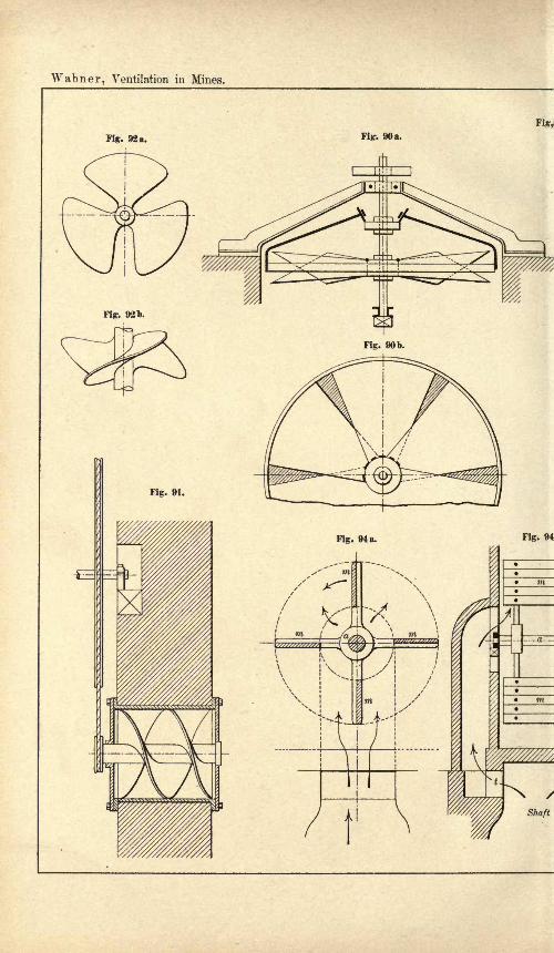
Wabner, Ventilation in Mines.
Fig,
Fig. 92 a.

Plate XV.
Fig. 93 a. Fig. 93b.
Fig-. 97 a.
Fig. 971).
Specially printed for Scott, Greenwood & Co.


Wabner, Ventilation in Mines.
Fig. 99b.

Plate XVI.
Fig. 101 a.
Rittinger's Ventilating Fan
Specially printed for Scott, Greenwood & Co.


Wabner, Ventilation in Mines,
Fig. 103.
Harzo's Ventilating J\vn.
Fig. 102 a.
Rittinger Centrifugal Fan at Mont-Cenis. t< --breadth of slide--
--->]

Plate XVII.
Fig. 104 a.
Kraft's Turbine Ventilator.
Specially printed for Scott, Greenwood & Co.


Wabner, Ventilation in Mines.

Plate XVIII.
Specially printed for Scott, Greenwood & Co.


Wabner, Ventilation in Mines.

Plate XIX.
Specially printed for Scott, Greenwood ft Co.


Wabner, Ventilation in Mines.

Plate XX.
Specially printed for Scott, Greenwood & Co.


Wabner, Ventilation in Mines.

Plate XXI.
-4000
Specially printed for Scott, Greenwood & Co.


Wabner. Ventilation in Mines.
Fig. 116 d.
Section along A-B.
(Plate XXI)

Plate XXII.
Fig. 116c.
Section along Gr-F.
(Plate XXI)
m


Wabner, Ventilation in Mines.
Fig. 117 a. Fig. 147 b.

Plate XXIII.
Fig. 119c.
Pelzor Fan. (Fig. 119 a -c). Section along m-n of Fig. 119b.
Specially printed for Scott, Greenwood & Co.


Wabner, Ventilation in Mines.
Fig. 118 a. Longitudinal Sect o A-B.

Plate XXIV.
Fig. 118c. Cross Section.
Kley Fan at the Bismarck Pit.
Specially printed for Scott, Greenwood & Co.


Wabner, Ventilation in Mines.
f- 2400 X
Fig. 119 d.
x

Plate XXY.
Fig. 119f.
Specially printed for Scott, Greenwood & Co.


Wabner, Ventilation in Mines.

Plate XXVI.
^^^p^.:^^
mm.
Specially printed for Scott, Greenwood & Co.


Wabner, Ventilation in Mines.

Plate XXVII.
Rateau Fan (Fig. 125 a -c).
Specially printed for Scott, Greenwood & Co.


Wabner, Ventilation in Mines.

Plate XXVIII.
Fig. 130. Fig. 131.
Fig. 129. Guibal Fan(exhaust or blower)
Fig. 136 a. Safety Door (after Guibal)
Specially printed for Scott, Greenwood & Co.


Wabner, Ventilation in Mines.
^^y^^s^&ill}!fi!^^f^^^^^m

Plate XXDL
Fig. 438 b. Profile.
&i^^
('
Specially printed for Scott, Greenwood & Co.


AVabner, Ventilation in Mines.
Air current for the
oilier workings

Plate XXX.
Specially printed for Scott, Greenwood & Co.


A Valuable Book for Collieries, Mining Engineers, and Managers.
RECOVERY WORKAFTER PIT FIRES.
A DESCRIPTION OF THE PRINCIPAL METHODS PURSUED, ESPECIALLY
IN FIERY MINES, AND OF THE VARIOUS APPLIANCES EMPLOYED,SUCH AS RESPIRATORY AND RESCUE APPARATUS, DAMS, ETC.
By ROBERT LAMPRECHT,Mining Engineer and Manager.
TRANSLATED FROM THE GERMAN.
Illustrated by Seven Large Plates, containing 76 Illustrations.
DEMY 8vo. WOt. 175 PAGES.
TABLE OF CONTENTS.Preface.
I. Causes of Pit Fires.
II. Preventive Regulations.III. Indications of an Existing or In-
cipient Fire.
IV. Appliances for Working in Irre-
spirable Gases.
V. Extinguishing Pit Fires.
VI. Rescue Stations.
VII. Spontaneous Ignition of Coal in
Bulk.
Index.
LIST OF ILLUSTRATIONS.Plate I. Respiratory and Rescue Appli-
ances Precautions against Fire.
Plate II. Respiratory and Rescue Ap-paratus.
Plate III. Respiratory and Rescue Ap-paratusStretchers.
Plate IV. Dams.
Plate V. Signalling Appliances DamConstruction Cable Laying.
Plate VI. Working with Diving Gear in
Irrespirable Gases Gallery Work.
Plate VII. Working with Diving Gearin Irrespirable Gases (Mayer Sys-tem) Appliances in the Shaft.
Price 10s. 6d. ; India and British Colonies, 11s.;
Other Countries, 12s. Strictly Net. Post Free.
SCOTT, GREENWOOD & CO.,19 LUDGATE HILL, LONDON, E.G.
16

EVAPORATING, CONDENSING,AND
COOLING APPARATUS.EXPLANATIONS, FORMUL/E, AND TABLES FOR USE IN PRACTICE.
By E. HAUSBRAND, Engineer.Translated from the Second, Revised German, Edition
By A. C. WRIGHT, IYI.A. (Oxon.), B.Sc. (Lond.)
21 Illustrations and 76 Tables. 400 Pages. Demy 8vo. 1903.
TABLE OF CONTENTS.Chapters I. The Coefficient of Transmission of
Heat, , and the Mean Temperature Difference,8m. II. Parallel and Opposite Currents.- III.
Apparatus for Heating with Direct Fire. IV.The Injection of Saturated Steam. V. Super-heated Steam. VI. Evaporation by Means ofHot Liquids. VII. The Transference of Heat in
General, and Transference by Means of Satur=ated Steam in Particular. VIII. The Transfer=ence of Heat from Saturated Steam in Pipes(Coils) and Double Bottoms. IX. Evaporationin a Vacuum. X. The Multiple-effect Evap-orator. A. The Evaporative Capacity of EachVessel. B. The Percentage of Dry Material in the
Liquid in Each Vessel. XI. Multiple-effectEvaporators, from which Extra Steam is taken.XII. The Weight of Water which must be
Evaporated from 100 kilos, of Liquor in orderto bring its Original Percentage of Solids from1-25 per cent, up to 20-70 per cent. XIII. TheRelative Proportion of the Heating Surfaces inthe Elements of the Multiple Evaporator andtheir Real Dimensions. XIV. The PressureExerted by Currents of Steam and Air uponFloating Drops of Water.-XV. The Motion of
Floating Drops of Water, upon which Press
Currents of Steam. XVI. The Splashing of
Evaporating Liquids. XVII. The Diameter of
Pipes for Steam, Alcohol Vapour, and Air.XVIII. The Diameter of Water Pipes. XIX.The Loss of Heat from Apparatus and Pipes tothe Surrounding Air, and Means for Prevent-ing the Escape. XX. Condensers. A. Jet Con-densers. B. Surface Condensers (Coolers'). XXI.Heating Liquids by Means of Steam. A. SteamHeating Coils in the Liquid. B. Steam Vessels -with
Double Bottoms. C. The Liquidflows tlirough Tubesaround which Steam is at rest. XXII. The Cool-ing of Liquids. A. The Direct Introduction of Ice.
B. The Direct Addition of Cold to Hot Liquid. C.
By Partial Evaporation. D. By Means of a ColderLiquid. E. Open Surface-Coolers. F. By Contactivith Metallic Surfaces Cooled by Air. G. Direct
Cooling by Means ofA ir. H . CoolingA ir by Means ofWater. XXIII. The Volumes to be Exhaustedfrom Condensers by the Air Pumps.- XXIV. AFew Remarks on Air Pumps and the Vacuathey Produce.-XXV. The Volumetric Effi-
ciency of Air-Pumps. XXVI. The Volumes ofAir which must be Exhausted from a Vessel inorder to Reduce its Original Pressure to aCertain Lower Pressure. INDEX.
LIST OF TABLES.
No.3. The Properties of Certain Fuels.
9. The Properties of Saturated Steam.ii. Comparison of the Coefficients of Transmission of
Heat, k, for Copper, Iron, and Lead Pipes.
13. The Hourly Evaporation of Water by Means of
Copper Tubes.
15. The Boiling Points of Certain Liquids in aVacuum.
18. The Amount of Evaporation, and Percentage of
Dry Matter in the Liquid, in Each Vessel of the
Multiple- Evaporator (without Extra Steant).
23. The Velocities at which Currents of Steam, Air,and Carbonic Acid exert upon Drops of Water a
pressure equal to, and double, their weight.27. Velocity of the Steam in the Steam Space of
Vacuum Evaporators.30. The Loss of Pressure bv Steam in Pipes.31. The Velocity of Steam 'in Pipes.33. The Velocity of the Vapour of Aqueous Alcohol in
Pipes.
Among the 76 Tables are the following:
No.38. Results of Experiments on Loss of Heat.
39. The Loss of Heat from Pipes and Cylinders(Pe"clet).
41. The Weight of Cooling Water required to Con-dense i kilo, of Steam.
46. The Heating of Sheets, Jets, and Drops of Waterby direct contact with Steam.
49. Dimensions of the Wet Jet-Condenser, without
Steps.
53. The Coefficient of Transmission of Heat betweenSteam and Water which does not boil.
65. The Length of a Cooling Pipe of 10-70 mm. Dia-
meter, when its Internal Cooling Surface is 0.25-7
sq. m.68. The Cooling Surface of Open Surface-Coolers.
70. Example of the Direct Cooling of Water by Meansof Air.
72. The Consumption of Cooling Water and Volumesof Air to be Exhausted in Condensing 100 kilos.
of Steam in Wet Jet-Condensers.
Price 10s. 6d. ; India and Colonies, 11s.;
Other Countries, 12s. Strictly Net.

SIDEROLOGY:THE SCIENCE OF IRON
(The Constitution of Iron Allots and Slags).
BY
HANNS FREIHERR V. JtJPTNER,Lecturer at the School of Mining at Leoben.
TRANSLATED FROM THE GERMAN.
345 Pages. 11 Plates. 10 Illustrations. Demy 8vo. 1902.
CONTENTS.THE CONSTITUTION OF IRON ALLOYS
AND SLAGS.BOOK I. The Theory of Solution. Chapters I.
Solutions. II. Molten Alloys : Varieties of Solutions.
III. Osmotic Pressure. IV. Relation between Os-
motic Pressure and Other Properties of Solutions. V.
Osmotic Pressure and Molecular Weight of the Dis-
solved Substance. VI. Solution of Gases. VII. Solid
Solutions. VIII. Solubility. IX. Diffusion. X.Electrical Conductivity : Constitution of Electrolytesand Metals. XI. Thermal Expansion.BOOK 1 1. Micrography. Chapters I. General.
II. Microstructure. III. The Micrographic Con-stituents of Iron. IV. Relation between Micrographi-cal Composition, Carbon Content, and Thermal Treat-
ment of Iron Alloys. V. The Microstructure of Slags.BOOK III. Chemical Composition of the Alloys
of Iron. Chapters I. Introduction. II. Constituents
of Iron Alloys : Carbon. III. Constituents of the
Iron Alloys : Carbon. Opinions and Researches on
Combined Carbon. IV. Opinions and Researches
on Combined Carbon (Contimiation.}. V. Opinions
and Researches on Combined Carbon (Conclusion).
VI. Applying the Curves of Solution Deducted from
the Curves of Recalescence to the Determination of the
Chemical Composition of the Carbon present in Iron
Alloys. VII. The Constituents of Iron : Iron. VIII.
The Constituents of Iron Alloys : Manganese. IX.
Remaining Constituents of Iron Alloys: A. Silicon;
B. Phosphorus ; C. Sulphur ;D. Chromium ;
E.
Tungsten : F. Molybdenum ; G. Nickel, Copper,
Titanium ;H. Oxygen. X. Gases.
BOOK IV. The Chemical Composition of Slag.
Chapters I. Introductory. II. Silicate Slags. III.
Calculating the Composition of Silicate Slags. IV.
Phosphate Slags. V. Oxide Slags.
Appendix.Index.
Price 10s. 6d. ; India and Colonies, 11s.;
Other Countries, 12s. Strictly Net.
IN THE PRESS-
HAULAGE AND WINDINGMACHINERY FOR MINES.
FROM THE GERMAN OF KARL VOLK.
Royal 8vo. 6 Plates. 146 Illustrations.

THE PREVENTION OF SMOKE.
Combined with the Economical
Combustion of Fuel.
By W. C. POPPLEWELL,M.Sc., A.M.Inst., C.J?., Consulting Engineer.
Demy 8vo. 46 Illustrations. 190 Pages. 1901.
CONTENTS.INTRODUCTORY. General Evils resulting froma smoky atmosphere Influence of smoke on fogsSmoke from domestic fires The waste of fuel.
CHAPTER I. Fuels and combustion Chemicalactions taking place during combustion Quantityof air required for combustion Combustion of coalin boiler furnaces Formation of smoke Satisfactorycombustion in boiler furnaces Effect of air supplyon economy and smoke.
CHAPTER II. Combustion in ordinary hand-firedboilers Air leakages The econometer Air supplyat the fire-door Air supply above the fire-door Air
supply at the bridge Defects of a continuous air
supply Special grates for hand-firing Granger'ssystem Mason's furnace The Welton furnace.
CHAPTER III. Stoking by mechanical meansBennis' mechanical stoker Proctor's mechanicalstoker Vicar's mechanical stoker Cass" mechanicalstoker Sinclair's mechanical stoker Proctor's cook-
ing stoker Juckes' furnace The Murphy furnaceUnderfed mechanical stoker.
CHAPTER IV. Powdered fuel firing The Wegenersystem of firing Whelpley and Storer's system.
CHAPTER V. Gaseous fuel Siemens and Wilson's
producers Dowson's producer gas Coke oven gasProduction and use of Mond gas.
CHAPTER VI. The testing of boilers, and smokeobservations Measuring instruments used Fuelcalorimeters Thomson's calorimeter Bomb cal-
orimeters of Berthelot and Mahler Calorific value
from analysis of the fuel Analysis of the fuel gasesResults of a trial Smoke observations Timedensity scales English scales, Paris scale, Swiss
scale, Prussian scale, Ringelmann's scale.
CHAPTER VII. Some standard smoke tests-
English Smoke Commissions, 1881 and 1895 Prus-
sian Smoke Commission Mr. Hales' report Parisk smoke tests Report of H.M. Chief Inspector of
Alkali Works.
CHAPTER VIII. The legal aspect of the smoke
question The Public Health Act of 1875 Modeof proceeding in the different cities and towns :
Bolton, Bristol, Cardiff, Edinburgh, Glasgow, Leeds,
London, Manchester, Newcastle, Salford, Sheffield.
CHAPTER IX. The means to be adopted for
lessening the smoke in our atmosphere Temporaryand partial Permanent and partial Permanentand complete Future developments.
INDEX.
PRESS NOTICES."Everybody interested in smoke prevention will
derive the greatest benefit from Mr. Popplewell'streatise, and will learn much that is new to them."Public Health Engineer."The Manchester expert who writes this book is
thoroughly equipped for the task, and he has produced
a work which ought to be in the hands of all Sanitary
Inspectors and Health Committees, and it would be a
useful present from manufacturers to stokers, instead
of possibly spending the value of the volume in paymentof fines." Sheffield Independent.
Price 7s. 6d. ; India and Colonies, 8s.;
Other Countries, 8s. 6d. Strictly Net.
SCOTT, GREENWOOD & CO.,19 LUDGATE HILL, LONDON, E.G.

Catalogue
Mooks

(Paints, Colours, House Decoration, Pigmentsand Printing Inks.)
THE CHEMISTRY OF PIGMENTS. By ERNEST J. PARRY,B.Sc. (Lond.), F.I.C., F.C.S., and J. H. COSTE, F.I.C., F.C.S. Demy8vo. Five Illustrations. 285 pp. Price 10s. 6d. net. (Post free,,
10s. lOd. home; 11s. 3d. abroad.)
Contents.Introductory. Light White Light The Spectrum The Invisible Spectrum Normal
Spectrum Simple Nature of Pure Spectral Colour The Recomposition of White LightPrimary and Complementary Colours Coloured Bodies Absorption Spectra The Appli =
cation of Pigments. Uses of Pigments: Artistic, Decorative, Protective Methods of
Application of Pigments : Pastels and Crayons, Water Colour, Tempera Painting, Fresco,.Encaustic Painting, Oil-colour Painting, Keramic Art, Enamel, Stained and Painted Glass,Mosaic Inorganic Pigments. White Lead Zinc White Enamel White Whitening-Red Lead Litharge Vermilion Royal Scarlet The Chromium Greens Chromates of Lead,.Zinc,- Silver and Mercury Brunswick Green The Ochres Indian Red Venetian RedSiennas and Umbers Light Red Cappagh Brown Red Oxides Mars Colours Terre Verte-Prussian Brown Cobalt Colours Cceruleum Smalt Copper Pigments Malachite
Bremen Green Scheele's Green Emerald Green Verdigris Brunswick Green Non-arsenical Greens Copper Blues Ultramarine Carbon Pigments Ivory Black Lamp Black
Bistre Naples Yellow Arsenic Sulphides : Orpiment, Realgar Cadmium YellowVandyck Brown Organic Pigments. Prussian Blue Natural Lakes Cochineal CarmineCrimson Lac Dye Scarlet Madder Alizarin Campeachy Quercitron Rhamnus
Brazil Wood Alkanet Santal Wood Archil Coal-tar Lakes Red Lakes Alizarin Com-pounds Orange and Yellow Lakes Green and Blue Lakes Indigo Dragon's BloodGamboge Sepia Indian Yellow, Puree Bitumen, Asphaltum, Mummy Index.
THE MANUFACTURE OF PAINT. A Practical Handbookfor Paint Manufacturers, Merchants and Painters. By J. CRUICKSHANKSMITH, B.Sc. Demy 8vo. [New Edition in Preparation..
DICTIONARY OF CHEMICALS AND RAW PRO-DUCTS USED IN THE MANUFACTURE OFPAINTS, COLOURS, VARNISHES AND ALLIEDPREPARATIONS. By GEORGE H. HURST, F.C.S. Demy8vo. 380 pp. Price 7s. 6d. net. (Post free, 8s. home
;8s. 6d. abroad.^
THE MANUFACTURE OF LAKE PIGMENTS FROMARTIFICIAL COLOURS. By FRANCIS H. JENNISON,F.I.C., F.C.S. Sixteen Coloured Plates, showing Specimens of
Eighty-nine Colours, specially prepared from the Recipes givenin the Book. 136 pp. Demy 8vo. Price 7s. 6d. net. (Post free,
7s. lOd. home; 8s. abroad.)
THE MANUFACTURE OF MINERAL AND LAKEPIGMENTS. Containing Directions for the Manufactureof all Artificial, Artists and Painters' Colours, Enamel, Soot and Me-tallic Pigments. A Text-book for Manufacturers, Merchants, Artists^
and Painters. By Dr. JOSEF BERSCH. Translated by A. C. WRIGHT,M.A. (Oxon.), B.Sc. (Lond.). Forty-three Illustrations. 476 pp., demy8vo. Price 12s. 6d. net. (Post free, 13s. home
; 13s. 6d. abroad.)
RECIPES FOR THE COLOUR, PAINT, VARNISH, OIL,SOAP AND DRYSALTERY TRADES. Compiled byAN ANALYTICAL CHEMIST. Second Revised Edition. 330 pp. Demy-8vo. Price 10s. 6d. net. (Post free, lls. home
;11s. 3d. abroad.)

PAINTS, COLOURS, ETC. continued.
OILMEN'S SUNDRIES AND HOW TO MAKE THEM.Being a Collection of Practical Recipes for Boot Polishes, Blues,Metal Polishes, Disinfectants, etc., compiled from "
Oils, Colours andDrysalteries ". Crown 8vo. 130 pages. Price 2s. 6d. net. (Postfree, 2s. 9d. home ; 2s. lOd. abroad.)
OIL COLOURS AND PRINTERS' INKS. By LouisEDGAR ANDS. Translated from the German. 215 pp. Crown 8vo.56 Illustrations. Price 5s. net. (Post free, 5s. 4d. home
;5s. 6d. abroad.)
MODERN PRINTING INKS. A Practical Handbook for
Printing Ink Manufacturers and Printers. By ALFRED SEYMOUR.Demy 8vo. Six Illustrations. 90 pages. Price 5s. net. (Post free,5s. 4d. home
;5s. 6d. abroad.)
Contents.Introduction. Division of Labour A Separate Industry Choice of Materials Skilful
Manipulation Some Important Factors The Medium Ink and Colour Mixing A Justifica-
tion. Linseed Oil. Extraction of the Oil Classification Mechanical Purification
Adulteration Boiled Oil Preparation of Boiled Oil An Alternative Process. Varnish.A Vehicle and Essential Component A Reference to Lithography Baltic Oil Preparationof Varnish The Modern Method An Old Argument Letterpress Varnish A CheaperMedium A Suggestive Recipe Fire Risks Gradations of Varnish. Dry Colours. ARecommendation An Endless Variety of Materials Earth Colours Mineral ColoursSubstrates Toning Earth Colours Physical Characteristics Colouring Power Brilliance
Purity of Tone Permanence. Dry Colours Blacks, Whites, Yellows Lampblack-Process of Manufacture Calcination Carbon Black Acetylene Black A Simple Test Leadand Zinc Whites White Earth Colours Yellows Yellow Ochres Mineral Yellows. DryColours Reds, Browns. Classification of Reds Genuine Vermilions PreparationImitation Vermilions Umber, Raw and Burnt Sienna, Raw and Burnt. Blues, Greens.Ultramarine Blue A Useful Tint Other Similar Blues Cobalt Blues Prussian Chineseand Bronze Blues A Test for Purity Greens Compound Greens Mineral Greens. Lakes.
Characteristics Lake Derivatives A Point of Importance Red Lakes MadderCochineal and Carmine Brazil Wood Alizarine a Coaltar Derivative Yellow Lakes BlueLakes Green Lakes. The Grinding of Printing Inks. Ink-grinding Machinery Ink-
grinding Mill A Novel Machine Hand Grinding Treatment of Gritty Colours A Questionof Proportion Approximate Calculation Soap Saturation Friction Heat Consistent
Grinding. Ink and Colour Mixing. A Necessary Acquisition Ink Mixing Defined MixedGreen Inks Mixed Brown Inks Tints Ink Mixing Lithographic Inks Characteristics ofYellows Mixing Vermilion Ultramarine and Other Blues Bronze, Prussian and ChineseBlues Working Consistency Reducing Medium Letterpress Inks Gloss Inks Three-colour Inks Ink-mixing Machine. The Characteristics of Some Printing Processes.A Supplementary Discussion Letterpress Inks Three-colour Printing Lithographic PrintingInks An Important Feature Suggestive Points Tinplate Printing. Driers. A Valuable
Auxiliary Energetic Drying Inks The Theory of Drying Liquid Driers Terebene PasteDriers Letterpress Driers Powder Driers Turpentine as a Drier. Bronze Powders andBronzing. A Brief Justification Bronze Printing Inks Bronze Powders The Process ofManufacture Preparation of the Leaf Grinding and Grading Bronzing Mediums RequisiteQualities Wax Varnish. "Things Worth Knowing." A Record of Notes andExperiences Index.
(See also Writing Inks, p. 10.)
THREE HUNDRED SHADES AND HOW TO MIXTHEM. For Architects, Painters and Decorators. By A.
DESAINT, Artistic Interior Decorator of Paris. The book contains 100
folio Plates, measuring 12 in. by 7 in., each Plate containing specimensof three artistic shades. These shades are all numbered, and their
composition and particulars for mixing are fully given at the beginningof the book. Each Plate is interleaved with grease-proof paper, andthe volume is very artistically bound in art and linen with the Shieldof the Painters' Guild impressed on the cover in gold and silver. Price21s. net. (Post free, 21s. 6d. home
;22s. 6d. abroad.)
HOUSE DECORATING AND PAINTING. By W.NORMAN BROWN. Eighty-eight Illustrations. 150 pp. Crown 8vo.Price 3s. 6d. net. (Post free, 3s. 9d. home and abroad.)

PAINTS, COLOURS, ETC. continued.
A HISTORY OP DECORATIVE ART. By W. NORMANBROWN. Thirty-nine Illustrations. 96 pp. Crown 8vo. Price Is. net,
(Post free, Is. 3d. home and abroad.)
WORKSHOP WRINKLES for Decorators, Painters, Paper-hangers and Others. ByW. N. BROWN. Crown 8vo. 128pp. SecondEdition. Price 2s. 6d. net. (Post free, 2s. 9d. home
;2s. lOd. abroad.>
CASEIN. By ROBERT SCHERER. Translated from the Germanby CHAS. SALTER. Demy 8vo. Illustrated. Second Revised EnglishEdition. 160 pp. Price 7s. 6d. net. (Post free, 7s. lOd. home;8s. abroad.)
SIMPLE METHODS FOR TESTING PAINTERS'MATERIALS. By A. C. WRIGHT, M.A. (Oxon.), B.Sc.
(Lond.). Crown 8vo. 160 pp. Price 5s. net. (Post free, 5s. 3d.
home;5s. 6d. abroad.)
IRON - CORROSION, ANTI - FOULING AND ANTI-CORROSIVE PAINTS. Translated from the German ofLouis EDGAR ANDES. Sixty-two Illustrations. 275 pp. Demy 8voPrice 10s. 6d. net. (Post free, 10s. lOd. home; 11s. 3d. abroad.)
THE TESTING AND VALUATION OF RAWMATERIALS USED IN PAINT AND COLOURMANUFACTURE. By M. W. JONES, F.C.S. A Bookfor the Laboratories of Colour Works. 88 pp. Crown 8vo. Price5s. net. (Post free, 5s. 3d. home and abroad.)
THE MANUFACTURE AND COMPARATIVE MERITSOF WHITE LEAD AND ZINC WHITE PAINTS. ByG. PETIT, Civil Engineer, etc. Translated from the French. Crown 8vo.
100 pp. Price 4s. net. (Post free, 4s. 3d. home ;4s. 4d. abroad.)
STUDENTS' HANDBOOK OF PAINTS, COLOURS, OILSAND VARNISHES. By JOHN FURNELL. Crown 8vo. 12Illustrations. 96pp. Price 2s. 6d. net. (Post free, 2s. 9d. home and abroad.}
PREPARATION AND USES OF WHITE ZINC PAINTS,Translated from the French of P. FLEURY. Crown 8vo. 280 pages.32 Tables. Price 6s. net. (Post free, 6s. 4d. home
;6s. 6d. abroad.)[Just published.
Contents.First Part. Chapters I., General Remarks. Technical Principles. II., Painting- on
Woodwork. Ordinary Outside Work Inside Work. III., Better Class Painting onWoodwork. IV., Painting on Plaster, on Mortar, and on Soft and Porous Ceilings.V., Hints on Painting with White Zinc. VI., Testing Commercial Zinc Whites.VII., The Experiments of the Dutch Commission Officially Entrusted to make Com-parative Trials between White Lead and White Zinc. VIII., Results and Criticismsof the Experiments of the Dutch Commission. Final Report of October 5, 1909.
Second Part. Chapters IX., Manufacture and Different Treatments of WhiteZinc Its Modifications and Improvements. X., The Legislative History of WhiteZinc Paint. XL, Legislation. XII., Methods of Qualitative Analysis. Examination ofPaints. Fixed and Essential Oils. Waxes. Formula for Encaustic and Waterproof Paints.
Analysis of Paints. White Paints. Analysis of White Lead. Analysis of White Zinc. Blacks.Red Pigments. Carmine and Lakes. Yellow Colours. Green Pigments. Blue Pigments.Brown Colours. Analysis of Binders or Liquid's. Testing Preservation and Improvement ofVarnishes by Ageing. Analysis of Yellow and White Wax. Selected Furniture Polish Recipe..Normal Polish for Floors, Parquets, and Woodwork. Virgin Wax Polish for Flattening ofPaints or Polishing of Varnishes. Formulae for a Waterproof Composition for Plaster andStone and Damp Walls. Special and More Economical Formulas for Waterproofing Plaster^
Copious Index.

(Varnishes and Drying Oils.)THE MANUFACTURE OF VARNISHES ANT>
KINDRED INDUSTRIES. By J. GEDDES MC!NTOSH.Second, greatly enlarged, English Edition, in three Volumes, based onand including the work of Ach. Livache.
VOLUME I. OIL CRUSHING, REFINING AND BOIL-ING, THE MANUFACTURE OF LINOLEUM,PRINTING AND LITHOGRAPHIC INKS, ANDINDIA-RUBBER SUBSTITUTES. Demy 8vo. 150
pp. 29 Illustrations. Price 7s. 6d. net. (Post free, 7s. lOd. home;
8s. abroad.)VOLUME II. VARNISH MATERIALS AND OIL-
VARNISH MAKING. Demy 8vo. 70 Illustrations.
220 pp. Price 10s. 6d. net. (Post free, 10s. lOd. home ;1 Is. 3d. abroad.)
VOLUME III. SPIRIT VARNISHES AND SPIRITVARNISH MATERIALS. Demy 8vo. Illustrated.
464 pp. Price 12s. 6d. net. (Post free, 13s. home ; 13s. 6d. abroad.)
DRYING OILS, BOILED OIL AND SOLID ANDLIQUID DRIERS. By L. E. ANDES. Expressly Writtenfor this Series of Special Technical Books, and the Publishers hold!
the Copyright for English and Foreign Editions. Forty-two Illustra-
tions. 342 pp. Demy 8vo. Price 12s. 6d. net. (Post free, 13s. home ;
13s. 3d. abroad.)
(Oils, Fats, Waxes, Greases, Petroleum.)LUBRICATING OILS, FATS AND GREASES: Their
Origin, Preparation, Properties, Uses and Analyses. A Handbook for
Oil Manufacturers, Refiners and Merchants, and the Oil and FatIndustry in General. By GEORGE H. HURST, F.C.S. Third Revisedand Enlarged Edition. Seventy-four Illustrations. 384 pp. Demy8vo. Price 10s. 6d. net. (Post tree, 11s. home: 11s. 3d. abroad.)
TECHNOLOGY OF PETROLEUM : Oil Fields of theWorld Their History, Geography and Geology Annual Productionand Development Oil-well Drilling Transport. By HENRY NEU-BERGER and HENRY NOALHAT. Translated from the French by J. G..
MclNTOSH. 550 pp. 153 Illustrations. 26 Plates. Super Royal 8vo..
Price 21s. net. (Post free, 21s. 9d. home; 23s. 6d. abroad.)MINERAL WAXES : Their Preparation and Uses. By.
RUDOLF GREGORIUS. Translated from the German. Crown 8vo. 25O
pp. 32 Illustrations. Price 6s. net. (Post free, 6s. 4d. home ;
6s. 6d. abroad.)
Contents.Ozokerite Ceresine Paraffin Refining Paraffin Mineral Wax Appliances for
Extracting, Distilling and Refining Ozokerite Uses of Ceresine, Paraffin andMineral Waxes Paint and Varnish Removers Leather and Piston-Rod Greases-Recipes for Silk, Cotton and Linen Dressings Candles.
THE PRACTICAL COMPOUNDING OF OILS, TAL-LOW AND GREASE FOR LUBRICATION, ETC.By AN EXPERT OIL REFINER. Second Edition. 100 pp. Demy 8vo.Price 7s. 6d. net. (Post free, 7s. lOd. home ; 8s. abroad.)
Contents.Introductory Remarks on the General Nomenclature of Oils, Tallow and Greases
suitable for Lubrication Hydrocarbon Oils Animal and Fish Oils CompoundOils Vegetable Oils Lamp Oils Engine Tallow, Solidified Oils and PetroleumJelly Machinery Greases: Loco and Anti-friction Clarifying and Utilisationof Waste Fats, Oils, Tank Bottoms, Drainings of Barrels and Drums, PickingsUp, Dregs, etc. The Fixing and Cleaning of Oil Tanks, etc. Appendix andGeneral Information.

THE MANUFACTURE OF LUBRICANTS, SHOEPOLISHES AND LEATHER DRESSINGS. ByRICHARD BRUNNER. Translated from the Sixth German Edition byCHAS. SALTER. 10 Illustrations. Crown 8vo. 170 pp. Price 7s. 6d.net. (Post free, 7s. lOd. home; 8s. abroad.)
THE OIL MERCHANTS' MANUAL AND OIL TRADEREADY RECKONER. Compiled by FRANK F. SHERRIFF.Second Edition Revised and Enlarged. Demy 8vo. 214 pp. 1904.With Two Sheets of Tables. Price 7s. 6d. net. (Post free, 7s. lOd.home
;8s. 3d. abroad.)
ANIMAL FATS AND OILS: Their Practical Production,Purification and Uses for a great Variety of Purposes. Their Pro-
perties, Falsification and Examination. Translated from the Germanof Louis EDGAR ANDES. Sixty-two Illustrations. 240 pp. SecondEdition, Revised and Enlarged. Demy 8vo. Price 10s. 6d. net.
(Post free, 10s. lOd. home; 11s. 3d. abroad.)
VEGETABLE FATS AND OILS : Their Practical Prepara-tion, Purification and Employment for Various Purposes, their Proper-ties, Adulteration and Examination. Translated from the German of
Louis EDGAR ANDES. Ninety-four Illustrations. 340 pp. SecondEdition. Demy 8vo. Price 10s. 6d. net. (Post free, 11s. home;Us. 6d. abroad.)
EDIBLE FATS AND OILS : Their Composition, Manufactureand Analysis. By W. H. SIMMONS, B.Sc. (Lond.), and C. A. MITCHELL,B.A. (Oxon.). Demy 8vo. 150 pp. Price 7s. 6d. net. (Post free,7s. 9d. home
;8s. abroad.)
Contents.Introduction. Physiological Considerations Constitution of Fats and Oils Trygly-
ceride Glyceride Butyrin Isovalerin Caproin Caprylin Caprin Laurin MyristinPalmitin Stearin Olein Ricinolein Stearic Acid Series Oleic Acid Series Linolic AcidSeries Linolenic Acid Series Ricinolenic Acid Series. Raw Materials used in the Manu-facture of Edible Fats and Oils. Tallow Mutton Beef Lard Lard Oil Cocoanut Oil
Maize Oil Cotton-seed Oil Cotton-seed Stearine Olive Oil Arachis Oil (Earthnut orPea-nut Oil) Sesame Oil Palm Nut Oil (Palm Kernel Oil) Sunflower Seed Oil CacaoButter or Oil of Theobroma Palm Oil Soya Bean Oil Shea Butter Mowrah-seed Oil
Margosa Oil. Bleaching, Deodorising, and Refining Fats and Oils. Physical MethodsWashing, Freezing, Filtration, Treatment, Steaming Removal of Stearines Methods of
Filtration Chemical Methods Caustic Soda Sodium Carbonate Alkaline Earths Fre-senius Bleaching of Oils Charcoal Fullers' Earth Ozone Hydrosulphites Sodium Bi-
sulphite Sodium Hydrosulphite Formaldehyde Organic Peroxides Deodorisation of FatsTreatment of Rancid Fats. Butter. Butter Fat Water Salt Curd Keeping Propertiesof Butter Rancidity of Butter Renovated Butter Preservatives in Butter Physical Char-acteristics Solubility Refractorative Examination Chemical Characteristics Hehner &Reichert Values Influence of the Food of the Cows Cocoanut Oil in Butter Artificial
Colouring Matters. Lard. Lard Oil Rendering of Lard Commercial Grades : (1) NeutralLard
; (2) Leaf Lard; (3) Choice Steam Lard or Choice Lard ; (4) Prime Steam Lard; (5) Guts
Lard Crystals Influence of Food Acidity of Lard Water Polenske The Iodine ValueLard Oil. Margarine and Other Butter Substitutes. Margarine, Oleomargarine or
Artificial Butter Invention and Development Modern Processes and Formulae VegetableButter Modern Process Vegetable Butter Palm Oil. Salad Oils. Oils used for Culinaryand Confectionery Purposes Chocolate Fats Olive Oils Sesame Oil Cotton-seed Oil
Sunflower Oil Poppy Oil Maize Oil -Chocolate Fats Cocoanut and Palm Kernel Oil Stear-ines Other Vegetable Fats. Analysis of Raw Materials and Finished Products. RawMaterials Specific Gravity Free Fatty Acids Saponification Value Saponification Equiv-alent Iodine Absorption Wjj's Method Bromine Absorption -Titer or Solidifying of the
Fatty Acids Refractive Index Unsaponifiable Matter Valenta's Acetic Acid Test Mau-mene's Test Bromine Thermal Value Baudouin's Test Tocher's Test Olive Oil Cotton-seed Oil Halphen's Test Arachis Oil Butter Water Examination of the Fat RefractivePower Soluble and Insoluble Fatty Acids Insoluble Fatty Acids Casein Curd ColouringMatters Boron Compounds Fluorides Margarine, Vegetable Butter or other Butter Sub-stitutes Lard Cheese Water Ash Fat Nitrogen Chocolate Unsweetened ChocolateSweetened Chocolate Granulated or Ground Chocolate Chocolate Covered Goods Milk
Chocolate Fat Palm-nut Stearine Dika or Gaboon Fat Borneo Tallow or Tankawang Fat
Illipe Fat Fibre Total Nitrogen Sugar. Statistics of the Trade in Edible Oil*.
United Kingdom Trade Exports Italian Trade in Olive Oil Spanish Oil Trade VegetableOil Trade of France Cotton-seed Oil in the United States.

(Essential Oils and Perfumes.)THE CHEMISTRY OP ESSENTIAL OILS AND ARTI-
FICIAL PERFUMES. By ERNEST J. PARRY, B.Sc.(Lond.), F.I.C., F.C.S. Second Edition, Revised and Enlarged. 552 pp,20 Illustrations. Demy 8vo. Price 12s. 6d. net. (Post free, 13s. home -
13s. 6d. abroad.)
(Soap Manufacture.)SOAPS. A Practical Manual of the Manufacture of Domestic,
Toilet and other Soaps. By GEORGE H. HURST, F.C.S. 390 pp.66 Illustrations. Demy 8vo. 2nd edition. Price 12s. 6d. net. (Postfree, 13s. home; 13s. 6d. abroad.)
TEXTILE SOAPS AND OILS. Handbook on the Prepara-tion, Properties and Analysis of the Soaps and Oils used in Textile
Manufacturing, Dyeing and Printing. By GEORGE H. HURST, F.C.S.Crown 8vo. 195 pp. Price 5s. net. (Post free, 5s. 4d. home
; 5s. 6d.
abroad.)
THE HANDBOOK OF SOAP MANUFACTURE. ByWM. H. SIMMONS, B.Sc. (Lond.), F.C.S. and H. A. APPLEION. Demy8vo. 160 pp. 27 Illustrations. Price 8s. 6d. net. (Post free,.8s. lOd. home ;
9s. abroad.)Contents.
Definition of Soap. Properties Hydrolysis Detergent Action. Constitution of Oilsand Fats, and their Saponification. Researches of Chevreul and Berthelot MixedGlycerides Modern Theories of Saponification Hydrolysis accelerated by (1) Heat orElectricity. (2) Ferments, Castor-seed Ferment, Steapsin Emulsin and (3) ChemicalReagents, Sulphuric Acid, Twitchell's Reagent, Hydrochloric Acid, Lime, Magnesia, ZincOxide, Soda and Potash. Raw Materials used in Soap-making. Fats and Oils WasteFats Fatty Acids Less-known Oils and Fats of Limited Use Various New Fats and Oils-
Suggested for Soap-making Rosin Alkali (Caustic and Carbonated) Water Salt Soap-stock. Bleaching and Treatment of Raw Materials intended for Soap-making.Palm Oil Cottonseed Oil Cottonseed " Foots" Vegetable Oils Animal Fats Bone Fat-Rosin. Soap- making. Classification of Soaps Direct combination of Fatty Acids withAlkali Cold Process Soaps Saponification under Increased or Diminished Pressure SoftSoap Marine Soap Hydrated Soaps, Smooth and Marbled Pasting or SaponificationGraining Out Boiling on Strength Fitting Curd Soaps Curd Mottled Blue and Grey-Mottled Soaps Milling Base Yellow Household Soaps Resting of Pans and Settling ofSoap Utilisation of Nigres Transparent Soaps Saponifying Mineral Oil Electrical Pro-duction of Soap. Treatment of Settled Soap. Cleansing Crutching Liquoring of Soaps
Filling Neutralising, Colouring and Perfuming Disinfectant Soaps Framing SlabbingBarring Open and Close Piling Drying Stamping Cooling. Toilet, Textile and
Miscellaneous Soaps. Toilet Soaps Cold Process Soaps Settled Boiled Soaps RemeltedSoaps Milled Soaps Drying, Milling and Incorporating Colour, Perfumes, or Medicaments-Perfumes Colouring Matter Neutralising and Super-fatting Material Compressing
Cutting Textile Soaps Soaps for Woollen, Cotton and Silk Industries Patent Textile
Soaps Stamping Medicated Soaps Ether Soap Floating Soaps Shaving SoapsMiscellaneous Soaps. Soap Perfumes. Essential Oils Source and Preparation Properties
Artificial and Synthetic Perfumes. Glycerine Manufacture and Purification. Treat-ment of Lyes Evaporation Crude Glycerine Distillation Distilled and DynamiteGlycerine Chemically Pure Glycerine Animal Charcoal for Decolorisation Glycerineresultant from other methods of Saponification Yield of Glycerine from Fats and Oils.
Analysis of Raw Materials, Soap and Glycerine. Fats and Oils Alkalies and Alkali'
Salts Essential Oils Soap Lyes Crude Glycerine. Statistics of the Soap Industry.Appendix A. Comparison of Degrees Twaddell, Beaume and Actual Densities.Appendix B. Comparison of Different Thermometric Scales. Appendix C. Table ofthe Specific Gravities of Solutions of Caustic Soda. Appendix D. Table of Strengthof Caustic Potash Solutions at 60 F. Index.
MANUAL OF TOILET SOAPMAKING, including Medi-cated Soaps, Stain -removing Soaps, Metal Polishing Soaps, SoapPowders and Detergents Translated from the German of Dr. C.Deite. Demy 4to. 150 pages. 79 Illustrations. Price 12s. 6d. net.
(Post free, 13s. home ; 13s. 6d. abroad.)

8
(Cosmetical Preparations.)
COSMETICS : MANUFACTURE, EMPLOYMENTAND TESTING OF ALL COSMETIC MATERIALSAND COSMETIC SPECIALITIES. Translatedfrom the German of Dr. THEODOR ROLLER. Crown 8vo. 262 pp.Price 5s. net. (Post free, 5s. 4d. home
;5s. 6d. abroad.)
(Glue, Bone Products and Manures.)OLUE AND GLUE TESTING. By SAMUEL RIDEAL, D.Sc.
(Lond.), F.I.C. Fourteen Engravings. 144 pp. Demy 8vo. Price10s. 6d. net. (Post free, 10s. lOd. home ; 11s. abroad.)
BONE PRODUCTS AND MANURES : An Account of themost recent Improvements in the Manufacture of Fat, Glue, AnimalCharcoal, Size, Gelatine and Manures. By THOMAS LAMBERT. SecondRevised Edition. Demy 8vo. 172 pp. 17 Illustrations. Price 7s. 6dnet. (Post free, 7s. lOd. home
;8s. abroad.) [Just published .
(See also Chemical Manures, p. 10.)
(Chemicals, Waste Products, etc.)
REISSUE OF CHEMICAL ESSAYS OP C. W.SCHEELE. First Published in English in 1786. Trans-lated from the Academy of Sciences at Stockholm, with Additions. 300
pp. Demy 8vo. Price 5s. net. (Post free 5s. 6d. home ;5s. 9d. abroad.)
Contents.Memoir : C. W. Scheele and his work (written for this edition by J. G. Mclntosh) On
Fluor Mineral and its Acid On Fluor Mineral Chemical Investigation of Fluor Acid,with a View to the Earth which it Yields, by Mr. Wiegler Additional Information
Concerning Fluor Minerals On Manganese, Magnesium, or Magnesia Vitrariorum OnArsenic and its Acid Remarks upon Salts of Benzoin On Silex, Clay and Alum Analysisof the Calculus Vesical Method of Preparing Mercurius Dulcis Via Humida Cheaper andmore Convenient Method of Preparing Pulvis Algarothi Experiments upon MolybdaenaExperiments on Plumbago Method of Preparing a New Green Colour Of the De-
composition of Neutral Salts by Unslaked Lime and Iron On the Quantity of Pure Air whichis Daily Present in our Atmosphere On Milk and its Acid On the Acid of Saccharum LactisOn the Constituent Parts of Lapis Ponderosus or Tungsten Experiments and Observations
on Ether Index.
THE MANUFACTURE OP ALUM AND THE SUL-PHATES AND OTHER SALTS OF ALUMINA ANDIRON. Their Uses and Applications as Mordants in Dyeingand Calico Printing, and their other Applications in the Arts Manufac-
tures, Sanitary Engineering, Agriculture and Horticulture. Translatedfrom the French of LUCIEN GESCHWIND. 195 Illustrations. 400 pp.
Royal 8vo. Price 12s. 6d. net. (Post free, 13s. home; 13s. 6d. abroad.)
AMMONIA AND ITS COMPOUNDS : Their Manufactureand Uses. By CAMILLE VINCENT, Professor at the Central School of
Arts and Manufactures, Paris. Translated from the French by M. J.
SALTER. Royal 8vo. 114 pp. Thirty-two Illustrations. Price 5s. net.
(Post free, 5s. 4d. home ; 5s. 6d. abroad.)

CHEMICAL WORKS : Their Design, Erection, and Equip-ment. By S. S. DYSON and S. S. CLARKSON. Royal 8vo. 220 pp.With 9 Folding Plates and 80 Illustrations. Price 21s. net. (Postfree, 21s. 6d. home; 22s. abroad.)
MANUAL OP CHEMICAL ANALYSIS, as applied to the
Assay of Fuels, Ores Metals. Alloys, Salts and other Mineral Products.
By E. PROST, D.Sc. Translated by J. CRUICKSHANK SMITH, B.Sc.
Royal 8vo. 300 pages. 44 Illustrations. Pricel2s.6d.net. (Postfree, 13s. home ;
13s 6d. abroad.)TESTING OF CHEMICAL REAGENTS FOR PURITY.
Translated from the German of Dr. C. KRAUCH. Royal 8vo. 350 pages..Price 12s. 6d. net. (Post free, 13s. home ;
13s. 6d. abroad.)SHALE OILS AND TARS and their Products. By Dr. W.
SCHEITHAUER. Translated from the German. Demy 8vo. 190 pp.70 Illustrations and 4 Diagrams. Price 8s. 6d. net. (Post free,8s. lOd. home; 9s. abroad.) [Just published.
Contents.Chapters I., History of the Shale and Lignite-tar Industry. II., The Bituminous
Raw Materials. Occurrence Origin Properties and Composition Working Utilization.
III., The Production of Distillation Tar. The Dry-distillation Process The Winning of
Lignite Tar The Messel Tar Industry The Recovery of Shale Tar in Scotland. IV., TheDistillation Products. The Tar The Tar Water (Ammonia Liquor) Gas The DistillationResidues. V., The Distillation of the Tar and Tar Oils. The Distillation Process TarDistilling in the Saxon-Thuringian Industry The Messel Distillation Process The Distilla-
tion Process in the Scottish Industry. VI., I. Chemical Treatment of the Tar and itsDistillates. The Refining Process The Refining Process in the Saxon-Thuringian IndustryRefining Process in the Messel Industry Refining Process in the Scottish Industry.
II. The Utilization of the Refinery Waste. Uses and Treatment. VII., The Manu-facture of Paraffin. The Manufacture of Paraffin in the Saxon-Thuringian IndustryManufacture of Paraffin in the Messel Industry Paraffin Manufacture in the Scottish
Industry. VIII., Products Furnished by Shale Oil and Lignite=Tar. IX., Candle-making. The Raw Materials The Candle Material The Wick The Colouring Matters.The Manufacture The Moulding Process Finishing Packing the Candles Working upCandle Waste. X.. Chemical Composition of the Tars and their Distillates. -LigniteTar Shale Tar. XL, The Laboratory Work. Testing the Raw Materials Testing theTars and otler Distillation Products Testing the Tar Oils Testing the Reagents used for
Refining the Oils and Paraffin Testing the Paraffin Tests Applied in Candle Works Test-
ing the By-Products of Tar Distillation. XII., Statistics. Index.
INDUSTRIAL ALCOHOL. A Practical Manual on theProduction and Use of Alcohol for Industrial Purposes and for Use asa Heating Agent, as an Illuminant and as a Source of Motive Power.
By J. G. MclNTOSH. Demy 8vo. 1907. 250 pp. With 75 Illustra-
tions and 25 Tables. Price 7s. 6d. net. (Post free, 7s. 9d. home;
8s. abroad.)THE UTILISATION OF WASTE PRODUCTS. A Treatise
on the Rational Utilisation, Recovery and Treatment of Waste Pro-ducts of all kinds. By Dr. THEODOR KOLLER. Translated from theSecond Revised German Edition. Twenty-two Illustrations. Demy8vo. 280 pp. Price 7s. 6d. net. (Post free, 7s. lOd. home
; 8s. 3d.
abroad.)ANALYSIS OF RESINS AND BALSAMS. Translated
from the German of Dr. KARL DIETERICH. Demy 8vo. 340 pp.Price 7s. 6d. net. (Post free, 7s. lOd. home ; 8s. 3d. abroad.)
DISTILLATION OF RESINS, RESINATE LAKES ANDPIGMENTS, CARBON PIGMENTS AND PIGMENTSFOR TYPEWRITING MACHINES, MANIFOLDERS,ETC. By VICTOR SCHWEIZER. Demy 8vo. 185 pages.68 Illustrations. Price 7s. 6d. net. (Post free, 8s. home
;8s. 3d.
abroad.)DISINFECTION AND DISINFECTANTS. By Dr. M,
CHRISTIAN. Translated from the German. Crown 8vo. About 120 pp.[In the press.

10
(Agricultural Chemistry and Manures.)MANUAL OF AGRICULTURAL CHEMISTRY. By
HERBERT INGLE, F.I.C.,F.C.S.,Late Lecturer on Agricultural Chemistry,the Leeds University ;
Lecturer in the Victoria University. Thirdand Revised Edition. 400 pp. 16 Illustrations. Demy 8vo. Price7s. 6d. net. (Post free, 8s. home
;8s. 6d. abroad.)
[Just published.
Contents.The Atmosphere The Soil The Reactions occurring in Soils The Analysis and Com-
position of Soils Manuring and General Manure- Special Manures Application o f ManuresThe Analysis and Valuation of Manures The Chemical Constituents of Plants The Plant
Crops The Animal Foods and Feeding Milk and Milk Products The Analysis of Milkand Milk Products Miscellaneous Products used in Agriculture Appendix Index.
(For Insecticides, Fungicides and Weed Killers, see p. 28.)
CHEMICAL MANURES. By J. FRITSCH. Translated fromthe French, with numerous Notes. Demy 8vo. 350 pp. 69 Illustra-
tions and 108 Tables. Price 10s. 6d. net. (Post free, 11s. home;11s. 6d. abroad.)
Contents.History Origin and Distribution of Phosphoric Acid in Nature Properties of Phos-
phorus Principal Phosphate Deposits Drying and Enrichment of Phosphates HistoricalReview of Superphosphate Manufacture Theory of Manufacture of Soluble PhosphatesManufacture of Superphosphate Crushing, Sifting, Drying, and Storing of SuperphosphateRetrogradation Compound Manures The Manufacture of Phosphoric Acid, Double
Superphosphates, and Various Products The Manufacture of Phosphorus in the ElectricFurnace Manufacture of Bone Dust and of Bone Superphosphate (Vitriolized Bones)Manufacture of Basic Slag Nitrogenous Manures Manufacture of Manure from AnimalWaste Recovery of Nitrogen from Distillery By-Products Manufacture of Cyanamide andof Nitrate of Lime Nitrogenized Phosphatic Manures Potassic Manures Transference-and Handling of Raw Materials and Finished Products.
(See also Bone Products and Manures, p. 8.)
(Writing Inks and Sealing Waxes.)INK MANUFACTURE : Including Writing, Copying, Litho-
graphic, Marking, Stamping, and Laundry Inks. By SIGMUND LEHNER.Three Illustrations. Crown 8vo. 162 pp. Translated from the Germanof the Fifth Edition. Price 5s. net. (Post free, 5s. 3d. home; 5s. 6d.
abroad.)
SEALING-WAXES, WAFERS AND OTHER ADHES-IVES FOR THE HOUSEHOLD, OFFICE, WORK-SHOP AND FACTORY. By H. C. STANDAGE. Crown8vo. 96 pp. Price 5s. net. (Post free, 5s. 3d. home
; 5s. 4d. abroad.)
(Lead Ores and Lead Compounds.)LEAD AND ITS COMPOUNDS. By THOS. LAMBERT,
Technical and Consulting Chemist. Demy 8vo. 226 pp. Forty Illus-
trations. Price 7s. 6d. net. (Post free, 7s. lOd. home ; 8s. 3d. abroad.)
NOTES ON LEAD ORES : Their Distribution and Properties.By JAS. FAIRIE, F.G.S. Crown 8vo. 64 pages. Price Is. net.
(Post free, Is. 3d. home;
Is. 4d. abroad.)
(White Lead and Zinc White Paints, see p. 4.)

11
(Industrial Hygiene.)THE RISKS AND DANGERS TO HEALTH OF VARI-
OUS OCCUPATIONS AND THEIR PREVENTION.By LEONARD A. PARRY, M.D., B.Sc. (Lond.). 196 pp. Demy 8vo.
Price 7s. 6d. net. (Post free, 7s. lOd. home;8s. abroad.)
(Industrial Uses of Air, Steam and Water.)DRYING BY MEANS OF AIR AND STEAM. Explana-
tions, Formulae, and Tables for Use in Practice. Translated from the
German of E. HAUSBRAND. Second Revised English Edition. Crown.8vo. 80 pp. Two folding Diagrams and Thirteen Tables. Price 5s. net.
(Post free, 5s. 3d. home; 5s. 6d. abroad.)Contents.
The Metric and British Systems Compared Comparison between Fahrenheit and Centi-
grade Thermometers. Chapters I. Introduction and Lists of Symbols II. Calculations of
the Maximum Weight of Saturated Aqueous Vapour which can be contained in 1 kilo, of Airat different Pressures and Temperatures III. Calculation of the necessary Weight andVolume of Air, and of the least Expenditure of Heat, for Drying Apparatus with Heated Air, at
Atmospheric Pressure (a) With the assumption that the Air is completely saturatedwith Vapour both before entry and at its exit from the Apparatus (b) When the Atmos-pheric Air is completely saturated before entry, but at its exit is only |, or J saturatedwith moisture (c) When the Atmospheric Air is not saturated with Water Vapour before
entering the Drying Apparatus. IV. Drying Apparatus in which, in the Drying Chamber, a
Pressure, higher or lower than that of the Atmosphere, is Artificially Maintained V.
Drying by means of Superheated Steam without Air VI. Heating Surface, Velocity of theAir Current, Dimensions of the Drying Room, Surface of the Drying Material, Losses of
Heat Index.
List of Tables.I. Pressures and weights of 1 cubic metre of saturated water vapour and of dry air
The weight of water in 1 kilo. ( f air at the absolute (barometric) pressures of 250, 500, 740,760, 780 and 1,140 mm., and at temperatures from- 20 to + 100 C., when the air is completelysaturated with vapour. II. Weight and volume of air, outlet temperature of air andexpenditure of heat required to evaporate 100 kilos, of water when the external tempera-ature is - 20 to+ 30 C., the maximum temperature is 30 to 130 C., the barometric pressureis 760 mm. The external air and the air at its exit are both completely saturated with watervapour. III. Pressures and weights of 1 cubic metre off, and \ saturated water vapour and.of the accompanying dry air The weights of f, and saturated vapour contained in 1
kilo, of air, with the barometer at 760 mm., and at temperatures from - 20 to + 100 C.IV., V. and VI. Weight and volume of air, temperature of exit and expenditure of heatrequired to evaporate 100 kilos, of water when the external temperature is - 20 to + 30 C.,the maximum temperature is 35, 50, 70, 100 and 130 C., the external air is completelysaturated and the emergent air is only f, J and J saturated with water vapour Also expendi-ture of heat when the external air is f saturated. VII. Temperatures at which the air wouldbe completely saturated with water if it is only f , J or J saturated by the same quantity ofwater at certain higher temperatures. VIII., IX. and X. The weight and volume of air, tem-perature of exit and expenditure of heat required to evaporate 100 kilos, of water when theexternal temperature is - 20, and + 30 C., the maximum temperature is 35, 50, 70, 100and 130 C., and both external and emergent air are completely saturated \\ ith watervapour. VIII. T^e absolute pressure is 1,140 mm. (1 atmos.) 50. IX. The absolute pressureis 500 mm. (H atmos.) 51. X. The absolute pressure is 250 mm. (1 atmos.) 52. XI. Theweights of steam and their volumes, before and after heating required to evaporate 100kilos, of water in the circuit drying apparatus, without air, at absolute pressures of 148to 2,660 mm., and with maximum temperature of 65 to 200 C. XII. The quantities ofheat given up by 1 square metre of the source of heat in 1 hour when the external air is
at - 20 to + 30 C., the source of heat is at 100 to 140 C., the heated air is at 35 to 130C., and the air current passes over the heating surface with a velocity of 1 to 6 metres persecond. XIII. Losses of heat, in calories, by drying apparatus in one hour from 1 squaremetre of masonry, wooden wall or simple window at temperature differences betweeninterior and exterior of 5 to 100 C.
(See also "Evaporating, Condensing and Cooling Apparatus" p. 25.)
PURE AIR, OZONE AND WATER. A Practical Treatiseof their Utilisation and Value in Oil, Grease, Soap, Paint, Glue andother Industries. By W. B. COWELL. Twelve Illustrations. Crown8vo. 85 pp. Price 5s. net. (Post free, 5s. 3d. home
; 5s. 6d. abroad.),

12
THE INDUSTRIAL USES OF WATER. COMPOSI-TION EFFECTS TROUBLES REMEDIES RE-SIDUARY WATERS PURIFICATION ANALYSIS.By H. DE LA Coux. Royal 8vo. Translated from the French andRevised by ARTHUR MORRIS. 364 pp. 135 Illustrations. Price 10s. 6d.
net. (Post free, 11s. home; 11s. 6d. abroad.)Contents.
Chemical Action of Water in Nature and in Industrial Use Composition of Waters
Solubility of Certain Salts in Water Considered from the Industrial Point of View Effects onthe Boiling of Water Effects of Water in the Industries Difficulties with Water FeedWater for Boilers Water in Dyeworks, Print Works, and Bleach Works Water in the
Textile Industries and in Conditioning Water in Soap Works Water in Laundries andWashhouses Water in Tanning Water in Preparing Tannin and Dyewood Extracts Waterin Papermaking Water in Photography Water in Sugar Refining Water in Making Ices
and Beverages Water in Cider Making Water in Brewing Water in Distilling PreliminaryTreatment and Apparatus Substances Used for Preliminary Chemical Purification Com-mercial Specialities and their Employment Precipitation of Matters in Suspension in Water
Apparatus for the Preliminary Chemical Purification of Water Industrial Filters Indus-
trial Sterilisation of Water Residuary Waters and their Purification Soil Filtration
Purification by Chemical Processes Analyses Index.
(See Books on Smoke Prevention, Engineering and Metallurgy, p. 25, etc)
(X Rays.)PRACTICAL X RAY WORK. By FRANK T. ADDYMAN,
B.Sc. (Lond.), F.I.C., Member of the Roentgen Society of London;Radiographer to St. George's Hospital ;
Demonstrator of Physics and
Chemistry, and Teacher of Radiography in St. George's HospitalMedical School. Demy 8vo. Twelve Plates from Photographs of X RayWork. Fifty-two Illustrations. 200 pp. Price 10s. 6d. net. (Post free,
10s. lOd. home; 11s. 3d. abroad.)Contents.
Historical Work leading up to the Discovery of the X Rays The Discovery Appara-tus and its Management Electrical Terms Sources of Electricity Induction Coils-Electrostatic Machines Tubes Air Pumps Tube Holders and Stereoscopic ApparatusFluorescent Screens Practical X Ray Work Installations Radioscopy RadiographyX Rays in Dentistry X Rays in Chemistry X Rays in War Index.
List of Plates.Frontispiece Congenital Dislocation of Hip-Joint. I., Needle in Finger. II., Needle in
'Foot. III., Revolver Bullet in Calf and Leg. IV., A Method of Localisation. V., Stellate
'Fracture of Patella showing shadow of "Strapping ".VI., Sarcoma. VII., Six-weeks-old
Injury to Elbow showing new Growth of Bone. VIII., Old Fracture of Tibia and Fibula
'badly set. IX., Heart Shadow. X., Fractured Femur showing Grain of Splint. XI., Bar-
bell's Method of Localisation.
(India=Rubber and Qutta Percha.)INDIA-RUBBER AND GUTTA PERCHA. Second
English Edition, Revised and Enlarged. Based on the French work of
T. SEELIGMANN, G. LAMY TORRILHON and H. FALCONNET by JOHNGEDDES MC!NTOSH. Royal 8vo. 100 Illustrations. 400 pages. Price
12s. 6d. net. (Post free, 13s. home ;13s. 6d. abroad.)
Contents.India- Rubber. Indiarubber, Latex Definitions Laticiferous Vessels Botanical OriginHabitats Methods of obtaining the Latex Methods of Preparing Raw or Crude India-
rubber Rubber Cultivation in Various Countries Climatology Soil Rational Culture andAcclimatisation of the Different Species of Indiarubber Plants Classification of the Com-mercial Species of Raw Rubber Physical and Chemical Properties of the Latex and of
Indiarubber General Considerations Mechanical Transformation of Natural Rubber into
Washed or Normal Rubber (Purification) Softening, Cutting, Washing, Drying, Storage-Mechanical Transformation of Normal Rubber into Masticated Rubber Vulcanisation of
Normal Rubber Chemical and Physical Properties of Vulcanised Rubber Hardened Rubberor Ebonite Considerations on Mineralisation and Other Mixtures Coloration and Dyeing-Analysis of Natural or Normal Rubber and Vulcanised Rubber Rubber Substitutes-Imitation Rubber Analysis of Indiarubber.
Qutta Percha. Definition of Gutta Percha Botanical Origin Habitat Climatology-Soil Rational Culture Methods of Collection Felling and Ringing versus Tapping Extrac-tion of Gutta Percha from Leaves by Toluene, etc. Classification of the Different Species of
Commercial Gutta Percha Physical and Chemical Properties of Gutta Percha MechanicalTreatment of Gutta Percha Methods of Analysing Gutta Percha Gutta Percha Substitute*.

13
(Leather Trades.)THE LEATHER WORKER'S MANUAL. Being a Com-
pendium of Practical Recipes and Working Formulae for Curriers,Bootmakers, Leather Dressers, Blacking Manufacturers, Saddlers,Fancy Leather Workers. By H. C. STANDAGE. Demy 8vo. 165 pp.Price 7s. 6d. net. (Post free, 7s. lOd. home
; 8s. abroad.)
Contents.Blackings, Polishes, Glosses, Dressings, Renovators, etc., for Boot and Shoe Leather-
Harness Blackings, Dressings, Greases, Compositions, Soaps, and Boot-top Powders andLiquids, etc., etc. Leather Grinders' Sundries Currier's Seasonings, Blacking Compounds,Dressings, Finishes, Glosses, etc. Dyes and Stains for Leather Miscellaneous InformationChrome Tannage Index.
(See also Manufacture of Shoe Polishes, Leather Dressings, etc., p. 6.)
(Pottery, Bricks, Tiles, Glass, etc.)
MODERN BRICKMAKING. By ALFRED B. SEARLE. Royal8vo. 440 pages. 260 Illustrations. Price 12s. 6d. net. (Post free,13s. home; 13s. 6d. abroad.)
Contents.Nature and Selection of Clays. Lake and River Deposited Clays Rock Clays Shale
Fire-clay. The Colour of Bricks. Marls White, Yellow, and Red Bricks Terra-cottaBlue Bricks. General Characteristics of Bricks. Fletton, Bath, and Accrington Bricks
London Stocks Plastic Bricks Sand-faced Bricks Glazed Bricks Fire Bricks Qualitiesof Bricks. Sand, Breeze, and other Materials. Chalk-water General Manufacture ofJBricks Clay-washing Haulage Hand-Brickmaking Preparation of the Paste Pugging
Slop-moulding Sand-moulding Drying Shrinking Pressing Clamp Kilns Firing aClamp. Plastic Moulding by Machinery. Wire-cut Bricks Brick Machines and Plant-Crushing Rolls Grinding Mills Wet Pans. Mixers and Feeders. Pug-mills, MouthpiecePresses, and Auger Machines Expression Roller Machines Cutting Tables RepressingScrew Presses Eccentric Represses Die-Boxes. Drying. Transport. Stiff-plasticProcess. Mill Feeding Machines Grinding Mills Elevating Screens Sieves RevolvingScreens Stiff-plastic Brickmaking Machines Repressing Carrying-off Drying Kilos.Semi- Dry or Semi-Plastic Process. Lamination Drying Troubles Moulds and Arrises.The Dry or Dust Process. Lamination. Kilns. Down-draught Kilns Horizontal-draughtKilns Continuous Kilns Up-draught Kilns Newcastle Kiln Gas-fired Kilns Semi-con-tinuous Kilns Hoffmann Kilns Hot-air Flues Temporary and Permanent Flues ChamberKilns Steam Draught Mechanical Draught Gas-fired Continuous Kilns Muffle Kilns-Kiln Construction. Choice of Bricks Foundations Construction of Arches and CrownsFire Boxes Feed-holes Chimneys Selecting a Kiln. Setting and Burning. Up-draughtand Down-draught Kilns Horizontal-draught or Continuous Kiln Glazed Bricks. Firing.Drying or Steaming Volatilization Full Fire Smoking Seger Cones Draught GaugeCooling. Vitrified Bricks for Special Work. Clinkers and Paving Bricks Acid-proofBricks. Fire-Bricks and Blocks. Materials Grog Grinding Blocks Drying DippedFire-bricks Firing Silica Bricks Canister Bricks Bauxite and Magnesia BricksNeutral Fire-bricks. Glazed Bricks. Pressing Dipping Glazes Coloured Glazes Ma-jolica Glazes Firing Salt-glazed Bricks. Perforated, Radial, and Hollow Bricks.Fireproof Flooring. Moulded and Ornamental Bricks Drying Raw Clay Sources ofDifficulty and Loss. Improper Materials or Site Unsuitable Methods of Working Lackof Capital Defective Accounting. Index.
THE MANUAL OF PRACTICAL POTTING. Compiledby Experts, and Edited by CHAS. F. BINNS. Third Edition, Revisedand Enlarged. 200 pp. Demy 8vo. Price 17s. 6d. net. (Post free,17s. lOd. home; 18s. 3d. abroad.)
POTTERY DECORATING. A Description of all the Pro-cesses for Decorating Pottery and Porcelain. By R. HAINBACH.Translated from the German. Crown 8vo. 250 pp. Twenty-twoIllustrations. Price 7s. 6d. net. (Post free, 7s. lOd. home ; 8s. abroad.)

14
A TREATISE ON CERAMIC INDUSTRIES. A CompleteManual for Pottery, Tile, and Brick Manufacturers. By EMILBBOURRY. A Revised Translation from the French, with some Critical
Notes by ALFRED B. SEARLE. Demy 8vo. 308 Illustrations. 460 pp.Price 12s. 6d. net. (Post free, 13s. home; 13s. 6d. abroad.)
Contents.Preface. Definition and Classification of Ceramic Ware. Brief History of Ceramics.
Raw Materials of Bodies. Plastic Bodies Properties and Composition Preparation Puri-fication. Processes of Formation: Thowing, Expression, Moulding, Pressing, Casting. Slipping. Drying Evaporation Aeration Heat Absorption. Glazes: Manufacture andApplication. Firing: Properties of Bodies and Glazes during Firing Kilns. Decoration:Materials and Methods. Terra Cottas Bricks Hollow Blocks Roofing Tiles PavingBricks Pipes Architectural and Decorative Terra-Cotta Common Pottery Tobacco PipesLustre Ware Tests. Fireclay Goods : Varieties, Methods of Manufacture and Tests.
Faiences: Classification, Composition, Methods of Manufacture and Decoration. StonewarePaving Tiles Sanitary Ware For Domestic Purposes For Chemic 1 Purposes Decora-
tive Objects. Porcelain : Classification Composition Manufacture Decoration.
ARCHITECTURAL POTTERY. Bricks, Tiles, Pipes, Ena-melled Terra-cottas, Ordinary and Incrusted Quarries, StonewareMosaics, Faiences and Architectural Stoneware. By LEON LEFEVRE.Translated from the French by K. H. BIRD, M.A., and W. MOOREBINNS. With Five Plates. 950 Illustrations in the Text, and numerousestimates. 500 pp., royal 8vo. Price 15s. net. (Post free, 15s. 6d.
home;16s. 6d. abroad.)
CERAMIC TECHNOLOGY : Being some Aspects of Tech-nical Science as Applied to Pottery Manufacture. Edited by CHARLESF. BINNS. 100 pp. Demy 8vo. Price 12s. 6d. net. (Post free,12s. lOd. home; 13s. abroad.)
Contents.Preface The Chemistry of Pottery Analysis and Synthesis Clays and their Com-
ponents The Biscuit Oven Pyrometry Glazes and their Composition Colours andColour-making Index.
THE ART OF RIVETING GLASS, CHINA ANDEARTHENWARE. By J. HOWORTH. Second Edition.
Paper Cover. Price Is. net. (By post, home or abroad, Is. Id.)
NOTES ON POTTERY CLAYS. The Distribution, Pro-
perties, Uses and Analyses of Ball Clays, China Clays and ChinaStone. By JAS. FAIRIE, F.G.S. 132 pp. Crown 8vo. Price 3s. 6d.
net. (Post free, 3s. 9d. home ;3s. lOd. abroad.)
HOW TO ANALYSE CLAY. By H. M. ASHBY. Demy 8vo.72 pp. 20 Illustrations. Price 3s. 6d. net. (Post free, 3s. 9d. home
;
3s. lOd. abroad.)
A Reissue of
THE HISTORY OP THE STAFFORDSHIRE POTTER-IBS
;AND THE RISE AND PROGRESS OF THE
MANUFACTURE OF POTTERY AND PORCELAIN.With References to Genuine Specimens, and Notices of Eminent Pot-ters. By SIMEON SHAW. (Originally published in 1829.) 265 pp..
Demy 8vo. Price 5s. net. (Post free, 5s. 4d. home;5s. 9d. abroaJ.)

15
A Reissue of
THE CHEMISTRY OF THE SEVERAL NATURALAND ARTIFICIAL HETEROGENEOUS COM-POUNDS USED IN MANUFACTURING POR-CELAIN, GLASS AND POTTERY. By SIMEON SHAW.(Originally published in 1837.) 750 pp. Royal 8vo. Price 10s. net.
(Post free, 10s. 6d. home ;12s. abroad.)
BRITISH POTTERY MARKS. By G. WOOLLISCROFT RHEAD.Demy 8vo. 310 pp. With upwards of Twelve-hundred Illustrations ofMarks in the Text. Price 7s. 6d. net. (Post free, 8s. home
; 8s. 3d.
abroad.)
(Glassware, Glass Staining and Painting.)
HECIPES FOR FLINT GLASS MAKING. By a BritishGlass Master and Mixer. Sixty Recipes. Being Leaves from the
Mixing Book of several experts in the Flint Glass Trade, containingup -to date recipes and valuable information as to Crystal, Demi-crystaland Coloured Glass in its many varieties. It contains the recipes for
cheap metal suited to pressing, blowing, etc., as well as the most costlycrystal and ruby. Second Edition. Crown 8vo. Price 10s. 6d. net.
(Post free, 10s. 9d. home;10s. lOd. abroad.)
Contents.Ruby Ruby from Copper Flint for using with the Ruby for Coating A German Metal-
Cornelian, or Alabaster Sapphire Blue Crysophis Opal Turquoise Blue Gold ColourDark Green Green (common) Green for Malachite Blue for Malachite Black for Mala-chite Black Common Canary Batch Canary White Opaque Glass Sealing-wax RedFlint Flint Glass (Crystal and Demi) Achromatic Glass Paste Glass White FnamelFirestone Dead White (for moons) White Agate Canary Canary Enamel Index.
A TREATISE ON THE ART OF GLASS PAINTING.Prefaced with a Review of Ancient Glass. By ERNEST R. SUPPLING.With One Coloured Plate and Thirty-seven Illustrations. Demy 8vo.140 pp. Price 7s. 6d. net. (Post free, 7s. lOd. home; 8s. abroad.)
Contents.A Short History of Stained Glass Designing Scale Drawings Cartoons and the Cut LineVarious Kinds of Glass Cutting for Windows The Colours and Brushes used in Glass
Painting Painting on Glass Dispersed Patterns Diapered Patterns Aciding FiringFret Lead Glazing Index.
(Paper Making, Paper Dyeing and Testing.)
THE DYEING OF PAPER PULP. A Practical Treatise forthe use of Papermakers, Paperstainers, Students and others. ByJULIUS ERFURT. Manager of a Paper Mill. Translated into Englishand Edited with Additions by JULIUS H6BNER, F.C.S., Lecturer onPapermaking at the Manchester Municipal Technical School. WithIllustrations and 157 patterns of paper dyed in the pulp. Royal8vo, 180 pp. Price 15s. net. (Post free, 15s. 6d. home; 16s. 6d. abroad.)
Contents.Behaviour of the Paper Fibres during the Process of Dyeing, Theory of the
Mordant Colour Fixing Mediums (Mordants) Influence of the Quality of the WaterUsed Inorganic Colours Organic Colours -Practical Application of the Coal TarColours according to their Properties and their Behaviour towards the DifferentPaper Fibres Dyed Patterns on Various Pulp Mixtures Dyeing to Shade Index.

16
THE PAPER MILL CHEMIST. By HENRY P. STEVENS,M.A., Ph.D., F.I.C. Royal 12mo. 60 Illustrations. 300 pp. Price7s. 6d. net. (Post free 7s. 9d. home
;7s. lOd. abroad.)
Contents.Introduction. Dealing with the Apparatus required in Chemical Work and General
Chemical Manipulation, introducing the subject of Qualitative and Quantitative Analysis.Fuels. Analysis of Coal, Coke and other Fuels Sampling and Testing for Moisture, Ash,Calorific Value, etc. Comparative Heating Value of different Fuels and Relative Efficiency.Water. Analysis for Steam Raising and for Paper Making Purposes generally WaterSoftening and Purification A List of the more important Water Softening Plant, givingPower required, Weight, Space Occupied, Out-put and Approximate Cost. Raw Materialsand Detection of Adulterants. Analysis and Valuation of the more important Chemicalsused in Paper Making, including Lime, Caustic Soda, Sodium Carbonate, Mineral Acids,Bleach Antichlor, Alum, Rosin and Rosin Size, Glue Gelatin and Casein, Starch, China Clay,Blanc Fixe, Satin White and other Loading Materials, Mineral Colours and Aniline Dyes.Manufacturing Operations. Rags and the Chemical Control of Rag Boiling EspartoBoiling Wood Boiling Testing Spent Liquors and Recovered Ash Experimental Testswith Raw Fibrous Materials Boiling in Autoclaves Bleaching and making up Hand SheetsExamination of Sulphite Liquors Estimation of Moisture in Pulp and Half-stuff Recom-
mendations of the British Wood Pulp Association. Finished Products. Paper Testing,including Physical, Chemical and Microscopical Tests, Area, Weight, Thickness, ApparentSpecific Gravity, Bulk or Air Space. Determination of Machine Direction, Thickness,Strength, Stretch, Resistance to Crumpling and Friction, Transparency, Absorbency andother qualities of Blotting Papers Determination of the Permeability of Filtering PapersDetection and Estimation of Animal and Vegetable Size in PaperSizing Qualities of
Paper Fibrous Constituents Microscopical Examination of Fibres The Effect of Beatingon Fibres Staining Fibres -Mineral Matter Ash Qualitative and Quantitative Examina-tion of Mineral Matter Examination of Coated Papers and Colouring Matters in Paper.Tables. English and Metrical Weights and Measures with Equivalents Conversion ofGrams to Grains and vice versa Equivalent Costs per lb., cwt.,and ton Decimal Equivalentsof Ibs., qrs., and cwts. Thermometric and Barometric Scales Atomic Weights and MolecularWeights Factors for Calculating the Percentage of Substance Sought from the Weight ofSubstance Found Table of Solubilities of Substances Treated of in Paper Making SpecificGravity Tables of such substances as are used in Paper Making, including Sulphuric Acid,Hydrochloric Acid, Bleach, Milk of Lime, Caust c Soda, Carbonate of Soda, etc., givingPercentage Strength with Specific Gravity and Degrees Tw. Hardness Table for SoapTests Dew Point Wet and Dry Bulb Tables Properties of Saturated Steam, givingTemperature, Pressure and Volume List of Different Machines used in the Paper MakingIndustry, giving Size, Weight, Space Occupied, Power to Drive, Out-put and ApproximateCost Calculation of Moisture in Pulp Rag-Boiling Tables, giving Percentages of Lime,Soda and Time required Loss in Weight in Rags and other Raw Materials during Boilingand Bleaching Conditions of Buying and Selling as laid down by the Paper Makers' Associa-tion Table of Names and Sizes of Papers Table for ascertaining the Weight per Ream fromthe Weight per Sheet Calculations of Areas and Volumes Logarithms Blank pages forNotes.
THE TREATMENT OF PAPER FOR SPECIALPURPOSES. By L. E. ANDES. Translated from theGerman. Crown 8vo. 48 Illustrations. 250 pp. Price 6s. net. (Postfree, 6s. 4d. home
;6s. 6d. abroad.)
Contents.I., Parchment Paper, Vegetable Parchment. The Parchment Paper Machine-
Opaque Supple Parchment Paper Thick Parchment Krugler's Parchment Paper and Parch-ment Slates Double and Triple Osmotic Parchment Utilising Waste Parchment PaperParchmented Linen and Cotton Parchment Millboard Imitation Horn and Ivory fromParchment Paper Imitation Parchment Paper Artificial Parchment Testing the SulphuricAcid. II., Papers for Transfer Pictures. III., Papers for Preservative and PackingPurposes. Butter Paper Wax Paper Paraffin Paper Wrapping Paper for Silverware
Waterproof Paper Anticorrosive Paper. IV., Grained Transfer Papers. V., Fireproof andAntifalsification Papers. VI., Paper Articles. Vulcanised Paper Mache Paper Bottles-Plastic Articles of Paper Waterproof Coverings for Walls and Ceilings Paper Wheels,Roofing and Boats Parer Barrels Paper Boxes Paper Horseshoes. VII., Gummed Paper.VIII., Hectograph Papers. IX., Insecticide Papers. Fly Papers Moth Papers. X.,Chalk and Leather Papers. Glacd Chalk Paper Leather Paper Imitation Leather.
XL, Luminous Papers Blue-Print Papers Blotting Papers. XII., Metal Papers Medi-cated Papers. XIII., Marbled Papers. XIV., Tracing and Copying Papers Iridiscent orMother of Pearl Papers. XV., Photographic Papers Shellac Paper Fumigating PapersTest Papers. XVI., Papers for Cleaning and Polishing Purposes Glass PaperPumic Paper Emery Paper. XVII., Lithographic Transfer Papers. XIX., SundrySpecial Papers Satin Paper Enamel Paper Cork Paper Split Paper Electric PaperPaper Matches Magic Pictures Laundry Blue Papers Blue Paper for Bleachers. XX.,Waterproof Papers Washable Drawing Papers Washable Card Washable Coloured PaperWaterproof Millboard Sugar Paper. XXL, The Characteristics of Paper Paper Testing.

17
(Enamelling on Metal.)ENAMELS AND ENAMELLING. For Enamel Makers,
Workers in Gold and Silver, and Manufacturers of Objects of Art.
By PAUL RANDAU. Translated from the German. Second and RevisedEdition. With Sixteen Illustrations. Demy 8vo. 200 pp. Price
10s. 6d. net. (Post free, 10s. lOd. home;
11s. abroad.)
[Just published.
THE ART OP ENAMELLING ON METAL. By W.NORMAN BROWN. Twenty-eight Illustrations. Crown 8vo. 60 pp.Price 2s. 6d. net. (Post free, 2s. 9d. home and abroad.)
(Textile and Dyeing Subjects.)THE FINISHING OF TEXTILE FABRICS (Woollen,
Worsted, Union and other Cloths). By ROBERTS BEAUMONT, M.Sc.,M.I.Mech.E., Professor of Textile Industries, the University of Leeds;Author of " Colour in Woven Design"; "Woollen and Worsted ClothManufacture "
;
" Woven Fabrics at the World's Fair ";Vice-President
of the Jury of Award at the Paris Exhibition, 1900; Inspector of Tex-
tile Institutes; Society of Arts Silver Medallist
; Honorary Medallistof the City and Guilds of London Institute. With 150 Illustrations of
Fibres, Yarns and Fabrics, also Sectional and other Drawings of
Finishing Machinery. Demy 8vo. 260 pp. Price 10s. 6d. net. (Postfree, 10s. lOd. home; 11s. 3d. abroad.)
Contents.Woollen, Worsted and Union Fabrics Processes of Finishing and their Effects The
Process of Scouring : Scouring Machines Theory of Felting: Fabric Structure CompoundFabrics Fulling and Milling Machinery. The Theory of Raising Raising Machinery andthe Raising Process Cutting, Cropping or Shearing Lustring Processes and MachineryMethods of Finishing Index.
FIBRES USED IN TEXTILE AND ALLIED INDUS-TRIES. By C. AINSWORTH MITCHELL, B.A. (Oxon.), F.I.C.,and R. M. PRIDEAUX, F.I.C. With 66 Illustrations specially drawndirect from the Fibres. Demy 8vo. 200 pp. Price 7s. 6d. net.
(Post free, 7s. lOd. home ; 8s. abroad.)
Contents.Classification of Fibres. General Characteristics of Fibres Microscopical Examination
of Fibres Stegmata Chemical Examination Ultimate Fibres Methyl Value Moisture in
Fibres. Wool. Nature of Wool Commercial Varieties Characteristics of Good Wool-Merino Microscopical Appearance Mould in Wool Felting Property Curl of WoolChemical Composition Action of Reagents on Wool Chlorinised Wool Detection of DyedFibres in Wool Conditioning of Wool. Vicuna Camel Hair Alpaca Llama Hair-Mohair Cashmere Goats' Hair Cow Hair Horse Hair Deer Hair Reindeer Hair
Rabbits' Hair Cats' Hair Dogs' Hair Kangaroo's Hair Human Hair. Silk.Origin of Silk Reeling Waste Silk History Commercial Varieties of Thread Size ofYarns Wild Silks Microscopical Characteristics Colour of Silk Size of Fibres Strengthand Elasticity Specific Gravity Chemical Composition Fibroin Sericin Hydrolysis ofSilk Proteins Action of Chemical Agents Absorption of Tannin Weighting Differentiationand Separation from other Fibres. Cotton. History Commercial Varieties Structure ofthe Fibre Cell Walls Dimensions of Fibre Chemical Composition Cellulose Action of
Reagents Nitrated Cotton Examination of Bleached Fabrics Absorption of TanninAbsorption of Gases Absorption of Dyestuffs
"Animalizing
"of Cotton Sized Cotton
Polished Cotton Mould in Cotton Waterproofed Cotton. Mercerised Cotton. HistoryStructural Alteration of Fibres Affinity for Dyestuffs Chemical Changes in MercerisationEffect upon Strength of Fibre Measurement of Shrinkage Reactions and Tests for Mercer-ised Cotton Dyestuff Tests. Artificial Silks. Linen and Ramie. Linen : Source-Varieties of Commercial Flax Retting of Flax Lustrous Linen Use of Linen as a Textile
Characteristics of the Fibre Structure Action of Reagents Physical Properties Com-position Flax Wax. Ramie : Source Preparation History Properties Composition.Jute and other Fibres. Brush Fibres. Vegetable Downs and Upholstery Fibres.Bombax Cottons Kapok Ochroma Down Kumbi or Galgal Vegetable Silk AsclepiasCotton Calotropis Down Beaumantia Down Other Vegetable Silks Vegetable WoolTillandsia Fibre Vegetable Horsehair. Index.

18
DRESSINGS AND FINISHINGS FOR TEXTILEFABRICS AND THEIR APPLICATION. Descriptionof all the Materials used in Dressing Textiles : Their Special Pro-
perties, the Preparation of Dressings and their Employment in
Finishing Linen, Cotton, Woollen and Silk Fabrics. Fireproof andWaterproof Dressings, together with the principal machinery employed.Translated from the Third German Edition of FRIEDRICH POLLEYN.Demy 8vo. 280 pp. Sixty Illustrations. Price 7s. 6d. net. (Postfree, 7s. lOd. home ;
8s. abroad.)
Contents.The Dressing Process and Materials for Same Stiffening^ and Glazes Wheaten
Starch Maize Starch Rice Starch Buckwheat Starch Arrowroot Tapioca SagoArtichoke Starch Differentiating and Examining Starches The Gelatinization Temperatureof Starches Flour Protamol for Dressings and Sizes Adhesive Dressings Gluten-Protein Glue Vegetable Glue Arbol Gum Apparatine Vegetable Glue Dressing Pus-cher's Vegetable Glue Vegetable Glue Containing Fat Dextrin (British Gum) Preparationof Dextrin Gum, Gum Arabic Feronia Gum Cherry Gum, Plum Tree Gum Testing GumArabic Tragacanth Vegetable Mucilage Carragheen Moss Iceland Moss Hai'-Th-ioFleawort Seed Linseed Peru Gum Ceylon Moss Canary Grass Seed Albumin CaseinCaseo Gum Glutin Glue Gelatine Starch S>rup Potato Syrup Colophony (Rosin)
Materials for Soft Dressings Glycerine Wax Paraffin Wax Stearine Fats and FattyOils Soaps Softenings Dressings for Filling and Loading Alum Barium ChlorideBarium Sulphate Barium Carbonate Bleaching Powder Lead Sulphate Gypsum Cal-cium Chloride Magnesium Chloride Sodium Sulphate Glauber Salt Magnesium Sulphate(Epsom Salt) Magnesium Carbonate Magnesia White Magnesium Silicate China Clay(Aluminium Silicate) Zinc Chloride Alkali Silicates Water-Glass Antiseptic DressingIngredients Dyeing and Blueing Agents Ultramarine Blue Paris Blue Soluble ParisBlue Indigpcarmine Various Dressings Endosmin Eau de Crystall CrystallfixeLukon Algin Paramentine Cream Softening Norgine Dressing Soaps Gum TragasolSenegalin Monopol Soap Liquid Size for Dressing Bleached and Coloured Fabrics
Vegetable Gum Dressing Gum Substitute S. Size Puntschart's Vegetable Glue VegetableClue and P. Size The Preparations of Dressings Various Adjuncts to Dressing Pre-parations Fatty Adjuncts Potato Starch and Rosin Adjunct Dressing Composition Hai'-
Thap Dressing Appliances for the Preparations of Dressings Rushton's Size Boiler
Sifting Machine Recipes for Dressings Dressings for Linens For Medium Finish ForHeavy Finish For Very Hea\y Finish- -Damask Dressings For Crash Linens For VeryGlossy Linens Dressings for Black Cottons Black Glace Dressings Black Dressing for
Half-WoollensYarn Dressings Laundry Glazes Yarn Sizing Finishing WoollenGoods Silk Finish for Wool Looke's Dressing for Worsteds Dressing for Flannels andWoollens Dressing for Heavy Trouserings Dressing for Inferior Woollens Protamol
Dressing for Wool Dressing for Worsteds, Cheviots, and Half-Woollens Back Dressing for
Worsteds Finishing Woollens by the Electric Current Finishing Silk Fabrics SingleDressing for Silk Full Dressing for Silk Amber Dressing Finishing Half-Silk Satins
Waterproof Dressings Alexanderson's Recipe Recipe of Arieny-Flouy, Baypl and LaurensBalard's Recipe Chevallot and Girres' Recipe Felton's Recipe Kappelin's Recipe
Sorel's Recipe Waterproof Dressing for Linens and Cottons Half-Woollens Jacquelin'sProcess of Waterproofing Linens, Cottons, Woollens and Silks Baswitz's Recipe Doering'sRecipe Various Waterproofing Recipes Fireproof Dressings Special Finishing Pro-cesses Imparting a Silky Appearance to Vegetable Fibres Silvering and Gilding Silk-Flexible Mother-of-Pearl Design on Various Fabrics Metal Lustre Finishes ApplyingSpangles to Fabrics Colour Photography on Woven Fabrics Gold and Silver DesignsApplied by Heat Imitating Embroidery and Lace Silvering and Gilding Silks Velvet Effect
Embossed Metal or Colour Designs on Velvet Metallizing Clothing Materials Boui.loneFinish The Application of Dressing Preparations Testing Dressings.
THE CHEMICAL TECHNOLOGY OF TEXTILEFIBRES: Their Origin, Structure, Preparation, Washing,Bleaching, Dyeing, Printing and Dressing. By Dr. GEORG VONGEORGIEVICS. Translated from the German by CHARLES SALTER.320 pp. Forty-seven Illustrations. Royal 8vo. Price 10s. 6d. net.
(Post free, 11s. home ;11s. 3d. abroad.)
POWER-LOOM WEAVING AND YARN NUMBERING,According to Various Systems, with Conversion Tables. Translatedfrom the German of ANTHON GRUNER. With Twenty-six Diagramsin Colours. 150 pp. Crown 8vo. Price 7s. 6d. net. (Post free,
7s. 9d. home ; 8s. abroad.)

19
TEXTILE RAW MATERIALS AND THEIR CON-VERSION INTO YARNS. (The Study of the RawMaterials and the Technology of the Spinning Process.) By JULIU&ZIPSER. Translated from German by CHARLES SALTER. 302 Illus-
trations. 500 pp. Demy 8vo. Price 10s. 6d. net. (Post free, 11s.
home; 11s. 6d. abroad.)GRAMMAR OF TEXTILE DESIGN. By H. NISBET,
Weaving and Designing Master, Bolton Municipal Technical School.
Demy 8vo. 280 pp. 490 Illustrations and Diagrams. Price 6s. net.
(Post free, 6s. 4d. home ;6s. 6d. abroad.)Contents.
THE PLAIN WEAVE AND ITS MODIFICATIONS. TWILL AND KINDRED WEAVES. Classifi-
cation of Twill Weaves. DIAMOND AND KINDRED WEAVES. BEDFORD CORDS. BACKEDFABRICS. FUSTIANS. TERRY PILE FABRICS. GAUZE AND LENO FABRICS. TISSUE, LAPPET,AND SWIVEL FIGURING ; ALSO ONDULE EFFECTS, AND LOOPED FABRICS.
ART NEEDLEWORK AND DESIGN, POINT LACE. AManual of Applied Art for Secondary Schools and Continuation Classes.
By M. E. WILKINSON. Oblong quarto. With 22 Plates. Bound in
Art Linen. Price 3s. 6d. net. (Post free, 3s. lOd. home; 4s. aoroad.)Contents.
Sampler of Lace Stitches Directions for working Point Lace, tracing Patterns, etc.
List of Materials and Implements required for working. Plates I., Simple Lines, Straight and'
Slanting, and Designs formed from them. II., Patterns formed from Lines in previousLesson. III., Patterns formed from Lines in previous Lesson. IV., Simple Curves, and.
Designs formed from them. V., Simple Leaf form, and Designs formed from it. VI., Ele-
mentary Geometrical forms, with Definitions. VII., Exercises on previous Lessons. VIII.,Filling of a Square, Oblong and Circle with Lace Stitches. IX., Design for Tie End, basedon simple Leaf form. X., Lace ButterHies (Freehand). XL. Twenty simple Designs evolved:from Honiton Braid Leaf. XII., Design for Lace Handkerchief, based on previous Lesson.XIII., Design for Tea-cosy. XIV., Freehand Lace Collar. XV., Freehand Lace Cuff (tomatch). XVI., Application of Spray from Lesson XI. XVII., Adaptation of Curves withina Square, for Lace Cushion Centre. XVIII., Conventional Spray for corner of Tea-cloth.
XIX., Geometrical form for Rosebowl D'Oyley, to be originally filled in. XX., Geometricalform for Flower-vase D'Oyley, to be originally filled in. Each Lesson contains Instructionsfor Working, and application of new Stitches from Sampler.HOME LACE-MAKING. A Handbook for Teachers and
Pupils. By M. E. W. MILROY. Crown 8vo. 64 pp. With 3 Platesand 9 Diagrams. Price Is. net. (Post free, Is. 3d. home
;Is. 4d.
abroad.)THE CHEMISTRY OF HAT MANUFACTURING. Lec-
tures delivered before the Hat Manufacturers' Association. By WAT-SON SMITH, F.C.S., F.I.C. Revised and Edited by ALBERT SHONK.Crown 8vo. 132 pp. 16 Illustrations. Price 7s. 6d. net. (Post free,.
7s. 9d. home; 7s. lOd. abroad.)
THE TECHNICAL TESTING OF YARNS AND TEX-TILE FABRICS. With Reference to Official Specifica-tions. Translated from the German of Dr. J. HERZFELD. SecondEdition. Sixty-nine Illustrations. 200 pp. Demy 8vo. Price 10s. 6d,net (Post free, 10s. lOd. home ;
11s. abroad.)DECORATIVE AND FANCY TEXTILE FABRICS.
By R. T. LORD. For Manufacturers and Designers of Carpets, Damask,Dress and all Textile Fabrics. 200 pp. Demy 8vo. 132 Designs andIllustrations. Price7s.6d.net. (Post free, 7s. lOd. home ; 8s. abroad. V
THEORY AND PRACTICE OF DAMASK WEAVING.By H. KINZER and K. WALTER. Royal 8vo. Eighteen Folding Plates.Six Illustrations. Translated from the German. 110pp. Price 8s. 6d,net. (Post free, 9s. home ; 9s. 6d. abroad.)
Contents.The Various Sorts of Damask Fabrics Drill (Ticking, Handloom-made) Whole
Damask for Tablecloths Damask with Ground- and Connecting-warp Threads FurnitureDamask Lampas or Hangings Church Damasks The Manufacture of Whole DamaskDamask Arrangement wirh and without Cross-Shedding The Altered Cone-arrangement
The Principle of the Corner Lifting Cord The Roller Principle The Combination of theJacquard with the so-called Damask MachineThe Special Damask Machine The Combina-tion of Two Tyings.

20
FAULTS IN THE MANUFACTURE OF WOOLLENGOODS AND THEIR PREVENTION. By NICOLASREISER. Translated from the Second German Edition. Crown 8vo.
Sixty-three Illustrations. 170 pp. Price 5s. net. (Post free, 5s. 4d.
home;5s. 6d. abroad.)
Contents.Improperly Chosen Raw Material or Improper Mixtures Wrong Treatment of the
Material in Washing, Carbonisation, Drying, Dyeing and Spinning Improper Spacing of theGoods in the Loom Wrong Placing of Colours Wrong Weight or Width of the Goods
Breaking of Warp and Weft Threads Presence of Doubles, Singles, Thick, Loose,and too Hard Twisted Threads as well as Tangles, Thick Knots and the Like Errors in
Cross-weaving Inequalities, i.e., Bands and Stripes Dirty Borders Defective SelvedgesHoles and Buttons Rubbed Places Creases Spots Loose and Bad Colours Badly DyedSelvedges Hard Goods Brittle Goods Uneven Goods Removal of Bands, Stripes,Creases and Spots.
SPINNING AND WEAVING CALCULATIONS, especiallyrelating to Woollens. From the German of N. REISER. Thirty-fourIllustrations. Tables. 160 pp. Demy 8vo. 1904. Price 10s. 6d. net.
(Post free, 10s. lOd. home ; 11s. abroad.)ANALYSIS OF WOVEN FABRICS. By A. F. BARKER
and E. MIDGLEY. Demy 8vo. About 200 pp. [In the press.
WATERPROOFING OF FABRICS. By Dr. S. MIERZINSKI.Crown 8vo. 104 pp. 29 Illus. Price 5s. net. (Post free, 5s. 3d. home
;
5s. 4d. abroad.)Contents.
Introduction Preliminary Treatment of the Fabric Waterproofing with Acetate ofAlumina Impregnation of the Fabric Drying Waterproofing with Paraffin Waterproofingwith Ammonium Cuprate Waterproofing with Metallic Oxides Coloured WaterproofFabrics Waterproofing with Gelatine, Tannin, Caseinate of Lime and other Bodies Manu-facture of Tarpaulin British Waterproofing Patents Index.
HOW TO MAKE A WOOLLEN MILL PAY. By JOHNMACKIE. Crown 8vo. 76 pp. Price 3s. 6d. net. (Post free, 3s. 9d.
home;3s. lOd. abroad.)
Contents.Blends, Piles, or Mixtures of Clean Scoured Wools Dyed Wool Book The Order BookPattern Duplicate Books Management and Oversight Constant Inspection of Mill De-
partments Importance of Delivering Goods to Time, Shade, Strength, etc. Plums.
YARN AND WARP SIZING IN ALL ITS BRANCHES.Translated from the German of CARL KRETSCHMAR. Royal 8vo. 123
Illustrations. 150 pp. Price 10s. 6d. net. (Post free, 10s. lOd. home ;
11s. abroad.)Contents.
The Materials to be Sized Linen or Flax Ramie and Jute Wool The Materials usedin Sizing The Sized Material The Sizing Process; (a) Appliances for, and Method of , pre-
paring the size ; (b) Sizing the Yarn in Hanks or Warps by hand ; (c) Machine Sizing Sizing
Recipes for Different Effects Combined Dyeing and Sizing The Purchase and Testing of
Sizing Ingredients.
(For" Textile Soaps and Oils
"see p. 7.)
(Colour, Colour Printing, Matching, Dyeingand Dye =
stuffs.)THE COLOUR PRINTING OF CARPET YARNS. Manual
for Colour Chemists and Textile Printers. By DAVID PATERSON,F.C.S. Seventeen Illustrations. 136 pp. Demy 8vo. Price 7s. 6d.
net. (Post free, 7s. lOd. home ; 8s. abroad.)Contents.
Structure and Constitution ofWool Fibre Yarn Scouring Scouring Materials Water for
Scouring Bleaching Carpet Yarns Colour Making for Yarn Printing Colour PrintingPastes Colour Recipes for Yarn Printing Science of Colour Mixing Matching of Colours
"Hank" Printing Printing Tapestry Carpet Yarns Yarn Printing Steaming Printed
Yarns Washing of Steamed Yarns Aniline Colours Suitable for Yarn Printing Glossary of
Dyes and Dye-wares used in Wood Yarn Printing Appendix.

21
THE SCIENCE OF COLOUR MIXING. A Manual in-
tended for the use of Dyers, Calico Printers and Colour Chemists. ByDAVID PATERSON, F.C.S. Forty-one Illustrations, Five Coloured Plates,and Four Plates showing Eleven Dyed Specimens of Fabrics. 132
pp. Demy 8vo. Price 7s. 6d. net. (Post free, 7s. lOd. home;
8s.
abroad.)Contents.
Colour a Sensation ; Colours of Illuminated Bodies ; Colours of Opaque and TransparentBodies ; Surface Colour Analysis of Light ; Spectrum ; Homogeneous Colours ; ReadyMethod of Obtaining a Spectrum Examination of Solar Spectrum ; The Spectroscope andIts Construction; Colourists' Use of the Spectroscope Colour by Absorption ; Solutions andDyed Fabrics; Dichroic Coloured Fabrics in Gaslight Colour Primaries of the Scientistversus the Dyer and Artist; Colour Mixing by Rotation and Lye Dyeing; Hue, Purity,Brightness; Tints; Shades, Scales, Tones, Sad and Sombre Colours Colour Mixing; Pureand Impure Greens, Orange and Violets; Large Variety of Shades from few Colours; Con-sideration of the Practical Primaries : Red, Yellow and Blue Secondary Colours ; Nomen-clature of Violet and Purple Group ; Tints and Shades of Violet; Changes in Artificial LightTertiary Shades ; Broken Hues ; Absorption Spectra of Tertiary Shades Appendix : Four
'Plates with Dyed Specimens Illustrating Text Index.
DYERS' MATERIALS : An Introduction to the Examination,Evaluation and Application of the most important Substances used in
Dyeing, Printing, Bleaching and Finishing. By PAUL HEERMAN, Ph.D.Translated from the German by A. C. WRIGHT, M.A. (Oxon.), B.Sc.
(Lond.). Twenty-four Illustrations. Crown 8vo. 150 pp. Price 5s.
net. (Post free, 5s. 4d. home;5s. 6d. abroad.)
COLOUR MATCHING ON TEXTILES. A Manual in-
tended for the use of Students of Colour Chemistry, Dyeing andTextile Printing. By DAVID PATERSON, F.C.S. Coloured Frontis-
piece. Twenty-nine Illustrations and Fourteen Specimens Of DyedFabrics. Demy 8vo. 132 pp. Price 7s. 6d. net. (Post free, 7s. lOd.home
;8s. abroad.)
COLOUR: A HANDBOOK OF THE THEORY OPCOLOUR. By GEORGE H. HURST, F.C.S. With TenColoured Plates and Seventy-two Illustrations. 160 pp. Demy 8vo.Price 7s. 6d. net. (Post free, 7s. lOd. home
;8s. abroad.)
Reissue of
THE ART OF DYEING WOOL, SILK AND COTTON.Translated from the French of M. HELLOT, M. MACQUER and M. LBPILEUR D'APLIGNY. First Published in English in 1789. Six Plates.
Demy 8vo. 446 pp. Price 5s. net. (Post free, 5s. 6d. home; 6s.
abroad.)
THE CHEMISTRY OF DYE-STUFFS. By Dr. GEORG VONGEORGIEVICS. Translated from the Second German Edition. 412 pp.Demy 8vo. Price 10s. 6d. net. (Post free, 11s. home
;11s. 6d. abroad.)
THE DYEING OF COTTON FABRICS: A PracticalHandbook for the Dyer and Student. By FRANKLIN BEECH, PracticalColourist and Chemist. 272 pp. Forty-four Illustrations of Bleachingand Dyeing Machinery. Demy 8vo. Price 7s. 6d. net. (Post free,7s. lOd. home
;8s. abroad.)
THE DYEING OF WOOLLEN FABRICS. By FRANKLINBEECH, Practical Colourist and Chemist. Thirty-three Illustrations.
Demy 8vo. 228 pp. Price 7s. 6d. net. (Post free, 7s. lOd. home ;
8s. abroad.)

22
(Silk Manufacture.)SILK THROWING AND WASTE SILK SPINNING,
By HOLLINS RAYNER. Demy 8vo. 170pp. 117 Illus. Price5s.net.
(Post free, 5s. 4d. home; 5s. 6d. abroad.)Contents.
The Silkworm Cocoon Reeling and Qualities of Silk Silk Throwing Silk Wastes ThePreparation of Silk Waste for Degumming Silk Waste Degumming, Schapping and Dis-
charging The Opening and Dressing of Wastes Silk Waste "Drawing
" or "Preparing
"
Machinery Long Spinning Short Spinning Spinning and Finishing Processes Utilisation
of Waste Products Noil Spinning Exhaust Noil Spinning.
(Bleaching and Bleaching Agents.)A PRACTICAL TREATISE ON THE BLEACHING OF
LINEN AND COTTON YARN AND FABRICS. ByL. TAILFER, Chemical and Mechanical Engineer. Translated from theFrench by JOHN GEDDES MC!NTOSH. Demy 8vo. 303 pp. TwentyIllus. Price 12s. 6d. net. (Post free, 13s. home
; 13s. 6d. abroad.)
MODERN BLEACHING AGENTS AND DETERGENTS.By Professor MAX BOTTLER. Translated from the German. Crown8vo. 16 Illustrations. 160 pages. Price 5s. net. (Post free, 5s. 3d.
home;5s. 6d. abroad.)
Contents.Bleaching Agents Old and New Bleaching Methods and Bleaching Agents Sodium
Peroxide Perborates Ozone Sodium B sulphite and Hydrosulphurous Acid DischargingColour from Textile Fabrics with Hydrosulphurous Acid Permanganate Hydrogen Per-
oxideBleaching Fats, Oils, Wax and Paraffin Solid, Stable Calcium Hypochlorite andBleaching Soda Electric Bleaching Detergents Benzine Soaps Extractive Detergentsand Detergent Mixtures Carbon Tetrachloride Aceto-Oxalic Acid as a Detergent ; SpecialMethods of Removing Stains Bleaching Processes Used in Chemical Cleaning HydrogenPeroxide as a Detergent Oxygan as a Detergent Sodium Peroxide as a Detergent SundryNew Detergents and Cleansing Agents.
(Cotton Spinning, Cotton Waste and
Cotton Combing.)COTTON SPINNING (First Year). By THOMAS THORNLEY,
Spinning Master, Bolton Technical School. 160pp. Eighty-four Illus-
trations. Crown Svo. Second Impression. Price 3s. net. (Post free,3s. 4d. home
;3s. 6d. abroad.)
COTTON SPINNING (Intermediate, or Second Year). ByTHOMAS THORNLEY. Second Impression. 180 pp. Seventy Illustra-
tions. Crown Svo. Price 5s. net. (Post free, 5s. 4d. home ; 5s. 6d.
abroad.)
COTTON SPINNING (Honours, or Third Year). By THOMASTHORNLEY. 216 pp. Seventy-four Illustrations. Crown Svo. SecondEdition. Price 5s. net. (Post free, 5s. 4d. home ;
5s. 6d. abroad.)
COTTON COMBING MACHINES. By THOS. THORNLEY,Spinning Master, Technical School, Bolton. Demy Svo. 117 Illustra-
tions. 300pp. Price7s.6d.net. (Post free, 8s. home ;8s. 6d. abroad.)
COTTON WASTE : Its Production, Characteristics, Regula-tion, Opening, Carding, Spinning and Weaving. By THOS. THORNLEY.
Demy Svo. 286 pp. 60 Illustrations. Price 7s. 6d. net. (Post free,
7s. lOd. home;8s. abroad.) [Just published.

23
Contents of " Cotton Waste ".
The Production, Characteristics, and Regulation of Cotton Waste. The Use ofCotton Waste The Making of Waste in Cotton Mills ; Introduction The Blowing-roomVarious Kinds of Waste Droppings Waste fr m Crighton Opener with Hopper FeederScutcher Droppings The Leaf Bars Licker-in Fly The Beater Bars of Openers andScutchers The Schaelibaum Bars Testing for Waste Calculations on Waste per cent.
Summary of Wastes Carding Engine Waste Card Strips Long Fibre in Flat Strips TheStripping of Flat Cards Removal of Stripping Dust Claims for Vacuum System of StrippingCylinders and Doffers of Cards Dust Extraction and the Wire Clothing of a Card VacuumSystem of Stripping The Front Plate of the Carding Engine Communications on the FrontPlate Question sent to the Author Holland'-; Web Conductor for Carding Engines HandCards Undercasings Comber Waste The Disposal of the Comber Waste Lecture De-fects in Rovings : Their Causes and Remedies The Work on Self-acting Mules SpinningWaste, Middle Iron Roller Laps, Fluker Rods, and Crows for Mule Bottom Rollers BandingA Manager's Letter on Waste in Cotton Mills The Waste Question Waste and Stop-
motions for Doubling Frames Extra Waste from Inferior Cotton Fuller Details of Waste in
Indian Mills Double Yarn on Ring Frames.
Treatment of Best Cotton Wastes in Cotton-spinning Mills, with Other Notes.Treatment of Roving Waste Roving Waste Opening Modern Roving Waste OpenersDelivery of Waste Blending of the Waste from Roving Opener Excessive Use of WasteThe Cyl nder Lags'of Roving Waste Opener The Gearing Another Make of Roving WasteOpener Thread Extractor Automatic Feed Process of Recovering Good Cotton from Card-
ing hngine Strips Letter on Cotton Mill Waste.
The Opening and Cleaning of Cotton Waste. Summary of Machines more or less
used in the Treatment of Cotton Waste Possible Systems of Machinery in using CottonWaste Mixings Soaping Apparatus Opening and Cleaning of Cotton Waste: GeneralRemarks Productions The Willow Central Feature : Strong Spikes A Make of Willow-General Appearance of Willow Spiked Cylinders Weighting of Feed Rollers PreparationSystem Cop-bottom Machine Blow-room Fires Heavy Driving The Soaper Systems ofMachines The Scutcher Extra Beaters Cop-bottom Breaking Machine Single-BeaterLap-form ng Scutching Machine with Hopper Feeder The Scutcher Bars and Lap-lickingHard Ends The Crighton.
The Carding of Cotton Waste. Rollers and Clearers Action of Roller and Clearer-Specification of Cotton Waste Card The Cylinder The Wire Covering Methods of Feedingthe Breaker Card Double Lap Method Single breaking Carding Engine Methods of Feed-ing the Finisher Card The Lap Drum The Scotch Feed Tin Rollers The Derby DoublerDerby Doubler for Cotton Waste Improved Lattice Feed The "Fancy" and " Humbug
"
Rollers The Fancy Roller Single-finishing Carding Engine Breaker and Finisher CardsCombined with Scotch Feed Methods of Delivering Cotton Waste from Finisher CardsThe Preparation System The Ring Doffer System Rubbers The Tape Condenser TheRubbers Patent " Leather Tape
" Condenser Waste Carding, Side Slivers Patent for Per-fecting Side Ends in Carding Engines Remarks on Cotton Waste Carding Patent AutomaticFeeding Machine for Breaking Carding Engines Single Finishing Carding Engine with PatentQuadruple Coiling and Can Motion Adjustment of Rollers and Clearers Flat Card The"Humbug," "Fancy," and "Dirt" Rollers: General Remarks The Universal CardingPrinciple Universal Cotton Waste Set, 72 in. wide Tape Condensers Double DoffingArrangement for Cotton Waste Cards Other Double Doffer Condensers Condenser BobbinsThe Waste Card Condenser Feed Rollers of Card Special Rollers Preparation System
Waste Carding Engines : Double Cards Condenser Combined Driving for Cards ImprovedWaste Slubbing Frame for Preparatory System.
Final Spinning Machines for Cotton Waste. Peculiar Spinning Machines The CanSpinning Frame The Spindle and Cop Cup-Spinning Machine Spinning Frame THE SELF-ACTOR MULE. Draughting of Cotton Waste on the Waste Mule The Headstocks Spindlesand Productions Cotton Waste Mule with Cotton Headstock Driving for Variable SpindleSpeeds Three Speeds of Spindle Stop Motions Remarks on Three-speed Driving and WasteMules Round of Movements in Cotton Waste Mule The Slubbing Motion Wheel SlubbingMotion Self-acting Mule Slubbing Motion Draw-back Motion Spindle Stop Motion The" Draw-back " Motion Winding Click Motion Details Special Motions Guage and SpeedRing Frame for Cotton Waste.
The Use of Cotton Waste Yarns in Weaving. The Weaving of Cotton Waste YarnsWoven Goods in which Yarns spun from Cotton Waste may be used Raising Process
Cleaning Cloths Double Cloth Weave from Waste Cotton Weft Waste in Weaving Sheds-Cop Skewering Improved Tubuhir Winding Machine.
Various Notes. The Counts of Cotton Waste Yarns Approximate Prices of CottonWaste Approximate Prices of Condenser Yarns Cotton Seed Products The CondenserRubbers Stripping Banding Overlooking and Kinds of Waste Hard Ends Workmen-Fine Counts from Waste Cone-drum Driving for Mules Use of Stores Woollen andWorsted Machines, Summary Carding and Spinning Machinery Coal City Guilds Examina-tion Question, 1909 Vigogne Yarns Extracts from Recent Consular Reports Wastes in theWoollen Trade Absorbent Cotton Waste in Doubling Waste in Wiping up Oil LooseCotton Bleaching Waste in American Mills Artificial Silk Baine's Loss Table, 1833 NewPatent Machine Fire Risk with Cotton Waste Danger of Flannelette Candlewick CarpetCops Condensed Yarn Objectionable Wastes Woollen Mill Wastes Indian Raw Cottonopious Index.

24
THE RING SPINNING FRAME : GUIDE FOR OVER-LOOKERS AND STUDENTS. By N. BOOTH. Crown8vo. 76 pages. Price 3s. net. (Post free, 3s. 3d. home
;3s. 6d. abroad.)
(Flax, Hemp and Jute Spinning.)MODERN FLAX, HEMP AND JUTE SPINNING AND
TWISTING. A Practical Handbook for the use of Flax,Hemp and Jute Spinners, Thread, Twine and Rope Makers. ByHERBERT R. CARTER, Mill Manager, Textile Expert and Engineer,Examiner in Flax Spinning to the City and Guilds of LondonInstitute. Demy 8vo. 1907. With 92 Illustrations. 200 pp. Price7s. 6d. net. (Post free, 7s. 9d. home
; 8s. abroad.)
(Collieries and Mines.)RECOVERY WORK AFTER PIT FIRES. By ROBERT
LAMPRECHT, Mining Engineer and Manager. Translated from theGerman. Illustrated by Six large Plates, containing Seventy-sixIllustrations. 175 pp. Demy 8vo. Price 10s. 6d. net. (Post free,10s. lOd. home; 11s. abroad.)
VENTILATION IN MINES. By ROBERT WABNER, MiningEngineer. Translated from the German. Royal 8vo. Thirty Platesand Twenty-two Illustrations. 240 pp. Price 10s. 6d. net. (Post free,
lls. home ;11s. 3d. abroad.)
HAULAGE AND WINDING APPLIANCES USED INMINES. By CARL VOLK. Translated from the German,Royal 8vo. With Six Plates and 148 Illustrations. 150 pp. Price8s. 6d. net. (Post free, 9s. home
;9s. 3d. abroad.)
Contents.Haulage Appliances Ropes Haulage Tubs and Tracks Cages and Winding Appliances
Winding Engines for Vertical Shafts Winding without Ropes Haulage in Levels andInclines The Working of Underground Engines Machinery for Downhill Haulage.
THE ELECTRICAL EQUIPMENT OP COLLIERIES. ByW. GALLOWAY DUNCAN, Electrical and Mechanical Engineer, Memberof the Institution of Mining Engineers, Head of the Government Schoolof Engineering, Dacca, India
;and DAVID PENMAN, Certificated Colliery
Manager, Lecturer in Mining to Fife County Committee. Demy 8vo.
310 pp. 155 Illustrations and Diagrams. Price 10s. 6d. net. (Postfree, lls. home ; lls. 3d. abroad.)
(Dental Metallurgy.)DENTAL METALLURGY : MANUAL FOR STUDENTSAND DENTISTS. By A. B. GRIFFITHS, Ph.D. Demy8vo. Thirty-six Illustrations. 200 pp. Price 7s. 6d. net. (Post free,
7s. lOd. home; 8s. abroad.)
Contents .
Introduction Physical Properties of the Metals Action of Certain Agents on Metals-
Alloys Action of Oral Bacteria on Alloys Theory and Varieties of Blowpipes Fluxes-Furnaces and Appliances Heat and Temperature Gold Mercury Silver Iron Copper-Zinc Magnesium Cadmium Tin Lead Aluminium Antimony Bismuth PalladiumPlatinum Iridium Nickel Practical Work Weights and Measures.

25
(Engineering, Smoke Prevention and
Metallurgy.)
THE PREVENTION OP SMOKE. Combined with the
Economical Combustion of Fuel. By W. C. POPPLEWELL, M.Sc.,
A.M.Inst., C.B., Consulting Engineer. Forty-six Illustrations. 190pp.
Demy 8vo. Price 7s. 6d. net. (Post free, 7s. lOd. home ; 8s. 3d. abroad.)
Contents.Fuel and Combustion Hand Firing in Boiler Furnaces Stoking by Mechanical Means-
Powdered Fuel Gaseous Fuel Efficiency and Smoke Tests of Boilers Some Standard
Smoke Trials The Legal Aspect of the Smoke Question The Best Means to be adopted for
the Prevention of Smoke Index.
GAS AND COAL DUST FIRING. A Critical Review of
the Various Appliances Patented in Germany for this purpose since
1885. By ALBERT PUTSCH. 130 pp. Demy 8vo. Translated from the
German. With 103 Illustrations. Price 5s. net. (Post free, 5s. 4d.
home; 5s. 6d. abroad.)
THE HARDENING AND TEMPERING OF STEELIN THEORY AND PRACTICE. By FRIDOLIN REISER.Translated from the German of the Third Edition. Crown 8vo.
120 pp. Price 5s. net. (Post free, 5s. 3d. home; 5s. 4d. abroad.)
SIDEROLOGY: THE SCIENCE OF IRON (The Con-stitution of Iron Alloys and Slags). Translated from German of
HANNS FREIHERR v. JUPTNER. 350 pp. Demy 8vo. Eleven Plates
and Ten Illustrations. Price 10s. 6d. net. (Post free, 11s. home;11s. 6d. abroad.)
EVAPORATING, CONDENSING AND COOLINGAPPARATUS. Explanations, Formulae and Tables for Usein Practice. By E. HAUSBRAND, Engineer. Translated by A. C.
WRIGHT, M.A. (Oxon.), B.Sc. (Lond.). With Twenty-one Illustra-
tions and Seventy-six Tables. 400 pp. Demy 8vo. Price 10s. 6d. net.
(Post free, 11s. home; 11s. 6d. abroad.)
(The" Broadway
" Series of Engineering
Handbooks.)One Uniform Size ; Narrow Crown 8vo. (Pocket Size.)
VOLUME I. ELEMENTARY PRINCIPALS OF RE-INFORCED CONCRETE CONSTRUCTION. ByEWART S. ANDREWS, B.Sc. Eng. (Lond.). 200 pp. With 57 Illus-
trations, Numerous Tables and Worked Examples. Price 3s. net.
(Post free, 3s. 3d. home;
3s. 6d. abroad.)
VOLUME II. GAS AND OIL ENGINES. By A. KIRSCHKE.Translated and Revised from the German, and adapted to Englishpractice. 160 pp. 55 Illustrations. Price 3s. net. (Post free,3s. 3d. home ; 3s. 6d. abroad.)

26
VOLUME III. IRON AND STEEL CONSTRUCTIONALWORK. By K. SCHINDLER. Translated and Revised fromthe German, and adapted to English practice. 140 pp. 115 Illus-trations. Price 3s. (3d. net. (Post free, 3s. 9d. home
;4s. abroad.)
VOLUME IV. TOOTHED GEARING. By G. T. WHITE,B.Sc. (Lond.). 2 pp. 136 Illustrations. Price 3s. 6d. net. (Postfree, 3s. 9d. home
;4s. abroad.)
VOLUME V. STEAM TURBINES : Their Theory and Con-struction. By H. WILDA. Translated and Revised from theGerman, and adapted to English practice. 200 pp. 104 Illus-trations Price 3s. 6d. net. (Post free, 3s. 9J. home
; 4s. abroad.)[Just published-
VOLUME VI. CRANES AND HOISTS. By H. WILDA.[In the press.
VOLUME VII. FOUNDRY MACHINERY. By E. TREIBER.[In the press.
VOLUME VIII. THE CALCULUS FOR ENGINEERS.By EWART S. ANDREWS, B.Sc. Eng. (Lond.), and H. BRYONHEYWOOD, B.Sc. (Lond.). [In preparation.
VOLUME IX. ILLUMINATION AND LIGHTING. ByA BLOK, B.Sc. [In preparation.
VOLUME X. MOTOR CAR MECHANISM. By W. E.DOMMETT. [In preparation.
Prospectus giving full Contents of any of the volumes VI.-X. sent, when ready,,to anyone sending their address to the Ptiblishers.
(Sanitary Plumbing:, Metal Work, etc.)
EXTERNAL PLUMBING WORK. A Treatise on LeadWork for Roofs. By JOHN W. HART, R.P.C. 180 Illustrations. 272:
pp. Demy 8vo. Second Edition Revised. Price 7s. 6d. net. (Postfree, 7s. lOd. home
;8s. abroad.)
HINTS TO PLUMBERS ON JOINT WIPING, PIPEBENDING AND LEAD BURNING. Third Edition,Revised and Corrected. By JOHN W. HART, R.P.C. 184 Illustrations.
313 pp. Demy 8vo. Price 7s. 6d. net. (Post free, 8s. home; 8s. 6d.
abroad.)
SANITARY PLUMBING AND DRAINAGE. By JOHNW. HART. Demy 8vo. With 208 Illustrations. 250 pp. 1904. Price7s. 6d. net. (Post free, 7s. lOd. home
;8s. abroad.)
THE PRINCIPLES OF HOT WATER SUPPLY. ByJOHN W. HART, R.P.C. With 129 Illustrations. 177 pp. Demy 8vo.
Price 7s. 6d. net. (Post free, 7s. lOd. home ;8s. abroad.)

27
THE PLUMBING, HEATING AND LIGHTINGANNUAL FOR 1911. The Trade Reference Book forPlumbers. Sanitary, Heating and Lighting Engineers, Builders' Mer-chants, Contractors and Architects. Including the translation ofHermann Recknagel's
" Kalender fur Gesundheits-Techniker," Hand-book for Heating, Ventilating and Domestic Engineers, of whichScott, Greenwood & Son have purchased the sole right for the EnglishLanguage. Demy 4to. Bound in cloth and gilt lettered. (Publishedin December, 1910.) Price 3s. net. (Post free, 3s. 4d. home
; 3s. 8d.
abroad.)
THE PRINCIPLES AND PRACTICE OF DIPPING,BURNISHING, LACQUERING AND BRONZINGBRASS WARE. By W. NORMAN BROWN. Revised andEnlarged Edition. 48 pp. Crown 8vo. Price 3s. net. (Post free,3s. 3d. home and abroad.)
A HANDBOOK ON JAPANNING. For Ironware, Tinware,and Wood, etc. By WILLIAM NORMAN BROWN. Second Edition. 70
pp. 13 Illustrations. Crown 8vo. Price 3s. 6d. net. (Post free,3s. 9d. home ;
4s. abroad.) . {Just published.
Contents.Introduction. Priming or Preparing the Surface to be Japanned The First Stage in
the Japanning oF Wood or of Leather without a Priming. Japan Grounds. White JapanGrounds Blue Japan Grounds Scarlet Japan Ground Red Japan Ground Bright PaleYellow Grounds Green Japan Grounds Orange-Coloured Grounds Purple Grounds BlackGrounds Common Black Japan Grounds on Metal Tortoise-shell Ground Painting JapanWork Varnishing Japan Work. Japanning
1 or Enamelling1 Metals. Enamelling Bed-
stead Frames and Similar Large Pieces Japanning Tin, such as Tea-trays and Similar GoodsEnamelling Old Work. Enamelling and Japanning Stoves. Apparatus used in
Japanning and Enamelling Modern Japanning and Enamelling Stoves Stoves Heatedby Direct Fire Stoves Heated by Hot-water Pipes Pigments suitable for Japanningwith Natural Lacquer White Pigments Red Pigments Blue Pigments Yellow Pig-ments Green Pigments Black Pigments Methods of Application Modern Methods of
Japanning and Enamelling with Natural Japanese Lacquer. Colours for PolishedBrass Miscellaneous. Painting on Zinc or on Galvanized Iron Bronzing CompositionsGolden Varnish for Metal Carriage Varnish Metal Polishes Black Paints Black Stainsfor Iron Varnishes for Iron Work. Processes for Tin-Plating. Amalgam ProcessImmersion Process Battery Process Weigler's Process Hern's Process. Galvanizing.Index.
(Electric Wiring, etc.)
ELECTRIC WIRING AND FITTING. By SYDNEY P.
WALKER, R.N., M.I.E.E., M.I.Min.E., A.M.Inst.C.E., etc., etc. Crown8vo. 150 pp. With Illustrations and Tables. Price 5s. net. (Postfree, 5s. 3d. home; 5s. 6d. abroad.)
THE DEVELOPMENT OF THE INCANDESCENTELECTRIC LAMP. By G. BASIL BARHAM, A.M.I.E.E.
Demy 8vo. 200 pp. With Two Plates, Ten Tables and Twenty-five Illustrations. Price 5s. net. (Post free, 5s. 4d. home
;5s. 6<d.
abroad.) [Just published.

28
WIRING CALCULATIONS FOR ELECTRIC LIGHTAND POWER INSTALLATIONS. A Practical Hand-book containing Wiring Tables, Rules, and Formulae for the Use ofArchitects, Engineers, Mining Engineers, and Electricians, WiringContractors and Wiremen, etc. By G. W. LUMMIS PATERSON. Crown8vo. 35 Tables. 96 pp. Price 5s. net. (Post free 5s. 3d. home
;
5s. 6d. abroad.) [Just published.Contents.
Systems of Electrical Distribution Direct Current Wiring Calculations Data Relating toDirect Current Motors Data Relating to Direct Current Dynamos Alternating CurrentWiring Calculations Alternating Current Motor Wiring Calculations Calculation of Alter-
nating Current Exposed Wiring Circuits Data Relating to Alternating Current MotorsInsulation Resistance Minimum Insulation Resistance of Electric Light Installation 1 Lampto 150 Lamps Particulars of E'ectrical Conductors Approx
;mate Wiring Capacity of MetalConduits Carrying Capacity of Conductors in 16 Candle Power Lamps at Various Voltagesand Efficiencies Current Density in Conductors 1000 Amperes per square inch.
(Brewing and Botanical.)HOPS IN THEIR BOTANICAL, AGRICULTURAL
AND TECHNICAL ASPECT, AND AS AN ARTICLEOF COMMERCE. By EMMANUEL GROSS. Translatedfrom the German. Seventy-eight Illustrations. 340 pp. Demy 8vo.Price 10s. 6d. net. (Post free, 11s. home; 11s. 6d. abroad.)
INSECTICIDES, FUNGICIDES, AND WEED KILLERS.By E. BOURCART, D.Sc. Translated from the French. Revised and
Adapted to British Standards and Practice. Demy 8vo. 450 pp. 83Tables and 12 Illustrations. Price 12s. 6d. net. (Post free, 13s. home ;
13s. 6d. abroad.) [Just published.Contents.
Introduction. Relative and Absolute Diseases Etiology Symbiosis TherapeuticsSurgical Treatment Chemical Treatment Curative Treatment Indispensable Properties ofthe Chemical Agents Methods of Using Chemical Products in Treating the Diseases of PlantsUse of Chemical Agents in the Form of Powder Uee of Chemical Agents in the Liquid
Form Prophylaxy Preventive Surgical Treatments Preventive Treatment by Means of
Chemical Agents Growth Stimulants Nutrition Exhaustion of the Soil Cho-ce of SpeciesMeteorological Influences United Efforts to Exterminate Injurious Insects, Fungi, and
Weeds. Water, Hot and Cold Submersion ot Field, Forest, and Vineyard Scalding.CHEMICAL AGENTS AND PRODUCTS EMPLOYED Derivatives of Carbon (CarbonCompounds) I. Products derived from the Fatty Series: Petroleum (Burning Oil)Petroleum Sprays Petroleum Oil and Soap Emulsions Petroleum Spirit Vaseline AcetyleneChloroform Carbonic Oxide-Methyl Alcohol Ethyl Alcohol Amylic Alcohol Glycerine
(Tri-Hydric Alcohol) Ether Mercaptan Formic Aldehyde Acetic Acid Oxalic AcidOils and Fats Soaps Hard Soap Soft Soap Whale Oil Soap Fish Oil Soap 2.
Products of the Aromatic Series: Benzol-Coal Tar- Wood Tar Naphthalene-Ter-penes Oleo Resins Galipot Turpentine Rosins Rosin Soaps Rosin Emulsions MetallicRosinates Copper Rosinate Camphor Nitrobenzene Carbolic Acid Picric Acid Cresol
"Sapocarbol
" Creosote " Creolines " "Lysol
" Potassium Dinitro-Cresylate Thymol/3-Naphthol Methyl Violet Tobacco (Nicotine Tobacco Juice) Quassia Hellebore
Pyrethra Delphinium (Larkspur) Strychnine Nux Vomica Walnut Leaves Glue CutchAloes Glossary of the Principal Diseases of Plants and the Parasites which occa-
sion them Copious Index, including the Names of Cultivated Plants and Diseasesfrom which each Plant may suffer.
(For Agricultural Chemistry, see p. 10.)
(Wood Products, Timber and Wood Waste.)WOOD PRODUCTS : DISTILLATES AND EXTRACTS.
By P. DUMESNY, Chemical Engineer, Expert before the Lyons Com-mercial Tribunal, Member of the International Association of LeatherChemists
; and J. NOYER. Translated from the French by DONALDGRANT. Royal 8vo. 320 pp. 103 Illustrations and Numerous Tables.Price 10s. 6d. net. (Post free, lls. home
; 11s. 6d. abroad.)

29
TIMBER : A Comprehensive Study of Wood in all its Aspects.(Commercial and Botanical), showing the Different Applications andUses of Timber in Various Trades, etc. Translated from the French-
of PAUL CHARPENTIER. Royal 8vo. 437 pp. 178 Illustrations. Price12s. 6d. net. (Post free, 13s. home
;14s. abroad.)
Contents.
Physical and Chemical Properties of Timber Composition of the Vegetable Bodies,
Chief Elements M. Fremy's Researches Elementary Organs of Plants and especially ofForests Different Parts of Wood Anatomically and Chemically Considered General Pro-
perties of Wood Description of the Different Kinds of Wood Principal Essences withCaducous Leaves Coniferous Resinous Trees Division of the Useful Varieties of Timberin the Different Countries of the Globe European Timber African Timber Asiatic
Timber American Timber Timber of Oceania Forests General Notes as to Forests ; their
Influence Opinions as to Sylviculture Improvement of Forests Unwooding and Rewooding,Preservation of Forests Exploitation of Forests Damage caused to Forests Different
Alterations The Preservation of Timber Generalities Causes and Progress of De-terioration History of Different Proposed Processes Dessication Superficial Carbonisationof Timber Processes by Immersion Generalities as to Antiseptics Employed Injection,Processes in Closed VesselsThe Boucherie System, Based upon the Displacement of the-
Sap Processes for Making Timber Uninflammable Applications of Timber Generalities
Working Timber Paving Timber for Mines Railway Traverses Accessory ProductsGums Works of M. Fremy Resins Barks Tan Application of Cork The Application of"
Wood to Art and Dyeing Different Applications of Wood Hard Wood Distillation ofWood Pyroligneous Acid Oil of Wood Distillation of Resins Index.
THE UTILISATION OF WOOD WASTE. Translated from,the German of ERNST HUBBARD. Crown 8vo. 192 pp. Fifty Illustra-
tions. Price 5s. net. (Post free, 5s. 4d. home;5s. 6d. abroad.)
(See also Utilisation of Waste Products, p. g.)
(Building and Architecture.)
ORNAMENTAL CEMENT WORK. By OLIVER WHEATLEY.Demy 8vo. 83 Illustrations. 128 pp. Price 5s. net. (Post free,5s. 4d. home; 5s. 6d. abroad.) [Jrist published.
Contents.Introduction Chapters I., Workshop II., Plain Work III., Technique IV., Choice of
Ornaments V., Extended Uses.
THE PREVENTION OF DAMPNESS IN BUILDINGS;with Remarks on the Causes, Nature and Effects of Saline, Efflores-cences and Dry-rot, for Architects, Builders, Overseers, Plasterers,.Painters and House Owners. By ADOLF WILHELM KEIM. Translatedfrom the German of the second revised Edition by M. J. SALTER, F.I.C.,F.C.S. Eight Coloured Plates and Thirteen Illustrations. Crown 8vo.115 pp. Price 5s. net. (Post free, 5s. 3d. home; 5s. 4d. abroad.)
HANDBOOK OP TECHNICAL TERMS USED IN ARCHI-TECTURE AND BUILDING, AND THEIR ALLIEDTRADES AND SUBJECTS. By AUGUSTINE C. PASSMORE,Demy 8vo. 380 pp. Price 7s. 6d. net. (Post free, 8s. home
; 8s, 6d...
abroad.)

30
(Foods, Drugs and Sweetmeats.)TOOD AND DRUGS. By E. J. PARRY, B.Sc., F.I.C., F.C.S.
Volume I. The Analysis of Food and Drugs (Chemical and Micro-
scopical). Royal 8vo. 724 pp. Price 21s. net. (Post free, 21s. 6d.
home; 22s. 6d. British Colonies; 23s. 3d. other Foreign Countries).Volume II. The Sale of Food and Drugs Acts, 1875-19U7. Royal 8vo.
184 pp. Price 7s. 6d. net (Post free, 7s. lOd. home;8s. abroad).
Contents of Volume I.
Tea, Cocca and Chocolate, Coffee Milk, Cheese, Butter, Lard, Suet, Olive Oil The Car-'bohydrate Foods The Starches and Starchy Foods Spices, Flavouring Essences, etc.Alcoholic Beverages Flesh Foods Microscopical Analysis Drugs containing Alkaloids, etc.
Drugs (generally) The Essential Oils of the British Pharmacopoeia Fatty Oils, Waxes, and'Soaps of the British Pharmacopoeia The Chemicals of the British Pharmacopoeia.
Contents of Volume II.The Sale of Food and Drugs Act, 1875 Description of Offences Appointment and Duties
of Analysts, and Proceedings to obtain Analysis Proceedings against Offenders Expenses of
executing the Act The Sale of Food and Drugs Amendment Act, 1879 The Sale of Foodand Drugs Acts, 1899 The Margarine Act, 1887 The Butter and Margarine Act, 1907.
THE MANUFACTURE OF PRESERVED FOODS ANDSWEETMEATS. By A. HAUSNER. With Twenty-eightIllustrations. Translated from the German of the third enlargedEdition. Second English Edition. Crown 8vo. 225 pp. Price 7s. 6d.
net. (Post free, 7s. 9d. home; 7s. lOd. abroad.)Contents.
The Manufacture of Conserves Introduction The Causes of the Putrefaction of FoodThe Chemical Composition of Foods The Products of Decomposition The Causes of Fer-
mentation and Putrefaction Preservative Bodies The Various Methods of Preserving FoodThe Preservation of Animal Food Preserving Meat by Means of Ice The Preservation
of Meat by Charcoal Preservation of Meat by Drying The Preservation of Meat by theExclusion of Air The Appert Method Preserving Flesh by Smoking Quick Smoking Pre-
serving Meat with Salt Quick Salting by Air Pressure Quick Salting by Liquid Pressure
Gamgee's Method of Preserving Meat The Preservation of Eggs Preservation of Whiteand Yolk of Egg Milk Preservation Condensed Milk The Preservation of Fat Manu-facture of Soup Tablets Meat Biscuits Extract of Beef The Preservation of VegetableFoods in General Compressing Vegetables Preservation of Vegetables by Appert's MethodThe Preservation of Fruit Preservation of Fruit by Storage The Preservation of Fruit
by Drying Drying Fruit by Artificial Heat Roasting Fruit The Preservation of Fruit with
Sugar Boiled Preserved Fruit The Preservation of Fruit in Spirit, Acetic Acid or GlycerinePreservation of Fruit without Boiling Jam Manufacture The Manufacture of Fruit
Jellies The Making of Gelatine Jellies The Manufacture of " Sulzen " The Preservation of
Fermented Beverages The Manufacture of Candies Introduction The Manufacture of
Candied Fruit The Manufacture of Boiled Sugar and Caramel The Candying of Fruit
Caramelised Fruit The Manufacture of Sugar Sticks, or Barley Sugar Bonbon Making-Fruit Drops The Manufacture of Dragees The Machinery and Appliances used in CandyManufacture Dyeing Candies and Bonbons Essential Oils used in Candy Making FruitEssences The Manufacture of Filled Bonbons, Liqueur Bonbons and Stamped LozengesRecipes for Jams and Jellies Recipes for Bonbon Making Dragdes Appendix Index.
RECIPES FOR THE PRESERVING OF FRUIT, VEGE-TABLES AND MEAT. By E. WAGNER. Translatedfrom the German. Crown 8vo. 125pp. With 14 Illustrations. Price5s. net. (Post free, 5s. 3d. home; 5s. 4d. abroad.)
(Dyeing Fancy Goods.)THE ART OF DYEING AND STAINING MARBLE,
ARTIFICIAL STONE, BONE, HORN, IVORY ANDWOOD, AND OF IMITATING ALL SORTS OFWOOD. A Practical Handbook for the Use of Joiners,
Turners, Manufacturers of Fancy Goods, Stick and Umbrella Makers,Comb Makers, etc. Translated from the German of D. H. SOXHLET,Technical Chemist. Crown 8vo. 168 pp. Price 5s net. (Post free,
-5s. 3d. home;5s. 4d. abroad.)

31
(Celluloid.)CELLULOID : Its Raw Material, Manufacture, Properties and!
Uses. A Handbook for Manufacturers of Celluloid and Celluloid
Articles, and all Industries using Celluloid ;also for Dentists and
Teeth Specialists. By Dr. Fr. BOCKMANN, Technical Chemist. Trans-lated from the Third Revised German Edition. Crown 8vo. 120 pp..With 49 Illustrations. Price 5s. net. (Post free, 5s. 3d. home
;5s. 4d..
abroad.)Contents.
Chapters I., Raw Materials for the Manufacture of Celluloid : Cellulose and PyroxylinGun-cotton Properties of Gun-cotton Special Gun cottons for Celluloid Manufacture-
Nitrating Centrifugalisers- Collodion Wool Methods of Preparing Collodion Wool Cam-phor Japanese (Formosa) Camphor, Ordinary Camphor Borneo Camphor (Borneol),Sumatra Camphor, Camphol, Baros Camphor) Properties of Camphor Artificial CamphorCamphor Substitutes. II,, The Manufacture of Celluloid; Manufacturing Camphor by
the Aid of Heat and Pressure Manufacture of Celluloid by Dissolving Gun-cotton in an<
Alcoholic Solution of Camphor Preparing Celluloid by the Cold Process Preparation withan Ethereal Solution of Camphor Preparation with a Solution of Camphor and Wood!Spirit. III., The Employment of Pyroxylin for Artificial Silk : Denitratingand Colouring Pyroxylin Uninflammable Celluloid Celluloid and Cork CompositionIncombustible Celluloid Substitute Xylonite or Fibrolithoid. IV., Properties ofc
Celluloid. V., Testing Celluloid VI., Application and Treatment of Celluloid:Caoutchouc Industry Making Celluloid Ornaments Working by the Cold Process
Working by the Warm Process Celluloid Combs Celluloid as a Basis for Artificial
Teeth Stained Celluloid Sheets as a Substitute for Glass Celluloid Printing Blocks-and Stamps Collapsible Seamless Vessels of Celluloid Making Celluloid Balls CelluloidPosters Pressing Hollow Celluloid Articles Casting Celluloid Articles Method for Pro-
ducing Designs on Plates or Sheets of Celluloid, Xylonite, etc. Imitation TortoiseshellMetallic Incrustations Imitation Florentine Mosaic Celluloid Collars and Cuffs Phono-graph Cylinder Composition Making Umbrella and Stick Handles of Celluloid Celluloid'Dolls Celluloid for Ships' Bottoms Celluloid Pens Colouring Finished Celluloid Articles-
Printing on Celluloid Employment of Celluloid (and Pyroxylin) in Lacquer Varnishes Index.
(Lithography, Printing and Engraving.)PRACTICAL LITHOGRAPHY. By ALFRED SEYMOUR.
Demy 8vo. With Frontispiece and 33 Illus. 120 pp. Price 5s..
net. (Post free, 5s. 4d. home; 5s. 6d. abroad.)
Contents.Stones Transfer Inks Transfer Papers Transfer Printing Litho Press Press Work-
Machine Printing Colour Printing Substitutes for Lithographic Stones Tin Plate Printingand Decoration Photo-Lithography.
PRINTERS' AND STATIONERS' READY RECKONERAND COMPENDIUM. Compiled by VICTOR GRAHAM.Crown 8vo. 112 pp. 1904. Price 3s. 6d. net. (Post free, 3s. 9d. home;3s. lOd. abroad.)
Contents.Price of Paper per Sheet, Quire, Ream and Lb. Cost of 100 to 1000 Sheets at various
Sizes and Prices per Ream Cost of Cards Quantity Table Sizes and Weights of Paper,Cards, etc. Notes on Account Books Discount Tables Sizes of spaces Leads to a Ib.
Dictionary Measure for Bookwork Correcting Proofs, etc.
ENGRAVING FOR ILLUSTRATION. HISTORICAL.AND PRACTICAL NOTES. By J. KIRKBRIDE. 72 pp.Two Plates and 6 Illustrations. Crown 8vo. Price 2s. 6d. net. (Postfree, 2s. 9d. home; 2s. lOd. abroad.)
(For Printing Inks, see p. 3.)
(Bookbinding.)PRACTICAL BOOKBINDING. By PAUL ADAM. Translated
from the German. Crown 8vo. 180 pp. 127 Illustrations. Price 5s..
net. (Post free, 5s. 4d. home ; 5s. 6d. abroad).

32
(Sugar Refining.)THE TECHNOLOGY OP SUGAR : Practical Treatise on
the Modern Methods of Manufacture of Sugar from the Sugar Cane andSugar Beet. By JOHN GEDDES MC!NTOSH. Second Revised andEnlarged Edition. DemySvo. Fully Illustrated. 436pp. Seventy-sixTables. Price 10s. 6d. net. (Post free, 11s. home; 11s. 6d. abroad.)
(See"Evaporating, Condensing, etc., Apparatus ," p. 25.)
(Emery.)EMERY AND THE EMERY INDUSTRY. Translated
from the German of A. HAENIG. Crown 8vo. 45 Illustrations. 110pp.Price 5s. net. (Post free, 5s. 3d. home
;5s. 6d. abroad.)
Contents.Abrasive Materials. Natural Abrasive Materials Emery Corundum The Artificial
Abrasives: Carborundum, Acheron's Carborundum Furnace Equipment and Operation ofCarborundum Works, Purification and Properties of Carborundum, Output of Carborundum
Artificial Corundum Crushed Steel Electrite. Emery and Grinding Discs. The Pre-paration of Discs and Emery Wheels The Binding Medium Hardness and Grain Peri-pheral Velocity Hardness of the Abrasive Material The Manufacture of Emery Discs, etc.
Varieties and Shapes of Emery Discs Wheels and Cylinders Experiments on the Stabilityand Capacity of Emery Wheels Points on the Use of Grinding Discs The Further Treat-ment of Grinding Discs Mounting the Discs Guards Results of Bursting Tests DustExhauster Roughing and Trueing the Grinding Discs. Grinding: Machines. Introductory
Principal Types of Grinding Machines Tool-Grinding Machines Knife-Grinding MachinesSaw-Sharpening Machines Machines for Grinding Flat Surfaces Special Types of Grind-
ing Machines Circular Grinding Universal Tool Grinding Machines Working ResultsObtained in Practical Grinding.
(Libraries and Bibliography.)CLASSIFIED GUIDE TO TECHNICAL AND COM-
MERCIAL BOOKS. Compiled by EDGAR GREENWOOD.Demy 8vo. 224 pp. 1904. Being a Subject-list of the PrincipalBritish and American Books in print ; giving Title, Author, Size, Date,Publisher and Price. Price 5s. net. (Post free, 5s. 4d. home
;5s. 6d.
abroad.)
HANDBOOK TO THE TECHNICAL AND ARTSCHOOLS AND COLLEGES OF THE UNITEDKINGDOM. Containing particulars of nearly 1,000 Techni-cal, Commercial and Art Schools throughout the United Kingdom.With full particulars of the courses of instruction, names of principals,secretaries, etc. Demy 8vo. 150 pp. Price 3s. 6d. net. (Post free,3s. lOd. home
;4s. abroad.)
THE LIBRARIES, MUSEUMS AND ART GALLERIESYEAR BOOK, 1910-11. Being the Third Edition of Green-wood's " British Library Year Book ". Edited by ALEX. J. PHILIP.
Demy 8vo. 286 pp. Price 5s. net. (Post free, 5s. 4d. home ; 5s. 6d.
abroad.)
SCOTT, GREENWOOD & SON,Gecbnical JBoofc an> Gtafce journal jpublisbers,
8 BROADWAY, LUDGATE, LONDON, E.G.'Telegraphic Address,
"Printeries, Gent London ".
April, 1913.


237520VsJ
"7 /
UNIVERSITY OF CALIFORNIA LIBRARY
