air conditioning and mechanical ventilation
TRANSCRIPT
႔
I
Chapter - 1 Fundamental and Basic Concept ၁.၁ (Units of Measurement) 1-1 ၁.၂ Atmospheric Pressure ၊ Absolute Pressure ၊ Gauge Pressure and Vacuum Pressure 1-1 _ ၁.၂.၁ Pressure of Liquid Column ႔ Head 1-5 ၁.၃ (heat) (temperature) 1-7 ၁.၃.၁ (Absolute Zero) 1-7 ၁.၃.၂ Absolute Temperature (Scale) 1-8 ၁.၄ (Temperature) (Volume) 1-9 ၁.၅ (Pressure) (Volume) 1-11 ၁.၆ Enthalpy 1-12 ၁.၇ Sensible Heat and Latent Heat 1-14 ၁.၈ (Heat) 1-18 ၁.၉ (Phase Change of Water) 1-20 ၁.၁၀ (Melting Temperature) 1-21 ၁.၁၁ (Boiling Point) 1-21 ၁.၁၂ Condensation Temperature 1-21 ၁.၁၃ Solidification Temperature 1-21 ၁.၁၄ Saturated ၊ Subcooled Superheated 1-27 ၁.၁၅ Saturated Property Table (Steam Table) 1-28
Chapter - 2 Understanding Psychrometrics ၂.၁ Psychrometric 2-1 ၂.၁.၁ ႔ (evaporation) 2-5 _ ၂.၁.၂ ႔ ႔ (Condensation) 2-5 ၂.၂ (Standard Air) 2-5 ၂.၃ (Specific Heat of Air) 2-6 ၂.၄ Dalton’s Law 2-8 ၂.၅ s o t a t 2-9 ၂.၅.၁ Dry Bulb (Temperature) 2-9 ၂.၅.၂ Wet Bulb (Temperature) 2-10 ၂.၅.၃ Dew Point (Temperature) 2-12 ၂.၅.၄ on nsat on 2-16 ၂.၅.၅ Humidity Ratio 2-18 ၂.၅.၆ Relative Humidity 2-18 ၂.၅.၇ (Specific Volume) 2-22 ၂.၅.၈ (Enthalpy) 2-23 ၂.၆ Sensible H at (Cooling Heating) 2-26 ၂.၇ Lat nt at (Humidification Dehumidification) 2-26
AIR CONDITIONING AND MECHANICAL VENTILATION
VOLUME ONE
Air Conditioning and Mechanical Ventilation (Vol. 1) ႔
II
၂.၈ Sensible Latent Process 2-30 ၂.၉ Air Mixing Process 2-38 ၂.၁၀ Determining Supply Air Condition 2-38 ၂.၁၂ Psychrometric Analysis 2-44 ၂.၁၃ Contact Factor (CF)၊ Bypass Factor (BF) Effective Surface Temperature (EST) 2-47 ၂.၁၄ Reheat 2-49 ၂.၁၅ Fan (Heat) Fan Heat Gain 2-49 ၂.၁၆ Water Spray into Air Steam (Adiabatic Saturation) 2-51 ၂.၁၇ Steam Injection 2-52 ၂.၁၈ Chilled Water Air Washer 2-53 ၂.၁၉ 2-54
Chapter - 3 Air Handling Units ၃.၁ Air Handling Unit (AHU) 3-1 ၃.၂ AHU (Component) 3-3 _ ၃.၂.၁ Mixing Box 3-3 _ ၃.၂.၂ (Air Filter) 3-4 _ ၃.၂.၃ Heating Coil 3-6 _ ၃.၂.၄ Cooling Coil 3-6 _ ၃.၂.၅ Humidifier 3-6 _ ၃.၂.၆ Fan ႔ Blower 3-6 ၃.၃. Air Handling Unit Technical Data 3-6 ၃.၄ Air Handling Unit Fire Mode 3-10 ၃.၅ Cooling Coils Heating Coils 3-11 _ ၃.၅.၁ Direct Expansion Coil(DX Coil) 3-12 _ ၃.၅.၂ Chilled Water Cooling Coil 3-13 _ ၃.၅.၃ Hot Water Heating Coil 3-14 _ ၃.၅.၄ Steam Heating Coil 3-14 ၃.၆ Coil (Size) 3-15 ၃.၇ AHU Cooling Coil 3-16 _ ၃.၇.၁ Coil Row Fin 3-17 ၃.၈ Dry Coil Wet Coil 3-19 ၃.၉ AHU Cooling Coil Specification 3-20 ၃.၁ Sensible Capacity ၊ Latent Capacity Total Capacity 3-24 ၃.၁၁ Cooling Coil Header Connection 3-26 ၃.၁၂ AHU Pipe ၊ Fitting Device 3-27 _ ၃.၁၂.၁ (A) Gate Valves 3-28 _ ၃.၁၂.၂ (B) Pressure Gauge 3-28 _ ၃.၁၂.၃ (C) Temperature Gauge ႔ Thermometer 3-29 _ ၃.၁၂.၄ (D) Strainer 3-29 _ ၃.၁၂.၅ (E) Balancing Valve 3-29 _ ၃.၁၂.၆ (F) Chilled Water Control Valve ႔ Modulating Valve 3-29 ၃.၁၃ AHU FCU Drain 3-30
႔
III
၃.၁၄ Air Handling Unit ( AHU ) (Code) 3-31 _ ၃.၁၄.၁ AHU Fan System Design Criteria 3-31 ၃.၁၅ VAV AHU Controller Control Logic 3-33 _ ၃.၁၅.၁ Description of DDC Inputs and Outputs 3-34 _ ၃.၁၅.၂ DDC Terminal Block Assignment (UAH2484L) 3-38 _ ၃.၁၅.၃ AHU Control Logic 3-38
Chapter - 4 Cooling Towers
၄.၁ Introduction 4-1 ၄.၂ Cooling Tower (Technical Terms) 4-2 ၄.၃ Condenser Water Piping Configuration 4-4 ၄.၃.၁ One to One System (Individual System) 4-5 ၄.၃.၂ Common Condenser water Header at Chiller and Cooling Tower 4-6 ၄.၃.၃ Common Condenser Water Header at Cooling Tower 4-6 ၄.၄ Classification of Cooling Towers 4-7 ၄.၅ Cross Flow Tower Counter Flow Tower ႔ 4-9 ၄.၆ Direct Contact ႔ Open Cooling Tower Closed Circuit Cooling Tower 4-10 ၄.၇ Cooling Tower (Component) 4-12 ၄.၈ (Principle of Operation) 4-17 ၄.၉ (Design Conditions) 4-21 ၄.၁၀ Cooling Tower Heat Transfer 4-22 ၄.၁၁ Cooling Tower Performance Factors 4-24 ၄.၁၂ Condenser Water Flow Rate 4-25 ၄.၁၃ ႔ (Heat Balancing) 4-26 ၄.၁၄ (Selection Consideration) 4-28 ၄.၁၅ (Cooling Tower Sizing) 4-30 ၄.၁၆ (Installation of Cooling Tower) 4-31 ၄.၁၇ Capacity Control 4-32 ၄.၁၈ Condenser Water Temperature Reset 4-36 ၄.၁၉ (Maintenance) 4-38 ၄.၂၀ Make Up Water 4-38 ၄.၂၁ (Makeup Water Tank Size) 4-41 ၄.၂၂ Cooling Tower Piping 4-43 ၄.၂၃ 4-43
Chapter - 5 Air Distribution Systems ၅.၁ Duct (Types) 5-3 ၅.၁.၁ Duct (Shapes of Air Duct) 5-3 ၅.၁.၂ Flexible Connection ႔ Flexible Duct 5-3 ၅.၁.၃ Vertical Duct and Horizontal Duct 5-4 ၅.၁.၄ Supply Air Duct ၊ Return Air Duct and Outdoor Air Duct 5-4 ၅.၁.၅ Duct Layout 5-5 ၅.၂ Duct System (Classification) 5-6
Air Conditioning and Mechanical Ventilation (Vol. 1) ႔
IV
၅.၃ Duct (Duct Construction) 5-8 ၅.၃.၁ D t (Ductwork Materials) 5-10 ၅.၃.၂ Duct Seal 5-11 ၅.၃.၃ Duct ns lat on (External Insulation) 5-14 ၅.၃.၄ Duct ns lat on (Internal Insulation) 5-15 ၅.၃.၅ Access Doors 5-16 ၅.၃.၆ Duct Test Holes 5-16 ၅.၃.၇ Duct fittings 5-16 ၅.၄ Duct Support Hanger 5-17 ၅.၅ Duct Properties 5-19 ၅.၅.၁ Duct Heat Gain ႔ Duct Heat Loss 5-19 ၅.၅.၂ Aspect Ratio 5-19 ၅.၅.၃ (Sound Control) 5-20 ၅.၅.၄ (Duct leakage) 5-22 ၅.၅.၅ SMACNA Ductwork Testing 5-23 ၅.၆ Duct (Sizing) 5-24 ၅.၆.၁ Duct (Sizing) 5-24 ၅.၆.၂ (Friction Losses in Duct) 5-27 ၅.၆.၃ Head and Pressure 5-27 ၅.၆.၄ Friction Chart (Pressure Drop) 5-29 ၅.၆.၅ Calculation for Duct Static Pressure Loss by Formula 5-31 ၅.၇ Duct (Duct Design) 5-35 ၅.၇.၁ Design (information) 5-35 ၅.၇.၂ Duct Design Criteria 5-37 ၅.၇.၃ Design Procedure 5-37 ၅.၈ Fire Dampers 5-39 ၅.၈.၁ Fire Compartments 5-39 ၅.၈.၂ Fire Damper 5-41 ၅.၈.၃ Standard Fire Damper ႔ Static Fire Damper 5-41 ၅.၈.၄ Fire damper (Pressure D o 5-41 ၅.၉ Control Dampers 5-42 ၅.၉.၁ ( ) Two Position Duty 5-46 ၅.၉၂ ( ) Capacity Control Duty 5-49 ၅.၉.၃ (ဂ) Mixing duty 5-52 ၅.၁၀ Air Distribution Devices 5-54 ၅.၁၀.၁ Air Pattern 5-54 ၅.၁၀.၂ Air Diffuser 5-58 ၅.၁၀.၃ Diffuser ႔ Characteristic Length 5-60 ၅.၁၀.၄ (Air Outlet) (Noise Level) 5-60 ၅.၁၀.၅ Plenum Slot Diffuser 5-60 ၅.၁၁ Duct Cleaning 5-61
႔
V
Chapter - 6 Fans and Blowers ၆.၁ Total Pressure ၊ Static Pressure and Velocity Pressure 6-1 ၆.၂ Positive Pressure Duct and Negative Pressure Duct 6-3 ၆.၃ Duct Velocity Profile 6-4 ၆.၄ Fan 6-5 ၆.၅ Fan Equations 6-6 ၆.၅.၁ Fan Pressure and Velocity Relationship 6-7 ၆.၅.၂ Fan Efficiency 6-8 ၆.၆ Fan 6-9 ၆.၆.၁ Fan Blower ႔ 6-10 ၆.၆.၂ Fan Rating (Class) 6-10 ၆.၆.၃ Overloading Fan and Non Overloading Fan 6-11 ၆.၇ Axial Fan 6-12 ၆.၇.၁ Axial Fan (Principle of Operation) 6-12 ၆.၇.၂ Axial Fan Impeller Design 6-13 ၆.၇.၃ Axial Fan (Performance) 6-14 ၆.၈ Centrifugal Fan 6-15 ၆.၈.၁ Centrifugal Fan (Principle of Operation) 6-16 ၆.၈.၂ Centrifugal Fan Impeller Blade Design 6-20 ၆.၈.၃ Centrifugal Fan Velocity Triangle 6-24 ၆.၈.၄ Centrifugal Fan Arrangement 6-25 ၆.၉ tall ၊ Stall Region Stall Characteristics 6-26 ၆.၁၀ System (System Resistance) 6-28 ၆.၁၀.၁ st s stan 6-28 ၆.၁၀.၂ Duct System Damper st 6-29 ၆.၁၀.၃ (Air Filter) st 6-30 ၆.၁၁ Fan Performance Curve ႔ Pressure - Volume Curve 6-31 ၆.၁၂ Fan Law ( ႔ ) Law Of Fan Performance 6-34 ၆.၁၃ Fan Curves System Resistance Curves 6-37 ၆.၁၄ Design Operating Point Actual Operating Point 6-40 ၆.၁၅ Fan Control 6-41 ၆.၁၅.၁ Control 6-43 ၆.၁၅.၂ st Da Control 6-43 ၆.၁၅.၃ Inlet Louver Damper Inlet Guide Vane (IGV) Control 6-43 ၆.၁၆ Multiple Fan Systems - Fans in Series and Parallel 6-45 ၆.၁၆.၁ Two Fans in Series 6-47 ၆.၁၆.၂ Two Fans in Parallel 6-47 ၆.၁၆.၃ Additional Consideration 6-49 ၆.၁၆.၄ Isolation Damper 6-49 ၆.၁၆.၅ Review 6-50
Air Conditioning and Mechanical Ventilation (Vol. 1) ႔
VI
၆.၁၇ Fan o an 6-51 ၆.၁၈ Noise Consideration 6-53 ၆.၁၉ Fan Selection Criteria 6-54 ၆.၂၀ 6-54
Chapter - 7 Ventilation ၇.၁ (Indoor Air Quality) 7-1 ၇.၁.၁ (IAQ) (Causes of Poor IAQ) 7-1 ၇.၁.၂ (IAQ Control Methods) 7-2 ၇.၁.၃ (IAQ) (IAQ Factors) 7-2 ၇.၁.၄ (IAQ) (CO2 Levels) 7-2 ၇.၂ (Natural Ventilation) 7-3 ၇.၂.၁ Stack Effect 7-4 ၇.၂.၂ (Design Information) 7-6 ၇.၂.၃ Design outputs 7-6 ၇.၂.၄ (Calculation Approach) 7-7 ၇.၂.၅ Design Watch Points 7-7 ၇.၃ Mechanical Ventilation 7-8 ၇.၃.၁ os t ss at ss 7-8 ၇.၄ Hospital Operation Room Ventilation 7-8 ၇.၄.၁ Ceiling Construction 7-12 ၇.၅ (Essential Rooms) MV System 7-13 ၇.၅.၁ ( ) (Exit Staircase) ႔ 7-14 ၇.၅.၂ ( ) Smoke Stop Lobby 7-17 ၇.၅.၃ (ဂ) Fire Command Center (FCC) Room 7-18 ၇.၅.၄ (ဃ) Smoke Stop Lobby and Fire Fighting Lobby 7-20 ၇.၅.၅ ( ) Fire Pump Room (Generator Room) 7-22 ၇.၅.၆ ( ) Flammable and Explosive Substances Rooms 7-24 ၇.၅.၇ ( ) (Kitchen) 7-24 ၇.၆ Air Handling Systems 7-30 ၇.၆.၁ Smoke Tripping of AHU 7-31 ၇.၇ Engineered Smoke Control System - Design Consideration and Over View 7-33 ၇.၇.၁ Designed Fire Size 7-36 ၇.၇.၂ Smoke Extraction System 7-39 ၇.၈ Basement Car Park CO Monitoring and Ventilation Fan Control System 7-43 ၇.၈.၁ Safe Level of ႔(CO) ႔ 7-43 ၇.၈.၂ Understanding of Basement Car Park Mechanical Ventilation System Design 7-44 ၇.၈.၃ Basement Car Park COMonitoring System's Design Consideration 7-46 ၇.၈.၄ (CO) ႔ Sensor 7-48 ၇.၈.၅ Control Strategies 7-48 ၇.၈.၆ (Energy Saving) 7-49 ၇.၉ Mechanical Smoke Purging System for Basement Car Park 7-50 ၇.၁၀ (Outdoor Air Requirement) 7-52
႔
VII
၇.၁၀.၁ ASHRAE Standard 62.1 2004 (Minimum Ventilation Rates ) 7-53 ၇.၁၁ Supply Air Rate 7-55 ၇.၁၁.၁ (Outdoor Air Intake) 7-57 ၇.၁၂ Contamination ၊ ႔ ႔ 7-58 ၇.၁၂.၁ 7-58 ၇.၁၂.၂ Return Air ၊ Transfer Air Exhaust Air ႔ 7-59 ၇.၁၃ Exhaust Air 7-61 ၇.၁၃.၁ Toilet Ventilation Rates 7-61 ၇.၁၃.၂ Minimum Exhaust Rates 7-61 ၇.၁၃.၃ Exhaust Air Rates and Pressure Relationship 7-62
႔ Chapter-1 Fundamental and Basic Concept
1-1
Chapter-1 Fundamental and Basic Concept
၁.၁ (Units of Measurement) Air Conditioning and Mechanical Ventilation (ACMV) Heating ၊ Ventilation and Air
Conditioning (HVAC) ႔၌ US SI US US (IP ) English system ႔ Imperial system (inch)၊ (pound)
၌ US ႔ Imperial system
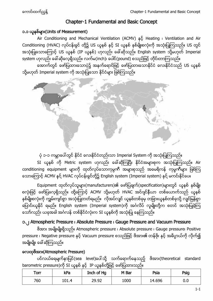
၁-၁ Imperial System
SI Metric system Air conditioning equipment ACMV ႔ HVAC ႔၌ English system (Imperial system) ႔
Equipment (manufacturers)၏ (specification) ႔ ACMV ႔ HVAC ႔ English system (Imperial system) ႔ SI
၁.၂ Atmospheric Pressure ၊ Absolute Pressure ၊ Gauge Pressure and Vacuum Pressure Atmospheric pressure ၊ Absolute pressure ၊ Gauge pressure၊ Positive
pressure ၊ Negative pressure Vacuum pressure ၏
(Atmospheric Pressure) (sea level ႔ (theoretical standard barometric pressure) SI IP ႔
Torr kPa Inch of Hg M Bar Psia Psig
760 101.4 29.92 1000 14.696 0.0
Air Conditioning and Mechanical Ventilation (Vol. 1) ႔
1-2
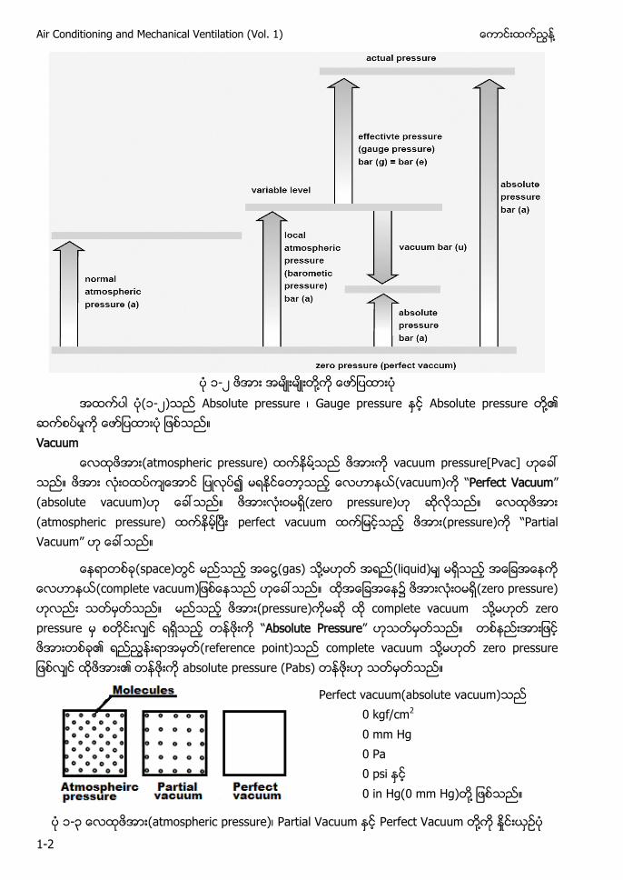
၁-၂ ႔
(၁-၂) Absolute pressure ၊ Gauge pressure Absolute pressure ႔၏ Vacuum
(atmospheric pressure) ႔ vacuum pressure[Pvac] (vacuum) “Perfect Vacuum” (absolute vacuum) (zero pressure) (atmospheric pressure) perfect vacuum (pressure) “Partial Vacuum”
(space) ႔(gas) ႔ (liquid) c m acuum (zero pressure) (pressure) complete vacuum ႔ zero pressure “Absolute Pressure” ၏ (reference point) complete vacuum ႔ r r ur ၏ absolute pressure (Pabs)
Perfect vacuum(absolute vacuum) 0 kgf/cm2 0 mm Hg 0 Pa 0 psi 0 in Hg(0 mm Hg) ႔
၁-၃ (atmospheric pressure)၊ Partial Vacuum Perfect Vacuum ႔
႔ Chapter-1 Fundamental and Basic Concept
1-3
(sea level)၌ (atmospheric pressure)
(Patm) Pabs ႔ Patm Patm Pabs 14.7 psi ႔ Patm a u 14.7 psia
(instrument) fluid ၏ ႔ (atmospheric pressure) ႔ (atmospheric pressure) “Gauge Pr ur ” Pg Absolute pressure ၊ atmospheric pressure gauge pressure ႔၏
Gauge pressure gauge ႔ rum
Absolute pressure gauge pressure atmospheric pressure ႔
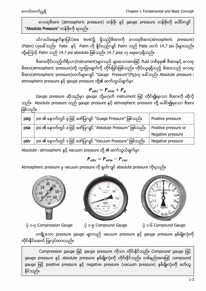
psig psi ၏ g “Guag Pr ur ” Positive pressure
psia psi ၏ a “ u Pr ur ” Positive pressure or Negative pressure
psiv psi ၏ v “Vacuum Pr ur ” Negative pressure
Absolute ၊ atmospheric vacuum pressure ႔ ၏
Atmospheric pressure vacuum pressure absolute pressure
၁-၄ Compression Gauge ၁-၅ Compound Gauge ၁-၆ Compound Gauge
pressure gauge vacuum pressure gauge pressure
(atmospheric pressure) gauge pressure “Absolute Pressure”
m r gaug gauge pressure m u gaug gauge pressure absolute pressure c m u gaug positive pressure negative pressure (vacuum pressure)
Air Conditioning and Mechanical Ventilation (Vol. 1) ႔
1-4
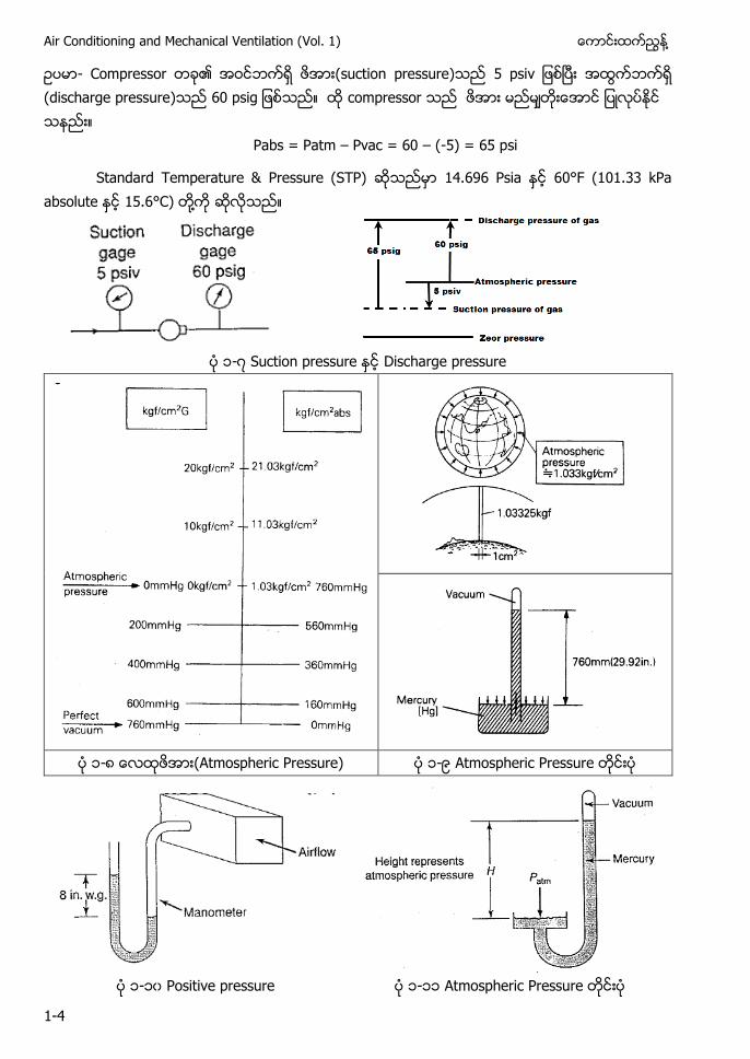
- Compressor ၏ (suction pressure) (discharge pressure) g compressor
Pabs = Patm – Pvac = 60 – (-5) = 65 psi
Standard Temperature & Pressure (STP) 14.696 Psia 60°F (101.33 kPa absolute 15.6°C) ႔
၁-၇ Suction pressure Discharge pressure
၁-၈ (Atmospheric Pressure) ၁-၉ Atmospheric Pressure
၁-၁၀ Positive pressure ၁-၁၁ Atmospheric Pressure
႔ Chapter-1 Fundamental and Basic Concept
1-5
၁.၂.၁ Pressure of Liquid Column ႔ Head ACMV (pressure) (liquid) ၏ ႔
(liquid) (water) (mercury) ႔ ACMV equipment fan ႔ pump “Head”
(technical term) Head ၏ (height of liquid column) (pressure) a ၏
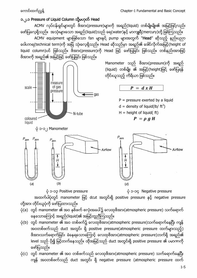
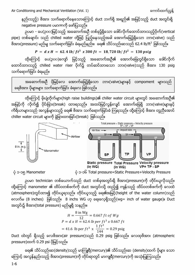
Manometer (pressure) (liquid) ၏ g ႔
P = pressure exerted by a liquid d = density of liquid(lb/ ft3) H = height of liquid( ft)
၁-၁၂ Manometer
၁-၁၃ Positive pressure ၁-၁၄ Negative pressure
ma m r dcut positive pressure negative pressure ႔ (a) manometer ၏ ၌ (atmospheric pressure)
(liquid)၏ (b) manometer ၏ ၌ (atmospheric pressure)
duct positive pressure(atmospheric pressure ) (atmospheric pressure) ၏ level duct positive pressure ၏
(c) manometer ၏ (atmospheric pressure) duct negative pressure (atmospheric pressure
Air Conditioning and Mechanical Ventilation (Vol. 1) ႔
1-6
) duct ၏ duct negative pressure
- (၃၀၀ ၌ (vertical pipe) chilled water ႔ (valve) (pressure) ၏ 62.4 lb/ft3
(၃၀၀ ၏ chilled water riser ၌ (valve) 130 psig
(high raise buildings)၏ chiller water circuit ၏
(break) (valve) ၏ ႔ chiller water circuit (break)
၁-၁၅ Manometer ၁-၁၆ Total pressure=Static Pressure+Velocity Pressure
technician duct (pressure) ႔ manometer ၏ duct ႔ (atmosphere) ၏ (height of the water column) ၈ (8 inches) 8 inchs WG (wg= inch of water gauge) Duct (total pressure)
Duct (air pressure) g (atmospheric pressure) 0.29 psi
၏ (density) (mercury)၏ (density) (pressure) (mercury)
၌ (valve) compoment
႔ Chapter-1 Fundamental and Basic Concept
1-7
႔ (low pressure) manometer (density) mercury(Hg)
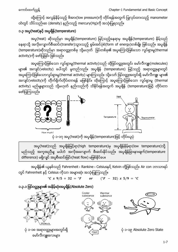
၁.၃ (heat) (temperature)
(heat) (temperature) ႔ (temperature) ႔ ႔ (transfer) (form of energy) (temperature) တ ႔ ၏ (thermal activity)
(thermal activity) (molecules) ၏ (velocity) m ra ur တ (thermal activity) ႔ ၏ (velocity) (thermal activity) ႔ m ra ur
၁-၁၇ (heat) m ra ur
၏ Fahrenheit ၊ Rankine ၊ Celsius ႔ Kelvin ႔ Air con
Fahrenheit Celsius
၁.၃.၁ ၏ (Absolute Zero)
၁-၁၈ တ မားအတြငးရ ေမာလကးေလးမား
၁-၁၉ Absolute Zero State
(heat) (high temperature) (low temperature) ႔ (temperature difference) (heat flow)
Air Conditioning and Mechanical Ventilation (Vol. 1) ႔
1-8
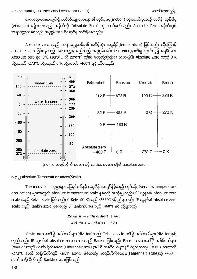
တ မားအတြငးရ ေမာလကးေလးမား၏ လႈပရားမႈ(motion) လးဝ ၊ (vibration) “Absolute Zero” Absolute Zero တ သည
Absolute zero တ ၏ m ra ur ႔ a u r တ မ မညသည အပစြမးအင(heat energy) ၍ Absolute zero 0°C (zero°C ႔ zero°F) ႔ Absolute Zero 0 K ႔ -273°C ႔ 0°R ႔ -460°F
၁-၂၀ celsius ႔၏ absolute zero
၁.၃.၂ Absolute Temperature (Scale)
Thermodynamic ၧာမား ေျဖရငးရနႏင အပခန အလြနနမသည လပငနး (very low temperature application) မားအ absolute temperature scale SI ၏ absolute zero scale ca 0 Kelvin(0 K) -273°C IP ၏ absolute zero scale Rankin ca 0°Rankin(0°R) -460°F
Kelvin (division) Celsius ca (division) IP ၏ absolute zero scale a Rankin ေပၚရ (division) ( a r ca Celsius -273°C ႔ Kelvin (Fahrenheit scale) -460°F ႔ Rankin
႔ Chapter-1 Fundamental and Basic Concept
1-9
၁.၄ (T m ra ur (Volume “ (air)၌ ”
(volume) 0°F ၌ ၏ (fr c
100°F (volume) 0°F 0°F 1°F 0°F 1/460 ( (၄၆၀) (၁) ) -100°F ၏ 0°F 21.7%(100/460) ( ) -100°F ၏ 0°F ၏ (100-21.7=78.3) 78.3%
-460°F ႔ -460°F ႔ (liquid) ႔
တ (substance) -460°F ႔ -460°F absolute zero temperature -460°F (reference) “Absolute Temperature” ႔ 100°F ၏ absolute temperature 100°F +460 = 560°R 20°F ၏ absolute temperature 20°F + 460 = 480°R
Absolute temperature ၏ (concept) ၏ air con (theory)
(constant pressure) (volume) (temperature) ႔
V1 = Initial volume of air T1 = Initial absolute temperature
V2 = Final volume of air T2 = Final absolute temperature
- 45°F (volume) 2100 ft3 125°F ႔ (volume)
(volume) ၏ (temperature) u r c a r ur (definite ra ႔ (expansion) ႔ (contraction)

Air Conditioning and Mechanical Ventilation (Vol. 1) ႔
1-10
Initial absolute temperature = 460 + 45°F = 505°R Final absolute temperature = 460 + 125°F = 585°R
= 2100 x 585 / 505 = 2432.7 ft3 volume @ 125°F - 110°F (volume) 1500 ft3 70°F ႔ (volume)
Initial absolute temperature = 460 + 110°F = 570 Final absolute temperature = 460 + 70°F = 530
= 1500 x 530 / 570 = 1395 ft3 volume @ 70°F - 100°F ၏ (volume) 20°F ၏
= 1.167 or 16.7% Larger (၁၆.၇% ) V2/V1 = T2/T1 ၏ ႔
(volume) (formula ႔ reference point reference point Standard Air
V2/V1 = T2/T1 T1 = 70°F, V1 = 13.34 ft3 V2 = V1 T2/T1 T1 = 70 + 460 = 530°F
V2 = 13.34 x T2 / 530
T2 V2 V2 T2 ႔ (pressure) 14.7 psia ၏ (volume) (temperature)၏ V (IP )
- 120(lb) 90°F 14.7 psia (volume)
= 550/39.7 = 13.85 ft3 volume @ 90°F = 13.85 ft3/lb
(၁၂၀) = 120 lb x 13.85 ft3/lb = 1662 ft3
“Standard Air Condition” ႔ (dry air) 70°F a 13.34 ft3
႔ Chapter-1 Fundamental and Basic Concept
1-11
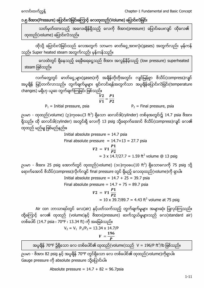
၁.၅ (Pressure) (Volume)
႔ (gases) Super heated steam
႔ (gases) (compress)
(temperature changes)
P1 = Initial pressure, psia P2 = Final pressure, psia
- (volume) (၃) (3 ft3) (cylinder) ၌ 14.7 psia (cylinder) 13 psig ႔ (compress) ၏
Initial absolute pressure = 14.7 psia Final absolute pressure = 14.7+13 = 27.7 psia
= 3 x 14.7/27.7 = 1.59 ft3 volume @ 13 psig
- g (volume) (၁၀) (10 ft3) 75 psig ႔ (compress) final pressure (volume)
Initial absolute pressure = 14.7 + 25 = 39.7 psia Final absolute pressure = 14.7 + 75 = 89.7 psia
= 10 x 39.7/89.7 = 4.43 ft3 volume at 75 psig
Air con (air) ႔ ၏ (volume) (pressure) (standard air) (14.7 psia ၊ 70°F ၊ 13.34 ft)
V2 = V1 P1/P2 = 13.34 x 14.7/P
- 82 psig 70°F ၏ (volume) Gauge pressure absolute pressure ႔
Absolute pressure = 14.7 + 82 = 96.7psia
(pressure) ၏ (volume)
႔ (low pressure) su r a am
70°F ၌ ၏ (volume) V = 196/P ft3
Air Conditioning and Mechanical Ventilation (Vol. 1) ႔
1-12
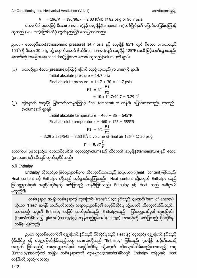
V = 196/P = 196/96.7 = 2.03 ft3/lb @ 82 psig or 96.7 psia (pressure) (temperature)
(volume - (atmospheric pressure) 14.7 psia 85°F 10ft3 30 psig ႔ (compress) 125°F (condition) ၏ (volume) (၁) r ur (volume)
Initial absolute pressure = 14.7 psia Final absolute pressure = 14.7 + 30 = 44.7 psia
= 10 x 14.7/44.7 = 3.29 ft3 (၂) ႔ final temperature
(volume) Initial absolute temperature = 460 + 85 = 545°R Final absolute temperature = 460 + 125 = 585°R
= 3.29 x 585/545 = 3.53 ft3/lb volume @ final air 125°F @ 30 psig
၏ (volume) ၏ (temperature) (pressure)
၁.၆ Enthalpy Enthalpy a c
Heat content Enthalpy ႔ Heat content ႔ Enthalpy ၏ Enthalpy Heat
၏ Heat
႔ “Enthalpy” ( ႔ ) ၏ ႔ (Enthalpy) ႔ (transfer) Enthalpy Heat ႔
႔ (transfer) (form of energy) “ a ” တ ၏ ႔ Enthalpy Enthalpy ၏ (transfer) (energy) (energy)
႔ Chapter-1 Fundamental and Basic Concept
1-13
႔ ႔ (transfer) (heat) Enthalpy ( ) (transfer) ( ႔၏ ႔ ႔ )
(temperature)၊ (heat) Enthalpy ႔
(temperature) ၏ thermal level ႔ thermal intensity rma
(high temperature body) (Enthalpy) Enthalpy (transfer) “ eat” a ra r ( ) ႔ (amount of heat) (mass)
Definition - heat is defined as the form of energy that is transferred between two systems by virtue of temperature difference.
System rg system ႔ (Ein) system (Eout )
Ech = change in stored energy in the system Ein = energy added to (entering) the system Eout = energy removed (leaving) the system
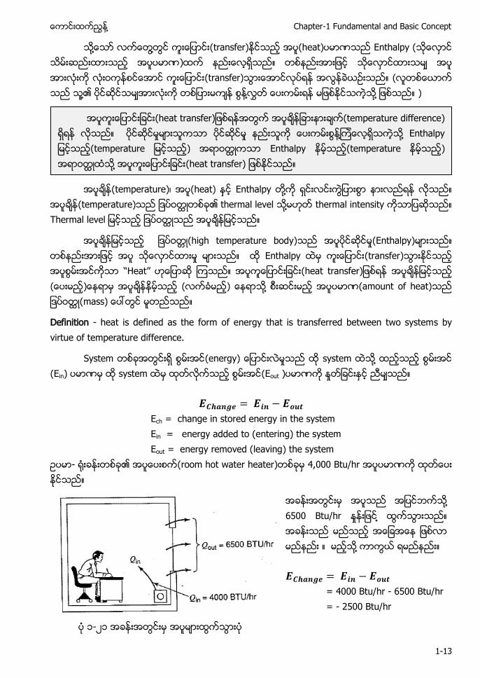
- ၏ (room hot water heater) 4,000 Btu/hr
႔ 6500 Btu/hr ႔ ႔ = 4000 Btu/hr - 6500 Btu/hr = - 2500 Btu/hr
၁-၂၁
a ra r (temperature difference) ႔ ႔ a m ra ur ) Enthalpy (temperature ) ႔ (heat transfer)
Air Conditioning and Mechanical Ventilation (Vol. 1) ႔
1-14
(heater)
(heat) a ၏ ႔ ႔ insulate ႔ 25,000 Btu/hr (electric heater)
Air con ႔၏ (nature)
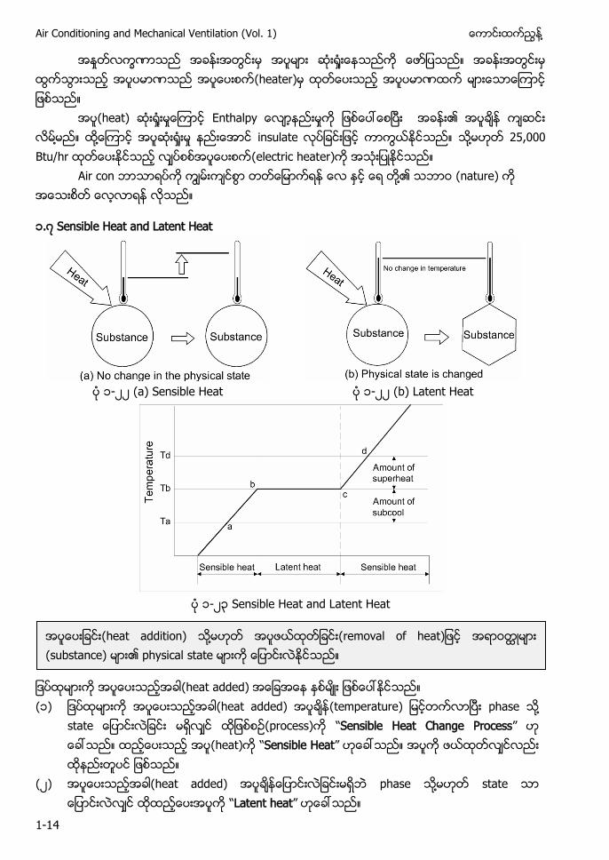
၁.၇ Sensible Heat and Latent Heat
၁-၂၂ (a) Sensible Heat ၁-၂၂ (b) Latent Heat
၁-၂၃ Sensible Heat and Latent Heat
(heat added) (၁) (heat added) m ra ur phase ႔
a (process) “Sensible Heat Change Process” (heat) “Sensible Heat”
(၂) (heat added) phase ႔ state “Latent heat”
(heat addition) ႔ r m a a (substance) ၏ physical state
႔ Chapter-1 Fundamental and Basic Concept
1-15
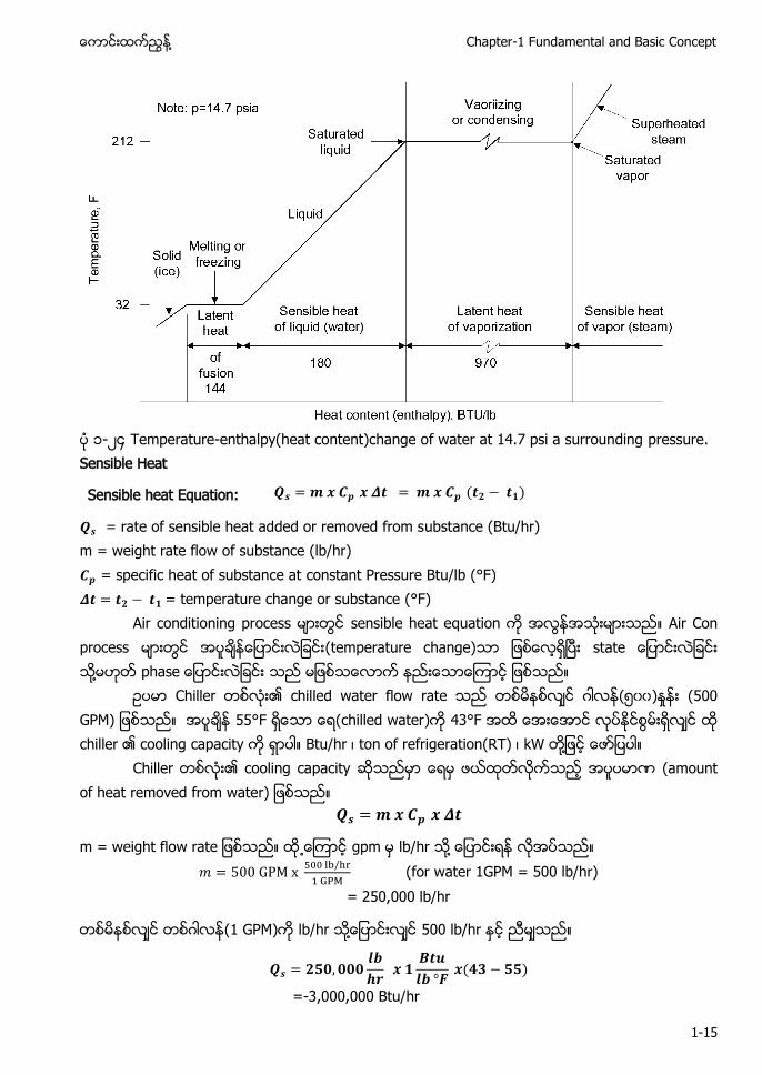
၁-၂၄ Temperature-enthalpy(heat content)change of water at 14.7 psi a surrounding pressure. Sensible Heat
Sensible heat Equation:
= rate of sensible heat added or removed from substance (Btu/hr) m = weight rate flow of substance (lb/hr) = specific heat of substance at constant Pressure Btu/lb (°F) = temperature change or substance (°F)
Air conditioning process sensible heat equation Air Con process (temperature change) a ႔ a
Chiller ၏ chilled water flow rate (၅၀၀) (500 GPM) 55°F (chilled water) 43°F chiller ၏ cooling capacity Btu/hr ၊ ton of refrigeration(RT) ၊ kW ႔
Chiller ၏ cooling capacity (amount of heat removed from water)
m g ra gpm lb/hr ႔
(for water 1GPM = 500 lb/hr) = 250,000 lb/hr
(1 GPM) lb/hr ႔ 500 lb/hr
=-3,000,000 Btu/hr
Air Conditioning and Mechanical Ventilation (Vol. 1) ႔
1-16
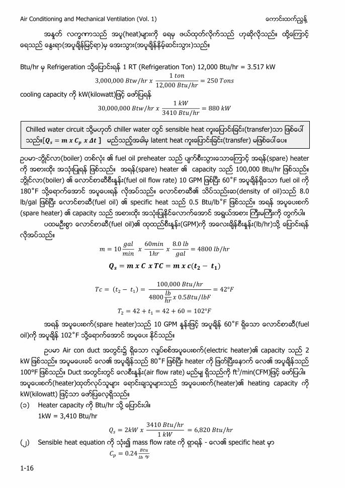
(heat) ႔ ( ) ( ) Btu/hr Refrigeration ႔ 1 RT (Refrigeration Ton) 12,000 Btu/hr = 3.517 kW
cooling capacity a
- (boiler) ၏ fuel oil preheater (spare) heater (spare) heater ၏ capacity u r (boiler) ၏ (fuel oil flow rate) 10 GP ˚ fuel oil 180˚ ႔ ၏ (density of oil) ga (fuel oil) ၏ specific heat 0.5 Btu/lb˚ (spare heater) ၏ capacity
(fuel oil)၏ (GPM) (lb/hr) ႔
(spare heater) 10 GPM ˚ (fuel oil) ˚ ႔
Air con duct (electric heater)၏ capacity ၏ ˚ heater ၏ Duct (air flow rate) ft3 m (heater) (heater)၏ heating capacity kW(kilowatt) (၁) Heater capacity Btu/hr ႔
1kW = 3,410 Btu/hr
(၂) Sensible heat equation mass flow rate - ၏ specific heat
Chilled water circuit ႔ chiller water sensible heat (transfer) [ ] latent heat (transfer)
႔ Chapter-1 Fundamental and Basic Concept
1-17
(၃) CFM ႔
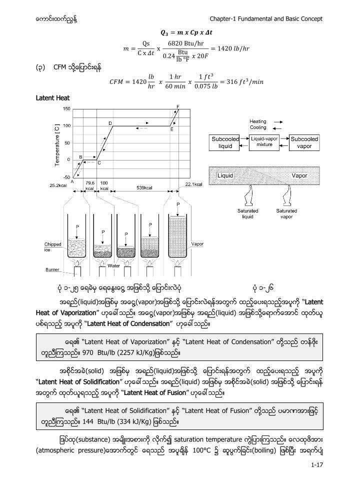
Latent Heat
၁-၂၅ ႔ ႔ ၁-၂၆
(liquid) ႔(vapor) ႔ “Latent Heat of Vaporization” ႔(vapor) (liquid) ႔ “Latent Heat of Condensation”
(solid) (liquid) ႔
“Latent Heat of Solidification” (liquid) (solid) ႔ “Latent Heat of Fusion”
(substance) saturation temperature
a m r c r ur 100°C (boiling)
၏ “La a Va r a ” “La a a ” ႔ 970 Btu/lb g
၏ “La a Solidification” “La a u ” ႔ 144 Btu/lb g
Air Conditioning and Mechanical Ventilation (Vol. 1) ႔
1-18
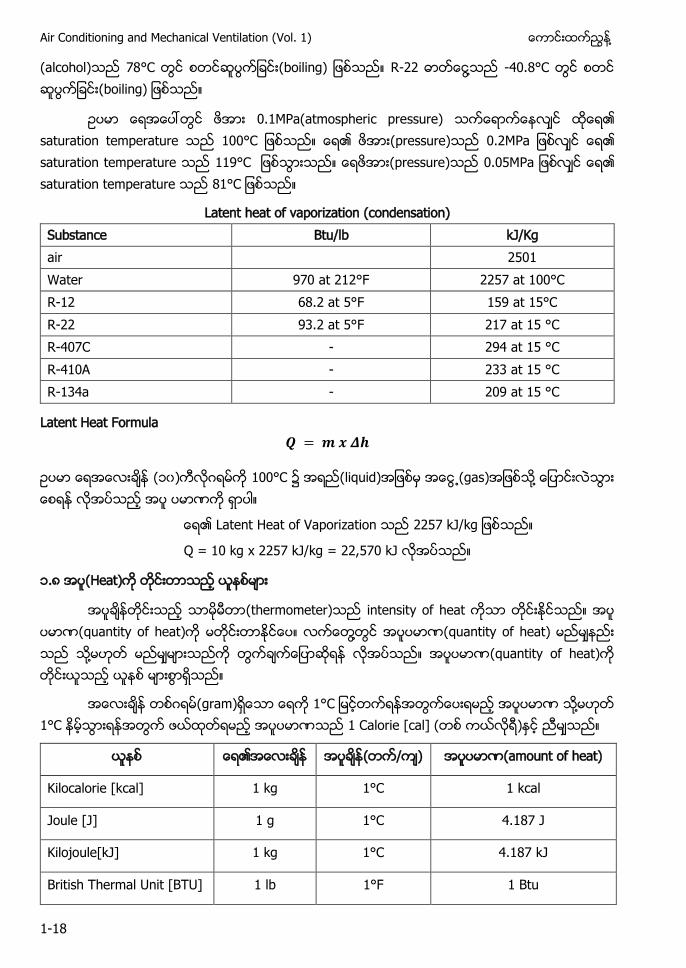
(alcohol) 78°C g R-22 ႔ -40.8°C g
အေပၚတြင ဖအား 0.1MPa(atmospheric pressure) ၏ saturation temperature ၏ (pressure) Pa ၏ saturation temperature ဖအား(pressure) Pa ၏ saturation temperature
Latent heat of vaporization (condensation) Substance Btu/lb kJ/Kg air 2501 Water 970 at 212°F 2257 at 100°C R-12 68.2 at 5°F 159 at 15°C R-22 93.2 at 5°F 217 at 15 °C R-407C - 294 at 15 °C R-410A - 233 at 15 °C R-134a - 209 at 15 °C
Latent Heat Formula
(၁၀) 100°C ၌ (liquid) (gas) ႔
၏ Latent Heat of Vaporization g
Q = 10 kg x 2257 kJ/kg = 22,570 kJ
၁.၈ (Heat)
(thermometer) intensity of heat (quantity of heat) ႔ (quantity of heat) ႔ (quantity of heat)
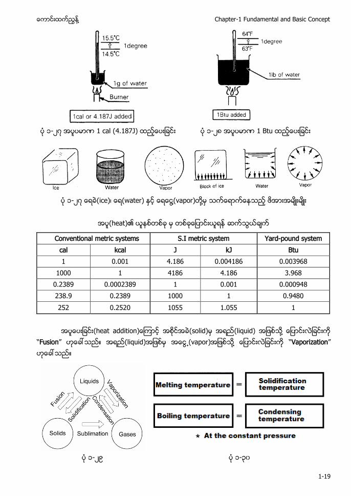
(gram) 1° ႔ 1°C 1 Calorie [cal] ( )
၏ ( / ) (amount of heat)
Kilocalorie [kcal] 1 kg 1°C 1 kcal
Joule [J] 1 g 1°C 4.187 J
Kilojoule[kJ] 1 kg 1°C 4.187 kJ
British Thermal Unit [BTU] 1 lb 1°F 1 Btu
႔ Chapter-1 Fundamental and Basic Concept
1-19
၁-၂၇ 1 cal (4.187J) ၁-၂၈ 1 Btu
၁-၂၇ (ice)၊ (water) ႔(vapor) ႔
(heat)၏
Conventional metric systems S.I metric system Yard-pound system cal kcal J kJ Btu 1 0.001 4.186 0.004186 0.003968
1000 1 4186 4.186 3.968 0.2389 0.0002389 1 0.001 0.000948 238.9 0.2389 1000 1 0.9480 252 0.2520 1055 1.055 1
a a (solid) (liquid) ႔
“Fusion” (liquid) (vapor) ႔ “Vaporization”
၁-၂၉ ၁-၃၀
Air Conditioning and Mechanical Ventilation (Vol. 1) ႔
1-20
(solid) (vapor) ႔ ( ႔ ) “Sublimation” a r m a (vapor) (liquid) ႔ “Condensation” (liquid) (solid) ႔ “Solidification”
၁.၉ ၏ (Phase Change of Water)
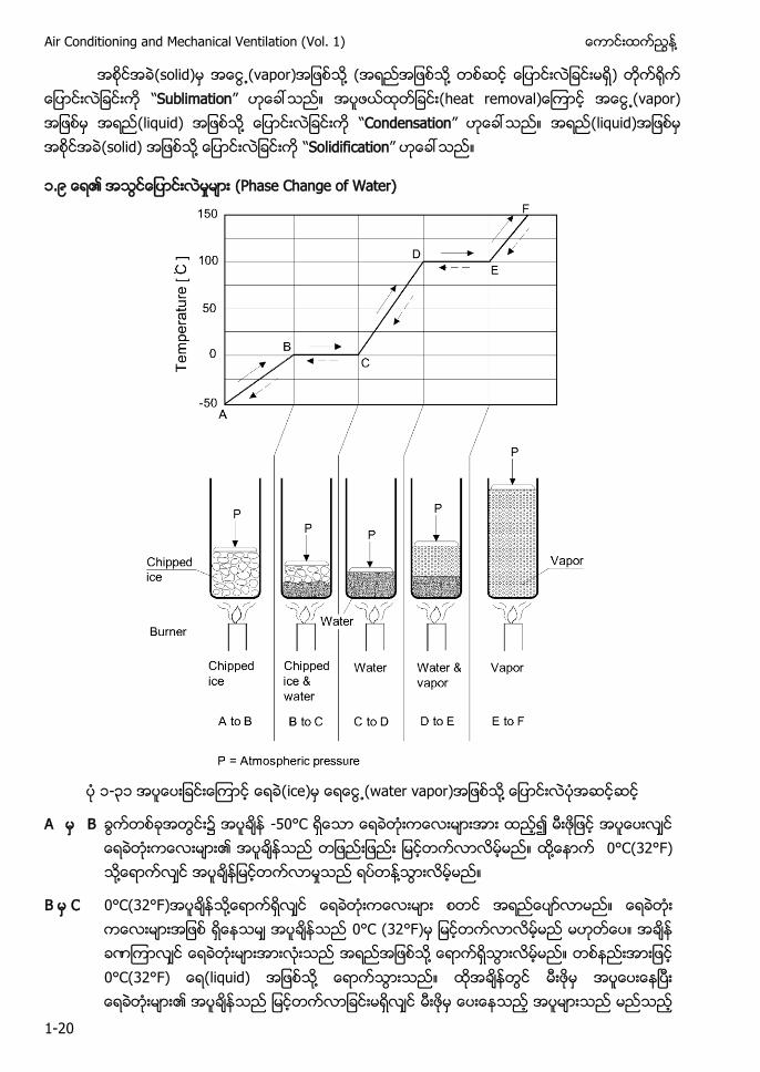
၁-၃၁ (ice) (water vapor) ႔
A B
-50°C ၍ ၏ ႔ 0°C(32°F) ႔ ႔
B C 0°C(32°F) ႔ 0°C (32°F) ႔ 0°C(32° (liquid) ႔ ၏
႔ Chapter-1 Fundamental and Basic Concept
1-21
႔ 0°C(32° (ice) 0°C(32° (liquid) ႔ a ႔
C D 0°C(32°F) 100°C(212°F) ႔
D E 100°C(212°F) ႔ 100°C(vapor) ႔ (water) 100° ႔
E F saturated vapor 100°C(212° ႔(vapor) Saturated vapor “Superheat Temperature”
၁.၁၀ (Melting Temperature)
(solid) (liquid) ႔ (melting temperature) ႔ (melting point) (atmospheric pressure) (water)၏ (melting point) 0°C (32°F)
၁.၁၁ (Boiling Point) (liquid) (vapor) ႔
(boiling temperature) ႔ (boiling point) ႔ evaporation temperature ႔ vaporization temperature ႔ saturation temperature (atmospheric pressure) ၏ (boiling point) 100°C(212° (heat adding)
၁.၁၂ Condensation Temperature
(vapor) (liquid) ႔ condensing temperature ႔ saturation temperature ၏ condensation temperature 100°C (212°
၁.၁၃ Solidification Temperature
(solid) ႔ “Solidification Temperature” ၏ solidification temperature 0°C (32°F) (heat removal)
(boiling point) (melting point) ႔ (atmospheric pressure) (water)၏ (boiling point) ၍ ေျပာငးလေနသည။
Air Conditioning and Mechanical Ventilation (Vol. 1) ႔
1-22
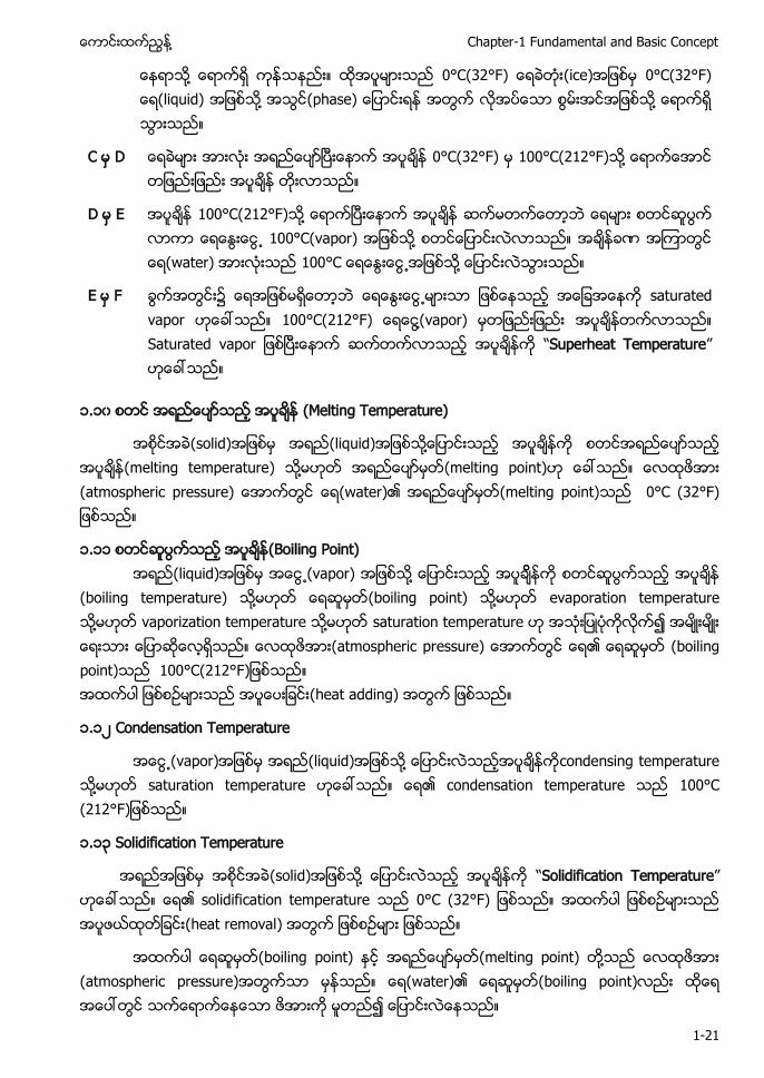
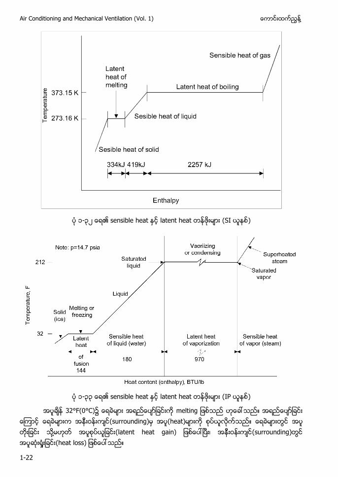
၁-၃၂ ၏ sensible heat latent heat (SI )
၁-၃၃ ၏ sensible heat latent heat (IP )
32°F(0°C)၌ m g (surrounding) (heat) ႔ (latent heat gain) ၊ (surrounding) (heat loss)
႔ Chapter-1 Fundamental and Basic Concept
1-23
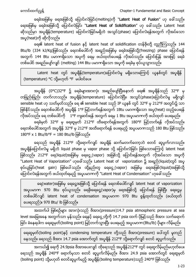
႔ (melting) “Latent Heat of Fusion” ႔ “Latent Heat of Solidification” Latent heat m ra ur (phase) (heat)
၏ latent heat of fusion latent heat of solidification ႔ 144 Btu/lb g ႔(freezing) a 144 Btu (melting) 144 Btu
(0°C)32°F ၏ 32°F
(temperature) ၊ (phase sensible heat ၏ sensible heat IP 32°F 212°F ၌ 1° 1Btu (heat) 1°F 1 Btu
32°F 212°F 180° 32°F 212°F u 180°F x 1 Btu/lb°F = 180 Btu/lb
212°F ႔ liquid phase vapor phase ႔ a a 212° (liquid) (vapor) ႔ “Latent Heat of Vaporization” Latent heat of vaporization (liquid) (heat gain) ႔ (vapor) (liquid) ႔ “Latent Heat of Condensation”
(pressure)14.7 psia atmospheric pressure at sea
level ႔ 14.7 psia g (Btu/lb)
၍ 24.9psia 212°F
240° a (boiling point) ႔ (boiling temperature) 240°
Latent heat m ra ur (temperature) °C ႔ °F
(water) ႔ ႔ latent heat of vaporization 970 Btu ႔(vapor) ႔ ႔ latent heat of condensation 970 Btu ႔ ( ) u
(boiling point) condensing temperature ႔ (pressure) a 212°F ႔
Air Conditioning and Mechanical Ventilation (Vol. 1) ႔
1-24
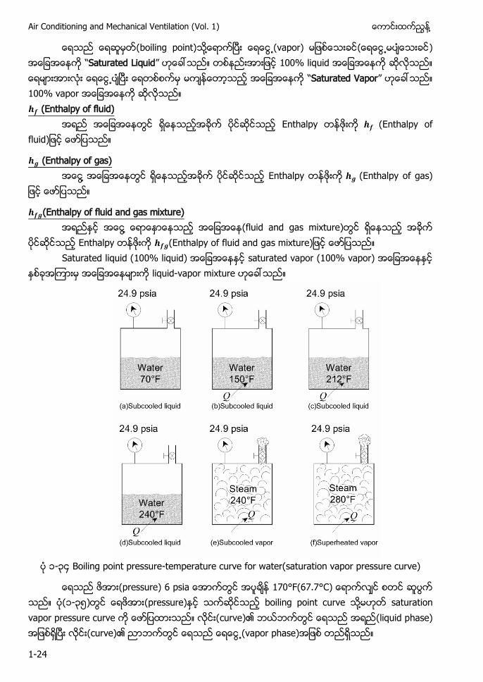
(boiling point) ႔ (vapor) ) “Saturated Liquid” 100% liquid “Saturated Vapor” 100% vapor (Enthalpy of fluid)
Enthalpy a u
(Enthalpy of gas) ႔ Enthalpy a ga
(Enthalpy of fluid and gas mixture) ႔ (fluid and gas mixture)
Enthalpy (En a u a ga m ur Saturated liquid (100% liquid) saturated vapor (100% vapor)
liquid-vapor mixture
၁-၃၄ Boiling point pressure-temperature curve for water(saturation vapor pressure curve)
r ur a 170°F(67.7° (၁-၃၅) (pressure) boiling point curve ႔ saturation vapor pressure curve (curve)၏ (liquid phase) (curve)၏ (vapor phase)
႔ Chapter-1 Fundamental and Basic Concept
1-25
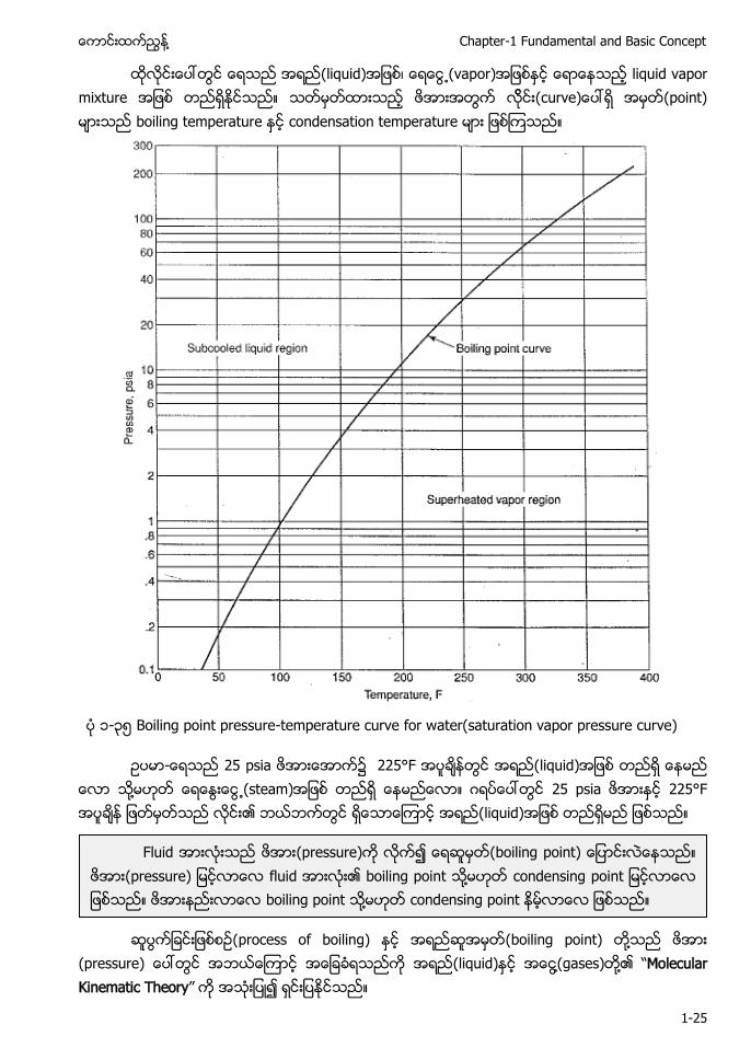
(liquid) ၊ (vapor) liquid vapor mixture cur (point) boiling temperature condensation temperature
၁-၃၅ Boiling point pressure-temperature curve for water(saturation vapor pressure curve)
- 25 psia ၌ 225°F အရည(liquid) ႔ (steam) 25 psia 225°F ၏ (liquid)
(process of boiling) (boiling point) ႔
(pressure) (liquid) ႔(gases) ႔၏ “Molecular Kinematic Theory” ၍
Fluid (pressure) ၍ g (pressure) fluid ၏ boiling point ႔ c g boiling point ႔ condensing point
Air Conditioning and Mechanical Ventilation (Vol. 1) ႔
1-26
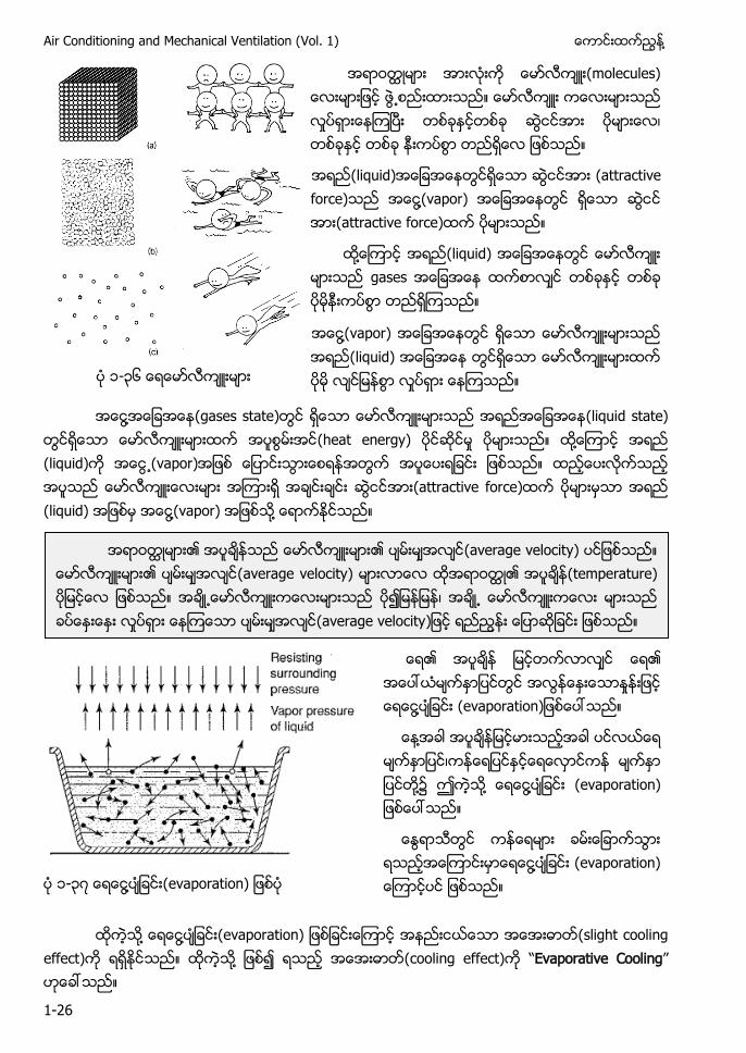
တ m cu ၊
(liquid) (attractive force) ႔(vapor) (attractive force)
႔ (liquid) gases
႔(vapor) (liquid) ၁-၃၆
႔ (gases state) (liquid state) (heat energy) ႔ (liquid) (vapor) (attractive force) (liquid) ႔(vapor) ႔
၏ ၏ ႔ a ra
႔ ၊ ႔ ဤ ႔ ႔ a ra
႔ a ra ၁-၃၇ ႔ (evaporation)
႔ ႔ a ra (slight cooling effect) ႔ (cooling effect) “Evaporative Cooling”
၏ ၏ (average velocity) ၏ (average velocity) ၏ (temperature) ၍ ၊ (average velocity
႔ Chapter-1 Fundamental and Basic Concept
1-27
႔ (evaporative cooling) -၄ (chapter-4)
14.7 psia 70°F ၏ (average velocity) (escape)
(70°C ) c (average velocity (escape)
(surrounding) (alcohol) ၍ (alcohol) ႔ (evaporate) ၌ a
(liquid)၏ (surface) (vapor) ႔ (liquid)၏ ႔ (pressure) vapor pressure ၏ u ur ac ႔ vapor pressure (surrounding pressure) ႔ (evaporation) ႔ (liquid)၏
႔ ၏ c ၏ bond (vapor) vapor pressure of liquid (surrounding pressure)
molecular bond g r c
(heat) (temperature) ၏ (velocity)
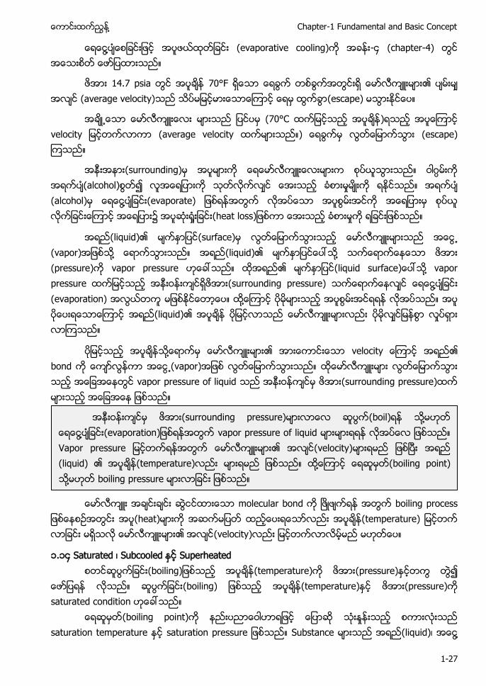
၁.၁၄ Saturated ၊ Subcooled Superheated g (temperature) (pressure) ၍
(boiling) (temperature) (pressure) saturated condition
(boiling point) saturation temperature a ura r ur Substance (liquid)၊ ႔
(surrounding pressure) (boil) ႔ ႔ (evaporation vapor pressure of liquid Va r r ur ၏ (velocity) (liquid) ၏ (temperature) ႔ (boiling point) ႔ boiling pressure
Air Conditioning and Mechanical Ventilation (Vol. 1) ႔
1-28
(vapor) ႔ (liquid-vapor mixture) saturated liquid saturated vapor ၍
Saturated vapor boiling temperature ၌ ရာႏႈနးျပညအေငြ႔(100% vapor) Saturated liquid boiling temperature ၌ ရာႏႈနးျပည (100% liquid)
(liquid)၏ (temperature) saturation temperature(condensing point)
subcooled liquid (pressure) saturation temperature subcooled temperature superheat temperature Saturation temperature phase ႔
၁.၁၅ Saturated Property Table (Steam Table)
Substance ၏ saturation temperature (corresponding pressure) (table)
၏ saturated property table saturated steam table ႔ steam table Steam table Air con saturation temperature steam table Saturation temperature corresponding pressure saturation temperature corresponding pressure Corresponding pressure saturation temperature
10 psia ၏ 10 psia corresponding pressure Steam table 10 psia saturation temperature (boiling point) 193°F 193°F
- 150 psia 300°F ႔ (liquid) ႔ (vapor)
Steam table 150 psia saturation temperature(boiling point) ႔ 150 psia 358°F ႔ 300°F 358°F subcool region (liquid)
-End-
႔ (vapor temperature) saturation temperature ႔ (boiling point) ႔(vapor) superheated vapor
႔ Chapter-2 Understanding Psychrometrics
2-1
Chapter-2 Understanding Psychrometrics
- ( ) ( ) Dry Bulb ၊ Wet Bulb ၊ Relative Humidity(RH)၊ p f u ၊ Dew ၊
Enthalpy S a a Psychrometrics (physical meaning)
(ဂ) a ဂ air property)
(ဃ) P a ဂ air property) ဂ (properties f a )
( ) Sensible heat ၊ a a a a ႔ p )
( ) mixed air) ဂ (properties)
( ) Psychrometric equation) ၊ a tota a a ႔ ႔
၂.၁ Psychrometric
American Society of Heating, Refrigerating, and Air conditioning Engineers (ASHRAE) ႔ C (temperature)၊ (humidity)၊ ႔ (cleanliness) ႔ (distribution) ႔ (treat) air conditioning p )
air con ႔ ႔
Comfort a Industrial air conditioin Comfort Air Conditioning (confortable) ႔ Industrial Air Conditioin ၊ ၊ p ႔ (air treatment) ႔ ႔ ဂ properties of air)
Psychro ဂ a p ) a u u ap instrument) ႔ Psychrometrics a - a ap ႔ a
p f a a a u a u temperature, u , a a u u f pa
Air Conditioning and Mechanical Ventilation (Vol. 1) ႔
2-2
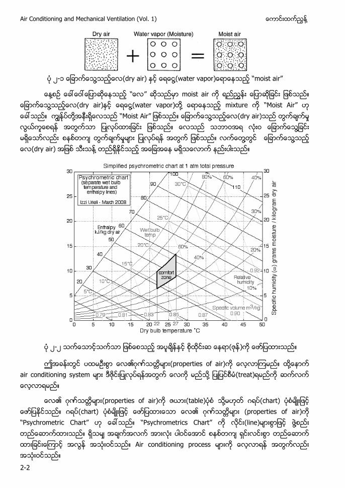
၂-၁ ႔ (dry air) ႔ a ap ) a
႔ moist air ႔ (dry air) ႔(water vapor) ႔ mixture M ႔ M ႔ (dry air) ႔ ႔ ႔ (dry air) ႔
၂-၂ ( )
ဂ (properties of air) ႔ air conditioning system ႔ (treat)
ဂ (properties of air) (table) ႔ ဂ (chart) ဂ (chart) ဂ (properties of air) Psychrometric Chart C a line) ႔ Air conditioning process
႔ Chapter-2 Understanding Psychrometrics
2-3
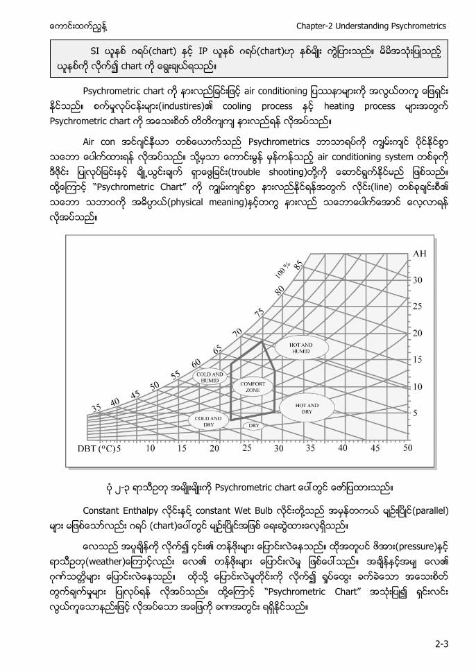
Psychrometric c a a
u ) cooling process heating process Psychrometric c a
Air con ဂ Psychrometrics ႔ air conditioning system (trouble shooting) ႔ ႔ c C a (line) (physical meaning)
၂-၃ Psychrometric c a
Constant Enthalpy ႔ constant Wet Bulb ႔ (parallel) ဂ a )
p u ) ( a ) ဂ ႔ ႔ C a
SI ဂ (chart) IP ဂ (chart) chart
Air Conditioning and Mechanical Ventilation (Vol. 1) ႔
2-4
- u p p p a a u p ႔ a - ႔
line) straight line) process curve) p process) ႔
႔
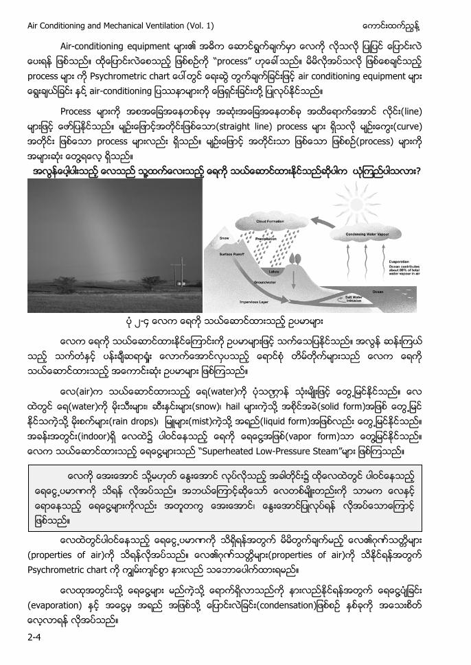
၂-
(air) (water) (water) ၊ (snow)၊ hail ႔ (solid form) ႔ (rain drops)၊ (mist) ႔ (liquid form) (indoor) ၌ ႔ (vapor form) ႔ ႔ Sup a L -Pressure Steam
ဂ (properties of air) ဂ properties of air) P a
႔ ႔ ႔ ႔ (evaporation) ႔ ႔ (condensation)
႔ ႔ ၊
႔ Chapter-2 Understanding Psychrometrics
2-5
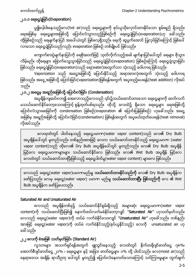
၂ ၁ ၁ ႔ (Evaporation)
(hot air) ႔ ႔ ႔ ႔ (evaporation) ႔ evaporation
႔ ႔ (evaporation) ႔ ႔ (evaporation) a )
Vaporization ႔ ႔ ႔ vaporization) a a ) ၂.၁.၂ ႔ ႔ (Condensation)
႔ ႔ ႔ ၌ ႔ ႔ c a (e ap a ) ႔ ႔ condensation) a a )
Saturated Air and Unsaturated Air
၌ ႔ (water vapor content) Saturated Air ႔(water vapor) Unsaturated Air ႔(water vapor) ( ) unsaturated air
၂.၂ (Standard Air) ဂ ႔ ၊
ဂ ႔ ၂၁ ၊ ႔ ႔ ၁ ႔ a ) ၊ ၊ ၊
႔ (water vapor content) Dry Bulb ႔ (water vapor content) Dry Bulb Dry Bulb ႔ Wet Bulb ႔ (water vapor content)
႔(water vapor) Dry Bulb ႔(water vapor) Wet Bulb
Air Conditioning and Mechanical Ventilation (Vol. 1) ႔
2-6
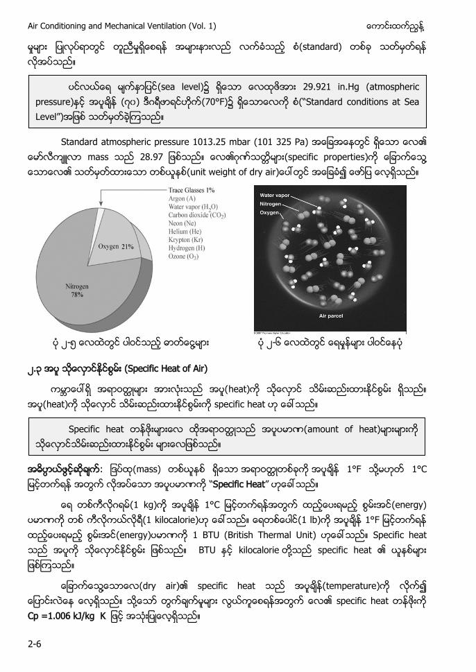
(standard)
Standard atmospheric pressure 1013.25 mbar (101 325 Pa)
mass ဂ (specific properties) ႔ (unit w f a )
၂-၅ ႔ ၂-၆
၂.၃ (Specific Heat of Air)
heat) h a ) p f a
mass) 1°F ႔ C Specific Heat
ဂ k ) 1°C (energy) kilocalorie) (1 lb) 1° energy) BTU (British Thermal Unit) Spec f a a ႔ sp f a
႔ a ) p f a p a u ) ႔ p f a Cp =1.006 kJ/kg K
(sea l ) 29.921 in.Hg (atmospheric p u ) ၀) ဂ (70°F) S a a a S a L )
Specific heat a u f a )
႔ Chapter-2 Understanding Psychrometrics
2-7
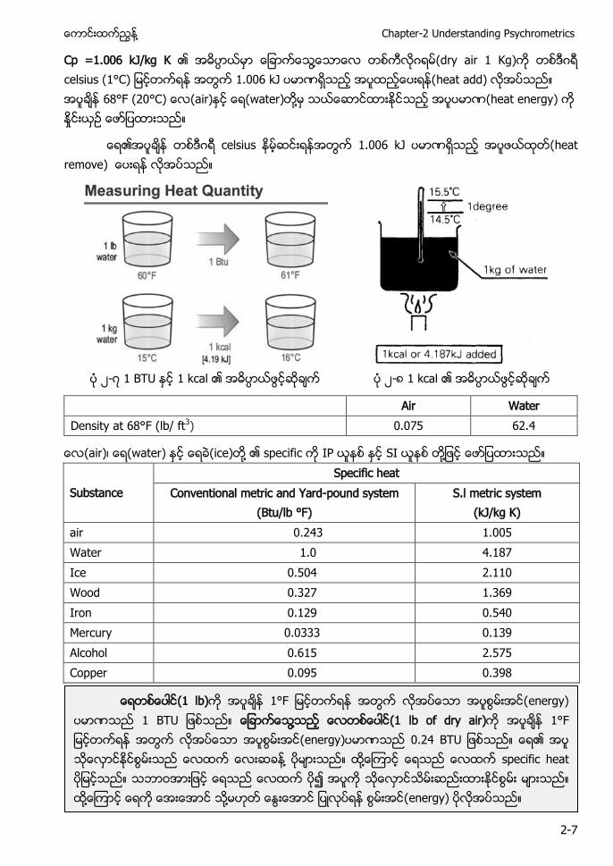
Cp =1.006 kJ/kg K ႔ ဂ (dry air ) ဂ celsius (1°C) heat add) 68°F (20°C) (air) (water) ႔ (heat energy)
ဂ celsius heat remove)
၂- 1 BTU 1 kcal ၂- 1 kcal
Air Water Density at 68°F (lb/ ft3) 0.075 62.4
(air)၊ (water) (ice) ႔ specific IP SI ႔
Substance Specific heat
Conventional metric and Yard-pound system (Btu/lb °F)
S.l metric system (kJ/kg K)
air 0.243 1.005 Water 1.0 4.187 Ice 0.504 2.110 Wood 0.327 1.369 Iron 0.129 0.540 Mercury 0.0333 0.139 Alcohol 0.615 2.575 Copper 0.095 0.398
(1 lb) 1° ) ႔ (1 lb of dry air) 1° ) ႔ ႔ specific heat ႔ ႔ )
Air Conditioning and Mechanical Ventilation (Vol. 1) ႔
2-8
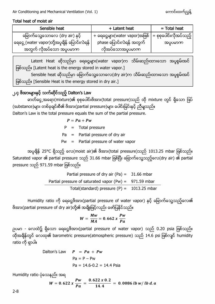
Total heat of moist air Sensible heat + Latent heat = Total heat
႔ (dry air) (water vapor) ႔
+ ႔ (water vapor) p a
=
၂. Da ’ La
(mixture) (total pressure) mixture (substance) (partial pressure) Da ’ La a p u ua u f pa a p u
P = Total pressure Pa = Partial pressure of dry air Pw = Partial pressure of water vapor
25°C (moist air) (total pressure) a Saturated vapor partial pressure a ႔ (dry air) partial pressure a
Partial pressure of dry air (Pa) = 31.66 mbar Partial pressure of saturated vapor (Pw) = 971.59 mbar Total(standard) pressure (P) = 1013.25 mbar
Humidity ratio ႔ (partial pressure of water vapor) ႔ (partial pressure of dry air) ႔
- ၌ ႔ (partial pressure of water vapor) p a barometric pressure(atmospheric pressure) p humidity ratio
Da ’ La Pa = P – Pw Pa = 14.6-0.2 = 14.4 Psia
Humidity ratio
Latent Heat ႔ (water vapor) [Latent heat is the energy stored in water vapor.]
Sensible heat ႔ (dry air) [Sensible Heat is the energy stored in dry air.]
႔ Chapter-2 Understanding Psychrometrics
2-9
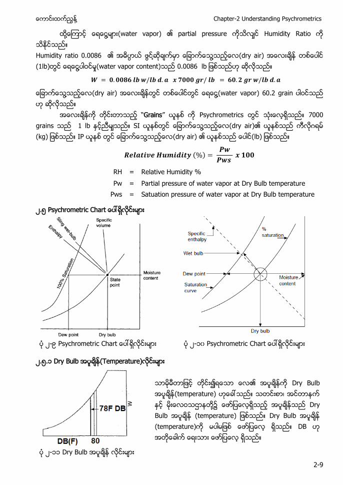
႔ ႔ (water vapor) partial pressure Humidity Ratio Humidity ratio 0.0086 ႔ ႔ (dry air) (1lb) ႔ (water vapor content)
႔ (dry air) ႔(water vapor) 60.2 grain
Grains Psychrometrics 7000 grains 1 lb SI ႔ (dry air) ဂ (kg) IP ႔ (dry air) (lb)
( )
RH = Relative Humidity % Pw = Partial pressure of water vapor at Dry Bulb temperature Pws = Satuation pressure of water vapor at Dry Bulb temperature
၂.၅ Psychrometric C a
၂-၉ Psychrometric C a ၂-၁၀ Psychrometric C a
၂.၅.၁ Dry Bulb (Temperature)
Dry Bulb temperature) ၊ ႔၌ Dry Bulb (temperature) Dry Bulb (temperature) DB
၂-၁၁ Dry Bulb
Air Conditioning and Mechanical Ventilation (Vol. 1) ႔
2-10
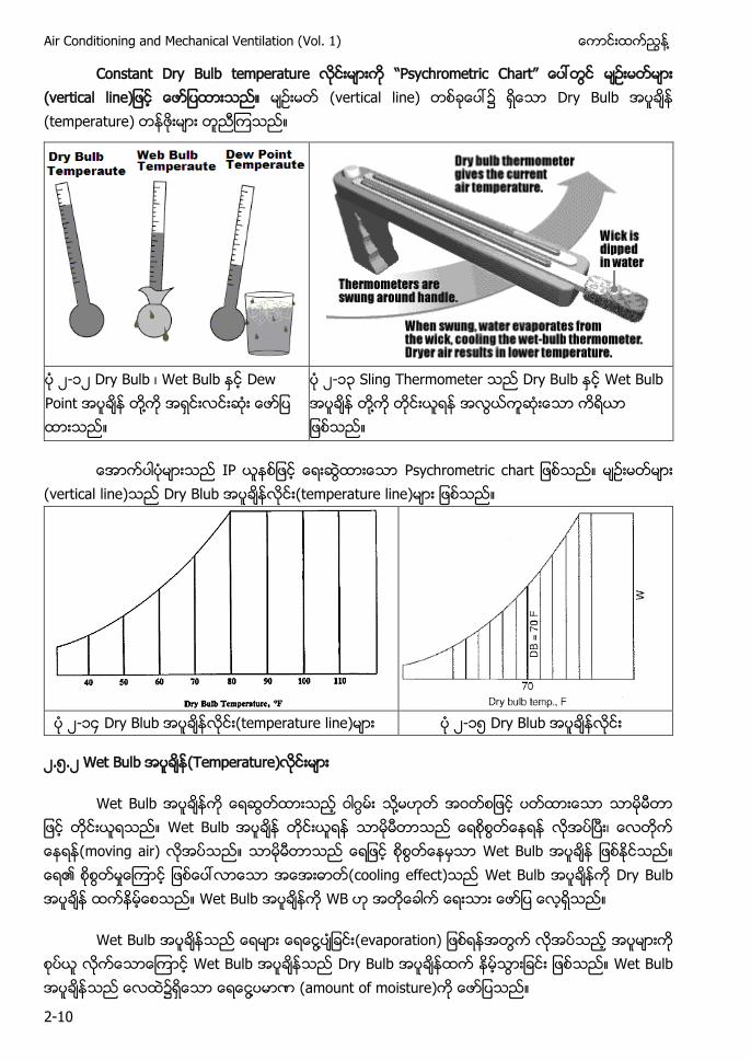
Constant Dry Bulb p a u C a (vertical l ) (vertical line) ၌ Dry Bulb (temperature)
၂-၁၂ Dry Bulb ၊ u Dew Point ႔
၂-၁၃ S Dry Bulb Wet Bulb ႔
Psychrometric c a (vertical line) Dry u (temperature line)
၂-၁ Dry u (temperature line) ၂-၁၅ Dry u
၂.၅.၂ Wet Bulb (Temperature)
Wet Bulb ဂ ႔ Wet Bulb ၊ ( a ) Wet Bulb cooling effect) Wet Bulb Dry u Wet Bulb WB
Wet Bulb ႔ (evaporation) Wet Bulb Dry Bulb Wet Bulb ႔ (amount of moisture)
႔ Chapter-2 Understanding Psychrometrics
2-11
႔ (water vapor) ( ) ႔
(evaporation) cooling effect) Dry Bulb Wet u ႔
u u
a a a a u a
၂-၁၆ Dry Bulb ၂-၁ Dry Bulb
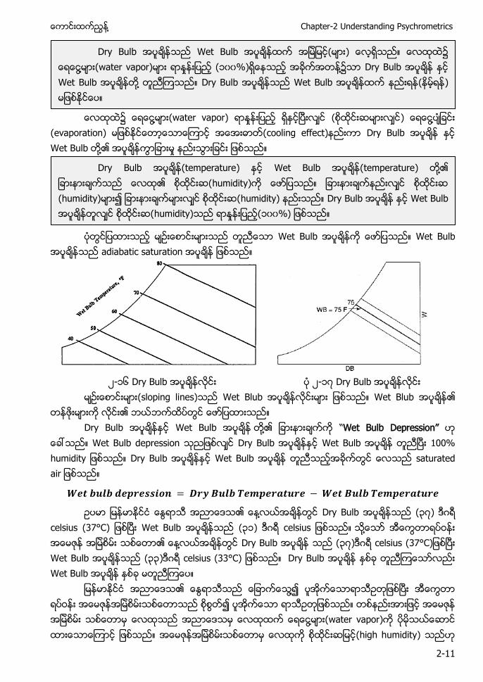
(sloping lines) W u W u
Dry Bulb u ႔ Wet Bulb Depression Wet Bulb depression Dry Bulb u u Dry Bulb u a u a a
႔ Dry Bulb ၃ ) ဂ celsius (37°C) Wet Bulb ၃၁) ဂ c u ႔ ႔ Dry Bulb ၃ ) ဂ celsius C) Wet Bulb (၃၃) ဂ celsius (33°C) Dry Bulb Wet Bulb
႔ ႔ (water vapor) (high humidity)
Dry Bulb Wet Bulb ) ႔ a ap ) ၁၀၀ ) ႔၌ Dry Bulb u ႔ Dry Bulb u )
Dry Bulb temperature) u temperature) ႔ humidity) (humidity) humidity) Dry Bulb u u ) (၁၀၀ )
Air Conditioning and Mechanical Ventilation (Vol. 1) ႔
2-12
(low humidity) ႔ ႔ energy) ႔ (water vapor)
°F P a P a
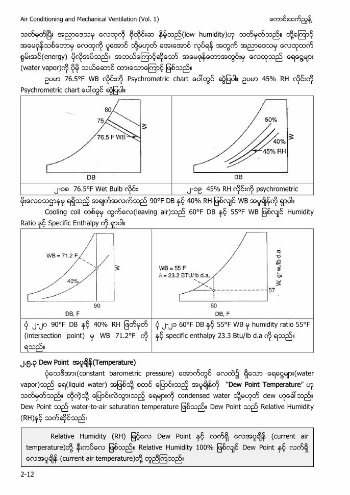
၂-၁ 76.5°F Wet Bulb ၂-၁၉ psychrometric
D WB Cooling coil leaving air) D Humidity
Ra Specific E a p
၂-၂၀ 90°F DB (intersection point) WB 71.2°F
၂-၂၁ D humidity ratio 55° specific enthalpy u a
၂.၅.၃ Dew Point (Temperature) (constant barometric pressure) ႔ (water
vapor) (liquid water) ႔ Dew Point Temperature ႔ condensed water ႔ dew Dew Point wate - -a a u a p a u Dew Point Relative Humidity (RH)
Relative Humidity ) Dew Point (current air temperature) ႔ Relative Hu Dew Point (current air temperature) ႔
႔ Chapter-2 Understanding Psychrometrics
2-13
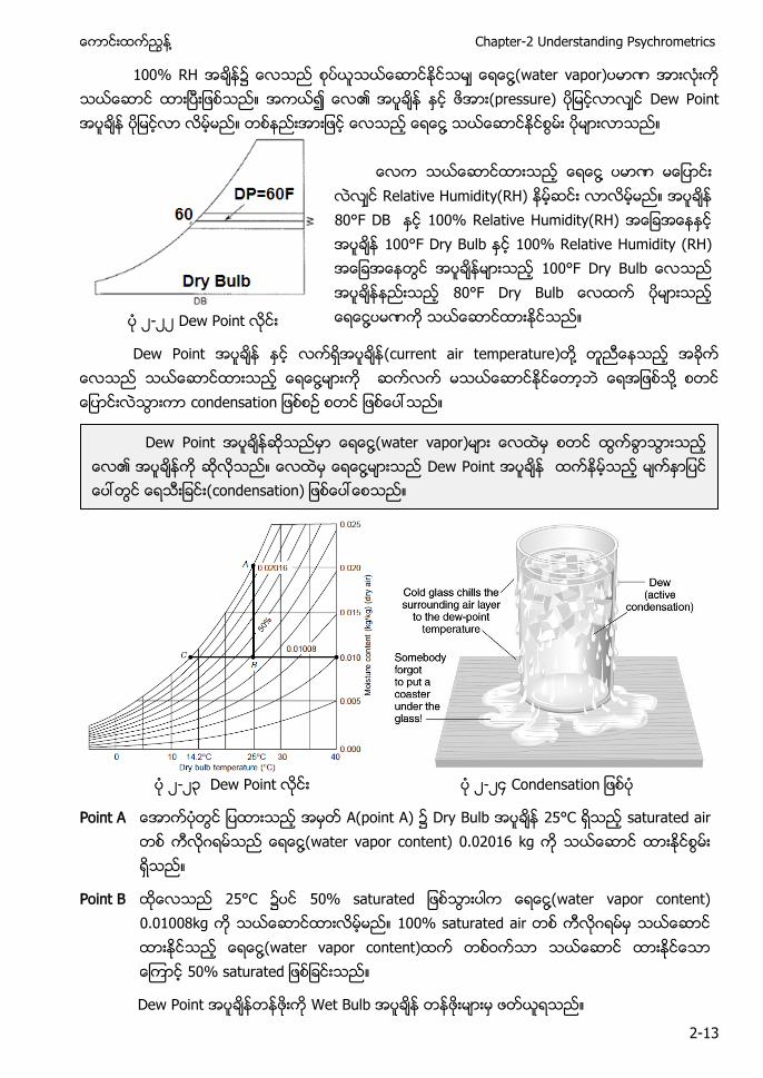
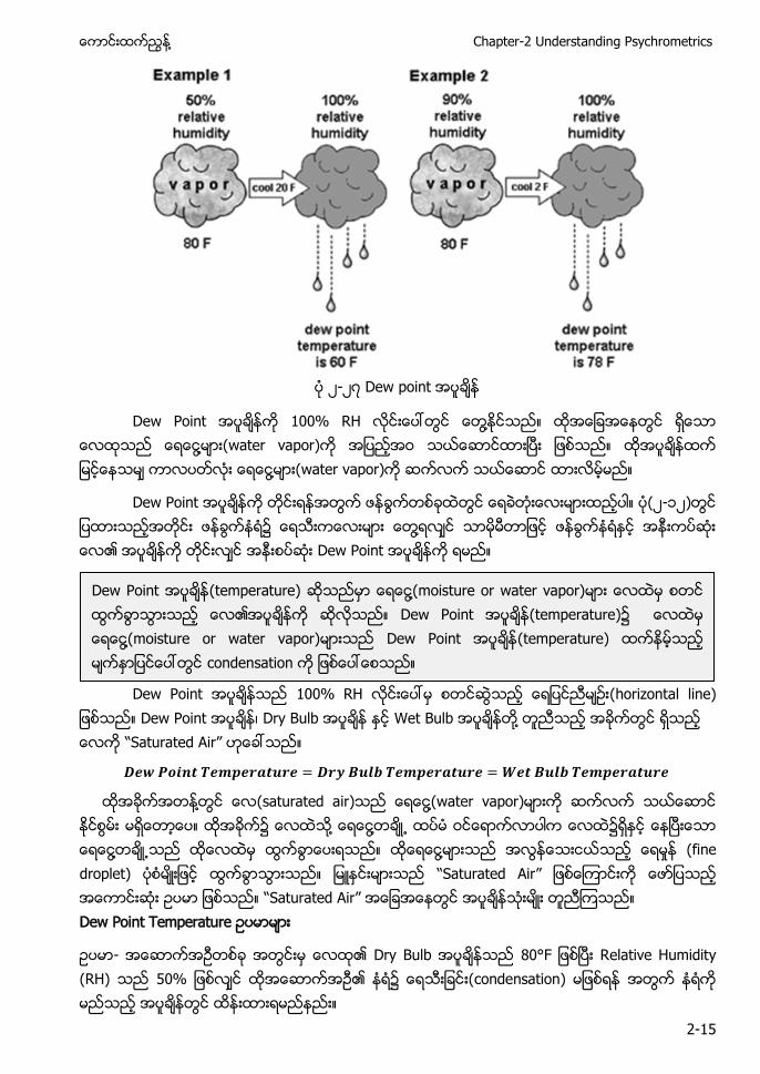
100% RH ႔(water vapor) (pressure) Dew Point ႔
႔ Relative Humidity(RH) 80°F DB 100% Relative Humidity(RH) 100°F Dry Bulb 100% Relative Humidity (RH) D u D u ႔ ၂-၂၂ Dew Point
Dew Point (current air temperature) ႔ ႔ ႔ condensation
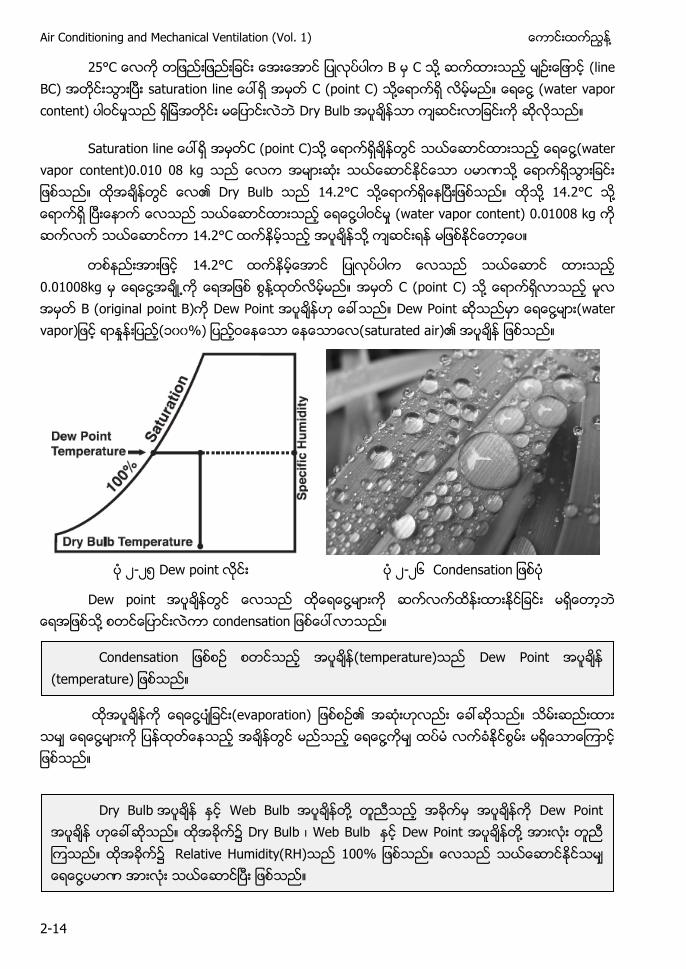
၂-၂၃ Dew Point ၂-၂ C a
Point A A(point A) ၌ Dry Bulb 25°C saturated air ဂ ႔(water vapor content) 0.02016 kg
Point B 25°C ၌ a u a ႔(water vapor content) 0.01008kg 100% saturated air ဂ ႔(water vapor content) a u a
Dew Point Wet Bulb
Dew Point ႔(water vapor) ႔ Dew Point condensation)
Air Conditioning and Mechanical Ventilation (Vol. 1) ႔
2-14
C B C ႔ (line BC) a u a C (point C) ႔ ႔ (water vapor content) Dry Bulb
Sa u a C (point C) ႔ ႔(water vapor content)0.010 08 kg ႔ Dry Bulb 14.2°C ႔ ႔ 14.2°C ႔ ႔ (water vapor content) 0.01008 kg 14.2°C ႔
14.2°C 0.01008kg ႔ ႔ C (point C) ႔ B (original point B) Dew Point Dew Point ႔ ( a ap ) ၁၀၀ ) saturated a )
၂-၂၅ Dew point ၂-၂၆ C a
Dew point ႔ ႔ c a
႔ ap a )
႔ ႔
C a temperature) Dew Point (temperature)
Dry Bulb u ႔ D D u ၊ u D ႔ a u ) % ႔
႔ Chapter-2 Understanding Psychrometrics
2-15
၂-၂ D p
D ႔ ႔ (water vapor) ႔ (water vapor)
Dew Point ၂-၁၂) ႔ Dew Point
Dew Point 100% RH (horizontal line) Dew Point ၊ Dry Bulb Wet Bulb ႔ Saturated Air
႔ (saturated air) ႔(water vapor) ႔ ႔ ႔ ႔ (fine droplet) Saturated Air Saturated Air Dew Point T p a u
- Dry Bulb 80°F Relative Humidity (RH) condensation)
Dew Point (temperature) ႔(moisture or water vapor) Dew Point (temperature) ႔(moisture or water vapor) Dew Point (temperature) condensation
Air Conditioning and Mechanical Ventilation (Vol. 1) ႔
2-16
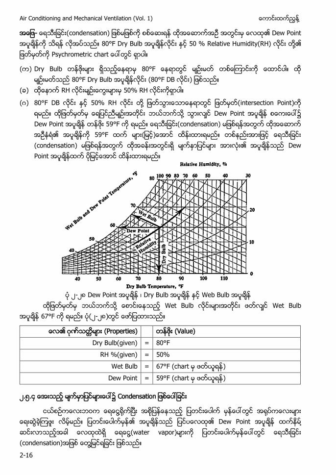
- condensation) Dew Point 80°F Dry Bulb Relative Humidity(RH) ႔ Psychrometric a
( ) Dry Bulb 80°F Dry Bulb ( D )
( )
(ဂ) D ႔ intersection Point) ႔ Dew Point Dew Point condensation) ) (condensation) Dew Point
၂-၂ Dew Point ၊ Dry Bulb Web Bulb
႔ Wet Bulb Wet Bulb 67°F (၂-၂ )
ဂ (Properties) (Value) Dry Bulb(given) = 80°F
RH %(given) = 50% Wet Bulb = 67°F (chart )
Dew Point = 59°F (chart )
၂.၅. ၌ C a
႔ Dew Point ႔ ႔(water vapor) (condensation) ႔
႔ Chapter-2 Understanding Psychrometrics
2-17
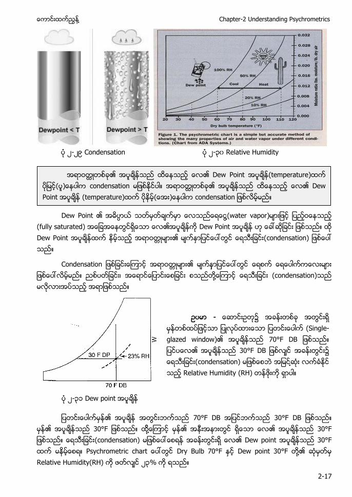
၂-၂၉ Condensation ၂-၃၀ Relative Humidity
Dew Point ႔(water vapor)
(fully saturated) Dew Point Dew Point condensation)
C a ၊ ႔ (condensation)
- (Single- az ) 70°F DB D ၌ condensation) ႔ Relative Humidity (RH)
၂-၃၁ Dew point
70°F DB D ႔ (condensation) Dew point 30°F Psychrometric a Dry Bulb 70°F Dew point 30°F ႔ Relative Humidity(RH) ၂၃%
D ( p a u ) ) condensati D Point ( p a u ) ) c a
Air Conditioning and Mechanical Ventilation (Vol. 1) ႔
2-18
(condensation) ႔ RH ၂၃ (double glazed window) RH% (condensation)
RH ၂၃% (condensation) ႔
၂ ၅ ၅ u a
u a ၌ ႔ water vapor) ႔ ႔ dry a )
( ) ( )
( )
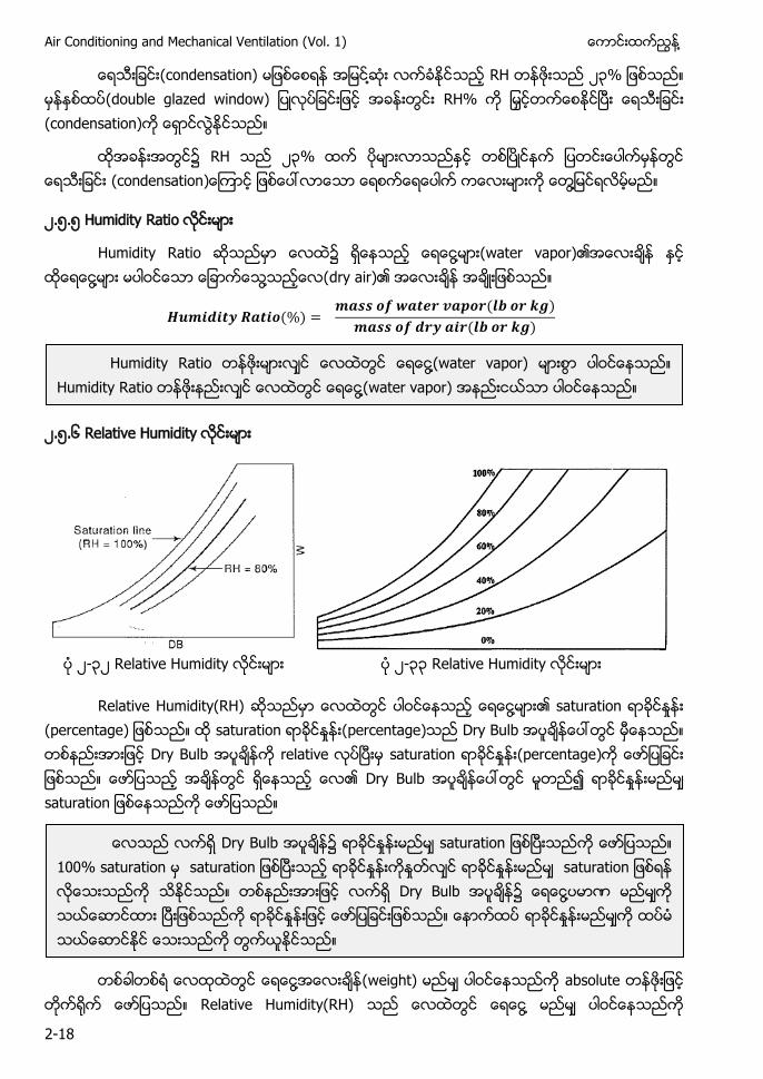
၂.၅.၆ Relative Humidity
၂-၃၂ Relative Humidity ၂-၃၃ Relative Humidity
Relative Humidity(RH) ႔ saturation (percentage) saturation (percentage) Dry Bulb Dry Bulb a saturation (percentage) Dry Bulb a u a
႔ (weight) absolute
Relative Humidity(RH) ႔
u a ႔(water vapor) u a ႔(water vapor)
Dry Bulb ၌ sa u a 100% saturation sa u a sa u a Dry Bulb ၌ ေရေငြ႔ပမာဏ
႔ Chapter-2 Understanding Psychrometrics
2-19
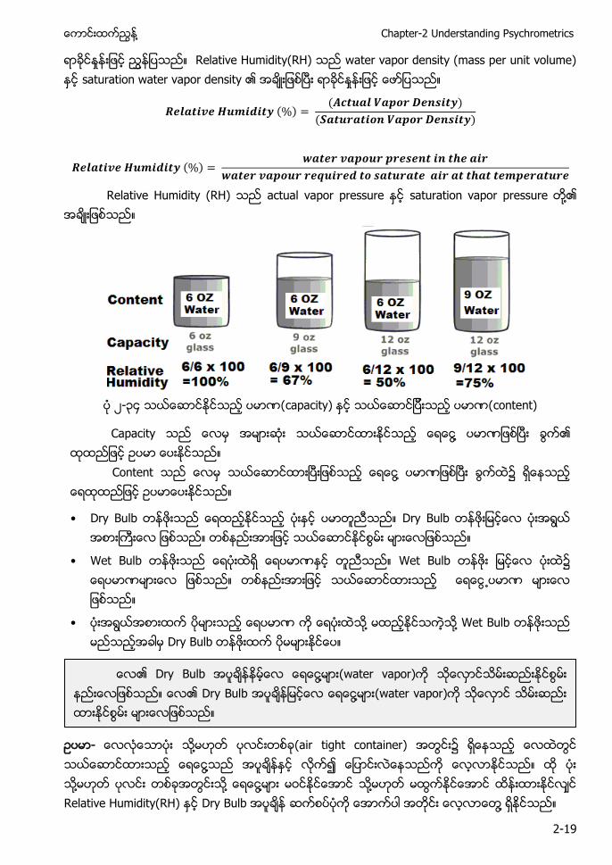
Relative Humidity(RH) a ap a p u u ) saturation water vapor density
( ) ( )
( )
( )
Relative Humidity (RH) actual vapor p u saturation vapor pressure ႔
၂-၃ apa ) content)
Capa ႔
C ႔
• D u D u
• u u
• ႔ ႔ u D u
- ႔ (air tight container) တြင ႔ ႔ ႔ ႔ ႔ Relative Humidity(RH) Dry Bulb ႔
D u ႔ ( a ap ) D u ႔ (water vapor)
Air Conditioning and Mechanical Ventilation (Vol. 1) ႔
2-20
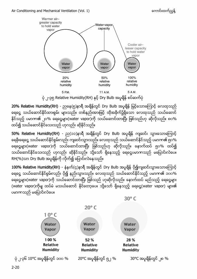
၂-၃၅ Relative Humidity(RH) Dry Bulb
20% Relative Humidity(RH) - (၅) Dry Bulb ႔ ၂၀ ႔ ( a ap ) ၀
50% Relative Humidity(RH) - (၁၁) Dry Bulb ႔ ၅၀ ႔ (water vapor) ၅၀ ႔ ႔ RH(%) Dry Bulb
100% Relative Humidity(RH) - ( ) Dry Bulb ႔ ၁၀၀ ႔ (water vapor) ႔ (water vapor) ႔ ႔(water vapor)
၂-၃၆ C ၁၀၀ C ၅၂ C ၂
႔ Chapter-2 Understanding Psychrometrics
2-21
႔ (water vapor) u Relative Humidity(RH) Relative Humidity(RH) (present temperature) (present temperature) Relative Humidity (RH)
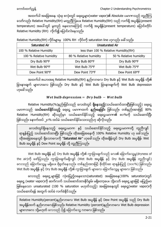
Relative Humidity(RH) 100% RH saturation line Saturated Air Unsaturated Air
100 % Relative Humidity less than 100 % Relative Humidity(RH) 100 % Relative humidity 80 % Relative humidity 50 % Relative humidity
Dry Bulb 90°F Dry Bulb 80°F Dry Bulb 90°F Wet Bulb 90°F Wet Bulb 75°F Wet Bulb 75°F Dew Point 90°F Dew Point 73°F Dew Point 69°F
Relative Humidity(RH) Dry Bulb Wet Bulb ႔ Dry Bulb Wet Bu Wet Bulb depression
Relative Humidity(%) ( ) ႔ ႔ 80% Relative Humidity(RH) ႔ ၀% ၂၀%
Wet Bulb Dry Bulb ႔ ႔ (dryness of the air) (Wet Bulb Dry Bulb ) ႔ (၁၀၀%) Wet Bulb Dry Bulb ႔ ႔
(saturated) (100% saturation) ႔ (water vapor) ႔ unsaturated (100 % saturation ) ႔(water vapor)
႔ ႔ ႔ 100% Relative Humidity Saturated Air Dry Bulb ၊ Wet Bulb Dew Point ႔
Relative Humidity(percent) Wet Bulb Dew Point Dry Bulb Relative Humidity (percent) Wet Bulb depression ႔ ႔
Air Conditioning and Mechanical Ventilation (Vol. 1) ႔
2-22
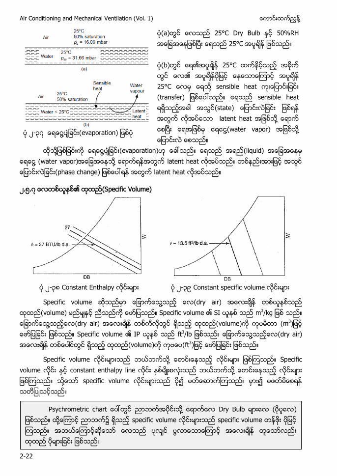
(a) 25°C Dry Bulb 50%RH 25°C (b) 25°C 25°C ႔ sensible heat (transfer) sensible heat (state) latent heat ႔ ႔(water vapor) ႔
၂-၃ ႔ (evaporation)
႔ ႔ (evaporation) (liquid) ႔ (water vapor) ႔ latent heat (phase change) latent heat
၂.၅. (Specific Volume)
၂-၃ C a a p ၂-၃၉ Constant specif u
Specific volume ႔ (dry air) (volume) Specific volume SI m3 ႔ (dry air) (volume) (m3) Specific volume IP ft3 ႔ (dry air) (volume) (ft3)
Specific volume ႔ Specific volume constant enthalpy line ႔ ႔ specific volume
Psychrometric a ႔ Dry Bulb ( ) ႔ ၌ specific volume specific volume
႔ Chapter-2 Understanding Psychrometrics
2-23
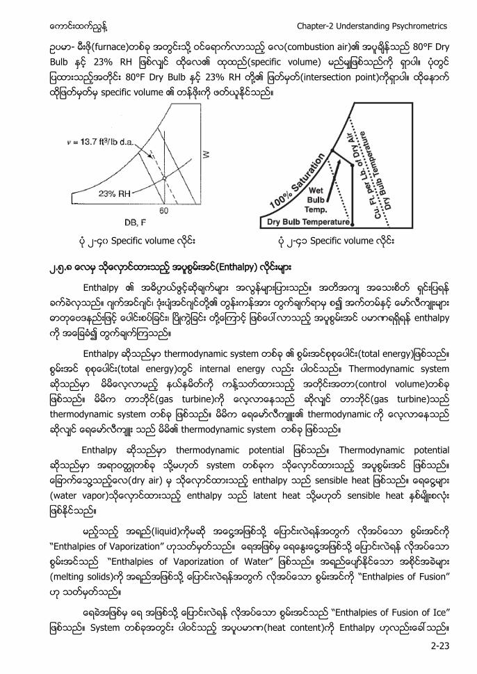
- (furnace) ႔ (combustion air) 80°F Dry Bulb (specific volume) 80°F Dry Bulb 23% RH ႔ (intersection point) specific volume
၂- ၀ Specific volume ၂- ၁ Specific volume
၂.၅. (Enthalpy)
a p ဂ ဂ ၊ ဂ ႔ ၊ ႔ enthalpy
a p a (total energy) (total energy) i a Thermodynamic system ႔ (control volume) (gas turbine) (gas turbine) t a thermodynamic thermodynamic system
En a p thermodynamic p a Thermodynamic p a ႔ ႔ dry air) enthalpy a ႔ (water vapor) a p latent heat ႔ sensible heat
(liquid) ႔ ႔ a p f Vaporization ႔ ႔ a p f Vaporization of Water (melting solids) ႔ a p f usion
႔ a p f usion of Ice S (heat content) a p
Air Conditioning and Mechanical Ventilation (Vol. 1) ႔
2-24
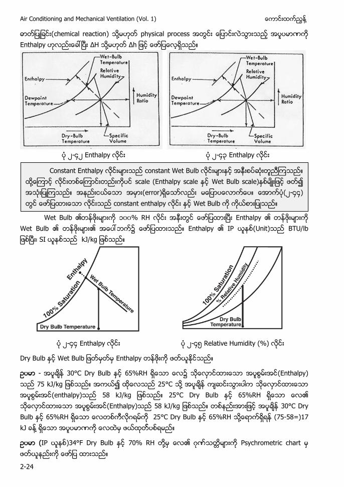
chemical reaction) ႔ p a p a p ΔH ႔ Δ
၂- ၂ Enthalpy ၂- ၃ Enthalpy
Wet Bulb ၁၀၀ RH E a p
Wet Bulb a p Unit) ၊ S
၂- Enthalpy ၂- ၅ Relative Humidity (%)
Dry Bulb Wet Bu Enthalpy
- 30°C Dry Bulb (Enthalpy) °C ႔ (enthalpy) °C Dry Bulb Enthalpy) 30°C Dry Bulb ဂ °C Dry Bulb 65%RH ႔ (75-58=)17 ႔
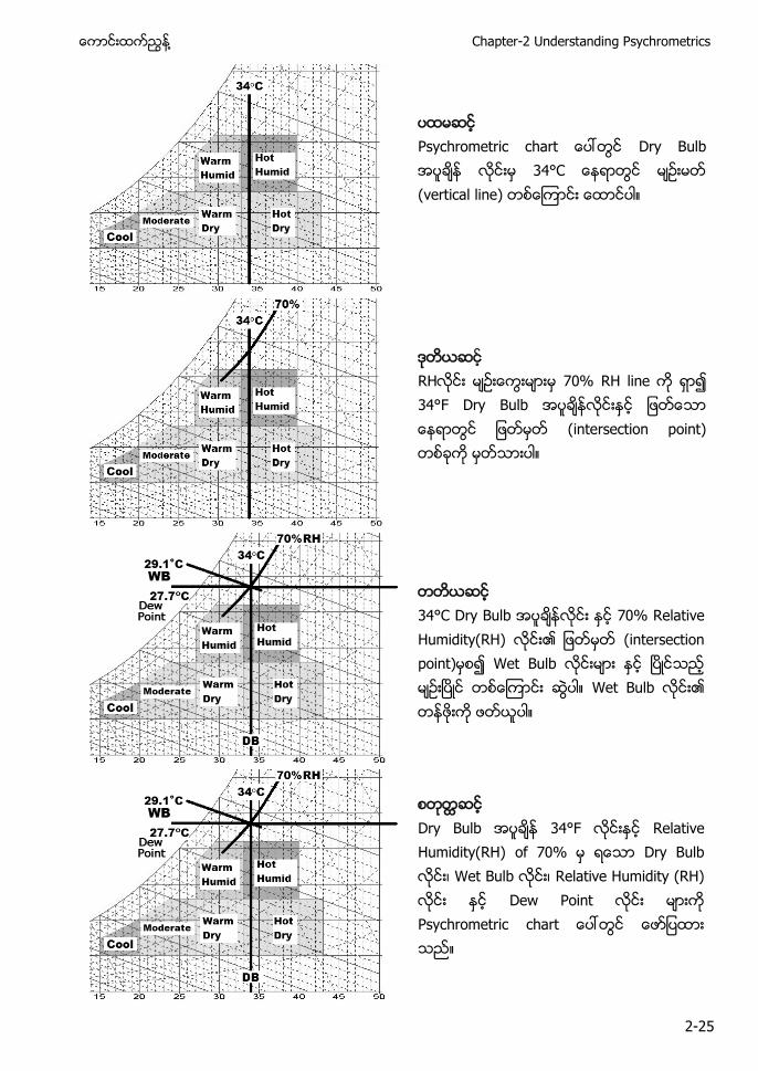
( )34°F Dry Bulb RH ႔ ဂ Psychrometric a
C a a p constant Wet Bu ႔ scale (E a p a Wet Bu a ) ) ၂- ) a a p Wet Bulb
႔ Chapter-2 Understanding Psychrometrics
2-25
P a Dry Bulb C (vertical line)
34°F Dry Bulb (intersection point)
34°C Dry Bulb Relative Humidity(RH) (intersection p ) Wet Bulb Wet Bulb
Dry Bulb Relative Humidity(RH) f Dry Bulb ၊ Wet Bulb ၊ Relative Humidity (RH) D Psychrometric a
Air Conditioning and Mechanical Ventilation (Vol. 1) ႔
2-26
၂.၆ Sensible Heat (Cooling Heating)
( ) ႔ (heat add) ႔ (heat remove) ( ) (heat add) Dry Bulb
a ) Dry Bulb (ဂ) ႔ (water vapor content) (ဃ) Process constant humidity ႔
(heat add) ႔ sensible a p Enthalpy (heat remove) ႔ sensible p a p ႔
Parameters Sensible heating (heat ga )
Sensible cooling (heat loss )
Dry Bulb Temperature (increases) (decreases) Enthalpy (increases) (decreases) Humid Volume (increases) (decreases) Wet Bulb Temperature (increases) (decreases) Percentage Saturation (decreases) (increases) Moisture Content (constant) (constant) Dew Point Temperature (constant) (constant) Vapor Pressure (constant) (constant)
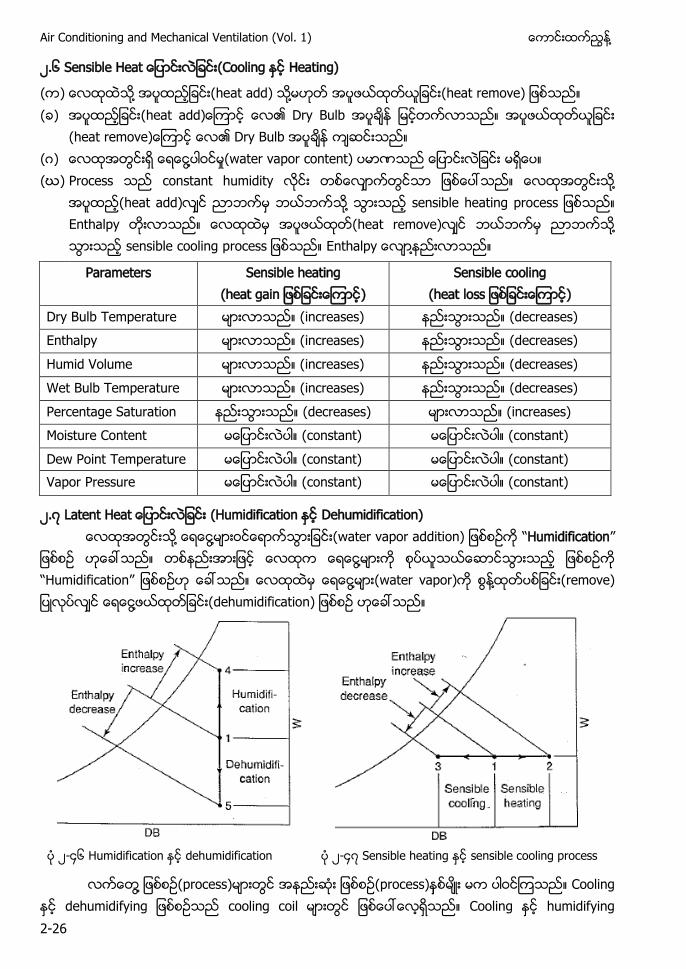
၂. Latent Heat (Humidification Dehumidification) ႔ ႔ (water vapor addition) Humidification ႔ Humidification ႔ (water vapor) ႔ (remove) ႔ (dehumidification)
၂- ၆ Humidification dehumidification ၂- Sensible heating sensible cooling process
႔ (process) (process) Cooling d u f cooling coil Cooling u f
႔ Chapter-2 Understanding Psychrometrics
2-27
air washer Humidification ႔ dehumidification (concept)
႔(water vapor) ႔ humidification ratio Enthalpy Latent heat ႔ (water vapor) (removal) humidification ratio Enthalpy Air conditioning process ႔ dehumidification ႔ humidification ႔
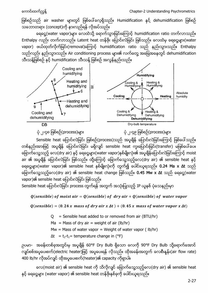
၂- (process) ၂- ၉ (process)
Sensible heat (process) sensible heat (transfer) ႔ (dry air) ႔ (water vapor) moist air ႔ ႔ (dry air) sensible heat ႔ (water vapor) sensible heat 0.24 Ma x Δ ႔ (dry air) sensible heat a 0.45 M x Δ ႔(water vapor) sensible heat Sensible heat process IP
( ) ( ) ( )
( ) ( ) ( )
Q = Sensible heat added to or removed from air (BTU/hr) Ma = Mass of dry air = weight of air (lb/hr) Mw = Mass of water vapor = Weight of water vapor ( lb/hr) Δ = t2-t1= temperature change in (°F)
- 60°F Dry Bulb 90°F Dry Bulb ႔ a ) (air flow rate) 400 lb/hr (heater) capacity
(moist air) sensible heat ႔ (dry air) sensible heat ႔ (water vapor) sensible heat
Air Conditioning and Mechanical Ventilation (Vol. 1) ႔
2-28
( ) ( ) ( )
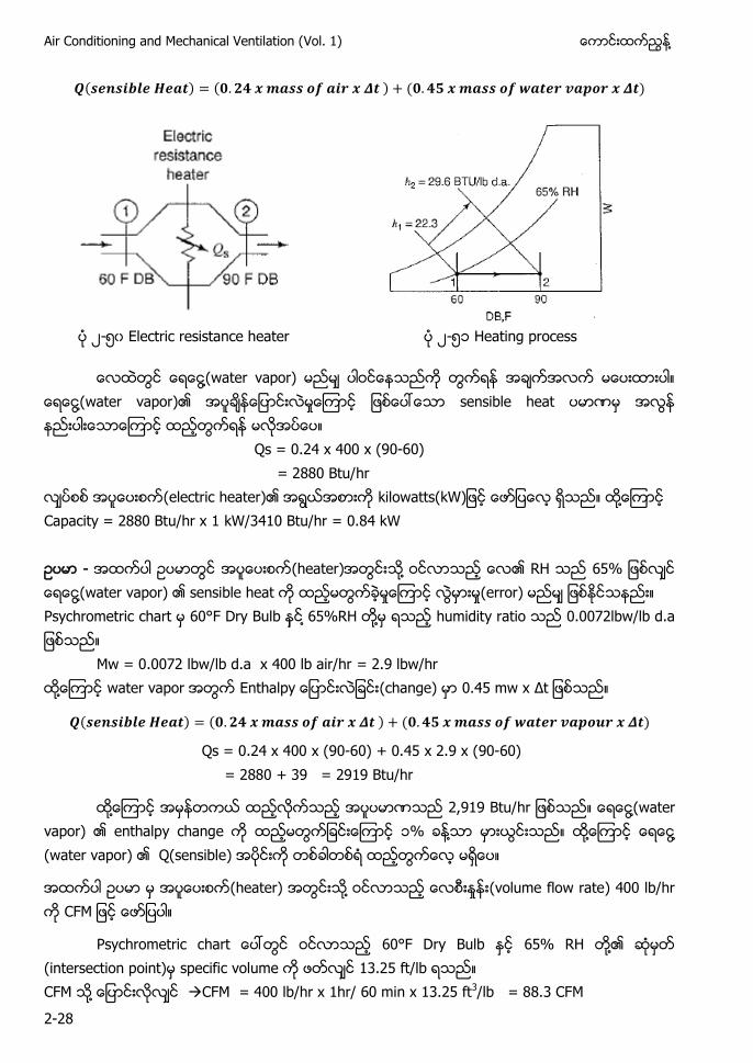
၂-၅၀ Electric resistance heater ၂-၅၁ Heating process
႔ water vapor) ႔ water vapor) sensible heat
Qs = 0.24 x 400 x (90-60) = 2880 Btu/hr
(electric heater) kilowatts(kW) ႔ Capacity = 2880 Btu/hr x 1 kW/3410 Btu/hr = 0.84 kW - (heater) ႔ RH ႔ water vapor) sensible heat (error) Psychrometric chart 60°F Dry Bulb ႔ 65%RH ႔ humidity ratio a
Mw = 0.0072 lbw/lb d.a x 400 lb air/hr = 2.9 lbw/hr ႔ water vapor a p (change) x Δ
( ) ( ) ( )
Qs = 0.24 x 400 x (90-60) + 0.45 x 2.9 x (90-60) = 2880 + 39 = 2919 Btu/hr
႔ , u ႔ water vapor) enthalpy change ၁% ႔ ႔ ႔ (water vapor) Q(sensible)
(heater) ႔ (volume flow rate) 400 lb/hr C M
Psychrometric c a 60°F Dry Bulb 65% RH ႔ (intersection point) specific volume 13.25 ft/lb CFM ႔ CFM = 400 lb/hr x 1hr/ 60 min x 13.25 ft3/lb = 88.3 CFM
႔ Chapter-2 Understanding Psychrometrics
2-29
႔(gas) specific volume ႔(gas) (temperature) ႔ (pressure) ႔ (entering air) CFM (leaving air) CFM
Leaving air specific volume 14.0 ft3 a Leaving air flow rate (CFM) = 400 lb/hr x 1hr/60min x 14.0 ft3/lb = 93.3 CFM
႔ CFM air con equipment
႔ C M (pressure) ႔ ႔ ၊ ႔ (manufacturer) standard air condition CFM
S a a Condition Specific volume of 13.3 ft3/lb da Density 0.75 lb/ ft3 da) ˚ Dry Bulb
႔ Air con ဂ
( ) ( )( ) ( ) ( )( )
CFM - cooling coil sensible cooling capacity 50,000 Btu/hr cooling coil ႔ ˚ Dry Bulb 2000 CFM ႔ cooling coil ˚ Dry Bulb coil (performance)
- cooling coil sensible cooling p f a ၊ sensible cooling
( ) ( ) ( )
Cooling coil sensible performance (leaving air) ˚ Dry Bulb
႔ (evaporation) latent heat of vaporization u ႔ (evaporation) ႔ ႔ (vaporization)
Law of conservation of mass (entering air) (leaving air) ႔ (leaving air) CFM (entering air) CFM mass flow rate volume metric flow rate
Air Conditioning and Mechanical Ventilation (Vol. 1) ႔
2-30
1055 Btu/lb ( ) ( ’ ’ ) ( ) ( ’ ’ )
QL= Latent heat change (Btu/hr or watt) W2’ – W1’ = u ity ratio change (gr w/ lb dry air)
၂. Sensible Latent Process Air conditioning system process ၌ sensible heat latent heat
Cooling dehumidification (process) sensible heat (cooling)
latent heat (dehumidification) (process) (heat) total heat Air side
IP QTotal = Q Sensible + Q Latent QS(Btu/hr) = 1.1 x CFM x (t2-t1) QL(Btu/hr) = 0.68 x CFM x (W2 – W1) QTotal(Btu/hr) = 4.5 x CFM x (h2-h1)
SI QTotal = Q Sensible + Q Latent QS (watt) = 1.232 x L/s x (t2-t1) QL(watt) = 3012 x L/s x (W2 – W1) QTotal(watt)= 1.2 x L/s x (h2-h1)
Q = Sensible heat (Q S) ၊ Latent heat (Q L) ၊ Total heat (QTotal) CFM ႔ L/s = Volume flow rate of air being process. h2-h1 Δ ) = Enthalpy change (Btu/lb °F) ႔ (kJ/kg K)
t2-t1 (Δ ) = Temperature c a ˚C) ႔ ˚ ) w2 – w1(Δ ) = Humidity ratio change (lbw/lb d.a) ႔ (kg/kg d.a)
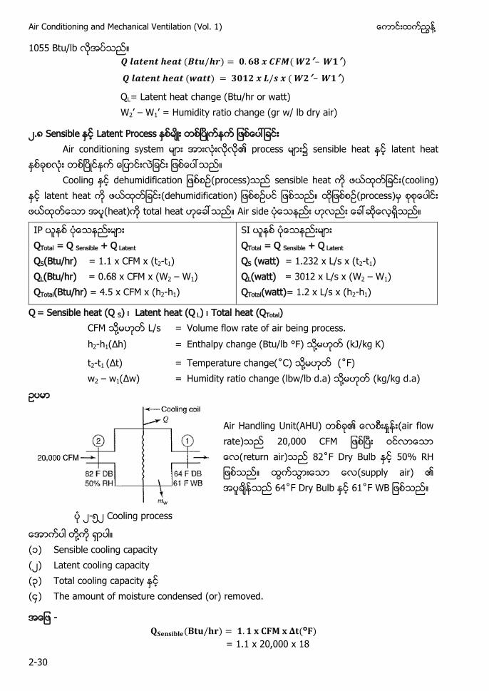
Air Handling Unit(AHU) (air flow rate) , C M (return air) ˚ Dry Bulb (supply air) ˚ Dry Bulb ˚
၂-၅၂ Cooling process
႔ (၁) Sensible cooling capacity (၂) Latent cooling capacity (၃) Total cooling capacity ( ) The amount of moisture condensed (or) removed.
- ( ) ( )
= 1.1 x 20,000 x 18
႔ Chapter-2 Understanding Psychrometrics
2-31
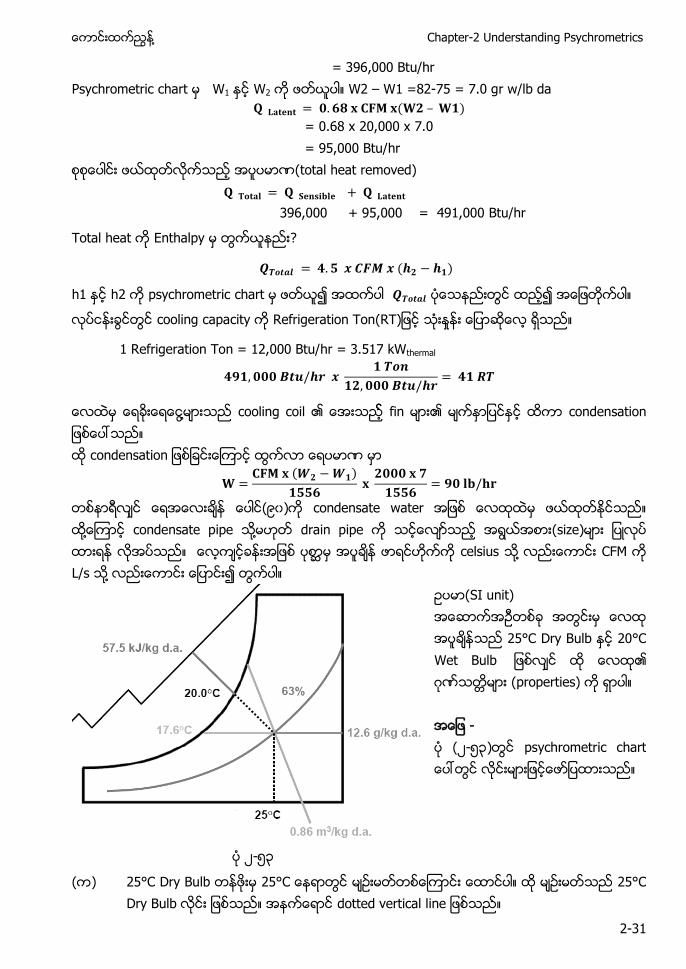
= 396,000 Btu/hr Psychrometric chart W1 W2 W2 – W1 =82-75 = 7.0 gr w/lb da
( )
= 0.68 x 20,000 x 7.0 = 95,000 Btu/hr
(total heat removed)
396,000 + 95,000 = 491,000 Btu/hr
Total heat Enthalpy ?
( )
h1 h2 psychrometric chart
cooling capacity Refrigeration Ton )
1 Refrigeration Ton = 12,000 Btu/hr = 3.517 kWthermal
႔ cooling coil fin c a c a
( )
(၉၀) condensate water ႔ condensate pipe ႔ drain pipe (size) celsius ႔ CFM L/s ႔
(SI unit) 25°C Dry Bulb 20°C Wet Bulb ဂ (properties) - (၂-၅၃) p a
၂-၅၃
( ) 25°C Dry Bulb C 25°C D u dotted vertical l
Air Conditioning and Mechanical Ventilation (Vol. 1) ႔
2-32
( ) 20°C Wet Bu 20°C Wet Bu 20°C Wet Bu dotted s pp
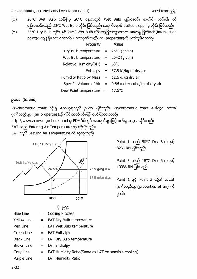
(ဂ) 25°C Dry Bulb 20°C Wet Bu ႔ intersection point) ဂ (properties)
Property Value Dry Bulb temperature = 25°C (given) Wet Bulb temperature = 20°C (given) Relative Humidity(RH) = 63%
Enthalpy = 57.5 kJ/kg of dry air Humidity Ratio by Mass = 12.6 g/kg dry air
Specific Volume of Air = 0.86 meter cube/kg of dry air Dew Point temperature = 17.6°C
(SI unit)
a a ဂ (air properties) p a D Entering Air T p a u L Leaving Air T p a u
50°C Dry Bulb 18°C Dry Bulb ႔
ဂ properties of air)
၂-၅ Blue Line = Cooling Process Yellow Line = EAT Dry Bulb temperature Red Line = EAT Wet Bulb temperature Green Line = EAT Enthalpy Black Line = LAT Dry Bulb temperature Brown Line = LAT Enthalpy Grey Line = EAT Humidity Ratio(Same as LAT on sensible cooling) Purple Line = LAT Humidity Ratio
႔ Chapter-2 Understanding Psychrometrics
2-33
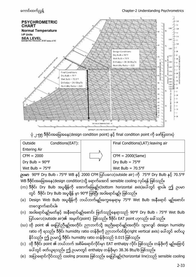
၂-၅၅ design condition p ) final condition p
Outside Conditions(EAT): Entering Air
Final Conditions(LAT):leaving air
CFM = 2000 Dry Bulb = 90°F Wet Bulb = 75°F
CFM = 2000(Same) Dry Bulb = 75°F Wet Bulb = 70.5°F
90°F Dry Bulb ၊ C M outside air) 75°F Dry Bulb 70.5°F WB design condition) ႔ sensible ( ) Dry Bulb z a ax )
Dry Bulb ( ) Design Web u u
(ဂ) 90°F D u ၊ u
outside air) p ) p (ဃ) p ႔ u
a u a right vertical axis) ၌ u a
( ) p a p a p u
( ) p horizontal line) sensible
Air Conditioning and Mechanical Ventilation (Vol. 1) ႔
2-34
horizontal line) sensible a
(leaving air condition) LAT Dry Bulb = u = p ႔ locate) L a p (brown line) u L u a purple line)
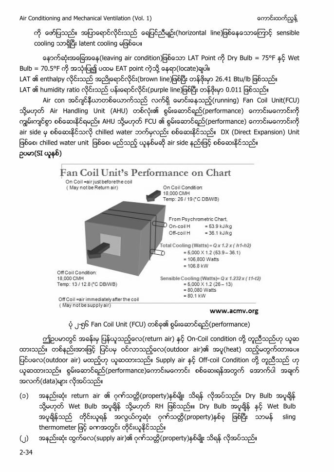
Air c ဂ (running) Fan Coil Unit(FCU) ႔ Air Handling Unit (AHU) performance) AHU ႔ FCU performance) air s a DX (Direct Expansion) ၊ chilled water u ၊ air side (S )
၂-၅၆ a C C ) performance)
return air) On-Coil condition ႔ outdoor air) a ) outdoor air) Supply air Off-coil Condition ႔ performance) data)
(၁) return a ဂ property) Dry Bulb ႔ Wet Bulb ႔ RH Dry Bulb Wet Bulb ဂ property) sling t
(၂) supply air) ဂ property)
႔ Chapter-2 Understanding Psychrometrics
2-35
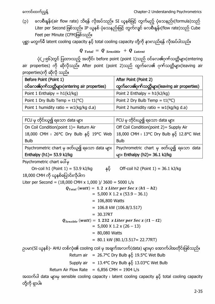
(၃) air flow rate) S formula) Liter per S flow rate) Cube Feet per Minute (CFM)
a apa total cooling capa ႔
၂-၅၆) before point (point 1) ဂ entering
air properties) After point (point 2) ဂ leaving air properties) Before Point (Point 1) ဂ entering air properties)
After Point (Point 2) ဂ leaving air properties)
Point 1 Enthalpy = h1(kJ/kg) Point 2 Enthalpy = h1(kJ/kg) Point 1 Dry Bulb Temp = t1(°C) Point 2 Dry Bulb Temp = t1(°C) Point 1 humidity ratio = w1(kg/kg d.a) Point 2 humidity ratio = w1(kg/kg d.a)
.
FCU da a C da a On Coil Condition(point 1)= Return Air 18,000 CMH ၊ °C Dry Bulb °C Web Bulb
Off Coil Condition(point 2)= Supply Air 18,000 CMH ၊ 13°C D u °C Wet Bulb
Psychrometric chart da a Enthalpy (h1)= 53.9 kJ/kg
a da a Enthalpy (h2)= 36.1 kJ/kg
Psychrometric c a On-coil h1 (Point 1) = 53.9 kJ/kg Off-coil h2 (Point 1) = 36.1 kJ/kg 18,000 CM Liter per Second = (18,000 CMH x 1,000 )/ 3600 = 5000 L/s
( ) ( )
= 5,000 X 1.2 x (53.9 – 36.1) = 106,800 Watts = 106.8 kW (106.8/3.517) = 30.37RT
( ) ( )
= 5,000 X 1.2 x (26 – 13) = 80,080 Watts = 80.1 kW (80.1/3.517= 22.77RT)
(S )- data) Return air = 26.7°C Dry Bulb 19.5°C Wet Bulb
Supply air = 13.4°C Dry Bulb 13.03°C Wet Bulb Return Air Flow Rate = 6,856 CMH = 1904 L/s
a a sensible cooling capa ၊ latent cooling capa total cooling capacity ႔
Air Conditioning and Mechanical Ventilation (Vol. 1) ႔
2-36
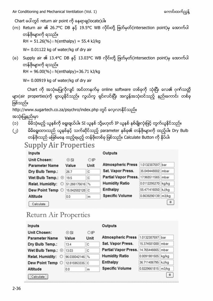
C a return air p (locate) ( ) u a C DB C ႔ (intersection p )
RH = 51.26(%) ၊ h(enthalpy) = 55.4 kJ/kg
W= 0.01122 kg of water/kg of dry air
( ) Supp a C DB C ႔ (intersection point)
= ) ၊ h(enthalpy)=36.71 kJ/kg
W= 0.00919 kg of water/kg of dry air
C a f a ဂ air properties) http://www.sugartech.co.za/psychro/index.php (၁) S ႔ (၂) pa a Dry Bulb
Calculate u ၊
႔ Chapter-2 Understanding Psychrometrics
2-37
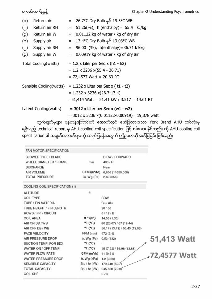
(၁) Return air = 26.7°C Dry Bulb 19.5°C WB (၂) Return air RH = 51.26(%), h (enthalpy)= 55.4 kJ/kg (၃) Return air W = 0.01122 kg of water / kg of dry air (၁) Supply air = 13.4°C Dry Bulb 13.03°C WB (၂) Supply air RH = 96.00 (%), h(enthalpy)=36.71 kJ/kg (၃) Supply air W = 0.00919 kg of water / kg of dry air
Total Cooling(watts) = 1.2 x Liter per Sec x (h1 - h2) = 1.2 x 3236 x(55.4 - 36.71) = 72,4577 Watt = 20.63 RT
Sensible Cooling(watts) = 1.232 x Liter per Sec x ( t1 - t2) = 1.232 x 3236 x(26.7-13.4) =51,414 Watt = 51.41 kW / 3.517 = 14.61 RT
Latent Cooling(watts) = 3012 x Liter per Sec x (w1 - w2) = 3012 x 3236 x(0.01122-0.00919)= 19,878 watt
Yor a technical r p p f a AHU cooling coil specificat
Air Conditioning and Mechanical Ventilation (Vol. 1) ႔
2-38
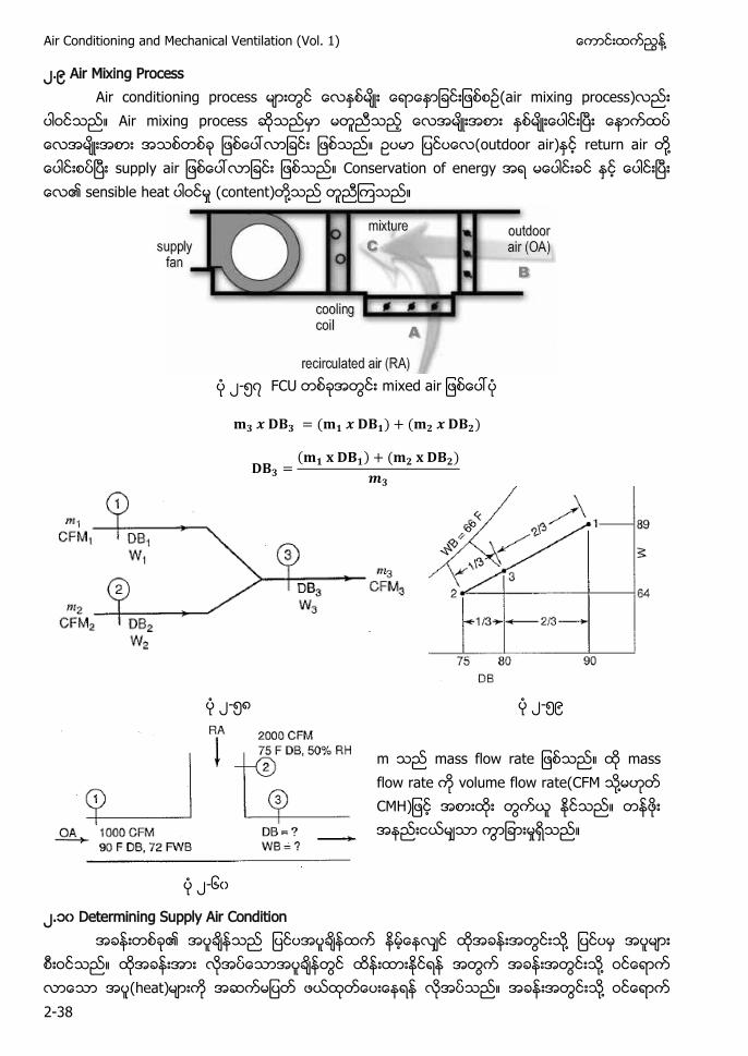
၂.၉ Air Mixing Process Air conditioning process (air mixing process)
Air mixing process (outdoor air) return air ႔ supply air Conservation of energy sensible heat (content) ႔
၂-၅ FCU x a
( ) ( )
( ) ( )
၂-၅ ၂-၅၉
m a f a mass flow rate volume flow rate(CFM ႔ CMH)
၂-၆၀
၂.၁၀ Determining Supply Air Condition ႔ ႔ (heat) ႔
႔ Chapter-2 Understanding Psychrometrics
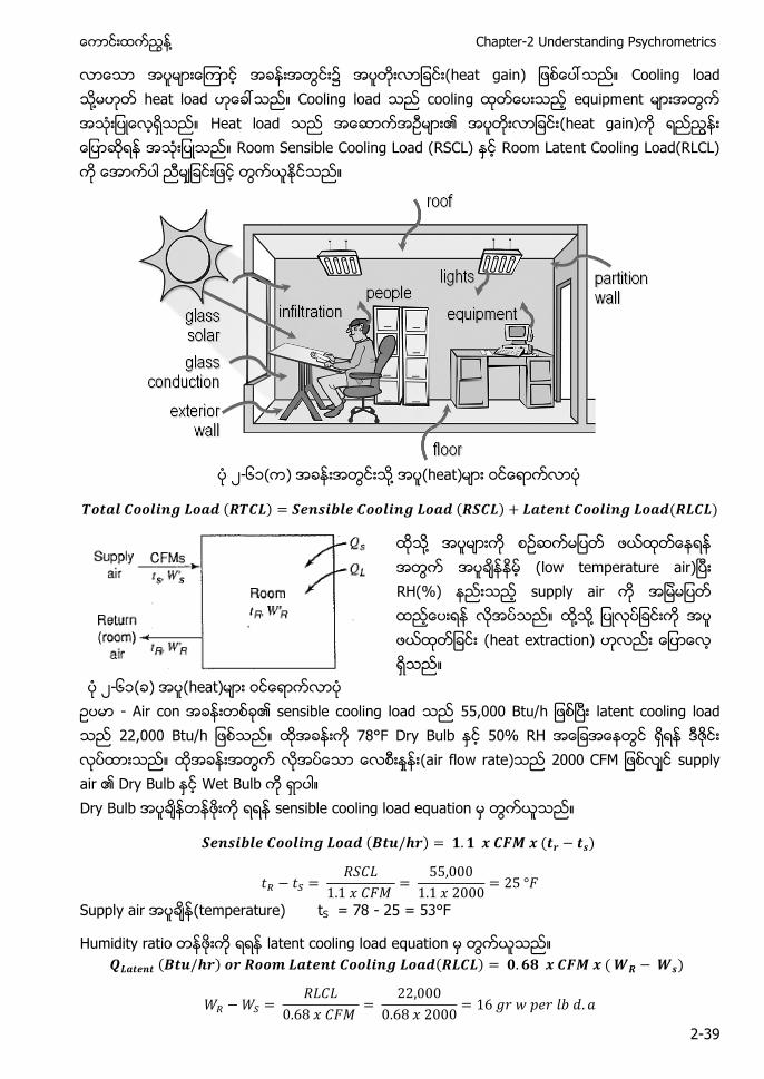
2-39
းအတြငး၌ (heat gain) Cooling load ႔ heat load Cooling load cooling equipment Heat load (heat gain) Room Sensible Cooling Load (RSCL) Room Latent Cooling Load(RLCL)
၂-၆၁( ) ႔ (heat)
( ) ( ) ( )
႔ (low temperature air) RH(%) supply air ႔ ႔ (heat extraction)
၂-၆၁( ) (heat) - Air con sensible cooling load , u latent cooling load , u 78°F Dry Bulb 50% RH (air flow rate) C M supply air Dry Bulb Wet Bulb Dry Bulb sensible cooling load equation
( ) ( )
Supply air (temperature) tS = 78 - 25 = 53°F
Humidity ratio latent cooling load equation ( ) ( ) ( )
Air Conditioning and Mechanical Ventilation (Vol. 1) ႔
2-40
Chart WR WR = 71 gr w/lb d.a Supply air humidity ratio
WS = 71 - 16 = 55 gr w/lb d.a CFM ႔ CMH Supply a u f
a supply air Dry Bulb ၊ RH (%) ႔ Wet Bulb ႔
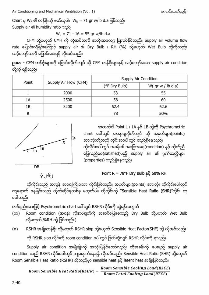
- CFM CFM supply air condition ႔
Point Supply Air Flow (CFM) Supply Air Condition
(°F Dry Bulb) W( gr w / lb d.a) 1 2000 53 55 1A 2500 58 60 1B 3200 62.4 62.6 R 78 50%
Point 1 ၊ 1A 1B ႔ Psychrometric a (points) ႔ (condition) (satisfied) supply air ဂ (properties)
Point R = 78°F Dry Bulb 50% RH ၂-၆၂
(points) Sensible Heat Ratio (SHR)
Psychrometric c a RSHR ( ) Room condition ( Dry Bulb ႔ Wet Bulb
႔ %RH ႔ )
( ) RSHR ႔ RSHR slop ႔ Sensible Heat Factor(SHF) ႔
RSHR slop room c RSHR
Supply air condition supply air condition RSHR Sensible Heat Ratio (SHR) ႔ Room Sensible Heat Ratio (RSHR) sensible heat latent heat
( ) ( )
( )
႔ Chapter-2 Understanding Psychrometrics
2-41
၂-၆၃ ၂-၆
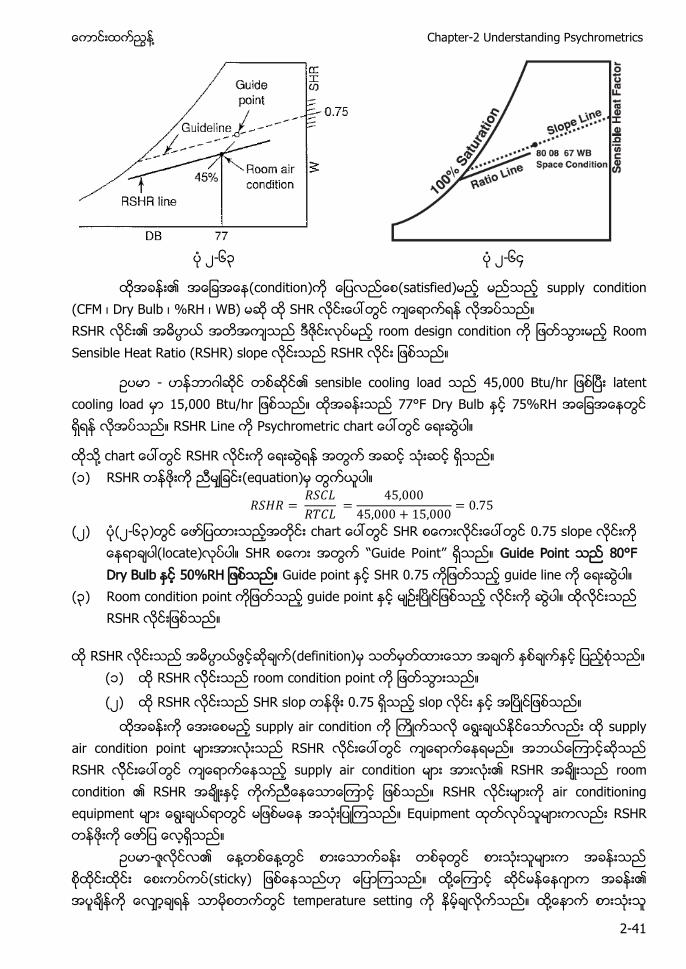
(condition) (satisfied) supply condition (CFM ၊ Dry Bulb ၊ %RH ၊ WB) SHR RSHR room design condition Room Sensible Heat Ratio (RSHR) slope RSHR
- ဂ sensible cooling load , u latent cooling load , u 77°F Dry Bulb 75%RH RSHR Line Psychrometric a
႔ c a RSHR (၁) RSHR (equation)
(၂) (၂-၆၃) c a SHR 0.75 slope (locate) SHR Guide Point Guide Point 80°F Dry Bulb Guide point SHR 0.75 guide line
(၃) Room condition point guide point RSHR
RSHR (definition) (၁) RSHR room condition point
(၂) RSHR SHR slop 0.75 slop
supply air condition supply air condition point RSHR RSHR supply air condition RSHR room condition RSHR RSHR air conditioning equipment Equipment RSHR
- ႔ ႔ (sticky) ႔ ဂ temperature setting ႔
Air Conditioning and Mechanical Ventilation (Vol. 1) ႔
2-42
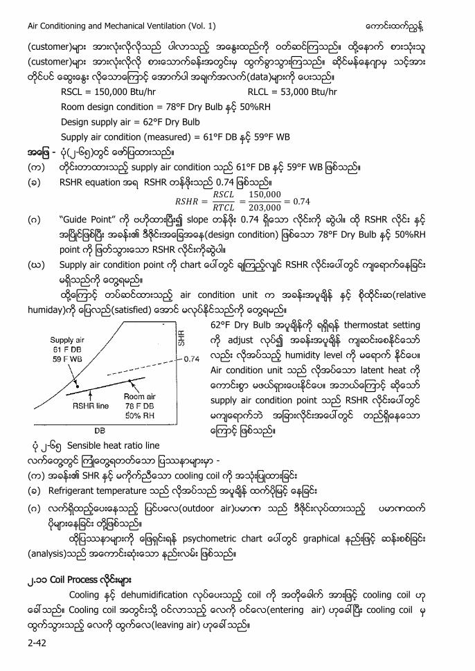
(customer) ႔ (customer) ဂ (data) RSCL = 150,000 Btu/hr RLCL = 53,000 Btu/hr Room design condition = 78°F Dry Bulb 50%RH Design supply air = 62°F Dry Bulb Supply air condition (measured) = 61°F DB 59°F WB - (၂-၆၅) ( ) supply air condition 61°F DB ( ) RSHR equation RSHR
(ဂ) Guide Point slope 0.74 RSHR (design condition) 78°F Dry Bulb 50%RH point RSHR
(ဃ) Supply air condition point c a RSHR ႔
႔ air condition unit (relative humiday) (satisfied) ႔
62°F Dry Bulb thermostat setting adjust humidity level Air condition unit latent heat supply air condition point RSHR
၂-၆၅ Sensible heat ratio line ႔ ႔ - ( ) SHR cooling coil ( ) Refrigerant temperature
(ဂ) (outdoor air) ႔
p a graphical (analysis)
၂.၁၁ Coil Process Cooling dehumidification coil cooling coil Cooling coil ႔ (entering air) cooling coil (leaving air)
႔ Chapter-2 Understanding Psychrometrics
2-43
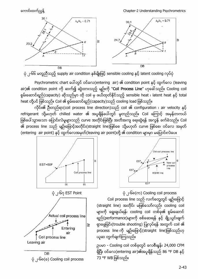
၂-၆၆ supply air condition sensible cooling latent cooling
a (entering air) condition point (leaving air) condition point Coil Process Line Cooling coil (capacity) coil sensible heat ၊ latent heat total heat ႔ Coil (capacity) a
(coil process line direction) coil configuration ၊ air velocity refrigerant ႔ chilled water C curve Coil process line a ) ႔ u ၊ (entering air point) (leaving air point) ႔ condition
၂-၆ EST Point ၂-၆ ( ) Cooling coil process
၂-၆ ( ) Cooling coil process
Coil process line ႔ (straight line) cooling coil ၊ cooling coil (performance) u ) coil process line a )
- Cooling coil 24,000 CFM (entering air) 86 °F DB
Air Conditioning and Mechanical Ventilation (Vol. 1) ႔
2-44
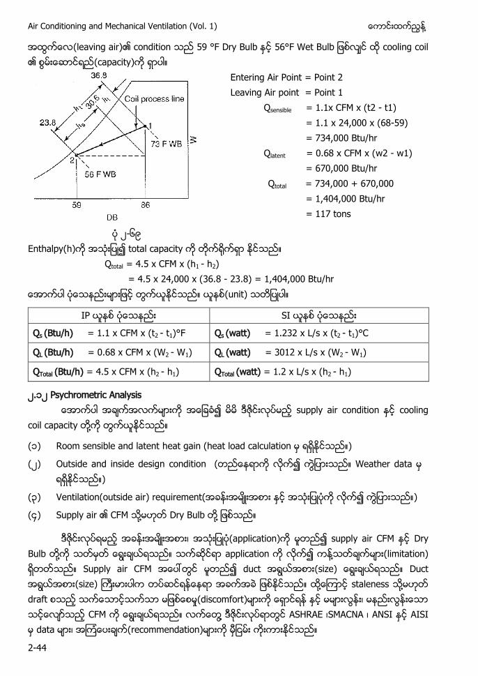
(leaving air) condition 59 °F Dry Bulb 56°F Wet Bulb cooling coil (capacity)
Entering Air Point = Point 2 Leaving Air point = Point 1
Qsensible = 1.1x CFM x (t2 - t1) = 1.1 x 24,000 x (68-59) = 734,000 Btu/hr
Qlatent = 0.68 x CFM x (w2 - w1) = 670,000 Btu/hr Qtotal = 734,000 + 670,000 = 1,404,000 Btu/hr = 117 tons
၂-၆၉ Enthalpy(h) total capacity Qtotal = 4.5 x CFM x (h1 - h2) = 4.5 x 24,000 x (36.8 - 23.8) = 1,404,000 Btu/hr (unit)
IP SI
Qs (Btu/h) = 1.1 x CFM x (t2 - t1)°F Qs (watt) = 1.232 x L/s x (t2 - t1)°C
QL (Btu/h) = 0.68 x CFM x (W2 - W1) QL (watt) = 3012 x L/s x (W2 - W1)
QTotal (Btu/h) = 4.5 x CFM x (h2 - h1) QTotal (watt) = 1.2 x L/s x (h2 - h1)
၂.၁၂ Psychrometric Analysis supply air condition cooling coil capacity ႔
(၁) Room sensible and latent heat gain (heat load calculation )
(၂) Outside and inside design condition ( Weather data )
(၃) Ventilation(outside air) requirement( )
( ) Supply air CFM ႔ Dry Bulb ႔
၊ (application) supply air CFM Dry Bulb ႔ application ႔ (limitation) Supply air CFM duct (size) Duct (size) ႔ staleness ႔ draft (discomfort) ၊ CFM ႔ ASHRAE ၊SMACNA ၊ ANSI AISI data ၊ (recommendation)
႔ Chapter-2 Understanding Psychrometrics
2-45
data air conditioning system RSCL , u RLCL , u (outdoor) design condition 94°F Dry Bulb 75°F Wet Bulb (indoor) design condition 78°F Dry Bulb
( utside air) C M Supply air (temperature difference) ႔ ( ) Supply air CFM
( ) Supply air conditioning
(ဂ) Conditioning entering cooling coil
(ဃ) Cooling coil sensible ၊ latent and total load
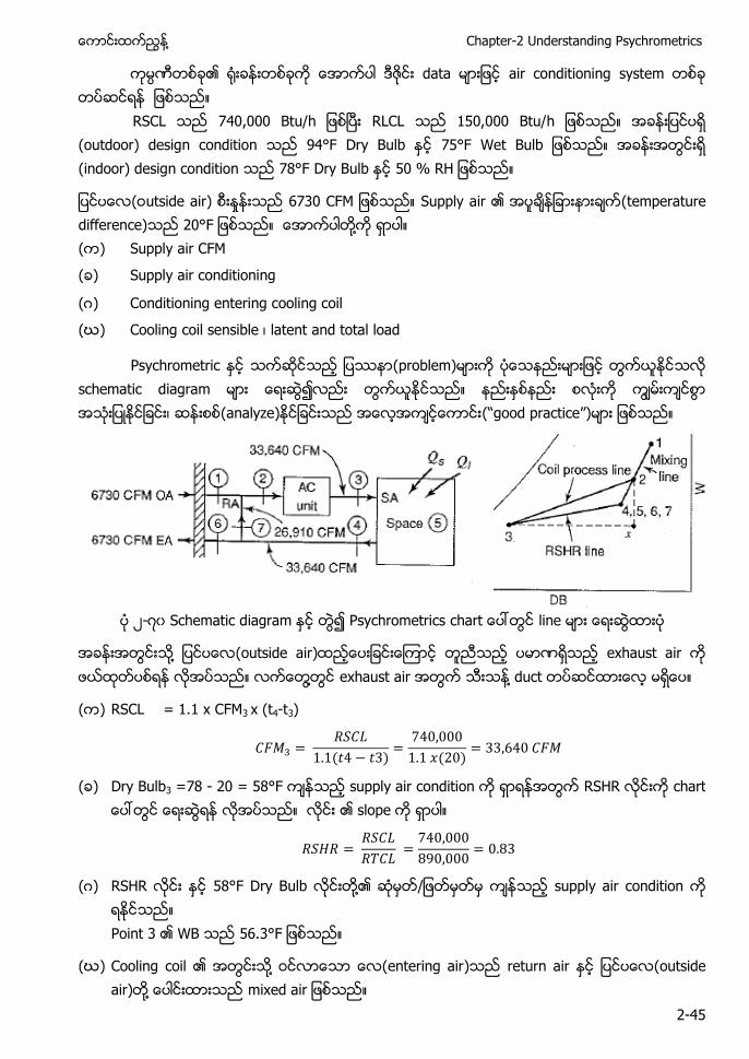
Psychrometric (problem) schematic diagram ၊ (analyze) ( p a )
၂- ၀ Schematic diagram Psychrometrics a line
႔ (outside air) exhaust air ႔ exhaust air ႔ duct
( ) RSCL = 1.1 x CFM3 x (t4-t3)
( )
( )
( ) Dry Bulb3 =78 - 20 = 58°F supply air condition RSHR a slope
(ဂ) RSHR 58°F Dry Bulb ႔ supply air condition Point 3 WB
(ဃ) Cooling coil ႔ (entering air) return air (outside air) ႔ m x a
Air Conditioning and Mechanical Ventilation (Vol. 1) ႔
2-46
Mixed air ( ) ( )
( ) ( )
Mixing line point 1 point 7 81.2°F Dry Bulb p Point 2 cooling coil ႔ (entering air) (condition) WB2 67.2°F
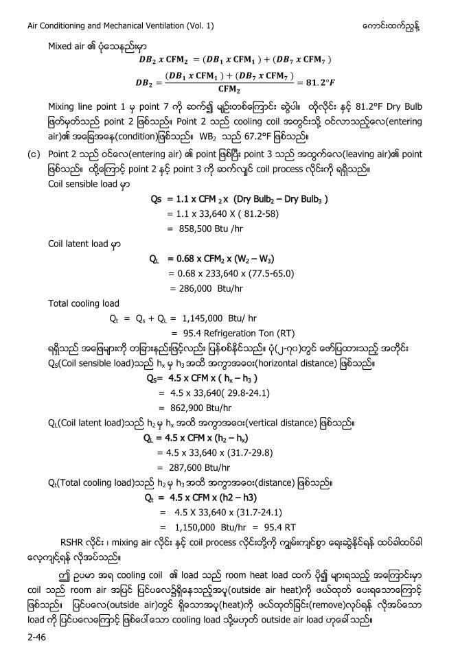
( ) Point 2 (entering air) p point 3 (leaving air) p ႔ point 2 point 3 coil process Coil sensible load Qs = 1.1 x CFM 2 x (Dry Bulb2 – Dry Bulb3 ) = 1.1 x 33,640 X ( 81.2-58) = 858,500 Btu /hr Coil latent load QL = 0.68 x CFM2 x (W2 – W3) = 0.68 x 233,640 x (77.5-65.0) = 286,000 Btu/hr Total cooling load Qt = Qs + QL = 1,145,000 Btu/ hr
= 95.4 Refrigeration Ton (RT) (၂- ၀) QS(Coil sensible load) hx h3 (horizontal distance)
QS= 4.5 x CFM x ( hx – h3 ) = 4.5 x 33,640( 29.8-24.1) = 862,900 Btu/hr
QL(Coil latent load) h2 hx (vertical distance) QL = 4.5 x CFM x (h2 – hx)
= 4.5 x 33,640 x (31.7-29.8) = 287,600 Btu/hr
Qt(Total cooling load) h2 h3 (distance) Qt = 4.5 x CFM x (h2 – h3) = 4.5 X 33,640 x (31.7-24.1) = 1,150,000 Btu/hr = 95.4 RT
RSHR ၊ mixing air coil process ႔ ႔
cooling coil load room heat load coil room air (outside air heat) (outside air) (heat) (remove) load cooling load ႔ outside air load
႔ Chapter-2 Understanding Psychrometrics
2-47
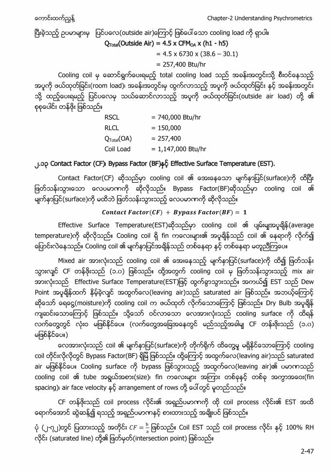
u a ) cooling load QTotal(Outside Air) = 4.5 x CFMOA x (h1 - h5) = 4.5 x 6730 x (38.6 – 30.1) = 257,400 Btu/hr
Cooling coil total cooling load ႔ (room load)၊ ႔ (outside air load) ႔
RSCL = 740,000 Btu/hr RLCL = 150,000 QTotal(OA) = 257,400 Coil Load = 1,147,000 Btu/hr
၂.၁၃ Contact Factor (CF)၊ Bypass Factor (BF) Effective Surface Temperature (EST).
Contact Factor(CF) cooling coil (surface) Bypass Factor(BF) cooling coil (surface)
( ) ( )
Effective Surface Temperature(EST) cooling coil (average temperature) Cooling coil fin coil Cooling coil
Mixed air cooling coil (surface) CF (၁.၀) ႔ cooling coil mix air Effective Surface Temperature(EST) EST Dew Point (leaving air) saturated air ႔(moisture) cooling coil Dry Bulb ႔ cooling surface ႔ ( ႔ CF (၁.၀) ) coil (surface) ႔ cooling coil Bypass Factor(BF) ႔ (leaving air) saturated air Cooling surface b pa (leaving air) cooling coil tube (size)၊ fin (fin spacing)၊ air face velocity arrangement of rows ႔
CF coil process coil process EST ႔
(၂- ၂)
Coil EST coil process 100% RH
(saturated line) ႔ (intersection point)
Air Conditioning and Mechanical Ventilation (Vol. 1) ႔
2-48
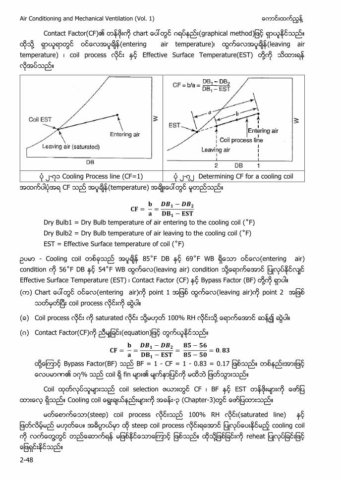
Contact Factor(CF) c a ဂ (graphical method) ႔ (entering air temperature)၊ (leaving air temperature) ၊ coil process Effective Surface Temperature(EST) ႔
၂- ၁ Cooling Process line (CF=1) ၂- ၂ Determining CF for a cooling coil CF (temperature)
Dry Bulb1 = Dry Bulb temperature of air entering to the cooling coil (˚ ) Dry Bulb2 = Dry Bulb temperature of air leaving to the cooling coil (˚ ) EST = Effective Surface temperature of coil (˚ )
- Cooling coil ˚ DB 69˚ (entering air) condition 56˚ DB 54˚ (leaving air) condition ႔ Effective Surface Temperature (EST) ၊ Contact Factor (CF) Bypass Factor (BF) ႔
( ) C a (entering air) point 1 (leaving air) point 2 coil process
( ) Coil process saturated ႔ 100% RH ႔ ႔
(ဂ) Contact Factor(CF) (e ua )
႔ Bypass Factor(BF) BF = 1 - CF = 1 - 0.83 = 0.17 ၁ % coil fin
Coil coil selection CF ၊ BF EST C -၃ (Chapter-3)
(steep) coil process 100% RH (saturated line) steep coil process cooling coil ႔ ႔ r a
႔ Chapter-2 Understanding Psychrometrics
2-49
၂.၁ Reheat
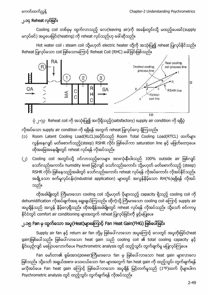
Cooling coil (leaving air) ႔ (supply ) (heating) reheat
Hot water coil ၊ steam coil ႔ electric heater ႔ r a a Reheat Coil (RHC)
၂- ၃ Reheat coil (satisfactory) supply air condition
supply air condition r a (၁) Room Latent Cooling Load(RLCL) Room Total Cooling Load(RTCL)
(steep) RSHR saturation line reheat
(၂) Cooling coil ႔ 100% outside air ၊ humidity l ႔ (steep) RSHR reheat (industrial application) RH(%)
cooling coil ႔ capacity cooling coil dehumidification ႔ supply air reheat ႔ comfort air conditioning a
၂.၁၅ Fan (Heat) a a a )
Supply air fan return air fan ႔ a a ) heat gain cooling coil total cooling capacity Psychrometric analysis
a (power) ၊ fan heat gain ႔ fan fan heat gain a a a (1°F) Psychrometric analysis
Air Conditioning and Mechanical Ventilation (Vol. 1) ႔
2-50
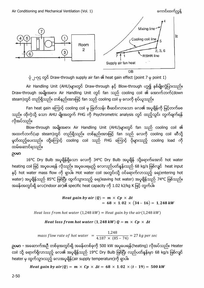
၂- Draw-through supply air fan heat gain effect (point 7 point 1)
Air Handling Unit (AHU) Draw-through Blow-through Draw-through Air Handling Unit fan cooling coil (down steam) fan cooling coil
Fan heat gain cooling coil ႔ AHU FHG Psychrometric analysis Blow-through Air Handling Unit (AHU) fan cooling coil (up steam) fan cooling coil ႔ ႔ cooling coil FHG cooling load
16°C Dry Bulb 34°C Dry Bulb ႔ a a 68 k heat input hot water mass flow Hot water coil ႔ (entering hot water) C (leaving hot water) C (indoor air) specific heat capacity 1.02
( )
( )
( ) ( )
( )
( )
- 500 kW (heating) Heater coil ႔ 19°C Dry Bulb heater (air supply temperature)
( ) ( )
႔ Chapter-2 Understanding Psychrometrics
2-51
( )
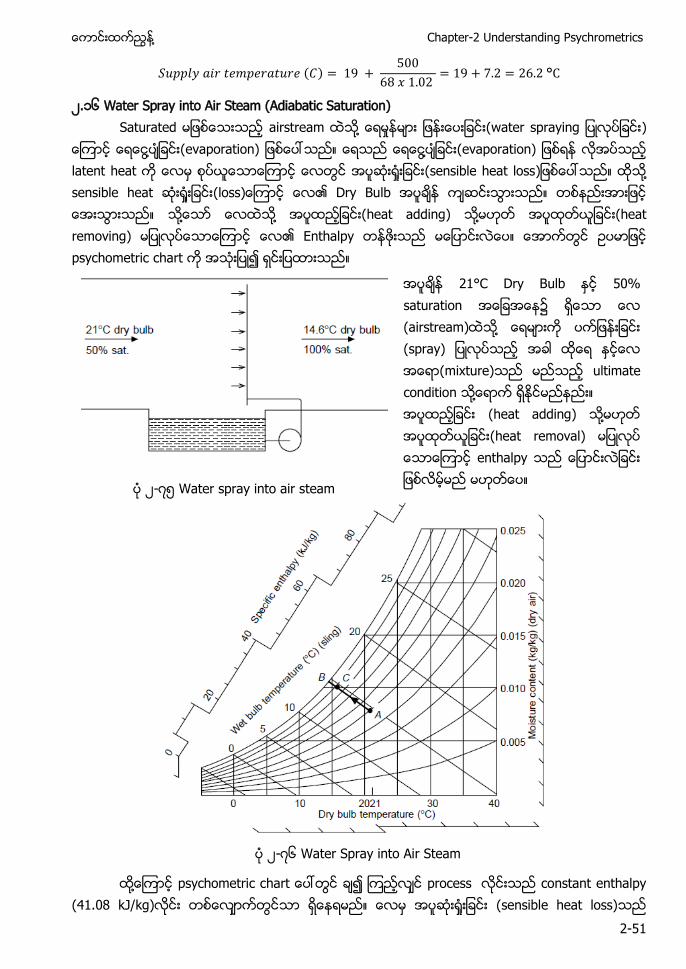
၂.၁၆ Water Spray into Air Steam (Adiabatic Saturation) Saturated airstream ႔ a p a )
႔ (evaporation) ႔ (evaporation) latent heat (sensible heat loss) ႔ sensible heat (loss) Dry Bulb ႔ ႔ (heat adding) ႔ (heat removing) Enthalpy psychometric chart
21°C Dry Bulb 50% saturation (airstream) ႔ (spray) (mixture) ultimate condition ႔ (heat adding) ႔ (heat removal) enthalpy ၂- ၅ Water spray into air steam
၂- ၆ Water Spray into Air Steam
႔ p a process constant enthalpy (41.08 kJ/kg) (sensible heat loss)
Air Conditioning and Mechanical Ventilation (Vol. 1) ႔
2-52
a a a ) sensible heat latent heat
(mixture) saturation ႔ ႔ ap a ) enthalpy enthalpy
(final condition) 14.6°C Dry Bulb ၊ 14.6°C Wet Bulb၊ 14.6°C Dew Point ၊ a u a Ultimate condition ႔ saturation point (၂- ၆) (point C) AC/AB spray system effectiveness
Adiabatic (constant enthalpy) AC constant Wet Bulb 0.2K ႔ (error) ႔ constant Wet Bulb ႔ (dry air) ႔(water vapor) ႔ mixture Gas mixture
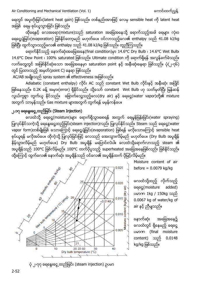
၂.၁ (Steam Injection) ႔ ႔(moisture) (water spraying)
႔ ႔ (steam injection) Steam ႔(water vapor form) ႔ (evaporation) sensible heat ႔ (Dry Bulb ) Dry Bulb ႔ steam C 100°C superheated ႔
Moisture content of air before = 0.0079 kg/kg ႔ ႔(moisture added) 1kg / 150kg 0.0067 kg of water/kg of air ႔ (final moisture content) 0.0148 kg/kg
၂- (steam injection)
႔ Chapter-2 Understanding Psychrometrics
2-53
Steam injection 100°C ႔(steam) 21°C Dry Bulb ၊ 50% saturation
(airstream) ႔ 1 kg steam/150 kg dry air (final condition)
Dry Bulb ႔(steam) specific heat capacity ႔ 20°C –100°C ႔(steam) specific heat capacity
( ) ( )
႔(steam) humidity Dry Bulb
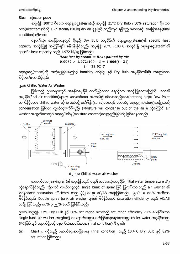
၂.၁ Chilled Water Air Washer
(final air condition) (entering air) Dew Point chilled water ႔ (spray) ႔(moisture) a (Moisture will condense out of the air.) ႔ air washer ႔ u )
၂- Chilled water air washer
(leaving air) (initial water temperature B ) ႔ ႔ ႔ a f p a air washer saturation efficiency (၂- ၀) AC/AB ၅၀% ၀% Double spray bank air washer saturation efficiency AC/AB ၀% ၉၅%
23°C Dry Bulb a u a a u a ff single bank air washer ႔ (spray) chiller water C (final condition)
(a) Chart (final condition) 10.4°C Dry Bulb a u a
Air Conditioning and Mechanical Ventilation (Vol. 1) ႔
2-54
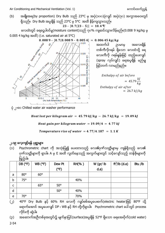
(b) (by proportion) Dry Bulb 23°C (၁၀၀) ( ၀) Dry Bulb 23°C 5°C
( ) ႔ (moisture content) ၀% (0.008 9 kg/kg
0.005 4 kg/kg ) (i.e. saturated air at 5°C) (
ဂ ႔ ဂ (spray )
၂- ၀ Chilled water air washer performance
၂.၁၉ (၁)
Psychrometric chart ဂ ဂ A E
DB (°F) WB (°F) Dew Pt (°F)
RH(% ) W (gr/ lb d.a)
ft3/lb (d.a) Btu /lb
a 80° 60° b 75° 40% c 65° 50° d 50° 40% e 70° 70%
(၂) 40°F Dry Bulb (electric heater) 80°F ႔ DP ၊ WB RH ႔ Psychrometric a process
(၃) (surface) 52°F (cold water)
႔ Chapter-2 Understanding Psychrometrics
2-55
75°F Dry Bulb RH% ႔ condensation)
( ) 90°F Dry Bulb 70°F Dry Bulb 56°F DB 54°F WB ႔ cooling dehumidification process p
(၅) ( ) (၆) C M (air flow rate) Fan Coil Unit(FCU) 80°F Dry Bulb
70% RH (entering air) (leaving air) 58°F Dry Bulb 56.5°F WB ႔ ႔ (၁) Sensible load (၂) Latent load (၃) Total load ( ) Moisture Gallon P u M)
( ) Room Sensible Cooling Load(RSRL) , u ၊ Room Latent Cooling Load(RLCL) 31,000 Btu/hr Room Sensible Heat Ratio(RSHR)
( ) 75°F Dry Bulb 50% RH Room Sensible Cooling Load (RSCL) 112,000 Btu/hr Room Latent Cooling load (RLCL) , u supply (air flow rate) 5,00 C M supply air Dry Bulb Wet Bulb ႔
(၉) Room Sensible Cooling Load(RSRL) , u Room Latent Cooling Load(RLCL) 9,000 Btu design condition 77°F Dry Bulb Supply air 58°F Dry Bulb Supply air flow rate (CFM) supply air Wet Bulb ႔
(၁၀) Cooling coil ႔ 80°F Dry Bulb 66°F Wet Bulb 60°F Dry Bulb 57°F Wet Bulb cooling coil Bypass Factor(BF) ၊ Contact Factor(CF) Effective Surface Temperature(EST) ႔
(၁၁) 82°F Dry Bulb 67°F Dry Bulb CF 0.91 cooling coil Effective Surface Temperature(EST) 55°F Coil Dry Bulb Wet Bulb ႔
(၁၂) A/C unit 55°F Dry Bulb 55% RH (outdoor air condition) 95°F Dry Bulb 74°F Wet Bulb (flow rate) C M ႔
( ) RSCL ၊ RLCL RTCL ( ) Outside air load cooling coil Contact Factor (CF) (ဂ) ႔ arrangement ႔ condition
(၁၃) condition 78°F Dry Bulb Load RSCL
Air Conditioning and Mechanical Ventilation (Vol. 1) ႔
2-56
18,000 Btu/hr RLCL , u air condition 900 CFM supply air 58°F Dry Bulb 56°F Dry Bulb condition ႔ air con unit Dry Bulb Wet Bulb ၊
(၁ ) 76°F Dry Bulb 50% RH RSCL , u RLCL , u A/C unit 56°F Dry Bulb 54°F Dry Bulb supply air design condition reheat coil (energy) (waste)
(၁၅) RSCL = 812,000 Btu/hr RLCL = 235,000 Btu/hr Ventilation air = 6,000 CFM Supply air = 56°F Dry Bulb Space conditions = 77°F Dry Bulb 50% RH ႔ ( ) Apparatus arrangement (schematic diagram ) ( ) Supply air CFM Dry Bulb (ဂ) Mixed air conditioning (ဃ) Coil sensible load ၊ latent load total load ႔ ( ) (outdoor air) sensible load ၊ latent load total load ႔ ( ) coil Contract Factor(CF) Bypass Factor(BF) ႔ ( ) C a process (point )
(၁၆) Air conditioning unit ႔ 20,000 CFM 80°F Dry Bulb
60% RH (leaving air) 57°F Dry Bulb ႔ ( ) A/C unit cooling capacity (Btu/hr ) ( ) A/C unit a (water removal rate) (ဂ) A/C unit sensible load (ဃ) Leaving air Dew Point ( ) Effective surface temperature (apparatus Dew Point)
(၁ ) ႔ ႔ sensible cooling load , u Latent cooling load , u design condition 76°F Dry Bulb ႔ supply air 58°F Dry Bulb ( ) Equipment duct arrangement ( ) supply air (CFM)
႔ Chapter-2 Understanding Psychrometrics
2-57
(ဂ) supply air (CFM) Wet Bulb ၊ Enthalpy ၊ Relative Humidity(RH) (moisture content) gr/lb lb/lb
(ဃ) (outdoor air) 260 CFM (outdoor air) 95°F Dry Bulb 76°F u (outdoor air) Return air x air con unit ႔ (mixed air) ႔ entering air Mixed air Dry Bulb Wet Bulb ၊ enthalpy ၊ Relative Humidity(RH) (moisture content) (gr/lb and lb/lb) ႔
( ) Refrigerating unit (size) Btu/hr ႔ refrigeration ton (outdoor air) cooling load
( ) (outside air flow) 260 CFM 130 CFM ႔ ႔ A/C unit capacity u )p a
(၁ ) sensible cooling load 200,000 Btu/hr latent a , u 76°F Dry Bulb 64°F Wet Bulb (outside air flow rate) C M (outdoor air) condition 95°F Dry Bulb 76°F Wet Bulb (outdoor air) (return air) (mix) mixed air ႔ entering air air con unit ႔
( ) Equipment duct arrangement ႔ (sketch) ( ) Room Sensible Heat Ratio (RSHR) (ဂ) Supp a (flow rate) Supply air 60°F D u
(ဃ) (outdoor air) sensible cooling load Btu/hr ႔
refrigeration ton ( ) Effective Surface Temperature(EST) (EST apparatus Dew Point
) ( ) Coil Contact Factor(CF) Bypass Factor (BF) ႔
(၁၉) A/C unit outdoor air 3000 CFM ၊ 95°F Dry Bulb 76°F u Return air 20,000 CFM ၊ 78°F Dry Bulb Mixed air return air (outdoor air) ႔ Air con unit (leaving air) ႔ supply air 52°F Dry Bulb
( ) Air con unit total load Btu/hr ႔ refrigeration ton ( ) C (electric heat) 58.5°F
Dry Bulb ႔ reheat (electric heat) (capacity)
-End-
႔ Chapter-3 Air Handling Units
3-1
Chapter - 3 Air Handling Units
၃-၁
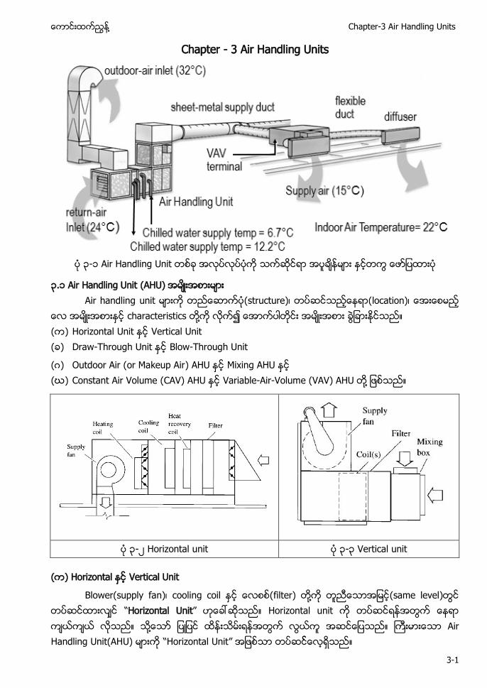
၃.၁ (AHU) Air handling ( (
characteristics ႔ ( ) Vertical Unit ( ) - Blow-Through Unit
(ဂ) Outdoor Air (or Makeup Air) (ဃ) Constant Air Volume (CAV) Variable-Air-Volume (VAV) ႔
၃-၂ Horizontal unit ၃-၃ Vertical unit
( ) Vertical Unit
Blower(supply fan) cooling coil filter) ႔ (same level) “Horizontal Unit” ႔ “ nit”
Air Conditioning and Mechanical Ventilation (Vol. 1) ႔
3-2
cooling “Vertical Unit” AHU blower “Vertical Unit” (foot print ႔ ႈ Vertical unit Air Handling Unit “Vertical Unit”
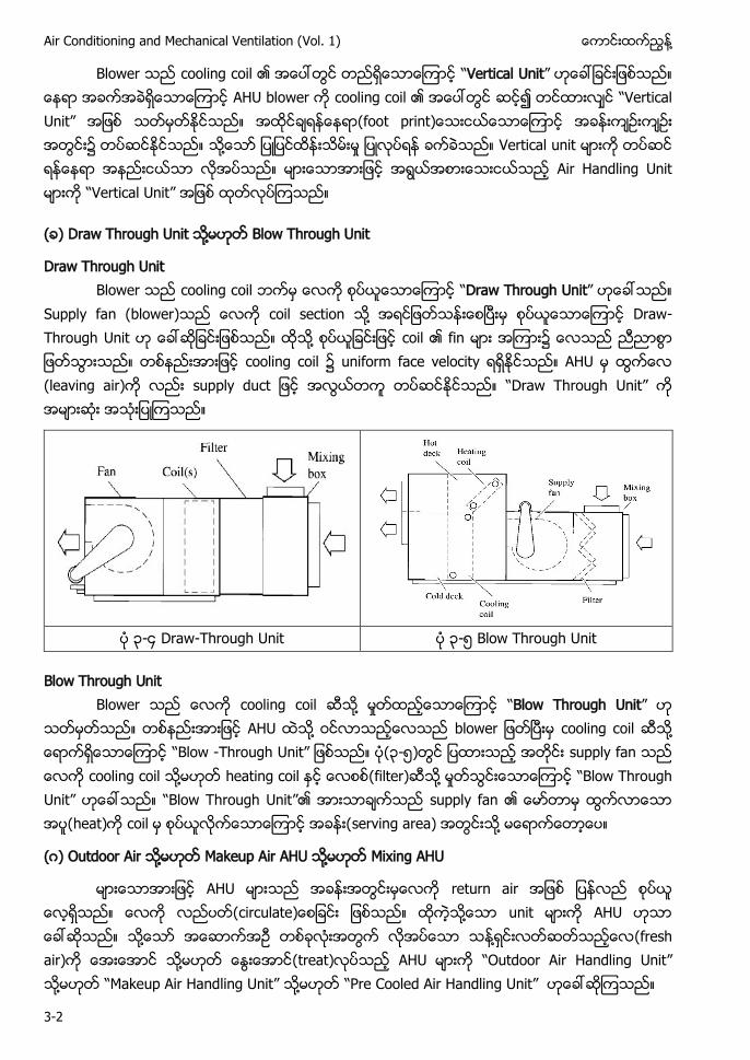
( ) Draw Through Unit ႔ Blow Through Unit
Draw Through Unit cooling c “Draw Through Unit”
Supply fan (blower) coil section ႔ - ႔ fin ၌ cooling coil ၌ (leav “Draw Through Unit”
၃-၄ Draw-Through Unit ၃-၅ Blow Through Unit
Blow Through Unit cooling coil ႔ ႈ “Blow Through Unit”
႔ b cooling c ႔ “Blow -Through Unit” ၃-၅ s cooling coil ႔ (filter) ႔ ႈ “Blow Through Unit” “Blow Through Unit” supply fan heat) serving area) ႔
(ဂ) Outdoor Air ႔ Makeup Air AHU ႔ Mixing AHU
circulate ႔ u ႔ ႔ (fresh air) ႔ (treat) “Outdoor Air Handling Unit” ႔ “Makeup Air Handling Unit” ႔ “Pre Cooled Air Handling Unit”
႔ Chapter-3 Air Handling Units
3-3
Outdoor air treat) “Outdoor Air Handling Unit” “Makeup Air Handling Unit” ႔ “Pre Cooled Air Handling Unit”
၌ condensation) (condensation outdoor AHU မားက ႏစလကမ သ႔မဟတ ႏစလကမ ထက ထသည
(ဃ) Constant Air Volume (CAV) AHU ႔ Variable-Air-Volume (VAV) AHU
ႈ (air flow rate) “Constant Air Volume(CAV) AHU” ႔ “Variable Air Volume (VAV) AHU” ႈ (constant air flow rate “Constant Air Volume Air Handling Unit(CAV AHU ”
ႈ (air flow rate) “Variable Air Volume Air Handling Unit(VAV AHU)” d Variable Air Volume Box (VAV Box) Variab -၉(Chapter-9)
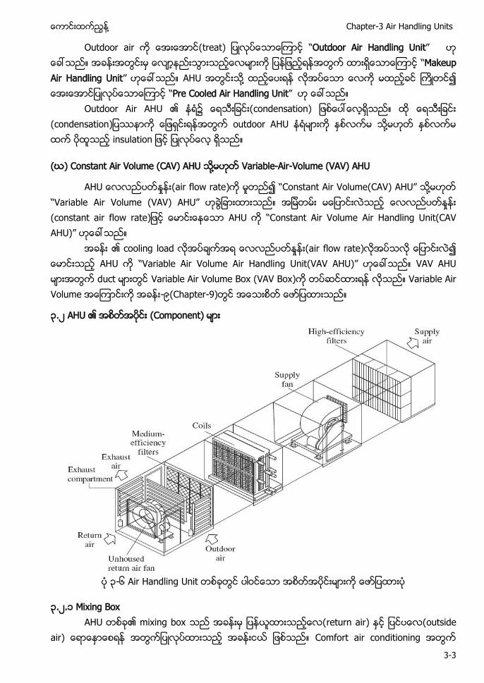
၃.၂ Component)
၃-၆
၃.၂.၁ return air) outside
air) Com
Air Conditioning and Mechanical Ventilation (Vol. 1) ႔
3-4
႔ ႈ outside air) outside air) return air (outside air) (mixed air ႔ damper ႈ(linear relationship)
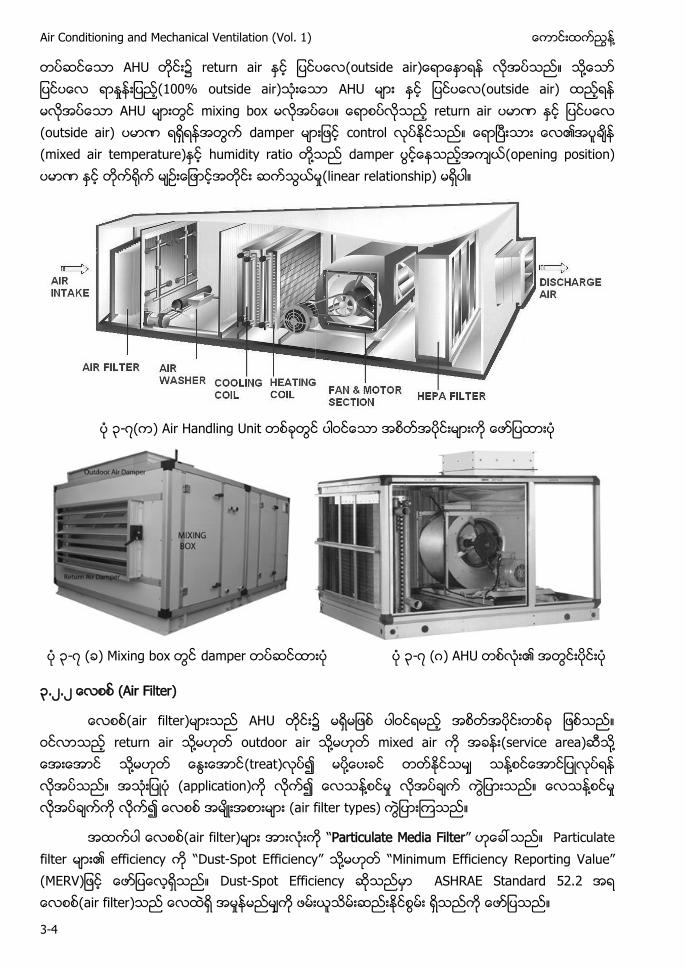
၃-၇
၃-၇ ) damper ၃-၇ ဂ)
၃.၂.၂ Air Filter)
air filter) return air ႔ outdoor air ႔ (service area) ႔ ႔ ႔ ႔ (application) ႔ ႈ ႔ ႈ (air filter types)
air filter) “Particulate Media Filter” Particulate filter efficiency “ -Spot E ” ႔ “ inimum Efficiency Reporting Value” (MERV Dust-Spot Efficiency ASHRAE Standard 52.2 air filter ႈ
႔ Chapter-3 Air Handling Units
3-5
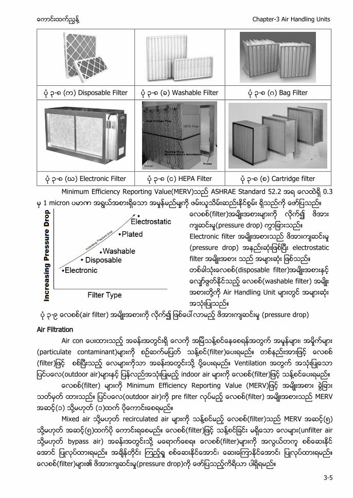
၃-၈ ( ) Disposable Filter ၃-၈ ( ) Washable Filter ၃-၈ (ဂ) Bag Filter
၃-၈ (ဃ) Electronic Filter ၃-၈ ( ) HEPA Filter ၃-၈ ( ) Cartridge filter
Minimum Efficiency Reporting Value(MERV) ASHRAE Standard 52.2 0.3 1 micron ႈ
filter) ႈ(pressure drop) E ႈ (pressure drop) electrostatic filter disposable filter) washable filter) ႔ Air Handlin
၃-၉ air filter) ႈ (pressure drop)
Air Filtration ႔ ႈ ႈ
(particulate contaminant) ႔ filter (filter ႔ ႔ outdoor air) ႔
filter) outdoor air) filter) (၁ ႔ (၁)
Mixed air ႔ r ႔ filter) ၅ ႔ ၅ ႔ ( ႔ bypass air) ႔ filter) ႈ filter) ၏ ႈ(pressure drop)
Air Conditioning and Mechanical Ventilation (Vol. 1) ႔
3-6
d (filter) s filter) ၏ (quality) filter) d ႔
Recalculated air ႔ mixed air ႔ outdoor air) s fine particle ႔ Pollution standard index of outd (၁၀၀ fine particle) ႔
၃.၂.၃ Heating Coil heating coil ႔ heater
electric heat steam heating coil
၃.၂.၄ Cooling Coil Cooling c chilled water cooling coil direct expansion (DX) cooling coil
၃.၂.၅ Humidifier ႔(moisture) air) ႔
Humidifier - steam humidifier ႔
၃.၂.၆ Fan ႔ Blower circulate) fan ႔ b B
-၆ (Chapter-
၃.၃. technical data s
Unit Name AHU 1-1 7 AHU 1-1 reference number
(model) 7 7 ဤ model York ႔
Unit Configuratioin (Horizontal)
blower “ ” ) “ orizontal c ”
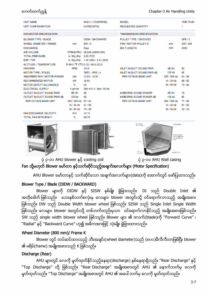
႔ Chapter-3 Air Handling Units
3-7
၃-၁၀ cooling coil ၃-၁၁ W
Fan ႔ (Motor Specification)
AHU Blower
Blower Type / Blade (DIDW / BACKWARD) B W SISW Double Inlet
b ႔ W Double Width blower w W Single Inlet Single W b ႔ W single width b blade) “Forward Curve” “Radial” “Backward Curve”
Wheel Diameter (800 mm)/ Frame K wheel diameter (၈၀၀) blower
frame)
Discharge (Rear) ႈ (discharge “ Discharge”
“Top Discharge” ႔ “ Discharge” ႈ “Top Discharge” ႈ
Air Conditioning and Mechanical Ventilation (Vol. 1) ႔
3-8
Air Volume = 28,249 CFM (CMH 48,000) AHU b air volume) 28,249 CFM (48,000 CMH)
(၄၈၀၀) ႈ (48,000 CMH “volume flow rate”
Total Pressure = 2.83 in. Wg (707 Pa) AHU b total pressure 2.83 inch of water column (707
Pa) total pressure ႈ ႈ(pressure loss) Mixing b ႈ ႈ pressure loss) cooling coil ႈ ႈ pressure loss) filter ႈ ႈ (pressure loss) ႈ ႈ pressure loss) ႈ ႈ (losses)
ESP / TSP (Pa) = 1.40 in. Wg (350 Pa) / 2.41 in. Wg (603 Pa) “External Static Pressure” “Total Static
Pressure” AHU blower “External Static Pressure” 1.40 inch of water column (350 Pa) Total static p 2.41 inch of water column (603 Pa
External/total static p AHU blower total Pressure) m ႈ ႈ ႈ ႈ filter ႈ ႈ filter pressure loss) ႈ ႈ (pressure losses ႈ pressure) External/total static pressure diffuser ႈ pressure drop) damper ႈ pressure drop)
Altitude / Temperature = 0(0)/ 68.9(20.5) sea level)
Fan Speed (RPM) = 1019 AHU blower ႈ (၁၀၁၉)
Motor Type /Poles = TEFC - IP55 / 4 "Totally Enclosed, Fan Cooled" winding) enclosure) fan motor e (protection against solid and Liquid )
Absorbed Fan / Motor Power kW = 13.50 kW / 16.20 kW Absorbed p blower shaft) power) Belt d s ႔ belt d ႔ ႈ ႈ
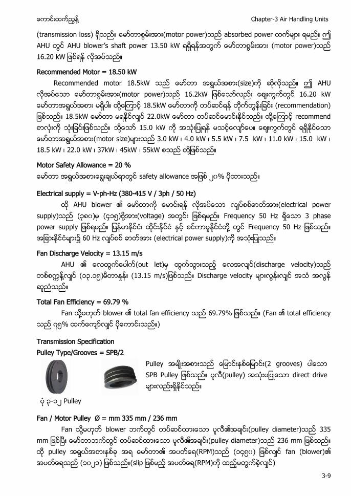
႔ Chapter-3 Air Handling Units
3-9
(transmission loss) motor power) absorbed p AHU blower’ . W (motor power) . W
Recommended Motor = 18.50 kW Recommended motor 18.5kW size) AHU motor power) . W . W ႔ . W (recommendation) . W 22. W ႔ recommend ႔ .0 W (motor size) . W 4. W . W 7. W . W . W . W . W 7 W 4 W 5kW ႔
Motor Safety Allowance = 20 % safety allowance ၂၀
Electrical supply = V-ph-Hz (380-415 V / 3ph / 50 Hz) AHU blower (electrical power
supply (၃၈၀) ၄၁၅ ႔ (voltage) Frequency ႔ Frequency 60 Hz (electrical power supply
Fan Discharge Velocity = 13.15 m/s (out let) discharge velocity)
႔ (၁၃.၁၅) ႈ .
Total Fan Efficiency = 69.79 % Fan ႔ blower .7 (F
၇၅
Transmission Specification Pulley Type/Grooves = SPB/2
2 grooves) d
၃-၁၂
Fan / Motor Pulley Ø = mm 335 mm / 236 mm Fan ႔ blower pulley diameter
pulley diameter ( (၁၄၅၀) fan (blower) (၁၀၂၁) (s ( )
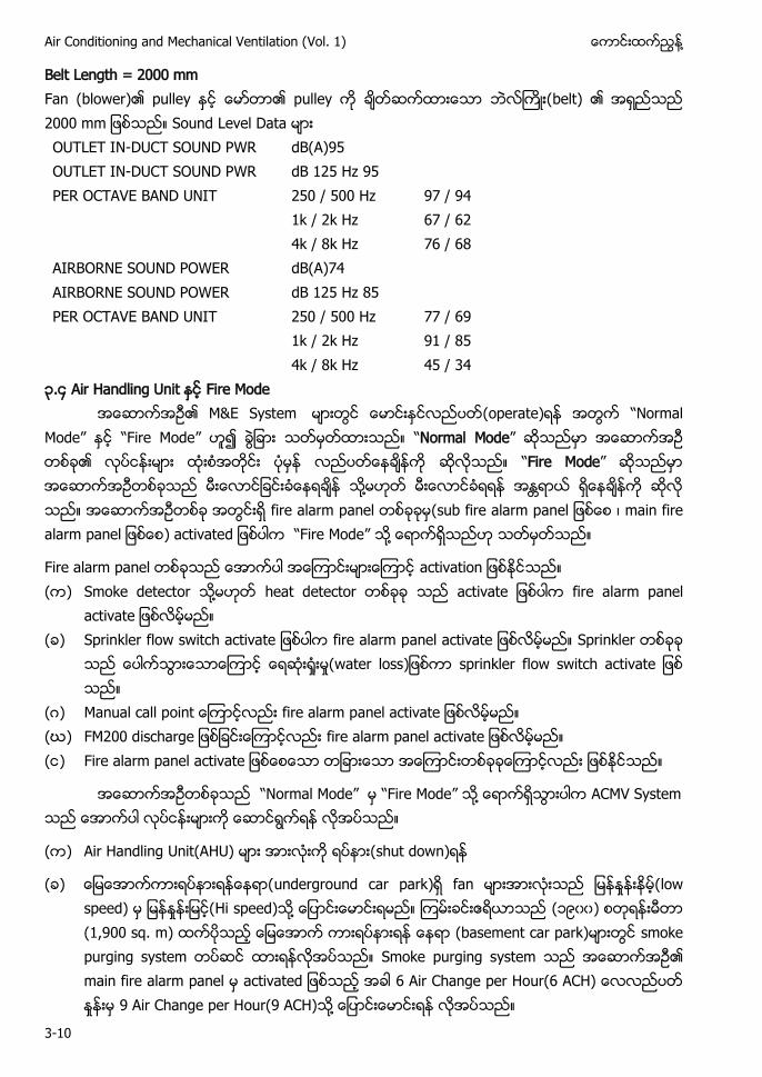
Air Conditioning and Mechanical Ventilation (Vol. 1) ႔
3-10
Belt Length = 2000 mm Fan (blower) belt) OUTLET IN-DUCT SOUND PWR dB(A)95 OUTLET IN-DUCT SOUND PWR dB 125 Hz 95 PER OCTAVE BAND UNIT 250 / 500 Hz 97 / 94 1k / 2k Hz 67 / 62 4k / 8k Hz 76 / 68 AIRBORNE SOUND POWER dB(A)74 AIRBORNE SOUND POWER dB 125 Hz 85 PER OCTAVE BAND UNIT 250 / 500 Hz 77 / 69 1k / 2k Hz 91 / 85 4k / 8k Hz 45 / 34 ၃.၄ Air Handling Unit Fire Mode
(operate “Normal Mode” “Fire Mode” “Normal Mode” “Fire Mode” ႔ fire alarm panel (sub fire alarm p main fire alarm p ) “ ” ႔
Fire alarm p ( ) Smoke detector ႔ heat detector fire alarm p
( ) Sprinkler f fire alarm p Sprinkler
ႈ ႈ(water loss sprinkler f
(ဂ) Manual call p fire alarm p (ဃ) FM200 d fire alarm p ( ) Fire alarm p
“Normal Mode” “ ” ႔
( ) Air Handling Unit(AHU) (shut down)
( ) underground car park ႈ low speed) ႈ Hi speed) ႔ (၁၉၀၀) (1,900 sq. m) smoke purging system Smoke purging system a 6 Air Change per Hour(6 ACH) ႈ 9 Air Change per Hour(9 ACH) ႔
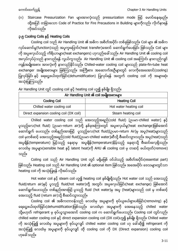
႔ Chapter-3 Air Handling Units
3-11
(ဂ) Staircase Pressurization Fan p ႔ Code of Practice for Fire Precautions in Building
၃.၅ s Heating Coils Cooling c
ႈ(function) heat t heat exchangers) cooling coil cooling coil Chilled-water cooling coil plate-fin-tube heat exchanger cooling ႔ cooling coil
cooling coil heating coil Air
Cooling Coil Heating Coil Chilled water cooling coil Hot water heating coil
Direct expansion cooling coil (DX coil) Steam heating coil
Chilled water cooling coil -chilled water hot fluid) [ -return air] ႔ ႈ heat exchange hot fluid -return Air] ( c cold fluid) -chilled water] ႔ (heat) (temperature) (temperature) ႔ s latent heat) remove)
Coiling c (essential part) Heating c heating c
Hot water steam coil heating coil Hot water c fluid(return air) fluid(hot water) ႔ heat exchange) fluid (hot water) c fluid (return air) ႔
Cooling coil (removing) ႔ (dehumidification chilled water ႔ refrigerant cooling coil Cooling c chilled water cooling coil direct expansion cooling coil (DX coil) Chilled water chilled water cooling coil refrigerant cooling coil DX (Direct expansion) cooling coil
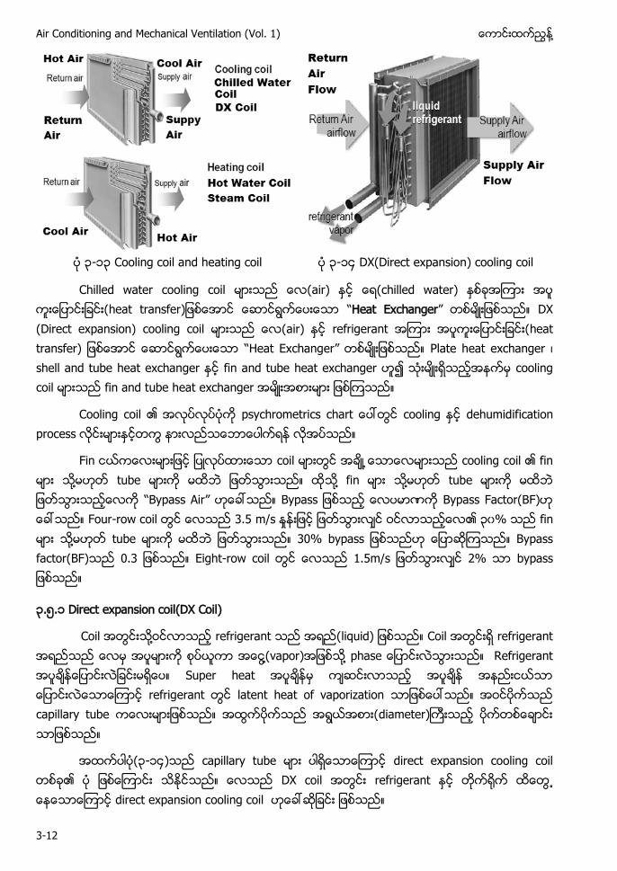
Air Conditioning and Mechanical Ventilation (Vol. 1) ႔
3-12
၃-၁၃ Cooling coil and heating coil ၃-၁၄ DX(Direct expansion) cooling coil
Chilled water cooling coil ir) “Heat Exchanger” DX (Direct expansion) cooling coil ir) refrigerant heat transfer) “Heat Exchanger” Plate heat exchanger cooling coil fin and tube heat exchanger
C dehumidif
F cooling coil ႔ tube ႔ ႔ tube “Bypass Air” Bypass Factor(BF) F - . m/s ႈ ၃၀ ႔ tube Bypass factor(BF) 0.3 E - . 2
၃.၅.၁ (DX Coil)
႔ refrigerant liquid) refrigerant ႔ ) ႔ p refrigerant latent heat of vaporization capillary tube diameter)
(၃-၁၄) capillary tube direct expansion cooling coil DX coil refrigerant ႕ direct expansion cooling coil
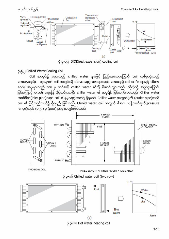
႔ Chapter-3 Air Handling Units
3-13
၃-၁၅ DX(Direct expansion) cooling coil
၃.၅.၂ Chilled Water Cooling Coil
႔ chilled water ႔ ႔ (inlet pipe) Chiller water (outlet pipe) ႔ pressure r ၁၇၅ ၃၀၀
၃-၁၆ oil (two row)
၃-၁၈ heating coil
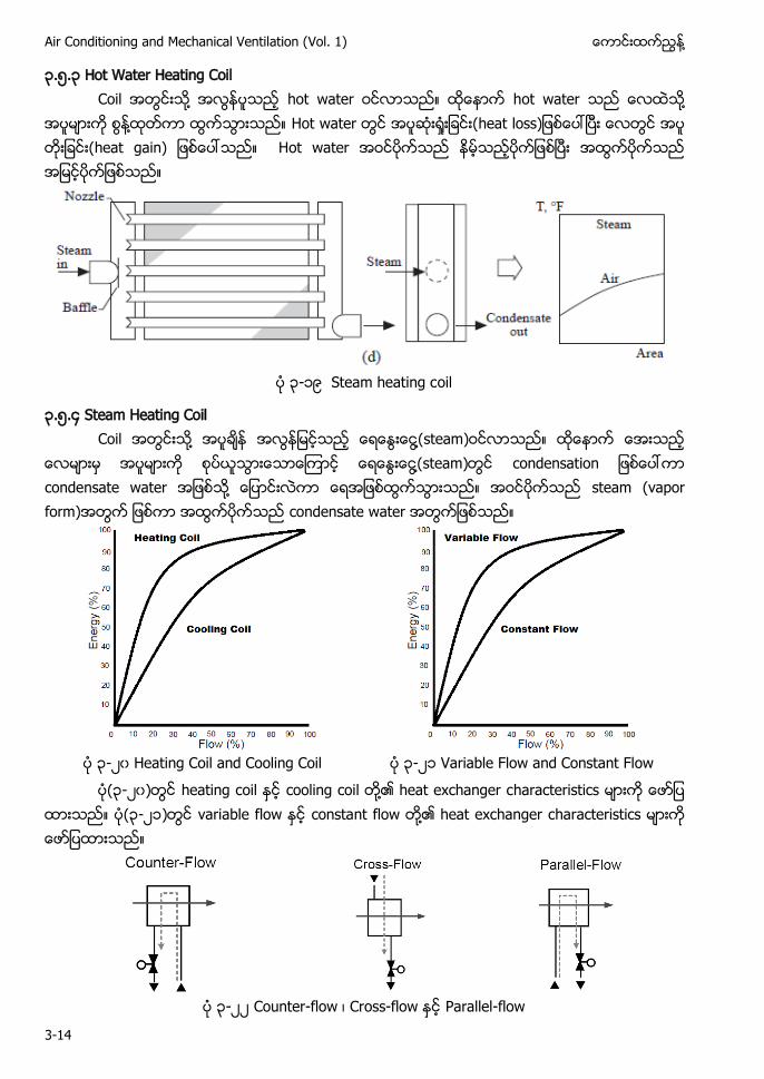
Air Conditioning and Mechanical Ventilation (Vol. 1) ႔
3-14
၃.၅.၃ W oil C ႔ h ႔ ႔ Hot water ႈ H
၃-၁၉ oil
၃.၅.၄ oil C ႔ ႔ steam)
႔ condensation ႔ steam (vapor form)
၃-၂၀ ၃-၂၁
(၃-၂၀) heating coil cooling coil ႔ heat exchanger characteristics (၃-၂၁) variable flow constant flow ႔ heat exchanger characteristics
၃-၂၂ Counter-flow Cross-flow Parallel-flow
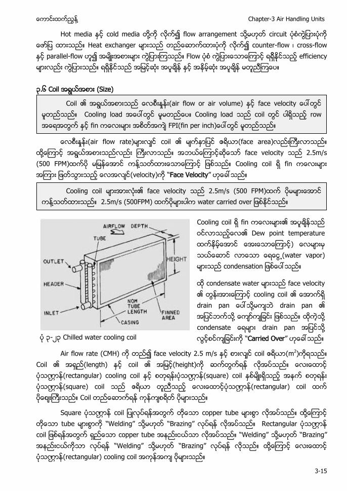
႔ Chapter-3 Air Handling Units
3-15
Hot media cold media ႔ flow arrangement ႔ circuit Heat exchanger counter-flow cross-flow parallel-flow Flow efficiency ၃.၆ Coil (Size)
ႈ (air flow rate) coil (face area) ႔ face velocity 2.5m/s (500 FPM) ႔ Cooling coil fin (velocity) “Face Velocity”
Cooling coil fin Dew point temperature ႕(water vapor) condensation
condensate water face velocity cooling coil d ႔ drain pan ႔ ႔ drain pan ႔ “Carried Over” ၃-၂၃ Chilled water cooling coil
Air flow rate (CMH) face velocity 2.5 m/s coil (m2) Coil (length) coil (height) (rectangular) cooling coil (square) coil (square) coil (rectangular) coil Coil
Square copper tube ႔ tube “Welding” ႔ “Brazing” Rectangular copper tube “Welding” ႔ “ ” “W ” ႔ “ ” ႔ (rectangular) cooling coil
Coil ႈ (air flow or air volume) face Cooling load Cooling load coil row fin FPI(
Cooling coil face velocity 2.5m/s (500 FPM) ႔ 2.5m/s (500FPM)
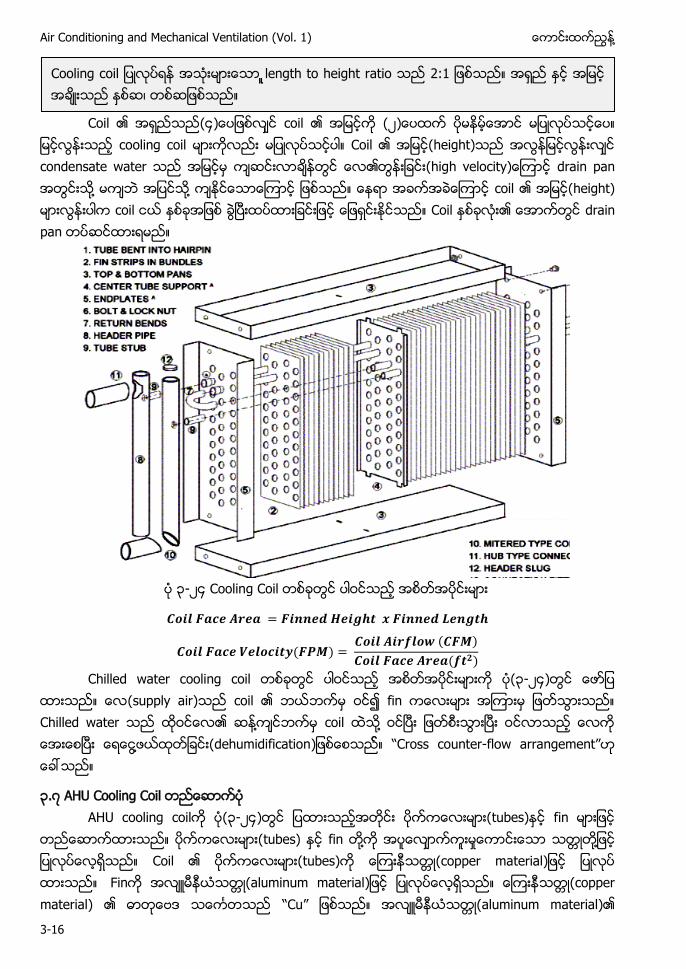
Air Conditioning and Mechanical Ventilation (Vol. 1) ႔
3-16
Coil (၄ coil (၂
cooling coil Coil (height) condensate water drain pan ႔ ႔ coil (height) coil Coil drain pan
၃-၂၄
C ၃-၂၄ (supply air) ႔ ႔ ႔ dehumidification “ counter-flow ”
၃.၇ AHU cooling coil ၃-၂၄ tubes) f
tubes) fin ႔ ႈ ႔ tubes) (copper material Fin (aluminum material (copper material) “Cu” (aluminum material)
length to height ratio
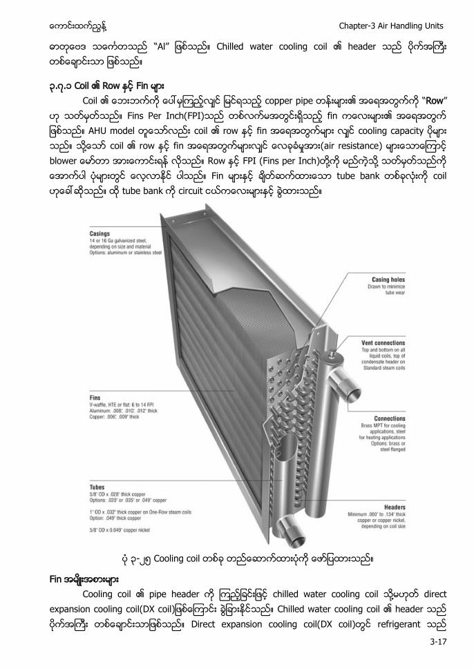
႔ Chapter-3 Air Handling Units
3-17
“Al” Chilled water cooling coil
၃.၇.၁ copper p “Row”
Fins Per Inch(FPI) fin ow fin cooling capacity ႔ fin ႈ (air resistance) blower Row FPI (Fins per Inch) ႔ ႔ Fin c tube b
၃-၂၅
႔
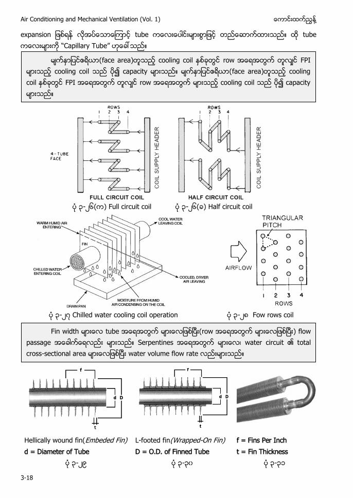
Air Conditioning and Mechanical Ventilation (Vol. 1) ႔
3-18
expansion “ ”
၃-၂၆ Full circuit coil ၃-၂၆ Half circuit coil
၃-၂၇ Chilled water cooling coil operation ၃-၂၈ Fow rows coil
Hellically wound fin(Embeded Fin) L-footed fin(Wrapped-On Fin) f = Fins Per Inch d = Diameter of Tube D = O.D. of Finned Tube t = Fin Thickness
၃-၂၉ ၃-၃၀ ၃-၃၁
face area) face area)
) S water circuit -
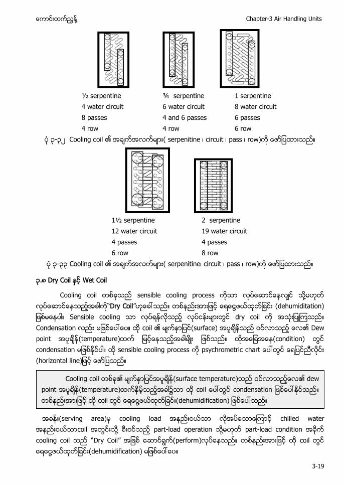
႔ Chapter-3 Air Handling Units
3-19
½ serpentine
4 water circuit 8 passes 4 row
¾ serpentine 6 water circuit 4 and 6 passes 4 row
1 serpentine 8 water circuit 6 passes 6 row
၃-၃၂ oil
1½ serpentine
12 water circuit 4 passes 6 row
2 serpentine 19 water circuit 4 passes 8 row
၃-၃၃ Cooling coil
၃.၈ Wet Coil
Cooling coil s ႔ “Dry Coil” ႔ (dehumiditation) dry coil C c surface) D temperature) condition) c (
(serving area) cooling lo chilled water c ႔ part-load operation ႔ - cooling coil “Dry Coil” perform) ႔ dehumidification
(surface temperature) dew p temperature) ၌ ႔
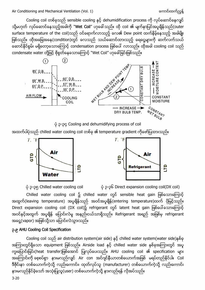
Air Conditioning and Mechanical Ventilation (Vol. 1) ႔
3-20
Cooling c s dehumidification ႔ “Wet Coil” c D ႔ condensation p cooling coil condensate water ႔ “Wet Coil”
၃-၃၄ Cooling and dehumidifying process of coil
chilled water cooling coil temperature gradient
၃-၃၅ Chilled water cooling coil ၃-၃၆ Direct expansion cooling coil(DX coil)
Chilled water cooling coil chilled water (leaving temperature) (entering temperature) Direct expansion cooling coil (DX coil) refrigerant l ႈ Refrigerant refrigerant ႔(vapor) ႔
၃.၉ AHU Cooling Coil Specification
Cooling coil air distribution system(air side) chilled water system(water side) e Airside load chilled water side (heat transfer AHU Air c ဂ ႔ (manufacturer) ႔ (user) ႔
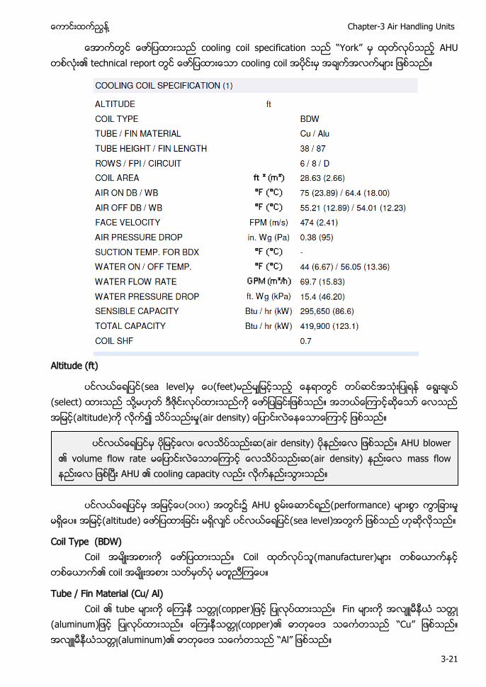
႔ Chapter-3 Air Handling Units
3-21
cooling coil specifica “York” technical r cooling coil
Altitude (ft)
sea level) ( (select) ႔ altitude) ႈ(air density
၁၀၀) ႈ altitude sea level)
Coil Type (BDW) (manufacture
c
Tube / Fin Material (Cu/ Al) ube (copper
(aluminum (copper) “Cu” (aluminum) “Al”
air density) AHU blower air density)
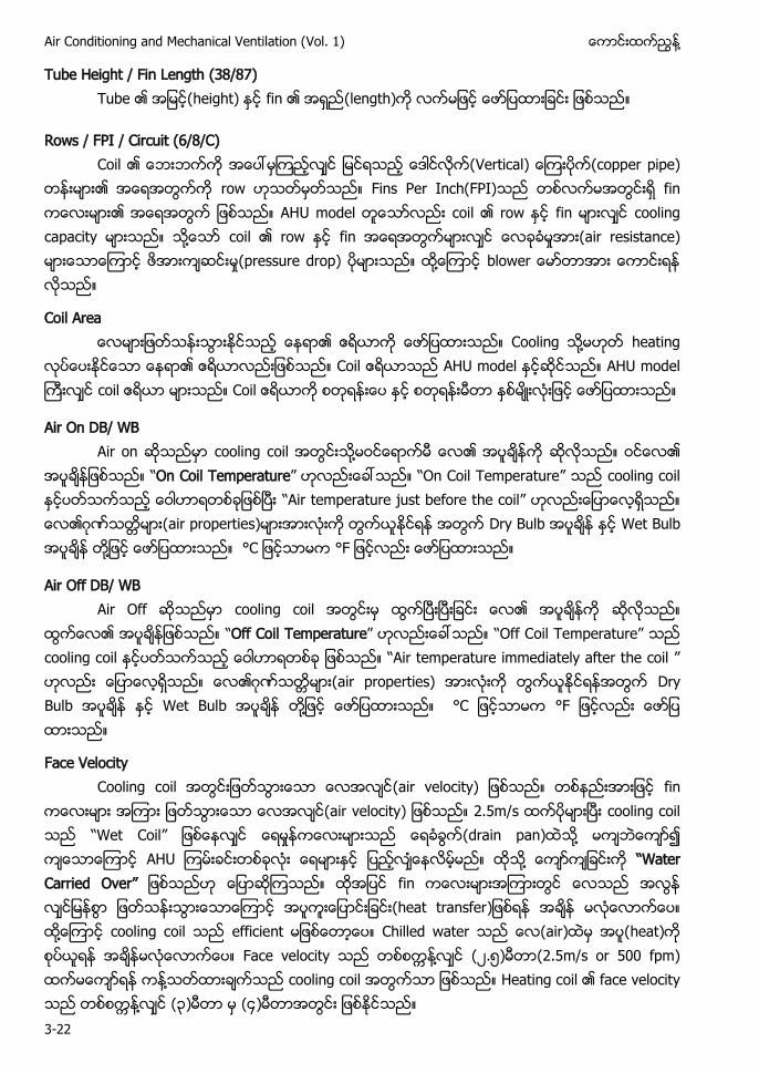
Air Conditioning and Mechanical Ventilation (Vol. 1) ႔
3-22
Tube Height / Fin Length (38/87) height f (length)
Rows / FPI / Circuit (6/8/C) Vertical) copp row Fins Per Inch(FPI) f f cooling c ႔ coi fin ႈ (air resistance) ႈ(pressure drop) ႔ b
Coil Area ႔ heating
Coil AHU model c Coil
Air On DB/ WB cooling coil ႔ “On Coil Temperature” “ ” cooling coil “ ” ဂ air properties) Dry Bulb Wet Bulb ႔
Air Off DB/ WB cooling coil “Off Coil Temperature” “ ” cooling coil “ ” ဂ air properties) Dry Bulb Wet Bulb ႔
Face Velocity Cooling c (air velocity) f air velocity) 2.5m/s cooling coil “Wet Coil” ႈ (drain pan) ႔ ႔ “W Carried O ” f (heat transfer ႔ cooling coil (air) heat) Face v ႔ ၂.၅ (2.5m/s or 500 fpm) ႔ cooling coil Heating c ႔ ၃ ၄
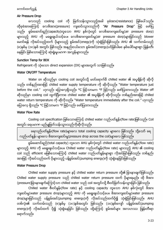
႔ Chapter-3 Air Handling Units
3-23
Air Pressure Drop cooling coil resistance)
pressure) ”Air Pressure Drop” ႈ air pressure dorp) ႈ air pressure dorp) b (၈) (၁၀) energy) ႈ ႈ
Sunction Temp for BDX direct expansion (DX)
Water ON/OFF Temperature
W cooling c ႔ chilled w chilled water supply te “W .” W cooling coil chilled w chilled w “W emperature immediately after the coil.”
Water Flow Rate
Cooling c chilled water ႈ (flow rate
total capacity) chilled w ႈ (flow rate)
AH Chilled w ႈ (flow rate) cooling coil e chilled w ႈ ႔ pumping energy
Water Pressure Drop
Chilled water supply pressure chilled water return pressure ႔ Chilled water supply pressure chilled water return pressure (pressure chilled w c ႔
Chilled water ႈ (flow rate) cooling c ႈ water pressure drop) ႈ water pressure drop) ႔ pumping energy) (၈) (၁၀) (၁ ) ႔ pumping energy) ႔
ႈ (flow rate ႔ ႈ ႈ(pressure drop across the coil
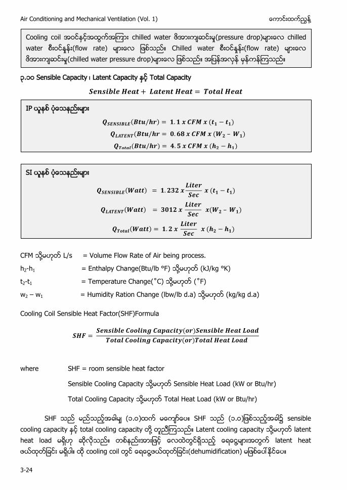
Air Conditioning and Mechanical Ventilation (Vol. 1) ႔
3-24
၃.၁ Total Capacity
CFM ႔ L/s = Volume Flow Rate of Air being process.
h2-h1 = Enthalpy Change(Btu/lb °F) ႔ (kJ/kg °K)
t2-t1 = Temperature Change(˚ ) ႔ (˚
w2 – w1 = Humidity Ration Change (lbw/lb d.a) ႔ (kg/kg d.a)
Cooling Coil Sensible Heat Factor(SHF)Formula
where SHF = room sensible heat factor
Sensible Cooling Capacity ႔ Sensible Heat Load (kW or Btu/hr)
Total Cooling Capacity ႔ Total Heat Load (kW or Btu/hr)
(၁. ) ၁. sensible cooling capacity ႔ Latent cooling capacity ႔ latent heat l ႔ ႔ dehumidification)
c ႈ ႈ Chilled wat ႈ ႈ chilled water pressure dro
IP
SI
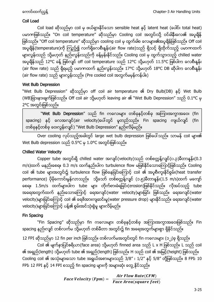
႔ Chapter-3 Air Handling Units
3-25
Coil Load Coil load coil sensible heat latent heat total heat)
“ ” Cooling coil ႔ “ ” cooling coil Off coil (temperature) ႈ (air flow rate) ႔ ႔ Cooling coil chilled water 12°C ႔ off coil temperature 12°C ႔ 11.5°C ႈ (air flow rate) 17°C ႔ 18°C DB ႈ (air flow rate) (Pre cooled coil )
Wet Bulb Depression “W ulb Depression” off coil air temperature Dry Bulb(DB) Wet Bulb (WB Off coil air ႔ leaving air “W Bulb ” 0.1°C 2°C
Over cooling large wet bulb d coil
Wet Bulb depression 0.5°C 1.0°C
Chilled Water Velocity Copper tube chilled water (velocity) ႔ (၀.၃) ႈ (0.3 m/s) 0.3 m/s turbulence flow Cooling coil tube coil (heat transfer performance) ႔ ႔ (၁.၅) ႈ (1.5 m/s) 1.5m/s tube tube (water velocity) (water velocity) coil ႈ(water pressure drop) (water velocity) ႔ ႈ
Fin Spacing “ pacing” fin Fin spacing ႔ fin
12 FPI fin (၁၂) Coil (face area) ႔ finned area L coil
(length) ႔ tube (length) H coil (height) Cooling coil tube ” ” ” ႔ 8 FPI 10 FPI 12 FPI 14 FPI fin spacing ႕
“Wet Bulb Depression” fin (fin spacing) Fin spacing (fin “W ”
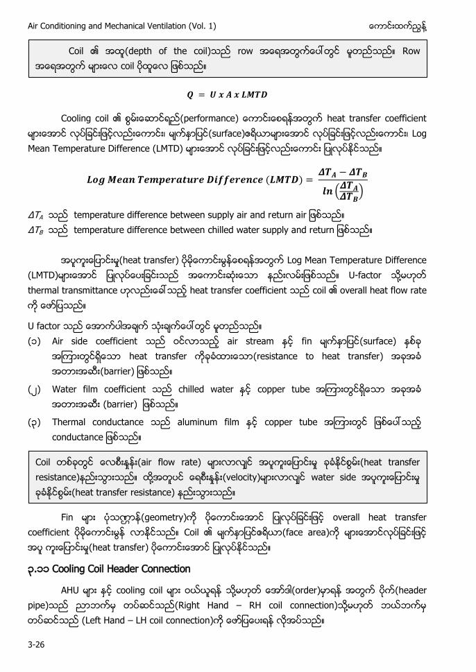
Air Conditioning and Mechanical Ventilation (Vol. 1) ႔
3-26
Cooling coil (performance) heat transfer coefficient (surface) Log Mean Temperature Difference (LMTD)
(
)
Δ A temperature difference between supply air and return a Δ B temperature difference between chilled water supply and r
ႈ(heat transfer) Log Mean Temperature Difference (LMTD) U-factor ႔ thermal transmittance heat transfer coefficient coil overall heat flow rate
U factor (၁) Air side coefficient air stream fin (surface)
heat transfer (resistance to heat transfer) (barrier)
(၂) Water film coefficient chilled water copper tube (barrier)
(၃) Thermal conductance aluminum film copper tube
Fin (geometry) overall heat transfer coefficient Coil (face area) ႈ(heat transfer)
၃.၁၁ Cooling Coil Header Connection
AHU cooling coil ႔ (order) (header pipe) (Right Hand – RH coil connection) ႔ (Left Hand – LH coil connection)
Coil (depth of the coil) row Row coil
Coil ႈ (air flow rate) ႈ (heat transfer resistance) ႔ ႈ (velocity) water side ႈ (heat transfer resistance)
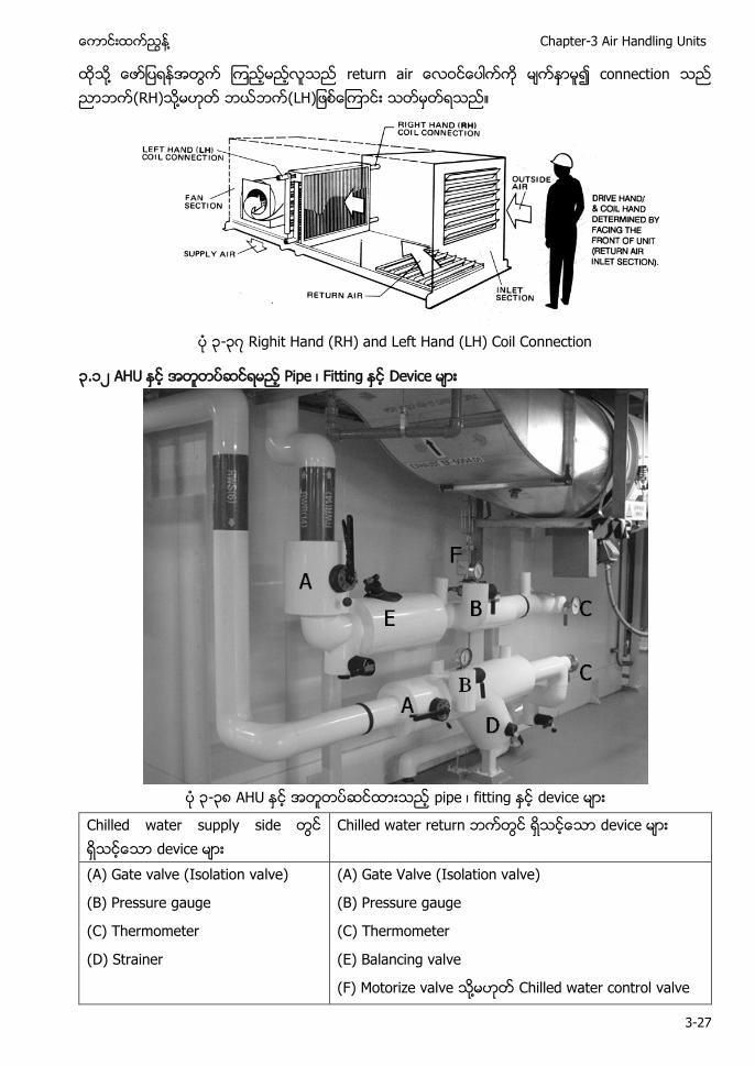
႔ Chapter-3 Air Handling Units
3-27
႔ return a connection (RH) ႔ (LH
၃-၃၇ Righit Hand (RH) and Left Hand (LH) Coil Connection
၃.၁၂ AHU Pipe Fitting Device
၃-၃၈ AHU pipe fitting device
Chilled water supply side device
Chilled water return device
(A) Gate valve (Isolation valve)
(B) Pressure gauge
(C) Thermometer
(D) Strainer
(A) Gate Valve (Isolation valve)
(B) Pressure gauge
(C) Thermometer
(E) Balancing valve
(F) Motorize valve ႔ Chilled water control valve
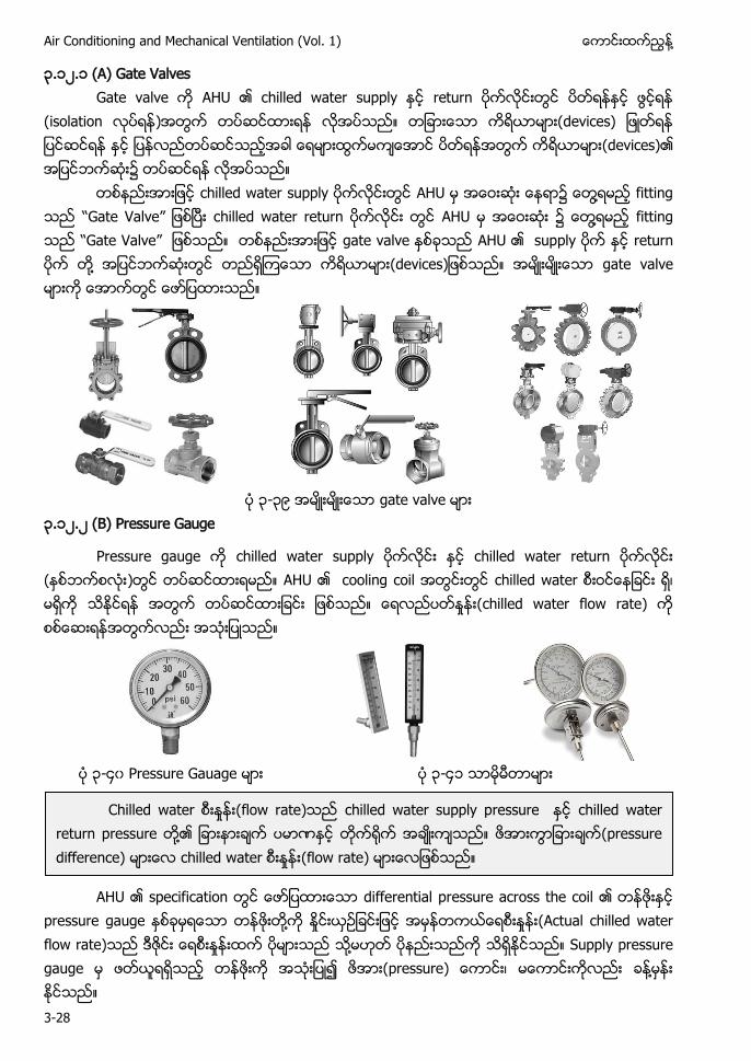
Air Conditioning and Mechanical Ventilation (Vol. 1) ႔
3-28
၃.၁၂.၁ (A) Gate Valves Gate valve AHU chilled water supply return
(isolation ) (devices) (devices)
chilled water supply AHU ႔ fitting “Gate Valve” chilled water return AHU ၌ ႔ fitting “Gate Valve” gate valve AHU supply return ႔ gate valve
၃-၃၉ gate valve
၃.၁၂.၂ (B) Pressure Gauge
Pressure gauge chilled water supply chilled water return ( ) AHU cooling coil chilled water ႈ (chilled water flow rate)
၃-၄၀ Pressure Gauage ၃-၄၁
AHU specification differential pressure across the coil
pressure gauge ႔ ႈ ႈ (Actual chilled water flow rate) ႈ ႔ Supply pressure gauge (pressure ႔
Chilled water ႈ (flow rate) chilled water supply pressure chilled water return pressure ႔ (pressure difference) chilled water ႈ (flow rate)
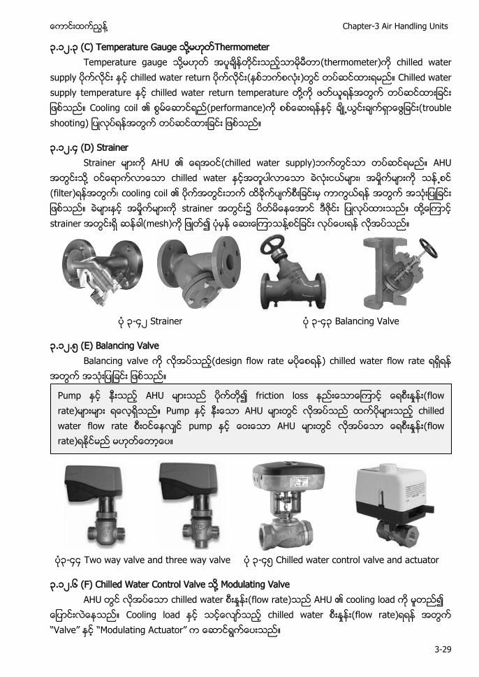
႔ Chapter-3 Air Handling Units
3-29
၃.၁၂.၃ (C) Temperature Gauge ႔ Thermometer Temperature gauge ႔ (thermometer) chilled water
supply chilled water return ( ) Chilled water supply temperature chilled water return temperature ႔ Cooling coil (performance) ႕ (trouble shooting)
၃.၁၂.၄ (D) Strainer Strainer AHU (chilled water supply) AHU
႔ chilled water ႈ ႕ (filter) cooling coil ႈ strainer ႔ strainer (mesh) ႔
၃-၄၂ Strainer ၃-၄၃ Balancing Valve
၃.၁၂.၅ (E) Balancing Valve Balancing valve (design flow rate ) chilled water flow rate
၃-၄၄ Two way valve and three way valve ၃-၄၅ Chilled water control valve and actuator
၃.၁၂.၆ (F) Chilled Water Control Valve ႔ Modulating Valve AHU chilled water ႈ (flow rate) AHU cooling load ၍
Cooling load chilled water ႈ (flow rate) “Valve” “Modulating Actuator”
Pump AHU friction loss ႈ (flow rate) Pump AHU chilled water flow rate pump AHU ႈ (flow rate)
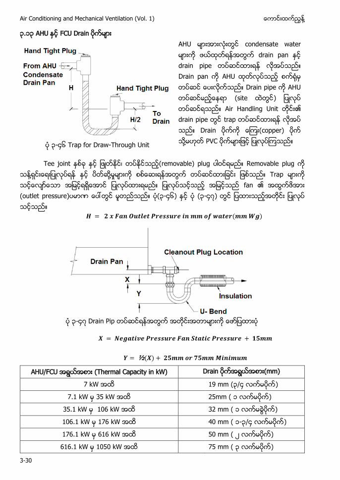
Air Conditioning and Mechanical Ventilation (Vol. 1) ႔
3-30
၃.၁၃ AHU FCU Drain
AHU condensate water drain pan drain pipe Drain pan AHU Drain pipe AHU (site ) Air Handling Unit drain pipe trap Drain (copper) ႔ PVC ၃-၄၆ Trap for Draw-Through Unit
Tee joint (removable) plug Removable plug ႔ ႔ ႈ Trap fan (outlet pressure) (၃-၄၆) (၃-၄၇)
၃-၄၇
AHU/FCU (Thermal Capacity in kW) Drain (mm)
7 kW 19 mm (၃/၄ )
7.1 kW 35 kW 25mm ( ၁ )
35.1 kW 106 kW 32 mm ( ၁ )
106.1 kW 176 kW 40 mm ( ၁-၃/၄ )
176.1 kW 616 kW 50 mm ( ၂ )
616.1 kW 1050 kW 75 mm ( ၃ )
႔ Chapter-3 Air Handling Units
3-31
၃.၁၄ Air Handling Unit ( AHU ) (Code) (၁) Air Handling Unit control device
(၂) AHU cooling coil finned coil 8 row (8 row ႔ ) Air treatment process ၏ row cooling coil cooling coil ႔ ႔ (cleaning) servicing
(၃) Cooling coil condensate water (drain) U bend Condensate drain pan floor trap (Air break between the condensate drain pope and the floor trap. )
(၄) AHU (switched off) cooling coil condensate water AHU
(၅) AHU ၏ fan ႔ blower cooling coil ႔ chilled water
(၆) AHU ၏ ႔ abrasion resistant
(၇) AHU စၥညးမား သေလာငသမးဆညးထားျခငး မျပရ။ Air con system ၥ AHU system (installation)
(၈) AHU Code of practice for Fire Precaution (operate) (fire safety requirement)
၃.၁၄.၁ AHU Fan System Design Criteria AHU fan ႔ blower ၏ 4 kW Fan power limitation in air conditioning system
Allowable Nameplate motor power
Constant Volume (CAV AHU) Variable Volume 1.7 kW / m³/s 2.4 kW / m³/s
Variable Air Volume (VAV) AHU fan nameplate motor 2.4 kW/m³/s ( ႔ ႈ 2.4 kW )
Constant Air Volume System (CAV) AHU fan motor ၏ nameplate reading 1.7 kW/ m³/s ( ႔ (1 m3) ႈ 1.7 kW )
Air conditioning system (automatically s
Air Conditioning and Mechanical Ventilation (Vol. 1) ႔
3-32
( ) 7 day timer ႔ schedule AHU (start/stop (temporary operation) function
( ) Occupancy sensor occupancy sensor (၃၀) (no occupant) (detect) AHU (shutdown)
(ဂ) Security system security system AHU (shutdown) (guest room) (manual on/off) AHU
(ဃ) ႈ (air flow rate) 5 m³/s AHU optimum start control ၀ Optimum start control algorithm set point (room temperature) ႔၏ (differential temperature) scheduled occupancy ႔၏ ႔
( ) ၏ AHU (zone) ၏ 2300 m² (zone) ႔
( ) AHU (shutdown) AHU (outdoor air intake) exhaust air system (shutdown)
( ) AHU ႔ “pre occupancy building cool-down” - - outdoor air damper
( ) A (space) outdoor supply air exhaust system damper
( ) Damper (pressure) damper ၏ ႈ(maximum leakage rate) 100 l/s per m² damper ႈ (leak) 100 L/s
႔ • 2.4 m³/s fan system exhausted air
outdoor air connection • ႈ (design airflow) ၁၀% (zone)
exhaust air system • (zone)
၏ (power) 0.5 kW automatic shutdown
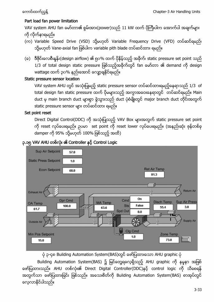
႔ Chapter-3 Air Handling Units
3-33
Part load fan power limitation VAV ၏ (power) 11 kW ( ) Variable Speed Drive (VSD) ႔ Variable Frequency Drive (VFD)
႔ - variable pith blade
( ) ႈ (design airflow) ၏ ၅၀% static pressure set point ၏ demand design wattage ၃၀%
Static pressure sensor location VAV system AHU static pressure sensor 1/3 of
total design fan static pressure Main duct main branch duct duct major branch duct static pressure sensor
Set point reset Direct Digital Control(DDC) VAV Box static pressure set point
reset set point reset lower ( damper 95% ႔ )
၃.၁၅ VAV AHU Controller Control Logic
၃-၄၈ Building Automation System(BAS) AHU graphic
Building Automation System(BAS) ၌ ႔ AHU graphic AHU Direct Digital Controller(DDC) control logic Building Automation System(BAS)
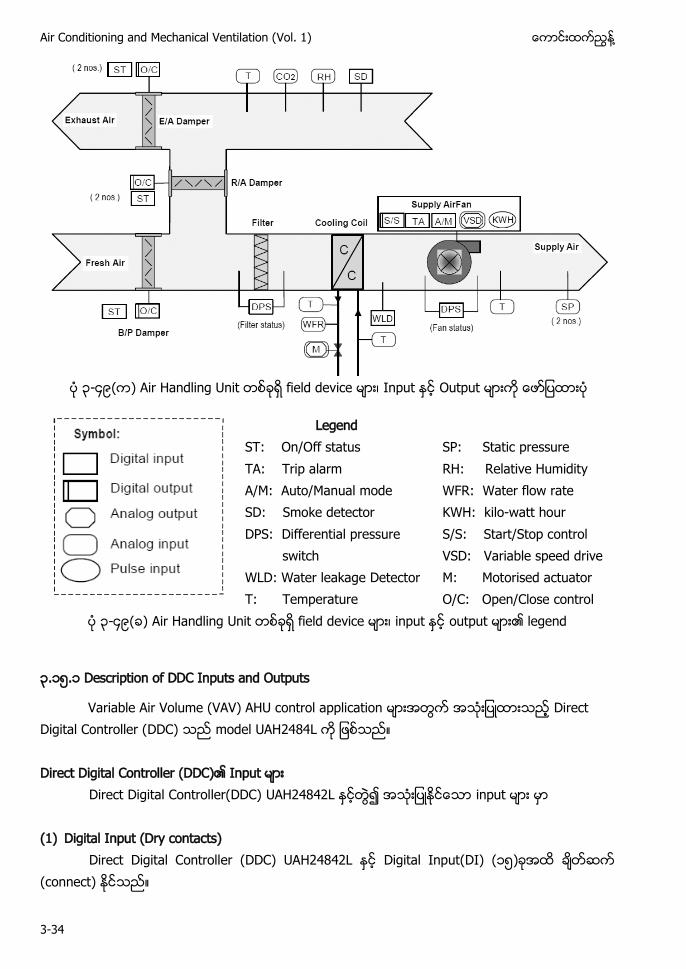
Air Conditioning and Mechanical Ventilation (Vol. 1) ႔
3-34
၃-၄၉ Air Handling Unit field device Input Output
Legend ST: On/Off status TA: Trip alarm A/M: Auto/Manual mode SD: Smoke detector DPS: Differential pressure switch WLD: Water leakage Detector T: Temperature
SP: Static pressure RH: Relative Humidity WFR: Water flow rate KWH: kilo-watt hour S/S: Start/Stop control VSD: Variable speed drive M: Motorised actuator O/C: Open/Close control
၃-၄၉ Air Handling Unit field device input output legend
၃.၁၅.၁ Description of DDC Inputs and Outputs
Variable Air Volume (VAV) AHU control application Direct Digital Controller (DDC) model UAH2484L Direct Digital Controller (DDC) Input
Direct Digital Controller(DDC) UAH24842L input (1) Digital Input (Dry contacts)
Direct Digital Controller (DDC) UAH24842L Digital Input(DI) (၁၅) (connect)
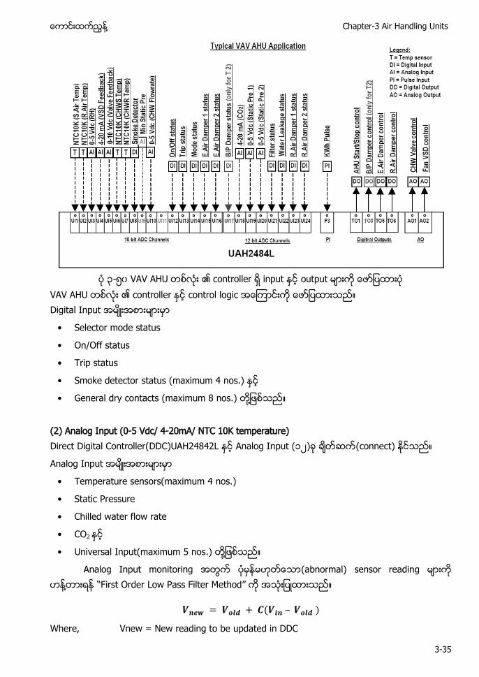
႔ Chapter-3 Air Handling Units
3-35
၃-၅၀ VAV AHU controller input output
VAV AHU controller control logic Digital Input
• Selector mode status
• On/Off status
• Trip status
• Smoke detector status (maximum 4 nos.)
• General dry contacts (maximum 8 nos.) ႔
(2) Analog Input (0-5 Vdc/ 4-20mA/ NTC 10K temperature) Direct Digital Controller(DDC)UAH24842L Analog Input (၁၂) (connect)
Analog Input
• Temperature sensors(maximum 4 nos.)
• Static Pressure
• Chilled water flow rate
• CO2
• Universal Input(maximum 5 nos.) ႔
Analog Input monitoring (abnormal) sensor reading ႔ “ rder Low Pass Filter Method”
Where, Vnew = New reading to be updated in DDC
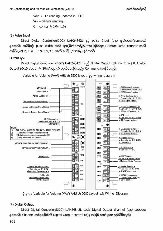
Air Conditioning and Mechanical Ventilation (Vol. 1) ႔
3-36
Vold = Old reading updated in DDC Vin = Sensor reading, C = constant(0.0~ 1.0)
(3) Pulse Input Direct Digital Controller(DDC) UAH24842L pulse Input (၁) (connect)
pulse width (၅၀) ႔(50ms) Accumulated counter (value) 0 1,999,999,999 (display)
Output Direct Digital Controller (DDC) UAH24842L Digital Output (24 Vac Triac) & Analog
Output (0-10 Vdc or 4- 20mA) C
Variable Air Volume (VAV) AHU DDC layout wiring diagram
၃-၅၁ Variable Air Volume (VAV) AHU DDC Layout Wiring Diagram
(4) Digital Output
Direct Digital Controller(DDC) UAH24842L Digital Output channel (၅) Channel Digital Output control (၁) configure

႔ Chapter-3 Air Handling Units
3-37
AHU / AHU Start/Stop(Individual schedule or manual control) / Fan 1 Start/Stop(Individual schedule manual control)(used as By pass damper control ) / Fan 2 Start/Stop(Individual schedule manual control) Return air damper / Return air damper Open/Close control(interlock with AHU operation) Exhaust air damper / Exhaust air damper Open/Close control(interlock with AHU operation) Variable Air Volume (VAV) AHU Typical Sensor Termination
၃-၅၂ Variable Air Volume(VAV)AHU Typical Sensor Termination
(5) Analog Output Direct Digital Controller(DDC) UAH24842L Analog output channel • AHU Variable Speed Drive(VSD) control
• AHU chilled water valve control ႔
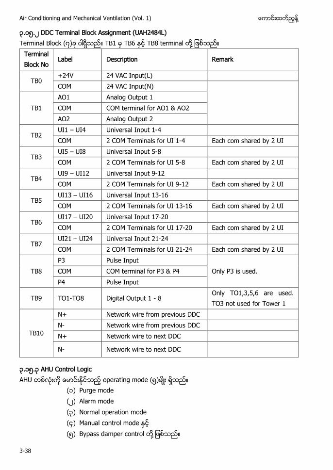
Air Conditioning and Mechanical Ventilation (Vol. 1) ႔
3-38
၃.၁၅.၂ DDC Terminal Block Assignment (UAH2484L) Terminal Block (၇) TB1 TB6 TB8 terminal ႔
Terminal Block No
Label Description Remark
TB0 +24V 24 VAC Input(L) COM 24 VAC Input(N)
TB1
AO1 Analog Output 1 COM COM terminal for AO1 & AO2 AO2 Analog Output 2
TB2 UI1 – UI4 Universal Input 1-4 COM 2 COM Terminals for UI 1-4 Each com shared by 2 UI
TB3 UI5 – UI8 Universal Input 5-8 COM 2 COM Terminals for UI 5-8 Each com shared by 2 UI
TB4 UI9 – UI12 Universal Input 9-12 COM 2 COM Terminals for UI 9-12 Each com shared by 2 UI
TB5 UI13 – UI16 Universal Input 13-16 COM 2 COM Terminals for UI 13-16 Each com shared by 2 UI
TB6 UI17 – UI20 Universal Input 17-20 COM 2 COM Terminals for UI 17-20 Each com shared by 2 UI
TB7 UI21 – UI24 Universal Input 21-24 COM 2 COM Terminals for UI 21-24 Each com shared by 2 UI
TB8 P3 Pulse Input
Only P3 is used. COM COM terminal for P3 & P4 P4 Pulse Input
TB9 TO1-TO8 Digital Output 1 - 8 Only TO1,3,5,6 are used. TO3 not used for Tower 1
TB10
N+ Network wire from previous DDC N- Network wire from previous DDC N+ Network wire to next DDC
N- Network wire to next DDC
၃.၁၅.၃ AHU Control Logic AHU operating mode (၅) (၁) Purge mode (၂) Alarm mode (၃) Normal operation mode (၄) Manual control mode (၅) Bypass damper control ႔
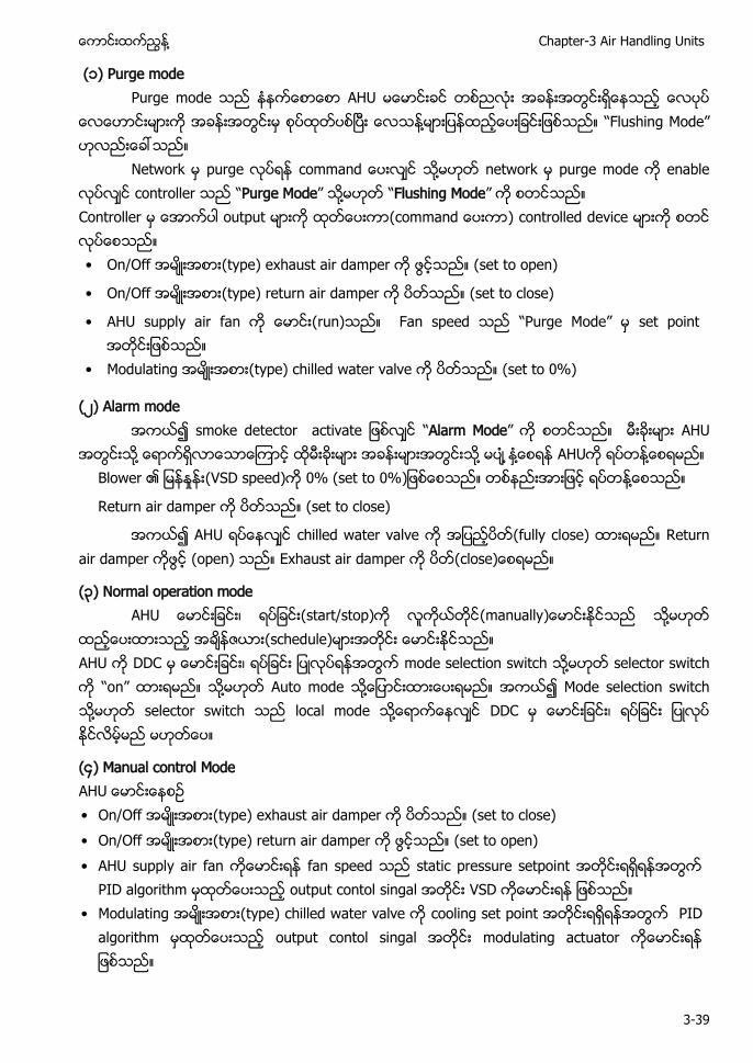
႔ Chapter-3 Air Handling Units
3-39
(၁) Purge mode Purge mode AHU
႔ “Flushing Mode”
Network purge ႔ network purge mode enable controller “Purge Mode” ႔ “Flushing Mode” Controller output ( ) controlled device • On/Off (type) exhaust air damper (set to open)
• On/Off (type) return air damper (set to close)
• AHU supply air fan (run) Fan speed “ ode” set point
• Modulating (type) chilled water valve (set to 0%)
(၂) Alarm mode “Alarm Mode” AHU
႔ ႔ ႔ AHU ႔ Blower ႈ (VSD speed) 0% (set to 0% ႔
Return air damper (set to close)
AHU chilled water valve (fully close) Return air damper (open) Exhaust air damper (
(၃) Normal operation mode (start/stop) (manually ႔
(schedule) AHU DDC mode selection switch ႔ selector switch “on” ႔ Auto mode ႔ Mode selection switch ႔ selector switch local mode ႔ DDC
(၄) Manual control Mode • On/Off (type) exhaust air damper (set to close) • On/Off (type) return air damper (set to open) • AHU supply air fan fan speed static pressure setpoint
PID algorithm output contol singal VSD • Modulating (type) chilled water valve cooling set point PID
algorithm output contol singal modulating actuator
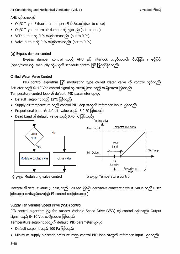
Air Conditioning and Mechanical Ventilation (Vol. 1) ႔
3-40
AHU • On/Off type Exhaust air damper (set to close) • On/Off type return air damper (set to open) • VSD output 0 % (set to 0 %) • Valve output 0 % (set to 0 %) (၅) Bypass damper control
Bypass damper control AHU interlock (open/close) manually ႔ Chilled Water Valve Control
modulating type chilled water valve control Actuator 0~10 Vdc control signal Temperature control loop default PID parameter • Default setpoint • Supply air temperature control PID loop • Proportional band default value . • Dead band default value .4
၃-၅၃ Modulating valve control ၃-၅၄ Temperature control
Integral default value (I gain) derivative constant default value ( PI control ) Supply Fan Variable Speed Drive (VSD) control f Variable Speed Drive (VSD) control Output signal 0~10 Vdc Temperature setpoint default PID parameter • Default setpoint
• Minimum supply air static pressure control PID loop
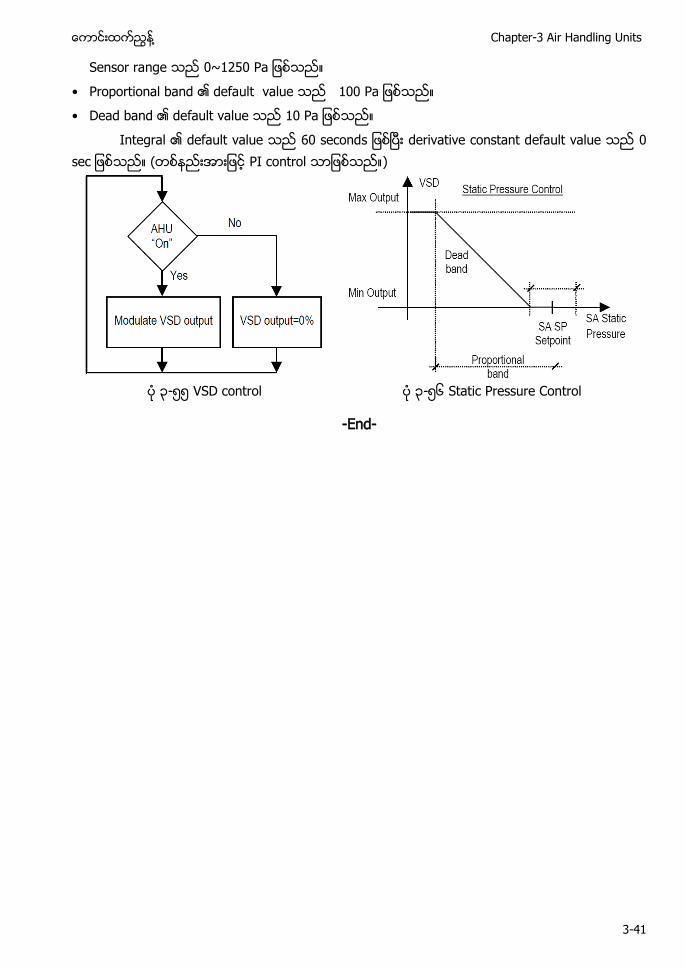
႔ Chapter-3 Air Handling Units
3-41
Sensor range
• Proportional band default value • Dead band default value
Integral default value 60 seconds derivative constant default value ( PI control )
၃-၅၅ VSD control ၃-၅၆ Static Pressure Control
-End-
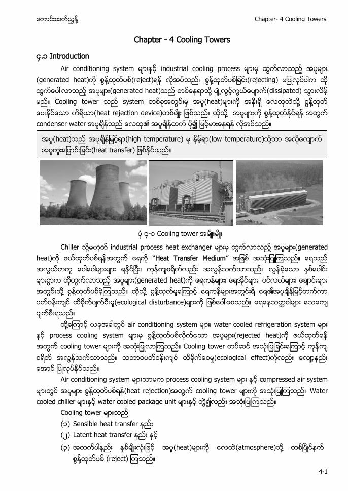
႔ Chapter- 4 Cooling Towers
4-1
Chapter - 4 Cooling Towers
၄.၁ Introduction Air conditioning system မားႏင industrial cooling process မားမ ထြကလာသည အပမား
(generated heat)က စြန႔ထတပစ(reject)ရန လအပသည။ စြန႔ထတပစျခငး(rejecting) မျပလပပါက ထ ထြကေပၚလာသည အပမား(generated heat)သည တစေနရာသ႔ (dissipated) သြားလမ မည။ Cooling tower သည system တစခအတြငးမ အပ(heat)မားက အနးရ ေလထထသ႔ စြန႔ထတ ေပးႏငေသာ ကရယာ(heat rejection device)တစမး ျဖစသည။ ထသ႔ အပမားက စြန႔ထတႏငရန အတြက condenser water အပခနသည ေလထ၏ အပခနထက ပ၍ ျမငမားေနရန လအပသည။
၄-
Chiller ႔ industrial process heat exchanger မားမ ထြကလာသည အပမား(generated heat)က ဖယထတပစရနအတြက ေရက “Heat Transfer Medium” အျဖစ အသးျပၾကသည။ ေရသည အလြယတက ေပါေပါမားမား ရႏငၿပး၊ ကနကစရတလညး အလြနသကသာသည။ လြနခေသာ နစေပါငး မားစြာက ထထြကလာသည အပမား(generated heat)က ေရကနမား၊ ေရအငမား၊ ပငလယမား၊ ေခာငးမား အတြငးသ႔ စြန႔ထတပစခၾကသည။ ထသ႔ စြန႔ထတမႈေၾကာင ေရကနမားအတြငးရ ေရ၏အပခနျမငတကကာ ႈ(ecological disturbance)မားက ျဖစေပၚေစသည။ ေရေနသတဝါမား ေသေက ပကစးရသည။
ထ႔ေၾကာင ယခအခါတြင air conditioning system မား၊ water cooled refrigeration system မား ႏင process cooling system မားမ စြန႔ထတပစလကေသာ အပမား(rejected heat)က ဖယထတရန အတြက cooling tower မားက အသးျပလာၾကသည။ Cooling tower တပဆင အသးျပျခငးေၾကာင ကနက စရတ အလြနသကသာသည။ သဘာဝပတဝနးကင ထခကေစမႈ(ecological effect)ကလညး ေလာနညး ေအာင ျပလပႏငသည။
Air conditioning system မားသာမက process cooling system မား ႏင compressed air system မားတြင အပမား စြန႔ထတပစရန(heat rejection)အတြက cooling tower မားက အသးျပၾကသည။ Water cooled chiller မားႏင water cooled package unit မားႏင တြ၍လညး အသးျပၾကသည။ Cooling tower မားသည ( ) Sensible heat transfer (၂) Latent heat transfer ႏင
(၃) အထကပါနညး ႏစမးလးျဖင အပ(heat)မားက ေလထ(atmosphere)သ႔ တစၿပငနက စြန႔ထတပစ (reject) ၾကသည။
အပ(heat)သည အပခနျမငရာ(high temperature) မ နမရာ(low temperature)သ႔႔သာ အလေလာက အပကးေျပာငးျခငး(heat transfer) ျဖစႏငသည။
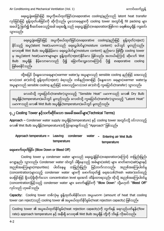
Air Conditioning and Mechanical Ventilation (Vol. 1) ႔
4-2
႔ (evaporative cooling)နညးသည latent heat transfer လပျခငးျဖင စြန႔ထတပစျခငးက ဆလသည။ ပေသာေရမားက cooling tower အတြငးရ fill packing မား အေပၚ၌ ျဖတ၍ စးဆငးေစသညအခါ ေရအခ႕သည ေရေငြ႔ပျခငး(evaporation)ျဖစကာ ေရ၏အပခန ကဆငး သြားသည။
ထ႔အျပင ပေႏြးေသာေရမား(warmer water)မ အပမားသည sensible cooling နညးျဖင ေအးသည
ေလ(cool air)ထသ႔ စြန႔ထတ(reject) ခရသည။ တစနညးအားျဖင ပေႏြးေသာ ေရမား(warmer water)မ အပမားသည sensible cooling နညးျဖင ေအးသညေလ(cool air)ထသ႔ ကးေျပာငး(transfer) သြားသည။
၄.၂ Cooling Tower ႏငသကဆငေသာ အေခၚအေဝၚမား(Technical Terms)
Approach – Condenser water supply အပခန(temperature) ႏင cooling tower အတြငးသ႔ ဝငလာသည ေလ၏ Wet Bulb အပခန(temperature)တ႔ ျခားနားခကသည “Approach” ျဖစသည။
Approach temperature = Leaving condenser water temperature
- Entering air Wet Bulb temperature
(Blow Down or Bleed Off)
Cooling tower မ condenser water မားသည ေရေငြ႔ပျခငး(evaporation)ေၾကာင တျဖညးျဖညး ေလာနညး သြားသည။ Condenser water ထတြင ပါရေနသည အခမား(solid) မား၊ ဓာတဆား(salt)မားႏင မား(impurities) ပါဝငေနမႈ တျဖညးျဖညး ျမငတကလာသည။ ႈ (concentration)မားသည condenser water မားက ေဖာကထတ၍ ေရအသစ(fresh water) ထည ေပးျခငးျဖင ရသငရထကေသာ concentration level ရေအာင ထနးထားရသည။ ထသ ႔ ႈ (concentration)ျမငသည condenser water မား ေဖာကချခငးက “Blow Down” သ႔မဟတ “Bleed Off” လပသည ဟေခၚသည။
Capacity: Cooling tower တစလးမ စြန႔ထတပစႏငေသာ အပပမာဏ (amount of heat that cooling tower can reject) cooling tower ၏ အပဖယထတႏငစြမး(heat rejection capacity) ျဖစသည။
႔ (evaporative cooling)နညးျဖင စြန႔ထတ(reject) ႏငသည အပ(latent heat)ပမာဏသည ေရေငြ႔႔႔ပါဝငမႈ(moisture content) ေပၚတြင မတညသည။ ေလထ၏ Wet Bulb နမေလ ေရေငြ႔ပါဝငမႈ(moisture content) နညးေလ ၿ cooling tower အပ(latent heat)ပမာဏမားမား စြန႔႔႔႔ထတ(reject)ႏငေလ ျဖစသည။ အဘယေၾကာင ဆေသာ Wet Bulb နမေသာေလသည ပ၍ ေျခာကေသြ႔႔ေသာေၾကာင evaporative cooling ျဖစေစႏငသည။
ေလထသ႔ (transfer)သြားသည “S s b H a ” ပမာဏသည ေလ၏ Dry Bulb (temperature)ေပၚတြင မတညသည။ ေလထသ႔ (transfer)သြားသည “La Heat” ပမာဏသည ေလ၏ Wet Bulb (temperature)ေပၚတြင မတညသည။
Cooling tower ၏ အပဖယထတႏငစြမး(heat rejection capacity)က တြကရန ေရလညပတႏႈနး(flow rate)၊ approach temperature ႏင ၏ Wet Bulb တ႔႔က သရန လအပသည။
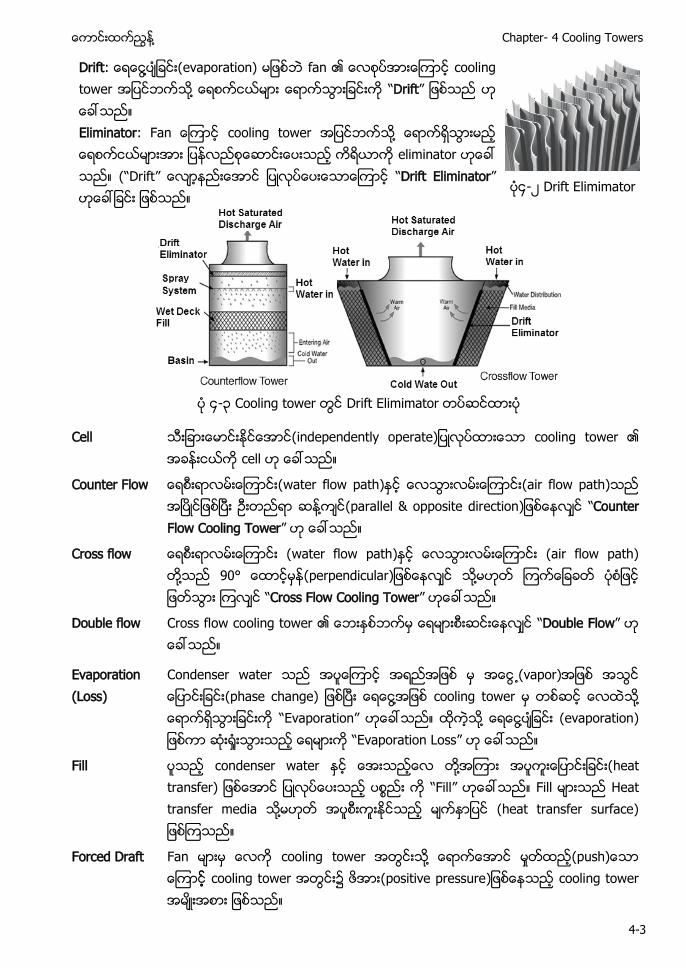
႔ Chapter- 4 Cooling Towers
4-3
Drift: ေရေငြ႔ပျခငး(evaporation) မျဖစ fan ၏ ေလစပအားေၾကာင cooling tower အျပငဘကသ႔ ေရစကငယမား ေရာကသြားျခငးက “Drift” ဟ ေခၚသည။ Eliminator: Fan ေၾကာင cooling tower အျပငဘကသ႔ ေရာကရသြားမည ေရစကငယမားအား ျပနလညစေဆာငးေပးသည ကရယာက eliminator ဟေခၚ သည။ (“Drift” “Drift Eliminator” ဟေခၚျခငး ျဖစသည။
၄-၂ Drift Elimimator
၄-၃ Cooling tower Drift Elimimator
Cell ( a လပထားေသာ cooling tower ၏ အခနးငယက cell ဟ ေခၚသည။
Counter Flow ေရစးရာလမးေၾကာငး(water flow path)ႏင ေလသြားလမးေၾကာငး(air flow path)သည အၿပငျဖစၿပး ဥးတညရာ ဆန႔ကင(parallel & opposite direction ေနလင “Counter Flow Cooling Tower” ဟ ေခၚသည။
Cross flow ေရစးရာလမးေၾကာငး (water flow path)ႏင ေလသြားလမးေၾကာငး (air flow path) တ႔သည 90° ေထာငမန(perpendicular)ျဖစေနလင သ႔မဟတ ၾကကေျခခတ ပစျဖင ျဖတသြား ၾကလင “Cross Flow Cooling Tower” ဟေခၚသည။
Double flow
Cross flow cooling tower ၏ ေဘးႏစဘကမ ေရမားစးဆငးေနလင “Double Flow” ဟ ေခၚသည။
Evaporation (Loss)
Condenser water သည အပေၾကာင အရညအျဖစ မ အေငြ႕(vapor)အျဖစ အသြင ေျပာငးျခငး( as a ၿပး ေရေငြ႔အျဖစ cooling tower မ တစဆင ေလထသ႔ ေရာကရသြားျခငးက “Evaporation” ဟေခၚသည။ ထကသ႔ ေရေငြ႔ပျခငး (evaporation) ျဖစကာ ဆး႐ႈးသြားသည ေရမားက “Evaporation Loss” ဟ ေခၚသည။
Fill
ပသည condenser water ႏင ေအးသညေလ တ႔အၾကား အပကးေျပာငးျခငး(heat transfer) ျဖစေအာင ျပလပေပးသည ပစၥညး က “Fill” ဟေခၚသည။ Fill Heat transfer media သ႔မဟတ အပစးကးႏငသည မကႏာျပင (heat transfer surface) ျဖစၾကသည။
Forced Draft
Fan မားမ ေလက cooling tower အတြငးသ႔ ေရာကေအာင မႈတထည(push)ေသာ ေၾကာင cooling tower အတြငး၌ (positive pressure)ျဖစေနသည cooling tower အမးအစား ျဖစသည။
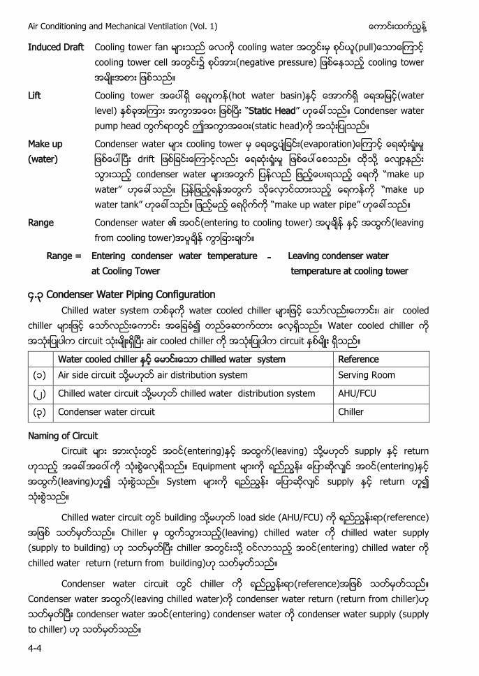
Air Conditioning and Mechanical Ventilation (Vol. 1) ႔
4-4
Induced Draft Cooling tower fan မားသည ေလက cooling water အတြငးမ စပယ(pull)ေသာေၾကာင cooling tower cell အတြငး၌ (negative pressure) ျဖစေနသည cooling tower အမးအစား ျဖစသည။
Lift Cooling tower အေပၚရ (hot water basin)ႏင ေအာကရ ေရအျမင(water level) ႏစခအၾကား အကြာအေဝး ျဖစၿပး “Static Head” ဟေခၚသည။ Condenser water pump head တြကရာတြင ဤအကြာအေဝး(static head)က အသးျပသည။
Make up (water)
Condenser water မား cooling tower မ ေရေငြ႔ပျခငး(evaporation)ေၾကာင ေရဆးရႈးမႈ ျဖစေပၚၿပး drift ျဖစျခငးေၾကာငလညး ေရဆး႐ႈးမႈ ျဖစေပၚေစသည။ ထသ႔ ေလာနညး သြားသည condenser water မားအတြက ျပနလည ျဖညေပးရသည ေရက “make up water” ဟေခၚသည။ ျဖညရနအတြက သေလာငထားသည ေရကနက “make up water tank” ဟေခၚသည။ ျဖညမည ေရပကက “make up water pipe” ဟေခၚသည။
Range Condenser water ၏ အဝင(entering to cooling tower) အပခန ႏင အထြက(leaving from cooling tower)အပခန ကြာျခားခက။
Range = Entering condenser water temperature at Cooling Tower
- Leaving condenser water temperature at cooling tower
၄.၃ Condenser Water Piping Configuration Chilled water system water cooled ၊ air cooled
chiller Water cooled chiller ၿ air cooled chiller
Water cooled chiller chilled water system Reference ( Air side circuit ႔ air distribution system Serving Room
(၂ Chilled water ႔ chilled water distribution system AHU/FCU
(၃ Condenser water circuit Chiller
Naming of Circuit Circuit (entering) (leaving) ႔ supply return
(entering) ( a s supply return
Chilled water circuit building ႔ load side (AHU/FCU) (reference) (leaving) chilled water chilled water supply (supply to building) ၿ chiller ႔ (entering) chilled water chilled water return (return from building)
Condenser water circuit chiller (reference) Condenser water (leaving chilled water) condenser water return (return from chiller) ၿ condenser water (entering) condenser water condenser water supply (supply to chiller)
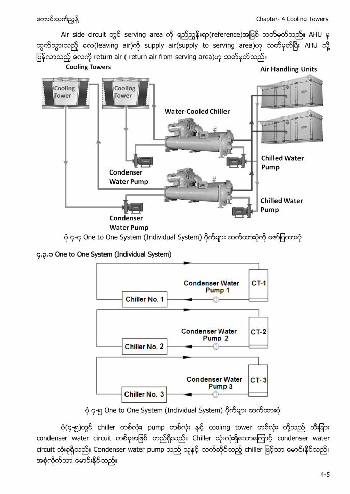
႔ Chapter- 4 Cooling Towers
4-5
Air side circuit serving area (reference) H (leaving air) supply air(supply to serving area) ၿ AHU ႔ return air ( return air from serving area)
၄-၄ One to One System (Individual System)
၄.၃. One to One System (Individual System)
၄-၅ One to One System (Individual System)
(၄-၅) chiller တစလး၊ pump တစလး ႏင cooling tower တစလး တ႔သည သးျခား condenser water circuit တစခအျဖစ တညရသည။ Chiller သးလးရေသာေၾကာင condenser water circuit သးခရသည။ Condenser water pump သည သႏင သကဆငသည chiller ျဖငသာ ေမာငးႏငသည။ အစလကသာ ေမာငးႏငသည။
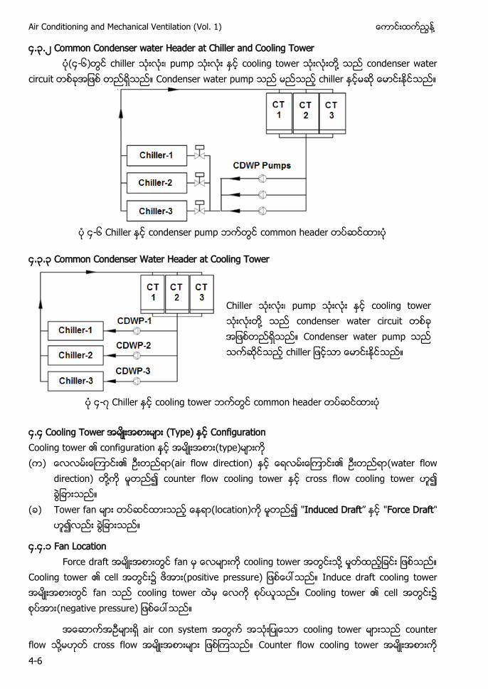
Air Conditioning and Mechanical Ventilation (Vol. 1) ႔
4-6
၄.၃.၂ Common Condenser water Header at Chiller and Cooling Tower (၄-၆) chiller သးလး၊ pump သးလး ႏင cooling tower သးလးတ႔ သည condenser water
circuit တစခအျဖစ တညရသည။ Condenser water pump သည မညသည chiller ႏငမဆ ေမာငးႏငသည။
၄-၆ Chiller condenser pump common header
၄.၃.၃ Common Condenser Water Header at Cooling Tower
Chiller သးလး၊ pump သးလး ႏင cooling tower သးလးတ႔ သည condenser water circuit တစခ အျဖစတညရသည။ Condenser water pump သည သကဆငသည chiller ျဖငသာ ေမာငးႏငသည။
၄-၇ Chiller cooling tower common header
၄.၄ Cooling Tower (Type) Configuration Cooling tower ၏ configuration (type) ( ) ၏ (air flow direction) ၏ (water flow
direction) ႔ counter flow cooling tower cross flow cooling tower
( ) Tower fan (location) "Induced Draft” "Force Draft”
၄.၄. Fan Location Force draft အမးအစားတြင fan မ ေလမားက cooling tower အတြငးသ႔ မႈတထညျခငး ျဖစသည။
Cooling tower ၏ cell အတြငး၌ (positive pressure) ျဖစေပၚသည။ Induce draft cooling tower အမးအစားတြင fan သည cooling tower ထမ ေလက စပယသည။ Cooling tower ၏ cell အတြငး၌ (negative pressure) ျဖစေပၚသည။
အေဆာကအဥမားရ air con system အတြက အသးျပေသာ cooling tower မားသည counter flow သ႔မဟတ cross flow အမးအစားမား ျဖစၾကသည။ Counter flow cooling tower အမးအစားက
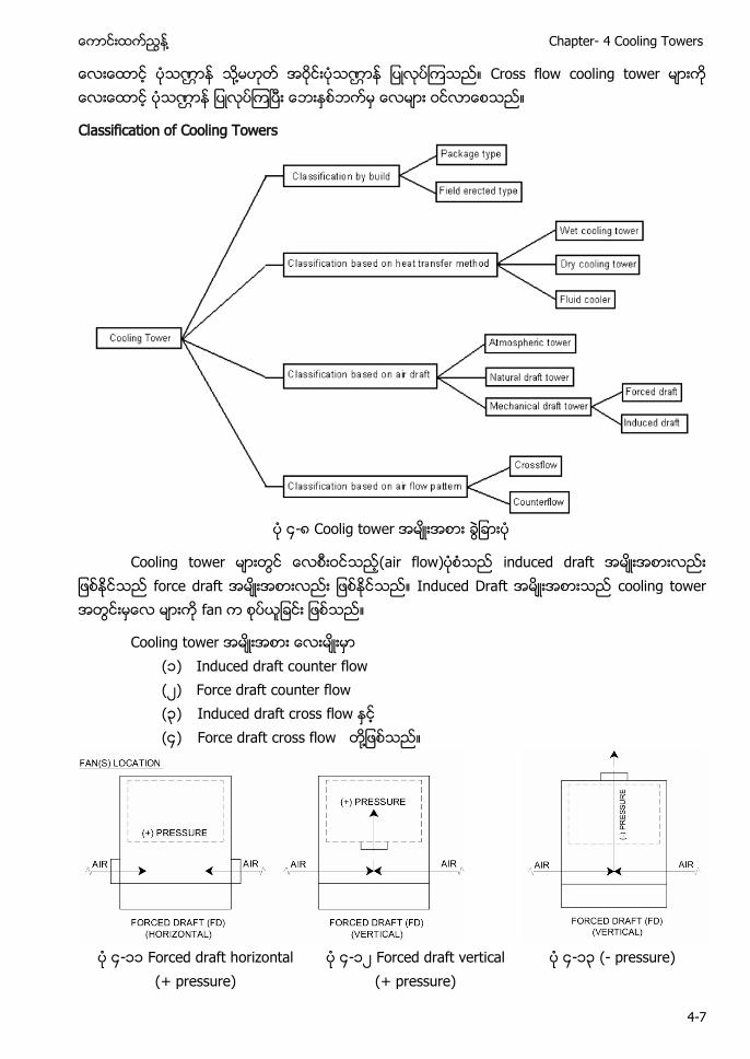
႔ Chapter- 4 Cooling Towers
4-7
ေလးေထာင ပသဏၭာန ႔ အဝငးပသဏၭာန ျပလပၾကသည။ Cross flow cooling tower မားက ေလးေထာင ပသဏၭာန ျပလပၾကၿပး ေဘးႏစဘကမ ေလမား ဝငလာေစသည။
Classification of Cooling Towers
၄-၈ Coolig tower
Cooling tower မားတြင (air flow) သည induced draft အမးအစားလညး ျဖစႏငသည force draft အမးအစားလညး ျဖစႏငသည။ Induced Draft အမးအစားသည cooling tower အတြငးမေလ မားက fan က စပယျခငး ျဖစသည။
Cooling tower ( ) Induced draft counter flow (၂) Force draft counter flow (၃) Induced draft cross flow (၄) Force draft cross flow ႔
၄- Forced draft horizontal
(+ pressure) ၄- ၂ Forced draft vertical
(+ pressure) ၄- ၃ (- pressure)
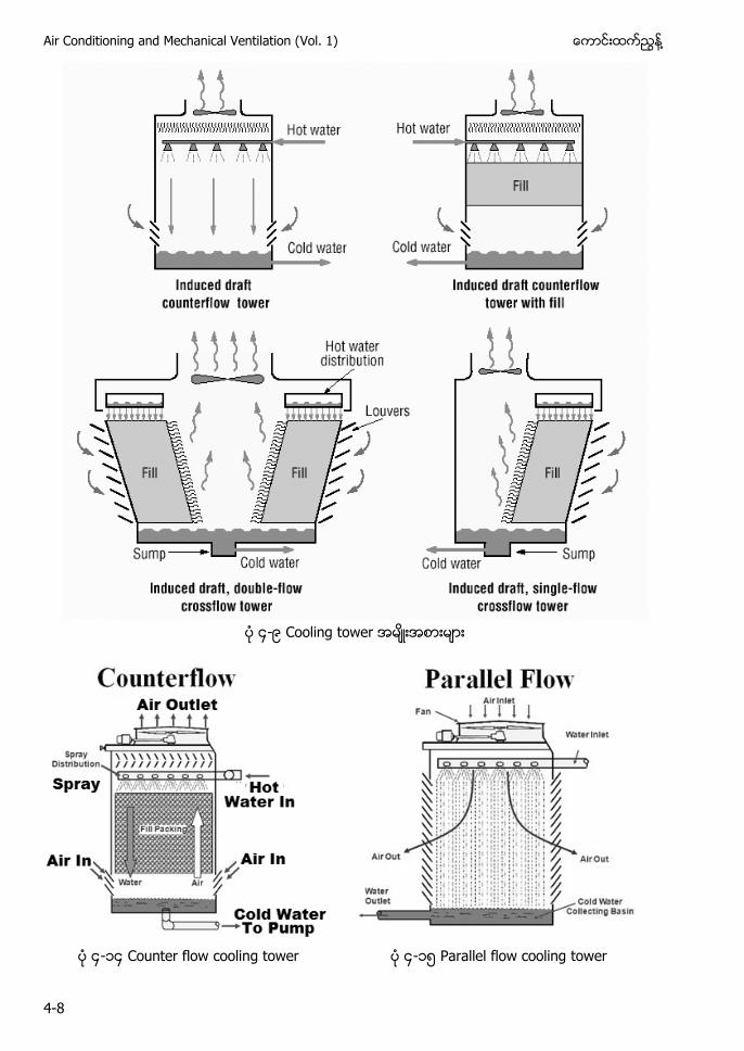
Air Conditioning and Mechanical Ventilation (Vol. 1) ႔
4-8
၄-၉
၄- ၄ Counter flow cooling tower ၄- ၅ Parallel flow cooling tower
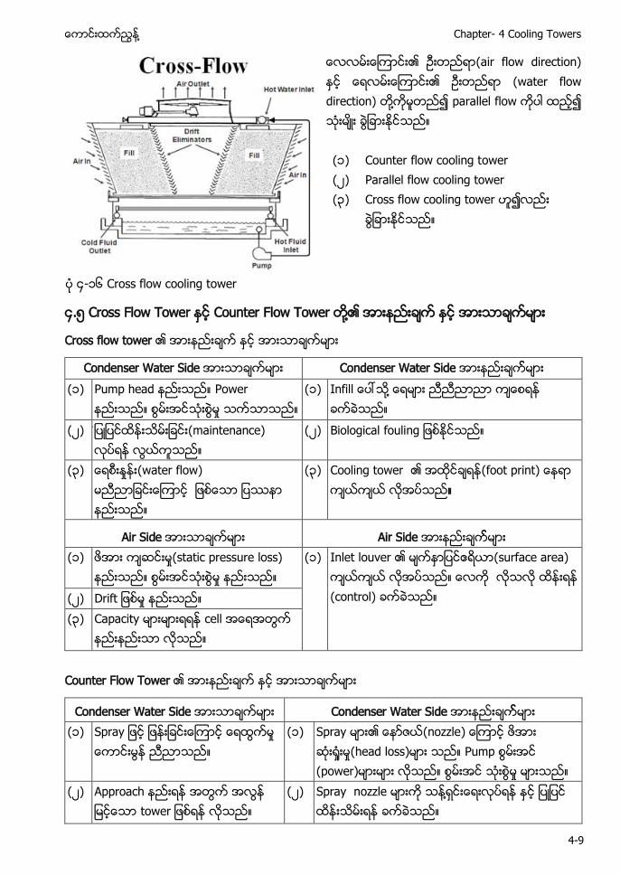
႔ Chapter- 4 Cooling Towers
4-9
၏ (air flow direction) ႏင ၏ (water flow direction) တ႔ကမတည၍ parallel flow ကပါ ထည၍ သ မး ခြျခားႏငသည။ ( ) Counter flow cooling tower (၂) Parallel flow cooling tower (၃) Cross flow cooling tower ဟ၍လညး
ခြျခားႏငသည။
၄- ၆ Cross flow cooling tower
၄.၅ Cross Flow Tower ႏင Counter Flow Tower ႔၏ အားနညးခက ႏင အားသာခကမား
Cross flow tower ၏ အားနညးခက ႏင အားသာခကမား
Condenser Water Side အားသာခကမား Condenser Water Side အားနညးခကမား (၁) Pump head နညးသည။ Power
နညးသည။ စြမးအင ႈ သကသာသည။ (၁) Infill ေပၚသ႔ ေရမား ကေစရန
ခကခသည။ (၂) (maintenance)
(၂) Biological fouling ျဖစႏငသည။
(၃) ႈ (water flow) မညညာျခငးေၾကာင ျဖစေသာ ျပနာ နညးသည။
(၃) Cooling tower ၏ (foot print) ေနရာ ကယကယ လအပသည
Air Side အားသာခကမား Air Side အားနညးခကမား (၁) ႈ(static pressure loss)
ႈ (၁) Inlet louver ၏ ဧရယာ(surface area)
ကယကယ လအပသည။ ေလက (control) ခကခသည။ (၂) Drift ျဖစမႈ နညးသည။
(၃) Capacity မားမား cell အေရအတြက နညးနညးသာ လသည။
Counter Flow Tower ၏ အားနညးခက ႏင အားသာခကမား
Condenser Water Side အားသာခကမား Condenser Water Side အားနညးခကမား (၁) Spray ျဖင ျဖနးျခငးေၾကာင ေရထြကမႈ
ေကာငးမြန ညညာသည (၁) Spray မား၏ (nozzle) ေၾကာင
ႈ ႈ(head loss)မား သည။ Pump (power)မားမား လသည။ ႈ
(၂) Approach နညးရန အတြက အလြန ျမငေသာ tower ျဖစရန လသည။
(၂) Spray nozzle မားက သန႔ရငးေရးလပရန ႏင ျပျပင ထနးသမးရန ခကခသည။
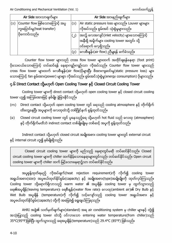
Air Conditioning and Mechanical Ventilation (Vol. 1) ႔
4-10
Air Side အားသာခကမား Air Side အားနညးခကမား
(၁) Counter flow ျဖစေသာေၾကာင ႈ(heat transfer) ပေကာငးသည။
(၁) Air static pressure loss မားသည။ Louver မားမား လအပသည။ ႈ
(၂) ၌ (inlet velocity) မားေသာေၾကာင အနးရ အမႈကမား cooling tower အတြငး သ႔ ဝငေရာက ေလရသည။
(၃) ႈ (air flow) ညမရန ခကခသည။
Counter flow tower မားသည cross flow tower မားထက အထငခရနေနရာ (foot print) သာေၾကာင တပဆငရန ေနရာကဥးကဥးသာ လအပသည။ Counter flow tower မားသည cross flow tower မားထက ႈ (air flow) မားၿပး ဖအားကဆငးမႈ(static pressure loss) မား ေသာေၾကာင fan (power) မားစြာ လအပသည။ စြမးအငသးစြမႈ(energy consumption) မားသည။
၄.၆ Direct Contact ႔ Open Cooling Tower ႏင Closed Circuit Cooling Tower
Cooling tower မားက direct contact သ႔မဟတ open cooling tower ႏင closed circuit cooling tower ဟ၍ အၾကမးအားျဖင ႏစမး ခြျခားႏငသည။
( ) Direct contact သ႔မဟတ open cooling tower တြင ေရသည cooling atmosphere ႏင တက႐က ထေတြ႔ေနၿပး အပမားက ေလထထသ႔ တစၿပငနက စြန႔ထတသည။
( ) Closed circuit cooling tower တြင ပေနသညေရ သ႔မဟတ hot fluid သည ေလထ (atmosphere) ႏင တက႐ကမထဘ indirect contact တစမးမးမ တစဆင အပက စြန႔ထတသည။
Indirect contact ႔ closed circuit အမးအစား cooling tower မားတြင external circuit ႏင internal circuit ဟ၍ ႏစမးရသည။
႔ လအပခက(heat rejection requirement)က လက၍ cooling tower အရြယအစား(size)၊ (capacity) ႏင အမးအစား(type)အမးမးက ထတလပၾကသည။ Cooling tower သ႔ေရာကရလာသည warm water ၏ အပခန၊ cooling tower မ ထြကသြားသည ေရ၏အပခန(leaving temperature)၊ ႈ (water flow rate)၊ (ambient air)၏ Dry Bulb ႏင Wet Bulb အပခန (temperature)က လက၍ သငေလာသည cooling tower အရြယအစား ႏင (capacity) တ႔က အေျခခ၍ ေရြးခယၾကရသည။
AHRI ႔၏ (standard) air conditioning system မ chiller မားႏင တြ၍ အသးျပသည cooling tower သ႔ ငလာေသာ entering water temperature(from chiller)သည 35°C(95°F)ျဖစၿပး ထြကသြားသည ေရအပခန(temperature)သည 29.4°C (85°F) ျဖစသည။
Closed circuit cooling tower မားက မညသည ေနရာတြငမဆ တပဆငႏငသည။ Closed circuit cooling tower မားက chiller ထကနမေသာေနရာမားတြငလညး တပဆငႏငသည။ Open circuit cooling tower မားက chiller ထက ျမငေသာေနရာ၌သာ တပဆငႏငသည။
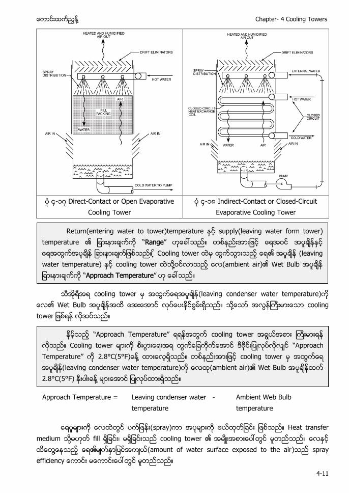
႔ Chapter- 4 Cooling Towers
4-11
၄- ၇ Direct-Contact or Open Evaporative
Cooling Tower ၄- ၈ Indirect-Contact or Closed-Circuit
Evaporative Cooling Tower
သအရအရ cooling tower မ အထြကေရအပခန(leaving condenser water temperature)က
ေလ၏ Wet Bulb အထ ေအးေအာင လပေပးႏငစြမးရသည။ သ႔ေသာ အလြနႀကးမားေသာ cooling tower ျဖစရန လအပသည။
Approach Temperature =
Leaving condenser water -temperature
Ambient Web Bulb temperature
ေရပမားက ေလထတြင ပကျဖနး(spray)ကာ အပမားက ဖယထတျခငး ျဖစသည။ Heat transfer medium ႔ fill ရျခငး၊ မရျခငးသည cooling tower ၏ အမးအစားေပၚတြင မတညသည။ ေလႏင ထေတြ႔ေနသည ေရ၏မကႏာျပငအကယ(amount of water surface exposed to the air)သည spray efficiency ေကာငး မေကာငးေပၚတြင မတညသည။
Return(entering water to tower)temperature ႏင supply(leaving water form tower) temperature ၏ ျခားနားခကက “Range” ဟေခၚသည။ ျခားနားခကျဖစသည။ Cooling tower ထမ ထြကသြားသည ေရ၏ (leaving water temperature) ႏင cooling tower ထသ႔႔ ႔ဝငလာသည ေလ(ambient air)၏ Wet Bulb ျခားနားခကက “Approach Temperature” ဟ ေခၚသည။
နမသည “Approach T a ” cooling tower Cooling tower မားက စးပြားေရးအရ တြကေျခကကေအာင ဒဇငးျပလပလလင “Approach Temperature” က 2.8°C(5°F)ခန႔႔ ထားေလရသည။ တစနညး cooling tower မ အထြကေရ အပခန(leaving condenser water temperature)က ေလထ(ambient air)၏ Wet Bulb ထက 2.8°C(5°F) နးပါးခန႔ မားေအာင ျပလပထားရသည။
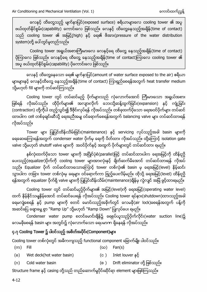
Air Conditioning and Mechanical Ventilation (Vol. 1) ႔
4-12
ေလႏင ထေတြ႔ေနေသာ ေရ၏ မကႏာျပင(amount of water surface exposed to the air) ဧရယာ
မားမားႏင ေလႏငထေတြ႔ ေနသညအခန(time of contact) ၾကာရညေစရနအတြက heat transfer medium ႔ fill က တပဆငၾကသည။
Cooling tower တြင တပဆငမည ပကမားသည လေလာကေအာင ႀကးမားေသာ အရြယအစား ျဖစရန လအပသည။ ထပကမား၏ အလားလက ေဘးသ႔ဆန႔ထြကျခငး(expansion) ႏင က႕ျခငး (contraction) တ႔ကပါ ထညသြငး၍ ဒဇငးလပရန လအပသည။ တစခထကပေသာ ေရအဝငပကမား တပဆင ထားပါက cell တစခခငးဆသ႔ ေရအညအမ ဝငေရာကေစရနအတြက balancing valve မား တပဆငထားရန လအပသည။
Tower မား ျပျပငထနးသမးျခငး(maintenance) ႏင s သညအခါ basin မားက ေရေဆးေၾကာရနအတြက condenser water ပကမ ေရက ပတထား လအပသည။ ထ႔ေၾကာင isolation gate valve ႔ shutoff valve မားက အဝငပကႏင အထြက ပကမားတြင တပဆငထား ရမည။
ႏစလးထကပေသာ tower မားက အၿပငပစ(parallel တပဆငထားပါက (equalizer က cooling tower မားအားလးႏင ခတဆကမေအာင တပဆငထားရန လအပ သည။ E a တပဆငထားေသာေၾကာင tower တစလး၏ basin မ ေရအျမင(level) နမဆငး သြားပါက တျခား tower တစလးမ ေရမား ဝငေရာကကာ ျဖညေပးလမမည။ ထသ႔ ေရအျမင(level) ထနးညႇ ရနအတြက a ရ valve မားက ျပျပငထနးသမး(maintenance)ခနမ လြလင အျမ ဖြငထားရမည။
Cooling tower တြင တပဆငမညပကမား၏ အျမင(level)က (operating water level) ထက နမႏငသမနမေအာင တပဆငေပးရန လအပသည။ Cooling tower ရပနား(shutdown)ထားသညအခါ ေရမလေစရန ႏင pump မားက စတင ေမာငးသညအခကတြင ေလမခ(air lock)ေစရနအတြက ပန႔က အဆငေျပ ေခာေမြ စြာ “Ramp Up” ႔ “Ra Down” ျပလပေပး ရမည။
C s a ခန၌ ေရစပယသညပကလငး(water suction line)၌ ေလမခေစရန basin မား အတြငး၌ လေလာကေသာ ေရပမာဏ ရေနရန လအပသည။
၄.၇ Cooling Tower ၌ (Component)
Cooling tower တစလးတြင အဓကကသည f a မး ပါဝငသည။ (က) Fill (ဃ) Fan(s)
(ခ) Wet deck(hot water basin) (င ) Inlet louver
(ဂ) Cold water basin (စ ) Drift eliminator တ႔ ျဖစသည။
Structure frame ႏင casing တ႔သည တညေဆာကမႈပငးဆငရာ element မားျဖစၾကသည။
႔ (exposed surface) ဧရယာမားေလ cooling tower ၏ (capability) ေကာငးေလ ျဖစသည။ ေလႏင ထေတြ႔ေနသညအခန(time of contact) သည cooling tower ၏ အျမင( high) ႏင ေရ၏ ဖအား(pressure of the water distribution system)တ႔႔ ေပၚတြငမတညသည။
Cooling tower အရြယအစားႀကးမားေလ ေလႏငေရ ထေတြ႔ ေနသညအခန(time of contact ၾကာေလ ျဖစသည။ ေလႏငေရ ထေတြ႔႔ ေနသညအခန(time of contact)ၾကာေလ cooling tower ၏ (capability) ပေကာငးေလ ျဖစသည။
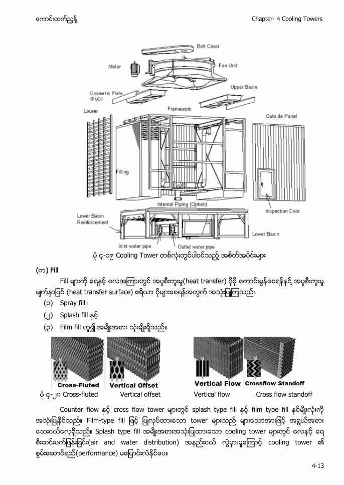
႔ Chapter- 4 Cooling Towers
4-13
၄- ၉ Cooling Tower
(က) Fill Fill မားက ေရႏင ေလအၾကားတြင အပစးကးမႈ(heat transfer) ပမ ေကာငးမြနေစရနနင႔ အပစးကးမႈ မကႏာျပင (heat transfer surface) ဧရယာ မားေစရနအတြက အသးျပၾကသည။
(၁) a f ၊
(၂) Splash fill ႏင
(၃) Film fill ဟ၍ အမးအစား သးမးရသည။
၄-၂၀ Cross-fluted Vertical offset Vertical flow Cross flow standoff
Counter flow ႏင cross flow tower မားတြင splash type fill ႏင film type fill ႏစမးလးက အသးျပႏငသည။ Film-type fill ျဖင ျပလပထားေသာ tower မားသည မားေသာအားျဖင အရြယအစား ေသးငယေလရသည။ Splash type fill အမးအစားအသးျပထားေသာ cooling tower မားတြင ေလႏင (air and water distribution) အနညးငယ လြမားမႈေၾကာင cooling tower ၏ (performance)
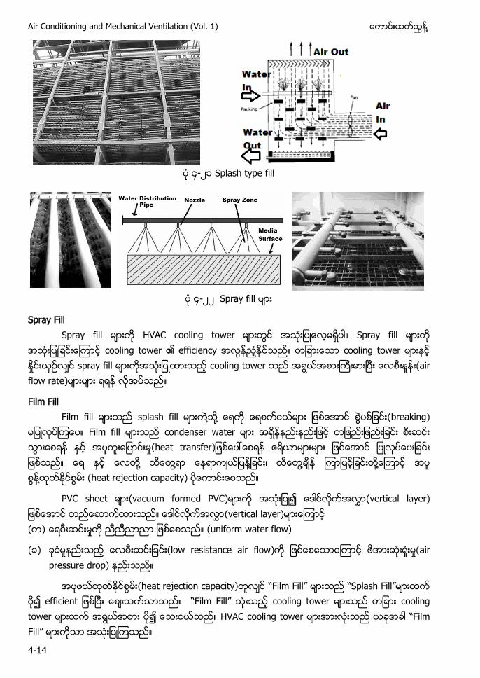
Air Conditioning and Mechanical Ventilation (Vol. 1) ႔
4-14
၄-၂ Splash type fill
၄-၂၂ Spray fill မား
Spray Fill Spray fill မားက HVAC cooling tower မားတြင အသးျပေလမရပါ။ Spray fill မားက
အသးျပျခငးေၾကာင cooling tower ၏ efficiency အလြနညႏ သည။ တျခားေသာ cooling tower မားႏင ႏႈငးယဥလင spray fill ကအသးျပထားသည cooling tower သည အရြယအစားႀကးမားၿပး ႈ (air flow rate)မားမား ရရန လအပသည။
Film Fill Film fill မားသည splash fill မားက႔သ႔ ေရက ေရစကငယမား ျဖစေအာင ခြပစျခငး(breaking) မျပလပၾကေပ။ Film fill မားသည condenser water မား အရနနညးနညးျဖင တျဖညးျဖညးျခငး စးဆငး သြားေစရန ႏင အပကးေျပာငးမႈ(heat transfer ဧရယာမားမား ျဖစေအာင ျပလပေပးျခငး သည။ ေရ ႏင ေလတ႔ ထေတြ႔ရာ ေနရာကယျပန႔ျခငး၊ ထေတြ႔ခန ၾကာျမငျခငးတ႔ေၾကာင အပ စြန႔ထတႏငစြမး (heat rejection capacity) ပေကာငးေစသည။
PVC sheet မား(vacuum formed PVC)မားက အသးျပ၍ ေဒါငလကအလႊာ(vertical layer) ျဖစေအာင တညေဆာကထားသည။ ေဒါငလကအလႊာ(vertical layer)မားေၾကာင ( ) ေရစးဆငးမႈက ညညညာညာ ျဖစေစသည။ (uniform water flow)
( ) ခခမႈနညးသည ေလစးဆငးျခငး(low resistance air flow)က ျဖစေစေသာေၾကာင ဖအားဆး႐ႈးမႈ(air pressure drop) နညးသည။
အပဖယထတႏငစြမး(heat rejection capacity)တလင “F F ” မားသည “Splash Fill”မားထက ပ၍ efficient ျဖစၿပး ေစးသကသာသည။ “F F ” သးသည cooling tower မားသည တျခား cooling tower မားထက အရြယအစား ပ၍ ေသးငယသည။ HVAC cooling tower မားအားလးသည ယခအခါ “F F ” ကသာ အသးျပၾကသည။
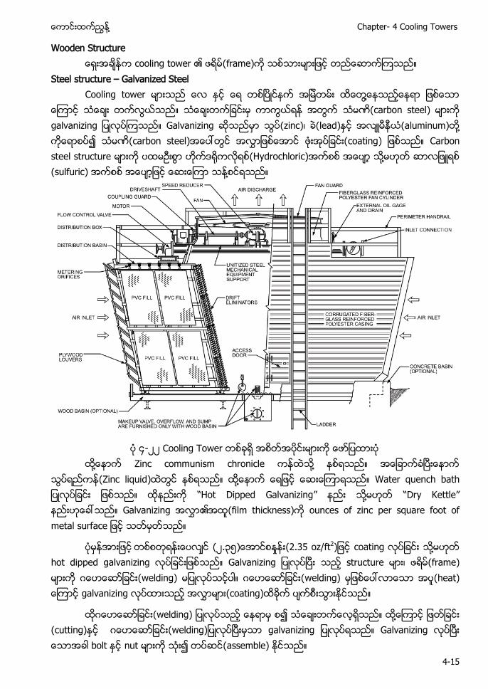
႔ Chapter- 4 Cooling Towers
4-15
Wooden Structure ေရးအခနက cooling tower ၏ ဖရမ(frame)က သစသားမားျဖင တညေဆာကၾကသည။ Steel structure – Galvanized Steel Cooling tower မားသည ေလ ႏင ေရ တစၿပငနက အျမတမး ထေတြ႔ေနသညေနရာ ျဖစေသာ ေၾကာင သေခး တကလြယသည။ သေခးတကျခငးမ ကာကြယရန အတြက သမဏ(carbon steel) မားက galvanizing ျပလပၾကသည။ Galvanizing ဆသညမာ သြ (zinc)၊ ခ(lead)ႏင အလမနယ(aluminum)တ႔ ကေရာစပ၍ သမဏ(carbon steel)အေပၚတြင အလႊာျဖစေအာင ဖးအပျခငး(coating) ျဖစသည။ Carbon steel structure မားက ပထမဥးစြာ ဟကဒ (Hydrochloric)အကစစ အေပ ႔ (sulfuric) အကစစ အေပာျဖင ေဆးေၾကာ သန႔စငရသည။
၄-၂၂ Cooling Tower ထ႔ေနာက Zinc communism chronicle ကနထသ႔ နစရသည။ အေျခာကခၿပးေနာက
သြပရညကန(Zinc liquid)ထတြင နစရသည။ ထ႔ေနာက ေရျဖင ေဆးေၾကာရသည။ Water quench bath ျပလပျခငး ျဖစသည။ ထနညးက “Hot Dipped Galvanizing” နညး ႔ “D Kettle” နညးဟေခၚသည။ Galvanizing ၏အထ(film thickness)က ounces of zinc per square foot of metal surface ျဖင သတမတသည။
ပမနအားျဖင တစစတရနးေပလင (၂.၃၅)ေအာငစႏႈနး(2.35 oz/ft2)ျဖင coating လပျခငး ႔ hot dipped galvanizing လပျခငးျဖစသည။ Galvanizing ျပလပၿပး သည structure မား၊ ဖရမ(frame) မားက ဂေဟေဆာျခငး(welding) မျပလပသငပါ။ ဂေဟေဆာျခငး(welding) မျဖစေပၚလာေသာ အပ(heat) ေၾကာင galvanizing လပထားသည အလႊာမား(coating)ထခက ပကစးသြားႏငသည။
ထဂေဟေဆာျခငး(welding) ျပလပသည ေနရာမ စ၍ သေခးတကေလရသည။ ထ႔ေၾကာင ျဖတျခငး (cutting)ႏင ဂေဟေဆာျခငး(welding)ျပလပၿပးမသာ galvanizing ျပလပရသည။ Galvanizing လပၿပး ေသာအခါ bolt ႏင nut မားက သး၍ တပဆင(assemble) ႏငသည။
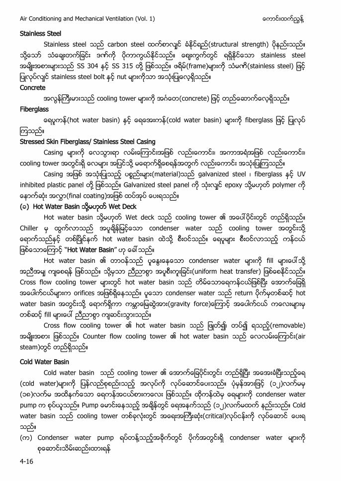
Air Conditioning and Mechanical Ventilation (Vol. 1) ႔
4-16
Stainless Steel Stainless steel သည carbon steel ထကစာလင ခႏငရည(structural strength) ပနညးသည။ သ႔ေသာ သေခးတကျခငး ဒဏက ပကာကြယႏငသည။ ေစးကြကတြင ရရႏငေသာ stainless steel အမးအစားမားသည SS 304 ႏင SS 315 တ႔ ျဖစသည။ ဖရမ(frame)မားက သမဏ(stainless steel) ျဖင ျပလပလင stainless steel bolt ႏင nut မားကသာ အသးျပေလရသည။ Concrete
အလြနႀကးမားသည cooling tower မားက အဂၤေတ(concrete) ျဖင တညေဆာကေလရသည။ Fiberglass (hot water basin) ႏင ေရေအးကန(cold water basin) မားက fiberglass ျဖင ျပလပ ၾကသည။ Stressed Skin Fiberglass/ Stainless Steel Casing Casing မားက ေလသြားရာ လမးေၾကာငးအျဖစ လညးေကာငး၊ အကာအရအျဖစ လညးေကာငး၊ cooling tower အတြငးရ ေလမား အျပငသ႔ မေရာကရေစရနအတြက လညးေကာငး အသးျပ သည။ Casing အျဖစ အသးျပသည (material)သည galvanized steel ၊ fiberglass ႏင UV inhibited plastic panel တ႔ ျဖစသည။ Galvanized steel panel က သးလင epoxy ႔ polymer က ေနာကဆး အလႊာ(final coating)အျဖစ ထပအပ ေပးရသည။ (ခ) Hot Water Basin ႔ Wet Deck Hot water basin ႔ Wet deck သည cooling tower ၏ အေပၚပငးတြင တညရသည။ Chiller condenser water cooling tower ႔ ၿ hot water basin ႔ “Hot Water Basin” Hot water basin ၏ တာဝနသည ပေႏြးေနေသာ condenser water မားက fill မားေပၚသ႔ အညအမ ကေစရန ျဖစသည။ သ႔မသာ ညညာစြာ အပစ ကးျခငး(uniform heat transfer) ျဖစေစႏငသည။ Cross flow cooling tower မားတြင hot water basin သည တမေသာေရကနငယျဖစၿပး ေအာကေျခရ အေပါကငယမားက orifices အျဖစရေနသည။ ပေသာ condenser water သည return မတ ဆင hot water basin အတြငးသ႔ ေရာကရကာ ေျမဆြအား(gravity force)ေၾကာင အေပါကငယ ကေလးမားမ တစဆင fill မားေပၚ ညညာစြာ ကဆငးသြားသည။ Cross flow cooling tower ၏ hot water basin သည ျဖတ၍၊ တပ၍ ရသည(removable) အမးအစား ျဖစသည။ Counter flow cooling tower ၏ hot water basin သည ေလလမးေၾကာငး(air steam)တြင တညရသည။
Cold Water Basin Cold water basin သည cooling tower ၏ ေအာကေျခပငးတြငး တညရၿပး အေအးခၿပးသညေရ (cold water)မားက ျပနလညစစညးသည အလပက လပေဆာငေပးသည။ ပမနအားျဖင (၁၂)လကမမ (၁၈)လကမ အထနကေသာ ေရကနအငယစားကေလး ျဖစသည။ ထကနထမ ေရမားက condenser water pump စပယသည။ Pump ေမာငးေနသည အခနတြင ေရအနကသည (၁၂)လကမထက နညးသည။ Cold water basin သည cooling tower တစခလးတြင အေရးအႀကးဆး(critical)လပငနးက လပေဆာင ေပးရ သည။ ( ) Condenser water pump ရပတန႔သညအခကတြင ပကအတြငးရ condenser water မားက
စေဆာငးသမးဆညးထားရန
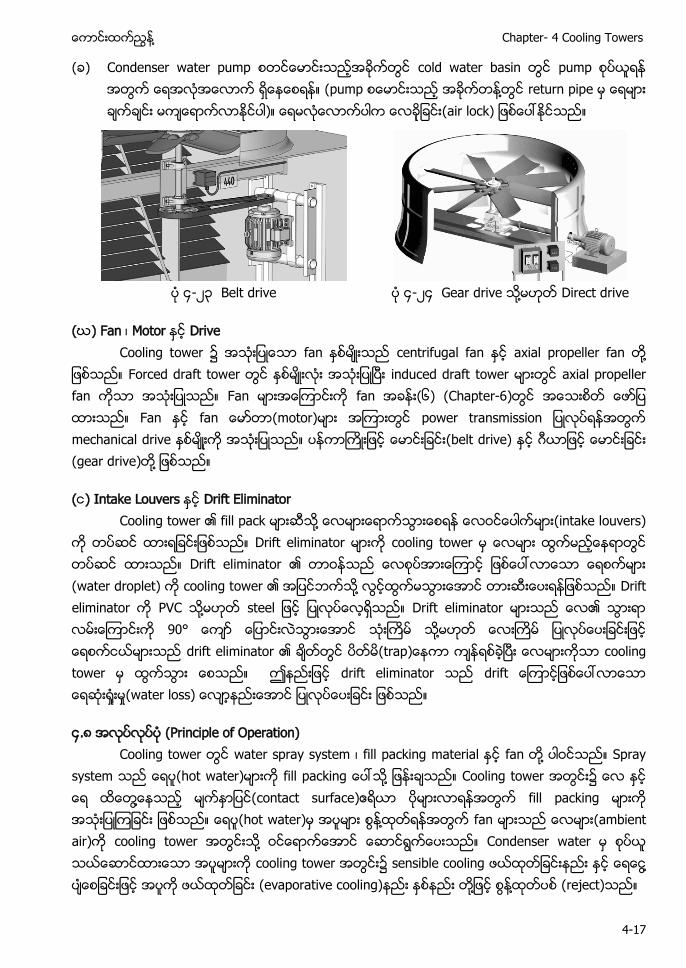
႔ Chapter- 4 Cooling Towers
4-17
( ) Condenser water pump စတငေမာငးသညအခကတြင cold water basin တြင pump စပယရန အတြက ေရအလအေလာက ရေနေစရန။ (pump စေမာငးသည အခကတန႔တြင return pipe မ ေရမား ခကခငး မကေရာကလာႏငပါ)။ ေရမလေလာကပါက ေလချခငး(air lock) ျဖစေပၚႏငသည။
၄-၂၃ Belt drive ၄-၂၄ Gear drive ႔ Direct drive
(ဃ) Fan ၊ Motor ႏင Drive Cooling tower ၌ အသးျပေသာ fan ႏစမးသည centrifugal fan ႏင axial propeller fan တ႔ ျဖစသည။ Forced draft tower တြင ႏစမးလး အသးျပၿပး induced draft tower မားတြင axial propeller fan ကသာ အသးျပသည။ Fan မားအေၾကာငးက fan အခနး(၆) (Chapter-6)တြင အေသးစတ ေဖာျပ ထားသည။ Fan ႏင fa (motor)မား အၾကားတြင power transmission ျပလပရနအတြက mechanical drive မးက အသးျပသည။ (belt drive) ႏင ဂယာျဖင ေမာငးျခငး (gear drive)တ႔ ျဖစသည။
(င) Intake Louvers ႏင Drift Eliminator Cooling tower ၏ fill pack မားဆသ႔ ေလမားေရာကသြားေစရန ေလဝငေပါကမား(intake louvers) က တပဆင ထားရျခငးျဖစသည။ Drift eliminator မားက cooling tower မ ေလမား ထြကမညေနရာတြင တပဆင ထားသည။ Drift eliminator ၏ တာဝနသည ေလစပအားေၾကာင ျဖစေပၚလာေသာ ေရစကမား (water droplet) cooling tower ၏ အျပငဘကသ႔ လြငထြကမသြားေအာင တားဆးေပးရနျဖစသည။ Drift eliminator က PVC ႔ steel ျဖင ျပလပေလရသည။ Drift eliminator မားသည ေလ၏ သြားရာ လမးေၾကာငးက 90° ေကာ ေျပာငးလသြားေအာင သးႀကမ သ႔မဟတ ေလး ျပလပေပးျခငးျဖင ေရစကငယမားသည drift eliminator ၏ ခတတြင ပတမ(trap ကာ ကနရစခၿပး ေလမားကသာ cooling tower မ ထြကသြား ေစသည။ ဤနညးျဖင drift eliminator သည drift ေၾကာငျဖစေပၚလာေသာ ေရဆး႐ႈးမႈ(water loss) ေလာနညးေအာင ျပလပေပးျခငး ျဖစသည။
၄.၈ အလပလပပ (Principle of Operation) Cooling tower တြင water spray system ၊ fill packing material ႏင fan တ႔ ပါဝငသည။ Spray
system သည (hot water)မားက fill packing ေပၚသ႔ ျဖနးခသည။ Cooling tower အတြငး၌ ထေတြ႔ေနသည မကႏာျပင(contact surface)ဧရယာ ပမားလာရနအတြက fill packing မားက အသးျပၾကျခငး ျဖစသည။ (hot water)မ အပမား စြန႔ထတရနအတြက fan မားသည ေလမား(ambient air)က cooling tower အတြငးသ႔ သည။ Condenser water မ စပယ သယေဆာငထားေသာ အပမားက cooling tower အတြငး၌ sensible cooling နညး ႏင ႔ (evaporative cooling)နညး ႏစနညး တ႔ျဖင စြန႔ထတပစ (reject)သည။
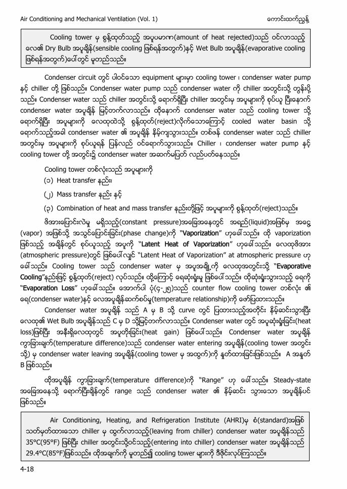
Air Conditioning and Mechanical Ventilation (Vol. 1) ႔
4-18
Condenser circuit တြင ပါဝငေသာ equipment မားမာ cooling tower ၊ condenser water pump
ႏင chiller တ႔ ျဖစသည။ Condenser water pump သည condenser water က chiller အတြငးသ႔ တြနးပ႔ သည။ Condenser water သည chiller အတြငးသ႔ ေရာကရၿပး chiller အတြငးမ အပမားက စပယ ၿပးေနာက condenser water အပခန ျမငတကလာသည။ ထေနာက condenser water သည cooling tower သ႔ ေရာကရၿပး အပမားက ေလထထသ႔ စြန႔ထတ(reject)လကေသာေၾကာင cooled water basin သ႔ ေရာကသညအခါ condenser water ၏ အပခန နမကသြားသည။ တစဖန condenser water သည chiller အတြငးမ အပမားက စပယရန ျပနလည ဝငေရာကသြားသည။ Chiller ၊ condenser water pump ႏင cooling tower တ႔ အတြငး၌ condenser water အဆကမျပတ လညပတေနသည။
Cooling tower တစလးသည အပမားက ( ) Heat transfer နညး၊
(၂) Mass transfer နညး ႏင
(၃) Combination of heat and mass transfer နညးတ႔ျဖင အပမားက စြန႔ထတ(reject)သည။
ဖအားေျပာငးလမႈ မရသည(constant pressure)အေျခအေနတြင အရည(liquid)အျဖစမ ႔ (vapor) အျဖစသ႔ အသြငေျပာငးျခငး(phase change)က “Vaporization” ဟေခၚသည။ ထ vaporization ျဖစသည အခနတြင စပယသည အပက “Latent Heat of Vaporization” ဟေခၚသည။ ေလထဖအား (atmospheric pressure)တြင ျဖစေပၚလင “La H a f Va a ” at atmospheric pressure ဟ ေခၚသည။ Cooling tower သည condenser water မ အပအခ႕က ေလထအတြငးသ႔ “Evaporative Cooling” ျဖင စြန႔ထတ(reject) လပသည။ ထ ႔ေၾကာင ေရဆး႐ႈးမႈ ျဖစေပၚသည။ ထဆး ႈ “Evaporation Loss” ဟေခၚသည။ ေအာကပါ (၄-၂၅)သည counter flow cooling tower တစလး ၏ ေရ(condenser water)ႏင ေလအပခနဆကစပမႈ(temperature relationship) ျပထားသည။
Condenser water အပခန သည A မ B သ႔ curve တြင ျပထားသညအတငး နမဆငးသြားၿပး ေလထ၏ Wet Bulb အပခနသည C မ D သ႔ျမငတကလာသည။ Condenser water တြင အပဆး႐ႈးျခငး(heat loss)ျဖစၿပး တြင အပ (heat gain) ျဖစေပၚသည။ Condenser water အပခန ကြာျခားခက(temperature difference)သည condenser water entering အပခန(cooling tower အတြငး သ႔) မ condenser water leaving အပခန(cooling tower မ အထြက) ႈ A အႏႈတ B ျဖစသည။
(temperature difference) “Range” Steady-state ႔ ၿ range condenser water ၏
Cooling tower မ စြန႔ထတသည အပပမာဏ(amount of heat rejected)သည ဝငလာသည ေလ၏ Dry Bulb အပခန(sensible cooling ျဖစရနအတြက)ႏင Wet Bulb အပခန(evaporative cooling ျဖစရနအတြက)ေပၚတြင မတညသည။
Air Conditioning, Heating, and Refrigeration Institute (AHRI) (standard) chiller (leaving from chiller) condenser water ( F ၿ chiller ႔ (entering into chiller) condenser water ( F cooling tower
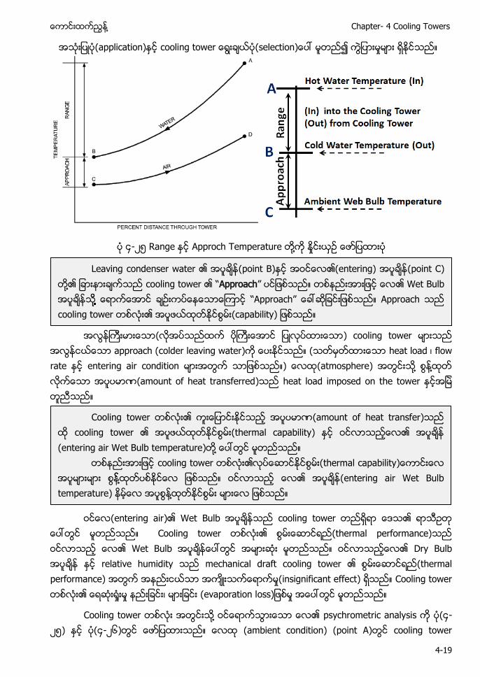
႔ Chapter- 4 Cooling Towers
4-19
(application) (s ႈ
၄-၂၅ Ra Approch T a ႔ ႈ
အလြနႀကးမားေသာ(လအပသညထက ပႀကးေအာင ျပလပထားေသာ) cooling tower သည
အလြနငယေသာ approach (colder leaving water)က ေပးႏငသည။ (သတမတထားေသာ heat load ၊ flow rate ႏင entering air condition မားအတြက သာျဖစသည။) ေလထ(atmosphere) အတြငးသ႔ စြန႔ထတ လကေသာ အပပမာဏ(amount of heat transferred)သည heat load imposed on the tower ႏငအျမ တညသည။
(entering air)၏ Wet Bulb သည cooling tower တညရရာ ေဒသ၏ ရာသဥတ
ေပၚတြင မတညသည။ Cooling tower တစလး၏ (thermal performance)သည ဝငလာသည ေလ၏ Wet Bulb ေပၚတြင အမားဆး မတညသည။ ဝငလာသညေလ၏ Dry Bulb ႏင relative humidity သည mechanical draft cooling tower ၏ (thermal performance) အတြက အနညးငယသာ အကးသကေရာကမႈ(insignificant effect) ရသည။ Cooling tower တစလး၏ ေရဆး႐ႈးမႈ နညးျခငး၊ မားျခငး (evaporation loss)ျဖစမႈ အေပၚတြင မတညသည။
Cooling tower တစလး အတြငး ႔ ဝငေရာကသြားေသာ ေလ၏ psychrometric analysis က ပ(၄-၂၅) ႏင ပ(၄-၂၆)တြင ေဖာျပထားသည။ ေလထ (ambient condition) (point A)တြင cooling tower
Leaving condenser water ၏ အပခန(point B)ႏင အဝငေလ၏(entering) (point C) တ႔၏ ျခားနားခကသည cooling tower ၏ “Approach” ပငျဖစသည။ တစနညးအားျဖင ေလ၏ Wet Bulb အပခနသ႔႔႔႔႔႔႔႔ ေရာကေအာင ေနေသာေၾကာင “Approach” ေခၚဆျခငးျဖစသည။ Approach သည cooling tower တစလး၏ အပဖယထတႏငစြမး(capability) ျဖစသည။
Cooling tower တစလး၏ ႏငသည ပမာဏ(amount of heat transfer)သည ထ cooling tower ၏ အပဖယထတႏငစြမး(thermal capability) ႏင ၏ (entering air Wet Bulb temperature)တ႔ ေပၚတြင မတညသည။
တစနညးအားျဖင cooling tower တစလး၏လပေဆာငႏငစြမး(thermal capability)ေကာငးေလ အပမားမား စြန႔ထတပစႏငေလ ျဖစသည။ ၏ (entering air Wet Bulb temperature) နမေလ အပစြန႔ထတႏငစြမး မားေလ ျဖစသည။
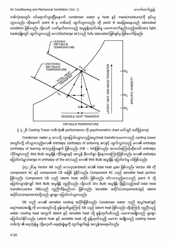
Air Conditioning and Mechanical Ventilation (Vol. 1) ႔
4-20
တစလးအတြငး ဝငေရာကသြားၿပးေနာက condenser water မ heat ႏင mass(moisture)က စပယ သြားသည။ ထေနာက point B မ တစဆင ထြကသြားသည။ ထ point B အေျခအေနသည saturated condition ျဖစသည။ သ႔ေသာ သတမတထားသည အပစြန႔ထတပစမႈ ပမာဏထကနညးသညအခါ(very light loads)မးတြင ထြကသြားသည ေလ(discharge air)သည fully saturated ျဖစခငမ ျဖစေပလမမည။
၄-၂၆ Cooling Tower ၏ performance s a
Condenser water မ ေလသ႔ ကးေျပာငးသြားသညအပ(heat transfer)ပမာဏသည cooling tower အတြငးသ႔ ဝငသြားသညေလ၏ enthalpy (enthalpy of entering air)ႏင ထြကသြားသည ေလ၏ enthalpy (enthalpy of leaving air)ကြာျခားခက ျဖစသည။ ( B − )ျဖစသည။ အဘယေၾကာငဆေသာ enthalpy လငးမားသည Wet Bulb လငးမားႏင အလြန နးကပစြာ ရေနသာေၾကာငျဖစသည။ ေလ၏ enthalpy ေျပာငးလမႈ(change in enthalpy of the air)သည ေလ၏ Wet Bulb ေျပာငးလမႈ ပငျဖစသည။
ပ(၄-၂၆)မ Vector AB သည (ambient air)၏ total heat gain ျဖစသည။ Vector AB က component AC ႏင component CB အျဖစ ခြႏငသည။ Component AC သည sensible heat portion ျဖစသည။ Component CB သည latent heat အပငး ျဖစသည။ ဝငလာသညေလသည point D သ႔ ေျပာငးသြားခလင Wet Bulb သည။ သ႔ေသာ Dry Bulb ပျမငသညအခါ total heat transfer(vector DB)သည တညလမမညသာ ျဖစသည။ Sensible (components)ႏင latent (component)တ႔သည မားစြာ ေျပာငးလသြားသည။
DE သည ေလ၏ sensible cooling အပငးျဖစသည။ Condenser water သည အပ(heat)ႏင ေရ(mass)အခ က ေလအတြငးသ႔ စြနထတမႈေၾကာင EB သည latent heat ျဖစသည။ ထ ႔ေၾကာင တညသည water cooling load အတြက latent ႏင sensible heat တ႔ စြန႔ထတပစသည ပမာဏအခးသည မားစြာ ေျပာငးလႏငသည။ Latent heat ႏင sensible heat တ႔ စြန႔ထတသည ပမာဏ အခးသည cooling tower တစလး ၏ ေရသးစြမႈ သ႔မဟတ ေရဆး ႈ မႈက တြကခကရန အလြနအေရးပါသည။
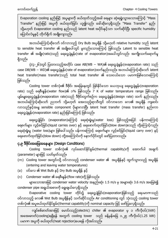
႔ Chapter- 4 Cooling Towers
4-21
အဘယေၾကာငဆေသာ ဝငလာသည Dry Bulb ႔ relative humidity သည latent
to sensible heat transfer ၏ အခးေပၚတြင မတညေသာေၾကာင ျဖစသည။ Latent to sensible heat transfer ၏ အခး(ratio)သည ေရေငြ႔ပႏႈနး(rate of evaporation)အေပၚတြငလညး အကးသကေရာကမႈ ရသည။
ပ(၄-၂၆)တြင ျပထားသညအတငး case AB(WB − W )၏ ေရေငြ႔ပႏႈနး(evaporation rate) သည case DB(WB − WD)၏ ေရေငြ႔ပႏႈနး(rate of evaporation)ထကနညးသည။ အဘယေၾကာငဆေသာ latent heat transfer(mass transfer)သည total heat transfer ၏ ေသးငယေသာ ပမာဏျဖစေသာေၾကာင ျဖစသည။
Cooling tower တစလး၏ ဒဇငး အေျခေနတြင ျဖစႏငေသာ ေယဘယ ေရေငြ႔ပႏႈနး(evaporation rate) သည ေရစးႏႈနး(water flow)၏ ၁% ျဖစသည။ 7 K of water temperature range ျဖစသည။ ပမးမေရေငြ႔ပႏႈနး(evaporation rate)သည ဒဇငးတြကစဥက ေရေငြ႔ပႏႈနး(design rate) ထက နညးသည။ အဘယေၾကာငဆေသာ ညဘက သ႔မဟတ ေအးသညရာသတြင ဝငလာေသာ ေလ၏ အပခန ကဆငး လာသညႏငအမ sensible component ပမားလာၿပး latent heat transfer (mass transfer) နညးကာ ေရေငြ႔ပႏႈနး(evaporation rate) နညးျခငးေၾကာင ျဖစသည။
ေရေငြ႔ပျခငး (evaporation)ေၾကာင ေရဆး ႈးမႈ(water loss) ျဖစသညအျပင ပနကာေၾကာင ေရစကမား လြငစငျခငး(liquid carries over) ႏင (blow down)စသည တ႔ေၾကာငလညး ေရဆး ႈးမႈ (water loss)မား ျဖစေပၚသည။ ပနကာေၾကာင ေရစကမား လြငစငျခငး(liquid carry over) ႏင ေရေဖာကထတျခငး(blow down) တ႔အေၾကာငးက ေနာကပငးတြင ေဖာျပထားသည။
၄.၉ ဒဇငးအေျခအေနမား (Design Conditions) Cooling tower တစလး၏ လပေဆာငႏငစြမး(thermal capability)က ေအာကပါ
(parameter) မားျဖင သတမတသည။ ( ) Cooling tower အတြငးသ႔ ဝငလာသည condenser water ၏ အပခနႏင ထြကသြားသည အပခန
(entering and leaving water temperatures) ( ) ဝငေလ ၏ Wet Bulb ႏင Dry Bulb အပခန
(ဂ) Condenser water ၏ ႈ (flow rate)တ႔ ျဖစသည။ condenser water velocity 1.5 m/s 3.6 m/s
condenser pipe Evaporative cooling tower တငး၌ ေရေငြ႔ပျခငး(evaporation)ျဖစသည ေရပမာဏသည
ဝငလာသည ေလ၏ Wet Bulb အပခနႏင သကဆငသည။ Air conditioning တြင သးသည cooling tower တစလး၏ အပဖယထတႏငစြမး(thermal capability)က nominal capacity ျဖင ေဖာျပေလရသည။
Evaporation cooling ႈ “Mass Transfer” ဟ “Mass Transfer” ႔ Evaporation cooling latent heat အပငးႏငသာ သကဆငၿပး specific humidity ေျပာငးလမႈႏင တက႐က အခးကသည။
လပစစဓာတအားျဖင ေမာငးသည(electric) chiller ၏ evaporator မ ၁ ကလဝပ(1kW) အေအးဓာတ(cooling)ရရရန အတြက cooling tower သည ခန႔မနးေျခ ၁.၂၅ ကလဝပ(1.25 kW) (heat rejection လအပသည။
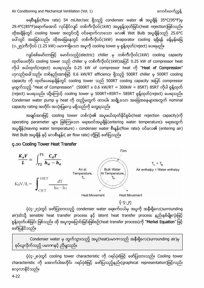
Air Conditioning and Mechanical Ventilation (Vol. 1) ႔
4-22
ေရစးႏႈနး(flow rate) 54 mLiter/sec ရသည condenser water ၏ အပခန 35°C(95°F)မ 29.4°C(85°F)ေရာကေအာင လပႏငလင တစကလဝပ(1kW) ႔ (heat rejection)ျဖစသည။ ထအခနတြင cooling tower အတြငးသ႔ ဝငေရာကလာေသာ ေလ၏ Wet Bulb အပခနသည 25.6°C ေပၚတြင အေျခခသည။ ထအေျခေနတြင တစကလဝပ(1kW) evaporator cooling ရရရန ခန႔မနးေျခ (၁.၂၅)ကလဝပ (1.25 kW) ပမာဏရေသာ အပက cooling tower မ စြန႔ထတ(reject) ေပးရမည။
လပစစေမာတာျဖင ေမာငးသည(electric) chiller မ တစကလဝပ(1kW) cooling capacity ထတေပးတငး cooling tower သည chiller မ တစကလဝပ(1kW)အျပင 0.25 kW of compressor heat ကပါ ဖယထတ(reject) ေပးရသည။ 0.25 kW of compressor heat က “Heat of Compression” ဟလညးေခၚသည။ တစနညးအားျဖင 0.6 kW/RT efficiency ရသည 500RT chiller မ 500RT cooling capacity က ထတေပးေနခနတြင cooling tower သည 500RT cooling capacity အျပင compressor မထြကသည “Hea f ss ” (500RT x 0.6 kW/RT = 300kW = 85RT) 85RT ကပါ စြန႔ထတ (reject) ေပးရသည။ ထ႔ေၾကာင cooling tower မ 500RT+85RT= 585RT စြန႔ထတ(reject) ေပးရသည။ Condenser water pump မ heat က ထညမတြက ထားပါ။ အခ႕ေသာ အေျခအေနမားအတြက nominal capacity rating အတငး အသးျပေလ မရသညက ေတြ႔ရသည။
အခပအားျဖင cooling tower တစလး၏ အပဖယထတႏငစြမး(heat rejection capacity)က operating parameter မား ျဖစၾကေသာ ေရအဝငအပခန(entering water temperature)၊ ေရအထြက အပခန(leaving water temperature) ၊ condenser water ႈ (flow rate)၊ ၏ (entering air) Wet Bulb ႏင ႈ ( air flow rate) တ႔ျဖင ေဖာျပသည။
၄.၁၀ Cooling Tower Heat Transfer
∫
၄-၂၇ ပ(၄-၂၇)တြင ေဖာျပထားသည condenser water ေရစကငယမ အပက အနးရေလ(surrounding
air)ထသ႔ sensible heat transfer process ႏင latent heat transfer process ႏစမးလးျဖင ႔ ျဖစသည။ ထ အပကးေျပာငးျခငးျဖစစဥ(heat transfer process)က “Merkel Equation” ျဖင ေဖာျပႏငသည။
ပ(၄-၂၈)တြင cooling tower characteristic က ဂရပပစျဖင ေဖာျပထားသည။ Cooling tower
characteristic ဂ ( a a s a
Condenser water မ ထြကသြားသည အပ(heat)ပမာဏသည အနးရေလ(surrounding air)မ စပယလကသည ပမာဏႏင ညမသည။
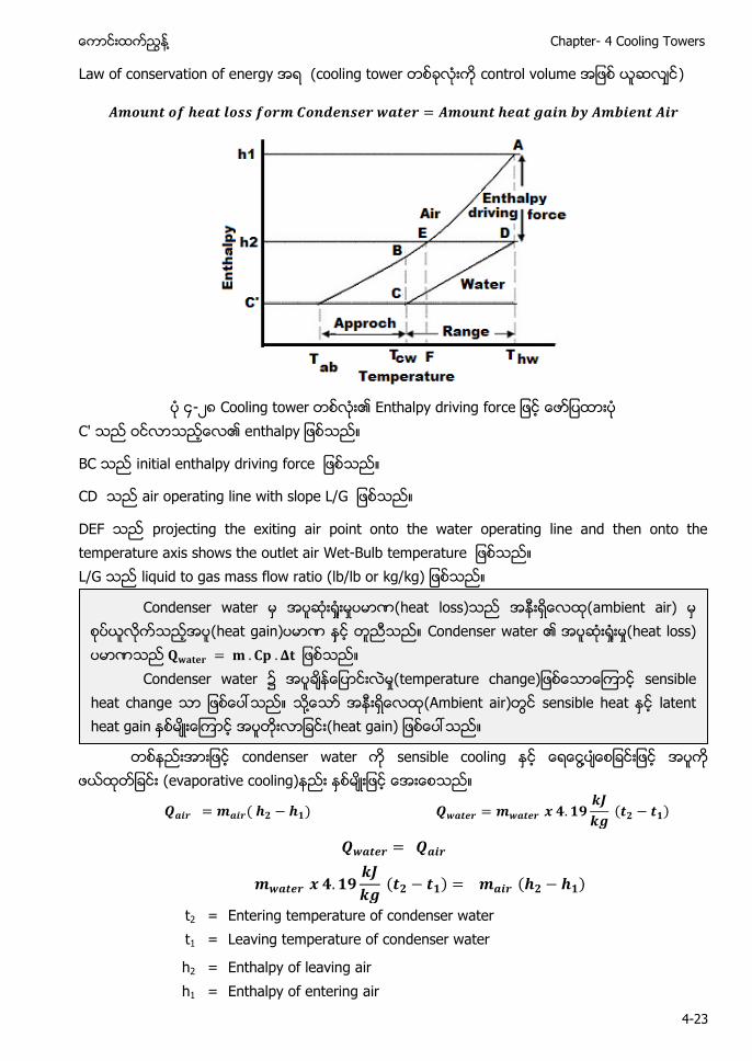
႔ Chapter- 4 Cooling Towers
4-23
Law of conservation of energy အရ (cooling tower တစခလးက control volume အျဖစ ယဆလင)
၄-၂၈ Cooling tower ၏ Enthalpy driving force
C' ၏ a
BC i a a f
CD a a s L
DEF projecting the exiting air point onto the water operating line and then onto the temperature axis shows the outlet air Wet-Bulb a L/G liquid to gas mass flow ratio (lb/lb or kg/kg)
တစနညးအားျဖင condenser water က sensible cooling ႏင ႔
(evaporative cooling)နညး ႏစမးျဖင ေအးေစသည။
t2 = Entering temperature of condenser water t1 = Leaving temperature of condenser water
h2 = Enthalpy of leaving air h1 = Enthalpy of entering air
Condenser water မ အပဆး႐ႈးမႈပမာဏ(heat loss)သည အနးရေလထ(ambient air) (heat gain)ပမာဏ နင တညသည။ Condenser water ၏ အပဆး႐ႈးမႈ(heat loss) ပမာဏသည ျဖစသည။
Condenser water ၌ အပခနေျပာငးလမႈ(temperature change)ျဖစေသာေၾကာင sensible heat change ျဖစေပၚသည။ ႔ (Ambient air)တြင sensible heat ႏင latent heat gain ႏစမးေၾကာင အပ ျခငး(heat gain) ျဖစေပၚသည။
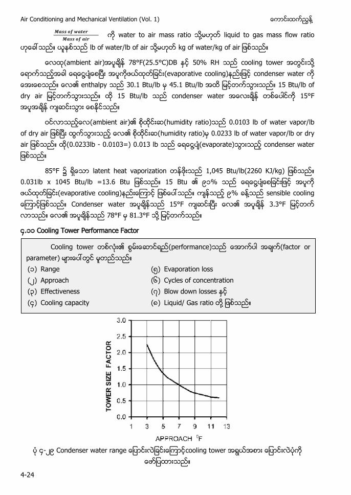
Air Conditioning and Mechanical Ventilation (Vol. 1) ႔
4-24
water to air mass ratio ႔ liquid to gas mass flow ratio
lb of water/lb of air ႔ kg of water/kg f a
(ambient air) 78°F(25.5°C)DB ႏင 50% RH သည cooling tower အတြငးသ႔ ေရာကသညအခါ ႔ ၿ (evaporative cooling)နညးျဖင condenser water က ေအးေစသည။ ၏ enthalpy သည 30.1 Btu/lb မ 45.1 Btu/lb အထ ျမငတကသြားသည။ 15 Btu/lb of dry air ျမငတကသြားသည။ ထ 15 Btu/lb သည condenser water အေလးခန တစေပါငက 15°F အပအခန ကဆငးသြား ေစႏငသည။
ဝငလာသညေလ(ambient air)၏ စထငးဆ(humidity ratio)သည 0.0103 lb of water vapor/lb of dry air ျဖစၿပး ထြကသြားသည ေလ၏ စထငးဆ(humidity ratio)မ 0.0233 lb of water vapor/lb or dry air ျဖစသည။ ထ(0.0233lb - 0.0103=) 0.013 lb သည ေရေငြ႔ပ(evaporate)သြားသည condenser water ျဖစသည။
85°F ၌ ရေသာ latent heat vaporization တနဖးသည 1,045 Btu/lb(2260 KJ/kg) ျဖစသည။ 0.031lb x 1045 Btu/lb =13.6 Btu ျဖစသည။ 15 Btu ၏ ၉ % သည ႔ (evaporative cooling)နညးေၾကာင ျဖစ သည။ ကနသည ၉% ခန႔သည sensible cooling ေၾကာငျဖစသည။ Condenser water အပခနသည 15°F ကဆငးၿပး ေလ၏ အပခန 3.3°F တက လာသည။ ၏ 78°F မ 81.3°F သ႔
၄.၁၁ Cooling Tower Performance Factor
၄-၂၉ Condenser water range ေျပာငးလျခငးေၾကာငcooling tower အရြယအစား ေျပာငးလပက
ေဖာျပထားသည။
Cooling tower ၏ စြမးေဆာငရည(performance)သည ေအာကပါ အခက(factor or parameter) သည ( ) Range (၅) Evaporation loss (၂) Approach (၆) Cycles of concentration (၃) Effectiveness (၇) Blow down losses (၄) Cooling capacity (၈) Liquid/ Gas ratio ႔
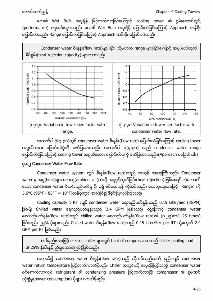
႔ Chapter- 4 Cooling Towers
4-25
၏ Wet Bulb ျမငတကလာျခငးေၾကာင cooling tower ၏ (performance) ကဆငးသြားသည။ ၏ Wet Bulb ေျပာငးလျခငးေၾကာင Approach ေျပာငးလသည။ Range ေျပာငးလျခငးေၾကာင Approach တနးဖး ေျပာငးလသည။
၄-၃၀ Variation in tower size factor with
range. ၄-၃ Variation in tower size factor with
condenser water flow rate.
အထကပါ (၄-၃ )တြင condenser water ႈ (flow rate) ေျပာငးလျခငးေၾကာင cooling tower အရြယအစား ေျပာငးလပက ေဖာျပထားသည။ အထကပါ (၄-၃၀) သည condenser water range ေျပာငးလျခငးေၾကာင cooling tower အရြယအစား ေျပာငးလပက ေဖာျပထားသည။(Approach မေျပာငးပါ။)
၄.၁၂ Condenser Water Flow Rate
Condenser water system တြင ႈ (flow rate)သည အလြန အေရးႀကးသည။ Condenser water မ (heat)မား ေလထ(ambient air) သ႔ အပစြန႔ထတျခငး(heat rejection) ျဖစေစရန လေလာက ေသာ condenser water လညပတမႈ ရ၊ မရ စစေဆးရန လအပသည။ ေယဘယအားျဖင “Ra ” က 5.6°C (95°F - 85°F = 10°F)တနဖးတြင အေျခခ၍ ဒဇငးျပလပၾကသည။
Cooling capacity 1 RT condenser wat ႈ 0.19 Liter/Sec (3GPM) ၿ a ႈ ထ႔ေၾကာင condenser water ေရလညပတႏႈနး(flow rate)သည chilled water ေရလညပတႏႈနး(flow rate)၏ (၁.၂၅)ဆ(1.25 times) ျဖစသည။ ၂၅% ပမားသည။ Chilled water ႈ (flow rate)သည 0.15 Liter/Sec per RT ႔ 2.4 GPM per RT ျဖစသည။
အကယ၍ condenser water ႈ (flow rate)သည လအပသညထက နညးလင condenser
water return temperature ျမငတကလာလမမည။ Chiller တြငးသ႔ အပခနျမငသည condenser water ဝငေရာကလာလင refrigerant ၏ condensing pressure ျမငတကလာၿပး compressor ၏ ႈ(power consumption) ပမား လာလမမည။
Condenser water ႈ (flow rate)မားျခငး ႔ range မားျခငးေၾကာင အပ ဖယထတ ႏငစြမး(heat rejection capacity) မားလာသည။
တစနညးအားျဖင electric chiller heat of compression သည chiller cooling load ၏ 25% ႏင ညမ သည။
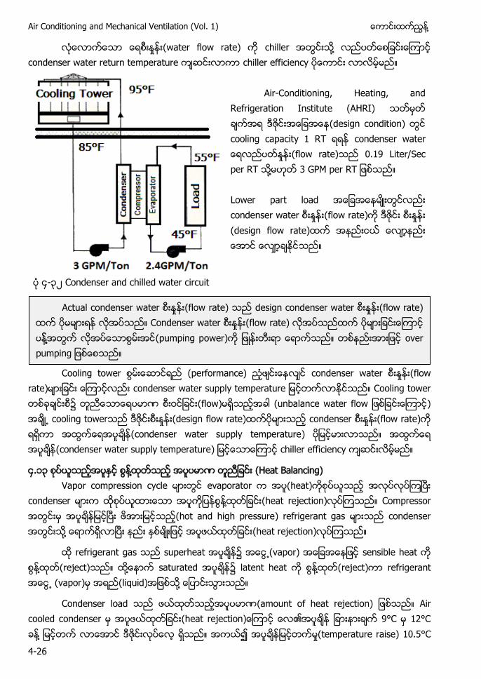
Air Conditioning and Mechanical Ventilation (Vol. 1) ႔
4-26
လေလာကေသာ ႈ (water flow rate) က chiller အတြငးသ႔ လညပတေစျခငးေၾကာင condenser water return temperature ကဆငးလာကာ chiller efficiency ပေကာငး လာလမမည။
Air-Conditioning, Heating, and
Refrigeration Institute (AHRI) (design condition) တြင cooling capacity 1 RT s a ႈ (flow rate) 0.19 Liter/Sec per RT ႔ 3 GPM per RT ျဖစသည။ Lower part load အေျခအေနမးတြငလညး condenser water ႈ (flow rate)က ႈ (design flow rate)ထက အနညးငယ ေလာနညး ေအာင ေလာခႏငသည။
၄-၃၂ Condenser and chilled water circuit
Cooling tower (performance) ညဖငးေနလင condenser water ႈ (flow
rate)မားျခငး ေၾကာငလညး condenser water supply temperature ျမငတကလာႏငသည။ Cooling tower တစခခငးစ၌ တညေသာေရပမာဏ (flow)မရသညအခါ (unbalance water flow ျဖစျခငးေၾကာင) အခ႕ cooling towerသည ဒဇငး ႈ (design flow rate)ထကပမားသည condenser ႈ (flow rate)က ရရကာ အထြကေရအပခန(condenser water supply temperature) ျမငမားလာသည။ အထြကေရ အပခန(condenser water supply temperature) ျမငေသာေၾကာင chiller efficiency ကဆငးလမမည။
၄.၁၃ စပယသညအပႏင စြန႔ထတသည အပပမာဏ တညျခငး (Heat Balancing) Vapor compression cycle မားတြင evaporator က အပ(heat)ကစပယသည အလပလပၾကၿပး
condenser မားက ထစပယထားေသာ အပကျပန ႔ (heat rejection)လပၾကသည။ Compressor အတြငးမ အပခနျမငၿပး ဖအားျမငသည(hot and high pressure) refrigerant gas မားသည condenser အတြငးသ႔ ေရာကရလာၿပး နညး ႏစမးျဖင အပဖယထတျခငး(heat rejection)လပၾကသည။
refrigerant gas သည superheat အပခန၌ (vapor) sensible heat က စြန႔ထတ(reject)သည။ ထ႔ေနာက saturated ၌ latent heat က စြန႔ထတ(reject)ကာ refrigerant (vapor)မ အရည(liquid)အျဖစသ႔ ေျပာငးသြားသည။
Condenser load သည ဖယထတသညအပပမာဏ(amount of heat rejection) ျဖစသည။ Air cooled condenser မ အပဖယထတျခငး(heat rejection)ေၾကာင ေလ၏အပခန 9°C မ 12°C ခန႔ ျမငတက လာေအာင ဒဇငးလပေလ ရသည။ အကယ၍ အပခနျမငတကမႈ(temperature raise) 10.5°C
Actual condenser water ႈ (flow rate) သည design condenser water ႈ (flow rate) ထက မမားရန လအပသည။ Condenser water ႈ (flow rate) လအပသညထက ပမားျခငးေၾကာင ႔ ႔ (pumping power)က ျဖနးတးရာ ေရာကသည။ တစနညးအားျဖင over pumping ျဖစေစသည။
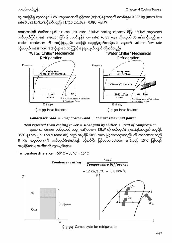
႔ Chapter- 4 Cooling Towers
4-27
က အေျခခ၍ တြကလင 1kW အပပမာဏက စြန႔ထတ(reject)ရနအတြက ေလစးႏႈနး 0.093 kg (mass flow rate 0.093 kg/kW)လအပသည။ [1/(10.5x1.02)= 0.093 kg/kW]
ဥပမာအားျဖင ႐းခနးတစခ၏ air con unit သည 350kW cooling capacity ရၿပး 430kW အပပမာဏ ဖယထတျခငး(heat rejection)ျဖစရန ေလစးႏႈနး(flow rate) 40.85 kg/s သ႔မဟတ 36 m3/s ရသည air-cooled condenser က အသးျပရမည။ ႔ volume flow rate ႔ mass flow rate မားေသာေၾကာင ေနရာကယကယ လအပသည။
၄-၃၃ Heat Balance ၄-၃၄ Heat Balance
ဥပမာ condenser တစခသည အပ(heat)ပမာဏ 12kW က ဖယထတ(reject)ရနအတြက အပခန 35°C ရေသာ ျပငပေလ(outdoor air) သည အပခန 50°C အထ ျမငတကသြားသည။ ထ condenser သည 8 kW အပပမာဏက ဖယထတ(reject)ရန လအပၿပး (outdoor air)သည 15°C ျဖစလင အပခနမညမ အထတက သြားမညနညး။
Temperature d ff –
= 12 kW/15°C = 0.8 W
၄-၃၅ Carnot cycle for refrigeration
Air Conditioning and Mechanical Ventilation (Vol. 1) ႔
4-28
ထ condenser သည 1°C အပခနကြာျခားတငး(temperature difference) အပပမာဏ 0.8 kW က ဖယထတ(reject) ႏငစြမးရသည။
၄.၁၄ ေရြးခယရာတြင စဥးစားရမည အခကမား (Selection Consideration)
၏ (application)ႏင သငေလာမနကနေသာ cooling tower က ေရြးခယအတြက ေအာကပါ အခကအလကမားက ထညသြငးစဥးစားရန လအပသည။ ( ) Cooling duty (လအပေသာ ႈ (capacity) ၊ ေမာငးႏငမည duty အမးအစား) ( ) Economics [စးပြားေရးတြကေခကကမႈ၊ တပဆငရနကနကစရတ(installation cost) ၊ ေမာငးႏင
လညပတရန ကနကစရတ (operation cost)] (ဂ) Required services (လအပသည ဆားဗစအမးအစားမား) (ဃ) Environmental conditions (ပတဝနးကငက ထခကမႈရ မရ၊ ေကာငး၊ ေဆး႐ ႔ လအမားစ
ႏင နးသညေနရာတြင cooling tower က တပဆငရန မသငေလာေပ။ Legionella ပးမႊား (pathogenic gram) ေၾကာင ျဖစသည။) Legionella အေၾကာငး အေသးစတ သလပါက http://www.nea.gov.sg/cms/qed/cop_legionella.pdf
( ) Maintenance requirements (ျပျပငထနးသမးရန လအပခကမား) ႏင ( ) Aesthetics- အျမငလပမႈ ရ၊ မရ တ႔ျဖစသည။ (လျမငကြငးတြင တပဆငထားေသာ cooling tower
မားအား ၾကညေကာငးေအာင ျပလပထားရန သ႔မဟတ ကာရထားရန လအပသည။) အထကပါ အခကအလကမားသည တစခႏငတစခ အျပနအလနဆကစပမႈ ရၾကသည။
တစခခငးစက ဆနးစစေရြးခယ ရမည။
cooling tower ေရြးခယျခငးႏင သကဆငေသာ အခကအလကမားမာ
( ) Safety features ၊ safety codes သကဆငေသာ ေဘးရနကငးရငးေရး စညးမညး စညးကမး မားက လကနာရမည
(၂) အေဆာကအဥ အမးအစားက လက၍ ခမတထားသည code မားက လကနာရမည (Conformity to building codes)
(၃) General design and rigidity of structures (တညေဆာကမည structure ဒဇငး ႏင အမးအစား)
(၄) Relative effects of corrosion, scale, or deterioration on service life (သေခးတကျခငး၊ ေရညႇ တကျခငး၊ စြမးရညကဆငးျခငး ႏင အသးျပႏငသည သကတမးတျခငး စသညတ႔ႏင သကဆငေသာ အခကမား)
(၅) Availability of spare parts (အပပစၥညးမား အလြယတက ရရႏငမႈ)
(၆) Experience and reliability of manufacturers (ထတလပသ၏ လပငနးအေတြ႔အၾကႏင စတခႏငမႈရ ၊ မရ)
(၇) Independent certification of thermal ratings (ေဖာျပထားေသာ စြမးေဆာငရညႏႈနး(rating) က ထတလပသမဟတသည တျခားေသာအဖြ႔ တစခခမ ေထာကခေပးမႈ)
(၈) Operating flexibility for economical operation at varying loads or during seasonal changes. (ေႏြ၊မး၊ေဆာငး ရာသဥတအားလး၌ ျဖစေပၚႏငသည load မား အားလး ႏင ကကညေအာင ေမာငးႏငမႈ)တ႔ ျဖစသည။
႔ Chapter- 4 Cooling Towers
4-29
ထအခကအလကမားအျပင တနခါမႈ(equipment vibration)၊ ဆညသ(sound levels) ၊ ဆညသေလာနညးေအာင ေဆာငရြကျခငး(acoustical attenuation)၊ ဗသကာဒဇငး(architectural design) ႏင လကေလာ ညေထြျဖစမႈ တ႔ကလညး အဓကထား စဥးစားရမည ျဖစသည။
Cooling duty ႏငသကဆငေသာ အခကအလကမားသည အျမင(height)၊ အရည(length)၊ အထ (width)၊ ေလလညပတႏႈနး(volume of airflow)၊ fan ႏင pump တ႔၏ စြမးအငသးစြမႈႏနး(energy consumption)၊ တညေဆာကထားသည ပစၥညးအမးအစား(materials of construction)၊ ေရအရညအေသြး (water quality) ႏင ေစးကြကတြင ရရႏငမႈ(availability)တ႔ ျဖစသည။
မမအေဆာကအဥ ႔ မမ system အတြက အေကာငးဆးႏင အသငေလာဆးေသာ cooling tower အမးအစားႏင အရြယအစားက economic evaluation လပၿပးမသာ ရရႏငသည။ နညးပညာအရ (technically) အသငေလာဆးျဖစရန လအပသလ စးပြားေရအရ(economically)လညး အကးအျမတ မားရန လအပသည။
2007 ASHRAE Handbook စာအပမ Chapter 36 ၌ ပါရေသာ HVAC Applications အပငးတြင အသးမားသည ႈ ၊ နညး(economic evaluation) ႏစမးက ေဖာျပ ထားသည။ ( ) Life Cycle Costing (equipment တစခ စဝယသညေန႔မ သးမရ၍ ဖကပစသညေနအထ ကနက
စရတ စစေပါငးက တြကသညနညး)ႏင (၂) Payback analysis (ဝယၿပး တပဆငရန ကနကစရတမားက ျပနလညရရရန ႏစမညမၾကာသညက
တြကသညနညး ျဖစသည။) အထကပါ နညးႏစနညး အနကမ ႀကကႏစသကရာ နညးက အသးျပႏငသည။
အစပငးကနကစရတမား (initial cost) အတြက ေအာကပါ အခကအလကတ႔က ထညသြငး စဥးစား သငသည။ • Erected cost of equipment (ျငမး၊ ကရနး စသညတ႔အတြက ကနကစရတ) • Costs of interface with other subsystems (သကဆငသည တျခားေသာ subsystem မားႏင
interface လပရန ကနကစရတ) • Pumps and prime movers (ပန႔ စသည တ႔အတြကကနကစရတ) • Electrical wiring to pump and fan motors (ပန႔ ၊ ေမာတာ ႏင fan ေမာတာ တ႔၏ လပစစဝါယာႏင
သကဆငေသာ ကနကစရတ) • Electrical controls and switchgear (လပစစ panel မား ႏင control မား၊ switchgear ႔ အတြက
ကနကစရတ) • Piping to and from the tower (ပကမား တပဆငရနအတြက ကနကစရတ) • Tower basin ၊ sump screens ၊ overflow piping and makeup lines ၊ if not furnished by the
manufacturer (တျခားေသာ အစတအပငးမား အတြက ကနကစရတ) • Shutoff and control valves (ဘားမားအတြက ကနကစရတ) • Walkways ၊ ladders ၊ etc., providing access to the tower ၊ if not furnished by the manufacturer
(ေလာကလမး၊ ေလကားတ႔အတြက ကနကစရတ) • Fire protection sprinkler system (မးေဘးကာကြယေရး အစအမမားအတြက ကနကစရတ) • ပငဆငမႈအတြက ကနကစရတ(ownership cost)ႏင ထနးသမးျပျပငမႈ ကနကစရတ(maintenance
costs) တ႔အတြက ေအာကပါ အခကအလကတ႔က ထညသြငး စဥးစားသငသည။
Air Conditioning and Mechanical Ventilation (Vol. 1) ႔
4-30
• System energy costs (fans, pumps, etc.) (တစနာရေမာငးရနအတြက လအပသည စြမးအင အတြက ကနကစရတ)
• Energy demand charges (လပစစဓာတအားခ ကနကစရတ) • Expected equipment life (အေမာလငႏငဆးေသာ အသးျပႏငမည သကတမး) • Maintenance and repair costs (ထနးသမးစရတ ႏင ျပျပငစရတ) • Money costs (အတးတြက၊ ေငြေၾကးေဖာငးပြမႈ စသညတ႔အတြက ထညေဆာငးရမည စရတ)
၄.၁၅ အရြယအစား ေရြးခယျခငး (Cooling Tower Sizing)
Cooling tower မားသည central air conditioning system မ စြန႔ထတသည (heat) မားက သာမက chiller ၏ compressor မ (heat)မားကလညး အတတကြ စြန႔ထတေပးရသည။ Chiller မ (heat of compression)ပမာဏသည chiller ၏ efficiency ေပၚတြင မတညသည။ အၾကမးအားျဖင (electric) chiller cooling load ၏ ၂၅% ျဖစသည။ ထ႔ေၾကာင cooling tower ၏ အရြယအစား(size)သည chiller cooling capacity ၏ ၁၂၅% ျဖစသည။ (၁.၂၅ ဆခန႔ ျဖစသည)။ လပစစေမာတာျဖင ေမာငးသည chiller အတြကသာ ျဖစသည။
Chiller efficiency သည cooling tower ၏ အရြယအစား(size)ေပၚတြင မတညသည။ Cooling tower ၏ အရြယအစားသည လအပသညထက ေသးငယေနလင အပဖယထတျခငး(heat rejection) မလေလာကေသာေၾကာင (condenser supply water(leaving)temperature) ျမငတက လာလမမည။ ထ႔ေၾကာင chiller efficiency ကဆငးသြားႏငသည။ Cooling tower မ (condenser supply water temperature) နမလင chiller ၏ efficiency ပေကာငးလာသည။
Cooling tower သည သအရအရ (leaving condenser temperature)က ေလ၏ Wet Bulb သ႔ေရာကေအာင နမခေပး ႏငသည။ ထသ႔ နမခရနအတြက (surface area)ကယကယႏင ႈ (air flow)မားမား လအပသည။ ထကသ႔ ဒဇငးလပထားေသာ cooling tower သည chiller efficiency က ပမ ေကာငးမြနေစေသာလညး cooling tower ႔ တပဆငခ ႏင (operating cost) စသညတ႔ အဆမတန မားလာလမမည။ လအပသညထက ပမားသည cooling tower အေရအတြကက တပဆငထားရန လအပလမမည။
ထ႔ေၾကာင cooling tower (initial capital cost) ႏင chiller cooling tower ၏ (operating cost)တ႔ အၾကားတြင အေကာငးဆး(optiminum) ျဖစေအာင ခနဆ၍ ေရြးခယရျခငး ျဖစသည။
Cooling tower ၏ မကႏာျပငဧရယာ(surface area)နညးျခငး၊ မားျခငးသည capital cost(cooling tower တနဖး)ႏငသာ သကဆငသည။ Cooling tower ၏ ႈ (air flow)နညးျခငး၊ မားျခငး သည (operating cost) ႏငသာ သကဆငသည။ ထ႔ေၾကာင တညေသာ cooling capacity ရသည cooling tower ႏစလးတြင မကႏာျပငဧရယာ (surface area)မားၿပး ႈ (air flow)နညးသည cooling tower သည capital cost မားၿပး (operating cost) နညးလမမည။ မကႏာျပငဧရယာ(surface area)နညးၿပး ႈ (air flow) မားသည cooling tower သည capital cost နညးၿပး (operating cost)မားလမမည။
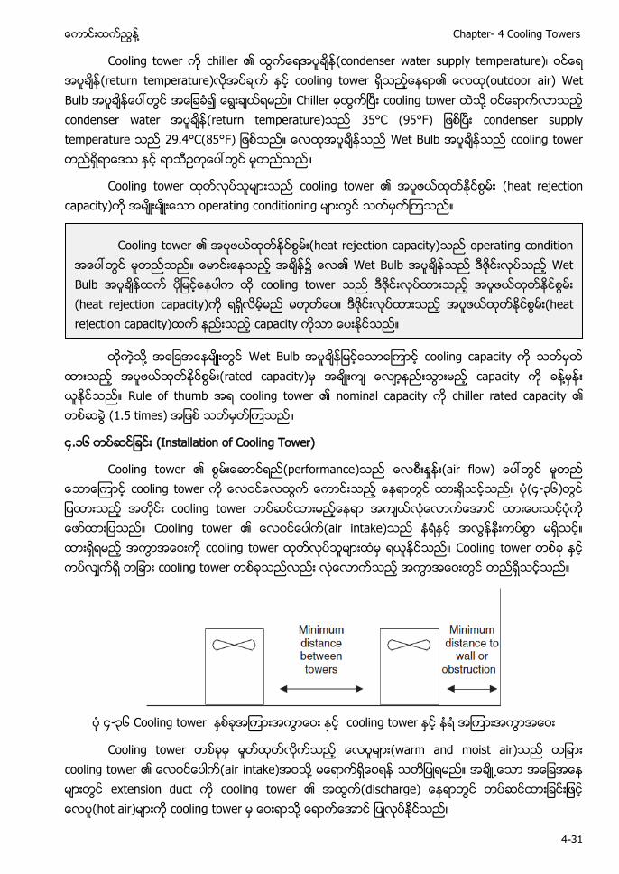
႔ Chapter- 4 Cooling Towers
4-31
Cooling tower က chiller ၏ (condenser water supply temperature)၊ ဝငေရ အပခန(return temperature)လအပခက ႏင cooling tower ရသညေနရာ၏ (outdoor air) Wet Bulb ေပၚတြင အေျခခ၍ ေရြးခယရမည။ Chiller မထြကၿပး cooling tower ထသ႔ ဝငေရာကလာသည condenser water (return temperature)သည 35°C (95°F) ျဖစၿပး condenser supply temperature သည 29.4°C(85°F) ျဖစသည။ Wet Bulb cooling tower ရာသဥတေပၚတြင မတညသည။
Cooling tower ထတလပသမားသည cooling tower ၏ အပဖယထတႏငစြမး (heat rejection capacity)က အမးမးေသာ operating conditioning မားတြင သတမတၾကသည။
ထကသ႔ အေျခအေနမးတြင Wet Bulb ျမငေသာေၾကာင cooling capacity က သတမတ
ထားသည အပဖယထတႏငစြမး(rated capacity)မ အခးက ေလာနညးသြားမည capacity က ခန႔မနး ယႏငသည။ Rule of thumb အရ cooling tower ၏ nominal capacity က chiller rated capacity ၏ တစဆခြ (1.5 times) အျဖစ သတမတၾကသည။
၄.၁၆ တပဆငျခငး (Installation of Cooling Tower)
Cooling tower ၏ စြမးေဆာငရည(performance)သည ႈ (air flow) ေပၚတြင မတည ေသာေၾကာင cooling tower က ေလဝငေလထြက ေကာငးသည ေနရာတြင ထားရသငသည။ ပ(၄-၃၆)တြင ျပထားသည အတငး cooling tower တပဆငထားမညေနရာ အကယလေလာကေအာင ထားေပးသငပက ေဖာထားျပသည။ Cooling tower ၏ (air intake)သည နရႏင အလြနနးကပစြာ မရသင။ ထားရရမည အကြာအေဝးက cooling tower ထတလပသမားထမ ရယႏငသည။ Cooling tower တစခ ႏင ကပလကရ တျခား cooling tower တစခသညလညး လေလာကသည အကြာအေဝးတြင တညရသငသည။
၄-၃၆ Cooling tower cooling tower
Cooling tower တစခမ မႈတထတလကသည (warm and moist air)သည တျခား cooling tower ၏ ေလဝငေပါက(air intake)အဝသ႔ မေရာကရေစရန သတျပရမည။ အခ႕ေသာ အေျခအေန မားတြင extension duct က cooling tower ၏ အထြက(discharge) ေနရာတြင တပဆငထားျခငးျဖင ေလပ(hot air)မားက cooling tower မ ေဝးရာသ႔ ေရာကေအာင ျပလပႏငသည။
Cooling tower ၏ အပဖယထတႏငစြမး(heat rejection capacity)သည operating condition အေပၚတြင မတညသည။ ေမာငးေနသည အခန၌ ေလ၏ Wet Bulb သည Wet Bulb ထက ပျမငေနပါက ထ cooling tower သည လပထားသည အပဖယထတႏငစြမး (heat rejection capacity) အပဖယထတႏငစြမး(heat rejection capacity)ထက နညးသည capacity ကသာ ေပးႏငသည။
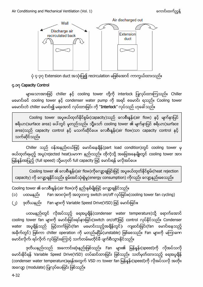
Air Conditioning and Mechanical Ventilation (Vol. 1) ႔
4-32
၄-၃၇ Extension duct recirculation
၄. ၇ Capacity Control
မားေသာအားျဖင chiller ႏင cooling tower တ႔က interlock ျပလပထားၾကသည။ Chiller မေမာငးခင cooling tower condenser water pump က အရင စေမာငး ရသည။ Cooling tower မေမာငးဘ chiller ေမာငး၍ မရေအာင လပထားျခငး က “Interlock” လပသည ဟေခၚသည။
Chiller သည (part load condition)တြင cooling tower မ
ဖယထတရမည အပ(rejected heat)ပမာဏ နညးသည။ ထကသ႔ အေျခအေနမးတြင cooling tower အား ႈ (full speed) ႔ full capacity ျဖင ေမာငးရန မလအပေပ။
Cooling tower ၏ ႈ (air flow)က နညးႏစမးျဖင ေလာခႏငသည။ ( ) ပထမနညး Fan အားလးက အတတကြ switch on/off လပျခငး။(cooling tower fan cycling)
(၂) ဒတယနညး Fan မားက Variable Speed Drive(VSD) ျဖင ေမာငးျခငး။
ပထမနညးတြင လအပသည ေရအပခန(condenser water temperature)သ႔ ေရာကေအာင cooling tower fan မားက ၊ (switch on/off)ျဖင control လပႏငသည။ Condenser water သည ျမငတကျခငး(fan မေမာငးသညအခနတြင)၊ ကဆငးျခငး(fan ေမာငးေနသည အခကတြင) ျဖစကာ chiller operation က မတညမၿငမ(unstable) ျဖစေစသည။ Fan မားက မၾကာခဏ ေမာငးလက၊ ရပလက လပျခငးေၾကာင သကတမးမတငမ ပကစးသြားႏငသည။
ဒတယနညးသည အေကာငးဆးနညးျဖစသည။ Fan မား၏ ႈ (speed)က လအပသလ ေမာငးႏငရန Variable Speed Drive(VSD) တပဆငထားျခငး ျဖစသည။ သတမတထားသည ေရအပခန (condenser water temperature)ရရနအတြက VSD က tower fa ႈ (speed)က လအပသလ အတး၊ အေလာ (modulate) ျပလပေပးျခငး ျဖစသည။
Cooling tower (capacity)သည ေလစးႏႈနး(air flow) (surface area) ေပၚတြင မတညသည။ သ႔႔႔ေသာ cooling tower ၏ မကႏာျပင ဧရယာ(surface area)သည capacity control ႏင မသကဆငေပ။ ေလစးႏႈနး(air flow) capacity control ႏင သကဆငသည။
Cooling tower ၏ ႈ (air flow)ကေလာချခငးျဖင အပဖယထတႏငစြမး(heat rejection capacity) က ေလာခႏငသည။ ႈ(energy consumption) ကလညး ေလာနညးေစသည။
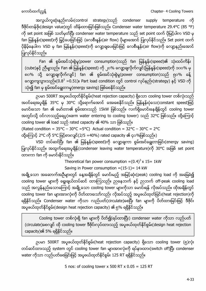
႔ Chapter- 4 Cooling Towers
4-33
အလြယကဆးနညးလမး(control strategy)သည condenser supply temperature က ဒဇငးတနဖး(design value)တြင ထနးထားျခငးျဖစသည။ Condenser water temperature 29.4°C (85 °F) က set point အျဖစ သတမတၿပး condenser water temperature သည set point ထက ပျမငပါက VSD မ fa ႈ (speed)က ျမႇငေပးျခငး ( ႈ (air flow) ပမားေအာင ျပလပ Set point ထက ပနမေနပါက VSD မ fa ႈ (speed)က ေလာခေပးျခငး ႈ (air flow)က ေလာနညးေအာင ျပလပႏငသည။
ဥပမာ 500RT အပဖယထတႏငစြမး(heat rejection capacity) ရေသာ cooling tower တစလးသည 35°C 30°C သ႔ေရာကေအာင ေအးေစႏငသည။ ျမနႏႈနးပေသ(constant speed)ျဖင ေမာငးေသာ fan ၏ ေမာတာ၏ စြမးအားသည 15kW ျဖစသည။ cooling tower အတြငးသ႔ ဝငလာသညေရပ(warm water entering to cooling tower) သည 32°C ျဖစသည။ ထ႔ေၾကာင cooling tower ၏ load သည rated capacity ၏ 40% ျဖစသည။ (Rated condition = 35°C – 30°C =5°C) Actual condition = 32°C – 30°C = 2°C ထ႔ေၾကာင 2°C 5° (2/5 =40%) rated capacity ၏ ၄၀ ) VSD တပဆငၿပး fan ၏ ျမနႏႈနး(speed)က ေလာခကာ စြမးအငေခြတာျခငး(energy saving) ျပလပႏငသည။ (condenser leaving water temperature)က 30°C အျဖစ set point ထားကာ fan က ေမာငးႏငသည။
Theoretical fan power consumption =(0.4)3 x 15= 1kW Saving in Power consumption =(15-1)= 14 kW
အခ႕ေသာ အေဆာကအဥမားတြင ေန႔အခနတြင ေမာငးမည အျမငဆး(peak) cooling load က အေျခခ၍ cooling tower မားက ေရြးခယတပဆင ထားၾကသည။ ညေနဘက ႏင ညဘက off-peak cooling load သည အလြနနညးေသာေၾကာင အခ႕ေသာ cooling tower မားကသာ ေမာငးရန လအပသည။ ထအခနတြင cooling tower fan မားအားလးက ပတထားေသာလညး လအပသည အပဖယထတျခငး(heat rejection)က ရရႏငသည။ Condenser water ကသာ လညပတ(circulate)ေစၿပး fan မားက ထားျခငးျဖင အပဖယထတႏငစြမး(design heat rejection capacity) ၏ ၅% ရရႏငသည။
ဥပမာ 500RT အပဖယထတႏငစြမး(heat rejection capacity) ရေသာ cooling tower (၅)လး တပဆငထားသည system တြင cooling tower fan မားအားလးက (switch off)ၿပး condenser water 125 RT ရရႏငသည။
5 nos: of cooling tower x 500 RT x 0.05 = 125 RT
Fan ၏ စြမးအငသးစြမႈ(power consumption)သည fa ႈ (speed)၏ သးထပကနး (cube)ႏင ညမသည။ Fan ၏ ျမနႏႈနး(speed) က ၂၀% ေလာခလကလင[ျမနႏႈနး(speed) ၀၀% ၈၀% ႔ ] fan ၏ ႈ(power consumption)သည ၅၀% ႔ ေလာကသြားသည။(0.83 =0.51) Part load condition တြင control (strategy) ႏင VSD က သး၍ fan မ စြမးအငေခြတာမႈ(energy saving) ျဖစေစႏငသည။
Cooling tower တစလးရ fan မားက ပတ ( ၿ ) condenser water လညပတ (circulate)ေစ cooling tower အပဖယထတႏငစြမး(design heat rejection capacity)၏ 5% ရရႏငသည။
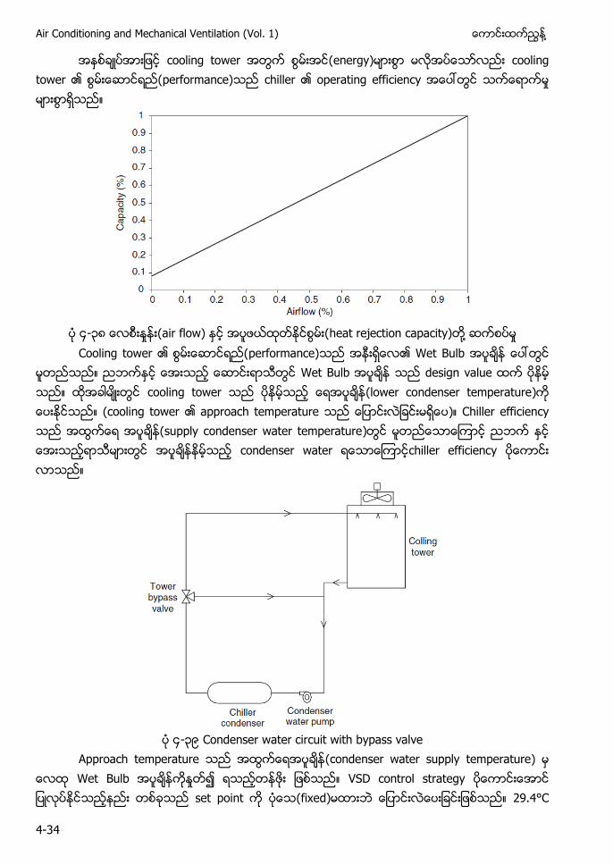
Air Conditioning and Mechanical Ventilation (Vol. 1) ႔
4-34
အႏစခပအားျဖင cooling tower အတြက စြမးအင(energy)မားစြာ မလအပေသာလညး cooling tower ၏ (performance)သည chiller ၏ operating efficiency အေပၚတြင သကေရာကမႈ မားစြာရသည။
၄-၃၈ ႈ (air flow) အပဖယထတႏငစြမး(heat rejection capacity) ႔ ႈ
Cooling tower ၏ (performance)သည အနးရေလ၏ Wet Bulb ေပၚတြင မတညသည။ ညဘကႏင ေအးသည ေဆာငးရာသတြင Wet Bulb သည design value ထက ပနမ သည။ ထအခါမးတြင cooling tower သည ပနမသည ေရအပခန(lower condenser temperature)က ေပးႏငသည။ (cooling tower ၏ approach temperature သည ေျပာငးလျခငးမရေပ)။ Chiller efficiency သည အထြကေရ အပခန(supply condenser water temperature)တြင မတညေသာေၾကာင ညဘက ေအးသညရာသမားတြင အပခနနမသည condenser water chiller efficiency ပေကာငး လာသည။
၄-၃၉ Condenser water circuit with bypass valve
Approach temperature သည (condenser water supply temperature) မ Wet Bulb ကႏႈတ၍ ရသညတနဖး ျဖစသည။ VSD control strategy ပေကာငးေအာင ျပလပႏငသညနညး တစခသည set point က ပေသ(fixed)မထားဘ ေျပာငးလေပးျခငးျဖစသည။ 29.4°C
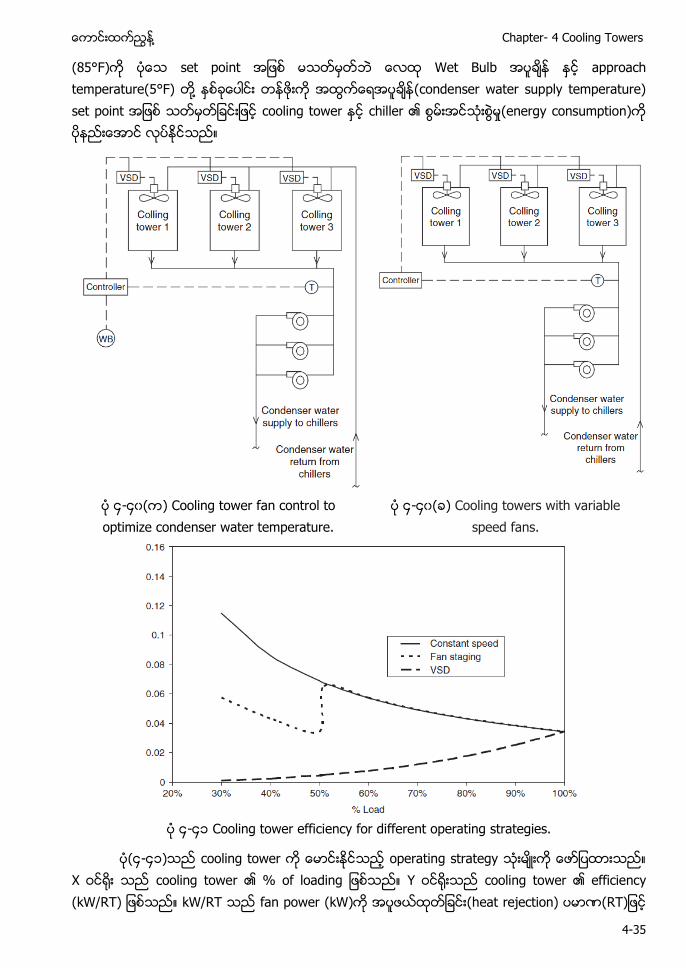
႔ Chapter- 4 Cooling Towers
4-35
(85°F)က ပေသ set point အျဖစ မသတမတဘ Wet Bulb ႏင approach temperature(5°F) တ႔ ႏစခေပါငး တနဖးက (condenser water supply temperature) set point အျဖစ သတမတျခငးျဖင cooling tower ႏင chiller ၏ ႈ(energy consumption)က ပနညးေအာင လပႏငသည။
၄-၄၀( ) Cooling tower fan control to optimize condenser water temperature.
၄-၄၀( ) Cooling towers with variable speed fans.
၄-၄ Cooling tower efficiency for different operating strategies.
ပ(၄-၄ )သည cooling tower က ေမာငးႏငသည operating strategy က ေဖာျပထားသည။ X ဝင႐း သည cooling tower ၏ % of loading ျဖစသည။ Y ဝင႐းသည cooling tower ၏ efficiency (kW/RT) ျဖစသည။ kW/RT သည fan power (kW)က အပဖယထတျခငး(heat rejection) (RT)ျဖင
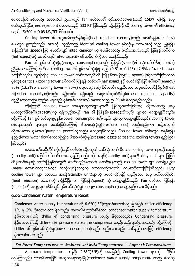
Air Conditioning and Mechanical Ventilation (Vol. 1) ႔
4-36
စားထားျခငးျဖစသည။ အထကပါ ဥပမာတြင fa ၏ (power)သည 15kW ျဖစၿပး အပ ဖယထတျခငး(heat rejection) သည 500 RT ျဖစသည။ ထ႔ေၾကာင ထ cooling tower ၏ efficiency သည 15/500 = 0.03 kW/RT ျဖစသည။
Cooling tower ၏ အပဖယထတႏငစြမး(heat rejection capacity)သည ႈ (air flow) ေပၚတြင မတညသည။ အားလး တညသည identical cooling tower ႏစလးမ ပထမအလးသည ျမနႏႈနး အျပည(full speed) ျဖင ေမာငး rated capacity က ေပးႏငသည။ ဒတယအလးသည ျမနႏႈနးတစဝက (half speed)ျဖင ေမာငး rated capacity ၏ တစဝကကသာ ေပးႏငသည။
Fan ၏ ႈ(energy consumption)သည ႈ (speed)၏ သးထပကနး(cube)ႏင ညမေသာေၾကာင ဒတယ cooling tower၏ ႈသည (0.53 = 0.125) 12.5% of rated power သာျဖစသည။ ထ႔ေၾကာင cooling tower တစလးတညးက ႈ (full speed) ျဖငေမာငးျခငးထက ပစတ(identical) cooling tower ႏစလးက ျမနႏႈနးတစဝက(half speed)ႏင ေမာငးျခငးျဖင စြမးအင(energy) 50% (12.5% x 2 cooling tower = 50%) (save) ႏငသည။ တညေသာ အပဖယထတႏငစြမး(heat rejection capacity)ကလညး ရရသည။ ရရသည အပဖယထတႏငစြမး(heat rejection capacity) တညေသာလညး ေပးရသည စြမးအင(energy) ပမာဏသည ၅၀% ႔ ေလာနညးသည။
ထ႔ေၾကာင cooling tower အေရအတြကမားမားက ၿပငတေမာငးျခငးျဖင လအပသည အပ ဖယထတႏငစြမး(capacity)က ရရသညအျပင fan ၏ ႈ (speed)ကလညး မားစြာ ေလာခႏငသည။ ထ႔ေၾကာင fan ႈ ႈ (power consumption)ကလညး မားစြာ ေလာခႏငသည။ Cooling tower အေရအတြက မားမား ေမာငးျခငးေၾကာင ႈ ႈ(pressure loss) လညးနညးကာ ပန႔အတြက လအပေသာ စြမးအား(pumping power)ကလညး ေလာခႏငသည။ Cooling tower တငးတြင ႈ (lower water flow)ေသာေၾကာင ႈ ႈ(pressure losses across the cooling tower) နညးျခငး ျဖစသည။ အေဆာကအဥတငးလလတြင တစလး သ႔မဟတ တစလးထက ပေသာ cooling tower မားက အရန (standby unit)အျဖစ တပဆငထားေလရၾကသည။ ထ အရန(standby unit)မားက duty unit ျပျပင ထနးသမးေနစဥ အသးျပရနအတြက ေသာလညးေကာငး၊ ေမာငးေနသည cooling tower မား စကခ႕ယြငး (break down)သညအခါတြင အသးျပရနအတြက ေသာလညးေကာငး တပဆငထားျခငးျဖစသည။ Duty cooling tower မား သာမက အရန(standby unit)မားက ေမာငးျခငးျဖင တညေသာ အပ ဖယထတျခငး (heat rejection) ပမာဏက ရရႏငၿပး fa ႈ (speed) က ေလာခႏငသည။ Fan ႈ (speed) က ေလာခေပးႏငလင ႈ(energy consumption) ေလာနညး လာ ည။
၄.၁၈ Condenser Water Temperature Reset
Approach temperature 2.8°C(5°F) Cooling tower မားက ဒဇငး လပ သည။ သာမနအားျဖင (condenser water supply temperature)သည
Condenser water supply temperature က 0.6°C(1°F)ကဆငးေအာငလပျခငးျဖင chiller efficiency 1% မ 2% ပေကာငးလာ ႏငသည။ အဘယေၾကာငဆေသာ condenser water supply temperature နမေသာေၾကာင chiller ၏ condensing pressure လညး နမလာသည။ Condensing pressure နမေသာေၾကာင differential pressure across the compressor သညလညး နညးလာသည။ ထ႔ေၾကာင chiller ၏ စြမးအငသးစြမႈ(power consumption)လညး နညးလာသည။ တစနညးအားျဖင efficiency ပေကာငးလာသည။
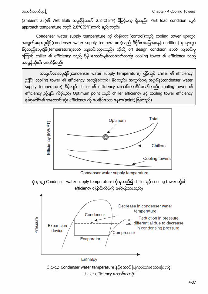
႔ Chapter- 4 Cooling Towers
4-37
(ambient air)၏ Wet Bulb ထက 2.8°C(5°F) ပျမငေလ ရသည။ Part load condition တြင approach temperature သည 2.8°C(5°F)ထက နညးသည။
Condenser water supply temperature က ထနးထား(control)သည cooling tower မားတြင (condenser water supply temperature)သည ဒဇငးအေျခအေန(condition) မ မားစြာ နမသညအပခန(temperature)အထ ကဆငးသြားသည။ ထသ႔ off design condition အထ ကဆငးမႈ ေၾကာင chiller ၏ efficiency သည ပမ ေကာငးမြနလာေသာလညး cooling tower ၏ efficiency သည အလြနဆးဝါး ေနလမမည။
၄-၄၂ Condenser water supply temperature က မတည၍ chiller ႏင cooling tower ႔၏
efficiency ေျပာငးလပက ေဖာျပထားသည။
၄-၄၃ Condenser water temperature
ff
(condenser water supply temperature) ျမငလင chiller ၏ efficiency ညၿပး cooling tower ၏ efficiency အလြနေကာငး သည။ (condenser water supply temperature) နမလင chiller ၏ efficiency ေကာငးလာ cooling tower ၏ efficiency ညဖငး လမမည။ Optimum point သည chiller efficiency ႏင cooling tower efficiency ႏစခေပါငး၏ အေကာငးဆး efficiency က ေပးႏငေသာ ေနရာ(point) ျဖစသည။
Air Conditioning and Mechanical Ventilation (Vol. 1) ႔
4-38
ထ႔ေၾကာင overall optimum operating point သည condenser water ၏ အနမဆး အပခန (temperature) မဟတေပ။ တစနညးအားျဖင (condenser water supply temperature) နမလာေလ chiller efficiency ေကာငးလာေလ ျဖစေသာလညး system efficiency (chiller ၊ pump ႏင cooling tower ႏစခေပါငး) ပေကာငးလာလမမည မဟတေပ။ Optimum operating point chiller plant room System design၊ equipment ၏ efficiency configuration ႔ optimum point
၄.၁၉ (Maintenance) Cooling tower တစခ၏ အေျခအေန(condition)သည water spray system ၊ fill packing ႏင fan တ႔၏ အေျခအေန ေပၚတြင မတညသည။ ပမန ျပျပငထနးသမးမႈမား ျပလပရန လအပသည။
Spray system အလပေကာငးေကာငး မလပသညအခါ ေရမားသည fill packing ေပၚသ႔ အညအမ မကေရာကဘ (discharge bar)ေပၚသ႔ ေရမား တက႐ကေရာကရသြားသည။ Infill ႔ fill packing မား ပကစးေနပါက ေကာငးစြာ အပကးေျပာငးျခငး(heat transfer) ျဖစႏငလမမည မဟတေပ။
Cooling tower fan မားသည ပနကာႀကးျဖငေမာငးသည(belt driven) fan မား ျဖစၾကသည။ ပနကာႀကး (belt tension)မမနျခငး၊ alignment မမနျခငး၊ slip ျဖစမႈမားျခငး တ႔ေၾကာင လအပသည ႈ (air flow)က မရရႏငေပ။ Spray မားေကာငးစြာ အလပမလပျခငး ၊ fill မား ပကစးေနျခငး ႏင fa ႈ (speed) ေႏးျခငး တ႔ေၾကာင cooling tower ၏ စြမးေဆာငရည(performance)ကဆငးျခငး ျဖစသည။
Condenser water system သည open system ျဖစ condenser water မား ေရေငြ႔ပျခငး (evaporation)ျဖစေပၚသည။ ထ႔ေၾကာင ျပနျဖညရနေရ(makeup water)လအပသည။ Chiller efficiency သည condenser water အရညအေသြးေပၚတြင မတညသည။ Chemical ႔ Non chemical water treatment က သးျခငးျဖင condenser water ၏ အရညအေသြး(quality)က လကခႏငသည အဆငတြင ထနးထားႏငသည။ သေခး၊ ေၾကးေခး တကျခငးမ ကာကြယရန၊ ေရည ျဖစျခငးမ တားဆးရန(prevent scaling) ႏင chiller ၏ condenser tube မား ေခးတကျခငး(fouling)မ ကာကြယရန အတြက water treatment system လအပသည။
၄.၂၀ Make Up Water
Cooling tower မ ေရဆးရႈးမႈ(water loss)ျဖစေပၚရသညအေၾကာငးမားမာ ( ) Evaporation loss (၂) Drift loss ႏင (၃) Blown down loss ႔ bleed off loss တ႔ေၾကာင ျဖစသည။
ထအခက ခကလးက ေသခာစြာတြကခကႏငမသာ make up water system ကေသခာစြာ ဒဇငး ျပလပႏငမညျဖစသည။
( ) Evaporation loss: ၏ heat of vaporization 1045 Btu/lb at 85°F(29.4°C) ျဖစသည။ Condenser water စပယထားေသာ အပမားသည cooling tower သ႔ေရာကသညအခါ စြန႔ထတ ပစၿပး ေရမားက ႔(vapor)အျဖစသ႔ ေျပာငးေစသည။ ပမနအားျဖင Condenser water temperature 35°C မ 29.4°C အတြငးျဖစသည။ 85°F(29.4°C) အပခနတြင ေရတစေပါငသည 1045 Btu အပပမာဏက သယေဆာငၿပး ႔(water vapor)အျဖစသ႔ ေျပာငးလသြားကာ ေလထသ႔ ေရေငြ႔ပသြားသည။
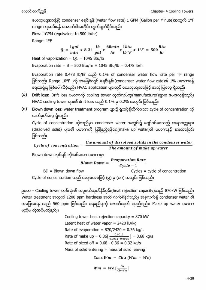
႔ Chapter- 4 Cooling Towers
4-39
ေယဘယအားျဖင s ႈ (water flow rate) 1 GPM (Gallon per Minute)အတြက 1°F range ကဆငးရန ေအာကပါအတငး တြကခကႏငသည။ Flow: 1GPM (equivalent to 500 lb/hr) Range: 1°F
Heat of vaporization = Q1 = 1045 Btu/lb Evaporation rate = B = 500 Btu/hr ÷ 1045 Btu/lb = 0.478 lb/hr
Evaporation rate 0.478 lb/hr သည 0.1% of condenser water flow rate per °F range ျဖစသည။ Range 10°F ႈ (condenser water flow rate)၏ 1% ႔ ႈ ႈ မည။ HVAC application မားတြင ေယဘယအားျဖင အသးျပေလ ရသည။
( ) Drift loss: Drift loss ပမာဏက cooling tower (manufacturer)မားမ ေပးေလရသည။ HVAC cooling tower မား၏ drift loss သည 0.1% 0.2% အတြငး ျဖစသည။
(ဂ) Blown down loss: water treatment program မား၌ ရသငရထကေသာ cycle of concentration က သတမတေလ ရသည။ Cycle of concentration ဆသညမာ condenser water အတြငး၌ (dissolved solid) မား၏ ပမာဏက (make up water)၏ ပမာဏႏင စားထားျခငး ျဖစသည။
Blown down ပမာဏမာ
BD = Blown down flow Cycles = cycle of concentration Cycle of concentration သည အမားအားျဖင (၅) မ (၁၀) အတြငး ျဖစသည။
ဥပမာ - Cooling tower တစလး၏ အပဖယထတႏငစြမး(heat rejection capacity)သည 870kW ျဖစသည။ Water treatment အတြက 1200 ppm hardness အထ လကခႏငသည။ အခလကရ condenser water ၏ အေျခအေန သည 560 ppm ျဖစသည။ ေရမညမက ေဖာကထတ ရမညနညး။ Make up water မညမ လအပမညနညး။
Cooling tower heat rejection capacity = 870 kW Latent heat of water vapor = 2420 kJ/kg Rate of evaporation = 870/2420 = 0.36 kg/s Rate of make up = 0.36[
] = 0.68 kg/s
Rate of bleed off = 0.68 - 0.36 = 0.32 kg/s Mass of solid entering = mass of solid leaving
Air Conditioning and Mechanical Ventilation (Vol. 1) ႔
4-40
ေလ၏ specific heat capacity(1.02 kJ/kg °K) ၏ specific heat capacity ထက နညးေသာေၾကာင တညေသာ အပပမာဏက ဖယထတရန ထထညမားမား လ သည။ ေလ၏ specific volume မားေသာေၾကာင air cooled condenser မားတြင ႈ (air volume flow rate) မားမား လအပသည။ ေရ၏ specific heat capacity ေလထက ပမားေသာေၾကာင water cooled condenser မားအတြက ႈ (water volume flow rate) နညးနညးသာ လအပသည။
8 kW အပပမာဏက ဖယထတပစရနအတြက အပခနျခားနားခက(temperature difference) 10°C ျဖစရန လအပသည။ ထ႔ေၾကာင ျပငပေလအပခန(outdoor air tempeature) 15°C မ 25°C (15+10) အပခနထေရာကေအာင ျမငတကသြား လမမည။
အျမငဆးေလ၏ အပခန(maximum outdoor air temperature)က အေျခခ၍ condenser မား၏ design load က တြကခက ၾကသည။
ပထမ ဥပမာ မ 350 kW cooling capacity ႏင 450 kW အပဖယထတျခငး(heat rejection)အတြက water cooled condenser ကသာ အသးျပလင 9.8 Liter/sec သာ လအပသည။ ဥပမာ - 930 kW အပပမာဏက ဖယထတ(reject)ရနအတြက condenser တစခ၏ အပခနျခားနားခက (temperature difference) သည 5.2°C ျဖစလင ႈ (water flow rate) မညမ လအပမညနညး။
ΔT Cp for water = 4.19 kJ/kgK m = 930 ÷ (5.2 x 4.19)= 43 kg/s
Cooling tower မားသည ထထညႀကးမားေသာ ေရမ အပမားက ႔ (evaporative cooling)နညးျဖင စြန႔ထတ(reject)သည။ Evaporative cooling ေၾကာင ေရဆး႐ႈးမႈ(water loss)ျဖစေပၚသည။ Cooling tower မ leaving condenser temperature သည outdoor air Wet Bulb ထက 3°C မ 8°C ျမငသည အပခန ျဖစသည။
ဥပမာ Condenser load သည 400 kW ျဖစလင 0.16 kg/s ႏႈနးျဖင ေရဆး ႈးမည။
ထ႔ေၾကာင condenser water system အတြငး၌ ေရပမာဏေလာနညးလာသညအတြက ေရထည ေပးရန လအပသည။ ေရထပျဖညေပးသည ပကက make up water pipe ဟေခၚၿပး ထညျဖည ေပးရသည ေရက make up water ဟေခၚသည။ မညသညေရမးျဖစပါေစ ေရတငးတြင ေပာဝငေနသည ဓာတသတမား(dissolved salts)ပါဝငသည။ ေရမား ေရေငြ႔ပ(evaporate)သြားသညအခါ ေပာဝငေနသည ဓာတသတမား(dissolved salts)ေရထ တြင ဆကလက ကနရေနဆ ျဖစသည။ ထပျဖညသညေရ(make up water)ႏငအတ dissolved salt မားထပမ ေရာကရလာသျဖင ေရထတြင dissolved salt မား အခနႏငအမ မားျပားလာသည။ ထကသ႔ မားျပား လာျခငးက ဓာတသတမား ႈ (dissolved salt concentration) ျမငလာသညဟ ေျပာေလ ရသည။
အပ 1kW က စြန႔ထတ(reject)ရန အတြက ေရဆး႐ႈးမႈ(water loss)ပမာဏသည 0.00041 kg ျဖစသည။ တစနညးအားျဖင ေရ 1kg ဆး႐ႈးလင 2430 kJ ပမာဏ အပဖယထတျခငး(heat rejection) ျဖစေပၚသည။
Cooling tower ႀကးေလ၊ အပကးေျပာငးႏငသည(heat transfer) ဧရယာမားေလ၊ အပ ဖယထတႏငစြမး(heat rejection capacity) မားေလ ျဖစၿပး ေရဆး႐ႈးမႈလညး မားလမမည။
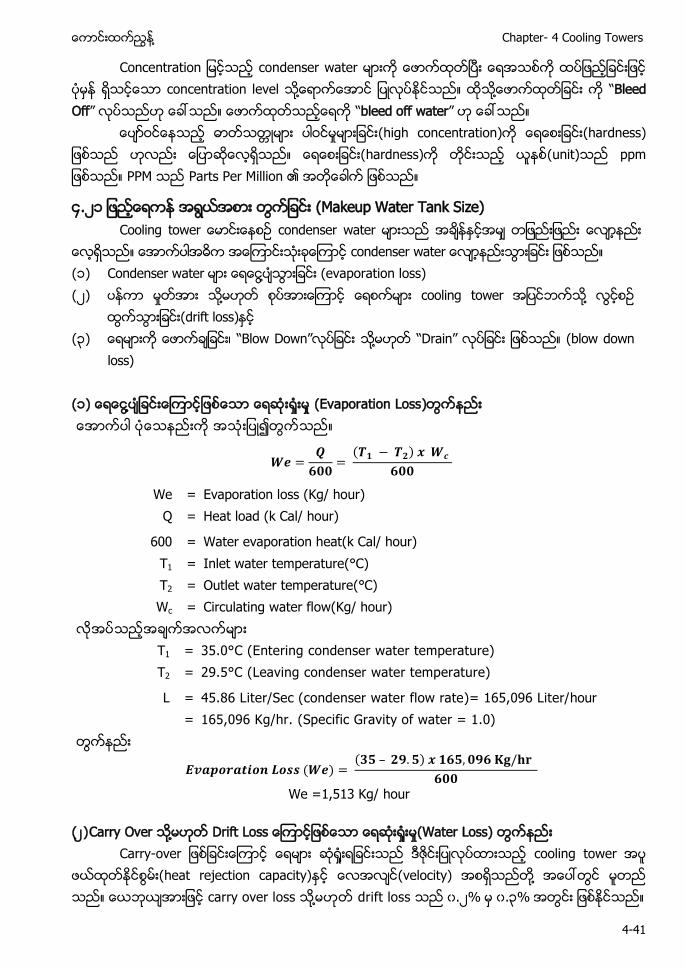
႔ Chapter- 4 Cooling Towers
4-41
Concentration ျမငသည condenser water မားက ေဖာကထတၿပး ေရအသစက ထပျဖညျခငးျဖင ပမန ရသငေသာ concentration level သ႔ေရာကေအာင ျပလပႏငသည။ ထသ႔ေဖာကထတျခငး က “Bleed Off” လပသညဟ ေခၚသည။ ေဖာကထတသညေရက “bleed off water” ဟ ေခၚသည။ ေပာဝငေနသည ဓာတသတမား ပါဝငမႈမားျခငး(high concentration)က ေရေစးျခငး(hardness ဟလညး ေျပာဆေလရသည။ ေရေစးျခငး(hardness)က တငးသည (unit)သည ppm ျဖစသည။ PPM သည Parts Per Million ၏ ျဖစသည။
၄.၂ (Makeup Water Tank Size) Cooling t condenser water
condenser wa ( ) Condenser water ႔ (evaporation loss) (၂) ႈ ႔ cooling tower ႔
(drift loss) (၃) ၊ “Blow Down” ႔ “Drain” (blow down
loss) ( ) ႔ ႈ ႈ (Evaporation Loss)
We = Evaporation loss (Kg/ hour) Q = Heat load (k Cal/ hour)
600 = Water evaporation heat(k Cal/ hour) T1 = Inlet water temperature(°C) T2 = Outlet water temperature(°C) Wc = Circulating water flow(Kg/ hour)
T1 = 35.0°C (Entering condenser water temperature) T2 = 29.5°C (Leaving condenser water temperature)
L = 45.86 Liter/Sec (condenser water flow rate)= 165,096 Liter/hour = 165,096 Kg/hr. (Specific Gravity of water = 1.0)
We =1,513 Kg/ hour
(၂ ) Carry Over ႔ Drift Loss ႈ ႈ(Water Loss) a - ႈ cooling tower အပ
ဖယထတႏငစြမး(heat rejection capacity) (velocity) ႔ carry over loss ႔ drift loss ၀.၂% ၀.၃%
Air Conditioning and Mechanical Ventilation (Vol. 1) ႔
4-42
၀.၂ Wco = 0.20% x 165,096 Wco = 330 kg/hr
(၃) Blow Down ႈ ႈ(Water Loss) b - Blow down loss
၏ ၃
(၄ (Make-up Water Requirement) make-up water circulating flow rate
= 1,513 + 330 + 495 = 2,041 kg/hr per cooling tower
(heat rejection capacity) 242RT cooling tower (၂၀၄ ) ဂ (2,041 kg) ႈ ၏ 1000kg/m3 ႔ cooling tower (full load (2 m3) ႈ
Cooling towers cooling towers ၿ ၿ
အရ (standby) ႔
make-up water
Mw = 2,041 kg/hour x 2 = 4,082 kg/hour ( 4,082 kg )
(၅) (Make-up Water Storage tank) (water storage tank) (space available)
႔ (၇၂ )
Total water requirement = 4,082 kg/hr x 18 hours =73,476 kg (( ၈) (၇၃ ၄၇၆) ဂ )
(water storage tank)
3m(W) x 8m(L) x 3m(H) = 72 m3
Make-up Water (storage tank)၏ cooling tower ( ၈)
တစနညးအားျဖင ႔ (storage tank) cooling tower ( ၈)
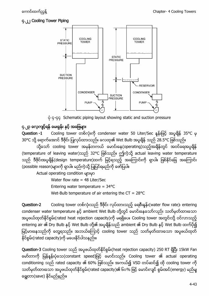
႔ Chapter- 4 Cooling Towers
4-43
၄.၂၂ Cooling Tower Piping
၄-၄၄ Schematic piping layout showing static and suction pressure
၄.၂၃ ေလကငရန ေမးခြနး ႏင အေျဖမား Question -1 Cooling tower တစလးက condenser water 50 Liter/Sec ႈ အပခန 35°C မ 30°C သ႔ ေရာကေအာင ဒဇငး ျပလပထားသည။ ၏ Wet Bulb သည 28.5°C ျဖစသည။ သ႔ေသာ cooling tower အမနတကယ ေမာငးေန(operating)သညအခနတြင (temperature of leaving water)သည 32°C ျဖစသည။ ဤကသ႔ actual leaving water temperature သည ဒဇငးအပခန(design temperature)ထက ျမငရသည အေၾကာငးက ရာပါ။ ျဖစႏငေျခ အေၾကာငး (possible reason)မားက ရာပါ။ မညကသ႔ ျပျပငရမညက ေဖာျပပါ။
Actual operating condition မားမာ Water flow rate = 48 Liter/Sec Entering water temperature = 34°C Wet-Bulb temperature of air entering the CT = 28°C
Question-2 Cooling tower တစလးသည ဒဇငး လပထားသည ႈ (water flow rate)၊ entering condenser water temperature ႏင ambient Wet Bulb တ႔တြင ေမာငးေနေသာလညး အပဖယထတႏငစြမး(rated heat rejection capacity)က မရရေပ။ Cooling tower အတြငးသ႔ ဝငလာသည entering air ၏ Dry Bulb ႏင Wet Bulb တ႔၏ အပခနသည ambient ၏ Dry Bulb ႏင Wet Bulb ထကပ၍ ျမငမားေနသညက ေတြ႔ရသည။ အဘယေၾကာင cooling tower သည (rated capacity)က မေပးႏငပါသနညး။
Question-3 Cooling tower သည အပဖယထတႏငစြမး(heat rejection capacity) 250 RT ရၿပး 15kW Fan ေမာတာက ျ ႈ (constant speed)ျဖင ေမာငးသည။ Cooling tower ၏ actual operating conditioning သည rated capacity ၏ 60% ျဖစသည။ အကယ၍ VSD တပဆင၍ ထ cooling tower က (rated capacity)၏ ၆၀% ျဖင ေမာငးလင (energy) မညမ (save) ႏငမညနညး။
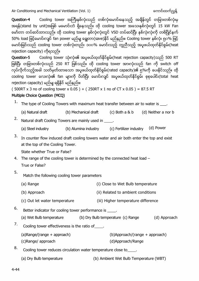
Air Conditioning and Mechanical Ventilation (Vol. 1) ႔
4-44
Question-4 Cooling tower အႀကးႏစလးသည တစလးေမာငးေနသည အခနတြင တျခားတစလးမ အရ (stand by unit)အျဖစ မေမာငးဘ ရေနသည။ ထ cooling tower အေသးႏစလးတြင 15 kW Fan ေမာတာ တပဆငထားသည။ ထ cooling tower ႏစလးလးတြင VSD တပဆငၿပး ႏစလးလးက တစၿပငနက 50% load ျဖငေမာငးလင fan power မညမ ေခြတာ(save) မညနညး။ Cooling tower ႏစလး ၅၀% ျဖင ေမာငးျခငးသည cooling tower တစလးတညး ၀၀% ေမာငးသည တညသည အပဖယထတႏငစြမး(heat rejection capacity) ကရသည။ Question-5 Cooling tower သးလး၏ အပဖယထတႏငစြမး(heat rejection capacity)သည 500 RT ျဖစၿပး တျခားတစလးသည 250 RT ျဖစသည။ ထ cooling tower အားလးသည fan က switch off လပလကသညအခါ (rated capacity)၏ ၅%က ေပးႏငသည။ ထ cooling tower ေလးလး၏ fan မားက ပတၿပး ေမာငးလင အပဖယထတႏငစြမး (total heat rejection capacity) မညမ ရရႏင မညနညး။ ( 500RT x 3 no of cooling tower x 0.05 ) + ( 250RT x 1 no of CT x 0.05 ) = 87.5 RT Multiple Choice Question (MCQ)
1. The type of Cooling Towers with maximum heat transfer between air to water is ___.
(a) Natural draft (b) Mechanical draft (c) Both a & b (d) Neither a nor b 2. Natural draft Cooling Towers are mainly used in ____.
(a) Steel industry (b) Alumina industry (c) Fertilizer industry (d) Power stations 3. In counter flow induced draft cooling towers water and air both enter the top and exist
at the top of the Cooling Tower.
State whether True or False? 4. The range of the cooling tower is determined by the connected heat load –
True or False? 5.
Match the following cooling tower parameters
(a) Range (i) Close to Wet Bulb temperature
(b) Approach (ii) Related to ambient conditions
(c) Out let water temperature (iii) Higher temperature difference
6. Better indicator for cooling tower performance is ____.
(a) Wet Bulb temperature (b) Dry Bulb temperature (c) Range (d) Approach 7.
Cooling tower effectiveness is the ratio of____.
(a)Range/(range + approach) (b)Approach/(range + approach) (c)Range/ approach (d)Approach/Range
8. Cooling tower reduces circulation water temperature close to____.
(a) Dry Bulb temperature (b) Ambient Wet Bulb Temperature (WBT)
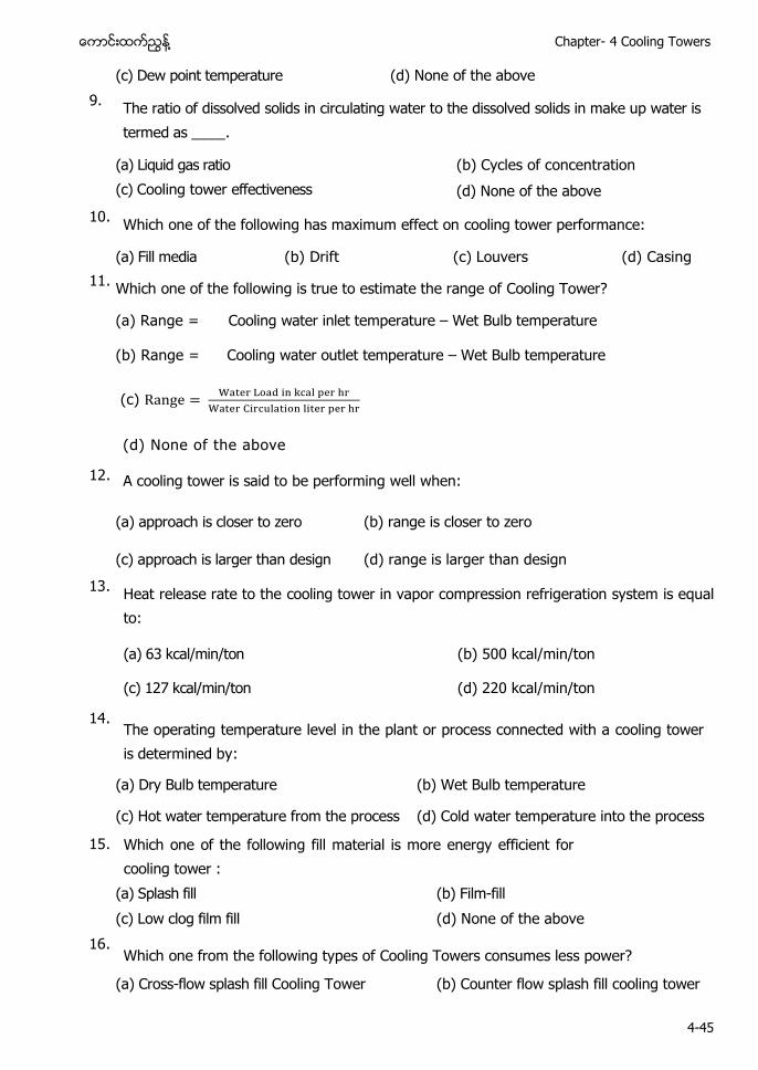
႔ Chapter- 4 Cooling Towers
4-45
(c) Dew point temperature (d) None of the above 9. The ratio of dissolved solids in circulating water to the dissolved solids in make up water is
termed as ____.
(a) Liquid gas ratio (b) Cycles of concentration (c) Cooling tower effectiveness
(d) None of the above 10. Which one of the following has maximum effect on cooling tower performance:
(a) Fill media (b) Drift (c) Louvers (d) Casing 11. Which one of the following is true to estimate the range of Cooling Tower?
(a) Range = Cooling water inlet temperature – Wet Bulb temperature
(b) Range = Cooling water outlet temperature – Wet Bulb temperature
(c)
(d) None of the above
12. A cooling tower is said to be performing well when:
(a) approach is closer to zero (b) range is closer to zero
(c) approach is larger than design (d) range is larger than design 13. Heat release rate to the cooling tower in vapor compression refrigeration system is equal
to:
(a) 63 kcal/min/ton (b) 500 kcal/min/ton
(c) 127 kcal/min/ton (d) 220 kcal/min/ton
14. The operating temperature level in the plant or process connected with a cooling tower is determined by:
(a) Dry Bulb temperature (b) Wet Bulb temperature
(c) Hot water temperature from the process (d) Cold water temperature into the process
15. Which one of the following fill material is more energy efficient for cooling tower :
(a) Splash fill (b) Film-fill (c) Low clog film fill (d) None of the above
16. Which one from the following types of Cooling Towers consumes less power?
(a) Cross-flow splash fill Cooling Tower (b) Counter flow splash fill cooling tower
Air Conditioning and Mechanical Ventilation (Vol. 1) ႔
4-46
(c) Counter flow film fill Cooling Tower (d) None of the above 17. L / G ratio in cooling tower is the ratio of ___.
(a) Length and girth (b)Length and Temperature gradient
(c) Water flow rate and air mass flow rate (d)Air mass flow rate and water flow rate
18. Normally the guaranteed best approach a cooling tower can achieve is ___. (a) 5 °C (b) 12 °C (c) 8 °C (d) 2.8 °C
19. The temperature selection normally chosen for designing of cooling tower is ___.
(a) Average maximum Wet Bulb for summer months
(b) Average maximum Wet Bulb for rainy months
(c) Average maximum Wet Bulb for winter months
(d) Average minimum Wet Bulb for summer months 20. Select the statement which is true for a FRP fan.
(a) It needs low starting torque (b) Increases life of gear box
(c) Easy handling and maintenance (d) All the above (Short Questions and Answers) 1. Mechanical draft cooling tower ၏ ႈ (air flow arrangements)
Mechanical draft cooling tower ႈ (air flow arrangements)
(a) Counter flow induced draft (b) Counter flow forced draft (c) Cross flow forced draft ႔
2. Cooling tower fan ၏ (blade) (material)
Cooling tower fan ၏ blade material
(1) Aluminum blades(metallic)
(2) Glass Reinforced Plastic(GRP) (3) Fiber Reinforced Plastic(FRP) ႔
3. Evaporative cooling tower (basic component)
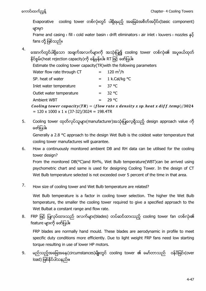
႔ Chapter- 4 Cooling Towers
4-47
Evaporative cooling tower (basic component) Frame and casing ၊ fill ၊ cold water basin ၊ drift eliminators ၊ air inlet ၊ louvers ၊ nozzles fans ႔
4. cooling tower ၏ အပဖယထတ ႏငစြမး(heat rejection capacity) ႔ RT Estimate the cooling tower capacity(TR)with the following parameters Water flow rate through CT = 120 m3/h SP. heat of water = 1 k.Cal/kg °C Inlet water temperature = 37 °C Outlet water temperature = 32 °C Ambient WBT = 29 °C
= 120 x 1000 x 1 x (37-32)/3024 = 198.4TR
5. Cooling tower (manufacturer) design approach value Generally a 2.8 °C approach to the design Wet Bulb is the coldest water temperature that cooling tower manufactures will guarantee.
6. How a continuously monitored ambient DB and RH data can be utilised for the cooling tower design? From the monitored DB(°C)and RH%, Wet Bulb temperature(WBT)can be arrived using psychometric chart and same is used for designing Cooling Tower. In the design of CT Wet Bulb temperature selected is not exceeded over 5 percent of the time in that area.
7. How size of cooling tower and Wet Bulb temperature are related?
Wet Bulb temperature is a factor in cooling tower selection. The higher the Wet Bulb temperature, the smaller the cooling tower required to give a specified approach to the Wet Bulbat a constant range and flow rate.
8. FR (blades) cooling tower fan ၏ feature
FRP blades are normally hand mould. These blades are aerodynamic in profile to meet specific duty conditions more efficiently. Due to light weight FRP fans need low starting torque resulting in use of lower HP motors.
9. (circumstances) cooling tower ၏ (over load)
Air Conditioning and Mechanical Ventilation (Vol. 1) ႔
4-48
Reasons for excessive electrical load on CT fan motors are: ( ) Voltage reduction (၂) Incorrect angle of axial fan blades (၃) Loose belts on centrifugal fans (၄) Over loading owing to excessive air flow-fill has minimum water loading per m3 of
tower (၅) Low ambient air temperature
10. Cooling plant 100 RT refrigeration 100 RT refrigeration ss cooling tower ၏ (size) 100 RT refrigeration absorption type chiller cooling tower ၏ (size)
100 RT refrigeration absorption type chiller cooling tower ၏ (size) ss Cooling Tower(size) ႔
11. Air conditioning compressor operation ၌ cooling water ၏ (temperature) ႔ ႈ Effect of cooling tower outlet water temperature on A/C compressors, 1 °C cooling water temperature rise may increase A/C compressor power consumption (kW) by 2.7%. Cooling water ၏ (temperature) 1°C A/C compressor power consumption (kW) ၂.၇% ႔
12. Cooling tower ၏ “Ra a ” “Ra ” “ a ” ၏
(1) “Ra ” s ff between the condenser water inlet and outlet temperature. “Ra ” condenser water ၏ (2) “ a ” s ff b a a and ambient Wet Bulb temperature. Though both parameters should be monitored, the “ a ” is a better indicator of cooling tower performance. “ a ” cooling tower (outlet) cold water temperature ambient Wet Bulb temperature ႔၏ monitor “ a ” cooling tower (performance) a
13. Cooling tower ၏ (performance) factor
႔ Chapter- 4 Cooling Towers
4-49
( ) Capacity and range (၂) Heat load (၃) Wet Bulb temperature
(၄) Approach and water flow (၅) Filling media
14. Cooling tower ၏ effectiveness
Cooling tower effectiveness in percentage is the ratio of range, to the ideal range, i.e., difference between cooling water inlet temperature and ambient Wet Bulb temperature or in other words it is = Range /(Range + Approach).
15. Cooling tower ၏ evaporation loss ႔
Evaporation loss is the water quantity evaporated for cooling duty. An empirical relation used often is:
16. Cooling tower fan FRP blade ၏ (conventional blade ႈ ) FRP blade (optimum) aerodynamic profile ၂၀% ၃၀% ႈ(energy saving) (low starting torque) ႔ capacity gearbox ၊ motor bearing ႔၏ ၊
17. Cooling tower ၏ blowdown quantity
Blow Down = Evaporation Loss /(C.O.C. – 1) C.O.C = Cycle of concentration
18. What will be the effect of cooling water temperature in heat rate in thermal power plants?
Cooling water ၏ (temperature) thermal power plant ႔ Effect of Cooling tower outlet water temperature on thermal power plant: 1°C temperature drop in cooling water will lead to heat rate saving of 5 kcal/kWh in thermal power plant.
Air Conditioning and Mechanical Ventilation (Vol. 1) ႔
4-50
Cooling water ႔ condenser water ၏ (temperature) 1°C thermal power plant rate saving of 5 kcal/kWh
19. Cooling tower media fill Fill media
( ) Splash fill media (၂) Film fill media ႔
20. Cooling tower fill media fill “ ff ”
PVC ႔ polypropylene ႔ polymer filll “ ff ”
End
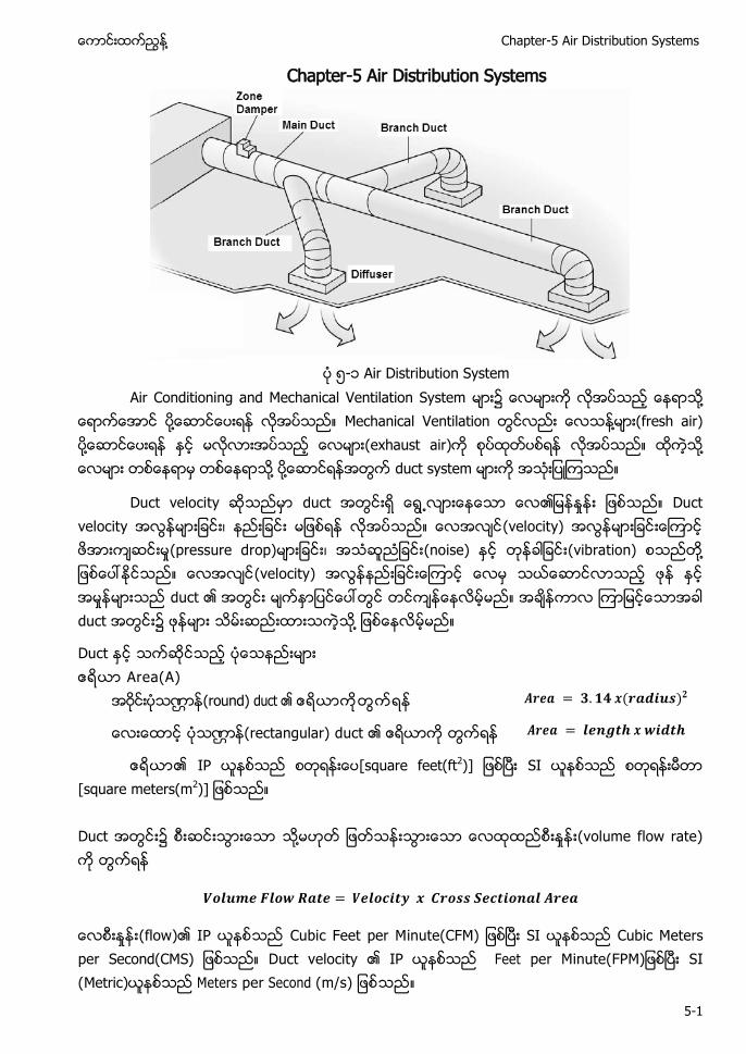
႔ Chapter-5 Air Distribution Systems
5-1
Chapter-5 Air Distribution Systems
၅-၁ Air Distribution System
Air Conditioning and Mechanical Ventilation System ၌ ႔ ႔ Mechanical Ventilation ႔ (fresh air) ႔ (exhaust air) ႔ ႔ ႔ duct system
Duct velocity duct ႕ Duct velocity (velocity) (pressure drop) (noise) (vibration) ႔ (velocity) duct duct ၌ ႔
Duct Area(A) (round) duct
(rectangular) duct
IP [square feet(ft2)] SI [square meters(m2)] Duct ၌ ႔ (volume flow rate)
(flow) IP Cubic Feet per Minute(CFM) SI Cubic Meters per Second(CMS) Duct velocity IP Feet per Minute(FPM) SI (Metric) Meters per Second (m/s)
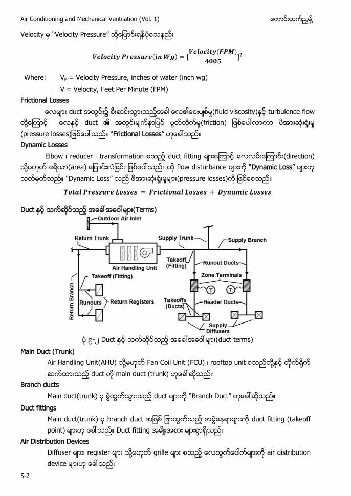
Air Conditioning and Mechanical Ventilation (Vol. 1) ႔
5-2
Velocity “Velocity Pressure” ႔
Where: VP = Velocity Pressure, inches of water (inch wg) V = Velocity, Feet Per Minute (FPM)
Frictional Losses duct ၌ (fluid viscosity) turbulence flow
႔ duct (friction) “Frictional Losses” Dynamic Losses
Elbow reducer transformation duct fitting (direction) ႔ (area) flow disturbance “Dynamic Loss” “Dynamic Loss” (pressure losses)
Duct Terms)
၅- duct terms)
Main Duct (Trunk) ႔ Fan Coil Unit FC ႔
Branch ducts “B h ” Duct fittings Main duct(trunk b h duct fitting (t
Air Distribution Devices ႔
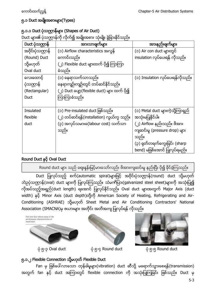
႔ Chapter-5 Air Distribution Systems
5-3
၅.၁ Duct (Types)
၅.၁.၁ Duct (Shapes of Air Duct) Duct
Duct (Round) Duct ႔ Oval duct
(၁) Airflow characteristics ( ) Flexible duct
(၁) Air con duct insulation
(Rectangular) Duct
(၁ ( (flexible duct)
(၁) Insulation
Insulated flexible duct
(၁ - ( ) (installation) (၃) (labour cost)
(၁) Metal duct ႔ ( ) Airflow (pressure drop) (၃) (sharp bend)
Round Duct Oval Duct
(automatic spiral) (round) duct ႔ (oval) duct (galvanized steel sheet) (duct length) Oval duct Major Axis (duct width) Minor Axis (duct depth) ႔ American Society of Heating, Refrigerating and Air-Conditioning (ASHRAE) ႔ Sheet Metal and Air Conditioning Contractors' National Association (SMACNA)
၅-၃ Oval duct ၅-၄ Round duct ၅-၅ Round duct
၅.၁. Flexible Connection ႔ Flexible Duct Fan (vibration) duct ႔ (transmission)
fan duct flexible connection Duct
Round duct
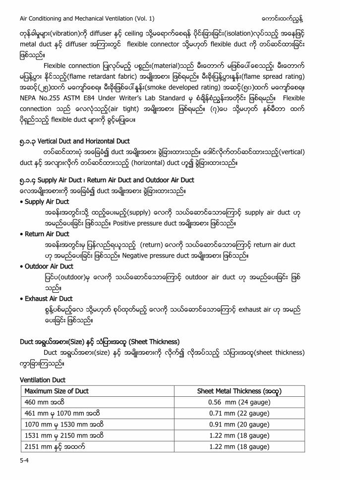
Air Conditioning and Mechanical Ventilation (Vol. 1) ႔
5-4
(vibration) diffuser ceiling ႔ (isolation) metal duct diffuser flexible connector ႔ flexible duct F (material) ႔ (flame retardant fabric) ႔ (flame spread rating) ( ၅) (smoke developed rating) (၅၀) NE N .255 ST E84 W ’ L S Flexible connection (air tight) ႔ flexible duct ၅.၁.၃ Vertical Duct and Horizontal Duct
duct (vertical) duct (horizontal) duct
၅.၁.၄ Supply Air Duct Return Air Duct and Outdoor Air Duct duct • S y Air Duct ႔ (s y supply air duct
Positive pressure duct • R Air Duct (r return air duct
Negative pressure duct • O Air Duct (outdoor) outdoor air duct
• E h Air Duct ႔ ႔ exhaust air
Duct (Size) (Sheet Thickness)
Duct (size) (sheet thickness)
Ventilation Duct Maximum Size of Duct Sheet Metal Thickness ( ) 460 mm 0.56 mm (24 gauge) 461 mm 1070 mm 0.71 mm (22 gauge) 1070 mm 1530 mm 0.91 mm (20 gauge) 1531 mm 2150 mm 1.22 mm (18 gauge) 2151 mm 1.22 mm (18 gauge)
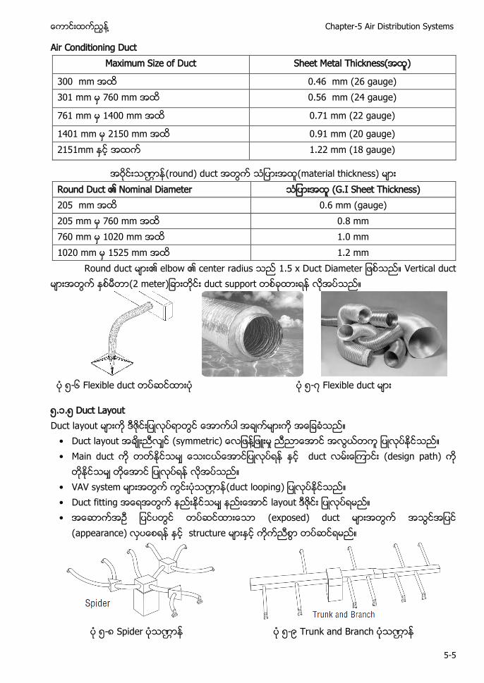
႔ Chapter-5 Air Distribution Systems
5-5
Air Conditioning Duct Maximum Size of Duct Sheet Metal Thickness( )
300 mm 0.46 mm (26 gauge) 301 mm 760 mm 0.56 mm (24 gauge)
761 mm 1400 mm 0.71 mm (22 gauge)
1401 mm 2150 mm 0.91 mm (20 gauge) 2151mm 1.22 mm (18 gauge)
(round) duct (material thickness) Round Duct Nominal Diameter (G.I Sheet Thickness) 205 mm 0.6 mm (gauge) 205 mm 760 mm 0.8 mm 760 mm 1020 mm 1.0 mm 1020 mm 1525 mm 1.2 mm
Round duct elbow center radius .5 Vertical duct 2 duct support
၅-၆ Flexible duct ၅- Flexible duct
၅.၁.၅ Duct Layout Duct layout • Duct layout y ႔ • Main duct duct (design path)
• VAV system (duct looping • Duct fitting layout • (exposed) duct
(appearance) structure
၅-၈ Spider ၅-၉ Trunk and Branch
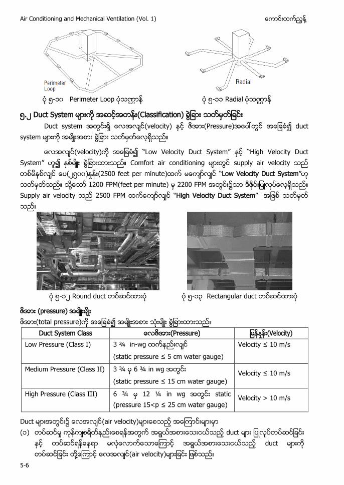
Air Conditioning and Mechanical Ventilation (Vol. 1) ႔
5-6
၅-၁၀ Perimeter Loop ၅-၁၁ Radial
၅. Duct System (Classification) Duct system (velocity) (Pressure) duct
system
(velocity) “L w V y System” “ h Velocity Duct System” Comfort air conditioning supply air velocity ( ၅၀၀) (2500 feet per minute) “Low Velocity Duct System” ႔ 1200 FPM(feet per minute) 2200 FPM ၌ Supply air velocity 2500 FPM “High Velocity Duct System”
၅-၁ Round duct ၅-၁၃ Rectangular duct
(pressure) (total pressure)
Duct System Class (Pressure) (Velocity) Low Pressure (Class I) 3 ¾ in-wg
( ≤ 5 w )
V y ≤ 0 /
Medium Pressure (Class II) 3 ¾ 6 ¾ in wg
( ≤ 5 w ) V y ≤ 0 /
High Pressure (Class III) 6 ¾ 12 ¼ in wg static ( 5< ≤ 25 w )
Velocity > 10 m/s
Duct ၌ (air velocity) (၁) duct
duct ႔ (air velocity)
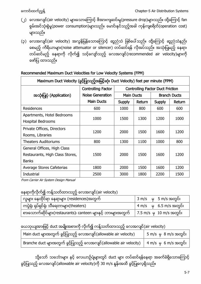
႔ Chapter-5 Air Distribution Systems
5-7
( ) (air velocity) (pressure drop) ႔ fan (power consumption) (operation cost)
(၃) (air velocity) ႔ (noise attenuator or silencer) (recommended air velocity)
Recommended Maximum Duct Velocities for Low Velocity Systems (FPM)
Maximum Duct Velocity ( Duct Velocity) feet per minute (FPM)
(Application) Controlling Factor Noise Generation
Main Ducts
Controlling Factor Duct Friction Main Ducts Branch Ducts
Supply Return Supply Return Residences 600 1000 800 600 600 Apartments, Hotel Bedrooms Hospital Bedrooms
1000 1500 1300 1200 1000
Private Offices, Directors Rooms, Libraries
1200 2000 1500 1600 1200
Theaters Auditoriums 800 1300 1100 1000 800 General Offices, High Class Restaurants, High Class Stores, Banks
1500
2000
1500
1600
1200
Average Stores Cafeterias 1800 2000 1500 1600 1200 Industrial 2500 3000 1800 2200 1500
From Carrier Air System Design Manual ႔ (air velocity) (residences) 3 m/s 5 m/s (theaters) 4 m/s 6.5 m/s (restaurants) canteen 7.5 m/s 10 m/s
duct ႔ (air velocity)
Main duct (allowable air velocity) 5 m/s 8 m/s
Branche duct (allowable air velocity) 4 m/s 6 m/s
႔ duct
(allowable air velocity) 30 m/s
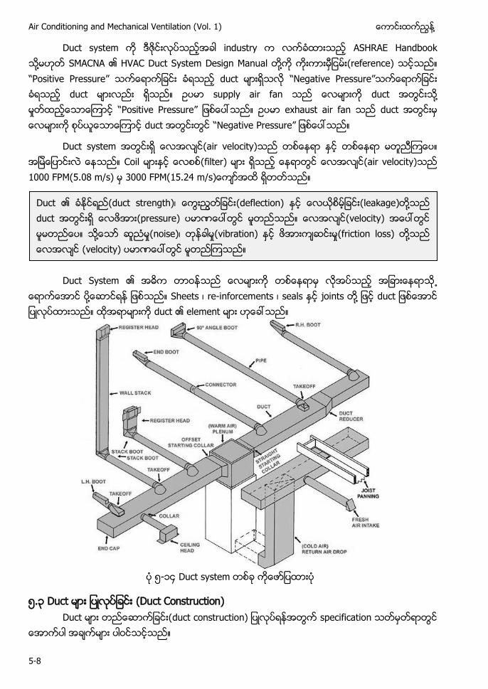
Air Conditioning and Mechanical Ventilation (Vol. 1) ႔
5-8
Duct system industry ASHRAE Handbook ႔ SMACNA HVAC Duct System Design Manual ႔ (reference) “ ” duct “N ” duct supply air fan duct ႔ “Positive Pressure” exhaust air fan duct duct “Negative Pressure”
Duct system (air velocity) Coil (filter) (air velocity) 1000 FPM(5.08 m/s) 3000 FPM(15.24 /
Duct System ႕ ႔ Sheets re-inforcements seals joints ႔ duct duct element
၅-၁၄ Duct system
၅.၃ (Duct Construction) duct
Duct (duct strength) (deflection) (leakage) ႔ duct (pressure) (velocity) ႔ (noise) (vibration) (friction loss) ႔ (velocity)
႔ Chapter-5 Air Distribution Systems
5-9
(၁) standards) SMACNA duct construction standards 2005 ႔ ASHRAE standard ႔ local codes
( ) Duct joint y ႔ ႔
(၃) duct hanger ႔
(၄) Welding grinding ႔ (၅) Double-wall and lining (၆) Painting (d ( ) (material types) (၈)
Sh C C ’ N S CN Duct Construction Manuals (၁) SMACNA — HVAC Duct Construction Standards Metal and Flexible (Third Edition) ( ) SMACNA — Fibrous Glass Duct Construction Standards (Fifth Edition) (၃) SMACNA — Rectangular Industrial Duct Construction Standard (First Edition) (၄) SMACNA — Round Industrial Duct Construction Standard (First Edition) (၅) SMACNA — Thermoplastic Duct (PVC) Construction Manual (First Edition)
Duct
(toilets) ႔ return air duct supply air stream
Supply air duct return air duct (abrasion)
(ceiling space) return air air plenum (ceiling and the side-walls) (plastering) (painting) ႔ Masonry duct ႔
(rigid) duct steel aluminum glass-fibre batt mineral wool
Duct ႔ duct lining glass fibre batt ႔ mineral wool air stream ႔ (erosion of fibres)
Duct (supported hanger bracket (metal) Duct covering duct lining flexible connection material -
Air Conditioning and Mechanical Ventilation (Vol. 1) ႔
5-10
႔ (combustible material) ( ) “C ” ၌ (methods)
surface flame spread rating (class 1) ႕ (flame spread rating) class zero duct lining material class zero
( ) duct Ventilation ductwork terminal unit ventilation grille air diffuser flexible connection (2 m) ႕ (thermal movements) flexible joint 250 mm
Flexible joint ႔ (not easily ignitable) British Standard BS 476: Part 5
Duct ႔ (opening) Air duct air duct support fitting plenum ( joints seam stiffening reinforcing and access opening ) ASHRAE Handbook Institution of Heating and Ventilating Engineers(IHVE) guide books ႔ SMACNA Manuals (construction standards)
၅.၃.၁ Ductwork Materials)
၁ S V C applications) Galvanized steel sheets
ASTM A90 A525 52 ႔ C
24 b h ASTM A569 ၃
႔ aluminum y h ASTM B209
၄ S
h h fume hood exhaust ႔ s Stacks h 304 304L 3 6 or 316L stainless steel sheets ASTM A167
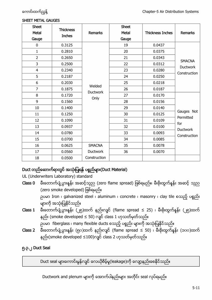
႔ Chapter-5 Air Distribution Systems
5-11
SHEET METAL GAUGES Sheet Metal Gauge
Thickness Inches
Remarks Sheet Metal Gauge
Thickness Inches Remarks
0 0.3125
Welded Ductwork
Only
19 0.0437
SMACNA Ductwork
Construction
1 0.2810 20 0.0375 2 0.2650 21 0.0343 3 0.2500 22 0.0312 4 0.2340 23 0.0280 5 0.2187 24 0.0250 6 0.2030 25 0.0218 7 0.1875 26 0.0187 8 0.1720 27 0.0170
Gauges Not Permitted for Ductwork Construction
9 0.1560 28 0.0156 10 0.1400 29 0.0140 11 0.1250 30 0.0125 12 0.1090 31 0.0109 13 0.0937 32 0.0100 14 0.0780 33 0.0093 15 0.0700 34 0.0085 16 0.0625 SMACNA
Ductwork Construction
35 0.0078 17 0.0560 36 0.0070 18 0.0500
Duct (Duct Material) UL (Underwriters Laboratory) standard Class 0
႕ ( Iron galvanized steel aluminum concrete masonry clay tile
Class 1 ႕ ( ၅) ≤ 25 ( ၅) ( ≤ 50) class 1 fiberglass many flexible ducts
Class 2 ႕ (၅၀) ≤ 50 (၁၀၀) ≤ 00 class 2
၅.၃. Duct Seal
Ductwork and plenum seal
Duct seal (leakage)
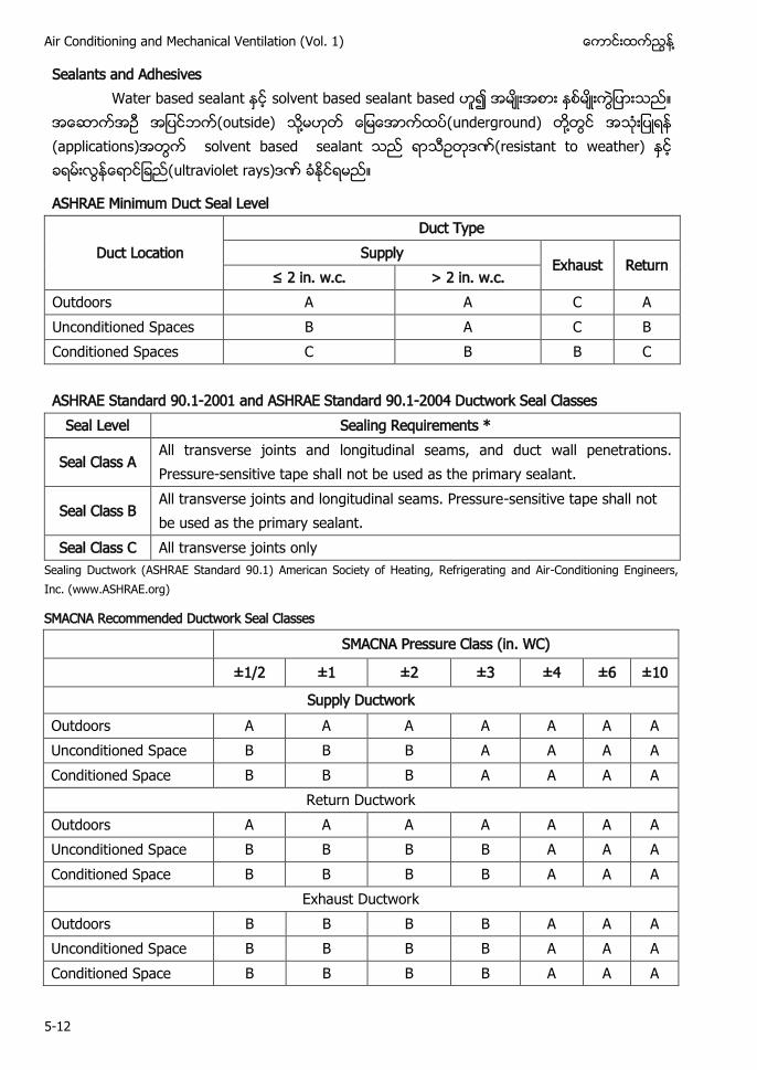
Air Conditioning and Mechanical Ventilation (Vol. 1) ႔
5-12
Sealants and Adhesives W ႔ ႔ (applications) solvent based sealant w h y
ASHRAE Minimum Duct Seal Level
Duct Location Duct Type
Supply Exhaust Return
≤ 2 . w. . > 2 in. w.c. Outdoors A A C A Unconditioned Spaces B A C B Conditioned Spaces C B B C ASHRAE Standard 90.1-2001 and ASHRAE Standard 90.1-2004 Ductwork Seal Classes
Seal Level Sealing Requirements *
Seal Class A All transverse joints and longitudinal seams, and duct wall penetrations. Pressure-sensitive tape shall not be used as the primary sealant.
Seal Class B All transverse joints and longitudinal seams. Pressure-sensitive tape shall not be used as the primary sealant.
Seal Class C All transverse joints only Sealing Ductwork (ASHRAE Standard 90.1) American Society of Heating, Refrigerating and Air-Conditioning Engineers, Inc. (www.ASHRAE.org)
SMACNA Recommended Ductwork Seal Classes SMACNA Pressure Class (in. WC) ±1/2 ±1 ±2 ±3 ±4 ±6 ±10
Supply Ductwork Outdoors A A A A A A A Unconditioned Space B B B A A A A Conditioned Space B B B A A A A
Return Ductwork Outdoors A A A A A A A Unconditioned Space B B B B A A A Conditioned Space B B B B A A A
Exhaust Ductwork Outdoors B B B B A A A Unconditioned Space B B B B A A A Conditioned Space B B B B A A A
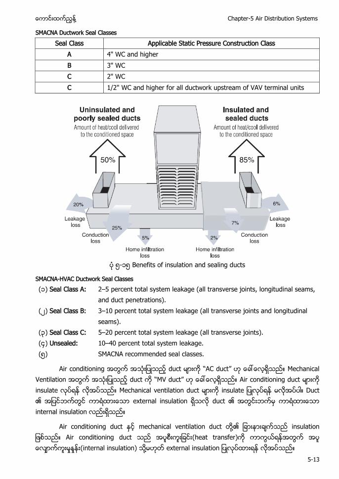
႔ Chapter-5 Air Distribution Systems
5-13
SMACNA Ductwork Seal Classes Seal Class Applicable Static Pressure Construction Class
A 4" WC and higher B 3" WC C 2" WC C 1/2" WC and higher for all ductwork upstream of VAV terminal units
၅-၁၅ Benefits of insulation and sealing ducts
SMACNA-HVAC Ductwork Seal Classes (၁) Seal Class A: 2–5 percent total system leakage (all transverse joints, longitudinal seams,
and duct penetrations). ( ) Seal Class B: 3–10 percent total system leakage (all transverse joints and longitudinal
seams). (၃) Seal Class C: 5–20 percent total system leakage (all transverse joints). (၄) Unsealed: 10–40 percent total system leakage. (၅) SMACNA recommended seal classes.
Air conditioning duct “AC duct” Mechanical Ventilation duct “MV duct” Air conditioning duct insulate Mechanical ventilation duct insulate Duct external insulation duct internal insulation
Air conditioning duct mechanical ventilation duct ႔ Air conditioning duct (heat transfer) (internal insulation) ႔
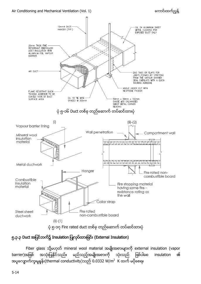
Air Conditioning and Mechanical Ventilation (Vol. 1) ႔
5-14
၅-၁၆ Duct
၅-၁ Fire rated duct
၅.၃.၃ Duct ၌ (External Insulation)
Fiber glass ႔ mineral wool material external insulation (vapor barrier) insulation (thermal conductivity) 0.0332 W/m2 K
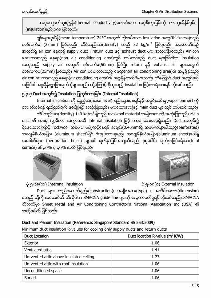
႔ Chapter-5 Air Distribution Systems
5-15
(mean temperature) 24°C insulation (thickness)
25 (density) 32 kg/m3 air c supply duct return duct exhaust duct Air con (non air conditioning area) duct insulation supply air 50 return exhaust air 25 Air con (non air conditioning area) a (air conditioning area) ႔ duct ႔
၅.၃.၄ Duct ၌ (Internal Insulation) Internal insulation (noise level) (vapor barrier)
main duct (density) 140 kg/m3 rockwool material Main
duct (၅) internal i Duct ၌ rockwool ႕ (0.46mm) (perforated) h h (perforation holes) (total surface) ၃၀% ၄၀%
၅-၁၈( ) Internnal insulation ၅-၁၈( ) External insulation
Duct (construction) (type) (dimension) ႔ SMACNA guide line SMACNA Sh C C ’ N S
Duct and Plenum Insulation (Reference: Singapore Standard SS 553:2009) Minimum duct insulation R-values for cooling only supply ducts and return ducts Duct Location Duct location R-value (m2 K/W) Exterior 1.06 Ventilated attic 1.41 Un-vented attic above insulated ceiling 1.77 Un-vented attic with roof insulation 1.06 Unconditioned space 1.06 Buried 1.06
(thermal conductivity (insulation)
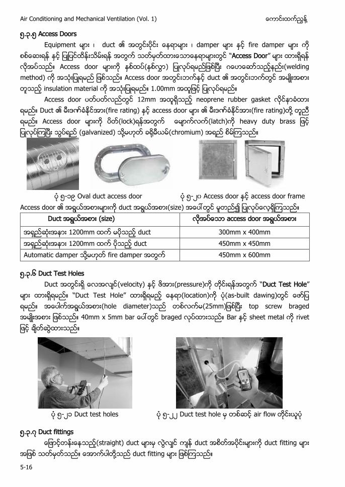
Air Conditioning and Mechanical Ventilation (Vol. 1) ႔
5-16
၅.၃.၅ Access Doors Equipment duct damper fire damper “Access Door” Access door ( (welding method) Access door duct insulation material 1.00mm
Access door 12mm neoprene rubber gasket Duct (fire rating) access door (fire rating) ႔ Access door (lock) (latch) h y y (galvanized) ႔ (chromium)
၅-၁၉ Oval duct access door ၅- ၀ Access door access door frame
Access door duct (size) Duct (size) access door
1200mm duct 300mm x 400mm 1200mm duct 450mm x 450mm Automatic damper ႔ fire damper 450mm x 600mm
၅.၃.၆ Duct Test Holes Duct (velocity) (pressure) “Duct Test Hole” “ T ” (location) (as-built dawing) (hole diameter) 25 top screw braged 40 5 braged Bar sheet metal
၅- ၁ Duct test holes ၅- Duct test hole air flow
၅.၃. Duct fittings (straight) duct duct duct fitting
႔ duct fitting
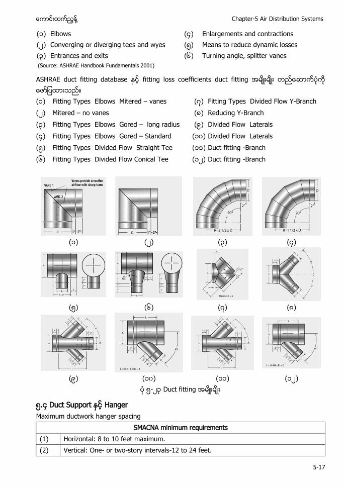
႔ Chapter-5 Air Distribution Systems
5-17
(၁) Elbows (၄) Enlargements and contractions ( ) Converging or diverging tees and wyes (၅) Means to reduce dynamic losses (၃) Entrances and exits (၆) Turning angle, splitter vanes (Source: ASHRAE Handbook Fundamentals 2001)
ASHRAE duct fitting database fitting loss coefficients duct fitting (၁) Fitting Types Elbows Mitered – vanes ( ) Fitting Types Divided Flow Y-Branch ( ) Mitered – no vanes (၈) Reducing Y-Branch (၃) Fitting Types Elbows Gored – long radius (၉) Divided Flow Laterals (၄) Fitting Types Elbows Gored – Standard (၁၀) Divided Flow Laterals (၅) Fitting Types Divided Flow Straight Tee (၁၁) Duct fitting -Branch (၆) Fitting Types Divided Flow Conical Tee (၁ ) Duct fitting -Branch
(၁) ( ) (၃) (၄)
(၅) (၆) ( ) (၈)
(၉) (၁၀) (၁၁) (၁ ) ၅- ၃ Duct fitting
၅.၄ Duct Support Hanger Maximum ductwork hanger spacing
SMACNA minimum requirements (1) Horizontal: 8 to 10 feet maximum. (2) Vertical: One- or two-story intervals-12 to 24 feet.
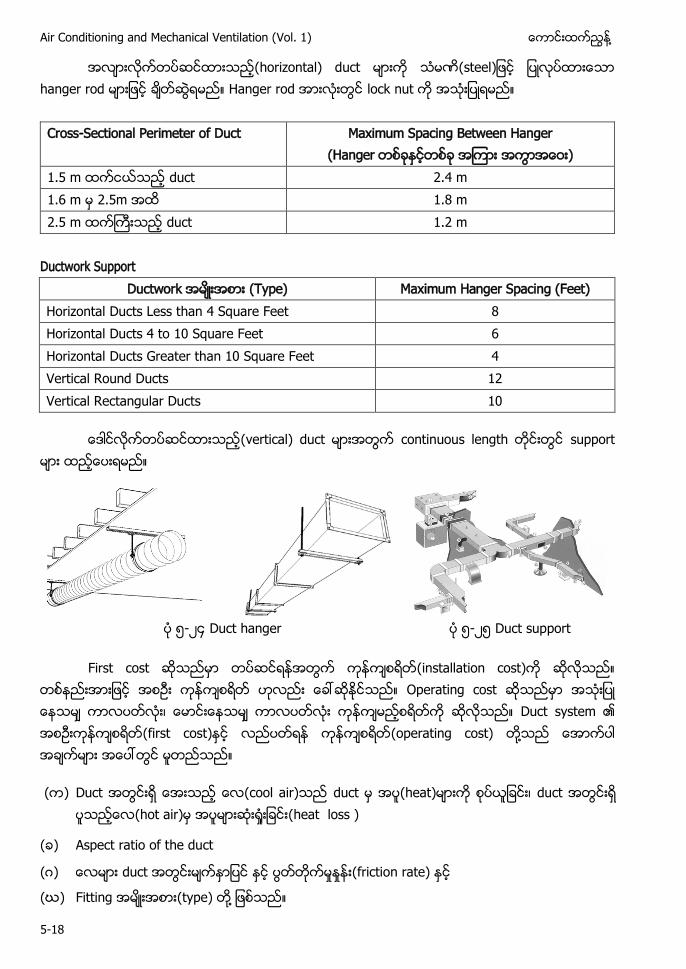
Air Conditioning and Mechanical Ventilation (Vol. 1) ႔
5-18
(horizontal) duct hanger rod Hanger rod lock nut
Cross-Sectional Perimeter of Duct Maximum Spacing Between Hanger
(Hanger ) 1.5 m duct 2.4 m 1.6 m 2.5m 1.8 m 2.5 m duct 1.2 m
Ductwork Support
Ductwork (Type) Maximum Hanger Spacing (Feet) Horizontal Ducts Less than 4 Square Feet 8 Horizontal Ducts 4 to 10 Square Feet 6 Horizontal Ducts Greater than 10 Square Feet 4 Vertical Round Ducts 12 Vertical Rectangular Ducts 10
(vertical) duct continuous length support
၅- ၄ Duct hanger ၅- ၅ Duct support
First cost (installation cost) Operating cost Duct system (first cost) (operating cost) ႔
( ) Duct (cool air) duct (heat) duct (hot air) (heat loss )
( ) Aspect ratio of the duct
( ) duct (friction rate)
(ဃ) Fitting (type) ႔
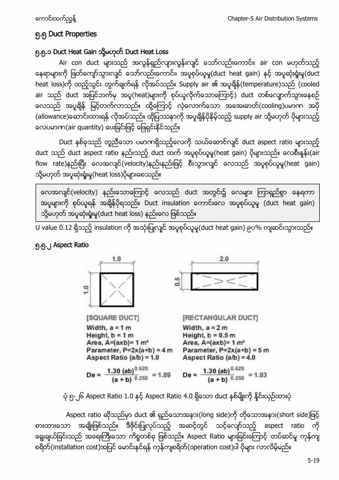
႔ Chapter-5 Air Distribution Systems
5-19
၅.၅ Duct Properties
၅.၅.၁ Duct Heat Gain ႔ Duct Heat Loss Air con duct air con (duct heat gain) (duct heat loss) Supply air (temperature) (cooled air duct (heat) ) duct ႔ (cooling) w supply air ႔ (air quantity)
Duct duct aspect ratio duct duct aspect ratio duct (heat gain) (air flow rate) (velocity) (heat gain) ႔ (heat loss)
U value 0.12 insulation (duct heat gain) ၉၀%
၅.၅. Aspect Ratio
၅- ၆ Aspect Ratio 1.0 Aspect Ratio 4.0 duct
Aspect ratio duct (long side) h aspect ratio Aspect Ratio (installation cost) (operation cost)
(velocity) duct ၌ Duct i (duct heat gain) ႔ (duct heat loss)
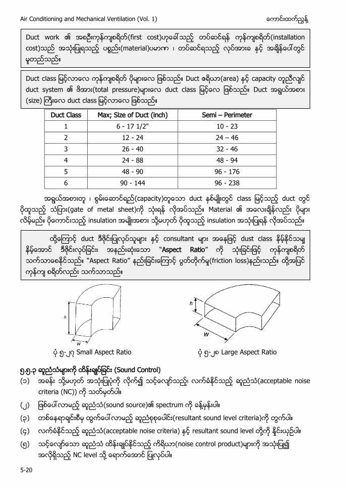
Air Conditioning and Mechanical Ventilation (Vol. 1) ႔
5-20
Duct Class Max; Size of Duct (inch) Semi – Perimeter
1 6 - 17 1/2" 10 - 23 2 12 - 24 24 – 46 3 26 - 40 32 - 46 4 24 - 88 48 - 94 5 48 - 90 96 - 176 6 90 - 144 96 - 238
(capacity) duct duct (gate of metal sheet) Material insulation ႔ insulation
၅- Small Aspect Ratio ၅- ၈ Large Aspect Ratio
၅.၅.၃ Sound Control) (၁) ႔ (acceptable noise
criteria (NC))
( ) (sound source) ႔
(၃) resultant sound level criteria)
(၄) ( ႔
(၅) noise control product) NC ႔
Duct work (first cost) (installation cost) (material)
Duct c Duct (area) capacity duct system (total pressure) duct c Duct (size) duct c
႔ duct consultant dust class “Aspect Ratio” “Aspect Ratio” (friction loss) ႔
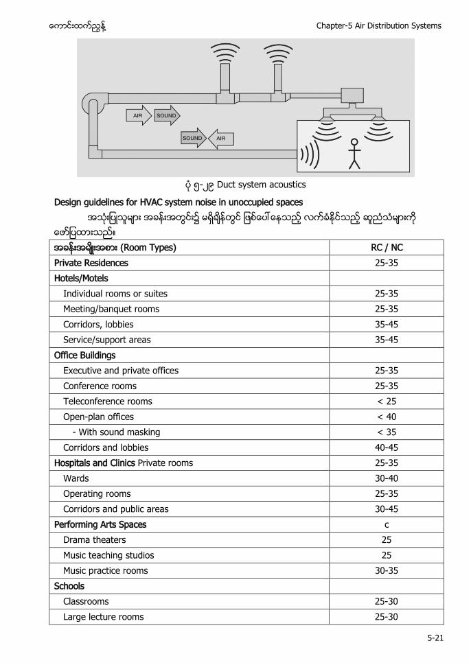
႔ Chapter-5 Air Distribution Systems
5-21
၅- ၉ Duct system acoustics
Design guidelines for HVAC system noise in unoccupied spaces ၌ (Room Types) RC / NC Private Residences 25-35 Hotels/Motels
Individual rooms or suites 25-35 Meeting/banquet rooms 25-35 Corridors, lobbies 35-45 Service/support areas 35-45
Office Buildings
Executive and private offices 25-35 Conference rooms 25-35 Teleconference rooms < 25 Open-plan offices < 40
- With sound masking < 35 Corridors and lobbies 40-45
Hospitals and Clinics Private rooms 25-35 Wards 30-40 Operating rooms 25-35 Corridors and public areas 30-45
Performing Arts Spaces c Drama theaters 25 Music teaching studios 25 Music practice rooms 30-35
Schools
Classrooms 25-30 Large lecture rooms 25-30
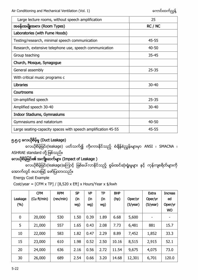
Air Conditioning and Mechanical Ventilation (Vol. 1) ႔
5-22
Large lecture rooms, without speech amplification 25 (Room Types) RC / NC Laboratories (with Fume Hoods)
Testing/research, minimal speech communication 45-55
Research, extensive telephone use, speech communication 40-50
Group teaching 35-45
Church, Mosque, Synagogue
General assembly 25-35
With critical music programs c
Libraries 30-40
Courtrooms
Un-amplified speech 25-35
Amplified speech 30-40 30-40
Indoor Stadiums, Gymnasiums
Gymnasiums and natatorium 40-50
Large seating-capacity spaces with speech amplification 45-55 45-55
၅.၅.၄ (Duct Leakage) (leakage) ANSI SMACNA
ASHRAE standard ႔ (Impact of Leakage )
Energy Cost Example Cost/year = [CFM x TP] / [8,520 x Eft] x Hours/Year x $/kwh
Leakage (%)
CFM (Cu ft/min)
RPM (rev/min)
SP (in wg)
VP (in wg)
TP (in wg)
BHP (hp) Oper/yr
(5/year)
Extra Oper/yr (5/year)
Increased
Oper/yr WO
0 20,000 530 1.50 0.39 1.89 6.68 5,600 - -
5 21,000 557 1.65 0.43 2.08 7.73 6,481 881 15.7
10 22,000 583 1.82 0.47 2.29 8.89 7,452 1,852 33.3
15 23,000 610 1.98 0.52 2.50 10.16 8,515 2,915 52.1
20 24,000 636 2.16 0.56 2.72 11.54 9,675 4,075 73.0
30 26,000 689 2.54 0.66 3.20 14.68 12,301 6,701 120.0
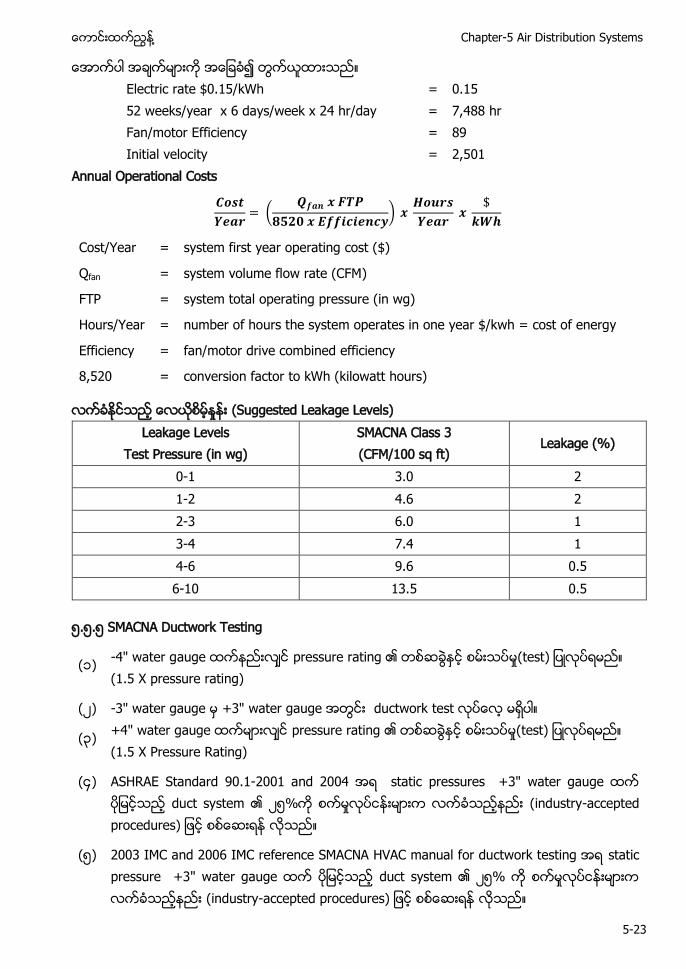
႔ Chapter-5 Air Distribution Systems
5-23
Electric rate $0.15/kWh = 0.15
52 weeks/year x 6 days/week x 24 hr/day = 7,488 hr Fan/motor Efficiency = 89 Initial velocity = 2,501
Annual Operational Costs
(
)
Cost/Year = system first year operating cost ($)
Qfan = system volume flow rate (CFM)
FTP = system total operating pressure (in wg)
Hours/Year = number of hours the system operates in one year $/kwh = cost of energy
Efficiency = fan/motor drive combined efficiency
8,520 = conversion factor to kWh (kilowatt hours)
(Suggested Leakage Levels) Leakage Levels
Test Pressure (in wg) SMACNA Class 3 (CFM/100 sq ft)
Leakage (%)
0-1 3.0 2 1-2 4.6 2 2-3 6.0 1 3-4 7.4 1 4-6 9.6 0.5 6-10 13.5 0.5
၅.၅.၅ SMACNA Ductwork Testing
(၁) -4" water g pressure r (test) (1.5 X pressure rating)
( ) -3" water gauge 3 water gauge w
(၃) +4" water gauge pressure rating (1.5 X Pressure Rating)
(၄) ASHRAE Standard 90.1-200 2004 static pressures +3" water gauge y ၅ y-
(၅) 2003 C 2006 C S CN V C w static pressure +3" water gauge y ၅ y-
Air Conditioning and Mechanical Ventilation (Vol. 1) ႔
5-24
၅.၆ Duct (Sizing)
y ၌ (၁) (space availability) ( ) ႕ (space air diffusion)
(၃) (noise levels) (၄) Duct (duct leakage) (၅) duct (duct heat gain) ႔
(duct heat loss) ( ) ႔ (air balancing) (၈) (fire and smoke
control) (၉) (initial investment cost) (၁၀) (system operating cost) ႔
႔ ႕ discomfort) S ႔ ႔ (air distribution)
construction) leakage) terminal) air duct insul h ႔ h ႔ system loss y ႔ Ductwork Sizes (၁) 4 4
( ) 8 4 smallest (၃)
24” 2” 0” 6” 2” 36” 48” 2” ႔
(၄) 4 (၅) 3 (smallest round size) duct
၅.၆.၁ Duct (Sizing) ( ) Pressurized Method
႔ Chapter-5 Air Distribution Systems
5-25
( ) Equal Friction Sizing Method (Constant Pressure Loss Method) ( ) Static Regain Method (ဃ) Total Pressure Method ( ) Velocity Reduction Method ( ) Constant Velocity Method ႔
႔ h (၁) Velocity Reduction Method ( ) Equal Friction Method
(၃) Static Regain Method ႔ Pressurized Method
duct ႔ ၌ duct ႔ ႔ ၌ duct (size) Equal Friction Sizing Method (Constant Pressure Loss Method)
Equal friction (method) (flexibility) ႔ Duct (pressure loss) duct
System ၌ duct 1 Pascal (1Pa/m) duct “Eq F h ” Supply extract duct system “Eq F h ”
ASHRAE duct (high and low limits for pressure loss per unit length) (velocity) ႔ duct (pressure loss per unit length) “Eq F h ” ( ) friction loss per unit length duct
1 Pascal( 1Pa/m) ( ) friction loss (1 Pa/m) (air flow rate) duct
Friction loss chart duct (size) ( ) (pressure loss) (section) friction loss
(duct section) elbow fitting friction loss
(ဃ) duct (size) friction loss coefficient duct (size) System
Air Conditioning and Mechanical Ventilation (Vol. 1) ႔
5-26
႔ “Eq F ” ႔ air balancing)
S R S h
“S R h ” duct (equal friction method ) (material)
“S R h ” terminal branch duct section (pressure loss) duct branch duct section (pressure loss) branch duct section (pressure loss)
duct (section) duct (section) ႔ (pressure losses) ႔ duct section duct (size) duct (section) duct (size) (p ႔ “S R h ” iteration process
ဃ T S Method T h h
V y R S h
Velocity reduction duct (air velocity) (velocity) (noise) Duct (acceptable velocity) (velocity) duct duct (size) (round) duct ႔ (rectangular) duct (size) (pressure losses)
(high noise level) (velocity) (noise level) ASHRAE SMACNA “ V C C S ”
C V y S h Constant velocity method duct ႔
(tender)၌ (specified) (velocity) ၍ duct duct (size) (pressure losses)
႔ Chapter-5 Air Distribution Systems
5-27
၅.၆. (Friction Losses in Duct) Friction loss fluid viscosity y
Friction loss
Eq h y loss per unit h
(friction loss) (၁) Duct (size) (velocity) friction loss ( ) Duct ၏ (interior surface roughness) friction loss (၃) (air flow rate) friction loss (၄) Duct (length) friction loss
၅.၆.၃ Head and Pressure Head
h h h y w. w head) ႔ q “Head” column liquid)
- ၅ Hea 5 meter of water column (WC) ႔ ႔ ႔ liquid)
႔ ႕ ႔
Air pressure 1 Pound per Square Inch (PSI) = 51.71 millimeter of mercury (mmHg) 5 . mm of mercury (mmHg
y-W h Eq f pipe ႔ d
(pressure drop f f y-W h Eq fully d w
Darcy and Colebrook Equations ႔ pipe) ၌ f
Air Conditioning and Mechanical Ventilation (Vol. 1) ႔
5-28
f ( ) Fluid laminar flow Reynolds ( ၀၀၀)
(Reynolds numbers less than 2000) Friction factor Reynolds number
( ) Fluid turbulent flow friction factor Reynolds (Reynolds number) (duct surface roughness) joint
F
√ (
√ )
R y h hy ႔
(non circular) duct laminar flow (inconsistencies) non circular duct laminar flow hydraulic diameter
Hydraulic Diameter(D) Reynolds Number(dimensionless)
Duct ၌ (turbulent or laminar) Reynolds Number
Reynolds Number ( ၃၀၀) “Laminar flow” (Laminar if Re < 2300)
Reynolds Number ( ၃၀၀) (၄၀၀၀) “Transient flow” (Transient for 2300 < Re < 4000)
႔ Chapter-5 Air Distribution Systems
5-29
Reynolds Number (၄၀၀၀) “Turbulent flow” (Turbulent if Re > 4000)
(Noncircular) Duct
hy
Rectangular Duct R flow
Flat Oval Duct
(
)
A = major axis of flat oval duct (mm) a = minor axis of flat oval duct (mm) P = perimeter of flat oval duct (mm)
Friction f R y h hy ႔ graph)
၅.၆.၄ F Ch Pressure Drop) S R E friction ch ( ) Friction losses (Pa/ m) ( ) Air Quantity (Liter per Second) ( ) Velocity (m/s) (ဃ) Round duct diameter ႔ (၁) Friction losses (Pa/m) h
0. / 00 / 0. / 5 / friction loss
( ) Air Quantity (Liter per Second) 20 L/ 200 000 L/
႔ hy roun square rectangular duct w q
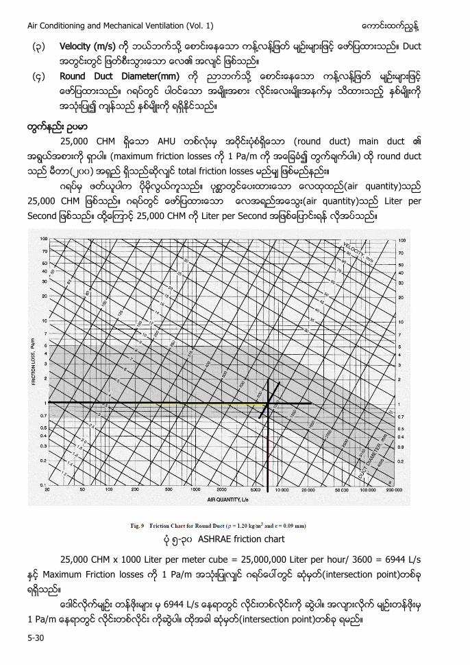
Air Conditioning and Mechanical Ventilation (Vol. 1) ႔
5-30
(၃) Velocity (m/s) ႔ ႔ ႔ Duct
(၄) Round Duct Diameter(mm) ႔ ႔ ႔ ၍
25 000 C
(maximum f / round duct ( ၀၀) total f
air quantity 25 000 C air quantity L S ႔ 25 000 C L S
၅-၃၀ ASHRAE friction chart
25,000 CHM x 1000 Liter per meter cube = 25,000,000 Liter per hour/ 3600 = 6944 L/s F /
6 44 L/ /
႔ Chapter-5 Air Distribution Systems
5-31
႔ ႔ ႔ ) ၉၃၀ ႔ ၉၃၀ 950mm diameter velocity) 0.2 / ႔ ASHRAE recommend duct velocity duct velocity) 10.2 m/s recommend duct velocity 50
y
Type of Duct Comfort Systems Industrial Systems High Speed Systems
m/s FPM m/s m/s FPM Main ducts 4 - 7 780 - 1380 8 - 12 1575 - 2360 10 - 18 1670 - 3540
Main branch ducts 3 - 5 590 - 985 5 - 8 985 - 1575 6 - 12 1180 - 2360
Branch ducts 1 - 3 200 - 590 3 - 5 590 - 985 5 - 8 985 - 1575 outlets inlets) ႔၌ velocity
unacceptable noise)
air flow rate) 8 000 C (rectangular 450 300 frictioin losses - / Air Flow Rate 18,000 C L S ႕ Air Flow Rate 18,000 CMH = 5,000 L/s
Rectangular d 450 300 ircular equivalent of rectangular duct for eq h 808mm 800
(air quantity) 5,000 L/s 800mm round duct d friction losses - Pa/m) . / ႔ Friction Loss Estimate 1.5 X System Length (ft./100) X Friction Rate (in.W.G./100 ft.).
၅.၆.၅ C S L y F
oss (formula)
၁ Ref: 2001 ASHRAE Fundamentals Handbook (SI), Chapter 34, Equation No:11
Where De = Circular Equivalent of Rectangular duct for equal length
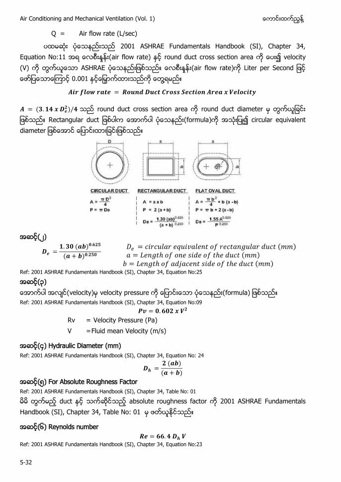
Air Conditioning and Mechanical Ventilation (Vol. 1) ႔
5-32
Q = Air flow rate (L/sec)
200 ASHRAE Fundamentals Handbook (SI), Chapter 34, Eq N air flow rate) v y V S R E air flow rate) L S 0.00 ႔
roun round duct d
R formula) circular eq
Ref: 2001 ASHRAE Fundamentals Handbook (SI), Chapter 34, Equation No:25
၃ y velocity p formula) Ref: 2001 ASHRAE Fundamentals Handbook (SI), Chapter 34, Equation No:09
Rv = Velocity Pressure (Pa) V = Fluid mean Velocity (m/s)
၄ y Ref: 2001 ASHRAE Fundamentals Handbook (SI), Chapter 34, Equation No: 24
၅ F R h F Ref: 2001 ASHRAE Fundamentals Handbook (SI), Chapter 34, Table No: 01
h 200 S R E F S Ch 34 T N 0
(၆) Reynolds number
Ref: 2001 ASHRAE Fundamentals Handbook (SI), Chapter 34, Equation No:23
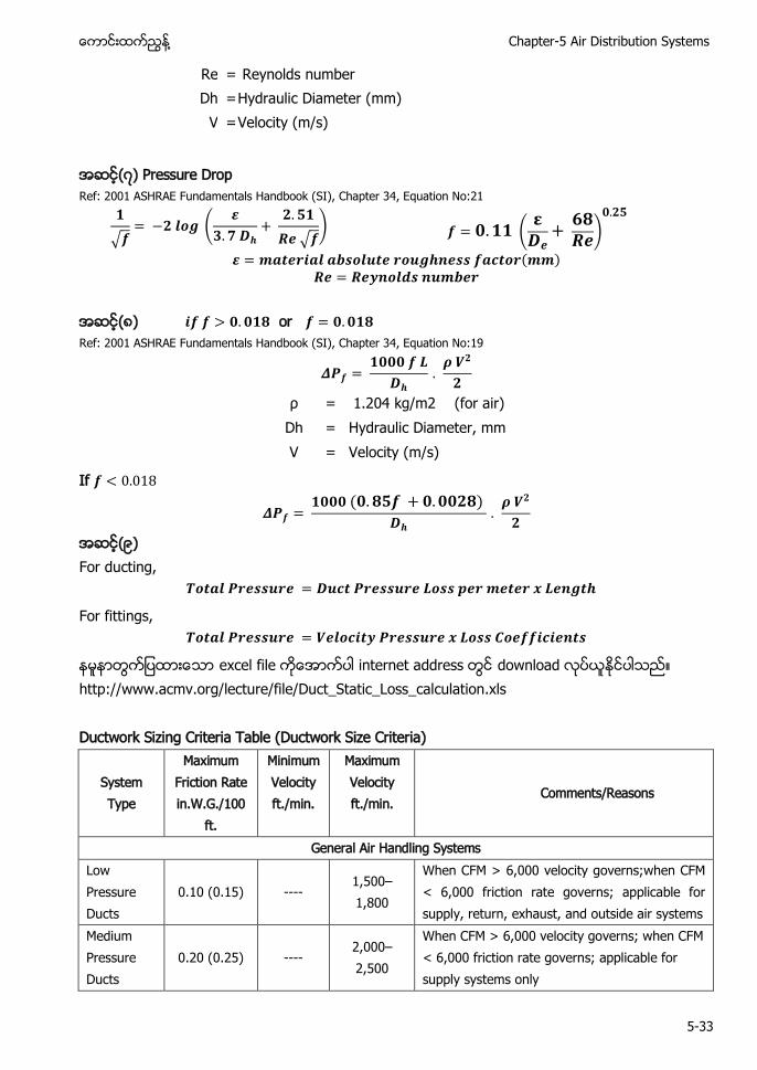
႔ Chapter-5 Air Distribution Systems
5-33
Re = Reynolds number Dh = Hydraulic Diameter (mm)
V = Velocity (m/s)
Ref: 2001 ASHRAE Fundamentals Handbook (SI), Chapter 34, Equation No:21
√ (
√ ) (
)
(၈) or Ref: 2001 ASHRAE Fundamentals Handbook (SI), Chapter 34, Equation No:19
ρ = 1.204 kg/m2 (for air) Dh = Hydraulic Diameter, mm V = Velocity (m/s)
If
၉ For ducting,
For fittings,
e internet a d w http://www.acmv.org/lecture/file/Duct_Static_Loss_calculation.xls Ductwork Sizing Criteria Table (Ductwork Size Criteria)
System Type
Maximum Friction Rate in.W.G./100
ft.
Minimum Velocity ft./min.
Maximum Velocity ft./min.
Comments/Reasons
General Air Handling Systems Low Pressure Ducts
0.10 (0.15) ---- 1,500–1,800
When CFM > 6,000 velocity governs;when CFM < 6,000 friction rate governs; applicable for supply, return, exhaust, and outside air systems
Medium Pressure Ducts
0.20 (0.25) ---- 2,000–2,500
When CFM > 6,000 velocity governs; when CFM < 6,000 friction rate governs; applicable for supply systems only
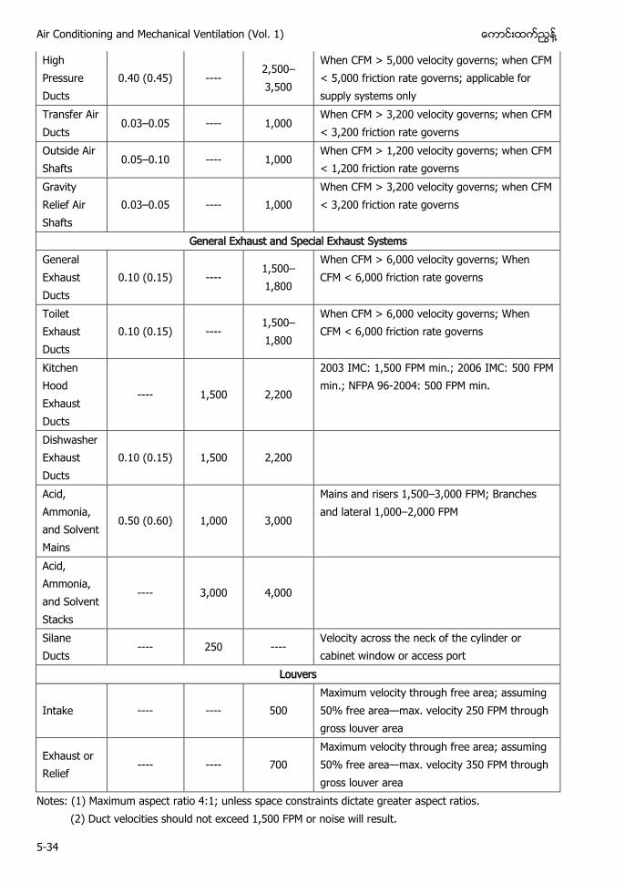
Air Conditioning and Mechanical Ventilation (Vol. 1) ႔
5-34
High Pressure Ducts
0.40 (0.45) ---- 2,500–3,500
When CFM > 5,000 velocity governs; when CFM < 5,000 friction rate governs; applicable for supply systems only
Transfer Air Ducts
0.03–0.05 ---- 1,000 When CFM > 3,200 velocity governs; when CFM < 3,200 friction rate governs
Outside Air Shafts
0.05–0.10 ---- 1,000 When CFM > 1,200 velocity governs; when CFM < 1,200 friction rate governs
Gravity Relief Air Shafts
0.03–0.05 ---- 1,000 When CFM > 3,200 velocity governs; when CFM < 3,200 friction rate governs
General Exhaust and Special Exhaust Systems General Exhaust Ducts
0.10 (0.15) ---- 1,500–1,800
When CFM > 6,000 velocity governs; When CFM < 6,000 friction rate governs
Toilet Exhaust Ducts
0.10 (0.15) ---- 1,500–1,800
When CFM > 6,000 velocity governs; When CFM < 6,000 friction rate governs
Kitchen Hood Exhaust Ducts
---- 1,500 2,200
2003 IMC: 1,500 FPM min.; 2006 IMC: 500 FPM min.; NFPA 96-2004: 500 FPM min.
Dishwasher Exhaust Ducts
0.10 (0.15) 1,500 2,200
Acid, Ammonia, and Solvent Mains
0.50 (0.60) 1,000 3,000
Mains and risers 1,500–3,000 FPM; Branches and lateral 1,000–2,000 FPM
Acid, Ammonia, and Solvent Stacks
---- 3,000 4,000
Silane Ducts
---- 250 ---- Velocity across the neck of the cylinder or cabinet window or access port
Louvers
Intake ---- ---- 500 Maximum velocity through free area; assuming 50% free area—max. velocity 250 FPM through gross louver area
Exhaust or Relief
---- ---- 700 Maximum velocity through free area; assuming 50% free area—max. velocity 350 FPM through gross louver area
Notes: (1) Maximum aspect ratio 4:1; unless space constraints dictate greater aspect ratios. (2) Duct velocities should not exceed 1,500 FPM or noise will result.
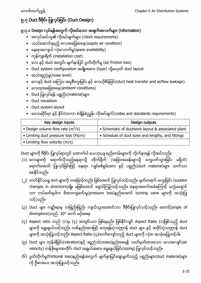
႔ Chapter-5 Air Distribution Systems
5-35
၅. Duct (Duct Design)
၅. .၁ Design (information) • (client requirements) • (supply air condition) • space availability) • installation cost) • air friction loss) • Duct system configuration (type) ႔ duct layout • noise level) • duct heat transfer and airflow leakage) • (ambient conditions) • (material) • Duct insulation • Duct system layout • (codes and standards requirements)
Key design inputs Design outputs • w 3/s) • S h w y & • L / • S h duct sizes and lengths, and fittings • L w y /
Duct (၁) ႔ ( ႔ ႔ )
(duct material)
( ) duct (sudden changes in directions) (pressure loss) turning vane
(၃) Duct (angle of divergence) 20°
(၄) Aspect ratio (၁) (၄) Aspect Ratio (၁ duct duct duct Aspect Ratio (၄) duct
(၅) Duct (vibration) (noise) (air velocity) duct
(၆) (frictional loss) (duct material)
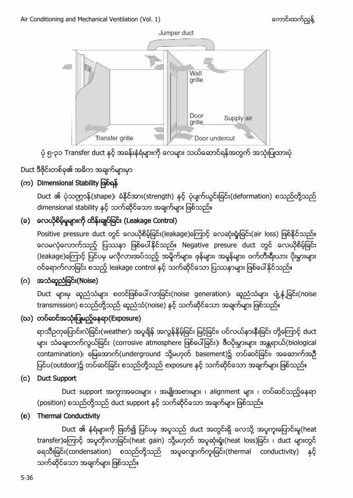
Air Conditioning and Mechanical Ventilation (Vol. 1) ႔
5-36
၅-၃၁ Transfer duct
Duct
( ) S y
Duct (shape) (strength) (deformation) ႔ dimensional stability
( ) (Leakage Control)
Positive pressure duct (air loss) Negative presure duct leakage control
( ) (Noise)
Duct (noise generation) ႕ ႕ (noise transmission) ႔ (noise)
(ဃ) (Exposure)
(weather) ႔ duct (corrosive a h ) (biological contamination) (underground ႔ basement)၌ (outdoor)၌ ႔ exposure
( ) Duct Support
Duct support alignment (position) ႔ duct support
( ) Thermal Conductivity
Duct duct ႔ (heat t (heat gain) ႔ h duct (condensation) ႔ (thermal conductivity)

႔ Chapter-5 Air Distribution Systems
5-37
Duct ႔ ႔ (expericence) (technical knowledge) (good practices) Duct (workshop) (fabricate) (site)၌ Drawing duct (dimension) internal dimension ႔ duct (size) w (dimemsion) ၅. . C (၁) Life-cycle cost(LCC) duct
duct (size) ( ) Damper ႔ duct duct
(size) configuration ႔
(sound level) VAV box (inlet) (excess pressure) sound attenuation
(၃) (critical path) ႔ duct (critical path) duct fitting equipment (local loss coefficients) ႔ (surplus pressure)
(၄) Supply air (volume flow rate) duct heat gain VAV system (volume flow rate) diversity factors Fan (discharge pressure) critical path
၅. .၃ Design Procedure
Air duct system • (supply volume flow rate) • ႕ ႔ (space air diffusion) (supply outlets)
(return inlets) • cold air (volume flow rate) warm air
(volume flow rate)
air duct system duct design software Computer-aided duct design (precise calculation) air duct system duct design
Air Conditioning and Mechanical Ventilation (Vol. 1) ႔
5-38
Design Procedure (၁) Verify local codes & material availability ( ) Preliminary duct layout (၃) Divide into consecutive duct sections (၄) Minimize local loss coefficients of duct fittings (၅) Select duct sizing methods (၆) Critical total pressure loss of tentative critical path ( ) Size branch ducts & balance total pressure at junctions (၈) Adjust supply flow rates according to duct heat gain (၉) Resize duct sections, recalculate & balance parallel paths (၁၀) Check sound level & add necessary attenuation
design procedure (၁၀) (၁) (client requirement)
(tender specification) (local codes) (material availability) ႔
( ) duct layout (preliminary) (supply outlets) (return inlets) fan main ducts branch takeoffs Air duct (duct) (space available)
(၃) Duct layout (duct sections) Duct segment (pressure drop) “Critical Path” critical path
(၄) Critical path duct fitting local loss coefficient
(၅) Air duct system characteristics duct (sizing methods) Duct system space available noise energy use initial cost ႔ maximum design air velocity Critical path duct section duct
(၆) Critical path (total pressure loss) Air duct system (total pressure loss)
( ) Branch duct Junction duct fitting component total pressure loss
(၈) Supply volume flow rate supply outlet duct heat gain (adjusted)
(၉) duct section (resizes) Total pressure loss
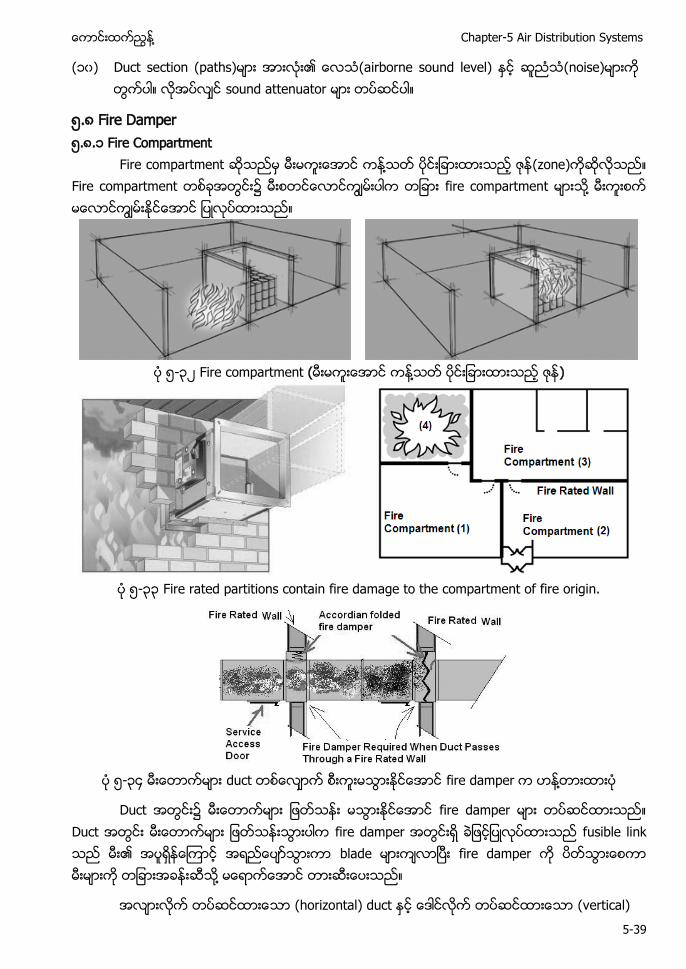
႔ Chapter-5 Air Distribution Systems
5-39
(၁၀) Duct section (paths) (airborne sound level) (noise) sound attenuator
၅.၈ Fire Damper ၅.၈.၁ Fire Compartment
Fire compartment ႔ (zone) Fire compartment ၌ fire compartment ႔
၅-၃ Fire compartment ( ႔ )
၅-၃၃ Fire rated partitions contain fire damage to the compartment of fire origin.
၅-၃၄ duct fire damper ႔
Duct ၌ fire damper Duct fire damper fusible link blade fire damper ႔
(horizontal) duct (vertical)
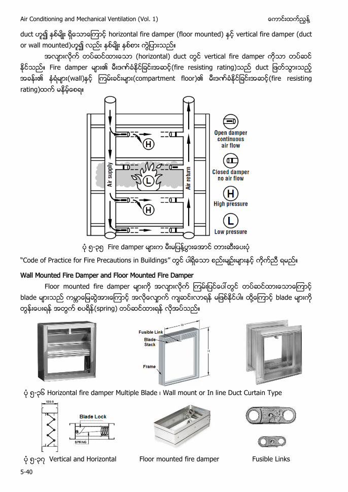
Air Conditioning and Mechanical Ventilation (Vol. 1) ႔
5-40
duct horizontal fire damper (floor mounted) vertical fire damper (duct or wall mounted)
(horizontal) duct vertical fire damper Fire damper (fire resisting rating) (wall) (compartment floor) (fire resisting rating)
၅-၃၅ Fire damper ႔
“Code of Practice for Fire Precautions in Buildings”
Wall Mounted Fire Damper and Floor Mounted Fire Damper Floor mounted fire damper
blade ႔ blade (spring)
၅-၃၆ Horizontal fire damper Multiple Blade Wall mount or In line Duct Curtain Type
၅-၃ Vertical and Horizontal Floor mounted fire damper Fusible Links
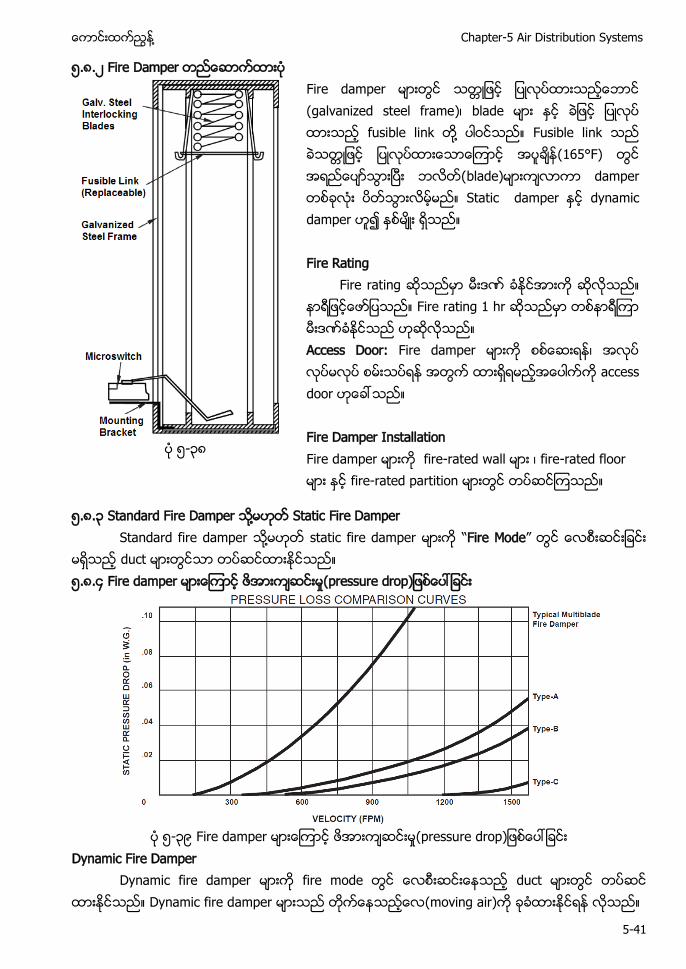
႔ Chapter-5 Air Distribution Systems
5-41
၅.၈. Fire Damper
F (galvanized steel frame fusible link ႔ Fusible link 65 F blade) damper Static damper y Fire Rating Fire r Fire r h Access Door: F Fire Damper Installation Fire d fire-rated w - fire-rated partition
၅-၃၈
၅.၈.၃ Standard Fire Damper ႔ Static Fire Damper Standard fire damper ႔ static fire damper “Fire Mode”
duct ၅.၈.၄ Fire damper
၅-၃၉ Fire damper
Dynamic Fire Damper Dynamic fire damper fire mode duct
Dynamic fire damper (moving air)
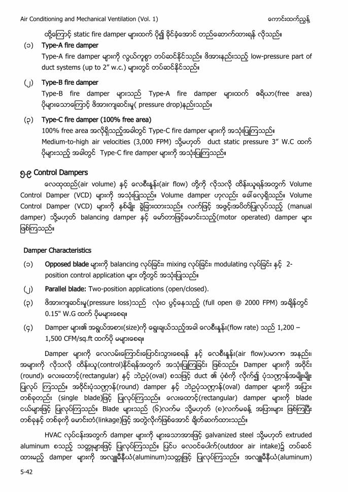
Air Conditioning and Mechanical Ventilation (Vol. 1) ႔
5-42
႔ static fire damper (၁) Type-A fire damper
Type-A fire damper low-pressure part of y 2” w. .
( ) Type-B fire damper Type-B fire damper Type-A fire damper (free area) ( pressure drop)
(၃) Type-C fire damper (100% free area) 100% free area Type-C fire damper Medium-to-high air velocities (3,000 FPM) ႔ 3” W.C Type-C fire damper
၅.၉ Control Dampers (air volume) (air flow) ႔ Volume
Control Damper (VCD) Volume damper Volume Control Damper (VCD) (manual damper) ႔ balancing damper (motor operated) damper
Damper Characteristics
၁ Opposed blade bala mixing modulating 2-position control application ႔
Parallel blade: Two-position applications (open/closed).
၃ (full open @ 2000 F 0.15" W.G
၄ w 200 –1,500 CF / q.
Damper (air flow) (control) Damper (round) (rectangular) (oval) duct (round) damper (oval) damper (rectangular) damper blade Blade (၆) ႔ (၈) ႔
HVAC damper galvanized steel ႔ extruded aluminum (outdoor air intake)၌ damper (aluminum) (aluminum)
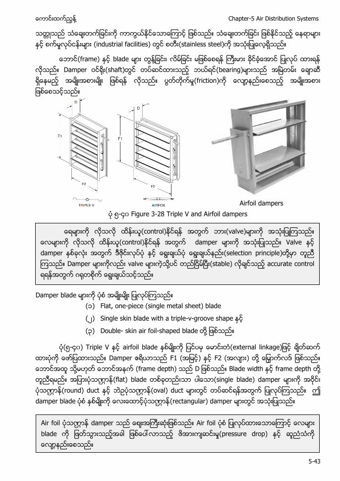
႔ Chapter-5 Air Distribution Systems
5-43
(industrial facilities) (stainless steel)
(frame) blade ႔ Damper (shaft) (bearing) (friction)
Airfoil dampers ၅-၄၀ Figure 3-28 Triple V and Airfoil dampers
Damper blade (၁) Flat, one-piece (single metal sheet) blade
( ) Single skin blade with a triple-v-groove shape
(၃) Double- skin air foil-shaped blade ႔
(၅-၄၀) Triple V airfoil blade Damper F1 ( ) F2 ( ) ႔ ႔ (frame depth) Blade width frame depth ႔ (flat) blade (single blade) damper (round) duct (oval) duct damper blade (rectangular) damper
(control) (valve) (control) damper Valve damper (selection principle) ႔ Damper valve ႔ (stable) accurate control
Air foil damper Air foil blade (pressure drop)
Air Conditioning and Mechanical Ventilation (Vol. 1) ႔
5-44
Triple V groove blade (velocity) 2000 FPM ႔ 1500 FPM Blade (overlap) (tight closure)
Blade (edge) ၌ compressible sealing strip (leakage) sealing strip ႔ (silicon rubber) ႔ (extruded vinyl Silicon rubber
Seal damper (fully open) (fully closed) ႔ (performance) (frame) blade seal Damper (standard leakage) 50 CF q h
(249 Pa damper 50 CFM Air foil blade low leakage damper 6 damper 10 CFM
HVAC system shut off damper (low leakage) damper 24 damper 2 CFM (2 CFM per square foot at 1 inch wg) Damper (minimum leakage) ANSI/ ASHRAE/ IESNA Standard 90.1-2004 ႔ Ultra-low leak damper 4 CFM/ft2 Low leak damper 10 CFM/ft2 Cooling load system ultra-low leak damper
Blade (linkage) (၅-၄၀) blade (linkage) damper (linkage) ႔ ( ) (pressure drop) (corrosion) ႔
damper ၌ damper (seal) Blade Damper ႔ (maintenance)
Damper actuator damper (oversized)
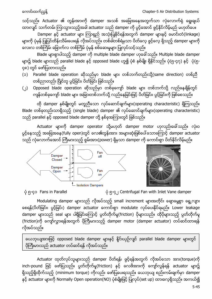
႔ Chapter-5 Air Distribution Systems
5-45
Actuator damper actuator damper Damper actuator damper (linkage) damper Blade damper multiple blade damper Multiple blade damper ၌ blade parallel blade opposed blade (၅-၄ ) (၅-၄၈) (၁) Parallel blade operation blade ႔(same direction)
( ) Opposed blade operation blade ႔
blade ႔
damper (operating characteristic) Blade (single blade) damper (operating characteristic) parallel opposed blade damper ႔
Actuator damper operator ႔ damper motor (fully open) damper actuator (power) damper
၅-၄၁ Fans in Parallel ၅-၄ Centrifugal Fan with Inlet Vane damper
Modulating damper small increment ႔ ႕ ( modulate Lower leakage damper seal (friction) (friction) damper motor (damper actuator)
Actuator damper (torque) h- (friction) actuator ၌ (minimum torque) damper actuator Normally Open operation(NO) (set up)
opposed blade damper parallel blade damper actuator
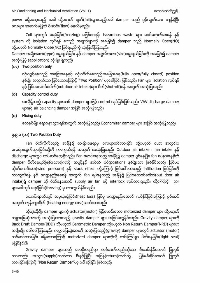
Air Conditioning and Mechanical Ventilation (Vol. 1) ႔
5-46
power ႔ (fail) damper (flow)
Coil (freezing) hazardous waste system isolation damper Normally Open(NO) ႔ N y C NC Damper y damper damper (application) ( ) Two position only
(fully open/fully closed) position “Two Position” Fan isolation (out door air intake) (shut-off)
( ) Capacity control duty
capacity damper control VAV discharge damper air balancing damper
( ) Mixing duty
Economizer damper
၅.၉.၁ ( ) Two Position Duty
Fan ၌ ႔ duct ႔ Outdoor air intake fan intake discharge F ၌ damper fan damper (position) (wind pressure) stack effect ႔ fan ၌ (out door air intake) damper supply air fan interlock ႔ coil (freezing)
h (heating energy cost)
႔ damper motorized damper ႔ gravity damper ႔ Gravity damper Back Draft Damper(BDD) ႔ Barometric Damper ႔ Non Return Damper(NRD) (gravity) damper actuator (motor) motorized damper ႔ (tight seal)
Gravity damper (supply) (return) ႔ “Non Return Damper”
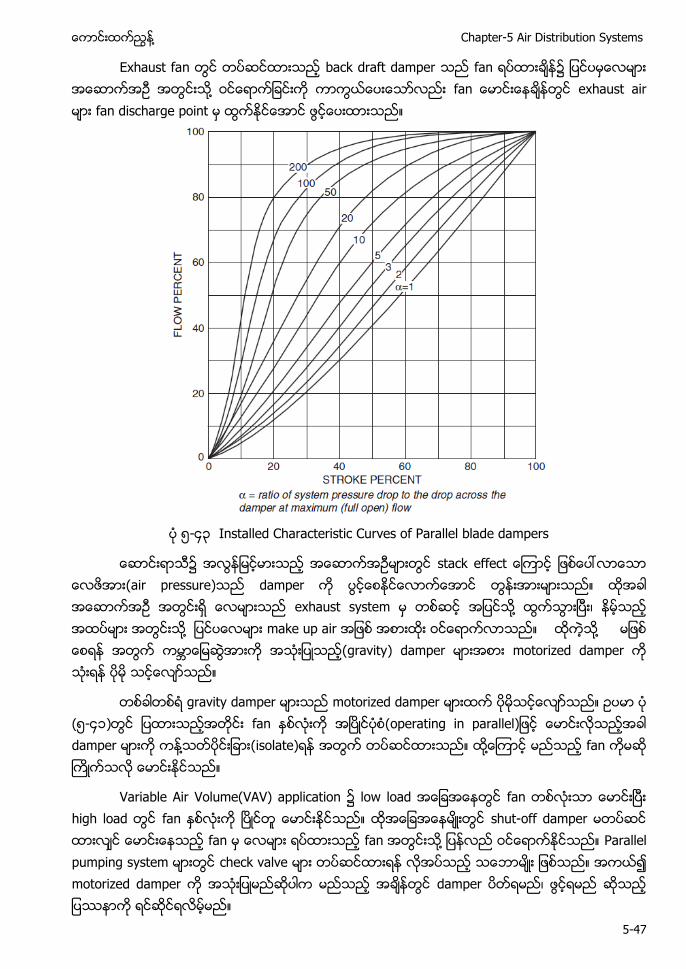
႔ Chapter-5 Air Distribution Systems
5-47
Exhaust fan back draft damper fan ၌ ႔ exhaust air fan discharge point
၅-၄၃ Installed Characteristic Curves of Parallel blade dampers
၌ (air pressure) damper exhaust system ႔ ႔ make up air ႔ (gravity) damper motorized damper
gravity damper motorized damper (၅-၄၁) fan damper ႔ (isolate) ႔ fan
Variable Air Volume(VAV) application ၌ low load fan high load fan shut-off damper fan fan ႔ Parallel pumping system check valve motorized damper damper
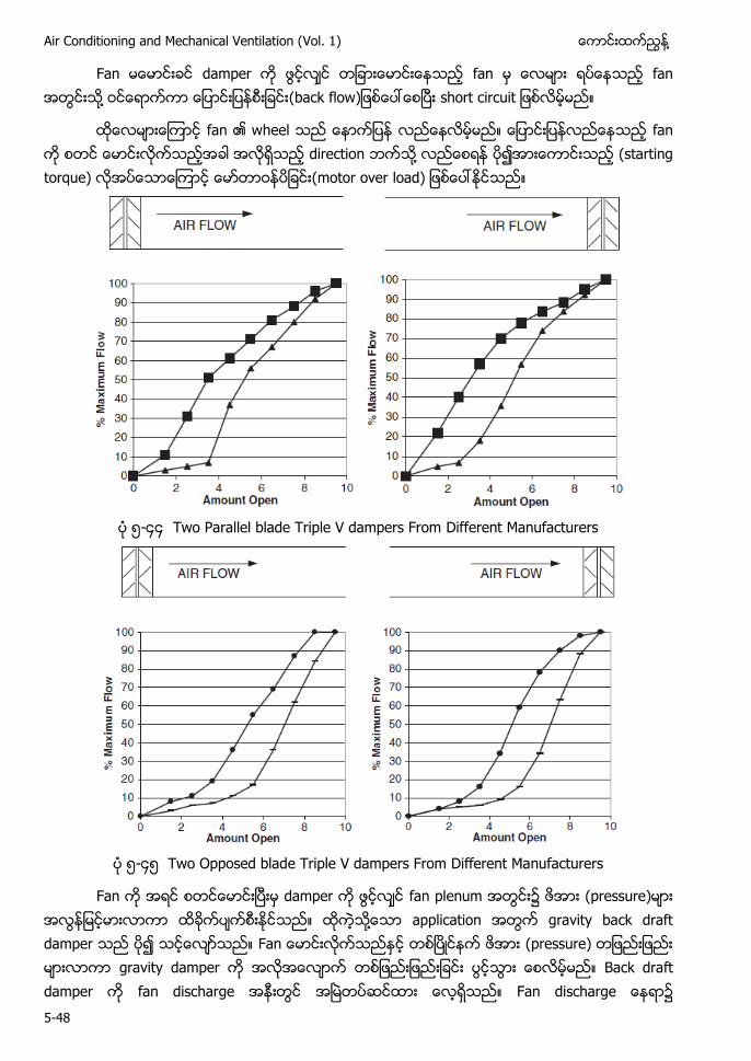
Air Conditioning and Mechanical Ventilation (Vol. 1) ႔
5-48
Fan damper fan fan ႔ w h
fan wheel fan direction ႔ (starting torque)
၅-၄၄ Two Parallel blade Triple V dampers From Different Manufacturers
၅-၄၅ Two Opposed blade Triple V dampers From Different Manufacturers
Fan damper fan plenum ၌ (pressure) ႔ application gravity back draft damper F (pressure) gravity damper Back draft damper fan discharge F h ၌
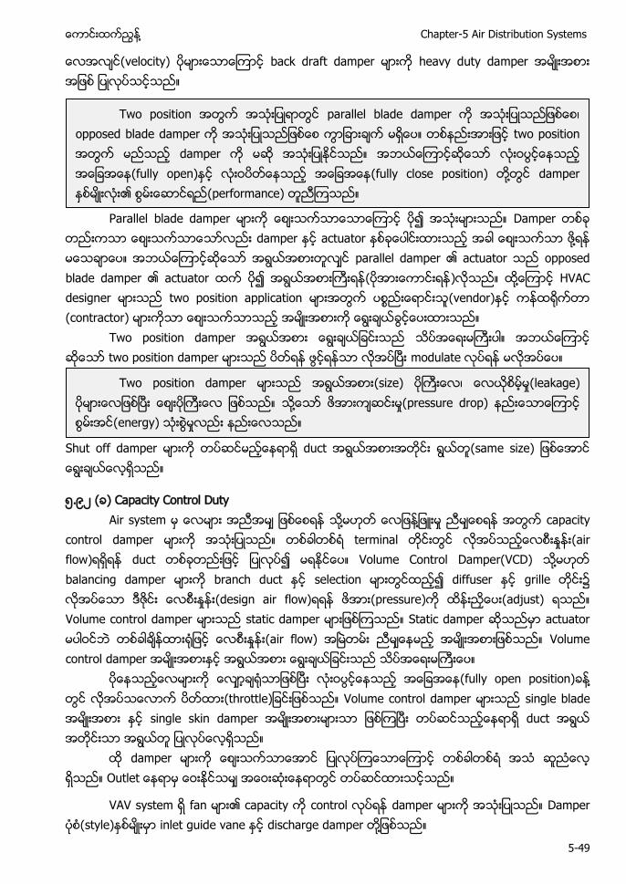
႔ Chapter-5 Air Distribution Systems
5-49
(velocity) back draft damper heavy duty damper
Parallel blade damper Damper
damper actuator ႔ parallel damper actuator opposed blade damper actuator ( ) ႔ HVAC designer two position application (vendor) (contractor)
Two position damper two position damper modulate
Shut off damper duct
၅.၉ ( ) Capacity Control Duty Air system ႔ ႔ capacity control damper terminal (air flow) duct Volume Control Damper(VCD) ႔ balancing damper branch duct selection diffuser grille ၌ (design air flow) (pressure) (adjust) Volume control damper static damper Static damper actuator (air flow) Volume control damper (fully open position) ႔ ( h Volume control damper single blade single skin damper duct damper Outle
VAV system fan capacity control damper Damper (style) inlet guide vane discharge damper ႔
Two position parallel blade damper opposed blade damper two position damper (fully open) (fully close position) ႔ damper (performance)
Two position damper (size) (leakage) ႔ pressure drop) (energy)
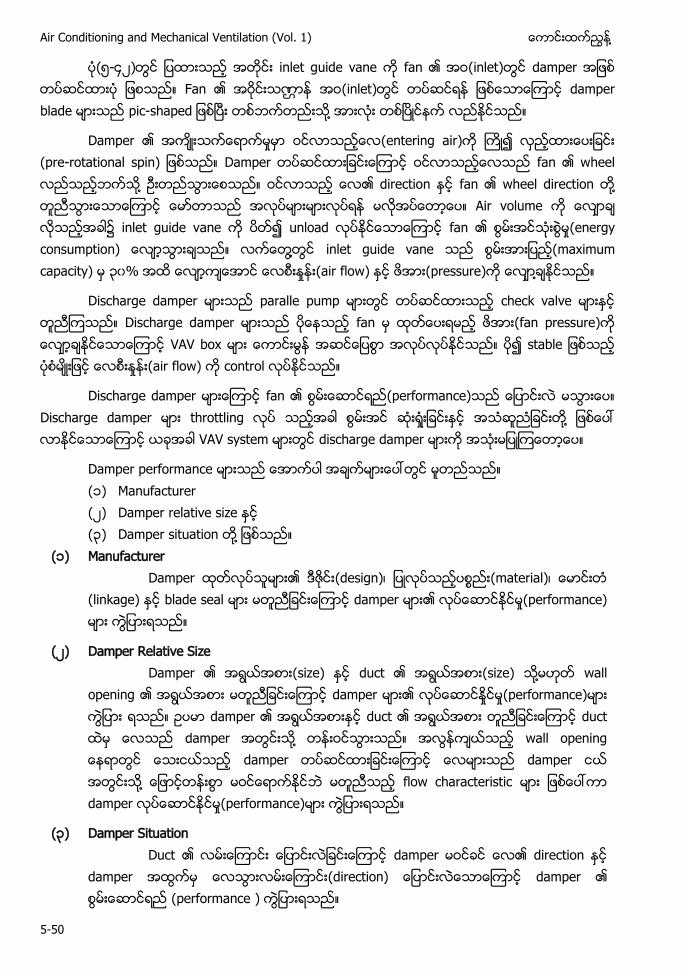
Air Conditioning and Mechanical Ventilation (Vol. 1) ႔
5-50
(၅-၄ ) inlet guide vane fan (inlet) damper Fan (inlet) damper blade - h ႔
Damper (entering air) - Damper fan wheel ႔ direction fan wheel direction ႔ Air volume ၌ inlet guide vane unload fan (energy ႔ inlet guide vane (maximum capacity) ၃၀% (air flow) (pressure) ႔
Discharge damper paralle pump check valve Discharge damper fan (fan pressure) VAV box (air flow) control
Discharge damper fan (performance) Discharge damper throttling ႔ VAV system discharge damper
Damper performance (၁) Manufacturer ( ) Damper relative size (၃) Damper situation ႔ (၁) Manufacturer
Damper (design) (material) (linkage) blade seal damper (performance)
( ) Damper Relative Size Damper (size) duct (size) ႔ wall
opening damper (performance) damper duct duct damper ႔ w damper damper ႔ flow characteristic damper (performance)
(၃) Damper Situation Duct damper direction
damper (direction) damper (performance )
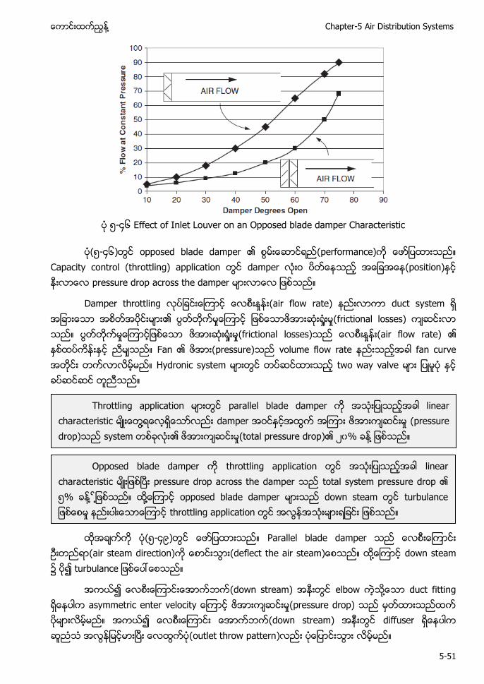
႔ Chapter-5 Air Distribution Systems
5-51
၅-၄၆ Effect of Inlet Louver on an Opposed blade damper Characteristic
(၅-၄၆) opposed blade damper (performance) Capacity control (throttling) application damper (position) pressure drop across the damper
Damper throttling (air flow rate) duct system (frictional losses) (frictional losses) (air flow rate) Fan (pressure) volume flow rate fan curve Hydronic system two way valve
(၅-၄၉) Parallel blade damper
(air steam direction) h ႔ down steam ၌
(down stream) elbow ႔ duct fitting y y (pressure drop) (down stream) diffuser (outlet throw pattern)
Throttling application parallel blade damper linear characteristic ႔ damper (pressure drop) system (total pressure drop) ၀% ႔
Opposed blade damper throttling application linear characteristic pressure drop across the damper total system pressure drop ၅% ႔ ႔ ႔႔ opposed blade damper down steam throttling application
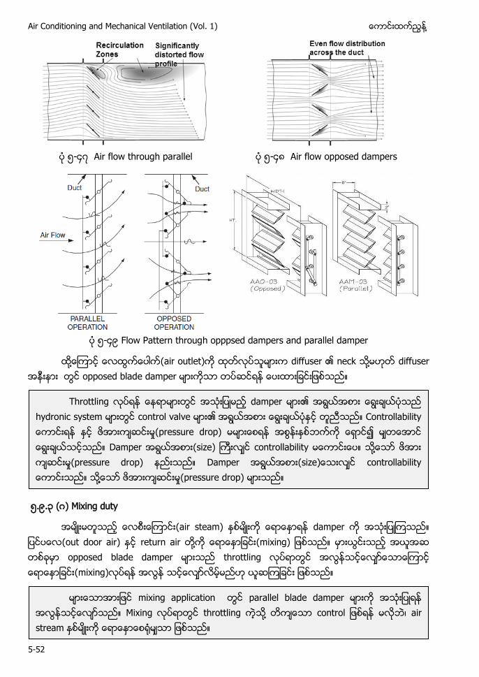
Air Conditioning and Mechanical Ventilation (Vol. 1) ႔
5-52
၅-၄ Air flow through parallel ၅-၄၈ Air flow opposed dampers
၅-၄၉ Flow Pattern through opppsed dampers and parallel damper
႔ (air outlet) diffuser neck ႔ diffuser opposed blade damper
၅.၉.၃ ( ) Mixing duty
(air steam) damper (out door air) return air ႔ opposed blade damper throttling (mixing)
Throttling damper hydronic system control valve C y (pressure drop) Damper (size) controllability ႔ (pressure drop) Damper (size y ႔႔ (pressure drop)
mixing application parallel blade damper Mixing throttling ႔ air stream
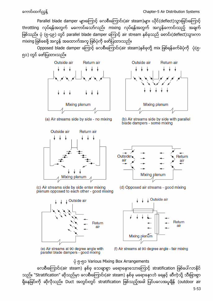
႔ Chapter-5 Air Distribution Systems
5-53
Parallel blade damper (air steam) (deflect) throttling mixing (၅-၄၉) air stream (deflect) ႔ O (air steam) ႔ (၅-၅၁)
၅-၅၁ Various Mixing Box Arrangements
(air steam) “S ” (air steam) ႔ Duct (outdoor air
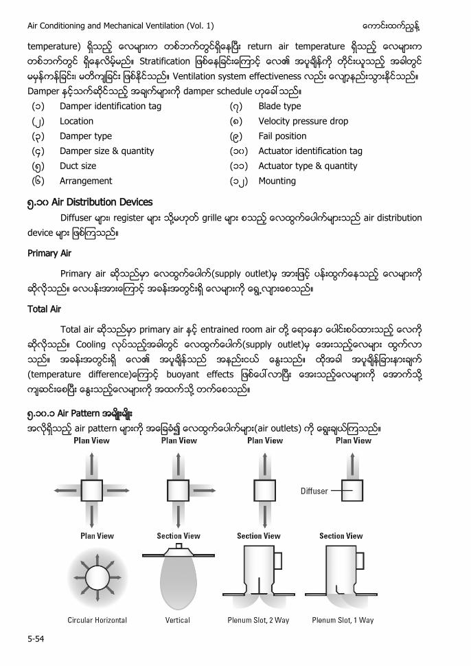
Air Conditioning and Mechanical Ventilation (Vol. 1) ႔
5-54
temperature) return air temperature S Ventilation system effectiveness Damper damper schedule ၁ Damper identification tag Blade type Location ၈ Velocity pressure drop ၃ Damper type ၉ Fail position ၄ Damper size & quantity ၁၀ Actuator identification tag ၅ Duct size ၁၁ Actuator type & quantity ၆ Arrangement ၁ Mounting
၅.၁၀ Air Distribution Devices Diffuser register ႔ grille air distribution
device
Primary Air
Primary air (supply outlet) ႕
Total Air
Total air primary air entrained room air ႔ Cooling (supply outlet) y ႔ ႔
၅.၁၀.၁ air
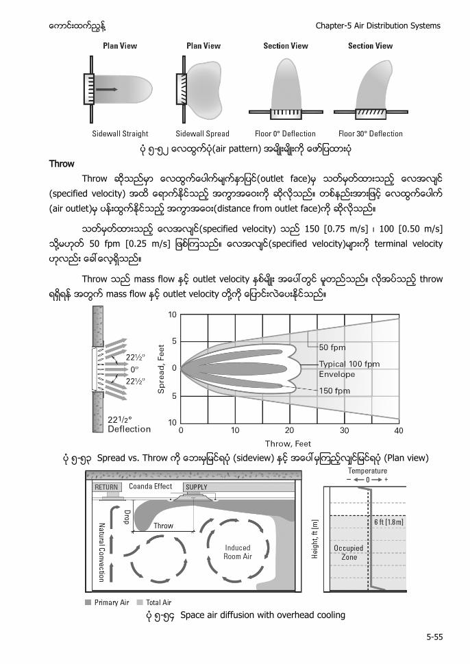
႔ Chapter-5 Air Distribution Systems
5-55
၅-၅
Throw Th w
(specified veloci y (air outlet
y 50 0. 5 m/s] 00 0.50 / ႔ 50 fpm [0.25 m/s] y y
Th w w y h w w y ႔
၅-၅၃ S . Th w w (Plan view)
၅-၅၄ Space air diffusion with overhead cooling
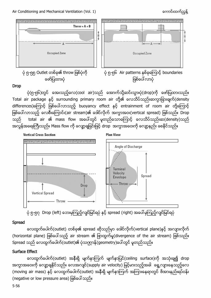
Air Conditioning and Mechanical Ventilation (Vol. 1) ႔
5-56
၅-၅၅ O h w
၅-၅၆
Drop
၅-၅၆ cool air ႔ drop) T y ႔ y y y ႔ (vertical spread) w density) w d
၅-၅ h
Spread
h h S outlet) y
Surface Effect ceiling d
supply air velocity) ႕ (moving air mass) w
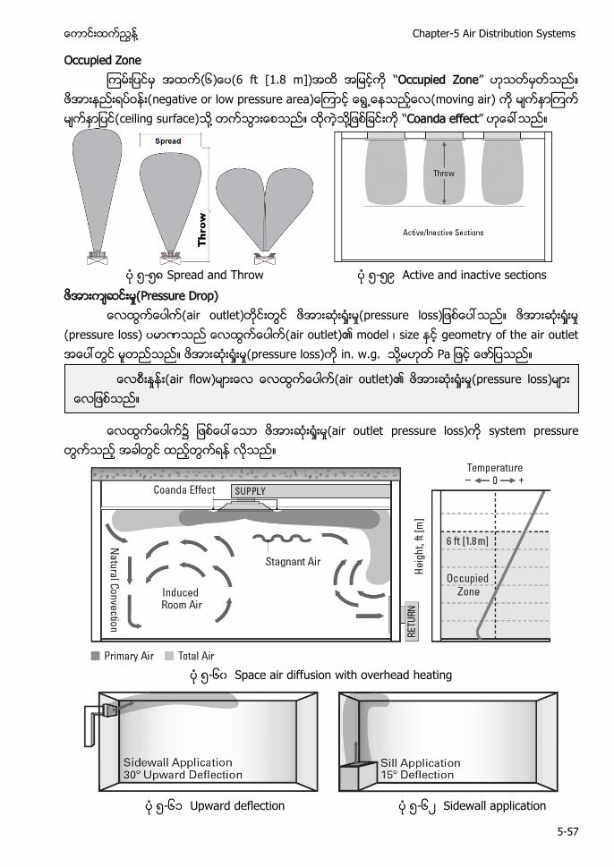
႔ Chapter-5 Air Distribution Systems
5-57
Occupied Zone ၆ 6 ft [1.8 m]) “Occupied Zone”
w ႕ ႔ ႔ “Coanda effect”
၅-၅၈ Spread and Throw ၅-၅၉ Active and inactive sections
Pressure Drop)
(pressure y h . w. . ႔
၌ air outlet y
၅-၆၀ Space air diffusion with overhead heating
၅-၆၁ Upward deflection ၅-၆ Sidewall application
air flow air outlet) pressure loss)
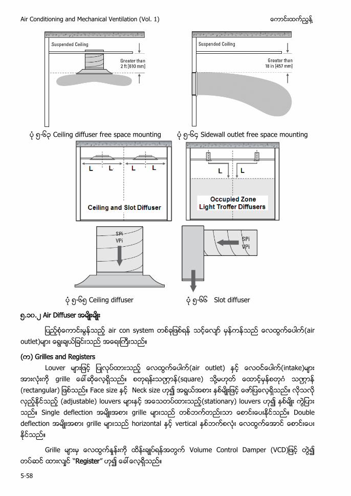
Air Conditioning and Mechanical Ventilation (Vol. 1) ႔
5-58
၅-၆၃ Ceiling diffuser free space mounting ၅-၆၄ Sidewall outlet free space mounting
၅-၆၅ Ceiling diffuser ၅-၆၆ Slot diffuser
၅.၁၀. Air Diffuser
air con system (air outlet)
( ) Grilles and Registers Louver (air outlet) (intake)
(square) ႔ Face size Neck size (adjustable) louvers (stationary) louvers Single deflection grille Double deflection grille horizontal vertical
Grille Volume Control Damper VC “Register”
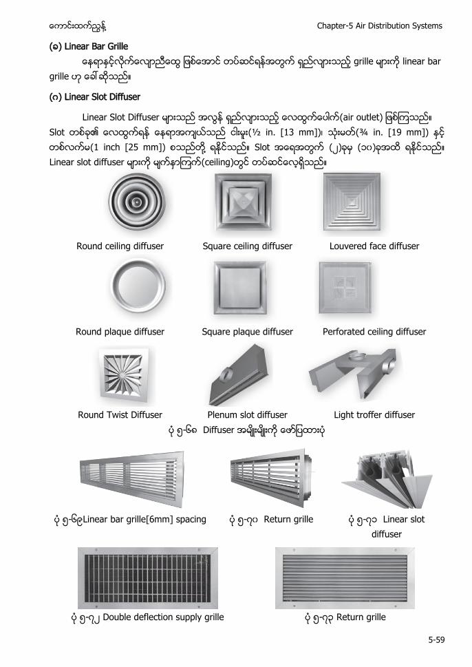
႔ Chapter-5 Air Distribution Systems
5-59
( ) Linear Bar Grille grille linear bar
grille
( ) Linear Slot Diffuser
Linear Slot Diffuser Slot (½ in. [13 mm]) (¾ in. [19 mm]) (1 inch [25 mm]) ႔ Slot ( ) (၁၀) Linear slot diffuser (ceiling)
Round ceiling diffuser Square ceiling diffuser Louvered face diffuser
Round plaque diffuser Square plaque diffuser Perforated ceiling diffuser
Round Twist Diffuser Plenum slot diffuser Light troffer diffuser
၅-၆၈ Diffuser
၅-၆၉Linear bar grille[6mm] spacing ၅- ၀ Return grille ၅- ၁ Linear slot
diffuser
၅- Double deflection supply grille ၅- ၃ Return grille
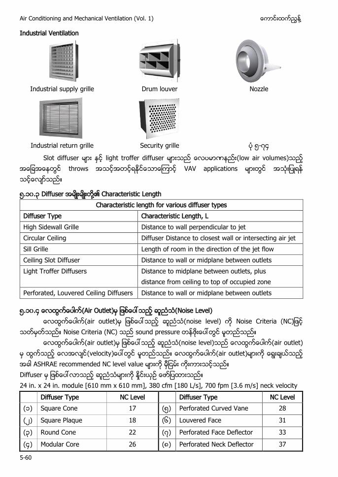
Air Conditioning and Mechanical Ventilation (Vol. 1) ႔
5-60
Industrial Ventilation
Industrial supply grille Drum louver Nozzle
Industrial return grille Security grille ၅- ၄
Slot diffuser light troffer diffuser (low air volumes) throws VAV applications
၅.၁၀.၃ Diffuser ႔ Characteristic Length Characteristic length for various diffuser types
Diffuser Type Characteristic Length, L High Sidewall Grille Distance to wall perpendicular to jet Circular Ceiling Diffuser Distance to closest wall or intersecting air jet Sill Grille Length of room in the direction of the jet flow Ceiling Slot Diffuser Distance to wall or midplane between outlets Light Troffer Diffusers Distance to midplane between outlets, plus
distance from ceiling to top of occupied zone Perforated, Louvered Ceiling Diffusers Distance to wall or midplane between outlets
၅.၁၀.၄ (Air Outlet) (Noise Level) (air outlet) (noise level) N C NC
Noise Criteria (NC) sound pressure (air outlet) (noise level) (air outlet)
(velocity (air outlet) ASHRAE recommended NC level value Diffuser 24 in. x 24 in. module [610 mm x 610 mm], 380 cfm [180 L/s], 700 fpm [3.6 m/s] neck velocity Diffuser Type NC Level Diffuser Type NC Level (၁) Square Cone 17 (၅) Perforated Curved Vane 28
( ) Square Plaque 18 (၆) Louvered Face 31
(၃) Round Cone 22 ( ) Perforated Face Deflector 33
(၄) Modular Core 26 (၈) Perforated Neck Deflector 37
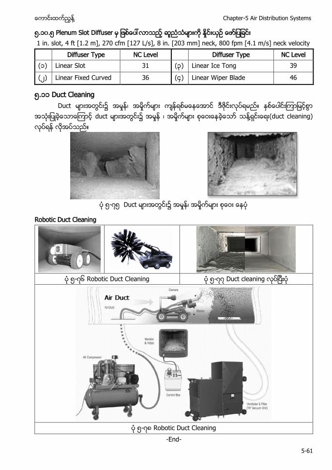
႔ Chapter-5 Air Distribution Systems
5-61
၅.၁၀.၅ Plenum Slot Diffuser 1 in. slot, 4 ft [1.2 m], 270 cfm [127 L/s], 8 in. [203 mm] neck, 800 fpm [4.1 m/s] neck velocity
Diffuser Type NC Level Diffuser Type NC Level (၁) Linear Slot 31 (၃) Linear Ice Tong 39
( ) Linear Fixed Curved 36 (၄) Linear Wiper Blade 46
၅.၁၁ Duct Cleaning Duct ၌
duct ၌ ႔ (duct cleaning)
၅- ၅ Duct ၌
Robotic Duct Cleaning
၅- ၆ Robotic Duct Cleaning ၅- Duct cleaning
၅- ၈ Robotic Duct Cleaning
-End-
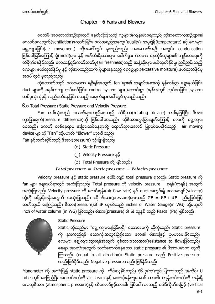
႔ Chapter-6 Fans and Blowers
6-1
Chapter - 6 Fans and Blowers
(ventilation ၊ (quality)၊ (temperature) (air movement) ႔ (mold) ႔ (air freshness) ႔ ၊ ႔ (excessive moisture)
ဏ fan ၊ duct ၊ control system ၊ system
၆.၁ Total Pressure ၊ Static Pressure and Velocity Pressure Fan (rotating device)
(pressure difference) ေလက တစေနရာမ အျခားတစေနရာသ႔ ေရာကသြားေအာင ျပလပေပးႏငသည air moving device မားက “Fan” သ႔မဟတ “Blower” ဟေခၚသည။ Fan (pressure) (၁) Static Pressure
(၂) Velocity Pressure
(၃) Total Pressure ႔
Velocity pressure static p total pressure Static pressure fan Total pressure velocity pressure ( ) Velocity pressure (air flow rate) duct (velocity) ႔ ႔ (pressure) (pressure) IP inches of Water Gauge(in WG) ႔ inch of water column (pressure) SI Pascal (Pa
Static Pressure ” ၌ (r s ဏ (e Posit
s ၆-၃( air steam (atmospheric pressure) (vertical
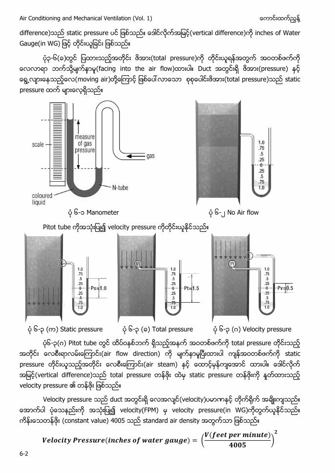
Air Conditioning and Mechanical Ventilation (Vol. 1) ႔
6-2
difference) vertical difference) i
၃-၆( ) ႔ (facing into the air flow) D (pressure) moving air ႔ total pressure) s
၆-၁ ၆-၂ No Air flow
Pitot tube velocity pressure
၆-၃ Static pressure ၆-၃ Total pressure ၆-၃ ဂ Velocity pressure
၆-၃(ဂ) Pitot tube total pressure (air flow direction) static pressure (air steam) (vertical difference) total pressure static pressure velocity pressure
Velocity pressure duct (velocity) ဏ velocity(FPM) velocity pressure(in WG) (constant value) 4005 standard air density
(
)
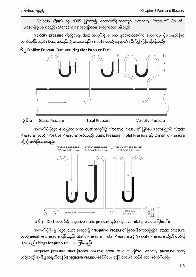
႔ Chapter-6 Fans and Blowers
6-3
velocity)
၌ velocity)
၆.၂ Positive Pressure Duct and Negative Pressure Duct
၆-၄ Static Pressure Total Pressure Velocity Pressure
d ၌ P Pressure” P ” P Pressure” P ၊ P P ႔
၆- negative static pressure negative total pressure
(၆- d ၌ Pressure” n P ၊ P Velocity P ႔ Negative pressure duct
Negative pressure d ၊ positive pressure d ၊ velo negative value)
Velocity (fpm) Velocity Pressure” in of wg) Standard air
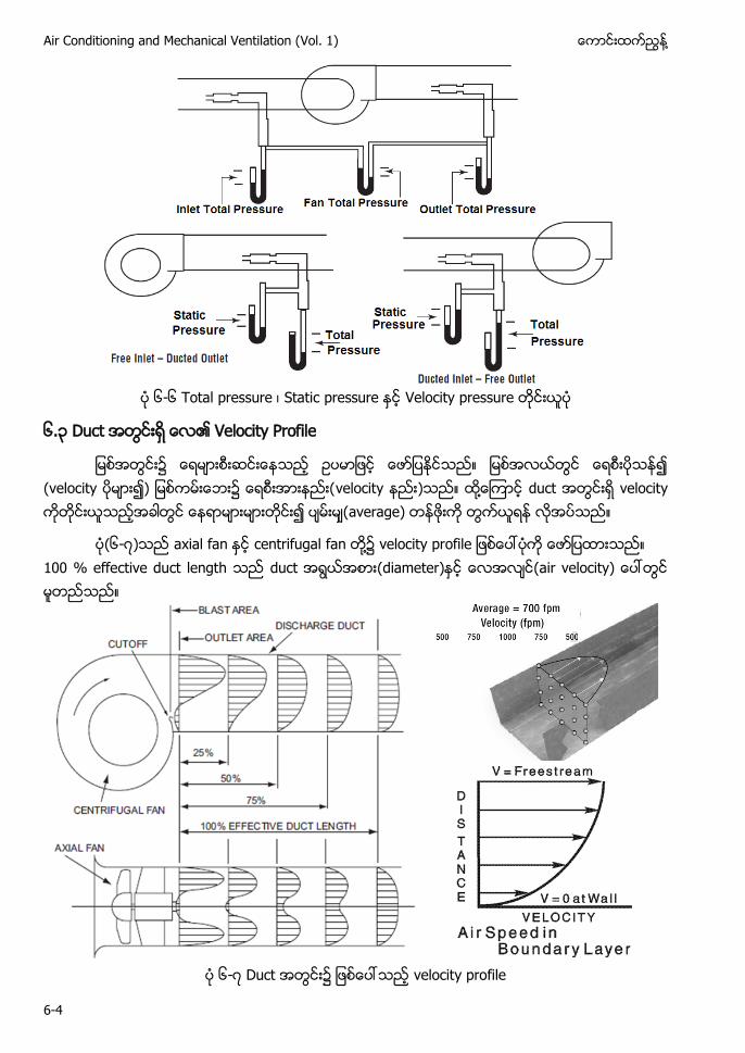
Air Conditioning and Mechanical Ventilation (Vol. 1) ႔
6-4
၆-၆ ၊ Static pressure Velocity pressure
၆ ၃ Velocity Profile
႔ av
(၆-၇) axial fan centrifugal fan ႔၌ velocity profile 100 % effective duct length duct (diameter)
၆-၇ Duct velocity profile
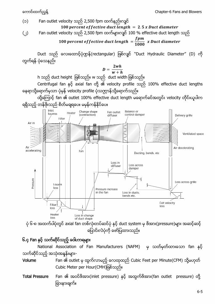
႔ Chapter-6 Fans and Blowers
6-5
(၁) Fan outlet velocity 2,500 fpm
(၂) Fan outlet velocity 2,500 fpm 100 % effective duct length
႑ H ”
h ax ႔
႔ ဏ ႔ ႔
၆-၈
၆.၄ Fan ႏင သကဆငသည ေဝါဟာရမား National Association of Fan Manufacturers (NAFM) မ သတမတထားေသာ fan ႏင သကဆငသည အသးအႏႈနးမား- Volume Fan ၏ outlet မ ထြကလာမည ေလထထည Cubic Feet per Minute(CFM) သ႔မဟတ
Cubic Meter per Hour(CMH)ျဖစသည။
Total Pressure Fan ၏ inlet pressure) ႏင အထြကဖအား(fan outlet pressure) တ႔ ျခားနားခက။
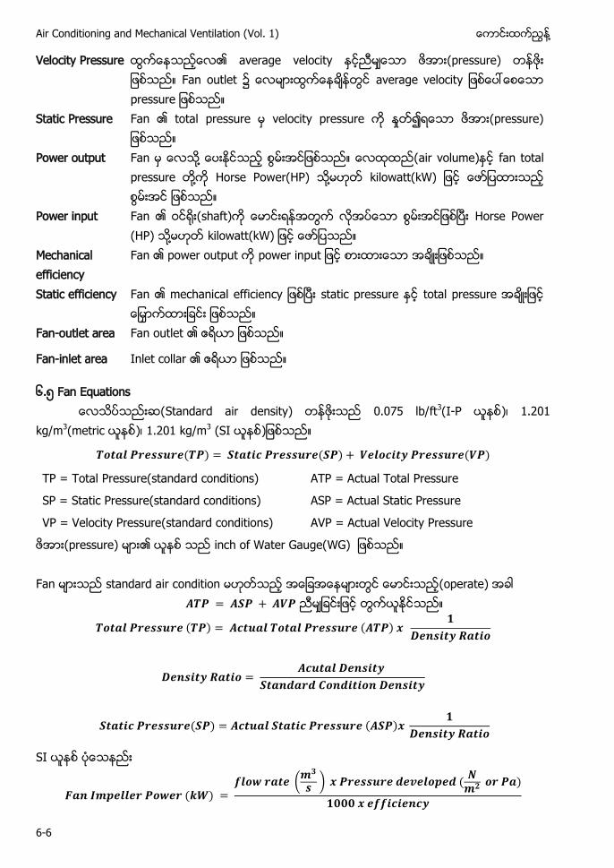
Air Conditioning and Mechanical Ventilation (Vol. 1) ႔
6-6
Velocity Pressure ထြကေနသညေလ၏ (pressure) Fan outlet ၌ ထြကေနခနတြင average velocity ျဖစေပၚေစေသာ pressure ျဖစသည။
Static Pressure Fan ၏ total pressure မ velocity pressure က ႏႈတ၍ရေသာ ဖအား(pressure) ျဖစသည။
Power output Fan မ ေလသ႔ ေပးႏငသည စြမးအငျဖစသည။ air volume)ႏင fan total pressure တ႔က Horse Power(HP) သ႔မဟတ kilowatt(kW) ျဖင ေဖာျပထားသည စြမးအင ျဖစသည။
Power input Fan ၏ ဝင႐း(shaft)က ေမာငးရနအတြက လအပေသာ စြမးအငျဖစၿပး Horse Power (HP) သ႔မဟတ kilowatt(kW) ျဖင ေဖာျပသည။
Mechanical efficiency
Fan ၏ power output က power input ျဖင စားထားေသာ အခးျဖစသည။
Static efficiency Fan ၏ mechanical efficiency ျဖစၿပး static pressure ႏင total pressure အခးျဖင ေျမႇာကထားျခငး ျဖစသည။
Fan-outlet area Fan outlet ၏ ဧရယာ ျဖစသည။
Fan-inlet area Inlet collar ၏ ဧရယာ ျဖစသည။
၆. Fan Equations Standard air density) 0.075 lb/ft3( -P ၊ 2
kg/m3 )၊ 1.201 kg/m3
TP = Total Pressure(standard conditions) ATP = Actual Total Pressure
SP = Static Pressure(standard conditions) ASP = Actual Static Pressure
VP = Velocity Pressure(standard conditions) AVP = Actual Velocity Pressure
(pressure) inch of Water Gauge(WG) Fan standard air condition (operate)
SI
(
)
႔ Chapter-6 Fans and Blowers
6-7
IP
ACFM = Actual ft3/min and BHP = Break Horse Power
6346 (constant) Pressure Horse Power ႔ ( ႔ a
) density condition
NFA F A ”
(
)
velocity pressure standard air Velocity(FPM)
velocity pressure(in WG) inch of water column ႔ Fan standard air
(
)
(
)
၆. .၁ Fan Pressure and Velocity Relationship
air stream) pressure) velocity) (relationship)
I ႔
(
)
P
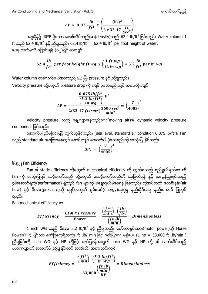
Air Conditioning and Mechanical Ventilation (Vol. 1) ႔
6-8
(
)
၌ 40°F (density 62.4 lb/ft3 W 2 lb/ft2 62.4 lb/ft3 = 62.4 lb/ft2 per foot height of water. ႔ (၁၂
(
)
႔
(
)
(
)
moving air)
sea level, standard air condition 0.075 lb/ft3) Fan
(
)
၆. .၂ Fan Efficiency
F ႔ ႔ (performance) air flow) pressure) energy) Fan mechanical e
(
) (
)
(
)
1 inch WG 2 lb/ft2 motor power) Horse Power(HP) (1 hp = 33,000 ft .lb/min ) HP ႔ HP ႔ ဏ
(
) (
)
(
)
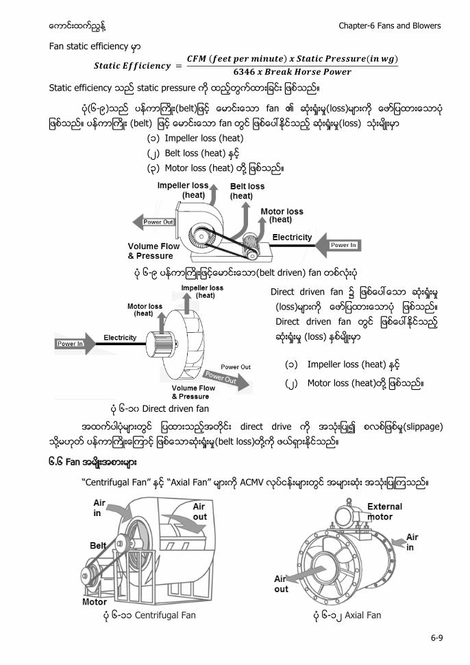
႔ Chapter-6 Fans and Blowers
6-9
Fan static e
Static effici
၆- loss) loss) ၁ Impeller loss (heat) ၂ Belt loss (heat) ၃ ႔
၆- (belt driven)
Direct driven Direct driven fan
၁) Impeller loss (heat)
၂) Motor loss (heat) ႔
၆-၁၀ Direct driven fan
direct drive (slippage) ႔ (belt loss) ႔
၆.၆ Fan အမးအစားမား
“Centrifugal Fan” ႏင “Axial Fan” မားက ACMV တြင အမားဆး အသး သည။
၆-၁၁ Centrifugal Fan ၆-၁၂ Axial Fan
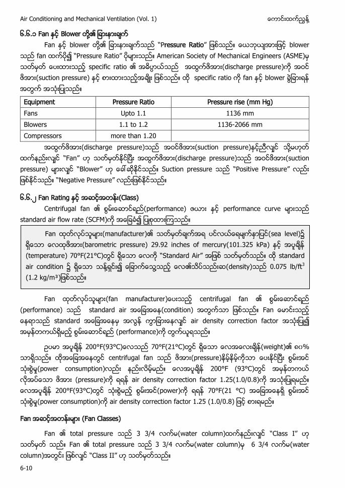
Air Conditioning and Mechanical Ventilation (Vol. 1) ႔
6-10
၆.၆.၁ Fan ႏင Blower တ႔၏ ျခားနားခက Fan ႏင blower တ႔၏ ျခားနားခကသည “Pressure Ratio” ျဖစသည။ ေယဘယအားျဖင blower
သည fan ထကပ၍ “Pressure Ratio” ပမားသည။ American Society of Mechanical Engineers (ASME)မ သတမတ ေပးထားသည သည အထြကဖအား(discharge pressure)က အဝင ဖအား(suction pressure) ႏင စားထားသညအခး ျဖစသည။ ထ specific ratio က fan ႏင blower ခြျခားရန အတြက အသးျပသည။
Equipment Pressure Ratio Pressure rise (mm Hg) Fans Upto 1.1 1136 mm Blowers 1.1 to 1.2 1136-2066 mm Compressors more than 1.20
အထြကဖအား(discharge pressure)သည အဝငဖအား(suction pressure) ညလင သ႔မဟတ ထကနညးလင Fan” ဟ သတမတႏငၿပး အထြကဖအား(discharge pressure)သည အဝငဖအား(suction pressure) မားလင “Blower” ဟ ေခၚဆႏငသည။ S P Pressure” Pressure”
၆.၆.၂ Fan Rating (Class) Centrifugal fan performance) ဇယား ႏင performance curve မားသည
standard air flow rate (SCFM)က အေျခခ၍ ျပစထားၾကသည။
Fan ထတလပသမား(fan manufacturer)ေပးသည centrifugal fan ၏ စြမးေဆာငရည
(performance) သည standard air အေျခအေန(condition) အတြကသာ ျဖစသည။ Fan ေမာငးသည ေနရာသည standard အေျခအေနမ အလြန ကြာျခားေနလင air density correction factor သးျပ၍ အမနတကယရမည စြမးေဆာငရည (performance)က တြကယရသည။
ဥပမာ အပခန 200°F(93°C)ေလသည 70°F(21°C)တြင ရေသာ ေလအေလးခန(weight ၈၀% သာရသည။ ထအေျခအေနတြင centrifugal fan သည ဖအား(pressure)နမနမကသာ ေပးႏငၿပး စြမးအင သးစြမႈ(power consumption)လညး နညးလမမည။ ေလအပခန 200°F (93°C)တြင အမနတကယ လအပေသာ ဖအား (pressure)က ရရန air density correction factor 1.25(1.0/0.8)က အသးျပရမည။ ေလအပခန 200°F(93°C)တြင သးစြမည စြမးအင(power)က ရရန 70°F(21 °C) အေျခအေနရ စြမးအင သးစြမႈ(power consumption)က air density correction factor 1.25 (1.0/0.8 စားရမည။
Fan Fan Classes)
Fan ၏ total pressure 3 3/4 လကမ(water column)ထကနညးလင “ ” ဟ သတမတ သည။ Fan ၏ total pressure 3 3/4 လကမ(water column)မ 6 3/4 လကမ(water column)အတြငး ျဖစလင “ ” ဟ သတမတသည။
Fan ထတလပသမား(manufacturer)၏ သတမတခကအရ ပငလယေရမကႏာျပင(sea level) ရေသာ ေလထဖအား(barometric pressure) 29.92 inches of mercury(101.325 kPa အပခန (temperature) 70°F(21°C)တြင ရေသာ ေလက “Standard Air” အျဖစ သတမတသည။ ထ standard သန႔ရငး၍ ေျခာကေသြ႔သည ေလ၏သပသညးဆ(density) 0.075 lb/ft3
(1.2 kg/m³)ျဖစသည။
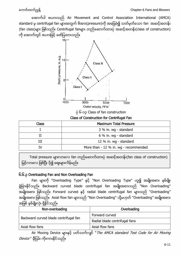
႔ Chapter-6 Fans and Blowers
6-11
ေအာကပါ ဇယားသည Air Movement and Control Association International (AMCA) standard မ အတြက ဖအား( သတမတေသာ fan အဆငအတနး (fan class)မား ျဖစသည။ Centrifuga class of construction)
၆-၁၃ Class of fan construction
Class of Construction for Centrifugal Fan Class Maximum Total Pressure
I 3 ¾ in. wg - standard II 6 ¾ in. wg - standard III 12 ¾ in. wg - standard IV More than - 12 ¾ in. wg - recommended
၆.၆.၃ Overloading Fan and Non Overloading Fan Fan မားက “Overloading Type” ႏင “Non Overloading Type” ဟ၍ အမးအစား ႏစမး
ခြျခားႏငသည။ Backward curved blade centrifugal fan အမးအစားသည “ O ” အမးအစား ျဖစသည။ Forward curved ႏင radial blade centrifugal fan မားသည “O ” အမးအစား ျဖစသည။ Axial flow fan မားသည “ O ” သ႔မဟတ “O ” အမးအစား အျဖစ ႏစမးလး ရႏငသည။
Non-overloading Overloading
Backward curved blade centrifugal fan Forward curved Radial blade centrifugal fans
Axial flow fans Axial flow fans Air Moving Device မားႏင ပတသကလင “The AMCA standard Test Code for Air Moving
” ကးကားႏငသည။
Total pressure မားလာေလ fan တညေဆာကထားပ အဆငအတနး(fan class of construction) ျမငလာေလ ျဖစၿပး ပ
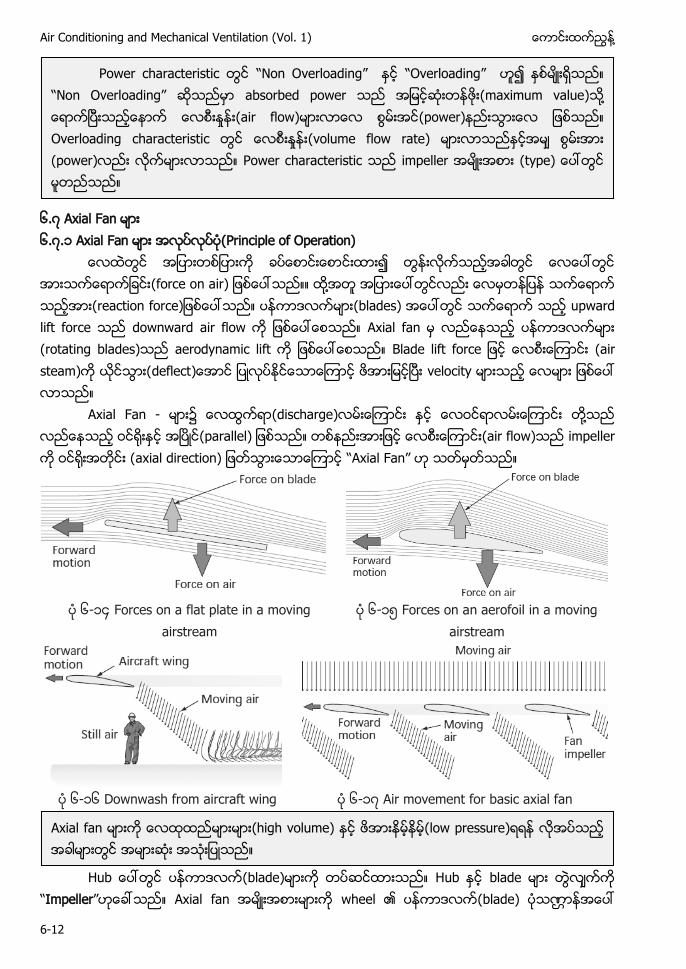
Air Conditioning and Mechanical Ventilation (Vol. 1) ႔
6-12
၆.၇ Axial Fan ၆.၇.၁ Axial Fan (Principle of Operation)
(force on air) ႔ ပနကာဒလကမား(blades) downward A ပနကာဒလကမား (rotating blades) aerodynamic lift B (air steam) deflect
Axial Fan - မား၌ ေလထြကရာ(discharge)လမးေၾကာငး ႏင ေလဝငရာလမးေၾကာငး တ႔သည လညေနသည ဝင းႏင အၿပင(parallel) ျဖစသည။ တစနညးအားျဖင (air flow)သည impeller က (axial direction) ျဖတသြားေသာေၾကာင “A F ” ဟ သတမတသည။
၆-၁၄ Forces on a flat plate in a moving
airstream ၆-၁ Forces on an aerofoil in a moving
airstream
၆-၁၆ Downwash from aircraft wing ၆-၁၇ Air movement for basic axial fan
H ပနကာဒလက(blade) H blade
Impeller” Axial fan အမးအစားမားက wheel ၏ ပနကာဒလက(blade) ပသဏၭာနအေပၚ
Power characteristic “ O ” “O ” “ O ” absorbed power (maximum value) ႔ (air flow) (power) Overloading characteristic (volume flow rate) (power) Power characteristic impeller (type
Axial fan မားက ေလထထညမားမား(high volume) ႏင ဖအားနမနမ(low pressure)ရရန လအပသည အခါမားတြင အမားဆး အသးျပသည။
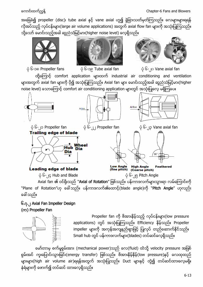
႔ Chapter-6 Fans and Blowers
6-13
အေျခခ propeller (disc)၊ axial ႏင vane axial ဟ၍ ခြျခားသတမတၾကသည။ ေလမားမားရရန လအပသည လပငနးမား(large air volume applications) အတြက axial flow fan မားက အသးျပၾကသည။ သ႔ေသာ ေမာငးသညအခါ ဆညသျမငမား(higher noise level) ေလရသည။
၆-၁၈ Propeller fans ၆-၁ Tube axial fan ၆-၂၀ Vane axial fan
႔ comfort industrial air conditioning and Axial fan higher comfort air
၆-၂၁ Propeller fan ၆-၂၂ Propeller fan ၆-၂၃ Vane axial fan
၆-၂၄ Hub and Blade ၆-၂ Pitch Angle
A Axial of Rotation” P Rotation” ပနကာဒလက၏ေထာင blade angle) Pitch Angle”
၆.၇.၂ Axial Fan Impeller Design ) Propeller Fan
Propeller fan က ဖအားနမသည လပငနးမား(low pressure applications) တြင အသးျပၾကသည။ Efficiency နမသည။ Propeller impeller မားက အကနအကနညးစြာျဖင ျပလပ တညေဆာကႏငသည။ Small hub တြင ပနကာဒလကမား(blades) တပဆငေလရသည။
ေမာတာမ စကမႈစြမးအား (mechanical power)သည ေလ(fluid) သ႔ velocity pressure အျဖစ စြမးအင ကးေျပာငးသြားျခငး(energy transfer) ျဖစသည။ ဖအားနမနမ(low pressure)ႏင ေလထထည မားမား(high air volume air) အတြက အသးျပသည။ Duct မားႏင တြ တပဆငထားေလမရ။ နရမားက ေဖာက
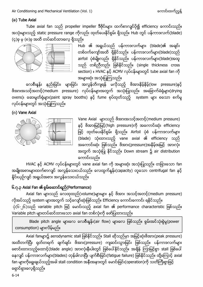
Air Conditioning and Mechanical Ventilation (Vol. 1) ႔
6-14
) Tube Axial Tube axial fan သည propeller impeller ဒဇငးမား ထကစာလငပ၍ efficiency ေကာငးသည။
အသးမားသည static pressure range ကလညး ထတေပးႏငစြမး ရသည။ Hub တြင ပနကာဒလက(blade) (၄)ခ မ (၈)ခ အထ တပဆငထားေလ ရသည။
Hub ၏ အရြယသည ပနကာဒလကမား (blade)၏ အခငး တစဝကေကာအထ ရႏငသည။ ပနကာဒလကမား(blade)သည airfoil ပစမးလညး ရႏငသည။ ပနကာဒလကမား(blade)အထ သည တစညတညး ျဖစႏငသည။ (single thickness cross section) ။ HVAC ႏင ACMV လပငနးမားတြင tube axial fan က အမားဆး အသးျပ သည။
ေလစးႏႈနး နညးျခငး၊ မားျခငး အလြနတကရန မလသည low pressure)ႏင ဖအားအသငအတင(medium pressure) မားအတြက အသးျပသည။ အေျခာကခ႐မား(drying ovens)၊ ေဆးမႈတ႐မား(paint spray booths) ႏင fume စပထတသည system မား စေသာ စကမႈ လပငနးမားတြင အသးျပၾကသည။
ဂ) Vane Axial
Vane Axial မားသည ဖအားအသငအတင(medium pressure) ႏင ဖအားျမငျမင(high pressure)က အေကာငးဆး efficiency ျဖင ထတေပးႏငစြမး ရသည။ Airfoil ပစ ပနကာဒလကမား (blade) သးထားသည vane axial ၏ efficiency သည အေကာငးဆး ျဖစသည။ ဖအား(pressure)အနမအျမင အားလး အတြက အသးျပ ႏငသည။ Down stream ၌ air distribution ေကာငးသည။
HVAC ႏင ACMV လပငနးမားတြင vane axial fan က အမားဆး အသးျပသည။ တျခားေသာ fan အမးအစားမားထကစာလင အလြနေသးငယသည။ ေလထြကႏႈနး(capacity) တေသာ centrifugal fan ႏင ႏႈငးယဥလင အရြယအစား အလြနေသးငယသည။
၆.၇.၃ Axial Fan (Performance) A volume) (medium pressure)
E (၆-၂၆) a Variable pitch axial fan
Axial fan ၌ aerodynamic stal (peak pressure)
pressure) s ပနကာဒလကမား(blades fatigue failure) ႔ stall con operation
Blade pitch angle (air flow) (power consumption)
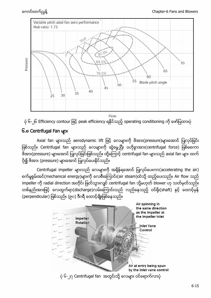
႔ Chapter-6 Fans and Blowers
6-15
၆-၂၆
၆ ၈ Fan မား
Axial fan centrifugal force) ႔
႔ Air flow သည impeller က radial direction အတငး ျဖတသြားလင centrifugal fan သ႔မဟတ blower ဟ သတမတသည။ တစနညးအားျဖင ေလထြကရာ(discharge)လမးေၾကာငးသည လညေနသည shaft) ႏင ေထာငမန (perpendicular) ျဖစသည။ (၉၀) ဒဂရ ေထာငခးျဖစေနသည။
၆-၂၇ Centrifugal fan ႔
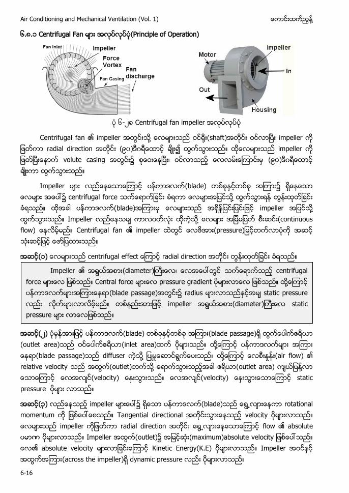
Air Conditioning and Mechanical Ventilation (Vol. 1) ႔
6-16
၆.၈.၁ Centrifugal Fan (Principle of Operation)
၆-၂၈ Centrifugal fan impeller
Centrifugal fan impeller ႔ (shaft) impeller radial direction ( ၀) ဂ impeller volute casing ၊ ( ၀) ဂ
Impeller ပနကာဒလက(blade) ၌ ၌ centrifugal force ႔ ပနကာဒလက(blade) impeller ႔ Impeller ႔ (continuous flow) Centrifugal fan impeller
(၁) radial direction
(၂) (blade) (blade passage) (outlet area) (inlet area) ႔ (blade passage) diffuser ႔ ႔ (air flow) relative velocity (outlet) ႔ (outlet area) ႔ (velocity) (velocity) static pressure
(၃) impeller ၌ ပနကာဒလက(blade) rotational momentum Tangential directional velocity impeller radial direction flow absolute ဏ Impeller (outlet) (maximum) absolute velocity Kinetic Energy(K.E) Impeller (across the impeller) dynamic pressure
Impeller (diameter) ၊ centrifugal force Central force pressure gradient ႔ (blade passage) radius static pressure impeller (diameter) static pressure
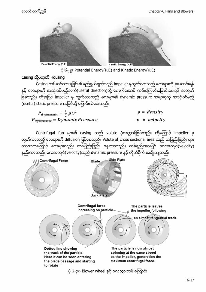
႔ Chapter-6 Fans and Blowers
6-17
၆-၂ Potential Energy(P.E) and Kinetic Energy(K.E)
Casing ႔ Housing Casing impeller (useful direction) ႔ ႔ impeller dynamic pressure (useful) static pressure ႔
Centrifugal fan casing volute ဏ ႔ impeller d Volute cross sectional area (velocity) (velocity) dynamic pressure
၆-၃၀
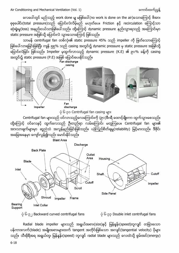
Air Conditioning and Mechanical Ventilation (Vol. 1) ႔
6-18
work done (total pressure) Friction (loss) ႔ dynamic pressure static pressure ႔
centrifugal fan static pressure 45% impeller % casing dynamic pressure static pressure ႔ Impeller dynamic pressure (K.E) ၀% ႔ casing static pressure (P.E)
၆-၃၁ Centrifugal fan casing Centrifugal fan မားသည ဝငလာသညေလေၾကာငးက (၉၀)ဒဂရ ေထာငခးကာ ထြကသြားေစသည။
ထ႔ေၾကာင ဝငေလႏင ထြကေလသည ဥးတညရာ လမးေၾကာငး မတၾကေပ။ Centrifugal fan မား၏ အားသာခကမားမာ ဆညသ အလြနနညးျခငးျဖစသည။ ယၾကညစတခမႈ(reliability) ျမငမားသည။ ဒဇငး အေျခအေနမာ ေကာလြန၍လညး ေမာငးႏငသည။
၆-၃၂ Backward curved centrifugal fans ၆-၃၃ Double inlet centrifugal fans
Radial blade impeller (size) (speed) ပနကာဒလက(blade) tangent (tangential velocity) ၊ (speed) radial blade ႔ (energy)
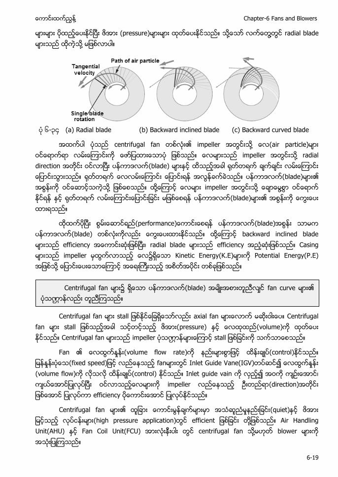
႔ Chapter-6 Fans and Blowers
6-19
(pressure) ႔ ႔ radial blade ႔
၆-၃၄ (a) Radial blade (b) Backward inclined blade (c) Backward curved blade
centrifugal fan ႔ air particle) impeller ႔ radial direction ပနကာဒလက(blade) ပနကာဒလက(blade) ႔ ႔ impeller ႔ ႔ ပနကာဒလက(blade)
ပနကာဒလက(blade) ပနကာဒလက(blade) ႔ backward inclined blade efficiency ၊ radial blade efficiency Casing impeller Kinetic Energy(K.E) Potential Energy(P.E) ႔
Centrifugal fan s axial fan Centrifugal
fan pressure) (volume) Centrifugal fan impeller ဏ s
Fan (volume flow rate) (control) fan Inlet Guide Vane(IGV) (volume flow) (control) Inlet guide vain ၊ impeller (direction) efficiency
Centrifugal fan မား၏ ထျခား ေကာငးမြနခကမားမာ အသဆညမႈနညးျခငး(quiet)ႏင ဖအား ျမငသည လပငနးမား(high pressure application)တြင efficient ျဖစျခငး တ႔ျဖစသည။ Air Handling Unit(AHU) ႏင Fan Coil Unit(FCU) အားလးနးပါး တြင centrifugal fan သ႔မဟတ blower မားက အသးျပၾကသည။
Centrifugal fan (blade) fan curve ဏ
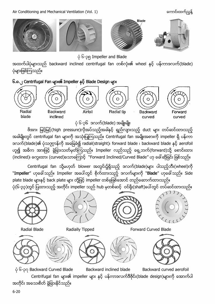
Air Conditioning and Mechanical Ventilation (Vol. 1) ႔
6-20
၆-၃ Impeller and Blade
အထကပါပမားသည backward inclined centrifugal fan တစလး၏ wheel ႏင ပနကာဒလက(blade) ပမားျဖစၾကသည။
၆.၈.၂ Centrifugal Fan မား၏ Impeller Blade Design
၆-၃၆ (blade)
ဖအား ျမငျမင(high pressure)လအပသညအခါႏင ရညလားသည duct မား တပဆငထားသည အခါမးတြင centrifugal fan မားက အသးျပၾကသည။ Centrifugal fan အမးအစားက impeller ရ ပနကာ ဒလက(blade) ပသဏၭာနက အေျခခ၍ radial(straight ၊ ၊ lade ႏင aerofoil ဟ၍ အဓက အားျဖင ခြျခားသတမတၾကသည။ Impeller လညသည ေရ႕ဘက(forward)သ႔ ေစာငးထား (inclined)၊ ေကြးထား (curved)ေသာေၾကာင “Forward Inclined/Curved Blade”
Centrifugal fan ႔ blower ၌ (blade) (wheel) Impeller” Impeller Blade” Side plate blade back plate ႔ impeller (၆-၃၃) impeller hub
Radial Blade Radially Tipped Forward Curved Blade
၆-၃၇ Backward Curved Blade Backward inclined blade Backward curved aerofoil ပနကာဒလကဒဇငး(blade design)
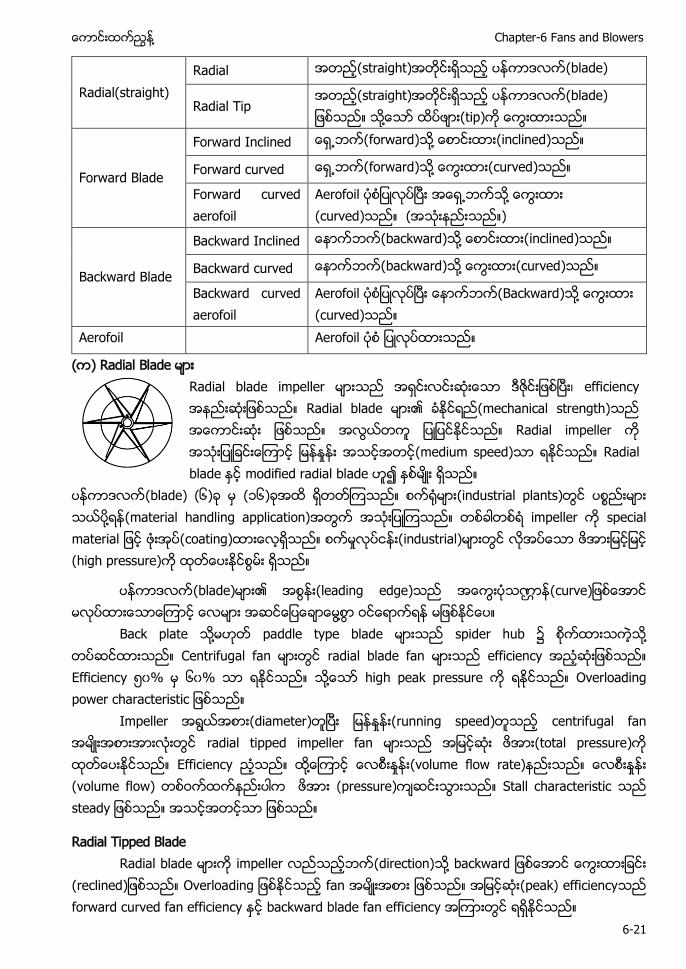
႔ Chapter-6 Fans and Blowers
6-21
Radial(straight) Radial (straight) ပနကာဒလက(blade)
Radial Tip (straight) ပနကာဒလက(blade) ႔ (tip)
Forward Blade
Forward Inclined ေရ႕ဘက(forward)သ႔ ေစာငးထား(inclined)သည။
Forward curved ေရ႕ဘက(forward)သ႔ ေကြးထား(curved)သည။
Forward curved aerofoil
Aerofoil ႔ ေကြးထား (curved)သည။ (အသးနညးသည။)
Backward Blade
Backward Inclined ေနာကဘက(backward)သ႔ ေစာငးထား(inclined)သည။
Backward curved ေနာကဘက(backward)သ႔ ေကြးထား(curved)သည။
Backward curved aerofoil
Aerofoil ေနာကဘက(Backward) ႔ ေကြးထား (curved)သည။
Aerofoil Aerofoil
) Radial B
Radial blade impeller မားသည အရငးလငးဆးေသာ ဒဇငးျဖစၿပး၊ efficiency အနညးဆးျဖစသည။ Radial b mechanical strength) ဆး ျဖစသည။ အလြယတက ျပျပငႏငသည။ Radial impeller က အသးျပျခငးေၾကာင (medium speed)သာ ရႏငသည။ Radial blade ႏင modified radial blade ဟ၍ ႏစမး ရသည။
ပနကာဒလက(blade) (၆)ခ မ (၁၆)ခအထ ရတတၾကသည။ စက႐မား(industrial plants)တြင ပစ ႔ (material handling application)အတြက အသးျပၾကသည။ တစခါတစရ impeller က special material ျဖင ဖးအပ(coating)ထားေလရသည။ စကမႈလပငနး(industrial)မားတြင လအပေသာ ဖအားျမငျမင (high pressure)က ထတေပးႏငစြမး ရသည။
ပနကာဒလက(blade) (leading edge) ဏ (curve ႔
Back plate ႔ paddle type blade spider hub ႔ Centrifugal fan radial blade fan efficiency Efficiency ၀% ၆၀% ႔ high peak pressure O Impeller (diameter) (running speed) centrifugal fan radial tipped impeller fan (total pressure) Efficiency ႔ (volume flow rate) (volume flow) (pressure) Stall characteristic
Radial Tipped Blade Radial blade impeller (direction) ႔ (reclined O fan (peak) efficiency forward curved fan efficiency backward blade fan efficiency
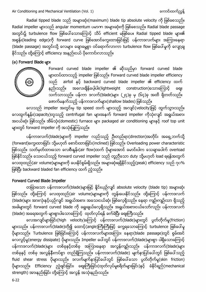
Air Conditioning and Mechanical Ventilation (Vol. 1) ႔
6-22
Radial tipped blade (maximum) blade tip absolute velocity Radial impeller angular momentum ဏ Radial blade passage efficient Radial tipped blade (leading edge) ပနကာဒလကမား အၾကားေနရာ (blade passage) ႔ ႔ ႔ ႔ efficiency
( ) Forward Blade
Forward curved blade impeller ၏ forward curved blade မားတပထားသည impeller ျဖစသည။ Forward curved blade impeller efficiency သည airfoil ႏင backward curved blade impeller ၏ efficiency ထက နညးသည။ အေလးခနေပါပါး(lightweight construction)ေသာေၾကာင ေစး သကသာသည။ ပနကာ ဒလက(blade)မား (၂၄)ခ မ (၆၄)ခ အထ ရတတသည။ shallow blades) ျဖစသည။
ေလသည မ tip speed ထက မားသည အလင(velocity)ျဖင ထြကသြားသည။ ေလထြကႏႈနး(capacity)တသည centrifugal fan မားအနက forward impeller ကသးလင အရြယအစား အငယဆး ျဖစသည။ အမသး(domestic) furnace မား packaged air conditioning မားႏင roof top unit မားတြင forward impeller က အသးျပၾကသည။
ပနကာဒလက(blade) impeller (direction) ႔ ႔ O (air flow) overload forward curved impeller duty ႔ load (air volume) (peak) efficiency ၇၀ backward bladed fan efficiency
Forward Curved Blade Impeller ပနကာဒလက(blade) absolute velocity (blade tip) ႔ (air volume) ႔ ပနကာဒလက (blade) forward curved blade ပနကာဒလက (blade) (high velocity ပနကာဒလက(blade) (friction) ပနကာဒလက(blade) (angle) ႔ Turbulence (blade passage) (energy dissipate) ပနကာဒလက(blade) ပနကာဒလက(blade) ပနကာဒလက(blade) ပနကာဒလက(blade) fluid shear stress (skin friction) Efficiency ၊ ( ) (mechanical strength) ႔
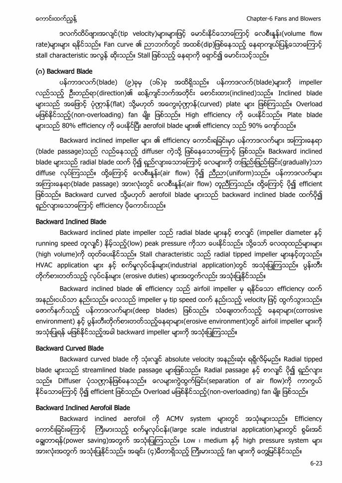
႔ Chapter-6 Fans and Blowers
6-23
(tip velocity) (volume flow rate) Fan curve (dip ႔ stall characteristic
(ဂ) Backward Blade ပနကာဒလက(blade) ( ) (၁၆) ပနကာဒလက(blade) impeller (direction) ႔ (inclined) Inclined blade ဏ (flat) ႔ ဏ (curved) plate Overload (non-overloading) fan High efficiency Plate blade 80% efficiency aerofoil blade efficiency 90
Backward inclined impeller e (blade passage) diffuser ႔ Backward inclined blade radial blade (gradually) diffuse ႔ (air flow) (uniform) (blade passage) (air flow) ႔ Backward curved ႔ aerofoil blade backward inclined blade efficiency
Backward Inclined Blade Backward inclined plate impeller radial blade (impeller diameter running speed ) (low) peak pressure ႔ (high volume) Stall characteristic radial tipped impeller HVAC application (industrial application) (erosive duties)
airfoil impeller မ ရႏငေသာ efficiency ထက အနညးငယသာ နညးသည။ ေလသည impeller မ tip speed ထက နညးသည velocity ျဖင ထြကသြားသည။ ေဇာကနကသည ပနကာဒလကမား(deep blades) ျဖစသည။ သေခးတကသည ေနရာမား(corrosive environment) erosive environment)တြင airfoil impeller မားက အသးျပရန မျဖစႏငသညအခါ backward impeller မားက အသးျပၾကသည။
Backward Curved Blade Backward curved blade absolute velocity Radial tipped blade streamlined blade passage Radial passage Diffuser ဏ (separation of air flow) Overload (non-overloading) fan
Backward Inclined Aerofoil Blade Backward inclined aerofoil ACMV system (large scale industrial application) (power saving) Low ၊ medium high pressure system (၄) fan ႔
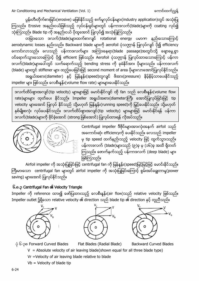
Air Conditioning and Mechanical Ventilation (Vol. 1) ႔
6-24
erosive) (industry application) Erosive ပနကာဒလက(blade) coating Blade tip
(blade) rotational energy ဏ aerodynamic losses Backward blade aerofoil ဏ (blade passage) ႔ Aerofoil ဏ ပနကာ ဒလက(blade) bending stress ပနကာဒလက (blade) stiffener second moment of area (diameter) (speed) (pressure) impeller (volume flow rate)
Centrifugal impeller ဒဇငးမားအားလးအနက airfoil သည အေကာငးဆး efficiencyက ေပးႏငသည။ ေလသည impeller မ tip speed ထကနညးသည velocity ျဖင ထြကသြားသည။ ပနကာဒလက (blade)မားသည (၉)ခ မ (၁၆)ခ အထ ရတတ ၾကသည။ ေဇာကနကသည ပနကာဒလက (deep blade) မား ျဖစၾကသည။
Airfoil impeller က အသးျပျခငးျဖင centrifugal fan က (speed)ျမငျမငျဖင ေမာငးႏငသည။ ႀကးမားေသာ centrifugal fan မားတြင airfoil impeller က အသးျပျခငးေၾကာင စြမးအငေခြတာမႈ(power saving) မားေအာင ျပလပႏငသည။
၆.၈.၃ Centrifugal Fan Velocity Triangle Impeller reference (air flow) relative Impeller outlet relative velocity direction blade tip direction
၆-၃၈ Forward Curved Blades Flat Blades (Radial Blade) Backward Curved Blades
V = Absolute velocity of air leaving blade(shown equal for all three blade type) Vr =Velocity of air leaving blade relative to blade Vb = Velocity of blade tip
(tip velocity) fan (volume flow rate) Impeller (diameter) tip velocity ႔ (running speed) ႔ (tip velocity) (blade) (
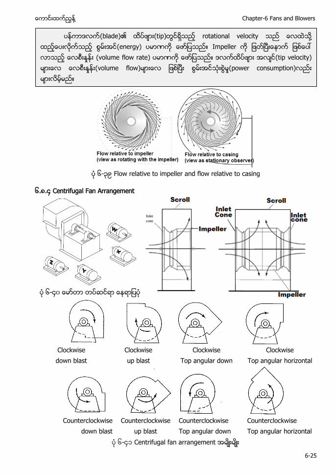
႔ Chapter-6 Fans and Blowers
6-25
၆-၃ Flow relative to impeller and flow relative to casing
၆.၈.၄ Centrifugal Fan Arrangement
၆-၄၀ ေမာတာ တပဆငရာ ေနရာျပပ
Clockwise down blast
Clockwise up blast
Clockwise Top angular down
Clockwise Top angular horizontal
Counterclockwise
down blast Counterclockwise
up blast Counterclockwise Top angular down
Counterclockwise Top angular horizontal
၆-၄၁ Centrifugal fan arrangement
ပနကာဒလက(blade) (tip) rotational velocity ႔ (energy) ဏ Impeller (volume flow rate) ဏ (tip velocity) (volume flow) စြမးအငသးစြမႈ(power consumption)
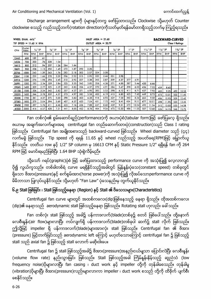
Air Conditioning and Mechanical Ventilation (Vol. 1) ႔
6-26
Discharge arrangement မားက ပမားႏငတကြ ေဖာျပထားသည။ Clockwise သ႔မဟတ Counter clockwise စသည လညသညဘက(rotation direction)ကသတမတရနေမာတာရသညဘကမ ၾကညရသည။
Fan တစလး၏ performance)က ဇယားပစ(tabular form)ျဖင ေဖာျပေလ ရသည။
ဇယားမ အခကအလကမားအရ centrifugal f Class I rating ျဖစသည။ Centrifugal fan အမးအစားသည backward-curved ျဖစသည။ Wheel diameter သည (၄၄) လကမခြ ျဖစသည။ Tip speed က ရရန wheel လညသည အပတေရ(RPM)ျဖင ေျမႇာကယ ႏငသည။ တတယ row ႏင 1/2" SP column မ 16613 CFM ႏင Static Pressure 1/2" ရရရန fan က 264 RPM ျဖင ေမာငးရမညျဖစၿပး 1.64 BHP သးစြလမမည။
သ႔ေသာ ဂရပ( performance curve ပ၍ လြယကသည။ တစခါတစရ curve မရရႏငသညအခါတြင (constant speed) တစခတြင ရေသာ ဖအား(pressure)ႏင စကစြမးအား(horse power)က အသးျပ၍ လအပေသာperformance curve က မမ ာသာ ျပလပယႏငသည။ သ႔မဟတ “Fan Law” ပေသနညးမ တြကယႏငသည။
၆. ၊ (Region) Stall (Characteristics)
Centrifugal fan curve (dip (dip) Rotating stall
Fan s (blade) ႔ (air flow) (blade) ၌ stall ႔ impeller (blade) Centrifugal fan (pressure) centrifugal fan stall axial fan
Centrifugal fan (pressure) (volume flow rate) (low frequency noise) fan casing ၊ duct work impeller ႔ (vibration) (pressure) impeller ၊ duct work ႔
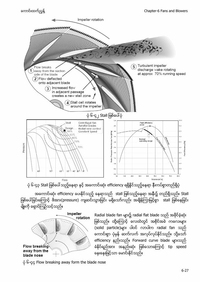
႔ Chapter-6 Fans and Blowers
6-27
၆-၄၂
၆-၄၃ efficiency
efficiency s ၌ (pressure)
Radial blade fan radial flat blade ႔ (solid particle) radial fan ႔ efficiency Forward curve blade t
၆-၄၄ Flow breaking away form the blade nose
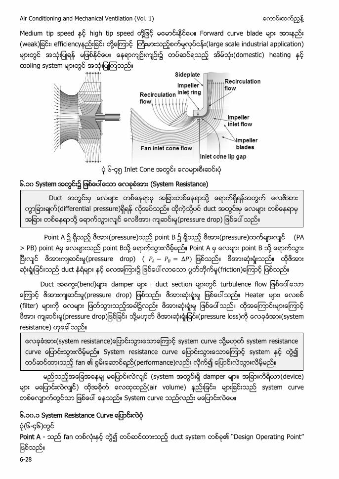
Air Conditioning and Mechanical Ventilation (Vol. 1) ႔
6-28
Medium tip speed high tip speed ႔ Forward curve blade (weak ၊ efficiency ႔ (large scale industrial application) (domestic) heating cooling system
၆-၄ Inlet Cone
၆.၁၀ System (System Resistance)
Point A (pressure) point B (pressure) (PA > PB) point A point B ႔ Point A point B ႔ (pressure drop) ( duct ၌ (friction
Duct (bend) ၊ damper ၊ duct section turbulence flow (pressure drop) Heater ၊ (filter) (pressure drop ႔ (pressure loss) (system resistance)
(system damper ၊ (device)
) air volume) ၊ system curve System curve
၆.၁၀.၁ R (၆-၄၆) Point A - fan duct system O P ”
Duct ႔ (differential pressure) ႔ duct ႔ (pressure drop
(system resistance system curve ႔ S system fan (performance)
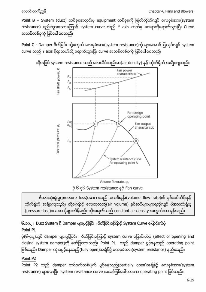
႔ Chapter-6 Fans and Blowers
6-29
Point B – System (duct) equipment (system resistance) system curve Y axis ႔ Curve
Point C - Damper ႔ (system resistance) system curve Y axis ႔ curve
႔ system resistance (air density)
၆-၄၆ System resistance Fan curve
၆.၁၀.၂ Duct System Damper ၊ Point P1 (၆-၄၇) damper ၊ system c (effect of opening and closing system damper) Point P1 damper o Damper (fully open) ၌ (system resistance)
Point P2 Point P2 damper (partially open) ၌ (system resistance) system resistance curve operating p
(pressure loss) ဏ (volume flow rate) ႔ (air volume) (pressure loss constant air density
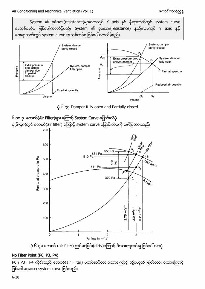
Air Conditioning and Mechanical Ventilation (Vol. 1) ႔
6-30
၆-၄၇ Damper fully open and Partially closed
၆.၁၀.၃ (Air Filter) ၆-၄၈ air filter) ေၾကာင system curve ေျပာငးလပက ေဖာျပထားသည။
၆-၄၈ air filter)
No Filter Point (P0, P3, P4) P0 ၊ P3 ၊ P4 လငးသည air Filter) မတပဆငထားေသာေၾကာင ႔ ျဖတထား ေသာေၾကာင ျဖစေပၚေနေသာ system curve ျဖစသည။
System (resistance) Y axis system curve System (resistance) Y axis system curve
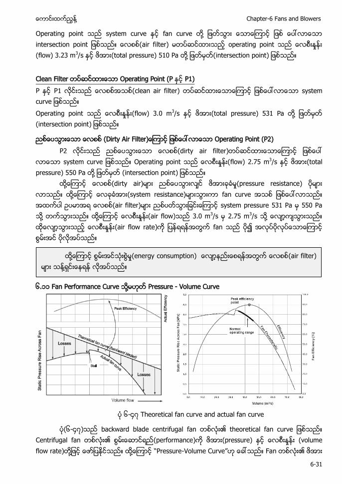
႔ Chapter-6 Fans and Blowers
6-31
Operating point သည system curve ႏင fan curve တ႔ ျဖတသြား ေသာေၾကာင ျဖစ ေပၚလာေသာ intersection point ျဖစသည။ air f operating point သည ေလစးႏႈနး (flow) 3.23 m3/s ႏင total pressure) 510 Pa တ ႔ ျဖတမတ(intersection point) ျဖစသည။ F Operating Point (P ႏင P1) P ႏင P1 လငးသည clean air filter) တပဆငထားေသာေၾကာင ျဖစေပၚလာေသာ system curve ျဖစသည။ Operating point သည ေလစးႏႈနး(flow) 3.0 m3/s ႏင total pressure) 531 Pa တ ႔ ျဖတမတ (intersection point) ျဖစသည။
(Dirty Air Filter Operating Point (P2) P2 လငးသည (dirty air filter)တပဆငထားေသာေၾကာင ျဖစေပၚ
လာေသာ system curve ျဖစသည။ Operating point သည ေလစးႏႈနး(flow) 2.75 m3/s ႏင (total pressure) 550 Pa တ ႔ ျဖတမတ (intersection point) ျဖစသည။
႔ (dirty air) (pressure resistance) ႔ (system resistance) fan curve (air filter) system pressure 531 Pa 550 Pa ႔ ႔ (air flow) 3.0 m3/s 2.75 m3/s ႔ (air flow rate) fan
၆.၁၁ Fan Performance Curve ႔ Pressure - Volume Curve
၆-၄၇ Theoretical fan curve and actual fan curve
(၆-၄၇) backward blade centrifugal fan Centrifugal fan (performance) (pressure) (volume flow rate) ႔ ႔ P - ” Fan
႔ (energy consumption) (air filter) ႔
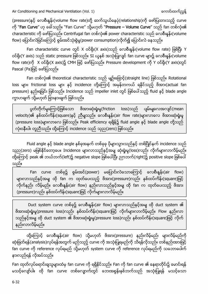
Air Conditioning and Mechanical Ventilation (Vol. 1) ႔
6-32
(pressure) (volume flow rate) ႔ (relationship) curve Fan Curve” F ” ႔ Pressure – Volume Curve” fan characteristic Centrifugal fan power characteristic (volume flow) (power consumption)
Fan characteristic curve X (X axis) (volume flow rate) Y (Y axis) static SI fan curve (volume flow rate) X (X axis)၌ H Pressure development Y (Y axis) Pascal (Pa
Fan theoretical characteristic (straight line) Rotational loss ၊ frictional loss incidence ႔ (actual fan pressure) Incidence impeller inlet fluid blade angle ႔
Fluid angle blade angle incidence
(zero) Incidence (loss) ႔ peak (left) negative slope (right) positive slope
႔ (air flow) ႔ ၊
(analysis) fan c reference ႔
Fan ထတလပေရာငးခသမားထမ fan curve က ရရႏငသည။ Fan က fan curve ၏ ေနရာတငး၌ ေမာငးရန မသငေလာပါ။ ထ fan curve တစေလာကတြင သည အသးျပရန မသငေသာ
(friction loss) (mean velocity) (square) (air flow rate) (pressure loss) Peak efficiency fluid angle blade angle ႔ ႔ incidence (zero)
Fan c ၌ power) (air flow) f pressure) (air flow) f (pressure) (square
Duct system c ၌ (air flow) duct s (pressure loss) (square F duct s (pressure loss) (square
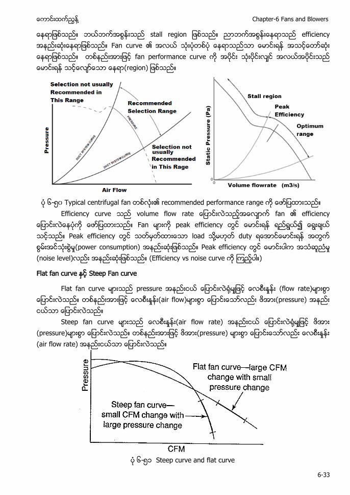
႔ Chapter-6 Fans and Blowers
6-33
ေနရာျဖစသည။ ဘယဘကအစြနးသည stall Fan curve ၏ အလယ သးပတစပ ေနရာသညသာ ေမာငးရန အသငေတာဆး ေနရာျဖစသည။ fan performance curve
၆- ၀ Ty recommended performance r Efficiency curve fan
Fan peak efficiency Peak efficiency load ႔ duty (power consumption) Peak efficiency (noise level) (Efficiency vs noise curve )
F Steep Fan curve
F (flow rat
(pressure)
၆- ၁ Steep curve and flat curve
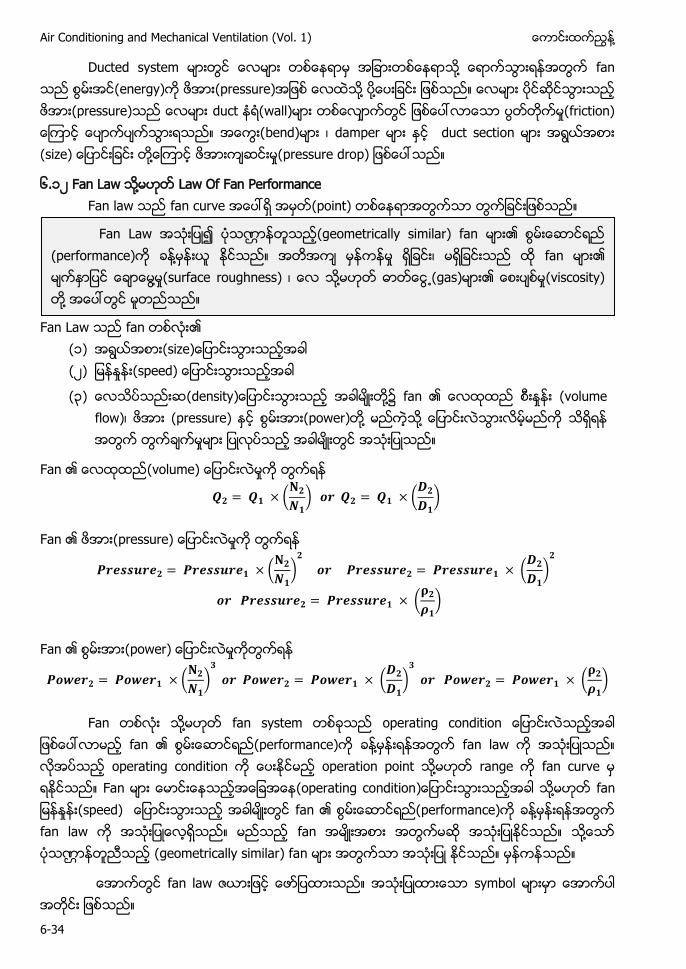
Air Conditioning and Mechanical Ventilation (Vol. 1) ႔
6-34
Ducted system ႔ energy) (pressure) ႔ ႔ (pressure) wall) frict bend) ၊ ႔ pressure drop
၆.၁၂ Fan Law ႔ Law Of Fan Performance Fan law fan curve (point)
Fan Law fan (၁) (၂) (speed)
(၃) (density ႔ fan (volume flow)၊ (pressure) (power) ႔ ႔
Fan (volume)
(
) (
)
Fan (pressure)
(
)
(
)
(
)
Fan (power)
(
)
(
)
(
)
Fan တစလး သ႔မဟတ fan system တစခသည operating condition ေျပာငးလသညအခါ ျဖစေပၚလာမည fan performance)က ခန႔မနးရနအတြက fan law က အသးျပသည။ လအပသည operating condition က ေပးႏငမည operation point သ႔မဟတ range က fan curve မ ရႏငသည။ F operating condition ႔ f (speed) fan performance)က ခန႔မနးရနအတြက fan law က အသးျပေလရသည။ မညသည f ႔ ဏ (geometrically similar) fan
ေအာကတြင fan law ဇယားျဖင ေဖာျပထားသည။ အသးျပထားေသာ symbol မားမာ ေအာကပါ အတငး ျဖစသည။
Fan Law ဏ (geometrically similar) fan (performance) ႔ ၊ fan ႔ (surface roughness) ၊ ႔ (gas) (viscosity) ႔
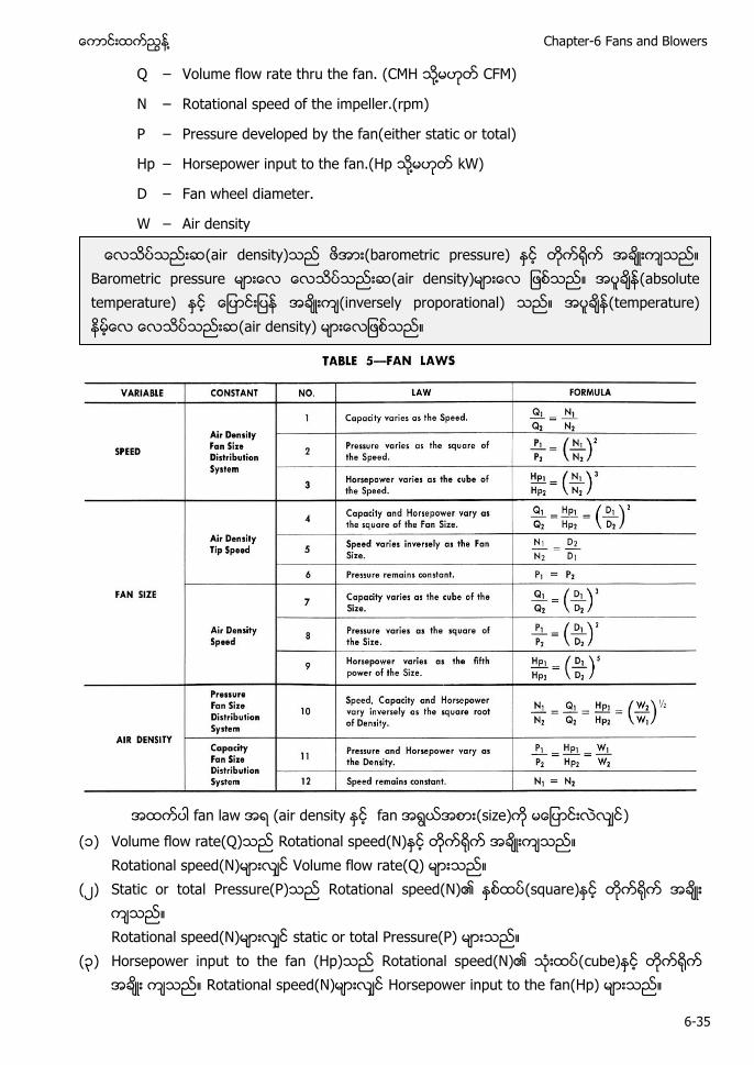
႔ Chapter-6 Fans and Blowers
6-35
Q – Volume flow rate thru the fan. (CMH သ႔မဟတ CFM)
N – Rotational speed of the impeller.(rpm)
P – Pressure developed by the fan(either static or total)
Hp – H H ႔ kW)
D – Fan wheel diameter.
W – Air density
အထကပါ fan law အရ (air d fan (size) )
(၁) Volume flow rate(Q)သည Rotational speed(N)ႏင တက႐က အခးကသည။ Rotational speed(N)မားလင Volume flow rate(Q) မားသည။ (၂) Static or total Pressure(P)သည Rotational speed(N)၏ ႏစထပ(square)ႏင တက႐က အခး
ကသည။ Rotational speed(N)မားလင static or total Pressure(P) မားသည။ (၃) Horsepower input to the fan (Hp)သည Rotational speed(N)၏ သးထပ(cube)ႏင တက႐က
အခး ကသည။ Rotational speed(N)မားလင Horsepower input to the fan(Hp) မားသည။
(air density) barometric pressu (air absolute temperature) (inversely proporational (
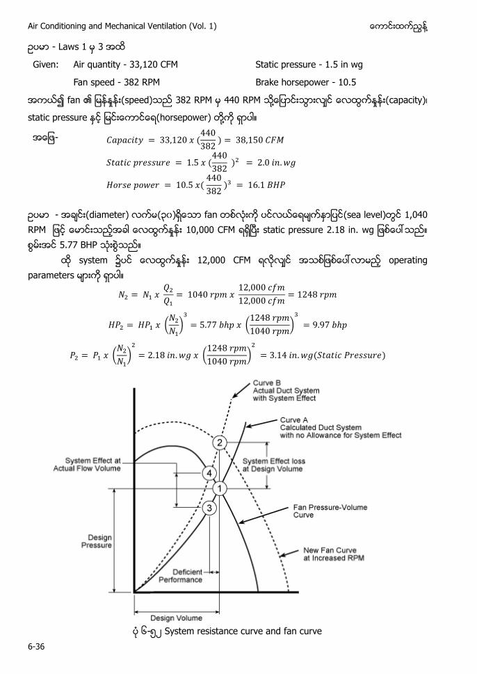
Air Conditioning and Mechanical Ventilation (Vol. 1) ႔
6-36
- L 3
Given: Air quantity - 33,120 CFM Static pressure - 1.5 in wg
Fan speed - 382 RPM Brake horsepower - 10.5
382 RPM RPM ႔ (capacity ၊
horsepower) ႔
- 𝐶𝑎𝑝𝑎𝑐𝑖𝑡𝑦 33 1 0 𝑥 440
38 38 1 0 𝐶𝐹𝑀
𝑆𝑡𝑎𝑡𝑖𝑐 𝑝𝑟𝑒𝑠𝑠𝑢𝑟𝑒 1 𝑥 440
38 2 0 𝑖𝑛 𝑤𝑔
𝐻𝑜𝑟𝑠𝑒 𝑝𝑜𝑤𝑒𝑟 10 𝑥 440
38 3 16 1 𝐵𝐻
- ၃၀ fan (sea level) 1,040 RPM 10,000 CFM static pressure 2.18 in. wg 5.77 BHP
system 2 F
2 𝑥 2
1040 𝑟𝑝 𝑥 1 000 𝑐
1 000 𝑐 1 48 𝑟𝑝
𝐻 2 𝐻 𝑥 ( 2
)3
𝑝 𝑥 (1 48 𝑟𝑝
1040 𝑟𝑝 )3
𝑝
2 𝑥 ( 2
)2
18 𝑖𝑛 𝑤𝑔 𝑥 (1 48 𝑟𝑝
1040 𝑟𝑝 )2
3 14 𝑖𝑛 𝑤𝑔 𝑆𝑡𝑎𝑡𝑖𝑐 𝑟𝑒𝑠𝑠𝑢𝑟𝑒
၆- ၂ System resistance curve and fan curve
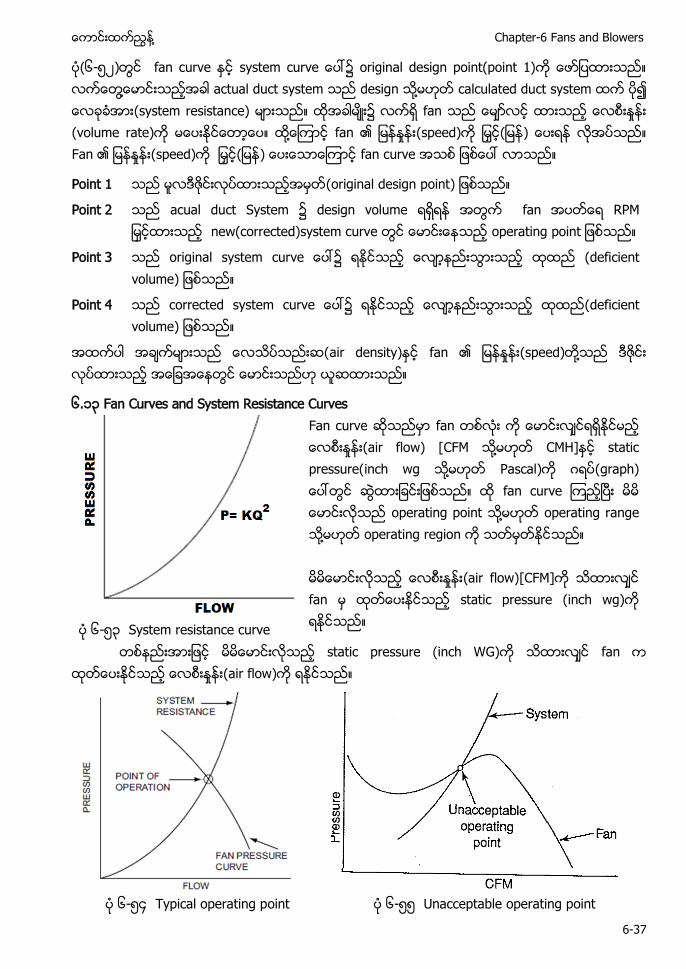
႔ Chapter-6 Fans and Blowers
6-37
(၆- ၂) fan curve original design point(point 1) ႔ actual duct system design ႔ calculated duct system (system resistance) ၌ fan (volume rate) ႔ fan (speed) ) Fan (speed) ) fan curve
Point 1 (original design point)
Point 2 acual duct System ၌ design volume fan RP new(corrected)system curve
Point 3 ၌ (deficient volume)
Point 4 ၌ (deficient volume)
air density) fan (speed) ႔
၆.၁၃ Fan Curves and System Resistance Curves
Fan curve ဆသညမာ fan တစလး က ေမာငးလငရရႏငမည (air flow) [ F ႔ CMH]ႏင static pressure( ႔ Pascal)က ဂရပ(graph) ေပၚတြင ဆြထားျခငးျဖစသည။ ထ fan curve ၾကညၿပး မမ ေမာငးလသည operating point သ႔မဟတ operating r ႔ operating region က သတမတႏငသည။ မမေမာငးလသည (air flow)[CFM]က သထားလင fan မ static pressure (inch wg)က ရႏငသည။ ၆- ၃ System resistance curve
တစနညးအားျဖင မမေမာငးလသည static pressure (inch WG)က သထားလင fan က (air flow)က ရႏငသည။
၆- ၄ Typical operating point ၆- Unacceptable operating point
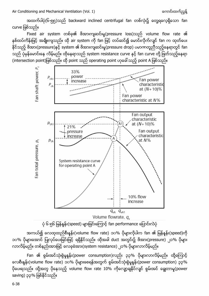
Air Conditioning and Mechanical Ventilation (Vol. 1) ႔
6-38
အထကပါပ(၆- )သည backward inclined centrifugal fan တစလး၌ ေတြ႔ရေလရေသာ fan curve ျဖစသည။
Fixed air system (pressure loss) volume flow rate air system fan (pressure) system (pressure drop) ဏ fan system resistance curve fan curve ႔ point operating point A
၆- ၆ (speed)
(volume flow rate) ၁၀% fan (speed) ၁၀% duct (pressure) ၂၁% (system resistance) ၂၁%
Fan (power consumption) ၃၃% ႔ (volume flow rate) ၁၀% (power consumption) ၃၃% ႔ volume flow rate 10% (power saving) ၃၃
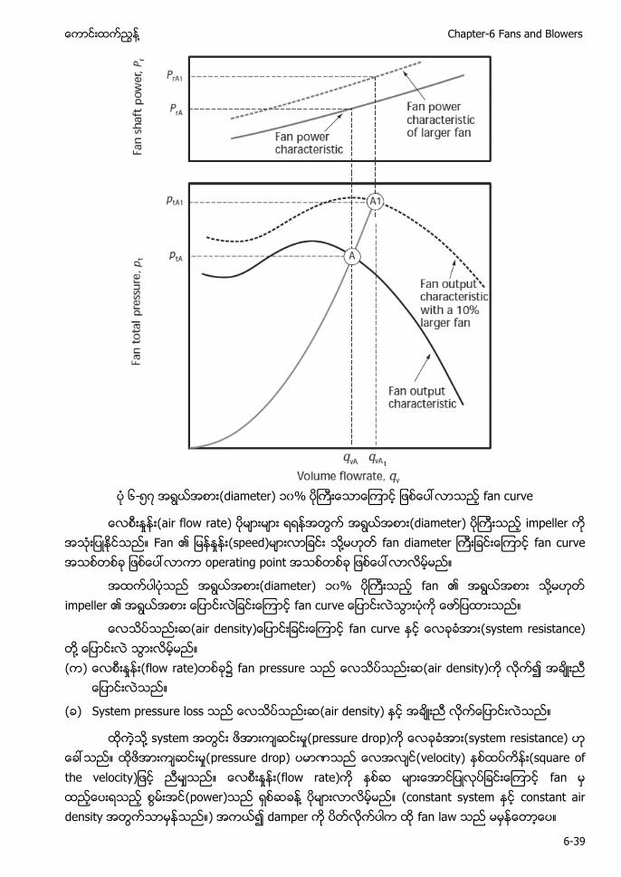
႔ Chapter-6 Fans and Blowers
6-39
၆- ၇ (diameter) ၁၀% fan curve
(air flow rate) (diameter) impeller Fan (speed) ႔ fan diameter fan curve operating point
(diameter) ၁၀% fan ႔ impeller
fan curve (system resistance) ႔ ( ) (flow rate) fan pressure (air density)
( ) System pressure loss (air density)
႔ pressure drop) system resistance) pressure drop) ဏ velocity) (square of the velocity (flow rate) fa (power) ႔ ( ) fan
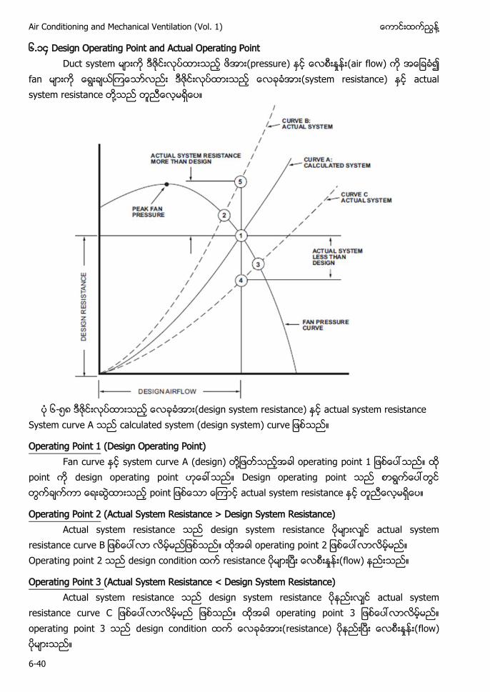
Air Conditioning and Mechanical Ventilation (Vol. 1) ႔
6-40
၆.၁၄ Design Operating Point and Actual Operating Point (pressure (air flow)
(system resistance) ႔
၆- ၈ (design system resistance) actual system resistance
A calculated system (design system)
Operating Point 1 (Design Operating Point) F system curve A (design) ႔ operating point
point design operating point Design operating point point ac
Operating Point 2 (Actual System Resistance > Design System Resistance) A design s
operating point 2 Operating point 2 flow)
Operating Point 3 (Actual System Resistance < Design System Resistance) A design s actual syst
operating point 3 operating point 3 resistance) flow)
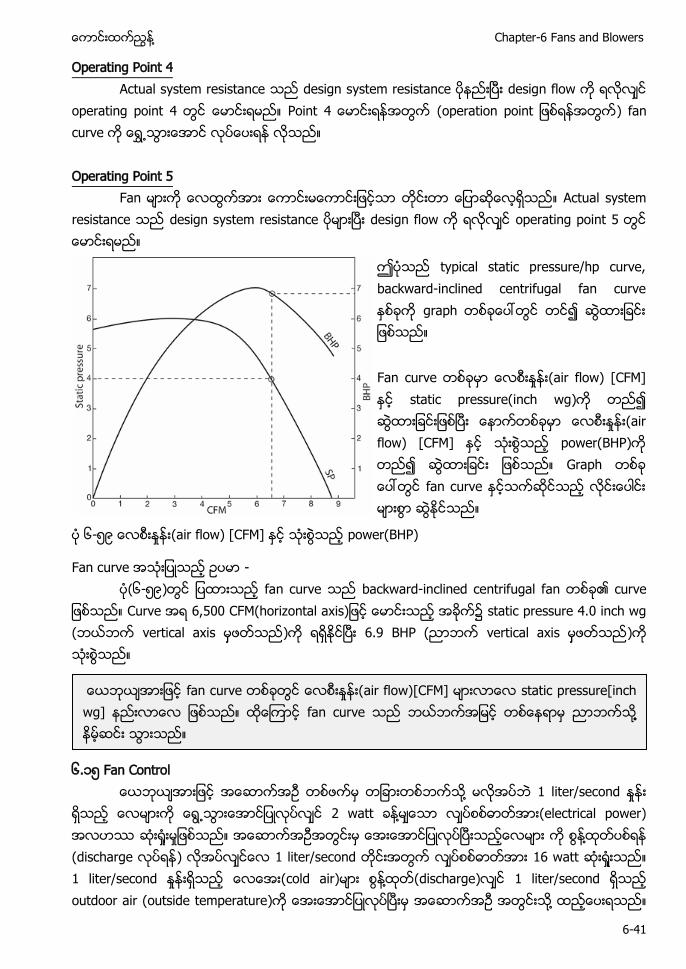
႔ Chapter-6 Fans and Blowers
6-41
Operating Point 4 A design s
operating point Point (operation point ) Operating Point 5
F A design s operating point
ဤပသည typical static pressure/hp curve, backward-inclined centrifugal ခက graph တစခေပၚတြင တင၍ ဆြထားျခငး ျဖစသည။ Fan curve တစခမာ (air flow) [CFM] ႏင static pressure(inch wg)က တည၍ ဆြထားျခငးျဖစၿပး ေနာကတစခမာ (air flow) [CFM] ႏင သးစြသည power(BHP)က တည၍ ဆြထားျခငး ျဖစသည။ Graph တစခ ေပၚတြင fan curve လငးေပါငး မားစြာ ဆြႏငသည။
၆- ၉ (air flow) [CFM] ႏင သးစြသည power(BHP)
Fan curve အသးျပသည ဥပမာ - ပ(၆- ၉)တြင ျပထားသည fan curve backward-inclined centrifugal fan
သည Curve အရ 6,500 CFM(horizontal axis)ျဖင ေမာငးသည အခက၌ static pressure 4.0 inch wg (ဘယဘက vertical axis မဖတသည)က ရရႏငၿပး 6.9 BHP (ညာဘက vertical axis မဖတသည)က သးစြသည။
၆.၁ Fan Control ႔ 1 liter/second 2 watt ႔ (electrical power) ႔ (discharge ) 1 liter/second 16 watt 1 liter/second (cold air) ႔ (discharge) 1 liter/second outdoor air (outside temperature) ႔
အားျဖင fan curve ေလစးႏႈနး(air flow)[CFM] မားလာေလ static pressure[inch wg] နညးလာေလ ျဖစသည။ ထေၾကာင fan curve သည ဘယဘကအျမင တစေနရာမ ညာဘကသ႔႔ နမဆငး သြားသည။
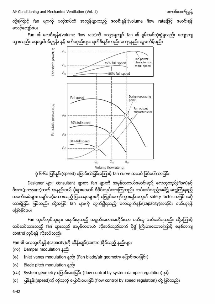
Air Conditioning and Mechanical Ventilation (Vol. 1) ႔
6-42
႔ fan (volume flow rate Fan (volume flow rate) fan ႔ ႔ ႔
၆-၆၀ (speed) fan curve
Designer ၊ consultant fan (flow) (pressure) ႔ ၊ safety factor ႔ fan (capacity)
Fan ႔ fan control
Fan (capacity) (control) ( ) Damper modulation
( ) Inlet vanes modulation (F )
(ဂ) Blade pitch modulation
(ဃ) (flow control by system damper regulation)
( ) (speed) (flow control by speed regulation) ႔
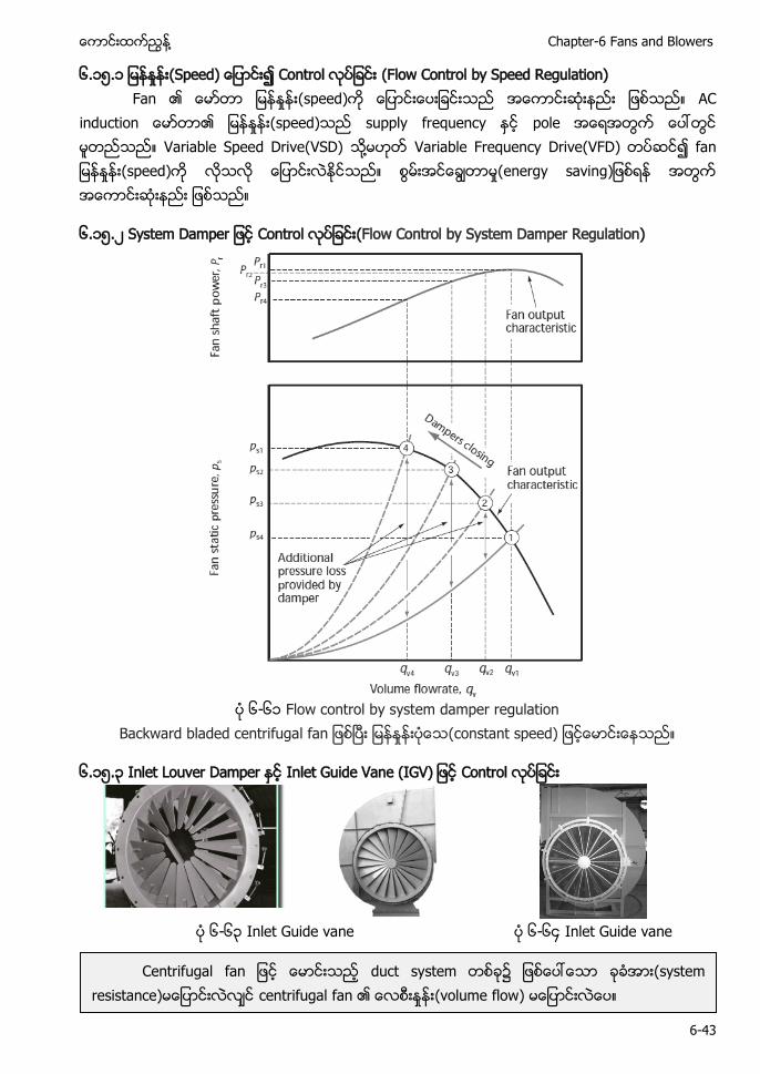
႔ Chapter-6 Fans and Blowers
6-43
၆.၁ .၁ (Speed) Control (Flow Control by Speed Regulation) Fan (speed) A
(speed) supply frequency pole Variable Speed Drive(VSD) ႔ Variable Frequency Drive(VFD) (speed) (energy saving
၆.၁ .၂ System D Control (Flow Control by System Damper Regulation)
၆-၆၁ Flow control by system damper regulation
B (constant speed)
၆.၁ .၃ Inlet Louver Damper Inlet Guide Vane (IGV) Control
၆-၆၃ Inlet Guide vane ၆-၆၄ Inlet Guide vane
duct system ၌ (system resistance) centrifugal fan (volume flow)
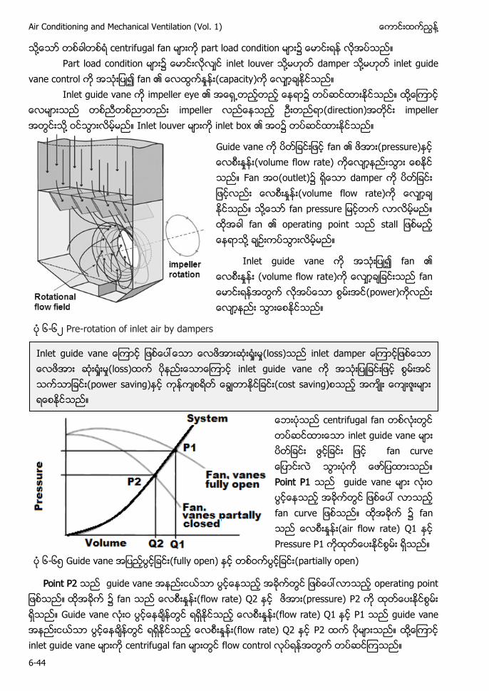
Air Conditioning and Mechanical Ventilation (Vol. 1) ႔
6-44
႔ centrifugal fan part load condition Part load condition inlet louver ႔ damper ႔ inlet guide vane control fan (capacity)
Inlet guide vane impeller eye ႔ impeller (direction) impeller ႔ Inlet louver inlet box
Guide vane fan (pressure) (volume flow rate) Fan (outlet) damper (volume flow rate) ႔ fan operating point ႔
Inlet guide vane fan (volume flow rate) (power)
၆-၆၂ Pre-rotation of inlet air by dampers
centrifugal fan inlet guide vane Point P1 guide vane ၌ fan (air flow rate) Q1 Pressure P1
၆-၆ Guide vane (fully open) (partially open)
Point P2 ၌ flow rate) Q2 pressure) P2 Guide vane flow rate) Q P guide vane flow rate) Q2 P2 ႔ inlet
Inlet guide v (loss) (loss) inlet guide vane (power saving) (cost saving)
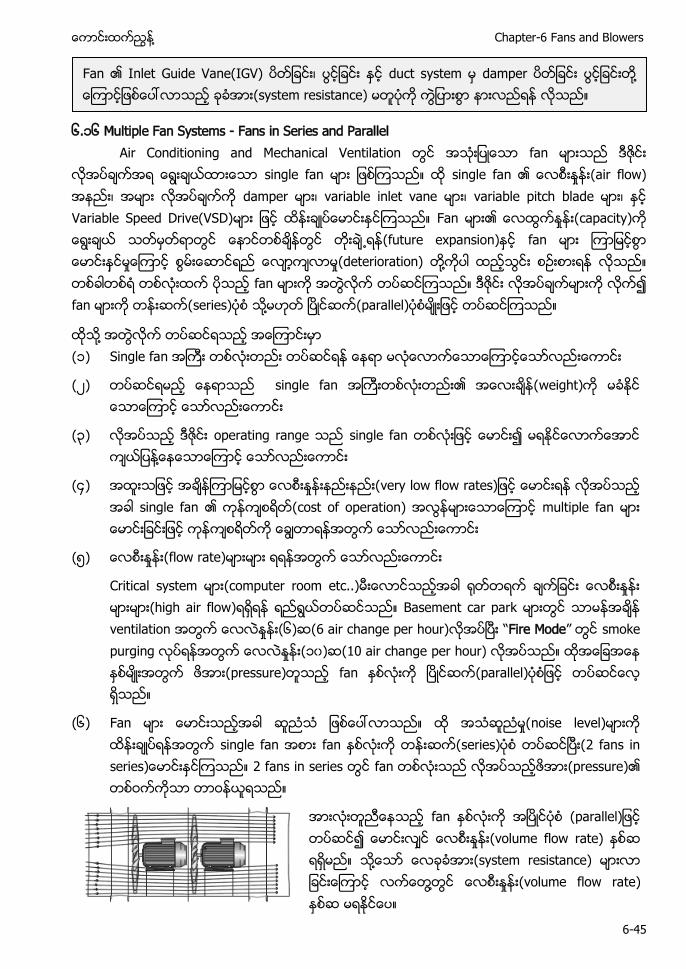
႔ Chapter-6 Fans and Blowers
6-45
၆.၁၆ Multiple Fan Systems - Fans in Series and Parallel
Air Conditioning and Mechanical Ventilation တြင အသးျပေသာ fan မားသည ဒဇငး လအပခကအရ ေရြးခယထားေသာ single fan မား ျဖစၾကသည။ ထ single fan ၏ (air flow) အနညး၊ အမား လအပခကက damper မား၊ variable inlet vane မား၊ variable pitch blade မား၊ ႏင Variable Speed Drive(VSD)မား ျဖင ထနးခပေမာငးႏင သည။ Fan မား၏ ေလထြကႏႈနး(capacity)က ေရြးခယ သတမတရာတြင ေနာငတစခနတြင တးခ႕ရန(future expansion)ႏင fan မား ၾကာျမငစြာ ေမာငးနငမႈေၾကာင စြမးေဆာငရည ေလာကလာမႈ(deterioration) တ႔ကပါ ထညသြငး စဥးစား ည။ တစခါတစရ တစလးထက ပသည fan မားက အတြလက တပဆငၾကသည။ ဒဇငး လအပခကမားက လက၍ fan မားက (series) သ႔မဟတ (parallel) မးျဖင တပဆငၾကသည။
ထသ႔ အတြလက တပဆငရသည အေၾကာငးမာ (၁) Single fan အႀကး တစလးတညး တပဆငရန ေနရာ မလေလာကေသာေၾကာငေသာလညးေကာငး
(၂) တပဆငရမည ေနရာသည single fan အႀကးတစလးတညး၏ အေလးခန(weight)က မခႏင ေသာေၾကာင ေသာလညးေကာငး
(၃) လအပသည ဒဇငး operating range သည single fan တစလးျဖင ေမာငး၍ မရႏငေလာကေအာင ကယျပန႔ေနေသာေၾကာင ေသာလညးေကာငး
(၄) အထးသျဖင အခနၾကာျမငစြာ ေလစးႏႈနးနညးနညး( ေမာငးရန လအပသည အခါ single fan ၏ ကနကစရတ(cost of operation) အလြနမားေသာေၾကာင multiple fan မား ေမာငးျခငးျဖင ကနကစရတက ေခြတာရနအတြက ေသာလညးေကာငး
( ) (flow rate) ရရနအတြက ေသာလညးေကာငး
Critical system မား(computer room etc..)မးေလာငသညအခါ တရက ခကျခငး ေလစးႏႈနး မားမား(high air flow)ရရရန ရညရြယတပဆငသည။ Basement car park မားတြင သာမနအခန ventilation အတြက ေလလႏႈနး(၆)ဆ(6 air change per hour)လအပၿပး “Fire Mode” တြင smoke purging လပရနအတြက ေလလႏႈနး(၁၀)ဆ(10 air change per hour) လအပသည။ ထအေျခအေန ႏစမးအတြက ဖအား(pressure)တသည fan ႏစလးက (parallel) တပဆငေလ ရသည။
(၆) Fan မား ေမာငးသညအခါ ဆညသ ျဖစေပၚလာသည။ ထ အသဆညမႈ(noise level)မားက ထနးခပရနအတြက single fan အစား fan လးက တနးဆက(series)ပစ တပဆငၿပး(2 fans in series)ေမာငးႏငၾကသည။ 2 fans in series တြင fan တစလးသည လအပသည (pressure)၏ တစဝကကသာ တာဝနယရသည။
fan (parallel (volume flow rate) ႔ (system resistance) ႔ (volume flow rate)
Fan Inlet Guide Vane(IGV) ၊ duct system damper ႔ (system resistance)
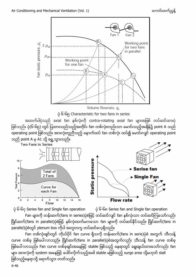
Air Conditioning and Mechanical Ventilation (Vol. 1) ႔
6-46
၆-၆ Characteristic for two fans in series
axial fan contra-rotating axial fan (၆-၆ ) fan point A operating p fan operating point point A A1 ႔
၆-၆၇ Series fan and Single fan operation ၆-၆၈ Series fan and Single fan operation F fans in series
fans in parallel fan fans in parallel
Fan fans in serie ႔ c ႔ fan c Fan curve တစခခငးအေနျဖင stable ျဖစသည ေနရာတြင ေရြးခယထားေသာလညး fan မား အားလးက system အေနျဖင ေပါငးလကသညအခါ stable ျဖစသည ႔ stall သ႔ ေရာကသြား တတသည။
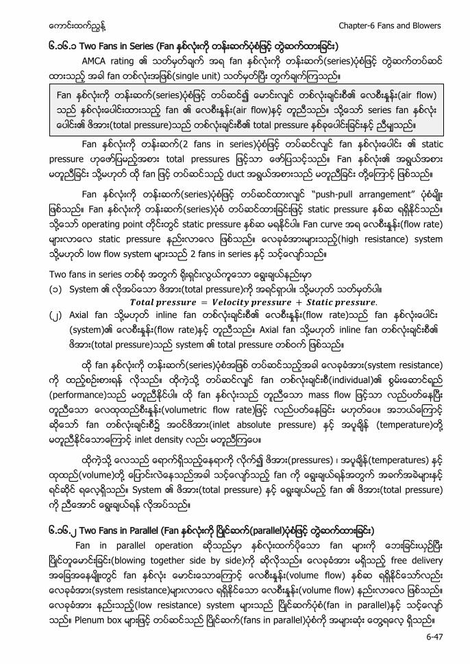
႔ Chapter-6 Fans and Blowers
6-47
၆.၁၆.၁ Two Fans in Series (Fan AMCA rating ၏ သတမတခက အရ fan (
သည အခါ fan တစလးအျဖစ(single unit) ၿပး တြကခကၾကသည။
Fan 2 fans in series fan ႏစလးေပါငး ၏ static
pressure ဟေဖာျပမညအစား total pressures ျဖငသာ ေဖာျပသငသည။ Fan ႏစလး၏ အရြယအစား မတညျခငး သ႔ ထ fan ျဖင တပဆငသည duct အရြယအစားသည မတညျခငး တ႔ေၾကာင ျဖစသည။
Fan ႏစလးက (series ျဖင တပဆငထားလင “push-pull arrangement” မး ျဖစသည။ Fan ႏစလးက (series တပဆငထားျခငးျဖင static pressure ႏစဆ ရရႏငသည။ သ႔ေသာ static pressure ႏစဆ မရႏငပါ။ F (flow rate) မားလာေလ static pressure နညးလာေလ ျဖစသည။ ေလခခအားမားသည(high resistance) system သ႔မဟတ low flow system မားသည 2 fans in series ႏင သငေလာသည။
Two fans in series တစစ အတြက းရငးလြယကေသာ ေရြးခယနညးမာ (၁) System ၏ လအပေသာ ဖအား(total pressure)က အရငရာပါ။ သ႔မဟတ သတမတပါ။
(၂) Axial fan သ႔မဟတ inline fan တစလးခငးစ၏ (flow rate)သည fan ႏစလးေပါငး
(system)၏ (flow rate)ႏင တညသည။ Axial fan သ႔မဟတ inline fan တစလးခငးစ၏ ဖအား(total pressure)သည system ၏ total pressure တစဝက ျဖစသည။
ထ fan ႏစလးက (series အျဖစ တပဆငသညအခါ system resistance) က ထညစဥးစားရန လသည။ ထကသ႔ တပဆငလင fan တစလးခငးစ(individual)၏ (performance)သည မတညႏငပါ။ ထ fan ႏစလးသည တညေသာ mass flow ျဖငသာ လညပတေနၿပး တညေသာ (volumetric flow rate)ျဖင လညပတေနျခငး မဟတေပ။ အဘယေၾကာင ဆေသာ fan တစလးခငးစ၌ အဝငဖအား(inlet absolute pressure) ႏင အပခန (temperature)တ႔ မတညႏငေသာေၾကာင inlet density လညး မတညၾကေပ။
ထကသ႔ ေလသည ေရာကရသညေနရာက လက၍ ဖအား(pressures) ၊ အပခန(temperatures) ႏင volume)တ႔ ေျပာငးလေနသညအခါ သငေလာသည fan က ေရြးခယရနအတြက အခကအခမားႏင ရငဆင ရေလရသည။ System ၏ ဖအား(total pressure) ႏင ေရြးခယမည fan ၏ ဖအား(total pressure) က ညေအာင ေရြးခယ
၆.၁၆.၂ Two Fans in Parallel (Fan (parallel Fan in parallel operation ဆသညမာ ႏစလးထကပေသာ fan မားက ေဘးျခငးယဥၿပး
ၿပငတေမာငးျခငး(blowing together side by side ဆလသည။ ေလခခအား မရသည free delivery အေျခအေနမးတြင fan ႏစလး ေမာငးေသာေၾကာင (volume flow) ႏစဆ ရရႏငေသာလညး (system resistance)မားလာေလ ရရႏငေသာ (volume flow) နညးလာေလ ျဖစသည။ ေလခခအား နညးသည(low resistance) system မားသည ၿပငဆကပစ(fan in parallel)ႏင သငေလာ သည။ Plenum box မားျဖင တပဆငသည ၿပငဆက(fans in parallel)ပစက အမားဆး ေတြ႔ရေလ ရသည။
Fan ႏစလးက တနးဆက(series)ပစျဖင တပဆင၍ ေမာငးလင တစလးခငးစ၏ (air flow) သည ႏစလးေပါငးထားသည fan ၏ (air flow)ႏင တညသည။ သ႔ေသာ series fan ႏစလး ေပါငး၏ total pressure)သည တစလးခငးစ၏ total pressure ႏစခေပါငးျခငးႏင ညမသည။
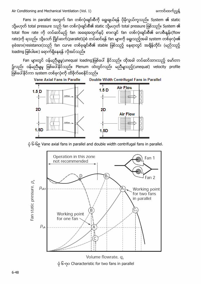
Air Conditioning and Mechanical Ventilation (Vol. 1) ႔
6-48
Fans in parallel အတြက fan တစလးခငးစက ေရြးခယရန ပမလြယကသည။ System ၏ ႔ total pressure သည fan တစလးခငးစ၏ ႔ total pressure ျဖစသည။ System ၏ total flow rate က တပဆငမည fan အေရအတြကႏင စားလင fan တစလးခငးစ၏ (flow rate)က ရသည။ သ႔ေသာ (parallel တပဆငရန fan မားက ေရြးသညအခါ system တစခလး၏ ခခအား(resistance)သည fan curve တစခခငးစ၏ stable ျဖစသည ေနရာတြင အခနတငး ( loading ျဖစပါေစ) ေရာကရေနရန လအပသည။
F (unequal loading ၌ P unequal) velocity profile
၆-၆ Vane axial fans in parallel and double width centrifugal fans in parallel.
၆-၇၀ Characteristic for two fans in parallel
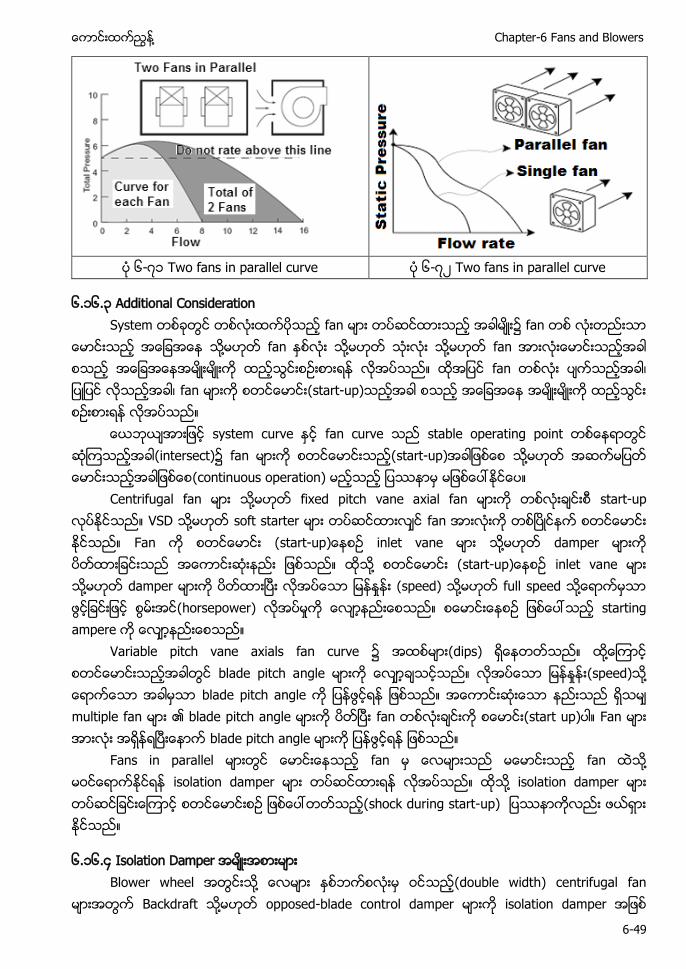
႔ Chapter-6 Fans and Blowers
6-49
၆-၇၁ ၆-၇၂
၆.၁၆.၃ Additional Consideration System တစခတြင တစလးထကပသည fan မား တပဆငထားသည အခါမး၌ fan တစ လးတညးသာ
ေမာငးသည အေျခအေန သ႔မဟတ fan ႏစလး သ႔မဟတ သးလး သ႔မဟတ fan အားလးေမာငးသညအခါ စသည အေျခအေနအမးမးက ထညသြငးစဥးစားရန လအပသည။ ထအျပင fan တစလး ပကသညအခါ၊ ျပျပင လသညအခါ၊ fan မားက စတငေမာငး(start-up)သညအခါ စသည အေျခအေန အမးမးက ထညသြငး စဥးစားရန လအပသည။
ေယဘယအားျဖင system curve ႏင fan curve သည stable operating point တစေနရာတြင ဆၾကသညအခါ(intersect)၌ fan မားက စတငေမာငးသည(start-up)အခါျဖစေစ သ႔မဟတ အဆကမျပတ ေမာငးသညအခါျဖစေစ(continuous operation) မညသည ျပနာမ မျဖစေပၚႏငေပ။
Centrifugal fan မား သ႔မဟတ က တစလးခငးစ start-up လပႏငသည။ VSD သ႔မဟတ soft starter မား တပဆငထားလင fan အားလးက တစၿပငနက စတငေမာငး ႏငသည။ Fan က စတငေမာငး (start-up)ေနစဥ ႔ damper မားက ပတထားျခငးသည အေကာငးဆးနညး ျဖစသည။ ထသ႔ စတငေမာငး (start-up)ေနစဥ သ႔မဟတ damper မားက ပတထားၿပး လအပေသာ (speed) သ႔မဟတ full speed ႔ေရာကမသာ ဖြငျခငးျဖင စြမးအင(horsepower) လအပမႈက ေလာနညးေစသည။ စေမာငးေနစဥ ျဖစေပၚသည starting ampere က ေလာနညးေစသည။
Variable pitch vane axials အထစမား(dips) ရေနတတသည။ ထ႔ေၾကာင စတငေမာငးသညအခါတြင blade pitch angle မားက ေလာခသငသည။ လအပေသာ (speed)သ႔ ေရာကေသာ အခါမသာ blade pitch angle က ျပနဖြငရန ျဖစသည။ အေကာငးဆးေသာ နညးသည ရသမ multiple fan မား ၏ blade pitch angle မားက ပတၿပး fan တစလးခငးက start up)ပါ။ Fan မား အားလး အရနရၿပးေနာက blade pitch angle မားက ျပနဖြငရန ျဖစသည။
Fans in parallel မားတြင ေမာငးေနသည fan မ ေလမားသည မေမာငးသည fan ထသ႔ မဝငေရာကႏငရန isolation damper မား တပဆငထားရန လအပသည။ ထသ႔ isolation damper မား တပဆငျခငးေၾကာင shock during start-up) ျပနာကလညး ဖယရား ႏငသည။
၆.၁၆.၄ Isolation Damper အမးအစားမား Blower wheel အတြငးသ႔ ေလမား ႏစဘကစလးမ ဝငသည(double width) centrifugal fan
မားအတြက ႔ opposed-blade control damper မားက isolation damper အျဖစ
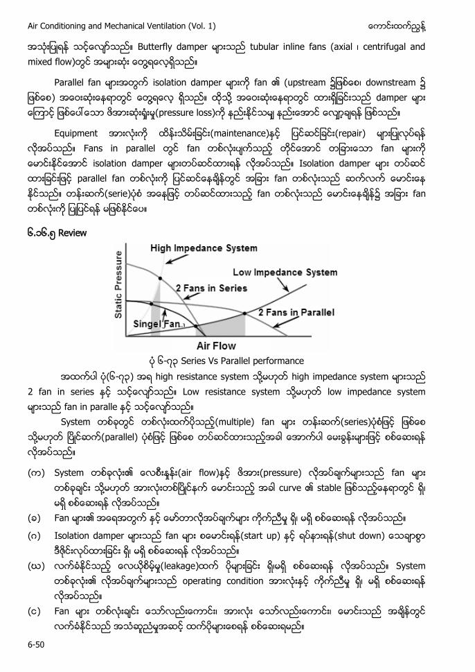
Air Conditioning and Mechanical Ventilation (Vol. 1) ႔
6-50
အသးျပရန သငေလာသည။ Butterfly damper မားသည tubular inline fans ( ၊ mixed flow)တြင အမားဆး ေတြ႔ရေလရသည။
Parallel fan မားအတြက isolation damper မားက fan ၏ (upstream ျဖစေစ၊ downstream ျဖစေစ) အေဝးဆးေနရာတြင ေတြ႔ရေလ ရသည။ ထသ႔ အေဝးဆးေနရာတြင ထားရျခငးသည damper ေၾကာင ျဖစေပၚေသာ e loss)က နညးႏငသမ နညးေအာင ရန ျဖစသည။
Equipment အားလးက ထနးသမးျခငး(maintenance)ႏင ျပငဆငျခငး(repair) လအပသည။ Fans in parallel တြင fan တစလးပကသည တငေအာင တျခားေသာ fan မားက ေမာငးႏငေအာင isolation တပဆငထားရန လအပသည။ Isolation damper မား တပဆင ထားျခငးျဖင parallel fan တစလးက ျပငဆငေနခနတြင အျခား fan တစလးသည ဆကလက ေမာငးေန ႏငသည။ (serie အေနျဖင တပဆငထားသည fan တစလးသည ေမာငးေနခန၌ အျခား fan တစလးက ျပျပငရန မျဖစႏငေပ။
၆.၁၆. Review
၆-၇၃ Series Vs Parallel performance
အထကပါ ပ(၆-၇၃) အရ high resistance system သ႔မဟတ high impedance system မားသည 2 fan in series ႏင သငေလာသည။ Low resistance system သ႔မဟတ low impedance system မားသည fan in paralle ႏင သငေလာသည။
System တစခတြင တစလးထကပသည(multiple) fan မား series ျဖစေစ သ႔မဟတ ၿပငဆက(parallel) ျဖစေစ တပဆငထားသညအခါ ေအာကပါ ေမးခြနးမားျဖင စစေဆးရန လအပသည။
( ) System တစခလး၏ (air flow)ႏင ဖအား(pressure) လအပခကမားသည fan မား တစခခငး သ႔မဟတ အားလးတစၿပငနက ေမာငးသည အခါ curve ၏ stab တြင ရ၊ မရ စစေဆးရန လအပသည။
( ) Fan မား၏ အေရအတြက ႏင ေမာတာလအပခကမား ကကညမႈ ရ၊ မရ စစေဆးရန လအပသည။
(ဂ) Isolation damper မားသည fan မား စေမာငးရန(start up) ႏင ရပနားရန(shut down) ေသခာစြာ ဒဇငးလပထားျခငး ရ၊ မရ စစေဆးရန လအပသည။
(ဃ) leakage)ထက ပမားျခငး ရ၊မရ စစေဆးရန လအပသည။ System တစခလး၏ လအပခကမားသည operating condition အားလးႏင ကကညမႈ ရ၊ မရ စစေဆးရန လအပသည။
( ) Fan မား တစလးခငး ေသာလညးေကာငး၊ အားလး ေသာလညးေကာငး၊ ေမာငးသည အခနတြင လကခႏငသည အသဆညမႈအဆင ထကပမားေစရန စစေဆးရမည။
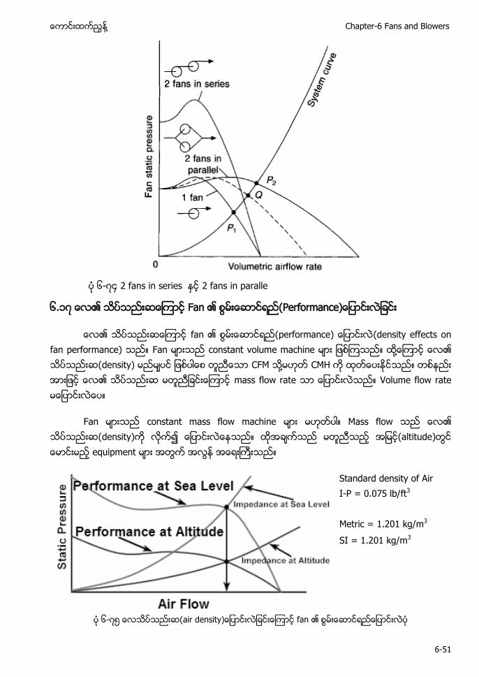
႔ Chapter-6 Fans and Blowers
6-51
၆-၇၄ 2 fans in series 2 fans in paralle
၆.၁၇ ေလ၏ သပသညးဆ Fan P
fan performance) (density effects on fan performance) Fan မားသည constant volume machine မား ျဖစၾကသည။ ထ႔ေၾကာင ေလ၏ သပသညးဆ(density) မညမပင ျဖစပါေစ တညေသာ CFM သ႔မဟတ CMH က ထတေပးႏငသည။ တစနညး အားျဖင ေလ၏ သပသညးဆ မတညျခငးေၾကာင mass flow rate သာ ေျပာငးလသည။ Volume flow rate မေျပာငးလေပ။
Fan မားသည constant mass flow machine မား မဟတပါ။ Mass flow သည ေလ၏ သပသညးဆ(density)က လက၍ ေျပာငးလေနသည။ ထအခကသည မတညသည အျမင(altitude)တြင ေမာငးမည equipment မား အတြက အလြန အေရးႀကးသည။
Standard density of Air I-P = 0.075 lb/ft3 Metric = 1.201 kg/m3 SI = 1.201 kg/m3
၆-၇
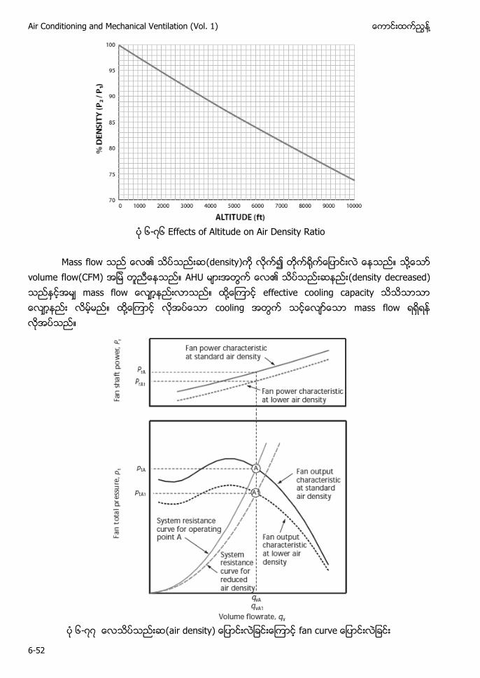
Air Conditioning and Mechanical Ventilation (Vol. 1) ႔
6-52
၆-၇၆ Effects of Altitude on Air Density Ratio
Mass flow သည ေလ၏ သပသညးဆ(density)က လက၍ တက႐က ေျပာငးလ ေနသည။ သ႔ေသာ
volume flow(CFM) အျမ တညေနသည။ AHU မားအတြက ေလ၏ သပသညးဆနညး(density decreased) သည ႏငအမ mass flow ေလာနညးလာသည။ ထ႔ေၾကာင effective cooling capacity သသသာသာ ေလာနညး လမမည။ ထ႔ေၾကာင လအပေသာ cooling အတြက သငေလာေသာ mass flow ရရရန လအပသည။
၆-၇၇ (air density)
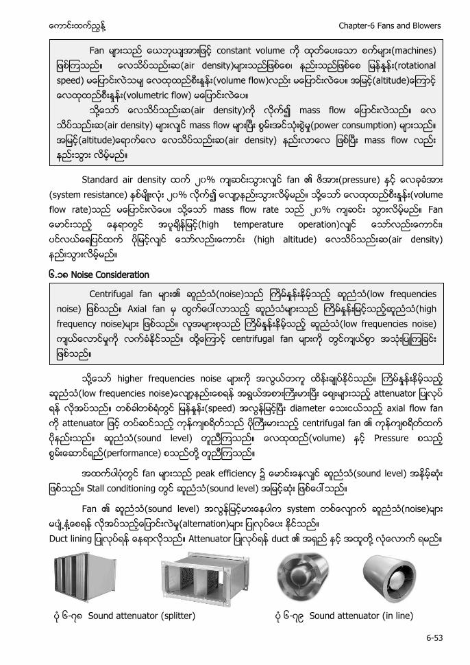
႔ Chapter-6 Fans and Blowers
6-53
Standard air density ၂၀% fan (pressure)
(system resistance) ၂၀% ႔ (volume flow rate) ႔ mass flow rate ၂၀% F (high temperature operation) ၊ (high altitude) (air density)
၆.၁၈ Noise Consideration
႔ higher frequencies noise (low frequencies (speed) axial flow fan centrifugal fan (sound level) volume) Pressure (performance) ႔
fan peak efficiency (sound level) Stall conditioning (sound level)
Fan (sound level) system (noise) ႔႔ (alternation) A duct ႔
၆-၇၈ Sound attenuator (splitter) ၆-၇ Sound attenuator (in line)
Fan constant volume (machines (air density) ၊ (rotational speed) (volume flow) (volumetric flow)
႔ (air density) (air density) mass flow (power consumption) (air density) mass flow
Centrifugal fan (noise) (low frequencies noise) Axial fan (high frequency noise) (low frequencies noise) ႔ centrifugal fan
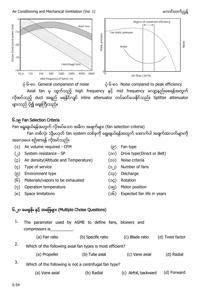
Air Conditioning and Mechanical Ventilation (Vol. 1) ႔
6-54
၆-၈၀ General comparison of noise ၆-၈၁ Noise compared to peak efficiency Axial fan high frequency m
duct inline attenuator Splitter attenuator
၆.၁ Fan Selection Criteria Fan ေရြးခယရနအတြက လအပေသာ အဓက အခကမား (fan selection criteria)
Fan တစလး သ႔မဟတ fan system တစခက ေရြးခယရနအတြက ေအာကပါ အခကအလကမားက အေလးေပး စဥးစာရန လအပသည။ (၁) Air volume required - CFM ( ) Fan type (၂) System resistance - SP (၁၀) Drive type(Direct or Belt) (၃) Air density(Altitude and Temperature) (၁၁) Noise criteria (၄) Type of service (၁၂) Number of fans ( ) Environment type (၁၃) Discharge (၆) Materials/vapors to be exhausted (၁၄) Rotation (၇) Operation temperature (၁ ) Motor position (၈) Space limitations (၁၆) Expected fan life in years
၆.၂၀ (Multiple Choise Questions)
1. The parameter used by ASME to define fans, blowers and compressors is__________.
(a) Fan ratio (b) Specific ratio (c) Blade ratio (d) Twist factor 2. Which of the following axial fan types is most efficient?
(a) Propeller (b) Tube axial (c) Vane axial (d) Radial
3. Which of the following is not a centrifugal fan type?
(a) Vane axial (b) Radial (c) Airfoil, backward (d) Forward
curved
႔ Chapter-6 Fans and Blowers
6-55
4. Match the following for centrifugal fan types.
Type Suitable for
(a) Backward curved (i) High pressure, medium flow
(b) Forward curved (ii) Medium pressure, high flow
(c) Radial (iii) High pressure, high flow
5. For fans, the relation between discharge and speed is indicated by____
6. The choice of fan type for a given application depends on
(a) Flow (b) Static Pressure (c) Both a & b (d) Neither (a) nor (b) 7. The efficiency of backward curved fans compared to forward curved fans is__
(a) Higher (b) Lower (c) Same (d) None
8. Name the fan which is more suitable for high pressure application?
(a) Propeller type fans (b) Tube-axial fans
(c) Backward curved centrifugal fan (d) None of the above 9. Axial fans are best suitable for _________________ application.
(a) Large flow, low head (b) Low flow, high head
(b) High head, large flow (d) Low flow, low head
10. The efficiency of forward curved fans compared to backward curved fans is ____
(a) lower (b) higher (c) same (d) none
11. The efficiency values of Vane axial fans are in the order of: (a) 78 – 85% (b) 60 – 70% (c) 90 – 95% (d) 50 – 60%
12. Backward curved fans have efficiency in the range of: (a) 65 – 70% (b) 75– 85% (c) 90 – 95% (d) 50 – 60%
13. The pressure to be considered for calculating the power required for centrifugal fans is: (a) Discharge static pressure (b) Static + dynamic pressure (c) Total static pressure (d) Static + ambient air pressure
Air Conditioning and Mechanical Ventilation (Vol. 1) ႔
6-56
14. Typical design efficiency of aerofoil fan handling clean air is: (a) 40 to 50% (b) 80 to 90% (c) 60 to 70% (d) 70 to 80%
15. The clearance required for efficient operation of impeller of 1 meter plus diameter in Radial type fans is ___________. (a) 5 to 10 mm (b) 1 to 2 mm (c) 20 to 30 mm (d) 0.5 to 1.5 mm
16. Which type of control gives maximum benefits for fan application from energy saving point of view? (a) Discharge damper control (b) Inlet guide vane control (c) Variable pitch control (d) Speed control
17. The pressure along the line of the flow that results from the air flowing through the duct is ______________. (a) Static pressure (b) Velocity pressure (c) Total pressure (d) Dynamic pressure
18. The outer tube of the pitot tube is used to measure __________________. (a) Static pressure (b) Velocity pressure (c) Total pressure (d) Dynamic pressure
19 Axial-flow fans are equipped with ________________. (a) Fixed blades (b) Curved blades (c) Flat blades (d) variable pitch blades
20 The ratio of maximum to minimum flow rate is called - (a) turn – up ratio (b) turn-down ratio (c) up-down ratio (d) None
21 The density of a gas at a temperature of 50 deg. C at site condition is _____________. (a) 0.94 kg/m3 (b) 1.2 kg/m3 (c) 1.5 kg/m3 (d) 1.4 kg/m3
Questions and Answers
Q1. ‘ entrifuga ‘A ႔
In centrifugal fans, pressure is developed due to the centrifugal force imparted to air, unlike axial flow fans where velocity energy is imparted to air, which in turn is converted to pressure energy at the fan outlet.
Q2. H f
Centrifugal fans are suitable for high pressure applications as compared to axial flow fans. Q3. Under which conditions of pressure ratios and volumes, low speed fans are preferred?
Low speed fans are preferred for low pressure ratios and large volumes.
႔ Chapter-6 Fans and Blowers
6-57
Q4. fan
A very conservative approach is adopted allocating large safety margins, resulting in oversized fans, which operate at flow rates much below their design values and consequently which leads to operate at very poor efficiency.
Q5.
(type)
Radial, forward curved and backward inclined fans. Q6. F (advantages)
Forward curved fans have the advantage of lower shut off power, which is desirable for low flow rate operation.
Q7. ၤFan performance) housing (type)
Performance ‘ Q8. (control)
a. Changing pulley ratio for drive and driven equipments. b. Variable frequency drive variable speed fluid coupling.
Q9. Fan application ၌ ႔ energy saving opportunities (
1. Change of impeller by a high efficiency impeller along with cone. 2. Change of fan assembly as a whole, by a high efficiency fan 3. Impeller de-rating(by a smaller diameter impeller) 4. Fan speed reduction by pulley diameter modifications for de-rating 5. Option of two speed motors or variable speed drives for variable duty conditions 6. Option of energy efficient flat belts, or, cogged raw edged V belts, in place of
conventional V belt systems, for reducing transmission losses. 7. Adopting inlet guide vanes in place of discharge damper control 8. Minimizing system resistance and pressure drops by improvements in duct system
Q10. Fan performance) speed ၊ power ၊ pressure ႔ affinity laws The affinity laws governing fan performance is given below:
Flow x speed
Pressure x (speed)2
Power x (speed)3
Air Conditioning and Mechanical Ventilation (Vol. 1) ႔
6-58
Q11. ” ” ႔
Speed control Guide vane control
The flow is varied in accordance with the process requirement by changing the speed of the fan.
The flow is varied by guiding the inlet air into the fan in the direction of impeller rotation in accordance with the process requirement.
Q12.
Fan (sizing) main factor)
The following are the factors considered for fan sizing: 1. Flow requirement in m3/hr 2. Pressure drop 3. Power requirement 4. Density of flowing gas at the site condition
Q13.
Fan performance) (factors)
The main factors affecting the performance of fans are flow, pressure, temperature, speed and damper positions on the fan side and the power input in KW on the motor side.
Q.14 ႔ F axial fan A
When the flow of air(or)fluid is parallel to the axis of the fan it is called an axial fan. Application areas of axial fans are: HVAC, drying ovens, exhaust system
Q.15.
R
Radial type of centrifugal fans is used at high pressure, medium flow conditions.
Example. Dust laden, moist air/gas in textile industry. Q16. ‘
B - (a) High pressure generation (b) High efficiency (c) Power reduction with increased flow
Q17. F ‘
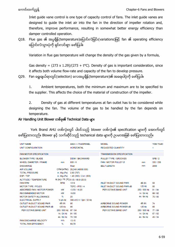
႔ Chapter-6 Fans and Blowers
6-59
Inlet guide vane control is one type of capacity control of fans. The inlet guide vanes are designed to guide the inlet air into the fan in the direction of impeller rotation and, therefore, improve performance, resulting in somewhat better energy efficiency than damper controlled operation.
Q18.
F (temperature variations
Variation in flue gas temperature will change the density of the gas given by a formula,
Gas density = (273 x 1.29)/(273 + t°C). Density of gas is important consideration, since it affects both volume flow-rate and capacity of the fan to develop pressure.
Q29. F selection) (temperature)
1. Ambient temperatures, both the minimum and maximum are to be specified to the supplier. This affects the choice of the material of construction of the impeller.
2. Density of gas at different temperatures at fan outlet has to be considered while designing the fan. The volume of the gas to be handled by the fan depends on temperature.
A H
AH b s t
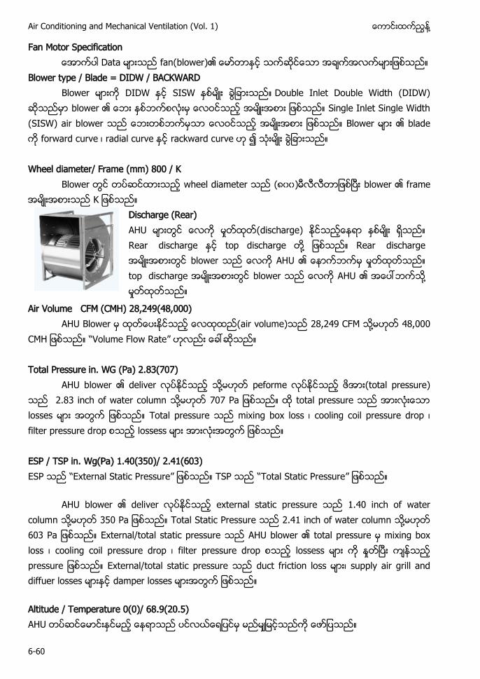
Air Conditioning and Mechanical Ventilation (Vol. 1) ႔
6-60
Fan Motor Specification fan(blower)
Blower type / Blade = DIDW / BACKWARD Double Inlet Double Width (DIDW)
blower Single Inlet Single Width (SISW) air b B forward curve ၊ rad rackward c
Wheel diameter/ Frame (mm) 800 / K
wheel diameter (၈၀၀)
Discharge (Rear) AH (discharge) R top d ႔ R b AH b AH ႔
Air Volume CFM (CMH) 28,249(48,000) AH air volume) 28 2 F ႔ 8
H Volume Flow Rate” Total Pressure in. WG (Pa) 2.83(707)
AHU b ႔ peforme total pressure) 2.83 inch of water column ႔ P total p l Total pressu mixing box loss ၊ cooling coil pressure drop ၊ filter pressure d ESP / TSP in. Wg(Pa) 1.40(350)/ 2.41(603) P External Static Pressure” P Total Static Pressure”
AHU b external static pressure 1.40 inch of water column ႔ 3 P Total Static Pressure 2 inch of water column ႔ 3 P AHU b mixing box loss ၊ ressure drop ၊ filter pressure drop p External/total static pressure ၊ supply air grill and d damper l
Altitude / Temperature 0(0)/ 68.9(20.5) AHU
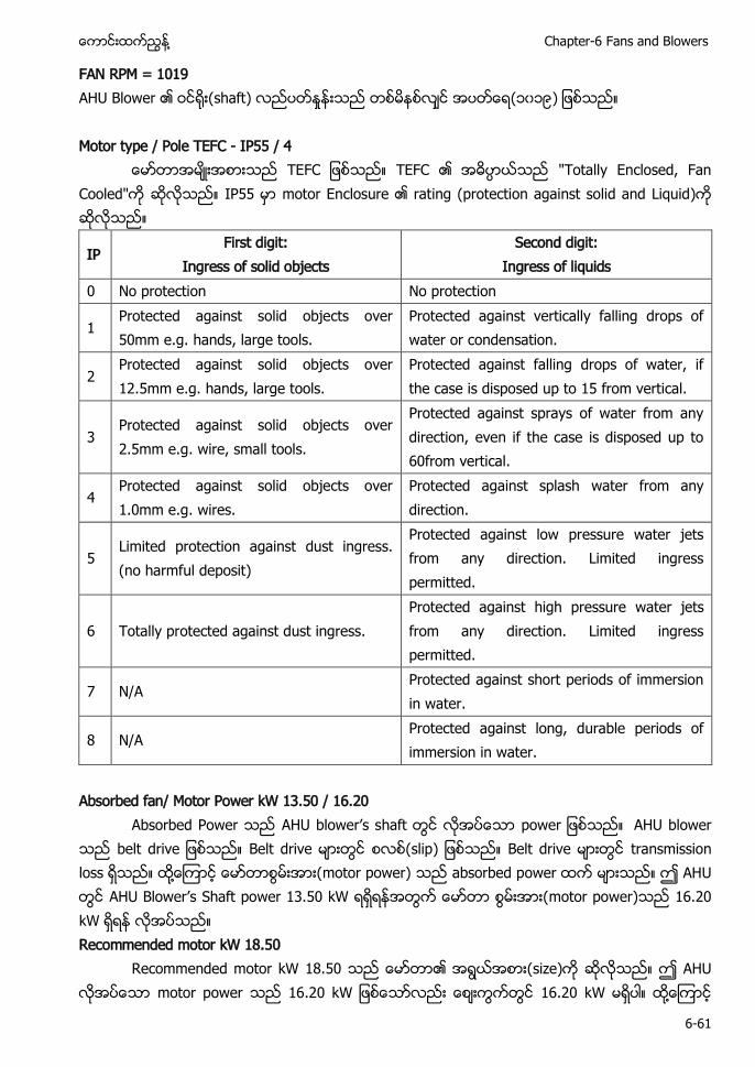
႔ Chapter-6 Fans and Blowers
6-61
FAN RPM = 1019 AH shaft) (၁၀၁ ) Motor type / Pole TEFC - IP55 / 4
F F F IP55 (protection against solid and Liquid)
IP First digit:
Ingress of solid objects Second digit:
Ingress of liquids 0 No protection No protection
1 Protected against solid objects over 50mm e.g. hands, large tools.
Protected against vertically falling drops of water or condensation.
2 Protected against solid objects over 12.5mm e.g. hands, large tools.
Protected against falling drops of water, if the case is disposed up to 15 from vertical.
3 Protected against solid objects over 2.5mm e.g. wire, small tools.
Protected against sprays of water from any direction, even if the case is disposed up to 60from vertical.
4 Protected against solid objects over 1.0mm e.g. wires.
Protected against splash water from any direction.
5 Limited protection against dust ingress. (no harmful deposit)
Protected against low pressure water jets from any direction. Limited ingress permitted.
6 Totally protected against dust ingress. Protected against high pressure water jets from any direction. Limited ingress permitted.
7 N/A Protected against short periods of immersion in water.
8 N/A Protected against long, durable periods of immersion in water.
Absorbed fan/ Motor Power kW 13.50 / 16.20
A P AHU b AHU b belt d slip t ႔ absorbed p AH AH 3 motor power) 2 Recommended motor kW 18.50
R 8 size) AH motor power 2 2 ႔
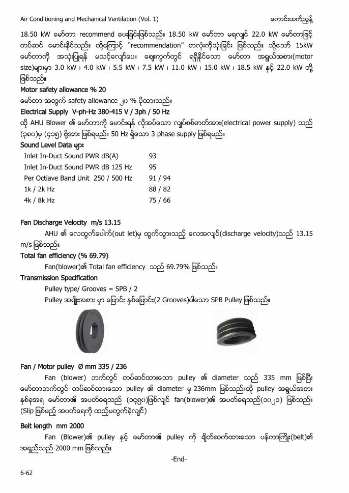
Air Conditioning and Mechanical Ventilation (Vol. 1) ႔
6-62
8 r 8 22 ႔ ecommendation” ႔ motor size) 3.0 kW ၊ 4.0 kW ၊ 5.5 kW ၊ 7.5 kW ၊ 11.0 kW ၊ 15.0 kW ၊ 18.5 kW 22 ႔ Motor safety allowance % 20 ၂၀ Electrical Supply V-ph-Hz 380-415 V / 3ph / 50 Hz AH electrical power supply (၃၈၀) ၄၁ ႔ H 3 phase s L Inlet In-Duct Sound PWR dB(A) 93 Inlet In-Duct Sound PWR dB 125 Hz 95 Per Octiave Band Unit 250 / 500 Hz 91 / 94 1k / 2k Hz 88 / 82 4k / 8k Hz 75 / 66
Fan Discharge Velocity m/s 13.15
AH discharge velocity) 3 Total fan efficiency (% 69.79)
Fan(blower) otal fan efficiency Transmission Specification
Pulley type/ Grooves = SPB / 2 Pulley (2 Grooves) SPB Pulley
Fan / Motor pulley Ø mm 335 / 236 Fan (blower) iameter 33
diameter 236mm (၁၄ ၀ fan(blower) ၁၀၂၁) (
Belt length mm 2000 Fan (Blower) (belt)
2 -End-
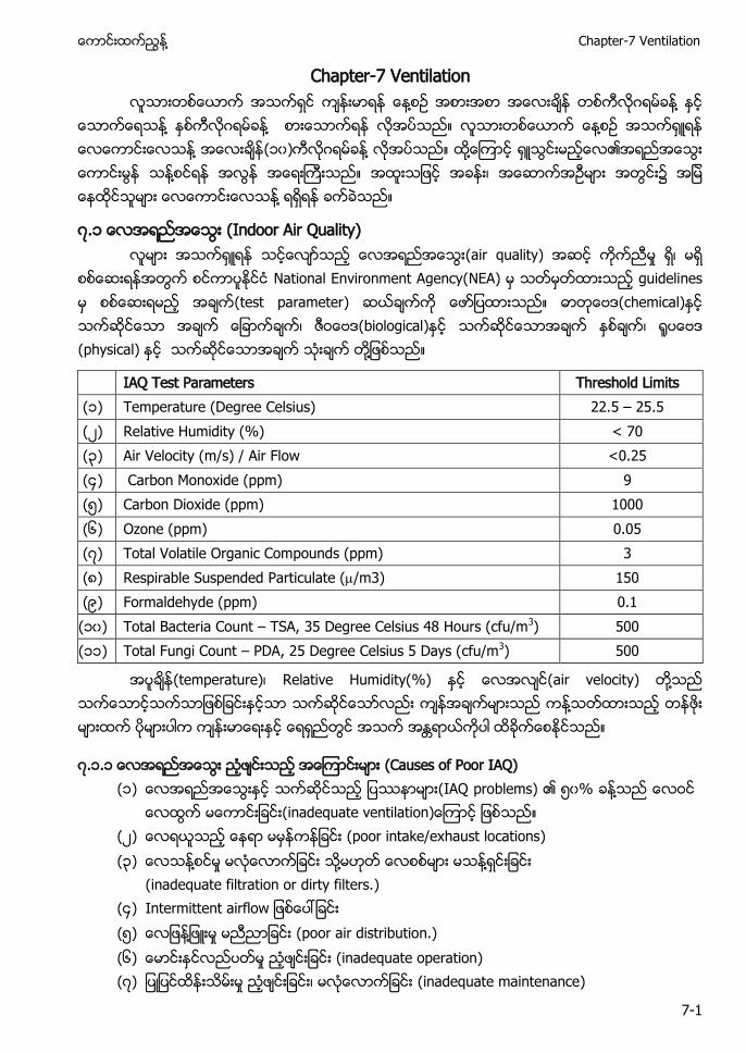
႔ Chapter-7 Ventilation
7-1
Chapter-7 Ventilation ႔ ႔
႔ ႔ ႔ ႔ (၁၀) ႔ ႔ ႔ ႔
၇.၁ (Indoor Air Quality) (air quality)
National Environment Agency(NEA) guidelines (test parameter) (chemical) (biological) (physical) ႔
IAQ Test Parameters Threshold Limits (၁) Temperature (Degree Celsius) 22.5 – 25.5 (၂) Relative Humidity (%) < 70 (၃) Air Velocity (m/s) / Air Flow <0.25 (၄) Carbon Monoxide (ppm) 9 (၅) Carbon Dioxide (ppm) 1000 (၆) Ozone (ppm) 0.05 (၇) Total Volatile Organic Compounds (ppm) 3 (၈) Respirable Suspended Particulate (/m3) 150 (၉) Formaldehyde (ppm) 0.1 (၁၀) Total Bacteria Count – TSA, 35 Degree Celsius 48 Hours (cfu/m3) 500 (၁၁) Total Fungi Count – PDA, 25 Degree Celsius 5 Days (cfu/m3) 500
(temperature) Relative Humidity(%) (air velocity) ႔ ႔
၇.၁.၁ (Causes of Poor IAQ) (၁) (IAQ problems) ၅၀% ႔
(၂) (poor intake/exhaust locations) (၃) ႔ ႔ ႔
(inadequate filtration or dirty filters.) (၄) Intermittent airflow (၅) ႔ (poor air distribution.) (၆) (inadequate operation) (၇) (inadequate maintenance)
Air Conditioning and Mechanical Ventilation (Vol. 1) ႔
7-2
၇.၁.၂ (IAQ (IAQ Control Methods) (၁)
(control temperature and humidity) (၂) ႔
(ventilation - dilution) (၃) (remove pollution source.) (၄) ႔ (filtration)
၇.၁.၃ (IAQ) (IAQ Factors) (air quality)
(၁) ႔ (thermal environment) (၂) (smoke) (၃) ႔ (odors) (၄) (irritants dust) (၅) Stress problems (perceptible, nonperceptible) (၆) ႔ (toxic gases carbon monoxide, carbon dioxide) (၇) (allergens pollen) (၈) (biological contaminants bacteria mold pathogens
legionella micro organisms fungi )
၇.၁.၄ (IAQ) (CO2 Levels) ႔(CO2)
(၁) (CO2 Levels) 350 PPM 400 PPM ႔ (Outdoor background level: 350 PPM CO2 avg.)
(၂) ASHRAE Standard 62 (CO2 Levels) 1000 PPM (ASHRAE Standard 62 recommends: 1000 PPM CO2 max.)
(၃) OSHA and U.S. Air Force standard (CO2 Levels) 650 PPM (OSHA and U.S. Air Force standard: 650 PPM CO2 max.)
(၄) (CO2 Levels) 800–1000 PPM ႔ (Human discomfort begins: 800–1000 PPM CO2.)
(၅) (CO2 Levels) 12,000 PPM (Long term health effects: >12,000 PPM CO2.)
၏ ( ) (remove heat)
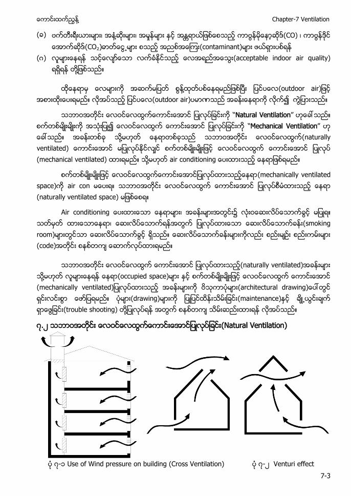
႔ Chapter-7 Ventilation
7-3
( ) ႔ (CO) (CO₂) (contaminant)
( ) (acceptable indoor air quality) ႔
႔ (outdoor (outdoor air)
“Natural Ventilation” “Mechanical Ventilation” ႔ (naturally ventilated) (mechanical ventilated) ႔ air condition
(mechanically ventilated space) air con (naturally ventilated space)
Air c (smoking room) (code)
(naturally ventilated) ႔ (occupied space) (drawing) (maintenance) (trouble shooting) ႔
၇.၂ (Natural Ventilation)
၇-၁ Use of Wind pressure on building (Cross Ventilation) ၇-၂ Venturi effect
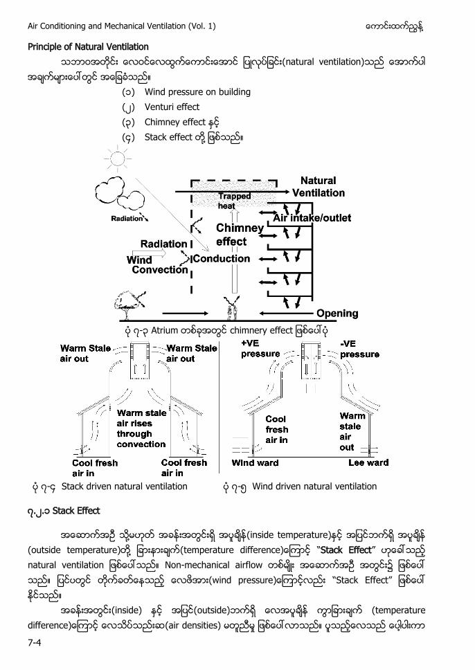
Air Conditioning and Mechanical Ventilation (Vol. 1) ႔
7-4
Principle of Natural Ventilation (natural ventilation)
(၁) Wind pressure on building (၂) Venturi effect (၃) Chimney effect (၄) Stack effect ႔
၇-၃ Atrium
၇-၄ Stack driven natural ventilation ၇-၅ Wind driven natural ventilation
၇.၂.၁ Stack Effect
႔ (inside temperature) (outside temperature) ႔ “Stack Effect” natural ventilation Non-mechanical airflow ၌ ( “Stack Effect”
(inside) (outside) (air densities)
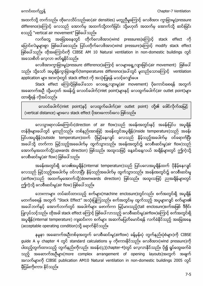
႔ Chapter-7 Ventilation
7-5
႔ (air densities) ႔ ႔ ႔ “ ”
႔ stack effect ျပ (wind pressure modify stack ထအေၾကာငးက CIBSE AM 10 Natural ventilation in non-domestic buildings
(air movement) ႔ (temperatures difference ventilation application stack effect
S (air movement) ႔ ၌ (inlet point) (air outlet point)
(direction of air flow)
(inside temperature) (outside temperature) ႔ ၌ (air flow) ႔(upwards direction) ႔ ႔ ဤ ႔ (air flow
(internal temperature) ၌ (airflow) ႔(downwards direction) ဤ ႔ (air flow
(machine enclosure) “Stack Effect” (tall enclosure) (airflow (internal temperature) (acceptable operating condition) ႔
(airflow) ႔ ) CIBSE guide A chapter 4 standard calculations (wind pressure) (၄)[chapter-4] (more complex arrangement of opening layouts) CIBSE publication AM10 Natural ventilation in non-domestic buildings 2005
(inlet point) (air outlet point) ႔ (vertical distance) stack effect
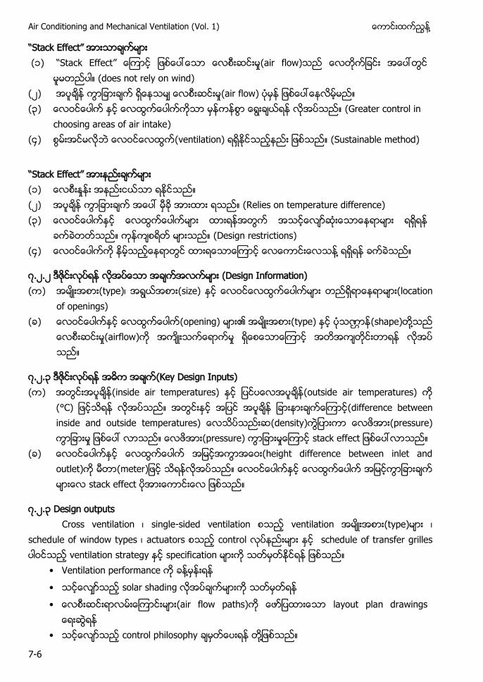
Air Conditioning and Mechanical Ventilation (Vol. 1) ႔
7-6
“S E ” (၁) “Stack Effect” (air flow)
does not rely on wind) (၂) (air flow) (၃) (Greater control in
choosing areas of air intake) (၄) (ventilation) (Sustainable method)
“S E ” (၁) (၂) (Relies on temperature difference) (၃)
(Design restrictions) (၄) ႔
၇.၂.၂ (Design Information) ( ) (type) (size) (location
of openings) ( ) (opening) (type) (shape) ႔
(airflow)
၇.၂.၃ (Key Design Inputs) ( ) (inside air temperatures) (outside air temperatures)
(° (difference between inside and outside temperatures) (density) (pressure) (pressure)
( ) (height difference between inlet and outlet) (meter stack effect
၇.၂.၃ Design outputs Cross ventilation single-sided ventilation ventilation (type)
schedule of window types actuators control schedule of transfer grilles ventilation strategy specification • Ventilation performance ႔
• solar shading • (air flow paths) la
• control philosophy ႔
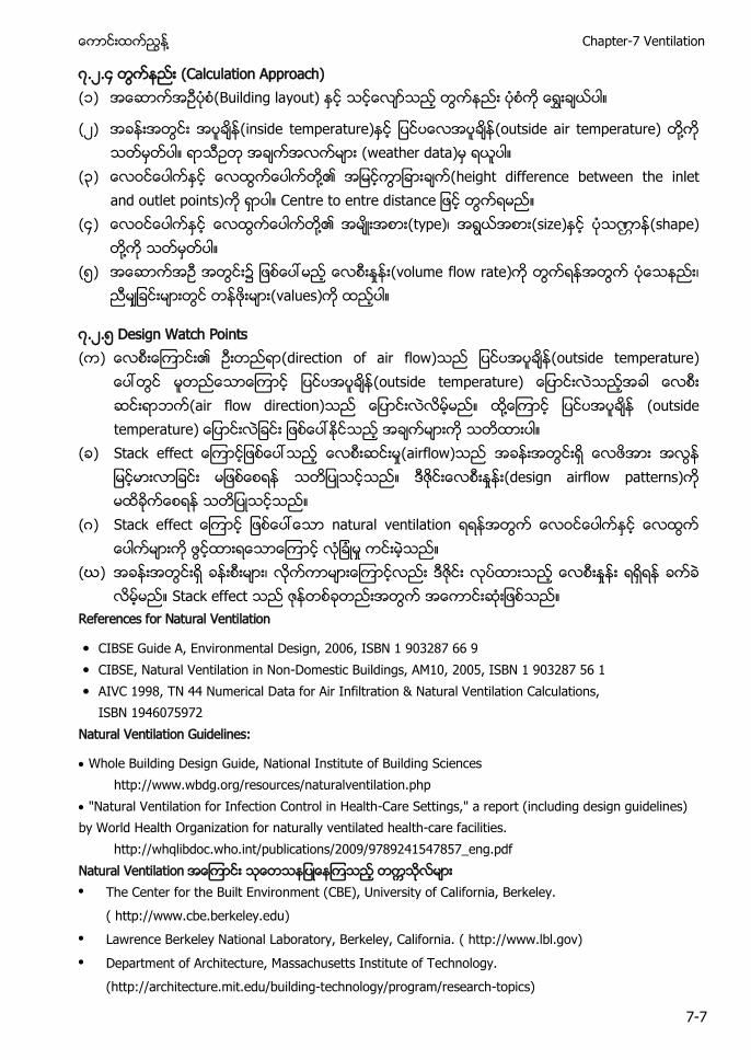
႔ Chapter-7 Ventilation
7-7
၇.၂.၄ (Calculation Approach) (၁) (Building layout)
(၂) (inside temperature) (outside air temperature) ႔ (weather data)
(၃) ႔ (height difference between the inlet and outlet points) Centre to
(၄) ႔ (type) (size) (shape) ႔
(၅) (volume flow rate) (values)
၇.၂.၅ Design Watch Points ( ) (direction of air flow) (outside temperature)
(outside temperature) (air flow direction) ႔ (outside temperature
( ) S (airflow) (design airflow patterns)
( ) S natural ventilation
(ဃ) Stack effect
References for Natural Ventilation
CIBSE Guide A, Environmental Design, 2006, ISBN 1 903287 66 9 CIBSE, Natural Ventilation in Non-Domestic Buildings, AM10, 2005, ISBN 1 903287 56 1 AIVC 1998, TN 44 Numerical Data for Air Infiltration & Natural Ventilation Calculations,
ISBN 1946075972 Natural Ventilation Guidelines:
Whole Building Design Guide, National Institute of Building Sciences http://www.wbdg.org/resources/naturalventilation.php
"Natural Ventilation for Infection Control in Health-Care Settings," a report (including design guidelines) by World Health Organization for naturally ventilated health-care facilities.
http://whqlibdoc.who.int/publications/2009/9789241547857_eng.pdf Natural Ventilation The Center for the Built Environment (CBE), University of California, Berkeley. ( http://www.cbe.berkeley.edu) Lawrence Berkeley National Laboratory, Berkeley, California. ( http://www.lbl.gov) Department of Architecture, Massachusetts Institute of Technology. (http://architecture.mit.edu/building-technology/program/research-topics)
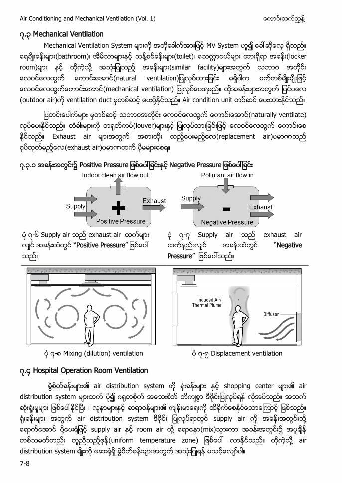
Air Conditioning and Mechanical Ventilation (Vol. 1) ႔
7-8
၇.၃ Mechanical Ventilation Mechanical Ventilation System MV System
(bathroom) ႔ (toilet) (locker room) ႔ (similar facility) (natural ventilation (mechanical ventilation) (outdoor air) ventilation duct ႔ Air condition unit
(naturally ventilate) (louver) Exhaust air (replacement air) (exhaust air)
၇.၃.၁
၇-၆ Supply air exhaust air “Positive Pressure”
၇-၇ Supply air exhaust air “Negative Pressure”
၇-၈ Mixing (dilution) ventilation ၇-၉ Displacement ventilation
၇.၄ Hospital Operation Room Ventilation
air distribution system shopping center air distribution system air distribution system supply air ႔ ႔ supply air room air ႔ (mix) (uniform temperature zone) ႔ air distribution system
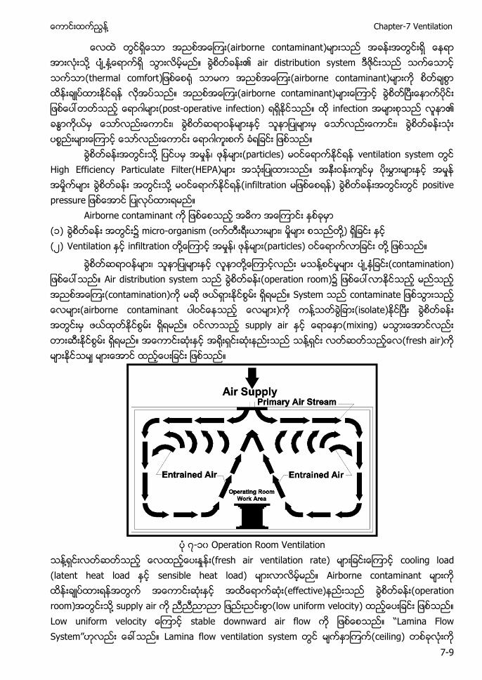
႔ Chapter-7 Ventilation
7-9
(airborne contaminant) ႔ ႔ air distribution system (thermal comfort (airborne contaminant) (airborne contaminant) (post-operative infection) infection
႔ (particles) ventilation system High Efficiency Particulate Filter(HEPA) ႔ (infiltration ) positive
Airborne contaminant (၁) micro-organism ( ႔) (၂) Ventilation infiltration ႔ (particles) ႔
႔ ႔ (contamination) Air distribution system (operation room)၌ (contamination) System (airborne contaminant ) ႔ (isolate) supply air (mixing) ႔ (fresh air)
၇-၁၀ Operation Room Ventilation
႔ (fresh air ventilation rate) cooling load (latent heat load sensible heat load) Airborne contaminant (effective) (operation room) ႔ supply air (low uniform velocity) stable downward air flow “Lamina Flow System” Lamina flow ventilation system (ceiling)
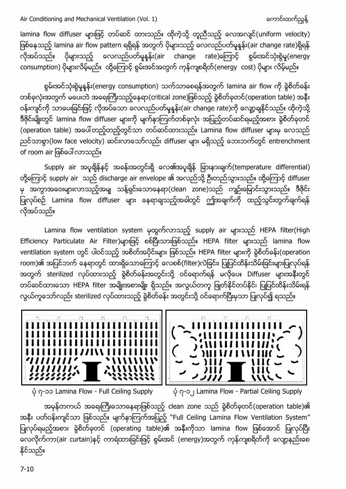
Air Conditioning and Mechanical Ventilation (Vol. 1) ႔
7-10
lamina flow diffuser ႔ (uniform velocity) lamina air flow pattern (air change rate) (air change rate (energy consumption) ႔ (energy cost)
(energy consumption) lamina air flow (critical zone (operation table) (air change rate) ႔ lamina flow diffuser (operation table) Lamina flow diffuser (low face velocity) diffuser
Supply air (temperature differential) ႔ supply air discharge air envelope ႔ ႔ diffuser ႔ (clean zone) Lamina flow diffuser
Lamina flow ventilation system supply air HEPA filter(High Efficiency Particulate Air Filter) HEPA filter lamina flow ventilation system HEPA filter (operation room) (filter) sterilized ႔ Diffuser HEPA filter sterilized ႔
၇-၁၁ Lamina Flow - Full Ceiling Supply ၇-၁၂ Lamina Flow - Partial Ceiling Supply
clean zone (operation table) “Full Ceiling Lamina Flow Ventilation System” (operating table) lamina f (air curtain) (energy)
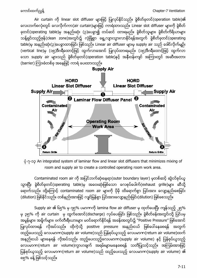
႔ Chapter-7 Ventilation
7-11
Air curtain linear slot diffuser (operation table) (air curtain) Linear slot diffuser (operating table) (၃ ႔ (clean zone) (operating table) (၃ Linear air diffuser supply air (vertical line) (၁၅) (၁၅) supply air (operation table) (barrier)
၇-၁၃ An integrated system of laminar flow and linear slot diffusers that minimizes mixing of
room and supply air to create a controlled operating room work area.
Contaminated room air (outer boundary layer) (operating table) (exhaust grille) ႔ ႔ contaminated room air (dilution) (dilution)
Supply air ၆၅% ၇၅% lamina flow air diffuser ၂၅% ၃၅% air curtain (discharge) ႔ “ ” ႔ positive pressure (supply air volume) (return air volume) (supply air volume) (return air volume) (return air volume) (supply air volume) ၈၅% ႔
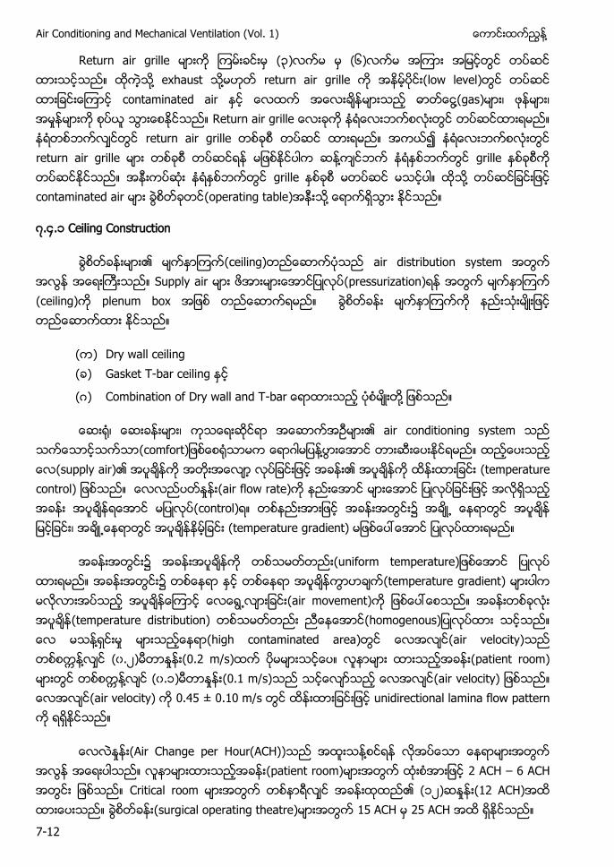
Air Conditioning and Mechanical Ventilation (Vol. 1) ႔
7-12
Return air grille (၃) (၆) ႔ exhaust ႔ return air grille (low level) contaminated air ႔(gas) return air grille return air grille ႔ grille grille ႔ contaminated air (operating table) ႔
၇.၄.၁ Ceiling Construction
(ceiling) air distribution system Supply air (pressurization) (ceiling) plenum box
( ) Dry wall ceiling ( ) Gasket T-bar ceiling
( ) - ႔
air conditioning system (comfort ႔ (supply air) (temperature control) (air flow rate) (control) (temperature gradient)
(temperature gradient) (air movement) (temperature distribution) ႔ (high contaminated area) (air velocity) ႔ (၀.၂) (0.2 m/s) (patient room) ႔ (၀.၁) (0.1 m/s) (air velocity) (air velocity) 0.45 ± 0.10 m/s unidirectional lamina flow pattern
(Air Change per Hour(ACH)) ႔ (patient room) 2 ACH – 6 ACH Critical room (၁၂) (12 ACH) (surgical operating theatre) 15 ACH 25 ACH
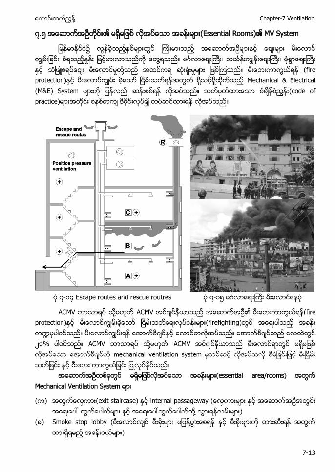
႔ Chapter-7 Ventilation
7-13
၇.၅ (Essential Rooms) MV System
၌ ႔ ဃ ႔ (fire protection) Mechanical & Electrical (M&E) S code of practice)
၇-၁၄ Escape routes and rescue routres ၇-၁၅
႔ (fire protection) ႑ ၂၁ ႔ mechanical ventilation s
(essential area/rooms) Mechanical Ventilation System
( ) (exit staircase) internal passageway ႔
( ) Smoke stop lobby ( ႔ )
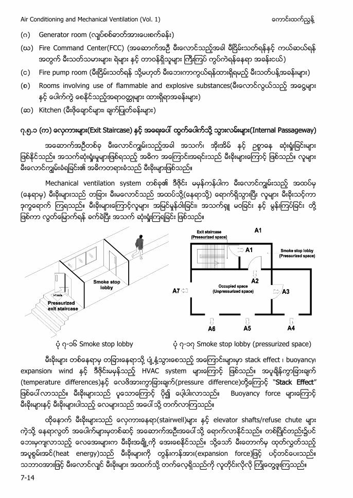
Air Conditioning and Mechanical Ventilation (Vol. 1) ႔
7-14
( ) Generator room ( )
(ဃ) Fire Command Center(FCC) ( )
( ) Fire pump room ( ႔ ႔
( ) Rooms involving use of flammable and explosive substances( ႔
( ) Kitchen ( )
၇.၅.၁ ( ) (Exit Staircase) ႔ (Internal Passageway)
Mechanical ventilation s ) ႔ ႔) ႔
၇-၁၆ Smoke stop lobby ၇-၁၇ Smoke stop lobby (pressurized space)
႔ ႔ stack eff (temperature differences) (pressure difference) ႔ “Stack Effect” Buoyancy f ႔
stairwell) elevator shafts/refuse chute ႔ ႔ ၌ ႔ (heat energy) expansion force ႔ ႔
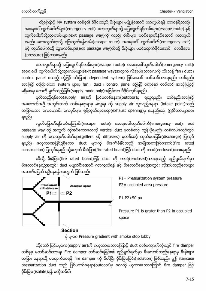
႔ Chapter-7 Ventilation
7-15
႔ emergency exit)
႔ (exit passage way) ႔ duct control p ႔ independent system) fan duct ႔ (
o s (intake point) ႔ (exhaust opening) ၅
emergency exit) exit passage w ႔ ႔ supply a (grillers diffusers) (discharge) duct (fire rated construction) ႔ fire rated b duct enclosed)
႔ fire rated b duct enclosed) duct
P1= Pressurization system pressure P2= occupied area pressure P1-P2>50 pa Pressure P1 is grater than P2 in occupied space
၇-၁၈ Pressure gradient with smoke stop lobby
႔ supply air) fire d ႔ fire damper isolation) staricase p isolate)
႔ ႔ ႔ ႔ (exit passage way ႔ ႔ (exit passage way ႔ (pressure
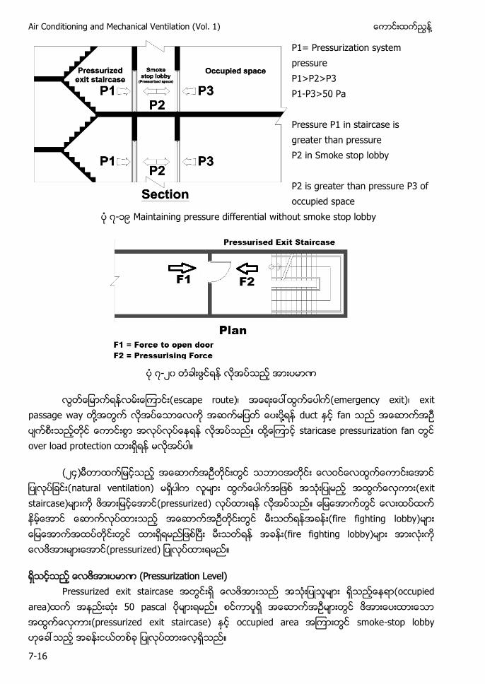
Air Conditioning and Mechanical Ventilation (Vol. 1) ႔
7-16
P1= Pressurization system pressure P1>P2>P3 P1-P3>50 Pa Pressure P1 in staircase is greater than pressure P2 in Smoke stop lobby P2 is greater than pressure P3 of occupied space
၇-၁၉ Maintaining pressure differential without smoke stop lobby
၇-၂၀
emergency exit) exit passage way ႔ ႔႔ f ႔ s over load p
(၂၄) natural ventilation) (exit staircase) pressurized) (fire fighting lobby) (fire fighting lobby) (pressurized)
(Pressurization Level) Pressurized exit staircase (occupied
area) p (pressurized exit staircase) -
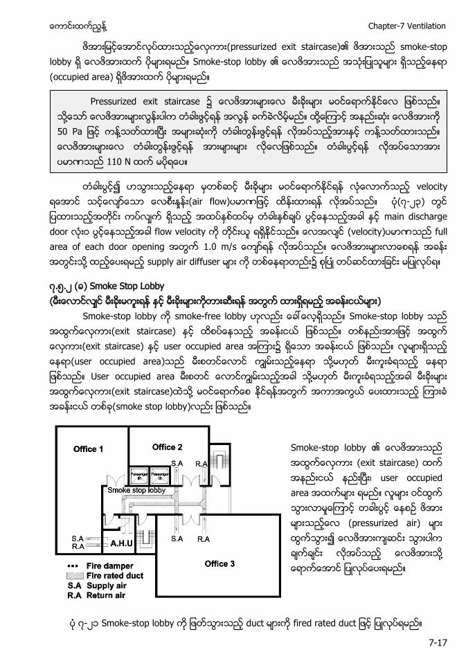
႔ Chapter-7 Ventilation
7-17
smoke-stop S - (occupied area)
(air flow) ၇-၂၃) main discharge (velocity) . ႔ ၌
၇.၅.၂ ( ) Smoke Stop Lobby ( )
S - smoke-f S - (exit staircase) (exit staircase) user occupied a ၌ user occupied area) ႔ User occupied a ႔ (exit staircase) ႔ (smoke stop lobby)
S - (exit staircase) user occupied a pressurized air) ႔
၇-၂၁ Smoke-stop lobby fired rated duct
Pressurized exit staircase ႔ ႔ ႔ ႔
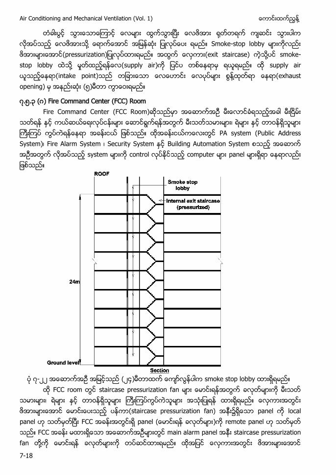
Air Conditioning and Mechanical Ventilation (Vol. 1) ႔
7-18
႔ S - (exit staircase) ႔ smoke-s ႔ s s (intake point) ႔ (exhaust opening) ၅
၇.၅.၃ ( ) Fire Command Center (FCC) Room Fire Command Center (FCC Room)
PA system (Public Address System) Fire Alarm System S S B S c panel
၇-၂၂ ၂၄ smoke stop lobby
staircase pressurization f staircase pressurization fan) local p panel remote panel main alarm panel staircase pressurization f ႔
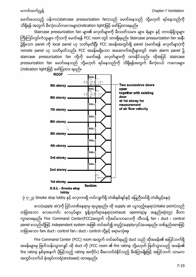
႔ Chapter-7 Ventilation
7-19
staircase pressurization fan) ႔ indication light
Staircase pressurization f FCC r Staircase local panel panel remote panel main alarm staircase pressurization f ႔ staircase pressurization fan ႔
၇-၂၃ Smoke stop lobby
s s (intake point) ႔ (exhaust opening) ၅) Fire Command Center(FCC) ႔ duct p ႔ i supply f duct duct ontrol ႔
Fire Command Center (FCC) r duct duct (FCC r fire rating ႔ r ) (enclosed)
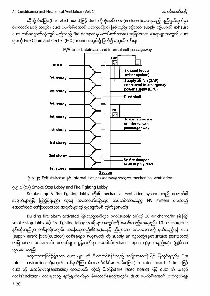
Air Conditioning and Mechanical Ventilation (Vol. 1) ႔
7-20
႔ fire rated board duct (enclosed) duct ႔ ႔ exhaust duct fire d duct Fire Command Center (FCC) room
M/V to exit staircase and internal exit passageway
၇-၂၄ E mechanical ventilation
၇.၅.၄ (ဃ) Smoke Stop Lobby and Fire Fighting Lobby Smoke-st ႔
Building f (supply air) - smoke-stop l fire fighting l ႔ - ၁၀ (s outdoor) s (intake point) ႔ (exhaust opening) ၅
Fire rated construction ႔ - ႔
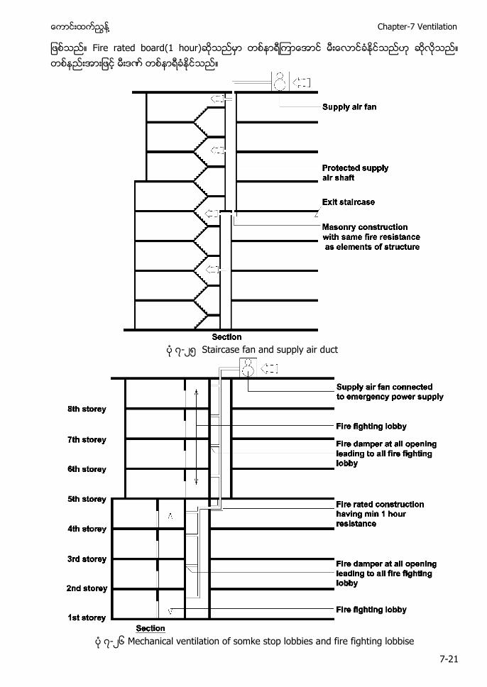
႔ Chapter-7 Ventilation
7-21
၇-၂၅ Staircase fan and supply air duct
၇-၂၆ Mechanical ventilation of somke stop lobbies and fire fighting lobbise
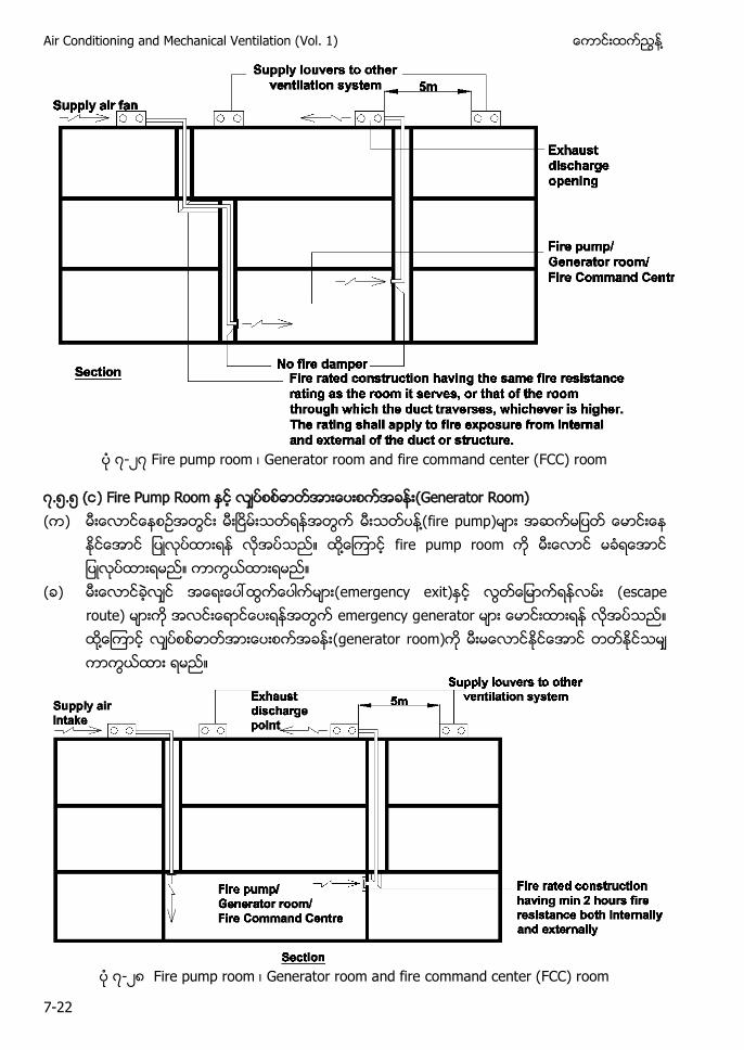
Air Conditioning and Mechanical Ventilation (Vol. 1) ႔
7-22
၇-၂၇ G
၇.၅.၅ ( ) Fire Pump Room (Generator Room) ( ) ႔ fire pump)
႔ f
( ) emergency exit (escape route) emergency g ႔ (generator room)
၇-၂၈ G
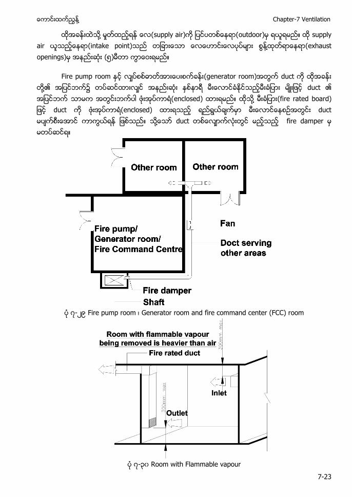
႔ Chapter-7 Ventilation
7-23
႔ s s (intake point) ႔ (exhaust openings) ၅
(generator room) duct ႔ enclosed) ႔ (fire rated board) duct enclosed) duct ႔ fire d
၇-၂၉ Fire pump room Generator room and fire command center (FCC) room
၇-၃၀ Room with Flammable vapour
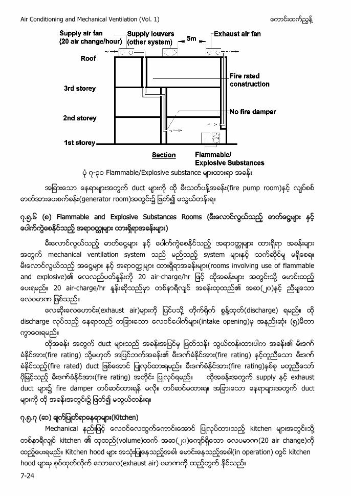
Air Conditioning and Mechanical Ventilation (Vol. 1) ႔
7-24
၇-၃၁ E
duct ႔ (fire pump room) (generator room)
၇.၅.၆ E S ႔
႔ ႔ - ႔ - (၂၀
exhaust air) ႔ ႔ (discharge) (intake opening) (၅
duct fire rating) ႔ fire rating) fire rated) fire rating) fire rating) ၌ duct
၇.၅.၇ ( ) (Kitchen) Mechanical kitchen ႔ kitchen ၏ (volume) (၂၀ (20 air change) Kitchen hood (in operation) kitchen hood (exhaust air)
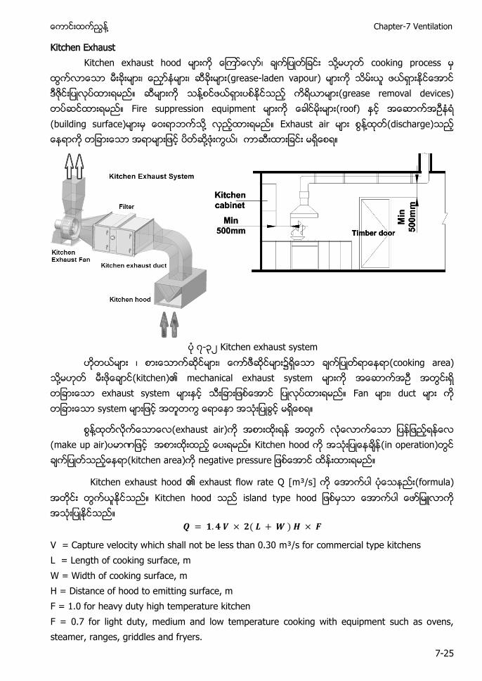
႔ Chapter-7 Ventilation
7-25
Kitchen Exhaust Kitchen exhaust hood ႔ cooking process (grease-laden vapour) ႔ (grease removal devices) Fire suppression equipment (roof) (building surface) ႔ Exhaust air ႔ (discharge) ႔
၇-၃၂ Kitchen exhaust system (cooking area) ႔ (kitchen) mechanical exhaust system exhaust system Fan duct system
႔ (exhaust air) (make up air) Kitchen hood (in operation) (kitchen area)
Kitchen exhaust hood ၏ exhaust flow rate Q [m³/s] (formula) Kitchen hood
V = Capture velocity which shall not be less than 0.30 m³/s for commercial type kitchens L = Length of cooking surface, m W = Width of cooking surface, m H = Distance of hood to emitting surface, m F = 1.0 for heavy duty high temperature kitchen F = 0.7 for light duty, medium and low temperature cooking with equipment such as ovens, steamer, ranges, griddles and fryers.
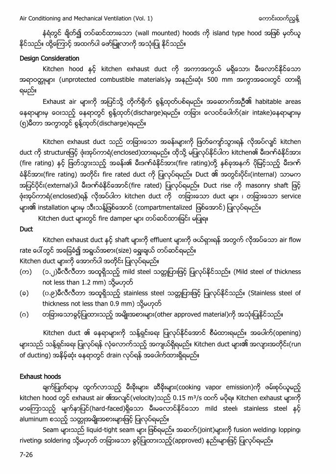
Air Conditioning and Mechanical Ventilation (Vol. 1) ႔
7-26
၍ (wall mounted) hoods island type hood ႔
Design Consideration Kitchen hood kitchen exhaust duct
(unprotected combustible materials) 500 mm
Exhaust air ႔ ႔ ၏ habitable areas ႔ (discharge) (၅) ႔ (discharge)
Kitchen exhaust duct kitchen duct enclosed) ႔ kitchen (fire rating) ၏ fire rating) ႔ (fire rating) fire rated duct Duct ၏ (internal) (external) (fire rated) Duct rise enclosed) kitchen duct duct service ၏ installation ႔ (compartmentalized )
Kitchen duct fire damper Duct
Kitchen exhaust duct shaft effluent air Kitchen duct ( ) (၁.၂) mild steel (Mild steel of thickness
not less than 1.2 mm) ႔ ( ) (၀.၉) stainless steel (Stainless steel of
thickness not less than 0.9 mm) ႔ ( ) (other approved material)
Kitchen duct ႔ (opening) ႔ Kitchen duct ၏ (run of ducting) drain Exhaust hoods
(cooking vapor emission) kitchen hood exhaust air (velocity) 0.15 m³/s Kitchen exhaust (hard-faced) mild steel stainless steel aluminum
Seam liquid-tight seam (joint) fusion welding lopping riveting soldering ႔ (approved)
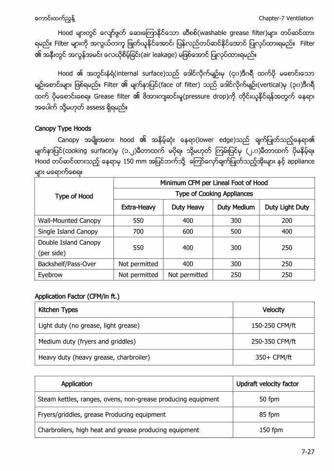
႔ Chapter-7 Ventilation
7-27
Hood (washable grease filter) Filter Filter ၏ (air leakage)
Hood ၏ (internal surface) (၄၀) Filter ၏ (face of filter) (vertical) (၃၀) Grease filter ၏ (pressure drop) ႔ assess
Canopy Type Hoods
Canopy hood ၏ (lower edge) (cooking surface) (၁.၂) ႔ (၂.၀) Hood 150 mm ႔ appliance
Type of Hood
Minimum CFM per Lineal Foot of Hood Type of Cooking Appliances
Extra-Heavy Duty Heavy Duty Medium Duty Light Duty
Wall-Mounted Canopy 550 400 300 200 Single Island Canopy 700 600 500 400 Double Island Canopy (per side)
550 400 300 250
Backshelf/Pass-Over Not permitted 400 300 250 Eyebrow Not permitted Not permitted 250 250
Application Factor (CFM/in ft.)
Kitchen Types Velocity
Light duty (no grease, light grease) 150-250 CFM/ft
Medium duty (fryers and griddles) 250-350 CFM/ft
Heavy duty (heavy grease, charbroiler) 350+ CFM/ft
Application Updraft velocity factor
Steam kettles, ranges, ovens, non-grease producing equipment 50 fpm
Fryers/griddles, grease Producing equipment 85 fpm
Charbroilers, high heat and grease producing equipment 150 fpm
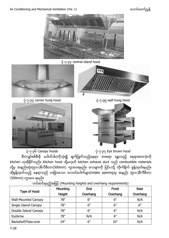
Air Conditioning and Mechanical Ventilation (Vol. 1) ႔
7-28
၇-၃၃ central island hood
၇-၃၄ corner hung hood ၇-၃၅ wall hung hood
၇-၃၆ Canopy hoods ၇-၃၇ Eye brown hood
( k Kitchen h ႔ kitchen e ႔ (၅၀၀) (500mm) ႔ ႔ ႔ intake opening) (၅၀၀) (500mm)
Mounting heights and overhang requirements)
Type of Hood Mounting Height
End Overhang
Front Overhang
Rear Overhang
Wall-Mounted Canopy 78" 6" 6" N/A Single Island Canopy 78" 6" 6" 6" Double Island Canopy 78" 6" 6" N/A Eyebrow 78" N/A 6" N/A Backshelf/Pass-over 24" 6" 10" N/A
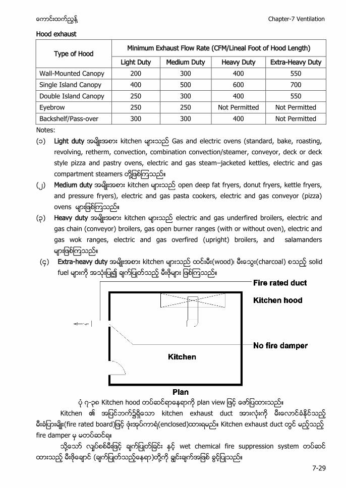
႔ Chapter-7 Ventilation
7-29
Hood exhaust
Type of Hood Minimum Exhaust Flow Rate (CFM/Lineal Foot of Hood Length)
Light Duty Medium Duty Heavy Duty Extra-Heavy Duty Wall-Mounted Canopy 200 300 400 550 Single Island Canopy 400 500 600 700 Double Island Canopy 250 300 400 550 Eyebrow 250 250 Not Permitted Not Permitted Backshelf/Pass-over 300 300 400 Not Permitted
Notes: (၁) Light duty G
– ႔
(၂) Medium duty open deep fat fryers, donut fryers, kettle fryers, and pressure fryers), electric and gas pasta cookers, electric and gas conveyor (pizza) ovens
(၃) Heavy duty electric and gas underfired broilers, electric and gas chain (conveyor) broilers, gas open burner ranges (with or without oven), electric and gas wok ranges, electric and gas overfired (upright) broilers, and salamanders
(၄) Extra-heavy duty charcoal solid fuel
၇-၃၈ Kitchen hood
K kitchen (fire rated board K fire damper
႔ wet chemical fire suppression syst ( ႔
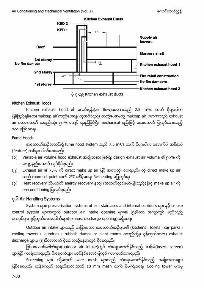
Air Conditioning and Mechanical Ventilation (Vol. 1) ႔
7-30
၇-၃၉ Kitchen exhaust ducts
Kitchen Exhaust Hoods Kitchen exhaust hood (air flow) 2.5 m³/s (makeup air) makeup air exhaust air ၅၀ mechanical
Fume Hoods fume hood system 7.5 m³/s (feature) (၁) Variable air volume hood exhaust design exhaust air volume ၅၀%
(၂) Exhaust air 75% direct make up air
room set point 2°C Re-heating (၃) Heat recovery ႔ energy recovery ( make up air
၇.၆ Air Handling Systems System pressurisation systems of exit staircases and internal corridors smoke
control system outdoor air intake opening (၅) ႔ (exhaust discharge opening)
Outdoor air intake (kitchens toilets car parks cooling towers laundries rubbish dumps or plant rooms ႔ ႔ ) exhaust discharge (၅)
(outdoor air intake) (insect screen)
Screening ႔ wire mesh 10 mm mesh Cooling tower
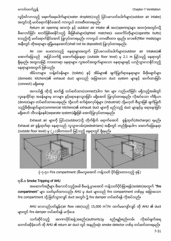
႔ Chapter-7 Ventilation
7-31
(water droplets) (outdoor air intake) ႔
Return air opening outdoor air intake (opening) ႔ (lighted matches) (cigarette butts) ႔ (filter media) (shall not b
Air con (outdoor air intakes) (outside floor level) .
႔ (toilets) (domestic kitchens) exhaust duct duct system (connect)
႔ (connect) fan (device) ႔ (industrial) ႔ (commercial kitchens) exhaust duct duct ႔ (separate system)
Exhaust air (outdoor) ႔ ႔ (discharge) Exhaust air ႔ (pedestrians) (outside floor level) (၂.၁)
၇-၄၀ ( ႔ )
၇.၆.၁ Smoke Tripping of AHU ႔ (isolate) “fire
compartment” duct ႔ duct fire damper
(air flow rate) m3 fire damper
authority) smoke detector
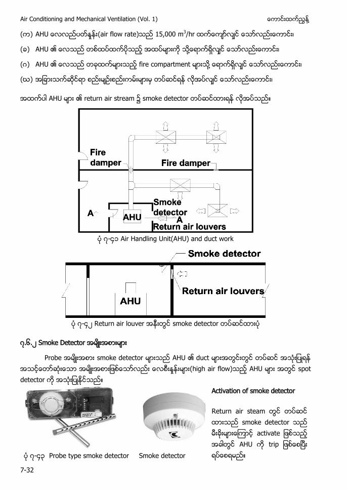
Air Conditioning and Mechanical Ventilation (Vol. 1) ႔
7-32
( ) (air flow rate) m3
( ) ႔
( ) ႔
(ဃ)
return air stream ၌ s
၇-၄၁ Air Handling Unit(AHU) and duct work
၇-၄၂
၇.၆.၂ S
s
Activation of smoke detector
Return air s smoke detec a t ၇-၄၃ Probe type smoke detector Smoke detector
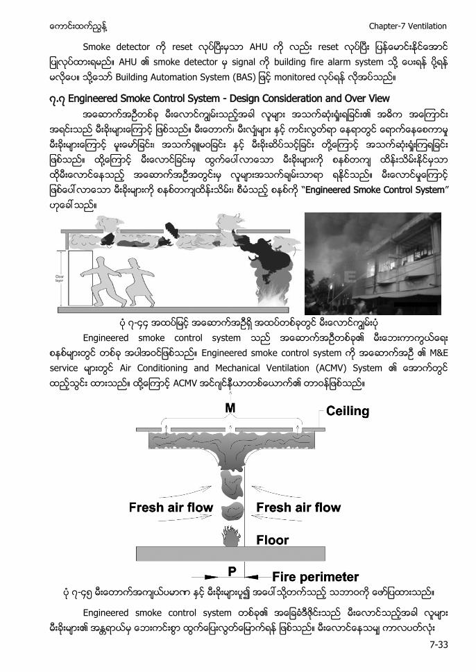
႔ Chapter-7 Ventilation
7-33
S s building fire alarm s ႔ ႔ ႔ Building Automation System (BAS)
၇.၇ Engineered Smoke Control System - Design Consideration and Over View
႔ ႔ “Engineered Smoke Control System”
၇-၄၄
Engineered smoke control system Engineered smoke control s E service Air Conditioning and Mechanical Ventilation (ACMV) S ႔
၇-၄၅ ႔
Engineered smoke control system
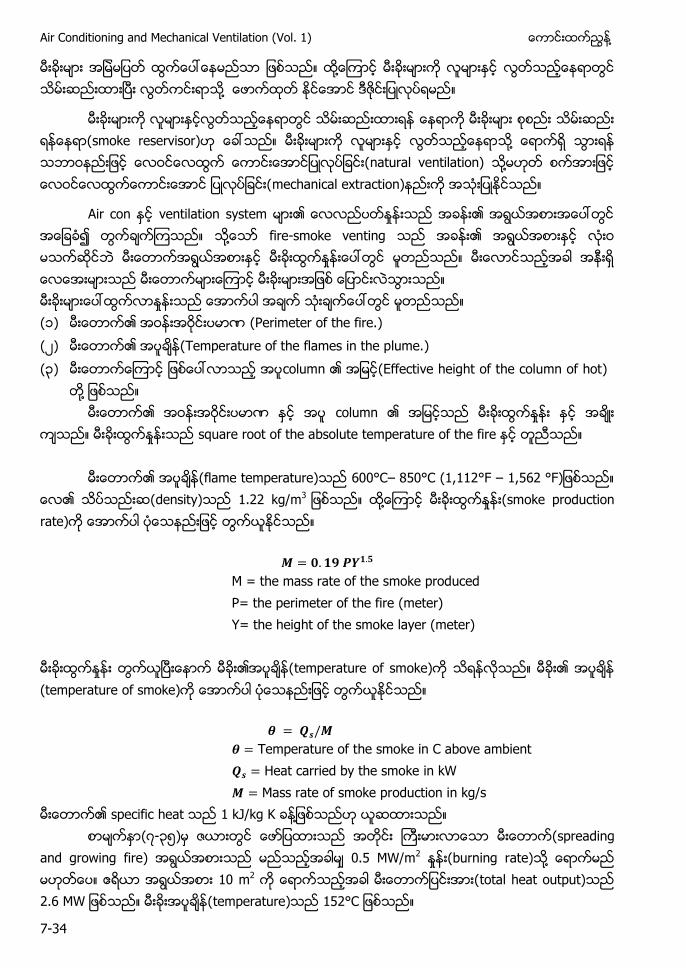
Air Conditioning and Mechanical Ventilation (Vol. 1) ႔
7-34
႔ ႔
smoke reservisor) ႔ na ႔
A ventilation system ႔ - (၁) (Perimeter of the fire.) (၂) (Temperature of the flames in the plume.) (၃) (Effective height of the column of hot)
႔
square root of the absolute temperature flame temperature) 600°C– 850°C (1,112°F –
. kg/m3 ႔
M = the mass rate of the smoke produced P= the perimeter of the fire (meter) Y= the height of the smoke layer (meter)
(temperature
Temperature of the smoke in C above ambient Heat carried by the smoke in kW Mass rate of smoke production in kg/s
specific heat 1 kJ/kg K ႔ ၇-၃၅ spreading
and growing fire) 0.5 MW/m2 ႔ m2 total heat output) 2.6 temperature)
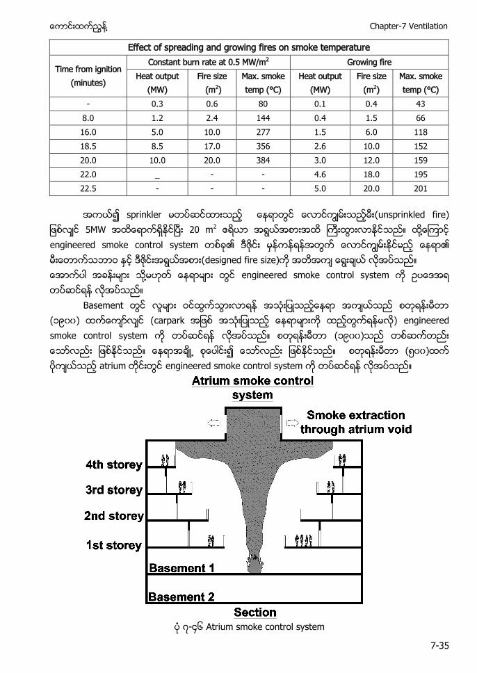
႔ Chapter-7 Ventilation
7-35
Effect of spreading and growing fires on smoke temperature
Time from ignition (minutes)
Constant burn rate at 0.5 MW/m2 Growing fire Heat output
(MW) Fire size
(m2) Max. smoke temp (°C)
Heat output (MW)
Fire size (m2)
Max. smoke temp (°C)
- 0.3 0.6 80 0.1 0.4 43 8.0 1.2 2.4 144 0.4 1.5 66 16.0 5.0 10.0 277 1.5 6.0 118 18.5 8.5 17.0 356 2.6 10.0 152 20.0 10.0 20.0 384 3.0 12.0 159 22.0 _ - - 4.6 18.0 195 22.5 - - - 5.0 20.0 201
(unsprinkled fire) 20 m2 ႔ engineered smoke control s designed fire s ႔ engineered smoke control system
B (၁၉၀၀) ( engineered smoke control system ၁၉၀၀ ၅၀၀ a engineered smoke control system
၇-၄၆ Atrium smoke control system
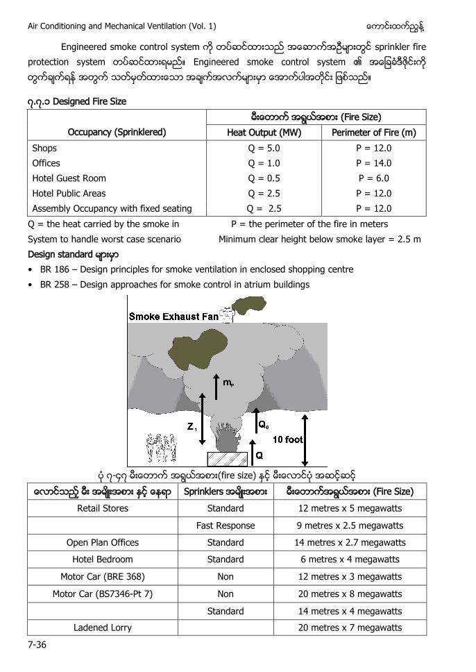
Air Conditioning and Mechanical Ventilation (Vol. 1) ႔
7-36
Engineered smoke control system sprinkler fire protection s Engineered smoke control system
၇.၇.၁ Designed Fire Size
Occupancy (Sprinklered) (Fire Size)
Heat Output (MW) Perimeter of Fire (m) Shops Q = 5.0 P = 12.0 Offices Q = 1.0 P = 14.0 Hotel Guest Room Q = 0.5 P = 6.0 Hotel Public Areas Q = 2.5 P = 12.0 Assembly Occupancy with fixed seating Q = 2.5 P = 12.0
Q = the heat carried by the smoke in P = the perimeter of the fire in meters System to handle worst case scenario Minimum clear height below smoke layer = 2.5 m • BR 186 – Design principles for smoke ventilation in enclosed shopping centre • BR 258 – Design approaches for smoke control in atrium buildings
၇-၄၇ (fire size)
Sprinklers Fire Size)
Retail Stores Standard 12 metres x 5 megawatts Fast Response 9 metres x 2.5 megawatts
Open Plan Offices Standard 14 metres x 2.7 megawatts
Hotel Bedroom Standard 6 metres x 4 megawatts
Motor Car (BRE 368) Non 12 metres x 3 megawatts
Motor Car (BS7346-Pt 7) Non 20 metres x 8 megawatts Standard 14 metres x 4 megawatts
Ladened Lorry 20 metres x 7 megawatts
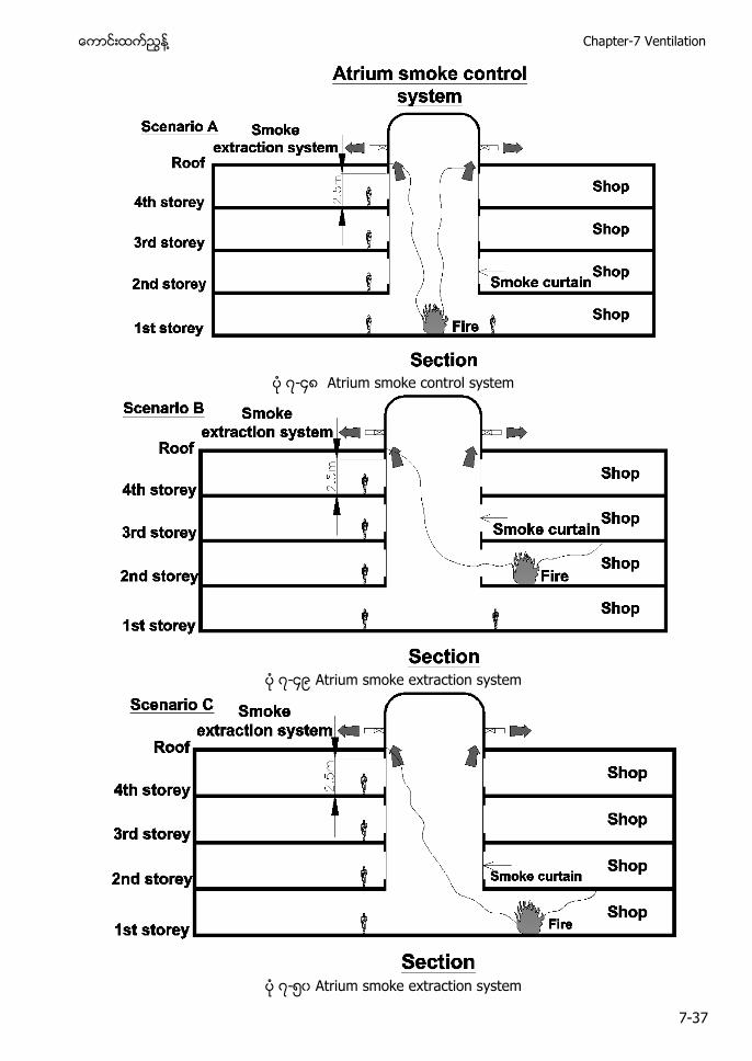
႔ Chapter-7 Ventilation
7-37
၇-၄၈ Atrium smoke control system
၇-၄၉ Atrium smoke extraction system
၇-၅၀ Atrium smoke extraction system
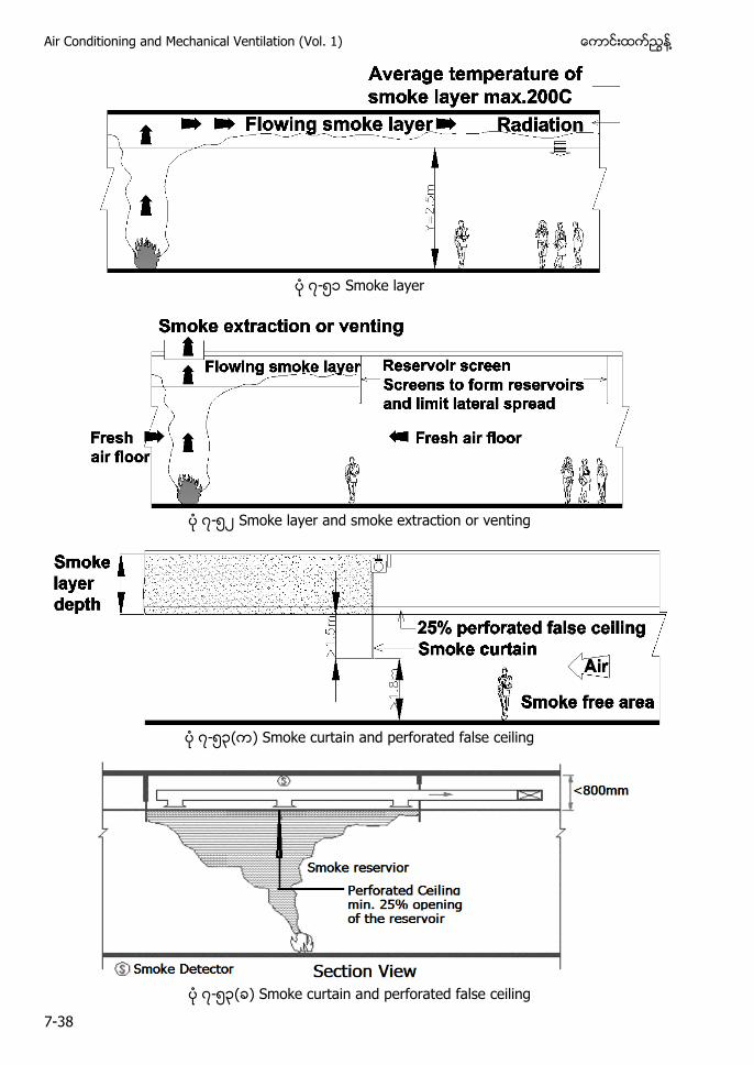
Air Conditioning and Mechanical Ventilation (Vol. 1) ႔
7-38
၇-၅၁ Smoke layer
၇-၅၂ Smoke layer and smoke extraction or venting
၇-၅၃( ) Smoke curtain and perforated false ceiling
၇-၅၃( ) Smoke curtain and perforated false ceiling
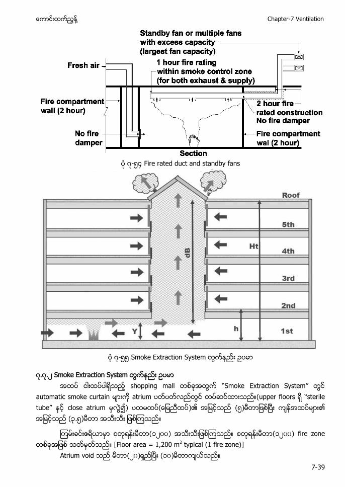
႔ Chapter-7 Ventilation
7-39
၇-၅၄ Fire rated duct and standby fans
၇-၅၅ Smoke Extraction System
၇.၇.၂ Smoke Extraction System shopping m “Smoke Extraction System”
automatic smoke curtain ( “ ” ) ) ၅ ၃.၅
၁၂၀၀ ၁၂၀၀ f [Floor area = 1,200 m2 typical (1 fire zone)]
Atrium (၂၀ (၁၀)
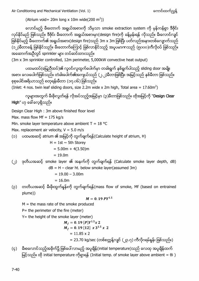
Air Conditioning and Mechanical Ventilation (Vol. 1) ႔
7-40
(Atrium void= 20m long x 10m wide(200 m2))
smoke extraction s design f ႔ design f 3m x 3 ၁၂ ႔ (၅၀၀၀ (3m x 3m sprinkler controlled, 12m perimeter, 5,000kW convective heat output)
) sliding door ၂.၂ ၁၇.၀၆) (Inlet: 4 nos. twin leaf sliding doors, size 2.2m wide x 2m high, Total area = 17.60m2)
၃ “Design Clear High”
Design Clear High : 3m above finished floor level Max. mass flow Mf = 175 kg/s Min. smoke layer temperature above ambient T = 18 °C Max. replacement air velocity, V = 5.0 m/s (၁) (Calculate height of atrium, H)
H = 1st ~ 5th Storey = 5.00m + 4(3.50)m = 19.0m
(၂) smoke layer (Calculate smoke layer depth, dB) dB = H – clear ht. below smoke layer(assumed 3m) = 19.00 – 3.00m = 16.0m
(၃) (mass flow of smoke, Mf (based on entrained plume))
M = the mass rate of the smoke produced P= the perimeter of the fire (meter) Y= the height of the smoke layer (meter)
[ ] [ ] = 11.85 x 2 = 23.70 kg/sec ( ႔ (၂၃.၇) )
(၄) ၌ (initial temperature) initial temperature (I . = θ )
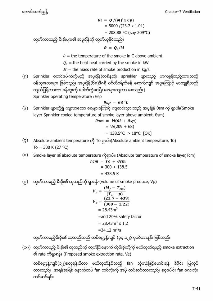
႔ Chapter-7 Ventilation
7-41
= 5000 /(23.7 x 1.01) = 208.88 °C (say 209°C)
the temperature of the smoke in C above ambient the heat heat carried by the smoke in kW the mass rate of smoke production in kg/s
(၅) Sprinkler ( sprinkler (၆၈) ႔ ႔ ) Sprinkler operating temperature θ
(၆) Sprinkler θ (Smoke
S θ
= ½(209 + 68) = 138.5°C > 18°C [OK]
(၇) (Absolute ambient temperature, To) To = 300 K (27 °C)
(၈) Smoke layer absolute temperature (Absolute temperature of smoke layer,Tcm) 𝑻𝒄 𝑻𝒐
= 300 + 138.5 = 438.5 K
(၉) -(volume of smoke produce, Vp)
𝑻𝒄
𝑻𝒐
= 28.43m3 =add 20% safety factor = 28.43m3 x 1.2 =34.12 m3/s
႔ ၃၄.၁၂
(၁၀) ႔ (Proposed smoke extraction rate, Ve)
႔ ၁၂ fan
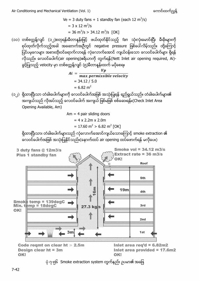
Air Conditioning and Mechanical Ventilation (Vol. 1) ႔
7-42
Ve = 3 duty fans + 1 standby fan (each 12 m3/s) = 3 x 12 m3/s = 36 m3/s > 34.12 m3/s [OK]
(၁၁) ႔ ၁၂ fan ႔ air opening) (Nett Inlet air opening required, Ai)- ႔ (၅)
𝑨
𝒂 𝒆𝒓 𝒃𝒍𝒆 𝒗𝒆𝒍𝒐𝒄 𝒕𝒚
= 34.12 / 5.0 = 6.82 m2
(၁၂) (Check Inlet Area Opening Available, Am) Am = 4 pair sliding doors = 4 x 2.2m x 2.0m = 17.60 m2 > 6.82 m2 [OK]
၇-၅၆ Smoke extraction system

႔ Chapter-7 Ventilation
7-43
၇.၈ Basement Car Park Carbon Monoxide Monitoring and Ventilation Fan Control System
basement car park) ႔ mechanical ventilation s (internal combustion) basement car p ၌ ႔ ႔ exhaust gas) ႔
႔ ၌
𝒆𝒍 𝑨 𝒓 𝒚 𝒓𝒐𝒄𝒂𝒓𝒃𝒐 𝒕𝒓𝒐 𝒆 𝒆 𝒂𝒓𝒃𝒐 𝒐 𝒆 𝒂𝒓𝒃𝒐 𝒐 𝒐 𝒆 𝒂𝒕𝒆𝒓
၇-၅၇ ႔
႔ ႔ ႔ (complete combustion) ႔ exhaust gas
( (CO) ႔ (CO) ႔ ႔ ႔ (CO) ႔ (oxygen atom) carbon atom) ႔ ႔ emissions) ႔ (
၇.၈.၁ Safe Level of ႔(CO) ႔
႔(CO) (CO) ႔ level 0 (zero) PPM
(CO) ႔ (၃၀) 30PPM Level (CO) ႔ 9PPM Level (CO) ႔ (၉) ႔ (CO) ႔ 10PPM level ( ႔ )
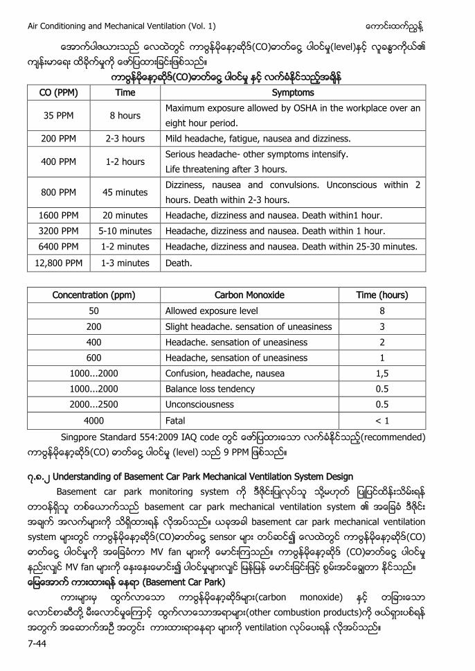
Air Conditioning and Mechanical Ventilation (Vol. 1) ႔
7-44
(CO) ႔ level)
႔ CO (PPM) Time Symptoms
35 PPM 8 hours Maximum exposure allowed by OSHA in the workplace over an eight hour period.
200 PPM 2-3 hours Mild headache, fatigue, nausea and dizziness.
400 PPM 1-2 hours Serious headache- other symptoms intensify. Life threatening after 3 hours.
800 PPM 45 minutes Dizziness, nausea and convulsions. Unconscious within 2 hours. Death within 2-3 hours.
1600 PPM 20 minutes Headache, dizziness and nausea. Death within1 hour. 3200 PPM 5-10 minutes Headache, dizziness and nausea. Death within 1 hour. 6400 PPM 1-2 minutes Headache, dizziness and nausea. Death within 25-30 minutes.
12,800 PPM 1-3 minutes Death.
Concentration (ppm) Carbon Monoxide Time (hours) 50 Allowed exposure level 8 200 Slight headache. sensation of uneasiness 3 400 Headache. sensation of uneasiness 2 600 Headache, sensation of uneasiness 1
1000...2000 Confusion, headache, nausea 1,5 1000...2000 Balance loss tendency 0.5 2000...2500 Unconsciousness 0.5
4000 Fatal < 1 Singpore Standard 554: I (recommended)
(CO) ႔ (level 9
၇.၈.၂ Understanding of Basement Car Park Mechanical Ventilation System Design Basement car park monitoring s ႔ basement car park mechanical ventilation s basement car park mechanical ventilation s (CO) ႔ s (CO) ႔ MV fan (CO) ႔ MV fan (Basement Car Park) (carbon monoxide) ႔ (other combustion products) ventilation
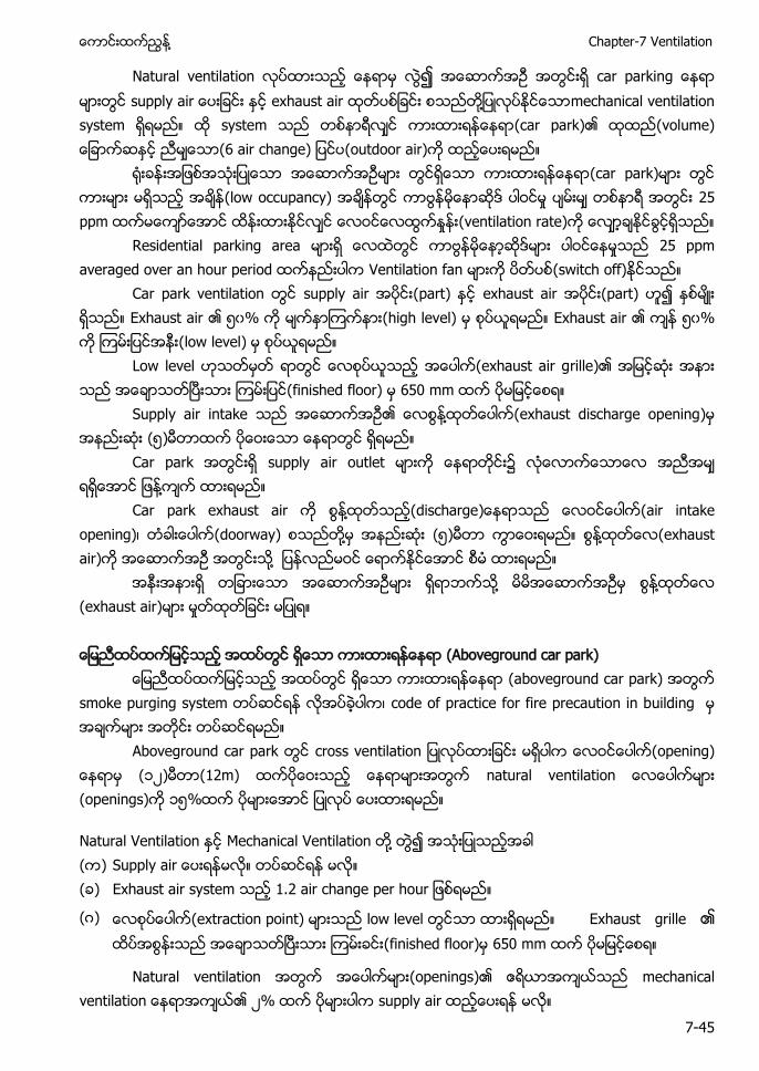
႔ Chapter-7 Ventilation
7-45
Natural ventilation ၍ supply exhaust air ႔ mechanical ventilation system system (car park) (6 air change) (outdoor air) (car park) (low occupancy) 25 ppm (ventilation rate) Residential parking area 25 ppm averaged over an hour period Ventilation fan (switch off) Car park ventilation supply air (part) exhaust air (part) ၍ ႏစမး ရသည။ Exhaust air ၏ ၅၀% (high level) Exhaust air ၅၀% (low level) Low level (exhaust air grille)၏ (finished floor) 650 mm Supply air intake ႔ (exhaust discharge opening) (၅) Car park supply air outlet ႔ Car park exhaust air ႔ (discharge (air intake opening) (doorway) ႔ (၅) ႔ (exhaust air) ႔ ႔ ႔ (exhaust air) (Aboveground car park) (aboveground car park) smoke purging system code of practice for fire precaution in building Aboveground car park (opening) (၁၂) (12m) natural ventilation (openings) ၁၅%
Natural Ventilation Mechanical Ventilation ႔ ( ) S ( ) Exhaust air system .
( ) (extraction point) low level Exhaust grille ၏ (finished floor) 650 mm
Natural ventilation (openings) ၂% supply air
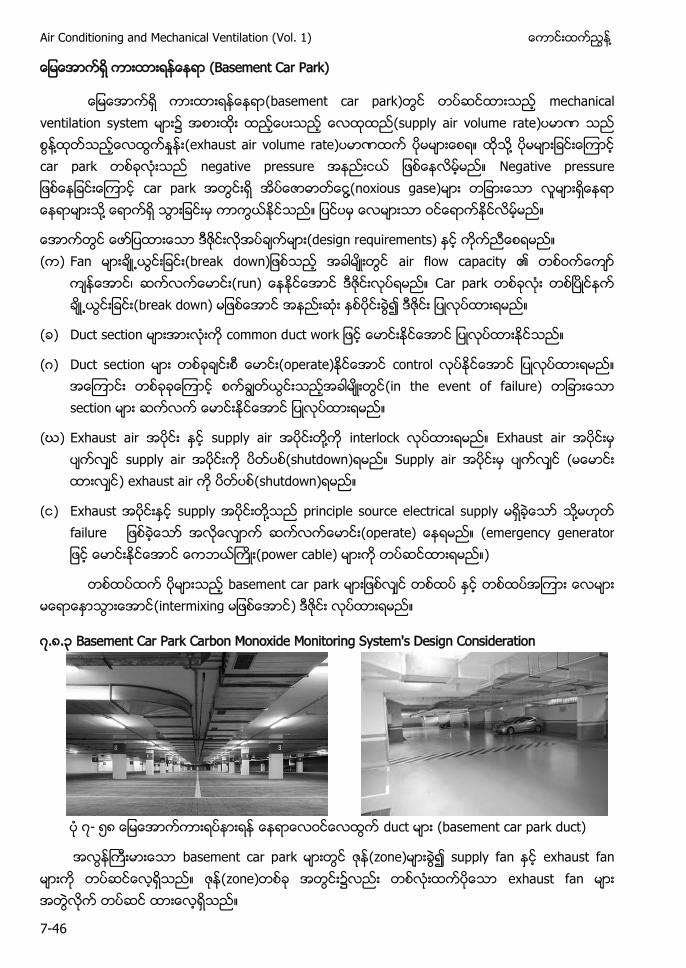
Air Conditioning and Mechanical Ventilation (Vol. 1) ႔
7-46
(Basement Car Park)
(basement car park) mechanical ventilation system (supply air volume rate) ႔ (exhaust air volume rate) ႔ car park negative pressure car park ႔(noxious gase) ႔
(design requirements) ( ) Fan (b air flow capacity
(run) Car park (break down)
( ) Duct section
( ) Duct section (operate) control (in the event of failure) section
(ဃ) Exhaust air supply air ႔ interlock Exhaust air supply air (shutdown) Supply air ( ) exhaust air (shutdown)
( ) Exhaust supply ႔ principle source electrical supply ႔ ( (power cable) )
basement car park (intermixing )
၇.၈.၃ Basement Car Park Carbon Monoxide Monitoring System's Design Consideration
၇- ၅၈ duct (basement car park duct)
basement car p (zone) supply fan exhaust fan (zone) exhaust fan
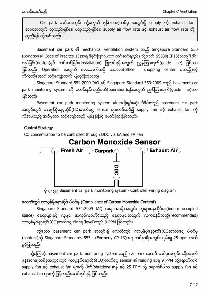
႔ Chapter-7 Ventilation
7-47
B S S 3 3 ႔ SS 3 3 guide line)
Singapore Standard I Singapore Standard 3 operation)
Basement basement car p (CO) ႔ exhaust f
Control Strategy CO concentration to be controlled through DDC via EA and FA Fan
၇- ၅၉ Basement car park monitoring system- Controller wiring diagram
Compliance of Carbon Monoxide Content) Singapore Standard I (indoor occupied
space) (recommended) (CO) ႔ level)
႔ (CO) ႔ (c Singapore Standards 553 - (Formerly CP 13)
႔ basement car park monitoring system car p ႔ (zone) (CO) ႔ s ႔ exhaust fan s ႔ exhaust fan
C ႔ s s exhaust air flow rate ႔
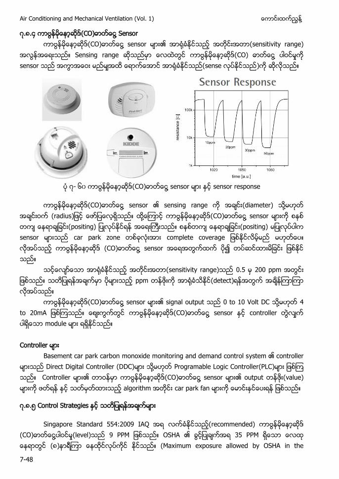
Air Conditioning and Mechanical Ventilation (Vol. 1) ႔
7-48
၇.၈.၄ (CO) ႔ Sensor ႔ s sensitivity range)
Sensing r CO) ႔ s sense
၇- ၆၀ ႔ s sensor response
႔ (diameter) ႔ (radius ႔ ႔ s ႔ sensor
sensitiv . ppm detect)
႔ s signal ႔ ႔ s c
Basement car park carbon monoxide monitoring and demand control s Direct Digital Controller (DDC) ႔ Programable Logic Controller(PLC) ႔ s output (value) car park fan
၇.၈.၅ Control Strategies
Singapore S I recommended) ႔ ( S 3 (၈) S
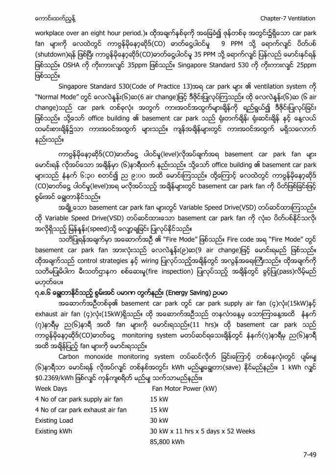
႔ Chapter-7 Ventilation
7-49
. car park fan CO) ႔ 9 PPM ႔ (shutdown) ႔ 35 PPM ႔ S 3 Singapore Standard 530
Singapore Standard 530(Code of Practice 13) car park “ ode” ၆ 6 air change ၆ ၆ change) car p ႔ basement car p ႔
႔ level) basement car park f ၆ ႔ ၆ ၃၀ ၉ ၀၀ ႔ ႔ (level) basement car park
basement car park fan Variable Speed Drive(VSD) Variable Speed Drive(VSD) basement car park fan speed) ႔
“ ode” Fire c “ ode” basement car park f ၉ 9 air change w fire inspection) pass) ၇.၈.၆ Energy Saving)
basement car park car park supply air f ၄ (15kW) exhaust air f ၄ (15kW) ႔ ႔ ၇ ၆ fan ( basement car park ႔ monitoring s ၇ ၆ fan
Carbon monoxide monitoring s (၆) save kWh . 3 Week Days Fan Motor Power (kW) 4 No of car park supply air fan 15 kW 4 No of car park exhaust air fan 15 kW Existing Load 30 kW Existing kWh 30 kW x 11 hrs x 5 days x 52 Weeks
85,800 kWh
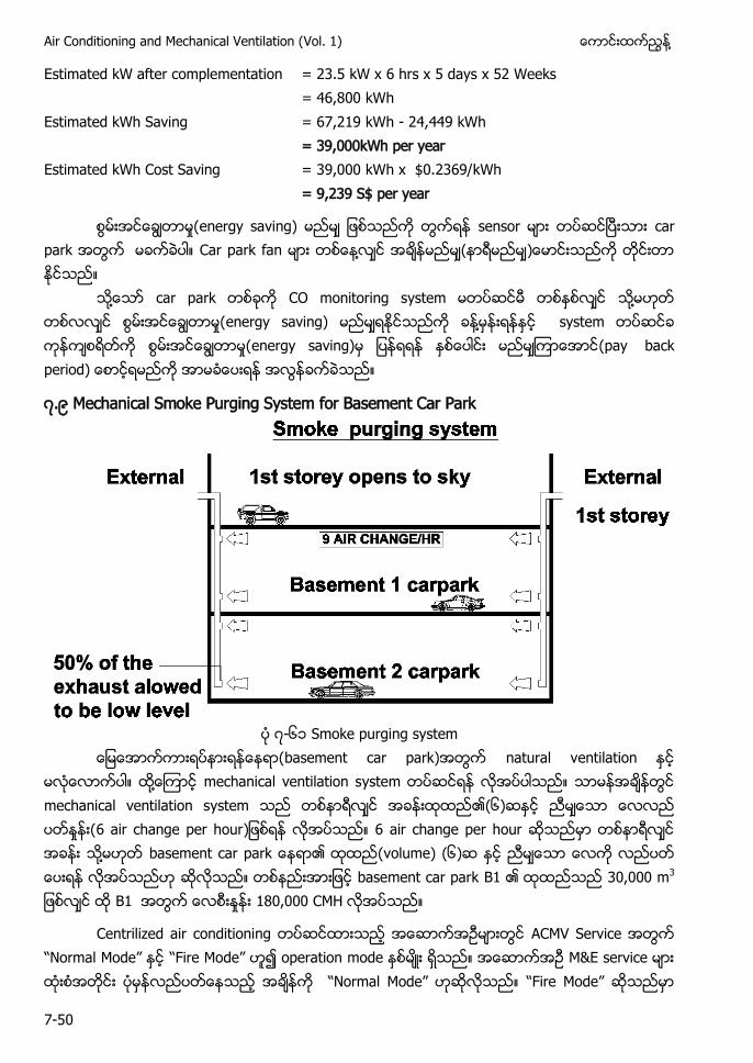
Air Conditioning and Mechanical Ventilation (Vol. 1) ႔
7-50
Estimated kW after complementation = 23.5 kW x 6 hrs x 5 days x 52 Weeks
= 46,800 kWh
Estimated kWh Saving = 67,219 kWh - 24,449 kWh
= 39,000kWh per year
Estimated kWh Cost Saving = 39,000 kWh x $0.2369/kWh
= 9,239 S$ per year
energy saving) s car p Car park fan ႔ (
႔ car p CO monitoring s ႔ ႔ system energy saving) (pay back period
၇.၉ Mechanical Smoke Purging System for Basement Car Park
၇-၆၁ Smoke purging system
basement car park) natural v ႔ mechanical ventilation system mechanical ventilation system ၆ 6 air change per hour air c ႔ basement car park (volume) (၆) basement car park B 30,000 m3
B1 180,000
Centrilized air conditioning ACMV Servic “ ” “ ode” operation M&E ser “ ” “ ode”
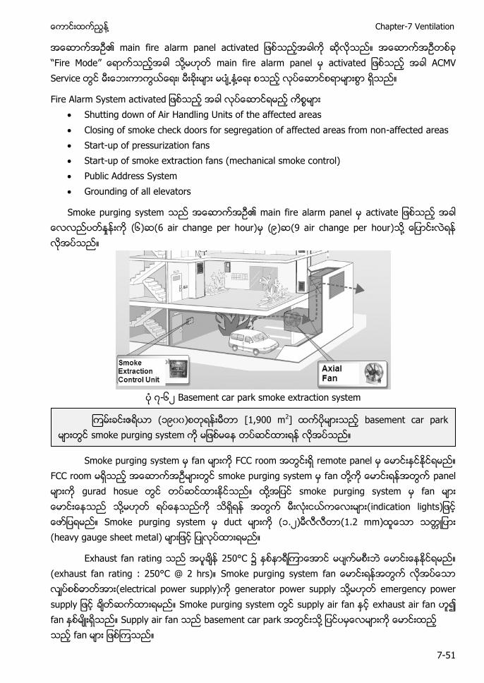
႔ Chapter-7 Ventilation
7-51
larm “ ode” ႔ main fire alarm panel a S ႔
Fire Alarm System a Shutting down of Air Handling Units of the affected areas Closing of smoke check doors for segregation of affected areas from non-affected areas Start-up of pressurization fans Start-up of smoke extraction fans (mechanical smoke control) Public Address System Grounding of all elevators
S activate ၆ ၉ ႔
၇-၆၂ Basement car park smoke extraction system
S remote panel
FCC room f ႔ panel ႔ fan ႔ S duct ၁.၂ . (heavy gauge sheet metal)
Exhaust fa (exha @ Smoke purging system generator power supply ႔ e S supply air exhaust air fan Supply air f basem ႔
၁၉၀၀ [1,900 m2] ba smoke purging s
Air Conditioning and Mechanical Ventilation (Vol. 1) ႔
7-52
Exhaust air fan ႔ fan Exhaust supply air f (hardwire inter-l ႔ - Exhaust air supply air f basement car park) Supply air f ႔ ) ႔
၇.၁၀ (Outdoor Air Requirement)
၌ (oxygen concentration) (carbon dioxide concentraion) ႔ (occupants) ႔ (fresh a
(outdoor air requirement) (occupants)
(per person) ႔ (per floor area) (outdoor air) ( ) (air flow rate per person)
႔ ဤ ႔ (per person ) ႔ ႔ (air quality) (rate) (contamination) (rate)
( ) (per floor area) litres per second per metre squared(l/s/m2 ဤ ႔ ( )
( ) (volume of the space) (air flow rate) Air Change rate per Hour(ACH- Air change rate per hour Ventilation infiltration ႔
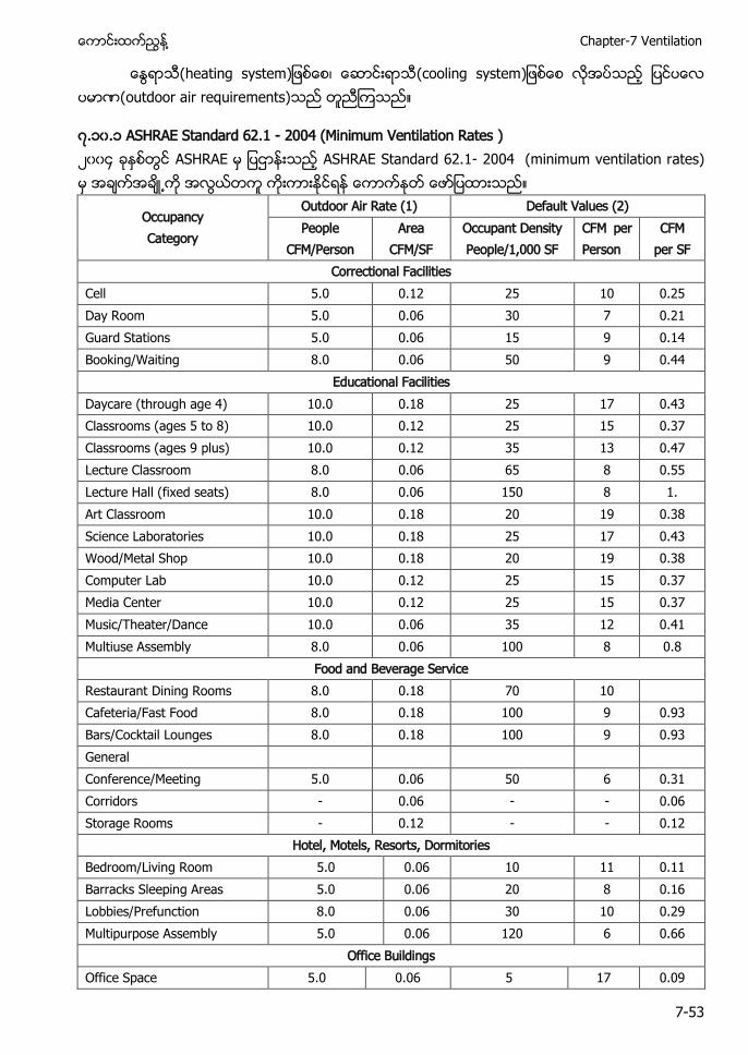
႔ Chapter-7 Ventilation
7-53
(heating system (cooling system (outdoor air requirements)
၇.၁၀.၁ ASHRAE Standard 62.1 2004 (Minimum Ventilation Rates ) ၂၀၀၄ ASHRAE ASHRAE Standard 62.1- 2004 (minimum ventilation rates)
Occupancy Category
Outdoor Air Rate (1) Default Values (2) People
CFM/Person Area
CFM/SF Occupant Density People/1,000 SF
CFM per Person
CFM per SF
Correctional Facilities Cell 5.0 0.12 25 10 0.25 Day Room 5.0 0.06 30 7 0.21 Guard Stations 5.0 0.06 15 9 0.14 Booking/Waiting 8.0 0.06 50 9 0.44
Educational Facilities Daycare (through age 4) 10.0 0.18 25 17 0.43 Classrooms (ages 5 to 8) 10.0 0.12 25 15 0.37 Classrooms (ages 9 plus) 10.0 0.12 35 13 0.47 Lecture Classroom 8.0 0.06 65 8 0.55 Lecture Hall (fixed seats) 8.0 0.06 150 8 1. Art Classroom 10.0 0.18 20 19 0.38 Science Laboratories 10.0 0.18 25 17 0.43 Wood/Metal Shop 10.0 0.18 20 19 0.38 Computer Lab 10.0 0.12 25 15 0.37 Media Center 10.0 0.12 25 15 0.37 Music/Theater/Dance 10.0 0.06 35 12 0.41 Multiuse Assembly 8.0 0.06 100 8 0.8
Food and Beverage Service Restaurant Dining Rooms 8.0 0.18 70 10 Cafeteria/Fast Food 8.0 0.18 100 9 0.93 Bars/Cocktail Lounges 8.0 0.18 100 9 0.93 General Conference/Meeting 5.0 0.06 50 6 0.31 Corridors - 0.06 - - 0.06 Storage Rooms - 0.12 - - 0.12
Hotel, Motels, Resorts, Dormitories Bedroom/Living Room 5.0 0.06 10 11 0.11 Barracks Sleeping Areas 5.0 0.06 20 8 0.16 Lobbies/Prefunction 8.0 0.06 30 10 0.29 Multipurpose Assembly 5.0 0.06 120 6 0.66
Office Buildings Office Space 5.0 0.06 5 17 0.09
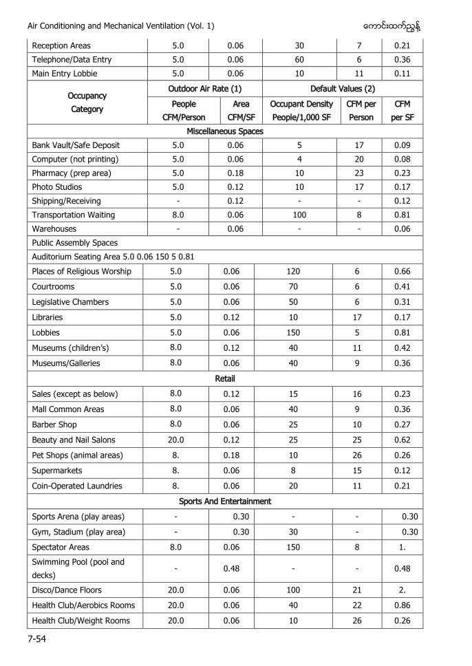
Air Conditioning and Mechanical Ventilation (Vol. 1) ႔
7-54
Reception Areas 5.0 0.06 30 7 0.21 Telephone/Data Entry 5.0 0.06 60 6 0.36 Main Entry Lobbie 5.0 0.06 10 11 0.11
Occupancy Category
Outdoor Air Rate (1) Default Values (2)
People CFM/Person
Area CFM/SF
Occupant Density People/1,000 SF
CFM per Person
CFM per SF
Miscellaneous Spaces Bank Vault/Safe Deposit 5.0 0.06 5 17 0.09 Computer (not printing) 5.0 0.06 4 20 0.08 Pharmacy (prep area) 5.0 0.18 10 23 0.23 Photo Studios 5.0 0.12 10 17 0.17 Shipping/Receiving - 0.12 - - 0.12 Transportation Waiting 8.0 0.06 100 8 0.81 Warehouses - 0.06 - - 0.06 Public Assembly Spaces Auditorium Seating Area 5.0 0.06 150 5 0.81 Places of Religious Worship 5.0 0.06 120 6 0.66
Courtrooms 5.0 0.06 70 6 0.41
Legislative Chambers 5.0 0.06 50 6 0.31
Libraries 5.0 0.12 10 17 0.17
Lobbies 5.0 0.06 150 5 0.81
’ 8.0 0.12 40 11 0.42
Museums/Galleries 8.0 0.06 40 9 0.36
Retail
Sales (except as below) 8.0 0.12 15 16 0.23
Mall Common Areas 8.0 0.06 40 9 0.36
Barber Shop 8.0 0.06 25 10 0.27
Beauty and Nail Salons 20.0 0.12 25 25 0.62
Pet Shops (animal areas) 8. 0.18 10 26 0.26
Supermarkets 8. 0.06 8 15 0.12
Coin-Operated Laundries 8. 0.06 20 11 0.21
Sports And Entertainment
Sports Arena (play areas) - 0.30 - - 0.30
Gym, Stadium (play area) - 0.30 30 - 0.30
Spectator Areas 8.0 0.06 150 8 1. Swimming Pool (pool and decks)
- 0.48 - - 0.48
Disco/Dance Floors 20.0 0.06 100 21 2.
Health Club/Aerobics Rooms 20.0 0.06 40 22 0.86
Health Club/Weight Rooms 20.0 0.06 10 26 0.26
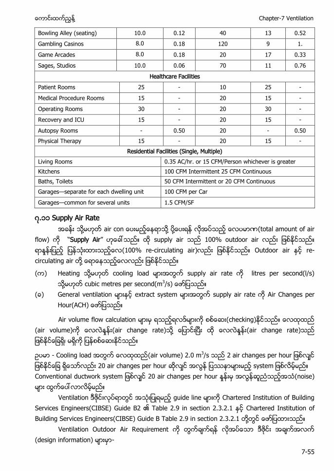
႔ Chapter-7 Ventilation
7-55
Bowling Alley (seating) 10.0 0.12 40 13 0.52
Gambling Casinos 8.0 0.18 120 9 1.
Game Arcades 8.0 0.18 20 17 0.33
Sages, Studios 10.0 0.06 70 11 0.76
Healthcare Facilities
Patient Rooms 25 - 10 25 -
Medical Procedure Rooms 15 - 20 15 -
Operating Rooms 30 - 20 30 -
Recovery and ICU 15 - 20 15 -
Autopsy Rooms - 0.50 20 - 0.50 Physical Therapy 15 - 20 15 -
Residential Facilities (Single, Multiple) Living Rooms 0.35 AC/hr. or 15 CFM/Person whichever is greater Kitchens 100 CFM Intermittent 25 CFM Continuous Baths, Toilets 50 CFM Intermittent or 20 CFM Continuous Garages—separate for each dwelling unit 100 CFM per Car
Garages—common for several units 1.5 CFM/SF
၇.၁၁ Supply Air Rate ႔ ai ႔ ႔ (total amount of air
flow) “Supply Air” supply air 100% outdoor air (100% re-circulating air) Outdoor air re-circulating air ႔
( ) Heating ႔ cooling load supply air rate litres per second(l/s) ႔ cubic metres per second(m3
( ) General ventilation extract system supply air rate Air Changes per Hour(ACH
Air volume flow calculation (checking) (air volume) (air change rate) ႔ (air change rate)
- Cooling load (air volume) 2.0 m3/s 2 air changes per hour 20 air changes per hour Conventional ductwork system 20 air changes per hour (noise)
Ventilation guide line Chartered Institution of Building Services Engineers(CIBSE) Guide B2 Table 2.9 in section 2.3.2.1 Chartered Institution of Building Services Engineers(CIBSE) Guide B Table 2.9 in section 2.3.2.1 ႔
Ventilation Outdoor Air Requirement (design information) -
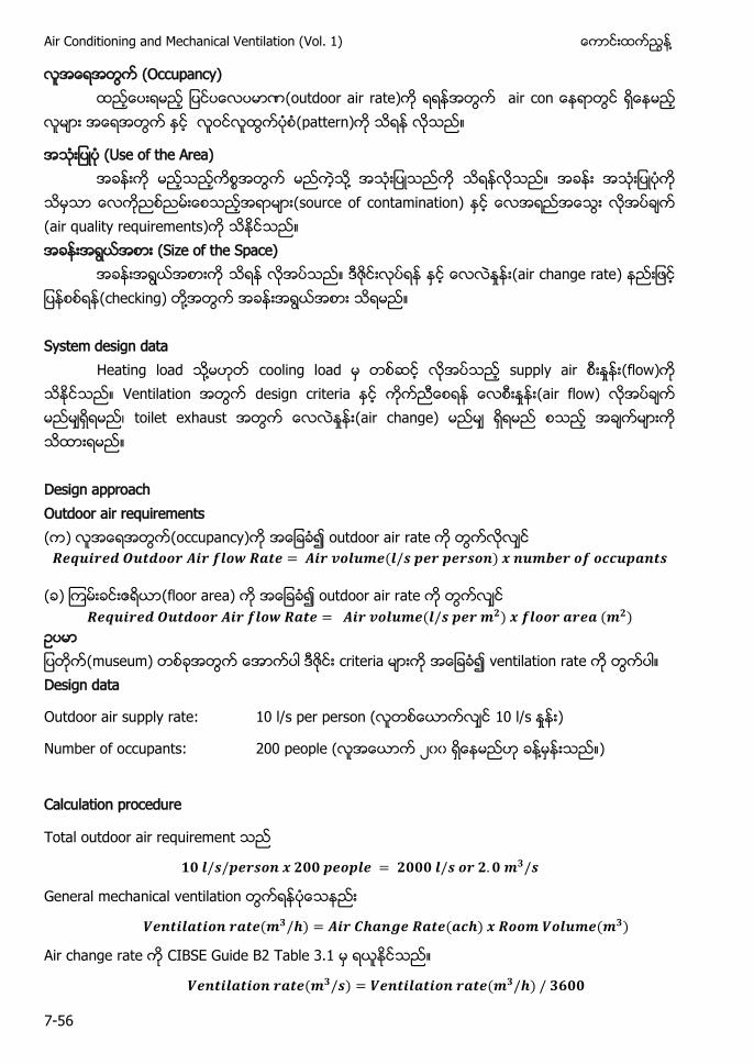
Air Conditioning and Mechanical Ventilation (Vol. 1) ႔
7-56
(Occupancy) (outdoor air rate) a
(pattern)
(Use of the Area) ႔
(source of contamination) (air quality requirements) (Size of the Space)
(air change rate) (checking) ႔ System design data
Heating load ႔ cooling load supply air (flow) Ventilation design criteria (air flow) toilet exhaust (air change) Design approach Outdoor air requirements ( ) (occupancy) outdoor air rate 𝒆 𝒓𝒆 𝒕 𝒐𝒐𝒓 𝑨 𝒓 𝒍𝒐 𝒂𝒕𝒆 𝑨 𝒓 𝒗𝒐𝒍 𝒆 𝒍 𝒆𝒓 𝒆𝒓 𝒐 𝒃𝒆𝒓 𝒐 𝒐𝒄𝒄 𝒂 𝒕
( ) (floor area) outdoor air rate 𝒆 𝒓𝒆 𝒕 𝒐𝒐𝒓 𝑨 𝒓 𝒍𝒐 𝒂𝒕𝒆 𝑨 𝒓 𝒗𝒐𝒍 𝒆 𝒍 𝒆𝒓 𝒍𝒐𝒐𝒓 𝒂𝒓𝒆𝒂
(museum) criteria ventilation rate Design data
Outdoor air supply rate: 10 l/s per person ( 10 l/s )
Number of occupants: 200 people ( ၂၀၀ ႔ )
Calculation procedure
Total outdoor air requirement
𝒍 𝒆𝒓 𝒐 𝒆𝒐 𝒍𝒆 𝒍 𝒐𝒓
General mechanical ventilation
𝒆 𝒕 𝒍𝒂𝒕 𝒐 𝒓𝒂𝒕𝒆 𝑨 𝒓 𝒂 𝒆 𝒂𝒕𝒆 𝒂𝒄 𝒐𝒐 𝒐𝒍 𝒆
Air change rate CIBSE Guide B2 Table 3.1
𝒆 𝒕 𝒍𝒂𝒕 𝒐 𝒓𝒂𝒕𝒆 𝒆 𝒕 𝒍𝒂𝒕 𝒐 𝒓𝒂𝒕𝒆
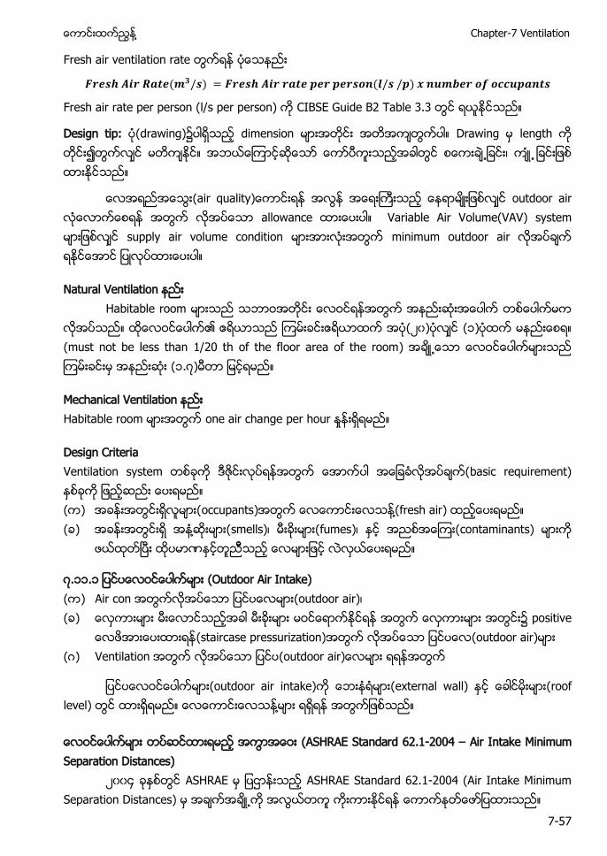
႔ Chapter-7 Ventilation
7-57
Fresh air ventilation rate
𝒓𝒆 𝑨 𝒓 𝒂𝒕𝒆 𝒓𝒆 𝑨 𝒓 𝒓𝒂𝒕𝒆 𝒆𝒓 𝒆𝒓 𝒐 𝒍 𝒃𝒆𝒓 𝒐 𝒐𝒄𝒄 𝒂 𝒕
Fresh air rate per person (l/s per person) CIBSE Guide B2 Table 3.3
Design tip: (drawing) dimension Drawing length
outdoor air allowance Variable Air Volume(VAV) system supply air volume condition minimum outdoor air
Natural Ventilation Habitable room
၂၀ ၁ (must not be less than 1/20 th of the floor area of the room ၁.၇
H one air
Design Criteria Ventilation system basic requirement) ( ) occupants ႔ fresh air ( ) ႔ smells fumes contaminants)
၇.၁၁.၁ (Outdoor Air Intake) ( ) Air con (outdoor air) ( )
(staircase pressurization) (outdoor air) ( ) Ventilation
(outdoor air intake) (external wall) (roof level) ႔ (ASHRAE Standard 62.1-2004 – Air Intake Minimum Separation Distances)
၂၀၀၄ ASHRAE ASHRAE Standard 62.1-2004 (Air Intake Minimum Separation Distances)
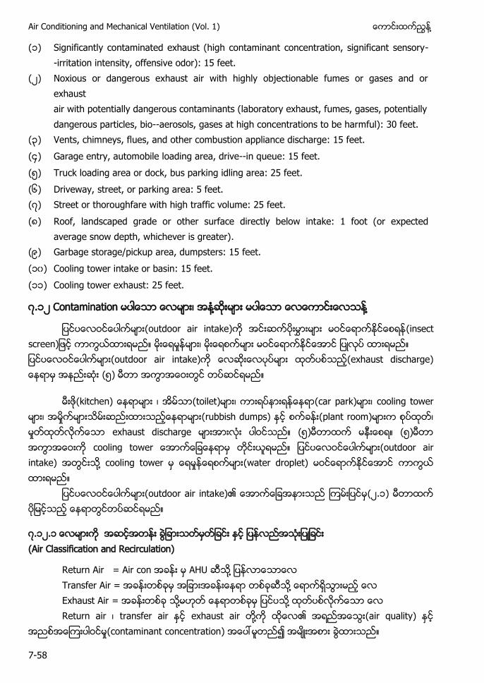
Air Conditioning and Mechanical Ventilation (Vol. 1) ႔
7-58
(၁) Significantly contaminated exhaust (high contaminant concentration, significant sensory-irritation intensity, offensive odor): 15 feet.
(၂) Noxious or dangerous exhaust air with highly objectionable fumes or gases and or exhaust air with potentially dangerous contaminants (laboratory exhaust, fumes, gases, potentially dangerous particles, bio-aerosols, gases at high concentrations to be harmful): 30 feet.
(၃) Vents, chimneys, flues, and other combustion appliance discharge: 15 feet. (၄) Garage entry, automobile loading area, drive-in queue: 15 feet. (၅) Truck loading area or dock, bus parking idling area: 25 feet. (၆) Driveway, street, or parking area: 5 feet. (၇) Street or thoroughfare with high traffic volume: 25 feet. (၈) Roof, landscaped grade or other surface directly below intake: 1 foot (or expected
average snow depth, whichever is greater). (၉) Garbage storage/pickup area, dumpsters: 15 feet. (၁၀) Cooling tower intake or basin: 15 feet. (၁၁) Cooling tower exhaust: 25 feet.
၇.၁၂ Contamination ႔ ႔
(outdoor air intake) (outdoor air intake) (exhaust discharge) (၅)
(toilet) (car park) cooling tower (rubbish dumps) (plant room) exhaust discharge (၅) (၅) c (outdoor air intake) ႔ cooling tower (water droplet)
(outdoor air intake)၏ (၂.၁)
၇.၁၂.၁ (Air Classification and Recirculation)
Return Air = Air con AHU ႔ Transfer Air = ႔ Exhaust Air = ႔ ႔ Return air transfer air exhaust air ႔ (air quality) (contaminant concentration) ၍
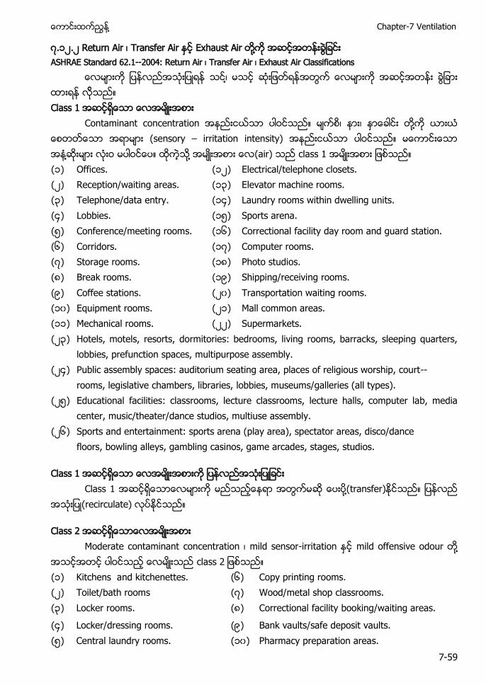
႔ Chapter-7 Ventilation
7-59
၇.၁၂.၂ Return Air Transfer Air Exhaust Air ႔ ASHRAE Standard 62.1-2004: Return Air Transfer Air Exhaust Air Classifications
Class 1 Contaminant concentration ႔ (sensory – irritation intensity) ႔ ႔ (air) class 1 (၁) Offices. (၁၂) Electrical/telephone closets. (၂) Reception/waiting areas. (၁၃) Elevator machine rooms. (၃) Telephone/data entry. (၁၄) Laundry rooms within dwelling units. (၄) Lobbies. (၁၅) Sports arena. (၅) Conference/meeting rooms. (၁၆) Correctional facility day room and guard station. (၆) Corridors. (၁၇) Computer rooms. (၇) Storage rooms. (၁၈) Photo studios. (၈) Break rooms. (၁၉) Shipping/receiving rooms. (၉) Coffee stations. (၂၀) Transportation waiting rooms. (၁၀) Equipment rooms. (၂၁) Mall common areas. (၁၁) Mechanical rooms. (၂၂) Supermarkets. (၂၃) Hotels, motels, resorts, dormitories: bedrooms, living rooms, barracks, sleeping quarters,
lobbies, prefunction spaces, multipurpose assembly. (၂၄) Public assembly spaces: auditorium seating area, places of religious worship, court-
rooms, legislative chambers, libraries, lobbies, museums/galleries (all types). (၂၅) Educational facilities: classrooms, lecture classrooms, lecture halls, computer lab, media
center, music/theater/dance studios, multiuse assembly. (၂၆) Sports and entertainment: sports arena (play area), spectator areas, disco/dance
floors, bowling alleys, gambling casinos, game arcades, stages, studios.
Class 1 Class 1 ႔(transfer)
(recirculate)
Class 2 Moderate contaminant concentration mild sensor-irritation mild offensive odour ႔
c (၁) Kitchens and kitchenettes. (၆) Copy printing rooms. (၂) Toilet/bath rooms (၇) Wood/metal shop classrooms. (၃) Locker rooms. (၈) Correctional facility booking/waiting areas.
(၄) Locker/dressing rooms. (၉) Bank vaults/safe deposit vaults. (၅) Central laundry rooms. (၁၀) Pharmacy preparation areas.
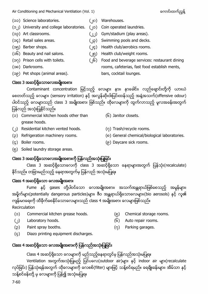
Air Conditioning and Mechanical Ventilation (Vol. 1) ႔
7-60
(၁၁) Science laboratories. (၂၀) Warehouses. (၁၂) University and college laboratories. (၂၁) Coin operated laundries. (၁၃) Art classrooms. (၂၂) Gym/stadium (play areas). (၁၄) Retail sales areas. (၂၃) Swimming pools and decks. (၁၅) Barber shops. (၂၄) Health club/aerobics rooms. (၁၆) Beauty and nail salons. (၂၅) Health club/weight rooms. (၁၇) Prison cells with toilets. (၂၆) Food and beverage services: restaurant dining
rooms, cafeterias, fast food establish ments, bars, cocktail lounges.
(၁၈) Darkrooms. (၁၉) Pet shops (animal areas).
Class 3 Contaminant concentration ႔
(sensory irritation) ႔ (offensive odour) class 3 (၁) Commercial kitchen hoods other than
grease hoods. (၆) Janitor closets.
(၂) Residential kitchen vented hoods. (၇) Trash/recycle rooms. (၃) Refrigeration machinery rooms. (၈) General chemical/biological laboratories. (၄) Boiler rooms. (၉) Daycare sick rooms. (၅) Soiled laundry storage areas.
Class 3 Class 3 class 3 (recalculate)
Class 4 Fume gases ႔ ရ ယျဖစေစသည အမႈနမား၊
အမႈကမား(potentially dangerous particles) ရာယရေသာေလမား၊(bio aerosols) ၏ class 4 Recirculation (၁) Commercial kitchen grease hoods. (၅) Chemical storage rooms. (၂) Laboratory hoods. (၆) Auto repair rooms. (၃) Paint spray booths. (၇) Parking garages. (၄) Diazo printing equipment discharges.
Class 4
Class 4 Ventilation (outdoor air) indoor air (recalculate
(filter) ႔ ႔ ႔ ၍
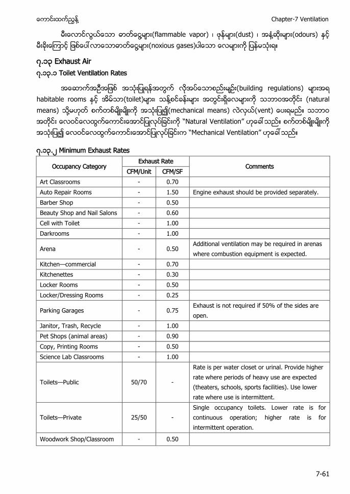
႔ Chapter-7 Ventilation
7-61
႔ (flammable vapor) (dust) ႔ (odours) ႔ (noxious gases)
၇.၁၃ Exhaust Air ၇.၁၃.၁ Toilet Ventilation Rates
building regulations toilet) ႔ (natural means ႔ mechanical means vent “ atural Ventilation” “ echanical Ventilation”
၇.၁၃.၂ Minimum Exhaust Rates
Occupancy Category Exhaust Rate
Comments CFM/Unit CFM/SF
Art Classrooms - 0.70 Auto Repair Rooms - 1.50 Engine exhaust should be provided separately. Barber Shop - 0.50 Beauty Shop and Nail Salons - 0.60 Cell with Toilet - 1.00 Darkrooms - 1.00
Arena - 0.50 Additional ventilation may be required in arenas where combustion equipment is expected.
Kitchen—commercial - 0.70 Kitchenettes - 0.30 Locker Rooms - 0.50 Locker/Dressing Rooms - 0.25
Parking Garages - 0.75 Exhaust is not required if 50% of the sides are open.
Janitor, Trash, Recycle - 1.00 Pet Shops (animal areas) - 0.90 Copy, Printing Rooms - 0.50 Science Lab Classrooms - 1.00
Toilets—Public 50/70 -
Rate is per water closet or urinal. Provide higher rate where periods of heavy use are expected (theaters, schools, sports facilities). Use lower rate where use is intermittent.
Toilets—Private 25/50 - Single occupancy toilets. Lower rate is for continuous operation; higher rate is for intermittent operation.
Woodwork Shop/Classroom - 0.50
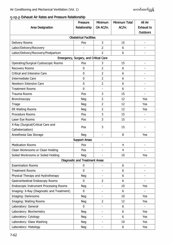
Air Conditioning and Mechanical Ventilation (Vol. 1) ႔
7-62
၇.၁၃.၃ Exhaust Air Rates and Pressure Relationship
Area Designation Pressure
Relationship Minimum OA AC/hr.
Minimum Total AC/hr.
All Air Exhaust to Outdoors
Obstetrical Facilities Delivery Rooms Pos 3 15 - Labor/Delivery/Recovery - 2 6 - Labor/Delivery/Recovery/Postpartum - 2 6 -
Emergency, Surgery, and Critical Care Operating/Surgical Cystoscopic Rooms Pos 3 15 - Recovery Rooms 0 2 6 - Critical and Intensive Care 0 2 6 - Intermediate Care 0 2 6 - Newborn Intensive Care 0 2 6 - Treatment Rooms 0 - 6 - Trauma Rooms Pos 3 15 - Bronchoscopy Neg 2 12 Yes Triage Neg 2 12 Yes ER Waiting Rooms Neg 2 12 Yes Procedure Rooms Pos 3 15 - Laser Eye Rooms Pos 3 15 - X-Ray (Surgical/Critical Care and Catheterization)
Pos 3 15 -
Anesthesia Gas Storage Neg - 8 Yes Support Areas
Medication Rooms Pos - 4 - Clean Workrooms or Clean Holding Pos - 4 - Soiled Workrooms or Soiled Holding Neg - 10 Yes
Diagnostic and Treatment Areas Examination Rooms 0 - 6 - Treatment Rooms 0 - 6 - Physical Therapy and Hydrotherapy Neg - 6 - Gastrointestinal Endoscopy Rooms 0 2 6 - Endoscopic Instrument Processing Rooms Neg - 10 Yes Imaging: X-Ray (Diagnostic and Treatment) 0 - 6 - Imaging: Darkrooms Neg - 10 Yes Imaging: Waiting Rooms Neg 2 12 Yes Laboratory: General 0 - 6 - Laboratory: Biochemistry Neg - 6 Yes Laboratory: Cytology Neg - 6 Yes Laboratory: Glass Washing Neg - 10 Yes Laboratory: Histology Neg - 6 Yes
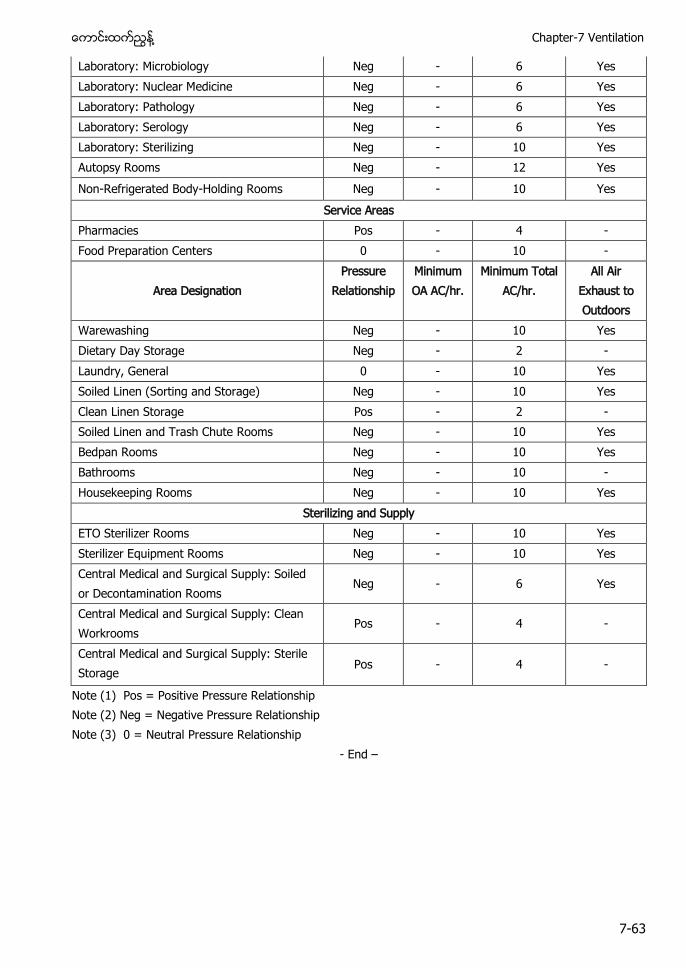
႔ Chapter-7 Ventilation
7-63
Laboratory: Microbiology Neg - 6 Yes Laboratory: Nuclear Medicine Neg - 6 Yes Laboratory: Pathology Neg - 6 Yes Laboratory: Serology Neg - 6 Yes Laboratory: Sterilizing Neg - 10 Yes Autopsy Rooms Neg - 12 Yes Non-Refrigerated Body-Holding Rooms Neg - 10 Yes
Service Areas Pharmacies Pos - 4 - Food Preparation Centers 0 - 10 -
Area Designation Pressure
Relationship Minimum OA AC/hr.
Minimum Total AC/hr.
All Air Exhaust to Outdoors
Warewashing Neg - 10 Yes Dietary Day Storage Neg - 2 - Laundry, General 0 - 10 Yes Soiled Linen (Sorting and Storage) Neg - 10 Yes Clean Linen Storage Pos - 2 - Soiled Linen and Trash Chute Rooms Neg - 10 Yes Bedpan Rooms Neg - 10 Yes Bathrooms Neg - 10 - Housekeeping Rooms Neg - 10 Yes
Sterilizing and Supply ETO Sterilizer Rooms Neg - 10 Yes Sterilizer Equipment Rooms Neg - 10 Yes Central Medical and Surgical Supply: Soiled or Decontamination Rooms
Neg - 6 Yes
Central Medical and Surgical Supply: Clean Workrooms
Pos - 4 -
Central Medical and Surgical Supply: Sterile Storage
Pos - 4 -
Note (1) Pos = Positive Pressure Relationship Note (2) Neg = Negative Pressure Relationship Note (3) 0 = Neutral Pressure Relationship
- End –
The Effect of Targeting Scheme on Tidal Volume Delivery During Volume Control Mechanical Ventilation
Alveolar instability caused by mechanical ventilation initially damages the nondependent normal lung