air conditioning system (for automatic air conditioning
TRANSCRIPT
AIR CONDITIONING – AIR CONDITIONING SYSTEM (for Automatic Air Conditioning Sys-tem) AC–1
AC
AIR CONDITIONING SYSTEM (for Automatic Air Conditioning System)PRECAUTION1. IF ANY OF FOLLOWING CONDITIONS ARE MET,
KEEP ENGINE IDLING WITH A/C ON (ENGINE SPEED AT LESS THAN 2000 RPM) FOR AT LEAST 1 MINUTE:• Refrigerant gas has been refilled or A/C parts have
been replaced.• A long time has elapsed since the engine was
stopped.NOTICE:If the engine speed exceeds 2,000 rpm, the A/C compressor may be damaged.
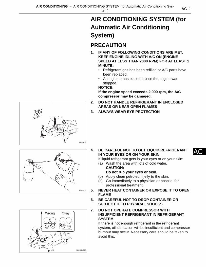
2. DO NOT HANDLE REFRIGERANT IN ENCLOSED AREAS OR NEAR OPEN FLAMES
3. ALWAYS WEAR EYE PROTECTION
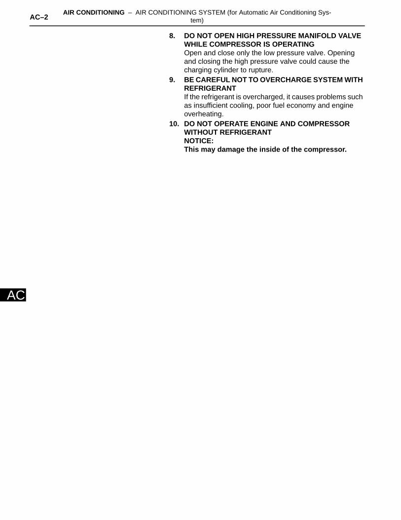
4. BE CAREFUL NOT TO GET LIQUID REFRIGERANT IN YOUR EYES OR ON YOUR SKINIf liquid refrigerant gets in your eyes or on your skin:(a) Wash the area with lots of cold water.
CAUTION:Do not rub your eyes or skin.
(b) Apply clean petroleum jelly to the skin.(c) Go immediately to a physician or hospital for
professional treatment.5. NEVER HEAT CONTAINER OR EXPOSE IT TO OPEN
FLAME6. BE CAREFUL NOT TO DROP CONTAINER OR
SUBJECT IT TO PHYSICAL SHOCKS7. DO NOT OPERATE COMPRESSOR WITH
INSUFFICIENT REFRIGERANT IN REFRIGERANT SYSTEMIf there is not enough refrigerant in the refrigerant system, oil lubrication will be insufficient and compressor burnout may occur. Necessary care should be taken to avoid this.
AC02810
AC02811
OkayWrong
LO HILOHI
N011084E03
AC–2 AIR CONDITIONING – AIR CONDITIONING SYSTEM (for Automatic Air Conditioning Sys-tem)
AC
8. DO NOT OPEN HIGH PRESSURE MANIFOLD VALVE WHILE COMPRESSOR IS OPERATINGOpen and close only the low pressure valve. Opening and closing the high pressure valve could cause the charging cylinder to rupture.
9. BE CAREFUL NOT TO OVERCHARGE SYSTEM WITH REFRIGERANTIf the refrigerant is overcharged, it causes problems such as insufficient cooling, poor fuel economy and engine overheating.
10. DO NOT OPERATE ENGINE AND COMPRESSOR WITHOUT REFRIGERANTNOTICE:This may damage the inside of the compressor.
AIR CONDITIONING – AIR CONDITIONING SYSTEM (for Automatic Air Conditioning Sys-tem) AC–3
AC
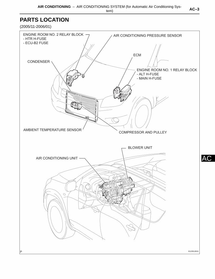
PARTS LOCATION(2005/11-2006/01)
ECM
AIR CONDITIONING UNIT
BLOWER UNIT
COMPRESSOR AND PULLEY
ENGINE ROOM NO. 1 RELAY BLOCK
- ALT H-FUSE
- MAIN H-FUSE
ENGINE ROOM NO. 2 RELAY BLOCK
- HTR H-FUSE
- ECU-B2 FUSE
AIR CONDITIONING PRESSURE SENSOR
AMBIENT TEMPERATURE SENSOR
CONDENSER
E123512E01
AC–4 AIR CONDITIONING – AIR CONDITIONING SYSTEM (for Automatic Air Conditioning Sys-tem)
AC
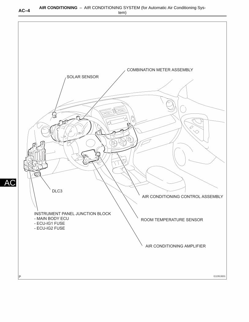
COMBINATION METER ASSEMBLY
DLC3
AIR CONDITIONING AMPLIFIER
ROOM TEMPERATURE SENSOR
AIR CONDITIONING CONTROL ASSEMBLY
INSTRUMENT PANEL JUNCTION BLOCK
- MAIN BODY ECU
- ECU-IG1 FUSE
- ECU-IG2 FUSE
SOLAR SENSOR
E123513E01
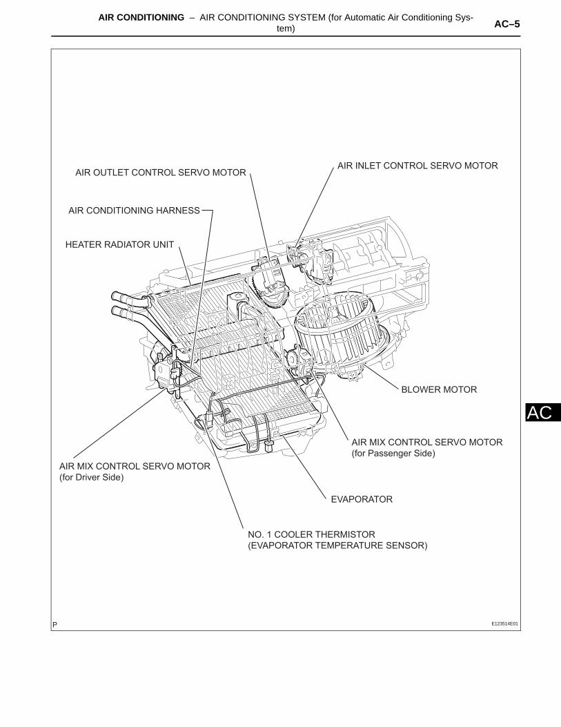
AIR CONDITIONING – AIR CONDITIONING SYSTEM (for Automatic Air Conditioning Sys-tem) AC–5
AC
HEATER RADIATOR UNIT
AIR MIX CONTROL SERVO MOTOR
(for Driver Side)
EVAPORATOR
NO. 1 COOLER THERMISTOR
(EVAPORATOR TEMPERATURE SENSOR)
AIR CONDITIONING HARNESS
AIR INLET CONTROL SERVO MOTOR
AIR MIX CONTROL SERVO MOTOR
(for Passenger Side)
AIR OUTLET CONTROL SERVO MOTOR
BLOWER MOTOR
E123514E01
AC–6 AIR CONDITIONING – AIR CONDITIONING SYSTEM (for Automatic Air Conditioning Sys-tem)
AC
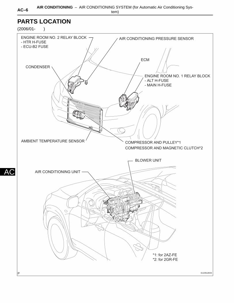
PARTS LOCATION(2006/01- )
ECM
AIR CONDITIONING UNIT
BLOWER UNIT
*1: for 2AZ-FE
*2: for 2GR-FE
COMPRESSOR AND MAGNETIC CLUTCH*2
COMPRESSOR AND PULLEY*1
ENGINE ROOM NO. 1 RELAY BLOCK
- ALT H-FUSE
- MAIN H-FUSE
ENGINE ROOM NO. 2 RELAY BLOCK
- HTR H-FUSE
- ECU-B2 FUSE
AIR CONDITIONING PRESSURE SENSOR
AMBIENT TEMPERATURE SENSOR
CONDENSER
E123512E03
AIR CONDITIONING – AIR CONDITIONING SYSTEM (for Automatic Air Conditioning Sys-tem) AC–7
AC
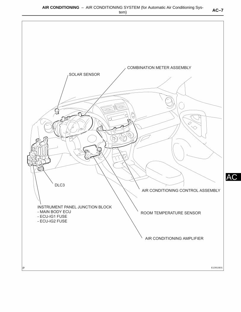
COMBINATION METER ASSEMBLY
DLC3
AIR CONDITIONING AMPLIFIER
ROOM TEMPERATURE SENSOR
AIR CONDITIONING CONTROL ASSEMBLY
INSTRUMENT PANEL JUNCTION BLOCK
- MAIN BODY ECU
- ECU-IG1 FUSE
- ECU-IG2 FUSE
SOLAR SENSOR
E123513E01

AC–8 AIR CONDITIONING – AIR CONDITIONING SYSTEM (for Automatic Air Conditioning Sys-tem)
AC
HEATER RADIATOR UNIT
AIR MIX CONTROL SERVO MOTOR
(for Driver Side)
EVAPORATOR
NO. 1 COOLER THERMISTOR
(EVAPORATOR TEMPERATURE SENSOR)
AIR CONDITIONING HARNESS
AIR INLET CONTROL SERVO MOTOR
AIR MIX CONTROL SERVO MOTOR
(for Passenger Side)
AIR OUTLET CONTROL SERVO MOTOR
BLOWER MOTOR
E123514E01
AIR CONDITIONING – AIR CONDITIONING SYSTEM (for Automatic Air Conditioning Sys-tem) AC–9
AC
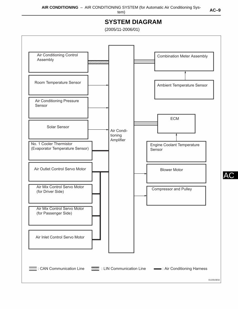
SYSTEM DIAGRAM(2005/11-2006/01)
Room Temperature Sensor
No. 1 Cooler Thermistor
(Evaporator Temperature Sensor)
Air Conditioning Pressure
Sensor
Solar Sensor
Air Conditioning Control
AssemblyCombination Meter Assembly
Ambient Temperature Sensor
Engine Coolant Temperature
Sensor
Compressor and Pulley
Blower Motor
ECM
Air Outlet Control Servo Motor
Air Mix Control Servo Motor
(for Driver Side)
Air Mix Control Servo Motor
(for Passenger Side)
Air Inlet Control Servo Motor
Air Condi-
tioning
Amplifier
: CAN Communication Line : Air Conditioning Harness: LIN Communication Line
E123515E02
AC–10 AIR CONDITIONING – AIR CONDITIONING SYSTEM (for Automatic Air Conditioning Sys-tem)
AC
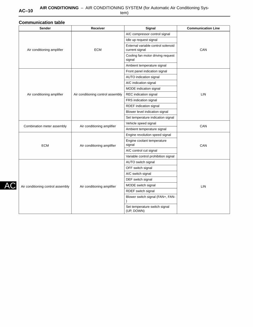
Communication tableSender Receiver Signal Communication Line
Air conditioning amplifier ECM
A/C compressor control signal
CAN
Idle up request signal
External variable control solenoid current signal
Cooling fan motor driving request signal
Ambient temperature signal
Air conditioning amplifier Air conditioning control assembly
Front panel indication signal
LIN
AUTO indication signal
A/C indication signal
MODE indication signal
REC indication signal
FRS indication signal
RDEF indication signal
Blower level indication signal
Set temperature indication signal
Combination meter assembly Air conditioning amplifierVehicle speed signal
CANAmbient temperature signal
ECM Air conditioning amplifier
Engine revolution speed signal
CANEngine coolant temperature signal
A/C control cut signal
Variable control prohibition signal
Air conditioning control assembly Air conditioning amplifier
AUTO switch signal
LIN
OFF switch signal
A/C switch signal
DEF switch signal
MODE switch signal
RDEF switch signal
Blower switch signal (FAN+, FAN-)
Set temperature switch signal (UP, DOWN)
AIR CONDITIONING – AIR CONDITIONING SYSTEM (for Automatic Air Conditioning Sys-tem) AC–11
AC
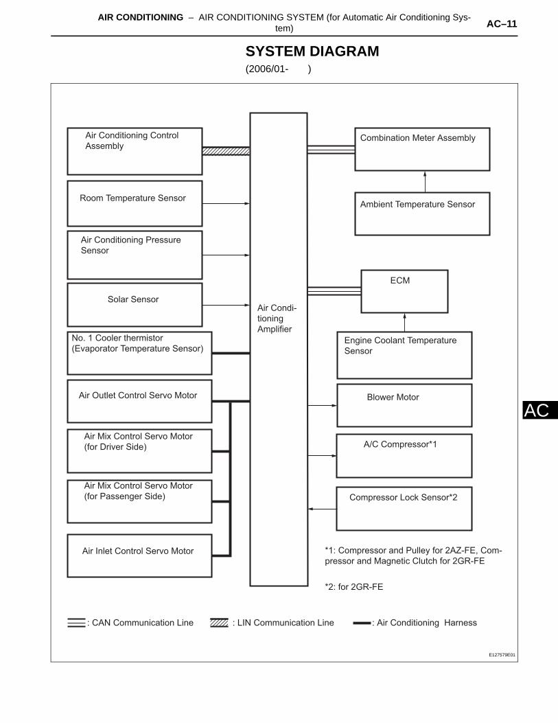
SYSTEM DIAGRAM(2006/01- )
Room Temperature Sensor
No. 1 Cooler thermistor
(Evaporator Temperature Sensor)
Air Conditioning Pressure
Sensor
Solar Sensor
Air Conditioning Control
AssemblyCombination Meter Assembly
Ambient Temperature Sensor
Engine Coolant Temperature
Sensor
A/C Compressor*1
*1: Compressor and Pulley for 2AZ-FE, Com-
pressor and Magnetic Clutch for 2GR-FE
*2: for 2GR-FE
Blower Motor
ECM
Air Outlet Control Servo Motor
Air Mix Control Servo Motor
(for Driver Side)
Air Mix Control Servo Motor
(for Passenger Side)
Air Inlet Control Servo Motor
Air Condi-
tioning
Amplifier
: CAN Communication Line : Air Conditioning Harness: LIN Communication Line
Compressor Lock Sensor*2
E127579E01

AC–12 AIR CONDITIONING – AIR CONDITIONING SYSTEM (for Automatic Air Conditioning Sys-tem)
AC
Communication tableSender Receiver Signal Communication Line
Air conditioning amplifier ECM
A/C compressor control signal
CAN
Idle up request signal
External variable control solenoid current signal
Cooling fan motor driving request signal
Ambient temperature signal
Air conditioning amplifier Air conditioning control assembly
Front panel indication signal
LIN
AUTO indication signal
A/C indication signal
MODE indication signal
REC indication signal
FRS indication signal
RDEF indication signal
Blower level indication signal
Set temperature indication signal
Combination meter assembly Air conditioning amplifierVehicle speed signal
CANAmbient temperature signal
ECM Air conditioning amplifier
Engine revolution speed signal
CANEngine coolant temperature signal
A/C control cut signal
Variable control prohibition signal
Air conditioning control assembly Air conditioning amplifier
AUTO switch signal
LIN
OFF switch signal
A/C switch signal
DEF switch signal
MODE switch signal
RDEF switch signal
Blower switch signal (FAN+, FAN-)
Set temperature switch signal (UP, DOWN)
AIR CONDITIONING – AIR CONDITIONING SYSTEM (for Automatic Air Conditioning Sys-tem) AC–13
AC
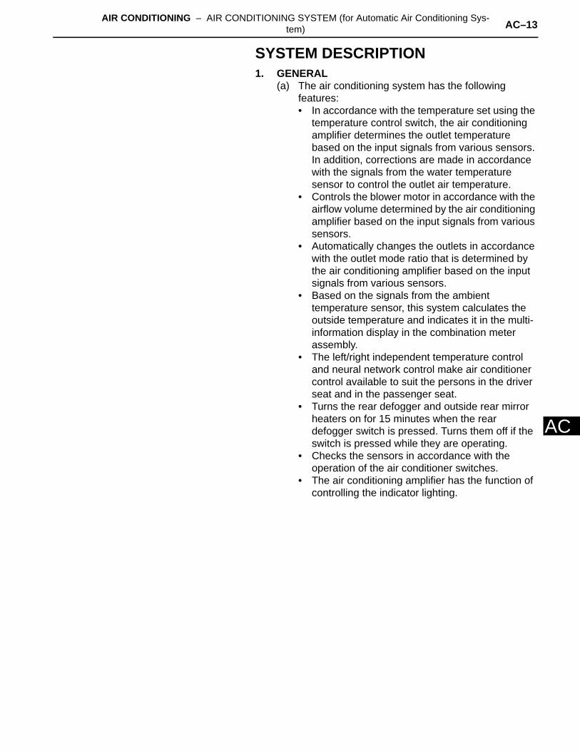
SYSTEM DESCRIPTION1. GENERAL
(a) The air conditioning system has the following features:• In accordance with the temperature set using the
temperature control switch, the air conditioning amplifier determines the outlet temperature based on the input signals from various sensors. In addition, corrections are made in accordance with the signals from the water temperature sensor to control the outlet air temperature.
• Controls the blower motor in accordance with the airflow volume determined by the air conditioning amplifier based on the input signals from various sensors.
• Automatically changes the outlets in accordance with the outlet mode ratio that is determined by the air conditioning amplifier based on the input signals from various sensors.
• Based on the signals from the ambient temperature sensor, this system calculates the outside temperature and indicates it in the multi-information display in the combination meter assembly.
• The left/right independent temperature control and neural network control make air conditioner control available to suit the persons in the driver seat and in the passenger seat.
• Turns the rear defogger and outside rear mirror heaters on for 15 minutes when the rear defogger switch is pressed. Turns them off if the switch is pressed while they are operating.
• Checks the sensors in accordance with the operation of the air conditioner switches.
• The air conditioning amplifier has the function of controlling the indicator lighting.
AC–14 AIR CONDITIONING – AIR CONDITIONING SYSTEM (for Automatic Air Conditioning Sys-tem)
AC
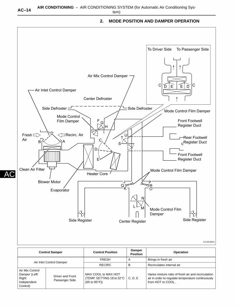
2. MODE POSITION AND DAMPER OPERATION
Control Damper Control Position Damper Position Operation
Air Inlet Control DamperFRESH A Brings in fresh air.
RECIRC B Recirculates internal air.
Air Mix Control Damper (Left/Right Independent Control)
Driver and Front Passenger Side
MAX COOL to MAX HOT(TEMP. SETTING 18 to 32°C (65 to 85°F))
C, D, EVaries mixture ratio of fresh air and recirculation air in order to regulate temperature continuously from HOT to COOL.
Blower Motor
Side Register Center Register
Mode Control Film
Damper
Side Register
L M
N
JQ
K ORP
Mode Control Film Damper
Front Footwell
Register Duct
Rear Footwell
Register Duct
Front Footwell
Register Duct
Air Mix Control Damper
Mode Control Film DamperSide Defroster
To Passenger SideTo Driver Side
Center Defroster
Side Defroster
Mode Control
Film Damper
Air Inlet Control Damper
Recirc. AirFresh
AirB A
FG
H
IU
T
C CD DE E
SC
D
E
Heater Core
Evaporator
Clean Air Filter
E123516E03
AIR CONDITIONING – AIR CONDITIONING SYSTEM (for Automatic Air Conditioning Sys-tem) AC–15
AC
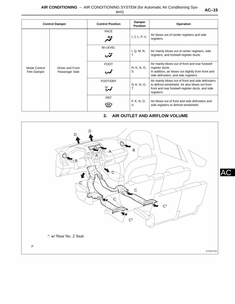
3. AIR OUTLET AND AIRFLOW VOLUME
Mode Control Film Damper
Driver and Front Passenger Side
FACE
I, J, L, P, U Air blows out of center registers and side registers.
BI-LEVELI, Q, M, R, T
Air mainly blows out of center registers, side registers, and footwell register ducts.
FOOTH, K, N, O, S
Air mainly blows out of front and rear footwell register ducts.In addition, air blows out slightly from front and side defrosters, and side registers.
FOOT/DEFG, K, N, O, T
Air mainly blows out of front and side defrosters to defrost windshield. Air also blows out from front and rear footwell register ducts, and side registers.
DEFF, K, N, O, U
Air blows out of front and side defrosters and side registers to defrost windshield.
Control Damper Control Position Damper Position Operation
B
BA
C
C
C
C
C*
C*
DD
A
*: w/ Rear No. 2 Seat
E123517E02
AC–16 AIR CONDITIONING – AIR CONDITIONING SYSTEM (for Automatic Air Conditioning Sys-tem)
AC
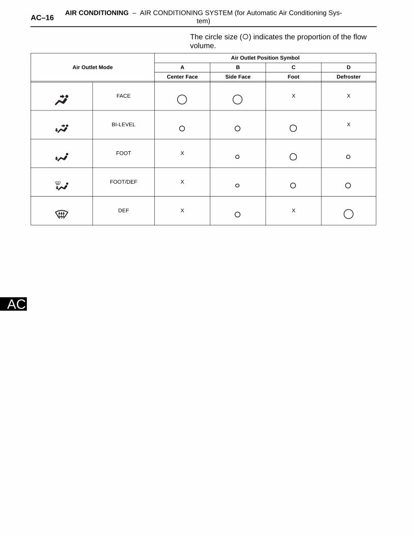
The circle size ( ) indicates the proportion of the flow volume.
Air Outlet Mode
Air Outlet Position Symbol
A B C D
Center Face Side Face Foot Defroster
FACE X X
BI-LEVEL X
FOOT X
FOOT/DEF X
DEF X X
AIR CONDITIONING – AIR CONDITIONING SYSTEM (for Automatic Air Conditioning Sys-tem) AC–17
AC
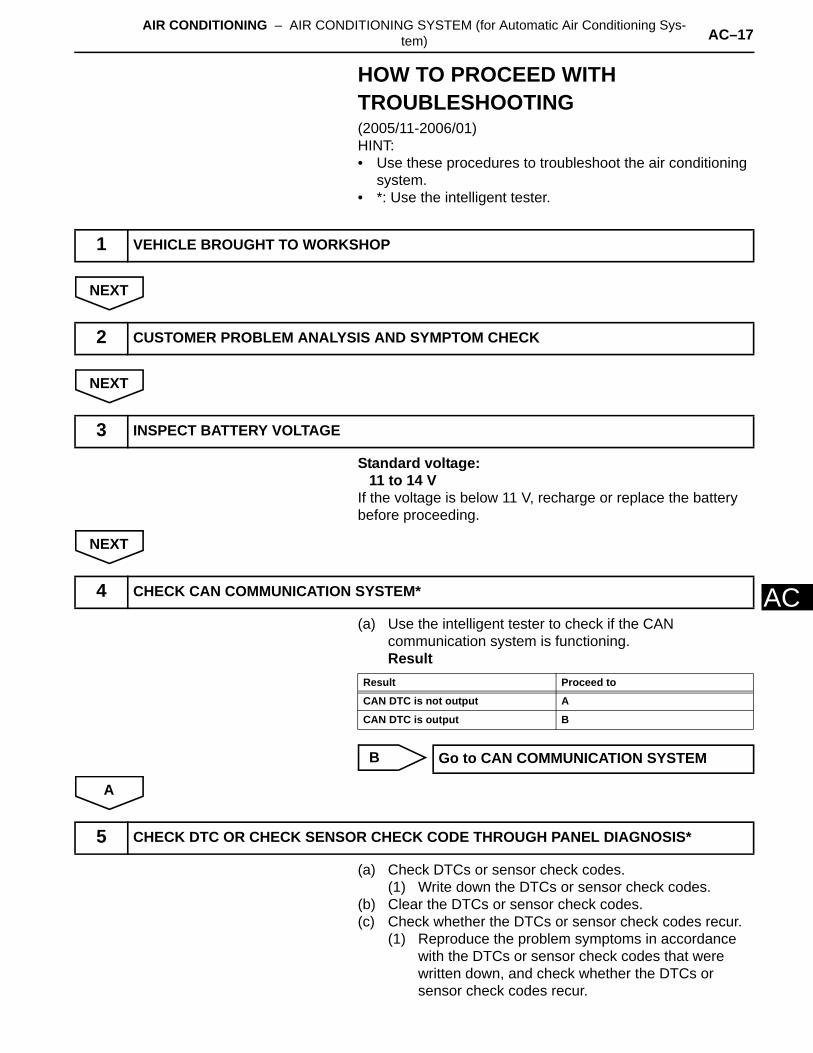
HOW TO PROCEED WITH TROUBLESHOOTING(2005/11-2006/01)HINT:• Use these procedures to troubleshoot the air conditioning
system.• *: Use the intelligent tester.
NEXT
NEXT
Standard voltage:11 to 14 V
If the voltage is below 11 V, recharge or replace the battery before proceeding.
NEXT
(a) Use the intelligent tester to check if the CAN communication system is functioning.Result
B
A
(a) Check DTCs or sensor check codes.(1) Write down the DTCs or sensor check codes.
(b) Clear the DTCs or sensor check codes.(c) Check whether the DTCs or sensor check codes recur.
(1) Reproduce the problem symptoms in accordance with the DTCs or sensor check codes that were written down, and check whether the DTCs or sensor check codes recur.
1 VEHICLE BROUGHT TO WORKSHOP
2 CUSTOMER PROBLEM ANALYSIS AND SYMPTOM CHECK
3 INSPECT BATTERY VOLTAGE
4 CHECK CAN COMMUNICATION SYSTEM*
Result Proceed to
CAN DTC is not output A
CAN DTC is output B
Go to CAN COMMUNICATION SYSTEM
5 CHECK DTC OR CHECK SENSOR CHECK CODE THROUGH PANEL DIAGNOSIS*
AC–18 AIR CONDITIONING – AIR CONDITIONING SYSTEM (for Automatic Air Conditioning Sys-tem)
AC
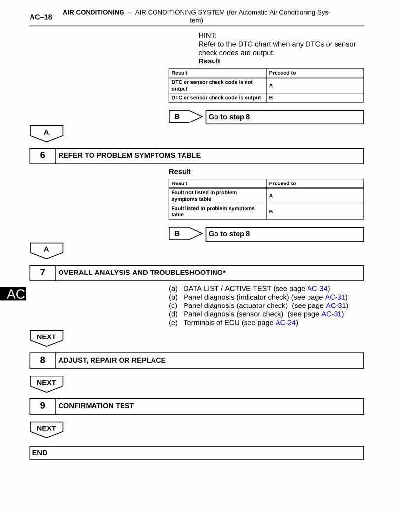
HINT:Refer to the DTC chart when any DTCs or sensor check codes are output.Result
B
A
Result
B
A
(a) DATA LIST / ACTIVE TEST (see page AC-34)(b) Panel diagnosis (indicator check) (see page AC-31)(c) Panel diagnosis (actuator check) (see page AC-31)(d) Panel diagnosis (sensor check) (see page AC-31)(e) Terminals of ECU (see page AC-24)
NEXT
NEXT
NEXT
Result Proceed to
DTC or sensor check code is not output A
DTC or sensor check code is output B
Go to step 8
6 REFER TO PROBLEM SYMPTOMS TABLE
Result Proceed to
Fault not listed in problem symptoms table A
Fault listed in problem symptoms table B
Go to step 8
7 OVERALL ANALYSIS AND TROUBLESHOOTING*
8 ADJUST, REPAIR OR REPLACE
9 CONFIRMATION TEST
END

AIR CONDITIONING – AIR CONDITIONING SYSTEM (for Automatic Air Conditioning Sys-tem) AC–19
AC
HOW TO PROCEED WITH TROUBLESHOOTING(2006/01- )HINT:• Use these procedures to troubleshoot the air conditioning
system.• *: Use the intelligent tester.
NEXT
NEXT
Standard voltage:11 to 14 V
If the voltage is below 11 V, recharge or replace the battery before proceeding.
NEXT
(a) Use the intelligent tester to check if the CAN communication system is functioning.Result
B
A
(a) Check DTCs or sensor check codes.(1) Write down the DTCs or sensor check codes.
(b) Clear the DTCs or sensor check codes.(c) Check whether the DTCs or sensor check codes recur.
(1) Reproduce the problem symptoms in accordance with the DTCs or sensor check codes that were written down, and check whether the DTCs or sensor check codes recur.
1 VEHICLE BROUGHT TO WORKSHOP
2 CUSTOMER PROBLEM ANALYSIS AND SYMPTOM CHECK
3 INSPECT BATTERY VOLTAGE
4 CHECK CAN COMMUNICATION SYSTEM*
Result Proceed to
CAN DTC is not output A
CAN DTC is output B
Go to CAN COMMUNICATION SYSTEM
5 CHECK DTC OR CHECK SENSOR CHECK CODE THROUGH PANEL DIAGNOSIS*

AC–20 AIR CONDITIONING – AIR CONDITIONING SYSTEM (for Automatic Air Conditioning Sys-tem)
AC
HINT:Refer to the DTC chart when any DTCs or sensor check codes are output.Result
B
A
Result
B
A
(a) DATA LIST / ACTIVE TEST (see page AC-37)(b) Panel diagnosis (indicator check) (see page AC-31)(c) Panel diagnosis (sensor check) (see page AC-31)(d) Panel diagnosis (actuator check) (see page AC-31)(e) Terminals of ECU (see page AC-27)
NEXT
NEXT
NEXT
Result Proceed to
DTC or sensor check code is not output A
DTC or sensor check code is output B
Go to step 8
6 REFER TO PROBLEM SYMPTOMS TABLE
Result Proceed to
Fault is not listed in problem symptoms table A
Fault is listed in problem symptoms table B
Go to step 8
7 OVERALL ANALYSIS AND TROUBLESHOOTING*
8 ADJUST, REPAIR OR REPLACE
9 CONFIRMATION TEST
END

AIR CONDITIONING – AIR CONDITIONING SYSTEM (for Automatic Air Conditioning Sys-tem) AC–21
AC
CUSTOMIZE PARAMETERSHINT:The following items can be customized.NOTICE:• When the customer requests a change in a function,
first make sure that the function can be customized.• Be sure to make a note of the current settings before
customizing.• When troubleshooting a function, first make sure that
the function is set to the default setting.Air conditioning system
Display (Item) Default Contents Setting
SET TEMP SHIFT(Set Temperature Shift) NORMAL To control with shifted temperature against
display temperature+2 C / +1 C / NORMAL / -1 C / -2 C
AIR INLET MODE(Air Inlet Mode) AUTO
In case of turning A/C ON when you desire to make compartment cool down quickly, this is function to change mode automatically to RECIRCULATION mode
MANUAL / AUTO
COMPRESSOR MODE(Compressor Mode) AUTO
Function to turn A/C ON automatically by pressing AUTO button when blower is ON and A/C is OFF
MANUAL / AUTO
COMPRS / DEF OPER(Compressor / Air Inlet DEF Operation)
LINK Function to turn A/C ON automatically linked with FRONT DEF button when A/C is OFF NORMAL / LINK
EVAP CTRL(Evaporator Control) AUTO
Function to set evaporator control to AUTOMATIC position (AUTO) to save power, or to coldest position (MANUAL) to dehumidify air and to prevent windows from fogging up
MANUAL / AUTO
FOOT / DEF MODE(Foot / DEF auto mode) ON Function to turn airflow from FOOT / DEF ON
automatically when AUTO MODE is ON OFF / ON
AUTO BLOW UP(Foot / DEF automatic blower up function)
ON Function to change blower level automatically when defroster is ON OFF / ON
AC–22 AIR CONDITIONING – AIR CONDITIONING SYSTEM (for Automatic Air Conditioning Sys-tem)
AC
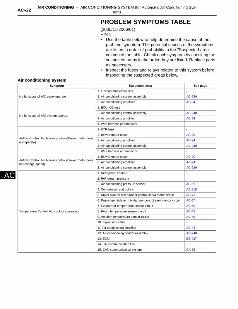
PROBLEM SYMPTOMS TABLE(2005/11-2006/01)HINT:• Use the table below to help determine the cause of the
problem symptom. The potential causes of the symptoms are listed in order of probability in the "Suspected area" column of the table. Check each symptom by checking the suspected areas in the order they are listed. Replace parts as necessary.
• Inspect the fuses and relays related to this system before inspecting the suspected areas below.
Air conditioning systemSymptom Suspected area See page
No functions of A/C panel operate
1. LIN communication line -
2. Air conditioning control assembly AC-240
3. Air conditioning amplifier AC-24
No functions of A/C system operate
1. ECU-IG2 fuse -
2. Air conditioning control assembly AC-240
3. Air conditioning amplifier AC-24
4. Wire harness or connector -
Airflow Control: No blower control (Blower motor does not operate)
1. HTR fuse -
2. Blower motor circuit AC-90
3. Air conditioning amplifier AC-24
4. Air conditioning control assembly AC-240
5. Wire harness or connector -
Airflow Control: No blower control (Blower motor does not change speed)
1. Blower motor circuit AC-90
2. Air conditioning amplifier AC-24
3. Air conditioning control assembly AC-240
Temperature Control: No cool air comes out
1. Refrigerant volume -
2. Refrigerant pressure -
3. Air conditioning pressure sensor AC-59
4. Compressor and pulley AC-215
5. Driver side air mix damper control servo motor circuit AC-73
6. Passenger side air mix damper control servo motor circuit AC-67
7. Evaporator temperature sensor circuit AC-50
8. Room temperature sensor circuit AC-43
9. Ambient temperature sensor circuit AC-46
10. Expansion valve -
11. Air conditioning amplifier AC-24
12. Air conditioning control assembly AC-240
13. ECM ES-427
14. LIN communication line -
15. CAN communication system CA-75

AIR CONDITIONING – AIR CONDITIONING SYSTEM (for Automatic Air Conditioning Sys-tem) AC–23
AC
Temperature Control: No warm air comes out
1. Driver side air mix damper control servo motor circuit AC-73
2. Passenger side air mix damper control servo motor circuit AC-67
3. Air conditioning harness -
4. Room temperature sensor circuit AC-43
5. Air conditioning amplifier AC-24
6. Air conditioning control assembly AC-240
7. ECM ES-427
8. LIN communication line -
9. CAN communication system CA-75
Temperature Control: Output air is warmer or cooler than set temperature or response is slow
1. Driver side solar sensor circuit AC-73
2. Passenger side solar sensor circuit AC-67
3. Room temperature sensor circuit AC-43
4. Air inlet damper control servo motor circuit AC-69
5. Heater radiator -
6. Expansion valve -
7. Air conditioning amplifier AC-24
8. Air conditioning control assembly AC-240
9. ECM ES-427
10. LIN communication line -
11. CAN communication system CA-75
Temperature Control: No temperature control (Only Max. cool or Max. warm)
1. Driver side solar sensor circuit AC-64
2. Passenger side solar sensor circuit AC-53
3. Air conditioning amplifier AC-24
4. Air conditioning control assembly AC-240
5. LIN communication line -
No air inlet control
1. Air conditioning control assembly AC-240
2. Air inlet damper control servo motor circuit AC-69
3. Evaporator temperature sensor circuit AC-50
4. Air conditioning amplifier AC-24
Diagnostic trouble codes are not recorded. Set mode is cleared when ignition switch turned to LOCK
1. Air conditioning amplifier AC-24
2. Back-up power source circuit AC-100
Symptom Suspected area See page
AC–24 AIR CONDITIONING – AIR CONDITIONING SYSTEM (for Automatic Air Conditioning Sys-tem)
AC
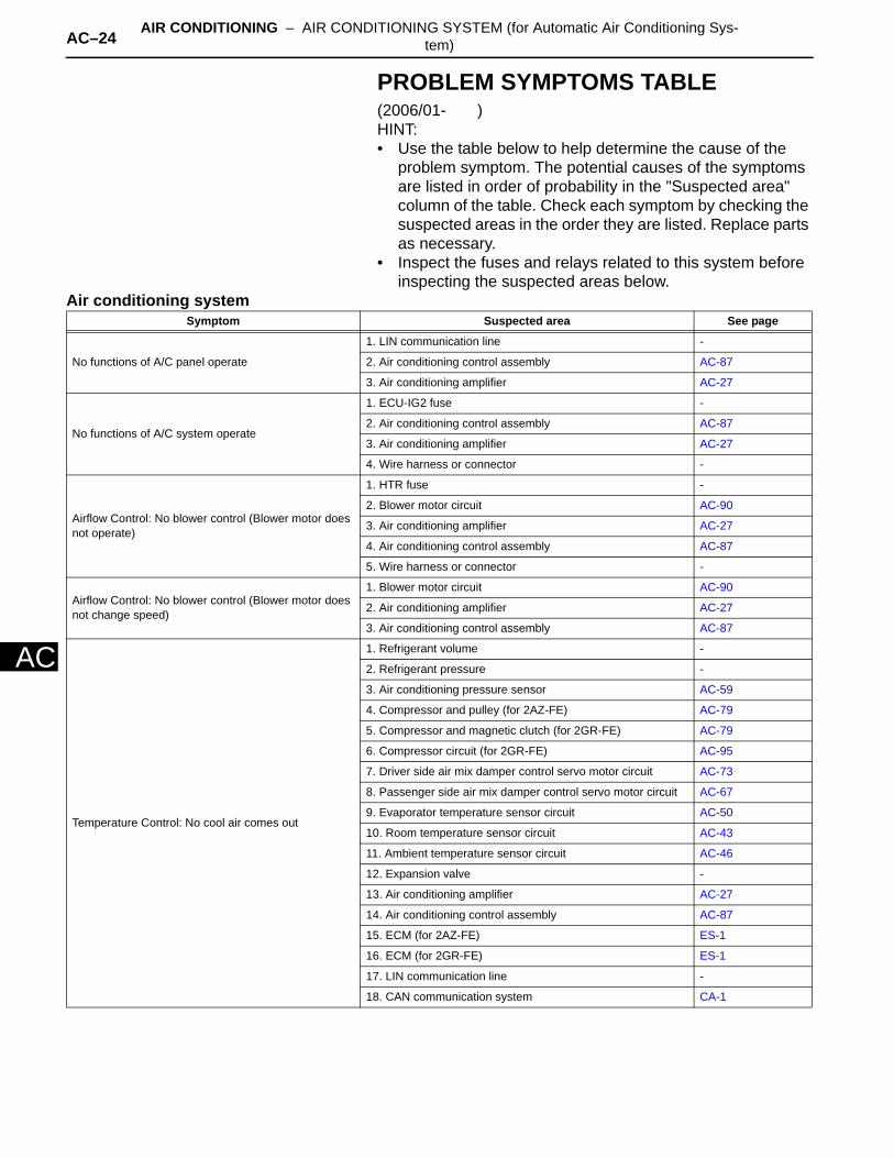
PROBLEM SYMPTOMS TABLE(2006/01- )HINT:• Use the table below to help determine the cause of the
problem symptom. The potential causes of the symptoms are listed in order of probability in the "Suspected area" column of the table. Check each symptom by checking the suspected areas in the order they are listed. Replace parts as necessary.
• Inspect the fuses and relays related to this system before inspecting the suspected areas below.
Air conditioning systemSymptom Suspected area See page
No functions of A/C panel operate
1. LIN communication line -
2. Air conditioning control assembly AC-87
3. Air conditioning amplifier AC-27
No functions of A/C system operate
1. ECU-IG2 fuse -
2. Air conditioning control assembly AC-87
3. Air conditioning amplifier AC-27
4. Wire harness or connector -
Airflow Control: No blower control (Blower motor does not operate)
1. HTR fuse -
2. Blower motor circuit AC-90
3. Air conditioning amplifier AC-27
4. Air conditioning control assembly AC-87
5. Wire harness or connector -
Airflow Control: No blower control (Blower motor does not change speed)
1. Blower motor circuit AC-90
2. Air conditioning amplifier AC-27
3. Air conditioning control assembly AC-87
Temperature Control: No cool air comes out
1. Refrigerant volume -
2. Refrigerant pressure -
3. Air conditioning pressure sensor AC-59
4. Compressor and pulley (for 2AZ-FE) AC-79
5. Compressor and magnetic clutch (for 2GR-FE) AC-79
6. Compressor circuit (for 2GR-FE) AC-95
7. Driver side air mix damper control servo motor circuit AC-73
8. Passenger side air mix damper control servo motor circuit AC-67
9. Evaporator temperature sensor circuit AC-50
10. Room temperature sensor circuit AC-43
11. Ambient temperature sensor circuit AC-46
12. Expansion valve -
13. Air conditioning amplifier AC-27
14. Air conditioning control assembly AC-87
15. ECM (for 2AZ-FE) ES-1
16. ECM (for 2GR-FE) ES-1
17. LIN communication line -
18. CAN communication system CA-1
AIR CONDITIONING – AIR CONDITIONING SYSTEM (for Automatic Air Conditioning Sys-tem) AC–25
AC
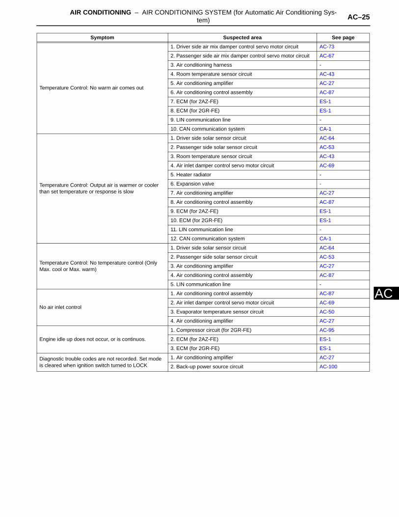
Temperature Control: No warm air comes out
1. Driver side air mix damper control servo motor circuit AC-73
2. Passenger side air mix damper control servo motor circuit AC-67
3. Air conditioning harness -
4. Room temperature sensor circuit AC-43
5. Air conditioning amplifier AC-27
6. Air conditioning control assembly AC-87
7. ECM (for 2AZ-FE) ES-1
8. ECM (for 2GR-FE) ES-1
9. LIN communication line -
10. CAN communication system CA-1
Temperature Control: Output air is warmer or cooler than set temperature or response is slow
1. Driver side solar sensor circuit AC-64
2. Passenger side solar sensor circuit AC-53
3. Room temperature sensor circuit AC-43
4. Air inlet damper control servo motor circuit AC-69
5. Heater radiator -
6. Expansion valve -
7. Air conditioning amplifier AC-27
8. Air conditioning control assembly AC-87
9. ECM (for 2AZ-FE) ES-1
10. ECM (for 2GR-FE) ES-1
11. LIN communication line -
12. CAN communication system CA-1
Temperature Control: No temperature control (Only Max. cool or Max. warm)
1. Driver side solar sensor circuit AC-64
2. Passenger side solar sensor circuit AC-53
3. Air conditioning amplifier AC-27
4. Air conditioning control assembly AC-87
5. LIN communication line -
No air inlet control
1. Air conditioning control assembly AC-87
2. Air inlet damper control servo motor circuit AC-69
3. Evaporator temperature sensor circuit AC-50
4. Air conditioning amplifier AC-27
Engine idle up does not occur, or is continuos.
1. Compressor circuit (for 2GR-FE) AC-95
2. ECM (for 2AZ-FE) ES-1
3. ECM (for 2GR-FE) ES-1
Diagnostic trouble codes are not recorded. Set mode is cleared when ignition switch turned to LOCK
1. Air conditioning amplifier AC-27
2. Back-up power source circuit AC-100
Symptom Suspected area See page
AC–26 AIR CONDITIONING – AIR CONDITIONING SYSTEM (for Automatic Air Conditioning Sys-tem)
AC
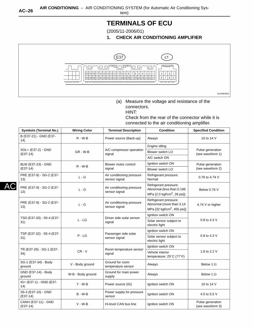
TERMINALS OF ECU(2005/11-2006/01)1. CHECK AIR CONDITIONING AMPLIFIER
(a) Measure the voltage and resistance of the connectors.HINT:Check from the rear of the connector while it is connected to the air conditioning amplifier.
E37 c1
E115964E03
Symbols (Terminal No.) Wiring Color Terminal Description Condition Specified Condition
B (E37-21) - GND (E37-14) R - W-B Power source (Back-up) Always 10 to 14 V
SOL+ (E37-2) - GND (E37-14) GR - W-B A/C compressor operation
signal
Engine idlingPulse generation(see waveform 1)Blower switch LO
A/C switch ON
BLW (E37-23) - GND (E37-14) R - W-B Blower motor control
signalIgnition switch ON Pulse generation
(see waveform 2)Blower switch LO
PRE (E37-9) - SG-2 (E37-13) L - G Air conditioning pressure
sensor signalRefrigerant pressure: Normal 0.76 to 4.74 V
PRE (E37-9) - SG-2 (E37-13) L - G Air conditioning pressure
sensor signal
Refrigerant pressure: Abnormal (less than 0.196 MPa [2.0 kgf/cm2, 28 psi])
Below 0.76 V
PRE (E37-9) - SG-2 (E37-13) L - G Air conditioning pressure
sensor signal
Refrigerant pressure: Abnormal (more than 3.14 MPa [32 kgf/cm2, 455 psi])
4.74 V or higher
TSD (E37-33) - S5-4 (E37-31) L - LG Driver side solar sensor
signal
Ignition switch ON0.8 to 4.3 VSolar sensor subject to
electric light
TSP (E37-32) - S5-4 (E37-31) P - LG Passenger side solar
sensor signal
Ignition switch ON0.8 to 4.3 VSolar sensor subject to
electric light
TR (E37-29) - SG-1 (E37-34) CR - V Room temperature sensor
signal
Ignition switch ON1.8 to 2.2 VVehicle interior
temperature: 25°C (77°F)
SG-1 (E37-34) - Body ground V - Body ground Ground for room
temperature sensor Always Below 1 Ω
GND (E37-14) - Body ground W-B - Body ground Ground for main power
supply Always Below 1 Ω
IG+ (E37-1) - GND (E37-14) Y - W-B Power source (IG) Ignition switch ON 10 to 14 V
S5-3 (E37-10) - GND (E37-14) B - W-B Power supply for pressure
sensor Ignition switch ON 4.5 to 5.5 V
CANH (E37-11) - GND (E37-14) V - W-B Hi-level CAN bus line Ignition switch ON Pulse generation
(see waveform 3)
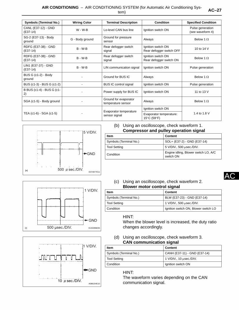
AIR CONDITIONING – AIR CONDITIONING SYSTEM (for Automatic Air Conditioning Sys-tem) AC–27
AC
(b) Using an oscilloscope, check waveform 1.Compressor and pulley operation signal
(c) Using an oscilloscope, check waveform 2.Blower motor control signal
HINT:When the blower level is increased, the duty ratio changes accordingly.
(d) Using an oscilloscope, check waveform 3.CAN communication signal
HINT:The waveform varies depending on the CAN communication signal.
CANL (E37-12) - GND (E37-14) W - W-B Lo-level CAN bus line Ignition switch ON Pulse generation
(see waveform 4)
SG-2 (E37-13) - Body ground G - Body ground Ground for pressure
sensor Always Below 1 Ω
RDFG (E37-38) - GND (E37-14) B - W-B Rear defogger switch
signalIgnition switch ONRear defogger switch OFF 10 to 14 V
RDFG (E37-38) - GND (E37-14) B - W-B Rear defogger switch
signalIgnition switch ONRear defogger switch ON Below 1 Ω
LIN1 (E37-37) - GND (E37-14) B - W-B LIN communication signal Ignition switch ON Pulse generation
BUS G (c1-2) - Body ground - Ground for BUS IC Always Below 1 Ω
BUS (c1-3) - BUS G (c1-2) - BUS IC control signal Ignition switch ON Pulse generation
B BUS (c1-4) - BUS G (c1-2) - Power supply for BUS IC Ignition switch ON 11 to 13 V
SGA (c1-5) - Body ground - Ground for evaporator temperature sensor Always Below 1 Ω
TEA (c1-6) - SGA (c1-5) - Evaporator temperature sensor signal
Ignition switch ON1.4 to 1.8 VEvaporator temperature:
15°C (59°F)
Symbols (Terminal No.) Wiring Color Terminal Description Condition Specified Condition
GND
5 V/DIV.
500 sec./DIV.E074977E11
Item Content
Symbols (Terminal No.) SOL+ (E37-2) - GND (E37-14)
Tool Setting 5 V/DIV., 500 µsec./DIV.
Condition Engine idling, Blower switch LO, A/C switch ON
GND
1 V/DIV.
500 μsec./DIV. E103396E05
Item Content
Symbols (Terminal No.) BLW (E37-23) - GND (E37-14)
Tool Setting 1 V/DIV., 500 µsec./DIV.
Condition Ignition switch ON, Blower switch LO
1 V/DIV.
GND
10 sec./DIV.A086154E10
Item Content
Symbols (Terminal No.) CANH (E37-11) - GND (E37-14)
Tool Setting 1 V/DIV., 10 µsec./DIV.
Condition Ignition switch ON

AC–28 AIR CONDITIONING – AIR CONDITIONING SYSTEM (for Automatic Air Conditioning Sys-tem)
AC
(e) Using an oscilloscope, check waveform 4.CAN communication signal
HINT:The waveform varies depending on the CAN communication signal.
2. CHECK AIR CONDITIONING CONTROL
(a) Measure the voltage and resistance of the connectors.
GND
1 V/DIV.
10 sec./DIV.A086155E11
Item Content
Symbols (Terminal No.) CANL (E37-12) - GND (E37-14)
Tool Setting 1 V/DIV., 10 µsec./DIV.
Condition Ignition switch ON
E23
E123518E01
Symbols (Terminal No.) Wiring Color Terminal Description Condition Specified Condition
IG+ (E23-2) - GND (E23-7) L - W-B Power source (IG) Ignition switch ON 10 to 14 V
GND (E23-7) - Body ground W-B - Body ground Ground for air conditioning
control assembly Always Below 1 Ω
LIN1 (E23-11) - GND (E23-7) B - W-B LIN communication signal Ignition switch ON Pulse generation
+B (E23-1) - GND (E23-7) R - W-B Power source (Back-up) Always 10 to 14 V
ACC (E23-8) - GND (E23-7) GR - W-B ACC power supply Always Below 1 Ω

AIR CONDITIONING – AIR CONDITIONING SYSTEM (for Automatic Air Conditioning Sys-tem) AC–29
AC
TERMINALS OF ECU(2006/01- )1. CHECK AIR CONDITIONING AMPLIFIER
(a) Measure the voltage and resistance of the connectors.HINT:Check from the rear of the connector while it is connected to the air conditioning amplifier.
E37 c1
E115964E03
Symbols (Terminal No.) Wiring Color Terminal Description Condition Specified Condition
B (E37-21) - GND (E37-14) R - W-B Power source (Back-up) Always 10 to 14 V
SOL+ (E37-2) - GND (E37-14) GR - W-B A/C compressor operation
signal
Engine idlingPulse generation(see waveform 1)Blower switch LO
A/C switch ON
BLW (E37-23) - GND (E37-14) R - W-B Blower motor control
signalIgnition switch ON Pulse generation
(see waveform 2)Blower switch LO
PRE (E37-9) - SG-2 (E37-13) L - G Air conditioning pressure
sensor signalRefrigerant pressure: Normal 0.76 to 4.74 V
PRE (E37-9) - SG-2 (E37-13) L - G Air conditioning pressure
sensor signal
Refrigerant pressure: Abnormal (less than 0.196 MPa [2.0 kgf/cm2, 28 psi])
Below 0.76 V
PRE (E37-9) - SG-2 (E37-13) L - G Air conditioning pressure
sensor signal
Refrigerant pressure: Abnormal (more than 3.14 MPa [32 kgf/cm2, 455 psi])
4.74 V or higher
TSD (E37-33) - S5-4 (E37-31) L - LG Driver side solar sensor
signal
Ignition switch ON0.8 to 4.3 VSolar sensor subject to
electric light
TSP (E37-32) - S5-4 (E37-31) P - LG Passenger side solar
sensor signal
Ignition switch ON0.8 to 4.3 VSolar sensor subject to
electric light
TR (E37-29) - SG-1 (E37-34) CR - V Room temperature sensor
signal
Ignition switch ON1.8 to 2.2 VVehicle interior
temperature: 25°C (77°F)
SG-1 (E37-34) - Body ground V - Body ground Ground for room
temperature sensor Always Below 1 Ω
GND (E37-14) - Body ground W-B - Body ground Ground for main power
supply Always Below 1 Ω
IG+ (E37-1) - GND (E37-14) Y - W-B Power source (IG) Ignition switch ON 10 to 14 V
S5-3 (E37-10) - GND (E37-14) B - W-B Power supply for pressure
sensor Ignition switch ON 4.5 to 5.5 V
CANH (E37-11) - GND (E37-14) V - W-B Hi-level CAN bus line Ignition switch ON Pulse generation
(see waveform 3)
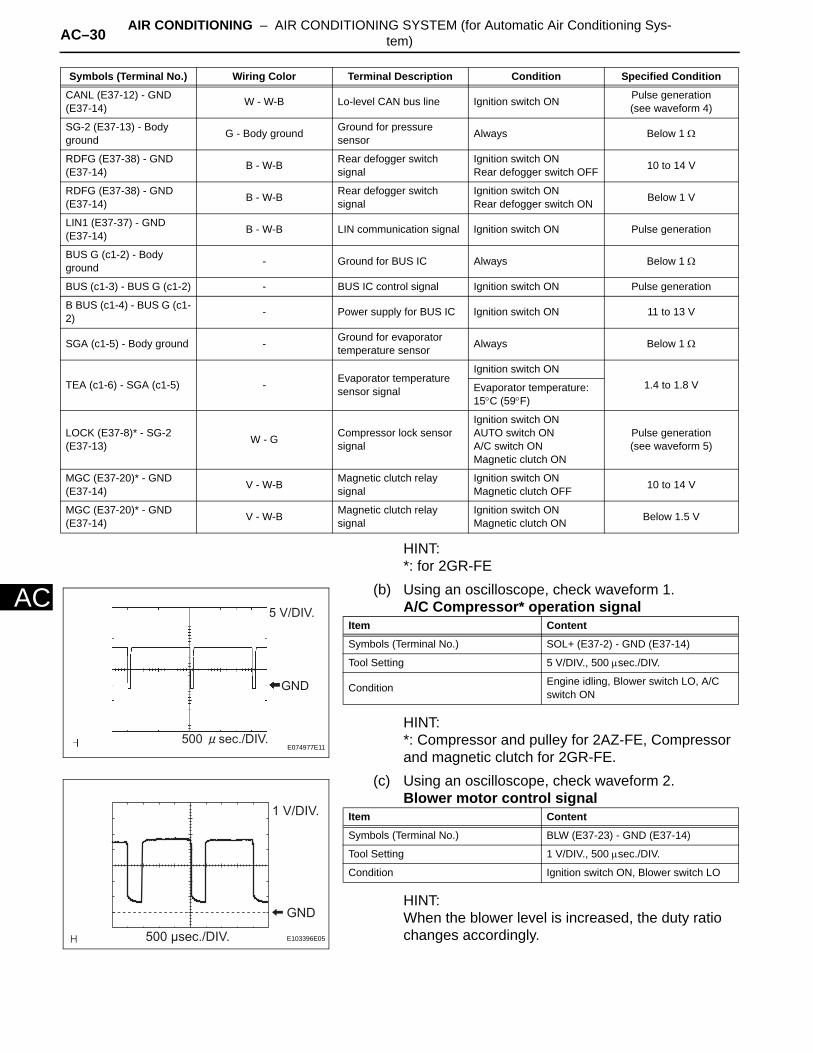
AC–30 AIR CONDITIONING – AIR CONDITIONING SYSTEM (for Automatic Air Conditioning Sys-tem)
AC
HINT:*: for 2GR-FE
(b) Using an oscilloscope, check waveform 1.A/C Compressor* operation signal
HINT:*: Compressor and pulley for 2AZ-FE, Compressor and magnetic clutch for 2GR-FE.
(c) Using an oscilloscope, check waveform 2.Blower motor control signal
HINT:When the blower level is increased, the duty ratio changes accordingly.
CANL (E37-12) - GND (E37-14) W - W-B Lo-level CAN bus line Ignition switch ON Pulse generation
(see waveform 4)
SG-2 (E37-13) - Body ground G - Body ground Ground for pressure
sensor Always Below 1 Ω
RDFG (E37-38) - GND (E37-14) B - W-B Rear defogger switch
signalIgnition switch ONRear defogger switch OFF 10 to 14 V
RDFG (E37-38) - GND (E37-14) B - W-B Rear defogger switch
signalIgnition switch ONRear defogger switch ON Below 1 V
LIN1 (E37-37) - GND (E37-14) B - W-B LIN communication signal Ignition switch ON Pulse generation
BUS G (c1-2) - Body ground - Ground for BUS IC Always Below 1 Ω
BUS (c1-3) - BUS G (c1-2) - BUS IC control signal Ignition switch ON Pulse generation
B BUS (c1-4) - BUS G (c1-2) - Power supply for BUS IC Ignition switch ON 11 to 13 V
SGA (c1-5) - Body ground - Ground for evaporator temperature sensor Always Below 1 Ω
TEA (c1-6) - SGA (c1-5) - Evaporator temperature sensor signal
Ignition switch ON1.4 to 1.8 VEvaporator temperature:
15°C (59°F)
LOCK (E37-8)* - SG-2 (E37-13) W - G Compressor lock sensor
signal
Ignition switch ONAUTO switch ONA/C switch ONMagnetic clutch ON
Pulse generation(see waveform 5)
MGC (E37-20)* - GND (E37-14) V - W-B Magnetic clutch relay
signalIgnition switch ONMagnetic clutch OFF 10 to 14 V
MGC (E37-20)* - GND (E37-14) V - W-B Magnetic clutch relay
signalIgnition switch ONMagnetic clutch ON Below 1.5 V
Symbols (Terminal No.) Wiring Color Terminal Description Condition Specified Condition
GND
5 V/DIV.
500 sec./DIV.E074977E11
Item Content
Symbols (Terminal No.) SOL+ (E37-2) - GND (E37-14)
Tool Setting 5 V/DIV., 500 µsec./DIV.
Condition Engine idling, Blower switch LO, A/C switch ON
GND
1 V/DIV.
500 μsec./DIV. E103396E05
Item Content
Symbols (Terminal No.) BLW (E37-23) - GND (E37-14)
Tool Setting 1 V/DIV., 500 µsec./DIV.
Condition Ignition switch ON, Blower switch LO
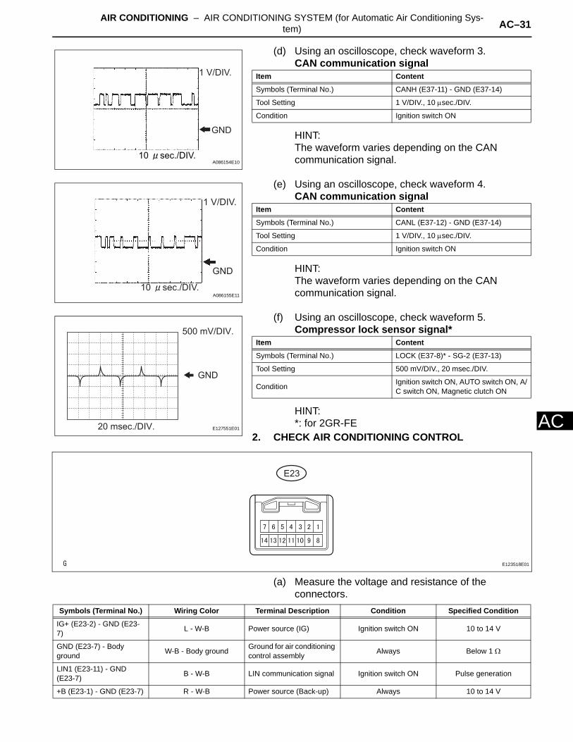
AIR CONDITIONING – AIR CONDITIONING SYSTEM (for Automatic Air Conditioning Sys-tem) AC–31
AC
(d) Using an oscilloscope, check waveform 3.CAN communication signal
HINT:The waveform varies depending on the CAN communication signal.
(e) Using an oscilloscope, check waveform 4.CAN communication signal
HINT:The waveform varies depending on the CAN communication signal.
(f) Using an oscilloscope, check waveform 5.Compressor lock sensor signal*
HINT:*: for 2GR-FE
2. CHECK AIR CONDITIONING CONTROL
(a) Measure the voltage and resistance of the connectors.
1 V/DIV.
GND
10 sec./DIV.A086154E10
Item Content
Symbols (Terminal No.) CANH (E37-11) - GND (E37-14)
Tool Setting 1 V/DIV., 10 µsec./DIV.
Condition Ignition switch ON
GND
1 V/DIV.
10 sec./DIV.A086155E11
Item Content
Symbols (Terminal No.) CANL (E37-12) - GND (E37-14)
Tool Setting 1 V/DIV., 10 µsec./DIV.
Condition Ignition switch ON
GND
20 msec./DIV.
500 mV/DIV.
E127551E01
Item Content
Symbols (Terminal No.) LOCK (E37-8)* - SG-2 (E37-13)
Tool Setting 500 mV/DIV., 20 msec./DIV.
Condition Ignition switch ON, AUTO switch ON, A/C switch ON, Magnetic clutch ON
E23
E123518E01
Symbols (Terminal No.) Wiring Color Terminal Description Condition Specified Condition
IG+ (E23-2) - GND (E23-7) L - W-B Power source (IG) Ignition switch ON 10 to 14 V
GND (E23-7) - Body ground W-B - Body ground Ground for air conditioning
control assembly Always Below 1 Ω
LIN1 (E23-11) - GND (E23-7) B - W-B LIN communication signal Ignition switch ON Pulse generation
+B (E23-1) - GND (E23-7) R - W-B Power source (Back-up) Always 10 to 14 V
AC–32 AIR CONDITIONING – AIR CONDITIONING SYSTEM (for Automatic Air Conditioning Sys-tem)
AC
ACC (E23-8) - GND (E23-7) GR - W-B ACC power supply Always Below 1 Ω
Symbols (Terminal No.) Wiring Color Terminal Description Condition Specified Condition
AIR CONDITIONING – AIR CONDITIONING SYSTEM (for Automatic Air Conditioning Sys-tem) AC–33
AC
DIAGNOSIS SYSTEM1. DESCRIPTION
(a) Air conditioning system data and the Diagnostic Trouble Codes (DTCs) can be read through the Data Link Connector 3 (DLC3) of the vehicle. When the system seems to be malfunctioning, use the intelligent tester to check for malfunctions and perform troubleshooting.
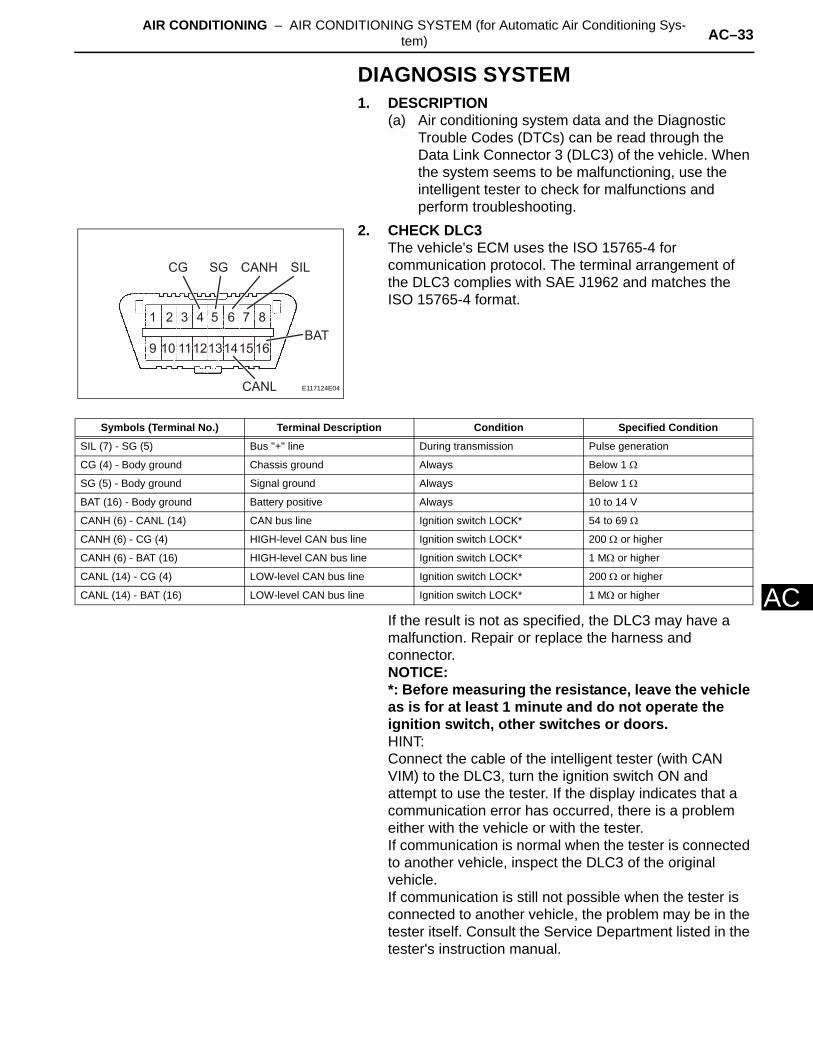
2. CHECK DLC3The vehicle's ECM uses the ISO 15765-4 for communication protocol. The terminal arrangement of the DLC3 complies with SAE J1962 and matches the ISO 15765-4 format.
If the result is not as specified, the DLC3 may have a malfunction. Repair or replace the harness and connector.NOTICE:*: Before measuring the resistance, leave the vehicle as is for at least 1 minute and do not operate the ignition switch, other switches or doors.HINT:Connect the cable of the intelligent tester (with CAN VIM) to the DLC3, turn the ignition switch ON and attempt to use the tester. If the display indicates that a communication error has occurred, there is a problem either with the vehicle or with the tester.If communication is normal when the tester is connected to another vehicle, inspect the DLC3 of the original vehicle.If communication is still not possible when the tester is connected to another vehicle, the problem may be in the tester itself. Consult the Service Department listed in the tester's instruction manual.
1 2 3 4 5 6 7 8
9 10 111213141516
CG SG CANH
CANL
BAT
SIL
E117124E04
Symbols (Terminal No.) Terminal Description Condition Specified Condition
SIL (7) - SG (5) Bus "+" line During transmission Pulse generation
CG (4) - Body ground Chassis ground Always Below 1 Ω
SG (5) - Body ground Signal ground Always Below 1 Ω
BAT (16) - Body ground Battery positive Always 10 to 14 V
CANH (6) - CANL (14) CAN bus line Ignition switch LOCK* 54 to 69 Ω
CANH (6) - CG (4) HIGH-level CAN bus line Ignition switch LOCK* 200 Ω or higher
CANH (6) - BAT (16) HIGH-level CAN bus line Ignition switch LOCK* 1 MΩ or higher
CANL (14) - CG (4) LOW-level CAN bus line Ignition switch LOCK* 200 Ω or higher
CANL (14) - BAT (16) LOW-level CAN bus line Ignition switch LOCK* 1 MΩ or higher

AC–34 AIR CONDITIONING – AIR CONDITIONING SYSTEM (for Automatic Air Conditioning Sys-tem)
AC
DTC CHECK / CLEAR1. CHECK DTC
(a) Connect the intelligent tester (with CAN VIM) to the DLC3.
(b) Turn the ignition switch ON and turn the intelligent tester ON.
(c) Read the DTC by following the prompts on the tester screen.HINT:Refer to the intelligent tester operator's manual for further details.
2. CLEAR DTC(a) Connect the intelligent tester (with CAN VIM) to the
DLC3.(b) Turn the ignition switch ON and turn the intelligent
tester ON.(c) Clear the DTC by following the prompts on the
tester screen.HINT:Refer to the intelligent tester operator's manual for further details.
Intelligent Tester
CAN VIM
DLC3
B127989E04
AIR CONDITIONING – AIR CONDITIONING SYSTEM (for Automatic Air Conditioning Sys-tem) AC–35
AC
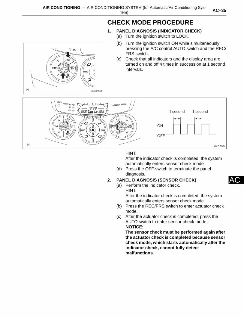
CHECK MODE PROCEDURE1. PANEL DIAGNOSIS (INDICATOR CHECK)
(a) Turn the ignition switch to LOCK.(b) Turn the ignition switch ON while simultaneously
pressing the A/C control AUTO switch and the REC/FRS switch.
(c) Check that all indicators and the display area are turned on and off 4 times in succession at 1 second intervals.
HINT:After the indicator check is completed, the system automatically enters sensor check mode.
(d) Press the OFF switch to terminate the panel diagnosis.
2. PANEL DIAGNOSIS (SENSOR CHECK)(a) Perform the indicator check.
HINT:After the indicator check is completed, the system automatically enters sensor check mode.
(b) Press the REC/FRS switch to enter actuator check mode.
(c) After the actuator check is completed, press the AUTO switch to enter sensor check mode.NOTICE:The sensor check must be performed again after the actuator check is completed because sensor check mode, which starts automatically after the indicator check, cannot fully detect malfunctions.
E123529E01
1 second 1 second
ON
OFF
E123530E01
AC–36 AIR CONDITIONING – AIR CONDITIONING SYSTEM (for Automatic Air Conditioning Sys-tem)
AC
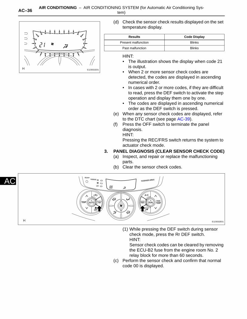
(d) Check the sensor check results displayed on the set temperature display.
HINT:• The illustration shows the display when code 21
is output.• When 2 or more sensor check codes are
detected, the codes are displayed in ascending numerical order.
• In cases with 2 or more codes, if they are difficult to read, press the DEF switch to activate the step operation and display them one by one.
• The codes are displayed in ascending numerical order as the DEF switch is pressed.
(e) When any sensor check codes are displayed, refer to the DTC chart (see page AC-39).
(f) Press the OFF switch to terminate the panel diagnosis.HINT:Pressing the REC/FRS switch returns the system to actuator check mode.
3. PANEL DIAGNOSIS (CLEAR SENSOR CHECK CODE)(a) Inspect, and repair or replace the malfunctioning
parts.(b) Clear the sensor check codes.
(1) While pressing the DEF switch during sensor check mode, press the Rr DEF switch.HINT:Sensor check codes can be cleared by removing the ECU-B2 fuse from the engine room No. 2 relay block for more than 60 seconds.
(c) Perform the sensor check and confirm that normal code 00 is displayed.
E123531E01
Results Code Display
Present malfunction Blinks
Past malfunction Blinks
E123532E01
AIR CONDITIONING – AIR CONDITIONING SYSTEM (for Automatic Air Conditioning Sys-tem) AC–37
AC
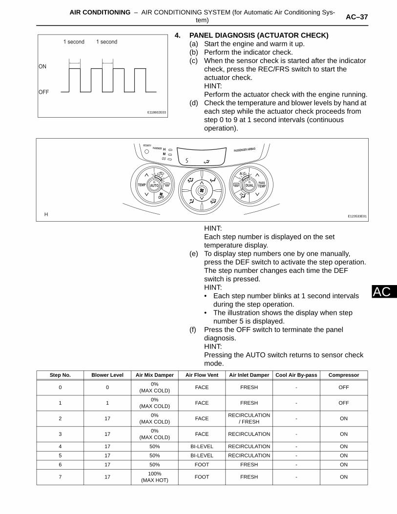
4. PANEL DIAGNOSIS (ACTUATOR CHECK) (a) Start the engine and warm it up.(b) Perform the indicator check.(c) When the sensor check is started after the indicator
check, press the REC/FRS switch to start the actuator check.HINT:Perform the actuator check with the engine running.
(d) Check the temperature and blower levels by hand at each step while the actuator check proceeds from step 0 to 9 at 1 second intervals (continuous operation).
HINT:Each step number is displayed on the set temperature display.
(e) To display step numbers one by one manually, press the DEF switch to activate the step operation. The step number changes each time the DEF switch is pressed.HINT:• Each step number blinks at 1 second intervals
during the step operation.• The illustration shows the display when step
number 5 is displayed.(f) Press the OFF switch to terminate the panel
diagnosis.HINT:Pressing the AUTO switch returns to sensor check mode.
1 second 1 second
ON
OFF
E118602E03
E123533E01
Step No. Blower Level Air Mix Damper Air Flow Vent Air Inlet Damper Cool Air By-pass Compressor
0 0 0% (MAX COLD) FACE FRESH - OFF
1 1 0% (MAX COLD) FACE FRESH - OFF
2 17 0% (MAX COLD) FACE RECIRCULATION
/ FRESH - ON
3 17 0% (MAX COLD) FACE RECIRCULATION - ON
4 17 50% BI-LEVEL RECIRCULATION - ON
5 17 50% BI-LEVEL RECIRCULATION - ON
6 17 50% FOOT FRESH - ON
7 17 100%(MAX HOT) FOOT FRESH - ON

AC–38 AIR CONDITIONING – AIR CONDITIONING SYSTEM (for Automatic Air Conditioning Sys-tem)
AC
DATA LIST / ACTIVE TEST(2005/11-2006/01)1. READ DATA LIST
HINT:Using the intelligent tester's DATA LIST allows switch, sensor, actuator and other item values to be read without removing any parts. Reading the DATA LIST early in troubleshooting is one way to save time.(a) Connect the intelligent tester (with CAN VIM) to the
DLC3.(b) Turn the ignition switch ON and turn the intelligent
tester ON.(c) Read the DATA LIST by following the prompts on
the tester.
Air conditioning amplifier
8 17 100%(MAX HOT) FOOT/DEF FRESH - ON
9 31 100%(MAX HOT) DEF FRESH - ON
Step No. Blower Level Air Mix Damper Air Flow Vent Air Inlet Damper Cool Air By-pass Compressor
Intelligent Tester
CAN VIM
DLC3
B127989E05
Item Measurement Item / Display (Range) Normal Condition Diagnostic Note
ROOM TEMPRoom temperature sensor /Min.: -6.5°C (20.3°F)Max.: 57.25°C (135.05°F)
Actual room temperature is displayed
Open circuit: -6.5°C (20.3°F)Short circuit: 57.25°C (135.05°F)
AMBI TEMP SENSAmbient temperature sensor /Min.: -23.3°C (-9.94°F)Max.: 65.95°C (150.71°F)
Actual ambient temperature is displayed
Open circuit: -23.3°C (-9.94°F)Short circuit: 65.95°C (150.71°F)
SOLAR SENS-D Driver side solar sensor /Min.: 0, Max.: 255
Driver side temperature increases as brightness increases -
SOLAR SENS-P Passenger side solar sensor /Min.: 0, Max.: 255
Passenger side temperature increases as brightness increases -
COOLANT TEMPEngine coolant temperature /Min.: 1.3°C (34.34°F)Max.: 90.55°C (194.99°F)
Actual engine coolant temperature is displayed after engine warmed up
-
SET TEMP-DDriver side set temperature /Min.: 0°C (32°F)Max.: 30°C (54°F)
Driver side actual set temperature is displayed -
SET TEMP-PPassenger side set temperature /Min.: 0°C (32°F)Max.: 30°C (54°F)
Passenger side actual set temperature is displayed -
ESTIMATE TEMP-D
Driver side estimated temperature /Min.: -358.4°C (-613.12°F)Max.: 358.4°C (677.12°F)
Driver side estimated temperature is displayed -
ESTIMATE TEMP-P
Passenger side estimated temperature /Min.: -358.4°C (-613.12°F)Max.: 358.4°C (677.12°F)
Passenger side estimated temperature is displayed -
BLOWER LEVEL Blower motor speed level /Min.: 0, Max.: 31
Increases in range between 0 and 31 as blower motor speed increases
-
AMBI TEMPAdjusted ambient temperature /Min.: -30.8°C (-23.44°F)Max.: 50.8°C (123.44°F)
- -
AIR CONDITIONING – AIR CONDITIONING SYSTEM (for Automatic Air Conditioning Sys-tem) AC–39
AC
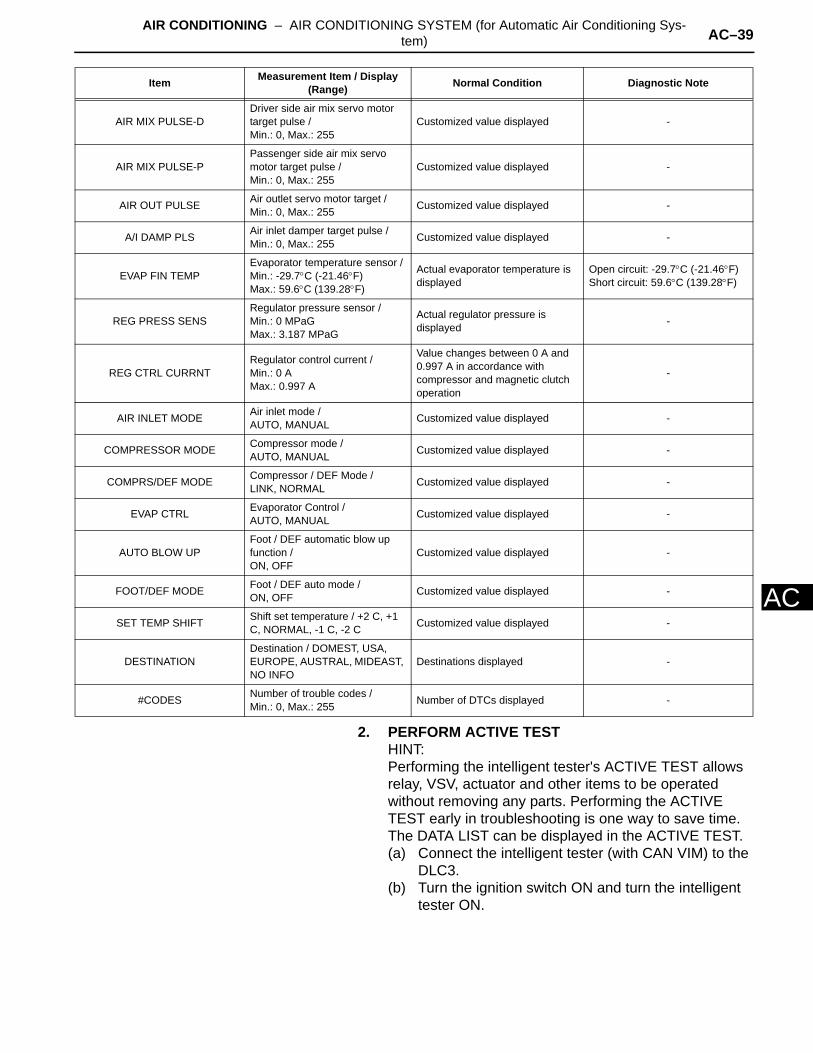
2. PERFORM ACTIVE TESTHINT:Performing the intelligent tester's ACTIVE TEST allows relay, VSV, actuator and other items to be operated without removing any parts. Performing the ACTIVE TEST early in troubleshooting is one way to save time. The DATA LIST can be displayed in the ACTIVE TEST.(a) Connect the intelligent tester (with CAN VIM) to the
DLC3.(b) Turn the ignition switch ON and turn the intelligent
tester ON.
AIR MIX PULSE-DDriver side air mix servo motor target pulse /Min.: 0, Max.: 255
Customized value displayed -
AIR MIX PULSE-PPassenger side air mix servo motor target pulse /Min.: 0, Max.: 255
Customized value displayed -
AIR OUT PULSE Air outlet servo motor target /Min.: 0, Max.: 255 Customized value displayed -
A/I DAMP PLS Air inlet damper target pulse /Min.: 0, Max.: 255 Customized value displayed -
EVAP FIN TEMPEvaporator temperature sensor /Min.: -29.7°C (-21.46°F)Max.: 59.6°C (139.28°F)
Actual evaporator temperature is displayed
Open circuit: -29.7°C (-21.46°F)Short circuit: 59.6°C (139.28°F)
REG PRESS SENSRegulator pressure sensor /Min.: 0 MPaGMax.: 3.187 MPaG
Actual regulator pressure is displayed -
REG CTRL CURRNTRegulator control current /Min.: 0 AMax.: 0.997 A
Value changes between 0 A and 0.997 A in accordance with compressor and magnetic clutch operation
-
AIR INLET MODE Air inlet mode /AUTO, MANUAL Customized value displayed -
COMPRESSOR MODE Compressor mode /AUTO, MANUAL Customized value displayed -
COMPRS/DEF MODE Compressor / DEF Mode /LINK, NORMAL Customized value displayed -
EVAP CTRL Evaporator Control /AUTO, MANUAL Customized value displayed -
AUTO BLOW UPFoot / DEF automatic blow up function /ON, OFF
Customized value displayed -
FOOT/DEF MODE Foot / DEF auto mode /ON, OFF Customized value displayed -
SET TEMP SHIFT Shift set temperature / +2 C, +1 C, NORMAL, -1 C, -2 C Customized value displayed -
DESTINATIONDestination / DOMEST, USA, EUROPE, AUSTRAL, MIDEAST, NO INFO
Destinations displayed -
#CODES Number of trouble codes /Min.: 0, Max.: 255 Number of DTCs displayed -
Item Measurement Item / Display (Range) Normal Condition Diagnostic Note

AC–40 AIR CONDITIONING – AIR CONDITIONING SYSTEM (for Automatic Air Conditioning Sys-tem)
AC
(c) Perform the ACTIVE TEST by following the prompts on the tester.
Air conditioning amplifier
DATA LIST / ACTIVE TEST(2006/01- )1. READ DATA LIST
HINT:Using the intelligent tester's DATA LIST allows switch, sensor, actuator and other item values to be read without removing any parts. Reading the DATA LIST early in troubleshooting is one way to save time.(a) Connect the intelligent tester (with CAN VIM) to the
DLC3.(b) Turn the ignition switch ON and turn the intelligent
tester ON.(c) Read the DATA LIST by following the prompts on
the tester.
Air conditioning amplifier
Item Test Details / Display (Range) Diagnostic Note
BLOWER MOTOR Blower motor /Min.: 0, Max.: 31 -
A/C COMPRESSOR A/C compressor /OFF, ON -
DEFOGGER RLY-R Defogger relay (Rear) /OFF, ON -
AIR MIX PULSE Air mix servo motor pulse /Min.: 0, Max.: 255 -
AIR MIX PULSE-P Air mix servo motor pulse (P side) /Min.: 0, Max.: 255 -
AIR OUT PULSE Air outlet servo motor pulse /Min.: 0, Max.: 255 -
A/I DAMP PLS Air inlet damper target pulse /Min.: 0, Max.: 255 -
Intelligent Tester
CAN VIM
DLC3
B127989E05
Item Measurement Item / Display (Range) Normal Condition Diagnostic Note
ROOM TEMPRoom temperature sensor /Min.: -6.5°C (20.3°F)Max.: 57.25°C (135.05°F)
Actual room temperature is displayed
Open circuit: -6.5°C (20.3°F)Short circuit: 57.25°C (135.05°F)
AMBI TEMP SENSAmbient temperature sensor /Min.: -23.3°C (-9.94°F)Max.: 65.95°C (150.71°F)
Actual ambient temperature is displayed
Open circuit: -23.3°C (-9.94°F)Short circuit: 65.95°C (150.71°F)
SOLAR SENS-D Driver side solar sensor /Min.: 0, Max.: 255
Driver side temperature increases as brightness increases -
SOLAR SENS-P Passenger side solar sensor /Min.: 0, Max.: 255
Passenger side temperature increases as brightness increases -
COOLANT TEMPEngine coolant temperature /Min.: 1.3°C (34.34°F)Max.: 90.55°C (194.99°F)
Actual engine coolant temperature is displayed after engine warmed up
-
SET TEMP-DDriver side set temperature /Min.: 0°C (32°F)Max.: 30°C (54°F)
Driver side actual set temperature is displayed -
SET TEMP-PPassenger side set temperature /Min.: 0°C (32°F)Max.: 30°C (54°F)
Passenger side actual set temperature is displayed -
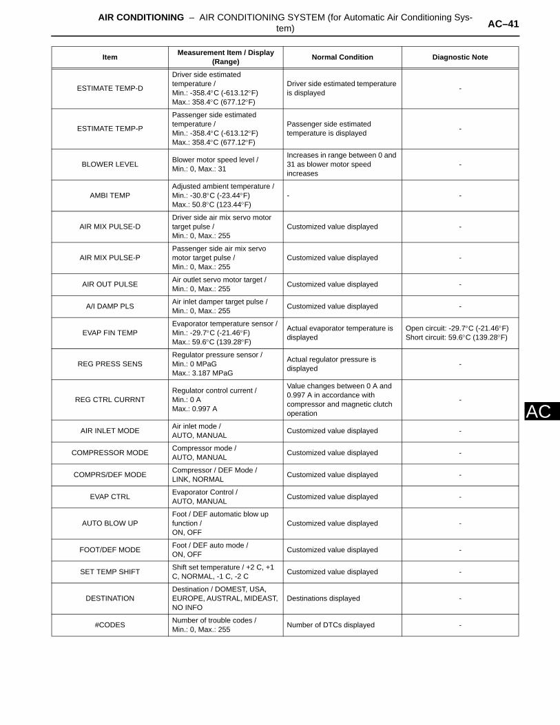
AIR CONDITIONING – AIR CONDITIONING SYSTEM (for Automatic Air Conditioning Sys-tem) AC–41
AC
ESTIMATE TEMP-D
Driver side estimated temperature /Min.: -358.4°C (-613.12°F)Max.: 358.4°C (677.12°F)
Driver side estimated temperature is displayed -
ESTIMATE TEMP-P
Passenger side estimated temperature /Min.: -358.4°C (-613.12°F)Max.: 358.4°C (677.12°F)
Passenger side estimated temperature is displayed -
BLOWER LEVEL Blower motor speed level /Min.: 0, Max.: 31
Increases in range between 0 and 31 as blower motor speed increases
-
AMBI TEMPAdjusted ambient temperature /Min.: -30.8°C (-23.44°F)Max.: 50.8°C (123.44°F)
- -
AIR MIX PULSE-DDriver side air mix servo motor target pulse /Min.: 0, Max.: 255
Customized value displayed -
AIR MIX PULSE-PPassenger side air mix servo motor target pulse /Min.: 0, Max.: 255
Customized value displayed -
AIR OUT PULSE Air outlet servo motor target /Min.: 0, Max.: 255 Customized value displayed -
A/I DAMP PLS Air inlet damper target pulse /Min.: 0, Max.: 255 Customized value displayed -
EVAP FIN TEMPEvaporator temperature sensor /Min.: -29.7°C (-21.46°F)Max.: 59.6°C (139.28°F)
Actual evaporator temperature is displayed
Open circuit: -29.7°C (-21.46°F)Short circuit: 59.6°C (139.28°F)
REG PRESS SENSRegulator pressure sensor /Min.: 0 MPaGMax.: 3.187 MPaG
Actual regulator pressure is displayed -
REG CTRL CURRNTRegulator control current /Min.: 0 AMax.: 0.997 A
Value changes between 0 A and 0.997 A in accordance with compressor and magnetic clutch operation
-
AIR INLET MODE Air inlet mode /AUTO, MANUAL Customized value displayed -
COMPRESSOR MODE Compressor mode /AUTO, MANUAL Customized value displayed -
COMPRS/DEF MODE Compressor / DEF Mode /LINK, NORMAL Customized value displayed -
EVAP CTRL Evaporator Control /AUTO, MANUAL Customized value displayed -
AUTO BLOW UPFoot / DEF automatic blow up function /ON, OFF
Customized value displayed -
FOOT/DEF MODE Foot / DEF auto mode /ON, OFF Customized value displayed -
SET TEMP SHIFT Shift set temperature / +2 C, +1 C, NORMAL, -1 C, -2 C Customized value displayed -
DESTINATIONDestination / DOMEST, USA, EUROPE, AUSTRAL, MIDEAST, NO INFO
Destinations displayed -
#CODES Number of trouble codes /Min.: 0, Max.: 255 Number of DTCs displayed -
Item Measurement Item / Display (Range) Normal Condition Diagnostic Note

AC–42 AIR CONDITIONING – AIR CONDITIONING SYSTEM (for Automatic Air Conditioning Sys-tem)
AC
2. PERFORM ACTIVE TESTHINT:Performing the intelligent tester's ACTIVE TEST allows relay, VSV, actuator and other items to be operated without removing any parts. Performing the ACTIVE TEST early in troubleshooting is one way to save time. The DATA LIST can be displayed in the ACTIVE TEST.(a) Connect the intelligent tester (with CAN VIM) to the
DLC3.(b) Turn the ignition switch ON and turn the intelligent
tester ON.(c) Perform the ACTIVE TEST by following the prompts
on the tester.Air conditioning amplifier
HINT:*1: for 2AZ-FE*2: for 2GR-FE
Item Test Details / Display (Range) Diagnostic Note
BLOWER MOTOR Blower motor /Min.: 0, Max.: 31 -
A/C COMPRESSOR*1 A/C CompressorOFF, ON -
A/C MAG CLUTCH*2 Magnetic clutch relay /OFF, ON Operating sound can be heard
DEFOGGER RLY-R Defogger relay (Rear) /OFF, ON -
AIR MIX PULSE Air mix servo motor pulse /Min.: 0, Max.: 255 -
AIR MIX PULSE-P Air mix servo motor pulse (P side) /Min.: 0, Max.: 255 -
AIR OUT PULSE Air outlet servo motor pulse /Min.: 0, Max.: 255 -
A/I DAMP PLS Air inlet damper target pulse /Min.: 0, Max.: 255 -
AIR CONDITIONING – AIR CONDITIONING SYSTEM (for Automatic Air Conditioning Sys-tem) AC–43
AC
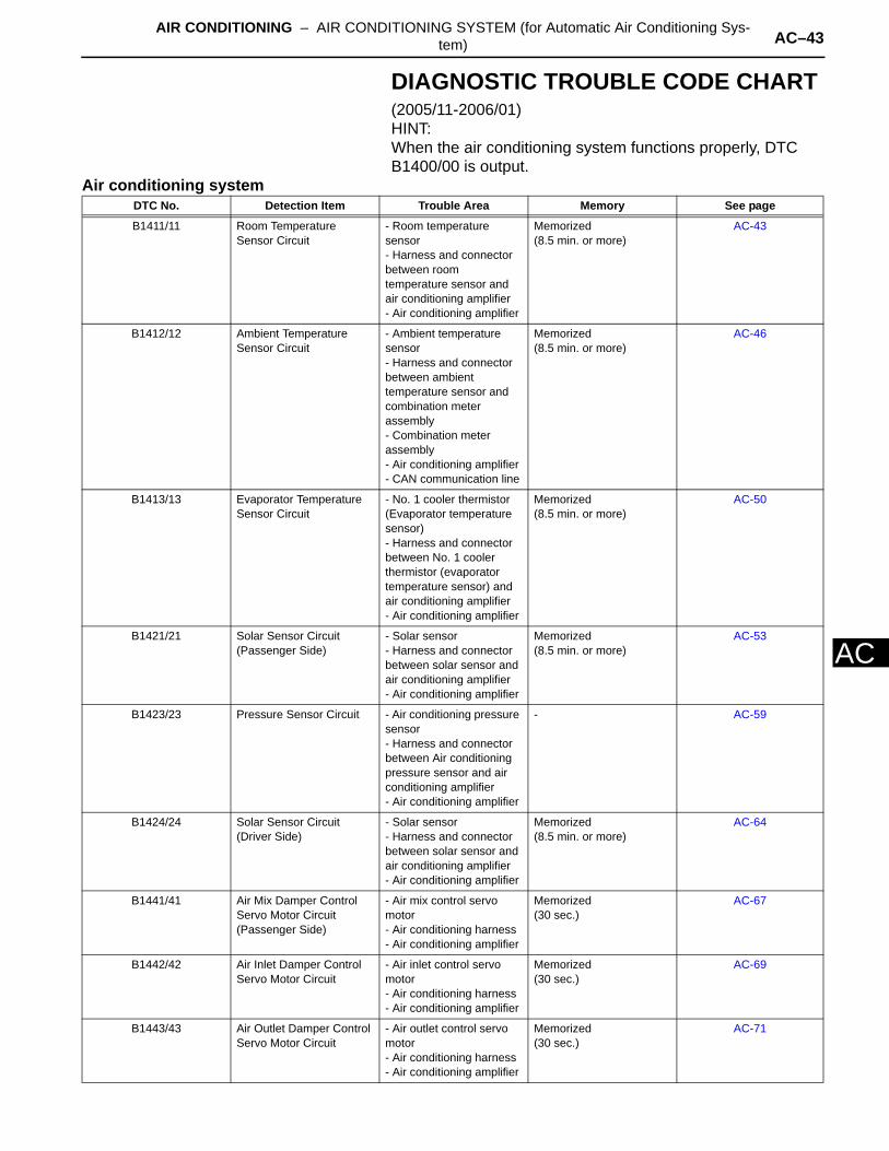
DIAGNOSTIC TROUBLE CODE CHART(2005/11-2006/01)HINT:When the air conditioning system functions properly, DTC B1400/00 is output.
Air conditioning systemDTC No. Detection Item Trouble Area Memory See page
B1411/11 Room Temperature Sensor Circuit
- Room temperature sensor- Harness and connector between room temperature sensor and air conditioning amplifier- Air conditioning amplifier
Memorized(8.5 min. or more)
AC-43
B1412/12 Ambient Temperature Sensor Circuit
- Ambient temperature sensor- Harness and connector between ambient temperature sensor and combination meterassembly- Combination meter assembly- Air conditioning amplifier- CAN communication line
Memorized(8.5 min. or more)
AC-46
B1413/13 Evaporator Temperature Sensor Circuit
- No. 1 cooler thermistor (Evaporator temperature sensor)- Harness and connector between No. 1 cooler thermistor (evaporator temperature sensor) and air conditioning amplifier- Air conditioning amplifier
Memorized(8.5 min. or more)
AC-50
B1421/21 Solar Sensor Circuit (Passenger Side)
- Solar sensor- Harness and connector between solar sensor and air conditioning amplifier- Air conditioning amplifier
Memorized(8.5 min. or more)
AC-53
B1423/23 Pressure Sensor Circuit - Air conditioning pressure sensor- Harness and connector between Air conditioning pressure sensor and air conditioning amplifier- Air conditioning amplifier
- AC-59
B1424/24 Solar Sensor Circuit (Driver Side)
- Solar sensor- Harness and connector between solar sensor and air conditioning amplifier- Air conditioning amplifier
Memorized(8.5 min. or more)
AC-64
B1441/41 Air Mix Damper Control Servo Motor Circuit (Passenger Side)
- Air mix control servo motor- Air conditioning harness- Air conditioning amplifier
Memorized(30 sec.)
AC-67
B1442/42 Air Inlet Damper Control Servo Motor Circuit
- Air inlet control servo motor- Air conditioning harness- Air conditioning amplifier
Memorized(30 sec.)
AC-69
B1443/43 Air Outlet Damper Control Servo Motor Circuit
- Air outlet control servo motor- Air conditioning harness- Air conditioning amplifier
Memorized(30 sec.)
AC-71
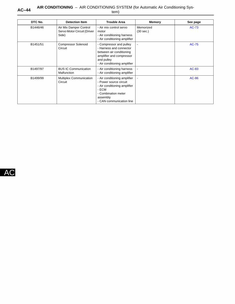
AC–44 AIR CONDITIONING – AIR CONDITIONING SYSTEM (for Automatic Air Conditioning Sys-tem)
AC
B1446/46 Air Mix Damper Control Servo Motor Circuit (Driver Side)
- Air mix control servo motor- Air conditioning harness- Air conditioning amplifier
Memorized(30 sec.)
AC-73
B1451/51 Compressor Solenoid Circuit
- Compressor and pulley- Harness and connector between air conditioning amplifier and compressor and pulley- Air conditioning amplifier
- AC-75
B1497/97 BUS IC Communication Malfunction
- Air conditioning harness- Air conditioning amplifier
- AC-83
B1499/99 Multiplex Communication Circuit
- Air conditioning amplifier - Power source circuit- Air conditioning amplifier- ECM- Combination meter assembly- CAN communication line
- AC-86
DTC No. Detection Item Trouble Area Memory See page
AIR CONDITIONING – AIR CONDITIONING SYSTEM (for Automatic Air Conditioning Sys-tem) AC–45
AC
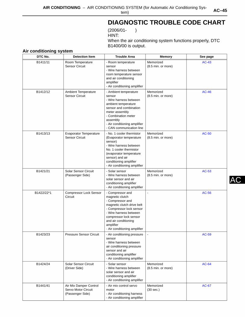
DIAGNOSTIC TROUBLE CODE CHART(2006/01- )HINT:When the air conditioning system functions properly, DTC B1400/00 is output.
Air conditioning systemDTC No. Detection Item Trouble Area Memory See page
B1411/11 Room Temperature Sensor Circuit
- Room temperature sensor- Wire harness between room temperature sensor and air conditioning amplifier- Air conditioning amplifier
Memorized(8.5 min. or more)
AC-43
B1412/12 Ambient Temperature Sensor Circuit
- Ambient temperature sensor- Wire harness between ambient temperature sensor and combination meter assembly- Combination meter assembly- Air conditioning amplifier- CAN communication line
Memorized(8.5 min. or more)
AC-46
B1413/13 Evaporator Temperature Sensor Circuit
- No. 1 cooler thermistor (Evaporator temperature sensor)- Wire harness between No. 1 cooler thermistor (evaporator temperature sensor) and air conditioning amplifier- Air conditioning amplifier
Memorized(8.5 min. or more)
AC-50
B1421/21 Solar Sensor Circuit (Passenger Side)
- Solar sensor- Wire harness between solar sensor and air conditioning amplifier- Air conditioning amplifier
Memorized(8.5 min. or more)
AC-53
B1422/22*1 Compressor Lock Sensor Circuit
- Compressor and magnetic clutch- Compressor and magnetic clutch drive belt- Compressor lock sensor- Wire harness between compressor lock sensor and air conditioning amplifier- Air conditioning amplifier
- AC-56
B1423/23 Pressure Sensor Circuit - Air conditioning pressure sensor- Wire harness between air conditioning pressure sensor and air conditioning amplifier- Air conditioning amplifier
- AC-59
B1424/24 Solar Sensor Circuit (Driver Side)
- Solar sensor- Wire harness between solar sensor and air conditioning amplifier- Air conditioning amplifier
Memorized(8.5 min. or more)
AC-64
B1441/41 Air Mix Damper Control Servo Motor Circuit (Passenger Side)
- Air mix control servo motor- Air conditioning harness- Air conditioning amplifier
Memorized(30 sec.)
AC-67
AC–46 AIR CONDITIONING – AIR CONDITIONING SYSTEM (for Automatic Air Conditioning Sys-tem)
AC
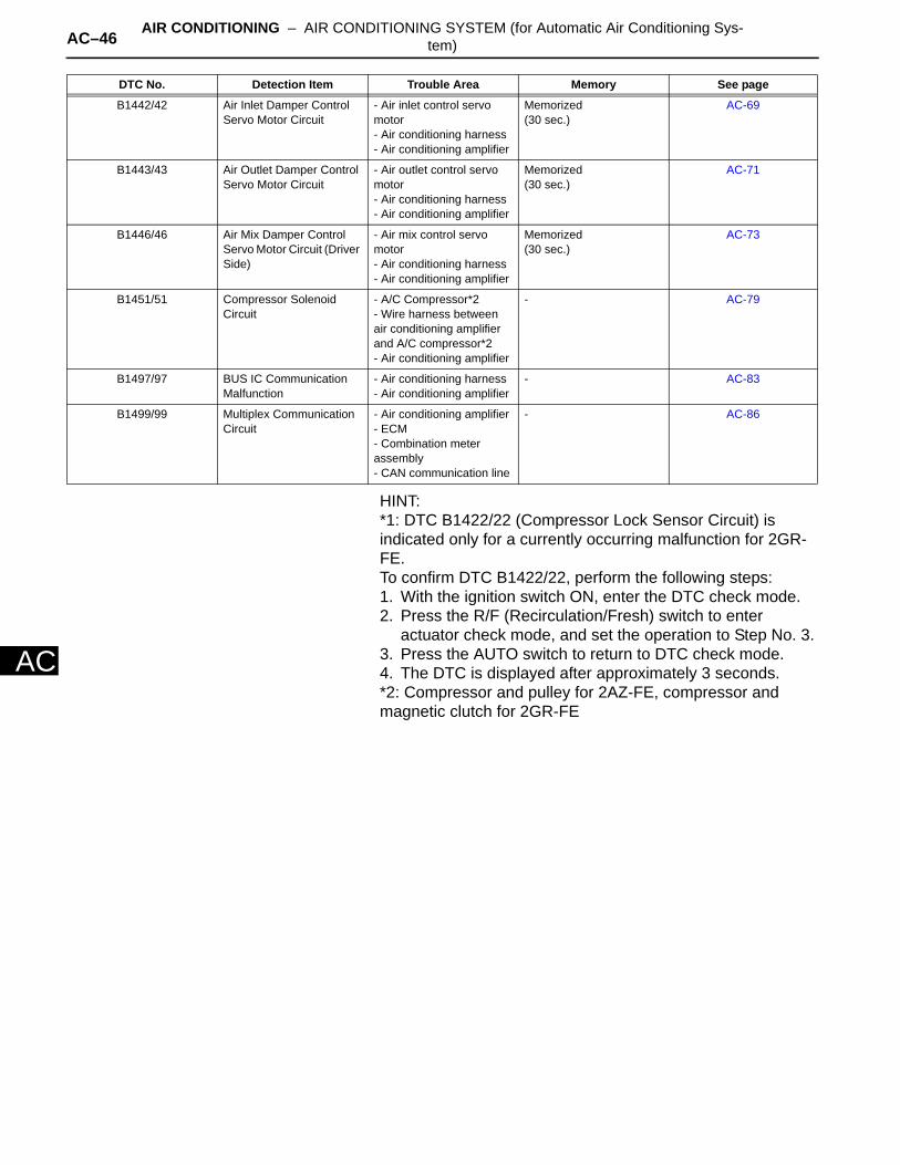
HINT:*1: DTC B1422/22 (Compressor Lock Sensor Circuit) is indicated only for a currently occurring malfunction for 2GR-FE.To confirm DTC B1422/22, perform the following steps:1. With the ignition switch ON, enter the DTC check mode.2. Press the R/F (Recirculation/Fresh) switch to enter
actuator check mode, and set the operation to Step No. 3.3. Press the AUTO switch to return to DTC check mode.4. The DTC is displayed after approximately 3 seconds.*2: Compressor and pulley for 2AZ-FE, compressor and magnetic clutch for 2GR-FE
B1442/42 Air Inlet Damper Control Servo Motor Circuit
- Air inlet control servo motor- Air conditioning harness- Air conditioning amplifier
Memorized(30 sec.)
AC-69
B1443/43 Air Outlet Damper Control Servo Motor Circuit
- Air outlet control servo motor- Air conditioning harness- Air conditioning amplifier
Memorized(30 sec.)
AC-71
B1446/46 Air Mix Damper Control Servo Motor Circuit (Driver Side)
- Air mix control servo motor- Air conditioning harness- Air conditioning amplifier
Memorized(30 sec.)
AC-73
B1451/51 Compressor Solenoid Circuit
- A/C Compressor*2- Wire harness between air conditioning amplifier and A/C compressor*2- Air conditioning amplifier
- AC-79
B1497/97 BUS IC Communication Malfunction
- Air conditioning harness- Air conditioning amplifier
- AC-83
B1499/99 Multiplex Communication Circuit
- Air conditioning amplifier- ECM- Combination meter assembly- CAN communication line
- AC-86
DTC No. Detection Item Trouble Area Memory See page

AIR CONDITIONING – AIR CONDITIONING SYSTEM (for Automatic Air Conditioning Sys-tem) AC–47
AC
DESCRIPTIONThe room temperature sensor is installed in the instrument panel to detect the room temperature and control the heater and air conditioner AUTO mode. The resistance of the room temperature sensor changes in accordance with the room temperature. As the temperature decreases, the resistance increases. As the temperature increases, the resistance decreases.The air conditioning amplifier applies a voltage (5 V) to the room temperature sensor and reads voltage changes as changes in the resistance of the room temperature sensor.
WIRING DIAGRAM
INSPECTION PROCEDURE
(a) Connect the intelligent tester (with CAN VIM) to the DLC3.
(b) Turn the ignition switch ON and turn the intelligent tester main switch ON.
(c) Select the item below in the DATA LIST, and read the value displayed on the intelligent tester.
Air conditioning amplifier
DTC B1411/11 Room Temperature Sensor Circuit
DTC No. DTC Detection Condition Trouble Area
B1411/11 Open or short in room temperature sensor circuit
• Room temperature sensor• Harness and connector between room
temperature sensor and air conditioning amplifier
• Air conditioning amplifier
1 READ VALUE OF INTELLIGENT TESTER (ROOM TEMP)
Room Temperature Sensor Air Conditioning Amplifier
ST+
ST-
TR
SG-1
E115796E02
Item Measurement Item / Display (Range) Normal Condition Diagnostic Note
ROOM TEMPRoom temperature sensor / Min.: -6.5°C (20.3°F)Max.: 57.25°C (135.05°F)
Actual room temperature is displayed
Open circuit: -6.5°C (20.3°F)Short circuit: 57.25°C (135.05°F)
AC–48 AIR CONDITIONING – AIR CONDITIONING SYSTEM (for Automatic Air Conditioning Sys-tem)
AC
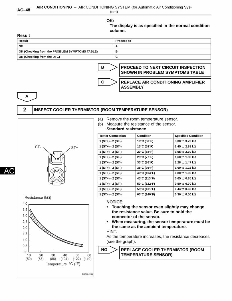
OK:The display is as specified in the normal condition column.
Result
B
C
A
(a) Remove the room temperature sensor.(b) Measure the resistance of the sensor.
Standard resistance
NOTICE:• Touching the sensor even slightly may change
the resistance value. Be sure to hold the connector of the sensor.
• When measuring, the sensor temperature must be the same as the ambient temperature.
HINT:As the temperature increases, the resistance decreases (see the graph).
NG
Result Proceed to
NG A
OK (Checking from the PROBLEM SYMPTOMS TABLE) B
OK (Checking from the DTC) C
PROCEED TO NEXT CIRCUIT INSPECTION SHOWN IN PROBLEM SYMPTOMS TABLE
REPLACE AIR CONDITIONING AMPLIFIER ASSEMBLY
2 INSPECT COOLER THERMISTOR (ROOM TEMPERATURE SENSOR)
4.0
3.5
3.0
2.5
2.0
1.5
1.0
0.5
0.010
(50)20
(68)30
(86)40
(104) (122) (140)50 60
Resistance (kΩ)
Temperature °C (°F)
ST+ST-
E117004E05
Tester Connection Condition Specified Condition
1 (ST+) - 2 (ST-) 10°C (50°F) 3.00 to 3.73 kΩ
1 (ST+) - 2 (ST-) 15°C (59°F) 2.45 to 2.88 kΩ
1 (ST+) - 2 (ST-) 20°C (68°F) 1.95 to 2.30 kΩ
1 (ST+) - 2 (ST-) 25°C (77°F) 1.60 to 1.80 kΩ
1 (ST+) - 2 (ST-) 30°C (86°F) 1.28 to 1.47 kΩ
1 (ST+) - 2 (ST-) 35°C (95°F) 1.00 to 1.22 kΩ
1 (ST+) - 2 (ST-) 40°C (104°F) 0.80 to 1.00 kΩ
1 (ST+) - 2 (ST-) 45°C (113°F) 0.65 to 0.85 kΩ
1 (ST+) - 2 (ST-) 50°C (122°F) 0.50 to 0.70 kΩ
1 (ST+) - 2 (ST-) 55°C (131°F) 0.44 to 0.60 kΩ
1 (ST+) - 2 (ST-) 60°C (140°F) 0.36 to 0.50 kΩ
REPLACE COOLER THERMISTOR (ROOM TEMPERATURE SENSOR)

AIR CONDITIONING – AIR CONDITIONING SYSTEM (for Automatic Air Conditioning Sys-tem) AC–49
AC
OK
(a) Disconnect the E21 sensor connector.(b) Disconnect the E37 amplifier connector.(c) Measure the resistance of the wire harness side
connectors.Standard resistance
NG
OK
3 CHECK WIRE HARNESS (ROOM TEMPERATURE SENSOR - AIR CONDITIONING AMPLIFIER)
X88
Wire Harness Side
Room Temperature Sensor
Air Conditioning Amplifier
E37
E21
TRSG-1
ST+ ST-
E115797E03
Tester Connection Specified Condition
E21-1 (ST+) - E37-29 (TR) Below 1 Ω
E21-2 (ST-) - E37-34 (SG-1) Below 1 Ω
E21-1 (ST+) - Body ground 1 MΩ or higher
E21-2 (ST-) - Body ground 1 MΩ or higher
REPAIR OR REPLACE HARNESS AND CONNECTOR
REPLACE AIR CONDITIONING AMPLIFIER ASSEMBLY

AC–50 AIR CONDITIONING – AIR CONDITIONING SYSTEM (for Automatic Air Conditioning Sys-tem)
AC
DESCRIPTIONThe ambient temperature sensor is installed in the front part of the condenser to detect the ambient temperature and control the air conditioner. The sensor is connected to the combination meter and detects fluctuations in the ambient temperature. This data is used for controlling the room temperature. The sensor sends a signal to the air conditioning amplifier via the combination meter. The resistance of the ambient temperature sensor changes in accordance with the ambient temperature. As the temperature decreases, the resistance increases. As the temperature increases, the resistance decreases.The air conditioning amplifier applies a voltage (5 V) to the ambient temperature sensor and reads voltage changes as changes in the resistance of the ambient temperature sensor. The combination meter sends the read signal to the air conditioning amplifier via CAN communication.
WIRING DIAGRAM
INSPECTION PROCEDURE
(a) Connect the intelligent tester (with CAN VIM) to the DLC3.
DTC B1412/12 Ambient Temperature Sensor Circuit
DTC No. DTC Detection Condition Trouble Area
B1412/12 Open or short in ambient temperature sensor circuit
• Ambient temperature sensor• Harness and connector between ambient
temperature sensor and combination meter assembly
• Combination meter• Air conditioning amplifier• CAN communication line
1 READ VALUE OF INTELLIGENT TESTER (AMBI TEMP SENS)
Ambient Temperature Sensor Combination Meter
: CAN Communication Line
Air Conditioning Amplifier
TX1+
TEMPOT+
OT-
CANH
CANL
CANH
CANL
E115798E04
AIR CONDITIONING – AIR CONDITIONING SYSTEM (for Automatic Air Conditioning Sys-tem) AC–51
AC
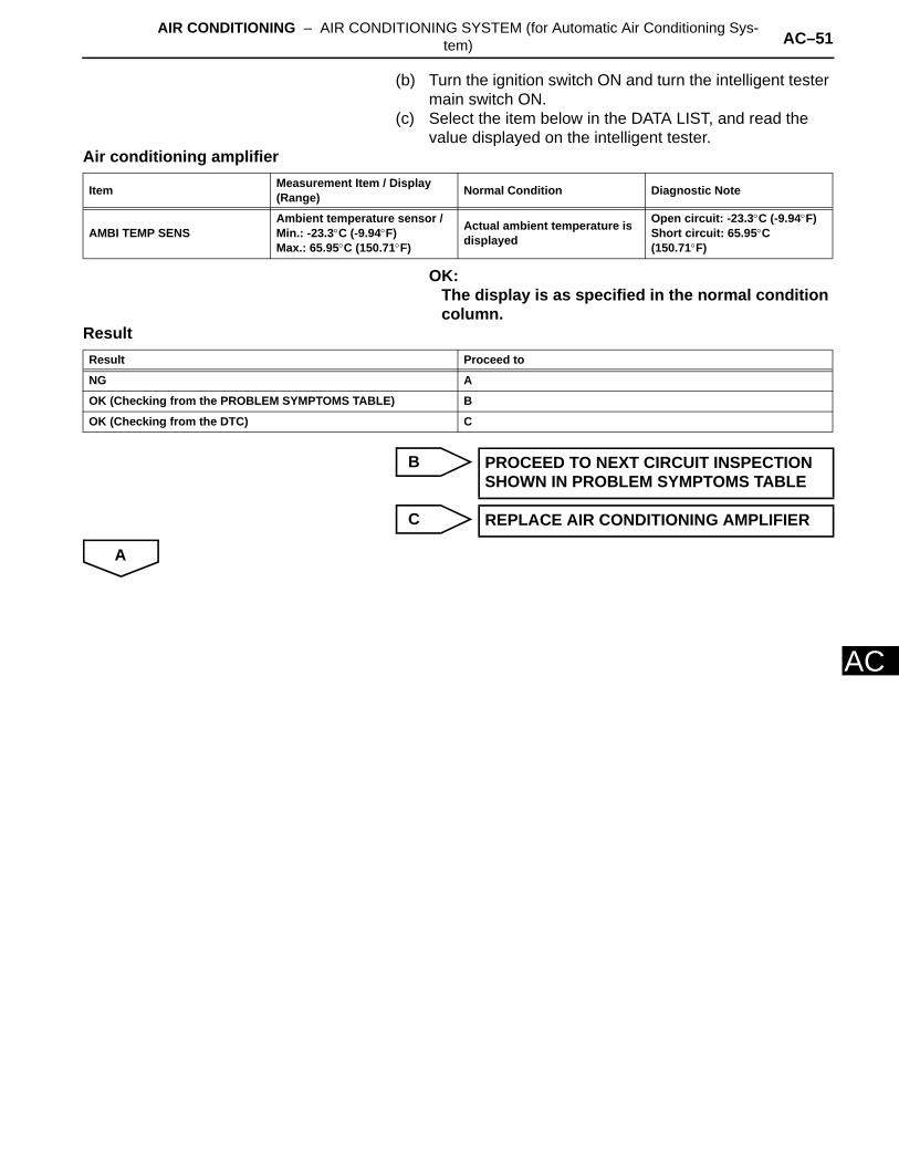
(b) Turn the ignition switch ON and turn the intelligent tester main switch ON.
(c) Select the item below in the DATA LIST, and read the value displayed on the intelligent tester.
Air conditioning amplifier
OK:The display is as specified in the normal condition column.
Result
B
C
A
Item Measurement Item / Display (Range) Normal Condition Diagnostic Note
AMBI TEMP SENSAmbient temperature sensor /Min.: -23.3°C (-9.94°F)Max.: 65.95°C (150.71°F)
Actual ambient temperature is displayed
Open circuit: -23.3°C (-9.94°F)Short circuit: 65.95°C (150.71°F)
Result Proceed to
NG A
OK (Checking from the PROBLEM SYMPTOMS TABLE) B
OK (Checking from the DTC) C
PROCEED TO NEXT CIRCUIT INSPECTION SHOWN IN PROBLEM SYMPTOMS TABLE
REPLACE AIR CONDITIONING AMPLIFIER
AC–52 AIR CONDITIONING – AIR CONDITIONING SYSTEM (for Automatic Air Conditioning Sys-tem)
AC
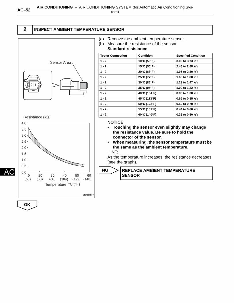
(a) Remove the ambient temperature sensor.(b) Measure the resistance of the sensor.
Standard resistance
NOTICE:• Touching the sensor even slightly may change
the resistance value. Be sure to hold the connector of the sensor.
• When measuring, the sensor temperature must be the same as the ambient temperature.
HINT:As the temperature increases, the resistance decreases (see the graph).
NG
OK
2 INSPECT AMBIENT TEMPERATURE SENSOR
4.0
3.5
3.0
2.5
2.0
1.5
1.0
0.5
0.010
(50)20
(68)30
(86)40
(104) (122) (140)50 60
Resistance (kΩ)
Temperature °C (°F)
Sensor Area
E114516E09
Tester Connection Condition Specified Condition
1 - 2 10°C (50°F) 3.00 to 3.73 kΩ
1 - 2 15°C (50°F) 2.45 to 2.88 kΩ
1 - 2 20°C (68°F) 1.95 to 2.30 kΩ
1 - 2 25°C (77°F) 1.60 to 1.80 kΩ
1 - 2 30°C (86°F) 1.28 to 1.47 kΩ
1 - 2 35°C (95°F) 1.00 to 1.22 kΩ
1 - 2 40°C (104°F) 0.80 to 1.00 kΩ
1 - 2 45°C (113°F) 0.65 to 0.85 kΩ
1 - 2 50°C (122°F) 0.50 to 0.70 kΩ
1 - 2 55°C (131°F) 0.44 to 0.60 kΩ
1 - 2 60°C (140°F) 0.36 to 0.50 kΩ
REPLACE AMBIENT TEMPERATURE SENSOR
AIR CONDITIONING – AIR CONDITIONING SYSTEM (for Automatic Air Conditioning Sys-tem) AC–53
AC
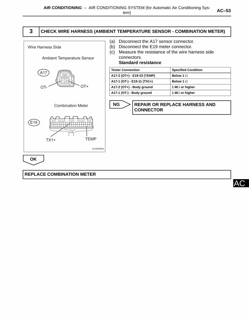
(a) Disconnect the A17 sensor connector.(b) Disconnect the E19 meter connector.(c) Measure the resistance of the wire harness side
connectors.Standard resistance
NG
OK
3 CHECK WIRE HARNESS (AMBIENT TEMPERATURE SENSOR - COMBINATION METER)
Ambient Temperature Sensor
Wire Harness Side
Combination Meter
A17
E19
TEMPTX1+
OT- OT+
E123520E01
Tester Connection Specified Condition
A17-2 (OT+) - E19-23 (TEMP) Below 1 Ω
A17-1 (OT-) - E19-11 (TX1+) Below 1 Ω
A17-2 (OT+) - Body ground 1 MΩ or higher
A17-1 (OT-) - Body ground 1 MΩ or higher
REPAIR OR REPLACE HARNESS AND CONNECTOR
REPLACE COMBINATION METER

AC–54 AIR CONDITIONING – AIR CONDITIONING SYSTEM (for Automatic Air Conditioning Sys-tem)
AC
DESCRIPTIONThe No. 1 cooler thermistor (evaporator temperature sensor) is installed on the evaporator in the air conditioning unit to detect the temperature of the cooled air that has passed through the evaporator and to control the air conditioner. It sends signals to the air conditioning amplifier. The signals change in accordance with the resistance of the No. 1 cooler thermistor (evaporator temperature sensor). As the temperature decreases, the resistance increases. As the temperature increases, the resistance decreases. The air conditioning amplifier applies a voltage (5 V) to the No. 1 cooler thermistor (evaporator temperature sensor) and reads voltage changes as changes in the resistance of the No. 1 cooler thermistor (evaporator temperature sensor). This sensor is used for frost prevention.
WIRING DIAGRAM
INSPECTION PROCEDURE
(a) Connect the intelligent tester (with CAN VIM) to the DLC3.
(b) Turn the ignition switch ON and turn the intelligent tester main switch ON.
(c) Select the item below in the DATA LIST, and read the value displayed on the intelligent tester.
Air conditioning amplifier
DTC B1413/13 Evaporator Temperature Sensor Circuit
DTC No. DTC Detection Condition Trouble Area
B1413/13 Open or short in evaporator temperature sensor circuit
• No. 1 cooler thermistor (evaporator temperature sensor)
• Harness and connector between No. 1 cooler thermistor (evaporator temperature sensor) and air conditioning amplifier
• Air conditioning amplifier
1 READ VALUE OF INTELLIGENT TESTER (EVAP FIN TEMP)
TEA
SGA
Air Conditioning AmplifierAir Conditioning Harness
No. 1 Cooler Thermistor
(Evaporator Temperature Sensor)
E123558E01
Item Measurement Item / Display (Range) Normal Condition Diagnostic Note
EVAP FIN TEMPEvaporator temperature sensor / Min.: -29.7°C (-21.46°F)Max.: 59.6°C (139.28°F)
Actual evaporator temperature is displayed
Open circuit: -29.7°C (-21.46°F)Short circuit: 59.6°C (139.28°F)
AIR CONDITIONING – AIR CONDITIONING SYSTEM (for Automatic Air Conditioning Sys-tem) AC–55
AC
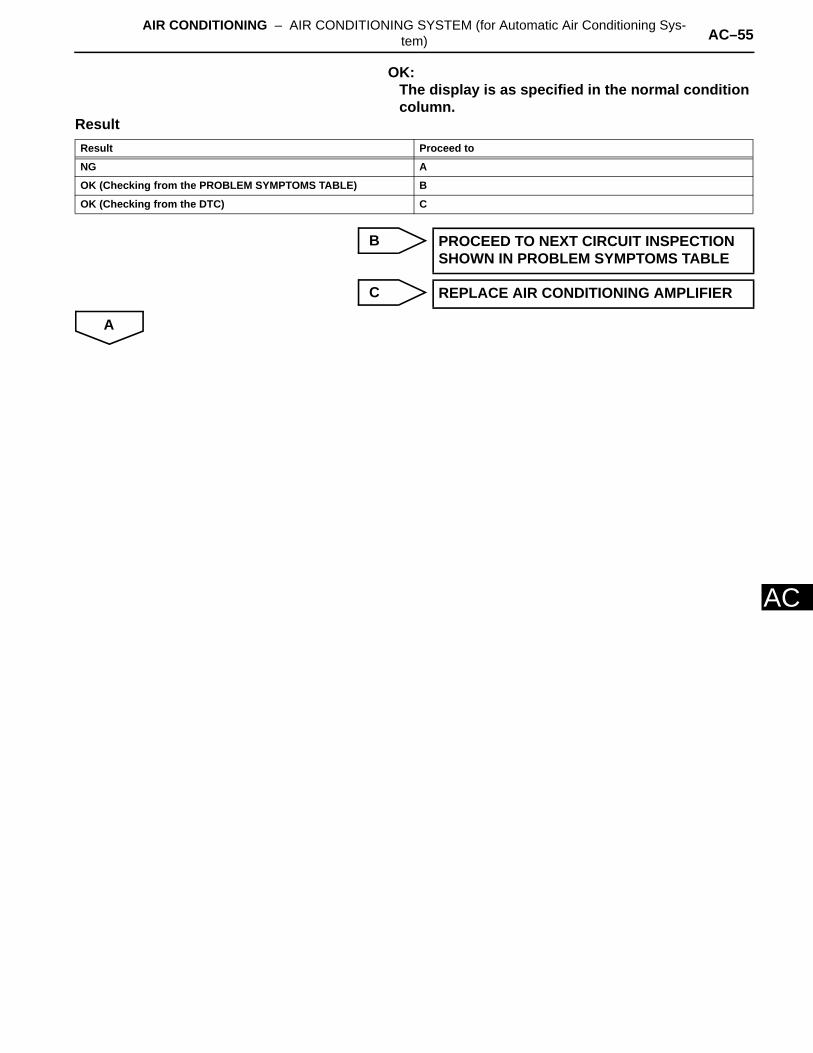
OK:The display is as specified in the normal condition column.
Result
B
C
A
Result Proceed to
NG A
OK (Checking from the PROBLEM SYMPTOMS TABLE) B
OK (Checking from the DTC) C
PROCEED TO NEXT CIRCUIT INSPECTION SHOWN IN PROBLEM SYMPTOMS TABLE
REPLACE AIR CONDITIONING AMPLIFIER
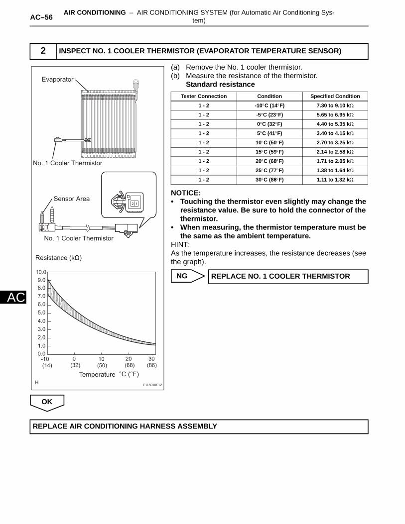
AC–56 AIR CONDITIONING – AIR CONDITIONING SYSTEM (for Automatic Air Conditioning Sys-tem)
AC
(a) Remove the No. 1 cooler thermistor.(b) Measure the resistance of the thermistor.
Standard resistance
NOTICE:• Touching the thermistor even slightly may change the
resistance value. Be sure to hold the connector of the thermistor.
• When measuring, the thermistor temperature must be the same as the ambient temperature.
HINT:As the temperature increases, the resistance decreases (see the graph).
NG
OK
2 INSPECT NO. 1 COOLER THERMISTOR (EVAPORATOR TEMPERATURE SENSOR)
20100-10(68)
30(86)(50)(32)(14)
4.0
5.0
6.0
7.0
8.0
9.0
10.0
3.0
2.0
1.0
0.0
Sensor Area
No. 1 Cooler Thermistor
No. 1 Cooler Thermistor
Evaporator
Resistance (kΩ)
Temperature °C (°F)
E115010E12
Tester Connection Condition Specified Condition
1 - 2 -10°C (14°F) 7.30 to 9.10 kΩ
1 - 2 -5°C (23°F) 5.65 to 6.95 kΩ
1 - 2 0°C (32°F) 4.40 to 5.35 kΩ
1 - 2 5°C (41°F) 3.40 to 4.15 kΩ
1 - 2 10°C (50°F) 2.70 to 3.25 kΩ
1 - 2 15°C (59°F) 2.14 to 2.58 kΩ
1 - 2 20°C (68°F) 1.71 to 2.05 kΩ
1 - 2 25°C (77°F) 1.38 to 1.64 kΩ
1 - 2 30°C (86°F) 1.11 to 1.32 kΩ
REPLACE NO. 1 COOLER THERMISTOR
REPLACE AIR CONDITIONING HARNESS ASSEMBLY

AIR CONDITIONING – AIR CONDITIONING SYSTEM (for Automatic Air Conditioning Sys-tem) AC–57
AC
DESCRIPTIONThe solar sensor, which is installed on the upper side of the instrument panel, detects sunlight and controls the air conditioning AUTO mode. The output voltage from the solar sensor varies in accordance with the amount of sunlight. When the sunlight increases, the output voltage increases. As the sunlight decreases, the output voltage decreases.The air conditioning amplifier detects changes in the output voltage from the solar sensor.
WIRING DIAGRAM
INSPECTION PROCEDURE
(a) Connect the intelligent tester (with CAN VIM) to the DLC3.
(b) Turn the ignition switch ON and turn the intelligent tester main switch ON.
(c) Select the item below in the DATA LIST, and read the value displayed on the intelligent tester.
DTC B1421/21 Solar Sensor Circuit (Passenger Side)
DTC No. DTC Detection Condition Trouble Area
B1421/21 Open or short in passenger side solar sensor circuit
• Solar sensor• Harness and connector between solar
sensor and air conditioning amplifier• Air conditioning amplifier
1 READ VALUE OF INTELLIGENT TESTER (SOLAR SENS-P)
Solar Sensor
TSP
SS
Air Conditioning Amplifier
TSP
S5-4
E115801E04
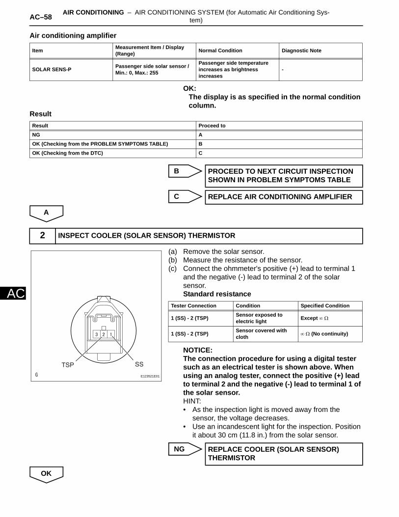
AC–58 AIR CONDITIONING – AIR CONDITIONING SYSTEM (for Automatic Air Conditioning Sys-tem)
AC
Air conditioning amplifier
OK:The display is as specified in the normal condition column.
Result
B
C
A
(a) Remove the solar sensor.(b) Measure the resistance of the sensor.(c) Connect the ohmmeter's positive (+) lead to terminal 1
and the negative (-) lead to terminal 2 of the solar sensor.Standard resistance
NOTICE:The connection procedure for using a digital tester such as an electrical tester is shown above. When using an analog tester, connect the positive (+) lead to terminal 2 and the negative (-) lead to terminal 1 of the solar sensor.HINT:• As the inspection light is moved away from the
sensor, the voltage decreases.• Use an incandescent light for the inspection. Position
it about 30 cm (11.8 in.) from the solar sensor.
NG
OK
Item Measurement Item / Display(Range) Normal Condition Diagnostic Note
SOLAR SENS-P Passenger side solar sensor /Min.: 0, Max.: 255
Passenger side temperature increases as brightness increases
-
Result Proceed to
NG A
OK (Checking from the PROBLEM SYMPTOMS TABLE) B
OK (Checking from the DTC) C
PROCEED TO NEXT CIRCUIT INSPECTION SHOWN IN PROBLEM SYMPTOMS TABLE
REPLACE AIR CONDITIONING AMPLIFIER
2 INSPECT COOLER (SOLAR SENSOR) THERMISTOR
SSTSPE123521E01
Tester Connection Condition Specified Condition
1 (SS) - 2 (TSP) Sensor exposed to electric light Except ∞ Ω
1 (SS) - 2 (TSP) Sensor covered with cloth ∞ Ω (No continuity)
REPLACE COOLER (SOLAR SENSOR) THERMISTOR
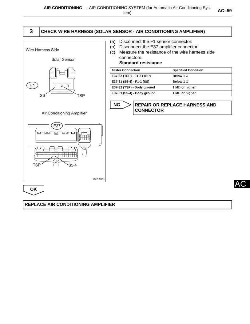
AIR CONDITIONING – AIR CONDITIONING SYSTEM (for Automatic Air Conditioning Sys-tem) AC–59
AC
(a) Disconnect the F1 sensor connector.(b) Disconnect the E37 amplifier connector.(c) Measure the resistance of the wire harness side
connectors.Standard resistance
NG
OK
3 CHECK WIRE HARNESS (SOLAR SENSOR - AIR CONDITIONING AMPLIFIER)
Wire Harness Side
Solar Sensor
Air Conditioning Amplifier
F1
E37
SS TSP
S5-4TSP
E123522E01
Tester Connection Specified Condition
E37-32 (TSP) - F1-2 (TSP) Below 1 Ω
E37-31 (S5-4) - F1-1 (SS) Below 1 Ω
E37-32 (TSP) - Body ground 1 MΩ or higher
E37-31 (S5-4) - Body ground 1 MΩ or higher
REPAIR OR REPLACE HARNESS AND CONNECTOR
REPLACE AIR CONDITIONING AMPLIFIER

AC–60 AIR CONDITIONING – AIR CONDITIONING SYSTEM (for Automatic Air Conditioning Sys-tem)
AC
DESCRIPTIONThis sensor sends 1 pulse per engine revolution to the air conditioning amplifier. If the ratio of the compressor speed divided by the engine speed is smaller than a predetermined value, the air conditioning amplifier turns the compressor off, and the indicator blinks at approximately 1 second intervals.
WIRING DIAGRAM
DTC B1422/22 Compressor Lock Sensor Circuit
DTC No. DTC Detection Condition Trouble Area
B1422/22
Open or short in compressor lock sensor circuitAll conditions below are detected for 3 seconds or more:1. Engine speed: 450 rpm or more2. Ratio between engine and compressor speed deviates 20% or more in comparison to normal operation
• Compressor and magnetic clutch• Compressor and magnetic clutch drive
belt• Compressor lock sensor• Wire harness between compressor lock
sensor and air conditioning amplifier• Air conditioning amplifier
Air Conditioning Amplifier
Compressor Lock Sensor
LOCK
SG-2
SSR+
SSR-
E127541E01
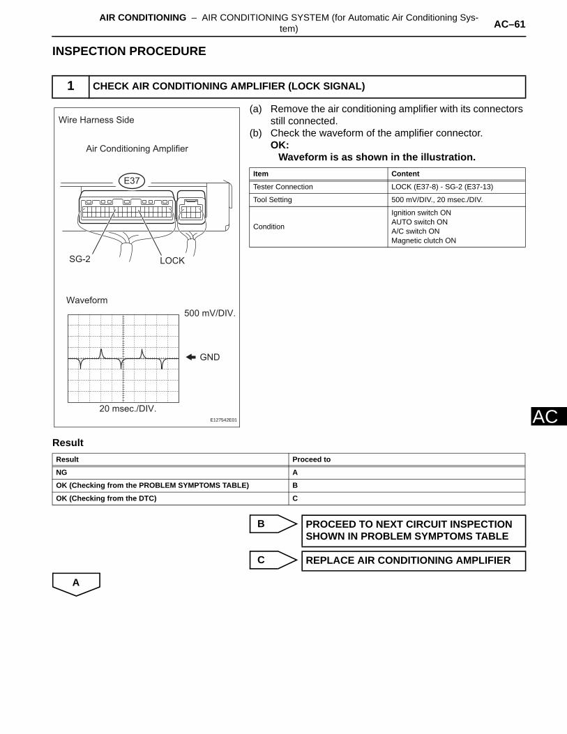
AIR CONDITIONING – AIR CONDITIONING SYSTEM (for Automatic Air Conditioning Sys-tem) AC–61
AC
INSPECTION PROCEDURE
(a) Remove the air conditioning amplifier with its connectors still connected.
(b) Check the waveform of the amplifier connector.OK:
Waveform is as shown in the illustration.
Result
B
C
A
1 CHECK AIR CONDITIONING AMPLIFIER (LOCK SIGNAL)
GND
20 msec./DIV.
500 mV/DIV.
Waveform
SG-2 LOCK
Air Conditioning Amplifier
E37
Wire Harness Side
E127542E01
Item Content
Tester Connection LOCK (E37-8) - SG-2 (E37-13)
Tool Setting 500 mV/DIV., 20 msec./DIV.
Condition
Ignition switch ONAUTO switch ONA/C switch ONMagnetic clutch ON
Result Proceed to
NG A
OK (Checking from the PROBLEM SYMPTOMS TABLE) B
OK (Checking from the DTC) C
PROCEED TO NEXT CIRCUIT INSPECTION SHOWN IN PROBLEM SYMPTOMS TABLE
REPLACE AIR CONDITIONING AMPLIFIER
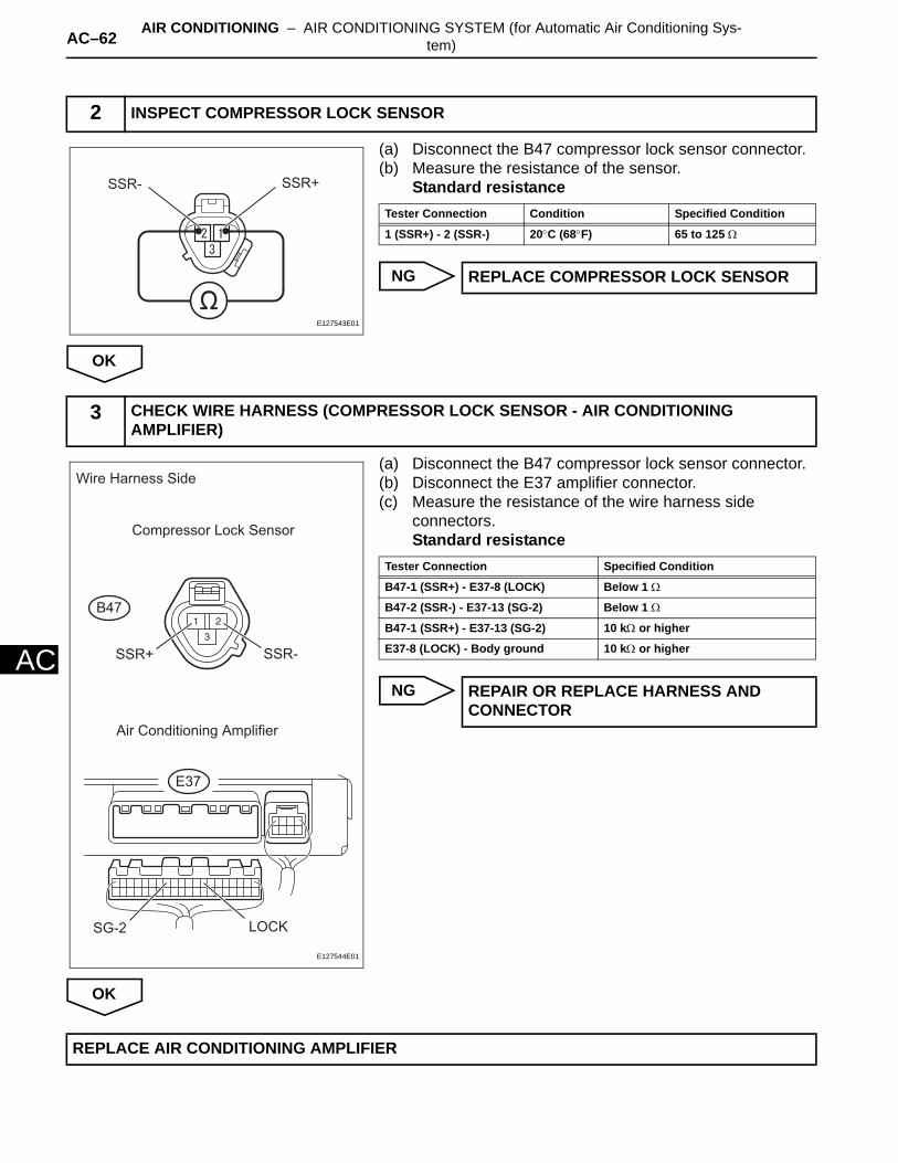
AC–62 AIR CONDITIONING – AIR CONDITIONING SYSTEM (for Automatic Air Conditioning Sys-tem)
AC
(a) Disconnect the B47 compressor lock sensor connector.(b) Measure the resistance of the sensor.
Standard resistance
NG
OK
(a) Disconnect the B47 compressor lock sensor connector.(b) Disconnect the E37 amplifier connector.(c) Measure the resistance of the wire harness side
connectors.Standard resistance
NG
OK
2 INSPECT COMPRESSOR LOCK SENSOR
SSR+SSR-
E127543E01
Tester Connection Condition Specified Condition
1 (SSR+) - 2 (SSR-) 20°C (68°F) 65 to 125 Ω
REPLACE COMPRESSOR LOCK SENSOR
3 CHECK WIRE HARNESS (COMPRESSOR LOCK SENSOR - AIR CONDITIONING AMPLIFIER)
Wire Harness Side
Compressor Lock Sensor
Air Conditioning Amplifier
B47
E37
SSR+ SSR-
SG-2 LOCK
E127544E01
Tester Connection Specified Condition
B47-1 (SSR+) - E37-8 (LOCK) Below 1 Ω
B47-2 (SSR-) - E37-13 (SG-2) Below 1 Ω
B47-1 (SSR+) - E37-13 (SG-2) 10 kΩ or higher
E37-8 (LOCK) - Body ground 10 kΩ or higher
REPAIR OR REPLACE HARNESS AND CONNECTOR
REPLACE AIR CONDITIONING AMPLIFIER

AIR CONDITIONING – AIR CONDITIONING SYSTEM (for Automatic Air Conditioning Sys-tem) AC–63
AC
DESCRIPTIONThis DTC is output when the refrigerant pressure is either extremely low (0.19 MPa [2.0 kgf/cm2, 28 psi] or less) or extremely high (3.14 MPa [32.0 kgf/cm2, 455 psi] or more). The air conditioning pressure sensor, which is installed on the pipe of the high pressure side, detects the refrigerant pressure and sends refrigerant pressure signals to the air conditioning amplifier. The air conditioning amplifier determines the pressure from the signals in accordance with the sensor characteristics, and controls the compressor accordingly.
WIRING DIAGRAM
DTC B1423/23 Pressure Sensor Circuit
DTC No. DTC Detection Condition Trouble Area
B1423/23 Open or short in air conditioning pressure sensor circuit
• Air conditioning pressure sensor• Harness and connector between air
conditioning pressure sensor and air conditioning amplifier
• Air conditioning amplifier
Air Conditioning Pressure Sensor Air Conditioning Amplifier
S5-3
SG-2
PRE
+
-
PR
E115012E02
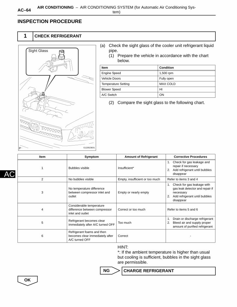
AC–64 AIR CONDITIONING – AIR CONDITIONING SYSTEM (for Automatic Air Conditioning Sys-tem)
AC
INSPECTION PROCEDURE
(a) Check the sight glass of the cooler unit refrigerant liquid pipe.(1) Prepare the vehicle in accordance with the chart
below.
(2) Compare the sight glass to the following chart.
HINT:*: If the ambient temperature is higher than usual but cooling is sufficient, bubbles in the sight glass are permissible.
NG
OK
1 CHECK REFRIGERANT
Sight Glass
E123523E01
Item Condition
Engine Speed 1,500 rpm
Vehicle Doors Fully open
Temperature Setting MAX COLD
Blower Speed HI
A/C Switch ON
Item Symptom Amount of Refrigerant Corrective Procedures
1 Bubbles visible Insufficient*
1. Check for gas leakage and repair if necessary
2. Add refrigerant until bubbles disappear
2 No bubbles visible Empty, insufficient or too much Refer to items 3 and 4
3No temperature difference between compressor inlet and outlet
Empty or nearly empty
1. Check for gas leakage with gas leak detector and repair if necessary
2. Add refrigerant until bubbles disappear
4Considerable temperature difference between compressor inlet and outlet
Correct or too much Refer to items 5 and 6
5 Refrigerant becomes clear immediately after A/C turned OFF Too much
1. Drain or discharge refrigerant2. Bleed air and supply proper
amount of purified refrigerant
6Refrigerant foams and then becomes clear immediately after A/C turned OFF
Correct -
CHARGE REFRIGERANT
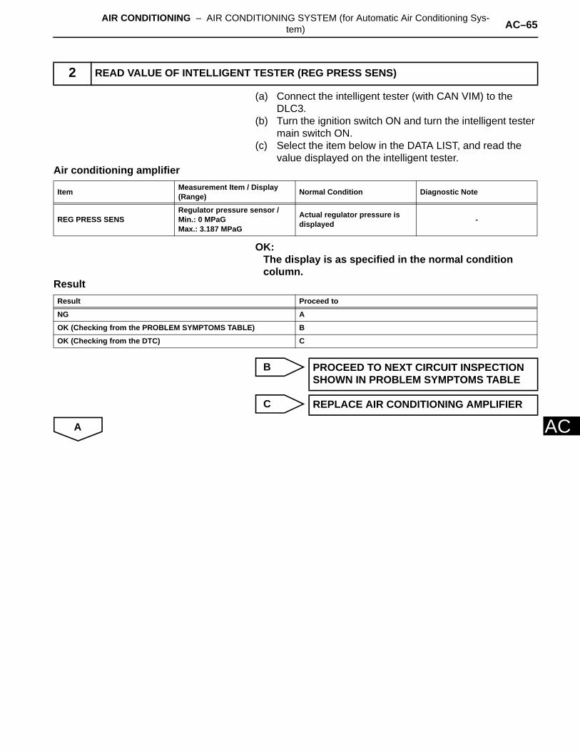
AIR CONDITIONING – AIR CONDITIONING SYSTEM (for Automatic Air Conditioning Sys-tem) AC–65
AC
(a) Connect the intelligent tester (with CAN VIM) to the DLC3.
(b) Turn the ignition switch ON and turn the intelligent tester main switch ON.
(c) Select the item below in the DATA LIST, and read the value displayed on the intelligent tester.
Air conditioning amplifier
OK:The display is as specified in the normal condition column.
Result
B
C
A
2 READ VALUE OF INTELLIGENT TESTER (REG PRESS SENS)
Item Measurement Item / Display(Range) Normal Condition Diagnostic Note
REG PRESS SENSRegulator pressure sensor /Min.: 0 MPaGMax.: 3.187 MPaG
Actual regulator pressure is displayed -
Result Proceed to
NG A
OK (Checking from the PROBLEM SYMPTOMS TABLE) B
OK (Checking from the DTC) C
PROCEED TO NEXT CIRCUIT INSPECTION SHOWN IN PROBLEM SYMPTOMS TABLE
REPLACE AIR CONDITIONING AMPLIFIER
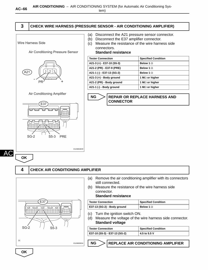
AC–66 AIR CONDITIONING – AIR CONDITIONING SYSTEM (for Automatic Air Conditioning Sys-tem)
AC
(a) Disconnect the A21 pressure sensor connector.(b) Disconnect the E37 amplifier connector.(c) Measure the resistance of the wire harness side
connectors.Standard resistance
NG
OK
(a) Remove the air conditioning amplifier with its connectors still connected.
(b) Measure the resistance of the wire harness side connector.Standard resistance
(c) Turn the ignition switch ON.(d) Measure the voltage of the wire harness side connector.
Standard voltage
NG
OK
3 CHECK WIRE HARNESS (PRESSURE SENSOR - AIR CONDITIONING AMPLIFIER)
Wire Harness Side
Air Conditioning Pressure Sensor
Air Conditioning Amplifier
A21
E37
- +PR
S5-3 PRESG-2
E115804E09
Tester Connection Specified Condition
A21-3 (+) - E37-10 (S5-3) Below 1 Ω
A21-2 (PR) - E37-9 (PRE) Below 1 Ω
A21-1 (-) - E37-13 (SG-2) Below 1 Ω
A21-3 (+) - Body ground 1 MΩ or higher
A21-2 (PR) - Body ground 1 MΩ or higher
A21-1 (-) - Body ground 1 MΩ or higher
REPAIR OR REPLACE HARNESS AND CONNECTOR
4 CHECK AIR CONDITIONING AMPLIFIER
SG-2 S5-3
E37
E115805E04
Tester Connection Specified Condition
E37-13 (SG-2) - Body ground Below 1 Ω
Tester Connection Specified Condition
E37-10 (S5-3) - E37-13 (SG-2) 4.5 to 5.5 V
REPLACE AIR CONDITIONING AMPLIFIER
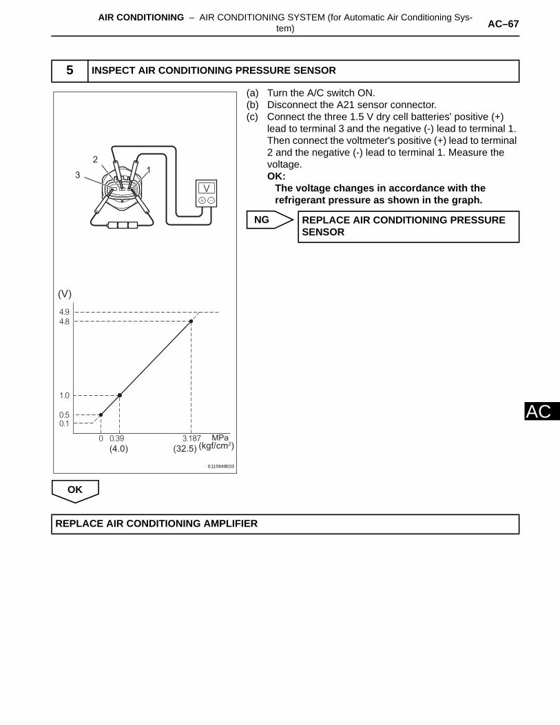
AIR CONDITIONING – AIR CONDITIONING SYSTEM (for Automatic Air Conditioning Sys-tem) AC–67
AC
(a) Turn the A/C switch ON.(b) Disconnect the A21 sensor connector.(c) Connect the three 1.5 V dry cell batteries' positive (+)
lead to terminal 3 and the negative (-) lead to terminal 1. Then connect the voltmeter's positive (+) lead to terminal 2 and the negative (-) lead to terminal 1. Measure the voltage.OK:
The voltage changes in accordance with the refrigerant pressure as shown in the graph.
NG
OK
5 INSPECT AIR CONDITIONING PRESSURE SENSOR
(V)
12
3
(4.0) (32.5) (kgf/cm2)
E115949E03
REPLACE AIR CONDITIONING PRESSURE SENSOR
REPLACE AIR CONDITIONING AMPLIFIER

AC–68 AIR CONDITIONING – AIR CONDITIONING SYSTEM (for Automatic Air Conditioning Sys-tem)
AC
DESCRIPTIONThe solar sensor, which is installed on the upper side of the instrument panel, detects sunlight and controls the air conditioning AUTO mode. The output voltage from the solar sensor varies in accordance with the amount of sunlight. When the sunlight increases, the output voltage increases. As the sunlight decreases, the output voltage decreases.The air conditioning amplifier detects changes in the output voltage from the solar sensor.
WIRING DIAGRAM
INSPECTION PROCEDURE
(a) Connect the intelligent tester (with CAN VIM) to the DLC3.
(b) Turn the ignition switch ON and turn the intelligent tester main switch ON.
(c) Select the item below in the DATA LIST, and read the value displayed on the intelligent tester.
DTC B1424/24 Solar Sensor Circuit (Driver Side)
DTC No. DTC Detection Condition Trouble Area
B1424/24 Open or short in passenger side solar sensor circuit
• Solar sensor• Harness and connector between solar
sensor and air conditioning amplifier• Air conditioning amplifier
1 READ VALUE OF INTELLIGENT TESTER (SOLAR SENSOR D SIDE)
Solar Sensor
TSD
SS
Air Conditioning Amplifier
TSD
S5-4
E115801E05
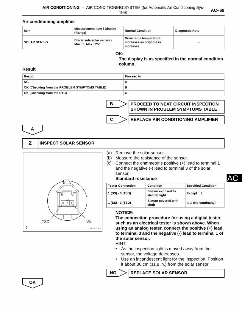
AIR CONDITIONING – AIR CONDITIONING SYSTEM (for Automatic Air Conditioning Sys-tem) AC–69
AC
Air conditioning amplifier
OK:The display is as specified in the normal condition column.
Result
B
C
A
(a) Remove the solar sensor.(b) Measure the resistance of the sensor.(c) Connect the ohmmeter's positive (+) lead to terminal 1
and the negative (-) lead to terminal 3 of the solar sensor.Standard resistance
NOTICE:The connection procedure for using a digital tester such as an electrical tester is shown above. When using an analog tester, connect the positive (+) lead to terminal 3 and the negative (-) lead to terminal 1 of the solar sensor.HINT:• As the inspection light is moved away from the
sensor, the voltage decreases.• Use an incandescent light for the inspection. Position
it about 30 cm (11.8 in.) from the solar sensor.
NG
OK
Item Measurement Item / Display(Range) Normal Condition Diagnostic Note
SOLAR SENS-D Driver side solar sensor /Min.: 0, Max.: 255
Driver side temperature increases as brightness increases
-
Result Proceed to
NG A
OK (Checking from the PROBLEM SYMPTOMS TABLE) B
OK (Checking from the DTC) C
PROCEED TO NEXT CIRCUIT INSPECTION SHOWN IN PROBLEM SYMPTOMS TABLE
REPLACE AIR CONDITIONING AMPLIFIER
2 INSPECT SOLAR SENSOR
SSTSDE123521E02
Tester Connection Condition Specified Condition
1 (SS) - 3 (TSD) Sensor exposed to electric light Except ∞ Ω
1 (SS) - 3 (TSD) Sensor covered with cloth ∞ Ω (No continuity)
REPLACE SOLAR SENSOR
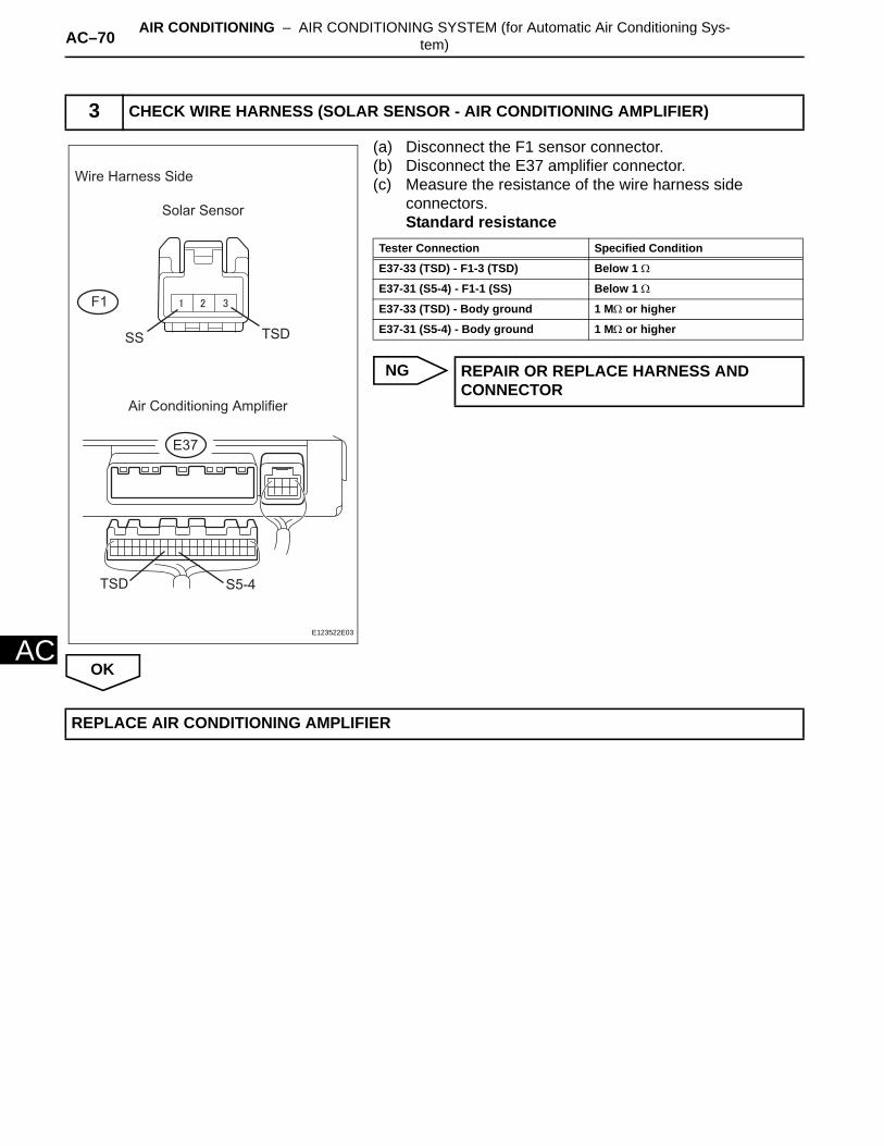
AC–70 AIR CONDITIONING – AIR CONDITIONING SYSTEM (for Automatic Air Conditioning Sys-tem)
AC
(a) Disconnect the F1 sensor connector.(b) Disconnect the E37 amplifier connector.(c) Measure the resistance of the wire harness side
connectors.Standard resistance
NG
OK
3 CHECK WIRE HARNESS (SOLAR SENSOR - AIR CONDITIONING AMPLIFIER)
Wire Harness Side
Solar Sensor
Air Conditioning Amplifier
F1
E37
SS TSD
S5-4TSD
E123522E03
Tester Connection Specified Condition
E37-33 (TSD) - F1-3 (TSD) Below 1 Ω
E37-31 (S5-4) - F1-1 (SS) Below 1 Ω
E37-33 (TSD) - Body ground 1 MΩ or higher
E37-31 (S5-4) - Body ground 1 MΩ or higher
REPAIR OR REPLACE HARNESS AND CONNECTOR
REPLACE AIR CONDITIONING AMPLIFIER
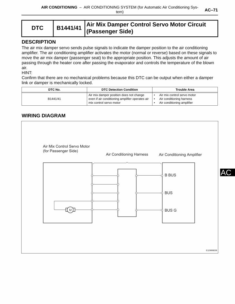
AIR CONDITIONING – AIR CONDITIONING SYSTEM (for Automatic Air Conditioning Sys-tem) AC–71
AC
DESCRIPTIONThe air mix damper servo sends pulse signals to indicate the damper position to the air conditioning amplifier. The air conditioning amplifier activates the motor (normal or reverse) based on these signals to move the air mix damper (passenger seat) to the appropriate position. This adjusts the amount of air passing through the heater core after passing the evaporator and controls the temperature of the blown air.HINT:Confirm that there are no mechanical problems because this DTC can be output when either a damper link or damper is mechanically locked.
WIRING DIAGRAM
DTC B1441/41 Air Mix Damper Control Servo Motor Circuit (Passenger Side)
DTC No. DTC Detection Condition Trouble Area
B1441/41Air mix damper position does not change even if air conditioning amplifier operates air mix control servo motor
• Air mix control servo motor• Air conditioning harness• Air conditioning amplifier
Air Conditioning Harness
Air Mix Control Servo Motor
(for Passenger Side)Air Conditioning Amplifier
B BUS
BUS
BUS G
E115806E08

AC–72 AIR CONDITIONING – AIR CONDITIONING SYSTEM (for Automatic Air Conditioning Sys-tem)
AC
INSPECTION PROCEDURE
(a) Connect the intelligent tester (with CAN VIM) to the DLC3.
(b) Turn the ignition switch ON and turn the intelligent tester main switch ON.
(c) Select the items below in the DATA LIST, and read the value displayed on the intelligent tester.
Air conditioning amplifier
OK:The display is as specified in the normal condition column.
Result
B
C
A
HINT:Since the servo motor cannot be tested when it is removed from the vehicle, replace the servo motor with a normal one and check that the condition returns to normal.OK:
Same problem does not occur.
NG
OK
1 READ VALUE OF INTELLIGENT TESTER (AIR MIX PULSE-P)
Item Measurement Item / Display (Range) Normal Condition Diagnostic Note
AIR MIX PULSE-PPassenger side air mix servo motor target pulse /Min.: 0, Max.: 255
Customized value displayed -
Result Proceed to
NG A
OK (Checking from PROBLEM SYMPTOMS TABLE) B
OK (Checking from DTC) C
PROCEED TO NEXT CIRCUIT INSPECTION SHOWN IN PROBLEM SYMPTOMS TABLE
REPLACE AIR CONDITIONING AMPLIFIER
2 REPLACE AIR MIX CONTROL SERVO MOTOR
REPAIR OR REPLACE AIR CONDITIONING HARNESS ASSEMBLY
SYSTEM IS OK

AIR CONDITIONING – AIR CONDITIONING SYSTEM (for Automatic Air Conditioning Sys-tem) AC–73
AC
DESCRIPTIONThe damper servo (air inlet control) sends pulse signals to indicate the damper position to the air conditioning amplifier. The air conditioning amplifier activates the motor (normal or reverse) based on these signals to move the air inlet control damper to the appropriate position, which controls the intake air settings (FRESH, FRESH / RECIRCULATION and RECIRCULATION).HINT:Confirm that there are no mechanical problems because this DTC can be output when either a damper link or damper is mechanically locked.
WIRING DIAGRAM
INSPECTION PROCEDURE
(a) Connect the intelligent tester (with CAN VIM) to the DLC3.
(b) Turn the ignition switch ON and turn the intelligent tester main switch ON.
(c) Select the items below in the DATA LIST, and read the value displayed on the intelligent tester.
DTC B1442/42 Air Inlet Damper Control Servo Motor Circuit
DTC No. DTC Detection Condition Trouble Area
B1442/42Air inlet damper position does not change even if air conditioning amplifier operates air inlet damper control servo motor
• Air inlet control servo motor• Air conditioning harness• Air conditioning amplifier
1 READ VALUE OF INTELLIGENT TESTER (A/I DAMP TARG PLS)
Air Conditioning HarnessAir Inlet Control Servo Motor Air Conditioning Amplifier
B BUS
BUS
BUS G
E115806E05

AC–74 AIR CONDITIONING – AIR CONDITIONING SYSTEM (for Automatic Air Conditioning Sys-tem)
AC
Air conditioning amplifier
OK:The display is as specified in the normal condition column.
Result
B
C
A
HINT:Since the servo motor cannot be tested when it is removed from the vehicle, replace the servo motor with a normal one and check that the condition returns to normal.OK:
Same problem does not occur.
NG
OK
Item Measurement Item / Display (Range) Normal Condition Diagnostic Note
A/I DAMP PLS Air inlet damper target pulse /Min.: 0, Max.: 255 Customized value displayed -
Result Proceed to
NG A
OK (Checking from PROBLEM SYMPTOMS TABLE) B
OK (Checking from DTC) C
PROCEED TO NEXT CIRCUIT INSPECTION SHOWN IN PROBLEM SYMPTOMS TABLE
REPLACE AIR CONDITIONING AMPLIFIER
2 REPLACE DAMPER SERVO SUB-ASSEMBLY
REPAIR OR REPLACE AIR CONDITIONING HARNESS ASSEMBLY
SYSTEM IS OK
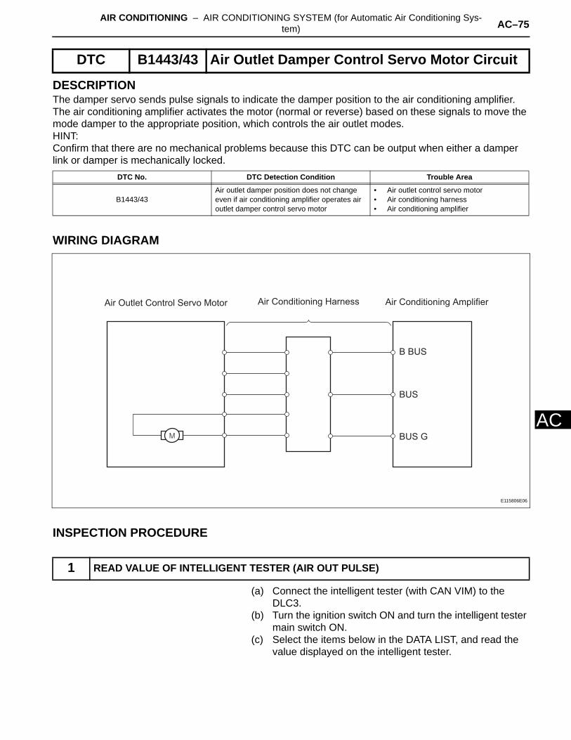
AIR CONDITIONING – AIR CONDITIONING SYSTEM (for Automatic Air Conditioning Sys-tem) AC–75
AC
DESCRIPTIONThe damper servo sends pulse signals to indicate the damper position to the air conditioning amplifier. The air conditioning amplifier activates the motor (normal or reverse) based on these signals to move the mode damper to the appropriate position, which controls the air outlet modes.HINT:Confirm that there are no mechanical problems because this DTC can be output when either a damper link or damper is mechanically locked.
WIRING DIAGRAM
INSPECTION PROCEDURE
(a) Connect the intelligent tester (with CAN VIM) to the DLC3.
(b) Turn the ignition switch ON and turn the intelligent tester main switch ON.
(c) Select the items below in the DATA LIST, and read the value displayed on the intelligent tester.
DTC B1443/43 Air Outlet Damper Control Servo Motor Circuit
DTC No. DTC Detection Condition Trouble Area
B1443/43Air outlet damper position does not change even if air conditioning amplifier operates air outlet damper control servo motor
• Air outlet control servo motor• Air conditioning harness• Air conditioning amplifier
1 READ VALUE OF INTELLIGENT TESTER (AIR OUT PULSE)
Air Conditioning HarnessAir Outlet Control Servo Motor Air Conditioning Amplifier
B BUS
BUS
BUS G
E115806E06
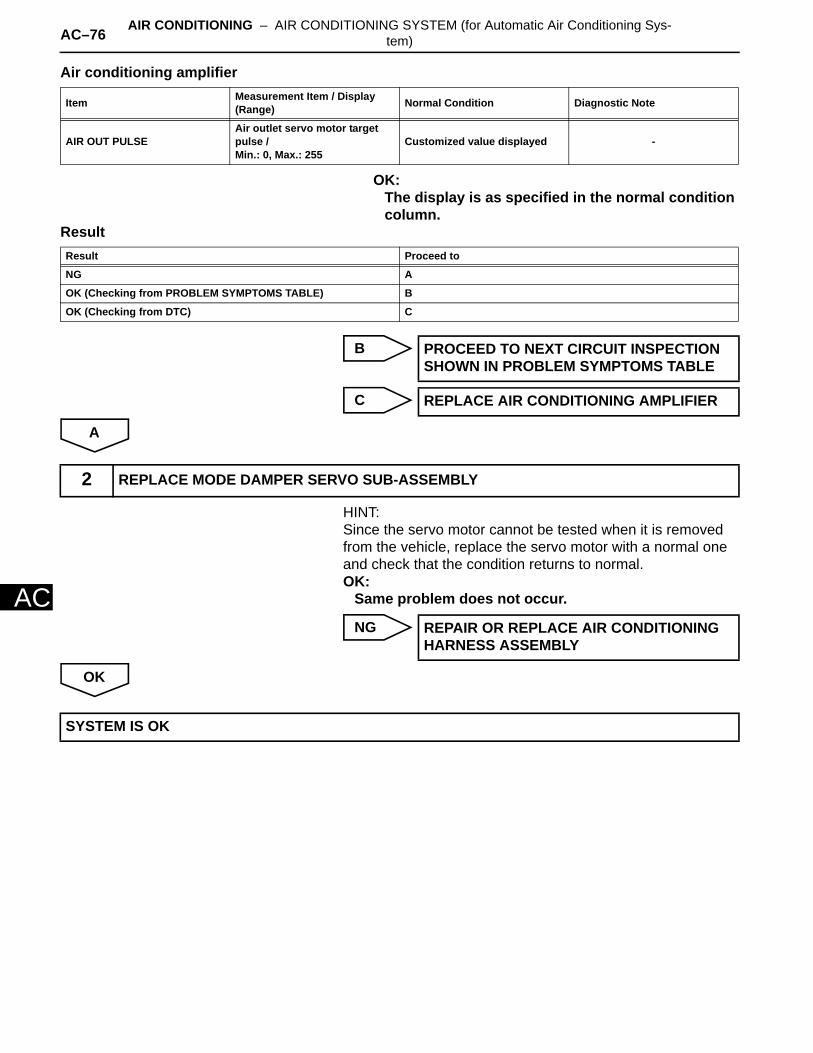
AC–76 AIR CONDITIONING – AIR CONDITIONING SYSTEM (for Automatic Air Conditioning Sys-tem)
AC
Air conditioning amplifier
OK:The display is as specified in the normal condition column.
Result
B
C
A
HINT:Since the servo motor cannot be tested when it is removed from the vehicle, replace the servo motor with a normal one and check that the condition returns to normal.OK:
Same problem does not occur.
NG
OK
Item Measurement Item / Display (Range) Normal Condition Diagnostic Note
AIR OUT PULSEAir outlet servo motor target pulse /Min.: 0, Max.: 255
Customized value displayed -
Result Proceed to
NG A
OK (Checking from PROBLEM SYMPTOMS TABLE) B
OK (Checking from DTC) C
PROCEED TO NEXT CIRCUIT INSPECTION SHOWN IN PROBLEM SYMPTOMS TABLE
REPLACE AIR CONDITIONING AMPLIFIER
2 REPLACE MODE DAMPER SERVO SUB-ASSEMBLY
REPAIR OR REPLACE AIR CONDITIONING HARNESS ASSEMBLY
SYSTEM IS OK

AIR CONDITIONING – AIR CONDITIONING SYSTEM (for Automatic Air Conditioning Sys-tem) AC–77
AC
DESCRIPTIONThe air mix damper servo sends pulse signals to indicate the damper position to the air conditioning amplifier. The air conditioning amplifier activates the motor (normal or reverse) based on these signals to move the air mix damper (driver seat) to the appropriate position. This adjusts the amount of air passing through the heater core after passing the evaporator and controls the temperature of the blown air.HINT:Confirm that there are no mechanical problems because this DTC can be output when either a damper link or damper is mechanically locked.
WIRING DIAGRAM
INSPECTION PROCEDURE
(a) Connect the intelligent tester (with CAN VIM) to the DLC3.
DTC B1446/46 Air Mix Damper Control Servo Motor Circuit (Driver Side)
DTC No. DTC Detection Condition Trouble Area
B1446/46Air mix damper position does not change even if air conditioning amplifier operates air mix control servo motor
• Air mix control servo motor• Air conditioning harness• Air conditioning amplifier
1 READ VALUE OF INTELLIGENT TESTER (AIR MIX SERVO TARG PULSE (D))
Air Conditioning Harness
Air Mix Control Servo Motor
(for Driver Side)Air Conditioning Amplifier
B BUS
BUS
BUS G
E115806E07
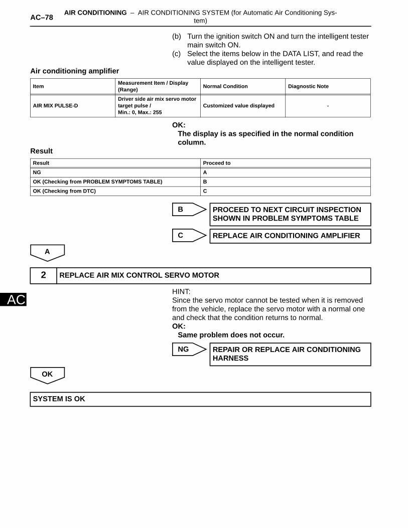
AC–78 AIR CONDITIONING – AIR CONDITIONING SYSTEM (for Automatic Air Conditioning Sys-tem)
AC
(b) Turn the ignition switch ON and turn the intelligent tester main switch ON.
(c) Select the items below in the DATA LIST, and read the value displayed on the intelligent tester.
Air conditioning amplifier
OK:The display is as specified in the normal condition column.
Result
B
C
A
HINT:Since the servo motor cannot be tested when it is removed from the vehicle, replace the servo motor with a normal one and check that the condition returns to normal.OK:
Same problem does not occur.
NG
OK
Item Measurement Item / Display (Range) Normal Condition Diagnostic Note
AIR MIX PULSE-DDriver side air mix servo motor target pulse /Min.: 0, Max.: 255
Customized value displayed -
Result Proceed to
NG A
OK (Checking from PROBLEM SYMPTOMS TABLE) B
OK (Checking from DTC) C
PROCEED TO NEXT CIRCUIT INSPECTION SHOWN IN PROBLEM SYMPTOMS TABLE
REPLACE AIR CONDITIONING AMPLIFIER
2 REPLACE AIR MIX CONTROL SERVO MOTOR
REPAIR OR REPLACE AIR CONDITIONING HARNESS
SYSTEM IS OK

AIR CONDITIONING – AIR CONDITIONING SYSTEM (for Automatic Air Conditioning Sys-tem) AC–79
AC
DESCRIPTIONIn this circuit, the compressor receives a refrigerant compression demand signal from the air conditioning amplifier. Based on this signal, the compressor changes the degree of refrigerant compression.
WIRING DIAGRAM
INSPECTION PROCEDURE
(a) Connect the intelligent tester (with CAN VIM) to the DLC3.
(b) Turn the ignition switch ON and turn the intelligent tester main switch ON.
(c) Select the items below in the DATA LIST, and read the value displayed on the intelligent tester.
DTC B1451/51 Compressor Solenoid Circuit(2005/11-2006/01)
DTC No. DTC Detection Condition Trouble Area
B1451/51 Open or short in solenoid of externally changeable compressor circuit
• Compressor and pulley• Harness and connector between air
conditioning amplifier and compressor and pulley
• Air conditioning amplifier
1 READ VALUE OF INTELLIGENT TESTER (REG CTRL CURRNT)
Compressor and Pulley Air Conditioning Amplifier
SOL+SOL+
SOL-
E115016E04
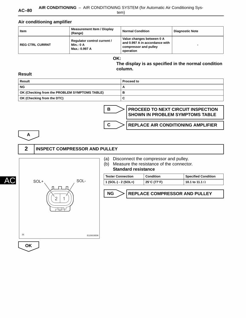
AC–80 AIR CONDITIONING – AIR CONDITIONING SYSTEM (for Automatic Air Conditioning Sys-tem)
AC
Air conditioning amplifier
OK:The display is as specified in the normal condition column.
Result
B
C
A
(a) Disconnect the compressor and pulley.(b) Measure the resistance of the connector.
Standard resistance
NG
OK
Item Measurement Item / Display (Range) Normal Condition Diagnostic Note
REG CTRL CURRNTRegulator control current /Min.: 0 AMax.: 0.997 A
Value changes between 0 A and 0.997 A in accordance with compressor and pulley operation
-
Result Proceed to
NG A
OK (Checking from the PROBLEM SYMPTOMS TABLE) B
OK (Checking from the DTC) C
PROCEED TO NEXT CIRCUIT INSPECTION SHOWN IN PROBLEM SYMPTOMS TABLE
REPLACE AIR CONDITIONING AMPLIFIER
2 INSPECT COMPRESSOR AND PULLEY
SOL+ SOL-
E115015E06
Tester Connection Condition Specified Condition
1 (SOL-) - 2 (SOL+) 25°C (77°F) 10.1 to 11.1 Ω
REPLACE COMPRESSOR AND PULLEY
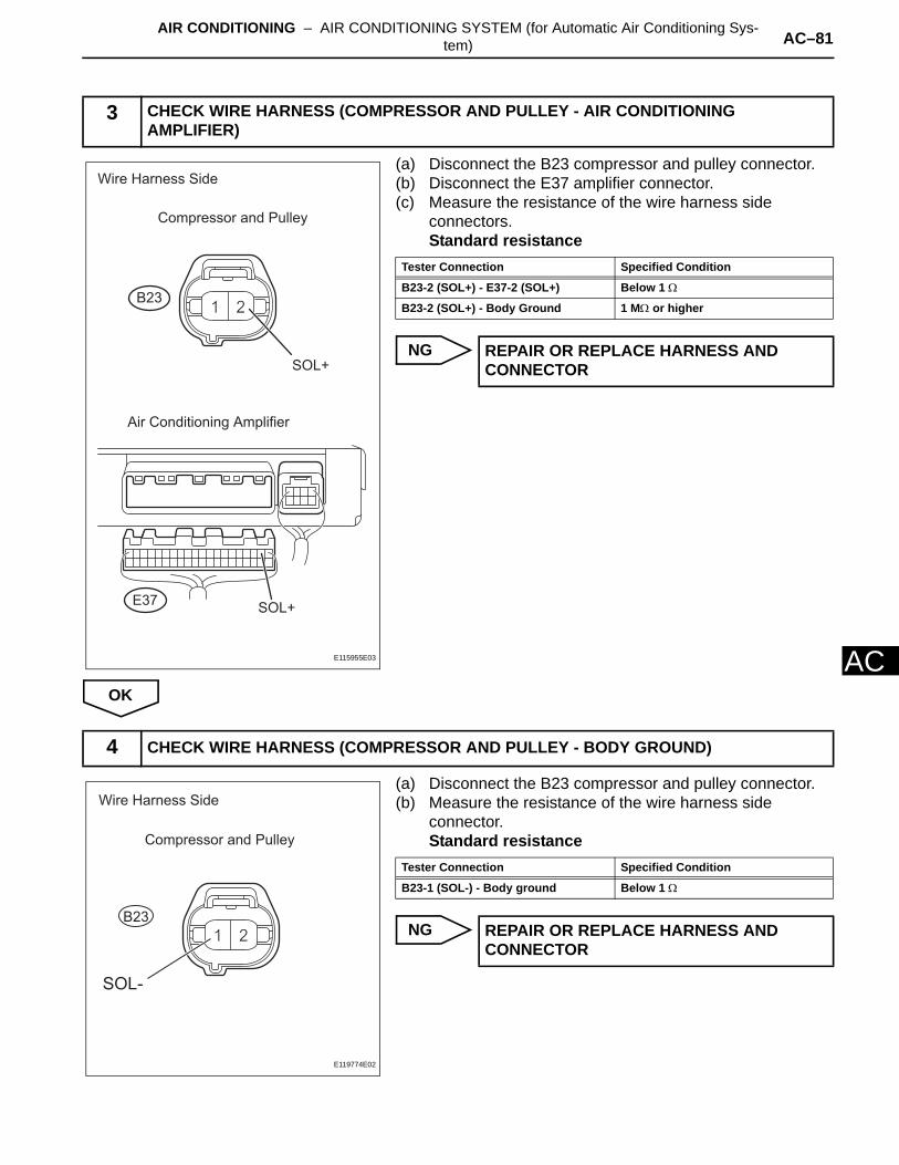
AIR CONDITIONING – AIR CONDITIONING SYSTEM (for Automatic Air Conditioning Sys-tem) AC–81
AC
(a) Disconnect the B23 compressor and pulley connector.(b) Disconnect the E37 amplifier connector.(c) Measure the resistance of the wire harness side
connectors.Standard resistance
NG
OK
(a) Disconnect the B23 compressor and pulley connector.(b) Measure the resistance of the wire harness side
connector.Standard resistance
NG
3 CHECK WIRE HARNESS (COMPRESSOR AND PULLEY - AIR CONDITIONING AMPLIFIER)
Wire Harness Side
Compressor and Pulley
B23
E37
Air Conditioning Amplifier
SOL+
SOL+
E115955E03
Tester Connection Specified Condition
B23-2 (SOL+) - E37-2 (SOL+) Below 1 Ω
B23-2 (SOL+) - Body Ground 1 MΩ or higher
REPAIR OR REPLACE HARNESS AND CONNECTOR
4 CHECK WIRE HARNESS (COMPRESSOR AND PULLEY - BODY GROUND)
Wire Harness Side
Compressor and Pulley
B23
SOL-
E119774E02
Tester Connection Specified Condition
B23-1 (SOL-) - Body ground Below 1 Ω
REPAIR OR REPLACE HARNESS AND CONNECTOR

AC–82 AIR CONDITIONING – AIR CONDITIONING SYSTEM (for Automatic Air Conditioning Sys-tem)
AC
OK
REPLACE AIR CONDITIONING AMPLIFIER
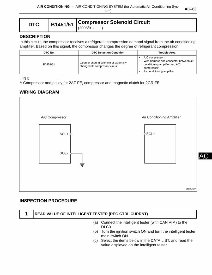
AIR CONDITIONING – AIR CONDITIONING SYSTEM (for Automatic Air Conditioning Sys-tem) AC–83
AC
DESCRIPTIONIn this circuit, the compressor receives a refrigerant compression demand signal from the air conditioning amplifier. Based on this signal, the compressor changes the degree of refrigerant compression.
HINT:*: Compressor and pulley for 2AZ-FE, compressor and magnetic clutch for 2GR-FE
WIRING DIAGRAM
INSPECTION PROCEDURE
(a) Connect the intelligent tester (with CAN VIM) to the DLC3.
(b) Turn the ignition switch ON and turn the intelligent tester main switch ON.
(c) Select the items below in the DATA LIST, and read the value displayed on the intelligent tester.
DTC B1451/51 Compressor Solenoid Circuit(2006/01- )
DTC No. DTC Detection Condition Trouble Area
B1451/51 Open or short in solenoid of externally changeable compressor circuit
• A/C compressor*• Wire harness and connector between air
conditioning amplifier and A/C compressor*
• Air conditioning amplifier
1 READ VALUE OF INTELLIGENT TESTER (REG CTRL CURRNT)
A/C Compressor Air Conditioning Amplifier
SOL+SOL+
SOL-
E115016E07
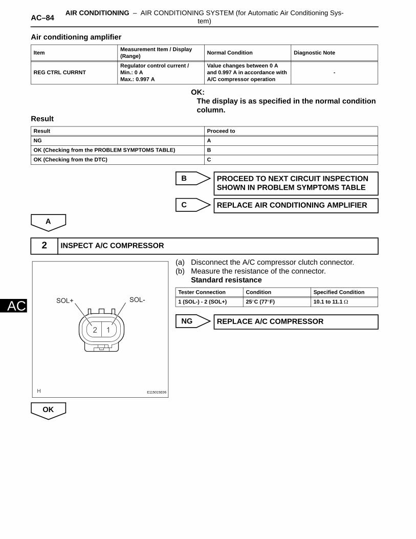
AC–84 AIR CONDITIONING – AIR CONDITIONING SYSTEM (for Automatic Air Conditioning Sys-tem)
AC
Air conditioning amplifier
OK:The display is as specified in the normal condition column.
Result
B
C
A
(a) Disconnect the A/C compressor clutch connector.(b) Measure the resistance of the connector.
Standard resistance
NG
OK
Item Measurement Item / Display (Range) Normal Condition Diagnostic Note
REG CTRL CURRNTRegulator control current /Min.: 0 AMax.: 0.997 A
Value changes between 0 A and 0.997 A in accordance with A/C compressor operation
-
Result Proceed to
NG A
OK (Checking from the PROBLEM SYMPTOMS TABLE) B
OK (Checking from the DTC) C
PROCEED TO NEXT CIRCUIT INSPECTION SHOWN IN PROBLEM SYMPTOMS TABLE
REPLACE AIR CONDITIONING AMPLIFIER
2 INSPECT A/C COMPRESSOR
SOL+ SOL-
E115015E06
Tester Connection Condition Specified Condition
1 (SOL-) - 2 (SOL+) 25°C (77°F) 10.1 to 11.1 Ω
REPLACE A/C COMPRESSOR
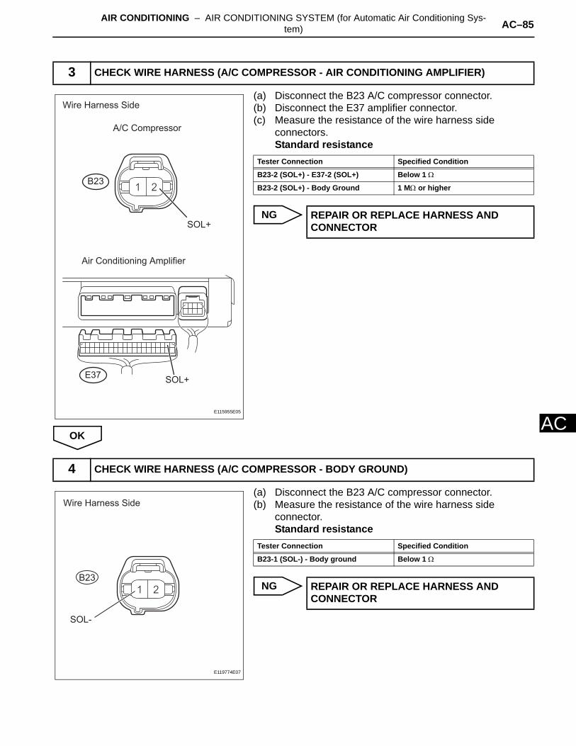
AIR CONDITIONING – AIR CONDITIONING SYSTEM (for Automatic Air Conditioning Sys-tem) AC–85
AC
(a) Disconnect the B23 A/C compressor connector.(b) Disconnect the E37 amplifier connector.(c) Measure the resistance of the wire harness side
connectors.Standard resistance
NG
OK
(a) Disconnect the B23 A/C compressor connector.(b) Measure the resistance of the wire harness side
connector.Standard resistance
NG
3 CHECK WIRE HARNESS (A/C COMPRESSOR - AIR CONDITIONING AMPLIFIER)
Wire Harness Side
A/C Compressor
B23
E37
Air Conditioning Amplifier
SOL+
SOL+
E115955E05
Tester Connection Specified Condition
B23-2 (SOL+) - E37-2 (SOL+) Below 1 Ω
B23-2 (SOL+) - Body Ground 1 MΩ or higher
REPAIR OR REPLACE HARNESS AND CONNECTOR
4 CHECK WIRE HARNESS (A/C COMPRESSOR - BODY GROUND)
Wire Harness Side
B23
SOL-
E119774E07
Tester Connection Specified Condition
B23-1 (SOL-) - Body ground Below 1 Ω
REPAIR OR REPLACE HARNESS AND CONNECTOR
AC–86 AIR CONDITIONING – AIR CONDITIONING SYSTEM (for Automatic Air Conditioning Sys-tem)
AC
OK
REPLACE AIR CONDITIONING AMPLIFIER
AIR CONDITIONING – AIR CONDITIONING SYSTEM (for Automatic Air Conditioning Sys-tem) AC–87
AC
DESCRIPTIONThe air conditioning harness connects the air conditioning amplifier and the servos. The air conditioning amplifier supplies power and sends operation instructions to each servo through the air conditioning harness. Each servo sends damper position information to the air conditioning amplifier.
DTC B1497/97 BUS IC Communication Malfunction
DTC No. DTC Detection Condition Trouble Area
B1497/97 Communication line error or open • Air conditioning harness• Air conditioning amplifier

AC–88 AIR CONDITIONING – AIR CONDITIONING SYSTEM (for Automatic Air Conditioning Sys-tem)
AC
WIRING DIAGRAM
Air Mix Control Servo Motor
(for Passenger Side)
Air Conditioning Amplifier
B BUS
BUS
BUS G
Air Outlet Control Servo Motor
Air Mix Control Servo Motor
(for Driver Side)
Air Inlet Control Servo Motor Air Conditioning Harness
E123524E01
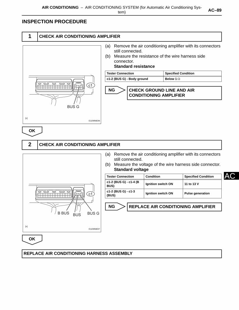
AIR CONDITIONING – AIR CONDITIONING SYSTEM (for Automatic Air Conditioning Sys-tem) AC–89
AC
INSPECTION PROCEDURE
(a) Remove the air conditioning amplifier with its connectors still connected.
(b) Measure the resistance of the wire harness side connector.Standard resistance
NG
OK
(a) Remove the air conditioning amplifier with its connectors still connected.
(b) Measure the voltage of the wire harness side connector.Standard voltage
NG
OK
1 CHECK AIR CONDITIONING AMPLIFIER
BUS G
c1
E115956E06
Tester Connection Specified Condition
c1-2 (BUS G) - Body ground Below 1 Ω
CHECK GROUND LINE AND AIR CONDITIONING AMPLIFIER
2 CHECK AIR CONDITIONING AMPLIFIER
BUS GB BUS BUS
c1
E115956E07
Tester Connection Condition Specified Condition
c1-2 (BUS G) - c1-4 (B BUS) Ignition switch ON 11 to 13 V
c1-2 (BUS G) - c1-3 (BUS) Ignition switch ON Pulse generation
REPLACE AIR CONDITIONING AMPLIFIER
REPLACE AIR CONDITIONING HARNESS ASSEMBLY

AC–90 AIR CONDITIONING – AIR CONDITIONING SYSTEM (for Automatic Air Conditioning Sys-tem)
AC
DESCRIPTIONThe air conditioning amplifier communicates data with the ECM and combination meter through the CAN communication system.
WIRING DIAGRAM
INSPECTION PROCEDURE
(a) Clear the DTC (see page AC-31).(b) Read the DTC (see page AC-31).
Result
B
A
DTC B1499/99 Multiplex Communication Circuit
DTC No. DTC Detection Condition Trouble Area
B1499/99 Open in CAN communication line
• Air conditioning amplifier• ECM• Combination meter• CAN communication line
1 CHECK DTC
ECM
Air Conditioning Amplifier Combination Meter
: CAN Communication Line
E120908E02
Result Proceed to
DTC (B1499/99) is output A (see page CA-1)
DTC (B1499/99) is not output B
SYSTEM IS OK
GO TO CAN COMMUNICATION SYSTEM
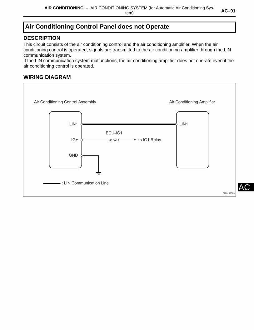
AIR CONDITIONING – AIR CONDITIONING SYSTEM (for Automatic Air Conditioning Sys-tem) AC–91
AC
DESCRIPTIONThis circuit consists of the air conditioning control and the air conditioning amplifier. When the air conditioning control is operated, signals are transmitted to the air conditioning amplifier through the LIN communication system.If the LIN communication system malfunctions, the air conditioning amplifier does not operate even if the air conditioning control is operated.
WIRING DIAGRAM
Air Conditioning Control Panel does not Operate
LIN1LIN1
Air Conditioning AmplifierAir Conditioning Control Assembly
ECU-IG1
IG+
GND
: LIN Communication Line
to IG1 Relay
E120289E03
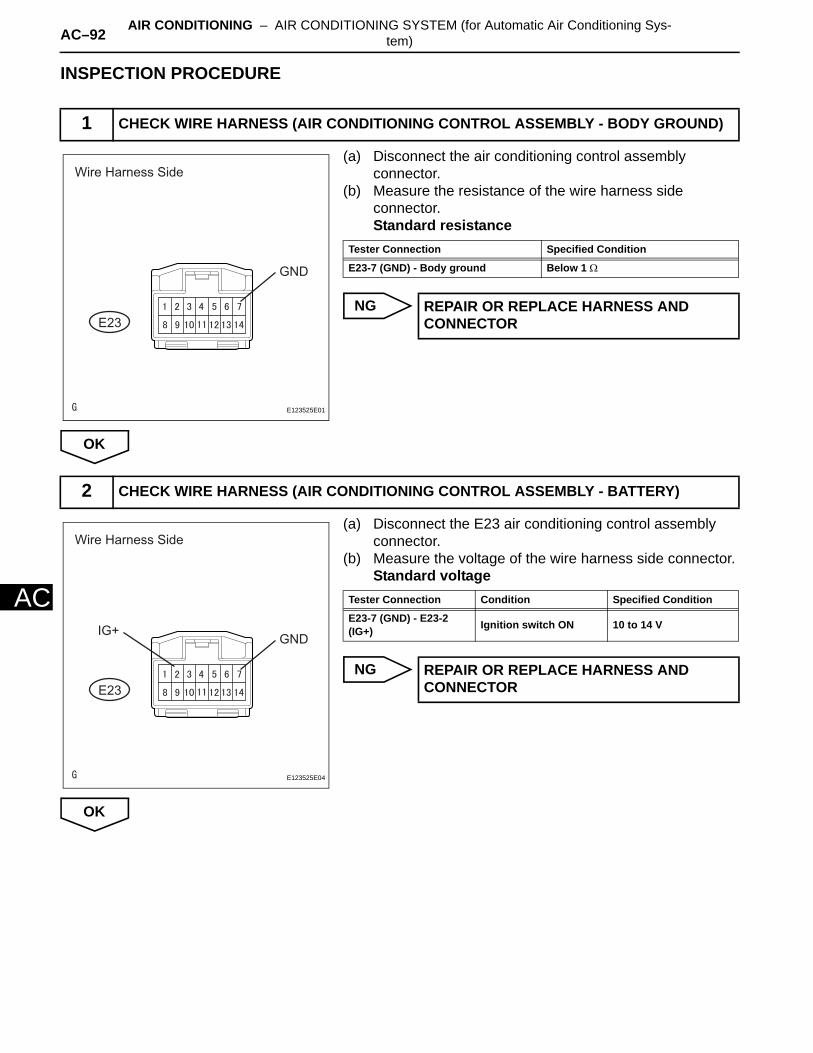
AC–92 AIR CONDITIONING – AIR CONDITIONING SYSTEM (for Automatic Air Conditioning Sys-tem)
AC
INSPECTION PROCEDURE
(a) Disconnect the air conditioning control assembly connector.
(b) Measure the resistance of the wire harness side connector.Standard resistance
NG
OK
(a) Disconnect the E23 air conditioning control assembly connector.
(b) Measure the voltage of the wire harness side connector.Standard voltage
NG
OK
1 CHECK WIRE HARNESS (AIR CONDITIONING CONTROL ASSEMBLY - BODY GROUND)
Wire Harness Side
E23
GND
E123525E01
Tester Connection Specified Condition
E23-7 (GND) - Body ground Below 1 Ω
REPAIR OR REPLACE HARNESS AND CONNECTOR
2 CHECK WIRE HARNESS (AIR CONDITIONING CONTROL ASSEMBLY - BATTERY)
Wire Harness Side
E23
GNDIG+
E123525E04
Tester Connection Condition Specified Condition
E23-7 (GND) - E23-2 (IG+) Ignition switch ON 10 to 14 V
REPAIR OR REPLACE HARNESS AND CONNECTOR

AIR CONDITIONING – AIR CONDITIONING SYSTEM (for Automatic Air Conditioning Sys-tem) AC–93
AC
(a) Disconnect the E23 control connector.(b) Disconnect the E37 amplifier connector.(c) Measure the resistance of the wire harness side
connectors.Standard resistance
NG
OK
(a) Replace the air conditioning control with a new or properly functioning one.
(b) Operate the air conditioning control to check that it functions properly.
Result
B
A
3 CHECK WIRE HARNESS (AIR CONDITIONING AMPLIFIER - AIR CONDITIONING CONTROL)
Wire Harness Side
Air Conditioning Control Assembly
Air Conditioning Amplifier
E23
E37
LIN1
LIN1
E123519E01
Tester Connection Specified Condition
E37-37 (LIN1) - E23-11 (LIN1) Below 1 Ω
REPAIR OR REPLACE HARNESS AND CONNECTOR
4 REPLACE AIR CONDITIONING AMPLIFIER
Result Proceed to
Air conditioning control malfunctions A
Air conditioning control functions properly B
END (AIR CONDITIONING CONTROL ASSEMBLY IS FAULTY)
REPLACE AIR CONDITIONING AMPLIFIER
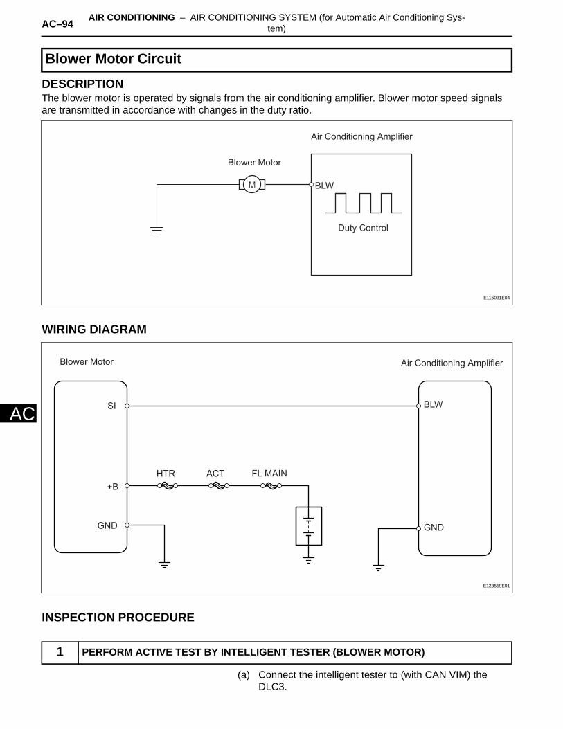
AC–94 AIR CONDITIONING – AIR CONDITIONING SYSTEM (for Automatic Air Conditioning Sys-tem)
AC
DESCRIPTIONThe blower motor is operated by signals from the air conditioning amplifier. Blower motor speed signals are transmitted in accordance with changes in the duty ratio.
WIRING DIAGRAM
INSPECTION PROCEDURE
(a) Connect the intelligent tester to (with CAN VIM) the DLC3.
Blower Motor Circuit
1 PERFORM ACTIVE TEST BY INTELLIGENT TESTER (BLOWER MOTOR)
BLW
Air Conditioning Amplifier
Blower Motor
Duty Control
E115031E04
BLW
GND
SI
Air Conditioning AmplifierBlower Motor
+B
GND
FL MAINHTR ACT
E123559E01
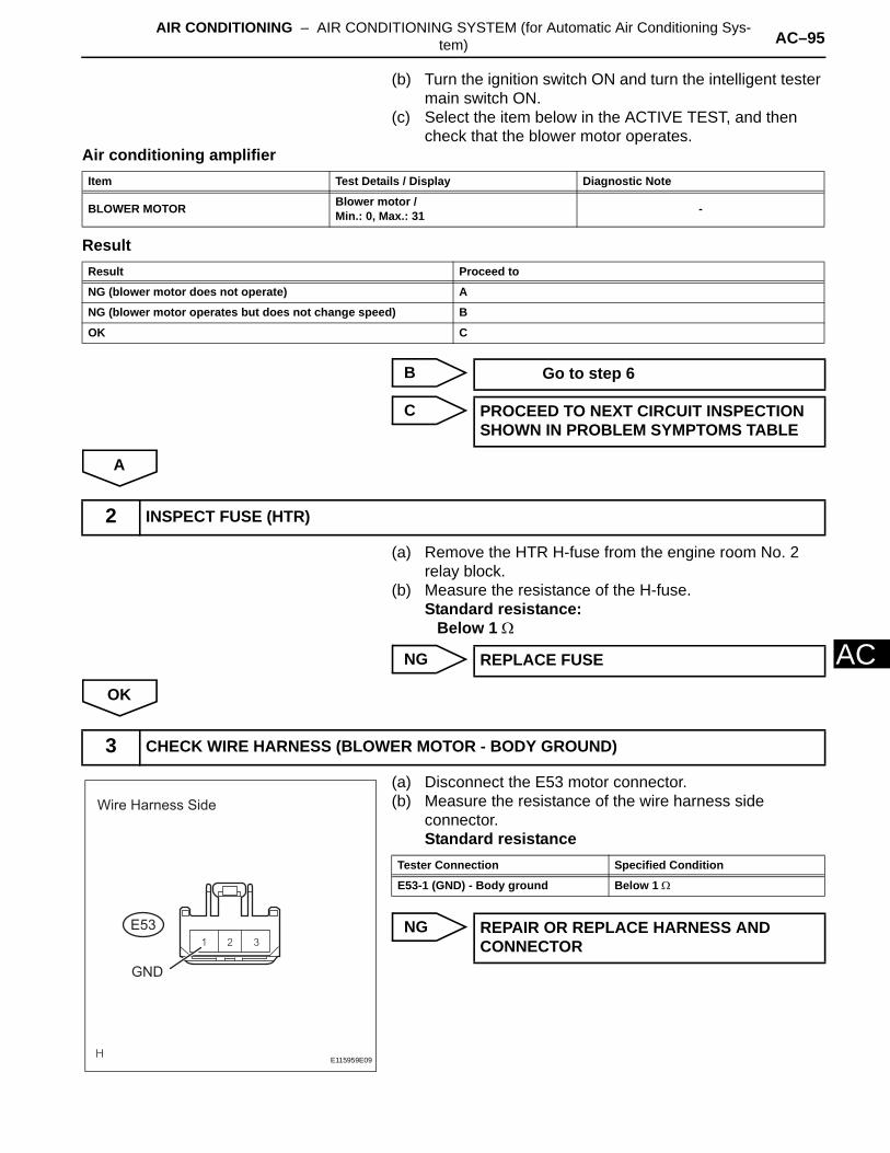
AIR CONDITIONING – AIR CONDITIONING SYSTEM (for Automatic Air Conditioning Sys-tem) AC–95
AC
(b) Turn the ignition switch ON and turn the intelligent tester main switch ON.
(c) Select the item below in the ACTIVE TEST, and then check that the blower motor operates.
Air conditioning amplifier
Result
B
C
A
(a) Remove the HTR H-fuse from the engine room No. 2 relay block.
(b) Measure the resistance of the H-fuse.Standard resistance:
Below 1 Ω
NG
OK
(a) Disconnect the E53 motor connector.(b) Measure the resistance of the wire harness side
connector.Standard resistance
NG
Item Test Details / Display Diagnostic Note
BLOWER MOTOR Blower motor /Min.: 0, Max.: 31 -
Result Proceed to
NG (blower motor does not operate) A
NG (blower motor operates but does not change speed) B
OK C
Go to step 6
PROCEED TO NEXT CIRCUIT INSPECTION SHOWN IN PROBLEM SYMPTOMS TABLE
2 INSPECT FUSE (HTR)
REPLACE FUSE
3 CHECK WIRE HARNESS (BLOWER MOTOR - BODY GROUND)
E53
Wire Harness Side
GND
E115959E09
Tester Connection Specified Condition
E53-1 (GND) - Body ground Below 1 Ω
REPAIR OR REPLACE HARNESS AND CONNECTOR
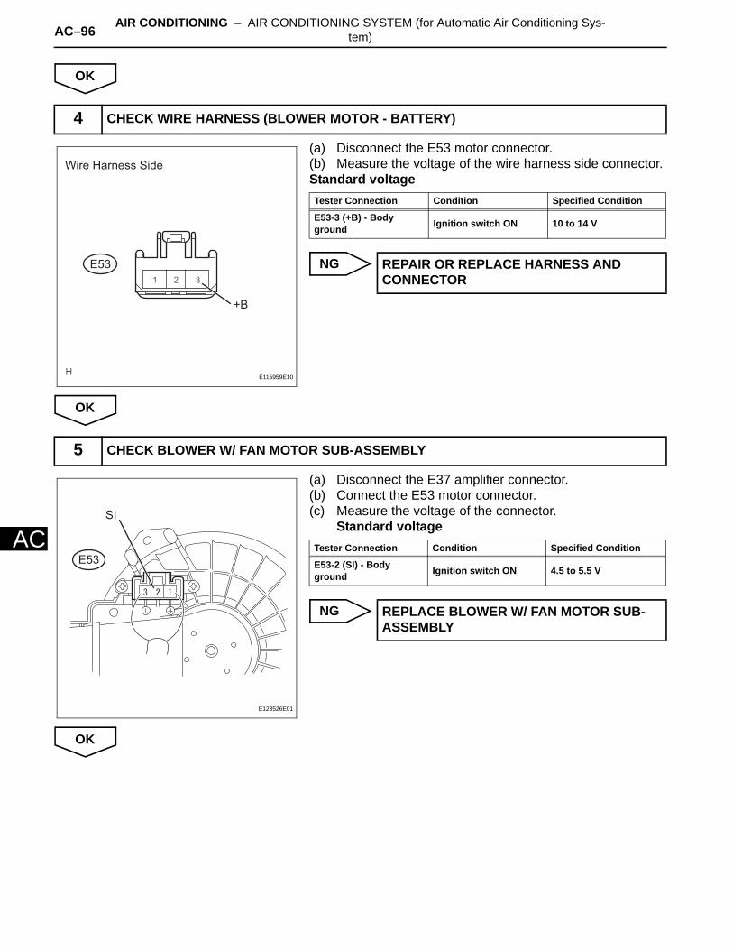
AC–96 AIR CONDITIONING – AIR CONDITIONING SYSTEM (for Automatic Air Conditioning Sys-tem)
AC
OK
(a) Disconnect the E53 motor connector.(b) Measure the voltage of the wire harness side connector.Standard voltage
NG
OK
(a) Disconnect the E37 amplifier connector.(b) Connect the E53 motor connector.(c) Measure the voltage of the connector.
Standard voltage
NG
OK
4 CHECK WIRE HARNESS (BLOWER MOTOR - BATTERY)
E53
Wire Harness Side
+B
E115959E10
Tester Connection Condition Specified Condition
E53-3 (+B) - Body ground Ignition switch ON 10 to 14 V
REPAIR OR REPLACE HARNESS AND CONNECTOR
5 CHECK BLOWER W/ FAN MOTOR SUB-ASSEMBLY
E53
SI
E123526E01
Tester Connection Condition Specified Condition
E53-2 (SI) - Body ground Ignition switch ON 4.5 to 5.5 V
REPLACE BLOWER W/ FAN MOTOR SUB-ASSEMBLY
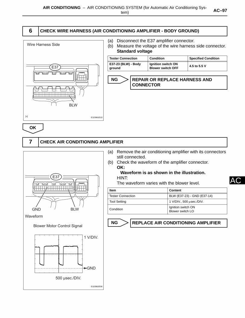
AIR CONDITIONING – AIR CONDITIONING SYSTEM (for Automatic Air Conditioning Sys-tem) AC–97
AC
(a) Disconnect the E37 amplifier connector.(b) Measure the voltage of the wire harness side connector.
Standard voltage
NG
OK
(a) Remove the air conditioning amplifier with its connectors still connected.
(b) Check the waveform of the amplifier connector.OK:
Waveform is as shown in the illustration.HINT:The waveform varies with the blower level.
NG
6 CHECK WIRE HARNESS (AIR CONDITIONING AMPLIFIER - BODY GROUND)
E37
BLW
Wire Harness Side
E115961E10
Tester Connection Condition Specified Condition
E37-23 (BLW) - Body ground
Ignition switch ONBlower switch OFF 4.5 to 5.5 V
REPAIR OR REPLACE HARNESS AND CONNECTOR
7 CHECK AIR CONDITIONING AMPLIFIER
E37
GND BLW
Waveform
GND
Blower Motor Control Signal
1 V/DIV.
500 μsec./DIV.
E115962E06
Item Content
Tester Connection BLW (E37-23) - GND (E37-14)
Tool Setting 1 V/DIV., 500 µsec./DIV.
Condition Ignition switch ONBlower switch LO
REPLACE AIR CONDITIONING AMPLIFIER
AC–98 AIR CONDITIONING – AIR CONDITIONING SYSTEM (for Automatic Air Conditioning Sys-tem)
AC
OK
REPLACE BLOWER W/ FAN MOTOR SUB-ASSEMBLY
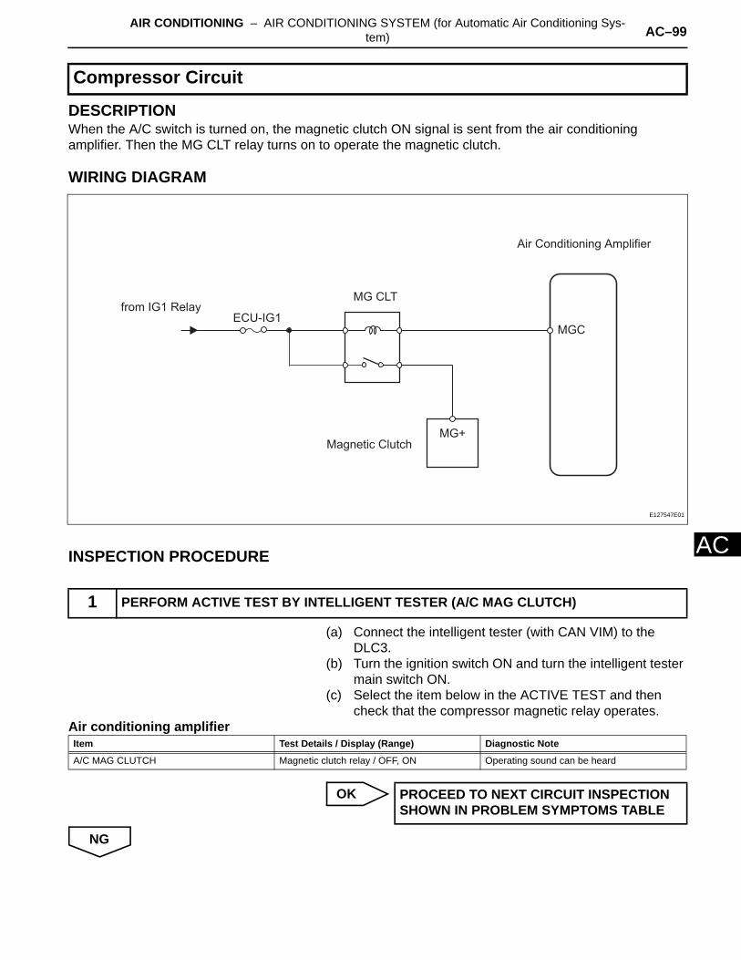
AIR CONDITIONING – AIR CONDITIONING SYSTEM (for Automatic Air Conditioning Sys-tem) AC–99
AC
DESCRIPTIONWhen the A/C switch is turned on, the magnetic clutch ON signal is sent from the air conditioning amplifier. Then the MG CLT relay turns on to operate the magnetic clutch.
WIRING DIAGRAM
INSPECTION PROCEDURE
(a) Connect the intelligent tester (with CAN VIM) to the DLC3.
(b) Turn the ignition switch ON and turn the intelligent tester main switch ON.
(c) Select the item below in the ACTIVE TEST and then check that the compressor magnetic relay operates.
Air conditioning amplifier
OK
NG
Compressor Circuit
1 PERFORM ACTIVE TEST BY INTELLIGENT TESTER (A/C MAG CLUTCH)
from IG1 RelayECU-IG1
Air Conditioning Amplifier
MG+
MG CLT
Magnetic Clutch
MGC
E127547E01
Item Test Details / Display (Range) Diagnostic Note
A/C MAG CLUTCH Magnetic clutch relay / OFF, ON Operating sound can be heard
PROCEED TO NEXT CIRCUIT INSPECTION SHOWN IN PROBLEM SYMPTOMS TABLE
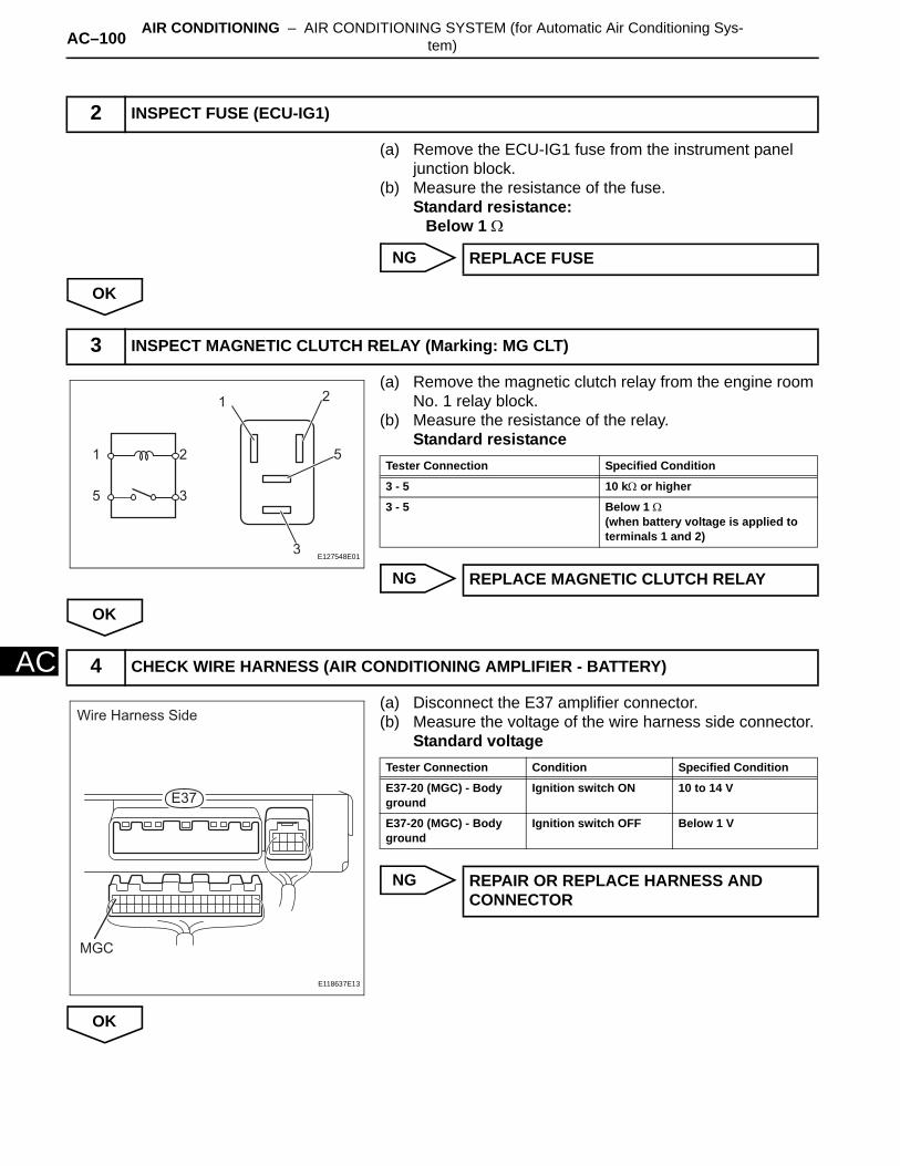
AC–100 AIR CONDITIONING – AIR CONDITIONING SYSTEM (for Automatic Air Conditioning Sys-tem)
AC
(a) Remove the ECU-IG1 fuse from the instrument panel junction block.
(b) Measure the resistance of the fuse.Standard resistance:
Below 1 Ω
NG
OK
(a) Remove the magnetic clutch relay from the engine room No. 1 relay block.
(b) Measure the resistance of the relay.Standard resistance
NG
OK
(a) Disconnect the E37 amplifier connector.(b) Measure the voltage of the wire harness side connector.
Standard voltage
NG
OK
2 INSPECT FUSE (ECU-IG1)
REPLACE FUSE
3 INSPECT MAGNETIC CLUTCH RELAY (Marking: MG CLT)
1
2
2
3
5
5
3
1
E127548E01
Tester Connection Specified Condition
3 - 5 10 kΩ or higher
3 - 5 Below 1 Ω(when battery voltage is applied to terminals 1 and 2)
REPLACE MAGNETIC CLUTCH RELAY
4 CHECK WIRE HARNESS (AIR CONDITIONING AMPLIFIER - BATTERY)
E37
Wire Harness Side
MGC
E118637E13
Tester Connection Condition Specified Condition
E37-20 (MGC) - Body ground
Ignition switch ON 10 to 14 V
E37-20 (MGC) - Body ground
Ignition switch OFF Below 1 V
REPAIR OR REPLACE HARNESS AND CONNECTOR

AIR CONDITIONING – AIR CONDITIONING SYSTEM (for Automatic Air Conditioning Sys-tem) AC–101
AC
(a) Remove the air conditioning amplifier with its connectors still connected.
(b) Measure the voltage of the connector.Standard voltage
NG
OK
(a) Disconnect the B47 magnetic clutch connector.(b) Connect the battery's positive (+) lead to terminal 3 of
the magnetic clutch and the negative (-) lead to the body ground.OK:
Magnetic clutch is engaged.
NG
OK
5 CHECK AIR CONDITIONING AMPLIFIER (MGC VOLTAGE)
MGC
E37
E115805E07
Tester Connection Condition Specified Condition
E37-20 (MGC) - Body ground
Ignition switch ONA/C switch OFF
10 to 14 V
E37-20 (MGC) - Body ground
Ignition switch ONA/C switch ON
Below 1.5 V
REPLACE AIR CONDITIONING AMPLIFIER
6 CHECK MAGNETIC CLUTCH
E127549E01
REPLACE MAGNETIC CLUTCH
REPAIR OR REPLACE WIRE HARNESS (MAGNETIC CLUTCH - ECU-IG1)
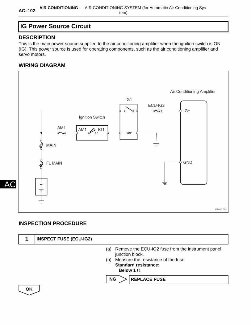
AC–102 AIR CONDITIONING – AIR CONDITIONING SYSTEM (for Automatic Air Conditioning Sys-tem)
AC
DESCRIPTIONThis is the main power source supplied to the air conditioning amplifier when the ignition switch is ON (IG). This power source is used for operating components, such as the air conditioning amplifier and servo motors.
WIRING DIAGRAM
INSPECTION PROCEDURE
(a) Remove the ECU-IG2 fuse from the instrument panel junction block.
(b) Measure the resistance of the fuse.Standard resistance:
Below 1 Ω
NG
OK
IG Power Source Circuit
1 INSPECT FUSE (ECU-IG2)
IG1
Ignition Switch
Air Conditioning Amplifier
ECU-IG2
MAIN
FL MAIN
AM1 AM1 IG1
IG+
GND
E123527E01
REPLACE FUSE
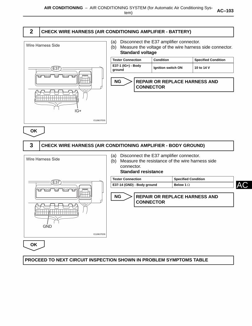
AIR CONDITIONING – AIR CONDITIONING SYSTEM (for Automatic Air Conditioning Sys-tem) AC–103
AC
(a) Disconnect the E37 amplifier connector.(b) Measure the voltage of the wire harness side connector.
Standard voltage
NG
OK
(a) Disconnect the E37 amplifier connector.(b) Measure the resistance of the wire harness side
connector.Standard resistance
NG
OK
2 CHECK WIRE HARNESS (AIR CONDITIONING AMPLIFIER - BATTERY)
E37
Wire Harness Side
IG+
E118637E05
Tester Connection Condition Specified Condition
E37-1 (IG+) - Body ground Ignition switch ON 10 to 14 V
REPAIR OR REPLACE HARNESS AND CONNECTOR
3 CHECK WIRE HARNESS (AIR CONDITIONING AMPLIFIER - BODY GROUND)
E37
Wire Harness Side
GND
E118637E06
Tester Connection Specified Condition
E37-14 (GND) - Body ground Below 1 Ω
REPAIR OR REPLACE HARNESS AND CONNECTOR
PROCEED TO NEXT CIRCUIT INSPECTION SHOWN IN PROBLEM SYMPTOMS TABLE
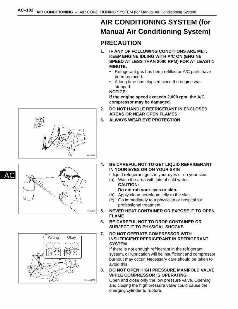
AC–102 AIR CONDITIONING – AIR CONDITIONING SYSTEM (for Manual Air Conditioning System)
AC
AIR CONDITIONING SYSTEM (for Manual Air Conditioning System)PRECAUTION1. IF ANY OF FOLLOWING CONDITIONS ARE MET,
KEEP ENGINE IDLING WITH A/C ON (ENGINE SPEED AT LESS THAN 2000 RPM) FOR AT LEAST 1 MINUTE:• Refrigerant gas has been refilled or A/C parts have
been replaced.• A long time has elapsed since the engine was
stopped.NOTICE:If the engine speed exceeds 2,000 rpm, the A/C compressor may be damaged.
2. DO NOT HANDLE REFRIGERANT IN ENCLOSED AREAS OR NEAR OPEN FLAMES
3. ALWAYS WEAR EYE PROTECTION
4. BE CAREFUL NOT TO GET LIQUID REFRIGERANT IN YOUR EYES OR ON YOUR SKINIf liquid refrigerant gets in your eyes or on your skin:(a) Wash the area with lots of cold water.
CAUTION:Do not rub your eyes or skin.
(b) Apply clean petroleum jelly to the skin.(c) Go immediately to a physician or hospital for
professional treatment.5. NEVER HEAT CONTAINER OR EXPOSE IT TO OPEN
FLAME6. BE CAREFUL NOT TO DROP CONTAINER OR
SUBJECT IT TO PHYSICAL SHOCKS7. DO NOT OPERATE COMPRESSOR WITH
INSUFFICIENT REFRIGERANT IN REFRIGERANT SYSTEMIf there is not enough refrigerant in the refrigerant system, oil lubrication will be insufficient and compressor burnout may occur. Necessary care should be taken to avoid this.
8. DO NOT OPEN HIGH PRESSURE MANIFOLD VALVE WHILE COMPRESSOR IS OPERATINGOpen and close only the low pressure valve. Opening and closing the high pressure valve could cause the charging cylinder to rupture.
AC02810
AC02811
OkayWrong
LO HILOHI
N011084E03
AIR CONDITIONING – AIR CONDITIONING SYSTEM (for Manual Air Conditioning System) AC–103
AC
9. BE CAREFUL NOT TO OVERCHARGE SYSTEM WITH REFRIGERANTIf the refrigerant is overcharged, it causes problems such as insufficient cooling, poor fuel economy and engine overheating.
10. DO NOT OPERATE ENGINE AND COMPRESSOR WITHOUT REFRIGERANTNOTICE:This may damage the inside of the compressor.
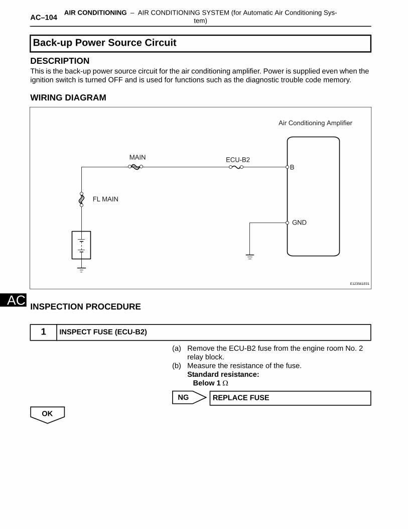
AC–104 AIR CONDITIONING – AIR CONDITIONING SYSTEM (for Automatic Air Conditioning Sys-tem)
AC
DESCRIPTIONThis is the back-up power source circuit for the air conditioning amplifier. Power is supplied even when the ignition switch is turned OFF and is used for functions such as the diagnostic trouble code memory.
WIRING DIAGRAM
INSPECTION PROCEDURE
(a) Remove the ECU-B2 fuse from the engine room No. 2 relay block.
(b) Measure the resistance of the fuse.Standard resistance:
Below 1 Ω
NG
OK
Back-up Power Source Circuit
1 INSPECT FUSE (ECU-B2)
FL MAIN
MAIN ECU-B2
Air Conditioning Amplifier
B
GND
E123561E01
REPLACE FUSE

AIR CONDITIONING – AIR CONDITIONING SYSTEM (for Automatic Air Conditioning Sys-tem) AC–105
AC
(a) Disconnect the E37 amplifier connector.(b) Measure the voltage of the wire harness side connector.
Standard voltage
NG
OK
(a) Disconnect the E37 amplifier connector.(b) Measure the resistance of the wire harness side
connector.Standard resistance
NG
OK
2 CHECK WIRE HARNESS (AIR CONDITIONING AMPLIFIER - BATTERY)
E37
Wire Harness Side
B
E118637E07
Tester Connection Specified Condition
E37-21 (B) - Body ground 10 to 14 V
REPAIR OR REPLACE HARNESS AND CONNECTOR
3 CHECK WIRE HARNESS (AIR CONDITIONING AMPLIFIER - BODY GROUND)
E37
Wire Harness Side
GND
E118637E08
Tester Connection Specified Condition
E37-14 (GND) - Body ground Below 1 Ω
REPAIR OR REPLACE HARNESS AND CONNECTOR
PROCEED TO NEXT CIRCUIT INSPECTION SHOWN IN PROBLEM SYMPTOMS TABLE
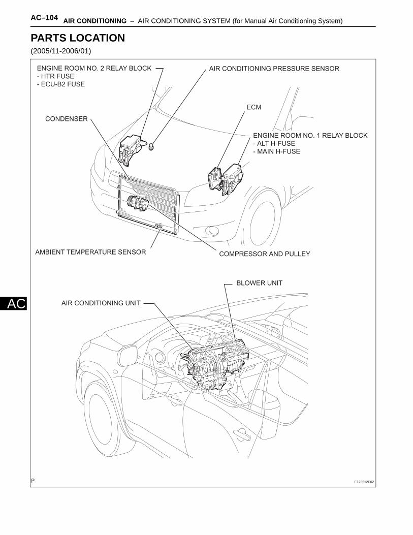
AC–104 AIR CONDITIONING – AIR CONDITIONING SYSTEM (for Manual Air Conditioning System)
AC
PARTS LOCATION(2005/11-2006/01)
ECM
AIR CONDITIONING UNIT
BLOWER UNIT
COMPRESSOR AND PULLEY
ENGINE ROOM NO. 1 RELAY BLOCK
- ALT H-FUSE
- MAIN H-FUSE
ENGINE ROOM NO. 2 RELAY BLOCK
- HTR FUSE
- ECU-B2 FUSE
AIR CONDITIONING PRESSURE SENSOR
AMBIENT TEMPERATURE SENSOR
CONDENSER
E123512E02

AIR CONDITIONING – AIR CONDITIONING SYSTEM (for Manual Air Conditioning System) AC–105
AC
COMBINATION METER ASSEMBLY
INSTRUMENT PANEL JUNCTION BLOCK
- HEATER RELAY (Marking: HTR)
- MAIN BODY ECU
- ECU-IG1 FUSE
- ECU-IG2 FUSE
DLC3
AIR CONDITIONING CONTROL ASSEMBLY
AIR CONDITIONING AMPLIFIER
E125203E02
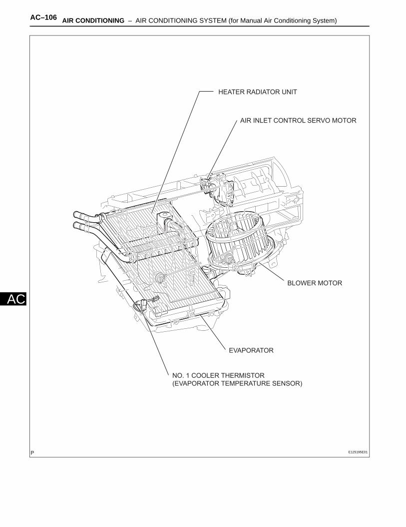
AC–106 AIR CONDITIONING – AIR CONDITIONING SYSTEM (for Manual Air Conditioning System)
AC
HEATER RADIATOR UNIT
EVAPORATOR
NO. 1 COOLER THERMISTOR
(EVAPORATOR TEMPERATURE SENSOR)
AIR INLET CONTROL SERVO MOTOR
BLOWER MOTOR
E125195E01
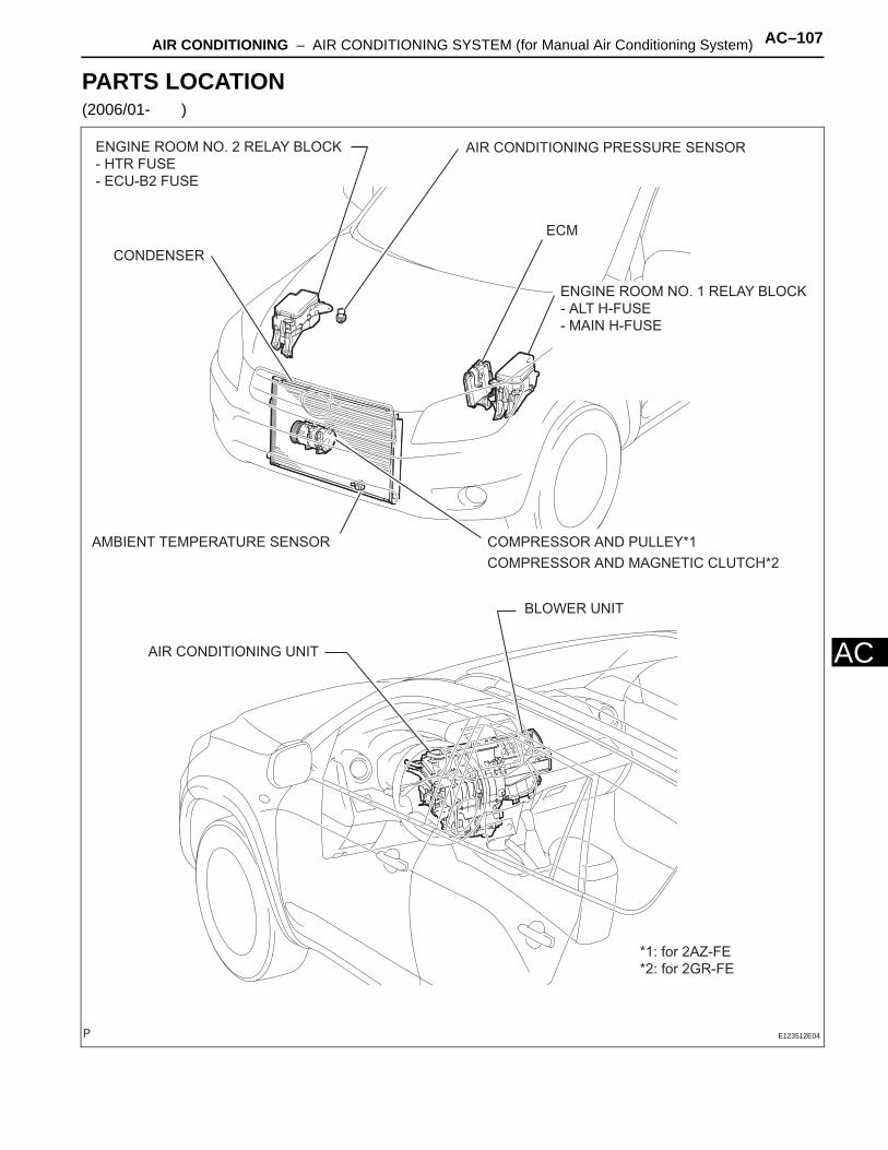
AIR CONDITIONING – AIR CONDITIONING SYSTEM (for Manual Air Conditioning System) AC–107
AC
PARTS LOCATION(2006/01- )
ECM
AIR CONDITIONING UNIT
BLOWER UNIT
COMPRESSOR AND PULLEY*1
COMPRESSOR AND MAGNETIC CLUTCH*2
ENGINE ROOM NO. 1 RELAY BLOCK
- ALT H-FUSE
- MAIN H-FUSE
ENGINE ROOM NO. 2 RELAY BLOCK
- HTR FUSE
- ECU-B2 FUSE
AIR CONDITIONING PRESSURE SENSOR
AMBIENT TEMPERATURE SENSOR
CONDENSER
*1: for 2AZ-FE
*2: for 2GR-FE
E123512E04
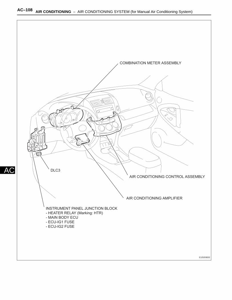
AC–108 AIR CONDITIONING – AIR CONDITIONING SYSTEM (for Manual Air Conditioning System)
AC
COMBINATION METER ASSEMBLY
INSTRUMENT PANEL JUNCTION BLOCK
- HEATER RELAY (Marking: HTR)
- MAIN BODY ECU
- ECU-IG1 FUSE
- ECU-IG2 FUSE
DLC3
AIR CONDITIONING CONTROL ASSEMBLY
AIR CONDITIONING AMPLIFIER
E125203E02
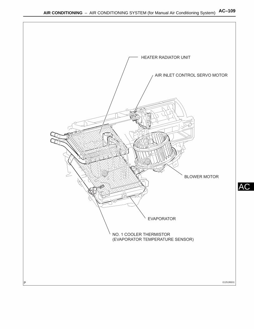
AIR CONDITIONING – AIR CONDITIONING SYSTEM (for Manual Air Conditioning System) AC–109
AC
HEATER RADIATOR UNIT
EVAPORATOR
NO. 1 COOLER THERMISTOR
(EVAPORATOR TEMPERATURE SENSOR)
AIR INLET CONTROL SERVO MOTOR
BLOWER MOTOR
E125195E01
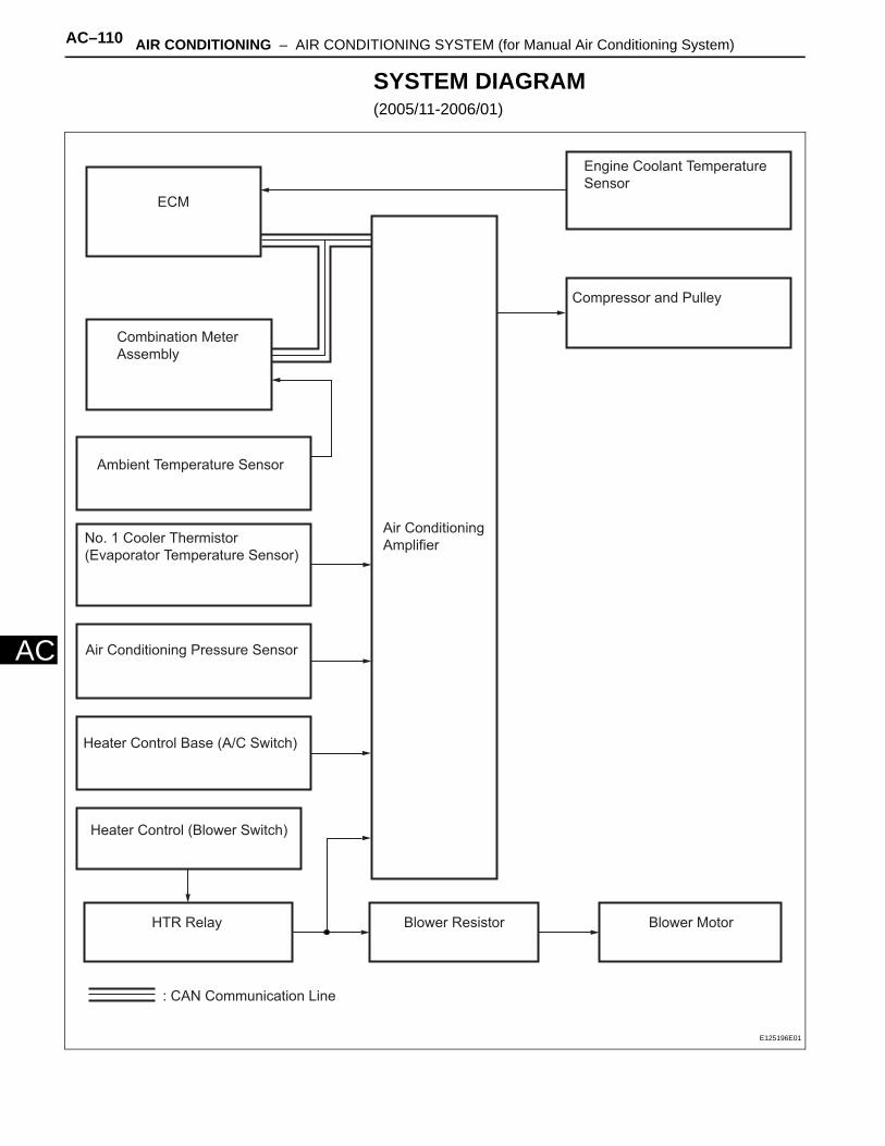
AC–110 AIR CONDITIONING – AIR CONDITIONING SYSTEM (for Manual Air Conditioning System)
AC
SYSTEM DIAGRAM(2005/11-2006/01)
Ambient Temperature Sensor
No. 1 Cooler Thermistor
(Evaporator Temperature Sensor)
Air Conditioning Pressure Sensor
Heater Control (Blower Switch)
Heater Control Base (A/C Switch)
HTR Relay Blower MotorBlower Resistor
ECM
Combination Meter
Assembly
Compressor and Pulley
Air Conditioning
Amplifier
Engine Coolant Temperature
Sensor
: CAN Communication Line
E125196E01

AIR CONDITIONING – AIR CONDITIONING SYSTEM (for Manual Air Conditioning System) AC–111
AC
Communication tableSender Receiver Signal Communication Line
Air conditioning amplifier ECM
A/C compressor control signal
CAN
Idle up request signal
External variable control solenoid current signal
Cooling fan motor driving request signal
Ambient temperature signal
Combination meter assembly Air conditioning amplifierVehicle speed signal
CANAmbient temperature signal
ECM Air conditioning amplifier
Engine revolution speed signal
CANEngine coolant temperature signal
A/C control cut signal
Variable control prohibition signal
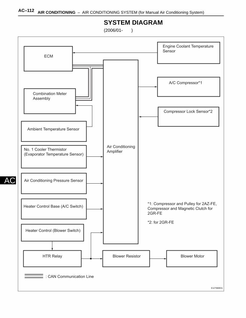
AC–112 AIR CONDITIONING – AIR CONDITIONING SYSTEM (for Manual Air Conditioning System)
AC
SYSTEM DIAGRAM(2006/01- )
Ambient Temperature Sensor
No. 1 Cooler Thermistor
(Evaporator Temperature Sensor)
Air Conditioning Pressure Sensor
Heater Control (Blower Switch)
Heater Control Base (A/C Switch)
HTR Relay Blower MotorBlower Resistor
ECM
Combination Meter
Assembly
A/C Compressor*1
Air Conditioning
Amplifier
Engine Coolant Temperature
Sensor
: CAN Communication Line
Compressor Lock Sensor*2
*1: Compressor and Pulley for 2AZ-FE,
Compressor and Magnetic Clutch for
2GR-FE
*2: for 2GR-FE
E127580E01
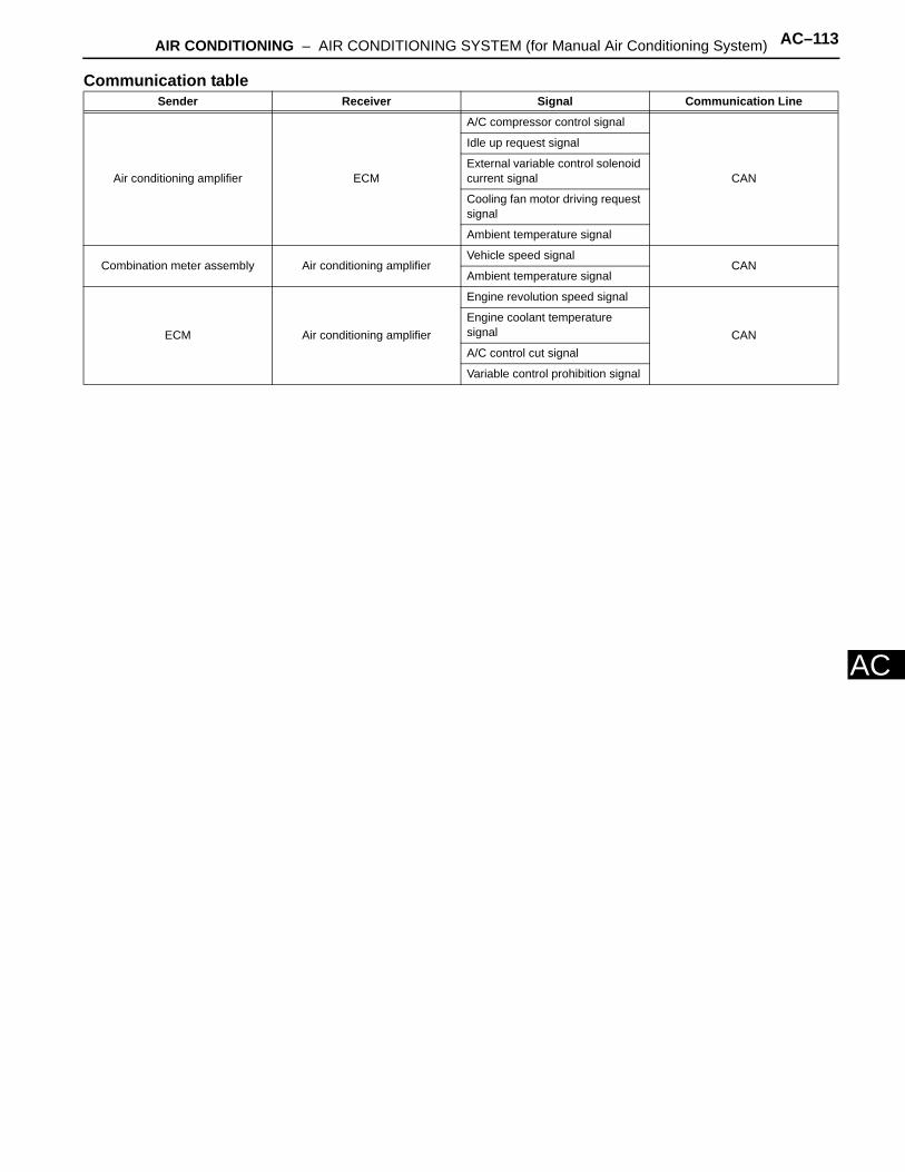
AIR CONDITIONING – AIR CONDITIONING SYSTEM (for Manual Air Conditioning System) AC–113
AC
Communication tableSender Receiver Signal Communication Line
Air conditioning amplifier ECM
A/C compressor control signal
CAN
Idle up request signal
External variable control solenoid current signal
Cooling fan motor driving request signal
Ambient temperature signal
Combination meter assembly Air conditioning amplifierVehicle speed signal
CANAmbient temperature signal
ECM Air conditioning amplifier
Engine revolution speed signal
CANEngine coolant temperature signal
A/C control cut signal
Variable control prohibition signal
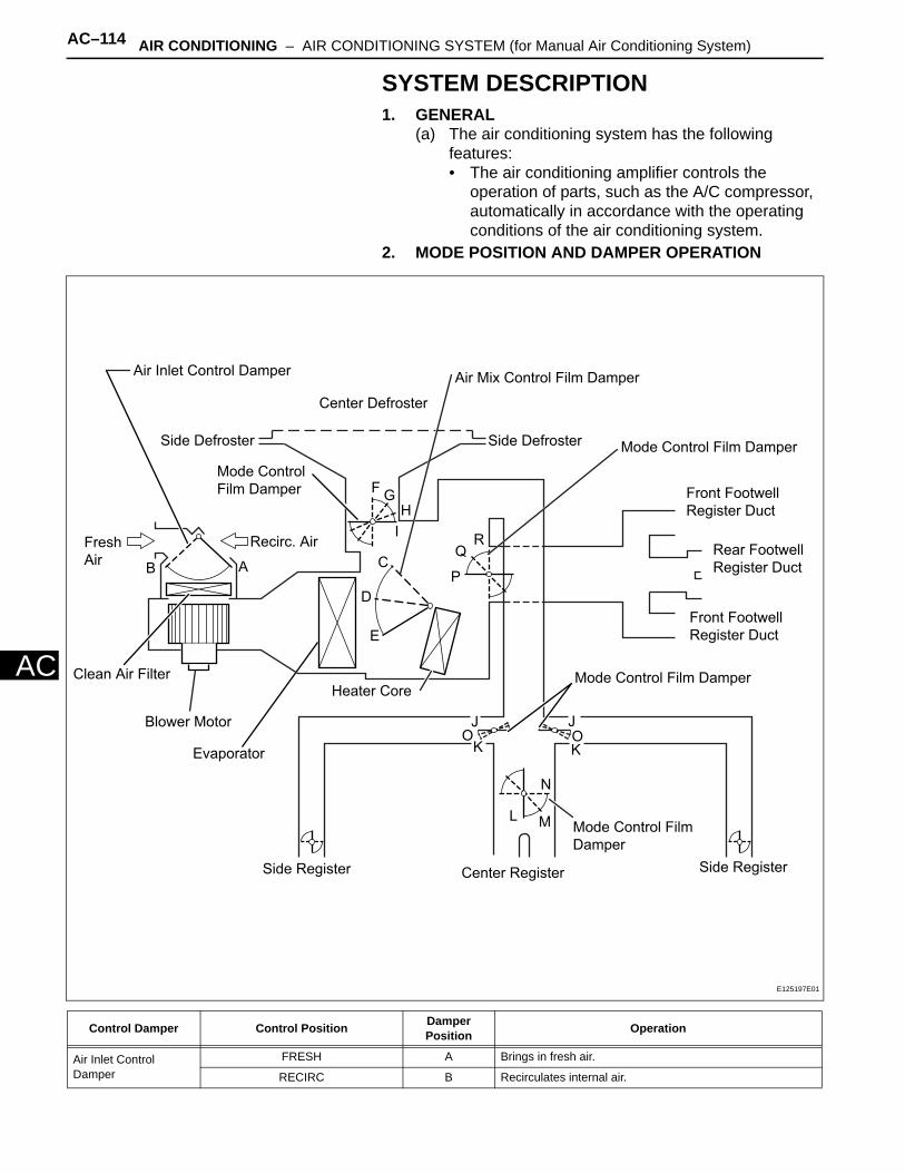
AC–114 AIR CONDITIONING – AIR CONDITIONING SYSTEM (for Manual Air Conditioning System)
AC
SYSTEM DESCRIPTION1. GENERAL
(a) The air conditioning system has the following features:• The air conditioning amplifier controls the
operation of parts, such as the A/C compressor, automatically in accordance with the operating conditions of the air conditioning system.
2. MODE POSITION AND DAMPER OPERATION
Control Damper Control Position Damper Position Operation
Air Inlet Control Damper
FRESH A Brings in fresh air.
RECIRC B Recirculates internal air.
Blower Motor
Side Register Center Register
Mode Control Film
Damper
Side Register
L M
N
JO
K KOJ
Mode Control Film Damper
Front Footwell
Register Duct
Rear Footwell
Register Duct
Front Footwell
Register Duct
Mode Control Film Damper
Air Mix Control Film Damper
Side Defroster
Center Defroster
Side Defroster
Mode Control
Film Damper
Air Inlet Control Damper
Recirc. AirFresh
AirB A
FG
H
IR
Q
PC
D
E
Heater Core
Evaporator
Clean Air Filter
E125197E01
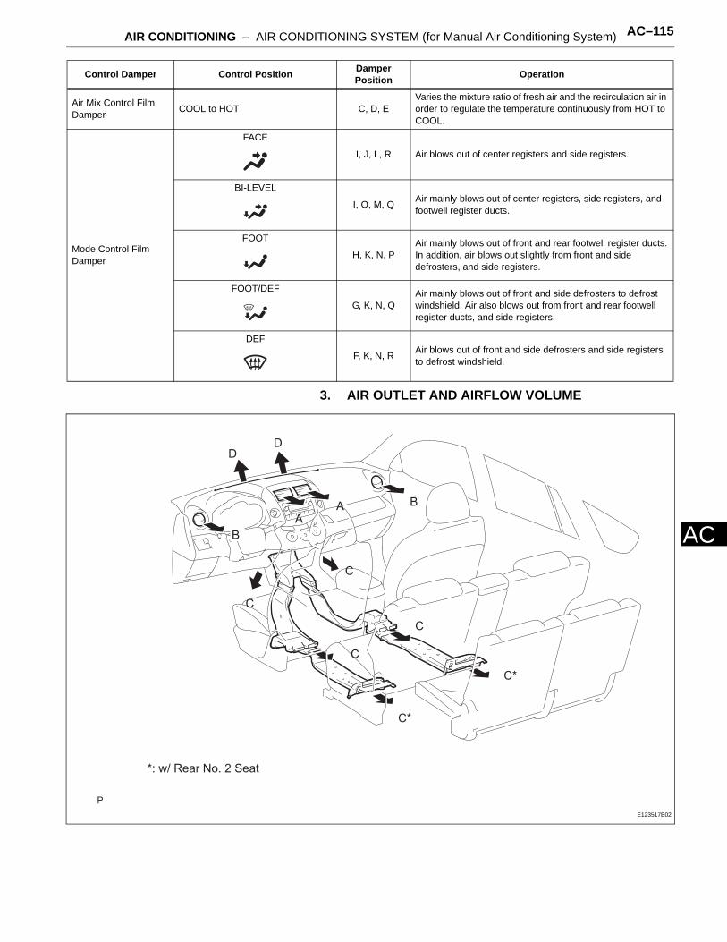
AIR CONDITIONING – AIR CONDITIONING SYSTEM (for Manual Air Conditioning System) AC–115
AC
3. AIR OUTLET AND AIRFLOW VOLUME
Air Mix Control Film Damper COOL to HOT C, D, E
Varies the mixture ratio of fresh air and the recirculation air in order to regulate the temperature continuously from HOT to COOL.
Mode Control Film Damper
FACE
I, J, L, R Air blows out of center registers and side registers.
BI-LEVEL
I, O, M, Q Air mainly blows out of center registers, side registers, and footwell register ducts.
FOOT
H, K, N, PAir mainly blows out of front and rear footwell register ducts.In addition, air blows out slightly from front and side defrosters, and side registers.
FOOT/DEF
G, K, N, QAir mainly blows out of front and side defrosters to defrost windshield. Air also blows out from front and rear footwell register ducts, and side registers.
DEF
F, K, N, R Air blows out of front and side defrosters and side registers to defrost windshield.
Control Damper Control Position Damper Position Operation
B
BA
C
C
C
C
C*
C*
DD
A
*: w/ Rear No. 2 Seat
E123517E02

AC–116 AIR CONDITIONING – AIR CONDITIONING SYSTEM (for Manual Air Conditioning System)
AC
The circle size ( ) indicates the proportion of the flow volume.
Air Outlet Mode
Air Outlet Position Symbol
A B C D
Center Face Side Face Foot Defroster
FACE X X
Bi-LEVEL X
FOOT X
FOOT/DEF X
DEF X X
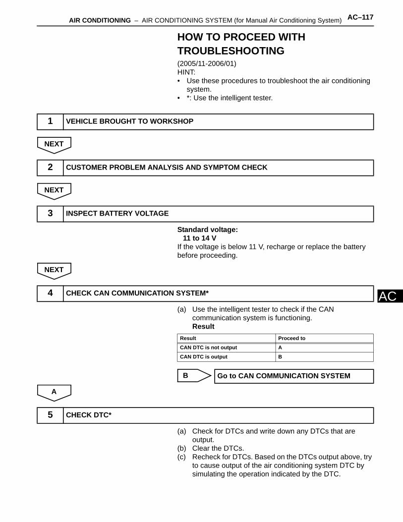
AIR CONDITIONING – AIR CONDITIONING SYSTEM (for Manual Air Conditioning System) AC–117
AC
HOW TO PROCEED WITH TROUBLESHOOTING(2005/11-2006/01)HINT:• Use these procedures to troubleshoot the air conditioning
system.• *: Use the intelligent tester.
NEXT
NEXT
Standard voltage:11 to 14 V
If the voltage is below 11 V, recharge or replace the battery before proceeding.
NEXT
(a) Use the intelligent tester to check if the CAN communication system is functioning.Result
B
A
(a) Check for DTCs and write down any DTCs that are output.
(b) Clear the DTCs.(c) Recheck for DTCs. Based on the DTCs output above, try
to cause output of the air conditioning system DTC by simulating the operation indicated by the DTC.
1 VEHICLE BROUGHT TO WORKSHOP
2 CUSTOMER PROBLEM ANALYSIS AND SYMPTOM CHECK
3 INSPECT BATTERY VOLTAGE
4 CHECK CAN COMMUNICATION SYSTEM*
Result Proceed to
CAN DTC is not output A
CAN DTC is output B
Go to CAN COMMUNICATION SYSTEM
5 CHECK DTC*

AC–118 AIR CONDITIONING – AIR CONDITIONING SYSTEM (for Manual Air Conditioning System)
AC
Result
B
A
Result
B
A
(a) DATA LIST / ACTIVE TEST (see page AC-127)(b) Terminals of ECU (see page AC-122)
NEXT
NEXT
NEXT
Result Proceed to
DTC is not output A
DTC is output B
Go to step 8
6 REFER TO PROBLEM SYMPTOMS TABLE
Result Proceed to
Fault is not listed in problem symptoms table A
Fault is listed in problem symptoms table B
Go to step 8
7 OVERALL ANALYSIS AND TROUBLESHOOTING*
8 ADJUST, REPAIR OR REPLACE
9 CONFIRMATION TEST
END
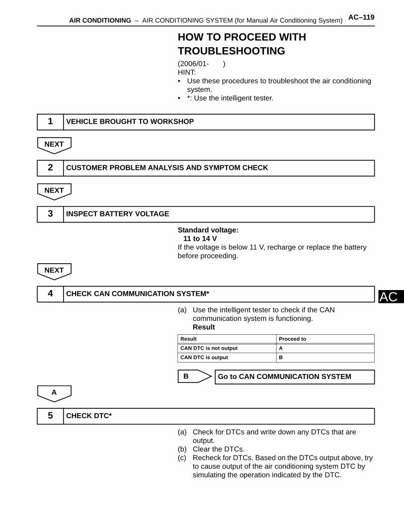
AIR CONDITIONING – AIR CONDITIONING SYSTEM (for Manual Air Conditioning System) AC–119
AC
HOW TO PROCEED WITH TROUBLESHOOTING(2006/01- )HINT:• Use these procedures to troubleshoot the air conditioning
system.• *: Use the intelligent tester.
NEXT
NEXT
Standard voltage:11 to 14 V
If the voltage is below 11 V, recharge or replace the battery before proceeding.
NEXT
(a) Use the intelligent tester to check if the CAN communication system is functioning.Result
B
A
(a) Check for DTCs and write down any DTCs that are output.
(b) Clear the DTCs.(c) Recheck for DTCs. Based on the DTCs output above, try
to cause output of the air conditioning system DTC by simulating the operation indicated by the DTC.
1 VEHICLE BROUGHT TO WORKSHOP
2 CUSTOMER PROBLEM ANALYSIS AND SYMPTOM CHECK
3 INSPECT BATTERY VOLTAGE
4 CHECK CAN COMMUNICATION SYSTEM*
Result Proceed to
CAN DTC is not output A
CAN DTC is output B
Go to CAN COMMUNICATION SYSTEM
5 CHECK DTC*
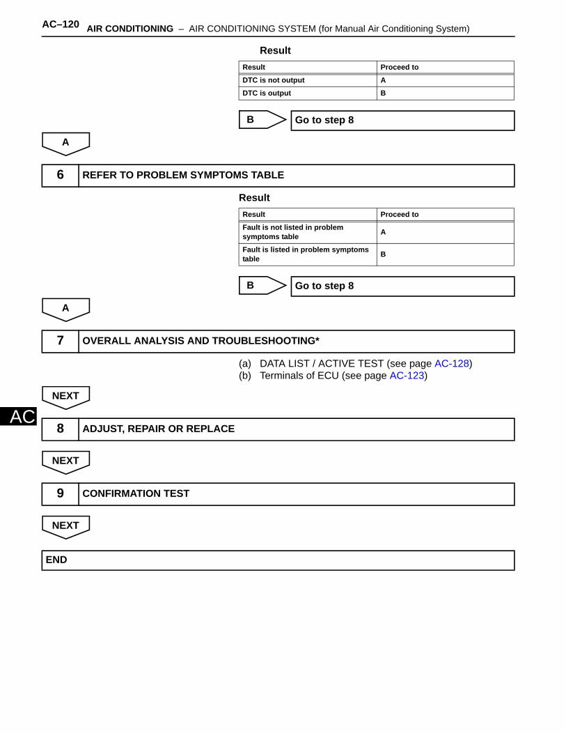
AC–120 AIR CONDITIONING – AIR CONDITIONING SYSTEM (for Manual Air Conditioning System)
AC
Result
B
A
Result
B
A
(a) DATA LIST / ACTIVE TEST (see page AC-128)(b) Terminals of ECU (see page AC-123)
NEXT
NEXT
NEXT
Result Proceed to
DTC is not output A
DTC is output B
Go to step 8
6 REFER TO PROBLEM SYMPTOMS TABLE
Result Proceed to
Fault is not listed in problem symptoms table A
Fault is listed in problem symptoms table B
Go to step 8
7 OVERALL ANALYSIS AND TROUBLESHOOTING*
8 ADJUST, REPAIR OR REPLACE
9 CONFIRMATION TEST
END

AIR CONDITIONING – AIR CONDITIONING SYSTEM (for Manual Air Conditioning System) AC–121
AC
PROBLEM SYMPTOMS TABLE(2005/11-2006/01)HINT:• Use the table below to help determine the cause of the
problem symptom. The potential causes of the symptoms are listed in order of probability in the "Suspected area" column of the table. Check each symptom by checking the suspected areas in the order they are listed. Replace parts as necessary.
• Inspect the fuses and relays related to this system before inspecting the suspected areas below.
Air conditioning systemSymptom Suspected area See page
No functions of A/C system operate
1. ECU-IG2 fuse -
2. Wire harness or connector -
3. Air conditioning amplifier AC-122
Airflow Control: Blower motor does not operate
1. HTR, ECU-IG1 fuse -
2. Blower motor circuit AC-157
3. Blower motor AC-207
4. Wire harness or connector -
Airflow Control: Blower motor does not change speed
1. Blower resistor AC-208
2. Blower motor AC-207
3. Heater control (blower switch) -
Temperature Control: No cool air comes out
1. Refrigerant volume -
2. Refrigerant pressure -
3. Air conditioning pressure sensor circuit AC-143
4. Heater control base (A/C switch) -
5. Compressor and pulley AC-215
6. Expansion valve -
7. Air conditioning amplifier AC-122
8. ECM ES-427
9. CAN communication CA-45
Compressor and pulley does not operate
1. ECU-IG2 fuse -
2. Refrigerant pressure -
3. Compressor and pulley AC-215
4. Air conditioning pressure sensor circuit AC-143
5. Evaporator temperature sensor circuit AC-136
6. Air conditioning amplifier AC-122
7. ECM ES-427
8. CAN communication CA-45
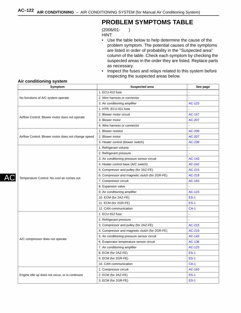
AC–122 AIR CONDITIONING – AIR CONDITIONING SYSTEM (for Manual Air Conditioning System)
AC
PROBLEM SYMPTOMS TABLE(2006/01- )HINT:• Use the table below to help determine the cause of the
problem symptom. The potential causes of the symptoms are listed in order of probability in the "Suspected area" column of the table. Check each symptom by checking the suspected areas in the order they are listed. Replace parts as necessary.
• Inspect the fuses and relays related to this system before inspecting the suspected areas below.
Air conditioning systemSymptom Suspected area See page
No functions of A/C system operate
1. ECU-IG2 fuse -
2. Wire harness or connector -
3. Air conditioning amplifier AC-123
Airflow Control: Blower motor does not operate
1. HTR, ECU-IG1 fuse -
2. Blower motor circuit AC-157
3. Blower motor AC-207
4. Wire harness or connector -
Airflow Control: Blower motor does not change speed
1. Blower resistor AC-208
2. Blower motor AC-207
3. Heater control (blower switch) AC-239
Temperature Control: No cool air comes out
1. Refrigerant volume -
2. Refrigerant pressure -
3. Air conditioning pressure sensor circuit AC-143
4. Heater control base (A/C switch) AC-242
5. Compressor and pulley (for 2AZ-FE) AC-215
6. Compressor and magnetic clutch (for 2GR-FE) AC-219
7. Compressor circuit AC-163
8. Expansion valve -
9. Air conditioning amplifier AC-123
10. ECM (for 2AZ-FE) ES-1
11. ECM (for 2GR-FE) ES-1
12. CAN communication CA-1
A/C compressor does not operate
1. ECU-IG2 fuse -
2. Refrigerant pressure -
3. Compressor and pulley (for 2AZ-FE) AC-215
4. Compressor and magnetic clutch (for 2GR-FE) AC-219
5. Air conditioning pressure sensor circuit AC-143
6. Evaporator temperature sensor circuit AC-136
7. Air conditioning amplifier AC-123
8. ECM (for 2AZ-FE) ES-1
9. ECM (for 2GR-FE) ES-1
10. CAN communication CA-1
Engine idle up does not occur, or is continuos
1. Compressor circuit AC-163
2. ECM (for 2AZ-FE) ES-1
3. ECM (for 2GR-FE) ES-1
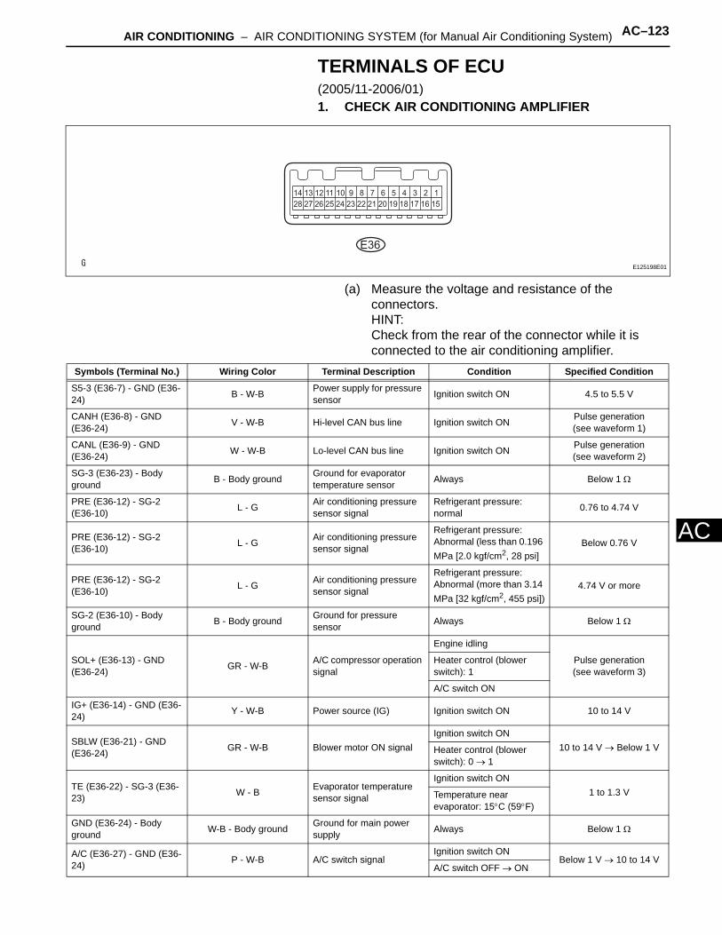
AIR CONDITIONING – AIR CONDITIONING SYSTEM (for Manual Air Conditioning System) AC–123
AC
TERMINALS OF ECU(2005/11-2006/01)1. CHECK AIR CONDITIONING AMPLIFIER
(a) Measure the voltage and resistance of the connectors.HINT:Check from the rear of the connector while it is connected to the air conditioning amplifier.
E36
E125198E01
Symbols (Terminal No.) Wiring Color Terminal Description Condition Specified Condition
S5-3 (E36-7) - GND (E36-24) B - W-B Power supply for pressure
sensor Ignition switch ON 4.5 to 5.5 V
CANH (E36-8) - GND (E36-24) V - W-B Hi-level CAN bus line Ignition switch ON Pulse generation
(see waveform 1)
CANL (E36-9) - GND (E36-24) W - W-B Lo-level CAN bus line Ignition switch ON Pulse generation
(see waveform 2)
SG-3 (E36-23) - Body ground B - Body ground Ground for evaporator
temperature sensor Always Below 1 Ω
PRE (E36-12) - SG-2 (E36-10) L - G Air conditioning pressure
sensor signalRefrigerant pressure: normal 0.76 to 4.74 V
PRE (E36-12) - SG-2 (E36-10) L - G Air conditioning pressure
sensor signal
Refrigerant pressure: Abnormal (less than 0.196 MPa [2.0 kgf/cm2, 28 psi]
Below 0.76 V
PRE (E36-12) - SG-2 (E36-10) L - G Air conditioning pressure
sensor signal
Refrigerant pressure: Abnormal (more than 3.14 MPa [32 kgf/cm2, 455 psi])
4.74 V or more
SG-2 (E36-10) - Body ground B - Body ground Ground for pressure
sensor Always Below 1 Ω
SOL+ (E36-13) - GND (E36-24) GR - W-B A/C compressor operation
signal
Engine idling
Pulse generation(see waveform 3)
Heater control (blower switch): 1
A/C switch ON
IG+ (E36-14) - GND (E36-24) Y - W-B Power source (IG) Ignition switch ON 10 to 14 V
SBLW (E36-21) - GND (E36-24) GR - W-B Blower motor ON signal
Ignition switch ON10 to 14 V → Below 1 VHeater control (blower
switch): 0 → 1
TE (E36-22) - SG-3 (E36-23) W - B Evaporator temperature
sensor signal
Ignition switch ON1 to 1.3 VTemperature near
evaporator: 15°C (59°F)
GND (E36-24) - Body ground W-B - Body ground Ground for main power
supply Always Below 1 Ω
A/C (E36-27) - GND (E36-24) P - W-B A/C switch signal
Ignition switch ONBelow 1 V → 10 to 14 V
A/C switch OFF → ON

AC–124 AIR CONDITIONING – AIR CONDITIONING SYSTEM (for Manual Air Conditioning System)
AC
(b) Using an oscilloscope, check waveform 1.CAN communication signal
HINT:The waveform varies depending on the CAN communication signal.
(c) Using an oscilloscope, check waveform 2.CAN communication signal
HINT:The waveform varies depending on the CAN communication signal.
(d) Using an oscilloscope, check waveform 3.Compressor and pulley operation signal
LED (E36-28) - Body ground GR - Body ground A/C switch indicator signal
Engine idling
10 to 14 V → Below 4 VA/C switch ON
Heater control (blower switch): 0 → 1
Symbols (Terminal No.) Wiring Color Terminal Description Condition Specified Condition
1 V/DIV.
GND
10 sec./DIV.A086154E10
Item Content
Symbols (Terminal No.) CANH (E36-8) - GND (E36-24)
Tool Setting 1 V/DIV., 10 µsec./DIV.
Condition Ignition switch ON
GND
1 V/DIV.
10 sec./DIV.A086155E11
Item Content
Symbols (Terminal No.) CANL (E36-9) - GND (E36-24)
Tool Setting 1 V/DIV., 10 µmsec./DIV.
Condition Ignition switch ON
GND
5 V/DIV.
500 sec./DIV.E074977E11
Item Content
Symbols (Terminal No.) SOL+ (E36-13) - GND (E36-24)
Tool Setting 5 V/DIV., 500 µsec./DIV.
Condition Engine idling, Blower switch LO, A/C switch ON

AIR CONDITIONING – AIR CONDITIONING SYSTEM (for Manual Air Conditioning System) AC–125
AC
TERMINALS OF ECU(2006/01- )1. CHECK AIR CONDITIONING AMPLIFIER
(a) Measure the voltage and resistance of the connectors.HINT:Check from the rear of the connector while it is connected to the air conditioning amplifier.
E36
E125198E01
Symbols (Terminal No.) Wiring Color Terminal Description Condition Specified Condition
S5-3 (E36-7) - GND (E36-24) B - W-B Power supply for pressure
sensor Ignition switch ON 4.5 to 5.5 V
CANH (E36-8) - GND (E36-24) V - W-B Hi-level CAN bus line Ignition switch ON Pulse generation
(see waveform 1)
CANL (E36-9) - GND (E36-24) W - W-B Lo-level CAN bus line Ignition switch ON Pulse generation
(see waveform 2)
SG-3 (E36-23) - Body ground B - Body ground Ground for evaporator
temperature sensor Always Below 1 Ω
PRE (E36-12) - SG-2 (E36-10) L - G Air conditioning pressure
sensor signalRefrigerant pressure: normal 0.76 to 4.74 V
PRE (E36-12) - SG-2 (E36-10) L - G Air conditioning pressure
sensor signal
Refrigerant pressure: Abnormal (less than 0.196 MPa [2.0 kgf/cm2, 28 psi]
Below 0.76 V
PRE (E36-12) - SG-2 (E36-10) L - G Air conditioning pressure
sensor signal
Refrigerant pressure: Abnormal (more than 3.14 MPa [32 kgf/cm2, 455 psi])
4.74 V or more
SG-2 (E36-10) - Body ground B - Body ground Ground for pressure
sensor Always Below 1 Ω
SOL+ (E36-13) - GND (E36-24) GR - W-B A/C compressor operation
signal
Engine idling
Pulse generation(see waveform 3)
Heater control (blower switch): 1
A/C switch ON
IG+ (E36-14) - GND (E36-24) Y - W-B Power source (IG) Ignition switch ON 10 to 14 V
SBLW (E36-21) - GND (E36-24) GR - W-B Blower motor ON signal
Ignition switch ON10 to 14 V → Below 1 VHeater control (blower
switch): 0 → 1
TE (E36-22) - SG-3 (E36-23) W - B Evaporator temperature
sensor signal
Ignition switch ON1 to 1.3 VTemperature near
evaporator: 15°C (59°F)
GND (E36-24) - Body ground W-B - Body ground Ground for main power
supply Always Below 1 Ω
A/C (E36-27) - GND (E36-24) P - W-B A/C switch signal
Ignition switch ONBelow 1 V → 10 to 14 V
A/C switch OFF → ON
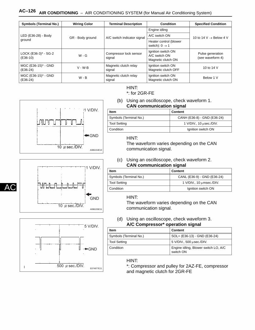
AC–126 AIR CONDITIONING – AIR CONDITIONING SYSTEM (for Manual Air Conditioning System)
AC
HINT:*: for 2GR-FE
(b) Using an oscilloscope, check waveform 1.CAN communication signal
HINT:The waveform varies depending on the CAN communication signal.
(c) Using an oscilloscope, check waveform 2.CAN communication signal
HINT:The waveform varies depending on the CAN communication signal.
(d) Using an oscilloscope, check waveform 3.A/C Compressor* operation signal
HINT:*: Compressor and pulley for 2AZ-FE, compressor and magnetic clutch for 2GR-FE
LED (E36-28) - Body ground GR - Body ground A/C switch indicator signal
Engine idling
10 to 14 V → Below 4 VA/C switch ON
Heater control (blower switch): 0 → 1
LOCK (E36-3)* - SG-2 (E36-10) W - G Compressor lock sensor
signal
Ignition switch ONA/C switch ONMagnetic clutch ON
Pulse generation(see waveform 4)
MGC (E36-15)* - GND (E36-24) V - W-B Magnetic clutch relay
signalIgnition switch ONMagnetic clutch OFF 10 to 14 V
MGC (E36-15)* - GND (E36-24) W - B Magnetic clutch relay
signalIgnition switch ONMagnetic clutch ON Below 1 V
Symbols (Terminal No.) Wiring Color Terminal Description Condition Specified Condition
1 V/DIV.
GND
10 sec./DIV.A086154E10
Item Content
Symbols (Terminal No.) CANH (E36-8) - GND (E36-24)
Tool Setting 1 V/DIV., 10 µsec./DIV.
Condition Ignition switch ON
GND
1 V/DIV.
10 sec./DIV.A086155E11
Item Content
Symbols (Terminal No.) CANL (E36-9) - GND (E36-24)
Tool Setting 1 V/DIV., 10 µmsec./DIV.
Condition Ignition switch ON
GND
5 V/DIV.
500 sec./DIV.E074977E11
Item Content
Symbols (Terminal No.) SOL+ (E36-13) - GND (E36-24)
Tool Setting 5 V/DIV., 500 µsec./DIV.
Condition Engine idling, Blower switch LO, A/C switch ON
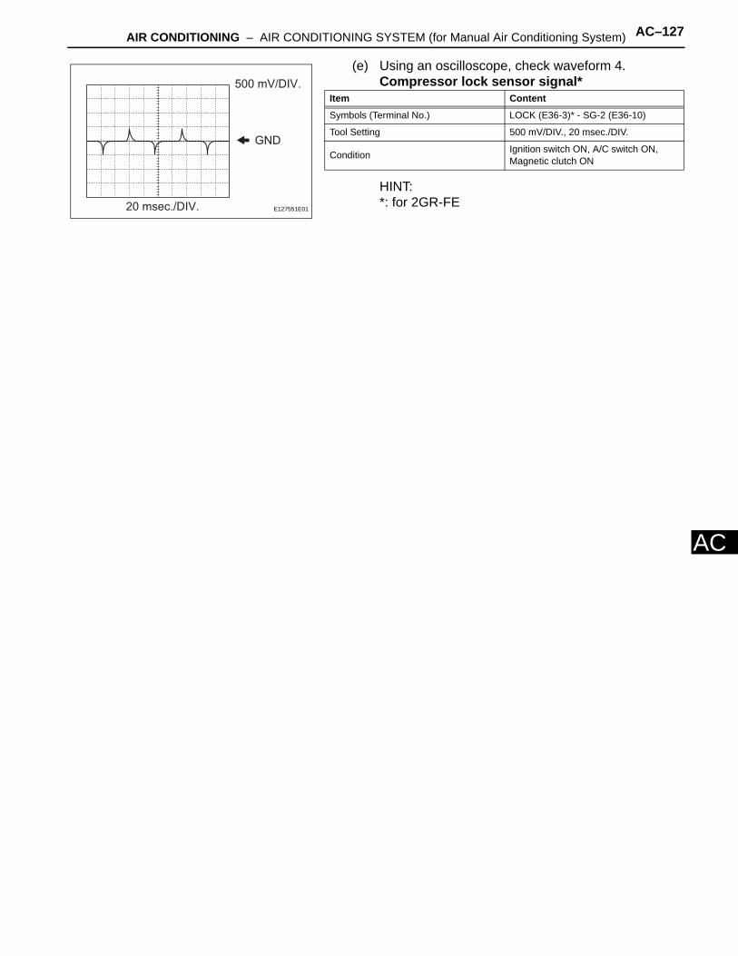
AIR CONDITIONING – AIR CONDITIONING SYSTEM (for Manual Air Conditioning System) AC–127
AC
(e) Using an oscilloscope, check waveform 4.Compressor lock sensor signal*
HINT:*: for 2GR-FE
GND
20 msec./DIV.
500 mV/DIV.
E127551E01
Item Content
Symbols (Terminal No.) LOCK (E36-3)* - SG-2 (E36-10)
Tool Setting 500 mV/DIV., 20 msec./DIV.
Condition Ignition switch ON, A/C switch ON, Magnetic clutch ON
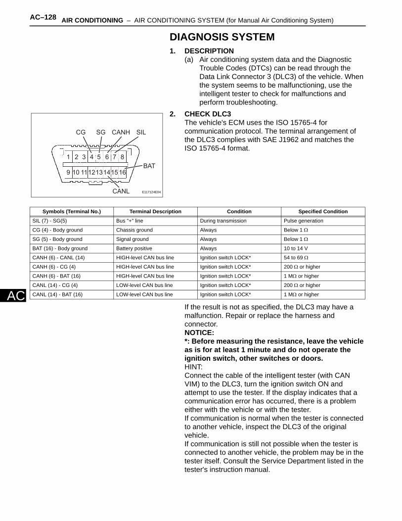
AC–128 AIR CONDITIONING – AIR CONDITIONING SYSTEM (for Manual Air Conditioning System)
AC
DIAGNOSIS SYSTEM1. DESCRIPTION
(a) Air conditioning system data and the Diagnostic Trouble Codes (DTCs) can be read through the Data Link Connector 3 (DLC3) of the vehicle. When the system seems to be malfunctioning, use the intelligent tester to check for malfunctions and perform troubleshooting.
2. CHECK DLC3The vehicle's ECM uses the ISO 15765-4 for communication protocol. The terminal arrangement of the DLC3 complies with SAE J1962 and matches the ISO 15765-4 format.
If the result is not as specified, the DLC3 may have a malfunction. Repair or replace the harness and connector.NOTICE:*: Before measuring the resistance, leave the vehicle as is for at least 1 minute and do not operate the ignition switch, other switches or doors.HINT:Connect the cable of the intelligent tester (with CAN VIM) to the DLC3, turn the ignition switch ON and attempt to use the tester. If the display indicates that a communication error has occurred, there is a problem either with the vehicle or with the tester.If communication is normal when the tester is connected to another vehicle, inspect the DLC3 of the original vehicle.If communication is still not possible when the tester is connected to another vehicle, the problem may be in the tester itself. Consult the Service Department listed in the tester's instruction manual.
1 2 3 4 5 6 7 8
9 10 111213141516
CG SG CANH
CANL
BAT
SIL
E117124E04
Symbols (Terminal No.) Terminal Description Condition Specified Condition
SIL (7) - SG(5) Bus "+" line During transmission Pulse generation
CG (4) - Body ground Chassis ground Always Below 1 Ω
SG (5) - Body ground Signal ground Always Below 1 Ω
BAT (16) - Body ground Battery positive Always 10 to 14 V
CANH (6) - CANL (14) HIGH-level CAN bus line Ignition switch LOCK* 54 to 69 Ω
CANH (6) - CG (4) HIGH-level CAN bus line Ignition switch LOCK* 200 Ω or higher
CANH (6) - BAT (16) HIGH-level CAN bus line Ignition switch LOCK* 1 MΩ or higher
CANL (14) - CG (4) LOW-level CAN bus line Ignition switch LOCK* 200 Ω or higher
CANL (14) - BAT (16) LOW-level CAN bus line Ignition switch LOCK* 1 MΩ or higher
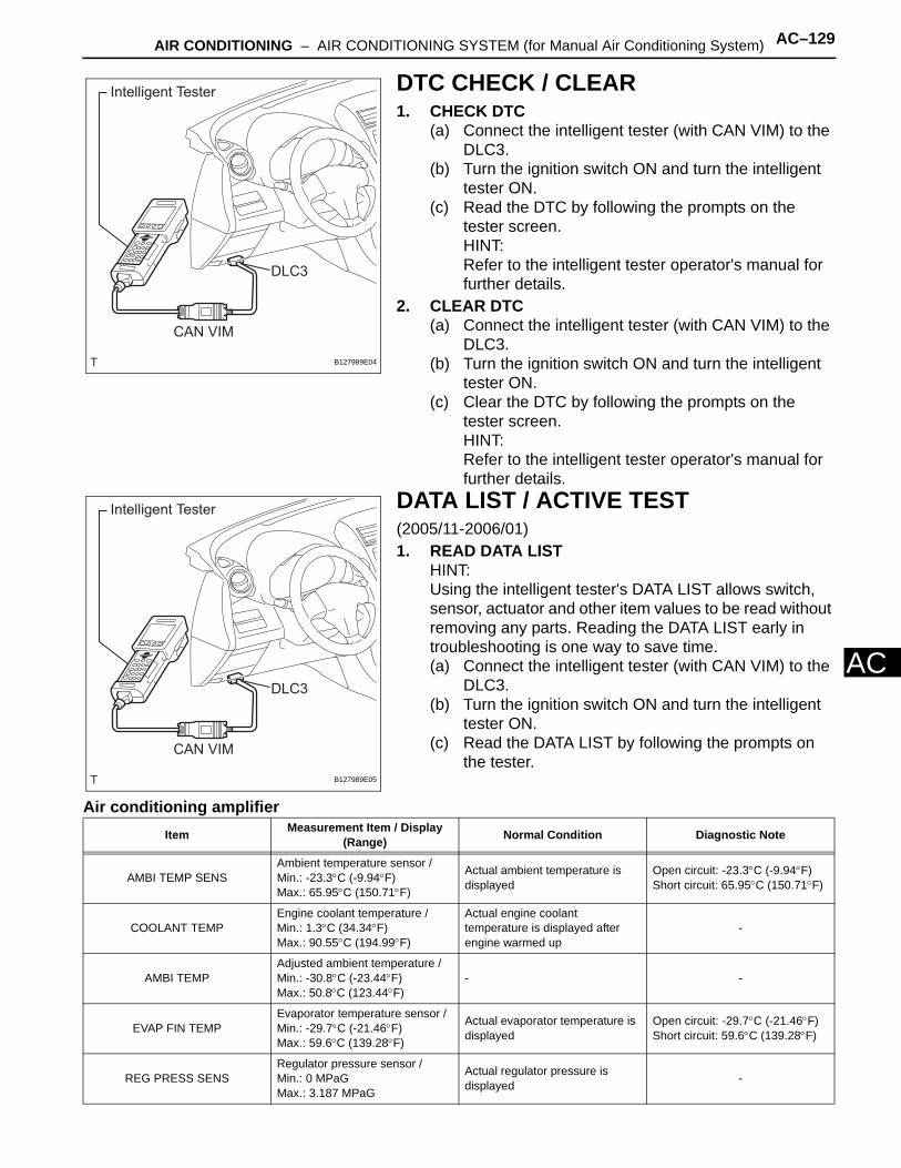
AIR CONDITIONING – AIR CONDITIONING SYSTEM (for Manual Air Conditioning System) AC–129
AC
DTC CHECK / CLEAR1. CHECK DTC
(a) Connect the intelligent tester (with CAN VIM) to the DLC3.
(b) Turn the ignition switch ON and turn the intelligent tester ON.
(c) Read the DTC by following the prompts on the tester screen.HINT:Refer to the intelligent tester operator's manual for further details.
2. CLEAR DTC(a) Connect the intelligent tester (with CAN VIM) to the
DLC3.(b) Turn the ignition switch ON and turn the intelligent
tester ON.(c) Clear the DTC by following the prompts on the
tester screen.HINT:Refer to the intelligent tester operator's manual for further details.
DATA LIST / ACTIVE TEST(2005/11-2006/01)1. READ DATA LIST
HINT:Using the intelligent tester's DATA LIST allows switch, sensor, actuator and other item values to be read without removing any parts. Reading the DATA LIST early in troubleshooting is one way to save time.(a) Connect the intelligent tester (with CAN VIM) to the
DLC3.(b) Turn the ignition switch ON and turn the intelligent
tester ON.(c) Read the DATA LIST by following the prompts on
the tester.
Air conditioning amplifier
Intelligent Tester
CAN VIM
DLC3
B127989E04
Intelligent Tester
CAN VIM
DLC3
B127989E05
Item Measurement Item / Display (Range) Normal Condition Diagnostic Note
AMBI TEMP SENSAmbient temperature sensor /Min.: -23.3°C (-9.94°F)Max.: 65.95°C (150.71°F)
Actual ambient temperature is displayed
Open circuit: -23.3°C (-9.94°F)Short circuit: 65.95°C (150.71°F)
COOLANT TEMPEngine coolant temperature /Min.: 1.3°C (34.34°F)Max.: 90.55°C (194.99°F)
Actual engine coolant temperature is displayed after engine warmed up
-
AMBI TEMPAdjusted ambient temperature /Min.: -30.8°C (-23.44°F)Max.: 50.8°C (123.44°F)
- -
EVAP FIN TEMPEvaporator temperature sensor /Min.: -29.7°C (-21.46°F)Max.: 59.6°C (139.28°F)
Actual evaporator temperature is displayed
Open circuit: -29.7°C (-21.46°F)Short circuit: 59.6°C (139.28°F)
REG PRESS SENSRegulator pressure sensor /Min.: 0 MPaGMax.: 3.187 MPaG
Actual regulator pressure is displayed -
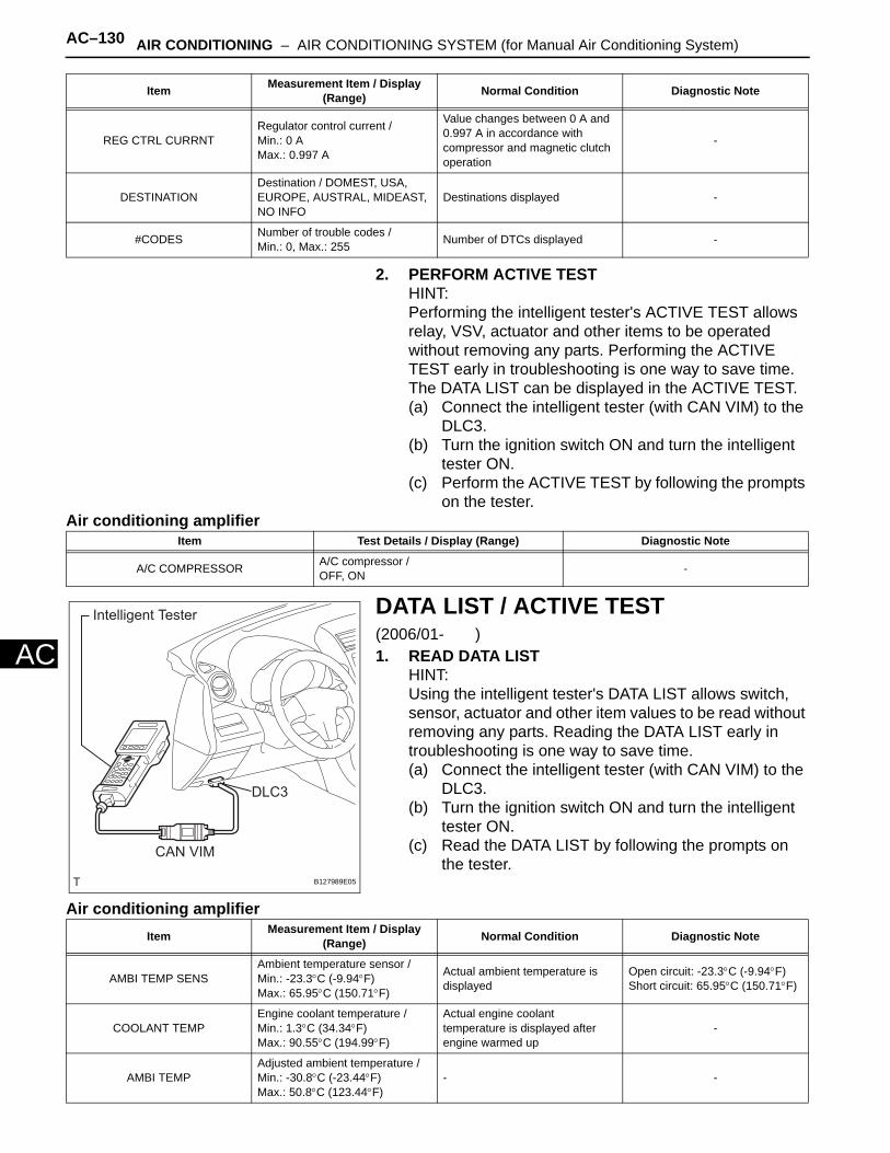
AC–130 AIR CONDITIONING – AIR CONDITIONING SYSTEM (for Manual Air Conditioning System)
AC
2. PERFORM ACTIVE TESTHINT:Performing the intelligent tester's ACTIVE TEST allows relay, VSV, actuator and other items to be operated without removing any parts. Performing the ACTIVE TEST early in troubleshooting is one way to save time. The DATA LIST can be displayed in the ACTIVE TEST.(a) Connect the intelligent tester (with CAN VIM) to the
DLC3.(b) Turn the ignition switch ON and turn the intelligent
tester ON.(c) Perform the ACTIVE TEST by following the prompts
on the tester.Air conditioning amplifier
DATA LIST / ACTIVE TEST(2006/01- )1. READ DATA LIST
HINT:Using the intelligent tester's DATA LIST allows switch, sensor, actuator and other item values to be read without removing any parts. Reading the DATA LIST early in troubleshooting is one way to save time.(a) Connect the intelligent tester (with CAN VIM) to the
DLC3.(b) Turn the ignition switch ON and turn the intelligent
tester ON.(c) Read the DATA LIST by following the prompts on
the tester.
Air conditioning amplifier
REG CTRL CURRNTRegulator control current /Min.: 0 AMax.: 0.997 A
Value changes between 0 A and 0.997 A in accordance with compressor and magnetic clutch operation
-
DESTINATIONDestination / DOMEST, USA, EUROPE, AUSTRAL, MIDEAST, NO INFO
Destinations displayed -
#CODES Number of trouble codes /Min.: 0, Max.: 255 Number of DTCs displayed -
Item Measurement Item / Display (Range) Normal Condition Diagnostic Note
Item Test Details / Display (Range) Diagnostic Note
A/C COMPRESSOR A/C compressor /OFF, ON -
Intelligent Tester
CAN VIM
DLC3
B127989E05
Item Measurement Item / Display (Range) Normal Condition Diagnostic Note
AMBI TEMP SENSAmbient temperature sensor /Min.: -23.3°C (-9.94°F)Max.: 65.95°C (150.71°F)
Actual ambient temperature is displayed
Open circuit: -23.3°C (-9.94°F)Short circuit: 65.95°C (150.71°F)
COOLANT TEMPEngine coolant temperature /Min.: 1.3°C (34.34°F)Max.: 90.55°C (194.99°F)
Actual engine coolant temperature is displayed after engine warmed up
-
AMBI TEMPAdjusted ambient temperature /Min.: -30.8°C (-23.44°F)Max.: 50.8°C (123.44°F)
- -

AIR CONDITIONING – AIR CONDITIONING SYSTEM (for Manual Air Conditioning System) AC–131
AC
2. PERFORM ACTIVE TESTHINT:Performing the intelligent tester's ACTIVE TEST allows relay, VSV, actuator and other items to be operated without removing any parts. Performing the ACTIVE TEST early in troubleshooting is one way to save time. The DATA LIST can be displayed in the ACTIVE TEST.(a) Connect the intelligent tester (with CAN VIM) to the
DLC3.(b) Turn the ignition switch ON and turn the intelligent
tester ON.(c) Perform the ACTIVE TEST by following the prompts
on the tester.Air conditioning amplifier
HINT:*1: for 2AZ-FE*2: for 2GR-FE
EVAP FIN TEMPEvaporator temperature sensor /Min.: -29.7°C (-21.46°F)Max.: 59.6°C (139.28°F)
Actual evaporator temperature is displayed
Open circuit: -29.7°C (-21.46°F)Short circuit: 59.6°C (139.28°F)
REG PRESS SENSRegulator pressure sensor /Min.: 0 MPaGMax.: 3.187 MPaG
Actual regulator pressure is displayed -
REG CTRL CURRNTRegulator control current /Min.: 0 AMax.: 0.997 A
Value changes between 0 A and 0.997 A in accordance with compressor and magnetic clutch operation
-
DESTINATIONDestination / DOMEST, USA, EUROPE, AUSTRAL, MIDEAST, NO INFO
Destinations displayed -
#CODES Number of trouble codes /Min.: 0, Max.: 255 Number of DTCs displayed -
Item Measurement Item / Display (Range) Normal Condition Diagnostic Note
Item Test Details / Display (Range) Diagnostic Note
A/C COMPRESSOR*1 A/C CompressorOFF, ON -
A/C MAG CLUTCH*2 Magnetic clutch relay /OFF, ON Operating sound can be heard
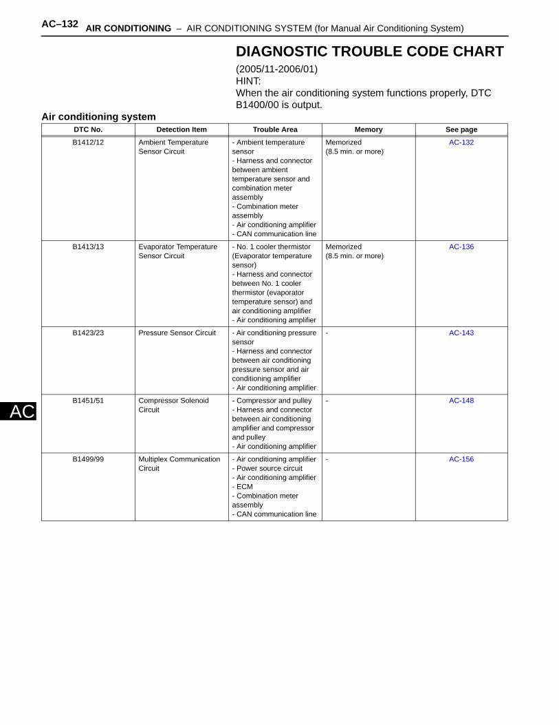
AC–132 AIR CONDITIONING – AIR CONDITIONING SYSTEM (for Manual Air Conditioning System)
AC
DIAGNOSTIC TROUBLE CODE CHART(2005/11-2006/01)HINT:When the air conditioning system functions properly, DTC B1400/00 is output.
Air conditioning systemDTC No. Detection Item Trouble Area Memory See page
B1412/12 Ambient Temperature Sensor Circuit
- Ambient temperature sensor- Harness and connector between ambient temperature sensor and combination meter assembly- Combination meter assembly- Air conditioning amplifier- CAN communication line
Memorized(8.5 min. or more)
AC-132
B1413/13 Evaporator Temperature Sensor Circuit
- No. 1 cooler thermistor (Evaporator temperature sensor)- Harness and connector between No. 1 cooler thermistor (evaporator temperature sensor) and air conditioning amplifier- Air conditioning amplifier
Memorized(8.5 min. or more)
AC-136
B1423/23 Pressure Sensor Circuit - Air conditioning pressure sensor- Harness and connector between air conditioning pressure sensor and air conditioning amplifier- Air conditioning amplifier
- AC-143
B1451/51 Compressor Solenoid Circuit
- Compressor and pulley- Harness and connector between air conditioning amplifier and compressor and pulley- Air conditioning amplifier
- AC-148
B1499/99 Multiplex Communication Circuit
- Air conditioning amplifier - Power source circuit- Air conditioning amplifier- ECM- Combination meter assembly- CAN communication line
- AC-156
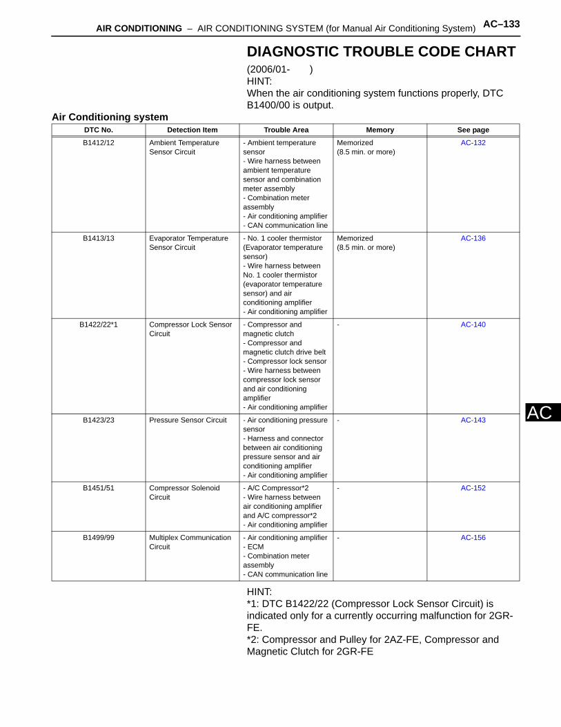
AIR CONDITIONING – AIR CONDITIONING SYSTEM (for Manual Air Conditioning System) AC–133
AC
DIAGNOSTIC TROUBLE CODE CHART(2006/01- )HINT:When the air conditioning system functions properly, DTC B1400/00 is output.
Air Conditioning system
HINT:*1: DTC B1422/22 (Compressor Lock Sensor Circuit) is indicated only for a currently occurring malfunction for 2GR-FE.*2: Compressor and Pulley for 2AZ-FE, Compressor and Magnetic Clutch for 2GR-FE
DTC No. Detection Item Trouble Area Memory See page
B1412/12 Ambient Temperature Sensor Circuit
- Ambient temperature sensor- Wire harness between ambient temperature sensor and combination meter assembly- Combination meter assembly- Air conditioning amplifier- CAN communication line
Memorized(8.5 min. or more)
AC-132
B1413/13 Evaporator Temperature Sensor Circuit
- No. 1 cooler thermistor (Evaporator temperature sensor)- Wire harness between No. 1 cooler thermistor (evaporator temperature sensor) and air conditioning amplifier- Air conditioning amplifier
Memorized(8.5 min. or more)
AC-136
B1422/22*1 Compressor Lock Sensor Circuit
- Compressor and magnetic clutch- Compressor and magnetic clutch drive belt- Compressor lock sensor- Wire harness between compressor lock sensor and air conditioning amplifier- Air conditioning amplifier
- AC-140
B1423/23 Pressure Sensor Circuit - Air conditioning pressure sensor- Harness and connector between air conditioning pressure sensor and air conditioning amplifier- Air conditioning amplifier
- AC-143
B1451/51 Compressor Solenoid Circuit
- A/C Compressor*2- Wire harness between air conditioning amplifier and A/C compressor*2- Air conditioning amplifier
- AC-152
B1499/99 Multiplex Communication Circuit
- Air conditioning amplifier- ECM- Combination meter assembly- CAN communication line
- AC-156
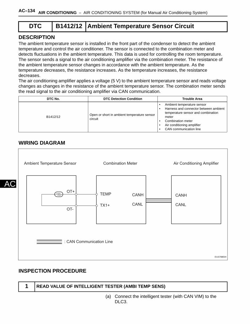
AC–134 AIR CONDITIONING – AIR CONDITIONING SYSTEM (for Manual Air Conditioning System)
AC
DESCRIPTIONThe ambient temperature sensor is installed in the front part of the condenser to detect the ambient temperature and control the air conditioner. The sensor is connected to the combination meter and detects fluctuations in the ambient temperature. This data is used for controlling the room temperature. The sensor sends a signal to the air conditioning amplifier via the combination meter. The resistance of the ambient temperature sensor changes in accordance with the ambient temperature. As the temperature decreases, the resistance increases. As the temperature increases, the resistance decreases.The air conditioning amplifier applies a voltage (5 V) to the ambient temperature sensor and reads voltage changes as changes in the resistance of the ambient temperature sensor. The combination meter sends the read signal to the air conditioning amplifier via CAN communication.
WIRING DIAGRAM
INSPECTION PROCEDURE
(a) Connect the intelligent tester (with CAN VIM) to the DLC3.
DTC B1412/12 Ambient Temperature Sensor Circuit
DTC No. DTC Detection Condition Trouble Area
B1412/12 Open or short in ambient temperature sensor circuit
• Ambient temperature sensor• Harness and connector between ambient
temperature sensor and combination meter
• Combination meter• Air conditioning amplifier• CAN communication line
1 READ VALUE OF INTELLIGENT TESTER (AMBI TEMP SENS)
Ambient Temperature Sensor Combination Meter
: CAN Communication Line
Air Conditioning Amplifier
TX1+
TEMPOT+
OT-
CANH
CANL
CANH
CANL
E115798E04

AIR CONDITIONING – AIR CONDITIONING SYSTEM (for Manual Air Conditioning System) AC–135
AC
(b) Turn the ignition switch ON and turn the intelligent tester main switch ON.
(c) Select the item below in the DATA LIST, and read the value displayed on the intelligent tester.
Air conditioning amplifier
OK:The display is as specified in the normal condition column.
Result
B
C
A
Item Measurement Item / Display (Range) Normal Condition Diagnostic Note
AMBI TEMP SENSAmbient temperature sensor /Min.: -23.3°C (-9.94°F)Max.: 65.95°C (150.71°F)
Actual ambient temperature is displayed
Open circuit: -23.3°C (-9.94°F)Short circuit: 65.95°C (150.71°F)
Result Proceed to
NG A
OK (Checking from the PROBLEM SYMPTOMS TABLE) B
OK (Checking from the DTC) C
PROCEED TO NEXT CIRCUIT INSPECTION SHOWN IN PROBLEM SYMPTOMS TABLE
REPLACE AIR CONDITIONING AMPLIFIER

AC–136 AIR CONDITIONING – AIR CONDITIONING SYSTEM (for Manual Air Conditioning System)
AC
(a) Remove the ambient temperature sensor.(b) Measure the resistance of the sensor.
Standard resistance
NOTICE:• Touching the sensor even slightly may change
the resistance value. Be sure to hold the connector of the sensor.
• When measuring, the sensor temperature must be the same as the ambient temperature.
HINT:As the temperature increases, the resistance decreases (see the graph).
NG
OK
2 INSPECT AMBIENT TEMPERATURE SENSOR
4.0
3.5
3.0
2.5
2.0
1.5
1.0
0.5
0.010
(50)20
(68)30
(86)40
(104) (122) (140)50 60
Resistance (kΩ)
Temperature °C (°F)
Sensor Area
E114516E09
Tester Connection Condition Specified Condition
1 - 2 10°C (50°F) 3.00 to 3.73 kΩ
1 - 2 15°C (50°F) 2.45 to 2.88 kΩ
1 - 2 20°C (68°F) 1.95 to 2.30 kΩ
1 - 2 25°C (77°F) 1.60 to 1.80 kΩ
1 - 2 30°C (86°F) 1.28 to 1.47 kΩ
1 - 2 35°C (95°F) 1.00 to 1.22 kΩ
1 - 2 40°C (104°F) 0.80 to 1.00 kΩ
1 - 2 45°C (113°F) 0.65 to 0.85 kΩ
1 - 2 50°C (122°F) 0.50 to 0.70 kΩ
1 - 2 55°C (131°F) 0.44 to 0.60 kΩ
1 - 2 60°C (140°F) 0.36 to 0.50 kΩ
REPLACE AMBIENT TEMPERATURE SENSOR
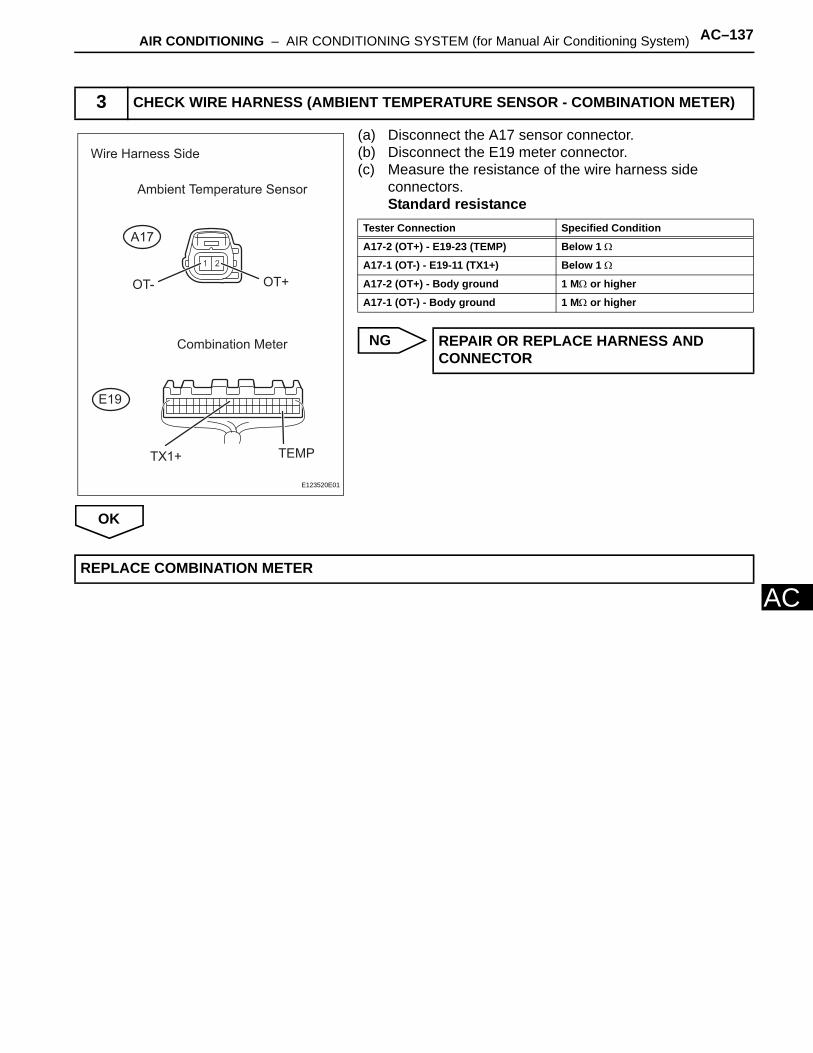
AIR CONDITIONING – AIR CONDITIONING SYSTEM (for Manual Air Conditioning System) AC–137
AC
(a) Disconnect the A17 sensor connector.(b) Disconnect the E19 meter connector.(c) Measure the resistance of the wire harness side
connectors.Standard resistance
NG
OK
3 CHECK WIRE HARNESS (AMBIENT TEMPERATURE SENSOR - COMBINATION METER)
Ambient Temperature Sensor
Wire Harness Side
Combination Meter
A17
E19
TEMPTX1+
OT- OT+
E123520E01
Tester Connection Specified Condition
A17-2 (OT+) - E19-23 (TEMP) Below 1 Ω
A17-1 (OT-) - E19-11 (TX1+) Below 1 Ω
A17-2 (OT+) - Body ground 1 MΩ or higher
A17-1 (OT-) - Body ground 1 MΩ or higher
REPAIR OR REPLACE HARNESS AND CONNECTOR
REPLACE COMBINATION METER
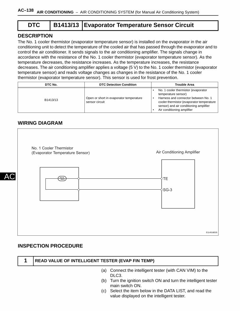
AC–138 AIR CONDITIONING – AIR CONDITIONING SYSTEM (for Manual Air Conditioning System)
AC
DESCRIPTIONThe No. 1 cooler thermistor (evaporator temperature sensor) is installed on the evaporator in the air conditioning unit to detect the temperature of the cooled air that has passed through the evaporator and to control the air conditioner. It sends signals to the air conditioning amplifier. The signals change in accordance with the resistance of the No. 1 cooler thermistor (evaporator temperature sensor). As the temperature decreases, the resistance increases. As the temperature increases, the resistance decreases. The air conditioning amplifier applies a voltage (5 V) to the No. 1 cooler thermistor (evaporator temperature sensor) and reads voltage changes as changes in the resistance of the No. 1 cooler thermistor (evaporator temperature sensor). This sensor is used for frost prevention.
WIRING DIAGRAM
INSPECTION PROCEDURE
(a) Connect the intelligent tester (with CAN VIM) to the DLC3.
(b) Turn the ignition switch ON and turn the intelligent tester main switch ON.
(c) Select the item below in the DATA LIST, and read the value displayed on the intelligent tester.
DTC B1413/13 Evaporator Temperature Sensor Circuit
DTC No. DTC Detection Condition Trouble Area
B1413/13 Open or short in evaporator temperature sensor circuit
• No. 1 cooler thermistor (evaporator temperature sensor)
• Harness and connector between No. 1 cooler thermistor (evaporator temperature sensor) and air conditioning amplifier
• Air conditioning amplifier
1 READ VALUE OF INTELLIGENT TESTER (EVAP FIN TEMP)
No. 1 Cooler Thermistor
(Evaporator Temperature Sensor) Air Conditioning Amplifier
TE
SG-3
E114518E05
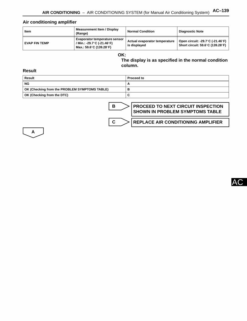
AIR CONDITIONING – AIR CONDITIONING SYSTEM (for Manual Air Conditioning System) AC–139
AC
Air conditioning amplifier
OK:The display is as specified in the normal condition column.
Result
B
C
A
Item Measurement Item / Display (Range) Normal Condition Diagnostic Note
EVAP FIN TEMPEvaporator temperature sensor / Min.: -29.7°C (-21.46°F)Max.: 59.6°C (139.28°F)
Actual evaporator temperature is displayed
Open circuit: -29.7°C (-21.46°F)Short circuit: 59.6°C (139.28°F)
Result Proceed to
NG A
OK (Checking from the PROBLEM SYMPTOMS TABLE) B
OK (Checking from the DTC) C
PROCEED TO NEXT CIRCUIT INSPECTION SHOWN IN PROBLEM SYMPTOMS TABLE
REPLACE AIR CONDITIONING AMPLIFIER

AC–140 AIR CONDITIONING – AIR CONDITIONING SYSTEM (for Manual Air Conditioning System)
AC
(a) Remove the No. 1 cooler thermistor.(b) Measure the resistance of the thermistor.
Standard resistance
NOTICE:• Touching the thermistor even slightly may change the
resistance value. Be sure to hold the connector of the thermistor.
• When measuring, the thermistor temperature must be the same as the ambient temperature.
HINT:As the temperature increases, the resistance decreases (see the graph).
NG
OK
2 INSPECT NO. 1 COOLER THERMISTOR (EVAPORATOR TEMPERATURE SENSOR)
20100-10(68)
30(86)(50)(32)(14)
4.0
5.0
6.0
7.0
8.0
9.0
10.0
3.0
2.0
1.0
0.0
Sensor Area
No. 1 Cooler Thermistor
No. 1 Cooler Thermistor
Evaporator
Resistance (kΩ)
Temperature °C (°F)
E115010E12
Tester Connection Condition Specified Condition
1 - 2 -10°C (14°F) 7.30 to 9.10 kΩ
1 - 2 -5°C (23°F) 5.65 to 6.95 kΩ
1 - 2 0°C (32°F) 4.40 to 5.35 kΩ
1 - 2 5°C (41°F) 3.40 to 4.15 kΩ
1 - 2 10°C (50°F) 2.70 to 3.25 kΩ
1 - 2 15°C (59°F) 2.14 to 2.58 kΩ
1 - 2 20°C (68°F) 1.71 to 2.05 kΩ
1 - 2 25°C (77°F) 1.38 to 1.64 kΩ
1 - 2 30°C (86°F) 1.11 to 1.32 kΩ
REPLACE NO. 1 COOLER THERMISTOR
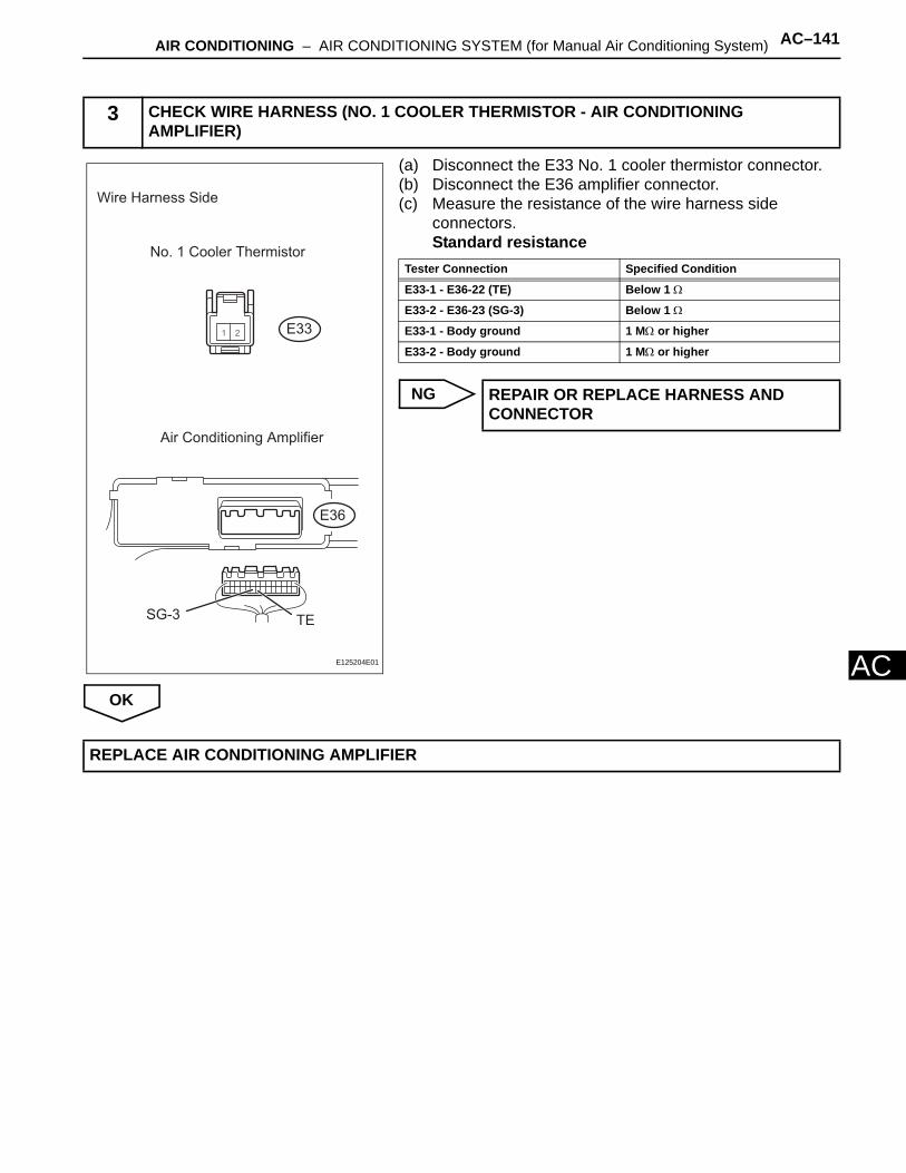
AIR CONDITIONING – AIR CONDITIONING SYSTEM (for Manual Air Conditioning System) AC–141
AC
(a) Disconnect the E33 No. 1 cooler thermistor connector.(b) Disconnect the E36 amplifier connector.(c) Measure the resistance of the wire harness side
connectors.Standard resistance
NG
OK
3 CHECK WIRE HARNESS (NO. 1 COOLER THERMISTOR - AIR CONDITIONING AMPLIFIER)
E33
Wire Harness Side
No. 1 Cooler Thermistor
Air Conditioning Amplifier
SG-3 TE
E36
E125204E01
Tester Connection Specified Condition
E33-1 - E36-22 (TE) Below 1 Ω
E33-2 - E36-23 (SG-3) Below 1 Ω
E33-1 - Body ground 1 MΩ or higher
E33-2 - Body ground 1 MΩ or higher
REPAIR OR REPLACE HARNESS AND CONNECTOR
REPLACE AIR CONDITIONING AMPLIFIER
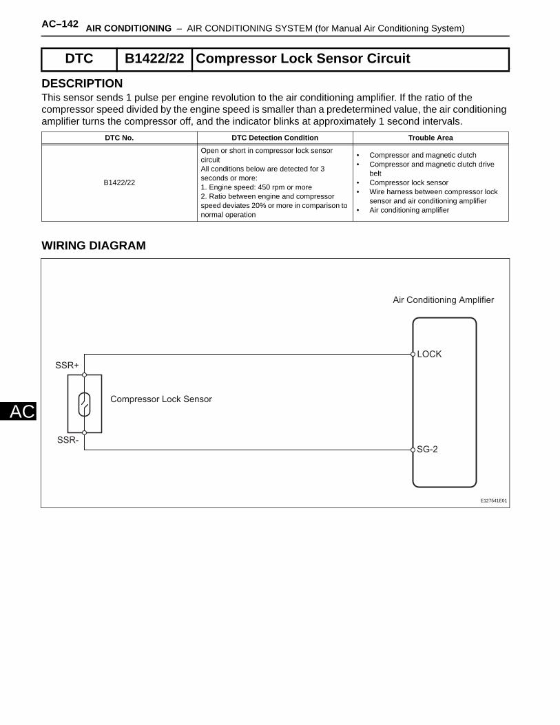
AC–142 AIR CONDITIONING – AIR CONDITIONING SYSTEM (for Manual Air Conditioning System)
AC
DESCRIPTIONThis sensor sends 1 pulse per engine revolution to the air conditioning amplifier. If the ratio of the compressor speed divided by the engine speed is smaller than a predetermined value, the air conditioning amplifier turns the compressor off, and the indicator blinks at approximately 1 second intervals.
WIRING DIAGRAM
DTC B1422/22 Compressor Lock Sensor Circuit
DTC No. DTC Detection Condition Trouble Area
B1422/22
Open or short in compressor lock sensor circuitAll conditions below are detected for 3 seconds or more:1. Engine speed: 450 rpm or more2. Ratio between engine and compressor speed deviates 20% or more in comparison to normal operation
• Compressor and magnetic clutch• Compressor and magnetic clutch drive
belt• Compressor lock sensor• Wire harness between compressor lock
sensor and air conditioning amplifier• Air conditioning amplifier
Air Conditioning Amplifier
Compressor Lock Sensor
LOCK
SG-2
SSR+
SSR-
E127541E01
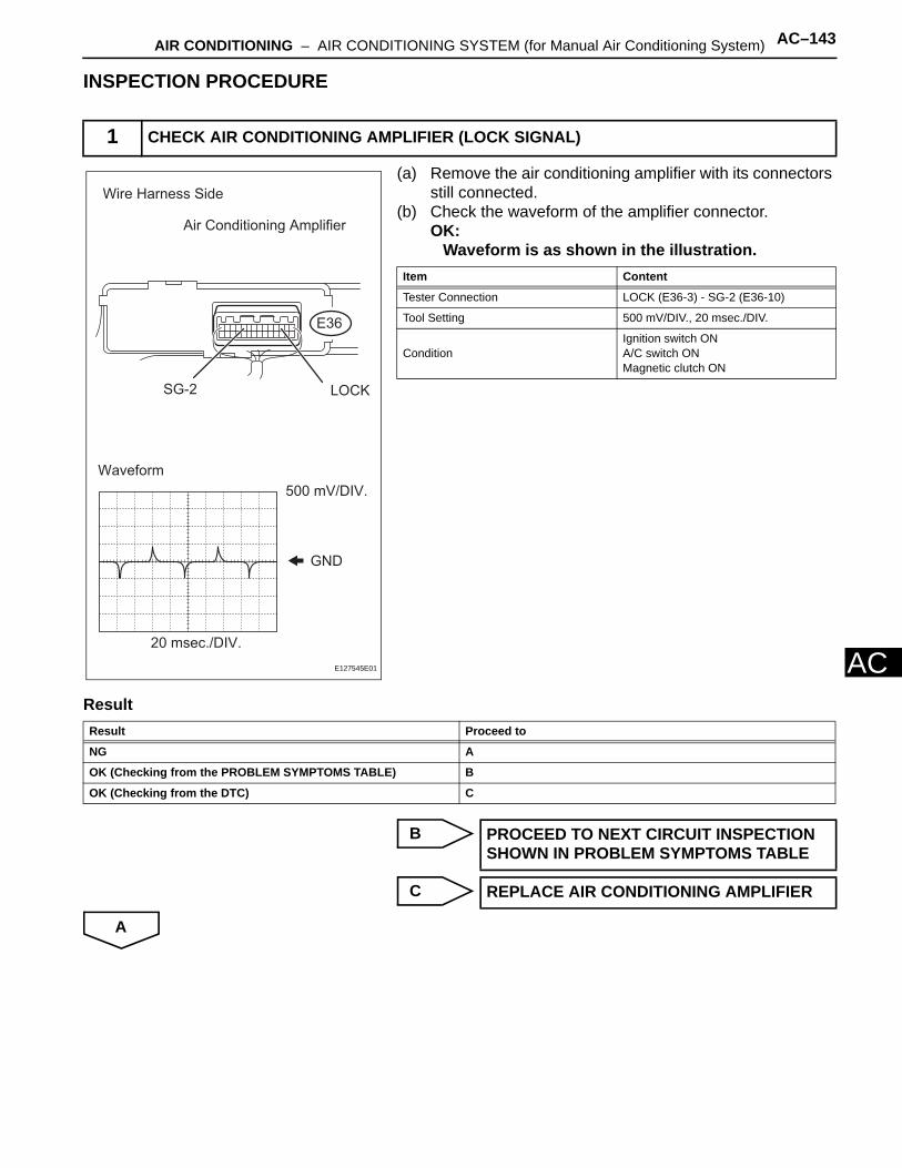
AIR CONDITIONING – AIR CONDITIONING SYSTEM (for Manual Air Conditioning System) AC–143
AC
INSPECTION PROCEDURE
(a) Remove the air conditioning amplifier with its connectors still connected.
(b) Check the waveform of the amplifier connector.OK:
Waveform is as shown in the illustration.
Result
B
C
A
1 CHECK AIR CONDITIONING AMPLIFIER (LOCK SIGNAL)
Air Conditioning Amplifier
SG-2
E36
LOCK
Wire Harness Side
GND
20 msec./DIV.
500 mV/DIV.
Waveform
E127545E01
Item Content
Tester Connection LOCK (E36-3) - SG-2 (E36-10)
Tool Setting 500 mV/DIV., 20 msec./DIV.
ConditionIgnition switch ONA/C switch ONMagnetic clutch ON
Result Proceed to
NG A
OK (Checking from the PROBLEM SYMPTOMS TABLE) B
OK (Checking from the DTC) C
PROCEED TO NEXT CIRCUIT INSPECTION SHOWN IN PROBLEM SYMPTOMS TABLE
REPLACE AIR CONDITIONING AMPLIFIER

AC–144 AIR CONDITIONING – AIR CONDITIONING SYSTEM (for Manual Air Conditioning System)
AC
(a) Disconnect the B47 compressor lock sensor connector.(b) Measure the resistance of the sensor.
Standard resistance
NG
OK
(a) Disconnect the B47 compressor lock sensor connector.(b) Disconnect the E36 amplifier connector.(c) Measure the resistance of the wire harness side
connectors.Standard resistance
NG
OK
2 INSPECT COMPRESSOR LOCK SENSOR
SSR+SSR-
E127543E01
Tester Connection Condition Specified Condition
1 (SSR+) - 2 (SSR-) 20°C (68°F) 65 to 125 Ω
REPLACE COMPRESSOR LOCK SENSOR
3 CHECK WIRE HARNESS (COMPRESSOR LOCK SENSOR - AIR CONDITIONING AMPLIFIER)
Compressor Lock Sensor
B47
SSR+ SSR-
Air Conditioning Amplifier
SG-2
E36
Wire Harness Side
LOCK
E127546E01
Tester Connection Specified Condition
B47-1 (SSR+) - E36-3 (LOCK) Below 1 Ω
B47-2 (SSR-) - E36-10 (SG-2) Below 1 Ω
B47-1 (SSR+) - E36-10 (SG-2) 10 kΩ or higher
E36-3 (LOCK) - Body ground 10 kΩ or higher
REPAIR OR REPLACE HARNESS AND CONNECTOR
REPLACE AIR CONDITIONING AMPLIFIER
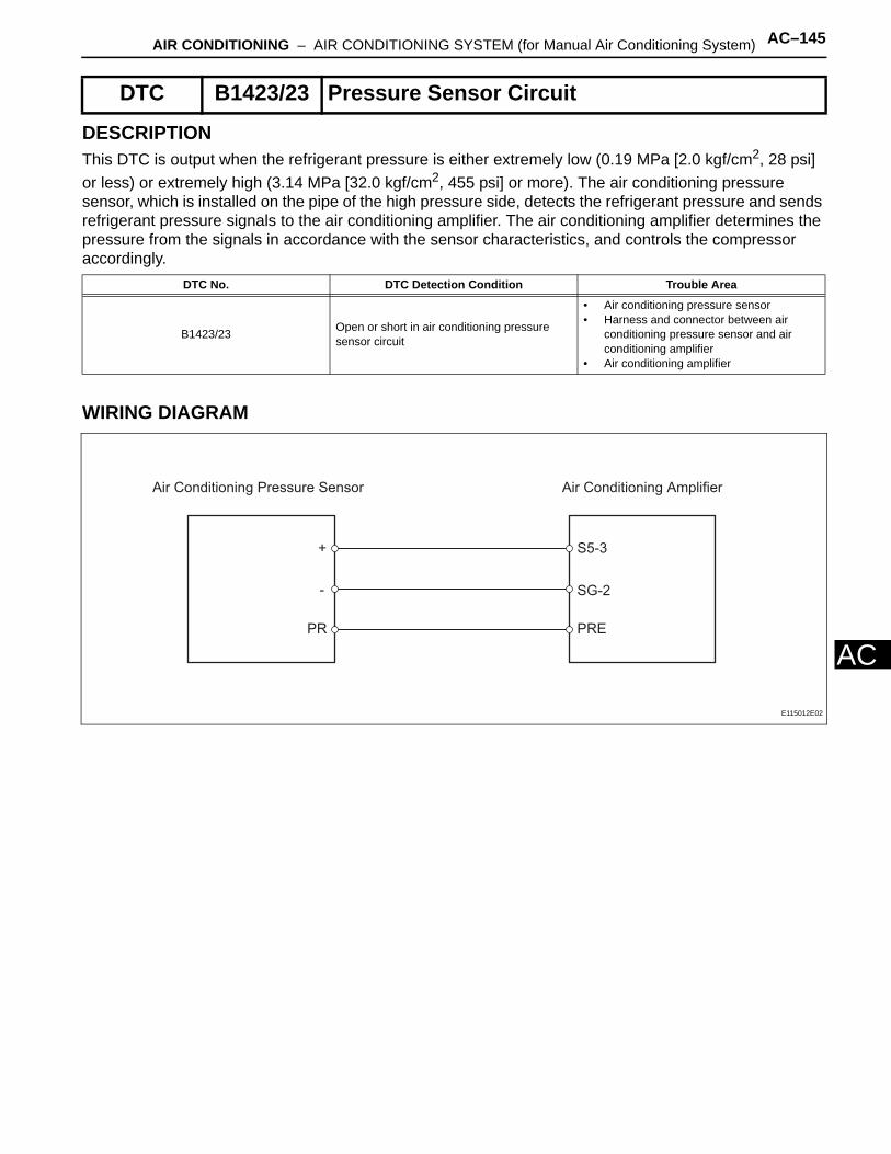
AIR CONDITIONING – AIR CONDITIONING SYSTEM (for Manual Air Conditioning System) AC–145
AC
DESCRIPTIONThis DTC is output when the refrigerant pressure is either extremely low (0.19 MPa [2.0 kgf/cm2, 28 psi] or less) or extremely high (3.14 MPa [32.0 kgf/cm2, 455 psi] or more). The air conditioning pressure sensor, which is installed on the pipe of the high pressure side, detects the refrigerant pressure and sends refrigerant pressure signals to the air conditioning amplifier. The air conditioning amplifier determines the pressure from the signals in accordance with the sensor characteristics, and controls the compressor accordingly.
WIRING DIAGRAM
DTC B1423/23 Pressure Sensor Circuit
DTC No. DTC Detection Condition Trouble Area
B1423/23 Open or short in air conditioning pressure sensor circuit
• Air conditioning pressure sensor• Harness and connector between air
conditioning pressure sensor and air conditioning amplifier
• Air conditioning amplifier
Air Conditioning Pressure Sensor Air Conditioning Amplifier
S5-3
SG-2
PRE
+
-
PR
E115012E02

AC–146 AIR CONDITIONING – AIR CONDITIONING SYSTEM (for Manual Air Conditioning System)
AC
INSPECTION PROCEDURE
(a) Check the sight glass of the cooler unit refrigerant liquid pipe.(1) Prepare the vehicle in accordance with the chart
below.
(2) Compare the sight glass to the following chart.
HINT:*: If the ambient temperature is higher than usual but cooling is sufficient, bubbles in the sight glass are permissible.
NG
OK
1 CHECK REFRIGERANT
Sight Glass
E123523E01
Item Condition
Engine Speed 1,500 rpm
Vehicle Doors Fully open
Temperature Setting MAX COLD
Blower Speed HI
A/C Switch ON
Item Symptom Amount of Refrigerant Corrective Procedures
1 Bubbles visible Insufficient*
1. Check for gas leakage and repair if necessary
2. Add refrigerant until bubbles disappear
2 No bubbles visible Empty, insufficient or too much Refer to items 3 and 4
3No temperature difference between compressor inlet and outlet
Empty or nearly empty
1. Check for gas leakage with gas leak detector and repair if necessary
2. Add refrigerant until bubbles disappear
4Considerable temperature difference between compressor inlet and outlet
Correct or too much Refer to items 5 and 6
5 Refrigerant becomes clear immediately after A/C turned OFF Too much
1. Drain or discharge refrigerant2. Bleed air and supply proper
amount of purified refrigerant
6Refrigerant foams and then becomes clear immediately after A/C turned OFF
Correct -
CHARGE REFRIGERANT

AIR CONDITIONING – AIR CONDITIONING SYSTEM (for Manual Air Conditioning System) AC–147
AC
(a) Connect the intelligent tester (with CAN VIM) to the DLC3.
(b) Turn the ignition switch ON and turn the intelligent tester main switch ON.
(c) Select the item below in the DATA LIST, and read the value displayed on the intelligent tester.
Air conditioning amplifier
OK:The display is as specified in the normal condition column.
Result
B
C
A
2 READ VALUE OF INTELLIGENT TESTER (REG PRESS SENS)
Item Measurement Item / Display(Range) Normal Condition Diagnostic Note
REG PRESS SENSRegulator pressure sensor /Min.: 0 MPaGMax.: 3.187 MPaG
Actual regulator pressure is displayed -
Result Proceed to
NG A
OK (Checking from the PROBLEM SYMPTOMS TABLE) B
OK (Checking from the DTC) C
PROCEED TO NEXT CIRCUIT INSPECTION SHOWN IN PROBLEM SYMPTOMS TABLE
REPLACE AIR CONDITIONING AMPLIFIER
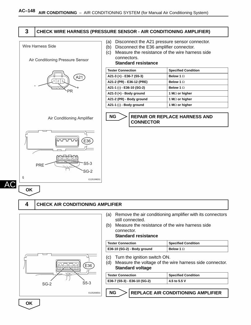
AC–148 AIR CONDITIONING – AIR CONDITIONING SYSTEM (for Manual Air Conditioning System)
AC
(a) Disconnect the A21 pressure sensor connector.(b) Disconnect the E36 amplifier connector.(c) Measure the resistance of the wire harness side
connectors.Standard resistance
NG
OK
(a) Remove the air conditioning amplifier with its connectors still connected.
(b) Measure the resistance of the wire harness side connector.Standard resistance
(c) Turn the ignition switch ON.(d) Measure the voltage of the wire harness side connector.
Standard voltage
NG
OK
3 CHECK WIRE HARNESS (PRESSURE SENSOR - AIR CONDITIONING AMPLIFIER)
A21
Wire Harness Side
Air Conditioning Pressure Sensor
Air Conditioning Amplifier
PR+-
PRE S5-3
SG-2
E36
E125199E01
Tester Connection Specified Condition
A21-3 (+) - E36-7 (S5-3) Below 1 Ω
A21-2 (PR) - E36-12 (PRE) Below 1 Ω
A21-1 (-) - E36-10 (SG-2) Below 1 Ω
A21-3 (+) - Body ground 1 MΩ or higher
A21-2 (PR) - Body ground 1 MΩ or higher
A21-1 (-) - Body ground 1 MΩ or higher
REPAIR OR REPLACE HARNESS AND CONNECTOR
4 CHECK AIR CONDITIONING AMPLIFIER
SG-2 S5-3
E36
E125200E01
Tester Connection Specified Condition
E36-10 (SG-2) - Body ground Below 1 Ω
Tester Connection Specified Condition
E36-7 (S5-3) - E36-10 (SG-2) 4.5 to 5.5 V
REPLACE AIR CONDITIONING AMPLIFIER

AIR CONDITIONING – AIR CONDITIONING SYSTEM (for Manual Air Conditioning System) AC–149
AC
(a) Turn the A/C switch ON.(b) Disconnect the A21 sensor connector.(c) Connect the three 1.5 V dry cell batteries' positive (+)
lead to terminal 3 and the negative (-) lead to terminal 1. Then connect the voltmeter's positive (+) lead to terminal 2 and the negative (-) lead to terminal 1. Measure the voltage.OK:
The voltage changes in accordance with the refrigerant pressure as shown in the graph.
NG
OK
5 INSPECT AIR CONDITIONING PRESSURE SENSOR
(V)
12
3
(4.0) (32.5) (kgf/cm2)
E115949E03
REPLACE AIR CONDITIONING PRESSURE SENSOR
REPLACE AIR CONDITIONING AMPLIFIER
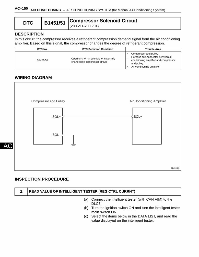
AC–150 AIR CONDITIONING – AIR CONDITIONING SYSTEM (for Manual Air Conditioning System)
AC
DESCRIPTIONIn this circuit, the compressor receives a refrigerant compression demand signal from the air conditioning amplifier. Based on this signal, the compressor changes the degree of refrigerant compression.
WIRING DIAGRAM
INSPECTION PROCEDURE
(a) Connect the intelligent tester (with CAN VIM) to the DLC3.
(b) Turn the ignition switch ON and turn the intelligent tester main switch ON.
(c) Select the items below in the DATA LIST, and read the value displayed on the intelligent tester.
DTC B1451/51 Compressor Solenoid Circuit(2005/11-2006/01)
DTC No. DTC Detection Condition Trouble Area
B1451/51 Open or short in solenoid of externally changeable compressor circuit
• Compressor and pulley• Harness and connector between air
conditioning amplifier and compressor and pulley
• Air conditioning amplifier
1 READ VALUE OF INTELLIGENT TESTER (REG CTRL CURRNT)
Compressor and Pulley Air Conditioning Amplifier
SOL+SOL+
SOL-
E115016E04
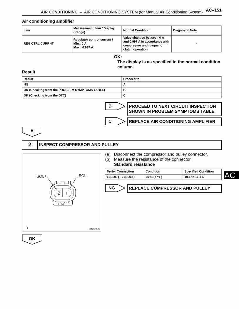
AIR CONDITIONING – AIR CONDITIONING SYSTEM (for Manual Air Conditioning System) AC–151
AC
Air conditioning amplifier
OK:The display is as specified in the normal condition column.
Result
B
C
A
(a) Disconnect the compressor and pulley connector.(b) Measure the resistance of the connector.
Standard resistance
NG
OK
Item Measurement Item / Display (Range) Normal Condition Diagnostic Note
REG CTRL CURRNTRegulator control current /Min.: 0 AMax.: 0.997 A
Value changes between 0 A and 0.997 A in accordance with compressor and magnetic clutch operation
-
Result Proceed to
NG A
OK (Checking from the PROBLEM SYMPTOMS TABLE) B
OK (Checking from the DTC) C
PROCEED TO NEXT CIRCUIT INSPECTION SHOWN IN PROBLEM SYMPTOMS TABLE
REPLACE AIR CONDITIONING AMPLIFIER
2 INSPECT COMPRESSOR AND PULLEY
SOL+ SOL-
E115015E06
Tester Connection Condition Specified Condition
1 (SOL-) - 2 (SOL+) 25°C (77°F) 10.1 to 11.1 Ω
REPLACE COMPRESSOR AND PULLEY
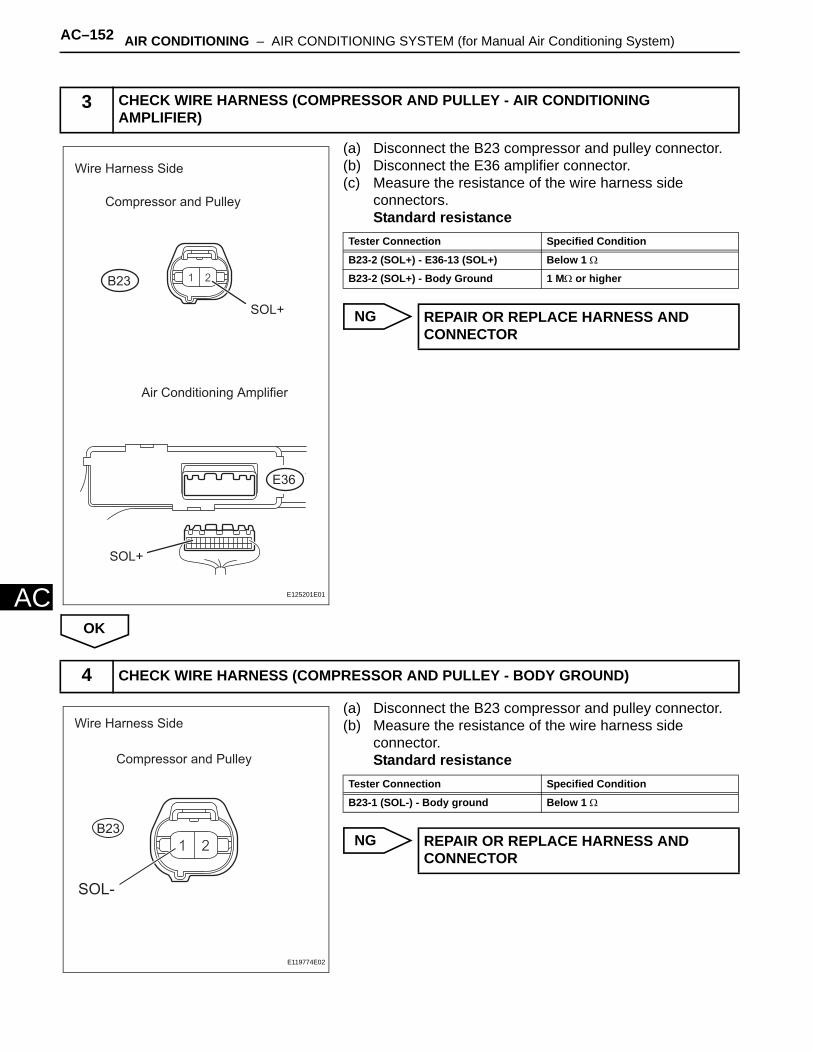
AC–152 AIR CONDITIONING – AIR CONDITIONING SYSTEM (for Manual Air Conditioning System)
AC
(a) Disconnect the B23 compressor and pulley connector.(b) Disconnect the E36 amplifier connector.(c) Measure the resistance of the wire harness side
connectors.Standard resistance
NG
OK
(a) Disconnect the B23 compressor and pulley connector.(b) Measure the resistance of the wire harness side
connector.Standard resistance
NG
3 CHECK WIRE HARNESS (COMPRESSOR AND PULLEY - AIR CONDITIONING AMPLIFIER)
B23
Wire Harness Side
Compressor and Pulley
Air Conditioning Amplifier
SOL+
SOL+
E36
E125201E01
Tester Connection Specified Condition
B23-2 (SOL+) - E36-13 (SOL+) Below 1 Ω
B23-2 (SOL+) - Body Ground 1 MΩ or higher
REPAIR OR REPLACE HARNESS AND CONNECTOR
4 CHECK WIRE HARNESS (COMPRESSOR AND PULLEY - BODY GROUND)
Wire Harness Side
Compressor and Pulley
B23
SOL-
E119774E02
Tester Connection Specified Condition
B23-1 (SOL-) - Body ground Below 1 Ω
REPAIR OR REPLACE HARNESS AND CONNECTOR

AIR CONDITIONING – AIR CONDITIONING SYSTEM (for Manual Air Conditioning System) AC–153
AC
OK
REPLACE AIR CONDITIONING AMPLIFIER
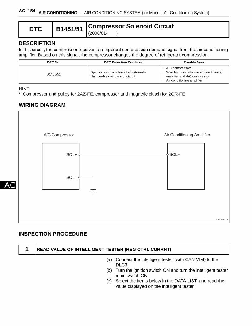
AC–154 AIR CONDITIONING – AIR CONDITIONING SYSTEM (for Manual Air Conditioning System)
AC
DESCRIPTIONIn this circuit, the compressor receives a refrigerant compression demand signal from the air conditioning amplifier. Based on this signal, the compressor changes the degree of refrigerant compression.
HINT:*: Compressor and pulley for 2AZ-FE, compressor and magnetic clutch for 2GR-FE
WIRING DIAGRAM
INSPECTION PROCEDURE
(a) Connect the intelligent tester (with CAN VIM) to the DLC3.
(b) Turn the ignition switch ON and turn the intelligent tester main switch ON.
(c) Select the items below in the DATA LIST, and read the value displayed on the intelligent tester.
DTC B1451/51 Compressor Solenoid Circuit(2006/01- )
DTC No. DTC Detection Condition Trouble Area
B1451/51 Open or short in solenoid of externally changeable compressor circuit
• A/C compressor*• Wire harness between air conditioning
amplifier and A/C compressor*• Air conditioning amplifier
1 READ VALUE OF INTELLIGENT TESTER (REG CTRL CURRNT)
A/C Compressor Air Conditioning Amplifier
SOL+SOL+
SOL-
E115016E08
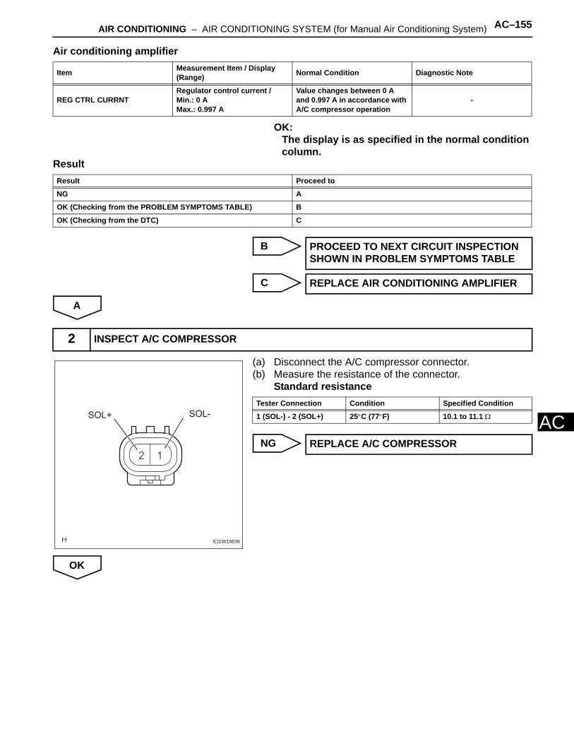
AIR CONDITIONING – AIR CONDITIONING SYSTEM (for Manual Air Conditioning System) AC–155
AC
Air conditioning amplifier
OK:The display is as specified in the normal condition column.
Result
B
C
A
(a) Disconnect the A/C compressor connector.(b) Measure the resistance of the connector.
Standard resistance
NG
OK
Item Measurement Item / Display (Range) Normal Condition Diagnostic Note
REG CTRL CURRNTRegulator control current /Min.: 0 AMax.: 0.997 A
Value changes between 0 A and 0.997 A in accordance with A/C compressor operation
-
Result Proceed to
NG A
OK (Checking from the PROBLEM SYMPTOMS TABLE) B
OK (Checking from the DTC) C
PROCEED TO NEXT CIRCUIT INSPECTION SHOWN IN PROBLEM SYMPTOMS TABLE
REPLACE AIR CONDITIONING AMPLIFIER
2 INSPECT A/C COMPRESSOR
SOL+ SOL-
E115015E06
Tester Connection Condition Specified Condition
1 (SOL-) - 2 (SOL+) 25°C (77°F) 10.1 to 11.1 Ω
REPLACE A/C COMPRESSOR
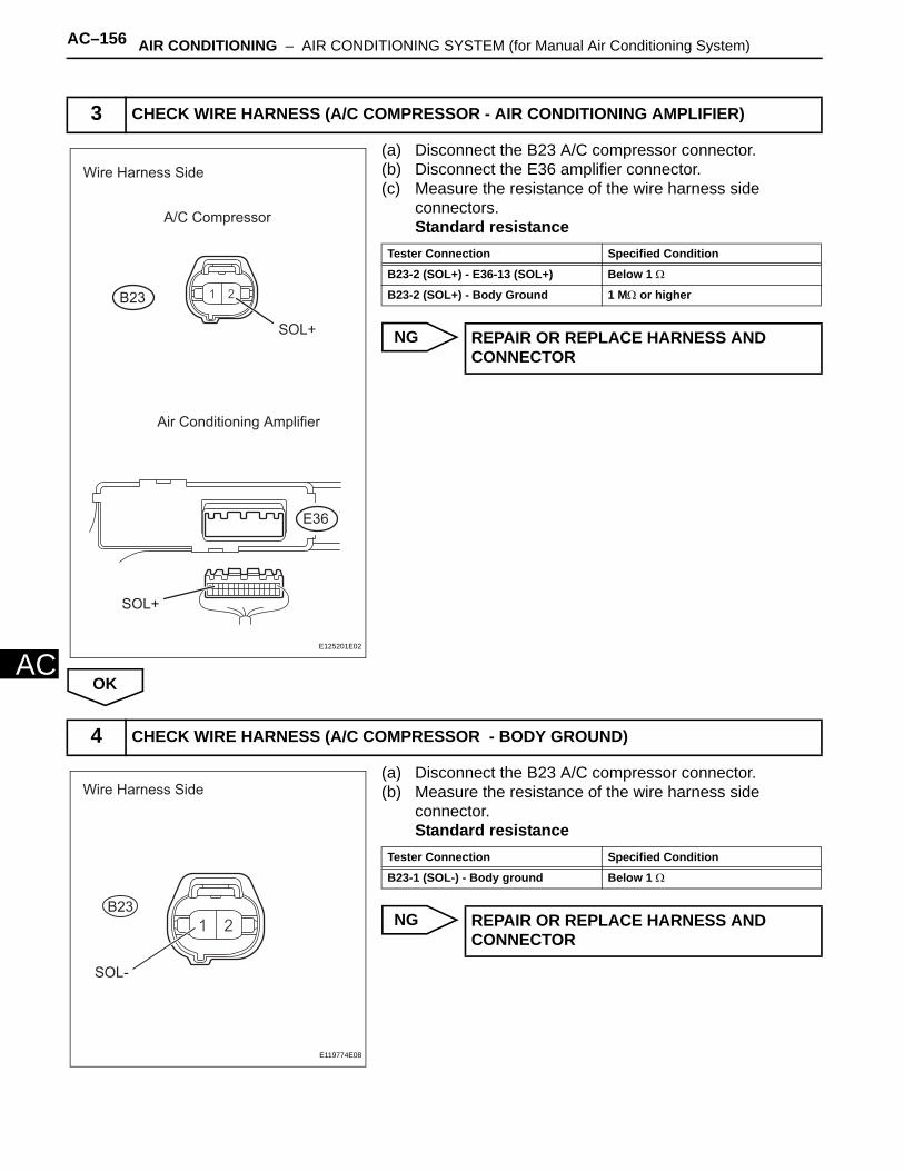
AC–156 AIR CONDITIONING – AIR CONDITIONING SYSTEM (for Manual Air Conditioning System)
AC
(a) Disconnect the B23 A/C compressor connector.(b) Disconnect the E36 amplifier connector.(c) Measure the resistance of the wire harness side
connectors.Standard resistance
NG
OK
(a) Disconnect the B23 A/C compressor connector.(b) Measure the resistance of the wire harness side
connector.Standard resistance
NG
3 CHECK WIRE HARNESS (A/C COMPRESSOR - AIR CONDITIONING AMPLIFIER)
B23
Wire Harness Side
A/C Compressor
Air Conditioning Amplifier
SOL+
SOL+
E36
E125201E02
Tester Connection Specified Condition
B23-2 (SOL+) - E36-13 (SOL+) Below 1 Ω
B23-2 (SOL+) - Body Ground 1 MΩ or higher
REPAIR OR REPLACE HARNESS AND CONNECTOR
4 CHECK WIRE HARNESS (A/C COMPRESSOR - BODY GROUND)
Wire Harness Side
B23
SOL-
E119774E08
Tester Connection Specified Condition
B23-1 (SOL-) - Body ground Below 1 Ω
REPAIR OR REPLACE HARNESS AND CONNECTOR
AIR CONDITIONING – AIR CONDITIONING SYSTEM (for Manual Air Conditioning System) AC–157
AC
OK
REPLACE AIR CONDITIONING AMPLIFIER
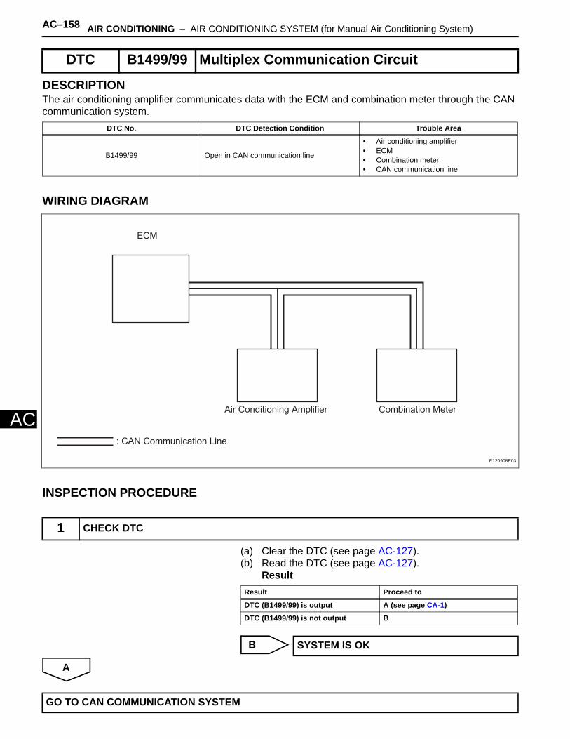
AC–158 AIR CONDITIONING – AIR CONDITIONING SYSTEM (for Manual Air Conditioning System)
AC
DESCRIPTIONThe air conditioning amplifier communicates data with the ECM and combination meter through the CAN communication system.
WIRING DIAGRAM
INSPECTION PROCEDURE
(a) Clear the DTC (see page AC-127).(b) Read the DTC (see page AC-127).
Result
B
A
DTC B1499/99 Multiplex Communication Circuit
DTC No. DTC Detection Condition Trouble Area
B1499/99 Open in CAN communication line
• Air conditioning amplifier• ECM• Combination meter• CAN communication line
1 CHECK DTC
ECM
Air Conditioning Amplifier Combination Meter
: CAN Communication Line
E120908E03
Result Proceed to
DTC (B1499/99) is output A (see page CA-1)
DTC (B1499/99) is not output B
SYSTEM IS OK
GO TO CAN COMMUNICATION SYSTEM
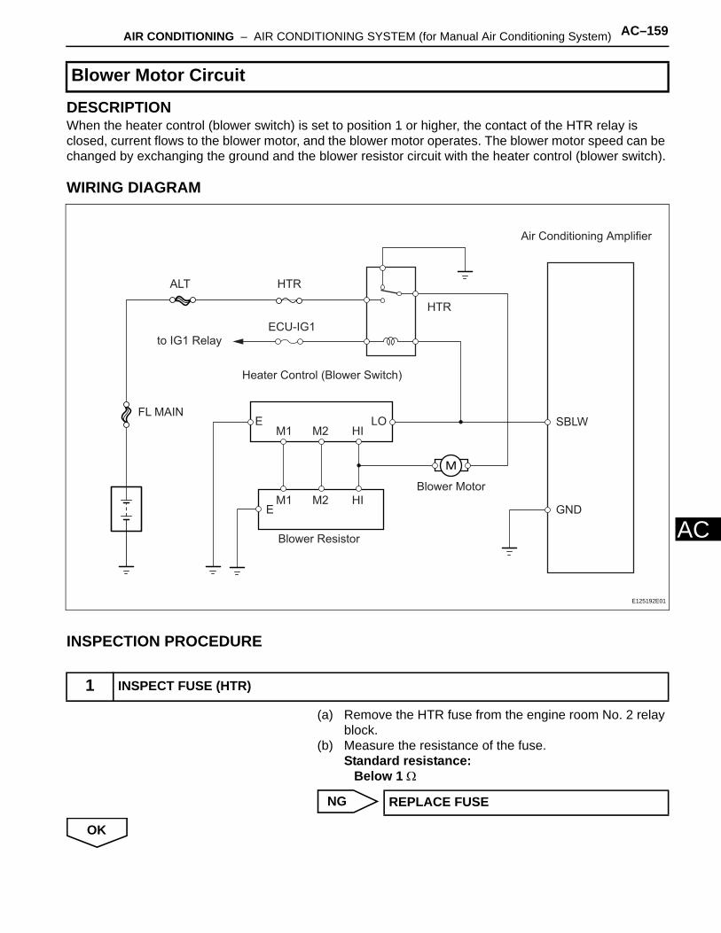
AIR CONDITIONING – AIR CONDITIONING SYSTEM (for Manual Air Conditioning System) AC–159
AC
DESCRIPTIONWhen the heater control (blower switch) is set to position 1 or higher, the contact of the HTR relay is closed, current flows to the blower motor, and the blower motor operates. The blower motor speed can be changed by exchanging the ground and the blower resistor circuit with the heater control (blower switch).
WIRING DIAGRAM
INSPECTION PROCEDURE
(a) Remove the HTR fuse from the engine room No. 2 relay block.
(b) Measure the resistance of the fuse.Standard resistance:
Below 1 Ω
NG
OK
Blower Motor Circuit
1 INSPECT FUSE (HTR)
Air Conditioning Amplifier
SBLW
GND
HTR
Blower Resistor
Blower Motor
Heater Control (Blower Switch)
HTRALT
FL MAIN
ECU-IG1
to IG1 Relay
LOHIM2M1
HIM2M1
E
E
E125192E01
REPLACE FUSE
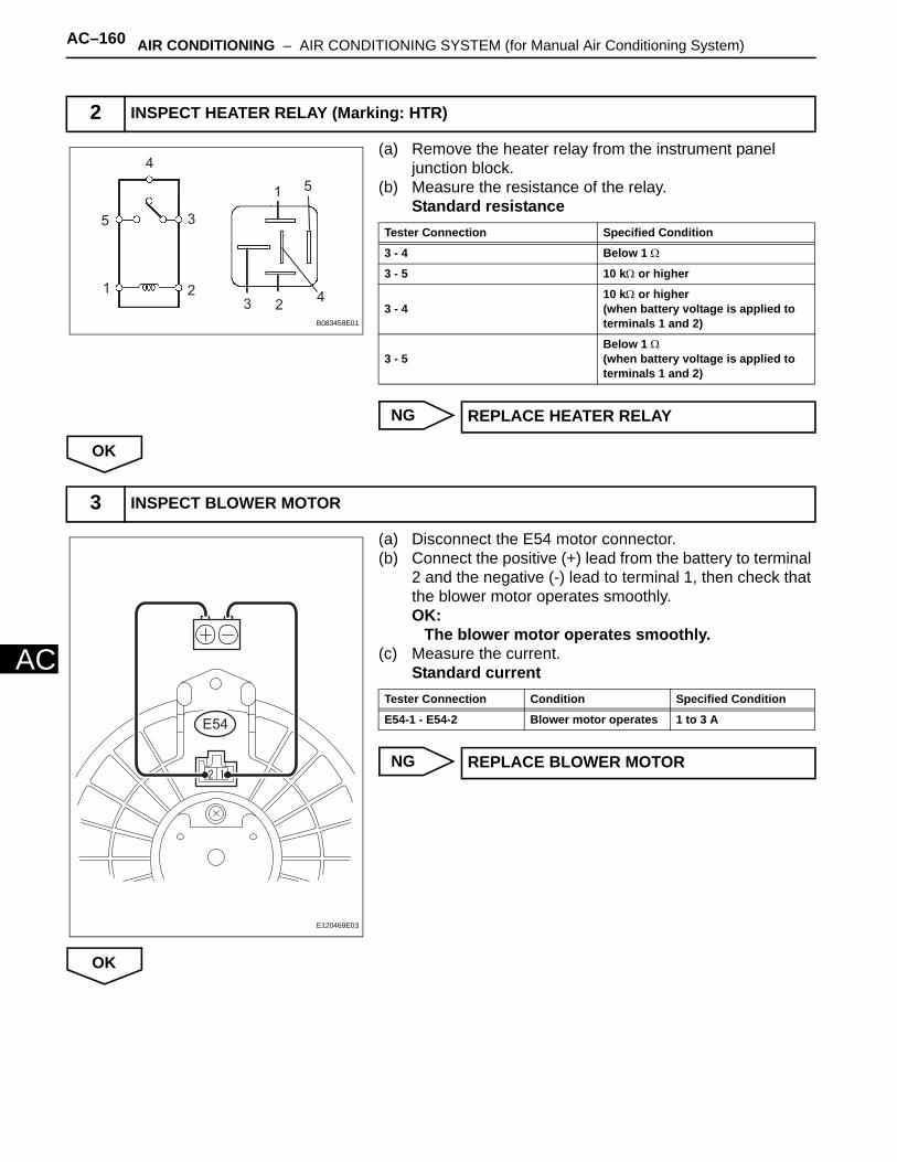
AC–160 AIR CONDITIONING – AIR CONDITIONING SYSTEM (for Manual Air Conditioning System)
AC
(a) Remove the heater relay from the instrument panel junction block.
(b) Measure the resistance of the relay.Standard resistance
NG
OK
(a) Disconnect the E54 motor connector.(b) Connect the positive (+) lead from the battery to terminal
2 and the negative (-) lead to terminal 1, then check that the blower motor operates smoothly.OK:
The blower motor operates smoothly.(c) Measure the current.
Standard current
NG
OK
2 INSPECT HEATER RELAY (Marking: HTR)
51
4
3
2
5
1
4
32
B083458E01
Tester Connection Specified Condition
3 - 4 Below 1 Ω
3 - 5 10 kΩ or higher
3 - 410 kΩ or higher(when battery voltage is applied to terminals 1 and 2)
3 - 5Below 1 Ω(when battery voltage is applied to terminals 1 and 2)
REPLACE HEATER RELAY
3 INSPECT BLOWER MOTOR
E54
E120469E03
Tester Connection Condition Specified Condition
E54-1 - E54-2 Blower motor operates 1 to 3 A
REPLACE BLOWER MOTOR
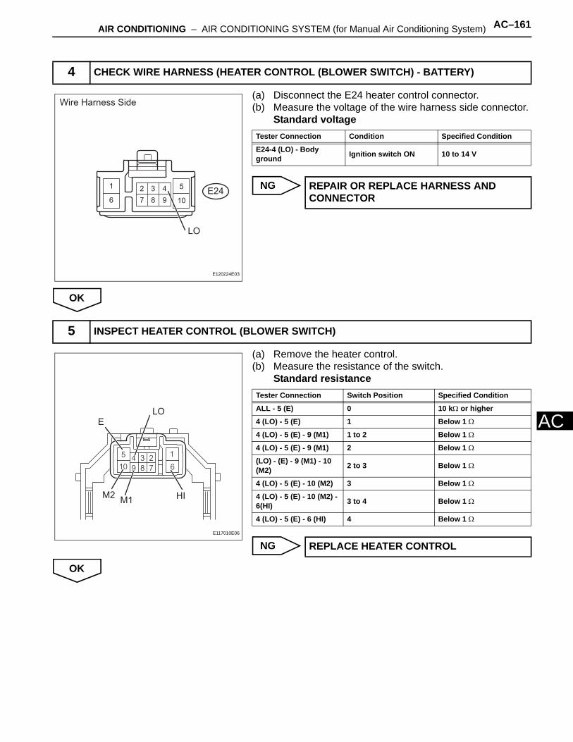
AIR CONDITIONING – AIR CONDITIONING SYSTEM (for Manual Air Conditioning System) AC–161
AC
(a) Disconnect the E24 heater control connector.(b) Measure the voltage of the wire harness side connector.
Standard voltage
NG
OK
(a) Remove the heater control.(b) Measure the resistance of the switch.
Standard resistance
NG
OK
4 CHECK WIRE HARNESS (HEATER CONTROL (BLOWER SWITCH) - BATTERY)
Wire Harness Side
LO
E24
E120224E03
Tester Connection Condition Specified Condition
E24-4 (LO) - Body ground Ignition switch ON 10 to 14 V
REPAIR OR REPLACE HARNESS AND CONNECTOR
5 INSPECT HEATER CONTROL (BLOWER SWITCH)
E
M2M1
LO
HI
E117010E06
Tester Connection Switch Position Specified Condition
ALL - 5 (E) 0 10 kΩ or higher
4 (LO) - 5 (E) 1 Below 1 Ω
4 (LO) - 5 (E) - 9 (M1) 1 to 2 Below 1 Ω
4 (LO) - 5 (E) - 9 (M1) 2 Below 1 Ω
(LO) - (E) - 9 (M1) - 10 (M2) 2 to 3 Below 1 Ω
4 (LO) - 5 (E) - 10 (M2) 3 Below 1 Ω
4 (LO) - 5 (E) - 10 (M2) - 6(HI) 3 to 4 Below 1 Ω
4 (LO) - 5 (E) - 6 (HI) 4 Below 1 Ω
REPLACE HEATER CONTROL
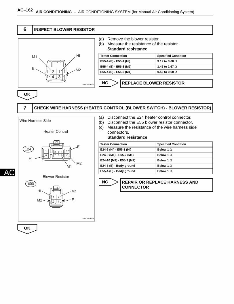
AC–162 AIR CONDITIONING – AIR CONDITIONING SYSTEM (for Manual Air Conditioning System)
AC
(a) Remove the blower resistor.(b) Measure the resistance of the resistor.
Standard resistance
NG
OK
(a) Disconnect the E24 heater control connector.(b) Disconnect the E55 blower resistor connector.(c) Measure the resistance of the wire harness side
connectors.Standard resistance
NG
OK
6 INSPECT BLOWER RESISTOR
HI
M2
M1
E
E120977E03
Tester Connection Specified Condition
E55-4 (E) - E55-1 (HI) 3.12 to 3.60 Ω
E55-4 (E) - E55-3 (M2) 1.45 to 1.67 Ω
E55-4 (E) - E55-2 (M1) 0.52 to 0.60 Ω
REPLACE BLOWER RESISTOR
7 CHECK WIRE HARNESS (HEATER CONTROL (BLOWER SWITCH) - BLOWER RESISTOR)
E24
E55
E
E
HI
HI
M1
M1
M2
M2
Wire Harness Side
Heater Control
Blower Resistor
E120283E05
Tester Connection Specified Condition
E24-6 (HI) - E55-1 (HI) Below 1 Ω
E24-9 (M1) - E55-2 (M1) Below 1 Ω
E24-10 (M2) - E55-3 (M2) Below 1 Ω
E24-5 (E) - Body ground Below 1 Ω
E55-4 (E) - Body ground Below 1 Ω
REPAIR OR REPLACE HARNESS AND CONNECTOR
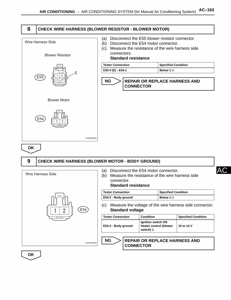
AIR CONDITIONING – AIR CONDITIONING SYSTEM (for Manual Air Conditioning System) AC–163
AC
(a) Disconnect the E55 blower resistor connector.(b) Disconnect the E54 motor connector.(c) Measure the resistance of the wire harness side
connectors.Standard resistance
NG
OK
(a) Disconnect the E54 motor connector.(b) Measure the resistance of the wire harness side
connector.Standard resistance
(c) Measure the voltage of the wire harness side connector.Standard voltage
NG
OK
8 CHECK WIRE HARNESS (BLOWER RESISTOR - BLOWER MOTOR)
Blower Motor
Wire Harness Side
Blower Resistor
E54
E55E
E120282E03
Tester Connection Specified Condition
E55-4 (E) - E54-1 Below 1 Ω
REPAIR OR REPLACE HARNESS AND CONNECTOR
9 CHECK WIRE HARNESS (BLOWER MOTOR - BODY GROUND)
Wire Harness Side
E54
E119793E03
Tester Connection Specified Condition
E54-2 - Body ground Below 1 Ω
Tester Connection Condition Specified Condition
E54-2 - Body groundIgnition switch ONHeater control (blower switch) 1
10 to 14 V
REPAIR OR REPLACE HARNESS AND CONNECTOR
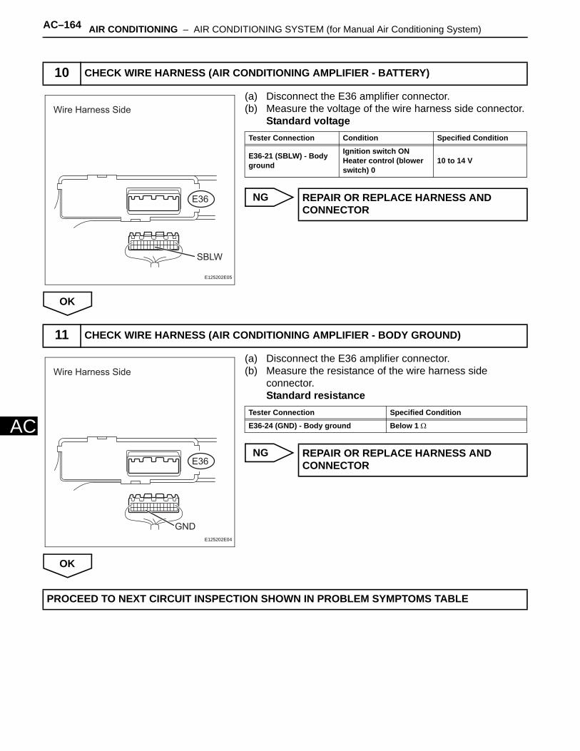
AC–164 AIR CONDITIONING – AIR CONDITIONING SYSTEM (for Manual Air Conditioning System)
AC
(a) Disconnect the E36 amplifier connector.(b) Measure the voltage of the wire harness side connector.
Standard voltage
NG
OK
(a) Disconnect the E36 amplifier connector.(b) Measure the resistance of the wire harness side
connector.Standard resistance
NG
OK
10 CHECK WIRE HARNESS (AIR CONDITIONING AMPLIFIER - BATTERY)
Wire Harness Side
SBLW
E36
E125202E05
Tester Connection Condition Specified Condition
E36-21 (SBLW) - Body ground
Ignition switch ONHeater control (blower switch) 0
10 to 14 V
REPAIR OR REPLACE HARNESS AND CONNECTOR
11 CHECK WIRE HARNESS (AIR CONDITIONING AMPLIFIER - BODY GROUND)
Wire Harness Side
GND
E36
E125202E04
Tester Connection Specified Condition
E36-24 (GND) - Body ground Below 1 Ω
REPAIR OR REPLACE HARNESS AND CONNECTOR
PROCEED TO NEXT CIRCUIT INSPECTION SHOWN IN PROBLEM SYMPTOMS TABLE

AIR CONDITIONING – AIR CONDITIONING SYSTEM (for Manual Air Conditioning System) AC–165
AC
DESCRIPTIONWhen the A/C switch is turned on, the magnetic clutch ON signal is sent from the air conditioning amplifier. Then the MG CLT relay turns on to operate the magnetic clutch.
WIRING DIAGRAM
INSPECTION PROCEDURE
(a) Connect the intelligent tester (with CAN VIM) to the DLC3.
(b) Turn the ignition switch ON and turn the intelligent tester main switch ON.
(c) Select the item below in the ACTIVE TEST and then check that the compressor magnetic relay operates.
Air conditioning amplifier
OK
NG
Compressor Circuit
1 PERFORM ACTIVE TEST BY INTELLIGENT TESTER (A/C MAG CLUTCH)
from IG1 RelayECU-IG1
Air Conditioning Amplifier
MG+
MG CLT
Magnetic Clutch
MGC
E127547E01
Item Test Details / Display (Range) Diagnostic Note
A/C MAG CLUTCH Magnetic clutch relay / OFF, ON Operating sound can be heard
PROCEED TO NEXT CIRCUIT INSPECTION SHOWN IN PROBLEM SYMPTOMS TABLE
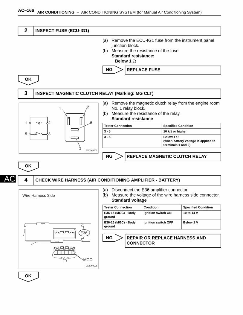
AC–166 AIR CONDITIONING – AIR CONDITIONING SYSTEM (for Manual Air Conditioning System)
AC
(a) Remove the ECU-IG1 fuse from the instrument panel junction block.
(b) Measure the resistance of the fuse.Standard resistance:
Below 1 Ω
NG
OK
(a) Remove the magnetic clutch relay from the engine room No. 1 relay block.
(b) Measure the resistance of the relay.Standard resistance
NG
OK
(a) Disconnect the E36 amplifier connector.(b) Measure the voltage of the wire harness side connector.
Standard voltage
NG
OK
2 INSPECT FUSE (ECU-IG1)
REPLACE FUSE
3 INSPECT MAGNETIC CLUTCH RELAY (Marking: MG CLT)
1
2
2
3
5
5
3
1
E127548E01
Tester Connection Specified Condition
3 - 5 10 kΩ or higher
3 - 5 Below 1 Ω(when battery voltage is applied to terminals 1 and 2)
REPLACE MAGNETIC CLUTCH RELAY
4 CHECK WIRE HARNESS (AIR CONDITIONING AMPLIFIER - BATTERY)
Wire Harness Side
MGC
E36
E125202E06
Tester Connection Condition Specified Condition
E36-15 (MGC) - Body ground
Ignition switch ON 10 to 14 V
E36-15 (MGC) - Body ground
Ignition switch OFF Below 1 V
REPAIR OR REPLACE HARNESS AND CONNECTOR
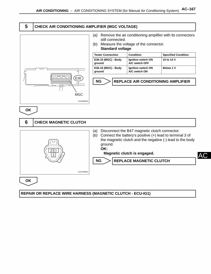
AIR CONDITIONING – AIR CONDITIONING SYSTEM (for Manual Air Conditioning System) AC–167
AC
(a) Remove the air conditioning amplifier with its connectors still connected.
(b) Measure the voltage of the connector.Standard voltage
NG
OK
(a) Disconnect the B47 magnetic clutch connector.(b) Connect the battery's positive (+) lead to terminal 3 of
the magnetic clutch and the negative (-) lead to the body ground.OK:
Magnetic clutch is engaged.
NG
OK
5 CHECK AIR CONDITIONING AMPLIFIER (MGC VOLTAGE)
MGC
E36
E125200E02
Tester Connection Condition Specified Condition
E36-15 (MGC) - Body ground
Ignition switch ONA/C switch OFF
10 to 14 V
E36-15 (MGC) - Body ground
Ignition switch ONA/C switch ON
Below 1 V
REPLACE AIR CONDITIONING AMPLIFIER
6 CHECK MAGNETIC CLUTCH
E127549E01
REPLACE MAGNETIC CLUTCH
REPAIR OR REPLACE WIRE HARNESS (MAGNETIC CLUTCH - ECU-IG1)

AC–168 AIR CONDITIONING – AIR CONDITIONING SYSTEM (for Manual Air Conditioning System)
AC
DESCRIPTIONThis is the main power source supplied to the air conditioning amplifier when the ignition switch is ON. This power source is used for operating components, such as the air conditioning amplifier and servo motors.
WIRING DIAGRAM
INSPECTION PROCEDURE
(a) Remove the ECU-IG2 fuse from the instrument panel junction block.
(b) Measure the resistance of the fuse.Standard resistance:
Below 1 Ω
NG
OK
IG Power Source Circuit
1 INSPECT FUSE (ECU-IG2)
IG1
Ignition Switch
Air Conditioning Amplifier
ECU-IG2
MAIN
FL MAIN
AM1 AM1 IG1
IG+
GND
E123527E01
REPLACE FUSE

AIR CONDITIONING – AIR CONDITIONING SYSTEM (for Manual Air Conditioning System) AC–169
AC
(a) Disconnect the E36 amplifier connector.(b) Measure the voltage of the wire harness side connector.
Standard voltage
NG
OK
(a) Disconnect the E36 amplifier connector.(b) Measure the resistance of the wire harness side
connector.Standard resistance
NG
OK
2 CHECK WIRE HARNESS (AIR CONDITIONING AMPLIFIER - BATTERY)
Wire Harness Side
IG+
E36
E125202E01
Tester Connection Condition Specified Condition
E36-14 (IG+) - Body ground Ignition switch ON 10 to 14 V
REPAIR OR REPLACE HARNESS AND CONNECTOR
3 CHECK WIRE HARNESS (AIR CONDITIONING AMPLIFIER - BODY GROUND)
Wire Harness Side
GND
E36
E125202E02
Tester Connection Specified Condition
E36-24 (GND) - Body ground Below 1 Ω
REPAIR OR REPLACE HARNESS AND CONNECTOR
PROCEED TO NEXT CIRCUIT INSPECTION SHOWN IN PROBLEM SYMPTOMS TABLE
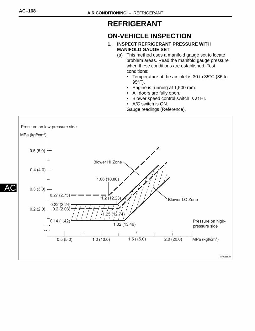
AC–168 AIR CONDITIONING – REFRIGERANT
AC
REFRIGERANTON-VEHICLE INSPECTION1. INSPECT REFRIGERANT PRESSURE WITH
MANIFOLD GAUGE SET(a) This method uses a manifold gauge set to locate
problem areas. Read the manifold gauge pressure when these conditions are established. Test conditions:• Temperature at the air inlet is 30 to 35°C (86 to
95°F).• Engine is running at 1,500 rpm.• All doors are fully open.• Blower speed control switch is at HI.• A/C switch is ON.Gauge readings (Reference).
MPa (kgf/cm2)
0.5 (5.0)
0.5 (5.0)
0.4 (4.0)
0.3 (3.0)
0.2 (2.0)
1.0 (10.0) 1.5 (15.0) 2.0 (20.0)
Blower HI Zone
1.06 (10.80)
1.2 (12.23)
1.25 (12.74)
1.32 (13.46)
0.27 (2.75)
0.22 (2.24)0.2 (2.03)
0.14 (1.42)
Blower LO Zone
MPa (kgf/cm2)
Pressure on low-pressure side
Pressure on high-
pressure side
I030081E04

AIR CONDITIONING – REFRIGERANT AC–169
AC
(1) Normally functioning refrigeration systemGauge reading
(2) The A/C system periodically changes between normal and improper function due to moisture in the refrigerant system.
(3) The A/C system does not function effectively due to insufficient cooling.
E050573E01
Pressure side Refrigerant volume
Low 0.15 to 0.25 MPa (1.5 to 2.5 kgf/cm2)
High 1.37 to 1.57 MPa (14 to 16 kgf/cm2)
Symptoms Probable Cause Diagnosis Corrective Actions
During operation, pressure on low pressure side cycles between normal and vacuum
Moisture in refrigeration system freezes at expansion valve orifice, causing temporary stop of cycle. However, when melted, normal state is restored.
- Drier is overly saturated- Moisture in refrigeration system freezes at expansion valve orifice and blocks refrigerant circulation
1. Replace cooler drier2. Remove moisture from cycle by repeatedly evacuating air3. Supply appropriate volume of new refrigerant
I022117E16
Symptoms Probable Cause Diagnosis Corrective Actions
- Pressure low on both low and high pressure sides- Cooling performance insufficient
Gas leakage from refrigeration system
- Insufficient refrigerant- Refrigerant leakage
1. Check for gas leakage and repair if necessary2. Supply appropriate volume of new refrigerant3. If indicated pressure value close to 0 when connected to gauge, create vacuum after inspecting and repairing the location of leakage
I022118E09

AC–170 AIR CONDITIONING – REFRIGERANT
AC
(4) The A/C system does not function effectively due to poor circulation of the refrigerant.
(5) The A/C system does not function intermittently because the refrigerant does not circulate.
Symptoms Probable Cause Diagnosis Corrective Actions
- Pressure low on both low and high pressure sides- Frost exists on piping from condenser to A/C unit
Refrigerant flow obstructed by dirt in condenser
Condenser clogged Replace condenser
I022119E10
Symptoms Probable Cause Diagnosis Corrective Actions
- Vacuum indicated on low pressure side, and extremely low pressure indicated on high pressure side- Frost or condensation seen on piping on both sides of condenser or expansion valve
- Refrigerant flow obstructed by moisture or dirt in refrigeration system- Refrigerant flow obstructed by gas leakage from expansion valve
Refrigerant does not circulate 1. Check expansion valve refrigerant2. Clean expansion valve by blowing air3. Replace condenser4. Evacuate air and charge appropriate volume of new refrigerant5. For gas leakage from expansion valve, replace expansion valve
I022120E09
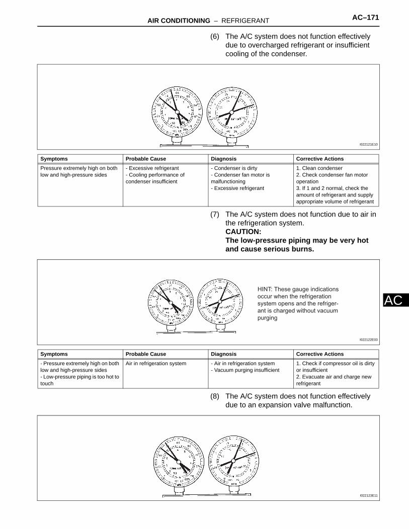
AIR CONDITIONING – REFRIGERANT AC–171
AC
(6) The A/C system does not function effectively due to overcharged refrigerant or insufficient cooling of the condenser.
(7) The A/C system does not function due to air in the refrigeration system.CAUTION:The low-pressure piping may be very hot and cause serious burns.
(8) The A/C system does not function effectively due to an expansion valve malfunction.
Symptoms Probable Cause Diagnosis Corrective Actions
Pressure extremely high on both low and high-pressure sides
- Excessive refrigerant- Cooling performance of condenser insufficient
- Condenser is dirty- Condenser fan motor is malfunctioning- Excessive refrigerant
1. Clean condenser2. Check condenser fan motor operation3. If 1 and 2 normal, check the amount of refrigerant and supply appropriate volume of refrigerant
I022121E10
Symptoms Probable Cause Diagnosis Corrective Actions
- Pressure extremely high on both low and high-pressure sides- Low-pressure piping is too hot to touch
Air in refrigeration system - Air in refrigeration system- Vacuum purging insufficient
1. Check if compressor oil is dirty or insufficient2. Evacuate air and charge new refrigerant
HINT: These gauge indications
occur when the refrigeration
system opens and the refriger-
ant is charged without vacuum
purging
I022122E03
I022123E11
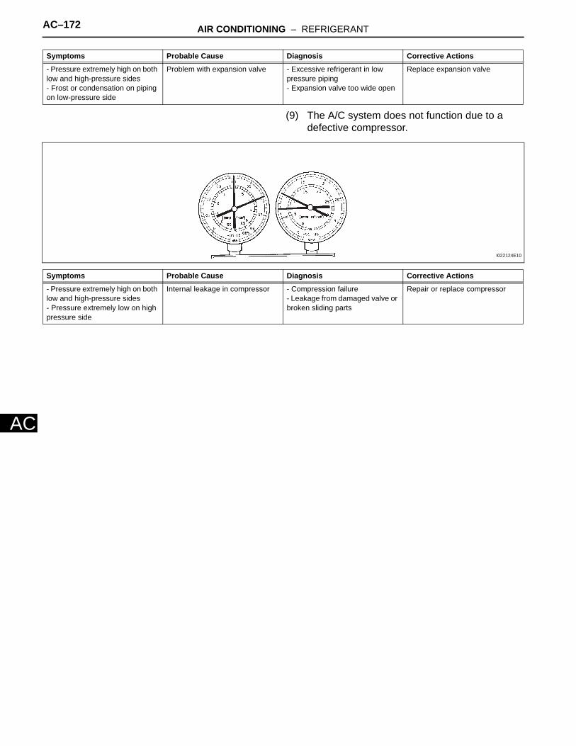
AC–172 AIR CONDITIONING – REFRIGERANT
AC
(9) The A/C system does not function due to a defective compressor.
Symptoms Probable Cause Diagnosis Corrective Actions
- Pressure extremely high on both low and high-pressure sides- Frost or condensation on piping on low-pressure side
Problem with expansion valve - Excessive refrigerant in low pressure piping- Expansion valve too wide open
Replace expansion valve
Symptoms Probable Cause Diagnosis Corrective Actions
- Pressure extremely high on both low and high-pressure sides - Pressure extremely low on high pressure side
Internal leakage in compressor - Compression failure- Leakage from damaged valve or broken sliding parts
Repair or replace compressor
I022124E10
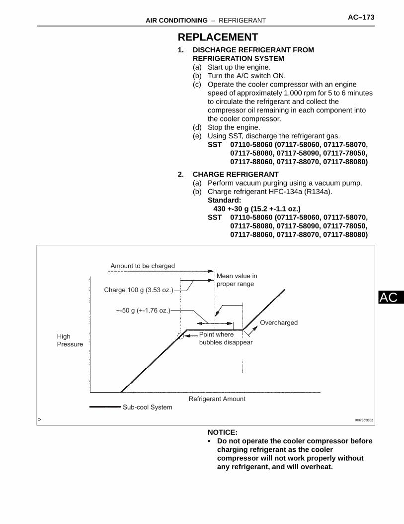
AIR CONDITIONING – REFRIGERANT AC–173
AC
REPLACEMENT1. DISCHARGE REFRIGERANT FROM
REFRIGERATION SYSTEM(a) Start up the engine.(b) Turn the A/C switch ON.(c) Operate the cooler compressor with an engine
speed of approximately 1,000 rpm for 5 to 6 minutes to circulate the refrigerant and collect the compressor oil remaining in each component into the cooler compressor.
(d) Stop the engine.(e) Using SST, discharge the refrigerant gas.
SST 07110-58060 (07117-58060, 07117-58070, 07117-58080, 07117-58090, 07117-78050, 07117-88060, 07117-88070, 07117-88080)
2. CHARGE REFRIGERANT(a) Perform vacuum purging using a vacuum pump.(b) Charge refrigerant HFC-134a (R134a).
Standard:430 +-30 g (15.2 +-1.1 oz.)
SST 07110-58060 (07117-58060, 07117-58070, 07117-58080, 07117-58090, 07117-78050, 07117-88060, 07117-88070, 07117-88080)
NOTICE:• Do not operate the cooler compressor before
charging refrigerant as the cooler compressor will not work properly without any refrigerant, and will overheat.
Sub-cool System
+-50 g (+-1.76 oz.)
Amount to be charged
Charge 100 g (3.53 oz.)
High Pressure
Refrigerant Amount
Overcharged
Point where bubbles disappear
Mean value in proper range
I037365E02
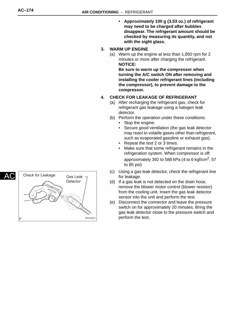
AC–174 AIR CONDITIONING – REFRIGERANT
AC
• Approximately 100 g (3.53 oz.) of refrigerant may need to be charged after bubbles disappear. The refrigerant amount should be checked by measuring its quantity, and not with the sight glass.
3. WARM UP ENGINE(a) Warm up the engine at less than 1,850 rpm for 2
minutes or more after charging the refrigerant.NOTICE:Be sure to warm up the compressor when turning the A/C switch ON after removing and installing the cooler refrigerant lines (including the compressor), to prevent damage to the compressor.
4. CHECK FOR LEAKAGE OF REFRIGERANT(a) After recharging the refrigerant gas, check for
refrigerant gas leakage using a halogen leak detector.
(b) Perform the operation under these conditions:• Stop the engine.• Secure good ventilation (the gas leak detector
may react to volatile gases other than refrigerant, such as evaporated gasoline or exhaust gas).
• Repeat the test 2 or 3 times.• Make sure that some refrigerant remains in the
refrigeration system. When compressor is off: approximately 392 to 588 kPa (4 to 6 kgf/cm2, 57 to 85 psi)
(c) Using a gas leak detector, check the refrigerant line for leakage.
(d) If a gas leak is not detected on the drain hose, remove the blower motor control (blower resistor) from the cooling unit. Insert the gas leak detector sensor into the unit and perform the test.
(e) Disconnect the connector and leave the pressure switch on for approximately 20 minutes. Bring the gas leak detector close to the pressure switch and perform the test.
Check for Leakage Gas Leak Detector
I042222E12
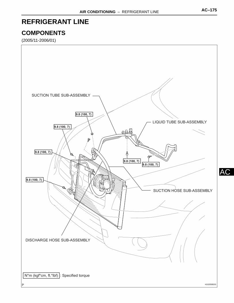
AIR CONDITIONING – REFRIGERANT LINE AC–175
AC
HEATER & AIR CONDITIONING SYSTEMAIR CONDITIONINGREFRIGERANT LINECOMPONENTS(2005/11-2006/01)
SUCTION TUBE SUB-ASSEMBLY
LIQUID TUBE SUB-ASSEMBLY
SUCTION HOSE SUB-ASSEMBLY
DISCHARGE HOSE SUB-ASSEMBLY
: Specified torqueN*m (kgf*cm, ft.*lbf)
9.8 (100, 7)
9.8 (100, 7)
9.8 (100, 7)
9.8 (100, 7)
9.8 (100, 7)9.8 (100, 7)
H102050E03
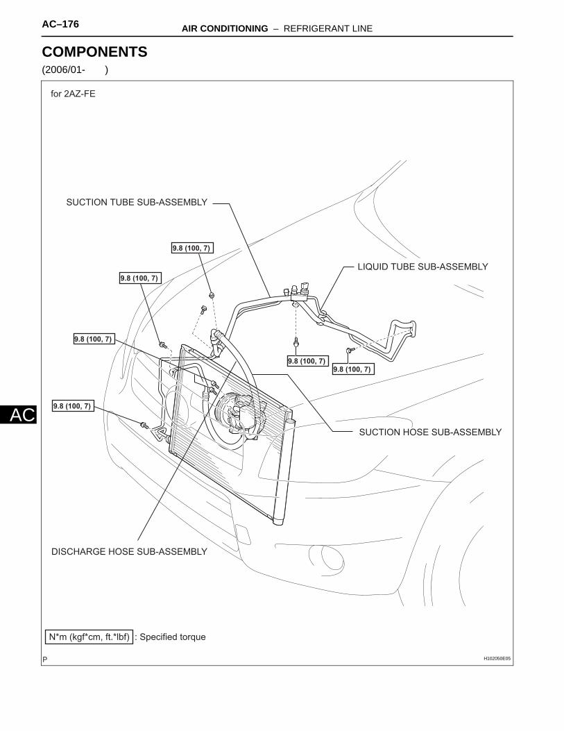
AC–176 AIR CONDITIONING – REFRIGERANT LINE
AC
COMPONENTS(2006/01- )
SUCTION TUBE SUB-ASSEMBLY
LIQUID TUBE SUB-ASSEMBLY
SUCTION HOSE SUB-ASSEMBLY
DISCHARGE HOSE SUB-ASSEMBLY
: Specified torqueN*m (kgf*cm, ft.*lbf)
9.8 (100, 7)
9.8 (100, 7)
9.8 (100, 7)
9.8 (100, 7)
9.8 (100, 7)9.8 (100, 7)
for 2AZ-FE
H102050E05
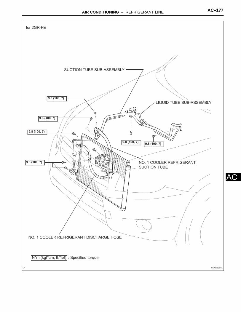
AIR CONDITIONING – REFRIGERANT LINE AC–177
AC
NO. 1 COOLER REFRIGERANT DISCHARGE HOSE
N*m (kgf*cm, ft.*lbf) : Specified torque
9.8 (100, 7)
9.8 (100, 7)
9.8 (100, 7)
9.8 (100, 7)
9.8 (100, 7)9.8 (100, 7)
NO. 1 COOLER REFRIGERANT
SUCTION TUBE
SUCTION TUBE SUB-ASSEMBLY
LIQUID TUBE SUB-ASSEMBLY
for 2GR-FE
H102052E01
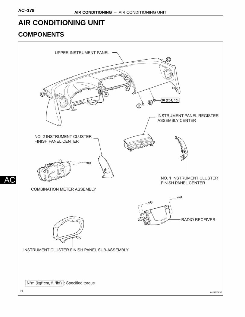
AC–178 AIR CONDITIONING – AIR CONDITIONING UNIT
AC
HEATER & AIR CONDITIONING SYSTEMAIR CONDITIONINGAIR CONDITIONING UNITCOMPONENTS
A
A
BB
C
C
: Specified torqueN*m (kgf*cm, ft.*lbf)
20 (204, 15)
UPPER INSTRUMENT PANEL
INSTRUMENT PANEL REGISTER
ASSEMBLY CENTER
NO. 2 INSTRUMENT CLUSTER
FINISH PANEL CENTER
COMBINATION METER ASSEMBLY
NO. 1 INSTRUMENT CLUSTER
FINISH PANEL CENTER
RADIO RECEIVER
INSTRUMENT CLUSTER FINISH PANEL SUB-ASSEMBLY
B129865E07
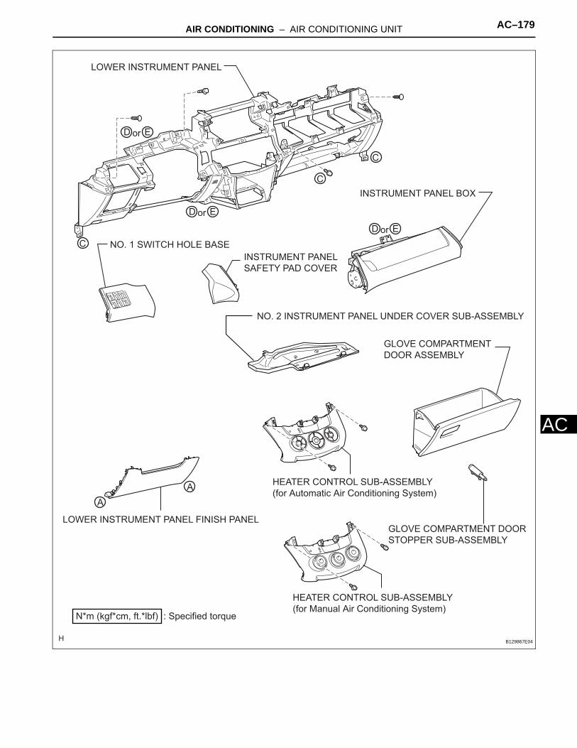
AIR CONDITIONING – AIR CONDITIONING UNIT AC–179
AC
HEATER CONTROL SUB-ASSEMBLY
(for Automatic Air Conditioning System)
HEATER CONTROL SUB-ASSEMBLY
(for Manual Air Conditioning System)
GLOVE COMPARTMENT DOOR
STOPPER SUB-ASSEMBLY
C
C
C
A
A
D Eor
D Eor
D Eor
: Specified torqueN*m (kgf*cm, ft.*lbf)
LOWER INSTRUMENT PANEL
INSTRUMENT PANEL BOX
NO. 1 SWITCH HOLE BASE
INSTRUMENT PANEL
SAFETY PAD COVER
NO. 2 INSTRUMENT PANEL UNDER COVER SUB-ASSEMBLY
GLOVE COMPARTMENT
DOOR ASSEMBLY
LOWER INSTRUMENT PANEL FINISH PANEL
B129867E04
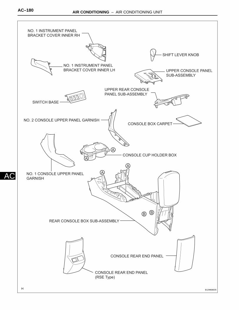
AC–180 AIR CONDITIONING – AIR CONDITIONING UNIT
AC
SHIFT LEVER KNOB
CONSOLE BOX CARPET
A
A
A
A
B B
NO. 1 INSTRUMENT PANEL
BRACKET COVER INNER RH
NO. 1 INSTRUMENT PANEL
BRACKET COVER INNER LH UPPER CONSOLE PANEL
SUB-ASSEMBLY
UPPER REAR CONSOLE
PANEL SUB-ASSEMBLY
SWITCH BASE
NO. 2 CONSOLE UPPER PANEL GARNISH
CONSOLE CUP HOLDER BOX
NO. 1 CONSOLE UPPER PANEL
GARNISH
REAR CONSOLE BOX SUB-ASSEMBLY
CONSOLE REAR END PANEL
CONSOLE REAR END PANEL
(RSE Type)
B129868E05

AIR CONDITIONING – AIR CONDITIONING UNIT AC–181
AC
: Specified torqueN*m (kgf*cm, ft.*lbf)
35 (360, 26)
50 (510, 37)
25 (255, 18)
25 (255, 18)
CLAMP
CLIP
CLIP
8.8 (90, 78 in.*lbf)
8.8 (90, 78 in.*lbf)
35 (360, 26)
STEERING PAD
UPPER STEERING COLUMN COVER
STEERING WHEEL ASSEMBLY
COMBINATION SWITCH ASSEMBLY
SPIRAL CABLE SUB-ASSEMBLYSTEERING COLUMN ASSEMBLY
LOWER STEERING COLUMN COVER
NO. 2 STEERING INTERMEDIATE SHAFT ASSEMBLY
COLUMN HOLE COVER SILENCER SHEET
C128801E04
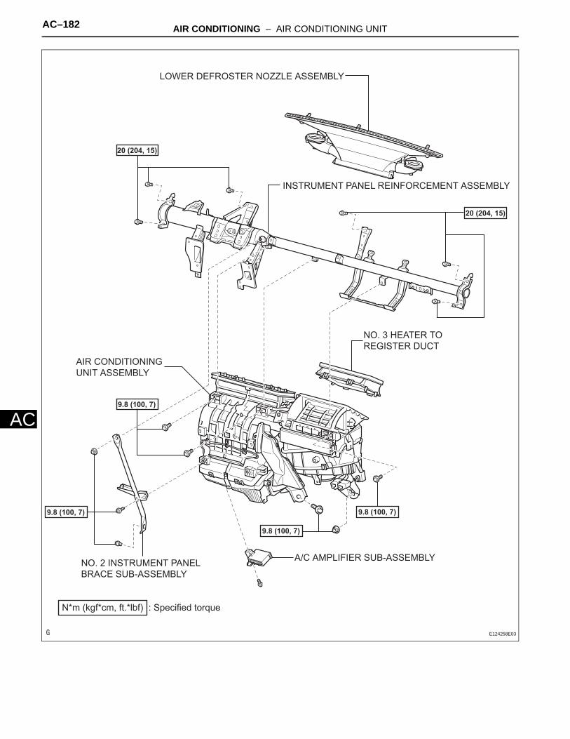
AC–182 AIR CONDITIONING – AIR CONDITIONING UNIT
AC
AIR CONDITIONING
UNIT ASSEMBLY
NO. 3 HEATER TO
REGISTER DUCT
INSTRUMENT PANEL REINFORCEMENT ASSEMBLY
A/C AMPLIFIER SUB-ASSEMBLY
: Specified torqueN*m (kgf*cm, ft.*lbf)
9.8 (100, 7)
9.8 (100, 7)
9.8 (100, 7)
9.8 (100, 7)
20 (204, 15)
20 (204, 15)
LOWER DEFROSTER NOZZLE ASSEMBLY
NO. 2 INSTRUMENT PANEL
BRACE SUB-ASSEMBLY
E124258E03
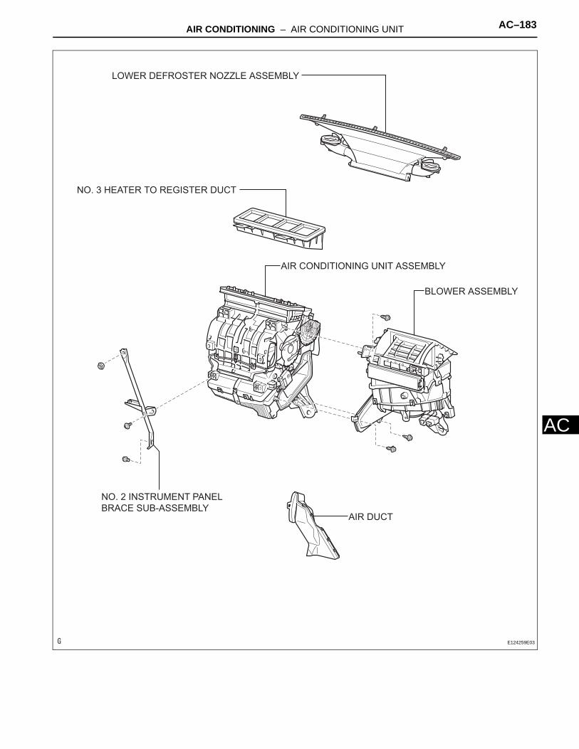
AIR CONDITIONING – AIR CONDITIONING UNIT AC–183
AC
AIR CONDITIONING UNIT ASSEMBLY
AIR DUCT
BLOWER ASSEMBLY
NO. 3 HEATER TO REGISTER DUCT
LOWER DEFROSTER NOZZLE ASSEMBLY
NO. 2 INSTRUMENT PANEL
BRACE SUB-ASSEMBLY
E124259E03

AC–184 AIR CONDITIONING – AIR CONDITIONING UNIT
AC AIR MIX CONTROL SERVO MOTOR
AIR OUTLET CONTROL SERVO MOTOR
HEATER RADIATOR UNIT
SUB-ASSEMBLY
AIR MIX CONTROL
SERVO MOTOR
AIR INLET CONTROL
SERVO MOTOR
EVAPORATOR TEMPERATURE SENSOR
NO. 1 COOLER EVAPORATOR SUB-ASSEMBLY
for Automatic Air Conditioning System
: Specified torqueN*m (kgf*cm, ft.*lbf)
Non-reusable part
O-RING
3.5 (35, 30 in.*lbf)
Compressor oil ND-OIL 8 or equivalentE124718E03
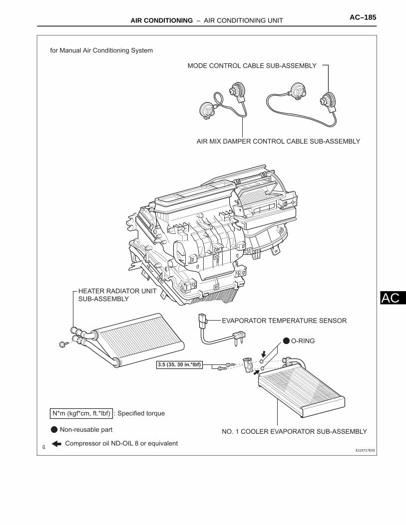
AIR CONDITIONING – AIR CONDITIONING UNIT AC–185
AC
for Manual Air Conditioning System
AIR MIX DAMPER CONTROL CABLE SUB-ASSEMBLY
MODE CONTROL CABLE SUB-ASSEMBLY
EVAPORATOR TEMPERATURE SENSOR
NO. 1 COOLER EVAPORATOR SUB-ASSEMBLY
HEATER RADIATOR UNIT
SUB-ASSEMBLY
: Specified torqueN*m (kgf*cm, ft.*lbf)
3.5 (35, 30 in.*lbf)
Non-reusable part
O-RING
Compressor oil ND-OIL 8 or equivalentE124717E03
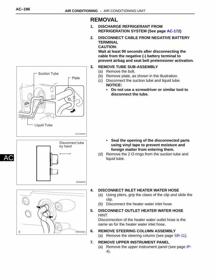
AC–186 AIR CONDITIONING – AIR CONDITIONING UNIT
AC
REMOVAL1. DISCHARGE REFRIGERANT FROM
REFRIGERATION SYSTEM (See page AC-172)2. DISCONNECT CABLE FROM NEGATIVE BATTERY
TERMINALCAUTION:Wait at least 90 seconds after disconnecting the cable from the negative (-) battery terminal to prevent airbag and seat belt pretensioner activation.
3. REMOVE TUBE SUB-ASSEMBLY(a) Remove the bolt.(b) Remove plate, as shown in the illustration.(c) Disconnect the suction tube and liquid tube.
NOTICE:• Do not use a screwdriver or similar tool to
disconnect the tube.
• Seal the opening of the disconnected parts using vinyl tape to prevent moisture and foreign matter from entering them.
(d) Remove the 2 O-rings from the suction tube and liquid tube.
4. DISCONNECT INLET HEATER WATER HOSE(a) Using pliers, grip the claws of the clip and slide the
clip.(b) Disconnect the heater water inlet hose.
5. DISCONNECT OUTLET HEATER WATER HOSEHINT:Disconnection of the heater water outlet hose is the same as for the heater water inlet hose.
6. REMOVE STEERING COLUMN ASSEMBLY(a) Remove the steering column (see page SR-11).
7. REMOVE UPPER INSTRUMENT PANEL(a) Remove the upper instrument panel (see page IP-
4).
Suction TubePlate
Liquid Tube
E127281E01
Disconnect tube by hand
I043960E02
H102044E01
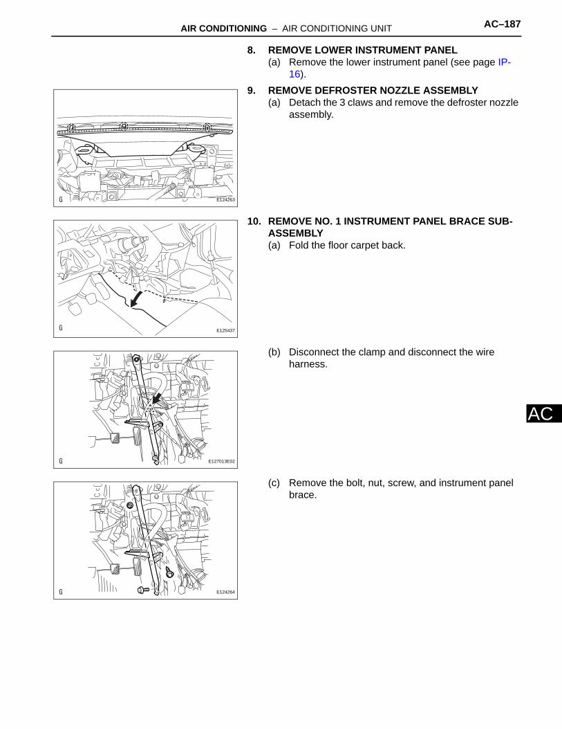
AIR CONDITIONING – AIR CONDITIONING UNIT AC–187
AC
8. REMOVE LOWER INSTRUMENT PANEL(a) Remove the lower instrument panel (see page IP-
16).9. REMOVE DEFROSTER NOZZLE ASSEMBLY
(a) Detach the 3 claws and remove the defroster nozzle assembly.
10. REMOVE NO. 1 INSTRUMENT PANEL BRACE SUB-ASSEMBLY(a) Fold the floor carpet back.
(b) Disconnect the clamp and disconnect the wire harness.
(c) Remove the bolt, nut, screw, and instrument panel brace.
E124263
E125437
E127013E02
E124264
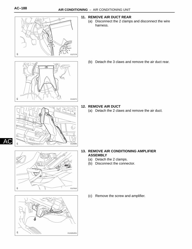
AC–188 AIR CONDITIONING – AIR CONDITIONING UNIT
AC
11. REMOVE AIR DUCT REAR(a) Disconnect the 2 clamps and disconnect the wire
harness.
(b) Detach the 3 claws and remove the air duct rear.
12. REMOVE AIR DUCT(a) Detach the 2 claws and remove the air duct.
13. REMOVE AIR CONDITIONING AMPLIFIER ASSEMBLY(a) Detach the 2 clamps.(b) Disconnect the connector.
(c) Remove the screw and amplifier.
E127179
E124272
E124265
E127015
: E124261E01

AIR CONDITIONING – AIR CONDITIONING UNIT AC–189
AC
14. REMOVE DRAIN COOLER HOSE(a) Remove the drain hose.
15. REMOVE INSTRUMENT PANEL REINFORCEMENT(a) Disconnect the 12 clamps.
(b) Remove the 4 bolts and disconnect the ground wire.
E124266
E124268E03
E124267

AC–190 AIR CONDITIONING – AIR CONDITIONING UNIT
AC
(c) Remove the 3 bolts.
(d) Remove the 6 bolts and instrument panel reinforcement.
16. REMOVE AIR CONDITIONER UNIT ASSEMBLY(a) Remove the bolt, nut and A/C unit.
E124269
E124270
E127016

AIR CONDITIONING – AIR CONDITIONING UNIT AC–191
AC
DISASSEMBLY1. REMOVE NO. 3 HEATER TO REGISTER DUCT
(a) Detach the 6 claws and remove the heater to register duct.
2. REMOVE AIR DUCT(a) Detach the 2 claws and remove the air duct.
3. REMOVE AIR OUTLET CONTROL SERVO MOTOR(a) Remove the 3 screws.(b) Detach the evaporator case from the blower case.
(c) Remove the 3 screws and disconnect the connector.
(d) Remove the air outlet control servo motor.
4. REMOVE AIR MIX CONTROL SERVO MOTOR(a) Remove the 3 screws and disconnect the
connector.(b) Remove the air mix control servo motor.
E127161
E126460
E127171
E124277
E124276
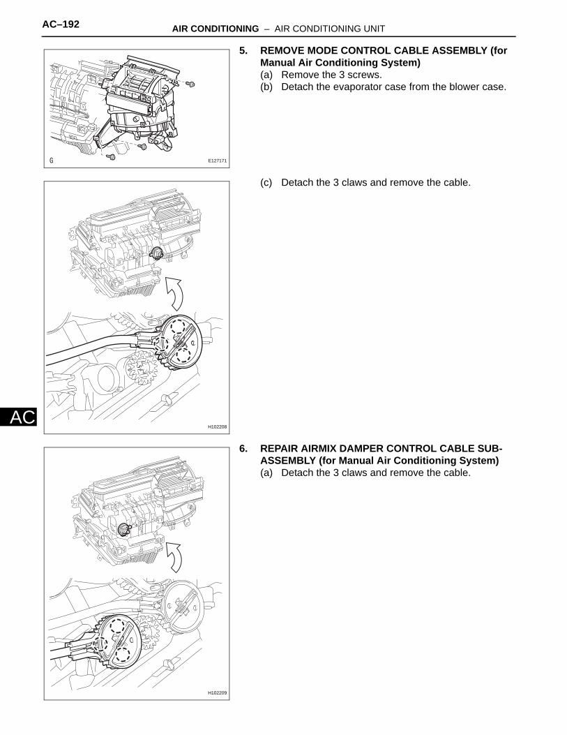
AC–192 AIR CONDITIONING – AIR CONDITIONING UNIT
AC
5. REMOVE MODE CONTROL CABLE ASSEMBLY (for Manual Air Conditioning System)(a) Remove the 3 screws.(b) Detach the evaporator case from the blower case.
(c) Detach the 3 claws and remove the cable.
6. REPAIR AIRMIX DAMPER CONTROL CABLE SUB-ASSEMBLY (for Manual Air Conditioning System)(a) Detach the 3 claws and remove the cable.
E127171
H102208
H102209
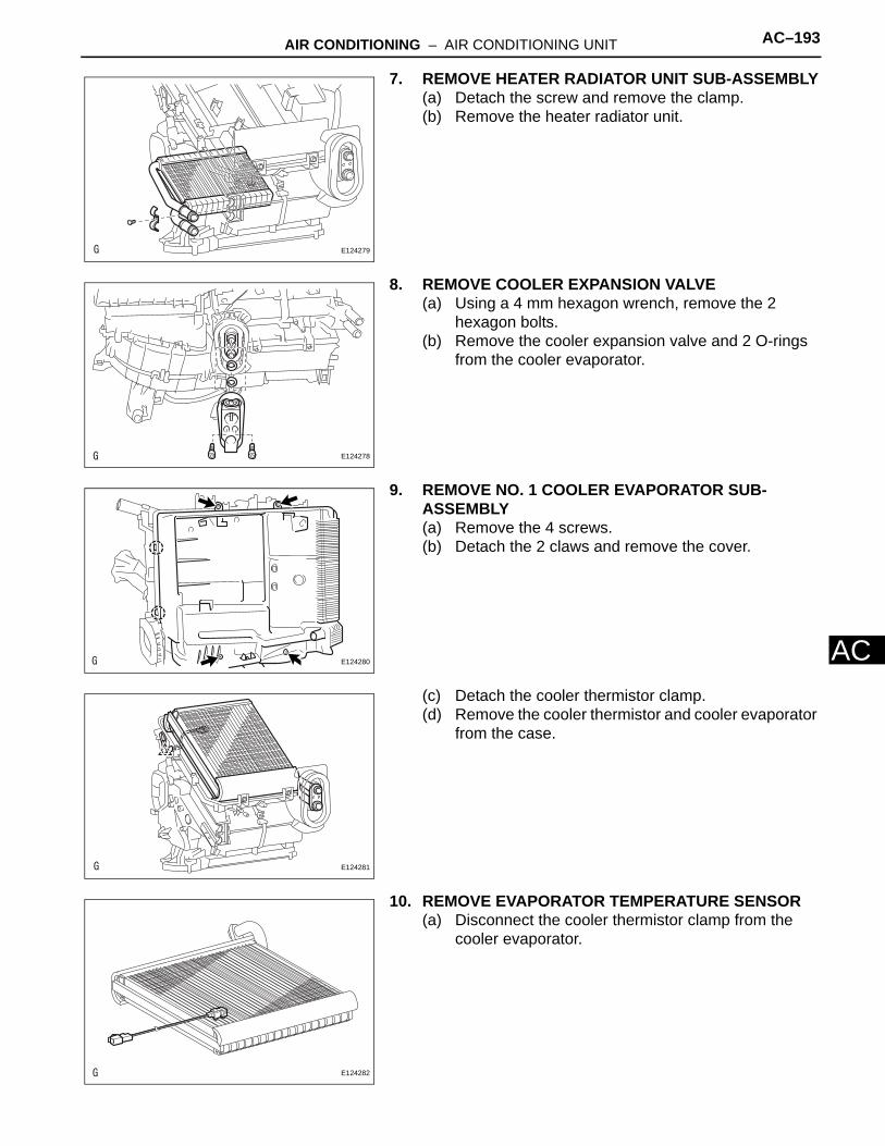
AIR CONDITIONING – AIR CONDITIONING UNIT AC–193
AC
7. REMOVE HEATER RADIATOR UNIT SUB-ASSEMBLY(a) Detach the screw and remove the clamp.(b) Remove the heater radiator unit.
8. REMOVE COOLER EXPANSION VALVE(a) Using a 4 mm hexagon wrench, remove the 2
hexagon bolts.(b) Remove the cooler expansion valve and 2 O-rings
from the cooler evaporator.
9. REMOVE NO. 1 COOLER EVAPORATOR SUB-ASSEMBLY(a) Remove the 4 screws.(b) Detach the 2 claws and remove the cover.
(c) Detach the cooler thermistor clamp.(d) Remove the cooler thermistor and cooler evaporator
from the case.
10. REMOVE EVAPORATOR TEMPERATURE SENSOR(a) Disconnect the cooler thermistor clamp from the
cooler evaporator.
E124279
E124278
E124280
E124281
E124282

AC–194 AIR CONDITIONING – AIR CONDITIONING UNIT
AC
REASSEMBLY1. INSTALL EVAPORATOR TEMPERATURE SENSOR
NOTICE:If reusing the evaporator, do not insert the sensor to a location where the sensor was previously inserted. Insert the sensor within range C shown in the illustration.(a) Install the evaporator temperature sensor as shown
in the illustration.
2. INSTALL NO. 1 COOLER EVAPORATOR SUB-ASSEMBLY(a) Install the cooler thermistor and cooler evaporator
on the case.(b) Attach the temperature sensor clamp.
(c) Attach the 2 claws to install the cover.(d) Install the 4 screws.
50 mm(1.96 in.)
34.3 mm(1.35 in.) E124283E01
E124281
E124280
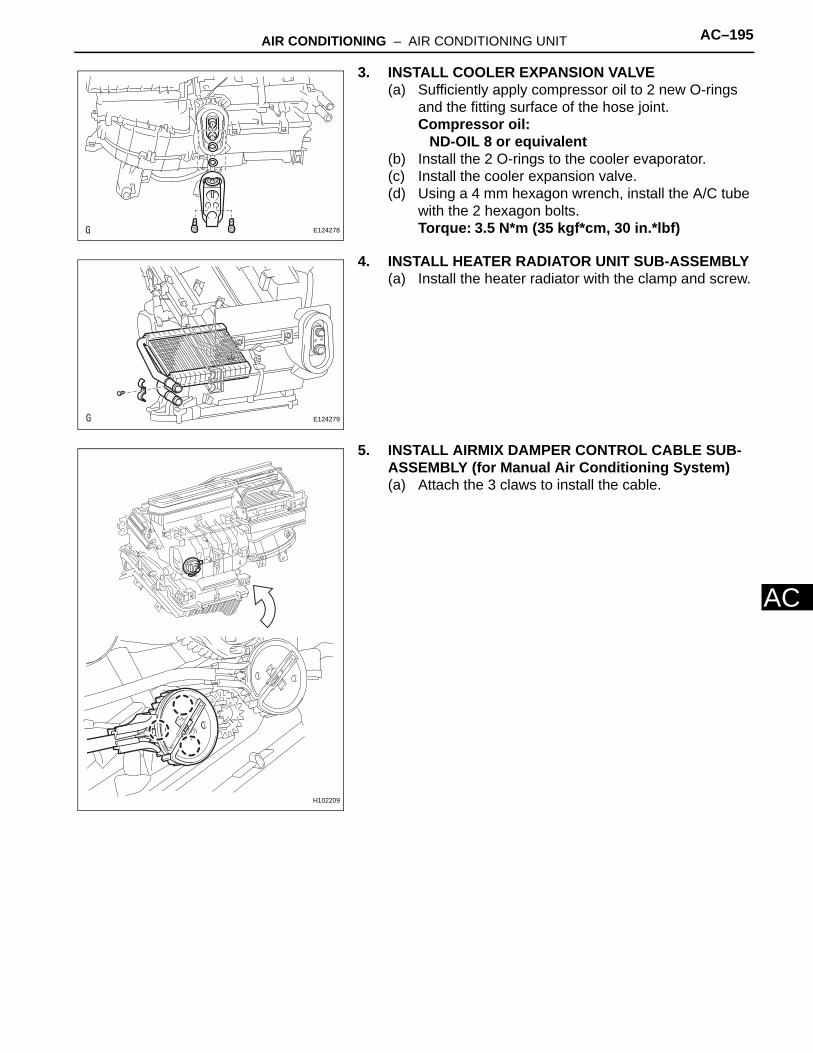
AIR CONDITIONING – AIR CONDITIONING UNIT AC–195
AC
3. INSTALL COOLER EXPANSION VALVE(a) Sufficiently apply compressor oil to 2 new O-rings
and the fitting surface of the hose joint.Compressor oil:
ND-OIL 8 or equivalent(b) Install the 2 O-rings to the cooler evaporator.(c) Install the cooler expansion valve.(d) Using a 4 mm hexagon wrench, install the A/C tube
with the 2 hexagon bolts. Torque: 3.5 N*m (35 kgf*cm, 30 in.*lbf)
4. INSTALL HEATER RADIATOR UNIT SUB-ASSEMBLY(a) Install the heater radiator with the clamp and screw.
5. INSTALL AIRMIX DAMPER CONTROL CABLE SUB-ASSEMBLY (for Manual Air Conditioning System)(a) Attach the 3 claws to install the cable.
E124278
E124279
H102209

AC–196 AIR CONDITIONING – AIR CONDITIONING UNIT
AC
6. INSTALL MODE CONTROL CABLE ASSEMBLY (for Manual Air Conditioning System)(a) Attach the 3 claws to install the cable.
(b) Attach the evaporator case to the blower case.(c) Install the cable with the 3 screws.
7. INSTALL AIR MIX CONTROL SERVO MOTOR(a) Install the air mix control servo motor with the 3
screws and connect the connector.
8. INSTALL AIR OUTLET CONTROL SERVO MOTOR(a) Install the air outlet control servo motor with the 3
screws and connect the connector.
H102208
E127171
E124276
E124277
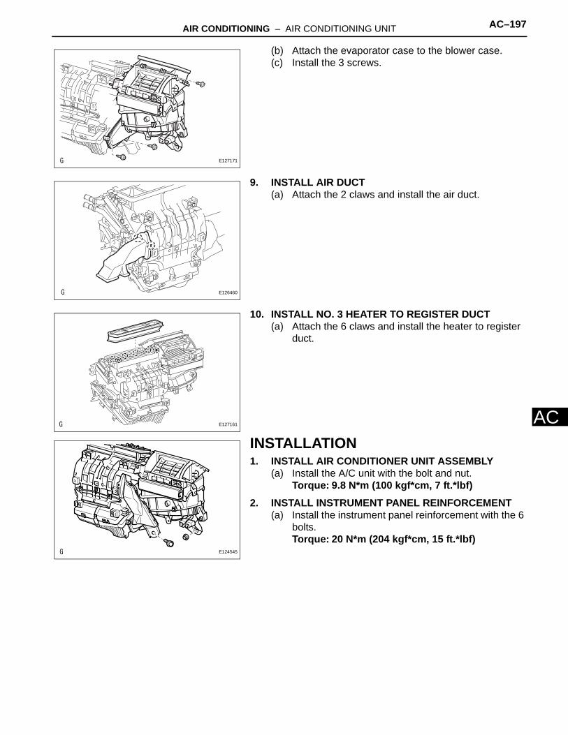
AIR CONDITIONING – AIR CONDITIONING UNIT AC–197
AC
(b) Attach the evaporator case to the blower case.(c) Install the 3 screws.
9. INSTALL AIR DUCT(a) Attach the 2 claws and install the air duct.
10. INSTALL NO. 3 HEATER TO REGISTER DUCT(a) Attach the 6 claws and install the heater to register
duct.
INSTALLATION1. INSTALL AIR CONDITIONER UNIT ASSEMBLY
(a) Install the A/C unit with the bolt and nut.Torque: 9.8 N*m (100 kgf*cm, 7 ft.*lbf)
2. INSTALL INSTRUMENT PANEL REINFORCEMENT(a) Install the instrument panel reinforcement with the 6
bolts.Torque: 20 N*m (204 kgf*cm, 15 ft.*lbf)
E127171
E126460
E127161
E124545
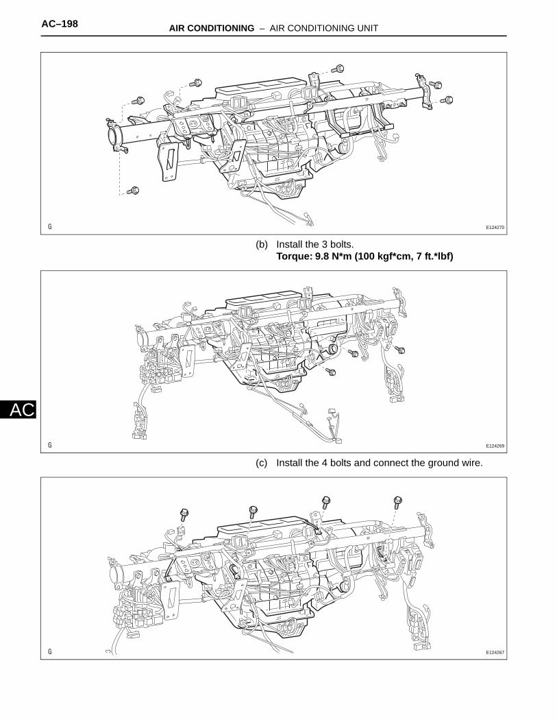
AC–198 AIR CONDITIONING – AIR CONDITIONING UNIT
AC
(b) Install the 3 bolts.Torque: 9.8 N*m (100 kgf*cm, 7 ft.*lbf)
(c) Install the 4 bolts and connect the ground wire.
E124270
E124269
E124267

AIR CONDITIONING – AIR CONDITIONING UNIT AC–199
AC
(d) Attach the 12 clamps.
3. INSTALL DRAIN COOLER HOSE(a) Install the drain hose.
4. INSTALL AIR CONDITIONING AMPLIFIER ASSEMBLY(a) Install the A/C amplifier with the screw.(b) Connect the connector.
(c) Attach the 2 clamps to the amplifier.
E124268E03
E124266
: E124261E01
E127015
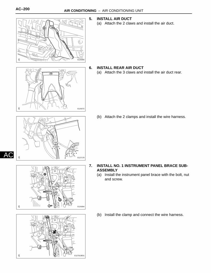
AC–200 AIR CONDITIONING – AIR CONDITIONING UNIT
AC
5. INSTALL AIR DUCT(a) Attach the 2 claws and install the air duct.
6. INSTALL REAR AIR DUCT(a) Attach the 3 claws and install the air duct rear.
(b) Attach the 2 clamps and install the wire harness.
7. INSTALL NO. 1 INSTRUMENT PANEL BRACE SUB-ASSEMBLY(a) Install the instrument panel brace with the bolt, nut
and screw.
(b) Install the clamp and connect the wire harness.
E124265
E124272
E127179
E124264
E127013E01
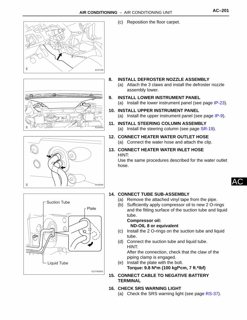
AIR CONDITIONING – AIR CONDITIONING UNIT AC–201
AC
(c) Reposition the floor carpet.
8. INSTALL DEFROSTER NOZZLE ASSEMBLY(a) Attach the 3 claws and install the defroster nozzle
assembly lower.
9. INSTALL LOWER INSTRUMENT PANEL(a) Install the lower instrument panel (see page IP-23).
10. INSTALL UPPER INSTRUMENT PANEL(a) Install the upper instrument panel (see page IP-9).
11. INSTALL STEERING COLUMN ASSEMBLY(a) Install the steering column (see page SR-19).
12. CONNECT HEATER WATER OUTLET HOSE(a) Connect the water hose and attach the clip.
13. CONNECT HEATER WATER INLET HOSEHINT:Use the same procedures described for the water outlet hose.
14. CONNECT TUBE SUB-ASSEMBLY(a) Remove the attached vinyl tape from the pipe.(b) Sufficiently apply compressor oil to new 2 O-rings
and the fitting surface of the suction tube and liquid tube.Compressor oil:
ND-OIL 8 or equivalent(c) Install the 2 O-rings on the suction tube and liquid
tube.(d) Connect the suction tube and liquid tube.
HINT:After the connection, check that the claw of the piping clamp is engaged.
(e) Install the plate with the bolt.Torque: 9.8 N*m (100 kgf*cm, 7 ft.*lbf)
15. CONNECT CABLE TO NEGATIVE BATTERY TERMINAL
16. CHECK SRS WARNING LIGHT(a) Check the SRS warning light (see page RS-37).
E127109
E124263
H102044
Suction Tube
Liquid Tube
Plate
E127302E01

AC–202 AIR CONDITIONING – AIR CONDITIONING UNIT
AC
17. REPLACE ENGINE COOLANTRefer to the following procedures (see page CO-6).
18. CHARGE REFRIGERANT (See page AC-172)19. WARM UP ENGINE (See page AC-173)20. CHECK FOR ENGINE COOLANT LEAKS21. CHECK FOR LEAKAGE OF REFRIGERANT (See
page AC-173)
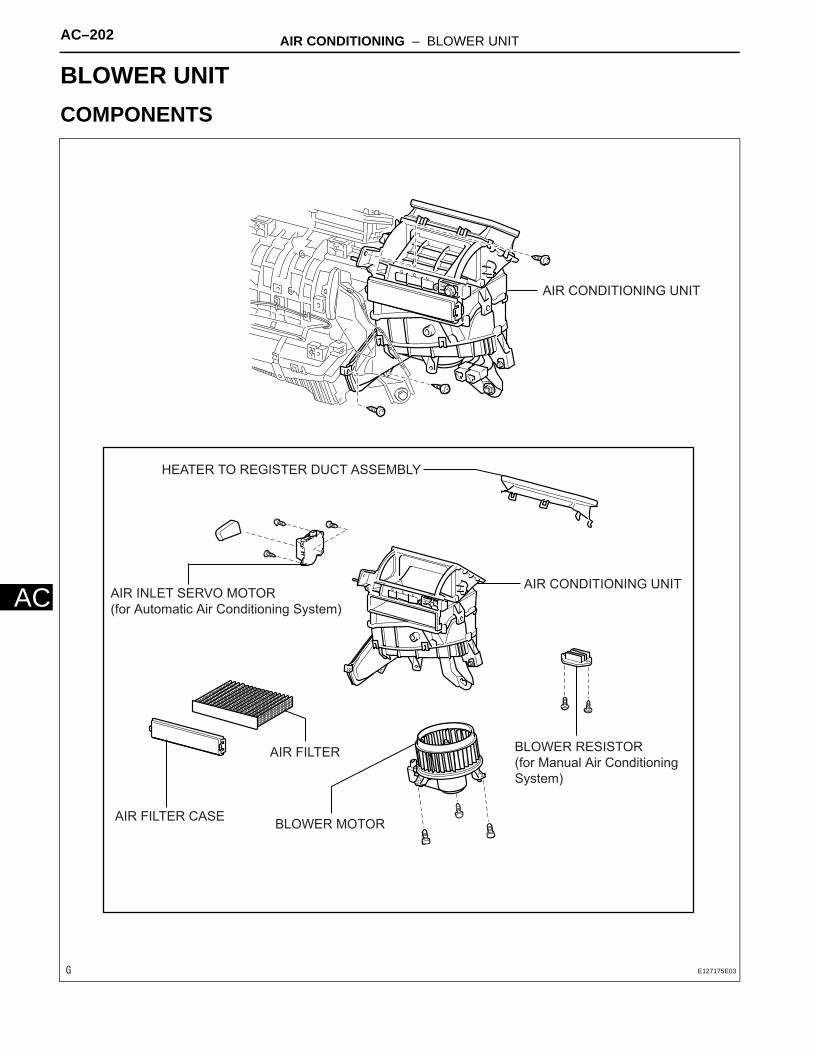
AC–202 AIR CONDITIONING – BLOWER UNIT
AC
HEATER & AIR CONDITIONING SYSTEMAIR CONDITIONINGBLOWER UNITCOMPONENTS
AIR CONDITIONING UNIT
AIR FILTER CASE
AIR INLET SERVO MOTOR
(for Automatic Air Conditioning System)
BLOWER MOTOR
BLOWER RESISTOR
(for Manual Air Conditioning
System)
HEATER TO REGISTER DUCT ASSEMBLY
AIR FILTER
AIR CONDITIONING UNIT
E127175E03

AIR CONDITIONING – BLOWER UNIT AC–203
AC
REMOVAL1. DISCONNECT CABLE FROM NEGATIVE BATTERY
TERMINALCAUTION:Wait at least 90 seconds after disconnecting the cable from the negative (-) battery terminal to prevent airbag and seat belt pretensioner activation.
2. REMOVE UPPER INSTRUMENT PANEL(a) Remove the upper instrument panel (see page IP-
4).
3. REMOVE LOWER INSTRUMENT PANEL(a) Remove the lower instrument panel (see page IP-
16).
4. REMOVE AIR DUCT (See page AC-188)5. REMOVE AIR CONDITIONING UNIT
(a) Remove the air conditioning unit (see page AC-185).
6. REMOVE BLOWER ASSEMBLY(a) Remove the 3 screws and blower.
DISASSEMBLY1. REMOVE HEATER TO REGISTER DUCT ASSEMBLY
(a) Detach the 7 claws and register duct.
2. REMOVE AIR FILTER CASE(a) Detach the 2 claws and remove the air filter case.(b) Remove the air filter.
E127171
E124273
E124286
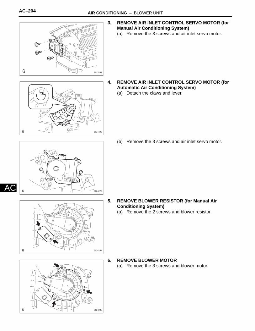
AC–204 AIR CONDITIONING – BLOWER UNIT
AC
3. REMOVE AIR INLET CONTROL SERVO MOTOR (for Manual Air Conditioning System)(a) Remove the 3 screws and air inlet servo motor.
4. REMOVE AIR INLET CONTROL SERVO MOTOR (for Automatic Air Conditioning System)(a) Detach the claws and lever.
(b) Remove the 3 screws and air inlet servo motor.
5. REMOVE BLOWER RESISTOR (for Manual Air Conditioning System)(a) Remove the 2 screws and blower resistor.
6. REMOVE BLOWER MOTOR(a) Remove the 3 screws and blower motor.
E127459
E127280
E124275
E124284
E124285
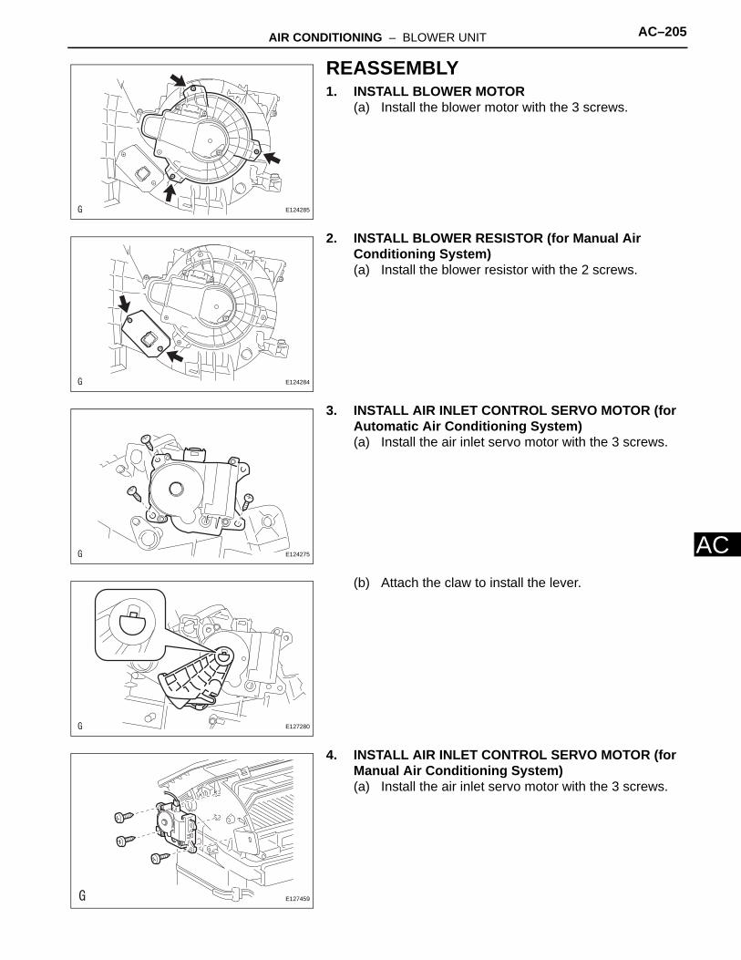
AIR CONDITIONING – BLOWER UNIT AC–205
AC
REASSEMBLY1. INSTALL BLOWER MOTOR
(a) Install the blower motor with the 3 screws.
2. INSTALL BLOWER RESISTOR (for Manual Air Conditioning System)(a) Install the blower resistor with the 2 screws.
3. INSTALL AIR INLET CONTROL SERVO MOTOR (for Automatic Air Conditioning System)(a) Install the air inlet servo motor with the 3 screws.
(b) Attach the claw to install the lever.
4. INSTALL AIR INLET CONTROL SERVO MOTOR (for Manual Air Conditioning System)(a) Install the air inlet servo motor with the 3 screws.
E124285
E124284
E124275
E127280
E127459

AC–206 AIR CONDITIONING – BLOWER UNIT
AC
5. INSTALL AIR FILTER CASE(a) Install the air filter.(b) Attach the 2 claws to install the air filter case.
6. INSTALL HEATER TO REGISTER DUCT ASSEMBLY(a) Attach the 7 claws to install the register duct.
INSTALLATION1. INSTALL BLOWER ASSEMBLY
(a) Install the blower assembly with the 3 screws.
2. INSTALL AIR CONDITIONING UNIT(a) Install the air conditioning unit (see page AC-197).
3. INSTALL AIR DUCT (See page AC-199)4. INSTALL LOWER INSTRUMENT PANEL
(a) Install the lower instrument panel (see page IP-23).
5. INSTALL UPPER INSTRUMENT PANEL(a) Install the upper instrument panel (see page IP-9).
6. CONNECT CABLE TO NEGATIVE BATTERY TERMINAL
7. CHECK SRS WARNING LIGHT(a) Check the SRS warning light (see page RS-37).
E124286
E124273
E127171
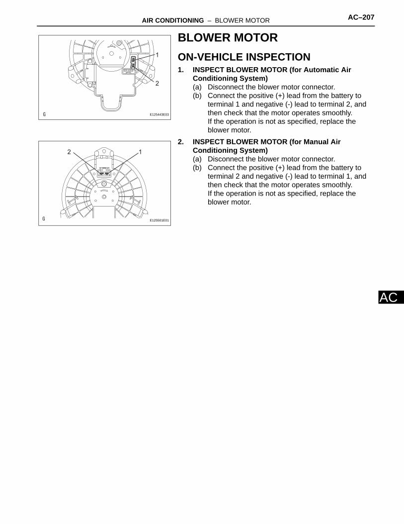
AIR CONDITIONING – BLOWER MOTOR AC–207
AC
BLOWER MOTORON-VEHICLE INSPECTION1. INSPECT BLOWER MOTOR (for Automatic Air
Conditioning System)(a) Disconnect the blower motor connector.(b) Connect the positive (+) lead from the battery to
terminal 1 and negative (-) lead to terminal 2, and then check that the motor operates smoothly.If the operation is not as specified, replace the blower motor.
2. INSPECT BLOWER MOTOR (for Manual Air Conditioning System)(a) Disconnect the blower motor connector.(b) Connect the positive (+) lead from the battery to
terminal 2 and negative (-) lead to terminal 1, and then check that the motor operates smoothly.If the operation is not as specified, replace the blower motor.
1
2
E125443E03
12
E125501E01
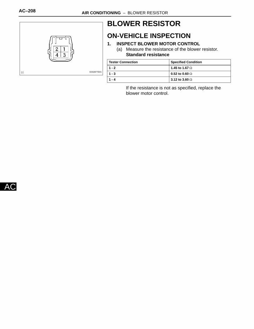
AC–208 AIR CONDITIONING – BLOWER RESISTOR
AC
BLOWER RESISTORON-VEHICLE INSPECTION1. INSPECT BLOWER MOTOR CONTROL
(a) Measure the resistance of the blower resistor.Standard resistance
If the resistance is not as specified, replace the blower motor control.
E032877E01
Tester Connection Specified Condition
1 - 2 1.45 to 1.67 Ω
1 - 3 0.52 to 0.60 Ω
1 - 4 3.12 to 3.60 Ω

AIR CONDITIONING – AIR INLET CONTROL SERVO MOTOR AC–209
AC
HEATER & AIR CONDITIONING SYSTEMAIR CONDITIONINGAIR INLET CONTROL SERVO MOTORCOMPONENTS
BLOWER ASSEMBLY
AIR INLET CONTROL SERVO MOTOR
(for Manual Air Conditioning System)
AIR INLET CONTROL SERVO MOTOR
(for Automatic Air Conditioning System)
E126831E01
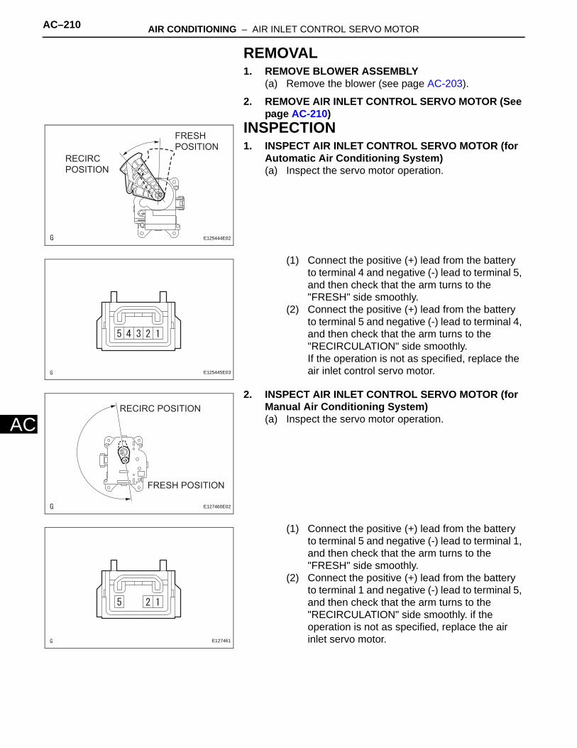
AC–210 AIR CONDITIONING – AIR INLET CONTROL SERVO MOTOR
AC
REMOVAL1. REMOVE BLOWER ASSEMBLY
(a) Remove the blower (see page AC-203).
2. REMOVE AIR INLET CONTROL SERVO MOTOR (See page AC-210)
INSPECTION1. INSPECT AIR INLET CONTROL SERVO MOTOR (for
Automatic Air Conditioning System)(a) Inspect the servo motor operation.
(1) Connect the positive (+) lead from the battery to terminal 4 and negative (-) lead to terminal 5, and then check that the arm turns to the "FRESH" side smoothly.
(2) Connect the positive (+) lead from the battery to terminal 5 and negative (-) lead to terminal 4, and then check that the arm turns to the "RECIRCULATION" side smoothly.If the operation is not as specified, replace the air inlet control servo motor.
2. INSPECT AIR INLET CONTROL SERVO MOTOR (for Manual Air Conditioning System)(a) Inspect the servo motor operation.
(1) Connect the positive (+) lead from the battery to terminal 5 and negative (-) lead to terminal 1, and then check that the arm turns to the "FRESH" side smoothly.
(2) Connect the positive (+) lead from the battery to terminal 1 and negative (-) lead to terminal 5, and then check that the arm turns to the "RECIRCULATION" side smoothly. if the operation is not as specified, replace the air inlet servo motor.
FRESH
POSITION
RECIRC
POSITION
E125444E02
E125445E03
FRESH POSITION
RECIRC POSITION
E127460E02
E127461

AIR CONDITIONING – AIR INLET CONTROL SERVO MOTOR AC–211
AC
INSTALLATION1. INSTALL AIR INLET CONTROL SERVO MOTOR (See
page AC-206)2. INSTALL BLOWER ASSEMBLY
(a) Install the blower (see page AC-206).
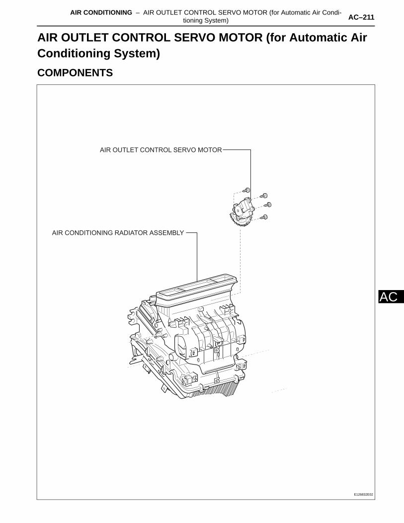
AIR CONDITIONING – AIR OUTLET CONTROL SERVO MOTOR (for Automatic Air Condi-tioning System) AC–211
AC
HEATER & AIR CONDITIONING SYSTEMAIR CONDITIONINGAIR OUTLET CONTROL SERVO MOTOR (for Automatic Air Conditioning System)COMPONENTS
AIR CONDITIONING RADIATOR ASSEMBLY
AIR OUTLET CONTROL SERVO MOTOR
E126832E02
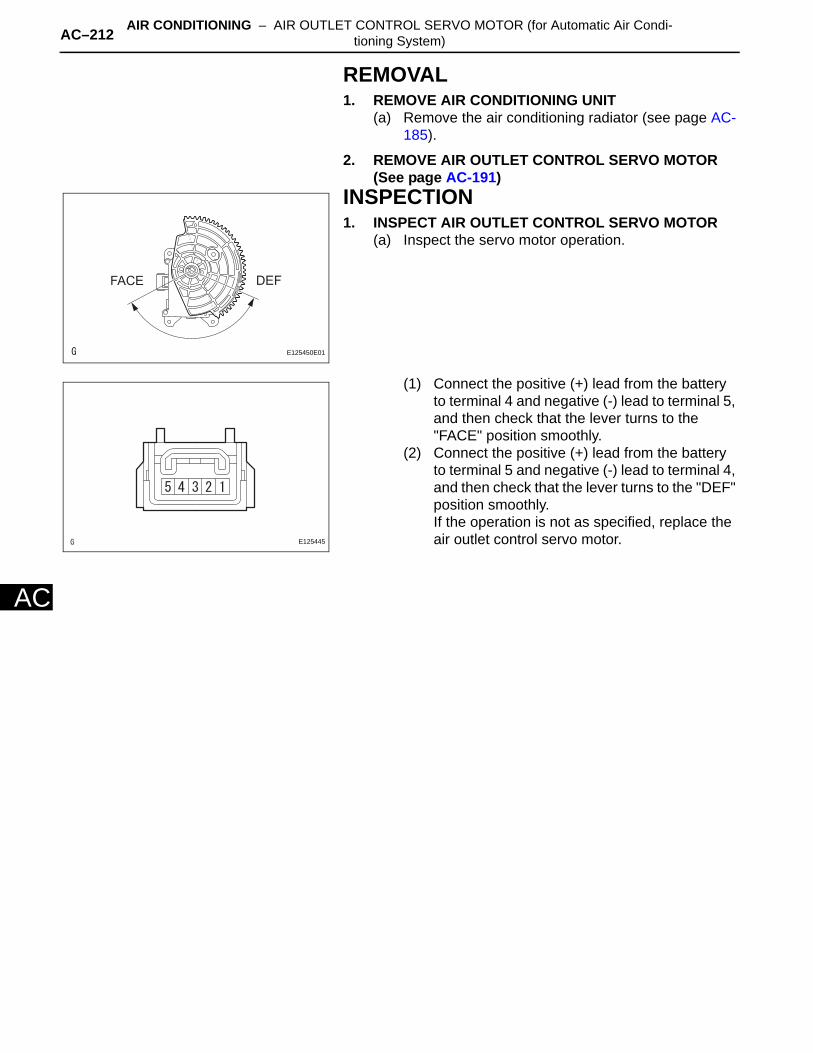
AC–212 AIR CONDITIONING – AIR OUTLET CONTROL SERVO MOTOR (for Automatic Air Condi-tioning System)
AC
REMOVAL1. REMOVE AIR CONDITIONING UNIT
(a) Remove the air conditioning radiator (see page AC-185).
2. REMOVE AIR OUTLET CONTROL SERVO MOTOR (See page AC-191)
INSPECTION1. INSPECT AIR OUTLET CONTROL SERVO MOTOR
(a) Inspect the servo motor operation.
(1) Connect the positive (+) lead from the battery to terminal 4 and negative (-) lead to terminal 5, and then check that the lever turns to the "FACE" position smoothly.
(2) Connect the positive (+) lead from the battery to terminal 5 and negative (-) lead to terminal 4, and then check that the lever turns to the "DEF" position smoothly.If the operation is not as specified, replace the air outlet control servo motor.
FACE DEF
E125450E01
E125445
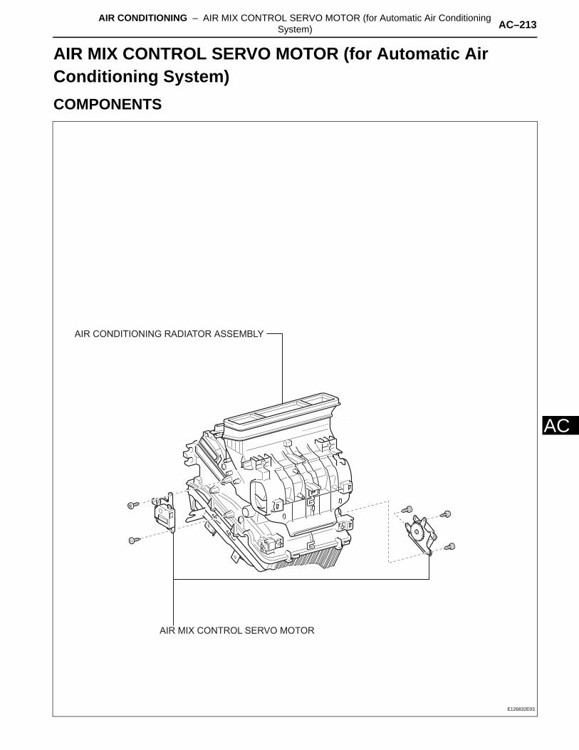
AIR CONDITIONING – AIR MIX CONTROL SERVO MOTOR (for Automatic Air Conditioning System) AC–213
AC
HEATER & AIR CONDITIONING SYSTEMAIR CONDITIONINGAIR MIX CONTROL SERVO MOTOR (for Automatic Air Conditioning System)COMPONENTS
AIR CONDITIONING RADIATOR ASSEMBLY
AIR MIX CONTROL SERVO MOTOR
E126832E03
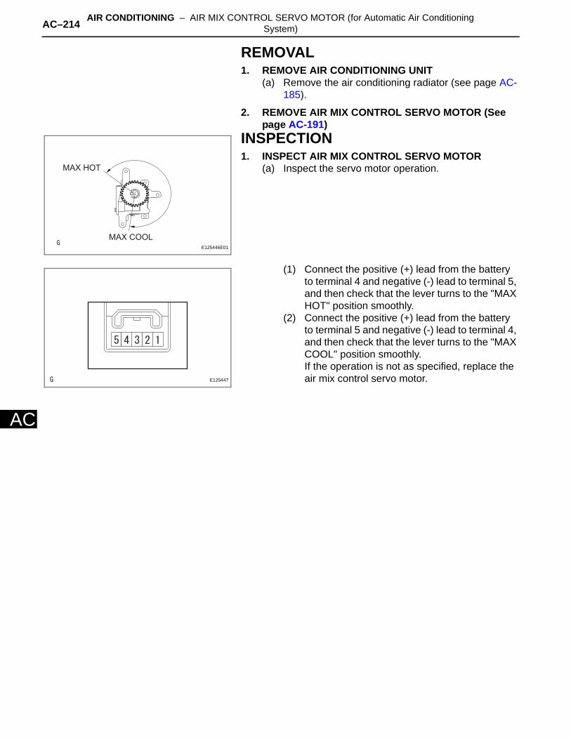
AC–214 AIR CONDITIONING – AIR MIX CONTROL SERVO MOTOR (for Automatic Air Conditioning System)
AC
REMOVAL1. REMOVE AIR CONDITIONING UNIT
(a) Remove the air conditioning radiator (see page AC-185).
2. REMOVE AIR MIX CONTROL SERVO MOTOR (See page AC-191)
INSPECTION1. INSPECT AIR MIX CONTROL SERVO MOTOR
(a) Inspect the servo motor operation.
(1) Connect the positive (+) lead from the battery to terminal 4 and negative (-) lead to terminal 5, and then check that the lever turns to the "MAX HOT" position smoothly.
(2) Connect the positive (+) lead from the battery to terminal 5 and negative (-) lead to terminal 4, and then check that the lever turns to the "MAX COOL" position smoothly.If the operation is not as specified, replace the air mix control servo motor.
MAX HOT
MAX COOL
E125446E01
E125447

AIR CONDITIONING – AIR OUTLET CONTROL SERVO MOTOR (for Automatic Air Condi-tioning System) AC–213
AC
INSTALLATION1. INSTALL AIR OUTLET CONTROL SERVO MOTOR
(See page AC-196)2. INSTALL AIR CONDITIONING UNIT
(a) Install the air conditioning radiator (see page AC-197).
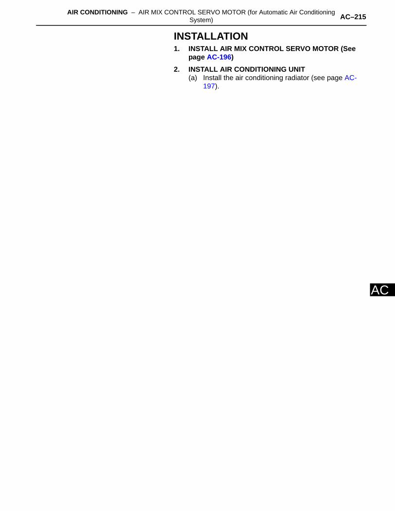
AIR CONDITIONING – AIR MIX CONTROL SERVO MOTOR (for Automatic Air Conditioning System) AC–215
AC
INSTALLATION1. INSTALL AIR MIX CONTROL SERVO MOTOR (See
page AC-196)2. INSTALL AIR CONDITIONING UNIT
(a) Install the air conditioning radiator (see page AC-197).
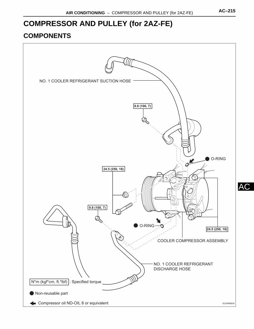
AIR CONDITIONING – COMPRESSOR AND PULLEY (for 2AZ-FE) AC–215
AC
HEATER & AIR CONDITIONING SYSTEMAIR CONDITIONINGCOMPRESSOR AND PULLEY (for 2AZ-FE)COMPONENTS
NO. 1 COOLER REFRIGERANT
DISCHARGE HOSE
NO. 1 COOLER REFRIGERANT SUCTION HOSE
24.5 (250, 18)
9.8 (100, 7)
9.8 (100, 7)
24.5 (250, 18)
COOLER COMPRESSOR ASSEMBLY
O-RING
O-RING
: Specified torqueN*m (kgf*cm, ft.*lbf)
Non-reusable part
Compressor oil ND-OIL 8 or equivalent E125455E02
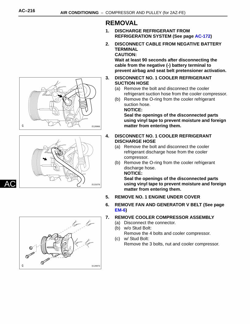
AC–216 AIR CONDITIONING – COMPRESSOR AND PULLEY (for 2AZ-FE)
AC
REMOVAL1. DISCHARGE REFRIGERANT FROM
REFRIGERATION SYSTEM (See page AC-172)2. DISCONNECT CABLE FROM NEGATIVE BATTERY
TERMINALCAUTION:Wait at least 90 seconds after disconnecting the cable from the negative (-) battery terminal to prevent airbag and seat belt pretensioner activation.
3. DISCONNECT NO. 1 COOLER REFRIGERANT SUCTION HOSE(a) Remove the bolt and disconnect the cooler
refrigerant suction hose from the cooler compressor.(b) Remove the O-ring from the cooler refrigerant
suction hose.NOTICE:Seal the openings of the disconnected parts using vinyl tape to prevent moisture and foreign matter from entering them.
4. DISCONNECT NO. 1 COOLER REFRIGERANT DISCHARGE HOSE(a) Remove the bolt and disconnect the cooler
refrigerant discharge hose from the cooler compressor.
(b) Remove the O-ring from the cooler refrigerant discharge hose.NOTICE:Seal the openings of the disconnected parts using vinyl tape to prevent moisture and foreign matter from entering them.
5. REMOVE NO. 1 ENGINE UNDER COVER6. REMOVE FAN AND GENERATOR V BELT (See page
EM-6)7. REMOVE COOLER COMPRESSOR ASSEMBLY
(a) Disconnect the connector.(b) w/o Stud Bolt:
Remove the 4 bolts and cooler compressor.(c) w/ Stud Bolt:
Remove the 3 bolts, nut and cooler compressor.
E126966
E131076
E126973

AIR CONDITIONING – COMPRESSOR AND PULLEY (for 2AZ-FE) AC–217
AC
INSTALLATION1. ADJUST ADJUST COMPRESSOR OIL
(a) When replacing the compressor and magnetic clutch with a new one, gradually discharge the refrigerant gas from the service valve, and drain the following amount of oil from the new compressor and magnetic clutch before installation.Standard:
(Oil capacity inside the new compressor and magnetic clutch: 130 + 15 cc (4.6 + 0.51 fl.oz.) ) -(Remaining oil amount in the removed compressor and magnetic clutch) = (Oil amount to be removed from the new compressor when replacing)
NOTICE:• When checking the compressor oil level,
observe the precautions on the cooler removal/installation.
• If a new compressor and magnetic clutch is installed without removing some oil remaining in the pipes of the vehicle, the oil amount will be too large. This prevents heat exchange in the refrigerant cycle and causes refrigerant failure.
• If the volume of oil remaining in the removed compressor and magnetic clutch is too small, check for oil leakage.
• Be sure to use ND-OIL 8 or equivalent for compressor oil.
2. INSTALL COOLER COMPRESSOR ASSEMBLY(a) w/o Stud Bolt:
Install the cooler compressor with the 4 bolts.Torque: 24.5 N*m (250 kgf*cm, 18 ft.*lbf)NOTICE:Tighten the bolts in the order shown in the illustration to install the cooler compressor.
(b) w/ Stud Bolt:Install the cooler compressor with the 3 bolts and nut.Torque: 24.5 N*m (250 kgf*cm, 18 ft.*lbf)NOTICE:Tighten the bolts in the order shown in the illustration to install the cooler compressor.
(c) Connect the connector.
(1)
(2) (3)
(4)
E134063E01
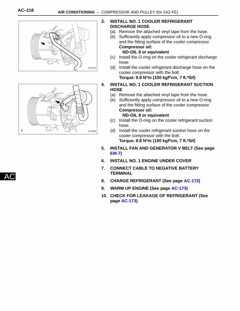
AC–218 AIR CONDITIONING – COMPRESSOR AND PULLEY (for 2AZ-FE)
AC
3. INSTALL NO. 1 COOLER REFRIGERANT DISCHARGE HOSE(a) Remove the attached vinyl tape from the hose.(b) Sufficiently apply compressor oil to a new O-ring
and the fitting surface of the cooler compressor.Compressor oil:
ND-OIL 8 or equivalent(c) Install the O-ring on the cooler refrigerant discharge
hose.(d) Install the cooler refrigerant discharge hose on the
cooler compressor with the bolt.Torque: 9.8 N*m (100 kgf*cm, 7 ft.*lbf)
4. INSTALL NO. 1 COOLER REFRIGERANT SUCTION HOSE(a) Remove the attached vinyl tape from the hose.(b) Sufficiently apply compressor oil to a new O-ring
and the fitting surface of the cooler compressor.Compressor oil:
ND-OIL 8 or equivalent(c) Install the O-ring on the cooler refrigerant suction
hose.(d) Install the cooler refrigerant suction hose on the
cooler compressor with the bolt.Torque: 9.8 N*m (100 kgf*cm, 7 ft.*lbf)
5. INSTALL FAN AND GENERATOR V BELT (See page EM-7)
6. INSTALL NO. 1 ENGINE UNDER COVER7. CONNECT CABLE TO NEGATIVE BATTERY
TERMINAL8. CHARGE REFRIGERANT (See page AC-172)9. WARM UP ENGINE (See page AC-173)10. CHECK FOR LEAKAGE OF REFRIGERANT (See
page AC-173)
E131076
E126966

AIR CONDITIONING – COMPRESSOR AND PULLEY (for 2GR-FE) AC–219
AC
HEATER & AIR CONDITIONING SYSTEMAIR CONDITIONINGCOMPRESSOR AND PULLEY (for 2GR-FE)COMPONENTS
N*m (kgf*cm, ft.*lbf) : Specified torque
Non-reusable part
24.5 (250, 18)
9.8 (100, 7)
9.8 (100, 7)
Compressor oil ND-OIL 8 or equivalent
O-RING
O-RING
COOLER COMPRESSOR ASSEMBLY
NO. 1 COOLER REFRIGERANT DISCHARGE HOSE
NO. 1 COOLER REFRIGERANT SUCTION HOSE
FAN AND GENERATOR V BELT
H102033E01
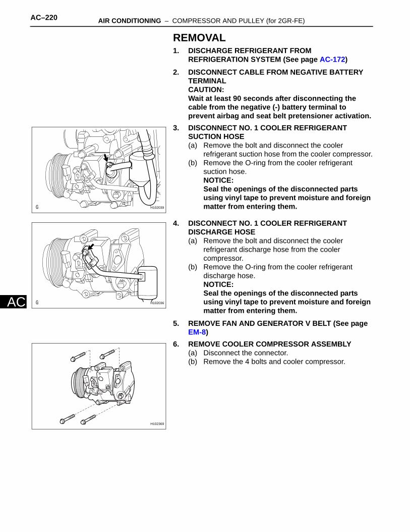
AC–220 AIR CONDITIONING – COMPRESSOR AND PULLEY (for 2GR-FE)
AC
REMOVAL1. DISCHARGE REFRIGERANT FROM
REFRIGERATION SYSTEM (See page AC-172)2. DISCONNECT CABLE FROM NEGATIVE BATTERY
TERMINALCAUTION:Wait at least 90 seconds after disconnecting the cable from the negative (-) battery terminal to prevent airbag and seat belt pretensioner activation.
3. DISCONNECT NO. 1 COOLER REFRIGERANT SUCTION HOSE(a) Remove the bolt and disconnect the cooler
refrigerant suction hose from the cooler compressor.(b) Remove the O-ring from the cooler refrigerant
suction hose.NOTICE:Seal the openings of the disconnected parts using vinyl tape to prevent moisture and foreign matter from entering them.
4. DISCONNECT NO. 1 COOLER REFRIGERANT DISCHARGE HOSE(a) Remove the bolt and disconnect the cooler
refrigerant discharge hose from the cooler compressor.
(b) Remove the O-ring from the cooler refrigerant discharge hose.NOTICE:Seal the openings of the disconnected parts using vinyl tape to prevent moisture and foreign matter from entering them.
5. REMOVE FAN AND GENERATOR V BELT (See page EM-8)
6. REMOVE COOLER COMPRESSOR ASSEMBLY(a) Disconnect the connector.(b) Remove the 4 bolts and cooler compressor.
H102039
H102036
H102369
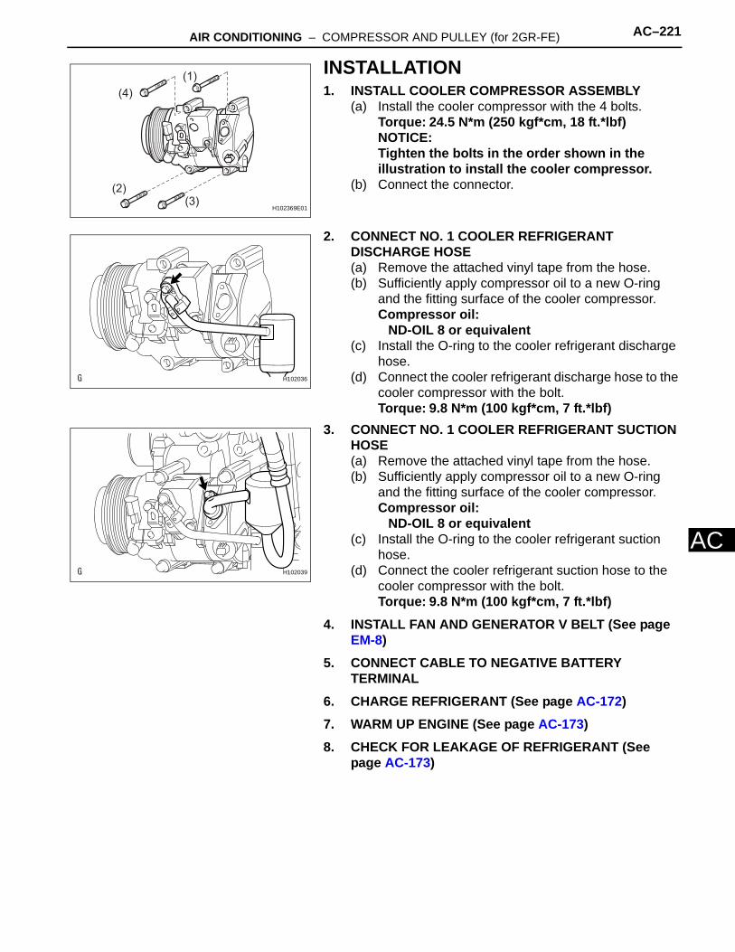
AIR CONDITIONING – COMPRESSOR AND PULLEY (for 2GR-FE) AC–221
AC
INSTALLATION1. INSTALL COOLER COMPRESSOR ASSEMBLY
(a) Install the cooler compressor with the 4 bolts.Torque: 24.5 N*m (250 kgf*cm, 18 ft.*lbf)NOTICE:Tighten the bolts in the order shown in the illustration to install the cooler compressor.
(b) Connect the connector.
2. CONNECT NO. 1 COOLER REFRIGERANT DISCHARGE HOSE(a) Remove the attached vinyl tape from the hose.(b) Sufficiently apply compressor oil to a new O-ring
and the fitting surface of the cooler compressor.Compressor oil:
ND-OIL 8 or equivalent(c) Install the O-ring to the cooler refrigerant discharge
hose.(d) Connect the cooler refrigerant discharge hose to the
cooler compressor with the bolt.Torque: 9.8 N*m (100 kgf*cm, 7 ft.*lbf)
3. CONNECT NO. 1 COOLER REFRIGERANT SUCTION HOSE(a) Remove the attached vinyl tape from the hose.(b) Sufficiently apply compressor oil to a new O-ring
and the fitting surface of the cooler compressor.Compressor oil:
ND-OIL 8 or equivalent(c) Install the O-ring to the cooler refrigerant suction
hose.(d) Connect the cooler refrigerant suction hose to the
cooler compressor with the bolt.Torque: 9.8 N*m (100 kgf*cm, 7 ft.*lbf)
4. INSTALL FAN AND GENERATOR V BELT (See page EM-8)
5. CONNECT CABLE TO NEGATIVE BATTERY TERMINAL
6. CHARGE REFRIGERANT (See page AC-172)7. WARM UP ENGINE (See page AC-173)8. CHECK FOR LEAKAGE OF REFRIGERANT (See
page AC-173)
(1)
(4)
(3)(2)
H102369E01
H102036
H102039
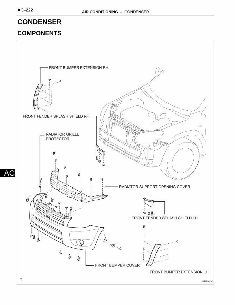
AC–222 AIR CONDITIONING – CONDENSER
AC
HEATER & AIR CONDITIONING SYSTEMAIR CONDITIONINGCONDENSERCOMPONENTS
FRONT BUMPER COVER
FRONT FENDER SPLASH SHIELD LH
FRONT BUMPER EXTENSION RH
FRONT FENDER SPLASH SHIELD RH
RADIATOR GRILLE
PROTECTOR
RADIATOR SUPPORT OPENING COVER
FRONT BUMPER EXTENSION LH
B127930E02
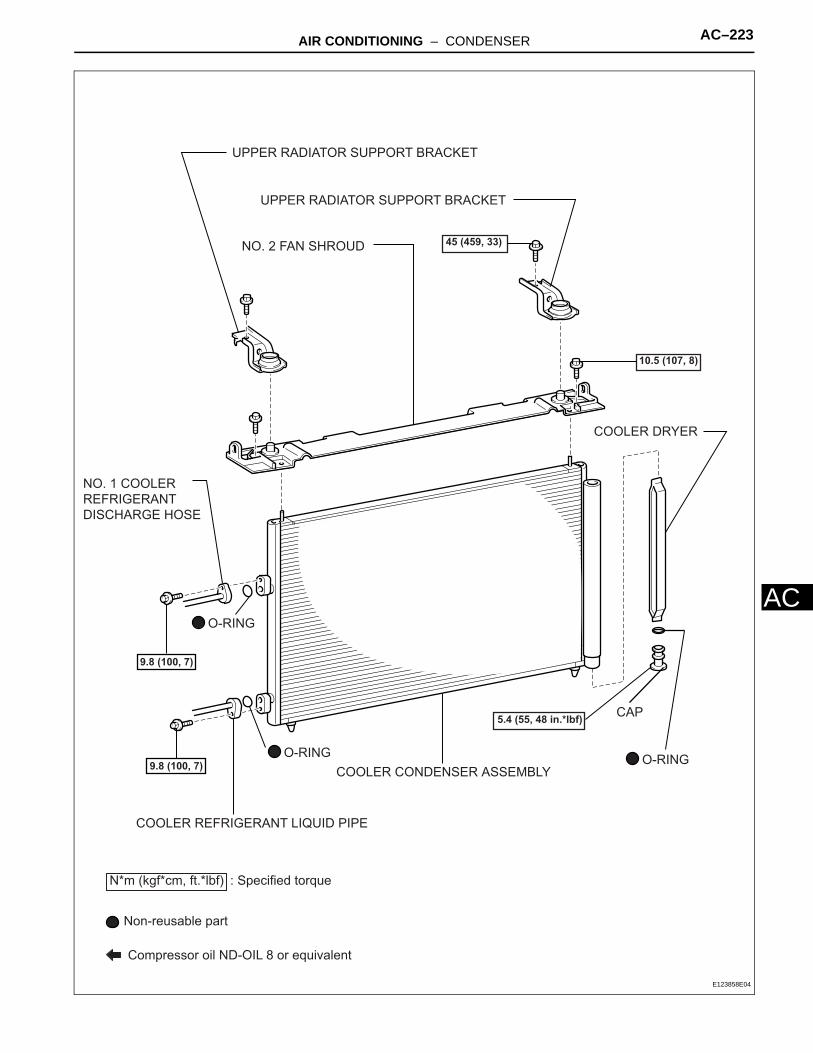
AIR CONDITIONING – CONDENSER AC–223
AC
COOLER CONDENSER ASSEMBLY
NO. 2 FAN SHROUD
UPPER RADIATOR SUPPORT BRACKET
UPPER RADIATOR SUPPORT BRACKET
COOLER REFRIGERANT LIQUID PIPE
NO. 1 COOLER
REFRIGERANT
DISCHARGE HOSE
COOLER DRYER
N*m (kgf*cm, ft.*lbf) : Specified torque
5.4 (55, 48 in.*lbf)
Non-reusable part
Compressor oil ND-OIL 8 or equivalent
O-RINGO-RING
O-RING
CAP
10.5 (107, 8)
45 (459, 33)
9.8 (100, 7)
9.8 (100, 7)
E123858E04
AC–224 AIR CONDITIONING – CONDENSER
AC
ON-VEHICLE INSPECTION1. INSPECT COOLER CONDENSER ASSEMBLY
(a) If the fins of the cooler condenser are dirty, clean them with water. Dry the fins with compressed air.NOTICE:Do not damage the fins of the condenser.
(b) If a fin of the cooler condenser is bent, straighten it using a screwdriver or pliers.
2. CHECK CONDENSER FOR LEAKAGE OF REFRIGERANT(a) Using a halogen leak detector, check the pipe joints
for gas leakage.(b) If gas leakage is detected in a joint, check the
torque of the joint.
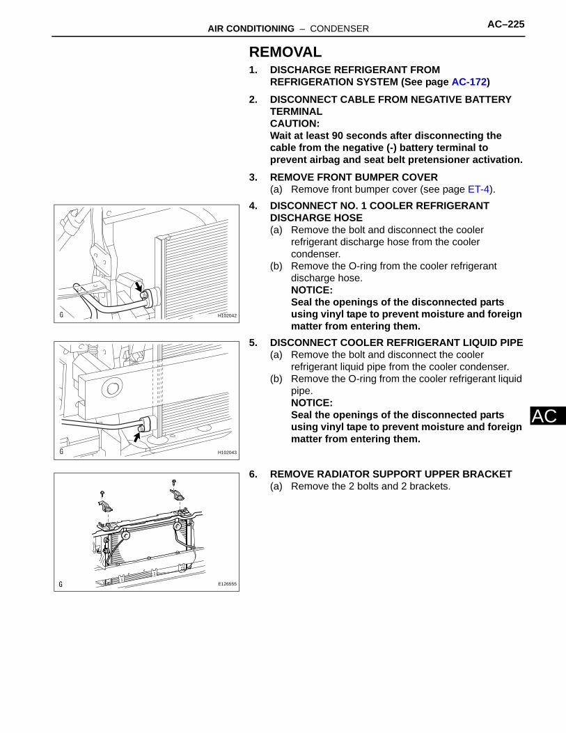
AIR CONDITIONING – CONDENSER AC–225
AC
REMOVAL1. DISCHARGE REFRIGERANT FROM
REFRIGERATION SYSTEM (See page AC-172)2. DISCONNECT CABLE FROM NEGATIVE BATTERY
TERMINALCAUTION:Wait at least 90 seconds after disconnecting the cable from the negative (-) battery terminal to prevent airbag and seat belt pretensioner activation.
3. REMOVE FRONT BUMPER COVER(a) Remove front bumper cover (see page ET-4).
4. DISCONNECT NO. 1 COOLER REFRIGERANT DISCHARGE HOSE(a) Remove the bolt and disconnect the cooler
refrigerant discharge hose from the cooler condenser.
(b) Remove the O-ring from the cooler refrigerant discharge hose.NOTICE:Seal the openings of the disconnected parts using vinyl tape to prevent moisture and foreign matter from entering them.
5. DISCONNECT COOLER REFRIGERANT LIQUID PIPE(a) Remove the bolt and disconnect the cooler
refrigerant liquid pipe from the cooler condenser.(b) Remove the O-ring from the cooler refrigerant liquid
pipe.NOTICE:Seal the openings of the disconnected parts using vinyl tape to prevent moisture and foreign matter from entering them.
6. REMOVE RADIATOR SUPPORT UPPER BRACKET(a) Remove the 2 bolts and 2 brackets.
H102042
H102043
E126555
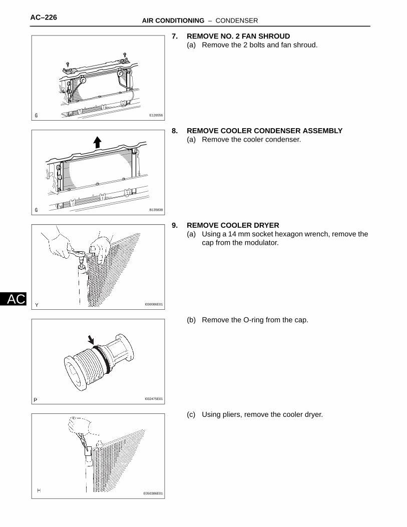
AC–226 AIR CONDITIONING – CONDENSER
AC
7. REMOVE NO. 2 FAN SHROUD(a) Remove the 2 bolts and fan shroud.
8. REMOVE COOLER CONDENSER ASSEMBLY(a) Remove the cooler condenser.
9. REMOVE COOLER DRYER(a) Using a 14 mm socket hexagon wrench, remove the
cap from the modulator.
(b) Remove the O-ring from the cap.
(c) Using pliers, remove the cooler dryer.
E126556
B135838
I030086E01
I032475E01
E050386E01
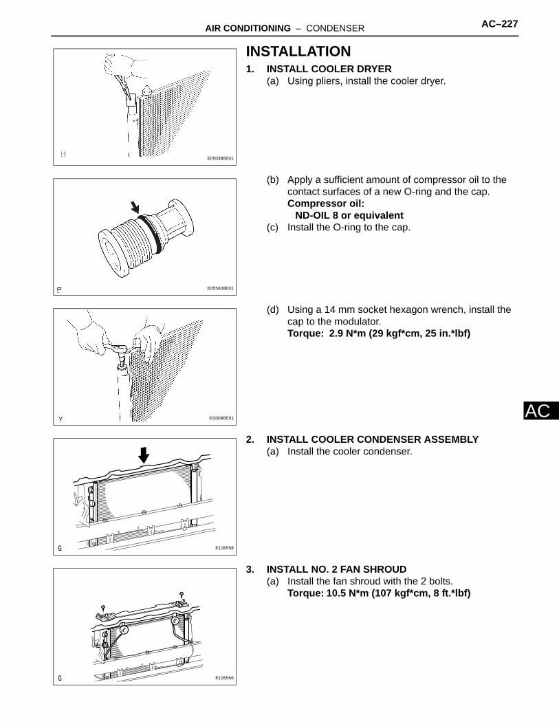
AIR CONDITIONING – CONDENSER AC–227
AC
INSTALLATION1. INSTALL COOLER DRYER
(a) Using pliers, install the cooler dryer.
(b) Apply a sufficient amount of compressor oil to the contact surfaces of a new O-ring and the cap.Compressor oil:
ND-OIL 8 or equivalent(c) Install the O-ring to the cap.
(d) Using a 14 mm socket hexagon wrench, install the cap to the modulator.Torque: 2.9 N*m (29 kgf*cm, 25 in.*lbf)
2. INSTALL COOLER CONDENSER ASSEMBLY(a) Install the cooler condenser.
3. INSTALL NO. 2 FAN SHROUD(a) Install the fan shroud with the 2 bolts.
Torque: 10.5 N*m (107 kgf*cm, 8 ft.*lbf)
E050386E01
E055408E01
I030086E01
E126558
E126556

AC–228 AIR CONDITIONING – CONDENSER
AC
4. INSTALL RADIATOR SUPPORT UPPER BRACKET(a) Install the 2 brackets with the 2 bolts.
Torque: 45 N*m (459 kgf*cm, 33 ft.*lbf)
5. INSTALL COOLER REFRIGERANT LIQUID PIPE(a) Remove the attached vinyl tape from the pipe and
the connecting part of the cooler condenser.(b) Sufficiently apply compressor oil to a new O-ring
and the fitting surface of the pipe joint.Compressor oil:
ND-OIL 8 or equivalent(c) Install the O-ring on the cooler refrigerant liquid
pipe.(d) Install the cooler refrigerant liquid pipe on the cooler
condenser with the bolt.Torque: 9.8 N*m (100 kgf*cm, 7 ft.*lbf)
6. INSTALL NO. 1 COOLER REFRIGERANT DISCHARGE HOSE(a) Remove the attached vinyl tape from the hose and
the connecting part of the cooler condenser.(b) Sufficiently apply compressor oil to a new O-ring
and the fitting surface of the hose joint.Compressor oil:
ND-OIL 8 or equivalent(c) Install the O-ring on the cooler refrigerant discharge
hose.(d) Install the cooler refrigerant discharge hose on the
cooler condenser with the bolt.Torque: 9.8 N*m (100 kgf*cm, 7 ft.*lbf)
7. ADJUST HOOD SUB-ASSEMBLY (See page ED-5)8. INSTALL FRONT BUMPER COVER
(a) Install the front bumper cover (see page ET-10).
9. CONNECT CABLE TO NEGATIVE BATTERY TERMINAL
10. CHARGE REFRIGERANT (See page AC-172)11. WARM UP ENGINE (See page AC-173)12. CHECK FOR LEAKAGE OF REFRIGERANT (See
page AC-173)
E126555
H102043
H102042
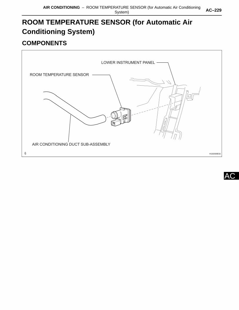
AIR CONDITIONING – ROOM TEMPERATURE SENSOR (for Automatic Air Conditioning System) AC–229
AC
HEATER & AIR CONDITIONING SYSTEMAIR CONDITIONINGROOM TEMPERATURE SENSOR (for Automatic Air Conditioning System)COMPONENTS
AIR CONDITIONING DUCT SUB-ASSEMBLY
ROOM TEMPERATURE SENSOR
LOWER INSTRUMENT PANEL
H102030E02
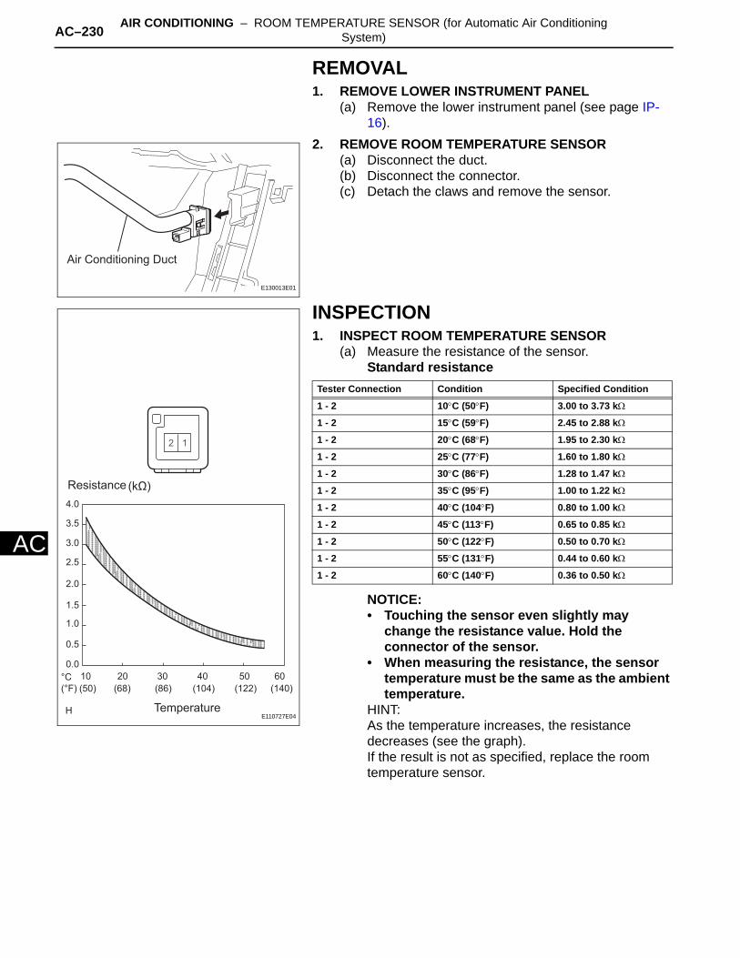
AC–230 AIR CONDITIONING – ROOM TEMPERATURE SENSOR (for Automatic Air Conditioning System)
AC
REMOVAL1. REMOVE LOWER INSTRUMENT PANEL
(a) Remove the lower instrument panel (see page IP-16).
2. REMOVE ROOM TEMPERATURE SENSOR(a) Disconnect the duct.(b) Disconnect the connector.(c) Detach the claws and remove the sensor.
INSPECTION1. INSPECT ROOM TEMPERATURE SENSOR
(a) Measure the resistance of the sensor. Standard resistance
NOTICE:• Touching the sensor even slightly may
change the resistance value. Hold the connector of the sensor.
• When measuring the resistance, the sensor temperature must be the same as the ambient temperature.
HINT:As the temperature increases, the resistance decreases (see the graph).If the result is not as specified, replace the room temperature sensor.
Air Conditioning Duct
E130013E01
Resistance
4.0
3.5
3.0
2.5
2.0
1.5
1.0
0.5
0.0
10
(50)
20
(68)
30
(86)
40
(104)
50
(122)
60
(140)
°C
(°F)
Temperature
(kΩ)
E110727E04
Tester Connection Condition Specified Condition
1 - 2 10°C (50°F) 3.00 to 3.73 kΩ
1 - 2 15°C (59°F) 2.45 to 2.88 kΩ
1 - 2 20°C (68°F) 1.95 to 2.30 kΩ
1 - 2 25°C (77°F) 1.60 to 1.80 kΩ
1 - 2 30°C (86°F) 1.28 to 1.47 kΩ
1 - 2 35°C (95°F) 1.00 to 1.22 kΩ
1 - 2 40°C (104°F) 0.80 to 1.00 kΩ
1 - 2 45°C (113°F) 0.65 to 0.85 kΩ
1 - 2 50°C (122°F) 0.50 to 0.70 kΩ
1 - 2 55°C (131°F) 0.44 to 0.60 kΩ
1 - 2 60°C (140°F) 0.36 to 0.50 kΩ
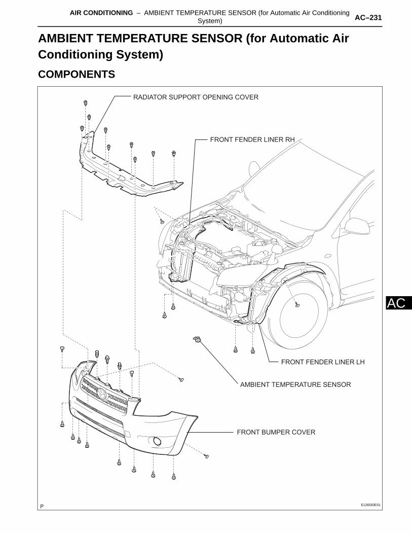
AIR CONDITIONING – AMBIENT TEMPERATURE SENSOR (for Automatic Air Conditioning System) AC–231
AC
HEATER & AIR CONDITIONING SYSTEMAIR CONDITIONINGAMBIENT TEMPERATURE SENSOR (for Automatic Air Conditioning System)COMPONENTS
AMBIENT TEMPERATURE SENSOR
RADIATOR SUPPORT OPENING COVER
FRONT FENDER LINER RH
FRONT FENDER LINER LH
FRONT BUMPER COVER
E126550E01

AC–232 AIR CONDITIONING – AMBIENT TEMPERATURE SENSOR (for Automatic Air Conditioning System)
AC
REMOVAL1. DISCONNECT CABLE FROM NEGATIVE BATTERY
TERMINALCAUTION:Wait at least 90 seconds after disconnecting the cable from the negative (-) battery terminal to prevent airbag and seat belt pretensioner activation.
2. REMOVE FRONT BUMPER COVER(a) Remove the front bumper cover (see page ET-4).
3. REMOVE AMBIENT TEMPERATURE SENSOR(a) Using a screwdriver, pull out the sensor, then
disconnect the connector.HINT:Tape the screwdriver tip before use.
INSPECTION1. INSPECT AMBIENT TEMPERATURE SENSOR
(a) Measure the resistance of the sensor.Standard resistance
NOTICE:• Touching the sensor even slightly may
change the resistance value. Hold the connector of the sensor.
• When measuring the resistance, the sensor temperature must be the same as the ambient temperature.
HINT:As the temperature increases, the resistance decreases (see the graph).If the result is not as specified, replace the ambient temperature sensor.
Sensor Area
Resistance
Temperature
(kΩ)
(°C)(°F)
4.0
3.5
3.0
2.5
2.0
1.5
1.0
0.5
0.010 20 30 40 50 60
140122104866850
E106870E07
Tester Connection Condition Specified Condition
1 - 2 10°C (50°F) 3.00 to 3.73 kΩ
1 - 2 15°C (59°F) 2.45 to 2.88 kΩ
1 - 2 20°C (68°F) 1.95 to 2.30 kΩ
1 - 2 25°C (77°F) 1.60 to 1.80 kΩ
1 - 2 30°C (86°F) 1.28 to 1.47 kΩ
1 - 2 35°C (95°F) 1.00 to 1.22 kΩ
1 - 2 40°C (104°F) 0.80 to 1.00 kΩ
1 - 2 45°C (113°F) 0.65 to 0.85 kΩ
1 - 2 50°C (122°F) 0.50 to 0.70 kΩ
1 - 2 55°C (131°F) 0.44 to 0.60 kΩ
1 - 2 60°C (140°F) 0.36 to 0.50 kΩ
AIR CONDITIONING – ROOM TEMPERATURE SENSOR (for Automatic Air Conditioning System) AC–231
AC
INSTALLATION1. INSTALL ROOM TEMPERATURE SENSOR
(a) Attach the claws to install the sensor.(b) Connect the connector.(c) Connect the duct.
2. INSTALL LOWER INSTRUMENT PANEL(a) Install the lower instrument panel (see page IP-23).
AIR CONDITIONING – AMBIENT TEMPERATURE SENSOR (for Automatic Air Conditioning System) AC–233
AC
INSTALLATION1. INSTALL AMBIENT TEMPERATURE SENSOR
(a) Connect the connector, and then push in the sensor.
2. INSTALL FRONT BUMPER COVER(a) Install the front bumper cover (see page ET-10).
3. CONNECT CABLE TO NEGATIVE BATTERY TERMINAL
4. CHECK SRS WARNING LIGHT(a) Check SRS warning light (see page RS-37).
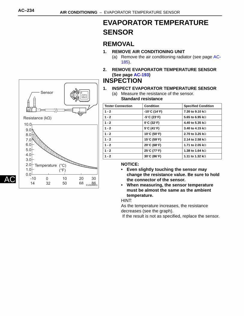
AC–234 AIR CONDITIONING – EVAPORATOR TEMPERATURE SENSOR
AC
EVAPORATOR TEMPERATURE SENSORREMOVAL1. REMOVE AIR CONDITIONING UNIT
(a) Remove the air conditioning radiator (see page AC-185).
2. REMOVE EVAPORATOR TEMPERATURE SENSOR (See page AC-193)
INSPECTION1. INSPECT EVAPORATOR TEMPERATURE SENSOR
(a) Measure the resistance of the sensor.Standard resistance
NOTICE:• Even slightly touching the sensor may
change the resistance value. Be sure to hold the connector of the sensor.
• When measuring, the sensor temperature must be almost the same as the ambient temperature.
HINT:As the temperature increases, the resistance decreases (see the graph). If the result is not as specified, replace the sensor.
10.09.08.07.06.05.04.03.02.01.00.0
-1014
032
3086
2068
1050
Sensor
Resistance (kΩ)
Temperature (°C)(°F)
E126546E01
Tester Connection Condition Specified Condition
1 - 2 -10°C (14°F) 7.30 to 9.10 kΩ
1 - 2 -5°C (23°F) 5.65 to 6.95 kΩ
1 - 2 0°C (32°F) 4.40 to 5.35 kΩ
1 - 2 5°C (41°F) 3.40 to 4.15 kΩ
1 - 2 10°C (50°F) 2.70 to 3.25 kΩ
1 - 2 15°C (59°F) 2.14 to 2.58 kΩ
1 - 2 20°C (68°F) 1.71 to 2.05 kΩ
1 - 2 25°C (77°F) 1.38 to 1.64 kΩ
1 - 2 30°C (86°F) 1.11 to 1.32 kΩ

AIR CONDITIONING – EVAPORATOR TEMPERATURE SENSOR AC–235
AC
INSTALLATION1. INSTALL EVAPORATOR TEMPERATURE SENSOR
(See page AC-193)2. INSTALL AIR CONDITIONING UNIT
(a) Install the air conditioning unit (see page AC-197).
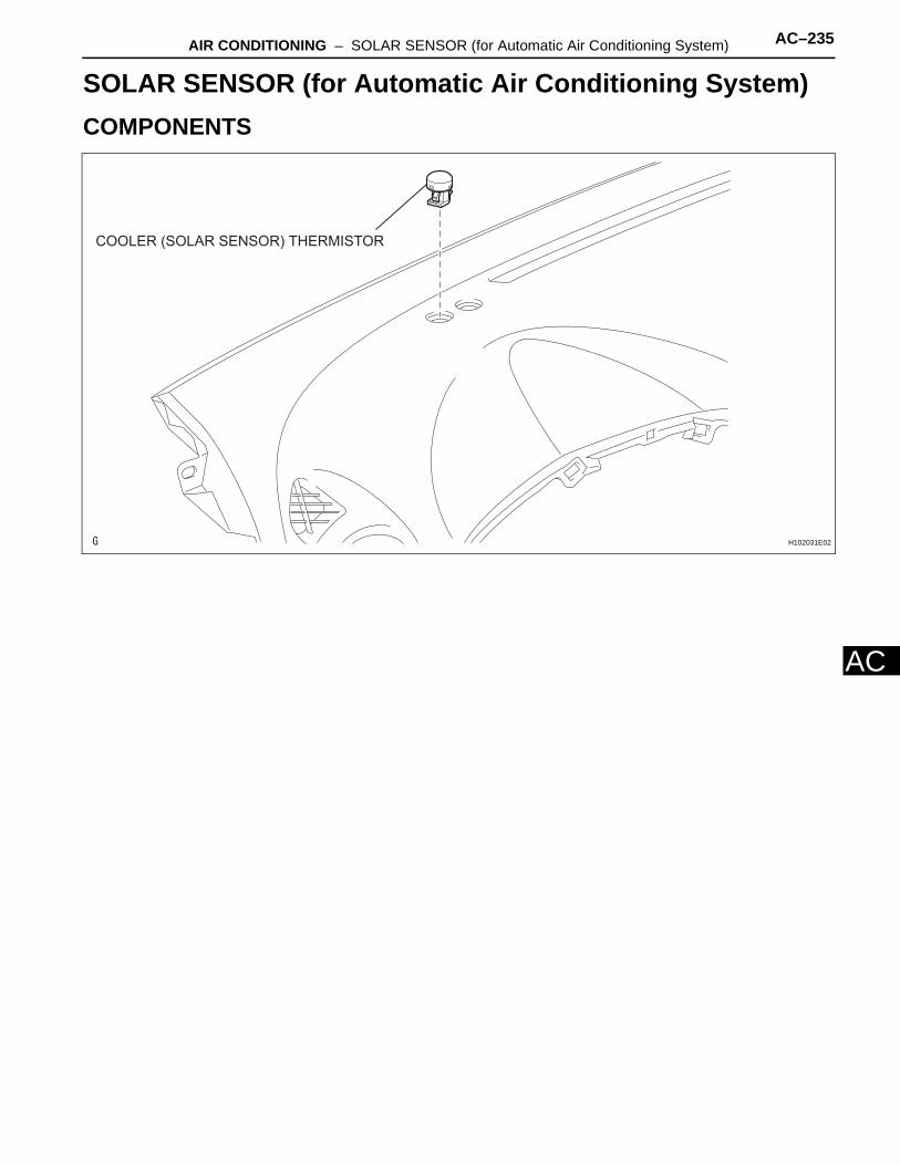
AIR CONDITIONING – SOLAR SENSOR (for Automatic Air Conditioning System) AC–235
AC
HEATER & AIR CONDITIONING SYSTEMAIR CONDITIONINGSOLAR SENSOR (for Automatic Air Conditioning System)COMPONENTS
COOLER (SOLAR SENSOR) THERMISTOR
H102031E02
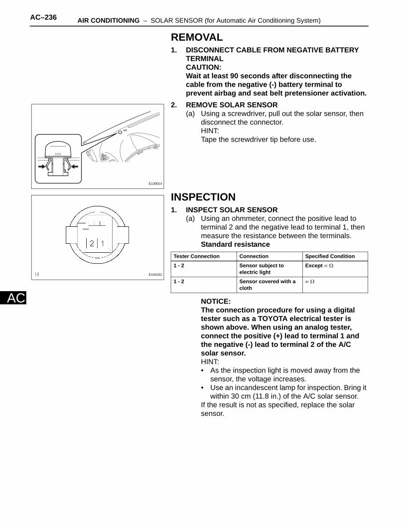
AC–236 AIR CONDITIONING – SOLAR SENSOR (for Automatic Air Conditioning System)
AC
REMOVAL1. DISCONNECT CABLE FROM NEGATIVE BATTERY
TERMINALCAUTION:Wait at least 90 seconds after disconnecting the cable from the negative (-) battery terminal to prevent airbag and seat belt pretensioner activation.
2. REMOVE SOLAR SENSOR(a) Using a screwdriver, pull out the solar sensor, then
disconnect the connector.HINT:Tape the screwdriver tip before use.
INSPECTION1. INSPECT SOLAR SENSOR
(a) Using an ohmmeter, connect the positive lead to terminal 2 and the negative lead to terminal 1, then measure the resistance between the terminals.Standard resistance
NOTICE:The connection procedure for using a digital tester such as a TOYOTA electrical tester is shown above. When using an analog tester, connect the positive (+) lead to terminal 1 and the negative (-) lead to terminal 2 of the A/C solar sensor.HINT:• As the inspection light is moved away from the
sensor, the voltage increases.• Use an incandescent lamp for inspection. Bring it
within 30 cm (11.8 in.) of the A/C solar sensor.If the result is not as specified, replace the solar sensor.
E130014
E104152
Tester Connection Connection Specified Condition
1 - 2 Sensor subject to electric light
Except ∞ Ω
1 - 2 Sensor covered with a cloth
∞ Ω
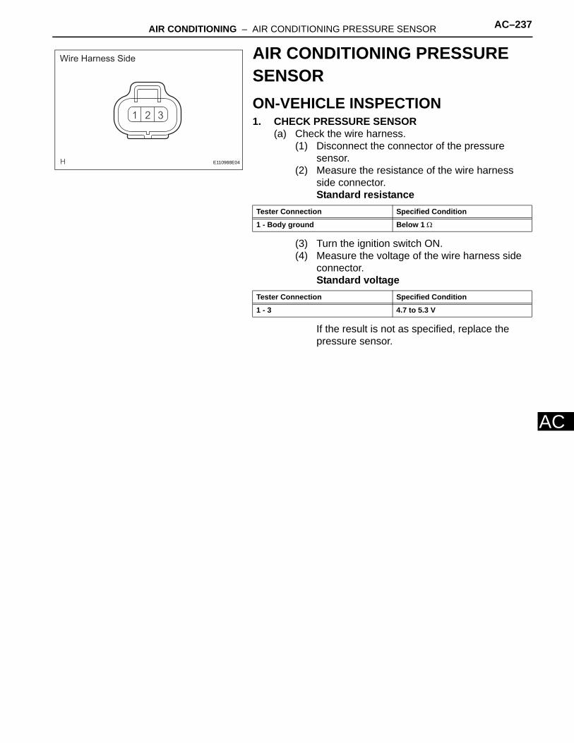
AIR CONDITIONING – AIR CONDITIONING PRESSURE SENSOR AC–237
AC
AIR CONDITIONING PRESSURE SENSORON-VEHICLE INSPECTION1. CHECK PRESSURE SENSOR
(a) Check the wire harness.(1) Disconnect the connector of the pressure
sensor.(2) Measure the resistance of the wire harness
side connector.Standard resistance
(3) Turn the ignition switch ON.(4) Measure the voltage of the wire harness side
connector.Standard voltage
If the result is not as specified, replace the pressure sensor.
Wire Harness Side
E110988E04
Tester Connection Specified Condition
1 - Body ground Below 1 Ω
Tester Connection Specified Condition
1 - 3 4.7 to 5.3 V
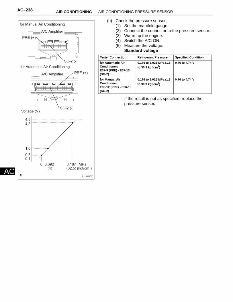
AC–238 AIR CONDITIONING – AIR CONDITIONING PRESSURE SENSOR
AC
(b) Check the pressure sensor.(1) Set the manifold gauge.(2) Connect the connector to the pressure sensor.(3) Warm up the engine.(4) Switch the A/C ON.(5) Measure the voltage.
Standard voltage
If the result is not as specified, replace the pressure sensor.
Voltage (V)
MPa(kgf/cm2)
4.94.8
0.392 3.187
1.0
0.50.1
0(4) (32.5)
for Automatic Air Conditioning
for Manual Air Conditioning
PRE (+)
PRE (+)
SG-2 (-)
SG-2 (-)
A/C Amplifier
A/C Amplifier
E126568E03
Tester Connection Refrigerant Pressure Specified Condition
for Automatic Air Conditioner:E37-9 (PRE) - E37-13 (SG-2)
0.176 to 3.025 MPa (1.8 to 30.9 kgf/cm2)
0.76 to 4.74 V
for Manual Air Conditioner:E36-12 (PRE) - E36-10 (SG-2)
0.176 to 3.025 MPa (1.8 to 30.9 kgf/cm2)
0.76 to 4.74 V
AIR CONDITIONING – SOLAR SENSOR (for Automatic Air Conditioning System) AC–237
AC
INSTALLATION1. INSTALL SOLAR SENSOR
(a) Connect the connector, and then push in the solar sensor.
2. CONNECT CABLE TO NEGATIVE BATTERY TERMINAL
3. CHECK SRS WARNING LIGHT(a) Check the SRS warning light (see page RS-37).
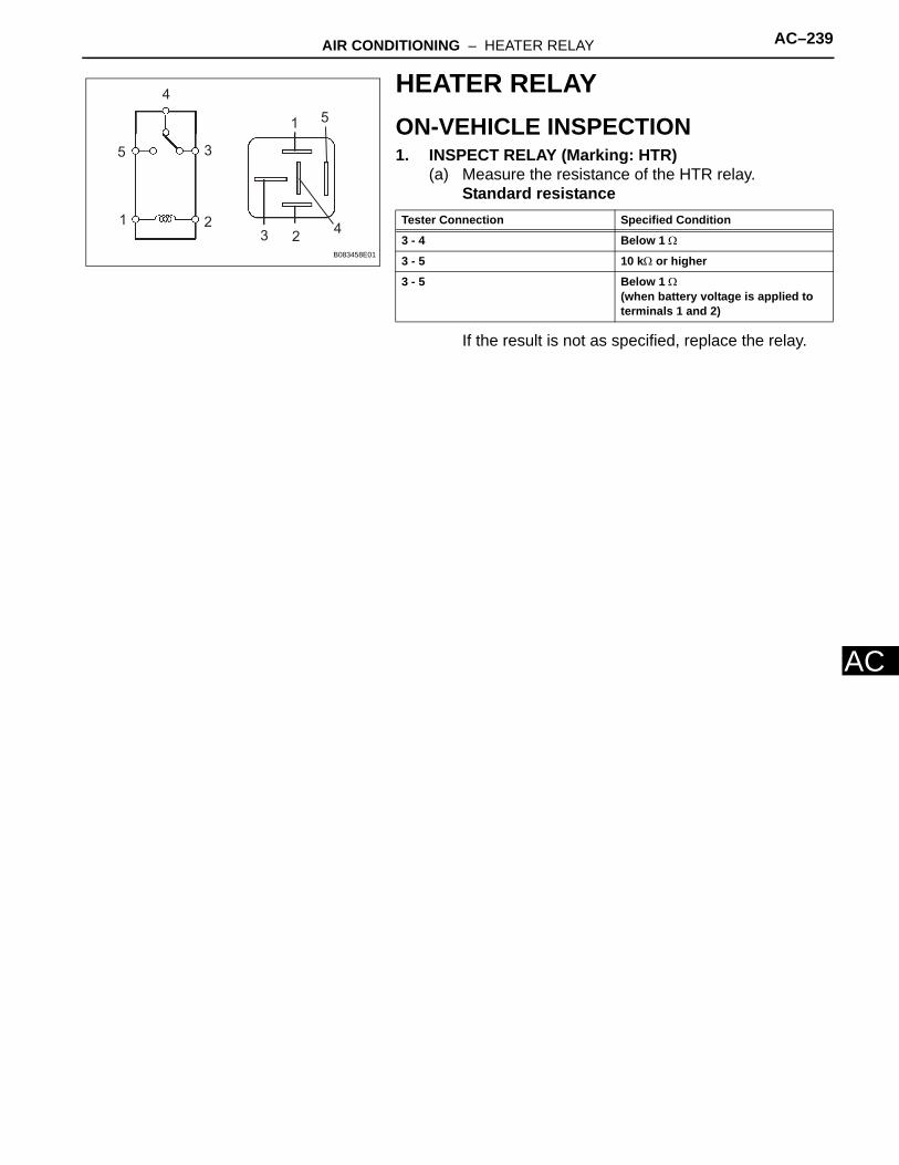
AIR CONDITIONING – HEATER RELAY AC–239
AC
HEATER RELAYON-VEHICLE INSPECTION1. INSPECT RELAY (Marking: HTR)
(a) Measure the resistance of the HTR relay.Standard resistance
If the result is not as specified, replace the relay.
51
4
3
2
5
1
4
3
2
B083458E01
Tester Connection Specified Condition
3 - 4 Below 1 Ω
3 - 5 10 kΩ or higher
3 - 5 Below 1 Ω(when battery voltage is applied to terminals 1 and 2)

AC–240 AIR CONDITIONING – AIR CONDITIONING CONTROL ASSEMBLY (for Automatic Air Con-ditioning System)
AC
HEATER & AIR CONDITIONING SYSTEMAIR CONDITIONINGAIR CONDITIONING CONTROL ASSEMBLY (for Automatic Air Conditioning System)COMPONENTS
AIR CONDITIONING CONTROL ASSEMBLY
E118689E01

AIR CONDITIONING – AIR CONDITIONING CONTROL ASSEMBLY (for Automatic Air Con-ditioning System) AC–241
AC
REMOVAL1. DISCONNECT CABLE FROM NEGATIVE BATTERY
TERMINALNOTICE:Wait at least 90 seconds after disconnecting the cable from the negative (-) battery terminal to prevent airbag and seat belt pretensioner activation.
2. REMOVE NO. 2 INSTRUMENT CLUSTER FINISH PANEL CENTER (See page IP-5)
3. REMOVE NO. 1 INSTRUMENT CLUSTER FINISH PANEL CENTER (See page IP-5)
4. REMOVE RADIO RECEIVER (See page IP-5)5. REMOVE AIR CONDITIONING CONTROL ASSEMBLY
(a) Remove the 2 screws.(b) Using a screwdriver, detach the 3 clips.
HINT:Tape the screwdriver tip before use.
(c) Connect the connectors and remove the air conditioning control.
INSTALLATION1. INSTALL AIR CONDITIONING CONTROL ASSEMBLY
(a) Connect the connectors.(b) Attach the 3 clips to install the air conditioning
control.(c) Install the 2 screws.
2. INSTALL RADIO RECEIVER (See page IP-10)3. INSTALL NO. 1 INSTRUMENT CLUSTER FINISH
PANEL CENTER (See page IP-10)4. INSTALL NO. 2 INSTRUMENT CLUSTER FINISH
PANEL CENTER (See page IP-10)5. CONNECT CABLE TO NEGATIVE BATTERY
TERMINAL6. CHECK SRS WARNING LIGHT
(a) Check the SRS warning light (see page RS-37).
E118690
E118690

AC–242 AIR CONDITIONING – AIR CONDITIONING CONTROL ASSEMBLY (for Manual Air Condi-tioning System)
AC
HEATER & AIR CONDITIONING SYSTEMAIR CONDITIONINGAIR CONDITIONING CONTROL ASSEMBLY (for Manual Air Conditioning System)COMPONENTS
AIR CONDITIONING CONTROL ASSEMBLY
AIR MIX CONTROL SWITCH
AIR VENT MODE CONTROL SWITCH
BLOWER CONTROL SWITCH
E118684E01

AIR CONDITIONING – AIR CONDITIONING CONTROL ASSEMBLY (for Manual Air Condi-tioning System) AC–243
AC
REMOVAL1. DISCONNECT CABLE FROM NEGATIVE BATTERY
TERMINALNOTICE:Wait at least 90 seconds after disconnecting the cable from the negative (-) battery terminal to prevent airbag and seat belt pretensioner activation.
2. REMOVE NO. 2 INSTRUMENT CLUSTER FINISH PANEL CENTER (See page IP-5)
3. REMOVE NO. 1 INSTRUMENT CLUSTER FINISH PANEL CENTER (See page IP-5)
4. REMOVE RADIO RECEIVER ASSEMBLY (See page IP-5)
5. REMOVE AIR CONDITIONING CONTROL ASSEMBLY(a) Remove the 2 screws.(b) Using a screwdriver, detach the 3 clips.
HINT:Tape the screwdriver tip before use.
(c) Disconnect the connectors and remove the air conditioning control.
6. REMOVE AIR MIX CONTROL SWITCH(a) Detach the 2 claws and remove the air mix control
switch.
7. REMOVE BLOWER CONTROL SWITCH(a) Detach the 2 claws and remove the blower control
switch.
E118688
E118685
E118686
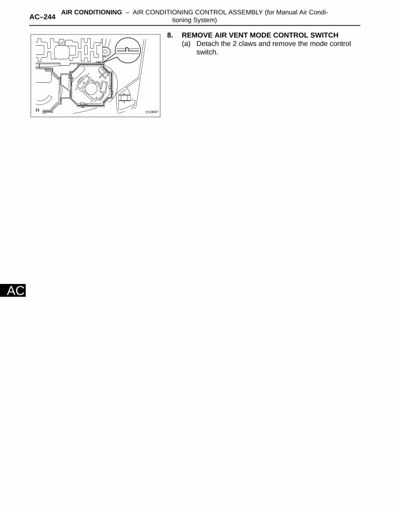
AC–244 AIR CONDITIONING – AIR CONDITIONING CONTROL ASSEMBLY (for Manual Air Condi-tioning System)
AC
8. REMOVE AIR VENT MODE CONTROL SWITCH(a) Detach the 2 claws and remove the mode control
switch.
E118687

AIR CONDITIONING – AIR CONDITIONING AMPLIFIER AC–245
AC
HEATER & AIR CONDITIONING SYSTEMAIR CONDITIONINGAIR CONDITIONING AMPLIFIERCOMPONENTS
AIR CONDITIONING AMPLIFIER ASSEMBLY
E124260E01
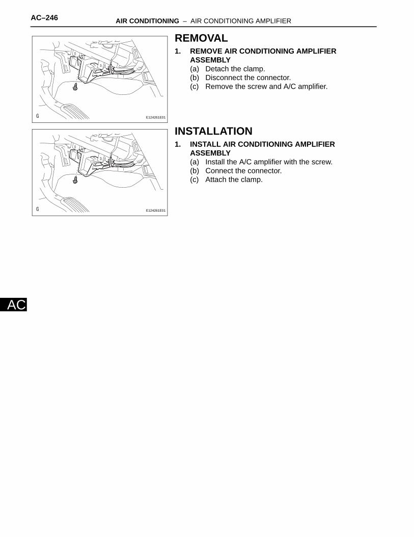
AC–246 AIR CONDITIONING – AIR CONDITIONING AMPLIFIER
AC
REMOVAL1. REMOVE AIR CONDITIONING AMPLIFIER
ASSEMBLY(a) Detach the clamp.(b) Disconnect the connector.(c) Remove the screw and A/C amplifier.
INSTALLATION1. INSTALL AIR CONDITIONING AMPLIFIER
ASSEMBLY(a) Install the A/C amplifier with the screw.(b) Connect the connector.(c) Attach the clamp.
: E124261E01
: E124261E01
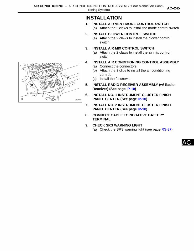
AIR CONDITIONING – AIR CONDITIONING CONTROL ASSEMBLY (for Manual Air Condi-tioning System) AC–245
AC
INSTALLATION1. INSTALL AIR VENT MODE CONTROL SWITCH
(a) Attach the 2 claws to install the mode control switch.
2. INSTALL BLOWER CONTROL SWITCH(a) Attach the 2 claws to install the blower control
switch.
3. INSTALL AIR MIX CONTROL SWITCH(a) Attach the 2 claws to install the air mix control
switch.4. INSTALL AIR CONDITIONING CONTROL ASSEMBLY
(a) Connect the connectors.(b) Attach the 3 clips to install the air conditioning
control.(c) Install the 2 screws.
5. INSTALL RADIO RECEIVER ASSEMBLY (w/ Radio Receiver) (See page IP-10)
6. INSTALL NO. 1 INSTRUMENT CLUSTER FINISH PANEL CENTER (See page IP-10)
7. INSTALL NO. 2 INSTRUMENT CLUSTER FINISH PANEL CENTER (See page IP-10)
8. CONNECT CABLE TO NEGATIVE BATTERY TERMINAL
9. CHECK SRS WARNING LIGHT(a) Check the SRS warning light (see page RS-37).
E118688