installation manual - toshiba air conditioning
TRANSCRIPT

Indoor UnitModel name:
Concealed Duct Type
AIR CONDITIONER (SPLIT TYPE)Installation Manual
English
For commercial use
RAV-RM561BTP-ERAV-RM801BTP-ERAV-RM1101BTP-ERAV-RM1401BTP-E
R32 or R410A

– 1 –
Thank you for purchasing this Toshiba air conditioner.Please read carefully through these instructions that contain important information which complies with the Machinery Directive (Directive 2006/42/EC), and ensure that you understand them.After completing the installation work, hand over this Installation Manual as well as the Owner’s Manual provided to the user, and ask the user to keep them in a safe place for future reference.
Generic Denomination: Air Conditioner
Definition of Qualified Installer or Qualified Service PersonThe air conditioner must be installed, maintained, repaired and removed by a qualified installer or qualified service person. When any of these jobs is to be done, ask a qualified installer or qualified service person to do them for you.A qualified installer or qualified service person is an agent who has the qualifications and knowledge described in the following table.
evah tsum tnega eht hcihw egdelwonk dna snoitacifilauQtnegA
Qualified installer
The qualified installer is a person who installs, maintains, relocates and removes the air conditioners made by Toshiba Carrier Corporation. He or she has been trained to install, maintain, relocate and remove the air conditioners made by Toshiba Carrier Corporation or, alternatively, he or she has been instructed in such operations by an individual or individuals who have been trained and is thus thoroughly acquainted with the knowledge related to these operations.The qualified installer who is allowed to do the electrical work involved in installation, relocation and removal has the qualifications pertaining to this electrical work as stipulated by the local laws and regulations, and he or she is a person who has been trained in matters relating to electrical work on the air conditioners made by Toshiba Carrier Corporation or, alternatively, he or she has been instructed in such matters by an individual or individuals who have been trained and is thus thoroughly acquainted with the knowledge related to this work.The qualified installer who is allowed to do the refrigerant handling and piping work involved in installation, relocation and removal has the qualifications pertaining to this refrigerant handling and piping work as stipulated by the local laws and regulations, and he or she is a person who has been trained in matters relating to refrigerant handling and piping work on the air conditioners made by Toshiba Carrier Corporation or, alternatively, he or she has been instructed in such matters by an individual or individuals who have been trained and is thus thoroughly acquainted with the knowledge related to this work.The qualified installer who is allowed to work at heights has been trained in matters relating to working at heights with the air conditioners made by Toshiba Carrier Corporation or, alternatively, he or she has been instructed in such matters by an individual or individuals who have been trained and is thus thoroughly acquainted with the knowledge related to this work.
Qualified service person
The qualified service person is a person who installs, repairs, maintains, relocates and removes the air conditioners made by Toshiba Carrier Corporation. He or she has been trained to install, repair, maintain, relocate and remove the air conditioners made by Toshiba Carrier Corporation or, alternatively, he or she has been instructed in such operations by an individual or individuals who have been trained and is thus thoroughly acquainted with the knowledge related to these operations.The qualified service person who is allowed to do the electrical work involved in installation, repair, relocation and removal has the qualifications pertaining to this electrical work as stipulated by the local laws and regulations, and he or she is a person who has been trained in matters relating to electrical work on the air conditioners made by Toshiba Carrier Corporation or, alternatively, he or she has been instructed in such matters by an individual or individuals who have been trained and is thus thoroughly acquainted with the knowledge related to this work.The qualified service person who is allowed to do the refrigerant handling and piping work involved in installation, repair, relocation and removal has the qualifications pertaining to this refrigerant handling and piping work as stipulated by the local laws and regulations, and he or she is a person who has been trained in matters relating to refrigerant handling and piping work on the air conditioners made by Toshiba Carrier Corporation or, alternatively, he or she has been instructed in such matters by an individual or individuals who have been trained and is thus thoroughly acquainted with the knowledge related to this work.The qualified service person who is allowed to work at heights has been trained in matters relating to working at heights with the air conditioners made by Toshiba Carrier Corporation or, alternatively, he or she has been instructed in such matters by an individual or individuals who have been trained and is thus thoroughly acquainted with the knowledge related to this work.
1-EN 2-EN
Original instruction
Please read this Installation Manual carefully before installing the Air Conditioner.• This Manual describes the installation method of the indoor unit.• For installation of the outdoor unit, follow the Installation Manual attached to the outdoor unit.• For precaution for safety, follow the Installation Manual attached to the outdoor unit.
ADOPTION OF R32 or R410A REFRIGERANTThis Air Conditioner has adopted a refrigerant HFC (R32 or R410A) which does not destroy the ozone layer.Be sure to check the refrigerant type for outdoor unit to be combined, and then install it.
Product information of ecodesign requirements. (Regulation (EU) 2016/2281)http://ecodesign.toshiba-airconditioning.eu/en
Contents1 Precautions for safety . . . . . . . . . . . . . . . . . . . . . . . . . . . . . . . . . . . . . . . . . . . . . . . . . . 3
2 Accessory parts . . . . . . . . . . . . . . . . . . . . . . . . . . . . . . . . . . . . . . . . . . . . . . . . . . . . . . . 7
3 Selection of installation place . . . . . . . . . . . . . . . . . . . . . . . . . . . . . . . . . . . . . . . . . . . . 7
4 Installation . . . . . . . . . . . . . . . . . . . . . . . . . . . . . . . . . . . . . . . . . . . . . . . . . . . . . . . . . . . 8
5 Drain piping . . . . . . . . . . . . . . . . . . . . . . . . . . . . . . . . . . . . . . . . . . . . . . . . . . . . . . . . . 10
6 Duct design . . . . . . . . . . . . . . . . . . . . . . . . . . . . . . . . . . . . . . . . . . . . . . . . . . . . . . . . . . 13
7 Refrigerant piping . . . . . . . . . . . . . . . . . . . . . . . . . . . . . . . . . . . . . . . . . . . . . . . . . . . . 14
8 Electrical connection . . . . . . . . . . . . . . . . . . . . . . . . . . . . . . . . . . . . . . . . . . . . . . . . . . 15
9 Applicable controls . . . . . . . . . . . . . . . . . . . . . . . . . . . . . . . . . . . . . . . . . . . . . . . . . . . 17
10 Test run . . . . . . . . . . . . . . . . . . . . . . . . . . . . . . . . . . . . . . . . . . . . . . . . . . . . . . . . . . . . . 22
11 Maintenance . . . . . . . . . . . . . . . . . . . . . . . . . . . . . . . . . . . . . . . . . . . . . . . . . . . . . . . . . 23
12 Troubleshooting . . . . . . . . . . . . . . . . . . . . . . . . . . . . . . . . . . . . . . . . . . . . . . . . . . . . . . 24
13 Appendix . . . . . . . . . . . . . . . . . . . . . . . . . . . . . . . . . . . . . . . . . . . . . . . . . . . . . . . . . . . . 27
– 2 –
EN
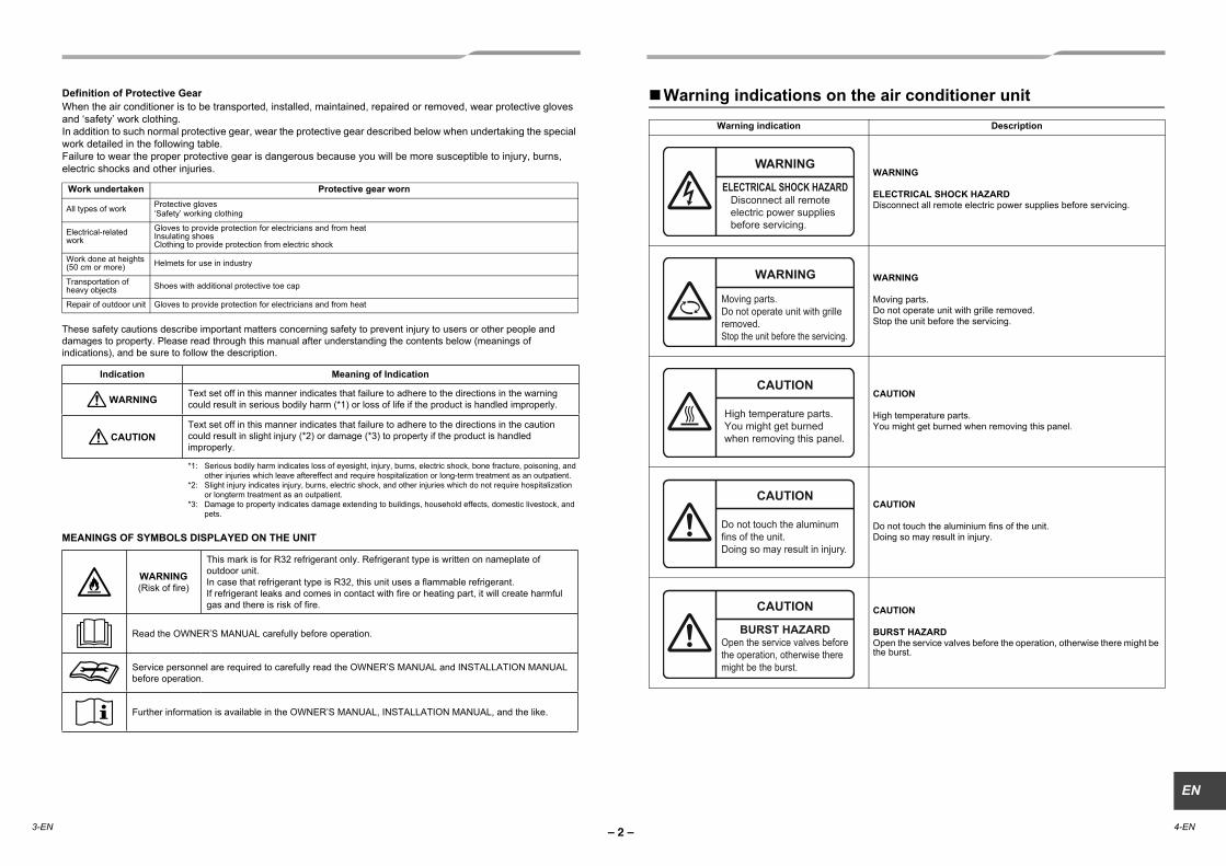
Definition of Protective Gear When the air conditioner is to be transported, installed, maintained, repaired or removed, wear protective gloves and ‘safety’ work clothing.In addition to such normal protective gear, wear the protective gear described below when undertaking the special work detailed in the following table.Failure to wear the proper protective gear is dangerous because you will be more susceptible to injury, burns, electric shocks and other injuries.
Work undertaken Protective gear worn
All types of work Protective gloves ‘Safety’ working clothing
Electrical-related work
Gloves to provide protection for electricians and from heat Insulating shoes Clothing to provide protection from electric shock
Work done at heights(50 cm or more) Helmets for use in industry
Transportation of heavy objects Shoes with additional protective toe cap
Repair of outdoor unit Gloves to provide protection for electricians and from heat
Warning indications on the air conditioner unitWarning indication Description
WARNING
ELECTRICAL SHOCK HAZARDDisconnect all remote electric power supplies before servicing.
WARNING
Moving parts. Do not operate unit with grille removed. Stop the unit before the servicing.
CAUTION
High temperature parts. You might get burned when removing this panel.
CAUTION
Do not touch the aluminium fins of the unit. Doing so may result in injury.
CAUTION
BURST HAZARDOpen the service valves before the operation, otherwise there might be the burst.
WARNING
ELECTRICAL SHOCK HAZARDDisconnect all remote electric power supplies before servicing.
WARNING
Moving parts.Do not operate unit with grille removed.Stop the unit before the servicing.
CAUTION
High temperature parts.You might get burned when removing this panel.
CAUTION
Do not touch the aluminum fins of the unit.Doing so may result in injury.
CAUTION
BURST HAZARDOpen the service valves before the operation, otherwise there might be the burst.
3-EN 4-EN
These safety cautions describe important matters concerning safety to prevent injury to users or other people anddamages to property. Please read through this manual after understanding the contents below (meanings ofindications), and be sure to follow the description.
Indication Meaning of Indication
WARNING Text set off in this manner indicates that failure to adhere to the directions in the warning could result in serious bodily harm (*1) or loss of life if the product is handled improperly.
CAUTIONText set off in this manner indicates that failure to adhere to the directions in the caution could result in slight injury (*2) or damage (*3) to property if the product is handled improperly.
*1: Serious bodily harm indicates loss of eyesight, injury, burns, electric shock, bone fracture, poisoning, and other injuries which leave aftereffect and require hospitalization or long-term treatment as an outpatient.
*2: Slight injury indicates injury, burns, electric shock, and other injuries which do not require hospitalization or longterm treatment as an outpatient.
*3: Damage to property indicates damage extending to buildings, household effects, domestic livestock, and pets.
MEANINGS OF SYMBOLS DISPLAYED ON THE UNIT
WARNING(Risk of fire)
This mark is for R32 refrigerant only. Refrigerant type is written on nameplate of outdoor unit.In case that refrigerant type is R32, this unit uses a flammable refrigerant.If refrigerant leaks and comes in contact with fire or heating part, it will create harmful gas and there is risk of fire.
Read the OWNER’S MANUAL carefully before operation.
Service personnel are required to carefully read the OWNER’S MANUAL and INSTALLATION MANUAL before operation.
Further information is available in the OWNER’S MANUAL, INSTALLATION MANUAL, and the like.
– 3 –
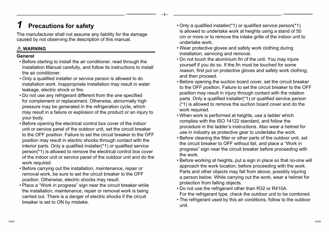
1 Precautions for safetyThe manufacturer shall not assume any liability for the damage caused by not observing the description of this manual.
WARNINGGeneral
• Before starting to install the air conditioner, read through the Installation Manual carefully, and follow its instructions to install the air conditioner.
• Only a qualifi ed installer or service person is allowed to do installation work. Inappropriate installation may result in water leakage, electric shock or fi re.
• Do not use any refrigerant different from the one specifi ed for complement or replacement. Otherwise, abnormally high pressure may be generated in the refrigeration cycle, which may result in a failure or explosion of the product or an injury to your body.
• Before opening the electrical control box cover of the indoor unit or service panel of the outdoor unit, set the circuit breaker to the OFF position. Failure to set the circuit breaker to the OFF position may result in electric shocks through contact with the interior parts. Only a qualifi ed installer(*1) or qualifi ed service person(*1) is allowed to remove the electrical control box cover of the indoor unit or service panel of the outdoor unit and do the work required.
• Before carrying out the installation, maintenance, repair or removal work, be sure to set the circuit breaker to the OFF position. Otherwise, electric shocks may result.
• Place a “Work in progress” sign near the circuit breaker while the installation, maintenance, repair or removal work is being carried out. There is a danger of electric shocks if the circuit breaker is set to ON by mistake.
• Only a qualifi ed installer(*1) or qualifi ed service person(*1) is allowed to undertake work at heights using a stand of 50 cm or more or to remove the intake grille of the indoor unit to undertake work.
• Wear protective gloves and safety work clothing during installation, servicing and removal.
• Do not touch the aluminium fi n of the unit. You may injure yourself if you do so. If the fi n must be touched for some reason, fi rst put on protective gloves and safety work clothing, and then proceed.
• Before opening the suction board cover, set the circuit breaker to the OFF position. Failure to set the circuit breaker to the OFF position may result in injury through contact with the rotation parts. Only a qualifi ed installer(*1) or qualifi ed service person (*1) is allowed to remove the suction board cover and do the work required.
• When work is performed at heights, use a ladder which complies with the ISO 14122 standard, and follow the procedure in the ladder’s instructions. Also wear a helmet for use in industry as protective gear to undertake the work.
• Before cleaning the fi lter or other parts of the outdoor unit, set the circuit breaker to OFF without fail, and place a “Work in progress” sign near the circuit breaker before proceeding with the work.
• Before working at heights, put a sign in place so that no-one will approach the work location, before proceeding with the work. Parts and other objects may fall from above, possibly injuring a person below. While carrying out the work, wear a helmet for protection from falling objects.
• Do not use the refrigerant other than R32 or R410A.For the refrigerant type, check the outdoor unit to be combined.
• The refrigerant used by this air conditions, follow to the outdoor unit.
5-EN 6-EN
– 4 –
EN
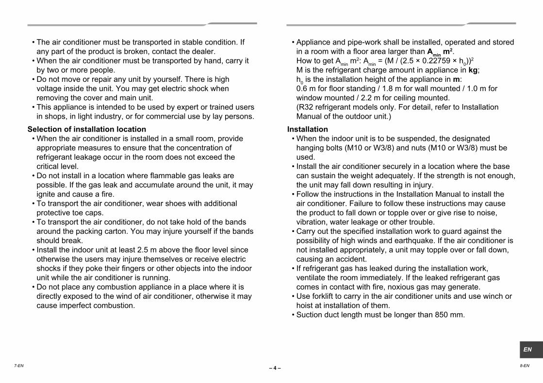
• The air conditioner must be transported in stable condition. If any part of the product is broken, contact the dealer.
• When the air conditioner must be transported by hand, carry it by two or more people.
• Do not move or repair any unit by yourself. There is high voltage inside the unit. You may get electric shock when removing the cover and main unit.
• This appliance is intended to be used by expert or trained users in shops, in light industry, or for commercial use by lay persons.
Selection of installation location• When the air conditioner is installed in a small room, provide
appropriate measures to ensure that the concentration of refrigerant leakage occur in the room does not exceed the critical level.
• Do not install in a location where fl ammable gas leaks are possible. If the gas leak and accumulate around the unit, it may ignite and cause a fi re.
• To transport the air conditioner, wear shoes with additional protective toe caps.
• To transport the air conditioner, do not take hold of the bands around the packing carton. You may injure yourself if the bands should break.
• Install the indoor unit at least 2.5 m above the fl oor level since otherwise the users may injure themselves or receive electric shocks if they poke their fi ngers or other objects into the indoor unit while the air conditioner is running.
• Do not place any combustion appliance in a place where it is directly exposed to the wind of air conditioner, otherwise it may cause imperfect combustion.
• Appliance and pipe-work shall be installed, operated and stored in a room with a fl oor area larger than Amin m2.How to get Amin m
2: Amin = (M / (2.5 × 0.22759 × h0))2
M is the refrigerant charge amount in appliance in kg;h0 is the installation height of the appliance in m:0.6 m for fl oor standing / 1.8 m for wall mounted / 1.0 m for window mounted / 2.2 m for ceiling mounted.(R32 refrigerant models only. For detail, refer to Installation Manual of the outdoor unit.)
Installation• When the indoor unit is to be suspended, the designated
hanging bolts (M10 or W3/8) and nuts (M10 or W3/8) must be used.
• Install the air conditioner securely in a location where the base can sustain the weight adequately. If the strength is not enough, the unit may fall down resulting in injury.
• Follow the instructions in the Installation Manual to install the air conditioner. Failure to follow these instructions may cause the product to fall down or topple over or give rise to noise, vibration, water leakage or other trouble.
• Carry out the specifi ed installation work to guard against the possibility of high winds and earthquake. If the air conditioner is not installed appropriately, a unit may topple over or fall down, causing an accident.
• If refrigerant gas has leaked during the installation work, ventilate the room immediately. If the leaked refrigerant gas comes in contact with fi re, noxious gas may generate.
• Use forklift to carry in the air conditioner units and use winch or hoist at installation of them.
• Suction duct length must be longer than 850 mm.
7-EN 8-EN
– 5 –
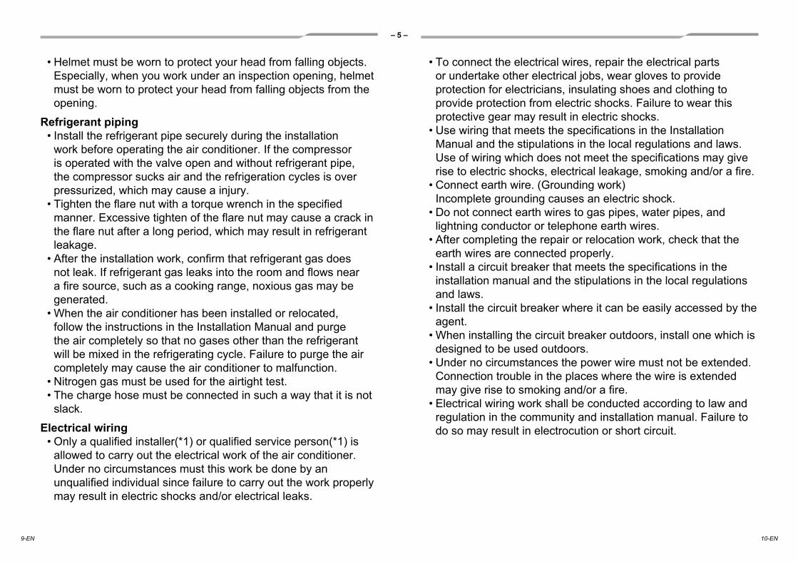
• Helmet must be worn to protect your head from falling objects.Especially, when you work under an inspection opening, helmet must be worn to protect your head from falling objects from the opening.
Refrigerant piping• Install the refrigerant pipe securely during the installation
work before operating the air conditioner. If the compressor is operated with the valve open and without refrigerant pipe, the compressor sucks air and the refrigeration cycles is over pressurized, which may cause a injury.
• Tighten the fl are nut with a torque wrench in the specifi ed manner. Excessive tighten of the fl are nut may cause a crack in the fl are nut after a long period, which may result in refrigerant leakage.
• After the installation work, confi rm that refrigerant gas does not leak. If refrigerant gas leaks into the room and fl ows near a fi re source, such as a cooking range, noxious gas may be generated.
• When the air conditioner has been installed or relocated, follow the instructions in the Installation Manual and purge the air completely so that no gases other than the refrigerant will be mixed in the refrigerating cycle. Failure to purge the air completely may cause the air conditioner to malfunction.
• Nitrogen gas must be used for the airtight test.• The charge hose must be connected in such a way that it is not
slack.
Electrical wiring• Only a qualifi ed installer(*1) or qualifi ed service person(*1) is
allowed to carry out the electrical work of the air conditioner. Under no circumstances must this work be done by an unqualifi ed individual since failure to carry out the work properly may result in electric shocks and/or electrical leaks.
• To connect the electrical wires, repair the electrical parts or undertake other electrical jobs, wear gloves to provide protection for electricians, insulating shoes and clothing to provide protection from electric shocks. Failure to wear this protective gear may result in electric shocks.
• Use wiring that meets the specifi cations in the Installation Manual and the stipulations in the local regulations and laws. Use of wiring which does not meet the specifi cations may give rise to electric shocks, electrical leakage, smoking and/or a fi re.
• Connect earth wire. (Grounding work) Incomplete grounding causes an electric shock.
• Do not connect earth wires to gas pipes, water pipes, and lightning conductor or telephone earth wires.
• After completing the repair or relocation work, check that the earth wires are connected properly.
• Install a circuit breaker that meets the specifi cations in the installation manual and the stipulations in the local regulations and laws.
• Install the circuit breaker where it can be easily accessed by the agent.
• When installing the circuit breaker outdoors, install one which is designed to be used outdoors.
• Under no circumstances the power wire must not be extended. Connection trouble in the places where the wire is extended may give rise to smoking and/or a fi re.
• Electrical wiring work shall be conducted according to law and regulation in the community and installation manual. Failure to do so may result in electrocution or short circuit.
9-EN 10-EN
– 6 –
EN
Test run• Before operating the air conditioner after having completed the
work, check that the electrical control box cover of the indoor unit and service panel of the outdoor unit are closed, and set the circuit breaker to the ON position. You may receive an electric shock if the power is turned on without fi rst conducting these checks.
• If there is any kind of trouble (such as an error display has appeared, smell of burning, abnormal sounds, the air conditioner fails to cool or heat or water is leaking) has occurred in the air conditioner, do not touch the air conditioner yourself but set the circuit breaker to the OFF position, and contact a qualifi ed service person. Take steps to ensure that the power will not be turned on (by marking “out of service” near the circuit breaker, for instance) until qualifi ed service person arrives. Continuing to use the air conditioner in the trouble status may cause mechanical problems to escalate or result in electric shocks or other trouble.
• After the work has fi nished, use an insulation tester set (500 V Megger) to check the resistance is 1 MΩ or more between the charge section and the non-charge metal section (Earth section). If the resistance value is low, a disaster such as a leak or electric shock is caused at user’s side.
• Upon completion of the installation work, check for refrigerant leaks and check the insulation resistance and water drainage. Then conduct a test run to check that the air conditioner is operating properly.
Explanations given to user• Upon completion of the installation work, tell the user where the
circuit breaker is located. If the user does not know where the circuit breaker is, he or she will not be able to turn it off in the event that trouble has occurred in the air conditioner.
• After the installation work, follow the Owner’s Manual to explain to the customer how to use and maintain the unit.
Relocation• Only a qualifi ed installer(*1) or qualifi ed service person(*1) is
allowed to relocate the air conditioner. It is dangerous for the air conditioner to be relocated by an unqualifi ed individual since a fi re, electric shocks, injury, water leakage, noise and/or vibration may result.
• When carrying out the pump-down work shut down the compressor before disconnecting the refrigerant pipe. Disconnecting the refrigerant pipe with the service valve left open and the compressor still operating will cause air or other gas to be sucked in, raising the pressure inside the refrigeration cycle to an abnormally high level, and possibly resulting in rupture, injury or other trouble.
CAUTIONThis Air Conditioner has adopted a refrigerant HFC (R32 or R410A) which does not destroy the ozone layer.
• As the R32 or R410A refrigerant is easily affected by impurities such as moisture, oxidized fi lm, oil, etc., due to the high pressure, be careful not to allow the moisture, dirt, existing refrigerant, refrigerating machine oil, etc., to get mixed up in the refrigeration cycle during the installation work.
• A special tool for the R32 or R410A refrigerant is required for installation.
• Use a new and clean piping materials for the connecting pipe so that moisture and dirt are not mixed together during the installation work.
• When using existing pipes, follow the installation manual enclosed with the outdoor unit.
(*1) Refer to the “Definition of Qualified Installer or Qualified Service Person.”
11-EN 12-EN

– 7 –
3 Selection of installation placeAvoid installing in the following placesSelect a location for the indoor unit where the cool or warm air will circulate evenly.Avoid installation in the following kinds of locations.
Saline area (coastal area)Locations with acidic or alkaline atmospheres (such as areas with hot springs, factories where chemicals or pharmaceuticals are made and places where the exhaust air from combustion appliances will be sucked into the unit). Doing so may cause the heat exchanger (its aluminum fins and copper pipes) and other parts to become corroded.Locations with atmospheres with mist of cutting oil or other types of machine oil. Doing so may cause the heat exchanger to become corroded, mists caused by the blockage of the heat exchanger to be generated, the plastic parts to be damaged, the heat insulators to peel off, and other such problems to result.Places where iron or other metal dust is present. If iron or other metal dust adheres to or collects on the interior of the air conditioner, it may spontaneously combust and start a fire.Locations where vapors from food oils are formed (such as kitchens where food oils are used). Blocked filters may cause the air conditioner’s performance to deteriorate, condensation to form, the plastic parts to be damaged, and other such problems to result.Locations near obstructions such as ventilation openings or lighting fixtures where the flow of the blown air will be disrupted (a disruption of the air flow may cause the air conditioner’s performance to deteriorate or the unit to shut down).Locations where an in-house power generator is used for the power supply.The power line frequency and voltage may fluctuate, and the air conditioner may not work properly as a result.On truck cranes, ships or other moving conveyances.The air conditioner must not be used for special applications (such as for storing food, plants, precision instruments or art works).(The quality of the items stored may be degraded.)Locations where high frequencies are generated (by inverter equipment, in-house power generators, medical equipment or communication equipment).(Malfunctioning or control trouble in the air conditioner or noise may adversely affect the equipment’s operation.)Locations where there is anything under the unit installed that would be compromised by wetness.(If the drain has become blocked or when the humidity is over 80 %, condensation from the indoor unit will drip, possibly causing damage to anything underneath.)In the case of the wireless type of system, rooms with the inverter type of fluorescent lighting or locations exposed to direct sunlight.(The signals from the wireless remote controller may not be sensed.)Locations where organic solvents are being used.The air conditioner cannot be used for liquefied carbonic acid cooling or in chemical plants.Location near doors or windows where the air conditioner may come into contact with high-temperature, high-humidity outdoor air.(Condensation may occur as a result.)Locations where special sprays are used frequently.
Installation under high-humidity atmosphereIn some cases including the rainy season, especially inside of the ceiling may become high-humidity atmosphere (dew-point temperature: 23 °C or higher).1. Installation to inside of the ceiling with tiles on the roof2. Installation to inside of the ceiling with slated roof
2 Accessory parts
Accessory parts
egasUepahSyt’Qeman traP
Installation Manual 1 This manual(Hand over to customers)(For other languages that do not appear in this Installation Manual, please refer to the enclosed CD-R.)
Owner’s Manual 1(Hand over to customers)(For other languages that do not appear in this Installation Manual, please refer to the enclosed CD-R.)
CD-ROM 1 — Owner’s Manual and Installation Manual
usni taeh roF2epip gnitalusni taeH lation of pipe connecting section
tinu nwod-gnignah roF8rehsaW
epip niard gnitcennoc roF1dnab esoH
epip niard fo retnec gnitsujda roF1esoh elbixelF
italusni taeh roF1rotalusni taeH on of drain connecting section
retlif eht gnixif roF1reppots retliF
epahSeman traPQ’ty
RM40~56 RM80 RM110~160
21)L 007( 1 liar gnixif retliF
21)L 007( 2 liar gnixif retliF
Filter fixing rail 3 (490 L) 2
Filter fixing rail 4 (490 L) 2
13-EN 14-EN

– 8 –
EN
Installation space (Unit: mm)
Reserve sufficient space required for installation or service work.
Filter cleaning sign term settingThe lighting term setup of the filter sign (Notification of filter cleaning) of the remote controller can be changed according to the condition of installation.For setup method, refer to “Filter sign setting” in the Applicable controls of this Manual.
100 or more
Air discharge
Ceiling
25A
25
2500
or
mor
e
B or more
70 o
r m
ore
5 or
m
ore
275
Service door (Ceiling opening)
Floor surface
Air discharge100 or more
450Check port
120
Service space(B for maintenance of air filter)
B
Ceiling25
50 or more
Service door (Ceiling opening)
570
Air intake
Air intake
57025Ceiling
Service door (Ceiling opening)
Air intake
57025Ceiling
Service door (Ceiling opening)
300 or moreAModel
Model
B 750 700
RM80 type 1050 500
RM110, RM140 type 1450 700
4 InstallationCAUTION
Strictly comply with the following rules to prevent damage of the indoor units and human injury.Do not put a heavy article on the indoor unit or let a person get on it. (Even units are packaged)Carry in the indoor unit as it is packaged if possible. If carrying in the indoor unit unpacked by necessity, use buffering cloth or other material to not damage the unit.To move the indoor unit, hold the hooking brackets (4 positions) only.Do not apply force to the other parts (such as refrigerant pipe, drain pan, foamed parts, or resin parts).Carry the package by two or more persons, and do not bundle it with plastic band at positions other than specified.To install vibration isolation material to hanging bolts, confirm that it does not increase the unit vibration.
External dimensions (Unit: mm)
Dimension
A B C D 700 765 640 750
RM80 type 1000 1065 940 1050
RM110, RM140 type 1400 1465 1340 145018
00275
75050 50
355
345
236
22
25
CL
570
43
187.5
131
415
113.5
Main unit dimension AHanging bolt pitch B
External dimensions of flange C
Drain pan / Drain pump check cover
Electrical control box
D
345
or m
ore
70 o
r mor
e
Hanging bolt pitch 650
3. Installation to a place where inside of the ceiling is used for pathway to intake the fresh air4. Installation to a kitchen
In the above cases, additionally attach the heat insulator to all positions of the air conditioner, which come to contact with the high-humidity atmosphere. In this case, arrange the side plate (Check port) so that it is easily removed.Apply also a sufficient heat insulation to the duct and connecting part of the duct.
[Reference] Condensation test conditions
Indoor side: 27 °C dry bulb temperature 24 °C wet bulb temperature
Air volume: Low air volume, operation time 4 hours
RM56 type
RM56 type
15-EN 16-EN
– 9 –
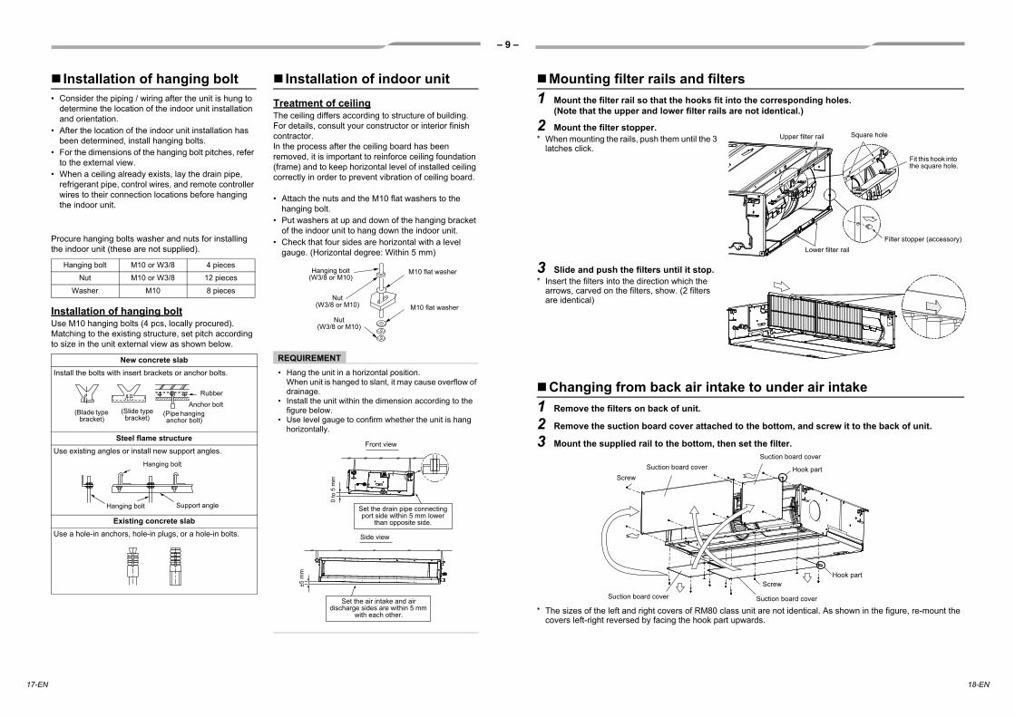
Installation of hanging boltConsider the piping / wiring after the unit is hung to determine the location of the indoor unit installation and orientation.After the location of the indoor unit installation has been determined, install hanging bolts.For the dimensions of the hanging bolt pitches, refer to the external view.When a ceiling already exists, lay the drain pipe, refrigerant pipe, control wires, and remote controller wires to their connection locations before hanging the indoor unit.
Procure hanging bolts washer and nuts for installing the indoor unit (these are not supplied).
Installation of hanging boltUse M10 hanging bolts (4 pcs, locally procured). Matching to the existing structure, set pitch according to size in the unit external view as shown below.
Installation of indoor unitTreatment of ceilingThe ceiling differs according to structure of building.For details, consult your constructor or interior finish contractor.In the process after the ceiling board has been removed, it is important to reinforce ceiling foundation (frame) and to keep horizontal level of installed ceiling correctly in order to prevent vibration of ceiling board.
Attach the nuts and the M10 flat washers to the hanging bolt.Put washers at up and down of the hanging bracket of the indoor unit to hang down the indoor unit.Check that four sides are horizontal with a level gauge. (Horizontal degree: Within 5 mm)
REQUIREMENTHang the unit in a horizontal position.When unit is hanged to slant, it may cause overflow of drainage.Install the unit within the dimension according to the figure below.Use level gauge to confirm whether the unit is hang horizontally.
Hanging bolt M10 or W3/8 4 pieces
Nut M10 or W3/8 12 pieces
Washer M10 8 pieces
New concrete slabInstall the bolts with insert brackets or anchor bolts.
Steel flame structureUse existing angles or install new support angles.
Existing concrete slabUse a hole-in anchors, hole-in plugs, or a hole-in bolts.
RubberAnchor bolt
(Blade type bracket)
(Slide type bracket) (Pipe hanging
anchor bolt)
Hanging bolt
Hanging bolt Support angle
Nut(W3/8 or M10)
M10 flat washer
M10 flat washer
Hanging bolt(W3/8 or M10)
Nut(W3/8 or M10)
0 to
5 m
m
±5 m
m
Set the air intake and air discharge sides are within 5 mm
with each other.
Set the drain pipe connecting port side within 5 mm lower
than opposite side.
Front view
Side view
Mounting filter rails and filters1 Mount the filter rail so that the hooks fit into the corresponding holes.
(Note that the upper and lower filter rails are not identical.)
Changing from back air intake to under air intake1 Remove the filters on back of unit.
2 Remove the suction board cover attached to the bottom, and screw it to the back of unit.
3 Mount the supplied rail to the bottom, then set the filter.
* The sizes of the left and right covers of RM80 class unit are not identical. As shown in the figure, re-mount the covers left-right reversed by facing the hook part upwards.
2 Mount the filter stopper.* When mounting the rails, push them until the 3
latches click.
3 Slide and push the filters until it stop.* Insert the filters into the direction which the
arrows, carved on the filters, show. (2 filters are identical)
Filter stopper (accessory)Lower filter rail
Square hole
Fit this hook into the square hole.
Upper filter rail
Suction board coverSuction board cover
Hook part
Hook partScrew
Suction board coverSuction board cover
Screw
17-EN 18-EN

– 10 –
EN
5 Drain pipingCAUTION
Following the Installation Manual, perform the drain piping work so that water is properly drained. Apply a heat insulation so as not to cause a dew condensation.Inappropriate piping work may result in water leakage in the room and wet furniture.
• Provide the indoor drain piping with proper heat insulation.• Provide the area where the pipe connects to the indoor unit with proper heat insulation. Improper heat insulation
will cause condensation to form.• The drain pipe must be sloping downward (at an angle of 1/100 or more), and do not run the pipe up and down
(arched shape) or allow it to form traps. Doing so may cause abnormal sounds.• Restrict the length of the traversing drain pipe to 20 meters or less. For a long pipe, provide support brackets at
intervals of 1.5 to 2 meters to prevent flapping.• Install the collective piping as shown in the following figure.• Do not provide any air vents. Otherwise, the drain water will spout, causing water to leak.• Do not allow any force to be applied to the connection area with the drain pipe.
Pipe material, size and insulatorThe following materials for piping work and insulating process are locally procured.
Connecting drain pipeInsert flexible drain hose into upper drain pipe of main unit as far as it will go. Fix it with hose band.
REQUIREMENTMount the flexible drain hose using the hose band without using adhesive.
Pipe material Hard vinyl chloride pipe VP25 (Nominal outer diameter Ø32 mm)
Insulator Foamed polyethylene foam, thickness: 10 mm or more
1.5 m to 2 mSupport bracket
Downward slope 1/100 or more
Arched shape
TrapDownward slope
1/100 or more
(Collective piping)
As long as possible (Approx. 10 cm)
Heat insulator
IncorrectVP30
Flexible drain hose
Hose band
Flexible drain hose
Hose band
Indoor unit
10 to
12
mm
15 mm or less
10 mm
Gravitational drainage
Drain up
1 Reattach the drain cap.* For gravitational drainage, remove the white connector
(CN504) on the upper left of the circuit board in the electrical control box.
2 Insert flexible drain hose into lower drain pipe and fix it with hose band.
3 Remove drain pump connector CN504.
When a down-gradient cannot be secured for the drain pipe, drain-up piping is possible.• The height of the drain pipe must be 850 mm or less from the underside
of the indoor unit.• Take the drain pipe out of the drain pipe joint with the indoor unit in 300
mm or less, and bend up the pipe vertically.• Immediately after the pipe is bent up vertically, lay the pipe making a
down-gradient.
Move the drain cap from the lower pipe to the upper pipe.
Lower pipe
Upper pipe
RedCN504
Black
850
or le
ss
Drain up setup dimensions
Flexible drain hose (supplied)
618
or le
ss
For drain pipes that will be connected after setup, make a
downward slope of 1/100 or more.
300 or less
19-EN 20-EN

– 11 –
Check the drainingIn the test run, check that water drain is properly performed and water does not leak from the connecting part of the pipes. When doing this, also check that no abnormal sounds are heard from the drain pump motor. Check draining also when installed in heating period.
When the electrical and wiring work has been completedPour some water by following the method shown in the following figure. Then, while performing a cooling operation, check that the water drains from the drain pipe connecting port (transparent) and that no water is leaking from the drain pipe.
When the electrical and wiring work has not been completed• Disconnect the float switch connector (3P: red) from the connector (CN34: red) on the printed circuit board inside
the electrical control box. (Before doing this, the power must be turned off.)• Connect a 220 V to 240 V supply voltage to (L) and (N) on the power supply terminal block. (Do not apply a 220
V to 240 V voltage to (A), (B) of the terminal block. Otherwise, the printed circuit board may be damaged.)• Pour the water by following the method shown in the following figure. (Amount of water poured: 1500 cc to 2000
cc)• When the power is turned on, the drain pump automatically starts running. Check whether the water is draining
from the drain pipe connecting port, and check that no water is leaking from the drain pipe.• After checking that the water drains and there are no water leaks, turn off the power, connect the float switch
connector to its original location (CN34) on the printed circuit board, and return the electrical control box to its original position.
Supply water hose
220 V to 240 V
Pull out connector CN34 (Red) from P.C. board.
WhiteRedBlack
Black
Heat insulating process• As shown in the figure, cover the flexible hose and hose band with the attached heat insulator up to the bottom
of the indoor unit tightly.• Cover the drain pipe tightly with a heat insulator procured locally so that it overlaps with the attached heat
insulator of the drain connecting section.
Connecting method of the duct
CAUTIONIncomplete heat insulation of the supply air flange and sealing may occur dewing resulted in falling of water drop.
Wrap the attached heat insulator tightly from the surface of the indoor unit.
Heat insulator of the drain connecting section(accessory)
Indo
or u
nit
Heat insulator(locally procured)
Flange (locally procured)
Aluminum tape (locally procured)
Aluminum tape (locally procured)
Under surface
Air discharge sideIndoor unit
Air intake side
Connect a duct to the outside of the flange
Duct: Insulation material(locally procured)
Flange
21-EN 22-EN

– 12 –
EN
Fan characteristicsRM56 RM80
RM110RM140
0
20
40
60
80
100
120
140
160
380 480 580 680 780 880 980
Standard air volume: 800 m3/h
Upper limit ofexternal static
pressure (120 Pa)High (120 Pa)
Lower limit of externalstatic pressure (120 Pa)
Low(120 Pa)
Standard filter pressure loss
Ext
erna
l sta
tic p
ress
ure
(Pa)
Air Volume (m3/h)
High (100 Pa)
High (80 Pa)
High (65 Pa)
High (50 Pa)
High (40 Pa)
High (30 Pa)
0
20
40
60
80
100
120
140
160
570 770670 970870 11701070 13701270 1470
Standard air volume: 1200 m3/h
Upper limit ofexternal static
pressure (120 Pa)
High (120 Pa)
Lower limit of externalstatic pressure (120 Pa)
Low(120 Pa)
Standard filter pressure loss
Ext
erna
l sta
tic p
ress
ure
(Pa)
Air Volume (m3/h)
High (100 Pa)
High (80 Pa)
High (65 Pa)
High (50 Pa)
High (40 Pa)
High (30 Pa)
0
20
40
60
80
100
120
140
160
1000 1200 1400 1600 1800 2000 2200 2400 2600
Standard air volume: 2100 m3/h
Upper limit ofexternal static
pressure (120 Pa)High (120 Pa)
Lower limit of externalstatic pressure (120 Pa)
Low(120 Pa)
Standard filter pressure loss
Ext
erna
l sta
tic p
ress
ure
(Pa)
Air Volume (m3/h)
High (100 Pa)
High (80 Pa)
High (65 Pa)
High (50 Pa)
High (40 Pa)
High (30 Pa)
23-EN 24-EN

– 13 –
6 Duct design
Arrangement (Unit: mm)
Referring to the following dimensions, manufacture duct at the local site.
254
2727
37.537.5
659.4
100
100
100100100100100100
235.
4
254
675
2727
87.5 87.5
660
235.
2 100
100
100100100100100
254
2727
37.537.5
959.4
235.
4
100
100
100100100100100100100100100
254
97537.537.5
2727
960
235.
2
100100100100100100100100100
100
100
254
2727
37.5 37.5
1359.4
100
100
235.
4
100100100100100100100100100100100100100
254
1375
2727
37.537.5
1360
235.
2 100
100
100100100100100100100100100100100100100
RM56
<Under air intake>
<Back air intake>
RM80
<Under air intake>
<Back air intake>
RM110, RM140
<Under air intake>
<Back air intake>
25-EN 26-EN

– 14 –
EN
Ø15.9 Ø9.5
RM56
RM80, RM110,RM140
Ø12.7 Ø6.4
ModelPipe size (mm)
Gas side Liquid side
7 Refrigerant pipingCAUTION
When the refrigerant pipe is long, provide support brackets at intervals of 2.5 m to 3 m to clamp the refrigerant pipe. Otherwise, abnormal sound may be generated.
Permissible piping length and height difference
They vary depending on the outdoor unit. For details, refer to the Installation Manual attached to the outdoor unit.
Pipe size
Connecting refrigerant pipingFlaring
Projection margin in flaring: B (Unit: mm)
Flaring diameter size: A (Unit: mm)
Outer dia. of copper pipe
Conventional tool used
6.4, 9.5 0.5 to 1.1 0.5 to 1.1
0.5 to 1.1 1.5 to 2.012.7, 15.9
Outer dia. of copper pipe A +0–0.4
The sealed gas was sealed at the atmospheric pressure so when the flare nut is removed, there will no “whooshing” sound: This is normal and is not indicative of trouble.Use two wrenches to connect the indoor unit pipe.
Use the tightening torque levels as listed in the following table.
CAUTIONTightening with an excessive torque may crack the nut depending on installation conditions.
EvacuationPerform vacuuming from the charge port of valve of the outdoor unit by using a vacuum pump.For details, follow to the Installation Manual attached to the outdoor unit.
Do not use the refrigerant sealed in the outdoor unit for evacuation.
REQUIREMENTFor the tools such as charge hose, use those manufactured exclusively for R32 or R410A.
Refrigerant amount to be addedFor addition of the refrigerant, add refrigerant “R32 orR410A” referring to the attached Installation Manual of outdoor unit.Use a scale to charge the refrigerant of specified amount.
REQUIREMENTCharging an excessive or too little amount of refrigerant causes a trouble of the compressor.Charge the refrigerant of specified amount.A personnel who charged the refrigerant should write down the pipe length and the added refrigerant amount in the F-GAS label of the outdoor unit. It is necessary to fix the compressor and refrigeration cycle malfunction.
Open the valve fullyOpen the valve of the outdoor unit fully. A 4 mm-hexagonal wrench is required for opening the valve.For details, refer to the Installation Manual attached to the outdoor unit.
Gas leak checkCheck with a leak detector or soap water whether gas leaks or not, from the pipe connecting section or cap of the valve.
REQUIREMENTUse a leak detector manufactured exclusively for HFC refrigerant (R32, R134a, R410A, etc.).
Outer dia. of connecting pipe (mm) Tightening torque (N m)
14 to 18
34 to 42
49 to 61
63 to 77
6.4
9.5
12.7
15.9
Work using double spannerTool used
Tightening torque of flare pipe connectionsIncorrect connections may cause not only a gas leak, but also a trouble of the refrigeration cycle.Align the centres of the connecting pipes and tighten the flare nut as far as possible with your fingers. Thentighten the nut with a spanner and torque wrench asshown in the figure.
6.4
9.5
12.7
15.9
9.1
13.2
16.6
19.7
IMPORTANT 4 POINTS FOR PIPING WORK
not allowed indoors. When mechanical connectors are reused indoors, sealing parts shall be renewed. When flared joints are reused indoors, the flare part shall be refabricated.
2. Tight connection (between pipes and unit)3. Evacuate the air in the connecting pipes by using
VACUUM PUMP.4. Check the gas leakage. (Connected points)
1. Reusable mechanical connectors and flared joints are
Remove burrs completely.Remaining burrs may cause gas leakage.
As the flaring sizes of R32 or R410A differ from those of refrigerant R22, the flare tools newly manufactured for R32 or R410A are recommended.However, the conventional tools can be used by adjusting projection margin of the copper pipe.
CAUTION
when removing burrs.
on the inner surface of flare processing part will cause refrigerant gas leak.
deformed, stepped, or flattened, and that there are no chips adhered or other problems, after flare processing.
surface.
CAUTION
* In case of flaring with the conventional flare tool, pull it out approx. 0.5 mm more than that for R22 to adjust to the specified flare size. The copper pipe gauge is useful for adjusting projection margin size.
27-EN 28-EN
– 15 –
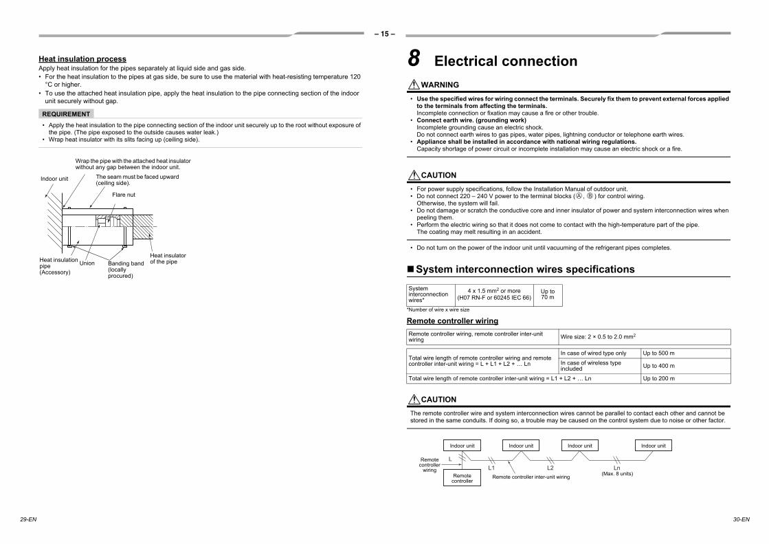
Heat insulation processApply heat insulation for the pipes separately at liquid side and gas side.• For the heat insulation to the pipes at gas side, be sure to use the material with heat-resisting temperature 120
°C or higher.• To use the attached heat insulation pipe, apply the heat insulation to the pipe connecting section of the indoor
unit securely without gap.
REQUIREMENT• Apply the heat insulation to the pipe connecting section of the indoor unit securely up to the root without exposure of
the pipe. (The pipe exposed to the outside causes water leak.)• Wrap heat insulator with its slits facing up (ceiling side).
Indoor unit
UnionHeat insulation pipe (Accessory)
Flare nut
Heat insulator of the pipe
Wrap the pipe with the attached heat insulator without any gap between the indoor unit.
The seam must be faced upward (ceiling side).
Banding band (locally procured)
8 Electrical connectionWARNING
• Use the specified wires for wiring connect the terminals. Securely fix them to prevent external forces applied to the terminals from affecting the terminals.Incomplete connection or fixation may cause a fire or other trouble.
• Connect earth wire. (grounding work)Incomplete grounding cause an electric shock.Do not connect earth wires to gas pipes, water pipes, lightning conductor or telephone earth wires.
• Appliance shall be installed in accordance with national wiring regulations.Capacity shortage of power circuit or incomplete installation may cause an electric shock or a fire.
CAUTION• For power supply specifications, follow the Installation Manual of outdoor unit.• Do not connect 220 – 240 V power to the terminal blocks ( , ) for control wiring.
Otherwise, the system will fail.• Do not damage or scratch the conductive core and inner insulator of power and system interconnection wires when
peeling them.• Perform the electric wiring so that it does not come to contact with the high-temperature part of the pipe.
The coating may melt resulting in an accident.
• Do not turn on the power of the indoor unit until vacuuming of the refrigerant pipes completes.
System interconnection wires specifications
*Number of wire x wire size
Remote controller wiring
CAUTIONThe remote controller wire and system interconnection wires cannot be parallel to contact each other and cannot be stored in the same conduits. If doing so, a trouble may be caused on the control system due to noise or other factor.
System interconnection wires*
4 x 1.5 mm2 or more(H07 RN-F or 60245 IEC 66)
Up to 70 m
Remote controller wiring, remote controller inter-unit wiring Wire size: 2 × 0.5 to 2.0 mm2
Total wire length of remote controller wiring and remote controller inter-unit wiring = L + L1 + L2 + … Ln
In case of wired type only Up to 500 m
In case of wireless type included Up to 400 m
Total wire length of remote controller inter-unit wiring = L1 + L2 + … Ln Up to 200 m
A B
L1L
L2 Ln
Indoor unit
Remote controller inter-unit wiring
Indoor unit Indoor unit Indoor unit
Remotecontroller
(Max. 8 units)
Remote controller
wiring
29-EN 30-EN

– 16 –
EN
Wiring between indoor unit and outdoor unit1. Figure below shows the wiring connections between the indoor and outdoor units and between the indoor units
and remote controller. The wires indicated by the broken lines or dot-and-dash lines are provided at the locally.2. Refer to the both indoor and outdoor unit wiring diagrams.3. The power of the indoor unit is supplied from the outdoor unit.
Wiring diagram
* Use 2-core shield wire (MVVS 0.5 to 2.0 mm2 or more) for the remote controller wiring in the simultaneous triple and simultaneous double twin systems to prevent noise problems. Be sure to connect both ends of the shield wire to earth leads.
* Connect earth wires for each indoor unit in the simultaneous twin, simultaneous triple and simultaneous double twin systems.
Single system Simultaneous twin system
Simultaneous triple and double twin system
A B
1
1
2
2
3
3Outdoor side
Power supply
Remote controller
Remote controller wiring
Indoor side
System interconnection wires
A B
1 2 3
A B
1
1
2
2
3
3
Power supply
Remote controller inter-unit wiring
Indoor side
Indoor power inter-unit wiringOutdoor side
Remote controller
Remote controller wiring
Indoor side
System interconnection wires
A B
1 2 3
A B
1 2 3
A B
1 2 3
A B
1 2 3
1 2 3
Power supply
Remote controller inter-unit wiring
Indoor side
Indoor power inter-unit wiring
Remote controller inter-unit wiring
Indoor side
Remote controller inter-unit wiring
Indoor side
Triple
Double twin
Indoor power inter-unit wiring
Indoor power inter-unit wiringOutdoor side
Remote controller
Remote controller wiring
Indoor side
System interconnection wires
Wire connectionREQUIREMENT• Connect the wires matching the terminal numbers. Incorrect connection causes a trouble.• Pass the wires through the bushing of wire connection holes of the indoor unit.• Keep a margin (Approx. 100 mm) on a wire to hang down the electrical control box at servicing or other purpose.• The low-voltage circuit is provided for the remote controller. (Do not connect the high-voltage circuit)
•
Remote controller wiringStrip off approx. 9 mm the wire to be connected.
Wiring diagram
• Before performing wiring work in the electrical control box, remove the air filter and the cover of the box (fixed with 2 screws).
• Remove screw A, and loosen screw B.• Pull up and open the electrical control box cover.• Tighten the screws of the terminal block firmly, and fix the wires with
the cord clamps attached to the electrical control box. (Do not apply tension to the connecting section of the terminal block.)
• Slide the electrical control box cover to install it. Do not pinch the wire and make the gap as small as possible when installing the cover.
Remove screw A.
Loosen screw B.Electrical control
box cover
System interconnection wire
Cord clamp
Remote controller wiring
Earth screw
Select side C or D for the power cable clamping position referring to the following table according to the cable type and diameter.* Cable clamp can be attached on either right or left side.When twin system are connected, clamp two cables with one cable clamp.
Wire type Specification Cable clamping position
Cabtyre cable 4-core stranded wire 2.5 mm² Side D
Cabtyre cable 4-core stranded wire 1.5 mm² Side C
Side D (Space: 8.5 mm) Side C (Space: 4 mm)
1 3
10
30
10
50
2
System interconnection wireEarth wire
2 m
m o
r le
ss
System interconnection wire
See the figure on the left for system interconnection wires to
the terminal block.
A
B
A
B
Terminal block
Remote controller
unit
Terminal block for remote controller wiring of indoor unit
Remote controller wire (Locally procured)
31-EN 32-EN

– 17 –
9 Applicable controlsREQUIREMENT• When you use this air conditioner for the first time, it
takes approx. 5 minutes until the remote controller becomes available after power-on. This is normal.<When power is turned on for the first time after installation> It takes approx. 5 minutes until the remote controller becomes available.
<When power is turned on for the second (or later) time> It takes approx. 1 minute until the remote controller becomes available.
• Normal settings were made when the indoor unit was shipped from factory. Change the indoor unit settings as required.
• Use the wired remote controller to change the settings.* The settings cannot be changed using the
wireless remote controller, sub remote controller, or remote-controller-less system (for central remote controller only). Therefore, install the wired remote controller to change the settings.
Basic procedure for changing settings
Change the settings while the air conditioner is not working. (Stop the air conditioner before making settings.)
CAUTIONSet only the CODE No. shown in the following table: Do NOT set any other CODE No.If a CODE No. not listed is set, it may not be possible to operate the air conditioner or other trouble with the product may result.
* The displays appearing during the setting process differ from the ones for previous remote controllers (AMT21E, AMT31E). (There are more CODE No.)
1 Push and hold button and “TEMP.” button simultaneously for 4 seconds or more. After a while, the display flashes as shown in the figure. Confirm that the CODE No. is [01].• If the CODE No. is not [01], push button to
clear the display content, and repeat the procedure from the beginning. (No operation of the remote controller is accepted for a while after button is pushed.)(While air conditioners are operated under the group control, “ALL” is displayed first. When
is pushed, the indoor unit number displayed following “ALL” is the header unit.)
Power on “SETTING” flashes
“SETTING” goes out
Remote controller is available
Approx. 5 minutes
Power on “SETTING” flashes
“SETTING” goes out
Remote controller is available
Approx. 1 minutes
1
6
13
25
4
(* Display content varies with the indoor unit model.)
2 Each time button is pushed, indoor unit numbers in the control group change cyclically. Select the indoor unit to change settings for.The fan of the selected unit runs and the louvers start swinging. The indoor unit for change settings can be confirmed.
3 Specify CODE No. [ ] with “TEMP.” / buttons.
4 Select SET DATA [ ] with “TIME” / buttons.
5 Push button. When the display changes from flashing to lit, the setup is completed.• To change settings of another indoor unit,
repeat from Procedure 2.• To change other settings of the selected indoor
unit, repeat from Procedure 3.Use button to clear the settings. To make settings after button was pushed, repeat from Procedure 2.
6 When settings have been completed, push button to determine the settings.
When button is pushed, flashes and then the display content disappears and the air conditioner enters the normal stop mode. (While is flashing, no operation of the remote controller is accepted.)
External static pressure settings
Set up a tap change based upon the external static pressure of the duct to be connected.To set up a tap change, follow to the basic operation procedure (1 → 2 → 3 → 4 → 5 → 6).• Specify [5d] to the CODE No. in procedure 3.• For the SET DATA of procedure 4, select a SET
DATA of the external static pressure to be set up from the following table.
<Change on wired remote controller>
The list above is when SW501-1 and SW501-2 is OFF.
SET DATA External static pressure0000 40 Pa
0001 30 Pa to 3 HP (Factory default)
0002 65 Pa
0003 50 Pa 4 to 6 HP (Factory default)
0004 80 Pa
0005 100 Pa
0006 120 Pa
33-EN 34-EN
– 18 –
EN
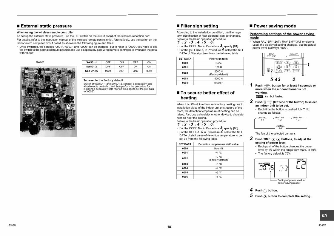
External static pressureWhen using the wireless remote controllerTo set up the external static pressure, use the DIP switch on the circuit board of the wireless reception part.For details, refer to the instruction manual of the wireless remote controller kit. Alternatively, use the switch on the indoor micro computer circuit board as shown in the following figure and table.* Once switched, the settings "0001", "0003", and "0006" can be changed, but to reset to "0000", you need to set
the switch to the normal (default) position and use a separately-sold wired remote controller to overwrite the data with "0000".
SW501-1 OFF ON OFF ON
SW501-2 OFF OFF ON ON
SET DATA 0000 0001 0003 0006
To reset to the factory defaultSwitch off SW501-1 and SW501-2, connect a separately-sold wired remote controller, and then perform the procedure for installing a separately-sold filter on this page to set the [5d] data to "0000".
Filter sign settingAccording to the installation condition, the filter sign term (Notification of filter cleaning) can be changed.Follow to the basic operation procedure(1 → 2 → 3 → 4 → 5 → 6).
For the CODE No. in Procedure 3, specify [01].For the [SET DATA] in Procedure 4, select the SET DATA of filter sign term from the following table.
To secure better effect of heating
When it is difficult to obtain satisfactory heating due to installation place of the indoor unit or structure of the room, the detection temperature of heating can be raised. Also use a circulator or other device to circulate heat air near the ceiling.Follow to the basic operation procedure(1 → 2 → 3 → 4 → 5 → 6).
For the CODE No. in Procedure 3, specify [06].For the SET DATA in Procedure 4, select the SET DATA of shift value of detection temperature to be set up from the following table.
Power saving modePerforming settings of the power saving mode* When RAV-SP***2AT / RAV-SM***3AT or older is
used, the displayed setting changes, but the actual power level is always “75%”.
1 Push button for at least 4 seconds or more when the air conditioner is not working.
, symbol flashs.
2 Push (left side of the button) to select an indoor unit to be set.
Each time the button is pushed, UNIT No. change as follows:
The fan of the selected unit runs.
3 Push TIME buttons, to adjust the setting of power level.
Each push of the button changes the power level by 1% within the range from 100% to 50%.The factory default is 75%
4 Push button.
5 Push button to complete the setting.
SET DATA Filter sign term0000 None
0001 150 H
0002 2500 H(Factory default)
0003 5000 H
0004 10000 H
SET DATA Detection temperature shift value0000 No shift
0001 +1 °C
0002 +2 °C(Factory default)
0003 +3 °C
0004 +4 °C
0005 +5 °C
0006 +6 °C
1
5 243
UNIT No. 1-1
UNIT No. 1-2
UNIT No. 1-3
UNIT No. 1-4
Setting of power level in power saving mode
SW501
35-EN 36-EN

– 19 –
Remote controller switch monitoring function
This function is available to call the service monitor mode from the remote controller even during a test run to acquire temperatures of sensors of the remote controller, indoor unit, and outdoor unit.
1 Push and buttons simultaneously for at least 4 seconds to call the service monitor mode.The service monitor indicator lights up and the header indoor unit number is displayed first. CODE No. is also displayed.
2 Pushing TEMP. buttons, select the number of sensor, etc. (CODE No.) to be monitored. (See the following table.)
3 Pushing (left side of the button), select an indoor unit to be monitored. The sensor temperatures of indoor units and their outdoor unit in the control group are displayed.
4 Push button to return to the normal display.
1 34
2
Indoor unit dataCODE No. Data name
01 Room temperature (remote controller)
02 Indoor unit intake air temperature (TA)
03 Indoor unit heat exchanger (coil) temperature (TCJ)
04 Indoor unit heat exchanger (coil) temperature (TC)
F3 Filter sign time
Outdoor unit dataCODE No. Data name
60 Outdoor unit heat exchanger (coil) temperature (TE)
61 Outside air temperature (TO)
62 Compressor discharge temperature (TD)
63 Compressor suction temperature (TS)
64 —
65 Heatsink temperature (THS)
6A Operating current (x1/10)
F1 Compressor cumulative operating hours (x100 h)
Group controlSimultaneous twin, triple or double twin systemA combination with an outdoor unit allows simultaneous ON/OFF operation of the indoor units. The following system patterns are available.- Two indoor units for the twin system- Three indoor units for the triple system- Four indoor units for the double-twin system
▼ Twin system
▼ Triple system
▼ Double twin
• For wiring procedure and wiring method, follow to the “Electrical connection” in this manual.• When the power supply has been turned on, the automatic address setup starts and which indicates that address
is being set up flashes on the display part.During setup of automatic address, the remote controller operation is not accepted.
Required time up to the finish of automatic addressing is approx. 5 minutes.
Outdoor unit
Finish of address setup by power-ON
Remote controller
Indoor unit Indoor unit
Outdoor unit
Finish of address setup by power-ON
Remote controller
Indoor unit Indoor unit Indoor unit
Outdoor unit
Finish of address setup by power-ON
Remote controller
Indoor unit Indoor unit Indoor unit Indoor unit
37-EN 38-EN

– 20 –
EN
Group control for system of multiple unitsOne remote controller can control maximum 8 indoor units as a group.
▼ Group control in single system
• For wiring procedure and wiring method of the individual line (Identical refrigerant line) system, follow to “Electrical connection”.
• Wiring between lines is performed in the following procedure.Connect the terminal block (A/B) of the indoor unit connected with a remote controller to the terminal blocks (A/B) of the indoor units of other indoor units by wiring the inter-unit wire of the remote controller.
• When the power supply has been turned on, the automatic address setup starts and which indicates that address is being set up flashes on the display part in about 3 minutes. During setup of automatic address, the remote controller operation is not accepted.
Required time up to the finish of automatic addressing is approx. 5 minutes.
NOTEIn some cases, it is necessary to change the address manually after setup of the automatic address according to the system configuration of the group control.• The follow mentioned system configuration is a case when complex systems in which systems of the simultaneous
twin and simultaneous triple unit is controlled as a group by a remote controller.
(Example) Group control for complex system
The above address is set by the automatic addressing when the power is turned on. However, line addresses and indoor addresses are set randomly. For this reason, change the setting to match line addresses with indoor addresses.
Outdoor unit
Indoor unitIndoor unitIndoor unitIndoor unitIndoor unit
Remote controllerFinish of address setup by power-ON
(Max. 8 units)
Outdoor unit Outdoor unit Outdoor unit Outdoor unit
Outdoor unit
Line system
Indoor No.
After setup of automatic address
(Example of random setup)
After setup change of
manual address
(Example of address setup change)
Outdoor unit
Indoor unit Indoor unit Indoor unit
Line address Group address
Indoor address
Address: 1-1-1 Address: 2-1-2 Address: 2-2-2
Address: 1-1-2 Address: 2-1-2 Address: 3-3-1
Procedureexample 1<Single system> <Twin system> <Triple system>
Outdoor unit
Indoor unit Indoor unit Indoor unit
Remote controller
Address: 3-1-2 Address: 3-2-2 Address: 3-3-2
Address: 3-1-2 Address: 2-2-2 Address: 1-2-2
[Procedure example]Manual address setup procedureWhile the operation stops, change the setup.(Stop the operation of the unit.)
1 Push + + buttons simultaneously for 4 seconds or more. After a while, the display part flashes as shown below. Check the displayed CODE No. is [10].When the CODE No. is other than [10], push button to clear the display and repeat procedure from the first step. (After pushing button, operation of the remote controller is not accepted for approx. 1 minute.) (For a group control, No. of the firstly displayed indoor unit becomes the header unit.)
2 Every time button is pushed, the indoor UNIT No. in the group control is displayed in order. Select the indoor unit of which setup is changed.In this time, the position of the indoor unit of which setup is changed can be confirmed because fan of the selected indoor unit operate.
31. Specify CODE No. [12] with TEMP. /
buttons. (CODE No. [12]: Line address)
2. Change the line address from [3] to [2] with TIME / buttons.
3. Push button.In this time, the setup finishes when the display changes from flashing to lighting.
41. Specify CODE No. [13] with TEMP. /
buttons. (CODE No. [13]: Indoor address)
2. Change the indoor address from [3] to [2] TIME / buttons.
3. Push button.In this time, the setup finishes when the display changes from flashing to lighting.
2,61
7
3 -1, 456
-1, -1,
7
3 -3, 4 -3,
3 -2, 4 -2, 5 -2
5 -3,
(* Display changes according to the model No. of indoor unit.)
Indoor UNIT No. before setup change is displayed.
Indoor UNIT No. before setup change is displayed.
39-EN 40-EN
– 21 –
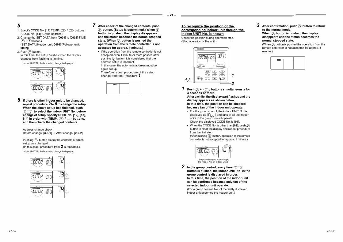
51. Specify CODE No. [14] TEMP. / buttons.
(CODE No. [14]: Group address)2. Change the SET DATA from [0001] to [0002] TIME
/ buttons.(SET DATA [Header unit: 0001] [Follower unit: 0002])
3. Push button.In this time, the setup finishes when the display changes from flashing to lighting.
6 If there is other indoor unit to be changed, repeat procedure 2 to 5 to change the setup.When the above setup has finished, push
to select the indoor UNIT No. before change of setup, specify CODE No. [12], [13], [14] in order with TEMP. / buttons, and then check the changed contents.
Address change check Before change: [3-3-1] → After change: [2-2-2]
Pushing button clears the contents of which setup was changed.(In this case, procedure from 2 is repeated.)
7 After check of the changed contents, push button. (Setup is determined.) When
button is pushed, the display disappears and the status becomes the normal stopped state. (When button is pushed the operation from the remote controller is not accepted for approx. 1 minute.)• If the operation from the remote controller is not
accepted even 1 minute or more passed after pushing button, it is considered that the address setup is incorrect.In this case, the automatic address must be again set up.Therefore repeat procedure of the setup change from the Procedure 1.
Indoor UNIT No. before setup change is displayed.
Indoor UNIT No. before setup change is displayed.
To recognize the position of the corresponding indoor unit though the indoor UNIT No. is knownCheck the position during operation stop.(Stop operation of the unit.)
1 Push + buttons simultaneously for 4 seconds or more.After a while, the display part flashes and the display appears as shown below.In this time, the position can be checked because fan of the indoor unit operate.• For the group control, the indoor UNIT No. is
displayed as [ ] and fans of all the indoor units in the group control operate.Check the displayed CODE No. is [01].
• When the CODE No. is other than [01], push button to clear the display and repeat procedure from the first step.(After pushing button, operation of the remote controller is not accepted for approx. 1 minute.)
2 In the group control, every time button is pushed, the indoor UNIT No. in the group control is displayed in order.In this time, the position of the indoor unit can be confirmed because only fan of the selected indoor unit operate. (For a group control, No. of the firstly displayed indoor unit becomes the header unit.)
3 After confirmation, push button to return to the normal mode.When button is pushed, the display disappears and the status becomes the normal stopped state.(When button is pushed the operation from the remote controller is not accepted for approx. 1 minute.)
21,3
1
(* Display changes according to the model No. of indoor unit.)
41-EN 42-EN
– 22 –
EN
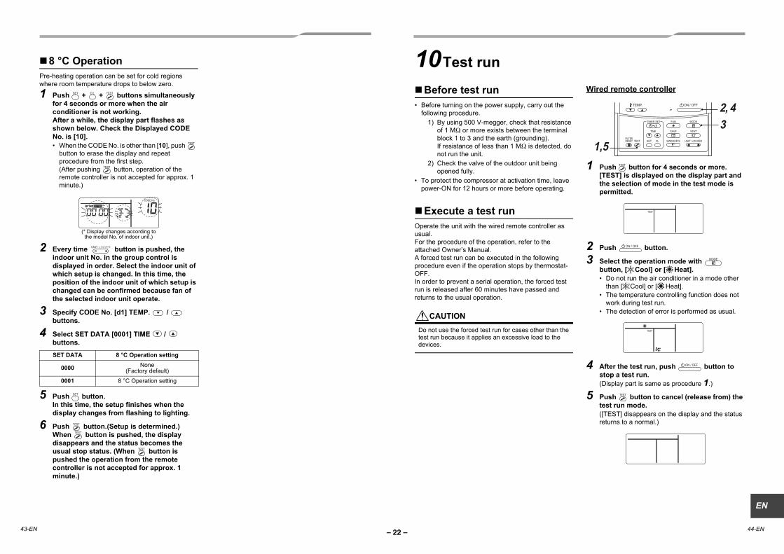
8 °C OperationPre-heating operation can be set for cold regions where room temperature drops to below zero.
1 Push + + buttons simultaneously for 4 seconds or more when the air conditioner is not working.After a while, the display part flashes as shown below. Check the Displayed CODE No. is [10].
When the CODE No. is other than [10], push button to erase the display and repeat procedure from the first step.(After pushing button, operation of the remote controller is not accepted for approx. 1 minute.)
2 Every time button is pushed, the indoor unit No. in the group control is displayed in order. Select the indoor unit of which setup is changed. In this time, the position of the indoor unit of which setup is changed can be confirmed because fan of the selected indoor unit operate.
3 Specify CODE No. [d1] TEMP. / buttons.
4 Select SET DATA [0001] TIME / buttons.
5 Push button.In this time, the setup finishes when the display changes from flashing to lighting.
6 Push button.(Setup is determined.)When button is pushed, the display disappears and the status becomes the usual stop status. (When button is pushed the operation from the remote controller is not accepted for approx. 1 minute.)
SET DATA 8 °C Operation setting
0000 None(Factory default)
0001 8 °C Operation setting
(* Display changes according to the model No. of indoor unit.)
10Test run
Before test runBefore turning on the power supply, carry out the following procedure.
1) By using 500 V-megger, check that resistance of 1 M or more exists between the terminal block 1 to 3 and the earth (grounding).If resistance of less than 1 M is detected, do not run the unit.
2) Check the valve of the outdoor unit being opened fully.
To protect the compressor at activation time, leave power-ON for 12 hours or more before operating.
Execute a test runOperate the unit with the wired remote controller as usual.For the procedure of the operation, refer to the attached Owner’s Manual.A forced test run can be executed in the following procedure even if the operation stops by thermostat-OFF.In order to prevent a serial operation, the forced test run is released after 60 minutes have passed and returns to the usual operation.
CAUTIONDo not use the forced test run for cases other than the test run because it applies an excessive load to the devices.
Wired remote controller
1 Push button for 4 seconds or more. [TEST] is displayed on the display part and the selection of mode in the test mode is permitted.
2 Push button.
3 Select the operation mode with button, [ Cool] or [ Heat].
Do not run the air conditioner in a mode other than [ Cool] or [ Heat].The temperature controlling function does not work during test run.The detection of error is performed as usual.
4 After the test run, push button to stop a test run.(Display part is same as procedure 1.)
5 Push button to cancel (release from) the test run mode.([TEST] disappears on the display and the status returns to a normal.)
2, 43
1,5
43-EN 44-EN
– 23 –
45-EN 46-EN
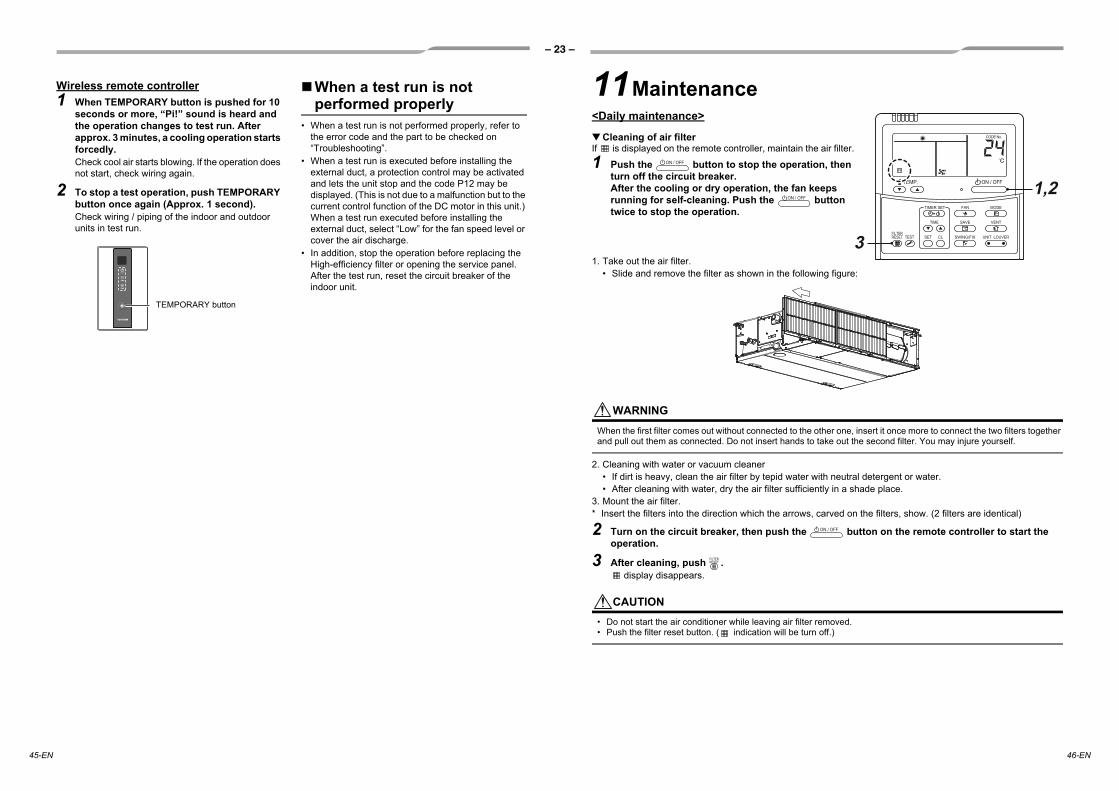
Wireless remote controller1 When TEMPORARY button is pushed for 10
seconds or more, “Pi!” sound is heard and the operation changes to test run. After approx. 3 minutes, a cooling operation starts forcedly.Check cool air starts blowing. If the operation does not start, check wiring again.
2 To stop a test operation, push TEMPORARY button once again (Approx. 1 second).Check wiring / piping of the indoor and outdoor units in test run.
When a test run is not performed properly
• When a test run is not performed properly, refer to the error code and the part to be checked on “Troubleshooting”.
• When a test run is executed before installing the external duct, a protection control may be activated and lets the unit stop and the code P12 may be displayed. (This is not due to a malfunction but to the current control function of the DC motor in this unit.) When a test run executed before installing the external duct, select “Low” for the fan speed level or cover the air discharge.
• In addition, stop the operation before replacing the High-efficiency filter or opening the service panel. After the test run, reset the circuit breaker of the indoor unit.
TEMPORARY button
11Maintenance<Daily maintenance>
▼ Cleaning of air filterIf is displayed on the remote controller, maintain the air filter.
1 Push the button to stop the operation, then turn off the circuit breaker.After the cooling or dry operation, the fan keeps running for self-cleaning. Push the button twice to stop the operation.
1. Take out the air filter.• Slide and remove the filter as shown in the following figure:
WARNINGWhen the first filter comes out without connected to the other one, insert it once more to connect the two filters together and pull out them as connected. Do not insert hands to take out the second filter. You may injure yourself.
2. Cleaning with water or vacuum cleaner• If dirt is heavy, clean the air filter by tepid water with neutral detergent or water.• After cleaning with water, dry the air filter sufficiently in a shade place.
3. Mount the air filter.* Insert the filters into the direction which the arrows, carved on the filters, show. (2 filters are identical)
2 Turn on the circuit breaker, then push the button on the remote controller to start the operation.
3 After cleaning, push . display disappears.
CAUTION• Do not start the air conditioner while leaving air filter removed.• Push the filter reset button. ( indication will be turn off.)
3
1,2

– 24 –
EN
47-EN 48-EN
▼ Periodic MaintenanceFor environmental conservation, it is strongly recommended that the indoor and outdoor units of the air conditioner in use be cleaned and maintained regularly to ensure efficient operation of the air conditioner.When the air conditioner is operated for a long time, periodic maintenance (once a year) is recommended. Furthermore, regularly check the outdoor unit for rust and scratches, and remove them or apply rustproof treatment, if necessary.As a general rule, when an indoor unit is operated for 8 hours or more daily, clean the indoor unit and outdoor unit at least once every 3 months. Ask a professional for this cleaning / maintenance work.Such maintenance can extend the life of the product though it involves the owner’s expense.Failure to clean the indoor and outdoor units regularly will result in poor performance, freezing, water leakage, and even compressor failure.Inspection before maintenanceFollowing inspection must be carried out by a qualified installer or qualified service person.
▼ Maintenance List
Parts Inspection method
Heat exchanger Access from inspection opening and remove the access panel. Examine the heat exchanger if there is any clogging or damages.
Fan motor Access from inspection opening and check if any abnormal noise can be heard.
Fan Access from inspection opening and remove the access panel. Examine the fan if there are any waggles, damages or adhesive dust.
Filter Go to installed location and check if there are any stains or breaks on the filter.
Drain pan Access from inspection opening and remove the access panel. Check if there is any clogging or drain water is polluted.
Part Unit Check (visual / auditory) Maintenance
Heat exchanger Indoor / outdoor Dust / dirt clogging, scratches Wash the heat exchanger when it is clogged.
Fan motor Indoor / outdoor Sound Take appropriate measures when abnormal sound is generated.
Filter Indoor Dust / dirt, breakage• Wash the filter with water when it is
contaminated.• Replace it when it is damaged.
Fan Indoor• Vibration, balance• Dust / dirt, appearance
• Replace the fan when vibration or balance is terrible.
• Brush or wash the fan when it is contaminated.
Air intake / discharge grilles Indoor / outdoor Dust / dirt, scratches Fix or replace them when they are
deformed or damaged.
Drain pan Indoor Dust / dirt clogging, drain contamination
Clean the drain pan and check the downward slope for smooth drainage.
Ornamental panel, louvres Indoor Dust / dirt, scratches Wash them when they are contaminated
or apply repair coating.
Exterior Outdoor • Rust, peeling of insulator• Peeling / lift of coat Apply repair coating.
12Troubleshooting
Confirmation and checkWhen an error occurred in the air conditioner, an error code and indoor UNIT No. appear on the display part of the remote controller.The error code is only displayed during the operation.If the display disappears, operate the air conditioner according to the following “Confirmation of error log” for confirmation.
Confirmation of error logWhen an error occurred on the air conditioner, the error log can be confirmed with the following procedure. (The error log is stored in memory up to 4 errors.)The log can be confirmed from both operating status and stop status.
1 When and buttons are pushed simultaneously for 4 seconds or more, the following display appears.If is displayed, the mode enters in the error log mode.• [01: Order of error log] is displayed in CODE No.• [Error code] is displayed in CHECK.• [Indoor unit address in which an error occurred]
is displayed in UNIT No.
2 Every pushing of button used to set temperature, the error log stored in memory is displayed in order.The numbers in CODE No. indicate CODE No. [01] (latest) → [04] (oldest).
REQUIREMENTDo not push button because all the error log of the indoor unit will be deleted.
3 After confirmation, push button to return to the usual display.
Error code Indoor UNIT No. in which an error occurred
3
2
1
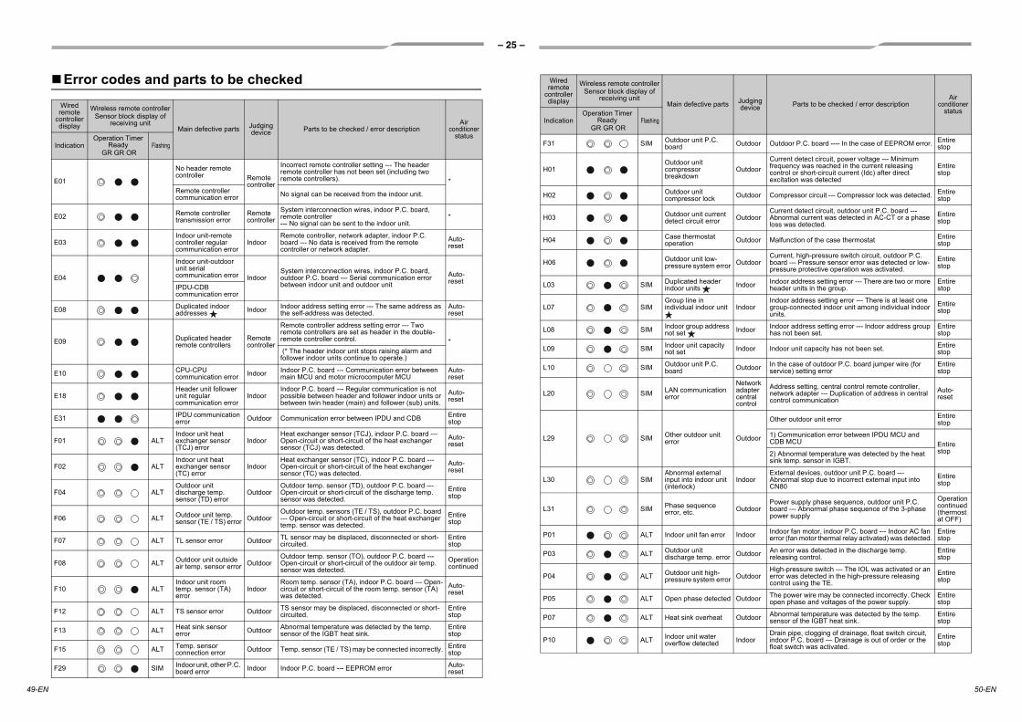
– 25 –
49-EN 50-EN
Error codes and parts to be checkedWired remote
controller display
Wireless remote controllerSensor block display of
receiving unitMain defective parts Judging
device Parts to be checked / error descriptionAir
conditioner status
IndicationOperation Timer
Ready GR GR OR
Flashing
E01
No header remote controller Remote
controller
Incorrect remote controller setting --- The header remote controller has not been set (including two remote controllers). *
Remote controller communication error No signal can be received from the indoor unit.
E02 Remote controller transmission error
Remote controller
System interconnection wires, indoor P.C. board, remote controller --- No signal can be sent to the indoor unit.
*
E03Indoor unit-remote controller regular communication error
IndoorRemote controller, network adapter, indoor P.C. board --- No data is received from the remote controller or network adapter.
Auto-reset
E04
Indoor unit-outdoor unit serial communication error Indoor
System interconnection wires, indoor P.C. board, outdoor P.C. board --- Serial communication error between indoor unit and outdoor unit
Auto-reset
IPDU-CDB communication error
E08 Duplicated indoor addresses Indoor Indoor address setting error --- The same address as
the self-address was detected.Auto-reset
E09 Duplicated header remote controllers
Remote controller
Remote controller address setting error --- Two remote controllers are set as header in the double-remote controller control. * (* The header indoor unit stops raising alarm and follower indoor units continue to operate.)
E10 CPU-CPU communication error Indoor Indoor P.C. board --- Communication error between
main MCU and motor microcomputer MCUAuto-reset
E18Header unit follower unit regular communication error
IndoorIndoor P.C. board --- Regular communication is not possible between header and follower indoor units or between twin header (main) and follower (sub) units.
Auto-reset
E31 IPDU communication error Outdoor Communication error between IPDU and CDB Entire
stop
F01 ALTIndoor unit heat exchanger sensor (TCJ) error
IndoorHeat exchanger sensor (TCJ), indoor P.C. board --- Open-circuit or short-circuit of the heat exchanger sensor (TCJ) was detected.
Auto-reset
F02 ALTIndoor unit heat exchanger sensor (TC) error
IndoorHeat exchanger sensor (TC), indoor P.C. board --- Open-circuit or short-circuit of the heat exchanger sensor (TC) was detected.
Auto-reset
F04 ALTOutdoor unit discharge temp. sensor (TD) error
OutdoorOutdoor temp. sensor (TD), outdoor P.C. board --- Open-circuit or short-circuit of the discharge temp. sensor was detected.
Entire stop
F06 ALT Outdoor unit temp. sensor (TE / TS) error Outdoor
Outdoor temp. sensors (TE / TS), outdoor P.C. board --- Open-circuit or short-circuit of the heat exchanger temp. sensor was detected.
Entire stop
F07 ALT TL sensor error Outdoor TL sensor may be displaced, disconnected or short-circuited.
Entire stop
F08 ALT Outdoor unit outside air temp. sensor error Outdoor
Outdoor temp. sensor (TO), outdoor P.C. board --- Open-circuit or short-circuit of the outdoor air temp. sensor was detected.
Operation continued
F10 ALTIndoor unit room temp. sensor (TA) error
IndoorRoom temp. sensor (TA), indoor P.C. board --- Open-circuit or short-circuit of the room temp. sensor (TA) was detected.
Auto-reset
F12 ALT TS sensor error Outdoor TS sensor may be displaced, disconnected or short-circuited.
Entire stop
F13 ALT Heat sink sensor error Outdoor Abnormal temperature was detected by the temp.
sensor of the IGBT heat sink.Entire stop
F15 ALT Temp. sensor connection error Outdoor Temp. sensor (TE / TS) may be connected incorrectly. Entire
stop
F29 SIM Indoor unit, other P.C. board error Indoor Indoor P.C. board --- EEPROM error Auto-
reset
F31 SIM Outdoor unit P.C. board Outdoor Outdoor P.C. board ---- In the case of EEPROM error. Entire
stop
H01Outdoor unit compressor breakdown
OutdoorCurrent detect circuit, power voltage --- Minimum frequency was reached in the current releasing control or short-circuit current (Idc) after direct excitation was detected
Entire stop
H02 Outdoor unit compressor lock Outdoor Compressor circuit --- Compressor lock was detected. Entire
stop
H03 Outdoor unit current detect circuit error Outdoor
Current detect circuit, outdoor unit P.C. board --- Abnormal current was detected in AC-CT or a phase loss was detected.
Entire stop
H04 Case thermostat operation Outdoor Malfunction of the case thermostat Entire
stop
H06 Outdoor unit low-pressure system error Outdoor
Current, high-pressure switch circuit, outdoor P.C. board --- Pressure sensor error was detected or low-pressure protective operation was activated.
Entire stop
L03 SIM Duplicated header indoor units Indoor Indoor address setting error --- There are two or more
header units in the group.Entire stop
L07 SIMGroup line in individual indoor unit Indoor
Indoor address setting error --- There is at least one group-connected indoor unit among individual indoor units.
Entire stop
L08 SIM Indoor group address not set Indoor Indoor address setting error --- Indoor address group
has not been set.Entire stop
L09 SIM Indoor unit capacity not set Indoor Indoor unit capacity has not been set. Entire
stop
L10 SIM Outdoor unit P.C. board Outdoor In the case of outdoor P.C. board jumper wire (for
service) setting errorEntire stop
L20 SIM LAN communication error
Network adapter central control
Address setting, central control remote controller, network adapter --- Duplication of address in central control communication
Auto-reset
L29 SIM Other outdoor unit error Outdoor
Other outdoor unit error Entire stop
1) Communication error between IPDU MCU and CDB MCU Entire
stop2) Abnormal temperature was detected by the heat sink temp. sensor in IGBT.
L30 SIMAbnormal external input into indoor unit (interlock)
IndoorExternal devices, outdoor unit P.C. board --- Abnormal stop due to incorrect external input into CN80
Entire stop
L31 SIM Phase sequence error, etc. Outdoor
Power supply phase sequence, outdoor unit P.C. board --- Abnormal phase sequence of the 3-phase power supply
Operation continued (thermostat OFF)
P01 ALT Indoor unit fan error Indoor Indoor fan motor, indoor P.C. board --- Indoor AC fan error (fan motor thermal relay activated) was detected.
Entire stop
P03 ALT Outdoor unit discharge temp. error Outdoor An error was detected in the discharge temp.
releasing control.Entire stop
P04 ALT Outdoor unit high-pressure system error Outdoor
High-pressure switch --- The IOL was activated or an error was detected in the high-pressure releasing control using the TE.
Entire stop
P05 ALT Open phase detected Outdoor The power wire may be connected incorrectly. Check open phase and voltages of the power supply.
Entire stop
P07 ALT Heat sink overheat Outdoor Abnormal temperature was detected by the temp. sensor of the IGBT heat sink.
Entire stop
P10 ALT Indoor unit water overflow detected Indoor
Drain pipe, clogging of drainage, float switch circuit, indoor P.C. board --- Drainage is out of order or the float switch was activated.
Entire stop
Wired remote
controller display
Wireless remote controllerSensor block display of
receiving unitMain defective parts Judging
device Parts to be checked / error descriptionAir
conditioner status
IndicationOperation Timer
Ready GR GR OR
Flashing

– 26 –
EN
51-EN 52-EN
: Lighting : Flashing : OFF : The air conditioner automatically enters the auto-address setting mode.ALT: When two LEDs are flashing, they flash alternately. SIM: When two LEDs are flashing, they flash in synchronization.Receiving unit display OR: Orange GR: Green
P12 ALT The fan error of the indoor unit Indoor
Abnormal operation of the indoor fan motor, indoor P.C. board, or indoor DC fan (over current or lock, etc.) is detected. External static pressure setting error.
Entire stop
P15 ALT Gas leakage detected Outdoor There may be gas leakage from the pipe or
connecting part. Check for gas leakage.Entire stop
P19 ALT 4-way valve error Outdoor(Indoor)
4-way valve, indoor temp. sensors (TC / TCJ) --- An error was detected due to temperature drop of the indoor unit heat exchanger sensor when heating.
Auto-reset
P20 ALT High-pressure protective operation Outdoor High-pressure protection Entire
stop
P22 ALT Outdoor unit fan error OutdoorOutdoor unit fan motor, outdoor unit P.C. board --- An error (overcurrent, locking, etc.) was detected in the outdoor unit fan drive circuit.
Entire stop
P26 ALT Outdoor unit inverter Idc activated Outdoor
IGBT, outdoor unit P.C. board, inverter wiring, compressor --- Short-circuit protection for compressor drive circuit devices (G-Tr / IGBT) was activated.
Entire stop
P29 ALT Outdoor unit position error Outdoor Outdoor unit P.C. board, high-pressure switch ---
Compressor motor position error was detected.Entire stop
P31 ALT Other indoor unit error Indoor
Another indoor unit in the group is raising an alarm. Entire stop
E03 / L07 / L03 / L08 alarm check locations and error description
Auto-reset
Wired remote
controller display
Wireless remote controllerSensor block display of
receiving unitMain defective parts Judging
device Parts to be checked / error descriptionAir
conditioner status
IndicationOperation Timer
Ready GR GR OR
Flashing

– 27 –
Work instructionsThe existing R22 and R410A piping can be reused for inverter R32 product installations.
WARNING
Confirming the existence of scratches or dents onthe existing pipes and confirming the reliability ofthe pipe strength are conventionally referred to thelocal site.If the specified conditions can be cleared, it ispossible to update existing R22 and R410A pipesto those for R32 models.
Basic conditions needed to reuse existingpipesCheck and observe the presence of three conditions inthe refrigerant piping works.1. Dry (There is no moisture inside of the pipes.)2. Clean (There is no dust inside of the pipes.)3. Tight (There are no refrigerant leaks.)
Restrictions for use of existing pipesIn the following cases, the existing pipes shouldnot be reused as they are. Clean the existing pipesor exchange them with new pipes.1. When a scratch or dent is heavy, be sure to use new
pipes for the refrigerant piping works.2. When the existing pipe thickness is thinner than the
specified “Pipe diameter and thickness,” be sure to use new pipes for the refrigerant piping works.
The operating pressure of refrigerant is high. If there is a scratch or dent on the pipe or a thinnerpipe is used, the pressure strength may be inadequate, which may cause the pipe to break in the worst case.
* Pipe diameter and thickness (mm)
3. When the outdoor unit was left with the pipes disconnected, or the gas leaked from the pipes and the pipes were not repaired and refilled.
There is the possibility of rain water or air, including moisture, entering the pipe.
4. When refrigerant cannot be recovered using a refrigerant recovery unit. There is the possibility that a large quantity of dirty oil or moisture remains inside the pipes.
5. When a commercially available dryer is attached to the existing pipes.
There is the possibility that copper green rust has been generated.
6. When the existing air conditioner is removed after refrigerant has been recovered.
Check if the oil is judged to be clearly different from normal oil.
The refrigerator oil is copper rust green in color: There is the possibility that moisture has mixed with
the oil and rust has been generated inside the pipe. There is discolored oil, a large quantity of residue, or a bad smell.
A large quantity of shiny metal dust or other wear residue can be seen in the refrigerant oil.
7. When the air conditioner has a history of the compressor failing and being replaced.
When discolored oil, a large quantity of residue, shiny metal dust, or other wear residue or mixture of foreign matter is observed, trouble will occur.
8. When temporary installation and removal of the air conditioner are repeated such as when leased etc.
9. If the type of refrigerator oil of the existing air conditioner is other than the following oil (Mineral oil), Suniso, Freol-S, MS (Synthetic oil), alkyl benzene (HAB, Barrel-freeze), ester series, PVE only of ether series.
The winding-insulation of the compressor may deteriorate.
NOTE
The above descriptions are results have been confirmed by our company and represent our views on our air conditioners, but do not guarantee the use of the existing pipes of air conditioners that have adopted R32, R410A in other companies.
Curing of pipesWhen removing and opening the indoor or outdoor unit for a long time, cure the pipes as follows: Otherwise rust may be generated when moisture or foreign matter due to condensation enters the pipes.
The rust cannot be removed by cleaning, and new pipes are necessary.
Placement location Term Curing manner
Outdoors1 month or more Pinching
Less than 1 monthPinching or taping
Indoors Every time
Are there scratches or dents on the existing pipes?
Is it possible to operate the existing air conditioner?
After the existing air conditioner is operated in cooling mode for approx. 30 minutes or longer,* recover the refrigerant.
For cleaning the pipes and recovering oil Refrigerant recovery: Pump down method
Remove the existing air conditioner from the piping and carry out flushing (nitrogen pressure 0.5 MPa) to remove any remains inside of the pipe.
Note: In case of twin pipes, also be sure to flush the branching pipe.
Connect the indoor / outdoor units to the existing pipe. Use a flare nut attached to the main unit for the indoor /floutdoor units. (Do not use the flare nut of the existing pipe.)
Re-machine the flare machining size to size for R32, R410A.
(Airtight test), Vacuum dry, Refrigerant charge, Gas leak check
Test run
Was largely discolored oil or a large quantity of remains discharged? (When the oil deteriorates,
the color of the oil changes to a muddy or black color.)
Existing pipes: Cannot be used. Use new pipes.
Clean the pipes or use new pipes.
Piping necessary to change the flare nut / machining size due to pipe compression
1) Flare nut width: H
H
2) Flare machining size: A
A
Do not apply refrigerator oil to the flare surface.
(If there is discharge of remains, it is judged that a large quantity of remains are present.)
YES
YES
NONO
NO
YES
Nitrogen gas pressure 0.5 MPa
13Appendix
Ø9.5 Ø12.7 Ø15.9Ø6.4Pipe outer diameter
ThicknessR32, R410A
0.8 0.8 0.8 1.0R22
(mm)Copper pipe outer diameter Ø6.4 Ø9.5 Ø12.7 Ø15.9
For R32, R410A 17 22 26 29For R22 Same as above 24 27
Ø6.4 Ø9.5 Ø12.7 Ø15.9
(mm)Copper pipe outer diameterFor R32, R410A 9.1 13.2 16.6 19.7For R22 9.0 13.0 16.2 19.4
Becomes a little larger for R32, R410A
54-EN53-EN

144 / 9 Moo 5, Bangkadi Industrial Park, Tivanon Road, Tambol Bangkadi, Amphur Muang, Pathumthani 12000, Thailand
1116950194