toshiba vf nc3 manual - xdocs.net
TRANSCRIPT
IIII
1
2
3
4
5
6
7
8
9
1010
1111
1212
1313
1414
1515
1616
E6581595
Read first
ISafety
precautions
Introduction
Contents
Connection
Operations
Setting
parameters
Main
parameters
Other
parameters
Operation with externalsignal
Monitoring the
operation status
Measures to satisfy the standards
Peripheral
devices
Table of parameters and data
Specifications
Before making
a service call
Inspection and
maintenance
Warranty
Disposal of the
inverter
NOTICE
1. Make sure that this instruction manual is delivered to the
end user of the inverter unit.
2. Read this manual before installing or operating the inverter
unit, and store it in a safe place for reference.
Instruction Manual
<Detailed manual>
TOSVERTTM
VF-nC3
1-phase 120V class 0.1 0.75kW
1-phase 240V class 0.1 2.2kW
3-phase 240V class 0.1 4kW
Industrial InverterFor 3-phase induction motors
E6581595
1
I I. Safety precautions
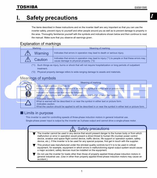
The items described in these instructions and on the inverter itself are very important so that you can use the
inverter safely, prevent injury to yourself and other people around you as well as to prevent damage to property in
the area. Thoroughly familiarize yourself with the symbols and indications shown below and then continue to read
the manual. Make sure that you observe all warnings given.
Explanation of markings Marking Meaning of marking
Warning Indicates that errors in operation may lead to death or serious injury.
Caution Indicates that errors in operation may lead to injury (*1) to people or that these errors may cause damage to physical property. (*2)
(*1) Such things as injury, burns or shock that will not require hospitalization or long periods of outpatient
treatment.
(*2) Physical property damage refers to wide-ranging damage to assets and materials.
Meanings of symbols Marking Meaning of marking
Indicates prohibition (Don't do it). What is prohibited will be described in or near the symbol in either text or picture form.
Indicates an instruction that must be followed. Detailed instructions are described in illustrations and text in or near the symbol.
-Indicates warning. What is warned will be described in or near the symbol in either text or picture form. -Indicates caution. What the caution should be applied to will be described in or near the symbol in either text or picture form.
Limits in purpose This inverter is used for controlling speeds of three-phase induction motors in general industrial use.
Single-phase power input is output by the inverter as 3-phase output and cannot drive a single-phase motor.
Safety precautions The inverter cannot be used in any device that would present danger to the human body or from which malfunction or error in operation would present a direct threat to human life (nuclear power control device, aviation and space flight control device, traffic device, life support or operation system, safety device, etc.). If the inverter is to be used for any special purpose, first get in touch with the supplier. This product was manufactured under the strictest quality controls but if it is to be used in critical equipment, for example, equipment in which errors in malfunctioning signal output system would cause a major accident, safety devices must be installed on the equipment. Do not use the inverter for loads other than those of properly applied three-phase induction motors in general industrial use. (Use in other than properly applied three-phase induction motors may cause an accident.)

E6581595
2
I General Operation
Warning See item
Disassembly
prohibited
• Never disassemble, modify or repair. This can result in electric shock, fire and injury. For repairs, call your sales distributor.
2.
Prohibited
• Do not open the terminal block cover while the inverter is on. The unit contains many high voltage parts and contact with them will result in electric shock.
• Don't stick your fingers into openings such as cable wiring hole and cooling fan covers. This can result in electric shock or other injury.
• Don't place or insert any kind of object into the inverter (electrical wire cuttings, rods, wires etc.). This can result in electric shock or fire.
• Do not allow water or any other fluid to come in contact with the inverter. This can result in electric shock or fire.
2.1 2.
2. 2.
Instruction
• After replacing the terminal block cover, turn the input power on. Turning on the input power without replacing the terminal block cover may lead to electric shock.
• If the inverter begins to emit smoke or an unusual odor, or unusual sounds, immediately turn power off. If the equipment is continued in operation in such a state, the result may be fire. Call your local sales agency for repairs.
• Always turn power off if the inverter is not used for long periods of time since there is a possibility of malfunction caused by leaks, dust and other material. If power is left on with the inverter in that state, it may result in fire.
2.1
3. 3.
Caution See item
Prohibited contact
• Do not touch heat radiating fins or discharge resistors. These device are hot, and you'll get burned if you touch them.
3.
E6581595
3
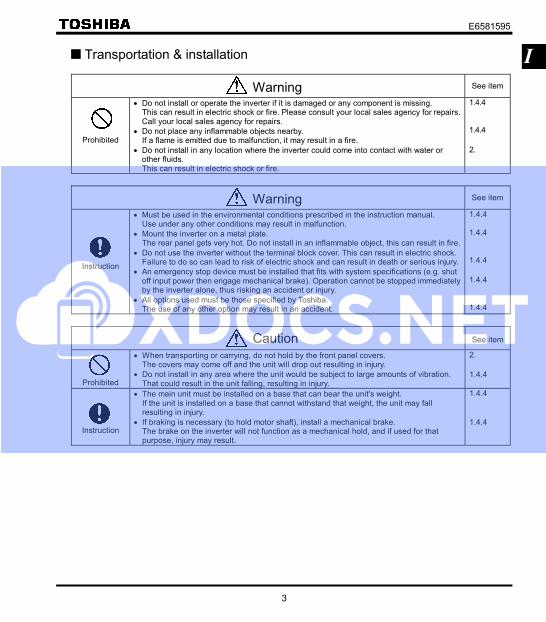
I Transportation & installation
Warning See item
Prohibited
• Do not install or operate the inverter if it is damaged or any component is missing. This can result in electric shock or fire. Please consult your local sales agency for repairs. Call your local sales agency for repairs.
• Do not place any inflammable objects nearby. If a flame is emitted due to malfunction, it may result in a fire.
• Do not install in any location where the inverter could come into contact with water or other fluids. This can result in electric shock or fire.
1.4.4 1.4.4
2.
Warning See item
Instruction
• Must be used in the environmental conditions prescribed in the instruction manual. Use under any other conditions may result in malfunction.
• Mount the inverter on a metal plate. The rear panel gets very hot. Do not install in an inflammable object, this can result in fire.
• Do not use the inverter without the terminal block cover. This can result in electric shock. Failure to do so can lead to risk of electric shock and can result in death or serious injury.
• An emergency stop device must be installed that fits with system specifications (e.g. shut off input power then engage mechanical brake). Operation cannot be stopped immediately by the inverter alone, thus risking an accident or injury.
• All options used must be those specified by Toshiba. The use of any other option may result in an accident.
1.4.4 1.4.4 1.4.4
1.4.4 1.4.4
Caution See item
Prohibited
• When transporting or carrying, do not hold by the front panel covers. The covers may come off and the unit will drop out resulting in injury.
• Do not install in any area where the unit would be subject to large amounts of vibration. That could result in the unit falling, resulting in injury.
2.
1.4.4
Instruction
• The main unit must be installed on a base that can bear the unit's weight. If the unit is installed on a base that cannot withstand that weight, the unit may fall resulting in injury.
• If braking is necessary (to hold motor shaft), install a mechanical brake. The brake on the inverter will not function as a mechanical hold, and if used for that purpose, injury may result.
1.4.4
1.4.4

E6581595
4
I Wiring
Warning
See item
Prohibited
• Do not connect input power to the output (motor side) terminals (U/T1,V/T2,W/T3). That will destroy the inverter and may result in fire.
• Do not connect resistors to the DC terminals (across PA/+ - PC/- or PO-PC/-). That may cause a fire.
• Within 15 minutes after turning off input power, do not touch wires of devices (MCCB) connected to the input side of the inverter. That could result in electric shock.
• When supplying power from a wall socket, do not exceed the rated capacity of the socket. Otherwise, this may generate excessive heat which can start a fire.
2.2
2.2
2.2
Warning See item
Instruction
• Electrical installation work must be done by a qualified expert. Connection of input power by someone who does not have that expert knowledge may result in fire or electric shock.
• Connect output terminals (motor side) correctly. If the phase sequence is incorrect, the motor will operate in reverse and that may result in injury.
• Wiring must be done after installation. If wiring is done prior to installation that may result in injury or electric shock
• The following steps must be performed before wiring. (1) Turn off all input power. (2) Wait at least 15 minutes and check to make sure that the charge lamp is no longer lit. (3) Use a tester that can measure DC voltage (400VDC or more), and check to make sure
that the voltage to the DC main circuits (across PA/+ - PC/-) is 45V or less. If these steps are not properly performed, the wiring will cause electric shock.
• Tighten the screws on the terminal board to specified torque. If the screws are not tightened to the specified torque, it may lead to fire.
• Check to make sure that the input power voltage is +10%, -15% of the rated power voltage written on the rating label (±10% when the load is 100% in continuous operation). If the input power voltage is not +10%, -15% of the rated power voltage (±10% when the load is 100% in continuous operation) this may result in fire.
2.1
2.1
2.1
2.1
2.1 1.4.4
Be Grounded
• Ground must be connected securely. If the ground is not securely connected, it could lead to electric shock or fire when a malfunction or current leak occurs.
2.1 2.2
Caution See item
Prohibited
• Do not attach equipment (such as noise filters or surge absorbers) that have built-in capacitors to the output (motor side) terminals. That could result in a fire.
2.1

E6581595
5
I
Warning
See item
Instruction
• Configuring settings on the setup menu incorrectly may break the inverter or lead to malfunction.
3.1
Operations
Warning
See item
Prohibited
• Never touch the internal terminals in the upper right while the front cover is open. There is a risk of shock because it carries a high voltage.
1.3.1
Warning
See item
Prohibited
• Do not touch inverter terminals when electrical power is going to the inverter even if the motor is stopped. Touching the inverter terminals while power is connected to it may result in electric shock.
• Do not touch switches when the hands are wet and do not try to clean the inverter with a damp cloth. Such practices may result in electric shock.
• Do not go near the motor in alarm-stop status when the retry function is selected. The motor may suddenly restart and that could result in injury. Take measures for safety, e.g. attaching a cover to the motor, against accidents when the motor unexpectedly restarts.
3.
3.
3.
Instruction
• After replacing the terminal block cover, turn the input power on. When installed inside a cabinet and using with the front cover removed, always close the cabinet doors first and then turn power on. Turning on the power with the terminal block cover or cabinet doors open may result in electric shock.
• Make sure that operation signals are off before resetting the inverter after malfunction. If the inverter is reset before turning off the operating signal, the motor may restart suddenly causing injury.
3.
3.
Caution See item
Prohibited
• Observe all permissible operating ranges of motors and mechanical equipment. (Refer to the motor's instruction manual.) Not observing these ranges may result in injury.
3.
When sequence for restart after a momentary failure is selected (inverter)
Caution See item
Instruction
• Stand clear of motors and mechanical equipment. If the motor stops due to a momentary power failure, the equipment will start suddenly after power recovers. This could result in unexpected injury.
• Attach warnings about sudden restart after a momentary power failure on inverters, motors and equipment for prevention of accidents in advance.
E6581595,6.12.1 E6581595,6.12.1
E6581595
6
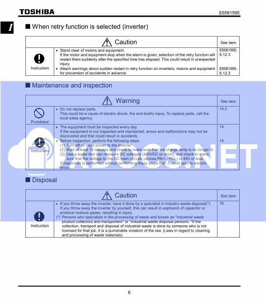
I When retry function is selected (inverter)
Caution See item
Instruction
• Stand clear of motors and equipment. If the motor and equipment stop when the alarm is given, selection of the retry function will restart them suddenly after the specified time has elapsed. This could result in unexpected injury.
• Attach warnings about sudden restart in retry function on inverters, motors and equipment for prevention of accidents in advance.
E6581595,6.12.3
E6581595,6.12.3
Maintenance and inspection
Warning
See item
Prohibited
• Do not replace parts. This could be a cause of electric shock, fire and bodily injury. To replace parts, call the local sales agency.
14.2
Instruction
• The equipment must be inspected every day. If the equipment is not inspected and maintained, errors and malfunctions may not be discovered and that could result in accidents.
• Before inspection, perform the following steps. (1) Turn off all input power to the inverter. (2) Wait at least 15 minutes and check to make sure that the charge lamp is no longer lit. (3) Use a tester that can measure DC voltages (400VDC or more), and check to make
sure that the voltage to the DC main circuits (across PA/+ - PC/-) is 45V or less. If inspection is performed without performing these steps first, it could lead to electric
shock.
14.
14.
Disposal
Caution See item
Instruction
• If you throw away the inverter, have it done by a specialist in industry waste disposal(*). If you throw away the inverter by yourself, this can result in explosion of capacitor or produce noxious gases, resulting in injury.
(*) Persons who specialize in the processing of waste and known as "industrial waste product collectors and transporters" or "industrial waste disposal persons. "If the collection, transport and disposal of industrial waste is done by someone who is not licensed for that job, it is a punishable violation of the law. (Laws in regard to cleaning and processing of waste materials)
16.
E6581595
7
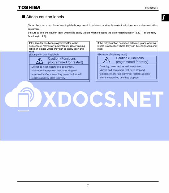
I Attach caution labels
Shown here are examples of warning labels to prevent, in advance, accidents in relation to inverters, motors and other
equipment.
Be sure to affix the caution label where it is easily visible when selecting the auto-restart function (6.13.1) or the retry
function (6.13.3).
If the inverter has been programmed for restart sequence of momentary power failure, place warning labels in a place where they can be easily seen and read. (Example of warning label)
If the retry function has been selected, place warning labels in a location where they can be easily seen and read. (Example of warning label)
Caution (Functions programmed for restart)
Do not go near motors and equipment.
Motors and equipment that have stopped
temporarily after momentary power failure will
restart suddenly after recovery.
Caution (Functions programmed for retry)
Do not go near motors and equipment.
Motors and equipment that have stopped
temporarily after an alarm will restart suddenly
after the specified time has elapsed.

E6581595
8
II
II. Introduction
Thank you for your purchase of the Toshiba "TOSVERT VF-nC3” industrial inverter. This is the Ver. 100 CPU version inverter. Please be informed that CPU version will be frequently upgraded.

E6581595
i
Contents
I Safety precautions.........................................................................................................................................................1
II Introduction....................................................................................................................................................................8
1. Read first .......................................................................................................................................................................A-1
1.1 Check product purchase....................................................................................................................................A-1
1.2 Contents of the product .....................................................................................................................................A-2
1.3 Names and functions.........................................................................................................................................A-3
1.4 Notes on the application ....................................................................................................................................A-12
2. Connection ....................................................................................................................................................................B-1
2.1 Cautions on wiring .............................................................................................................................................B-1
2.2 Standard connections ........................................................................................................................................B-2
2.3 Description of terminals .....................................................................................................................................B-5
3. Operations .....................................................................................................................................................................C-1
3.1 How to Set the Setup Menu...............................................................................................................................C-2
3.2 Simplified Operation of the VF-nC3 ...................................................................................................................C-4
3.3 How to operate the VF-nC3...............................................................................................................................C-9
3.4 Meter setting and adjustment ............................................................................................................................C-13
3.5 Setting the electronic thermal ............................................................................................................................C-16
3.6 Preset-speed operation (speeds in 15 steps) ....................................................................................................C-21
4. Setting parameters ........................................................................................................................................................D-1
4.1 Setting and Display Modes................................................................................................................................D-1
4.2 How to set parameters.......................................................................................................................................D-3
4.3 Functions useful in searching for a parameter or changing a parameter setting................................................D-7
4.4 Checking the region settings selection ..............................................................................................................D-12
4.5 EASY key function .............................................................................................................................................D-13
5. Main parameters............................................................................................................................................................E-1
5.1 Searching for changes using the history function () .................................................................................E-1
5.2 Setting a parameter using the guidance function () ..................................................................................E-2
5.3 Setting acceleration/deceleration time ...............................................................................................................E-5
5.4 Increasing starting torque ..................................................................................................................................E-7
5.5 Selection of operation mode ..............................................................................................................................E-10
5.6 Meter setting and adjustment ............................................................................................................................E-13
5.7 Forward/reverse run selection (Panel keypad) ..................................................................................................E-13
5.8 Maximum frequency ..........................................................................................................................................E-14
5.9 Upper limit and lower limit frequencies ..............................................................................................................E-15
5.10 Base frequency..................................................................................................................................................E-16