design of a rotary transformer for installations on large shafts
TRANSCRIPT
Citation: Toscani, N.; Brunetti, M.;
Carmeli, M.S.; Castelli Dezza, F.;
Mauri, M. Design of a Rotary
Transformer for Installations on
Large Shafts. Appl. Sci. 2022, 12, 2932.
https://doi.org/10.3390/
app12062932
Academic Editor: Gang Lei
Received: 31 December 2021
Accepted: 10 March 2022
Published: 13 March 2022
Publisher’s Note: MDPI stays neutral
with regard to jurisdictional claims in
published maps and institutional affil-
iations.
Copyright: © 2022 by the authors.
Licensee MDPI, Basel, Switzerland.
This article is an open access article
distributed under the terms and
conditions of the Creative Commons
Attribution (CC BY) license (https://
creativecommons.org/licenses/by/
4.0/).
applied sciences
Article
Design of a Rotary Transformer for Installations on Large Shafts
Nicola Toscani 1,* , Massimo Brunetti 2 , Maria Stefania Carmeli 1 , Francesco Castelli Dezza 1
and Marco Mauri 1
1 Politecnico di Milano, via La Masa 1, 20156 Milano, Italy; [email protected] (M.S.C.);[email protected] (F.C.D.); [email protected] (M.M.)
2 Leonardo Helicopters, via Giovanni Agusta 520, 21017 Cascina Costa, Italy; [email protected]* Correspondence: [email protected]
Abstract: Rotary transformers are adopted to transfer energy from primary to secondary in situationsin which the two sides are in relative rotation. These devices are cylindrical transformers with twocores and the corresponding winding separated by an air gap. Their employment became quiteconvenient with the availability of power electronics, allowing the operation of electrical systemsat relatively high frequencies. In particular, this paper proposes the design of a light and efficienttransformer which can be used in applications involving large shafts. Moreover, a sliced arrangementfor the magnetic core is proposed together with the experimental validation of this solution on areduced-size prototype.
Keywords: rotary transformer; resonant inverter; design of magnetic cores; genetic optimization
1. Introduction
Transformers are electrical machines that allow us to transfer power between twodifferent parts of a circuit. Their more common application is in the field of power systemsand electrical transmission and distribution, since they can ensure galvanic insulationbetween the windings and they allow us to change voltage and current levels betweenthe two sides of the circuit. In the last decades, new applications arose due to the spreadof power electronics. In particular, the possibility to push the operational frequency upto hundreds or thousands Hz allowed the exploitation of magnetic cores which are farsmaller than the corresponding counterparts working at 50 or 60 Hz (see [1]) as well asenable their exploitation on electronics systems and printed circuit boards. Among thesenew applications, rotary transformers [2,3], allow power flow between parts of the systemswhich are in relative rotation. Since this energy transfer is obtained by splitting the core intwo by inserting an air gap, no brushes or sliprings are required. Therefore, such systemsallow the so-called wireless power transfer, which can be achieved also using a capacitivecoupling as shown in [4]. There are some examples of application of wireless powertransfer based on inductive coupling in rotating electrical machines. Indeed, sliprings canbe substituted by rotary transformers in wound rotor induction machines (see [5–7]) as wellas in synchronous ones (see [8]). In particular, this paper focuses on the design of a rotarytransformer suited for installations on large shafts, which are typical of automotive [9],railway [10], naval, aerospace [11,12], or some industrial applications. The goal of this workis to provide some guidelines for the design of efficient rotary transformers working insuch environments. Therefore, the main focus of the steps proposed here in the following isto reduce the weight of the device and to keep its radial size (with respect to shaft diameter)as small as possible. Indeed, an excess of inertia may jeopardize the performance of thesystem in which the transformer operates (e.g., an electrical machine, a train, an aircraft,etc.). To this aim, two multi-objective optimizations (similar to [13]) were performed. Thefirst is based on a brute-force grid search algorithm, which is needed to start approachingthe optimal result by exploring the available solutions. Then, this search was refined usinga genetic optimization [14], which is a generalization of the single-objective procedure
Appl. Sci. 2022, 12, 2932. https://doi.org/10.3390/app12062932 https://www.mdpi.com/journal/applsci
Appl. Sci. 2022, 12, 2932 2 of 17
proposed in [5]. The goal is to obtain a compact, efficient and light device that allowsa power transfer of about 4 kW from primary to secondary according to the applicationpresented in [11,12]. After that, a further weight reduction was obtained by slicing themagnetic core, similar to what is reported in [15]. This operation is a consequence of thehigher fragility of bulk cores with respect to split cores, in particular if ferrite or sinteredmaterials are adopted. Since this procedure may seem quite odd and, apparently, mightcompromise the coupling between the primary and secondary, an experimental validationperformed on a reduced-scale prototype is presented. This small-size device was realizedfollowing the same steps reported in this paper, allowing us to keep the realization costslimited. However, these tests were aimed at verifying that both the design approach andthe developed models allow us to predict the resulting performances of the device in anaccurate way. These two points are of paramount importance in view of tailoring thisproposed design to a specific application. Therefore, the paper is organized as follows:Starting from a general overview of the device and its equivalent circuits, the study goeson with an analytical investigation of the input impedance of the rotary transformer, whichis of paramount importance if some reactive power compensation strategies should beincluded in the system to improve both the active power transfer and system efficiency (seeSection 2). Then, Section 3 briefly presents the electromagnetic finite-elements simulationenvironments that were adopted for studying and optimizing the device. The design andthe performed optimizations are described in detail in Section 4. Then, the experimentalvalidation of this design approach based on a reduced-scale prototype is proposed inSection 5. Finally, conclusions are reported in Section 6.
2. Rotary Transformer: Model and Parameters
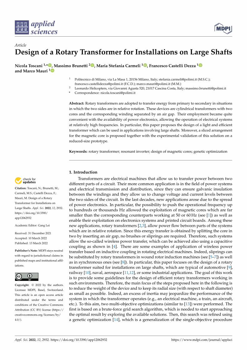
Different from power transformers installed in power plants or stations [16,17], pri-mary and secondary windings in rotary transformers do not share the same magnetic core.Indeed, two cores are required to allow relative movement between the two parts of thesystem. As a consequence, each winding is wound around the corresponding core. Due tothe particular structure of this device, the flux should cross the air gap at least twice to closethe magnetic path. The presence of any air gap is not foreseen in transformers installed inpower plants (which do not allow any relative movement between primary and secondarydue to their static application [18]) and it strongly impacts on the magnetic characteristicsof the device. On one hand, this contributes to linearizing the behaviour of the core, but,on the other hand, the magnetic coupling drops dramatically with respect to transformerswith a bulk core. As a matter of fact, the magnetic flux leakage is much higher than static,single-core solutions. Among the possible topologies which are available in the literaturefor rotary transformers [13,19], the co-axial topology was selected (see Figure 1) because itallows for an easy installation and it ensures robustness from a magnetic coupling point ofview. Indeed, the power transfer proves to be less sensible to misalignment and eccentricitythan other arrangements. It can be noted that the literature typically reports primary onthe outermost part of the structure and secondary on the innermost part. Actually, thischoice depends only on the particular configuration of the considered system, and nothingprevents the system from adopting the arrangement proposed in Figure 1.
Appl. Sci. 2022, 12, 2932 3 of 17
Figure 1. Coaxial topology for rotary transformers.
2.1. Equivalent Circuits
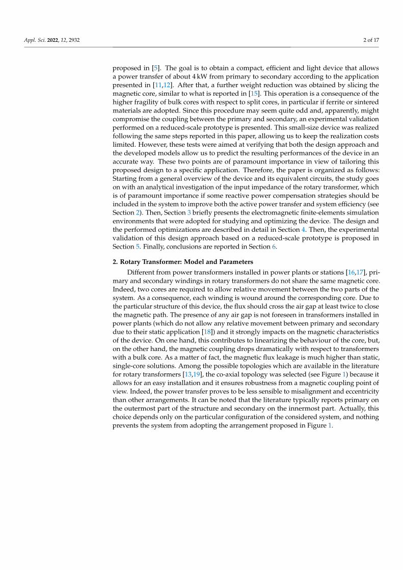
In view of the analysis with electromagnetic finite elements (FEM) software, an equiv-alent circuit based on a mutual inductor was considered (see Figure 2). This explains whythe extraction of the parameters of the equivalent circuit, L1, L2 and M, is simpler in anFEM environment. L1 and L2 are the self-inductances of the two windings, whereas Mstands for the mutual parameters between them.
i1(t)
v1(t)
R1 L1
−+M
di2(t)dt −
+ Mdi1(t)
dt
L2 R2
v2(t)
i2(t)
Figure 2. Equivalent circuit of the rotary transformer with mutual inductor.
It can be noted that L1, L2 and M allow for the evaluation of the magnetic coupling co-efficient between the two windings as well as the leakage Llk and magnetizing inductancesLm (referring to an approximate Γ-equivalent circuit for power transformers, see [16,20]) asfollows:
k =M√L1L2
(1)
Llk =(1− k2)L1 (2)
Lm = k2L1 (3)
Based on the equivalent circuit reported in Figure 2, the resistances R1 and R2 modelthe resistance of the copper for both windings. Therefore, the equations that model thistwo-port system are the following:
v1(t) = R1i1(t) + L1i1(t)
dt+ M
i2(t)dt
v2(t) = R2i2(t) + L2i2(t)
dt+ M
i1(t)dt
(4)
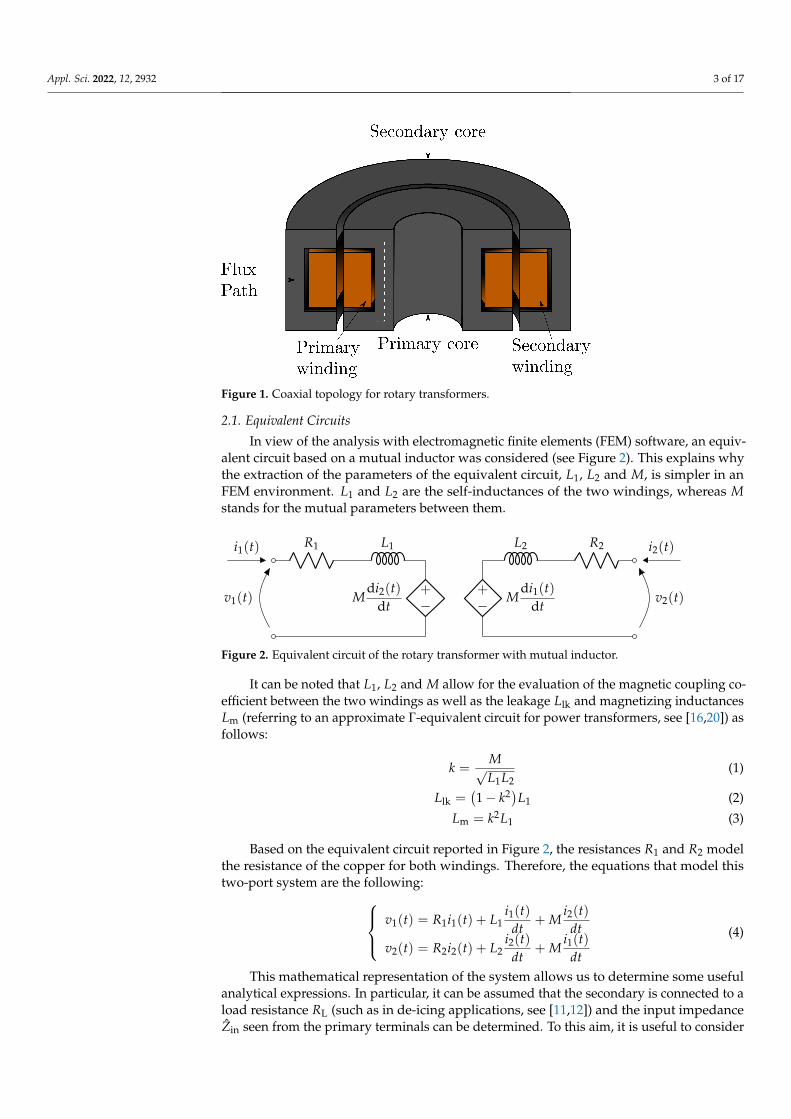
This mathematical representation of the system allows us to determine some usefulanalytical expressions. In particular, it can be assumed that the secondary is connected to aload resistance RL (such as in de-icing applications, see [11,12]) and the input impedanceZin seen from the primary terminals can be determined. To this aim, it is useful to consider
Appl. Sci. 2022, 12, 2932 4 of 17
the phasor domain (see Figure 3) to provide an expression of Zin, which is frequency-dependent, as well.
I1
V1
R1 jωL1
−+jωMI2 −
+ jωMI1
jωL2 R2 I2
RLV2Zin
Figure 3. Equivalent circuit of the rotary transformer with mutual inductor: phasor domain.
The solution of this circuit allows us to state that:
Zin(ω) =V1
I1= R1 + jωL1 +
ω2M2
(R2 + RL) + jωL2(5)
where ω = 2π f is the pulsation corresponding to the considered harmonic at frequency f .By splitting the real and the imaginary parts of this impedance, it is possible to identify Rinand Xin, which are both frequency-dependent:
Rin(ω) = R1 +ω2M2(R2 + RL)
(R2 + RL)2 + ω2L2
2
(6)
Xin(ω) = ωL1 −ω3M2L2
(R2 + RL)2 + ω2L2
2
(7)
2.2. Compensation Strategy
It can be stated that the source sees an impedance which is, in general, complex, fromEquations (6) and (7). Therefore, a significant amount of the input power is related to thenonzero imaginary part of Zin. This reactive nature of the impedance does not cause anyincrease in the active power transfer, but it raises the absolute value of the absorbed currentand therefore the ohmic losses (∝ I2), leading to a drop in the efficiency of the system η. Toeliminate Xin and to increase η, it is possible to design the transformer as:
ωL1 =ω3M2L2
(R2 + RL)2 + ω2L2
2
(8)
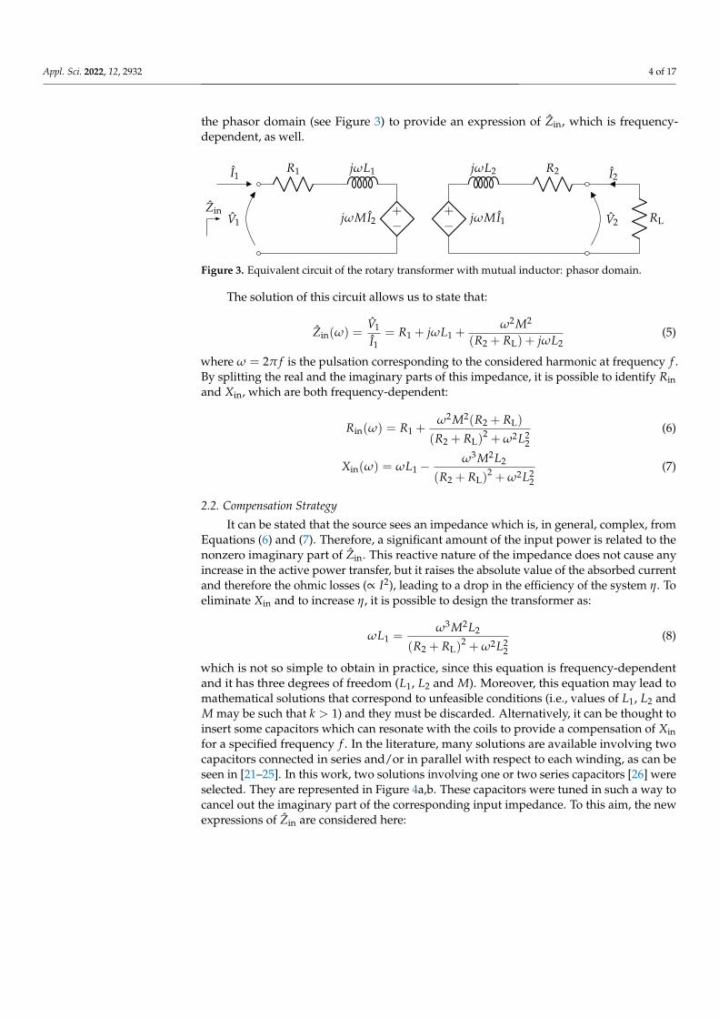
which is not so simple to obtain in practice, since this equation is frequency-dependentand it has three degrees of freedom (L1, L2 and M). Moreover, this equation may lead tomathematical solutions that correspond to unfeasible conditions (i.e., values of L1, L2 andM may be such that k > 1) and they must be discarded. Alternatively, it can be thought toinsert some capacitors which can resonate with the coils to provide a compensation of Xinfor a specified frequency f . In the literature, many solutions are available involving twocapacitors connected in series and/or in parallel with respect to each winding, as can beseen in [21–25]. In this work, two solutions involving one or two series capacitors [26] wereselected. They are represented in Figure 4a,b. These capacitors were tuned in such a way tocancel out the imaginary part of the corresponding input impedance. To this aim, the newexpressions of Zin are considered here:
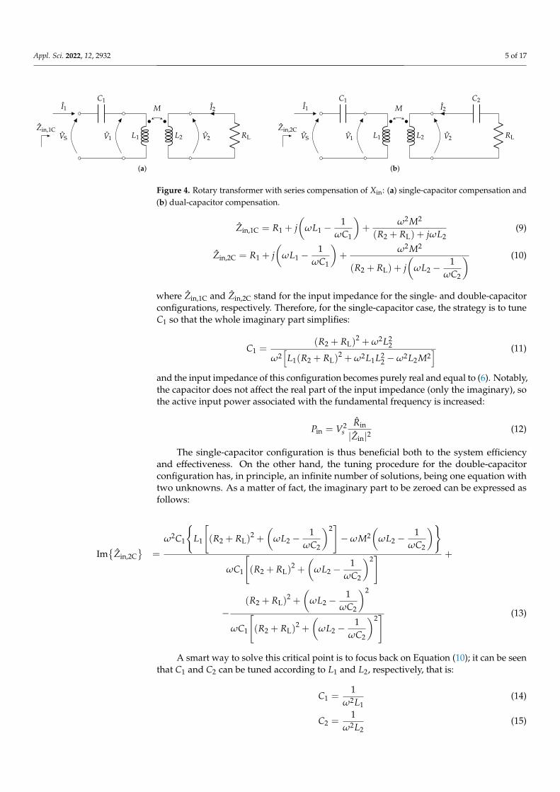
Appl. Sci. 2022, 12, 2932 5 of 17
I1
VS
C1
V1 L1 L2 V2
I2
RL
M
Zin,1C
(a)
I1
VS
C1
V1 L1 L2 V2
I2
C2
RL
M
Zin,2C
(b)
Figure 4. Rotary transformer with series compensation of Xin: (a) single-capacitor compensation and(b) dual-capacitor compensation.
Zin,1C = R1 + j(
ωL1 −1
ωC1
)+
ω2M2
(R2 + RL) + jωL2(9)
Zin,2C = R1 + j(
ωL1 −1
ωC1
)+
ω2M2
(R2 + RL) + j(
ωL2 −1
ωC2
) (10)
where Zin,1C and Zin,2C stand for the input impedance for the single- and double-capacitorconfigurations, respectively. Therefore, for the single-capacitor case, the strategy is to tuneC1 so that the whole imaginary part simplifies:
C1 =(R2 + RL)
2 + ω2L22
ω2[
L1(R2 + RL)2 + ω2L1L2
2 −ω2L2M2] (11)
and the input impedance of this configuration becomes purely real and equal to (6). Notably,the capacitor does not affect the real part of the input impedance (only the imaginary), sothe active input power associated with the fundamental frequency is increased:
Pin = V2s
Rin
|Zin|2(12)
The single-capacitor configuration is thus beneficial both to the system efficiencyand effectiveness. On the other hand, the tuning procedure for the double-capacitorconfiguration has, in principle, an infinite number of solutions, being one equation withtwo unknowns. As a matter of fact, the imaginary part to be zeroed can be expressed asfollows:
Im
Zin,2C
=
ω2C1
L1
[(R2 + RL)
2 +
(ωL2 −
1ωC2
)2]−ωM2
(ωL2 −
1ωC2
)
ωC1
[(R2 + RL)
2 +
(ωL2 −
1ωC2
)2] +
−(R2 + RL)
2 +
(ωL2 −
1ωC2
)2
ωC1
[(R2 + RL)
2 +
(ωL2 −
1ωC2
)2] (13)
A smart way to solve this critical point is to focus back on Equation (10); it can be seenthat C1 and C2 can be tuned according to L1 and L2, respectively, that is:
C1 =1
ω2L1(14)
C2 =1
ω2L2(15)
Appl. Sci. 2022, 12, 2932 6 of 17
allowing us to obtain a purely real input impedance equal to:
Zin = R1 +ω2M2
(R2 + RL)(16)
This choice allows for an easy tuning of the capacitors, which are less subjected tovariations of transformer parameters due to aging, temperature drifts and peculiar workingconditions with respect to the other single- or double-capacitor options. Moreover, eachcapacitor is bouncing energy with the winding on the same side only. Otherwise, thecompensation strategy foresees the flow of some energy between C1 and L2 or between C2and L1. On the other hand, it must be observed that compensation with two capacitorsdoes not necessarily imply that the active power increases with respect to the other caseswith no capacitor or one capacitor only. It is recommended to study the input impedancein an accurate way before choosing any compensation strategy.
2.3. Power Electronics
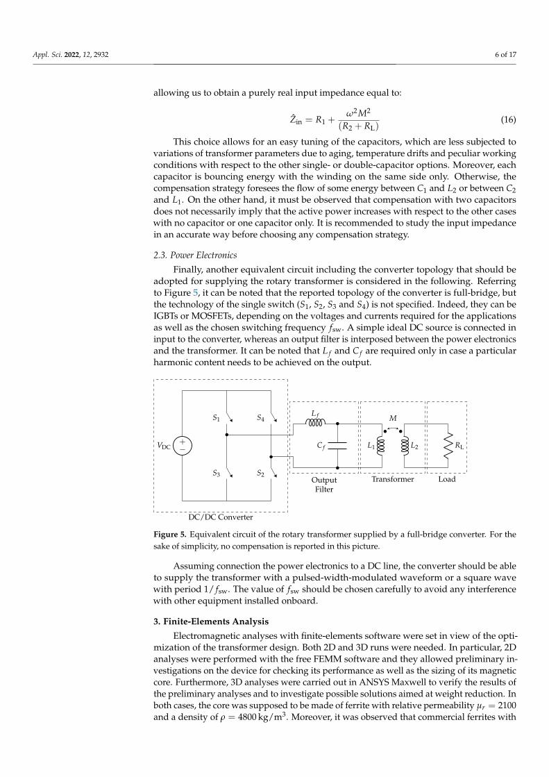
Finally, another equivalent circuit including the converter topology that should beadopted for supplying the rotary transformer is considered in the following. Referringto Figure 5, it can be noted that the reported topology of the converter is full-bridge, butthe technology of the single switch (S1, S2, S3 and S4) is not specified. Indeed, they can beIGBTs or MOSFETs, depending on the voltages and currents required for the applicationsas well as the chosen switching frequency fsw. A simple ideal DC source is connected ininput to the converter, whereas an output filter is interposed between the power electronicsand the transformer. It can be noted that L f and C f are required only in case a particularharmonic content needs to be achieved on the output.
S1
S3
S4
S2
L1 L2 RLC f
L f
−+VDC
M
DC/DC Converter
Transformer LoadOutputFilter
Figure 5. Equivalent circuit of the rotary transformer supplied by a full-bridge converter. For thesake of simplicity, no compensation is reported in this picture.
Assuming connection the power electronics to a DC line, the converter should be ableto supply the transformer with a pulsed-width-modulated waveform or a square wavewith period 1/ fsw. The value of fsw should be chosen carefully to avoid any interferencewith other equipment installed onboard.
3. Finite-Elements Analysis
Electromagnetic analyses with finite-elements software were set in view of the opti-mization of the transformer design. Both 2D and 3D runs were needed. In particular, 2Danalyses were performed with the free FEMM software and they allowed preliminary in-vestigations on the device for checking its performance as well as the sizing of its magneticcore. Furthermore, 3D analyses were carried out in ANSYS Maxwell to verify the results ofthe preliminary analyses and to investigate possible solutions aimed at weight reduction. Inboth cases, the core was supposed to be made of ferrite with relative permeability µr = 2100and a density of ρ = 4800 kg/m3. Moreover, it was observed that commercial ferrites with
Appl. Sci. 2022, 12, 2932 7 of 17
similar characteristics saturate for magnetic flux density equal to B = 0.4 T. Furthermore,the coils were realized in copper with a pessimistic filling factor k = 0.4.
3.1. Two-Dimensional Analyses
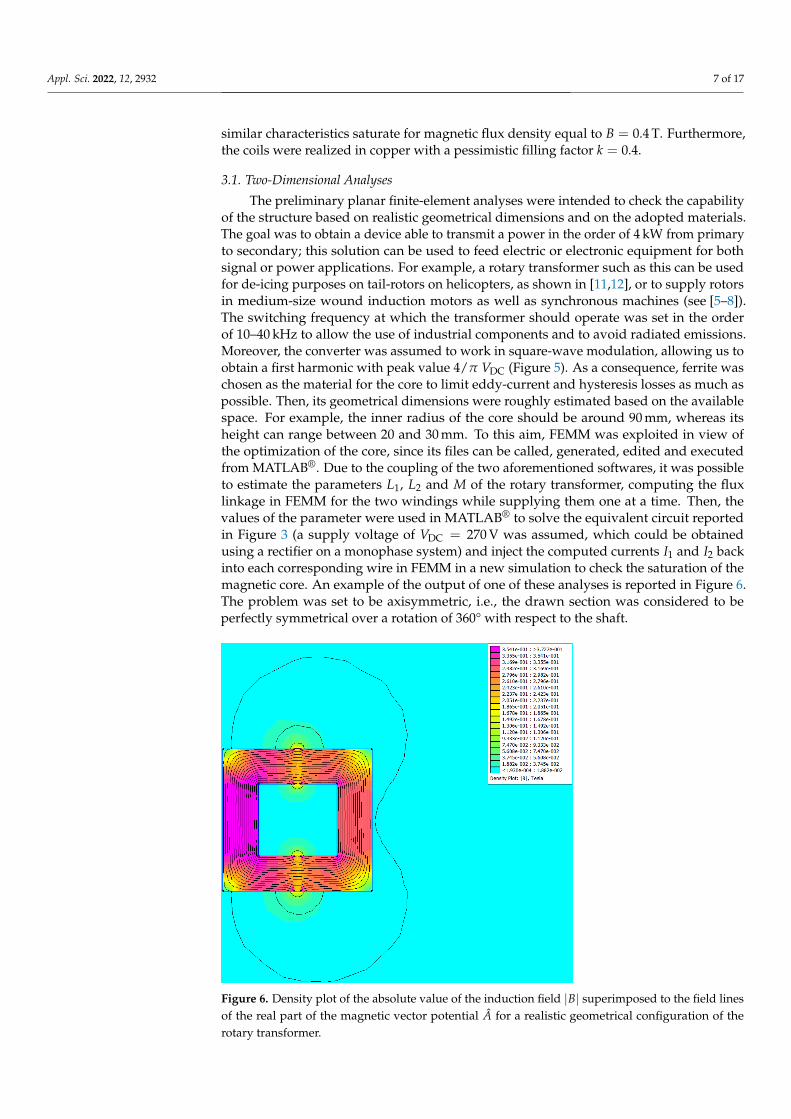
The preliminary planar finite-element analyses were intended to check the capabilityof the structure based on realistic geometrical dimensions and on the adopted materials.The goal was to obtain a device able to transmit a power in the order of 4 kW from primaryto secondary; this solution can be used to feed electric or electronic equipment for bothsignal or power applications. For example, a rotary transformer such as this can be usedfor de-icing purposes on tail-rotors on helicopters, as shown in [11,12], or to supply rotorsin medium-size wound induction motors as well as synchronous machines (see [5–8]).The switching frequency at which the transformer should operate was set in the orderof 10–40 kHz to allow the use of industrial components and to avoid radiated emissions.Moreover, the converter was assumed to work in square-wave modulation, allowing us toobtain a first harmonic with peak value 4/π VDC (Figure 5). As a consequence, ferrite waschosen as the material for the core to limit eddy-current and hysteresis losses as much aspossible. Then, its geometrical dimensions were roughly estimated based on the availablespace. For example, the inner radius of the core should be around 90 mm, whereas itsheight can range between 20 and 30 mm. To this aim, FEMM was exploited in view ofthe optimization of the core, since its files can be called, generated, edited and executedfrom MATLAB®. Due to the coupling of the two aforementioned softwares, it was possibleto estimate the parameters L1, L2 and M of the rotary transformer, computing the fluxlinkage in FEMM for the two windings while supplying them one at a time. Then, thevalues of the parameter were used in MATLAB® to solve the equivalent circuit reportedin Figure 3 (a supply voltage of VDC = 270 V was assumed, which could be obtainedusing a rectifier on a monophase system) and inject the computed currents I1 and I2 backinto each corresponding wire in FEMM in a new simulation to check the saturation of themagnetic core. An example of the output of one of these analyses is reported in Figure 6.The problem was set to be axisymmetric, i.e., the drawn section was considered to beperfectly symmetrical over a rotation of 360° with respect to the shaft.
Figure 6. Density plot of the absolute value of the induction field |B| superimposed to the field linesof the real part of the magnetic vector potential A for a realistic geometrical configuration of therotary transformer.
Appl. Sci. 2022, 12, 2932 8 of 17
These preliminary investigations were all static, that is, without simulating the spinof the transformer. However, they prove that a structure with an air gap of 1 mm iscapable of transferring power in the range 1–6 kW (depending on the cross section of themagnetic circuit and on the number of turns of the coils) from primary to secondary withoutsaturating the magnetic core.
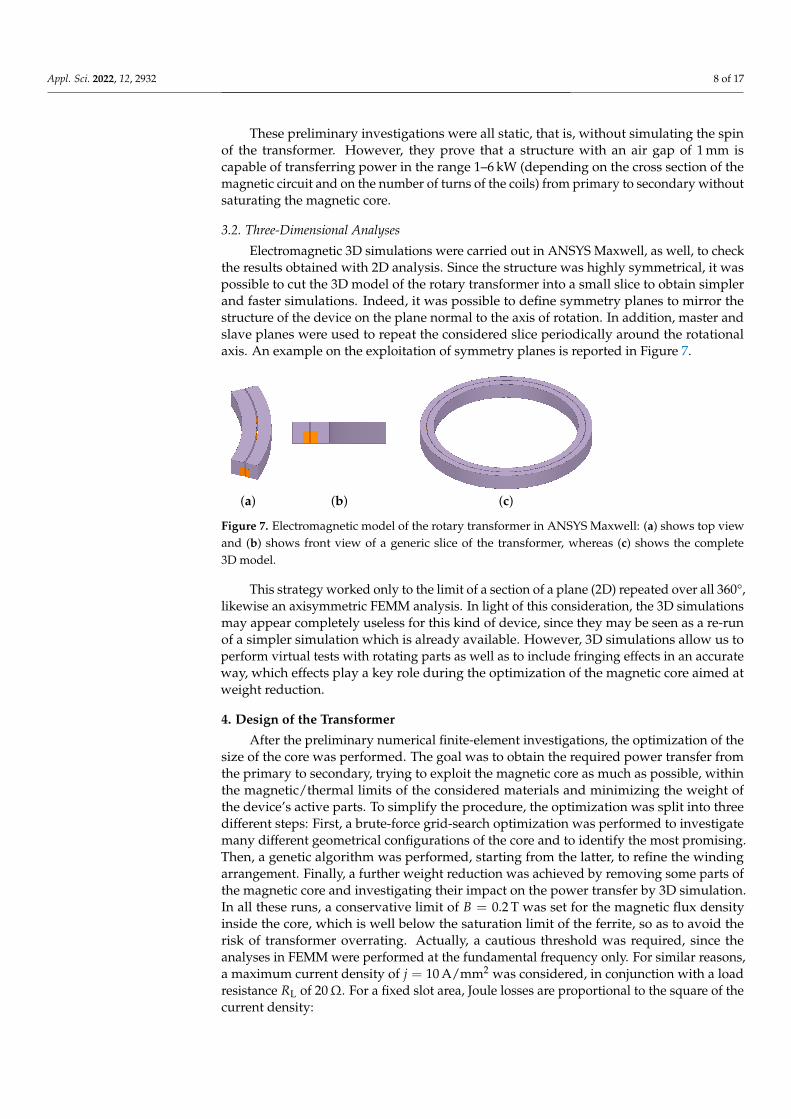
3.2. Three-Dimensional Analyses
Electromagnetic 3D simulations were carried out in ANSYS Maxwell, as well, to checkthe results obtained with 2D analysis. Since the structure was highly symmetrical, it waspossible to cut the 3D model of the rotary transformer into a small slice to obtain simplerand faster simulations. Indeed, it was possible to define symmetry planes to mirror thestructure of the device on the plane normal to the axis of rotation. In addition, master andslave planes were used to repeat the considered slice periodically around the rotationalaxis. An example on the exploitation of symmetry planes is reported in Figure 7.
(a) (b) (c)
Figure 7. Electromagnetic model of the rotary transformer in ANSYS Maxwell: (a) shows top viewand (b) shows front view of a generic slice of the transformer, whereas (c) shows the complete3D model.
This strategy worked only to the limit of a section of a plane (2D) repeated over all 360°,likewise an axisymmetric FEMM analysis. In light of this consideration, the 3D simulationsmay appear completely useless for this kind of device, since they may be seen as a re-runof a simpler simulation which is already available. However, 3D simulations allow us toperform virtual tests with rotating parts as well as to include fringing effects in an accurateway, which effects play a key role during the optimization of the magnetic core aimed atweight reduction.
4. Design of the Transformer
After the preliminary numerical finite-element investigations, the optimization of thesize of the core was performed. The goal was to obtain the required power transfer fromthe primary to secondary, trying to exploit the magnetic core as much as possible, withinthe magnetic/thermal limits of the considered materials and minimizing the weight ofthe device’s active parts. To simplify the procedure, the optimization was split into threedifferent steps: First, a brute-force grid-search optimization was performed to investigatemany different geometrical configurations of the core and to identify the most promising.Then, a genetic algorithm was performed, starting from the latter, to refine the windingarrangement. Finally, a further weight reduction was achieved by removing some parts ofthe magnetic core and investigating their impact on the power transfer by 3D simulation.In all these runs, a conservative limit of B = 0.2 T was set for the magnetic flux densityinside the core, which is well below the saturation limit of the ferrite, so as to avoid therisk of transformer overrating. Actually, a cautious threshold was required, since theanalyses in FEMM were performed at the fundamental frequency only. For similar reasons,a maximum current density of j = 10 A/mm2 was considered, in conjunction with a loadresistance RL of 20Ω. For a fixed slot area, Joule losses are proportional to the square of thecurrent density:
Appl. Sci. 2022, 12, 2932 9 of 17
PJoule ∝ j2 (17)
Therefore, the combination of a relatively low current density along with favourableair conditions (such as those of a typical helicopter de-icing application [11,12]) shouldavoid the risk of transformer overheating. The device was supplied with a sinusoidalvoltage that had a peak value of 4/π·270 V and f = 20 kHz. Namely, the first harmonicof a square wave with amplitude 270 V (which is equal to the DC bus voltage, as well)was considered. In principle, thermal analyses should be carried out, as well, during thedesign of the transformer (as reported in [27]); however, since no peculiar application wasconsidered, the current density constraint should limit the Joule losses and therefore preventoverheating. It should be underlined that compensation through resonant capacitors wasnot considered during this early design stage.
4.1. Grid-Search Optimization
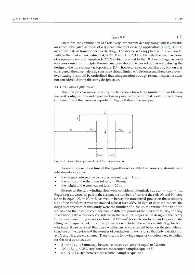
This first process aimed to study the behaviour for a large number of feasible geo-metrical configurations and to get as close as possible to the optimal result. Indeed, manycombinations of the variables reported in Figure 8 should be analysed.
rs wc1 wc2
wc
g
h w
ww1 ww2
h c
Figure 8. Geometrical parameters of the magnetic core.
To keep the execution time of the algorithm reasonably low, some constraints wereintroduced as follows:
• the air gap between the two cores was set to g = 1 mm;• the radius of the shaft was set to rs = 90 mm;• the height of the core was set to hc = 20 mm.
Moreover, the two winding slots were considered identical, i.e., ww1 = ww2 = ww.Regarding the electrical part of the system, the numbers of turns of the coils N1 and N2 wereset to be equal, N1 = N2 = N, as well, whereas the transferred power on the secondaryside of the transformer was constrained to be at least 2 kW. In light of these indications, thedegrees of freedom of this study were the number of turns N, the width of the windingslot ww and the thicknesses of the core in different points of the structure wc, wc1 and wc2.In addition, Litz wires were considered in the very first stages of the design of the rotarytransformer, assuming a cross section of 0.127 mm2 for each conductor and a pessimisticfilling factor equal to 0.4; thus, this optimization included the same variable NLitz for bothwindings. It can be noted that these widths can be constrained based on the geometricalstructure of the device and the number of conductors in each slot so that only variations inwc, N and NLitz are considered. Therefore, the following ranges of variation were exploitedfor this first optimization:
• 3 mm ≤ wc ≤ 8 mm, step between consecutive samples equal to 0.2 mm;• 100 ≤ NLitz ≤ 250, step between consecutive samples equal to 5;• 6 ≤ N ≤ 13, step between consecutive samples equal to 1.
Appl. Sci. 2022, 12, 2932 10 of 17
In detail, the grid-search foresaw the variation of the geometrical parameters in theaforementioned pre-determined samples at the beginning of each optimization step. Then,a first analysis in FEMM allowed us to evaluate the inductance matrix of each configuration.Based on these data, the equivalent circuit reported in Figure 3 was exploited to computethe current that should flow in each winding and the power transfer, as well (allowing us tocheck the corresponding limits on j and P2, as well). Finally, a new analysis in FEMM wasrun to obtain the information regarding the possible saturation of the ferrite core. Hence,the best candidate showed the parameters reported in Table 1. The optimization procedureran in about 9287 s on a desktop PC with Intel® Core™ i7-8700 processor at 3.20 GHz andwith 16 GB RAM.
Table 1. Comparison between the results obtained in the three optimization procedures.
Parameter Grid-Search Genetic Algorithm C-Ferrites
wc 4.20 mm 4.04 mm 4.04 mm
wc1 5.40 mm 4.04 mm 4.04 mm
wc2 4.78 mm 4.04 mm 4.04 mm
ww 2.97 mm 2.05 mm 2.05 mm
P2 2.70 kW 3.72 kW 3.76 kW
L1 130.61 µH 306.46 µH 283.04 µH
L2 130.70 µH 427.83 µH 395.87 µH
M 125.89 µH 351.55 µH 325.59 µH
N1 7 11 11
N2 7 13 13
Weight 0.91 kg 0.66 kg 0.55 kg
4.2. Genetic Optimization
Starting from the result obtained from the grid search algorithm, a multi-objectivegenetic optimization was set to improve the performance of the best candidate. The geneticoptimization was performed in order to converge faster than the brute-force approach to asolution for the transformer considering the large number of constraints that are imposedon this design. The goal was to obtain the best turn ratio, not too far from one, as well as torefine the geometrical dimensions of the core in order to transfer 3.6 kW on the secondarywhile minimizing the weight of the rotary transformer. Regarding the number of turns,N1 and N2 were now relatively free to vary since the selected load did not have strictvoltage limits, different than in [28,29], in which the transformation ratio was imposed.A 30% maximum variation of the turn ratio was considered. Litz wires were no longerconsidered in this investigation, since the operational frequency was not too high andtherefore costs could be reduced. As a matter of fact, investigations between these twooptimizations highlight that skin effect should not be an issue if the wires are wisely sized.Indeed, conductors can be connected in parallel inside each slot (namely, a sort of Litzwire with a low number of strands having greater cross sections) to improve the fillingfactor and limit the resistance of the associated winding. Moreover, the same limit on thecurrent density foreseen for the grid-search optimization was set. All these goals wereachieved in MATLAB®, finding the Pareto front of three fitness functions using the geneticalgorithm. These three functions to be minimized were the overall weight of the device,|P2 − 3.6 kW| and
∣∣j1 − 10 A/mm2∣∣. It is important to note that j1 was chosen because the
primary current is always higher than the secondary. Moreover, in view of a practicalrealization of a prototype of the device, the two cores were constrained to be equal tosimplify their manufacturing process. The size of the flux path in the whole cross sectionwas set constant (as suggested in [2]), that is, wc1 = wc2 = wc, and the width of the winding
Appl. Sci. 2022, 12, 2932 11 of 17
slots ww was considered a variable, as well. Therefore, the following ranges of variationswere considered:
• 2 mm ≤ ww ≤ 6 mm;• 4 mm ≤ wc ≤ 6 mm• 5 ≤ N1 ≤ 15• 5 ≤ N2 ≤ 15
Furthermore, height of the cores, air gap width and shaft radius were set constant, asshown in the previous subsection. The outcome of this procedure was a transformer withthe characteristics reported in Table 1. The genetic optimization ran in about 31,705 s on adesktop PC with Intel® Core™ i7-8700 processor at 3.20 GHz and with 16 GB RAM.
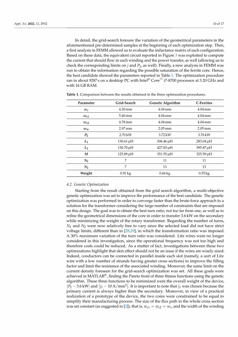
4.3. Realization of the Core and Further Weight Reduction
The attention was moved to more practical aspects related to the realization of theferrite core after the two optimization procedures. Indeed, due to the high fragility of theferrite, it is not simple to shape the core as desired. The winding slot should be dug on atoroid with a high risk of cracking the material. In addition, vibrations during operationmay damage the bulk ferrite cores. Therefore, the possibility to realize them by placingsmall pieces of ferrites was investigated, as proposed in [15]. In particular, C-shaped ferriteswere identified as the most interesting products available on the market. In this way, afurther weight reduction was achieved due to the lack of material between adjacent ferrites.It must be noted that this operation is a trade off between the decrease in the couplingbetween primary and secondary (and therefore a drop in the transferred power) and weightreduction. Therefore, a filling factor around 80% was identified for both the volumes of thecores as the most suitable arrangement. Considering the outcome of the genetic algorithmreported previously as the reference design, this solution led to the placement of 75 ferriteson the innermost core and 85 on the outermost. Each piece of core had a width of 6 mmand showed the same cross section that can be obtained with the data reported in Table 1.The geometry of the winding was not affected by this operation. Figure 9 shows top andperspective views of the new cores. Despite the removal of ferromagnetic material, thecoupling between the two sides of the transformer was still high, and this arrangementallowed us to transfer even more power P2 on the secondary than in the solid core solution,with a weight reduction of 17.6%. The explanation of this result is that the power transferstrongly depends on the particular arrangement of the values L1, L2 and M, keeping theresistive parameters constant. Indeed:
P1 = Rin I21 = Rin
(V
Zin
)2=
(R1 +
ω2M2(R2 + RL)
(R2 + RL)2 + ω2L2
2
)·
· V2(R1 +
ω2M2(R2 + RL)
(R2 + RL)2 + ω2L2
2
)2
+
(ωL1 −
ω3M2L2
(R2 + RL)2 + ω2L2
2
)2 (18)
where P1 6= P2 due to the ohmic losses on R1 and R2 only. In this operation, the powertransfer was not brought to its global maximum point, but it was ensured that the goalof about 3.6 kW was still satisfied. The main data that refer to this new configuration arereported in Table 1. It can be noted that, this time, the inductance parameters were intendedas average values. Indeed, they depended on the particular alignment between primaryand secondary ferrite cores.
Appl. Sci. 2022, 12, 2932 12 of 17
(a) (b)
Figure 9. Electromagnetic model of the rotary transformer with C-shaped ferrites forming the cores:(a) top and (b) perspective views of the complete 3D model.
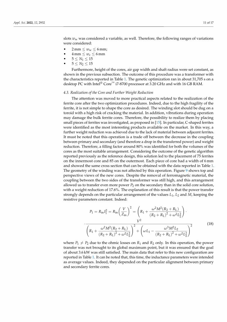
5. Validation Over a Reduced-Scale Prototype
Finally, the design procedure of rotary transformers proposed in this paper wasvalidated using a small-size prototype due to the cost of realization of a full-scale prototypeand the availability of materials. In particular, this test aimed to verify and investigate thepossibility of transferring power contactless from primary to secondary with split C-ferritesforming the two cores. The prototype had inner and outer diameters equal to 46.5 mm and93.5 mm, respectively, with a 1 mm air gap between the cores on the two sides. Therefore,forty-six manganese–zinc (MnZn by TDK, model B67350) C-ferrites were used: twentyof them were arranged to form the inner core, whereas the outer core was made with theremaining twenty-six. The size of each C-ferrite is reported in Figure 10.
5.3
55.2
5.9
15.2
6.7
Figure 10. Geometrical dimensions of each C-ferrite adopted in the reduced-size prototype. Quotesare reported in mm.
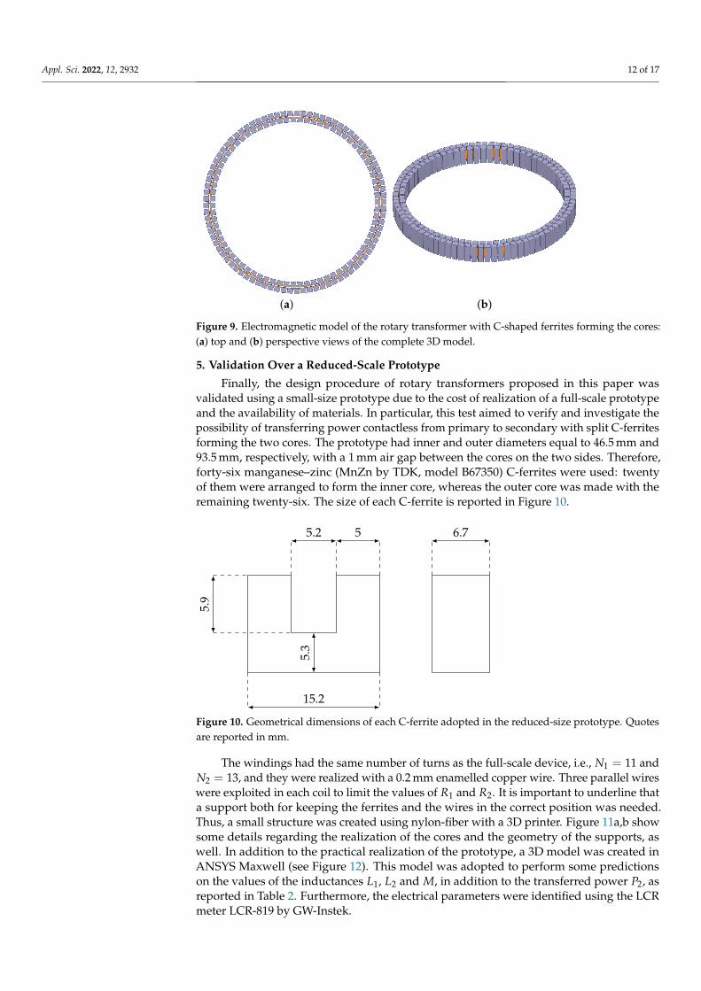
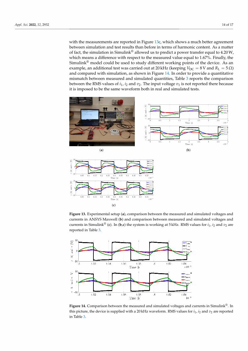
The windings had the same number of turns as the full-scale device, i.e., N1 = 11 andN2 = 13, and they were realized with a 0.2 mm enamelled copper wire. Three parallel wireswere exploited in each coil to limit the values of R1 and R2. It is important to underline thata support both for keeping the ferrites and the wires in the correct position was needed.Thus, a small structure was created using nylon-fiber with a 3D printer. Figure 11a,b showsome details regarding the realization of the cores and the geometry of the supports, aswell. In addition to the practical realization of the prototype, a 3D model was created inANSYS Maxwell (see Figure 12). This model was adopted to perform some predictionson the values of the inductances L1, L2 and M, in addition to the transferred power P2, asreported in Table 2. Furthermore, the electrical parameters were identified using the LCRmeter LCR-819 by GW-Instek.
Appl. Sci. 2022, 12, 2932 13 of 17
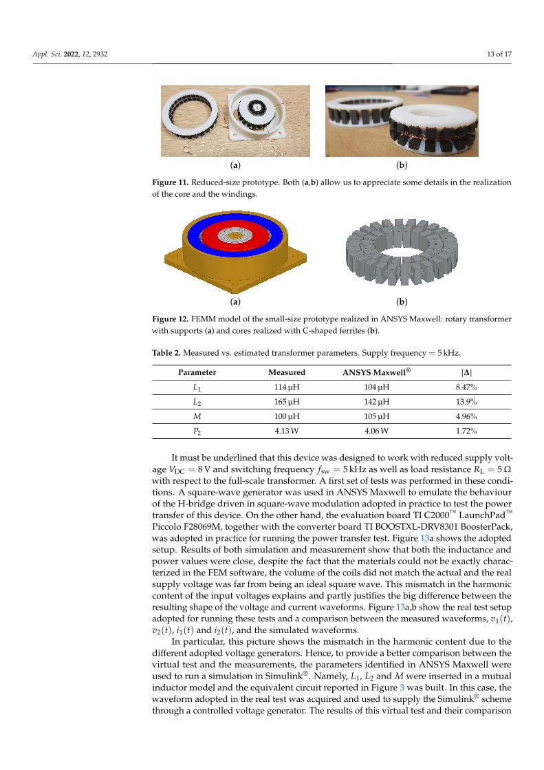
(a) (b)
Figure 11. Reduced-size prototype. Both (a,b) allow us to appreciate some details in the realizationof the core and the windings.
(a) (b)
Figure 12. FEMM model of the small-size prototype realized in ANSYS Maxwell: rotary transformerwith supports (a) and cores realized with C-shaped ferrites (b).
Table 2. Measured vs. estimated transformer parameters. Supply frequency = 5 kHz.
Parameter Measured ANSYS Maxwell® |∆|
L1 114 µH 104 µH 8.47%
L2 165 µH 142 µH 13.9%
M 100 µH 105 µH 4.96%
P2 4.13 W 4.06 W 1.72%
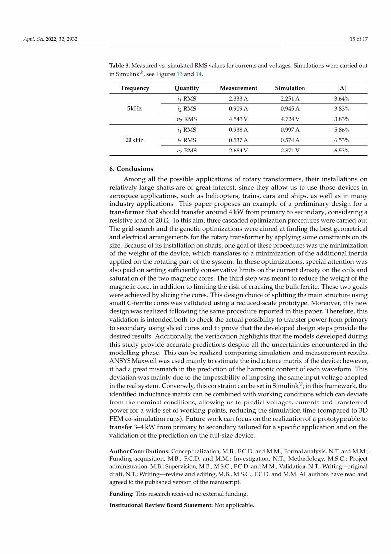
It must be underlined that this device was designed to work with reduced supply volt-age VDC = 8 V and switching frequency fsw = 5 kHz as well as load resistance RL = 5Ωwith respect to the full-scale transformer. A first set of tests was performed in these condi-tions. A square-wave generator was used in ANSYS Maxwell to emulate the behaviourof the H-bridge driven in square-wave modulation adopted in practice to test the powertransfer of this device. On the other hand, the evaluation board TI C2000™ LaunchPad™
Piccolo F28069M, together with the converter board TI BOOSTXL-DRV8301 BoosterPack,was adopted in practice for running the power transfer test. Figure 13a shows the adoptedsetup. Results of both simulation and measurement show that both the inductance andpower values were close, despite the fact that the materials could not be exactly charac-terized in the FEM software, the volume of the coils did not match the actual and the realsupply voltage was far from being an ideal square wave. This mismatch in the harmoniccontent of the input voltages explains and partly justifies the big difference between theresulting shape of the voltage and current waveforms. Figure 13a,b show the real test setupadopted for running these tests and a comparison between the measured waveforms, v1(t),v2(t), i1(t) and i2(t), and the simulated waveforms.
In particular, this picture shows the mismatch in the harmonic content due to thedifferent adopted voltage generators. Hence, to provide a better comparison between thevirtual test and the measurements, the parameters identified in ANSYS Maxwell wereused to run a simulation in Simulink®. Namely, L1, L2 and M were inserted in a mutualinductor model and the equivalent circuit reported in Figure 3 was built. In this case, thewaveform adopted in the real test was acquired and used to supply the Simulink® schemethrough a controlled voltage generator. The results of this virtual test and their comparison
Appl. Sci. 2022, 12, 2932 14 of 17
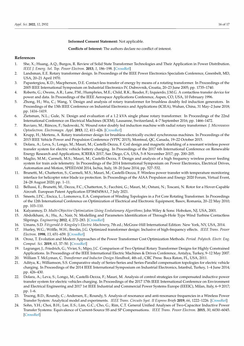
with the measurements are reported in Figure 13c, which shows a much better agreementbetween simulation and test results than before in terms of harmonic content. As a matterof fact, the simulation in Simulink® allowed us to predict a power transfer equal to 4.20 W,which means a difference with respect to the measured value equal to 1.67%. Finally, theSimulink® model could be used to study different working points of the device. As anexample, an additional test was carried out at 20 kHz (keeping VDC = 8 V and RL = 5Ω)and compared with simulation, as shown in Figure 14. In order to provide a quantitativemismatch between measured and simulated quantities, Table 3 reports the comparisonbetween the RMS values of i1, i2 and v2. The input voltage v1 is not reported there becauseit is imposed to be the same waveform both in real and simulated tests.
(a) (b)
(c)
Figure 13. Experimental setup (a), comparison between the measured and simulated voltages andcurrents in ANSYS Maxwell (b) and comparison between measured and simulated voltages andcurrents in Simulink® (c). In (b,c) the system is working at 5 kHz. RMS values for i1, i2 and v2 arereported in Table 3.
Figure 14. Comparison between the measured and simulated voltages and currents in Simulink®. Inthis picture, the device is supplied with a 20 kHz waveform. RMS values for i1, i2 and v2 are reportedin Table 3.
Appl. Sci. 2022, 12, 2932 15 of 17
Table 3. Measured vs. simulated RMS values for currents and voltages. Simulations were carried outin Simulink®, see Figures 13 and 14.
Frequency Quantity Measurement Simulation |∆|
5 kHz
i1 RMS 2.333 A 2.251 A 3.64%
i2 RMS 0.909 A 0.945 A 3.83%
v2 RMS 4.543 V 4.724 V 3.83%
20 kHz
i1 RMS 0.938 A 0.997 A 5.86%
i2 RMS 0.537 A 0.574 A 6.53%
v2 RMS 2.684 V 2.871 V 6.53%
6. Conclusions
Among all the possible applications of rotary transformers, their installations onrelatively large shafts are of great interest, since they allow us to use those devices inaerospace applications, such as helicopters, trains, cars and ships, as well as in manyindustry applications. This paper proposes an example of a preliminary design for atransformer that should transfer around 4 kW from primary to secondary, considering aresistive load of 20Ω. To this aim, three cascaded optimization procedures were carried out.The grid-search and the genetic optimizations were aimed at finding the best geometricaland electrical arrangements for the rotary transformer by applying some constraints on itssize. Because of its installation on shafts, one goal of these procedures was the minimizationof the weight of the device, which translates to a minimization of the additional inertiaapplied on the rotating part of the system. In these optimizations, special attention wasalso paid on setting sufficiently conservative limits on the current density on the coils andsaturation of the two magnetic cores. The third step was meant to reduce the weight of themagnetic core, in addition to limiting the risk of cracking the bulk ferrite. These two goalswere achieved by slicing the cores. This design choice of splitting the main structure usingsmall C-ferrite cores was validated using a reduced-scale prototype. Moreover, this newdesign was realized following the same procedure reported in this paper. Therefore, thisvalidation is intended both to check the actual possibility to transfer power from primaryto secondary using sliced cores and to prove that the developed design steps provide thedesired results. Additionally, the verification highlights that the models developed duringthis study provide accurate predictions despite all the uncertainties encountered in themodelling phase. This can be realized comparing simulation and measurement results.ANSYS Maxwell was used mainly to estimate the inductance matrix of the device; however,it had a great mismatch in the prediction of the harmonic content of each waveform. Thisdeviation was mainly due to the impossibility of imposing the same input voltage adoptedin the real system. Conversely, this constraint can be set in Simulink®; in this framework, theidentified inductance matrix can be combined with working conditions which can deviatefrom the nominal conditions, allowing us to predict voltages, currents and transferredpower for a wide set of working points, reducing the simulation time (compared to 3DFEM co-simulation runs). Future work can focus on the realization of a prototype able totransfer 3–4 kW from primary to secondary tailored for a specific application and on thevalidation of the prediction on the full-size device.
Author Contributions: Conceptualization, M.B., F.C.D. and M.M.; Formal analysis, N.T. and M.M.;Funding acquisition, M.B., F.C.D. and M.M.; Investigation, N.T.; Methodology, M.S.C.; Projectadministration, M.B.; Supervision, M.B., M.S.C., F.C.D. and M.M.; Validation, N.T.; Writing—originaldraft, N.T.; Writing—review and editing, M.B., M.S.C., F.C.D. and M.M. All authors have read andagreed to the published version of the manuscript.
Funding: This research received no external funding.
Institutional Review Board Statement: Not applicable.
Appl. Sci. 2022, 12, 2932 16 of 17
Informed Consent Statement: Not applicable.
Conflicts of Interest: The authors declare no conflict of interest.
References1. She, X.; Huang, A.Q.; Burgos, R. Review of Solid State Transformer Technologies and Their Application in Power Distribution.
IEEE J. Emerg. Sel. Top. Power Electron. 2013, 1, 186–198. [CrossRef]2. Landsman, E.E. Rotary transformer design. In Proceedings of the IEEE Power Electronics Specialists Conference, Greenbelt, MD,
USA, 20–21 April 1970.3. Papastergiou, K.D.; Macpherson, D.E. Contact-less transfer of energy by means of a rotating transformer. In Proceedings of the
2005 IEEE International Symposium on Industrial Electronics IV, Dubrovnik, Croatia, 20–23 June 2005; pp. 1735–1740.4. Roberts, G.; Owens, A.R.; Lane, P.M.; Humphries, M.E.; Child, R.K.; Bauder, F.; Izquierdo, J.M.G. A contactless transfer device for
power and data. In Proceedings of the IEEE Aerospace Applications Conference, Aspen, CO, USA, 10 February 1996.5. Zhong, H.; Wu, C.; Wang, Y. Design and analysis of rotary transformer for brushless doubly fed induction generators. In
Proceedings of the 13th IEEE Conference on Industrial Electronics and Applications (ICIEA), Wuhan, China, 31 May–2 June 2018;pp. 1416–1419.
6. Zietsman, N.L.; Gule, N. Design and evaluation of a 1.2 kVA single phase rotary transformer. In Proceedings of the 22ndInternational Conference on Electrical Machines (ICEM), Lausanne, Switzerland, 4–7 September 2016; pp. 1466–1472.
7. Ruviaro, M.; Rüncos, F.; Sadowski, N. Wound rotor doubly fed induction machine with radial rotary transformer. J. MicrowavesOptoelectron. Electromagn. Appl. 2013, 12, 411–426. [CrossRef]
8. Krupp, H.; Mertens, A. Rotary transformer design for brushless electrically excited synchronous machines. In Proceedings of the2015 IEEE Vehicle Power and Propulsion Conference (VPPC 2015), Montreal, QC, Canada, 19–22 October 2015.
9. Dolara, A.; Leva, S.; Longo, M.; Mauri, M.; Castelli-Dezza, F. Coil design and magnetic shielding of a resonant wireless powertransfer system for electric vehicle battery charging. In Proceedings of the 2017 6th International Conference on RenewableEnergy Research and Applications, ICRERA 2017, San Diego, CA, USA, 5–8 November 2017; pp. 200–205.
10. Maglio, M.M.; Carmeli, M.S.; Mauri, M.; Castelli-Dezza, F. Design and analysis of a high frequency wireless power feedingsystem for train axle telemetry. In Proceedings of the 2014 International Symposium on Power Electronics, Electrical Drives,Automation and Motion, SPEEDAM 2014, Ischia, Italy, 18–20 June 2014; pp. 527–532.
11. Brunetti, M.; Chatterton, S.; Carmeli, M.S.; Mauri, M.; Castelli-Dezza, F. Wireless power transfer with temperature monitoringinterface for helicopter rotor blade ice protection. In Proceedings of the AIAA Propulsion and Energy 2020 Forum, Virtual Event,24–28 August 2020; pp. 1–11.
12. Bellussi, E.; Brunetti, M.; Dezza, F.C.; Chatterton, S.; Facchini, G.; Mauri, M.; Ostuni, N.; Toscani, N. Rotor for a Hover-CapableAircraft. European Patent Application EP3845458A1, 7 July 2021.
13. Smeets, J.P.C.; Encica, L.; Lomonova, E.A. Comparison of Winding Topologies in a Pot Core Rotating Transformer. In Proceedingsof the 12th International Conference on Optimization of Electrical and Electronic Equipment, Basov, Romania, 20–22 May 2010;pp. 103–110.
14. Kalyanmoy, D. Multi-Objective Optimization Using Evolutionary Algorithms; John Wiley & Sons: Hoboken, NJ, USA, 2001.15. Abdolkhani, A.; Hu, A.; Nair, N. Modelling and Parameters Identification of Through-Hole Type Wind Turbine Contactless
Sliprings. Engineering 2012, 4, 272–283. [CrossRef]16. Umans, S.D. Fitzgerald & Kingsley’s Electric Machinery, 7th ed.; McGraw-Hill International Edition: New York, NY, USA, 2014.17. Hurley, W.G.; Wölfle, W.H.; Breslin, J.G. Optimized transformer design: Inclusive of high-frequency effects. IEEE Trans. Power
Electron. 1998, 13, 651–659. [CrossRef]18. Orosz, T. Evolution and Modern Approaches of the Power Transformer Cost Optimization Methods. Period. Polytech. Electr. Eng.
Comput. Sci. 2019, 63, 37–50. [CrossRef]19. Legranger, J.; Friedrich, G.; Vivier, S.; Mipo, J.C. Comparison of Two Optimal Rotary Transformer Designs for Highly Constrained
Applications. In Proceedings of the IEEE International Electric Machines & Drives Conference, Antalya, Turkey, 9–12 May 2007.20. William T. McLyman, C. Transformer and Inductor Design Handbook, 4th ed.; CRC Press: Boca Raton, FL, USA, 2011.21. Aditya, K.; Williamson, S.S. Comparative study of Series-Series and Series-Parallel compensation topologies for electric vehicle
charging. In Proceedings of the 2014 IEEE International Symposium on Industrial Electronics, Istanbul, Turkey, 1–4 June 2014;pp. 426–430.
22. Dolara, A.; Leva, S.; Longo, M.; Castelli-Dezza, F.; Mauri, M. Analysis of control strategies for compensated inductive powertransfer system for electric vehicles charging. In Proceedings of the 2017 17th IEEE International Conference on Environmentand Electrical Engineering and 2017 1st IEEE Industrial and Commercial Power Systems Europe (EEEIC), Milan, Italy, 6–9 2017;pp. 1–6.
23. Truong, B.D.; Roundy, C.; Andersen, E.; Roundy, S. Analysis of resonance and anti-resonance frequencies in a Wireless PowerTransfer System: Analytical model and experiments. IEEE Trans. Circuits Syst. II Express Briefs 2019, 66, 1222–1226. [CrossRef]
24. Sohn, Y.H.; Choi, B.H.; Lee, E.S.; Lim, G.C.; Cho, G.; Rim, C.T. General Unified Analyses of Two-Capacitor Inductive PowerTransfer Systems: Equivalence of Current-Source SS and SP Compensations. IEEE Trans. Power Electron. 2015, 30, 6030–6045.[CrossRef]

Appl. Sci. 2022, 12, 2932 17 of 17
25. Imaoka, J.; Nam, M.; Shoyama, M.; Fujita, H. Design of Series-Parallel combined resonant circuit with rotary transformer used forultrasonic spindle drive. In Proceedings of the IEEE 3rd International Future Energy Electronics Conference and ECCE Asia(IFEEC—ECCE Asia), Kaohsiung, Taiwan, 3–7 June 2017; pp. 2244–2249.
26. Cho, S.Y.; Lee, I.O.; Moon, S.C.; Moon, G.W.; Kim, B.C.; Kim, K.Y. Series-Series compensated wireless power transfer at twodifferent resonant frequencies. In Proceedings of the 2013 IEEE ECCE Asia Downunder—5th IEEE Annual International EnergyConversion Congress and Exhibition, Melbourne, VIC, Australia, 3–6 June 2013; pp. 1052–1058.
27. Godbehere, J.; Hopkins, A.; Yuan, X. Design and Thermal Analysis of a Rotating Transformer. In Proceedings of the IEEEInternational Electric Machines & Drives Conference (IEMDC), San Diego, CA, USA, 12–15 May 2019.
28. Amoiralis, E.I.; Tsili, M.A.; Kladas, A.G. Transformer Design and Optimization: A Literature Survey. IEEE Trans. Power Deliv.2019, 24, 1999–2024. [CrossRef]
29. Orosz, T.; Pánek, D.; Karban, P. FEM Based Preliminary Design Optimization in Case of Large Power Transformers. Appl. Sci.2020, 10, 1361. [CrossRef]