preliminary design of a lunar reconnaissance drone
TRANSCRIPT

ECOLE POLYTECHNIQUE FÉDÉRALE DE LAUSANNE
SEMESTER PROJECT REPORT
Preliminary Design of a LunarReconnaissance Drone
Authors:
Thomas Pfeiffer & Erik Uythoven
Project supervisor:
Dr. David Rodriguez
Responsible professor:
Prof. Jean-Paul Kneib
Lausanne - January 6, 2022

Semester Project ReportPreliminary Design of a Lunar Reconnaissance Drone
T. Pfeiffer & E. UythovenJanuary 6, 2022
Abstract
In this report, a preliminary design study of a compact lunar reconnaissance drone module which
will assist exploration rovers is presented. It is designed to assist future exploratory rover missions in
difficult environments such as PSRs or extreme topographies. Although similar concepts have been
validated on Mars by NASA’s Ingenuity helicopter, only few such ideas exist for lunar applications.
The main challenges of this project lie in the propulsion system to be used, the thermal system of
the drone (due to extreme temperatures) and the 3D mapping of the lunar surface using a flash lidar
system. These aspects were studied in detail with promising results: For a drone with a weight of
20 kg, 1 kg of green monopropellant is sufficient to cover a distance of a least 1 km before it needs
refuelling. In this report, it is assumed that the lightweight flash lidar technology should be developed
enough to allow for 10 cm resolution at 50 m flight altitude. This feasibility and initial design study
sets a foundation for lunar drones and exploration of the Moon using flying spacecrafts, although
many open questions remain to be solved and detailed designs to be performed.
i

Semester Project ReportPreliminary Design of a Lunar Reconnaissance Drone
T. Pfeiffer & E. UythovenJanuary 6, 2022
Acknowledgement
We would like to express our sincere gratitude to Dr. David Rodriguez for his excellent guidance and
for his supervision of this project. . We would also like to thank Dr. Hiroyuki Koizumi from the Uni-
versity of Tokyo for his precious technical support and feedback on propulsion and thermal systems.
Our gratitude is extended to Mustafa Mete from the EPFL Reconfigurable Robotics Lab for his pre-
cious advice on Earth-based drones and visual tracking systems. In addition, we would like to thank
Dr. Jan Uythoven for the proofreading of this report. Lastly, we would like to thank the EPFL Space
Center (eSpace) led by Prof. Jean-Paul Kneib for this great opportunity.
ii
Semester Project ReportPreliminary Design of a Lunar Reconnaissance Drone
T. Pfeiffer & E. UythovenJanuary 6, 2022
Contents
1 Introduction 1
2 State of the art 1
3 Lunar environment and PSRs 2
3.1 Surface temperature . . . . . . . . . . . . . . . . . . . . . . . . . . . . . . . . . . . . . . . . 2
3.2 Dust . . . . . . . . . . . . . . . . . . . . . . . . . . . . . . . . . . . . . . . . . . . . . . . . . . 3
3.3 Extreme topography . . . . . . . . . . . . . . . . . . . . . . . . . . . . . . . . . . . . . . . . 3
3.4 Radiation . . . . . . . . . . . . . . . . . . . . . . . . . . . . . . . . . . . . . . . . . . . . . . . 3
3.5 Challenge with existing mapping methods . . . . . . . . . . . . . . . . . . . . . . . . . . . 3
4 Mission definition 4
4.1 Mission objectives . . . . . . . . . . . . . . . . . . . . . . . . . . . . . . . . . . . . . . . . . 4
4.2 Heritage . . . . . . . . . . . . . . . . . . . . . . . . . . . . . . . . . . . . . . . . . . . . . . . 4
5 Fundamental design questions 5
5.1 Initial research . . . . . . . . . . . . . . . . . . . . . . . . . . . . . . . . . . . . . . . . . . . . 6
5.2 Initial analysis results and decision mind-map . . . . . . . . . . . . . . . . . . . . . . . . . 9
6 Drone design 12
6.1 Decomposition in subsystems . . . . . . . . . . . . . . . . . . . . . . . . . . . . . . . . . . 12
6.2 Functional decomposition and solutions . . . . . . . . . . . . . . . . . . . . . . . . . . . . 12
6.3 Product tree . . . . . . . . . . . . . . . . . . . . . . . . . . . . . . . . . . . . . . . . . . . . . 14
6.4 Details for the different subsystems . . . . . . . . . . . . . . . . . . . . . . . . . . . . . . . 15
6.5 N2 chart . . . . . . . . . . . . . . . . . . . . . . . . . . . . . . . . . . . . . . . . . . . . . . . 21
7 Drone base design 23
7.1 Product tree . . . . . . . . . . . . . . . . . . . . . . . . . . . . . . . . . . . . . . . . . . . . . 23
7.2 Decomposition in subsystems . . . . . . . . . . . . . . . . . . . . . . . . . . . . . . . . . . 24
7.3 Drone base functions . . . . . . . . . . . . . . . . . . . . . . . . . . . . . . . . . . . . . . . . 24
8 System Engineering Results 25
8.1 ConOps . . . . . . . . . . . . . . . . . . . . . . . . . . . . . . . . . . . . . . . . . . . . . . . . 25
8.2 Budgets . . . . . . . . . . . . . . . . . . . . . . . . . . . . . . . . . . . . . . . . . . . . . . . . 26
8.3 Requirements . . . . . . . . . . . . . . . . . . . . . . . . . . . . . . . . . . . . . . . . . . . . 28
8.4 Risk analysis . . . . . . . . . . . . . . . . . . . . . . . . . . . . . . . . . . . . . . . . . . . . . 28
9 Future work, open questions and limitations 32
10 Author’s opinion and outlook 32
iii

Semester Project ReportPreliminary Design of a Lunar Reconnaissance Drone
T. Pfeiffer & E. UythovenJanuary 6, 2022
11 Conclusions and discussion 33
References 35
A Lidar calculations 39
B Propulsion and flight trajectory calculations 39
B.1 Thrusters arrangement . . . . . . . . . . . . . . . . . . . . . . . . . . . . . . . . . . . . . . . 39
B.2 Flight simulation assumptions . . . . . . . . . . . . . . . . . . . . . . . . . . . . . . . . . . 39
B.3 Preliminary simulations . . . . . . . . . . . . . . . . . . . . . . . . . . . . . . . . . . . . . . 40
B.4 Detailed flight simulation . . . . . . . . . . . . . . . . . . . . . . . . . . . . . . . . . . . . . 42
B.5 More detailed flight simulation . . . . . . . . . . . . . . . . . . . . . . . . . . . . . . . . . . 42
B.6 Propellant tank mass estimation . . . . . . . . . . . . . . . . . . . . . . . . . . . . . . . . . 43
B.7 Pressurant mass and tank mass estimation . . . . . . . . . . . . . . . . . . . . . . . . . . . 43
B.8 Limitations . . . . . . . . . . . . . . . . . . . . . . . . . . . . . . . . . . . . . . . . . . . . . . 44
C Thermal analysis 46
C.1 Assumptions . . . . . . . . . . . . . . . . . . . . . . . . . . . . . . . . . . . . . . . . . . . . . 46
C.2 Calculations . . . . . . . . . . . . . . . . . . . . . . . . . . . . . . . . . . . . . . . . . . . . . 46
C.3 Temperature change results . . . . . . . . . . . . . . . . . . . . . . . . . . . . . . . . . . . . 47
C.4 Model limitations . . . . . . . . . . . . . . . . . . . . . . . . . . . . . . . . . . . . . . . . . . 47
D Power calculations 50
E Risk Analysis 50
F Illustrations 53
iv
Semester Project ReportPreliminary Design of a Lunar Reconnaissance Drone
T. Pfeiffer & E. UythovenJanuary 6, 2022
List of Figures
1 Color code for the choice and effects diagrams. . . . . . . . . . . . . . . . . . . . . . . . . 9
2 Effects of flying into the sunlight. . . . . . . . . . . . . . . . . . . . . . . . . . . . . . . . . . 10
3 Hopping versus hovering advantages. . . . . . . . . . . . . . . . . . . . . . . . . . . . . . . 10
4 Initial analysis results and decision mind-map. . . . . . . . . . . . . . . . . . . . . . . . . 11
5 Product tree of the lunar drone. . . . . . . . . . . . . . . . . . . . . . . . . . . . . . . . . . . 14
6 Choices and effects of spacecraft attitude control technologies. . . . . . . . . . . . . . . . 15
7 Top view (left) and side view (right) of the drone with its four thrusters (red). The x-axis
is in the main direction of flight. Angles alpha and beta are at 45 degrees. . . . . . . . . . 16
8 Illustration of the propulsion system of the drone. Note that components such as valves,
tubes and pressure regulators are not represented. . . . . . . . . . . . . . . . . . . . . . . 17
9 Schematic diagram of the drone’s propulsion system (based on [33] and [34]). . . . . . . 18
10 Flight proven copper thermal straps by the Space Dynamics Laboratory (SDL) [37]. . . . 20
11 N2 chart. . . . . . . . . . . . . . . . . . . . . . . . . . . . . . . . . . . . . . . . . . . . . . . . 22
12 Product tree of the drone base module. . . . . . . . . . . . . . . . . . . . . . . . . . . . . . 23
13 Lunar reconnaissance drone module: Concept of Operations. 1. Stand-by mode; 2.
Flight preparation and deployment; 3. Vertical ascent; 4. Horizontal flight and surface
mapping; 5. Vertical descent and landing. . . . . . . . . . . . . . . . . . . . . . . . . . . . 26
14 Illustration of the drone (Original image: X Energy). . . . . . . . . . . . . . . . . . . . . . 34
B.1 Possible thrusters arrangements: a) One single thruster with reaction wheels / control
moment gyroscopes b) 3-4 thrusters on the bottom c) 3-4 lateral thrusters d) One single
thruster on gimbal e) One single thruster and 3-4 small lateral thrusters. . . . . . . . . . 40
B.2 Three different flight profiles analyzed. . . . . . . . . . . . . . . . . . . . . . . . . . . . . . 42
B.3 Drone mass decrease due to propellant consumption. . . . . . . . . . . . . . . . . . . . . 43
B.4 Detailed flight profile simulation in Simulink. . . . . . . . . . . . . . . . . . . . . . . . . . 45
C.1 Drone temperature change ∆T [K] for various elapsed times t with respect to the ther-
mal source power Qg en and the emissivity/absorbtivity ϵ= α. . . . . . . . . . . . . . . . . 48
C.2 Evolution of the drone temperature T with respect to time t for Qg en = 500 W and ϵ =α= 0.8. . . . . . . . . . . . . . . . . . . . . . . . . . . . . . . . . . . . . . . . . . . . . . . . . 48
C.3 Drone equilibrium temperature T∞ with respect to the thermal source power Qg en and
the emissivity/absorbtivity ϵ= α. . . . . . . . . . . . . . . . . . . . . . . . . . . . . . . . . . 49
C.4 Drop of the drone temperature T with respect to time t , when the thermal source power
is zero. . . . . . . . . . . . . . . . . . . . . . . . . . . . . . . . . . . . . . . . . . . . . . . . . 49
D.1 MP 144350 xlr Rechargeable Li-ion cell by Saft [35]. . . . . . . . . . . . . . . . . . . . . . . 53
F.1 CAD render of the lunar reconnaissance drone. . . . . . . . . . . . . . . . . . . . . . . . . 53
F.2 Illustration of the drone (Original image: NASA). . . . . . . . . . . . . . . . . . . . . . . . 54
F.3 Illustration of the drone (Original image: NASA). . . . . . . . . . . . . . . . . . . . . . . . 54
v

Semester Project ReportPreliminary Design of a Lunar Reconnaissance Drone
T. Pfeiffer & E. UythovenJanuary 6, 2022
List of Tables
1 Advantages and disadvantages of various mapping sensors . . . . . . . . . . . . . . . . . 6
2 Advantages and disadvantages of various propulsion technologies [23] . . . . . . . . . . 7
3 Morphological matrix of functions and solutions (selected one in green) . . . . . . . . . 13
4 Thruster main specifications [30] . . . . . . . . . . . . . . . . . . . . . . . . . . . . . . . . . 16
5 Typical operational and survival temperature ranges of various components according
to Larson et al [31], adapted and extended by the authors . . . . . . . . . . . . . . . . . . 19
6 Preliminary mass budget . . . . . . . . . . . . . . . . . . . . . . . . . . . . . . . . . . . . . 27
7 Preliminary power budget . . . . . . . . . . . . . . . . . . . . . . . . . . . . . . . . . . . . . 27
8 Severity matrix and risk color code . . . . . . . . . . . . . . . . . . . . . . . . . . . . . . . . 28
9 Preliminary drone requirements . . . . . . . . . . . . . . . . . . . . . . . . . . . . . . . . . 30
10 Preliminary drone base requirements . . . . . . . . . . . . . . . . . . . . . . . . . . . . . . 31
B.1 Thruster arrangement advantages and disadvantages . . . . . . . . . . . . . . . . . . . . 41
B.2 Results of preliminary trajectory calculations . . . . . . . . . . . . . . . . . . . . . . . . . 41
B.3 Results of the more detailed simulation . . . . . . . . . . . . . . . . . . . . . . . . . . . . . 42
B.4 Pressurant comparison . . . . . . . . . . . . . . . . . . . . . . . . . . . . . . . . . . . . . . . 44
D.1 MP 144350 xlr Rechargeable Li-ion cell specifications [35] . . . . . . . . . . . . . . . . . . 50
E.1 Preliminary risk analysis . . . . . . . . . . . . . . . . . . . . . . . . . . . . . . . . . . . . . . 51
vi
Semester Project ReportPreliminary Design of a Lunar Reconnaissance Drone
T. Pfeiffer & E. UythovenJanuary 6, 2022
Acronyms
AGL Above Ground Level. 6, 33
AV Avionics. 12
CDH Communication and data handling. 5, 12, 24
CMG Control Moment Gyroscopes. 39
ConOps Concept of Operations. 25, 32–34
DoD Depth-of-Discharge. 50
EL3 European Large Logistics Lander. 4, 5, 18, 33
EPFL École polytechnique fédérale de Lausanne. 1, 28
ERT EPFL Rocket Team. 28
ESA European Space Agency. 4, 5, 18
eSpace EPFL Space Center. ii
FMEA Failure Mode and Effects Analysis. 28, 50
FoS Factor of Safety. 43, 44
GPIM Green Propellan Infusion Mission. 17
HPGP High Performance Green Propulsion. 16
IF Interfaces. 24
IMU Inertial Measurement Unit. 20
JPL Jet Propulsion Laboratory. 1
Lidar laser imaging, detection, and ranging. 4, 6, 7, 13, 18, 21, 25, 27–29, 33, 39
LRO Lunar Reconnaissance Orbiter. 3, 4
MIT Massachusetts Institute of Technology. 2
NASA National Aeronautics and Space Administration. 1, 2, 4, 5, 17
OBC On-Board Computer. 21
PL Payload. 12
PR Propulsion. 12, 24
vii
Semester Project ReportPreliminary Design of a Lunar Reconnaissance Drone
T. Pfeiffer & E. UythovenJanuary 6, 2022
PSR Permanently Shadowed Regions. 1–4, 7–9, 19, 21, 33, 34
PWR Power. 12, 24
RCS Reaction Control System. 13
RW Reaction Wheels. 39
ST Structures. 12, 24
TH Thermal. 12, 24
UAVs unmanned aerial vehicles. 20
VIPER Volatiles Investigating Polar Exploration Rover. 4
WEB Warm Electronics Box. 17, 19
viii
Semester Project ReportPreliminary Design of a Lunar Reconnaissance Drone
T. Pfeiffer & E. UythovenJanuary 6, 2022
1 Introduction
For over 50 years our Moon has been the primary target of human exploration in space. However,
only twelve astronauts have visited its surface so far [1] and Mars is moving more and more into the
spotlight. Nevertheless, the Moon still is of great scientific interest to space agencies, not least as a
test and preparation for visiting Mars. With the Artemis mission, the National Aeronautics and Space
Administration (NASA) is preparing to bring humans back to the Moon for the first time after several
decades [2]. Moon bases are planned to be built and therefore lunar exploration is one of the chal-
lenges to be mastered in the future. In the search of possible locations for lunar bases the lunar South
Pole is of particular interest as water ice is expected to be found in these regions [3, 4, 5]. However,
these regions represent significant challenges for exploration to most wheeled rovers designed so far.
The extremely low temperatures due to everlasting shadows in these so called Permanently Shadowed
Regions (PSR) and the lack of sunlight are the main reasons for these difficulties.
Until now, mostly wheeled rovers are used for uncrewed exploration of extraterrestrial and lunar
surfaces. However, they are often large and bulky due to the complex payload they carry (power,
scientific instruments, communication, etc.) and are limited in terms of locomotion, especially in
difficult terrain. Precise knowledge about their environment for route planning is crucial and often
rely on limited-resolution satellite data from lunar orbiters, which is even worse in PSRs. The need of
a simple, lightweight and cheap scouting method is becoming more and more apparent. Unlike on
Mars, which has an atmosphere allowing for drones with propellers such as the Ingenuity helicopter
[6] to fly, the Moon does not have any atmosphere and alternative solutions are required.
The goal of this project is to study the feasibility of a compact lunar reconnaissance drone module
for rovers and to propose a preliminary design. It highlights the main challenges of such a system and
sets the baseline for future developments.
The study is realized as a semester project by two Master students at the École polytechnique
fédérale de Lausanne (EPFL), both with a background in Mechanical Engineering. The project started
in September of 2021 and ended in January of 2022.
2 State of the art
The use of lightweight and compact vehicles for exploration of unknown terrain is not new and has
evolved especially in the last decades with the miniaturization of electrical and mechanical compo-
nents: On Earth, drones are being used to explore disaster and war zones before sending in humans.
In addition, they are used for repetitive tasks such as surveillance for wildfire prevention or inspection
of buildings and factories. They have the advantage of easy and fast deployment and operation, all
while being cheap and transportable. Outside Earth, the Ingenuity helicopter by NASA’s Jet Propul-
sion Laboratory (JPL) is the first powered controlled extraterrestrial aircraft successfully tested on the
martian surface [6]. On the Moon however, no such vehicles exist yet and have only been proposed
in a few concept studies so far.
1

Semester Project ReportPreliminary Design of a Lunar Reconnaissance Drone
T. Pfeiffer & E. UythovenJanuary 6, 2022
In a Master’s thesis from 2011 on the development of a cold gas propulsion system for the TALARIS
Hopper [7] written at the Massachusetts Institute of Technology (MIT), a lunar hopper prototype for
Earth-based testing equipped with a cold gas propulsion system is proposed. The thesis focuses on
the propulsion system of the hopper and its testing and represents a great base for the development of
future lunar hoppers. In a thesis from 2013 ("Mission Design for Safe Traverse of Planetary Hoppers")
by B.E. Cohanim [8], a detailed study of planetary hoppers for exploration purposes is presented. A
group of Master students from the University of Southampton have successfully designed and tested
a prototype of a "vertical take-off, vertical landing" lunar hopper [9].
In a more recent Master’s thesis from 2020 by G. Podestà ("Lunar Nano Drone for a mission of
exploration of lava tubes on the Moon: Propulsion System" [10]) another concept of a lunar explo-
ration drone is proposed. It concludes however that with the restrictive 12U constraint imposed on
the volume and currently available components this project is not feasible as by now. Nevertheless, it
offers another valuable contribution to the research and development of a lunar drone.
Intuitive Machines is an American start-up company planning to send their lunar lander ("Nova-
C") together with a lunar hopper/drone called "Micro-Nova" [11]. The goal of this hopper is to explore
craters, PSRs and lava tubes on the Moon, especially at its South Pole. As of 2021, Intuitive Machines
and NASA have finalized a $41.6 million dollars contract to built this system [12, 13]. Besides the size
of around 80 cm in length, width and height, not many details are known about the Micro-Nova drone.
3 Lunar environment and PSRs
The lunar surface represents a challenging environment for exploration, especially for wheeled rovers.
The lunar gravity and the lunar vacuum are two of several constraining factors to be considered. Grav-
ity on the Moon is about 1/6 of Earth’s gravity, and the lack of an atmosphere result in an omnipresent
hard vacuum and little thermal insulation: Mean surface temperatures range from -155°C during the
lunar night to +110°C during the day. The lunar South Pole in particular is even more challenging
than for example the landing sites of the Apollo missions, if not the most challenging regions besides
lunar lava tubes: So called Permanently Shadowed Regions (PSR)s and extreme topography make ex-
ploration by rover very difficult. The most important and restricting aspects of the lunar South Pole
are the surface temperature, the dust, the extreme topography and the radiation and are discussed
below.
3.1 Surface temperature
With an albedo of 0.07 to 0.10 the Moon absorbs most of the energy coming from the Sun. In com-
bination with the lack of atmosphere, it heats up and cools downs much faster than it is the case
on Earth. For these reasons, great temperature differences exist between illuminated surfaces and
shadow areas. According to NASA [14], temperatures at the lunar poles vary from 230 K at daytime to
40 K in dark polar craters, the latter often referred to as PSRs.
2
Semester Project ReportPreliminary Design of a Lunar Reconnaissance Drone
T. Pfeiffer & E. UythovenJanuary 6, 2022
These regions are never touched by sunlight due to the low angle of incidence and are expected to
hold significant amounts of water ice and other volatiles [5, 15].
The extreme gradient in temperature needs to be considered when designing the drone, as ther-
mal expansion and contraction of materials can appear and affect the performance of the system.
This temperature gradient does not only appear when contact between drone and any lunar surface
is established, but also already between the illuminated side and the dark side of the drone. This is
a common problem when designing any spacecraft exposed to the sun and can be solved with smart
thermal control and heat distribution.
3.2 Dust
The lunar soil is covered by layers of dust and rock fragments, called regolith. Its density can vary
depending on the geographical location but is usually considered sufficient to support larger space-
crafts. The dust adheres to most of the equipment used on the lunar surface. All the components
must therefore be sealed. The dust also limits the use of lubricants and renders the use of optical
instruments such as camera lenses or mirrors more challenging. Moreover, solar panels are expected
to show lower efficiency once coated in the dust [14].
Dust dispersion by the propulsion system of the drone can therefore pose a significant problem
not only to the drone itself, but also to the rover or a lunar base it might be deployed from.
3.3 Extreme topography
Lunar topography, especially at the poles, is characterized by rocks, steep craters and several moun-
tain massifs. The latter can have elevation differences of over 8 km depending on the region and
stretch out over several tens of kilometers [16, 17]. For a rover on an exploration mission however,
minor obstacles such as small rocks or pits in the regolith can become already major issues if not
foreseen. Slopes above 20 degrees inclination in combination with these obstacles are challenges not
easy to overcome.
3.4 Radiation
Radiation of various types (electromagnetic and particle radiation, ionizing radiation such as solar
wind or cosmic rays) and micrometeorites are factors which can have a negative impact on electron-
ics, solar panels and instruments. Proper shielding and radiation-hardened components are aspects
to consider in the design of the system [14].
3.5 Challenge with existing mapping methods
Currently, mappings of the moon are done by lunar orbiters, such as the Lunar Reconnaissance Or-
biter (LRO). This orbiter provides the highest resolution map of the moon with precision of 0.5 meters
per pixel in illuminated regions [18]. In PSRs however, due to the absence of light, the exposure time
3
Semester Project ReportPreliminary Design of a Lunar Reconnaissance Drone
T. Pfeiffer & E. UythovenJanuary 6, 2022
of the LRO’s cameras needs to be longer. In combination with the orbital velocity, this greatly reduces
the mapping precision. Therefore, the most detailed maps inside PSRs made from orbit have a limited
resolution of 10 to 20 m/pixel [19]. This is not sufficient to plan rover navigation paths.
4 Mission definition
The semester project’s study will be based on two space missions currently being planned: NASA’s
Volatiles Investigating Polar Exploration Rover (VIPER) mission [20], expected to explore the lunar
South Pole in 2023, and ESA’s European Large Logistics Lander (EL3) Polar Explorer scientific mission
[21, 22], which will take place in the late 2020s and early 2030s. These two missions will explore
the polar regions of our Moon, searching for water ice among others. They will encounter two central
challenges: Extreme topography and Permanently Shadowed Regions. These two factors present high
risks and difficulties to rover navigation.
A lunar reconnaissance drones could provide a solution to these challenges by scouting the path
of the rover in advance. Existing concepts however are of significant mass and complexity so far. The
mission statement of this study is:
Assist a lunar rover mission in PSRs or extreme topography with a
compact lunar reconnaissance drone module.
4.1 Mission objectives
From the mission definition the following objectives of this study are defined:
• Propose a conceptual design of a lightweight and compact lunar drone module for scouting
and exploration (localized high resolution mapping) purposes to assist a large-scale lunar rover
mission in inaccessible or extreme environments
• Lay a foundation for quick and simple means of exploration for future Moon missions.
• If possible, the drone should be reusable, modular and adaptable.
In this context, high resolution mapping is defined as a mapping of resolution smaller or equal to
the characteristic length of a rover. This could for example be the radius of the rover wheel, a few tens
of centimeters.
4.2 Heritage
As mentioned before, no existing heritage missions exist so far. However, this project is heavily in-
spired by reconnaissance drones used on Earth which are usually equipped with optical or infrared
cameras. Recently, laser imaging, detection, and ranging (Lidar) systems have often been added as
mapping sensor for reconnaissance drones. As for the propulsion system, small satellites such as mi-
cro satellites are used as reference. They are relatively well developed and require similar levels of
thrust [23].
4
Semester Project ReportPreliminary Design of a Lunar Reconnaissance Drone
T. Pfeiffer & E. UythovenJanuary 6, 2022
5 Fundamental design questions
Based on the mission definition stated in section 4, several high level requirements and mission de-
sign aspects can be derived. These objectives are based on NASA’s Viper mission [20] and ESA’s EL3
Lunar Polar Explorer Mission [22]. They are listed here:
1. The payload is a high resolution mapping sensor (mission def.).
2. The drone can be deployed multiple times (mission def.).
3. The distance travelled into a PSR by the rover is 250 m (EL3).
4. Day/night cycles:
(a) Lunar night of up to 4 Earth days in standby mode (VIPER).
(b) 0.25 day/night duty cycle (EL3).
5. The rover mission duration is at least 24 months (EL3) [24].
Designing a mission around these objectives is a central aspect of this project. The main open
questions at this point are:
1. Flight strategy:
(a) Covered distance.
(b) Altitude profile: ballistic hopping with or without landing, flight at constant height, or a
combination of both.
(c) Trajectory: straight line forth and back, loop circuit, adaptation to the environment, etc.
2. Propulsion system to be used:
(a) Propellant type.
(b) Thruster configuration.
3. Definition of thermal requirements and identification of technological difficulties.
4. Choice of mapping sensor type.
5. Choice of the power source.
6. Communication and data handling (CDH) strategy.
7. How to manage reusability.
8. Definition of the interfaces with the rover.
5
Semester Project ReportPreliminary Design of a Lunar Reconnaissance Drone
T. Pfeiffer & E. UythovenJanuary 6, 2022
5.1 Initial research
Initially, the research is focused on the flight trajectory, propulsion system, thermal analysis and
choice of mapping sensor. These are the mission defining choices that need to be done and that
are covered below.
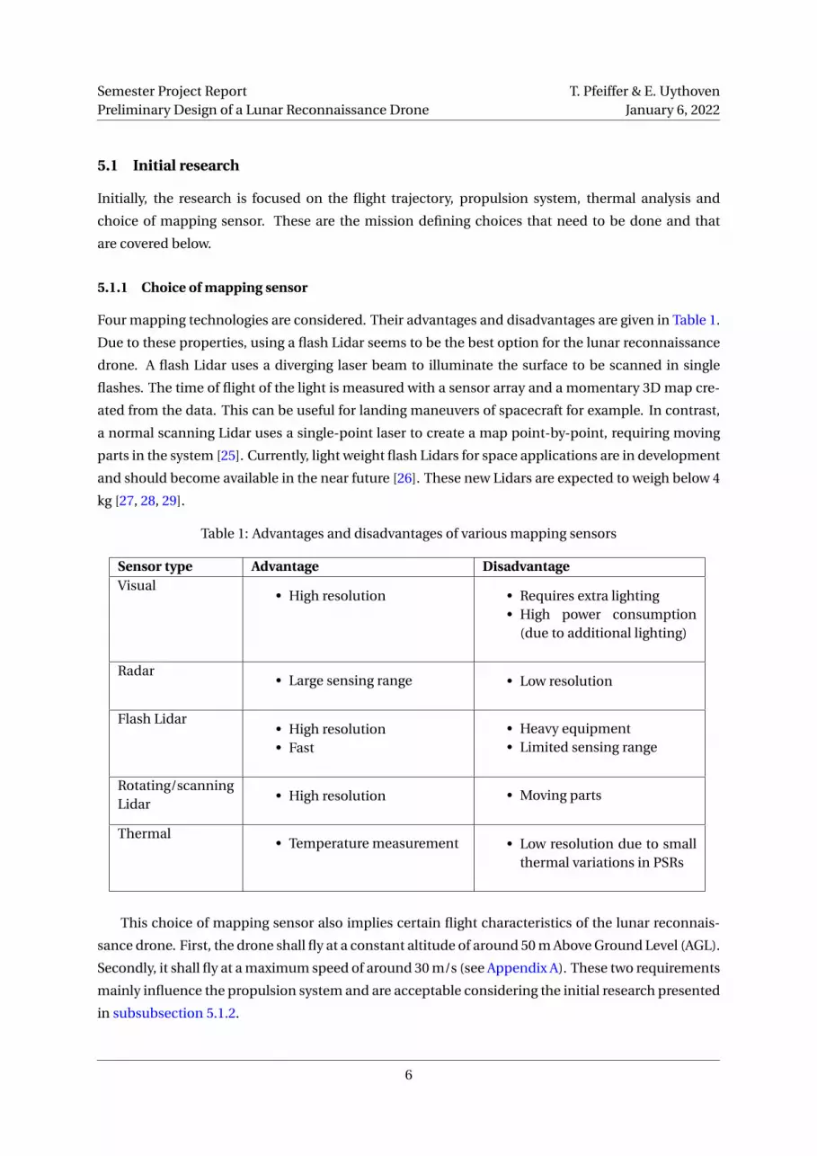
5.1.1 Choice of mapping sensor
Four mapping technologies are considered. Their advantages and disadvantages are given in Table 1.
Due to these properties, using a flash Lidar seems to be the best option for the lunar reconnaissance
drone. A flash Lidar uses a diverging laser beam to illuminate the surface to be scanned in single
flashes. The time of flight of the light is measured with a sensor array and a momentary 3D map cre-
ated from the data. This can be useful for landing maneuvers of spacecraft for example. In contrast,
a normal scanning Lidar uses a single-point laser to create a map point-by-point, requiring moving
parts in the system [25]. Currently, light weight flash Lidars for space applications are in development
and should become available in the near future [26]. These new Lidars are expected to weigh below 4
kg [27, 28, 29].
Table 1: Advantages and disadvantages of various mapping sensors
Sensor type Advantage DisadvantageVisual
• High resolution • Requires extra lighting• High power consumption
(due to additional lighting)
Radar• Large sensing range • Low resolution
Flash Lidar• High resolution• Fast
• Heavy equipment• Limited sensing range
Rotating/scanningLidar
• High resolution • Moving parts
Thermal• Temperature measurement • Low resolution due to small
thermal variations in PSRs
This choice of mapping sensor also implies certain flight characteristics of the lunar reconnais-
sance drone. First, the drone shall fly at a constant altitude of around 50 m Above Ground Level (AGL).
Secondly, it shall fly at a maximum speed of around 30 m/s (see Appendix A). These two requirements
mainly influence the propulsion system and are acceptable considering the initial research presented
in subsubsection 5.1.2.
6
Semester Project ReportPreliminary Design of a Lunar Reconnaissance Drone
T. Pfeiffer & E. UythovenJanuary 6, 2022
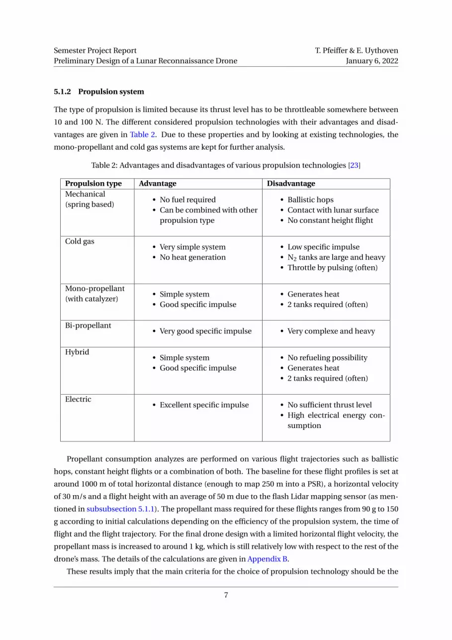
5.1.2 Propulsion system
The type of propulsion is limited because its thrust level has to be throttleable somewhere between
10 and 100 N. The different considered propulsion technologies with their advantages and disad-
vantages are given in Table 2. Due to these properties and by looking at existing technologies, the
mono-propellant and cold gas systems are kept for further analysis.
Table 2: Advantages and disadvantages of various propulsion technologies [23]
Propulsion type Advantage DisadvantageMechanical(spring based)
• No fuel required• Can be combined with other
propulsion type
• Ballistic hops• Contact with lunar surface• No constant height flight
Cold gas• Very simple system• No heat generation
• Low specific impulse• N2 tanks are large and heavy• Throttle by pulsing (often)
Mono-propellant(with catalyzer)
• Simple system• Good specific impulse
• Generates heat• 2 tanks required (often)
Bi-propellant• Very good specific impulse • Very complexe and heavy
Hybrid• Simple system• Good specific impulse
• No refueling possibility• Generates heat• 2 tanks required (often)
Electric• Excellent specific impulse • No sufficient thrust level
• High electrical energy con-sumption
Propellant consumption analyzes are performed on various flight trajectories such as ballistic
hops, constant height flights or a combination of both. The baseline for these flight profiles is set at
around 1000 m of total horizontal distance (enough to map 250 m into a PSR), a horizontal velocity
of 30 m/s and a flight height with an average of 50 m due to the flash Lidar mapping sensor (as men-
tioned in subsubsection 5.1.1). The propellant mass required for these flights ranges from 90 g to 150
g according to initial calculations depending on the efficiency of the propulsion system, the time of
flight and the flight trajectory. For the final drone design with a limited horizontal flight velocity, the
propellant mass is increased to around 1 kg, which is still relatively low with respect to the rest of the
drone’s mass. The details of the calculations are given in Appendix B.
These results imply that the main criteria for the choice of propulsion technology should be the
7
Semester Project ReportPreliminary Design of a Lunar Reconnaissance Drone
T. Pfeiffer & E. UythovenJanuary 6, 2022
weight of the entire subsystem, as well as its controllability (throttleability). The type of flight trajec-
tory is not critical from a propulsion point of view. Therefore, the simplest flight strategy should be
chosen (see subsubsection 5.1.4).
5.1.3 Thermal analysis
The operating temperature of the drone is limited due to the electronic components, propellant tanks,
and due to the thermal expansion of optics making the measurements less accurate. Therefore, it is
necessary to control the temperature change, especially in the very harsh environment of the Moon.
The temperature of the drone should stay between 0 and 50 °C (see Table 5).
The temperature evolution calculations with respect to time in different scenarios are shown in
Appendix C. These show that without adding radiators (added weight and complexity), the heating of
the drone should be limited to Qg en = 1500 W. This heat source is the combination of joule heating,
thrusters firing and the incoming sunlight. The surface coating of the drone can be chosen to have an
appropriate emissitity and limit the temperature change during the flight. A high emissivity (ϵ≥ 0.8)
is required for large heat source powers for flight lasting around 10 minutes (t = 600 s). The detailed
graphs of the temperature changes can be seen on Figure C.1 and Figure C.2.
If the drone is to be used in the sunlight and in PSRs, the heat source would vary a lot due to the
sunlight. Therefore, an active thermal control would be necessary: Either electric heaters would be
needed during missions inside PSRs, or radiators would be required for flights in the sunlight. Each
comes with advantages and disadvantages and a combination of both would also be possible.
An other way to get rid of heat would be by conduction with the lunar soil. This would however
mean that the drone needs to perform a landing on unknown terrain, and that a lot of lunar dust
would be dispersed. Therefore, this option is not considered.
Additionally, since the drone will probably have a high emissivity, it will rapidly cool down when
it is not used. A graph of this temperature evolution can be seen in Figure C.4. This implies that the
drone shall be protected under an insulating heat shield when stored on the rover. It will also have to
be connected to the rover’s thermal system or have its own heaters to maintain a temperature around
0 °C.
However, it is to be noted that these thermal calculation assume a uniform temperature distribu-
tion and constant boundary conditions (no transition between sunlight and shadow is considered).
Therefore, a more in depth thermal analysis will be required to further develop the drone and its base.
5.1.4 Flight trajectory
The flight trajectory presents many options which all have different effects, advantages and disad-
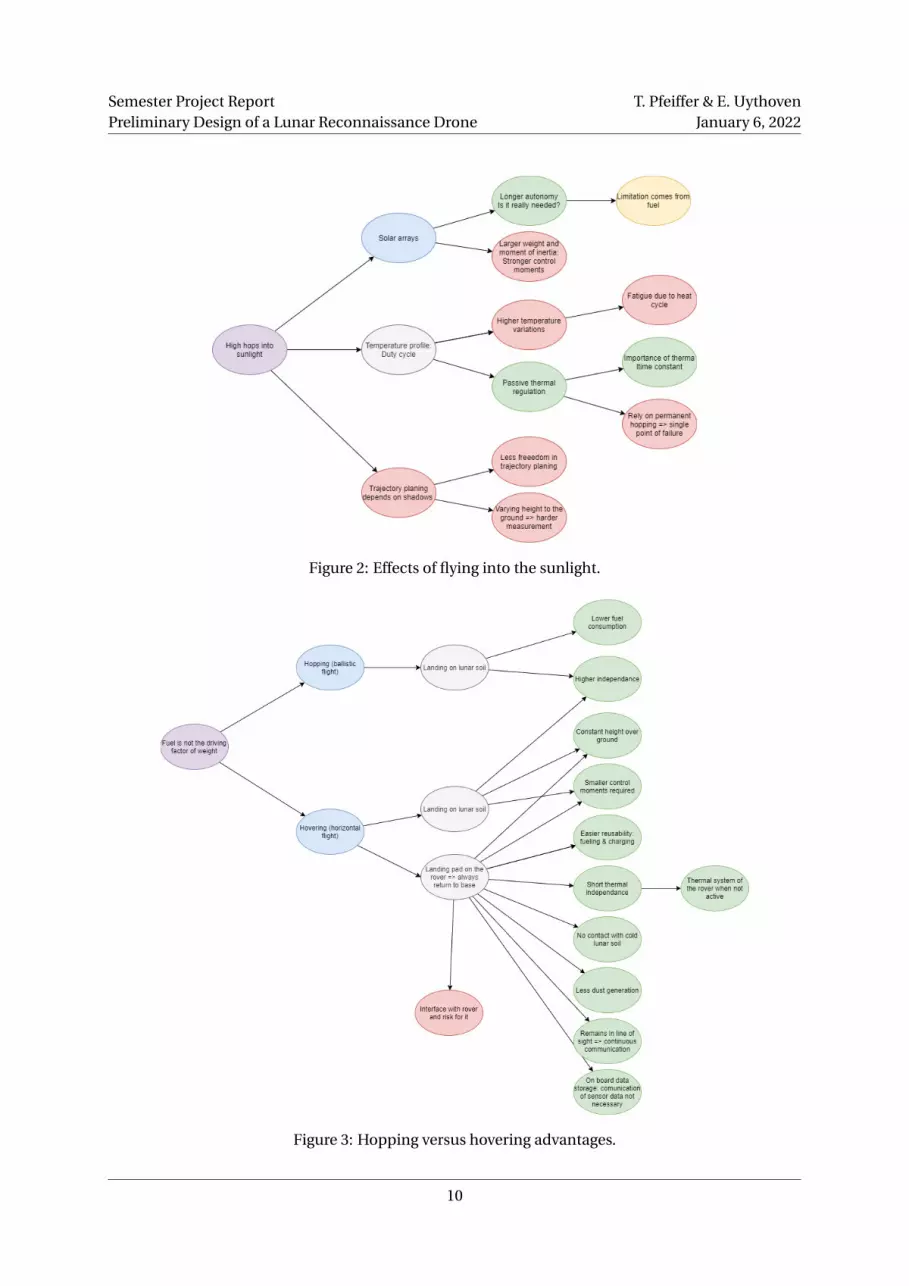
vantages. The options of the study are whether the drone flies into the sunlight or not and whether
it performs hops or flies at a constant height. Diagrams with these questions, choices, effects are
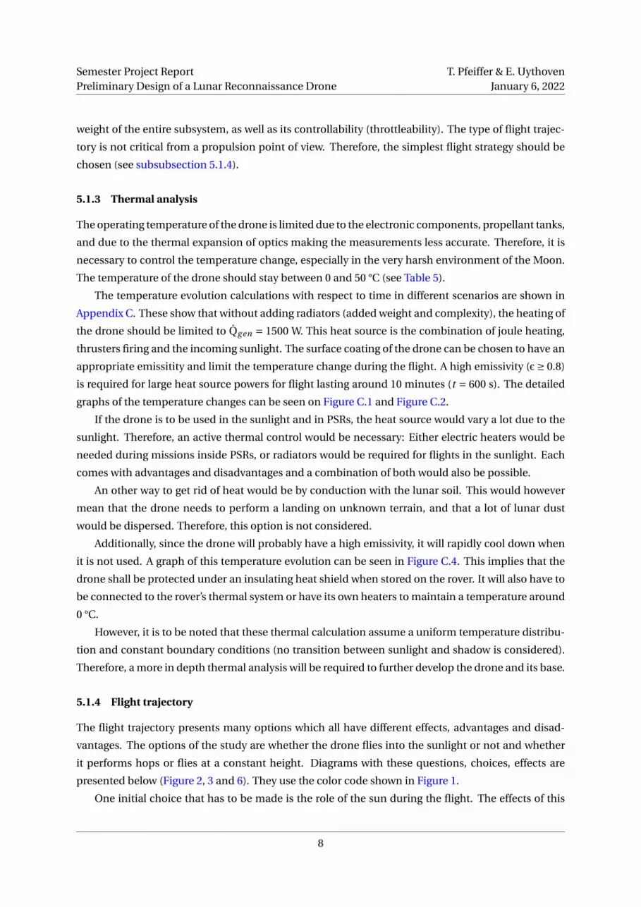
presented below (Figure 2, 3 and 6). They use the color code shown in Figure 1.
One initial choice that has to be made is the role of the sun during the flight. The effects of this
8
Semester Project ReportPreliminary Design of a Lunar Reconnaissance Drone
T. Pfeiffer & E. UythovenJanuary 6, 2022
Figure 1: Color code for the choice and effects diagrams.
decision are shown in Figure 2. It can be seen that there are mostly disadvantages of the drone re-
quiring sunlight to function properly due to power and thermal requirements. Moreover, in the later
design, it will be shown that solar panels are not necessary if the drone can charge its batteries on the
rover (drone base). Therefore, the choice to not go into the sunlight is made.
If a flight into the sunlight is required for other types of missions than exploring PSRs, the thermal
systems of the drone will have to evacuate the extra heat, probably by using radiators. This aspect
wasn’t studied in detail and will depend on the required flexibility of the drone.
Knowing that fuel is no the driving factor of the drone’s mass, both ballistic hopping and flying at a
constant height need to be considered. Their respective advantages are shown in Figure 3. This figure
also includes the scenario of the drone always landing on its base on the rover. This flight strategy has
many advantages in terms of reusability (charging and refueling), communication (mapping data can
be transferred by wire after landing) and for the flexibility of deployment (drone can be on standby for
a long time). It is therefor decided to go with this last strategy: a flight at constant height for mapping
with a return to base. This also prevents the drone from landing on the lunar ground and dispersing
dust.
5.2 Initial analysis results and decision mind-map
All the results and subsequent decisions are summarized in the decision mind-map shown in Figure 4.
9
Semester Project ReportPreliminary Design of a Lunar Reconnaissance Drone
T. Pfeiffer & E. UythovenJanuary 6, 2022
Figure 2: Effects of flying into the sunlight.
Figure 3: Hopping versus hovering advantages.
10

Semester Project ReportPreliminary Design of a Lunar Reconnaissance Drone
T. Pfeiffer & E. UythovenJanuary 6, 2022
Figure 4: Initial analysis results and decision mind-map.
11

Semester Project ReportPreliminary Design of a Lunar Reconnaissance Drone
T. Pfeiffer & E. UythovenJanuary 6, 2022
6 Drone design
To be able to analyze the system further and find the technological challenges, an initial design of the
drone is made. This initial design helps for the visualization of how all the different parts influence
each other and makes the writing of requirements and budgets easier. Several iterations of specifica-
tions and rapid designs are realized during the course of this project.
6.1 Decomposition in subsystems
The subsystem of the drone are defined as follows:
• AV - Avionics: Onboard computer (OBC), attitude control and object detection and avoidance
• CDH - Communication & data handling: Data processing, storage and transmission
• PL - Payload: 3D mapping and imaging instruments
• PR - Propulsion: thrusters, plumbing and tanks
• PWR - Power: Batteries and cables
• ST - Structures
• TH - Thermal
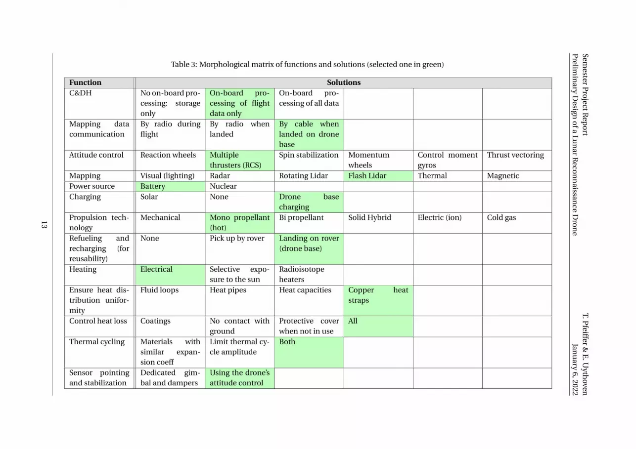
6.2 Functional decomposition and solutions
The first design step is to perform a functional decomposition and identify possible solutions for each
function. In Table 3, this is done by the means of a morphological matrix. The chosen solution for
each function is highlighted in green. More details on the different components are given in subsec-
tion 6.4.
12
Semester
Pro
jectRep
ort
Prelim
inary
Design
ofa
Lun
arR
econ
naissan
ceD
ron
eT.P
feiffer&
E.U
ythoven
Janu
ary6,2022
Table 3: Morphological matrix of functions and solutions (selected one in green)
Function SolutionsC&DH No on-board pro-
cessing: storageonly
On-board pro-cessing of flightdata only
On-board pro-cessing of all data
Mapping datacommunication
By radio duringflight
By radio whenlanded
By cable whenlanded on dronebase
Attitude control Reaction wheels Multiplethrusters (RCS)
Spin stabilization Momentumwheels
Control momentgyros
Thrust vectoring
Mapping Visual (lighting) Radar Rotating Lidar Flash Lidar Thermal MagneticPower source Battery NuclearCharging Solar None Drone base
chargingPropulsion tech-nology
Mechanical Mono propellant(hot)
Bi propellant Solid Hybrid Electric (ion) Cold gas
Refueling andrecharging (forreusability)
None Pick up by rover Landing on rover(drone base)
Heating Electrical Selective expo-sure to the sun
Radioisotopeheaters
Ensure heat dis-tribution unifor-mity
Fluid loops Heat pipes Heat capacities Copper heatstraps
Control heat loss Coatings No contact withground
Protective coverwhen not in use
All
Thermal cycling Materials withsimilar expan-sion coeff
Limit thermal cy-cle amplitude
Both
Sensor pointingand stabilization
Dedicated gim-bal and dampers
Using the drone’sattitude control
13
Semester Project ReportPreliminary Design of a Lunar Reconnaissance Drone
T. Pfeiffer & E. UythovenJanuary 6, 2022
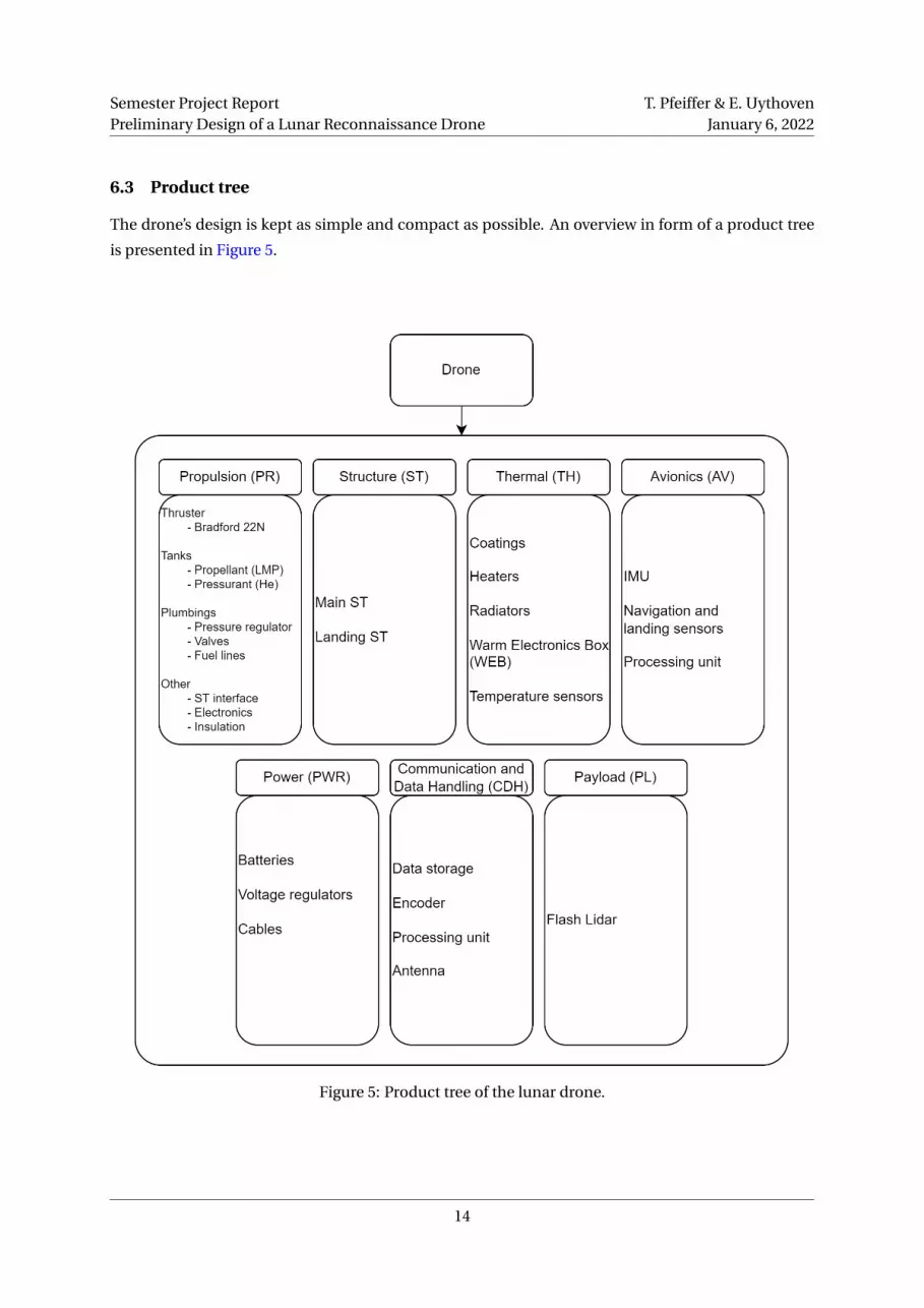
6.3 Product tree
The drone’s design is kept as simple and compact as possible. An overview in form of a product tree
is presented in Figure 5.
Figure 5: Product tree of the lunar drone.
14
Semester Project ReportPreliminary Design of a Lunar Reconnaissance Drone
T. Pfeiffer & E. UythovenJanuary 6, 2022
6.4 Details for the different subsystems
The drone is decomposed into seven subsystems which are described below.
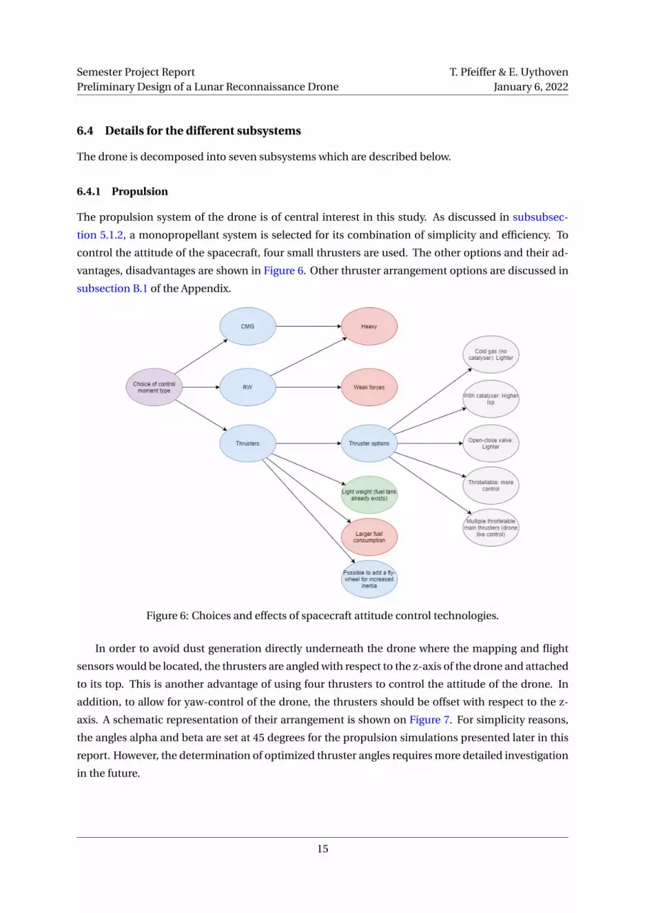
6.4.1 Propulsion
The propulsion system of the drone is of central interest in this study. As discussed in subsubsec-
tion 5.1.2, a monopropellant system is selected for its combination of simplicity and efficiency. To
control the attitude of the spacecraft, four small thrusters are used. The other options and their ad-
vantages, disadvantages are shown in Figure 6. Other thruster arrangement options are discussed in
subsection B.1 of the Appendix.
Figure 6: Choices and effects of spacecraft attitude control technologies.
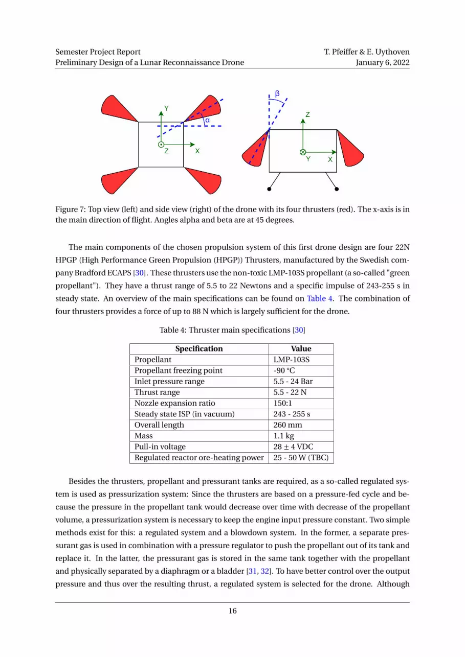
In order to avoid dust generation directly underneath the drone where the mapping and flight
sensors would be located, the thrusters are angled with respect to the z-axis of the drone and attached
to its top. This is another advantage of using four thrusters to control the attitude of the drone. In
addition, to allow for yaw-control of the drone, the thrusters should be offset with respect to the z-
axis. A schematic representation of their arrangement is shown on Figure 7. For simplicity reasons,
the angles alpha and beta are set at 45 degrees for the propulsion simulations presented later in this
report. However, the determination of optimized thruster angles requires more detailed investigation
in the future.
15
Semester Project ReportPreliminary Design of a Lunar Reconnaissance Drone
T. Pfeiffer & E. UythovenJanuary 6, 2022
Figure 7: Top view (left) and side view (right) of the drone with its four thrusters (red). The x-axis is inthe main direction of flight. Angles alpha and beta are at 45 degrees.
The main components of the chosen propulsion system of this first drone design are four 22N
HPGP (High Performance Green Propulsion (HPGP)) Thrusters, manufactured by the Swedish com-
pany Bradford ECAPS [30]. These thrusters use the non-toxic LMP-103S propellant (a so-called "green
propellant"). They have a thrust range of 5.5 to 22 Newtons and a specific impulse of 243-255 s in
steady state. An overview of the main specifications can be found on Table 4. The combination of
four thrusters provides a force of up to 88 N which is largely sufficient for the drone.
Table 4: Thruster main specifications [30]
Specification ValuePropellant LMP-103SPropellant freezing point -90 °CInlet pressure range 5.5 - 24 BarThrust range 5.5 - 22 NNozzle expansion ratio 150:1Steady state ISP (in vacuum) 243 - 255 sOverall length 260 mmMass 1.1 kgPull-in voltage 28 ± 4 VDCRegulated reactor ore-heating power 25 - 50 W (TBC)
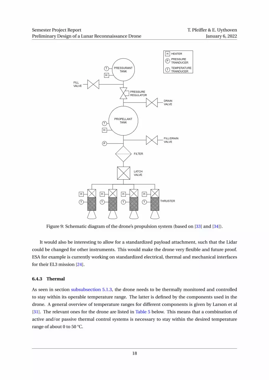
Besides the thrusters, propellant and pressurant tanks are required, as a so-called regulated sys-
tem is used as pressurization system: Since the thrusters are based on a pressure-fed cycle and be-
cause the pressure in the propellant tank would decrease over time with decrease of the propellant
volume, a pressurization system is necessary to keep the engine input pressure constant. Two simple
methods exist for this: a regulated system and a blowdown system. In the former, a separate pres-
surant gas is used in combination with a pressure regulator to push the propellant out of its tank and
replace it. In the latter, the pressurant gas is stored in the same tank together with the propellant
and physically separated by a diaphragm or a bladder [31, 32]. To have better control over the output
pressure and thus over the resulting thrust, a regulated system is selected for the drone. Although
16

Semester Project ReportPreliminary Design of a Lunar Reconnaissance Drone
T. Pfeiffer & E. UythovenJanuary 6, 2022
this system is heavier due to the higher amount of components needed, it is easier to control and to
refuel, which is critical to make the drone reusable.
The exact masses and volumes of the pressurant and propellant tanks are calculated in the ap-
pendix subsection B.6 and are sufficient for two straight-line flights of 1000 m each, if the system is
optimized. The pressurant insertion is controlled by a pressure regulator for better pressure control
in the propellant tank. A simplified representation of the drone’s propulsion system placement on
the drone is depicted in Figure 8. A more detailed schematic diagram of the propulsion system on its
own is represented in Figure 9. It is based on the Green Propellan Infusion Mission (GPIM) by NASA
and other satellite propulsion systems [31, 33, 34].
Figure 8: Illustration of the propulsion system of the drone. Note that components such as valves,tubes and pressure regulators are not represented.
6.4.2 Structure
The drone’s structure needs to hold all the components in place with respect to each other. It also
needs to have landing legs or other features that will interface with the drone base, including a hold
down mechanism. Moreover, it should be made of materials with similar expansion coefficients to
avoid any thermal stresses on the structure. No detailed structure has been developed in the scope of
this project but several ideas were formulated.
One idea could be to use the titanium propellant tanks as part of the structure. The rest of the
structure could therefore also be made of titanium.
From a thermal perspective, it would also make sense to isolate the different subsystems such as
the thrusters, the rest of the propulsion system and all the electronics/sensors. For example, the heat
of the thrusters firing should not be conducted into the rest of the drone. The electronics and sensors
could also be placed in a Warm Electronics Box (WEB) to better control their temperature.
17
Semester Project ReportPreliminary Design of a Lunar Reconnaissance Drone
T. Pfeiffer & E. UythovenJanuary 6, 2022
Figure 9: Schematic diagram of the drone’s propulsion system (based on [33] and [34]).
It would also be interesting to allow for a standardized payload attachment, such that the Lidar
could be changed for other instruments. This would make the drone very flexible and future proof.
ESA for example is currently working on standardized electrical, thermal and mechanical interfaces
for their EL3 mission [24].
6.4.3 Thermal
As seen in section subsubsection 5.1.3, the drone needs to be thermally monitored and controlled
to stay within its operable temperature range. The latter is defined by the components used in the
drone. A general overview of temperature ranges for different components is given by Larson et al
[31]. The relevant ones for the drone are listed in Table 5 below. This means that a combination of
active and/or passive thermal control systems is necessary to stay within the desired temperature
range of about 0 to 50 °C.
18

Semester Project ReportPreliminary Design of a Lunar Reconnaissance Drone
T. Pfeiffer & E. UythovenJanuary 6, 2022
Table 5: Typical operational and survival temperature ranges of various components according toLarson et al [31], adapted and extended by the authors
Component Operational SurvivalBatteries [35] -30 to 60 °C -40 to 60 °CPower Box Baseplates -10 to 50 °C -20 to 60 °CC&DH Box Baseplates -20 to 60 °C -40 to 75 °CAntennas -100 to 100 °C -120 to 120 °CSolar Panels -150 to 110 °C -120 to 120 °CTanks [36] 0 to 50 °C -Propellant (LMP-103S) -5 to 60 °C -90 to 120 °C
The main challenge for the thermal system of the drone is the tuning of the passive components
(heat capacity, emissivity and absorptivity) to reduce the needed power of the active thermal system
(heaters). Since cooling the spacecraft would require heavy radiators, it is preferable to use heaters
when necessary. Therefore, the drone should be able to evacuate all the heat when flying in the sun-
light. The critical components should be placed close together in a Warm Electronics Box (WEB) and
a "propulsion box" to keep them at an operable temperature by using active electrical heaters. This
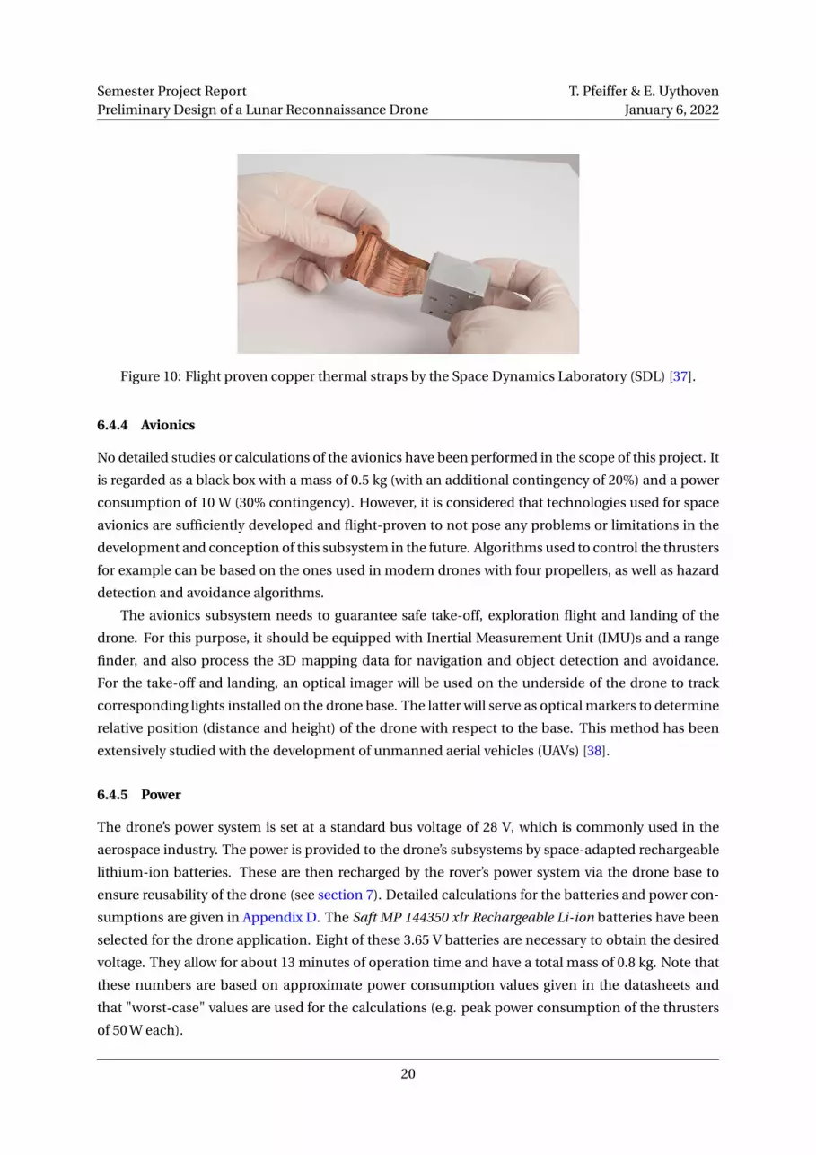
is especially necessary when flying into PSRs. In addition, heat straps, often used in small satellites
[23], can be used to help distribute the heat via conduction (example shown on Figure 10). Finally, the
absorbtivity and emissivity of the drone can be controlled with help of special paint and surface coat-
ings which are commonly used in the aerospace industry. Calculations of evacuated thermal power
with respect to the emissivity and absorptivity as well as temperature variations of the drone during a
flight are presented in Appendix C. These calculations are based on a significant number of assump-
tions, such as the uniformity of temperature distribution in the drone. Therefore, a more detailed
analysis is still required to define exactly which components should be used where and how.
The four thrusters are one of the main heat sources in the system (together with sunlight and
electrical power consumption). The removal of heat produced by these thrusters represents another
challenge for the thermal system but after a discussion with Prof. Hiroyuki Koizumi from University
of Tokyo, a specialist in space propulsion, it appears to be feasible to dissipate heat of the thrusters
via radiation. The engine bell and combustion chamber are allowed to become red hot and radiate
their thermal energy into space while thermal conduction to the spacecraft structure can be kept very
small.
Finally, when the drone is not in use, it should be protected under an insulating cover. This is due
to the large temperature losses of the drone when it is not used and no heat is generated internally.
Figure C.4 shows this decrease of temperature if the drone is in the shadow and not protected. More
details on the insulating cover are given in section 7.
19
Semester Project ReportPreliminary Design of a Lunar Reconnaissance Drone
T. Pfeiffer & E. UythovenJanuary 6, 2022
Figure 10: Flight proven copper thermal straps by the Space Dynamics Laboratory (SDL) [37].
6.4.4 Avionics
No detailed studies or calculations of the avionics have been performed in the scope of this project. It
is regarded as a black box with a mass of 0.5 kg (with an additional contingency of 20%) and a power
consumption of 10 W (30% contingency). However, it is considered that technologies used for space
avionics are sufficiently developed and flight-proven to not pose any problems or limitations in the
development and conception of this subsystem in the future. Algorithms used to control the thrusters
for example can be based on the ones used in modern drones with four propellers, as well as hazard
detection and avoidance algorithms.
The avionics subsystem needs to guarantee safe take-off, exploration flight and landing of the
drone. For this purpose, it should be equipped with Inertial Measurement Unit (IMU)s and a range
finder, and also process the 3D mapping data for navigation and object detection and avoidance.
For the take-off and landing, an optical imager will be used on the underside of the drone to track
corresponding lights installed on the drone base. The latter will serve as optical markers to determine
relative position (distance and height) of the drone with respect to the base. This method has been
extensively studied with the development of unmanned aerial vehicles (UAVs) [38].
6.4.5 Power
The drone’s power system is set at a standard bus voltage of 28 V, which is commonly used in the
aerospace industry. The power is provided to the drone’s subsystems by space-adapted rechargeable
lithium-ion batteries. These are then recharged by the rover’s power system via the drone base to
ensure reusability of the drone (see section 7). Detailed calculations for the batteries and power con-
sumptions are given in Appendix D. The Saft MP 144350 xlr Rechargeable Li-ion batteries have been
selected for the drone application. Eight of these 3.65 V batteries are necessary to obtain the desired
voltage. They allow for about 13 minutes of operation time and have a total mass of 0.8 kg. Note that
these numbers are based on approximate power consumption values given in the datasheets and
that "worst-case" values are used for the calculations (e.g. peak power consumption of the thrusters
of 50 W each).
20

Semester Project ReportPreliminary Design of a Lunar Reconnaissance Drone
T. Pfeiffer & E. UythovenJanuary 6, 2022
6.4.6 Communication and data handling
Communication between drone and base can be separated into two modes: Communication when
the drone is docked on the base and in-flight communication. During flight, the drone captures 3D
mapping data of the lunar ground with its Lidar system (see subsubsection 5.1.1 and subsubsec-
tion 6.4.7). This data is not only temporarily stored on the drone, but also directly processed by its
On-Board Computer (OBC) to determine flight parameters such as position and altitude and to be
used by the hazard detection and avoidance system. The data sent to the base during flight is lim-
ited to drone health, position tracking, power and propellant consumption (housekeeping data). The
data received by the drone are health checks and commands (e.g. abort mission and return to base).
When docked to the base and connected via cable, the drone transmits the mapping data to the rover.
Housekeeping data is continuously sent and monitored as well.
6.4.7 Payload
The main payload is a flash Lidar used as a mapping sensor, as described in subsubsection 5.1.1.
The high resolution map can then be used by the rover to chose its exploration path, especially into
PSRs. As mentioned previously, lightweight flash Lidars for space applications are in development
and should become available in the near future. These new Lidars are expected to weigh below 4 kg.
Detailed calculations giving requirements on the Lidar’s resolution and imaging frequency are given
in Appendix A.
Additionally, the Lidar should be interchangeable with other payloads and sensors. This will make
the drone more flexible. It will be able to adapt to new needs and do different types of missions. A
potential outlook and more ideas are given in section 10.
6.5 N2 chart
All of the design choices somehow influence the other decisions. To visualize how these decisions
affect each other, an N2 chart was created. The mission defining choices are highlighted in green on
the diagonal of the chart. The influences are marked with an "x" when trivial and more details are
given for the other pairs.
21

Semester
Pro
jectRep
ort
Prelim
inary
Design
ofa
Lun
arR
econ
naissan
ceD
ron
eT.P
feiffer&
E.U
ythoven
Janu
ary6,2022
Figure 11: N2 chart.
22
Semester Project ReportPreliminary Design of a Lunar Reconnaissance Drone
T. Pfeiffer & E. UythovenJanuary 6, 2022
7 Drone base design
The design of the drone base is out of the scope of this project. However, certain components, inter-
faces and functions have been identified during the design of the drone itself.
7.1 Product tree
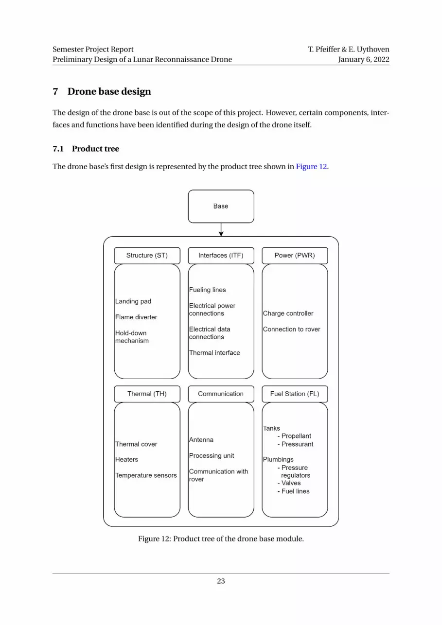
The drone base’s first design is represented by the product tree shown in Figure 12.
Figure 12: Product tree of the drone base module.
23

Semester Project ReportPreliminary Design of a Lunar Reconnaissance Drone
T. Pfeiffer & E. UythovenJanuary 6, 2022
7.2 Decomposition in subsystems
The subsystem of the drone base are defined as follows:
• CDH - Communication & data handling: Data transmission to the rover
• IF - Interfaces with rover: Mechanical, power and signal interface between base module and
rover
• PR - Propulsion: Propellant and pressurant storage
• PWR - Power
• ST - Structures
• TH - Thermal: Thermal and radiation protection for the drone
7.3 Drone base functions
The drone base has four main functions:
• Provide a shelter for the drone when not in use, i.e.:
– Attach/secure the drone during flight to the Moon and rest of the rover mission with a
reversible hold down and release system.
– Insulate the drone to prevent large temperature losses with a radiation cover.
– If possible, connect to drone to the thermal system of the rover.
• Provide a take-off and landing base, including:
– A flame diverter to direct the thrusters exhaust away from the rover.
– Features to ease the landing of the drone (for example optical markers or lights)
• Provide a data connection to transfer the mapping sensor data from the drone to the rover.
• Allow for the refuelling and recharging of the drone to make multiple flight possible and there-
fore have:
– Propellant and pressurant tanks.
– Fuel line connection and disconnection systems.
The main challenge for this drone base will be to make it as compact and as independent as pos-
sible, such that it can easily be integrated on various rovers and be used for other future applications.
The size of the refuelling tanks could be adapted to the number of flights the drone is expected to
perform (e.g. ten flights). Solar cells on the cover for additional power generation could also be imag-
ined.
24
Semester Project ReportPreliminary Design of a Lunar Reconnaissance Drone
T. Pfeiffer & E. UythovenJanuary 6, 2022
8 System Engineering Results
Based on the decisions taken and the design choices made in the previous chapters, a more in-depth
and detailed design and concept of the system can be derived. Specifically, a detailed Concept of
Operations (ConOps) is presented, as well as preliminary mass and power budgets and high level
requirements. These results can be used as a starting point of future, more detailed development
projects around the drone and its base.
8.1 ConOps
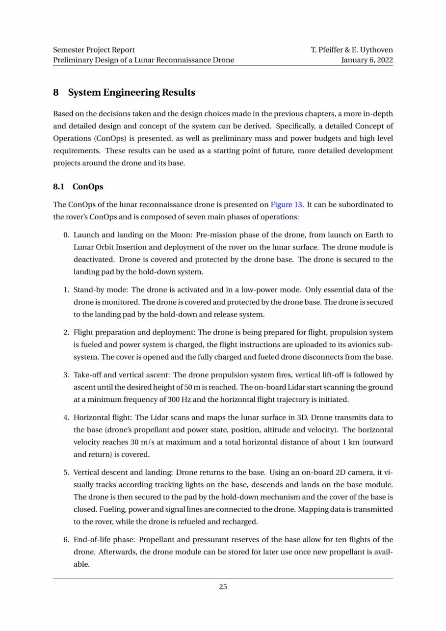
The ConOps of the lunar reconnaissance drone is presented on Figure 13. It can be subordinated to
the rover’s ConOps and is composed of seven main phases of operations:
0. Launch and landing on the Moon: Pre-mission phase of the drone, from launch on Earth to
Lunar Orbit Insertion and deployment of the rover on the lunar surface. The drone module is
deactivated. Drone is covered and protected by the drone base. The drone is secured to the
landing pad by the hold-down system.
1. Stand-by mode: The drone is activated and in a low-power mode. Only essential data of the
drone is monitored. The drone is covered and protected by the drone base. The drone is secured
to the landing pad by the hold-down and release system.
2. Flight preparation and deployment: The drone is being prepared for flight, propulsion system
is fueled and power system is charged, the flight instructions are uploaded to its avionics sub-
system. The cover is opened and the fully charged and fueled drone disconnects from the base.
3. Take-off and vertical ascent: The drone propulsion system fires, vertical lift-off is followed by
ascent until the desired height of 50 m is reached. The on-board Lidar start scanning the ground
at a minimum frequency of 300 Hz and the horizontal flight trajectory is initiated.
4. Horizontal flight: The Lidar scans and maps the lunar surface in 3D. Drone transmits data to
the base (drone’s propellant and power state, position, altitude and velocity). The horizontal
velocity reaches 30 m/s at maximum and a total horizontal distance of about 1 km (outward
and return) is covered.
5. Vertical descent and landing: Drone returns to the base. Using an on-board 2D camera, it vi-
sually tracks according tracking lights on the base, descends and lands on the base module.
The drone is then secured to the pad by the hold-down mechanism and the cover of the base is
closed. Fueling, power and signal lines are connected to the drone. Mapping data is transmitted
to the rover, while the drone is refueled and recharged.
6. End-of-life phase: Propellant and pressurant reserves of the base allow for ten flights of the
drone. Afterwards, the drone module can be stored for later use once new propellant is avail-
able.
25
Semester Project ReportPreliminary Design of a Lunar Reconnaissance Drone
T. Pfeiffer & E. UythovenJanuary 6, 2022
Figure 13: Lunar reconnaissance drone module: Concept of Operations. 1. Stand-by mode; 2. Flightpreparation and deployment; 3. Vertical ascent; 4. Horizontal flight and surface mapping; 5. Verticaldescent and landing.
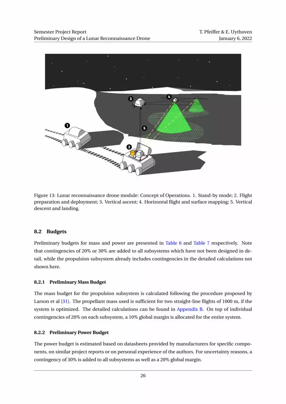
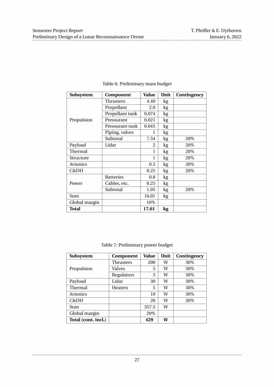
8.2 Budgets
Preliminary budgets for mass and power are presented in Table 6 and Table 7 respectively. Note
that contingencies of 20% or 30% are added to all subsystems which have not been designed in de-
tail, while the propulsion subsystem already includes contingencies in the detailed calculations not
shown here.
8.2.1 Preliminary Mass Budget
The mass budget for the propulsion subsystem is calculated following the procedure proposed by
Larson et al [31]. The propellant mass used is sufficient for two straight-line flights of 1000 m, if the
system is optimized. The detailed calculations can be found in Appendix B. On top of individual
contingencies of 20% on each subsystem, a 10% global margin is allocated for the entire system.
8.2.2 Preliminary Power Budget
The power budget is estimated based on datasheets provided by manufacturers for specific compo-
nents, on similar project reports or on personal experience of the authors. For uncertainty reasons, a
contingency of 30% is added to all subsystems as well as a 20% global margin.
26
Semester Project ReportPreliminary Design of a Lunar Reconnaissance Drone
T. Pfeiffer & E. UythovenJanuary 6, 2022
Table 6: Preliminary mass budget
Subsystem Component Value Unit Contingency
Propulsion
Thrusters 4.40 kgPropellant 2.0 kgPropellant tank 0.074 kgPressurant 0.021 kgPressurant tank 0.045 kgPiping, valves 1 kgSubtotal 7.54 kg 20%
Payload Lidar 2 kg 20%Thermal 1 kg 20%Structure 1 kg 20%Avionics 0.5 kg 20%C&DH 0.25 kg 20%
PowerBatteries 0.8 kgCables, etc. 0.25 kgSubtotal 1.05 kg 20%
Sum 16.01 kgGlobal margin 10%Total 17.61 kg
Table 7: Preliminary power budget
Subsystem Component Value Unit Contingency
PropulsionThrusters 200 W 30%Valves 5 W 30%Regulators 5 W 30%
Payload Lidar 30 W 30%Thermal Heaters 5 W 30%Avionics 10 W 30%C&DH 20 W 30%Sum 357.5 WGlobal margin 20%Total (cont. incl.) 429 W
27
Semester Project ReportPreliminary Design of a Lunar Reconnaissance Drone
T. Pfeiffer & E. UythovenJanuary 6, 2022
8.3 Requirements
In order to facilitate the drone and base design process, a set of high level requirements are defined.
They act as a first reference at the beginning of the project and are revisited and adapted accordingly
when required throughout the process. The requirements are presented in Table 9 and Table 10 be-
low and are separated in Drone Requirements and Drone Base Requirements. Note that both are of
preliminary nature and require deeper reflection in the future. The abbreviations under the "system"
column are the acronyms of the different subsystems. SYS stands for a general requirement on the
entire system.
8.4 Risk analysis
Although not all subsystems are designed in detail at this stage of the project and more time needs to
be allocated for this in the future, a preliminary risk analysis can be realized here. For this, a simpli-
fied Failure Mode and Effects Analysis (FMEA) is done based on the theory learned in the ENG-421
EPFL course (Fundamentals in Systems Engineering) and in the CS-487 EPFL course (Industrial au-
tomation), a method also used by the EPFL Rocket Team (ERT), in which both of this report’s authors
are active.
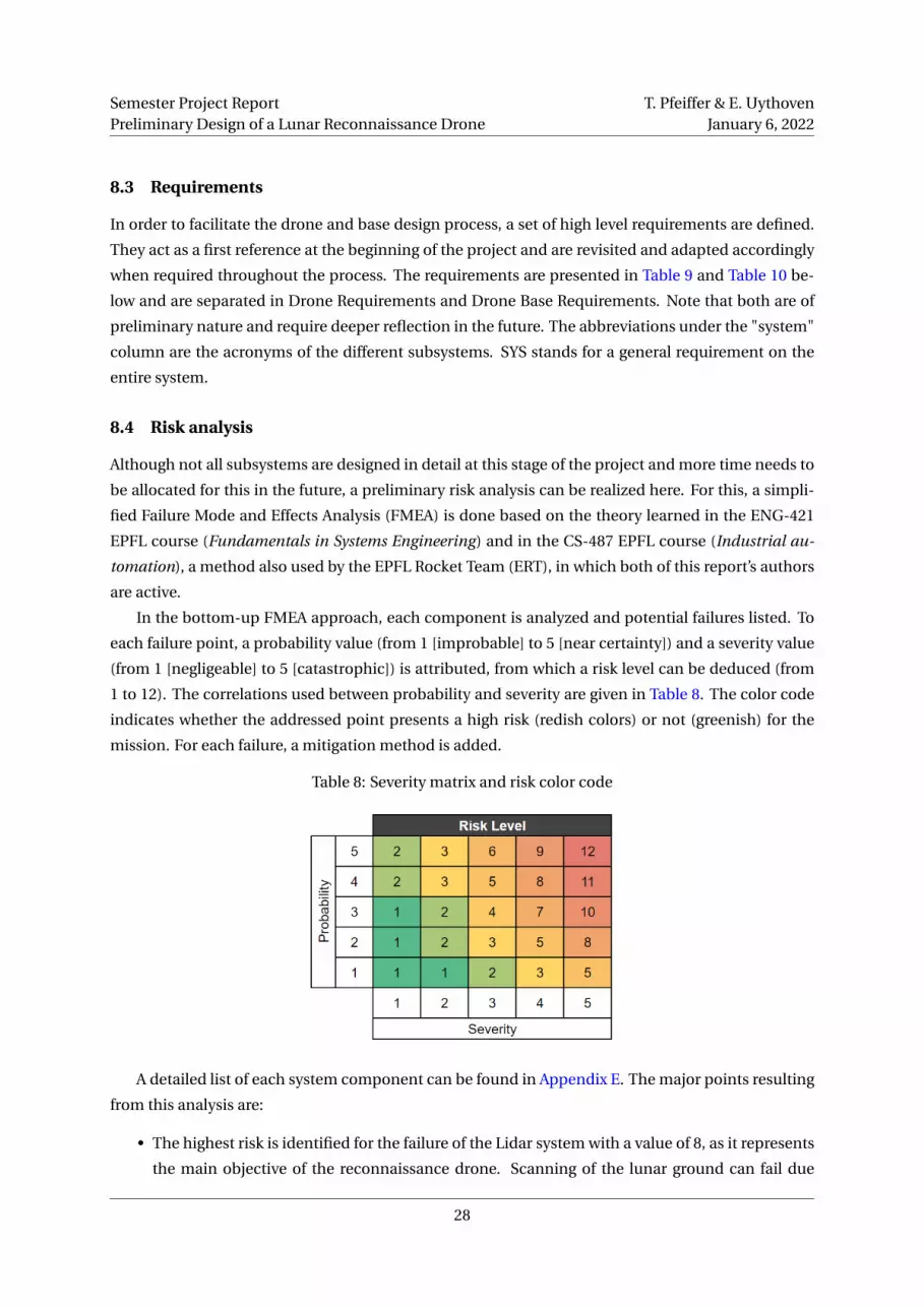
In the bottom-up FMEA approach, each component is analyzed and potential failures listed. To
each failure point, a probability value (from 1 [improbable] to 5 [near certainty]) and a severity value
(from 1 [negligeable] to 5 [catastrophic]) is attributed, from which a risk level can be deduced (from
1 to 12). The correlations used between probability and severity are given in Table 8. The color code
indicates whether the addressed point presents a high risk (redish colors) or not (greenish) for the
mission. For each failure, a mitigation method is added.
Table 8: Severity matrix and risk color code
A detailed list of each system component can be found in Appendix E. The major points resulting
from this analysis are:
• The highest risk is identified for the failure of the Lidar system with a value of 8, as it represents
the main objective of the reconnaissance drone. Scanning of the lunar ground can fail due
28
Semester Project ReportPreliminary Design of a Lunar Reconnaissance Drone
T. Pfeiffer & E. UythovenJanuary 6, 2022
to various reasons, but mainly either due to dust limiting the laser operation or due to failure
of the Lidar system itself. To mitigate the first reason, dust dispersion needs to be reduced or
prevented. For this, the thrusters are angled away from the drone and a fire deflector used on
the drone base. For the second reason, the Lidar system needs to be extensively tested before
the mission in order to guarantee its nominal operation on the Moon.
• Another risk due to dust dispersion relates to the optical tracking system of the drone, which is
used for take-off and landing. Here, if tracking of the according lights installed on the base fails,
especially landing becomes very difficult. Again, dust dispersion needs to be mitigated.
• A further high risk is found in the propulsion system: As the flight of the drone relies on all
four thrusters, one or more defect thrusters can have a significant impact on the mission. If
one thruster does not operate correctly, an "emergency flight mode" could be implemented,
which allows for the drone to return to the base with only three active thrusters, but very limited
control possibilities. If more than one thruster fails, the mission cannot be executed and fails.
To prevent thruster problems, extensive testing is required and fire tests necessary before each
flight.
• Another risk concern the power capacity of the batteries, which can be mitigated with redun-
dant batteries.
• All moving mechanisms in space represent a high risk due to cold-welding and lubrication as-
pects. These mechanisms include the drone-base interfaces (power, propulsion and data), the
radiation cover and the hold-down mechanism of the base module. Again, extensive testing
and the use of appropriate lubricants is necessary, as some failures (e.g. cover does not open)
mean permanent mission failure.
29

Semester
Pro
jectRep
ort
Prelim
inary
Design
ofa
Lun
arR
econ
naissan
ceD
ron
eT.P
feiffer&
E.U
ythoven
Janu
ary6,2022
Table 9: Preliminary drone requirements
ID code System Short Detailed description Verification2021-D-AV-01 AV Autonomous landing The drone shall be capable of autonomous landing on the drone base Testing2021-D-AV-04 AV PL independence The drone shall be independent of its payload Demonstration2021-D-AV-02 AV Position tracking The drone shall track its position in space during flight Testing2021-D-AV-03 AV Return to base The drone shall be capable to abort its flight mission and return to the base autonomously Testing2021-D-AV-05 AV Obstacle detection The drone should use the acquired 3D mapping data for obstacle detection and avoidance during flight Testing2021-D-AV-05 AV Altitude acquisition The drone shall measure its altitude independently of the mapping sensor for object avoidance during flight Testing2021-D-CDH-01 CDH In-flight communication The drone shall use wireless radio antennas to transmit data directly to the rover when within sight Demonstration2021-D-CDH-02 CDH Rover communication The drone should always be in sight with the rover Analysis2021-D-CDH-03 CDH Com range The communication range of the drone shall be at least 2 times the flight range Testing2021-D-CDH-04 CDH Hovering strategy The flight shall ensure direct communication with the rover and household and flight data transmitted to the rover Demonstration2021-D-CDH-05 CDH Data storage inflight 3D mapping data shall be stored on the drone during the flight Demonstration2021-D-CDH-06 CDH Data transmission 3D mapping data shall be transmitted to the rover after landing on the base Demonstration2021-D-PL-01 PL Payload mapping resolution The payload shall provide a mapping resolution of <0.5 m/pixel Demonstration2022-D-PL-02 PL Mapping range The drone's flight altitude shall be within the mapping range Testing2021-D-PL-03 PL Mapping technology The mapping should be three-dimensional Demonstration2021-D-PL-04 PL Continuous mapping The payload shall provide a continuous mapping under the flight path Demonstration2021-D-PL-05 PL Adaptability The drone's payload should be interchangeable with instrumentation of similar size and power requirements Testing2021-D-PR-07 PR Drone horizontal velocity The maximum horizontal flight velocity shall lie below 50 m/s Testing2021-D-PR-08 PR Flight altitude The drone shall flight at 50 m (± 10 m) during the mapping Testing2021-D-PR-01 PR Dust dispersion The propulsion system shall not limit the mapping due to dust dispersion Testing2021-D-PR-02 PR Flight range The propulsion system shall be capable of covering a horizontal distance of at least 1000 m Testing2021-D-PR-03 PR Propellant toxicity The propulsion system should avoid the use of highly toxic propellants Inspection2021-D-PR-04 PR Refualability The propulsion system shall be refualable by the drone base Testing2021-D-PR-05 PR Propellant freezing pt. The propellant's freezing point shall be below -50°C Testing2021-D-PR-06 PR Pressurant freezing pt. The pressurant's freezing point shall be below -50°C Testing2021-D-PWR-01 PWR Power capacity The power system shall provide all energy required for one flight (with contingency) Testing2021-D-PWR-02 PWR Rechargeability The power system shall be rechargeable by the drone base Testing2021-D-ST-01 ST Storage size The drone's volume shall fit within the drone base Inspection2021-D-SYS-01 SYS Dust proofness The drone shall be completely dust proof against lunar regolith (equivalent rating: IP6) Testing2021-D-SYS-02 SYS Landing slopes The drone shall be able to land on its base with inclinations up to 25° Testing2021-D-SYS-03 SYS Mass & volume The drone shall not exceed a mass of 20 kg Demonstration2021-D-SYS-04 SYS Rover integration The drone should deploy without help of an active onboard deployment mechanism on the rover Demonstration
2021-D-TH-01 TH Stand-by temp. The drone's thermal system shall keep the drone's temperature between [-20°C, 60°C] during stand-by phase with help of a radiation cover on the drone base Testing
2021-D-TH-03 TH Thermal control The drone shall be equipped with active thermal control Demonstration2021-D-TH-04 TH Operational temp. The drone's and thermal system shall keep the drone's temperature between [0°C, 50°C] during operation phase Testing
30

Semester
Pro
jectRep
ort
Prelim
inary
Design
ofa
Lun
arR
econ
naissan
ceD
ron
eT.P
feiffer&
E.U
ythoven
Janu
ary6,2022
Table 10: Preliminary drone base requirements
ID code System Short Detailed description Verification2021-B-CDH-01 CDH Data reception & transmission The base shall receive the drone's data and transmit it to the rover by cable Testing2021-B-CDH-02 CDH Com The base shall send commands and receive flight and household data from the drone during the flight Testing2021-B-IF-01 IF Power interface The base shall allow for the drone to be charged by the rover's power subsystem Testing2021-B-IF-02 IF Connection system The base shall be equipped with a mechanically actuated connector system for the drone for power, propulsion and data Testing2021-B-IF-03 IF Standard interfaces The base should be adapted to standard power, thermal and data interfaces to be defined by space agencies in the future Demonstration2021-B-PR-01 PR Propellant capacity The base shall hold propellant tanks to refuel the drone's propellant tank at least 10 times Demonstration2021-B-PR-02 PR Pressurant capacity The base shall hold pressurant tanks to refuel the drone's pressurant tank at least 10 times Demonstration2021-B-ST-02 ST Deflector The base shall protect the rover from the drone's propulsion system Testing2021-B-ST-03 ST Hold-down mechanism The base shall hold down the drone while in standby mode Testing2021-B-TH-01 TH Thermal protection The base shall protect the drone from radiation and low temperatures Testing
31
Semester Project ReportPreliminary Design of a Lunar Reconnaissance Drone
T. Pfeiffer & E. UythovenJanuary 6, 2022
9 Future work, open questions and limitations
The main limitations and open questions to be addressed in the future are of different nature and
concern various aspects of the drone project.
One first study required would be a detailed analysis of the propulsion system with in-depth sim-
ulations and thruster arrangement trade-off. The limitations and possible improvements of the flight
simulations are already discussed in subsection B.8. As for the thruster arrangement, an optimal bal-
ance between high precision control and propellant efficiency needs to be determined. Another point
to be studied in the future are possible off-nominal flight performance situations, such as failure of
one or several thrusters, and how they can be mitigated or prevented. Possible solutions would be to
implement an emergency or reduced-thrust flight mode where the drone can return to the base us-
ing only three thrusters instead of four, or to increase the amount of thrusters used. Here, a detailed
trade-off with calculatory justifications is required.
Concerning the thermal subsystem of the drone, the analysis done in this report is limited and
simplified to some extend (see Appendix C). A detailed thermal study of the drone with given struc-
ture and materials, localized heat sources and sinks would be necessary in order to further develop
the drone. The effect of sunlight would also have to be included in the analysis, and one interesting
aspect to be explored would be the use of radiators for heat dissipation in this context.
Finally, the main aspect to be developed remains the base of the drone. Since it acts as interface
between drone and rover, it has to be adapted to rover designs and standards. A flame deflector
to protect the rover needs to be conceived as part of a thermal study of the drone base. A reliable
connection mechanism to recharge and refuel the drone as well as a hold-down system have to be
developed. Fuel tank masses and volumes need to be calculated and the weight of the base optimized.
The radiation cover design has to be investigated and its opening and closing mechanism thought
of. A communication subsystem with the drone with temporary data storage is also required in the
base’s design. From all this, detailed drone base system requirements have to be derived. They will
determine if such a drone plus base system is feasible for lunar exploration or if the ConOps has to be
adapted.
10 Author’s opinion and outlook
By doing this project, the authors learned about the main challenges of lunar exploration, specifically
at the lunar poles, and how to apply the basics of system engineering to a preliminary study of a lunar
reconnaissance drone. The general result of the study suggests that it is feasible to use small drones
such as Ingenuity on the Moon, though with a different propulsion technology which renders the
reusability more challenging. With the idea of a complete drone module package consisting of a drone
and a base, it is possible to offer a flexible solution to lunar exploration not only for rover missions,
but also for future lunar bases and facilities. The idea of modularity of the drone’s payload allows
for other instruments to be used and therefor other missions types to be addressed. For example,
32

Semester Project ReportPreliminary Design of a Lunar Reconnaissance Drone
T. Pfeiffer & E. UythovenJanuary 6, 2022
surveillance of Moon base construction by robots or aid in future rescue missions can be imagined if
the system is developed further. The drone could also be used to explore lunar caves and lava tubes
with more advanced mapping and trajectory planning algorithms. To extend the range and efficiency
of the drone system, several drones could be deployed at the same time. In the far future, the drone
system could also be applied to other moons and planets and help explore our solar system.
11 Conclusions and discussion
In this semester project report, a preliminary concept study of a lunar reconnaissance drone was re-
alized using Systems Engineering tools and approaches. These included the use of morphological
matrices and trade-off tables that helped the author’s proceed in a structured and efficient manner.
Several decision and consequence mind maps have been drawn to keep track of the choice’s justifi-
cation. The work was mainly focused on the design of a drone with a mapping payload in the form of
a Lidar to explore Permanently Shadowed Regions (PSR) and regions with high terrain inclinations.
These regions can indeed not be mapped from orbit with a sufficient resolution to plan exploration
rover trajectories. Therefore, a lunar reconnaissance drone would definitely be useful to assist rovers
on the Moon meant to go into PSRs.
The preliminary study of the lunar reconnaissance drone shows that its realization is in principle
feasible. The main aspects defining the mission (i.e. propulsion, thermal and mapping) have been
addressed and analyzed with reasonable assumptions. At this stage, the results obtained suggest that
the mission is feasible with currently or soon-to-be available technology. Secondary aspects such as
structure or avionics are kept as "black boxes" in the project and are points to be developed in the
future.
One potential ConOps is analyzed in this report. In the situation that the rover is on the edge of a
PSR and a trajectory into PSR needs to be determined, the drone can be deployed and take off from its
base which is attached to the rover. It then flies into the PSR at an altitude of approximately 50 m AGL
while mapping the area below itself. The flight is performed at a constant height to stay within the
range of the Lidar and to ease the data analysis. The horizontal velocity is defined by the sampling rate
of the mapping sensor and has been estimated to be at maximum 30 m/s. The horizontal distance
that can be covered is estimated to be about 1000 m, which is sufficient to map a region of 250 m into
the PSR (this is the distance into a PSR the EL3 rover is designed for).
Several conclusions where made from the initial feasibility research on the propulsion and ther-
mal systems. For the flight described above, the required propellant mass (1 kg) is low compared to
the rest of the drone’s weight (around 15− 20 kg). It is therefore critical to reduce the mass of the
remaining systems on the drone such as:
• The power system by using small batteries that are recharged after each flight and by avoiding
the need of solar panels.
• The communication system by storing the data on board and using only a small in flight com-
munication antenna.
33

Semester Project ReportPreliminary Design of a Lunar Reconnaissance Drone
T. Pfeiffer & E. UythovenJanuary 6, 2022
• The thermal system by using heaters when the drone is in the shadow instead of radiators for
when the drone is in the sun, and by shielding it when not in use.
• The propellant tanks by keeping their volume small, just enough for one flight, and refuelling
the drone once it has landed on its base.
Moreover, the drone should be kept between 0 and 50 °C to ensure its components operate well.
By performing the thermal analysis, it became clear that getting rid of extra heat would become the
main challenge. Since the drone is only cooled by radiation and its surface is limited, the main chal-
lenge is to remove extra heat during a flight in the sunlight. Surface coatings with high radiative
emissivity and low absorptivity should be used. On the other hand, when the drone flies into a PSR,
it will loose too much heat due to radiation and electric heaters shall be installed in strategic loca-
tions. Critical systems could also be isolated in insulated boxes to reduce heating power. When not in
use and not heated, the drone’s temperature will drop rapidly, up to 80 °C in two hours. Therefore, it
should be insulated by a heat shield/cover.
All these aspects motivate the design of a drone plus base system. The drone base would act as a
landing pad and flame deflector to reduce the dust being propelled by the engine exhaust. Moreover,
it would ensure the reusablity of the drone for multiple flights by implementing refuelling, recharging
and data transfer interfaces. This drone base has not been studied in detail in the scope of the project
and therefore still requires a lot of work, especially to determine its feasibility and budgets. The results
of this future study will show if such a system can be implemented on a rover or if the drone’s mission
ConOps has to be modified.
Figure 14: Illustration of the drone (Original image: X Energy).
34

Semester Project ReportPreliminary Design of a Lunar Reconnaissance Drone
T. Pfeiffer & E. UythovenJanuary 6, 2022
References
[1] National Aeronautics and Space Administration (NASA). Who has Walked on the Moon? NASA
Solar System Exploration. Apr. 28, 2021. URL: https://solarsystem.nasa.gov/news/890/
who-has-walked-on-the-moon (visited on 01/04/2022).
[2] NASA: Artemis. NASA. URL: https://www.nasa.gov/specials/artemis/index.html
(visited on 01/04/2022).
[3] V. T. Bickel et al. “Peering into lunar permanently shadowed regions with deep learning”. In:
Nature Communications 12.1 (Sept. 23, 2021), p. 5607. ISSN: 2041-1723. DOI: 10.1038/s41467-
021-25882-z. URL: https://www.nature.com/articles/s41467-021-25882-z (visited
on 09/25/2021).
[4] Janos Biswas, Simeon Barber, and Thibaud Chupin. Exploring the Moon with the Lunar Volatiles
Mobile Instrumentation – Extended (LUVMI-X) Platform. Jan. 31, 2020.
[5] Abigail Tabor. Ice Confirmed at the Moon’s Poles. NASA. Aug. 17, 2018. URL: http://www.nasa.
gov/feature/ames/ice-confirmed-at-the-moon-s-poles (visited on 01/04/2022).
[6] National Aeronautics and Space Administration (NASA). Mars Helicopter. 2022. URL: https:
//mars.nasa.gov/technology/helicopter/ (visited on 01/04/2022).
[7] Sarah L. (Sarah Lynn) Nothnagel. “Development of a cold gas propulsion system for the TA-
LARIS hopper”. Accepted: 2011-11-18T19:30:10Z. Thesis. Massachusetts Institute of Technol-
ogy, 2011. URL: https://dspace.mit.edu/handle/1721.1/67069 (visited on 01/04/2022).
[8] Babak Cohanim. “Mission design for safe traverse of planetary hoppers”. Accepted: 2013-11-
18T20:40:13Z. Thesis. Massachusetts Institute of Technology, 2013. URL: https://dspace.
mit.edu/handle/1721.1/82476 (visited on 09/28/2021).
[9] Marian Daogaru et al. “Lunar Hopper Mk. II Enhancements Summary Report”. original-date:
2017-02-09T17:04:01Z. PhD thesis. University of Southampton, 2016. 156 pp. URL: https://
github.com/uoslunarhopper/phaseVIreport/blob/605b2e4b707eb2ceaea450d8b9a01efa60f15932/
GDP_Report_Final.pdf (visited on 09/28/2021).
[10] Gabriele Podestà. “Lunar Nano Drone for a mission of exploration of lava tubes on the Moon:
Propulsion System - Master’s degree Thesis”. PhD thesis. Politecnico di Torino, 2020. 122 pp.
[11] Tim Craine and Matt Atwell. Intuitive Machines’ Micro-Nova Lava Tube Access - Lunar Surface
Innovation Consortium Extreme Access Focus Group Telecon. Intuitive Machines, Aug. 8, 2021.
[12] Intuitive Machines. Intuitive Machines and NASA Finalize Contract for Extreme Lunar Mobility
Spacecraft. Intuitive Machines. July 21, 2021. URL: https://www.intuitivemachines.com/
/post/intuitive-machines-and-nasa-finalize-contract-for-extreme-lunar-
mobility-spacecraft (visited on 01/04/2022).
35

Semester Project ReportPreliminary Design of a Lunar Reconnaissance Drone
T. Pfeiffer & E. UythovenJanuary 6, 2022
[13] Karin Valentine. NASA funds hopper to explore lunar polar craters. ASU News. July 21, 2021.
URL: https://news.asu.edu/20210720-nasa-funds-hopper-explore-lunar-polar-
craters (visited on 01/04/2022).
[14] National Aeronautics and Space Administration (NASA). Exploration Systems Mission Direc-
torate (ESMD) Course Material: Fundamentals of Lunar and Systems Engineering for Senior
Project Teams, with Application to a Lunar Excavator. Lunar Engineering Handbook. URL:https:
//www.eng.auburn.edu/~dbeale/ESMDCourse/index.htm (visited on 01/04/2022).
[15] Jeremi Gancet et al. “LUVMI AND LUVMI-X: LUNAR VOLATILES MOBILE INSTRUMENTATION
CONCEPT AND EXTENSION”. In: (), p. 8.
[16] Lunar and Planetary Institute. Lunar South Pole Atlas. 2022. URL: https://www.lpi.usra.
edu/lunar/lunar-south-pole-atlas/.
[17] Soderman. Scale of Lunar South Polar Mountains. Solar System Exploration Research Virtual
Institute. URL: https://sservi.nasa.gov/articles/scale-of-lunar-south-polar-
mountains/ (visited on 01/04/2022).
[18] Lunar Reconnaissance Orbiter. In: Wikipedia. Page Version ID: 1062501347. Dec. 28, 2021. URL:
https://en.wikipedia.org/w/index.php?title=Lunar_Reconnaissance_Orbiter&
oldid=1062501347 (visited on 01/03/2022).
[19] Megan Henriksen. Casting Light on Permanently Shadowed Regions | Lunar Reconnaissance
Orbiter Camera. Jan. 27, 2018. URL: http://lroc.sese.asu.edu/posts/979 (visited on
01/03/2022).
[20] Rick Chen. VIPER. National Aeronautics and Space Administration (NASA). Jan. 9, 2020. URL:
http://www.nasa.gov/viper (visited on 09/25/2021).
[21] ESA EL3: Ideas for exploring the Moon with a European lander – CRISP. Centro Ricerche Inno-
vative per lo Spazio (CRISP). 2020. URL: https://crisp.unipg.it/2020/05/esa-el3-
ideas-for-exploring-the-moon-with-a-european-lander/ (visited on 01/01/2022).
[22] European Space Agency. European Large Logistics Lander. URL: https://www.esa.int/
Science_Exploration/Human_and_Robotic_Exploration/Exploration/European_
Large_Logistics_Lander (visited on 01/04/2022).
[23] National Aeronautics and Space Administration (NASA). State-of-the-Art Small Spacecraft Tech-
nology Report - Small Spacecraft Systems Virtual Institute, Ames Research Center. Moffett Field,
California: Small Spacecraft Systems Virtual Institute, Ames Research Center, 2021. URL: https:
//www.nasa.gov/smallsat-institute/sst-soa.
[24] Confidental reference. available on request.
[25] Lidar - Wikipedia. URL: https://en.wikipedia.org/wiki/Lidar (visited on 01/06/2022).
36
Semester Project ReportPreliminary Design of a Lunar Reconnaissance Drone
T. Pfeiffer & E. UythovenJanuary 6, 2022
[26] V. Mitev et al. “Evaluation of novel technologies for the miniaturization of flash imaging li-
dar”. In: International Conference on Space Optics — ICSO 2014. International Conference on
Space Optics — ICSO 2014. Vol. 10563. SPIE, Nov. 17, 2017, pp. 1437–1445. DOI: 10.1117/12.
2304074. URL: https://www.spiedigitallibrary.org/conference-proceedings-of-
spie/10563/105634Z/Evaluation-of-novel-technologies-for-the-miniaturization-
of-flash-imaging/10.1117/12.2304074.full (visited on 10/22/2021).
[27] Alexandre Pollini. “SPAD for space active debris removal and exploration LiDARs - Interna-
tional SPAD Sensor Workshop”. June 5, 2020. URL: https://www.imagesensors.org/Past%
20Workshops/2020%20ISSW/Alexandre_Pollini_ISSW2020_CSEM.pdf.
[28] Alexandre Pollini, Christophe Pache, and Jacques Haesler. “CSEM Space Lidars for Imaging and
Rangefinding”. In: IGARSS 2018 - 2018 IEEE International Geoscience and Remote Sensing Sym-
posium. IGARSS 2018 - 2018 IEEE International Geoscience and Remote Sensing Symposium.
ISSN: 2153-7003. July 2018, pp. 1849–1852. DOI: 10.1109/IGARSS.2018.8519241.
[29] Georgios D. Tzeremes et al. “Altimetry, Imaging and Landing Location Selection Lidars for ESA
Space Applications”. In: IGARSS 2019 - 2019 IEEE International Geoscience and Remote Sensing
Symposium. IGARSS 2019 - 2019 IEEE International Geoscience and Remote Sensing Sympo-
sium. ISSN: 2153-7003. July 2019, pp. 4775–4778. DOI: 10.1109/IGARSS.2019.8900519.
[30] ECAPS by Bradford. Bradford ECAPS - Products - 22N. 2022. URL: https://www.ecaps.space/
products-22n.php (visited on 01/03/2022).
[31] Wiley J. Larson and J.R. Wertz. Space Mission Analysis and Design. 1st ed. Space Technology
Library. Springer Netherlands, 1991. 813 pp. ISBN: 978-0-7923-0970-3. URL: https://link.
springer.com/book/9780792309710 (visited on 01/04/2022).
[32] George P. Sutton and Oscar Biblarz. Rocket Propulsion Elements, 9th Edition | Wiley. Wiley.com.
URL: https://www.wiley.com/en-us/Rocket+Propulsion+Elements%2C+9th+Edition-
p-9781118753651 (visited on 01/04/2022).
[33] Ezgi Civek, Basar Seçkin, and Tugrul Tınaztepe. “An Industrialization Model for Satellite Propul-
sion System Manufacturing, Assembly, Integration & Test”. In: June 12, 2009.
[34] ESA Earth Observation Portal (eoPortal). GPIM (Green Propellant Infusion Mission) / STP-2. eo-
Portal Directory / Satellite Missions. 2022. URL: https://directory.eoportal.org/web/
eoportal/satellite-missions/g/gpim#lqy2M112bHerb (visited on 12/27/2021).
[35] Saft. Saft Batteries MP 144350 xlr - Rechargeable Li-ion cell Datasheet. 2018. URL: https://go.
epfl.ch/saftbattery.
[36] Spacecraft Propellant Tanks - MT AEROSPACE. URL: https://www.mt-aerospace.de/files/
mta/tankkatalog/MT-Tankkatalog.pdf.
[37] SDL Thermal Straps. Space Dynamics Laboratory (Utah State University). 2022. URL: https:
//www.sdl.usu.edu/capabilities/science- engineering/thermal- management/
thermal-straps (visited on 12/29/2021).
37
Semester Project ReportPreliminary Design of a Lunar Reconnaissance Drone
T. Pfeiffer & E. UythovenJanuary 6, 2022
[38] Phong Nguyen et al. “Remote Marker-Based Tracking for UAV Landing Using Visible-Light Cam-
era Sensor”. In: Sensors 17 (Aug. 30, 2017), p. 1987. DOI: 10.3390/s17091987.
[39] Pär-Olof Johannesson. What’s the Difference Between Frame- and Event-Based LiDAR? Elec-
tronic Design. Jan. 2021. URL:https://www.electronicdesign.com/markets/automotive/
article/21152870/terranet-whats-the-difference-between-frame-and-eventbased-
lidar (visited on 01/04/2022).
[40] Vanessa Mazzari. What is LiDAR technology? Génération Robots - Blog. Aug. 8, 2019. URL:https:
//www.generationrobots.com/blog/en/what- is- lidar- technology/ (visited on
01/04/2022).
[41] Mike Ball. Long-Range High Scan Rate LiDAR for UAVs Introduced. Unmanned Systems Tech-
nology. Apr. 30, 2019. URL: https://www.unmannedsystemstechnology.com/2019/04/
long-range-high-scan-rate-lidar-for-uavs-introduced/ (visited on 12/29/2021).
[42] LS LiDAR. HS Series High Speed LiDAR Scanner Products. LS LiDAR. 2022. URL: https://www.
leishenlidar.com/lidar-sensor-products/high-speed-lidar-scanner-sensor/
(visited on 12/29/2021).
38

Semester Project ReportPreliminary Design of a Lunar Reconnaissance Drone
T. Pfeiffer & E. UythovenJanuary 6, 2022
A Lidar calculations
In order to calculate requirements for the Lidar system, a minimum resolution needs to be set for a
given sample rate. For instance, modern Lidar systems used in cars are usually set below the 100 Hz
scan rate mark [39, 40], while recent systems for drones are capable of much higher frequencies such
as 200 to 400 Hz [41, 42]. For the lunar reconnaissance drone, a sample rate of 300 Hz is estimated.
The minimum resolution is fixed at 10 cm. This is based on the estimated wheel size of a typical lunar
rover (around 50 cm) and the resolution to be set below this value. The maximum horizontal velocity
of the drone can then be calculated with:
vhor,max = fsample · r esoluti on = 300 Hz ·0.1 m = 30 m/s (1)
This value appears to be a reasonable maximum velocity for the drone. In addition, a flight altitude
of 50 m is selected to stay within typical Lidar capabilities.
The resolution of the Lidar will be determined by the desired field of view (width of the terrain
being mapped under the drone). This field of view and therefore the resolution of the Lidar have not
been defined in this preliminary design project.
B Propulsion and flight trajectory calculations
B.1 Thrusters arrangement
Several potential placements of the four thrusters can be thought of and are represented on Figure B.1.
Advantages and disadvantages of each option are briefly listed in Table B.1. For option a), the
torque required for a slewing movement of 45 °is calculated [31] based on the preliminary flight sim-
ulation presented below (subsection B.3) and compared to available Reaction Wheels (RW) and Con-
trol Moment Gyroscopes (CMG) on the market. It can be concluded that RWs/CMGs are not suitable
for the lunar reconnaissance drone, since these systems are too heavy as the required torque is too
important.
It is decided to select option c) for the thruster arrangement of the drone, as it mitigates dust gen-
eration the best and allows for simple placement of the Lidar system and other sensors. In addition,
quadrocopter drone technology used on Earth can be used as reference for the control algorithms.
The possibly higher propellant consumption is put up for these advantages.
B.2 Flight simulation assumptions
Assumptions made for all calculations are the following:
• The drone’s mass is constant and fixed at 15 kg.
• The drone’s change in mass during the flight does not influence the propellant consumption.
39
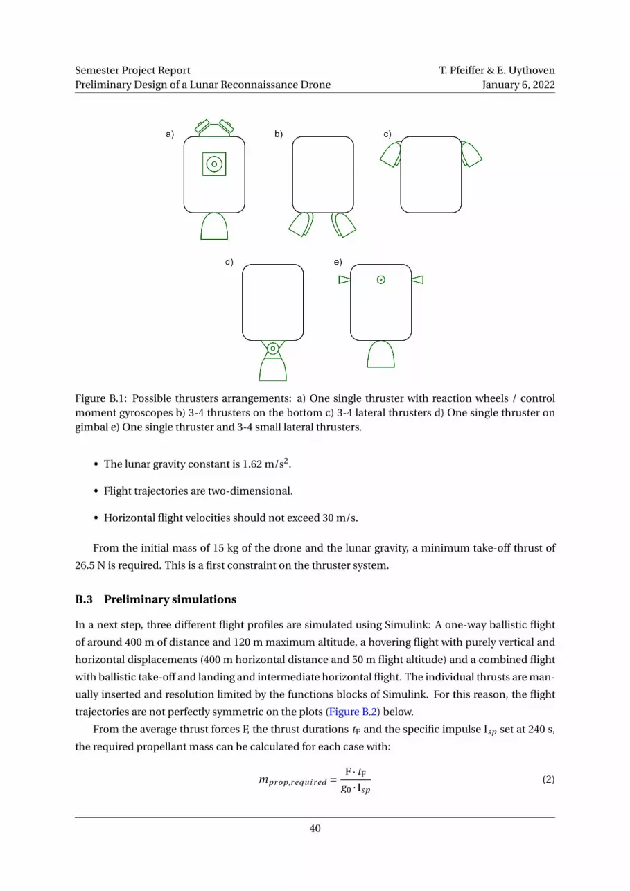
Semester Project ReportPreliminary Design of a Lunar Reconnaissance Drone
T. Pfeiffer & E. UythovenJanuary 6, 2022
Figure B.1: Possible thrusters arrangements: a) One single thruster with reaction wheels / controlmoment gyroscopes b) 3-4 thrusters on the bottom c) 3-4 lateral thrusters d) One single thruster ongimbal e) One single thruster and 3-4 small lateral thrusters.
• The lunar gravity constant is 1.62 m/s2.
• Flight trajectories are two-dimensional.
• Horizontal flight velocities should not exceed 30 m/s.
From the initial mass of 15 kg of the drone and the lunar gravity, a minimum take-off thrust of
26.5 N is required. This is a first constraint on the thruster system.
B.3 Preliminary simulations
In a next step, three different flight profiles are simulated using Simulink: A one-way ballistic flight
of around 400 m of distance and 120 m maximum altitude, a hovering flight with purely vertical and
horizontal displacements (400 m horizontal distance and 50 m flight altitude) and a combined flight
with ballistic take-off and landing and intermediate horizontal flight. The individual thrusts are man-
ually inserted and resolution limited by the functions blocks of Simulink. For this reason, the flight
trajectories are not perfectly symmetric on the plots (Figure B.2) below.
From the average thrust forces F, the thrust durations tF and the specific impulse Isp set at 240 s,
the required propellant mass can be calculated for each case with:
mpr op,r equi r ed = F · tF
g0 · Isp(2)
40
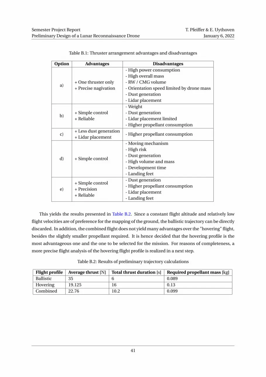
Semester Project ReportPreliminary Design of a Lunar Reconnaissance Drone
T. Pfeiffer & E. UythovenJanuary 6, 2022
Table B.1: Thruster arrangement advantages and disadvantages
Option Advantages Disadvantages
a)+ One thruster only+ Precise nagivation
- High power consumption- High overall mass- RW / CMG volume- Orientation speed limited by drone mass- Dust generation- Lidar placement
b)+ Simple control+ Reliable
- Weight- Dust generation- Lidar placement limited- Higher propellant consumption
c)+ Less dust generation+ Lidar placement
- Higher propellant consumption
d) + Simple control
- Moving mechanism- High risk- Dust generation- High volume and mass- Development time- Landing feet
e)+ Simple control+ Precision+ Reliable
- Dust generation- Higher propellant consumption- Lidar placement- Landing feet
This yields the results presented in Table B.2. Since a constant flight altitude and relatively low
flight velocities are of preference for the mapping of the ground, the ballistic trajectory can be directly
discarded. In addition, the combined flight does not yield many advantages over the "hovering" flight,
besides the slightly smaller propellant required. It is hence decided that the hovering profile is the
most advantageous one and the one to be selected for the mission. For reasons of completeness, a
more precise flight analysis of the hovering flight profile is realized in a next step.
Table B.2: Results of preliminary trajectory calculations
Flight profile Average thrust [N] Total thrust duration [s] Required propellant mass [kg]Ballistic 35 6 0.089Hovering 19.125 16 0.13Combined 22.76 10.2 0.099
41

Semester Project ReportPreliminary Design of a Lunar Reconnaissance Drone
T. Pfeiffer & E. UythovenJanuary 6, 2022
Figure B.2: Three different flight profiles analyzed.
B.4 Detailed flight simulation
In this more realistic flight simulation (again realized in Simulink), a trajectory closer to the final
ConOps is analized: Vertical take-off thrust until the desired flight altitude, initial horizontal thrust
and hovering thrust for 400 m, horizontal thrust in opposite direction and hovering back the 400 m,
hovering thrust plus breaking thrust and finally descent thrust. This flight profile is simulated once
with simplified thrusters angled in horizontal and vertical directions, and once with four thrusters at
45 °. The results of these simulations are presented in table Table B.3.
Table B.3: Results of the more detailed simulation
Flight profileTotal impulse[Ns]
Required propellantmass [kg]
Hovering, horizontal& vertical thrusters
2151 0.089
Hovering, thrustersangled at 45 °
19.125 0.13
Two major aspects stand out from these results: Firstly, the total propellant required is signifi-
cantly higher in the more detailed calculations than in the preliminary ones. Secondly, the flight with
thrusters angled at 45 °logically requires more propellant than the simplified first one.
B.5 More detailed flight simulation
Finally a third even more detailed version of the flight simulation is realized, where each angled
thruster is individually simulated. The Simulink layout for this version is presented on Figure B.4
below.
On Figure B.3, the drone’s decrease in mass due to propellant consumption is presented. From an
initial mass of 15 kg, the drone returns with a final mass of around 14 kg, resulting in 1 kg of propellant
required for one flight of around 800 m of total horizontal flight distance and 50 m of ascent and
descent and total flight time of 65 s. For the rest of the mission, a factor of two is introduced in the
propellant required, resulting in a comfortable margin. Also, a horizontal flight distance of 1000 m is
considered, as thruster angles are not optimized and drone mass loss is not considered so far.
42

Semester Project ReportPreliminary Design of a Lunar Reconnaissance Drone
T. Pfeiffer & E. UythovenJanuary 6, 2022
Figure B.3: Drone mass decrease due to propellant consumption.
B.6 Propellant tank mass estimation
The calculations for the propellant tank is based on the estimating calculations proposed in the hand-
book by Larson et al [31]. The material selected is Titanium for its low coefficient of thermal expansion
and the shape of the tank is spherical. The assumptions and parameters used for these calculations
are:
• Propellant density (LMP-103S): 1240 kg/m3
• Titanium max. allowable stress: 825 Mpa
• Titanium density: 4400 kg/m3
• Max. expected operating pressure Pp : 2.4 MPa
• Perfect gas law is considered
• Conservation of energy is considered
Using a Factor of Safety (FoS) of two, a tank wall thickness of 0.21 mm is found. In the following,
a more realistic thickness of 1.5 mm is used instead. A propellant tank weight of 0.074 kg can be
calculated (including an additional 20% margin).
B.7 Pressurant mass and tank mass estimation
For the calculation of the pressurant mass and tank mass, the procedure proposed by Sutton et al. in
Rocket Propulsion Elements is followed using the following parameters:
• Ambient temperature of T0 = 275 K
43

Semester Project ReportPreliminary Design of a Lunar Reconnaissance Drone
T. Pfeiffer & E. UythovenJanuary 6, 2022
• Same propellant and tank material properties as in subsection B.6
• Ideal flow conditions and an adiabatic process are considered
• Initial storage pressure P0 = 14 MPa
• Final tank pressure Pp = 2.4 MPa
Two different pressurants are compared: Nitrogen and Helium. The results are shown in Table B.4.
The latter yields a lighter tank after calculations: 0.045 kg (20% margin included) of mass, with a wall
thickness of 0.6 mm and a FoS of two.
Table B.4: Pressurant comparison
Pressurant Nitrogen HeliumTank radius [m] 0.0673 0.0344Tank wall thickness [mm] 1 0.6Tank mass [kg] (incl. 20% margin) 0.338 0.045
B.8 Limitations
The simulations realized for this project yield several limitations, namely:
• The drone’s mass is considered to be constant at all time. In reality, this changes with the pro-
pellant consumption and must be included in future studies.
• The propellant consumption is based on simplified equations and do not consider any losses
or other details. The resulting values need therefor to be taken with caution. A more detailed
simulation using exact consumption parameters provided by the thruster manufacturer would
be the next step to do.
• The Simulink model is hard coded by hand and values visually adapted in order to obtain "re-
alistic" flight profiles. A more detailed and preciser model (implying longer calculation times)
is required for better estimation of the drone’s flight behaviour.
• For the propellant and pressurant tank calculations, a more in-depth approach is needed, as
some of the results do not appear to be reasonable (e.g. pressurant tank wall thickness of 0.6
mm). Also, available tank dimensions on the market need to be included in the study.
• The thruster angles are set at 45° in the simulations, resulting in significant thrust losses in the
horizontal direction. A optimal balance between thruster angle and dust generation has to be
found in the future.
Nevertheless, the results given by the different simulations provide a useful reference point, not least
since very pessimistic assumptions and worst-case values are used. In reality, less propellant con-
sumption can probably be expected.
44

Semester Project ReportPreliminary Design of a Lunar Reconnaissance Drone
T. Pfeiffer & E. UythovenJanuary 6, 2022
Figure B.4: Detailed flight profile simulation in Simulink.
45

Semester Project ReportPreliminary Design of a Lunar Reconnaissance Drone
T. Pfeiffer & E. UythovenJanuary 6, 2022
C Thermal analysis
The evolution of the drone’s temperature with respect to time is performed by calculating the heat
transfer rate and by using a discrete time step model.
C.1 Assumptions
The assumptions for this model are:
• The drone is thermally independent of the rover (during the flight).
• The drone has a uniform temperature.
• The drone has a mass of m = 15 kg and an average heat capacity of cp = 900 J/K (mix of common
spacecraft materials).
• The drone’s initial temperature is supposed to be T = 5 °C.
• The drone’s surface is approximated as a cylinder of height h = 0.4 m and radius r = 0.25 m. It
has a surface area of A = 1.021 m2.
• Heat is only transferred to the environment by radiation.
• All the incoming an internally generated heat is considered as a single heat source term Qg en
[W]. This heat is produced by:
– Exposure to sunlight
– Joule heating of the electronic components1.
– Heating due to the thrusters firing.
• The background black body radiation is estimated at to be emitted at T∞ = 4 K, which is equal
to the black body temperature of deep space.
• The drone is considered as a grey body with its emissivity and absorptivity being equal and
independent of the wave length: ϵλ = ϵ= α= αλ.
C.2 Calculations
The transferred by radiation Qr ad [W] is given by:
Qr ad = Qabs − Qemi (3)
with Qemi [W] and Qabs [W] the emitted and absorbed heat respectively, which are equal to:
Qemi =−σ ·ϵ ·A ·T4 (4)
Qabs =σ ·ϵ ·A ·T4∞ (5)
where σ is the Stephan-Boltzmann constant. The temperature difference dT [K] between each time
step dt [s] is then given by:
1Approximately equal to the total electric power of the drone.
46
Semester Project ReportPreliminary Design of a Lunar Reconnaissance Drone
T. Pfeiffer & E. UythovenJanuary 6, 2022
dT = Qr ad + Qg en
m · cp·d t (6)
C.3 Temperature change results
The temperature change with respect to time, thermal source power and emissivity/absorptivity can
be seen in Figure C.1. A detailed time evolution for Qg en = 400 W and ϵ = α = 0.8, which is repre-
sentative of white paint, is shown in Figure C.2. The temperature of the drone after a very long time
(equilibrium temperature) is shown in Figure C.3.
These results clearly show that without installing radiators, the generated heat is not well evacu-
ated. To avoid this added complexity, the internal heat source due to the electric power consumption
and due to the thrusters firing should be limited to around 500 W. The surface finish (coatings and
paints) can be chosen accordingly to limit the temperature change during a mission. If the drone
should be able to function in the sunlight, a surface with a high ratio of emissivity over absorptivity
ϵ/α should be chosen.
It is also important to note that if the drone is not heated, its temperature will drop rapidly as seen
in Figure C.4. The drone should therefore rapidly be protected under an insulating cover with low
emissivity when not in use.
C.4 Model limitations
The thermal evolution model used here presents multiple limitations which should be studied in
future developments. Ideas of further studies are listed here:
• Modeling the temperature distribution in the drone with local hot and cold spots for different
scenarios.
• Effect of the sunlight in more detail:
– Illumination on one side of the drone only.
– Sunlight for only a part of the flight / of the missions.
• Optimizing the surface coating for emissivity ϵ and absorptivity α separately, as well as their
ratio.
47

Semester Project ReportPreliminary Design of a Lunar Reconnaissance Drone
T. Pfeiffer & E. UythovenJanuary 6, 2022
(a) t = 300 s. (b) t = 600 s.
(c) t = 900 s.
Figure C.1: Drone temperature change ∆T [K] for various elapsed times t with respect to the thermalsource power Qg en and the emissivity/absorbtivity ϵ= α.
Figure C.2: Evolution of the drone temperature T with respect to time t for Qg en = 500 W and ϵ= α=0.8.
48

Semester Project ReportPreliminary Design of a Lunar Reconnaissance Drone
T. Pfeiffer & E. UythovenJanuary 6, 2022
Figure C.3: Drone equilibrium temperature T∞ with respect to the thermal source power Qg en andthe emissivity/absorbtivity ϵ= α.
Figure C.4: Drop of the drone temperature T with respect to time t , when the thermal source poweris zero.
49

Semester Project ReportPreliminary Design of a Lunar Reconnaissance Drone
T. Pfeiffer & E. UythovenJanuary 6, 2022
D Power calculations
With a preliminary power consumption Pe estimated at 429 W (see 8.2.2) and a flight or operational
time top of estimated 10 minutes, the required battery capacity Cr can be calculated:
Cr =Pe · top
60 ·DoD ·N ·n= 55.9Wh = 2 Ah (7)
for a bus voltage of 28 V, where DoD is the Depth-of-Discharge of 0.2, N is the selected amount of
batteries (eight) and n is the battery-to-load transmission efficiency set at 0.8 [31]. The amount of
batteries can be determined from the bus voltage to be used for a given battery capacity:
N =⌈
Ubus
Cr
⌉(8)
The light-weight MP 144350 xlr Rechargeable Li-ion cells by Saft (Figure D.1) are suitable for this mis-
sion and have the following specifications (Table D.1):
Table D.1: MP 144350 xlr Rechargeable Li-ion cell specifications [35]
Battery Saft MP 144350 xlrForm factor PrismaticNominal voltage 3.65 VNominal capacity 2.6 AhMax. cont. discharge current 5.0 AMax. pulse discharge rate 10.0 ACycle life 1100Typical weight 66 gDischarge temp. range -35 to 60 °CCharge temp. range -30 to 60 °C
With the selected batteries by Saft, a total battery mass of 0.8 kg and a total capacity of 20.8 Ah is
calculated, resulting in a theoretical operational (flight) time of 13 minutes.
E Risk Analysis
A preliminary Failure Mode and Effects Analysis (FMEA) is presented in table Table E.1. Note that this
analysis needs to be revisited and updated while developing and planning the mission. The version
presented here may be incomplete and requires further elaboration in the future.
50
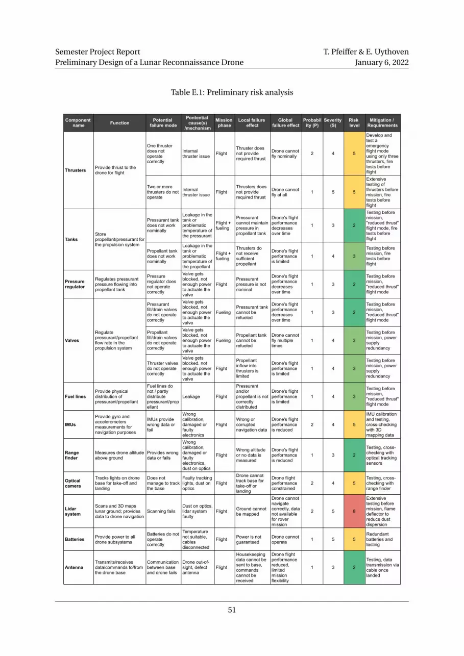
Semester Project ReportPreliminary Design of a Lunar Reconnaissance Drone
T. Pfeiffer & E. UythovenJanuary 6, 2022
Table E.1: Preliminary risk analysis
Component name Function Potential
failure modePontential cause(s)
/mechanism
Mission phase
Local failure effect
Global failure effect
Probability (P)
Severity (S)
Risk level
Mitigation / Requirements
Thrusters Provide thrust to the drone for flight
One thruster does not operate correctly
Internal thruster issue Flight
Thruster does not provide required thrust
Drone cannot fly nominally 2 4 5
Develop and test a emergency flight mode using only three thrusters, fire tests before flight
Two or more thrusters do not operate
Internal thruster issue Flight
Thrusters does not provide required thrust
Drone cannot fly at all 1 5 5
Extensive testing of thrusters before mission, fire tests before flight
TanksStore propellant/pressurant for the propulsion system
Pressurant tank does not work nominally
Leakage in the tank or problematic temperature of the pressurant
Flight + fueling
Pressurant cannot maintain pressure in propellant tank
Drone's flight performance decreases over time
1 3 2
Testing before mission, "reduced thrust" flight mode, fire tests before flight
Propellant tank does not work nominally
Leakage in the tank or problematic temperature of the propellant
Flight + fueling
Thrusters do not receive sufficient propellant
Drone's flight performance is limited
1 4 3
Testing before mission, fire tests before flight
Pressure regulator
Regulates pressurant pressure flowing into propellant tank
Pressure regulator does not operate correctly
Valve gets blocked, not enough power to actuate the valve
FlightPressurant pressure is not nominal
Drone's flight performance decreases over time
1 3 2
Testing before mission, "reduced thrust" flight mode
Valves
Regulate pressurant/propellant flow rate in the propulsion system
Pressurant fill/drain valves do not operate correctly
Valve gets blocked, not enough power to actuate the valve
FuelingPressurant tank cannot be refueled
Drone's flight performance decreases over time
1 3 2
Testing before mission, "reduced thrust" flight mode
Propellant fill/drain valves do not operate correctly
Valve gets blocked, not enough power to actuate the valve
FuelingPropellant tank cannot be refueled
Drone cannot fly multiple times
1 4 3
Testing before mission, power supply redundancy
Thruster valves do not operate correctly
Valve gets blocked, not enough power to actuate the valve
Flight
Propellant inflow into thrusters is limited
Drone's flight performance is limited
1 4 3
Testing before mission, power supply redundancy
Fuel linesProvide physical distribution of pressurant/propellant
Fuel lines do not / partly distribute pressurant/propellant
Leakage Flight
Pressurant and/or propellant is not correctly distributed
Drone's flight performance is limited
1 4 3
Testing before mission, "reduced thrust" flight mode
IMUs
Provide gyro and accelerometers measurements for navigation purposes
IMUs provide wrong data or fail
Wrong calibration, damaged or faulty electronics
FlightWrong or corrupted navigation data
Drone's flight performance is reduced
2 4 5
IMU calibration and testing, cross-checking with 3D mapping data
Range finder
Measures drone altitude above ground
Provides wrong data or fails
Wrong calibration, damaged or faulty electronics, dust on optics
FlightWrong altitude or no data is measured
Drone's flight performance is reduced
1 3 2
Testing, cross-checking with optical tracking sensors
Optical camera
Tracks lights on drone base for take-off and landing
Does not manage to track the base
Faulty tracking lights, dust on optics
Flight
Drone cannot track base for take-off or landing
Drone flight performance constrained
2 4 5Testing, cross-checking with range finder
Lidar system
Scans and 3D maps lunar ground; provides data to drone navigation
Scanning failsDust on optics, lidar system faulty
Flight Ground cannot be mapped
Drone cannot navigate correctly, data not available for rover mission
2 5 8
Extensive testing before mission, flame deflector to reduce dust dispersion
Batteries Provide power to all drone subsystems
Batteries do not operate correctly
Temperature not suitable, cables disconnected
Flight Power is not guaranteed
Drone cannot operate 1 5 5
Redundant batteries and testing
AntennaTransmits/receives data/commands to/from the drone base
Communication between base and drone fails
Drone out-of-sight, defect antenna
Flight
Housekeeping data cannot be sent to base, commands cannot be received
Drone flight performance reduced, limited mission flexibility
1 3 2
Testing, data transmission via cable once landed
51
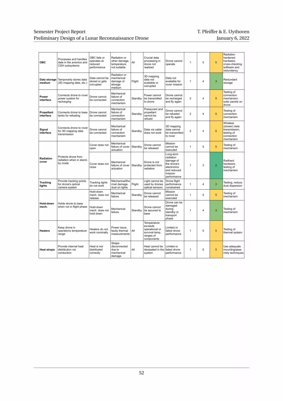
OBCProcesses and handles data in the avionics and CDH subsystems
OBC fails or operates at reduced performance
Radiation or other damage, temperature not suitable
All
Crucial data processing in drone not realized
Drone cannot operate 1 5 5
Radiation hardened hardware, cross-checking software and redundancy
Data storage medium
Temporarily stores data (3D mapping data, etc.)
Data cannot be stored or gets corrupted
Radiation or mechanical damage of storage medium
Flight
3D mapping data not available or corrupted
Data not available for rover mission
1 4 3 Redundant storage
Power interface
Connects drone to rover power system for recharging
Drone cannot be connected
Mechanical failure of connection mechanism
StandbyPower cannot be transmitted to drone
Drone cannot be recharged and fly again
2 4 5
Testing of connection mechanism, solar panels on drone
Propellant interface
Connects drone to base tanks for refueling
Drone cannot be connected
Mechanical failure of connection mechanism
Standby
Pressurant and propellant cannot be refueld
Drone cannot be refueled and fly again
2 4 5Testing of connection mechanism
Signal interface
Connects drone to rover for 3D mapping data transmission
Drone cannot be connected
Mechanical failure of connection mechanism
Standby Data via cable does not work
3D mapping data cannot be transmitted to rover
2 4 5
Wireless (slower) data transmission, testing of connection mechanism
Radiation cover
Protects drone from radiation when in stand-by mode
Cover does not open
Mechanical failure of cover actuation
Standby Drone cannot be released
Mission cannot be executed
1 5 5 Testing of mechanism
Cover does not close
Mechanical failure of cover actuation
StandbyDrone is not protected from radiation
Long-term radiation damage of the drone's electronics and reduced mission performance
1 3 2
Radhard hardware, testing of mechanism
Tracking lights
Provide tracking points for drone's optical camera system
Tracking lights do not work
Mechanical/thermal damage, dust on lights
FlightLight cannot be used by drones optical sensors
Drone flight performance constrained
1 4 3 Testing, reduce dust dispersion
Hold-down mech.
Holds drone to base when not in flight phase
Hold-down mech. does not release
Mechanical failure Standby Drone cannot
be released
Mission cannot be executed
1 5 5 Testing of mechanism
Hold-down mech. does not hold down
Mechanical failure Standby
Drone cannot be secured to base
Drone can be damaged during standby or transport phase
1 4 3 Testing of mechanism
HeatersKeep drone in operations temperature range
Heaters do not work nominally
Power issue, faulty thermal measurements
All
Temperature exceeds operational or survival temp. ranges of components
Limited or failed drone performance
1 5 5 Testing of thermal system
Heat strapsProvide internal heat distribution via conduction
Heat is not distributed correctly
Straps disconnected due to mechanical damage
AllHeat cannot be dissipated in the system
Limited or failed drone performance
1 5 5Use adequate mounting/assembly techniques
Semester Project ReportPreliminary Design of a Lunar Reconnaissance Drone
T. Pfeiffer & E. UythovenJanuary 6, 2022
52
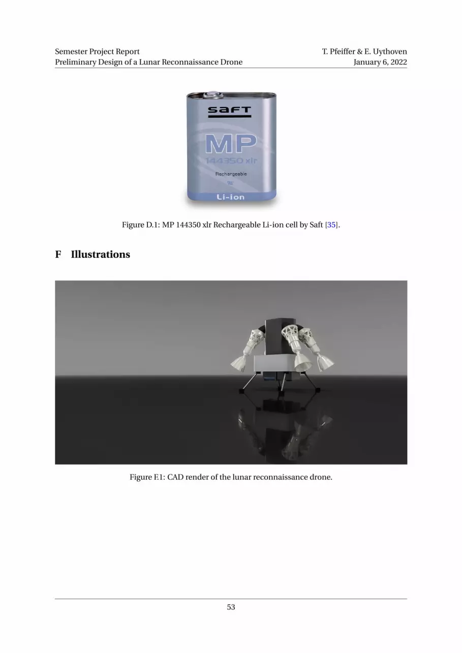
Semester Project ReportPreliminary Design of a Lunar Reconnaissance Drone
T. Pfeiffer & E. UythovenJanuary 6, 2022
Figure D.1: MP 144350 xlr Rechargeable Li-ion cell by Saft [35].
F Illustrations
Figure F.1: CAD render of the lunar reconnaissance drone.
53

Semester Project ReportPreliminary Design of a Lunar Reconnaissance Drone
T. Pfeiffer & E. UythovenJanuary 6, 2022
Figure F.2: Illustration of the drone (Original image: NASA).
Figure F.3: Illustration of the drone (Original image: NASA).
54