svalbird - a sustainable, multi-functional fixed-wing drone
TRANSCRIPT

svalbird - A sustainable, multi-functional fixed-wing droneresearch platform
Brandon J.A. van Schaik1
Under supervision of:dr.ir. H.C.J. Mulders1 & prof. F. Sigernes2,3
Eindhoven University of Technology (TU/e)1The University Centre in Svalbard (UNIS)2
Kjell Henriksen Observatory (KHO)3
Correspondence concerning this work can be addressed to:[email protected] (Brandon van Schaik)
December 20, 2021
Abstract
This work explores the potential of a Do-It-Yourself fixed-wing drone research platform to studythe aurora borealis at the Kjell Henriksen Observatory, located near Longyearbyen, Norway, onthe archipelago of Svalbard (78 º N 15 º E). This method is compared to the state-of-the-art inatmospheric experiments: the weather balloon, and several other drone platforms. In this worka fixed-wing drone was designed and constructed and successfully tested during the Svalbard’spolar night. With this it can be concluded that there is indeed great potential in these UnmannedAerial Vehicle campaigns on Svalbard for both auroral, as other types of empirical sciences thatrequire a camera to face to the air or the ground. This work emphasizes the value of off-the-shelfdrone solutions on the market currently, as they are well equipped for the technological problemsat hand, though the Do-It-Yourself fixed-wing drone platform can be developed continuously as alow cost option.

Preface
The work that I have done over the past thirteen weeks on Svalbard, and the months before that inanticipation of this internship, makes me very proud. The way that the University Centre in Svalbardprovides students with such freedom in their research, and encouraging challenges that are merelydreams to many students, is really inspiring. I first realized that I wanted to do internship abroadin Svalbard in January 2020, after seeing a documentary on arctic research. The fact that these re-searchers were able to combine their passion for being outdoors and challenging yourself physicallyin harsh environments, whilst also challenging the mind in their research gave me intense motivationto achieve this myself. What I did not expect was that my extremely ambitious project would bewelcomed with such open arms.
In my short time here on Svalbard, I have learned a lot about finances, electronics, drones, andthe environment of Svalbard. A key factor to making this internship so interesting and enjoyablewas the fact that there were so many things that I had never done before. I was submerged in allkinds of challenges that I knew nothing about, figuring these things out on my own was difficult andsometimes frustrating in the moment, but so much more rewarding after I had figured out the solu-tion. This does not mean that I had any lack in support from my supervisors, Fred and Hjalmar, andmany other researchers and technicians such as Mikko, Marcos, Marius and Stein. But they under-stood that I wanted to be challenged in this manner, and gave me the space to figure it out on my own.
The experience of living and studying in Svalbard, is something that has changed the way I wantto continue my career as a researcher and entrepreneur. I had forgotten how enjoyable these hardwareprojects are. Something I hadn’t done since I went to high school. Furthermore, the attitude of UNIStowards fieldwork has opened my mind that it is possible to combine my love for the outdoors withresearch. My favorite fieldwork trips must be the ones with their destination at the Kjell HenriksenObservatory. Using the bandwagon from Mine 7, to reach the deserted mountainside of Breinosa inthe pitch black polar night whilst we see the dancing green strands of Aurora Borealis above us, istruly the best commuting experience, I think anyone can have.Helping out the Alaska Fairbanks, and Clemson University researchers with their C-REX-2A rocketlaunch was among those trips to the KHO. Though, I wasn’t able to provide any in-depth supportwith the data and science behind the project. It was a pleasure to help Lamar with the camera setupon the deck during the snowstorm, and seeing the successful release of all 20 ampules from the rocketpayload during the polar cusp event of December 1st, 2021.
In retrospect, the only thing that I will not miss from Svalbard is the infuriatingly long deliverytimes of packages. The amount of time that I spent refreshing tracking orders on my laptop and phoneis nearly worth 1 ECTS by itself! The importance of redundant components for any hardware projecthas come to my attention in the most harsh possible way. I will never take transport of goods forgranted on the mainland anymore. I think if these problems had not occurred, I would have been ableto fly svalbird-1 as early as October, though I think that all the troubleshooting has given me theopportunity to really take a deep dive in all the technologies that are under the surface. It has givenme a more thorough understanding of the whole system itself.
It has been a great pleasure, and I feel very lucky to have been able to perform my internship onSvalbard throughout the constant uncertainty of the pandemic. Now on my return back to the Nether-lands, I will surely reminisce about my adventures and achievements on the beautiful archipelago ofSvalbard.
i

Contents
Preface i
List of Abbreviations iv
List of Figures vi
List of Tables vii
1 Introduction 11.1 The Kjell Henriksen Observatory . . . . . . . . . . . . . . . . . . . . . . . . . . . . . . . 11.2 Studying the aurora borealis . . . . . . . . . . . . . . . . . . . . . . . . . . . . . . . . . . 21.3 Weather balloons . . . . . . . . . . . . . . . . . . . . . . . . . . . . . . . . . . . . . . . . 21.4 The multi-functional research platform: svalbird . . . . . . . . . . . . . . . . . . . . . 31.5 Vision of svalbird . . . . . . . . . . . . . . . . . . . . . . . . . . . . . . . . . . . . . . . 31.6 Research question . . . . . . . . . . . . . . . . . . . . . . . . . . . . . . . . . . . . . . . . 31.7 Financial support . . . . . . . . . . . . . . . . . . . . . . . . . . . . . . . . . . . . . . . . 41.8 Involved organizations . . . . . . . . . . . . . . . . . . . . . . . . . . . . . . . . . . . . . 41.9 Structure of this work . . . . . . . . . . . . . . . . . . . . . . . . . . . . . . . . . . . . . 5
2 Background 62.1 Weather balloons . . . . . . . . . . . . . . . . . . . . . . . . . . . . . . . . . . . . . . . . 6
2.1.1 Launch, ascent and return . . . . . . . . . . . . . . . . . . . . . . . . . . . . . . . 62.2 The requirements for svalbird . . . . . . . . . . . . . . . . . . . . . . . . . . . . . . . . 72.3 Principles of Unmanned Aerial Vehicles . . . . . . . . . . . . . . . . . . . . . . . . . . . 8
2.3.1 Quad copter drones and Vertical Take-off and Landing . . . . . . . . . . . . . . . 82.3.2 Fixed-wing drones and gliding . . . . . . . . . . . . . . . . . . . . . . . . . . . . 9
2.4 Limitations of Unmanned Aerial Vehicles . . . . . . . . . . . . . . . . . . . . . . . . . . 92.4.1 Civil drone categories . . . . . . . . . . . . . . . . . . . . . . . . . . . . . . . . . 92.4.2 Svalbard environment and surroundings . . . . . . . . . . . . . . . . . . . . . . . 10
3 Procedures 113.1 Construction of svalbird-1 . . . . . . . . . . . . . . . . . . . . . . . . . . . . . . . . . . 11
3.1.1 V-tail winglets . . . . . . . . . . . . . . . . . . . . . . . . . . . . . . . . . . . . . 123.1.2 V-tail connectors . . . . . . . . . . . . . . . . . . . . . . . . . . . . . . . . . . . . 123.1.3 Wings . . . . . . . . . . . . . . . . . . . . . . . . . . . . . . . . . . . . . . . . . . 133.1.4 Wing connectors . . . . . . . . . . . . . . . . . . . . . . . . . . . . . . . . . . . . 133.1.5 Main body . . . . . . . . . . . . . . . . . . . . . . . . . . . . . . . . . . . . . . . 143.1.6 Electronics and flight computer . . . . . . . . . . . . . . . . . . . . . . . . . . . . 153.1.7 Radio . . . . . . . . . . . . . . . . . . . . . . . . . . . . . . . . . . . . . . . . . . 16
3.2 Weather balloon experimental setup . . . . . . . . . . . . . . . . . . . . . . . . . . . . . 173.2.1 Balloon . . . . . . . . . . . . . . . . . . . . . . . . . . . . . . . . . . . . . . . . . 173.2.2 Parachute . . . . . . . . . . . . . . . . . . . . . . . . . . . . . . . . . . . . . . . . 173.2.3 Tracking device . . . . . . . . . . . . . . . . . . . . . . . . . . . . . . . . . . . . . 173.2.4 Payload . . . . . . . . . . . . . . . . . . . . . . . . . . . . . . . . . . . . . . . . . 183.2.5 Bill of materials . . . . . . . . . . . . . . . . . . . . . . . . . . . . . . . . . . . . 18
4 Results and Discussion 194.1 Pre-flight checks for svalbird-1 . . . . . . . . . . . . . . . . . . . . . . . . . . . . . . . 19
4.1.1 Flight computer configuration . . . . . . . . . . . . . . . . . . . . . . . . . . . . . 194.1.2 GPS lock . . . . . . . . . . . . . . . . . . . . . . . . . . . . . . . . . . . . . . . . 19

4.1.3 Arming the drone . . . . . . . . . . . . . . . . . . . . . . . . . . . . . . . . . . . 194.1.4 Servo calibration . . . . . . . . . . . . . . . . . . . . . . . . . . . . . . . . . . . . 204.1.5 ESC calibration . . . . . . . . . . . . . . . . . . . . . . . . . . . . . . . . . . . . . 204.1.6 Ground tests . . . . . . . . . . . . . . . . . . . . . . . . . . . . . . . . . . . . . . 204.1.7 Troubleshooting of svalbird-1 . . . . . . . . . . . . . . . . . . . . . . . . . . . . 21
4.2 Aurora borealis photography experiment with a weather balloon . . . . . . . . . . . . . 224.2.1 Preparation . . . . . . . . . . . . . . . . . . . . . . . . . . . . . . . . . . . . . . . 224.2.2 Flight . . . . . . . . . . . . . . . . . . . . . . . . . . . . . . . . . . . . . . . . . . 234.2.3 Points of improvement . . . . . . . . . . . . . . . . . . . . . . . . . . . . . . . . . 23
4.3 Aurora borealis photography experiment with svalbird-1 . . . . . . . . . . . . . . . . . 244.3.1 Preparation . . . . . . . . . . . . . . . . . . . . . . . . . . . . . . . . . . . . . . . 244.3.2 First flight . . . . . . . . . . . . . . . . . . . . . . . . . . . . . . . . . . . . . . . 244.3.3 Second flight . . . . . . . . . . . . . . . . . . . . . . . . . . . . . . . . . . . . . . 244.3.4 Reflection on svalbird requirements . . . . . . . . . . . . . . . . . . . . . . . . . 25
5 Multi-Criteria Analysis 265.1 Methodology . . . . . . . . . . . . . . . . . . . . . . . . . . . . . . . . . . . . . . . . . . 26
5.1.1 Potential solutions of the MCA . . . . . . . . . . . . . . . . . . . . . . . . . . . . 275.1.2 Criteria of the MCA . . . . . . . . . . . . . . . . . . . . . . . . . . . . . . . . . . 28
5.2 Results . . . . . . . . . . . . . . . . . . . . . . . . . . . . . . . . . . . . . . . . . . . . . . 295.2.1 Stakeholder interview . . . . . . . . . . . . . . . . . . . . . . . . . . . . . . . . . 295.2.2 Criteria weighting . . . . . . . . . . . . . . . . . . . . . . . . . . . . . . . . . . . 305.2.3 Multi-Criteria Analysis Results . . . . . . . . . . . . . . . . . . . . . . . . . . . . 31
6 Conclusion 34
7 Recommendations 35
References 36
Appendix 40
A Financial support: context and conditions 40
B Civil drone certificates for the open category 41
C 3D prints for svalbird-1 43
D svalbird project proposal 45
E Pre-flight checklist 55
F Weather balloon launch application: related documents 57F.1 Letter to Norwegian air authority . . . . . . . . . . . . . . . . . . . . . . . . . . . . . . . 57F.2 Norwegain air authority response . . . . . . . . . . . . . . . . . . . . . . . . . . . . . . . 58F.3 Weather balloon proposal . . . . . . . . . . . . . . . . . . . . . . . . . . . . . . . . . . . 59

List of Abbreviations
AMSL Above Mean Sea Level. 2, 7, 11, 24, 25, 29, 32
APRS Automated Packet Reporting System. 17, 18, 23
AUX Auxiliary. 15
CAN Controller Area Network. 16
CAPEX Capital Expenditures. 28
DIY Do-It-Yourself. 1, 11, 27, 28, 31–34
EASA European Union Aviation Safety Agency. vi, 9, 10, 15, 24, 25, 27, 28, 35, 41
ESC Electronic Speed Controller. iii, vi, 13, 20–22, 31, 35, 55
ESTEC European Space Research and Technology Centre. 40
GPS Global Positioning System. ii, 15, 19
HSE Health, Safety, and Environment. 10
HSI Hyper Spectral Imager. 3, 40
I2C Inter-Integrated Circuit. 15
kgCO2eq. kilograms of CO2 equivalent emissions. 28, 31
KHO Kjell Henriksen Observatory. ii, vi, 1–4, 6, 7, 11, 17, 18, 22, 23, 25, 27, 34, 35, 40
LED Light Emitting Diode. 19
MCA Multi-Criteria Analysis. iii, vi, 5, 11, 26–29, 31
NLR Netherlands Aerospace Centre. 4, 5, 40
OPEX Operational Expenditures. 28
Pixhawk Pixhawk flight controller. vi, 15, 16, 19, 25, 34, 55
PWM Pulse Width Modulation. 15
RC Remote Control. 11, 15, 16
SBEC Switching Battery Elimination Circuit. 14, 15
SBUS Serial Bus. 15
SSID Secondary System Identification. 17, 18
iv

TU/e Eindhoven University of Technology. 1, 4, 40
UAV Unmanned Aerial Vehicle. ii, 1, 3, 4, 6, 8–10, 20, 24, 26–28, 34, 41, 56
UNIS The University Centre in Svalbard. 1, 3, 4, 10, 11, 21, 27, 32, 34, 35, 40
USB Universal Serial Bus. 17, 19
VAT Value Added Tax. 4
VTOL Vertical Take-off and Landing. ii, 8, 9, 27, 31, 32, 34
WiFi Wireless Fidelity. 16, 25
v

List of Figures
1 Magnetic field lines of a magnet (left) [1], and the magnetic field lines of the earth withthe sun on the left side, skewing the magnetic field to a teardrop like shape (right) [2, 3]. 1
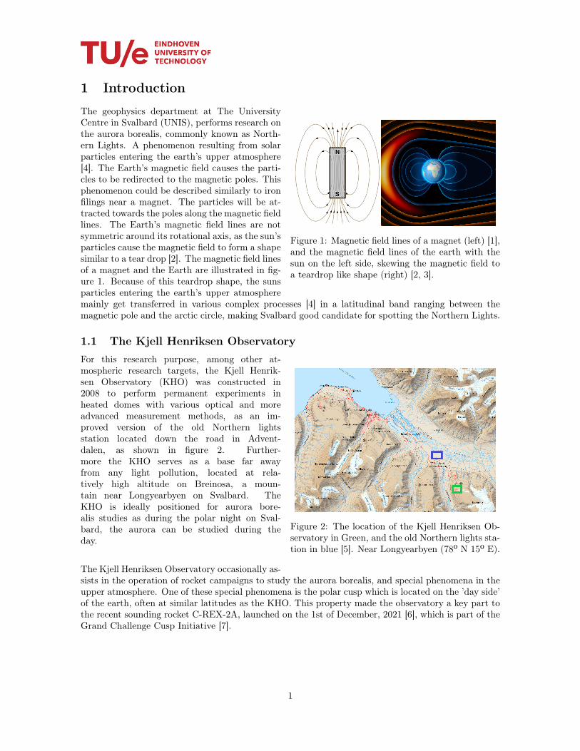
2 The location of the Kjell Henriksen Observatory in Green, and the old Northern lightsstation in blue [5]. Near Longyearbyen (78º N 15º E). . . . . . . . . . . . . . . . . . . . 1
3 The path of five weather balloon launched near Ny-Ålesund in May, 2011[10]. . . . . . . 24 (a) Standard atmosphere temperature profile for altitudes up to 32 km. The sharp
change at 11 km marks the boundary between the troposphere (the atmospheric layernearest to the Earth’s surface) and the stratosphere. (b) Air density as a function ofaltitude, for the temperature profile of (a). Also shown is the altitude dependence ofthe weather balloon aerodynamic drag coefficient, inferred from measurement data. (c)Balloon radius as a function of altitude. (d) Ascent speed for a 1-m radius balloon filledwith hydrogen (upper curve) and helium (lower curve). Note the near-constant rateabove 7 km. Sourced from M. Denny, 2016 in figure 1 [20]. . . . . . . . . . . . . . . . . . 7
5 Quadcopter schematic: (a) The structure of a quadcopter (b) Description of Pitch, Roll,and Yaw angles. Sourced from Kuantama et al., 2017 in figure 1 [24]. . . . . . . . . . . . 8
6 Schematic of forces on a wingfoil surface, from Nancy Hall at NASA.gov [25]. . . . . . . . 97 The ’Believer’ fixed-wing drone model by MakeFlyEasy. . . . . . . . . . . . . . . . . . . 118 Schematic representation of the V-tail winglets. . . . . . . . . . . . . . . . . . . . . . . . 129 Schematic representation of the V-tail connectors. . . . . . . . . . . . . . . . . . . . . . 1210 Schematic representation of the wings. . . . . . . . . . . . . . . . . . . . . . . . . . . . . 1311 Schematic location of the wing connectors. . . . . . . . . . . . . . . . . . . . . . . . . . . 1312 Schematic representation of the main body. . . . . . . . . . . . . . . . . . . . . . . . . . 1413 Servo rail of the Pixhawk flight controller [33]. . . . . . . . . . . . . . . . . . . . . . . . 1514 The main board of the Pixhawk flight controller. . . . . . . . . . . . . . . . . . . . . . . 1515 The general communication structure of the RF Design RFD 900x TXMOD v2 setup [35]. 1616 Transmitter module modification to the Taranis Q X7 [35]. . . . . . . . . . . . . . . . . 1617 Schematic of the weather balloon experimental setup, to scale. . . . . . . . . . . . . . . 1718 The black-and-white night vision camera, RunCam OWL Plus . . . . . . . . . . . . . . 1819 Example of a USB to FDTI cable [47]. . . . . . . . . . . . . . . . . . . . . . . . . . . . . 2120 Crossfire radio communication setup. . . . . . . . . . . . . . . . . . . . . . . . . . . . . . 2121 ESC burn marks after the peak power test. . . . . . . . . . . . . . . . . . . . . . . . . . 2222 The most clear frame including aurora borealis of the weather balloon experiment. The
aurora strand can be seen on the right side of the picture, in a thin vertical strip. . . . . 2323 Overview of the MCA process . . . . . . . . . . . . . . . . . . . . . . . . . . . . . . . . . 2624 The author’s proof of graduation from the online theory exam of EASA open category
regulations for Civil drones. Received on September 24th, 2021. . . . . . . . . . . . . . . 4125 The author’s certificate of proficiency in all Open category regulations of Civil drone
activities. Received on September 24th, 2021. . . . . . . . . . . . . . . . . . . . . . . . . 4226 The camera mount used to fit the aurora camera between the two carbon spars in the
middle of teh drone fuselage. . . . . . . . . . . . . . . . . . . . . . . . . . . . . . . . . . 4327 The reinforcement cap for the top of the drone fuselage to fit the camera through and
reinforce its position. . . . . . . . . . . . . . . . . . . . . . . . . . . . . . . . . . . . . . . 4428 The reinforcement cap for the bottom of the drone fuselage to fit the antenna and protect
the external part of the antenna during impacts due to landing. . . . . . . . . . . . . . . 44
vi

List of Tables
1 Bill of materials for the weather balloon, including costs. . . . . . . . . . . . . . . . . . . 182 Multi-Criteria Analysis table for the potential solutions of svalbird. . . . . . . . . . . . 313 Complete list of invoices that have been declared to the project’s account within the
project budget. . . . . . . . . . . . . . . . . . . . . . . . . . . . . . . . . . . . . . . . . . 40
vii
1 Introduction
Figure 1: Magnetic field lines of a magnet (left) [1],and the magnetic field lines of the earth with thesun on the left side, skewing the magnetic field toa teardrop like shape (right) [2, 3].
The geophysics department at The UniversityCentre in Svalbard (UNIS), performs research onthe aurora borealis, commonly known as North-ern Lights. A phenomenon resulting from solarparticles entering the earth’s upper atmosphere[4]. The Earth’s magnetic field causes the parti-cles to be redirected to the magnetic poles. Thisphenomenon could be described similarly to ironfilings near a magnet. The particles will be at-tracted towards the poles along the magnetic fieldlines. The Earth’s magnetic field lines are notsymmetric around its rotational axis, as the sun’sparticles cause the magnetic field to form a shapesimilar to a tear drop [2]. The magnetic field linesof a magnet and the Earth are illustrated in fig-ure 1. Because of this teardrop shape, the sunsparticles entering the earth’s upper atmospheremainly get transferred in various complex processes [4] in a latitudinal band ranging between themagnetic pole and the arctic circle, making Svalbard good candidate for spotting the Northern Lights.
1.1 The Kjell Henriksen Observatory
Figure 2: The location of the Kjell Henriksen Ob-servatory in Green, and the old Northern lights sta-tion in blue [5]. Near Longyearbyen (78º N 15º E).
For this research purpose, among other at-mospheric research targets, the Kjell Henrik-sen Observatory (KHO) was constructed in2008 to perform permanent experiments inheated domes with various optical and moreadvanced measurement methods, as an im-proved version of the old Northern lightsstation located down the road in Advent-dalen, as shown in figure 2. Further-more the KHO serves as a base far awayfrom any light pollution, located at rela-tively high altitude on Breinosa, a moun-tain near Longyearbyen on Svalbard. TheKHO is ideally positioned for aurora bore-alis studies as during the polar night on Sval-bard, the aurora can be studied during theday.
The Kjell Henriksen Observatory occasionally as-sists in the operation of rocket campaigns to study the aurora borealis, and special phenomena in theupper atmosphere. One of these special phenomena is the polar cusp which is located on the ’day side’of the earth, often at similar latitudes as the KHO. This property made the observatory a key part tothe recent sounding rocket C-REX-2A, launched on the 1st of December, 2021 [6], which is part of theGrand Challenge Cusp Initiative [7].
1

1.2 Studying the aurora borealisThe aurora borealis is located in the upper atmosphere with the lowest aurora borealis activity startingfar above the operational range of aircraft. Studying the aurora has become a difficult occupation.Studying the aurora from the ground is only an option if there are little obstruction in the form ofclouds, and the sun, moon and the light pollution from nearby human activity does not shine toobrightly to reduce the signal to noise ratio. The former of which is within reach of innovation to avoidin the future.The importance of continually studying the aurora borealis is of importance to understand the causeof its appearance, and how the appearance of aurora borealis in a given location at any given time canbe predicted. The cloud layer on Svalbard is located between 1000 m Above Mean Sea Level (AMSL)and 3500 m AMSL [9, 8]. This altitude can be easily reached by weather balloons, and by attaching anight vision camera to the payload of such balloons, one can study the aurora borealis on cloudy daysfor several minutes, whereas normally it would be impossible to collect any data.
1.3 Weather balloons
Figure 3: The path of five weather balloon launchednear Ny-Ålesund in May, 2011[10].
Throughout all this atmospheric science thatis being performed, weather balloons are oftenlaunched on Svalbard due to its unique loca-tion [10]. This process of launching weather bal-loons for scientific purposes is often referred toas weather ballooning. Weather balloons are of-ten filled with Helium to generate buoyancy. Be-low the balloon, a small mass can be attachedcalled the payload. This payload consists of at-mospheric experiments such as cameras, hyperspectral imagers, temperature sensors, humiditysensors etc. The balloon rises through the atmo-sphere due to its buoyancy, while the radio sendsback the sensor data to a ground station. As theatmosphere thins, the balloon expands to equal-ize its pressure, and explodes at a maximum alti-tude by over-expansion, or by a popping mecha-nism operated by the research team [11].The pay-load then falls to the ground rapidly, however thefall is slowed down by a parachute.Though the weather balloons trajectory throughthe atmosphere is fully governed by the wind,valuable research data can be gathered duringthe flight. The path of these weather balloons are unpredictable and highly chaotic. As can be seenin figure 3. This makes payload recovery very difficult in most cases, and not financially beneficial ingeneral.Unfortunately, the weather balloons are single use, and since recovery of the balloon debris and payloadis often not performed, the costs of launching weather balloons is relatively large. Furthermore, thisdebris is detrimental to the environment of Svalbard and the oceans surrounding it. Making weatherballoons very undesirable from many perspectives.But as Svalbard is often cloud covered, the importance of an ‘eye above the cloud’ is essential to max-imize data collection of the upper atmosphere with optical instruments. Traditionally, these single-useweather balloons are used to study phenomena like the aurora borealis from the KHO, and many otherresearch sites on Svalbard [10], as there is a lack of a better alternative.
2

1.4 The multi-functional research platform: svalbirdApart from the polar night research, the light season time is used to study various other air- andground targets on the archipelago, using the similar camera setups as used on the weather balloon.In recent years, the Unmanned Aerial Vehicle (UAV) has become extremely popular for this typeof research, such as research on upper atmosphere research targets [12]. On Svalbard in particular,oceanography, glaciology, and marine biology are but a few research topics that are thoroughly studiedby The University Centre in Svalbard.
In this sense, a multi-functional research platform seems to be viable as a research tool for the KjellHenriksen Observatory, and various departments of UNIS. Ongoing work to test the Hyper SpectralImager (HSI) v4, developed by Moon Labs, includes not only gimbal stabilization during airbornecampaigns, but also calibration and data handling [13]. The HSI v4 instrument is a clear candidatefor this work during daylight conditions. For polar night conditions, the KHO has developed auroracamera setups for weather balloon launches, for both aurora borealis research aswell as for use duringrocket campaigns.
Combining this idea of using a drone platform for both ground and air based research targets with asimilar camera setup, a sustainable, and multi-functional drone research platform, called svalbird,was envisioned.The value proposition of svalbird is based on finances and ease of use, as airborne research equipmentis at higher risk and therefore are governed by strict regulations. With the multi-functional platformthe project partners (Chapter 1.8) aim to certify a single platform to perform the majority of theKHO and UNIS airborne research, which will then automatically conform with the safety protocols.Simplifying the research preparation significantly by reducing the bureaucratic load of certifying theirairborne research equipment.Previously, quad copter drones have been tested as an alternative for weather balloons for severalground based photographing campaigns, but due to their short range and high energy costs of carryingresearch equipment, a more suitable alternative has to be found [14].
A logical step for the next iteration of svalbird, is to step away from quad copter drones and moveforward toward fixed-wing drones as they have shown recent potential in high altitude and long rangemissions [15, 12].
1.5 Vision of svalbirdShort term vision statement - The short term vision of svalbird is to choose, develop and constructa first prototype for the sustainable, and multi-functional fixed-wing drone research platform, to testwithin the open regulations of drone operations of Svalbard. With the means of observing the auroraborealis as a proof-of-concept.Long term vision statement - On the long term, svalbird envisions to use the lessons learned fromthe short term vision’s goals to develop a sustainable and multi-functional fixed-wing drone researchplatform that can replace the disposable, expensive, and polluting method of weather balloon activitiesfor various air-, and ground-based targets including studying the aurora borealis above the cloud layer.This platform shall be capable and certified to fly beyond visual line of sight, above the cloud layer onSvalbard.
1.6 Research questionThis work aims to fulfill all goals encapsulated in the short term vision statement of svalbird. There-fore, this work firstly describes the safety and regulatory facets of Unmanned Aerial Vehicle flight,and operations in the arctic environment. Continued by the construction and testing of the fixed-wing drone. Comparing the collected data with weather balloon flight data to ultimately perform
3

a multi-criteria analysis of potential solutions for the multi-functional research platform. From this,several different drone types are tested versus weather balloons to conclude the main research question:
Is it technically, environmentally, and financially advantageous for the Kjell Henriksen Observatoryand The University Centre in Svalbard to replace the disposable, expensive, and polluting weatherballoons by drones for their airborne research projects with various air- and ground-based targets?
1.7 Financial supportThe author is honored in personally receiving the Netherlands Aerospace Centre’s trust in providinga budget of e2.000,−, excluding VAT, for enabling the international collaboration between the KjellHenriksen Observatory, The University Centre in Svalbard, and the Eindhoven University of Technol-ogy by finding a common ground to explore the capabilities of Unmanned Aerial Vehicles in researchapplications around the globe.The detailed description of the context of the financial support and it’s conditions, are described inAppendix A.
1.8 Involved organizationsProject partner – The University Centre in Svalbard (UNIS),Longyearbyen, Norway. The University Centre in Svalbard (UNIS) is theworld’s northernmost higher education institution, located in Longyearbyen at78º N. They provide research-based education for the next generation of Arc-tic experts in biology, geology, geophysics and technology. With this vision,UNIS aims to enable better solutions to geophysical surveying on Svalbardand throughout the polar regions [16].
Project partner – Kjell Henriksen Observatory (KHO),Longyearbyen, Norway. The Kjell Henriksen Observatory(KHO) is an optical observatory located at the archipelago Sval-bard 1000 km north of mainland Norway (78 º N 15 º E). It housesmore than 25 optical instruments as well as other non-optical in-struments, which are employed for research on the middle- andupper atmosphere. The KHO is a world leader in polar surveying and aims to continue innovatingwith this project [17].
International research partner – Eindhoven University of Technol-ogy (TU/e), Eindhoven, the Netherlands. TU/e is a leading interna-tional university specialized in engineering science and technology and aims tocontribute to solving the major issues in the field of sustainability. The TU/ewants to be among the most sustainable universities in the Netherlands andhas opted for an integral approach. The TU/e has collaborated extensivelywith the project partners via internships and graduation exchanges. This work has been facilitated inthis exact manner [18].
4

Financial supporter – Netherlands Aerospace Centre (NLR),Amsterdam, the Netherlands. The challenges in the aviation industryare always larger than today. Solely by continuously connecting of profoundinsights in the customer’s needs with leading knowledge and research facili-ties, makes swift innovation possible. The Netherlands Aerospace Centre isthe connecting link between science, business, and government [19].
1.9 Structure of this workTo answer the research question, a Multi-Criteria Analysis is employed. For this purpose the weatherballoon and the svalbird research platform will be covered in-depth. To structure the work accord-ingly, these in-depth discussions will be covered in the following three chapters. Seperately in theMulti-Criteria Analysis section, the results from the in-depth research of these two research platformswill be used to conclude on the original research question.
5

2 Background
The conundrum of atmospheric experiments is clear. The weather balloon is currently the most viableoption to gather reliable data in many weather conditions. Since weather ballooning has been the state-of-the-art in such experiments for many decades, the process has been documented extremely well, andthe correct equipment and education to handle these experiments has been completely absorbed intothe research environment. Even though it is clear that weather ballooning is not a sustainable optionfor performing research, the loss of the payload has become the golden standard, because the ease-of-use is unmatched.
To drive the innovation in phasing out these disposable, expensive, and polluting weather balloons, onemust find an alternative that is at the very least equal in user experience and reliability whilst reducingthe financial and environmental impact. To this end, the first step is to define the requirements of theUAV with respect to a weather balloons and weather conditions, and the constraints of UAVs in thetarget research environment.
2.1 Weather balloonsWeather balloons consist of the balloon which is often filled with Helium gas, or Hydrogen, as thesegasses have a lower density than the surrounding air and therefore will generate a buoyant force. TheKHO uses a gas called ’Balloon Helium’. This gas is not as pure as the Helium gas used in chemicalapplications, but is rather of a lower quality to reduce costs. The lower quality implies that there is ahigher concentration of particles that are not Helium, which increases the density of the gas slightly.This is mainly a financial consideration as the performance is generally not changed noticeably.Connected between the opening of the balloon and the payload, is a tether with a tracking instrument.This tether seals the balloon closed and keeps the whole system together.
2.1.1 Launch, ascent and return
To launch a weather balloon the buoyant force of the Helium in the balloon must be greater thanthe total amount of gravitational force on the mass such that there is a net force upwards. Duringthe ascent, the balloon expands due to the decrease in atmospheric pressure, and the buoyant forceincreases. Since the expansion of the balloon is limited due to the plastic surface being extremely thin.This surface acts as a thin layer of surface tension increasing the pressure inside of the balloon. Theascent rate slowly levels out to a nominal ascent speed [20]. Consider the following figure from M.Denny, 2016 [20] in figure 4, where a generalization of the atmospheric conditions shows the ascentspeed for a typical weather balloon as a function of its altitude.
To calculate the exact amount of Helium required to launch a payload to its desired altitude, thereexist calculators which have prepared the properties of commonly used balloons to provide an estimateof the launch volume and buoyant force at launch [21, 22].
6

[t]
Figure 4: (a) Standard atmosphere temperature profile for altitudes up to 32 km. The sharp changeat 11 km marks the boundary between the troposphere (the atmospheric layer nearest to the Earth’ssurface) and the stratosphere. (b) Air density as a function of altitude, for the temperature profileof (a). Also shown is the altitude dependence of the weather balloon aerodynamic drag coefficient,inferred from measurement data. (c) Balloon radius as a function of altitude. (d) Ascent speed for a 1-m radius balloon filled with hydrogen (upper curve) and helium (lower curve). Note the near-constantrate above 7 km. Sourced from M. Denny, 2016 in figure 1 [20].
2.2 The requirements for svalbirdAccording to the previously stated capabilities of weather balloons, and the requirements to observeaurora borealis above the cloud layer on Svalbard, the following requirements for the svalbird systemare specified:
• svalbird must be able to fly above the cloud layer at at least 1500 m AMSL, but preferablyabove 3500 m AMSL
• svalbird must be able to carry a camera payload that weighs approximately 280 grams.
• svalbird must be able to house the payload camera inside the drone such that the camera ispointed upwards, and the antenna is not obstructed.
• svalbird must be able to return to a retrievable position, in a reusable state such that thesystem can be reused.
• svalbird must transmit its location at least once per minute for logging purposes
• svalbird must be controllable from a hand held controller or laptop from a specified groundstation such as the KHO.
• svalbird must be able to fly in twilight and night conditions.
7

• svalbird must be able to photograph the aurora borealis.
2.3 Principles of Unmanned Aerial VehiclesWith this basic understanding of the weather balloon and what is required to compete with the weatherballoon on critera such as; data quality, ease-of-use, user experience, and reliability among others, theoptions in UAVs should be explored. There exist several types of Unmanned Aerial Vehicles, theprincipal type of which is the quad copter drone, in recent years the fixed-wing drone has flourishedwith prospects of surveying applications. These two UAVs operate on distinct basis.
2.3.1 Quad copter drones and Vertical Take-off and Landing
Quad copter drones, or quadcopters, are commonly used Unmanned Aerial Vehicles among many hob-byists and academics alike to study various phenomena. The ease of use of quadcopters makes hardto reach locations accessible and affordable for aerial photography. The quadcopter finds it name itscross formation of four propellers, propelling air vertically such as an helicopter [23, 24].By controlling each propeller individually with smart algorithms, and by means of using various orien-tation sensors, a quadcopter can reach high stability during flight whilst carrying camera equipment.This principle is illustrated in figure 5.By rotating propeller blades, air is accelerated and in turn, a force is exerted in the opposite directionon the UAV. There exist Vertical Take-off and Landing (VTOL) capable UAVs that use the principleof quadcopters by having vertical propellers to assist in take-off and landing to reduce ground area use[23, 24].
Figure 5: Quadcopter schematic: (a) The structure of a quadcopter (b) Description of Pitch, Roll, andYaw angles. Sourced from Kuantama et al., 2017 in figure 1 [24].
8

2.3.2 Fixed-wing drones and gliding
Figure 6: Schematic of forces on a wingfoil surface,from Nancy Hall at NASA.gov [25].
Fixed-wing drones are different types of Un-manned Aerial Vehicles that operate simi-larly to aircraft. Their propellers generatea force on the UAV in the horizontal direc-tion. This acceleration generates speed suchthat the wings of the UAV start generat-ing lift. The lift is generated by the shapeof the wingfoil that by its shape and an-gle towards the wind velocity (figure 6), re-duces the pressure over the top surface, in-ducing a net upwards force on the UAV[25].
Even when the propellers are turned off, the mo-mentum of the UAV keeps the fixed-wing drone at speed, allowing the wings to generate lift such thatgliding without power becomes possible. Since generating the lift of the wings is such an efficient pro-cess, long distance and high altitude operations with fixed-wing drones becomes much more feasible.Though, the payload capacity of fixed-wing drones is lower than that of quadcopters or VTOL UAVs.
2.4 Limitations of Unmanned Aerial VehiclesTo operate in public airspace, one must adhere to all rules and regulation as defined by the aviationauthorities. Since this project operates on the archipelago of Svalbard, it is under jurisdiction ofthe European Union Aviation Safety Agency (EASA) [26]. The EASA sets out a framework for safeoperation of manned and unmanned aircraft. For this purpose, the category of Civil drones (unmannedaircraft) is of interest.
2.4.1 Civil drone categories
There exist three categories of civil drone operations according to the EASA framework. ’Open’ cat-egory addressing the lower-risk operations. ’Specific’ category addressing riskier operations requiringauthorisation from national authorities, and ’Certified’ category where licensing of the drone pilots isrequired to ensure safety during operation [27].
Open category regulationsThe open category regulations are designated in Cx-labels:
• C0 - Self-built or toys, 0 to 250 grams
• C1 - Micro drones, 0 to 900 grams
• C2 - Mini drones, 0 to 4000 grams
• C3 - General drones, 0 to 25 kilograms
• C4 - Self-built, 0 to 25 kilograms
These Cx labels are split in three open sub-categories: A1, for C0 & C1, the drone has to be kept inline of sight at all times, it may not fly over groups of people nor over uninvolved persons and animals.A2, for C2, the drone has to be kept in line of sight at all times, it may fly over groups within 30meters, or 5 meters within low speed mode (max. 3 m/s). Finally, A3, for C2, C3 & C4, the dronehas to be kept in line of sight at all times, it may fly over groups within 30 meters and may not flycloser than 150 meters of buildings. All activities must be within 120m above ground level with an
9

exception of flying over buildings larger than 120 meters [27].Aspiring drone pilots may be educated on these three categories through online teachings throughvarious third-party organizations [27].
Specific and certified category regulationsTo fly beyond visual line of sight and above the maximum height of 120 meters above ground level, onemay apply for a specific or certified category rating. This requires the involvement of a certified EASArepresentative to discuss the planned operations of the drone and the risks that are involved in thesecampaigns. According to the risk of these operations, the different types of categories are advised tothe drone owners, where from the process of certifying the UAV can be started. This process requiresseveral test flights to show the capabilities of the vehicle. Certified category test flights are by definitionmore strict in allowing the pilot and their UAV to be certified for operations [27].
2.4.2 Svalbard environment and surroundings
The arctic environment of Svalbard brings a plethora of challenges. Especially concerning fieldwork, inand around Longyearbyen, requires researchers to adhere to health, safety and environment guidelinesas postulated by the Health, Safety, and Environment (HSE) department of The University Centre inSvalbard. In the following subsection, the impact of the environment and the surroundings on Svalbardhave on the svalbird project, and what precautions are being taking to ensure the success, and mostimportantly, safety of the operations [28].
Arctic climateLongyearbyen is categorized as a tundra climate where, in the months of November and December, theaverage day temperature ranges from -8C to -14C [29]. These temperatures require special handlingfor drone operations, in particular the effects of ice forming on propellers and wings which impactlift and handling performance [30]. Furthermore, carrying out missions from remote ground stationsrequires more preparation to create a comfortable shelter to operate from [31].This project is operated with a strong understanding of these limitations. Particularly, the first pro-totype that will be presented in this work serves to quantify these guidelines for this end specifically.
Polar bear safetyA large risk factor in operating at remote ground stations on Svalbard, is the danger of polar bears.During flight testing and campaigns, the fieldwork team includes a designated member responsible forpolar bear lookout. The crew is equipped by the The University Centre in Svalbard (UNIS) logisticaldepartment with Mauser 30− 06 rifle, flare gun including flare and exploding charges to protect them-selves against bears in self defence. Furthermore, emergency beacons are supplied. The risks of thecampaigns are discussed with a HSE expert in advance of the expedition, here the risk of encounteringa polar bear is discussed thoroughly [28].
Wildlife protectionDuring drone operations, the crew is focused on ensuring the protection of the wildlife of Svalbard, adistance postulated by the safety framework on civil drone operations by EASA of 30 meters from anyunsuspecting animal is yielded. As most of the drone operations are handled at altitudes higher than30 meters, care is taken during launch and landing to choose the correct locating as to not disturb theground wildlife. During flight, the pilot is responsible to keeping the drone in visual line of sight, andthey are ought to scan the surroundings for animals in crossing trajectories to the drone and adjustthe route accordingly. This responsibility continues to exist during autonomous flying as all operationsare within visual line of sight, the pilot can intervene the trajectory at any time [27].
10

3 Procedures
Now that the basic requirements and limitations of atmospheric experiments are clear, the frameworkof the analysis must be drafted. In this section, a thorough documentation of the construction of thefirst prototype of the fixed-wing drone will be given, followed by the experimental setup of the weatherballoon. Finally, the MCA process will be discussed, after which the potential solutions and criteriathat will be addressed in the analysis will be introduced.
3.1 Construction of svalbird-1For the first prototype of svalbird, called svalbird-1, the ’believer’ model fixed-wing drone is used asillustrated in figure 7. It has a wingspan of 1960mm and has a maximum take-off weight of 5.5kg, thetotal weight of the frame and required electronics excluding the camera equipment is approximately2.8kg, the payload capability is 2.7kg for additional batteries besides the 8000mAh battery and cameraequipment. The cruising speed is 20m/s, and the model is considered to be the most stable fixed-wingdrone on the market for DIY projects.
Figure 7: The ’Believer’ fixed-wing drone model by MakeFlyEasy.
It is believed that the Believer is able to fly above the cloud layer on Svalbard at at least 1500 mAMSL, however this hypothesis is yet to be tested.Due to the hardened bottom of the vehicle, the drone can be landed on soft soil or snow. The latterof which is in abundance at the KHO on Svalbard. Furthermore, it is also possible to catch the dronewith nets and blankets in an emergency.
In this section, the construction process of svalbird-1 is documented, as there exist no literatureon construction manuals for this model, except for a build guide on an RC forum [32], the constructionprocess will documented in detail due to popular request1. The construction process is documentedaccording to part location and not in chronological order as to not confuse the positioning of someparts.In general, the chronological order of construction is to start with introducing the structural reinforce-ments into the body of the drone, continued by the gluing of small parts to the Styrofoam, after whichthe servos and motors are positioned in the wings and the V-tail. The electronics are then wired tothe connectors and the final electronics in the body are completed.
The drone is divided into five different general parts from least to most complicated: V-tail winglets1In discussion with Associate Professor Marius Jonassen and Head Engineer Marcos Porcires in the Arctic Geophysics
department at The University Centre in Svalbard, it was stated that the detailed construction process of the drone wouldbe of great interest.
11

(Section 3.1.1), V-tail connectors (Section 3.1.2), wings (Section 3.1.3), wing connectors (Section 3.1.4),and main body (Section 3.1.5).
3.1.1 V-tail winglets
Figure 8: Schematic representation of theV-tail winglets.
The V-tail winglet part is a single-part Styrofoam piece.There are black plastic reinforcement parts that are glued tothe Styrofoam, in which a plastic rotating part is situated.This is connected via a small bolt with a nut to a longthin metal rod to the control surface. Both ends of themetal rods are threaded, on which a plastic part with afree moving bearing to fit the bolt and nut on both sides isfitted. On the control surface, there is a small rectangularindent in the Styrofoam, where a small plastic part can beglued to connect to the other end of the metal rod with asimilar bolt and nut configuration. The metal rod is locatedat the top of the drone when attached to the main body.For extra reinforcement the thinner part of the Styrofoamthat acts as a hinge for the control surface can be tapedover with strong and broad tape. Make sure to extend thecontrol surface to its maximum angle before taping on theconvex side of the hinge.In figure 8, the separate parts are highlighted for context.In particular, note the dark gray parts of the rotator andthe plastic reinforcement piece on the control surface thatare connected via the metal rod indicated by the verticaldark gray line.
3.1.2 V-tail connectors
Figure 9: Schematic representation of theV-tail connectors.
The V-tail connector parts are glued to the main body,these parts aim connect the main body to the V-tailwinglets in the previous section. The reinforcement partson these winglets are connected by two plastic tubes on ei-ther side that fit into the V-tail connector. On the outside ofthe v-tail connector, an indent is located on the connectingsurface where a metal hook part is positioned by two screwsto secure the V-tail winglets. With a small button on thereinforcement part of the V-tail winglets, the hook can bedisconnected to release the V-tail winglets from the mainbody. When attaching the V-tail winglets, the hook auto-matically secures the two parts together. It is paramountthat the V-tail connector parts are glued securely as thereare many stresses acting on the part during flight as thecontrol surfaces generate large amount of drag and shearforces.Inside the V-tail connector parts there is a hole where the3530 type servos fit exactly. On these servos, the counter-part to the rotator part on the V-tail winglet is placed toallow the servo’s movement to transfer to the control sur-face. The servo is secured into place by two bolts and the three jumper cables are threaded throughthe main body.
12

3.1.3 Wings
Figure 10: Schematic representation ofthe wings.
The wings have the largest control surfaces, which are con-trolled by a servo located in an indent in the Styrofoam inthe middle of the wing. This servo has a single arm whichsticks through the plastic servo protector plate which is con-nected with the same metal rod and plastic reinforcementpart on the control surface as the V-tail winglet in section3.1.1. With a thin opening the servo cable is routed to theengine bay in which the motor is located connected to itspropeller via three smaller bolts that has a larger bolt inthe rotational axis on which the carbon propeller can bemounted with a small plastic ring, to secure the propellerto the motor, a washer ring and a nut are tightened. Themotor is mounted on a wooden part that is glued into thelarge Styrofoam wing part.In the engine bay, the three three-phase cables from thebrushless motor are connected to the ESC which has twohigh voltage power cables and three motor controller cables.The middle wire of both the ESC and the Servo are the 5.2V+ cable of the low voltage system, and are therefore com-bined. On top of this engine bay, a smaller Styrofoam partis glued to the main wing part to complete the wing shape.A plastic reinforcement part with two holes for two carbon spars that fit through the main body toreinforce the wings, is glued to the surface of the wing that is connected to the main body. In thisreinforcement part, an electrical connector, called a D-sub connector, with a high voltage + and -connection, and five low voltage jumper cable connectors is place to which the three servo cables aresoldered, next to the two auxiliary cables of the ESC, as the + cable of the ESC is combined with the+ cable of the servo.
3.1.4 Wing connectors
Figure 11: Schematic location of the wingconnectors.
The wing connectors are glued to the main body with theopposite side of the seven-cable electrical connector. It isparamount that this part is glued tightly to the main bodyas many forces are working on this part. The carbon sparsthread through the connector pieces to both wings with acarbon tube in the main body for extra reinforcement. Theelectrical connector has two large connectors for the highvoltage 4S (4 cells) DC battery + and - wires, and three topconnectors that have the +, - and single wire of the servo.On the bottom two connectors, the - and signal cable forthe ESC are housed.Since the servo and ESC cables are too short, 1m long male-female jumper cables are used to extend the low voltagejumper cables. The same colors are conserved for the servoextension cables, however the - and signal cable of the brushless motor is replaced with a gray andwhite cable respectively.
13

3.1.5 Main body
Figure 12: Schematic representation ofthe main body.
The main body is constructed out of two mirrored pieces ofStyrofoam that are glued over the center line of the drone.Within these two pieces, many reinforcement pieces of woodand plexiglass are installed. There are three latches on thetop of the main body, starting with the largest in the frontof the body, followed by a smaller one in similar width inbetween the two carbon spars and the smallest latch in theback of the drone near the V-tail connectors. On the bot-tom of the main body, a parachute bay has a similar trap-door but without the mechanical locking system as there isspace for a fifth servo to release the trapdoor at will. Thistrapdoor is taped shut in this project as the functionality isof little use to this end. These mechanical locking systemshave a Plexiglas reinforcement with hole for the locking sys-tem. On the doors itself, there is a plastic part that is gluedto the Styrofoam door. These pieces line up without tweak-ing in the main body. On the bottom of the drone thereare two landing pads made of strong but flexible plastic, alarger one in the front and a smaller one near the back. Inbetween these landing pads a small indent is made not todamage the most vulnerable part of the drone.In total there are 2x3 cables coming from the back twoservos, and 2x(2 motor cables + 3 servo cables + 2 highvoltage cables) coming from the wing connectors, in total20 cables coming into the main body.To power the drone, a 4S LiPo battery (14.8V) with a maleXT60 connector is placed in the front of the main bodywith Velcro tape. This battery is connected to the currentsensor that governs the power output of the battery andhas smaller jumper cables that power the flight computerat 5.2V. After this current sensor, the power cable is splitinto three high voltage lines at 14.8V. Two go to the mo-tor cables on both wings and the latter is connected to theSwitching Battery Elimination Circuit (SBEC). The SBECtransforms the 14.8V line into two 5.2V outputs that willpower all the jumper cables later on.In between the two carbon spars, the camera payload is po-sitioned facing upwards through the front most latch door.A custom part is 3D printed (appendix C) to fit the camerato secure the camera in the latch door and give it the bestfield of view of the sky. On the same axis of this hole inthe hatch door, a smaller hole is made in the bottom ofthe main body for the antenna to fit through. The antennafolds backwards to fit within the landing pads of the drone.Similarly a custom 3D printed part (C) is fitted in this holefor security, this part features an extended half cylindricalprotector for the antenna in case of a hard landing, to notdamage the antenna.Further back in the main body of the drone, a wooden plate is placed in the main body that acts asreinforcement for the flight computer. Which is placed in the flight direction with Velcro tape to this
14

plate. The GPS and antenna thread through a hole in the side of the main body to outside the drone.The GPS is fixed at the top of the drone with Velcro tape, whereas the antenna is freely hung outsideof the body. On the bottom of the drone behind the parachute bay, there is a blinking green light.This light should be turned to blinking mode when flying in twilight or night conditions to adhere toEASA regulations.Finally, in the nose of the main body, a Pitot tube is place through a hole in the main body to facedirectly in the direction of flight.
3.1.6 Electronics and flight computer
Figure 13: Servo rail of the Pixhawkflight controller [33].
All the low voltage cables are connected to the servo railof the Pixhawk, located on the back of the Pixhawk, as il-lustrated in figure 13. The servo rail consists of 3x16 pins.The first two columns of are the RC and SBUS pins, re-spectively. The former of which connects to the receiver ofthe radio. Next to this, the Main output rail consists of3x8 pins. which are connected to the following cables.
1. Servo left wing (Elevon Left)
2. Servo right wing (Elevon Right)
3. Servo left V-tail (Vtail Left)
4. Servo right V-tail (Vtail Right)
5. Left Motor (Throttle)
6. Right Motor (Throttle)
7. SBEC
8. SBEC
Figure 14: The main board of the Pix-hawk flight controller.
The two SBEC connections are to provide the power, asall the ground pins on the top row are connected in theservo rail, similar to the power pins on the middle row.The bottom rail of pins sends the signal to the electron-ics via Pulse Width Modulation (PWM) signals. Finally,there are six AUX out pins that are not used in thisbuild.
Furthermore, some auxiliary electronics and sensors areconnected to the main board of the Pixhawk flight con-troller, as illustrated in figure 14. The arming switch is asmall electronics component that is used as a second step tothe arming process of the drone, which is elaborated in sec-tion 4.1.3. The Telemetry radio is connected to the teleme-try radio wires from the receiver, the other wires from thereceiver are connected to the servo rail on the RC columnas described in the previously in this section. The currentsensor is connected with the six-wire connector as can be seen on the left of the current sensor in figure12, which powers the flight computer with the battery power. This current sensor connector does notpower the servo rail on the back of the Pixhawk, which is powered by the main output columns 7and 8 as noted above in this section. Furthermore, the buzzer is connected to the buzzer connector,which gives audio information of the status of the flight computer [34]. The GPS + Compass has twoconnector, which are connected to the GPS and I2C port, respectively. Finally, the airspeed sensor,
15

which is connected to the Pitot tube in the nose of the main body of the drone, is connected to theCAN port on the main board.
3.1.7 Radio
Figure 15: The general communicationstructure of the RF Design RFD 900xTXMOD v2 setup [35].
The radio that is used to communicate with svalbird-1is a telemetry radio, that communicates radio signals fromthe hand held controller to the flight computer, and thesensor data from the flight computer back to the groundstation. For this the the RF Design RFD 900x TXMODv2 [35] is used. This external radio communication unit isconnected to the hand held controller Taranis Q X7 [36] asillustrated in figure 15. This setup operates at 900MHz fre-quency, and with the 1W power limitation, this setup cancommunicate over 40km in range. The telemetry radio isconnected to the RC port on the servo rail of the Pixhawk,and on the telemetry 1 port on the main board. The trans-mitter module on the handheld controller serves as its ownWiFi hotspot, to which a laptop can be connected to serveas a ground station and substitute to the hand held drone.Via MissionPlanner, the drone can be tracked on a map, and waypoints can be set to which the dronenavigates in autopilot mode. The general communication structure is illustrated in figure 16.
Figure 16: Transmitter module modification to the Taranis Q X7 [35].
16

3.2 Weather balloon experimental setup
Figure 17: Schematic of the weatherballoon experimental setup, toscale.
In this section, the experimental setup of the weather balloonis described. After which the total costs are summarized. Theexperimental setup of the balloon train excluding the payload iscopied directly from HighAltitudeScience.com. The reader isreferred to their website for a detailed description of weather bal-loon setups, and thorough analyses of weather balloon activities.[37]
3.2.1 Balloon
The 1m balloon weighing 350g from HighAltitudeScience [38] ismade of highly elastic plastic with a strong neck to fill and sealthe balloon from. The helium is pumped in via a hose throughthe neck of the balloon until a certain positive lift is generated.The balloon is designed in such a manner that it will pop at acertain air pressure that corresponds to the desired maximumaltitude of the balloon. By varying the amount of Helium in theballoon, one can differ the ascent speed and maximum altitude.More Helium corresponds to a faster ascent, but a lower maxi-mum altitude.After the balloon has reached its desired buoyancy, the balloonis shut by two zipties to the neck of the balloon, after which theballoon’s neck is folded in half, ziptied and taped over to avoidthe sharp edges. The balloon is the first part in the whole bal-loon train, and the balloon wire is threaded through this foldedballoon neck, and is securely knotted in place.
3.2.2 Parachute
Five meters further down in the balloon train, the wire is con-nected to the apex of the 1 meter parachute by HighAltitude-Science [38]. In the lower loop of the parachute a new wire isthreaded through, but not yet secured, to continue the balloontrain.
3.2.3 Tracking device
The tracking device used in this experiment is the StratoTrackfrom StratoGear [39]. The device weighs 30g including its AAbattery powering the tracking device from 24h up to 168h de-pending on the transmission frequency ranging from one perminute to one per fifteen minutes. The StratoTrack has a builtin antenna that can reach up to 400km. Together with the Strat-Track USB converter cable, the callsign and SSID of the trackercan be changed [40].Callsigns and SSIDs are standardized protocols for the Auto-mated Packet Reporting System (APRS). The callsign serves asan alias for a specific weather balloon or any other moving devicetransmitting its precise location and data. The weather balloonslaunched by the Kjell Henriksen Observatory operate under thecallsign JW5JUA.
17

The SSID stands for the Secondary System Identification, to make sure that multiple devices runningon the same callsign can be separated. For example ground stations and balloons can operate underthe same callsign but a different SSID. There exist 16 different possible SSIDs, e.g. 10 is the standardSSID for ground stations, 11 for a weather balloon, and 12 is a general tracker box. Therefore theStratoTrack device operated by the KHO operates as JW5JUA-11 [41].To track the movement and basic data of the weather balloon, a ground station at the KHO is installed,and via a so-called ’Digipeater’ [41], the APRS data is transmitted to the internet, where the weatherballoon can tracked by everyone who can access the internet at aprs.fi [42].
The wire is threaded through the lower and top hole in the battery compartment, after which thewire is threaded through the lower loop of the parachute. The excess wire is threaded through the toploop of the antenna of the StratoTrack and knotted in place.
3.2.4 Payload
The payload consists of a black-and-white night vision camera, RunCam OWL Plus [43, 44], illustratedin figure 18. The RunCam is placed in a custom 3D printed mount including On-Screen display andtransmitter for the video signal. This camera setup is connected with a fishing wire to the bottomof the balloon train at five meters below the parachute. The payload is stabilized by a swivel that isplaced in between the wire from the balloon train and the fishing line on the camera setup.The full experimental setup is illustrated, to scale, in figure 17.
Figure 18: The black-and-white night vision camera, RunCam OWL Plus
3.2.5 Bill of materials
The total list of materials for the weather balloon research platform are summarized below in table 1.
Table 1: Bill of materials for the weather balloon, including costs.
Item Costs [e]StratoTrack APRS 200Flight Train Kit 15Weather Balloon 350g 35Near Space Parachute 1.0 m 35Night Vision Camera 100Total 385
18

4 Results and Discussion
Following the construction of svalbird-1, the process of testing svalbird-1 may be described. Thestory will be told in chronological order, in reflection of the troubleshooting that occurred during thepre-flight, and ground testing sessions. This is continued by the aurora photography experiments withboth svalbird-1 and the weather balloon.
4.1 Pre-flight checks for svalbird-1After the drone has been constructed physically, the flight computer must be configured to have thecorrect parameters to fly a fixed-wing drone with svalbird-1’s control surfaces, weight, and inertia forfly-by-wire or autonomous flying. After configuration, all systems are checked to be running correctlybefore the drone can be armed. If the drone is armed, the motors and servos are responding to theinput on the handheld radio. When all these systems are working, the drone can be taken outside forthe first time for ground tests where the propellers are connected to the motor to check if all systemsrespond well to the high power and force on the drone and its electronics. These steps are describedin chronological order to avoid any errors in pre-flight testing.
In appendix E, a comprehensive checklist before flight is given. This protocol should be followedbefore every single flight of svalbird-1 to assure safe flying conditions.
4.1.1 Flight computer configuration
The Pixhawk flight controller can be flashed with a program called ArduPilot [45], a flight computerprogram that is operated by a large open-source community. ArduPilot recommends to use the Mis-sionPlanner software [46]. From which the Pixhawk, can be connected by USB cable to the computer.Inside MissionPlanner, the ArduPlane section of software from ArduPilot is installed to the Pixhawk,as svalbird-1 is a plane-like drone. After the software is flashed to the Pixhawk, several sensors haveto be calibrated in the Pixhawk, the GPS and the Pitot tube.
Firstly, the accelerometers in the Pixhawk and GPS are calibrated by aligning the two with arrowson the Pixhawk and GPS to the same direction, and aligning the all three Cartesian directions withgravity. The MissionPlanner software indicates on which side the setup should be place to calibratethe accelerometers.Secondly, the compass is to be calibrated, for this the same setup must be rotated in all three degreesof freedom until enough distinct data points are collected to establish the compass’ direction.Thirdly, the radio is calibrated. The transmitter and receiver are connected by the simple press of abutton on both devices to pair. After which, the MissionPlanner software will register the movement ofthe radio on 16 of the main channels. All sticks and switches should be moved to maximum deflectionto calibrate the operating range of the radio.
4.1.2 GPS lock
Fourthly, the drone setup must be taken outside, or to a place where GPS is easily received. TheGPS is placed on top of the aircraft, and starts looking for satellite to connect to. On first setup, thisprocess takes up to 15 minutes after which, multiple LEDs on the GPS start blinking green.
4.1.3 Arming the drone
Fifthly, after all the previous steps have been completed successfully, the left stick of the radio canbe moved to the maximum bottom right position. After holding the stick there for several seconds,the Pixhawk buzzer will make a long constant frequency beep, after which, the button on the armingswitch can be pressed for several seconds. The main LED on the Pixhawk will turn solid blue. It is
19

of the greatest importance that the propellers are disconnected from the motor before performing thisstep.
4.1.4 Servo calibration
Sixthly, all servos must be documented in the servo calibration window on MissionPlanner accordingto the enumeration in section 3.1.6. The sticks on the handheld radio can be moved to its maximumpositions to check the movement of the servos. Make sure to not move the throttle at all at thispoint. The input of the radio may correspond to some servo’s to move in the opposite direction thanexpected. In this case, one can change press the inverse button in the servo calibration window ofMissionPlanner. If this step is performed correctly, the servos should respond accordingly.
4.1.5 ESC calibration
Seventhly, the high voltage power cables must be disconnected from both ESCs. After which thethrottle of the radio must be set to maximum. Now the power cables can be reconnected after whichthe ESCs will make a musical melody indicating that the ESCs have entered calibration. After themelody has stopped, the throttle must be set to minimum. Again, the ESCs will emit a melodyindicating the finalization of the calibration.Eigthly, make sure that the propellers are disconnected from the motor and that there are no looseitems in the vicinity of the motors. In particular metal and magnetic items should be kept far awayfrom the motor. Now the throttle can be moved throughout its operation range and the motors willrespond accordingly.
4.1.6 Ground tests
Finally, the ground tests can be performed on the drone to verify that all systems are operatingaccordingly. The ground tests consists of three consecutive tests that must be confirmed before thedrone is cleared to fly.
1. Servo and propeller test. In this test the propellers are tightened to the motor axis, andthe system is armed. The drone is held off the ground in a safe, outdoor area where the pilotthrottles up to 20% of maximum power and confirms that the propellers are moving in the correctdirection and at approximately equal power. When the motors are powered, all servos are testedto confirm they move in the correct direction for any input.
2. Peak power test. In this test, the propellers are tightened to the motor axis, and the systemis armed. The drone is held off the ground in a safe, outdoor area where the pilot throttles upslowly over the course of approximately five seconds to maximum power, after which the pilotimmediately throttles back to 0% throttle in approximately three seconds.
3. Sustained maximum power test. In this test, the propellers are tightened to the motor axis,and the system is armed. The drone is held off the ground in a safe, outdoor area where the pilotthrottles up slowly over the course of approximately five seconds to maximum power, after whichmaximum power is held for at least ten seconds before the pilot throttles back to 0% throttle inapproximately three seconds.
If the drone system passes all three ground tests consecutively and successfully. The drone is clearedto fly from the pilot’s point of view. Of course the regulations for UAVs still apply in any condition.These ground tests are designed to confirm that the drone will operate correctly when in operation,and that the chance of any mechanical or electrical failures during flight is drastically reduced.
20

4.1.7 Troubleshooting of svalbird-1
Figure 19: Example of a USB to FDTIcable [47].
During the testing of svalbird-1 the author ran into sev-eral problems related to the radio communications, ESCs,and motors of the drone. The following subsections describethe point at which the problem occurred and how this wassubsequently solved.
Radio troubleshooting In step three of section 4.1.1,Flight computer configuration, the radio is calibrated. Dur-ing the process of calibration, the transmitter unit on thehand held controller is connected to the laptop to set upthe details of the connection between the transmitter andreceiver.The transmitter was updated to the newest drivers via theWiFi connection. However, to establish a connection be-tween a transmitter and receiver, both pieces of hardwaremust be on the same version of drivers. To update the re-ceiver module a special FDTI to USB cable is required.Since there is no way to downgrade the version of drivers on the transmitter, a new order had tobe made from mainland Europe to get the cable to update the drivers on the receiver. With thetimescale of the project being very limited, the decision was made to exchange the RFD 900x radiocommunication setup for an existing radio communication setup from a colleague in UNIS.
Figure 20: Crossfire radio communica-tion setup.
The new radio setup is similar in being an external radiocommunication setup. The Crossfire nano receiver is not atelemetry radio however, which means that the sensor datacan not be sent back to the ground station. However, thehandheld inputs can be transferred to the flight computer.This new setup was borrowed in full for the sake of timelimitations, and will be returned after the finalization of theproject.In figure 20, the new Crossfire setup is illustrated. Thesystem has similar capabilities to the RFD 900x system,with a range of over 40km, and capabilities to connect toa remote ground station such as a laptop to input flightroutes via way points in auto pilot mode.
ESC problem During the second ground test, peakpower test, in section 4.1.6, the motors seemed tostutter significantly nearing 60% of full power. Af-ter approximately two seconds of this stuttering, theright wing ESC caught fire, and the ground test wasaborted.After consideration of the burn marks on the ESC, as in fig-ure 21, it was concluded that a short circuit had occurredin the internal electronics of the ESC due to some kind ofvoltage peak [48].
To avoid this problem in the future a total of 1500 µF in capacitors was installed parallel to eachESC [48]. Though the author was delayed two weeks in continuing testing due to delivery delays of areplacement ESC.
21

Figure 21: ESC burn marks after thepeak power test.
Motor problem With the new capacitors and ESC in-stalled, the peak power test was successful. However in thethird and final ground tests, the sustained maximum powertest, the ESC connected to the same motor as in the pre-vious problem caught fire. After consideration of the causeof this fire by looking at the burn marks. It was noted thatthe burn marks were nearly identical to the burn marks onthe previous ESC problem. From this it was theorized thata short was generated between two of the three-phase ca-bles connecting from the ESC to the motor. As it is highlyunlikely for two ESCs to fail in similar ways on the mo-tor. The cause of this motor short is likely caused by smallmetal filings being pulled inside the motors windings by thepermanent magnets and the high wind speed caused by thepropeller.To solve this problem, a replacement motor and severalreplacement ESCs were ordered, with a similar two weekdelivery time delaying the testing process further.
Flight computer problem During the sustained powerground test, the power module connected to the indicatedvoltage drop on the flight computer. This caused the failsafe of the flight computer to cut the power supply to theflight computer. Since no redundant power system was con-nected to the flight computer, the system lost all computa-tion power.To by-pass this, the was subsequently powered via the servorail on the back board of the flight computer on a separateline from the power module.
Camera receiver problem In the maiden flight of svalbird-1, the night vision camera was con-nected to the remote receiver and display. During field testing, the battery of this remote receiverreached critically low voltage levels rendering the camera system unusable.In future flights, an effort should be made to retain the battery temperature by logging data from awarm location such as the KHO, or a car with heating on. Furthermore, chemical hand warmers canbe used as a makeshift solution to a battery heater.
4.2 Aurora borealis photography experiment with a weather balloonOn Wednesday 8 December, a weather balloon was launched from Kjell Henriksen Observatory, tocollect a baseline of data to understand what the state-of-the-art entails for optical weather balloondata.
4.2.1 Preparation
In preparation to launch the weather balloon, all materials, including a large Helium steel-compressedbottle, were moved to the KHO via bandwagon. This bottle houses approximately six weather ballooncharges of Helium in it. This process takes approximately 30 minutes, or 5 minutes per launch. Afterthis, the construction of the weather balloon train was a simple process. From starting to measure thelengths of wire until the balloon was ready for launch, lasted approximately 50 minutes. Since thiswas the first attempt at a weather balloon launch, this process could be easily optimized to take 30minutes.
22

To get permission to launch a weather balloon, a letter was written to the Norwegian air authority.This was swiftly accepted within a week. The affiliated documents to this interaction are attached inappendix F.
4.2.2 Flight
Figure 22: The most clear frame including auroraborealis of the weather balloon experiment. Theaurora strand can be seen on the right side of thepicture, in a thin vertical strip.
Launching a weather balloon is a straight-forward procedure. Check all trackers anddata collection is running before the bal-loon is let go in an open area. Thenight vision RunCam in the payload couldsend data to the ground station at theKHO. For approximately 20 minutes, the cam-era generated data from above the cloudlayer.
A key instance that showed the vulnerability ofthe data quality of the weather balloon is that theballoon shook violently approximately 30 metersafter launch, when the balloon hit a large gust ofwind. This caused the camera to rotate rapidlywith a frequency of ≈ .5Hz throughout the mea-surement phase. Since the sample frequency ofthe camera is 1Hz, and out of phase with therotation of the camera, the images are hard toanalyze. In particular, it was unclear in whichdirection the camera was making photos. Because neighboring photos did not have the same field ofview, and the signal to noise ratio of the images was low, it was nearly impossible to confirm thatthe faint clouds of light were either aurora borealis or light pollution from Longyearbyen. On 1.51%of the frame of the weather balloon data, aurora borealis is undoubtedly seen. In figure 22, the bestdistinguishable frame of this video is shown. On the right of this frame, the vertical strand of auroraborealis can be seen. The fact that the strand is vertical displays the fact that the camera is rotatingaround the vertical axis rapidly.
Besides the payload, the StratoTrack APRS stopped operating during flight. The likely cause ofthis is the large decrease in temperature, lower the battery voltage below the minimum. As the pay-load descended on the parachute, and the ambient temperature increased above -52C, the StratoTrackcontinued logging. Because of this, 35 minutes of balloon sampling, after the camera had stoppedtransmitting was lost, and the position of the weather balloon was unknown.
4.2.3 Points of improvement
In future weather balloon launches it is paramount to increase the stability of the payload, by intro-ducing a long rod to increase the rotational inertia of the payload. Furthermore, this rod should beshaped like a wing to align the camera with the wind direction. In addition to this, the RunCam wasunable to reach a satisfactory signal to noise ratio. A better, and likely more expensive, camera shouldbe used as a payload to allow for a increased signal to noise ratio in the logged footage. Furthermorehe data connected from the payload to the KHO was insufficient. The 20 minutes of useful data isthe bare minimum of data to make a weather balloon launch worthwhile. This is mainly due to theweather balloon keeping vertical speed as the balloon reaches above the clouds, making the time win-dow where the balloon is above the clouds and within transmission range very small. Finally, the factthat only one frame per second was logged at the ground station, even though 25 frames per second
23

were transmitted in real time made the final analysis much more challenging. The use of compressionalgorithms during the logging is therefore very important. In post processing of the weather balloondata the H264 compression was used to compress the original footage. This resulted in a compressionfactor of 100 in 1, emphasizing the improvement that can be made in this.
4.3 Aurora borealis photography experiment with svalbird-1In succession of the weather balloon launch to collect baseline data of aerial aurora borealis footage,svalbird-1 performed two flights to collect data of the aurora borealis in a aerial campaigns.
4.3.1 Preparation
To fly svalbird-1 in the open airspace of Svalbard in Adventdalen near the old northern light station(figure 2), the author has acquired the certificates to fly any UAV within the EASA ’open’ categoryframework. These documents are attached in appendix B.
4.3.2 First flight
The first flight was performed in Adventdalen near the old northern light station on 13 December13:15 universal time. The weather conditions were clear with a 6m/s ESE wind with 9m/s gusts wasmeasured by the Adventdalen weather station. The drone was launched in headwind conditions fromstanding position at 50% throttle. The drone was stable in flight, in particular the crosswind conditionswere surprisingly stable. An important trait for a drone platform to fly above the cloud layer. Withtailwind conditions, the drone required less than 10% throttle to maintain altitude as it reached a peakaltitude of 50m AMSL. In tailwind conditions, the motors were turned off for landing. The landingon soft snow caused a soft landing where the drone slid for approximately 15m over the snow beforecoming to rest with no apparent damages.Due to the problem described in section 4.1.7, no camera data was collected during this flight.
4.3.3 Second flight
The second flight was performed in the same location as the former on 14 December 7:35 universaltime. The weather conditions were clear with a 2m/s E wind with 4m/s gusts. The drone was launchedheaded west with tailwind conditions at 70% throttle. This deemed to be insufficient throttle as thewings were not able to create sufficient lift.The drone was inspected for any damages which were not noted at the time. After which the dronewas relaunched at 90% throttle with the same heading. The drone pitched up aggressively after launchas control surfaces had no authority over the orientation of the plane as the torque induced by themisaligned moter was far greater. In a large arch the drone came down, vertically, into the snow after38 seconds.During this flight, 25 frames per second data of the camera inside the fixed-wing drone was recordedand logged. Although in post processing the aurora borealis was not distinguished from the backgroundnoise, it was noted that from outside light sources showing up on the camera display, the platform wassignificantly more stable in flight. No vibrations or rotations were noted in this recording besides thecurving of the plane in this large arch.Furthermore, after the crash landing that brought an abrupt ending to the data collection, the damageson svalbird-1 were observed. It was concluded that the repairs of the fixed wing drone platform wouldtake up to one week of work, where most damage was done to the fuselage of the UAV. There was nodamage noted on camera system further strengthening the argument that the drone platform is indeedreusable in the worst possible landing conditions.
24

4.3.4 Reflection on svalbird requirements
Referring back to section 2.2, the following reflections are given to the requirements.
• svalbird must be able to fly above the cloud layer at at least 1500 mAMSL, but preferablyabove 3500 mAMSL.svalbird-1 was not able to ultimately prove that it can be flown at these altitudes as this wouldrequire more advanced EASA drone certificates. Though the impressive stability of the plane inthe crosswind conditions with 9m/s crosswind gusts on the first flight only encourage the successof a drone platform at this altitude.
• svalbird must be able to carry a camera payload that weighs approximately 280 grams.The total weight of the svalbird system is 3080 grams including the camera payload. This isfar within the 5500 gram maximum take-off weight of the svalbird.
• svalbird must be able to house the payload camera inside the drone such that the camera ispointed upwards, and the antenna is not obstructed. The svalbird system can house the camerasetup within its fuselage with a camera hole in the top of the drone and a antenna hole in thebottom part of the fuselage.
• svalbird must be able to return to a retrievable position, in a reusable state such that thesystem can be reused.The second flight of svalbird-1 has proven that even in the worst possible landing conditions,such as a vertical impact with the ground at cruising speeds still makes the plane system reusableafter the minor damages to the fuselage are repaired.
• svalbird must transmit its location at least once per minute for logging purposes.The svalbird-1 did not use the telemetry radio options, and therefore did not log its locationback to the ground station. However, the Pixhawk flight controller system has a large trackrecord of having these logging systems working seamlessly at much higher frequency. [45]
• svalbird must be controllable from a hand held controller or laptop from a specified groundstation such as the KHO.svalbird-1 has proven that the drone is controllable from a hand held controller. The WiFiconnections to a laptop of phone have not been tested out in the field, however they have beentested in the ground testing phase successfully.
• svalbird must be able to fly in twilight and night conditions.Both flights of svalbird-1 have proved that flying within twilight and night conditions wereboth legally and physically possible.
• svalbird must be able to photograph the aurora borealis.svalbird-1 has yet to make its first distinguishable aurora borealis photograph, but with thedata collected from the second flight, the stability of the frame undoubtedly will allow the systemto make many aurora borealis photographs in the future.
25

5 Multi-Criteria Analysis
With a solid understanding of the requirements and limitations in designing an alternative to theweather balloon, a methodical, and objective method of decision making should be introduced. AMulti-Criteria Analysis (MCA) is method of scientifically, objectively judging potential solutions toany problem according to a large sum of criteria ranging from technical requirements to social andenvironmental topics. The MCA is often used in social science and has recently become popular in therenewable energy scene as a combination of these various criteria becomes of importance in decisionon these topics [49]. They operate by firstly defining the methodology of the analysis in which, theprocess of carefully choosing the various potential solutions to be tested in this process, followed bydetermining the criteria which should used to evaluate the potential solutions. It is of key importancehere to choose criteria that are independent of each other, as double counting of criteria that aresimilar may cause a skewed end result of the analysis. Furthermore, the weighting of the criteria isusually determined by interviewing stakeholders on the problem at hand to reach a consensus on whichcriteria are of most importance. Finally, all potential solutions are evaluated on the criteria and byconsidering the weight of these results, a ranking of the preferred solutions is given [50].
5.1 MethodologyAMulti-Criteria Analysis (MCA) is used to compare the potential solutions. The objective of the MCAis to rank the potential solutions on their performances on various carefully selected criteria; givinginsight into the best option for the stakeholder on whether is worth pursuing Unmanned Aerial Vehiclesas opposed to weather balloons. The criteria are assigned with weighting factors to differentiate intheir subsequent priority.
Figure 23: Overview of the MCA process
These priorities are based on the views of the main stake-holder of the project which are researchers at these fa-cilities. An overview of the MCA process is describedin figure 23. This starts with the criteria evaluation,where the criteria on which the potential solutions areevaluated, are formulated. Followed by the weight as-signment to all criteria according to the view of the mainstakeholder. These two steps are performed in section5.1.2 and 5.2.2, respectively. From this, the evaluationmatrix can be drafted in section 5.2. In this section,the calculation process is performed. Here the quan-titative and qualitative data is analysed separately bystandardisation, and conversion to numerical data, re-spectively. From this the overall dominance scores aregenerated. Though the overall dominance scores may beconsidered as the objectively best next step in the con-tinuation of research, the process lacks a go/no-go eval-uation on whether one of the criteria is located outsideof the realistic limitations of the research project, there-fore penalties may be assigned to potential solutions thatare considered unrealistic for the research project. Thepenultimate step is to rank the potential solutions be-fore the potential solution is taken as the next logicalstep in the continuation of the research.
26

5.1.1 Potential solutions of the MCA
In this project, the Do-It-Yourself (DIY) fixed-wing drone called svalbird-1 is compared head-to-headagainst the weather balloon. To enrich the understanding of what the future goals of the svalbirdvision should entail, several potential solutions that have similarities with svalbird-1. The author’schoice to opt for a DIY setup as a first prototype originates from the limited budget available for thesedevelopment projects. Buying off-the-shelf solutions are much more expensive, but costs much less indevelopment time. The consideration of these two facts can be simply modelled by a lump sum salaryof e50 per hour for development is assumed. The potential solutions that have common grounds tothe DIY fixed-wing drone are three distinct types of UAV systems that could replace the baseline inthe future. Since this study focuses on building a fixed-wing drone, the data on this solution will bethe most accurate, and the latter UAV types are estimated on the criteria according to their relativeposition to the fixed-wing drone.
Weather balloon The weather balloon is commonly used to study the higher atmosphere, andperform meteorological studies. A weather balloon is a single use tool for such measurements and canreach heights of up to 30km above sea level. During this time, data can be measured and transmittedto ground stations. The weather balloons are largely uncontrollable, the rotation of the payload duringflight can be minimised by stabilisation during launch, however the course of the payload is controlledby the wind direction on different altitudes. There exists a large arrangement of literature [51, 41,20] on weather balloons and their characteristics in different conditions and have therefore been usedpreviously on rocket campaigns performed by UNIS and the KHO.
DIY fixed-wing drone (svalbird-1) The fixed-wing drone excels in surveying applications. It isoften used for agricultural and built-environment applications due to its ability to cover large distanceson a single charge [25]. Fixed-wing drones require a large amount of energy to speed up to generatesufficient lift for level flight and therefore the payload capabilities of a fixed-wing drone is less than thatof a quad copter. However, once up to speed, the ascent to higher altitudes is considered to be moreefficient and therefore is capable of operating longer at high altitudes. The positioning of fixed-wingdrones in the sky is relatively easy with flight computers that are able to fly by waypoints set by theoperator on the ground. Though positioning is not a problem, the stability of the measurements dueto the high cruising speed may cause disturbances in the measurements. The fixed-wing drone has yetto be used by UNIS and the KHO.
DIY quad copter drone The quad copter drone has recently become popular in commercial andprivate use due to its cheap costs and its ease of use in many different applications. The stabilityof a quad copter drone is considered one of its main assets for many uses in the field. Furthermore,the payload capability of a quad copter is considerable, however the range of flight and maximumaltitude is strongly limited by these payloads. Especially on high altitude missions, the payloadweight is extremely costly on its flight time. The simplicity and widespread use of quadcopters inmany applications has lead to the use of quad copter drones in previous research projects for rocketcampaigns by UNIS and the KHO [23, 24].
DIY VTOL fixed-wing drone The VTOL fixed-wing drone aims to combine the best qualitiesof a quad copter drone and a fixed wing drone, with Vertical Take-off and Landing (VTOL), thedrone is capable of launching large payloads whilst accelerating to generate lift on the wing surfaces,and uses the large wing area to efficiently glide to higher altitudes. At high altitudes, the dronecan be decelerated again by activating the VTOL rotors to generate lift for level flight such that thedisturbances in measurements is reduced. The control of VTOL fixed-wing drones is more complicatedthan the previously mentioned solutions and therefore requires highly skilled drone pilots and will needto adhere to more strict regulations in the framework of civil drone safety of EASA as described in theprevious chapter [25, 23, 24].
27

Off-the-shelf fixed-wing drone Similar to svalbird-1, the fixed-wing drone excels in surveyingapplications. This potential solution distinguishes itself in the increased price tag in exchange for sim-plicity of the user. All construction and troubleshooting work is avoided by outsourcing. Furthermore,these off-the-shelf solutions tend to have the state-of-the-art technologies included such as autonomousflying, and are often certified to ’specific’ and ’certified’ categories in the civil drone regulations byEASA.
5.1.2 Criteria of the MCA
The five potential solutions will be evaluated on various criteria which are split into three subsequentcategories: financial, environmental and technical.During the MCA process, it is paramount that properties of the potential solutions are not doublecounted in different criteria, for example in user friendliness and regulation rigidity which overlap inthe fact hat the regulation rigidity impacts the user friendliness of a potential solution. To avoid doublecounting, preventive measures are taken in the weighing process.
Financial
Long-term investment costs (CAPEX) - represent the purchase costs of a potential solutionin first order, commonly referred to as Capital Expenditures (CAPEX). As some potential solutionsare reusable, the Long-term investment costs include only the costs that are to be used over multiplecampaigns such as ground equipment or materials and components that are returned without anyapparent damage after a rocket campaign. Furthermore, the construction and troubleshooting workperformed for the DIY UAV systems are considered with a lump sum salary of e50 per hour. Thesecosts should be as low as possible to minimize the impact of the stakeholder’s investment. The long-term investment costs are quantifiable costs expressed in Euros [e].
Campaign costs (OPEX) - represent the operational costs such as maintenance and expendablematerials and components of a potential solution during a rocket campaign, commonly referred toas Operational Expenditures (OPEX). These costs are recurring on ever rocket campaign and aretherefore kept as low as possible. The campaign costs are quantifiable costs expressed in Euros percampaign
[e · campaign−1
].
Environmental
Campaign emissions - represents the total emissions of CO2 equivalent in the complete life-cycleof the expandable materials and components, and the maintenance of potential solution. For this cri-terium, a life-cycle assessment is drafted to quantify the emissions. The emissions are to be keptas low as possible to have a minimal impact on the environment. The campaign emissions is aquantifiable criteria expressed in kilograms of CO2 equivalent emissions (kgCO2eq.) per campaign[kgCO2eq. · campaign−1
].
Campaign waste - represents the total waste material in kilos that is dumped in the Svalbardenvironment before, during, or after a campaign. For this criterium, the total mass of the potentialsolution that is launched during a campaign is multiplied by the chance of loss in the Svalbard en-vironment. This campaign waste is to be kept as low as possible to have a minimal impact on theSvalbard environment. The campaign waste is a quantifiable criteria expressed in kilos per campaign[kg · campaign−1
].
28

Technical
Operational duration - represents the effective time of measuring that a potential solution canmanage during a single launch. For this criteria, the time that a potential solution can be locatedabove the cloud-layer of Svalbard at a theoretical altitude of 1500 m Above Mean Sea Level (AMSL)and within controllable distance to the ground station such that data can be transferred. The oper-ational duration is preferably as large as possible to maximise the data collection. The operationalduration is a quantifiable criterium expressed in minutes [min].
Preparation time - represents the amount of work that is required to prepare the potential solutionbefore every launch. If multiple persons are required to prepare the potential solution for launch, thetotal time is multiplied by the amount of personnel. This does not include the time of initial assembly.The preparation time is to be kept as low as possible. The preparation time is a quantifiable criteriumexpressed in minutes by person per campaign
[min · person · campaign−1
].
Data quality - represents the reliability of the data in image quality, the ability to control the imag-ing location, and the signal to noise ratio which is limited by the movement of the craft during launch.These three separate criterium are combined in a quantitative criteria as it can only be theorised atthis moment. The overall data quality is to be kept as high as possible to gain as much knowledge aspossible from launches during campaigns. This criterium is qualitative and therefore represented witha ranking from + to ++++.
User friendliness - represents the difficulty of construction, preparation, maintenance, and controlof the potential solution, before, during, and after a campaign. As in the previous criteria, various as-pects are combined in one as these factors can only be theorised at this moment. The user friendlinessis to be kept as high as possible to make the tool more accessible, and not to become a nuisance to thestakeholders during campaigns. User friendliness is a qualitative criterium and therefore is representedwith a ranking from + to ++++.
Regulation flexibility - represents the strictness of the regulatory framework surrounding thelaunch of the potential solutions outside, and during rocket campaigns. Furthermore, it representsthe amount of preparation work that needs to be performed and presented to authorities for launchapproval. The regulation flexibility is to be kept as high as possible to allow for sufficient room forexperimentation and research during rocket launches without the craft being limited in their researchcapabilities due to regulations. The regulation flexibility is a qualitative criterium and there is repre-sented with a ranking from + to ++++ as it has a positive impact on the dominance score.
5.2 ResultsAccording to the MCA process described in the previous section, the four potential solutions are gradedaccording to the chosen criteria. Furthermore, the weighting factors have been determined by meansof an interview with the main stakeholders of the project. In the following section, the three categoriesof criteria are discussed, followed by the final MCA results.
5.2.1 Stakeholder interview
From various discussions and interviews with the project leads and stakeholders the position fromwhich the potential solutions should be evaluated is formulated. According to the stakeholders, better
29

data is always the goal of the research, however this is balanced by mainly the time and money thatis required to reach this level of data. In particular, the time spend on bureaucratic processes such asregulations are heavily weighed upon their consideration. If regulations are strict to the point wherethe freedom of launching the platform is limited to such a degree that more time is spend on paperwork than on the actual mission, it is considered to be outside of the limits of use.Since it is unclear how many missions are to be flown with reusable potential solutions, the weightof campaign costs is hard to estimate according to the stakeholders. However, a low campaign costallows for freedom in operation such that ideas can be tested with a significantly lower barrier. Thisis considered to be highly desirable. Moreover, the reusable platforms are highly desirable due to thepossibility of using higher value payloads in future missions.
The environmental impact of the potential solutions is not considered to be of high priority as theimpact is considered to be relatively small, the most emphasis is placed on the waste materials thatare lost in the Svalbard environment. The environmental criteria are considered to be of lowest priority.
A permit to fly at any time with consideration of the authorities is considered to be the highestobtainable. Even if the data quality is considerably worse, the freedom of launching at any time isworthwhile.Furthermore, importance of operational time was stipulated. Smooth operation with a small crew isconsidered to be ideal, for many of the potential solutions a crew is required for operations, this is con-sidered to be less desirable than a long preparation time. Operation time of 50 minutes is consideredto be sufficient, as longer missions are usually not performed.According to the stakeholders, the possible flight conditions are considered to be of low importancefor craft that are controllable in the air, in particular the user friendliness of the weather balloon isconsidered to be low due to the uncontrolled travel throughout its mission.
5.2.2 Criteria weighting
From the stakeholder interview, an overview of the importance of the three categories of criteria canbe made. It was clearly stated that Technical criteria (50%) are a leading factor in decision makingfor research, this is closely followed by the Financial criteria (40%) as funding is often the limitingfactor in continuing with research. The importance of the Environmental criteria (10%) is recognized,but from the research stakeholder point of view this is of least importance as the scale of waste thatis generated is considered to be reasonably small.
From this, the financial criteria are given 10%, and 30% weights to the long-term investment costs andcampaign costs, respectively. The campaign costs are considered to be more important as they arerecurring for every operation. Since it is highly uncertain how many flights may be performed with thereusable solutions, the costs may not be easily combined. With the current weighting, it is assumedthat the reusable platforms can be used thrice before decommissioning.The environmental criteria consist of the kgCO2eq. which is considered to be less important than theamount of waste dropped in the nature. Since the amount of emissions is relatively small, the wastematerial that is littered in nature is examined to be considerably more important.Finally, the technical criteria consist of the operational duration, the least weighted criteria in thiscategory due to the indifference in operational duration after the 30 minute flight time. Furthermore,the preparation time is considered to be similar in weighting. The three qualitative categories areconsidered to be of greatest importance in the multi-criteria analysis and are graded accordingly indirect interview of the stakeholders. From this the Regulation rigidity is considered of most value,after which it is shortly followed by Data Quality and User friendliness, respectively.
30

5.2.3 Multi-Criteria Analysis Results
In consideration of the various criteria for the four potential solutions, the following MCA matrixis generated. In this subsection, the content of this matrix will be elaborated upon for all criteria,respectively.
Table 2: Multi-Criteria Analysis table for the potential solutions of svalbird.
Financial
Long-term investment costs - In the long-term investment costs, both the material costs and workrequired to construct the system were considered. This work was valued at a lump sum salary of e50per hour. For the weather balloon this price consists solely of construction costs, as all material costsare included in the campaign costs. In the DIY fixed-wing drone, e2.000 is dedicated to the materialsof building the drone, in addition to e6.000 in working hours (120 hours). Similar work hours for thequad copter are used whereas for the DIY VTOL fixed-wing drone the working hours were increase to200 hours in total. Finally, the off-the-shelf solution was evaluated at e30.000 according to a quotefrom the market leader in fixed-wing surveying drones Wingtra. [52]
Campaign costs - The weather balloon campaign costs are quoted from the auroral balloon cameraexperiment proposal in appendix F.3. Furthermore the campaign are estimated on the likelihood ofparts malfunctioning or breaking during regular operations. The most common breakages are ESCsand propellers, both these parts cost approximately e15 per piece. Since, the quad copter drone hasdouble the amount of parts the chance of malfunctioning is increased. In particular for the VTOLfixed-wing drone, the moving motor mounts are more prone to breakages. Finally, for the off-the-shelfsolution the price of these parts are increased because these logistics go through a third-part company.
Environmental
Campaign emissions - The campaign emissions of the drones are estimated to be negligible. Con-sidering that the lifetime emissions of these drones is relatively small and that these drones can bereused for many times, this assumption is justified. For the weather balloon, this assumption does nothold, as the camera, battery, balloon, parachute and Helium are disposed after each flight the emissionsare significant. The majority of the emissions are related to the batteries as they are by far the mostimpactful to the environment [53]. According to the international council of clean transportation theemissions related to LiPo batteries such as the one used for the night vision camera is estimated to bebetween 56 and 494 kgCO2eq. per kWh of battery. The battery used for this camera is 11.1 Wh, andtherefore equals to 5 kgCO2eq. in its largest estimate.[54]
31

Campaign waste - Similarly to the campaign emissions, the drone systems are assumed to havenegligible waste to the environment as the systems are proven to be reusable. Since the weather balloonweight approximately 500 g in total the the amount of waste per campaign is estimated to be 0.5 kg.
Technical
Operational duration -The operational time of the weather balloon has been estimated to 60minutes as with the cloud layer ending on 2000 m AMSL, and the service ceiling of the balloon being20000 m AMSL, the weather balloon will be in this altitude for 60 minutes with an average ascent speedof 5 m/s. svalbird-1 the operational time of svalbird is estimated to be 50 minutes approximatelywhich includes climbing above the cloud layer which may take up to 20 minutes for ascent. The VTOLfixed-wing drone is estimated to have a slightly shorter operational time due to the extra weight itcarries in the VTOL system. The off-the-shelf solution has a much larger battery on board which iscapable of travelling twice the distance as svalbird-1 [52].In particular the DIY Quad copter drone is an interesting case, as previous projects at UNIS haveshown little promise to a quad copter being able to carry the required camera equipment to above thecloud layer at all. Therefore the quad copter is not fit for its purpose here and will therefore get ahefty penalty in its scoring.
Preparation time - As we found during the auroral weather balloon experiment, the preparationtime for the weather balloon is approximately 90 minutes. The svalbird-1 preparation took approx-imately 14 minutes. It is estimated that there is a similar preparation time for the other DIY drones.However for the off-the-shelf solution, the protocols are much more advanced and the data that canbe collected from those systems are much more advanced, increasing the preparation time.
Data quality - As discussed in the weather balloon experiment, the data quality of the weatherballoon experiment is extremely poor, although the svalbird-1 platform has proven to be far superiorin stability, the data quality can still be improved upon. With the hovering capabilities of quad coptersand VTOLs, the data quality is estimated to be even better. Finally, for the off-the-shelf fixed-wingdrone platform, the data quality is estimated to be the best as the off-the-shelf solutions have a proventrack record of years in experience from surveying various ground and air-based targets.
User friendliness - During the balloon experiment, the simplicity of the weather balloon showedin the preparation phase, all preparatory steps were clear and easy to execute. Furthermore, afterlaunch, the data was logged automatically, and no there was no more work to be done on the flightitself making it a very user friendly method. The DIY drones are less user friendly as they have to becontrolled by a dedicated pilot for the whole mission, whilst colleagues have to take care of the dataand logging. The VTOL drone is the least user friendly as the control of the drone requires muchmore advanced technologies to fly. With autonomous flying the user friendliness of these drones wouldincrease dramatically, and therefore the off-the-shelf solution is granted the top scoring rating in thiscategory.
Regulation rigidity - The weather balloon launch was easily authorized by air authority and there-fore is granted the highest rating versus the drone systems. The DIY drones must currently all operatein the ’Open’ category which does not allow them to fly above the cloud layer, although the ’Specific’category rating is definitely feasible in a follow-up research project to allow this to happen. The off-the-shelf solution already is certified to the subsequent categories to fly above the cloud layer, howeverstill permission has to be granted to fly above the cloud layer for every flight.
32

And thus from the results of table 2 it can be concluded that the off-the-shelf solution is the highestranked potential solution. The main factor in this lies within its ease of use and simplicity of installationfor the stakeholders. Furthermore, the rest of the drones such as the DIY fixed-wing or svalbird-1are highly ranked. This shows the potential of drones for auroral research in the future. The weatherballoon will become much more expensive after many missions will be sent out and that is why thecampaign costs are highly penalized in the overall score. Finally it must be noted that the DIY quadcopter drone is disregarded as a possible solution to the research platform as it shows no capabilitiesof flying above the cloud layer on Svalbard and therefore is not fit for the requirements of svalbird.Therefore the scoring of this potential solution is penalized.
33

6 Conclusion
In this work a vast process of ideation, design, construction, and testing has been considered to forma clear understanding of the possible solution space for an airborne research platform. The currentstate-of-the-art of weather ballooning has been proven to be outperformed by Unmanned Aerial Vehi-cles. In particular the case for using an off-the-shelf fixed-wing drone for a multi-functional researchgoal, such as using it for auroral studies during the polar night on Svalbard, and for oceanography orglaciology in the light season makes a strong financial argument for The University Centre in Svalbard.The Do-It-Yourself approach to developing a first prototype of a fixed-wing drone research platformfor such purposes has brought great insight in the requirements and limitations to atmospheric re-search. In particular, the value of outsourcing the troubleshooting and development of already wellestablished features in the current state-of-the-art in UAVs. This makes the case for the off-the-shelfsolution so strong, as these, although expensive, solutions conform perfectly with the requirements ofthe stakeholders in their research plans.Furthermore, a quadcopter drone and a VTOL fixed-wing drone are considered as a DIY option, how-ever the quadcopter is not suitable for auroral studies as it is unable to carry a sufficient payload abovethe cloudlayer. The DIY VTOL fixed-wing drone has a mediocre performance due to the added costsand complexity of the setup.
Though the case for the DIY fixed-wing drone solution which was constructed during this work, calledsvalbird-1, is still not neglected. The first prototype has shown great promise with regards to ease-of-use during troubleshooting. The open source platform of the Pixhawk flight controller has showngreat potential in its active fora and community to help in the construction of a drone. Furthermore,the outstanding results during the flight testing has shown great hope for the stability of the platformat higher altitude and therefore is likely to be successful as a cheap option to auroral research beforesufficient funding is acquired for the more complete off-the-shelf solutions. This success is formed intwo ways, firstly the stability of the platform in crosswind conditions. The time pressure that wasexperienced in the flight testing phase of the project caused the author to accept a larger criteria ofweather conditions for flight testing. In the first flight a 6 m/s mean wind speed with 9 m/s gustswas measured. This reached far beyond the expected capabilities of the svalbird platform. Thoughit proved to be stable in even these conditions. Secondly, the second flight contributed greatly to thesuccess of svalbird-1 by showing the stability of the video platform and the reusability even afterthe worst possible crash conditions. The plane suffered minor damages from the impact and can besalvaged within a reasonable amount of time.
The ease of use for launching weather balloons still seems to be a feasible case, however greatly outperformed by drones, the simplicity of launch and the fact that preparation requires only 90 minutesbefore a balloon launch without any prior construction or troubleshooting is tempting. The weatherballoon may serve as a platform to verify that the vast increase in funding for permanent drone systemsat the KHO is worthwhile in there studies for aurora borealis.
It is therefore unequivocally the case that it is advantageous for the Kjell Henriksen Observatoryand The University Centre in Svalbard to replace the disposable, expensive, and polluting weatherballoons by drones for their airborne research projects with various air- and ground-based targets. Inthe short term with the svalbird-1 platform which can be developed continuously in further researchprojects, and in the long term with off-the-shelf fixed-wing drone solution.
34

7 Recommendations
Following this work, the author advises the stakeholders to continue to explore the capabilities offixed-wing drone research platforms for their airborne campaigns. The first step in this is employingmore researches at The University Centre in Svalbard, which may be in the form of interns or ex-change students similar to the nature of this work. These researchers may continue the work on thesvalbird-1 prototype. For this, the budget of does not have to be increased dramatically, as mostmaterial requirements are in place to advance the project. The repairs on svalbird-1 are feasiblewith materials at the logistics department of UNIS, and the operations of svalbird-1 may be con-tinued. In particular an interesting next opportunity is to start working towards a type certificatefor svalbird-1. This must be performed in close relation with the European Union Aviation SafetyAgency, and therefore UNIS must make an effort to form a close partnership with this organization.As this work has concluded that the drone platforms form a great potential for research throughoutmany departments of UNIS, the efforts of this project may be spread to more departments. The arcticbiology department is a great candidate for this. As in particular the head of this department hascontinued to show its interests in drone projects, as can be seen in his prior support to this work.Further work, and publications on this topic will strengthen the argument and storyline of the stake-holders in applying for sufficient funding to get off-the-shelf solutions for a permanent airborne researchdivision. The promise of drone systems for this type of research has been a clear outcome of this work,and it will undoubtedly be the case for these further projects.
With these funding applications, new research opportunities open up. Such as the market research forthe best and most suitable off-the-shelf solution for the stakeholders. This work has merely assumeda basic understanding of the state-of-the-art in the privatized drone business, and therefore can notmake a strong recommendation on which system to aim for at this point. Furthermore, it is expectedthat the process of acquiring this funding will take a vast amount of time, in which the state-of-the-art in this business has rapidly advanced. It is therefore paramount that the state of this market ismonitored closely during the funding application process.
There are also more practical matters that can be recommended in succession of this work. In par-ticular the importance of redundancy is key to the success of the airborne research division for thestakeholders. If the gap in the aurora data due to cloud coverage must be sealed permanently, multipledrone systems must be employed. The logistics of this matter are no simple task and will requirefull-time leadership. Furthermore, it is inevitable that. even with with an autonomous drone, acci-dents during campaigns will continue to happen and the stakeholders must be prepared for this. Inparticular parts such as propellers, motors and Electronic Speed Controllers are to be in stock at alltimes in further research.
The author is positively inclined in concluding that the future of drone operations on Svalbard willbe successful and wide-spread for multiple applications, and that the Kjell Henriksen Observatory andThe University Centre in Svalbard can be the leader in this rapid technological advance.
35

References
[1] Aleander Goncharov. How does Earth sustain its magnetic field? | Carnegie Institution for Sci-ence. Dec. 2021. url: https://carnegiescience.edu/news/how-does-earth-sustain-its-magnetic-field (visited on 12/02/2021).
[2] Don Hampton. C-REX-2A Introductory Lecture. Longyearbyen, Norway, 2021.[3] Pstricks: Magnetic Field Lines of a Bar Magnet - TeX - LaTeX Stack Exchange. url: https:
//tex.stackexchange.com/questions/468225/pstricks-magnetic-field-lines-of-a-bar-magnet (visited on 12/02/2021).
[4] Gunnar Thór, Jóhannesson Katrín, and Anna Lund. “Aurora Borealis: Choreographies of dark-ness and light”. In: (2017). doi: 10.1016/j.annals.2017.02.001. url: http://dx.doi.org/10.1016/j.annals.2017.02.001.
[5] TopoSvalbard - Norsk Polarinstitutt. url: https://toposvalbard.npolar.no/ (visited on12/02/2021).
[6] Anna Blaustein. NASA Rocket to Study Mysterious Area Above the North Pole | NASA. url:https://www.nasa.gov/feature/goddard/2021/science-at-the-cusp-nasa-rocket-to-study-mysterious-area-above-the-north-pole (visited on 12/02/2021).
[7] GrandChallenge. About Grand Challenge Initiative Projects; CUSP M/LT – GCI. url: https://www.grandchallenge.no/about-grand-challenge/ (visited on 12/02/2021).
[8] Marion Maturilli and Kerstin Ebell. “Twenty-five years of cloud base height measurements byceilometer in Ny-Ålesund, Svalbard”. In: Earth System Science Data 10.3 (Aug. 2018), pp. 1451–1456. issn: 18663516. doi: 10.5194/essd-10-1451-2018.
[9] Ewa Łupikasza and Oskar Lipiński. “Cloud cover over spitsbergen and its relation to atmosphericcirculation (1983-2015)”. In: Geographia Polonica 90.1 (2017), pp. 21–38. issn: 00167282. doi:10.7163/GPOL.0076.
[10] Tjarda Roberts et al. “Controlled meteorological (CMET) balloon profiling of the Arctic atmo-spheric boundary layer around Spitsbergen compared to a mesoscale model”. In: AtmosphericChemistry and Physics Discussion 15 (Oct. 2015). doi: 10.5194/acpd-15-27539-2015.
[11] National Weather Service US Department of Commerce NOAA. “Weather Balloons”. In: ().[12] Mike Cherney. Drone Makers’ Ambition Soars to the Stratosphere - ProQuest. url: https:
//www.proquest.com/docview/2280317807?accountid=27128 (visited on 12/02/2021).[13] Fred Sigernes, Rune Storvold, and Tor Arne Johansen. “A Bird’s view of Svalbard from ground
into space - SVALBIRD”. Longyearbyen, Norway, 2020.[14] Fred Sigernes et al. “Do it yourself hyperspectral imager for handheld to airborne operations”. In:
Optics Express, Vol. 26, Issue 5, pp. 6021-6035 26.5 (Mar. 2018), pp. 6021–6035. issn: 1094-4087.doi: 10.1364/OE.26.006021. url: https://www.osapublishing.org/viewmedia.cfm?uri=oe-26-5-6021&seq=0&html=true%20https://www.osapublishing.org/abstract.cfm?uri=oe-26-5-6021%20https://www.osapublishing.org/oe/abstract.cfm?uri=oe-26-5-6021.
[15] Leonardo A. Fagundes, Vitor Barbosa Souza, and Alexandre S. Brandao. “On the Evaluationof Access-point Handovers for UAVs in Long-distance Missions”. In: 2021 International Confer-ence on Unmanned Aircraft Systems, ICUAS 2021 (June 2021), pp. 1520–1529. doi: 10.1109/ICUAS51884.2021.9476781.
[16] UNIS | The University Centre in Svalbard. url: https://www.unis.no/ (visited on 12/03/2021).[17] The Kjell Henriksen Observatory. url: http://kho.unis.no/ (visited on 12/03/2021).[18] Eindhoven University of Tehcnology | Vision. url: https://www.tue.nl/en/our-university/
about-the-university/sustainability/sustainability-at-the-tue/vision/ (visited on12/03/2021).
[19] Missie en visie - Royal Netherlands Aerospace Centre. url: https://www.nlr.nl/over-ons/missie-en-visie/ (visited on 12/03/2021).
36

[20] 3k Denny. “Weather Balloon Ascent Rate”. In: The Physics Teacher 54.5 (Apr. 2016), p. 268.issn: 0031-921X. doi: 10.1119/1.4947151. url: https://aapt-scitation-org.dianus.libr.tue.nl/doi/abs/10.1119/1.4947151.
[21] Balloon Performance Calculator. url: http://tools.highaltitudescience.com/ (visited on12/03/2021).
[22] habitat burst calculator. url: http://habhub.org/calc/ (visited on 12/03/2021).[23] Vasilis T A - T T - Tzivaras. Building a quadcopter with Arduino : design, build, and fly your
personal quadcopter, using commonly available electronics to capture incredible photographs andrecord phenomenal videos LK - https://tue.on.worldcat.org/oclc/935744745. Engels. Birming-ham, UK, 2015. url: https://search.ebscohost.com/login.aspx?direct=true&scope=site&db=nlebk&db=nlabk&AN=1136524%20http://www.myilibrary.com?id=885053%20https://www.overdrive.com/search?q=ACCD962F- AAD4- 4B49- 8793- 9FEB095C39A9%20https://public.ebookcentral.proquest.com/choice/publicfullrecord.aspx?p=4520697 % 20https : / / proquest . safaribooksonline . com / 9781785281846 % 20https : / /www.safaribooksonline.com/library/view//9781785281846/?ar%20http://proquest.tech.safaribooksonline.de/9781785281846%20https://samples.overdrive.com/?crid=accd962f- aad4- 4b49- 8793- 9feb095c39a9&.epub- sample.overdrive.com%20https://img1.od-cdn.com/ImageType-100/6135-1/%7BACCD962F-AAD4-4B49-8793-9FEB095C39A9%7DImg100.jpg.
[24] Endrowednes Kuantama et al. “PID and Fuzzy-PID Control Model for Quadcopter Attitude withDisturbance Parameter”. In: International Journal of Computers, Communications and Control12 (June 2017), pp. 519–532. doi: 10.15837/ijccc.2017.4.2962.
[25] Nancy Hall. Aerodynamic Forces. May 2021. url: https://www.grc.nasa.gov/www/k-12/airplane/presar.html (visited on 12/03/2021).
[26] EASA By Country | EASA. url: https://www.easa.europa.eu/domains/international-cooperation/easa-by-country (visited on 12/09/2021).
[27] Civil drones (unmanned aircraft) | EASA. url: https://www.easa.europa.eu/domains/civil-drones (visited on 12/02/2021).
[28] Health, safety and environment (HSE) - UNIS. url: https://www.unis.no/resources/hse/(visited on 12/02/2021).
[29] Yr - Longyearbyen - Historikk. url: https://www.yr.no/nb/historikk/graf/1-2759929/Norge/Svalbard/Svalbard/Longyearbyen (visited on 12/02/2021).
[30] O. M. Haaland et al. “Detection and Isolation of Propeller Icing and Electric Propulsion SystemFaults in Fixed-Wing UAVs”. In: 2021 International Conference on Unmanned Aircraft Systems,ICUAS 2021 (June 2021), pp. 377–386. doi: 10.1109/ICUAS51884.2021.9476695.
[31] F Sigernes, T Svenøe, and C S Deehr. “The Auroral Station in Adventdalen, Svalbard (78 N, 15E)”. In: Chinese Journal of Polar Science (2001), pp. 1–4. url: http://haldde.unis.no.
[32] Believer Twin-tractor 1960mm Mapping /FPV Plane - full review / mods / owner’s thread -RC Groups. url: https://www.rcgroups.com/forums/showthread.php?2984973-Believer-Twin-tractor-1960mm-Mapping-FPV-Plane-full-review-mods-owner-s-thread (visited on11/01/2021).
[33] Powering the Pixhawk — Copter documentation. url: https://ardupilot.org/copter/docs/common-powering-the-pixhawk.html (visited on 12/06/2021).
[34] Tune/Sound Meanings · PX4 v1.9.0 User Guide. url: https://docs.px4.io/v1.9.0/en/getting_started/tunes.html (visited on 12/06/2021).
[35] “RFD TXMOD User Manual”. In: (). url: www.rfdesign.com.au.[36] Taranis Q X7 - FrSky - Lets you set the limits. url: https://www.frsky-rc.com/taranis-q-
x7-3/ (visited on 12/09/2021).[37] High Altitude Science. url: https://www.highaltitudescience.com/ (visited on 12/09/2021).[38] Weather Balloon 350 g – High Altitude Science. url: https://www.highaltitudescience.
com/products/near-space-balloon-350-g (visited on 12/08/2021).
37

[39] Strato Track — Strato Gear. url: https://www.stratogear.com/strato-track (visited on12/03/2021).
[40] Strato USB Cable User Guide — Strato Gear. url: https://www.stratogear.com/strato-usb-cable (visited on 12/03/2021).
[41] Michael Martens. APRS: SSIDs, Paths, and Beacons - KB9VBR Antennas. url: https://www.jpole-antenna.com/2018/09/25/aprs-ssids-paths-and-beacons/ (visited on 12/03/2021).
[42] Google Maps APRS. url: https : / / aprs . fi / # ! lat = 59 . 955 & lng = 10 . 859 (visited on12/03/2021).
[43] Sigernes, Fred et al. “The Auroral Balloon Camera Experiment”. Longyearbyen, Norway, 2021.[44] RunCam Owl Plus. url: https://shop.runcam.com/runcam-owl-plus/ (visited on 12/08/2021).[45] ArduPilot - Versatile, Trusted, Open. url: https://ardupilot.org/ (visited on 12/08/2021).[46] Mission Planner Home — Mission Planner documentation. url: https://ardupilot.org/
planner/ (visited on 12/08/2021).[47] TTL-234X-5V FTDI, Future Technology Devices International Ltd | Cable Assemblies | DigiKey.
url: https://www.digikey.no/en/products/detail/ftdi,-future-technology-devices-international-ltd/TTL-234X-5V/6823719?utm_adgroup=Smart%20Cables&utm_source=google&utm_medium=cpc&utm_campaign=Shopping_Product_Cable%20Assemblies&utm_term=&productid=6823719&gclid=CjwKCAiA78aNBhAlEiwA7B76p4WqQ7w-q0J4xP7TD8ub755t6v63XQmMtdwW-6YGyAQrQNS1qtp3zxoC0hkQAvD_BwE (visited on 12/09/2021).
[48] Dual motor single battery throttle problem - Hardware / Planes - ArduPilot Discourse. url:https://discuss.ardupilot.org/t/dual-motor-single-battery-throttle-problem/76846/8 (visited on 12/09/2021).
[49] José Ramón. T A - T T - San Cristóbal Mateo. Multi criteria analysis in the renewable energyindustry LK - https://tue.on.worldcat.org/oclc/773034402. Engels. London ; 2012. url: http://site.ebrary.com/id/10523937%20https://search.ebscohost.com/login.aspx?direct=true&scope=site&db=nlebk&db=nlabk&AN=537405%20http://www.myilibrary.com?id=357492%20https://public.ebookcentral.proquest.com/choice/publicfullrecord.aspx?p=883982%20http://books.scholarsportal.info/viewdoc.html?id=/ebooks/ebooks2/springer/2012-05-29/1/9781447123460%20https://doi.org/10.1007/978-1-4471-2346-0%20https://link.springer.com/book/10.1007%2F978-1-4471-2345-3%20https://link.springer.com/book/10.1007%2F978- 1- 4471- 2346- 0%20http://dx.doi.org.ezproxy.aub.edu.lb/10.1007/978- 1- 4471- 2346- 0%20http://catdir.loc.gov/catdir/enhancements/fy1304/2011941703-t.html%20http://catdir.loc.gov/catdir/enhancements/fy1304/2011941703-b.html%20http://catdir.loc.gov/catdir/enhancements/fy1304/2011941703-d.html.
[50] Arjan Kirkels. “Multi criteria analysis 5LEF0 AK 2018”. In: Multi criteria anlysis (MCA) TU/e.Ed. by Arjan Kirkles. Eindhoven: TU/e, 2018. url: https://canvas.tue.nl/courses/16344/files/2988158?module_item_id=253760.
[51] Nobuyuki 1940- T A - T T - Yajima. Scientific ballooning : technology and applications of ex-ploration balloons floating in the stratosphere and the atmospheres of other planets. Engels. NewYork, 2009. doi: 10.1007/978-0-387-09727-5.LK-https://tue.on.worldcat.org/oclc/405547098. url: http://site.ebrary.com/id/10294605%20https://search.ebscohost.com/login.aspx?direct=true&scope=site&db=nlebk&db=nlabk&AN=276953%20http://www.myilibrary.com?id=223631%20https://public.ebookcentral.proquest.com/choice / publicfullrecord . aspx ? p = 437987 % 20http : / / books . scholarsportal . info /viewdoc.html?id=/ebooks/ebooks0/springer/2010-02-11/1/9780387097275%20https://doi.org/10.1007/978-0-387-09727-5%20http://www.springerlink.com/content/m74p56/%20http://springerlink.com/openurl.asp?genre=book&isbn=978-0-387-09725-1%20https://link.springer.com/book/10.1007%2F978- 0- 387- 09727- 5%20https://link.springer.com/book/10.1007/978-0-387-09725-1%20https://link.springer.com/book/10.1007/978-0-387-09727-5%20https://discover.gcu.ac.uk/discovery/openurl?
38

institution=44GLCU_INST&vid=44GLCU_INST:44GLCU_VU2&?u.ignore_date_coverage=true&rft.mms_id=991002481316303836.
[52] Wingtra – The professional VTOL drone for mapping and surveying. url: https://wingtra.com/ (visited on 12/16/2021).
[53] Anna Boyden, Vi Kie Soo, and Matthew Doolan. “The Environmental Impacts of RecyclingPortable Lithium-Ion Batteries”. In: (2016). issn: 2212-8271. doi: 10.1016/j.procir.2016.03.100. url: www.sciencedirect.com.
[54] Dale Hall and Nic Lutsey. “Effects of battery manufacturing on electric vehicle life-cycle green-house gas emissions”. In: (2018). doi: 10.1088/1748- 9326/11/5/054010. url: http://iopscience.iop.org/article/10.1088/1748-9326/11/5/054010.
[55] Believer Twin-tractor 1960mm Mapping /FPV Plane - full review / mods / owner’s thread -RC Groups. url: https://www.rcgroups.com/forums/showthread.php?2984973-Believer-Twin-tractor-1960mm-Mapping-FPV-Plane-full-review-mods-owner-s-thread (visited on11/01/2021).
[56] Michael 3tens. 4S: SSIDs, Paths, and Beacons - KB9VBR Antennas. url: https://www.jpole-antenna.com/2018/09/25/4s-ssids-paths-and-beacons/ (visited on 12/03/2021).
[57] Google Maps 4S. url: https://4s.fi/#!lat=59.955&lng=10.859 (visited on 12/03/2021).[58] EU Dronebewijs • Drone Class. url: https://eudronebewijs.nl/ (visited on 12/05/2021).
39

A Financial support: context and conditions
In anticipation of the author’s visit to Svalbard, Norway over a thirteen long week internship at TheUniversity Centre in Svalbard, to construct the first prototype of svalbird: svalbird-1. The fourthquartile of the academic year 2020/2021 was dedicated to draft the svalbird project proposal (Ap-pendix D), and use this to secure a budget. To this end, several potential financial supporters werecontacted from organizations such as European Space Research and Technology Centre (ESTEC), theUniversity fund at the Eindhoven University of Technology, and ultimately the Netherlands AerospaceCentre. The latter of which agreed to fund the svalbird project with a budget of €2.000,- excludingVAT, in exchange for a Kjell Henriksen Observatory in-house developed Hyper Spectral Imager.The transaction was agreed upon on September 1st, 2021, from which the budget was transferred toa separate project account at Eindhoven University of Technology accessible to the author for mate-rials, shipping costs, and courses. The project account will be accessible until the end of the internship.
The author is free to declare purchases to the project account with regard to the project, the pro-posed bill of materials int he proposal has varied over the project’s span, and therefore the costs havechanged. Furthermore, in troubleshooting several packages were mailed to UNIS’s post address withreplacement parts which have been declared, separately.The full list of declarations is given in table 3.
Table 3: Complete list of invoices that have been declared to the project’s account within the projectbudget.
The budget is rounded down to e2.000,00 and the remainder is waived on behalf of the author.
40

B Civil drone certificates for the open category
As stated in section 2.4.1, to fly a UAV in the Open regulations on Svalbard, one must be educatedfor these three categories through online teachings through various third-party organisations. As partof this internship, the author has taken part in such online teachings at a private organization DroneClass, at eudronebewijs.nl [58]. From which the author has received two certificates to operate anykind of UAV in the Open regulations of EASA, in Svalbard and any other EASA member state.The following two documents, were received on September 24th, 2021. The former of which is theproof of graduation from the online theory exam (figure 24), the latter is the certificate of proficiencyin all Open category regulations of Civil drone activities (figure 25).
Nederland
Bewijs van voltooiing van een online theorie-examen
Voornaam: Brandon J A Achternaam: van SchaikNLD-RP-vid4ri23y63f Datum geldig tot: 24.09.2026
Figure 24: The author’s proof of graduation from the online theory exam of EASA open categoryregulations for Civil drones. Received on September 24th, 2021.
41

Nederland
Vaardigheidsbewijs
Voornaam: Brandon J A Achternaam: van SchaikNLD-RP-dt2c7eil3ju7 Datum geldig tot: 24.09.2026
Figure 25: The author’s certificate of proficiency in all Open category regulations of Civil droneactivities. Received on September 24th, 2021.
42

C 3D prints for svalbird-1
The author designed several custom made mounts for the aurora camera to fit in the drone fuselage.In this appendix, the designs of the prints are shown including a brief description of the purpose ofthe part. These designs were made in Autodesk Fusion 360.
Figure 26: The camera mount used to fit the aurora camera between the two carbon spars in themiddle of teh drone fuselage.
43

Figure 27: The reinforcement cap for the top of the drone fuselage to fit the camera through andreinforce its position.
Figure 28: The reinforcement cap for the bottom of the drone fuselage to fit the antenna and protectthe external part of the antenna during impacts due to landing.
44

D svalbird project proposal
Below the final proposal for the svalbird project, drafted on May 25th, 2021.
DRAFT PROPOSAL CONFIDENTIAL May 25, 2021
Page 1 of 2
SVALBIRD – A fixed-wing drone photography platform above the cloud layer on Svalbard
Brandon van Schaik1,2, Fred Sigernes1 & Hjalmar Mulders2
1 The University Centre on Svalbard (UNIS), N-9171 Longyearbyen, Norway
Correspondence concerning this proposal can be addressed to:
[email protected] (Brandon van Schaik)
Summary The project to develop a fixed-wing drone photography platform that provides a sustainable solution for aurora imaging above the cloud layer on Svalbard. Furthermore, the platform should also be sufficiently multi-functional to photograph ground-based targets for surveying applications. Ultimately, the platform aims to provide real-time footage (25fps) of air-, and ground-based targets. This project serves as a steppingstone to enable a hyper spectral imaging platform above the cloud layer in future research, which has a large potential market (e.g. military, surveyors, prospectors, geophysicists, meteorologist, marine biologists, glaciologists, etc.).
Contents Summary ................................................................................................................................................. 1
1. Introduction ................................................................................................................................ 2
Hyper spectral imaging ............................................................................................................... 2
Kjell Henriksen Observatory ....................................................................................................... 2
2. The fixed-wing drone platform .................................................................................................. 3
Fixed-wing drone ........................................................................................................................ 3
Electronics and telemetry .......................................................................................................... 3
Payload ....................................................................................................................................... 3
Experimental setup .................................................................................................................... 4
Complete system ........................................................................................................................ 5
3. Value proposition ....................................................................................................................... 5
Example expedition: Weather balloon ....................................................................................... 5
Example expedition: Fixed-wing drone ...................................................................................... 5
Added value ................................................................................................................................ 6
Man-hours ..................................................................................................................... 6
Investment costs ........................................................................................................... 6
Applicability/User friendliness ...................................................................................... 6
Summary ....................................................................................................................... 6
4. Involved parties .......................................................................................................................... 7
5. Activities and Deliverables ......................................................................................................... 7
45

DRAFT PROPOSAL CONFIDENTIAL May 25, 2021
Page 2 of 3
6. Future plans ................................................................................................................................ 9
References ............................................................................................................................................... 9
1. Introduction The Kjell Henriksen Observatory (KHO) operates rocket campaigns to study the aurora borealis near Longyearbyen, Svalbard (78⁰ N 16⁰ E). As Svalbard is often cloud covered, the importance of an ‘eye above the cloud’ is prevalent. Traditionally, single-use weather balloons are used to study the dayside cleft aurora and airglow from the KHO. Though, this solution works is limited in its use conditions, the problem of losing the payload after a single launch limits the capabilities of using more expensive equipment, like hyper spectral cameras, on such expeditions.
The financial and environmental waste that is created calls for a sustainable alternative that both cuts costs, and ‘travels’ with it’s time to ensure minimal waste to the pristine environment of the Svalbard archipelago. A fixed-wing drone platform can satisfy all these requirements whilst also providing valuable information on ground- and air-based targets with large potential markets, without competitors yet, by using hyper spectral imaging.
Hyper spectral imaging The recent developments in drone technology, CMOS (Complementary Metal Oxide Semiconductor) image sensors, gimbals based on MEMS (Micro Electro Mechanical Systems), IMUs (Inertial Measurements Units) and 3D printing open new possibilities on how to construct and use our instruments from airborne platforms. One example is our small size and low weight (<200 g) serial produced Hyper Spectral Imager version 4 (HSI v4) made for medium sized commercially available Quadcopters capable of handling payloads less than 1 kg [1].
Figure 1: Three out of ten serial produced Hyper Spectral Imagers (HSI) version 4 by Moon labs.
Ongoing work to test the HSI v4 includes not only gimbal stabilization during airborne campaigns, but also calibration and data handling [2,3,4,5]. This instrument is a clear candidate to our project during daylight conditions. The main drawback is the operational range, short flight time and payload capability of medium sized commercially available drones. We therefore propose to develop a fixed-wing drone platform with new operational possibilities in range and speed with 700g payload to test our already developed instruments. The complete system named SVALBIRD will handle both traditional daylight remote sensing of the ground surface and low light detection of aurora above the cloud layer of the Kjell Henriksen Observatory (KHO).
Kjell Henriksen Observatory Note that KHO is operated by UNIS and is a world-class optical observatory located 12 km from Longyearbyen, Svalbard (78o N 16o E). Its main target is the dayside cleft aurora and airglow. KHO, located on the same hilltop as the EISCAT Svalbard radar, hosts instruments from 24 different institutions. This includes 17 non-optical instruments and 28 optical instruments that run 24 hours a
46

DRAFT PROPOSAL CONFIDENTIAL May 25, 2021
Page 3 of 4
day (within typical sunlight constraints), including eleven all-sky cameras, meridian scanning photometers, fluxgate and induction coil magnetometers, and a variety of spectrometers. These instruments supported the SCIFER, CAPER, SERSIO, SCIFER2, CREX, CAPER2, CHI, ICI-1-5, RENU and RENU2 rocket campaigns by NASA. The data from KHO provided important information regarding context in making the decision to launch, as well as complementing the in-situ observations of future rockets and radar campaigns.
2. The fixed-wing drone platform The fixed-wing drone platform consist of three main elements: the fixed-wing drone model, the telemetry, and the payload. In the following section the three elements are discussed:
Fixed-wing drone In this project, we aim to use a ‘believer’ model fixed-wing drone as the first prototype. It has a wingspan of 1960mm and can carry a payload of up to 700g additionally, next to the UAV and telemetry. The maximum take-off weight is 5.5kg and the recommended flying speed is 20m/s.
Figure 2: The 'Believer' fixed-wing drone model.
With correct telemetry and electronics, the Believer can fly above the cloud layer in Svalbard, at approximately 1500m AMSL.
Due to the hardened bottom of the vehicle, the drone can be landed on soft soil or snow. The latter of which is in abundance at the KHO on Svalbard. Furthermore, it is also possible to catch the drone with nets and blankets in an emergency.
Electronics and telemetry The drone requires two motors, four servo motors, an Electronic Speed Controller (ESC), and a Battery Elimination Circuit (BEC), LiPo battery, current sensor and a controller. Moreover, several sensors are required in the telemetry, such as: GPS, pressure, temperature, humidity, airspeed sensor and a small RGB camera. Controlled by a RasberryPi.
Payload The payload consists of a camera with a logging device connected to its own transceiver. Consider figure 3 of the aurora balloon camera. The RunCam Night Eagle FPV camera has a transmitting range of up to 5 km with the 2.4GHz, 500mW transmitter.
This payload is supplied by the Kjell Henriksen Observatory and therefore isn’t included in the final parts list. The payload as an approximate worth of €500,-.
47

DRAFT PROPOSAL CONFIDENTIAL May 25, 2021
Page 4 of 5
Experimental setup From this the following experimental setup is derived in figure 4:
Figure 4: Experimental setup
In the first tests, the Aurora Camera Module will be a separate unit inside of the Fixed-wing drone airframe, as the camera module is already constructed as its own entity. In further prototyping, the aurora camera may be connected to the drone controller module, making the second transmitter and receiver connection, directly to the KHO redundant.
Figure 3: Camera mounted to 3D printed mount frame. (1) RunCam Night Eagle camera, (2) 3D printed mount frame, (3) 11.1V 3S 1000mAh LiPo battery, (4) On Screen Display module (OSD) with GPS, (5) OSD Current sensor, (6) 2.4GHz 500mW A/V – Tx Video Transmitter, (7) OSD setup mouse, and (8) battery power cord. Left shows experimental setup.
48

DRAFT PROPOSAL CONFIDENTIAL May 25, 2021
Page 5 of 6
Complete system The complete system combines the three elements, from which we find the following bill of materials and budget for this project:
3. Value proposition In this section, the details of both expedition modes are discussed. From these examples, a deliberation will be made on the cost and benefits of the subsequent options. Firstly, a typical weather balloon expedition is described after which a typical fixed-wing drone expedition is covered. Finally, a simple calculation for the added value is
Example expedition: Weather balloon According to KHO staff experienced with launching weather balloons, launching a weather balloon is a two-person job of 30min. The equipment on-board is expendable as there is no recovery of the balloon and the payload after launch.
Furthermore, the control of the weather balloon is extremely limited as the trajectory is based on the wind. Consider the following trajectory of a weather balloon traveling over 42km in ascent with a payload of 1050g, and a total of 60km over the whole trajectory:
In total, the balloon travelled 25.9km from launch to landing, as the crow flies. The balloons ascend at an approximate speed of 5m/s and have a bust altitude of approximately 30,000m. Since KHO is located at 500m, the total flight time is about 100min. Finally, the weather balloons are filled with 0.6kg of Helium, sourced locally from Longyearbyen.
Example expedition: Fixed-wing drone According to drone experts from TU/e, the operation of a VTOL airplane drone is a one person job lasting the whole mission flight time with about 30 minutes of preparation (programming mission plan, charging batteries, unpacking drone, calibrating IMU and GPS etc.). The on-board equipment is 100%
Figure 5: A typical trajectory of a weather balloon launched at the KHO. Including bursting and landing positions on Svalbard.
49

DRAFT PROPOSAL CONFIDENTIAL May 25, 2021
Page 6 of 7
reusable after recovery of the drone which can be landed practically 'on a dime' with the VTOL capabilities.
According to the believer drone manufacturer capable of carrying a payload of 700g, to up to 3000m in altitude. With a cruise speed of 20m/s and large range potential due to the large payload. This drone may fly up to 300+km according to estimates of the drone experts from TU/e.
A large concern of using survey drones in Svalbard is crosswinds and icing on propellers. Crosswinds up to and above 25km/h are manageable. Furthermore, the impact of icing on the drone’s stability is unclear and will be investigated in this project.
Added value Man-hours Assuming a similar mission length for a balloon and drone flight. The weather balloon mission totals at 1 man-hours (excluding data processing) spread over two staff members, whereas the drone requires 30min preparation + 100min of flight time totaling at 1.7 man-hours (excluding data processing) for one staff member. A forfait salary of €100 per hour is assumed.
Investment costs Every balloon launch requires the investment in a balloon, Helium and payload. For a regular camera set-up these costs are approximately €500,- per launch. In the case of using a hyper spectral imager, the costs rise over €10.000,- per launch due to the preciousness of the device. The drone is reusable and therefore only requires a small investment in maintenance and charging of less than €5 per flight,
next to the initial investment of €1.000,-. A drone can be flown for 500+ flights before retirement. Totaling at less than €7 per flight.
Applicability/User friendliness According to the UNIS weather balloon experts, balloon is effectively measuring from above the cloud layer until burst. (1.500m – 30.000m AMSL). Reducing rotation of the camera at launch is key and under high wind the camera footage may be unusable due to the fast rotation. The drone can fly at constant altitude and a sufficiently low speed such that the impact of the movement will not impact the footage. Furthermore, due to the large payload capacity a great value is created by opening the market to ground-based targets as well as multiple air-based target options besides aurora.
Summary In conclusion the following deliberations can be made:
Cost-benefit deliberation for both expedition platforms
Platform Weather balloon Fixed-wing drone Dimension
Criteria
Man-hours € 100 € 170 € per expedition
Investment costs € 500 (> €10.000 for Hyper spectral setup) < € 7 € per expedition
Applicability/User friendliness
Single application. (- - -) Susceptible to wind. (-)
Ground and air targets (+ + +) Can operate in worse conditions (+)
Qualitative
50

DRAFT PROPOSAL CONFIDENTIAL May 25, 2021
Page 7 of 8
For a regular camera setup, the fixed-wing drone platform costs less than a third of the weather balloon. With the hyper spectral camera setup, the fixed-wing drone platform is more than 50 times cheaper with more capabilities in the harsh Svalbard conditions.
4. Involved parties Project partner – University Centre in Svalbard (UNIS), Longyearbyen. The University Centre in Svalbard (UNIS) is the world’s northernmost higher education institution, located in Longyearbyen at 78º N. We provide research-based education of the next generation of Arctic experts in biology, geology, geophysics and technology. In this vision, UNIS aims to enable better solutions to geophysical surveying on Svalbard and throughout the polar regions.
Project partner – Kjell Henriksen Observatory (KHO), Longyearbyen. The Kjell Henriksen Observatory (KHO) in Svalbard is an optical observatory located at the archipelago Svalbard 1000 km north of mainland Norway (78 º N 16 º E). Here more than 25 optical instruments as well as other non-optical instruments, are employed for research on the middle- and upper atmosphere. The KHO is a world leader in polar surveying and aims to continue innovating with this project. KHO LOGO
Involved Party – Eindhoven University of Technology (TU/e), Eindhoven. TU/e is a leading international university specialized in engineering science and technology and aims to contribute to solving the major issues in the field of sustainability. The TU/e wants to be among the most sustainable universities in the Netherlands and has opted for an integral approach. The TU/e has collaborated extensively with the project partners via internships and graduation exchanges.
5. Activities and Deliverables This project is intended as a feasibility study for imaging ground and air targets using a fixed-wing drone above the cloud layer in Svalbard. Therefore, within the project trajectory, the following activities will be performed:
1. In the research phase, a study on the possible design solutions that have been researched previously will be carried out. During this phase, the following aspects will be detailed:
a. The test requirements will be determined. What are the basic requirements for a fixed-wing drone above the cloud layer on Svalbard?
b. The fixed-wing drone platform, and what capabilities it has. There is particular focus on whether this platform adheres to the test requirements.
c. The payload will be detailed, consisting of maximum weight, data streams and its ability to reach all targets.
d. The telemetry and electronics will be detailed on the platform to communicate with the ground control.
e. The goals of the experimental test plan will be determined. After completion of this phase, the project group will deliver a report on the possible design solutions for ground and air targets using a fixed-wing drone above the cloud layer in Svalbard, detailing the required components.
2. The construction phase follows with the ground testing of the critical success factors of the fixed-wing drone platform and its payload and finally the construction of the platform. In this phase, the following aspects will be considered.
a. The operation conditions of the payload. Here, the stability conditions of the payload camera are determined.
51

DRAFT PROPOSAL CONFIDENTIAL May 25, 2021
Page 8 of 9
b. The communication and data streams will be tested to ensure flawless communication during flight.
c. The fixed-wing drone platform will be constructed and connected to the ground control. This includes proper pre-flight testing.
d. The goals of the experimental test plan from phase 1 will be reconsidered and detailed to fit within the project’s capabilities and requirements.
e. Finally, the first images will be taken from the ground-laying platform of the aurora. After completion of this phase, the project group will deliver an extension of the report detailing the experimental setup with finalized components including, but not limited to wiring diagram, payload details and communication systems.
3. Finally, the experimental phase succeeds the construction phase. In this phase, the fixed-wing drone platform will be flown in different experimental conditions as determined in the previous phases. In particular, the following deliverables will emerge:
a. What are the operational conditions of the fixed-wing drone platform? This includes, but is not limited to temperature ranges, windspeed, humidity, light level and illumination, operational range and visual contact with the platform
b. Aurora images taken during flight of the fixed-wing drone platform above the cloud layer of Svalbard.
c. Ground based images of requested locations on Svalbard including its nearby coastlines.
These three phases are the main contents of this first technical feasibility study of the SVALBIRD project. In succession to this project, further research will be performed on implementing the hyper-spectral camera setup on the fixed-wing drone platform. In the long term, the Kjell Henriksen Observatory and the University Centre in Svalbard have a research agenda including autonomous fixed-wing drone surveyors which will be able to supply large quantities of data of the air and ground based targets on Svalbard for many research applications and the calibration of research equipment.
To this end, the project phases can be listed in subsequent work packages:
1. Create a list of Requirements, Preferences and Constraints (RPCs) The list of RPCs of the intended research subjects is determined including their respective goals. These will be detailed further in work package 6. Deliverable: RPC list.
2. Design solution research The platform, payload, telemetry and electronics will be researched, and a complete list of materials is created. Deliverable: Report on possible design solutions for ground and air targets using a fixed-wing drone above the cloud layer in Svalbard, detailing the required components
3. Ground testing The operational conditions of the payload are determined. Deliverable: Operational conditions of the payload.
4. Design-focused modelling Using the previous work package’s deliverable, the intended fixed-wing drone platform will be modelled including the components and their internal wiring and communication streams. Deliverable: digital model of the fixed-wing drone platform
5. Basic imaging The first Aurora will be taking from the ground laying drone to test all equipment and communications. Deliverable: Aurora images, go/no-go on drone flight.
52

DRAFT PROPOSAL CONFIDENTIAL May 25, 2021
Page 9 of 10
6. Experimental testing The drone will undergo several experimental tests as determined in work package 1. Deliverable: the operational conditions of the fixed-wing drone platform.
7. Advanced imaging The drone will image requested target such as the Aurora using the standard payload camera as detailed in figure 3. Deliverable: fixed-wing drone images above the cloud layer on Svalbard.
8. Project management and planning The project will be managed and guided by the chief of the Kjell Henriksen Observatory, Fred Sigernes and the project coach, Hjalmar Mulders.
The project group aims to perform the above-mentioned work packages according to the following planning in figure 6:
Figure 6: Project planning
6. Future plans This project is meant as a first prototype to greater drone imaging plans for the main stakeholders: University Centre in Svalbard and the Kjell Henriksen observatory. In succession to this project, the stakeholders aim to scale up the drone to a larger variant which enables long term flight on Svalbard. In addition to this, the possibility of introducing solar panels to the aircraft would increase the operational time even further. Potentially, the drone can be scaled up to fly indefinitely during the ‘midnight sun’ days on Svalbard for extensive surveying research.
References
1. Fred Sigernes, Mikko Syrjäsuo, Rune Storvold, João Fortuna, Mariusz Eivind Grøtte, and Tor Arne Johansen, "Do it yourself hyperspectral imager for handheld to airborne operations," Opt. Express 26, 6021-6035 (2018), https://doi.org/10.1364/OE.26.006021
2. Marie Bøe Henriksen, Joseph Landon Garrett, Elizabeth Frances Prentice, Fred Sigernes, Annette Stahl and Tor Arne Johansen (2019), Real-time Corrections For A Low-cost Hyperspectral Instrument, IEEE, https://doi.org/10.1109/WHISPERS.2019.8921350
3. Marie Bøe Henriksen, Master, May 2019, Hyperspectral Imager Calibration Characterisation and Image Correction, Department of Engineering Cybernetics, Norwegian University of Science and Technology.
4. Charlotte Maartje Van Hazendonk, Erasmus+ Trainee, Calibration of a Hyper Spectral Imager, Eindhoven University of Technology, The Netherlands, August - December 2019.
53

DRAFT PROPOSAL CONFIDENTIAL May 25, 2021
Page 10 of 10
5. Adrienne Esmeralda Oudijk, Erasmus+ Trainee, Hyperspectral Data Cube Compression Techniques and Quality Assessments, Eindhoven University of Technology, The Netherlands, February - June 2020.
54

E Pre-flight checklist
� Check battery charge on drone battery.
� Connect USB cable to laptop and Pixhawk.
� Check all high voltage cables to be connected correctly.
� Check all servo and control cables to be connected correctly.
� Align GPS module and Pixhawk body in the flight direction.
� Calibrate the accelerometers through MissionPlanner.
� Calibrate the compass through MissionPlanner.
� Turn on hand held radio.
� Check hand held radio battery charge.
� Calibrate radio in MissionPlanner.
� Verify GPS lock on GPS module and MissionPlanner.
� Verify the main LED on the Pixhawk is blinking blue (blue, off, blue, off...).
� Arm the drone by pushing the left handle on the handheld to the bottom right for several seconds.
� Press and hold the arm switch connected to the Pixhawk, the LED on the switch should. turnsolid green.
� Calibrate the servos through MissionPlanner, make sure all servos move correctly with all stickmovement.
� Calibrate the ESCs by unplugging the high voltage cables to the ESCs. Throttle up to maximumthrottle. Reconnect the high voltage cables as before. The ESCs will make a musical melody.When the melody finishes, throttle down to minimum. Another ESC melody will play.
� Verify the drone is assembled securely.
� Close all latches on the main body.
� Perform ground test 1: Servo and propeller test. In this test the propellers are tightened to themotor axis, and the system is armed. The drone is held off the ground in a safe, outdoor areawhere the pilot throttles up to 20% of maximum power and confirms that the propellers aremoving in the correct direction and at approximately equal power. When the motors are power,all servos are tested to confirm they move in the correct direction for any input. Continue ifsuccessful.
� Perform ground test 2: Peak power test. In this test, the propellers are tightened to the motoraxis, and the system is armed. The drone is held off the ground in a safe, outdoor area wherethe pilot throttles up slowly over the course of approximately five seconds to maximum power,after which the pilot immediately throttles back to 0% throttle in approximately three seconds.Continue if successful.
� Perform ground test 3: Sustained maximum power test. In this test, the propellers are tightenedto the motor axis, and the system is armed. The drone is held off the ground in a safe, outdoorarea where the pilot throttles up slowly over the course of approximately five seconds to maximumpower, after which maximum power is held for at least ten seconds before the pilot throttles backto 0% throttle in approximately three seconds. Continue if successful
� Turn on LED blinker light to blink in green.
55

� Check for suitable landing zone in the vicinity. (Look for soft snow or grass/moss, reasonablyflat, of slightly inclined uphill. Minimum width of three meters, Minimum length of ten meters.Make sure there are no tall obstructions within a range of 50m in the landing approach direction.Check for cross winds, the landing should preferably be done in head wind conditions.)
� Check for any unsuspecting humans and, or animals within a range of 150m around the launchand landing site.
� Check for other air traffic (planes, helicopters, UAVs, birds). Make sure there is a clear area of150m in radius around the launch and landing site before continuing.
� Turn on aurora camera.
� Turn on receiving setup for aurora camera.
� Check battery charge on aurora camera and receiving setup.
� Check SD card in receiving setup.
� Check current weather conditions.
� Check the forecasted weather conditions for the total expected flight time, plus one hour.
You are ready to fly!
56

F Weather balloon launch application: related documents
F.1 Letter to Norwegian air authority
Adresse: Postboks 156, N-9171 Longyearbyen | Telefon: (47) 79 02 33 00 | Faks: (47) 79 02 33 01 E-post: [email protected] | Web: www.unis.no | Organisasjonsnummer: 985 204 454
Luftfartstilsynet Postboks 243 8001 Bodø Deres ref. Vår ref. FS03112021-1 Dato: 03.11.2021 Søknad om tillatelse å sende opp værballonger fra Kjell Henriksen Observatoriet (KHO). KHO planlegger å sende opp 6 værballonger under C-REX-2A rakett kampanjen som blir skutt opp fra Andøya Space i perioden 29.11.2021 til 16.12.2021. Hovedmålet er å utvikle et verktøy for å detektere nordlys når det er overskyet. Ved KHO har vi lang erfaring med nordlys målinger fra Svalbard. Her måler vi øvre atmosfæriske parametere og utnytter de unike forutsetninger og data som Svalbards lokasjon gir under dagnordlys ovalen. Utstyret består av en rød farget ballong på volum 1 m3 som er fylt med helium. Under ballongen er det festet en rød 1 m diameter fallskjerm, en radio amatør sender for posisjon og selve nyttelasten som består av ett analogt video kamera med sender. Vekten er under 300 gram. See vedlegg for detaljer. Ballongen er beregnet til å stige med 4 meter per sekund til en makshøyde på 20 km. Ett ballong opp slip vil vare ca. 3 timer når været tillater det og eventuell tillatelse fra dere gis. Naturligvis innebærer det også at vi skal ha direkte kontakt med tårnet ved Longyear lufthavn og at klare rutiner for bruk blir etablert. Vi beregner å sende opp 6 stykker i måle perioden. Tidsrommet er fra 03:00 til 12:00 lokal tid. Kun en per dag vil sendes opp. Vi vil derfor be om tillatelse fra Luftfartstilsynet til å kunne sende opp ballongen i begrensede perioder i det aktuelle tidsrommet og på det aktuelle stedet. Aktuell måleperiode: fra og med 29/11 2021 til og med 16/12 2021. Område: Kjell Henriksen Observatoriet (78o 8' 52.8''N, 16o 2' 34.8''E) 525 moh. Tidsrom: 03:00-12:00 lokal tid. Kontakter før og under måleperioden: Professor Fred Sigernes, tlf: +47 915 31203, Epost: [email protected] Kopi av søknad sendes Kontrolltårnet på Svalbard lufthavn
57

F.2 Norwegain air authority response
Luftfartstilsynet / Civil Aviation AuthorityT: +47 75 58 50 00 Postadresse: Besøksadresse: Fakturaadresse: Fakturamottak DFØF: +47 75 58 50 05 Postboks 243 Sjøgata 45-47 Postboks 4746E: [email protected] 8001 BODØ 8006 BODØ [email protected] 7468 TRONDHEIM
Universitetssenteret på Svalbard UNISPostboks 1569171 LONGYEARBYENNorge
v/ Fred Sigernes
Saksbehandler: Arild RasmussenTelefon direkte: +47 98261853Vår dato: 09.11.2021Vår referanse: 20/20507-30
Deres dato 03.11.2021Deres referanse: FS03112021-1
Fred Siegernes - Tillatelse til slipp av friballong med last
Bakgrunn
Vi viser til din søknad om slipp av ubemannet friballong med kamera og GPS ved Kjell
Henriksen Observatoriet (KHO) i perioden 29.11.2021 - 16.12.2021.
Regelverk
Saken har blitt behandlet etter forskrift 22. desember 2014 nr. 980 om lufttrafikkregler og
operative prosedyrer, publisert som BSL F 1-1 som gjennomfører forordning (EU) nr. 923/2012.
Vilkår
Luftfartstilsynet fastsetter følgende vilkår for slipp av ballong:
1. Tillatelsen gjelder for et slipp i perioden 29.11.2021 til og med 16.12.2021.
2. Vekten av ballongen inkludert nyttelast skal være mindre enn 4 kg.
3. Ballong som sendes over 150 meter skal være utstyrt med elektronisk følgeutstyr som
kan opplyse om ballongens posisjon i nåtid.
4. Slipp av ballong skal være koordinert med Longyear lufthavn.
58

F.3 Weather balloon proposal
[BALLON CAMERA] November 3, 2021
1
The Auroral Balloon Camera Experiment
FRED SIGERNES (JW5JUA) 1, MIKKO SYRJÄSUO 1, BRANDON VAN SCHAIK 1,2 AND MARK CONDE 3
1University Centre in Svalbard (UNIS), N-9171 Longyearbyen, Norway 2Eindhoven University of Technology, Netherlands
3University of Alaska, Geophysical Institute, Fairbanks, USA
1. Short background This document describes the development of a weather balloon camera launched to detect the
occurrence of aurora and Sun illuminated artificial clouds released into the dayside ionosphere above
Svalbard. Six prototypes are proposed launched from The Kjell Henriksen Observatory (KHO) during the
C-REX-2A (Cusp Region Experiment – 2A) rocket campaign in the moon down period of November to mid
December 2021. The rocket will be launched from Andøya Space. The main purpose is to be able to
optically detect aurora even if there are low altitude clouds obscuring our field of view from the ground.
2. Sky view conditions and target position
Figure 1. Theoretical sky map for C-REX-2A as seen from KHO 10.12.2021 at 08:55 UT.
Fig. 1 shows the expected sky conditions for the C-REX-2A rocket at 10th December 2021 at 08:55 UT (Red dayside cusp aurora) as seen from Longyearbyen. The aurora is classified as a Kp = 3 sized oval at normal geomagnetic activity level. The artificial clouds should be detected to the South-West at an elevation close to 45 degrees. The rocket trajectory is plotted in orange color. The apogee of the rocket is close to 630 km. At these high altitudes any artificial cloud will be illuminated by the Sun as seen from Svalbard. The cloud layer altitude at Svalbard is typically 2-3 km above KHO during the winter (personal communication Torgeir Mørk). Our aim is to use a Helium filled balloon to lift the optical payload above this level for a limited time to check the sky conditions.
59

[BALLON CAMERA] November 3, 2021
2
2. Experimental setup
Figure 2. The Auroral Balloon camera experimental setup.
The experimental setup is shown in Fig. 2. A standard 350 g weather balloon filled with Helium is used. A 1m diameter parachute is attached to the balloon line to deaccelerate the payload on return to prevent damage when it lands. Below the parachute, an APRS (Automatic Packet Reporting System) transmitter with an internal GPS (Global Position System) is installed to keep track of the balloon during flight. The frequency of the StratoTrack APRS is set to 144.800 MHz. The transmitting power is typically 20 dBm. The receiver station is connected to internet (APRS iGate) and installed close to the SuperDarn radar at Breinosa (JW5JUA-10), respectively. It reports the position of the balloon each minute to the website http://aprs.fi . The callsign of the balloon is JW5JUA-11. The items described above are well tested and used for near-space flights the last decade by the weather balloon community. The balloon parts are listed in Table 1 below.
Item Detailed description Cost[$]
1 StatoTrack APRS 199.00
2 Flight Train Kit 15.00
3 Weather Balloon 350g 35.00
4 Near Space Parachute 1.0 m 35.00 Table 1. Balloon part list with links and costs.
Note that all balloon parts are ordered from the company High Altitude Science to keep the logistics simple. The payload is located at least 4m below the StratoTrack to allow it to transmit freely without interference as recommended by High Altitude Science. A ball bearing swivel and a light weight pool noodle is used to minimize rotation of the camera mount.
3. The payloads Technology developed for radio controlled aircrafts using First-Person View (FPV) analog video cameras
are used in this experiment. The Audio Video (AV) signal is transmitted to our ground receiving stations
located at KHO.
The frequency for the first prototype is 5.8GHz with a transmitting power of 600 mW. For this unit an
On-Screen Display (OSD) module overlays flight data using an internal GPS onto the camera AV signal.
60

[BALLON CAMERA] November 3, 2021
3
This track data is also transmitted via the audio channel to the ground receiver. Furthermore, an iPhone
is connected to the receiver to listen to the audio signal to track the payload. The second prototype (5
units) transmits a 250 mW signal at frequency of 1.3 GHz. The latter units do not have OSD modules. For
all payloads the parts are assembled using 3D printed mount frames. Fig. 3 shows the assembled
prototype payloads. Table 2 and 3 list all the components used.
Figure 3. Cameras mounted to 3D printed mount frames. Panel (A) is the first prototype using an OSD module and a
5.8 GHz video transmitter. Panel (B) is one out of five prototype 2 cameras with the 1.3 GHz video transmitter. (1)
RunCam, (2) 3D printed mount frame, (3) 11.1V 3S 1000mAh LiPo battery, (4) On Screen Display Module (EzOSD)
with GPS, (5) OSD Current sensor, (6) 5.8G/1.3Hz 600/250mW A/V – Tx Video Transmitter, (7) camera OSD setup
mouse, (8) battery power cord, and (9) plastic bucket weather protection.
Item Description 5.8 GHz prototype 1 Cost [EUR]
1 RunCam OWL Plus 41.19
2 On Screen Display Module (EzOSD) with 10Hz GPS 162.51
3 5.8GHz 600mW A/V - Tx 23.60
4 iTelemetry audio receiver for iPhone 17.25
5 SkyZone HD02 5.8GHz 40CH DVR FPV monitor - Rx 81.88
6 Camera battery (11.1V 3S 1000mAh LiPo) 10.89 Table 2. Main camera parts to prototype 1 with links and costs.
Item Description 1.3 GHz prototype 2 Cost [EUR]
1 RunCam Night Eagle 2 PRO 72.65
2 1.3Gz 250mW A/V-Tx 36.19
3 RMRC 900MHz-1.3 GHz-Rx 49.92
4 Camera battery (11.1V 3S 1000mAh LiPo) 6.60 Table 3. Main camera parts to prototype 2 with links and costs.
The 3D printed camera mount frames are Y shaped with slots to mount electronic accessories. The
cameras are press fit mounted. Prototype 1 camera mass is 169 g. The mass is increased to 266 g with
the battery (97 g). Furthermore, it is increased to 306 g if plastic bucket protection (40 g) is needed.
Prototype 2 camera is only 96 g without the battery (87 g).
Prototype 1 will then have a total component cost of approximately 238 EUR, while prototype type 2
costs approximately 50% less (115 EUR).
61

[BALLON CAMERA] November 3, 2021
4
4. Size of Balloon?
Figure 4. Basic balloon equations.
Case Total mass (kg) Volume m3 Radius (m)
1 0.1 0.098 0.286
2 0.2 0.196 0.360
3 0.3 0.294 0.413
4 0.4 0.392 0.454
5 0.5 0.490 0.489
6 0.6 0.588 0.520
7 0.7 0.686 0.547
8 0.8 0.784 0.572
9 0.9 0.882 0.595
10 1.0 0.980 0.616
11 1.1 1.078 0.636
12 1.2 1.176 0.655 Table 4. Helium balloon size calculations.
The radius R of the Helium balloon may be calculated from equations (1) and (2). A prototype 1 payload
of m = 306 g with a balloon weight of 350 g and parachute of 75 g gives us a total mass of 0.731 kg. A
factor of 1.5 should be applied to create sufficient lift (guesswork), which corresponds to a positive lift of
62

[BALLON CAMERA] November 3, 2021
5
366 g. Total mass then becomes m = 1.5 x 0.656 kg =1.1 kg using a R = 0.64 m radius balloon with volume
V = 1.1 m3. For prototype 2 the payload mass is only 183 g, which leads to R = 0.6 m and V = 0.9 m3 with
a positive lift of 304 g. These values are compatible with the Balloon Performance Calculator by High
Altitude Science listed in Table 5.
Key parameters Prototype 1 Prototype 2
Balloons size (g) 350 350
Payload mass (g) 381 258
Positive lift (g) 365 304
Volume (m3) 1.12 0.93
Burst altitude (km) 27 28
Ascent rate (m/s) 4.2 4.1
Ascent time (minutes) 106 114 Table 5. Balloon Performance
Note that a 50 L Helium cylinder at pressure 200 bar will according to Boyle’s law provide ~10 m3 of
Helium at 1 atm.
5. Video range calculations
Frequency Tx Power (mW) Range (km)
900MHz 500 21.03
1.2GHz 500 15.77
1.3GHz 250 10.29
2.4 GHz 500 7.88
5.8GHz 600 3.57 Table 6. Video range calculations from http://www.maxmyrange.com.
Tx and Rx antennas are pigtails (rubber ducky-whip-3dBm).
Note that the range of the video signal is highly dependent on type of antennas. Using a Crosshair
tracker receiver antenna and a simple whip transmitter antenna should increase the range up to 16 km
for prototype 2.
6. Optical tracking Optical tracking of the balloon may easily be conducted by the Svalpoint tracking system at KHO. The
narrow beam video receiver antenna could either be mounted to our existing optical trackers or to a
designated stepper motor tracker.
Preliminary conclusion Our Helium balloon powered payloads will travel at an average ascent rate of approximately 4 m/s up to
bursts altitudes of 28 km. The ascent time is in the order of 2 hours. Descent is approximately 45
minutes with the 1 m diameter parachute. The prototype 2 video signal will be lost on ascent after
about 42 minutes using simple Rubber ducky antennas, which should give us sufficient time to decide
whether it is aurora above the cloud layer or not during a rocket campaign window.
63

[BALLON CAMERA] November 3, 2021
6
Budget and order list
Item Description Cost [$] # Sum [$] Order
1 RunCam Night Eagle 2 PRO 80.00 5 400.00 x
2 Fat Shark 1.3Gz 250mW A/V-Tx 40.00 5 200.00 x
3 Camera battery (11.1V 3S 1000mAh LiPo) 7.50 10 75.00 x
4 RMRC 900MHz-1.3 GHz-Rx 55.00 2 110.00 x
5 Crosshair XTreme 1.3GHz (RHCP) 65.00 1 65.00 x
6 StatoTrack APRS 199.00 5 995.00 X
7 Flight Train Kit 15 10 150.00 X
8 Weather Balloon 350g 35.00 10 350.00 X
9 Near Space Parachute 1.0 m 35.00 10 350.00 x
10 Tools / misc. 500.00 1 500.00 -
11 APRS iGate, software radio and antenna 600 1 600.00 X
Diamond X30N antennas 1024NOK 120 2 240.00
Sub $4035.00 -
12 Pole Position Helium Balloon gas (50L) 762.00 1 762.00 x
13 Rent of Helium cylinders/day 1.5 30 45.00 x
Total $4842.00 -
64