fan wing aircraft
TRANSCRIPT

Fan Wing AircraftMarch 9, 2015
Akshay AnantharamanElectrical and Electronics
Engineering National Institute of Technology,
TiruchirappalliTrichy, Tamil Nadu
Contact: 9677846046 E-mail:[email protected]
Yashvi SinghMetallurgical and Materials
Engineering National Institute of Technology,
TiruchirappalliTrichy, Tamil Nadu
Contact: 9789827144 E-mail:[email protected]
Deepak VellampalliProduction Engineering
National Institute of Technology,Tiruchirappalli
Trichy, Tamil NaduContact: 8903494784 E-mail:[email protected]
An aircraft as the solution for thepopulation boom and the alarmingpollution.
I. ABSTRACT
This project aims at fabricating afan wing aircraft that uses a simplecross-flow fan mounted in the wingto provide distributed propulsionand augmented wing lift at very lowflying speeds. Various scienceconcepts that cause lift in a normalfixed wing aircraft have beenenhanced to provide augmented liftin the fan wing aircraft. The fanwing aircraft is designed to takethe aviation industry to new heightsand to widen the modern daytransportation. Reducing theenvironmental concerns such as noiseand air pollution has been toppriority while designing thisaircraft. Hence, we believe that thefan wing aircraft is a step towardsa greener and a safer world.
II. TABLE OF CONTENTS
Sl. No. Contents PageI. Abstract 1II. Table of Contents 1III. Introduction 2IV. What is a fan wing? 2V. History of Fan Wing 2VI. Motivation 2
a. Expansion of Indian Aviation 2b. Hub connectivity 3c. Lead over drones and helicopters 3
VII Working Principle 3
1

.a. Primary Flow 3b. Secondary Flow 3c. Coanda effect 3d. Twin Tail Design 4
VIII.
Analysis 4
IX. Specifications 5a. Overall Dimensions 5b. Material Specifications 6c. Electronics Specifications 6
X. Advantages 6a. Stall resistance 6b. USTOL 6c. Military Surveillance 7d. Medical or Disaster Evacuation 7e. Reduced noise pollution 7
XI. Conclusion 7XII. Acknowledgement 7XIII. Citations 7
III. INTRODUCTION
This project was built to solvevarious problems faced by thepresent day aviation industry. Fewof these major problems faced by thefixed wing aircrafts includestalling, requirement of longrunways, turbulence under unsteadyflow of air over the wing controlsurfaces, and poor fuel economy. Thesolution was our innovation on FanWing Aircraft.
IV. FAN WING AIRCRAFT
In contrast to the present dayaircrafts that have wings that arefixed to the fuselage, a fan wingaircraft has a rotatory cross-flowfan as a part of the wing.Helicopter has a very low pay-loadcapacity but can operate on confined
spaces on the ground. A fixed wingaircraft has a high pay-loadcapacity, but needs a large groundspace to operate. A fan wingaircraft is a combination of theadvantages of a helicopter and anaircraft. The high pay-load capacityand the requirement of only aconfined space on the ground tooperate gives it the advantage overmost of the flying machines today.
V. HISTORY OF FAN WING AIRCRAFT
The idea of fan wing aircraft wasput forward by Mr. Patrick Pebblesfew years ago. On the path tocommercialize this idea, he starteda company by the name of Fan Wing.We have taken this project a stepfurther by radically modifying hisdesign. Mr. Pebbles’s design of the
2

wing was to mount this cross-flowfan in the place of the leading edgeproviding greater lift as comparedto the existing fixed wing aircraft.
Figure 1: Mr. Pebbles’s design cross-section
VI. MOTIVATION
a. Expansion of Indian Aviation
Indian aviation has been expandingexponentially over the past fewyears not only in terms orpassengers, but also in terms ofcargo. The recent trend of thepopulation shopping online meansgreater requirement of cargotransportation. Air travel being thequickest mode of transportation, isbeing chosen by these onlineretailers. A Kurt Salmon specialreport states that with retailersforecasting continued growth of e-commerce holiday sales – which in2014 rose 9.3% year over year,according to the national retailfederation – shipping andfulfillment issues are a chiefconcern, as delivery delaysinfuriated customers who werepromised that the packages they
ordered would arrive by Christmas.Retailers cannot process returnsuntil the merchandise arrives at theappropriate facility. For manycompanies, this is a multistepprocess that involves manycheckpoints along the way,ultimately slowing down thecustomer’s refund. Limiting thenumber of carriers who touch theprocess and strategically locatingreturns processing centersthroughout the country may allowshipments to make it back to theretailer more quickly. This projectis aimed to transport goods betweenhubs quickly hence reducing thenumber of checkpoints for theretailers.
b. Hub Connectivity
Passenger transportation in Indiahas been fairly poor. The roadconnectivity to certain hubs isquite unreliable and the rail roadsystem captures all the time whiletransporting people. Our projectwanted rectify this problem bysuggesting a machine that can getpeople quickly to any location.
c. Lead over Drones and Helicopters
The pay-load a fan wing aircraft cancarry is enormously high as comparedto that of a drone or a helicopter.Moreover, fixed wing aircrafts areincapable of flying over air spacesuch that of a valley. Our projectalso aimed to build an aircraft thatis capable of performing tasks that
3

drones and helicopters fail toperform.
VII. WORKING PRINCIPLE
a. Primary Flow- Artificial Downdrift
Our design of the wing helps itgenerate lift force by severalmethods. We have incorporated adeflector plate that uses theartificial downdraft of air tocreate lift. The air that is suckedin by the cross flow fan gets blownout at a high velocity onto thedeflector plate. This flow can bereferred to as the primary flow. Thedeflector plate deflects this highvelocity air downwards into thestatic (horizontal) streamlines ofair below the aircraft. When thishigh velocity air hits thesehorizontal streamlines of air at anangle below 90o, they bend theseinitially horizontal streamlines atthe points of contacts. This can beeasily pictured by thinking of aheavy object bending the uppersurface of the cushion it is placedon. These deflected high velocityair experiences a change in momentumduring this process at a given time.As we all know, change in momentumin a given time interval results ina force. According to Newton’s thirdlaw of motion, every action hasequivalent opposite reaction. Thereaction force in this case isaround the upper range of the acuteangle spectrum. As it is at anangle, it has two components: a highmagnitude vertical component that
provides part of the lift force tothe aircraft and a lower magnitudehorizontal component (in thedirection of motion) providing partof the thrust force required to movethe aircraft. This is one of themajor design innovations we havebrought to Mr. Pebble’s model.
b. Secondary Flow
The cross-flow fan also shoots theair onto the upper surface of thewing. This can be referred to as thesecondary flow. As the wing is analtered form of an aerofoil and asthe fan is pushing accelerated airover the upper surface of the wing,lift is created using the normallift principle’s we already knowincluding pressure difference,Bernoulli’s principle.
Figure 2: Streamline diagram of a fan wingcross-section
c. Coanda Effect
Another interesting phenomenon thatis enhanced in this project is theCoanda effect. Sticking of an object
4
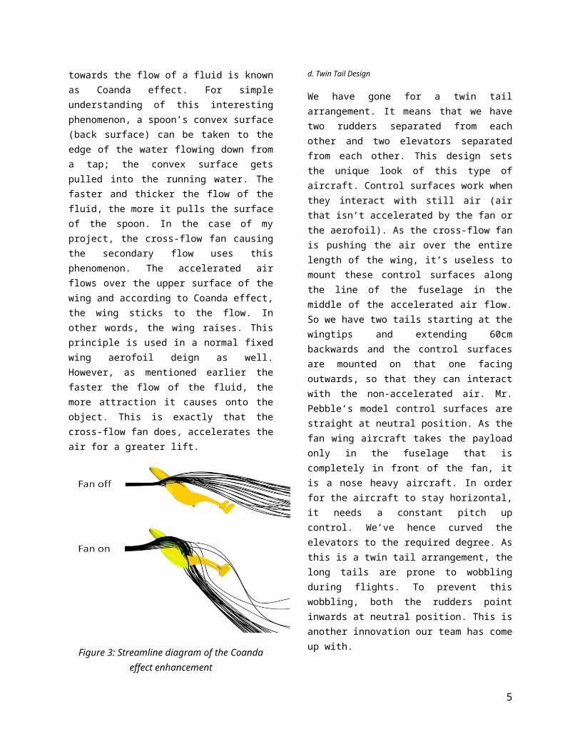
towards the flow of a fluid is knownas Coanda effect. For simpleunderstanding of this interestingphenomenon, a spoon’s convex surface(back surface) can be taken to theedge of the water flowing down froma tap; the convex surface getspulled into the running water. Thefaster and thicker the flow of thefluid, the more it pulls the surfaceof the spoon. In the case of myproject, the cross-flow fan causingthe secondary flow uses thisphenomenon. The accelerated airflows over the upper surface of thewing and according to Coanda effect,the wing sticks to the flow. Inother words, the wing raises. Thisprinciple is used in a normal fixedwing aerofoil deign as well.However, as mentioned earlier thefaster the flow of the fluid, themore attraction it causes onto theobject. This is exactly that thecross-flow fan does, accelerates theair for a greater lift.
Figure 3: Streamline diagram of the Coandaeffect enhancement
d. Twin Tail Design
We have gone for a twin tailarrangement. It means that we havetwo rudders separated from eachother and two elevators separatedfrom each other. This design setsthe unique look of this type ofaircraft. Control surfaces work whenthey interact with still air (airthat isn’t accelerated by the fan orthe aerofoil). As the cross-flow fanis pushing the air over the entirelength of the wing, it’s useless tomount these control surfaces alongthe line of the fuselage in themiddle of the accelerated air flow.So we have two tails starting at thewingtips and extending 60cmbackwards and the control surfacesare mounted on that one facingoutwards, so that they can interactwith the non-accelerated air. Mr.Pebble’s model control surfaces arestraight at neutral position. As thefan wing aircraft takes the payloadonly in the fuselage that iscompletely in front of the fan, itis a nose heavy aircraft. In orderfor the aircraft to stay horizontal,it needs a constant pitch upcontrol. We’ve hence curved theelevators to the required degree. Asthis is a twin tail arrangement, thelong tails are prone to wobblingduring flights. To prevent thiswobbling, both the rudders pointinwards at neutral position. This isanother innovation our team has comeup with.
5

Figure 4: The twin tail arrangement with a modified neutral position of the control surfaces
VIII. ANALYSIS
Figure 5: Lift efficiency vs. flight speed
Figure 6: Lift efficiency vs. rotational speed
Figure 7: Thrust efficiency vs. flight speed
Figure 8: Thrust efficiency vs. rotational speed
Figure 9: Drag force vs. flight speed
Figure 10: Lift force vs. flight speed
6

Figure 11: Drag force vs. Rotational speed Figure 12: Lift force vs. rotational speed
IX. SPECIFICATIONS
a. Overall Dimensions
Sl No. Aspect Specification1. Wing span 1.09 meters2. Fuselage length 0.6 meters3. Tail length 0.6 meters4. Aspect ratio 3.875. Rudder area 15% of wing area6. Elevator area 30% of wing area7. Number of blades 32 (16 per wing)
b. Material Specifications
Sl. No. Component Specification1 Cross-flow fan blades Hard balsa wood (density:
0.1g/cc)2. Discs to hold the blades Plywood3. Axis of the cross-flow fan Carbon fiber rod4. Fuselage Bathroom door5. Deflector plate Fiber reinforced plastic6. Modified aerofoil Coroplast7. Control surfaces Coroplast8. Push rods Mild Steel9. Bearings Steel ball bearings10. Adhesive Araldite
c. Electronics Specifications
Sl. No. Component Specification1. Battery Lithium polymer – 4 cell –
7

3100mAH2. Electronic Speed Controller 30A3. Brushless DC Motor 800kV4. Servos 24grams and 9 grams5. Transmitter 6-channel avionics6. Receiver 6-channel avionics
X. ADVANTAGES
a. Stall Resistance
In a normal aerofoil, the line thatconnects the leading edge of theaircraft to the training edge isknown as the chord line. The anglethat the chord line makes withrespect to the horizontal is knownas angle of attack. Under normalconditions, the streamline of airthat moves on the upper surface ofthe aerofoil sticks to the aerofoilwing. As the plane is being pitchedup, the angle of attack increases.After a specific angle of attack,the streamlines that moves on theupper surface of the wing no longersticks to the upper surface. This isknown as boundary layer separation.When boundary layer separationoccurs, the wings no longer createlift and the result is a stall. Theplane falls like an object from theskies. This dangerous act ofstalling never occurs on a fan wingaircraft as the cross-flow fanpushes high velocity air over theupper surface of the wingirrespective of the angle of attack.
Figure 13: Streamline diagram explain theboundary layer separation
b. USTOL – Ultra Short Take-offs and Landings
The fixed wing aircrafts mostly usehuge jet engines to help them movefast enough so that they can bumpinto the air in front of themdeflecting the air by their aerofoilto create lift. In a fan wingaircraft, the primary and thesecondary flow of air causes bothlift and thrust. In other words, theair that is being pushed by thecross-flow fan is used for both,lift and thrust. Hence sufficientlift force can be achieved at lowground speeds. The required lengthof runway for a fan wing is veryshort. This makes it fall under theUSTOL category where USTOL is the
8
abbreviation for ultra-short take-off and landing.
c. Military Surveillance
This machine makes an excellentsurveillance aircraft as it cancreate enough lift to keep it in theair at low speeds. Hence, themilitary application for thisaircraft is immense. Another problemfaced by the fixed wing aircrafts isits inability to fly in valleys. Jetengine sucks in all the air ahead ofit and when the aircraft enters avalley, the vacuum created in theabsence of air causes zero liftbeing created. That is why dronesaren’t used to perform militaryactivities over valleys. As the fanwing aircraft uses the air ahead ofit to create lift by deflectiondown, into the valley in this case,they can safely fly over anyterrain. Moreover, as the cross-flowfan keeps a steady secondary flowover the upper surface of the wing,the amount of rate of change ofpressure difference is minimal andhence turbulence is significantlyreduced. This allows the aircraft tobe flown under any weatherconditions.
d. Medical or Disaster Evacuation
Fan Wing aircraft is very muchessential in medical or disasterevacuation. Fan Wing aircraft can belooked as a sum of helicopter and anaircraft. It can carry pay load thatis as high as that of an aircraft
but can takes-off like a helicopter.Similar to that of a helicopter thenose is rather down during take-offs. As it needs a very limitedspace to land and take off, and cancarry huge pay-loads, these can beflown into any city or town forevacuation. This quality of the fanwing can take intercitytransportation or hub connectivityto new heights. Jet aircrafts occupythe higher altitude of the sky.These can boost the transportationsystem by occupying the loweraltitudes of the sky as they aredesigned to fly low and slow.
e. Reduced Noise Pollution
Fan wing aircraft is expected toproduce only 65-75 dB of sound.Chetak and Pratap helicoptersproduce 94-114 dB and 104-110 dB ofsound respectively. Thus a fan wingaircraft is optimum for an eco-friendly world.
XI. CONCLUSION
As our research shows, this aircraftfixes all the gaps present intoday’s aviation industry. This isnot only done for the mere purposeof passenger transportation, butalso cargo shipment. To make it evenmore better, this aircraft achievesthis goal with a reduced noiseproduction and thus takes this busyworld towards a cleaner world.
XII. ACKNOWLEDGEMENT
9

This project would have neverreached its finish line without thehelp of Mr. Anubhav Bhatt. He wasnot only our technical advisor butalso a major hand in the fabricationof our fan wing aircraft. Since thecommencement of this project inSeptember 2014, Mr. Anubhav has beenguiding us and ensuring that all thetechnical challenges we face aredealt with thorough research.
Mr. Siddhant Chandra is anotherperson to be acknowledged for thecompletion of this project. Hismotivation and support to ensurethat we stay on schedule weregreatly needed in the progress ofthis project.
We sincerely thank everyone who hascontributed their hand towardsgetting this project into the skies.
XIII. CITATIONS
[1] www.fanwing.com – home of theFanWing inventors.[2] Versteeeg H.K., Malalasekera W.:“An Introduction to ComputationalFluid Dynamics, The Finite VolumeMethod”, Pearson, Prentice Hall,2007.[3] Krzysztof Kurec, Janusz Piechna:“Numerical Analysis of ModifiedFanwing concept”, Institute ofAviation and Applied Mechanics,Warsaw University of Technology,2009.[4] Warwick, Graham. "Intermodal-container Air Cargo Concepts AttractInterest (Cargo Cult)" Aviation Week
& Space Technology page 15, 25August 2014. Accessed: 26 August2014.[5] FANWING - The Fixed-WingContender in the Rotorcraft Segment,Frost and Sullivan, 10 Jan 2011[6]FanWing UAV gets airborne afterground roll of only 1m RobCoppinger, FlightInternational 01/05/07, AccessedAugust 2007.[7] Could FanWing go from LSA toheavy lifter?, Robert Coppinger,Aircraft Owners and PilotsAssociation, November 22, 2011.Accessed June 2012
10