s e.) ec - national reconnaissance office
TRANSCRIPT
. '11 A EiL EIG NRO APPROVED FOR RELEASE 1 JULY 2015
MANNED ORBITING LABORATORY (MOL)
ORBITING VEHICLE
POWER UTILIZATION CONTROL
SAFSL EXHIBIT 30001
(7:1 TT-3 (7") ri" r-'• • N,\ • 3 S E.) EC F
i r. g rz
L-6005 Copy 2? of
Page / of 4/

• 6— ta _1 a
NRO APPROVED FOR RELEASE 1 JULY 2015
4
9-\FS1 • 300 I Pow OTIL ;L\ --1-10 ft\LI
The undersigned has reviewed the document and
vndersta.nds the contents to the extent necessary
• to scope subsequent proposals.
(S ig nc cl)JAL, j ci-,174,71
(Signed)
0 /*-- (Signed) /-6 r (Signed)
47-1,--4›-Z-„,(-
',7, .9 .17 27;4 Z xi, • /1;7 LISigned)
1'1: rie ity (Signed) (Signed) • • s.
(Signed) (Signed)
(Signed) (Signed)
1 •
(Signed)
(Signed(Signed
(Signed)_ jj
a
, rrch T?ErT SPECIAL • EA 11 F.) I I G
L-6005 Copy-22? of
Page 2- of L2_

:. -4...
\t S I._ ,,. 14 , 0, i -1- • • -:3c... 0 c 1 ct 6,..i- ,.7 ,-.t . (.1 I\ 1-) j, t ri LS
C.::!.6.1-..)....,(- =7'72 A7C d. -̀.. (.1." C L. ; C 0- 6
V 7 i L6- /\ Ti C, k: Ce -, ., -;---i?... p L_. j--- ..k... e-‘ e f:-_t_, . -i-, .\-'1 : 7 I ;•-• C:: • E ° t C (-- 1:::- 12-
NRO APPROVED FOR RFLEASE 1 JULY 2015-
r " E 6 i 2,3 1-: A. 11 D L [.1
The undersIgncd understands. tha technical cont.c.,nt of this document and
endorses the requirents stated tharcin.
T.7 .. ____. ■-----,••---7 -.%-/` • —747° '."7 • „6,-- , , ,-,.... ,,:z:-;e-/:-.-,-;':,-z. t ,-; c.._-/. ,tl4-1-, ,,,C"/V-4."(:-e; /"-Z.✓et :--/. /./;,"::-:-.•-----_/.,-:<:'"7:-1--- 71A--:lz-1-"-----1""---
• • .///t/ '7/ 6 ;) 5.; - -2 • ......, •
1-1---) - 7-
• =-=-- --e ,.../ ,..c. . ,./
....,e,,o,...e.l.„_,-‘4.- ,/,47.--. .5---- -....,:',..-e=- 1-1, .g.:^-7-"-- „../.....5;j7!--!.-•"-•-c..1-<.:--'T j
._,.
%, ::1) 7
C ( .__...-.
r. ,N
:,,A,!-(:, - ...t___
. A,...._, ___,........_ • .....--
6---C--
I
74
. i ---,--- -- .-,-.. ,., ,(7 ,
( s----CL • / n l4,,C-- -(/ ' 3 . / ,--7.„,,,-...f z.; .X.,C.-1..;-1::.... / ,.,..‘......L...-- .--/-„,-.L.t, . -. ,. .=2.---
•--) • •
t - I
SPFC1A
L-6065
Copy23 of 44
Page 7 of /4../
NRO APPROVED FOR RELEASE 1 JULY 2015
A L,3 LI) t.. Q v "a
This exhibit establishes the peak and average power allocations for each
segment of the Manned Orbiting Laboratory Orbiting Vehicle. It defines
the modes and the assumptions used in determining power utilization against
these allocations. It also establishes the minimum data requirements for
requests for changes to this exhibit.
This' document shall be upgraded as required to reflect approved changes in
. the Contents. Approved changes shall appear as Annexes to this document.'
L-6005
. - - rTh e:; r773
a - U.1 A
SPECIAL H rt,
Copy ")...-3of lft
11 C Page 2 of
Ur ■,...76 VA V: A C',..1D 1 LI NRO APPROVED FOR RELEASE 1 JULY 2015
TABLE OF CONTENTS
SECTION PAGE
1.0 FORW ORD 4
2.0 APPLICABLE DOCUMENTS 6
3.0 POWER ALLOCATIONS
3.1 Peak Power Definitions 7
3.2 OV Peak & Average Power Allocations 8
3.3 Gemini B Equipment Mode Allocations 11
3.4 Photographic Payload Equipment Mode 11
Allocations
3.4.1 Simultaneity Assumptions 13
3.5 Power Calculation Assumptions 13
4.0 POWER UTILIZATION CONTROL 17
4.1 Power Reporting 17
4.2 Exhibit Change Requests 17
TABLES
3.2 OV Power Allocations
9
ANNEX I 18
ro '''c v-z
"77:71—r—i ' L.:a Li
SPFCIAL ti A Dl.
L-6005 Copy '2_2 of //(.7 Page 3 of / '7
NRO APPROVED FOR RELEASE 1 JULY 2015
2.0 APPLICABLE DOCUMENTS
The following document of the exact issue shown form a part of this
specification to the extent specified herein.
SAFSL Exhibit 10003 Environmental Design and Test Criteria
for the MOL System Laboratory Module,
Mission Module, and Associated AGE.
r7., . •i
■:, L.-1
SPECIAL HAND :1G
1,6005
Copy .7_3of
Page f.,:./1 of/Z c
No/
D NRO APPROVED FOR RELEASE 1 JULY 2015
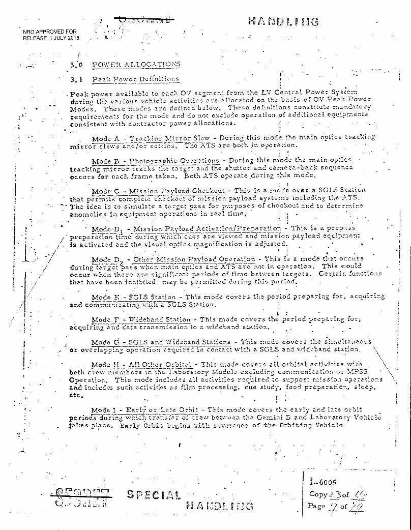
3.0 POWER ALLOCATIONS
3.1 Peak Power Definitions
•
Peak power available to each OV• segment from the LV Central Power System
Modes. These modes are defined below. These definitions constitute mandatory-
consistent with contractor power allocations.
during the various vehicle activities are allocated on the basis of OV Peak Power
requirements for the mode and do not exclude operation of additional equipments
. Mode A - Tracking Mirror Slew - During this mode the main optics tracking mirror slows and for settles. The ATEare both in operation.
Mode B - Photogra.ohic Operations - During this mode the main optics tracking mirror tracks the target and the shutter and camera-back sequence occurs for each frame taken. Both ATS operate .during this mode.
•
Mode. C - Mission Payload Checkout - This is a mode over a SGLS Station that permits complete checkout of mission payload systems including the ATS. The idea is to simulate a target pass for purposes of checkout and to deterrnjne anomolies in equipment operations in real time.
•
• -
• Mode.D - Mission Payload Activation/Preparation - This is a prepass preparation time during.which cues are viewed and mission payload equipment is activated and the visual optics magnification is adjusted,
• - • L Mode D2 - Other Mission Payload Operation - This is a mode that occurs
during target pass when main optics and A-TS are not in operation. This would occur when there are significant periods of time between targets. Certain functions that have been inhibited may be permitted during this period.
Mode E - SGLS Station - This mode covers the period preparing for, acquiring and communicating with a SGLS Station.
: Mode - Widebanci Station - This mode covers the period preparing for,
acquiring and data transmission to a wideband station.
Mode d - SGLS and 1.',rid.eband. Stations - This mode covers the simultaneous or overlapping operation required in contact with a SGLS and wideband station.
Mode H - All Other Orbital - This mode covers all orbital activities with both crew members in the Laboratory Module excluding communication or MPSS ' Operation. This mode includes all activities reqUired to support mission operations and includes such activities as film processing, cue study, food preparazicn, sleep, etc. : .
Mode I - Earl; or Late Orbit This mode covers the early and late orbit periods during which transfer of crew bc..tv.-een the Gemini B and Laboratory Vehicle sakes place. Early Orbit .::gins vi,tli severance of the Orbiting Vehicle
./
5'
1.11 U."? - ‘...c; V' C L L r C
it 4-
L-6005 Copy 2:3of
Page i/ of ;v • ' • . 1.7.1
NRO APPROVED FOR RELEASE i JULY. 2015 . .•
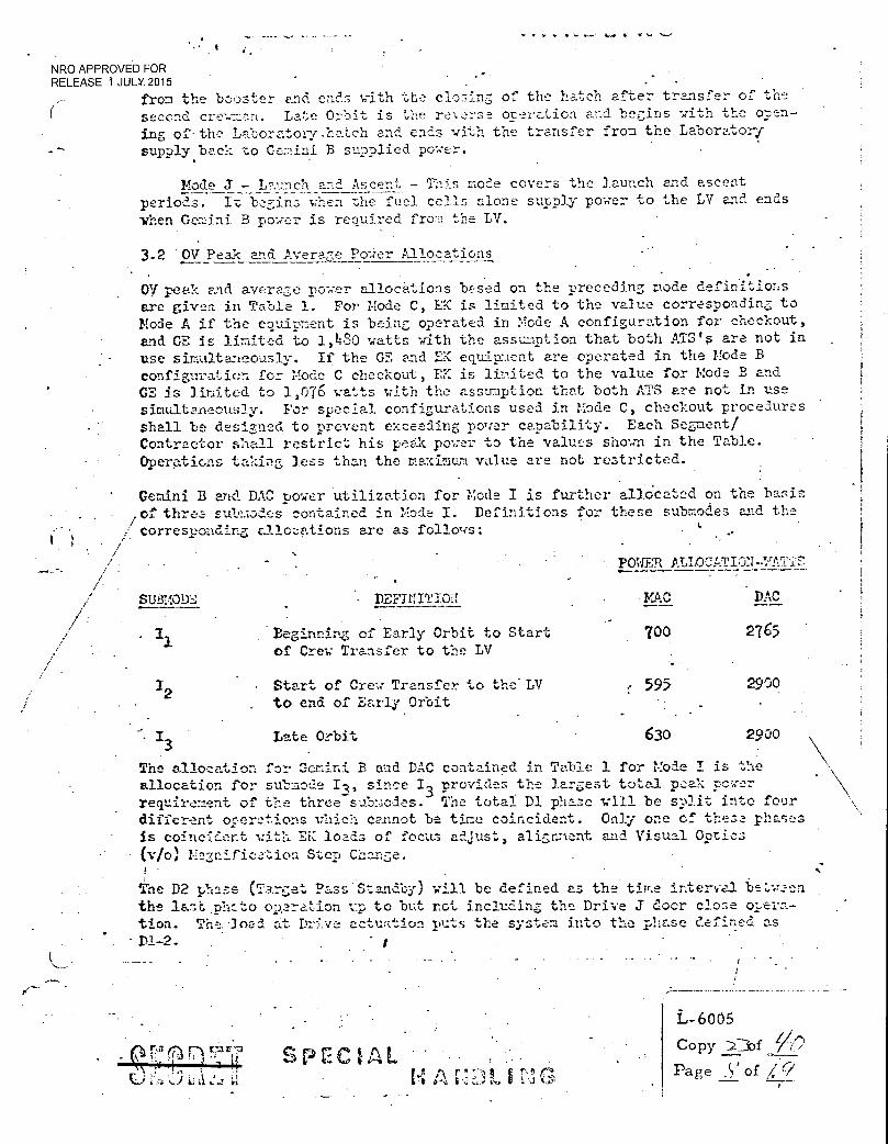
from the booster and ends with the closing of the hatch after transfer of the second crew=n. Late Orbit is the reverse oteration and begins with the open-ing of•the Laboratory.hatch and ends vith the transfer from the Laboratory supolyback to Gemini B supplied power.
Mode J - Launch and Ascent - This mode covers the launch and ascent periods. It begins when the fuel cells alone supply power to the LV and ends when Gemini. B power is required frog; the LV.
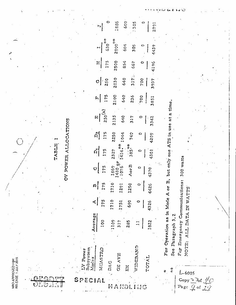
3.2 OV Peak and Average P0Wer Allocations
Oil peak and average rower allocations based on the preceding mode definitions are givea in Table 1. For Mode C, EC is limited to the value corresponding to Node A if the equipment is being operated in Mode A configuration for checkout, and GE is limited to 1,480 watts with the assumption that both ATS's are not in use simultaneously. If the GE and EK equip.ment are operated in the Mode E configuration for Mode C checkout, EK is limited to the value for Mode B and GE is limited to 1,076 watts with the assu-aption that both ATS are not in use simultaneously. For special configurations used in Mode C, checkout procedures shall be designed to prevent exceeding po'ler capability. Each Segment/ Contractor shall restrict his peak power to the values shown in the Table.
Operations taking less than the maximum value are not restricted.
Gemini B and DAC power utilization for Mode I is further allocated on the basis .of threa sul.:;aodes contained in Mode I. Definitions for these submodes and the / corresponding allocations are as follows: k , i / /
/ - /
• / SIMODE • DEF1NITIOH •VAC DAC
. I1
Beginning of Early Orbit to Start 700 2765 of Crew Transfer to the LV
POWER ALLOCATIC)N
2 . Start of Crew Transfer to the LV . to end of Early Orbit
595 2900
13
Late Orbit 630 2900
The allocation for Gemini B and DAC contained in Table 1 for Mode I is the allocation for submede I3, since 13 provides the largest total peak Fever requirement of the three submodes. The total Dl phase will be split into four different oceretions which cannot be time coincident. Only one of these phasas is coincident with EK. loads of focus adjust, alignment and Visual Optics
• (v/o) Legnification Step Change. •
The D2 phase (Target Pass Standby) will be defined as the time interval be.w.?en the la:t phc•to operation 1.1p to but not including the Drive J door close ol,era-tion. The load at Drive actuation .nuts the system into the phase defined as D1-2.
. • r7.)
.•J
r '
SPECIAL
L-6005
Copy z3of I/17' Page S
,of %
0 I '
o ,s0 CO 0 0
Cl F -4
* * * * 0 0 V in 0 0, Cl 0 0 0 cn '0 0, N0 cn V
N V
LI o -cii N tfl
.-4 in co N V
o o 0 N 0 N M Cl V ..--4 0 Cl
N CD JD Cl N N Cl•
I
N CO
In 0 0 o ,c14
Q Cl O f
N Cl
..,-44 4 .6 .
ni ril I 2
N ---I ...0 Cl
Cl ■--1
in o N o 1 . N .
M • N Cl 0
co
0 '
41 ..N in V 0 N
0 ',41 (.3 0 I 0" o N
to ..•,- N CID N 4.--1 I.
Nit E-i * * 44 Al ...,r-, enN , ,in
I en 0
.---4
0 0
m
*..*- M 0, ,;ti IM 0 I
N I..., NI, #. 4-)
T.4 W
0 I r6-4
■0 C CO e° 0 I co
:
N N Pi al 0 M 0,
Cr'...:) 4V3 00
I:3 .0 Cl d., .-4 .
tri as • .
01 1 —I os Lc) N k (ID 0 I NO 1.-
V 0 0
Lil o -- o , ..-t N N N
_' ..--4 -4 V d E-4 u .,4
-0 0 ..... z .--
p. \ 4 I 11.2 0 6■64 .6-4 160 CC?"' C..) 1 s4:IN g's C.- •••0 Cl
0 V
...4 N Z 5 \ ...4 ..-4 E ..z,
0
01 to
...., .....-i m N o 0 .--4 CO o Crs r-- 1r)
■•••4
_
6-1 I 66-4
w-1
INI CO
fq
o Z ....1
d en co
0
c, A
4" .4 . 0 d ti:1 r-4 k rd 0
0
P
OV
PO
WE
R A
LL
OC
AT
ION
S
74 5 0
o J o,
-g 0 Z.
SPECIAL
0 p d E
0 pi
W co rai
* • * L-6005
Copy
Page (/ of 7 y
NRO APPROVED FOR RELEASE 1 JULY 2015
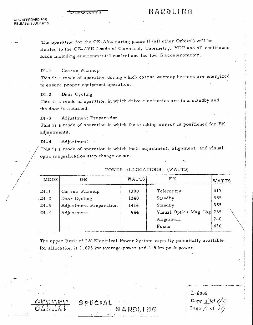
The operation for the GE-AVE during phase H (all other Orbital) will be
limited to the GE-AVE Loads of Command, Telemetry, VDP and all continuous
loads including environmental control and the low G accelerometer.
D1-1 . Coarse Warmup
This is a mode of operation during which coarse warmup heaters are energized
to ensure proper equipment operation.
D1-2 Door Cycling
This is a mode of operation in which drive electronics are in a standby and
the door is actuated.
D1-3 Adjustment Preparation
This is a mode of operation in which the tracking mirror is positioned for EK
adjustments.
D1-4 Adjustment
./ This is a mode of operation in which fpcis adjustment, alignment, and visual
optic magnification step change occur.
POWER ALLOCATIONS - (WATTS)
MODE GE WATTS EK WATTS
D1-1 Coarse Warmup 1300 Telemetry 317
DI-2 Door Cycling 1340 Standby .. 385
D1-3 Adjustment Preparation 1414 Standby 385
-D1-4 Adjustment 944 Visual Optics Mag Chg 785 \
Alignme__1. 740
Focus 430
The upper limit of LV Electrical Power System capacity potentially available
for allocation is 1.825 kw average power and 4.5 kw peak power.
SPECIAL
L-6005
Copy •_3of (AT Page L: of %.1
• t t ■‘:,..1 t.; L17.1
W 16.211,
. - NRO APPROVED FOR liELEASE. 1 JULY 2015
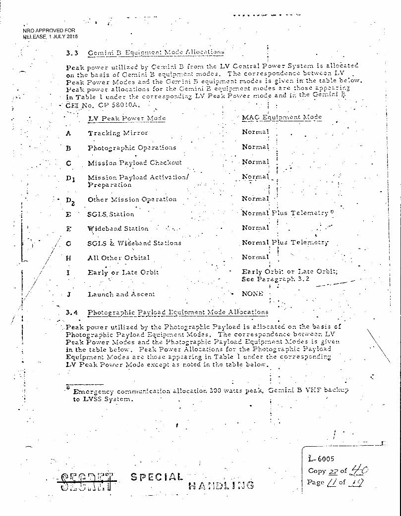
3.3
4.
Gemini B Equipment Mode Allocations.
Peak power utilized by Gemini B from the LV Central Power System is alloc- ated
On the basis of Gemini B eeuiprnent modes. The correspondence between LV Peak Power Modes and the Gerrini B equipment modes is given in hetable below. Peak power allocations for the Gemini B equipment modes are those apearing
in Table 1 under the corresponding LV Peak Power mode and in the Gemini
C'El No. CP 58010A.
L.V. Peak Power Mode
A Tracking Mirror
B Photographic Operations
• C Mission Payload Checkout
Di Mission Payload Activation/ Prepa ration
•• D2 Other Mission Operation
E SGIS.Station
E Wideband Station
• SGLS Wideband Stations
1-1 All Other Orbital . •
I Early or Late Orbit
Launch and Ascent
-• MAC Equipment Mode
Normal
Normal
Normal
Normal
.; , •
. .
Normal
Normal Plus Telemetry
Normal . • . '
Normal Plus Telemetry
• ! Normal • -
Early Orbit or Late Orbit; See Paragraph 3.2
- NONE
•
. .
-3
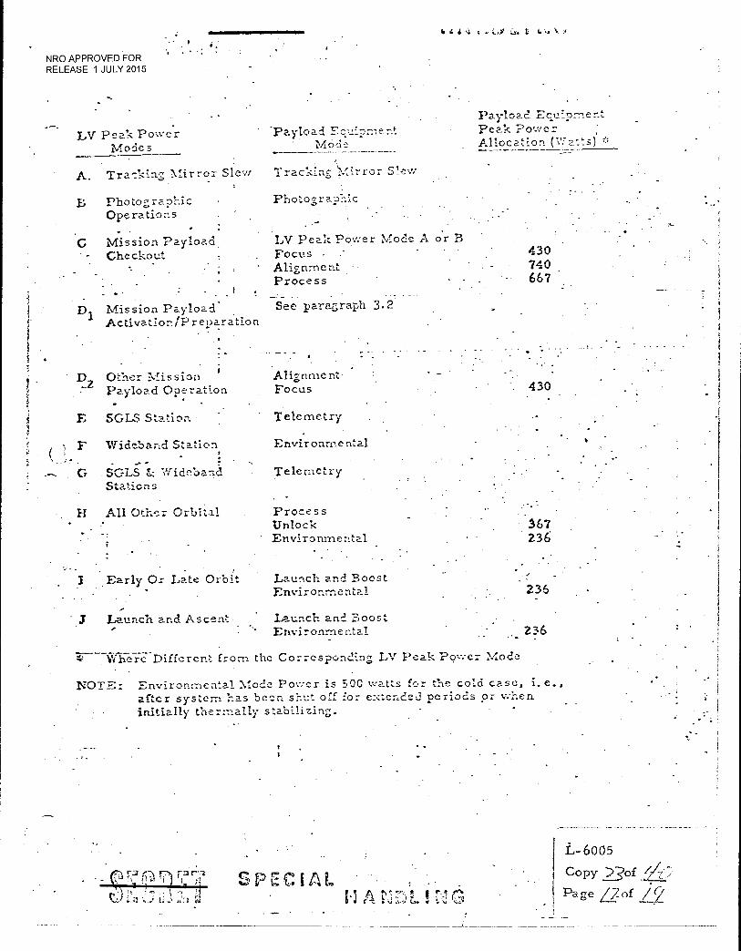
3.4 Photoa”a.oh.ic Payload Ecuiornent Mode Allocations • . .' •
..Peak power utilized by the Photographic Payload is allocated on the basis of Photographic Payload Equipment Modes. The correspondence between LV Peak Power Modes and the Photographic Payload E:quipz-nent Modes is givei in the table below. Peak Power Allocations for the Photographic Paylo::,_d Equipment Modes are those .appoaring in Table 1 under the corresponding LV Peak Poser Mode except as noted in the table 1.-,elow.
-* Emergency communication allocation 100 Watts peak. Gemini B VHF' backup
•
to LVSS System. • : •
t;•, c.77, • - - •
L
•
SPEC ifa. • -
L- 6005
Copy 24-7, of
Page L/ of
•
IN 4 4 ,4 t t.
NRO APPROVED FOR RELEASE 1 JULY 2015
LV Peak Power Mode 5
A. Traeking Mirror Slew
B Photographic Operations . .
G Mission Payload . Checkout
Payload Eculprnent
Payload Peak Power iQGti • Allocation (Watts)
Tracking 'Mirror Slew
Photogra.phic
LV Peak Power Mode A or B Focus • .- Alignment Process
430 740 667
Mission Payload . See parezraph 3.2
Activation/Preparation
• -
Alignment Focus L
Z Other Mission Pay load Operation
SGLS. Station • Telemetry
Wideband Station Envir onrne ntal
. SC:LS & Widoband Telemetry Stations
• - H All Other Orbital
Process Unlock
• Environmental
. 430
•
167 236
Early Or Late Orbit Launch and Boost Environmental 236
3 Launch and Ascent • Launch and Boost Environmental 236 •
Different from the Corresponding LV Peak Power Mode
NOTE: Environmental Mode Power is 500 watts for the cold case, i.e., after system has been shut of for eNtende.d periods or when initially thermally stabilizing.
(7.3 771 rar',3
1 I •:a
SPECIAL
1.1 A .
L-6005
Copy 23of :./„-/zi' '
Page /2.._of
(,5
NRO APPROVED FOR RELEASE 1 JULY 2015
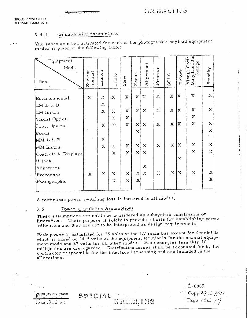
3.4. 1 • Simultaneity Assumption
The subsystem bus activated for each of the photographic payload equipment
modes is given in the following table:
• Equipment
Mode ,.._,
0 F-t .F.
0 9
til
Ali
gnm
ent
Pro
ce
s
SG
LS
Unlo
ck
Vis
ual
Opti
cl
Mag
nif
ica t
io21
C
han
ge
Sta
nd
by
••-f >
0 0 0
13.s 0 L
Environmental X X X X X X X X X X X
LM L & B X
LM Instru. X X X X X X X X X X
Visual Optics X X X
Proc. Instru,
Focus
X X- X
X
X
X
X X X X X X
MM L & B X
MM Instru. X X X X X X X X X X
Controls & Displays X X X X X X
Unlock X
Alignment X
Processor X X X X X X X X X X X
Photographic X X X X
A continuous power switching loss is incurred in all modes.
3. 5 Power Calcula'inn Assumptions
These assumptions are no't to be considered as subsystem constraints or limitations. Their purpose is solely to provide a basis for establishing power utilization and they are not to be interpreted as design requirements.
Peak power is calculated for 25 volts at the LV main bus except for Gemini B which is based on 24.5 volts at the equipment terminals for the normal equip-ment mode and 27 volts for all other modes. Peak energies less than 10 millijoules are disregarded. Distribution losses shall be accounted for by the contractor responsible for the interface harnessing and are included in the allocations.
,i, ,..., ? .4 , , .../ ILI , .1 :.■ a izi '..I.
SPECIAL I PI 11 s E >
r‘,
L-6o05
Copy 23of
Page /.-3of .//
r I I; -1 I La 'ej
NRO APPROVED FOR RELEASE 1 JULY 2015
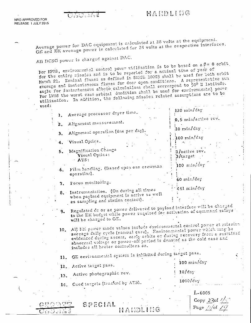
Average power for DAC equipment is calculated at 28 volts at the equipment. GE and EK average power is calcula.teci for 24 volts at the respective interfaces.
All DCSG power is charged against DAC.
For ITS'S', env:iron:lent-al control power utilization is to be based on a. 0 orbit.
for the entir. clission a.nci is to be reported for a nominal tine of ye:ir of
liarch 21. Nominal fluxes as defined. in S',!:".•31, 10003 shall be used for l'oth orbit
e.Vera,s-e and instanten:-..‘ous fluxe.s for door open. conditions. A rerlresentative. sun
anile for instant.anevi.s albedo. calculations shall correspond to 500 latitude.
For LVSS the worst case orbital Condition shall be used for environraentva power
utilization. In a-ddition, the folio insrelatedasstra-,-_,tions ale.to be
used: 120 min/day
1. Average processor dryer ti:r.e.
2. Alignment measurement. o. 5 min/a.ctive rev.
3. Alignment operation (One per day .10 min/day
4. Visual. Optics . 100 minidly
• .
5. Magnircat-lon Change - •
Visual Optics: Vactive rev.
3/target ATS:
6. Film Ilandlin5. (Based upon one crewrnan 100 rnin12-ay
Operation),
7. Focus monitoring. b0 rniniclay
S. Instrumentation. (On during all tines 441 rr.iniday
when payload equipment is active :.=_s VIE-11
as sampling and station contact).
9. Regulated do or ac power deur erect to payload interface will be el--,ared
to the EK budget while power rer,uired for activation of rel-ays
will be charged to GE.
10, All E7-': pc-.ver. mode values include environmental control power at rnissicn average daily cycle (r.orrnal case). Fnviro- —enta.1 power v.
--r_ich
evidenced during ascent, early orbits or during recovery from a sustain,-_ci
abnormal vDltase or power-off. neriod is denoted as the cold case and
includes all hE'.at.er cor_trollers on.
11. CsiE en.vironme_ntz.1 system is inhibited during target p ass.
12. Active target pass. .1 100 rniniday
13. Active photographic rev. 10/d2_
14. C- ed targets (traciK!c: by ATS' 1000/day
C r) 4-4
1- b
_ L- 6005
L/I Copy
I Page / 2tf ./'1/

1,6005
.Copy of ,,//
Page
11/AL',F LE [1G
: 185/day 15. Tracked targets (primary o;:stics). .- • ; .
16. TM pitch slew time. : 481 sec /day,
. . . !
17. TM roll sz.,:lw time. 703 sec/day
: .
•!:2405 sec/day
-18. TM tracking time. - i -
19. Photographed targets. . I 75/day • -
,--.-- .f •
- 20. Primary photographs par photo•r:-,:...phed target. 6 • i •
21. Secondary camera in-out cycles. i 1'/photographed target ; ;
t i ! 1
22. Secondary camera photographs-per •• , :
photographed tz.;_rget. , !
23. Door open time per active rev. i 390 sec i
24,, Door open cycles/clay.* - : 1 2.5/day
25; ZI, Checkbut, R&D active revs i : 2/day ' ,
: 10/day
; i • • - 20/day
Included in Item 19 above.
E,.6- , min/day
244. min/day (39 DAC; 205 C
. NRO APPROVED FOR RELEASE1 JULY 2015
•
•
-• •
a) targets tracked
b) number of targets cues
c) targets photographed
d) door open
26. Computer on-time
27. Station contacts based on contact times:
clear voice 4. /day for 12 n-.in total i at 25 percent duty cycle i on transmitter
.• ; 16/day for 90 min tc,tzl,
16/day for 93 r;-;:..n. total \
TLM. (must include c:f.p.a.5ility. to , 16/day for 90 mini total \
receive secure TRC's) • (16 with comp :_ter on I minute to accommodate computer summary data readout)
3/day for 40 min total
• ;
•
b) secure voice
c) track
el command
Includes ZI, Checkout, R&D and Photography only.
SPECIAL J A a
r r•
NRO APPROVED FOR RELEASE 1 JULY 2015
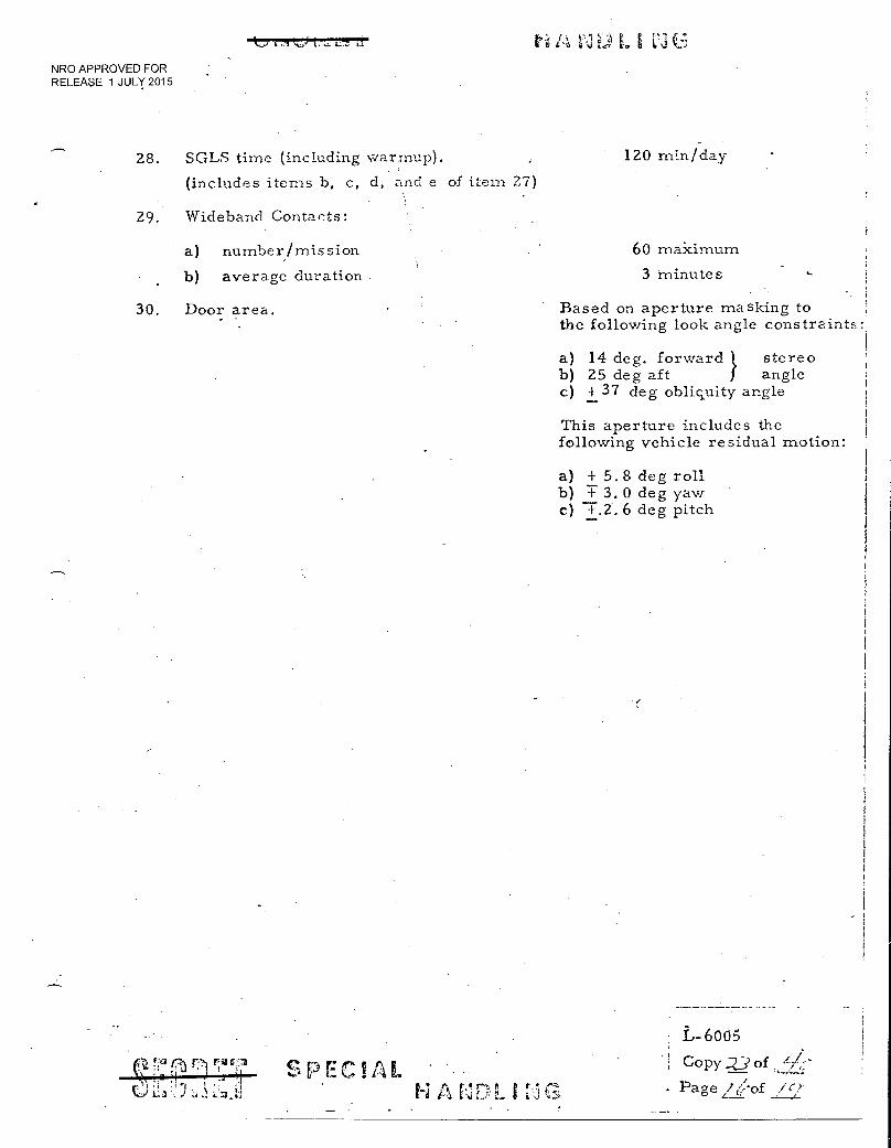
28. SGLS time (including warmup). 120 min/day
(includes items b, c, d, and e of item 27)
29. Wideband Contacts:
a) number/mission
b) average duration
60 makimum
a.. 3 minutes
30. Door area. Based on aperture masking to the following look angle constraints:
a) 14 deg. forward l stereo b) 25 deg aft angle c) + 37 deg obliquity angle
This aperture includes the following vehicle residual motion:
a) + 5.8 deg roll b) T 3.0 deg yaw c) 7.2.6 deg pitch
P. 71. -r3 F7-) r,4C3
tc.1 Ca_111 PECHAL ••
L-6005
coPy -23 of Page 1 (hf
NRO APPROVED FOR RELEASE 1 JULY 2015
H A. El Lti G
4.0 POWER. UTILIZATION CONT ROL
4.1 Power Reporting,
The allocations in this exhibit shall be utilized in all power reporting docume.ntatio to measure power requirements margins. Reported power utilization shall be based on the mode definitions and assumptions contained in this exhibit..
7.. 4.2 Exhibit Chance Requests • •
Approval is required for. all changes in the peak and average power allocations., mode definitions and assumptions. As a minimum requirement, request; for . changes must be accompanied by:
a) a detailed engineering analysis substantiating the need for a change,
b) verification that this change can be made without exceeding system allocation limits for peak and average power - capacity Znd without constraint of mission operational flexibility,
• . . c) a detailed statement of • system imPact (e.g., weight, schedule, reliab,ilit
documentation, and cost impact), with appropriate breakdown o: data zo permit SPO evaluation.
Where a change affects more than one associate contractor, the requ'est for ;e must be coordinated between all affected contractors and submitted as a.Co.-nbineci package with the above items identified for each c ontractor. .
- -rater ') r? •
■..-1 Lt
C 1 I.\ I • ~yrr..1 s I
L-6005 Copy-i_.:3 of
I Page 4/of
NRO APPROVED FOR RELEASE 1 JULY 2015
p .er-4 L.,
ANNEX 1
This Innex to SAFSL Exhibit 30001 contains the ground rules and assunptions applying to LVSS eouipn2nt and its operation and the associated LVSS pea? and average power allocations.
ECS
1. 140T., Sieve Heater and heater controllers are used for contingency only and eouipment -,tatts are not included in any peak or average.
2. Waste Managera,,nt Blower is operational. in .113d.e II only. •
3. The water heater is inhibited by crew action for 1TSS operation and will remain inhibited in nodes A, P, C, D1 and D2. It will not be turned on during mode- 12.
ELEC.-I'M:CAL - •
• 1. Contingency items do not contribute to average power (except as. noted).
2. Equipment connected to the inhibit bus is inhibited in Modes A, B, C, F'3 Fand G.
3. *-MPSS Feeder Losses are based on MPSS allocations.: MPSS Allocation Watts/2.4V z 1 volt MPSS Feeder Loss. . .
4. G/B Feeder Losses are based on 0/B allocations:: G/B Allocation Wat!...st 24V x 0.4 volt = Gill Feeder Loss.
ACTS /SCE:
1. Rotational thrustors are inhibited in Modes A, B, •C, C, J and F.
Z. Translation thrustor firing will occur in Mode H. Lower activity levels will be planned around orbit adjust. Load management will allow planned orbit adjust. •
3. Averaie., power calculations for ACTS/SCIS are based on the. following duty cycles:
51. 2% High Power 44. 6cito Low Power 4.2%. Standby
PROPULSION
The ACTS/Prop Low Thrustor heaters allocation is based on 75'n sir.ieta_neity for peak allocztions.
I
SPEC UAL
L-6005 Copy of !V (..;
I Page / t, /of C/
"1,1 t.:1 ti
/4 A El D I G NRO APPROVED FOR RELEASE 1 JULY 2015
BIO-INSTRUMENTATION
1. IR Spectrophotometer is considered non-operational in all modes except Modes C, E, and G.
2. Charged Particle Spectrometer is used on a contingency basis only and equipment watts are not included any peak.
3. Biological Dosimeter is included in Mode.
DISPLAY
1. Assume 1/3 of total EL Push Button Switches and EL status lights are on for all modes.
2. The EL Caution and Warning Matrices and Incandescent Push Button Switches (Lamp Test Only) are contingency items not included in peak mode allocations.
3. The EL Digital Clock is included in Mode H.
LIGHTING
/1. Main Floodlights are reported at 75% of full power for 10.5 hours per day and are off in Modes A, B, C, D2, II and J.
2. Auxiliary Floor Lights, Sleeping Area Floodlights, and Hygiene Area Floodlights are on in Mode H only.
3. EL Nomenclature Panel Lighting is on only in Modes A, B, C, and D2.
ACQUISITION
The Digital Recorder is operated in the record condition in Mode C.
DATA COMPUTATION
1. LVSS peak power allocations include full DCSG services for all modes. Computer power requirements are based upon 244 minutes of operation per day.
2. The printer is not operated in Modes A, B, and C.
12 j SPEC/PAL
L- 6005
Copy 9_D,f Page 14-lof icz./
8
t NRO APPROVED FOR RELEASE 1 JULY 2015
tr.3
S.AFSL EXHIBIT 30002
VIOL PROGRAM EFFECTIVENESS
SECTION 3
SAFSL Exhibit 10032 consistutes the remainder of the Effectiveness Exhibit and together with this section forms the total Exhibit 30002.
6 JUNE. 1968
f1 V Ct.5 rEt,
.74 .... I,
.1‘114 I,- 59 (8 Copy 2, Z ep -r.
Page ; of .
-
•
NRO APPROVED FOR . - • RELEASE 1 JULY 2015
■ ,2
1...d L....)
f\ 9 r k." (1-
Ll 3,
3. 1. System Mission Efiectiveness
3. I 1 Definition
Mission Effectiveness is defined as the reliability of the MOL System in
completing within design performance capability all functions necessary
.from liftoff to 'retrieval to support, provide, and return 95% of the
planned primary photographic data and the flight crew for a 30-day
mission. (R, AVE)
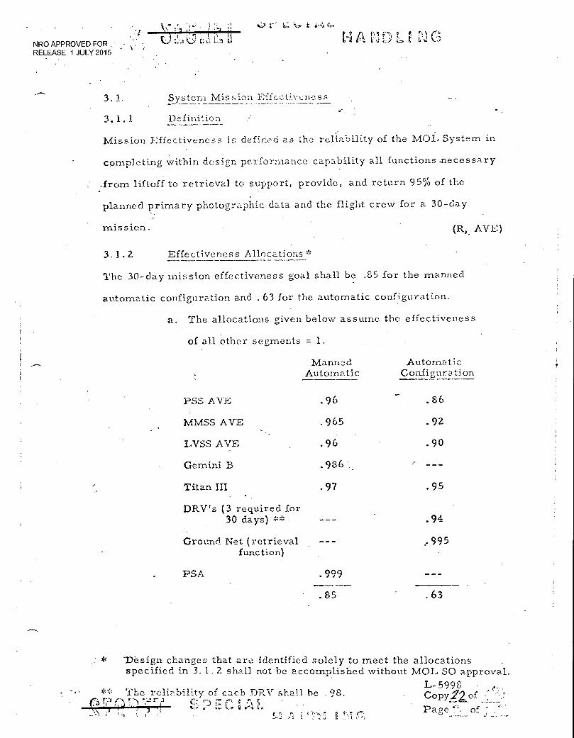
3. 1. 2 Effectiveness Allocations
The 30-day mission effectiveness goal shall be .85 for the manned
automatic configuration and . 63 for the automatic configuration.
a. The allocations given below assume the effectiveness
of all other segments = 1.
Manned Automatic
Automatic Configuration
... PSS .AVE .96 . .86
MMSS AVE .965 ' .92
LVSS AVE .96 .90
Gemini B .986. '
Titan III .97. .95
DRV's (3 required for 30 days) ** .94
Ground Net (retrieval function)
, 995
PSA .999
.85 .63
"Design changes that are identified solely to meet the allocations specified in 3.1.2 shall not be accomplished without MOL SO approval.
L-59.98 •••• Copy2lof •
Pacie of
** The reliz..1)ility of each DRV shall be .98. %-•-) s • • .„, ir L.. L-0
_\. •i ; ;Cr:2';
. NRO APPROVED FOR RELEASE 1 JULY 2015
Fri A H D t:,
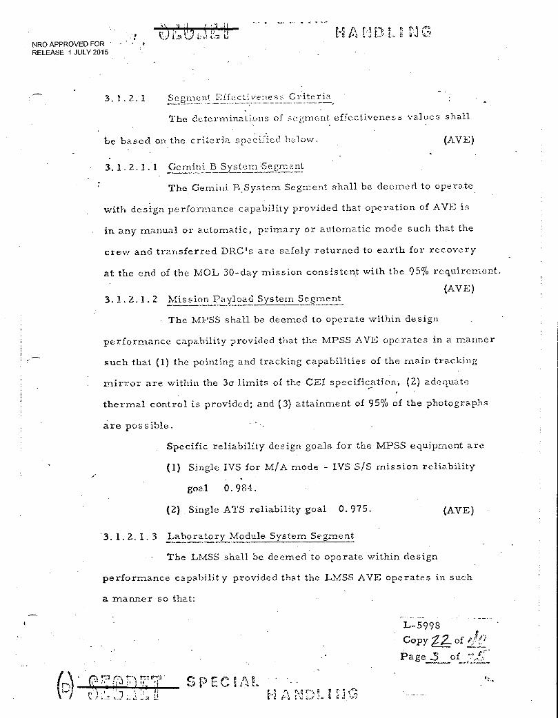
- 3.1.2.1• Segment Effectiveness Criteria
The deterrninatons of segment effectiveness values shall
be based on the criteria specified below.
3.1.2.1.1 Gemini B System Segment
(AVE)
The Gemini B. System Segment shall be deemed to operate .
with design performance capability provided that operation of AVE is"
in any manual or automatic, primary or automatic mode such that the
crew and transferred DRC's are safely returned to earth for recovery
at the end of the MOL 30-day mission consistent with the 95% requirement.
(AVE) 3.1.2.1.2 Mission Payload System Segment
The MPSS shall be deemed to operate within design
performance capability provided that the MPSS AVE operates in a manner
such that (1) the pointing and tracking capabilities of the main tracking
mirror are within the 3a limits of the CEI specification-, (2) adequate
thermal control is provided; and (3) attainment of 95% of the photographs
are possible.
Specific reliability design goals for the MPSS equipment are
(1) Single IVS for. M/A mode - IVS S/S mission reliability
goal 0.984.
(2) Single ATS reliability goal 0.975. (AVE)
. 3.1.2.1.3 Laboratory Module System Segment
The LMSS shall be deemed to operate within design
performance capabilit y provided that the LMSS AVE operates in such
a mariner so that:
L-5998
Copy 22of 1!;'
Page .3 of
rA f) 7.7.r,9 1:i. • ,) L,
SPEC AL E
r;-1 tit • NRO APPROVED FOR RELEASE 1 JULY 2015
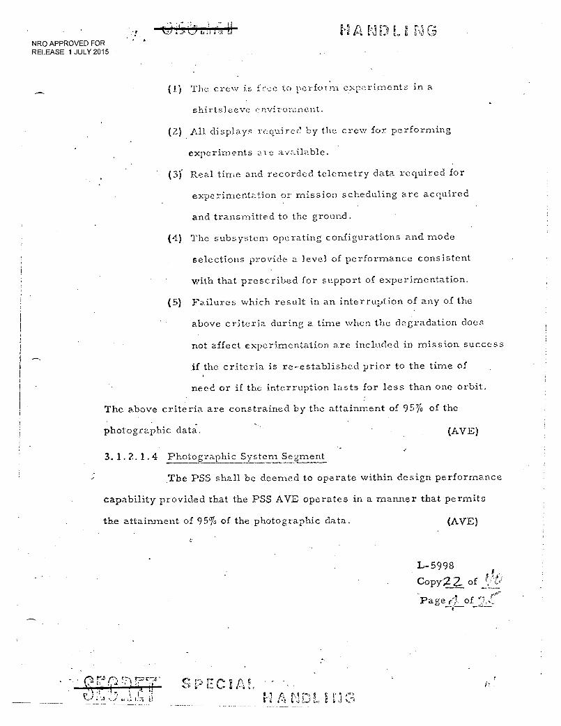
(1) The crew is free to perform experiments in a
shirtsleeve environment.
(2) All displays required by the crew for performing
experiments ale available.
(3) Real time and recorded telemetry data required for
experimentation or mission scheduling are acquired
and transmitted to the ground.
(4) The subsystem operating configurations and mode
selections provide a level of performance consistent
with that prescribed for support of experimentation.
(5) Failures which result in an interruption of any of the
above criteria during a time when the degradation does
not affect experimentation are included in mission success
.if the criteria is re-established prior to the time of
need or if the interruption lasts for less than one orbit.
The above criteria are constrained by the attainment of 95% of the
photographic data. (AVE)
3.1.2.1.4 Photographic System Segment
The PSS shall be deemed to operate within design performance
capability provided that the PSS AVE operates in a manner that permits
the attainment of 95% of the photographic data. (AVE)
•
T;:z Ti
, 7: ■•2 ' 1..7;
S C-) ECIA L I r, ri! 6-4 t
L-5998
Copy2 2. of
Page r1 of
r A t
r-)' r .0.: 4
NRO APPROVED FOR RELEASE 1 JULY 2015
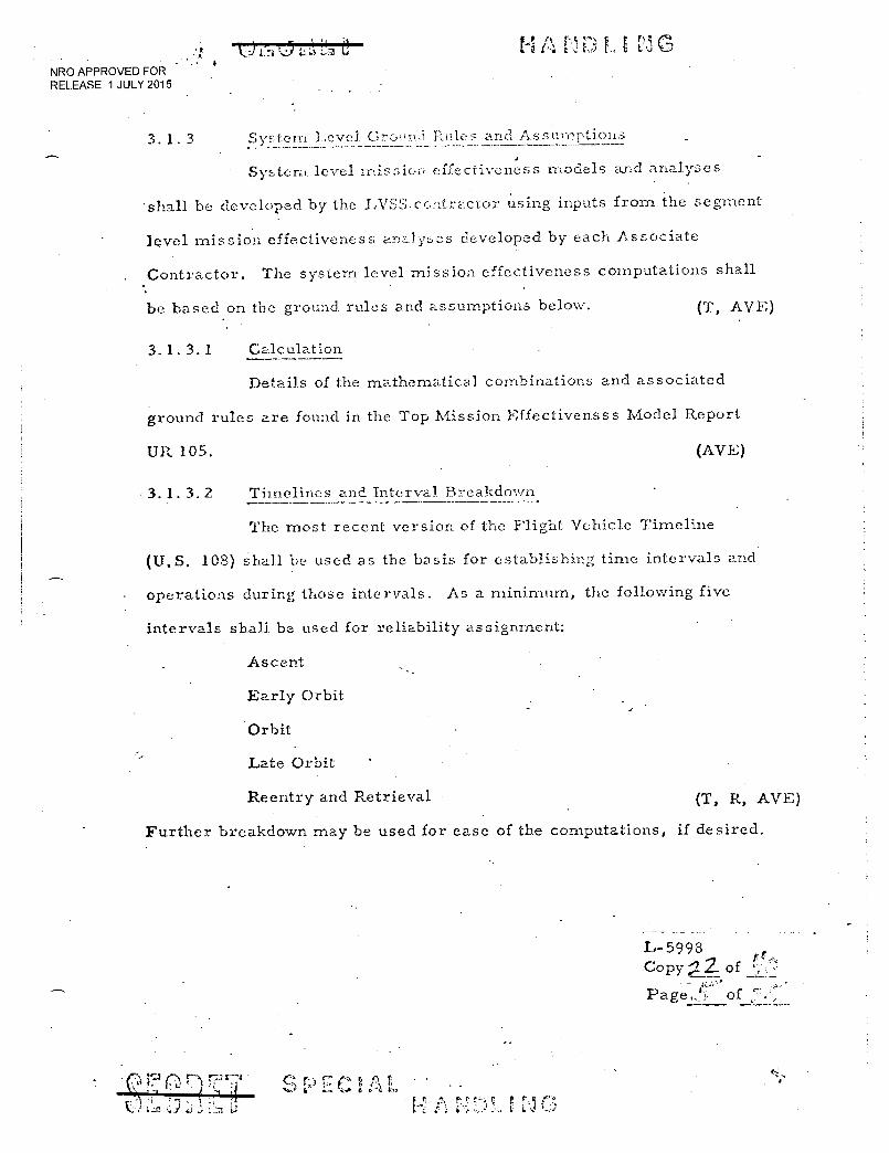
3. 1. 3 System Level. Ground Rules and AssulyTtions
System level missic.-- effectiveness model.s and analyses
'shall be developed by the LVSS.contra,ctor using inputs from the segment
level mission effectiveness analyses developed by each Associate
Contractor. The system. level mission effectiveness computations shall
be based on the ground rules and assumptions below. (T, AVE)
3.1.3.1 Calculation
Details of the mathematical combinations and associated
ground rules are found in the Top Mission Effectivensss Model Report
UR. 105. (AVE)
3. 1. 3. 2 Timelines and Interval Breakdown
The most recent version of the Flight Vehicle Timeline
(U.S. 108) shall be used as the basis for establishing time intervals and
operations during those intervals. As a minimum, the following five
intervals shall be used for reliability assignment:
Ascent
Early Orbit
Orbit
Late Orbit
Reentry and Retrieval
(T, It, AVE.)
Further breakdown may be used for ease of the computations, if desired.
L-5998 Copy 2 of
Page,. ), of
•
t; i rt: ti NRO APPROVED FOR RELEASE 1 JULY 2015
3. 1 . 4 Segment Level G-...o!nid Pules and Assumptions
The segment eilectvenss models and analyses, are to be
developed by each Associate Contractor for his segment and shall be
based on a methodology consistent. \-,71h system level effective'ness
, methodology. Each Contractor shall determine the equipment that is
required, to operate for the completion of each function, and develop
the necessary numerics. The segment level effectiveness model shall
be capable of providing the inputs required by the system level effectiveness
model. (T, AVE)
3. 1.5
Data
All input and output data, calculations, a.ssemptions, models,
and computer programs shall be available for review by MOI, SPO. (T, AVE)
L-5998
Copy. 22 of *4:0
Page • of in t
t • 11 -11
C n t.
1 T71 9,. 1
NRO APPROVED FOR RELEASE 1 JULY 20145 •
- . Z
3, "2.3
bili ty of Launch On. -.Cline T)
Dc
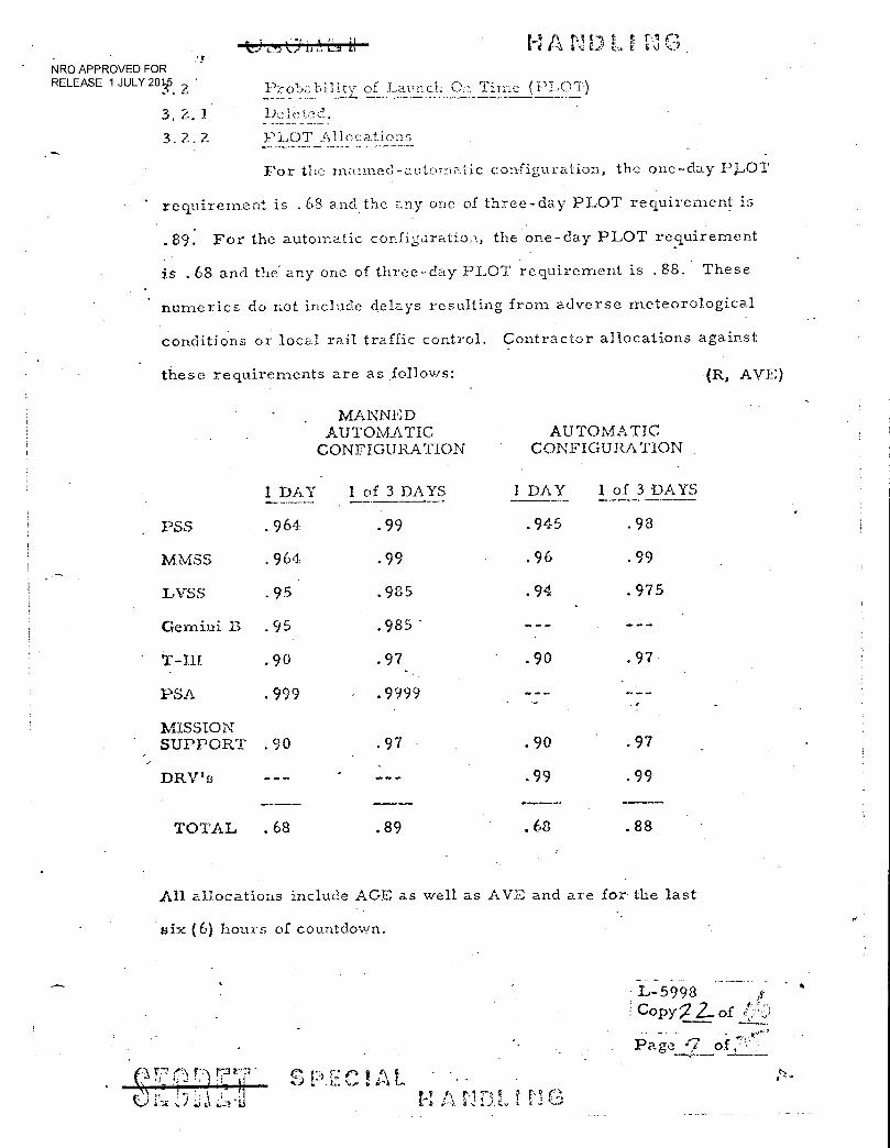
3. 2.2 PhOT Allocations
For the manned-autc-)matic configuration, the one-day PLOT
requirement is .68 and the any one of three-day PLOT requirement is
.89. For the automatic configuratio, the one-day PLOT requirement
is . 68 and the any one of three-day PLOT requirement is .88. These
numerics do not include delays resulting from adverse meteorological
conditions or local rail traffic control. Contractor allocations against
these requirements are as follows: • (R, AVE)
1 DAY
MANNED AUTOMATIC
CONFIGURATION
1 of 3 DAYS
AUTOMATIC CONFIGURATION .
1 DAY 1 of 3 DAYS
PSS .964 .99 .945 .98
MMSS .964 .99 .96 .99
LVSS .95 .935 .94 .975
Gemini B .95 .985 .1. ...00
T-III .90 .97 .90 .97
PSA .999 .9999
MISSION SUPPORT 90 . .97 .90 .97
DRV's .99 .99
TOTAL .68 .89 .68 .88
All allocations include AGE as well as AVE and are for the last
six (6) hours of countdown.
• L-5998 if
C°PY 2- of rc,!"
Page "7 of ';
: 2 1 7.) ;,j a :f
S C ! A • • •
H Ac. t G
_
NRO APPROVED FOR RELEASE 1 JULY 2015
r '• 'Z'f) V it: t r? L
L. 3 11
3.2.3 System Level Grou
•
and Assumptions
(U) System Level PLOT modc:1 and analyses shall be developed by DXC.
using inputs from segment level PLOT analyses developed by each :\ssociate
Contractor. The system level PLOT model shall be based on the ground
rules and assumptions below. (T, AVE)
3.2.3.1 Success Criteria
(U) A launch attempt shall be deemed to be successful if ignition occurs
during the one hour window. It shall be assumed that ignition will be withheld
if there is any known unco rrected failure of AVE equipment andior if the
ground/air communication operational requirements for ascent and early
orbit are not being met. (AVE)
3.2.3.2 Availability
(U) The 2-week-in-advance-specification shall be interpreted to imply that
activities prior to countdown can be planned so that the system is ready to
start countdown on time. In other words, it is to be assumed that the system
is available at the start of countdown. (AVE)
3.2.3.3 Countdown Timeline and Interval Breakdown
(U) The most recent version of the Launch Operation Flow Subgroup Base-
line Flow Sequence (LOFS) shall be used as the basis for establishing time
intervals for PLOT calculations. The timeline for the PLOT calculation shall
be divided into no more than 9 sub-intervals. The sub-intervals shall reflect
at least 1) the start and stop times of radio frequency silence, 2) time of
insertion of flight crew and 3) the retraction of the mobile service tower.
3.2.4 Segment Level Ground Rules and Assumptions (T, R, AVE)
(U) The segment PLOT models and analyses are to be developed by each
Associate Contractor for his segment and shall be based on a methodology
consistent with the System Level PLOT methodology. The segment level
PLOT model shall be capable of providing the inputs required by the System
Level PLOT Model. • (T, AVE)
• !-1 • r"-] /7)
• L• ■■ ) ,
L-5998
• Copy .,2;o _ Page
1 •",s t
\ I ' •
t•::.,) ;•:j
NRO APPROVED FOR RELEASE 1 JULY 2015
3. 2. 5 Coml-ionent Guidel racf; Sec rnent
(u) For each sub--interval, those components which meet
one of more of the following criteria shall be included in the segment
PLOT analysis.
a All AVE components shall he considered.
. b. When the 6,-.pected failures of an operating ground equipment component divided by the expected failures of the total segment operating ground equipment is greater than 0.01.
c. The total corrective action time is expected to be greater than 2.1 hours.
d. The corrective action requires segment disarming, deviating or refueling.
e. Failure requires revalidation of any AVE.
f. The failure of the operating ground equipment component has an effect which crosses a segment interface and. induces a, secondary dependent failure in that interfacing segment and/or requires changes in the nominal count-down procedures of that interfacing segment. Situations requiring recycling on the second segment or requiring that the second segment wait until corrective action is completed are covered here.
g. A Class III or Class IV hazard to the prime flight crew is involved.
h. The operating ground equipment component is "critical" according to the criteria set forth in the discussion of Reliability Critical. Items, RCI (See Paragraph 5. 3. 1).
i. The component is life limited. (See Paragraph 5. 3. 2). (T, R, AVE)
3. 2. 6 Data
(U) The input and output data, calculations, assumptions,
models, and computer programs used for Segment Level PLOT
assesment shall be available at the contractor's facility for review by
the MOL Systems Office. (T, AVE)
L-5998
CopyV, of f:7;
Page 0 of:
` - •
NRO APPROVED FOR RELEASE 1 JULY 2015
;A<
, !, • 1‘ ; v It A
; rq
1 ,L.
D "
a a—
•• 3.3 Y ANALYSIS •
(U) The analysis requirements for the MOL Safety Program are specified
in this section. Safety analyses shall be used to evaluate the hazardous -
conditions that may exist during the MOL mission and the resultant impact
on safety. An acceptable level of flight crew fatality risk is specified in
3.1.3.7 of SS-MOL-1B. The hazardous conditions to be considered are
specified. in MIL-S-38130A. The goals for the maximum probability of .•
occurrence of Class III and.IV hazards is specified 3.3.8 herein and
allocated to the affected segments. '(T, AVE)
(U) Safety analyses are required by MIL-S-38130A for all phases of MOL
system segment, and subsystem design and development. There exist a
number of analytical techniques that can satisfy this requirement. It is
intended that. the most effective of these approaches be applied to MOL design
to the extent necessary to verify that an acceptable level of safety has been
obtained. ' To achieve this goal within the MOL Associate Contractor structure,
each contractor must conduct a safety analysis effort compatible with the
programs of all other contractors. Requirements of. this section are designed
to provide compatibility by assuring uniform and timely application of
appropriate techniques at the integration level and apply•to those AVE, AGE
and facility equipments that support the prelaunch through retrieval phases of the
MOL mission. (T, AVE)
3. 3. 1 Analysis Methods
(U) Four safety analysis methods may be used to satisfy the requirements of
this exhibit for system level analysis: Gross Hazards Analysis, Fault Hazard
Analysis, Fault Tree Analysis, and Operating Safety Analyses. The extent
to which each analytical method is - applied, including schedules and milestones,
will be specified by the Contractor in his System Safety Plan (SSP), 5.3.'11.
The program for incorporating various Associate Contractor safety analyses into
integrated safety analyses of the overall system will be defined by the phase
integrating contractor in his SSP and in coordination with the supporting
Associate Contractors.
e 4.-3 771 • 11 rs:
•
r.„.); r
(T, P, AVE)
L-5998
Copy7 2 of. o
_ age t of
NRO APPROVED FOR RELEASE 1 JULY 2015
(U)For safety analysis of hazards cenfi.ned to an individk.al segment, alternative .
techniques may be utilized, providing (1) the data, supplied to the integrator is
in a form that can be utilized aeld (2) the Contractor in the SSP provides -
justification that the techniques being utilized accomplish the end result.
3.3.2 Responsibility. alvsis Integration
.(U) The Aerospace Corporation, systems level integration contractor, is
responsible for conducting•a gross hazards study, fault tree analyses and
operational analyses at the system level. The responsibilities for integration
of system safety for each mission phase shall be delegated to the associate
contractors specified below.
Prelaunch and Launch Phase Titan HIM S/S Contractor
Ascent. Phase Gemini B S/S Contractor
On-Orbit Phase Laboratory Vehicle S/S Contractor
Reentry and Retrieval Phase Gemini B S/S Contractor
The contractor responsible for the design a.nd development of a segment shall
meet the intent of MIL--S-38130A by conducting the analysis defined below, as
required, relative to his segment and supply the analyses data in a form that.
supports the integrated analyses defined above to the criteria provided below.
(T, AVE)
3. 3. 3 Gross Hazard Analysis
3.3. 3. 1 Scope of Study.
(U) A system level Gross Hazard Analysis (GHA) shall be performed to
provide a qualitative safety evaluation of the MOL design. This effort will be
performed by the system level integration contractor. (T, AVE)
3. 3. 3. 2 Environmental Hazards
(U) Hazards associated with the design operational environment will be identified
• by the Gross Hazard Analysis. The impact of changes in the operational
environment will be investigated to establish the degree to which each mission
phase should be evaluated for sensitivity to environmental conditions.
(T, AVE)
L-5998
Copy2 2. of 07) S
r. 9 rst
NRO APPROVED FOR RELEASE 1 JULY 2015
3.3.3.3 Source:
(U) Particular attention shall be ,2iven to sources, control and diStribution
of energy, such as ordnance devicc.'.s, fuels and propellants, and electrical
systenis. (T, AVE)
3.3.3.4
Other Hazards
(U) Other areas to be considered include, but are not limited to, the
following: •
a. Compatibility of materials
b. Electrical transients an d RF energy
c. Pressurized systems
d. Atmospheric Contamination
e. Human interface • (T, .AVE )
3.3.4 Fault Hazard Analysis
(U) A qualitative Fault Hazard Analysis (FHA) shall. be conducted to identify
potential hazards associated with each contractor's AVE and the OGE and
facility equipments required for the launch phase subsequent to prime
flight even-insertion into Gemini B and is performed by documenting all
identifiable component failure modes and defining their resultant effects.
(T, AVE')
3.3.4.1 Classification
(U) The hazard associated with each failure mode shall be classified in
conformity with the criteria listed in Paragraph 3.2.3 of MIL-S-38130.A..
Failures resulting in safe (Class I) or marginal (Class II) conditions or events.
required no further analysis. Failures resulting in critical (Class III) or
catastrophic (Class IV) conditions or events shall be reported to the procuring
agency and to the designers with recommendations for remedial action. (T, AVE)
3.3.5. Fault Tree Analysis
Fault tree analyses shall apply to the same time periods and equipment as the FI-Ln..
3.3.5.1 Scope
(C)
All. critical and catastrophic events shall be analyzed to deterrni:--,J:
nature of the hazard. Fault tree analyses (FTA) shall be used to identify events
or likely groups of events which will produce the defined undesired Class III or IV L-599.8_
P E Pa. n.e
NRO APPROVED FOR RELEASE 1 JULY 2015
ha z -ard, with a pctential t e predicted prime flight crew fatality,
or, in the case of the backup :•ecele qualitative Leult tree type of assessment
for equipment damage. AV E)
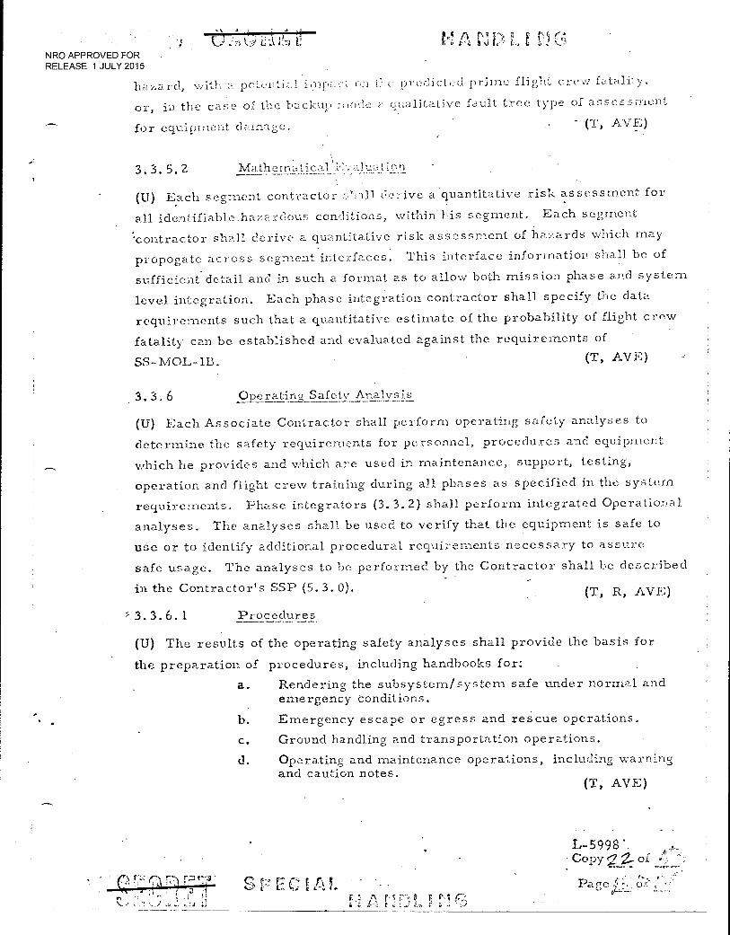
3. 3. 5. 2
(U) Each segment contractor :.:.all lye a quantitative risk assessment for
identifiable.hazardous conditions, within his segment. Each segment
'contractor shall derive a quantitative risk assessment of hazards which may
propogate across segment interfaces. This interface information shall be of
sufficient detail and in such a format as to allow both mission phase and system
level integration. Each phase integration contractor shall specify the data
requirements such that a quantitative estimate of the probability of flight crew
fatality can be established and evaluated against the requirements of
SS-MOL-113. (T, AVE)
3. 3. 6 Operatincf Safety Analysis
(U) Each Associate Contractor shall perform operating safety analyses to
determine the safety requirements for personnel, procedures and equipment
which he provides and which are used in maintenance, support, testing,
operation and flight crew training during all phases as specified in the system
requirements. Phase integrators (3.3.2) shall perform integrated Operational
analyses. The analyses shall be used to verify that the equipment is safe to
use or to identify additional procedural requirements necessary to assure
safe usage. The analyses to be performed by the Contractor shall be described
in the Contractor's SSP (5.3.0). (T, R, AVE)
= 3. 3. 6. 1 Procedures.
(U) The results of the operating safety analyses shall provide the basis for
the preparation of procedures, including handbooks for:
a. Rendering the subsystem/system safe under normal and emergency conditions.
b. Emergency escape or egress and rescue operations.
c. Ground handling and transportation operations.
d. Operating and maintenance operations, including warning and caution notes.
(T, AVE)
Copy- g of
S C r A !, Pate :J.-. 3.: y 141 r,
z t e
• , • L ti
NRO APPROVED FOR RELEASE 1 JULY 2015
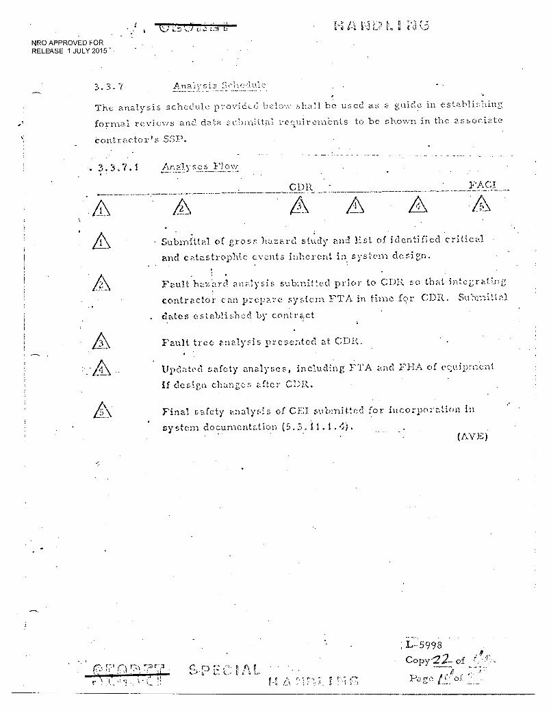
3.3.7 Analysis Schedule
" . The analysis schedule provided belr.)v,- shall be used as a guide in establishinz,
formal revievis and data submittal resuircudents to he shown in the associate
Contractor's SSP.
• 3 1 Ar, yscs
Cl)R • FACI
.3\
• Submittal of gross hazard study and list, of identified critical
and catastrophic events inherent in system design.
Fault hazard analysis submitted prior to CDR so that integrating
contractor can prepare system FTA in tin for CDR, Su'onlit t 1
dates established by contract
Fault tree analysis presented at CDR
Updated safety analyses, including FTA and FHA of eciuipment
if design changes after CDR.
Final safety analysis of CEI submitted for incorporation in
s y stem documentation (5. 3. 11 (AYE)
r Cs.:•• r P. i•\
r
L-5998
Copy22-- of _ ,•
Page
t1 A k.:01 ■;;::
NRO APPROVED FOR RELEASE 1 JULY 2015
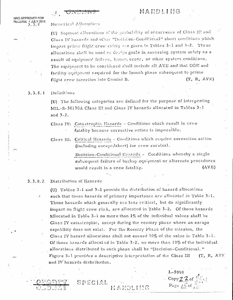
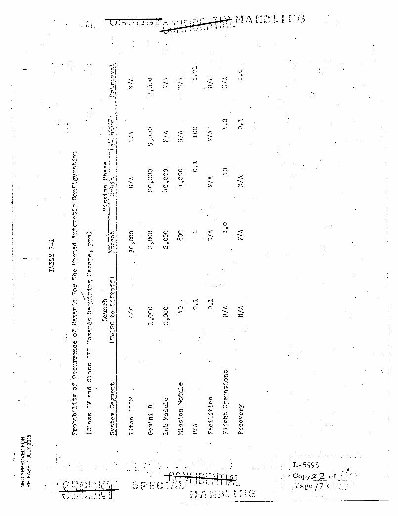
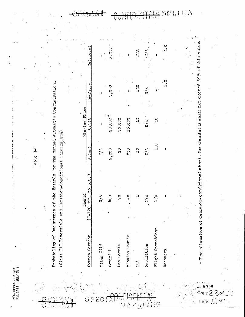
3.3.8 Numericz.11 atior;s
(U) Seernent allocations or the pi.obability of occurrence of Class III and
Class IV hazards and oth- "Decision-Conditional" abort conditions which
impact prime flight crew sa:Cety given in Tables 3-1 and 3-2. These
allocations shall be used s design goals in assessing system safety as a
result of equipment: failure, human. error, or other system conditions.
The equipment to be considered shall. include all AVE and that OGE and
facility equipment required for the launch phase subsequent to prime
flight crew insertion into Gemini B. (T, R, AVE)
3. 3. 8. 1 Definitions
(U) The following categories are defined for the purpose of interpreting
MIL-S-38130A Class III and Class IV hazards allocated in Tables 3-1
and 3-2.
Class IV: Catastrophic Hazards - Conditions which result in crew
fatality because corrective action is impossible.
Class III: Critical Hazards Conditions which require corrective action
(including escape/abort) for crew survival.
Decision-Conditional Hazards - Conditions whereby a single
subsequent failure of backup equipment or alternate procedures
would result in a crew fatality. (AVE)
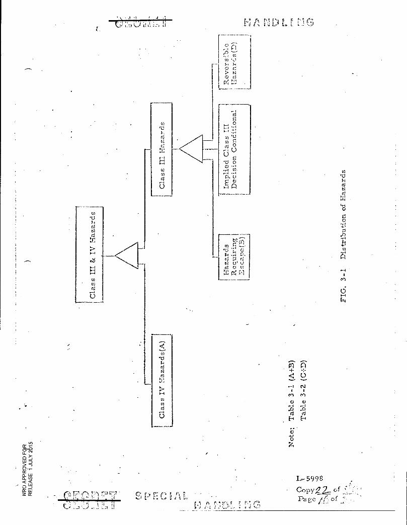
3.3.8.2 Distribution of Hazards
(U) Tables 3-1 and 3-2 provide the distribution of hazard allocations
such that those hazards of primary importance are allocated in Table 3-1.
Those hazards which generally are less critical, but do significantly
impact on flight crew risk, are allocated in Table 3-2. Of those hazards
balocated in Table 3-1 no more than 1% of the individual values shall be
Class IV catastrophic, except during the reentry phase where an escape
capability does not exist. For the Reentry Phase of the mission, the
Class IV hazard allocations shall not exceed 10% of the value in Table 3-1.
Of those hazards allocated in Table 3-2, no more than 10% of the individual
allocations distributed in each phase shall be "Decision-Conditional. "
Figure 3-1 provides a descriptive interpretation of the Class III (T, R, AVE
and IV hazards distribution.
4v `FO I 1̀‘
L-5998
• CopyZ of
gc J_.)-of
Not
e: T
able
3-
1
C)
L.-5998
- Copy;?2:7 '
Page f,"-, of ' • •
4-) .4-4
; C)
C.;
O
tii
Ft
4,
C)
hd E: tii
4-3 14'
C.>
▪
t) CS
Mission Module
Facilities
rt 0 0 • •
• r-1 I.: ..---
C.,
1.:-. Cs:
H • •
o r-1 0 <
H
I-4 4)
0-1 .
H
< .....,. -;
< ---... ,-...
H
0 •
1
< ......_ 74
..r" --..... ....„....
• •
0...-., 0 0 0 0 ‹.•.: .1.. \ 0 C 4.... ......
s....0 0 '16" v. .
C
4)
O U O
E.!
•-t Ts ▪ e, r;
E- ti
Ls c! 0 • P \ \ ,;:s
c, 4-- C) 43 4
U ra s.-t ,
o cs cs .2,
C Li
t-t Q3 O • E-4
.--, 1> C. 0 C C
E 0 C -0 0 r, C) O c C..) co
P I c...) • R. Ow
V: 0 04 Cu
4, < 01
(1.) P.
C)
< 0. 0 0 -....... • •
C 0 -7: C; -:
H • C. 0 C 0 0 ,-- 0 C H
r. 1--t CS N
•;.1 0 a C
0 'a
.41 a
>
• t.r) 0 14 C.)
. - 11 , 'LH
Cs.: 1
C'''' 0 ri ,0 0
t----
C O •e-f 4-3 C5
O U
)), C 4-3
E 0 4' 0
ni C) ,9
• 44 ..-• ei .0 E. L4 C-o
C,..
gi rr-1 /-1 CI N- Cl
0 rC +3
44-4 o
C.)
S. 0 CJ C) 0
4-3 rri r •■ ••■
rg 0 t:
....-.. 1: Pt CA •:..1 S-■ 0 N GS
..z." .,
...I 0 r: 0 .. 4-' Y i
0 C.)
0 ft-I
ft-I
0 c
f'd r
0 H . iof0 in X,
C)
1.--1
I-1
03
P-•
0 •■-■ V/
or
or: U
ci
c;
51
1. 43 C)
>
C) Cr.
43 ^-)
S. 0
4)
C) C) C3
0
na
4.)
•
0 C1/4:
4-)
C) 4-)
Cl)
• i
•
I
1
< q:. r.
<
1...: , . 1-4
it d 4) ..-i &-'
C.% C)
r r--,
0 0 0 Cr%
*
0 C..)
0 01
0 0 0 ..
C)
-.4 4 ...i V o C
1
Cr 0 0
4t, 0 tr.
0 CV
0 CV
O
I
I
0 0 0
kr) H
0 0 cO
CD
0
rj if, 0
el'.
C C) .. 0 CI
:
< ......., :":
0 0 H
0 e 1
0 H
H
.ct Cl) P-1
< •••., :-...
< *"..--
< ..,
'-
<
H
H 47
k.
o,
o el
H
<
• 1,4
VI
C 0 '.1 43 0 I-I 0 8. 4-3 ,,r: Cal H R.
0 r-{
.4
I
1
›.. 14 0 ›, o U 0
c4
C)
Li
.1
0 ::-■ (C) lie
co .,-
C)
0 CO 'cl
0
g C)
4-) 0
r 0 A cn
• r4
.1
0 S-1 0 14-4 rn bs 1-1 0 ci r cd
0 .44
0
1.1 0 .ri
C) .0
1.4
0
CI 0
..-: 4
0 0 0 .--; ri gd C)
.4 El
*
0 f -r- reqc ,
(7-, r") ro i-,
• 7.•
L-5998
Copy 2. of
_./
k,)
9, 7.1! r•-.?
NRO APPROVED FOR RELEASE 1 JULY 2015
APPENDIX
EK DEVIATJONS
TO
SAYS", 30002
-:" ; • 9 ,rk. . •
599.$ CoPY2Zof Pag 7 of
1
NRO APPROVED FOR RELEASE 1 JULY 2015
EK's current contract baseline calls for a reliability goal of at least
91. 4:,,7.0 for the probability of successfully exposing 14, 000 ft. of primary
reco:ed at an acceptable quality level in the manned-automatic mode.
This requirement is lower than the goal allocation given in paragraphs
• 3.1.1, 3,1.2, & 3.2,2.
Therfore a SAFSI, deviation to retain the contractual baseline is granted
until a study can .be performed to determine the capability of the PSS to
meet the SAE'S', 30002 requirements.
• Included in the study will be identification of changes required to approach
the SAFSI, effectiveness goal allocation.
r P f1 r
59_98 Como 7 of Page TT-, . of7"7
z
Se, 0 U)
P1 fr,
-g I
ci
*4-
P O
ri
-13 I ON 1-1
-1 C.' 4-1 I; 1 0
• (5
-
1 41 U P:1
1 ri ,K;
-P (i) 4-3 'CI • O C.) --t
C) Lc. F1 • I 1.4 I)
E f1 I
C) LI 11 • /--1
O
.E-1 c, 4.1 E4 tO 0
Ct c 4>
4= C3 4> 0 C) Cr) c 22
cl.
S1 F
C'' p. ■ c-4
C) 6 F.! •
.c'1 'It '1 ',0 ti
0 -1 •rt -1> fr
r) .,5 GI C) (4-4
Z-2) 1) 1 /--4 5,4
0 6 C) ,c1",-- (1) ,O
Fa rd •
ri 4 Q1 •,!a $4- tc-11
C) k 42 to to 0 I 0 4) 0 F t I
Pi P 4-1 Pi PS
SY
0 • ••
0 }--) v. 0. ;4 r{ ;../ CO ::
.0 4.) .... 0 4-3 .,!, ci , -.1 0 rj •13
-0 4' *,--C - EN.1 ,--i 14 0 cr3 , .-I 41 C \J 0 0 76' C■ , 1 .j.- : . .-- lc i r -51
grli S-t -,4 0 I
41 0 ,0 •ri H 411 Pi • Ps
0 0.1 0 ,-0
p_11 0C. - - it '3., r..r34 0 fa5-1
•,-4 ..- 4
-4
O :_-/ -..-:
c't i d 4> ri .$-0,1 404 .+,44, 41
✓c..s s
• -
4 ...-: s.:1 -1-'
L("\ }-a. -0 -1-.' .r> Fdi 0:i ::01
ti {k S4 0 r--I ,-1 •r: ^ C) ,-,1 4> 44 fil .„ 50, :_11-4 0\ O <1.', Pt 4-4 ,0 Ea 0 I ...-1 0
L i H 'Li r 1 :: Pi 0 gr4 4' d CV H
H ;,-s 0
rcl d CI ,c--:,-.. ''.. ri 0
O fis C) ..--t to 0 d C) q.1
1 6 sl 5o
'') 0 1-4 u) 41 C.A ,r) ..,..-1 .-1 1-1
0 ,--s d cl 0 r.4 0 ;-e H Ti -,f,
cl 4, 'ti 'd 1,1 ,-4 d ,c1 d ei:, : ., 1 o d .t> 5.4 0 0 rd
:., o 0 0 ri-, VI 0 • 4-4 -1-> 4> P 0 —4' O H r›...,--1 1r2 0 <1; 0 0
E-4 ;...I sal eJ 3:1 S. 4-1 ■.-1
,--1 e) ei
CS (Cl , -I 4-> -5) cl
el cr) 14 d ..": c-s A ,-i 1-.5 ":"---, s-1 P1 COi to
,ti.);
O 0 Pi Cr) 'CS 0 0 0 0 E) 0 , 0 0 0 O 0 (1 0 (,-.1 rd 0
Cil o i-I 1.4)
1- C) ,c-: , :., s il•
-P VI 0 I: K • r-i P4 4) :?: 41 0, '00 0:--3
; -I C.-) 0 Ci.1 c I Cl) '.1) I 0 e• -,-4 4, -,1 0 -4' 44 Pi;'
O *•4
4-3 H 0 -P 5,-, " 4) • 0 -P (4-, 'ti • tr.
tr.? •-g-{ •,. i -I-1 C.; Zt 21
P1 Ps (3") ,r1 I *" 4-)
1 '134.1 5C-31 r'ji
rli C.,) co ;-1 }-4 = :_.) ,4• 4./ iol f!". c; s--,-01, .,,-1 1.13 U) 41,-,,, (C) 0 to 0,
:_!$ cs
'ii c.) (1 0 c.)._,-; ,,..-, El, 'LI x ,ID 0 ',4 rj Es u) ,4.). ✓i. r-1 0 4 3 ;.- { 0 4> c..1 Pi r, • rs C) 6 'd -P CD
I 0 -) I-2-
Cr, --1 fac 0 d CO 01') •
1=1 -:.-1 . r-0C) c..i +.3 • :-.1
• -'-i .4;1 0 1-1 .-C1 1-4 CS
4-4 Si ,c--1 b0 0.1 El CS -/->
:--1 0 •ri 04 '3-1 E-, 11 04 s-ci H 0 e: 0 :--1 0 Hi Zi: Pi (,) ::: .4-4 fz-1 ,-4: P-1 • Cl r---, .0 0 rd >-.■
1,-4 rCi Pi L: r•-■ cli
Pi 0 O UJ
Pi •rI
to
qi
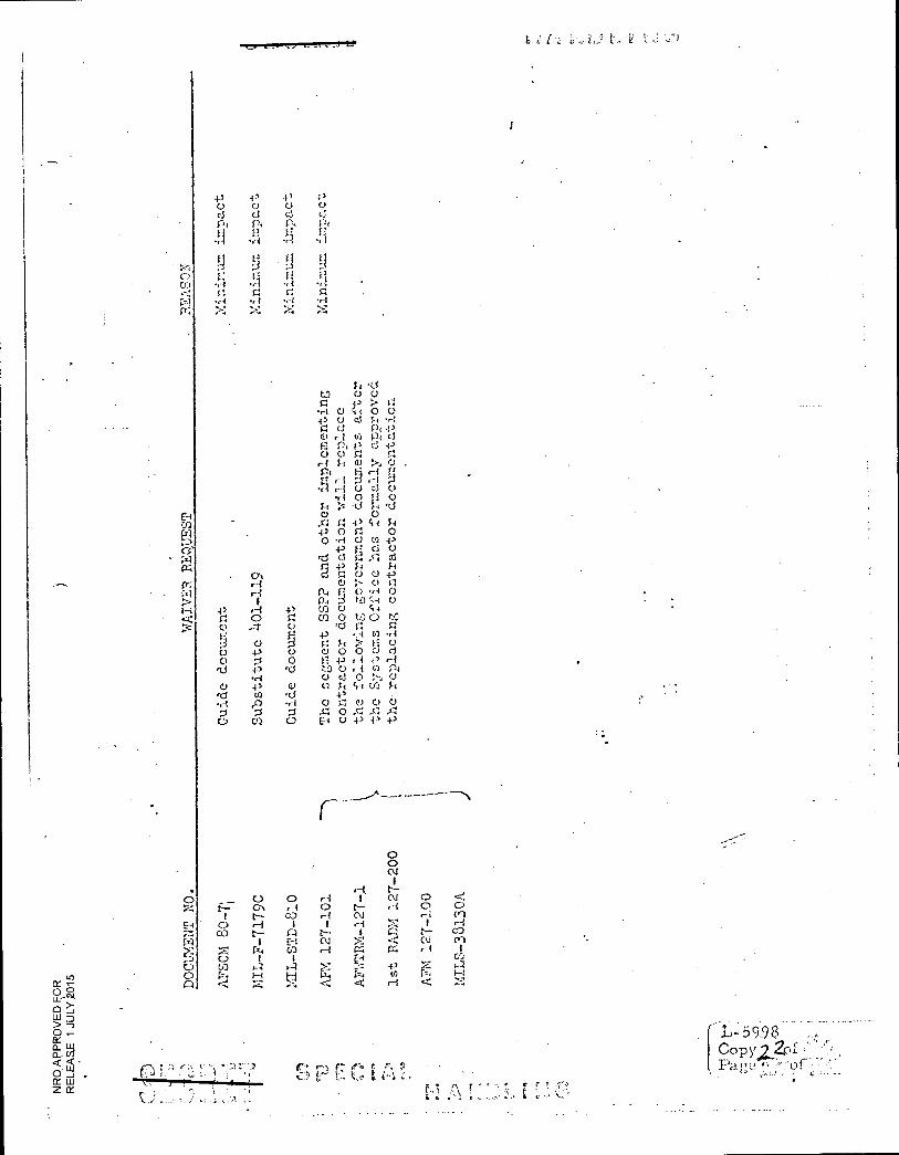
A FS0 P
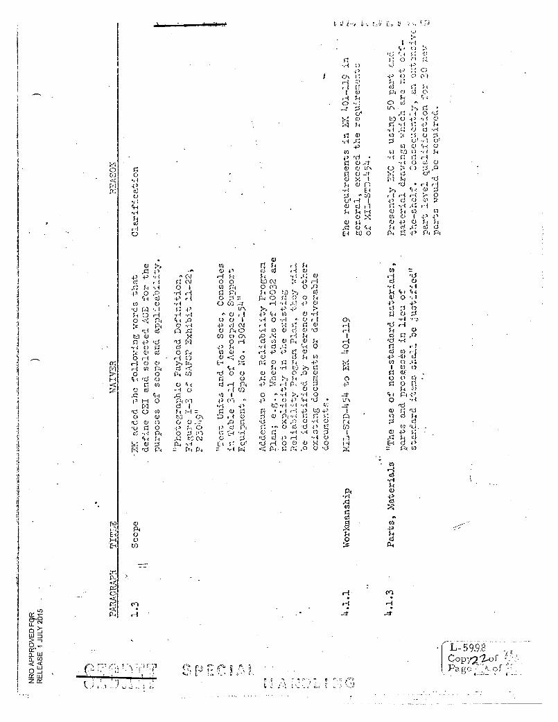
arts, Ma terials
9
47'
5 99.0
Copy2 2o of
•■ 4 ,0 O F--: 43 Ii , .'. 0
•, :.,- (.', __}.*, r, ),
, •r:
i •-- i • 4 ci-i •.- 1 r 4 C) ,c)ej
d ;-. ;r 0
--; •
0 e: ...,-; ,-1 ri 4 , 1 4 0 P.
• 0 -.1 O CI c4 ic)
-a -: 4-1 0 4) 1•-:3 $4
''-, 0 Pt 4 ' a) 1.--1 ...:
C) P., :---:-. H 0 4-) -ri 4) }-■ Ui ,a • c.) r-. 4 4 •*- { 1) d ,d, ..-1 ca 0 P-: 0 43 .-0 o '1 i
,. 11
;•1 0.1
O +3 g r: pi ti) •
•rt 0 r-1 O fi 43
4.1 O 4-3
E', P
0 r: 43 f-
0 4
0 ., i 4 , •-1 C) C) ,-0 4.4 Si 44 4 4 tJ O 0.i *, 1 0 4-4 -41 A P■ >-: E-4 C.) Al
.. 0 0 • 43 o 0 .::: c3 CO
0
qi -. I ,-1 4-/ rd 4.1 .0 41 -0 4.) H H 4 (
0 0 r -4 . Si 0 4) ;-4 ,d tz) 1-0 Pt 0 0 •■-i
d 0 4--,. 0 :.: 0 0 0 0 •c-J 0 d r.t C) 'LI -.• 0 ci...i ,.0 ;:c 0., • P., 0 ;_i 0 fi
r• ir: 0 o ...- 1 d 0 ',--., 0 ;._1 44 ',7$ CI 0 'd d
to :.3 C.) d ,d-1 ',CI 4,:), :1,34 0 1i 0 44 F 4 -0 0 Cie I'..0 0 .1-1 0 4-1 V ,0 0 4-4 g pi 0 " r-{
(4 0 •,4 = rO 0 ad ..-4 'CI 4-4 4.1 S. r--: ' 0 -15 0 t.-.0 S-4 El
10., 43 0 C.)
S-.4 r 4 '73 Cs r3 r4 C.) d H ! • - I ri, 0 0 al 0 P. CD
.7...) 0 d rd 4' g 0 F c V d 43 • H 43 0 -p ',4 .0 Sr d -,-t ,0 •ri •r1 4-3 t.t) 0 I:3 (..) fl CU (s) U F4, 43 T4 rd !
co) :1 c..cci -P.14 •pri In ',9. C') r‘:
•
C. '‘.0 O "":":: 'iCrl •Crl :S:5i :(71 'CI 41
o d cd C.r \ 0 '13 p, Fr: 0 S4 0 0, S1 r-.1
'CS ••• +3 - I I 4 4
1:-' -:- 4,C )':.;11 4 ''.: :11 - . '(-4::: = d 0 0 .--1 0 d i'.1 .0 CH r:LCS ;•-•->'2 'r-i0 40' Cji +3 *$-%"4 ,-"4-21? 0 4.) ..+-4 i 0 • 0 0 0 0 •-d o 4-1 0 c.% 1 0 ) d P-: 111- : ; 74, 5:),:: lc: 4tcr-.33,..,: p?04 , cEic .: . ,21 , cuorl , a: .. .. , i .ccil Us
F:
40 , CO ) ,-I rd 'H
4.3 CIE) Co) 0 r 1 0 -p 0 0 H
0 0 r' d , 1 1,, d Et 0 c.4 C) 0 ''' 4-4 0 cr4 ,C) 0 P4 ..--3 ;I: ,-7
tt--4 44 rc.-.4 I P 4-3 43 d 1:,:. ..d F-I •■-4 d re 0 0 0 0 rc..1 d 'CS .., 4 • d d 0 s_-: +3 .4-+ 0 i--1 0 0 0 0 -1- I 0 Crj
ta c.5 C) 0 il -ri -ri '0 •,-1 "ri :., r 4 0 4 3 ,-4 r, rd :4 O 0 4-s g: d rd 43 i F. 0 -■ -; -r-4 4-.4 r-4 0 CO t...1 CC'S C) 5.-1 0 C.) }. 0 ;J C) 4) ',-. 4.4 43 ' P-■ r i •c) IN?. H p 0 4-4 ,O c-: - d d .r...1 0 0 0 0 0 •,4 P4 0 c,1 0
d u ri 4-4 (4) c- I •,-4 0 c-+ qi 43 43 4-4 0 '' g 0 ,g 0 4)
P. •,-4 • H 43 0 C) c.) 1 0 -43 11 0 0 H .474 4-:." ..0 0 H U 0 44 d AD S-1 13 u Pi 0 •r 1 'd ,r)
el 4-1 0 0 0 d 43 7.1 0 0 0 4.3 0 , f-i rc:: g C.) 0 C3 +.3 0
CO ,L1 ,0 ,r.:: •r-1 0
= 04
.-.1.---r (..) ;..4 il. 0 CO c1-1 ,L-4 0 0 Cr: P4 :3.' cd c E-4 43 0 ',;".-t C..)
. ;
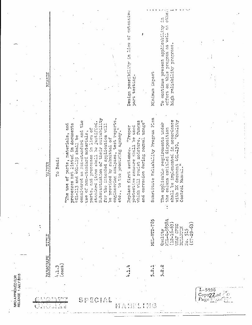
MIL
-STD
-735
<r!. co .--- UN Cr) C.> CO ■0
\ 1 P. i--I lr■ I 4." 1 \-0COE 01
H 1,1 U.\ CV r-i 1 1 ki 1 d t-7 • 4— • F--) H t.r) 0 CD
P:1
H (N.1
9 9 UN 47' \
C) U)
U-,-
ci ci
1-4 C) ; c.)
r(.1 ti Crl
0 ••■ •4 . 41
ci C) V) ci Al 4,
ci
N
Ci
4, ci C)
34
•
• I ci
0 0 0 0
O Ci 3-1
4 3 P.1 Cr C) C) S.+
r rcl ci f-40 00 • H
C-)
4) 0Ci
04)Pt
34 Ci i
-P 0 c-I 0
coC) ti
ci ci C)
5+4 to 0 3-4
P
C) 43
e4-4 C3
CO
;;•-:
Co
1%1 N
Lt, 41
c) S; 0
.4) •1
4> c.1
.!4 4) 1'
'U
/4 0
4,4) .
C3 -P
: Ci C)
c„3
ci ;3 •
H .-P -P
sl O 0 Cr. .43 •
• C) 41 3-1 1-4 r4 C.) P4 4,
C) C)
.0 CC)
$-;
C) F4
t.
C.,
c3 Ci (1). 4' ()
ci H c-i
4) '44 c1
E4 4/)
0 I
C! -A C7/ >•:
c".■ t O cd
14 C) 4'
C) C
4.! 0 n o 4)ci Ci cl C) •,-;
• ,c1 • H tO Pt H
.4,•7 0 • 441
-1 3-4 d cr"\
o ri P Ci
..c) . 0 d •Ci 44
U
3- 0
4,
d ri
,43 Ci v.!
•
Ci 4- 3 C,)
ci) C) V3 ...••=. l-05 ,0
S r 0 (I) 4. C> P4
34I C3 3+ CI C) 0 Li tY2 0 7,1
4-4 0 4) r.".) 43 34 C3 03 -0
F4
C.) H 0 r.),
Oci 0 P4
4., V)
0 ci H
C.) Cl ci Cl) Pt
Ci ci
4-,
▪ o 43 4" 0 •,-;
• C)
34 cd
•
C)
ci
:3
,14
,--4 '0d
4-4C)
0
C.) rC
C')
34 C)
ra 41
r •r1 N 0
0 4-3 4-4 +3 .1-1 34
0 43 o
41
(.1 4-, '."-1 ci e4-4 C.) C) 0
4-> ;A
Ci ci •r-
•r-i C) 4)
,0 P-; rd 43 •r4
0 E4 4:3 3-4 :•- -P ci
O 1 Cl
slso 0 o C.) 4'
.11 $-1 4, Pq 'd ci r, U ri C.;
*
•
P. 4.)
C) •,-t O 0 0 .4, Ci H
43 43 d Li ci
00 C) !;./ • ri Ci
C) II C) • .r I
r-1 0 4) PI (-3 -P 0 C) •r 1 0 •,•?", ;-4
• 3-3 • , 4)
Ci • g: 0 0 Ci c)
sl•-; O 43 I 3-4 0 d s•-•:
-P 43 ,-i
0 3--I
C) r .r1 ,0 ci ci
C) c') C) (-4 C) C.)
cd -QS Ci
,C3 4 5 340 Pi C)
C):1 CD
C) II
e—{
cd Ci cs;
• rt
•21 EL
E4
co co
CO
PAR
AG
RA
PH
•
CV
CO •
LC\ to
(7,7) c -. C r. r c.;
;j tt s. e
r I— 5998 , Co py2 201 Pa a e
,r) a —
>-)
LU
0
IAJ
rr <
0 UJ
Z
4 3 0 co Pi .:.!
•,-4
9 LI
,-I 0
.4-4 ....
..,
-0 C: d P; l'.1
, q
1 il .,1 0 -ri X
.p 0 :-..1 Pi k
" 2 r ,-,-1 0 •,-1 >4
.4) Cl d Pi F , 1
ti 2
•,-- 9 0 •ri
-P 0 d Pi f i
,--I
11 d
.t -4 g •ri
4.2 0 d C Ei
-e -I
f 1 2 r7. •r-t g •ri
Cr.. ON, r-i
I P1 _ ,--t U)
1 ■--1 F-1
..... I.C1
.-7.t I n E-4 W i
t- 1 I-I
•ct
-0- CV r-i
I C C-1
" VI I
1-1 1--4 ::--::
1 CO CC) , I
.1, f.,, -4
0\ 0 (.-V I
A E-I (J) I
C N P-,
- •
0
1 1 ,,-.0 cn ‘-.0 \ ..0
:6 LI .: 1-4 P-1
CC u) u) Ca 0 M
IL-S
TD
-1)4
3A
MIL
-S-8
5 12B
docu
men
t n
C)
C) 43 43 0
• f.4
-a
C) ,0 rd C)
VI • 0 0 rd
0 ci
0 4 )
to
•9 'Ci
0 Pi
1-4 o
fri•
a)
.0 • cd
0 C) c.1
0.1
C> d rd
d p r( )
X 0 Cr] EE U)
-N
1-4 1E1
cr", O ES ci
El $-E
C.) 4-E s1 4
ci
•
çl -P ci
Cr,
tab
le b
elo
w i
s
0
E-I
c'1
0
.....i cr,
tn. , t
H H
I 1
0.1 r 1 0
0 \ H
H 0 1---i
0, ,--1 r7:4 i.r.
▪
C) 01
r-1 VI E4 r 1 0 H
H C) U) I r- 1 H
1 1 CV I I
r4 -1-) 4) n 0 1--1 H o 121 I-: VI C\ 0 C.,
-.1' 0 C) C.,,,, H -1- --1- li r
0 0 ;Li C) C) C) C.)
4-) U (2 4-) 4 ) 4-, 4-,
4-; o 0 i 0 . i i A C 4.) ..-.) 4-) 43
./4 •F.4 •,1 *r i 'd
4-, C) 0 4) 4, 4-, 4-,
Ca ,c1 -LI in cn rn ca
.-0 •:-4 •,-1 r0 rn ra .) ;--1 Ci :-J Ii 0 0
U) 0 0 U) C!) til ti)
o CD tr. rt, 0\ \ \
-IT 0 u^\ tr. c0 CO H
H ‘ -1
1 (-4 C) --r
C) 4., ;3 43 -‘1 4-, cn ra 0
(r)
0 -a'
..
H I
C\' 0 0\ ,---1 C) 4-, -0
-13 '..-1 4-, tn P 0
tr)
0-••
C) r1 rr> ci () •-( H C Pi d
4-) 0
' -'7,
(1) r-t ,r3 ci U •H ,- -1 Pi P C)
4), 0 '.4
H ri
I , r .1 0' -z
2.) 4-, 0 +3 ■•4 43 cl P 0
U)
,c1 q.:1 0 C) -0 4-) C) C)
r-I H 00 CC
L-59_98 _ Copy 2Pf
2
Lo ..--1 ...Cr-..,`- 0 °
H
U. (,)
01 >-) 0 ,-• CC • 13_1u • CO < <
111
0 _1 0::„. ,, - tr,--, ( --. ■ ".-• ,5..2 n n
Ct LI V , 1 ) 'J ka-.) a - t._ \.-_. i; i., . a.„.., z ix
1 1 1 1 4:4 ›; ■-:1 I-1 1-1
I-1 t-4
C) cr )
Et;
0 0 0.1
t- 0.1
cci
4 ) (1)
r-1 An;
TRM
-127
-1
AVM
127
-100
M IL
- F- 7
179 C
OD
• C) Q C 4-) •,4 C.< o C 43 C) ci • ■•4 • d C) r d
P4 4' (5
H
•
S4Ci 0.1
El • H ;.) .-1 ▪ ri 0 ci C)
0 fl 0 rd J4
C) 0 SIC 4, g•t 4 , 0 II 0 o ,A C.) CR .4.>
43 11 C5 0 'd ci C ci
+) Fi 0 0 4-)
• CI ci V, 0 • 0
tisr -I 0 O tt 4 • tf, () ciC C
+' Ji 0
0 0 0 cl 0 •,-.$ 0 11 4,
o..1 ed tO u o 0.4 O d 0
C) 4, o f4 tt- 1-t 'ci rd +3 •s-{ C) C.) O 0 0 • Cl) E4 U • -P -P
- - —
4)
r-i
r-1 4'
c rt, CO
F.1 0 0 Ca C) -I C)
0
1:4
0 MIL
S-3
3130
A
0". " P • ka• k
r E
L-5996 Copy 2 Zol Pa c, e
NRO APPROVED FOR RELEASE- 1 JULY 2015 .
& L.
ce :01 .k/A
SAFSL EXHIBIT 30005
ELECTROMAGNETIC COMPATIBILITY REQUIREMENTS,
ORBITING VEHICLE, GENERAL SPECIFICATION
FOR THE
MANNED ORBITING LABORATORY
PROGRAM
"-Jui46-- —3-171rr. 1968
p- lnL
c L - 6 0 0 6 • I,
Copy of Page I f//?--O
e.,1
(Signed) ,
• (Signed )
(Signed)
(Signed)
NRO APPROVED FOR RELEASE 1 JULY 2015 SPECIAL HANDLING
5Mb'- c.)e 51".
The undersigned has reviewed the document and
understands the contents to the extent necessary
to scope subsequent proposals.
(Signed)_
(Signed)
(Si.gned)
(Signed)
(Signed)
SPECIAL HANDLING
u w7
NRO APPROVED FOR RELEASE 1 JULY 2015
r •
r
FORE1A'ORD
Electromagnetic Compatibility Desigii and Test Philosophy
Every precaution should be taken in.a Manned Spacecraft program to ensure the safety
of the astronauts. It is vitally important that all significant equipment involved
in the flight operate properly. One factor in ensuring such operation is the
control of Electromagnetic Compatibility (EMC), with the associated control of
Electromagnetic Interference (EMI). EMI generation and susceptibility must be
kept within limits to ensure that the composite system and its component vehicle
system, Aerospace ground equipment system, and their respective subsystems
and equipments are compatible within themselves and that they have a high
probability of operating within acceptable tolerances in conjunction with other
subsystems.
Experience with other space programs has pointed up the need for thorough EMC
testing and prompt application of necessary corrective measures, from preliminary
design through testing on the pad in or.der to minimize costly delays due to
last minute EMC "fixes."
EMC control can be most expeditiously, effectively, efficiently, and economically
applied during the engineering design development phase. For this reason, this
speCification discusses and stresses the design phases of EMC control and
establishes the EMC design and testrequirements for the composite system, its
component systems, and their respective subsystems and equipments.
The intent of this specification is not to impose arbitrary and unreasonable
requirements upon contractors,• but rather to assist them in engineering a
compatible composite system. For this reason, the various EMC control
plans and test plans, discussed herein, are highly important and significant
documents.
This specification utilizes the applicable portions of the governmental documents
noted in section 2. O. It further supplements this consolidation with additional
technical and management requirements to establish a MANNED SPACECRAFT
SPECIFICATION. This specification was derived from SSD Exhibit 64-4 and
the deviations granted to the MOL Associate Contractors. It applies only to the
segments comprising the Orbiting Vehicle and a different specification applies
to the T-IIIM. SAFSL Exhibit 10005 is identical to this document except EK
deviations have been deleted. Page 2 of 106
rs, '73 •-• .3 171 r--, r
;Page :;‹ of /,/ •••,-..
!! rtt, q t •.j NRO APPROVED FOR
F1ELEASE 1 JULY 2015
L aeopm,■•••••
L-, 77i en.r ps
t.
. L- 6 0 0 6 .
Copy.TV). of 4/C
: 'Pa cre _9 of i i' 7,--
CONTENTS
•
). SCOPE 1
. •1.1 Use 1
1. 1. 1 EMC Control Program 1 •
1:1.2 Application to Specifications 1
1.2 Classification 2
2. APPLICABLE DOCUMENTS 5
3. REQUIREMENTS 7
3. 1 Electromagnetic Compatibility Control Program 7
3. 1. 1 Composite System
7 3. 1. 1. 1 JIG. Control Board 7
3. 1. 1. 2 EMC Design Control Plan 8
3. 1 . 2 Subsystems and Equipment 9
3. 1. 2. 1 EMC Control Group 9
3. 1. 2. 2 EMC Design Control Plan 10
3. 1. 3 Short Duration Interference 11
3. 1. 4 Electromagnetic Interference Safety Margin 11
3. 1. 5 Electroexplosive Actuated Systems 12 •
•
3. 1.6 Government Fuihished Equipment 12 •
3.2 Design 13 3.2. 1 Interference Free Design 13 3. 2. 2 Susceptibility 13
3. 2. 3 Case Shielding 14
3. 2. 4 Bonding 14
Page 3 of 106
•
r • •,-7S F 1 11' F . Gas--1 L \,)
1,1• .1 0,
NRO APPROVED FOR RELEASE 1 JULY 2015 . II
..paie 4 of 106
•
C", 7', rs' P., ?? v c
_ L - 6 0 0 6
Copy? of Zt- of if 7-
L CONTENTS (Continued) •
3. 2. 5 Design Criteria 18
3.0. 5. 1 Wire Design 18
3. 2. 5. 2 Interconnecting Wires 21
3, 2. 5, 3 Grounding and Isolation 22
3. 2. 5. 4. EED Firing Circuits 23
3. 3 Interference Control Requirements 24
3. 3. 1 Subsystems and Equipment . 24
3. 3. 1. 1 Interference Generation Lii-nitt, 24
3.3. 1. 2 Sus c 25
3. 3. 1. 3 Electroexplonive Devices 27
3. 3. 2 Space Vehicle System 29
3. 3. 2. 1 Electrical/Electronic Compatibility Test • • • 29
3. 3. 2. 2 Improper Response 29
3. 3. 3 Validation of EED and EED Initiator Circuit 30
3. 3. 3. 1 Syntez-n Sensitivity 31
3. 3. 3. 2 Free entation of Data 31
4. QUALITY ASSURANCE PROVISIONS 33
4.1 Electromagnetic Compatibility Tent Plano 33
4. 1. 1 Compcieite System 33
4. 1. 1. 1 Schedule 33
1. 1. 1. 2 Content 33
4. 1. 2 Subsystems and Equipments 34
4. 1. 2. 1 Schedule 34
4.1. 2. 2 Content • 34
4. 1. 3 Teat Plan.tiched.ule ; 36
' EA f' e E [7: NRO APPROVED FOR RELEASE 1 JULY 2015 417) ■■,,
CONTENTS (Continued)
4. 2 Interference Measuring Instruments
4. 2. 1 Vehicle a.nd AGE Subsystem and System Test
• Equipment
4. 2. 2 Subsystem and Equipment
4.2.2. 1 Catcgory.A
• .4. 2. 2. 2 Category B
4. 2; 2. 3 Category C
4. 2. 2. 4 Broadband Spectrum Analyzers
4. 2. 2. 5 Automatic/Semiautomatic Test
37
37
37
37
39
39
39
Instrumentation 39 •
4. 3 Opernion of Measuring Instruments 40
4. 3. 1 Calibration 40
4. 3.2 Generator Accuracy 40
4. 3. 3 Broadband Interference Measurements 40
4. 3. 4 CW Interference Measurements 41
4. 3. 5 Pulsed CIV Interference Measurements 41
4. 3. 6 Monitoring 41
4. 3. 7 Bonding of Measuring Instruments 41
4. 3. 7. 1 Rod Antennas 41
4. 3. 7. 2 Instrument Grounding 42
4. 4 Test Frequencies 43
4.5 Tuning 44
4.6 Test Conditions 45
4. 6. 1 System 45
4.6. 2 Subsystems and Equipments 45
4.6. 2. 1 Ambient Interference Level 45
4. 6. 2. 2 Ground Plane 46
4.6. 2. 3 Bonding 46
4. 6. 2. 4 Power Supply Voltage 47
4. 6. 2. 5 Arrangement and Operating Conditions 47
Page 5 of 106
fm.
%LA.: • is t
- 6006 • Copy
r ' " Pale ,`.5 of
5.
6.
J
c". • • Oz:
• f7") • g L s:2 • NRO APPROVED FOR
RELEASE 1 JULY 2015 .
CONTENTS (Continued)
•
4. 6. 2. 6 Antenna Orientation and Positioning in Shielded Enclosures
4. 6-. 2. 7 Antenna Orientation and Positioning (Free Space)
4. 6. 2. S Loads
49
49 50
4. 7 Test Methods 51 4.7. 1 Composite System 51 • 4. 7. 1. 1 Implementation 51
4. 7. 1. 2 Improper Response ,: 51 4. 7. 1. 3 Test Approaches 52
4. 7. 2 Equipment''Tesi Methods 52 •
4. 7. 2. 1 Conducted Interference 53
4. 7. 2. 2 Radiated Interference 53
4. 7. 2. 3 Transmitter (Key- down) 53
4. 7. 2. 4 Transmitter Crossmodulation 54
4. 7. 2. 5 Susceptibility 54
4 . 7. 2. 6 Intermodula.tion 58
4. 7. 2. 7 • Receiver Front End Rejection 58 4. 7. 2. 8 Isolation Resistance Measurement
PREPARATION FOR DELIVERY 61
NOTES 63
'6. 1 Intended Use 63 6. 2 Definitions 63
6.3 Referenced Figures and Tables 76
Page 6 of .106
r
•
( L 6006 Copy 22,,ef
Pa cre 1-- °// ?-- /
•
T,1 A r r:- j r c, NRO APPROVED FOR
RELEASE 1 JULY 2015 •
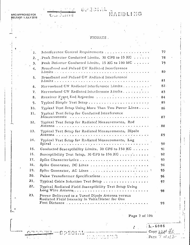
FIGURES .
1
1.
Z.
3.
Interference Control Requirements
.Peak Detector Conducted Limits, 30 CPS to 15 KC
Peak Detector Conducted Limits, 15 KC to 100 MC
77
78
79
4. Broadband and Pulsed CW Radiated Interference 1 Limits 80 i
5. Broadband and Pulsed CW Radiated Interference I
Limits 81 1
6. Narrowband CW Radiated Interference Limits 82. ! t
7. Narrowband CW Radiated Interference Limits 83 t
8. Receiver Front, End. Rejection v-1 - 84
9. Typical Simple Test Setup 85 I
10. Typical Test Setup Using More Than Two Power Lines . 86 1 11. Typical Test Setup for Conducted Interference
Measurements 87 12. Typical Test Setup for Radiated Measurements, Rod I :
Antenna . 88
13. Typical Test Setup for Radiated Measurements, Dipole Antenna 89 i
14. Typical Test Setup fo? Radiated Measurements, Log Spiral 90
I i
i 15. Conducted Susceptibility Limits, 30 CPS to 150 KC 91
16. Susceptibility Test Setup, 30 CPS to 150.1‹C - 92 I
17. Spike Characteristics 93 18. Spike Generator, DC Lines
.. 94
t 19.
20.
Spike Generator, AC Lines
Pulse Transformer Specifications
95
96 i 1
21. Typical Cable Induction Test Setup 97 i
22. Typical Radiated Field Susceptibility Test Setup Using Long Wire Antenna 98
23. Power Delivered to a Tuned Dipole Antenna versus Radiated Field Intensity in Volts/Meter for One
Foot Distance 99
L Page 7 of 106
L - 6 0 0 6
Lo.
. Pat-re 7 of Copy i2.(ef
: 7 %J.? C:.." i•• as
NRO APPROVED FOR RELEASE 1 JULY 2015
FIGURES (Continued)
Radiated Volts/Meter vs Line current in the Radiated Line 100
Comtersion Chart - Microvolts/kc to db/MC 101
Conversion Chart - Microvolts to d.b above One Microvolt 102
.24.
25.
26.
• •
7.;
• 1 •
..•
Page 8 of. I06 •
•
( L. - 6 0 0 6
Copy #,•T_
Paf7e of //'2...•
.Z.t1) 4.;
NRO APPROVED FOR RELEASE 1 JULY 2015
rq r, r r LJ
1.0 SCOPE
p This specification provides the requirements of an electromagnetic compatibility
(EMC) control program for each manned spacecraft composite system procured
by the Manned Orbiting Laboratory Systems Program Office (MOL.SPO). The
EMC control program for each such system shall be used by MOL SPO to establish
and maintain "engineered-in" EMC control from issuance of contractual go-ahead
of the program definition phase through the life of the affected system so that the
confidence .level and degree of probability of system performance in its operational
environment will be before the fact. All deliverable data and/or documentation specified in this Exhibit shall be in accordance with the respective contractor CDRL
1.1 USE (Dli142.3 or equiv.) as detailed by Forms 9.
For MCASTRO, SAFSL Exhibit 10005 shall be applicable to: new equipment,
extensively modified equipment, and equipment interfaces between associate F r
contractor segments.
R-AVE (a)
The contractor shall comply with the conducted and radiated
interference requirements imposed by the interface specifi-
cation as measured at the interface.
(b) SAFSL Exhibit 10005 shall apply to relays, solenoids,
swtiches, and EED Firing Circuits, but need not apply
to other passive equipment.
(c) The test requirements of SAFSL Exhibit 10005 shall not
apply to launch complex AGE not associated with vehicle
testing or that is not normally used in the vicinity of the
launch pad, LCC, or CSA. EMC for this AGE shall be
verified by successful functional utilization of this AGE
and inspection of the EMC design provisions.
EMC Control Program
T This specification shall be used by the integration contractor assigend such
responsibility by MOL SPO to establish and maintain the EMC control program
subject to the approval of MOL SPO for the affected composite system and to
establish and maintain the application of such a program to the component
systems and their respective subsystems and equipments, as formulated in
the applicable EMC design control plans, as verified by the applicable EMC
test plans, and as documented in the applicable EMC test reports.
Page 9 of 106 L - 6 0 0 6 • Copy . kf
Page (i/ of /1 1
3
NRO APPROVED FOR RELEASE 1 JULY 2015
• ri
•
L.••1
•
F • r
it t
1. 1 . 2 Application to Specifications
R-AVE The. applicable and intent of this specification shall be implemented in every
contractual specification, whatever its kind,• class, or sub-class, which
defines and describes any item of the composite system, the individual
systems, when that item may affect the electrical or electronic- functioning
of the composite, regardless of whether an aural, electrical, mechanical
or video input or output is involved.
1.2 CLASSIFICATION
This specification covers the EMC control of the Orbiting Vehicle Segments.
As a composite system, it will consist of all or part of:
(a) the vehicle which will consist of one or more stages and er:Vpsules or modules each of which may comprise all or part of the©e subsystems:
R-AVE 1 . spaceframe, including environment control, separation and joining mechanisms, observation and access areas and provisions therefore
2. propulsion, including primary, secondary, tertiary
3. electrical power, including primary and secondary power sources, such as batteries, solar arrays, fuel cells, and inverters
4. guidance and control, including attitude control and stabilization, orbital adjustment
5. communications, including telemetry, data link
6. life support which will comprise those devices, plumbing, wiring, scaling, seating, etc. which are installed in the life support compartments, bays, or other areas of the appropriate capsule(s) or module(s)
7. experimentation and observation equipments, self-contained power therefore, and the various accessories attendant thereon.
Page 10 of 106
L - 6 0 0 6
Pace /C of //7--
•
NRO APPROVED FOR RELEASE 1 JULY 2015
(b) The astronaut subsystem which will incluf.ie those equipments, materials, and items worn or carried by the individual men, such as radio transmitters and receivers, light sources, body functions, psychophysiological equipments, etc.
(c) The aerospace ground equipment system (AGE) consisting of:
1. the operational ground equipment (OGE) subsystem which includes the instrumentation, control and checkout consoles, cabling, wiring, communications, ground electrical power., fluid loading (whether liquid or gas), handling, including erecting, mating, demoting, adjusting, calibrating, command loading, and all other material. required to conduct precountdown tests, countdown, and launch
2. the maintenance ground equipment (MGE) subsystem which includes those items and material of the types noted in (1) above, (OGE), which are used to maintain the vehicle system in, or restore it to, a state of readiness for launch, countdown, and precountdown tests. For EK Only: Although support equipment not associated with the vehicle system in its final launch configuration is not considered part of the composite system and thus excluded from the requirements of this specification, factory checkout equipment used for EMC testing shall be designed such that its operation does not degrade the EMC or EMI test results or the operation of the AVE equipment under test.Dr other Associate Contractors, this EK deviation applies to non-CEI equipment.
3. exchange hardware used for electrical tests with the EDCTU, qualification, acceptance, and readiness tests shall meet the OGE EMC requirements or the allowable EMI limits specified in the appropriate interface specification.
For purposes of this specification, the operational environment shall be
understood to be that of the launch environment, including precountdown tests,
countdown, and launch, as encompassing the worst environment to be encountered
by the composite system, its component systems, and their respective sub-
systems and equipments. The ambient EMC environment surrounding the launch
vehicle is not included in the conditions stated in this specification. The
contractors shall inform the SPO when the ambient conditions (data to be furnished
by the SPO and analyzed by the EMC integrator) do not allow the contractor to
meet the requirements of this specification.
Page 11 of 106
L - 6 0 0 6
' Copy sof
Pace //of /I>
1/46" it 4.--2 L.
NRO APPROVED FOR RELEASE 1 JULY 2015
3 Li t r i
. 0 APPLICABLE DOCUMENTS
1 he following documents
f,,rm a part of this specification to the extent specified herein. In case of
conflict with this specification, the requirements of this specification shall
covern.
(a)
MIL-STD-831 - Test Report, Preparation of, dated
28 August 1963
(b)- MIL-B-5087B - Bonding, Electrical, and Lightning
Protection, for Aerospace Systems, dated 15 October 1964
(c)
MIL-STD-202C - Test Methods for Electronic and Electrical
(c1)
SAFSL 30034-EMC Control Plan Composite System 6 June 1968 Component Parts 12 September 1963
It is to be acknowledgd, that the documents listed below provided source
material for this specification, although their particular requirements are
not specified herein.
AFMTCP 80-2, 'Vol I Appendix A
MIL-STD-826(USAF)
MIL-E-6051
MIL-I-6181
MIL-I-26600
AF/BSD Exhibit 62-87
General Range Safety Plan, Air Force Missile Test Center, Patrick Air Force Base, Florida
Electromagnetic Interference Test Requirements and Test Methods
Electrical-Electronic System Compatibility and Interference Control Requirements for Aeronautical Weapon Systems, Aircraft Subsystems, and Aircraft (Cf. Aerospace Industries Association- proposed "D" revision thereto)
Interference Control Requirements, •Aircraft Equipment
Interference Control Requirements, Aeronautical Equipment
Electro-Interference Control Require-ments for Minuteman (WS-133B)
12 of --' L - 6 0 0 6
Copy -•
Pa ae
NRO APPROVED FOR RELEASE 1 JULY 2015
t.. •
ta.; • t
REQUIREMENTS
ELECTROMAGNETIC COMPATIBILITY CONTROL PROGRAM
Composite System
It is intent of this specification to provide the requirements of an
Electr magnetic Compatibility (EMC) Control Program for each ..
spacec:- aft composite system procured by the Manned Orbiting Laboratory
Syster Program Office (MOL SPO). Such a Program shall be used by MOL
SPO establish "engineered-in" electromagnetic compatibility control
from ?. ::proval of go-ahead orthe Program Definition Phase through
the lif-a of the affected composite system. The implementation of the EMC
Contrc,r Program requirements shall be accomplished by the EMC Control
Board ::irough thdeoinposite system EMC Design Control Plan and the
=r11 and equipment EMC Design Control Plans and through the EMC subsyr,•.
Test associated with each. The Test Plan Reports will document the
activk; and shall function as the formal record of contractual compliance
with
Electrr,fnagnetic compatibility shall be engineered-in by before-the-fact
de •sign •if the composite system components in accordance with the require-
ments -,f. this specification so as to preclude the existence of any potential
interference(s) in or between the components, i. e. , the vehicle
syster:, and the AGE system, regardless of where their electrical, aural,
video 2;:.d mechanical inputs and outputs fall within the. overall frequency
spectr.in of the composite system.
3. 1. 1. EMC Control Board
The E'LC Control Board shall be established by MOL SPO on the initiation
of go-:;head of the Program Definition Phase of a manned spacecraft .
composite system procurement program and shall function through comple-
tion of ..he Development Phase. The Board shall exercise technical control
of the composite system EMC Control Program, of the composite system
Page 13 of 106 Copy of 30
s specification.
r 'L71. ~s a -
L . - 6 0 0 6 Copy 171(,'
Pace /3 of //7----
u.
r'I A 7 NRO APPROVED FOR RELEASE 1 JULY 2015
EMC Design Control Plan which is established and maintained to implement
the Program, and of the EMC Test Plan which is established to verify the
composite system EMC Design Control Plan within the constraints of the
Control Program.
The VlvfC Control Board shall function as specified in the EMC Board Charter
contained in SAFSL 30035.
3.1 . 1. 2 EMC Design Control Plan
3.1 . 1 . 2.1 Schedule
The composite system EMC Design Control Plan shall be established by the
integration contractor, in coordination with the associate contractors, and
shall be submitted to MOL SPO for approval within ninety (90) calendar
days after contractual notice of go-ahead for the Program Definition Phase
from the procuring activity. At its descretion, MOL SPO shall convene the
EMC Control Board to resolve any problem areas arising from lack of complete
approval of the submitted Design Control Plan and to establish any schedule(s)
necessary for accomplishment of complete approval by MOL SPO.
Maintenance of the composite system EMC Design Control Plan shall be
the responsibility of the integration contractor who shall revise or supplement
it with the approval of lviOL SPO. This maintenance of the composite
Page 14 of 106
47,. '7) 772. r L -
L - 6 0 0 6
Copy
Page/y- of /0
r
NRO APPROVED FOR RELEASE 1 JULY 2015
system EMC Design Control Plan shat be directly related to the
EMC Design Control Plans for the individual subsystems and equipments
of the vehicle and AGE systems, as noted below.
3. 1. 1. 2. 2 Content
P The composite system EMC Design Control Plan shall delineate the methods
that shall be used by the EMC Integrator to ensure the electromagnetic
compatibility of the combined system segments, in a composite MOL system.
3. 1. 2 Subsystems and Equipments
3. 1 . 2. 1 EMC Control Group
T Each associate db'iLtiacto'r (this includes the integration contractor in his
function as a direct contractor for one or more of the vehicle and AGE
subsystems or equipments) shall establish an EMC Design Control Group
which shall function for the affected subsystems/equipments.
The EMC Design Control Group shall meet as required through the life
of the composite system program.
Page 15- of 106
L - 6 0 6 Copy /417
Pa cue
ar.
VV
NRO APPROVED FOR RELEASE 1 JULY 2015
EMC Design Control Pin
3.1:?. 2. 1 Schedule
Each associate contractor establish an EMC Des in Control Plan for
the individual subsystem(s) or equipment(s) for which he has contracted witu
the procuring activity and shall submit it(s) to the integration contractor
within forty-five .(45) days of contractual go-ahead of the Program Definition
Phase. Such a Plan shall ho maintained through the life of the composite
systsrn program and sh-r:11 r,2 su'lin-litt,26 in accordance with the schedule(s)
established by the integration contractor. Such a design control plan shall
include the constraints placed on subcontractors and suppliers to assure
1 EMC.
3.1.2. 2. 2 Content
Interference shall be controlled to eliminate undesired interaction and
malfunctioning of the respective electronic and electrical subsystems and . - equipments, regardless of whethei: the affected inputs and outputs of the
systems are electrical, aural, video, or mechanical. This requirement
applies to the entire frequency range of such subsystems and equipments,
and those for which "provisions for" have been incorporated,•when per-
forming their intended functions. There shall be no improper response,
whether unacceptable or inadvertent, from the output of any vehicle or AGE
subsystem or equipment because of electromagnetic interference produced
by any or all of the electrical, electronic, and other devices of the sub-
systems or equipments when tested in accordance with the applicable EMC
Test Plan (see section 4. 1).
Page 16 of 106
;7' .7) • . . 9—..; 4 ba
L - 6006
Copy ,2!r-.19f
Page /
NRO APPROVED FOR RELEASE 1 JULY 2015
This requires that .suc.:). subsystems and equipments not be adversely affected
by interference voltages and fields reaching them from external sources and
also requires that such equipment and subsystems not be sources of inter:-
ference which might adversely affect the operation of other equipments or
subsystems.
The design aspects of the composite system operational environment, utili-
zation of the inherent shielding characteristics of the vehicle or installation,
antenna location, shielding and bonding techniques, cable routing, the design
and location of interference control components, and alil other pertinent
design and control factors shall be included in the affected subsystem/equipment
Control plans.
Each Design Control Plan shall consider frequency management of all
equipments as a prime factor in controlling the operational electromagnetic
environment. Freqtfericy management shall consist of: control of all
assigned primary radiating bands and requencies, strict conservation of
spectrum bandwidths; control of all local oscillator frequencies and rise
times; gain bandwidth products, harmonic and sideband control, and time
duty cycle operation of equipment.
3.1.3 Short Duration Interference
RAVE Exemptions shall not be granted for short duration. or transient interference
in any EMC Design Control Plan, unless such interference occurs at such a
time sequence as to not affect the operation of the MOL System and with the
approval of MOL SPO (MCASTRO system segment single event switching
transients are not required to meet SAFSL 10005 interference requirements
provided they do not cause Flight Vehicle system interference. All Gemini B
System Segment switches and relays (except hand controller switches) will
be considered single event switching devices).
3.1.4 Electromagnetic Interference Safety Margin
R-AVE The Electromagnetic Interference Safety Margin (E/vIISM) shall be determined
for critical leads under operating conditions, including switching equipments
or subsystems ON and OFF manually by the astronauts or as programmed.
Operating conditions shall be defined as the launch environment for FV
system test, factory environment for segment testing and screen room or
factory environment for subsystem and equipment testing. The susceptibility
threshold shall be determined at the subsystem and equipment level within _
the constraints of this specification. The reference for system an.-L - 6 0 0 6 • t 1'. actu-.1 o7eratirc:, noise. Copy of 1
Page /— of ,
751
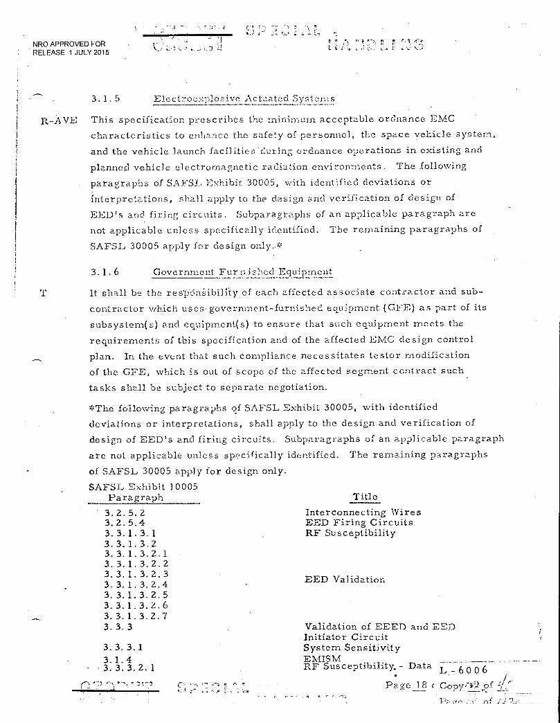
3.2.5.2 3.2.5.4 3.3.1.3.1 3.3.1.3.2 3.3.1.3.2.1 3.3.1.3.2.2 3.3.1.3.2.3 3.3.1.3.2.4 3.3.1.3.2.5 3.3.1.3.2.6 3.3.1.3.2.7 3.3.3
3.3.3.1 3.1.4
- 3.3.3.2.1
■Ir•i :;"
NRO APPROVED FOR RELEASE 1 JULY 2015 I i•
3.1. 5 Electroexplosive Actuated. Systems
R-AVE This specification prescribes the minimum acceptable ordnance EMC
characteristics to enhance the safety of personnel, the space vehicle system,
and the vehicle launch facilities during ordnance operations in existing and
planned vehicle electromagnetic radiation environments. The following
paragraphs of SAFSL Exhibit 30005, with identified deviations or
interpretations, shall apply to the design and verification of design of
EED's and firing circuits. Subparagraphs of an applicable paragraph are
not applicable unless specifically identified. The remaining paragraphs of
SAFSL 30005 apply for design only..*
3. 1 . 6 Government Fur n ished Equipment
T
It shall be the res'p.cinSibilfty of each affected associate contractor and sub-
contractor which uses. government-furnished equipment (GFE) as part of its
subsystem(s) and equipment(s) to ensure that such equipment meets the
requirements of this specification and of the affected EMC design control
plan. In the event that such compliance necessitates testor modification
of the GFE, which is out of scope of the affected segment contract such
tasks shall be subject to separate negotiation.
*The following paragraphs of SAFSL Exhibit 30005, with identified
deviations or interpretations, shall apply to the design and verification of
design of EED's and firing circuits. Subparagraphs of an applicable paragraph
are not applicable unless specifically identified. The remaining paragraphs
of SAFSL 30005 apply for design only.
SAFSL Exhibit 10005 Paragraph Title
Interconnecting Wires EED Firing Circuits RF Susceptibility
EED Validation
Validation of EEED and EED Initiator Circuit System Sensitivity EMISM RF Susceptibility,- Data L+- 6 0 0 6
• Page 18 e Copy7k).,?±.21.:
NRO APPROVED FOR RELEASE 1 JULY 2015
3.2 DESIGN
3. 2. 1 Interference-Free Desi ,7, n
R-AVE Interference control shall be considered in the basic design of all electronic
and electrical equipment and subsystems. The design shall be such that,
before any interference control components are applied, the amount of
interference inherently generated and propagated is the minimum achievable
consistent with good design practices. The api)lication of interference control
components that must be used, such as filtering, shielding and bonding,
shall conform to good aerospace engineering practice and should be an
integral part of the system. Any interference control components must
be of minimal weight and volume consistent with maximal reliability,
vehicle weight constraints and associated tradeoffs.
Separately installed and
external components shall not be used Unless specifically authorized by
the procuring activity.
R-AVE
3.2.2 Susceptibility
All equipment shall be designed to minimize susceptibility to interference
from other sources. Any enclosing case construction shall be designed
not only to minimize interference propagation but also to minimize
interference pick-up from external sources. Where conducted energy on
the power or other external leads might cause interference, these leads
shall be isolated from others to avoid coupling and where necessary and
feasible, shall have line filters at thieir entry - into the enclosing case.
Receiving antenna inputs or other low-level signal circuits shall be of
low impedance or of balanced design so that coaxial or other shielded
transmission lines can be used to ensure an interference-free installation.
Routing of such circuits within the equipment shall minimize circuit coupling
with power and control leads. There shall be no common impedance paths incompatible
or sharing of/grounn returns between different classifications such as or
signal, power, control or ordnance circuits/ within the same classifications .
Page 19 of 106
r fl 0-4 r,
• -11 z. •
- 6 0 0 6 Copy
r r
c
NRO APPROVED FOR RELEASE 1 JULY 2015
:I • •
•
3.2. 3 Case Shielding •
R-AVE
R-AVE
Mechanical discontinuities in the case of those enclosures intended to provide
EMI Shielding, (such as covers, inspection plates, and joints) shall be kept
to a minimum. All necessary discontinuities shall be electrically continuous
across the interface of the discontinuity so. as to provide a low-impedance
current path. Multiple-point spring-loaded contacts are suggested as a
desirable method of obtaining this low impedance continuity. Ventilation
openings shall be designed not to degrade the required case shielding
effectiveness. Electrical bonding shall be provided where access doors
or cover plates form a part of the shielding; hinges, in themselves, are
not considered satisfactory conductive paths.
3. 2. 4 Bonding
The provisions'of :\,111.2:-13-5087 with regard to characteristics, application
and testing of electrical bonding shall be applicable. The appropriate
MIL-B-5087B bonding class shall be used. The use of BE/CU or aluminum
bonding straps of L/W ratio 5 and a minimum thickness of 005 inches
is permitted. The requirements of paragraph 3.1-3.1. 3 of MILB 5087B
may be met through the use of contractors preferred parts list.
r^ r r r:
r-- Pace 20..Df 106 1 L•-• 60 06
. Copy
, of
NRO APPROVED FOR RELEASE 1 JULY 2015
t• k ;- L L- .
3. 2. 5 Design Criteria
3. 2. 5. 1 Interconnecting, Wire Design
A-AVE Line shielding shall not be used when equivalent interference reduction control
or containment can effectively he accomplished inside an equipment. It shall
not be used intentionally as a current carrying conductor, except for coaxial
conductors in rf circuits. Equipment requiring antennas, but not employing
wave guides, shall be designed to utilize coaxial cable as lead-in. When it
has been determined that a single braid shield is not adequate, a double or
triple braid, or a solid shield, shall be used as required. The following
criteria shall be used to determine signal line and shield configuration.
3. 2. 5. 1. 1 DC Supplies
To minimize the possibilitr of DC supply lines coupling interference to other
circuits and to protect them from receiving interference from other lines,
the best procedure is to use twisted-pair for the supply line and its return.
Shielding should not be used on power wires.
3.2. 5. 1 2 AC Power
Alternating current of comparatively high amperage, characteristic of most
AVE AC power lines, makes them potential sources of interference through
coup1;ing to adjacent lines. Transposed or twisted lines shall be used for all
AC power circuits. The routing of these lines shall be away from susceptible
lines. Shielding should not be' used on power wires.
3. 2. 5. I 3 Low Level Signals of Low Impedance (<1001vIV and ...1000;)
For runs internal to the equipment, the use of a twisted-pair alone may prove
adequate. For runs external to the equipment, twisted-pair shielded wire
shall be used. When shielded wire passes through a connector, three pins
shoUld be made available on the connector to provide insulated passage of the
two signal leads and the shield. Shields must be grounded at least at one
end. For signal wires external to equipments, balanced circuitry shall be
used. Low level RF circuits may use coaxial cable and need not be balanced.
Circuit impedance represents either the source or load impedance, whichever
is higher.
*The following design criteria are for wiring external to equipment, however
the criteria may be used as design guides for wiring internal to equipment.
.Page I L - 6 o 0 6 '" • CoPY.?f
Par:-::?f of
tV
NRO APPROVED FOR RELEASE 1 JULY 2015
3.2.5. 1. 4 Low Level Signals of 1-iiah Impedance (:.--_1001VIV >10002)
_-AVE Where signals from high impedance output devices must be transmitted over
any appreciable distance, an impedance transforming device such as a
transformer, cathode follower or transistor Should be used to lower the
transmission circuit impedance to 1000 ohms or lower. However, the use
of high impedance signals for transmission of information should, in general,
be scrupulously avoided, whether high or low level. Where the use of such
signals cannot be avoided, the interconnecting lead must be shielded and
the shield grounded. In some cases, the use of a double or triple shielded
cable grounded at each end may be required if the cable is in an intense
electrostatic environment. Circuits not meeting the impedance criteria of
z 1000 S-2 of 3.2.5. 1. 3 are defined as high impedance.
R VE
3.2.5. 1. 5 High Level Signals ( >1001vIV)
Signal circuits of high level will, in general, not be susceptible to EMI.
Rather, they may be a source of interference to lower level signal lines
For this reason, and dependent on other characteristics of the signal,
either a twisted-pair or a shielded lead should be used. Multiple shielding Shield
may be required if the signal is of sufficient level. / Grounding should be at
both ends of the shield to prevent electrostatic radiation from the cable.
3.2.5. 1. 6 Reference Voltages
The transmission of reference voltages should be avoided. If this is not
possible, care should be taken to minimize the possibility of introducing
interference as well as AC voltages. Grounding, where required, should
be only at one point. Treat the reference voltage•as a circuit, always
including its return lead either in the form of a twisted-pair or a shielded
or coaxial lead.
tr- t7".1
Page 22 of 10E L 6 0 0 6
Copy .-..42,c.)f
Pa Of
NRO APPROVED FOR RELEASE 1 JULY 2015
The use of twisted-pair and/or shiolding for the reference voltage lead and
its return will minimize the• pickup from sources of electromagnetic radiation.
In the case of AC reference voltages this treatment will aiso minimize the
interference effect that the reference voltage might have on other circuits.
Shielding of the twisted-pair may be helpful, especially when the circuit
impedance is not held to a. low value; hovvever, filtering of the reference
voltage inside the using equipment is to be preferred over the use of shield-
ing. The source impedance of the voltage should be maintained as low as
possible in .order to minimize electrostatic pickup. In any case, the using
element should see only the reference voltages, and not the reference voltage
plus small components of other signal and power voltages.
3. 2. 5. 1. 7 Control Voltages
The control of various functions is usually accomplished with the use of
voltages of either AC or DC which are switched on or off in a step manner.
Lines carrying such voltages are potential interference generators; they
should be of a nature that will hold coupling to other circuits at a minimum.
Separation and shielding are thus applicable.
3. 2. 5. 1.8 RF Signals (>150KHZor5l0 u sec rise/fall time signals)
R-AVE RF signals within a unit should be routed in such a way that cross coupling
between input and output circuits is held to a minimum. Outside the unit,
shielding should be used if necessary to prevent excessive radiation from
the wire or excessive pickup on the wire. Grounding of such shields shall
be multi-point and continuous for rf signals.
3. 2.5.1.9 Shield Continuity
R-AVE The electrical continuity and isolation of signal circuit electrical shields
shall be maintained through connectors, equipment, and/or junction boxes
intermediate between the signal source and the signal load. Any intermediate
terminal strip or block shall be shielded by a metallic enclosure which is
bonded to the structure. Where the number of connector
pins is limited, shields may be grouped on a selective basis and. carried
through on a single pin. Individual shield segment may be separately
grounded.
C.4 t" • 4 . .
Page 23 of 106
L- 6006
Copy
Pa / /C.'. •
C f. NRO APPROVED FOR RELEASE 1 JULY 2015
3. 2. 5. 1. 10 Shic.,Id . rezLkouts
Only the following methods of shield termination are acceptable.
(a) On the electrical connector, provided the connector
has a conductive finish and is provided with a con-
ductive path to structure.
(b) Direct to structure, provided the length of shield
-pigtail is 6 inches or less.
(c) Terminate inside of the equipment by means of a
pin in the electrical connector. The combined
length of the ground wire and pigtail shall be 6
inches or less.
It is preferred that the shield extend inside the connector shell. In the event
that this is not feasible, the shield breakout shall be so positioned that it is
as close as possible..with not more than1.5inch of unshielded, insulated wire
showing in back of the connector.
3. 2. 5. 2 Interconnecting Wires Categorization and Seperation
In order to reduce interactions between the different subsystems, inter-
connecting wiring shall be isolated in accordance with the following criteria.
A minimum of 4 inches shall be maintained between wires or wire bundles including ground umbilicals
of the different categories. Separation during constrained passages/may be
less than 4 inches but shall be resumed as soon as practical after passing
constrained area. (For EK: If cable separation is required to reduce inter-
actions between wires of different signal types, 4 inch separation, consistent
with space allocation factors, should be maintained between wires ) (For the
Gemini B Segment: In the re-entry module and at the interface between it
and the adapter, in order to reduce interaction between the different subsystems,
interconnecting wiring shall be isolated where feasible in accordance with
following criteria. A minimum of 4 inches shall be maintained between wires
or wire bundles of the different categories, except when different categories
use the same connector, or where space and/or weight constraints make such
separation impracticable. In such a .case, pin assignment and layout shall
stress isolation between different categories, and grounded spare pins shall
be utilized when available to provide isolation for sensitive circuits.
Page 2:1 of lot L - 6 0 0 6
Copy .■ '" of
Pace.
NRO APPROVED FOR
• t
RELEASE 1 JULY 2015
In the adapter moclule, interconnecting wiring s7-..F.11 ne separted using the
same criteria applied in the re-entry module except:
(a)
Wires crossing the interface between Gemini B and
associate contractor segments shall be classified
into categories I, II or III, as applicable. A
minimum of four (4) inches shall be maintained between
interface wires or wire bundles of these three (3)
categories. However, interface wires need not be
separated where they pass through guillotines.
Gemini B wires not crossing the interface may be
bundled with interface wires providing the interface
wire categorization is not violated).
The classifications clf- he following wire categoric:, are design requirements
to assure compatibility. Further subcategorization may be required to
achieve compatibility because of complexity of design cr in the cas-e of a
circuit filling the criteria for two categories and are not precluded by this specification
Category I
1. Three phase power distribution wiring (twisted)
2. Single phase power distribution (twisted with return wire)
3. Other wirinecarrying 115 volts ac
4. DC circuit wiring carrying currents (transients and
steady state) above 5 amps
5. Low voltage power circuits (ac)
6. Low voltage lighting circuits (ac)
Category II
Wiring carrying less than 36 V peak and current between •
100 ma and 5 amps.
Page 25 of 106
L- 6 0 0 6
copy aa._?f fare :.i 1 / 2-
NRO APPROVED FOR . .; ; t
RELEASE 1 JULY 2015
Cate o ry
1.. Lou' level circuits
2. Low voltage circuits •
3. Receiving antenna coaxial cables
Category TV
All ordnance firing circuits.
Category
(Not for GE
RE transmitting coaxial transmission lines and wave guides and EK)
(150 kc and above).
3. 2. 5. 3 Groundin2, and Isolation
A single-point grounding system shall be the design baseline. A deviation
to use multipoint ground will be granted when such is proven to be electro- ,.;
magnetically compatible. Each electrical component shall have the primary
power terminals isolated from its own case by a minimum DC resistance
of 1 MEGDEIM when all of its external harnesses are completely disconnected.
(For IVICASTRO a separate guidance and control ground may be used. Resulting
structure return shall not jeopardize system compatibility.)
3. Z. 5. 3. 1 Power. System Ground
-AVE The negative lead of individual power sources that are separated from each
other by 5 feet or more or are located in separate vehicle compartments
shall have its own Structure Ground Point (SGP) connected to the vehicle
frame adjacent to the power source. The length of the lead from the power
source to the SG? shall not exceed 16 feet and shall not extend through any
vehicle interface. All ground return leads for any one load shall be grounded
to the SGP for the power source of that load. All DC ground power supplies
shall be grounded at the SGP for that particular load. If more than one load
or SGP is involved, separate ground power supplies shall be used. There
shall be no sharing of ground return leads between separate subsystems. Any
deviation from this requirement shall be approved by MOL SPO. (For
MCASTRO, the negative lead of individual power sources, within the Gemini B
shall terminate at a negative bus which in turn is connected to one (I) structural
ground point on the spacecraft vehicle frame. The length of leads from power
Page 26 of 106
L- 6 0 0 6 - r- • P.
Copy 9,)c2f.
-p,
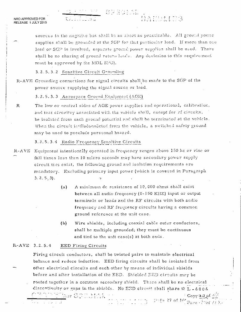
NRO APPROVED FOR RELEASE 1 JULY 2015
sources to the negative bus shall as short as practicable. All groul-ld power
supplies shall be grounded at the SGP for that particular load. If mo:ce than one
load or. SGP is involved, separate ground power supplies shall be used. There
shall be no sharing of ground return leads. Any deviation to this requirement
must be approved by the MOL SPO).
3. 2. 5. 3. 2 Sensitive Circuit Groundinc
R-AVE Grounding connections for signal circuits shall be made to the SGP of the
power source supplying the signal source or load.
3.2. 5. 3. 3 Aerospace Ground Equipment (AGE)
R The low or neutral sides of AGE power supplies and operational, calibration,
and test circuitry associated with the vehicle shall, except for rf circuits,
be isolated from each ground potential and shall be terminated at the vehicle.
When the circuit isliseonnbcted from the vehicle, a switched safety ground
may be used to preclude personnel hazard.
3. 2. 5. 3. 4 Radio Frequency Sensitive Circuits
R-AVE Equipment intentionally operated in frequency ranges above 150 1:c or rise or
fall.times loss than 10 micro seconds may have secondary power supply
circuit ties exist, the following ground and isolation requirements are
mandatory. Excluding primary input power (which is covered in Paragraph
3. 2. 5.; 3).
(a) A minimum dc resistance of 10, 000 ohms shall exist
between all audio frequency (0-150 KHZ) input or output
terminals or leads and the RF circuits with both audio
frequency and RF frequency circuits having a common
ground reference at the unit case.
(b) Wire shields, including coaxial cable outer conductors,
shall be multiple grounded; they must be continuous
and tied to the unit case(s) at both ends.
R-AVE 3.2.5.4 EED Firing Circuits
Firing circuit conductors, shall be twisted pairs to maintain electrical
balance and reduce induction. EED firing circuits shall be isolated from
other electrical circuits and each other by means of individual shields
before and after installation of the EED. Shielded 'ZED circuits may be
routed together in a common secondary shield. There shall be no electrical
discontinuity or gans in the shields. No EED circuit shall s=are L - 6 0 0 6
Cr—rsv -Al of TD or
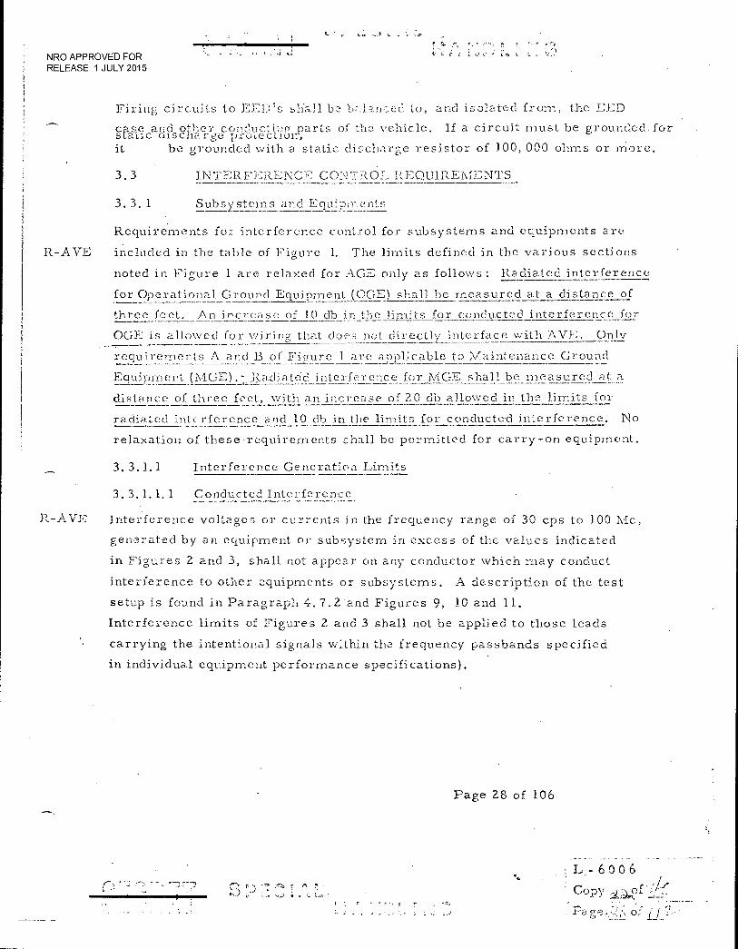
NRO APPROVED FOR •
RELEASE 1 JULY 2015
Firing circuits to EED's shall be balanced to, and isolated from, the FED
cas.e and other con_dAmtinp: parts of the vehicle. If a circuit must be grounded. for sLaLic oiscnarge pa.o,ection, it be grounded with a static discharge resistor of 100,000 ohms or more.
3.3 INTERFERENCE CONTROL REQUIREMENTS
3.3.1 Subsystems and Equipments
Requirements for interference control for subsystems and equipments are
R-AVE included in the table of Figure 1. The limits defined in the various sections
noted in Figure 1 are relaxed for AGE only as follows: Radiated interference
for Operational Ground Equipment (OGE) shall be measured at a distance of
three feet. An increase of 10 db in the limits for conducted interference for
OGE is allowed for wirinp- that does not directly interface with AVE, Only
requirements A and B of Figure 1 are applicable to I\./aintenance Ground
Equipment (MGE).-Ra.diated interference for MGE shall be measured at_a
distance of three feet, with an increase of 20 db allowed in the limits for
radiated interference and 10 db in the limits for conducted interference. No
relaxation of these •requirements shall be permitted for carry-on equipment.
3. 3.1.1 Interference Generation Limits
3. 3.1.1. 1 Conducted Interference
R- A VE Interference voltages or currents in the frequency range of 30 cps to 100 Mc,
generated by an equipment or subsystem in excess of the values indicated
in Figures 2 and 3, shall not appear on any conductor which may conduct
interference to other equipments or subsystems. A description of the test
setup is found in Paragraph 4.7.2 - and Figures 9, 10 and 11.
Interference limits of Figures 2 and 3 shall not be applied to those leads
carrying the intentional signals within the frequency passbands specified
in individual equipment performance specifications).
Page 28 of 106
• -3 1-7.7 L - 6 0 0 6
COpy
Page
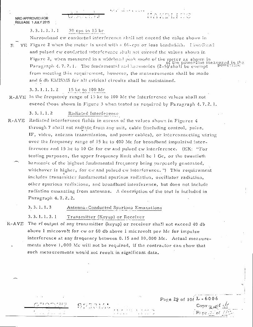
NRO APPROVED FOR RELEASE 1 JULY 2015
3.3. 1. 1. 1. 1 30 cps to 15 1:c
Narrowband c,,v conducted interference shall not exceed the value shown in
YE Figure 2 when the meter is used with a 60-cps or less banch,vi;i:h. 3: e.oz.-;..in'ai-13.
and pulsed cw conducted interference shall not exceed the values shown in
Figure 2, when measured in a '.videband pea:'_: mode of the meter as shown in of the powerline measured in the
Paragraph 4.7.2.1. The fundamental an,_: •i,ainnonics (2-5)/shall be exempt poweriine
from meeting this requirement, however, the measurements shall be made
and 6 db EIvIISM.S for all critical circuits shall be maintained.
3. 3. 1. 1. 1. 2 15 kc to 100 Mc
R-AVE In the frequenCy range of 15 kc to 100 Mc the interference values shall not
exceed those shown in Figure 3 when tested as required by Paragraph 4.7.2.1.
3. 3. 1. 1. 2 Radiated Interference
R-AVE Radiated interference fields in excess of the values shown in Figures 4
through 7 shall not radiate from any unit, cable (including control, pulse,
IF, video, antenna transmission, and power cables), or interconnecting wiri tr
over the frequency range of 15 kc to 400 Mc for broadband irnpulsivd inter-
ferences and 15 k.c to 10 Cc for cw and pulsed cw interference. (EK: "For
testing purposes, the upper frequency limit shall be 1 Gc, or the twentieth
harmonic of the highest fundamental frequency being purposely generated,
whichever is higher, for Cu' and pulsed cw interference. '') This requirement
includes transmitter fundamental spurious radiation, oscillator radiation,
other spurious radia-tions, and broadband interference, but does not include
radiation emanating from antennas. A description of the test is included in
Paragraph 4. 7. 2. 2.
R-AVE
3. 3. 1. 1. 3 Antenna-Conducted Spurious Emanations
3. 3. 1. 1.3. 1 Transmitter (Kcyup) or Receiver
The rf output of any transmitter (keyup) or receiver shall not exceed 40 db
above I microvolt for cw or 60 db above I microvolt per Mc for impulse
interference at any frequency between 0.15 and 10,000 Mc. Actual measure-
ments above 1,000 Mc will not be required, if the contractor can show that
such measurements would not result in significant data.
r.
••••• ..• ,
Page 2.2 of IN L- 6 0 0 6
Copy e,,Ls.kef
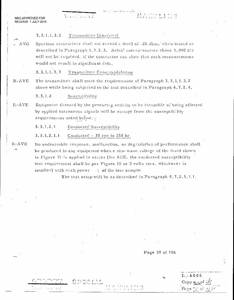
NRO APPROVED FOR RELEASE 1 JULY 2015
3. 3.1.1. 3. 2 Transmitter (I.eyee-N,..n)
AVE Spurious emanations shall not exceed a level of -25 dbm , when teste d as
described in Paragraph 4.7.2.3. Actual measurements above 1,000 Mc
will not be required, if the contractor can show that such measurements
would not result in significant data.
3. 3.1. 1. 3. 3 Transmitter Cros,imodulation
R-A.VE The transmitter shall meet the requirements of Paragraph 3. 3.1.1, 3.2
above while being subjected to the test described in Paragraph 4.7.2.4.
3. 3.1. Z
Susceptibility
R-AVE Equipment deemed by the procuring activity to be incapable of being affected
by applied extraneous signals will be exempt from the susceptibility
requirements noted..below.
3. 3.1_.2.1 Conducted Susceptibility
R-AVE
3. 3.1. 2.1.1 Conducted - 30 cps to 150 1:c
No undesirable response, malfunction, or degradation of performance shall
be produced in any equipment when a sine wave voltage of the level shown
in Figure 15 is applied in series (for AGE, the conducted susceptibility
test requirement shall be per Figure 15 or 3 volts rrns, whichever is
smaller) with each power of the test sample.
The test setup will he as described in Paragraph 4.7.2.5.1.1.
Page 30 of 106
- 6006 • Jr Copy aD.or i. -,-L
. Pacre".7,-; -
3
NRO APPROVED FOR RELEASE 1 JULY 2015
3. 3.1. 2.1. 2 Conducted - '150 1:.c. and Above
R-A
No undesirable response, malfunction, or degradation of perforrnance shall
be produced in a.ny equipment when anyf signal of +13 dbm, developed across
a 50 ohn-i load, is applied across. the pc.--Jier input terminals of the test
samples. The test description is found in Paragraph 4.7.2-5.1.2.
3. 3.1. 2.1. 3 Condncted -,Transient
R-AVE No undesirable response, malfunction, or degradation of performance shall
be produced. in any equipment when a pulse. or transient is induced in or
across the power line and between each power line and case in each polarity
using the test setup and transient description found in Paragraph 4.7.2.5.1.3.
(EK Deviation.: No undesirable response, malfunction, or degradation of
performance shall be produced in any equipment when. a pulse or transient is
induced into it in accordance with section 4.7.2.5.1.3. This is not a
requirement for equipment internal to the system (i.e., non-interface)
where it has been shown by analysis or test that the. equipment will not
be subjected to a transient of this magnitude. However, for internal
equipment, an appropriately reduced test level shall be used).
3. 3.1. 2. 2 Induced into Cable
R-AVE Interconnecting cables shall withstand, without evidence of equipment
performance degradation, the application of a magnetic field caused by a
wire carrying 20 amperes rms at the fundamental power frequency. The
test description is found in Paragraph 4.7.2.5.2.1.
Page 31 of 106
L, - 6 0 0 6 Copy °c.d. /
Pa crE.! of ,
•
NRO APPROVED FOR RELEASE 1 JULY 2015
3. 3.1.2. 3 Induced into Eovioment
R-AVE No undesirable response, malfunction, 01 degradation of performance shall
be produced in any equipment when it is subjected to an ambient magnetic
field as described in Paragraph 4. 7. 2.5. 2.2.
3. 3.1. 2. 4 Radiated Field
No undesirable response, malfunction, or degradation of performance
shall be produced in any equipment when it is subjected to the following
radiated fields:
R-AVE Frequency Field Strenth
0.015 to 35 Mc
10 vim
35 to'1000-Mc
5 vim
1 to 10 Cc
5 vim
R-AVE
R-AVE
The test setup and equipment are described in Paragraph 4.7.2.5.3. The
test shall be carried out to the level of equipment malfunction or a 6 db
higher field intensity, whichever is lower. However, if analysis or prior
test data indicates that equipment damage above the normal susceptibility
test limits will result, these malfunction threshold level tests need not
be performed and the susceptibility threshold shall be the susceptibility
test limits.
3. 3.1. 2. 5 Intermodulation
Receivers, preamplifiers, or antenna couplers shall not produce an output
indication when two sine wave signals, representing undesired signals, are
connected to the input terminals of the test sample. The test frequency
selection and levels are given in Paragraph 4.7.2.6.
3. 3.1.2. 6 Receiver Front End Rejection
Front end rejection of receivers shall be equal to or greater than the limit
shown in Figure 8, except that image rejection outside the tuning range of
the receiver shall be 60 db. This requirement shall apply to each tuning
unit on receivers with plug-in or separate tuning units. Dimension (a) in Figure
8 shall not be greater than 20 percent of(fc). A description of the test and the
method of calculating the front end rejection ratio are given in Paragraph 4.7.2.7.
Page 32 of 106
• j L.; 6 0 0 6
1 Copy .xi),?f (.7 (7-
[ NRO APPROVED FOR RELEASE 1 JULY 2015
3. 3. . 2.7 Su s
1-3..:AVE A susceptibility threshold curve shall be determined experimentally with
suppOrting analysis for each critical test point (See Paragraph 6. 2). This
data will be used during full system tctin to establish the EMISM. (See
Section 6).
II.- A V E
3. 3. 1.3 Electroexolosive Dt- vice-(EED's) Class A
MCASTRO: Applies to new EED's only. (NASA Gemini/EED's, analysis
and tests shall be conducted as reported in MAC Report B078 dated 21
February 1966, title, ''Analysis of Electromagnetic Radiation Hazard in
Gemini and Augmented Target Docking Adapter Pyrotechnic System.")
(For GE: The EEI)'s used on the D.RV are exempt from this requirement)
Page. 33 of 106
! L - 6 0 0 6
Copy ;:).,of
- --:or
•
NRO APPROVED FOR RELEASE 1 JULY 2015
R-AVE 3. 3. 1. 3. 1 Susceptibility
The susceptibility of each EED to RI' energy shall be determined over the
frequency range of 0.150 to 10, 000 l'...41.1Z with the following as a minimum number
of frequency points:
Test Frequency. Range (MHZ) Conditions
5 -10 CW
25 - 450 CW
900 1350 CW
• 1750 - 1850 CW
2200 - 2290 CW
5000 - 6000 CW-
8500 - 10, 000 CW
1750 -=.1850 Pulsed
2200 - 2290 Pulsed
500d - 6000 Pulsed
8500 - 10, 000 Pulsed
Susceptibility shall be determined for the following modes:
a. Pin-to-Pin (P-P),
b. Pin-to-Case (P-C),
c. Briclge.-wire-to-Briclgewire (B-B) (then requirement only applies to initiators with two or more bridgewires).
It-AVE 3. 3. 1. 3.2 EED Validation
The validation of compliance with 3.3.1.3.1 shall include the following:
R -AVE 3. 3. 1. 3. 2. 1 DC Constant Current Sensitivity Test (45 initiators)
A Bruceton test (Pin-to-Pin mode) using a group of 45 initiators using each
bridgewire shall be conducted in which the pulse time will be held constant and
the current will be variable. The pulse time in this test shall be 10 seconds or
longer. Five of the initiators may be used to find the proper starting level for
the test.
The DC constant current sensitivity Bruceton test data obtained for SAFSL Exhibit
10030 may be used in lieu of this testing.
•
L - 6 0 0 6
1 Copy a:.;;‘::‘,3
NRO APPROVED FOR RELEASE 1 JULY 2015
R- AVE 3.3.1.3.2.2 Impeciance i'vleasurernent (10 Initiators)
The dc resistance and RF impedance for all freouencies (and all -nodes) of
3.3.1.3.1 shall be. determined for a of 10 initiators.
R-AVE 3.3.1.3.2.3 RP Comparison Tests le bridge. - 135 initiators, Dual
bridge - 225 initiators)
The RF power exposure level for all of the RE' comparison tests shall be the
mean firing level determined in the 3.3.1.3.2.1 dc constant current test converted
to power. For this conversion to power, the RI- resistance shall be taken into
account. This calculated power will be delivered to the EED's at each test
frequency and in each mode, i. e. , pin-to-Din, pin-to-core, and bridgewire -to-
bridgewire. Non-fires from the pin-to-pin and bridgewire-to-bridgewire modes
may be revised for the pin-to-case mode testing.
Ten EED's shall be exposed to the test power at each condition for a duration of
10 seconds or greater (note: it is only necessary to size the pin-to-case test
sample to 5 since some no-fires should be obtained from the pin-to-pin tests).
If 8 or more of the 10 initiator samples fire, it shall be considered that the FED
at the particular frequency and mode is more sensitive than the dc level. Other-
wise it shall be assumed that initiator has a sensitivity equal to or less than the
dc level for the particular frequency and mode.
R-AVE RE' Bruceton Tests (80 initiators)
Following the probing tests of 3.3.1.3.2.3, two RE' Bruceton tests shall be
conducted at the most sensitive conditions.. In the event more than two conditions
have sensitivities greater than the dc level, RF Bruceton tests shall be run for
all these conditions.
R_AvE 3.3.1.3.2.5 EED Sensitivity
For the conditions having the 3.3.1.3.2.4 test, the RF Bruceton test data shall
be used to determine 0.001 probability of initiation with 95% confidence. For
those conditions where it is determined by 3.3.1.3.2.3 that the RF sensitivity is
less than the dc level (and where 3.3.1.3.2.4 tests were not made) it shall be
assumed that RF 0.001 probability of initiation with 95 confidence is the same
as the dc value.
L . - 6006
•-•
ii Copy
r

NRO APPROVED FOR RELEASE 1 JULY 2015
3. 3. 1. 3. 2. 6 Determination aini reporiing of the smallest field intensity
capable of producing in the EED, in its noral respective configuration, the
power determined in paragraph 3.3. I. 3. 2.4 above. The determination shall
be based on the most favorable conditions for induced power during routine
handling, processing, transport- and storage. Data shall be presented as
described in paragraph 3. 3. 3. 2 below.
4-Z7 7-7 ..›
L- 6 0 0 6 Copy f), 4
. Pa. e of /
NRO APPROVED FOR RELEASE 1 JULY 2015
R-AVE 3. 3. 1. 3. Z. 7 Evaluation of tlie EED as a receiver of RE ener;;y dun, installation.
The evaluation consist of determining and reporting the minimum RE
field intensity or field strength required to produce in the EED the power
determined according to paragraph 3.3.1.3.2.6 above. The evaluation shall
include the most favorable conditions for induced power, including unshorted,
uninstalled conditions. Data will be presented as described in paragraph
3. 3. 3. 2 below.
T
3. 3. 2
Space Vehicle System
3. 3. a. 1
Electrical/Electronic Compatibility Test
The first spacecraft's complete electrical/electronic system shall be sub-
jected to a complete functional compatibility test. The vehicle shall be
tested in accordalice with paragraph 4.7. 1 of this specification to demon-
strate compliance with its requirements. As.-iy modification or relocation of
the electrical or electronic subsystems or equipments, resulting from the
elimination of an unacceptable or inadvertent response as defined in para-
graphs 3.3.2.2 and 3.3.2.3 below, shall require a re-test unless such
specifically waived by the procuring activity.
3. 3. 2. 2 Improper Response
The requirement for improper response shall beconsidered to have been
met when the sum of all energy coupled into the most critical point of each
subsystem by extraneous. electromagnetic or electrostatic fields or by direct
conduction is at least 6 db below that input, which would produce or prevent
operation, actuation, or functioning. Detailed test methods, instrument-a.,
tion, monitored points, interference tolerance limits, and test procedures
applicable to the functional usage of the particular subsystem or component
shall be outlined in the test plan specified herein.
3.3. 2. 2. 1 Unacceptable Response
Output responses from any subsystem which are the result of operation of .
any planned combination of subsystems shall be unacceptable when these
jI~ - 6 0 0 6
Copy
Pa- e 10'
NRO APPROVED FOR RELEASE 1 JULY 2015
outputs cause the space system per fee.. .-nce to be degraded in excess of the
required performance limits. This unacceptable response for other than
aural outputs shall be determined in terms of .the degree that performance"
limits are degraded at the subsystem output. This degradation shall be
related, if applicable, to the signal plus noise to noise ratio (S N/N) at the
most critical point of the subsystem exhibiting the unacceptable response.
Unacceptable response for equipment providing aural outputs shall be
determined in terms of the electrical power equivalent, measured in the
audio line, .of the threshold of hearing in the system operating environment.
3.3.2.2.2
Inadvertent Response
Criteria. to prevent inadvertent response shall be defined interms of the
margin (EMISM) between interference levels and circuit thresholds of
operation at critical points within each subsystem. This 'margin, or
separation, shall be a minimum of 6 db but may be greater than 6 db
depending upon the characteristics of the particular subsystem. If the
criteria for inadvertent response at critical subsystem points cannot be
determined prior to test for inclusion in the test plan, these criteria may
be determined as part of the test. In such cases, the integration contractor
shall specify the test approach to be used in demonstrating that a 6 db
minimum EMISM exists at these critical points.
R 3.3.3 Validation of FED and EED Initiator Circuit
(MCASTRO Only: For NASA Gemini Class A EED's, analyses
and tests shall be conducted as reported in MAC Report B-078,
dated 21 February 1966, entitled, "Analysis of Electromagnetic
Radiation Hazard in Gemini and Augmented Target Docking
Adapter Pyrotechnic System.) (For GE: Existing EED's on
the DRV's are exempt) The EED's shall survive before, during and after installation when exposed
to the following electromagnetic fields:
Frequency Range
150 kc to 50 Mc
above 50 Mc
Field Intensity .
2 watts per square meter (28 volts per meter)
100 watts per square meter (194 volts per meter)
L - 6 0 0 6
Co-oy). of
Pao- e - of 2,
F r •••
‘f. NRO APPROVED FOR , RELEASE 1 JULY 2015
System Sens:it - I
The evaluation shall consist of determining analytically and/or experimentally
and reporting the minimum RE field intensity or field strength required to
produce in the EED the power determined in paragraph 3. 3. 1.3. 2. 4 above after
ordnance installation but with access ports open. Data will be presented as
des& ribed in. paragraph 3.3. 3.2 below.
3. 3. 3.7, Presentation of Data
3. 3. 3. 2. 1 Suscentibility
The RT.' susceptibility of each device shall be presented in graphical form.
The ordinate scale will be in relative db above or below a 0 db reference
level. The 0 db reference will be applicable ordnance survival level, as
defined in paragraph 3.3.3, and as noted below: P I db = 10 log -p--
db 20 log E l
Above .5(i Mc:
or
db = 10 log 100
db = 20 log 194
3. 3. 3. 2. 2 Positive Di3 Values
Positive db values will indicate EED susceptibility to RF fields of larger
magnitude than the survival levels contained in paragraph 3.3. 3 and, there-
fore, represent Safer conditions than negative db values. Data shall be pre-
sented on standard serni-logarithmic paper 8-1/2. by 10-1/2 inches with a
linear 'db scale and a logarithmic frequency scale. Graphical data will be
limited to the following frequency ranges per graph maximum:
0.100 to 100 Mc
100 to 10, 000 Mc
L - 6006 Copy ,) ,Apf
of ir
R-AVE 3, 3, 3,
5(1 Mc and below:
or
NRO APPROVED FOR
r •
RELEASE 1 JULY 2015
3. 3. 3. Z. 3 Graphical Data .1 . .
'Graphical data depicting the RI'. susceptibility of each F,ZD within each
frequency range for the four conditions describe:6 in paragraphs 3. 3. 1. 3. 3(a),
(b), and-(c) and 3. 3. 3. 1 are required. Where no sacrifice in clarity will I
result, the four conditions may be plotted as four curves on one graph for 1
each frequency range.
A description of the test equipment and test procedures used to obtain the 1 !
data shall be provided. I
; , {
,:.- • . 11.
•
• : L- 6 0 0 6
Copy --r,
of /
! --; ̀•• '
f
NRO APPROVED FOR RELEASE 1 JULY 2015
3. 3. 3. 2. 3 Graphical Data
Graphical data depicting the RE' susceptibility of each EED within each
frequency range for the conditi.c: ns described in paragraphs 3.3. 1.3.2.4
and 3. 3 3 1 are required. Where no sacrifice in clarity will result, the
conditions may be plotted as curves on one graph for each frequency range.
A description of the test equipment and test procedures and/or analyses
used to obtain the data shall be provided.
p
• R, J
- 6 0 0 6
Copy ..j.j.of
Pa gc-
I NRO APPROVED FOR I RELEASE 1 JULY 2015
r c j
4.0 QUALITY ASSURANCI-1; PROVISIONS
4.1 ELECTROl-JA GNETIC CO.\:1.-'ATIBILI'l.'Y TEST PLANS
4. 1. 1 Corm.7)osite System
R-AVE 4. 1 2 1. 1 Schedule
The composite system EMC test plan shall be prepared by the integration
contractor, in coordination with the associate..contractors, to outline the
techniques, procedures, and instruMentation to be used for verifying that
the vehicle system and the AGE system of the composite system are capable
of performing in accordance with the requirements of the composite syste,--n
EMC design control plan. The initial submittal of this test plan to MOL SPO
for approval shall be accomplished within six (6) months after issuance
of contractual go-ahead of the Development Phase or as specified by the
procuring activitY.. This composite system Test Plan shall be maintained
by the integration contractor through the life of the composite System
program by revisions at times scheduled by the EMC Control Board.
R-A.VE 4, 1. 1. 2 Content
The composite system EMC test plan shall include separate but related
sections for the vehicle and AGE systems. Each system section shall in-
corporate the electromagnetic compatibility design requirements for the
component subsystems and the general testing procedures for them and their
respective interfaces with the other subsystems of the vehicle and the AGE
as applicable. Of primary importance will be:
a. Susceptibility threshold cur.N.,e
b. The 6 db point for the EMISM
c. Test conditions
d. Frequency response or response time of test equipment
L- 6 0 0 6 r
Copy 1) of
. Fa of 1/ 2.
NRO APPROVED FOR RELEASE 1 JULY 2015
4. 1. 2 Subsystems and Epiprnents
R-AVE 4. 1. 2. 1 Schedule
Each associate contractor (this includes the integration contractor in his
function as a hardware contractor) shall submit to the integration contractor
within ninety (90) days after issuance of contractual go-ahead of the Develop-
ment Phase or as specified by the procuring activity an EMC test plan for
each equipment or subsystem of the vehicle or ACE systems for which he
has contracted. Eachs such test plan shall be used by the integration
contractor in preparation of the initial composite system EMC test plan and
shall be submitted individually to MOL SPO for approval. Each such subsystem/
equipment test plan shall be revised at time(s) specified by the integration
contractor or the EM.C. Control.Boa.rd, with the. latter the governing factor.
MOL, SPO shall convene the EMC Control Board to handle the resolution
of problem areas, assign action items to responsible contra.cter(s), and
schedule such action(s).
lc- AVE 4. 1. 2. 2 Content
Each subsystem/equipment EMC test plan shall present the methods, tech-
niques, procedures, and instrumentation to be used for testing to verify
the requirements of the applicable EMC design control plan(s). Items to
form part of the affected Test Plan shall include:
a. Nomenclature and serial numbers of test equipment to be used.
b. Methods of calibration to be used.
• c. Detector functions to be used on measuring equipment.
d. Methods of loading and triggering.
•
Copy (A:)of -771
Pare /I:
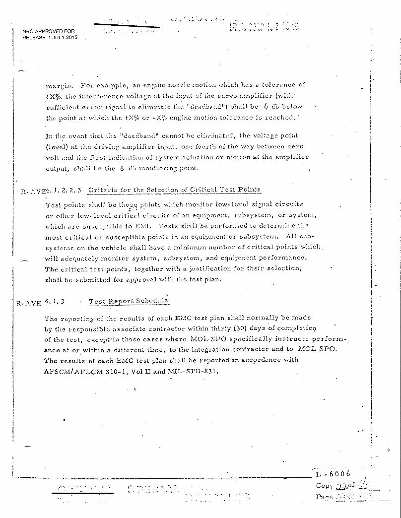
• 4 L NRO APPROVED FOR RELEASE 1 JULY 2015
margin. For example, an engine nozzle :notion which has a tolerance of
4-X50; the interference •voltage •at the input of the servo amplifier (with'
sufficient error signal to eliminate the "deadband") shall be 6 db below
the point at which the +X% or -X% engine motion tolerance is reached.
In the event that the "dcadband" cannot be eliminated, the voltage point
(level) at the driving amplifier input, one fourth of the way between zero
volt and the firSt indication of system actuation or motion at the amplifier
output, shall be the 6 db monitoring point.
t...AvEil. 1.2.2- 3 Criteria for the Selection of Critical Test Points
Test points shall be those points which monitor low-level signal circuits
or other low-level critical circuits of an equipment, subsystem, or system,
which are susceptible to EMI. Tests shall be performed to determine the
most critical or susceptible points in an equipment or subsystem. All sub-
systems on the vehicle shall have a minimum number of critical points which .
will adequately monitor system, subsystem, and equipment performance.
The critical test points, together with a justification for their selection,
shall be submitted for approval with the test plan.
nvE 4. 1. 3 Test Report Schedule
The reporting of the results of each EMC test plan shall normally be made
by the responsible associate contractor within thirty (30) days of completion
of the test, e.xcept-in those cases where Mal, SPO specifically instruct:: perform-.
ance at or within a different time, to the integration contractor and to MOL SPO.
The results of each EMC test plan shall be reported in accordance with
AFSCM/AFLCM 310-1, Vol LI and MIL-STD-831.
L - 6 0 0 6
Copy
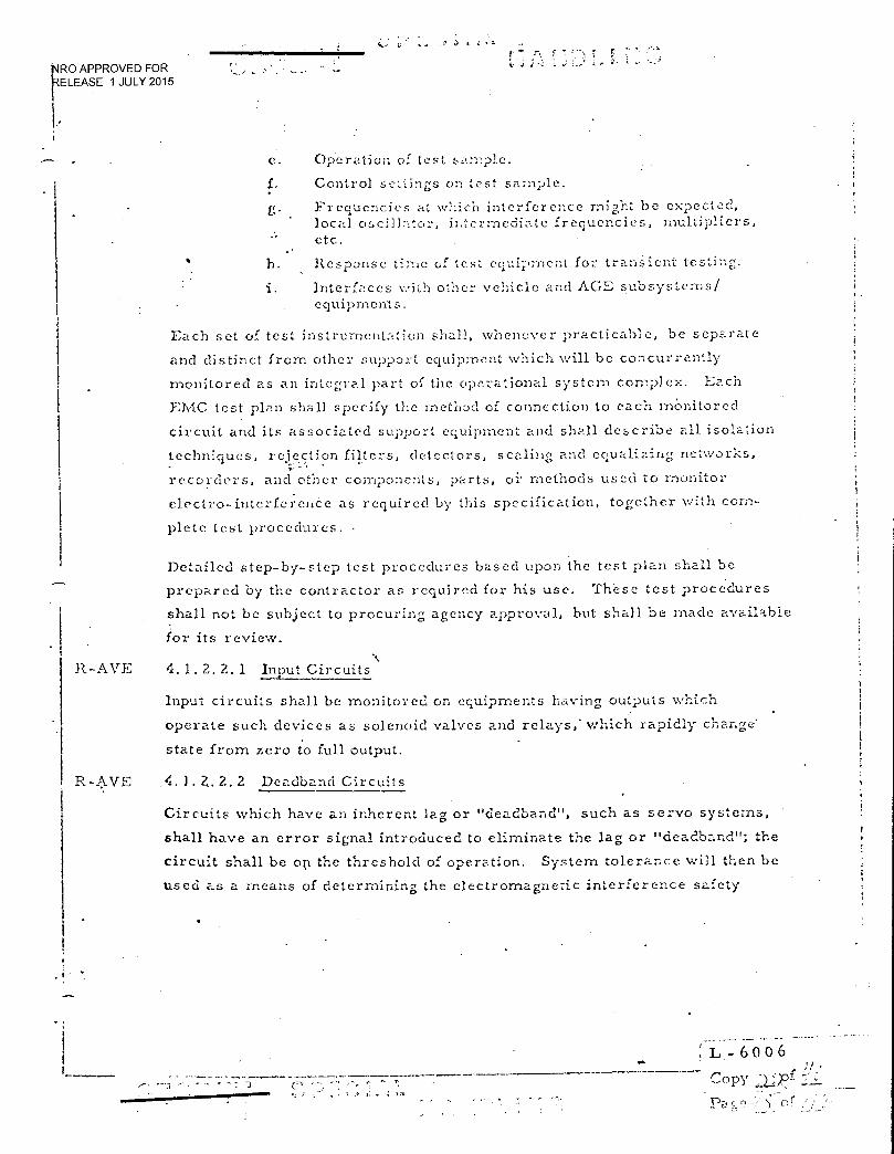
— • = r.
RO APPROVED FOR ELEASE 1 JULY 2015
e. Operation of test sample.
Control settings on test sample.
g. Frequencies at which interference might be expected, local oscill7:tor, intermediate frequencies, multipliers, etc.
h. Response time of test equipment for transient testing.
1. Interfaces with other vehicle and AGE subsystems/ equipments.
Each set of test instrumentation shall, whenever practicable, be separate
and distinct from other support equipment which will be concurrently
monitored as an integral part of the operational system complex. Each
EMC test plan shall specify the method of connection to each monitored
circuit and its associated support equipment and shall describe all isolation
techniques, rejection filters, detectors, scaling and equalizing networks, •
recorders, and other components, parts, of methods used to monitor
electro-interference as required by this specification, together with com-
plete test procedures. •
Detailed step-by-step test procedures based upon the test plan shall be
prepared by the contractor as required for his use. These test procedures
shall not be subject to procuring agency approval, but shall be made available
for its review.
R -AVE 4. 1. 2. 2. 1 Input Circuits
Input circuits shall be monitored on equipments having outputs which
operate such devices as solenoid valves and relays,' which rapidly change'
state from zero to full output.
R-AVE 4. 1. Z. 2. 2 Deadband Circuits
Circuits which have an inherent lag or "deadband", such as servo systems,
shall have an error signal introduced to eliminate the lag or "deadband"; the
circuit shall be op the threshold of operation. System tolerance will then be
used as a means of determining the electromagnetic interference safety
L.- 6 0 0 6
Copy
Pa
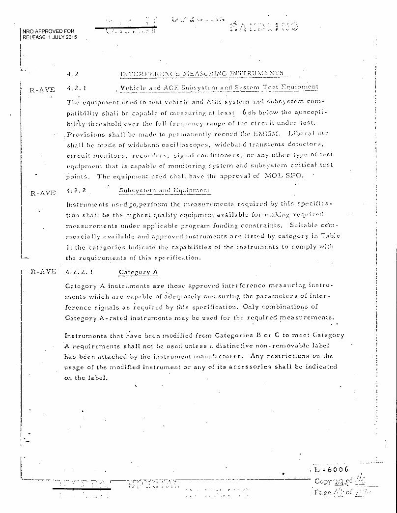
NRO APPROVED FOR RELEASE 1 JULY 2015
-1.2 /NTERFERENCE EASC RING
R-AVE 4.2. 1 Vehicle and AGY!: Subsystem and System Test Equipment
The equipment used to test vehicle and AGE system and subsystem corn--
patibility shall be capable of measuring at least 6db below the s•uscepti-
bili‘ty•threshold over the full frequency range of the circuit under test.
:Provisions shall be made to permanently record the EMISM. Liberal use
shall be made of wideband oscilloscopes, wideband transients detectors,
circuit monitors, recorders, signal conditioners, or any other type of test
equipment that is capable of monitoring system and subsystem critical test
points. The ec,uipment used shall have the approval of vtOL SPO.
R-AVE 4. 2. 2 Subsystem and Equipment
Instruments used,tp,perform the measurements required by this specifica-
tion shall be the highest quality equipment available for making required
measurements under applicable program funding constraints. Suitable co'rn-
mercially available and approved instruments are listed.by category in Table
1; the categories indicate the capabilities of the instruments to comply with
the requirements of this specification.
R-AVE 4, 2, 2, 1 Category A
Category A instruments are those approved interference measuring instru-
ments which arc capable of adequately measuring the parameters of inter-
ference signals as required by this specification. Only combinations of
Category A-rated instruments may he used for the required measurements.
Instruments that have been modified from Categories B or C to meet Category
A requirements shall not be used unless a distinctive non-removable label
has been attached by the instrument manufacturer. Any restrictions on the
usage of the modified instrument or any of its accessories shall be indicated
on the label.
. , L • - 6 0 0 6
' CGPY ,Z 11., 9f- -'_:-' - Pa7e -...),_‘:.• of
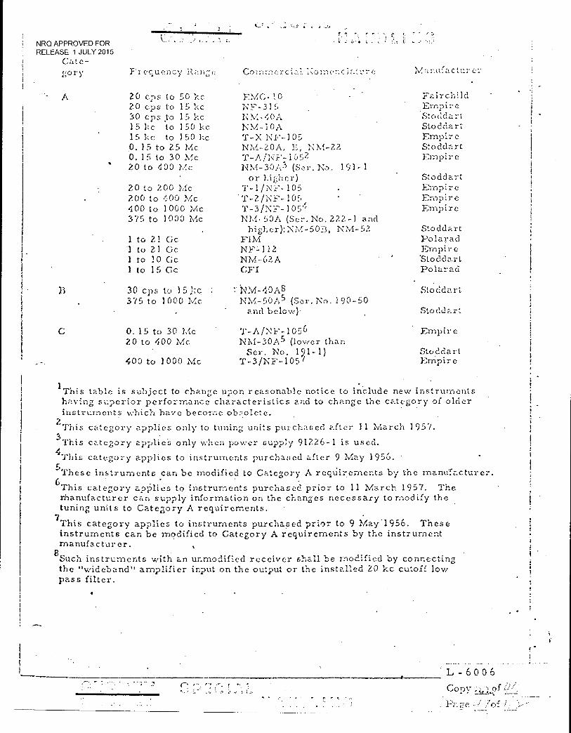
NRO APPROVED FOR RELEASE 1 JULY 2015
C; ate- gory eclue.ncy IV, a r.ta l C e
20 cps to 50 kc FMC •- 30 20 cps to 15 Ice NF-315 30 cps to 15 kc. NM-40A 15 1:c to 150 kc NM-30A 15 kc to 150 kc T-X NF-105 0. 15 to 25 Mc NM-20A, E, NM-22 0. 15 to 30 Mc T-i‘/NY:105:= 20 to 400 Mc NM-30A3 (Ser. No. 191-1
or higher) Stoddart 20 to 200 l'f:c T-1/NF-105 Empire 200 to 400 Mc T-2/NF-105, Empire 400 to 1000 Mc T-3/N.F-105'' Empire 375 to 1000 Mc NM-50A (Ser. No. 222-1 and
higher):NM-5013, NM-52 Stoddart 1 to ZI Cc FIM Polarad .1 to 21 Cc NF;-112 Ernpir e 1 to 10 Cc NM-62A 'Stoddart 1 to 15 Cc CFI Polarad
30 cps to 15 ;:c.-. : .NM-'',0A8 Stoddart 375 to 1000 Mc NM-50A5 (Ser. No. 190-50
and below) Stoddart
0. 15 to 30 Mc T-A/NF-1056 Empire 20 to 400 Mc NM-30A5 (lower than
Ser. No. 121-1) Stoddart 400 to 1000 Mc T-3/NF-105 1 Empire
'This table is subject to change upon reasonable notice to include new instruments having superior performance characteristics and to change the category of older instruments which have become •
2 This category applies only to tuning units purchased after 11 March 1957.
3This category applieS only when power supply 91226-1 is used.
`This category applies to instruments purchased after 9 May 195'6. 5These instruments can be modified to Category A reqUil-..,ernents by the manufacturer. 6This category applies to instruments purchased prior to 11 March 1957. The Manufacturer can supply information on the changes necessary to modify the tuning units to Category A requirements.
7This category applies to instruments purchased prior to 9 2,4ay .1956. These instruments can be modified to Category A requirements by the instrument manufacturer.
8Such instruments with an unmodified receiver shall be modified by connecting the "wideband" amplifier input on the output or the installed ZO kc cutoff low pass filter.
L- 6 0 0 6
:s
Copy ';;(,-,4of f")__
. FE:7e / -
A Fairchild Empire Stoddart Stoddart Empire Stoddart Empire
C
isIRO APPROVED FOR
1
tELEASE 1 JULY 2015
R _A \TE 9.2.2. 2 Category
Category 13 irstruzncnts are those instruments which are in general testing
use but which do not adequately measure the parameters of interference
signals as required by this spe;-ification.
Any such instrument must be modified to the Category A rating to permit its
use and must carry a non removable label certifying such uprating by the
instrument manufacturer or the contractor-user, as applicable.
R--AVE 4.2. 2.3 C
Category C instruments are those which have been recently developed• but do
not meet Category A requirements, and which can be modified by the manu-
facturer to attain a Category A rating.
Category C instruments shall not be used until all necessary modifications to
up-rate them to Category A have been accomplished. Each shall carry a
non-removable label certifying such by the instrument manufacturer or the
contractor-user, as applicable.
4. 2. 2. 4 Broadband Spectrum Analyzers
r • •
Broadband spectrum analyzers may be of assistance in determining areas of
interference and reducing overall test time.
4.Z. 2. 5 Automatic/Semiautomatic Test Instrumentatior.
Contractors should be alert to, and take full advantage of, the use of auto-
matic or semiautomatic :est instrumentation which will markedly reduce •
the test time required. Use of such devices 'shall be described in the ai_;p 7 -
cable test plan.
(iv
_
L 6 0 0 6
NRO APPROVED FOR RELEASE 1 JULY 2015
t-AVE 1. 3 OPERATION CY' ME1,.:;1_11:tING IN S RUNIFNTS - ---
For both conducted and radiated iotei- furence measurements, the instruments
used shall be calibrated and operated as indicated in their respective instruc-
tion manuals, subject to modification thei cof as noted in the affected EMC
test plan.
R. 4.3. 1 Calibration
Interference measuring instrumentation shall be maintained in a known con-
dition of accuracy. Periodic checks on the calibration accuracy shall be
made with laboratory generators. Re-calibration shall be accomplished
when the standardized gain Setting fails to reflect a meter reading within
plus or minus 20 percent of the known input signal. Substitution-type
measurements can be used in lieu of the calibrated method. It is therefore
.not necessary to caliVrate (adjust to a known value) the gain of the inter-
ference meter prior to making measurements. It shall be permissible to
'use either a calibrated sine wave or calibrated impulse noise generator (as
appropriate) in substitution with the unknown at the time of measurement,
Impulse noise generators which are integral with, or which accompany, an
interference meter must be periodically -checked against laboratory standards
to detect degradation due to time, usage, and transportation handling.
R-AVE 4 . 3. 2 Generator Accuracy
Laboratory-type signal generators and impulse generators capable of an
output voltage accuracy of at least 20 percent shall be used to calibrate
interference•measuring instruments and for substitution measurements. ,
R-AVE4. 3. 3 13.roadband Interference :V.eaiurernents
Broadband interference shall be measured by using an impulse generator
with the substitution technique (see Section 6.0), or by calibrating the
interference measuring instrument so that it reads directly in decibels above
one microvolt per unit bandwidth. The peak detector function on the inter-
ference measuring instruments shall be used for broadband and pulsed cw
•
L- 6 0 0 6
Copy ̀/
Pace
NRO.APPROVED FOR RELEASE 1 JULY 2015
iihe process tho meter to re -1 voltage per
unit bandwidth consists of dividing the meter reading; by the in-Ipulse bend-
-Width (see Section 6. 0) of the rneior.
R-AVE 4 3.4
CV,' Interference :.,./i..easurcrrients
CV/ interference shall be measured by calibrating the interference
measuring instrument so that it roads directly . in decibels above one
microvolt or by using a signal generator with a substitution technique.
R-AVE 4, 3. 5 Pulsed CV,' Interference Measurements
PulSed CW shall be measured in accordance with the procedures and limits
used for broadband interference.
R-AVE 3. 6
Monitoring.
The interference 31-1e.a.suring, instrument shall be monitored with a headset,
loudspeaker, oscilloscope, or other indicating devices, during all
measurements. Precaution shall be taken to ensure that the monitoring
does not influence the meter reading on the interference measuring
equipment.
When making "Peak Detector Function" readings on interference which is
steady, in the sense that there is no functional reason for it to vary with
time, the interference meter output shall be observed for a least ten
seconds, and there shall be ho appreciable variation within that time.
R-AVE 4. 3. 7 Bonding of Measuring Instruments
R-AVF,
interference measuring instruments used for radiated or conducted
measurements shall be grounded utilising the best available techniques
consistent with current MIL specification methods. Such methods shall
be delineated in the final EMC Test Plan.
4. 3, 7. 1 Rod Antennas
The counte..- poise on rod antennas shall be bonded to the ground plane with
a strap of.such length that the rod antenna can be positioned correctly. The
L - 6 0 0 6 r,
,) -• ,1 Copy ‘)..p
' Pa 7C`
r-,
NRO APPROVED FOR RELEASE 1 JULY 2015
strap shall be as wide as the cou;-:terpOi 55. This applies to rod antennas
utilizing the interfcrOnCe rrieL?.;3111:5ng inst instruments as a counterpoise and to
rod antennas mounted on a separate counterpoise.
R-AVE 4. 3. 7.2 Instrument Groun:'.ing,
The interfcrrence measuring instruments shall be physically grounded with
only one connection. If a copper strap is used, neither the ground clip, the
ground terminals, nor the power supply shall be connected to ground.
-t*
•_ .•- -• .•
L - 6 0 0 6
Copy
cre .`; :of / '
WO APPROVED FOR RELEASE 1 JULY 2015
.R-A\TE 4.4 . TEST
The interference measuring instrument shall be slowly tuned throui;li each
frequency octave.and the frequencies at w,hich the ma-,:imt.trii interference or
susceptibility is obtained sh.zW be selected as test frequencies. Test fre-
quencies shall not be selected prior to the interference test, except when
making broadband transient interference measurements. A minimum of
three measurements shall be raade in each frequency octave. If test Ire-
quencies arc pre-selected dui Mg broadband transient tests,? r:-.inimurn of
three measurements shall be made in each frequency octave below 1 Mc
and five measurements per octave above 1 Mc. The affected test report shall
include a certification that the test frequencies v.,ere selected after each
octave was scanned.
I L - 6 0 0 6
Copy
Pa e
NRO APPROVED FOR RELEASE 1 JULY 2015
r, 45
TUNING
For cquiprnent containin.7 Oscillator circuits, the interference measuring
ins:trument shall he tuned to, and rnea5;urements• should be made at, the
primary oscillator frec;uency and at. all h;,,rmonics up to the third
carrior harmonic (if the output carrier frec,:ency is different from the
primary oscillator freciuency) above the highest carrier harmonic which
measures 6 db below the allowed limit, Additiona.1 Cht?CkS shall be made
by scanning for and measuring any signal or spurious response that can
be anticipated,
L - 6 0 0 6
t..
\IRO APPROVED FOR RELEASE 1 JULY 2015
R-AVE
4.6 TEST CONDITIONS
4.6. / System
All electronic and electrical equipment included in the applicable system
test plan shall•be included in the system test complex and shall be in
nd'rroal operating condition as deterznined by the test procedures and tech-
niques specified in the detailed subsystem test plans. Specific provisions
shall include the following:
(a). All support equipment normally operating during a standard countdov.m and launch shall be operating.
(b) All flight systems shall be operating.
All pertinent missile test range support equipment such as radar, command transmitters, communica-tion transmitters, etc., shall be operating and
; directed at the vehicle.
(d) Mobile service or other such towers shall be removed
(e) A complete mission profile shall be performed. This shall include a simulated prelaunch, launch ascent and orbit. All systems will be operating, normally.
4. 6. 2
R-AVE 4.6. 2. 1
(f) Provisions shall be made for remote monitoring of the critical test points
(g) During tests, all electronic subsystems shall be operated in the modes or conditions expected to be most susceptible to interference.
Subsystems and Equipments
Ambient Interference Level
It is desirable that the ambient interference level during testing, measured
with the test sample de-energized, be at least 6 db belov:, the allowable
specified interference limit. However, in the event that at the time of
measurement, the levels of ambient interference plus test item interference
are not above the specifiedlimit, the tested item shall be considered to
have met the specified requirement. This requirement shall apply equally
to bbth radiated and conducted ambient interference levels.
L- 6 0 0 6
Copy -v,..Lef
Pa:
NRO APPROVED FOR RELEASE 1 JULY 2015
A shielded enclosure or screen room may u::ed if 21 Or desired.
If a shi c.lded ench--)sure is used, the minimum length shall be such that a
35 Mc tuned dipole can be placed roon: with at least 1?. inches
clearance between the antenna extl:ernitles and the shielded enclosure.
R-AVE/l. 6 . 2 . 2 Ground Plane
A. copper or brass ground plane, 0.01 inch thick minimum for copper,
0.025 inch thick minimum for brass, 12 square feet or more in area, with
a minimum width of 30 inches, shall be used. In a screen room, the ground
plane shall be bonded to the shielded room at intervals no greater than 3
feet and at both ends of the ground plane. The ground plane and sci:ecn
room walls may be considered equivalent to a vehicle spLcefran-le for pur-
no=,es of .no.rmal installation. For large eG.. .
mounted on a metal test stand, the test stand may be considered, for testing
purpoSes, to be part of the ground plane and shall be bonded accordingly.
When a shielded room is not used, the measuring equipment may be placed
on a solid support for operation. The support may be solid earth, steel or
iron flooring, metal bedplate, metal-covered planking, or the like.
R-AVE Bonding
Only the provisions included in the design of the equipment and specified in
the installation instructions in compliance with the EMC test plan,- shall be
used to bond units, such as equipment case and mount, together or to the
ground plane. If bonding straps are required to complete the test setup,
they shall conform to the requirements of paragraph 3.2.4. Connec-
tions made with such bond straps shall have clean metal-to-metal contact.
R-AVE 4 6. 2.3.. 1 Shock and Vibration Isolators
Shock or vibration isolators shall be used in the test setup, if they are
required in the operational installation. If bonding straps are supplied for
such isolators, they shall be connected to the ground plane. Bond straps
will only be used as specified in the operational installation.
L - 6 0 0 6 Con': of
of
NRO APPROVED FOR RELEASE 1 JULY 2015
R-AVE 4, 6, 2.. 3 . 2 Crou •
When an CN.terrill terminal or con:..ect-Jr avztilable for a ground connection
on the test sample, this terminal _...all be conn ected to the ground plane, if the
terminal is normally grounded in the instz:Ilation. If the installation conditions
are unknown, the terminal shall not be grounded.
R-AVE 4. 6. 2. 3. 3 Portable Emlini•nent
Portable equipment that is intended to be grounded through a power cord shall.
• not be bonded to the ground plane unless specific operating conditions require
bonding. In such case(s), bonding shall be utilized.
R-AVE 4. 6. 2. 4 Power Supply Voltage
The power supply voltages at the equipment terminals shall be within the
tolerances specified in the detail :, pr.t.cification for the test sample. 'I he AVE
test sample shall be operated at the maximum and minimum operating voltages
for audio conducted,:s;usceptibility. For all other tests the operating voltage shall
be within equipment voltage limits. All AGE tests will be conducted at nominal
line voltage.
R-AVE ' 4. 6. 2. 5 Arrangement and Operating Conditions
The general arrangement of equipment, interconnecting cable assemblies,
and supporting structures shall be such as to simulate actual installation and
usage insofar as practicable. The front surface of each unit shall be located
4 inches - 1/2 inch from the edge of the ground plane; interconnecting cables
shall be routed between the units and the edge of the ground plane. In those
cases where equipment size exceeds the ground plane dimensions, the above
instructions shall be adhered to as closely as possible.
R-AVE 4. 6. 2. 5. l Feed-Through Capacitors
Ten microfarad feed-through capacitors shall be required in the test sample
power lines when making interference measurements, unless the operational
power supply is being used to supply power to the test sample. These
capacitors shall be so selected that their respective temperature rise is not
mere than 5°C.
• C. 5", r r"Th
L - 6 0 0 6
Copy ;I:2)Pf Pare
NRO APPROVED FOR RELEASE 1 JULY 2015
When phase is important for specific test samples, matched capaci:or ,-:
be used. A bleeder resistor shall he con;lected across the capacitors to reduce
shock hazard. Figures 9 and 10 typical test setups utilizing the capacito-rg.
Feed-through capacitors may not be feasible in certain instances, as when
initial charging current would damage the test sample, when the total re-
active c;urrent would degrade the ac power supply, and, in some situations,
when testing switching devices. In such situations, the associate contractor
will specify Other methods or techniclues in the affected test plan. Neither
feed-through capacitors nor other impedance standardization devices shall
be used if the test sample is powered by the operational power supply.
R-AVE . 6.2. 5. Z Dummy Antennas
Any dummy anternas;:u:sed shall have ele.ctrical characteristics which closely
simul;:lte those of the norrnal antenna, and shall be shielded whore possible.
The dummy antenna shall be capable of handling the power required and shall
contain any unusual components which are used in the normal antenna such
as filter, crystal diodes, etc.).
A minimum 5-foot 'length of double shielded coaxial cable or special lines as
specified in the test requirements, shall be used between a transmitter and
its dummy antenna.
R-AVE4. 6. Z. 5. 3
Test Sample Leads
The test sample leads to the reqUired feed-through capacitors, when used,
shall be 24 inches -; 1 inch in length, where possible, and shall be so arranged
that the distance between the leads and from each lead to ground or grounded
enclosure is approximately 2 inches.
Interconnecting leads between units comprising test sample shall be between
_Z and 5 feet long. Leads from these units to auxiliary equipment, such as
meters and loads, shall be 5 feet long. The above is not a requirement for
audio frequency testing. In lie,t of these' requirements, an actual system
harness may be use,:. to interconnect the test c,-:ecimen with associate -3_ sources
or loads.
L - 6 0 6
Copy L2o.
TD
NRO APPROVED FOR RELEASE 1 JULY 2015
R-AVY, 4.6.2.6
h C test sample shall be ord on the plr::ne for ina:,;imunn inter-
ference effects within allowable opc -!.ating reouiremonts. Those interference
measuring instruments which use a roil antenna shall be so placed that the
rodantenn;.-± is in a vertical posit:on and time instrument panel or counter-
poise is 6 inches below the level of the ground plane. The rod antenna shall
be located at the point of maximum interference indications while the test
sample is operating in the steady state mode. This maximum is obtained
by moving the antenna along a line para.11,-,1 with the edge of the ground plane.
Those interference ineasuring instruments Which use a resonant dipole
antenna shall have the dipole positioned parallel with the front edge of the
ground plane. Its height shall be 12 inches - 1 inch above the. level of the
R.-AVE
ground plane and its center shall be adjacent to the geometrical center of
the units under test. The rod or the dipole antenna shall be located at the
distance from the test sample specified in the typical test setups. When the
dimen:-3ions of the dipole or directive antenna become smaller than the test
layout, the antenna. shall be moved parallel to the edge of the oround plane
to keep its sensitive elements adjacent to the point of maximum leakage or
susceptibility. In place of the above, more than one antenna may be used.
with the details delineated in the final Fish test plan. At frequencies from
25 up to and including 35 megacycles the measurements shall be taken with
the dipole antenna adjusted to35 Mc. The dipole antenna shall be adjusted
to the proper length at all frequencies above 35 Mc.
4.6.2.7 Antenna Orientation and Positioning (Free Snace)
Those interference measuring instruments which use a rod antenna shall be
so placed that the rod antenna is in a vertical position. Those interference
measuring instruments which use a dipole antenna shall be so placed that the
antenna is parallel with the test sample and on. the same level as the mid-
point of the test sample. The antenna shall be at the distance from the test
sample specified in the typical test setups. The antenna shall be located
at a point around the perimeter of the test sample where maximum inter-
ference signal is received.
L- .6 0 0 6
Copy. •,,t -..,4ef
, cf

•
NRO APPROVED FOR RELEASE 1 JULY 2015
R-AVE; 4. 6. 2. 8 Loads
The equipment under test shall be loaded v.,ith.the full mechanical and
electrical load, or equivalent, for which it is designed.
This recuirernent specifically includes electrical loading of the contacts
of mechanisms which are designed to control electrical loads ever, though
sach loads are physically separate from the equipment under test. Opera-
tion of voltage regulators and other circuits which operate intermittently is
required. The loads used shall simulate the. resistance, inductance, and
capacitance of the actual load. All input and output circuits, v.•hethee power,
signal, or control, which are otherwise unterminated in the test sarnple,
shall have impressed upon them appropriate simulated signals, with equiva-
lent circuit termination impedance.
L - 6 0 0 6
Co l ,f) of

•
NRO APPROVED FOR RELEASE 1 JULY 2015
:.7
TES'' M77THOD .'.3
4. 7. 1. ". Composite System
Tests to indicate improper (inadvertent or unacceptable) responses for the
composite system shall be based upon the general test approz,;ches of para-
graph 4 7. 1. 3. Tests shall be devised, to demonstrate compatibility of the
composite system over the complete spectrum associated with each component
system and that of the individual subsystem and ec.juipments of the systems
including its expected external electromagnetic environment. lnstruirientation
used shall have frequency responses adequate for this task. Vehicle and AGE;
system and subsystems capable - of :transmisSionor:reception at a multitude of
frequencies shall be tU Stedl at the minimum number of frequencies
to indicate cictctromagnetic compatibility. Frecueneies shall be i:idicated in
the interference test'plan, when applicable for a specific test approach.
?.-AVE 4. 7.1. 1 Implementation
The integration contractor shall establish test criteria for determining
compliance with this specification in terms of performance requirements
and definitions of vehicle and AGE system component and subsystem imp roper
responscs. These criteria sha..1 be included in the test plans specified herein,
along with detailed test methods, instrumentation, critical points, monitoring
points, and intended functioning of each subsystem.
R-AVE 4. 7.1. Z . Improper Response
4. 7. 1. 2.1 Inadvertent Response
Criteria to• provent inadvertent response shall be defined in terms of the
margin (EMISM) between interference levels and circuit. thresholds of opera-
tion at critical points within each subsystem. This margin, or separation,
shall be a minimum of 6 db exclusive of instrumentation errors but may be
greater than 6 db depending upon the characteristics of the particular subsystem.
If the criteria for inadvertent response at critical subsystem points cannot be
determined prior to test for inclusion in the test plan, these criteria may be
L- 6 0 0 6
Li
i
NRO APPROVED FOR RELEASE 1 JULY 2015
determined as part of the test. In such cases, the integration contractor shall
specify the test approach to be used in demonstrating that a 6 clb minimum
Elv1.15M exists at these critical points.
4. 7.1. 2. 2 Unacceptable. Response
Criteria for unacceptable response shall be in terms of performance limits
at a monitoring point at the output of the subsystem components. The
occurrence of unacceptable responses at those monitoring points during
testing Will constitute failure to meet the 2'ecwuiroINents of this specification
and are mandatory correction items. The EMISM for unacceptable response
shall. be 6 db, exclusive of instrumentation errors, and shall be determined ..:-., •
from a point_at which the,output, of the equipment under test reaches the
extremes of its acceptable tolerance. Out of tolerance operation of the
equipment resulting from interference is considered unacceptable
response.
4. 7.1. 3 Test Approaches
Tests shall be performed to demonstrate compliance with the improper
response- requirements of this specification. One or more of the following general
test approaches may be used:
a. Injecting interference at critical system points at a 6 db higher level than exists, exclusive of instrumentation errors, while monitoring oth: r system points for improper responses.
b. Measuring the susceptibility of critical system circuits for comparison to existing interference levels, to determine if a 6 db margin exists, exclusive of instrumentation errors.
c. Sensitizing the system sous to render it 6 db more susceptible: to interference exclusive of instrumentation errors, while monitoring for improper responses.
4. 7. 2 Equipment Test Methods
The radio frequency interference generation measurements described belov,, are
directly suitable for the measurement of steady state signals. In the case
of short duration signals having very low repetition rates, special test
r7,
L 6 0 0 6
Copy jilof
Pare
NRO APPROVED FOR RELEASE 1 JULY 2015
rricth, ods may be i _..red. The Scat (11.7.rat_ch shall he considered to be
the duration of the interference pulse at the output of the second detector
of the interference mce:er.
R.-AVE Into. rfe r c
Conduct:cc.] interference measurements shall be made over the frequency
range of 30 cps to 100 lie, using a clans-on interference current measuring
(meter) device and an appropriate receiver from Table ). In the• case of
a component with a large number of similar inputs or outputs, the conducted
interference measurements may be limited to representative conductors
in each cable. A typical test setup is shown in Figure 11. The test
conditions shall be as described in Paragraph 4.6.
For steady-state interference measurements, the current probe shall be
positioned at the p-:in-t .of interference on the lead to be tested.
This maximum interference point shall be located at each test frequency
for steady-state operation where the physical. length of the test specimen .
cable is greater than A/20, (A , free space wave length at the test frequency),
The location of the current probe shall be fully described in the test report.
Switching transients may be measured withwideband (minimum - 10 Mc)
oscilloscope directly connected across the test sample/signal/power leads.
R - A VE Radiated Interference
Radiated interference measurements shall be made from 15 kc to 10 Cc
for broadband/impulsive interference and 15 KHZ to 10 GHZ for CV. and
pulsed CW interference. Tipieal test setups are illustrated in Figures 12,
13 and 14. In the frequency range from I to 10 Gc, the measuring distance
shall be 3 feet. The antenna polarization and direction shall be adjusted for
maximum pickup. The antenna and measuring system correction factors
to be used are those specified by the interference measurement instrument
manufacturer. The test conditions shall be as described in Paragraph 4.6.
4.7.2.3 Transmitter (Keydown)
The transmitter shall be operated into a matched dummy load. A suitable
coupling device shall be used to sample the transmitter output and to protect
the measuring equipment, such as a bridge "T" or other filter rejection
network. Transfer and other characteristics of such devices shall be fully
described in the test report. Attention should be given to oscillator frequency
Page 59„c44. 106 L - 6 0 0 6
co-Dv-
NRO APPROVED FOR •RELEASE 1 JULY 2015
and harmonic:;, outputs from frequ.eney multipliers and crystal saver
circuits, beat frequency oscillator outpu'Ls, etc. External filters shall
not bc' used for complanec with the spcciedIamts herein without
MOL sPc-) approval.
R-AVE 4. 7. 2. - 4-
•• , • tr -, -hs ,-nitter shall meet cono..icieo
c'r• 3-3, tic
erhLna tior (1;e;,•do-•..--.)
s :1-•jc.ote t o of:-
f recidc,,o ty ,•_!rt er L;y at level 35 bnlov.. the fundan-,ental power. The off-
frequency n::•.] shall be within percent. of given funklan-:ental frecuency
yet outside the fundarric.ntz.1.1,..,nd c; ful•thei-, at least one of the, sum and
differ.::!nce .h ,?terodyne pre :;hall be in the rani;C: of 0. If) to 10, C:Or.!
Mc. Tic: tram:rnitre;. modolated Cid r noln-nally or 30 per-scat at
400 cps. As on alternate tt:st, condition, the off-frecducnoy be at
h-vol oh fund:..hnental power, the
3.3.1.1.3.2. is ch:tnged accordingly, to flito.tei,;:stiun-leni,.-..tion. The c:::-.7-
fre:inency sii, na.) shall be amplituclemodalated 30 percent at 1000 cps. The
transmitter and the off'freouency source shall ha.ve their outputs co nnec.tc(f.,
Z.);),':rr ly a to 1:10 et cZ;re'.11, t
the off- fr equency '11 he meaL•u. byz....restivc.' tc' transn., 1 ' o4"'-frequer.cy
and spurious le ■.'els shall . be rn,:...cIe at the transmitter output. with the same
meter couplin; ,, - icc used in paragr-tlph
R-AVE 4.7.?. 5
Susceptibilit ,.•
When performing susceptibility tests - on receivers; all exte-rnal and internal
controls shall be set for maximum signal plus noise-to-noise ratio. All
external and internal controls for squelch or limiting shall be set ,to give
minirnum limiting action. On other equipment, all external and internal
controls shall be set for rni,,-:r.nitzn indication of susceptibility, or, if this
C2.USOs an . equipment to malLincticn or to 1:..ccorr..e inoperable as a result of
such a control setting, the critical control shall 1.-.•e zdjustod as directed in
the ec...tipment instruction manual. The equipment under test shall not be
supplied with any inputs other them those required to energize the ecuip.,rnent,
to render the ecluiprnent capable of re.spon,:ing to int erferE.:ace, and. to provide
indication of opera10n:
Pai. e 5,0 of o L - 6 0 0 6
Copy f •
NRO APPROVED FOR RELEASE 1 JULY 2015
7731
R-AVE
1.7.?. 5. 1. C -_:-,:ctec7. 30 ens tc, 130 1-c
The Voltage levels indicated in Fire s -ze the ripple vol -:75 applied in
series with each power input of th,.:1::.st, The voltT-,:.;e u 111 be measured
as shown in 1::'igure 16 with the equ.p•1-,e.r.,t piwor sou see connected and the equipment
under test operating. Tests will be i-nade over the frequency rouge of 30 epf; to
150 he. if no malfunctions occur, the test shall be repeated at a 6 db higher
voltage level or the malfunction threshold level, K;hiche,:er is 10-,cr. However,
it an;_-- lysis or prior test data indicates that equi.7-in-:ent dal-nage above the normal
susceptibility test limits will result, those malfunction threshold level tests need
not- be performed and the susceptibility threshole, shall be the susceptibility test
limits. Equipment need not be qualified to the 6 db higher voltage- level. These
6 db tests may be run on development hardv..are. In those cases where the power
lines are heavily bypassed at the equipment, presenting a very low impedance to
the injected interference voltage, the followl:-, procedure may be followed.
The irit.-1'fOrell.Ce voltage injected into the pc,\ver line may be measured across
the secondary of the transformer provided the do power source used to supply
the equipment under test has an impedance of 0.1 ohm or lens. The audio fre-
quency ripple current from the interference generating source may be limited to
that resulting from an audio frequency generator having a 1/2 ohm output impedance.
Further, if the impedance of the power line looking into the equipment under test
is so low at the higher frequencies that the required test voltage cannot be attained
with a 50 watt generator, the following procedure may be used. Measure the ac
drive voltage of the amplifier output stage which produces the desired voltage in
series with the power line at 1000 cps. Maintain this drive voltage while making
the test over the required frequency band between 30 cps and 150 kc. The output
transformer characteristics should be flat over this frequency.
4.7.2.5.1.2 Conducted, 150 kc to 400 Mc
The test setup for 150 kc to 400 Mc shall be the same as in Paragraph 4.7.2.1,
except that the 10-rnicrofarad capacitors shall. be removed. If no malfunctions
occur, the test shall be repeated at a 6 db higher voltage level or the malfunction
threshold level; whichever is lower. However, if analysis or prior test data
indicates that equipment damage above the normal susceptibility test limits will
result, these malfunction threshold level tests need not be performed and the
susceptibility threshold shall be the susceptibility test limits. Equipment need
L - 6 0 0 6
Cc:1)y
NRO APPROVED FOR RELEASE 1 JULY 2015
not be qualified to the 6 (11, higher vol_ These 6 dip tests may be run
on. devc.:loprnent hardware. An att.,.:nuator, or equal terrnimAion, shall be used
at the end of the coaxial cable to properly terminate the signal source. A
coupling capacitor, having an j art C C of 5 ohms or less at the test frequency,
shall be connected from this terlriinntion to the lead under test. The capacitor
may be charged during the test to maintain the spoe'!-Jiied impedance. The signal
SOUIzCe output required is the applicable. 1 plus the nominal termina,tion
insertion loss. The test signal shall be applied. to each power lead in turn. When
necessary, components can be added in series with the power leads to isolate
the power source. The output impedance of the signal generator shall be aS
low as practicable and no greater than 50 ohms. Tests shall be made over the
frequency range of 150 1:c to 400 Mc. The rf signal shall be modulated 30 percent,
400 or 1,000 cps, on,:equipments that are not designed for other modulation
frequencies or special forms of modulation. When applicable, actual modulation
frequencies or special forms of modulation shall be used as appropriate.
R-AVE4.7.2.5.1.3. Conducted Transient
The transient or pulse shall be induced in or across the power lines and between
each power line and case in both the plus and minus polarities. A typical pulse
shape with definitions of amplitude, rise time and pulsewidth is shown in Figure 17.
The pulse repetition rate shall be at least two (2) pips. The transient generator
shall be..capable of delivering at least 30 x 10-3
joules to the test sample. If the
transient cannot be generated across the test sample with 30 millijoules, then the
component is assumed to have passed the test. The transient voltage shall be
measured across the input terminals of the test sample with the test sample operating.
Schematics of a suggested type of test equipment are shown in Figures 18 and 19.
4.7.2.5.2 Audio Frequency Induced
R-AVE 4.7.2.5.2.1 Induced into Cables
Interconnecting cables shall withstand, without evidence of equipment performance
degradation, the application of a magnetic field caused by a wire carrying 20 amperes
rms at 400 cps spaced 2 inches away. Other test frequencies, up to 15 kc depending
on the anticipated environment, shall be used as directed by the detail specification.
Power input and output leads are exempt from the requirement of this paragraph.
The applied magnetic field shall be generated by the current in a wire routed 2 inches
For EK non-interfacing equipment, use amplitude of 30 volts., for all 3 tests. All contractors use 30 volts for return lead to case test.
L - 6 0 0 6
Cop;'
Pa e o:
NRO APPROVED FOR RELEASE 1 JULY 2015
away and parallel to the cal_je uncle]: test fa a istalicc_ of 5 feet. The wire
shall be oriented in two angular positins, 00 degrees, a -part. about the cable.
To implement this, two wires 90 degrees -,part may be routed, and the current
then 'switched from one to the other (figure 21). Cabling of the test sample
shall be routed at least 2 inches away froi-n the ground plane or equipment rack.
The current carrying wires shall break from the test sample cable at
least 6 inches short of the cable connectors. The wire return leads shall be
kept at least 2 feet from the. cable under test and from all other cables of the
test sample. Cables need not be tested individually, but may be tested in whatever
bundled configuration is convenient. Regardless of the number of current
carrying wire segments installed for test, only one wire segment shall be
energized at a time.
14-11-VE 4.7.2.5.2.2 Induced Equipment
Equipment shall withstand, without evidence of performance degradation, an
ambient magnetic field at 400 cps. Other test frequencies may be used, as
defined by the affected test plan. The applied magnetic field shall be
generated by a minimum current of 20 amperes rills in a straight wire segment
which is located 2 inches from the sample unit periphery and from sample
interconnecting cables. The various units of the sample shall be individually
tested. The segment shall be oriented as necessary to thoroughly probe each
unit for susceptibility. The length of the segment shall be such that it extends,
at each end, 2 feet past the unit under test. The leads supplying current to
the segment shall be routed at least 2 feet from any portion of the sample and
from the segment itself (that portion of the segment directly opposite the unit
under test).
14-AVE 4. 7. 2. 5. 3 Radiated Field Susceptibility
The radiation field shall be established with a signal generator driving
the antenna listed below. The fields specified are those calculated
(assuming plane wave/free space propagations) to exist at the equipment
under test. The test setup is shown in figure 22 for the long wire antenna
and is similar to figures 13 and 14 for the other antennas, with the signal
source replacing the interference meter. For the dipole and directive
L - 6 0 0 6
Copy
Of
r P
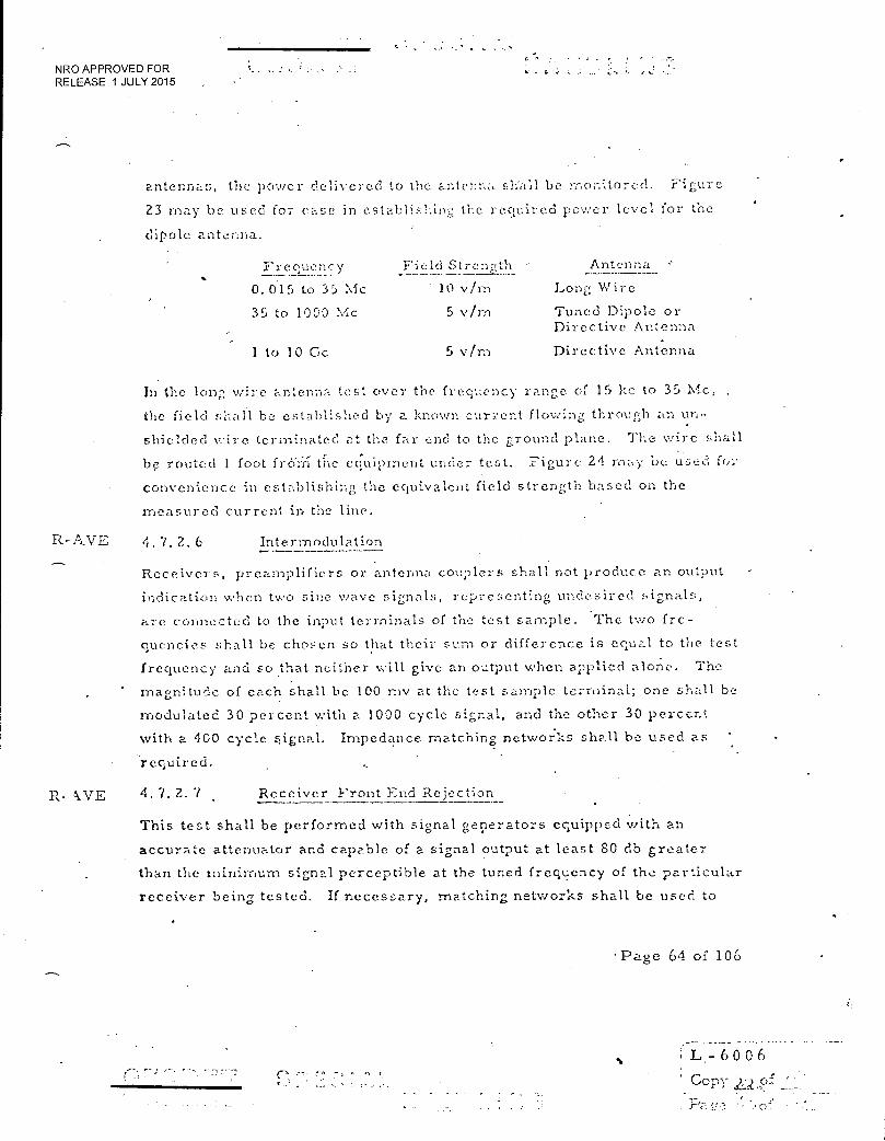
NRO APPROVED FOR G. . RELEASE 1 JULY 2015
antennas, the power delivered to the antenna shall be rnonitored. Figure
2.3 may be used for ease
dipole antenna.
in establisl:ing the required power level for the
1'1- Cane 31C: y Field Strength Antenna , 0.0.15 to 35 Mc . 10 vim Long Wire
35 to 1000 Mc 5 vim Tuned Dipole or Directive Antenna
1 to 10 Cc 5 vin-, Directive Antenna
In the long viire antenna test over the frequency range of 15 kc to 35 Mc,
the field shall be established by a known current flowing through an un-
shielded v•ire terminated at the far end to the ground plane. The wire shall
be routed 1 foot from the equipment under test. Figure 24 may be used for
convenience in establishing the equivalent field strength based on the
measured current in the line.
4.7.2.6 Intermodulation
Receivers, preamplifiers or antenna couplers shall not produce an output
indication when two sine wave signals, representing undesired signals,-
are connected to the input terminals of the test sample. The two fre-
quencies shall be chosen so that their sum or difference is equal to the test
frequency and so that neither will give an output when applied alone. The
magnitude of each shall be 100 my at the test sample terminal; one shall be
modulated 30 percent with a 1000 cycle signal, and the other 30 percent
with a 400 cycle signal. Impedance matching networks shall be used as
required.
R- EVE 4.7.2.7 Receiver Front End Rejection
This test shall be performed with signal generators equipped with an
accurate attenuator and capable of a signal output at least 80 db greater
than the minimum signal perceptible at the tuned frequency of the particular
receiver being tested. If necessary, matching networks shall be used to
Page 64 of 106
L 6 0 0 6
Copy 2„2,,o
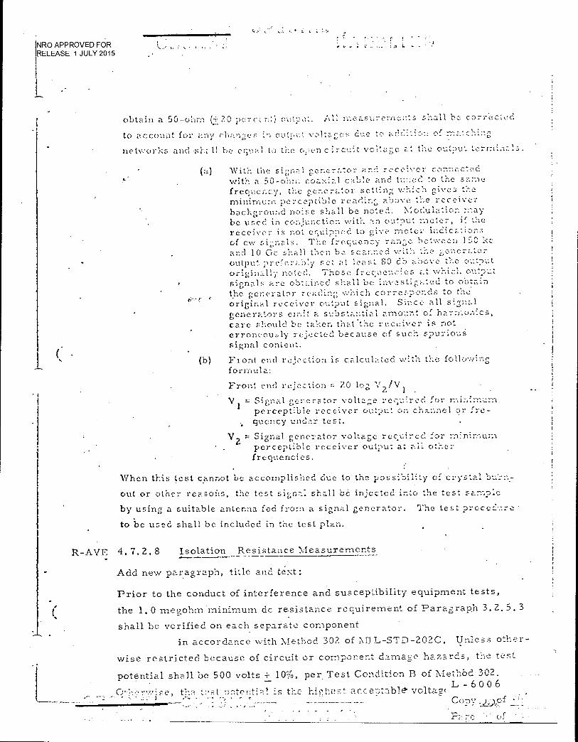
NRO APPROVED FOR RELEASE 1 JULY 2015
obtain a 50-olim (+_20 percent) outp,it. AU measurements all be corr:ected
to account for any changes in output voltages due to o f-
networks and be equal to the o,:.encircuit voltage at the output terminz.ls.
(a) with a 50-ohrn coaxial cable and tuned to the same With the signal generator and receiver connected
frequency, the generator setting which gives the minimum perceptible reading above tbe receiver background noise shall be noted. Modulation may be used in conjunction with an output meter, if the receiver is not equipped to 2ive meter indications of cw signals. The frequency range between ISC kc and 10 Gc shall then be scanned v., ith the generator output preferibly set at least SO db above the output originally noted. Those free q uencies at which output signals are obtained shall be investigated to obtain the generator reading which corresponds to the original receiver output signal. Since all signal generators emit a substantial amount of harmonics, care should be taken that .the receiver is not erroneously rejected because of such spurious signal content.
(b) Front end rejection is calculated with the following formula:
Front end rejection = 20 log V 2 /V i
V 1 Signal generator voltage required for minim-urn perceptible receiver output on channel or Ire-
, quency under test.
V 2 Signal generator voltage required for rrir,:----urn perceptible receiver output at all other frequencies.
When this test cannot be accomplished clue to the possibility of crystal bu'rn.-
out or other reasons, the test signal shall be injected into the test sample
by using a suitable antenna fed from a signal generator. The test procedure •
to be used shall be included in the test plan.
R-AVE 4. 7. 2. 8 Isolation Resistance Measurements
Add new paragraph, title and text:
Prior to the conduct of interference and susceptibility equipment tests,
(
the 1.0 megohm minimum dc resistance requirement of Paragrap.h 3.2.5. 3
shall be verified on each separate component
in accordance with Method 302 of MIL-STD-202C. Unless other-
wise restricted because of circuit or component damac:e hazards, the test
potential shall be 500 volts+ 1050, per. Test Condition B of Methbd 302.
t'ne t2st -potential is the h_cl-:est. ac: -:.;tabl& voltam L- 6 0 0 6
•
• o;
•
N R
O APPROVED FOR LEASE 1 JULY 2015
5. G PREP.e% RATION 17.
Not applicable.
L-6006 •
Copy .A.40..f.
1
NRO APPROVED FOR RELEASE 1 JULY 2015 •
r • r • t I' •
„
6. 0 NCti'ES
6. 1 IN'3.'ENDED
The test proc ed;i arC 5,;.tendee. o 0.115',1Yi• that
the electrical and electronic eqUiprnents of the connposite systc..rn components
space vehicle and AGE systems and their respective subsystems will operate
properly in service use when subjected to electromagnetic interference. voltages
and will not cause malfunctions by generation of, or response to, interference
voltages,
6. DYTINITIO:■S
The connotations described below shall obtain for the purposes of this
specification.
6. Z. 1 Aerosr.nace Ground Equipments (AGE)
The equipments required on land or water at a launch complex to maize an
aerospace composite system operational in its intended environment. This
includes all equipments required to install, launch, arrest, guide, control,
direct, inspect, test, adjust, calibrate, appraise, gauge, measure, assen-,b1c,
disassemble, handle, transp::,-_- t, safeguard, store, service, repair, overhaul,
maintain, and operate, as applicable, the composite system. This definition
applies regardless of the method of development, funding, or procurement.
AGE is subclassified as operating ground equipments (OGE) and maintenance
ground equipments (MUE). The tern: aerospace ground equipments has re-
placed the terms ground support e,-juipments (GSE) and groundope. re.ting
equipments (GOE:),
6. Z. 2 Ambient Interference
Ambient interference, for the purpose of this specification, Is the interference
level emanating from sources other than the test sample, including the internal
. background noise of the interference measuring equipment.
L - 6 0 0 (-)
f'• CO .• • X'•
■
NRO APPROVED FOR RELEASE 1 JULY 2015
6.2. 3 A ntenna Induced i.. rovolts
Antenna inc!uced nair rovr.lts i -- that voltage v..hich exists across te op....-
circuited antenna terminals.
6. 2.4 Associate Contractor
An aerospace industry concern which has directly contracted with the United
States Air Force Space Systems Division (SSD.] to supply spar.- o vehicle sub-
systern(s) or equipment(s), aerospace ground equipment end item(s), rnaterial
or services, or any con-.bination thereof for a specific program. It is to be
noted that an associate contractor may be as.,.;ignecl by SSID to function as the
integration contractor for the program, in which event the contractor carries
out a dual role as materiel 'supplier and as integrator.
6 .Z . 5 Certincation
A signed st at cm ent, by a responsible representative of a manned spacecraft
progS,arn certifying that the space vehicle ordnance systems:
(a)
Have been tested and evaluated in accordance with the requirements of this specification.
(h)
Comply with the criteria established by this specification.
6. 2. 6 Component
A component is a functional pat of a composite system, system, subsystem,
equipment, or assembly essential to operational completeness of that of which
it is a part. Examples are a manned vehicle system of a composite system,
a subsystem of the vehicle system, an antenna of the co....munications
subystem, and the case of an electronic device.
6. 2. 7 , Composite System
A comp.)site system consists of all or part of:
a. the vehicle v...hich will consist of one or more stages and capsules or modules each of which may comprise all or part of these subsystems:
1. spaceframe, including en•Tironment control, separa- tion and joir.'ng mechanisms, o'oservation and access areas and provisions therefore
. r -
L - 6 0 0 6
Couv . -
NRO APPROVED FOR RELEASE 1 JULY 2015
Z. propulsion, inCuding, prinary, secondary, tertiary
3. electrical power, includin: power sources, such as batteries, solar arrays, fuel cells, and inverters
guidance and control, including attitude control and
F:I.Lbi 1lret:('n, orl:tai adjustment
5. conlinunic,-itions, including telemetry, data link
6. life support which will comprise those devices, plumbing, wiring, sealing, seating!, etc. which are installed in the rife support compartments, bays, or other areas of the appropriate capsule(s) or
module:(s)
7. experimentation and observation equipments, 5011-contained power therefor, end the various acces-sories attendant thereon
b. the astronaut stlbsyster.-. which will include those equip- ments, materials, and items worn or carried by the individual men, such as radio transmitters and receivers, light sources, body functions, psychophysiological equipments, etc.
c. the aerospace ground equipment system (AGE) consistiili; of:
the operational ground equipment (OGE) subsystem which includes the instrumentation, control and checkout consol.es, cabling, wirint!,, cominunications, ground electrical power, fluid loading, (wheter liquid or gas), handling, including erecting, mating, demoting, adjusting, calibrating, corn:nand loading, and all other material required to conduct pre-countdown tests, countdown, and lancb
Z. the maintenance ground equipment (MG.E) subsys tem
which includes those items and materials of the types noted in (1) above, (OGFA, v..hich are used to maintain the vehicle system in, o restore it to, a state of readiness for launch, countdown, and pre-countclo\vn tests.
Note: Since the following are not subject to this specifica.t.ion, they are listed for information as to the elements of a composite system.
t. the telemetry, tracking, and command system .which
consists of:
1. the ground station network and the facilities and equipments thereof which are used to acquire data
- 60 0 6 • r C 07,DV
- • •
I
-"V
I
NRO APPROVED FOR RELEASE 1 JULY 2015
telernetcred from the vehicle fron-1 before launch throgh useful oT-1);tal le arnl rec-c,very, data and infc,rination on vehicle performanc.e, internal and :e:mal e.nvironment, data link transmissions, and, as applicable, conDri-.and
I oading
Z. the inter-station communications links, includinz landline, radio, subn'iarinc cable, etc.
3. the control center for ti- is notv.'ork, its inter-station Enks, and its data and inorrhation process-ing, and reduction facility(s) and equipments
4. the Advanced Range Instrumentation Shi25 (A..RIS) which function as mobile station:: and supply' similar info nation to the control center
c. the recovery system which consists of the facilities, ships, land vehicles, L- round effect machines, forces,
and their respective equipments which are used for air, water, or ground recovery of the manned capsule(s) or
module (a).
For purposes of this specification, the operational environment shall be
understood to be that of the launch environment, including pre-countdown
tests, countdown, and launch, as encompassing the worst environment to be
encountered by the composite system, its component systems, and their
respective subsystems and equipments.
6. 2. a Contractor-Fu'rnishc..-.0. Aer,-Jspace F..cuipment (C.FAE)
CFE is that piece(s) of equipment that is furnished by, and included in a system
or subsystem by an associate contractor as a comi:fpnent(s) of the subsystems
and equipments for which it has contracted with the procuring activity.
6. 2. 9 Critical Test Point
_• _ A critical test point is a point in a component subsyStem or system that.
is considered susceptible- to--electrornagneti,c interference, because of
sensitivity or inherent susceptibility, and which is important to mission
objectives. Critical test points shall be chosen for -demonstrating—
,- complianc:; to the 6 db EMISM requirement.
L - 6 0 0 6
— Coca '

NRO APPROVED FOR RELEASE 1 JULY 2015
t • .
6.2. IC' Current Sensitivity
The least iimount of current required to initiate a particular EEL) at a -
specified probability and confidence when conditions of ET:i-,D topeiature and
power api,lication are specified.
'6. 2. 11 Detectors
A. detector is any instrumentation device, including dc converters, rejection
filters, scaling resistors, flip-flops, zener diodes; or other parts or circuits,
used ,specifically and only al the monitored paint of piel:-up to provide data and
information as to subsystem or equipment performance to environment.
6. 2. 12 Electroexplo5-ive Device (EED)
A device in which electrical energy is used to cause initiation of explosives
etontained Th.e testy s limited in us..! to single comt:,onetits such as
primers, detonators, squibs. switches, etc. as opposed to fuses, S-A devices,
etc. which Cont-ain a number of individual explosive components the outp:t of
one forming the input to another and all of which being triggered by an eiectro-
explosive device.
6. 2. 13 Electromagnetic Environment
The electromagnetic environment or area interference level is the signal and
noise complex within which a space vehicle or system and their respective
subsystems or equipments are likely to be immersed in operational use.
6. 2. 14 Electromagnetic Interference Safety Mar -, in (i-2MISM)
The EMISM shall- be defined as the ratio between the susceptibility threshold
and the interference present on a critical test point n r siEnal line. The
EMISM shall be 6 db exclusive of instrurintittion errors.
6. 2. 15 Electro-Interference
Electro-interference is an undesired electrical phenomenon which is created
by, or which adversely affects, any device whose normal functioning is predi-
cated upon the utilization of electrical phenomena. Electrical interference is
known colloquially, and is referred to, as radio and electrical noise or inter-
I-
L - 6 0 0 6
NRO APPROVED FOR ; RELEASE 1 JULY 2015
ference, hash, jitter, grass, in.lriting, ambiguity, cross modulation, TV
interference (TV:), burn, etc. The v'orcl "interference" may be used along or
with appropriate modifiers in reference to some manifestation of electro-
int erfe relic c when mutually under F. t o. Ehclro-ir.tenferencc also includes
ground 10();s, radiated as well as cor;ducted noise, and self-g e nerated as well
as mutually- coupled crfere r.c e as it affects a component.
6. Z.16 C.' Ilt
Equipment is a majC:r functional part of zi :-Iy.;tern or subsystem, usually
consisting of several components, which is essential to operational complete-
ness of the syste m or subsystem. Examples are inertial platform of a
guidance subsystem, a radio command set and ground electrical power supply
of the operational around ec-juipment subsystem.
6.1. 17 Fire
The ignition of the prince explosive surrounding the bridgewire.
6.?.. 18 • Firin7 Circuit
The firing circuit of an installed EED includes 'all of the electrical circuits
and components between the initiation power source and the electroexplosive
eleiucnt of the EEL). The firing circuit power source shall be considered as
the last point of the electrical power entry to the ET-21) during the arming-firing
sequence.
6. Z. 19 Government-Furnished Eciu .:)ment (GFE)
GEE is that piece(s) of equipment which is furnished by the military directly
to the associate contractor for inclusion as such in a system or subsystem of
a composite system. 6.2.20 Improper Response
A subsystem or equipment response which may be either inadvertent or
unacceptable.
6.2:21 Im-)ulse Bandwidth
The impAse noise bandwidth of the interference measuring instrument should
be used in calculations involving broadband noise. Effective (random) band-
width should not be used.
NRO APPROVED FOR RELEASE 1 JULY 2015
6.2.22 lsiV
For the purpose of this spec ificdt ',on„ all broadband noise, ineludir.,, random
noise. is considered to be impulsive interference.
6.2.23 Inadvertent i.Cspors2
a An i nadVertcot response is a proper subsyst ICI response (s.vithin
normal range of limits) actuated by electro-interference but Occurring at
other than the normal operational cycle, which in turn causes improper
response to the total space system (e.g. , an automatic flight control system
comrnan(Jing a maximum pitch rate due to electro-interferencle at ruaxirnuier
velocity which overstresses the airframe, causing disintegration of the vehicle
in flight).
6. 2.24 Integration Contractor ••-• •
In an aerospace program, the associate contractor assigned by the procuring
activity the task of coordinating the activities of all of the associate contractors
to assure achievement of the planned con:posite Sy5teril electromagnetic
compatibility. Such coordination is subject to the apprOval of the procuring
activity.
6. 2.25 Interference Control
Interference control is that design, placement of components, shielding,
employment of rejection filters, and other techniques which effectively
regulate the interference environment and/or susceptibility of individual
Space Sy',3tein components.
6. 2.26 Maintenance Ground 1-2c,uipments (.:\fiCiE) - —
Those equipment end items of an aerospace ground equipment system which
are essential elements thereof for the maintaining of the operating ground
equipments in, or restoring them to, readiness condition for the respective
pre-countdown tests, countdown, and launch of the space vehicle; such end
items include calibration standards and testing equipments, collimators,
timing references, etc.
• L 6 0 0 6 •
-----
Con
NRO APPROVED FOR RELEASE 1 JULY 2015
(, . i. 2,7 1 C. 1" 0 t 5 1: 3 i•
The nez rest iti ,pl'O.C.11 to a f.tanclard u;lit of -measurement of 1...iro,-..;21.-,ancl radio
interference if in terms of iTlicrovolts; pe gacycle. Interference intensity
in n-iicrovolt:', er megacycle per m e g ac.ycle is equa l t o th e o f r oot
/neat) scare sine wave microvolts Nun-lc:cit.:lazed) applied to the input of he
measuring circuit at its center frequ.2ncy that will result in detector peak
respon;.c in the circuit equal to that resultin, from the interference pulse
being nicaf.:ur cI , divided by the impulse b;ndwidth of the circuit in megacycles.
The impulse band,.vidth is the area divided by the height of the voltage respon s e
versus radio frecrue;.cy selectivity curve from antenna through the peak
detectot- . Impulse bandwidth is approximately equivalent to the bandwidth
between the 0.45 voltage points on the selectivity curve.
o t r nt
0.1e Cr more points in a subsysten-; us ed to observe or measure unacceptable . ;
or inadvertent responses of the subsystem. Monitor points for determining I I
unacceptable response shall be at the output of each subsystem and need riot I
be electrical in nature. Monitor points used in conjunction with critical I
points in determining that no inadvertent response exists in the subsystem
1 may be located at either internal subsystem points or at the subsystem output.
If these monitor points occur at internal subsystem location, they will be
!
I
electrical in nature Z-..1-,Ci W1.1! he required due to the presence of non-analog. •
I I
circuitry bczween the critical points and the subsystem output. I I
i
1 6. "L 29 No-Fire
l I
6.Y. . The failure of an EED to tire upon the application of I
electrical energy, or i
.(b) The rendering of an EED to a pern-.a.nent inoperative state without any ignition process occurring (duciding).
6. 2. 30 - No-Fire Current I i
. t The current sensitivity at which no more than one 1:1-1:13 per thousand will fire 1 t
1 with a confidence of 95%. I
i i ;
L - 6 0 0 6 ----- Co
6. 2.31
RO APPROVED FOR ELEASE 1 JULY 2015
' -
No- Yirc Povie
,-„
The power ser.:•;itivity at which no more than one EED per thousand will fire
with a confi denc eof c):.;%.
6. Z. 32 Octave
An octave is a frequency ratio of 1 to ?.; i.e., from I to 2 MC, 2 to 4 Mc,
500 to 3000 Mc, et cetera.
6. 2.33 Open Space
The term open space, as used in this specification, is intended to designate
an ideal site for radiated int erfemence measurements. This ideal site should
be open, flat terrain at a considerable distance (100 feet or mor e) from
buildings, electric pc,wer lines, fences, trees, underground cab] s, and pipe
lines. This site should have a sufficiently low ambient level or radiated
interfcrence16' permit testing to the governing radiated interference limit at
any test frequency selected.
6.2. 34 Operationl IThvironinent
The aggregate of all conditions and influences which may affect the operation
of a composite system, vehicle systermand AGE system and their respective
subsystems and equipments, including physical location and operating charac-
teristics of surrounding or nearby equipments, temperature, humidity, z
pressure, acceleration, shouk,.vibration, radiation, contaminants, climatology,
corrosion, and other modifying conditions during pre.-countdown tests, count-
down, and launch. 1
6. 2. 35 Operaiing Gi ound Equipments (0,3E)
Those equipment end items of an aerospace ground equipment system, which
are essential operating elements thereof and which are used to directly
support pre-countdown tests, countdown, and launch of the vehicle; these
include such diverse end items as the launch complex cables, cameras, and
antennas and the system and subsystem test consoles and instrumentation.
1..—„—.____.-.—....—..------ ,—
L - 6 0 0 6
C
NRO APPROVED FOR RELEASE 1 JULY 2015
6.2. 3f, Operator and Observer :(:"itions
In those cases %,..here the operatoi's or observer's location seems to vary a
measurement reeding, a rninirnUni of 3 feet should be rntained
between his body and the antenna; the ci,:erator should change position slightly
until a vr,z1xinittiri reading is obtained. In all cases, as few observErl'S as
possible should be present in the screen 200m during the radiated
measurements.
6. 2. 37 POV.'C'r SC1iF;itivity
The least amount of electrical power reciuired to initiate a particular EZ,I)
at a specified probability and confidence when conditions of LED temperature
and power zlpplication arc specified.
6. 2. 3i; n a (7 .11 C' V %.! r FT End Reiectio,-,
Front-end rejection is the measured capability of a receiver, exp -i-es:iee, in
ciecibel;;, in rejecting signals at the antenna terminals that are outside the
channel, or frequency, to which the receiver is tuned. •
6.2.39 Receiver Internal BackrIround Noise
The receiver internal bacl:ground noise is the receiver Output obtained at the
test location, under the following conditions:
(a) All control L at standard settings.
(b) All other space vehicle eciuipinent off.
(c) A shielded dummy antenna connected to the receiver input.
6. 2.40 RE Field Intensity
The power flux density of electro-magnetic waves passing through a surface
normal to the direction of propagation.
6. 2.41 RE Field Strencth
The magnitude of the electric or magnetic field vector (E or H) at a given '
location resulting from the passage of radio waves.
. . .
L - 6 0 0 6
CcJPY •
NRO APPROVED FOR RELEASE 1 JULY 2015
6. 2. 42 R).;- Radiation llaza..-_
Tri-service limit for exposure to rf radiation for human safety ha.s been
established at 0. 0/ watt/cm2 at any frequency. It is possible to encounter
even higher power densities than this established safe maximum limit during
sthe testF required by this specification; howaver, these exceedin g ly high
densities are usually localized. Power densities of C.030 %vatticin have
been rneaS1.1 d on equipment near tuning adjustme iltS. A C 11:-to safety
precautions are recommended. This warning is intended to produce a healthy
respect for rf radiation.
6. 2. 43 It" Su s c ept ibi llt y
The magnitude of the smallest electric field expressed as an 'rf field intensity
or rf field strength capable of producing the no-fire current or no-fire power
iii an 371:::].).
6. 2. 44 Shield
A metallic barrier which completely encloses a device for the purpose of
preventing or reducing induced energy.
6. 2.45 • Slide-Back Circuit
To obtain a true peak reading, use is made of the slide back circuit technique.
Such a circuit consists of an adjustable bias on the detector diode which blocks
signals which produce voltages less than that required to ove•i- corne the bias. . •
The procedure is to adjust the bias manually until the output •indication just
disappears, using the highest possible gain of the output. stages. At this print,
the bias is just equal to the peak value of the applied signal.
6. 2.:6 Standard Antennas
Because of the non-uniformity of the electro-magnetic field which usually
exists close to a test sample, it is imperative that tests for radiated inter-
ference be conducted with antennas identical to those specified. Attempts to
correlate results obtained with other antennas by reducing the results to
L - 6 0 0 6
-r-, , ,727
NRO APPROVED FOR RELEASE 1 JULY 2015
mic:rovolts re nleter, b.ased calculations and ant.•..nna
effective height, inlay lie erroneo,..:n and will hat be acc eptecl a:.; indicating
coinpliairt:e with this specification.
u stitu t ien echnieue
This ten describes a method of Lnez, eu rr interfercnce. The rroethod depends
• on the use of a calibrated signal generator whose output is of sinnilar character
to that of the und;nown signal; that is, use of an imulse noise generator for
broadband noise measurements and a sine wave generator for cw rneasure-
rnents. The method is: connect the interference meter .to the ui:lmown signal
and record the reading. Disconnect the meter (at the meter terminals) Iron
the unl;no,,vn and connect it to the signal generator output. i,djust the signal
generator oulput level to obtain the previous reading. The unkno,_‘..n signal is
then considei ed to be .equal to the signal gent rater output in \vhatever units ,•• •
the generator calibration is stated.
Suhcy: tei n
A subsystem is a major functional part of a vehicle or aciospaca ground
equipm-ent system, usually consisting of several equi;ainents %,.hich are .
essential to the operational completeness of the subsystem. Tiliearnples are
the coinrrinieations subsystem of a space vehicle and the communications
checl;"out subsystem of the AGE..,
6. %. 49 SusCc.:ptibility
'',usceptibility is that characteristic which causes an equipment to malfunction
or exhibit an unde.sirable response when its case or any external lead or .
circuit, excepting antennas, is subjected to the specified radio or audio
frequency voltage or field. Unless otherwise specified, the term "no
inadvertent response" may be taken to mean that the extraceous electro-
magnetic energy which is introduced into a sample is 6 db below that which
would produce operation, actuation, or functioning of the sample.
L - 6 0 0 6 - Con's- of
•
'as
I, It rk r, r t L NRO APPROVED FOR
RELEASE 1 JULY 2015
.:3 't
6.2.50 SiisceDtibilyit- Threshold
The curve that gives the relation between , frequency (30 cps to 10 gc) and the
relative intensity of the signal at a critical test point which just causes opera-
tion or a response in the equipment, subsystem, or system.
b,2.51 System
A system is a major component of a composite system, including its subsys-
temn and equipments and in all related equipments, materials, services,
and personnel required to make the system a complete element of the com-
posite system and operational in its planned environment.
6.2.52 Unacceptable Resnonse
Unacceptable response or unacceptable degradation of performance is an
abnormality in the expected operation or output of receiver or subsystem • .
due to electro-:interference which may be considered improper. A complete
subsystem or. system failure would be termed a malfunction.
L - 6 0 0 6
Copy J.L-i).of
iof
NRO APPROVED FOR RELEASE 1 JULY 2015
r.I ,76 ! • •
i.:
6. 3 REFERENCED FIGURES AND TABLES
•
• •
•
•
L.- 6 0 0 6
r ° z
6 r [- Copy
Pa
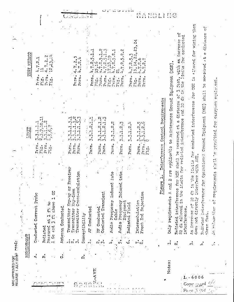
ro
01
r--1 C\ Cr: H 01 Ni
. • .
H •-1 •-I 0.1 N (v.) 44
. • • 0, • • •
r .1
re) „f. . tr.% Ill LIN •-t 44-\ 1.11 trN ..0 t-•-. • , • • N •
NN CV ■0 CV (V OD CV CV CV .c.1" CV CV a • - • ,--/ • • ,...‘ • ' • • •-• • •
N N-- : ' N ••• 1"---- N , C----. N N ^ N N • • • If ,, • • t-- • .- • • re) • •
'•41 ....1 ..-1. H -1 -4- ri .4 (U .4 .4- .--■ --4- -4 • • • • • • • . • • • •
cr.. 0 0 • 0 0 6P • 0 c..1 • Ci d
tt! t • t •t r'? C.I ..:{) :Ii)
C13 .4.-) C‘-‘J
C4 riq 114 P4 P-4 114 1,4 P4 P.4 C,4 P4 r.-_, 04 04
C ) t4 r74 V1
E4
(4
• 4--1
• C) •
to
4\I
'" N
•
• cy
r-i
r %-• 0.1 •-•
•
ti• lit a fr„
e:r4a u_ >- 0 _j
0 aW < •< 0
X
ro
..•
0 .0 0 1-4
P4 43 0 0 Li 5,;+ 6 •c1 C)
4-3 (I)
K./ Si 0
C3 '
•
8 1-.1
0 C.) 4-3
0 '-3 .0
?F-4 C43
•-4 43
4, 4--' ci (el
ft! rd rci
0.) c..)
4c'j 1-1 u4
.1-1 t) C.) '0 tU 0 CD 0
>-: H
• C121
• ' -
'Li V
43 C.) 0 ,..,., g 0
C.)
ci rl 0 0.
-43 Z <
• E4 Ei
0 4-) . r, ci.? t) S.
.4-4 0 .--: H CV cc) 01
•-1 ••0! el cr)-471 t-1 01 CC)
trNk0 0 1.--1 • O •- • 0 • • • . •
H H •---I CV in a1 • • • - • • • ,-.1 .--i r-t--- • , • , r--4 r--1 rA ' 01 • CV CV CV CV CU CV CV • • - • •• • . H • • 0 r-4 0 \ H V.-.) • •• • , trt .-{ H H H H H H •---1 H r---{
a • • • •• • • • • 7•-■ • • 4-3
Cr) Cr) 0-1 V-. Cr) Cc-) Cr) • , • •,. • • •
Cr) Cr) P .̀) Cr) Cr) Cr) C') Cr) • .. • • • • C_: 0
cr, cv Cr) -7.1. P-) Cr) o) Pr7) Pr) Cr) Cr) Cc.) Cr) 4,-) Cr) CO C3 • • • - . • • . . • • o
0 • 0 • c.1 0 0 0 0 0 ti ai Cl 0 0, • ,•1 1-4 t.',1 I-4 tO
44.4 t-4 4.. t-t Pal i■i) . 14 Sci fcti Sci ic-j /--4 S. tO --.1
P. I,-; f.14 r-•-, a) 0
II+ Iti 1-1 4 .P4 C-4 P4 rtici 0-4̀j Cr;-: 0 k 0
U . 43 •
' 1-1 H
1
•
1 0 , 0. .
••4 0 43 C) ri 4
:4 0 0 43 0 •-i .5-i
C7) • W y •4-..1 43 CI
14
c) o O PI 0
"
c., 0 0
4-3 Ki ,d 0 •a- I
c_i 0 , g ..., g 0 • r=4 O r0 C) C) H H rt
.4-1 . 43 .--I, % (01 0 ›-• 43 0 0 C.) c /.., g C) c.) r: rd 0 0 ts-.1 ,t4-1 C.) ' cd 0 . 0 c.) H •,--1 ••--) •c.1 V1 (1 0 -El 0 -P 0
c• r: C' ,ID U U ri t-I o c: d c.) c.! •,-.1 0 g ,d +3 o _;. S. P 44 rt.■ 0 ...-■ 0 d 0 1.-. EA E4 E-f Pi C-1 c., '< Cr-.4 H P-t
0 . C)
• • • P • • • • . •
-.. : .
- • • H CV 01 CO H 0.1 01 .4 U.\ ‘..0 N CO
•,_, •,-4 ,Fi -,1 .. rd I-3 fr. r...) tt. P4 0 0 rii
0 0 4-3 U t-,1 15n r-,1
0 0 0 4-3 C71 0 r-t fc-4 '74 4-3 43 4 3 ›'• 0 .1 0, c.) r- 4% -P 43 4-3 0 0 S. 0 S. 04 ''. rd 0
0 0 0 0 d f-t 4% zn
Li Si t ■ G (1) E-4 0 0 P. •,4 ci Cr-; 0,
re, (7. r. f
• 1,
• Cf)
• -1 CV
3 • T ••
., 71 Li
4) 04....,
..-• 0 -;-3.
4-4
0 •c1 1J o o
o 0 T. O 43 4,-4
J..i
Ca C.) 5.4 •• 4
Sc,;C "i . :( 1:
..--I :t
CI '4..1 O 0 S.
0 0 D 0 ar 1 G..-t
7., .1.3 O 0 q..5 .
• 0 c-r
lv-1 ...4:: 0 0
••7 ru 0
SP 4 t
4' 14 ..-it, r
:c ...: r-1
Sc- Cl
.11 a
4-3 ,--, if) O 4) 44-4 Ft o
CI C) 1 • ,C.-1 5,1 o CI •,-1 ()
O 51 4 V) C; •-.
...---1 :-, • -1 ;3
PI C..c 0 .3 - I O ,c) a.i .0 C.:‘ i
r"4,c, •ci n
;;--i (2)) 0 e.)• O ..--...
r.: '0 0 • ,--1 5--; iri
C.') .p .13 0 P „ (2
..4. i.:,. '
to r. o ..._.• s-{ o •,--1 (a, c, o 0 rci ;-4 4-1 0 iq .0
ci 0 4CI 3 C.
r: 5,
0 . 0 r: d 0
0 4-3 0 •,-1 Pi 4.
4-3 C, SA
r, ,-4 ....
0 'd 'Ci .1-1 ..',5 c-I 4 0
O 0' 0 '3
4, SU .43
-:-_, k c., c, .i.) i :..; ,L1 O :
C) -2, ', ;i
Co .-ri
•
:S .- , f
C3 C 11 r.::: 0 it c 0 0
.-4 0 0
e-::, Cl 4.3 . ‘,-..■ ..
,c sl., 0 • •-1
C4 .1-4 C ; Fl L•4 ri r-I•d •-i • ' C.; rt, -.": r".c".-
rd -' r Pa •-t •..., S. -I , P., ,•-, t-t .0 -P
c,. n :r....4'Z.
- 13 - I •C-1 0 :-I C.,
r-.' ! ..:46' 0 0
is
:q ::: C41F :: :.;
cd 0 0 0
3.; G•
t.t) C3.
ust 4..7,3
:4 ,....14
r t 0 ..--1
c 4 o o
11. 4-04 4,-;
-; 3 .4) ..:O 7.■ c { S.
0 42 rio) :: . i . . : : 0 0 C < r. .:::, C..)
S) 5- co .-.4 Gr!
0 >. •1 C.-4 •r 1
•-1 •4_,- 1 CCI: C.- 0 C.) 54 c4 o ;4 .--_,
al 0 cd • C () C..;
cr) C) 4.5 0 z
L - 6 0 0 6 Copy, : ,- )of
P e
177. 43 0 0 S-I -0 0 il 0 ..." 0 C.) rt 0 • .,-; r_:
0 C) 04 '0 H F. I " 0 4-3 "7...: 0 'eu-: 0 it 4ci0, ,,..3C4 4
t.0i: cl.:-:,. 0 49 c. ..J" in C.
ct
•
-.1 'Z.; .;:), •-• : 00 n...4-11 2 5: e -I
o crg.;, (v
CI ..Z4 .,.....Z , 00 r..." 47; 0
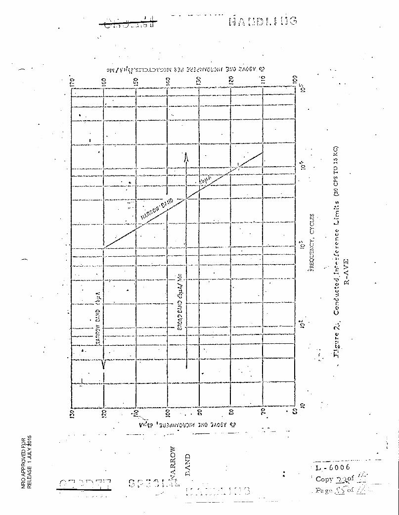
tii J) •4,
31.^1/VIlit'S.TIDA.DVD3IN 3e3VOL—Ait ?,;.10 Z.AGCV cp
0 C> 0 C> • 0 ••-•
................
............ ..-....... ...............-- .......* . ................
............... ...........
II
..........
........* ....................-
_
.4.
‘........., ............. ............. .....
. t
A
I .. _
.
L.
0‘"
. .
-........
NO
-9*-
L.NW:7-. _ _.............._
.....-.....--. ...... ......
*,...,..,..*_..........
att It.
..e,
..........____.„-"*7^
1
''' -
. .
> . - ......
.... ..r"
Z
0 Gr
'''''`
..C:i.-
0
*.":-....... ''''''''''.-
. .
..-‘'-' '''.. -''' -'-. -
-. .
...............,.......m.....-..............--
-........!....................--
'
-'. ---..- ..--.
...--... -,...
n .7,-...
• C:i
0 C.0
•,,L '.......:
4.
..1.7 VIL,■■• • ..,.....
. .
.............. s•
.
i
. v............ ....................... ..............: .......-
...*--.......
. .
........... ••■• ,.. ••••• Ina.. ,..104. sr....
...,.........../ ..................
A-a.
................... .e.■ C)
2 Z-•
Vel? 120dril'01.1:)14 71AOSY cP
L. - 6006
Copy
Page of ;
0
r 'TT
z
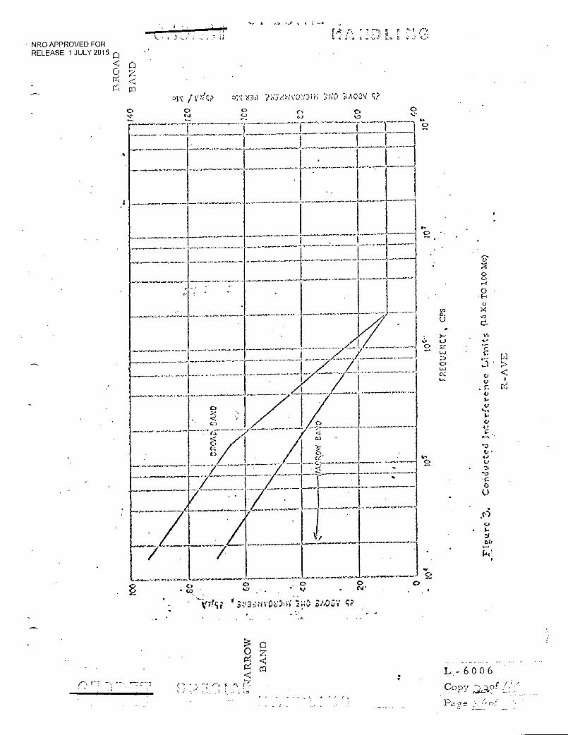
•
F Vos.,S—••••.1.,•
0 0 v.) . .
.0
• • . n „i P • ivOi::)i 3/.,NV V
2 •
•
t ..a
rz-h r (".■ L
• NRO APPROVED FOR RELEASE 1 JULY 2015 n
0 z re, <
DII /1:71cP 01,1nd Tz:3eh'VQ:1)IN ::,1:0 3/1,02V c? o o a 0 C• t...1 C., ....' .... •--.
.....................,......,-.._ r .......... _ .7_7 ___ f _....... .......: .7:17,7f .......I.T......T7_{......_r_____I ...„
- 1
..L
L,- 6 0 0 6
Copy f
•
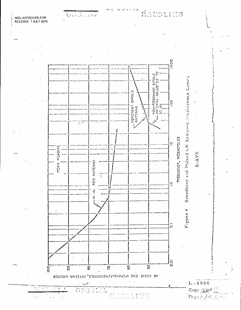
o3:)nm VtiN31NY 1 31.`)ADVD3N 3NO 3A0-57 P
'
6 0 0 6
Copy ;•of
/ of .; •
" 5 -••• ' . ,-)
NRO APPROVED FOR RELEASE 1 JULY 20.15
r f:, r .; e.
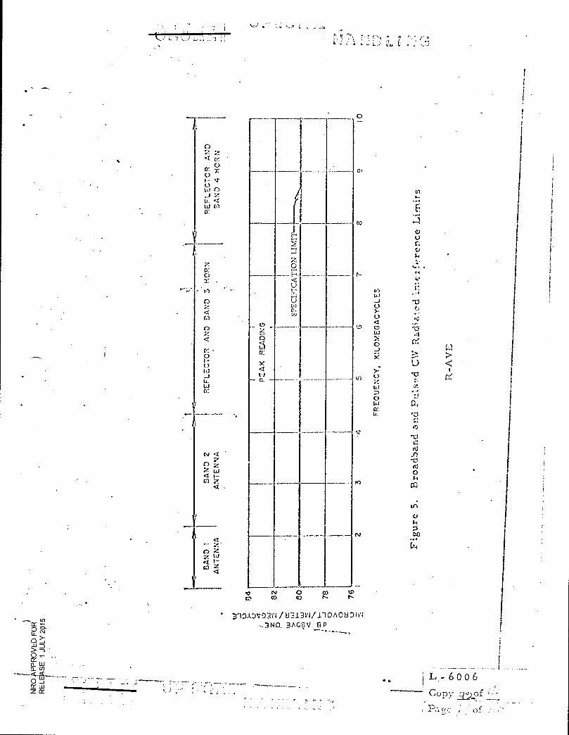
0
Co
r-
Ui _J 0 0
1_0 L., Ui
0
Cd
0
0 4.1
U_
t.r
to
fsJ
LT: e
•
C)
cr_ 0 r-
-J
w cr:
SA
ND
4 H
OR
N
z 0: 0
;-•-• t.)
C)
C)
z
0
U w IL Id Cr:
.-,
U c...1 o.
____.
- 0
.....
E---.
v)
3
__
._______
____. Z a 6 a: y a l....1
- C.
•
co Co 0 co
I0
o 0 _1 1.11 > 0
CL CL
0 _1 111
Z CC
• BlOADV031,1/b3.1.3N/r10A08Dite: 3ACgv e p
• • L-6006 -1—
Copy
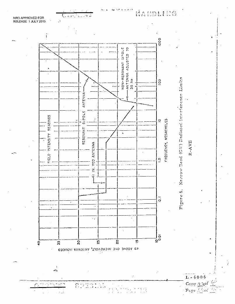
Lar
LU
0
AN
TE
NN
A
NO
N-R
ES
ON
AN
T O
tr''O
L. E
. -3 SC
NRO APPROVED FOR RELEASE 1 JULY 2015 •
0 0 0
-.N4.4•44.
0 • 0 404
■■
C.J
t•
o
4 •
• C.
3- • o
%)
"-;
o 0 LU
0 CL 4_
0
?.,
•••••
tr)
ft:
0
0 V
00 In 0 in 0 in rrl r-, N CV
030110NI VNN31NV incmou)tr4 3NO 3AQBV CP . .
_ - _ . L- 6 0 0 6 . ,.,
Cony
Pace ,. , of (":'' • - ..-
' "7.1 r
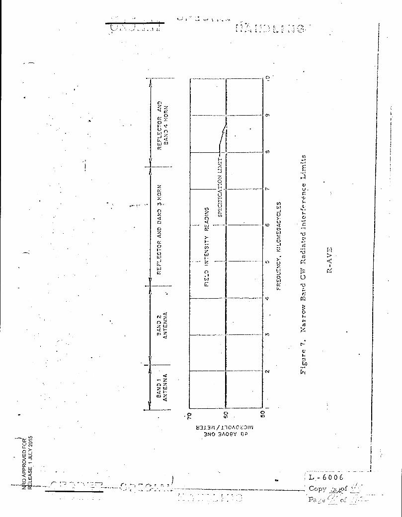
0 Ic
tr) U_
>- 0 11.1 D > 0 - CC 0_ 01
Cl)O
w < < 0_i
1
FIE
LD
IN
TE
NS
ITY
RE
AD
ING
SPE
CIF
ICA
TIO
N L
I MIT
! .
0
, o
U31..3Y1/.1.1C)A0DIVI 3NO 3A09V
•
L- 6006 .
Copy --2:)?f — pa -e ( C
co
C)
cc Cr: 0
w al
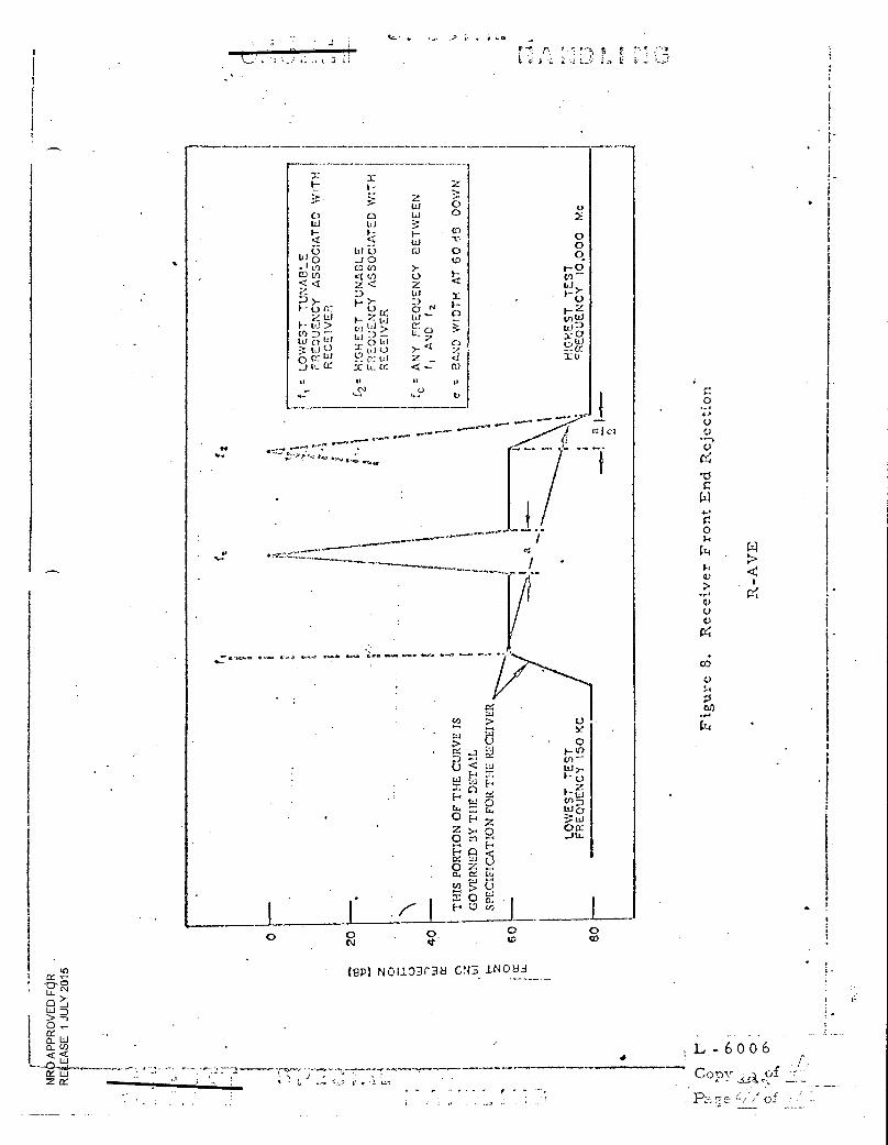
(9P NO1103r38 GN3 .114083 _
• Lla
L - 6 0 0 6 .
Copy - •
Pa q e / of .•
Z X
•
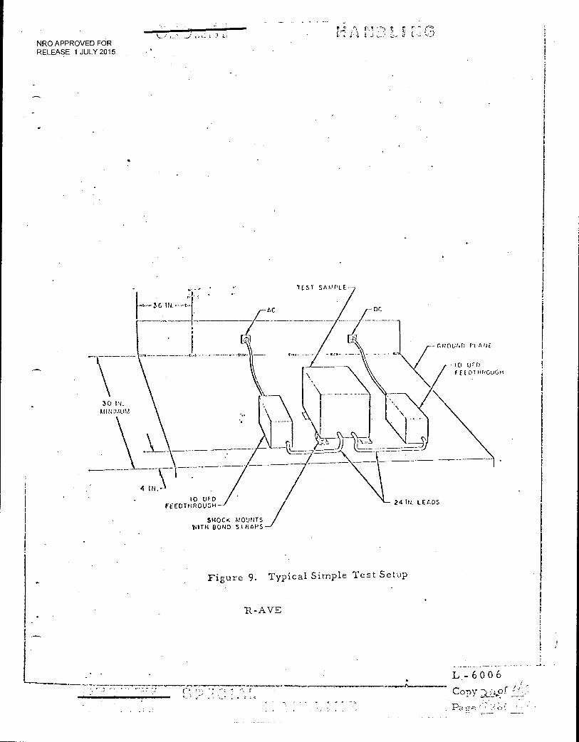
••
AC -DC
-(.f.rouND P1 ma.
IC) Ili() F ELDTHR0LIGH
'0 IN, Mit:P.41AI
IC) FEEDTHROUGH- 24 IN. LEADS
i SHOCK MOUNTS WITH BOND STRAPS
. . t. t. • r
j i !.; NRO APPROVED FOR RELEASE 1 JULY 2015
TEST sAmPLE--
Figure 9. Typical Simple Test Setup
It-AVE
• •
L 6 0 0 6 r
Copy
e •.; •
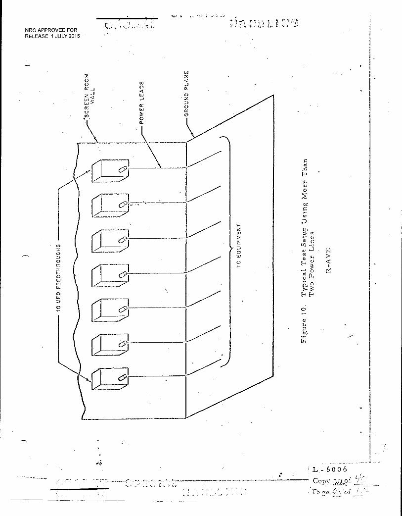
10 U
FO
F7.
ED
TH
RO
UG
IIS
GR
OUN
D PL
AN
E
PO
WE
R L
EA
DS
TO
EQ
UIP
ME
NT
0
r I
P.! L. !!, • ;: i; ,17.,:; I., C.
NRO APPROVED FOR RELEASE 1 JULY 2015
L - 6 0 0 6 Copy 22.,,p1 ..•
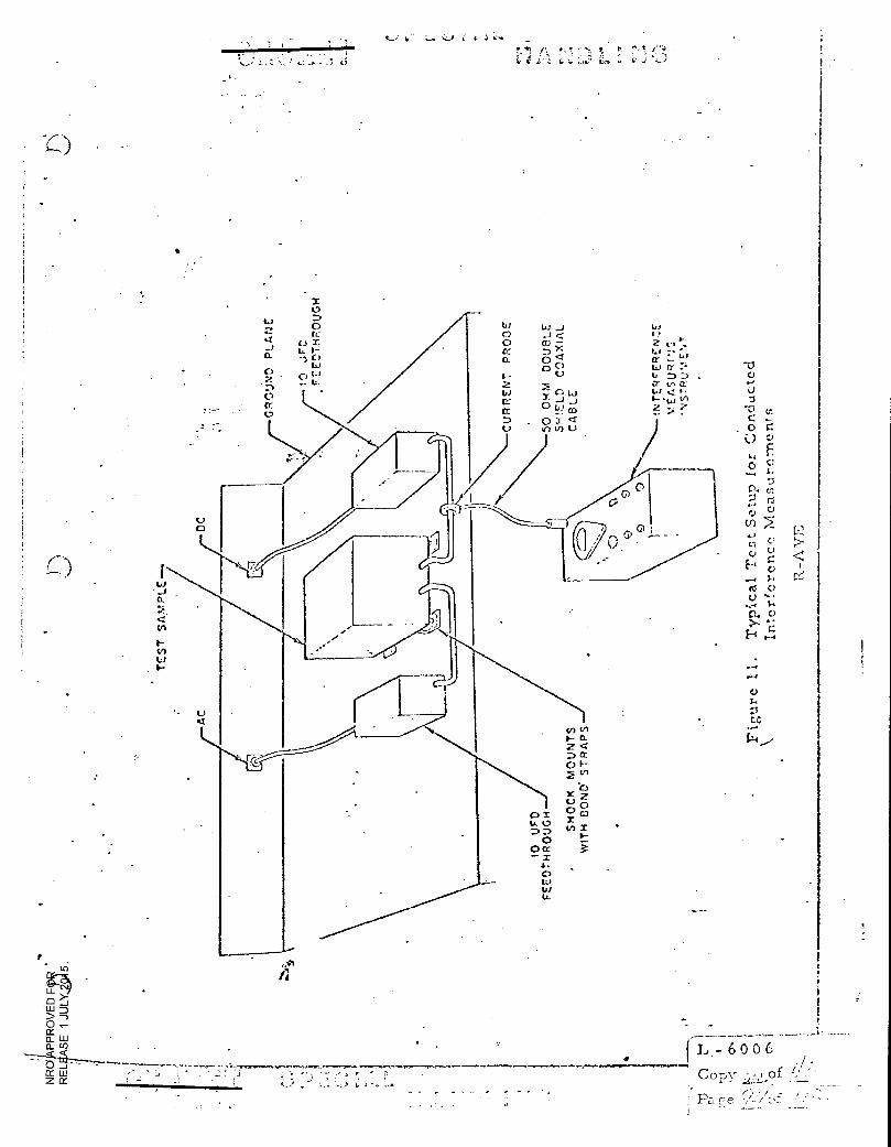
•
Ld _J VI ...1 < I-.. Cr) — 2 c. 1-..
0• • L
0 0 t...I Ir • • kJ D .
a- cc+ CC
i..) 2' 0 L,...1
. _.. co 2 ..
o J: a in v) t..)
-0 C.)
U
"Cl
. 0 r. () 1-)
0
cl
;-■ r3 U
0I 0 D 0
o cr
0 Is) U-
L-6006
Copy
: ge. of
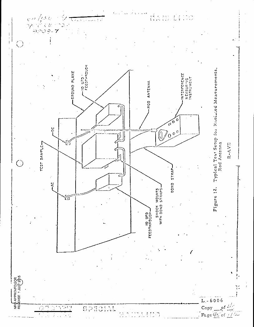
' r : - .• • •• • s- •
• -;
hi
z 41 Cr: 5 D 7.3 Li 4 V) 4
Li <
0 0
GR
OUN
D PLA
NE
La
I;
I- C,)
0
0. V) 0 I- 4 Z < D 0
V)
C-) X tp V) x
o x 4. 0
D 0
0o —
1-- 0 41 Li
I
1 -t;k
ul.
A.te
d M
ea
sure
me
nts
,
-a ID
04
ri Ctl
C.) <
° C•4
01
F4
rJ
f-I V eal
L - 6 0 0 6
Copy of 4-j
Pa „re Lcf
CC Z • • ,
V .
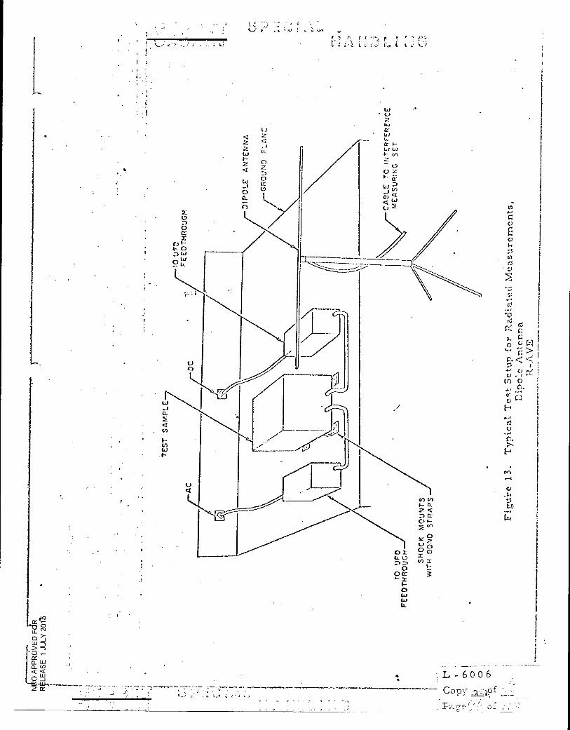
L - 6 0 0 6
Copy .,-,1;49f
DIP
OLE
AN
TE
NN
A
()
:.s
t. Ci C) O
'cr...
• • <
4.-1. I Cl •
Cl) on
H
•••
0.
H
cc
t4
O
LJ
.4r
tr)
I-
0 X LL
0 0 a
0 LJ
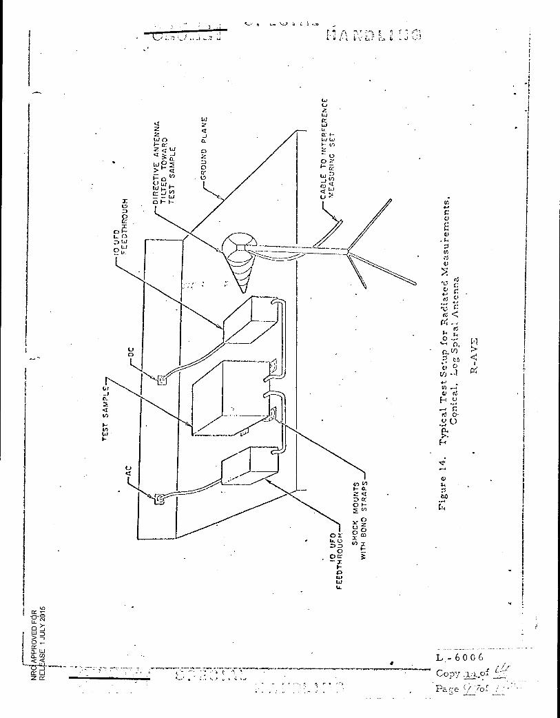
GR
OU
ND
PL
AN
E
:13
D w C)
CC "0- (NI
›-
D > —3 0
Ct- a. w
•
• *N■■••• ••■••■■••-• ••••■,••••••••■••••••u •••■
■ s w
z Ix sss
L- 6 0 0 6
Copy ,A.,L.rof
Pac'e 70-f -
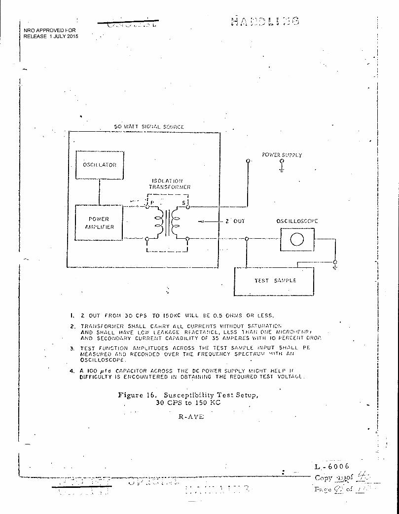
TEST SAMPLE
/n•
6v J t ■
NRO APPROVED FOR RELEASE 1 JULY 2015
•
50 WATT SIGNAL SOURCE
•
POWER SUPPLY 0• I
ISOLATION TRANSFORMER
OSCILLATOR
POWER
AMPLIFIER
'ter rSJ
OSCILLOSCOPE Z OUT
1
L—___.J
I. Z OUT FROM 30 CPS TO 15 0 KC WILL E3E 0.5 OHMS OR LESS.
2. TRANSFORMER SHALL CArtRY ALL CURRENTS WITHOUT SATURATION AND SHALL HAVE LOW LEAKAGE REACTANCE, LESS THAN ONE MICROE.NRI AND SECONDARY CURRENT CAPABILITY OF 35 AMPERES WITH 10 PERCENT DROP.
3. TEST FUNCTION AMPLITUDES ACROSS THE TEST SAMPLE INPUT SHALL PE MEASURED AND RECORDED OVER THE FREQUENCY SPECTRUM tf.fiTH AU
OSCILLOSCOPE.
4. A 100 p1d CAPACITOR ACROSS THE DC POWER SUPPLY MIGHT HELP IF DIFFICULTY IS ENCOUNTERED IN OBTAINING THE REQUIRED TEST VOLTACL
Figure 16. Susceptibility Test Setup, 30 CPS to 150 KC
R-AVE
L - 6 0 0 6 — Copy •),=)..of
r e
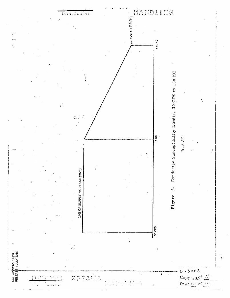
•
^ c •
10%
OF
SU
PP
LY
VO
LT
AG
E (1
LM
S)
c, ' 73
0
0 0
Z
(^4, r .• • n. • ;:
L - 6 0 0 6 ,
Copy
Pa ne r
0 tr
0
(I) rif0. 0
4_,
0. U
V)
C.)
•
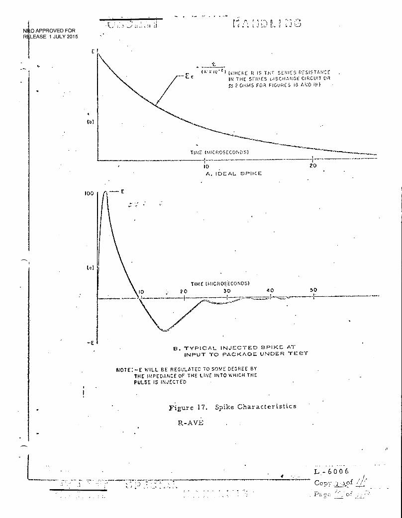
TITLE. (MICROSECONDS)
-1 f
10 20
A. IDEAL .PIKE
tit- 7;10 ..1) 1 (v,,HERE R IS TH SERIES RESISTANCE"
IN THE SERIES DISCHARGE CIRCUIT OR
2 OHMS FOR FIGURES ia AND I:0
40 APPROVED FOR R -LEASE 1 JULY 2015
4
100
(c)
TIME WiCRO5ECONDS)
10 20 30 40 50
E3. TYPICAL INJECTED SPIKE AT INPUT TO PACKAGE: UNDER TEST
NOTE:—E WILL BE REGULATED TO SOME DEGREE BY THE IMPEDANCE OF THE LINE INTO WHICH THE PULSE IS INJECTED
Figure 17. Spike Characteristics
R-AVE
NeriTs..1
L- 6 0 0 6 Cop
/ . y .) ;1: ...7,• •••••
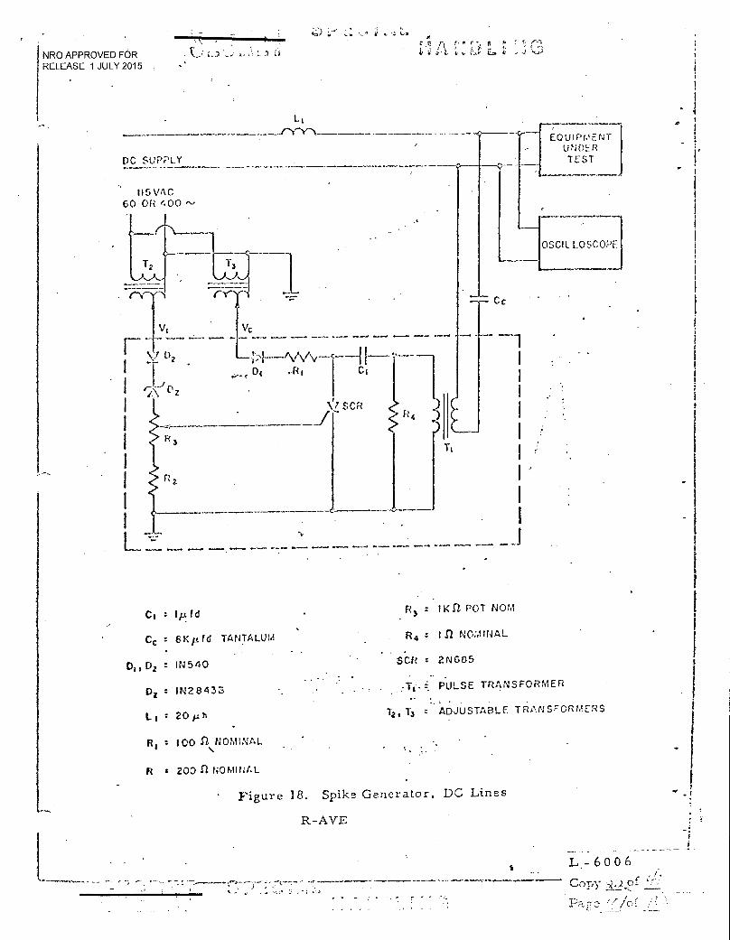
T1
Cc
NRO APPROVED FOR RELEASE 1 JULY 2015
L1 TY-Y-x
DC SUPPLY
115 VAC 60 OR < 00
EQUIPWEN UNDER TEST
----
[ OSCIL LOSCOPE
Vi Vc
.! D2
Di ,R1 Ci
L' z
.1L SCR
CI 1p.fd F? : ma POT NOM
Cc 6Kp.rd TANTALUM R : I II NOMINAL
D„ D2 1N540 SCR 2N665
Di 1N28433 Ti •i PULSE TRANSFORMER
Li t 20pn 12 1 13 ADJUSTABLE* TRANSFORMERS
100 St\NOMINAL
R t 200 n NOmINAL
Figure 18. Spike Generator, DC Lines
R-AVE
L - 6 0 0
Copy
Pa r a o -
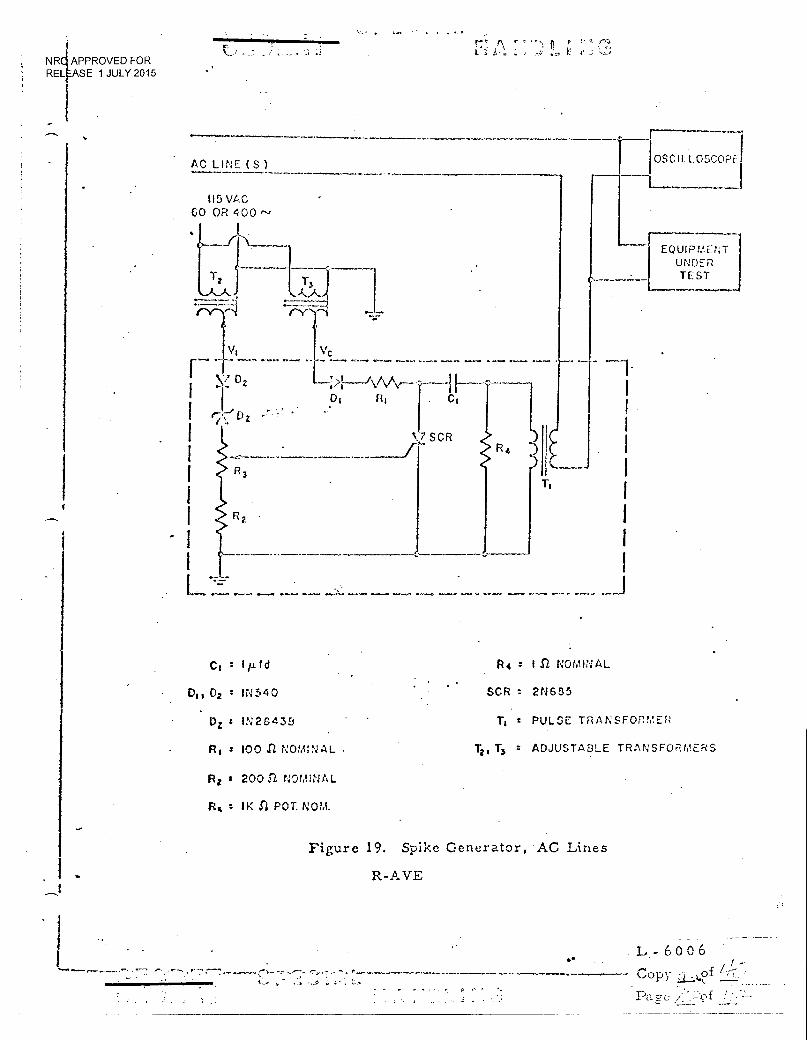
• A L ,. _ E e
NR APPROVED FOR RELEASE 1 JULY 2015
■■•••••••■•••••■••■■•■•••■
AC LINE (S )
115 VAC GO OR 400
1.
‘,7 SCR
qv*. •••■• 1....vme wawa.* •■■•:,.• • • orna a-V-4 ar e. • • 4.
Cl
Do 02 : lr,4540
Dz s IN2D433
R S 3 100 ,r2 NOMINAL •
R4 1 (1 NOMINAL
SCR 2N685
Ti I PULSE TRANSFORMER
-13 ADJUSTAE3LE TRANSFORMERS
fla I 200 2 NOr■ NAL
RI 1K S2 POT. NOM.
Figure 19. Spike Generator, AC Lines
R-AVE
o• L- 6 0 0 6
Copy :2 )of •
OSCILLOSCOPE
EQUIPMENT UNDER TEST
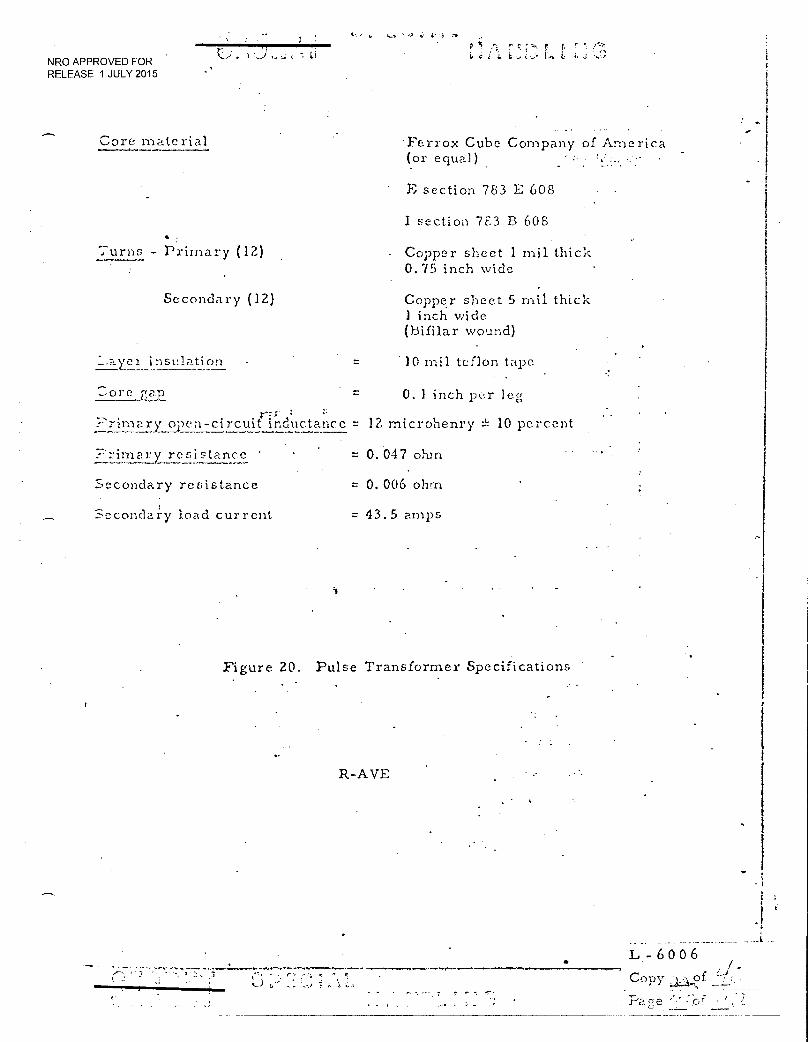
' • •_^.. r r
'74 , L NRO APPROVED FOR RELEASE 1 JULY 2015
Core material •Ferrox Cube Company of America
(or equal)
Turns - Primary (12)
Secondary (12)
E section 783 E 608
I section 7E3 B 608
Copper sheet 1 mil thick 0. 75 inch wide
Copper sheet 5 mil thick 1 inch wide (Bifilar wound)
Layer insulation 10 mil teflon tape
Core gap = 0. 1 inch per leg
?rimari open-circuit inductance = 12 microhenry e-- 10 percent
primary resistance = 0.047 ohm •..
secondary resistance := 0. 006 ohm
Secondary load current = 43.5 amps
Figure 20. Pulse Transformer Specifications
R-AVE
L - 6006
Copy j:_.+ °f
Pare
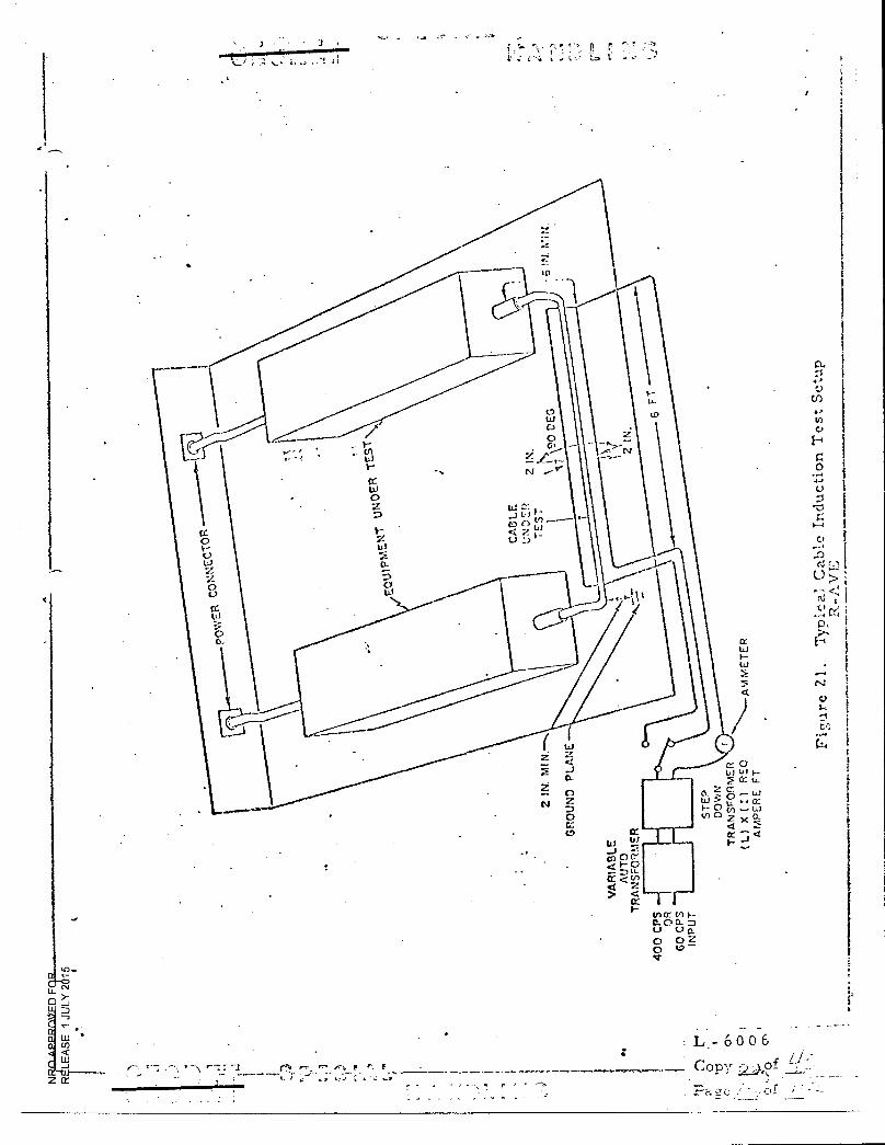
• . I
. r 7. , ■ :o _
•
o
cc to
E
e
C)U)
a
C) Lr)
0 • •
C)
d 4.1 G
0 U.) U 1 I.-
U./ 5 C:-.- : Li
U. .'-•
CC U.
Li
.....
CC
<I"0
cC > cr
r-
Cr
L- 6 0 0 6 •
Copy 2 , .
- • of
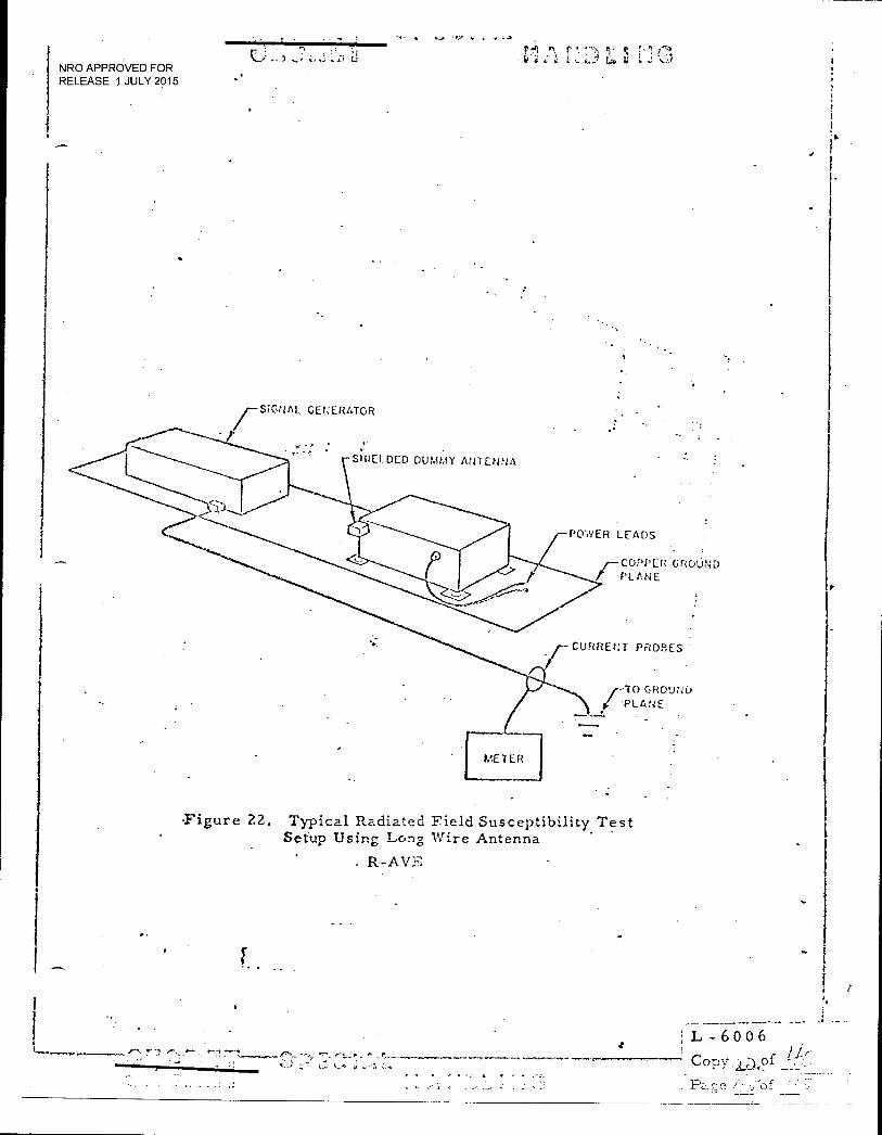
P!.‘I r, .mt !•1, L.) t. I; .2
NRO APPROVED FOR RELEASE 1 JULY 2015
SIGNAL GENERATOR
SHIELDED DUMMY ANTENNA
POWER LEADS
"-COPPER GROUND PLANE
CURRENT PROBES
TO GROUND .PLANE
-Figure 22. Typical Radiated Field Susceptibility Test Setup Using Long Wire Antenna
R-AVE
••
f I
r
L 6 0 0 6
Copy,13,of
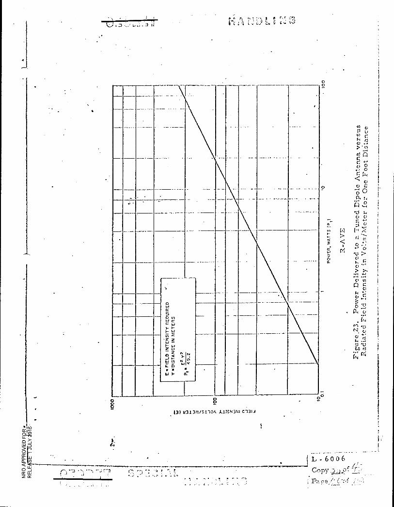
0 8
0 0
(3) 21313t1/S1.10A 1.1.1SN3tit 0131.J
^ ". A r. rr
- •
E ■
FIE
LD
INT
EN
SIT
Y R
EO
LHR
ED
Y
*IN
ST
AN
CE
IN
ME
TE
RS
•
E2
y2
Pt :17
1
0
PO
WE
R. W
AT
TS (
PO
•
0
L - 6 0 0 6 ;010.0111.0.11R.I...M.P.•••••■•••■••■
.‘ rc, 73 r
•
r - Copy jLP- cp-- , .
+••■■ •••••••••■•••••••-• o■-•■•■■■■••
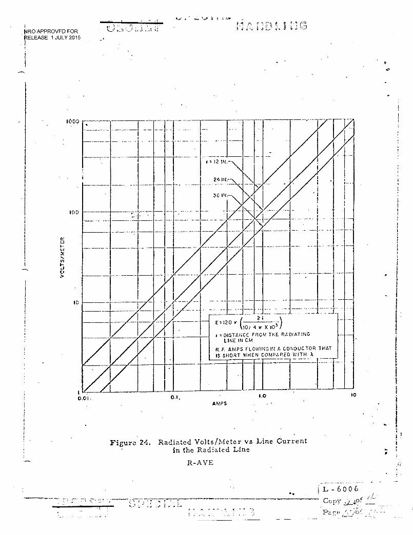
I0 1.0 0.1. 0.01.
t4RO APPROVED FOR RELEASE 1 JULY 2015
" 7i • '• •
•
r p !•.! (-4
-
-
I _
r r- 12 IN
24 IN.
3G IN.
I
.
- .
•
/ 4 --- - --i- - --
•
10: 4 7r X 103 )
FROM TEE RADIATING r = DISTANCr LINE IN CIO.
R. F. AMPS FLOWING IN A CONDUC TOR T HAT IS SHORT WHEN OMPARED WITH A
.. . .
AMPS
Figure 24. Radiated Volts/Meter vs Line Current in the Radiated Line
R-AVE
j L - 6 0 0 6 Copy , )Of
Pace
VO
LT
S/
ME
TE
R
1000
100
ID
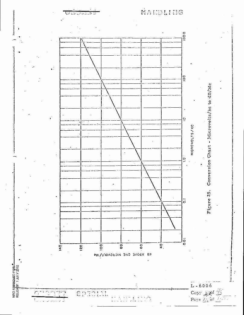
L1 ..7.1 p _, r 7 • !'=
; • • • •; •,71
• • 0
0
Mic
rovo
lts/k
c t
o d
B/M
c
0
MI C
RO
VO
LT 'S
/ K
C
0
0
• •
0
ni/.1.10A0t33iti 3NO 3A08V ea •
0 0 0
L - 6 0 0 6
Copy
Pace/
r F
t-•-' I-1 a ; • J• •
o o cv
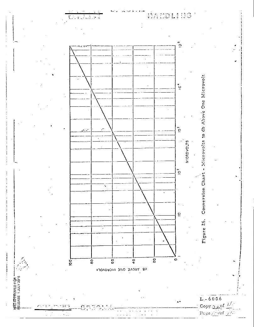
i.......,,,.,.....,...4) .4-,41...,,,,...... S
I-
e ••,e s•• ,••-•,, r • , 7 77 ,1 • 1 1 7 L 7.7 c.,7 ■
• I
0
0-4
0 oV
C)
0
. 0
0 1;Zi
0 4-,
. .
4-,
0
• 44
F.
0
(-4
0 0
0.)
0
MICRO
co cs,
110,106DIF■ 3N0 3A097 GP
- • L - 6 0 0 6 • - Copy o f
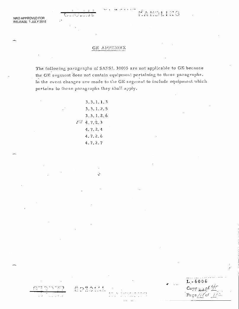
A
NRO APPROVED FOR RELEASE 1 JULY 2015
GE APPENDIX
The following paragraphs of SAFSL 30005 are not applicable to GE because
the GE segment does not contain equipment pertaining to these paragraphs.
In the event changes are made to the GE segment to include equipment which
pertains to these paragraphs they shall. apply.
3. 3. 1. 1. 3
3.3. 1. 2. 5
3.3. 1. 2. 6
/' 4. 7.2. 3
4. 7. 2. 4
4. 7. 2. 6
4. 7. 2. 7
L..- 6006
Copy
Pace /// (of ./
r '7
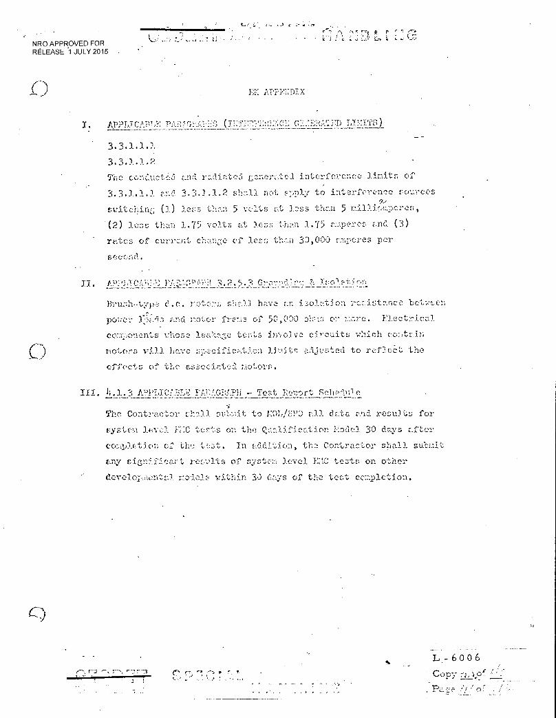
. ' •
NRO APPROVED FOR RELEASE 1 JULY 2015 •
• • . • •••• .! •
EK ZT:=DIX
AppLicv LY'•!TTS)
3.3.1.1.2
The conucte0 and radiated generated interference limits of
3.3.1.1.1 anf sh.....11 not aply to interference sources
switehin (1) less than 5 volts at loss than 5 millioperes,
(2) less than 1.75 volts at less th.an 1.75 .c.ipercs and (3)
rates of eurront ehanz-:e of less than 30,000 :.:-nperes per
second.
Brush-type e-c. roto:.-s shall have an i3oletion reeistance betws.en
power lads and motor frem,a of 50,030 eh,-Is or nave. Electrical
components whose lea%ac tests involve circuits w'nich colitain
motors viAl have.secifiction limits adjusted to reflect the
effects of the E.sociated nol.ors.
1; 3. . EL)PT,TC,' TiLw • 'rest Enort Sc1ad Je
The Contractor shall samit to rayspo all data and results for
uste!A level E..".0 tests on the 0:,..alification lode). 30 days after
eolaction of the ter3t. In addition, the Contractor shall subnit
any signifieart reaults of system level EC tests on other
r_oaels within 3d days of the test cc:Ipletion.
L- 6006
• of. -";:" Copy
JI.
C,)
I-. rj ••-• r r . r
-t, r r ;. 6 , 6
NRO APPROVED FOR RELEASE 1 JULY 2015
EK APPENDIX (continued)
The following paragraphs are not applicable to Eastman Kodak
Company because the Eastman Kodak Company segment does not
contain equipment pertaining to the paragraphs. In the event
changes are made to the EK segment to include equipment which
pertains to these paragraphs, they then shall apply.
3. 2. 5. 4 EED Firing Circuits
3. 3. 1. 2. 5 Intermodulation
3.3. 1. 2. 6 Receive Front End Rejection
3.3. 1. 3 - 3.3. 1. 3. 2. 3 Electroexplosion Devices (EEDS)
3.3.3 -3.3.3..'2.3.' - Validation of EED and FED Initiator Circuit
4. 7. 2. 3 Transmitter (Keydown)
4. 7. 2. 4 Transmitter Crossmodulation
4. 7. 2. 6 Intermodulation
4. 7. 2. 7 Receiver Front End Rejection
As an:alternate to maintaining the transient generator at + 100 v
during component operation, transient susceptibility testing may be
done with a transient source whose unloaded output voltage has been
set at + 100 v. To obtain the 30 niillijoule level, a 6 niicrofarad
capacitor will be used as an energy source of the transient. Peak
transient current will be limited by an equivalent generator output
impedance of 1 ohm.
lTh '72 cm,, r, r: ,. ; H. e
I L .- 6 0 0 6 !
Co • • o'r
Pa 7e /./;:i •
aFJF- P' aLtniX.1 HANDLING - NRO APPROVED FOR
RELEASE 1 JULY 2015_
WIRING HARNESS SPECIFICATION
FOR THE MOL SYSTEM
SAFSL EXHIBIT 30006
6 JUNE 1968
•
c 1.13 g2 T71131 ka
SPECIAL
HANDLING
Mat A-6* AP (Signed
(Signed)
(Signed) //
NRO APPROVED FOR RELEASE 1 JULY 2015
CERTIFICATION OF DOCUMENT CLASSIFICATION
I HEREBY CERTIFY THAT ALL PAGES OF THE ATTACHED DOCUMENT
1\t • •1.1. >> .) V \\ 0.1 \NI
( Document Title or Other Identification)
CARRY PROPER SECURITY CLASSIFICATION MARKINGS.
(Signed) :44
/7,/ i 5.\(SL /•. 11_,■
4-5
(Signed)
(Signed)
(Signed)
(Signed)
(Signed) /
. • SECRET
SPECIAL HANDLING
T.T4 T7') SPECIAL tt) L
L 6009
Coplr"r Page /2,._
NRO APPROVED FOR RELEASE 1.JULY 2015 . -
S E VIPAD/-1‘
3P9OG
The undersigned has reviewed the document and
understands the contents to the extent necessary
to scope subsequent proposals.
(Signed)
(Signed) •',Q \J ..15 ftlAy /94f
(Signed) ----)/ 14,-A1f„--- , (Signed)
•
(Signed ?-74 /ker
•
(Signed)
NRO APPROVED FOR
Kum- bPLCIAL HANDLING
RELEASE 1 JULY 2015
1.0 SCOPE
2.0 APPLICABLE DOCUMENTS
2. 1 Specifications
2. 1. 1 Military
3 0 REQUIREMENTS
3. 1 General Requirements
3. 2 Electromagnetic Compatibility
3. 2. 1 Shield Terminations
3. 2. 2 Redundant Wiring
3. 2. 3 Spare Wires
3.3 Propellant Compatibility
3.4 Flammability
3. 5 Connector s
3. 5. 1 Non-coaxial Connectors
3. 5. 2 Coaxial Connectors
3. 5. 3 Finish
3. 5. 4 Strain Relief
3. 5. 5 Orientation
3. 5. 6 Angle Connectors
3.6 Protection
3.6. 1 Abrasion Protection
3. 6. 2 Connector Protection
3.7 Splices
3. 7. 1 Rework
3. 8 Wires and Cables
3. 9 Wiring Harness Forming
3.10 Wire Lay
3. 10. 1 Parallel, Straight or Random Wire Lay
3. 10. 2 Twisted, Helical, or Contrahelical Wire Lay
3.11 Wiring Harness Breakouts
3. 12 Wiring Harness Ties
3. 13 Jacketed or Molded Wiring Harnesses
3. 14 Handling
3. 15 Installation
3.16 Rework and Repair
7r7)77 SPECIAL HANDLING
L =6 0 0 9
Copy301Of
Page of
NRO APPROVED FOR RELEASE 1 JULY 2015
- - :
5PECIAL HANDL! NG
4.0 QUALITY ASSURANCE PROVISIONS
4. 1 General
4.2 Acceptance Tests
4. 2. 1 Examination of Product
4.2.2 Electrical Continuity _
4. 2. 3 Insulation Resistance
4. 2. 4 Dielectric Strength
4. 2. 5 Order of Electrical Tests
5. 0 PREPARATION FOR DELIVERY
6. 0 NOTES
6. 1 Definitions
6. 1. 1 Wiring Harness
APPENDIX "A"
APPENDIX "B"
APPENDIX "C"
APPENDIX "D"
SPECIAL t--71 A
1.4-6 009
•CopY.
Page 4L of Lz-
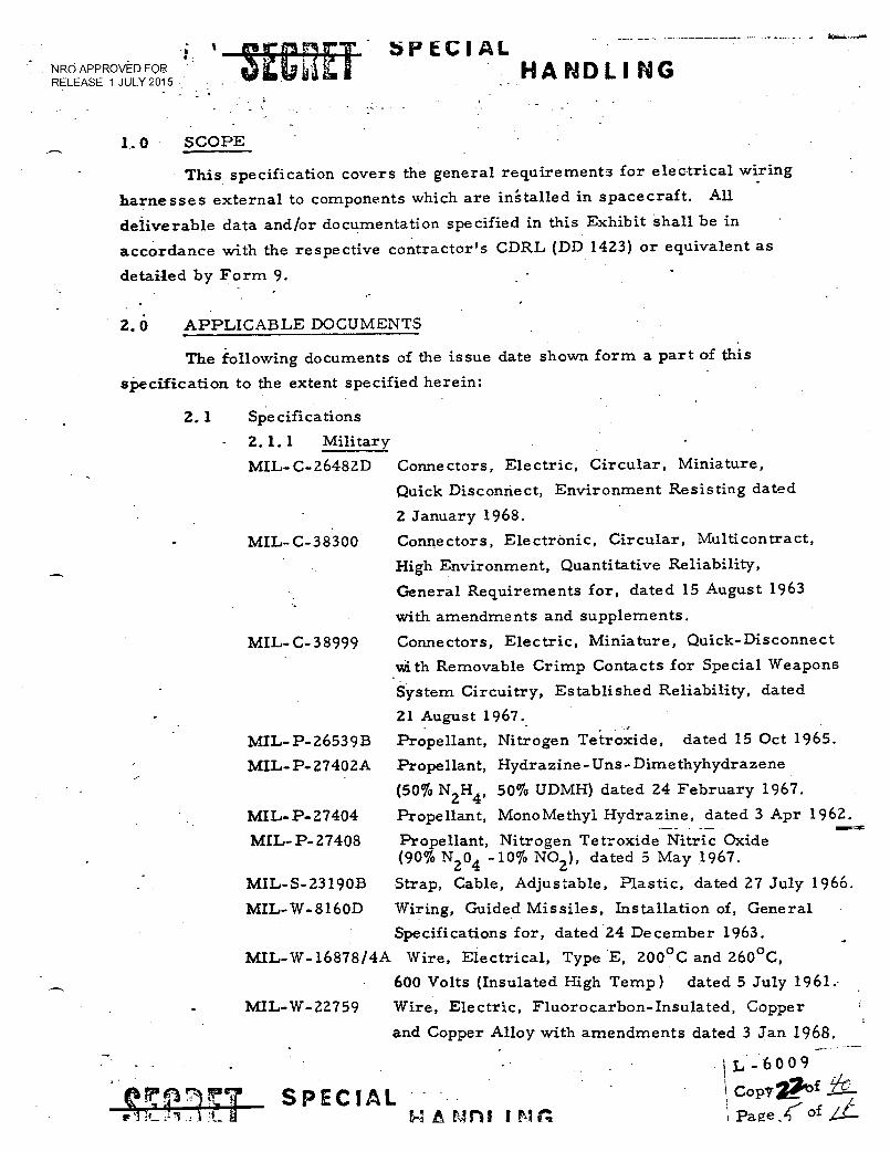
NRO APPROVED FOR RELEASE 1 JULY 2015
SPECIAL HANDLING
1.0 SCOPE
This specification covers the general requirements for electrical wiring
harnesses external to components which are installed in spacecraft. All
deliverable data and/or documentation specified in this Exhibit shall be in
accordance with the respective contractor's CDRL (DD 1423) or equivalent as
detailed by Form 9.
2.0 APPLICABLE DOCUMENTS
The following documents of the issue date shown form a part of this
specification to the extent specified herein:
2.1
Specifications
2.1.1 Military
MIL- C- 26482D Conne ctors, Electric, Circular, Miniature,
Quick Disconnect, Environment Resisting dated
2 January 1968.
MIL- C-38300
Connectors, Electronic, Circular, Multicontract,
High Environment, Quantitative Reliability,
General Requirements for, dated 15 August 1963
with amendments and supplements.
MIL-C-38999
Connectors, Electric, Miniature, Quick-Disconnect
with Removable Crimp Contacts for Special Weapons
System Circuitry, Established Reliability, dated
21 August 1967.
MIL-P-26539B Propellant, Nitrogen Tetroxide, dated 15 Oct 1965.
MIL-P-27402A Propellant, Hydrazine-Uns-Dimethyhydrazene
(50% N2H4, 50% UDMH) dated 24 February 1967.
MIL- P- 27404
Propellant, MonoMethyl Hydrazine, dated 3 Apr 1962.
MIL- P- 27408
Propellant, Nitrogen Tetroxide Nitric Oxide (90% N204 -10% NO2), dated 5 May 1967.
MIL-S-23190B
Strap, Cable, Adjustable, Plastic, dated 27 July 1966.
MIL-W-8160D
Wiring, Guided Missiles, Installation of, General
Specifications for, dated 24 December 1963.
MIL-W-16878/4A Wire, Electrical, Type E, 200°C and 260°C,
600 Volts (Insulated High Temp) dated 5 July 1961.
MIL-W-22759 Wire, Electric, Fluorocarbon-Insulated, Copper
and Copper Alloy with amendments dated 3 Jan 1968.
172 9 7, SPECIAL
pl .1,1-1 _I LI 14 A mni
• IL - 6 0 0 9
CoPygld
Page of
HANDLING NRO APPROVED FOR _ RELEASE 1 JULY 2015
• MIL- C-22557A Connectors, Co-axial, Radio Frequency,
Miniature, (Screw-on), General Specification
for, dated 26 January 1967.
MIL- C-24308 *, Connector, Electric, Rectangular, Miniature,
Polarized Shell, Rack and Panel General
Specification for, dated 30 November 1967 with
supplement.
MIL-C-39012
Connector, Co-axial, Radio Frequency, General
Specification for, dated 23 May 1966 with
Amendments and Supplement.
MIL- C-23329A Connector, Co-axial, Radio Frequency, Series
SC, dated 15 February 1965 with Supplements
and Ammendments.
MIL-W-81381(AS) Wire, Electric, Polymide-Insulated, Copper
and Copper Alloy, dated 15 October 1966.
NAS 1599
Connectors, General Purpose, Electrical,Miniature
(Rev. 3)
Circular, Environmental Resisting, 200°C Maximum
Temperature, dated 15 October 1966.
MS 33586
Metals, Definition of Dissimilar, dated 16 Dec 1958.
MSC-PPD-2
Propellant, Inhibited, Nitrogen Tetroxide, dated 6 January 1966.
SAFSL Exhibit Electromagnetic Compatibility Requirements, 30005 Orbiting Vehicle, General Specification for the
Manned Orbiting Laboratory, dated 7 June 1968.
SAFSL Exhibit Nonmetalic Materials Combustion & Atmospheric 10010 Contamination Control Standard.
3.0 REQUIREMENTS
3.1 General Requirements
In the case of a conflict between this document and any applicable
document, this document shall prevail.
3.2 Electromagnetic Compatibility
The wiring harness shall be designed and installed to aid the
system in meeting the electromagnetic compatibility requirements of SAFSL
Exhibit 30005. The wiring harness shall comply with the SAFSL Exhibit 30005.
requirements
grounding.
for wire routing, signal
SPECIAL -•• HANDLING
la- 6 0 0 9 • Ii
Copy 3iof ri) Page` Z.L of S
7 p FTV77
separation, wire twisting, shielding and
NRO APPROVED FOR RELEASE 1 JULY 2015
tszolnrcT OL1Jii-Li
SPECIAL HANDLING
3.2.1 Shield Terminations
Shield terminations shall be in accordance with SAFSL
Exhibit 30005. Shield terminations at the same end of the harness shall not be
successively connected in series, one to another with one end of this chain being
grounded or carried through on connector contacts.
3.2.2 Redundant Wiring
Where practicable, redundant-circuit wiring shall be
routed in separate wire bundles, and separation of wire bundles shall be main-
. tained to the maximum extent possible, including the use of separate connectors.
3.2.3 Spare Wires
All wire harnesses located in inaccessible areas of the
Orbiting Vehicle that contain circuits which if inoperative will result in a launch
countdown termination shall include spares. Inaccessible areas are defined as
"those areas where replacement wires cannot be installed on the launch pad".
All spare wires shall be terminated in connectors at each end of the harness.
3.3 Propellant Compatibility
In those areas subject to exposure to hypergolic propellants the
wiring harness and all parts used in the wiring installation shall be compatible
with the MOL system propellants which are specified in MIL-P-26539A, MIL-
P-27404, MIL-P-27408, MSC-PPD-2, and MIL-P-27402, except for direct
contact as a result of spillage or immersion. The wiring harness shall be
capable of continued operation folloWing short duration exposure to spacecraft
propellants as a result of spillage; however, extensive spillage prior to launch
shall be sufficient cause for replacement of affected wiring harnesses.
3.4 Flammability
The design of the wiring harness shall minimize effects of
potentially catastrophic fires within the AVE by reducing the quantity of flammable
materials, limiting ignition sources and limiting flame propagation paths. SAFSL
Exhibit 10010 shall be used as a guide.
3.5 Connectors
3. 5. 1 Non-coaxial Connectors
Connectors shall be of the removable crimp-contact
type, except where use of such connectors is not feasible or where approval of
L - 6009
Copy?"7:of rj 77 SPECIAL OL 0 G ' Page 2 of gr
u Da. HANDLING NRO APPROVED FOR RELEASE 1 JULY 2015
another type has been granted by the MOL System Office. Each connector
shall meet the performance requirements of one of the following specifications
as a minimum:
a) MIL-C-26482
b) MIL- C-38300
c) MIL-C-38999
d) NAS-1599
e) MIL-W-8160, paragraphs 3.7.6; 3.7.6.1, 3.7.6.2, 3.7.6.3,
exclusive of subparagraphs.
1) MIL-C-24308
3. 5. 2 Co-Axial Connectors
Each co-axial connector shall meet the requirements of
one of the following specifications:
a) MIL-C-39012
b) MIL-C-23329
c) MIL-W-8160 - paragraph 3.7.6.4
d) MIL-C-22557
3. 5. 3 Finish
The finish of connector shells and accessory hardware
shall provide an electrically-conductive path from mated plugs to receptacles
from cable-clamp screws to connector shells. Connector finishes shall not flake,
peel, chip, corrode or sublimate when subjected to their normal handling,
storage and operational environments.
3. 5. 4 Strain Relief
All wiring harnesses terminating in connectors shall be
provided with some form of strain relief to relieve the strain on the wire
connections at the connector contacts which is exerted when the connector is
handled. Acceptable forms of strain relief are strain-relief clamps, potting,
and shrink-fit plastic boots.
3. 5. 5 Orientation
The wiring harness shall be so designed that the nominal
orientation of connectors at wiring harness terminations will not require
connector rotation to mate the connector.
7,1 r7, •
• S 11 'j ( -• J:i.1
SPECIAL HANDLING .
; 600 99
;0_ copy, 15f
page /V of
NRO APPROVED FOR RELEASE 1 JULY 2015
r C41 461 a.
HANDLING
3. 5. 6 Angle Connectors
Where space limitations do not permit the wiring harness
clearance in mating and demating of the harness connectors, angle connectors
or backshells should be used.
3. 6 Protection
Protection of wiring harnesses shall be inaccordance with para-
graphs 3.9.3, 3.9.3.1, 3.9.3.2 and 3.9.3.5 of MIL-W-8160. Harness design
and manufacturing techniques shall be specified and controlled so that potential
ignition due to damaged wire insulation shall be minimized.
3.6. 1 Abrasion Protection
The wiring harness shall be provided with protection
from abrasion from adjacent hardware and ground and flight crew action and
prevent damage in areas of potential chafing, nicking, scuffing or cutting.
3. 6. 2 Connector Protection
Wiring harness connectors shall be provided with
protective plastic caps or other suitable means to protect them from damage
and contamination during handling, shipping, storage, and installation.
3.7 Splices
Splices shall not be used in wiring harness assemblies.
3. 7. 1 Rework
The use of splices in, the wiring harness rework shall be
used only with the approval of the loCal government representative.
3.8 Wires and Cables
Selection of wires and cables for wiring harnesses shall be in
accordance with paragraphs 3. 6. 1, 3. 6. 1. 5, 3. 6. 1. 6, 3. 6. 1. 6. 1, and 3. 6. 1. 6. 2
of MIL-W-8160. The voltage drop from the main power bus to the using sub-
system shall not exceed two (2) volts under continuous operating conditions at
the minimum specified main bus voltage unless otherwise approved by the
procuring activity. Wires and cables shall meet the requirements of MIL-W-
22759, MIL-W-81381 or MIL-W-16878, or MIL-C-17 as a minimum.
3. 9 Wiring Harness Forming 37
Where a wiring harness must conform to a three-dimensional
7 7 77 SPECIAL .- 3iI.JabiLli H A 11 D L 1 1'4 G
L-6009
Copy 14-
: Page 2. of
NRO APPROVED FOR RELEASE 1 JULY 2015
br Lc! AL HANDLING
configuration in the installation, the wiring harness shall be fabricated on a
three-dimensional form or layout, except where fabrication on a two-dimensional
form or layout provides sufficient flexibility to proclude excessive strain, on the
harness in the installation. Where a two-dimensional form is used, the require-
ments of paragraph 3.9.5 of MIL-W-8160 shall apply.
3.10 Wire Lay
3.10.1 Parallel, Straight or Random Lay
A wiring harness may 'Lie fabricated with a parallel,
straight or random wire lay over that portion of the harness which is permanently
installed in the Orbiting Vehicle and which is not subject to movement after
installation.
3.10.2 Twisted, Helical, or Contrahelical Wire Lay
Wiring harnesses, consisting of more than four con-
ductors which are terminated in connectors and which are subject to mating and
demating, shall be fabricated with a twisted, helical, or contrahelical wire lay
over that portion of the harness which is subject to movement during the mating
and demating operations.
3.11 Wiring Harness Breakouts
Wiring harness breakouts shall be brought out in the direction in
which the breakout is routed. Breakouts shall be fabricated to provide minimum
stress on the conductors and shall be provided with adequate support to maintain
the breakout configuration during handling and installation.
3.12 Wiring harness Ties .
Wiring harness ties shall not be made close to the back of
connectors so as to subject the conductor connection to undue strain. The
distance from the first tie to the back of the connector shall not be less than
one and one-half (1 1/2) times the outside diameter of the connector.
3.13 Jacketed or Molded Wiring Harnesses
A wiring harness which is completely jacketed in heat-shrinkable
tubing or which has a molded jacketing shall have a twisted, helical, or con-
trahelical wire lay over the entire jacketed or molded length.
3.14 Handling
Means shall be provided to protect the wiring harness from damage
v71177 SPECIAL • • ma
- - -- 60 09
'1.21 f 1/7- Copv c
HANDLING NRO APPROVED FOR RELEASE 1 JULY 2615 •
and contamination during handling, shipping, storage, and installation, and
adequate support shall be provided to maintain the configuration or prevent.
damage to preformed bends during these operations.
3.15 Installation
Installation of wiring harness shall be in accordance with
paragraph 3.10 and subordinate paragraphs of MIL-W-8160. Approval by the
prOcuring activity is not required for use of alternate support devices.
3.16- Rework and Repair
The contractor documentation shall include in-process inspection
of the wiring harness, as well as the acceptance, inspection acceptance or other
test criteria which shall be applied to assure that the harness will meet the
mechanical and electrical requirements.
4.0 QUALITY ASSURANCE PROVISIONS
4.1 General
The contractor documentation shall include in-process inspection
of the wiring harness, as well as the acceptance, inspection acceptance or other
test criteria which shall be applied to assure that the harness will meet the
mechanical and electrical requirements.
4.2 Acceptance Tests .
Each wiring harness delivered for acceptance shall receive, as
a minimum, the following tests:
4.2.1 Examination of Product
4.2.2 Electrical Continuity
4.2.3 Insulation Resistance
This test shall be performed at a dc potential of at least
500 volts. The insulation resistance between each conductor and every other
shield, and between each conductor and connector shell shall be greater than
100 megohms. Component pigtails may be excluded from this test.
4.2.4 Dielectric Strength
This test shall be performed at a 60-hertz ac potential
which is no less than 75 percent of the rms value of that specified for acceptance
SZP SPECIAL HANDLING
A.•-6 0 0 9
Cor,r7Vof
Pag; /i of P-e"
so se vd ai an HANDL! NU NRO APPROVED FOR RELEASE 1 JULY 2015
testing of the associated harness connectors or at 1000 volts rms plus twice
the maximum working voltage of the harness, whichever is the lesser. The
test potential shall be applied for one minute at a rate of no less than 500 volts
rms per second until the desired test potential is reached. The test potential
shall be applied between each conductor and every other conductor, between
each conductor and every conductor shield, and between each conductor and
connector shell. (Coaxial cables are, and component pigtails may be, excluded
from this test). The test time may be reduced if a correlated higher test
potential is used or if the test is repeated.
4.2.5 Order of Electrical Tests
The electrical tests shall be performed in the following
order:
a) Electrical Continuity
b) Dielectric Strength
c) Insulation Resistance
5. 0 PREPARATION FOR DELIVERY
Not applicable.
6. 0 NOTES
6. 1 Definitions
• 6. 1. 1 Wiring Harness
A wire bundle external to the components made up of
wires and/or cables and connectors or other terminations.
,t)
: L-60 09
S r rt 1ps Tow, - ital., -4 i i,';.J id iaa
SPECIAL • HANDLING
Copy 06f
Page 12.---of
NRO APPROVED FOR RELEASE T JULY 2015
sErypiET tt.:1 AL HANDL! 11G
APPENDIX "A"
DAC DEVIATIONS
1. ; Paragraph 3.2. 3 - •
Revise the last sentence to read as follows: "All spare wires shall be terminated in connectors at each end of the wire harness (except for Douglas Flyaway Umbilical)".
2. Paragraph 3. 5. 4 -
Revise the last sentence to read as follows: "Acceptable forms of strain relief are strain-relief clamps, potting, shrink-fit plastic boots, and wire sealing grommets."
3. Paragraph 3.7 -
Revise the sentence to read as follows: "Splices shall not be used in wiring harness assemblies except for connecting spare wires in the Douglas Flyaway Umbilical wire harness."
7 SPECIAL e% I IL _It. Ir.
L - 6 0 0 9
Coi?. 2,10f / 2. (i7
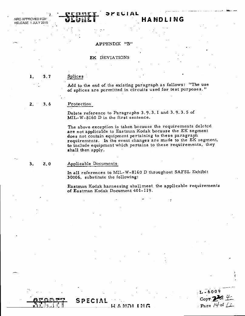
NRO APPROVED KIR RELEASE 1 JULY 2015
"""" HA NDLI NG
APPENDIX "B"
EK DEVIATIONS
1. 3.7 Splices
Add to the end of the existing paragraph as follows: "The use of splices are permitted in circuits used for test purposes."
2. 3.6 Protection
Delete reference to Paragraphs 3.9.3.1 and 3. 9. 3. 5 of MIL-W-8160 D in the first sentence.
The above exception is taken because the requirements deleted are not applicable to Eastman Kodak because the EK segment does not contain equipment pertaining to these paragraph requirements. In the event changes are made to the EK segment, to include equipment which pertains to these requirements, they shall then apply.
3. 2.0 Applicable Documents
In all references to MIL-W-8160 D throughout SAFSL Exhibit 30006, substitute the following:
Eastman Kodak harnessing shall meet the applicable requirements of Eastman Kodak Document 401-119.
e,- 5:. P .:. 7,7 SPECIAL 1 1_ • . P._ A ton; 1 tin
— L -6009
CopV'
Page /4i- of Li:-
•
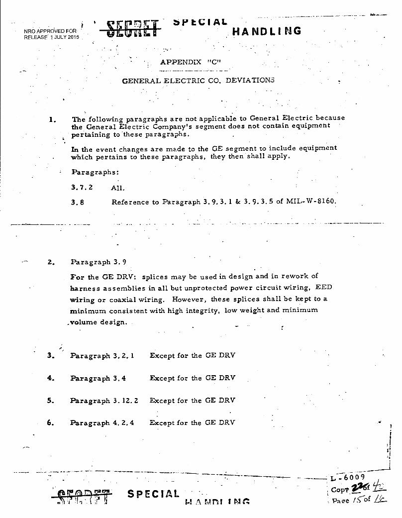
NRO APPROVED FOR. RELEASE. 1 JULY 2015
brtCIAL HA NDLI
APPENDIX "C"
GENERAL ELECTRIC CO. DEVIATIONS
1. The following paragraphs are not applicable to General Electric because the General Electric Company's segment does not contain equipment pertaining to these paragraphs.
In the event changes are made to the GE segment to include equipment which pertains to these paragraphs, they then shall apply.
Paragraphs:
3.7.2 All.
3.8 Reference to Paragraph 3. 9. 3. 1 & 3.9.3.5 of MIL-W-8160.
2. Paragraph 3.9
For the GE DRV: splices may be used in design and in rework of
harness assemblies in all but unprotected power circuit wiring, EED
wiring or coaxial wiring. However, these splices shall be kept to a
minimum consistent with high integrity, low weight and minimum
_volume design.
3. Paragraph 3.2.1 Except for the GE DRV
4. Paragraph 3.4 Except for the GE DRV
5. Paragraph 3.12.2 Except for the GE DRV
6. Paragraph 4.2.4 Except for the GE DRV
1721,- SPECIAL 'S 4 s! C4 A FAA 5'31 1 PI r4
1.1
09
Cop? 202(1 Page Lc-of 1k—
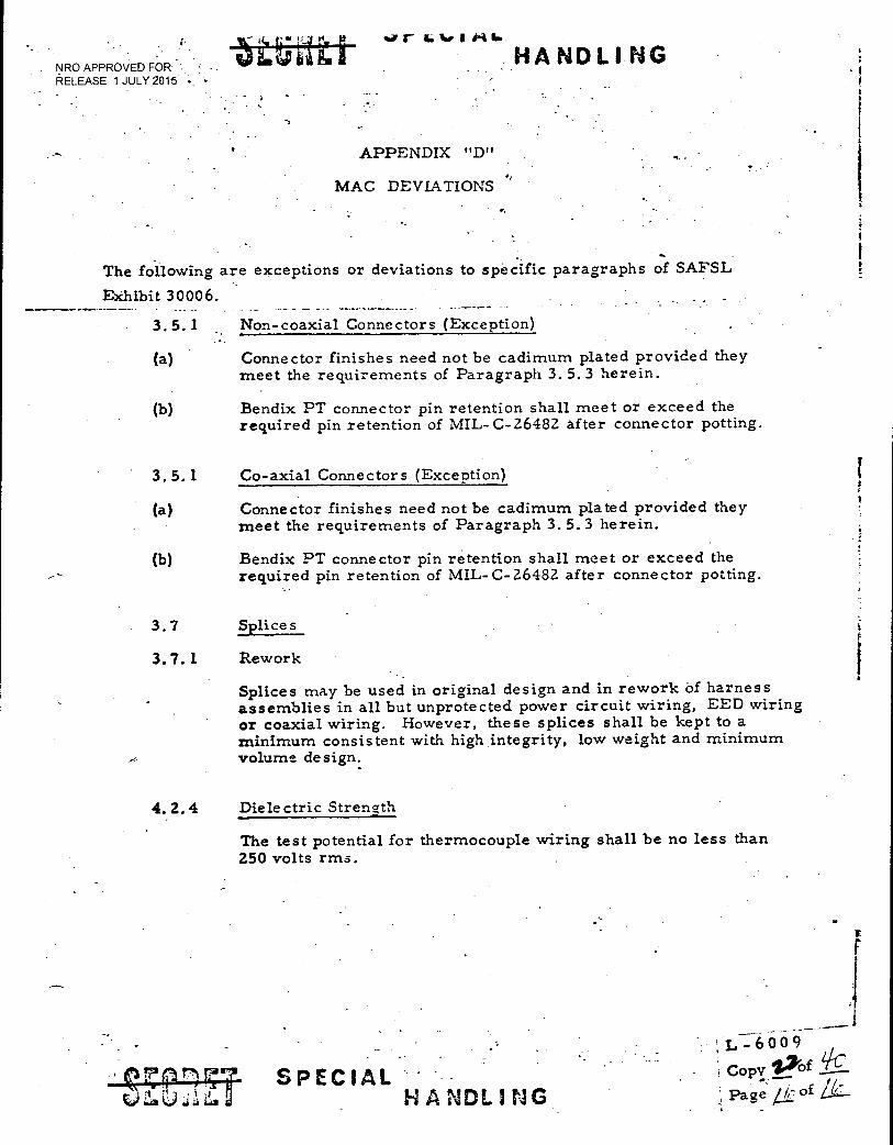
VV GtirIM 16
NRO APPROVED FOR RELEASE 1 JULY 2015
HANDLING
APPENDIX "D"
MAC DEVIATIONS
The following are exceptions or deviations to specific paragraphs of SAFSL
Exhibit 30006.
3.5. 1 Non-coaxial Connectors (Exception)
(a) Connector finishes need not be cadimum plated provided they meet the requirements of Paragraph 3. 5. 3 herein.
(b) Bendix PT connector pin retention shall meet or exceed the required pin retention of MIL-C-26482 after connector potting.
3.5.1 Co-axial Connectors (Exception)
(a) Connector finishes need not be cadimum plated provided they meet the requirements of Paragraph 3.5.3 herein.
(b) Bendix PT connector pin retention shall meet or exceed the required pin retention of MIL-C-26482 after connector potting.
3.7 Splices
3.7.1 Rework
Splices may be used in original design and in rework Of harness assemblies in all but unprotected power circuit wiring, EED wiring or coaxial wiring. However, these splices shall be kept to a minimum consistent with high integrity, low weight and minimum volume design.
4.2.4 Dielectric Strength
The test potential for thermocouple wiring shall be no less than 250 volts rms.
SPECIAL HANDLING
Lctop6vO 7lt,00 9 f Libc,/
Page' of
T
• • •
NRO APPROVED FOR RELEASE 1 JULY 2015
SAFSL EXHIBIT 30012
-
DESIGN LOADS
FOR THE
140L ORBITING VEHICLE
6 JUNE 1968
1-IA1:49LS. VIA " BYEMAN CONTROL. SYSTEM ONLY,
•
SECRET SPECIAL HANDLING L-6002
ICopya of t/i) Page of jt7
A.,NPQ■t:J• Syzte.:as Prorfram Office B.
- Aerozpac7; CorporaLIon R. H. Herndon
: - DottlaE- Aircra ft Cc::ipany B. P. Crass
•
/-, General Electric ompsny C. kbbate
McDonnellilsrAics Company R. E. Rolte
it4:1 g- 5=4 East;:r.e0Wdak A. S. Bennett
Se-. rot-
•
—11,-6002
Copy_ =2/ of do — r." ..as
SECRET SPEC!AL .timIDLING
•:— NRO APPROVED FOR RELEASE 1. JULY 2015
-SE-C44.1-: SPECIAL HANNAH / 6; ji
• :II..., • • ..v .•.1..■••••6
' REVIEW OF
SAFSL EXHIBIT 30012
DESIGN LOADS CRITERIA FOR THE
MOL ORBITING VEHICLE
May 21, 1968
The undersigned has reviewed the document and understands the contents to the extent necessary to scope subsequent proposals.
NOTE: Signature acknowledges agreement with this document, but such agreement does not extend to the documents referenced herein which are not yet agreed upon.
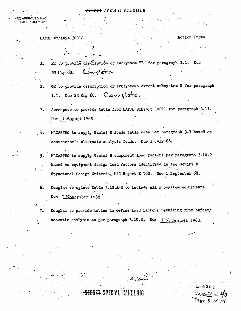
•
- NRO APPROVED FOR -RELEASE 1 JULY 2015
74)torrit&P
SAFSL Exhibit 30012 Action Items
•
1. EX: t64rovide—Segcriptioh of subsystem "B" for paragraph 1.1. Due
23 May 68.
2. GE to provide description of subsystems except subsystem B for paragraph
1.1. .Due 23 May 68. (2.0.,,,,NO4rVe.
3. Aerospace to provide table from SAFSL Exhibit 10011 for paragraph 3.11.
Due1 August 1968
MACASTRO to supply Gemini B loads table data per paragraph 3.1 based on
-.contractor's alternate analysis loads. Due 1 July 68.
5. MACASTRO to supply Gemini B component load factors per paragraph 3.10.2
. based on equipment design load factors identified in the Gemini B
Structural Design Criteria, MAC Report E -168. Due 1 September 68.
• 6. Douglas to update Table 3.10.1-2 to include all subsystem equipments.
Due November 1968.
7. Douglas to provide tables to define load factors resulting from buffet/
acoustic analysis as per paragraph 3.10.2. Due 1 November 1968.
-9E-Glig-SPECI HANDLING L-6 0 0 2
Copx.,Pf of 110 Page 3 of
NRO APPROVED FOR RELEASE tJULY 2015
DESIGN LOADS FOR THE MOL ORBITING VEHICLE
1.0 SCOPE - •
(K) 1.1 Item Description - This document sets forth the design loads for the
:MOL Orbiting Vehicle during all mission phases. This document as applicable
to AVE only.
Subsystem description is given in annex TBD. Mass properties, stiffness
properties, orbiting vehicle external configuration and associated dynamic
modeling for each of the noted subsystems are provided in IFS-MOL-101002,
IFS-MOL-101004, IFS-MOL-707017 and IFS-101.12. Loads resulting from
externally applied sources are specified herein.
(M) 1.2 Definitions - For the purpose of this specification, the following
. definitions are valid.
(M) 1.2.1 Limit Load - The maximum anticipated load, or combination of loads,
which a structure may be expected to experience during the performance of
- specified missions in specified environments.
00 .1.2.2 Ultimate Load - Obtained by multiplying the limit load by the ultimate
factor of safety.
(R) 1.2.3 Factor of Safety - A factor to account for uncertainties and variations
from item to item in material properties, fabrication quality and details,
internal and external load distributions, random behavior characteristics of
• '" •
L- 6002 SECRET SPECIAL` SPECIAL 11MIDLIIIG
Copf9-/ of 110
_ _
LbliiL
NRO APPROVED FOR RELEASE 1 JULY 2015
the applied environments, i.e., steady-state aerodynamics, engine thrusts and
thrust transients, gusts, etc. MOL factors of safety are defined in SAFSL
Exhibits 30044 and 12004 and have been appropriately combined with the limit
loads to estabthlrultthlte loads contaiqed herein.
(M) 1.2.4 Components - A component is defined as the lowest level of assembly of
parts, arranged within one package (black box), that will permit performance
of a prescribed function. Examples of components are valves, actuators,
amplifiers, batteries, junction boxes, etc. Vehicle structures are not con-
sidered as components.
(R) 1.3 Design Conditions - The design loads as specified in Section 3.0 shall be
combined with the appropriate environments as specified in SAFSL Exhibits 10003
and 12003 in the manner as specified in SAFSL Exhibits 10004 and 12004, respec-
tively, and shall be combined with the launch and ascent trajectory data
specified in IFS-MOL-101002 and IFS-MOL-101004.
(M) 1.4 Coordinate System - The Coordinate system utilized herein
is given in SS-110L-1B.
(K) 1.5 Documentation Reauirements - All deliverable data and/or documentation
specified in this exhibit shall be in accordance with the raspective contractor's
'On (DD 1423 or equivalent) as detailed by Forms 9.
(B) 2.0 APPLICABLE DOCUMENTS - The following documents of the exact issue shown
form a part of this specification to the extent specified herein. In the
event of conflict between documents referenced, here and content of Section 3,
.•••■••
SEMI SPECIAL HANDLING
L-6002 Copy,d/ of cf0
Page c of V?
• - NIRO APPROVED FOR RELEASE 1 JULY 2015.
SECRET SPECIa HA21.13
the detailed content of Section 3 shall be considered a superseding
requirement.
•
SPECIFICATIONS • Military
SS-MOL-1B System Performance and Design Requirements-General Specifications
L-6002 Copy:70/ of 40
-72
SAFSL Exhibit 30033
SAFSL Exhibit 30044
SAFSL Exhibit 10011
SAFSL Exhibit 12003
SAFSL Exhibit 12004
Other
IFS-MOL-101002 20 July 1967
IFS -E0L-101004
Environmental Design Criteria and Test Requirements for the MOL System Orbiting Vehicle, less Gemini B, and AGE
Structural Criteria for Laboratory Vehicle for MOL Prograa
Crew Systems Design Compatibility Criteria
Environmental and Test Requirements-Gemini B Spacecraft
Structural Specification--Gemini B Spacecraft
Orbiting Vehicle CEI No. 207001A to T-IIIM
Orbiting Vehicle CEI No. 207001B to T-IIIM
IFS-MOL-707017 Laboratory Vehicle, CEI No. 207013A to 22 December 1967 Mission Payload System Segment AVE,
CEI and GE AVE, CEI KOL010A1
IF 101.12 28 February 1968
Dynamic Mission Payload System Segment to Photographic System Interface Specification for the MOL System CDRL Item No. 64, Data Item No. E-106
SECRET SPECIAL WRING
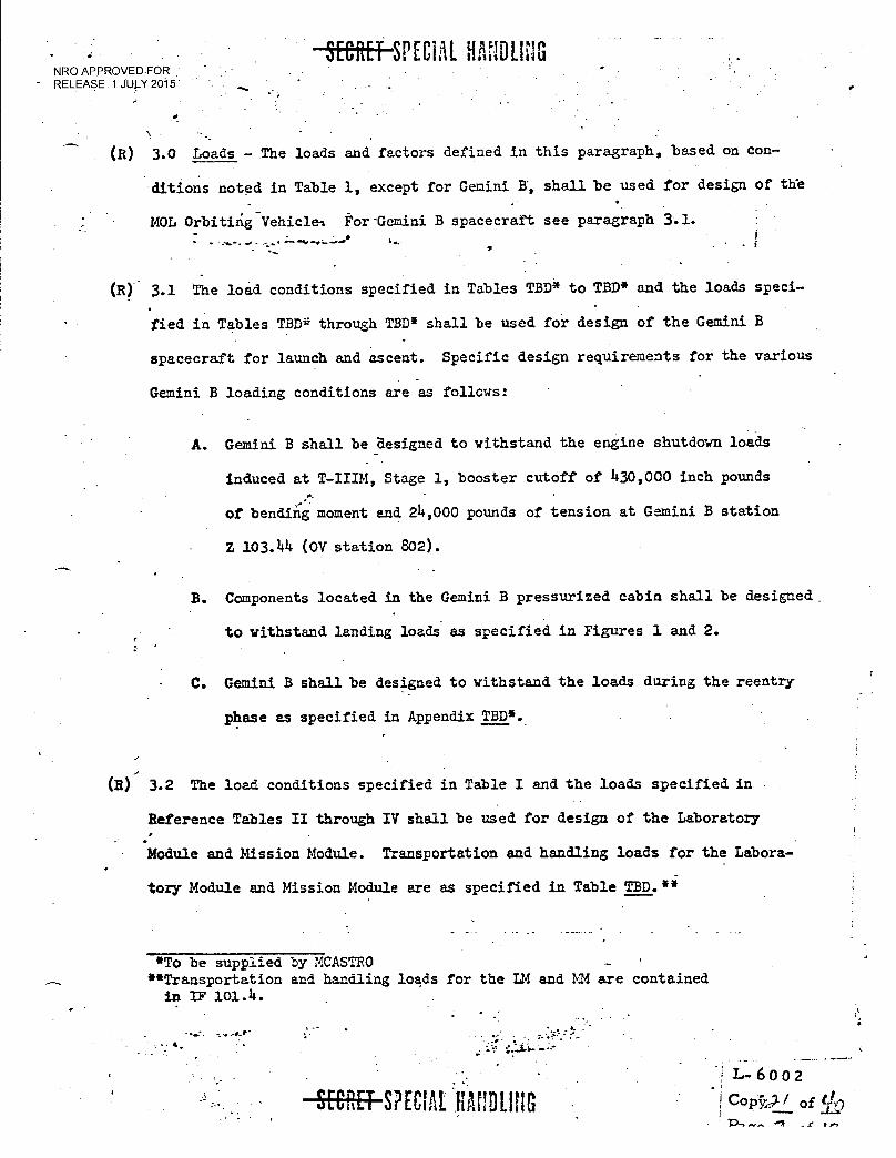
SPECIAL HANDLING NRO APPROVED FOR
- RELEASE 1 JULY 2015
(R) 3.0 Loads - The loads and factors defined in this paragraph, based on con-
ditions noted in Table 1, except for Gemini II', shall be used for design of th'e
MOL Orbiting- Vehicle% For-Gemini B spacecraft see paragraph 3.1.
a
(R) 3.1 The load conditions specified in Tables TBD* to TBD* and the loads speci-
fied in Tables TBD* through TBD* shall be used for design of the Gemini B
spacecraft for launch and ascent. Specific design requirements for the various
Gemini B loading conditions are as follows:
A. Gemini B shall be designed to withstand the engine shutdown loads
induced at T-IIIM, Stage 1, booster cutoff of 430,000 inch pounds
of bending moment and 24,000 pounds of tension at Gemini B station
Z 103.44 (OV station 802).
B. Components located in the Gemini B pressurized cabin shall be designed.
to withstand landing loads as specified in Figures 1 and 2.
C. Gemini B shall be designed to withstand the loads during the reentry
phase as specified in Appendix TBD*.
(1) 3.2 The load conditions specified in Table I and the loads specified in
Reference Tables II through IV shall be used for design of the Laboratory
Module and Mission Module. Transportation and handling loads for the Labora-
tory Module and Mission Module are as specified in Table TBD.**
*To be supplied by MCASTRO **Transportation and handling loads for the LM and MM are contained in IF 101.4.
L-6002
I Cop.-Tr-7/ of • _
SECRET S?ECIAL HAULING
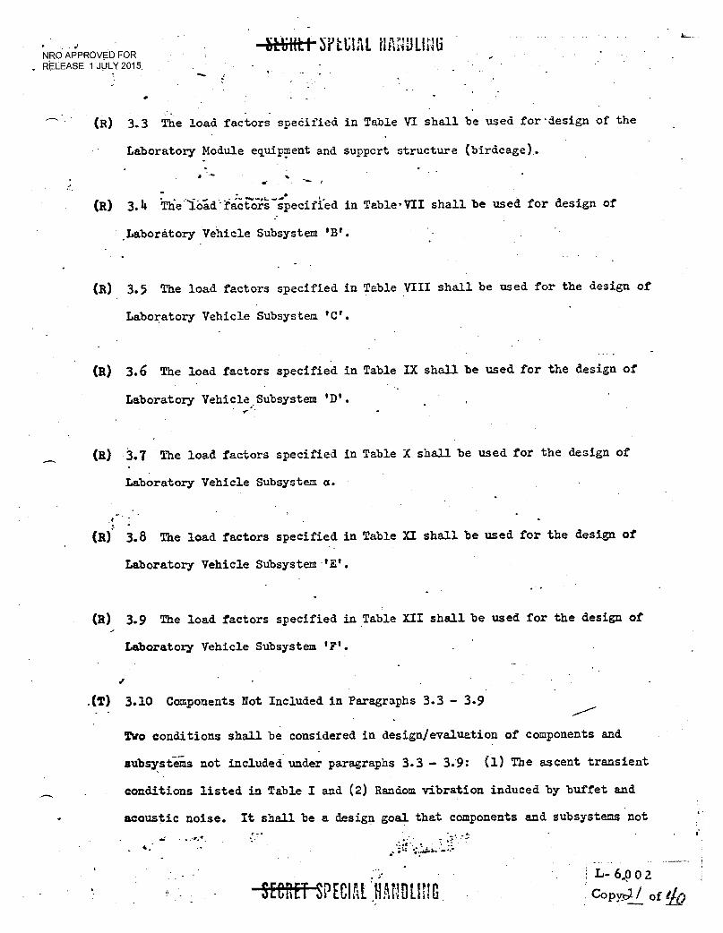
• NRO APPROVED FOR
. RELEASE 1 JULY 2015
4rEfrifttjnt;IAL
(R) 3.3 The load factors spedified in Table VI shall be used for - design of the
Laboratory Module equipment and support structure (birdcage).
•••••
(R) 3.4 Th'e'io-id-fEiCiO7-ihecifi.ed in Table,VII shall be used for design of
Laboratory Vehicle Subsystem 'B'.
(R) 3.5 The load factors specified in Table VIII shall be used for the design of
Laboratory Vehicle Subsystem 'C'.
(H) 3.6 The load factors specified in Table IX shall be used for the design of
Laboratory Vehicle Subsystem 'D'.
(8) 3.7 The load factors specified in Table X shall be used for the design of
Laboratory Vehicle Subsystem a.
(8) 3.8 The load factors specified in Table XI shall be used for the design of
Laboratory Vehicle Subsystem 'E'.
(R) 3.9 The load factors specified in Table XII shall be used for the design of
Laboratory Vehicle Subsystem 'F'.
.(T) 3.10 Components Not Included in Paragraphs 3.3 - 3.9
Two conditions shall be considered in design/evaluation of components and
subsystems not included under paragraphs 3.3 - 3.9: (1) The ascent transient
conditions listed in Table I and (2) Random vibration induced by buffet and
acoustic noise. It shall be a design goal that components and subsystems not
. - •
R SPECIALBANDLING L- 6002
Copt's >/- / of /0
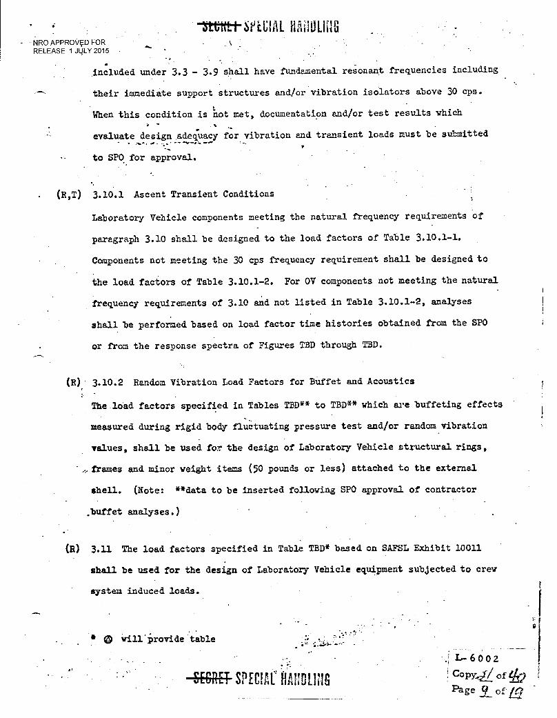
• SeLUIAL NRO APPROVED FOR RELEASE 1 JULY 2015
vv.
included under 3.3 - 3.9 shall have fundamental resonant frequencies including
their immediate support structures and/or vibration isolators above 30 cps.
When this condition is not met, documentation and/or test results which
evaluate design Adequacy for vibration and transient loads must be submitted - - V
to SPO for approval.
(R,T) 3.10.1 Ascent Transient Conditions
Laboratory Vehicle components meeting the natural frequency requirements of
paragraph 3.10 shall be designed to the load factors of Table 3.10.1-1.
Components not meeting the 30 cps frequency requirement shall be designed to
the load factors of Table 3.10.1-2. For OV components not meeting the natural
frequency requirements of 3.10 and not listed in Table 3.10.1-2, analyses
shall be performed based on load factor time histories obtained from the SPO
or from the response spectra of Figures TBD through TBD.
(R) 3.10.2 Random Vibration Load Factors for Buffet and Acoustics
The load factors specified in Tables TBD** to TBD** which are buffeting effects
measured during rigid body fluctuating pressure test and/or random vibration
values, shall be used for the design of Laboratory Vehicle structural rings,
frames and minor weight items (50 pounds or less) attached to the external
shell. (Note: **data to be inserted following SPO approval of contractor
.buffet analyses.)
(R) 3.11 The load factors specified in Table TBD* based on SAFSL Exhibit 10011
shall be used for the design of Laboratory Vehicle equipment subjected to crew
system induced loads.
0 vill'Provide table
L-6602
Copy,i/ of Page ci of Lti7
SECRET SPECIAL HANDLING
NRO APPROVED FOR - - RELEASE 1 JULY 2015
•
Gemini B components and support structure shall be designed to withstand
such factors specified in Table 3.10.1-3*.
a -•
•
Note: Requires change to paragraph 4.d. page 8 of SAFSL 10004.
r.
SPECIAL HANDLING 1,-6002 Copy Of of k) Page 'El of
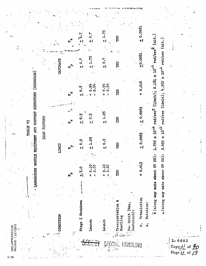
0
qUq
H
E4 tR E4
0 04
cn
0
LOAD
FA
CT
OR
S
.3 ti • 0 0
O St 0 O ci r-1
0 r-4
•r4 X cd d 43
Stag
e I Sh
utdo
wn
• • < •,tt
Rc.)
Tri
0 H (4 t-t
O t.)
C.;-"IT:rtt
: 3 0
4 a 5 es .4
4 u 0 C, /-1
43
14 t1Z 0 = rA •ei 0 .-4 0 ,O
a.1 z is 0 E4 =
r- +1 'd ,-1 0 .0 11 SY .14 0 cl
43 I to 0 0 0 CO.
L- 6002 - Copycil of A)
Page (
•
1._ of
- — **A • . • • al I t%.11
i''• • 10
L'''' . 0
to t.: r4 A
ri . CO 0 0 0
v. e-f 1. • ...
W t-- t— I": cd •cl E4 . ••
k aS • ?.,
0 r-I 0 A * c..; 1-s __....
i-t Z +I +1 ' +I P +1 , ....., E.4 0 I 4s-1 0
r-I X
X s-1 -
- ‘.0 CO N
ri i \ 0 ..-7 -7 ...7 ...7 r-• Cr) CO CT CT CA C\ 0
a t‘l N 0 N 0 R 0 • *A
• +1 + I •
+ I
O
▪
'11 •ri or-II art r-4
Lr's V....
Z.4
+ 1 + 1 +1 14 k
II 0 0 r-i \IA N
a a 0
E +1., :s rd
0 ..... ..... . 0) 0)
cd c3
N CO
..I' •.-1.
I' I 0 0
1111 r--I r4
V) X X 0 UN
N 0• '1/40 NI ▪ • . • E4 0 0 pA
pq 0 04' CA .4"
H1-4 +I +l +1 H +I r-1 1r)
• •
*••••. 0 0 C.) 0
M 6 t-- .-t ›-
o 0 o •-t ‘c) .--1 \‘::, o
1 • • • • o 4,
1.1 ot 0 N 0 0 0 m
X 4" 0 0
-If I + 1 + 1 .0 .0
el ed • VA
.
+t +1 +! +1 .-4 O 4./
0 0,1 ••■••
0 . 1 0 0 r4 CO +ft..
in V C) 1.11 0
0 .)::: ----
a • •
•
• •
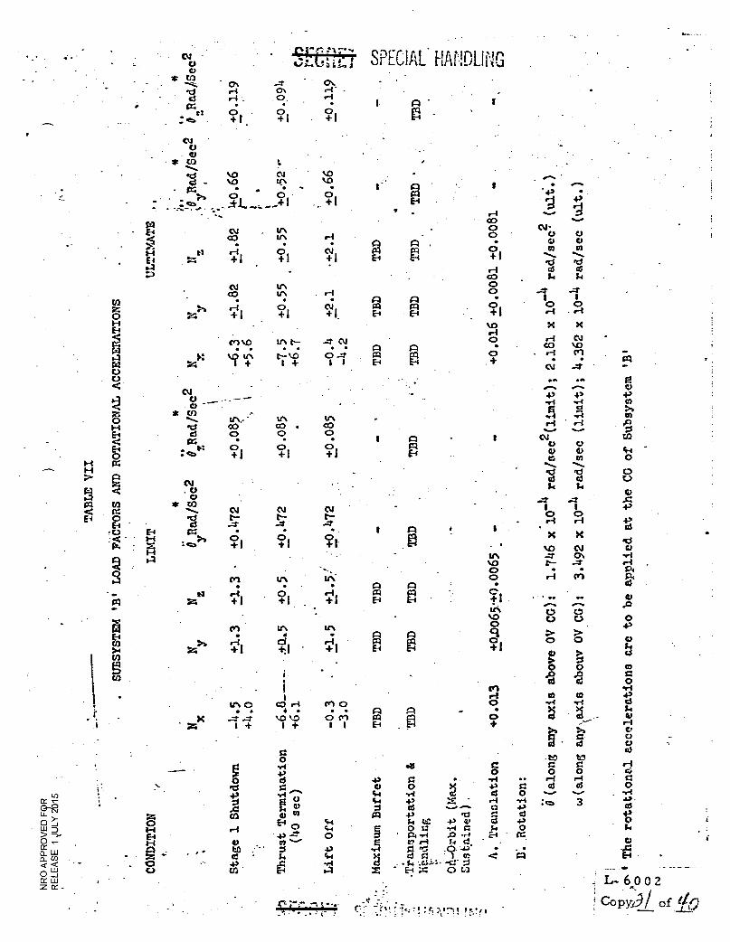
04 • • * 01 : .....
mi kt:3 N 1.0 %.0 0 _ 1.0 11.71 A I - 1:4?I,
• • • -.. . 0 0 0
I :4 . ..-.. 0 .......
17.
ii 0
0 0
0
4, •C
4' 0
•ti 0
••-i
r-I . PI P., es o 0 0 4-) 0
b 0 0
cd 0 .15 0 I 1 4-1
.v4 el Cet 0 0
r-I
it, o co 'I • • • • 0 cn • •
1-4 ..
01 I
V. a $4
X -.7 ---1. ‘.0 %.0 EP1 E 0 - 0 to O
+ t ' = 8 + 1 + I I 0
>f
5 0 0 0 '1 - Et) 0 AS c.• C 0 •rf 0 O 0 •P
+1 0 • 0 /-4 cS O 0 .14 43 0 CI g ek vi .•..t ..4 1•4 -1.1 .-I -ri : cz■ QS in
E g 0 4-5
CC ,- Ue..-t9 Z
El r.. 0 03
CH k 4C 43 C' k Sq 4-3
cd ..-....--• •0 0 d
a +" >- 0 14 0
0 4') 0 0 ....1 1-1
+3 --- 0 ..0
Zi. CH 5 • 24-1,4 :61-9 Ei • rd.
L.L.I D 0 .- CC H
a) - • • ..... v'
.., .....• V 4,
4.1 •••-1 g 20 ego 7 :. < .... ,.., ,c; -0, .4.,) • -...: E.4 - .
V CL Li S. < < - U Ei .4
Xti . .E.44., .11.1. -8- C.,1 z ... 0_ co 0 .a -.-■ 0 -J M LU Z -
ILI
. 7. .' I..... 6 0 0 2 ..
-.4.1...a.- c.--.t-1;%.-T.,-, :,,:•.7--il I.!,■ ! Copy /oft . .
• • r-4 S Cy:
tr. . - tn.. . A
• .. 0 • PI + 1 . + I + 1 Ei .. 0,-...
0
S-1 N • E4...., N t-i 0 0 of 4.) w • ca 0 •
01 , 1_, 1, .-4 0 01 Cq ...... ••••• E-4 ...
.g. + I + I + 1 El 'CI '0 I-1 03 0
S. Si CV tr. -.1. ---1' 0:3 tr. . r-1
Czt 10 0
1 0 N Cq r-• el t-I • t"-S O M + 1 + 1 + Ei
H X X E-4 CO
UN t•-• -7 N CO %Co M crl V) • • • • • • A ..-4 Cn
I-1 t--- 0 • • c4 z >: kat ttN+ 1 + I I Ei 04 ..7
0 <
CV
.....s.: 7).,..:
43 4 Q 0 "
a O -.:
* CO ••4 ft-II
....,.. UN 1.11 0 •--1 • ri CO • C0 H .0 4:0
El : *a Mit4 0 0 0
0
C.;...:, ......v
o 4)
O E4 es o o . . I s
+1 +1 +1 a o a ..... ....
-a mt .E2 N S
0. 8
04
--0 . 0 0 cs) * 03 I I C4 0 0 ls• d .7 -7 t•- .7 0 •11 I••••• r-I ri El ' I - . . I • o si C4 X X : •*44 - . I-I 0
I-4 :•::. 1 + i °+l• •0 0.1
M 01 UN UN CI C3 >
}, .-I Cl 0-1 RI P 0
m +I +1 • +1 E-, 0 I cn 0.,
TA
BL
E V
II
0.1 "'"'
C rC " t SPECIAL HANDLING 0 .....;.. 'zit-, G * cn ....._-_ ' ch ..-+ . - • cr.
•dri O∎ I-I - - d . 0, r
. 1.
E --
-0c: o
•
- o o - I I I
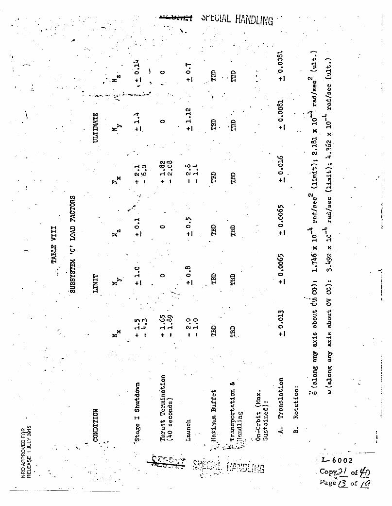
zx A A al E-4
O
+1 . -
1-4 •
0
+1 •
•••••••■ •••
axis about
5
0
4.
HANDLING •
60 C( O E4
ry V • tO
R:S
TABLE VIII
• 0
zN +1
O to
O A
E-4
0
+{
O
0 ri
+1 10
X
A
rn
•c0
O ri
>a + 1 •
O
CO
0
-0 O
tiN •O co
• • 6-4 r{
+
O O +(
axis about
'Stage I Shu tdown
Trans lation
0 0
(11 Rl
I I E-1
0 ..3 .64
+3 g X
• C6 6) 0
d 0 g.4 ..-4 X
„rf ..... C.4 4-/
E .t) 0 cc) 0 ... .0 .. 4., .., LI = .... = 0 = p -.-,
Ei 0
5 =4, Si = 4. 0 .0 E 0 r-4 0 +)
C.I 0 'd
ct la
g ga
0 ....tri d c 0
0 d • $4 d 14 . 0 0
d •••• -4' >:: E_, .—.... 1.1
-r 3 mit", f• .6 . • • i4;-:et • r ri
• ;r:13•
bC1
6'
3 4,
O tr.
L- 6002
Copy)/ of
Page( of
.m I
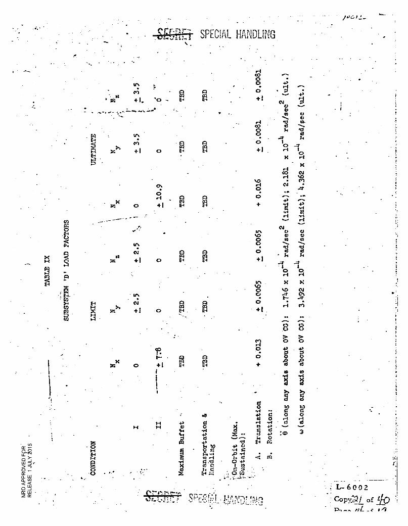
,
CU .....•
0 0 0 0 til CA ..... --.... fcl mi cd 03
• k $4
11. In
+ I. ̀0
:-.......,.....•••• a
WI
+1 0
ON
0 el
0 + 1
. ..
It: CU
+ 1 0
n Oa E-4
- r:
Epa
4
ra El
A Cq E4
1:6
A
fl
A ra E
• r-i co o 0 • o + 1
c0 - 0 •
0
+1
V) r-I . o
UN NO 0 0 . 0 +1
43
........ H S z
C4 0 E-1
•S U
P.
X Q t-1
axis about OV CG):
axis about OV CO
):
en e-I 0
0
Tran
s la tio
n
•
L- 6 0 0 2 Cogv j
of Pn
• - . SPECIAI HANDLING •
't xk 0 +1 E-
E4 \O • • 0
C)
- : E - tr. • Ea .
>4 E4 N A A 0 . •--I cn e-1 z ...
+I 0 EE-/ +1 a
x )--I
CO 14
0
NO ...?
0 •--1
N ON
---1'
0 d d
tO tO Clzr
Cl 0 0 0 .14 CI SI3
: 0
C4
.0
xx 1-.1 -13 0 • H w 0
44 .1 4. 4) Z •• O d
O 0 0 r.....4
-..4 a
..rg1
S3 -,zi O 4 el a 1. -, 1 u) a 0
rt, ■•••••;,•
• •
17:1
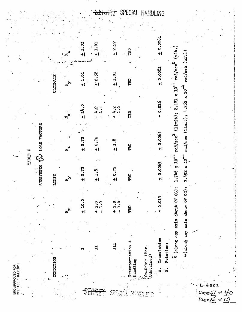
ti
zx
0.10
•-• C) 0
CO al C)
0 ••••• VI
0 ̀"••- • ci •11
0 14 a1
+ 1 ...7)4
..-7 I 0 1 0-1 0
r-1 X
X.
O-1 %,0 OD 01
0-1 ...I %.0
0 • Cr) • 0.1 •
0 ••7 •••
+ •••••• • . 43
-e-t 43 0 sr
0i
•r4
.-1 •ri
...-. ri
111 .......
%.0 No 0
0 c) C) . CI tf2
0 •••.... ■.. MS
+ i c3 d
7.4 Si
I
t
•
SPECIAL HANDLING . .
ri .-1 0 , 0
ri • ri
+j +L
•
ri N r4 0 UN 0
+1 +
0 • Nom'
...I • • r-1 .4' ri
+1 + 1
CO rd 0 El 0 44 : CV
e••• CCVs.. 9
Q0 0 ..-1 0 to
>' 0 z +1 +1 +1 r4 '.3_...,
' El
9 '- - ei • N
f. '-•-VD
a
:2*. F-4
E 1-1 }4 El 0 r1 0 ta
z>0 +l +1 +1
Cl) 0.4
4-4 CO 0 ; 0 t 0
t. 4' ••••
+! r-I - • •••••
• • • •
2.222.. • ..22.2
0.5 C.)
0 43 P• 4-1 01 ri fel ri f=l V V
zX P. . + +1 + 1 + 1 0 0
do P 4 cd to to
Cy1 • 0 0 0 0 0 0
0 • . •
I-4
z
1-4 1-4 1-.1
..
i-4 I-1 1-1
.is a 0
..-4 41 415 4,
0 bl 0
. X CS 4s.
.........---. .1:1
+P C' •.;
E-1 = . 0 CO
, • P".!4.•7•44 4.!.
g g >. >.. g g
vs o to .t!) •,4 •• a a 43 !I 0 0 GI 0 .-4 .-4 .-I ...I CS d u4 .4-1 a ci
; CD 3 - CI 43 Si 0
a
L- 6 0 0 2
Copy-c / of YO
Page /5' of
Q. .r4 • •,-4 a rt Sr CCI a Ts 43 . .
F. 0:1 C ta -U: Pa 0 1. d C
• 4.3
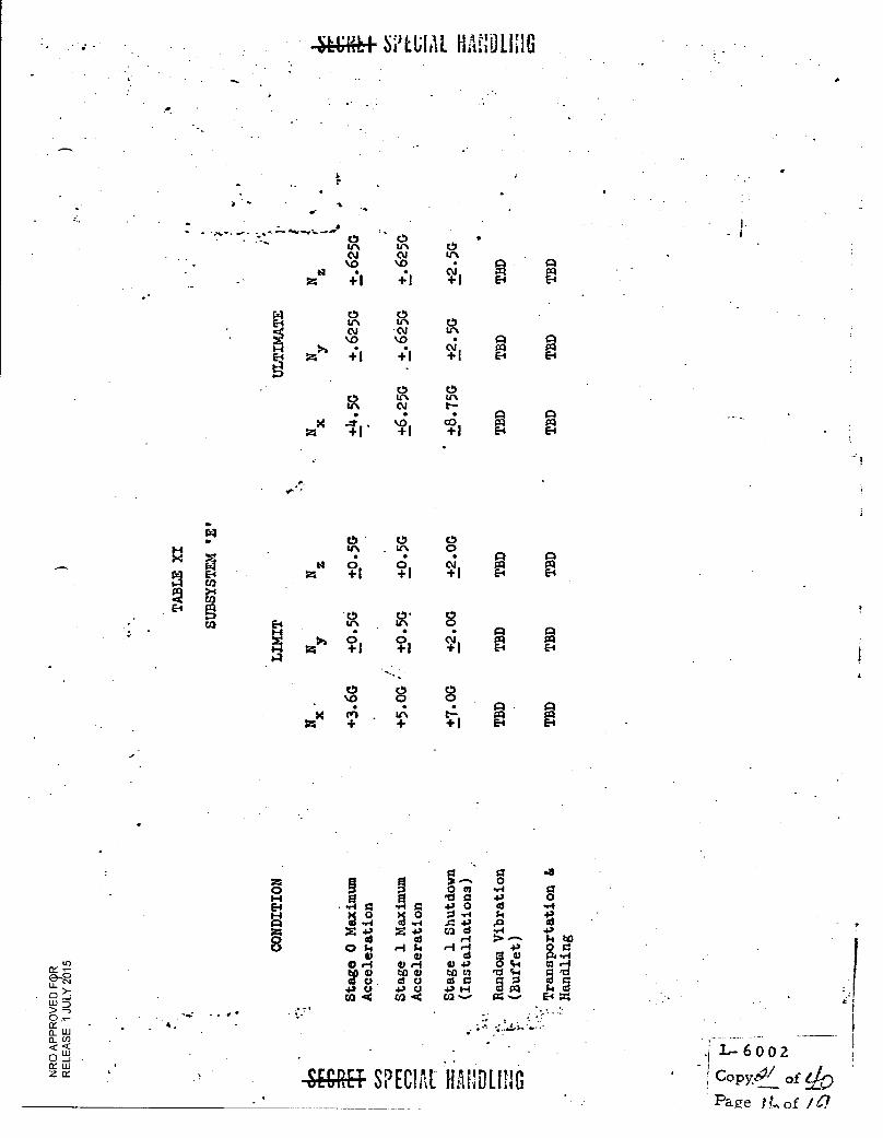
4444+ S t;IAL HAEOLIIIG
. 0 0 .
In Ir. 0
cv cv uN
v, v, • A PI 0 . . a/ P:1 Ccl
+1 +1 + 1 E-4 E4
r4 o o 54El I" LA
•••■ Ckl .(\J
%.0 . UN
ko . .
N al rz co z +1 +1 +1 E-4 E-4
0 0
0 LIN tn
Ifit al
+
Ls-
4. . . ci H —1. • kr, P:1
p.
0 • 0 0
V\ . LA 0
. . A A
z bi o 0 a Ill al
+1 +1 41 El El
0 0- 8 E-. ." .r. 1-4 • • CU XI C:1 in 4 +1 +1 +1 >'. 0
Z 0 '4 El A
00 0 .0 0 a;
+ +1
0 0 g . . . . . . g
0 CI .r.
4 0 4 4., e ...I
g .2 g .2 .1 5 9 .1 11 +) 0
X4.' X4.' cs3 cS +.1 d 03 r-4 > ---- $.4
•
tce 0
OS.. ,-I Si ,1r1 +3 0 O d M V $24 -,-1
Or4 0 .—I U+' 0 cs4 al r4
T g 00 0 td) tri 'ac-. p mo ci0 0 0 g cg 2 g
4'{1 +2 0 +'H
CO .4 Ca 44 Ca •-•• C4 ■-•• EA • ,
SECRET SPECIAL HAULING
CON
DIT
ION
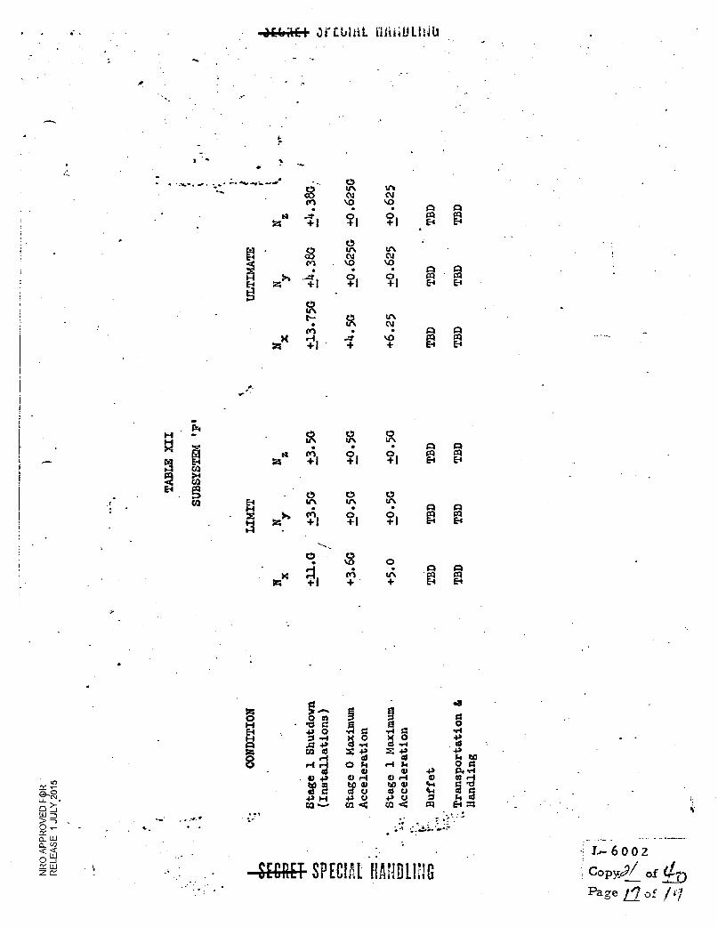
g ...... 0 0 0 0 0 0 4
g . 0 4. 0 0 v-i 0 '-I
44 a o ...I cis g o4 Co al
000 u+. Id 0 CA *---
r ::,..... !. ;4 1:.-je:•• .....
= +2
V m ,-4 We al C.;
CO *4
= +3 as 1.1 k
V <LI •—I WO 43 u
CM
4., V
44 fe-s A
41 $.4 tO 0 V 1:14 vi 4
Sy g El =
CON
DIT
ION
• • 4E-6 Af. I ait.taili
_ 0 8 LA
CV Ws N
cn kr) va ii -4 o
A A PI PI
El
+ 1 + I 0 + 1 El
In
cv IA CV
Cn V> ■.0 • A C-1
.---4 0 0 P:1 PI Z>• + 1 + I + f E-I E-4
0 In
C. 0 tr.
ce. v. N
k r-4 . 07
•
V) Eal PI ZI + I + + ti E-4
iir4 H
g 0
IA 0 IA
0
+1 . 0 +1 °+1
c:1 ra co Ht El E4 N co
2 >I a)
El 0
CO 0
LA L 0 A LA
1-1 .
= z
cr +; PI
1 0 + 1 0
+ I re A
El N
0 0 A
+1 + + H
•-•
aN
SECRET SPECIAL liANDLIIG L- 600 2
Copy.69/ of (1--4 Page LI of /
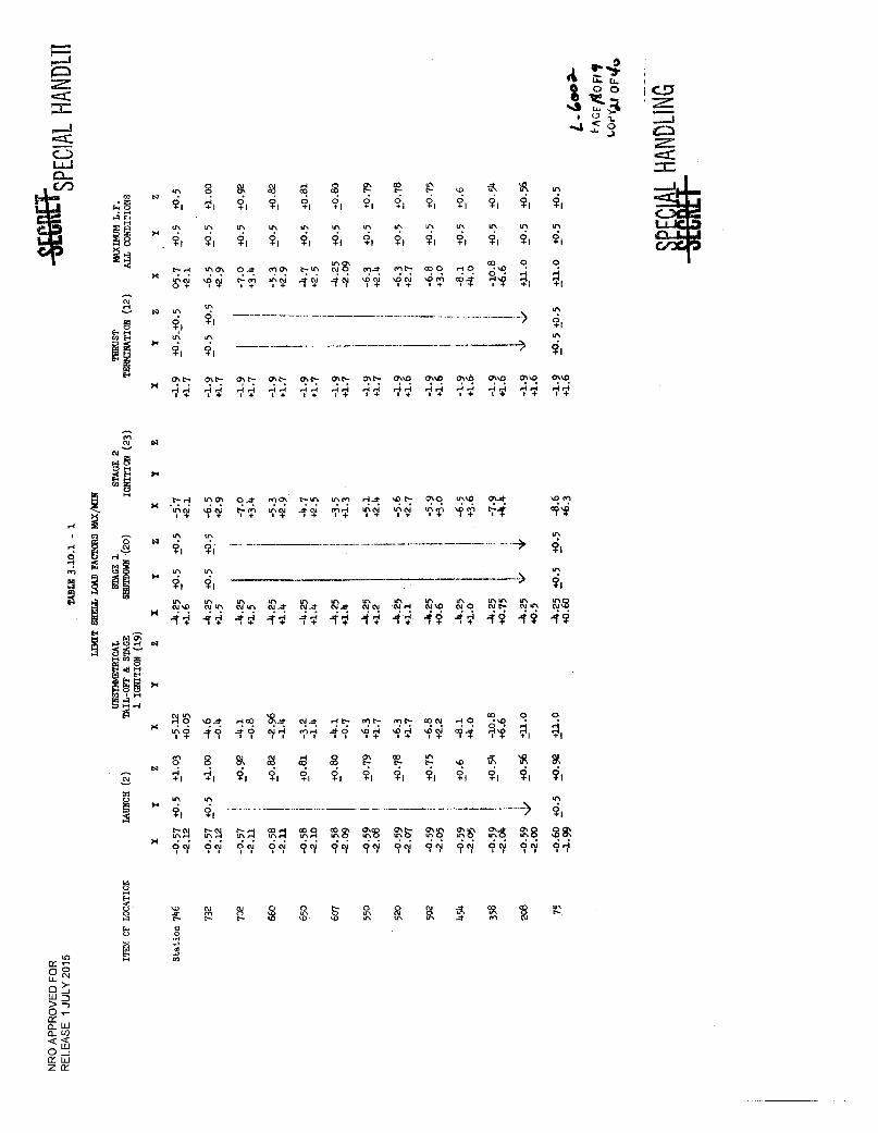
vp. 4 m.19:
c...0
w 0 0 zr. i0 ;Li
I (7
t̀r' 3 cn
8 '11
In
Ti
1/41.1?
a Ti
In
0-7 tZT
Ti
uN
Ti
Ma% • •
a Ti
U1
• • Jr+
5)-1
Ws
Ti
tAO, NO • • -V?
Ti
UN
Tt
M.d. • • `i).T.
T-1
UN
TI
MC.- • •
g Ti
V\
MO • •
.11
ti■
Ho • •
(11
?1
9.0 e •
1T
Ul
1
4.1
•=:c
Lc,
‘1
0
+1
© '' LA
T1
(". .4.4 I4-
oroG. '1(+
C■".. - I4 +
O .*
it,
Ti lr,
47.p. HH o+
C".... (7:t7 r4H HH 14. e+
mch un i.
) \
CAt'- fir; 1+
m TY.
(1:ts: HH I+
as 'ill-
CT.° He4 1+
.0c.. fi
Cir.4! Hr4 o+
0.o '7'T
g."4: HH 1+
'IT
T:S4) H.4 t+
a
'71
/
Cr."C! HH e+
SPEC
IAL
HAN
DL1
1
w "„;
.4 oC HS 0
17
2 m gi ~
0
IV 11 11 11 11 11 /1 /T 11 IT IT IT NM NW, NI^ N.* N.* NAt NN NH NW N O Nt■ NUN NW LAU\ In
H gleiH A ' HM *-7 N.* HM- MC■ oiN. HO
TT -V? 1T °el T1 1'1 '11 '11 '1.T. '11 1T
V 8 k qc7 '0 8 r-• 71, u,
FRN q@ L-":1 t9,A tUA ,T.11 FP.8 8 9? 9cy 9 cy 9c 9cy 9c 9§ c? cy 9 cy 9 cy 9q 99 91
ITEM OF LOCATION
1
Ps
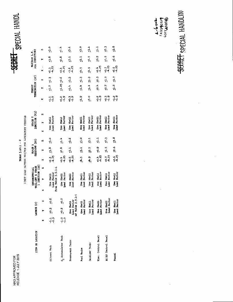
(1 1.1 1P :?: a a a OH 0. 0. 00 .0 0. Ad 40 44 Mg dg 44 Mg dg w.-. >, OW mIlk ri 0.c1 0 ,c1 SI•li eml tIM flIM
M H gA DA Ai Dl DA PA Al DA 8 x
ri
8 W F
1,1 N
N
H
8
N
X
4
N
0
+I
co en + I
In MN NA. + . , H +I
t--
• '44-1
HO' HH + 1
"4. H 1
c°. CV- 1
in ...1-N O.; + . .. ?I tr. N ,4 +I
No... ?II
ri in I
H en +I
u, .ON 6_4 + . , H .I.I
-1.
+1
ma; 71
0
+1
H
TI
u, II
rn H +I
-4. +1
°: VI
ri +1
tr. + est I
Cr. 1 1
(n H +I
•1 H +1
0 N +I
H H 1
0., ? I
in ..1.N T -
L': ?I
4: 7'1
Cu°: ?'-11
en N I
u, +I
u, C-N ?4
0 H +I
t.: Ti
mg: i'l
co en I
so +1
IA .ON ci4 [-
+1
N VI
Na: HH + i
All At' a A il co co M4 gA a4 aa • :
0 0A
g P gA
N T1
Cu q 0 N ° -4. H N 0 5•1 'I H M CO Cu A N "+" 1 +1 -11).1 +1 Ti +1 +1 +1 ,
, E H ,:; eliR . co . i " ci: ,..r. . i ol H w, T., c-e, i., qi, VI M1 m +1 +1 +1
1 5
'40
tn MIN
+1/
tr, Lr, ..4.N sON.
?-i 11 'I: (7' -11 II
trs tr, in .7N t-N %ON ..-i. -,f N At + (
(x. :(3:7' N 1
Q '-' H1308 H
2 4H VIA All All Ail Ali At Ai': 0 co co a AZ Afil
.15 0 0 0 .S it'S m >. 4
Si'' PA H
AM', to A m mN Mg 44 A g ■ H
V •cf 41. .1:1 1.! 1:1 !ti If : " c.o.o. OM omp grg. ,§ gA gA gA gAD .A
8 Du1..
HO, 00
tUQ
H
8
.41 U 8
0 a N
0 1.11 > 0 <- 0_ W acn ¢ w O J
LU zc
Pres
sura
nt T
anks
A 7.4 4 Ox
idiz
er T
anks
Elec
. Con
trol
Pan
el
Con t
rol Pa
nel
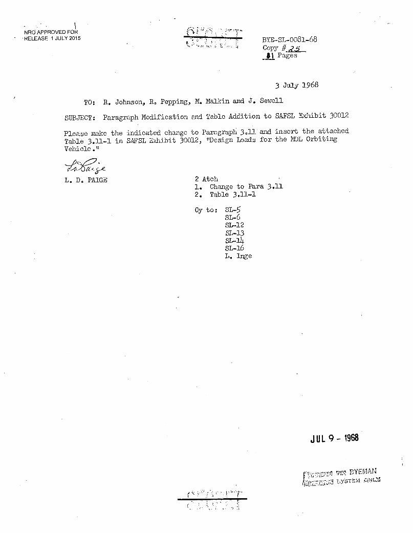
NRO APPROVED FOR - RELEASE 1 JULY 2015
BYE-SL-0081-68 Copy #
$1 Pages
3 July 1968
TO: R. Johnson, R. Pepping, M. Malkin and J. Sewell
SUBJECT: Paragraph Modification and Table Addition to SAFSL Exhibit 30012
Please make the indicated change to Paragraph 3.11 and insert the attached Table 3.11-1 in SAFSL Exhibit 30012, "Design Loads for the NOL Orbiting Vehicle."
ez.cke_
L. D. PAIGE 2 Atch 1. Change to Para 3.11 2. Table 3.11-1
Cy to: SL- SL-6 SL-12 S1-13 SL-lb SL-16 L. Inge
JUL 9 - 1968
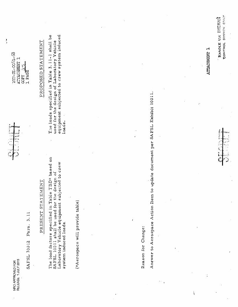
H
co
H
H
CC ei
O . 0
H
U)
CO 0 0
tr I
E—I <I
P4 (14 El 0 <4 C.) 1-1 0
0 04
a) -0
d ,0
M
.73 Cd
0 ■-1
Ti
U
";.1 ?-■
a)
;.4 0
4-
1-1 0
.-0 Cd 1
4-4 0
bt,
-0 a)
0 •
a..)
(1) >, U)
a) 1.4
0 4-)
a)
SA
FS
L 30
012
(*A
e ro
space w
ill
pro
vid
e ta
ble
)
)10
U
0
.-4
O O
r-4
.0 • r4
111
U) I-1
U)
114
a) 0.
a)
UO
a)
P.
0
a)
1-1
0 43
a) U cd P. U) O a)
O
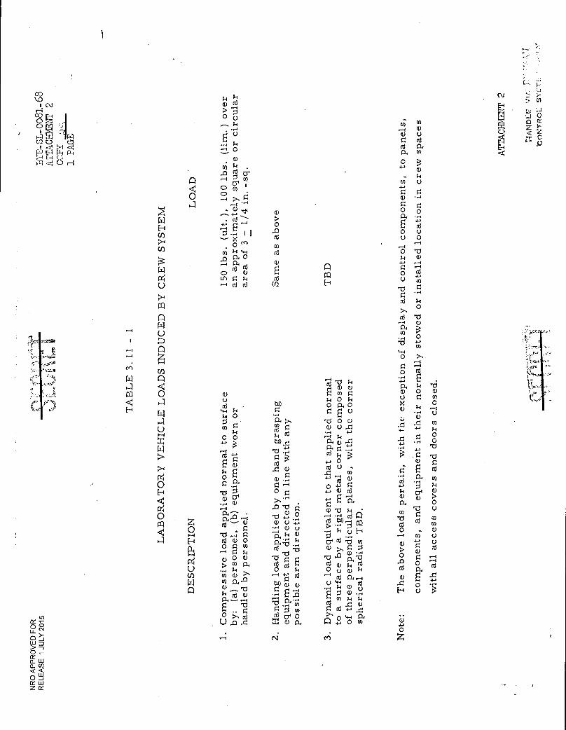
DE
SC
RIP
TI O
N
L
Q P CU ...T.
a) d > "5 E. O 0 .. '..1
iLt
..,... k CO Ci) Ci
. - r4 .--1 (I) r..)
Z
..-, k 0 cd 0
U.: <
u a) 0
•—, 0 rd 0-,
— 0. En . a) 0 >
u) ;-■ . 4-, ,..- ,o cd,_, co
a) .. k
(:) .--4 ..-. (f)
Cr' 1 Cl) C..7
CD cn
-l- 0
O ›.. .--1 a) .H HI ,--1 ..-1 0 0
a) ti 0 0
147C't -----
(1)
> ..--1
.--..
:-.) ..-1 ± I .0 o
o 0 P.' : d
--_-1, ,.....•x cd 0 0
o r u) .--I
a; sq 4.1 cd -01 "0 ,c, 0., 0 k a) .---1 04 a)
Cd Cd E n c) 0 cia 0 14 in g :_, cd 0 '-' cd rd (r) H u)
-0 0 O --, a! PI
>. 0 cd "Cs
.--1 0
CO 0, 5
• H 0
..C7 -F-, (/) --,'
t.,.., %,...4-.a, • ›, :I_
,--1 t . Ce.
• .—!
'''''' (11
0
4, l'
..-i 0
74d ICIJ) ;(14) 04 ;1 /1
a) U) 0 CO 0
U k 0 /-1 0 cd tan 0 a, 0 X k
0 E r.) a) .,--, 4-, 7-1 g k 0 ... 0.) O 0. y, -c3 0 c) :,.%
rn En H a) u ..0 .0 -0 4-, k cd " .. -,
70 0
\/
0 •-1k'4 X
.
.
0
O
t
T
, 0
3 a a)
▪ 0 ..0 a) cd 0 - 0 a) .,..
-0 to O " 0 4, "-{:j 0.) ..-■
1,4
g fl' Cd ...4
...4 0 .-4 0 4-' °
•
0
li 0 4 4, 0.) al k o-'
a) c7' >., -4 4' Tit a) a) .,.., a) ,c4 0.
..sa -0 13) 10 k • Ci) '-0 cl, .1:1 .-I -0 1., ,
CL) 0 .--4 • ...I ri 0 '0 rd cd (1)
<I.) C.) .4-, rd to .-1 rn > ." 0 rd 0 •-, a) u • r-I 1.1 0 H 0 -
'0 .--1 0 7:1, k a) 0 ...4 .--1 u) rd a) 0
fa, ."E's .;.1 cO cd 'V cr) a) 0j 0 0 co rd -0 a) ›, ̀ 0 > a) -4 )-I -0 O 0 (I.) 10 d '0 .- CE:)1., ;El 0 0 > cl) fa, cd aj 0 d 0 k cd -0 0
..... )-1 0 &4 0 0 a) ;-' cd 0.
©§ 0.) ••"' .--1 4a, al .---1
04 -I a) co 0.,.-0 M a) a) u 4-4 cd -0 .,.., s.., a.) 0 (1) --. -0 0 d ,--4 0 H U k d 0 _-,, 0 .0 E
0 ...1 0,-- --i u) )4 k
'0 .a, .;1 cd .0 0 E '" 0 En 0 cd 4., x O ›., al cd co 0 >, ,,..1 a, 'a; (..) X) .4 a) 0., n 2 0 .
40' --I Ni ce; Z
LA
BO
RA
TO
RY
VE
HIC
LE
LO
AD
S I
ND
UC
ED
BY
CR
EW
SY
ST
EM
t()N
TR
C,,L
S
Y:
wi
NRO APPROVED FOR RELEASE 1 JULY 2015
BYE-SL-0015-68 ATTACHMENT 1 Copy 11 Paces
REPLACEMENT PAGES
for
SAFSL Exhibit 30020
"SYSTEMS TEST AND OPERATIONS PLAN"
dated
Jane 1968
), 1-1ANZIL.17 VA BYEMAN. • tor-rnou SYSTEM ONLY
. •:- •
(Signed) -71;
(Signed)
(Signed)
(Signed)
(Signed)
(Signed)
(Signed)
(Signed)
vu A. 54 -1-1
NRO APPROVED FOR RELEASE 1 JULY 2015 -WM-SPECIAL HANDLING
S AFSL EXHIBIT 30020
SYSTEMS TEST AND OPERATIONS PLAN
The undersigned has reviewed the document and
understands the contents to the extent necessary
to scope subsequent proposals, provided the required
CDRL (DD Form 1423 and Forms 9, or equivalent
thereof) is received with the RFP.
--est-eftErf SPECIAL HAWLING
NRO APPROVED FOR RELEASE 1 JULY 2015
BIE-SL-0015-68 Copy # 1 Page
'7 roq 1"4
9 July 1968
SUBJECT: Change Pages for SU'SL Ejlibit 30020
TO: R.L. Johnson, R. Popping, 14 Nhjkin and J. Sowell
The atLaehed repl2ecm3nt pages are to be inserted in the June 1968 issue of SAYSL KOIlbjt 30020, uSystems Test and Operations
L. D. PAIGE
1 Atch SAFSL Exhibit 30020 Replacement Pages
Cy to: SL-5 SL-6 SL-7 SL-12 SL-13 SL-14 SL-16 J, Chalmers/
1Th". fr f:rt çlpa
t. r !
HANDLE VIA. ill'EMAH CONTROL SYSTEM ONLX
NRO APPROVED FOR (D) weriti+j+dspEciAL
RELEASE 1 JULY 2015
SAFSAL EXHIBIT 0020
SYSTEM TEST & OPERATIONS PLAN
JUNE 1968
B. A. HOHMANN
W. F'. SAMPSON S. M. TENNANT
B. P. LEONARD
gECP DT SPECIAL HANDLING HANDLE VIA entEcari
CONTROL SYSTEM ONLY.
S pr f7, F!'s [L — 5 9 9 9 Copy ,',3 of ,[9
Paoe , -Of ---
NRO APPROVED FOR RELEASE 1 JULY 2015
(D) SLGfhr, f SPLCIAL HANDLING
TABLE OF CONTENTS
Page
1. 0 PURPOSE 3
2.0 SCOPE 4
3.0 TERMINOLOGY 5
4.0 TEST AND OPERATIONS REQUIREMENTS AND POLICY 10
5. 0 MANAGEMENT STRUCTURE 14
6.0 TEST AND OPERATIONS DOCUMENTATION 18
APPENDIX A - ABBREVIATIONS 33
■•••■•.,
r );77, 7-■ r:31711
\\ j
1L-5999__ --
Copy )/3 of el"., Page If ..
L
NRO APPROVED FOR RELEASE 1 JULY 2015
1.0
PURPOSE
This document is directive and shall be used by all agencies for planning
the ground test and flight operations programs. The System Test and
Operations Plan (STOP) identifies and defines the policies and require-
ments common to both "Test" and "Operations" and the interrelationships
required for standardizing lower level planning documentation.
Co r..2 ,•••") 7-N r.7.1171
i■ ■ SPEC 41.44.';,-,T:-.C7 r r D ING rj
ri, 5 9 , 9
(Copy )73 of
Page ::; of :I.e.'
L
NRO APPROVED FOR RELEASE 1 JULY 2015
2. 0
SCOPE
This document covers the test and operational aspects of the MOL Program.
The concepts and principles contained herein shall be applied against all
aspects of the MOL Program. For purposes of standardizing definitions,
policies, responsibilities, and requirements the most complex version of the
MOL Flight Vehicle (#3) is used herein as a baseline. For other vehicles
similar (appropriate) terminology will be used as necessary.
Documents called out are applicable as specified herein. All deliverable
data and/or documentation specified in this exhibit shall be in accordance
with the respective contractor's CDRL (DD 1423) as detailed by Forms 9
(or equivalent).
•
(23 rT2 1,3 77) r? .1 •
rifirrm: SPECIAL I-IA 'ND! INC
\ .41 [
L - 5 9 9 9
Copy> ) of .°!,,*)
Paae (''' ..i3f :' er , -
. t
NRO APPROVED FOR RELEASE 1 JULY 2015
3.0
TERMINOLOGY
The following terminology shall be adhered to by all associate contractors
and supporting government agencies in preparing their required plans and
other supporting documents.
Associate Contractor (MOL)
A. C. Electronics Division (ACED)
Aerojet-General Corporation (AGC)
Douglas Aircraft Company (DAC)
Eastman Kodak Company (EK)
General Electric Company (GE)
Hamilton Standard (HS)
Martin Marietta Corporation (MMC)
McDonnell Astronautics Company (MAC)
TRW Systems Group (TRW)
United Technology Center (UTC)
Whirlpool Corporation
Flight Operations (i. e. , Operations) - All activities associated with
MOL operations from prelaunch preparation (simulation/rehearsals,
AFSCF checkout, etc.) through laboratory vehicle disposal, data
retrieval and post flight evaluation.
Flight Vehicle - The flight vehicle (FV) consists of the T-IIIM launch
vehicle and the MOL orbiting vehicle (OV).
Flight Vehicle Timeline (Operational) - A nominal, chronological
sequence, relationship, and status of all FV and ground resources
necessary to perform the MOL real-time operational mission. It
includes the time, approximate orbital elements/location, subsystem
status, consumable profiles, crew activity, and ground support
r7.3 „7,3 :7-3
• ) S P :EC I AL "ANDLING.
: 771
L - 5 9 9 9
I Copy?' 3 of :1,?.)
( Page
A L 1 13 ; NRO APPROVED FOR RELEASE 1 JULY 2015
L. t4 4 4:1 lv
associated with the oper.ational sequences required to accomplish
the MOL flight objectives from crew ingress on the pad to Gemini B
splashdown and laboratory vehicle disposal. In the case of the
automatic configuration, the timeline includes all operational
sequences from FV liftoff through OV disposal.
Flight Vehicle Timeline (Test) - A chronological sequence and relation-
- ship of all activities associated with FV hardware from first AVE
arrival at VAFB through FV liftoff and turnaround.
Government Agencies
6595th Aerospace Test Wing (A TW)
Aerospace Medical Division (AMD) (AFSC)
Air Force Satellite Control Facility (AFSCF)
Air Force Western Test Range (AFWTR)
Air Weather Service (AWS)
DOD Manager for Manned Space Flight Support (DDMS)
SAMSO Plans and Operations Office (SMLC)
Ground Test (i. e. , Test) - General term encompassing all test
activity from start of initial in-plant development through FV liftoff.
This activity also includes turnaround.
Laboratory Vehicle - The integrated AVE of and in the mated laboratory
module (LM) and mission module (MM).
Launch Operations - That portion of ground test associated with VAFB.
Includes all functions and activities required to handle, assemble,
maintain, checkout, and launch the MOL FV, turnaround, and all
related plans and procedures.
Liftoff - Event determined by FV motion in the vertical direction as
detected by electrical signal to the ground equipment.
L - 5 9 9 9 sf Copy )•3 of .7. Y),
ge _ a -. p •
NRO APPROVED FOR RELEASE 1 JULY 2015
Mission - This is part of the orbital phase and is to be used only with
reference to the objectives and operations associated with the MM
experiments.
Orbiting Vehicle - For the manned/automatic mode the OV consists of
the LM, MM, crew equipment, and the Gemini B. For the automatic
mode, the Gemini B and crew equipment are replaced by a support
module.
Software - Computer programs and their associated documentation.
Support Module - The support module consists of a tank section, a
recovery section including six Data Reentry Vehicles, and a fairing
section.
System - The MOL system.
System Segment - A discrete package of system performance require-
ments, functional interfaces, and/or contract end items (CEI's)
contracted to one contractor or assigned to one government agency
directly responsible to the procuring agency for that part of the system's
total performance.
System Test and Operations - MOL system test and operations starts
with in-factory development tests, proceeds with that testing activity
associated with a particular FV, and terminates with recovery of the
data and/or crew retrieval, laboratory vehicle disposal, and post
flight analysis.
Turnaround - Those activities following FV liftoff necessary to
refurbish the launch site for receipt of the next flight hardware.
i f •
HANDLING
ss 7.1
9 9 9
Copy) :4 of e: s.„
Page
(D) ::;;PF:CIAL r: ir\ -
4.-••■■
• ■
kZ4 E -H A I", L El (3 NRO APPROVED FOR V
RELEASE 1 JULY 2015
Post Flight' Evaluation - Post Flight Evaluation is that evaluation
conducted to accomplish the following:
a. To analyze and resolve to corrective levels MOL - system anomalies.
b. To verify accomplishment of specific MOL flight test objectives.
Data from design, ground test and flight operations is used to
support post flight evaluation.
.=1:C=.7.+SPECIA!. . !CANDLING
L - 5 9 9 9
Copy 73 of tif.?)
..1 Page 5,1._
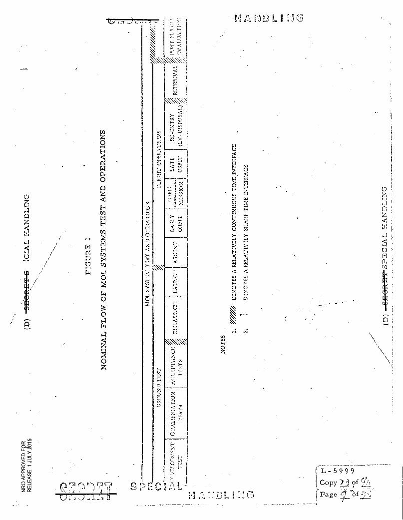
FIG
URE
1
NO
MIN
AL
FL
OW
OF
MO
L SY
ST
EMS
TE
ST
AN
D O
PE
RA
TIO
NS
- 5 9 9 9 of ,
Copy 73 of
Paae el of (;:' ! r)
. )
z ii
z
o
MO
L S
YS
TE
M
•g /1 l'•1 g M • 5 5',
• ::%.!S4 t; E
DE
NO
TE
S A
RE
LA
TIV
EL
Y S
HA
RP
TIM
E I
NT
ER
FA
CE
DE
NO
TE
S A
RE
LA
TIV
ELY
CO
NT
INU
OUS
TIM
E I
NT
ER
FAC
E
0 z
0
>
•
E"
• 0
z
0
V r t'i P •. Lr. {)
NRO APPROVED FOR RELEASE 1 JULY 2015
4. 0
TEST AND OPERATIONS REQUIREMENTS AND POLICY
The proper relationship of personnel safety, security, and program objectives
must be recognized during the design, planning, and conduct of MOL Ground
Testing and Flight Operations. No data will be collected nor tests conducted
for the sole purpose of incentive determination.
The general policies contained herein shall be expanded and amplified in both
the General Ground Test Plan (GGTP) and the Flight Test and Operations Plan
(FTOP). The GGTP shall be adhered to by all associate contractors and
supporting agencies in preparing their implementing plans and documents.
/ Additional guidance for preparation of the implementing plans and documents
/ will be provided in the FTOP.
The GGTP defines in-plant development, qualification, and acceptance testing
and launch operations at VAFB through FV liftoff, turnaround, and publication
of final test reports.
The FTOP defines the operations activities from flight crew ingress or FV
liftoff, as appropriate, through lab vehicle disposal. It shall include those
activities required to prepare the flight operations support systems (AFSCF)
and Operational Training and Evaluation Facility (OTEF) prior to launch.
In addition, the FTOP shall include the requirements for Launch Operations
support of the AFSCF and publication of final test reports. The VAFB Launch
Operations Requirement document includes the requirements for AFSCF
support of Launch Operations.
4. 1 Personnel Safety
Personnel safety shall be the prime consideration in all phases of planning,
design, test and operations.
rz E7a 7
Li L_. / _s -t
SPECIAL ,r) I
9 9
(.Copy Y3 of
f
g, r,4 r-- I:4 t "113
NRO APPROVED FOR RELEASE 1 JULY 2016
(TP) 4.2 Compliance with Program Requirements
The system test and operations program shall be planned and conducted to
verify System Performance/Design Requirements (SP/DR). To insure this,
all test and operations plans (excluding certain Development Plans) submitted`
in accordance with Contract Data Requirements List (CDRL) DD Forms 1423
will be approved• prior to use.
(TP) 4.3 Establishment of a Data Baseline
The planning, conduct and reporting of system level qualification, acceptance
and launch site tests shall produce test data that can be utilized for analysis
during systems level acceptance tests, launch site tests or flight. These data
will constitute a test data base which will be retrievable for use on a timely
basis, as required. The data base is intended for use by the contractors in
support of systems test and operations.
(TP) 4.4 Fidelity of Test
Where practical and significant, ground tests shall be conducted in a simulated
operational environment/configuration. Determination of practicality and
significance shall be made by the associate contractors or supporting govern-
ment agencies with MOL SO approval. While special test programs may be
used in the airborne computer for certain ground tests, verified airborne
computer programs shall nominally be used. To provide the necessary fidelity,
test command messages must be compatible with operational command
messages where hardware configuration permits.
4. 5 Flight Crew Participation
The flight crew shall participate in the system test and operations program
as specified in the hardware /software test and operations plans.
17,1 7Thl r371
L:1
C • 7.• P 7CT I-I A 'ND t,rNcr 1.1 r • ":"-"N
J
L - 5 9 9 9
Copy Y3 of "
Page J./ of
i;s4:2: L
NRO APPROVED FOR RELEASE 1 JULY 2015
(TP) 4.6 Failure Analysis and Corrective Action
To assure positive control over test and operations problems, failures,
potential failures, and their analyses and corrective action, a reporting
system shall be established in accordance with SAFSL 30002.
(TP) 4. 7 Test and Operations Plans
Test and operations plans shall have as their basic goal the verification that
program requirements are met. In building a test and operations program,
the building block concept of sequential testing in operational modes will
prevail. Each associate contractor shall define the tests and operations
required to satisfy program/contractual requirements. Post operations
evaluation must include recommendations that specifically address subsequent
FV undergoing test.
(TP) 4. 8 Test and Operations Criteria
The criteria used to evaluate test and operational performance shall be
based on the requirements in the CEI and/or other applicable specifications.
Parametric limits necessary for evaluating Qualification, Acceptance, Launch
Operations Testing and Flight Operations shall be established prior to use.
Development Tests are excluded from this policy except as specifically
identified to the associate contractors by the MOL SO.
(TP) 4. 9 Software Policy
During test and training activities prior to launch, both AVE flight support
and system support software will be used in conjunction with various test
vehicles and simulators. Verified computer programs under test must be
essentially identical with that anticipated for use during the operation.
In subsystems used for testing purposes (e. g. , AGE or simulators), special
software may be used to simulate interface reactions which are not actually
present during a test. The simulation must be essentially indistinguishable
from the actual interfacing system as viewed from the software subsystem
under test.
e 7 (73 17?
L- 5 9 9 9 Copy )/3 of t,,A
Page .,';`,1'.! 7of
. r.r-rt? V.T SPECIAL TrANDLING
3 C , 3,
r.
NRO APPROVED FOR RELEASE 1 JULY 2015
BYE-SL-0015-68 Page 2 SAFSL EXHIBIT 30020 Revised July 1968
4. 10 MOL System Readiness
MOL SO test and operations documentation shall define a system to provide
assurance of MOL System Readiness for flight.
Replaces Page 13
HANnLE VIA BYEMAN CONTROL SYSTEM 0-7g;Si
1 hr. L B E (41
NRO APPROVED FOR RELEASE 1 JULY 2015
5. 0
MANAGEMENT STRUCTURE
This section identifies the participating test and operations government
agencies and associate contractors and the respective roles and responsi-
. bilities within the MOL system test and operations program.
5. 1 MOL Director
The MOL Director is responsible for establishment, management, and con-
duct of all aspects of test and operations for the MOL Program.
5. 2 MOL Deputy Director
The MOL Deputy Director, the implementing agent of the MOL Director, is
responsible for the integrity of the overall system during all phases of test
and operations.
5.3 MOL Systems Office
The MOL Systems Office (MOL SO), under the direct control and supervision
of the Deputy Director, MOL, directs the test and operations of the overall
MOL system. This includes responsibility for contracting, acquisition of
test facilities, ground test, flight operations, personnel safety, and test and
operations analysis and reporting. MOL SO shall be interpreted to include
the Aerospace Corporation, where applicable, in fulfilling its role as General
Systems Engineering and Technical Direction (GSE/TD) contractor.
5.4 Aerospace Corporation
The Aerospace Corporation is the contractor responsible for providing GSE/TD
for the MOL SO for test and operations functions.
p . SPECIA I, I-TANDI,INC.3
L - 5 9 9 9
Copy Y. of °:°.,;'
ra,.... ge
NRO APPROVED FOR RELEASE 1 JULY 2015
(TP) ' 5. 5 Associate Contractors
Each associate contractor is responsible throughout the cycle of test and
operations for meeting performance allocations, safety, effectiveness, and
specifications applicable to the associate contractor's hardware. When the
hardware/software delivered by one associate contractor is absorbed in an
assembly to be delivered by another associate, the assembly, host, and/or
integrating contractor herein referred to as the integrating contractor has
the responsibility to ensure that overall test and operations allocations and
integrated test requirements have been fulfilled, and that agreement has
been reached with the delivering associate contractor(s) on all test and
operations requirements, plans, and procedures which will be established
against or performed at the assembled level.
The associate contractor delivering hardware/software to be absorbed in a
higher level assembly is responsible for negotiating with the, integrating
contractor appropriate test and operations requirements, plans, and
procedures. Each associate contractor is also responsible for negotiating
test and operational interfaces relating to his hardware/software with all
affected associate contractors.
System level test and operations analyses are required to ensure that
operational and performance requirements are met. Each associate contractor,
is responsible for detailed analyses appropriate to the software and equip-
ments being delivered by that associate contractor. Additionally, participation
in related higher level system studies will be required.
0 7 r2,73
L - 5 9 9 9
Copy1'33 of
Page/ of ,!,e;. T:T „SPECIAL HANDLING
r." 7- 17Thti rir7,! a
L C5 NRO APPROVED FOR RELEASE 1 JULY 2015
Areas of associate test and operations responsibilities are:
a. Hamilton Standard, Division of United Aircraft Corporation -
Hamilton Standard (HS) is the associate contractor for the pressure
suite assembly (PSA) system segment.
b. Whirlpool Corporation - Whirlpool is responsible for providing
the MOL feeding system segment for all MOL manned flights.
c. TRW Systems (TRW) - TRW will provide STC computer programs
for mission planning and evaluations, and for monitoring and
controlling ascent and reentry operations.
d. McDonnell Astronautics Coproration (MAC) - MAC is the
associate contractor for the Gemini B system segment.
e. Eastman Kodak Company (EK) - EK is the associate contractor
for the photographic system segment.
f. General Electric Company (GE) - GE is the associate contractor
for the MM system segment.
g. AC Electronics Division (ACED) - ACED is the associate con-
tractor for the booster inertial guidance system (BIGS) segment.
h. Aerojet-General Corporation (AGC) - AGC is the associate con-
tractor for the booster liquid rocket engine system segment.
United Technology Corporation (UTC) - UTC is the associate con-
tractor for the booster solid rocket motor system segment.
j. Douglas Aircraft Company (DAC) - DAC is the associate contractor
for the laboratory vehicle system segment.
k. Martin Marietta Corporation (IvIMC) - MMC is the associate con-
tractor for the Titan HIM system segment.
*-3 1-7) rTh r-3
L - 5 9 9 9
Copy) 3 of IL
Pagefi, of
C,3
I
t
NRO APPROVED FOR RELEASE 1 JULY 2015
(TP) At a given site, integrating associate contractor responsibility for the
collation, analysis, optimization and/or publication, as necessary, of the
plans and procedures for integrated development, qualification, and accep-
tance testing, and for the integrated conduct of test (i. e. , "Test Direction"),
.for the integrated hardware level is indicated below under integration con-
tractor. In addition to launc.h operations functions performed by associate
contractors and integrating associate contractors at VAFB, separate support
services to the MOL SO/6595th ATW are required and are specified below
under Support Contractor (Reference SAFSL Exhibit 20023).
Site Integrating Contractor Support Contractor
VF GE
Roch EK
HB MDC (LM/LV), GE (MM)
St. L. MDC
Denver MMC
VAFB MMC (T-IIIM), MDC (OV), GE (MM) MMC (FV), MDC (OV & MS)
5. 6 SAMSO Plans and Operations Office, Communications, and Electronics Division
This agency is responsible for acquisition and installation of the MOL ground
communications system at VAFB in accordance with the requirements of the
. MOL SO. This agency will direct the communication planning contractor in
preparation of the Communication Plan and control the contract for the
communications installation contractor during installation of the communications
equipment.
5. 7 6595th Aerospace Test Wing (ATW)
The 6595th ATW Manned Systems Division (VWM) is responsible for Launch
Operations at VAFB. The ATW, as a direct arm of the MOL SO, is responsible
for the direction, management, conduct and control of MOL Program activities
at VAFB. The ATW interfaces with and ensures AFWTR support.
ra n r-7; ,
4
r-.7) r: r• • I . NCr
,-- L - 5 9 9 9
Copy/3 of Pa ge j"-)
(,) L X„. Li
„ S k"1,7A i '13 LING NRO APPROVED FOR RELEASE 1 JULY 2015
'5.8 SAMSO Deputy Commander, for Satellite Control Operations, AFSCF
This agency is responsible for developing and providing those resources at the
Satellite Test Center (STC) and the AFSCF Global Tracking and Communication
•Networks as necessary to support MOL operations during flight preparation
and through all flight phases as defined in the Orbital Requirements Document
(ORD), This includes the processing and control of data necessary for support
of the flight; the engineering design of telemetry and tracking station equipment,
control consoles, AFSCF system support software, integration of all teleme-
tered data formatting requirements and procedures, and interfacing with AFWTR
and VAFB activities.
5. 9 Air Force Western Test Range (AFWTR)
AFWTR, the lead range for MOL, is responsible for ensuring support of all
launch operations requirements as defined in the Program Requirements
Document (PRD). This includes support from other ranges and government
agencies external to the AFWTR. (Data acquisition during ascent for range
safety decisions will be an AFWTR responsibility). AFWTR will provide
support as appropriate to AFSCF for mission control at the STC.
5.10 DOD Manager for Manned Space Flight Support (DDMS)
DDMS will provide and control the recovery forces necessary to effect
" retrieval of the flight crew, spacecraft and data in the areas specified in the
Manned Recovery Requirements Document and the spacecraft as specified in
the Gemini B Recovery Requirements Document.
5.11 Air Weather Service (AWS) (Military Airlift Command)
AWS is responsible for natural aerospace environment support and services
to the MOL Program.
5,12 Aerospace Medical Division (AMD) (AFSC)
AMD is responsible for providing bioastronautics research, development, test
and operations support to the MOL Program.
r,) 7'1 c73
FJ 3 :1 ,± it
r-3 ':rap CP T CTA .T\ r') !NG
L - 5 9 9 9
Copy) of
Page
S P r C'S P I., IA ,ING
•
L - 5 9 9 9
Copy) ?.) of (1.4')
Page/ I-Of:7V; • `.; 3
f r:Z3 ^fj, • d
'''71 AL' I; A r L t G NRO APPROVED FOR RELEASE 1 JULY 2015
.(13) 6. 0
TEST AND OPERATIONS DOCUMENTATION
'6. 1 General
This section summarizes, for planning purposes, the MOL test and operations
documentation. It does not supersede the requirements of the CDRL. Document
format, content, scheduled submittals, revision requirements, and governmental
approval requirements are governed by the CDRL DD Form 1423 and AFSC
Form 9 (or equivalent) where applicable for each associate contractor. This
section establishes a common basis of reference for:
a. Document Titles and Terminology
b. Documentation Relationships
c. General Scope
d. Input and Integrate Responsibilities
6. 2 Top Documentation
6. 2. 1 System Test and Operations Plan (STOP)
The STOP establishes planning and standardization requirements applicable to
both Ground Test and Flight Test and Operations. It identifies roles and
responsibilities of agencies and contractors involved in MOL test and operations
activities.
6.2. 1. 1 General Ground Test Plan (GGTP)
The GGTP provides a summary of all elements of testing to be conducted
during the development, qualification, acceptance, and launch operations test
programs for which each associate contractor and operating agency is respon-
sible. General requirements, boundaries, and guidelines for the tests to be
performed from start of initial factory development testing through integrated
MOL system level testing and launch are established.
a v„)
...zr i .1 n NRO APPROVED FOR RELEASE 1 JULY 2015
6. 2. 1. 2 Flight Test and Operations Plan' (FTOP)
The FTOP provides guidance to all contractors and government agencies
participating in MO I, flight operations. It represents the MOL baseline for
flight test and operations and is the basis for developing the details of sub-
ordinate documentation. The FTOP also provides program management with
an overview of the operational concepts and philosophies to be employed in
the Operations associated with the flight tests.
The FTOP covers the flight from insertion of the flight crew in the FV or FV
liftoff, as appropriate, and on through publication of final test reports. It
also covers planning and training necessary to accomplish the above.
6. 3 Documentation Tree and Table
A schematic presentation of the top and working level test and operations
oriented documents is provided in Figure 2.
-The functional grouping of test and operations documents in Table 1 is as
follows:
I Top Level Planning Documents
II Ground Test Documents
III Flight Test and Operations Documents
IV Test and Operations Requirements Documents and Support Plans
V Evaluation Documents
The documents, the agency, and contractor responsibilities for inputs to/or
providing the documents, and the responsibilities for integration and pub-
lication of the documents are described.
1
Copy
L - 5 9 9 9
Copy 1".-3 of !f•+> ---- ", , --""
Page,,? -) of , - ,.,
J, 1(-) • ,
L. 7 3 L11 j
( L-1 1 )17 C: IA T. rr.% :\:1-)Tr C 1 IN r 1,1
rat 1.-i g
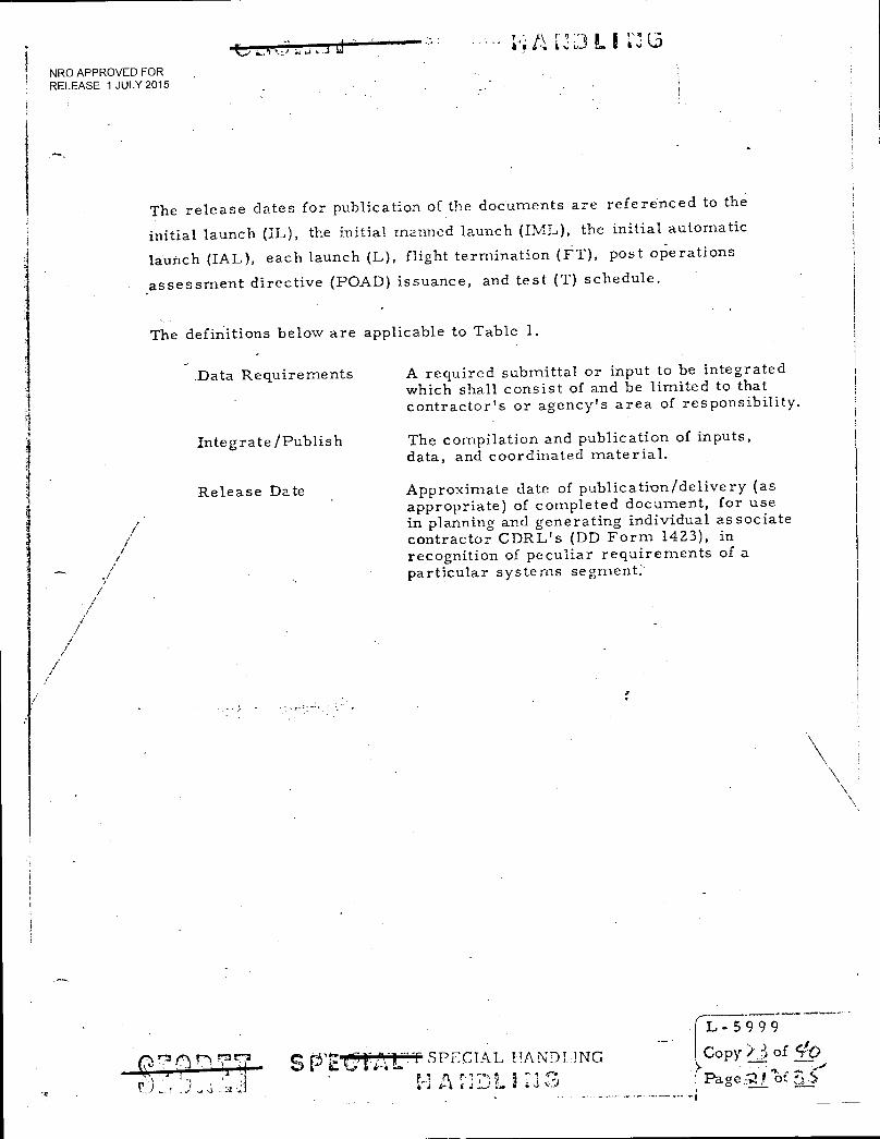
■ t.) a; LI
NRO APPROVED FOR RELEASE 1 JULY 2015
The release dates for publication of the documents are referenced to the
initial launch (IL), the initial manned launch (IML), the initial automatic
launch (IAL), each launch (L), flight termination (FT), post operations
assessment directive (POAD) issuance, and test (T) schedule.
The definitions below are applicable to Table 1.
Data Requirements
Integrate /Publish
Release Date
A required submittal or input to be integrated which shall consist of and be limited to that contractor's or agency's area of responsibility.
The compilation and publication of inputs, data, and coordinated material.
Approximate date of publication/delivery (as appropriate) of completed document, for use in planning and generating individual associate contractor CDRL's (DD Form 1423), in recognition of peculiar requirements of a particular systems segment.
r
s T SPECIAL 1-1ANDTING
4P-.1 .:.‘" I •(;7701
L - 5 9 9 9
Copy 3 of Sec>
Page.;? of ,

• NRO APPROVED FOR CONTROL Lop .
RELEASE 1 JULY 2015
- • .
Control lIalber W I-I S - 809
. Copy Numc.er 1 thru 6 . •
Name of Courier • .
J. F. Chalmers .
Source . •-
J.- F. Chalmers .AddresSee - -
. ,
Distribution - . .
Description, Date, Subject, cy number, number of pages, any other identifying
control number MOL Orbiting Vehicle Power Utilizaton Control SAFSL EXHIBIT 30001
. dated 2 April 1968, 19 pages -
• Attachment's
- • .
Remarks . .
This document same as L- .6,-? 771
c, i.- Receipt Signature Date Invctntory Date I l_Ds,Dos:_tion
1 ,---\ (_._ N CIL,V,.....7,c_9_,__.0
- / 511 76 • J. F. Chalmers
2 ti
D. R. Howard
3 W. F. Sampson S. M. Tennant/ S. S. Strong 4
5 .
_ [
B. A. Hohmann
6 -
---
B. Moss
. .
- .
_ . .
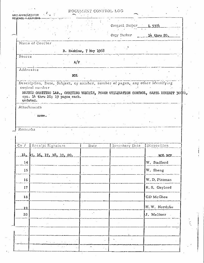
R
DocumL-NT. CONTROL. LOG NRO APPROVED FOR '-
:Lb--1 dttL-1--Z 77-- -- - . .
• . - • . ' •
• . Con :::01 liumber . 1_53711
- _
• Copy Nun'oe.r ]A thru 20. •
Name c,f Couier • - . . . B. Haskins, 7 May 1968 -
Source . . •
• A/F :•.
. ...... 1,-3clrestee - -
MOL . . . .
Description, Date, Subject, cy number, number of pages, any other identifying control number
MANNED ORBITING IAB., ORBITING VEHICLE, POET UTILIZATION COBTROL, SAFSL EXHIBIT 30S cys. 124- thru 20; 19 pages each. undated. . .
Attac .
hment:F. - -
none. . . .
• . . .
Inventory nate I)isDosition
20. _ __MOLBCF
14 . • . W. Stafford
15 .
. - W. Sheng
1 16 • -
-- - — --- W. D. Pittman
17 .. RS. Gaylord
18 GD McGhee
.
— H. W, Nordylce
20 . J. Meltzer
. . •
- I •
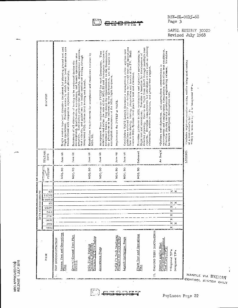
BYE-SL-0015-68 Page 3
SAFSL EXIII.BIT 30020 Revised July 168
Cb
E A 13
o„, E a 0o a y
.c 0 4.
8.̂2. 0
ro
ro
0 • 0 tr'
0
Imp
lem
en
ts t
he F
VT
RP
at
VA
FB
.
50
'0
sti
ng
an
d/o
r
P. ,`
0
7.a U)
0.)
0.
TO
P D
OC
UM
EN
TA
TIO
N
0
GI AI
0
..4
U
"t
Ga
r
0
O
ora
t ions
Re
Lan
ce P
lan
s
04
0
r3 . a
CI
- !Oa& G-MarlitaiGTO•716...12 112-Grai• •
< .0°3 frn..0' co co co o• co:
004 G 1:4 .-1
0
ac" ti
H141
0 0 0 0 0 0 0 u.) cn
r.0 0 0 0 0
a a 4 a 0 0
4d
•u G -• u
.0
C •
> fs,
TD-
o m
o
,,0> 0
E 0
0 0.
ti ft 2
02- - 0
V7 N
X X
X X Y.
Y,
X X X
-1.1LOtOMOIr=O1.7=COO■261,J,'-̀"
0.3
far,74 F,= +7,7: F-7,1 FrMrx sr-7m
HANDLE VIA BYEPrLAN
CONTROL SYSTEM ONLY
Replac Pese 22
-;-
ro
` ,,S
eg
ment
TP
's
Inte
grate
d T
P's
..-suetoi
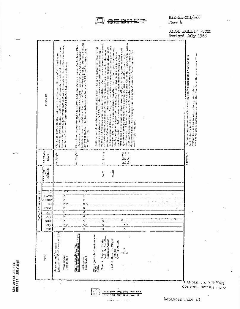
! ec,
`. - a. D. 0 r
N oc
57c15,-ta o ", CZ 5 ",s'
0.'1 00 ad o d • • U 00 o *
SYN
OPS
IS
HAZ,ZE..-)LE' VIA ,r-..-1YE MA NT CONTROL SY:2111:4 0 LY
ADOCIPID7-
tl (7.- •;-., rf r7.-1 vr:3 kloact5
BYE—SL-0015-68 Page 4
SAFSL EXHIBIT 30020 Revised July 1968
.0 T. .. E ?rE' .0.) . ,..., N N .1,s,, 0: N ...., „
.-'1 g ■ I
o
0 oo
GO IC;
co
13 0
731:1
0 DI
0
'o P`
CO y«
Ut N
G t.
5 co 5N 5 u
g-• 5 ta • 4) Ea (11
-.4 N 0 V V
U.0 CD '0 c,
(f21
0 LI1
E.-. .. >Ea kx x-2---- 'r.; I s mill x x
-̀ .-: F -111111.N1 X X
a0 X X X X C • aElov I X
0.01 X x DO V
DIIIV D X X X X
X X
3V1 >4
0 a,
`S ,1
.5. ̀C' .--,..1 7d S
>1. 41 46 :14 li ., -.
C
0
■.* t; ,,, :'' iT' E-. an 0 , .... CV:
R. U_ 5,!g,,
'9.1)., rt.. ,,',,' r...
E 4 !!,' :4' CL ,—. :4
0 }_1 o Z,9 *-_, LLI D an J .i1.3) > —) 0 ct a. LLE 0_ 0) ¢ w 0 ..i X W Z rt
Replaces Page 23
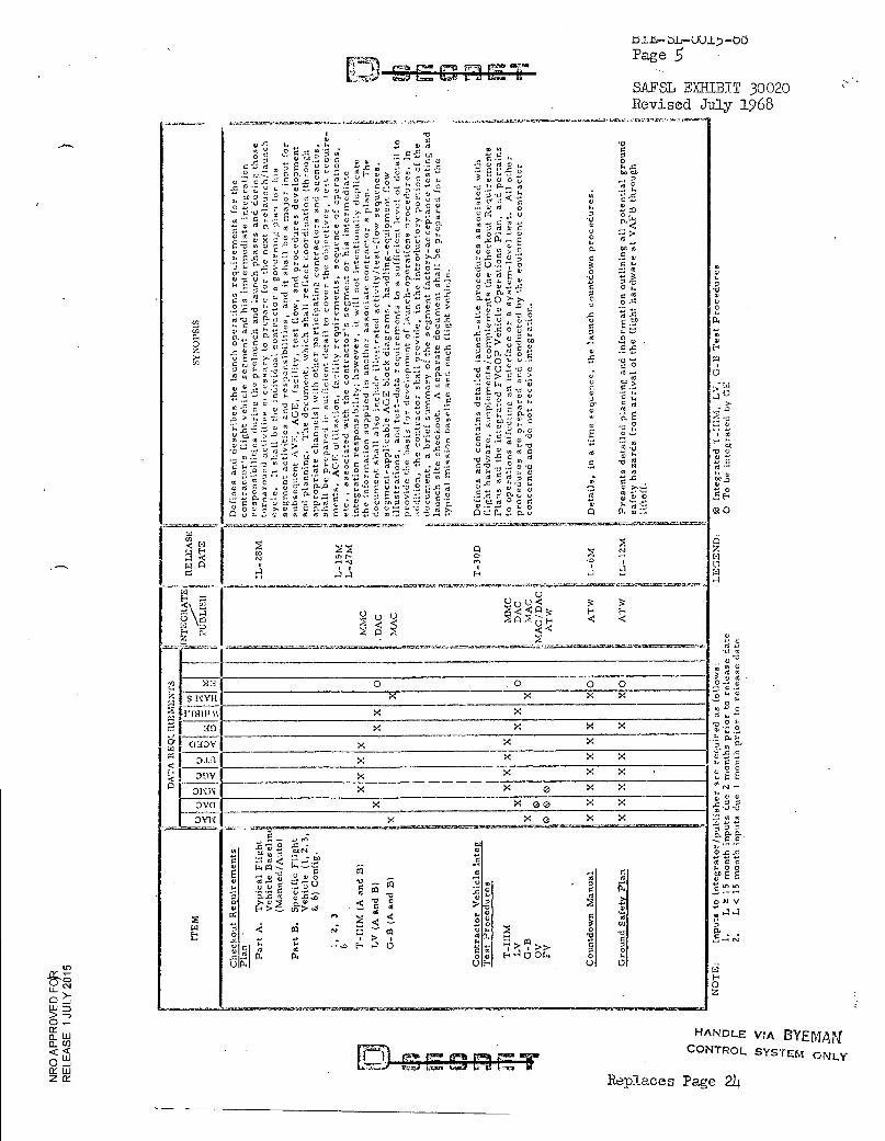
0
CO
Efal ..n. r • bL-UU1)-00
Page 5
SAFSL EXHIBIT 30020 Revised July 1968
C
C 2-0.2 E ,7.AT <, g
.0 0
, 4' 0
..-0 0 A 0 k k .z - 1.: -E 2 00 00
G., V 0 0 .■4 g .
`',...,T .k'4 .̀ ...-,,
.a ,, 6 ,: ,S 4'0'' 4. . . ._ 0-0 N. t „-„, t .. C,. g 2-.. P. ..,.., t . 0.-T.lEt.00'...-_-,.. ' E 0 2,-54 ,°., g °.' I; ~>
n :4' 0 I Z', ..k• '-L 0 4T - Y c - c') 5.: ,; (9- , ..■' '' ■.) u
Na' A.
"cc :':, 00 01 •-• ;g m 0 - -b . 0 r -̀d' -`-, 51.'''...-1, o'- '00 0 O 0 0 c E :1 g 0 ,. P° ..Z. , t,', L. .2 :;:' 6 >,... F k
!'. n ..;-, .9. 0 .0 E .2. ,, ,, ,,, , ..a' 0 k , ..-. 0 -F.:: ,; ,.. " ... o c; .2 -' u g .c -•1 8 71. ''-'1', ,c',..' ' ° .-. O --' ..L1 g 0 t°,- 7,:' c;
0 T.
T01-,i' ' -.2 .2 .. '' ,w. g :4 4: I i t -' u„ '.,i .2[-„' ..,11, ..z;
,.., 0 [1..."' C'd
Y 0 .E 'l `',!..il g ;)°. „,,`'.t.i.l.,x2t-t':, ... „
0.. ,, 0 ::- ,..,>- o -c
.r.o -.-- T ,,,," ...,.., 0.. g 7:,, p . 0 9 .0 . i ' 0. , , E. . .,. . ' g° . .5 c$: § ; 0 0 0 .-- 0
'"0" E -. ' T., 49; rd -c
7 d r,' 2 rel : l' '"'' 2 ''al ''' "1 ?3, il: ■,' :22 -:1 , '-' 4
6.' 4 z: 0 .4 7-,,-6 2' 18 C: , t.,,.,' E f ..> 0 .: `-', g E > t -5,.. ..,` °
O ,..
: i : Z : ›- - ; ' '3. :- ';' ; :- . . ,tr 1 . :'' ''' ::: 0:2 i '8 : '-1 E . 'i i 7 : 2 -1:°• • :q
. - - .'' S..' Or 1 '1" 6v - 6 7'8 02..-,E. , u,, O 5 -2
--,... 0 1-:. -,a. 0 .?.,:u o .c., 0 ,., 6 -6 -7 ,t,' A
-0 r. 0 «. .7 7
0 'a' > 5, g › Z ; "2 . '0". ''.: r- 0 0 ,., ...1 0 ..-- 48 . . ,, .... 0 4. 0 0 E 0 y v .. ... Y. ,,,,..: 7.. •-■ , w", :.), ..: , 0 x .i.., ...^.: ... < . ,.. . g .: ,,,,,
o :L'..c,_, „ I,. z - ,.; .,, ,..,,... 0 ,., E . .0,0it ,,,, ,L ,.,,-, 8 "- ''' E --: ...,-, 0 -0 ,. E < , '0' 0, T. d `-' `,".
F 4
0 V.1
m c.3 C „... ? 0 0 , T ., ..::: ■-• • ;.. g.: 0 0 .12 ,P :..', .... 5 7 to '6 E c d. 5 > :i.: 0 -.:-.: 0 ..,; - 2 i' c c .02 78 ,,,, ,.,, v .. ...a rj "' '; ,..7 p, 0 '7 '8 ,, ...8 -,,.. . 8 _ .- g -t ...1.„ - . ..., ., g .r -Fx > --' -;, r4 I-'
. x .2 ..0 0 ....
,, - ... Q ,., u id ,- 0 0 2 ,, > u 0 ...-4 0 ... ... < ',., 0 -,'(-'1 'E,' ," l'', 'g 04 o -.2 o "..' -o ,,,
o. 5 ..c '' 0 -0 > .... , 0 m A g 0' e;: 'E '-'- " '8' a ,'i s'-..̀‹) 2 .8 -0'1 2,2 ̀0' '' x .
2 o .. ' '.'t' 1-4 .2 v 5 I." -g g '-' x -, 'C'i 1 ;LI .g '' 0> ?;•,.. . . 8 ,„.-, ,E 8%-.. g.1! _:1F g -. "--: g , - , .`g.'0 ,': 8* ̀0' :',.: 7; ',.-.., .2 , ,.,' 7.. g 6 0 „ u t.,, 0 o -:., u 0 5• .. ,,,, ..-■ 2 i-,-. 2 'cl. 8 c`2,' 8 y« ,>)' g g g g-g E t .5-E -2 g 2 a.-- ,`I r.:
A co o NI
10 t•-- N el •-■ N
.-1.-1 I) H
U
4̀ o 0 q ¢ <
A A 7.i. <,) _4E.
,y) >12 0 0 O 0
S 11V/I
111111111
30 X
G33 F: D J.1
Dov DNI‘i
DVCI X
OVN X X e
O
O z
HANDLE VIA BYEMAN CONTROL SYSTEM ONLY
Replaces Page 21.E
0
'id' i.. -0 A)
Q C)
K ‘'d'
0 -,-., .42.
>4 >< >< 7,' ;.. 0 .., 0 0. X 0 .-, 0
C
.r. sO X X X ' '.
'S 2 x x ..t., 0, E- E--- . 0 X x x cf ... .
,1 '' .. X >4 >4 o o E
X e x X ,,, 0., ._, t00
. .
.. ....... .ssar-J. -.,... = 7̂00S20-.000. 0 .0 - s . ---. r. rt '
7' 7 t'" 0
--- ....,
0 A .7 N .
r.. .---' Z... ..4 F4 cl ::,, -
0 .. w oo "
...! r,
0
0
tjp E 5 0 FC,I TV).
V ,_, ...
4 Lr■ ,r,
m>..i 0.. 5. 1 e > z ..,,,
0
0 Ai V
.4 t. ,,,,, 0
V : .4 -I ..,
Di ..; V. .--.0 E.-■ ...1
v.. D. .
0 [--. a o w 1-■ 4 0 or. o
uir
em
ents
v... I. F
2 4 -̀o'fq, ;J. g 17;
G
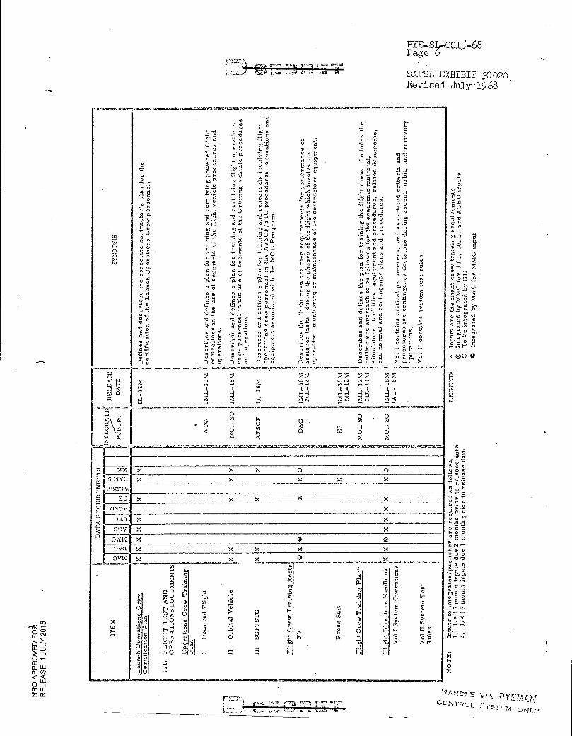
toe m 5. CI u W
U NC
toO c K 0 g.
`4 .5
- la
• A
u o U „2 cu p C
fo>' .s.b .0 — O
CD .0 0
4YP 0 "
* 00
U
BYE-314-0015-68 Page 6
SAFSL EXHIBIT 30020 Revised July.1968
0 7.
MN
,
SYN
OP
SIS
-
-
,
1
i '.
.IL
-12M
, I'. , D
efi
nes
an
d d
esc
ribes
t he
ass
oc
iate
co
ntr
ac
tor's
pla
n f
or
the
11 c
ert
ific
atio
n o
f t h
e L
aunc
h O
pera
tions
Cre
w p
ers
onnel.
fi' 4,, li P.
.
1
1 A
TC
. I
ML
-3
0M
Descr
ibes
and
de
fin
es
a p
lan
fo
r tr
ain
ing a
nd
cert
ify
ing p
ow
ere
d f
lig
ht
1 i c
ontr
oll
ers
in
th
e u
se o
f se
gm
ents
of
the
flig
ht
ve
hic
le p
roc
edure
s an
d 1r .,
t 1 o
pera
tions.
i ij M
OL
SO
IM
L-
15M
11 D
esc
rib
s a
nd
de
fin
es
a p
lan
fo
r tr
ain
ing
an
d c
ert
ify
ing
fli
gh
t op
era
tions
,, 1 c
rew
pers
onn
el
in t
he
use
of seg
men
ts o
f t h
e O
rbit
ing V
ehic
le p
roc
edure
s
1 an
d o
pera
t io
ns.
11
a
1
, A
FS
CF
1 IL
-15M
t D
esc
rib
es
and
de
fin
es a p
lan
fo
r tr
ain
ing a
nd
reh
ears
als
invo
lvin
g f
lig
ht
II op
era
tio
ns
cre
w p
ers
onn
el in
th
e A
FS
CF
/ST
C p
roce
du
res,
op
era
tio
ns
an
d
1
1 eq
uip
men
t ass
oc
iate
d w
ith t
he M
OL
Pro
gra
m.
l
LI !
4 I
ir
e D
AC
P., IM
L-
36m
. ', D
esc
rib
es
t he
flig
ht cre
w t
rain
ing r
equir
em
en
ts fo
r p
erfo
rman
ce
of
t M
L-
12M
I a
ss
ign
ed t
ask
s,
du
ring t
he
ph
as
es o
f th
e fl
igh
t w
hic
h i
nv
olv
e th
e 11
opera
tio
n, m
on
ito
ring o
r m
ain
ten
anc
e o
f th
e c
ontr
acto
rs e
qu
ipm
ent.
,
1
HS
IM
L-
36
M 1
M
L-
12M
11
t . , M
OL
SO
1
IML
-3
5M
1 Desc
rib
es
and de
fines
the
pla
n f
or
tra
inin
g t
he
flig
ht
cre
w.
Inclu
des th
e M
L-
11M
5 o
utl
ine
an
d a
pp
roach
to
he f
oll
ow
ed fo
r th
e aca
dem
ic m
ate
rial,
I! s
imu
lato
rs,
fac
ilit
ies,
eq
uip
men
t an
d p
roce
du
res,
re
late
d d
ocu
ments
,
MO
L S
O
ti im
L_
.1.8
m ii; a
nd
no
rmal
an
d c
on
t ing
ency
pla
ns
an
d p
roce
dure
s.
IAL
- 8
M i: , Vol I c
on
tain
s c
riti
cal
para
mete
rs, an
d a
sso
cia
ted
crit
eri
a an
d
iip
r c
o e
dure
s fo
r co
nti
ng
ency
decis
ion
s d
urin
g a
sc
ent,
orb
it, an
d re
cov
ery
,
.1 :,
i o
pera
tions.
ii ii V
ol II
co
nta
ins
sy
stem
tes
t ru
les.
P 111
it h
li
.;,
to
,11 t.)
U
:::
5 :7-1
„, ,,
1
; < <
,
0
_,
C.) 41
: ". : <
.1
. ;
= .
C:
■ I 1
7 -1
< ; .
-: , • - r .
( :,
i : .̀ ;
4 1 ,
; --.
-- -
x X X o 0 x x x x
x x x x x . x
X >e. X x x o
x x x x . : x x -----
t . 0 . .2 (1 . & oh X V
7 0
,-1
- m F.
z .F.,
W 5 '0
Q "
Z 0 H
0 3
CI Q
P 0, .
m .7. u g 41 0 — E- — ''
(-. H 2
d ' c , 2 0 t,1 2
'-,_i N
.?. W 0 0 ....
4. 0 U .
. a .. 0 .. co H u ..4 H .c (.4 o T,
f-■ 3 . .., w . a ■
o . 0 0 1 ri. o m ."0" 1
.4
Cl. . . - ..
... 1
.., N
W H
a 3 Q
m . > . 0
a .4E' ....
174
.
X 0 0 -5
N
o "' 6
:A W
o V
n . — t4,
0 F & o
E E o I; ;1.
- :::: ,t, 8 8 8 > > 14
W F
.
c0 •0
0 V
o g *0'
• „ „ 14
2 ▪ •-• ;c„.E
c. C.,
0,
O
•
K 0 N 0 0
4 E O N
.2 ,o °3
- E. 0 t.„, 0 0 • 0 0 c 55
AI V
ol a 4
11..7.,01 /77a e e:k •
HAN L t7. WA ;Z.1 Y574t1
CONTROL. 1.5T,171 1-jr
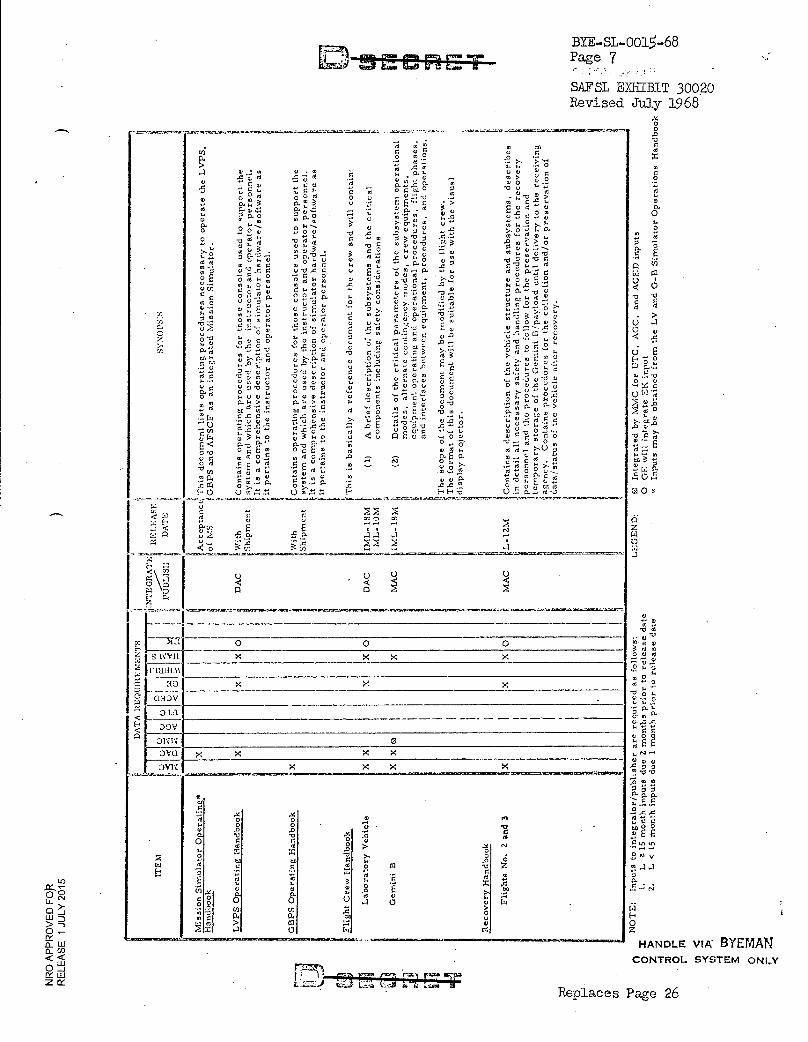
reco
ver
y.
Fli
g hts
No.
2
and 3
Rec
overy
Han
dboo
k
ME-CREZT BYE—SL-0015-68 Page 7
SAFSL EXHIBIT 30020 Revised July 1968
SYN
OPS
IS
This
is
bas
ical
ly a
re
fere
nce
docu
me
nt f
or
the
cre
w a
nd
wil
l co
nta
in:
< <
cn G. > a ..._.1. 4, . ., 4, -V ,' : .2, --o. '3 -2
t.E‘',; „., r, ,., 0.,0 0 , P. 1.. P. °
0 0. t. ....1 ,'' P.• 0 g , 2 . p. .....2. 0 2 2 4, o I'' --- ..of.,
o ..o 4,1 ',;' ... . ''' 'U '31 . v ' 3 aq ; ''...0 --1 ',", -.4 z S-F. -.. .0-„, ...! 0,..0 ,,,,,,-, .....00 ..-0x0
• t). P2 ,,. 1,, ''' t. ..II a.
2. t 5 P. 0 V°,.. M 0 C .m ° E E O' 05E0
I'0, o . m td O" 0 d
C). ..• .5 ,6 t .5 ., .-. "E. o v
,'"°
I. o 0 g. t 0 0 g' ,.5 ,.....5o
p...,.' :-._ .,;:i4 p ...0 .,; 7.' 'a' .f, t; g .',3; 48 .', '0' .... 0 0 p -0 0 5, p -0 p a. ,., 0 .00 At . 001'..
;,,, p.. ,... a co p. ,, > a, to'''i,,',2 w r".1...
:".“,4 .0 X 0 4, .5,04, ,'' 11 2 ' :a' 0 2 q ti 3 ,-, 0 't.5 M 0
E P- — 0 E . 8"Tg': 5o . a o 0 . a 0 .2. oz
o a c .8
M .gd'S-: fgrdil
11. ',O r. P. V, 4̀ ,, .
H (_, U n U y ;Ll
7d 7 al
i .> :' ..c
to CO 0
U U > 0
"G‘'
- ') 0 0 EVd
52 52 `" O
..5.. .2 0 5 r. -2 5 3 ''S 5 ..p'.
-0 c, :,'', ',-3T,, 'c A0
CI o
1 O virli ''''' -2 4,
17y>"
00'00 "O' g 'a7 -°
-o..2-."
>0,2
00 . 7,i u.o
22' M.-9-' 7:45 "5 '.111
" -' .1' & 0 c0; c : 5
2 2 ra..F, ni-,i 4, ° 74 O u ' "°:=1
H -..̀ 2," .2 .. m3 '17: 2 1:-O '' E .4
;°.4. 000. u m ■. 4
5, Y, . 2 4'..; gl' E
.,1,' :r, '-'74 ''''''
... 5 o . s,-; eo,.2,
0 .r.n.. ; 5 •a' -o u, . 7.: °- 'g '.r--.. :V8 .0 E .,- ,"85 -0 .0.--. ...
.<?, E 2' g ,...00 o t., E., wms.
;--4 0 E 0.
17'
oo v..:.._,
.5..5.!..., P H -c,
U , V :■44 •O "Z. E . g .r. ,uu a..... :,.. . 4:: . 5
CC 0 a3
2- 02 0. u„'.2 ›.
p
0 0 0
0:13V 0 LA DOH OWN 0 0V(.1 DV1V. X
7.771•1:7171.1
X
X
o al2
2 1 U
00 42
0
2
000
o 8
Han
dboo
k
GB
PS
Op e
rati
ng H
and
book
Fli
g ht C
rew
Han
dboo
k
0
p.
.3.•412■5011•11•11.,Vi.1.111.1.1ip......
O O .0
ro
9, P.C.,
0
0
0. "0.
0 (.) !
a 0 .
E 3
' o 17?: cr, .0 4,
bob
r4 2, 0 2.
zz
0 d, Vd
0 1' 7_ .- MCD
0 a d
00 '
' 0
.
0 0 0
E E
." v. 4, .0 55
"§".45̀?' g 04 a. a.
2 t4 00 aN U1
2 Ai V
00 00 P. 4
0 z HANDLE VIA- BYEMAN CONTROL SYSTEM ONLY
Replaces Page 26
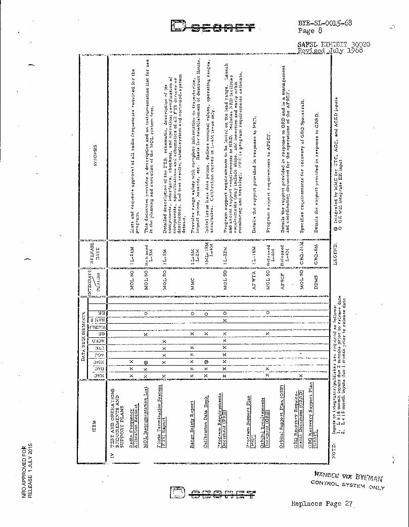
5 0.
• a
0 0 0 0H
O. .2
wx o r W
fs, u •-• •r, to 3
2 (4 o
00
z
0 C=1
r.4 H0 z
BYE-SL-0015-68 Page 8
SAPS'. EXHIBIT 30020 7u1y 1968
4ii 4
1
li RE
LEA
SE'!
SYNO
PSIS
DA
TE r,
4
o co c; ; V. o .0 ..)
g . 0) t.t .g r u
... t. C;
E -
o 1 r, E I., . '8 "o' .; a HO 0 ,, ,... .., E , ._, ,„ 0 . .Iu ,. E - - -0 0 ,,,..,., 2 o ,... ._, t; .,,,,, .5 :. -0 -.-, I a) o. .5: 48 .:.'s 9 . t.' .t' 1,1 Y:.,48`) g c.; 0 1:1 !-., c .... P. 0 T. ut ,, _.„ „ A 0
UV- 0 0 cn
0 ri to ?, 't",: . -a 'id' g ,.. a) .... A . .' 0 . '7 4., E ¢ E -a P. o r, E o ,i, ;., ,.?, - ., o - o 0
.0 c o 0 !.4 eF - . ,,,, - . :1,' ... A .5 :'.', 6 . - ,;', -.-- c ;;;' g -5 .o 4 5 •
2 E u .9, 0 '2 0 .,°•.' > . ..., , , p 2 n c4 ,̀5 4 g 3 T %- 4 71 1-11‘ '-' 0 ° U 2 ° t.f) 0- 0 . ,A „ 0 c .,., ,-. P- 0 ., 0 C. of T j Q E g '1 - ." '0 - 1; E o o a
. 2 0 co 2 ..t.' .0 " Z. 0. , ; , ■ Z ,-. 0 ,
j .2
,.., 0 , >, .5 0 0) ... '5 0 E 'U 6 >. 0 0 6' .!-/ g t4 En 0 1.., 44
'V g V 0 2 0 -- .... . , ., o O v o 0 0 o •-• -c 0 a ..... 0 „, V .-1 0) 4 0 '0., ° /''. 0 0, a
0. .4 0. 0 O. t. ... . 0 . ., .., .0. ;,,, . A , 3 A ,,.., 4 . . •-• It .1-1 4 U ° 01 0 0 0) o 0 --. ' 0 . -5 -8, m T.. ' -P.; o ,; - ,... 4-. In >
0 H '''.„„ tii 'V ° E" P° '', ot 40' .0.N 0 ° ()
0o a, - 1--, u 0 • - o - > '5. u 4 a • . .. .4 . F. ' '8 o , ,,A, c,.,1 t., ,,,) ''' .P. v ,; *; '. oEm- 'a o 13 ,-. .-• -c,
;°. ,.„'" :-.- o 73 7 4,-; . E. Q .1 E .-0 t, t., 4,11 *5 8 ° `f "3 : - °. -5 -
0. ,i, ,,; t..0 .1 ?,..,, te 5 0 E o o 0. -0 x 0 u 0 -.-. -;"P., -5 f; g' ' -E. :-.•
H 4 5 ° 0 tt •••• ''' 0 , el c, 0 1.• u O. 0.' d.,g ' DA'
0 '0 °M... t' '..-. 4, ... $4 .4J >4 , t In t.,,?, E t .., .-. 0 - . ' 4 it o ..- -,., 6 '-• 0 . 0 Z3 CL 4 11. '' RI 4 '-' 6' '6 a u),.. ?. 0. 0 t. ,..z .... ✓. ,,, t, ,,,u , .---,, -g o, o, ..; -5
0 ,°•• 0 ... 0 rf C 0 2 0 .•••• tn 0 04 oo ' 07 oi. a; 4 0 • 0 ' 4 td
° "R' t 'a' 16. k '8 m :3 4 t ,° 0.' 4° m .! .• s. 4) .0 . 0 , tn ...
0 0 .• . E -.-. H .4
z E F. '0 t • g3 ?1 'LI E‘d 0 o ,-, o o o 0 2 at 6 1 ••0 :.40004 ..°t •-•V t.'"•' .2 .7, k :-. 0 :... :- . •i 0. 0. ,.., - -; 4 1 ,.., A • ,, ... 'AC g 0 (,), - .. .r. -3 f:;551;,. 45, 0 a. ',.. o o ,g . 0 t.) -0 o 0 i., V 1. ."a E-; ..5. 682.24 0". f. .0, ,̀4 P% g E n a n g vt ei
-,- ,t, .4. ' -', V\ ̀" >: " '''■ (4 .s ,.., u-, ...0 N ,.. ,-.1 N -• d .4 d nt, a. V 6 a
21 --',',21 ._ 2a -i >, ,.. a 7; ...1 -,,' .-/ 0'1 4 •-• _, -.. ..-, ... --' 0 0
0 0 0 0 0 0 to to co to H to .-1 .1 4 0 A 4 m 4.) .1
< < A
Ii DA
TA R
EQU
IREM
ENT S
ri
---r -
-------
--n--, [
NTEG
RATE
I '.' c
n
0 I
o 0 r j ,
C").
g. .,
:.
ruic
H
-s I -
-r. -
0 i- 6
41 : --
1 -r
. M
;-_,-
.
i il
....." ■
•■•—
•- -
---,-----------------<---- -,-.=------- -------=L-- -
0 0 0 0 0 X
X X X X X X X X X X X X X •
X 0 X X 0 X X x X X X X X x X X X X X
•■mmommcmteausAmm.... -.....mammuteratm r...m.m0mcmemmam
c.1 H
u., Z 0 q rA '4
-4 (i) u),
I=1 f-• `--' 0 a. z..1 0 0W ° 111 0 r.:1 •=. Z L4 ,...E" E < 0 6 E. a, !/ a P. ;5 w w o Han
>.-
... . .-1 0
..... 7; ' m 0 5
o ° 01 5
,... g
4 ;-_, 0 .4
„, ai >. 0.) 0 2 - 2
*". ...
.."O' ;-; 1=4
t-,- ,_.1
g . o
- u 6.,
..x 0 0 cq A
r=1 0 .2 •-• .0 - - 0 0
5 m .... g 0
o .s.i, 0 0 ,x
5 V,
0 1- P.,
r o li:
,E, ,.. 0 1:14 0 - CO .,., 4 E
V, 0 u 0 ;-.
al a.
,
. .. 0 ,
„ a
,..,
1 •.''
-,' ,-. o
t-,.. P O
co 0
...., 4'11. .4 [-•1 s. 0
---.,, o o. o) ,J
F, '..5 0 t. o
i 0 HI -5
0 cd 7.. co > o u a 0' t01 o
°V
0 - P., 0 4, O. o 0 - 0 -,-. V)
t.; 0 0 r) 0 „, a
0 0 C° E o°
0.,
f 1 (771 f'" 17.1,77• EmPo CLs1.4 • L.::; 6
WAIsititC VTA: tWE'MAti CONTROL. SYSTEM
ONLY
Replaces Page 27
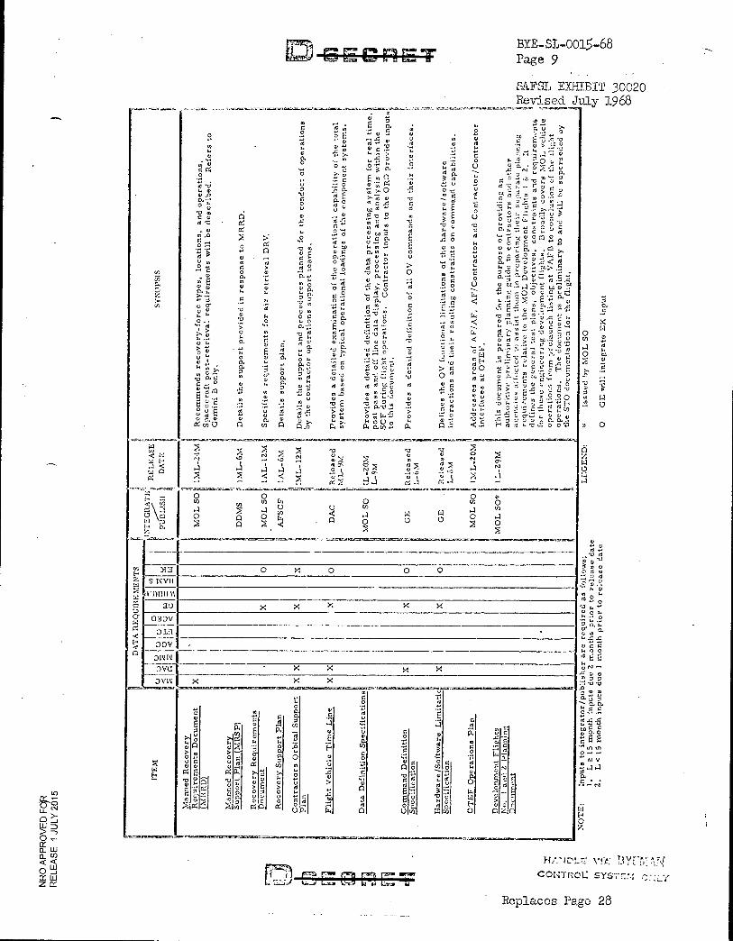
Issu
ed b
y M
OL
SO
GE
wil
l in
teg
rate
EK
inp
ut
0
CE- CrIET BYE-SL-0015-68 Page 9
SAFSL EXHIBIT 30020 Revised July 1968
se D
AT
A R
EQ
UIR
EM
EN
TS
—
ON
TE
GR
AT
1 R
EL
EA
SE
5:
•
DA
TE
S
YN
OP
SIS
U
=1
G P
UB
LIS
H ' ti
N q .
„ .,- M
OL
SO
. 1M
L- 2
.1M
R
ecom
men
ds
reco
ve
ry-fo
rce ty
pes, lo
cati
ons, an
d o
pera
t io
ns.
r
i:
il
S
pacecra
ft p
ost-
retr
ieval
req
uir
em
ents
will be d
esc
ri b
ed. R
efe
rs to
FFF 11
Gem
ini
B o
nly
.
" ;:.. ii
0 11 D
DM
S
:I 1M
L-
6M
. D
eta
ils t
he s
up
port
pr
ov
ided i
n r
esp
on
se to
M
RR
D.
,,
i .
. r
MO
L S
OI. 1
AL
-1
2/Y
1 u
Sp
ec
ifie
s req
uir
em
en
ts fo
r a
ir r
etr
iev
al D
RV
. g '
P il A
FS
CF
' 1
AL
-6M
i D
eta
ils s
up
port p
lan
. ':
0 ,
M i
IML
- 12M
D
eta
ils t
he s
upp
or
t an
d p
roced
ure
s p
lan
ned f
or
th
e c
on
du
ct o
f operati
on
s r
, by t
he c
ontr
ac
tor
op
er
at i
ons
supp
ort
team
s.
11 1
. 0
1: D
AC
R
ele
ased i
Prov
i des
a d
eta
ile
d e
xam
inati
on
of
t he o
per
ati
ona
l c
ap
abil
ity o
f t h
e to
tal
'ML
-9M
4 sy
ste
m b
ase
d o
n t
yp
ical
op
era
tio
nal
load
ing
s o
f th
e c
om
po
nen
t sy
ste
ms.
l ig;
g ii
MO
L S
O
' IL
-2
0M
P
rov
ides
a d
eta
iled
de
finit
ion
of
the d
ata
process
ing
sy
ste
m f
or
re
al
tim
e,
i L
-9M
I p
ost
pass a
nd o
ff l
ine d
ata
dis
pla
y, p
roces
sin
g a
nd
an
aly
sis
wit
hin
th
e
id
SC
F d
urin
g fl
igh
t op
era
tion
s. C
on
trac
tor
inp
uts
to t
he O
RD
pro
vid
e inp
uts
. to t
his
do
cu
men
t.
Iii G
E
Rele
as
ed
Pro
vid
es a d
eta
ile
d d
efi
nit
ion
of
al l
OV
co
mm
an
ds
an
d t
heir
in
ter
faces.
ICIL
-6M
i
:j
i G
E
. a R
ele
ase
d II
Defi
nes
th
e O
V fu
nc
t io
nal
lim
ita
tio
ns o
f th
e har
dw
ar
e/s
oft
ware
L
! i
L-O
M
inte
rac
tio
ns
an
d t
heir
resu
ltin
g c
on
str
ain
ts o
n c
om
man
d c
ap
abi l
itie
s.
t 4 P 0 M
OL
SO
N
EV:L
-101,4
y A
ddre
sses a
rea
s o
f A
F/A
F,
AF
/Co
ntr
ac
tor
an
d C
ontr
ac
tor/C
on
trac
tor i
hh F, in
terfa
ce
s a
t O
TE
F.
P M
OL
SO*
g 1L
-19
M
Th
is docum
en
t is
pre
pare
d fo
r th
e p
urp
os
e o
f p
rov
idin
g a
n
au
tho
rit
ive p
reli
min
ary
pla
nn
ing g
uid
e to c
on
trac
tors
an
d o
the
r f.
I
ag
en
cie
s a
ffec
ted
to a
ss
ist th
em
in
pre
par
ing
th
eir
sep
ara
te p
lann
ing
I
•
,, re
quir
em
ents
re
lati
ve to
th
e ;V
IOL
De
ve
lopm
en
t F
lig
hts
I &
2
, a
li de
fin
es th
e g
ene
ral
tes
t p
lans, o
bje
cti
ves, constr
ain
ts a
nd
req
uir
em
ents
for th
ese
eng
inee
rin
g d
ev
elo
pm
en
t fl
ights
. B
ro
adly
co
vers
MO
L v
eh
icle
I',
op
era
tions
fcom
pre
launch l
ist i
ng a
t V
AF
B t
o c
onc
lus
ion
of th
e f
lig
ht
i a 114
• op
era
tio
ns. T
he d
ocu
men
t is
pre
lim
ina
ry t
o a
nd w
ill be
sup
ers
ed
ed
oy
i
1 i
1 t
he S
TO
do
cu
men
tati
on f
or th
e f
lig
ht.
o x o o 0
x x x x x
. x x x x x x
w E.
_,.,..........=
V V
'z'
,,s
4E 0 E
r1
V
E 2 ii
,, , r 4 ._'---.
''
t > 0
""
0 ›.
..,.....,............,-,...=.....,=......,=................
V; 0.—.1
.
ti:
>4. .5 , Q
ta. t:
g 'f", ,1)-
a
0
w
.- - 0
g c4
.7........113."-
1-; O
cn
,,,, , I
2 0 4 V ° u
0
0 F ..., al 0 E E-
Z
:E 0 >
- " C., P., 1
OS
'C' O
. 0 co 0
V
c .... V n P. A
.17.ara lmiacaauxe■at,
0 0 .i.,
0
C) 2
4
E 0 0
',11
,::
.1
....
.-1 0 F. al 4,
g 0 cn 2
;' m
1". 0, (0 Z
.54 0., 0 0
. 2
0 4 " ' 0 9
t' r'l co 0
-. x r.... .... FZ.
...,—
C'!_ a
E,
c.
>
;-... - C .7: .'
1-1./Y4CLT7:
COP-ITROL: SYST7::-1
Replaces Page 28
O
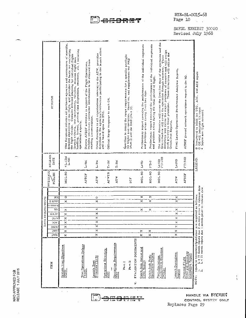
LE
GE
ND
:
-o
d o d
°O..%
'4 0 '4
0
.P; 0'.0 0.
C .
!E)
1.‘) •g-0,0
ayy 0 0.0,
yxx0.00
1 'q SEE "Lf.1
AlO V Naato
0 7.
ra7)
IL.70• k&ZS, U Mna T BYE-SL-0015-68
Page 10
SAFSL EXHIBIT 30020
Revised July 1968
11 il I,
i
"".
..'.....
..'.."..
"...."
11/
AT '
A R
E C
A I Il
l E N
IE N
TS
..."
......1
1 NT
E G_
___-
lt A
T E It E
LE
A sE
Il sy
Nop
sis
c - '
, a a
0 a
a 4
: 5_
:-:
c, .
_, L.,
w =
-4
x
•
, a ;: .-.
---..
— w
=
. .
• ,
I: .
El Pr
-BU
SH
.:
■ D
ATE
-- .........r..... -.... ....,....... V
U 0 0 ..5
:-A . d t' U CD 0) H 0 0 0 a C 4 E
0 m ,,,, 0.•-• . CO CO 0 ... 0 '0
6'; '4. . -g..0' 2 ..0 g' ̀, ?; 0 :'.5 0-..-. '2.-0 .
,,- m d 4,:!.t.n .;:-..'42 .E sg 4 ,...u.,`"'0. u, 0 y, 0 7 7 0E' 7: .--1
IL V
-..": g..% 0,4 - _ 0. 07..., 0 • ,,,,, 0
20 - 0. „ > 5 .iv
,....."..&' .2 -•5 •0 -0 .,›...g..1 • 0›
-_,- '..E., H ..-. ...0 0 0 .0 ,, ,,d.„. r,
0c ''' ''' ''-'>0
000.. 0•,,
',;,°>' Kld, .E., O. g
0 0 .-0,„ 0
u.0--0 Oa 0,„0 0.0 X ..0..; 0 00 ° g 0 .-0,,> 0 c .E •-.' '-' '' r4 u) g.ao--. ° 4 v .."T_. d Q, O 0 ...4 0 40t,' !' .' 4 ..-' ..- E .", ..!.o.o o d C. o o 'L.-. ..0 ... 0 o 0 .... P m t..0 k -. 0 9.
00. 0 0 6 E.,,,, 74, ',.., 4., o `Oa ,'' g'ci.: •?'. 0 UT.ace 00 a...1 .0 4 6 ..0 ,-, k ..9 4 .
>0;70 40 kk VIA E. Eo ,-..8ao U 0 0 0 71 '-'7.: Q4 o
r4.-6-ET.... O d .:4 CE)4.
I.>. kt .,....8m
ka4, F V 8--..'4' 0 0.
,,...,o ,E .."" 0 v .'., .o. (...,-..0
ov o ..-•oi--. g .
fo4.g '6O ''.9. C. r...4 0:1,-. ' o m-m- 4,, o u 5., - .a-m E o
.4 ....,0 . . ,..g..2. 0, q , ,t, v 0 m . .8 .!- ---.8 -" ....g 9 ..: 0 0).°0 % 'o .-..- d
1.,,,, L. 0 '-'v U d CC CL .-, > 0 0 ....
0-,..-.mE-0 e..-. 06 0 0c0-, 0 :74 '-'2d - .-..'- g„.,-.,,o 2 . ,
c...-.-. .0. 7.71 o .5 EA R. 0 0 ,_. ,.. :., ,., . - 0 0.
...gg z,,,-. ,.. d mom VC OC :=1""" m 0
m".5VO.m -z-4,4'd 0.20 g •• 0a, ,?,.r• >7... .',2 °- 0 ,x 0
'8,3 g g ->. _9 :='.',4 0 E -514n 62. go P'0 0 0 -2
0.; - d Et'., 6. y. , - , "r° OUCH ,; ,''t 3
4' « .J. :. O. 0 7.:6 .m .0 „?..,..:1...7.'6.r. ..,,.. 0 ac-, s.9 d d a «do v 0.0 om 04 ....r.0
4' :".....d 4 8. ' 11 0 . 0.. C., V .?. '0 0 0 0. C U t.. 0 .. Q . a. 0 ,0
'"-4 - E g' 44,E >1' . 0,x kd kd k07.1 O 0 ,, ..z, ,., tj) ..0 vomoum --'.>-' -4
,o....o coy° 0 0'0 a .0T >- E sCE "°"..- 0 o E:.0.-.:L.- --dt m'o v.... 0 m d ,9 .14) 74 1.5 . '81 g ,.. 00% ,,.; < .,.11, y.34 C-0 0.0 .a0'.0 d CO
::ciT7...00.21 2 y .,, -,,,, .._ ,.. ge ge E4 5..; -1 -..-1..414 u -O.V, 7t.! -4
11,--It
F. :O. --...,..6.. U
g'-'''' g20 Ic.,• ...' 0, 0.0 udFl.... g 0 _ ,, 0 . I. 0 •.-. , .0 •-• 0 r3 t. -,-, 0 4 0 da. .. o x 0.-.a . ..-. 0.o% kc ,.0 .dc..100 ..-. N H.0..:7.:x0 O....,0 nvd 0 4.d P ■ d H ,.7'..-0.'%0 N <
a x la v z.x.r.c ..mc-.:,...awn. .c....,mr.-.asna.-=,-Icrc.,---sco-ese, .,-..._.. -,,....,==.„,.,- -...., c.m-. s.. .-..gc...z.,.,... w -s,
I '.-. N>.
0 0
00 n
Q
, 4 + H
a I-, E. .-- f.H +
4 i-4H
0 o4 0 0 0 co N H c0 CO VI fk
.10 W N 4 4 4 0
co 0 0 E-, E.--. 0 4( H 14 F. °°i Z 4 4 . 4 4 W < <
I 0 0 X X X X X X X X.
X X X X X X X X -
X X x X X X
X X X X X X X X
X x X
W H
o v
. o ..-, .0
0 H
w
E.__,
0 v
0
o tl 1.. u 0-
d ...,. `,*, H:._..
Hu -(9«
2 g .-1A
t.-1 ,-,..;-'
„.„
.?. u
Er ! H '''' A
o c > .9, .4
. '.-4. '-'.4 01--"!-
,_
u, V a,
1.. ...
0
° c 2
)., d „. ,Q ad
0°
.)
Z (4
'0
0 0 ! Z 0
..» 0 ‹t t t P ..gg, 4 d < 00 a. 1:1(
.4 ......
Ot w co
'''
I
Ele, I° --... ..4 1;
6o
t48.
oo
'.'1:t .."0..
a)
.... ,... o
-9.C) .., ''.' g 0° g 5,..... (DA ...9. 4;: '-''
D...a....' 6'.°
I m
, 0 ..c.....
NI a
.
70,
,.., .coo
tr.
0 0
L,..,-, .-o'29. 0 .1'1
Go
ei 1 :0 () 0
.5 m ,-.
1
;•1 '=rat r3m4 cr=4 =7.41 HANDLE VIA BYEMAJ'
ay. CONTROL SYSTEM ONLY
Replaces Page 29
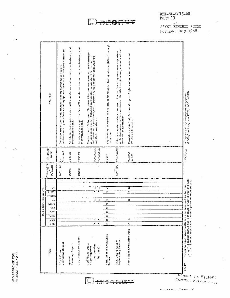
0
a,
0 d
• U 'O
O td M. 0
- 0 d
• - 0 2 0
'0
O O
a 0.
" 5 6 . • 0 0 4 E E 1.4 N -
0 0 „,
0.5 .5.E
00 g 0
E
6
tn O tn
Al V
4 a
E:i
O
BYE-SL-0015-68 Page 11
SAFSL EYJIIBIT 30020 Revised July 1968
("0...:311.,,...4.-TITS.L,
2 ..... co 0.
0 Z a. co
-...:-.2.11%.11.a::. 1.0.401:111,-.6,1K=V •=...%,..ii0=4,at.11,,... .......P,-■•••.:=0111:4C...u.:X., ..746.710.7..........-.1or "V.V.... .--,.....76...9:1.--30,14,....C.A..1.1.13.
.0 to
V 13 Z
>. 0 0 o u
, 0 0 . .c ..)° -.
0 5.,
. a, . ,0 u > s„ C - .r. 0 .
0 O 0 ... g c
0 -- .. rl v° - . 0 ,, ,-. ..- o 0 0 ,-, 0 0 _fT 0
0 - -. .2 v 'c' .:... 0>.- 0
0 0 u - a 0 1-, 0 0 . , o .. u
. 0 0 .0 0 . 0 0 . ..., . 0...... U 0 V 0 0
m
a.. GO
C......
70 ...€ f
U
e. K ra E 0 o
..,..0 o o „5,,,ta a,--' ... .., to
00 ::., 0 E -0' t '
0 0 0 '4 8 . c .F. >,,,, 0, ... 0 0 ...0. a.
-0 •-• .... ,__, 0 0 a 0
0 '04 m . P 1:1 .... C. 7a
0 C C
0. .,' > . '1 , . 0 °' ,,,
0 0 C C U • . 0'0
I.. Z X
g 4 m 0 E .,: ° 0 0 . .0
E.;. z , .- - - ... k 0 40 ..... ‘....
0 E a d . k d C .3 0 ke
P-• 0. 0-. 0' a. c .-. , > n V) o 0 .
° " 0 0 k.... , C u W 0
F. 0 v U a.
c., °' *'' 'a n. •
. 0 F-':. 0 c co. . 0 0
.,..
0 0 > '0':-.°C;
..3 0.3.3 I, 0 3.
5 0 X X to .2 . 0 ... 0 >-• g., ,., U ‘.3 -..._ ... C k td. ...,
0 U .3.' ... . -C 0 0 0
" k > k.. -Cr... Y' 0 3.. y , .t11 5 0
0 -,., .. „ - 0 ,, 7,,
P• v ,., ■-. ''>'• S • .?i .-`2 c, 0., ,.., o o , :, i g la;
0 0 .. w a. v ,,, ‘,, v r: >• ''' ' E g i) g '' °• ° 7.! E . ',ii 01
a. - Et .›... c '-" c .. ..E.... . - - -- 2, 0 .', '..,. 0"'
. od CA Ot',DIO .... U 0 7,. 0 0 ..C. >, 3' . 1.1
a.. Z 71 0 K
. 0 0 .j..;■ ., . c • . E a ''' '.
....11 00 d . 20Uk . .3 : : . -C-. 0 ' -3 . go 0 0 u ,-• 8 0.' E g. 0 0 .- .=. c ,.. „ • 0-1 0
? ,-I. 0 0 0 0 74 1, .!•_,' ''' ..:C . •!■' ''''' . :,. ..5'
0 '0 0 V0 ° ‘,1,' > Ol 't 'E c .9 LI ..„ ,... . ›...
oc. 11,..o
RE
LE
AS
E
1 DA
TE
04 -131-7....-Japi... -S7 1 .,...-airtc.ziee.C-,..c.x.7.......... -x-mr...a-..1.¢.1=4.5--■■■••Matac-Ar-cl.l.:C7_,Ita . r.e,-.C.....,..9.7MTIMIT., l =2.3. -..X.S..07.7.91........
0 Q 0 a a a
I "J ut ,..., CO
0 0 0
0 ,C
.
0 r + ›.. ......
0 n 0 .,'
Q 3.r.
Cl + + < < -.1. < N .0
. ....I H E. 0 0 + 0 ....1 ■-.1
< 0 L, 44 a. 0., .-.1 C. =..„„ .......,...._-'-x._...........,_-..._.................-..,_ ._.---..._.,.,.................
DA
TA
RE
QU
IRE
ME
NT
S
!.
L)
I (-) c.4
g P
UB
LIS
H
u
4:1
0' 0 cr, En an c0
,-.1 I .1 0 n n
A n o
x x x x x x x x
x x x x x x x x
x x x x x x
....
...
kl
E-•
.-.-1.1...
N4 0 a.'
M 0 7.'1 0 . . . ... 0. 0 * r, %
*. a)
.., ' 7:: .... 0 0 o 1: ', r, 5 > . 0. 4
a . >, 4.1 0 0
a) P. t. c' z' T., --. Ng > o P. ,,,,, ,,,, 2 ELI
C4 0 3
0 .1.3 bo
0 be 0 10 .0 or .5 u
k C >, , ",.: MD
.3-• V a, 0 '----. .1 k• 14 t
.0 T. c ),..4-, .!.., -.22. , . ill
F,,, .0 0 g a , 0 - 5 ,...
:--, .0 0 0 01 o tr.: 0 0. g .. v ... 0 0
E., n o U t, I, 4. [..1 171.
-
...„.....,,
....a......33 t..31,../ 113......3 :.••...1, t..1 ii L.-...-.0 it
HANDLF: BYEMAT:.. toNrnoL
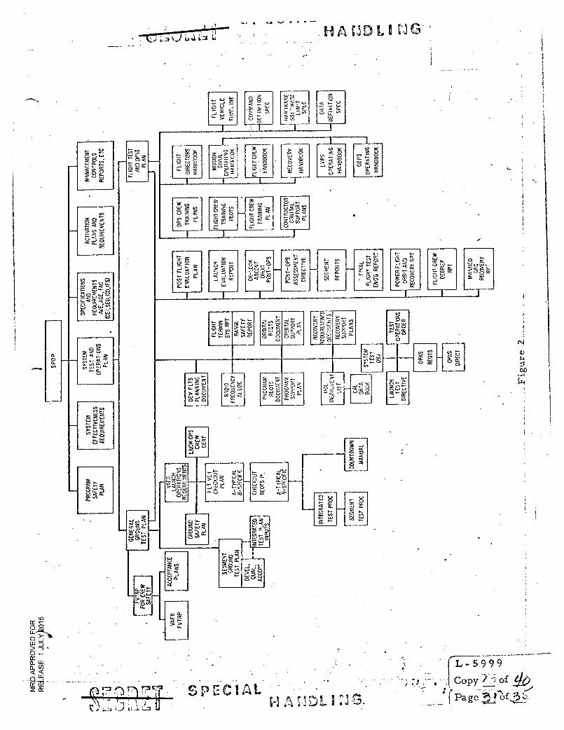
• L ti A L I LI G
t-.
3 -J
<
=7,
0
O
2 5 o r-
= ";"
< C.
z O -
0-
O
1
2 - 41 0
• CC 2 C>
41 CC 2 0 V 2.
- J
C
2 0 > 0 2 4.■ CC
• o O 8 ;
, 41 CC
ES =
V 1. SJ+O 0
E O
L -5999 Copy 7i of
• _—:,'Page .
of
0
< 0 0 0 2 - < CC
2
- 1
- 1.1 .g;
LLI 43 CC
L11
=
- LU
•
07
-
' 0 0- Iv
1 , 0w
L., 0
0 Co,
CC CC41 <
‘4..
C 8 „,
< <
ova CC CI. 0
L./ ,
Z Z r, __I 0
0 2 0
J L-Q
tg.
I- I.- e 2
a_ ,... C. /2 CC
4./ U-
7- -.1 -- , V 41 ,..- 4J 4. < - OW - ..._
, C a. — a. ... 2 CC 1- Lo -.- .0 CC 2, 0 ,x ..., a- > r.,- ,..,
2 o - 0 41
0 0 ;3 ...1 CC
0- 2U.
4.1
CC CC O
O CL
1- < ,Z
L., 0 4/
‘Lt. 0 O
'-- -1 ,:,_ '.
0 3 ..0 0 0- 41 ....--..... V .- Cl I-, C, •-0 CC 14 I $
0 <
• --1 < 2 laQ., •-
SPECIAL
JV
o < Ca 0 1- 2
O
0 4—
1
Z cr
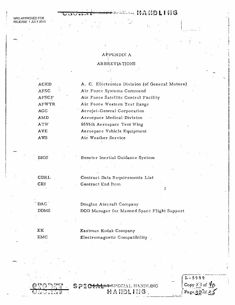
" CI, A D 1. Li NRO APPROVED FOR RELEASE 1 JULY 2015
APPENDIX A
ABBREVIATIONS
ACED A. C. Electronics Division (of General Motors)
AFSC Air Force Systems Command
AFSCF Air Force Satellite Control Facility
AFWTR Air Force Western Test Range
AGC Aerojet-General Corporation
AMD Aerospace Medical Division
ATW 6595th Aerospace Test Wing
AVE Aerospace Vehicle Equipment
AWS Air Weather Service
BIGS Booster Inertial Guidance System
Douglas Aircraft Company
DOD Manager for Manned Space Flight Support
CDRL
CEI
' DAC'
DDMS
EK
EMC
S p PECIAL IIANDLING
HAND I, I .
- 5 9 9 9 Copy of 11/)
?Paget', of
Contract Data Requirements List
Contract End Item
Eastman Kodak Company
Electromagnetic Compatibility
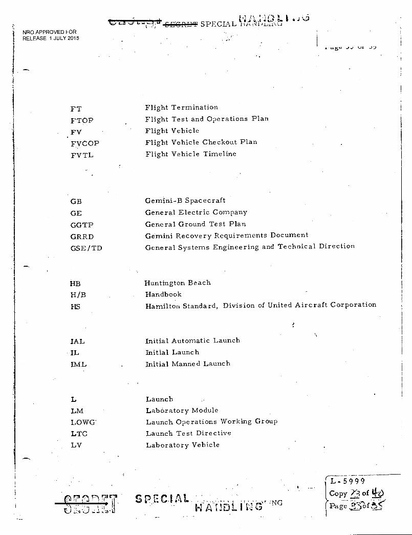
'10 EnIlET SPECIAL r-!ito:t)4...,z:r:
NRO APPROVED FOR RELEASE 1 JULY 2015
J1,
FT Flight Termination
FTOP Flight Test and Operations Plan
FV Flight Vehicle
FVCOP Flight Vehicle Checkout Plan
FVTL Flight Vehicle Timeline
GB Gemini-B Spacecraft
GE General Electric Company
GGTP General Ground Test Plan
GRRD Gemini Recovery Requirements Document
GSE/TD General Systems Engineering and Technical Direction
HB Huntington Beach
H/B Handbook
HS Hamilton Standard, Division of United Aircraft Corporation
IAL Initial Automatic Launch
IL Initial Launch
IML Initial Manned Launch
L Launch
LM Laboratory Module
LOWG' Launch Operations Working Group
LTC Launch Test Directive
LV Laboratory Vehicle
,_______ 'L-5999
Copy Y-3 of 110
Page < -• . i i ,-3 1
Z... .: 3 - .1 :-.., - s SPA CIA
II A rID1 4
:NG v‘2
•
6 j
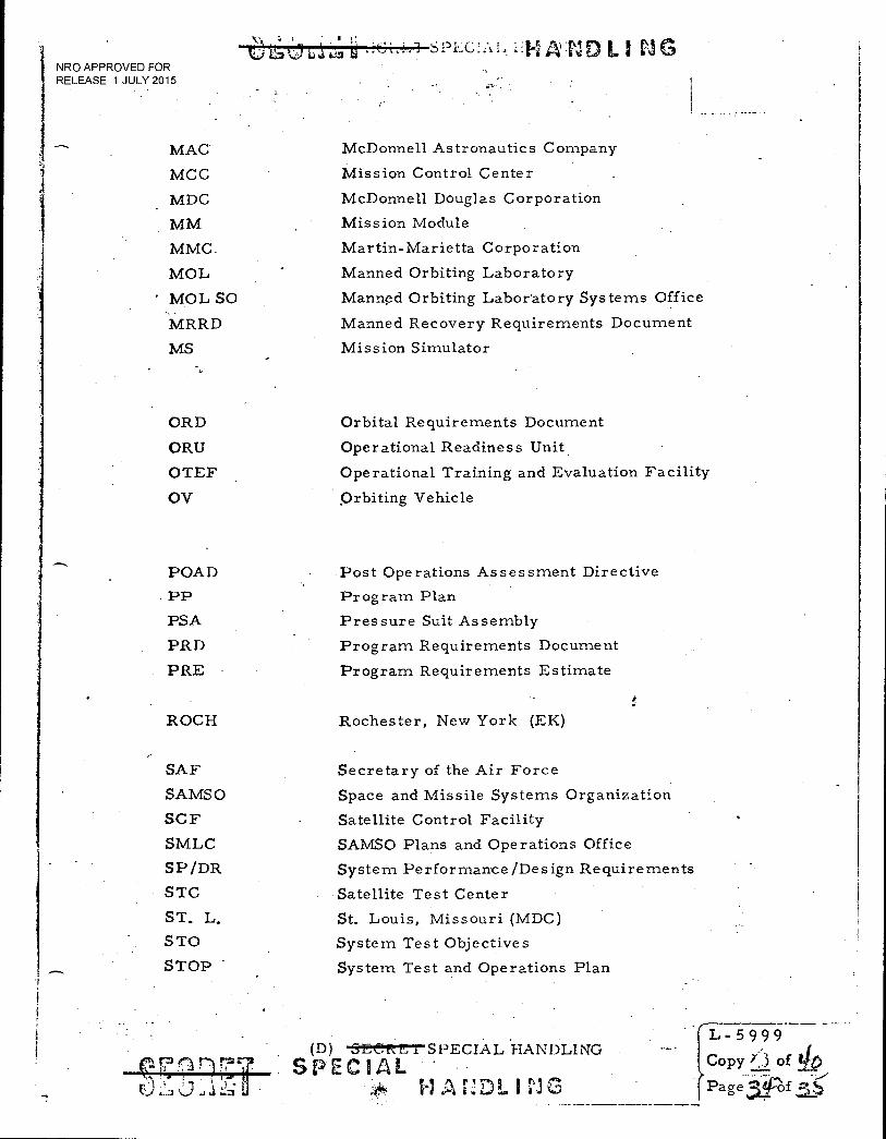
NRO APPROVED FOR RELEASE 1 JULY 2015
s r I
es* Li LAZ it-2 A :ND LI CI G
MAC McDonnell Astronautics Company
MCC Mission Control Center
MDC McDonnell Douglas Corporation
MM Mission Module
MMC. Martin-Marietta Corporation
MOL Manned Orbiting Laboratory
MOL SO Manned Orbiting Laboratory Systems Office
MRRD Manned Recovery Requirements Document
MS Mission Simulator
ORD Orbital Requirements Document
ORU Operational Readiness Unit
OTEF Operational Training and Evaluation Facility
OV Orbiting Vehicle
POAD Post Operations Assessment Directive
PP Program Plan
PSA Pressure Suit Assembly
PRD Program Requirements Document
PRE Program Requirements Estimate
ROCH Rochester, New York (EK)
SAF
SAMS()
SCF
SMLC
SP /DR
STC
ST. L.
STO
STOP
Secretary of the Air Force
Space and Missile Systems Organization
Satellite Control Facility
SAMSO Plans and Operations Office
System Performance/Design Requirements
Satellite Test Center
St. Louis, Missouri (MDC)
System Test Objectives
System Test and Operations Plan
.(0) C,ErtrSPECIAL HANDLING SPECIAL
L - 5 9 9 9
Copy f,-.3 of 40
Pa g e f
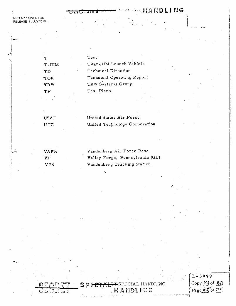
•. - thwiDLinci NRO APPROVED FOR RELEASE 1 JULY 2015 .
T Test
T-IIIM Titan-IIIM Launch Vehicle
TD Technical Direction
'TOR Technical Operating Report
-TRW TRW Systems Group
TP Test Plans
USAF
UTC
United States Air Force
United Technology Corporation
VAFB Vandenberg Air Force Base
VF Valley Forge, Pennsylvania (GE)
VTS Vandenberg Tracking Station
L-5999 L - 5999
S P-ISPECIAL HANDLING Copy YAof 1.0
NM- I Page f