engine control system section ec
TRANSCRIPT
ENGINE CONTROL SYSTEM
SECTIONECCONTENTS
QG
TROUBLE DIAGNOSIS - INDEX ..................................10Alphabetical & P No. Index for DTC .........................10
PRECAUTIONS .............................................................16Supplemental Restraint System (SRS) ″AIRBAG″ and ″SEAT BELT PRE-TENSIONER″.............16Precautions for On Board Diagnostic (OBD)System of Engine and A/T.........................................16Engine Fuel & Emission Control System ..................17Wiring Diagrams and Trouble Diagnosis...................19
PREPARATION .............................................................20Special Service Tools ................................................20Commercial Service Tools .........................................20
ENGINE AND EMISSION CONTROL OVERALLSYSTEM.........................................................................21
Engine Control Component Parts Location...............21Circuit Diagram..........................................................25System Diagram ........................................................29Vacuum Hose Drawing ..............................................30System Chart .............................................................31
ENGINE AND EMISSION BASIC CONTROLSYSTEM DESCRIPTION ...............................................32
Multiport Fuel Injection (MFI) System .......................32Electronic Ignition (EI) System ..................................34Air Conditioning Cut Control......................................35Fuel Cut Control (at no load & high enginespeed) ........................................................................36Evaporative Emission System...................................36Positive Crankcase Ventilation ..................................39
BASIC SERVICE PROCEDURE ...................................40Fuel Pressure Release ..............................................40Fuel Pressure Check .................................................40Fuel Pressure Regulator Check ................................41Injector .......................................................................41How to Check Idle Speed and Ignition Timing..........43Preparation ................................................................44Inspection Procedure.................................................47Idle Air Volume Learning ...........................................57
ON BOARD DIAGNOSTIC SYSTEMDESCRIPTION ...............................................................59
Introduction ................................................................59Two Trip Detection Logic ...........................................59Emission-related Diagnostic Information ...................60NATS (Nissan Anti-theft System) ..............................74Malfunction Indicator (MI) ..........................................74OBD System Operation Chart (With Euro-OBDModels Only)..............................................................78CONSULT-II ...............................................................83Generic Scan Tool (GST) ..........................................94
TROUBLE DIAGNOSIS - INTRODUCTION ..................96Introduction ................................................................96Work Flow..................................................................98
TROUBLE DIAGNOSIS - BASIC INSPECTION .........100Basic Inspection/Sedan ...........................................100Basic Inspection/Hatchback.....................................128
TROUBLE DIAGNOSIS - GENERALDESCRIPTION .............................................................153
DTC Inspection Priority Chart..................................153Fail-safe Chart .........................................................154Symptom Matrix Chart.............................................155CONSULT-II Reference Value in Data MonitorMode........................................................................159Major Sensor Reference Graph in Data MonitorMode........................................................................161ECM Terminals and Reference Value .....................164
TROUBLE DIAGNOSIS - SPECIFICATION VALUE ..173Description ...............................................................173Testing Condition .....................................................173Inspection Procedure...............................................173Diagnostic Procedure ..............................................174
TROUBLE DIAGNOSIS FOR INTERMITTENTINCIDENT.....................................................................177
Description ...............................................................177Diagnostic Procedure ..............................................177
TROUBLE DIAGNOSIS FOR POWER SUPPLY ........178Main Power Supply and Ground Circuit..................178
DTC P0100 MASS AIR FLOW SENSOR (MAFS) ......187Component Description ...........................................187CONSULT-II Reference Value in Data MonitorMode........................................................................187ECM Terminals and Reference Value .....................187On Board Diagnosis Logic.......................................187Fail-safe Mode.........................................................188DTC Confirmation Procedure ..................................188Wiring Diagram........................................................189Diagnostic Procedure ..............................................191Component Inspection.............................................193
DTC P0110 INTAKE AIR TEMPERATURESENSOR ......................................................................194
Component Description ...........................................194On Board Diagnosis Logic.......................................195DTC Confirmation Procedure ..................................195Wiring Diagram........................................................196Diagnostic Procedure ..............................................198Component Inspection.............................................200
DTC P0115 ENGINE COOLANT TEMPERATURESENSOR ......................................................................201
Component Description ...........................................201CONSULT-II Reference Value in Data MonitorMode........................................................................201On Board Diagnosis Logic.......................................201Fail-safe Mode.........................................................202DTC Confirmation Procedure ..................................202Wiring Diagram........................................................203Diagnostic Procedure ..............................................205Component Inspection.............................................206
DTC P0120 THROTTLE POSITION SENSOR ...........207Component Description ...........................................207CONSULT-II Reference Value in Data MonitorMode........................................................................207ECM Terminals and Reference Value .....................208On Board Diagnosis Logic.......................................208Fail-safe Mode.........................................................208DTC Confirmation Procedure ..................................208Wiring Diagram........................................................210Diagnostic Procedure ..............................................212Component Inspection.............................................214
DTC P0130 HEATED OXYGEN SENSOR 1(FRONT) (CIRCUIT).....................................................216
Component Description ...........................................216CONSULT-II Reference Value in Data MonitorMode........................................................................216ECM Terminals and Reference Value .....................216On Board Diagnosis Logic.......................................217DTC Confirmation Procedure ..................................217Overall Function Check ...........................................218Wiring Diagram........................................................219Diagnostic Procedure ..............................................221
Component Inspection.............................................222DTC P0131 HEATED OXYGEN SENSOR 1(FRONT) (LEAN SHIFT MONITORING) .....................224
Component Description ...........................................224CONSULT-II Reference Value in Data MonitorMode........................................................................224ECM Terminals and Reference Value .....................224On Board Diagnosis Logic.......................................225DTC Confirmation Procedure ..................................225Overall Function Check ...........................................226Diagnostic Procedure ..............................................226Component Inspection.............................................228
DTC P0132 HEATED OXYGEN SENSOR 1(FRONT) (RICH SHIFT MONITORING) ......................230
Component Description ...........................................230CONSULT-II Reference Value in Data MonitorMode........................................................................230ECM Terminals and Reference Value .....................230On Board Diagnosis Logic.......................................231DTC Confirmation Procedure ..................................231Overall Function Check ...........................................232Diagnostic Procedure ..............................................232Component Inspection.............................................234
DTC P0133 HEATED OXYGEN SENSOR 1(FRONT).......................................................................236
Component Description ...........................................236CONSULT-II Reference Value in Data MonitorMode........................................................................236ECM Terminals and Reference Value .....................236On Board Diagnosis Logic.......................................237DTC Confirmation Procedure ..................................237Overall Function Check ...........................................238Wiring Diagram........................................................239Diagnostic Procedure ..............................................241Component Inspection.............................................243
DTC P0134 HEATED OXYGEN SENSOR 1(FRONT) (HIGH VOLTAGE) ........................................245
Component Description ...........................................245CONSULT-II Reference Value in Data MonitorMode........................................................................245ECM Terminals and Reference Value .....................245On Board Diagnosis Logic.......................................246DTC Confirmation Procedure ..................................246Wiring Diagram........................................................247Diagnostic Procedure ..............................................249Component Inspection.............................................250
DTC P0135 HEATED OXYGEN SENSOR 1(FRONT) HEATER .......................................................252
Description ...............................................................252CONSULT-II Reference Value in Data MonitorMode........................................................................252ECM Terminals and Reference Value .....................252
CONTENTS (Cont’d)
EC-2
On Board Diagnosis Logic.......................................252DTC Confirmation Procedure ..................................253Wiring Diagram........................................................254Diagnostic Procedure ..............................................256Component Inspection.............................................257
DTC P0137 HEATED OXYGEN SENSOR 2(REAR) (MIN. VOLTAGE MONITORING) ...................258
Component Description ...........................................258CONSULT-II Reference Value in Data MonitorMode........................................................................258ECM Terminals and Reference Value .....................258On Board Diagnosis Logic.......................................258DTC Confirmation Procedure ..................................259Overall Function Check ...........................................260Wiring Diagram........................................................261Diagnostic Procedure ..............................................263Component Inspection.............................................265
DTC P0138 HEATED OXYGEN SENSOR 2(REAR) (MAX. VOLTAGE MONITORING) .................267
Component Description ...........................................267CONSULT-II Reference Value in Data MonitorMode........................................................................267ECM Terminals and Reference Value .....................267On Board Diagnosis Logic.......................................267DTC Confirmation Procedure ..................................268Overall Function Check ...........................................269Wiring Diagram........................................................270Diagnostic Procedure ..............................................272Component Inspection.............................................273
DTC P0139 HEATED OXYGEN SENSOR 2(REAR) .........................................................................275
Component Description ...........................................275CONSULT-II Reference Value in Data MonitorMode........................................................................275ECM Terminals and Reference Value .....................275On Board Diagnosis Logic.......................................275DTC Confirmation Procedure ..................................276Overall Function Check ...........................................277Wiring Diagram........................................................278Diagnostic Procedure ..............................................280Component Inspection.............................................282
DTC P0140 HEATED OXYGEN SENSOR 2(REAR) (HIGH VOLTAGE) ..........................................284
Component Description ...........................................284CONSULT-II Reference Value in Data MonitorMode........................................................................284ECM Terminals and Reference Value .....................284On Board Diagnosis Logic.......................................284DTC Confirmation Procedure ..................................285Overall Function Check ...........................................285Wiring Diagram........................................................286Diagnostic Procedure ..............................................288
Component Inspection.............................................289DTC P0141 HEATED OXYGEN SENSOR 2HEATER (REAR) .........................................................291
Description ...............................................................291CONSULT-II Reference Value in Data MonitorMode........................................................................291ECM Terminals and Reference Value .....................291On Board Diagnosis Logic.......................................292DTC Confirmation Procedure ..................................292Wiring Diagram........................................................293Diagnostic Procedure ..............................................295Component Inspection.............................................296
DTC P0171 FUEL INJECTION SYSTEMFUNCTION (LEAN SIDE) ............................................297
On Board Diagnosis Logic.......................................297DTC Confirmation Procedure ..................................297Wiring Diagram........................................................299Diagnostic Procedure ..............................................301
DTC P0172 FUEL INJECTION SYSTEMFUNCTION (RICH SIDE) .............................................305
On Board Diagnosis Logic.......................................305DTC Confirmation Procedure ..................................305Wiring Diagram........................................................307Diagnostic Procedure ..............................................309
DTC P0180 FUEL TANK TEMPERATURESENSOR (WHERE FITTED)........................................313
Component Description ...........................................313On Board Diagnosis Logic.......................................313DTC Confirmation Procedure ..................................313Wiring Diagram........................................................315Diagnostic Procedure ..............................................316Component Inspection.............................................317
DTC P0300 - P0304 NO. 4 - 1 CYLINDERMISFIRE, MULTIPLE CYLINDER MISFIRE ...............318
On Board Diagnosis Logic.......................................318DTC Confirmation Procedure ..................................318Diagnostic Procedure ..............................................319
DTC P0325 KNOCK SENSOR (KS) ...........................324Component Description ...........................................324ECM Terminals and Reference Value .....................324On Board Diagnosis Logic.......................................324DTC Confirmation Procedure ..................................324Wiring Diagram........................................................325Diagnostic Procedure ..............................................326Component Inspection.............................................327
DTC P0335 CRANKSHAFT POSITION SENSOR(POS)............................................................................328
Component Description ...........................................328ECM Terminals and Reference Value .....................328On Board Diagnosis Logic.......................................329DTC Confirmation Procedure ..................................329Wiring Diagram........................................................330
CONTENTS (Cont’d)
EC-3
Diagnostic Procedure ..............................................332Component Inspection.............................................334
DTC P0340 CAMSHAFT POSITION SENSOR(CMPS) (PHASE) .........................................................335
Component Description ...........................................335ECM Terminals and Reference Value .....................335On Board Diagnosis Logic.......................................336DTC Confirmation Procedure ..................................336Wiring Diagram........................................................337Diagnostic Procedure ..............................................339Component Inspection.............................................342
DTC P0400 EGR FUNCTION (CLOSED) (WHEREFITTED)........................................................................343
Description ...............................................................343CONSULT-II Reference Value in Data MonitorMode........................................................................344ECM Terminals and Reference Value .....................344On Board Diagnosis Logic.......................................344DTC Confirmation Procedure ..................................345Wiring Diagram........................................................347Diagnostic Procedure ..............................................349Component Inspection.............................................351
DTC P0403 EGR VOLUME CONTROL VALVE(CIRCUIT).....................................................................352
Description ...............................................................352CONSULT-II Reference Value in Data MonitorMode........................................................................353ECM Terminals and Reference Value .....................353On Board Diagnosis Logic.......................................353DTC Confirmation Procedure ..................................353Wiring Diagram........................................................355Diagnostic Procedure ..............................................357Component Inspection.............................................358
DTC P0420 THREE WAY CATALYST FUNCTION ...359On Board Diagnosis Logic.......................................359DTC Confirmation Procedure ..................................359Overall Function Check ...........................................360Diagnostic Procedure ..............................................360
DTC P0443 EVAP CANISTER PURGE VOLUMECONTROL SOLENOID VALVE (CIRCUIT) .................364
Description ...............................................................364CONSULT-II Reference Value in Data MonitorMode........................................................................364ECM Terminals and Reference Value .....................365On Board Diagnosis Logic.......................................365DTC Confirmation Procedure ..................................365Wiring Diagram........................................................366Diagnostic Procedure ..............................................368Component Inspection.............................................369
DTC P0500 VEHICLE SPEED SENSOR (VSS) .........370Component Description ...........................................370ECM Terminals and Reference Value .....................370
On Board Diagnosis Logic.......................................370DTC Confirmation Procedure ..................................370Wiring Diagram........................................................372Diagnostic Procedure ..............................................375
DTC P0505 IDLE AIR CONTROL VALVE (IACV) -AUXILIARY AIR CONTROL (AAC) VALVE ...............376
Description ...............................................................376CONSULT-II Reference Value in Data MonitorMode........................................................................377ECM Terminals and Reference Value .....................377On Board Diagnosis Logic.......................................377DTC Confirmation Procedure ..................................377Wiring Diagram........................................................378Diagnostic Procedure ..............................................380Component Inspection.............................................384
DTC P0510 CLOSED THROTTLE POSITIONSWITCH (WHERE FITTED).........................................385
Component Description ...........................................385CONSULT-II Reference Value in Data MonitorMode........................................................................385ECM Terminals and Reference Value .....................385On Board Diagnosis Logic.......................................385DTC Confirmation Procedure ..................................385Overall Function Check ...........................................386Wiring Diagram........................................................387Diagnostic Procedure ..............................................388Component Inspection.............................................389
DTC P0605 ECM .........................................................391Component Description ...........................................391On Board Diagnosis Logic.......................................391DTC Confirmation Procedure ..................................391Diagnostic Procedure ..............................................392
DTC P1111 INTAKE VALVE TIMING CONTROLSOLENOID VALVE ......................................................393
Component Description ...........................................393Operation .................................................................393CONSULT-II Reference Value in Data MonitorMode........................................................................393ECM Terminals and Reference Value .....................393On Board Diagnosis Logic.......................................393DTC Confirmation Procedure ..................................394Wiring Diagram........................................................395Diagnostic Procedure ..............................................397Component Inspection.............................................398
DTC P1131 SWIRL CONTROL VALVE SOLENOIDVALVE (CIRCUIT) (WHERE FITTED) .........................399
Description ...............................................................399CONSULT-II Reference Value in Data MonitorMode........................................................................399ECM Terminals and Reference Value .....................400Component Description ...........................................400On Board Diagnosis Logic.......................................400
CONTENTS (Cont’d)
EC-4
DTC Confirmation Procedure ..................................400Wiring Diagram........................................................402Diagnostic Procedure ..............................................403Component Inspection.............................................404
DTC P1217 OVERHEAT (COOLING SYSTEM) .........406System Description..................................................406CONSULT-II Reference Value in Data MonitorMode........................................................................406ECM Terminals and Reference Value .....................407On Board Diagnosis Logic.......................................407Overall Function Check ...........................................408Wiring Diagram........................................................409Diagnostic Procedure ..............................................410Main 12 Causes of Overheating..............................416Component Inspection.............................................416
DTC P1401 EGR TEMPERATURE SENSOR(WHERE FITTED) ........................................................418
Component Description ...........................................418On Board Diagnosis Logic.......................................418DTC Confirmation Procedure ..................................418Wiring Diagram........................................................421Diagnostic Procedure ..............................................423Component Inspection.............................................424
DTC P1402 EGR FUNCTION (OPEN) (WHEREFITTED)........................................................................425
Description ...............................................................425CONSULT-II Reference Value in Data MonitorMode........................................................................426ECM Terminals and Reference Value .....................426On Board Diagnosis Logic.......................................426DTC Confirmation Procedure ..................................427Wiring Diagram........................................................429Diagnostic Procedure ..............................................431Component Inspection.............................................432
DTC P1605 A/T DIAGNOSIS COMMUNICATIONLINE .............................................................................434
System Description..................................................434ECM Terminals and Reference Value .....................434On Board Diagnosis Logic.......................................434DTC Confirmation Procedure ..................................434Wiring Diagram........................................................435Diagnostic Procedure ..............................................436
DTC P1706 PARK/NEUTRAL POSITION (PNP)SWITCH .......................................................................437
Component Description ...........................................437CONSULT-II Reference Value in Data MonitorMode........................................................................437ECM Terminals and Reference Value .....................437On Board Diagnosis Logic.......................................437DTC Confirmation Procedure ..................................437Overall Function Check ...........................................438Wiring Diagram........................................................439
Diagnostic Procedure ..............................................440INTAKE AIR TEMPERATURE SENSOR ....................442
Component Description ...........................................442Wiring Diagram........................................................444Diagnostic Procedure ..............................................446Component Inspection.............................................448
HEATED OXYGEN SENSOR 1 (FRONT)...................450Component Description ...........................................450CONSULT-II Reference Value in Data MonitorMode........................................................................450ECM Terminals and Reference Value .....................450Wiring Diagram........................................................451Diagnostic Procedure ..............................................453Component Inspection.............................................455
HEATED OXYGEN SENSOR 1 HEATER (FRONT) ...457Description ...............................................................457CONSULT-II Reference Value in Data MonitorMode........................................................................457ECM Terminals and Reference Value .....................457Wiring Diagram........................................................458Diagnostic Procedure ..............................................460Component Inspection.............................................461
HEATED OXYGEN SENSOR 2 (REAR) .....................462Component Description ...........................................462CONSULT-II Reference Value in Data MonitorMode........................................................................462ECM Terminals and Reference Value .....................462Wiring Diagram........................................................463Diagnostic Procedure ..............................................465Component Inspection.............................................467
HEATED OXYGEN SENSOR 2 HEATER (REAR) .....469Description ...............................................................469CONSULT-II Reference Value in Data MonitorMode........................................................................469ECM Terminals and Reference Value .....................469Wiring Diagram........................................................470Diagnostic Procedure ..............................................472Component Inspection.............................................474
SWIRL CONTROL VALVE CONTROL SYSTEM(WHERE FITTED) ........................................................475
Description ...............................................................475CONSULT-II Reference Value in Data MonitorMode........................................................................475ECM Terminals and Reference Value .....................476Component Description ...........................................476Wiring Diagram........................................................477Diagnostic Procedure ..............................................478Component Inspection.............................................482
CRANKSHAFT POSITION SENSOR (POS) ...............484Component Description ...........................................484ECM Terminals and Reference Value .....................484Wiring Diagram........................................................485
CONTENTS (Cont’d)
EC-5
Diagnostic Procedure ..............................................487Component Inspection.............................................490
EGR VOLUME CONTROL SYSTEM (WHEREFITTED)........................................................................491
Description ...............................................................491CONSULT-II Reference Value in Data MonitorMode........................................................................492ECM Terminals and Reference Value .....................493Wiring Diagram........................................................494Diagnostic Procedure ..............................................496Component Inspection.............................................501
EVAP CANISTER PURGE VOLUME CONTROLSOLENOID VALVE ......................................................503
Description ...............................................................503CONSULT-II Reference Value in Data MonitorMode........................................................................503ECM Terminals and Reference Value .....................504Wiring Diagram........................................................505Diagnostic Procedure ..............................................507Component Inspection.............................................510
IDLE AIR CONTROL VALVE (IACV) - AUXILIARYAIR CONTROL ............................................................511
Description ...............................................................511CONSULT-II Reference Value in Data MonitorMode........................................................................512ECM Terminals and Reference Value .....................512Wiring Diagram........................................................513Diagnostic Procedure ..............................................515Component Inspection.............................................519
CLOSED THROTTLE POSITION SWITCH(WHERE FITTED) ........................................................520
Component Description ...........................................520ECM Terminals and Reference Value .....................520Wiring Diagram........................................................521Diagnostic Procedure ..............................................522Component Inspection.............................................525
INTAKE VALVE TIMING CONTROL SOLENOIDVALVE ..........................................................................526
Component Description ...........................................526Operation .................................................................526CONSULT-II Reference Value in Data MonitorMode........................................................................526ECM Terminals and Reference Value .....................526Wiring Diagram........................................................527Diagnostic Procedure ..............................................529Component Inspection.............................................531
A/T COMMUNICATION LINE ......................................532System Description..................................................532Wiring Diagram........................................................533Diagnostic Procedure ..............................................534
PARK/NEUTRAL POSITION (PNP) SWITCH ............536Component Description ...........................................536
CONSULT-II Reference Value in Data MonitorMode........................................................................536ECM Terminals and Reference Value .....................536Wiring Diagram........................................................537Diagnostic Procedure ..............................................538
INJECTOR ...................................................................541Component Description ...........................................541CONSULT-II Reference Value in Data MonitorMode........................................................................541ECM Terminals and Reference Value .....................541Wiring Diagram........................................................542Diagnostic Procedure ..............................................544Component Inspection.............................................546
IGNITION SIGNAL .......................................................547Component Description ...........................................547CONSULT-II Reference Value in Data MonitorMode........................................................................547ECM Terminals and Reference Value .....................547Wiring Diagram........................................................548Diagnostic Procedure ..............................................551Component Inspection.............................................555
START SIGNAL ...........................................................557CONSULT-II Reference Value in Data MonitorMode........................................................................557ECM Terminals and Reference Value .....................557Wiring Diagram........................................................558Diagnostic Procedure ..............................................559
FUEL PUMP.................................................................561System Description..................................................561Component Description ...........................................561CONSULT-II Reference Value in Data MonitorMode........................................................................561ECM Terminals and Reference Value .....................562Wiring Diagram........................................................563Diagnostic Procedure ..............................................564Component Inspection.............................................566
POWER STEERING OIL PRESSURE SWITCH .........567Component Description ...........................................567CONSULT-II Reference Value in Data MonitorMode........................................................................567ECM Terminals and Reference Value .....................567Wiring Diagram........................................................568Diagnostic Procedure ..............................................569Component Inspection.............................................570
REFRIGERANT PRESSURE SENSOR ......................572Description ...............................................................572ECM Terminals and Reference Value .....................572Wiring Diagram........................................................573Diagnostic Procedure ..............................................575
ELECTRICAL LOAD SIGNAL .....................................578CONSULT-II Reference Value in Data MonitorMode........................................................................578
CONTENTS (Cont’d)
EC-6

ECM Terminals and Reference Value .....................578Wiring Diagram........................................................579Diagnostic Procedure - Load Signal - .....................583Diagnostic Procedure - Heater Control Panel(Fan Switch) - ..........................................................589Component Inspection.............................................590
MI & DATA LINK CONNECTORS ..............................591Wiring Diagram........................................................591
SERVICE DATA AND SPECIFICATIONS (SDS) .......593Fuel Pressure Regulator..........................................593Idle Speed and Ignition Timing................................593Mass Air Flow Sensor..............................................593Intake Air Temperature Sensor................................593Engine Coolant Temperature Sensor ......................593Throttle Position Sensor ..........................................593Heated Oxygen Sensor 1 Heater (Front) ................593Heated Oxygen Sensor 2 Heater (Rear).................593Fuel Tank Temperature Sensor (Where Fitted) .......594EGR Volume Control Valve (Where Fitted).............594EGR Temperature Sensor (Where Fitted)...............594EVAP Canister Purge Volume Control Valve ..........594IACV-AAC Valve ......................................................594Injector .....................................................................594Ignition Coil with Power Transistor ..........................594Condenser ...............................................................594Fuel Pump ...............................................................594Crankshaft Position Sensor (POS)..........................595Camshaft Position Sensor (PHASE) .......................595
YD
TROUBLE DIAGNOSIS - INDEX ................................596Alphabetical & P No. Index for DTC .......................596
PRECAUTIONS ...........................................................598Supplemental Restraint System (SRS) ″AIRBAG″ and ″SEAT BELT PRE-TENSIONER″...........598Engine Fuel & Emission Control System ................599Precautions ..............................................................600Wiring Diagrams and Trouble Diagnosis.................601
PREPARATION ...........................................................602Special Service Tools ..............................................602
ENGINE AND EMISSION CONTROL OVERALLSYSTEM.......................................................................603
Engine Control Component Parts Location.............603Circuit Diagram........................................................606System Diagram ......................................................608System Chart ...........................................................609
ENGINE AND EMISSION BASIC CONTROLSYSTEM DESCRIPTION .............................................610
Fuel Injection Control System .................................610Fuel Injection Timing Control System......................611Air Conditioning Cut Control....................................612
Fuel Cut Control (at no load & high enginespeed) ......................................................................612Crankcase Ventilation System.................................613
BASIC SERVICE PROCEDURE .................................614Injection Tube and Injection Nozzle ........................614Electronic Control Fuel Injection Pump...................618Fuel Filter.................................................................625
ON BOARD DIAGNOSTIC SYSTEMDESCRIPTION .............................................................627
DTC and MI Detection Logic ...................................627Diagnostic Trouble Code (DTC) ..............................627Malfunction Indicator (MI) ........................................628CONSULT-II .............................................................632
TROUBLE DIAGNOSIS - INTRODUCTION ................637Introduction ..............................................................637Work Flow................................................................639
TROUBLE DIAGNOSIS - BASIC INSPECTION .........641Basic Inspection.......................................................641
TROUBLE DIAGNOSIS - GENERALDESCRIPTION .............................................................646
Symptom Matrix Chart.............................................646CONSULT-II Reference Value in Data MonitorMode........................................................................656Major Sensor Reference Graph in Data MonitorMode........................................................................658ECM Terminals and Reference Value .....................659
TROUBLE DIAGNOSIS FOR INTERMITTENTINCIDENT.....................................................................665
Description ...............................................................665Diagnostic Procedure ..............................................665
TROUBLE DIAGNOSIS FOR POWER SUPPLY ........666Main Power Supply and Ground Circuit..................666
DTC P0100 MASS AIR FLOW SEN ...........................673Component Description ...........................................673CONSULT-II Reference Value in Data MonitorMode........................................................................673ECM Terminals and Reference Value .....................673On Board Diagnosis Logic.......................................673DTC Confirmation Procedure ..................................673Wiring Diagram........................................................675Diagnostic Procedure ..............................................677
DTC P0115 COOLANT TEMP SEN ............................680Description ...............................................................680On Board Diagnosis Logic.......................................680DTC Confirmation Procedure ..................................680Wiring Diagram........................................................682Diagnostic Procedure ..............................................683
DTC P0120 ACCEL POS SENSOR ............................685Description ...............................................................685CONSULT-II Reference Value in Data MonitorMode........................................................................685ECM Terminals and Reference Value .....................685
CONTENTS (Cont’d)
EC-7
On Board Diagnosis Logic.......................................686DTC Confirmation Procedure ..................................686Wiring Diagram........................................................687Diagnostic Procedure ..............................................688
DTC P0335 CRANK POS SEN (TDC) ........................695Description ...............................................................695CONSULT-II Reference Value in Data MonitorMode........................................................................695ECM Terminals and Reference Value .....................695On Board Diagnosis Logic.......................................695DTC Confirmation Procedure ..................................696Wiring Diagram........................................................697Diagnostic Procedure ..............................................698
DTC P0500 VEHICLE SPEED SEN ............................701Description ...............................................................701ECM Terminals and Reference Value .....................701On Board Diagnosis Logic.......................................701Overall Function Check ...........................................701Wiring Diagram........................................................703Diagnostic Procedure ..............................................705
DTC P0571 BRAKE SW ..............................................706Description ...............................................................706ECM Terminals and Reference Value .....................706On Board Diagnosis Logic.......................................706DTC Confirmation Procedure ..................................706Wiring Diagram........................................................708Diagnostic Procedure ..............................................710
DTC P1107 ECM 10 ....................................................714Description ...............................................................714On Board Diagnosis Logic.......................................714DTC Confirmation Procedure ..................................714Diagnostic Procedure ..............................................715
DTC P1180 P9.FUEL TEMP SEN ...............................716Description ...............................................................716CONSULT-II Reference Value in Data MonitorMode........................................................................716ECM Terminals and Reference Value .....................717On Board Diagnosis Logic.......................................717DTC Confirmation Procedure ..................................717Wiring Diagram........................................................719Diagnostic Procedure ..............................................721
DTC P1202 FUEL CUT SYSTEM2 .............................723Description ...............................................................723CONSULT-II Reference Value in Data MonitorMode........................................................................723ECM Terminals and Reference Value .....................724On Board Diagnosis Logic.......................................724DTC Confirmation Procedure ..................................724Wiring Diagram........................................................726Diagnostic Procedure ..............................................728
DTC P1217 OVER HEAT ............................................730Description ...............................................................730
CONSULT-II Reference Value in Data MonitorMode........................................................................730ECM Terminals and Reference Value .....................730On Board Diagnosis Logic.......................................731Overall Function Check ...........................................732Wiring Diagram........................................................733Diagnostic Procedure ..............................................735Main 12 Causes of Overheating..............................756
DTC P1241 P7.F/INJ TIMG FB ...................................757Description ...............................................................757CONSULT-II Reference Value in Data MonitorMode........................................................................757ECM Terminals and Reference Value .....................758On Board Diagnosis Logic.......................................758DTC Confirmation Procedure ..................................758Wiring Diagram........................................................760Diagnostic Procedure ..............................................762
DTC P1251 P4.SPILL/V CIRC ....................................764Description ...............................................................764CONSULT-II Reference Value in Data MonitorMode........................................................................764ECM Terminals and Reference Value .....................765On Board Diagnosis Logic.......................................765DTC Confirmation Procedure ..................................765Wiring Diagram........................................................767Diagnostic Procedure ..............................................769
DTC P1337 P2.DTC PULSE SIG ................................771Description ...............................................................771CONSULT-II Reference Value in Data MonitorMode........................................................................771ECM Terminals and Reference Value .....................772On Board Diagnosis Logic.......................................772DTC Confirmation Procedure ..................................772Wiring Diagram........................................................774Diagnostic Procedure ..............................................776
DTC P1341 P1.CAM POS SEN ..................................778Description ...............................................................778CONSULT-II Reference Value in Data MonitorMode........................................................................778ECM Terminals and Reference Value .....................779On Board Diagnosis Logic.......................................779DTC Confirmation Procedure ..................................779Wiring Diagram........................................................781Diagnostic Procedure ..............................................783
DTC P1600 P3.PUMP COMM LINE............................785Description ...............................................................785CONSULT-II Reference Value in Data MonitorMode........................................................................785ECM Terminals and Reference Value .....................786On Board Diagnosis Logic.......................................786DTC Confirmation Procedure ..................................786Wiring Diagram........................................................788
CONTENTS (Cont’d)
EC-8
Diagnostic Procedure ..............................................790DTC P1603 ECM 12, DTC P1607 ECM 2...................792
Description ...............................................................792On Board Diagnosis Logic.......................................792DTC Confirmation Procedure ..................................792Diagnostic Procedure ..............................................793
DTC P1620 ECM RLY .................................................794ECM Terminals and Reference Value .....................794On Board Diagnosis Logic.......................................794DTC Confirmation Procedure ..................................794Wiring Diagram........................................................795Diagnostic Procedure ..............................................797
DTC P1621 ECM 15 ....................................................799Description ...............................................................799On Board Diagnosis Logic.......................................799DTC Confirmation Procedure ..................................799Diagnostic Procedure ..............................................800
DTC P1660 BATTERY VOLTAGE ..............................801On Board Diagnosis Logic.......................................801DTC Confirmation Procedure ..................................801Diagnostic Procedure ..............................................801
DTC P1690 P5.PUMP C/MODULE .............................803Description ...............................................................803CONSULT-II Reference Value in Data MonitorMode........................................................................803ECM Terminals and Reference Value .....................804On Board Diagnosis Logic.......................................804DTC Confirmation Procedure ..................................804Diagnostic Procedure ..............................................805
GLOW CONTROL SYSTEM .......................................806Description ...............................................................806ECM Terminals and Reference Value .....................807
Wiring Diagram........................................................808Diagnostic Procedure ..............................................809
EGR VOLUME CONTROL SYSTEM ..........................815Description ...............................................................815CONSULT-II Reference Value in Data MonitorMode........................................................................816ECM Terminals and Reference Value .....................816Wiring Diagram........................................................817Diagnostic Procedure ..............................................819
START SIGNAL ...........................................................823Wiring Diagram........................................................823Diagnostic Procedure ..............................................824
PARK/NEUTRAL POSITION (PNP) SWITCH(WHERE FITTED) ........................................................826
Description ...............................................................826CONSULT-II Reference Value in Data MonitorMode........................................................................826ECM Terminals and Reference Value .....................826Wiring Diagram........................................................827Diagnostic Procedure ..............................................828
AIR CONDITIONER CONTROL ..................................830Wiring Diagram........................................................830
MI & DATA LINK CONNECTORS ..............................831Wiring Diagram........................................................831
SERVICE DATA AND SPECIFICATIONS (SDS) .......834General Specifications.............................................834Injection Nozzle .......................................................834Engine Coolant Temperature Sensor ......................834Crankshaft Position Sensor (TDC) ..........................834Glow Plug ................................................................834Accelerator Position Sensor ....................................834EGR Volume Control Valve .....................................834
CONTENTS (Cont’d)
EC-9
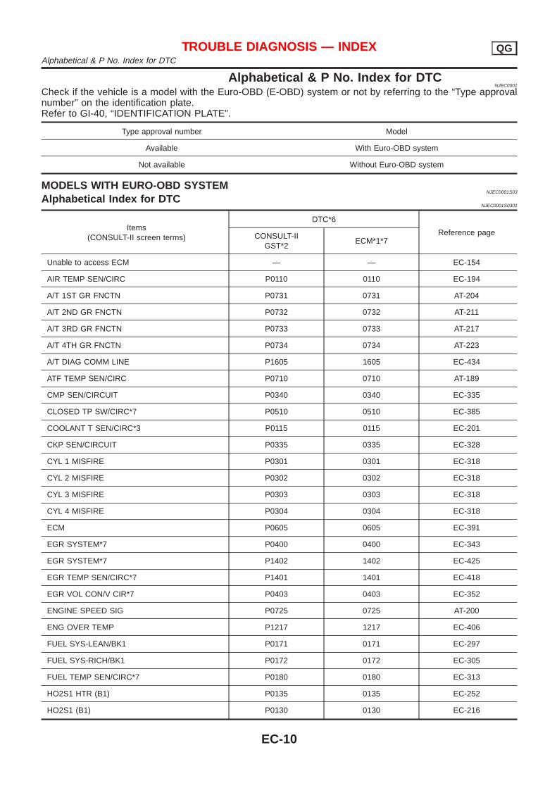
Alphabetical & P No. Index for DTCNJEC0001
Check if the vehicle is a model with the Euro-OBD (E-OBD) system or not by referring to the “Type approvalnumber” on the identification plate.Refer to GI-40, “IDENTIFICATION PLATE”.
Type approval number Model
Available With Euro-OBD system
Not available Without Euro-OBD system
MODELS WITH EURO-OBD SYSTEMNJEC0001S03
Alphabetical Index for DTCNJEC0001S0301
Items(CONSULT-II screen terms)
DTC*6
Reference pageCONSULT-IIGST*2
ECM*1*7
Unable to access ECM — — EC-154
AIR TEMP SEN/CIRC P0110 0110 EC-194
A/T 1ST GR FNCTN P0731 0731 AT-204
A/T 2ND GR FNCTN P0732 0732 AT-211
A/T 3RD GR FNCTN P0733 0733 AT-217
A/T 4TH GR FNCTN P0734 0734 AT-223
A/T DIAG COMM LINE P1605 1605 EC-434
ATF TEMP SEN/CIRC P0710 0710 AT-189
CMP SEN/CIRCUIT P0340 0340 EC-335
CLOSED TP SW/CIRC*7 P0510 0510 EC-385
COOLANT T SEN/CIRC*3 P0115 0115 EC-201
CKP SEN/CIRCUIT P0335 0335 EC-328
CYL 1 MISFIRE P0301 0301 EC-318
CYL 2 MISFIRE P0302 0302 EC-318
CYL 3 MISFIRE P0303 0303 EC-318
CYL 4 MISFIRE P0304 0304 EC-318
ECM P0605 0605 EC-391
EGR SYSTEM*7 P0400 0400 EC-343
EGR SYSTEM*7 P1402 1402 EC-425
EGR TEMP SEN/CIRC*7 P1401 1401 EC-418
EGR VOL CON/V CIR*7 P0403 0403 EC-352
ENGINE SPEED SIG P0725 0725 AT-200
ENG OVER TEMP P1217 1217 EC-406
FUEL SYS-LEAN/BK1 P0171 0171 EC-297
FUEL SYS-RICH/BK1 P0172 0172 EC-305
FUEL TEMP SEN/CIRC*7 P0180 0180 EC-313
HO2S1 HTR (B1) P0135 0135 EC-252
HO2S1 (B1) P0130 0130 EC-216
TROUBLE DIAGNOSIS — INDEX QGAlphabetical & P No. Index for DTC
EC-10
Items(CONSULT-II screen terms)
DTC*6
Reference pageCONSULT-IIGST*2
ECM*1*7
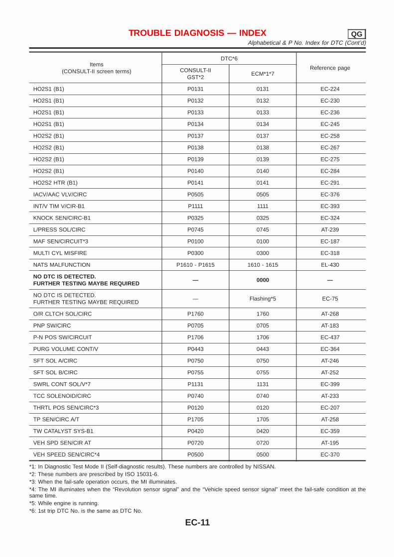
HO2S1 (B1) P0131 0131 EC-224
HO2S1 (B1) P0132 0132 EC-230
HO2S1 (B1) P0133 0133 EC-236
HO2S1 (B1) P0134 0134 EC-245
HO2S2 (B1) P0137 0137 EC-258
HO2S2 (B1) P0138 0138 EC-267
HO2S2 (B1) P0139 0139 EC-275
HO2S2 (B1) P0140 0140 EC-284
HO2S2 HTR (B1) P0141 0141 EC-291
IACV/AAC VLV/CIRC P0505 0505 EC-376
INT/V TIM V/CIR-B1 P1111 1111 EC-393
KNOCK SEN/CIRC-B1 P0325 0325 EC-324
L/PRESS SOL/CIRC P0745 0745 AT-239
MAF SEN/CIRCUIT*3 P0100 0100 EC-187
MULTI CYL MISFIRE P0300 0300 EC-318
NATS MALFUNCTION P1610 - P1615 1610 - 1615 EL-430
NO DTC IS DETECTED.FURTHER TESTING MAYBE REQUIRED
— 0000 —
NO DTC IS DETECTED.FURTHER TESTING MAYBE REQUIRED
— Flashing*5 EC-75
O/R CLTCH SOL/CIRC P1760 1760 AT-268
PNP SW/CIRC P0705 0705 AT-183
P-N POS SW/CIRCUIT P1706 1706 EC-437
PURG VOLUME CONT/V P0443 0443 EC-364
SFT SOL A/CIRC P0750 0750 AT-246
SFT SOL B/CIRC P0755 0755 AT-252
SWRL CONT SOL/V*7 P1131 1131 EC-399
TCC SOLENOID/CIRC P0740 0740 AT-233
THRTL POS SEN/CIRC*3 P0120 0120 EC-207
TP SEN/CIRC A/T P1705 1705 AT-258
TW CATALYST SYS-B1 P0420 0420 EC-359
VEH SPD SEN/CIR AT P0720 0720 AT-195
VEH SPEED SEN/CIRC*4 P0500 0500 EC-370
*1: In Diagnostic Test Mode II (Self-diagnostic results). These numbers are controlled by NISSAN.*2: These numbers are prescribed by ISO 15031-6.*3: When the fail-safe operation occurs, the MI illuminates.*4: The MI illuminates when the “Revolution sensor signal” and the “Vehicle speed sensor signal” meet the fail-safe condition at thesame time.*5: While engine is running.*6: 1st trip DTC No. is the same as DTC No.
TROUBLE DIAGNOSIS — INDEX QGAlphabetical & P No. Index for DTC (Cont’d)
EC-11
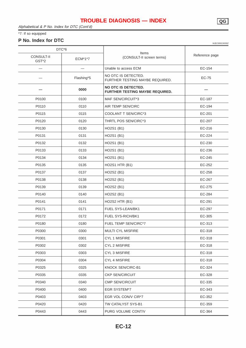
*7: If so equipped
P No. Index for DTCNJEC0001S0302
DTC*6Items
(CONSULT-II screen terms)Reference pageCONSULT-II
GST*2ECM*1*7
— — Unable to access ECM EC-154
— Flashing*5NO DTC IS DETECTED.FURTHER TESTING MAYBE REQUIRED.
EC-75
— 0000NO DTC IS DETECTED.FURTHER TESTING MAYBE REQUIRED.
—
P0100 0100 MAF SEN/CIRCUIT*3 EC-187
P0110 0110 AIR TEMP SEN/CIRC EC-194
P0115 0115 COOLANT T SEN/CIRC*3 EC-201
P0120 0120 THRTL POS SEN/CIRC*3 EC-207
P0130 0130 HO2S1 (B1) EC-216
P0131 0131 HO2S1 (B1) EC-224
P0132 0132 HO2S1 (B1) EC-230
P0133 0133 HO2S1 (B1) EC-236
P0134 0134 HO2S1 (B1) EC-245
P0135 0135 HO2S1 HTR (B1) EC-252
P0137 0137 HO2S2 (B1) EC-258
P0138 0138 HO2S2 (B1) EC-267
P0139 0139 HO2S2 (B1) EC-275
P0140 0140 HO2S2 (B1) EC-284
P0141 0141 HO2S2 HTR (B1) EC-291
P0171 0171 FUEL SYS-LEAN/BK1 EC-297
P0172 0172 FUEL SYS-RICH/BK1 EC-305
P0180 0180 FUEL TEMP SEN/CIRC*7 EC-313
P0300 0300 MULTI CYL MISFIRE EC-318
P0301 0301 CYL 1 MISFIRE EC-318
P0302 0302 CYL 2 MISFIRE EC-318
P0303 0303 CYL 3 MISFIRE EC-318
P0304 0304 CYL 4 MISFIRE EC-318
P0325 0325 KNOCK SEN/CIRC-B1 EC-324
P0335 0335 CKP SEN/CIRCUIT EC-328
P0340 0340 CMP SEN/CIRCUIT EC-335
P0400 0400 EGR SYSTEM*7 EC-343
P0403 0403 EGR VOL CON/V CIR*7 EC-352
P0420 0420 TW CATALYST SYS-B1 EC-359
P0443 0443 PURG VOLUME CONT/V EC-364
TROUBLE DIAGNOSIS — INDEX QGAlphabetical & P No. Index for DTC (Cont’d)
EC-12
DTC*6Items
(CONSULT-II screen terms)Reference pageCONSULT-II
GST*2ECM*1*7
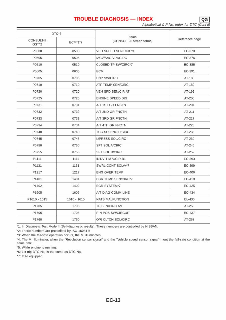
P0500 0500 VEH SPEED SEN/CIRC*4 EC-370
P0505 0505 IACV/AAC VLV/CIRC EC-376
P0510 0510 CLOSED TP SW/CIRC*7 EC-385
P0605 0605 ECM EC-391
P0705 0705 PNP SW/CIRC AT-183
P0710 0710 ATF TEMP SEN/CIRC AT-189
P0720 0720 VEH SPD SEN/CIR AT AT-195
P0725 0725 ENGINE SPEED SIG AT-200
P0731 0731 A/T 1ST GR FNCTN AT-204
P0732 0732 A/T 2ND GR FNCTN AT-211
P0733 0733 A/T 3RD GR FNCTN AT-217
P0734 0734 A/T 4TH GR FNCTN AT-223
P0740 0740 TCC SOLENOID/CIRC AT-233
P0745 0745 L/PRESS SOL/CIRC AT-239
P0750 0750 SFT SOL A/CIRC AT-246
P0755 0755 SFT SOL B/CIRC AT-252
P1111 1111 INT/V TIM V/CIR-B1 EC-393
P1131 1131 SWRL CONT SOL/V*7 EC-399
P1217 1217 ENG OVER TEMP EC-406
P1401 1401 EGR TEMP SEN/CIRC*7 EC-418
P1402 1402 EGR SYSTEM*7 EC-425
P1605 1605 A/T DIAG COMM LINE EC-434
P1610 - 1615 1610 - 1615 NATS MALFUNCTION EL-430
P1705 1705 TP SEN/CIRC A/T AT-258
P1706 1706 P-N POS SW/CIRCUIT EC-437
P1760 1760 O/R CLTCH SOL/CIRC AT-268
*1: In Diagnostic Test Mode II (Self-diagnostic results). These numbers are controlled by NISSAN.*2: These numbers are prescribed by ISO 15031-6*3: When the fail-safe operation occurs, the MI illuminates.*4: The MI illuminates when the “Revolution sensor signal” and the “Vehicle speed sensor signal” meet the fail-safe condition at thesame time.*5: While engine is running.*6: 1st trip DTC No. is the same as DTC No.*7: If so equipped
TROUBLE DIAGNOSIS — INDEX QGAlphabetical & P No. Index for DTC (Cont’d)
EC-13
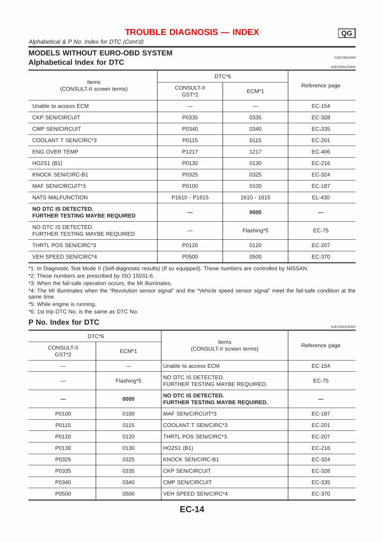
MODELS WITHOUT EURO-OBD SYSTEMNJEC0001S04
Alphabetical Index for DTCNJEC0001S0401
Items(CONSULT-II screen terms)
DTC*6
Reference pageCONSULT-IIGST*2
ECM*1
Unable to access ECM — — EC-154
CKP SEN/CIRCUIT P0335 0335 EC-328
CMP SEN/CIRCUIT P0340 0340 EC-335
COOLANT T SEN/CIRC*3 P0115 0115 EC-201
ENG OVER TEMP P1217 1217 EC-406
HO2S1 (B1) P0130 0130 EC-216
KNOCK SEN/CIRC-B1 P0325 0325 EC-324
MAF SEN/CIRCUIT*3 P0100 0100 EC-187
NATS MALFUNCTION P1610 - P1615 1610 - 1615 EL-430
NO DTC IS DETECTED.FURTHER TESTING MAYBE REQUIRED
— 0000 —
NO DTC IS DETECTED.FURTHER TESTING MAYBE REQUIRED
— Flashing*5 EC-75
THRTL POS SEN/CIRC*3 P0120 0120 EC-207
VEH SPEED SEN/CIRC*4 P0500 0500 EC-370
*1: In Diagnostic Test Mode II (Self-diagnostic results) (If so equipped). These numbers are controlled by NISSAN.*2: These numbers are prescribed by ISO 15031-6.*3: When the fail-safe operation occurs, the MI illuminates.*4: The MI illuminates when the “Revolution sensor signal” and the “Vehicle speed sensor signal” meet the fail-safe condition at thesame time.*5: While engine is running.*6: 1st trip DTC No. is the same as DTC No.
P No. Index for DTCNJEC0001S0402
DTC*6Items
(CONSULT-II screen terms)Reference pageCONSULT-II
GST*2ECM*1
— — Unable to access ECM EC-154
— Flashing*5NO DTC IS DETECTED.FURTHER TESTING MAYBE REQUIRED.
EC-75
— 0000NO DTC IS DETECTED.FURTHER TESTING MAYBE REQUIRED.
—
P0100 0100 MAF SEN/CIRCUIT*3 EC-187
P0115 0115 COOLANT T SEN/CIRC*3 EC-201
P0120 0120 THRTL POS SEN/CIRC*3 EC-207
P0130 0130 HO2S1 (B1) EC-216
P0325 0325 KNOCK SEN/CIRC-B1 EC-324
P0335 0335 CKP SEN/CIRCUIT EC-328
P0340 0340 CMP SEN/CIRCUIT EC-335
P0500 0500 VEH SPEED SEN/CIRC*4 EC-370
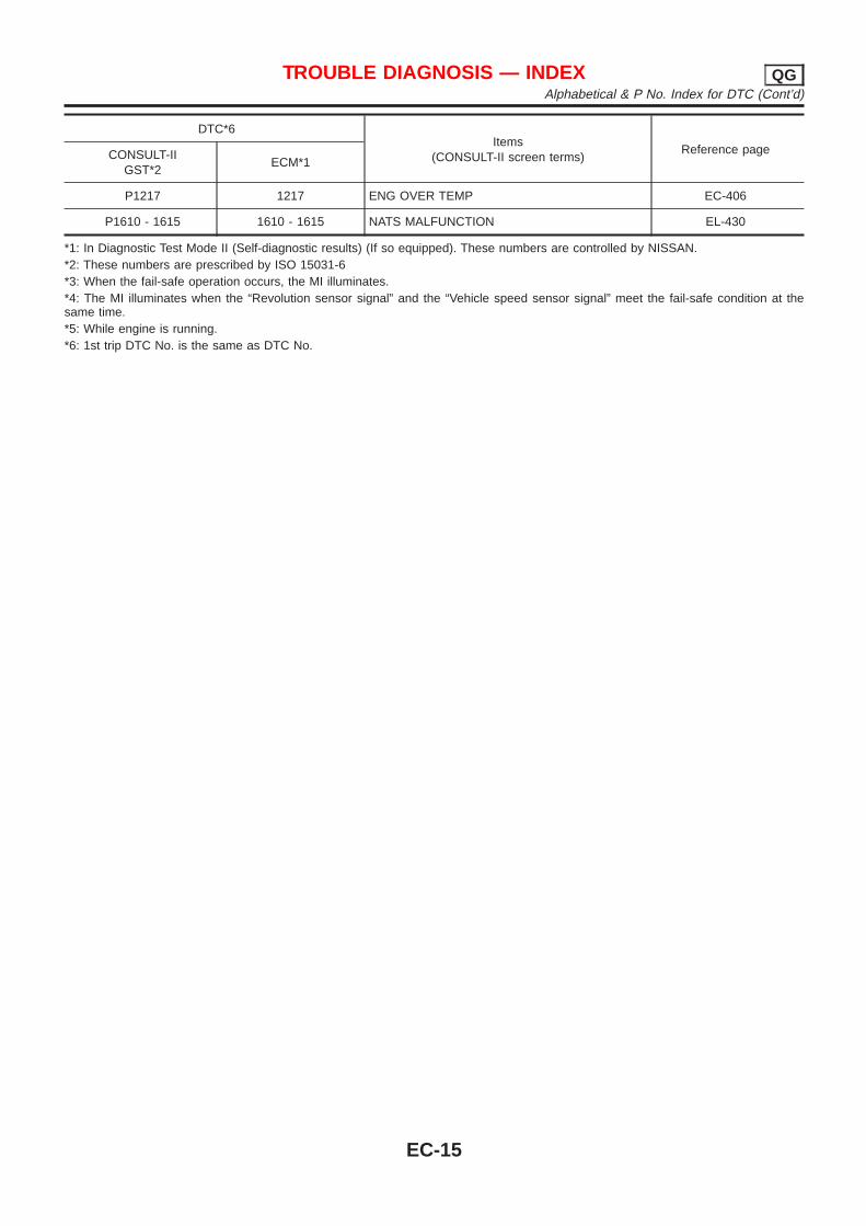
TROUBLE DIAGNOSIS — INDEX QGAlphabetical & P No. Index for DTC (Cont’d)
EC-14
DTC*6Items
(CONSULT-II screen terms)Reference pageCONSULT-II
GST*2ECM*1
P1217 1217 ENG OVER TEMP EC-406
P1610 - 1615 1610 - 1615 NATS MALFUNCTION EL-430
*1: In Diagnostic Test Mode II (Self-diagnostic results) (If so equipped). These numbers are controlled by NISSAN.*2: These numbers are prescribed by ISO 15031-6*3: When the fail-safe operation occurs, the MI illuminates.*4: The MI illuminates when the “Revolution sensor signal” and the “Vehicle speed sensor signal” meet the fail-safe condition at thesame time.*5: While engine is running.*6: 1st trip DTC No. is the same as DTC No.
TROUBLE DIAGNOSIS — INDEX QGAlphabetical & P No. Index for DTC (Cont’d)
EC-15
Supplemental Restraint System (SRS) “AIRBAG” and “SEAT BELT PRE-TENSIONER”
NJEC0002
The Supplemental Restraint System such as “AIR BAG” and “SEAT BELT PRE-TENSIONER” used along witha seat belt, helps to reduce the risk or severity of injury to the driver and front passenger for certain types ofcollision. The SRS system composition which is available to NISSAN MODEL N16 is as follows (The compo-sition varies according to the destination and optional equipment.):+ For a frontal collision
The Supplemental Restraint System consists of driver air bag module (located in the center of the steer-ing wheel), front passenger air bag module (located on the instrument panel on passenger side), front seatbelt pre-tensioners, a diagnoses sensor unit, warning lamp, wiring harness and spiral cable.
+ For a side collisionThe Supplemental Restraint System consists of front side air bag module (located in the outer side of frontseat), side air bag (satellite) sensor, diagnoses sensor unit (one of components of air bags for a frontalcollision), wiring harness, warning lamp (one of components of air bags for a frontal collision).
Information necessary to service the system safely is included in the RS section of this Service Manual.WARNING:+ To avoid rendering the SRS inoperative, which could increase the risk of personal injury or death
in the event of a collision which would result in air bag inflation, all maintenance should be per-formed by an authorized NISSAN dealer.
+ Improper maintenance, including incorrect removal and installation of the SRS, can lead to per-sonal injury caused by unintentional activation of the system. For removal of Spiral Cable and AirBag Module, see the RS section.
+ Do not use electrical test equipment on any circuit related to the SRS unless instructed to in thisService Manual. SRS wiring harness can be identified by yellow harness connector.
Precautions for On Board Diagnostic (OBD)System of Engine and A/T
NJEC0003
The ECM has an on board diagnostic system. It will light up the malfunction indicator (MI) to warn the driverof a malfunction causing emission deterioration.CAUTION:+ Be sure to turn the ignition switch “OFF” and disconnect the negative battery terminal before any
repair or inspection work. The open/short circuit of related switches, sensors, solenoid valves, etc.will cause the MI to light up.
+ Be sure to connect and lock the connectors securely after work. A loose (unlocked) connector willcause the MI to light up due to the open circuit. (Be sure the connector is free from water, grease,dirt, bent terminals, etc.)
+ Certain systems and components, especially those related to OBD, may use a new style slide-locking type harness connector.For description and how to disconnect, refer to EL section, “Description”, “HARNESS CONNEC-TOR”.
+ Be sure to route and secure the harnesses properly after work. The interference of the harness witha bracket, etc. may cause the MI to light up due to the short circuit.
+ Be sure to connect rubber tubes properly after work. A misconnected or disconnected rubber tubemay cause the MI to light up due to the malfunction of fuel injection system, etc.
+ Be sure to erase the unnecessary malfunction information (repairs completed) from the ECM andTCM (Transmission Control Module) before returning the vehicle to the customer.
PRECAUTIONS QGSupplemental Restraint System (SRS) “AIR BAG” and “SEAT BELT PRE-TENSIONER”
EC-16
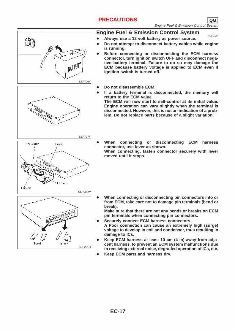
SEF706Y
Engine Fuel & Emission Control System=NJEC0004
+ Always use a 12 volt battery as power source.+ Do not attempt to disconnect battery cables while engine
is running.+ Before connecting or disconnecting the ECM harness
connector, turn ignition switch OFF and disconnect nega-tive battery terminal. Failure to do so may damage theECM because battery voltage is applied to ECM even ifignition switch is turned off.
SEF707Y
+ Do not disassemble ECM.+ If a battery terminal is disconnected, the memory will
return to the ECM value.The ECM will now start to self-control at its initial value.Engine operation can vary slightly when the terminal isdisconnected. However, this is not an indication of a prob-lem. Do not replace parts because of a slight variation.
SEF908W
+ When connecting or disconnecting ECM harnessconnector, use lever as shown.When connecting, fasten connector securely with levermoved until it stops.
SEF291H
+ When connecting or disconnecting pin connectors into orfrom ECM, take care not to damage pin terminals (bend orbreak).Make sure that there are not any bends or breaks on ECMpin terminals when connecting pin connectors.
+ Securely connect ECM harness connectors.A Poor connection can cause an extremely high (surge)voltage to develop in coil and condenser, thus resulting indamage to ICs.
+ Keep ECM harness at least 10 cm (4 in) away from adja-cent harness, to prevent an ECM system malfunctions dueto receiving external noise, degraded operation of ICs, etc.
+ Keep ECM parts and harness dry.
PRECAUTIONS QGEngine Fuel & Emission Control System
EC-17
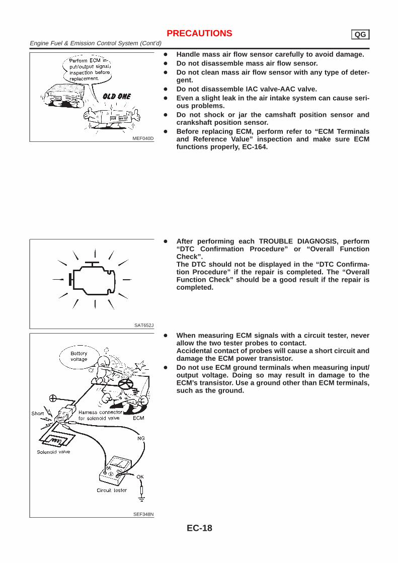
MEF040D
+ Handle mass air flow sensor carefully to avoid damage.+ Do not disassemble mass air flow sensor.+ Do not clean mass air flow sensor with any type of deter-
gent.+ Do not disassemble IAC valve-AAC valve.+ Even a slight leak in the air intake system can cause seri-
ous problems.+ Do not shock or jar the camshaft position sensor and
crankshaft position sensor.+ Before replacing ECM, perform refer to “ECM Terminals
and Reference Value” inspection and make sure ECMfunctions properly, EC-164.
SAT652J
+ After performing each TROUBLE DIAGNOSIS, perform“DTC Confirmation Procedure” or “Overall FunctionCheck”.The DTC should not be displayed in the “DTC Confirma-tion Procedure” if the repair is completed. The “OverallFunction Check” should be a good result if the repair iscompleted.
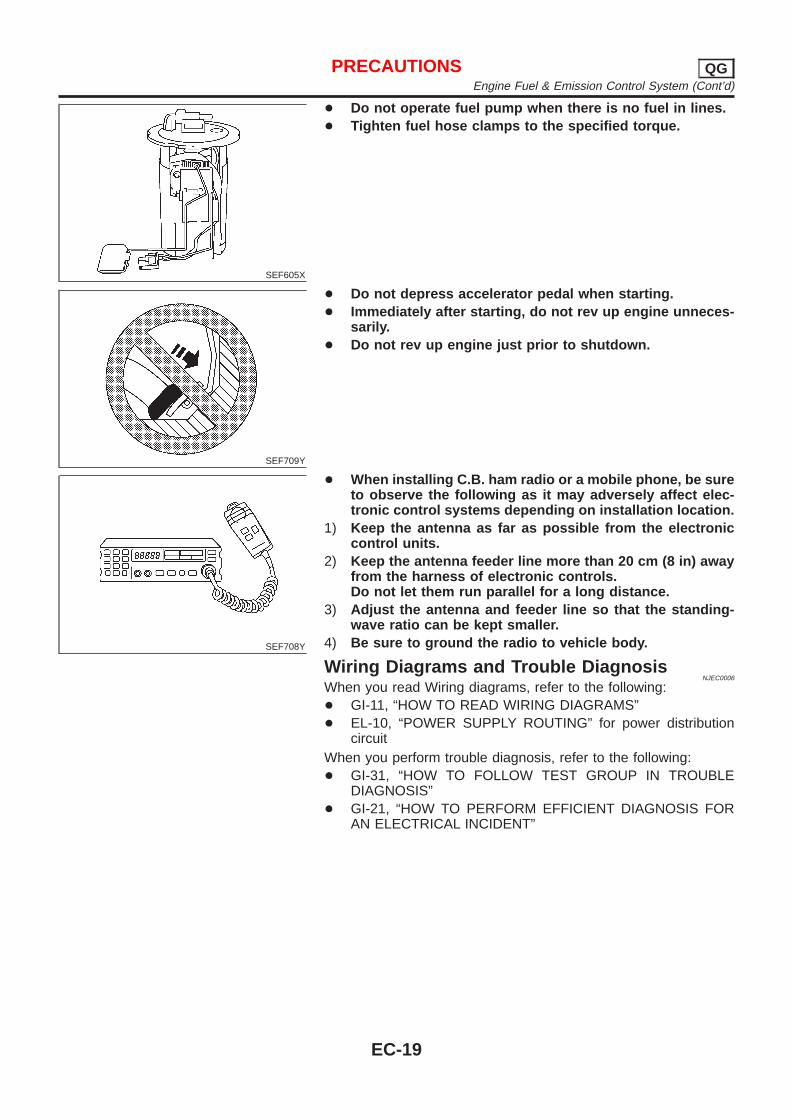
SEF348N
+ When measuring ECM signals with a circuit tester, neverallow the two tester probes to contact.Accidental contact of probes will cause a short circuit anddamage the ECM power transistor.
+ Do not use ECM ground terminals when measuring input/output voltage. Doing so may result in damage to theECM’s transistor. Use a ground other than ECM terminals,such as the ground.
PRECAUTIONS QGEngine Fuel & Emission Control System (Cont’d)
EC-18
SEF605X
+ Do not operate fuel pump when there is no fuel in lines.+ Tighten fuel hose clamps to the specified torque.
SEF709Y
+ Do not depress accelerator pedal when starting.+ Immediately after starting, do not rev up engine unneces-
sarily.+ Do not rev up engine just prior to shutdown.
SEF708Y
+ When installing C.B. ham radio or a mobile phone, be sureto observe the following as it may adversely affect elec-tronic control systems depending on installation location.
1) Keep the antenna as far as possible from the electroniccontrol units.
2) Keep the antenna feeder line more than 20 cm (8 in) awayfrom the harness of electronic controls.Do not let them run parallel for a long distance.
3) Adjust the antenna and feeder line so that the standing-wave ratio can be kept smaller.
4) Be sure to ground the radio to vehicle body.
Wiring Diagrams and Trouble DiagnosisNJEC0006
When you read Wiring diagrams, refer to the following:+ GI-11, “HOW TO READ WIRING DIAGRAMS”+ EL-10, “POWER SUPPLY ROUTING” for power distribution
circuitWhen you perform trouble diagnosis, refer to the following:+ GI-31, “HOW TO FOLLOW TEST GROUP IN TROUBLE
DIAGNOSIS”+ GI-21, “HOW TO PERFORM EFFICIENT DIAGNOSIS FOR
AN ELECTRICAL INCIDENT”
PRECAUTIONS QGEngine Fuel & Emission Control System (Cont’d)
EC-19
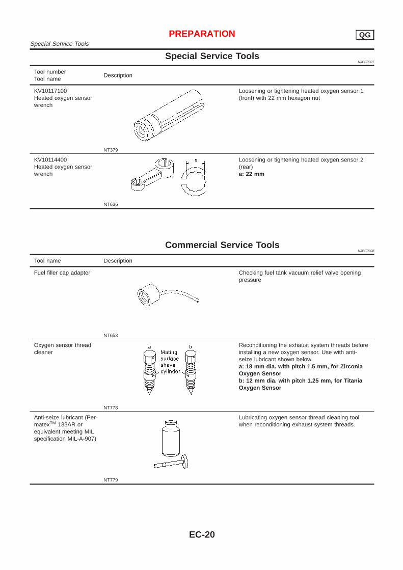
Special Service ToolsNJEC0007
Tool numberTool name
Description
KV10117100Heated oxygen sensorwrench
NT379
Loosening or tightening heated oxygen sensor 1(front) with 22 mm hexagon nut
KV10114400Heated oxygen sensorwrench
NT636
Loosening or tightening heated oxygen sensor 2(rear)a: 22 mm
Commercial Service ToolsNJEC0008
Tool name Description
Fuel filler cap adapter
NT653
Checking fuel tank vacuum relief valve openingpressure
Oxygen sensor threadcleaner
NT778
Reconditioning the exhaust system threads beforeinstalling a new oxygen sensor. Use with anti-seize lubricant shown below.a: 18 mm dia. with pitch 1.5 mm, for ZirconiaOxygen Sensorb: 12 mm dia. with pitch 1.25 mm, for TitaniaOxygen Sensor
Anti-seize lubricant (Per-matexTM 133AR orequivalent meeting MILspecification MIL-A-907)
NT779
Lubricating oxygen sensor thread cleaning toolwhen reconditioning exhaust system threads.
PREPARATION QGSpecial Service Tools
EC-20
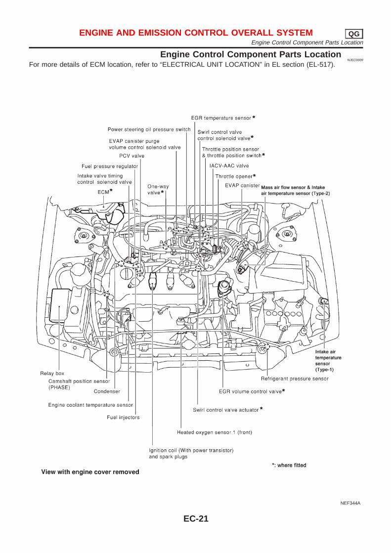
Engine Control Component Parts LocationNJEC0009
For more details of ECM location, refer to “ELECTRICAL UNIT LOCATION” in EL section (EL-517).
NEF344A
ENGINE AND EMISSION CONTROL OVERALL SYSTEM QGEngine Control Component Parts Location
EC-21
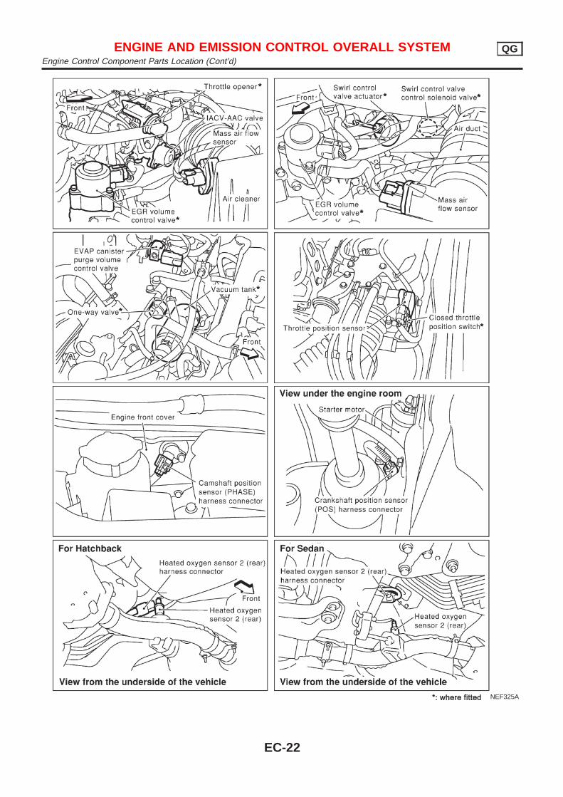
NEF325A
ENGINE AND EMISSION CONTROL OVERALL SYSTEM QGEngine Control Component Parts Location (Cont’d)
EC-22
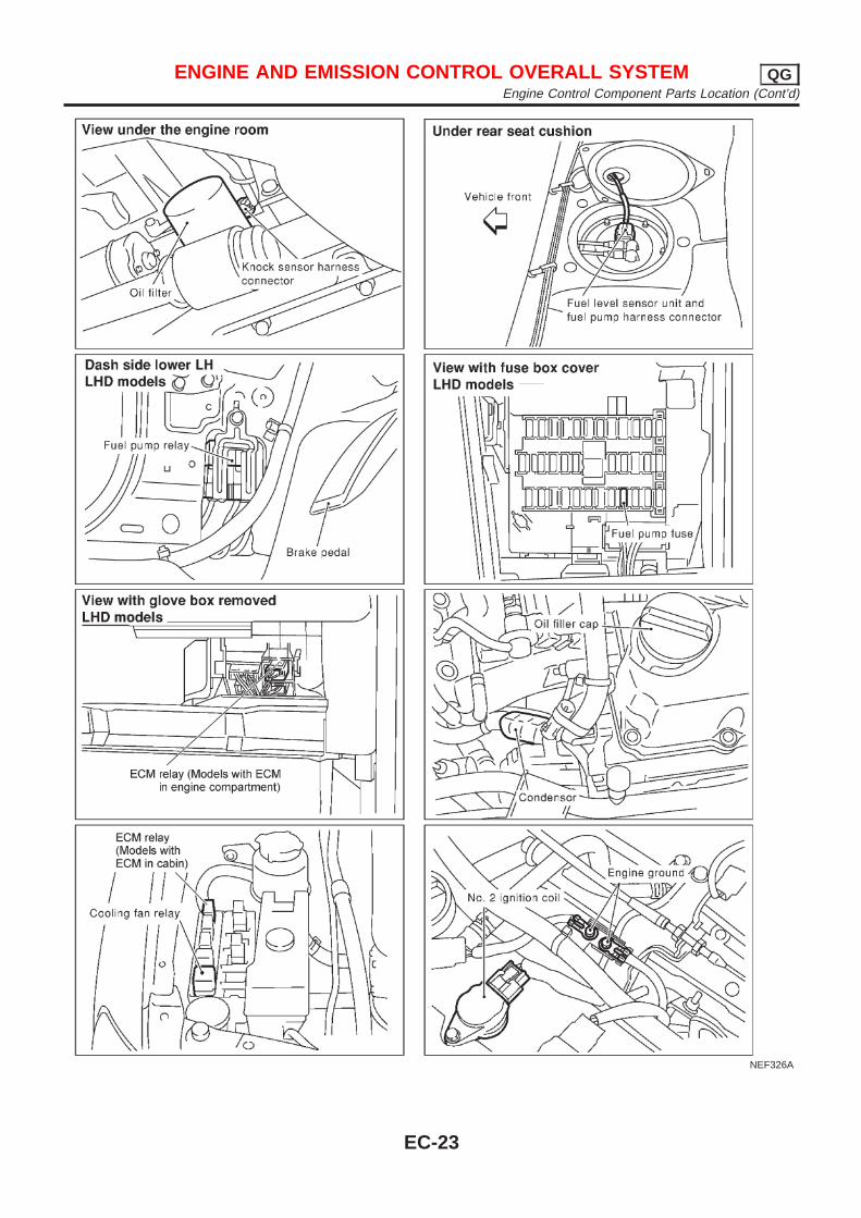
NEF326A
ENGINE AND EMISSION CONTROL OVERALL SYSTEM QGEngine Control Component Parts Location (Cont’d)
EC-23
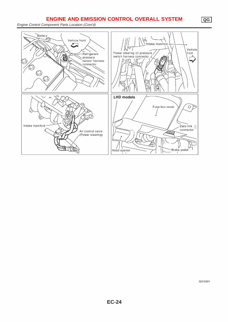
SEF599Y
ENGINE AND EMISSION CONTROL OVERALL SYSTEM QGEngine Control Component Parts Location (Cont’d)
EC-24
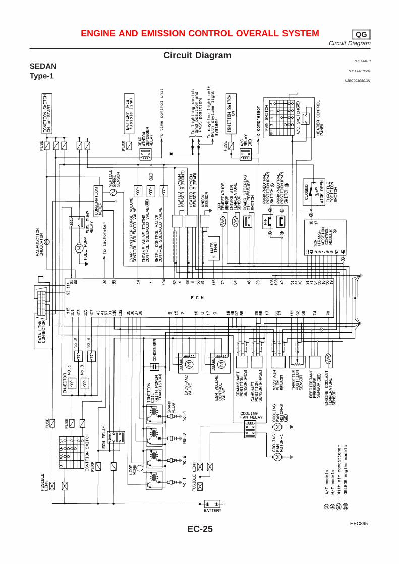
Circuit DiagramNJEC0010
SEDANNJEC0010S01
Type-1NJEC0010S0101
HEC895
ENGINE AND EMISSION CONTROL OVERALL SYSTEM QGCircuit Diagram
EC-25
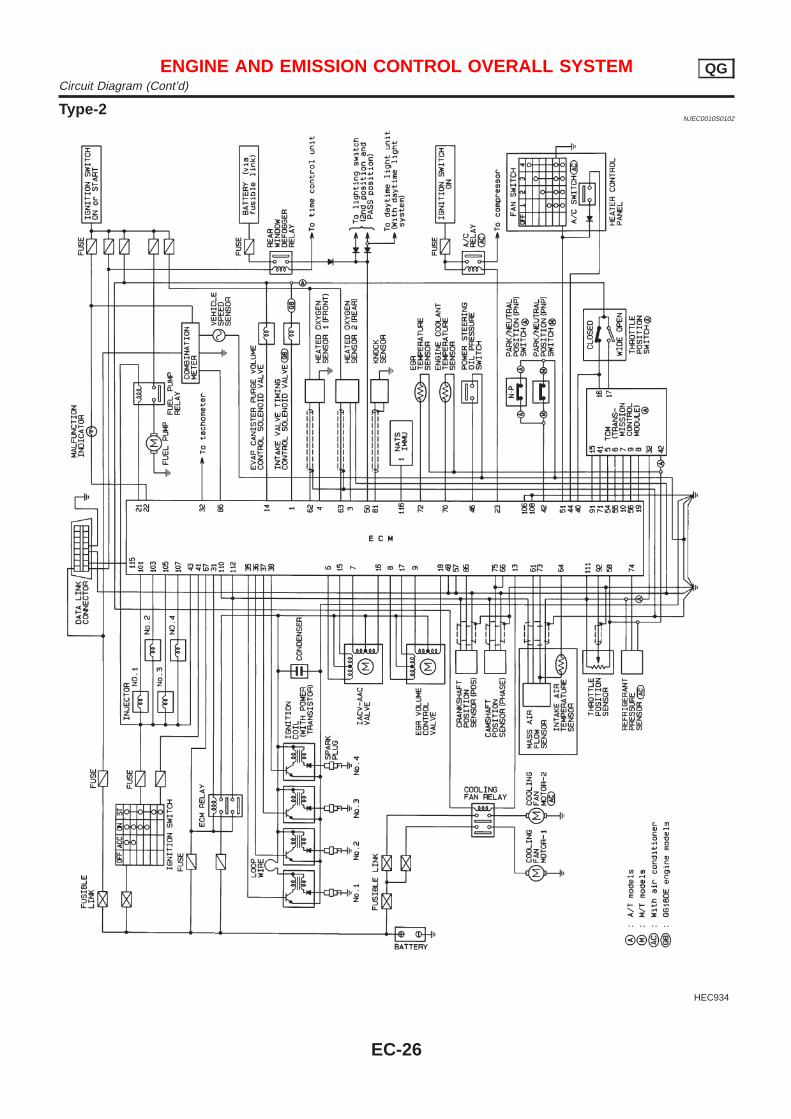
Type-2NJEC0010S0102
HEC934
ENGINE AND EMISSION CONTROL OVERALL SYSTEM QGCircuit Diagram (Cont’d)
EC-26
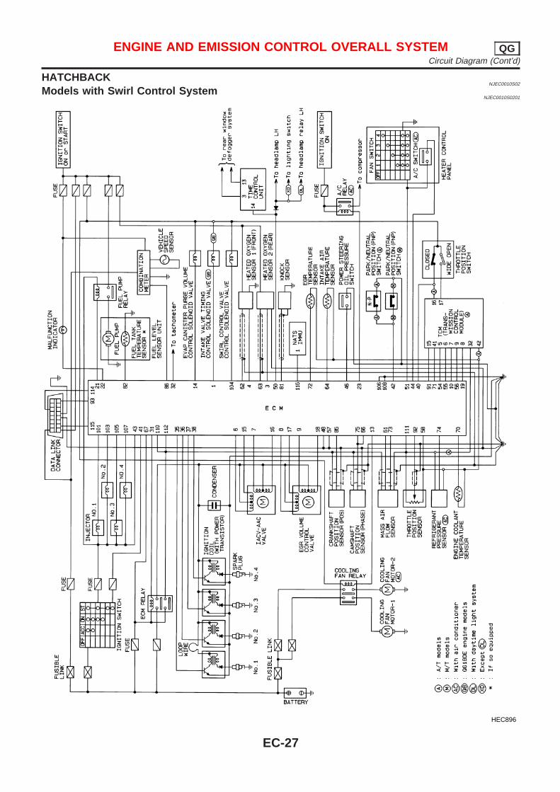
HATCHBACKNJEC0010S02
Models with Swirl Control SystemNJEC0010S0201
HEC896
ENGINE AND EMISSION CONTROL OVERALL SYSTEM QGCircuit Diagram (Cont’d)
EC-27
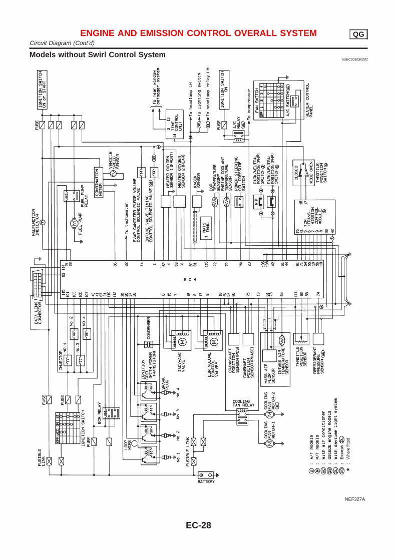
Models without Swirl Control SystemNJEC0010S0202
NEF327A
ENGINE AND EMISSION CONTROL OVERALL SYSTEM QGCircuit Diagram (Cont’d)
EC-28
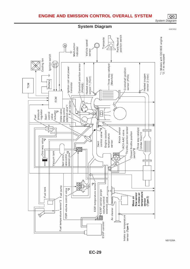
System DiagramNJEC0011
NEF328A
ENGINE AND EMISSION CONTROL OVERALL SYSTEM QGSystem Diagram
EC-29
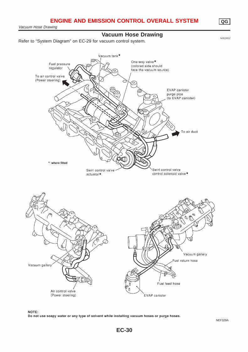
Vacuum Hose DrawingNJEC0012
Refer to “System Diagram” on EC-29 for vacuum control system.
NEF329A
ENGINE AND EMISSION CONTROL OVERALL SYSTEM QGVacuum Hose Drawing
EC-30
System ChartNJEC0013
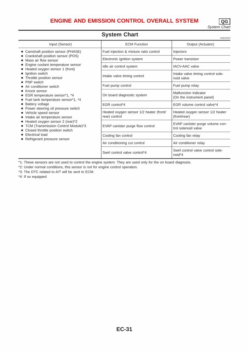
Input (Sensor) ECM Function Output (Actuator)
+ Camshaft position sensor (PHASE)+ Crankshaft position sensor (POS)+ Mass air flow sensor+ Engine coolant temperature sensor+ Heated oxygen sensor 1 (front)+ Ignition switch+ Throttle position sensor+ PNP switch+ Air conditioner switch+ Knock sensor+ EGR temperature sensor*1, *4+ Fuel tank temperature sensor*1, *4+ Battery voltage+ Power steering oil pressure switch+ Vehicle speed sensor+ Intake air temperature sensor+ Heated oxygen sensor 2 (rear)*2+ TCM (Transmission Control Module)*3+ Closed throttle position switch+ Electrical load+ Refrigerant pressure sensor
Fuel injection & mixture ratio control Injectors
Electronic ignition system Power transistor
Idle air control system IACV-AAC valve
Intake valve timing controlIntake valve timing control sole-noid valve
Fuel pump control Fuel pump relay
On board diagnostic systemMalfunction indicator(On the instrument panel)
EGR control*4 EGR volume control valve*4
Heated oxygen sensor 1/2 heater (front/rear) control
Heated oxygen sensor 1/2 heater(front/rear)
EVAP canister purge flow controlEVAP canister purge volume con-trol solenoid valve
Cooling fan control Cooling fan relay
Air conditioning cut control Air conditioner relay
Swirl control valve control*4Swirl control valve control sole-noid*4
*1: These sensors are not used to control the engine system. They are used only for the on board diagnosis.*2: Under normal conditions, this sensor is not for engine control operation.*3: The DTC related to A/T will be sent to ECM.*4: If so equipped
ENGINE AND EMISSION CONTROL OVERALL SYSTEM QGSystem Chart
EC-31
Multiport Fuel Injection (MFI) SystemDESCRIPTION
NJEC0014
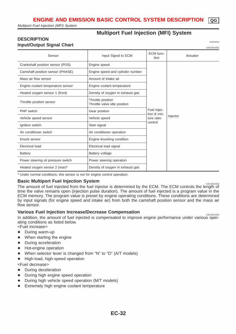
Input/Output Signal ChartNJEC0014S01
Sensor Input Signal to ECMECM func-
tionActuator
Crankshaft position sensor (POS) Engine speed
Fuel injec-tion & mix-ture ratiocontrol
Injector
Camshaft position sensor (PHASE) Engine speed and cylinder number
Mass air flow sensor Amount of intake air
Engine coolant temperature sensor Engine coolant temperature
Heated oxygen sensor 1 (front) Density of oxygen in exhaust gas
Throttle position sensorThrottle positionThrottle valve idle position
PNP switch Gear position
Vehicle speed sensor Vehicle speed
Ignition switch Start signal
Air conditioner switch Air conditioner operation
Knock sensor Engine knocking condition
Electrical load Electrical load signal
Battery Battery voltage
Power steering oil pressure switch Power steering operation
Heated oxygen sensor 2 (rear)* Density of oxygen in exhaust gas
* Under normal conditions, this sensor is not for engine control operation.
Basic Multiport Fuel Injection SystemNJEC0014S02
The amount of fuel injected from the fuel injector is determined by the ECM. The ECM controls the length oftime the valve remains open (injection pulse duration). The amount of fuel injected is a program value in theECM memory. The program value is preset by engine operating conditions. These conditions are determinedby input signals (for engine speed and intake air) from both the camshaft position sensor and the mass airflow sensor.
Various Fuel Injection Increase/Decrease CompensationNJEC0014S03
In addition, the amount of fuel injected is compensated to improve engine performance under various oper-ating conditions as listed below.<Fuel increase>+ During warm-up+ When starting the engine+ During acceleration+ Hot-engine operation+ When selector lever is changed from “N” to “D” (A/T models)+ High-load, high-speed operation<Fuel decrease>+ During deceleration+ During high engine speed operation+ During high vehicle speed operation (M/T models)+ Extremely high engine coolant temperature
ENGINE AND EMISSION BASIC CONTROL SYSTEM DESCRIPTION QGMultiport Fuel Injection (MFI) System
EC-32
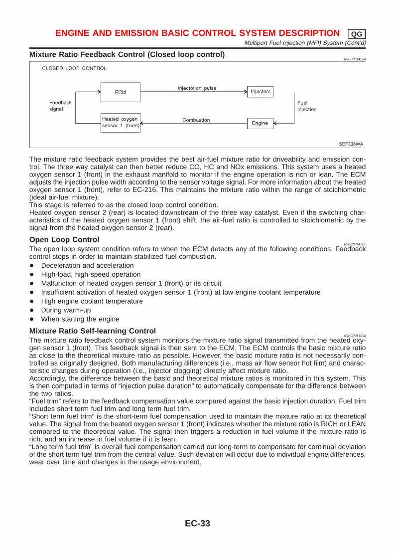
Mixture Ratio Feedback Control (Closed loop control)NJEC0014S04
SEF336WA
The mixture ratio feedback system provides the best air-fuel mixture ratio for driveability and emission con-trol. The three way catalyst can then better reduce CO, HC and NOx emissions. This system uses a heatedoxygen sensor 1 (front) in the exhaust manifold to monitor if the engine operation is rich or lean. The ECMadjusts the injection pulse width according to the sensor voltage signal. For more information about the heatedoxygen sensor 1 (front), refer to EC-216. This maintains the mixture ratio within the range of stoichiometric(ideal air-fuel mixture).This stage is referred to as the closed loop control condition.Heated oxygen sensor 2 (rear) is located downstream of the three way catalyst. Even if the switching char-acteristics of the heated oxygen sensor 1 (front) shift, the air-fuel ratio is controlled to stoichiometric by thesignal from the heated oxygen sensor 2 (rear).
Open Loop ControlNJEC0014S05
The open loop system condition refers to when the ECM detects any of the following conditions. Feedbackcontrol stops in order to maintain stabilized fuel combustion.+ Deceleration and acceleration+ High-load, high-speed operation+ Malfunction of heated oxygen sensor 1 (front) or its circuit+ Insufficient activation of heated oxygen sensor 1 (front) at low engine coolant temperature+ High engine coolant temperature+ During warm-up+ When starting the engine
Mixture Ratio Self-learning ControlNJEC0014S06
The mixture ratio feedback control system monitors the mixture ratio signal transmitted from the heated oxy-gen sensor 1 (front). This feedback signal is then sent to the ECM. The ECM controls the basic mixture ratioas close to the theoretical mixture ratio as possible. However, the basic mixture ratio is not necessarily con-trolled as originally designed. Both manufacturing differences (i.e., mass air flow sensor hot film) and charac-teristic changes during operation (i.e., injector clogging) directly affect mixture ratio.Accordingly, the difference between the basic and theoretical mixture ratios is monitored in this system. Thisis then computed in terms of “injection pulse duration” to automatically compensate for the difference betweenthe two ratios.“Fuel trim” refers to the feedback compensation value compared against the basic injection duration. Fuel trimincludes short term fuel trim and long term fuel trim.“Short term fuel trim” is the short-term fuel compensation used to maintain the mixture ratio at its theoreticalvalue. The signal from the heated oxygen sensor 1 (front) indicates whether the mixture ratio is RICH or LEANcompared to the theoretical value. The signal then triggers a reduction in fuel volume if the mixture ratio isrich, and an increase in fuel volume if it is lean.“Long term fuel trim” is overall fuel compensation carried out long-term to compensate for continual deviationof the short term fuel trim from the central value. Such deviation will occur due to individual engine differences,wear over time and changes in the usage environment.
ENGINE AND EMISSION BASIC CONTROL SYSTEM DESCRIPTION QGMultiport Fuel Injection (MFI) System (Cont’d)
EC-33

Fuel Injection TimingNJEC0014S07
SEF337W
Two types of systems are used.Sequential Multiport Fuel Injection System
NJEC0014S0701
Fuel is injected into each cylinder during each engine cycle according to the firing order. This system is usedwhen the engine is running.Simultaneous Multiport Fuel Injection System
NJEC0014S0702
Fuel is injected simultaneously into all four cylinders twice each engine cycle. In other words, pulse signals ofthe same width are simultaneously transmitted from the ECM.The four injectors will then receive the signals two times for each engine cycle.This system is used when the engine is being started and/or if the fail-safe system (CPU) is operating.
Fuel Shut-offNJEC0014S08
Fuel to each cylinder is cut off during deceleration or operation of the engine at excessively high speeds.
Electronic Ignition (EI) SystemDESCRIPTION
NJEC0015
Input/Output Signal ChartNJEC0015S01
Sensor Input Signal to ECMECM func-
tionActuator
Crankshaft position sensor (POS) Engine speed
Ignition tim-ing control
Power transistor
Camshaft position sensor (PHASE) Engine speed and cylinder number
Mass air flow sensor Amount of intake air
Engine coolant temperature sensor Engine coolant temperature
Throttle position sensorThrottle positionThrottle valve idle position
Vehicle speed sensor Vehicle speed
Ignition switch Start signal
Knock sensor Engine knocking
PNP switch Gear position
Battery Battery voltage
ENGINE AND EMISSION BASIC CONTROL SYSTEM DESCRIPTION QGMultiport Fuel Injection (MFI) System (Cont’d)
EC-34
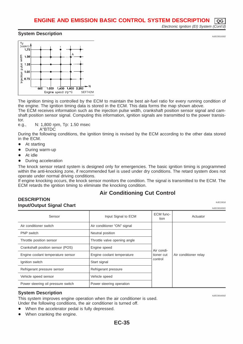
System DescriptionNJEC0015S02
SEF742M
The ignition timing is controlled by the ECM to maintain the best air-fuel ratio for every running condition ofthe engine. The ignition timing data is stored in the ECM. This data forms the map shown above.The ECM receives information such as the injection pulse width, crankshaft position sensor signal and cam-shaft position sensor signal. Computing this information, ignition signals are transmitted to the power transis-tor.e.g., N: 1,800 rpm, Tp: 1.50 msec
A°BTDCDuring the following conditions, the ignition timing is revised by the ECM according to the other data storedin the ECM.+ At starting+ During warm-up+ At idle+ During accelerationThe knock sensor retard system is designed only for emergencies. The basic ignition timing is programmedwithin the anti-knocking zone, if recommended fuel is used under dry conditions. The retard system does notoperate under normal driving conditions.If engine knocking occurs, the knock sensor monitors the condition. The signal is transmitted to the ECM. TheECM retards the ignition timing to eliminate the knocking condition.
Air Conditioning Cut ControlDESCRIPTION
NJEC0016
Input/Output Signal ChartNJEC0016S01
Sensor Input Signal to ECMECM func-
tionActuator
Air conditioner switch Air conditioner “ON” signal
Air condi-tioner cutcontrol
Air conditioner relay
PNP switch Neutral position
Throttle position sensor Throttle valve opening angle
Crankshaft position sensor (POS) Engine speed
Engine coolant temperature sensor Engine coolant temperature
Ignition switch Start signal
Refrigerant pressure sensor Refrigerant pressure
Vehicle speed sensor Vehicle speed
Power steering oil pressure switch Power steering operation
System DescriptionNJEC0016S02
This system improves engine operation when the air conditioner is used.Under the following conditions, the air conditioner is turned off.+ When the accelerator pedal is fully depressed.+ When cranking the engine.
ENGINE AND EMISSION BASIC CONTROL SYSTEM DESCRIPTION QGElectronic Ignition (EI) System (Cont’d)
EC-35
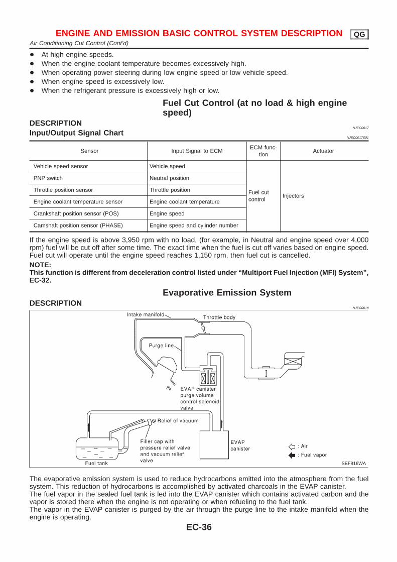
+ At high engine speeds.+ When the engine coolant temperature becomes excessively high.+ When operating power steering during low engine speed or low vehicle speed.+ When engine speed is excessively low.+ When the refrigerant pressure is excessively high or low.
Fuel Cut Control (at no load & high enginespeed)
DESCRIPTIONNJEC0017
Input/Output Signal ChartNJEC0017S01
Sensor Input Signal to ECMECM func-
tionActuator
Vehicle speed sensor Vehicle speed
Fuel cutcontrol
Injectors
PNP switch Neutral position
Throttle position sensor Throttle position
Engine coolant temperature sensor Engine coolant temperature
Crankshaft position sensor (POS) Engine speed
Camshaft position sensor (PHASE) Engine speed and cylinder number
If the engine speed is above 3,950 rpm with no load, (for example, in Neutral and engine speed over 4,000rpm) fuel will be cut off after some time. The exact time when the fuel is cut off varies based on engine speed.Fuel cut will operate until the engine speed reaches 1,150 rpm, then fuel cut is cancelled.NOTE:This function is different from deceleration control listed under “Multiport Fuel Injection (MFI) System”,EC-32.
Evaporative Emission SystemDESCRIPTION
NJEC0018
SEF916WA
The evaporative emission system is used to reduce hydrocarbons emitted into the atmosphere from the fuelsystem. This reduction of hydrocarbons is accomplished by activated charcoals in the EVAP canister.The fuel vapor in the sealed fuel tank is led into the EVAP canister which contains activated carbon and thevapor is stored there when the engine is not operating or when refueling to the fuel tank.The vapor in the EVAP canister is purged by the air through the purge line to the intake manifold when theengine is operating.
ENGINE AND EMISSION BASIC CONTROL SYSTEM DESCRIPTION QGAir Conditioning Cut Control (Cont’d)
EC-36
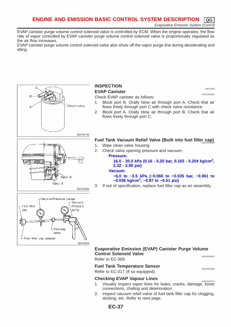
EVAP canister purge volume control solenoid valve is controlled by ECM. When the engine operates, the flowrate of vapor controlled by EVAP canister purge volume control solenoid valve is proportionally regulated asthe air flow increases.EVAP canister purge volume control solenoid valve also shuts off the vapor purge line during decelerating andidling.
SEF917W
INSPECTIONNJEC0019
EVAP CanisterNJEC0019S01
Check EVAP canister as follows:1. Block port B. Orally blow air through port A. Check that air
flows freely through port C with check valve resistance.2. Block port A. Orally blow air through port B. Check that air
flows freely through port C.
SEF918W
SEF943S
Fuel Tank Vacuum Relief Valve (Built into fuel filler cap)NJEC0019S03
1. Wipe clean valve housing.2. Check valve opening pressure and vacuum.
Pressure:16.0 - 20.0 kPa (0.16 - 0.20 bar, 0.163 - 0.204 kg/cm 2,2.32 - 2.90 psi)
Vacuum:−6.0 to −3.5 kPa (−0.060 to −0.035 bar, −0.061 to−0.036 kg/cm 2, −0.87 to −0.51 psi)
3. If out of specification, replace fuel filler cap as an assembly.
Evaporative Emission (EVAP) Canister Purge VolumeControl Solenoid Valve
NJEC0019S07
Refer to EC-369.
Fuel Tank Temperature SensorNJEC0019S08
Refer to EC-317 (If so equipped).
Checking EVAP Vapour LinesNJEC0019S13
1. Visually inspect vapor lines for leaks, cracks, damage, looseconnections, chafing and deterioration.
2. Inspect vacuum relief valve of fuel tank filler cap for clogging,sticking, etc. Refer to next page.
ENGINE AND EMISSION BASIC CONTROL SYSTEM DESCRIPTION QGEvaporative Emission System (Cont’d)
EC-37
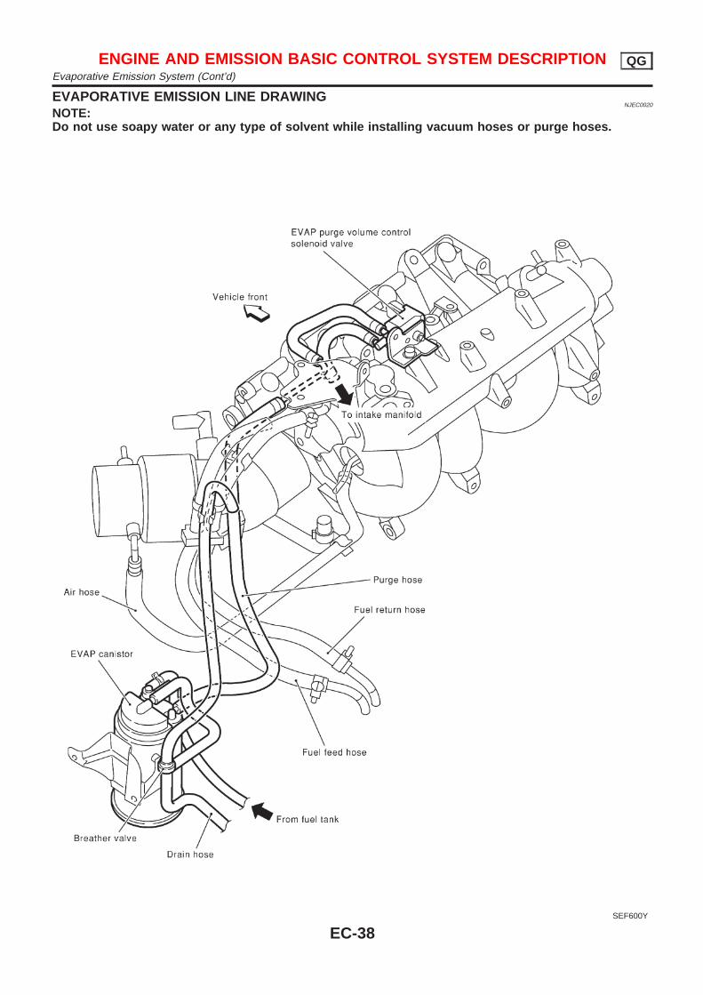
EVAPORATIVE EMISSION LINE DRAWINGNJEC0020
NOTE:Do not use soapy water or any type of solvent while installing vacuum hoses or purge hoses.
SEF600Y
ENGINE AND EMISSION BASIC CONTROL SYSTEM DESCRIPTION QGEvaporative Emission System (Cont’d)
EC-38
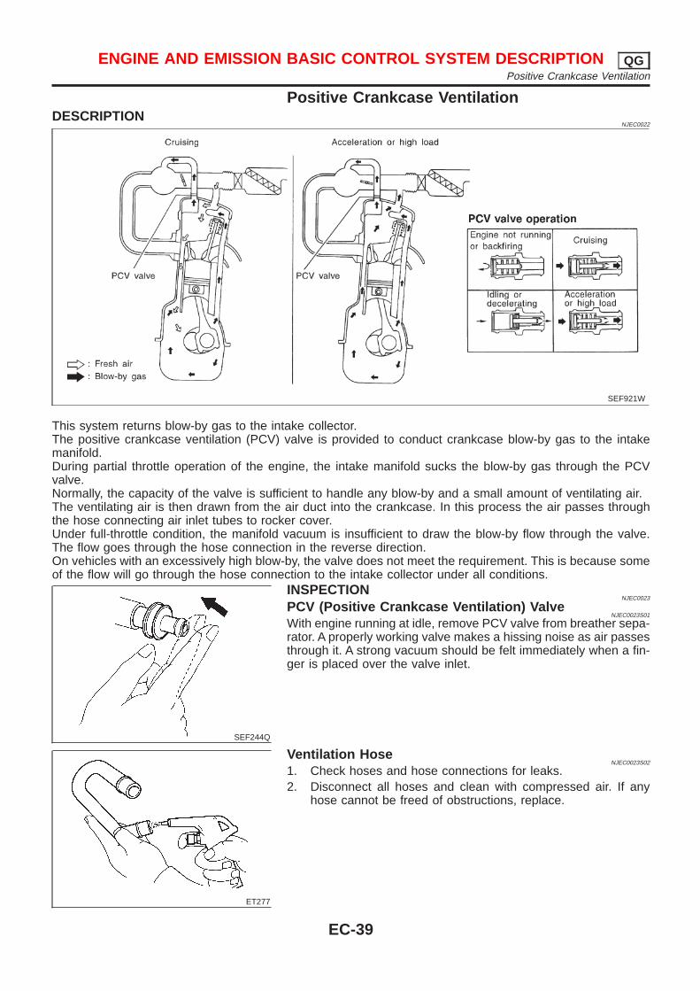
Positive Crankcase VentilationDESCRIPTION
NJEC0022
SEF921W
This system returns blow-by gas to the intake collector.The positive crankcase ventilation (PCV) valve is provided to conduct crankcase blow-by gas to the intakemanifold.During partial throttle operation of the engine, the intake manifold sucks the blow-by gas through the PCVvalve.Normally, the capacity of the valve is sufficient to handle any blow-by and a small amount of ventilating air.The ventilating air is then drawn from the air duct into the crankcase. In this process the air passes throughthe hose connecting air inlet tubes to rocker cover.Under full-throttle condition, the manifold vacuum is insufficient to draw the blow-by flow through the valve.The flow goes through the hose connection in the reverse direction.On vehicles with an excessively high blow-by, the valve does not meet the requirement. This is because someof the flow will go through the hose connection to the intake collector under all conditions.
SEF244Q
INSPECTIONNJEC0023
PCV (Positive Crankcase Ventilation) ValveNJEC0023S01
With engine running at idle, remove PCV valve from breather sepa-rator. A properly working valve makes a hissing noise as air passesthrough it. A strong vacuum should be felt immediately when a fin-ger is placed over the valve inlet.
ET277
Ventilation HoseNJEC0023S02
1. Check hoses and hose connections for leaks.2. Disconnect all hoses and clean with compressed air. If any
hose cannot be freed of obstructions, replace.
ENGINE AND EMISSION BASIC CONTROL SYSTEM DESCRIPTION QGPositive Crankcase Ventilation
EC-39
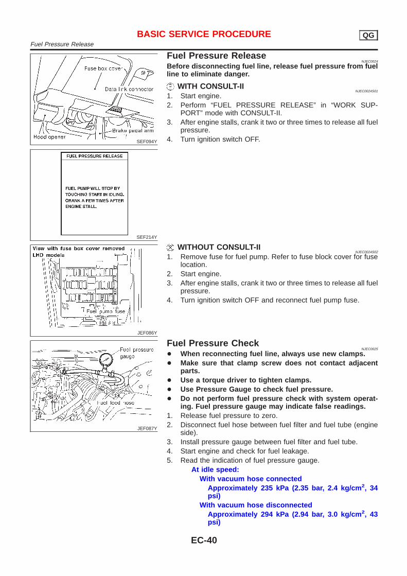
SEF094Y
SEF214Y
Fuel Pressure ReleaseNJEC0024
Before disconnecting fuel line, release fuel pressure from fuelline to eliminate danger.
WITH CONSULT-IINJEC0024S01
1. Start engine.2. Perform “FUEL PRESSURE RELEASE” in “WORK SUP-
PORT” mode with CONSULT-II.3. After engine stalls, crank it two or three times to release all fuel
pressure.4. Turn ignition switch OFF.
JEF086Y
WITHOUT CONSULT-IINJEC0024S02
1. Remove fuse for fuel pump. Refer to fuse block cover for fuselocation.
2. Start engine.3. After engine stalls, crank it two or three times to release all fuel
pressure.4. Turn ignition switch OFF and reconnect fuel pump fuse.
JEF087Y
Fuel Pressure CheckNJEC0025
+ When reconnecting fuel line, always use new clamps.+ Make sure that clamp screw does not contact adjacent
parts.+ Use a torque driver to tighten clamps.+ Use Pressure Gauge to check fuel pressure.+ Do not perform fuel pressure check with system operat-
ing. Fuel pressure gauge may indicate false readings.1. Release fuel pressure to zero.2. Disconnect fuel hose between fuel filter and fuel tube (engine
side).3. Install pressure gauge between fuel filter and fuel tube.4. Start engine and check for fuel leakage.5. Read the indication of fuel pressure gauge.
At idle speed:With vacuum hose connected
Approximately 235 kPa (2.35 bar, 2.4 kg/cm 2, 34psi)
With vacuum hose disconnectedApproximately 294 kPa (2.94 bar, 3.0 kg/cm 2, 43psi)
BASIC SERVICE PROCEDURE QGFuel Pressure Release
EC-40
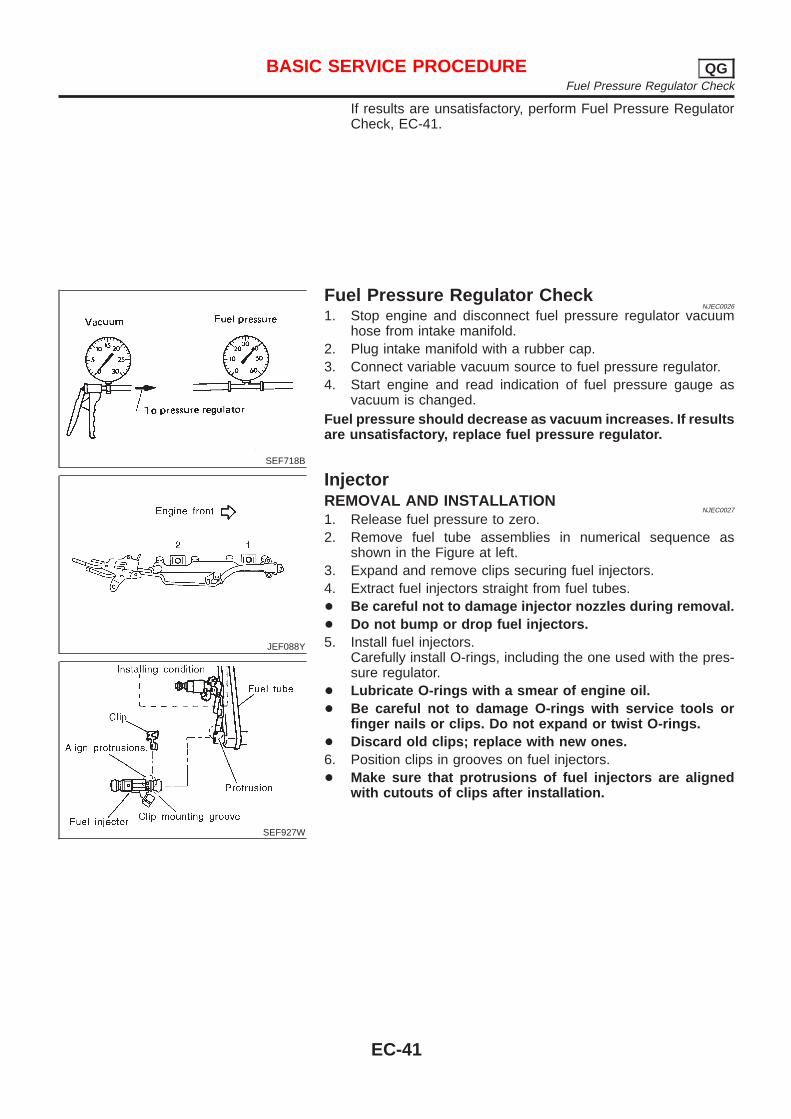
If results are unsatisfactory, perform Fuel Pressure RegulatorCheck, EC-41.
SEF718B
Fuel Pressure Regulator CheckNJEC0026
1. Stop engine and disconnect fuel pressure regulator vacuumhose from intake manifold.
2. Plug intake manifold with a rubber cap.3. Connect variable vacuum source to fuel pressure regulator.4. Start engine and read indication of fuel pressure gauge as
vacuum is changed.Fuel pressure should decrease as vacuum increases. If resultsare unsatisfactory, replace fuel pressure regulator.
JEF088Y
SEF927W
InjectorREMOVAL AND INSTALLATION
NJEC0027
1. Release fuel pressure to zero.2. Remove fuel tube assemblies in numerical sequence as
shown in the Figure at left.3. Expand and remove clips securing fuel injectors.4. Extract fuel injectors straight from fuel tubes.+ Be careful not to damage injector nozzles during removal.+ Do not bump or drop fuel injectors.5. Install fuel injectors.
Carefully install O-rings, including the one used with the pres-sure regulator.
+ Lubricate O-rings with a smear of engine oil.+ Be careful not to damage O-rings with service tools or
finger nails or clips. Do not expand or twist O-rings.+ Discard old clips; replace with new ones.6. Position clips in grooves on fuel injectors.+ Make sure that protrusions of fuel injectors are aligned
with cutouts of clips after installation.
BASIC SERVICE PROCEDURE QGFuel Pressure Regulator Check
EC-41
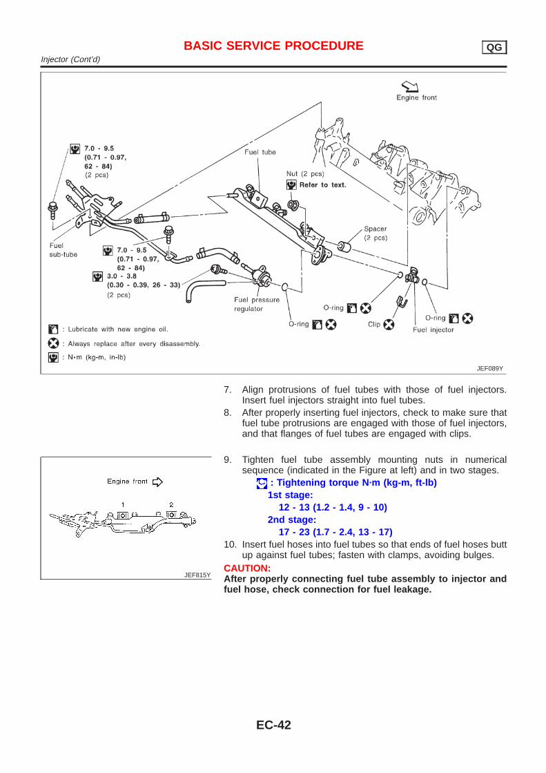
JEF089Y
7. Align protrusions of fuel tubes with those of fuel injectors.Insert fuel injectors straight into fuel tubes.
8. After properly inserting fuel injectors, check to make sure thatfuel tube protrusions are engaged with those of fuel injectors,and that flanges of fuel tubes are engaged with clips.
JEF815Y
9. Tighten fuel tube assembly mounting nuts in numericalsequence (indicated in the Figure at left) and in two stages.
: Tightening torque N·m (kg-m, ft-lb)1st stage:
12 - 13 (1.2 - 1.4, 9 - 10)2nd stage:
17 - 23 (1.7 - 2.4, 13 - 17)10. Insert fuel hoses into fuel tubes so that ends of fuel hoses butt
up against fuel tubes; fasten with clamps, avoiding bulges.CAUTION:After properly connecting fuel tube assembly to injector andfuel hose, check connection for fuel leakage.
BASIC SERVICE PROCEDURE QGInjector (Cont’d)
EC-42
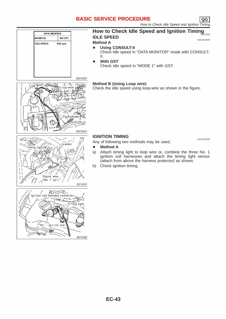
SEF058Y
How to Check Idle Speed and Ignition TimingNJEC0028
IDLE SPEEDNJEC0028S05
Method A+ Using CONSULT-II
Check idle speed in “DATA MONITOR” mode with CONSULT-II.
+ With GSTCheck idle speed in “MODE 1” with GST.
SEF453Y
Method B (Using Loop wire)Check the idle speed using loop-wire as shown in the figure.
JEF150Y
JEF438Z
IGNITION TIMINGNJEC0028S06
Any of following two methods may be used.+ Method Aa) Attach timing light to loop wire or, combine the three No. 1
ignition coil harnesses and attach the timing light sensor(attach from above the harness protector) as shown.
b) Check ignition timing.
BASIC SERVICE PROCEDURE QGHow to Check Idle Speed and Ignition Timing
EC-43
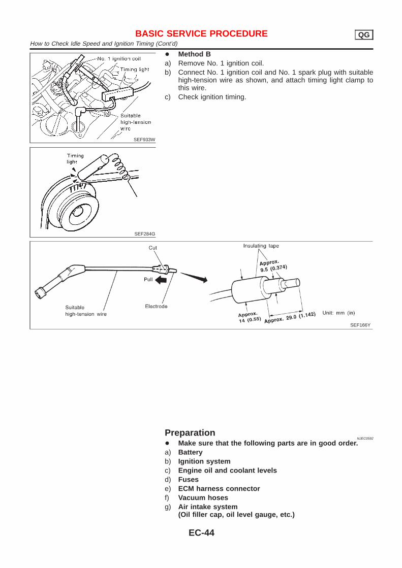
SEF933W
SEF284G
+ Method Ba) Remove No. 1 ignition coil.b) Connect No. 1 ignition coil and No. 1 spark plug with suitable
high-tension wire as shown, and attach timing light clamp tothis wire.
c) Check ignition timing.
SEF166Y
PreparationNJEC0592
+ Make sure that the following parts are in good order.a) Batteryb) Ignition systemc) Engine oil and coolant levelsd) Fusese) ECM harness connectorf) Vacuum hosesg) Air intake system
(Oil filler cap, oil level gauge, etc.)
BASIC SERVICE PROCEDURE QGHow to Check Idle Speed and Ignition Timing (Cont’d)
EC-44
h) Fuel pressurei) Engine compressionj) EGR valve operationk) Throttle valvel) EVAP system+ On models equipped with air conditioner, checks should
be carried out while the air conditioner is “OFF”.+ When checking idle speed on models equipped with A/T,
ignition timing and mixture ratio, checks should be carriedout while shift lever is in “P” or “N” position.
+ When measuring “CO” percentage, insert probe morethan 40 cm (15.7 in) into tail pipe.
+ Turn off headlamps, heater blower, rear window defogger.+ On vehicles equipped with daytime light systems, set
lighting switch to the 1st position to light only smalllamps.
+ Keep front wheels pointed straight ahead.+ If engine stops immediately after starting or idle condition
is unstable, perform the following to initialize IACV-AACvalve:
a) Stop engine and wait 9 seconds.b) Turn ignition “ON” and wait 1 second.c) Turn ignition “OFF” and wait 9 seconds.+ Make sure the cooling fan has stopped.
BASIC SERVICE PROCEDURE QGPreparation (Cont’d)
EC-45
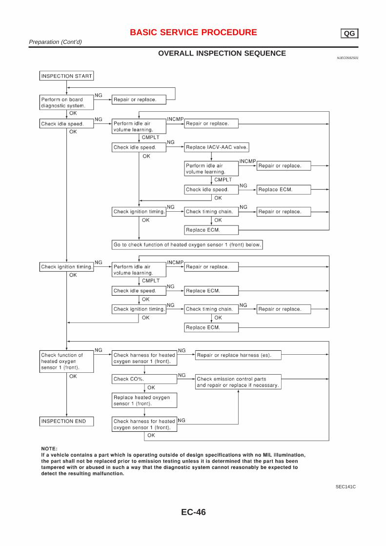
OVERALL INSPECTION SEQUENCENJEC0592S01
SEC141C
BASIC SERVICE PROCEDURE QGPreparation (Cont’d)
EC-46
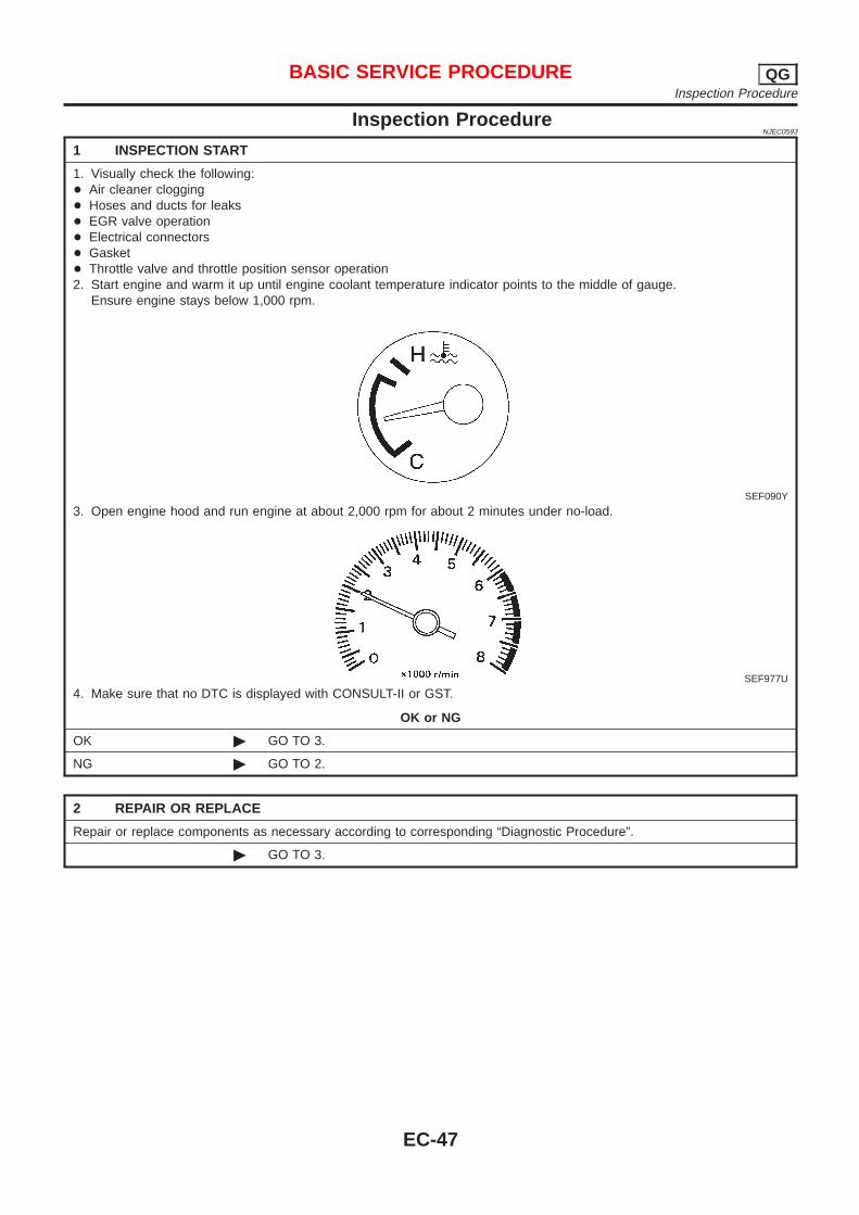
Inspection ProcedureNJEC0593
1 INSPECTION START
1. Visually check the following:+ Air cleaner clogging+ Hoses and ducts for leaks+ EGR valve operation+ Electrical connectors+ Gasket+ Throttle valve and throttle position sensor operation2. Start engine and warm it up until engine coolant temperature indicator points to the middle of gauge.
Ensure engine stays below 1,000 rpm.
SEF090Y
3. Open engine hood and run engine at about 2,000 rpm for about 2 minutes under no-load.
SEF977U
4. Make sure that no DTC is displayed with CONSULT-II or GST.
OK or NG
OK © GO TO 3.
NG © GO TO 2.
2 REPAIR OR REPLACE
Repair or replace components as necessary according to corresponding “Diagnostic Procedure”.
© GO TO 3.
BASIC SERVICE PROCEDURE QGInspection Procedure
EC-47
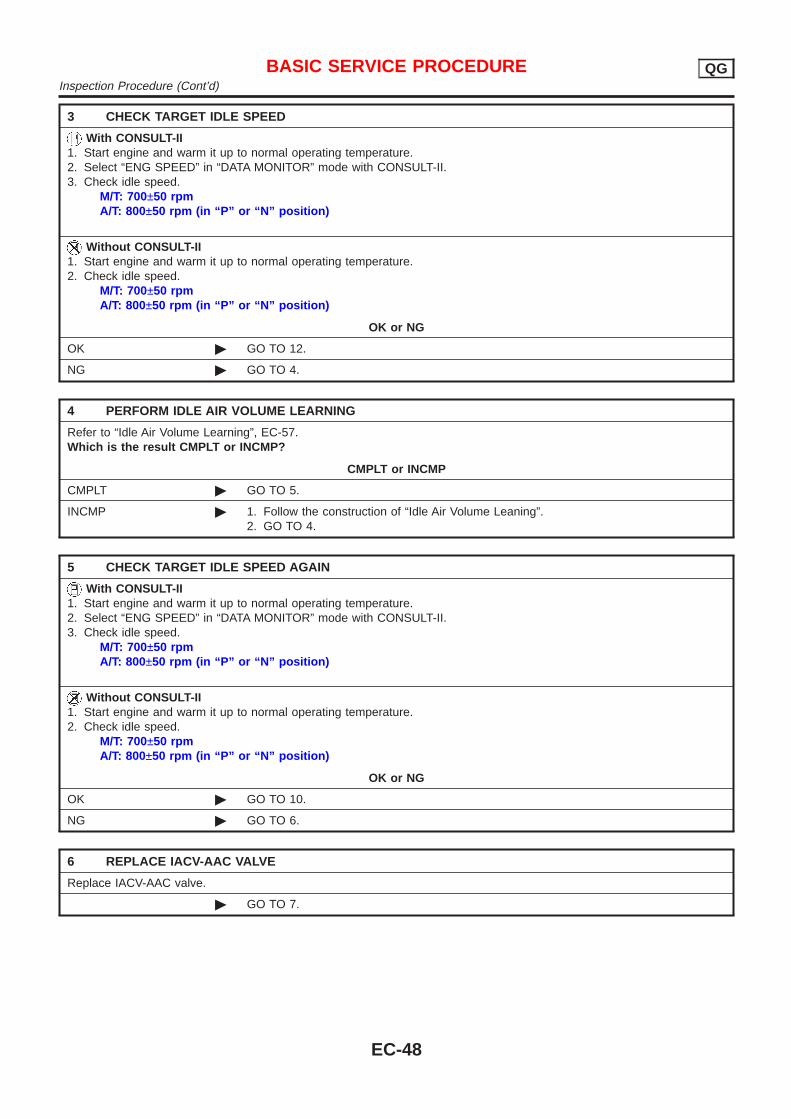
3 CHECK TARGET IDLE SPEED
With CONSULT-II1. Start engine and warm it up to normal operating temperature.2. Select “ENG SPEED” in “DATA MONITOR” mode with CONSULT-II.3. Check idle speed.
M/T: 700±50 rpmA/T: 800±50 rpm (in “P” or “N” position)
Without CONSULT-II1. Start engine and warm it up to normal operating temperature.2. Check idle speed.
M/T: 700±50 rpmA/T: 800±50 rpm (in “P” or “N” position)
OK or NG
OK © GO TO 12.
NG © GO TO 4.
4 PERFORM IDLE AIR VOLUME LEARNING
Refer to “Idle Air Volume Learning”, EC-57.Which is the result CMPLT or INCMP?
CMPLT or INCMP
CMPLT © GO TO 5.
INCMP © 1. Follow the construction of “Idle Air Volume Leaning”.2. GO TO 4.
5 CHECK TARGET IDLE SPEED AGAIN
With CONSULT-II1. Start engine and warm it up to normal operating temperature.2. Select “ENG SPEED” in “DATA MONITOR” mode with CONSULT-II.3. Check idle speed.
M/T: 700±50 rpmA/T: 800±50 rpm (in “P” or “N” position)
Without CONSULT-II1. Start engine and warm it up to normal operating temperature.2. Check idle speed.
M/T: 700±50 rpmA/T: 800±50 rpm (in “P” or “N” position)
OK or NG
OK © GO TO 10.
NG © GO TO 6.
6 REPLACE IACV-AAC VALVE
Replace IACV-AAC valve.
© GO TO 7.
BASIC SERVICE PROCEDURE QGInspection Procedure (Cont’d)
EC-48
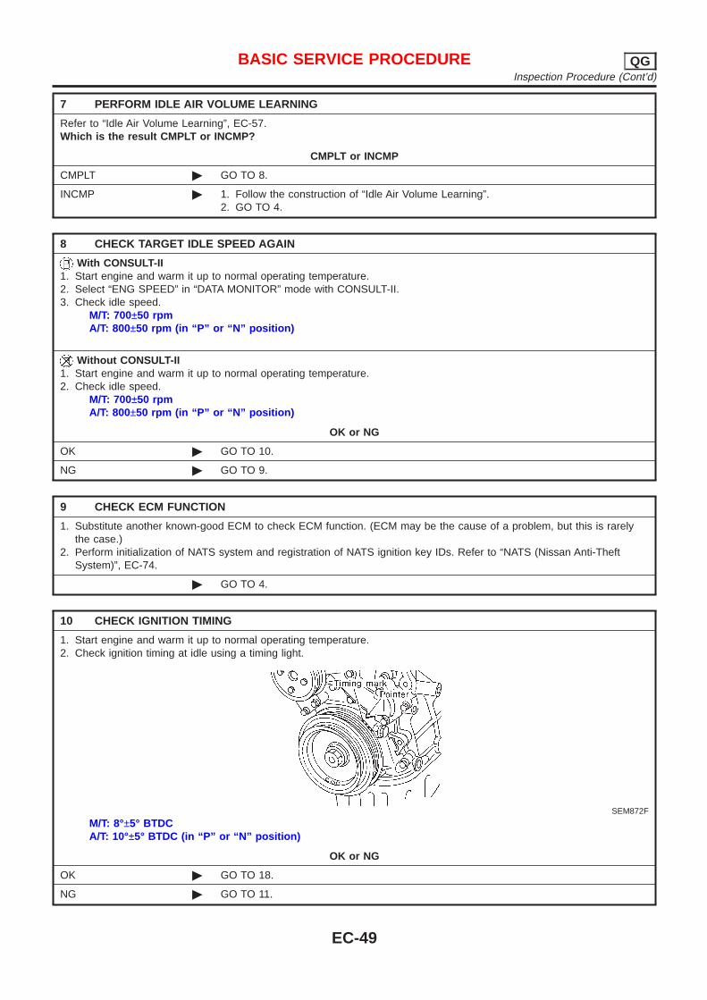
7 PERFORM IDLE AIR VOLUME LEARNING
Refer to “Idle Air Volume Learning”, EC-57.Which is the result CMPLT or INCMP?
CMPLT or INCMP
CMPLT © GO TO 8.
INCMP © 1. Follow the construction of “Idle Air Volume Learning”.2. GO TO 4.
8 CHECK TARGET IDLE SPEED AGAIN
With CONSULT-II1. Start engine and warm it up to normal operating temperature.2. Select “ENG SPEED” in “DATA MONITOR” mode with CONSULT-II.3. Check idle speed.
M/T: 700±50 rpmA/T: 800±50 rpm (in “P” or “N” position)
Without CONSULT-II1. Start engine and warm it up to normal operating temperature.2. Check idle speed.
M/T: 700±50 rpmA/T: 800±50 rpm (in “P” or “N” position)
OK or NG
OK © GO TO 10.
NG © GO TO 9.
9 CHECK ECM FUNCTION
1. Substitute another known-good ECM to check ECM function. (ECM may be the cause of a problem, but this is rarelythe case.)
2. Perform initialization of NATS system and registration of NATS ignition key IDs. Refer to “NATS (Nissan Anti-TheftSystem)”, EC-74.
© GO TO 4.
10 CHECK IGNITION TIMING
1. Start engine and warm it up to normal operating temperature.2. Check ignition timing at idle using a timing light.
SEM872F
M/T: 8°±5° BTDCA/T: 10°±5° BTDC (in “P” or “N” position)
OK or NG
OK © GO TO 18.
NG © GO TO 11.
BASIC SERVICE PROCEDURE QGInspection Procedure (Cont’d)
EC-49
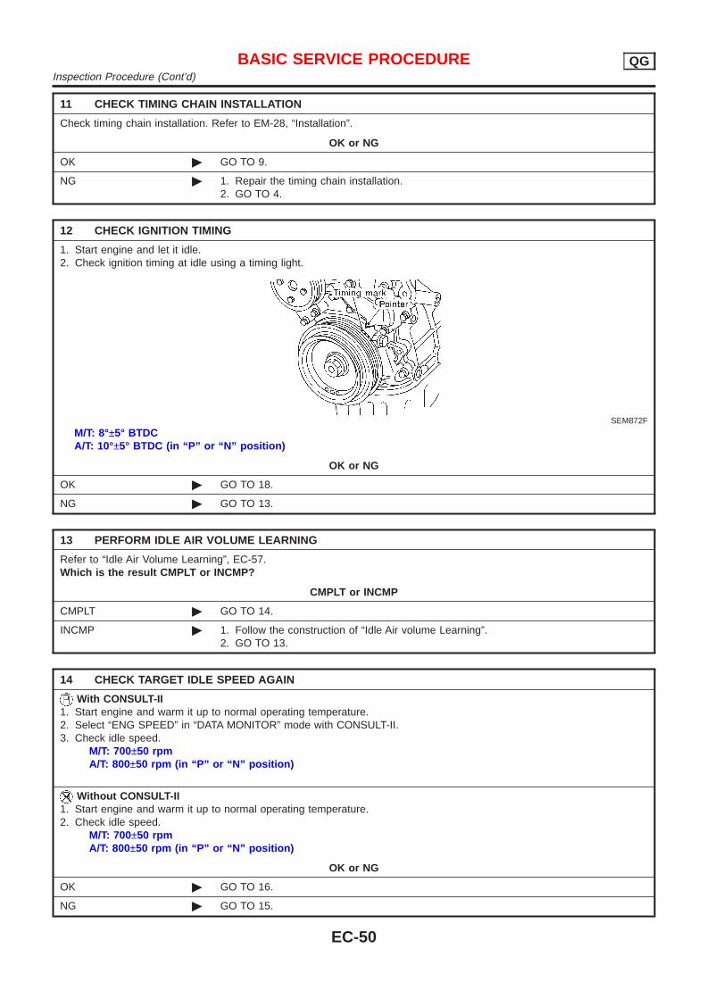
11 CHECK TIMING CHAIN INSTALLATION
Check timing chain installation. Refer to EM-28, “Installation”.
OK or NG
OK © GO TO 9.
NG © 1. Repair the timing chain installation.2. GO TO 4.
12 CHECK IGNITION TIMING
1. Start engine and let it idle.2. Check ignition timing at idle using a timing light.
SEM872F
M/T: 8°±5° BTDCA/T: 10°±5° BTDC (in “P” or “N” position)
OK or NG
OK © GO TO 18.
NG © GO TO 13.
13 PERFORM IDLE AIR VOLUME LEARNING
Refer to “Idle Air Volume Learning”, EC-57.Which is the result CMPLT or INCMP?
CMPLT or INCMP
CMPLT © GO TO 14.
INCMP © 1. Follow the construction of “Idle Air volume Learning”.2. GO TO 13.
14 CHECK TARGET IDLE SPEED AGAIN
With CONSULT-II1. Start engine and warm it up to normal operating temperature.2. Select “ENG SPEED” in “DATA MONITOR” mode with CONSULT-II.3. Check idle speed.
M/T: 700±50 rpmA/T: 800±50 rpm (in “P” or “N” position)
Without CONSULT-II1. Start engine and warm it up to normal operating temperature.2. Check idle speed.
M/T: 700±50 rpmA/T: 800±50 rpm (in “P” or “N” position)
OK or NG
OK © GO TO 16.
NG © GO TO 15.
BASIC SERVICE PROCEDURE QGInspection Procedure (Cont’d)
EC-50
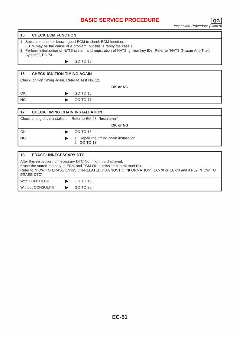
15 CHECK ECM FUNCTION
1. Substitute another known-good ECM to check ECM function.(ECM may be the cause of a problem, but this is rarely the case.)
2. Perform initialization of NATS system and registration of NATS ignition key IDs. Refer to “NATS (Nissan Anti-TheftSystem)”, EC-74.
© GO TO 13.
16 CHECK IGNITION TIMING AGAIN
Check ignition timing again. Refer to Test No. 12.
OK or NG
OK © GO TO 18.
NG © GO TO 17.
17 CHECK TIMING CHAIN INSTALLATION
Check timing chain installation. Refer to EM-28, “Installation”.
OK or NG
OK © GO TO 15.
NG © 1. Repair the timing chain installation.2. GO TO 13.
18 ERASE UNNECESSARY DTC
After this inspection, unnecessary DTC No. might be displayed.Erase the stored memory in ECM and TCM (Transmission control module).Refer to “HOW TO ERASE EMISSION-RELATED DIAGNOSTIC INFORMATION”, EC-70 or EC-73 and AT-52, “HOW TOERASE DTC”.
With CONSULT-II © GO TO 19.
Without CONSULT-II © GO TO 20.
BASIC SERVICE PROCEDURE QGInspection Procedure (Cont’d)
EC-51
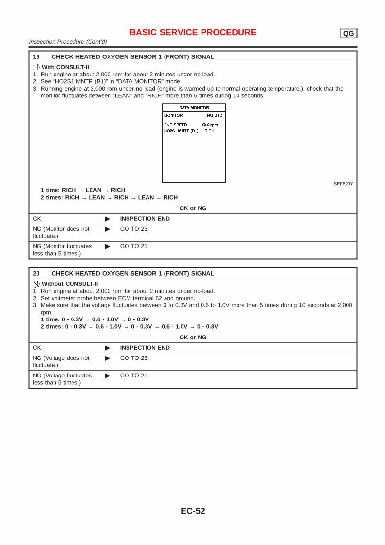
19 CHECK HEATED OXYGEN SENSOR 1 (FRONT) SIGNAL
With CONSULT-II1. Run engine at about 2,000 rpm for about 2 minutes under no-load.2. See “HO2S1 MNTR (B1)” in “DATA MONITOR” mode.3. Running engine at 2,000 rpm under no-load (engine is warmed up to normal operating temperature.), check that the
monitor fluctuates between “LEAN” and “RICH” more than 5 times during 10 seconds.
SEF820Y
1 time: RICH → LEAN → RICH2 times: RICH → LEAN → RICH → LEAN → RICH
OK or NG
OK © INSPECTION END
NG (Monitor does notfluctuate.)
© GO TO 23.
NG (Monitor fluctuatesless than 5 times.)
© GO TO 21.
20 CHECK HEATED OXYGEN SENSOR 1 (FRONT) SIGNAL
Without CONSULT-II1. Run engine at about 2,000 rpm for about 2 minutes under no-load.2. Set voltmeter probe between ECM terminal 62 and ground.3. Make sure that the voltage fluctuates between 0 to 0.3V and 0.6 to 1.0V more than 5 times during 10 seconds at 2,000
rpm.1 time : 0 - 0.3V → 0.6 - 1.0V → 0 - 0.3V2 times : 0 - 0.3V → 0.6 - 1.0V → 0 - 0.3V → 0.6 - 1.0V → 0 - 0.3V
OK or NG
OK © INSPECTION END
NG (Voltage does notfluctuate.)
© GO TO 23.
NG (Voltage fluctuatesless than 5 times.)
© GO TO 21.
BASIC SERVICE PROCEDURE QGInspection Procedure (Cont’d)
EC-52
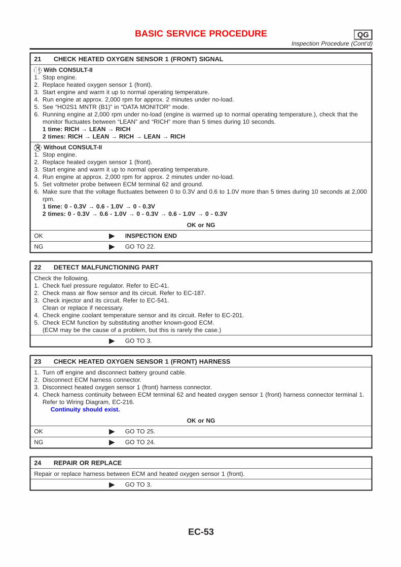
21 CHECK HEATED OXYGEN SENSOR 1 (FRONT) SIGNAL
With CONSULT-II1. Stop engine.2. Replace heated oxygen sensor 1 (front).3. Start engine and warm it up to normal operating temperature.4. Run engine at approx. 2,000 rpm for approx. 2 minutes under no-load.5. See “HO2S1 MNTR (B1)” in “DATA MONITOR” mode.6. Running engine at 2,000 rpm under no-load (engine is warmed up to normal operating temperature.), check that the
monitor fluctuates between “LEAN” and “RICH” more than 5 times during 10 seconds.1 time: RICH → LEAN → RICH2 times: RICH → LEAN → RICH → LEAN → RICH
Without CONSULT-II1. Stop engine.2. Replace heated oxygen sensor 1 (front).3. Start engine and warm it up to normal operating temperature.4. Run engine at approx. 2,000 rpm for approx. 2 minutes under no-load.5. Set voltmeter probe between ECM terminal 62 and ground.6. Make sure that the voltage fluctuates between 0 to 0.3V and 0.6 to 1.0V more than 5 times during 10 seconds at 2,000
rpm.1 time : 0 - 0.3V → 0.6 - 1.0V → 0 - 0.3V2 times : 0 - 0.3V → 0.6 - 1.0V → 0 - 0.3V → 0.6 - 1.0V → 0 - 0.3V
OK or NG
OK © INSPECTION END
NG © GO TO 22.
22 DETECT MALFUNCTIONING PART
Check the following.1. Check fuel pressure regulator. Refer to EC-41.2. Check mass air flow sensor and its circuit. Refer to EC-187.3. Check injector and its circuit. Refer to EC-541.
Clean or replace if necessary.4. Check engine coolant temperature sensor and its circuit. Refer to EC-201.5. Check ECM function by substituting another known-good ECM.
(ECM may be the cause of a problem, but this is rarely the case.)
© GO TO 3.
23 CHECK HEATED OXYGEN SENSOR 1 (FRONT) HARNESS
1. Turn off engine and disconnect battery ground cable.2. Disconnect ECM harness connector.3. Disconnect heated oxygen sensor 1 (front) harness connector.4. Check harness continuity between ECM terminal 62 and heated oxygen sensor 1 (front) harness connector terminal 1.
Refer to Wiring Diagram, EC-216.Continuity should exist.
OK or NG
OK © GO TO 25.
NG © GO TO 24.
24 REPAIR OR REPLACE
Repair or replace harness between ECM and heated oxygen sensor 1 (front).
© GO TO 3.
BASIC SERVICE PROCEDURE QGInspection Procedure (Cont’d)
EC-53
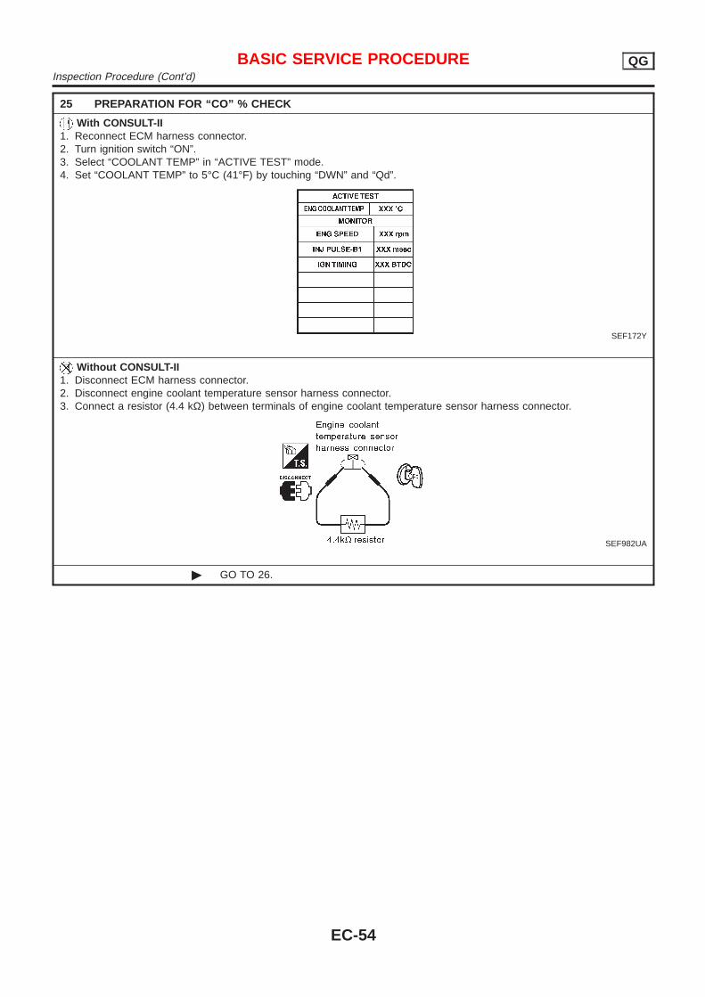
25 PREPARATION FOR “CO” % CHECK
With CONSULT-II1. Reconnect ECM harness connector.2. Turn ignition switch “ON”.3. Select “COOLANT TEMP” in “ACTIVE TEST” mode.4. Set “COOLANT TEMP” to 5°C (41°F) by touching “DWN” and “Qd”.
SEF172Y
Without CONSULT-II1. Disconnect ECM harness connector.2. Disconnect engine coolant temperature sensor harness connector.3. Connect a resistor (4.4 kΩ) between terminals of engine coolant temperature sensor harness connector.
SEF982UA
© GO TO 26.
BASIC SERVICE PROCEDURE QGInspection Procedure (Cont’d)
EC-54
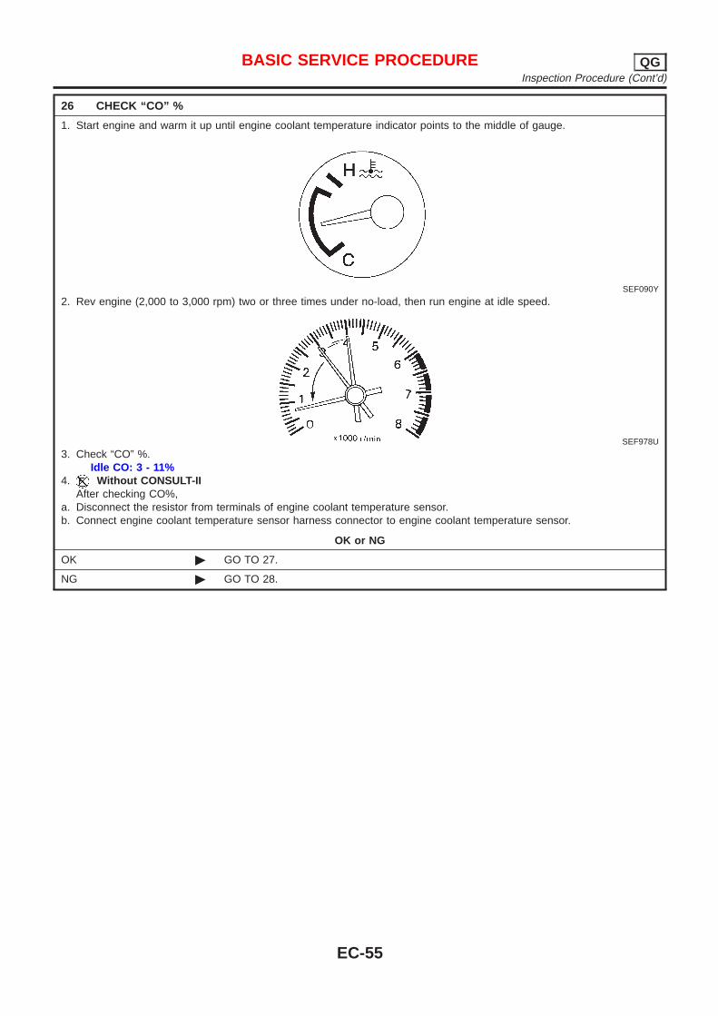
26 CHECK “CO” %
1. Start engine and warm it up until engine coolant temperature indicator points to the middle of gauge.
SEF090Y
2. Rev engine (2,000 to 3,000 rpm) two or three times under no-load, then run engine at idle speed.
SEF978U
3. Check “CO” %.Idle CO: 3 - 11%
4. Without CONSULT-IIAfter checking CO%,
a. Disconnect the resistor from terminals of engine coolant temperature sensor.b. Connect engine coolant temperature sensor harness connector to engine coolant temperature sensor.
OK or NG
OK © GO TO 27.
NG © GO TO 28.
BASIC SERVICE PROCEDURE QGInspection Procedure (Cont’d)
EC-55
27 CHECK HEATED OXYGEN SENSOR 1 (FRONT) SIGNAL
With CONSULT-II1. Stop engine.2. Replace heated oxygen sensor 1 (front).3. Start engine and warm it up to normal operating temperature.4. Run engine at approx. 2,000 rpm for approx. 2 minutes under no-load.5. See “HO2S1 MNTR (B1)” in “DATA MONITOR” mode.6. Maintaining engine at 2,000 rpm under no-load (engine is warmed up to normal operating temperature.), check that the
monitor fluctuates between “LEAN” and “RICH” more than 5 times during 10 seconds.1 time: RICH → LEAN → RICH2 times: RICH → LEAN → RICH → LEAN → RICH
Without CONSULT-II1. Stop engine.2. Replace heated oxygen sensor 1 (front).3. Start engine and warm it up to normal operating temperature.4. Run engine at approx. 2,000 rpm for approx. 2 minutes under no-load.5. Set voltmeter probe between ECM terminal 62 and ground.6. Make sure that voltage fluctuates between 0 - 0.3V and 0.6 - 1.0V more than 5 times during 10 seconds at 2,000 rpm.
1 time : 0 - 0.3V → 0.6 - 1.0V → 0 - 0.3V2 times : 0 - 0.3V → 0.6 - 1.0V → 0 - 0.3V → 0.6 - 1.0V → 0 - 0.3V
OK or NG
OK © GO TO 3.
NG © GO TO 28.
28 DETECT MALFUNCTIONING PART
Check the following.+ Connect heated oxygen sensor 1 (front) harness connectors to heated oxygen sensors 1 (front).+ Check fuel pressure regulator. Refer to EC-41.+ Check mass air flow sensor and its circuit. Refer to EC-187.+ Check injector and its circuit. Refer to EC-541.
Clean or replace if necessary.+ Check engine coolant temperature sensor and its circuit. Refer to EC-201.+ Check ECM function by substituting another known-good ECM.
(ECM may be the cause of a problem, but this is rarely the case.)
© GO TO 3.
BASIC SERVICE PROCEDURE QGInspection Procedure (Cont’d)
EC-56
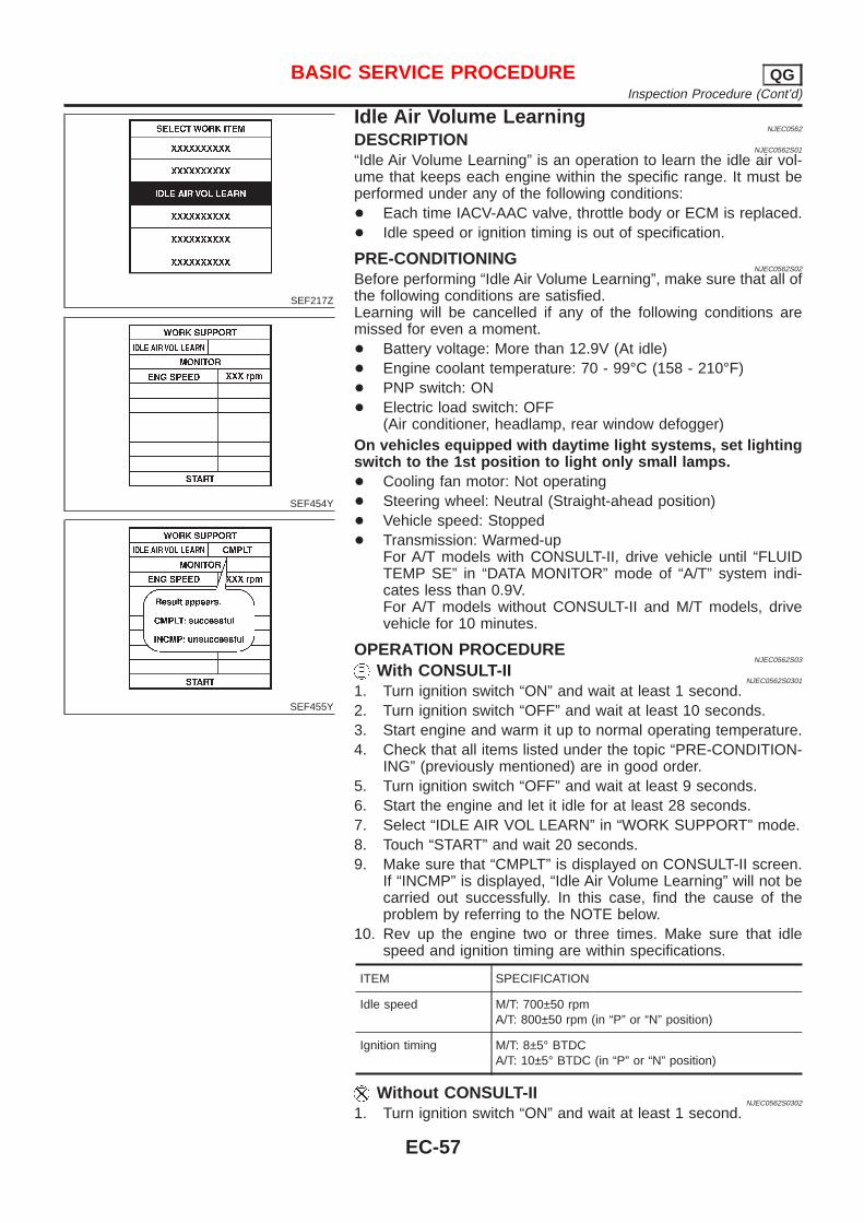
SEF217Z
SEF454Y
SEF455Y
Idle Air Volume LearningNJEC0562
DESCRIPTIONNJEC0562S01
“Idle Air Volume Learning” is an operation to learn the idle air vol-ume that keeps each engine within the specific range. It must beperformed under any of the following conditions:+ Each time IACV-AAC valve, throttle body or ECM is replaced.+ Idle speed or ignition timing is out of specification.
PRE-CONDITIONINGNJEC0562S02
Before performing “Idle Air Volume Learning”, make sure that all ofthe following conditions are satisfied.Learning will be cancelled if any of the following conditions aremissed for even a moment.+ Battery voltage: More than 12.9V (At idle)+ Engine coolant temperature: 70 - 99°C (158 - 210°F)+ PNP switch: ON+ Electric load switch: OFF
(Air conditioner, headlamp, rear window defogger)On vehicles equipped with daytime light systems, set lightingswitch to the 1st position to light only small lamps.+ Cooling fan motor: Not operating+ Steering wheel: Neutral (Straight-ahead position)+ Vehicle speed: Stopped+ Transmission: Warmed-up
For A/T models with CONSULT-II, drive vehicle until “FLUIDTEMP SE” in “DATA MONITOR” mode of “A/T” system indi-cates less than 0.9V.For A/T models without CONSULT-II and M/T models, drivevehicle for 10 minutes.
OPERATION PROCEDURENJEC0562S03
With CONSULT-IINJEC0562S0301
1. Turn ignition switch “ON” and wait at least 1 second.2. Turn ignition switch “OFF” and wait at least 10 seconds.3. Start engine and warm it up to normal operating temperature.4. Check that all items listed under the topic “PRE-CONDITION-
ING” (previously mentioned) are in good order.5. Turn ignition switch “OFF” and wait at least 9 seconds.6. Start the engine and let it idle for at least 28 seconds.7. Select “IDLE AIR VOL LEARN” in “WORK SUPPORT” mode.8. Touch “START” and wait 20 seconds.9. Make sure that “CMPLT” is displayed on CONSULT-II screen.
If “INCMP” is displayed, “Idle Air Volume Learning” will not becarried out successfully. In this case, find the cause of theproblem by referring to the NOTE below.
10. Rev up the engine two or three times. Make sure that idlespeed and ignition timing are within specifications.
ITEM SPECIFICATION
Idle speed M/T: 700±50 rpmA/T: 800±50 rpm (in “P” or “N” position)
Ignition timing M/T: 8±5° BTDCA/T: 10±5° BTDC (in “P” or “N” position)
Without CONSULT-IINJEC0562S0302
1. Turn ignition switch “ON” and wait at least 1 second.
BASIC SERVICE PROCEDURE QGInspection Procedure (Cont’d)
EC-57
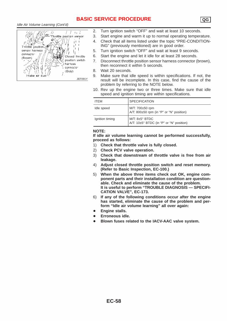
JEF091Y
2. Turn ignition switch “OFF” and wait at least 10 seconds.3. Start engine and warm it up to normal operating temperature.4. Check that all items listed under the topic “PRE-CONDITION-
ING” (previously mentioned) are in good order.5. Turn ignition switch “OFF” and wait at least 9 seconds.6. Start the engine and let it idle for at least 28 seconds.7. Disconnect throttle position sensor harness connector (brown),
then reconnect it within 5 seconds.8. Wait 20 seconds.9. Make sure that idle speed is within specifications. If not, the
result will be incomplete. In this case, find the cause of theproblem by referring to the NOTE below.
10. Rev up the engine two or three times. Make sure that idlespeed and ignition timing are within specifications.
ITEM SPECIFICATION
Idle speed M/T: 700±50 rpmA/T: 800±50 rpm (in “P” or “N” position)
Ignition timing M/T: 8±5° BTDCA/T: 10±5° BTDC (in “P” or “N” position)
NOTE:If idle air volume learning cannot be performed successfully,proceed as follows:1) Check that throttle valve is fully closed.2) Check PCV valve operation.3) Check that downstream of throttle valve is free from air
leakage.4) Adjust closed throttle position switch and reset memory.
(Refer to Basic Inspection, EC-100.)5) When the above three items check out OK, engine com-
ponent parts and their installation condition are question-able. Check and eliminate the cause of the problem.It is useful to perform “TROUBLE DIAGNOSIS — SPECIFI-CATION VALVE”, EC-173.
6) If any of the following conditions occur after the enginehas started, eliminate the cause of the problem and per-form “Idle air volume learning” all over again:
+ Engine stalls.+ Erroneous idle.+ Blown fuses related to the IACV-AAC valve system.
BASIC SERVICE PROCEDURE QGIdle Air Volume Learning (Cont’d)
EC-58
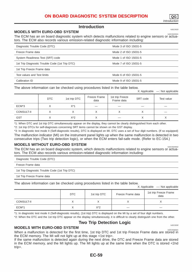
IntroductionNJEC0029
MODELS WITH EURO-OBD SYSTEMNJEC0029S01
The ECM has an on board diagnostic system which detects malfunctions related to engine sensors or actua-tors. The ECM also records various emission-related diagnostic information including:
Diagnostic Trouble Code (DTC) Mode 3 of ISO 15031-5
Freeze Frame data Mode 2 of ISO 15031-5
System Readiness Test (SRT) code Mode 1 of ISO 15031-5
1st Trip Diagnostic Trouble Code (1st Trip DTC) Mode 7 of ISO 15031-5
1st Trip Freeze Frame data
Test values and Test limits Mode 6 of ISO 15031-5
Calibration ID Mode 9 of ISO 15031-5
The above information can be checked using procedures listed in the table below.X: Applicable —: Not applicable
DTC 1st trip DTCFreeze Frame
data1st trip Freeze
Frame dataSRT code Test value
ECM*3 X X*1 — — — —
CONSULT-II X X X X X —
GST X X*2 X — X X
*1: When DTC and 1st trip DTC simultaneously appear on the display, they cannot be clearly distinguished from each other.*2: 1st trip DTCs for self-diagnoses concerning SRT items cannot be shown on the GST display.*3: In diagnostic test mode II (Self-diagnostic results), DTC is displayed on MI. DTC uses a set of four digit numbers. (If so equipped)
The malfunction indicator (MI) on the instrument panel lights up when the same malfunction is detected in twoconsecutive trips (Two trip detection logic), or when the ECM enters fail-safe mode. (Refer to EC-154.)
MODELS WITHOUT EURO-OBD SYSTEMNJEC0029S02
The ECM has an on board diagnostic system, which detects malfunctions related to engine sensors or actua-tors. The ECM also records various emission-related diagnostic information including:
Diagnostic Trouble Code (DTC)
Freeze Frame data
1st Trip Diagnostic Trouble Code (1st Trip DTC)
1st Trip Freeze Frame data
The above information can be checked using procedures listed in the table below.X: Applicable —: Not applicable
DTC 1st trip DTC Freeze Frame data1st trip Freeze Frame
data
CONSULT-II X X X X
ECM*1 X X*2 — —
*1: In diagnostic test mode II (Self-diagnostic results), (1st trip) DTC is displayed on the MI by a set of four digit numbers.*2: When the DTC and the 1st trip DTC appear on the display simultaneously, it is difficult to clearly distinguish one from the other.
Two Trip Detection LogicNJEC0030
MODELS WITH EURO-OBD SYSTEMNJEC0030S01
When a malfunction is detected for the first time, 1st trip DTC and 1st trip Freeze Frame data are stored inthe ECM memory. The MI will not light up at this stage <1st trip>.If the same malfunction is detected again during the next drive, the DTC and Freeze Frame data are storedin the ECM memory, and the MI lights up. The MI lights up at the same time when the DTC is stored <2ndtrip>.
ON BOARD DIAGNOSTIC SYSTEM DESCRIPTION QGIntroduction
EC-59
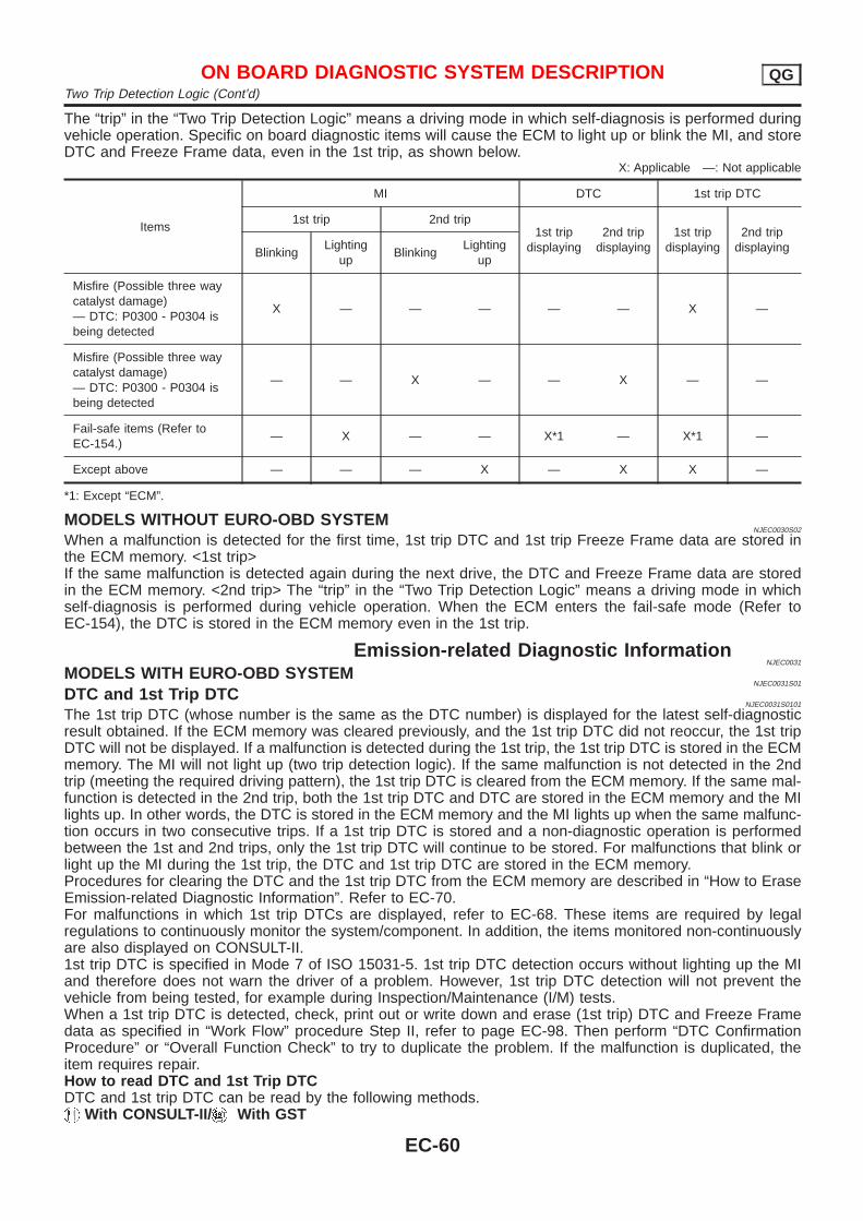
The “trip” in the “Two Trip Detection Logic” means a driving mode in which self-diagnosis is performed duringvehicle operation. Specific on board diagnostic items will cause the ECM to light up or blink the MI, and storeDTC and Freeze Frame data, even in the 1st trip, as shown below.
X: Applicable —: Not applicable
Items
MI DTC 1st trip DTC
1st trip 2nd trip1st trip
displaying2nd trip
displaying1st trip
displaying2nd trip
displayingBlinkingLighting
upBlinking
Lightingup
Misfire (Possible three waycatalyst damage)— DTC: P0300 - P0304 isbeing detected
X — — — — — X —
Misfire (Possible three waycatalyst damage)— DTC: P0300 - P0304 isbeing detected
— — X — — X — —
Fail-safe items (Refer toEC-154.)
— X — — X*1 — X*1 —
Except above — — — X — X X —
*1: Except “ECM”.
MODELS WITHOUT EURO-OBD SYSTEMNJEC0030S02
When a malfunction is detected for the first time, 1st trip DTC and 1st trip Freeze Frame data are stored inthe ECM memory. <1st trip>If the same malfunction is detected again during the next drive, the DTC and Freeze Frame data are storedin the ECM memory. <2nd trip> The “trip” in the “Two Trip Detection Logic” means a driving mode in whichself-diagnosis is performed during vehicle operation. When the ECM enters the fail-safe mode (Refer toEC-154), the DTC is stored in the ECM memory even in the 1st trip.
Emission-related Diagnostic InformationNJEC0031
MODELS WITH EURO-OBD SYSTEMNJEC0031S01
DTC and 1st Trip DTCNJEC0031S0101
The 1st trip DTC (whose number is the same as the DTC number) is displayed for the latest self-diagnosticresult obtained. If the ECM memory was cleared previously, and the 1st trip DTC did not reoccur, the 1st tripDTC will not be displayed. If a malfunction is detected during the 1st trip, the 1st trip DTC is stored in the ECMmemory. The MI will not light up (two trip detection logic). If the same malfunction is not detected in the 2ndtrip (meeting the required driving pattern), the 1st trip DTC is cleared from the ECM memory. If the same mal-function is detected in the 2nd trip, both the 1st trip DTC and DTC are stored in the ECM memory and the MIlights up. In other words, the DTC is stored in the ECM memory and the MI lights up when the same malfunc-tion occurs in two consecutive trips. If a 1st trip DTC is stored and a non-diagnostic operation is performedbetween the 1st and 2nd trips, only the 1st trip DTC will continue to be stored. For malfunctions that blink orlight up the MI during the 1st trip, the DTC and 1st trip DTC are stored in the ECM memory.Procedures for clearing the DTC and the 1st trip DTC from the ECM memory are described in “How to EraseEmission-related Diagnostic Information”. Refer to EC-70.For malfunctions in which 1st trip DTCs are displayed, refer to EC-68. These items are required by legalregulations to continuously monitor the system/component. In addition, the items monitored non-continuouslyare also displayed on CONSULT-II.1st trip DTC is specified in Mode 7 of ISO 15031-5. 1st trip DTC detection occurs without lighting up the MIand therefore does not warn the driver of a problem. However, 1st trip DTC detection will not prevent thevehicle from being tested, for example during Inspection/Maintenance (I/M) tests.When a 1st trip DTC is detected, check, print out or write down and erase (1st trip) DTC and Freeze Framedata as specified in “Work Flow” procedure Step II, refer to page EC-98. Then perform “DTC ConfirmationProcedure” or “Overall Function Check” to try to duplicate the problem. If the malfunction is duplicated, theitem requires repair.How to read DTC and 1st Trip DTCDTC and 1st trip DTC can be read by the following methods.
With CONSULT-II/ With GST
ON BOARD DIAGNOSTIC SYSTEM DESCRIPTION QGTwo Trip Detection Logic (Cont’d)
EC-60
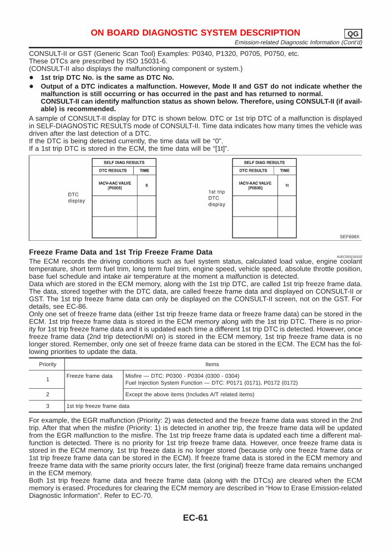
CONSULT-II or GST (Generic Scan Tool) Examples: P0340, P1320, P0705, P0750, etc.These DTCs are prescribed by ISO 15031-6.(CONSULT-II also displays the malfunctioning component or system.)+ 1st trip DTC No. is the same as DTC No.+ Output of a DTC indicates a malfunction. However, Mode II and GST do not indicate whether the
malfunction is still occurring or has occurred in the past and has returned to normal.CONSULT-II can identify malfunction status as shown below. Therefore, using CONSULT-II (if avail-able) is recommended.
A sample of CONSULT-II display for DTC is shown below. DTC or 1st trip DTC of a malfunction is displayedin SELF-DIAGNOSTIC RESULTS mode of CONSULT-II. Time data indicates how many times the vehicle wasdriven after the last detection of a DTC.If the DTC is being detected currently, the time data will be “0”.If a 1st trip DTC is stored in the ECM, the time data will be “[1t]”.
SEF698X
Freeze Frame Data and 1st Trip Freeze Frame DataNJEC0031S0102
The ECM records the driving conditions such as fuel system status, calculated load value, engine coolanttemperature, short term fuel trim, long term fuel trim, engine speed, vehicle speed, absolute throttle position,base fuel schedule and intake air temperature at the moment a malfunction is detected.Data which are stored in the ECM memory, along with the 1st trip DTC, are called 1st trip freeze frame data.The data, stored together with the DTC data, are called freeze frame data and displayed on CONSULT-II orGST. The 1st trip freeze frame data can only be displayed on the CONSULT-II screen, not on the GST. Fordetails, see EC-86.Only one set of freeze frame data (either 1st trip freeze frame data or freeze frame data) can be stored in theECM. 1st trip freeze frame data is stored in the ECM memory along with the 1st trip DTC. There is no prior-ity for 1st trip freeze frame data and it is updated each time a different 1st trip DTC is detected. However, oncefreeze frame data (2nd trip detection/MI on) is stored in the ECM memory, 1st trip freeze frame data is nolonger stored. Remember, only one set of freeze frame data can be stored in the ECM. The ECM has the fol-lowing priorities to update the data.
Priority Items
1Freeze frame data Misfire — DTC: P0300 - P0304 (0300 - 0304)
Fuel Injection System Function — DTC: P0171 (0171), P0172 (0172)
2 Except the above items (Includes A/T related items)
3 1st trip freeze frame data
For example, the EGR malfunction (Priority: 2) was detected and the freeze frame data was stored in the 2ndtrip. After that when the misfire (Priority: 1) is detected in another trip, the freeze frame data will be updatedfrom the EGR malfunction to the misfire. The 1st trip freeze frame data is updated each time a different mal-function is detected. There is no priority for 1st trip freeze frame data. However, once freeze frame data isstored in the ECM memory, 1st trip freeze data is no longer stored (because only one freeze frame data or1st trip freeze frame data can be stored in the ECM). If freeze frame data is stored in the ECM memory andfreeze frame data with the same priority occurs later, the first (original) freeze frame data remains unchangedin the ECM memory.Both 1st trip freeze frame data and freeze frame data (along with the DTCs) are cleared when the ECMmemory is erased. Procedures for clearing the ECM memory are described in “How to Erase Emission-relatedDiagnostic Information”. Refer to EC-70.
ON BOARD DIAGNOSTIC SYSTEM DESCRIPTION QGEmission-related Diagnostic Information (Cont’d)
EC-61
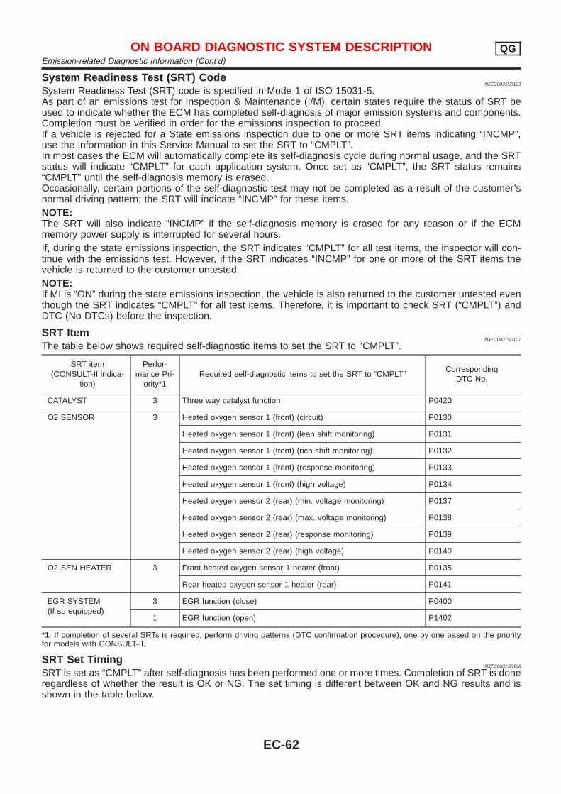
System Readiness Test (SRT) CodeNJEC0031S0103
System Readiness Test (SRT) code is specified in Mode 1 of ISO 15031-5.As part of an emissions test for Inspection & Maintenance (I/M), certain states require the status of SRT beused to indicate whether the ECM has completed self-diagnosis of major emission systems and components.Completion must be verified in order for the emissions inspection to proceed.If a vehicle is rejected for a State emissions inspection due to one or more SRT items indicating “INCMP”,use the information in this Service Manual to set the SRT to “CMPLT”.In most cases the ECM will automatically complete its self-diagnosis cycle during normal usage, and the SRTstatus will indicate “CMPLT” for each application system. Once set as “CMPLT”, the SRT status remains“CMPLT” until the self-diagnosis memory is erased.Occasionally, certain portions of the self-diagnostic test may not be completed as a result of the customer’snormal driving pattern; the SRT will indicate “INCMP” for these items.NOTE:The SRT will also indicate “INCMP” if the self-diagnosis memory is erased for any reason or if the ECMmemory power supply is interrupted for several hours.If, during the state emissions inspection, the SRT indicates “CMPLT” for all test items, the inspector will con-tinue with the emissions test. However, if the SRT indicates “INCMP” for one or more of the SRT items thevehicle is returned to the customer untested.NOTE:If MI is “ON” during the state emissions inspection, the vehicle is also returned to the customer untested eventhough the SRT indicates “CMPLT” for all test items. Therefore, it is important to check SRT (“CMPLT”) andDTC (No DTCs) before the inspection.
SRT ItemNJEC0031S0107
The table below shows required self-diagnostic items to set the SRT to “CMPLT”.
SRT item(CONSULT-II indica-
tion)
Perfor-mance Pri-
ority*1Required self-diagnostic items to set the SRT to “CMPLT”
CorrespondingDTC No.
CATALYST 3 Three way catalyst function P0420
O2 SENSOR 3 Heated oxygen sensor 1 (front) (circuit) P0130
Heated oxygen sensor 1 (front) (lean shift monitoring) P0131
Heated oxygen sensor 1 (front) (rich shift monitoring) P0132
Heated oxygen sensor 1 (front) (response monitoring) P0133
Heated oxygen sensor 1 (front) (high voltage) P0134
Heated oxygen sensor 2 (rear) (min. voltage monitoring) P0137
Heated oxygen sensor 2 (rear) (max. voltage monitoring) P0138
Heated oxygen sensor 2 (rear) (response monitoring) P0139
Heated oxygen sensor 2 (rear) (high voltage) P0140
O2 SEN HEATER 3 Front heated oxygen sensor 1 heater (front) P0135
Rear heated oxygen sensor 1 heater (rear) P0141
EGR SYSTEM(If so equipped)
3 EGR function (close) P0400
1 EGR function (open) P1402
*1: If completion of several SRTs is required, perform driving patterns (DTC confirmation procedure), one by one based on the priorityfor models with CONSULT-II.
SRT Set TimingNJEC0031S0108
SRT is set as “CMPLT” after self-diagnosis has been performed one or more times. Completion of SRT is doneregardless of whether the result is OK or NG. The set timing is different between OK and NG results and isshown in the table below.
ON BOARD DIAGNOSTIC SYSTEM DESCRIPTION QGEmission-related Diagnostic Information (Cont’d)
EC-62
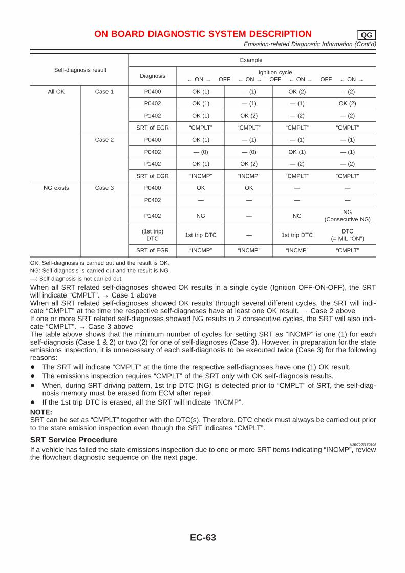
Self-diagnosis result
Example
DiagnosisIgnition cycle
← ON → OFF ← ON → OFF ← ON → OFF ← ON →
All OK Case 1 P0400 OK (1) — (1) OK (2) — (2)
P0402 OK (1) — (1) — (1) OK (2)
P1402 OK (1) OK (2) — (2) — (2)
SRT of EGR “CMPLT” “CMPLT” “CMPLT” “CMPLT”
Case 2 P0400 OK (1) — (1) — (1) — (1)
P0402 — (0) — (0) OK (1) — (1)
P1402 OK (1) OK (2) — (2) — (2)
SRT of EGR “INCMP” “INCMP” “CMPLT” “CMPLT”
NG exists Case 3 P0400 OK OK — —
P0402 — — — —
P1402 NG — NGNG
(Consecutive NG)
(1st trip)DTC
1st trip DTC — 1st trip DTCDTC
(= MIL “ON”)
SRT of EGR “INCMP” “INCMP” “INCMP” “CMPLT”
OK: Self-diagnosis is carried out and the result is OK.NG: Self-diagnosis is carried out and the result is NG.—: Self-diagnosis is not carried out.
When all SRT related self-diagnoses showed OK results in a single cycle (Ignition OFF-ON-OFF), the SRTwill indicate “CMPLT”. → Case 1 aboveWhen all SRT related self-diagnoses showed OK results through several different cycles, the SRT will indi-cate “CMPLT” at the time the respective self-diagnoses have at least one OK result. → Case 2 aboveIf one or more SRT related self-diagnoses showed NG results in 2 consecutive cycles, the SRT will also indi-cate “CMPLT”. → Case 3 aboveThe table above shows that the minimum number of cycles for setting SRT as “INCMP” is one (1) for eachself-diagnosis (Case 1 & 2) or two (2) for one of self-diagnoses (Case 3). However, in preparation for the stateemissions inspection, it is unnecessary of each self-diagnosis to be executed twice (Case 3) for the followingreasons:+ The SRT will indicate “CMPLT” at the time the respective self-diagnoses have one (1) OK result.+ The emissions inspection requires “CMPLT” of the SRT only with OK self-diagnosis results.+ When, during SRT driving pattern, 1st trip DTC (NG) is detected prior to “CMPLT” of SRT, the self-diag-
nosis memory must be erased from ECM after repair.+ If the 1st trip DTC is erased, all the SRT will indicate “INCMP”.NOTE:SRT can be set as “CMPLT” together with the DTC(s). Therefore, DTC check must always be carried out priorto the state emission inspection even though the SRT indicates “CMPLT”.
SRT Service ProcedureNJEC0031S0109
If a vehicle has failed the state emissions inspection due to one or more SRT items indicating “INCMP”, reviewthe flowchart diagnostic sequence on the next page.
ON BOARD DIAGNOSTIC SYSTEM DESCRIPTION QGEmission-related Diagnostic Information (Cont’d)
EC-63
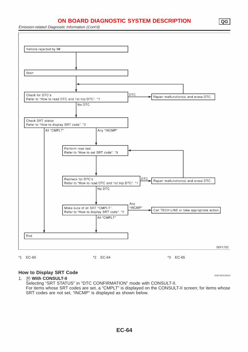
SEF170Z
*1 EC-60 *2 EC-64 *3 EC-65
How to Display SRT CodeNJEC0031S0110
1. With CONSULT-IISelecting “SRT STATUS” in “DTC CONFIRMATION” mode with CONSULT-II.For items whose SRT codes are set, a “CMPLT” is displayed on the CONSULT-II screen; for items whoseSRT codes are not set, “INCMP” is displayed as shown below.
ON BOARD DIAGNOSTIC SYSTEM DESCRIPTION QGEmission-related Diagnostic Information (Cont’d)
EC-64
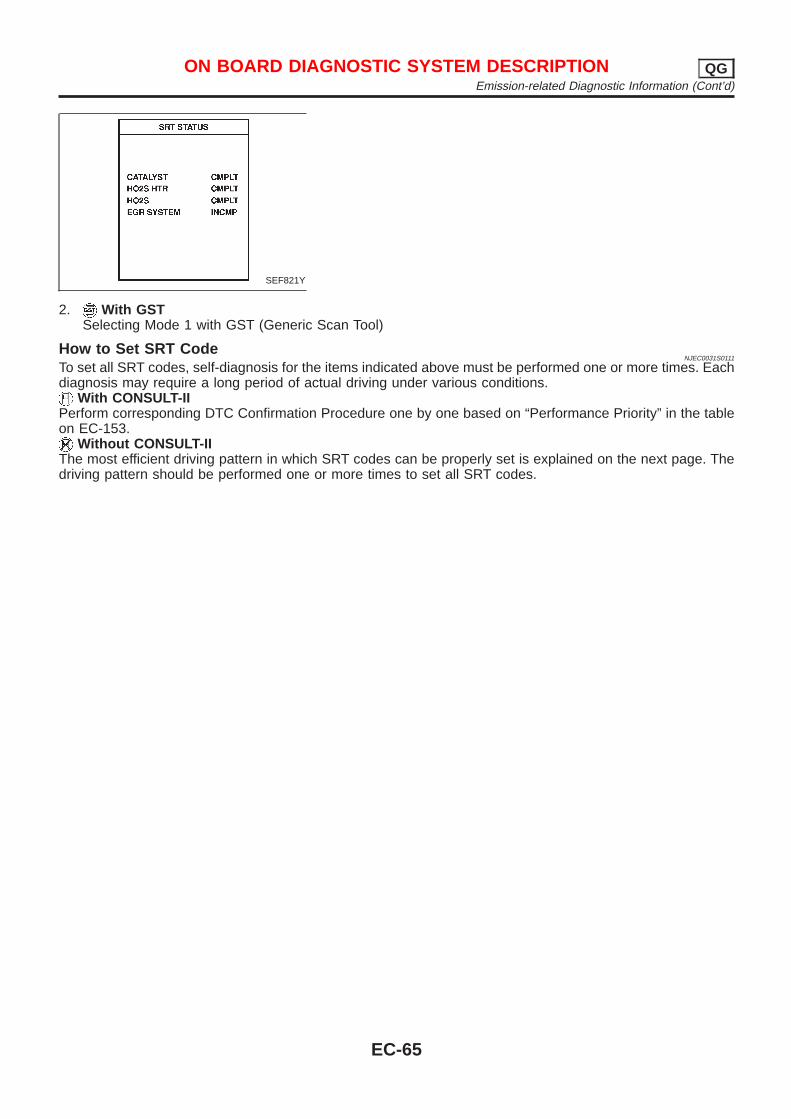
SEF821Y
2. With GSTSelecting Mode 1 with GST (Generic Scan Tool)
How to Set SRT CodeNJEC0031S0111
To set all SRT codes, self-diagnosis for the items indicated above must be performed one or more times. Eachdiagnosis may require a long period of actual driving under various conditions.
With CONSULT-IIPerform corresponding DTC Confirmation Procedure one by one based on “Performance Priority” in the tableon EC-153.
Without CONSULT-IIThe most efficient driving pattern in which SRT codes can be properly set is explained on the next page. Thedriving pattern should be performed one or more times to set all SRT codes.
ON BOARD DIAGNOSTIC SYSTEM DESCRIPTION QGEmission-related Diagnostic Information (Cont’d)
EC-65
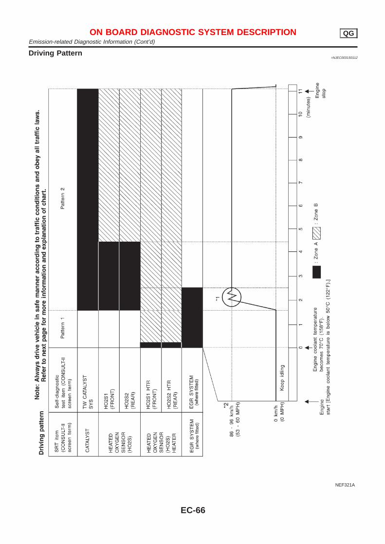
Driving Pattern=NJEC0031S0112
NEF321A
ON BOARD DIAGNOSTIC SYSTEM DESCRIPTION QGEmission-related Diagnostic Information (Cont’d)
EC-66
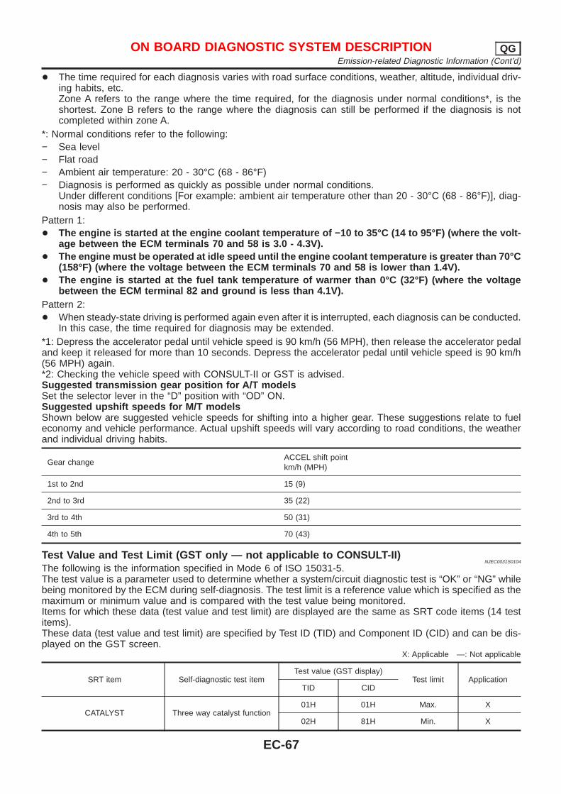
+ The time required for each diagnosis varies with road surface conditions, weather, altitude, individual driv-ing habits, etc.Zone A refers to the range where the time required, for the diagnosis under normal conditions*, is theshortest. Zone B refers to the range where the diagnosis can still be performed if the diagnosis is notcompleted within zone A.
*: Normal conditions refer to the following:− Sea level− Flat road− Ambient air temperature: 20 - 30°C (68 - 86°F)− Diagnosis is performed as quickly as possible under normal conditions.
Under different conditions [For example: ambient air temperature other than 20 - 30°C (68 - 86°F)], diag-nosis may also be performed.
Pattern 1:+ The engine is started at the engine coolant temperature of −10 to 35°C (14 to 95°F) (where the volt-
age between the ECM terminals 70 and 58 is 3.0 - 4.3V).+ The engine must be operated at idle speed until the engine coolant temperature is greater than 70°C
(158°F) (where the voltage between the ECM terminals 70 and 58 is lower than 1.4V).+ The engine is started at the fuel tank temperature of warmer than 0°C (32°F) (where the voltage
between the ECM terminal 82 and ground is less than 4.1V).Pattern 2:+ When steady-state driving is performed again even after it is interrupted, each diagnosis can be conducted.
In this case, the time required for diagnosis may be extended.*1: Depress the accelerator pedal until vehicle speed is 90 km/h (56 MPH), then release the accelerator pedaland keep it released for more than 10 seconds. Depress the accelerator pedal until vehicle speed is 90 km/h(56 MPH) again.*2: Checking the vehicle speed with CONSULT-II or GST is advised.Suggested transmission gear position for A/T modelsSet the selector lever in the “D” position with “OD” ON.Suggested upshift speeds for M/T modelsShown below are suggested vehicle speeds for shifting into a higher gear. These suggestions relate to fueleconomy and vehicle performance. Actual upshift speeds will vary according to road conditions, the weatherand individual driving habits.
Gear changeACCEL shift pointkm/h (MPH)
1st to 2nd 15 (9)
2nd to 3rd 35 (22)
3rd to 4th 50 (31)
4th to 5th 70 (43)
Test Value and Test Limit (GST only — not applicable to CONSULT-II)NJEC0031S0104
The following is the information specified in Mode 6 of ISO 15031-5.The test value is a parameter used to determine whether a system/circuit diagnostic test is “OK” or “NG” whilebeing monitored by the ECM during self-diagnosis. The test limit is a reference value which is specified as themaximum or minimum value and is compared with the test value being monitored.Items for which these data (test value and test limit) are displayed are the same as SRT code items (14 testitems).These data (test value and test limit) are specified by Test ID (TID) and Component ID (CID) and can be dis-played on the GST screen.
X: Applicable —: Not applicable
SRT item Self-diagnostic test itemTest value (GST display)
Test limit ApplicationTID CID
CATALYST Three way catalyst function01H 01H Max. X
02H 81H Min. X
ON BOARD DIAGNOSTIC SYSTEM DESCRIPTION QGEmission-related Diagnostic Information (Cont’d)
EC-67
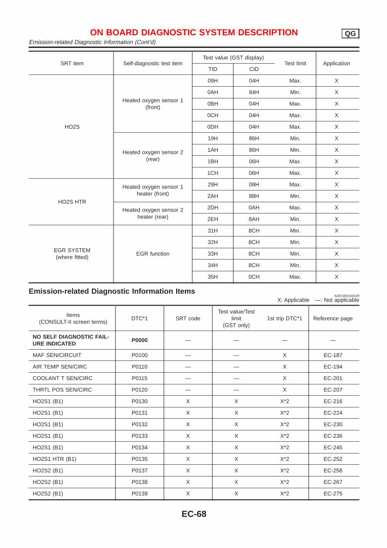
SRT item Self-diagnostic test itemTest value (GST display)
Test limit ApplicationTID CID
HO2S
Heated oxygen sensor 1(front)
09H 04H Max. X
0AH 84H Min. X
0BH 04H Max. X
0CH 04H Max. X
0DH 04H Max. X
Heated oxygen sensor 2(rear)
19H 86H Min. X
1AH 86H Min. X
1BH 06H Max. X
1CH 06H Max. X
HO2S HTR
Heated oxygen sensor 1heater (front)
29H 08H Max. X
2AH 88H Min. X
Heated oxygen sensor 2heater (rear)
2DH 0AH Max. X
2EH 8AH Min. X
EGR SYSTEM(where fitted)
EGR function
31H 8CH Min. X
32H 8CH Min. X
33H 8CH Min. X
34H 8CH Min. X
35H 0CH Max. X
Emission-related Diagnostic Information ItemsNJEC0031S0105
X: Applicable —: Not applicable
Items(CONSULT-II screen terms)
DTC*1 SRT codeTest value/Test
limit(GST only)
1st trip DTC*1 Reference page
NO SELF DIAGNOSTIC FAIL-URE INDICATED
P0000 — — — —
MAF SEN/CIRCUIT P0100 — — X EC-187
AIR TEMP SEN/CIRC P0110 — — X EC-194
COOLANT T SEN/CIRC P0115 — — X EC-201
THRTL POS SEN/CIRC P0120 — — X EC-207
HO2S1 (B1) P0130 X X X*2 EC-216
HO2S1 (B1) P0131 X X X*2 EC-224
HO2S1 (B1) P0132 X X X*2 EC-230
HO2S1 (B1) P0133 X X X*2 EC-236
HO2S1 (B1) P0134 X X X*2 EC-245
HO2S1 HTR (B1) P0135 X X X*2 EC-252
HO2S2 (B1) P0137 X X X*2 EC-258
HO2S2 (B1) P0138 X X X*2 EC-267
HO2S2 (B1) P0139 X X X*2 EC-275
ON BOARD DIAGNOSTIC SYSTEM DESCRIPTION QGEmission-related Diagnostic Information (Cont’d)
EC-68
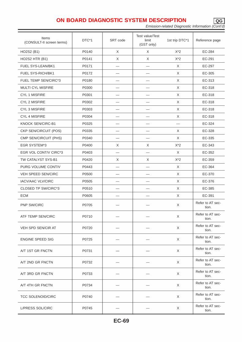
Items(CONSULT-II screen terms)
DTC*1 SRT codeTest value/Test
limit(GST only)
1st trip DTC*1 Reference page
HO2S2 (B1) P0140 X X X*2 EC-284
HO2S2 HTR (B1) P0141 X X X*2 EC-291
FUEL SYS-LEAN/BK1 P0171 — — X EC-297
FUEL SYS-RICH/BK1 P0172 — — X EC-305
FUEL TEMP SEN/CIRC*3 P0180 — — X EC-313
MULTI CYL MISFIRE P0300 — — X EC-318
CYL 1 MISFIRE P0301 — — X EC-318
CYL 2 MISFIRE P0302 — — X EC-318
CYL 3 MISFIRE P0303 — — X EC-318
CYL 4 MISFIRE P0304 — — X EC-318
KNOCK SEN/CIRC-B1 P0325 — — — EC-324
CKP SEN/CIRCUIT (POS) P0335 — — X EC-328
CMP SEN/CIRCUIT (PHS) P0340 — — X EC-335
EGR SYSTEM*3 P0400 X X X*2 EC-343
EGR VOL CONT/V CIRC*3 P0403 — — X EC-352
TW CATALYST SYS-B1 P0420 X X X*2 EC-359
PURG VOLUME CONT/V P0443 — — X EC-364
VEH SPEED SEN/CIRC P0500 — — X EC-370
IACV/AAC VLV/CIRC P0505 — — X EC-376
CLOSED TP SW/CIRC*3 P0510 — — X EC-385
ECM P0605 — — X EC-391
PNP SW/CIRC P0705 — — XRefer to AT sec-
tion.
ATF TEMP SEN/CIRC P0710 — — XRefer to AT sec-
tion.
VEH SPD SEN/CIR AT P0720 — — XRefer to AT sec-
tion.
ENGINE SPEED SIG P0725 — — XRefer to AT sec-
tion.
A/T 1ST GR FNCTN P0731 — — XRefer to AT sec-
tion.
A/T 2ND GR FNCTN P0732 — — XRefer to AT sec-
tion.
A/T 3RD GR FNCTN P0733 — — XRefer to AT sec-
tion.
A/T 4TH GR FNCTN P0734 — — XRefer to AT sec-
tion.
TCC SOLENOID/CIRC P0740 — — XRefer to AT sec-
tion.
L/PRESS SOL/CIRC P0745 — — XRefer to AT sec-
tion.
ON BOARD DIAGNOSTIC SYSTEM DESCRIPTION QGEmission-related Diagnostic Information (Cont’d)
EC-69
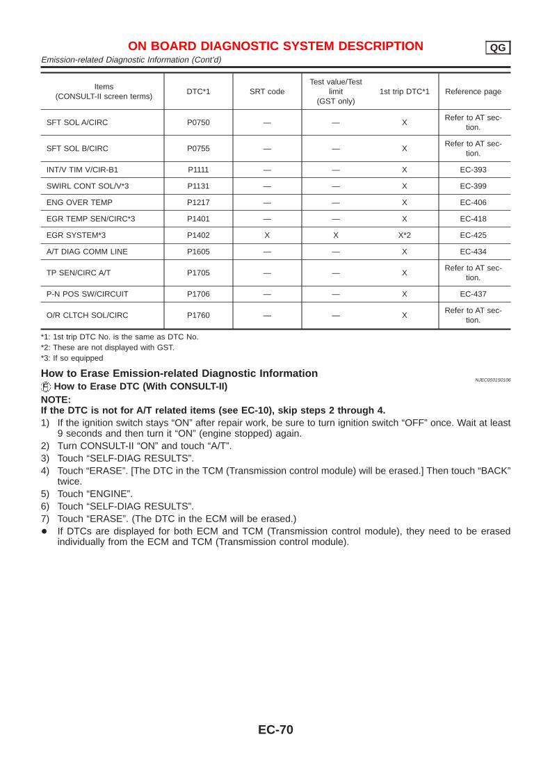
Items(CONSULT-II screen terms)
DTC*1 SRT codeTest value/Test
limit(GST only)
1st trip DTC*1 Reference page
SFT SOL A/CIRC P0750 — — XRefer to AT sec-
tion.
SFT SOL B/CIRC P0755 — — XRefer to AT sec-
tion.
INT/V TIM V/CIR-B1 P1111 — — X EC-393
SWIRL CONT SOL/V*3 P1131 — — X EC-399
ENG OVER TEMP P1217 — — X EC-406
EGR TEMP SEN/CIRC*3 P1401 — — X EC-418
EGR SYSTEM*3 P1402 X X X*2 EC-425
A/T DIAG COMM LINE P1605 — — X EC-434
TP SEN/CIRC A/T P1705 — — XRefer to AT sec-
tion.
P-N POS SW/CIRCUIT P1706 — — X EC-437
O/R CLTCH SOL/CIRC P1760 — — XRefer to AT sec-
tion.
*1: 1st trip DTC No. is the same as DTC No.*2: These are not displayed with GST.*3: If so equipped
How to Erase Emission-related Diagnostic InformationNJEC0031S0106
How to Erase DTC (With CONSULT-II)NOTE:If the DTC is not for A/T related items (see EC-10), skip steps 2 through 4.1) If the ignition switch stays “ON” after repair work, be sure to turn ignition switch “OFF” once. Wait at least
9 seconds and then turn it “ON” (engine stopped) again.2) Turn CONSULT-II “ON” and touch “A/T”.3) Touch “SELF-DIAG RESULTS”.4) Touch “ERASE”. [The DTC in the TCM (Transmission control module) will be erased.] Then touch “BACK”
twice.5) Touch “ENGINE”.6) Touch “SELF-DIAG RESULTS”.7) Touch “ERASE”. (The DTC in the ECM will be erased.)+ If DTCs are displayed for both ECM and TCM (Transmission control module), they need to be erased
individually from the ECM and TCM (Transmission control module).
ON BOARD DIAGNOSTIC SYSTEM DESCRIPTION QGEmission-related Diagnostic Information (Cont’d)
EC-70
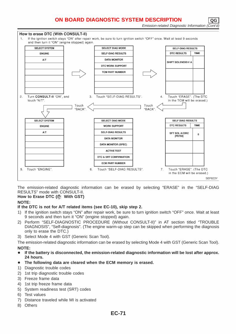
SEF823Y
The emission-related diagnostic information can be erased by selecting “ERASE” in the “SELF-DIAGRESULTS” mode with CONSULT-II.How to Erase DTC ( With GST)NOTE:If the DTC is not for A/T related items (see EC-10), skip step 2.1) If the ignition switch stays “ON” after repair work, be sure to turn ignition switch “OFF” once. Wait at least
9 seconds and then turn it “ON” (engine stopped) again.2) Perform “SELF-DIAGNOSTIC PROCEDURE (Without CONSULT-II)” in AT section titled “TROUBLE
DIAGNOSIS”, “Self-diagnosis”. (The engine warm-up step can be skipped when performing the diagnosisonly to erase the DTC.)
3) Select Mode 4 with GST (Generic Scan Tool).The emission-related diagnostic information can be erased by selecting Mode 4 with GST (Generic Scan Tool).NOTE:+ If the battery is disconnected, the emission-related diagnostic information will be lost after approx.
24 hours.+ The following data are cleared when the ECM memory is erased.1) Diagnostic trouble codes2) 1st trip diagnostic trouble codes3) Freeze frame data4) 1st trip freeze frame data5) System readiness test (SRT) codes6) Test values7) Distance traveled while MI is activated8) Others
ON BOARD DIAGNOSTIC SYSTEM DESCRIPTION QGEmission-related Diagnostic Information (Cont’d)
EC-71
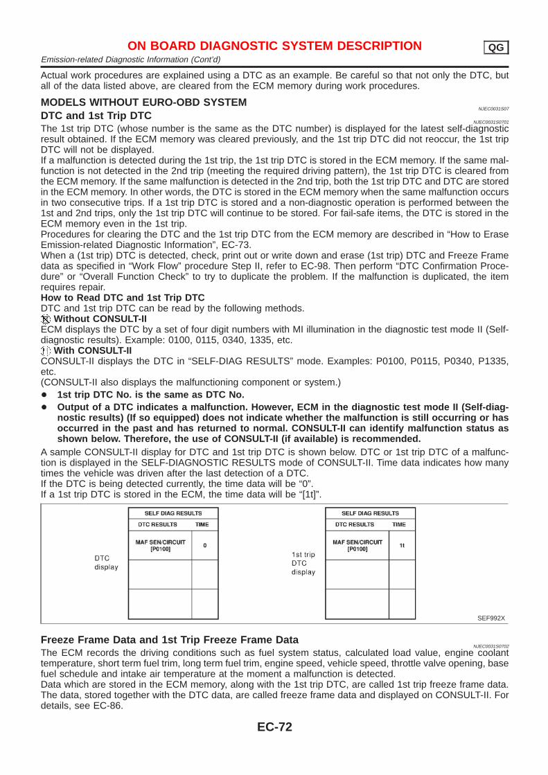
Actual work procedures are explained using a DTC as an example. Be careful so that not only the DTC, butall of the data listed above, are cleared from the ECM memory during work procedures.
MODELS WITHOUT EURO-OBD SYSTEMNJEC0031S07
DTC and 1st Trip DTCNJEC0031S0701
The 1st trip DTC (whose number is the same as the DTC number) is displayed for the latest self-diagnosticresult obtained. If the ECM memory was cleared previously, and the 1st trip DTC did not reoccur, the 1st tripDTC will not be displayed.If a malfunction is detected during the 1st trip, the 1st trip DTC is stored in the ECM memory. If the same mal-function is not detected in the 2nd trip (meeting the required driving pattern), the 1st trip DTC is cleared fromthe ECM memory. If the same malfunction is detected in the 2nd trip, both the 1st trip DTC and DTC are storedin the ECM memory. In other words, the DTC is stored in the ECM memory when the same malfunction occursin two consecutive trips. If a 1st trip DTC is stored and a non-diagnostic operation is performed between the1st and 2nd trips, only the 1st trip DTC will continue to be stored. For fail-safe items, the DTC is stored in theECM memory even in the 1st trip.Procedures for clearing the DTC and the 1st trip DTC from the ECM memory are described in “How to EraseEmission-related Diagnostic Information”, EC-73.When a (1st trip) DTC is detected, check, print out or write down and erase (1st trip) DTC and Freeze Framedata as specified in “Work Flow” procedure Step II, refer to EC-98. Then perform “DTC Confirmation Proce-dure” or “Overall Function Check” to try to duplicate the problem. If the malfunction is duplicated, the itemrequires repair.How to Read DTC and 1st Trip DTCDTC and 1st trip DTC can be read by the following methods.
Without CONSULT-IIECM displays the DTC by a set of four digit numbers with MI illumination in the diagnostic test mode II (Self-diagnostic results). Example: 0100, 0115, 0340, 1335, etc.
With CONSULT-IICONSULT-II displays the DTC in “SELF-DIAG RESULTS” mode. Examples: P0100, P0115, P0340, P1335,etc.(CONSULT-II also displays the malfunctioning component or system.)+ 1st trip DTC No. is the same as DTC No.+ Output of a DTC indicates a malfunction. However, ECM in the diagnostic test mode II (Self-diag-
nostic results) (If so equipped) does not indicate whether the malfunction is still occurring or hasoccurred in the past and has returned to normal. CONSULT-II can identify malfunction status asshown below. Therefore, the use of CONSULT-II (if available) is recommended.
A sample CONSULT-II display for DTC and 1st trip DTC is shown below. DTC or 1st trip DTC of a malfunc-tion is displayed in the SELF-DIAGNOSTIC RESULTS mode of CONSULT-II. Time data indicates how manytimes the vehicle was driven after the last detection of a DTC.If the DTC is being detected currently, the time data will be “0”.If a 1st trip DTC is stored in the ECM, the time data will be “[1t]”.
SEF992X
Freeze Frame Data and 1st Trip Freeze Frame DataNJEC0031S0702
The ECM records the driving conditions such as fuel system status, calculated load value, engine coolanttemperature, short term fuel trim, long term fuel trim, engine speed, vehicle speed, throttle valve opening, basefuel schedule and intake air temperature at the moment a malfunction is detected.Data which are stored in the ECM memory, along with the 1st trip DTC, are called 1st trip freeze frame data.The data, stored together with the DTC data, are called freeze frame data and displayed on CONSULT-II. Fordetails, see EC-86.
ON BOARD DIAGNOSTIC SYSTEM DESCRIPTION QGEmission-related Diagnostic Information (Cont’d)
EC-72
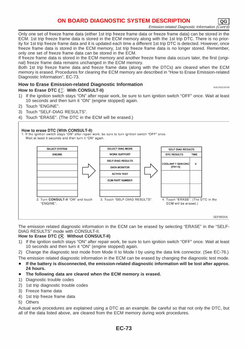
Only one set of freeze frame data (either 1st trip freeze frame data or freeze frame data) can be stored in theECM. 1st trip freeze frame data is stored in the ECM memory along with the 1st trip DTC. There is no prior-ity for 1st trip freeze frame data and it is updated each time a different 1st trip DTC is detected. However, oncefreeze frame data is stored in the ECM memory, 1st trip freeze frame data is no longer stored. Remember,only one set of freeze frame data can be stored in the ECM.If freeze frame data is stored in the ECM memory and another freeze frame data occurs later, the first (origi-nal) freeze frame data remains unchanged in the ECM memory.Both 1st trip freeze frame data and freeze frame data (along with the DTCs) are cleared when the ECMmemory is erased. Procedures for clearing the ECM memory are described in “How to Erase Emission-relatedDiagnostic Information”, EC-73.
How to Erase Emission-related Diagnostic InformationNJEC0031S0706
How to Erase DTC ( With CONSULT-II)1) If the ignition switch stays “ON” after repair work, be sure to turn ignition switch “OFF” once. Wait at least
10 seconds and then turn it “ON” (engine stopped) again.2) Touch “ENGINE”.3) Touch “SELF-DIAG RESULTS”.4) Touch “ERASE”. (The DTC in the ECM will be erased.)
SEF993XA
The emission related diagnostic information in the ECM can be erased by selecting “ERASE” in the “SELF-DIAG RESULTS” mode with CONSULT-II.How to Erase DTC ( Without CONSULT-II)1) If the ignition switch stays “ON” after repair work, be sure to turn ignition switch “OFF” once. Wait at least
10 seconds and then turn it “ON” (engine stopped) again.2) Change the diagnostic test mode from Mode II to Mode I by using the data link connector. (See EC-76.)The emission related diagnostic information in the ECM can be erased by changing the diagnostic test mode.+ If the battery is disconnected, the emission-related diagnostic information will be lost after approx.
24 hours.+ The following data are cleared when the ECM memory is erased.1) Diagnostic trouble codes2) 1st trip diagnostic trouble codes3) Freeze frame data4) 1st trip freeze frame data5) OthersActual work procedures are explained using a DTC as an example. Be careful so that not only the DTC, butall of the data listed above, are cleared from the ECM memory during work procedures.
ON BOARD DIAGNOSTIC SYSTEM DESCRIPTION QGEmission-related Diagnostic Information (Cont’d)
EC-73
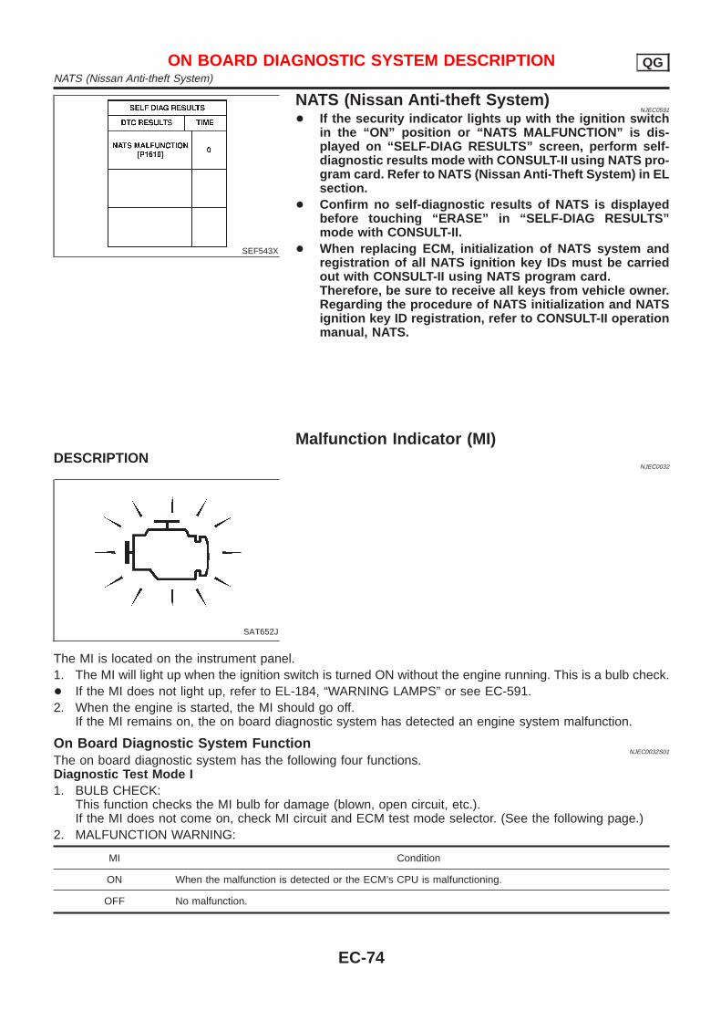
SEF543X
NATS (Nissan Anti-theft System)NJEC0591
+ If the security indicator lights up with the ignition switchin the “ON” position or “NATS MALFUNCTION” is dis-played on “SELF-DIAG RESULTS” screen, perform self-diagnostic results mode with CONSULT-II using NATS pro-gram card. Refer to NATS (Nissan Anti-Theft System) in ELsection.
+ Confirm no self-diagnostic results of NATS is displayedbefore touching “ERASE” in “SELF-DIAG RESULTS”mode with CONSULT-II.
+ When replacing ECM, initialization of NATS system andregistration of all NATS ignition key IDs must be carriedout with CONSULT-II using NATS program card.Therefore, be sure to receive all keys from vehicle owner.Regarding the procedure of NATS initialization and NATSignition key ID registration, refer to CONSULT-II operationmanual, NATS.
Malfunction Indicator (MI)DESCRIPTION
NJEC0032
SAT652J
The MI is located on the instrument panel.1. The MI will light up when the ignition switch is turned ON without the engine running. This is a bulb check.+ If the MI does not light up, refer to EL-184, “WARNING LAMPS” or see EC-591.2. When the engine is started, the MI should go off.
If the MI remains on, the on board diagnostic system has detected an engine system malfunction.
On Board Diagnostic System FunctionNJEC0032S01
The on board diagnostic system has the following four functions.Diagnostic Test Mode I1. BULB CHECK:
This function checks the MI bulb for damage (blown, open circuit, etc.).If the MI does not come on, check MI circuit and ECM test mode selector. (See the following page.)
2. MALFUNCTION WARNING:
MI Condition
ON When the malfunction is detected or the ECM’s CPU is malfunctioning.
OFF No malfunction.
ON BOARD DIAGNOSTIC SYSTEM DESCRIPTION QGNATS (Nissan Anti-theft System)
EC-74
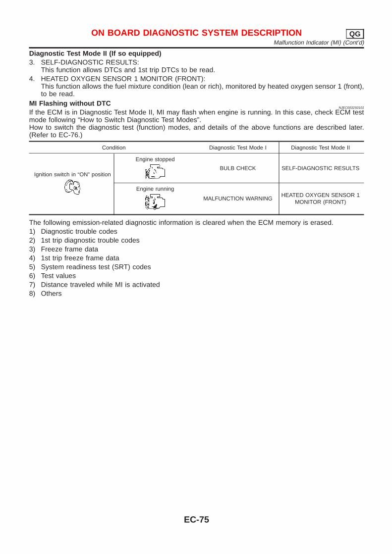
Diagnostic Test Mode II (If so equipped)3. SELF-DIAGNOSTIC RESULTS:
This function allows DTCs and 1st trip DTCs to be read.4. HEATED OXYGEN SENSOR 1 MONITOR (FRONT):
This function allows the fuel mixture condition (lean or rich), monitored by heated oxygen sensor 1 (front),to be read.
MI Flashing without DTCNJEC0032S0101
If the ECM is in Diagnostic Test Mode II, MI may flash when engine is running. In this case, check ECM testmode following “How to Switch Diagnostic Test Modes”.How to switch the diagnostic test (function) modes, and details of the above functions are described later.(Refer to EC-76.)
Condition Diagnostic Test Mode I Diagnostic Test Mode II
Ignition switch in “ON” position
Engine stopped
BULB CHECK SELF-DIAGNOSTIC RESULTS
Engine running
MALFUNCTION WARNINGHEATED OXYGEN SENSOR 1
MONITOR (FRONT)
The following emission-related diagnostic information is cleared when the ECM memory is erased.1) Diagnostic trouble codes2) 1st trip diagnostic trouble codes3) Freeze frame data4) 1st trip freeze frame data5) System readiness test (SRT) codes6) Test values7) Distance traveled while MI is activated8) Others
ON BOARD DIAGNOSTIC SYSTEM DESCRIPTION QGMalfunction Indicator (MI) (Cont’d)
EC-75
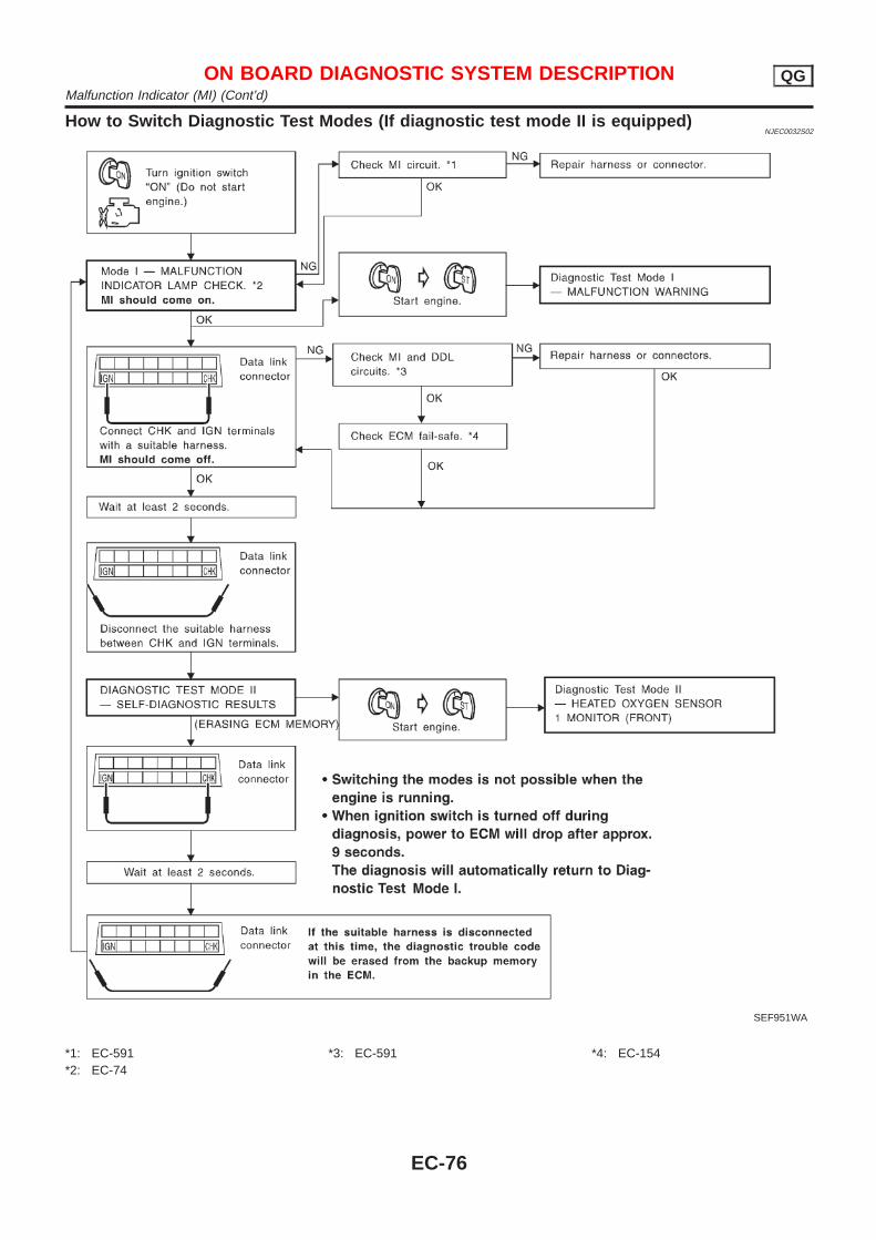
How to Switch Diagnostic Test Modes (If diagnostic test mode II is equipped)NJEC0032S02
SEF951WA
*1: EC-591*2: EC-74
*3: EC-591 *4: EC-154
ON BOARD DIAGNOSTIC SYSTEM DESCRIPTION QGMalfunction Indicator (MI) (Cont’d)
EC-76
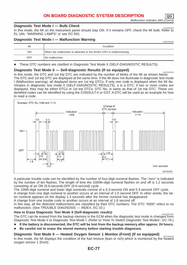
Diagnostic Test Mod e I — Bulb CheckNJEC0032S03
In this mode, the MI on the instrument panel should stay ON. If it remains OFF, check the MI bulb. Refer toEL-184, “WARNING LAMPS” or see EC-591.
Diagnostic Test Mod e I — Malfunction WarningNJEC0032S04
MI Condition
ON When the malfunction is detected or the ECM’s CPU is malfunctioning.
OFF No malfunction.
+ These DTC numbers are clarified in Diagnostic Test Mode II (SELF-DIAGNOSTIC RESULTS).
Diagnostic Test Mode II — Self-diagnostic Results (If so equipped)NJEC0032S05
In this mode, the DTC and 1st trip DTC are indicated by the number of blinks of the MI as shown below.The DTC and 1st trip DTC are displayed at the same time. If the MI does not illuminate in diagnostic test modeI (Malfunction warning), all displayed items are 1st trip DTCs. If only one code is displayed when the MI illu-minates in diagnostic test mode II (SELF-DIAGNOSTIC RESULTS), it is a DTC; if two or more codes aredisplayed, they may be either DTCs or 1st trip DTCs. DTC No. is same as that of 1st trip DTC. These uni-dentified codes can be identified by using the CONSULT-II or GST. A DTC will be used as an example for howto read a code.
SEF952W
A particular trouble code can be identified by the number of four-digit numeral flashes. The “zero” is indicatedby the number of ten flashes. The length of time the 1000th-digit numeral flashes on and off is 1.2 secondsconsisting of an ON (0.6-second)-OFF (0.6-second) cycle.The 100th-digit numeral and lower digit numerals consist of a 0.3-second ON and 0.3-second OFF cycle.A change from one digit numeral to another occurs at an interval of 1.0 second OFF. In other words, the lat-ter numeral appears on the display 1.3 seconds after the former numeral has disappeared.A change from one trouble code to another occurs at an interval of 1.8 second off.In this way, all the detected malfunctions are classified by their DTC numbers. The DTC “0000” refers to nomalfunction. (See TROUBLE DIAGNOSIS — INDEX, EC-10.)How to Erase Diagnostic Test Mode II (Self-diagnostic results)
NJEC0032S0501
The DTC can be erased from the backup memory in the ECM when the diagnostic test mode is changed fromDiagnostic Test Mode II to Diagnostic Test Mode I. (Refer to “How To Switch Diagnostic Test Modes”, EC-76.)+ If the battery is disconnected, the DTC will be lost from the backup memory after approx. 24 hours.+ Be careful not to erase the stored memory before starting trouble diagnoses.
Diagnostic Test Mode II — Heated Oxygen Sensor 1 Monitor (Front) (If so equipped)NJEC0032S06
In this mode, the MI displays the condition of the fuel mixture (lean or rich) which is monitored by the heatedoxygen sensor 1 (front).
ON BOARD DIAGNOSTIC SYSTEM DESCRIPTION QGMalfunction Indicator (MI) (Cont’d)
EC-77
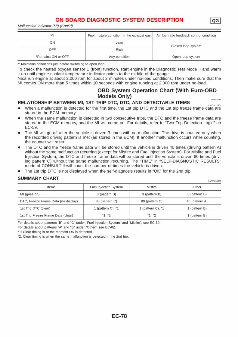
MI Fuel mixture condition in the exhaust gas Air fuel ratio feedback control condition
ON LeanClosed loop system
OFF Rich
*Remains ON or OFF Any condition Open loop system
*: Maintains conditions just before switching to open loop.
To check the heated oxygen sensor 1 (front) function, start engine in the Diagnostic Test Mode II and warmit up until engine coolant temperature indicator points to the middle of the gauge.Next run engine at about 2,000 rpm for about 2 minutes under no-load conditions. Then make sure that theMI comes ON more than 5 times within 10 seconds with engine running at 2,000 rpm under no-load.
OBD System Operation Chart (With Euro-OBDModels Only)
NJEC0033
RELATIONSHIP BETWEEN MI, 1ST TRIP DTC, DTC, AND DETECTABLE ITEMSNJEC0033S01
+ When a malfunction is detected for the first time, the 1st trip DTC and the 1st trip freeze frame data arestored in the ECM memory.
+ When the same malfunction is detected in two consecutive trips, the DTC and the freeze frame data arestored in the ECM memory, and the MI will come on. For details, refer to “Two Trip Detection Logic” onEC-59.
+ The MI will go off after the vehicle is driven 3 times with no malfunction. The drive is counted only whenthe recorded driving pattern is met (as stored in the ECM). If another malfunction occurs while counting,the counter will reset.
+ The DTC and the freeze frame data will be stored until the vehicle is driven 40 times (driving pattern A)without the same malfunction recurring (except for Misfire and Fuel Injection System). For Misfire and FuelInjection System, the DTC and freeze frame data will be stored until the vehicle is driven 80 times (driv-ing pattern C) without the same malfunction recurring. The “TIME” in “SELF-DIAGNOSTIC RESULTS”mode of CONSULT-II will count the number of times the vehicle is driven.
+ The 1st trip DTC is not displayed when the self-diagnosis results in “OK” for the 2nd trip.
SUMMARY CHARTNJEC0033S02
Items Fuel Injection System Misfire Other
MI (goes off) 3 (pattern B) 3 (pattern B) 3 (pattern B)
DTC, Freeze Frame Data (no display) 80 (pattern C) 80 (pattern C) 40 (pattern A)
1st Trip DTC (clear) 1 (pattern C), *1 1 (pattern C), *1 1 (pattern B)
1st Trip Freeze Frame Data (clear) *1, *2 *1, *2 1 (pattern B)
For details about patterns “B” and “C” under “Fuel Injection System” and “Misfire”, see EC-80.For details about patterns “A” and “B” under “Other”, see EC-82.*1: Clear timing is at the moment OK is detected.*2: Clear timing is when the same malfunction is detected in the 2nd trip.
ON BOARD DIAGNOSTIC SYSTEM DESCRIPTION QGMalfunction Indicator (MI) (Cont’d)
EC-78
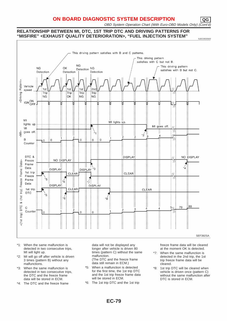
RELATIONSHIP BETWEEN MI, DTC, 1ST TRIP DTC AND DRIVING PATTERNS FOR“MISFIRE” <EXHAUST QUALITY DETERIORATION>, “FUEL INJECTION SYSTEM”
NJEC0033S03
SEF392SA
*1: When the same malfunction isdetected in two consecutive trips,MI will light up.
*2: MI will go off after vehicle is driven3 times (pattern B) without anymalfunctions.
*3: When the same malfunction isdetected in two consecutive trips,the DTC and the freeze framedata will be stored in ECM.
*4: The DTC and the freeze frame
data will not be displayed anylonger after vehicle is driven 80times (pattern C) without the samemalfunction.(The DTC and the freeze framedata still remain in ECM.)
*5: When a malfunction is detectedfor the first time, the 1st trip DTCand the 1st trip freeze frame datawill be stored in ECM.
*6: The 1st trip DTC and the 1st trip
freeze frame data will be clearedat the moment OK is detected.
*7: When the same malfunction isdetected in the 2nd trip, the 1sttrip freeze frame data will becleared.
*8: 1st trip DTC will be cleared whenvehicle is driven once (pattern C)without the same malfunction afterDTC is stored in ECM.
ON BOARD DIAGNOSTIC SYSTEM DESCRIPTION QGOBD System Operation Chart (With Euro-OBD Models Only) (Cont’d)
EC-79
EXPLANATION FOR DRIVING PATTERNS FOR “MISFIRE <EXHAUST QUALITYDETERIORATION>”, “FUEL INJECTION SYSTEM”
NJEC0033S04
Driving Pattern BNJEC0033S0401
Driving pattern B means the vehicle operation as follows:All components and systems should be monitored at least once by the OBD system.+ The B counter will be cleared when the malfunction is detected once regardless of the driving pattern.+ The B counter will be counted up when driving pattern B is satisfied without any malfunction.+ The MI will go off when the B counter reaches 3. (*2 in EC-79)
Driving Pattern CNJEC0033S0402
Driving pattern C means the vehicle operation as follows:1) The following conditions should be satisfied at the same time:
Engine speed: (Engine speed in the freeze frame data) ±375 rpmCalculated load value: (Calculated load value in the freeze frame data) × (1±0.1) [%]Engine coolant temperature (T) condition:
+ When the freeze frame data shows lower than 70°C (158°F), “T” should be lower than 70°C (158°F).+ When the freeze frame data shows higher than or equal to 70°C (158°F), “T” should be higher than or
equal to 70°C (158°F).Example:If the stored freeze frame data is as follows:Engine speed: 850 rpm, Calculated load value: 30%, Engine coolant temperature: 80°C (176°F)To be satisfied with driving pattern C, the vehicle should run under the following conditions:Engine speed: 475 - 1,225 rpm, Calculated load value: 27 - 33%, Engine coolant temperature: more than 70°C(158°F)+ The C counter will be cleared when the malfunction is detected regardless of driving pattern C.+ The C counter will be counted up when driving pattern C is satisfied without the same malfunction.+ The DTC will not be displayed after C counter reaches 80.+ The 1st trip DTC will be cleared when C counter is counted once without the same malfunction after DTC
is stored in ECM.
ON BOARD DIAGNOSTIC SYSTEM DESCRIPTION QGOBD System Operation Chart (With Euro-OBD Models Only) (Cont’d)
EC-80
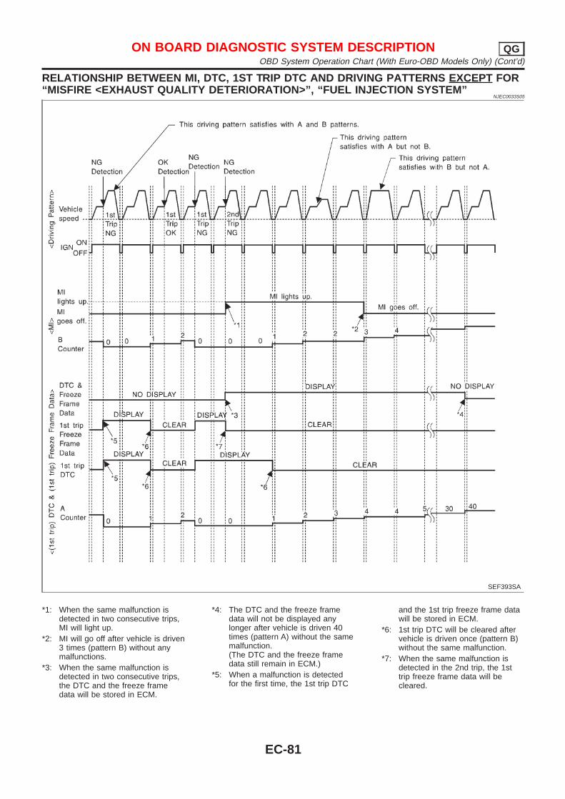
RELATIONSHIP BETWEEN MI, DTC, 1ST TRIP DTC AND DRIVING PATTERNS EXCEPT FOR“MISFIRE <EXHAUST QUALITY DETERIORATION>”, “FUEL INJECTION SYSTEM”
NJEC0033S05
SEF393SA
*1: When the same malfunction isdetected in two consecutive trips,MI will light up.
*2: MI will go off after vehicle is driven3 times (pattern B) without anymalfunctions.
*3: When the same malfunction isdetected in two consecutive trips,the DTC and the freeze framedata will be stored in ECM.
*4: The DTC and the freeze framedata will not be displayed anylonger after vehicle is driven 40times (pattern A) without the samemalfunction.(The DTC and the freeze framedata still remain in ECM.)
*5: When a malfunction is detectedfor the first time, the 1st trip DTC
and the 1st trip freeze frame datawill be stored in ECM.
*6: 1st trip DTC will be cleared aftervehicle is driven once (pattern B)without the same malfunction.
*7: When the same malfunction isdetected in the 2nd trip, the 1sttrip freeze frame data will becleared.
ON BOARD DIAGNOSTIC SYSTEM DESCRIPTION QGOBD System Operation Chart (With Euro-OBD Models Only) (Cont’d)
EC-81
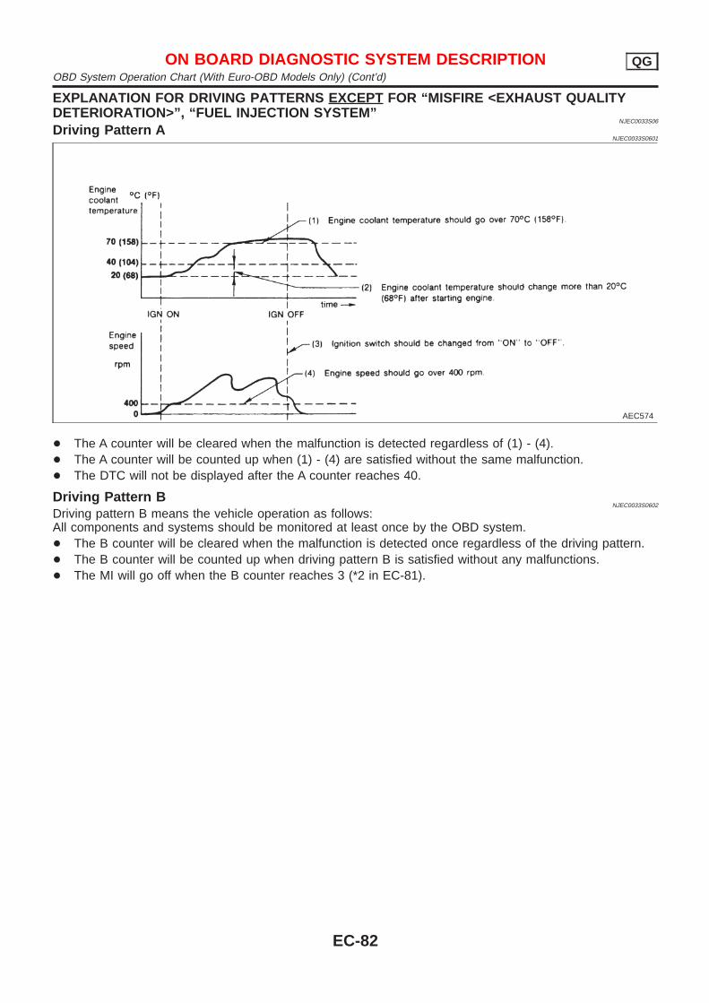
EXPLANATION FOR DRIVING PATTERNS EXCEPT FOR “MISFIRE <EXHAUST QUALITYDETERIORATION>”, “FUEL INJECTION SYSTEM”
NJEC0033S06
Driving Pattern ANJEC0033S0601
AEC574
+ The A counter will be cleared when the malfunction is detected regardless of (1) - (4).+ The A counter will be counted up when (1) - (4) are satisfied without the same malfunction.+ The DTC will not be displayed after the A counter reaches 40.
Driving Pattern BNJEC0033S0602
Driving pattern B means the vehicle operation as follows:All components and systems should be monitored at least once by the OBD system.+ The B counter will be cleared when the malfunction is detected once regardless of the driving pattern.+ The B counter will be counted up when driving pattern B is satisfied without any malfunctions.+ The MI will go off when the B counter reaches 3 (*2 in EC-81).
ON BOARD DIAGNOSTIC SYSTEM DESCRIPTION QGOBD System Operation Chart (With Euro-OBD Models Only) (Cont’d)
EC-82
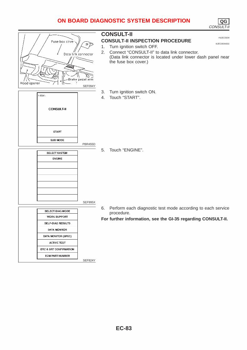
SEF094Y
CONSULT-II=NJEC0034
CONSULT-II INSPECTION PROCEDURENJEC0034S01
1. Turn ignition switch OFF.2. Connect “CONSULT-II” to data link connector.
(Data link connector is located under lower dash panel nearthe fuse box cover.)
PBR455D
3. Turn ignition switch ON.4. Touch “START”.
SEF995X
5. Touch “ENGINE”.
SEF824Y
6. Perform each diagnostic test mode according to each serviceprocedure.
For further information, see the GI-35 regarding CONSULT-II.
ON BOARD DIAGNOSTIC SYSTEM DESCRIPTION QGCONSULT-II
EC-83
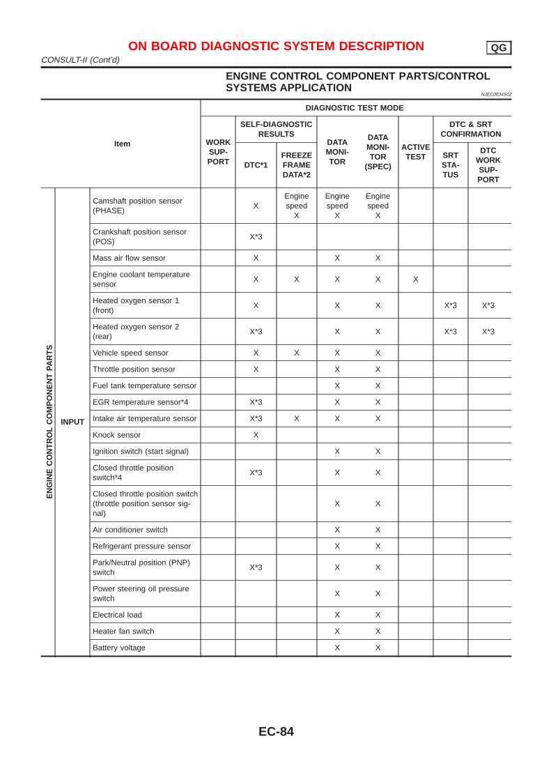
ENGINE CONTROL COMPONENT PARTS/CONTROLSYSTEMS APPLICATION
NJEC0034S02
Item
DIAGNOSTIC TEST MODE
WORKSUP-PORT
SELF-DIAGNOSTICRESULTS
DATAMONI-TOR
DATAMONI-TOR
(SPEC)
ACTIVETEST
DTC & SRTCONFIRMATION
DTC*1FREEZEFRAMEDATA*2
SRTSTA-TUS
DTCWORKSUP-PORT
EN
GIN
EC
ON
TR
OL
CO
MP
ON
EN
TPA
RT
S
INPUT
Camshaft position sensor(PHASE)
XEnginespeed
X
Enginespeed
X
Enginespeed
X
Crankshaft position sensor(POS)
X*3
Mass air flow sensor X X X
Engine coolant temperaturesensor
X X X X X
Heated oxygen sensor 1(front)
X X X X*3 X*3
Heated oxygen sensor 2(rear)
X*3 X X X*3 X*3
Vehicle speed sensor X X X X
Throttle position sensor X X X
Fuel tank temperature sensor X X
EGR temperature sensor*4 X*3 X X
Intake air temperature sensor X*3 X X X
Knock sensor X
Ignition switch (start signal) X X
Closed throttle positionswitch*4
X*3 X X
Closed throttle position switch(throttle position sensor sig-nal)
X X
Air conditioner switch X X
Refrigerant pressure sensor X X
Park/Neutral position (PNP)switch
X*3 X X
Power steering oil pressureswitch
X X
Electrical load X X
Heater fan switch X X
Battery voltage X X
ON BOARD DIAGNOSTIC SYSTEM DESCRIPTION QGCONSULT-II (Cont’d)
EC-84
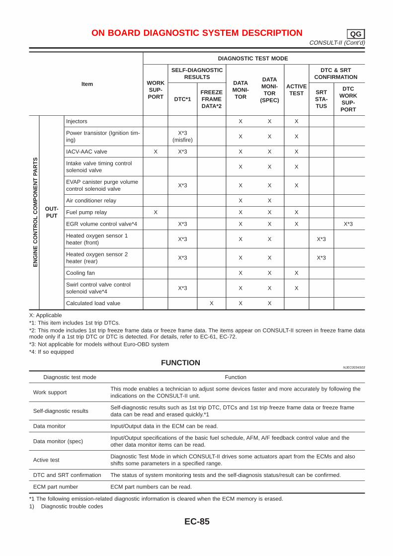
Item
DIAGNOSTIC TEST MODE
WORKSUP-PORT
SELF-DIAGNOSTICRESULTS
DATAMONI-TOR
DATAMONI-TOR
(SPEC)
ACTIVETEST
DTC & SRTCONFIRMATION
DTC*1FREEZEFRAMEDATA*2
SRTSTA-TUS
DTCWORKSUP-PORT
EN
GIN
EC
ON
TR
OL
CO
MP
ON
EN
TPA
RT
S
OUT-PUT
Injectors X X X
Power transistor (Ignition tim-ing)
X*3(misfire)
X X X
IACV-AAC valve X X*3 X X X
Intake valve timing controlsolenoid valve
X X X
EVAP canister purge volumecontrol solenoid valve
X*3 X X X
Air conditioner relay X X
Fuel pump relay X X X X
EGR volume control valve*4 X*3 X X X X*3
Heated oxygen sensor 1heater (front)
X*3 X X X*3
Heated oxygen sensor 2heater (rear)
X*3 X X X*3
Cooling fan X X X
Swirl control valve controlsolenoid valve*4
X*3 X X X
Calculated load value X X X
X: Applicable*1: This item includes 1st trip DTCs.*2: This mode includes 1st trip freeze frame data or freeze frame data. The items appear on CONSULT-II screen in freeze frame datamode only if a 1st trip DTC or DTC is detected. For details, refer to EC-61, EC-72.*3: Not applicable for models without Euro-OBD system*4: If so equipped
FUNCTIONNJEC0034S03
Diagnostic test mode Function
Work supportThis mode enables a technician to adjust some devices faster and more accurately by following theindications on the CONSULT-II unit.
Self-diagnostic resultsSelf-diagnostic results such as 1st trip DTC, DTCs and 1st trip freeze frame data or freeze framedata can be read and erased quickly.*1
Data monitor Input/Output data in the ECM can be read.
Data monitor (spec)Input/Output specifications of the basic fuel schedule, AFM, A/F feedback control value and theother data monitor items can be read.
Active testDiagnostic Test Mode in which CONSULT-II drives some actuators apart from the ECMs and alsoshifts some parameters in a specified range.
DTC and SRT confirmation The status of system monitoring tests and the self-diagnosis status/result can be confirmed.
ECM part number ECM part numbers can be read.
*1 The following emission-related diagnostic information is cleared when the ECM memory is erased.1) Diagnostic trouble codes
ON BOARD DIAGNOSTIC SYSTEM DESCRIPTION QGCONSULT-II (Cont’d)
EC-85
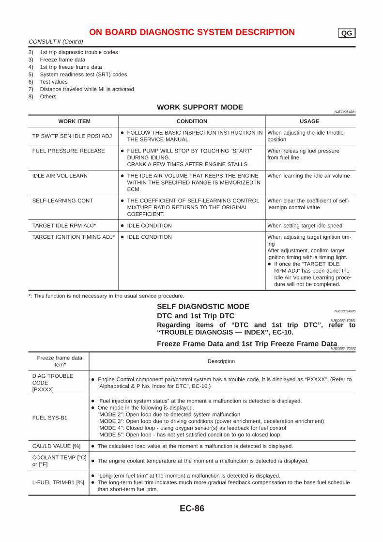
2) 1st trip diagnostic trouble codes3) Freeze frame data4) 1st trip freeze frame data5) System readiness test (SRT) codes6) Test values7) Distance traveled while MI is activated.8) Others
WORK SUPPORT MODENJEC0034S04
WORK ITEM CONDITION USAGE
TP SW/TP SEN IDLE POSI ADJ+ FOLLOW THE BASIC INSPECTION INSTRUCTION IN
THE SERVICE MANUAL.When adjusting the idle throttleposition
FUEL PRESSURE RELEASE + FUEL PUMP WILL STOP BY TOUCHING “START”DURING IDLING.CRANK A FEW TIMES AFTER ENGINE STALLS.
When releasing fuel pressurefrom fuel line
IDLE AIR VOL LEARN + THE IDLE AIR VOLUME THAT KEEPS THE ENGINEWITHIN THE SPECIFIED RANGE IS MEMORIZED INECM.
When learning the idle air volume
SELF-LEARNING CONT + THE COEFFICIENT OF SELF-LEARNING CONTROLMIXTURE RATIO RETURNS TO THE ORIGINALCOEFFICIENT.
When clear the coefficient of self-learnign control value
TARGET IDLE RPM ADJ* + IDLE CONDITION When setting target idle speed
TARGET IGNITION TIMING ADJ* + IDLE CONDITION When adjusting target ignition tim-ingAfter adjustment, confirm targetignition timing with a timing light.+ If once the “TARGET IDLE
RPM ADJ” has been done, theIdle Air Volume Learning proce-dure will not be completed.
*: This function is not necessary in the usual service procedure.
SELF DIAGNOSTIC MODENJEC0034S05
DTC and 1st Trip DTCNJEC0034S0501
Regarding items of “DTC and 1st trip DTC”, refer to“TROUBLE DIAGNOSIS — INDEX”, EC-10.
Freeze Frame Data and 1st Trip Freeze Frame DataNJEC0034S0502
Freeze frame dataitem*
Description
DIAG TROUBLECODE[PXXXX]
+ Engine Control component part/control system has a trouble code, it is displayed as “PXXXX”. (Refer to“Alphabetical & P No. Index for DTC”, EC-10.)
FUEL SYS-B1
+ “Fuel injection system status” at the moment a malfunction is detected is displayed.+ One mode in the following is displayed.
“MODE 2”: Open loop due to detected system malfunction“MODE 3”: Open loop due to driving conditions (power enrichment, deceleration enrichment)“MODE 4”: Closed loop - using oxygen sensor(s) as feedback for fuel control“MODE 5”: Open loop - has not yet satisfied condition to go to closed loop
CAL/LD VALUE [%] + The calculated load value at the moment a malfunction is detected is displayed.
COOLANT TEMP [°C]or [°F]
+ The engine coolant temperature at the moment a malfunction is detected is displayed.
L-FUEL TRIM-B1 [%]+ “Long-term fuel trim” at the moment a malfunction is detected is displayed.+ The long-term fuel trim indicates much more gradual feedback compensation to the base fuel schedule
than short-term fuel trim.
ON BOARD DIAGNOSTIC SYSTEM DESCRIPTION QGCONSULT-II (Cont’d)
EC-86
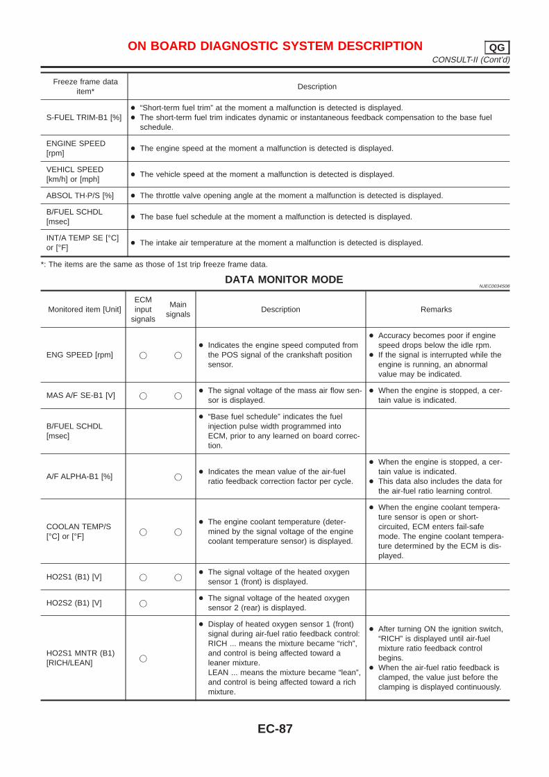
Freeze frame dataitem*
Description
S-FUEL TRIM-B1 [%]+ “Short-term fuel trim” at the moment a malfunction is detected is displayed.+ The short-term fuel trim indicates dynamic or instantaneous feedback compensation to the base fuel
schedule.
ENGINE SPEED[rpm]
+ The engine speed at the moment a malfunction is detected is displayed.
VEHICL SPEED[km/h] or [mph]
+ The vehicle speed at the moment a malfunction is detected is displayed.
ABSOL TH·P/S [%] + The throttle valve opening angle at the moment a malfunction is detected is displayed.
B/FUEL SCHDL[msec]
+ The base fuel schedule at the moment a malfunction is detected is displayed.
INT/A TEMP SE [°C]or [°F]
+ The intake air temperature at the moment a malfunction is detected is displayed.
*: The items are the same as those of 1st trip freeze frame data.
DATA MONITOR MODENJEC0034S06
Monitored item [Unit]ECMinput
signals
Mainsignals
Description Remarks
ENG SPEED [rpm] j j
+ Indicates the engine speed computed fromthe POS signal of the crankshaft positionsensor.
+ Accuracy becomes poor if enginespeed drops below the idle rpm.
+ If the signal is interrupted while theengine is running, an abnormalvalue may be indicated.
MAS A/F SE-B1 [V] j j+ The signal voltage of the mass air flow sen-
sor is displayed.+ When the engine is stopped, a cer-
tain value is indicated.
B/FUEL SCHDL[msec]
+ “Base fuel schedule” indicates the fuelinjection pulse width programmed intoECM, prior to any learned on board correc-tion.
A/F ALPHA-B1 [%] j+ Indicates the mean value of the air-fuel
ratio feedback correction factor per cycle.
+ When the engine is stopped, a cer-tain value is indicated.
+ This data also includes the data forthe air-fuel ratio learning control.
COOLAN TEMP/S[°C] or [°F]
j j
+ The engine coolant temperature (deter-mined by the signal voltage of the enginecoolant temperature sensor) is displayed.
+ When the engine coolant tempera-ture sensor is open or short-circuited, ECM enters fail-safemode. The engine coolant tempera-ture determined by the ECM is dis-played.
HO2S1 (B1) [V] j j+ The signal voltage of the heated oxygen
sensor 1 (front) is displayed.
HO2S2 (B1) [V] j+ The signal voltage of the heated oxygen
sensor 2 (rear) is displayed.
HO2S1 MNTR (B1)[RICH/LEAN]
j
+ Display of heated oxygen sensor 1 (front)signal during air-fuel ratio feedback control:RICH ... means the mixture became “rich”,and control is being affected toward aleaner mixture.LEAN ... means the mixture became “lean”,and control is being affected toward a richmixture.
+ After turning ON the ignition switch,“RICH” is displayed until air-fuelmixture ratio feedback controlbegins.
+ When the air-fuel ratio feedback isclamped, the value just before theclamping is displayed continuously.
ON BOARD DIAGNOSTIC SYSTEM DESCRIPTION QGCONSULT-II (Cont’d)
EC-87
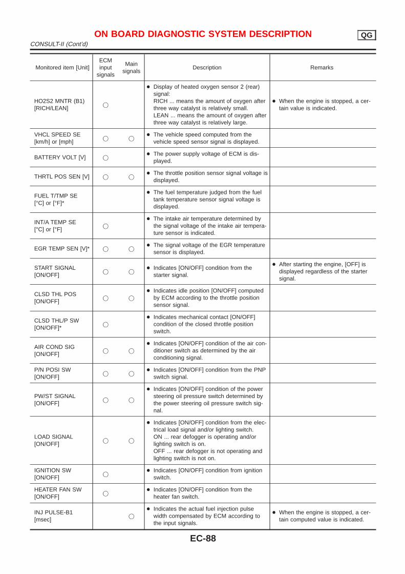
Monitored item [Unit]ECMinput
signals
Mainsignals
Description Remarks
HO2S2 MNTR (B1)[RICH/LEAN]
j
+ Display of heated oxygen sensor 2 (rear)signal:RICH ... means the amount of oxygen afterthree way catalyst is relatively small.LEAN ... means the amount of oxygen afterthree way catalyst is relatively large.
+ When the engine is stopped, a cer-tain value is indicated.
VHCL SPEED SE[km/h] or [mph]
j j+ The vehicle speed computed from the
vehicle speed sensor signal is displayed.
BATTERY VOLT [V] j+ The power supply voltage of ECM is dis-
played.
THRTL POS SEN [V] j j+ The throttle position sensor signal voltage is
displayed.
FUEL T/TMP SE[°C] or [°F]*
+ The fuel temperature judged from the fueltank temperature sensor signal voltage isdisplayed.
INT/A TEMP SE[°C] or [°F]
j
+ The intake air temperature determined bythe signal voltage of the intake air tempera-ture sensor is indicated.
EGR TEMP SEN [V]* j j+ The signal voltage of the EGR temperature
sensor is displayed.
START SIGNAL[ON/OFF]
j j+ Indicates [ON/OFF] condition from the
starter signal.
+ After starting the engine, [OFF] isdisplayed regardless of the startersignal.
CLSD THL POS[ON/OFF]
j j
+ Indicates idle position [ON/OFF] computedby ECM according to the throttle positionsensor signal.
CLSD THL/P SW[ON/OFF]*
j
+ Indicates mechanical contact [ON/OFF]condition of the closed throttle positionswitch.
AIR COND SIG[ON/OFF]
j j
+ Indicates [ON/OFF] condition of the air con-ditioner switch as determined by the airconditioning signal.
P/N POSI SW[ON/OFF]
j j+ Indicates [ON/OFF] condition from the PNP
switch signal.
PW/ST SIGNAL[ON/OFF]
j j
+ Indicates [ON/OFF] condition of the powersteering oil pressure switch determined bythe power steering oil pressure switch sig-nal.
LOAD SIGNAL[ON/OFF]
j j
+ Indicates [ON/OFF] condition from the elec-trical load signal and/or lighting switch.ON ... rear defogger is operating and/orlighting switch is on.OFF ... rear defogger is not operating andlighting switch is not on.
IGNITION SW[ON/OFF]
j+ Indicates [ON/OFF] condition from ignition
switch.
HEATER FAN SW[ON/OFF]
j+ Indicates [ON/OFF] condition from the
heater fan switch.
INJ PULSE-B1[msec]
j
+ Indicates the actual fuel injection pulsewidth compensated by ECM according tothe input signals.
+ When the engine is stopped, a cer-tain computed value is indicated.
ON BOARD DIAGNOSTIC SYSTEM DESCRIPTION QGCONSULT-II (Cont’d)
EC-88
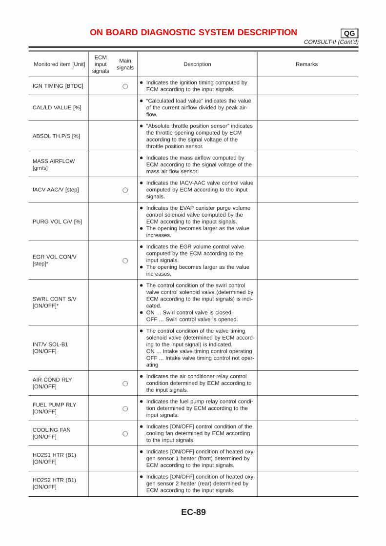
Monitored item [Unit]ECMinput
signals
Mainsignals
Description Remarks
IGN TIMING [BTDC] j+ Indicates the ignition timing computed by
ECM according to the input signals.
CAL/LD VALUE [%]+ “Calculated load value” indicates the value
of the current airflow divided by peak air-flow.
ABSOL TH.P/S [%]
+ “Absolute throttle position sensor” indicatesthe throttle opening computed by ECMaccording to the signal voltage of thethrottle position sensor.
MASS AIRFLOW[gm/s]
+ Indicates the mass airflow computed byECM according to the signal voltage of themass air flow sensor.
IACV-AAC/V [step] j
+ Indicates the IACV-AAC valve control valuecomputed by ECM according to the inputsignals.
PURG VOL C/V [%]
+ Indicates the EVAP canister purge volumecontrol solenoid valve computed by theECM according to the inpuct signals.
+ The opening becomes larger as the valueincreases.
EGR VOL CON/V[step]*
j
+ Indicates the EGR volume control valvecomputed by the ECM according to theinput signals.
+ The opening becomes larger as the valueincreases.
SWRL CONT S/V[ON/OFF]*
+ The control condition of the swirl controlvalve control solenoid valve (determined byECM according to the input signals) is indi-cated.
+ ON ... Swirl control valve is closed.OFF ... Swirl control valve is opened.
INT/V SOL-B1[ON/OFF]
+ The control condition of the valve timingsolenoid valve (determined by ECM accord-ing to the input signal) is indicated.ON ... Intake valve timing control operatingOFF ... Intake valve timing control not oper-ating
AIR COND RLY[ON/OFF]
j
+ Indicates the air conditioner relay controlcondition determined by ECM according tothe input signals.
FUEL PUMP RLY[ON/OFF]
j
+ Indicates the fuel pump relay control condi-tion determined by ECM according to theinput signals.
COOLING FAN[ON/OFF]
j
+ Indicates [ON/OFF] control condition of thecooling fan determined by ECM accordingto the input signals.
HO2S1 HTR (B1)[ON/OFF]
+ Indicates [ON/OFF] condition of heated oxy-gen sensor 1 heater (front) determined byECM according to the input signals.
HO2S2 HTR (B1)[ON/OFF]
+ Indicates [ON/OFF] condition of heated oxy-gen sensor 2 heater (rear) determined byECM according to the input signals.
ON BOARD DIAGNOSTIC SYSTEM DESCRIPTION QGCONSULT-II (Cont’d)
EC-89
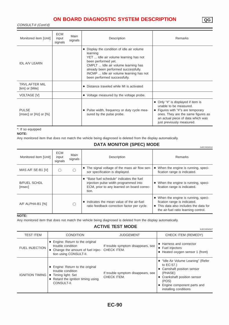
Monitored item [Unit]ECMinput
signals
Mainsignals
Description Remarks
IDL A/V LEARN
+ Display the condition of idle air volumelearningYET ... Idle air volume learning has notbeen performed yet.CMPLT ... Idle air volume learning hasalready been performed successfully.INCMP ... Idle air volume learning has notbeen performed successfully.
TRVL AFTER MIL[km] or [Mile]
+ Distance traveled while MI is activated
VOLTAGE [V] + Voltage measured by the voltage probe.
PULSE[msec] or [Hz] or [%]
+ Pulse width, frequency or duty cycle mea-sured by the pulse probe.
+ Only “#” is displayed if item isunable to be measured.
+ Figures with “#”s are temporaryones. They are the same figures asan actual piece of data which wasjust previously measured.
*: If so equippedNOTE:Any monitored item that does not match the vehicle being diagnosed is deleted from the display automatically.
DATA MONITOR (SPEC) MODENJEC0034S11
Monitored item [Unit]ECMinput
signals
Mainsignals
Description Remarks
MAS A/F SE-B1 [V] j j+ The signal voltage of the mass air flow sen-
sor specification is displayed.+ When the engine is running, speci-
fication range is indicated.
B/FUEL SCHDL[msec]
+ “Base fuel schedule” indicates the fuelinjection pulse width programmed intoECM, prior to any learned on board correc-tion.
+ When the engine is running, speci-fication range is indicated.
A/F ALPHA-B1 [%] j+ Indicates the mean value of the air-fuel
ratio feedback correction factor per cycle.
+ When the engine is running, speci-fication range is indicated.
+ This data also includes the data forthe air-fuel ratio learning control.
NOTE:Any monitored item that does not match the vehicle being diagnosed is deleted from the display automatically.
ACTIVE TEST MODENJEC0034S07
TEST ITEM CONDITION JUDGEMENT CHECK ITEM (REMEDY)
FUEL INJECTION
+ Engine: Return to the originaltrouble condition
+ Change the amount of fuel injec-tion using CONSULT-II.
If trouble symptom disappears, seeCHECK ITEM.
+ Harness and connector+ Fuel injectors+ Heated oxygen sensor 1 (front)
IGNITION TIMING
+ Engine: Return to the originaltrouble condition
+ Timing light: Set+ Retard the ignition timing using
CONSULT-II.
If trouble symptom disappears, seeCHECK ITEM.
+ “Idle Air Volume Leaning” (Referto EC-57.)
+ Camshaft position sensor(PHASE)
+ Crankshaft position sensor(POS)
+ Engine component parts andinstalling conditions
ON BOARD DIAGNOSTIC SYSTEM DESCRIPTION QGCONSULT-II (Cont’d)
EC-90
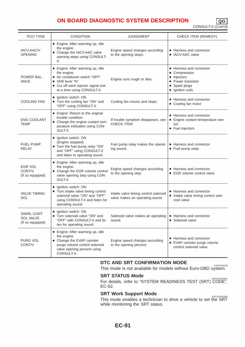
TEST ITEM CONDITION JUDGEMENT CHECK ITEM (REMEDY)
IACV-AAC/VOPENING
+ Engine: After warming up, idlethe engine.
+ Change the IACV-AAC valveopening steps using CONSULT-II.
Engine speed changes accordingto the opening steps.
+ Harness and connector+ IACV-AAC valve
POWER BAL-ANCE
+ Engine: After warming up, idlethe engine.
+ Air conditioner switch “OFF”+ Shift lever “N”+ Cut off each injector signal one
at a time using CONSULT-II.
Engine runs rough or dies.
+ Harness and connector+ Compression+ Injectors+ Power transistor+ Spark plugs+ Ignition coils
COOLING FAN+ Ignition switch: ON+ Turn the cooling fan “ON” and
“OFF” using CONSULT-II.Cooling fan moves and stops.
+ Harness and connector+ Cooling fan motor
ENG COOLANTTEMP
+ Engine: Return to the originaltrouble condition
+ Change the engine coolant tem-perature indication using CON-SULT-II.
If trouble symptom disappears, seeCHECK ITEM.
+ Harness and connector+ Engine coolant temperature sen-
sor+ Fuel injectors
FUEL PUMPRELAY
+ Ignition switch: ON(Engine stopped)
+ Turn the fuel pump relay “ON”and “OFF” using CONSULT-IIand listen to operating sound.
Fuel pump relay makes the operat-ing sound.
+ Harness and connector+ Fuel pump relay
EGR VOLCONT/V(If so equipped)
+ Engine: After warming up, idlethe engine.
+ Change the EGR volume controlvalve opening step using CON-SULT-II.
Engine speed changes accordingto the opening step.
+ Harness and connector+ EGR volume control valve
VALVE TIMINGSOL
+ Ignition switch: ON+ Turn intake valve timing control
solenoid valve “ON” and “OFF”using CONSULT-II and listen foroperating sound.
Intake valve timing control solenoidvalve makes an operating sound.
+ Harness and connector+ Intake valve timing control sole-
noid valve
SWIRL CONTSOL VALVE(If so equipped)
+ Ignition switch: ON+ Turn solenoid valve “ON” and
“OFF” with CONSULT-II and lis-ten for operating sound.
Solenoid valve makes an operatingsound.
+ Harness and connector+ Solenoid valve
PURG VOLCONT/V
+ Engine: After warming up, idlethe engine.
+ Change the EVAP canisterpurge volume control solenoidvalve opening percent usingCONSULT-II.
Engine speed changes accordingto the opening percent.
+ Harness and connector+ EVAP canister purge volume
control solenoid valve
DTC AND SRT CONFIRMATION MODENJEC0034S08
This mode is not available for models without Euro-OBD system.
SRT STATUS ModeNJEC0034S0801
For details, refer to “SYSTEM READINESS TEST (SRT) CODE”,EC-62.
SRT Work Support ModeNJEC0034S0803
This mode enables a technician to drive a vehicle to set the SRTwhile monitoring the SRT status.
ON BOARD DIAGNOSTIC SYSTEM DESCRIPTION QGCONSULT-II (Cont’d)
EC-91
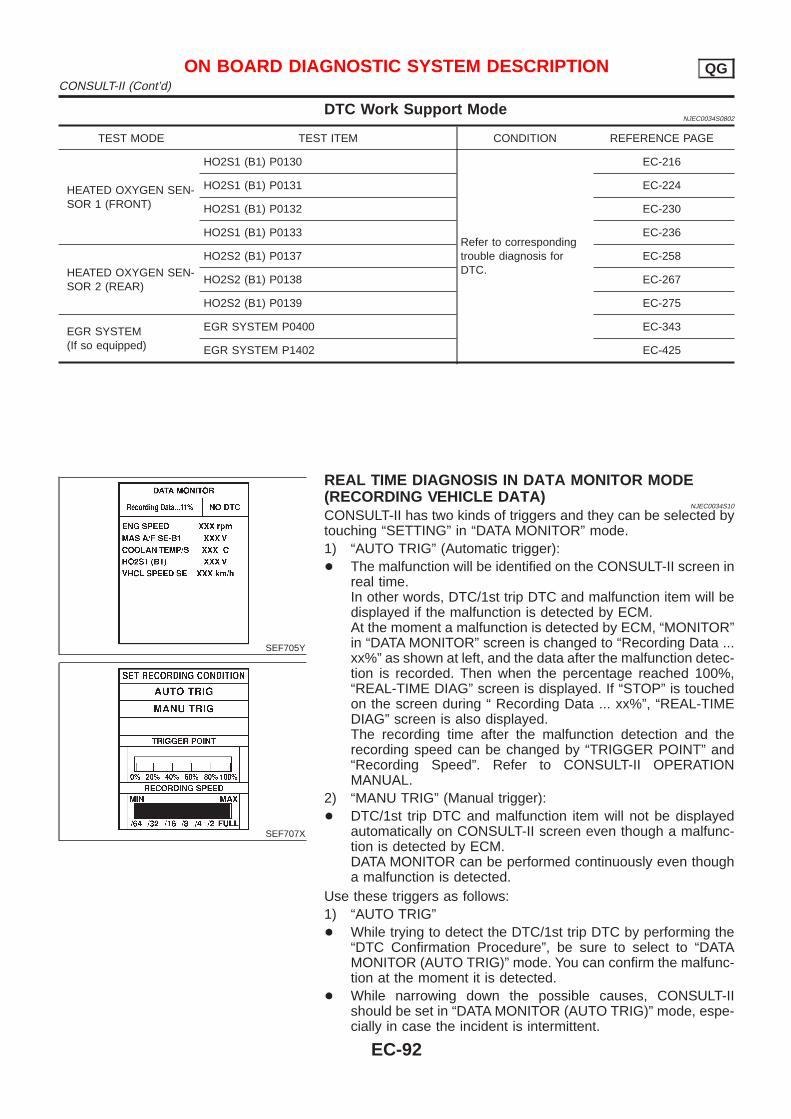
DTC Work Support ModeNJEC0034S0802
TEST MODE TEST ITEM CONDITION REFERENCE PAGE
HEATED OXYGEN SEN-SOR 1 (FRONT)
HO2S1 (B1) P0130
Refer to correspondingtrouble diagnosis forDTC.
EC-216
HO2S1 (B1) P0131 EC-224
HO2S1 (B1) P0132 EC-230
HO2S1 (B1) P0133 EC-236
HEATED OXYGEN SEN-SOR 2 (REAR)
HO2S2 (B1) P0137 EC-258
HO2S2 (B1) P0138 EC-267
HO2S2 (B1) P0139 EC-275
EGR SYSTEM(If so equipped)
EGR SYSTEM P0400 EC-343
EGR SYSTEM P1402 EC-425
SEF705Y
SEF707X
REAL TIME DIAGNOSIS IN DATA MONITOR MODE(RECORDING VEHICLE DATA)
NJEC0034S10
CONSULT-II has two kinds of triggers and they can be selected bytouching “SETTING” in “DATA MONITOR” mode.1) “AUTO TRIG” (Automatic trigger):+ The malfunction will be identified on the CONSULT-II screen in
real time.In other words, DTC/1st trip DTC and malfunction item will bedisplayed if the malfunction is detected by ECM.At the moment a malfunction is detected by ECM, “MONITOR”in “DATA MONITOR” screen is changed to “Recording Data ...xx%” as shown at left, and the data after the malfunction detec-tion is recorded. Then when the percentage reached 100%,“REAL-TIME DIAG” screen is displayed. If “STOP” is touchedon the screen during “ Recording Data ... xx%”, “REAL-TIMEDIAG” screen is also displayed.The recording time after the malfunction detection and therecording speed can be changed by “TRIGGER POINT” and“Recording Speed”. Refer to CONSULT-II OPERATIONMANUAL.
2) “MANU TRIG” (Manual trigger):+ DTC/1st trip DTC and malfunction item will not be displayed
automatically on CONSULT-II screen even though a malfunc-tion is detected by ECM.DATA MONITOR can be performed continuously even thougha malfunction is detected.
Use these triggers as follows:1) “AUTO TRIG”+ While trying to detect the DTC/1st trip DTC by performing the
“DTC Confirmation Procedure”, be sure to select to “DATAMONITOR (AUTO TRIG)” mode. You can confirm the malfunc-tion at the moment it is detected.
+ While narrowing down the possible causes, CONSULT-IIshould be set in “DATA MONITOR (AUTO TRIG)” mode, espe-cially in case the incident is intermittent.
ON BOARD DIAGNOSTIC SYSTEM DESCRIPTION QGCONSULT-II (Cont’d)
EC-92
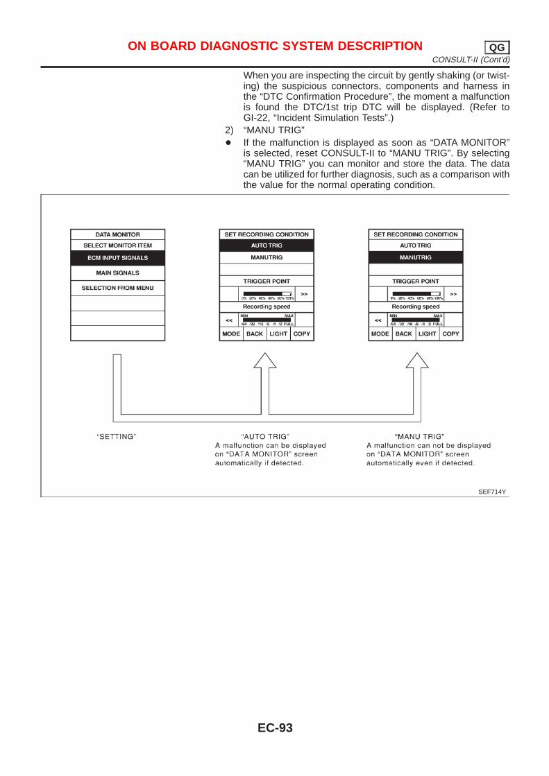
When you are inspecting the circuit by gently shaking (or twist-ing) the suspicious connectors, components and harness inthe “DTC Confirmation Procedure”, the moment a malfunctionis found the DTC/1st trip DTC will be displayed. (Refer toGI-22, “Incident Simulation Tests”.)
2) “MANU TRIG”+ If the malfunction is displayed as soon as “DATA MONITOR”
is selected, reset CONSULT-II to “MANU TRIG”. By selecting“MANU TRIG” you can monitor and store the data. The datacan be utilized for further diagnosis, such as a comparison withthe value for the normal operating condition.
SEF714Y
ON BOARD DIAGNOSTIC SYSTEM DESCRIPTION QGCONSULT-II (Cont’d)
EC-93
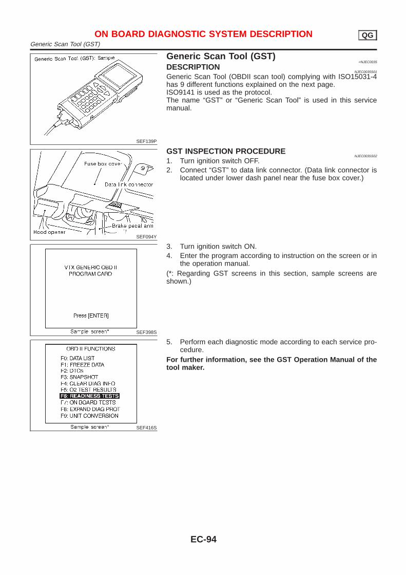
SEF139P
Generic Scan Tool (GST)=NJEC0035
DESCRIPTIONNJEC0035S01
Generic Scan Tool (OBDII scan tool) complying with ISO15031-4has 9 different functions explained on the next page.ISO9141 is used as the protocol.The name “GST” or “Generic Scan Tool” is used in this servicemanual.
SEF094Y
GST INSPECTION PROCEDURENJEC0035S02
1. Turn ignition switch OFF.2. Connect “GST” to data link connector. (Data link connector is
located under lower dash panel near the fuse box cover.)
SEF398S
3. Turn ignition switch ON.4. Enter the program according to instruction on the screen or in
the operation manual.(*: Regarding GST screens in this section, sample screens areshown.)
SEF416S
5. Perform each diagnostic mode according to each service pro-cedure.
For further information, see the GST Operation Manual of thetool maker.
ON BOARD DIAGNOSTIC SYSTEM DESCRIPTION QGGeneric Scan Tool (GST)
EC-94
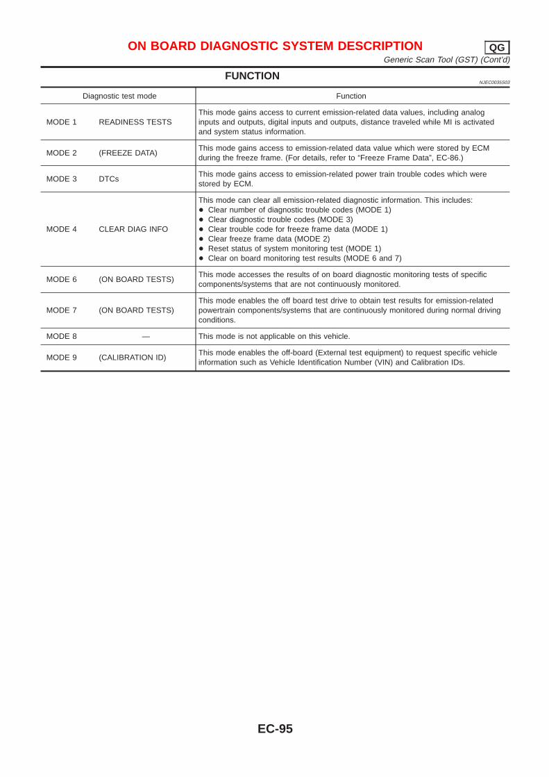
FUNCTIONNJEC0035S03
Diagnostic test mode Function
MODE 1 READINESS TESTSThis mode gains access to current emission-related data values, including analoginputs and outputs, digital inputs and outputs, distance traveled while MI is activatedand system status information.
MODE 2 (FREEZE DATA)This mode gains access to emission-related data value which were stored by ECMduring the freeze frame. (For details, refer to “Freeze Frame Data”, EC-86.)
MODE 3 DTCsThis mode gains access to emission-related power train trouble codes which werestored by ECM.
MODE 4 CLEAR DIAG INFO
This mode can clear all emission-related diagnostic information. This includes:+ Clear number of diagnostic trouble codes (MODE 1)+ Clear diagnostic trouble codes (MODE 3)+ Clear trouble code for freeze frame data (MODE 1)+ Clear freeze frame data (MODE 2)+ Reset status of system monitoring test (MODE 1)+ Clear on board monitoring test results (MODE 6 and 7)
MODE 6 (ON BOARD TESTS)This mode accesses the results of on board diagnostic monitoring tests of specificcomponents/systems that are not continuously monitored.
MODE 7 (ON BOARD TESTS)This mode enables the off board test drive to obtain test results for emission-relatedpowertrain components/systems that are continuously monitored during normal drivingconditions.
MODE 8 — This mode is not applicable on this vehicle.
MODE 9 (CALIBRATION ID)This mode enables the off-board (External test equipment) to request specific vehicleinformation such as Vehicle Identification Number (VIN) and Calibration IDs.
ON BOARD DIAGNOSTIC SYSTEM DESCRIPTION QGGeneric Scan Tool (GST) (Cont’d)
EC-95
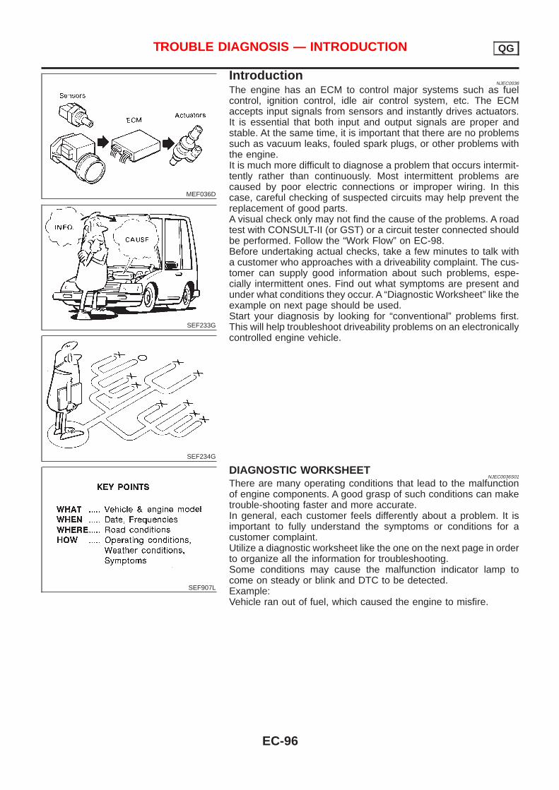
MEF036D
SEF233G
SEF234G
IntroductionNJEC0036
The engine has an ECM to control major systems such as fuelcontrol, ignition control, idle air control system, etc. The ECMaccepts input signals from sensors and instantly drives actuators.It is essential that both input and output signals are proper andstable. At the same time, it is important that there are no problemssuch as vacuum leaks, fouled spark plugs, or other problems withthe engine.It is much more difficult to diagnose a problem that occurs intermit-tently rather than continuously. Most intermittent problems arecaused by poor electric connections or improper wiring. In thiscase, careful checking of suspected circuits may help prevent thereplacement of good parts.A visual check only may not find the cause of the problems. A roadtest with CONSULT-II (or GST) or a circuit tester connected shouldbe performed. Follow the “Work Flow” on EC-98.Before undertaking actual checks, take a few minutes to talk witha customer who approaches with a driveability complaint. The cus-tomer can supply good information about such problems, espe-cially intermittent ones. Find out what symptoms are present andunder what conditions they occur. A “Diagnostic Worksheet” like theexample on next page should be used.Start your diagnosis by looking for “conventional” problems first.This will help troubleshoot driveability problems on an electronicallycontrolled engine vehicle.
SEF907L
DIAGNOSTIC WORKSHEETNJEC0036S01
There are many operating conditions that lead to the malfunctionof engine components. A good grasp of such conditions can maketrouble-shooting faster and more accurate.In general, each customer feels differently about a problem. It isimportant to fully understand the symptoms or conditions for acustomer complaint.Utilize a diagnostic worksheet like the one on the next page in orderto organize all the information for troubleshooting.Some conditions may cause the malfunction indicator lamp tocome on steady or blink and DTC to be detected.Example:Vehicle ran out of fuel, which caused the engine to misfire.
TROUBLE DIAGNOSIS — INTRODUCTION QG
EC-96
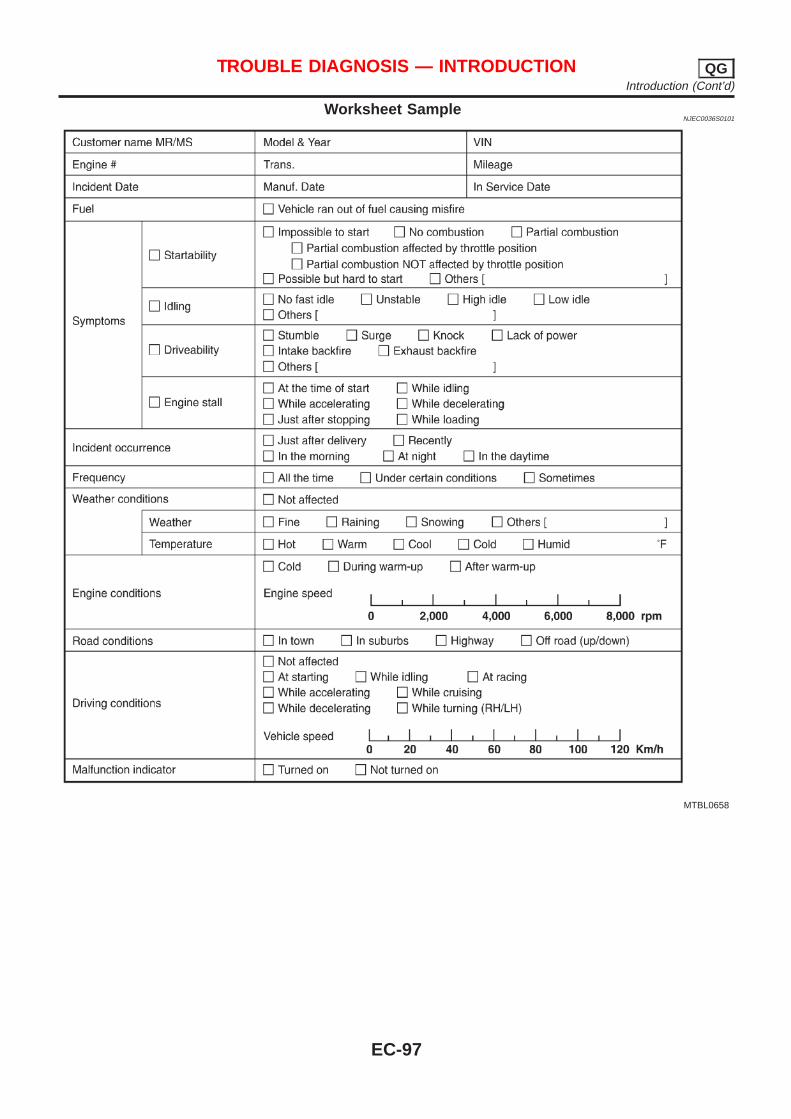
Worksheet SampleNJEC0036S0101
MTBL0658
TROUBLE DIAGNOSIS — INTRODUCTION QGIntroduction (Cont’d)
EC-97
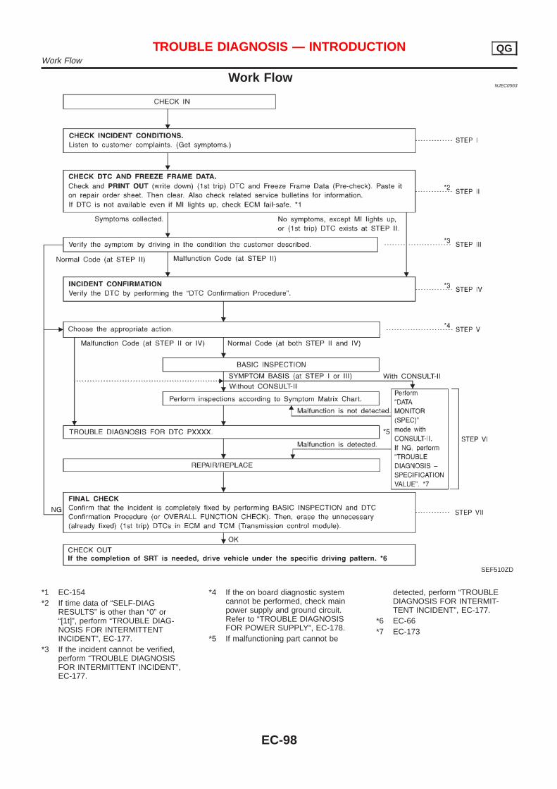
Work FlowNJEC0563
SEF510ZD
*1 EC-154*2 If time data of “SELF-DIAG
RESULTS” is other than “0” or“[1t]”, perform “TROUBLE DIAG-NOSIS FOR INTERMITTENTINCIDENT”, EC-177.
*3 If the incident cannot be verified,perform “TROUBLE DIAGNOSISFOR INTERMITTENT INCIDENT”,EC-177.
*4 If the on board diagnostic systemcannot be performed, check mainpower supply and ground circuit.Refer to “TROUBLE DIAGNOSISFOR POWER SUPPLY”, EC-178.
*5 If malfunctioning part cannot be
detected, perform “TROUBLEDIAGNOSIS FOR INTERMIT-TENT INCIDENT”, EC-177.
*6 EC-66*7 EC-173
TROUBLE DIAGNOSIS — INTRODUCTION QGWork Flow
EC-98
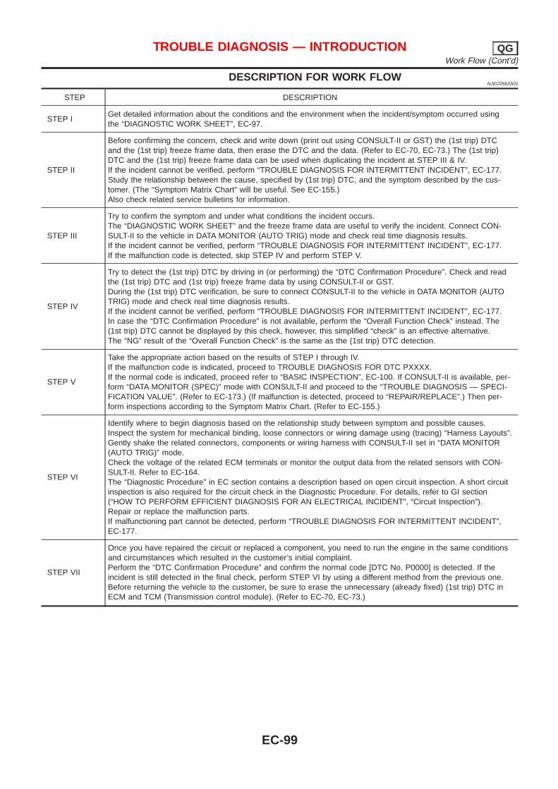
DESCRIPTION FOR WORK FLOWNJEC0563S01
STEP DESCRIPTION
STEP IGet detailed information about the conditions and the environment when the incident/symptom occurred usingthe “DIAGNOSTIC WORK SHEET”, EC-97.
STEP II
Before confirming the concern, check and write down (print out using CONSULT-II or GST) the (1st trip) DTCand the (1st trip) freeze frame data, then erase the DTC and the data. (Refer to EC-70, EC-73.) The (1st trip)DTC and the (1st trip) freeze frame data can be used when duplicating the incident at STEP III & IV.If the incident cannot be verified, perform “TROUBLE DIAGNOSIS FOR INTERMITTENT INCIDENT”, EC-177.Study the relationship between the cause, specified by (1st trip) DTC, and the symptom described by the cus-tomer. (The “Symptom Matrix Chart” will be useful. See EC-155.)Also check related service bulletins for information.
STEP III
Try to confirm the symptom and under what conditions the incident occurs.The “DIAGNOSTIC WORK SHEET” and the freeze frame data are useful to verify the incident. Connect CON-SULT-II to the vehicle in DATA MONITOR (AUTO TRIG) mode and check real time diagnosis results.If the incident cannot be verified, perform “TROUBLE DIAGNOSIS FOR INTERMITTENT INCIDENT”, EC-177.If the malfunction code is detected, skip STEP IV and perform STEP V.
STEP IV
Try to detect the (1st trip) DTC by driving in (or performing) the “DTC Confirmation Procedure”. Check and readthe (1st trip) DTC and (1st trip) freeze frame data by using CONSULT-II or GST.During the (1st trip) DTC verification, be sure to connect CONSULT-II to the vehicle in DATA MONITOR (AUTOTRIG) mode and check real time diagnosis results.If the incident cannot be verified, perform “TROUBLE DIAGNOSIS FOR INTERMITTENT INCIDENT”, EC-177.In case the “DTC Confirmation Procedure” is not available, perform the “Overall Function Check” instead. The(1st trip) DTC cannot be displayed by this check, however, this simplified “check” is an effective alternative.The “NG” result of the “Overall Function Check” is the same as the (1st trip) DTC detection.
STEP V
Take the appropriate action based on the results of STEP I through IV.If the malfunction code is indicated, proceed to TROUBLE DIAGNOSIS FOR DTC PXXXX.If the normal code is indicated, proceed refer to “BASIC INSPECTION”, EC-100. If CONSULT-II is available, per-form “DATA MONITOR (SPEC)” mode with CONSULT-II and proceed to the “TROUBLE DIAGNOSIS — SPECI-FICATION VALUE”. (Refer to EC-173.) (If malfunction is detected, proceed to “REPAIR/REPLACE”.) Then per-form inspections according to the Symptom Matrix Chart. (Refer to EC-155.)
STEP VI
Identify where to begin diagnosis based on the relationship study between symptom and possible causes.Inspect the system for mechanical binding, loose connectors or wiring damage using (tracing) “Harness Layouts”.Gently shake the related connectors, components or wiring harness with CONSULT-II set in “DATA MONITOR(AUTO TRIG)” mode.Check the voltage of the related ECM terminals or monitor the output data from the related sensors with CON-SULT-II. Refer to EC-164.The “Diagnostic Procedure” in EC section contains a description based on open circuit inspection. A short circuitinspection is also required for the circuit check in the Diagnostic Procedure. For details, refer to GI section(“HOW TO PERFORM EFFICIENT DIAGNOSIS FOR AN ELECTRICAL INCIDENT”, “Circuit Inspection”).Repair or replace the malfunction parts.If malfunctioning part cannot be detected, perform “TROUBLE DIAGNOSIS FOR INTERMITTENT INCIDENT”,EC-177.
STEP VII
Once you have repaired the circuit or replaced a component, you need to run the engine in the same conditionsand circumstances which resulted in the customer’s initial complaint.Perform the “DTC Confirmation Procedure” and confirm the normal code [DTC No. P0000] is detected. If theincident is still detected in the final check, perform STEP VI by using a different method from the previous one.Before returning the vehicle to the customer, be sure to erase the unnecessary (already fixed) (1st trip) DTC inECM and TCM (Transmission control module). (Refer to EC-70, EC-73.)
TROUBLE DIAGNOSIS — INTRODUCTION QGWork Flow (Cont’d)
EC-99
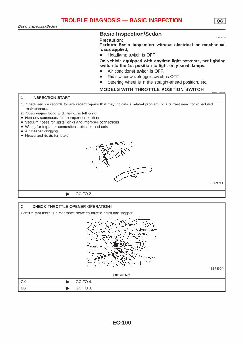
Basic Inspection/SedanNJEC1736
Precaution:Perform Basic Inspection without electrical or mechanicalloads applied;+ Headlamp switch is OFF,On vehicle equipped with daytime light systems, set lightingswitch to the 1st position to light only small lamps.+ Air conditioner switch is OFF,+ Rear window defogger switch is OFF,+ Steering wheel is in the straight-ahead position, etc.
MODELS WITH THROTTLE POSITION SWITCHNJEC1736S01
1 INSPECTION START
1. Check service records for any recent repairs that may indicate a related problem, or a current need for scheduledmaintenance.
2. Open engine hood and check the following:+ Harness connectors for improper connections+ Vacuum hoses for splits, kinks and improper connections+ Wiring for improper connections, pinches and cuts+ Air cleaner clogging+ Hoses and ducts for leaks
SEF983U
© GO TO 2.
2 CHECK THROTTLE OPENER OPERATION-I
Confirm that there is a clearance between throttle drum and stopper.
SEF850Y
OK or NG
OK © GO TO 4.
NG © GO TO 3.
TROUBLE DIAGNOSIS — BASIC INSPECTION QGBasic Inspection/Sedan
EC-100
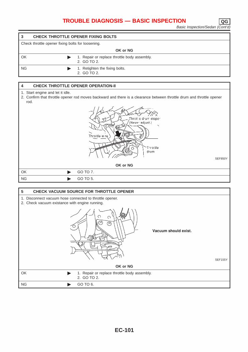
3 CHECK THROTTLE OPENER FIXING BOLTS
Check throttle opener fixing bolts for loosening.
OK or NG
OK © 1. Repair or replace throttle body assembly.2. GO TO 2.
NG © 1. Retighten the fixing bolts.2. GO TO 2.
4 CHECK THROTTLE OPENER OPERATION-II
1. Start engine and let it idle.2. Confirm that throttle opener rod moves backward and there is a clearance between throttle drum and throttle opener
rod.
SEF850Y
OK or NG
OK © GO TO 7.
NG © GO TO 5.
5 CHECK VACUUM SOURCE FOR THROTTLE OPENER
1. Disconnect vacuum hose connected to throttle opener.2. Check vacuum existance with engine running.
SEF155Y
OK or NG
OK © 1. Repair or replace throttle body assembly.2. GO TO 2.
NG © GO TO 6.
TROUBLE DIAGNOSIS — BASIC INSPECTION QGBasic Inspection/Sedan (Cont’d)
EC-101
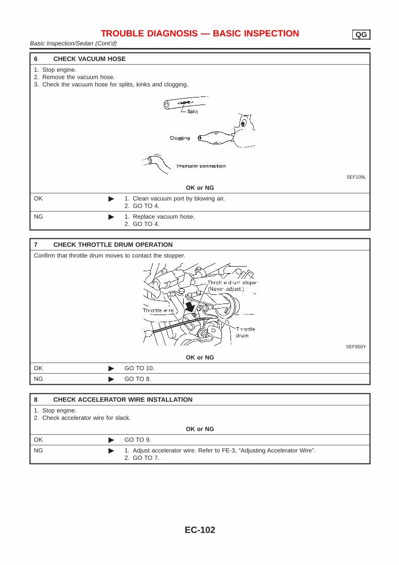
6 CHECK VACUUM HOSE
1. Stop engine.2. Remove the vacuum hose.3. Check the vacuum hose for splits, kinks and clogging.
SEF109L
OK or NG
OK © 1. Clean vacuum port by blowing air.2. GO TO 4.
NG © 1. Replace vacuum hose.2. GO TO 4.
7 CHECK THROTTLE DRUM OPERATION
Confirm that throttle drum moves to contact the stopper.
SEF850Y
OK or NG
OK © GO TO 10.
NG © GO TO 8.
8 CHECK ACCELERATOR WIRE INSTALLATION
1. Stop engine.2. Check accelerator wire for slack.
OK or NG
OK © GO TO 9.
NG © 1. Adjust accelerator wire. Refer to FE-3, “Adjusting Accelerator Wire”.2. GO TO 7.
TROUBLE DIAGNOSIS — BASIC INSPECTION QGBasic Inspection/Sedan (Cont’d)
EC-102
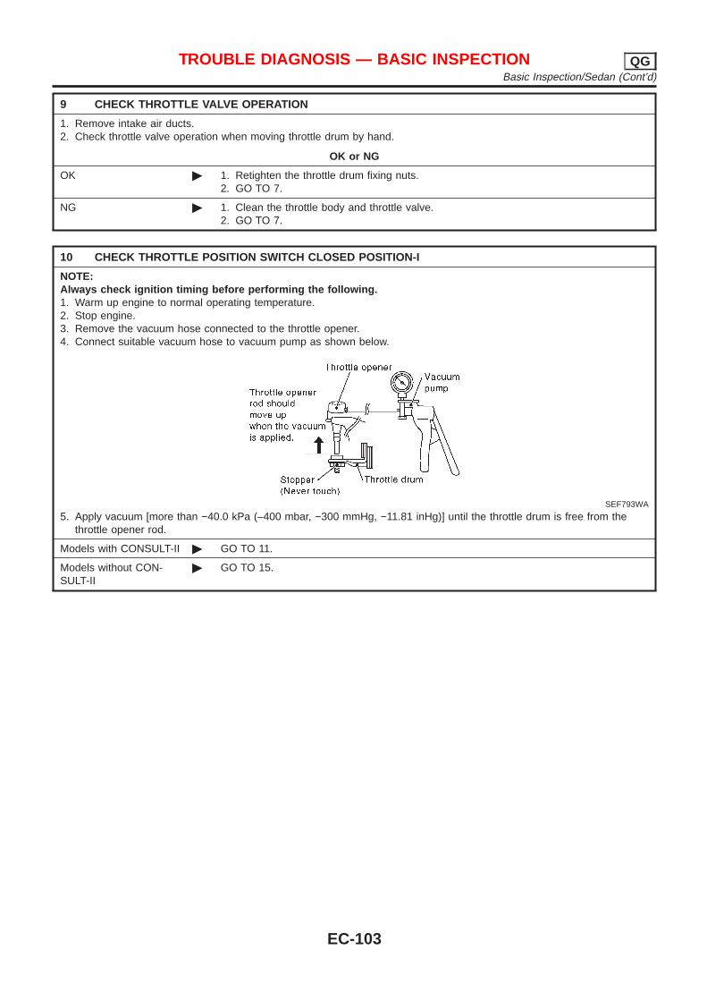
9 CHECK THROTTLE VALVE OPERATION
1. Remove intake air ducts.2. Check throttle valve operation when moving throttle drum by hand.
OK or NG
OK © 1. Retighten the throttle drum fixing nuts.2. GO TO 7.
NG © 1. Clean the throttle body and throttle valve.2. GO TO 7.
10 CHECK THROTTLE POSITION SWITCH CLOSED POSITION-I
NOTE:Always check ignition timing before performing the following.1. Warm up engine to normal operating temperature.2. Stop engine.3. Remove the vacuum hose connected to the throttle opener.4. Connect suitable vacuum hose to vacuum pump as shown below.
SEF793WA
5. Apply vacuum [more than −40.0 kPa (–400 mbar, −300 mmHg, −11.81 inHg)] until the throttle drum is free from thethrottle opener rod.
Models with CONSULT-II © GO TO 11.
Models without CON-SULT-II
© GO TO 15.
TROUBLE DIAGNOSIS — BASIC INSPECTION QGBasic Inspection/Sedan (Cont’d)
EC-103

11 CHECK THROTTLE POSITION SWITCH CLOSED POSITION-II
With CONSULT-II1. Connect “CONSULT-II” to the data link connector and select “ENGINE” from the menu. Refer to EC-83.2. Turn ignition switch “ON”.3. Select “TP SW/TP SEN IDLE POSI ADJ” in “WORK SUPPORT” mode with CONSULT-II.4. Read “CLSD THL/P SW” signal under the following conditions.+ Insert a 0.05 mm (0.0020 in) and 0.15 mm (0.0059 in) feeler gauge alternately between stopper and throttle drum as
shown in the figure and check the signal.
SEF073X
SEF715Y
“CLSD THL/P SW” signal should remain “ON” while inserting 0.05 mm (0.0020 in) feeler gauge.“CLSD THL/P SW” signal should remain “OFF” while inserting 0.15 mm (0.0059 in) feeler gauge.
OK or NG
OK © GO TO 14.
NG © GO TO 12.
TROUBLE DIAGNOSIS — BASIC INSPECTION QGBasic Inspection/Sedan (Cont’d)
EC-104
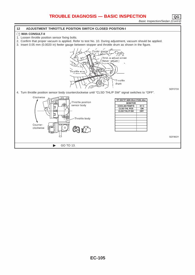
12 ADJUSTMENT THROTTLE POSITION SWITCH CLOSED POSITION-I
With CONSULT-II1. Loosen throttle position sensor fixing bolts.2. Confirm that proper vacuum is applied. Refer to test No. 10. During adjustment, vacuum should be applied.3. Insert 0.05 mm (0.0020 in) feeler gauge between stopper and throttle drum as shown in the figure.
SEF073X
4. Turn throttle position sensor body counterclockwise until “CLSD THL/P SW” signal switches to “OFF”.
SEF863Y
© GO TO 13.
TROUBLE DIAGNOSIS — BASIC INSPECTION QGBasic Inspection/Sedan (Cont’d)
EC-105
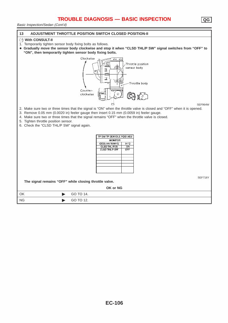
13 ADJUSTMENT THROTTLE POSITION SWITCH CLOSED POSITION-II
With CONSULT-II1. Temporarily tighten sensor body fixing bolts as follows.+ Gradually move the sensor body clockwise and stop it when “CLSD THL/P SW” signal switches from “OFF” to
“ON”, then temporarily tighten sensor body fixing bolts.
SEF964W
2. Make sure two or three times that the signal is “ON” when the throttle valve is closed and “OFF” when it is opened.3. Remove 0.05 mm (0.0020 in) feeler gauge then insert 0.15 mm (0.0059 in) feeler gauge.4. Make sure two or three times that the signal remains “OFF” when the throttle valve is closed.5. Tighten throttle position sensor.6. Check the “CLSD THL/P SW” signal again.
SEF716Y
The signal remains “OFF” while closing throttle valve.
OK or NG
OK © GO TO 14.
NG © GO TO 12.
TROUBLE DIAGNOSIS — BASIC INSPECTION QGBasic Inspection/Sedan (Cont’d)
EC-106
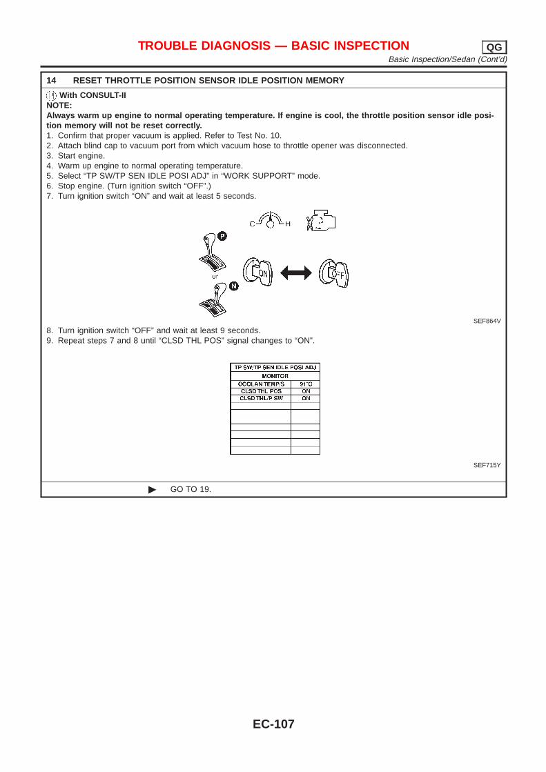
14 RESET THROTTLE POSITION SENSOR IDLE POSITION MEMORY
With CONSULT-IINOTE:Always warm up engine to normal operating temperature. If engine is cool, the throttle position sensor idle posi-tion memory will not be reset correctly.1. Confirm that proper vacuum is applied. Refer to Test No. 10.2. Attach blind cap to vacuum port from which vacuum hose to throttle opener was disconnected.3. Start engine.4. Warm up engine to normal operating temperature.5. Select “TP SW/TP SEN IDLE POSI ADJ” in “WORK SUPPORT” mode.6. Stop engine. (Turn ignition switch “OFF”.)7. Turn ignition switch “ON” and wait at least 5 seconds.
SEF864V
8. Turn ignition switch “OFF” and wait at least 9 seconds.9. Repeat steps 7 and 8 until “CLSD THL POS” signal changes to “ON”.
SEF715Y
© GO TO 19.
TROUBLE DIAGNOSIS — BASIC INSPECTION QGBasic Inspection/Sedan (Cont’d)
EC-107
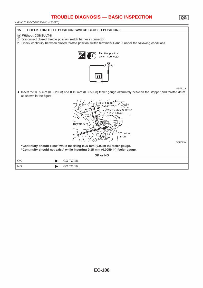
15 CHECK THROTTLE POSITION SWITCH CLOSED POSITION-II
Without CONSULT-II1. Disconnect closed throttle position switch harness connector.2. Check continuity between closed throttle position switch terminals 4 and 5 under the following conditions.
SEF711X
+ Insert the 0.05 mm (0.0020 in) and 0.15 mm (0.0059 in) feeler gauge alternately between the stopper and throttle drumas shown in the figure.
SEF073X
“Continuity should exist” while inserting 0.05 mm (0.0020 in) feeler gauge.“Continuity should not exist” while inserting 0.15 mm (0.0059 in) feeler gauge.
OK or NG
OK © GO TO 18.
NG © GO TO 16.
TROUBLE DIAGNOSIS — BASIC INSPECTION QGBasic Inspection/Sedan (Cont’d)
EC-108
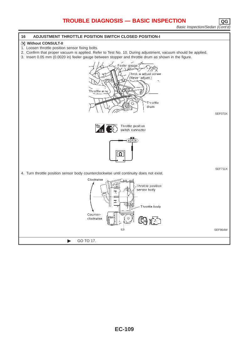
16 ADJUSTMENT THROTTLE POSITION SWITCH CLOSED POSITION-I
Without CONSULT-II1. Loosen throttle position sensor fixing bolts.2. Confirm that proper vacuum is applied. Refer to Test No. 10. During adjustment, vacuum should be applied.3. Insert 0.05 mm (0.0020 in) feeler gauge between stopper and throttle drum as shown in the figure.
SEF073X
SEF711X
4. Turn throttle position sensor body counterclockwise until continuity does not exist.
SEF964W
© GO TO 17.
TROUBLE DIAGNOSIS — BASIC INSPECTION QGBasic Inspection/Sedan (Cont’d)
EC-109
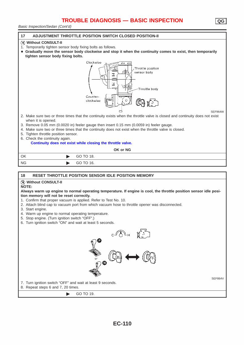
17 ADJUSTMENT THROTTLE POSITION SWITCH CLOSED POSITION-II
Without CONSULT-II1. Temporarily tighten sensor body fixing bolts as follows.+ Gradually move the sensor body clockwise and stop it when the continuity comes to exist, then temporarily
tighten sensor body fixing bolts.
SEF964W
2. Make sure two or three times that the continuity exists when the throttle valve is closed and continuity does not existwhen it is opened.
3. Remove 0.05 mm (0.0020 in) feeler gauge then insert 0.15 mm (0.0059 in) feeler gauge.4. Make sure two or three times that the continuity does not exist when the throttle valve is closed.5. Tighten throttle position sensor.6. Check the continuity again.
Continuity does not exist while closing the throttle valve.
OK or NG
OK © GO TO 18.
NG © GO TO 16.
18 RESET THROTTLE POSITION SENSOR IDLE POSITION MEMORY
Without CONSULT-IINOTE:Always warm up engine to normal operating temperature. If engine is cool, the throttle position sensor idle posi-tion memory will not be reset correctly.1. Confirm that proper vacuum is applied. Refer to Test No. 10.2. Attach blind cap to vacuum port from which vacuum hose to throttle opener was disconnected.3. Start engine.4. Warm up engine to normal operating temperature.5. Stop engine. (Turn ignition switch “OFF”.)6. Turn ignition switch “ON” and wait at least 5 seconds.
SEF864V
7. Turn ignition switch “OFF” and wait at least 9 seconds.8. Repeat steps 6 and 7, 20 times.
© GO TO 19.
TROUBLE DIAGNOSIS — BASIC INSPECTION QGBasic Inspection/Sedan (Cont’d)
EC-110
19 CHECK (1ST TRIP) DTC
1. Turn ignition switch “OFF”.2. Release vacuum from throttle opener.3. Remove vacuum pump and vacuum hose from throttle opener.4. Reinstall original vacuum hose to throttle opener securely.5. Start engine and warm it up to normal operating temperature.6. Rev (2,000 to 3,000 rpm) two or three times.7. Make sure no (1st trip) DTC is displayed with CONSULT-II or GST.
OK or NG
OK © GO TO 21.
NG © GO TO 20.
20 REPAIR MALFUNCTION
Repair or replace components as necessary according to corresponding “Diagnostic Procedure”.
© GO TO 19.
21 CHECK TARGET IDLE SPEED
With CONSULT-II1. Start engine and warm it up to normal operating temperature.2. Select “ENG SPEED” in “DATA MONITOR” mode with CONSULT-II.3. Check idle speed.
M/T: 700±50 rpmA/T: 800±50 rpm (in “P” or “N” position)
Without CONSULT-II1. Start engine and warm it up to normal operating temperature.2. Check idle speed.
M/T: 700±50 rpmA/T: 800±50 rpm (in “P” or “N” position)
OK or NG
OK © GO TO 31.
NG © GO TO 22.
22 PERFORM IDLE AIR VOLUME LEARNING
Refer to “Idle Air Volume Learning”, EC-57.Which is the result CMPLT or INCMP?
CMPLT or INCMP
CMPLT © GO TO 23.
INCMP © 1. Follow the construction of “Idle Air Volume Leaning”.2. GO TO 22.
TROUBLE DIAGNOSIS — BASIC INSPECTION QGBasic Inspection/Sedan (Cont’d)
EC-111
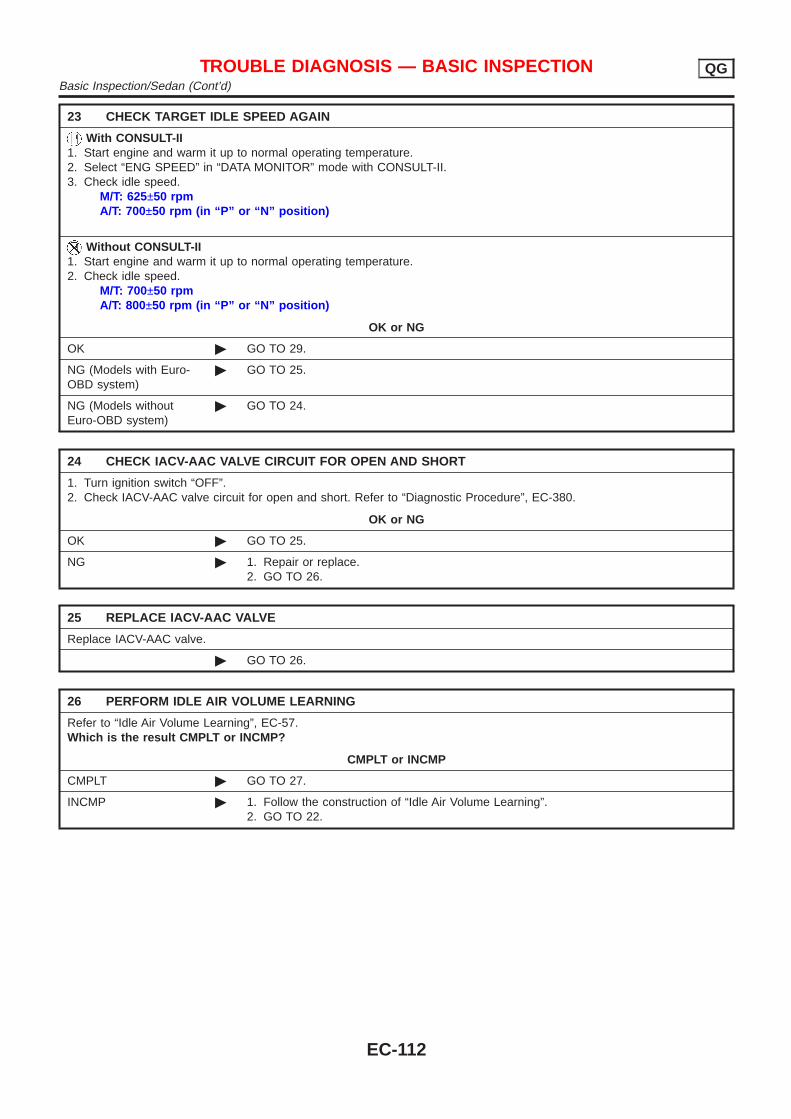
23 CHECK TARGET IDLE SPEED AGAIN
With CONSULT-II1. Start engine and warm it up to normal operating temperature.2. Select “ENG SPEED” in “DATA MONITOR” mode with CONSULT-II.3. Check idle speed.
M/T: 625±50 rpmA/T: 700±50 rpm (in “P” or “N” position)
Without CONSULT-II1. Start engine and warm it up to normal operating temperature.2. Check idle speed.
M/T: 700±50 rpmA/T: 800±50 rpm (in “P” or “N” position)
OK or NG
OK © GO TO 29.
NG (Models with Euro-OBD system)
© GO TO 25.
NG (Models withoutEuro-OBD system)
© GO TO 24.
24 CHECK IACV-AAC VALVE CIRCUIT FOR OPEN AND SHORT
1. Turn ignition switch “OFF”.2. Check IACV-AAC valve circuit for open and short. Refer to “Diagnostic Procedure”, EC-380.
OK or NG
OK © GO TO 25.
NG © 1. Repair or replace.2. GO TO 26.
25 REPLACE IACV-AAC VALVE
Replace IACV-AAC valve.
© GO TO 26.
26 PERFORM IDLE AIR VOLUME LEARNING
Refer to “Idle Air Volume Learning”, EC-57.Which is the result CMPLT or INCMP?
CMPLT or INCMP
CMPLT © GO TO 27.
INCMP © 1. Follow the construction of “Idle Air Volume Learning”.2. GO TO 22.
TROUBLE DIAGNOSIS — BASIC INSPECTION QGBasic Inspection/Sedan (Cont’d)
EC-112
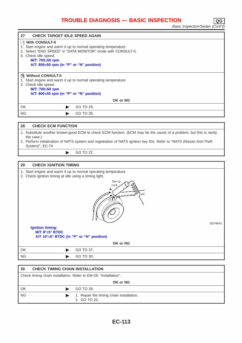
27 CHECK TARGET IDLE SPEED AGAIN
With CONSULT-II1. Start engine and warm it up to normal operating temperature.2. Select “ENG SPEED” in “DATA MONITOR” mode with CONSULT-II.3. Check idle speed.
M/T: 700±50 rpmA/T: 800±50 rpm (in “P” or “N” position)
Without CONSULT-II1. Start engine and warm it up to normal operating temperature.2. Check idle speed.
M/T: 700±50 rpmA/T: 800±50 rpm (in “P” or “N” position)
OK or NG
OK © GO TO 29.
NG © GO TO 28.
28 CHECK ECM FUNCTION
1. Substitute another known-good ECM to check ECM function. (ECM may be the cause of a problem, but this is rarelythe case.)
2. Perform initialization of NATS system and registration of NATS ignition key IDs. Refer to “NATS (Nissan Anti-TheftSystem)”, EC-74.
© GO TO 22.
29 CHECK IGNITION TIMING
1. Start engine and warm it up to normal operating temperature.2. Check ignition timing at idle using a timing light.
SEF984U
Ignition timing:M/T 8°±5° BTDCA/T 10°±5° BTDC (in “P” or “N” position)
OK or NG
OK © GO TO 37.
NG © GO TO 30.
30 CHECK TIMING CHAIN INSTALLATION
Check timing chain installation. Refer to EM-28, “Installation”.
OK or NG
OK © GO TO 28.
NG © 1. Repair the timing chain installation.2. GO TO 22.
TROUBLE DIAGNOSIS — BASIC INSPECTION QGBasic Inspection/Sedan (Cont’d)
EC-113
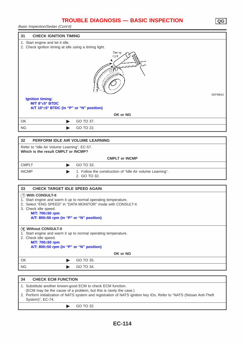
31 CHECK IGNITION TIMING
1. Start engine and let it idle.2. Check ignition timing at idle using a timing light.
SEF984U
Ignition timing:M/T 8°±5° BTDCA/T 10°±5° BTDC (in “P” or “N” position)
OK or NG
OK © GO TO 37.
NG © GO TO 22.
32 PERFORM IDLE AIR VOLUME LEARNING
Refer to “Idle Air Volume Learning”, EC-57.Which is the result CMPLT or INCMP?
CMPLT or INCMP
CMPLT © GO TO 33.
INCMP © 1. Follow the construction of “Idle Air volume Learning”.2. GO TO 32.
33 CHECK TARGET IDLE SPEED AGAIN
With CONSULT-II1. Start engine and warm it up to normal operating temperature.2. Select “ENG SPEED” in “DATA MONITOR” mode with CONSULT-II.3. Check idle speed.
M/T: 700±50 rpmA/T: 800±50 rpm (in “P” or “N” position)
Without CONSULT-II1. Start engine and warm it up to normal operating temperature.2. Check idle speed.
M/T: 700±50 rpmA/T: 800±50 rpm (in “P” or “N” position)
OK or NG
OK © GO TO 35.
NG © GO TO 34.
34 CHECK ECM FUNCTION
1. Substitute another known-good ECM to check ECM function.(ECM may be the cause of a problem, but this is rarely the case.)
2. Perform initialization of NATS system and registration of NATS ignition key IDs. Refer to “NATS (Nissan Anti-TheftSystem)”, EC-74.
© GO TO 32.
TROUBLE DIAGNOSIS — BASIC INSPECTION QGBasic Inspection/Sedan (Cont’d)
EC-114
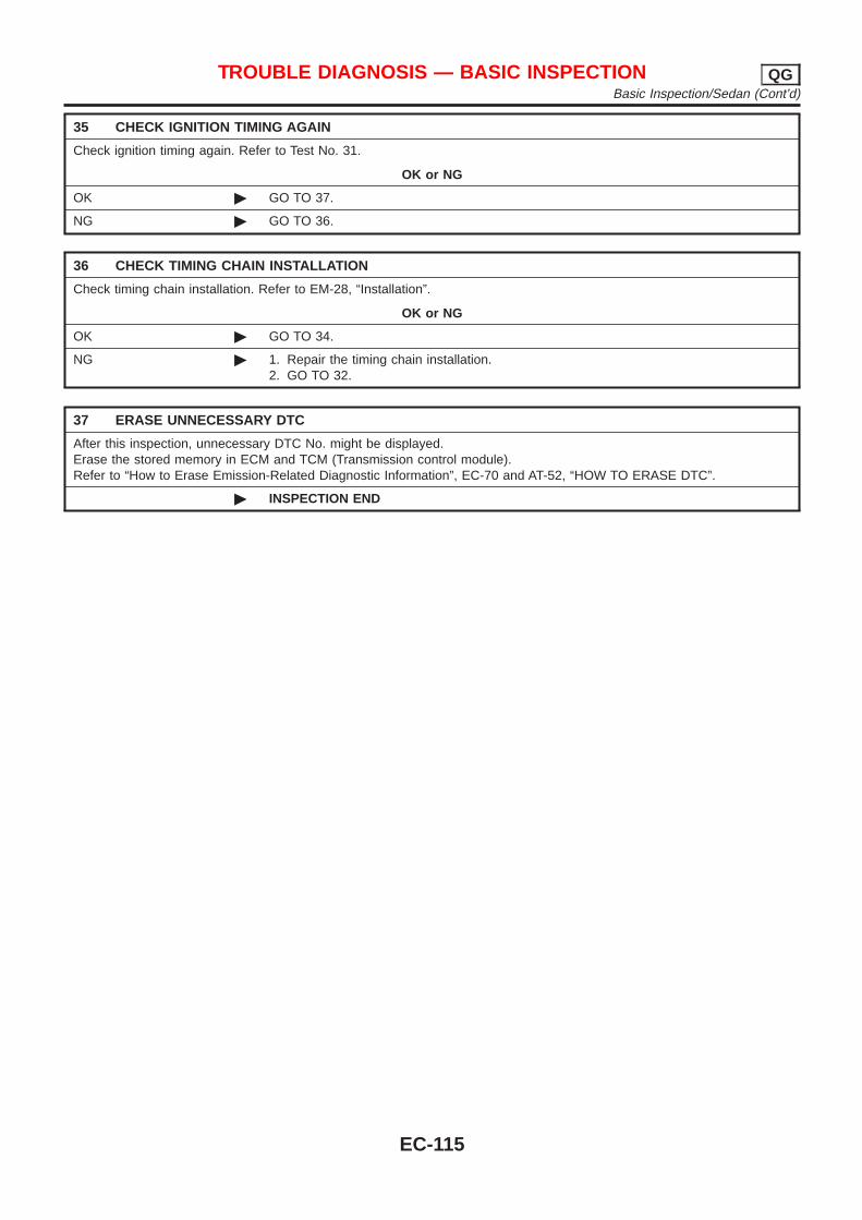
35 CHECK IGNITION TIMING AGAIN
Check ignition timing again. Refer to Test No. 31.
OK or NG
OK © GO TO 37.
NG © GO TO 36.
36 CHECK TIMING CHAIN INSTALLATION
Check timing chain installation. Refer to EM-28, “Installation”.
OK or NG
OK © GO TO 34.
NG © 1. Repair the timing chain installation.2. GO TO 32.
37 ERASE UNNECESSARY DTC
After this inspection, unnecessary DTC No. might be displayed.Erase the stored memory in ECM and TCM (Transmission control module).Refer to “How to Erase Emission-Related Diagnostic Information”, EC-70 and AT-52, “HOW TO ERASE DTC”.
© INSPECTION END
TROUBLE DIAGNOSIS — BASIC INSPECTION QGBasic Inspection/Sedan (Cont’d)
EC-115
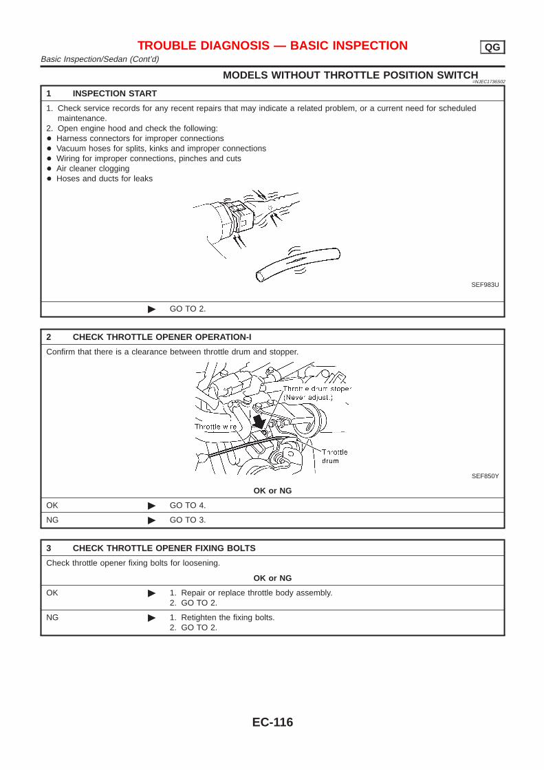
MODELS WITHOUT THROTTLE POSITION SWITCH=NJEC1736S02
1 INSPECTION START
1. Check service records for any recent repairs that may indicate a related problem, or a current need for scheduledmaintenance.
2. Open engine hood and check the following:+ Harness connectors for improper connections+ Vacuum hoses for splits, kinks and improper connections+ Wiring for improper connections, pinches and cuts+ Air cleaner clogging+ Hoses and ducts for leaks
SEF983U
© GO TO 2.
2 CHECK THROTTLE OPENER OPERATION-I
Confirm that there is a clearance between throttle drum and stopper.
SEF850Y
OK or NG
OK © GO TO 4.
NG © GO TO 3.
3 CHECK THROTTLE OPENER FIXING BOLTS
Check throttle opener fixing bolts for loosening.
OK or NG
OK © 1. Repair or replace throttle body assembly.2. GO TO 2.
NG © 1. Retighten the fixing bolts.2. GO TO 2.
TROUBLE DIAGNOSIS — BASIC INSPECTION QGBasic Inspection/Sedan (Cont’d)
EC-116
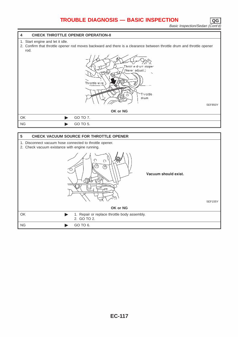
4 CHECK THROTTLE OPENER OPERATION-II
1. Start engine and let it idle.2. Confirm that throttle opener rod moves backward and there is a clearance between throttle drum and throttle opener
rod.
SEF850Y
OK or NG
OK © GO TO 7.
NG © GO TO 5.
5 CHECK VACUUM SOURCE FOR THROTTLE OPENER
1. Disconnect vacuum hose connected to throttle opener.2. Check vacuum existance with engine running.
SEF155Y
OK or NG
OK © 1. Repair or replace throttle body assembly.2. GO TO 2.
NG © GO TO 6.
TROUBLE DIAGNOSIS — BASIC INSPECTION QGBasic Inspection/Sedan (Cont’d)
EC-117

6 CHECK VACUUM HOSE
1. Stop engine.2. Remove the vacuum hose.3. Check the vacuum hose for splits, kinks and clogging.
SEF109L
OK or NG
OK © 1. Clean vacuum port by blowing air.2. GO TO 4.
NG © 1. Replace vacuum hose.2. GO TO 4.
7 CHECK THROTTLE DRUM OPERATION
Confirm that throttle drum moves to contact the stopper.
SEF850Y
OK or NG
OK © GO TO 10.
NG © GO TO 8.
8 CHECK ACCELERATOR WIRE INSTALLATION
1. Stop engine.2. Check accelerator wire for slack.
OK or NG
OK © GO TO 9.
NG © 1. Adjust accelerator wire. Refer to FE-3, “Adjusting Accelerator Wire”.2. GO TO 7.
TROUBLE DIAGNOSIS — BASIC INSPECTION QGBasic Inspection/Sedan (Cont’d)
EC-118

9 CHECK THROTTLE VALVE OPERATION
1. Remove intake air ducts.2. Check throttle valve operation when moving throttle drum by hand.
OK or NG
OK © 1. Retighten the throttle drum fixing nuts.2. GO TO 7.
NG © 1. Clean the throttle body and throttle valve.2. GO TO 7.
10 CHECK THROTTLE POSITION SENSOR CLOSED POSITION-I
NOTE:Always check ignition timing before performing the following.1. Warm up engine to normal operating temperature.2. Stop engine.3. Remove the vacuum hose connected to the throttle opener.4. Connect suitable vacuum hose to vacuum pump as shown below.
SEF793WA
5. Apply vacuum [more than −40.0 kPa (–400 mbar, −300 mmHg, −11.81 inHg)] until the throttle drum is free from thethrottle opener rod.
Models with CONSULT-II © GO TO 11.
Models without CON-SULT-II
© GO TO 15.
TROUBLE DIAGNOSIS — BASIC INSPECTION QGBasic Inspection/Sedan (Cont’d)
EC-119
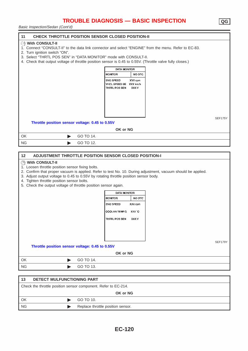
11 CHECK THROTTLE POSITION SENSOR CLOSED POSITION-II
With CONSULT-II1. Connect “CONSULT-II” to the data link connector and select “ENGINE” from the menu. Refer to EC-83.2. Turn ignition switch “ON”.3. Select “THRTL POS SEN” in “DATA MONITOR” mode with CONSULT-II.4. Check that output voltage of throttle position sensor is 0.45 to 0.55V. (Throttle valve fully closes.)
SEF175Y
Throttle position sensor voltage: 0.45 to 0.55V
OK or NG
OK © GO TO 14.
NG © GO TO 12.
12 ADJUSTMENT THROTTLE POSITION SENSOR CLOSED POSITION-I
With CONSULT-II1. Loosen throttle position sensor fixing bolts.2. Confirm that proper vacuum is applied. Refer to test No. 10. During adjustment, vacuum should be applied.3. Adjust output voltage to 0.45 to 0.55V by rotating throttle position sensor body.4. Tighten throttle position sensor bolts.5. Check the output voltage of throttle position sensor again.
SEF179Y
Throttle position sensor voltage: 0.45 to 0.55V
OK or NG
OK © GO TO 14.
NG © GO TO 13.
13 DETECT MULFUNCTIONING PART
Check the throttle position sensor component. Refer to EC-214.
OK or NG
OK © GO TO 10.
NG © Replace throttle position sensor.
TROUBLE DIAGNOSIS — BASIC INSPECTION QGBasic Inspection/Sedan (Cont’d)
EC-120
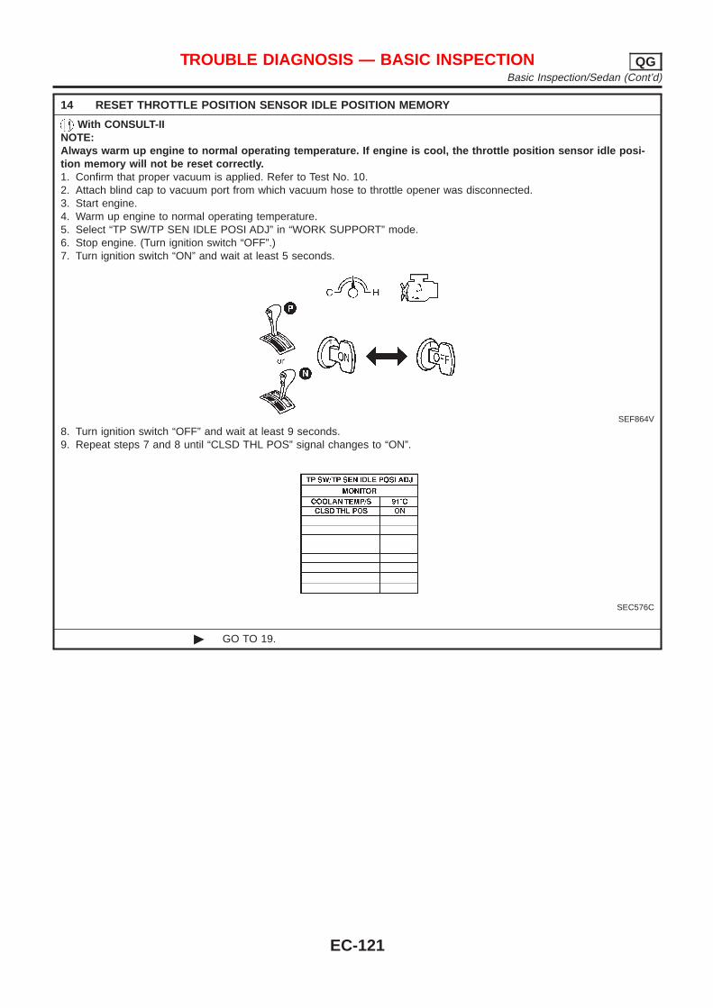
14 RESET THROTTLE POSITION SENSOR IDLE POSITION MEMORY
With CONSULT-IINOTE:Always warm up engine to normal operating temperature. If engine is cool, the throttle position sensor idle posi-tion memory will not be reset correctly.1. Confirm that proper vacuum is applied. Refer to Test No. 10.2. Attach blind cap to vacuum port from which vacuum hose to throttle opener was disconnected.3. Start engine.4. Warm up engine to normal operating temperature.5. Select “TP SW/TP SEN IDLE POSI ADJ” in “WORK SUPPORT” mode.6. Stop engine. (Turn ignition switch “OFF”.)7. Turn ignition switch “ON” and wait at least 5 seconds.
SEF864V
8. Turn ignition switch “OFF” and wait at least 9 seconds.9. Repeat steps 7 and 8 until “CLSD THL POS” signal changes to “ON”.
SEC576C
© GO TO 19.
TROUBLE DIAGNOSIS — BASIC INSPECTION QGBasic Inspection/Sedan (Cont’d)
EC-121
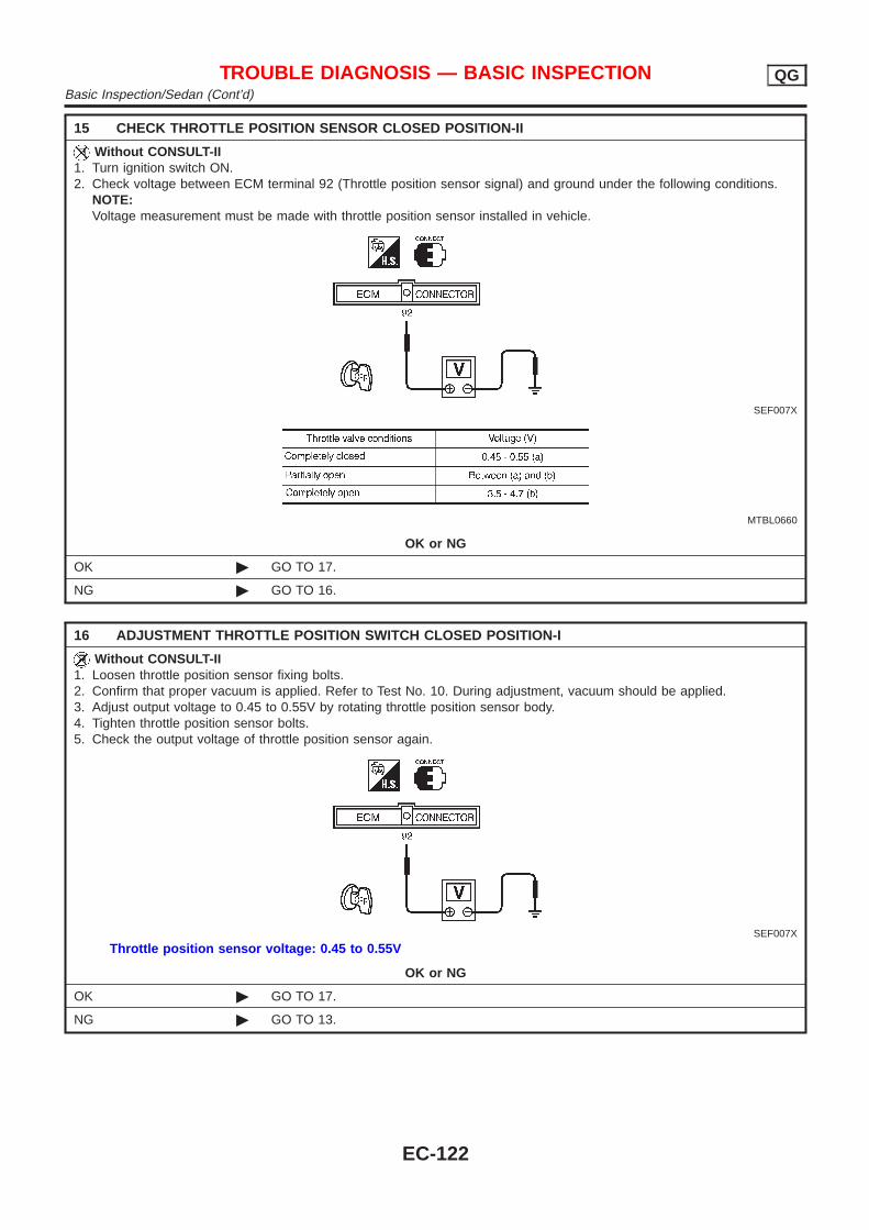
15 CHECK THROTTLE POSITION SENSOR CLOSED POSITION-II
Without CONSULT-II1. Turn ignition switch ON.2. Check voltage between ECM terminal 92 (Throttle position sensor signal) and ground under the following conditions.
NOTE:Voltage measurement must be made with throttle position sensor installed in vehicle.
SEF007X
MTBL0660
OK or NG
OK © GO TO 17.
NG © GO TO 16.
16 ADJUSTMENT THROTTLE POSITION SWITCH CLOSED POSITION-I
Without CONSULT-II1. Loosen throttle position sensor fixing bolts.2. Confirm that proper vacuum is applied. Refer to Test No. 10. During adjustment, vacuum should be applied.3. Adjust output voltage to 0.45 to 0.55V by rotating throttle position sensor body.4. Tighten throttle position sensor bolts.5. Check the output voltage of throttle position sensor again.
SEF007X
Throttle position sensor voltage: 0.45 to 0.55V
OK or NG
OK © GO TO 17.
NG © GO TO 13.
TROUBLE DIAGNOSIS — BASIC INSPECTION QGBasic Inspection/Sedan (Cont’d)
EC-122
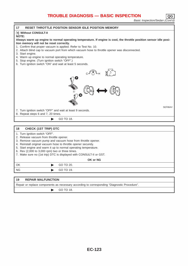
17 RESET THROTTLE POSITION SENSOR IDLE POSITION MEMORY
Without CONSULT-IINOTE:Always warm up engine to normal operating temperature. If engine is cool, the throttle position sensor idle posi-tion memory will not be reset correctly.1. Confirm that proper vacuum is applied. Refer to Test No. 10.2. Attach blind cap to vacuum port from which vacuum hose to throttle opener was disconnected.3. Start engine.4. Warm up engine to normal operating temperature.5. Stop engine. (Turn ignition switch “OFF”.)6. Turn ignition switch “ON” and wait at least 5 seconds.
SEF864V
7. Turn ignition switch “OFF” and wait at least 9 seconds.8. Repeat steps 6 and 7, 20 times.
© GO TO 18.
18 CHECK (1ST TRIP) DTC
1. Turn ignition switch “OFF”.2. Release vacuum from throttle opener.3. Remove vacuum pump and vacuum hose from throttle opener.4. Reinstall original vacuum hose to throttle opener securely.5. Start engine and warm it up to normal operating temperature.6. Rev (2,000 to 3,000 rpm) two or three times.7. Make sure no (1st trip) DTC is displayed with CONSULT-II or GST.
OK or NG
OK © GO TO 20.
NG © GO TO 19.
19 REPAIR MALFUNCTION
Repair or replace components as necessary according to corresponding “Diagnostic Procedure”.
© GO TO 18.
TROUBLE DIAGNOSIS — BASIC INSPECTION QGBasic Inspection/Sedan (Cont’d)
EC-123
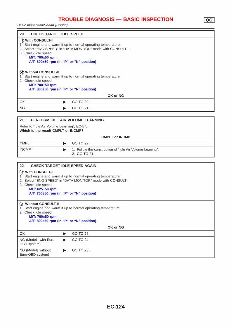
20 CHECK TARGET IDLE SPEED
With CONSULT-II1. Start engine and warm it up to normal operating temperature.2. Select “ENG SPEED” in “DATA MONITOR” mode with CONSULT-II.3. Check idle speed.
M/T: 700±50 rpmA/T: 800±50 rpm (in “P” or “N” position)
Without CONSULT-II1. Start engine and warm it up to normal operating temperature.2. Check idle speed.
M/T: 700±50 rpmA/T: 800±50 rpm (in “P” or “N” position)
OK or NG
OK © GO TO 30.
NG © GO TO 21.
21 PERFORM IDLE AIR VOLUME LEARNING
Refer to “Idle Air Volume Learning”, EC-57.Which is the result CMPLT or INCMP?
CMPLT or INCMP
CMPLT © GO TO 22.
INCMP © 1. Follow the construction of “Idle Air Volume Leaning”.2. GO TO 21.
22 CHECK TARGET IDLE SPEED AGAIN
With CONSULT-II1. Start engine and warm it up to normal operating temperature.2. Select “ENG SPEED” in “DATA MONITOR” mode with CONSULT-II.3. Check idle speed.
M/T: 625±50 rpmA/T: 700±50 rpm (in “P” or “N” position)
Without CONSULT-II1. Start engine and warm it up to normal operating temperature.2. Check idle speed.
M/T: 700±50 rpmA/T: 800±50 rpm (in “P” or “N” position)
OK or NG
OK © GO TO 28.
NG (Models with Euro-OBD system)
© GO TO 24.
NG (Models withoutEuro-OBD system)
© GO TO 23.
TROUBLE DIAGNOSIS — BASIC INSPECTION QGBasic Inspection/Sedan (Cont’d)
EC-124
23 CHECK IACV-AAC VALVE CIRCUIT FOR OPEN AND SHORT
1. Turn ignition switch “OFF”.2. Check IACV-AAC valve circuit for open and short. Refer to “Diagnostic Procedure”, EC-380.
OK or NG
OK © GO TO 24.
NG © 1. Repair or replace.2. GO TO 25.
24 REPLACE IACV-AAC VALVE
Replace IACV-AAC valve.
© GO TO 25.
25 PERFORM IDLE AIR VOLUME LEARNING
Refer to “Idle Air Volume Learning”, EC-57.Which is the result CMPLT or INCMP?
CMPLT or INCMP
CMPLT © GO TO 26.
INCMP © 1. Follow the construction of “Idle Air Volume Learning”.2. GO TO 21.
26 CHECK TARGET IDLE SPEED AGAIN
With CONSULT-II1. Start engine and warm it up to normal operating temperature.2. Select “ENG SPEED” in “DATA MONITOR” mode with CONSULT-II.3. Check idle speed.
M/T: 700±50 rpmA/T: 800±50 rpm (in “P” or “N” position)
Without CONSULT-II1. Start engine and warm it up to normal operating temperature.2. Check idle speed.
M/T: 700±50 rpmA/T: 800±50 rpm (in “P” or “N” position)
OK or NG
OK © GO TO 28.
NG © GO TO 27.
27 CHECK ECM FUNCTION
1. Substitute another known-good ECM to check ECM function. (ECM may be the cause of a problem, but this is rarelythe case.)
2. Perform initialization of NATS system and registration of NATS ignition key IDs. Refer to “NATS (Nissan Anti-TheftSystem)”, EC-74.
© GO TO 21.
TROUBLE DIAGNOSIS — BASIC INSPECTION QGBasic Inspection/Sedan (Cont’d)
EC-125
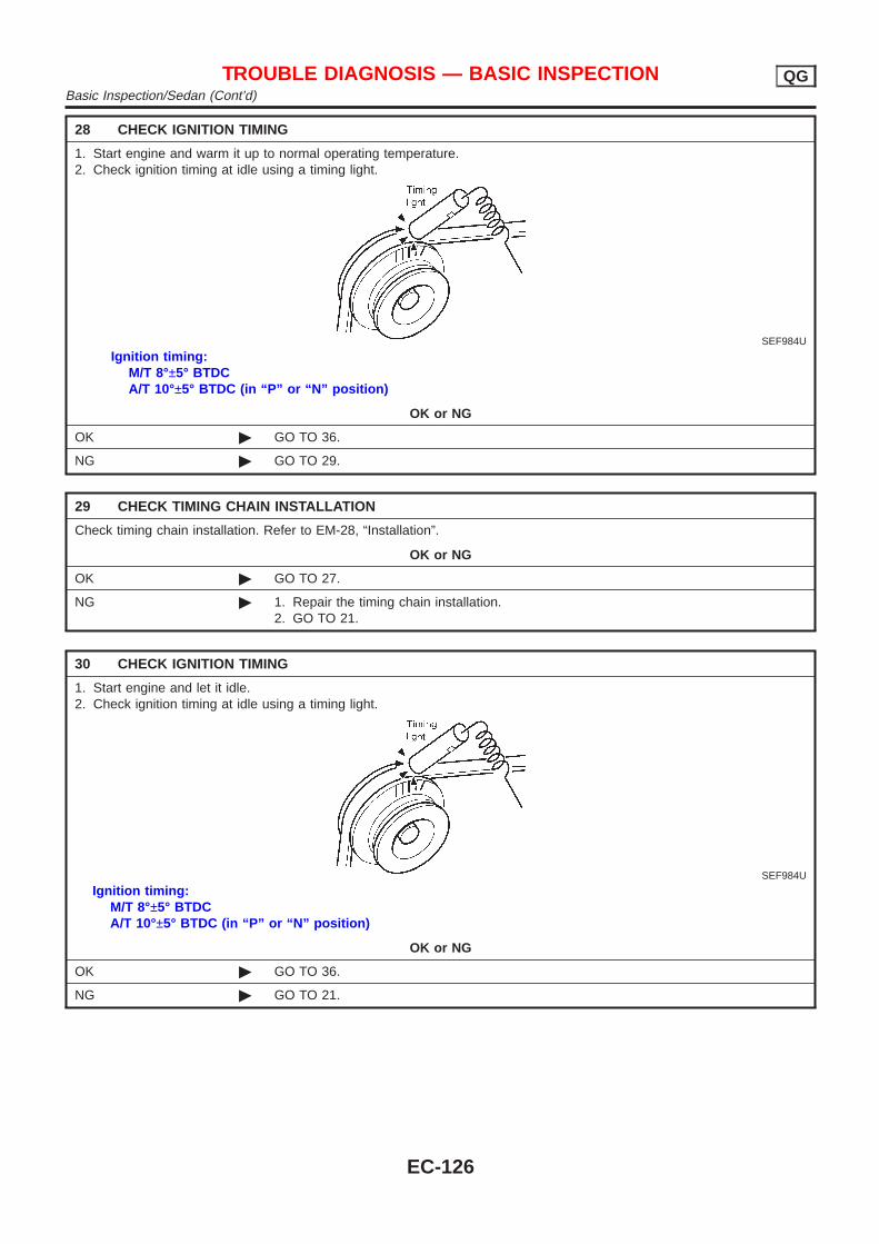
28 CHECK IGNITION TIMING
1. Start engine and warm it up to normal operating temperature.2. Check ignition timing at idle using a timing light.
SEF984U
Ignition timing:M/T 8°±5° BTDCA/T 10°±5° BTDC (in “P” or “N” position)
OK or NG
OK © GO TO 36.
NG © GO TO 29.
29 CHECK TIMING CHAIN INSTALLATION
Check timing chain installation. Refer to EM-28, “Installation”.
OK or NG
OK © GO TO 27.
NG © 1. Repair the timing chain installation.2. GO TO 21.
30 CHECK IGNITION TIMING
1. Start engine and let it idle.2. Check ignition timing at idle using a timing light.
SEF984U
Ignition timing:M/T 8°±5° BTDCA/T 10°±5° BTDC (in “P” or “N” position)
OK or NG
OK © GO TO 36.
NG © GO TO 21.
TROUBLE DIAGNOSIS — BASIC INSPECTION QGBasic Inspection/Sedan (Cont’d)
EC-126
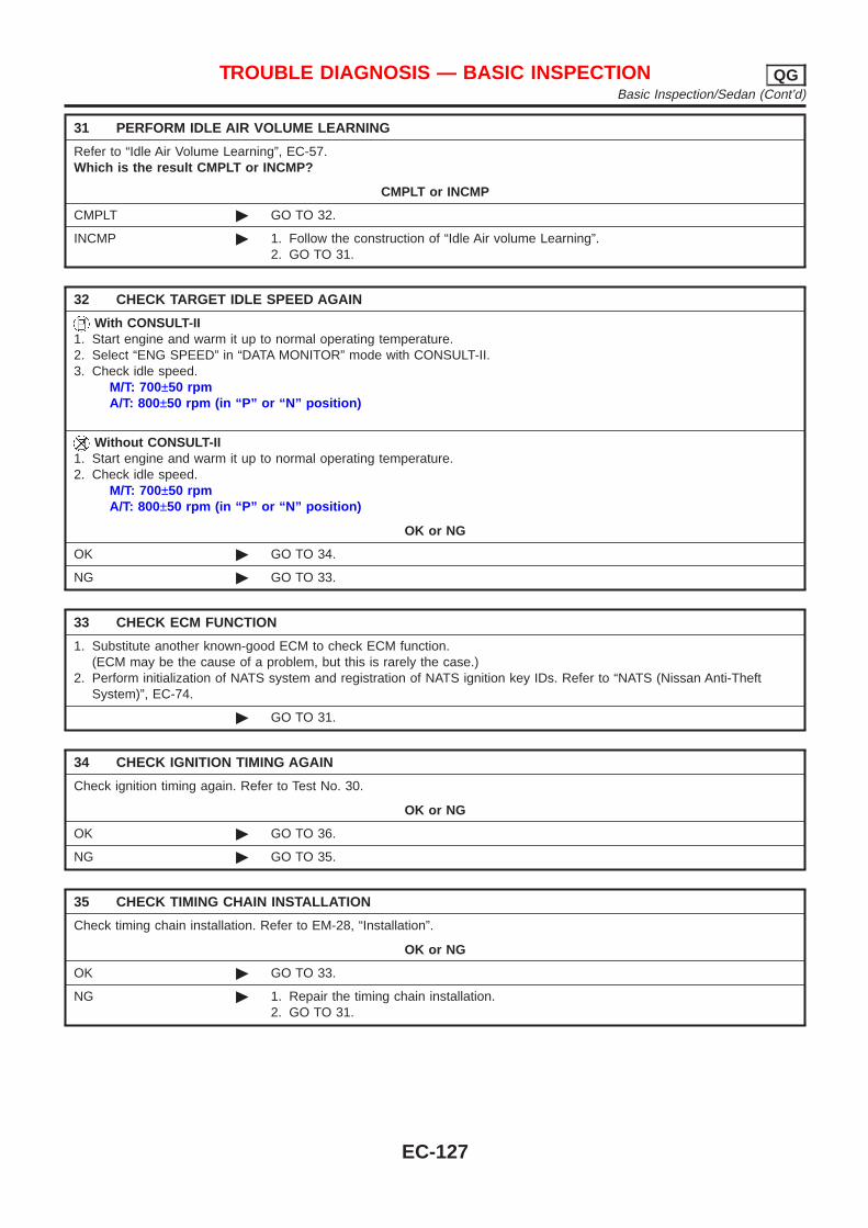
31 PERFORM IDLE AIR VOLUME LEARNING
Refer to “Idle Air Volume Learning”, EC-57.Which is the result CMPLT or INCMP?
CMPLT or INCMP
CMPLT © GO TO 32.
INCMP © 1. Follow the construction of “Idle Air volume Learning”.2. GO TO 31.
32 CHECK TARGET IDLE SPEED AGAIN
With CONSULT-II1. Start engine and warm it up to normal operating temperature.2. Select “ENG SPEED” in “DATA MONITOR” mode with CONSULT-II.3. Check idle speed.
M/T: 700±50 rpmA/T: 800±50 rpm (in “P” or “N” position)
Without CONSULT-II1. Start engine and warm it up to normal operating temperature.2. Check idle speed.
M/T: 700±50 rpmA/T: 800±50 rpm (in “P” or “N” position)
OK or NG
OK © GO TO 34.
NG © GO TO 33.
33 CHECK ECM FUNCTION
1. Substitute another known-good ECM to check ECM function.(ECM may be the cause of a problem, but this is rarely the case.)
2. Perform initialization of NATS system and registration of NATS ignition key IDs. Refer to “NATS (Nissan Anti-TheftSystem)”, EC-74.
© GO TO 31.
34 CHECK IGNITION TIMING AGAIN
Check ignition timing again. Refer to Test No. 30.
OK or NG
OK © GO TO 36.
NG © GO TO 35.
35 CHECK TIMING CHAIN INSTALLATION
Check timing chain installation. Refer to EM-28, “Installation”.
OK or NG
OK © GO TO 33.
NG © 1. Repair the timing chain installation.2. GO TO 31.
TROUBLE DIAGNOSIS — BASIC INSPECTION QGBasic Inspection/Sedan (Cont’d)
EC-127
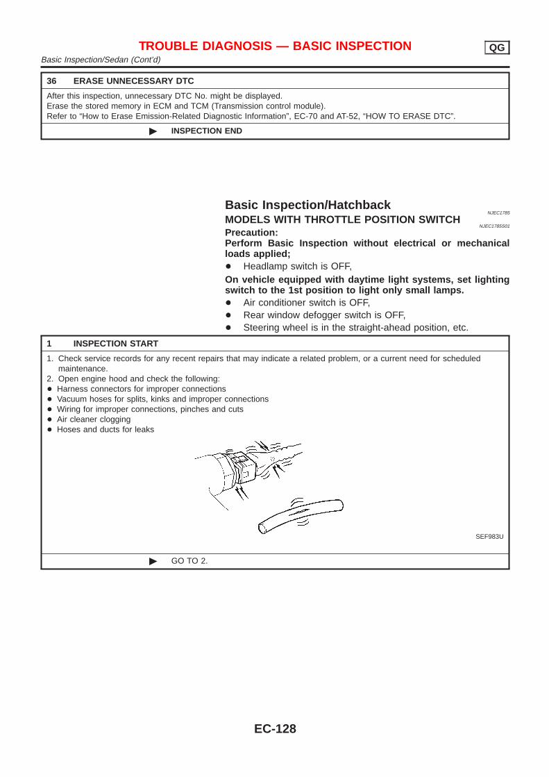
36 ERASE UNNECESSARY DTC
After this inspection, unnecessary DTC No. might be displayed.Erase the stored memory in ECM and TCM (Transmission control module).Refer to “How to Erase Emission-Related Diagnostic Information”, EC-70 and AT-52, “HOW TO ERASE DTC”.
© INSPECTION END
Basic Inspection/HatchbackNJEC1785
MODELS WITH THROTTLE POSITION SWITCHNJEC1785S01
Precaution:Perform Basic Inspection without electrical or mechanicalloads applied;+ Headlamp switch is OFF,On vehicle equipped with daytime light systems, set lightingswitch to the 1st position to light only small lamps.+ Air conditioner switch is OFF,+ Rear window defogger switch is OFF,+ Steering wheel is in the straight-ahead position, etc.
1 INSPECTION START
1. Check service records for any recent repairs that may indicate a related problem, or a current need for scheduledmaintenance.
2. Open engine hood and check the following:+ Harness connectors for improper connections+ Vacuum hoses for splits, kinks and improper connections+ Wiring for improper connections, pinches and cuts+ Air cleaner clogging+ Hoses and ducts for leaks
SEF983U
© GO TO 2.
TROUBLE DIAGNOSIS — BASIC INSPECTION QGBasic Inspection/Sedan (Cont’d)
EC-128
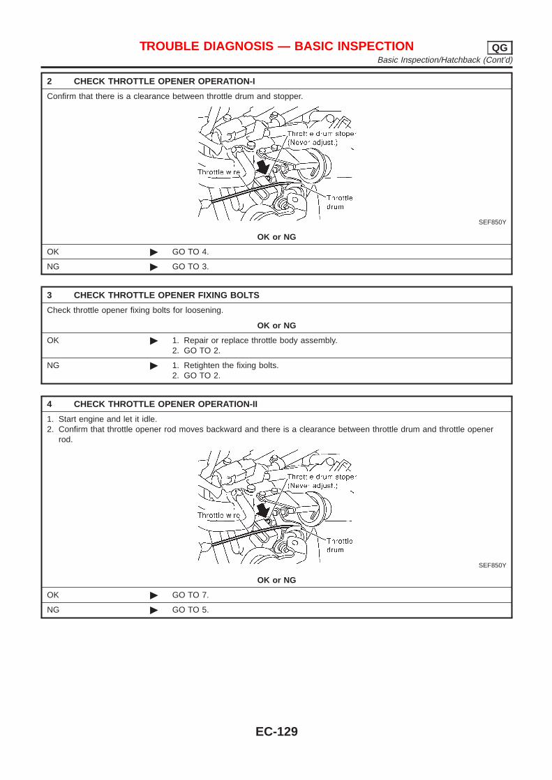
2 CHECK THROTTLE OPENER OPERATION-I
Confirm that there is a clearance between throttle drum and stopper.
SEF850Y
OK or NG
OK © GO TO 4.
NG © GO TO 3.
3 CHECK THROTTLE OPENER FIXING BOLTS
Check throttle opener fixing bolts for loosening.
OK or NG
OK © 1. Repair or replace throttle body assembly.2. GO TO 2.
NG © 1. Retighten the fixing bolts.2. GO TO 2.
4 CHECK THROTTLE OPENER OPERATION-II
1. Start engine and let it idle.2. Confirm that throttle opener rod moves backward and there is a clearance between throttle drum and throttle opener
rod.
SEF850Y
OK or NG
OK © GO TO 7.
NG © GO TO 5.
TROUBLE DIAGNOSIS — BASIC INSPECTION QGBasic Inspection/Hatchback (Cont’d)
EC-129
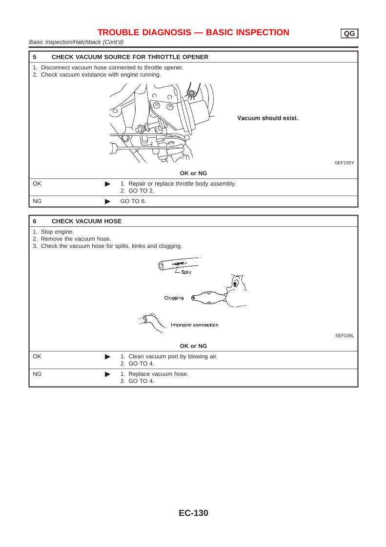
5 CHECK VACUUM SOURCE FOR THROTTLE OPENER
1. Disconnect vacuum hose connected to throttle opener.2. Check vacuum existance with engine running.
SEF155Y
OK or NG
OK © 1. Repair or replace throttle body assembly.2. GO TO 2.
NG © GO TO 6.
6 CHECK VACUUM HOSE
1. Stop engine.2. Remove the vacuum hose.3. Check the vacuum hose for splits, kinks and clogging.
SEF109L
OK or NG
OK © 1. Clean vacuum port by blowing air.2. GO TO 4.
NG © 1. Replace vacuum hose.2. GO TO 4.
TROUBLE DIAGNOSIS — BASIC INSPECTION QGBasic Inspection/Hatchback (Cont’d)
EC-130
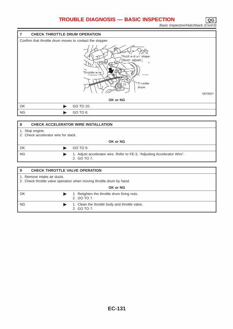
7 CHECK THROTTLE DRUM OPERATION
Confirm that throttle drum moves to contact the stopper.
SEF850Y
OK or NG
OK © GO TO 10.
NG © GO TO 8.
8 CHECK ACCELERATOR WIRE INSTALLATION
1. Stop engine.2. Check accelerator wire for slack.
OK or NG
OK © GO TO 9.
NG © 1. Adjust accelerator wire. Refer to FE-3, “Adjusting Accelerator Wire”.2. GO TO 7.
9 CHECK THROTTLE VALVE OPERATION
1. Remove intake air ducts.2. Check throttle valve operation when moving throttle drum by hand.
OK or NG
OK © 1. Retighten the throttle drum fixing nuts.2. GO TO 7.
NG © 1. Clean the throttle body and throttle valve.2. GO TO 7.
TROUBLE DIAGNOSIS — BASIC INSPECTION QGBasic Inspection/Hatchback (Cont’d)
EC-131
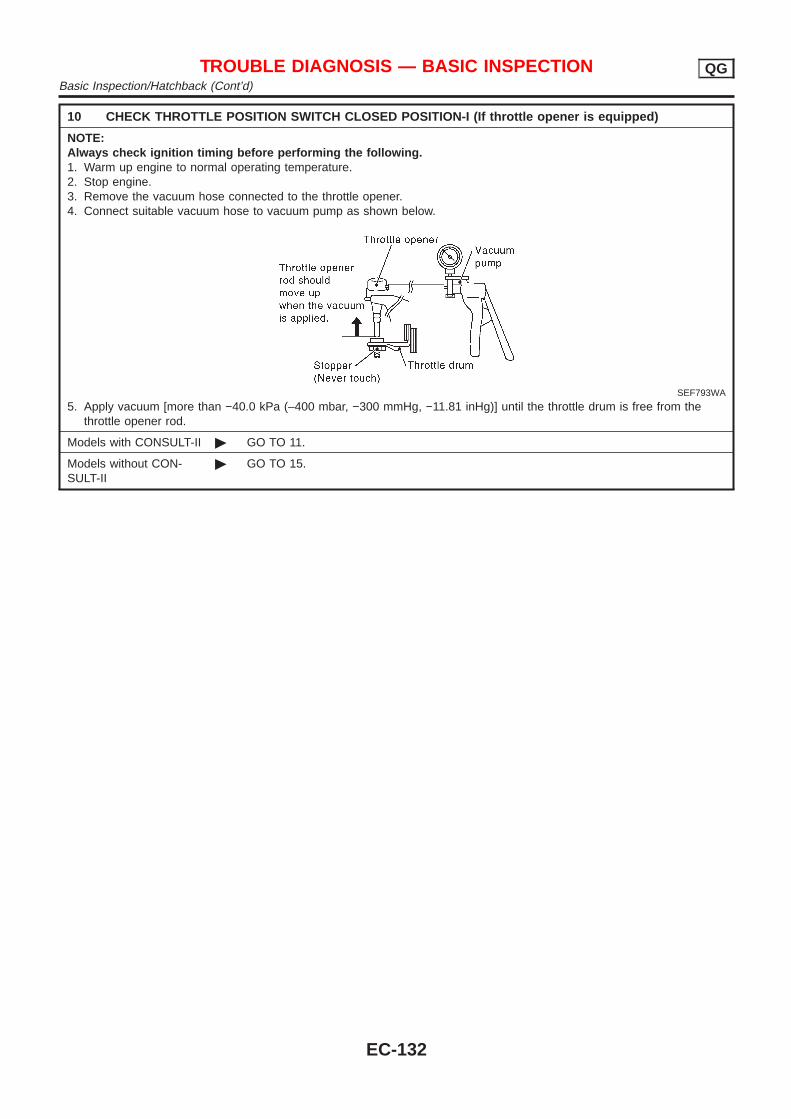
10 CHECK THROTTLE POSITION SWITCH CLOSED POSITION-I (If throttle opener is equipped)
NOTE:Always check ignition timing before performing the following.1. Warm up engine to normal operating temperature.2. Stop engine.3. Remove the vacuum hose connected to the throttle opener.4. Connect suitable vacuum hose to vacuum pump as shown below.
SEF793WA
5. Apply vacuum [more than −40.0 kPa (–400 mbar, −300 mmHg, −11.81 inHg)] until the throttle drum is free from thethrottle opener rod.
Models with CONSULT-II © GO TO 11.
Models without CON-SULT-II
© GO TO 15.
TROUBLE DIAGNOSIS — BASIC INSPECTION QGBasic Inspection/Hatchback (Cont’d)
EC-132
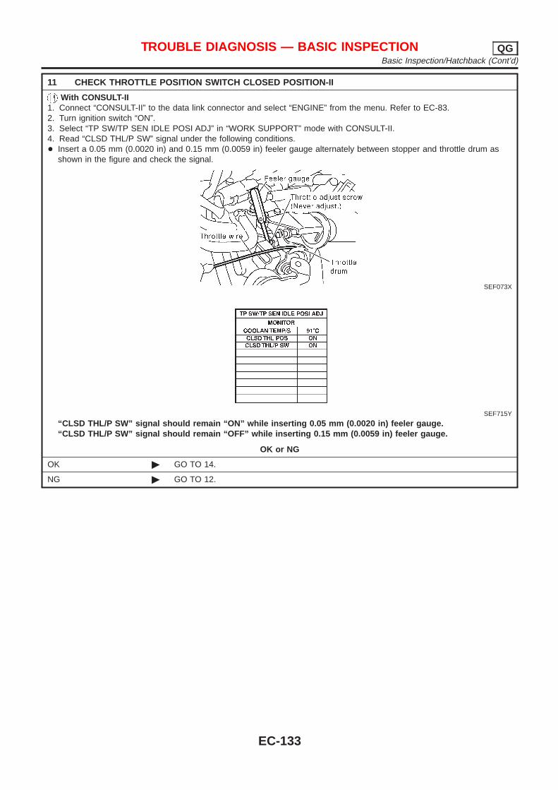
11 CHECK THROTTLE POSITION SWITCH CLOSED POSITION-II
With CONSULT-II1. Connect “CONSULT-II” to the data link connector and select “ENGINE” from the menu. Refer to EC-83.2. Turn ignition switch “ON”.3. Select “TP SW/TP SEN IDLE POSI ADJ” in “WORK SUPPORT” mode with CONSULT-II.4. Read “CLSD THL/P SW” signal under the following conditions.+ Insert a 0.05 mm (0.0020 in) and 0.15 mm (0.0059 in) feeler gauge alternately between stopper and throttle drum as
shown in the figure and check the signal.
SEF073X
SEF715Y
“CLSD THL/P SW” signal should remain “ON” while inserting 0.05 mm (0.0020 in) feeler gauge.“CLSD THL/P SW” signal should remain “OFF” while inserting 0.15 mm (0.0059 in) feeler gauge.
OK or NG
OK © GO TO 14.
NG © GO TO 12.
TROUBLE DIAGNOSIS — BASIC INSPECTION QGBasic Inspection/Hatchback (Cont’d)
EC-133
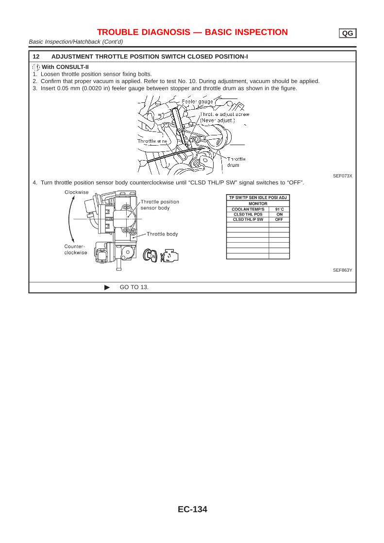
12 ADJUSTMENT THROTTLE POSITION SWITCH CLOSED POSITION-I
With CONSULT-II1. Loosen throttle position sensor fixing bolts.2. Confirm that proper vacuum is applied. Refer to test No. 10. During adjustment, vacuum should be applied.3. Insert 0.05 mm (0.0020 in) feeler gauge between stopper and throttle drum as shown in the figure.
SEF073X
4. Turn throttle position sensor body counterclockwise until “CLSD THL/P SW” signal switches to “OFF”.
SEF863Y
© GO TO 13.
TROUBLE DIAGNOSIS — BASIC INSPECTION QGBasic Inspection/Hatchback (Cont’d)
EC-134
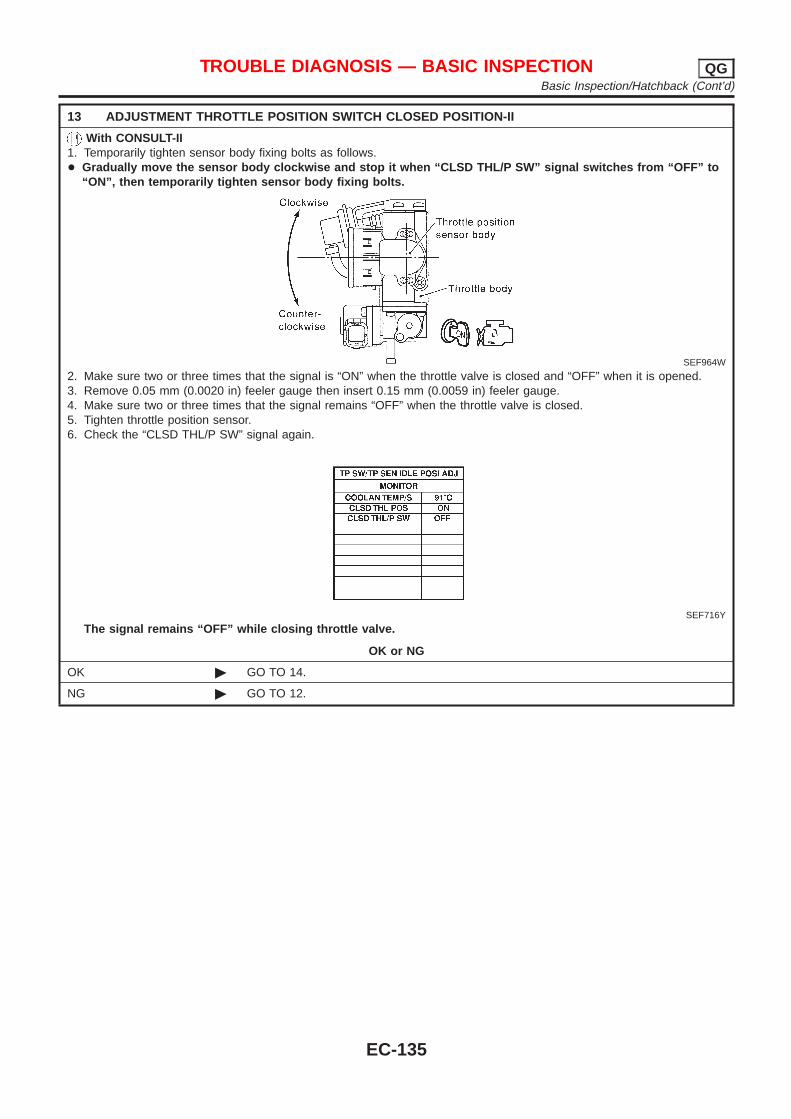
13 ADJUSTMENT THROTTLE POSITION SWITCH CLOSED POSITION-II
With CONSULT-II1. Temporarily tighten sensor body fixing bolts as follows.+ Gradually move the sensor body clockwise and stop it when “CLSD THL/P SW” signal switches from “OFF” to
“ON”, then temporarily tighten sensor body fixing bolts.
SEF964W
2. Make sure two or three times that the signal is “ON” when the throttle valve is closed and “OFF” when it is opened.3. Remove 0.05 mm (0.0020 in) feeler gauge then insert 0.15 mm (0.0059 in) feeler gauge.4. Make sure two or three times that the signal remains “OFF” when the throttle valve is closed.5. Tighten throttle position sensor.6. Check the “CLSD THL/P SW” signal again.
SEF716Y
The signal remains “OFF” while closing throttle valve.
OK or NG
OK © GO TO 14.
NG © GO TO 12.
TROUBLE DIAGNOSIS — BASIC INSPECTION QGBasic Inspection/Hatchback (Cont’d)
EC-135
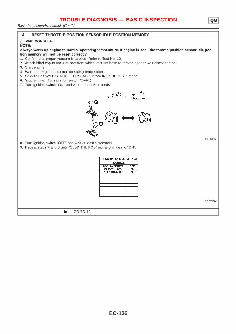
14 RESET THROTTLE POSITION SENSOR IDLE POSITION MEMORY
With CONSULT-IINOTE:Always warm up engine to normal operating temperature. If engine is cool, the throttle position sensor idle posi-tion memory will not be reset correctly.1. Confirm that proper vacuum is applied. Refer to Test No. 10.2. Attach blind cap to vacuum port from which vacuum hose to throttle opener was disconnected.3. Start engine.4. Warm up engine to normal operating temperature.5. Select “TP SW/TP SEN IDLE POSI ADJ” in “WORK SUPPORT” mode.6. Stop engine. (Turn ignition switch “OFF”.)7. Turn ignition switch “ON” and wait at least 5 seconds.
SEF864V
8. Turn ignition switch “OFF” and wait at least 9 seconds.9. Repeat steps 7 and 8 until “CLSD THL POS” signal changes to “ON”.
SEF715Y
© GO TO 19.
TROUBLE DIAGNOSIS — BASIC INSPECTION QGBasic Inspection/Hatchback (Cont’d)
EC-136
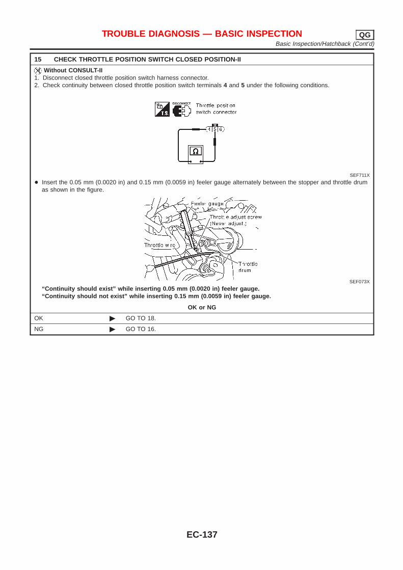
15 CHECK THROTTLE POSITION SWITCH CLOSED POSITION-II
Without CONSULT-II1. Disconnect closed throttle position switch harness connector.2. Check continuity between closed throttle position switch terminals 4 and 5 under the following conditions.
SEF711X
+ Insert the 0.05 mm (0.0020 in) and 0.15 mm (0.0059 in) feeler gauge alternately between the stopper and throttle drumas shown in the figure.
SEF073X
“Continuity should exist” while inserting 0.05 mm (0.0020 in) feeler gauge.“Continuity should not exist” while inserting 0.15 mm (0.0059 in) feeler gauge.
OK or NG
OK © GO TO 18.
NG © GO TO 16.
TROUBLE DIAGNOSIS — BASIC INSPECTION QGBasic Inspection/Hatchback (Cont’d)
EC-137
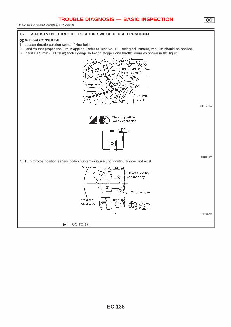
16 ADJUSTMENT THROTTLE POSITION SWITCH CLOSED POSITION-I
Without CONSULT-II1. Loosen throttle position sensor fixing bolts.2. Confirm that proper vacuum is applied. Refer to Test No. 10. During adjustment, vacuum should be applied.3. Insert 0.05 mm (0.0020 in) feeler gauge between stopper and throttle drum as shown in the figure.
SEF073X
SEF711X
4. Turn throttle position sensor body counterclockwise until continuity does not exist.
SEF964W
© GO TO 17.
TROUBLE DIAGNOSIS — BASIC INSPECTION QGBasic Inspection/Hatchback (Cont’d)
EC-138
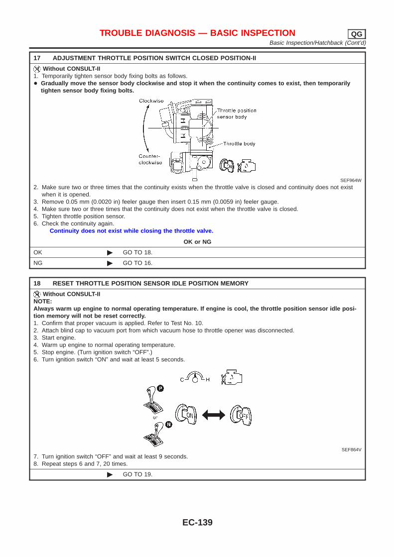
17 ADJUSTMENT THROTTLE POSITION SWITCH CLOSED POSITION-II
Without CONSULT-II1. Temporarily tighten sensor body fixing bolts as follows.+ Gradually move the sensor body clockwise and stop it when the continuity comes to exist, then temporarily
tighten sensor body fixing bolts.
SEF964W
2. Make sure two or three times that the continuity exists when the throttle valve is closed and continuity does not existwhen it is opened.
3. Remove 0.05 mm (0.0020 in) feeler gauge then insert 0.15 mm (0.0059 in) feeler gauge.4. Make sure two or three times that the continuity does not exist when the throttle valve is closed.5. Tighten throttle position sensor.6. Check the continuity again.
Continuity does not exist while closing the throttle valve.
OK or NG
OK © GO TO 18.
NG © GO TO 16.
18 RESET THROTTLE POSITION SENSOR IDLE POSITION MEMORY
Without CONSULT-IINOTE:Always warm up engine to normal operating temperature. If engine is cool, the throttle position sensor idle posi-tion memory will not be reset correctly.1. Confirm that proper vacuum is applied. Refer to Test No. 10.2. Attach blind cap to vacuum port from which vacuum hose to throttle opener was disconnected.3. Start engine.4. Warm up engine to normal operating temperature.5. Stop engine. (Turn ignition switch “OFF”.)6. Turn ignition switch “ON” and wait at least 5 seconds.
SEF864V
7. Turn ignition switch “OFF” and wait at least 9 seconds.8. Repeat steps 6 and 7, 20 times.
© GO TO 19.
TROUBLE DIAGNOSIS — BASIC INSPECTION QGBasic Inspection/Hatchback (Cont’d)
EC-139
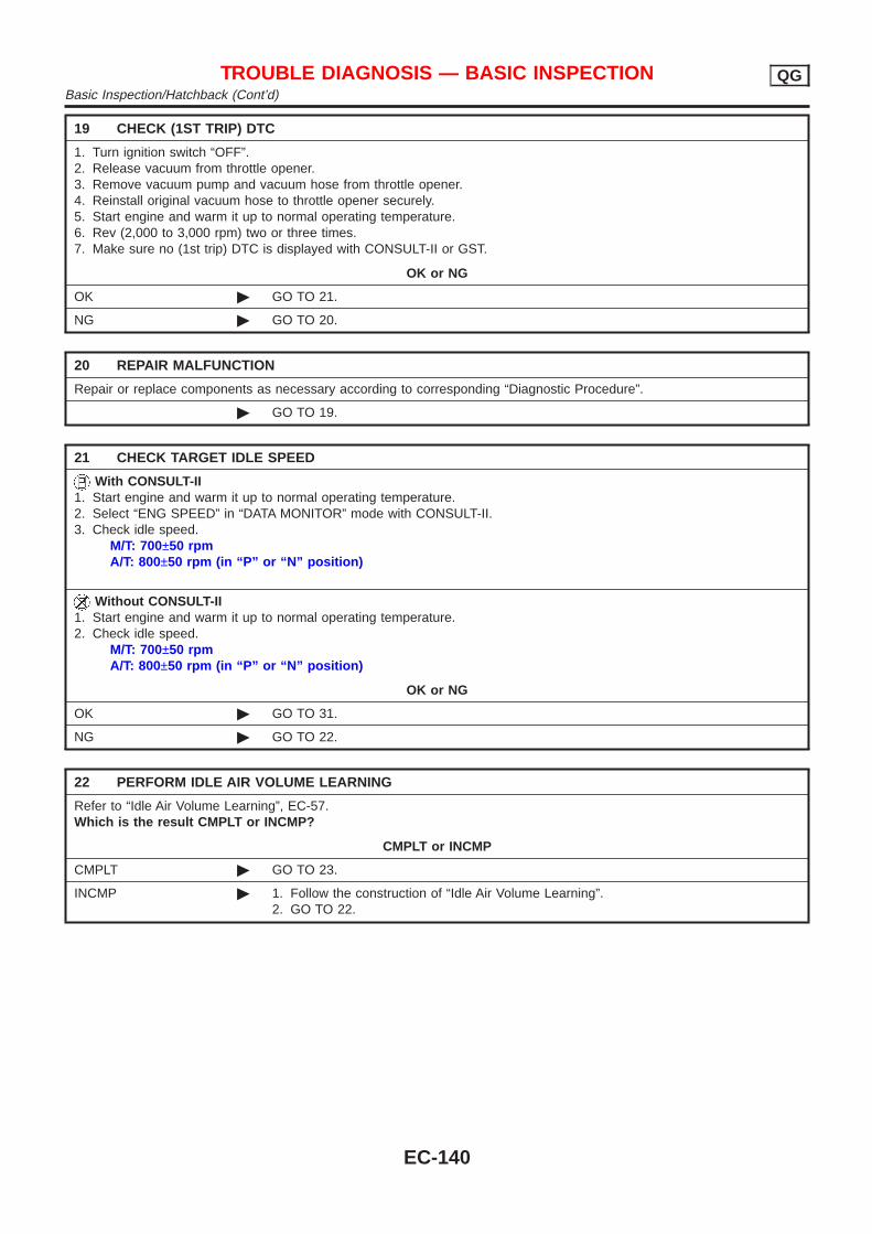
19 CHECK (1ST TRIP) DTC
1. Turn ignition switch “OFF”.2. Release vacuum from throttle opener.3. Remove vacuum pump and vacuum hose from throttle opener.4. Reinstall original vacuum hose to throttle opener securely.5. Start engine and warm it up to normal operating temperature.6. Rev (2,000 to 3,000 rpm) two or three times.7. Make sure no (1st trip) DTC is displayed with CONSULT-II or GST.
OK or NG
OK © GO TO 21.
NG © GO TO 20.
20 REPAIR MALFUNCTION
Repair or replace components as necessary according to corresponding “Diagnostic Procedure”.
© GO TO 19.
21 CHECK TARGET IDLE SPEED
With CONSULT-II1. Start engine and warm it up to normal operating temperature.2. Select “ENG SPEED” in “DATA MONITOR” mode with CONSULT-II.3. Check idle speed.
M/T: 700±50 rpmA/T: 800±50 rpm (in “P” or “N” position)
Without CONSULT-II1. Start engine and warm it up to normal operating temperature.2. Check idle speed.
M/T: 700±50 rpmA/T: 800±50 rpm (in “P” or “N” position)
OK or NG
OK © GO TO 31.
NG © GO TO 22.
22 PERFORM IDLE AIR VOLUME LEARNING
Refer to “Idle Air Volume Learning”, EC-57.Which is the result CMPLT or INCMP?
CMPLT or INCMP
CMPLT © GO TO 23.
INCMP © 1. Follow the construction of “Idle Air Volume Learning”.2. GO TO 22.
TROUBLE DIAGNOSIS — BASIC INSPECTION QGBasic Inspection/Hatchback (Cont’d)
EC-140

23 CHECK TARGET IDLE SPEED AGAIN
With CONSULT-II1. Start engine and warm it up to normal operating temperature.2. Select “ENG SPEED” in “DATA MONITOR” mode with CONSULT-II.3. Check idle speed.
M/T: 700±50 rpmA/T: 800±50 rpm (in “P” or “N” position)
Without CONSULT-II1. Start engine and warm it up to normal operating temperature.2. Check idle speed.
M/T: 700±50 rpmA/T: 800±50 rpm (in “P” or “N” position)
OK or NG
OK © GO TO 29.
NG (Models with Euro-OBD system)
© GO TO 25.
NG (Models withoutEuro-OBD system)
© GO TO 24.
24 CHECK IACV-AAC VALVE CIRCUIT FOR OPEN AND SHORT
1. Turn ignition switch “OFF”.2. Check IACV-AAC valve circuit for open and short. Refer to “Diagnostic Procedure”, EC-376.
OK or NG
OK © GO TO 25.
NG © 1. Repair or replace.2. GO TO 26.
25 REPLACE IACV-AAC VALVE
Replace IACV-AAC valve.
© GO TO 26.
26 PERFORM IDLE AIR VOLUME LEARNING
Refer to “Idle Air Volume Learning”, EC-57Which is the result CMPLT or INCMP?
CMPLT or INCMP
CMPLT © GO TO 27.
INCMP © 1. Follow the construction of “Idle Air Volume Learning”.2. GO TO 22.
TROUBLE DIAGNOSIS — BASIC INSPECTION QGBasic Inspection/Hatchback (Cont’d)
EC-141
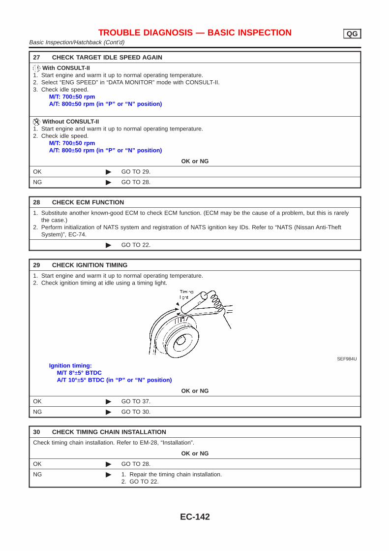
27 CHECK TARGET IDLE SPEED AGAIN
With CONSULT-II1. Start engine and warm it up to normal operating temperature.2. Select “ENG SPEED” in “DATA MONITOR” mode with CONSULT-II.3. Check idle speed.
M/T: 700±50 rpmA/T: 800±50 rpm (in “P” or “N” position)
Without CONSULT-II1. Start engine and warm it up to normal operating temperature.2. Check idle speed.
M/T: 700±50 rpmA/T: 800±50 rpm (in “P” or “N” position)
OK or NG
OK © GO TO 29.
NG © GO TO 28.
28 CHECK ECM FUNCTION
1. Substitute another known-good ECM to check ECM function. (ECM may be the cause of a problem, but this is rarelythe case.)
2. Perform initialization of NATS system and registration of NATS ignition key IDs. Refer to “NATS (Nissan Anti-TheftSystem)”, EC-74.
© GO TO 22.
29 CHECK IGNITION TIMING
1. Start engine and warm it up to normal operating temperature.2. Check ignition timing at idle using a timing light.
SEF984U
Ignition timing:M/T 8°±5° BTDCA/T 10°±5° BTDC (in “P” or “N” position)
OK or NG
OK © GO TO 37.
NG © GO TO 30.
30 CHECK TIMING CHAIN INSTALLATION
Check timing chain installation. Refer to EM-28, “Installation”.
OK or NG
OK © GO TO 28.
NG © 1. Repair the timing chain installation.2. GO TO 22.
TROUBLE DIAGNOSIS — BASIC INSPECTION QGBasic Inspection/Hatchback (Cont’d)
EC-142
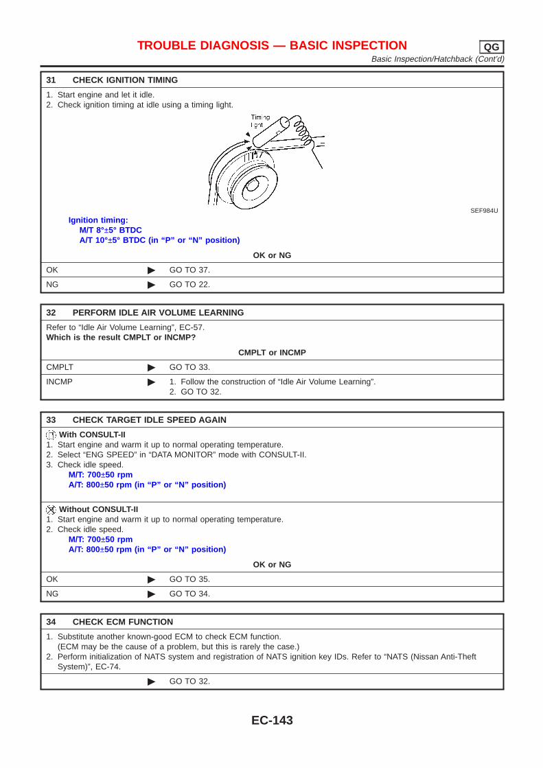
31 CHECK IGNITION TIMING
1. Start engine and let it idle.2. Check ignition timing at idle using a timing light.
SEF984U
Ignition timing:M/T 8°±5° BTDCA/T 10°±5° BTDC (in “P” or “N” position)
OK or NG
OK © GO TO 37.
NG © GO TO 22.
32 PERFORM IDLE AIR VOLUME LEARNING
Refer to “Idle Air Volume Learning”, EC-57.Which is the result CMPLT or INCMP?
CMPLT or INCMP
CMPLT © GO TO 33.
INCMP © 1. Follow the construction of “Idle Air Volume Learning”.2. GO TO 32.
33 CHECK TARGET IDLE SPEED AGAIN
With CONSULT-II1. Start engine and warm it up to normal operating temperature.2. Select “ENG SPEED” in “DATA MONITOR” mode with CONSULT-II.3. Check idle speed.
M/T: 700±50 rpmA/T: 800±50 rpm (in “P” or “N” position)
Without CONSULT-II1. Start engine and warm it up to normal operating temperature.2. Check idle speed.
M/T: 700±50 rpmA/T: 800±50 rpm (in “P” or “N” position)
OK or NG
OK © GO TO 35.
NG © GO TO 34.
34 CHECK ECM FUNCTION
1. Substitute another known-good ECM to check ECM function.(ECM may be the cause of a problem, but this is rarely the case.)
2. Perform initialization of NATS system and registration of NATS ignition key IDs. Refer to “NATS (Nissan Anti-TheftSystem)”, EC-74.
© GO TO 32.
TROUBLE DIAGNOSIS — BASIC INSPECTION QGBasic Inspection/Hatchback (Cont’d)
EC-143
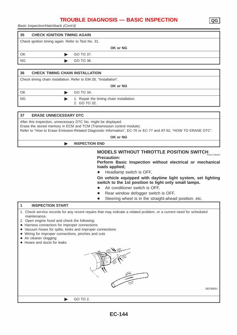
35 CHECK IGNITION TIMING AGAIN
Check ignition timing again. Refer to Test No. 31.
OK or NG
OK © GO TO 37.
NG © GO TO 36.
36 CHECK TIMING CHAIN INSTALLATION
Check timing chain installation. Refer to EM-28, “Installation”.
OK or NG
OK © GO TO 34.
NG © 1. Repair the timing chain installation.2. GO TO 32.
37 ERASE UNNECESSARY DTC
After this inspection, unnecessary DTC No. might be displayed.Erase the stored memory in ECM and TCM (Transmission control module).Refer to “How to Erase Emission-Related Diagnostic Information”, EC-70 or EC-77 and AT-52, “HOW TO ERASE DTC”.
OK or NG
© INSPECTION END
MODELS WITHOUT THROTTLE POSITION SWITCHNJEC1785S02
Precaution:Perform Basic Inspection without electrical or mechanicalloads applied;+ Headlamp switch is OFF,On vehicle equipped with daytime light system, set lightingswitch to the 1st position to light only small lamps.+ Air conditioner switch is OFF,+ Rear window defogger switch is OFF,+ Steering wheel is in the straight-ahead position, etc.
1 INSPECTION START
1. Check service records for any recent repairs that may indicate a related problem, or a current need for scheduledmaintenance.
2. Open engine hood and check the following:+ Harness connectors for improper connections+ Vacuum hoses for splits, kinks and improper connections+ Wiring for improper connections, pinches and cuts+ Air cleaner clogging+ Hoses and ducts for leaks
SEF983U
© GO TO 2.
TROUBLE DIAGNOSIS — BASIC INSPECTION QGBasic Inspection/Hatchback (Cont’d)
EC-144
2 CHECK THROTTLE DRUM OPERATION-I
Confirm that throttle drum is in contact with the stopper.
OK or NG
OK (with CONSULT-II) © GO TO 5.
OK (without CONSULT-II)
© GO TO 8.
NG © GO TO 3.
3 CHECK ACCELERATOR WIRE INSTALLATION
Check accelerator wire for slack.
OK or NG
OK © GO TO 4.
NG © Adjust accelerator wire. Refer to FE section, “Adjusting Accelerator Wire”.
4 CHECK THROTTLE VALVE OPERATION
1. Remove intake air ducts.2. Check throttle valve operation when moving throttle drum by hand.
OK or NG
OK © Retighten the throttle drum fixing nuts.
NG © Clean the throttle body and throttle valve.
5 CHECK CLOSED THROTTLE POSITION SWITCH IDLE POSITION
With CONSULT-II1. Start engine and warm it up to normal operating temperature.2. Stop engine.3. Turn ignition switch “ON”.4. Select “THRTL POS SEN” and “CLSD THL POS” in “DATA MONITOR” mode with CONSULT-II.5. Make sure that “THRTL POS SEN” indicates 0.35 to 0.65V, and “CLSD THL POS” indicates “ON”. (Accelerator pedal is
fully released).
OK or NG
OK © GO TO 11.
NG © GO TO 6.
TROUBLE DIAGNOSIS — BASIC INSPECTION QGBasic Inspection/Hatchback (Cont’d)
EC-145
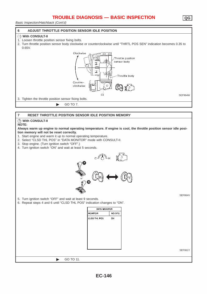
6 ADJUST THROTTLE POSITION SENSOR IDLE POSITION
With CONSULT-II1. Loosen throttle position sensor fixing bolts.2. Turn throttle position sensor body clockwise or counterclockwise until “THRTL POS SEN” indication becomes 0.35 to
0.65V.
SEF964W
3. Tighten the throttle position sensor fixing bolts.
© GO TO 7.
7 RESET THROTTLE POSITION SENSOR IDLE POSITION MEMORY
With CONSULT-IINOTE:Always warm up engine to normal operating temperature. If engine is cool, the throttle position sensor idle posi-tion memory will not be reset correctly.1. Start engine and warm it up to normal operating temperature.2. Select “CLSD THL POS” in “DATA MONITOR” mode with CONSULT-II.3. Stop engine. (Turn ignition switch “OFF”.)4. Turn ignition switch “ON” and wait at least 5 seconds.
SEF864V
5. Turn ignition switch “OFF” and wait at least 9 seconds.6. Repeat steps 4 and 6 until “CLSD THL POS” indication changes to “ON”.
SEF061Y
© GO TO 11.
TROUBLE DIAGNOSIS — BASIC INSPECTION QGBasic Inspection/Hatchback (Cont’d)
EC-146
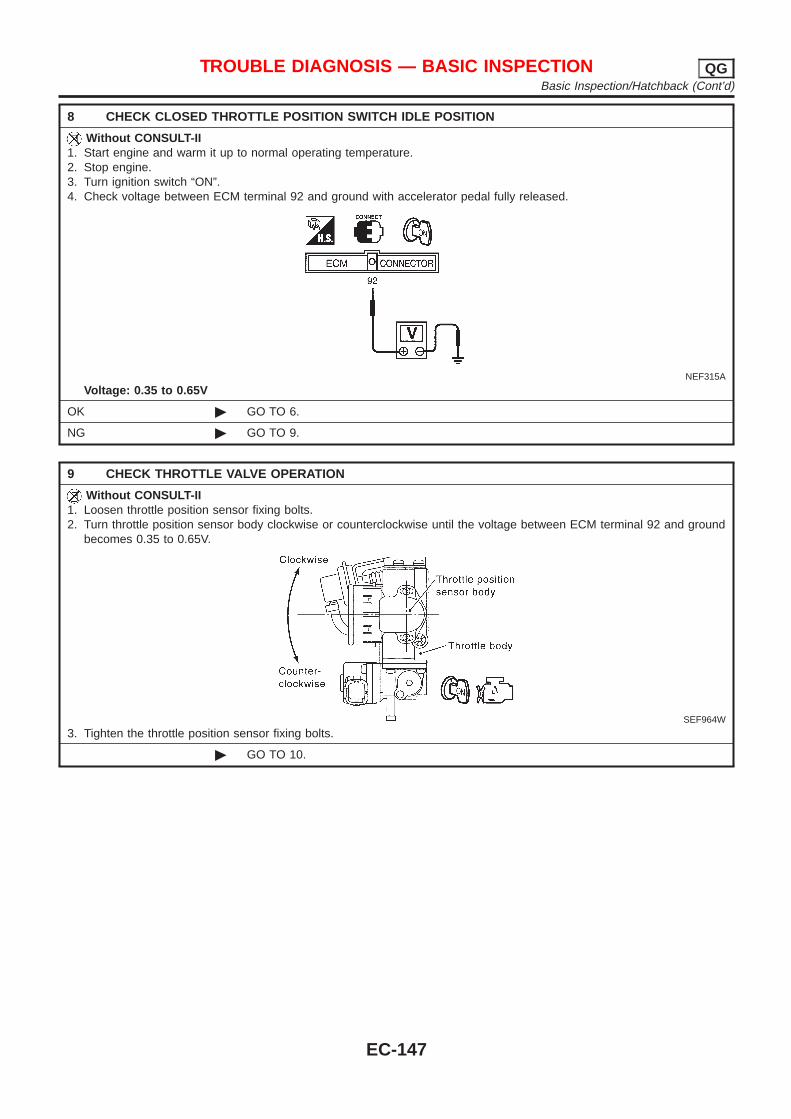
8 CHECK CLOSED THROTTLE POSITION SWITCH IDLE POSITION
Without CONSULT-II1. Start engine and warm it up to normal operating temperature.2. Stop engine.3. Turn ignition switch “ON”.4. Check voltage between ECM terminal 92 and ground with accelerator pedal fully released.
NEF315A
Voltage: 0.35 to 0.65V
OK © GO TO 6.
NG © GO TO 9.
9 CHECK THROTTLE VALVE OPERATION
Without CONSULT-II1. Loosen throttle position sensor fixing bolts.2. Turn throttle position sensor body clockwise or counterclockwise until the voltage between ECM terminal 92 and ground
becomes 0.35 to 0.65V.
SEF964W
3. Tighten the throttle position sensor fixing bolts.
© GO TO 10.
TROUBLE DIAGNOSIS — BASIC INSPECTION QGBasic Inspection/Hatchback (Cont’d)
EC-147
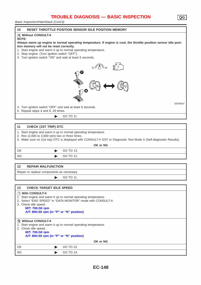
10 RESET THROTTLE POSITION SENSOR IDLE POSITION MEMORY
Without CONSULT-IINOTE:Always warm up engine to normal operating temperature. If engine is cool, the throttle position sensor idle posi-tion memory will not be reset correctly.1. Start engine and warm it up to normal operating temperature.2. Stop engine. (Turn ignition switch “OFF”).3. Turn ignition switch “ON” and wait at least 5 seconds.
SEF864V
4. Turn ignition switch “OFF” and wait at least 9 seconds.5. Repeat steps 4 and 6, 20 times.
© GO TO 11.
11 CHECK (1ST TRIP) DTC
1. Start engine and warm it up to normal operating temperature.2. Rev (2,000 to 3,000 rpm) two or three times.3. Make sure no (1st trip) DTC is displayed with CONSULT-II GST or Diagnostic Test Mode II (Self-diagnostic Results).
OK or NG
OK © GO TO 13.
NG © GO TO 12.
12 REPAIR MALFUNCTION
Repair or replace components as necessary
© GO TO 11.
13 CHECK TARGET IDLE SPEED
With CONSULT-II1. Start engine and warm it up to normal operating temperature.2. Select “ENG SPEED” in “DATA MONITOR” mode with CONSULT-II.3. Check idle speed.
M/T: 700±50 rpmA/T: 800±50 rpm (in “P” or “N” position)
Without CONSULT-II1. Start engine and warm it up to normal operating temperature.2. Check idle speed.
M/T: 700±50 rpmA/T: 800±50 rpm (in “P” or “N” position)
OK or NG
OK © GO TO 22.
NG © GO TO 14.
TROUBLE DIAGNOSIS — BASIC INSPECTION QGBasic Inspection/Hatchback (Cont’d)
EC-148
14 PERFORM IDLE AIR VOLUME LEARNING
Refer to “Idle Air Volume Learning”, EC-57Which is the result CMPLT or INCMP?
CMPLT or INCMP
CMPLT © GO TO 15.
INCMP © 1. Follow the instruction of “Idle Air Volume Learning”.2. GO TO 14.
15 CHECK TARGET IDLE SPEED AGAIN
With CONSULT-II1. Start engine and warm it up to normal operating temperature.2. Select “ENG SPEED” in “DATA MONITOR” mode with CONSULT-II.3. Check idle speed.
M/T: 700±50 rpmA/T: 800±50 rpm (in “P” or “N” position)
Without CONSULT-II1. Start engine and warm it up to normal operating temperature.2. Check idle speed.
M/T: 700±50 rpmA/T: 800±50 rpm (in “P” or “N” position)
OK or NG
OK © GO TO 29.
NG (Models with Euro-OBD system)
© GO TO 17.
NG (Models withoutEuro-OBD system)
© GO TO 16.
16 CHECK IACV-AAC VALVE CIRCUIT FOR OPEN AND SHORT
1. Turn ignition switch “OFF”.2. Check IACV-AAC valve circuit for open and short. Refer to “Diagnostic Procedure”, EC-376.
OK or NG
OK © GO TO 17.
NG © 1. Repair or replace.2. GO TO 18.
17 REPLACE IACV-AAC VALVE
Replace IACV-AAC valve.
© GO TO 18.
18 PERFORM IDLE AIR VOLUME LEARNING
Refer to “Idle Air Volume Learning”, EC-57Which is the result CMPLT or INCMP?
CMPLT or INCMP
CMPLT © GO TO 19.
INCMP © 1. Follow the instruction of “Idle Air Volume Learning”.2. GO TO 14.
TROUBLE DIAGNOSIS — BASIC INSPECTION QGBasic Inspection/Hatchback (Cont’d)
EC-149
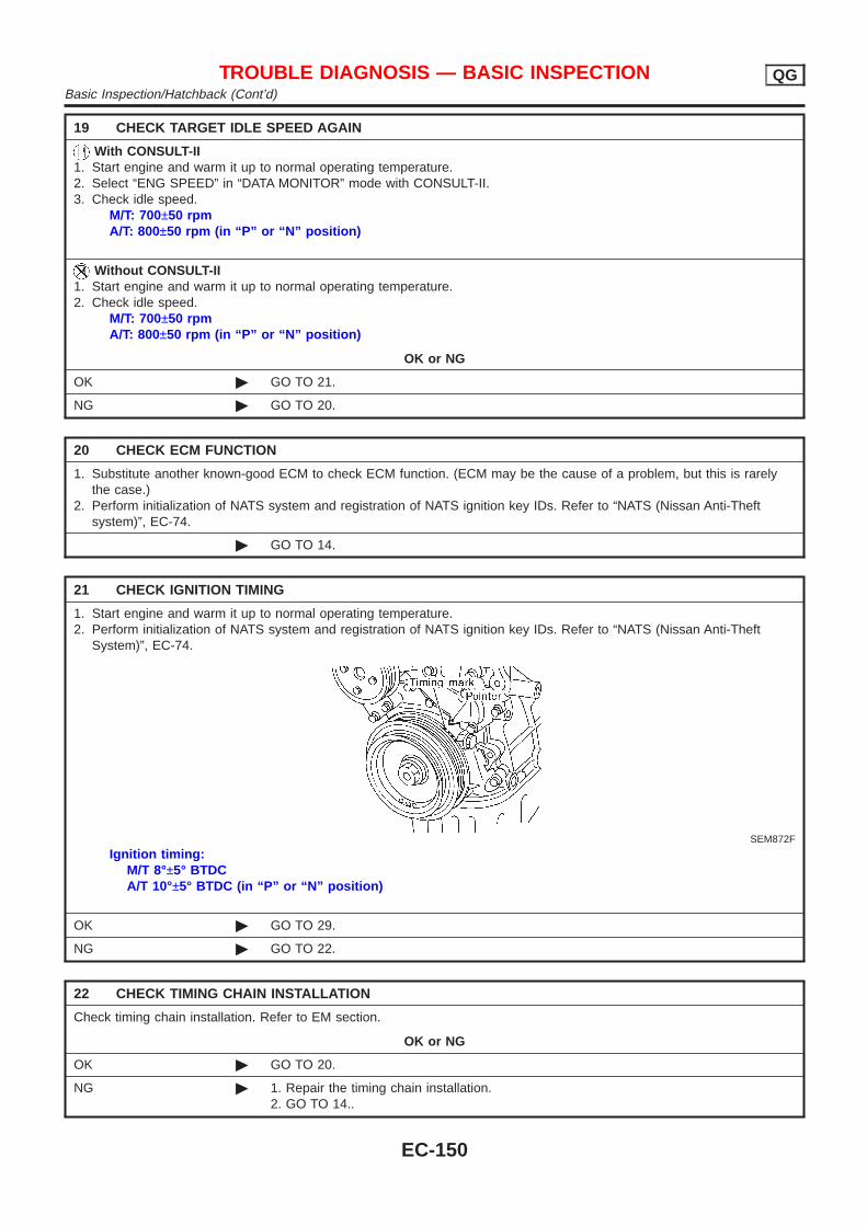
19 CHECK TARGET IDLE SPEED AGAIN
With CONSULT-II1. Start engine and warm it up to normal operating temperature.2. Select “ENG SPEED” in “DATA MONITOR” mode with CONSULT-II.3. Check idle speed.
M/T: 700±50 rpmA/T: 800±50 rpm (in “P” or “N” position)
Without CONSULT-II1. Start engine and warm it up to normal operating temperature.2. Check idle speed.
M/T: 700±50 rpmA/T: 800±50 rpm (in “P” or “N” position)
OK or NG
OK © GO TO 21.
NG © GO TO 20.
20 CHECK ECM FUNCTION
1. Substitute another known-good ECM to check ECM function. (ECM may be the cause of a problem, but this is rarelythe case.)
2. Perform initialization of NATS system and registration of NATS ignition key IDs. Refer to “NATS (Nissan Anti-Theftsystem)”, EC-74.
© GO TO 14.
21 CHECK IGNITION TIMING
1. Start engine and warm it up to normal operating temperature.2. Perform initialization of NATS system and registration of NATS ignition key IDs. Refer to “NATS (Nissan Anti-Theft
System)”, EC-74.
SEM872F
Ignition timing:M/T 8°±5° BTDCA/T 10°±5° BTDC (in “P” or “N” position)
OK © GO TO 29.
NG © GO TO 22.
22 CHECK TIMING CHAIN INSTALLATION
Check timing chain installation. Refer to EM section.
OK or NG
OK © GO TO 20.
NG © 1. Repair the timing chain installation.2. GO TO 14..
TROUBLE DIAGNOSIS — BASIC INSPECTION QGBasic Inspection/Hatchback (Cont’d)
EC-150
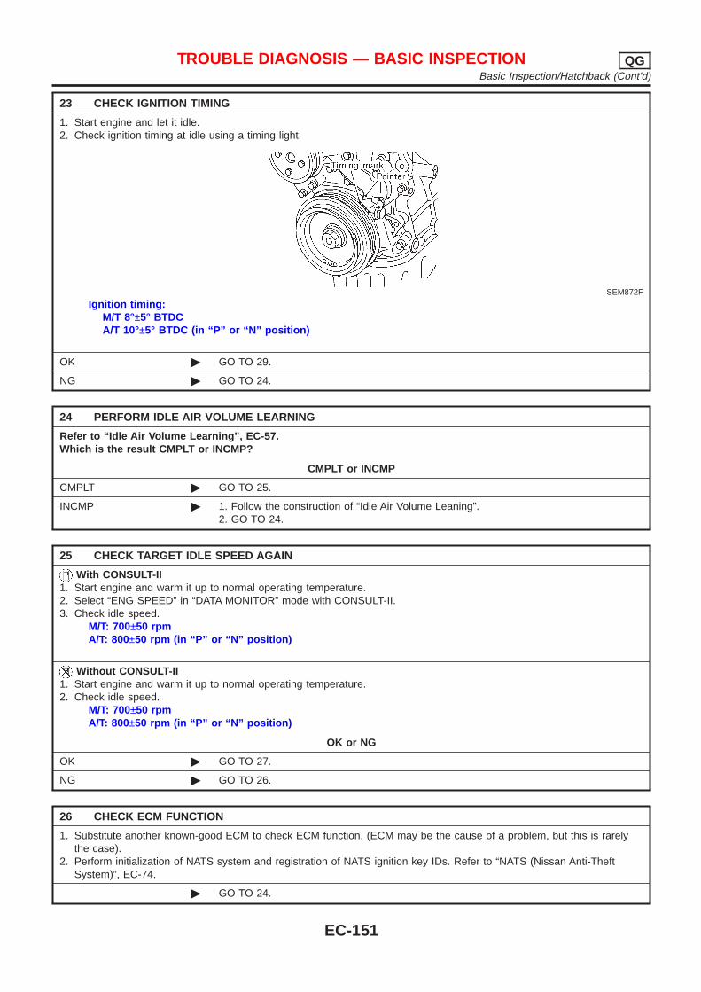
23 CHECK IGNITION TIMING
1. Start engine and let it idle.2. Check ignition timing at idle using a timing light.
SEM872F
Ignition timing:M/T 8°±5° BTDCA/T 10°±5° BTDC (in “P” or “N” position)
OK © GO TO 29.
NG © GO TO 24.
24 PERFORM IDLE AIR VOLUME LEARNING
Refer to “Idle Air Volume Learning”, EC-57.Which is the result CMPLT or INCMP?
CMPLT or INCMP
CMPLT © GO TO 25.
INCMP © 1. Follow the construction of “Idle Air Volume Leaning”.2. GO TO 24.
25 CHECK TARGET IDLE SPEED AGAIN
With CONSULT-II1. Start engine and warm it up to normal operating temperature.2. Select “ENG SPEED” in “DATA MONITOR” mode with CONSULT-II.3. Check idle speed.
M/T: 700±50 rpmA/T: 800±50 rpm (in “P” or “N” position)
Without CONSULT-II1. Start engine and warm it up to normal operating temperature.2. Check idle speed.
M/T: 700±50 rpmA/T: 800±50 rpm (in “P” or “N” position)
OK or NG
OK © GO TO 27.
NG © GO TO 26.
26 CHECK ECM FUNCTION
1. Substitute another known-good ECM to check ECM function. (ECM may be the cause of a problem, but this is rarelythe case).
2. Perform initialization of NATS system and registration of NATS ignition key IDs. Refer to “NATS (Nissan Anti-TheftSystem)”, EC-74.
© GO TO 24.
TROUBLE DIAGNOSIS — BASIC INSPECTION QGBasic Inspection/Hatchback (Cont’d)
EC-151
27 CHECK IGNITION TIMING AGAIN
Check ignition timing again. Refer to Test No. 23.
OK © GO TO 29.
NG © GO TO 28.
28 CHECK TIMING CHAIN INSTALLATION
Check timing chain installation. Refer to EM section.
OK or NG
OK © GO TO 26.
NG © 1. Repair the timing chain installation.2. GO TO 24.
29 ERASE UNNECESSARY DTC
After this inspection, unnecessary DTC No. might be displayed.Erase the stored memory in ECM.Refer to “HOW TO ERASE EMISSION-RELATED DIAGNOSTIC INFORMATION”, EC-70.
© INSPECTION END
TROUBLE DIAGNOSIS — BASIC INSPECTION QGBasic Inspection/Hatchback (Cont’d)
EC-152
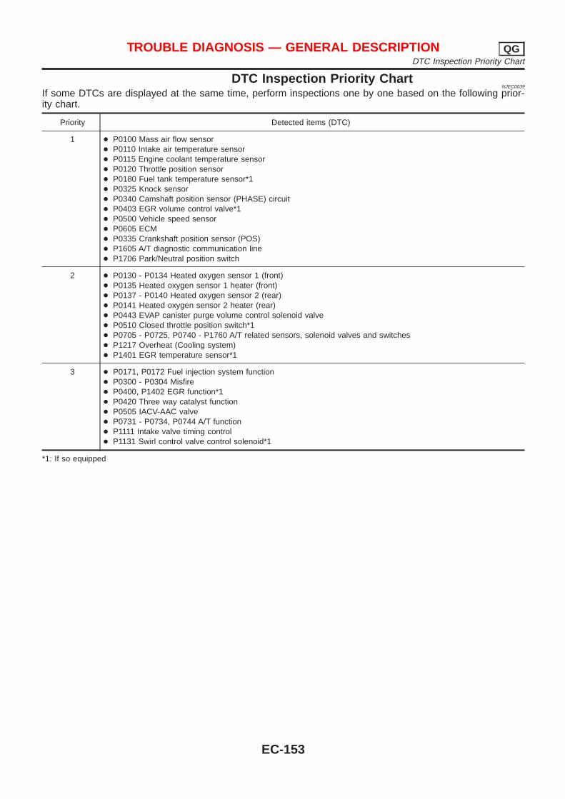
DTC Inspection Priority ChartNJEC0039
If some DTCs are displayed at the same time, perform inspections one by one based on the following prior-ity chart.
Priority Detected items (DTC)
1 + P0100 Mass air flow sensor+ P0110 Intake air temperature sensor+ P0115 Engine coolant temperature sensor+ P0120 Throttle position sensor+ P0180 Fuel tank temperature sensor*1+ P0325 Knock sensor+ P0340 Camshaft position sensor (PHASE) circuit+ P0403 EGR volume control valve*1+ P0500 Vehicle speed sensor+ P0605 ECM+ P0335 Crankshaft position sensor (POS)+ P1605 A/T diagnostic communication line+ P1706 Park/Neutral position switch
2 + P0130 - P0134 Heated oxygen sensor 1 (front)+ P0135 Heated oxygen sensor 1 heater (front)+ P0137 - P0140 Heated oxygen sensor 2 (rear)+ P0141 Heated oxygen sensor 2 heater (rear)+ P0443 EVAP canister purge volume control solenoid valve+ P0510 Closed throttle position switch*1+ P0705 - P0725, P0740 - P1760 A/T related sensors, solenoid valves and switches+ P1217 Overheat (Cooling system)+ P1401 EGR temperature sensor*1
3 + P0171, P0172 Fuel injection system function+ P0300 - P0304 Misfire+ P0400, P1402 EGR function*1+ P0420 Three way catalyst function+ P0505 IACV-AAC valve+ P0731 - P0734, P0744 A/T function+ P1111 Intake valve timing control+ P1131 Swirl control valve control solenoid*1
*1: If so equipped
TROUBLE DIAGNOSIS — GENERAL DESCRIPTION QGDTC Inspection Priority Chart
EC-153
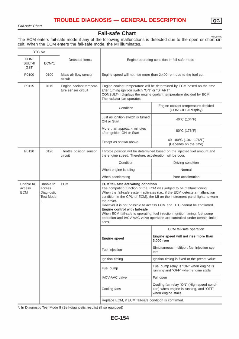
Fail-safe Chart=NJEC0040
The ECM enters fail-safe mode if any of the following malfunctions is detected due to the open or short cir-cuit. When the ECM enters the fail-safe mode, the MI illuminates.
DTC No.
Detected items Engine operating condition in fail-safe modeCON-SULT-II
GSTECM*1
P0100 0100 Mass air flow sensorcircuit
Engine speed will not rise more than 2,400 rpm due to the fuel cut.
P0115 0115 Engine coolant tempera-ture sensor circuit
Engine coolant temperature will be determined by ECM based on the timeafter turning ignition switch “ON” or “START”.CONSULT-II displays the engine coolant temperature decided by ECM.The radiator fan operates.
ConditionEngine coolant temperature decided
(CONSULT-II display)
Just as ignition switch is turnedON or Start
40°C (104°F)
More than approx. 4 minutesafter ignition ON or Start
80°C (176°F)
Except as shown above40 - 80°C (104 - 176°F)(Depends on the time)
P0120 0120 Throttle position sensorcircuit
Throttle position will be determined based on the injected fuel amount andthe engine speed. Therefore, acceleration will be poor.
Condition Driving condition
When engine is idling Normal
When accelerating Poor acceleration
Unable toaccessECM
Unable toaccessDiagnosticTest ModeII
ECM ECM fail-safe activating conditionThe computing function of the ECM was judged to be malfunctioning.When the fail-safe system activates (i.e., if the ECM detects a malfunctioncondition in the CPU of ECM), the MI on the instrument panel lights to warnthe driver.However it is not possible to access ECM and DTC cannot be confirmed.Engine control with fail-safeWhen ECM fail-safe is operating, fuel injection, ignition timing, fuel pumpoperation and IACV-AAC valve operation are controlled under certain limita-tions.
ECM fail-safe operation
Engine speedEngine speed will not rise more than3,000 rpm
Fuel injectionSimultaneous multiport fuel injection sys-tem
Ignition timing Ignition timing is fixed at the preset value
Fuel pumpFuel pump relay is “ON” when engine isrunning and “OFF” when engine stalls
IACV-AAC valve Full open
Cooling fansCooling fan relay “ON” (High speed condi-tion) when engine is running, and “OFF”when engine stalls.
Replace ECM, if ECM fail-safe condition is confirmed.
*: In Diagnostic Test Mode II (Self-diagnostic results) (If so equipped)
TROUBLE DIAGNOSIS — GENERAL DESCRIPTION QGFail-safe Chart
EC-154
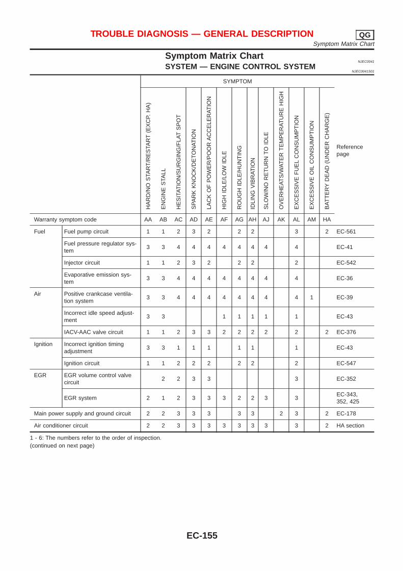
Symptom Matrix ChartNJEC0041
SYSTEM — ENGINE CONTROL SYSTEMNJEC0041S01
SYMPTOM
Referencepage
HA
RD
/NO
STA
RT
/RE
STA
RT
(EX
CP.
HA
)
EN
GIN
ES
TALL
HE
SIT
AT
ION
/SU
RG
ING
/FLA
TS
PO
T
SP
AR
KK
NO
CK
/DE
TO
NA
TIO
N
LAC
KO
FP
OW
ER
/PO
OR
AC
CE
LER
AT
ION
HIG
HID
LE/L
OW
IDLE
RO
UG
HID
LE/H
UN
TIN
G
IDLI
NG
VIB
RA
TIO
N
SLO
W/N
OR
ET
UR
NT
OID
LE
OV
ER
HE
AT
S/W
AT
ER
TE
MP
ER
AT
UR
EH
IGH
EX
CE
SS
IVE
FU
EL
CO
NS
UM
PT
ION
EX
CE
SS
IVE
OIL
CO
NS
UM
PT
ION
BA
TT
ER
YD
EA
D(U
ND
ER
CH
AR
GE
)
Warranty symptom code AA AB AC AD AE AF AG AH AJ AK AL AM HA
Fuel Fuel pump circuit 1 1 2 3 2 2 2 3 2 EC-561
Fuel pressure regulator sys-tem
3 3 4 4 4 4 4 4 4 4 EC-41
Injector circuit 1 1 2 3 2 2 2 2 EC-542
Evaporative emission sys-tem
3 3 4 4 4 4 4 4 4 4 EC-36
Air Positive crankcase ventila-tion system
3 3 4 4 4 4 4 4 4 4 1 EC-39
Incorrect idle speed adjust-ment
3 3 1 1 1 1 1 EC-43
IACV-AAC valve circuit 1 1 2 3 3 2 2 2 2 2 2 EC-376
Ignition Incorrect ignition timingadjustment
3 3 1 1 1 1 1 1 EC-43
Ignition circuit 1 1 2 2 2 2 2 2 EC-547
EGR EGR volume control valvecircuit
2 2 3 3 3 EC-352
EGR system 2 1 2 3 3 3 2 2 3 3EC-343,352, 425
Main power supply and ground circuit 2 2 3 3 3 3 3 2 3 2 EC-178
Air conditioner circuit 2 2 3 3 3 3 3 3 3 3 2 HA section
1 - 6: The numbers refer to the order of inspection.(continued on next page)
TROUBLE DIAGNOSIS — GENERAL DESCRIPTION QGSymptom Matrix Chart
EC-155
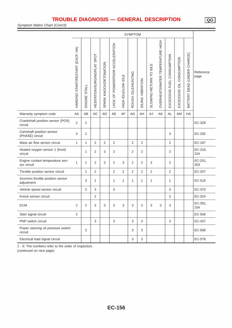
SYMPTOM
Referencepage
HA
RD
/NO
STA
RT
/RE
STA
RT
(EX
CP.
HA
)
EN
GIN
ES
TALL
HE
SIT
AT
ION
/SU
RG
ING
/FLA
TS
PO
T
SP
AR
KK
NO
CK
/DE
TO
NA
TIO
N
LAC
KO
FP
OW
ER
/PO
OR
AC
CE
LER
AT
ION
HIG
HID
LE/L
OW
IDLE
RO
UG
HID
LE/H
UN
TIN
G
IDLI
NG
VIB
RA
TIO
N
SLO
W/N
OR
ET
UR
NT
OID
LE
OV
ER
HE
AT
S/W
AT
ER
TE
MP
ER
AT
UR
EH
IGH
EX
CE
SS
IVE
FU
EL
CO
NS
UM
PT
ION
EX
CE
SS
IVE
OIL
CO
NS
UM
PT
ION
BA
TT
ER
YD
EA
D(U
ND
ER
CH
AR
GE
)
Warranty symptom code AA AB AC AD AE AF AG AH AJ AK AL AM HA
Crankshaft position sensor (POS)circuit
2 2 EC-328
Camshaft position sensor(PHASE) circuit
3 2 3 EC-335
Mass air flow sensor circuit 1 1 2 2 2 2 2 2 EC-187
Heated oxygen sensor 1 (front)circuit
1 2 3 2 2 2 2EC-216,224
Engine coolant temperature sen-sor circuit
1 1 2 3 2 3 2 2 3 2EC-201,203
Throttle position sensor circuit 1 2 2 2 2 2 2 2 EC-207
Incorrect throttle position sensoradjustment
3 1 1 1 1 1 1 1 EC-519
Vehicle speed sensor circuit 2 3 3 3 EC-370
Knock sensor circuit 2 3 EC-324
ECM 2 2 3 3 3 3 3 3 3 3 3EC-391,154
Start signal circuit 2 EC-558
PNP switch circuit 3 3 3 3 3 EC-437
Power steering oil pressure switchcircuit
2 3 3 EC-568
Electrical load signal circuit 3 3 EC-578
1 - 6: The numbers refer to the order of inspection.(continued on next page)
TROUBLE DIAGNOSIS — GENERAL DESCRIPTION QGSymptom Matrix Chart (Cont’d)
EC-156
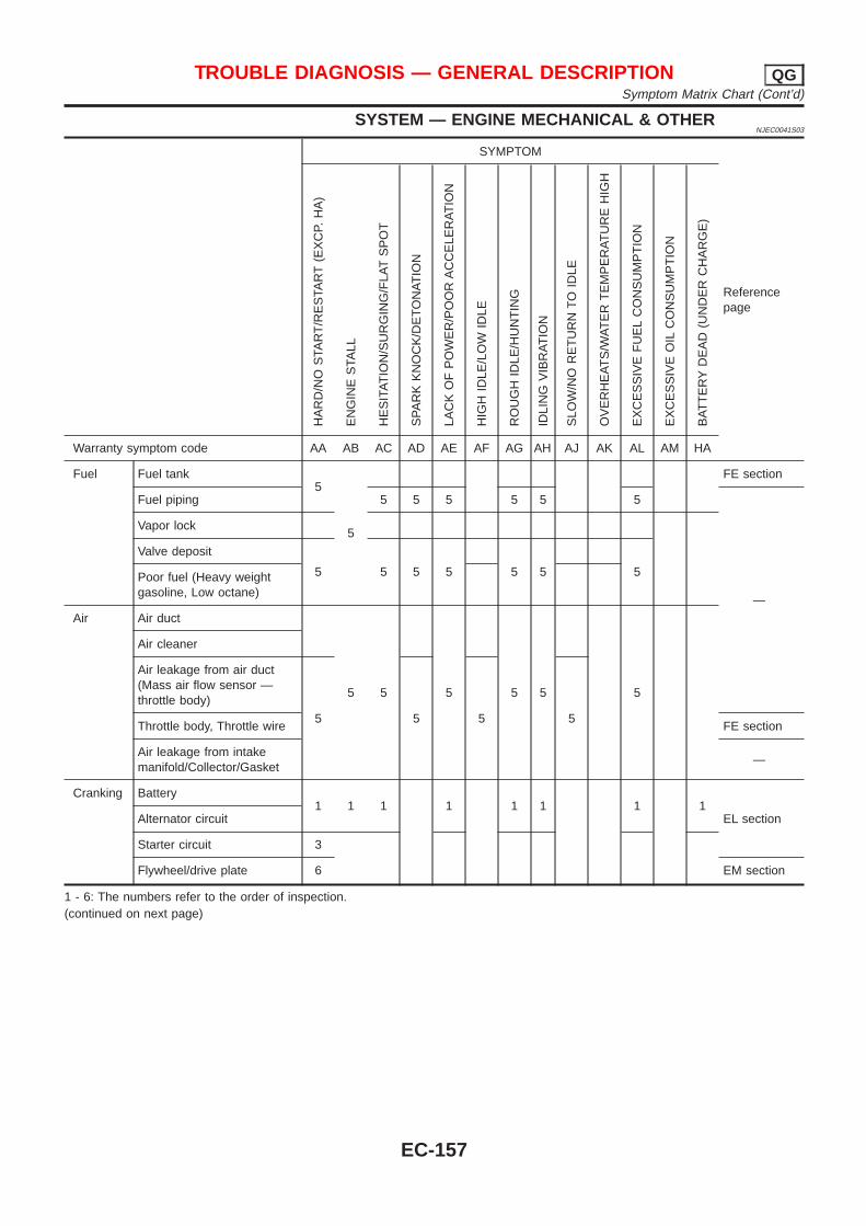
SYSTEM — ENGINE MECHANICAL & OTHERNJEC0041S03
SYMPTOM
Referencepage
HA
RD
/NO
STA
RT
/RE
STA
RT
(EX
CP.
HA
)
EN
GIN
ES
TALL
HE
SIT
AT
ION
/SU
RG
ING
/FLA
TS
PO
T
SP
AR
KK
NO
CK
/DE
TO
NA
TIO
N
LAC
KO
FP
OW
ER
/PO
OR
AC
CE
LER
AT
ION
HIG
HID
LE/L
OW
IDLE
RO
UG
HID
LE/H
UN
TIN
G
IDLI
NG
VIB
RA
TIO
N
SLO
W/N
OR
ET
UR
NT
OID
LE
OV
ER
HE
AT
S/W
AT
ER
TE
MP
ER
AT
UR
EH
IGH
EX
CE
SS
IVE
FU
EL
CO
NS
UM
PT
ION
EX
CE
SS
IVE
OIL
CO
NS
UM
PT
ION
BA
TT
ER
YD
EA
D(U
ND
ER
CH
AR
GE
)
Warranty symptom code AA AB AC AD AE AF AG AH AJ AK AL AM HA
Fuel Fuel tank5
5
FE section
Fuel piping 5 5 5 5 5 5
—
Vapor lock
Valve deposit
5 5 5 5 5 5 5Poor fuel (Heavy weightgasoline, Low octane)
Air Air duct
5 5 5 5 5 5
Air cleaner
Air leakage from air duct(Mass air flow sensor —throttle body)
5 5 5 5Throttle body, Throttle wire FE section
Air leakage from intakemanifold/Collector/Gasket
—
Cranking Battery1 1 1 1 1 1 1 1
EL sectionAlternator circuit
Starter circuit 3
Flywheel/drive plate 6 EM section
1 - 6: The numbers refer to the order of inspection.(continued on next page)
TROUBLE DIAGNOSIS — GENERAL DESCRIPTION QGSymptom Matrix Chart (Cont’d)
EC-157
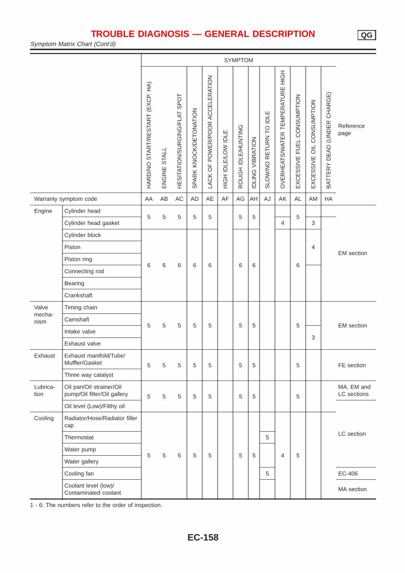
SYMPTOM
Referencepage
HA
RD
/NO
STA
RT
/RE
STA
RT
(EX
CP.
HA
)
EN
GIN
ES
TALL
HE
SIT
AT
ION
/SU
RG
ING
/FLA
TS
PO
T
SP
AR
KK
NO
CK
/DE
TO
NA
TIO
N
LAC
KO
FP
OW
ER
/PO
OR
AC
CE
LER
AT
ION
HIG
HID
LE/L
OW
IDLE
RO
UG
HID
LE/H
UN
TIN
G
IDLI
NG
VIB
RA
TIO
N
SLO
W/N
OR
ET
UR
NT
OID
LE
OV
ER
HE
AT
S/W
AT
ER
TE
MP
ER
AT
UR
EH
IGH
EX
CE
SS
IVE
FU
EL
CO
NS
UM
PT
ION
EX
CE
SS
IVE
OIL
CO
NS
UM
PT
ION
BA
TT
ER
YD
EA
D(U
ND
ER
CH
AR
GE
)
Warranty symptom code AA AB AC AD AE AF AG AH AJ AK AL AM HA
Engine Cylinder head5 5 5 5 5 5 5 5
EM section
Cylinder head gasket 4 3
Cylinder block
6 6 6 6 6 6 6 6
4Piston
Piston ring
Connecting rod
Bearing
Crankshaft
Valvemecha-nism
Timing chain
5 5 5 5 5 5 5 5 EM sectionCamshaft
Intake valve3
Exhaust valve
Exhaust Exhaust manifold/Tube/Muffler/Gasket 5 5 5 5 5 5 5 5 FE section
Three way catalyst
Lubrica-tion
Oil pan/Oil strainer/Oilpump/Oil filter/Oil gallery 5 5 5 5 5 5 5 5
MA, EM andLC sections
Oil level (Low)/Filthy oil
LC section
Cooling Radiator/Hose/Radiator fillercap
5 5 5 5 5 5 5 4 5
Thermostat 5
Water pump
Water gallery
Cooling fan 5 EC-406
Coolant level (low)/Contaminated coolant
MA section
1 - 6: The numbers refer to the order of inspection.
TROUBLE DIAGNOSIS — GENERAL DESCRIPTION QGSymptom Matrix Chart (Cont’d)
EC-158
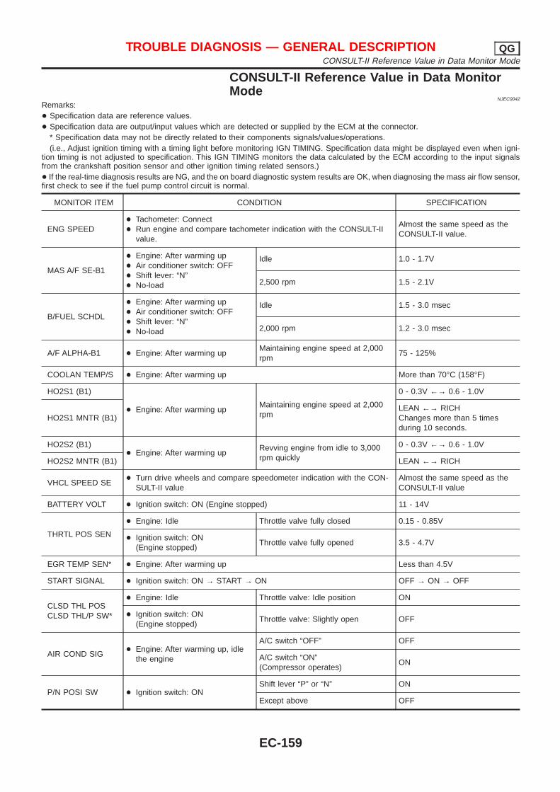
CONSULT-II Reference Value in Data MonitorMode
NJEC0042
Remarks:+ Specification data are reference values.+ Specification data are output/input values which are detected or supplied by the ECM at the connector.
* Specification data may not be directly related to their components signals/values/operations.(i.e., Adjust ignition timing with a timing light before monitoring IGN TIMING. Specification data might be displayed even when igni-
tion timing is not adjusted to specification. This IGN TIMING monitors the data calculated by the ECM according to the input signalsfrom the crankshaft position sensor and other ignition timing related sensors.)+ If the real-time diagnosis results are NG, and the on board diagnostic system results are OK, when diagnosing the mass air flow sensor,first check to see if the fuel pump control circuit is normal.
MONITOR ITEM CONDITION SPECIFICATION
ENG SPEED+ Tachometer: Connect+ Run engine and compare tachometer indication with the CONSULT-II
value.
Almost the same speed as theCONSULT-II value.
MAS A/F SE-B1
+ Engine: After warming up+ Air conditioner switch: OFF+ Shift lever: “N”+ No-load
Idle 1.0 - 1.7V
2,500 rpm 1.5 - 2.1V
B/FUEL SCHDL
+ Engine: After warming up+ Air conditioner switch: OFF+ Shift lever: “N”+ No-load
Idle 1.5 - 3.0 msec
2,000 rpm 1.2 - 3.0 msec
A/F ALPHA-B1 + Engine: After warming upMaintaining engine speed at 2,000rpm
75 - 125%
COOLAN TEMP/S + Engine: After warming up More than 70°C (158°F)
HO2S1 (B1)
+ Engine: After warming upMaintaining engine speed at 2,000rpm
0 - 0.3V ←→ 0.6 - 1.0V
HO2S1 MNTR (B1)LEAN ←→ RICHChanges more than 5 timesduring 10 seconds.
HO2S2 (B1)+ Engine: After warming up
Revving engine from idle to 3,000rpm quickly
0 - 0.3V ←→ 0.6 - 1.0V
HO2S2 MNTR (B1) LEAN ←→ RICH
VHCL SPEED SE+ Turn drive wheels and compare speedometer indication with the CON-
SULT-II valueAlmost the same speed as theCONSULT-II value
BATTERY VOLT + Ignition switch: ON (Engine stopped) 11 - 14V
THRTL POS SEN
+ Engine: Idle Throttle valve fully closed 0.15 - 0.85V
+ Ignition switch: ON(Engine stopped)
Throttle valve fully opened 3.5 - 4.7V
EGR TEMP SEN* + Engine: After warming up Less than 4.5V
START SIGNAL + Ignition switch: ON → START → ON OFF → ON → OFF
CLSD THL POSCLSD THL/P SW*
+ Engine: Idle Throttle valve: Idle position ON
+ Ignition switch: ON(Engine stopped)
Throttle valve: Slightly open OFF
AIR COND SIG+ Engine: After warming up, idle
the engine
A/C switch “OFF” OFF
A/C switch “ON”(Compressor operates)
ON
P/N POSI SW + Ignition switch: ONShift lever “P” or “N” ON
Except above OFF
TROUBLE DIAGNOSIS — GENERAL DESCRIPTION QGCONSULT-II Reference Value in Data Monitor Mode
EC-159
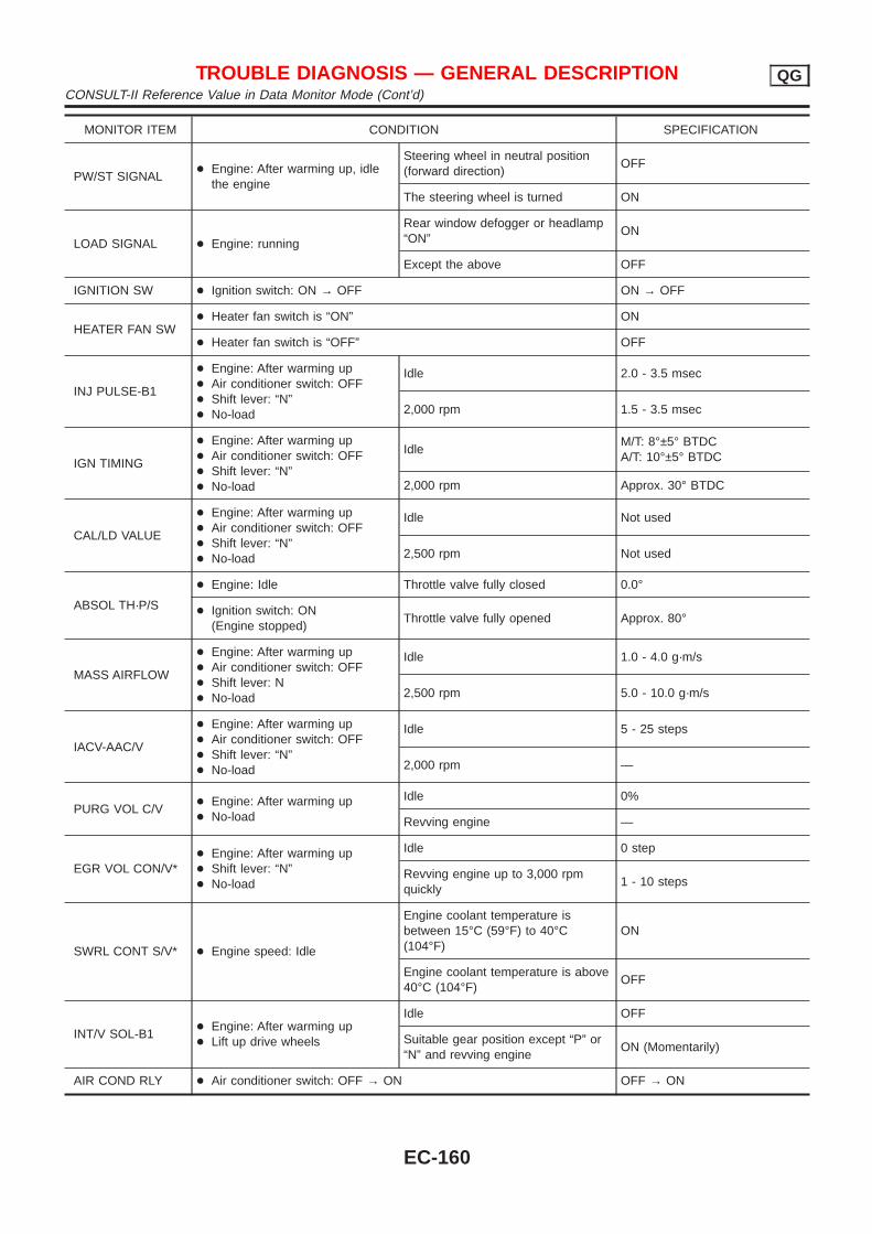
MONITOR ITEM CONDITION SPECIFICATION
PW/ST SIGNAL+ Engine: After warming up, idle
the engine
Steering wheel in neutral position(forward direction)
OFF
The steering wheel is turned ON
LOAD SIGNAL + Engine: running
Rear window defogger or headlamp“ON”
ON
Except the above OFF
IGNITION SW + Ignition switch: ON → OFF ON → OFF
HEATER FAN SW+ Heater fan switch is “ON” ON
+ Heater fan switch is “OFF” OFF
INJ PULSE-B1
+ Engine: After warming up+ Air conditioner switch: OFF+ Shift lever: “N”+ No-load
Idle 2.0 - 3.5 msec
2,000 rpm 1.5 - 3.5 msec
IGN TIMING
+ Engine: After warming up+ Air conditioner switch: OFF+ Shift lever: “N”+ No-load
IdleM/T: 8°±5° BTDCA/T: 10°±5° BTDC
2,000 rpm Approx. 30° BTDC
CAL/LD VALUE
+ Engine: After warming up+ Air conditioner switch: OFF+ Shift lever: “N”+ No-load
Idle Not used
2,500 rpm Not used
ABSOL TH·P/S
+ Engine: Idle Throttle valve fully closed 0.0°
+ Ignition switch: ON(Engine stopped)
Throttle valve fully opened Approx. 80°
MASS AIRFLOW
+ Engine: After warming up+ Air conditioner switch: OFF+ Shift lever: N+ No-load
Idle 1.0 - 4.0 g·m/s
2,500 rpm 5.0 - 10.0 g·m/s
IACV-AAC/V
+ Engine: After warming up+ Air conditioner switch: OFF+ Shift lever: “N”+ No-load
Idle 5 - 25 steps
2,000 rpm —
PURG VOL C/V+ Engine: After warming up+ No-load
Idle 0%
Revving engine —
EGR VOL CON/V*+ Engine: After warming up+ Shift lever: “N”+ No-load
Idle 0 step
Revving engine up to 3,000 rpmquickly
1 - 10 steps
SWRL CONT S/V* + Engine speed: Idle
Engine coolant temperature isbetween 15°C (59°F) to 40°C(104°F)
ON
Engine coolant temperature is above40°C (104°F)
OFF
INT/V SOL-B1+ Engine: After warming up+ Lift up drive wheels
Idle OFF
Suitable gear position except “P” or“N” and revving engine
ON (Momentarily)
AIR COND RLY + Air conditioner switch: OFF → ON OFF → ON
TROUBLE DIAGNOSIS — GENERAL DESCRIPTION QGCONSULT-II Reference Value in Data Monitor Mode (Cont’d)
EC-160
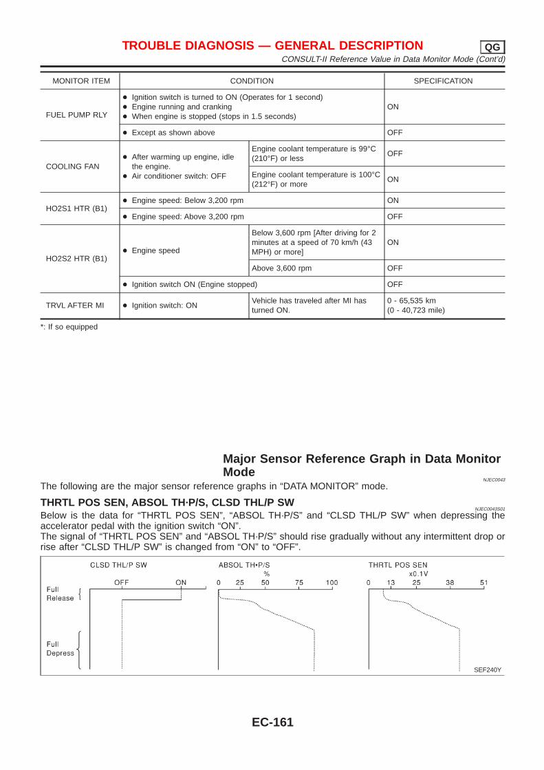
MONITOR ITEM CONDITION SPECIFICATION
FUEL PUMP RLY
+ Ignition switch is turned to ON (Operates for 1 second)+ Engine running and cranking+ When engine is stopped (stops in 1.5 seconds)
ON
+ Except as shown above OFF
COOLING FAN+ After warming up engine, idle
the engine.+ Air conditioner switch: OFF
Engine coolant temperature is 99°C(210°F) or less
OFF
Engine coolant temperature is 100°C(212°F) or more
ON
HO2S1 HTR (B1)+ Engine speed: Below 3,200 rpm ON
+ Engine speed: Above 3,200 rpm OFF
HO2S2 HTR (B1)+ Engine speed
Below 3,600 rpm [After driving for 2minutes at a speed of 70 km/h (43MPH) or more]
ON
Above 3,600 rpm OFF
+ Ignition switch ON (Engine stopped) OFF
TRVL AFTER MI + Ignition switch: ONVehicle has traveled after MI hasturned ON.
0 - 65,535 km(0 - 40,723 mile)
*: If so equipped
Major Sensor Reference Graph in Data MonitorMode
NJEC0043
The following are the major sensor reference graphs in “DATA MONITOR” mode.
THRTL POS SEN, ABSOL TH·P/S, CLSD THL/P SWNJEC0043S01
Below is the data for “THRTL POS SEN”, “ABSOL TH·P/S” and “CLSD THL/P SW” when depressing theaccelerator pedal with the ignition switch “ON”.The signal of “THRTL POS SEN” and “ABSOL TH·P/S” should rise gradually without any intermittent drop orrise after “CLSD THL/P SW” is changed from “ON” to “OFF”.
SEF240Y
TROUBLE DIAGNOSIS — GENERAL DESCRIPTION QGCONSULT-II Reference Value in Data Monitor Mode (Cont’d)
EC-161
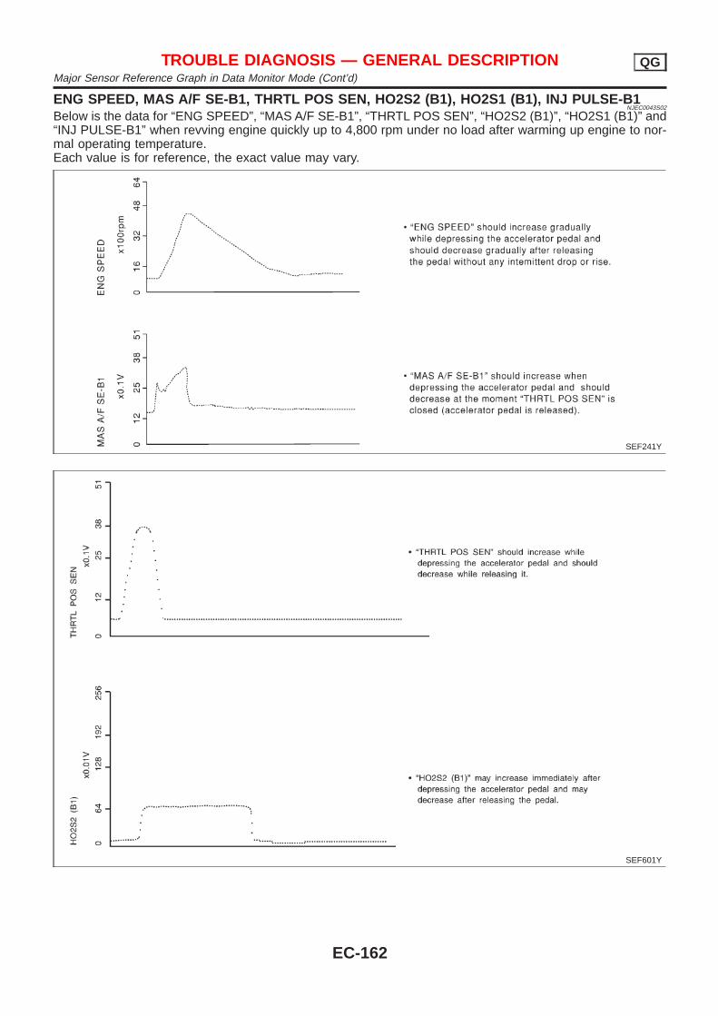
ENG SPEED, MAS A/F SE-B1, THRTL POS SEN, HO2S2 (B1), HO2S1 (B1), INJ PULSE-B1NJEC0043S02
Below is the data for “ENG SPEED”, “MAS A/F SE-B1”, “THRTL POS SEN”, “HO2S2 (B1)”, “HO2S1 (B1)” and“INJ PULSE-B1” when revving engine quickly up to 4,800 rpm under no load after warming up engine to nor-mal operating temperature.Each value is for reference, the exact value may vary.
SEF241Y
SEF601Y
TROUBLE DIAGNOSIS — GENERAL DESCRIPTION QGMajor Sensor Reference Graph in Data Monitor Mode (Cont’d)
EC-162
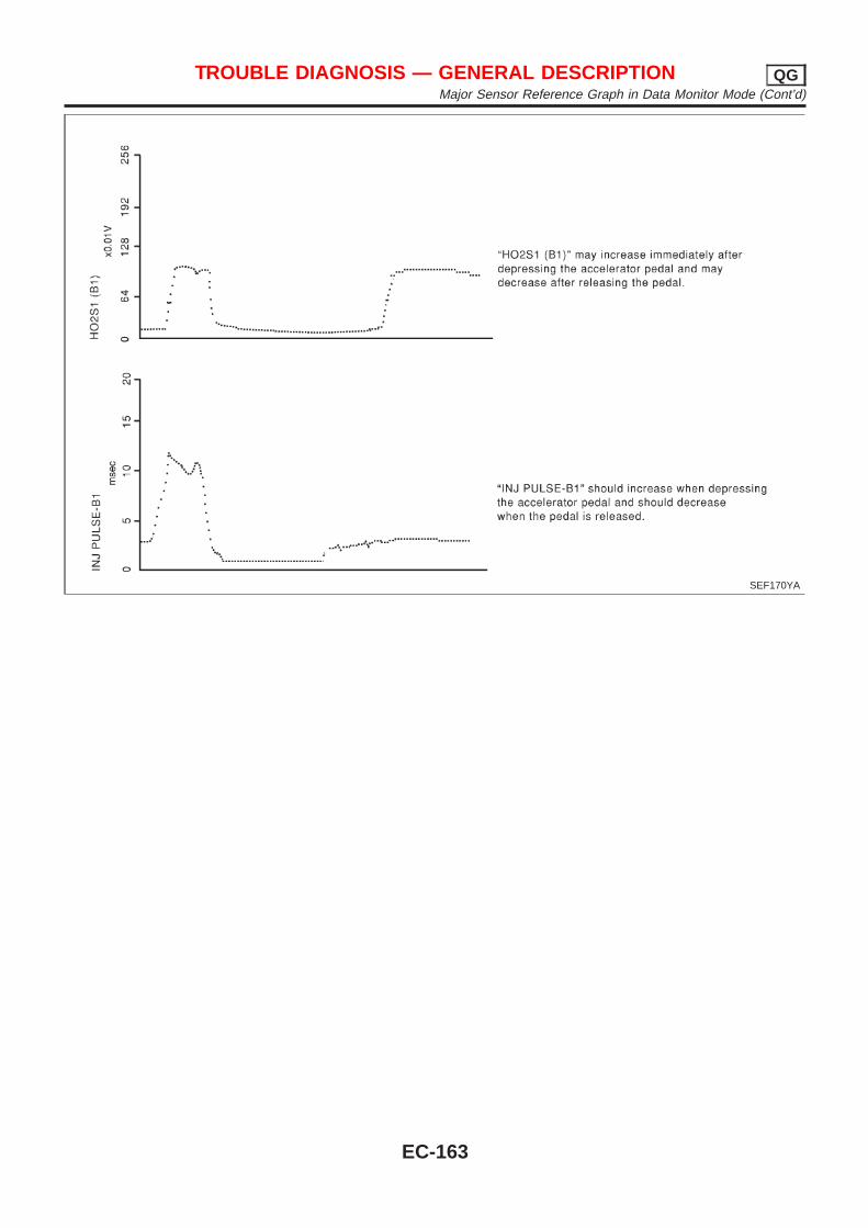
SEF170YA
TROUBLE DIAGNOSIS — GENERAL DESCRIPTION QGMajor Sensor Reference Graph in Data Monitor Mode (Cont’d)
EC-163
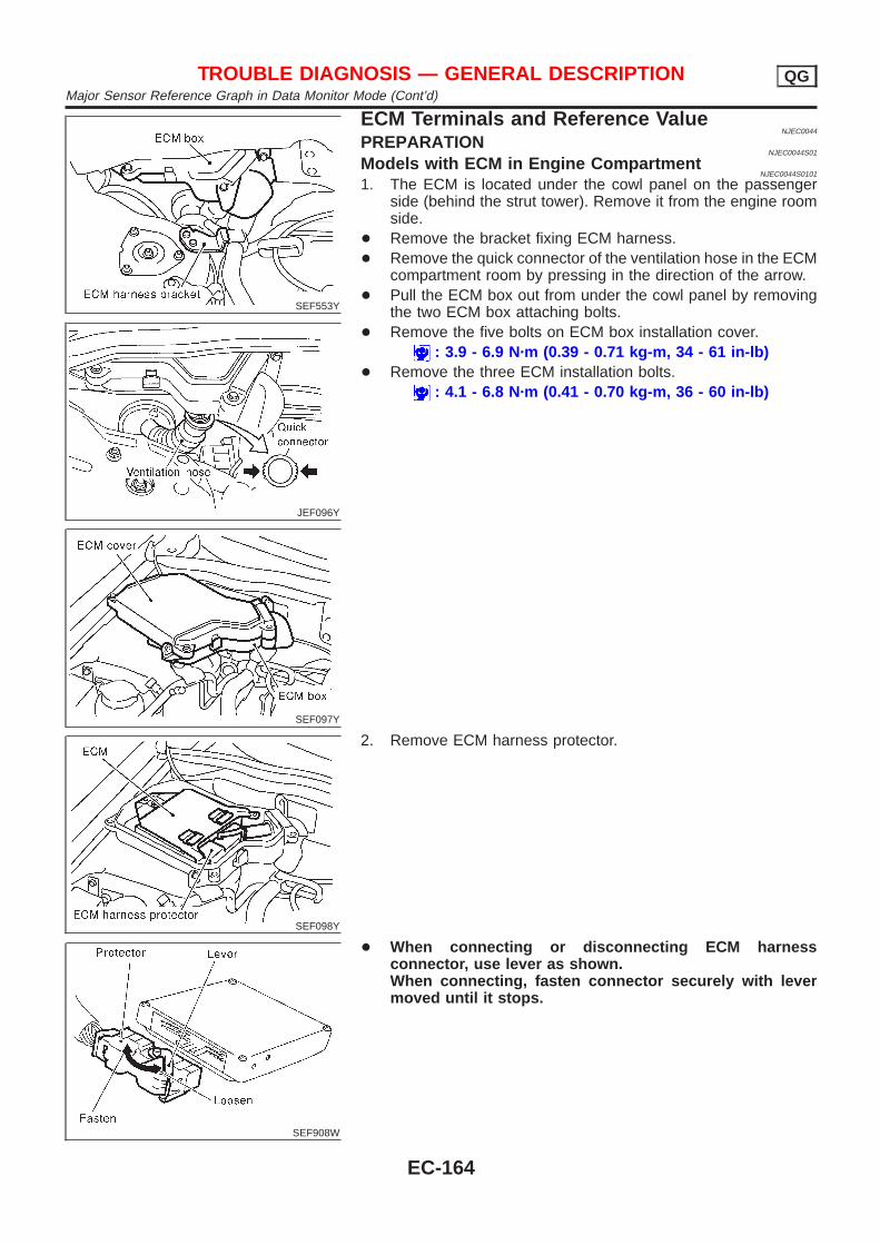
SEF553Y
JEF096Y
SEF097Y
ECM Terminals and Reference ValueNJEC0044
PREPARATIONNJEC0044S01
Models with ECM in Engine CompartmentNJEC0044S0101
1. The ECM is located under the cowl panel on the passengerside (behind the strut tower). Remove it from the engine roomside.
+ Remove the bracket fixing ECM harness.+ Remove the quick connector of the ventilation hose in the ECM
compartment room by pressing in the direction of the arrow.+ Pull the ECM box out from under the cowl panel by removing
the two ECM box attaching bolts.+ Remove the five bolts on ECM box installation cover.
: 3.9 - 6.9 N·m (0.39 - 0.71 kg-m, 34 - 61 in-lb)+ Remove the three ECM installation bolts.
: 4.1 - 6.8 N·m (0.41 - 0.70 kg-m, 36 - 60 in-lb)
SEF098Y
2. Remove ECM harness protector.
SEF908W
+ When connecting or disconnecting ECM harnessconnector, use lever as shown.When connecting, fasten connector securely with levermoved until it stops.
TROUBLE DIAGNOSIS — GENERAL DESCRIPTION QGMajor Sensor Reference Graph in Data Monitor Mode (Cont’d)
EC-164
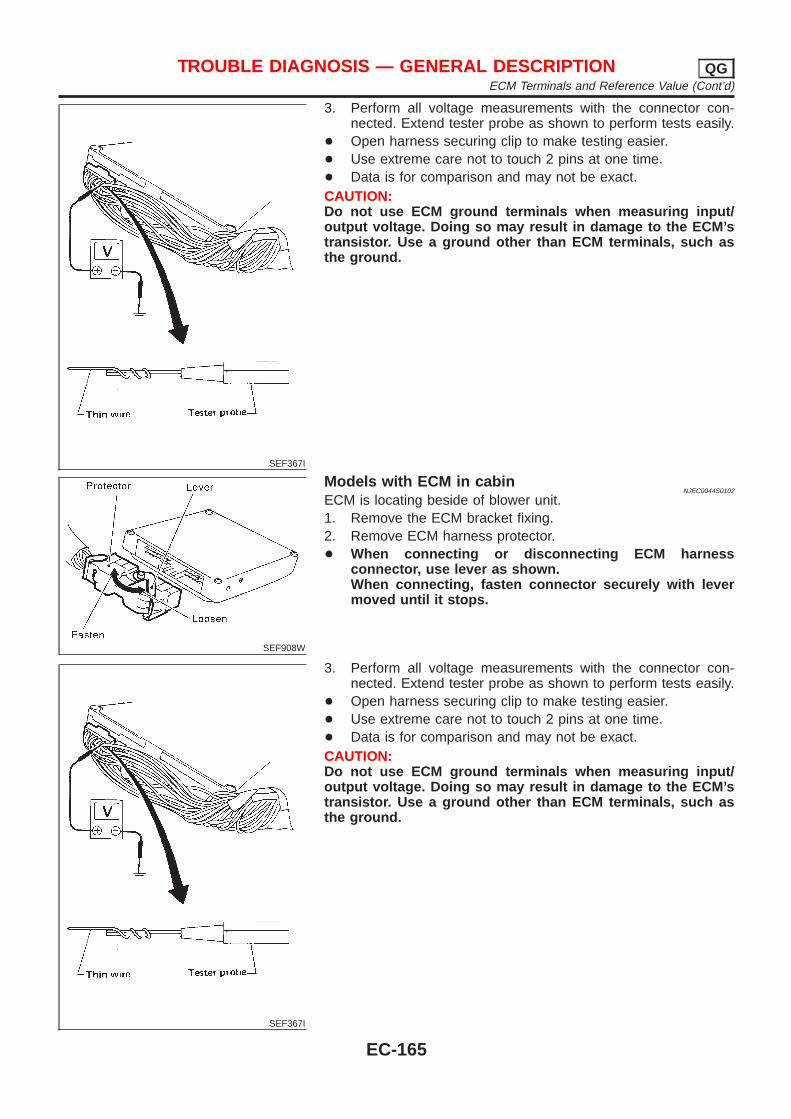
SEF367I
3. Perform all voltage measurements with the connector con-nected. Extend tester probe as shown to perform tests easily.
+ Open harness securing clip to make testing easier.+ Use extreme care not to touch 2 pins at one time.+ Data is for comparison and may not be exact.CAUTION:Do not use ECM ground terminals when measuring input/output voltage. Doing so may result in damage to the ECM’stransistor. Use a ground other than ECM terminals, such asthe ground.
SEF908W
Models with ECM in cabinNJEC0044S0102
ECM is locating beside of blower unit.1. Remove the ECM bracket fixing.2. Remove ECM harness protector.+ When connecting or disconnecting ECM harness
connector, use lever as shown.When connecting, fasten connector securely with levermoved until it stops.
SEF367I
3. Perform all voltage measurements with the connector con-nected. Extend tester probe as shown to perform tests easily.
+ Open harness securing clip to make testing easier.+ Use extreme care not to touch 2 pins at one time.+ Data is for comparison and may not be exact.CAUTION:Do not use ECM ground terminals when measuring input/output voltage. Doing so may result in damage to the ECM’stransistor. Use a ground other than ECM terminals, such asthe ground.
TROUBLE DIAGNOSIS — GENERAL DESCRIPTION QGECM Terminals and Reference Value (Cont’d)
EC-165
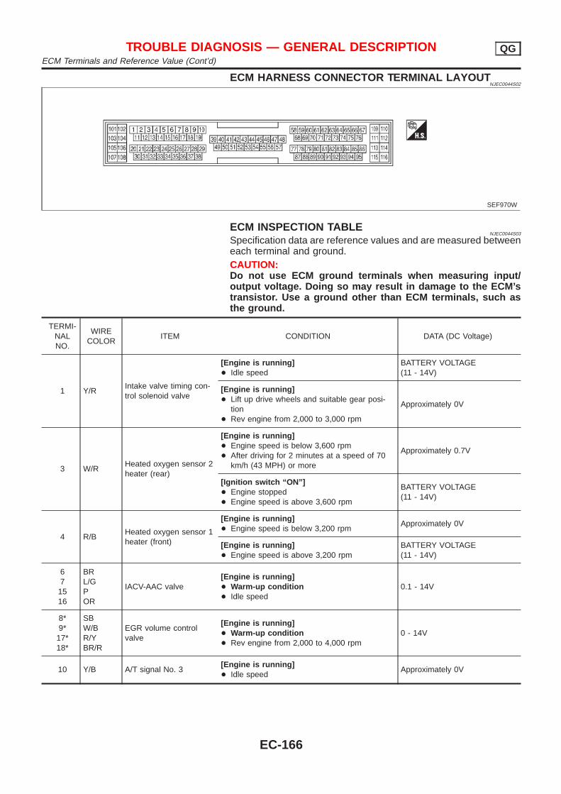
ECM HARNESS CONNECTOR TERMINAL LAYOUTNJEC0044S02
SEF970W
ECM INSPECTION TABLENJEC0044S03
Specification data are reference values and are measured betweeneach terminal and ground.CAUTION:Do not use ECM ground terminals when measuring input/output voltage. Doing so may result in damage to the ECM’stransistor. Use a ground other than ECM terminals, such asthe ground.
TERMI-NALNO.
WIRECOLOR
ITEM CONDITION DATA (DC Voltage)
1 Y/RIntake valve timing con-trol solenoid valve
[Engine is running]+ Idle speed
BATTERY VOLTAGE(11 - 14V)
[Engine is running]+ Lift up drive wheels and suitable gear posi-
tion+ Rev engine from 2,000 to 3,000 rpm
Approximately 0V
3 W/RHeated oxygen sensor 2heater (rear)
[Engine is running]+ Engine speed is below 3,600 rpm+ After driving for 2 minutes at a speed of 70
km/h (43 MPH) or more
Approximately 0.7V
[Ignition switch “ON”]+ Engine stopped+ Engine speed is above 3,600 rpm
BATTERY VOLTAGE(11 - 14V)
4 R/BHeated oxygen sensor 1heater (front)
[Engine is running]+ Engine speed is below 3,200 rpm
Approximately 0V
[Engine is running]+ Engine speed is above 3,200 rpm
BATTERY VOLTAGE(11 - 14V)
67
1516
BRL/GPOR
IACV-AAC valve[Engine is running]+ Warm-up condition+ Idle speed
0.1 - 14V
8*9*17*18*
SBW/BR/YBR/R
EGR volume controlvalve
[Engine is running]+ Warm-up condition+ Rev engine from 2,000 to 4,000 rpm
0 - 14V
10 Y/B A/T signal No. 3[Engine is running]+ Idle speed
Approximately 0V
TROUBLE DIAGNOSIS — GENERAL DESCRIPTION QGECM Terminals and Reference Value (Cont’d)
EC-166
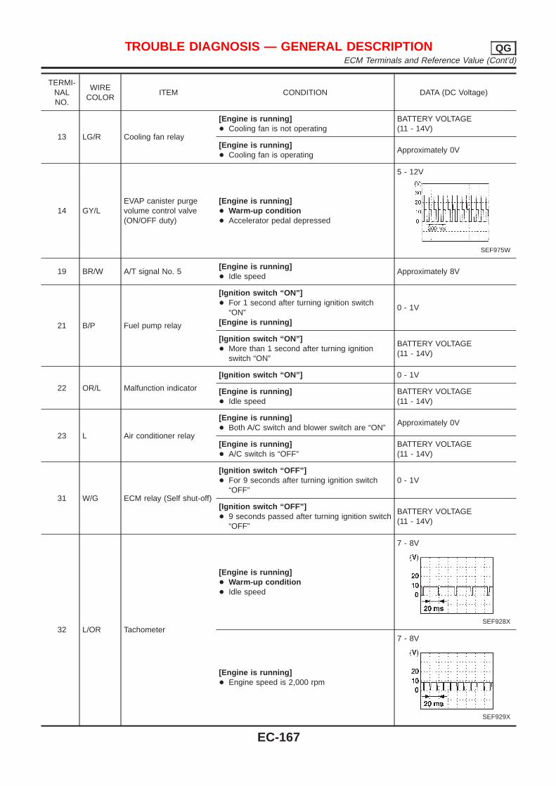
TERMI-NALNO.
WIRECOLOR
ITEM CONDITION DATA (DC Voltage)
13 LG/R Cooling fan relay
[Engine is running]+ Cooling fan is not operating
BATTERY VOLTAGE(11 - 14V)
[Engine is running]+ Cooling fan is operating
Approximately 0V
14 GY/LEVAP canister purgevolume control valve(ON/OFF duty)
[Engine is running]+ Warm-up condition+ Accelerator pedal depressed
5 - 12V
SEF975W
19 BR/W A/T signal No. 5[Engine is running]+ Idle speed
Approximately 8V
21 B/P Fuel pump relay
[Ignition switch “ON”]+ For 1 second after turning ignition switch
“ON”[Engine is running]
0 - 1V
[Ignition switch “ON”]+ More than 1 second after turning ignition
switch “ON”
BATTERY VOLTAGE(11 - 14V)
22 OR/L Malfunction indicator
[Ignition switch “ON”] 0 - 1V
[Engine is running]+ Idle speed
BATTERY VOLTAGE(11 - 14V)
23 L Air conditioner relay
[Engine is running]+ Both A/C switch and blower switch are “ON”
Approximately 0V
[Engine is running]+ A/C switch is “OFF”
BATTERY VOLTAGE(11 - 14V)
31 W/G ECM relay (Self shut-off)
[Ignition switch “OFF”]+ For 9 seconds after turning ignition switch
“OFF”0 - 1V
[Ignition switch “OFF”]+ 9 seconds passed after turning ignition switch
“OFF”
BATTERY VOLTAGE(11 - 14V)
32 L/OR Tachometer
[Engine is running]+ Warm-up condition+ Idle speed
7 - 8V
SEF928X
[Engine is running]+ Engine speed is 2,000 rpm
7 - 8V
SEF929X
TROUBLE DIAGNOSIS — GENERAL DESCRIPTION QGECM Terminals and Reference Value (Cont’d)
EC-167
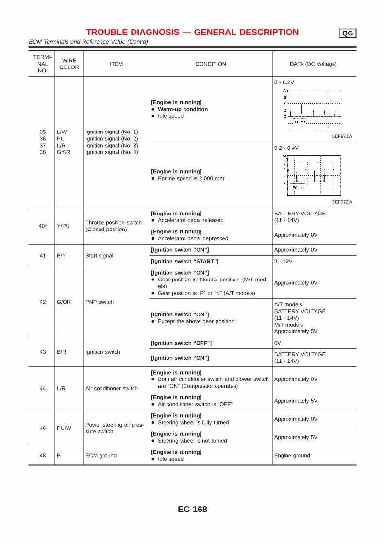
TERMI-NALNO.
WIRECOLOR
ITEM CONDITION DATA (DC Voltage)
35363738
L/WPUL/RGY/R
Ignition signal (No. 1)Ignition signal (No. 2)Ignition signal (No. 3)Ignition signal (No. 4)
[Engine is running]+ Warm-up condition+ Idle speed
0 - 0.2V
SEF971W
[Engine is running]+ Engine speed is 2,000 rpm
0.2 - 0.4V
SEF972W
40* Y/PUThrottle position switch(Closed position)
[Engine is running]+ Accelerator pedal released
BATTERY VOLTAGE(11 - 14V)
[Engine is running]+ Accelerator pedal depressed
Approximately 0V
41 B/Y Start signal[Ignition switch “ON”] Approximately 0V
[Ignition switch “START”] 9 - 12V
42 G/OR PNP switch
[Ignition switch “ON”]+ Gear position is “Neutral position” (M/T mod-
els)+ Gear position is “P” or “N” (A/T models)
Approximately 0V
[Ignition switch “ON”]+ Except the above gear position
A/T modelsBATTERY VOLTAGE(11 - 14V)M/T modelsApproximately 5V
43 B/R Ignition switch
[Ignition switch “OFF”] 0V
[Ignition switch “ON”]BATTERY VOLTAGE(11 - 14V)
44 L/R Air conditioner switch
[Engine is running]+ Both air conditioner switch and blower switch
are “ON” (Compressor operates)Approximately 0V
[Engine is running]+ Air conditioner switch is “OFF”
Approximately 5V
46 PU/WPower steering oil pres-sure switch
[Engine is running]+ Steering wheel is fully turned
Approximately 0V
[Engine is running]+ Steering wheel is not turned
Approximately 5V
48 B ECM ground[Engine is running]+ Idle speed
Engine ground
TROUBLE DIAGNOSIS — GENERAL DESCRIPTION QGECM Terminals and Reference Value (Cont’d)
EC-168

TERMI-NALNO.
WIRECOLOR
ITEM CONDITION DATA (DC Voltage)
50 L/BElectrical load signal(Headlamp andRear defogger)
[Engine is running]+ Headlamp switch or rear defogger switch is
“ON”
BATTERY VOLTAGE(11 - 14V)
[Engine is running]+ Headlamp switch and rear defogger switch
are “OFF”Approximately 0V
51 LG/B Blower fan SW
[Ignition switch “ON”]+ Blower fan switch is “ON”
Approximately 0V
[Ignition switch “ON”]+ Blower fan switch is “OFF”
Approximately 5V
54 Y/R A/T signal No. 1[Engine is running]+ Idle speed
Approximately 0V
55 Y/G A/T signal No. 2[Engine is running]+ Idle speed
Approximately 0V
56 G/Y A/T signal No. 4[Engine is running]+ Idle speed
Approximately 0V
57 B ECM ground[Engine is running]+ Idle speed
Engine ground
58 B Sensors’ ground[Engine is running]+ Warm-up condition+ Idle speed
Approximately 0V
61 G Mass air flow sensor
[Engine is running]+ Warm-up condition+ Idle speed
1.0 - 1.7V
[Engine is running]+ Warm-up condition+ Engine speed is 2,500 rpm
1.5 - 2.1V
62 WHeated oxygen sensor 1(front)
[Engine is running]+ Warm-up condition+ Engine speed is 2,000 rpm
0 - Approximately 0.7V
SEF008W
63 LHeated oxygen sensor 2(rear)
[Engine is running]+ After warming up to normal operating tem-
perature and engine speed is 3,000 rpm0 - Approximately 1.0V
64 Y/BIntake air temperaturesensor
[Engine is running]Approximately 0 - 4.8VOutput voltage varies withintake air temperature
TROUBLE DIAGNOSIS — GENERAL DESCRIPTION QGECM Terminals and Reference Value (Cont’d)
EC-169
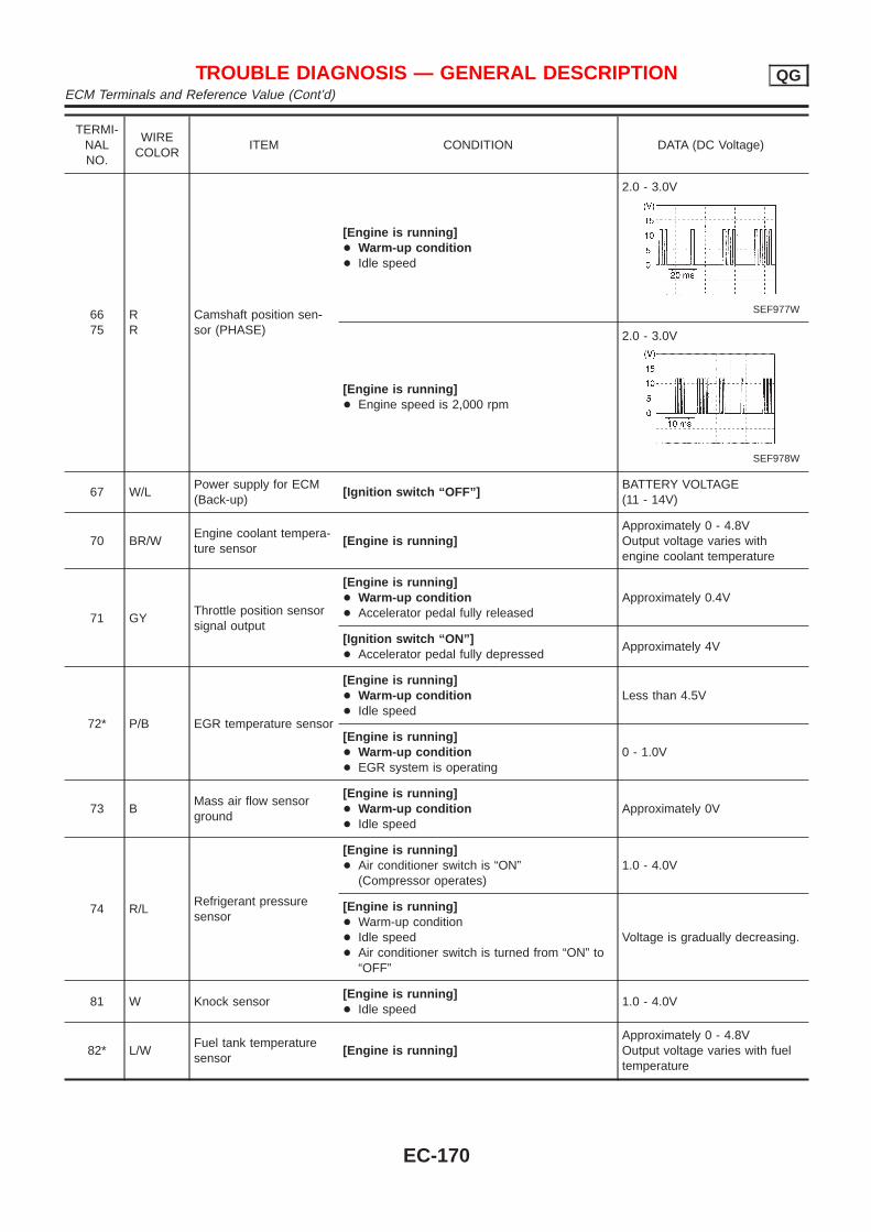
TERMI-NALNO.
WIRECOLOR
ITEM CONDITION DATA (DC Voltage)
6675
RR
Camshaft position sen-sor (PHASE)
[Engine is running]+ Warm-up condition+ Idle speed
2.0 - 3.0V
SEF977W
[Engine is running]+ Engine speed is 2,000 rpm
2.0 - 3.0V
SEF978W
67 W/LPower supply for ECM(Back-up)
[Ignition switch “OFF”]BATTERY VOLTAGE(11 - 14V)
70 BR/WEngine coolant tempera-ture sensor
[Engine is running]Approximately 0 - 4.8VOutput voltage varies withengine coolant temperature
71 GYThrottle position sensorsignal output
[Engine is running]+ Warm-up condition+ Accelerator pedal fully released
Approximately 0.4V
[Ignition switch “ON”]+ Accelerator pedal fully depressed
Approximately 4V
72* P/B EGR temperature sensor
[Engine is running]+ Warm-up condition+ Idle speed
Less than 4.5V
[Engine is running]+ Warm-up condition+ EGR system is operating
0 - 1.0V
73 BMass air flow sensorground
[Engine is running]+ Warm-up condition+ Idle speed
Approximately 0V
74 R/LRefrigerant pressuresensor
[Engine is running]+ Air conditioner switch is “ON”
(Compressor operates)1.0 - 4.0V
[Engine is running]+ Warm-up condition+ Idle speed+ Air conditioner switch is turned from “ON” to
“OFF”
Voltage is gradually decreasing.
81 W Knock sensor[Engine is running]+ Idle speed
1.0 - 4.0V
82* L/WFuel tank temperaturesensor
[Engine is running]Approximately 0 - 4.8VOutput voltage varies with fueltemperature
TROUBLE DIAGNOSIS — GENERAL DESCRIPTION QGECM Terminals and Reference Value (Cont’d)
EC-170
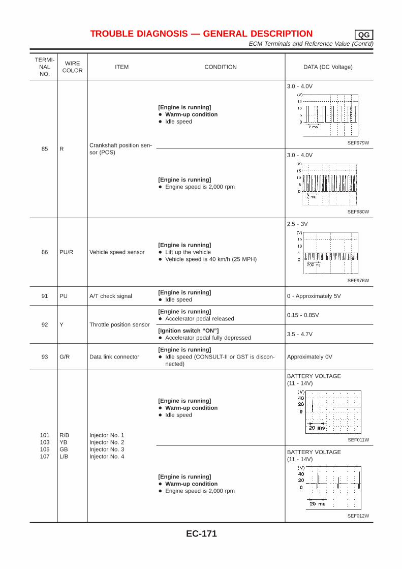
TERMI-NALNO.
WIRECOLOR
ITEM CONDITION DATA (DC Voltage)
85 RCrankshaft position sen-sor (POS)
[Engine is running]+ Warm-up condition+ Idle speed
3.0 - 4.0V
SEF979W
[Engine is running]+ Engine speed is 2,000 rpm
3.0 - 4.0V
SEF980W
86 PU/R Vehicle speed sensor[Engine is running]+ Lift up the vehicle+ Vehicle speed is 40 km/h (25 MPH)
2.5 - 3V
SEF976W
91 PU A/T check signal[Engine is running]+ Idle speed
0 - Approximately 5V
92 Y Throttle position sensor
[Engine is running]+ Accelerator pedal released
0.15 - 0.85V
[Ignition switch “ON”]+ Accelerator pedal fully depressed
3.5 - 4.7V
93 G/R Data link connector[Engine is running]+ Idle speed (CONSULT-II or GST is discon-
nected)Approximately 0V
101103105107
R/BYBGBL/B
Injector No. 1Injector No. 2Injector No. 3Injector No. 4
[Engine is running]+ Warm-up condition+ Idle speed
BATTERY VOLTAGE(11 - 14V)
SEF011W
[Engine is running]+ Warm-up condition+ Engine speed is 2,000 rpm
BATTERY VOLTAGE(11 - 14V)
SEF012W
TROUBLE DIAGNOSIS — GENERAL DESCRIPTION QGECM Terminals and Reference Value (Cont’d)
EC-171
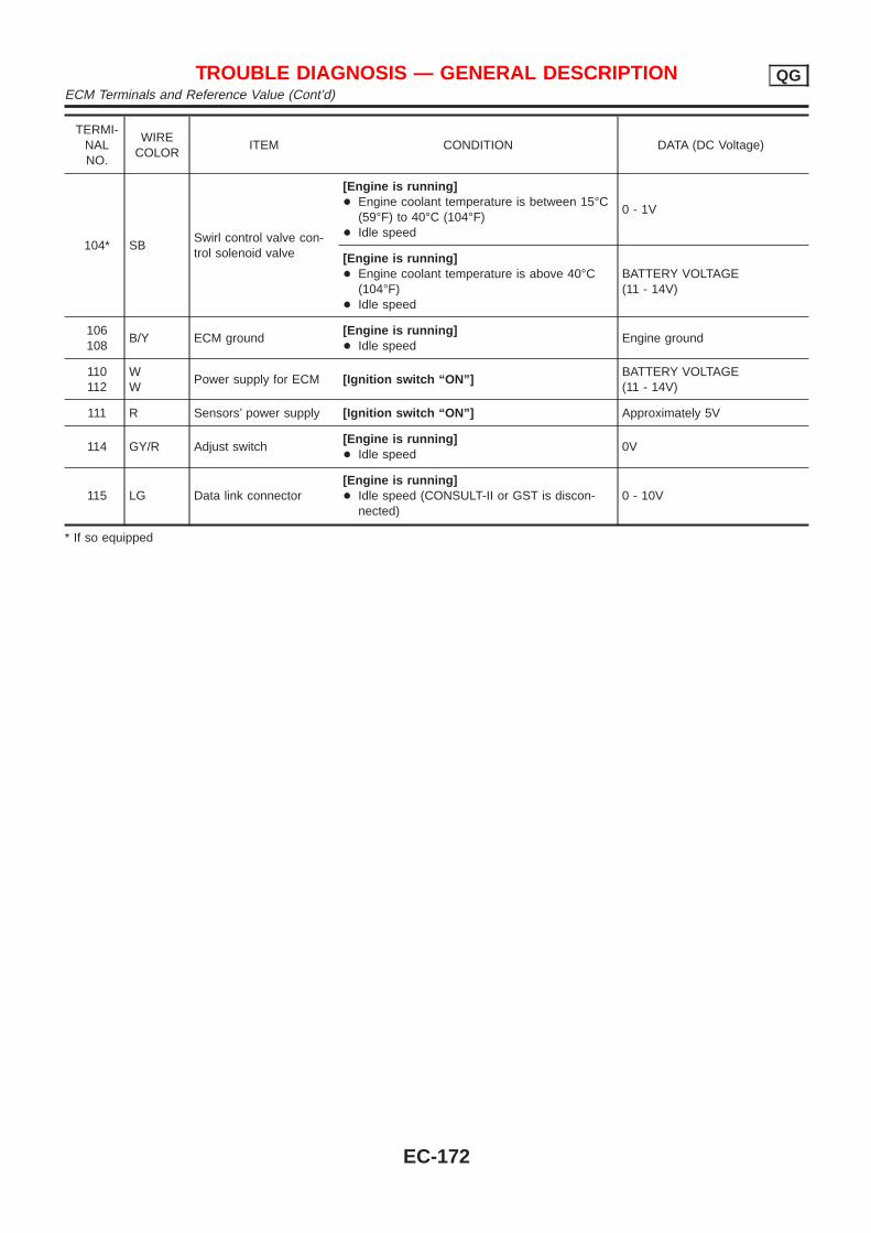
TERMI-NALNO.
WIRECOLOR
ITEM CONDITION DATA (DC Voltage)
104* SBSwirl control valve con-trol solenoid valve
[Engine is running]+ Engine coolant temperature is between 15°C
(59°F) to 40°C (104°F)+ Idle speed
0 - 1V
[Engine is running]+ Engine coolant temperature is above 40°C
(104°F)+ Idle speed
BATTERY VOLTAGE(11 - 14V)
106108
B/Y ECM ground[Engine is running]+ Idle speed
Engine ground
110112
WW
Power supply for ECM [Ignition switch “ON”]BATTERY VOLTAGE(11 - 14V)
111 R Sensors’ power supply [Ignition switch “ON”] Approximately 5V
114 GY/R Adjust switch[Engine is running]+ Idle speed
0V
115 LG Data link connector[Engine is running]+ Idle speed (CONSULT-II or GST is discon-
nected)0 - 10V
* If so equipped
TROUBLE DIAGNOSIS — GENERAL DESCRIPTION QGECM Terminals and Reference Value (Cont’d)
EC-172
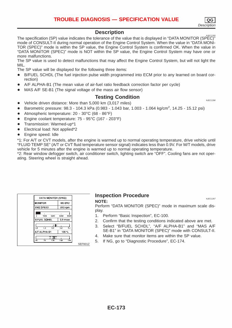
DescriptionNJEC1265
The specification (SP) value indicates the tolerance of the value that is displayed in “DATA MONITOR (SPEC)”mode of CONSULT-II during normal operation of the Engine Control System. When the value in “DATA MONI-TOR (SPEC)” mode is within the SP value, the Engine Control System is confirmed OK. When the value in“DATA MONITOR (SPEC)” mode is NOT within the SP value, the Engine Control System may have one ormore malfunctions.The SP value is used to detect malfunctions that may affect the Engine Control System, but will not light theMIL.The SP value will be displayed for the following three items:+ B/FUEL SCHDL (The fuel injection pulse width programmed into ECM prior to any learned on board cor-
rection)+ A/F ALPHA-B1 (The mean value of air-fuel ratio feedback correction factor per cycle)+ MAS A/F SE-B1 (The signal voltage of the mass air flow sensor)
Testing ConditionNJEC1266
+ Vehicle driven distance: More than 5,000 km (3,017 miles)+ Barometric pressure: 98.3 - 104.3 kPa (0.983 - 1.043 bar, 1.003 - 1.064 kg/cm2, 14.25 - 15.12 psi)+ Atmospheric temperature: 20 - 30°C (68 - 86°F)+ Engine coolant temperature: 75 - 95°C (167 - 203°F)+ Transmission: Warmed-up*1+ Electrical load: Not applied*2+ Engine speed: Idle*1: For A/T or CVT models, after the engine is warmed up to normal operating temperature, drive vehicle until“FLUID TEMP SE” (A/T or CVT fluid temperature sensor signal) indicates less than 0.9V. For M/T models, drivevehicle for 5 minutes after the engine is warmed up to normal operating temperature.*2: Rear window defogger switch, air conditioner switch, lighting switch are “OFF”. Cooling fans are not oper-ating. Steering wheel is straight ahead.
SEF601Z
Inspection ProcedureNJEC1267
NOTE:Perform “DATA MONITOR (SPEC)” mode in maximum scale dis-play.1. Perform “Basic Inspection”, EC-100.2. Confirm that the testing conditions indicated above are met.3. Select “B/FUEL SCHDL”, “A/F ALPHA-B1” and “MAS A/F
SE-B1” in “DATA MONITOR (SPEC)” mode with CONSULT-II.4. Make sure that monitor items are within the SP value.5. If NG, go to “Diagnostic Procedure”, EC-174.
TROUBLE DIAGNOSIS — SPECIFICATION VALUE QGDescription
EC-173
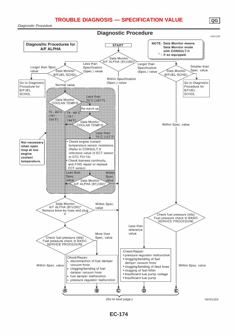
Diagnostic ProcedureNJEC1268
SEF613ZA
TROUBLE DIAGNOSIS — SPECIFICATION VALUE QGDiagnostic Procedure
EC-174
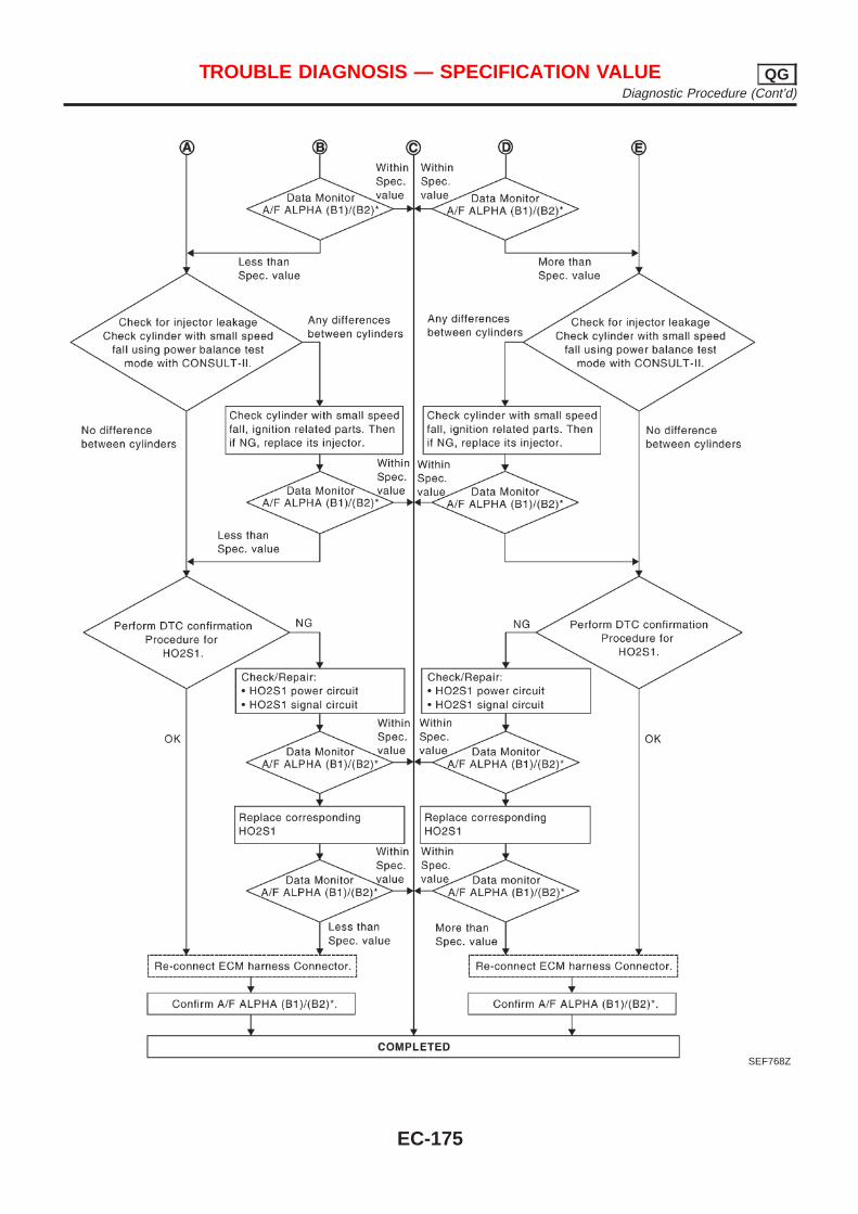
SEF768Z
TROUBLE DIAGNOSIS — SPECIFICATION VALUE QGDiagnostic Procedure (Cont’d)
EC-175
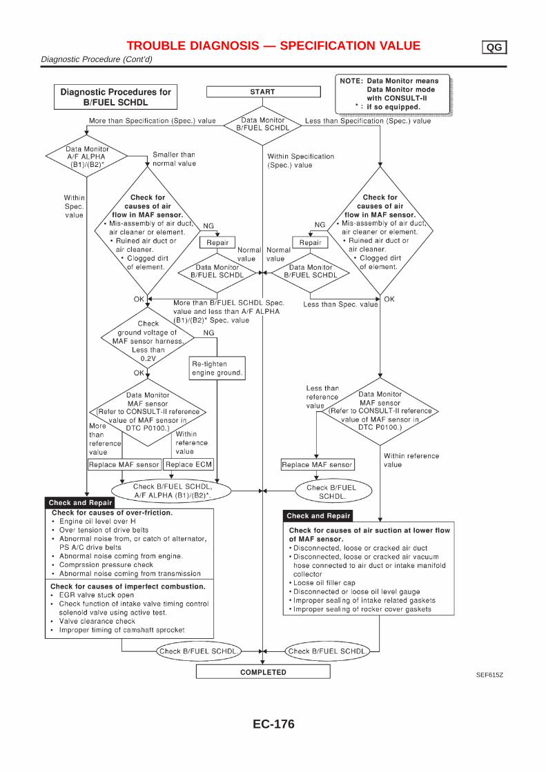
SEF615Z
TROUBLE DIAGNOSIS — SPECIFICATION VALUE QGDiagnostic Procedure (Cont’d)
EC-176
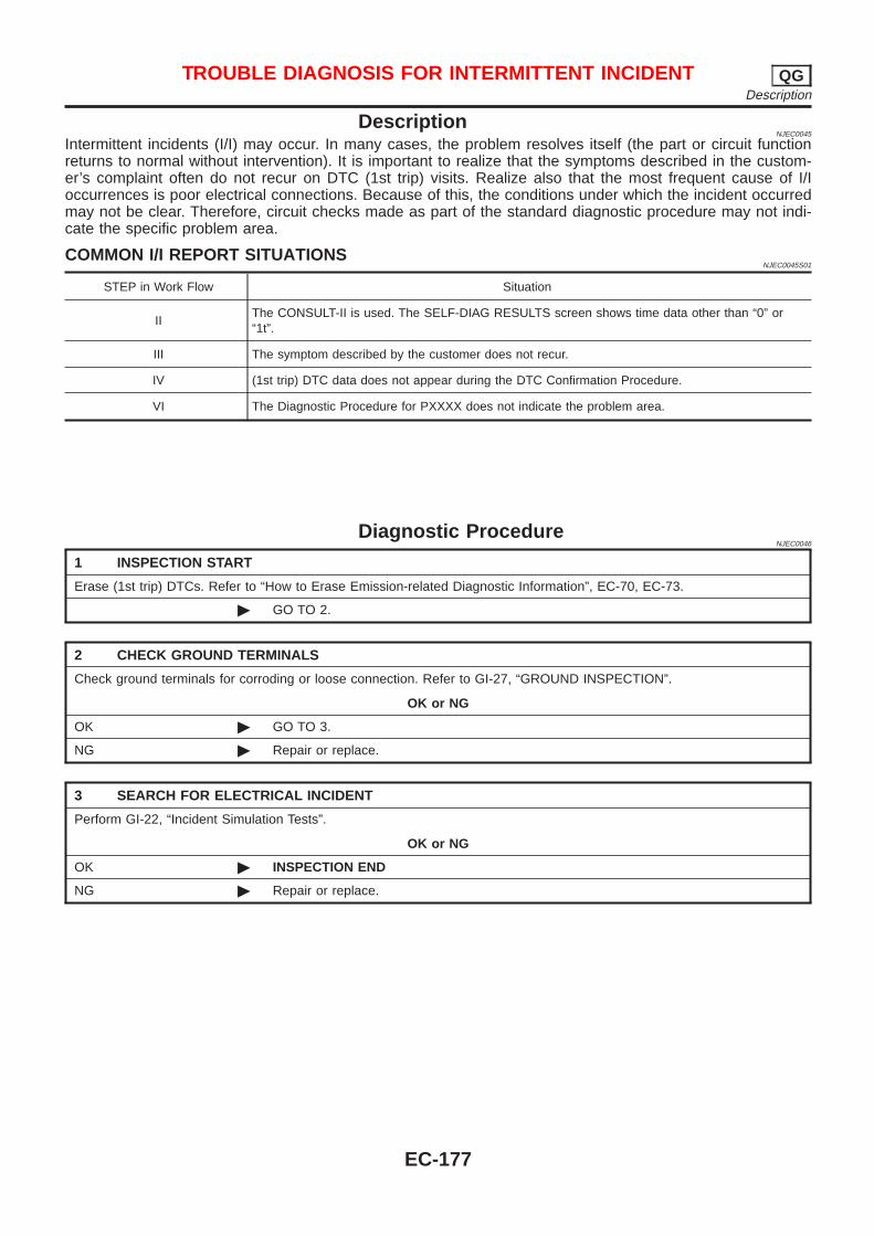
DescriptionNJEC0045
Intermittent incidents (I/I) may occur. In many cases, the problem resolves itself (the part or circuit functionreturns to normal without intervention). It is important to realize that the symptoms described in the custom-er’s complaint often do not recur on DTC (1st trip) visits. Realize also that the most frequent cause of I/Ioccurrences is poor electrical connections. Because of this, the conditions under which the incident occurredmay not be clear. Therefore, circuit checks made as part of the standard diagnostic procedure may not indi-cate the specific problem area.
COMMON I/I REPORT SITUATIONSNJEC0045S01
STEP in Work Flow Situation
IIThe CONSULT-II is used. The SELF-DIAG RESULTS screen shows time data other than “0” or“1t”.
III The symptom described by the customer does not recur.
IV (1st trip) DTC data does not appear during the DTC Confirmation Procedure.
VI The Diagnostic Procedure for PXXXX does not indicate the problem area.
Diagnostic ProcedureNJEC0046
1 INSPECTION START
Erase (1st trip) DTCs. Refer to “How to Erase Emission-related Diagnostic Information”, EC-70, EC-73.
© GO TO 2.
2 CHECK GROUND TERMINALS
Check ground terminals for corroding or loose connection. Refer to GI-27, “GROUND INSPECTION”.
OK or NG
OK © GO TO 3.
NG © Repair or replace.
3 SEARCH FOR ELECTRICAL INCIDENT
Perform GI-22, “Incident Simulation Tests”.
OK or NG
OK © INSPECTION END
NG © Repair or replace.
TROUBLE DIAGNOSIS FOR INTERMITTENT INCIDENT QGDescription
EC-177
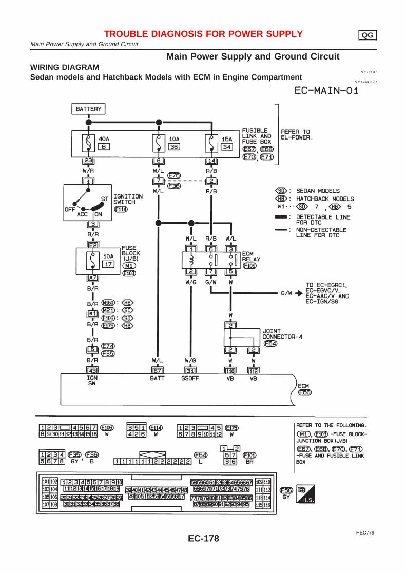
Main Power Supply and Ground CircuitWIRING DIAGRAM
NJEC0047
Sedan models and Hatchback Models with ECM in Engine CompartmentNJEC0047S01
HEC779
TROUBLE DIAGNOSIS FOR POWER SUPPLY QGMain Power Supply and Ground Circuit
EC-178
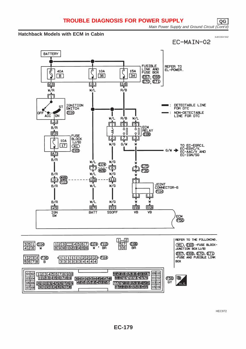
Hatchback Models with ECM in CabinNJEC0047S02
HEC972
TROUBLE DIAGNOSIS FOR POWER SUPPLY QGMain Power Supply and Ground Circuit (Cont’d)
EC-179
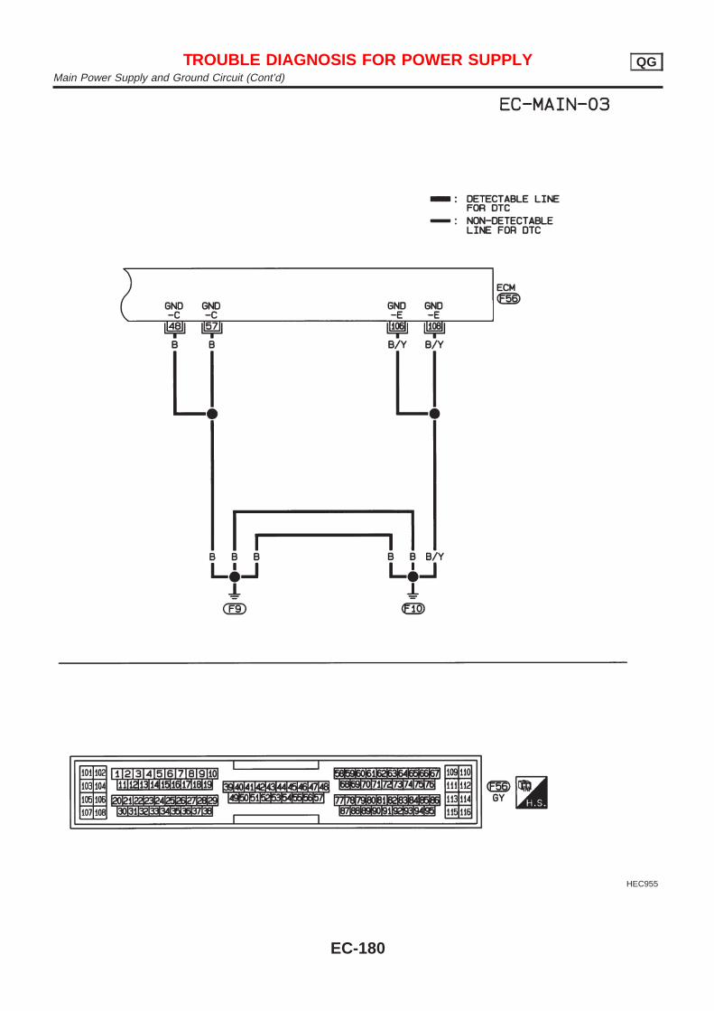
HEC955
TROUBLE DIAGNOSIS FOR POWER SUPPLY QGMain Power Supply and Ground Circuit (Cont’d)
EC-180
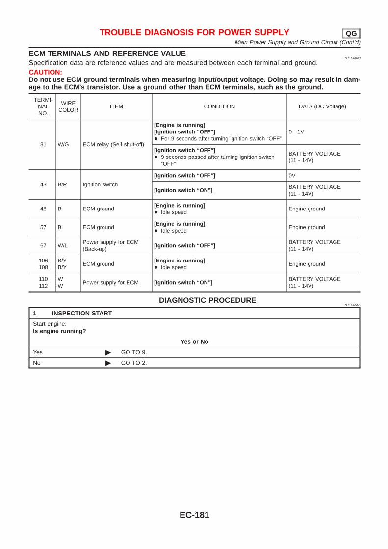
ECM TERMINALS AND REFERENCE VALUENJEC0048
Specification data are reference values and are measured between each terminal and ground.CAUTION:Do not use ECM ground terminals when measuring input/output voltage. Doing so may result in dam-age to the ECM’s transistor. Use a ground other than ECM terminals, such as the ground.
TERMI-NALNO.
WIRECOLOR
ITEM CONDITION DATA (DC Voltage)
31 W/G ECM relay (Self shut-off)
[Engine is running][Ignition switch “OFF”]+ For 9 seconds after turning ignition switch “OFF”
0 - 1V
[Ignition switch “OFF”]+ 9 seconds passed after turning ignition switch
“OFF”
BATTERY VOLTAGE(11 - 14V)
43 B/R Ignition switch
[Ignition switch “OFF”] 0V
[Ignition switch “ON”]BATTERY VOLTAGE(11 - 14V)
48 B ECM ground[Engine is running]+ Idle speed
Engine ground
57 B ECM ground[Engine is running]+ Idle speed
Engine ground
67 W/LPower supply for ECM(Back-up)
[Ignition switch “OFF”]BATTERY VOLTAGE(11 - 14V)
106108
B/YB/Y
ECM ground[Engine is running]+ Idle speed
Engine ground
110112
WW
Power supply for ECM [Ignition switch “ON”]BATTERY VOLTAGE(11 - 14V)
DIAGNOSTIC PROCEDURENJEC0565
1 INSPECTION START
Start engine.Is engine running?
Yes or No
Yes © GO TO 9.
No © GO TO 2.
TROUBLE DIAGNOSIS FOR POWER SUPPLY QGMain Power Supply and Ground Circuit (Cont’d)
EC-181
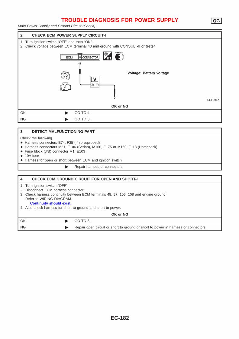
2 CHECK ECM POWER SUPPLY CIRCUIT-I
1. Turn ignition switch “OFF” and then “ON”.2. Check voltage between ECM terminal 43 and ground with CONSULT-II or tester.
SEF291X
OK or NG
OK © GO TO 4.
NG © GO TO 3.
3 DETECT MALFUNCTIONING PART
Check the following.+ Harness connectors E74, F35 (If so equipped)+ Harness connectors M21, E106 (Sedan), M160, E175 or M169, F113 (Hatchback)+ Fuse block (J/B) connector M1, E103+ 10A fuse+ Harness for open or short between ECM and ignition switch
© Repair harness or connectors.
4 CHECK ECM GROUND CIRCUIT FOR OPEN AND SHORT-I
1. Turn ignition switch “OFF”.2. Disconnect ECM harness connector.3. Check harness continuity between ECM terminals 48, 57, 106, 108 and engine ground.
Refer to WIRING DIAGRAM.Continuity should exist.
4. Also check harness for short to ground and short to power.
OK or NG
OK © GO TO 5.
NG © Repair open circuit or short to ground or short to power in harness or connectors.
TROUBLE DIAGNOSIS FOR POWER SUPPLY QGMain Power Supply and Ground Circuit (Cont’d)
EC-182
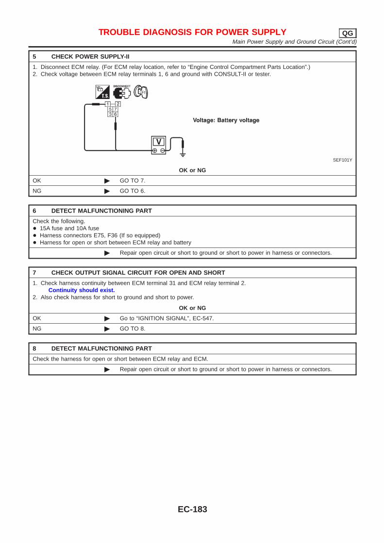
5 CHECK POWER SUPPLY-II
1. Disconnect ECM relay. (For ECM relay location, refer to “Engine Control Compartment Parts Location”.)2. Check voltage between ECM relay terminals 1, 6 and ground with CONSULT-II or tester.
SEF101Y
OK or NG
OK © GO TO 7.
NG © GO TO 6.
6 DETECT MALFUNCTIONING PART
Check the following.+ 15A fuse and 10A fuse+ Harness connectors E75, F36 (If so equipped)+ Harness for open or short between ECM relay and battery
© Repair open circuit or short to ground or short to power in harness or connectors.
7 CHECK OUTPUT SIGNAL CIRCUIT FOR OPEN AND SHORT
1. Check harness continuity between ECM terminal 31 and ECM relay terminal 2.Continuity should exist.
2. Also check harness for short to ground and short to power.
OK or NG
OK © Go to “IGNITION SIGNAL”, EC-547.
NG © GO TO 8.
8 DETECT MALFUNCTIONING PART
Check the harness for open or short between ECM relay and ECM.
© Repair open circuit or short to ground or short to power in harness or connectors.
TROUBLE DIAGNOSIS FOR POWER SUPPLY QGMain Power Supply and Ground Circuit (Cont’d)
EC-183
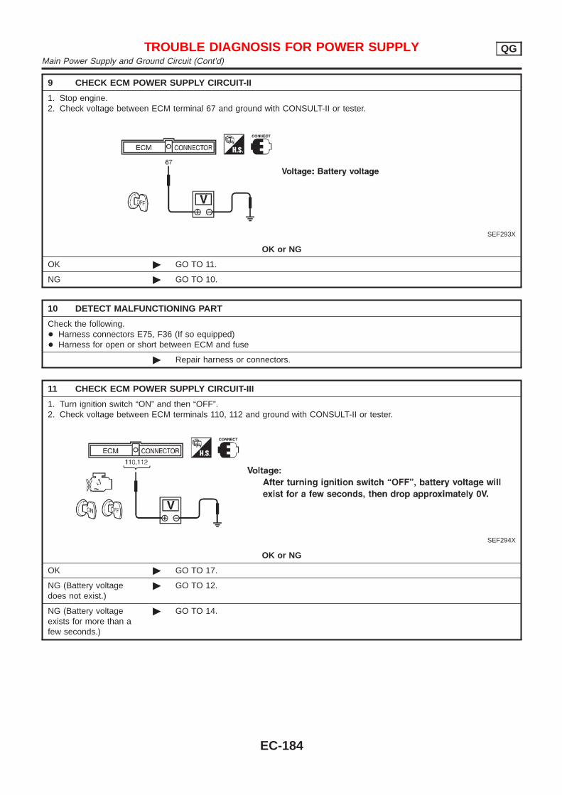
9 CHECK ECM POWER SUPPLY CIRCUIT-II
1. Stop engine.2. Check voltage between ECM terminal 67 and ground with CONSULT-II or tester.
SEF293X
OK or NG
OK © GO TO 11.
NG © GO TO 10.
10 DETECT MALFUNCTIONING PART
Check the following.+ Harness connectors E75, F36 (If so equipped)+ Harness for open or short between ECM and fuse
© Repair harness or connectors.
11 CHECK ECM POWER SUPPLY CIRCUIT-III
1. Turn ignition switch “ON” and then “OFF”.2. Check voltage between ECM terminals 110, 112 and ground with CONSULT-II or tester.
SEF294X
OK or NG
OK © GO TO 17.
NG (Battery voltagedoes not exist.)
© GO TO 12.
NG (Battery voltageexists for more than afew seconds.)
© GO TO 14.
TROUBLE DIAGNOSIS FOR POWER SUPPLY QGMain Power Supply and Ground Circuit (Cont’d)
EC-184
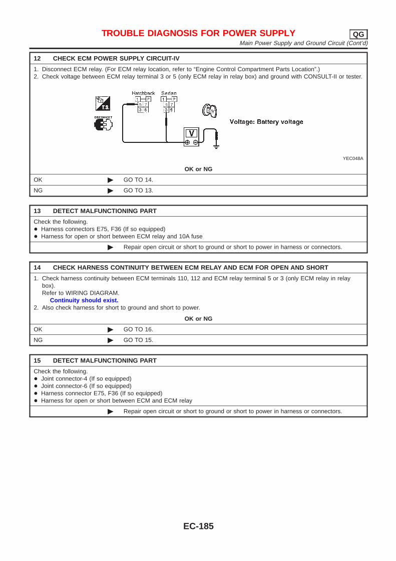
12 CHECK ECM POWER SUPPLY CIRCUIT-IV
1. Disconnect ECM relay. (For ECM relay location, refer to “Engine Control Compartment Parts Location”.)2. Check voltage between ECM relay terminal 3 or 5 (only ECM relay in relay box) and ground with CONSULT-II or tester.
YEC048A
OK or NG
OK © GO TO 14.
NG © GO TO 13.
13 DETECT MALFUNCTIONING PART
Check the following.+ Harness connectors E75, F36 (If so equipped)+ Harness for open or short between ECM relay and 10A fuse
© Repair open circuit or short to ground or short to power in harness or connectors.
14 CHECK HARNESS CONTINUITY BETWEEN ECM RELAY AND ECM FOR OPEN AND SHORT
1. Check harness continuity between ECM terminals 110, 112 and ECM relay terminal 5 or 3 (only ECM relay in relaybox).Refer to WIRING DIAGRAM.
Continuity should exist.2. Also check harness for short to ground and short to power.
OK or NG
OK © GO TO 16.
NG © GO TO 15.
15 DETECT MALFUNCTIONING PART
Check the following.+ Joint connector-4 (If so equipped)+ Joint connector-6 (If so equipped)+ Harness connector E75, F36 (If so equipped)+ Harness for open or short between ECM and ECM relay
© Repair open circuit or short to ground or short to power in harness or connectors.
TROUBLE DIAGNOSIS FOR POWER SUPPLY QGMain Power Supply and Ground Circuit (Cont’d)
EC-185
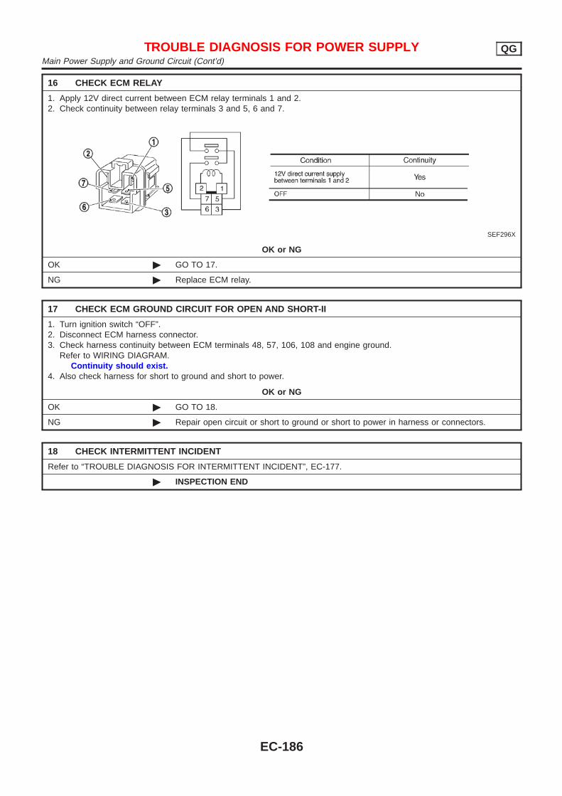
16 CHECK ECM RELAY
1. Apply 12V direct current between ECM relay terminals 1 and 2.2. Check continuity between relay terminals 3 and 5, 6 and 7.
SEF296X
OK or NG
OK © GO TO 17.
NG © Replace ECM relay.
17 CHECK ECM GROUND CIRCUIT FOR OPEN AND SHORT-II
1. Turn ignition switch “OFF”.2. Disconnect ECM harness connector.3. Check harness continuity between ECM terminals 48, 57, 106, 108 and engine ground.
Refer to WIRING DIAGRAM.Continuity should exist.
4. Also check harness for short to ground and short to power.
OK or NG
OK © GO TO 18.
NG © Repair open circuit or short to ground or short to power in harness or connectors.
18 CHECK INTERMITTENT INCIDENT
Refer to “TROUBLE DIAGNOSIS FOR INTERMITTENT INCIDENT”, EC-177.
© INSPECTION END
TROUBLE DIAGNOSIS FOR POWER SUPPLY QGMain Power Supply and Ground Circuit (Cont’d)
EC-186
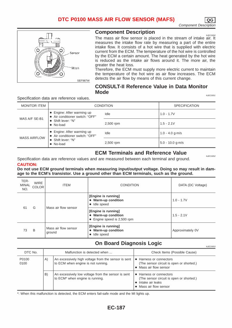
SEF987W
Component DescriptionNJEC0050
The mass air flow sensor is placed in the stream of intake air. Itmeasures the intake flow rate by measuring a part of the entireintake flow. It consists of a hot wire that is supplied with electriccurrent from the ECM. The temperature of the hot wire is controlledby the ECM a certain amount. The heat generated by the hot wireis reduced as the intake air flows around it. The more air, thegreater the heat loss.Therefore, the ECM must supply more electric current to maintainthe temperature of the hot wire as air flow increases. The ECMdetects the air flow by means of this current change.
CONSULT-II Reference Value in Data MonitorMode
NJEC0051
Specification data are reference values.
MONITOR ITEM CONDITION SPECIFICATION
MAS A/F SE-B1
+ Engine: After warming up+ Air conditioner switch: “OFF”+ Shift lever: “N”+ No-load
Idle 1.0 - 1.7V
2,500 rpm 1.5 - 2.1V
MASS AIRFLOW
+ Engine: After warming up+ Air conditioner switch: “OFF”+ Shift lever: “N”+ No-load
Idle 1.0 - 4.0 g·m/s
2,500 rpm 5.0 - 10.0 g·m/s
ECM Terminals and Reference ValueNJEC0052
Specification data are reference values and are measured between each terminal and ground.CAUTION:Do not use ECM ground terminals when measuring input/output voltage. Doing so may result in dam-age to the ECM’s transistor. Use a ground other than ECM terminals, such as the ground.
TER-MINAL
NO.
WIRECOLOR
ITEM CONDITION DATA (DC Voltage)
61 G Mass air flow sensor
[Engine is running]+ Warm-up condition+ Idle speed
1.0 - 1.7V
[Engine is running]+ Warm-up condition+ Engine speed is 2,500 rpm
1.5 - 2.1V
73 BMass air flow sensorground
[Engine is running]+ Warm-up condition+ Idle speed
Approximately 0V
On Board Diagnosis LogicNJEC0053
DTC No. Malfunction is detected when ... Check Items (Possible Cause)
P01000100
A) An excessively high voltage from the sensor is sentto ECM when engine is not running.
+ Harness or connectors(The sensor circuit is open or shorted.)
+ Mass air flow sensor
B) An excessively low voltage from the sensor is sentto ECM* when engine is running.
+ Harness or connectors(The sensor circuit is open or shorted.)
+ Intake air leaks+ Mass air flow sensor
*: When this malfunction is detected, the ECM enters fail-safe mode and the MI lights up.
DTC P0100 MASS AIR FLOW SENSOR (MAFS) QGComponent Description
EC-187
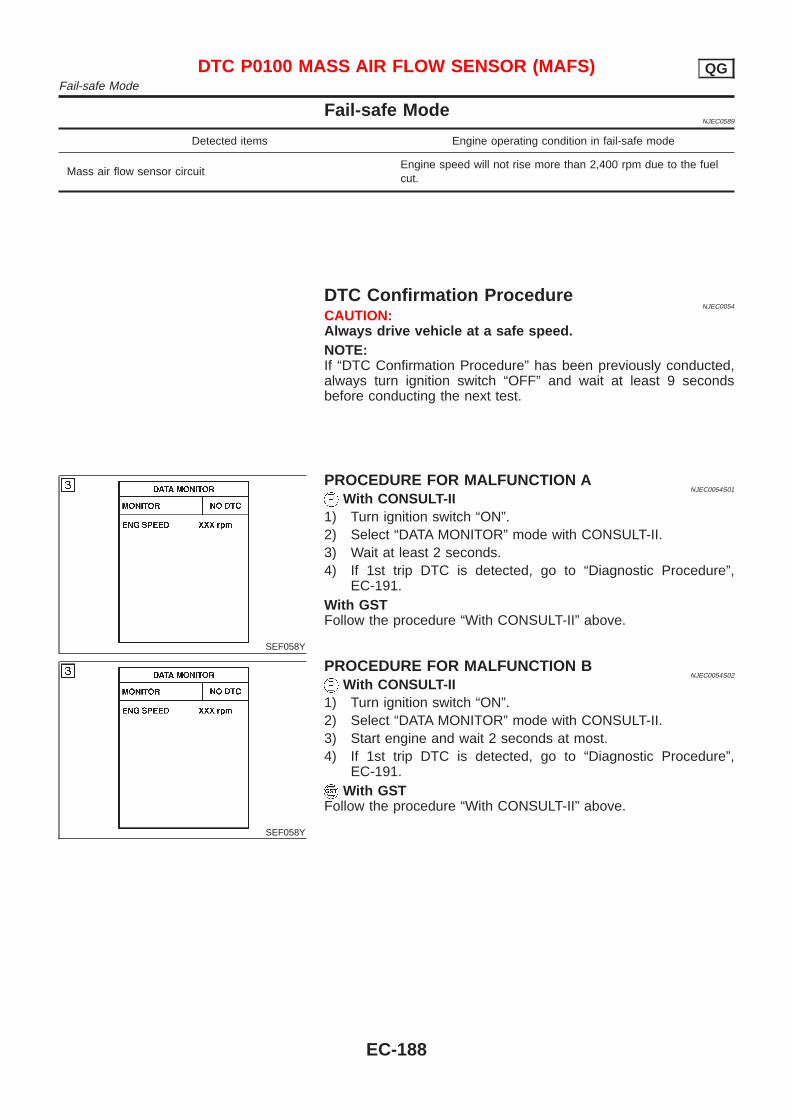
Fail-safe ModeNJEC0589
Detected items Engine operating condition in fail-safe mode
Mass air flow sensor circuitEngine speed will not rise more than 2,400 rpm due to the fuelcut.
DTC Confirmation ProcedureNJEC0054
CAUTION:Always drive vehicle at a safe speed.NOTE:If “DTC Confirmation Procedure” has been previously conducted,always turn ignition switch “OFF” and wait at least 9 secondsbefore conducting the next test.
SEF058Y
PROCEDURE FOR MALFUNCTION ANJEC0054S01
With CONSULT-II1) Turn ignition switch “ON”.2) Select “DATA MONITOR” mode with CONSULT-II.3) Wait at least 2 seconds.4) If 1st trip DTC is detected, go to “Diagnostic Procedure”,
EC-191.With GSTFollow the procedure “With CONSULT-II” above.
SEF058Y
PROCEDURE FOR MALFUNCTION BNJEC0054S02
With CONSULT-II1) Turn ignition switch “ON”.2) Select “DATA MONITOR” mode with CONSULT-II.3) Start engine and wait 2 seconds at most.4) If 1st trip DTC is detected, go to “Diagnostic Procedure”,
EC-191.With GST
Follow the procedure “With CONSULT-II” above.
DTC P0100 MASS AIR FLOW SENSOR (MAFS) QGFail-safe Mode
EC-188
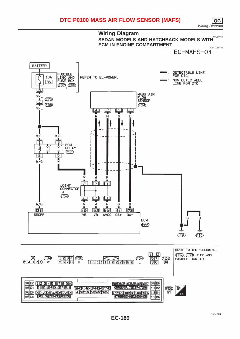
Wiring DiagramNJEC0056
SEDAN MODELS AND HATCHBACK MODELS WITHECM IN ENGINE COMPARTMENT
NJEC0056S01
HEC781
DTC P0100 MASS AIR FLOW SENSOR (MAFS) QGWiring Diagram
EC-189
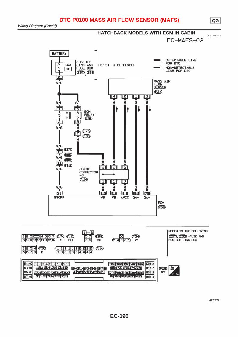
HATCHBACK MODELS WITH ECM IN CABINNJEC0056S02
HEC973
DTC P0100 MASS AIR FLOW SENSOR (MAFS) QGWiring Diagram (Cont’d)
EC-190
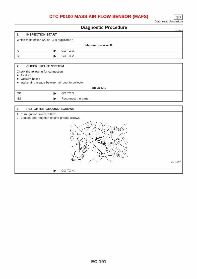
Diagnostic ProcedureNJEC0057
1 INSPECTION START
Which malfunction (A, or B) is duplicated?
Malfunction A or B
A © GO TO 3.
B © GO TO 2.
2 CHECK INTAKE SYSTEM
Check the following for connection.+ Air duct+ Vacuum hoses+ Intake air passage between air duct to collector
OK or NG
OK © GO TO 3.
NG © Reconnect the parts.
3 RETIGHTEN GROUND SCREWS
1. Turn ignition switch “OFF”.2. Loosen and retighten engine ground screws.
JEF104Y
© GO TO 4.
DTC P0100 MASS AIR FLOW SENSOR (MAFS) QGDiagnostic Procedure
EC-191
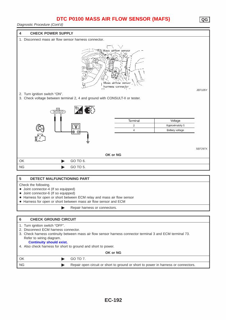
4 CHECK POWER SUPPLY
1. Disconnect mass air flow sensor harness connector.
JEF105Y
2. Turn ignition switch “ON”.3. Check voltage between terminal 2, 4 and ground with CONSULT-II or tester.
SEF297X
OK or NG
OK © GO TO 6.
NG © GO TO 5.
5 DETECT MALFUNCTIONING PART
Check the following.+ Joint connector-4 (If so equipped)+ Joint connector-6 (If so equipped)+ Harness for open or short between ECM relay and mass air flow sensor+ Harness for open or short between mass air flow sensor and ECM
© Repair harness or connectors.
6 CHECK GROUND CIRCUIT
1. Turn ignition switch “OFF”.2. Disconnect ECM harness connector.3. Check harness continuity between mass air flow sensor harness connector terminal 3 and ECM terminal 73.
Refer to wiring diagram.Continuity should exist.
4. Also check harness for short to ground and short to power.
OK or NG
OK © GO TO 7.
NG © Repair open circuit or short to ground or short to power in harness or connectors.
DTC P0100 MASS AIR FLOW SENSOR (MAFS) QGDiagnostic Procedure (Cont’d)
EC-192
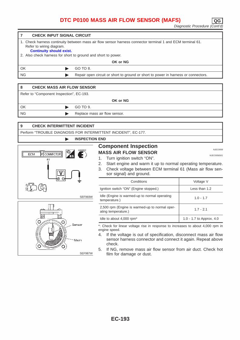
7 CHECK INPUT SIGNAL CIRCUIT
1. Check harness continuity between mass air flow sensor harness connector terminal 1 and ECM terminal 61.Refer to wiring diagram.
Continuity should exist.2. Also check harness for short to ground and short to power.
OK or NG
OK © GO TO 8.
NG © Repair open circuit or short to ground or short to power in harness or connectors.
8 CHECK MASS AIR FLOW SENSOR
Refer to “Component Inspection”, EC-193.
OK or NG
OK © GO TO 9.
NG © Replace mass air flow sensor.
9 CHECK INTERMITTENT INCIDENT
Perform “TROUBLE DIAGNOSIS FOR INTERMITTENT INCIDENT”, EC-177.
© INSPECTION END
SEF993W
SEF987W
Component InspectionNJEC0058
MASS AIR FLOW SENSORNJEC0058S01
1. Turn ignition switch “ON”.2. Start engine and warm it up to normal operating temperature.3. Check voltage between ECM terminal 61 (Mass air flow sen-
sor signal) and ground.
Conditions Voltage V
Ignition switch “ON” (Engine stopped.) Less than 1.2
Idle (Engine is warmed-up to normal operatingtemperature.)
1.0 - 1.7
2,500 rpm (Engine is warmed-up to normal oper-ating temperature.)
1.7 - 2.1
Idle to about 4,000 rpm* 1.0 - 1.7 to Approx. 4.0
*: Check for linear voltage rise in response to increases to about 4,000 rpm inengine speed.
4. If the voltage is out of specification, disconnect mass air flowsensor harness connector and connect it again. Repeat abovecheck.
5. If NG, remove mass air flow sensor from air duct. Check hotfilm for damage or dust.
DTC P0100 MASS AIR FLOW SENSOR (MAFS) QGDiagnostic Procedure (Cont’d)
EC-193
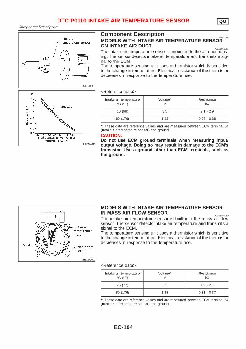
SEF206T
Component DescriptionNJEC0066
MODELS WITH INTAKE AIR TEMPERATURE SENSORON INTAKE AIR DUCT
NJEC0066S01
The intake air temperature sensor is mounted to the air duct hous-ing. The sensor detects intake air temperature and transmits a sig-nal to the ECM.The temperature sensing unit uses a thermistor which is sensitiveto the change in temperature. Electrical resistance of the thermistordecreases in response to the temperature rise.
SEF012P
<Reference data>
Intake air temperature°C (°F)
Voltage*V
ResistancekΩ
20 (68) 3.5 2.1 - 2.9
80 (176) 1.23 0.27 - 0.38
*: These data are reference values and are measured between ECM terminal 64(Intake air temperature sensor) and ground.
CAUTION:Do not use ECM ground terminals when measuring input/output voltage. Doing so may result in damage to the ECM’stransistor. Use a ground other than ECM terminals, such asthe ground.
SEC500C
MODELS WITH INTAKE AIR TEMPERATURE SENSORIN MASS AIR FLOW SENSOR
NJEC0066S02
The intake air temperature sensor is built into the mass air flowsensor. The sensor detects intake air temperature and transmits asignal to the ECM.The temperature sensing unit uses a thermistor which is sensitiveto the change in temperature. Electrical resistance of the thermistordecreases in response to the temperature rise.
<Reference data>
Intake air temperature°C (°F)
Voltage*V
ResistancekΩ
25 (77) 3.3 1.9 - 2.1
80 (176) 1.28 0.31 - 0.37
*: These data are reference values and are measured between ECM terminal 64(Intake air temperature sensor) and ground.
DTC P0110 INTAKE AIR TEMPERATURE SENSOR QGComponent Description
EC-194
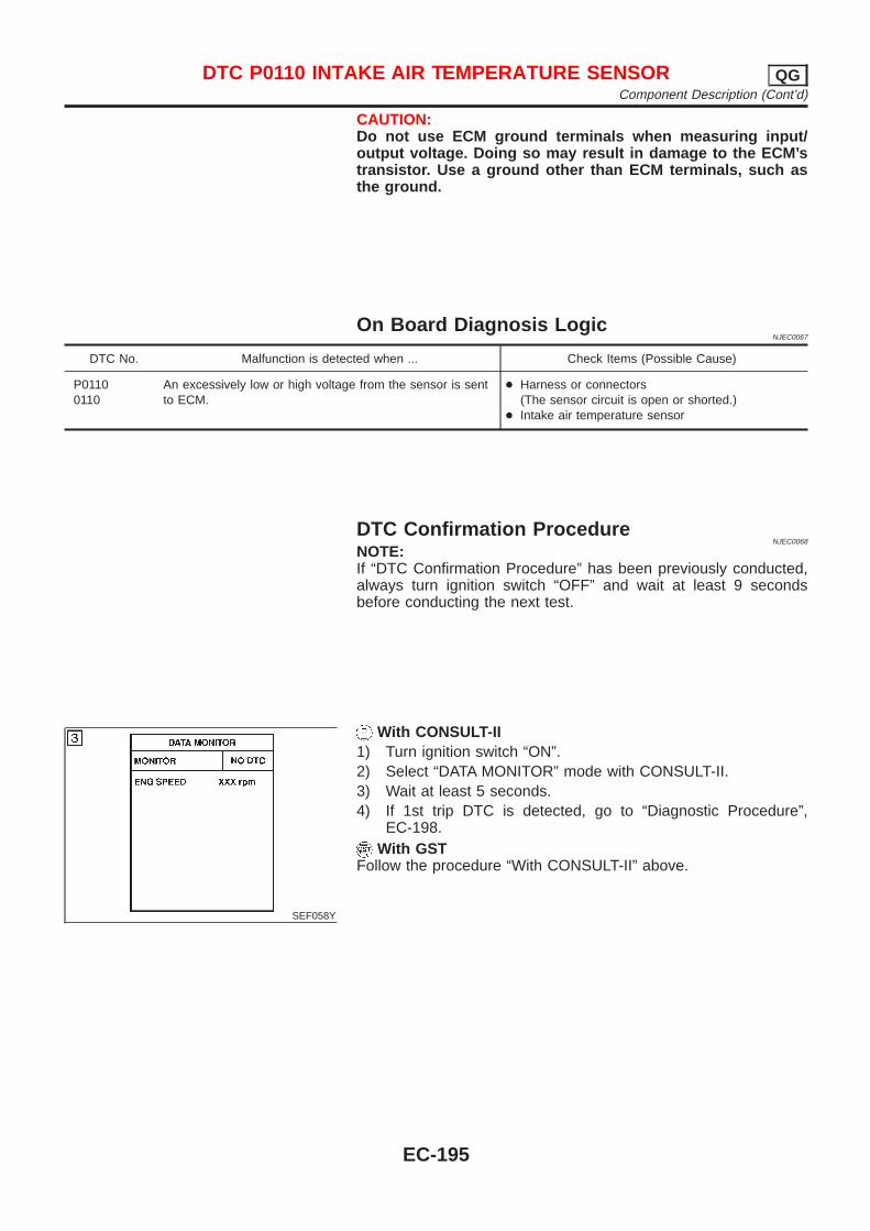
CAUTION:Do not use ECM ground terminals when measuring input/output voltage. Doing so may result in damage to the ECM’stransistor. Use a ground other than ECM terminals, such asthe ground.
On Board Diagnosis LogicNJEC0067
DTC No. Malfunction is detected when ... Check Items (Possible Cause)
P01100110
An excessively low or high voltage from the sensor is sentto ECM.
+ Harness or connectors(The sensor circuit is open or shorted.)
+ Intake air temperature sensor
DTC Confirmation ProcedureNJEC0068
NOTE:If “DTC Confirmation Procedure” has been previously conducted,always turn ignition switch “OFF” and wait at least 9 secondsbefore conducting the next test.
SEF058Y
With CONSULT-II1) Turn ignition switch “ON”.2) Select “DATA MONITOR” mode with CONSULT-II.3) Wait at least 5 seconds.4) If 1st trip DTC is detected, go to “Diagnostic Procedure”,
EC-198.With GST
Follow the procedure “With CONSULT-II” above.
DTC P0110 INTAKE AIR TEMPERATURE SENSOR QGComponent Description (Cont’d)
EC-195
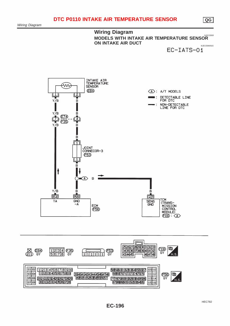
Wiring DiagramNJEC0069
MODELS WITH INTAKE AIR TEMPERATURE SENSORON INTAKE AIR DUCT
NJEC0069S01
HEC782
DTC P0110 INTAKE AIR TEMPERATURE SENSOR QGWiring Diagram
EC-196
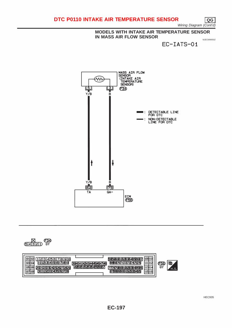
MODELS WITH INTAKE AIR TEMPERATURE SENSORIN MASS AIR FLOW SENSOR
NJEC0069S02
HEC935
DTC P0110 INTAKE AIR TEMPERATURE SENSOR QGWiring Diagram (Cont’d)
EC-197
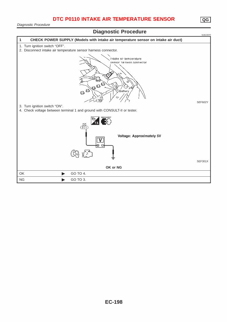
Diagnostic ProcedureNJEC0070
1 CHECK POWER SUPPLY (Models with intake air temperature sensor on intake air duct)
1. Turn ignition switch “OFF”.2. Disconnect intake air temperature sensor harness connector.
SEF602Y
3. Turn ignition switch “ON”.4. Check voltage between terminal 1 and ground with CONSULT-II or tester.
SEF301X
OK or NG
OK © GO TO 4.
NG © GO TO 3.
DTC P0110 INTAKE AIR TEMPERATURE SENSOR QGDiagnostic Procedure
EC-198
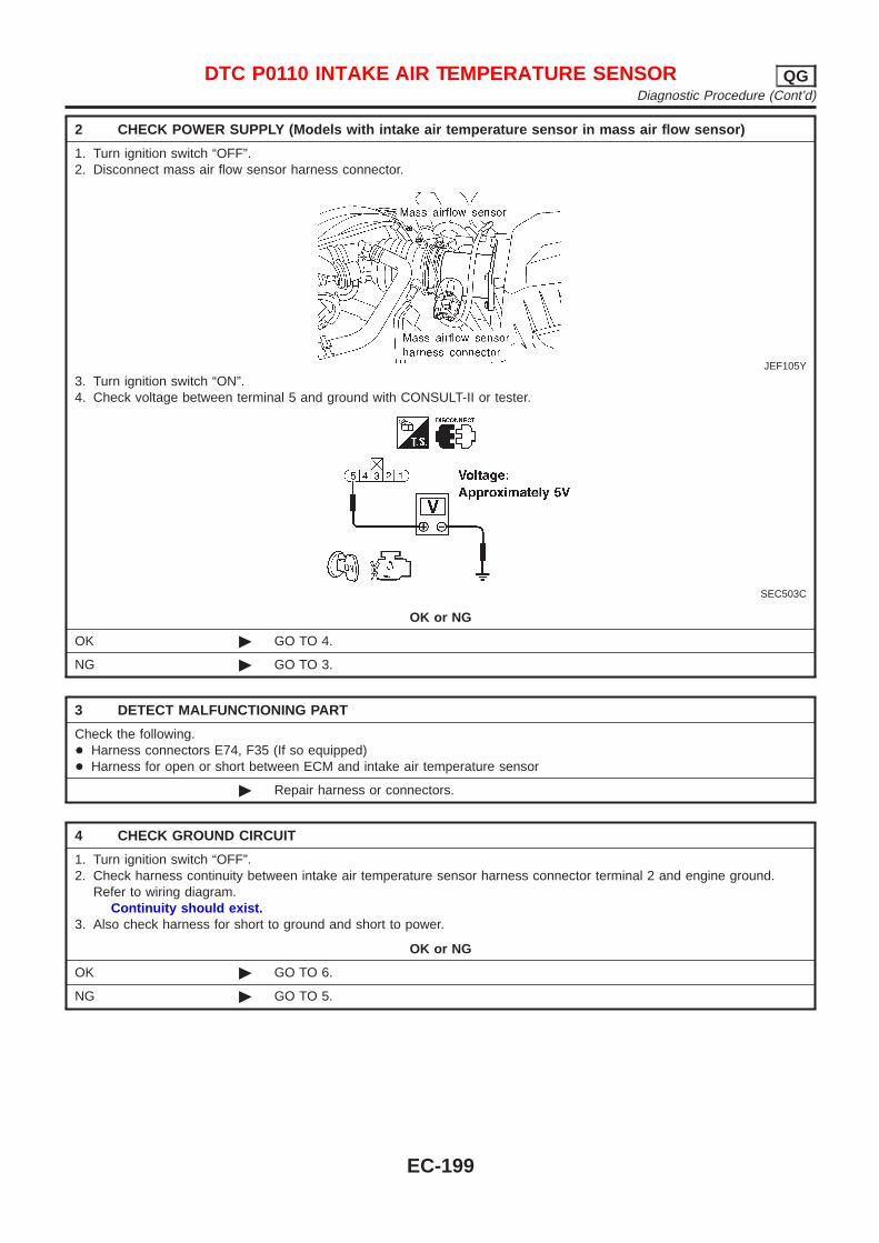
2 CHECK POWER SUPPLY (Models with intake air temperature sensor in mass air flow sensor)
1. Turn ignition switch “OFF”.2. Disconnect mass air flow sensor harness connector.
JEF105Y
3. Turn ignition switch “ON”.4. Check voltage between terminal 5 and ground with CONSULT-II or tester.
SEC503C
OK or NG
OK © GO TO 4.
NG © GO TO 3.
3 DETECT MALFUNCTIONING PART
Check the following.+ Harness connectors E74, F35 (If so equipped)+ Harness for open or short between ECM and intake air temperature sensor
© Repair harness or connectors.
4 CHECK GROUND CIRCUIT
1. Turn ignition switch “OFF”.2. Check harness continuity between intake air temperature sensor harness connector terminal 2 and engine ground.
Refer to wiring diagram.Continuity should exist.
3. Also check harness for short to ground and short to power.
OK or NG
OK © GO TO 6.
NG © GO TO 5.
DTC P0110 INTAKE AIR TEMPERATURE SENSOR QGDiagnostic Procedure (Cont’d)
EC-199
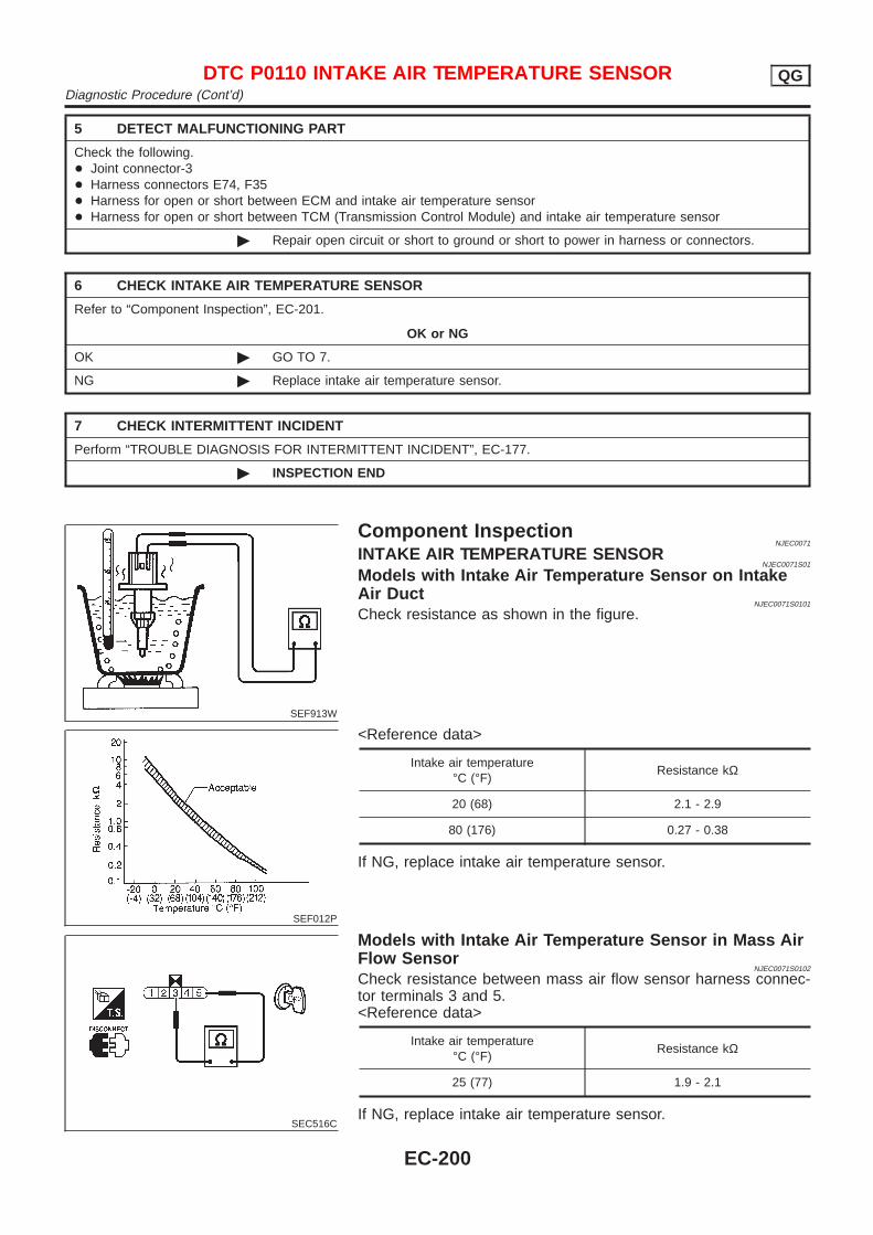
5 DETECT MALFUNCTIONING PART
Check the following.+ Joint connector-3+ Harness connectors E74, F35+ Harness for open or short between ECM and intake air temperature sensor+ Harness for open or short between TCM (Transmission Control Module) and intake air temperature sensor
© Repair open circuit or short to ground or short to power in harness or connectors.
6 CHECK INTAKE AIR TEMPERATURE SENSOR
Refer to “Component Inspection”, EC-201.
OK or NG
OK © GO TO 7.
NG © Replace intake air temperature sensor.
7 CHECK INTERMITTENT INCIDENT
Perform “TROUBLE DIAGNOSIS FOR INTERMITTENT INCIDENT”, EC-177.
© INSPECTION END
SEF913W
Component InspectionNJEC0071
INTAKE AIR TEMPERATURE SENSORNJEC0071S01
Models with Intake Air Temperature Sensor on IntakeAir Duct
NJEC0071S0101
Check resistance as shown in the figure.
SEF012P
<Reference data>
Intake air temperature°C (°F)
Resistance kΩ
20 (68) 2.1 - 2.9
80 (176) 0.27 - 0.38
If NG, replace intake air temperature sensor.
SEC516C
Models with Intake Air Temperature Sensor in Mass AirFlow Sensor
NJEC0071S0102
Check resistance between mass air flow sensor harness connec-tor terminals 3 and 5.<Reference data>
Intake air temperature°C (°F)
Resistance kΩ
25 (77) 1.9 - 2.1
If NG, replace intake air temperature sensor.
DTC P0110 INTAKE AIR TEMPERATURE SENSOR QGDiagnostic Procedure (Cont’d)
EC-200
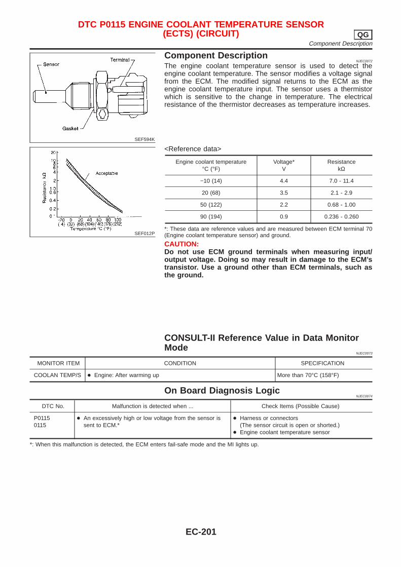
SEF594K
Component DescriptionNJEC0072
The engine coolant temperature sensor is used to detect theengine coolant temperature. The sensor modifies a voltage signalfrom the ECM. The modified signal returns to the ECM as theengine coolant temperature input. The sensor uses a thermistorwhich is sensitive to the change in temperature. The electricalresistance of the thermistor decreases as temperature increases.
SEF012P
<Reference data>
Engine coolant temperature°C (°F)
Voltage*V
ResistancekΩ
−10 (14) 4.4 7.0 - 11.4
20 (68) 3.5 2.1 - 2.9
50 (122) 2.2 0.68 - 1.00
90 (194) 0.9 0.236 - 0.260
*: These data are reference values and are measured between ECM terminal 70(Engine coolant temperature sensor) and ground.
CAUTION:Do not use ECM ground terminals when measuring input/output voltage. Doing so may result in damage to the ECM’stransistor. Use a ground other than ECM terminals, such asthe ground.
CONSULT-II Reference Value in Data MonitorMode
NJEC0073
MONITOR ITEM CONDITION SPECIFICATION
COOLAN TEMP/S + Engine: After warming up More than 70°C (158°F)
On Board Diagnosis LogicNJEC0074
DTC No. Malfunction is detected when ... Check Items (Possible Cause)
P01150115
+ An excessively high or low voltage from the sensor issent to ECM.*
+ Harness or connectors(The sensor circuit is open or shorted.)
+ Engine coolant temperature sensor
*: When this malfunction is detected, the ECM enters fail-safe mode and the MI lights up.
DTC P0115 ENGINE COOLANT TEMPERATURE SENSOR(ECTS) (CIRCUIT) QG
Component Description
EC-201
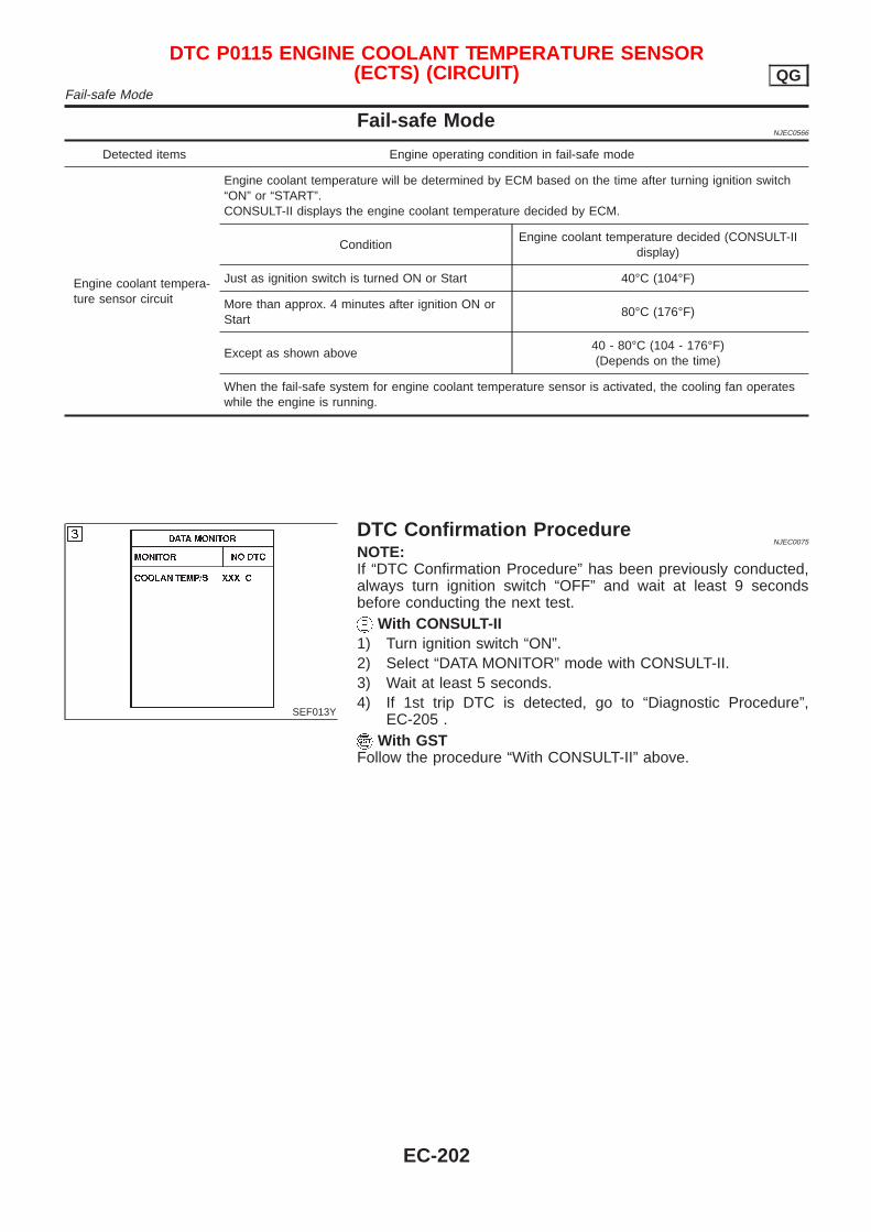
Fail-safe ModeNJEC0566
Detected items Engine operating condition in fail-safe mode
Engine coolant tempera-ture sensor circuit
Engine coolant temperature will be determined by ECM based on the time after turning ignition switch“ON” or “START”.CONSULT-II displays the engine coolant temperature decided by ECM.
ConditionEngine coolant temperature decided (CONSULT-II
display)
Just as ignition switch is turned ON or Start 40°C (104°F)
More than approx. 4 minutes after ignition ON orStart
80°C (176°F)
Except as shown above40 - 80°C (104 - 176°F)(Depends on the time)
When the fail-safe system for engine coolant temperature sensor is activated, the cooling fan operateswhile the engine is running.
SEF013Y
DTC Confirmation ProcedureNJEC0075
NOTE:If “DTC Confirmation Procedure” has been previously conducted,always turn ignition switch “OFF” and wait at least 9 secondsbefore conducting the next test.
With CONSULT-II1) Turn ignition switch “ON”.2) Select “DATA MONITOR” mode with CONSULT-II.3) Wait at least 5 seconds.4) If 1st trip DTC is detected, go to “Diagnostic Procedure”,
EC-205 .With GST
Follow the procedure “With CONSULT-II” above.
DTC P0115 ENGINE COOLANT TEMPERATURE SENSOR(ECTS) (CIRCUIT) QG
Fail-safe Mode
EC-202
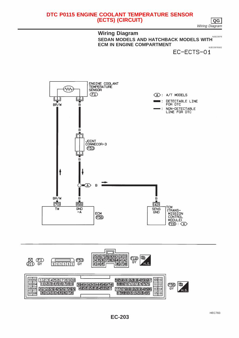
Wiring DiagramNJEC0076
SEDAN MODELS AND HATCHBACK MODELS WITHECM IN ENGINE COMPARTMENT
NJEC0076S01
HEC783
DTC P0115 ENGINE COOLANT TEMPERATURE SENSOR(ECTS) (CIRCUIT) QG
Wiring Diagram
EC-203
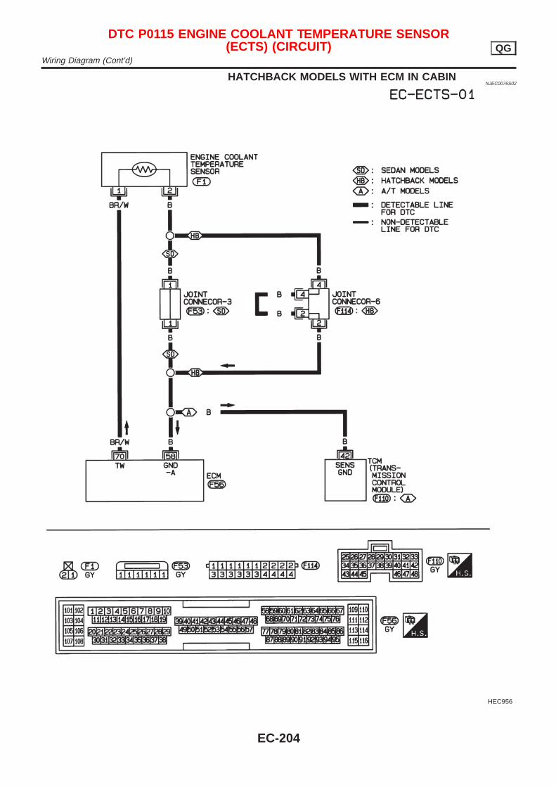
HATCHBACK MODELS WITH ECM IN CABINNJEC0076S02
HEC956
DTC P0115 ENGINE COOLANT TEMPERATURE SENSOR(ECTS) (CIRCUIT) QG
Wiring Diagram (Cont’d)
EC-204
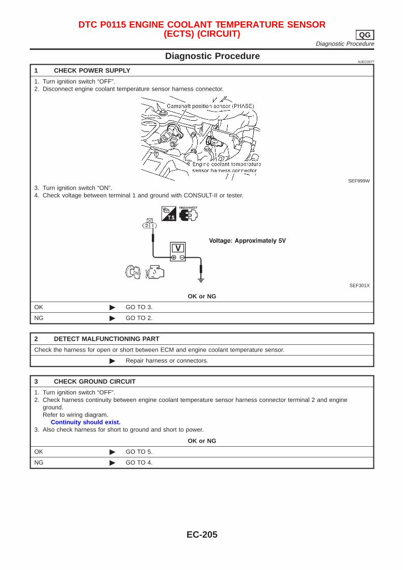
Diagnostic ProcedureNJEC0077
1 CHECK POWER SUPPLY
1. Turn ignition switch “OFF”.2. Disconnect engine coolant temperature sensor harness connector.
SEF999W
3. Turn ignition switch “ON”.4. Check voltage between terminal 1 and ground with CONSULT-II or tester.
SEF301X
OK or NG
OK © GO TO 3.
NG © GO TO 2.
2 DETECT MALFUNCTIONING PART
Check the harness for open or short between ECM and engine coolant temperature sensor.
© Repair harness or connectors.
3 CHECK GROUND CIRCUIT
1. Turn ignition switch “OFF”.2. Check harness continuity between engine coolant temperature sensor harness connector terminal 2 and engine
ground.Refer to wiring diagram.
Continuity should exist.3. Also check harness for short to ground and short to power.
OK or NG
OK © GO TO 5.
NG © GO TO 4.
DTC P0115 ENGINE COOLANT TEMPERATURE SENSOR(ECTS) (CIRCUIT) QG
Diagnostic Procedure
EC-205
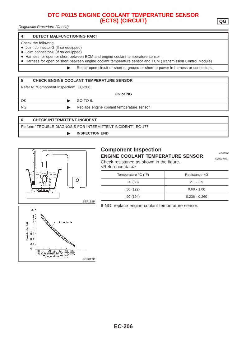
4 DETECT MALFUNCTIONING PART
Check the following.+ Joint connector-3 (If so equipped)+ Joint connector-6 (If so equipped)+ Harness for open or short between ECM and engine coolant temperature sensor+ Harness for open or short between engine coolant temperature sensor and TCM (Transmission Control Module)
© Repair open circuit or short to ground or short to power in harness or connectors.
5 CHECK ENGINE COOLANT TEMPERATURE SENSOR
Refer to “Component Inspection”, EC-206.
OK or NG
OK © GO TO 6.
NG © Replace engine coolant temperature sensor.
6 CHECK INTERMITTENT INCIDENT
Perform “TROUBLE DIAGNOSIS FOR INTERMITTENT INCIDENT”, EC-177.
© INSPECTION END
SEF152P
SEF012P
Component InspectionNJEC0078
ENGINE COOLANT TEMPERATURE SENSORNJEC0078S01
Check resistance as shown in the figure.<Reference data>
Temperature °C (°F) Resistance kΩ
20 (68) 2.1 - 2.9
50 (122) 0.68 - 1.00
90 (194) 0.236 - 0.260
If NG, replace engine coolant temperature sensor.
DTC P0115 ENGINE COOLANT TEMPERATURE SENSOR(ECTS) (CIRCUIT) QG
Diagnostic Procedure (Cont’d)
EC-206
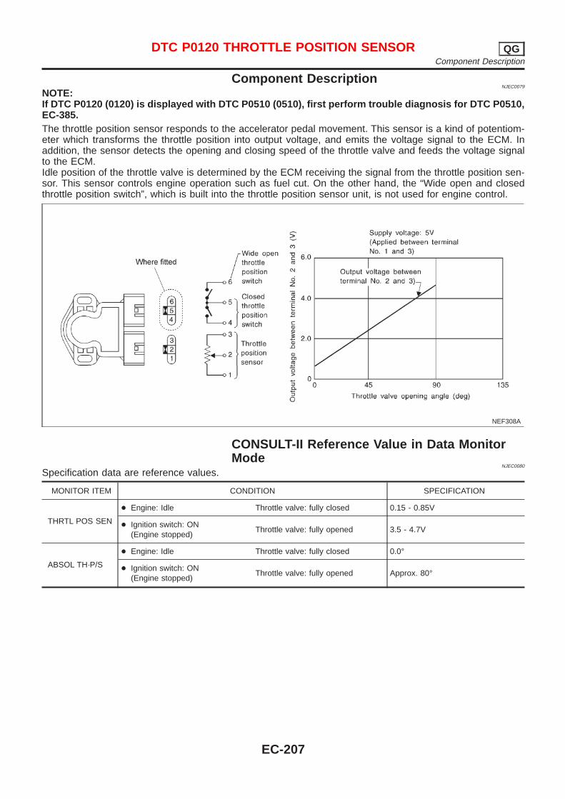
Component DescriptionNJEC0079
NOTE:If DTC P0120 (0120) is displayed with DTC P0510 (0510), first perform trouble diagnosis for DTC P0510,EC-385.The throttle position sensor responds to the accelerator pedal movement. This sensor is a kind of potentiom-eter which transforms the throttle position into output voltage, and emits the voltage signal to the ECM. Inaddition, the sensor detects the opening and closing speed of the throttle valve and feeds the voltage signalto the ECM.Idle position of the throttle valve is determined by the ECM receiving the signal from the throttle position sen-sor. This sensor controls engine operation such as fuel cut. On the other hand, the “Wide open and closedthrottle position switch”, which is built into the throttle position sensor unit, is not used for engine control.
NEF308A
CONSULT-II Reference Value in Data MonitorMode
NJEC0080
Specification data are reference values.
MONITOR ITEM CONDITION SPECIFICATION
THRTL POS SEN
+ Engine: Idle Throttle valve: fully closed 0.15 - 0.85V
+ Ignition switch: ON(Engine stopped)
Throttle valve: fully opened 3.5 - 4.7V
ABSOL TH·P/S
+ Engine: Idle Throttle valve: fully closed 0.0°
+ Ignition switch: ON(Engine stopped)
Throttle valve: fully opened Approx. 80°
DTC P0120 THROTTLE POSITION SENSOR QGComponent Description
EC-207
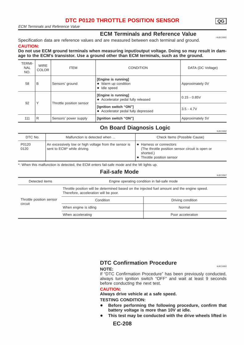
ECM Terminals and Reference Value=NJEC0081
Specification data are reference values and are measured between each terminal and ground.CAUTION:Do not use ECM ground terminals when measuring input/output voltage. Doing so may result in dam-age to the ECM’s transistor. Use a ground other than ECM terminals, such as the ground.
TERMI-NALNO.
WIRECOLOR
ITEM CONDITION DATA (DC Voltage)
58 B Sensors’ ground[Engine is running]+ Warm up condition+ Idle speed
Approximately 0V
92 Y Throttle position sensor
[Engine is running]+ Accelerator pedal fully released
0.15 - 0.85V
[Ignition switch “ON”]+ Accelerator pedal fully depressed
3.5 - 4.7V
111 R Sensors’ power supply [Ignition switch “ON”] Approximately 5V
On Board Diagnosis LogicNJEC0082
DTC No. Malfunction is detected when ... Check Items (Possible Cause)
P01200120
An excessively low or high voltage from the sensor issent to ECM* while driving.
+ Harness or connectors(The throttle position sensor circuit is open orshorted.)
+ Throttle position sensor
*: When this malfunction is detected, the ECM enters fail-safe mode and the MI lights up.
Fail-safe ModeNJEC0567
Detected items Engine operating condition in fail-safe mode
Throttle position sensorcircuit
Throttle position will be determined based on the injected fuel amount and the engine speed.Therefore, acceleration will be poor.
Condition Driving condition
When engine is idling Normal
When accelerating Poor acceleration
DTC Confirmation ProcedureNJEC0083
NOTE:If “DTC Confirmation Procedure” has been previously conducted,always turn ignition switch “OFF” and wait at least 9 secondsbefore conducting the next test.CAUTION:Always drive vehicle at a safe speed.TESTING CONDITION:+ Before performing the following procedure, confirm that
battery voltage is more than 10V at idle.+ This test may be conducted with the drive wheels lifted in
DTC P0120 THROTTLE POSITION SENSOR QGECM Terminals and Reference Value
EC-208
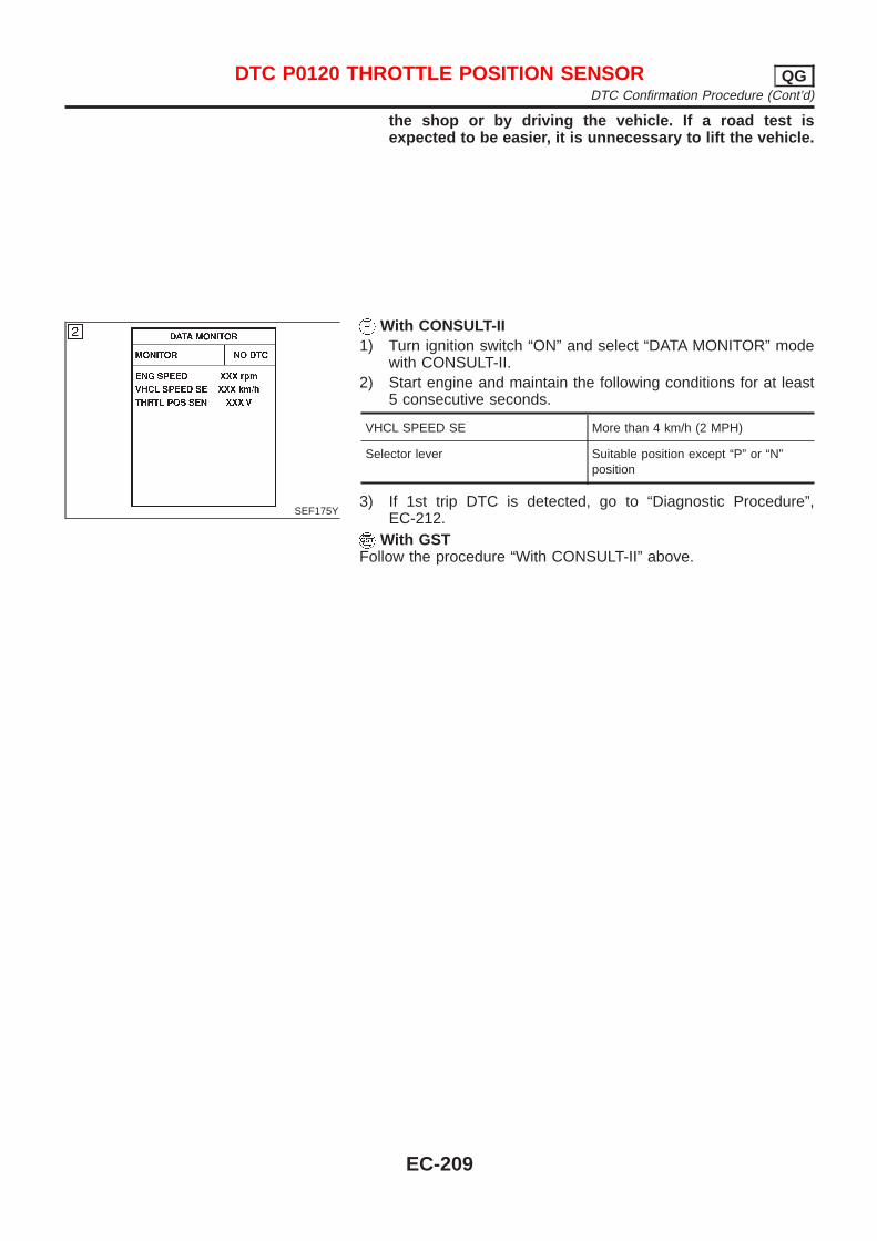
the shop or by driving the vehicle. If a road test isexpected to be easier, it is unnecessary to lift the vehicle.
SEF175Y
With CONSULT-II1) Turn ignition switch “ON” and select “DATA MONITOR” mode
with CONSULT-II.2) Start engine and maintain the following conditions for at least
5 consecutive seconds.
VHCL SPEED SE More than 4 km/h (2 MPH)
Selector lever Suitable position except “P” or “N”position
3) If 1st trip DTC is detected, go to “Diagnostic Procedure”,EC-212.
With GSTFollow the procedure “With CONSULT-II” above.
DTC P0120 THROTTLE POSITION SENSOR QGDTC Confirmation Procedure (Cont’d)
EC-209
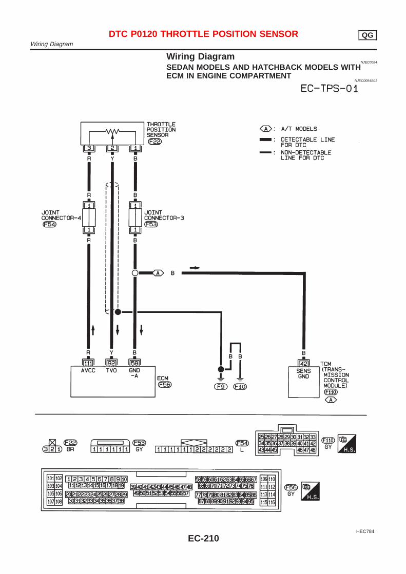
Wiring DiagramNJEC0084
SEDAN MODELS AND HATCHBACK MODELS WITHECM IN ENGINE COMPARTMENT
NJEC0084S01
HEC784
DTC P0120 THROTTLE POSITION SENSOR QGWiring Diagram
EC-210
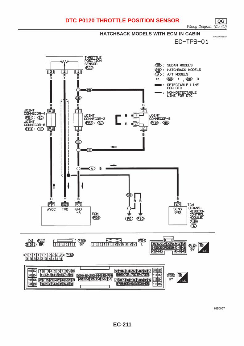
HATCHBACK MODELS WITH ECM IN CABINNJEC0084S02
HEC957
DTC P0120 THROTTLE POSITION SENSOR QGWiring Diagram (Cont’d)
EC-211
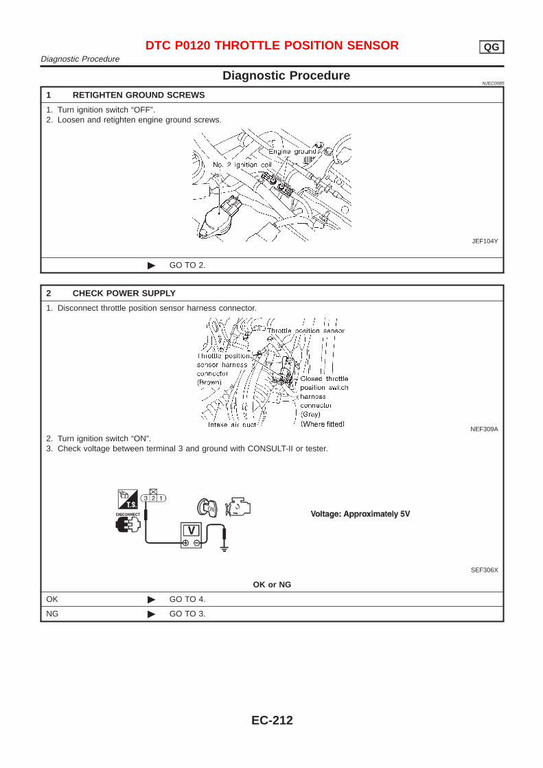
Diagnostic ProcedureNJEC0085
1 RETIGHTEN GROUND SCREWS
1. Turn ignition switch “OFF”.2. Loosen and retighten engine ground screws.
JEF104Y
© GO TO 2.
2 CHECK POWER SUPPLY
1. Disconnect throttle position sensor harness connector.
NEF309A
2. Turn ignition switch “ON”.3. Check voltage between terminal 3 and ground with CONSULT-II or tester.
SEF306X
OK or NG
OK © GO TO 4.
NG © GO TO 3.
DTC P0120 THROTTLE POSITION SENSOR QGDiagnostic Procedure
EC-212
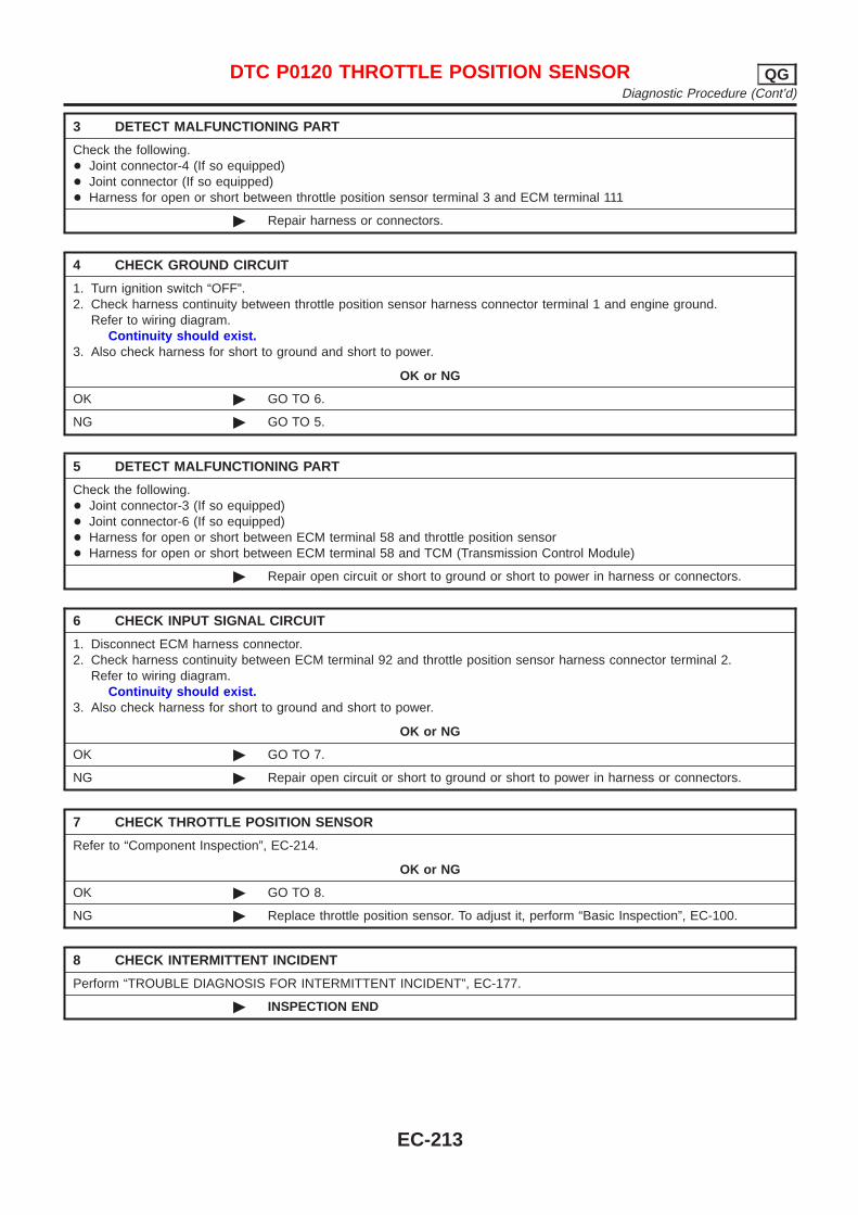
3 DETECT MALFUNCTIONING PART
Check the following.+ Joint connector-4 (If so equipped)+ Joint connector (If so equipped)+ Harness for open or short between throttle position sensor terminal 3 and ECM terminal 111
© Repair harness or connectors.
4 CHECK GROUND CIRCUIT
1. Turn ignition switch “OFF”.2. Check harness continuity between throttle position sensor harness connector terminal 1 and engine ground.
Refer to wiring diagram.Continuity should exist.
3. Also check harness for short to ground and short to power.
OK or NG
OK © GO TO 6.
NG © GO TO 5.
5 DETECT MALFUNCTIONING PART
Check the following.+ Joint connector-3 (If so equipped)+ Joint connector-6 (If so equipped)+ Harness for open or short between ECM terminal 58 and throttle position sensor+ Harness for open or short between ECM terminal 58 and TCM (Transmission Control Module)
© Repair open circuit or short to ground or short to power in harness or connectors.
6 CHECK INPUT SIGNAL CIRCUIT
1. Disconnect ECM harness connector.2. Check harness continuity between ECM terminal 92 and throttle position sensor harness connector terminal 2.
Refer to wiring diagram.Continuity should exist.
3. Also check harness for short to ground and short to power.
OK or NG
OK © GO TO 7.
NG © Repair open circuit or short to ground or short to power in harness or connectors.
7 CHECK THROTTLE POSITION SENSOR
Refer to “Component Inspection”, EC-214.
OK or NG
OK © GO TO 8.
NG © Replace throttle position sensor. To adjust it, perform “Basic Inspection”, EC-100.
8 CHECK INTERMITTENT INCIDENT
Perform “TROUBLE DIAGNOSIS FOR INTERMITTENT INCIDENT”, EC-177.
© INSPECTION END
DTC P0120 THROTTLE POSITION SENSOR QGDiagnostic Procedure (Cont’d)
EC-213
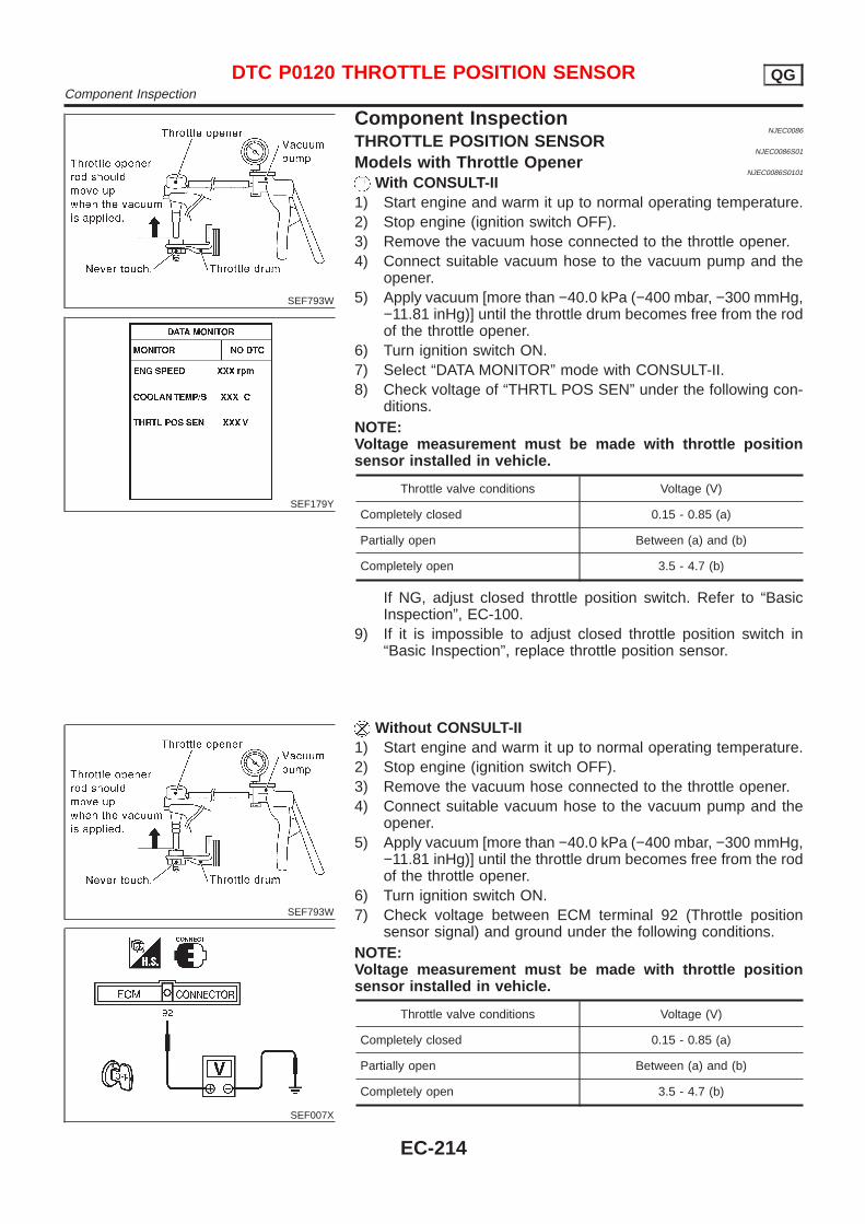
SEF793W
SEF179Y
Component InspectionNJEC0086
THROTTLE POSITION SENSORNJEC0086S01
Models with Throttle OpenerNJEC0086S0101
With CONSULT-II1) Start engine and warm it up to normal operating temperature.2) Stop engine (ignition switch OFF).3) Remove the vacuum hose connected to the throttle opener.4) Connect suitable vacuum hose to the vacuum pump and the
opener.5) Apply vacuum [more than −40.0 kPa (−400 mbar, −300 mmHg,
−11.81 inHg)] until the throttle drum becomes free from the rodof the throttle opener.
6) Turn ignition switch ON.7) Select “DATA MONITOR” mode with CONSULT-II.8) Check voltage of “THRTL POS SEN” under the following con-
ditions.NOTE:Voltage measurement must be made with throttle positionsensor installed in vehicle.
Throttle valve conditions Voltage (V)
Completely closed 0.15 - 0.85 (a)
Partially open Between (a) and (b)
Completely open 3.5 - 4.7 (b)
If NG, adjust closed throttle position switch. Refer to “BasicInspection”, EC-100.
9) If it is impossible to adjust closed throttle position switch in“Basic Inspection”, replace throttle position sensor.
SEF793W
SEF007X
Without CONSULT-II1) Start engine and warm it up to normal operating temperature.2) Stop engine (ignition switch OFF).3) Remove the vacuum hose connected to the throttle opener.4) Connect suitable vacuum hose to the vacuum pump and the
opener.5) Apply vacuum [more than −40.0 kPa (−400 mbar, −300 mmHg,
−11.81 inHg)] until the throttle drum becomes free from the rodof the throttle opener.
6) Turn ignition switch ON.7) Check voltage between ECM terminal 92 (Throttle position
sensor signal) and ground under the following conditions.NOTE:Voltage measurement must be made with throttle positionsensor installed in vehicle.
Throttle valve conditions Voltage (V)
Completely closed 0.15 - 0.85 (a)
Partially open Between (a) and (b)
Completely open 3.5 - 4.7 (b)
DTC P0120 THROTTLE POSITION SENSOR QGComponent Inspection
EC-214

If NG, adjust closed throttle position switch. Refer to “BasicInspection”, EC-100.
8) If it is impossible to adjust closed throttle position switch in“Basic Inspection”, replace throttle position sensor.
NEF069A
Models without Throttle OpenerNJEC0086S0102
With CONSULT-II1) Stop engine (ignition switch OFF).2) Turn ignition switch ON.3) Select “DATA MONITOR” mode with CONSULT-II.4) Check voltage of “THRTL POS SEN” under the following con-
ditions.NOTE:Voltage measurement must be made with throttle positionsensor installed in vehicle.
Throttle valve conditions Voltage (V)
Completely closed 0.35 - 0.65 (a)
Partially open Between (a) and (b)
Completely open 3.7 - 4.5 (b)
If NG, adjust closed throttle position switch. Refer to “BasicInspection”, EC-100.
5) If it is impossible to adjust closed throttle position sensor idleposition in “Basic Inspection”, replace throttle position sensor.
SEF007X
Without CONSULT-II1) Stop engine (ignition switch OFF).2) Turn ignition switch ON.3) Check voltage between ECM terminal 92 (Throttle position
sensor signal) and ground under the following conditions.NOTE:Voltage measurement must be made with throttle positionsensor installed in vehicle.
Throttle valve conditions Voltage (V)
Completely closed 0.35 - 0.65 (a)
Partially open Between (a) and (b)
Completely open 3.7 - 4.5 (b)
If NG, adjust throttle position sensor idle position. Refer to“Basic Inspection”, EC-100.
4) If it is impossible to adjust throttle position sensor idle positionin “Basic Inspection”, replace throttle position sensor.
DTC P0120 THROTTLE POSITION SENSOR QGComponent Inspection (Cont’d)
EC-215
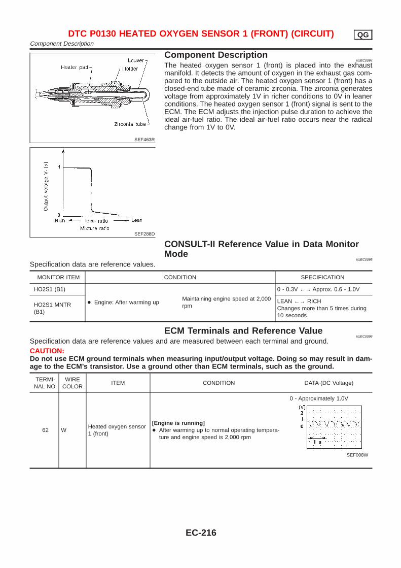
SEF463R
SEF288D
Component DescriptionNJEC0094
The heated oxygen sensor 1 (front) is placed into the exhaustmanifold. It detects the amount of oxygen in the exhaust gas com-pared to the outside air. The heated oxygen sensor 1 (front) has aclosed-end tube made of ceramic zirconia. The zirconia generatesvoltage from approximately 1V in richer conditions to 0V in leanerconditions. The heated oxygen sensor 1 (front) signal is sent to theECM. The ECM adjusts the injection pulse duration to achieve theideal air-fuel ratio. The ideal air-fuel ratio occurs near the radicalchange from 1V to 0V.
CONSULT-II Reference Value in Data MonitorMode
NJEC0095
Specification data are reference values.
MONITOR ITEM CONDITION SPECIFICATION
HO2S1 (B1)
+ Engine: After warming upMaintaining engine speed at 2,000rpm
0 - 0.3V ←→ Approx. 0.6 - 1.0V
HO2S1 MNTR(B1)
LEAN ←→ RICHChanges more than 5 times during10 seconds.
ECM Terminals and Reference ValueNJEC0096
Specification data are reference values and are measured between each terminal and ground.CAUTION:Do not use ECM ground terminals when measuring input/output voltage. Doing so may result in dam-age to the ECM’s transistor. Use a ground other than ECM terminals, such as the ground.
TERMI-NAL NO.
WIRECOLOR
ITEM CONDITION DATA (DC Voltage)
62 WHeated oxygen sensor1 (front)
[Engine is running]+ After warming up to normal operating tempera-
ture and engine speed is 2,000 rpm
0 - Approximately 1.0V
SEF008W
DTC P0130 HEATED OXYGEN SENSOR 1 (FRONT) (CIRCUIT) QGComponent Description
EC-216
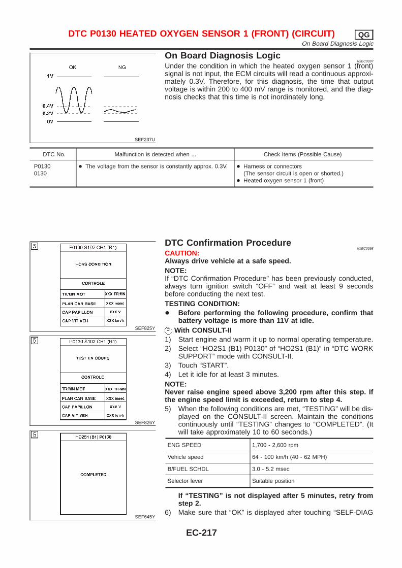
SEF237U
On Board Diagnosis LogicNJEC0097
Under the condition in which the heated oxygen sensor 1 (front)signal is not input, the ECM circuits will read a continuous approxi-mately 0.3V. Therefore, for this diagnosis, the time that outputvoltage is within 200 to 400 mV range is monitored, and the diag-nosis checks that this time is not inordinately long.
DTC No. Malfunction is detected when ... Check Items (Possible Cause)
P01300130
+ The voltage from the sensor is constantly approx. 0.3V. + Harness or connectors(The sensor circuit is open or shorted.)
+ Heated oxygen sensor 1 (front)
SEF825Y
SEF826Y
SEF645Y
DTC Confirmation ProcedureNJEC0098
CAUTION:Always drive vehicle at a safe speed.NOTE:If “DTC Confirmation Procedure” has been previously conducted,always turn ignition switch “OFF” and wait at least 9 secondsbefore conducting the next test.TESTING CONDITION:+ Before performing the following procedure, confirm that
battery voltage is more than 11V at idle.With CONSULT-II
1) Start engine and warm it up to normal operating temperature.2) Select “HO2S1 (B1) P0130” of “HO2S1 (B1)” in “DTC WORK
SUPPORT” mode with CONSULT-II.3) Touch “START”.4) Let it idle for at least 3 minutes.NOTE:Never raise engine speed above 3,200 rpm after this step. Ifthe engine speed limit is exceeded, return to step 4.5) When the following conditions are met, “TESTING” will be dis-
played on the CONSULT-II screen. Maintain the conditionscontinuously until “TESTING” changes to “COMPLETED”. (Itwill take approximately 10 to 60 seconds.)
ENG SPEED 1,700 - 2,600 rpm
Vehicle speed 64 - 100 km/h (40 - 62 MPH)
B/FUEL SCHDL 3.0 - 5.2 msec
Selector lever Suitable position
If “TESTING” is not displayed after 5 minutes, retry fromstep 2.
6) Make sure that “OK” is displayed after touching “SELF-DIAG
DTC P0130 HEATED OXYGEN SENSOR 1 (FRONT) (CIRCUIT) QGOn Board Diagnosis Logic
EC-217
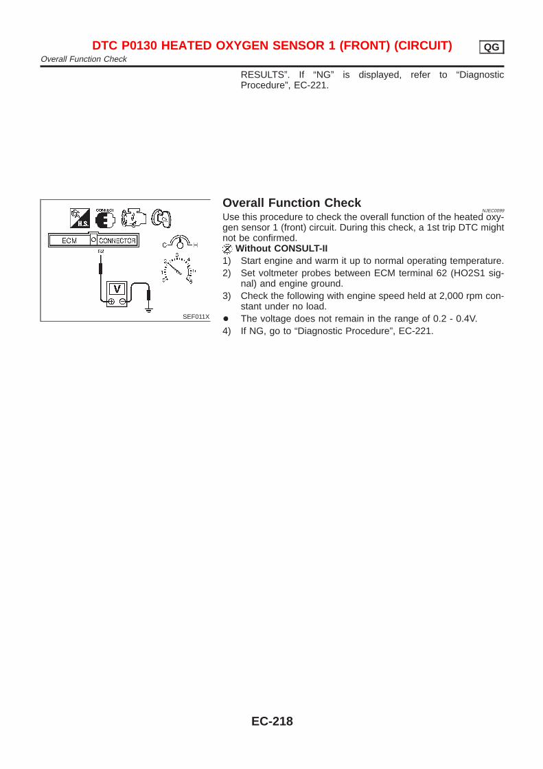
RESULTS”. If “NG” is displayed, refer to “DiagnosticProcedure”, EC-221.
SEF011X
Overall Function CheckNJEC0099
Use this procedure to check the overall function of the heated oxy-gen sensor 1 (front) circuit. During this check, a 1st trip DTC mightnot be confirmed.
Without CONSULT-II1) Start engine and warm it up to normal operating temperature.2) Set voltmeter probes between ECM terminal 62 (HO2S1 sig-
nal) and engine ground.3) Check the following with engine speed held at 2,000 rpm con-
stant under no load.+ The voltage does not remain in the range of 0.2 - 0.4V.4) If NG, go to “Diagnostic Procedure”, EC-221.
DTC P0130 HEATED OXYGEN SENSOR 1 (FRONT) (CIRCUIT) QGOverall Function Check
EC-218

Wiring DiagramNJEC0100
SEDAN MODELS AND HATCHBACK MODELS WITHECM IN ENGINE COMPARTMENT
NJEC0100S03
HEC785
DTC P0130 HEATED OXYGEN SENSOR 1 (FRONT) (CIRCUIT) QGWiring Diagram
EC-219

HATCHBACK MODELS WITH ECM IN CABINNJEC0100S04
HEC936
DTC P0130 HEATED OXYGEN SENSOR 1 (FRONT) (CIRCUIT) QGWiring Diagram (Cont’d)
EC-220
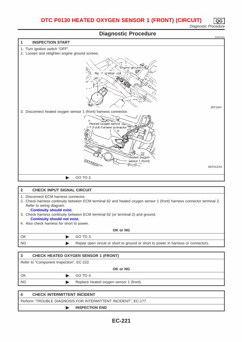
Diagnostic ProcedureNJEC0101
1 INSPECTION START
1. Turn ignition switch “OFF”.2. Loosen and retighten engine ground screws.
JEF104Y
3. Disconnect heated oxygen sensor 1 (front) harness connector.
SEF012XA
© GO TO 2.
2 CHECK INPUT SIGNAL CIRCUIT
1. Disconnect ECM harness connector.2. Check harness continuity between ECM terminal 62 and heated oxygen sensor 1 (front) harness connector terminal 2.
Refer to wiring diagram.Continuity should exist.
3. Check harness continuity between ECM terminal 62 (or terminal 2) and ground.Continuity should not exist.
4. Also check harness for short to power.
OK or NG
OK © GO TO 3.
NG © Repair open circuit or short to ground or short to power in harness or connectors.
3 CHECK HEATED OXYGEN SENSOR 1 (FRONT)
Refer to “Component Inspection”, EC-222.
OK or NG
OK © GO TO 4.
NG © Replace heated oxygen sensor 1 (front).
4 CHECK INTERMITTENT INCIDENT
Perform “TROUBLE DIAGNOSIS FOR INTERMITTENT INCIDENT”, EC-177.
© INSPECTION END
DTC P0130 HEATED OXYGEN SENSOR 1 (FRONT) (CIRCUIT) QGDiagnostic Procedure
EC-221
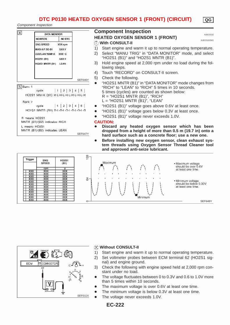
SEF646Y
SEF647Y
Component InspectionNJEC0102
HEATED OXYGEN SENSOR 1 (FRONT)NJEC0102S01
With CONSULT-II1) Start engine and warm it up to normal operating temperature.2) Select “MANU TRIG” in “DATA MONITOR” mode, and select
“HO2S1 (B1)” and “HO2S1 MNTR (B1)”.3) Hold engine speed at 2,000 rpm under no load during the fol-
lowing steps.4) Touch “RECORD” on CONSULT-II screen.5) Check the following.+ “HO2S1 MNTR (B1)” in “DATA MONITOR” mode changes from
“RICH” to “LEAN” to “RICH” 5 times in 10 seconds.5 times (cycles) are counted as shown below:R = “HO2S1 MNTR (B1)”, “RICH”L = “HO2S1 MNTR (B1)”, “LEAN”
+ “HO2S1 (B1)” voltage goes above 0.6V at least once.+ “HO2S1 (B1)” voltage goes below 0.3V at least once.+ “HO2S1 (B1)” voltage never exceeds 1.0V.CAUTION:+ Discard any heated oxygen sensor which has been
dropped from a height of more than 0.5 m (19.7 in) onto ahard surface such as a concrete floor; use a new one.
+ Before installing new oxygen sensor, clean exhaust sys-tem threads using Oxygen Sensor Thread Cleaner tooland approved anti-seize lubricant.
SEF648Y
SEF011X
Without CONSULT-II1) Start engine and warm it up to normal operating temperature.2) Set voltmeter probes between ECM terminal 62 (HO2S1 sig-
nal) and engine ground.3) Check the following with engine speed held at 2,000 rpm con-
stant under no load.+ The voltage fluctuates between 0 to 0.3V and 0.6 to 1.0V more
than 5 times within 10 seconds.+ The maximum voltage is over 0.6V at least one time.+ The minimum voltage is below 0.3V at least one time.+ The voltage never exceeds 1.0V.
DTC P0130 HEATED OXYGEN SENSOR 1 (FRONT) (CIRCUIT) QGComponent Inspection
EC-222

1 time: 0 - 0.3V → 0.6 - 1.0V → 0 - 0.3V2 times: 0 - 0.3V → 0.6 - 1.0V → 0 - 0.3V → 0.6 - 1.0V → 0 -0.3V
CAUTION:+ Discard any heated oxygen sensor which has been
dropped from a height of more than 0.5 m (19.7 in) onto ahard surface such as a concrete floor; use a new one.
+ Before installing new oxygen sensor, clean exhaust sys-tem threads using Oxygen Sensor Thread Cleaner tooland approved anti-seize lubricant.
DTC P0130 HEATED OXYGEN SENSOR 1 (FRONT) (CIRCUIT) QGComponent Inspection (Cont’d)
EC-223

SEF463R
SEF288D
Component DescriptionNJEC0103
The heated oxygen sensor 1 (front) is placed into the exhaustmanifold. It detects the amount of oxygen in the exhaust gas com-pared to the outside air. The heated oxygen sensor 1 (front) has aclosed-end tube made of ceramic zirconia. The zirconia generatesvoltage from approximately 1V in richer conditions to 0V in leanerconditions. The heated oxygen sensor 1 (front) signal is sent to theECM. The ECM adjusts the injection pulse duration to achieve theideal air-fuel ratio. The ideal air-fuel ratio occurs near the radicalchange from 1V to 0V.
CONSULT-II Reference Value in Data MonitorMode
NJEC0104
Specification data are reference values.
MONITOR ITEM CONDITION SPECIFICATION
HO2S1 (B1)
+ Engine: After warming upMaintaining engine speed at 2,000rpm
0 - 0.3V ←→ Approx. 0.6 - 1.0V
HO2S1 MNTR(B1)
LEAN ←→ RICHChanges more than 5 times during10 seconds.
ECM Terminals and Reference ValueNJEC0105
Specification data are reference values and are measured between each terminal and ground.CAUTION:Do not use ECM ground terminals when measuring input/output voltage. Doing so may result in dam-age to the ECM’s transistor. Use a ground other than ECM terminals, such as the ground.
TERMI-NALNO.
WIRECOLOR
ITEM CONDITION DATA (DC Voltage)
62 WHeated oxygen sensor1 (front)
[Engine is running]+ After warming up to normal operating temperature
and engine speed is 2,000 rpm
0 - Approximately 1.0V
SEF008W
DTC P0131 HEATED OXYGEN SENSOR 1 (FRONT) (LEAN SHIFTMONITORING) QG
Component Description
EC-224
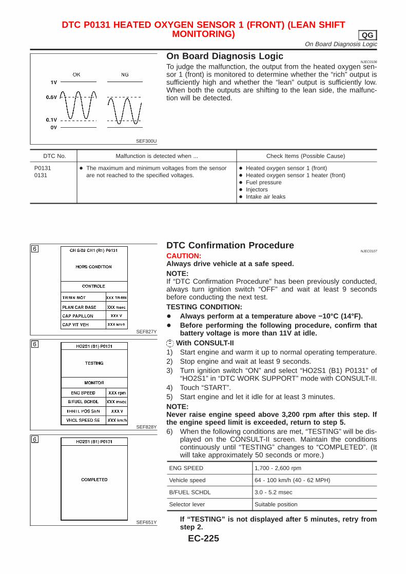
SEF300U
On Board Diagnosis LogicNJEC0106
To judge the malfunction, the output from the heated oxygen sen-sor 1 (front) is monitored to determine whether the “rich” output issufficiently high and whether the “lean” output is sufficiently low.When both the outputs are shifting to the lean side, the malfunc-tion will be detected.
DTC No. Malfunction is detected when ... Check Items (Possible Cause)
P01310131
+ The maximum and minimum voltages from the sensorare not reached to the specified voltages.
+ Heated oxygen sensor 1 (front)+ Heated oxygen sensor 1 heater (front)+ Fuel pressure+ Injectors+ Intake air leaks
SEF827Y
SEF828Y
SEF651Y
DTC Confirmation ProcedureNJEC0107
CAUTION:Always drive vehicle at a safe speed.NOTE:If “DTC Confirmation Procedure” has been previously conducted,always turn ignition switch “OFF” and wait at least 9 secondsbefore conducting the next test.TESTING CONDITION:+ Always perform at a temperature above −10°C (14°F).+ Before performing the following procedure, confirm that
battery voltage is more than 11V at idle.With CONSULT-II
1) Start engine and warm it up to normal operating temperature.2) Stop engine and wait at least 9 seconds.3) Turn ignition switch “ON” and select “HO2S1 (B1) P0131” of
“HO2S1” in “DTC WORK SUPPORT” mode with CONSULT-II.4) Touch “START”.5) Start engine and let it idle for at least 3 minutes.NOTE:Never raise engine speed above 3,200 rpm after this step. Ifthe engine speed limit is exceeded, return to step 5.6) When the following conditions are met, “TESTING” will be dis-
played on the CONSULT-II screen. Maintain the conditionscontinuously until “TESTING” changes to “COMPLETED”. (Itwill take approximately 50 seconds or more.)
ENG SPEED 1,700 - 2,600 rpm
Vehicle speed 64 - 100 km/h (40 - 62 MPH)
B/FUEL SCHDL 3.0 - 5.2 msec
Selector lever Suitable position
If “TESTING” is not displayed after 5 minutes, retry fromstep 2.
DTC P0131 HEATED OXYGEN SENSOR 1 (FRONT) (LEAN SHIFTMONITORING) QG
On Board Diagnosis Logic
EC-225

7) Make sure that “OK” is displayed after touching “SELF-DIAGRESULTS”. If “NG” is displayed, refer to “DiagnosticProcedure”, EC-226.
SEF011X
Overall Function CheckNJEC0108
Use this procedure to check the overall function of the heated oxy-gen sensor 1 (front) circuit. During this check, a 1st trip DTC mightnot be confirmed.
Without CONSULT-II1) Start engine and warm it up to normal operating temperature.2) Set voltmeter probes between ECM terminal 62 (HO2S1 sig-
nal) and engine ground.3) Check the following with engine speed held at 2,000 rpm con-
stant under no load.+ The maximum voltage is over 0.6V at least one time.+ The minimum voltage is over 0.1V at least one time.4) If NG, go to “Diagnostic Procedure”, EC-226.
Diagnostic ProcedureNJEC0109
1 RETIGHTEN HEATED OXYGEN SENSOR 1 (FRONT)
1. Turn ignition switch “OFF”.2. Loosen and retighten heated oxygen sensor 1 (front).
Tightening torque:40 - 60 N·m (4.1 - 6.1 kg-m, 30 - 44 ft-lb)
© GO TO 2.
DTC P0131 HEATED OXYGEN SENSOR 1 (FRONT) (LEAN SHIFTMONITORING) QG
DTC Confirmation Procedure (Cont’d)
EC-226
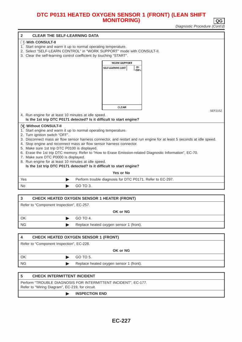
2 CLEAR THE SELF-LEARNING DATA
With CONSULT-II1. Start engine and warm it up to normal operating temperature.2. Select “SELF-LEARN CONTROL” in “WORK SUPPORT” mode with CONSULT-II.3. Clear the self-learning control coefficient by touching “START”.
SEF215Z
4. Run engine for at least 10 minutes at idle speed.Is the 1st trip DTC P0171 detected? Is it difficult to start engine?
Without CONSULT-II1. Start engine and warm it up to normal operating temperature.2. Turn ignition switch “OFF”.3. Disconnect mass air flow sensor harness connector, and restart and run engine for at least 5 seconds at idle speed.4. Stop engine and reconnect mass air flow sensor harness connector.5. Make sure 1st trip DTC P0100 is displayed.6. Erase the 1st trip DTC memory. Refer to “How to Erase Emission-related Diagnostic Information”, EC-70.7. Make sure DTC P0000 is displayed.8. Run engine for at least 10 minutes at idle speed.
Is the 1st trip DTC P0171 detected? Is it difficult to start engine?
Yes or No
Yes © Perform trouble diagnosis for DTC P0171. Refer to EC-297.
No © GO TO 3.
3 CHECK HEATED OXYGEN SENSOR 1 HEATER (FRONT)
Refer to “Component Inspection”, EC-257.
OK or NG
OK © GO TO 4.
NG © Replace heated oxygen sensor 1 (front).
4 CHECK HEATED OXYGEN SENSOR 1 (FRONT)
Refer to “Component Inspection”, EC-228.
OK or NG
OK © GO TO 5.
NG © Replace heated oxygen sensor 1 (front).
5 CHECK INTERMITTENT INCIDENT
Perform “TROUBLE DIAGNOSIS FOR INTERMITTENT INCIDENT”, EC-177.Refer to “Wiring Diagram”, EC-219, for circuit.
© INSPECTION END
DTC P0131 HEATED OXYGEN SENSOR 1 (FRONT) (LEAN SHIFTMONITORING) QG
Diagnostic Procedure (Cont’d)
EC-227
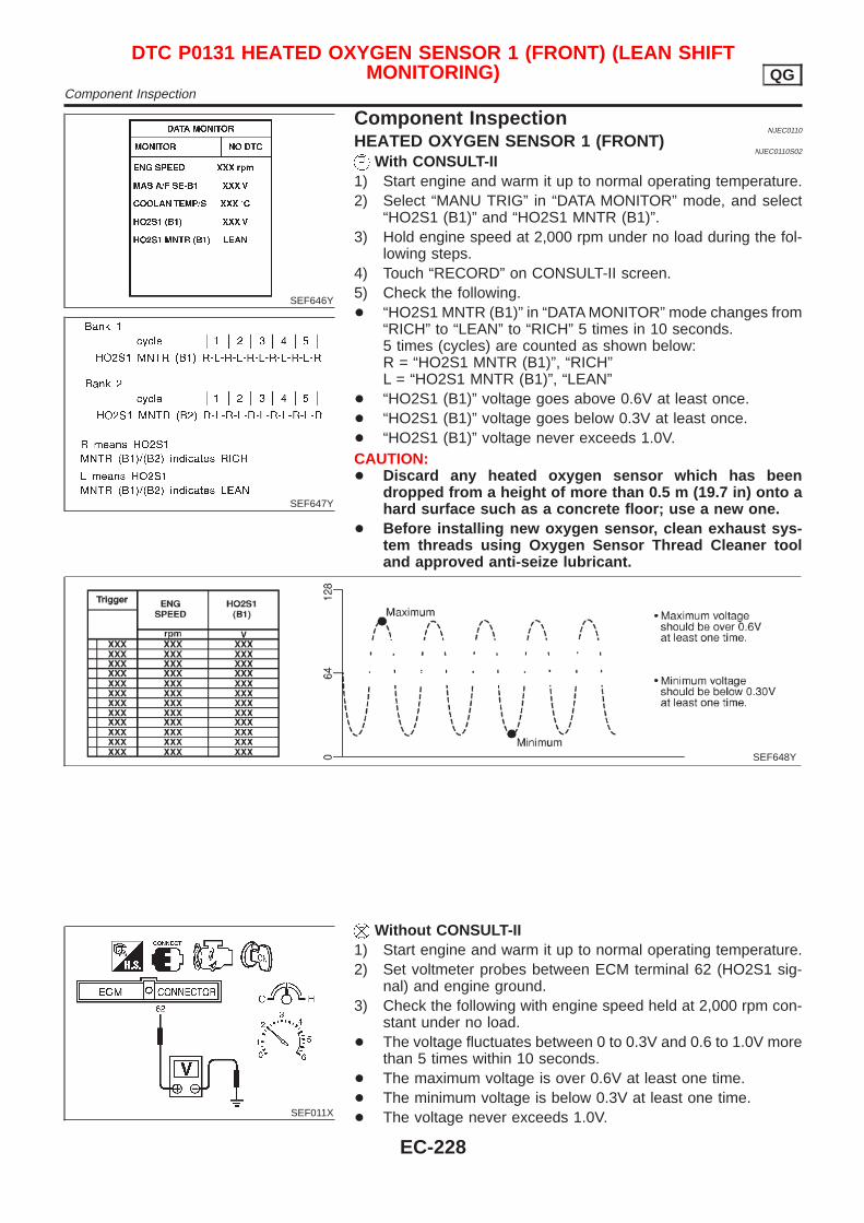
SEF646Y
SEF647Y
Component InspectionNJEC0110
HEATED OXYGEN SENSOR 1 (FRONT)NJEC0110S02
With CONSULT-II1) Start engine and warm it up to normal operating temperature.2) Select “MANU TRIG” in “DATA MONITOR” mode, and select
“HO2S1 (B1)” and “HO2S1 MNTR (B1)”.3) Hold engine speed at 2,000 rpm under no load during the fol-
lowing steps.4) Touch “RECORD” on CONSULT-II screen.5) Check the following.+ “HO2S1 MNTR (B1)” in “DATA MONITOR” mode changes from
“RICH” to “LEAN” to “RICH” 5 times in 10 seconds.5 times (cycles) are counted as shown below:R = “HO2S1 MNTR (B1)”, “RICH”L = “HO2S1 MNTR (B1)”, “LEAN”
+ “HO2S1 (B1)” voltage goes above 0.6V at least once.+ “HO2S1 (B1)” voltage goes below 0.3V at least once.+ “HO2S1 (B1)” voltage never exceeds 1.0V.CAUTION:+ Discard any heated oxygen sensor which has been
dropped from a height of more than 0.5 m (19.7 in) onto ahard surface such as a concrete floor; use a new one.
+ Before installing new oxygen sensor, clean exhaust sys-tem threads using Oxygen Sensor Thread Cleaner tooland approved anti-seize lubricant.
SEF648Y
SEF011X
Without CONSULT-II1) Start engine and warm it up to normal operating temperature.2) Set voltmeter probes between ECM terminal 62 (HO2S1 sig-
nal) and engine ground.3) Check the following with engine speed held at 2,000 rpm con-
stant under no load.+ The voltage fluctuates between 0 to 0.3V and 0.6 to 1.0V more
than 5 times within 10 seconds.+ The maximum voltage is over 0.6V at least one time.+ The minimum voltage is below 0.3V at least one time.+ The voltage never exceeds 1.0V.
DTC P0131 HEATED OXYGEN SENSOR 1 (FRONT) (LEAN SHIFTMONITORING) QG
Component Inspection
EC-228

1 time: 0 - 0.3V → 0.6 - 1.0V → 0 - 0.3V2 times: 0 - 0.3V → 0.6 - 1.0V → 0 - 0.3V → 0.6 - 1.0V → 0 -0.3V
CAUTION:+ Discard any heated oxygen sensor which has been
dropped from a height of more than 0.5 m (19.7 in) onto ahard surface such as a concrete floor; use a new one.
+ Before installing new oxygen sensor, clean exhaust sys-tem threads using Oxygen Sensor Thread Cleaner tooland approved anti-seize lubricant.
DTC P0131 HEATED OXYGEN SENSOR 1 (FRONT) (LEAN SHIFTMONITORING) QG
Component Inspection (Cont’d)
EC-229
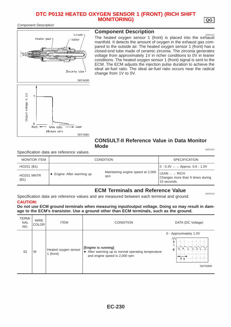
SEF463R
SEF288D
Component DescriptionNJEC0111
The heated oxygen sensor 1 (front) is placed into the exhaustmanifold. It detects the amount of oxygen in the exhaust gas com-pared to the outside air. The heated oxygen sensor 1 (front) has aclosed-end tube made of ceramic zirconia. The zirconia generatesvoltage from approximately 1V in richer conditions to 0V in leanerconditions. The heated oxygen sensor 1 (front) signal is sent to theECM. The ECM adjusts the injection pulse duration to achieve theideal air-fuel ratio. The ideal air-fuel ratio occurs near the radicalchange from 1V to 0V.
CONSULT-II Reference Value in Data MonitorMode
NJEC0112
Specification data are reference values.
MONITOR ITEM CONDITION SPECIFICATION
HO2S1 (B1)
+ Engine: After warming upMaintaining engine speed at 2,000rpm
0 - 0.3V ←→ Approx. 0.6 - 1.0V
HO2S1 MNTR(B1)
LEAN ←→ RICHChanges more than 5 times during10 seconds.
ECM Terminals and Reference ValueNJEC0113
Specification data are reference values and are measured between each terminal and ground.CAUTION:Do not use ECM ground terminals when measuring input/output voltage. Doing so may result in dam-age to the ECM’s transistor. Use a ground other than ECM terminals, such as the ground.
TERMI-NALNO.
WIRECOLOR
ITEM CONDITION DATA (DC Voltage)
62 WHeated oxygen sensor1 (front)
[Engine is running]+ After warming up to normal operating temperature
and engine speed is 2,000 rpm
0 - Approximately 1.0V
SEF008W
DTC P0132 HEATED OXYGEN SENSOR 1 (FRONT) (RICH SHIFTMONITORING) QG
Component Description
EC-230
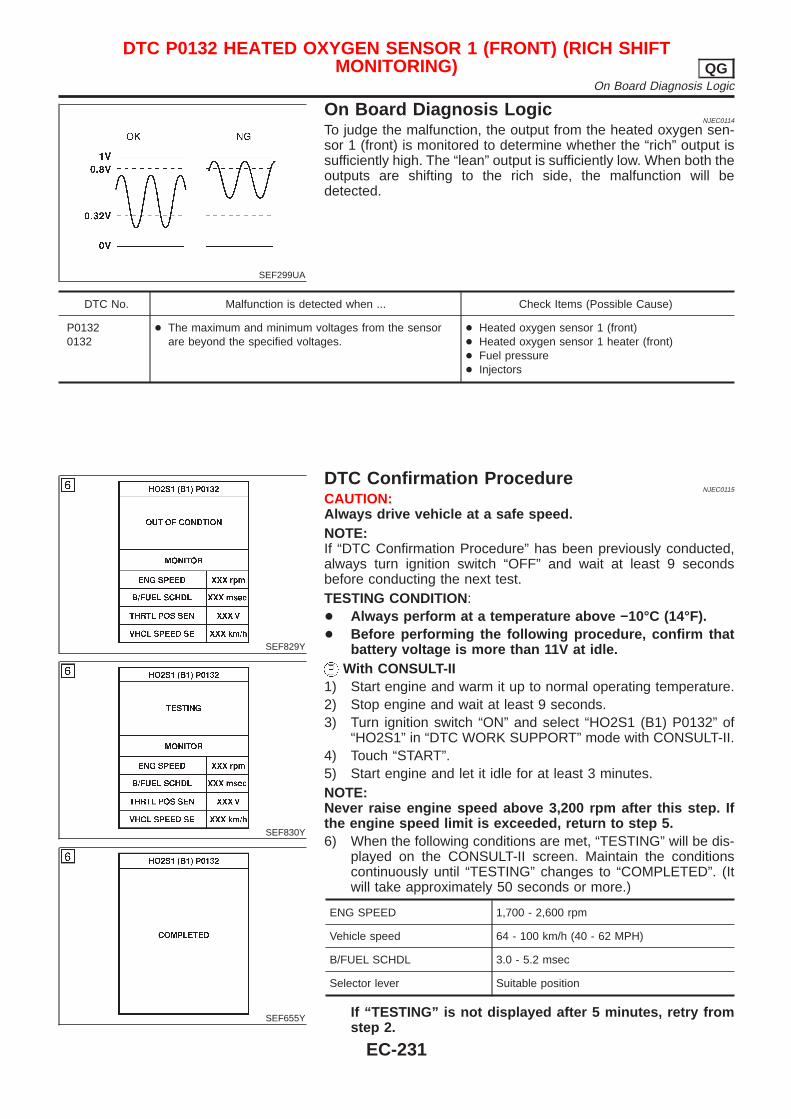
SEF299UA
On Board Diagnosis LogicNJEC0114
To judge the malfunction, the output from the heated oxygen sen-sor 1 (front) is monitored to determine whether the “rich” output issufficiently high. The “lean” output is sufficiently low. When both theoutputs are shifting to the rich side, the malfunction will bedetected.
DTC No. Malfunction is detected when ... Check Items (Possible Cause)
P01320132
+ The maximum and minimum voltages from the sensorare beyond the specified voltages.
+ Heated oxygen sensor 1 (front)+ Heated oxygen sensor 1 heater (front)+ Fuel pressure+ Injectors
SEF829Y
SEF830Y
SEF655Y
DTC Confirmation ProcedureNJEC0115
CAUTION:Always drive vehicle at a safe speed.NOTE:If “DTC Confirmation Procedure” has been previously conducted,always turn ignition switch “OFF” and wait at least 9 secondsbefore conducting the next test.TESTING CONDITION:+ Always perform at a temperature above −10°C (14°F).+ Before performing the following procedure, confirm that
battery voltage is more than 11V at idle.With CONSULT-II
1) Start engine and warm it up to normal operating temperature.2) Stop engine and wait at least 9 seconds.3) Turn ignition switch “ON” and select “HO2S1 (B1) P0132” of
“HO2S1” in “DTC WORK SUPPORT” mode with CONSULT-II.4) Touch “START”.5) Start engine and let it idle for at least 3 minutes.NOTE:Never raise engine speed above 3,200 rpm after this step. Ifthe engine speed limit is exceeded, return to step 5.6) When the following conditions are met, “TESTING” will be dis-
played on the CONSULT-II screen. Maintain the conditionscontinuously until “TESTING” changes to “COMPLETED”. (Itwill take approximately 50 seconds or more.)
ENG SPEED 1,700 - 2,600 rpm
Vehicle speed 64 - 100 km/h (40 - 62 MPH)
B/FUEL SCHDL 3.0 - 5.2 msec
Selector lever Suitable position
If “TESTING” is not displayed after 5 minutes, retry fromstep 2.
DTC P0132 HEATED OXYGEN SENSOR 1 (FRONT) (RICH SHIFTMONITORING) QG
On Board Diagnosis Logic
EC-231
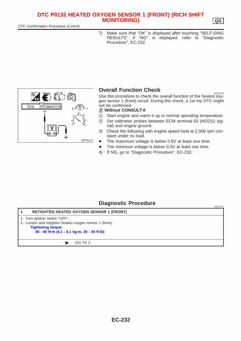
7) Make sure that “OK” is displayed after touching “SELF-DIAGRESULTS”. If “NG” is displayed, refer to “DiagnosticProcedure”, EC-232.
SEF011X
Overall Function CheckNJEC0116
Use this procedure to check the overall function of the heated oxy-gen sensor 1 (front) circuit. During this check, a 1st trip DTC mightnot be confirmed.
Without CONSULT-II1) Start engine and warm it up to normal operating temperature.2) Set voltmeter probes between ECM terminal 62 (HO2S1 sig-
nal) and engine ground.3) Check the following with engine speed held at 2,000 rpm con-
stant under no load.+ The maximum voltage is below 0.8V at least one time.+ The minimum voltage is below 0.3V at least one time.4) If NG, go to “Diagnostic Procedure”, EC-232.
Diagnostic ProcedureNJEC0117
1 RETIGHTEN HEATED OXYGEN SENSOR 1 (FRONT)
1. Turn ignition switch “OFF”.2. Loosen and retighten heated oxygen sensor 1 (front).
Tightening torque:40 - 60 N·m (4.1 - 6.1 kg-m, 30 - 44 ft-lb)
© GO TO 2.
DTC P0132 HEATED OXYGEN SENSOR 1 (FRONT) (RICH SHIFTMONITORING) QG
DTC Confirmation Procedure (Cont’d)
EC-232
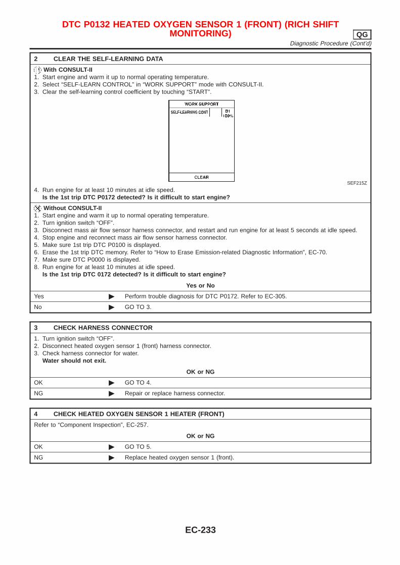
2 CLEAR THE SELF-LEARNING DATA
With CONSULT-II1. Start engine and warm it up to normal operating temperature.2. Select “SELF-LEARN CONTROL” in “WORK SUPPORT” mode with CONSULT-II.3. Clear the self-learning control coefficient by touching “START”.
SEF215Z
4. Run engine for at least 10 minutes at idle speed.Is the 1st trip DTC P0172 detected? Is it difficult to start engine?
Without CONSULT-II1. Start engine and warm it up to normal operating temperature.2. Turn ignition switch “OFF”.3. Disconnect mass air flow sensor harness connector, and restart and run engine for at least 5 seconds at idle speed.4. Stop engine and reconnect mass air flow sensor harness connector.5. Make sure 1st trip DTC P0100 is displayed.6. Erase the 1st trip DTC memory. Refer to “How to Erase Emission-related Diagnostic Information”, EC-70.7. Make sure DTC P0000 is displayed.8. Run engine for at least 10 minutes at idle speed.
Is the 1st trip DTC 0172 detected? Is it difficult to start engine?
Yes or No
Yes © Perform trouble diagnosis for DTC P0172. Refer to EC-305.
No © GO TO 3.
3 CHECK HARNESS CONNECTOR
1. Turn ignition switch “OFF”.2. Disconnect heated oxygen sensor 1 (front) harness connector.3. Check harness connector for water.
Water should not exit.
OK or NG
OK © GO TO 4.
NG © Repair or replace harness connector.
4 CHECK HEATED OXYGEN SENSOR 1 HEATER (FRONT)
Refer to “Component Inspection”, EC-257.
OK or NG
OK © GO TO 5.
NG © Replace heated oxygen sensor 1 (front).
DTC P0132 HEATED OXYGEN SENSOR 1 (FRONT) (RICH SHIFTMONITORING) QG
Diagnostic Procedure (Cont’d)
EC-233
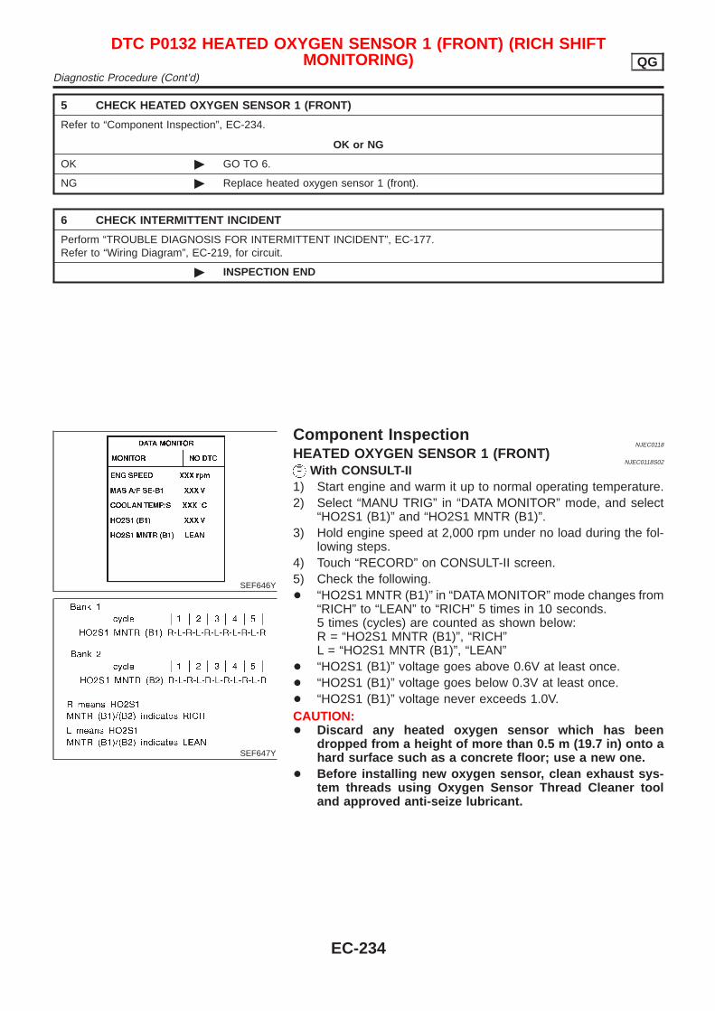
5 CHECK HEATED OXYGEN SENSOR 1 (FRONT)
Refer to “Component Inspection”, EC-234.
OK or NG
OK © GO TO 6.
NG © Replace heated oxygen sensor 1 (front).
6 CHECK INTERMITTENT INCIDENT
Perform “TROUBLE DIAGNOSIS FOR INTERMITTENT INCIDENT”, EC-177.Refer to “Wiring Diagram”, EC-219, for circuit.
© INSPECTION END
SEF646Y
SEF647Y
Component InspectionNJEC0118
HEATED OXYGEN SENSOR 1 (FRONT)NJEC0118S02
With CONSULT-II1) Start engine and warm it up to normal operating temperature.2) Select “MANU TRIG” in “DATA MONITOR” mode, and select
“HO2S1 (B1)” and “HO2S1 MNTR (B1)”.3) Hold engine speed at 2,000 rpm under no load during the fol-
lowing steps.4) Touch “RECORD” on CONSULT-II screen.5) Check the following.+ “HO2S1 MNTR (B1)” in “DATA MONITOR” mode changes from
“RICH” to “LEAN” to “RICH” 5 times in 10 seconds.5 times (cycles) are counted as shown below:R = “HO2S1 MNTR (B1)”, “RICH”L = “HO2S1 MNTR (B1)”, “LEAN”
+ “HO2S1 (B1)” voltage goes above 0.6V at least once.+ “HO2S1 (B1)” voltage goes below 0.3V at least once.+ “HO2S1 (B1)” voltage never exceeds 1.0V.CAUTION:+ Discard any heated oxygen sensor which has been
dropped from a height of more than 0.5 m (19.7 in) onto ahard surface such as a concrete floor; use a new one.
+ Before installing new oxygen sensor, clean exhaust sys-tem threads using Oxygen Sensor Thread Cleaner tooland approved anti-seize lubricant.
DTC P0132 HEATED OXYGEN SENSOR 1 (FRONT) (RICH SHIFTMONITORING) QG
Diagnostic Procedure (Cont’d)
EC-234
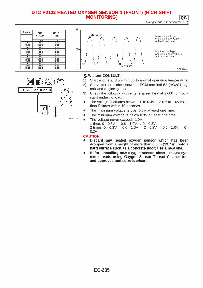
SEF648Y
SEF011X
Without CONSULT-II1) Start engine and warm it up to normal operating temperature.2) Set voltmeter probes between ECM terminal 62 (HO2S1 sig-
nal) and engine ground.3) Check the following with engine speed held at 2,000 rpm con-
stant under no load.+ The voltage fluctuates between 0 to 0.3V and 0.6 to 1.0V more
than 5 times within 10 seconds.+ The maximum voltage is over 0.6V at least one time.+ The minimum voltage is below 0.3V at least one time.+ The voltage never exceeds 1.0V.
1 time: 0 - 0.3V → 0.6 - 1.0V → 0 - 0.3V2 times: 0 - 0.3V → 0.6 - 1.0V → 0 - 0.3V → 0.6 - 1.0V → 0 -0.3V
CAUTION:+ Discard any heated oxygen sensor which has been
dropped from a height of more than 0.5 m (19.7 in) onto ahard surface such as a concrete floor; use a new one.
+ Before installing new oxygen sensor, clean exhaust sys-tem threads using Oxygen Sensor Thread Cleaner tooland approved anti-seize lubricant.
DTC P0132 HEATED OXYGEN SENSOR 1 (FRONT) (RICH SHIFTMONITORING) QG
Component Inspection (Cont’d)
EC-235
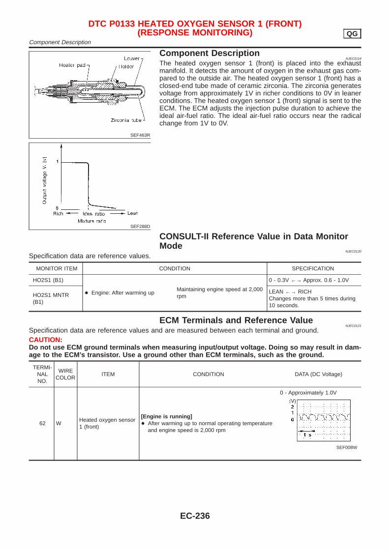
SEF463R
SEF288D
Component DescriptionNJEC0119
The heated oxygen sensor 1 (front) is placed into the exhaustmanifold. It detects the amount of oxygen in the exhaust gas com-pared to the outside air. The heated oxygen sensor 1 (front) has aclosed-end tube made of ceramic zirconia. The zirconia generatesvoltage from approximately 1V in richer conditions to 0V in leanerconditions. The heated oxygen sensor 1 (front) signal is sent to theECM. The ECM adjusts the injection pulse duration to achieve theideal air-fuel ratio. The ideal air-fuel ratio occurs near the radicalchange from 1V to 0V.
CONSULT-II Reference Value in Data MonitorMode
NJEC0120
Specification data are reference values.
MONITOR ITEM CONDITION SPECIFICATION
HO2S1 (B1)
+ Engine: After warming upMaintaining engine speed at 2,000rpm
0 - 0.3V ←→ Approx. 0.6 - 1.0V
HO2S1 MNTR(B1)
LEAN ←→ RICHChanges more than 5 times during10 seconds.
ECM Terminals and Reference ValueNJEC0121
Specification data are reference values and are measured between each terminal and ground.CAUTION:Do not use ECM ground terminals when measuring input/output voltage. Doing so may result in dam-age to the ECM’s transistor. Use a ground other than ECM terminals, such as the ground.
TERMI-NALNO.
WIRECOLOR
ITEM CONDITION DATA (DC Voltage)
62 WHeated oxygen sensor1 (front)
[Engine is running]+ After warming up to normal operating temperature
and engine speed is 2,000 rpm
0 - Approximately 1.0V
SEF008W
DTC P0133 HEATED OXYGEN SENSOR 1 (FRONT)(RESPONSE MONITORING) QG
Component Description
EC-236
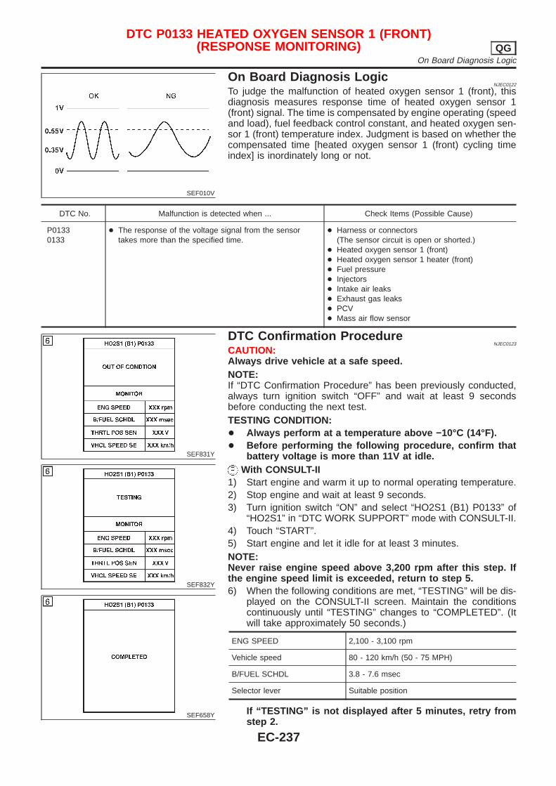
SEF010V
On Board Diagnosis LogicNJEC0122
To judge the malfunction of heated oxygen sensor 1 (front), thisdiagnosis measures response time of heated oxygen sensor 1(front) signal. The time is compensated by engine operating (speedand load), fuel feedback control constant, and heated oxygen sen-sor 1 (front) temperature index. Judgment is based on whether thecompensated time [heated oxygen sensor 1 (front) cycling timeindex] is inordinately long or not.
DTC No. Malfunction is detected when ... Check Items (Possible Cause)
P01330133
+ The response of the voltage signal from the sensortakes more than the specified time.
+ Harness or connectors(The sensor circuit is open or shorted.)
+ Heated oxygen sensor 1 (front)+ Heated oxygen sensor 1 heater (front)+ Fuel pressure+ Injectors+ Intake air leaks+ Exhaust gas leaks+ PCV+ Mass air flow sensor
SEF831Y
SEF832Y
SEF658Y
DTC Confirmation ProcedureNJEC0123
CAUTION:Always drive vehicle at a safe speed.NOTE:If “DTC Confirmation Procedure” has been previously conducted,always turn ignition switch “OFF” and wait at least 9 secondsbefore conducting the next test.TESTING CONDITION:+ Always perform at a temperature above −10°C (14°F).+ Before performing the following procedure, confirm that
battery voltage is more than 11V at idle.With CONSULT-II
1) Start engine and warm it up to normal operating temperature.2) Stop engine and wait at least 9 seconds.3) Turn ignition switch “ON” and select “HO2S1 (B1) P0133” of
“HO2S1” in “DTC WORK SUPPORT” mode with CONSULT-II.4) Touch “START”.5) Start engine and let it idle for at least 3 minutes.NOTE:Never raise engine speed above 3,200 rpm after this step. Ifthe engine speed limit is exceeded, return to step 5.6) When the following conditions are met, “TESTING” will be dis-
played on the CONSULT-II screen. Maintain the conditionscontinuously until “TESTING” changes to “COMPLETED”. (Itwill take approximately 50 seconds.)
ENG SPEED 2,100 - 3,100 rpm
Vehicle speed 80 - 120 km/h (50 - 75 MPH)
B/FUEL SCHDL 3.8 - 7.6 msec
Selector lever Suitable position
If “TESTING” is not displayed after 5 minutes, retry fromstep 2.
DTC P0133 HEATED OXYGEN SENSOR 1 (FRONT)(RESPONSE MONITORING) QG
On Board Diagnosis Logic
EC-237
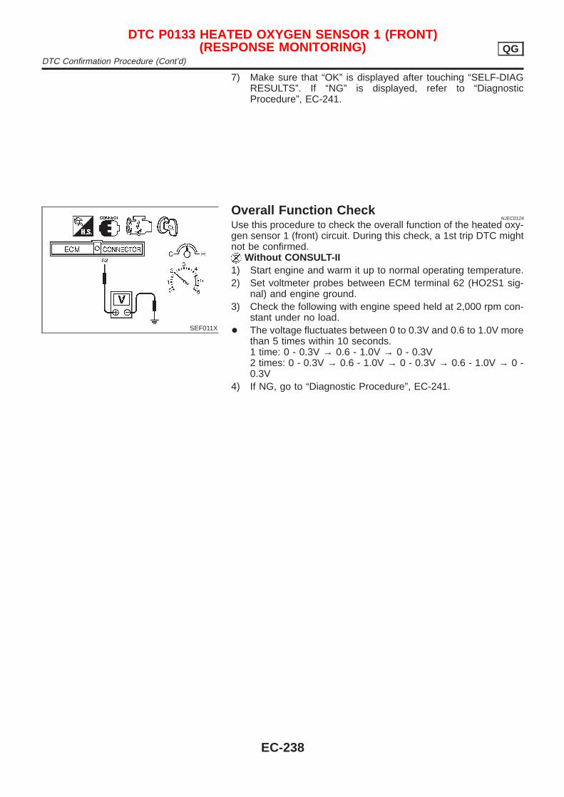
7) Make sure that “OK” is displayed after touching “SELF-DIAGRESULTS”. If “NG” is displayed, refer to “DiagnosticProcedure”, EC-241.
SEF011X
Overall Function CheckNJEC0124
Use this procedure to check the overall function of the heated oxy-gen sensor 1 (front) circuit. During this check, a 1st trip DTC mightnot be confirmed.
Without CONSULT-II1) Start engine and warm it up to normal operating temperature.2) Set voltmeter probes between ECM terminal 62 (HO2S1 sig-
nal) and engine ground.3) Check the following with engine speed held at 2,000 rpm con-
stant under no load.+ The voltage fluctuates between 0 to 0.3V and 0.6 to 1.0V more
than 5 times within 10 seconds.1 time: 0 - 0.3V → 0.6 - 1.0V → 0 - 0.3V2 times: 0 - 0.3V → 0.6 - 1.0V → 0 - 0.3V → 0.6 - 1.0V → 0 -0.3V
4) If NG, go to “Diagnostic Procedure”, EC-241.
DTC P0133 HEATED OXYGEN SENSOR 1 (FRONT)(RESPONSE MONITORING) QG
DTC Confirmation Procedure (Cont’d)
EC-238
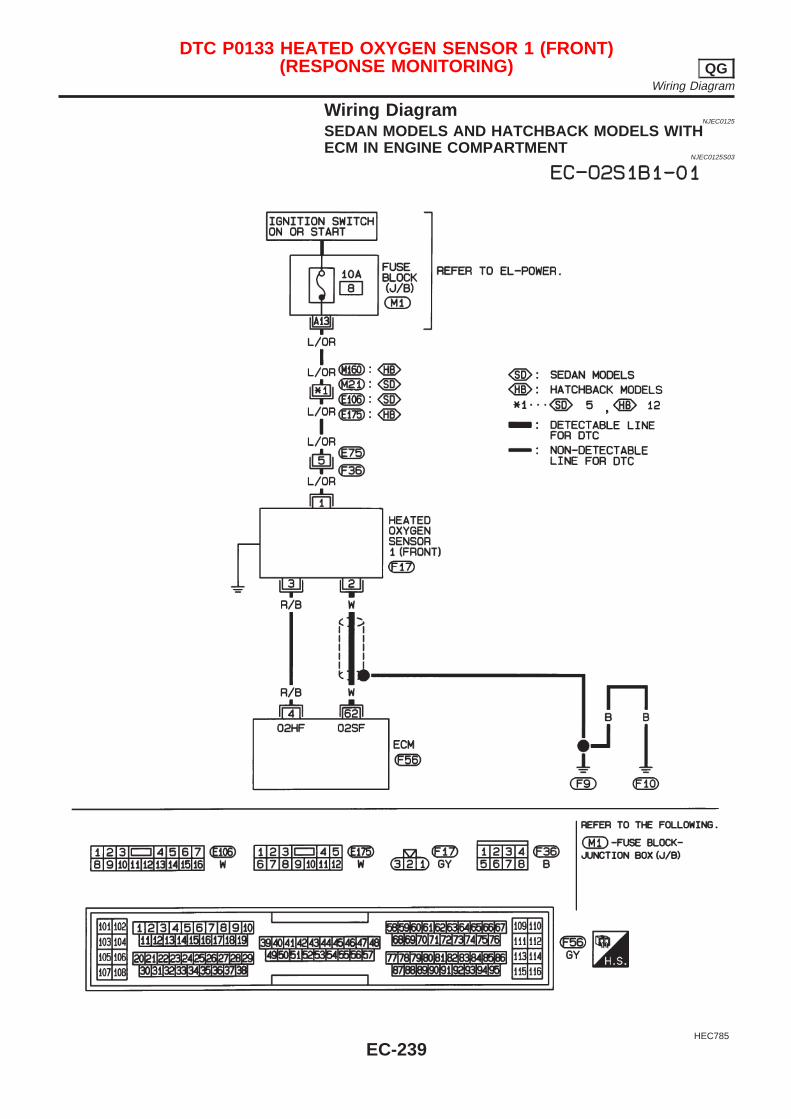
Wiring DiagramNJEC0125
SEDAN MODELS AND HATCHBACK MODELS WITHECM IN ENGINE COMPARTMENT
NJEC0125S03
HEC785
DTC P0133 HEATED OXYGEN SENSOR 1 (FRONT)(RESPONSE MONITORING) QG
Wiring Diagram
EC-239

HATCHBACK MODELS WITH ECM IN CABINNJEC0125S04
HEC936
DTC P0133 HEATED OXYGEN SENSOR 1 (FRONT)(RESPONSE MONITORING) QG
Wiring Diagram (Cont’d)
EC-240
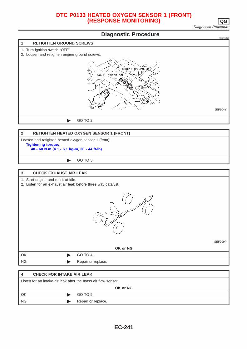
Diagnostic ProcedureNJEC0126
1 RETIGHTEN GROUND SCREWS
1. Turn ignition switch “OFF”.2. Loosen and retighten engine ground screws.
JEF104Y
© GO TO 2.
2 RETIGHTEN HEATED OXYGEN SENSOR 1 (FRONT)
Loosen and retighten heated oxygen sensor 1 (front).Tightening torque:
40 - 60 N·m (4.1 - 6.1 kg-m, 30 - 44 ft-lb)
© GO TO 3.
3 CHECK EXHAUST AIR LEAK
1. Start engine and run it at idle.2. Listen for an exhaust air leak before three way catalyst.
SEF099P
OK or NG
OK © GO TO 4.
NG © Repair or replace.
4 CHECK FOR INTAKE AIR LEAK
Listen for an intake air leak after the mass air flow sensor.
OK or NG
OK © GO TO 5.
NG © Repair or replace.
DTC P0133 HEATED OXYGEN SENSOR 1 (FRONT)(RESPONSE MONITORING) QG
Diagnostic Procedure
EC-241
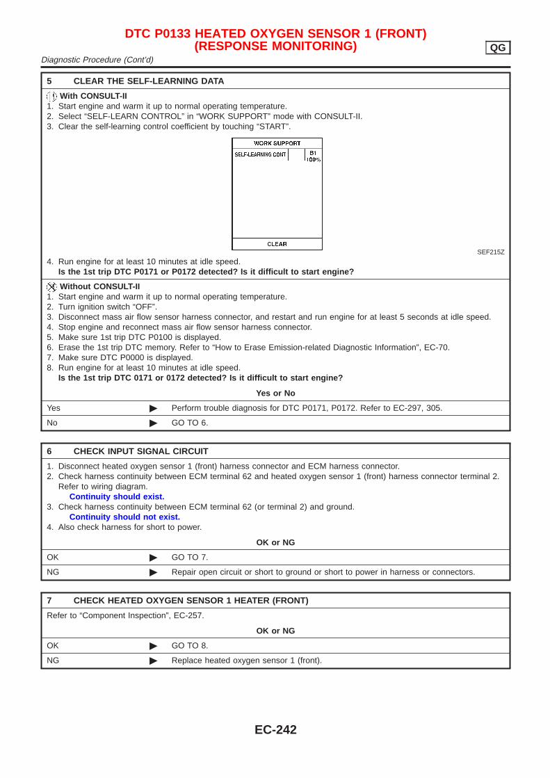
5 CLEAR THE SELF-LEARNING DATA
With CONSULT-II1. Start engine and warm it up to normal operating temperature.2. Select “SELF-LEARN CONTROL” in “WORK SUPPORT” mode with CONSULT-II.3. Clear the self-learning control coefficient by touching “START”.
SEF215Z
4. Run engine for at least 10 minutes at idle speed.Is the 1st trip DTC P0171 or P0172 detected? Is it difficult to start engine?
Without CONSULT-II1. Start engine and warm it up to normal operating temperature.2. Turn ignition switch “OFF”.3. Disconnect mass air flow sensor harness connector, and restart and run engine for at least 5 seconds at idle speed.4. Stop engine and reconnect mass air flow sensor harness connector.5. Make sure 1st trip DTC P0100 is displayed.6. Erase the 1st trip DTC memory. Refer to “How to Erase Emission-related Diagnostic Information”, EC-70.7. Make sure DTC P0000 is displayed.8. Run engine for at least 10 minutes at idle speed.
Is the 1st trip DTC 0171 or 0172 detected? Is it difficult to start engine?
Yes or No
Yes © Perform trouble diagnosis for DTC P0171, P0172. Refer to EC-297, 305.
No © GO TO 6.
6 CHECK INPUT SIGNAL CIRCUIT
1. Disconnect heated oxygen sensor 1 (front) harness connector and ECM harness connector.2. Check harness continuity between ECM terminal 62 and heated oxygen sensor 1 (front) harness connector terminal 2.
Refer to wiring diagram.Continuity should exist.
3. Check harness continuity between ECM terminal 62 (or terminal 2) and ground.Continuity should not exist.
4. Also check harness for short to power.
OK or NG
OK © GO TO 7.
NG © Repair open circuit or short to ground or short to power in harness or connectors.
7 CHECK HEATED OXYGEN SENSOR 1 HEATER (FRONT)
Refer to “Component Inspection”, EC-257.
OK or NG
OK © GO TO 8.
NG © Replace heated oxygen sensor 1 (front).
DTC P0133 HEATED OXYGEN SENSOR 1 (FRONT)(RESPONSE MONITORING) QG
Diagnostic Procedure (Cont’d)
EC-242
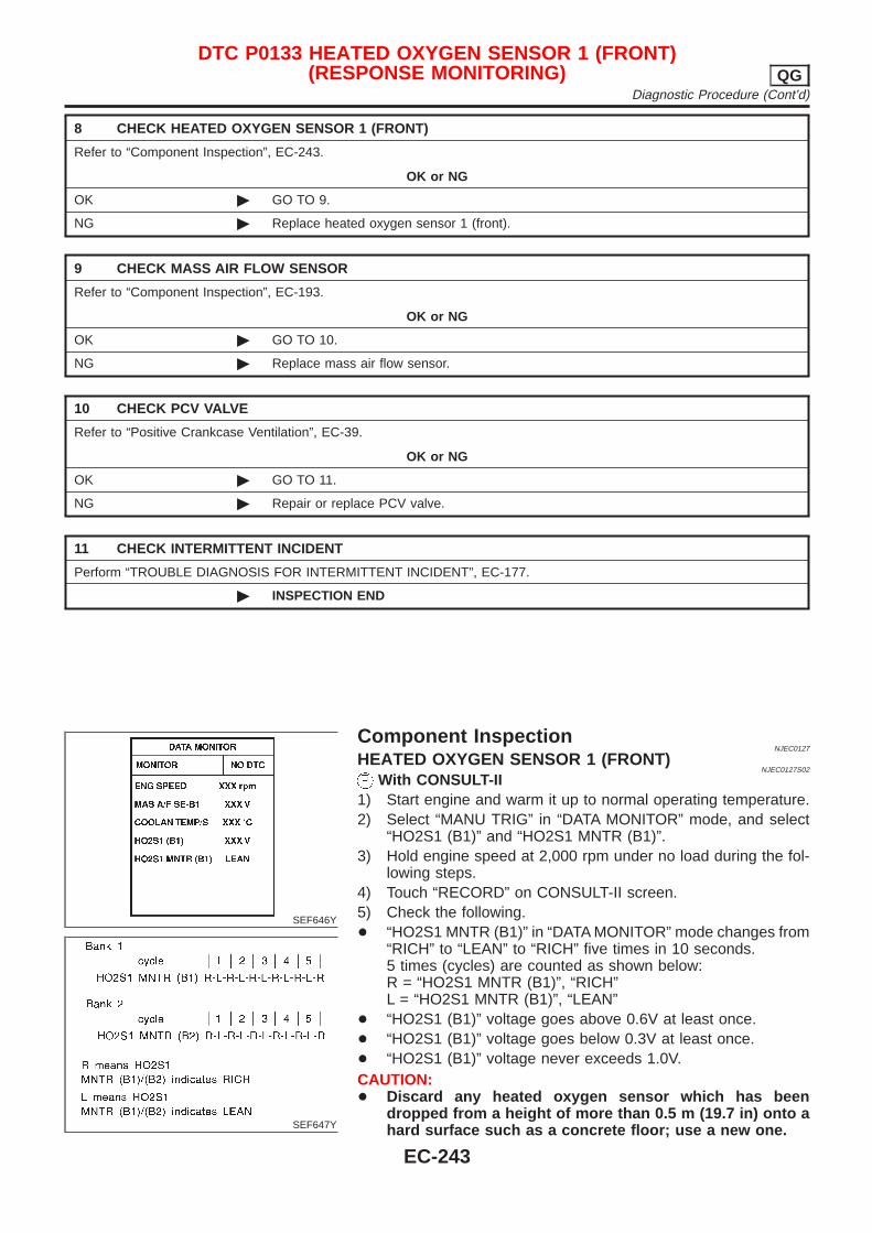
8 CHECK HEATED OXYGEN SENSOR 1 (FRONT)
Refer to “Component Inspection”, EC-243.
OK or NG
OK © GO TO 9.
NG © Replace heated oxygen sensor 1 (front).
9 CHECK MASS AIR FLOW SENSOR
Refer to “Component Inspection”, EC-193.
OK or NG
OK © GO TO 10.
NG © Replace mass air flow sensor.
10 CHECK PCV VALVE
Refer to “Positive Crankcase Ventilation”, EC-39.
OK or NG
OK © GO TO 11.
NG © Repair or replace PCV valve.
11 CHECK INTERMITTENT INCIDENT
Perform “TROUBLE DIAGNOSIS FOR INTERMITTENT INCIDENT”, EC-177.
© INSPECTION END
SEF646Y
SEF647Y
Component InspectionNJEC0127
HEATED OXYGEN SENSOR 1 (FRONT)NJEC0127S02
With CONSULT-II1) Start engine and warm it up to normal operating temperature.2) Select “MANU TRIG” in “DATA MONITOR” mode, and select
“HO2S1 (B1)” and “HO2S1 MNTR (B1)”.3) Hold engine speed at 2,000 rpm under no load during the fol-
lowing steps.4) Touch “RECORD” on CONSULT-II screen.5) Check the following.+ “HO2S1 MNTR (B1)” in “DATA MONITOR” mode changes from
“RICH” to “LEAN” to “RICH” five times in 10 seconds.5 times (cycles) are counted as shown below:R = “HO2S1 MNTR (B1)”, “RICH”L = “HO2S1 MNTR (B1)”, “LEAN”
+ “HO2S1 (B1)” voltage goes above 0.6V at least once.+ “HO2S1 (B1)” voltage goes below 0.3V at least once.+ “HO2S1 (B1)” voltage never exceeds 1.0V.CAUTION:+ Discard any heated oxygen sensor which has been
dropped from a height of more than 0.5 m (19.7 in) onto ahard surface such as a concrete floor; use a new one.
DTC P0133 HEATED OXYGEN SENSOR 1 (FRONT)(RESPONSE MONITORING) QG
Diagnostic Procedure (Cont’d)
EC-243
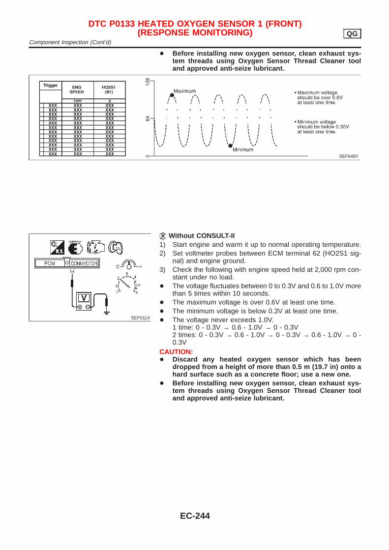
+ Before installing new oxygen sensor, clean exhaust sys-tem threads using Oxygen Sensor Thread Cleaner tooland approved anti-seize lubricant.
SEF648Y
SEF011X
Without CONSULT-II1) Start engine and warm it up to normal operating temperature.2) Set voltmeter probes between ECM terminal 62 (HO2S1 sig-
nal) and engine ground.3) Check the following with engine speed held at 2,000 rpm con-
stant under no load.+ The voltage fluctuates between 0 to 0.3V and 0.6 to 1.0V more
than 5 times within 10 seconds.+ The maximum voltage is over 0.6V at least one time.+ The minimum voltage is below 0.3V at least one time.+ The voltage never exceeds 1.0V.
1 time: 0 - 0.3V → 0.6 - 1.0V → 0 - 0.3V2 times: 0 - 0.3V → 0.6 - 1.0V → 0 - 0.3V → 0.6 - 1.0V → 0 -0.3V
CAUTION:+ Discard any heated oxygen sensor which has been
dropped from a height of more than 0.5 m (19.7 in) onto ahard surface such as a concrete floor; use a new one.
+ Before installing new oxygen sensor, clean exhaust sys-tem threads using Oxygen Sensor Thread Cleaner tooland approved anti-seize lubricant.
DTC P0133 HEATED OXYGEN SENSOR 1 (FRONT)(RESPONSE MONITORING) QG
Component Inspection (Cont’d)
EC-244

SEF463R
SEF288D
Component DescriptionNJEC0128
The heated oxygen sensor 1 (front) is placed into the exhaustmanifold. It detects the amount of oxygen in the exhaust gas com-pared to the outside air. The heated oxygen sensor 1 (front) has aclosed-end tube made of ceramic zirconia. The zirconia generatesvoltage from approximately 1V in richer conditions to 0V in leanerconditions. The heated oxygen sensor 1 (front) signal is sent to theECM. The ECM adjusts the injection pulse duration to achieve theideal air-fuel ratio. The ideal air-fuel ratio occurs near the radicalchange from 1V to 0V.
CONSULT-II Reference Value in Data MonitorMode
NJEC0129
Specification data are reference values.
MONITOR ITEM CONDITION SPECIFICATION
HO2S1 (B1)
+ Engine: After warming upMaintaining engine speed at 2,000rpm
0 - 0.3V ←→ Approx. 0.6 - 1.0V
HO2S1 MNTR(B1)
LEAN ←→ RICHChanges more than 5 times during10 seconds.
ECM Terminals and Reference ValueNJEC0130
Specification data are reference values and are measured between each terminal and ground.CAUTION:Do not use ECM ground terminals when measuring input/output voltage. Doing so may result in dam-age to the ECM’s transistor. Use a ground other than ECM terminals, such as the ground.
TERMI-NALNO.
WIRECOLOR
ITEM CONDITION DATA (DC Voltage)
62 WHeated oxygen sensor1 (front)
[Engine is running]+ After warming up to normal operating temperature
and engine speed is 2,000 rpm
0 - Approximately 1.0V
SEF008W
DTC P0134 HEATED OXYGEN SENSOR 1 (FRONT) (HIGH VOLTAGE) QGComponent Description
EC-245
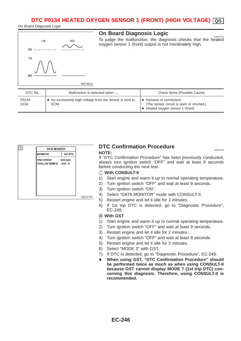
SEF301U
On Board Diagnosis LogicNJEC0131
To judge the malfunction, the diagnosis checks that the heatedoxygen sensor 1 (front) output is not inordinately high.
DTC No. Malfunction is detected when ... Check Items (Possible Cause)
P01340134
+ An excessively high voltage from the sensor is sent toECM.
+ Harness or connectors(The sensor circuit is open or shorted.)
+ Heated oxygen sensor 1 (front)
SEF174Y
DTC Confirmation ProcedureNJEC0132
NOTE:If “DTC Confirmation Procedure” has been previously conducted,always turn ignition switch “OFF” and wait at least 9 secondsbefore conducting the next test.
With CONSULT-II1) Start engine and warm it up to normal operating temperature.2) Turn ignition switch “OFF” and wait at least 9 seconds.3) Turn ignition switch “ON”.4) Select “DATA MONITOR” mode with CONSULT-II.5) Restart engine and let it idle for 2 minutes.6) If 1st trip DTC is detected, go to “Diagnostic Procedure”,
EC-249.With GST
1) Start engine and warm it up to normal operating temperature.2) Turn ignition switch “OFF” and wait at least 9 seconds.3) Restart engine and let it idle for 2 minutes.4) Turn ignition switch “OFF” and wait at least 9 seconds.5) Restart engine and let it idle for 2 minutes.6) Select “MODE 3” with GST.7) If DTC is detected, go to “Diagnostic Procedure”, EC-249.+ When using GST, “DTC Confirmation Procedure” should
be performed twice as much as when using CONSULT-IIbecause GST cannot display MODE 7 (1st trip DTC) con-cerning this diagnosis. Therefore, using CONSULT-II isrecommended.
DTC P0134 HEATED OXYGEN SENSOR 1 (FRONT) (HIGH VOLTAGE) QGOn Board Diagnosis Logic
EC-246
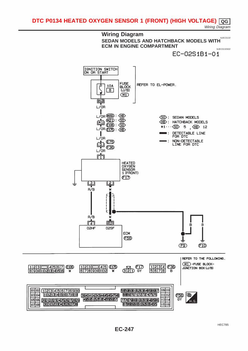
Wiring DiagramNJEC0133
SEDAN MODELS AND HATCHBACK MODELS WITHECM IN ENGINE COMPARTMENT
NJEC0133S03
HEC785
DTC P0134 HEATED OXYGEN SENSOR 1 (FRONT) (HIGH VOLTAGE) QGWiring Diagram
EC-247
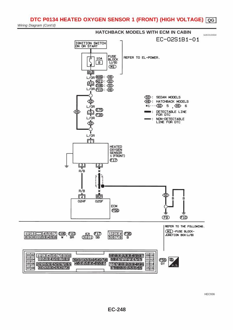
HATCHBACK MODELS WITH ECM IN CABINNJEC0133S04
HEC936
DTC P0134 HEATED OXYGEN SENSOR 1 (FRONT) (HIGH VOLTAGE) QGWiring Diagram (Cont’d)
EC-248
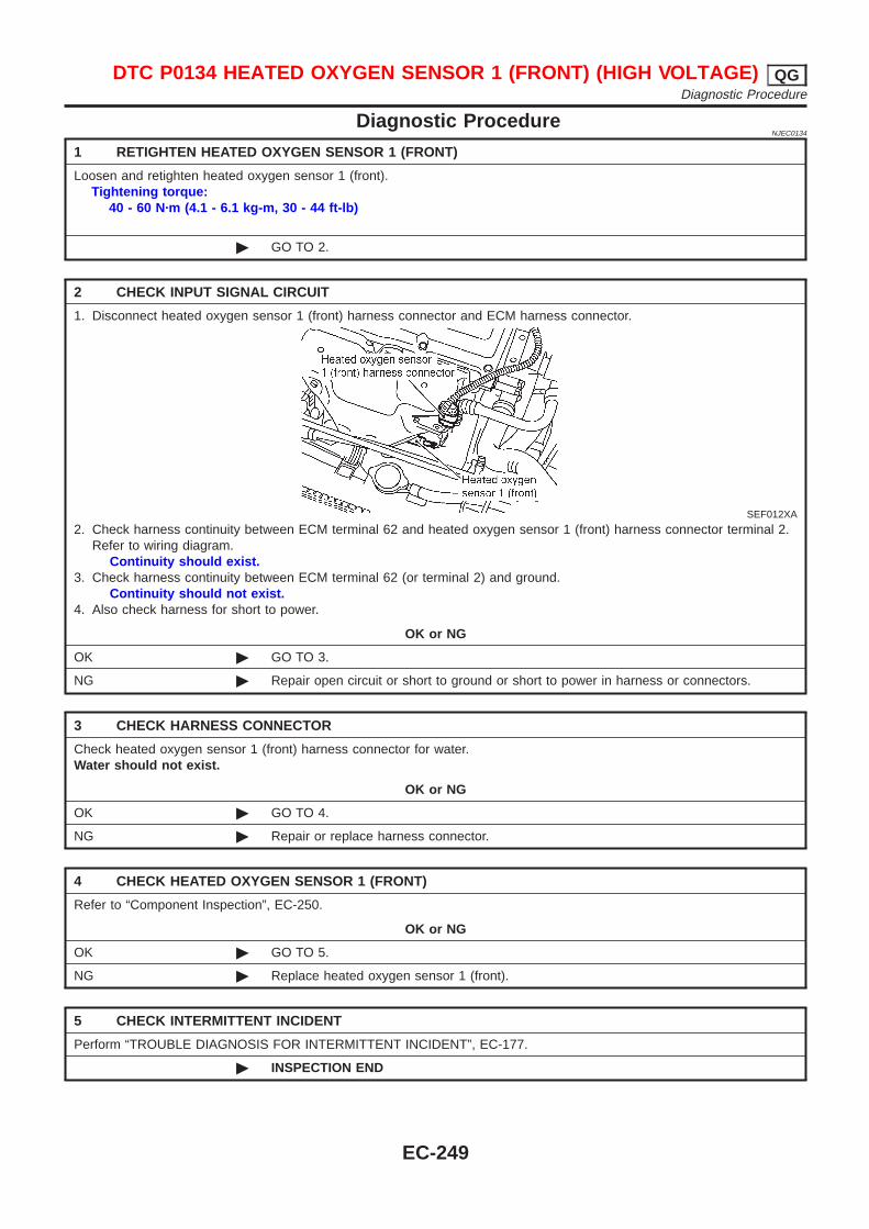
Diagnostic ProcedureNJEC0134
1 RETIGHTEN HEATED OXYGEN SENSOR 1 (FRONT)
Loosen and retighten heated oxygen sensor 1 (front).Tightening torque:
40 - 60 N·m (4.1 - 6.1 kg-m, 30 - 44 ft-lb)
© GO TO 2.
2 CHECK INPUT SIGNAL CIRCUIT
1. Disconnect heated oxygen sensor 1 (front) harness connector and ECM harness connector.
SEF012XA
2. Check harness continuity between ECM terminal 62 and heated oxygen sensor 1 (front) harness connector terminal 2.Refer to wiring diagram.
Continuity should exist.3. Check harness continuity between ECM terminal 62 (or terminal 2) and ground.
Continuity should not exist.4. Also check harness for short to power.
OK or NG
OK © GO TO 3.
NG © Repair open circuit or short to ground or short to power in harness or connectors.
3 CHECK HARNESS CONNECTOR
Check heated oxygen sensor 1 (front) harness connector for water.Water should not exist.
OK or NG
OK © GO TO 4.
NG © Repair or replace harness connector.
4 CHECK HEATED OXYGEN SENSOR 1 (FRONT)
Refer to “Component Inspection”, EC-250.
OK or NG
OK © GO TO 5.
NG © Replace heated oxygen sensor 1 (front).
5 CHECK INTERMITTENT INCIDENT
Perform “TROUBLE DIAGNOSIS FOR INTERMITTENT INCIDENT”, EC-177.
© INSPECTION END
DTC P0134 HEATED OXYGEN SENSOR 1 (FRONT) (HIGH VOLTAGE) QGDiagnostic Procedure
EC-249
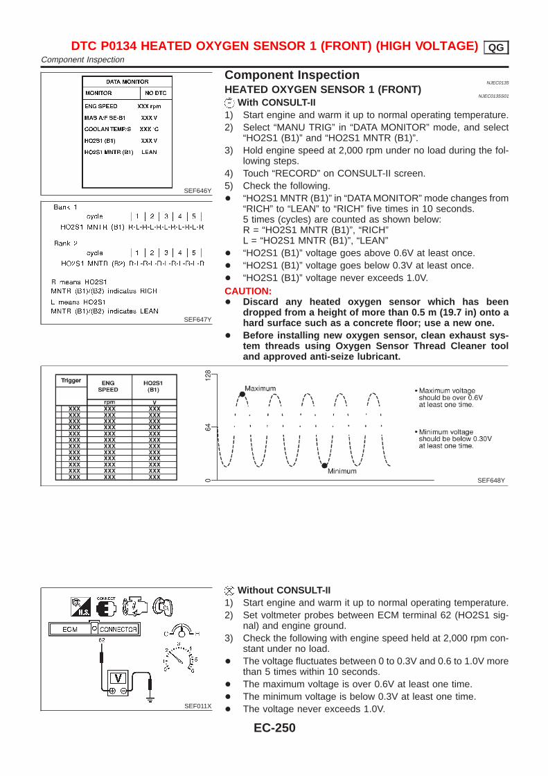
SEF646Y
SEF647Y
Component InspectionNJEC0135
HEATED OXYGEN SENSOR 1 (FRONT)NJEC0135S01
With CONSULT-II1) Start engine and warm it up to normal operating temperature.2) Select “MANU TRIG” in “DATA MONITOR” mode, and select
“HO2S1 (B1)” and “HO2S1 MNTR (B1)”.3) Hold engine speed at 2,000 rpm under no load during the fol-
lowing steps.4) Touch “RECORD” on CONSULT-II screen.5) Check the following.+ “HO2S1 MNTR (B1)” in “DATA MONITOR” mode changes from
“RICH” to “LEAN” to “RICH” five times in 10 seconds.5 times (cycles) are counted as shown below:R = “HO2S1 MNTR (B1)”, “RICH”L = “HO2S1 MNTR (B1)”, “LEAN”
+ “HO2S1 (B1)” voltage goes above 0.6V at least once.+ “HO2S1 (B1)” voltage goes below 0.3V at least once.+ “HO2S1 (B1)” voltage never exceeds 1.0V.CAUTION:+ Discard any heated oxygen sensor which has been
dropped from a height of more than 0.5 m (19.7 in) onto ahard surface such as a concrete floor; use a new one.
+ Before installing new oxygen sensor, clean exhaust sys-tem threads using Oxygen Sensor Thread Cleaner tooland approved anti-seize lubricant.
SEF648Y
SEF011X
Without CONSULT-II1) Start engine and warm it up to normal operating temperature.2) Set voltmeter probes between ECM terminal 62 (HO2S1 sig-
nal) and engine ground.3) Check the following with engine speed held at 2,000 rpm con-
stant under no load.+ The voltage fluctuates between 0 to 0.3V and 0.6 to 1.0V more
than 5 times within 10 seconds.+ The maximum voltage is over 0.6V at least one time.+ The minimum voltage is below 0.3V at least one time.+ The voltage never exceeds 1.0V.
DTC P0134 HEATED OXYGEN SENSOR 1 (FRONT) (HIGH VOLTAGE) QGComponent Inspection
EC-250

1 time: 0 - 0.3V → 0.6 - 1.0V → 0 - 0.3V2 times: 0 - 0.3V → 0.6 - 1.0V → 0 - 0.3V → 0.6 - 1.0V → 0 -0.3V
CAUTION:+ Discard any heated oxygen sensor which has been
dropped from a height of more than 0.5 m (19.7 in) onto ahard surface such as a concrete floor; use a new one.
+ Before installing new oxygen sensor, clean exhaust sys-tem threads using Oxygen Sensor Thread Cleaner tooland approved anti-seize lubricant.
DTC P0134 HEATED OXYGEN SENSOR 1 (FRONT) (HIGH VOLTAGE) QGComponent Inspection (Cont’d)
EC-251
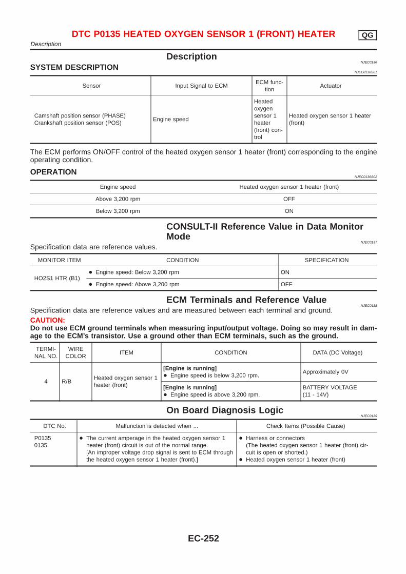
DescriptionNJEC0136
SYSTEM DESCRIPTIONNJEC0136S01
Sensor Input Signal to ECMECM func-
tionActuator
Camshaft position sensor (PHASE)Crankshaft position sensor (POS)
Engine speed
Heatedoxygensensor 1heater(front) con-trol
Heated oxygen sensor 1 heater(front)
The ECM performs ON/OFF control of the heated oxygen sensor 1 heater (front) corresponding to the engineoperating condition.
OPERATIONNJEC0136S02
Engine speed Heated oxygen sensor 1 heater (front)
Above 3,200 rpm OFF
Below 3,200 rpm ON
CONSULT-II Reference Value in Data MonitorMode
NJEC0137
Specification data are reference values.
MONITOR ITEM CONDITION SPECIFICATION
HO2S1 HTR (B1)+ Engine speed: Below 3,200 rpm ON
+ Engine speed: Above 3,200 rpm OFF
ECM Terminals and Reference ValueNJEC0138
Specification data are reference values and are measured between each terminal and ground.CAUTION:Do not use ECM ground terminals when measuring input/output voltage. Doing so may result in dam-age to the ECM’s transistor. Use a ground other than ECM terminals, such as the ground.
TERMI-NAL NO.
WIRECOLOR
ITEM CONDITION DATA (DC Voltage)
4 R/BHeated oxygen sensor 1heater (front)
[Engine is running]+ Engine speed is below 3,200 rpm.
Approximately 0V
[Engine is running]+ Engine speed is above 3,200 rpm.
BATTERY VOLTAGE(11 - 14V)
On Board Diagnosis LogicNJEC0139
DTC No. Malfunction is detected when ... Check Items (Possible Cause)
P01350135
+ The current amperage in the heated oxygen sensor 1heater (front) circuit is out of the normal range.[An improper voltage drop signal is sent to ECM throughthe heated oxygen sensor 1 heater (front).]
+ Harness or connectors(The heated oxygen sensor 1 heater (front) cir-cuit is open or shorted.)
+ Heated oxygen sensor 1 heater (front)
DTC P0135 HEATED OXYGEN SENSOR 1 (FRONT) HEATER QGDescription
EC-252
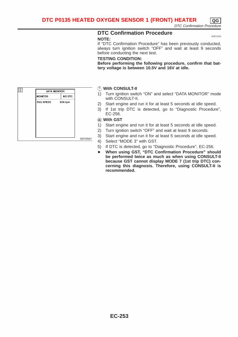
DTC Confirmation ProcedureNJEC0140
NOTE:If “DTC Confirmation Procedure” has been previously conducted,always turn ignition switch “OFF” and wait at least 9 secondsbefore conducting the next test.TESTING CONDITION:Before performing the following procedure, confirm that bat-tery voltage is between 10.5V and 16V at idle.
SEF058Y
With CONSULT-II1) Turn ignition switch “ON” and select “DATA MONITOR” mode
with CONSULT-II.2) Start engine and run it for at least 5 seconds at idle speed.3) If 1st trip DTC is detected, go to “Diagnostic Procedure”,
EC-256.With GST
1) Start engine and run it for at least 5 seconds at idle speed.2) Turn ignition switch “OFF” and wait at least 9 seconds.3) Start engine and run it for at least 5 seconds at idle speed.4) Select “MODE 3” with GST.5) If DTC is detected, go to “Diagnostic Procedure”, EC-256.+ When using GST, “DTC Confirmation Procedure” should
be performed twice as much as when using CONSULT-IIbecause GST cannot display MODE 7 (1st trip DTC) con-cerning this diagnosis. Therefore, using CONSULT-II isrecommended.
DTC P0135 HEATED OXYGEN SENSOR 1 (FRONT) HEATER QGDTC Confirmation Procedure
EC-253

Wiring DiagramNJEC0141
SEDAN MODELS AND HATCHBACK MODELS WITHECM IN ENGINE COMPARTMENT
NJEC0141S03
HEC786
DTC P0135 HEATED OXYGEN SENSOR 1 (FRONT) HEATER QGWiring Diagram
EC-254

HATCHBACK MODELS WITH ECM IN CABINNJEC0141S04
HEC938
DTC P0135 HEATED OXYGEN SENSOR 1 (FRONT) HEATER QGWiring Diagram (Cont’d)
EC-255
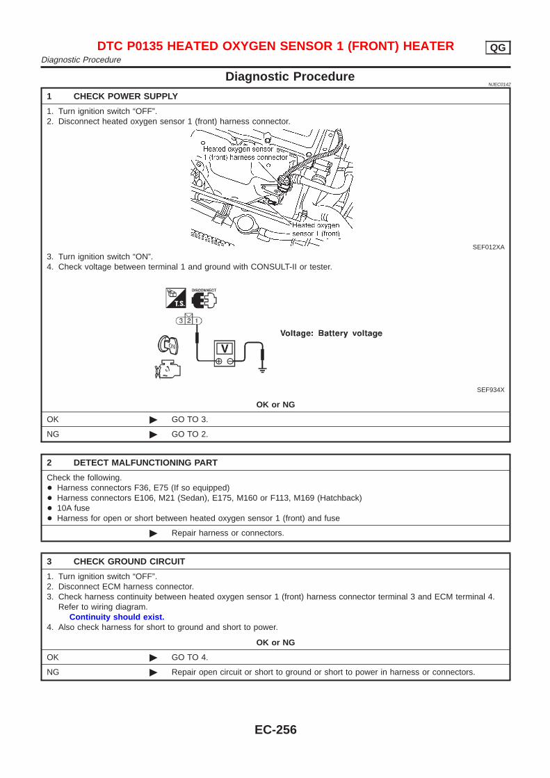
Diagnostic ProcedureNJEC0142
1 CHECK POWER SUPPLY
1. Turn ignition switch “OFF”.2. Disconnect heated oxygen sensor 1 (front) harness connector.
SEF012XA
3. Turn ignition switch “ON”.4. Check voltage between terminal 1 and ground with CONSULT-II or tester.
SEF934X
OK or NG
OK © GO TO 3.
NG © GO TO 2.
2 DETECT MALFUNCTIONING PART
Check the following.+ Harness connectors F36, E75 (If so equipped)+ Harness connectors E106, M21 (Sedan), E175, M160 or F113, M169 (Hatchback)+ 10A fuse+ Harness for open or short between heated oxygen sensor 1 (front) and fuse
© Repair harness or connectors.
3 CHECK GROUND CIRCUIT
1. Turn ignition switch “OFF”.2. Disconnect ECM harness connector.3. Check harness continuity between heated oxygen sensor 1 (front) harness connector terminal 3 and ECM terminal 4.
Refer to wiring diagram.Continuity should exist.
4. Also check harness for short to ground and short to power.
OK or NG
OK © GO TO 4.
NG © Repair open circuit or short to ground or short to power in harness or connectors.
DTC P0135 HEATED OXYGEN SENSOR 1 (FRONT) HEATER QGDiagnostic Procedure
EC-256
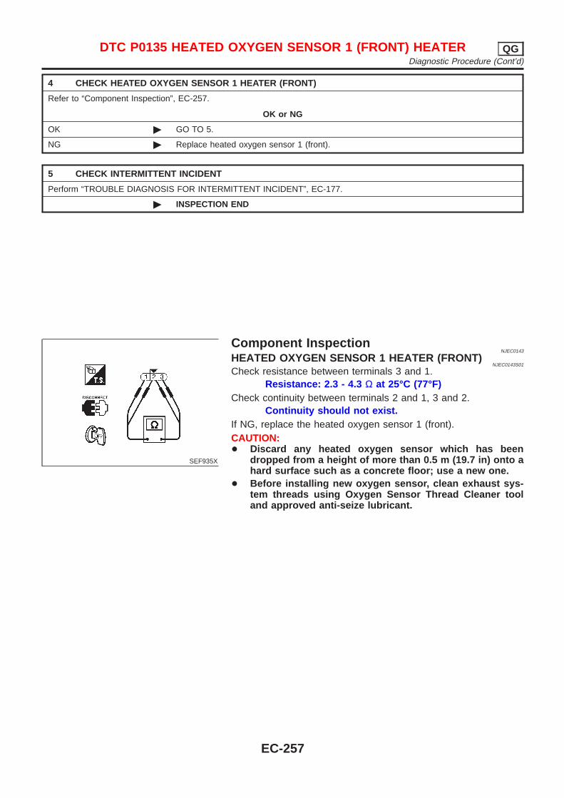
4 CHECK HEATED OXYGEN SENSOR 1 HEATER (FRONT)
Refer to “Component Inspection”, EC-257.
OK or NG
OK © GO TO 5.
NG © Replace heated oxygen sensor 1 (front).
5 CHECK INTERMITTENT INCIDENT
Perform “TROUBLE DIAGNOSIS FOR INTERMITTENT INCIDENT”, EC-177.
© INSPECTION END
SEF935X
Component InspectionNJEC0143
HEATED OXYGEN SENSOR 1 HEATER (FRONT)NJEC0143S01
Check resistance between terminals 3 and 1.Resistance: 2.3 - 4.3 Ω at 25°C (77°F)
Check continuity between terminals 2 and 1, 3 and 2.Continuity should not exist.
If NG, replace the heated oxygen sensor 1 (front).CAUTION:+ Discard any heated oxygen sensor which has been
dropped from a height of more than 0.5 m (19.7 in) onto ahard surface such as a concrete floor; use a new one.
+ Before installing new oxygen sensor, clean exhaust sys-tem threads using Oxygen Sensor Thread Cleaner tooland approved anti-seize lubricant.
DTC P0135 HEATED OXYGEN SENSOR 1 (FRONT) HEATER QGDiagnostic Procedure (Cont’d)
EC-257
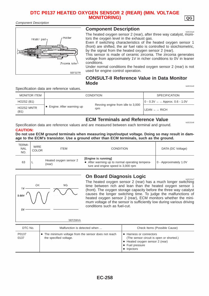
SEF327R
Component DescriptionNJEC0144
The heated oxygen sensor 2 (rear), after three way catalyst, moni-tors the oxygen level in the exhaust gas.Even if switching characteristics of the heated oxygen sensor 1(front) are shifted, the air fuel ratio is controlled to stoichiometric,by the signal from the heated oxygen sensor 2 (rear).This sensor is made of ceramic zirconia. The zirconia generatesvoltage from approximately 1V in richer conditions to 0V in leanerconditions.Under normal conditions the heated oxygen sensor 2 (rear) is notused for engine control operation.
CONSULT-II Reference Value in Data MonitorMode
NJEC0145
Specification data are reference values.
MONITOR ITEM CONDITION SPECIFICATION
HO2S2 (B1)
+ Engine: After warming upRevving engine from idle to 3,000rpm
0 - 0.3V ←→ Approx. 0.6 - 1.0V
HO2S2 MNTR(B1)
LEAN ←→ RICH
ECM Terminals and Reference ValueNJEC0146
Specification data are reference values and are measured between each terminal and ground.CAUTION:Do not use ECM ground terminals when measuring input/output voltage. Doing so may result in dam-age to the ECM’s transistor. Use a ground other than ECM terminals, such as the ground.
TERMI-NALNO.
WIRECOLOR
ITEM CONDITION DATA (DC Voltage)
63 LHeated oxygen sensor 2(rear)
[Engine is running]+ After warming up to normal operating tempera-
ture and engine speed is 3,000 rpm0 - Approximately 1.0V
SEF258VA
On Board Diagnosis LogicNJEC0147
The heated oxygen sensor 2 (rear) has a much longer switchingtime between rich and lean than the heated oxygen sensor 1(front). The oxygen storage capacity before the three way catalystcauses the longer switching time. To judge the malfunctions ofheated oxygen sensor 2 (rear), ECM monitors whether the mini-mum voltage of the sensor is sufficiently low during various drivingconditions such as fuel-cut.
DTC No. Malfunction is detected when ... Check Items (Possible Cause)
P01370137
+ The minimum voltage from the sensor does not reachthe specified voltage.
+ Harness or connectors(The sensor circuit is open or shorted.)
+ Heated oxygen sensor 2 (rear)+ Fuel pressure+ Injectors
DTC P0137 HEATED OXYGEN SENSOR 2 (REAR) (MIN. VOLTAGEMONITORING) QG
Component Description
EC-258

SEF833Y
SEF834Y
SEF835Y
DTC Confirmation ProcedureNJEC0594
CAUTION:Always drive vehicle at a safe speed.NOTE:+ “COMPLETED” will appear on CONSULT-II screen when all
tests “COND1”, “COND2” and “COND3” are completed.+ If “DTC Confirmation Procedure” has been previously
conducted, always turn ignition switch “OFF” and wait at least9 seconds before conducting the next test.
TESTING CONDITION:Never stop engine during this procedure. If the engine isstopped, retry this procedure from step 2 in “Procedure forCOND1”.
With CONSULT-IIProcedure for COND11) Start engine and warm it up to normal operating temperature.2) Turn ignition switch “OFF” and wait at least 9 seconds.3) Turn ignition switch “ON” and select “HO2S2 (B1) P0137” of
“HO2S2” in “DTC WORK SUPPORT” mode with CONSULT-II.4) Touch “START”.5) Start engine and let it idle for at least 30 seconds.6) Rev engine up to 2,000 rpm 2 or 3 times quickly under no load.
If “COMPLETED” appears on CONSULT-II screen, go to step2 in “Procedure for COND3”.If “COMPLETED” does not appear on CONSULT-II screen, goto the following step.
7) Drive vehicle at a speed of more than 70 km/h (43 MPH) for 2consecutive minutes.
8) When the following conditions are met, “TESTING” will be dis-played at “COND1” on the CONSULT-II screen. Maintain theconditions continuously until “TESTING” changes to “COM-PLETED”. (It will take approximately 60 seconds.)
ENG SPEED 1,500 - 3,600 rpm
Vehicle speed Above 70 km/h (43 MPH)
Selector lever Suitable position
NOTE:+ If “TESTING” is not displayed after 5 minutes, retry from
step 2 in “Procedure for COND1”.+ If “COMPLETED” already appears at “COND2” on CON-
SULT-II screen before “Procedure for COND2” isconducted, it is unnecessary to conduct step 1 in “Proce-dure for COND2”.
SEF836Y
Procedure for COND21) While driving, release accelerator pedal completely with “OD”
OFF (A/T models), or 4th gear position (M/T models) from theabove condition [step 8] until “INCOMPLETE” at “COND2” onCONSULT-II screen has turned to “COMPLETED”. (It will takeapproximately 4 seconds.)
NOTE:If “COMPLETED” already appears at “COND3” on CONSULT-IIscreen before “Procedure for COND3” is conducted, it isunnecessary to conduct step 1 in “Procedure for COND3”.
DTC P0137 HEATED OXYGEN SENSOR 2 (REAR) (MIN. VOLTAGEMONITORING) QG
On Board Diagnosis Logic (Cont’d)
EC-259
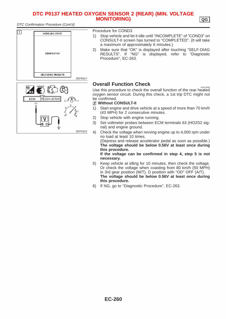
SEF661Y
Procedure for COND31) Stop vehicle and let it idle until “INCOMPLETE” of “COND3” on
CONSULT-II screen has turned to “COMPLETED”. (It will takea maximum of approximately 6 minutes.)
2) Make sure that “OK” is displayed after touching “SELF-DIAGRESULTS”. If “NG” is displayed, refer to “DiagnosticProcedure”, EC-263.
SEF032X
Overall Function CheckNJEC0595
Use this procedure to check the overall function of the rear heatedoxygen sensor circuit. During this check, a 1st trip DTC might notbe confirmed.
Without CONSULT-II1) Start engine and drive vehicle at a speed of more than 70 km/h
(43 MPH) for 2 consecutive minutes.2) Stop vehicle with engine running.3) Set voltmeter probes between ECM terminals 63 (HO2S2 sig-
nal) and engine ground.4) Check the voltage when revving engine up to 4,000 rpm under
no load at least 10 times.(Depress and release accelerator pedal as soon as possible.)The voltage should be below 0.56V at least once duringthis procedure.If the voltage can be confirmed in step 4, step 5 is notnecessary.
5) Keep vehicle at idling for 10 minutes, then check the voltage.Or check the voltage when coasting from 80 km/h (50 MPH)in 3rd gear position (M/T), D position with “OD” OFF (A/T).The voltage should be below 0.56V at least once duringthis procedure.
6) If NG, go to “Diagnostic Procedure”, EC-263.
DTC P0137 HEATED OXYGEN SENSOR 2 (REAR) (MIN. VOLTAGEMONITORING) QG
DTC Confirmation Procedure (Cont’d)
EC-260
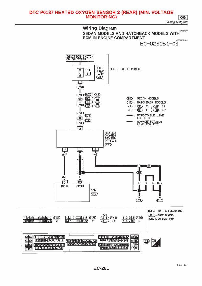
Wiring DiagramNJEC0150
SEDAN MODELS AND HATCHBACK MODELS WITHECM IN ENGINE COMPARTMENT
NJEC0150S03
HEC787
DTC P0137 HEATED OXYGEN SENSOR 2 (REAR) (MIN. VOLTAGEMONITORING) QG
Wiring Diagram
EC-261
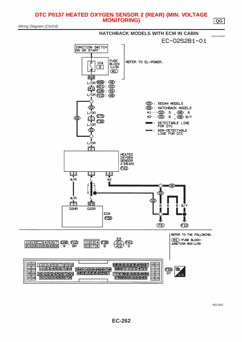
HATCHBACK MODELS WITH ECM IN CABINNJEC0150S04
HEC940
DTC P0137 HEATED OXYGEN SENSOR 2 (REAR) (MIN. VOLTAGEMONITORING) QG
Wiring Diagram (Cont’d)
EC-262
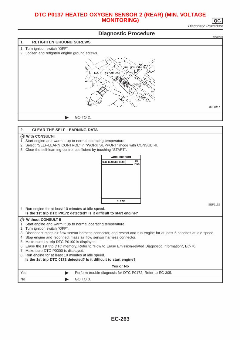
Diagnostic ProcedureNJEC0151
1 RETIGHTEN GROUND SCREWS
1. Turn ignition switch “OFF”.2. Loosen and retighten engine ground screws.
JEF104Y
© GO TO 2.
2 CLEAR THE SELF-LEARNING DATA
With CONSULT-II1. Start engine and warm it up to normal operating temperature.2. Select “SELF-LEARN CONTROL” in “WORK SUPPORT” mode with CONSULT-II.3. Clear the self-learning control coefficient by touching “START”.
SEF215Z
4. Run engine for at least 10 minutes at idle speed.Is the 1st trip DTC P0172 detected? Is it difficult to start engine?
Without CONSULT-II1. Start engine and warm it up to normal operating temperature.2. Turn ignition switch “OFF”.3. Disconnect mass air flow sensor harness connector, and restart and run engine for at least 5 seconds at idle speed.4. Stop engine and reconnect mass air flow sensor harness connector.5. Make sure 1st trip DTC P0100 is displayed.6. Erase the 1st trip DTC memory. Refer to “How to Erase Emission-related Diagnostic Information”, EC-70.7. Make sure DTC P0000 is displayed.8. Run engine for at least 10 minutes at idle speed.
Is the 1st trip DTC 0172 detected? Is it difficult to start engine?
Yes or No
Yes © Perform trouble diagnosis for DTC P0172. Refer to EC-305.
No © GO TO 3.
DTC P0137 HEATED OXYGEN SENSOR 2 (REAR) (MIN. VOLTAGEMONITORING) QG
Diagnostic Procedure
EC-263
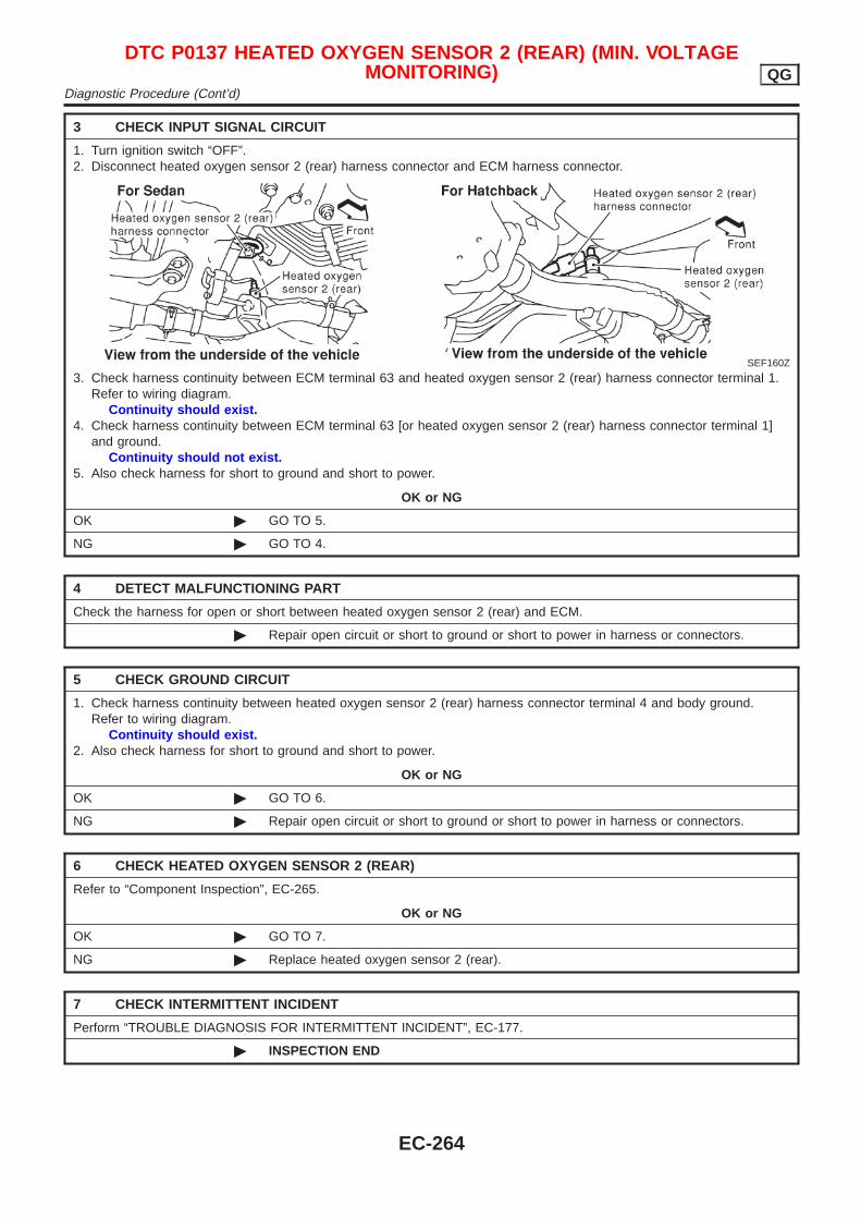
3 CHECK INPUT SIGNAL CIRCUIT
1. Turn ignition switch “OFF”.2. Disconnect heated oxygen sensor 2 (rear) harness connector and ECM harness connector.
SEF160Z
3. Check harness continuity between ECM terminal 63 and heated oxygen sensor 2 (rear) harness connector terminal 1.Refer to wiring diagram.
Continuity should exist.4. Check harness continuity between ECM terminal 63 [or heated oxygen sensor 2 (rear) harness connector terminal 1]
and ground.Continuity should not exist.
5. Also check harness for short to ground and short to power.
OK or NG
OK © GO TO 5.
NG © GO TO 4.
4 DETECT MALFUNCTIONING PART
Check the harness for open or short between heated oxygen sensor 2 (rear) and ECM.
© Repair open circuit or short to ground or short to power in harness or connectors.
5 CHECK GROUND CIRCUIT
1. Check harness continuity between heated oxygen sensor 2 (rear) harness connector terminal 4 and body ground.Refer to wiring diagram.
Continuity should exist.2. Also check harness for short to ground and short to power.
OK or NG
OK © GO TO 6.
NG © Repair open circuit or short to ground or short to power in harness or connectors.
6 CHECK HEATED OXYGEN SENSOR 2 (REAR)
Refer to “Component Inspection”, EC-265.
OK or NG
OK © GO TO 7.
NG © Replace heated oxygen sensor 2 (rear).
7 CHECK INTERMITTENT INCIDENT
Perform “TROUBLE DIAGNOSIS FOR INTERMITTENT INCIDENT”, EC-177.
© INSPECTION END
DTC P0137 HEATED OXYGEN SENSOR 2 (REAR) (MIN. VOLTAGEMONITORING) QG
Diagnostic Procedure (Cont’d)
EC-264
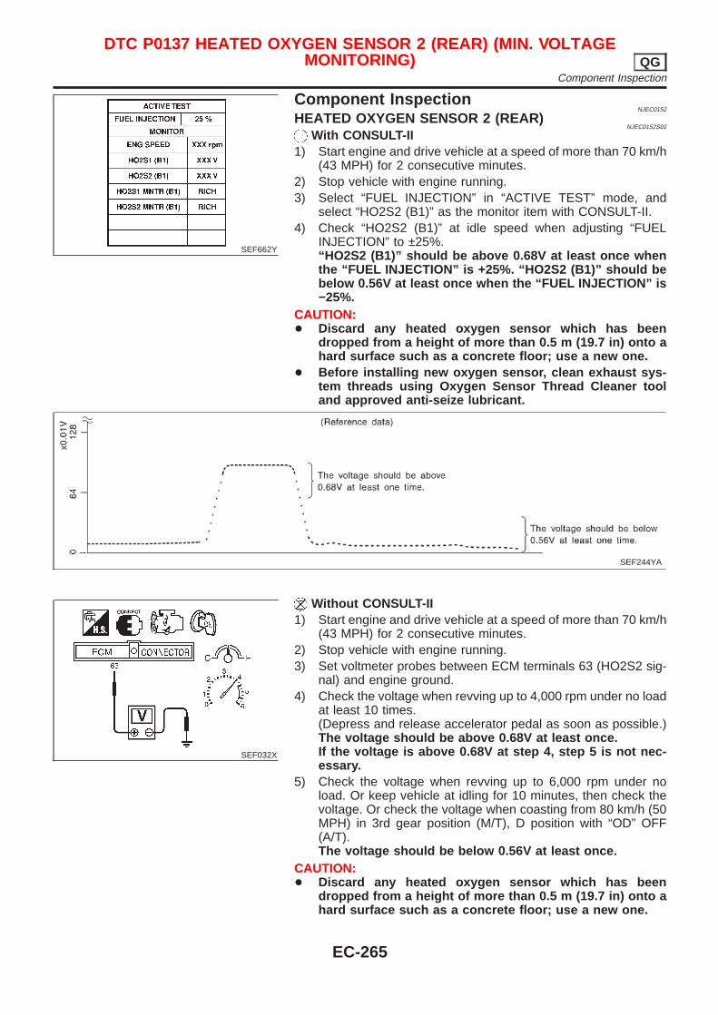
SEF662Y
Component InspectionNJEC0152
HEATED OXYGEN SENSOR 2 (REAR)NJEC0152S01
With CONSULT-II1) Start engine and drive vehicle at a speed of more than 70 km/h
(43 MPH) for 2 consecutive minutes.2) Stop vehicle with engine running.3) Select “FUEL INJECTION” in “ACTIVE TEST” mode, and
select “HO2S2 (B1)” as the monitor item with CONSULT-II.4) Check “HO2S2 (B1)” at idle speed when adjusting “FUEL
INJECTION” to ±25%.“HO2S2 (B1)” should be above 0.68V at least once whenthe “FUEL INJECTION” is +25%. “HO2S2 (B1)” should bebelow 0.56V at least once when the “FUEL INJECTION” is−25%.
CAUTION:+ Discard any heated oxygen sensor which has been
dropped from a height of more than 0.5 m (19.7 in) onto ahard surface such as a concrete floor; use a new one.
+ Before installing new oxygen sensor, clean exhaust sys-tem threads using Oxygen Sensor Thread Cleaner tooland approved anti-seize lubricant.
SEF244YA
SEF032X
Without CONSULT-II1) Start engine and drive vehicle at a speed of more than 70 km/h
(43 MPH) for 2 consecutive minutes.2) Stop vehicle with engine running.3) Set voltmeter probes between ECM terminals 63 (HO2S2 sig-
nal) and engine ground.4) Check the voltage when revving up to 4,000 rpm under no load
at least 10 times.(Depress and release accelerator pedal as soon as possible.)The voltage should be above 0.68V at least once.If the voltage is above 0.68V at step 4, step 5 is not nec-essary.
5) Check the voltage when revving up to 6,000 rpm under noload. Or keep vehicle at idling for 10 minutes, then check thevoltage. Or check the voltage when coasting from 80 km/h (50MPH) in 3rd gear position (M/T), D position with “OD” OFF(A/T).The voltage should be below 0.56V at least once.
CAUTION:+ Discard any heated oxygen sensor which has been
dropped from a height of more than 0.5 m (19.7 in) onto ahard surface such as a concrete floor; use a new one.
DTC P0137 HEATED OXYGEN SENSOR 2 (REAR) (MIN. VOLTAGEMONITORING) QG
Component Inspection
EC-265

+ Before installing new oxygen sensor, clean exhaust sys-tem threads using Oxygen Sensor Thread Cleaner tooland approved anti-seize lubricant.
DTC P0137 HEATED OXYGEN SENSOR 2 (REAR) (MIN. VOLTAGEMONITORING) QG
Component Inspection (Cont’d)
EC-266
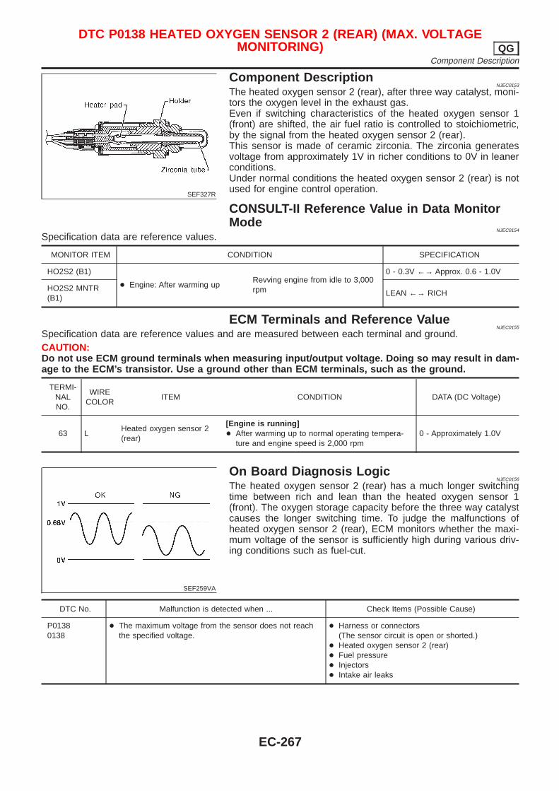
SEF327R
Component DescriptionNJEC0153
The heated oxygen sensor 2 (rear), after three way catalyst, moni-tors the oxygen level in the exhaust gas.Even if switching characteristics of the heated oxygen sensor 1(front) are shifted, the air fuel ratio is controlled to stoichiometric,by the signal from the heated oxygen sensor 2 (rear).This sensor is made of ceramic zirconia. The zirconia generatesvoltage from approximately 1V in richer conditions to 0V in leanerconditions.Under normal conditions the heated oxygen sensor 2 (rear) is notused for engine control operation.
CONSULT-II Reference Value in Data MonitorMode
NJEC0154
Specification data are reference values.
MONITOR ITEM CONDITION SPECIFICATION
HO2S2 (B1)
+ Engine: After warming upRevving engine from idle to 3,000rpm
0 - 0.3V ←→ Approx. 0.6 - 1.0V
HO2S2 MNTR(B1)
LEAN ←→ RICH
ECM Terminals and Reference ValueNJEC0155
Specification data are reference values and are measured between each terminal and ground.CAUTION:Do not use ECM ground terminals when measuring input/output voltage. Doing so may result in dam-age to the ECM’s transistor. Use a ground other than ECM terminals, such as the ground.
TERMI-NALNO.
WIRECOLOR
ITEM CONDITION DATA (DC Voltage)
63 LHeated oxygen sensor 2(rear)
[Engine is running]+ After warming up to normal operating tempera-
ture and engine speed is 2,000 rpm0 - Approximately 1.0V
SEF259VA
On Board Diagnosis LogicNJEC0156
The heated oxygen sensor 2 (rear) has a much longer switchingtime between rich and lean than the heated oxygen sensor 1(front). The oxygen storage capacity before the three way catalystcauses the longer switching time. To judge the malfunctions ofheated oxygen sensor 2 (rear), ECM monitors whether the maxi-mum voltage of the sensor is sufficiently high during various driv-ing conditions such as fuel-cut.
DTC No. Malfunction is detected when ... Check Items (Possible Cause)
P01380138
+ The maximum voltage from the sensor does not reachthe specified voltage.
+ Harness or connectors(The sensor circuit is open or shorted.)
+ Heated oxygen sensor 2 (rear)+ Fuel pressure+ Injectors+ Intake air leaks
DTC P0138 HEATED OXYGEN SENSOR 2 (REAR) (MAX. VOLTAGEMONITORING) QG
Component Description
EC-267
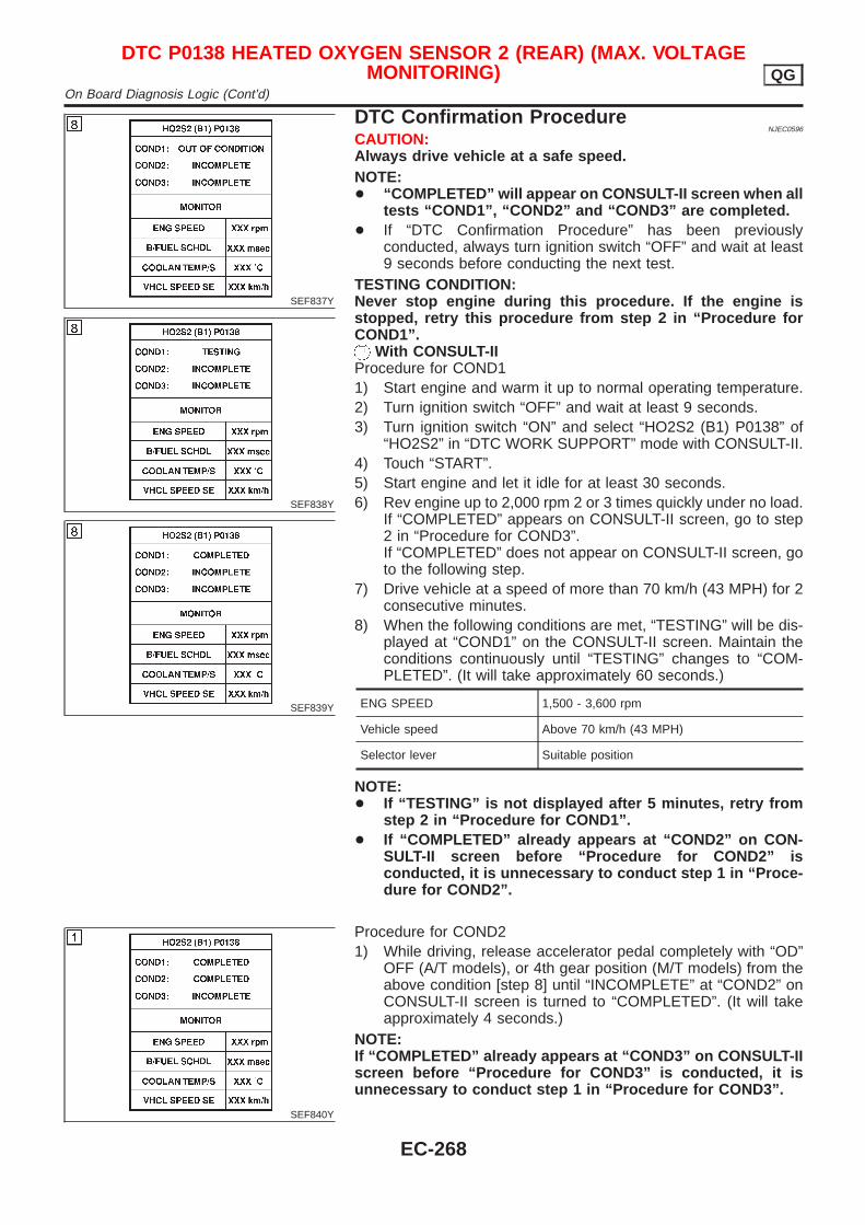
SEF837Y
SEF838Y
SEF839Y
DTC Confirmation ProcedureNJEC0596
CAUTION:Always drive vehicle at a safe speed.NOTE:+ “COMPLETED” will appear on CONSULT-II screen when all
tests “COND1”, “COND2” and “COND3” are completed.+ If “DTC Confirmation Procedure” has been previously
conducted, always turn ignition switch “OFF” and wait at least9 seconds before conducting the next test.
TESTING CONDITION:Never stop engine during this procedure. If the engine isstopped, retry this procedure from step 2 in “Procedure forCOND1”.
With CONSULT-IIProcedure for COND11) Start engine and warm it up to normal operating temperature.2) Turn ignition switch “OFF” and wait at least 9 seconds.3) Turn ignition switch “ON” and select “HO2S2 (B1) P0138” of
“HO2S2” in “DTC WORK SUPPORT” mode with CONSULT-II.4) Touch “START”.5) Start engine and let it idle for at least 30 seconds.6) Rev engine up to 2,000 rpm 2 or 3 times quickly under no load.
If “COMPLETED” appears on CONSULT-II screen, go to step2 in “Procedure for COND3”.If “COMPLETED” does not appear on CONSULT-II screen, goto the following step.
7) Drive vehicle at a speed of more than 70 km/h (43 MPH) for 2consecutive minutes.
8) When the following conditions are met, “TESTING” will be dis-played at “COND1” on the CONSULT-II screen. Maintain theconditions continuously until “TESTING” changes to “COM-PLETED”. (It will take approximately 60 seconds.)
ENG SPEED 1,500 - 3,600 rpm
Vehicle speed Above 70 km/h (43 MPH)
Selector lever Suitable position
NOTE:+ If “TESTING” is not displayed after 5 minutes, retry from
step 2 in “Procedure for COND1”.+ If “COMPLETED” already appears at “COND2” on CON-
SULT-II screen before “Procedure for COND2” isconducted, it is unnecessary to conduct step 1 in “Proce-dure for COND2”.
SEF840Y
Procedure for COND21) While driving, release accelerator pedal completely with “OD”
OFF (A/T models), or 4th gear position (M/T models) from theabove condition [step 8] until “INCOMPLETE” at “COND2” onCONSULT-II screen is turned to “COMPLETED”. (It will takeapproximately 4 seconds.)
NOTE:If “COMPLETED” already appears at “COND3” on CONSULT-IIscreen before “Procedure for COND3” is conducted, it isunnecessary to conduct step 1 in “Procedure for COND3”.
DTC P0138 HEATED OXYGEN SENSOR 2 (REAR) (MAX. VOLTAGEMONITORING) QG
On Board Diagnosis Logic (Cont’d)
EC-268
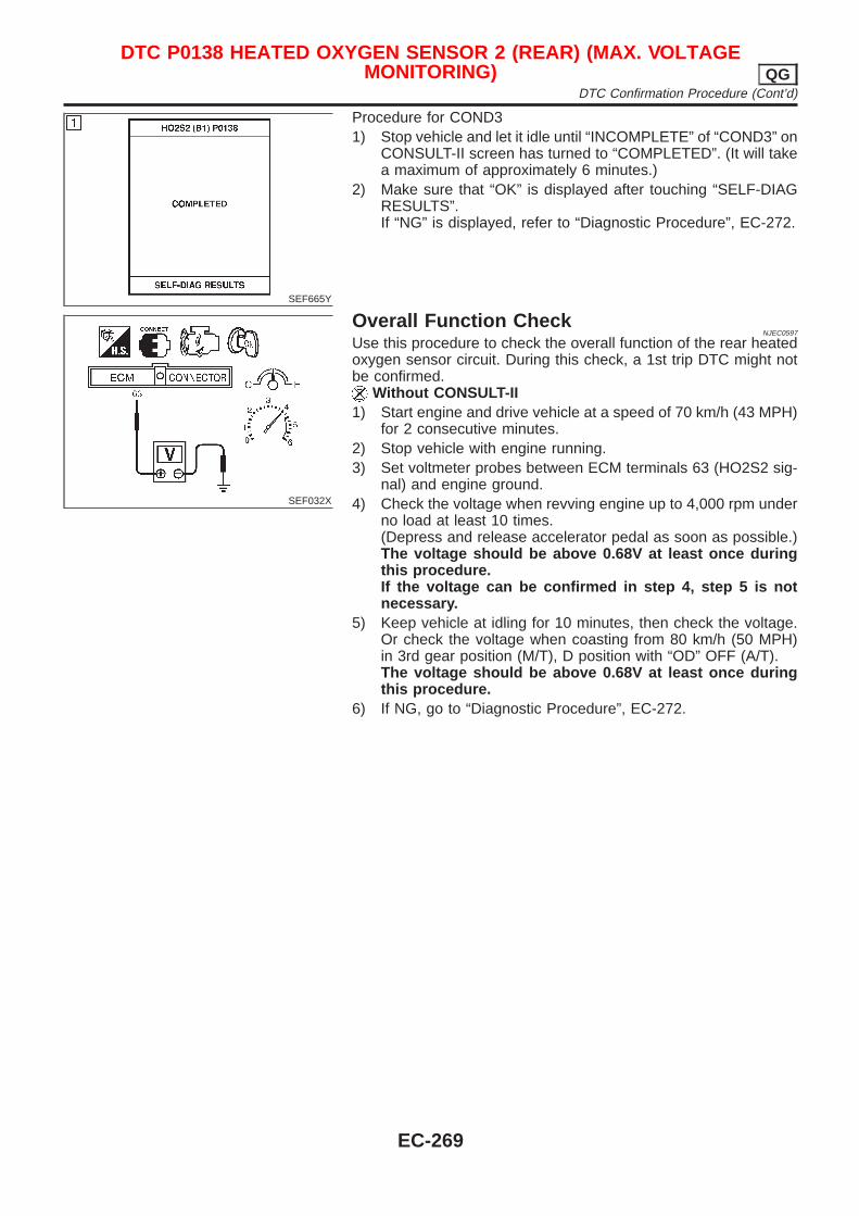
SEF665Y
Procedure for COND31) Stop vehicle and let it idle until “INCOMPLETE” of “COND3” on
CONSULT-II screen has turned to “COMPLETED”. (It will takea maximum of approximately 6 minutes.)
2) Make sure that “OK” is displayed after touching “SELF-DIAGRESULTS”.If “NG” is displayed, refer to “Diagnostic Procedure”, EC-272.
SEF032X
Overall Function CheckNJEC0597
Use this procedure to check the overall function of the rear heatedoxygen sensor circuit. During this check, a 1st trip DTC might notbe confirmed.
Without CONSULT-II1) Start engine and drive vehicle at a speed of 70 km/h (43 MPH)
for 2 consecutive minutes.2) Stop vehicle with engine running.3) Set voltmeter probes between ECM terminals 63 (HO2S2 sig-
nal) and engine ground.4) Check the voltage when revving engine up to 4,000 rpm under
no load at least 10 times.(Depress and release accelerator pedal as soon as possible.)The voltage should be above 0.68V at least once duringthis procedure.If the voltage can be confirmed in step 4, step 5 is notnecessary.
5) Keep vehicle at idling for 10 minutes, then check the voltage.Or check the voltage when coasting from 80 km/h (50 MPH)in 3rd gear position (M/T), D position with “OD” OFF (A/T).The voltage should be above 0.68V at least once duringthis procedure.
6) If NG, go to “Diagnostic Procedure”, EC-272.
DTC P0138 HEATED OXYGEN SENSOR 2 (REAR) (MAX. VOLTAGEMONITORING) QG
DTC Confirmation Procedure (Cont’d)
EC-269
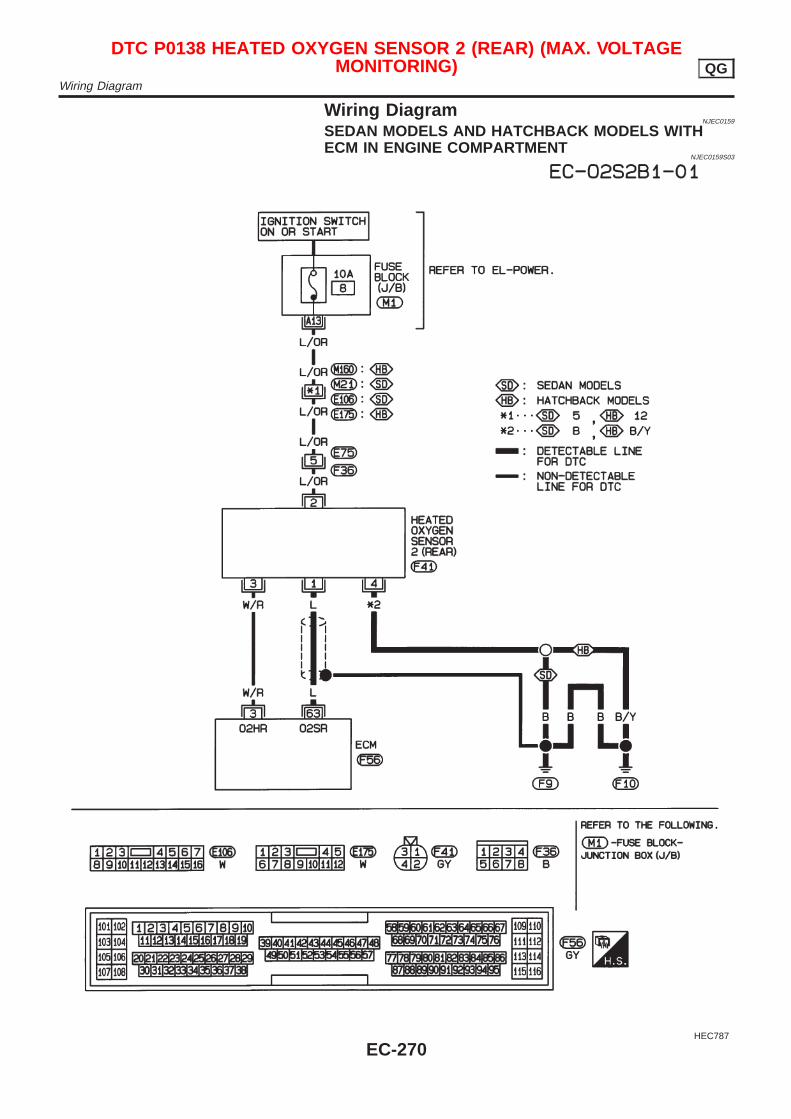
Wiring DiagramNJEC0159
SEDAN MODELS AND HATCHBACK MODELS WITHECM IN ENGINE COMPARTMENT
NJEC0159S03
HEC787
DTC P0138 HEATED OXYGEN SENSOR 2 (REAR) (MAX. VOLTAGEMONITORING) QG
Wiring Diagram
EC-270
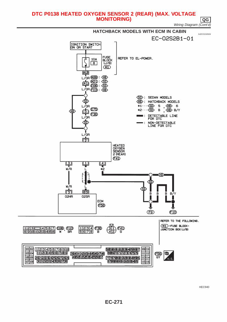
HATCHBACK MODELS WITH ECM IN CABINNJEC0159S04
HEC940
DTC P0138 HEATED OXYGEN SENSOR 2 (REAR) (MAX. VOLTAGEMONITORING) QG
Wiring Diagram (Cont’d)
EC-271
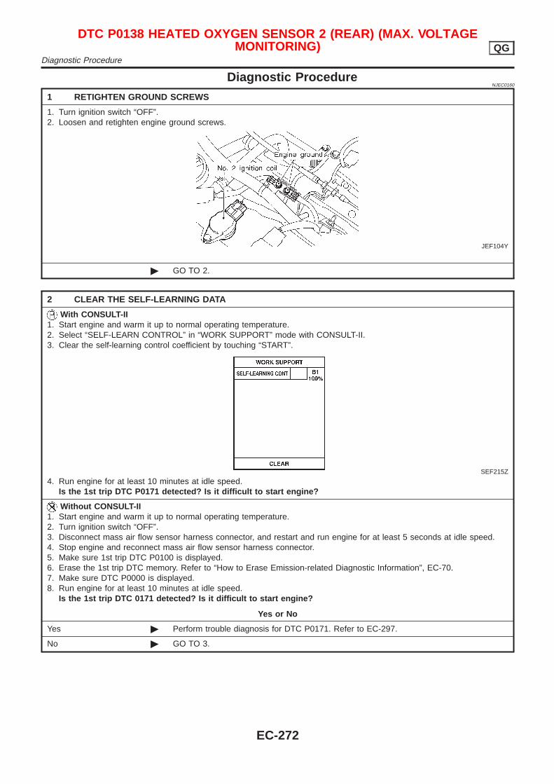
Diagnostic ProcedureNJEC0160
1 RETIGHTEN GROUND SCREWS
1. Turn ignition switch “OFF”.2. Loosen and retighten engine ground screws.
JEF104Y
© GO TO 2.
2 CLEAR THE SELF-LEARNING DATA
With CONSULT-II1. Start engine and warm it up to normal operating temperature.2. Select “SELF-LEARN CONTROL” in “WORK SUPPORT” mode with CONSULT-II.3. Clear the self-learning control coefficient by touching “START”.
SEF215Z
4. Run engine for at least 10 minutes at idle speed.Is the 1st trip DTC P0171 detected? Is it difficult to start engine?
Without CONSULT-II1. Start engine and warm it up to normal operating temperature.2. Turn ignition switch “OFF”.3. Disconnect mass air flow sensor harness connector, and restart and run engine for at least 5 seconds at idle speed.4. Stop engine and reconnect mass air flow sensor harness connector.5. Make sure 1st trip DTC P0100 is displayed.6. Erase the 1st trip DTC memory. Refer to “How to Erase Emission-related Diagnostic Information”, EC-70.7. Make sure DTC P0000 is displayed.8. Run engine for at least 10 minutes at idle speed.
Is the 1st trip DTC 0171 detected? Is it difficult to start engine?
Yes or No
Yes © Perform trouble diagnosis for DTC P0171. Refer to EC-297.
No © GO TO 3.
DTC P0138 HEATED OXYGEN SENSOR 2 (REAR) (MAX. VOLTAGEMONITORING) QG
Diagnostic Procedure
EC-272
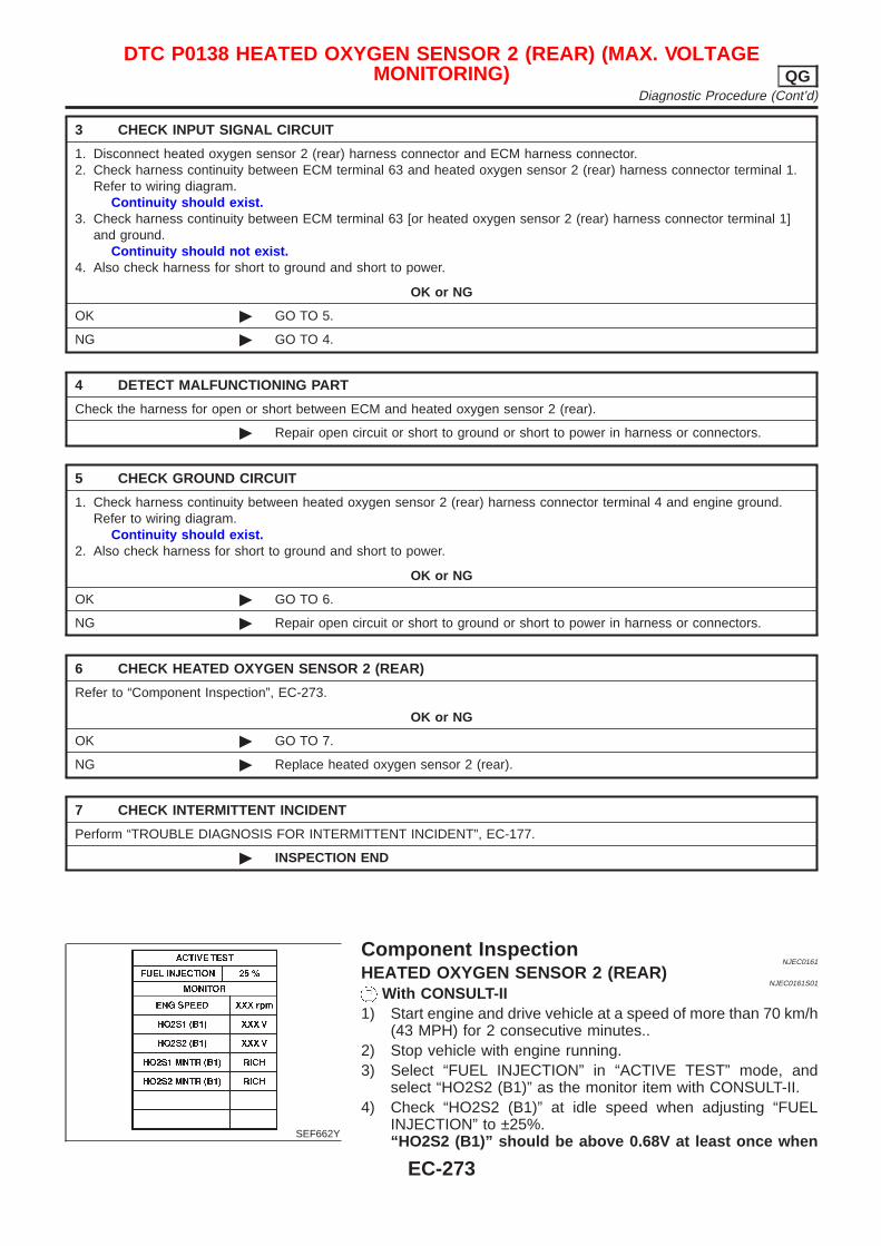
3 CHECK INPUT SIGNAL CIRCUIT
1. Disconnect heated oxygen sensor 2 (rear) harness connector and ECM harness connector.2. Check harness continuity between ECM terminal 63 and heated oxygen sensor 2 (rear) harness connector terminal 1.
Refer to wiring diagram.Continuity should exist.
3. Check harness continuity between ECM terminal 63 [or heated oxygen sensor 2 (rear) harness connector terminal 1]and ground.
Continuity should not exist.4. Also check harness for short to ground and short to power.
OK or NG
OK © GO TO 5.
NG © GO TO 4.
4 DETECT MALFUNCTIONING PART
Check the harness for open or short between ECM and heated oxygen sensor 2 (rear).
© Repair open circuit or short to ground or short to power in harness or connectors.
5 CHECK GROUND CIRCUIT
1. Check harness continuity between heated oxygen sensor 2 (rear) harness connector terminal 4 and engine ground.Refer to wiring diagram.
Continuity should exist.2. Also check harness for short to ground and short to power.
OK or NG
OK © GO TO 6.
NG © Repair open circuit or short to ground or short to power in harness or connectors.
6 CHECK HEATED OXYGEN SENSOR 2 (REAR)
Refer to “Component Inspection”, EC-273.
OK or NG
OK © GO TO 7.
NG © Replace heated oxygen sensor 2 (rear).
7 CHECK INTERMITTENT INCIDENT
Perform “TROUBLE DIAGNOSIS FOR INTERMITTENT INCIDENT”, EC-177.
© INSPECTION END
SEF662Y
Component InspectionNJEC0161
HEATED OXYGEN SENSOR 2 (REAR)NJEC0161S01
With CONSULT-II1) Start engine and drive vehicle at a speed of more than 70 km/h
(43 MPH) for 2 consecutive minutes..2) Stop vehicle with engine running.3) Select “FUEL INJECTION” in “ACTIVE TEST” mode, and
select “HO2S2 (B1)” as the monitor item with CONSULT-II.4) Check “HO2S2 (B1)” at idle speed when adjusting “FUEL
INJECTION” to ±25%.“HO2S2 (B1)” should be above 0.68V at least once when
DTC P0138 HEATED OXYGEN SENSOR 2 (REAR) (MAX. VOLTAGEMONITORING) QG
Diagnostic Procedure (Cont’d)
EC-273
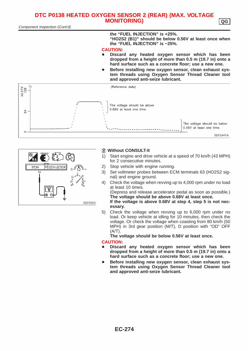
the “FUEL INJECTION” is +25%.“HO2S2 (B1)” should be below 0.56V at least once whenthe “FUEL INJECTION” is −25%.
CAUTION:+ Discard any heated oxygen sensor which has been
dropped from a height of more than 0.5 m (19.7 in) onto ahard surface such as a concrete floor; use a new one.
+ Before installing new oxygen sensor, clean exhaust sys-tem threads using Oxygen Sensor Thread Cleaner tooland approved anti-seize lubricant.
SEF244YA
SEF032X
Without CONSULT-II1) Start engine and drive vehicle at a speed of 70 km/h (43 MPH)
for 2 consecutive minutes.2) Stop vehicle with engine running.3) Set voltmeter probes between ECM terminals 63 (HO2S2 sig-
nal) and engine ground.4) Check the voltage when revving up to 4,000 rpm under no load
at least 10 times.(Depress and release accelerator pedal as soon as possible.)The voltage should be above 0.68V at least once.If the voltage is above 0.68V at step 4, step 5 is not nec-essary.
5) Check the voltage when revving up to 6,000 rpm under noload. Or keep vehicle at idling for 10 minutes, then check thevoltage. Or check the voltage when coasting from 80 km/h (50MPH) in 3rd gear position (M/T), D position with “OD” OFF(A/T).The voltage should be below 0.56V at least once.
CAUTION:+ Discard any heated oxygen sensor which has been
dropped from a height of more than 0.5 m (19.7 in) onto ahard surface such as a concrete floor; use a new one.
+ Before installing new oxygen sensor, clean exhaust sys-tem threads using Oxygen Sensor Thread Cleaner tooland approved anti-seize lubricant.
DTC P0138 HEATED OXYGEN SENSOR 2 (REAR) (MAX. VOLTAGEMONITORING) QG
Component Inspection (Cont’d)
EC-274
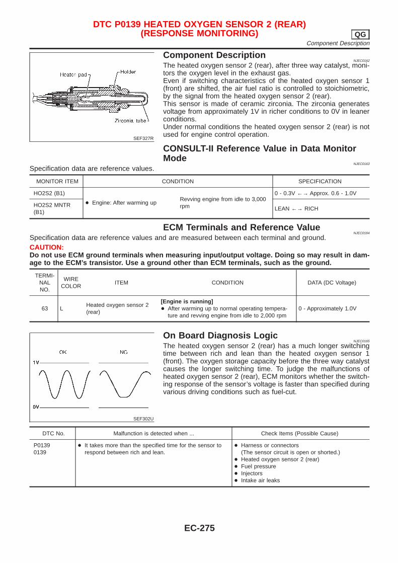
SEF327R
Component DescriptionNJEC0162
The heated oxygen sensor 2 (rear), after three way catalyst, moni-tors the oxygen level in the exhaust gas.Even if switching characteristics of the heated oxygen sensor 1(front) are shifted, the air fuel ratio is controlled to stoichiometric,by the signal from the heated oxygen sensor 2 (rear).This sensor is made of ceramic zirconia. The zirconia generatesvoltage from approximately 1V in richer conditions to 0V in leanerconditions.Under normal conditions the heated oxygen sensor 2 (rear) is notused for engine control operation.
CONSULT-II Reference Value in Data MonitorMode
NJEC0163
Specification data are reference values.
MONITOR ITEM CONDITION SPECIFICATION
HO2S2 (B1)
+ Engine: After warming upRevving engine from idle to 3,000rpm
0 - 0.3V ←→ Approx. 0.6 - 1.0V
HO2S2 MNTR(B1)
LEAN ←→ RICH
ECM Terminals and Reference ValueNJEC0164
Specification data are reference values and are measured between each terminal and ground.CAUTION:Do not use ECM ground terminals when measuring input/output voltage. Doing so may result in dam-age to the ECM’s transistor. Use a ground other than ECM terminals, such as the ground.
TERMI-NALNO.
WIRECOLOR
ITEM CONDITION DATA (DC Voltage)
63 LHeated oxygen sensor 2(rear)
[Engine is running]+ After warming up to normal operating tempera-
ture and revving engine from idle to 2,000 rpm0 - Approximately 1.0V
SEF302U
On Board Diagnosis LogicNJEC0165
The heated oxygen sensor 2 (rear) has a much longer switchingtime between rich and lean than the heated oxygen sensor 1(front). The oxygen storage capacity before the three way catalystcauses the longer switching time. To judge the malfunctions ofheated oxygen sensor 2 (rear), ECM monitors whether the switch-ing response of the sensor’s voltage is faster than specified duringvarious driving conditions such as fuel-cut.
DTC No. Malfunction is detected when ... Check Items (Possible Cause)
P01390139
+ It takes more than the specified time for the sensor torespond between rich and lean.
+ Harness or connectors(The sensor circuit is open or shorted.)
+ Heated oxygen sensor 2 (rear)+ Fuel pressure+ Injectors+ Intake air leaks
DTC P0139 HEATED OXYGEN SENSOR 2 (REAR)(RESPONSE MONITORING) QG
Component Description
EC-275
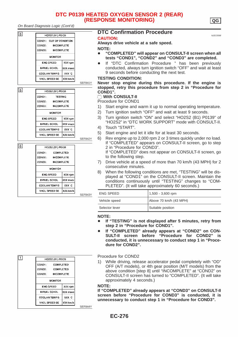
SEF841Y
SEF842Y
SEF843Y
DTC Confirmation ProcedureNJEC0598
CAUTION:Always drive vehicle at a safe speed.NOTE:+ “COMPLETED” will appear on CONSULT-II screen when all
tests “COND1”, “COND2” and “COND3” are completed.+ If “DTC Confirmation Procedure ” has been previously
conducted, always turn ignition switch “OFF” and wait at least9 seconds before conducting the next test.
TESTING CONDITION:Never stop engine during this procedure. If the engine isstopped, retry this procedure from step 2 in “Procedure forCOND1”.
With CONSULT-IIProcedure for COND11) Start engine and warm it up to normal operating temperature.2) Turn ignition switch “OFF” and wait at least 9 seconds.3) Turn ignition switch “ON” and select “HO2S2 (B1) P0139” of
“HO2S2” in “DTC WORK SUPPORT” mode with CONSULT-II.4) Touch “START”.5) Start engine and let it idle for at least 30 seconds.6) Rev engine up to 2,000 rpm 2 or 3 times quickly under no load.
If “COMPLETED” appears on CONSULT-II screen, go to step2 in “Procedure for COND3”.If “COMPLETED” does not appear on CONSULT-II screen, goto the following step.
7) Drive vehicle at a speed of more than 70 km/h (43 MPH) for 2consecutive minutes.
8) When the following conditions are met, “TESTING” will be dis-played at “COND1” on the CONSULT-II screen. Maintain theconditions continuously until “TESTING” changes to “COM-PLETED”. (It will take approximately 60 seconds.)
ENG SPEED 1,500 - 3,600 rpm
Vehicle speed Above 70 km/h (43 MPH)
Selector lever Suitable position
NOTE:+ If “TESTING” is not displayed after 5 minutes, retry from
step 2 in “Procedure for COND1”.+ If “COMPLETED” already appears at “COND2” on CON-
SULT-II screen before “Procedure for COND2” isconducted, it is unnecessary to conduct step 1 in “Proce-dure for COND2”.
SEF844Y
Procedure for COND21) While driving, release accelerator pedal completely with “OD”
OFF (A/T models), or 4th gear position (M/T models) from theabove condition [step 8] until “INCOMPLETE” at “COND2” onCONSULT-II screen has turned to “COMPLETED”. (It will takeapproximately 4 seconds.)
NOTE:If “COMPLETED” already appears at “COND3” on CONSULT-IIscreen before “Procedure for COND3” is conducted, it isunnecessary to conduct step 1 in “Procedure for COND3”.
DTC P0139 HEATED OXYGEN SENSOR 2 (REAR)(RESPONSE MONITORING) QG
On Board Diagnosis Logic (Cont’d)
EC-276
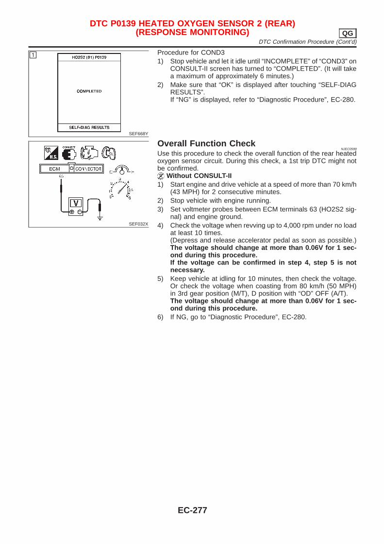
SEF668Y
Procedure for COND31) Stop vehicle and let it idle until “INCOMPLETE” of “COND3” on
CONSULT-II screen has turned to “COMPLETED”. (It will takea maximum of approximately 6 minutes.)
2) Make sure that “OK” is displayed after touching “SELF-DIAGRESULTS”.If “NG” is displayed, refer to “Diagnostic Procedure”, EC-280.
SEF032X
Overall Function CheckNJEC0599
Use this procedure to check the overall function of the rear heatedoxygen sensor circuit. During this check, a 1st trip DTC might notbe confirmed.
Without CONSULT-II1) Start engine and drive vehicle at a speed of more than 70 km/h
(43 MPH) for 2 consecutive minutes.2) Stop vehicle with engine running.3) Set voltmeter probes between ECM terminals 63 (HO2S2 sig-
nal) and engine ground.4) Check the voltage when revving up to 4,000 rpm under no load
at least 10 times.(Depress and release accelerator pedal as soon as possible.)The voltage should change at more than 0.06V for 1 sec-ond during this procedure.If the voltage can be confirmed in step 4, step 5 is notnecessary.
5) Keep vehicle at idling for 10 minutes, then check the voltage.Or check the voltage when coasting from 80 km/h (50 MPH)in 3rd gear position (M/T), D position with “OD” OFF (A/T).The voltage should change at more than 0.06V for 1 sec-ond during this procedure.
6) If NG, go to “Diagnostic Procedure”, EC-280.
DTC P0139 HEATED OXYGEN SENSOR 2 (REAR)(RESPONSE MONITORING) QG
DTC Confirmation Procedure (Cont’d)
EC-277
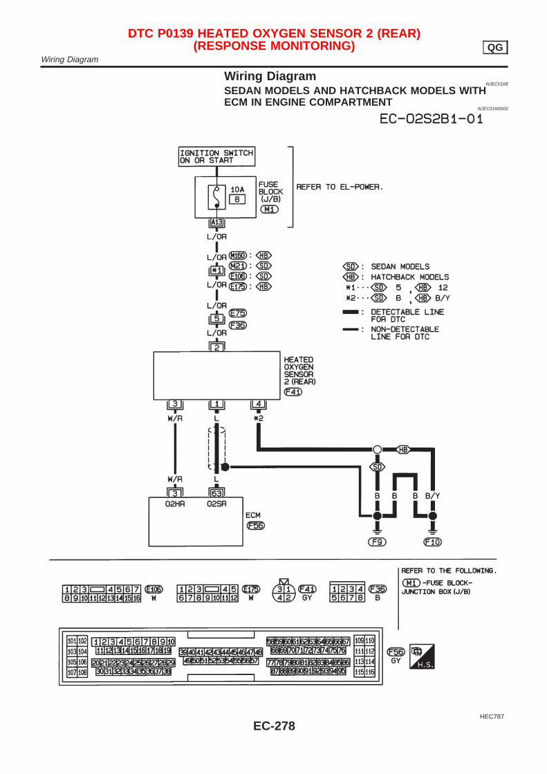
Wiring DiagramNJEC0168
SEDAN MODELS AND HATCHBACK MODELS WITHECM IN ENGINE COMPARTMENT
NJEC0168S03
HEC787
DTC P0139 HEATED OXYGEN SENSOR 2 (REAR)(RESPONSE MONITORING) QG
Wiring Diagram
EC-278

HATCHBACK MODELS WITH ECM IN CABINNJEC0168S04
HEC940
DTC P0139 HEATED OXYGEN SENSOR 2 (REAR)(RESPONSE MONITORING) QG
Wiring Diagram (Cont’d)
EC-279
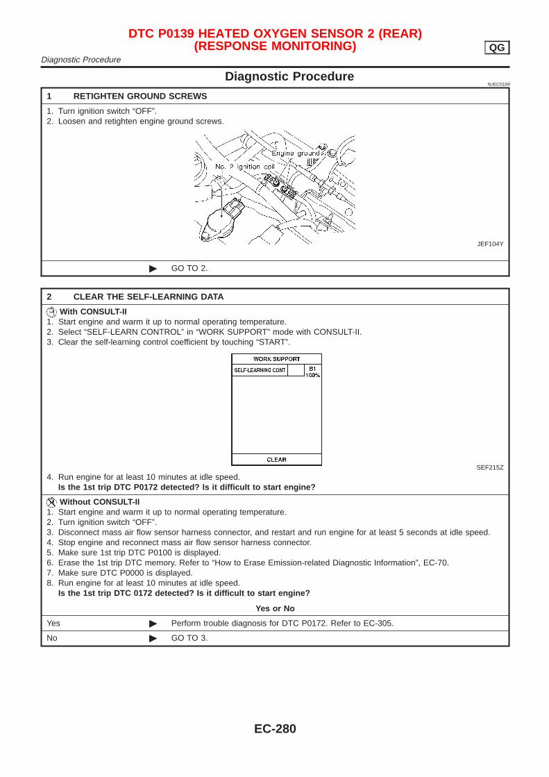
Diagnostic ProcedureNJEC0169
1 RETIGHTEN GROUND SCREWS
1. Turn ignition switch “OFF”.2. Loosen and retighten engine ground screws.
JEF104Y
© GO TO 2.
2 CLEAR THE SELF-LEARNING DATA
With CONSULT-II1. Start engine and warm it up to normal operating temperature.2. Select “SELF-LEARN CONTROL” in “WORK SUPPORT” mode with CONSULT-II.3. Clear the self-learning control coefficient by touching “START”.
SEF215Z
4. Run engine for at least 10 minutes at idle speed.Is the 1st trip DTC P0172 detected? Is it difficult to start engine?
Without CONSULT-II1. Start engine and warm it up to normal operating temperature.2. Turn ignition switch “OFF”.3. Disconnect mass air flow sensor harness connector, and restart and run engine for at least 5 seconds at idle speed.4. Stop engine and reconnect mass air flow sensor harness connector.5. Make sure 1st trip DTC P0100 is displayed.6. Erase the 1st trip DTC memory. Refer to “How to Erase Emission-related Diagnostic Information”, EC-70.7. Make sure DTC P0000 is displayed.8. Run engine for at least 10 minutes at idle speed.
Is the 1st trip DTC 0172 detected? Is it difficult to start engine?
Yes or No
Yes © Perform trouble diagnosis for DTC P0172. Refer to EC-305.
No © GO TO 3.
DTC P0139 HEATED OXYGEN SENSOR 2 (REAR)(RESPONSE MONITORING) QG
Diagnostic Procedure
EC-280
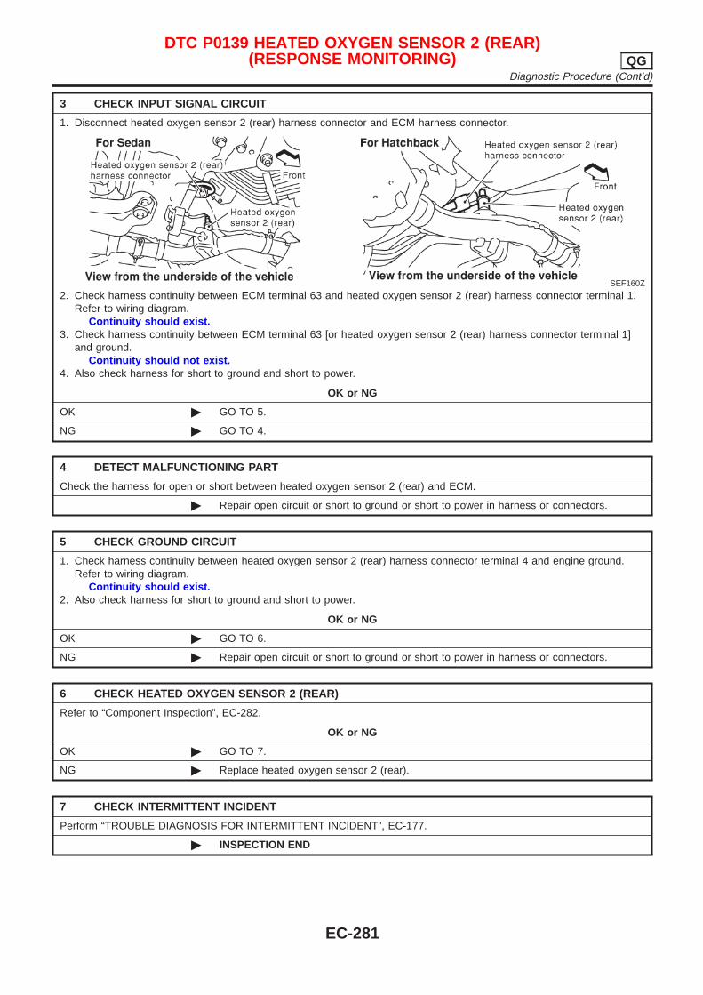
3 CHECK INPUT SIGNAL CIRCUIT
1. Disconnect heated oxygen sensor 2 (rear) harness connector and ECM harness connector.
SEF160Z
2. Check harness continuity between ECM terminal 63 and heated oxygen sensor 2 (rear) harness connector terminal 1.Refer to wiring diagram.
Continuity should exist.3. Check harness continuity between ECM terminal 63 [or heated oxygen sensor 2 (rear) harness connector terminal 1]
and ground.Continuity should not exist.
4. Also check harness for short to ground and short to power.
OK or NG
OK © GO TO 5.
NG © GO TO 4.
4 DETECT MALFUNCTIONING PART
Check the harness for open or short between heated oxygen sensor 2 (rear) and ECM.
© Repair open circuit or short to ground or short to power in harness or connectors.
5 CHECK GROUND CIRCUIT
1. Check harness continuity between heated oxygen sensor 2 (rear) harness connector terminal 4 and engine ground.Refer to wiring diagram.
Continuity should exist.2. Also check harness for short to ground and short to power.
OK or NG
OK © GO TO 6.
NG © Repair open circuit or short to ground or short to power in harness or connectors.
6 CHECK HEATED OXYGEN SENSOR 2 (REAR)
Refer to “Component Inspection”, EC-282.
OK or NG
OK © GO TO 7.
NG © Replace heated oxygen sensor 2 (rear).
7 CHECK INTERMITTENT INCIDENT
Perform “TROUBLE DIAGNOSIS FOR INTERMITTENT INCIDENT”, EC-177.
© INSPECTION END
DTC P0139 HEATED OXYGEN SENSOR 2 (REAR)(RESPONSE MONITORING) QG
Diagnostic Procedure (Cont’d)
EC-281
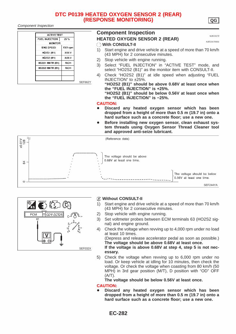
SEF662Y
Component InspectionNJEC0170
HEATED OXYGEN SENSOR 2 (REAR)NJEC0170S01
With CONSULT-II1) Start engine and drive vehicle at a speed of more than 70 km/h
(43 MPH) for 2 consecutive minutes.2) Stop vehicle with engine running.3) Select “FUEL INJECTION” in “ACTIVE TEST” mode, and
select “HO2S2 (B1)” as the monitor item with CONSULT-II.4) Check “HO2S2 (B1)” at idle speed when adjusting “FUEL
INJECTION” to ±25%.“HO2S2 (B1)” should be above 0.68V at least once whenthe “FUEL INJECTION” is +25%.“HO2S2 (B1)” should be below 0.56V at least once whenthe “FUEL INJECTION” is −25%.
CAUTION:+ Discard any heated oxygen sensor which has been
dropped from a height of more than 0.5 m (19.7 in) onto ahard surface such as a concrete floor; use a new one.
+ Before installing new oxygen sensor, clean exhaust sys-tem threads using Oxygen Sensor Thread Cleaner tooland approved anti-seize lubricant.
SEF244YA
SEF032X
Without CONSULT-II1) Start engine and drive vehicle at a speed of more than 70 km/h
(43 MPH) for 2 consecutive minutes.2) Stop vehicle with engine running.3) Set voltmeter probes between ECM terminals 63 (HO2S2 sig-
nal) and engine ground.4) Check the voltage when revving up to 4,000 rpm under no load
at least 10 times.(Depress and release accelerator pedal as soon as possible.)The voltage should be above 0.68V at least once.If the voltage is above 0.68V at step 4, step 5 is not nec-essary.
5) Check the voltage when revving up to 6,000 rpm under noload. Or keep vehicle at idling for 10 minutes, then check thevoltage. Or check the voltage when coasting from 80 km/h (50MPH) in 3rd gear position (M/T), D position with “OD” OFF(A/T).The voltage should be below 0.56V at least once.
CAUTION:+ Discard any heated oxygen sensor which has been
dropped from a height of more than 0.5 m (19.7 in) onto ahard surface such as a concrete floor; use a new one.
DTC P0139 HEATED OXYGEN SENSOR 2 (REAR)(RESPONSE MONITORING) QG
Component Inspection
EC-282

+ Before installing new oxygen sensor, clean exhaust sys-tem threads using Oxygen Sensor Thread Cleaner tooland approved anti-seize lubricant.
DTC P0139 HEATED OXYGEN SENSOR 2 (REAR)(RESPONSE MONITORING) QG
Component Inspection (Cont’d)
EC-283
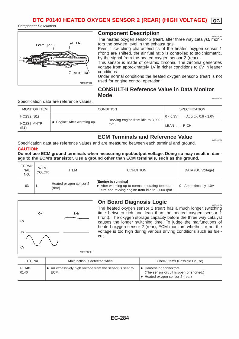
SEF327R
Component DescriptionNJEC0171
The heated oxygen sensor 2 (rear), after three way catalyst, moni-tors the oxygen level in the exhaust gas.Even if switching characteristics of the heated oxygen sensor 1(front) are shifted, the air fuel ratio is controlled to stoichiometric,by the signal from the heated oxygen sensor 2 (rear).This sensor is made of ceramic zirconia. The zirconia generatesvoltage from approximately 1V in richer conditions to 0V in leanerconditions.Under normal conditions the heated oxygen sensor 2 (rear) is notused for engine control operation.
CONSULT-II Reference Value in Data MonitorMode
NJEC0172
Specification data are reference values.
MONITOR ITEM CONDITION SPECIFICATION
HO2S2 (B1)
+ Engine: After warming upRevving engine from idle to 3,000rpm
0 - 0.3V ←→ Approx. 0.6 - 1.0V
HO2S2 MNTR(B1)
LEAN ←→ RICH
ECM Terminals and Reference ValueNJEC0173
Specification data are reference values and are measured between each terminal and ground.CAUTION:Do not use ECM ground terminals when measuring input/output voltage. Doing so may result in dam-age to the ECM’s transistor. Use a ground other than ECM terminals, such as the ground.
TERMI-NALNO.
WIRECOLOR
ITEM CONDITION DATA (DC Voltage)
63 LHeated oxygen sensor 2(rear)
[Engine is running]+ After warming up to normal operating tempera-
ture and revving engine from idle to 2,000 rpm0 - Approximately 1.0V
SEF305U
On Board Diagnosis LogicNJEC0174
The heated oxygen sensor 2 (rear) has a much longer switchingtime between rich and lean than the heated oxygen sensor 1(front). The oxygen storage capacity before the three way catalystcauses the longer switching time. To judge the malfunctions ofheated oxygen sensor 2 (rear), ECM monitors whether or not thevoltage is too high during various driving conditions such as fuel-cut.
DTC No. Malfunction is detected when ... Check Items (Possible Cause)
P01400140
+ An excessively high voltage from the sensor is sent toECM.
+ Harness or connectors(The sensor circuit is open or shorted.)
+ Heated oxygen sensor 2 (rear)
DTC P0140 HEATED OXYGEN SENSOR 2 (REAR) (HIGH VOLTAGE) QGComponent Description
EC-284
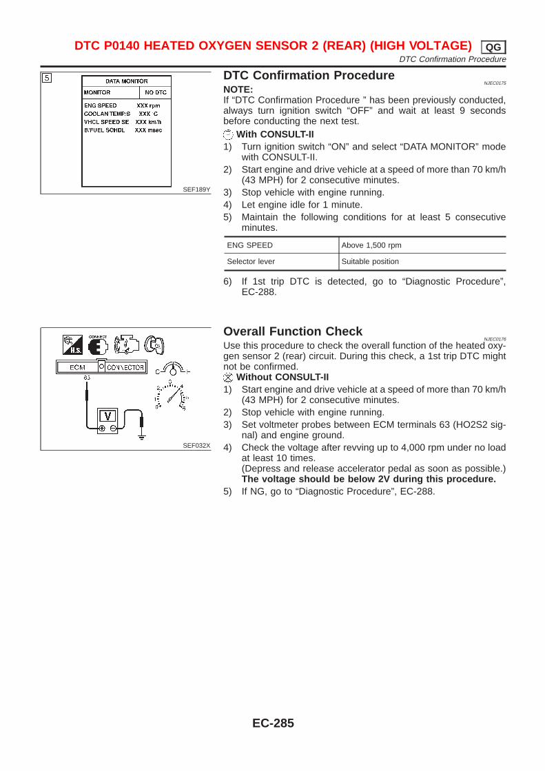
SEF189Y
DTC Confirmation ProcedureNJEC0175
NOTE:If “DTC Confirmation Procedure ” has been previously conducted,always turn ignition switch “OFF” and wait at least 9 secondsbefore conducting the next test.
With CONSULT-II1) Turn ignition switch “ON” and select “DATA MONITOR” mode
with CONSULT-II.2) Start engine and drive vehicle at a speed of more than 70 km/h
(43 MPH) for 2 consecutive minutes.3) Stop vehicle with engine running.4) Let engine idle for 1 minute.5) Maintain the following conditions for at least 5 consecutive
minutes.
ENG SPEED Above 1,500 rpm
Selector lever Suitable position
6) If 1st trip DTC is detected, go to “Diagnostic Procedure”,EC-288.
SEF032X
Overall Function CheckNJEC0176
Use this procedure to check the overall function of the heated oxy-gen sensor 2 (rear) circuit. During this check, a 1st trip DTC mightnot be confirmed.
Without CONSULT-II1) Start engine and drive vehicle at a speed of more than 70 km/h
(43 MPH) for 2 consecutive minutes.2) Stop vehicle with engine running.3) Set voltmeter probes between ECM terminals 63 (HO2S2 sig-
nal) and engine ground.4) Check the voltage after revving up to 4,000 rpm under no load
at least 10 times.(Depress and release accelerator pedal as soon as possible.)The voltage should be below 2V during this procedure.
5) If NG, go to “Diagnostic Procedure”, EC-288.
DTC P0140 HEATED OXYGEN SENSOR 2 (REAR) (HIGH VOLTAGE) QGDTC Confirmation Procedure
EC-285
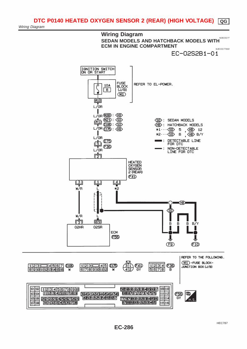
Wiring DiagramNJEC0177
SEDAN MODELS AND HATCHBACK MODELS WITHECM IN ENGINE COMPARTMENT
NJEC0177S03
HEC787
DTC P0140 HEATED OXYGEN SENSOR 2 (REAR) (HIGH VOLTAGE) QGWiring Diagram
EC-286
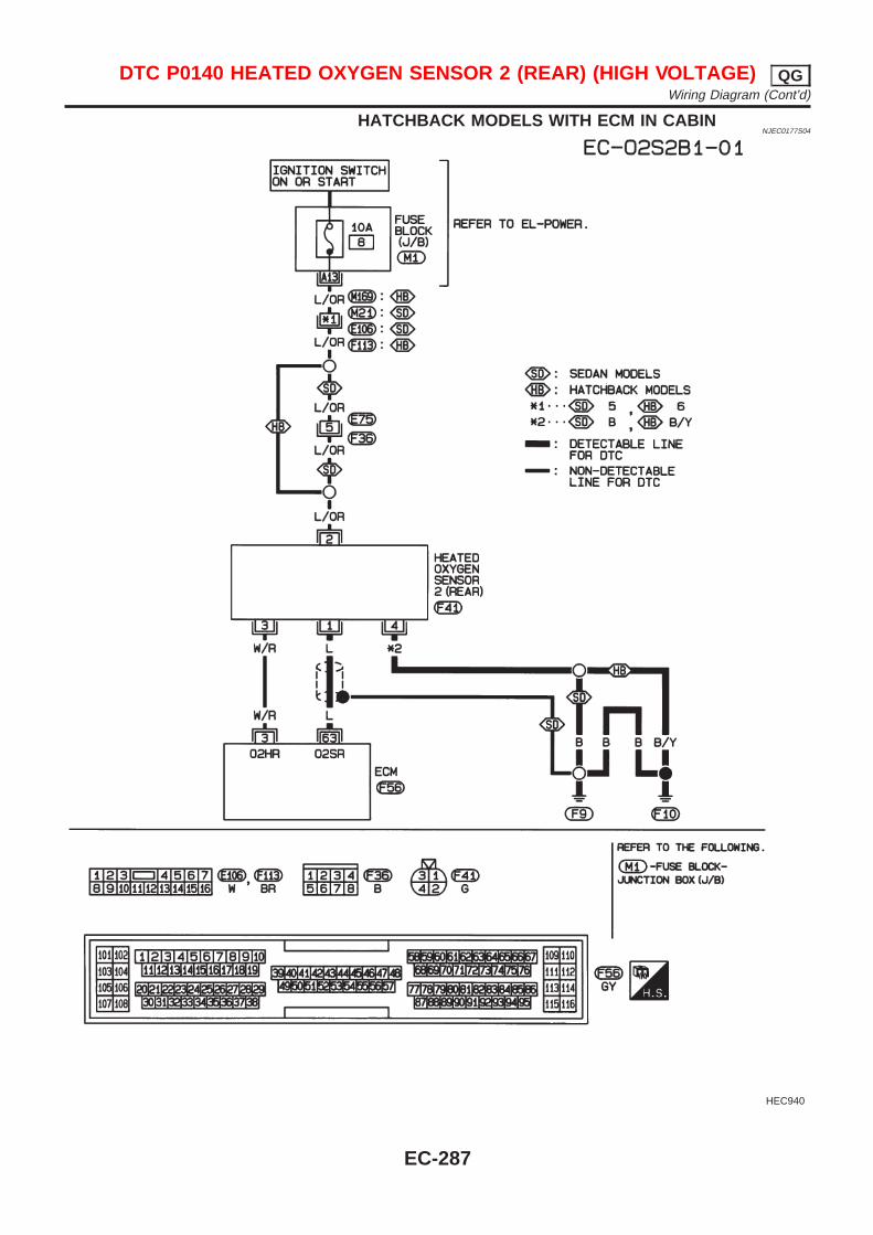
HATCHBACK MODELS WITH ECM IN CABINNJEC0177S04
HEC940
DTC P0140 HEATED OXYGEN SENSOR 2 (REAR) (HIGH VOLTAGE) QGWiring Diagram (Cont’d)
EC-287
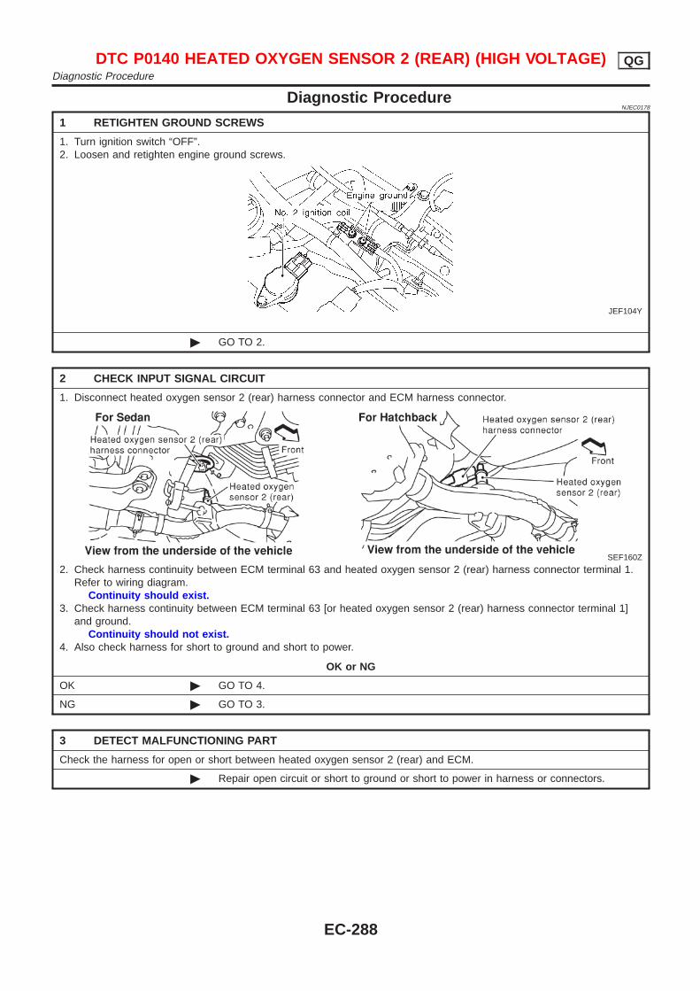
Diagnostic ProcedureNJEC0178
1 RETIGHTEN GROUND SCREWS
1. Turn ignition switch “OFF”.2. Loosen and retighten engine ground screws.
JEF104Y
© GO TO 2.
2 CHECK INPUT SIGNAL CIRCUIT
1. Disconnect heated oxygen sensor 2 (rear) harness connector and ECM harness connector.
SEF160Z
2. Check harness continuity between ECM terminal 63 and heated oxygen sensor 2 (rear) harness connector terminal 1.Refer to wiring diagram.
Continuity should exist.3. Check harness continuity between ECM terminal 63 [or heated oxygen sensor 2 (rear) harness connector terminal 1]
and ground.Continuity should not exist.
4. Also check harness for short to ground and short to power.
OK or NG
OK © GO TO 4.
NG © GO TO 3.
3 DETECT MALFUNCTIONING PART
Check the harness for open or short between heated oxygen sensor 2 (rear) and ECM.
© Repair open circuit or short to ground or short to power in harness or connectors.
DTC P0140 HEATED OXYGEN SENSOR 2 (REAR) (HIGH VOLTAGE) QGDiagnostic Procedure
EC-288
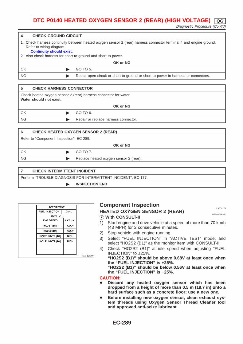
4 CHECK GROUND CIRCUIT
1. Check harness continuity between heated oxygen sensor 2 (rear) harness connector terminal 4 and engine ground.Refer to wiring diagram.
Continuity should exist.2. Also check harness for short to ground and short to power.
OK or NG
OK © GO TO 5.
NG © Repair open circuit or short to ground or short to power in harness or connectors.
5 CHECK HARNESS CONNECTOR
Check heated oxygen sensor 2 (rear) harness connector for water.Water should not exist.
OK or NG
OK © GO TO 6.
NG © Repair or replace harness connector.
6 CHECK HEATED OXYGEN SENSOR 2 (REAR)
Refer to “Component Inspection”, EC-289.
OK or NG
OK © GO TO 7.
NG © Replace heated oxygen sensor 2 (rear).
7 CHECK INTERMITTENT INCIDENT
Perform “TROUBLE DIAGNOSIS FOR INTERMITTENT INCIDENT”, EC-177.
© INSPECTION END
SEF662Y
Component InspectionNJEC0179
HEATED OXYGEN SENSOR 2 (REAR)NJEC0179S01
With CONSULT-II1) Start engine and drive vehicle at a speed of more than 70 km/h
(43 MPH) for 2 consecutive minutes.2) Stop vehicle with engine running.3) Select “FUEL INJECTION” in “ACTIVE TEST” mode, and
select “HO2S2 (B1)” as the monitor item with CONSULT-II.4) Check “HO2S2 (B1)” at idle speed when adjusting “FUEL
INJECTION” to ±25%.“HO2S2 (B1)” should be above 0.68V at least once whenthe “FUEL INJECTION” is +25%.“HO2S2 (B1)” should be below 0.56V at least once whenthe “FUEL INJECTION” is −25%.
CAUTION:+ Discard any heated oxygen sensor which has been
dropped from a height of more than 0.5 m (19.7 in) onto ahard surface such as a concrete floor; use a new one.
+ Before installing new oxygen sensor, clean exhaust sys-tem threads using Oxygen Sensor Thread Cleaner tooland approved anti-seize lubricant.
DTC P0140 HEATED OXYGEN SENSOR 2 (REAR) (HIGH VOLTAGE) QGDiagnostic Procedure (Cont’d)
EC-289
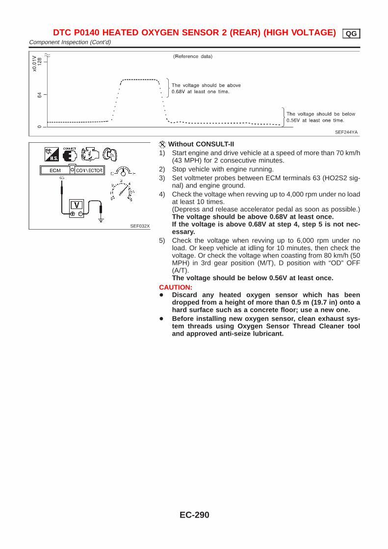
SEF244YA
SEF032X
Without CONSULT-II1) Start engine and drive vehicle at a speed of more than 70 km/h
(43 MPH) for 2 consecutive minutes.2) Stop vehicle with engine running.3) Set voltmeter probes between ECM terminals 63 (HO2S2 sig-
nal) and engine ground.4) Check the voltage when revving up to 4,000 rpm under no load
at least 10 times.(Depress and release accelerator pedal as soon as possible.)The voltage should be above 0.68V at least once.If the voltage is above 0.68V at step 4, step 5 is not nec-essary.
5) Check the voltage when revving up to 6,000 rpm under noload. Or keep vehicle at idling for 10 minutes, then check thevoltage. Or check the voltage when coasting from 80 km/h (50MPH) in 3rd gear position (M/T), D position with “OD” OFF(A/T).The voltage should be below 0.56V at least once.
CAUTION:+ Discard any heated oxygen sensor which has been
dropped from a height of more than 0.5 m (19.7 in) onto ahard surface such as a concrete floor; use a new one.
+ Before installing new oxygen sensor, clean exhaust sys-tem threads using Oxygen Sensor Thread Cleaner tooland approved anti-seize lubricant.
DTC P0140 HEATED OXYGEN SENSOR 2 (REAR) (HIGH VOLTAGE) QGComponent Inspection (Cont’d)
EC-290
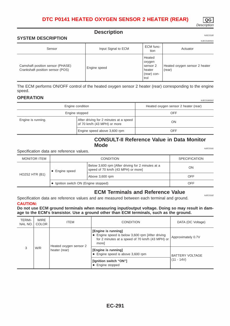
DescriptionNJEC0180
SYSTEM DESCRIPTIONNJEC0180S01
Sensor Input Signal to ECMECM func-
tionActuator
Camshaft position sensor (PHASE)Crankshaft position sensor (POS)
Engine speed
Heatedoxygensensor 2heater(rear) con-trol
Heated oxygen sensor 2 heater(rear)
The ECM performs ON/OFF control of the heated oxygen sensor 2 heater (rear) corresponding to the enginespeed.
OPERATIONNJEC0180S02
Engine condition Heated oxygen sensor 2 heater (rear)
Engine stopped OFF
Engine is running. After driving for 2 minutes at a speedof 70 km/h (43 MPH) or more
ON
Engine speed above 3,600 rpm OFF
CONSULT-II Reference Value in Data MonitorMode
NJEC0181
Specification data are reference values.
MONITOR ITEM CONDITION SPECIFICATION
HO2S2 HTR (B1)+ Engine speed
Below 3,600 rpm [After driving for 2 minutes at aspeed of 70 km/h (43 MPH) or more]
ON
Above 3,600 rpm OFF
+ Ignition switch ON (Engine stopped) OFF
ECM Terminals and Reference ValueNJEC0182
Specification data are reference values and are measured between each terminal and ground.CAUTION:Do not use ECM ground terminals when measuring input/output voltage. Doing so may result in dam-age to the ECM’s transistor. Use a ground other than ECM terminals, such as the ground.
TERMI-NAL NO.
WIRECOLOR
ITEM CONDITION DATA (DC Voltage)
3 W/RHeated oxygen sensor 2heater (rear)
[Engine is running]+ Engine speed is below 3,600 rpm [After driving
for 2 minutes at a speed of 70 km/h (43 MPH) ormore]
Approximately 0.7V
[Engine is running]+ Engine speed is above 3,600 rpm BATTERY VOLTAGE
(11 - 14V)[Ignition switch “ON”]+ Engine stopped
DTC P0141 HEATED OXYGEN SENSOR 2 HEATER (REAR) QGDescription
EC-291
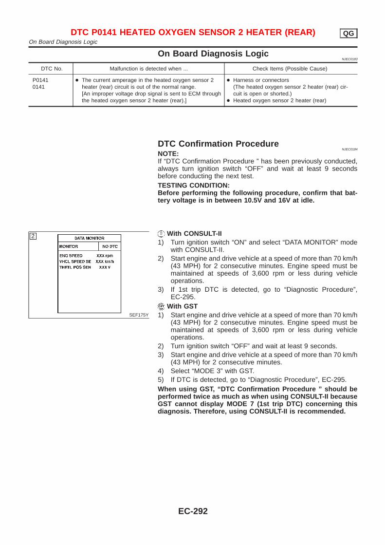
On Board Diagnosis LogicNJEC0183
DTC No. Malfunction is detected when ... Check Items (Possible Cause)
P01410141
+ The current amperage in the heated oxygen sensor 2heater (rear) circuit is out of the normal range.[An improper voltage drop signal is sent to ECM throughthe heated oxygen sensor 2 heater (rear).]
+ Harness or connectors(The heated oxygen sensor 2 heater (rear) cir-cuit is open or shorted.)
+ Heated oxygen sensor 2 heater (rear)
DTC Confirmation ProcedureNJEC0184
NOTE:If “DTC Confirmation Procedure ” has been previously conducted,always turn ignition switch “OFF” and wait at least 9 secondsbefore conducting the next test.TESTING CONDITION:Before performing the following procedure, confirm that bat-tery voltage is in between 10.5V and 16V at idle.
SEF175Y
With CONSULT-II1) Turn ignition switch “ON” and select “DATA MONITOR” mode
with CONSULT-II.2) Start engine and drive vehicle at a speed of more than 70 km/h
(43 MPH) for 2 consecutive minutes. Engine speed must bemaintained at speeds of 3,600 rpm or less during vehicleoperations.
3) If 1st trip DTC is detected, go to “Diagnostic Procedure”,EC-295.
With GST1) Start engine and drive vehicle at a speed of more than 70 km/h
(43 MPH) for 2 consecutive minutes. Engine speed must bemaintained at speeds of 3,600 rpm or less during vehicleoperations.
2) Turn ignition switch “OFF” and wait at least 9 seconds.3) Start engine and drive vehicle at a speed of more than 70 km/h
(43 MPH) for 2 consecutive minutes.4) Select “MODE 3” with GST.5) If DTC is detected, go to “Diagnostic Procedure”, EC-295.When using GST, “DTC Confirmation Procedure ” should beperformed twice as much as when using CONSULT-II becauseGST cannot display MODE 7 (1st trip DTC) concerning thisdiagnosis. Therefore, using CONSULT-II is recommended.
DTC P0141 HEATED OXYGEN SENSOR 2 HEATER (REAR) QGOn Board Diagnosis Logic
EC-292
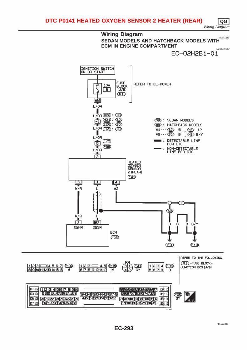
Wiring DiagramNJEC0185
SEDAN MODELS AND HATCHBACK MODELS WITHECM IN ENGINE COMPARTMENT
NJEC0185S03
HEC788
DTC P0141 HEATED OXYGEN SENSOR 2 HEATER (REAR) QGWiring Diagram
EC-293
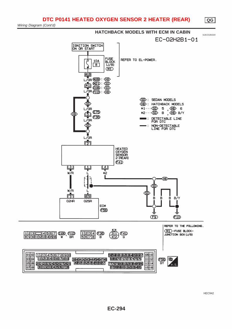
HATCHBACK MODELS WITH ECM IN CABINNJEC0185S04
HEC942
DTC P0141 HEATED OXYGEN SENSOR 2 HEATER (REAR) QGWiring Diagram (Cont’d)
EC-294
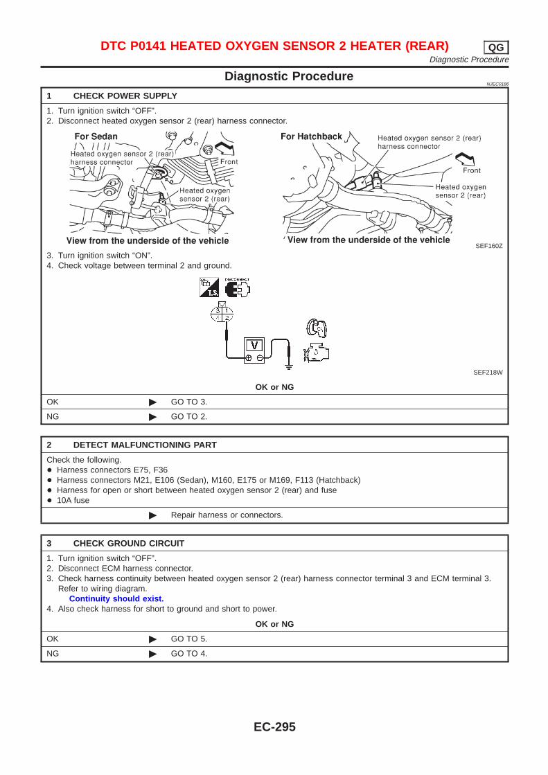
Diagnostic ProcedureNJEC0186
1 CHECK POWER SUPPLY
1. Turn ignition switch “OFF”.2. Disconnect heated oxygen sensor 2 (rear) harness connector.
SEF160Z
3. Turn ignition switch “ON”.4. Check voltage between terminal 2 and ground.
SEF218W
OK or NG
OK © GO TO 3.
NG © GO TO 2.
2 DETECT MALFUNCTIONING PART
Check the following.+ Harness connectors E75, F36+ Harness connectors M21, E106 (Sedan), M160, E175 or M169, F113 (Hatchback)+ Harness for open or short between heated oxygen sensor 2 (rear) and fuse+ 10A fuse
© Repair harness or connectors.
3 CHECK GROUND CIRCUIT
1. Turn ignition switch “OFF”.2. Disconnect ECM harness connector.3. Check harness continuity between heated oxygen sensor 2 (rear) harness connector terminal 3 and ECM terminal 3.
Refer to wiring diagram.Continuity should exist.
4. Also check harness for short to ground and short to power.
OK or NG
OK © GO TO 5.
NG © GO TO 4.
DTC P0141 HEATED OXYGEN SENSOR 2 HEATER (REAR) QGDiagnostic Procedure
EC-295
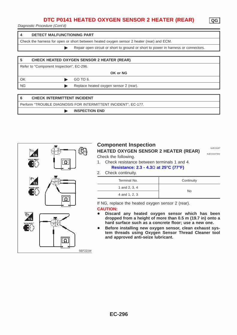
4 DETECT MALFUNCTIONING PART
Check the harness for open or short between heated oxygen sensor 2 heater (rear) and ECM.
© Repair open circuit or short to ground or short to power in harness or connectors.
5 CHECK HEATED OXYGEN SENSOR 2 HEATER (REAR)
Refer to “Component Inspection”, EC-296.
OK or NG
OK © GO TO 6.
NG © Replace heated oxygen sensor 2 (rear).
6 CHECK INTERMITTENT INCIDENT
Perform “TROUBLE DIAGNOSIS FOR INTERMITTENT INCIDENT”, EC-177.
© INSPECTION END
SEF221W
Component InspectionNJEC0187
HEATED OXYGEN SENSOR 2 HEATER (REAR)NJEC0187S01
Check the following.1. Check resistance between terminals 1 and 4.
Resistance: 2.3 - 4.3 Ω at 25°C (77°F)2. Check continuity.
Terminal No. Continuity
1 and 2, 3, 4No
4 and 1, 2, 3
If NG, replace the heated oxygen sensor 2 (rear).CAUTION:+ Discard any heated oxygen sensor which has been
dropped from a height of more than 0.5 m (19.7 in) onto ahard surface such as a concrete floor; use a new one.
+ Before installing new oxygen sensor, clean exhaust sys-tem threads using Oxygen Sensor Thread Cleaner tooland approved anti-seize lubricant.
DTC P0141 HEATED OXYGEN SENSOR 2 HEATER (REAR) QGDiagnostic Procedure (Cont’d)
EC-296
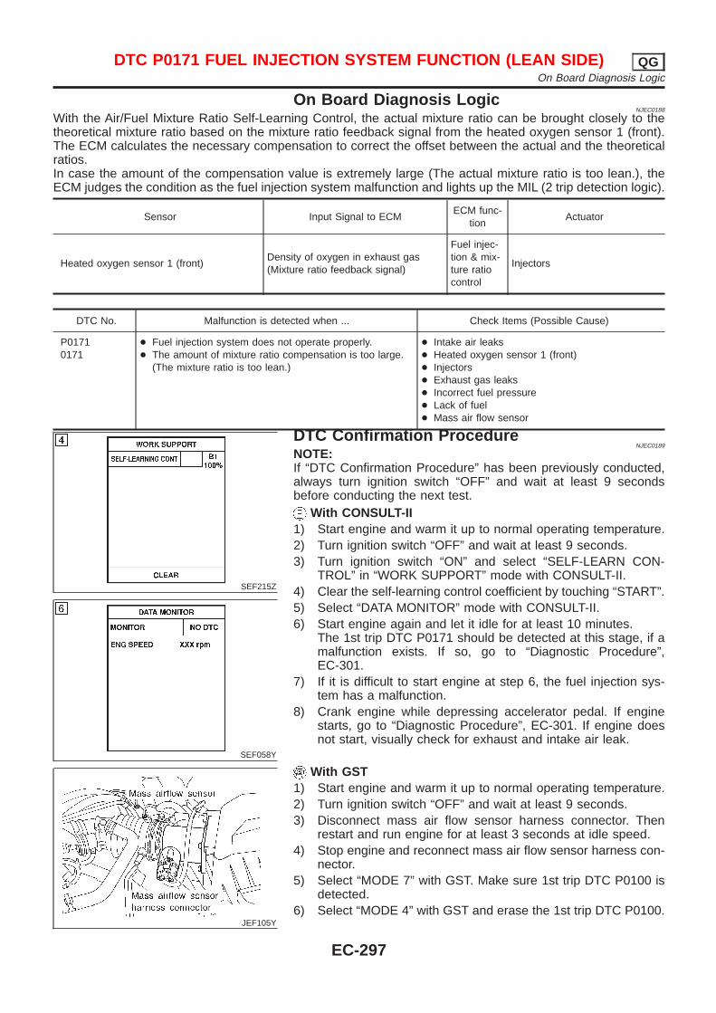
On Board Diagnosis LogicNJEC0188
With the Air/Fuel Mixture Ratio Self-Learning Control, the actual mixture ratio can be brought closely to thetheoretical mixture ratio based on the mixture ratio feedback signal from the heated oxygen sensor 1 (front).The ECM calculates the necessary compensation to correct the offset between the actual and the theoreticalratios.In case the amount of the compensation value is extremely large (The actual mixture ratio is too lean.), theECM judges the condition as the fuel injection system malfunction and lights up the MIL (2 trip detection logic).
Sensor Input Signal to ECMECM func-
tionActuator
Heated oxygen sensor 1 (front)Density of oxygen in exhaust gas(Mixture ratio feedback signal)
Fuel injec-tion & mix-ture ratiocontrol
Injectors
DTC No. Malfunction is detected when ... Check Items (Possible Cause)
P01710171
+ Fuel injection system does not operate properly.+ The amount of mixture ratio compensation is too large.
(The mixture ratio is too lean.)
+ Intake air leaks+ Heated oxygen sensor 1 (front)+ Injectors+ Exhaust gas leaks+ Incorrect fuel pressure+ Lack of fuel+ Mass air flow sensor
SEF215Z
SEF058Y
DTC Confirmation ProcedureNJEC0189
NOTE:If “DTC Confirmation Procedure” has been previously conducted,always turn ignition switch “OFF” and wait at least 9 secondsbefore conducting the next test.
With CONSULT-II1) Start engine and warm it up to normal operating temperature.2) Turn ignition switch “OFF” and wait at least 9 seconds.3) Turn ignition switch “ON” and select “SELF-LEARN CON-
TROL” in “WORK SUPPORT” mode with CONSULT-II.4) Clear the self-learning control coefficient by touching “START”.5) Select “DATA MONITOR” mode with CONSULT-II.6) Start engine again and let it idle for at least 10 minutes.
The 1st trip DTC P0171 should be detected at this stage, if amalfunction exists. If so, go to “Diagnostic Procedure”,EC-301.
7) If it is difficult to start engine at step 6, the fuel injection sys-tem has a malfunction.
8) Crank engine while depressing accelerator pedal. If enginestarts, go to “Diagnostic Procedure”, EC-301. If engine doesnot start, visually check for exhaust and intake air leak.
JEF105Y
With GST1) Start engine and warm it up to normal operating temperature.2) Turn ignition switch “OFF” and wait at least 9 seconds.3) Disconnect mass air flow sensor harness connector. Then
restart and run engine for at least 3 seconds at idle speed.4) Stop engine and reconnect mass air flow sensor harness con-
nector.5) Select “MODE 7” with GST. Make sure 1st trip DTC P0100 is
detected.6) Select “MODE 4” with GST and erase the 1st trip DTC P0100.
DTC P0171 FUEL INJECTION SYSTEM FUNCTION (LEAN SIDE) QGOn Board Diagnosis Logic
EC-297
7) Start engine again and run it for at least 10 minutes at idlespeed.
8) Select “MODE 7” with GST. The 1st trip DTC P0171 should bedetected at this stage, if a malfunction exists. If so, go to“Diagnostic Procedure”, EC-301.
9) If it is difficult to start engine at step 8, the fuel injection sys-tem has a malfunction.
10) Crank engine while depressing accelerator pedal. If enginestarts, go to “Diagnostic Procedure”, EC-301. If engine doesnot start, visually check for exhaust and intake air leak.
DTC P0171 FUEL INJECTION SYSTEM FUNCTION (LEAN SIDE) QGDTC Confirmation Procedure (Cont’d)
EC-298
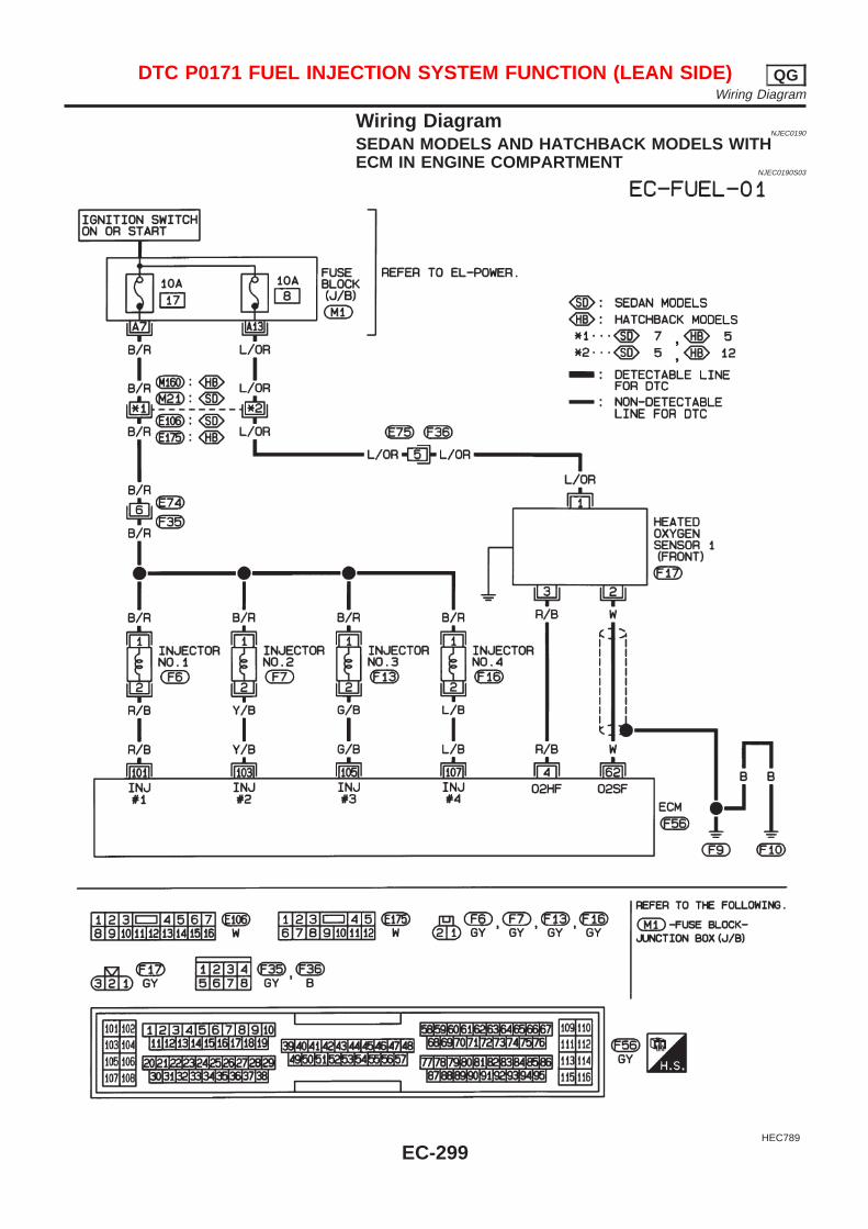
Wiring DiagramNJEC0190
SEDAN MODELS AND HATCHBACK MODELS WITHECM IN ENGINE COMPARTMENT
NJEC0190S03
HEC789
DTC P0171 FUEL INJECTION SYSTEM FUNCTION (LEAN SIDE) QGWiring Diagram
EC-299
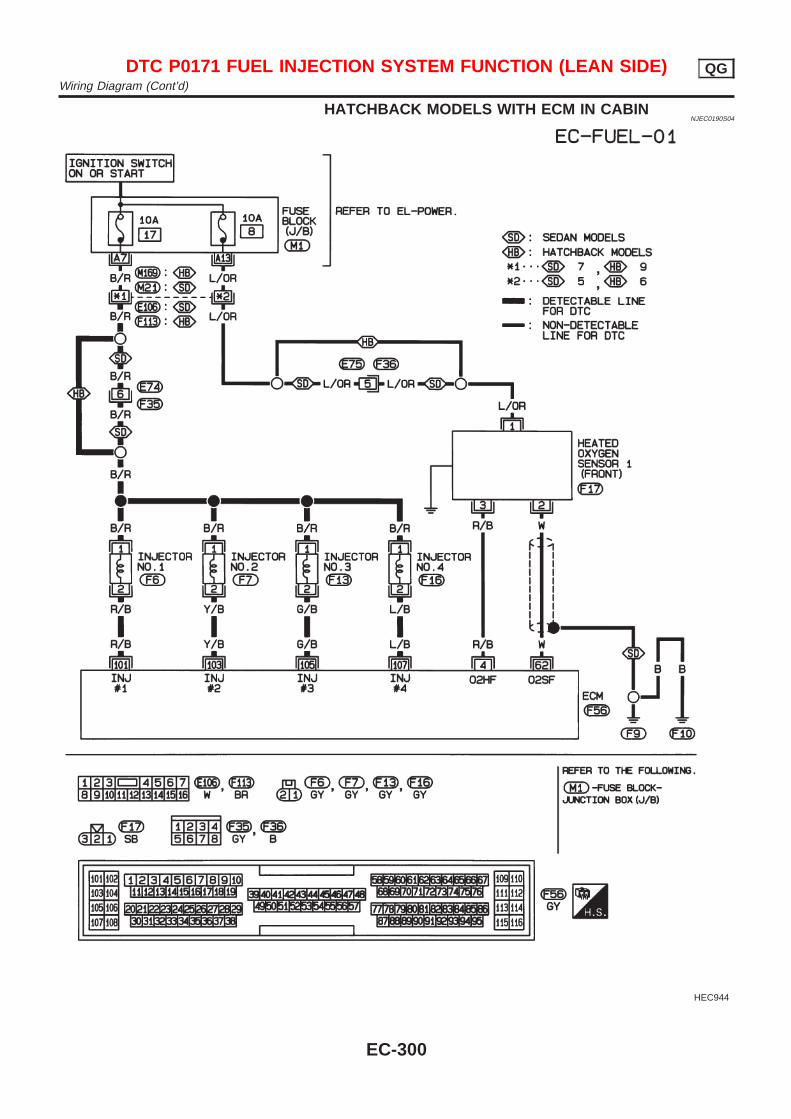
HATCHBACK MODELS WITH ECM IN CABINNJEC0190S04
HEC944
DTC P0171 FUEL INJECTION SYSTEM FUNCTION (LEAN SIDE) QGWiring Diagram (Cont’d)
EC-300
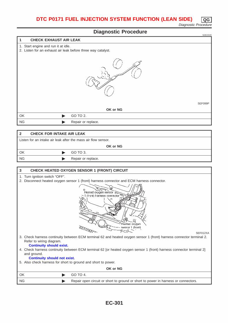
Diagnostic ProcedureNJEC0191
1 CHECK EXHAUST AIR LEAK
1. Start engine and run it at idle.2. Listen for an exhaust air leak before three way catalyst.
SEF099P
OK or NG
OK © GO TO 2.
NG © Repair or replace.
2 CHECK FOR INTAKE AIR LEAK
Listen for an intake air leak after the mass air flow sensor.
OK or NG
OK © GO TO 3.
NG © Repair or replace.
3 CHECK HEATED OXYGEN SENSOR 1 (FRONT) CIRCUIT
1. Turn ignition switch “OFF”.2. Disconnect heated oxygen sensor 1 (front) harness connector and ECM harness connector.
SEF012XA
3. Check harness continuity between ECM terminal 62 and heated oxygen sensor 1 (front) harness connector terminal 2.Refer to wiring diagram.
Continuity should exist.4. Check harness continuity between ECM terminal 62 [or heated oxygen sensor 1 (front) harness connector terminal 2]
and ground.Continuity should not exist.
5. Also check harness for short to ground and short to power.
OK or NG
OK © GO TO 4.
NG © Repair open circuit or short to ground or short to power in harness or connectors.
DTC P0171 FUEL INJECTION SYSTEM FUNCTION (LEAN SIDE) QGDiagnostic Procedure
EC-301

4 CHECK FUEL PRESSURE
1. Release fuel pressure to zero.Refer to EC-40.
2. Install fuel pressure gauge and check fuel pressure.At idling:
When fuel pressure regulator valve vacuum hose is connected.235 kPa (2.35 bar, 2.4 kg/cm 2, 34 psi)
When fuel pressure regulator valve vacuum hose is disconnected.294 kPa (2.94 bar, 3.0 kg/cm 2, 43 psi)
OK or NG
OK © GO TO 6.
NG © GO TO 5.
5 DETECT MALFUNCTIONING PART
Check the following.+ Fuel pump and circuit (Refer to EC-561.)+ Fuel pressure regulator (Refer to EC-41.)+ Fuel lines (Refer to “ENGINE MAINTENANCE” in MA section.)+ Fuel filter for clogging
© Repair or replace.
6 CHECK MASS AIR FLOW SENSOR
With CONSULT-IICheck “MASS AIR FLOW” in “DATA MONITOR” mode with CONSULT-II.
at idling: 1.0 - 4.0 g·m/secat 2,500 rpm: 5.0 - 10.0 g·m/sec
With GSTCheck mass air flow sensor signal in MODE 1 with GST.
at idling: 1.0 - 4.0 g·m/secat 2,500 rpm: 5.0 - 10.0 g·m/sec
OK or NG
OK © GO TO 7.
NG © Check connectors for rusted terminals or loose connections in the mass air flow sensorcircuit or engine grounds. Refer to EC-187.
DTC P0171 FUEL INJECTION SYSTEM FUNCTION (LEAN SIDE) QGDiagnostic Procedure (Cont’d)
EC-302
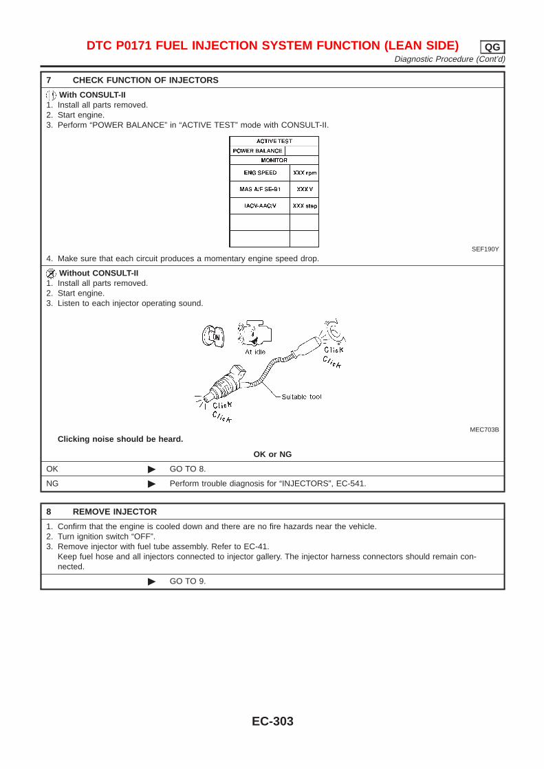
7 CHECK FUNCTION OF INJECTORS
With CONSULT-II1. Install all parts removed.2. Start engine.3. Perform “POWER BALANCE” in “ACTIVE TEST” mode with CONSULT-II.
SEF190Y
4. Make sure that each circuit produces a momentary engine speed drop.
Without CONSULT-II1. Install all parts removed.2. Start engine.3. Listen to each injector operating sound.
MEC703B
Clicking noise should be heard.
OK or NG
OK © GO TO 8.
NG © Perform trouble diagnosis for “INJECTORS”, EC-541.
8 REMOVE INJECTOR
1. Confirm that the engine is cooled down and there are no fire hazards near the vehicle.2. Turn ignition switch “OFF”.3. Remove injector with fuel tube assembly. Refer to EC-41.
Keep fuel hose and all injectors connected to injector gallery. The injector harness connectors should remain con-nected.
© GO TO 9.
DTC P0171 FUEL INJECTION SYSTEM FUNCTION (LEAN SIDE) QGDiagnostic Procedure (Cont’d)
EC-303
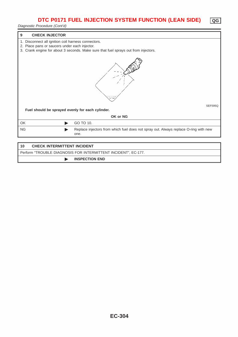
9 CHECK INJECTOR
1. Disconnect all ignition coil harness connectors.2. Place pans or saucers under each injector.3. Crank engine for about 3 seconds. Make sure that fuel sprays out from injectors.
SEF595Q
Fuel should be sprayed evenly for each cylinder.
OK or NG
OK © GO TO 10.
NG © Replace injectors from which fuel does not spray out. Always replace O-ring with newone.
10 CHECK INTERMITTENT INCIDENT
Perform “TROUBLE DIAGNOSIS FOR INTERMITTENT INCIDENT”, EC-177.
© INSPECTION END
DTC P0171 FUEL INJECTION SYSTEM FUNCTION (LEAN SIDE) QGDiagnostic Procedure (Cont’d)
EC-304
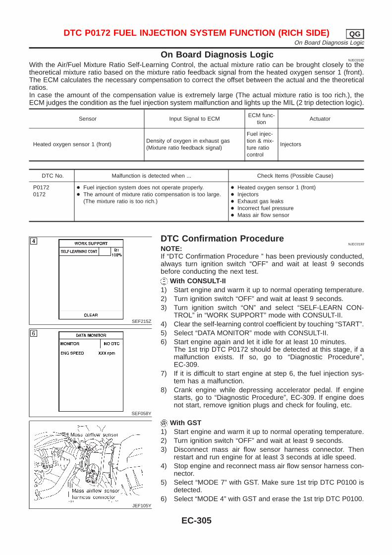
On Board Diagnosis LogicNJEC0192
With the Air/Fuel Mixture Ratio Self-Learning Control, the actual mixture ratio can be brought closely to thetheoretical mixture ratio based on the mixture ratio feedback signal from the heated oxygen sensor 1 (front).The ECM calculates the necessary compensation to correct the offset between the actual and the theoreticalratios.In case the amount of the compensation value is extremely large (The actual mixture ratio is too rich.), theECM judges the condition as the fuel injection system malfunction and lights up the MIL (2 trip detection logic).
Sensor Input Signal to ECMECM func-
tionActuator
Heated oxygen sensor 1 (front)Density of oxygen in exhaust gas(Mixture ratio feedback signal)
Fuel injec-tion & mix-ture ratiocontrol
Injectors
DTC No. Malfunction is detected when ... Check Items (Possible Cause)
P01720172
+ Fuel injection system does not operate properly.+ The amount of mixture ratio compensation is too large.
(The mixture ratio is too rich.)
+ Heated oxygen sensor 1 (front)+ Injectors+ Exhaust gas leaks+ Incorrect fuel pressure+ Mass air flow sensor
SEF215Z
SEF058Y
DTC Confirmation ProcedureNJEC0193
NOTE:If “DTC Confirmation Procedure ” has been previously conducted,always turn ignition switch “OFF” and wait at least 9 secondsbefore conducting the next test.
With CONSULT-II1) Start engine and warm it up to normal operating temperature.2) Turn ignition switch “OFF” and wait at least 9 seconds.3) Turn ignition switch “ON” and select “SELF-LEARN CON-
TROL” in “WORK SUPPORT” mode with CONSULT-II.4) Clear the self-learning control coefficient by touching “START”.5) Select “DATA MONITOR” mode with CONSULT-II.6) Start engine again and let it idle for at least 10 minutes.
The 1st trip DTC P0172 should be detected at this stage, if amalfunction exists. If so, go to “Diagnostic Procedure”,EC-309.
7) If it is difficult to start engine at step 6, the fuel injection sys-tem has a malfunction.
8) Crank engine while depressing accelerator pedal. If enginestarts, go to “Diagnostic Procedure”, EC-309. If engine doesnot start, remove ignition plugs and check for fouling, etc.
JEF105Y
With GST1) Start engine and warm it up to normal operating temperature.2) Turn ignition switch “OFF” and wait at least 9 seconds.3) Disconnect mass air flow sensor harness connector. Then
restart and run engine for at least 3 seconds at idle speed.4) Stop engine and reconnect mass air flow sensor harness con-
nector.5) Select “MODE 7” with GST. Make sure 1st trip DTC P0100 is
detected.6) Select “MODE 4” with GST and erase the 1st trip DTC P0100.
DTC P0172 FUEL INJECTION SYSTEM FUNCTION (RICH SIDE) QGOn Board Diagnosis Logic
EC-305
7) Start engine again and run it for at least 10 minutes at idlespeed.
8) Select “MODE 7” with GST. The 1st trip DTC P0172 should bedetected at this stage, if a malfunction exists. If so, go to“Diagnostic Procedure”, EC-309.
9) If it is difficult to start engine at step 8, the fuel injection sys-tem has a malfunction.
10) Crank engine while depressing accelerator pedal.If engine starts, go to “Diagnostic Procedure”, EC-309. Ifengine does not start, remove ignition plugs and check forfouling, etc.
DTC P0172 FUEL INJECTION SYSTEM FUNCTION (RICH SIDE) QGDTC Confirmation Procedure (Cont’d)
EC-306

Wiring DiagramNJEC0194
SEDAN MODELS AND HATCHBACK MODELS WITHECM IN ENGINE COMPARTMENT
NJEC0194S03
HEC789
DTC P0172 FUEL INJECTION SYSTEM FUNCTION (RICH SIDE) QGWiring Diagram
EC-307

HATCHBACK MODELS WITH ECM IN CABINNJEC0194S04
HEC944
DTC P0172 FUEL INJECTION SYSTEM FUNCTION (RICH SIDE) QGWiring Diagram (Cont’d)
EC-308
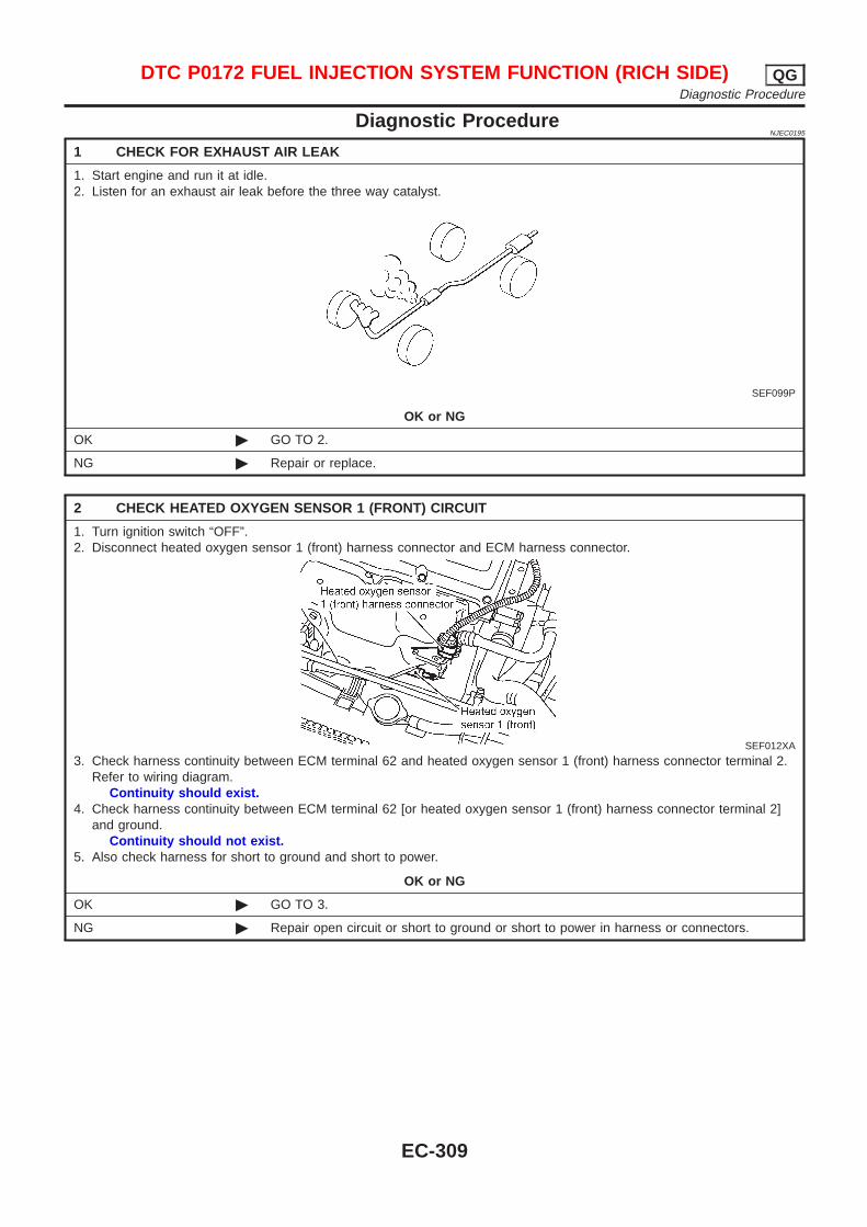
Diagnostic ProcedureNJEC0195
1 CHECK FOR EXHAUST AIR LEAK
1. Start engine and run it at idle.2. Listen for an exhaust air leak before the three way catalyst.
SEF099P
OK or NG
OK © GO TO 2.
NG © Repair or replace.
2 CHECK HEATED OXYGEN SENSOR 1 (FRONT) CIRCUIT
1. Turn ignition switch “OFF”.2. Disconnect heated oxygen sensor 1 (front) harness connector and ECM harness connector.
SEF012XA
3. Check harness continuity between ECM terminal 62 and heated oxygen sensor 1 (front) harness connector terminal 2.Refer to wiring diagram.
Continuity should exist.4. Check harness continuity between ECM terminal 62 [or heated oxygen sensor 1 (front) harness connector terminal 2]
and ground.Continuity should not exist.
5. Also check harness for short to ground and short to power.
OK or NG
OK © GO TO 3.
NG © Repair open circuit or short to ground or short to power in harness or connectors.
DTC P0172 FUEL INJECTION SYSTEM FUNCTION (RICH SIDE) QGDiagnostic Procedure
EC-309
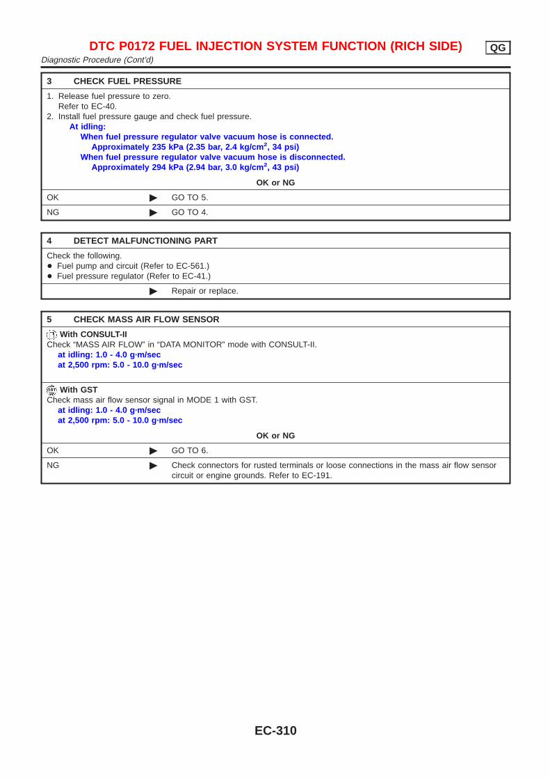
3 CHECK FUEL PRESSURE
1. Release fuel pressure to zero.Refer to EC-40.
2. Install fuel pressure gauge and check fuel pressure.At idling:
When fuel pressure regulator valve vacuum hose is connected.Approximately 235 kPa (2.35 bar, 2.4 kg/cm 2, 34 psi)
When fuel pressure regulator valve vacuum hose is disconnected.Approximately 294 kPa (2.94 bar, 3.0 kg/cm 2, 43 psi)
OK or NG
OK © GO TO 5.
NG © GO TO 4.
4 DETECT MALFUNCTIONING PART
Check the following.+ Fuel pump and circuit (Refer to EC-561.)+ Fuel pressure regulator (Refer to EC-41.)
© Repair or replace.
5 CHECK MASS AIR FLOW SENSOR
With CONSULT-IICheck “MASS AIR FLOW” in “DATA MONITOR” mode with CONSULT-II.
at idling: 1.0 - 4.0 g·m/secat 2,500 rpm: 5.0 - 10.0 g·m/sec
With GSTCheck mass air flow sensor signal in MODE 1 with GST.
at idling: 1.0 - 4.0 g·m/secat 2,500 rpm: 5.0 - 10.0 g·m/sec
OK or NG
OK © GO TO 6.
NG © Check connectors for rusted terminals or loose connections in the mass air flow sensorcircuit or engine grounds. Refer to EC-191.
DTC P0172 FUEL INJECTION SYSTEM FUNCTION (RICH SIDE) QGDiagnostic Procedure (Cont’d)
EC-310
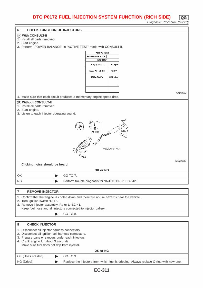
6 CHECK FUNCTION OF INJECTORS
With CONSULT-II1. Install all parts removed.2. Start engine.3. Perform “POWER BALANCE” in “ACTIVE TEST” mode with CONSULT-II.
SEF190Y
4. Make sure that each circuit produces a momentary engine speed drop.
Without CONSULT-II1. Install all parts removed.2. Start engine.3. Listen to each injector operating sound.
MEC703B
Clicking noise should be heard.
OK or NG
OK © GO TO 7.
NG © Perform trouble diagnosis for “INJECTORS”, EC-542.
7 REMOVE INJECTOR
1. Confirm that the engine is cooled down and there are no fire hazards near the vehicle.2. Turn ignition switch “OFF”.3. Remove injector assembly. Refer to EC-41.
Keep fuel hose and all injectors connected to injector gallery.
© GO TO 8.
8 CHECK INJECTOR
1. Disconnect all injector harness connectors.2. Disconnect all ignition coil harness connectors.3. Prepare pans or saucers under each injectors.4. Crank engine for about 3 seconds.
Make sure fuel does not drip from injector.
OK or NG
OK (Does not drip) © GO TO 9.
NG (Drips) © Replace the injectors from which fuel is dripping. Always replace O-ring with new one.
DTC P0172 FUEL INJECTION SYSTEM FUNCTION (RICH SIDE) QGDiagnostic Procedure (Cont’d)
EC-311
9 CHECK INTERMITTENT INCIDENT
Perform “TROUBLE DIAGNOSIS FOR INTERMITTENT INCIDENT”, EC-177.
© INSPECTION END
DTC P0172 FUEL INJECTION SYSTEM FUNCTION (RICH SIDE) QGDiagnostic Procedure (Cont’d)
EC-312

SEF463TA
Component DescriptionNJEC0196
The fuel tank temperature sensor is used to detect the fuel tem-perature inside the fuel tank. The sensor modifies a voltage signalfrom the ECM. The modified signal returns to the ECM as the fueltemperature input. The sensor uses a thermistor which is sensitiveto the change in temperature. The electrical resistance of the ther-mistor decreases as temperature increases.
SEF012P
<Reference data>
Fluid temperature°C (°F)
Voltage*V
ResistancekΩ
20 (68) 3.5 2.3 - 2.7
50 (122) 2.2 0.79 - 0.90
*: These data are reference values and are measured between ECM terminal 82(Fuel tank temperature sensor) and ground.
CAUTION:Do not use ECM ground terminals when measuring input/output voltage. Doing so may result in damage to the ECM’stransistor. Use a ground other than ECM terminals, such asthe ground.
On Board Diagnosis LogicNJEC0197
DTC No. Malfunction is detected when ... Check Items (Possible Cause)
P01800180
+ An excessively high or low voltage is sent to ECM. + Harness or connectors(The sensor circuit is open or shorted.)
+ Fuel tank temperature sensor
SEF194Y
DTC Confirmation ProcedureNJEC0198
NOTE:If “DTC Confirmation Procedure” has been previously conducted,always turn ignition switch “OFF” and wait at least 9 secondsbefore conducting the next test.
With CONSULT-II1) Turn ignition switch “ON”.2) Select “DATA MONITOR” mode with CONSULT-II.3) Wait at least 5 seconds.
If 1st trip DTC is detected, go to “Diagnostic Procedure”,EC-316.
DTC P0180 FUEL TANK TEMPERATURE SENSOR (WHERE FITTED) QGComponent Description
EC-313

With GSTFollow the procedure “With CONSULT-II” above.
DTC P0180 FUEL TANK TEMPERATURE SENSOR (WHERE FITTED) QGDTC Confirmation Procedure (Cont’d)
EC-314
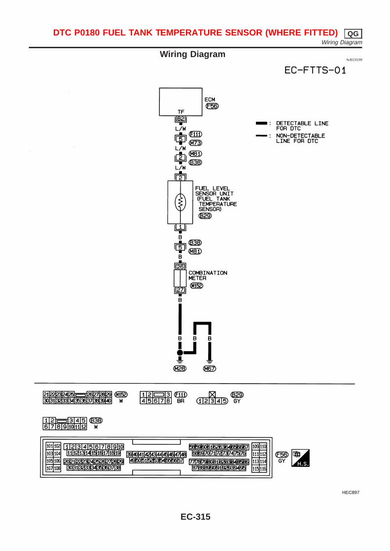
Wiring DiagramNJEC0199
HEC897
DTC P0180 FUEL TANK TEMPERATURE SENSOR (WHERE FITTED) QGWiring Diagram
EC-315
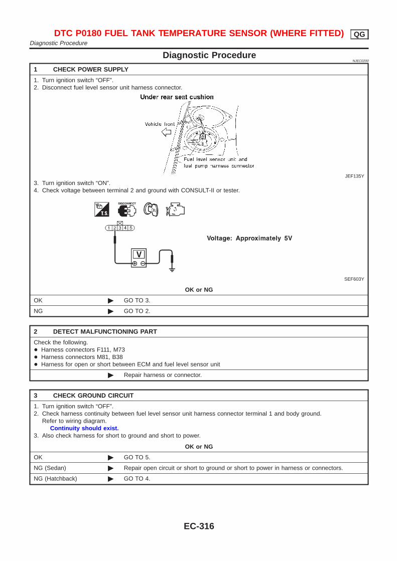
Diagnostic ProcedureNJEC0200
1 CHECK POWER SUPPLY
1. Turn ignition switch “OFF”.2. Disconnect fuel level sensor unit harness connector.
JEF135Y
3. Turn ignition switch “ON”.4. Check voltage between terminal 2 and ground with CONSULT-II or tester.
SEF603Y
OK or NG
OK © GO TO 3.
NG © GO TO 2.
2 DETECT MALFUNCTIONING PART
Check the following.+ Harness connectors F111, M73+ Harness connectors M81, B38+ Harness for open or short between ECM and fuel level sensor unit
© Repair harness or connector.
3 CHECK GROUND CIRCUIT
1. Turn ignition switch “OFF”.2. Check harness continuity between fuel level sensor unit harness connector terminal 1 and body ground.
Refer to wiring diagram.Continuity should exist.
3. Also check harness for short to ground and short to power.
OK or NG
OK © GO TO 5.
NG (Sedan) © Repair open circuit or short to ground or short to power in harness or connectors.
NG (Hatchback) © GO TO 4.
DTC P0180 FUEL TANK TEMPERATURE SENSOR (WHERE FITTED) QGDiagnostic Procedure
EC-316
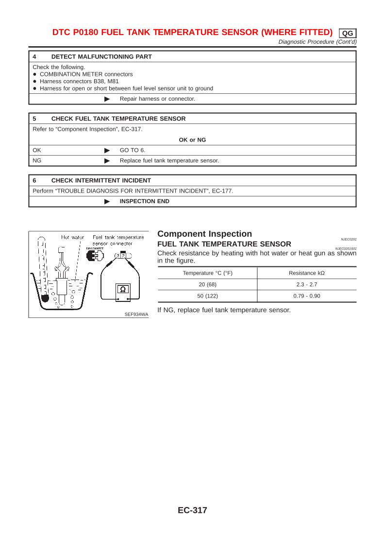
4 DETECT MALFUNCTIONING PART
Check the following.+ COMBINATION METER connectors+ Harness connectors B38, M81+ Harness for open or short between fuel level sensor unit to ground
© Repair harness or connector.
5 CHECK FUEL TANK TEMPERATURE SENSOR
Refer to “Component Inspection”, EC-317.
OK or NG
OK © GO TO 6.
NG © Replace fuel tank temperature sensor.
6 CHECK INTERMITTENT INCIDENT
Perform “TROUBLE DIAGNOSIS FOR INTERMITTENT INCIDENT”, EC-177.
© INSPECTION END
SEF934WA
Component InspectionNJEC0201
FUEL TANK TEMPERATURE SENSORNJEC0201S01
Check resistance by heating with hot water or heat gun as shownin the figure.
Temperature °C (°F) Resistance kΩ
20 (68) 2.3 - 2.7
50 (122) 0.79 - 0.90
If NG, replace fuel tank temperature sensor.
DTC P0180 FUEL TANK TEMPERATURE SENSOR (WHERE FITTED) QGDiagnostic Procedure (Cont’d)
EC-317

On Board Diagnosis LogicNJEC0202
If a misfire occurs, the engine speed will fluctuate. If the fluctuation is detected by the crankshaft position sen-sor (POS), the misfire is diagnosed.
Sensor Input Signal to ECM ECM function
Crankshaft position sensor (POS) Engine speed On board diagnosis of misfire
The misfire detection logic consists of the following two conditions.1. One Trip Detection Logic (Three Way Catalyst Damage)
When a misfire is detected which will overheat and damage the three way catalyst, the MI will start blink-ing; even during the first trip. In this condition, ECM monitors the misfire every 200 revolutions.If the misfire frequency decreases to a level that will not damage the three way catalyst, the MI will changefrom blinking to lighting up. (After the first trip detection, the MI will light up from engine starting. If a mis-fire is detected that will cause three way catalyst damage, the MI will start blinking.)
2. Two Trip Detection Logic (Exhaust quality deterioration)When a misfire that will not damage the three way catalyst (but will affect exhaust emission) occurs, theMI will light up based on two trip detection logic. In this condition, ECM monitors the misfire for every 1,000revolutions of the engine.
DTC No. Malfunction is detected when ... Check Items (Possible Cause)
P03000300
+ Multiple cylinders misfire. + Improper spark plug+ Insufficient compression+ Incorrect fuel pressure+ EGR volume control valve+ The injector circuit is open or shorted+ Injectors+ Intake air leak+ Insufficient ignition spark+ Lack of fuel+ Heated oxygen sensor 1 (front)
P03010301
+ No. 1 cylinder misfires.
P03020302
+ No. 2 cylinder misfires.
P03030303
+ No. 3 cylinder misfires.
P03040304
+ No. 4 cylinder misfires.
SEF058Y
DTC Confirmation ProcedureNJEC0203
CAUTION:Always drive vehicle at a safe speed.NOTE:If “DTC Confirmation Procedure” has been previously conducted,always turn ignition switch “OFF” and wait at least 9 secondsbefore conducting the next test.
With CONSULT-II1) Turn ignition switch “ON”, and select “DATA MONITOR” mode
with CONSULT-II.2) Start engine and warm it up to normal operating temperature.3) Turn ignition switch “OFF” and wait at least 9 seconds.4) Start engine again and drive at 1,500 - 3,000 rpm for at least
3 minutes.Hold the accelerator pedal as steady as possible.
NOTE:Refer to the freeze frame data for the test driving conditions.5) If 1st trip DTC is detected, go to “Diagnostic Procedure”,
EC-319.With GST
Follow the procedure “With CONSULT-II” above.
DTC P0300 - P0304 NO. 4 - 1 CYLINDER MISFIRE, MULTIPLE CYLINDERMISFIRE QG
On Board Diagnosis Logic
EC-318
Diagnostic ProcedureNJEC0204
1 CHECK FOR INTAKE AIR LEAK
1. Start engine and run it at idle speed.2. Listen for the sound of the intake air leak.
OK or NG
OK © GO TO 2.
NG © Discover air leak location and repair.
2 CHECK FOR EXHAUST SYSTEM CLOGGING
Stop engine and visually check exhaust tube, three way catalyst and muffler for dents.
OK or NG
OK © GO TO 3.
NG © Repair or replace it.
3 CHECK EGR FUNCTION
Perform DTC Confirmation Procedure for DTC P1402 EGR FUNCTION (OPEN).Refer to EC-425.
OK or NG
OK © GO TO 4.
NG © Repair EGR system.
DTC P0300 - P0304 NO. 4 - 1 CYLINDER MISFIRE, MULTIPLE CYLINDERMISFIRE QG
Diagnostic Procedure
EC-319
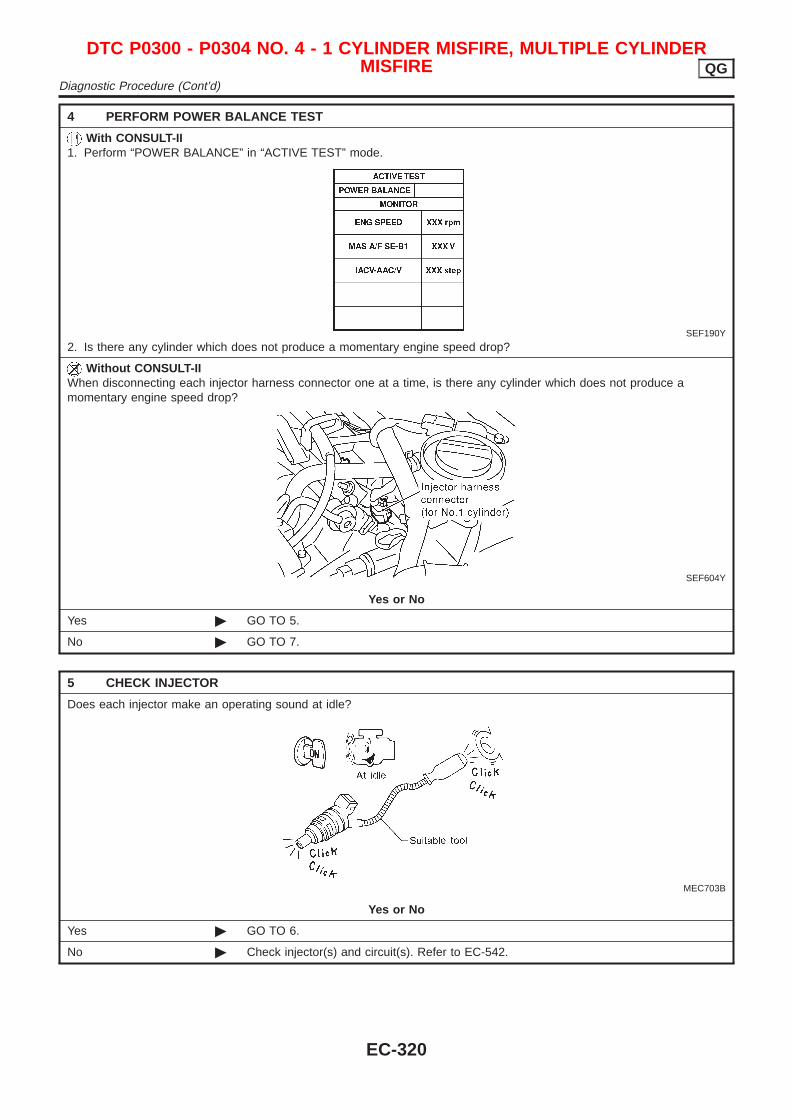
4 PERFORM POWER BALANCE TEST
With CONSULT-II1. Perform “POWER BALANCE” in “ACTIVE TEST” mode.
SEF190Y
2. Is there any cylinder which does not produce a momentary engine speed drop?
Without CONSULT-IIWhen disconnecting each injector harness connector one at a time, is there any cylinder which does not produce amomentary engine speed drop?
SEF604Y
Yes or No
Yes © GO TO 5.
No © GO TO 7.
5 CHECK INJECTOR
Does each injector make an operating sound at idle?
MEC703B
Yes or No
Yes © GO TO 6.
No © Check injector(s) and circuit(s). Refer to EC-542.
DTC P0300 - P0304 NO. 4 - 1 CYLINDER MISFIRE, MULTIPLE CYLINDERMISFIRE QG
Diagnostic Procedure (Cont’d)
EC-320
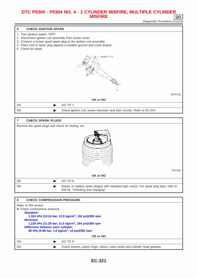
6 CHECK IGNITION SPARK
1. Turn Ignition switch “OFF”.2. Disconnect ignition coil assembly from rocker cover.3. Connect a known good spark plug to the ignition coil assembly.4. Place end of spark plug against a suitable ground and crank engine.5. Check for spark.
SEF575Q
OK or NG
OK © GO TO 7.
NG © Check ignition coil, power transistor and their circuits. Refer to EC-547.
7 CHECK SPARK PLUGS
Remove the spark plugs and check for fouling, etc.
SEF156I
OK or NG
OK © GO TO 8.
NG © Repair or replace spark plug(s) with standard type one(s). For spark plug type, refer toEM-19, “Checking and changing”.
8 CHECK COMPRESSION PRESSURE
Refer to EM section.+ Check compression pressure.
Standard:1,324 kPa (13.24 bar, 13.5 kg/cm 2, 192 psi)/350 rpm
Minimum:1,128 kPa (11.28 bar, 11.5 kg/cm 2, 164 psi)/350 rpm
Difference between each cylinder:98 kPa (0.98 bar, 1.0 kg/cm 2, 14 psi)/350 rpm
OK or NG
OK © GO TO 9.
NG © Check pistons, piston rings, valves, valve seats and cylinder head gaskets.
DTC P0300 - P0304 NO. 4 - 1 CYLINDER MISFIRE, MULTIPLE CYLINDERMISFIRE QG
Diagnostic Procedure (Cont’d)
EC-321

9 CHECK FUEL PRESSURE
1. Install any parts removed.2. Release fuel pressure to zero. Refer to EC-40.3. Install fuel pressure gauge and check fuel pressure.
JEF087Y
At idle: Approx. 235 kPa (2.35 bar, 2.4 kg/cm 2, 34 psi)
OK or NG
OK © GO TO 11.
NG © GO TO 10.
10 DETECT MALFUNCTIONING PART
Check the following.+ Fuel pump and circuit (Refer to EC-561.)+ Fuel pressure regulator (Refer to EC-41.)+ Fuel lines+ Fuel filter for clogging
© Repair or replace.
11 CHECK IGNITION TIMING
Perform “Basic Inspection”.Refer to EC-100.
OK or NG
OK © GO TO 12.
NG © 1. Perform “Idle Air Volume Learning”. Refer to EC-57.2. Check camshaft position sensor (PHASE) (EC-335) and crankshaft position sensor
(POS) (EC-328).
12 CHECK HEATED OXYGEN SENSOR 1 (FRONT)
Refer to “Component Inspection”, EC-222.
OK or NG
OK © GO TO 13.
NG © Replace heated oxygen sensor 1 (front).
DTC P0300 - P0304 NO. 4 - 1 CYLINDER MISFIRE, MULTIPLE CYLINDERMISFIRE QG
Diagnostic Procedure (Cont’d)
EC-322
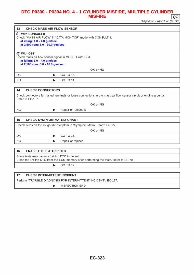
13 CHECK MASS AIR FLOW SENSOR
With CONSULT-IICheck “MASS AIR FLOW” in “DATA MONITOR” mode with CONSULT-II.
at idling: 1.0 - 4.0 g·m/secat 2,500 rpm: 5.0 - 10.0 g·m/sec
With GSTCheck mass air flow sensor signal in MODE 1 with GST.
at idling: 1.0 - 4.0 g·m/secat 2,500 rpm: 5.0 - 10.0 g·m/sec
OK or NG
OK © GO TO 15.
NG © GO TO 14.
14 CHECK CONNECTORS
Check connectors for rusted terminals or loose connections in the mass air flow sensor circuit or engine grounds.Refer to EC-187.
OK or NG
NG © Repair or replace it.
15 CHECK SYMPTOM MATRIX CHART
Check items on the rough idle symptom in “Symptom Matrix Chart”, EC-155.
OK or NG
OK © GO TO 16.
NG © Repair or replace.
16 ERASE THE 1ST TRIP DTC
Some tests may cause a 1st trip DTC to be set.Erase the 1st trip DTC from the ECM memory after performing the tests. Refer to EC-70.
© GO TO 17.
17 CHECK INTERMITTENT INCIDENT
Perform “TROUBLE DIAGNOSIS FOR INTERMITTENT INCIDENT”, EC-177.
© INSPECTION END
DTC P0300 - P0304 NO. 4 - 1 CYLINDER MISFIRE, MULTIPLE CYLINDERMISFIRE QG
Diagnostic Procedure (Cont’d)
EC-323
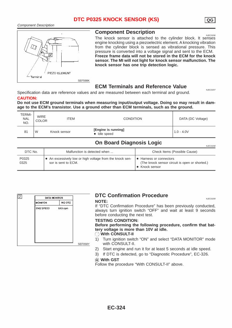
SEF598K
Component DescriptionNJEC0206
The knock sensor is attached to the cylinder block. It sensesengine knocking using a piezoelectric element. A knocking vibrationfrom the cylinder block is sensed as vibrational pressure. Thispressure is converted into a voltage signal and sent to the ECM.Freeze frame data will not be stored in the ECM for the knocksensor. The MI will not light for knock sensor malfunction. Theknock sensor has one trip detection logic.
ECM Terminals and Reference ValueNJEC0207
Specification data are reference values and are measured between each terminal and ground.CAUTION:Do not use ECM ground terminals when measuring input/output voltage. Doing so may result in dam-age to the ECM’s transistor. Use a ground other than ECM terminals, such as the ground.
TERMI-NALNO.
WIRECOLOR
ITEM CONDITION DATA (DC Voltage)
81 W Knock sensor[Engine is running]+ Idle speed
1.0 - 4.0V
On Board Diagnosis LogicNJEC0208
DTC No. Malfunction is detected when ... Check Items (Possible Cause)
P03250325
+ An excessively low or high voltage from the knock sen-sor is sent to ECM.
+ Harness or connectors(The knock sensor circuit is open or shorted.)
+ Knock sensor
SEF058Y
DTC Confirmation ProcedureNJEC0209
NOTE:If “DTC Confirmation Procedure” has been previously conducted,always turn ignition switch “OFF” and wait at least 9 secondsbefore conducting the next test.TESTING CONDITION:Before performing the following procedure, confirm that bat-tery voltage is more than 10V at idle.
With CONSULT-II1) Turn ignition switch “ON” and select “DATA MONITOR” mode
with CONSULT-II.2) Start engine and run it for at least 5 seconds at idle speed.3) If DTC is detected, go to “Diagnostic Procedure”, EC-326.
With GSTFollow the procedure “With CONSULT-II” above.
DTC P0325 KNOCK SENSOR (KS) QGComponent Description
EC-324
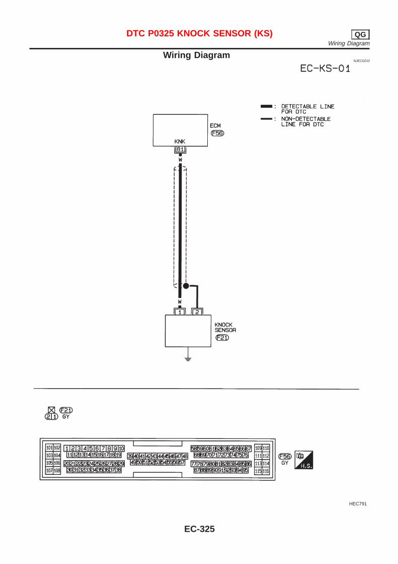
Wiring DiagramNJEC0210
HEC791
DTC P0325 KNOCK SENSOR (KS) QGWiring Diagram
EC-325
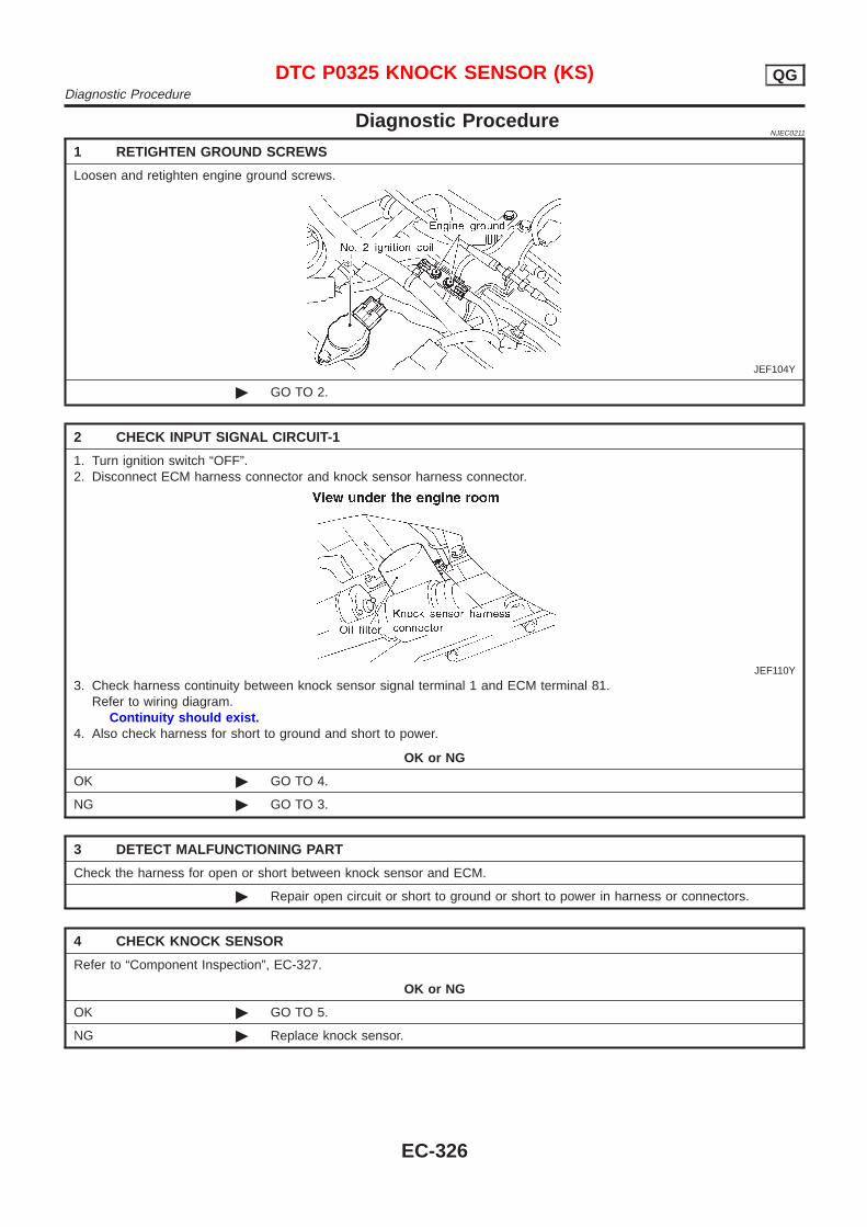
Diagnostic ProcedureNJEC0211
1 RETIGHTEN GROUND SCREWS
Loosen and retighten engine ground screws.
JEF104Y
© GO TO 2.
2 CHECK INPUT SIGNAL CIRCUIT-1
1. Turn ignition switch “OFF”.2. Disconnect ECM harness connector and knock sensor harness connector.
JEF110Y
3. Check harness continuity between knock sensor signal terminal 1 and ECM terminal 81.Refer to wiring diagram.
Continuity should exist.4. Also check harness for short to ground and short to power.
OK or NG
OK © GO TO 4.
NG © GO TO 3.
3 DETECT MALFUNCTIONING PART
Check the harness for open or short between knock sensor and ECM.
© Repair open circuit or short to ground or short to power in harness or connectors.
4 CHECK KNOCK SENSOR
Refer to “Component Inspection”, EC-327.
OK or NG
OK © GO TO 5.
NG © Replace knock sensor.
DTC P0325 KNOCK SENSOR (KS) QGDiagnostic Procedure
EC-326
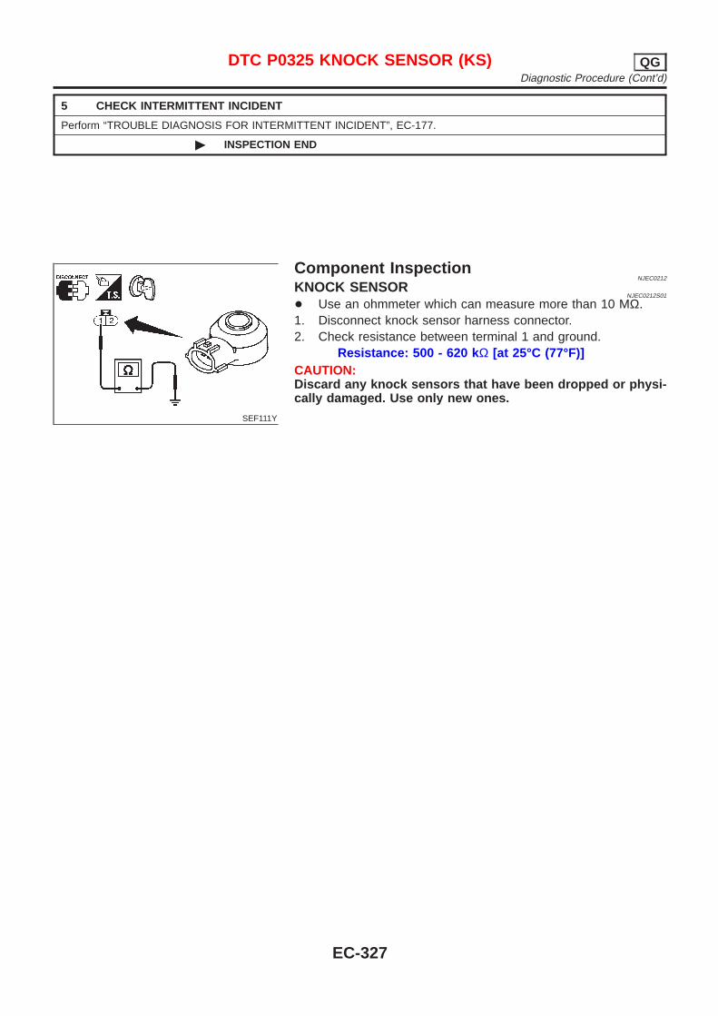
5 CHECK INTERMITTENT INCIDENT
Perform “TROUBLE DIAGNOSIS FOR INTERMITTENT INCIDENT”, EC-177.
© INSPECTION END
SEF111Y
Component InspectionNJEC0212
KNOCK SENSORNJEC0212S01
+ Use an ohmmeter which can measure more than 10 MΩ.1. Disconnect knock sensor harness connector.2. Check resistance between terminal 1 and ground.
Resistance: 500 - 620 k Ω [at 25°C (77°F)]CAUTION:Discard any knock sensors that have been dropped or physi-cally damaged. Use only new ones.
DTC P0325 KNOCK SENSOR (KS) QGDiagnostic Procedure (Cont’d)
EC-327
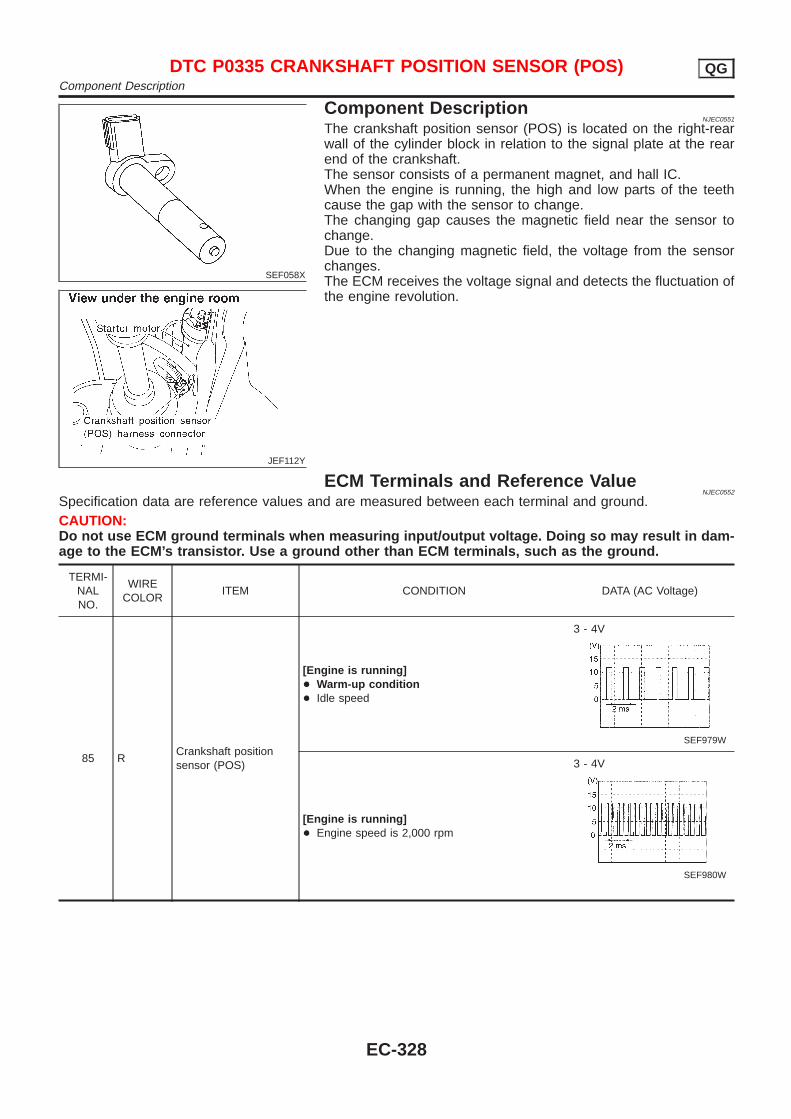
SEF058X
JEF112Y
Component DescriptionNJEC0551
The crankshaft position sensor (POS) is located on the right-rearwall of the cylinder block in relation to the signal plate at the rearend of the crankshaft.The sensor consists of a permanent magnet, and hall IC.When the engine is running, the high and low parts of the teethcause the gap with the sensor to change.The changing gap causes the magnetic field near the sensor tochange.Due to the changing magnetic field, the voltage from the sensorchanges.The ECM receives the voltage signal and detects the fluctuation ofthe engine revolution.
ECM Terminals and Reference ValueNJEC0552
Specification data are reference values and are measured between each terminal and ground.CAUTION:Do not use ECM ground terminals when measuring input/output voltage. Doing so may result in dam-age to the ECM’s transistor. Use a ground other than ECM terminals, such as the ground.
TERMI-NALNO.
WIRECOLOR
ITEM CONDITION DATA (AC Voltage)
85 RCrankshaft positionsensor (POS)
[Engine is running]+ Warm-up condition+ Idle speed
3 - 4V
SEF979W
[Engine is running]+ Engine speed is 2,000 rpm
3 - 4V
SEF980W
DTC P0335 CRANKSHAFT POSITION SENSOR (POS) QGComponent Description
EC-328
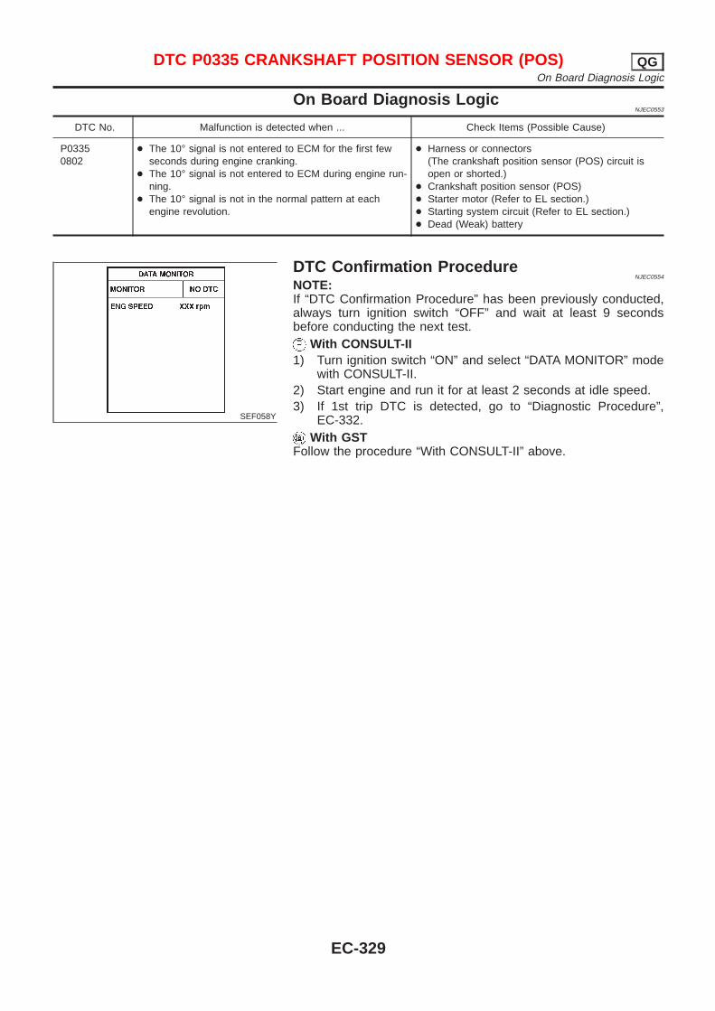
On Board Diagnosis LogicNJEC0553
DTC No. Malfunction is detected when ... Check Items (Possible Cause)
P03350802
+ The 10° signal is not entered to ECM for the first fewseconds during engine cranking.
+ The 10° signal is not entered to ECM during engine run-ning.
+ The 10° signal is not in the normal pattern at eachengine revolution.
+ Harness or connectors(The crankshaft position sensor (POS) circuit isopen or shorted.)
+ Crankshaft position sensor (POS)+ Starter motor (Refer to EL section.)+ Starting system circuit (Refer to EL section.)+ Dead (Weak) battery
SEF058Y
DTC Confirmation ProcedureNJEC0554
NOTE:If “DTC Confirmation Procedure” has been previously conducted,always turn ignition switch “OFF” and wait at least 9 secondsbefore conducting the next test.
With CONSULT-II1) Turn ignition switch “ON” and select “DATA MONITOR” mode
with CONSULT-II.2) Start engine and run it for at least 2 seconds at idle speed.3) If 1st trip DTC is detected, go to “Diagnostic Procedure”,
EC-332.With GST
Follow the procedure “With CONSULT-II” above.
DTC P0335 CRANKSHAFT POSITION SENSOR (POS) QGOn Board Diagnosis Logic
EC-329
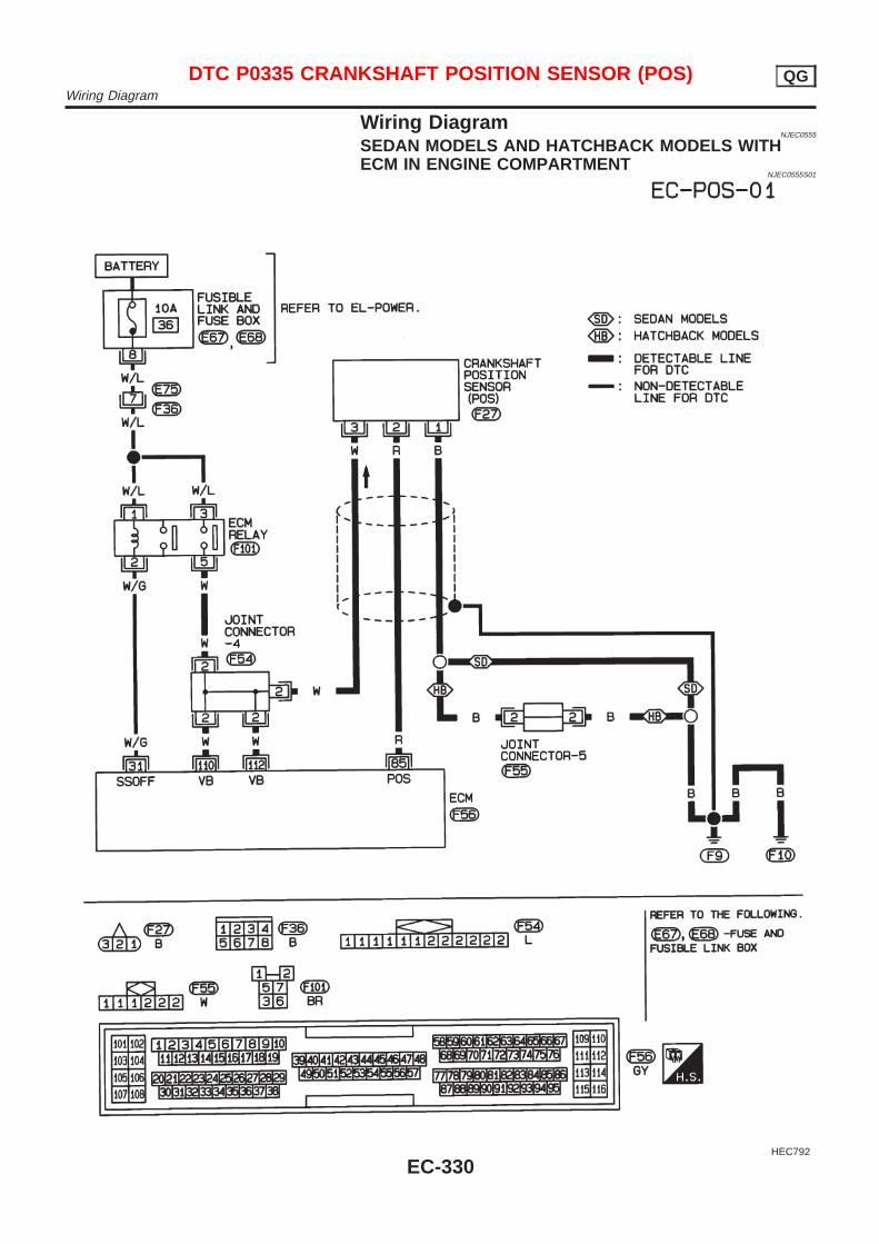
Wiring DiagramNJEC0555
SEDAN MODELS AND HATCHBACK MODELS WITHECM IN ENGINE COMPARTMENT
NJEC0555S01
HEC792
DTC P0335 CRANKSHAFT POSITION SENSOR (POS) QGWiring Diagram
EC-330
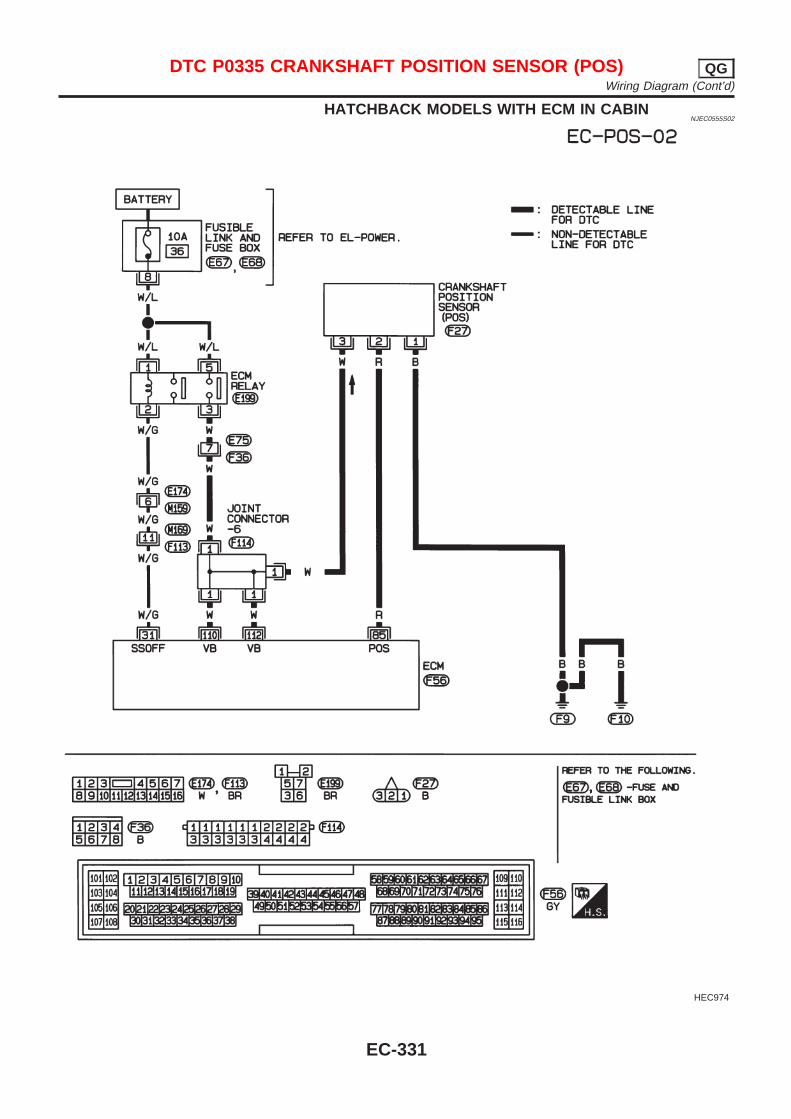
HATCHBACK MODELS WITH ECM IN CABINNJEC0555S02
HEC974
DTC P0335 CRANKSHAFT POSITION SENSOR (POS) QGWiring Diagram (Cont’d)
EC-331
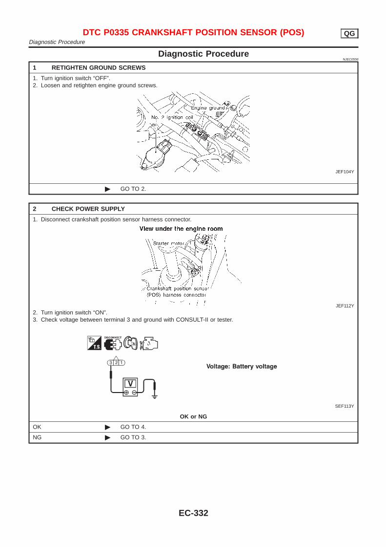
Diagnostic ProcedureNJEC0556
1 RETIGHTEN GROUND SCREWS
1. Turn ignition switch “OFF”.2. Loosen and retighten engine ground screws.
JEF104Y
© GO TO 2.
2 CHECK POWER SUPPLY
1. Disconnect crankshaft position sensor harness connector.
JEF112Y
2. Turn ignition switch “ON”.3. Check voltage between terminal 3 and ground with CONSULT-II or tester.
SEF113Y
OK or NG
OK © GO TO 4.
NG © GO TO 3.
DTC P0335 CRANKSHAFT POSITION SENSOR (POS) QGDiagnostic Procedure
EC-332
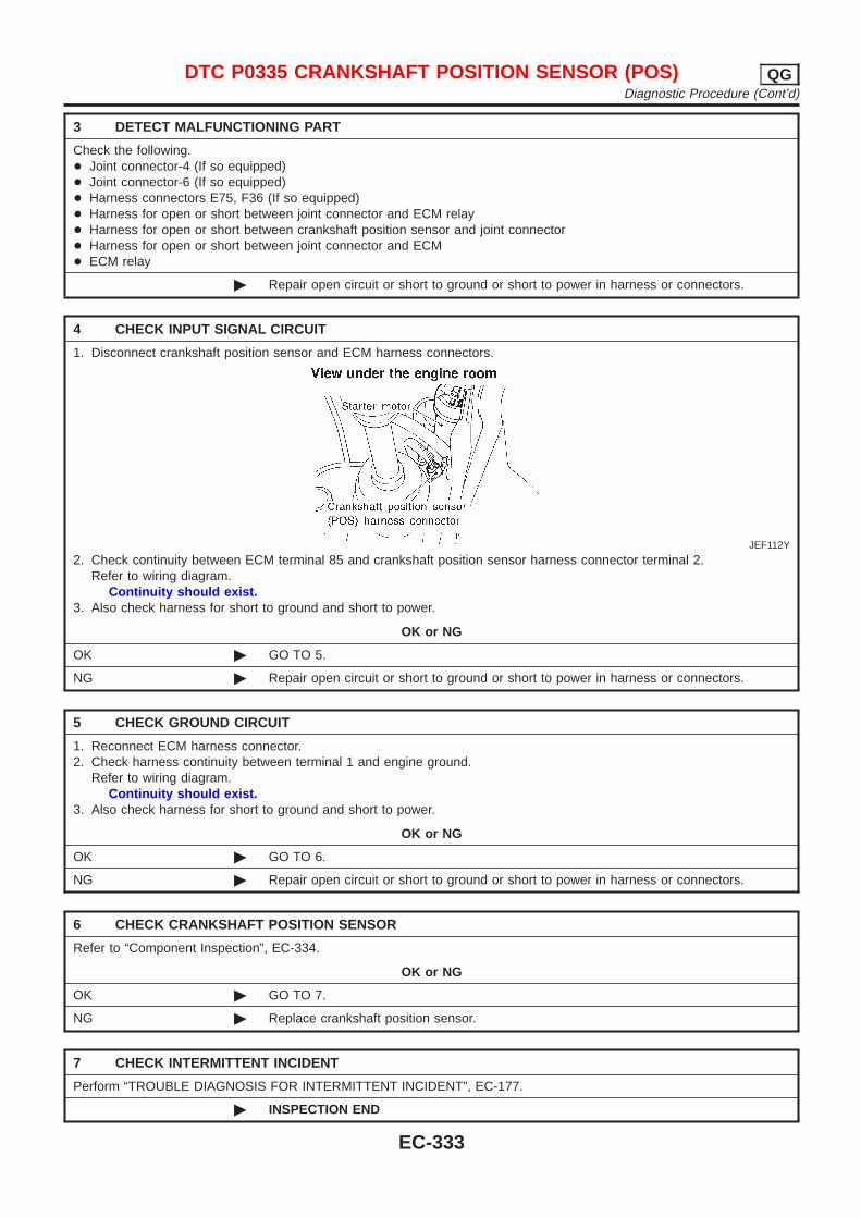
3 DETECT MALFUNCTIONING PART
Check the following.+ Joint connector-4 (If so equipped)+ Joint connector-6 (If so equipped)+ Harness connectors E75, F36 (If so equipped)+ Harness for open or short between joint connector and ECM relay+ Harness for open or short between crankshaft position sensor and joint connector+ Harness for open or short between joint connector and ECM+ ECM relay
© Repair open circuit or short to ground or short to power in harness or connectors.
4 CHECK INPUT SIGNAL CIRCUIT
1. Disconnect crankshaft position sensor and ECM harness connectors.
JEF112Y
2. Check continuity between ECM terminal 85 and crankshaft position sensor harness connector terminal 2.Refer to wiring diagram.
Continuity should exist.3. Also check harness for short to ground and short to power.
OK or NG
OK © GO TO 5.
NG © Repair open circuit or short to ground or short to power in harness or connectors.
5 CHECK GROUND CIRCUIT
1. Reconnect ECM harness connector.2. Check harness continuity between terminal 1 and engine ground.
Refer to wiring diagram.Continuity should exist.
3. Also check harness for short to ground and short to power.
OK or NG
OK © GO TO 6.
NG © Repair open circuit or short to ground or short to power in harness or connectors.
6 CHECK CRANKSHAFT POSITION SENSOR
Refer to “Component Inspection”, EC-334.
OK or NG
OK © GO TO 7.
NG © Replace crankshaft position sensor.
7 CHECK INTERMITTENT INCIDENT
Perform “TROUBLE DIAGNOSIS FOR INTERMITTENT INCIDENT”, EC-177.
© INSPECTION END
DTC P0335 CRANKSHAFT POSITION SENSOR (POS) QGDiagnostic Procedure (Cont’d)
EC-333
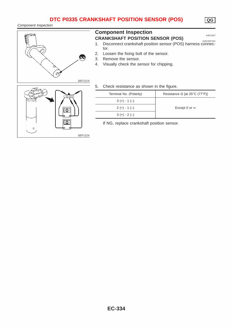
SEF121X
Component InspectionNJEC0557
CRANKSHAFT POSITION SENSOR (POS)NJEC0557S01
1. Disconnect crankshaft position sensor (POS) harness connec-tor.
2. Loosen the fixing bolt of the sensor.3. Remove the sensor.4. Visually check the sensor for chipping.
SEF122X
5. Check resistance as shown in the figure.
Terminal No. (Polarity) Resistance Ω [at 25°C (77°F)]
3 (+) - 1 (–)
Except 0 or ∞2 (+) - 1 (–)
3 (+) - 2 (–)
If NG, replace crankshaft position sensor.
DTC P0335 CRANKSHAFT POSITION SENSOR (POS) QGComponent Inspection
EC-334
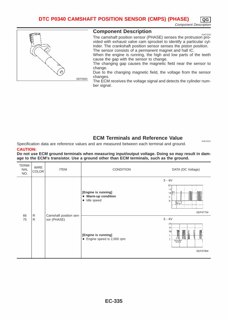
SEF058X
Component DescriptionNJEC0220
The camshaft position sensor (PHASE) senses the protrusion pro-vided with exhaust valve cam sprocket to identify a particular cyl-inder. The crankshaft position sensor senses the piston position.The sensor consists of a permanent magnet and hall IC.When the engine is running, the high and low parts of the teethcause the gap with the sensor to change.The changing gap causes the magnetic field near the sensor tochange.Due to the changing magnetic field, the voltage from the sensorchanges.The ECM receives the voltage signal and detects the cylinder num-ber signal.
ECM Terminals and Reference ValueNJEC0221
Specification data are reference values and are measured between each terminal and ground.CAUTION:Do not use ECM ground terminals when measuring input/output voltage. Doing so may result in dam-age to the ECM’s transistor. Use a ground other than ECM terminals, such as the ground.
TERMI-NALNO.
WIRECOLOR
ITEM CONDITION DATA (DC Voltage)
6675
RR
Camshaft position sen-sor (PHASE)
[Engine is running]+ Warm-up condition+ Idle speed
3 - 4V
SEF977W
[Engine is running]+ Engine speed is 2,000 rpm
3 - 4V
SEF978W
DTC P0340 CAMSHAFT POSITION SENSOR (CMPS) (PHASE) QGComponent Description
EC-335
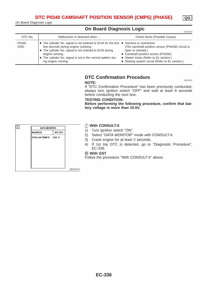
On Board Diagnosis LogicNJEC0222
DTC No. Malfunction is detected when ... Check Items (Possible Cause)
P03400340
+ The cylinder No. signal is not entered to ECM for the firstfew seconds during engine cranking.
+ The cylinder No. signal is not entered to ECM duringengine running.
+ The cylinder No. signal is not in the normal pattern dur-ing engine running.
+ Harness or connectors(The camshaft position sensor (PHASE) circuit isopen or shorted.)
+ Camshaft position sensor (PHASE)+ Starter motor (Refer to EL section.)+ Starting system circuit (Refer to EL section.)
DTC Confirmation ProcedureNJEC0223
NOTE:If “DTC Confirmation Procedure” has been previously conducted,always turn ignition switch “OFF” and wait at least 9 secondsbefore conducting the next test.TESTING CONDITION:Before performing the following procedure, confirm that bat-tery voltage is more than 10.5V.
SEF013Y
With CONSULT-II1) Turn ignition switch “ON”.2) Select “DATA MONITOR” mode with CONSULT-II.3) Crank engine for at least 2 seconds.4) If 1st trip DTC is detected, go to “Diagnostic Procedure”,
EC-339.With GST
Follow the procedure “With CONSULT-II” above.
DTC P0340 CAMSHAFT POSITION SENSOR (CMPS) (PHASE) QGOn Board Diagnosis Logic
EC-336
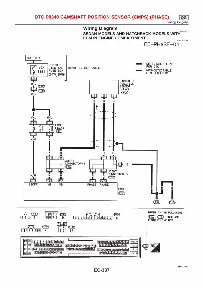
Wiring DiagramNJEC0224
SEDAN MODELS AND HATCHBACK MODELS WITHECM IN ENGINE COMPARTMENT
NJEC0224S01
HEC793
DTC P0340 CAMSHAFT POSITION SENSOR (CMPS) (PHASE) QGWiring Diagram
EC-337
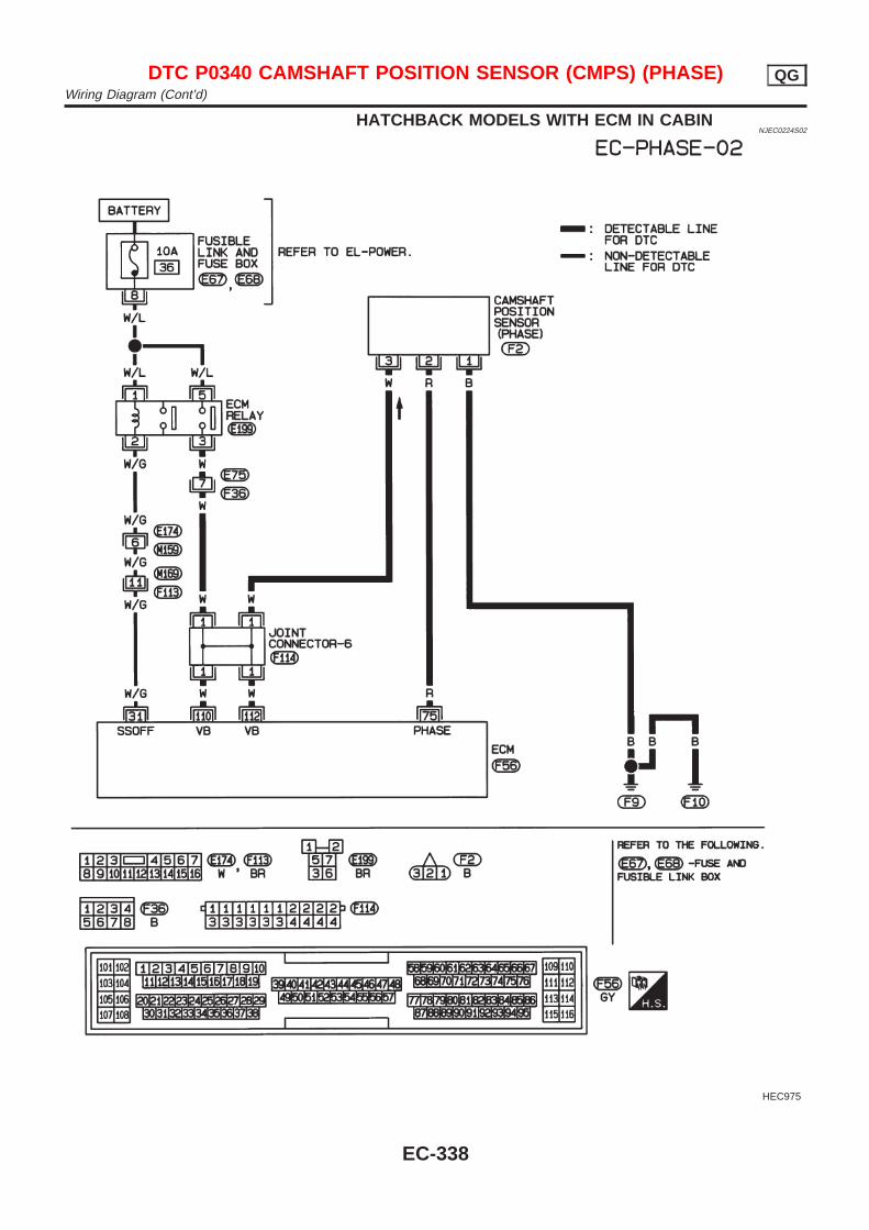
HATCHBACK MODELS WITH ECM IN CABINNJEC0224S02
HEC975
DTC P0340 CAMSHAFT POSITION SENSOR (CMPS) (PHASE) QGWiring Diagram (Cont’d)
EC-338
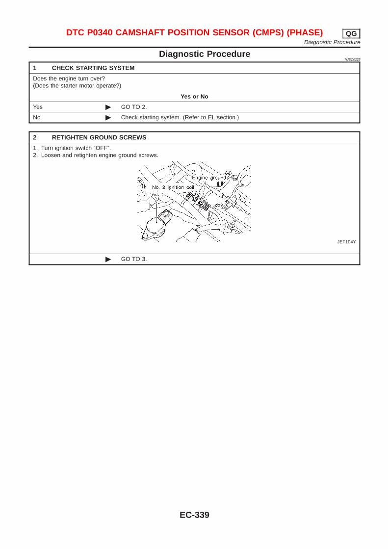
Diagnostic ProcedureNJEC0225
1 CHECK STARTING SYSTEM
Does the engine turn over?(Does the starter motor operate?)
Yes or No
Yes © GO TO 2.
No © Check starting system. (Refer to EL section.)
2 RETIGHTEN GROUND SCREWS
1. Turn ignition switch “OFF”.2. Loosen and retighten engine ground screws.
JEF104Y
© GO TO 3.
DTC P0340 CAMSHAFT POSITION SENSOR (CMPS) (PHASE) QGDiagnostic Procedure
EC-339
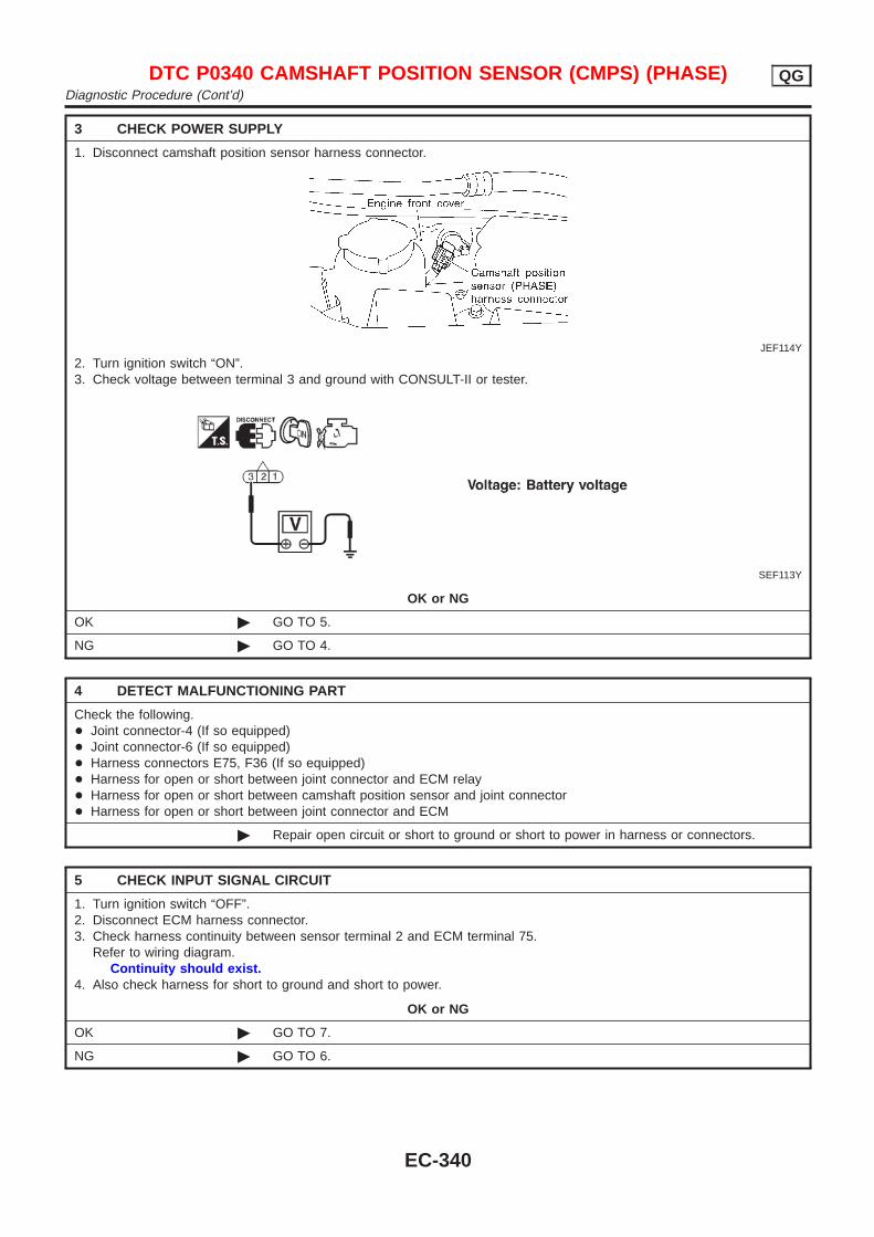
3 CHECK POWER SUPPLY
1. Disconnect camshaft position sensor harness connector.
JEF114Y
2. Turn ignition switch “ON”.3. Check voltage between terminal 3 and ground with CONSULT-II or tester.
SEF113Y
OK or NG
OK © GO TO 5.
NG © GO TO 4.
4 DETECT MALFUNCTIONING PART
Check the following.+ Joint connector-4 (If so equipped)+ Joint connector-6 (If so equipped)+ Harness connectors E75, F36 (If so equipped)+ Harness for open or short between joint connector and ECM relay+ Harness for open or short between camshaft position sensor and joint connector+ Harness for open or short between joint connector and ECM
© Repair open circuit or short to ground or short to power in harness or connectors.
5 CHECK INPUT SIGNAL CIRCUIT
1. Turn ignition switch “OFF”.2. Disconnect ECM harness connector.3. Check harness continuity between sensor terminal 2 and ECM terminal 75.
Refer to wiring diagram.Continuity should exist.
4. Also check harness for short to ground and short to power.
OK or NG
OK © GO TO 7.
NG © GO TO 6.
DTC P0340 CAMSHAFT POSITION SENSOR (CMPS) (PHASE) QGDiagnostic Procedure (Cont’d)
EC-340
6 DETECT MALFUNCTIONING PART
Check the following.+ Joint connector-5 (If so equipped)+ Harness for open or short between ECM and joint connector+ Harness for open or short between joint connector and camshaft position sensor
© Repair open circuit or short to ground or short to power in harness or connectors.
7 CHECK GROUND CIRCUIT
1. Turn ignition switch “OFF”.2. Check harness continuity between sensor terminal 1 or 3 and engine ground.
Refer to wiring diagram.Continuity should exist.
3. Also check harness for short to ground and short to power.
OK or NG
OK © GO TO 8.
NG © Repair open circuit or short to ground or short to power in harness or connectors.
8 CHECK CAMSHAFT POSITION SENSOR
Refer to “Component Inspection”, EC-342.
OK or NG
OK © GO TO 9.
NG © Replace camshaft position sensor.
9 CHECK INTERMITTENT INCIDENT
Perform “TROUBLE DIAGNOSIS FOR INTERMITTENT INCIDENT”, EC-177.
© INSPECTION END
DTC P0340 CAMSHAFT POSITION SENSOR (CMPS) (PHASE) QGDiagnostic Procedure (Cont’d)
EC-341
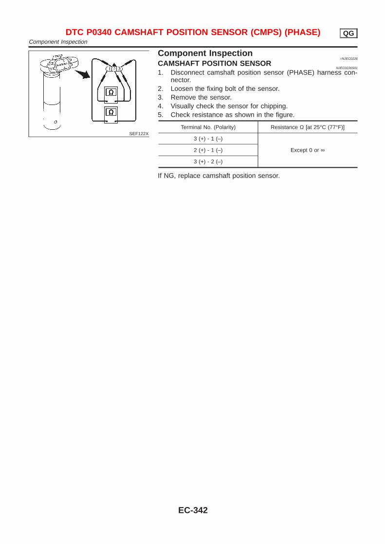
SEF122X
Component Inspection=NJEC0226
CAMSHAFT POSITION SENSORNJEC0226S01
1. Disconnect camshaft position sensor (PHASE) harness con-nector.
2. Loosen the fixing bolt of the sensor.3. Remove the sensor.4. Visually check the sensor for chipping.5. Check resistance as shown in the figure.
Terminal No. (Polarity) Resistance Ω [at 25°C (77°F)]
3 (+) - 1 (–)
Except 0 or ∞2 (+) - 1 (–)
3 (+) - 2 (–)
If NG, replace camshaft position sensor.
DTC P0340 CAMSHAFT POSITION SENSOR (CMPS) (PHASE) QGComponent Inspection
EC-342

DescriptionNJEC0227
SYSTEM DESCRIPTIONNJEC0227S01
Sensor Input Signal to ECMECM func-
tionActuator
Crankshaft position sensor (POS) Engine speed
EGR vol-ume control
EGR volume control valve
Camshaft position sensor (PHASE) Engine speed and cylinder number
Mass air flow sensor Amount of intake air
Engine coolant temperature sensor Engine coolant temperature
Ignition switch Start signal
Throttle position sensor Throttle position
Vehicle speed sensor Vehicle speed
Battery Battery voltage
Air conditioner switch Air conditioner operation
Power steering oil pressure switch Power steering load signal
Electrical load Electrical load signal
PNP switch Park/Neutral position signal
This system controls flow rate of EGR led from exhaust manifoldto intake manifold. The opening of the EGR by-pass passage in theEGR volume control valve changes to control the flow rate. Abuilt-in step motor moves the valve in steps corresponding to theECM output pulses. The opening of the valve varies for optimumengine control. The optimum value stored in the ECM is determinedby considering various engine conditions. The EGR volume controlvalve remains close under the following conditions.+ Low engine coolant temperature+ Engine starting+ High-speed engine operation+ Extremely light load engine operation+ Engine idling+ Excessively high engine coolant temperature+ Wide open throttle+ Mass air flow sensor malfunction+ Low battery voltage
SEF551W
DTC P0400 EGR FUNCTION (CLOSED) (WHERE FITTED) QGDescription
EC-343
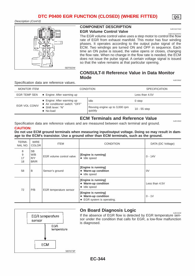
SEF552W
COMPONENT DESCRIPTIONNJEC0227S02
EGR Volume Control ValveNJEC0227S0201
The EGR volume control valve uses a step motor to control the flowrate of EGR from exhaust manifold. This motor has four windingphases. It operates according to the output pulse signal of theECM. Two windings are turned ON and OFF in sequence. Eachtime an ON pulse is issued, the valve opens or closes, changingthe flow rate. When no change in the flow rate is needed, the ECMdoes not issue the pulse signal. A certain voltage signal is issuedso that the valve remains at that particular opening.
CONSULT-II Reference Value in Data MonitorMode
NJEC0502
Specification data are reference values.
MONITOR ITEM CONDITION SPECIFICATION
EGR TEMP SEN + Engine: After warming up Less than 4.5V
EGR VOL CON/V
+ Engine: After warming up+ Air conditioner switch: “OFF”+ Shift lever: “N”+ No-load
Idle 0 step
Revving engine up to 3,000 rpmquickly
10 - 55 step
ECM Terminals and Reference ValueNJEC0503
Specification data are reference values and are measured between each terminal and ground.CAUTION:Do not use ECM ground terminals when measuring input/output voltage. Doing so may result in dam-age to the ECM’s transistor. Use a ground other than ECM terminals, such as the ground.
TERMI-NAL NO.
WIRECOLOR
ITEM CONDITION DATA (DC Voltage)
891718
SBW/BR/YBR/R
EGR volume control valve[Engine is running]+ Idle speed
0 - 14V
58 B Sensor’s ground[Engine is running]+ Warm-up condition+ Idle speed
0V
72 P/B EGR temperature sensor
[Engine is running]+ Warm-up condition+ Idle speed
Less than 4.5V
[Engine is running]+ Warm-up condition+ EGR system is operating.
0 - 1V
SEF073P
On Board Diagnosis LogicNJEC0228
If the absence of EGR flow is detected by EGR temperature sen-sor under the condition that calls for EGR, a low-flow malfunctionis diagnosed.
DTC P0400 EGR FUNCTION (CLOSED) (WHERE FITTED) QGDescription (Cont’d)
EC-344
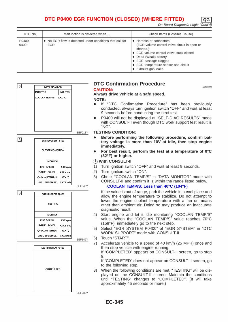
DTC No. Malfunction is detected when ... Check Items (Possible Cause)
P04000400
+ No EGR flow is detected under conditions that call forEGR.
+ Harness or connectors(EGR volume control valve circuit is open orshorted.)
+ EGR volume control valve stuck closed+ Dead (Weak) battery+ EGR passage clogged+ EGR temperature sensor and circuit+ Exhaust gas leaks
SEF013Y
SEF845Y
SEF846Y
SEF235Y
DTC Confirmation ProcedureNJEC0229
CAUTION:Always drive vehicle at a safe speed.NOTE:+ If “DTC Confirmation Procedure” has been previously
conducted, always turn ignition switch “OFF” and wait at least9 seconds before conducting the next test.
+ P0400 will not be displayed at “SELF-DIAG RESULTS” modewith CONSULT-II even though DTC work support test result is“NG”.
TESTING CONDITION:+ Before performing the following procedure, confirm bat-
tery voltage is more than 10V at idle, then stop engineimmediately.
+ For best result, perform the test at a temperature of 0°C(32°F) or higher.
With CONSULT-II1) Turn ignition switch “OFF” and wait at least 9 seconds.2) Turn ignition switch “ON”.3) Check “COOLAN TEMP/S” in “DATA MONITOR” mode with
CONSULT-II and confirm it is within the range listed below.COOLAN TEMP/S: Less than 40°C (104°F)
If the value is out of range, park the vehicle in a cool place andallow the engine temperature to stabilize. Do not attempt tolower the engine coolant temperature with a fan or meansother than ambient air. Doing so may produce an inaccuratediagnostic result.
4) Start engine and let it idle monitoring “COOLAN TEMP/S”value. When the “COOLAN TEMP/S” value reaches 70°C(158°F), immediately go to the next step.
5) Select “EGR SYSTEM P0400” of “EGR SYSTEM” in “DTCWORK SUPPORT” mode with CONSULT-II.
6) Touch “START”.7) Accelerate vehicle to a speed of 40 km/h (25 MPH) once and
then stop vehicle with engine running.If “COMPLETED” appears on CONSULT-II screen, go to step9.If “COMPLETED” does not appear on CONSULT-II screen, goto the following step.
8) When the following conditions are met, “TESTING” will be dis-played on the CONSULT-II screen. Maintain the conditionsuntil “TESTING” changes to “COMPLETED”. (It will takeapproximately 45 seconds or more.)
DTC P0400 EGR FUNCTION (CLOSED) (WHERE FITTED) QGOn Board Diagnosis Logic (Cont’d)
EC-345
ENG SPEED Above 2,400 rpm
Vehicle speed Above 90 km/h (56 MPH)
B/FUEL SCHDL 4.0 - 8.0 msec
Selector lever 4th or 5th
If “TESTING” is not displayed after 5 minutes, retry fromstep 2.
9) Make sure that “OK” is displayed after touching “SELF-DIAGRESULTS”. If “NG” is displayed, refer to “DiagnosticProcedure”, EC-349.
With GST1) Turn ignition switch “ON”.2) Check engine coolant temperature in MODE 1 with GST.
Engine coolant temperature: Less than 40°C (104°F)If the value is out of range, park the vehicle in a cool place andallow the engine temperature to stabilize. Do not attempt tolower the engine coolant temperature with a fan or meansother than ambient air. Doing so may produce an inaccuratediagnostic result.
3) Start engine and let it idle monitoring the value of “COOLANTEMP/S”. When the engine coolant temperature reaches 70°C(158°F), immediately go to the next step.
4) Maintain the following conditions for at least 1 minute.
Engine speed Above 2,400 rpm
Vehicle speed Above 90 km/h (56 MPH)
Selector lever 4th or 5th
5) Stop vehicle.6) Turn ignition switch “OFF” and wait at least 9 seconds, then
turn “ON”.7) Repeat step 2 to 4.8) Select “MODE 3” with GST.9) If DTC is detected, go to “DIAGNOSTIC PROCEDURE”,
EC-349.+ When using GST, “DTC CONFIRMATION PROCEDURE”
should be performed twice as much as when using CON-SULT-II because GST cannot diaplay MODE 7 (1st tripDTC) concerning this diagnosis. Therefore, using CON-SULT-II is recommended.
DTC P0400 EGR FUNCTION (CLOSED) (WHERE FITTED) QGDTC Confirmation Procedure (Cont’d)
EC-346
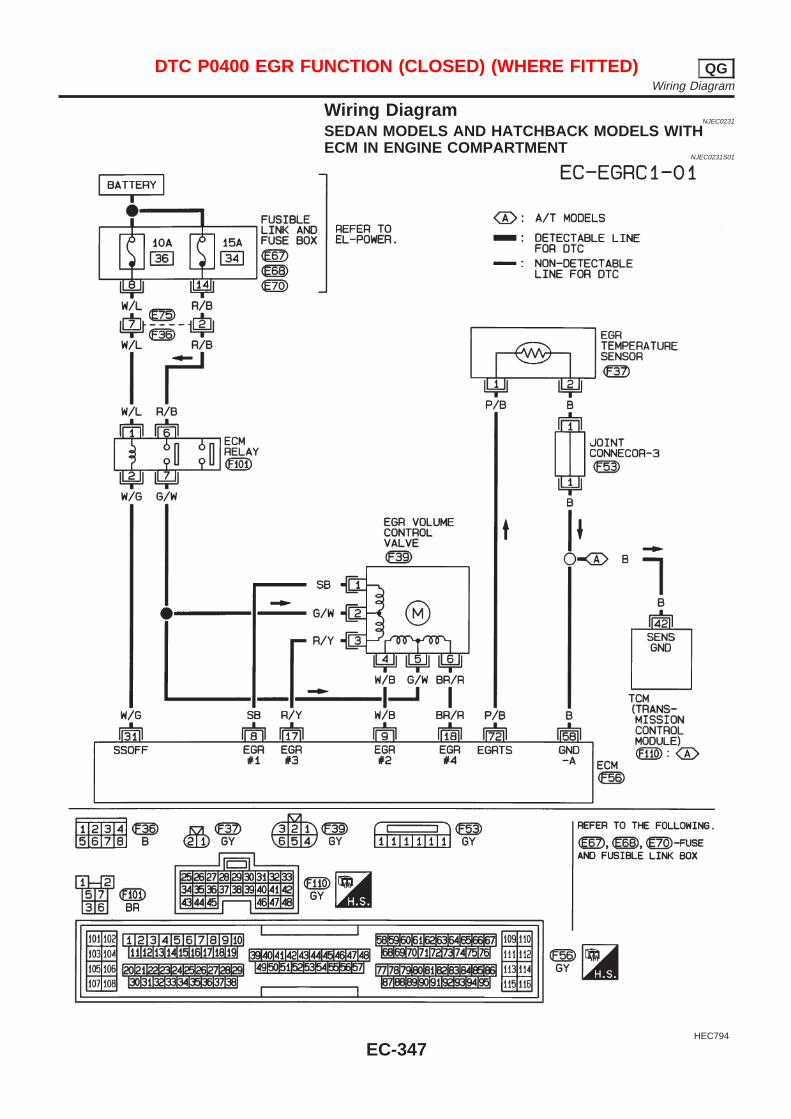
Wiring DiagramNJEC0231
SEDAN MODELS AND HATCHBACK MODELS WITHECM IN ENGINE COMPARTMENT
NJEC0231S01
HEC794
DTC P0400 EGR FUNCTION (CLOSED) (WHERE FITTED) QGWiring Diagram
EC-347
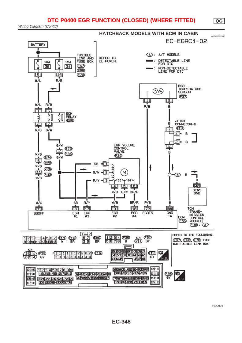
HATCHBACK MODELS WITH ECM IN CABINNJEC0231S02
HEC976
DTC P0400 EGR FUNCTION (CLOSED) (WHERE FITTED) QGWiring Diagram (Cont’d)
EC-348
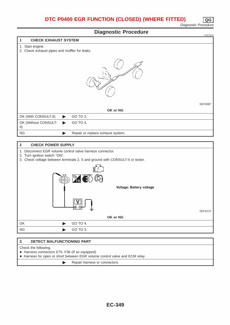
Diagnostic ProcedureNJEC0232
1 CHECK EXHAUST SYSTEM
1. Start engine.2. Check exhaust pipes and muffler for leaks.
SEF099P
OK or NG
OK (With CONSULT-II) © GO TO 2.
OK (Without CONSULT-II)
© GO TO 4.
NG © Repair or replace exhaust system.
2 CHECK POWER SUPPLY
1. Disconnect EGR volume control valve harness connector.2. Turn ignition switch “ON”.3. Check voltage between terminals 2, 5 and ground with CONSULT-II or tester.
SEF327X
OK or NG
OK © GO TO 4.
NG © GO TO 3.
3 DETECT MALFUNCTIONING PART
Check the following.+ Harness connectors E75, F36 (If so equipped)+ Harness for open or short between EGR volume control valve and ECM relay
© Repair harness or connectors.
DTC P0400 EGR FUNCTION (CLOSED) (WHERE FITTED) QGDiagnostic Procedure
EC-349
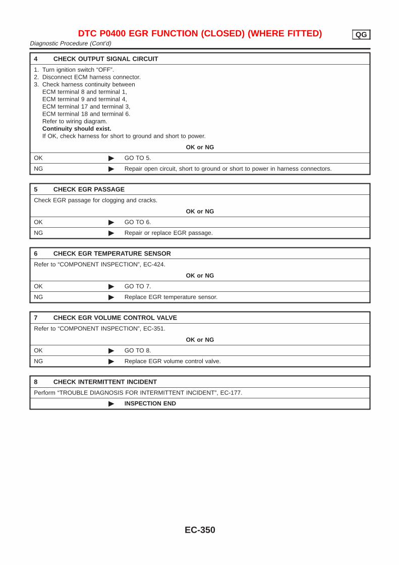
4 CHECK OUTPUT SIGNAL CIRCUIT
1. Turn ignition switch “OFF”.2. Disconnect ECM harness connector.3. Check harness continuity between
ECM terminal 8 and terminal 1,ECM terminal 9 and terminal 4,ECM terminal 17 and terminal 3,ECM terminal 18 and terminal 6.Refer to wiring diagram.Continuity should exist.If OK, check harness for short to ground and short to power.
OK or NG
OK © GO TO 5.
NG © Repair open circuit, short to ground or short to power in harness connectors.
5 CHECK EGR PASSAGE
Check EGR passage for clogging and cracks.
OK or NG
OK © GO TO 6.
NG © Repair or replace EGR passage.
6 CHECK EGR TEMPERATURE SENSOR
Refer to “COMPONENT INSPECTION”, EC-424.
OK or NG
OK © GO TO 7.
NG © Replace EGR temperature sensor.
7 CHECK EGR VOLUME CONTROL VALVE
Refer to “COMPONENT INSPECTION”, EC-351.
OK or NG
OK © GO TO 8.
NG © Replace EGR volume control valve.
8 CHECK INTERMITTENT INCIDENT
Perform “TROUBLE DIAGNOSIS FOR INTERMITTENT INCIDENT”, EC-177.
© INSPECTION END
DTC P0400 EGR FUNCTION (CLOSED) (WHERE FITTED) QGDiagnostic Procedure (Cont’d)
EC-350
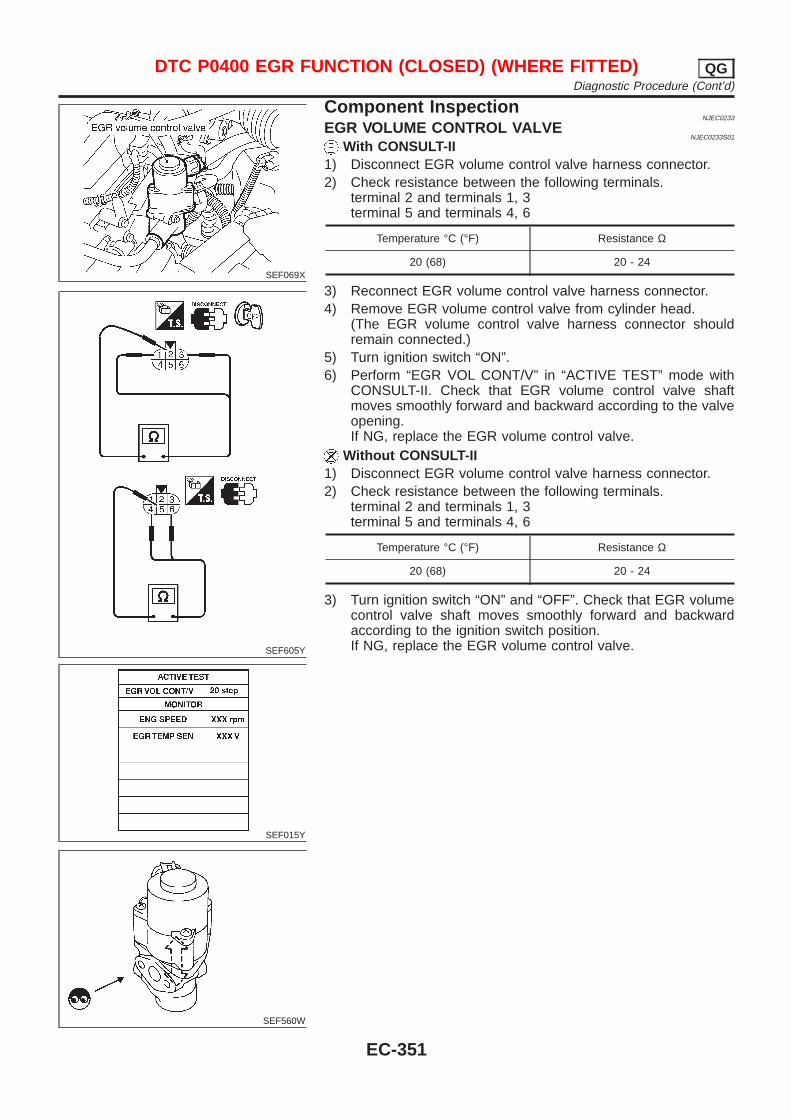
SEF069X
SEF605Y
SEF015Y
SEF560W
Component InspectionNJEC0233
EGR VOLUME CONTROL VALVENJEC0233S01
With CONSULT-II1) Disconnect EGR volume control valve harness connector.2) Check resistance between the following terminals.
terminal 2 and terminals 1, 3terminal 5 and terminals 4, 6
Temperature °C (°F) Resistance Ω
20 (68) 20 - 24
3) Reconnect EGR volume control valve harness connector.4) Remove EGR volume control valve from cylinder head.
(The EGR volume control valve harness connector shouldremain connected.)
5) Turn ignition switch “ON”.6) Perform “EGR VOL CONT/V” in “ACTIVE TEST” mode with
CONSULT-II. Check that EGR volume control valve shaftmoves smoothly forward and backward according to the valveopening.If NG, replace the EGR volume control valve.
Without CONSULT-II1) Disconnect EGR volume control valve harness connector.2) Check resistance between the following terminals.
terminal 2 and terminals 1, 3terminal 5 and terminals 4, 6
Temperature °C (°F) Resistance Ω
20 (68) 20 - 24
3) Turn ignition switch “ON” and “OFF”. Check that EGR volumecontrol valve shaft moves smoothly forward and backwardaccording to the ignition switch position.If NG, replace the EGR volume control valve.
DTC P0400 EGR FUNCTION (CLOSED) (WHERE FITTED) QGDiagnostic Procedure (Cont’d)
EC-351
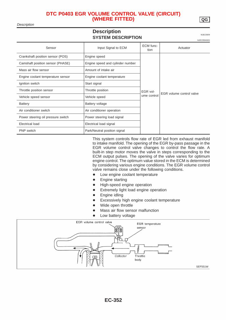
DescriptionNJEC0504
SYSTEM DESCRIPTIONNJEC0504S01
Sensor Input Signal to ECMECM func-
tionActuator
Crankshaft position sensor (POS) Engine speed
EGR vol-ume control
EGR volume control valve
Camshaft position sensor (PHASE) Engine speed and cylinder number
Mass air flow sensor Amount of intake air
Engine coolant temperature sensor Engine coolant temperature
Ignition switch Start signal
Throttle position sensor Throttle position
Vehicle speed sensor Vehicle speed
Battery Battery voltage
Air conditioner switch Air conditioner operation
Power steering oil pressure switch Power steering load signal
Electrical load Electrical load signal
PNP switch Park/Neutral position signal
This system controls flow rate of EGR led from exhaust manifoldto intake manifold. The opening of the EGR by-pass passage in theEGR volume control valve changes to control the flow rate. Abuilt-in step motor moves the valve in steps corresponding to theECM output pulses. The opening of the valve varies for optimumengine control. The optimum value stored in the ECM is determinedby considering various engine conditions. The EGR volume controlvalve remains close under the following conditions.+ Low engine coolant temperature+ Engine starting+ High-speed engine operation+ Extremely light load engine operation+ Engine idling+ Excessively high engine coolant temperature+ Wide open throttle+ Mass air flow sensor malfunction+ Low battery voltage
SEF551W
DTC P0403 EGR VOLUME CONTROL VALVE (CIRCUIT)(WHERE FITTED) QG
Description
EC-352
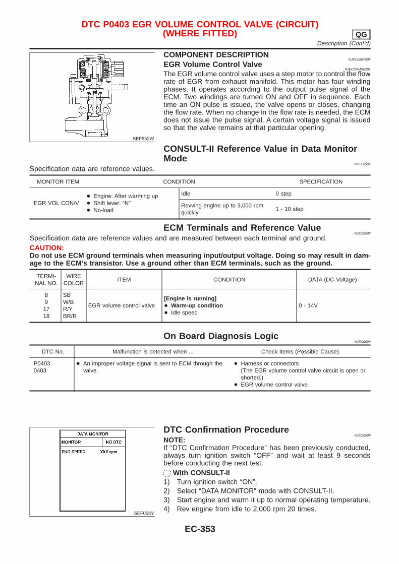
SEF552W
COMPONENT DESCRIPTIONNJEC0504S02
EGR Volume Control ValveNJEC0504S0201
The EGR volume control valve uses a step motor to control the flowrate of EGR from exhaust manifold. This motor has four windingphases. It operates according to the output pulse signal of theECM. Two windings are turned ON and OFF in sequence. Eachtime an ON pulse is issued, the valve opens or closes, changingthe flow rate. When no change in the flow rate is needed, the ECMdoes not issue the pulse signal. A certain voltage signal is issuedso that the valve remains at that particular opening.
CONSULT-II Reference Value in Data MonitorMode
NJEC0506
Specification data are reference values.
MONITOR ITEM CONDITION SPECIFICATION
EGR VOL CON/V+ Engine: After warming up+ Shift lever: “N”+ No-load
Idle 0 step
Revving engine up to 3,000 rpmquickly
1 - 10 step
ECM Terminals and Reference ValueNJEC0507
Specification data are reference values and are measured between each terminal and ground.CAUTION:Do not use ECM ground terminals when measuring input/output voltage. Doing so may result in dam-age to the ECM’s transistor. Use a ground other than ECM terminals, such as the ground.
TERMI-NAL NO.
WIRECOLOR
ITEM CONDITION DATA (DC Voltage)
891718
SBW/BR/YBR/R
EGR volume control valve[Engine is running]+ Warm-up condition+ Idle speed
0 - 14V
On Board Diagnosis LogicNJEC0508
DTC No. Malfunction is detected when ... Check Items (Possible Cause)
P04030403
+ An improper voltage signal is sent to ECM through thevalve.
+ Harness or connectors(The EGR volume control valve circuit is open orshorted.)
+ EGR volume control valve
SEF058Y
DTC Confirmation ProcedureNJEC0509
NOTE:If “DTC Confirmation Procedure” has been previously conducted,always turn ignition switch “OFF” and wait at least 9 secondsbefore conducting the next test.
With CONSULT-II1) Turn ignition switch “ON”.2) Select “DATA MONITOR” mode with CONSULT-II.3) Start engine and warm it up to normal operating temperature.4) Rev engine from idle to 2,000 rpm 20 times.
DTC P0403 EGR VOLUME CONTROL VALVE (CIRCUIT)(WHERE FITTED) QG
Description (Cont’d)
EC-353

If 1st trip DTC is detected, go to “DIAGNOSTICPROCEDURE”, EC-357.
With GSTFollow the procedure “With CONSULT-II” above.
DTC P0403 EGR VOLUME CONTROL VALVE (CIRCUIT)(WHERE FITTED) QG
DTC Confirmation Procedure (Cont’d)
EC-354
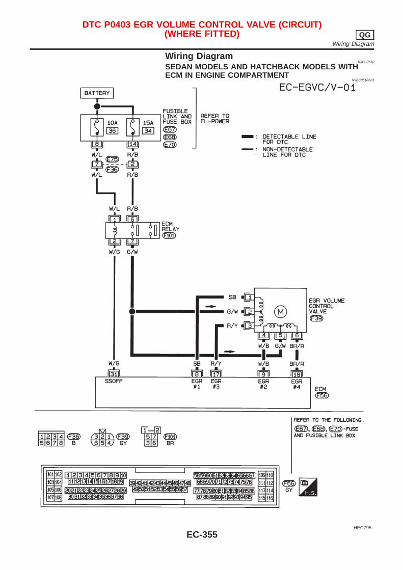
Wiring DiagramNJEC0510
SEDAN MODELS AND HATCHBACK MODELS WITHECM IN ENGINE COMPARTMENT
NJEC0510S01
HEC795
DTC P0403 EGR VOLUME CONTROL VALVE (CIRCUIT)(WHERE FITTED) QG
Wiring Diagram
EC-355
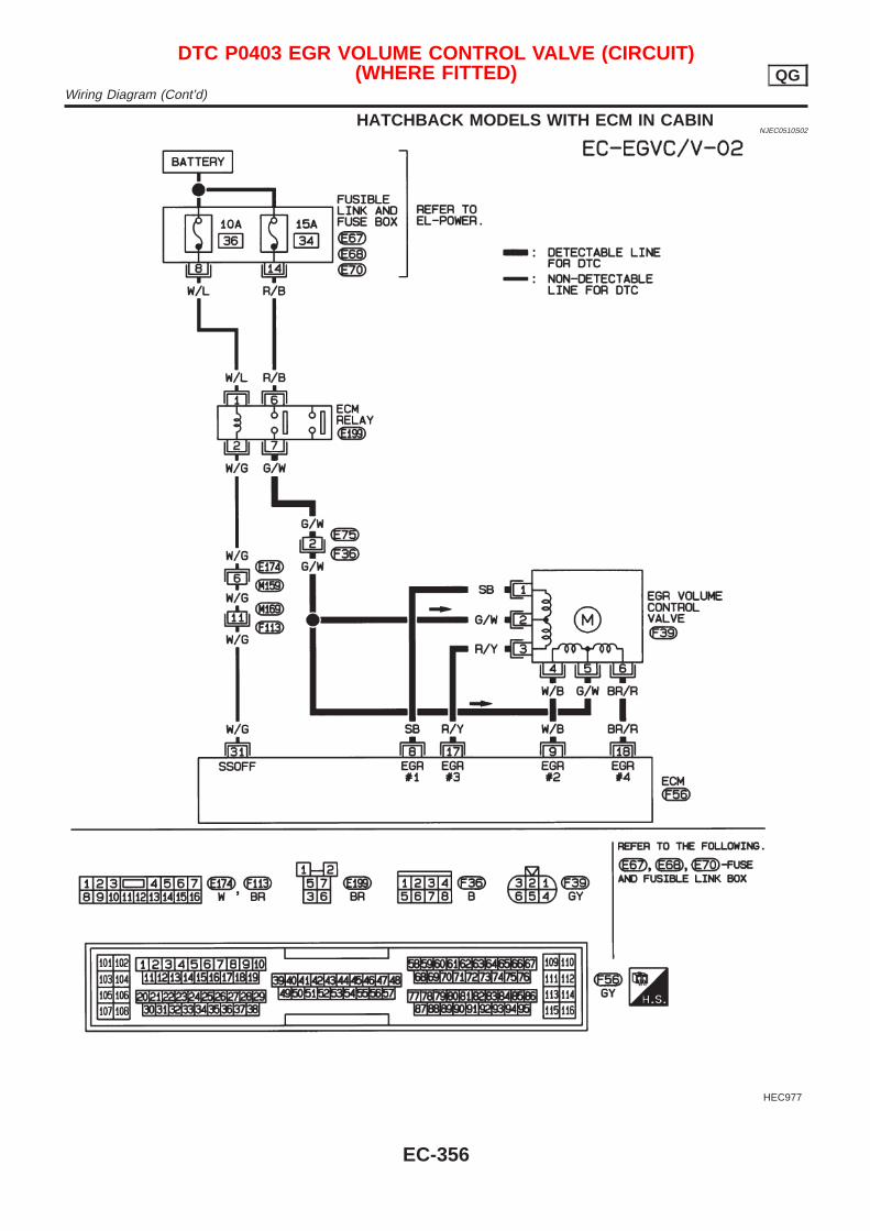
HATCHBACK MODELS WITH ECM IN CABINNJEC0510S02
HEC977
DTC P0403 EGR VOLUME CONTROL VALVE (CIRCUIT)(WHERE FITTED) QG
Wiring Diagram (Cont’d)
EC-356
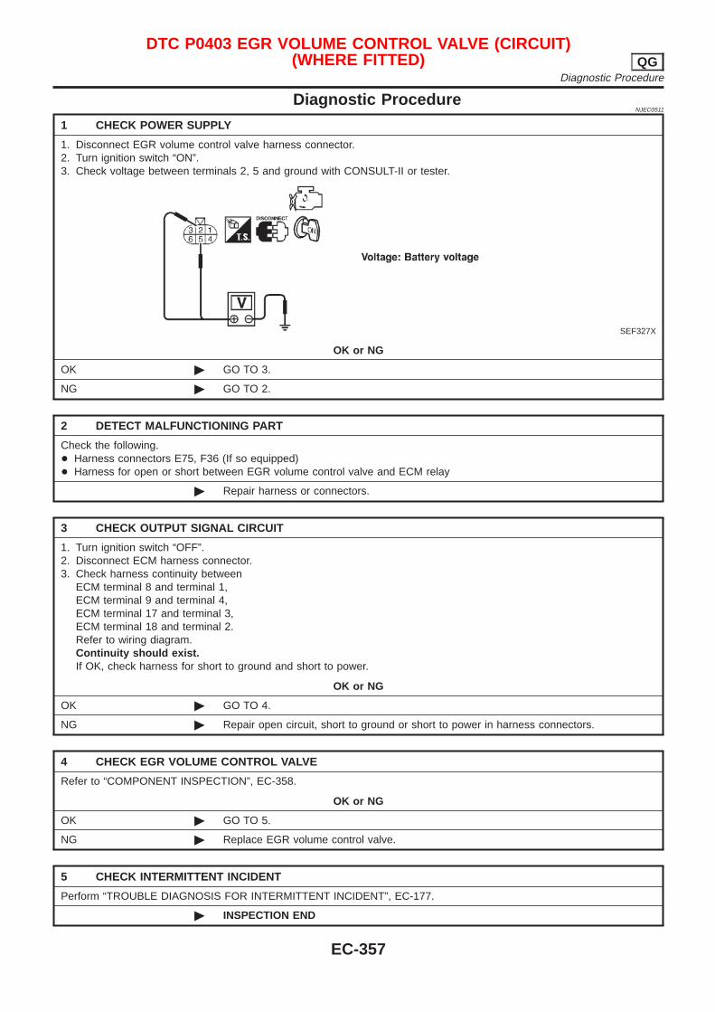
Diagnostic ProcedureNJEC0511
1 CHECK POWER SUPPLY
1. Disconnect EGR volume control valve harness connector.2. Turn ignition switch “ON”.3. Check voltage between terminals 2, 5 and ground with CONSULT-II or tester.
SEF327X
OK or NG
OK © GO TO 3.
NG © GO TO 2.
2 DETECT MALFUNCTIONING PART
Check the following.+ Harness connectors E75, F36 (If so equipped)+ Harness for open or short between EGR volume control valve and ECM relay
© Repair harness or connectors.
3 CHECK OUTPUT SIGNAL CIRCUIT
1. Turn ignition switch “OFF”.2. Disconnect ECM harness connector.3. Check harness continuity between
ECM terminal 8 and terminal 1,ECM terminal 9 and terminal 4,ECM terminal 17 and terminal 3,ECM terminal 18 and terminal 2.Refer to wiring diagram.Continuity should exist.If OK, check harness for short to ground and short to power.
OK or NG
OK © GO TO 4.
NG © Repair open circuit, short to ground or short to power in harness connectors.
4 CHECK EGR VOLUME CONTROL VALVE
Refer to “COMPONENT INSPECTION”, EC-358.
OK or NG
OK © GO TO 5.
NG © Replace EGR volume control valve.
5 CHECK INTERMITTENT INCIDENT
Perform “TROUBLE DIAGNOSIS FOR INTERMITTENT INCIDENT”, EC-177.
© INSPECTION END
DTC P0403 EGR VOLUME CONTROL VALVE (CIRCUIT)(WHERE FITTED) QG
Diagnostic Procedure
EC-357
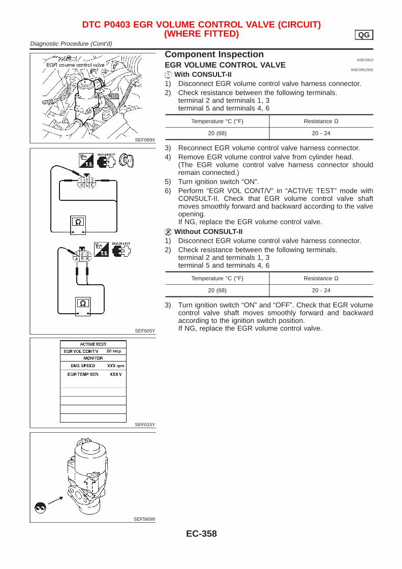
SEF069X
SEF605Y
SEF015Y
SEF560W
Component InspectionNJEC0512
EGR VOLUME CONTROL VALVENJEC0512S01
With CONSULT-II1) Disconnect EGR volume control valve harness connector.2) Check resistance between the following terminals.
terminal 2 and terminals 1, 3terminal 5 and terminals 4, 6
Temperature °C (°F) Resistance Ω
20 (68) 20 - 24
3) Reconnect EGR volume control valve harness connector.4) Remove EGR volume control valve from cylinder head.
(The EGR volume control valve harness connector shouldremain connected.)
5) Turn ignition switch “ON”.6) Perform “EGR VOL CONT/V” in “ACTIVE TEST” mode with
CONSULT-II. Check that EGR volume control valve shaftmoves smoothly forward and backward according to the valveopening.If NG, replace the EGR volume control valve.
Without CONSULT-II1) Disconnect EGR volume control valve harness connector.2) Check resistance between the following terminals.
terminal 2 and terminals 1, 3terminal 5 and terminals 4, 6
Temperature °C (°F) Resistance Ω
20 (68) 20 - 24
3) Turn ignition switch “ON” and “OFF”. Check that EGR volumecontrol valve shaft moves smoothly forward and backwardaccording to the ignition switch position.If NG, replace the EGR volume control valve.
DTC P0403 EGR VOLUME CONTROL VALVE (CIRCUIT)(WHERE FITTED) QG
Diagnostic Procedure (Cont’d)
EC-358
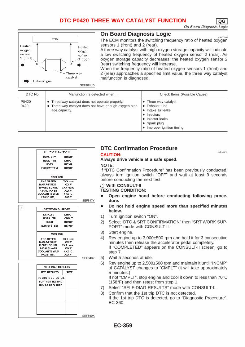
SEF184UD
On Board Diagnosis LogicNJEC0240
The ECM monitors the switching frequency ratio of heated oxygensensors 1 (front) and 2 (rear).A three way catalyst with high oxygen storage capacity will indicatea low switching frequency of heated oxygen sensor 2 (rear). Asoxygen storage capacity decreases, the heated oxygen sensor 2(rear) switching frequency will increase.When the frequency ratio of heated oxygen sensors 1 (front) and2 (rear) approaches a specified limit value, the three way catalystmalfunction is diagnosed.
DTC No. Malfunction is detected when ... Check Items (Possible Cause)
P04200420
+ Three way catalyst does not operate properly.+ Three way catalyst does not have enough oxygen stor-
age capacity.
+ Three way catalyst+ Exhaust tube+ Intake air leaks+ Injectors+ Injector leaks+ Spark plug+ Improper ignition timing
SEF847Y
SEF848Y
SEF560X
DTC Confirmation ProcedureNJEC0241
CAUTION:Always drive vehicle at a safe speed.NOTE:If “DTC Confirmation Procedure” has been previously conducted,always turn ignition switch “OFF” and wait at least 9 secondsbefore conducting the next test.
With CONSULT-IITESTING CONDITION:+ Open engine hood before conducting following proce-
dure.+ Do not hold engine speed more than specified minutes
below.1) Turn ignition switch “ON”.2) Select “DTC & SRT CONFIRMATION” then “SRT WORK SUP-
PORT” mode with CONSULT-II.3) Start engine.4) Rev engine up to 3,000±500 rpm and hold it for 3 consecutive
minutes then release the accelerator pedal completely.If “COMPLETED” appears on the CONSULT-II screen, go tostep 7.
5) Wait 5 seconds at idle.6) Rev engine up to 2,500±500 rpm and maintain it until “INCMP”
of CATALYST changes to “CMPLT” (it will take approximately5 minutes.)If not “CMPLT”, stop engine and cool it down to less than 70°C(158°F) and then retest from step 1.
7) Select “SELF-DIAG RESULTS” mode with CONSULT-II.8) Confirm that the 1st trip DTC is not detected.
If the 1st trip DTC is detected, go to “Diagnostic Procedure”,EC-360.
DTC P0420 THREE WAY CATALYST FUNCTION QGOn Board Diagnosis Logic
EC-359

SEF074X
Overall Function CheckNJEC0242
Use this procedure to check the overall function of the three waycatalyst. During this check, a 1st trip DTC might not be confirmed.
Without CONSULT-II1) Start engine and drive vehicle at a speed of more than 70 km/h
(43 MPH) for 2 consecutive minutes.2) Stop vehicle with engine running.3) Set voltmeters probes between ECM terminals 62 (HO2S1
signal), 63 (HO2S2 signal) and engine ground.4) Keep engine speed at 2,000 rpm constant under no load.5) Make sure that the voltage switching frequency (high & low)
between ECM terminal 63 and engine ground is much lessthan that of ECM terminal 62 and engine ground.Switching frequency ratio = A/BA: Heated oxygen sensor 2 (rear) voltage switching fre-quencyB: Heated oxygen sensor 1 (front) voltage switching fre-quencyThis ratio should be less than 0.75.If the ratio is greater than above, it means three way catalystdoes not operate properly.
NOTE:If the voltage at terminal 62 does not switch periodically morethan 5 times within 10 seconds at step 4, perform troublediagnosis for DTC P0133 first. (See EC-236.)
Diagnostic ProcedureNJEC0243
1 CHECK EXHAUST SYSTEM
Visually check exhaust tubes and muffler for dent.
OK or NG
OK © GO TO 2.
NG © Repair or replace.
DTC P0420 THREE WAY CATALYST FUNCTION QGOverall Function Check
EC-360
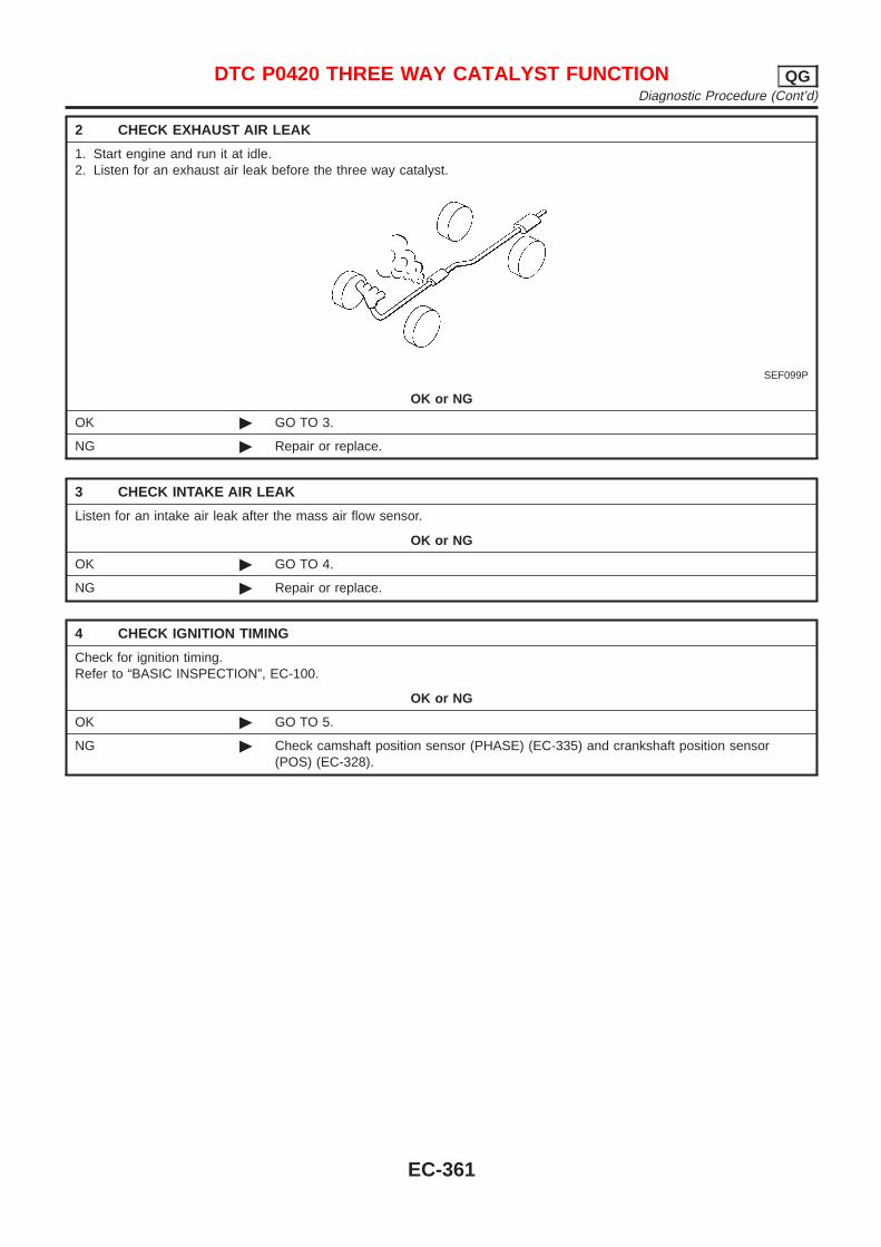
2 CHECK EXHAUST AIR LEAK
1. Start engine and run it at idle.2. Listen for an exhaust air leak before the three way catalyst.
SEF099P
OK or NG
OK © GO TO 3.
NG © Repair or replace.
3 CHECK INTAKE AIR LEAK
Listen for an intake air leak after the mass air flow sensor.
OK or NG
OK © GO TO 4.
NG © Repair or replace.
4 CHECK IGNITION TIMING
Check for ignition timing.Refer to “BASIC INSPECTION”, EC-100.
OK or NG
OK © GO TO 5.
NG © Check camshaft position sensor (PHASE) (EC-335) and crankshaft position sensor(POS) (EC-328).
DTC P0420 THREE WAY CATALYST FUNCTION QGDiagnostic Procedure (Cont’d)
EC-361
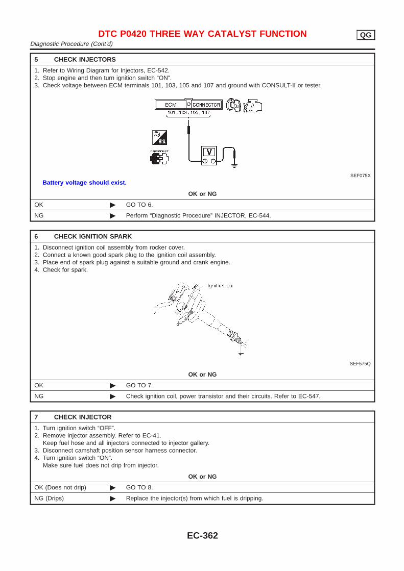
5 CHECK INJECTORS
1. Refer to Wiring Diagram for Injectors, EC-542.2. Stop engine and then turn ignition switch “ON”.3. Check voltage between ECM terminals 101, 103, 105 and 107 and ground with CONSULT-II or tester.
SEF075X
Battery voltage should exist.
OK or NG
OK © GO TO 6.
NG © Perform “Diagnostic Procedure” INJECTOR, EC-544.
6 CHECK IGNITION SPARK
1. Disconnect ignition coil assembly from rocker cover.2. Connect a known good spark plug to the ignition coil assembly.3. Place end of spark plug against a suitable ground and crank engine.4. Check for spark.
SEF575Q
OK or NG
OK © GO TO 7.
NG © Check ignition coil, power transistor and their circuits. Refer to EC-547.
7 CHECK INJECTOR
1. Turn ignition switch “OFF”.2. Remove injector assembly. Refer to EC-41.
Keep fuel hose and all injectors connected to injector gallery.3. Disconnect camshaft position sensor harness connector.4. Turn ignition switch “ON”.
Make sure fuel does not drip from injector.
OK or NG
OK (Does not drip) © GO TO 8.
NG (Drips) © Replace the injector(s) from which fuel is dripping.
DTC P0420 THREE WAY CATALYST FUNCTION QGDiagnostic Procedure (Cont’d)
EC-362
8 CHECK INTERMITTENT INCIDENT
Perform “TROUBLE DIAGNOSIS FOR INTERMITTENT INCIDENT”, EC-177.
Trouble is fixed © INSPECTION END
Trouble is not fixed © Replace three way catalyst.
DTC P0420 THREE WAY CATALYST FUNCTION QGDiagnostic Procedure (Cont’d)
EC-363
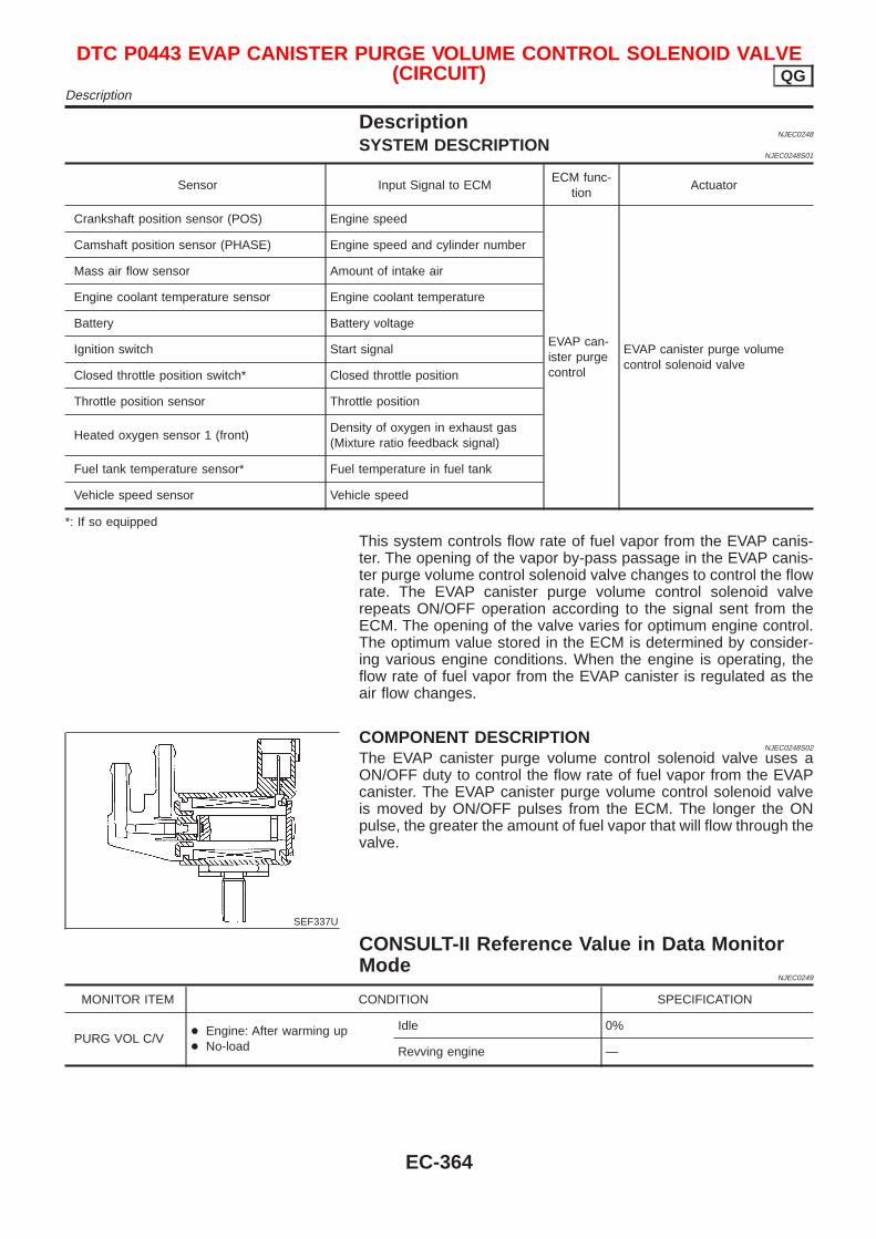
DescriptionNJEC0248
SYSTEM DESCRIPTIONNJEC0248S01
Sensor Input Signal to ECMECM func-
tionActuator
Crankshaft position sensor (POS) Engine speed
EVAP can-ister purgecontrol
EVAP canister purge volumecontrol solenoid valve
Camshaft position sensor (PHASE) Engine speed and cylinder number
Mass air flow sensor Amount of intake air
Engine coolant temperature sensor Engine coolant temperature
Battery Battery voltage
Ignition switch Start signal
Closed throttle position switch* Closed throttle position
Throttle position sensor Throttle position
Heated oxygen sensor 1 (front)Density of oxygen in exhaust gas(Mixture ratio feedback signal)
Fuel tank temperature sensor* Fuel temperature in fuel tank
Vehicle speed sensor Vehicle speed
*: If so equipped
This system controls flow rate of fuel vapor from the EVAP canis-ter. The opening of the vapor by-pass passage in the EVAP canis-ter purge volume control solenoid valve changes to control the flowrate. The EVAP canister purge volume control solenoid valverepeats ON/OFF operation according to the signal sent from theECM. The opening of the valve varies for optimum engine control.The optimum value stored in the ECM is determined by consider-ing various engine conditions. When the engine is operating, theflow rate of fuel vapor from the EVAP canister is regulated as theair flow changes.
SEF337U
COMPONENT DESCRIPTIONNJEC0248S02
The EVAP canister purge volume control solenoid valve uses aON/OFF duty to control the flow rate of fuel vapor from the EVAPcanister. The EVAP canister purge volume control solenoid valveis moved by ON/OFF pulses from the ECM. The longer the ONpulse, the greater the amount of fuel vapor that will flow through thevalve.
CONSULT-II Reference Value in Data MonitorMode
NJEC0249
MONITOR ITEM CONDITION SPECIFICATION
PURG VOL C/V+ Engine: After warming up+ No-load
Idle 0%
Revving engine —
DTC P0443 EVAP CANISTER PURGE VOLUME CONTROL SOLENOID VALVE(CIRCUIT) QG
Description
EC-364
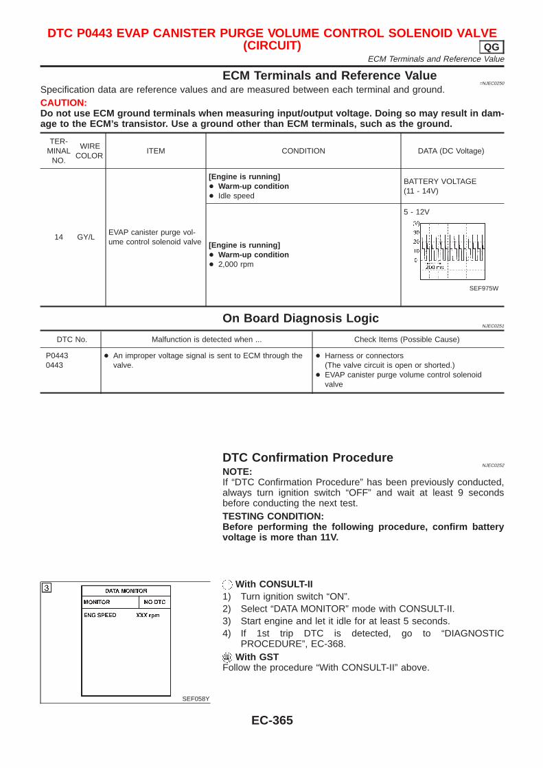
ECM Terminals and Reference Value=NJEC0250
Specification data are reference values and are measured between each terminal and ground.CAUTION:Do not use ECM ground terminals when measuring input/output voltage. Doing so may result in dam-age to the ECM’s transistor. Use a ground other than ECM terminals, such as the ground.
TER-MINAL
NO.
WIRECOLOR
ITEM CONDITION DATA (DC Voltage)
14 GY/LEVAP canister purge vol-ume control solenoid valve
[Engine is running]+ Warm-up condition+ Idle speed
BATTERY VOLTAGE(11 - 14V)
[Engine is running]+ Warm-up condition+ 2,000 rpm
5 - 12V
SEF975W
On Board Diagnosis LogicNJEC0251
DTC No. Malfunction is detected when ... Check Items (Possible Cause)
P04430443
+ An improper voltage signal is sent to ECM through thevalve.
+ Harness or connectors(The valve circuit is open or shorted.)
+ EVAP canister purge volume control solenoidvalve
DTC Confirmation ProcedureNJEC0252
NOTE:If “DTC Confirmation Procedure” has been previously conducted,always turn ignition switch “OFF” and wait at least 9 secondsbefore conducting the next test.TESTING CONDITION:Before performing the following procedure, confirm batteryvoltage is more than 11V.
SEF058Y
With CONSULT-II1) Turn ignition switch “ON”.2) Select “DATA MONITOR” mode with CONSULT-II.3) Start engine and let it idle for at least 5 seconds.4) If 1st trip DTC is detected, go to “DIAGNOSTIC
PROCEDURE”, EC-368.With GST
Follow the procedure “With CONSULT-II” above.
DTC P0443 EVAP CANISTER PURGE VOLUME CONTROL SOLENOID VALVE(CIRCUIT) QG
ECM Terminals and Reference Value
EC-365
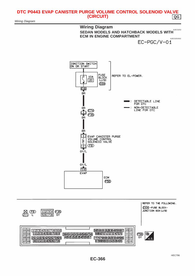
Wiring DiagramNJEC0253
SEDAN MODELS AND HATCHBACK MODELS WITHECM IN ENGINE COMPARTMENT
NJEC0253S01
HEC796
DTC P0443 EVAP CANISTER PURGE VOLUME CONTROL SOLENOID VALVE(CIRCUIT) QG
Wiring Diagram
EC-366
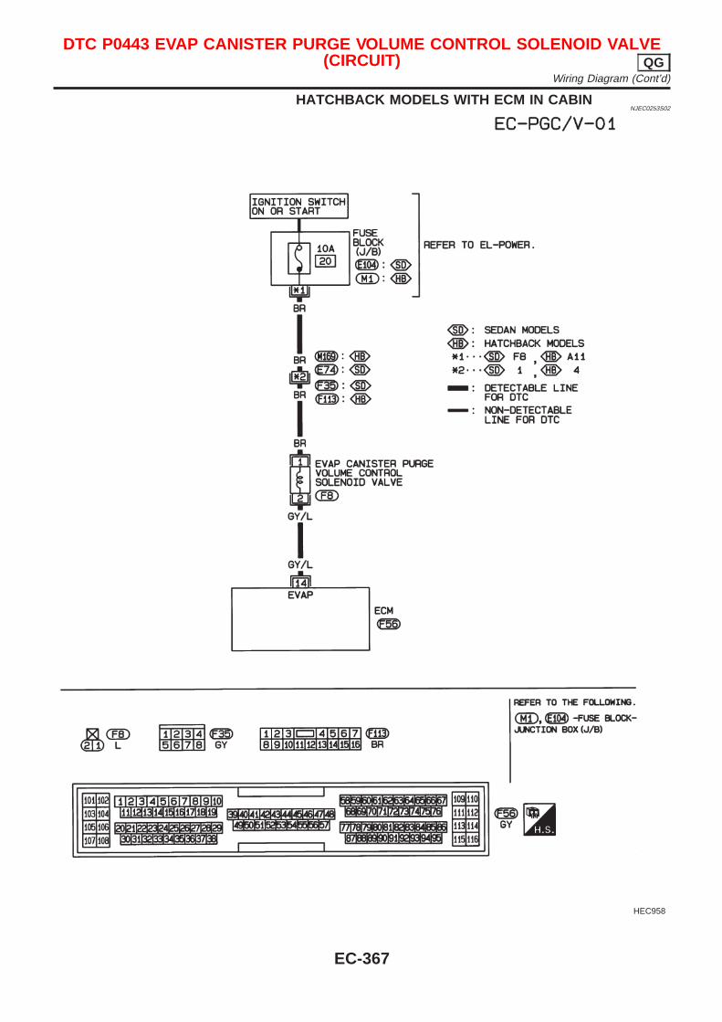
HATCHBACK MODELS WITH ECM IN CABINNJEC0253S02
HEC958
DTC P0443 EVAP CANISTER PURGE VOLUME CONTROL SOLENOID VALVE(CIRCUIT) QG
Wiring Diagram (Cont’d)
EC-367
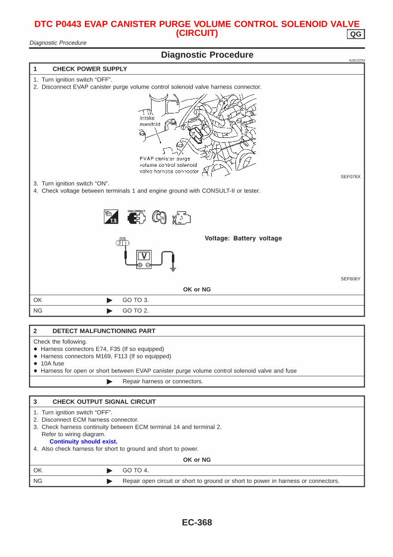
Diagnostic ProcedureNJEC0254
1 CHECK POWER SUPPLY
1. Turn ignition switch “OFF”.2. Disconnect EVAP canister purge volume control solenoid valve harness connector.
SEF076X
3. Turn ignition switch “ON”.4. Check voltage between terminals 1 and engine ground with CONSULT-II or tester.
SEF606Y
OK or NG
OK © GO TO 3.
NG © GO TO 2.
2 DETECT MALFUNCTIONING PART
Check the following.+ Harness connectors E74, F35 (If so equipped)+ Harness connectors M169, F113 (If so equipped)+ 10A fuse+ Harness for open or short between EVAP canister purge volume control solenoid valve and fuse
© Repair harness or connectors.
3 CHECK OUTPUT SIGNAL CIRCUIT
1. Turn ignition switch “OFF”.2. Disconnect ECM harness connector.3. Check harness continuity between ECM terminal 14 and terminal 2.
Refer to wiring diagram.Continuity should exist.
4. Also check harness for short to ground and short to power.
OK or NG
OK © GO TO 4.
NG © Repair open circuit or short to ground or short to power in harness or connectors.
DTC P0443 EVAP CANISTER PURGE VOLUME CONTROL SOLENOID VALVE(CIRCUIT) QG
Diagnostic Procedure
EC-368
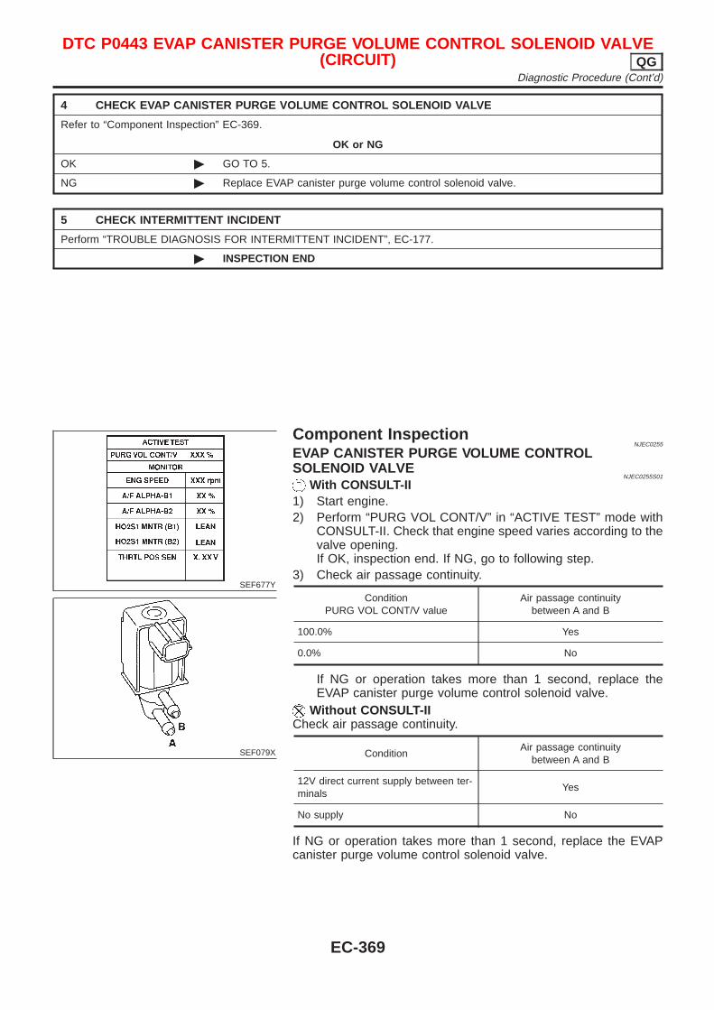
4 CHECK EVAP CANISTER PURGE VOLUME CONTROL SOLENOID VALVE
Refer to “Component Inspection” EC-369.
OK or NG
OK © GO TO 5.
NG © Replace EVAP canister purge volume control solenoid valve.
5 CHECK INTERMITTENT INCIDENT
Perform “TROUBLE DIAGNOSIS FOR INTERMITTENT INCIDENT”, EC-177.
© INSPECTION END
SEF677Y
SEF079X
Component InspectionNJEC0255
EVAP CANISTER PURGE VOLUME CONTROLSOLENOID VALVE
NJEC0255S01
With CONSULT-II1) Start engine.2) Perform “PURG VOL CONT/V” in “ACTIVE TEST” mode with
CONSULT-II. Check that engine speed varies according to thevalve opening.If OK, inspection end. If NG, go to following step.
3) Check air passage continuity.
ConditionPURG VOL CONT/V value
Air passage continuitybetween A and B
100.0% Yes
0.0% No
If NG or operation takes more than 1 second, replace theEVAP canister purge volume control solenoid valve.
Without CONSULT-IICheck air passage continuity.
ConditionAir passage continuity
between A and B
12V direct current supply between ter-minals
Yes
No supply No
If NG or operation takes more than 1 second, replace the EVAPcanister purge volume control solenoid valve.
DTC P0443 EVAP CANISTER PURGE VOLUME CONTROL SOLENOID VALVE(CIRCUIT) QG
Diagnostic Procedure (Cont’d)
EC-369
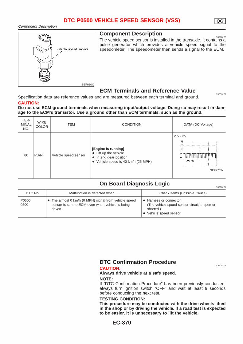
SEF080X
Component DescriptionNJEC0272
The vehicle speed sensor is installed in the transaxle. It contains apulse generator which provides a vehicle speed signal to thespeedometer. The speedometer then sends a signal to the ECM.
ECM Terminals and Reference ValueNJEC0273
Specification data are reference values and are measured between each terminal and ground.CAUTION:Do not use ECM ground terminals when measuring input/output voltage. Doing so may result in dam-age to the ECM’s transistor. Use a ground other than ECM terminals, such as the ground.
TER-MINAL
NO.
WIRECOLOR
ITEM CONDITION DATA (DC Voltage)
86 PU/R Vehicle speed sensor
[Engine is running]+ Lift up the vehicle+ In 2nd gear position+ Vehicle speed is 40 km/h (25 MPH)
2.5 - 3V
SEF976W
On Board Diagnosis LogicNJEC0274
DTC No. Malfunction is detected when ... Check Items (Possible Cause)
P05000500
+ The almost 0 km/h (0 MPH) signal from vehicle speedsensor is sent to ECM even when vehicle is beingdriven.
+ Harness or connector(The vehicle speed sensor circuit is open orshorted.)
+ Vehicle speed sensor
DTC Confirmation ProcedureNJEC0275
CAUTION:Always drive vehicle at a safe speed.NOTE:If “DTC Confirmation Procedure” has been previously conducted,always turn ignition switch “OFF” and wait at least 9 secondsbefore conducting the next test.TESTING CONDITION:This procedure may be conducted with the drive wheels liftedin the shop or by driving the vehicle. If a road test is expectedto be easier, it is unnecessary to lift the vehicle.
DTC P0500 VEHICLE SPEED SENSOR (VSS) QGComponent Description
EC-370
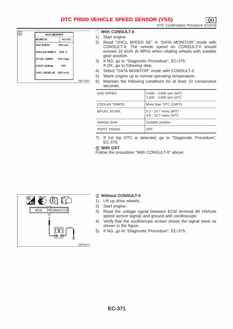
SEF196Y
With CONSULT-II1) Start engine2) Read “VHCL SPEED SE” in “DATA MONITOR” mode with
CONSULT-II. The vehicle speed on CONSULT-II shouldexceed 10 km/h (6 MPH) when rotating wheels with suitablegear position.
3) If NG, go to “Diagnostic Procedure”, EC-375.If OK, go to following step.
4) Select “DATA MONITOR” mode with CONSULT-II.5) Warm engine up to normal operating temperature.6) Maintain the following conditions for at least 10 consecutive
seconds.
ENG SPEED 2,600 - 4,000 rpm (M/T)2,600 - 3,000 rpm (A/T)
COOLAN TEMP/S More than 70°C (158°F)
B/FUEL SCHDL 5.3 - 10.7 msec (M/T)4.8 - 10.7 msec (A/T)
Selector lever Suitable position
PW/ST SIGNAL OFF
7) If 1st trip DTC is detected, go to “Diagnostic Procedure”,EC-375.
With GSTFollow the procedure “With CONSULT-II” above.
SEF607Y
Without CONSULT-II1) Lift up drive wheels.2) Start engine.3) Read the voltage signal between ECM terminal 86 (Vehicle
speed sensor signal) and ground with oscilloscope.4) Verify that the oscilloscope screen shows the signal wave as
shown in the figure.5) If NG, go to “Diagnostic Procedure”, EC-375.
DTC P0500 VEHICLE SPEED SENSOR (VSS) QGDTC Confirmation Procedure (Cont’d)
EC-371
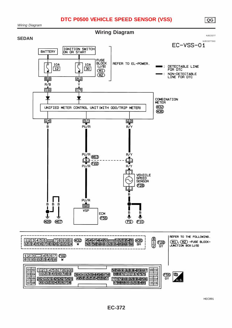
Wiring DiagramNJEC0277
SEDANNJEC0277S01
HEC891
DTC P0500 VEHICLE SPEED SENSOR (VSS) QGWiring Diagram
EC-372
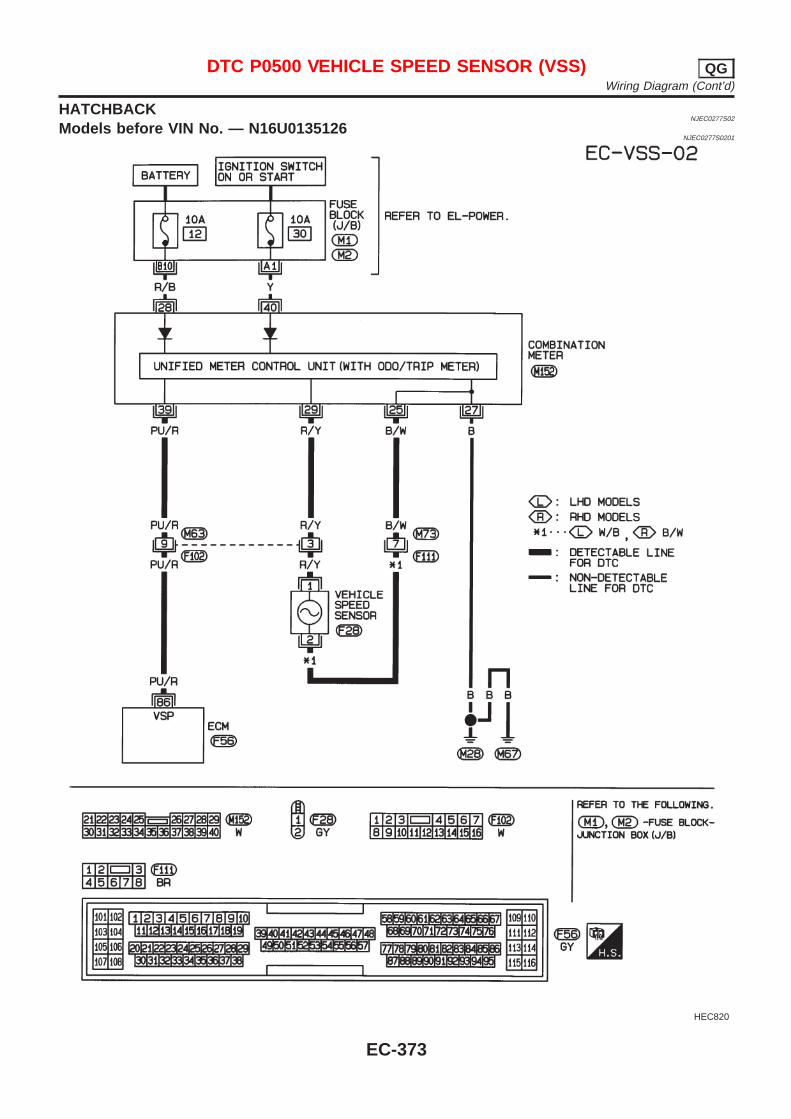
HATCHBACKNJEC0277S02
Models before VIN No. — N16U0135126NJEC0277S0201
HEC820
DTC P0500 VEHICLE SPEED SENSOR (VSS) QGWiring Diagram (Cont’d)
EC-373
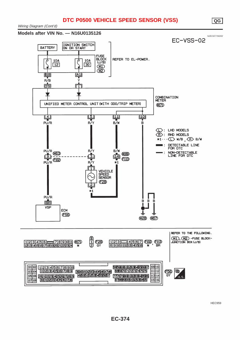
Models after VIN No. — N16U0135126NJEC0277S0202
HEC959
DTC P0500 VEHICLE SPEED SENSOR (VSS) QGWiring Diagram (Cont’d)
EC-374
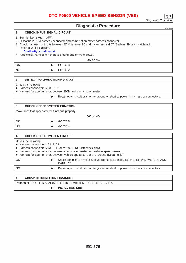
Diagnostic ProcedureNJEC0278
1 CHECK INPUT SIGNAL CIRCUIT
1. Turn ignition switch “OFF”.2. Disconnect ECM harness connector and combination meter harness connector.3. Check harness continuity between ECM terminal 86 and meter terminal 57 (Sedan), 39 or 4 (Hatchback).
Refer to wiring diagram.Continuity should exist.
4. Also check harness for short to ground and short to power.
OK or NG
OK © GO TO 3.
NG © GO TO 2.
2 DETECT MALFUNCTIONING PART
Check the following.+ Harness connectors M63, F102+ Harness for open or short between ECM and combination meter
© Repair open circuit or short to ground or short to power in harness or connectors.
3 CHECK SPEEDOMETER FUNCTION
Make sure that speedometer functions properly.
OK or NG
OK © GO TO 5.
NG © GO TO 4.
4 CHECK SPEEDOMETER CIRCUIT
Check the following.+ Harness connectors M63, F102+ Harness connectors M73, F111 or M169, F113 (Hatchback only)+ Harness for open or short between combination meter and vehicle speed sensor+ Harness for open or short between vehicle speed sensor and ground (Sedan only)
OK © Check combination meter and vehicle speed sensor. Refer to EL-144, “METERS ANDGAUGES”.
NG © Repair open circuit or short to ground or short to power in harness or connectors.
5 CHECK INTERMITTENT INCIDENT
Perform “TROUBLE DIAGNOSIS FOR INTERMITTENT INCIDENT”, EC-177.
© INSPECTION END
DTC P0500 VEHICLE SPEED SENSOR (VSS) QGDiagnostic Procedure
EC-375
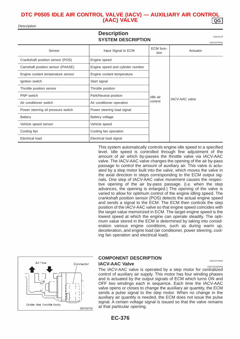
DescriptionNJEC0279
SYSTEM DESCRIPTIONNJEC0279S01
Sensor Input Signal to ECMECM func-
tionActuator
Crankshaft position sensor (POS) Engine speed
Idle aircontrol
IACV-AAC valve
Camshaft position sensor (PHASE) Engine speed and cylinder number
Engine coolant temperature sensor Engine coolant temperature
Ignition switch Start signal
Throttle position sensor Throttle position
PNP switch Park/Neutral position
Air conditioner switch Air conditioner operation
Power steering oil pressure switch Power steering load signal
Battery Battery voltage
Vehicle speed sensor Vehicle speed
Cooling fan Cooling fan operation
Electrical load Electrical load signal
This system automatically controls engine idle speed to a specifiedlevel. Idle speed is controlled through fine adjustment of theamount of air which by-passes the throttle valve via IACV-AACvalve. The IACV-AAC valve changes the opening of the air by-passpassage to control the amount of auxiliary air. This valve is actu-ated by a step motor built into the valve, which moves the valve inthe axial direction in steps corresponding to the ECM output sig-nals. One step of IACV-AAC valve movement causes the respec-tive opening of the air by-pass passage. (i.e. when the stepadvances, the opening is enlarged.) The opening of the valve isvaried to allow for optimum control of the engine idling speed. Thecrankshaft position sensor (POS) detects the actual engine speedand sends a signal to the ECM. The ECM then controls the stepposition of the IACV-AAC valve so that engine speed coincides withthe target value memorized in ECM. The target engine speed is thelowest speed at which the engine can operate steadily. The opti-mum value stored in the ECM is determined by taking into consid-eration various engine conditions, such as during warm up,deceleration, and engine load (air conditioner, power steering, cool-ing fan operation and electrical load).
SEF937W
COMPONENT DESCRIPTIONNJEC0279S02
IACV-AAC ValveNJEC0279S0202
The IACV-AAC valve is operated by a step motor for centralizedcontrol of auxiliary air supply. This motor has four winding phasesand is actuated by the output signals of ECM which turns ON andOFF two windings each in sequence. Each time the IACV-AACvalve opens or closes to change the auxiliary air quantity, the ECMsends a pulse signal to the step motor. When no change in theauxiliary air quantity is needed, the ECM does not issue the pulsesignal. A certain voltage signal is issued so that the valve remainsat that particular opening.
DTC P0505 IDLE AIR CONTROL VALVE (IACV) — AUXILIARY AIR CONTROL(AAC) VALVE QG
Description
EC-376
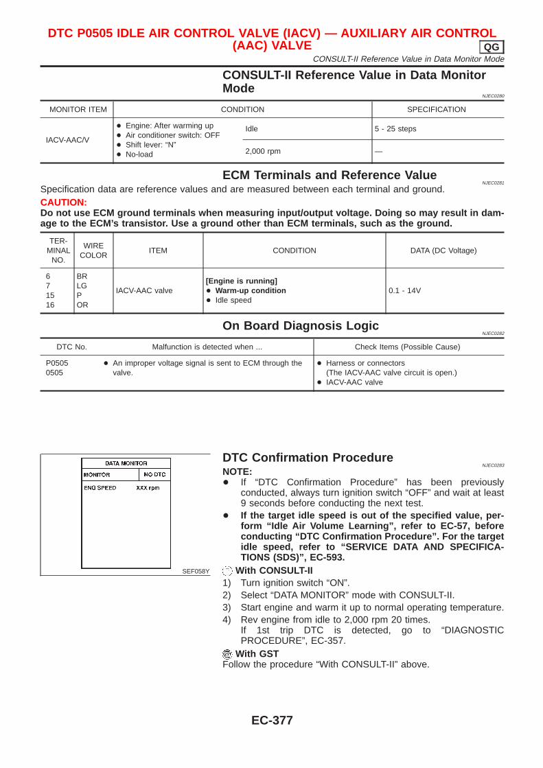
CONSULT-II Reference Value in Data MonitorMode
NJEC0280
MONITOR ITEM CONDITION SPECIFICATION
IACV-AAC/V
+ Engine: After warming up+ Air conditioner switch: OFF+ Shift lever: “N”+ No-load
Idle 5 - 25 steps
2,000 rpm —
ECM Terminals and Reference ValueNJEC0281
Specification data are reference values and are measured between each terminal and ground.CAUTION:Do not use ECM ground terminals when measuring input/output voltage. Doing so may result in dam-age to the ECM’s transistor. Use a ground other than ECM terminals, such as the ground.
TER-MINAL
NO.
WIRECOLOR
ITEM CONDITION DATA (DC Voltage)
671516
BRLGPOR
IACV-AAC valve[Engine is running]+ Warm-up condition+ Idle speed
0.1 - 14V
On Board Diagnosis LogicNJEC0282
DTC No. Malfunction is detected when ... Check Items (Possible Cause)
P05050505
+ An improper voltage signal is sent to ECM through thevalve.
+ Harness or connectors(The IACV-AAC valve circuit is open.)
+ IACV-AAC valve
SEF058Y
DTC Confirmation ProcedureNJEC0283
NOTE:+ If “DTC Confirmation Procedure” has been previously
conducted, always turn ignition switch “OFF” and wait at least9 seconds before conducting the next test.
+ If the target idle speed is out of the specified value, per-form “Idle Air Volume Learning”, refer to EC-57, beforeconducting “DTC Confirmation Procedure”. For the targetidle speed, refer to “SERVICE DATA AND SPECIFICA-TIONS (SDS)”, EC-593.
With CONSULT-II1) Turn ignition switch “ON”.2) Select “DATA MONITOR” mode with CONSULT-II.3) Start engine and warm it up to normal operating temperature.4) Rev engine from idle to 2,000 rpm 20 times.
If 1st trip DTC is detected, go to “DIAGNOSTICPROCEDURE”, EC-357.
With GSTFollow the procedure “With CONSULT-II” above.
DTC P0505 IDLE AIR CONTROL VALVE (IACV) — AUXILIARY AIR CONTROL(AAC) VALVE QG
CONSULT-II Reference Value in Data Monitor Mode
EC-377
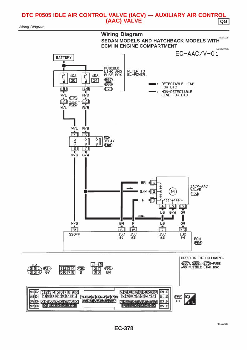
Wiring DiagramNJEC0284
SEDAN MODELS AND HATCHBACK MODELS WITHECM IN ENGINE COMPARTMENT
NJEC0284S01
HEC798
DTC P0505 IDLE AIR CONTROL VALVE (IACV) — AUXILIARY AIR CONTROL(AAC) VALVE QG
Wiring Diagram
EC-378
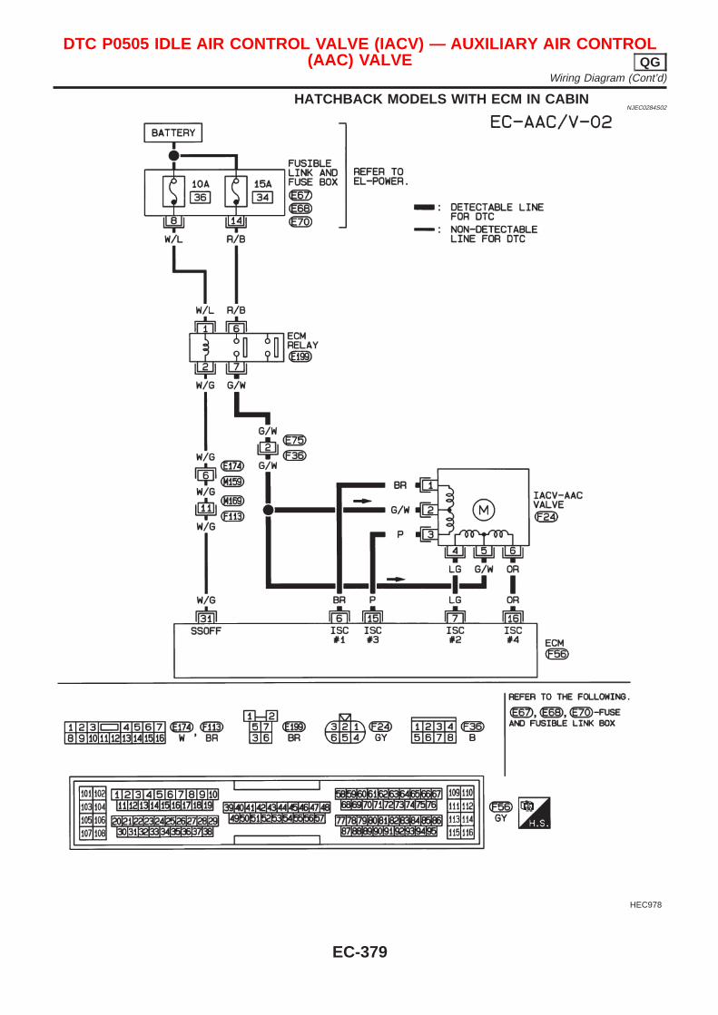
HATCHBACK MODELS WITH ECM IN CABINNJEC0284S02
HEC978
DTC P0505 IDLE AIR CONTROL VALVE (IACV) — AUXILIARY AIR CONTROL(AAC) VALVE QG
Wiring Diagram (Cont’d)
EC-379
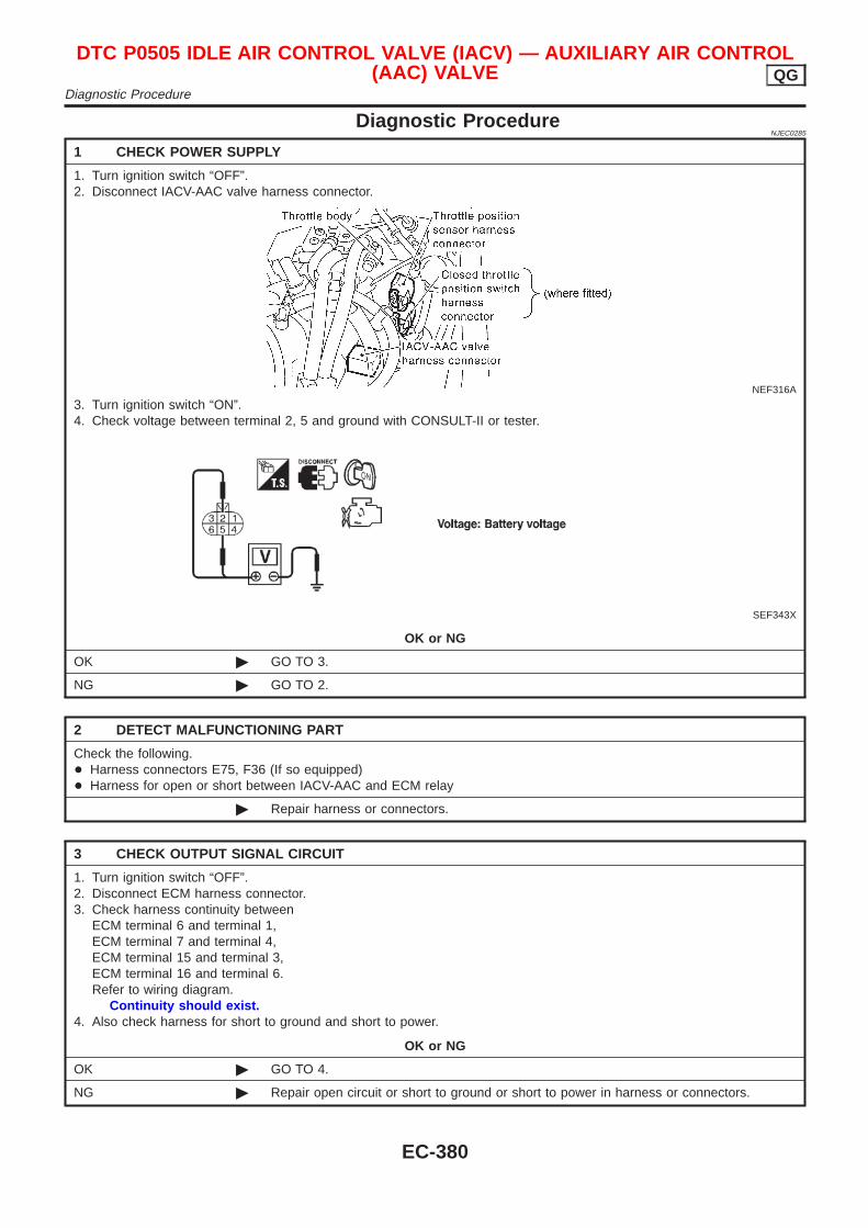
Diagnostic ProcedureNJEC0285
1 CHECK POWER SUPPLY
1. Turn ignition switch “OFF”.2. Disconnect IACV-AAC valve harness connector.
NEF316A
3. Turn ignition switch “ON”.4. Check voltage between terminal 2, 5 and ground with CONSULT-II or tester.
SEF343X
OK or NG
OK © GO TO 3.
NG © GO TO 2.
2 DETECT MALFUNCTIONING PART
Check the following.+ Harness connectors E75, F36 (If so equipped)+ Harness for open or short between IACV-AAC and ECM relay
© Repair harness or connectors.
3 CHECK OUTPUT SIGNAL CIRCUIT
1. Turn ignition switch “OFF”.2. Disconnect ECM harness connector.3. Check harness continuity between
ECM terminal 6 and terminal 1,ECM terminal 7 and terminal 4,ECM terminal 15 and terminal 3,ECM terminal 16 and terminal 6.Refer to wiring diagram.
Continuity should exist.4. Also check harness for short to ground and short to power.
OK or NG
OK © GO TO 4.
NG © Repair open circuit or short to ground or short to power in harness or connectors.
DTC P0505 IDLE AIR CONTROL VALVE (IACV) — AUXILIARY AIR CONTROL(AAC) VALVE QG
Diagnostic Procedure
EC-380
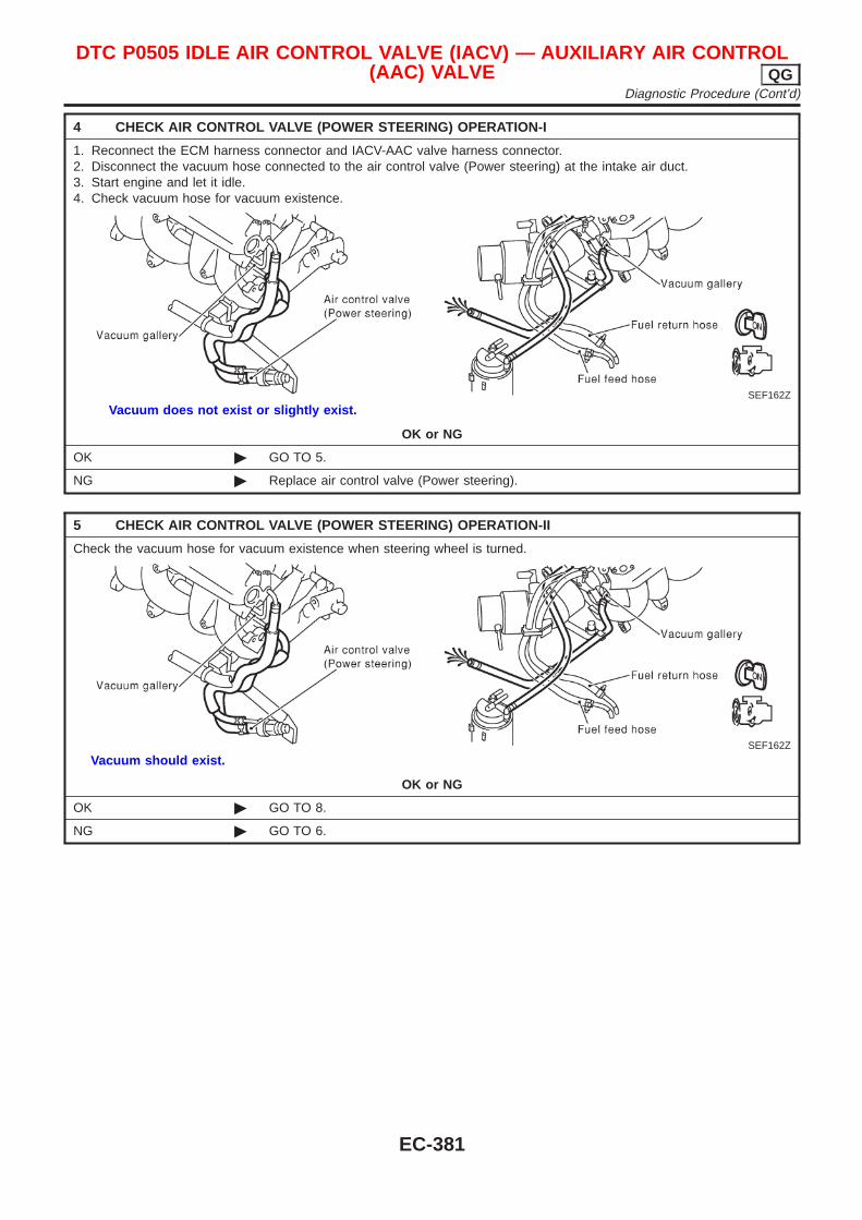
4 CHECK AIR CONTROL VALVE (POWER STEERING) OPERATION-I
1. Reconnect the ECM harness connector and IACV-AAC valve harness connector.2. Disconnect the vacuum hose connected to the air control valve (Power steering) at the intake air duct.3. Start engine and let it idle.4. Check vacuum hose for vacuum existence.
SEF162Z
Vacuum does not exist or slightly exist.
OK or NG
OK © GO TO 5.
NG © Replace air control valve (Power steering).
5 CHECK AIR CONTROL VALVE (POWER STEERING) OPERATION-II
Check the vacuum hose for vacuum existence when steering wheel is turned.
SEF162Z
Vacuum should exist.
OK or NG
OK © GO TO 8.
NG © GO TO 6.
DTC P0505 IDLE AIR CONTROL VALVE (IACV) — AUXILIARY AIR CONTROL(AAC) VALVE QG
Diagnostic Procedure (Cont’d)
EC-381
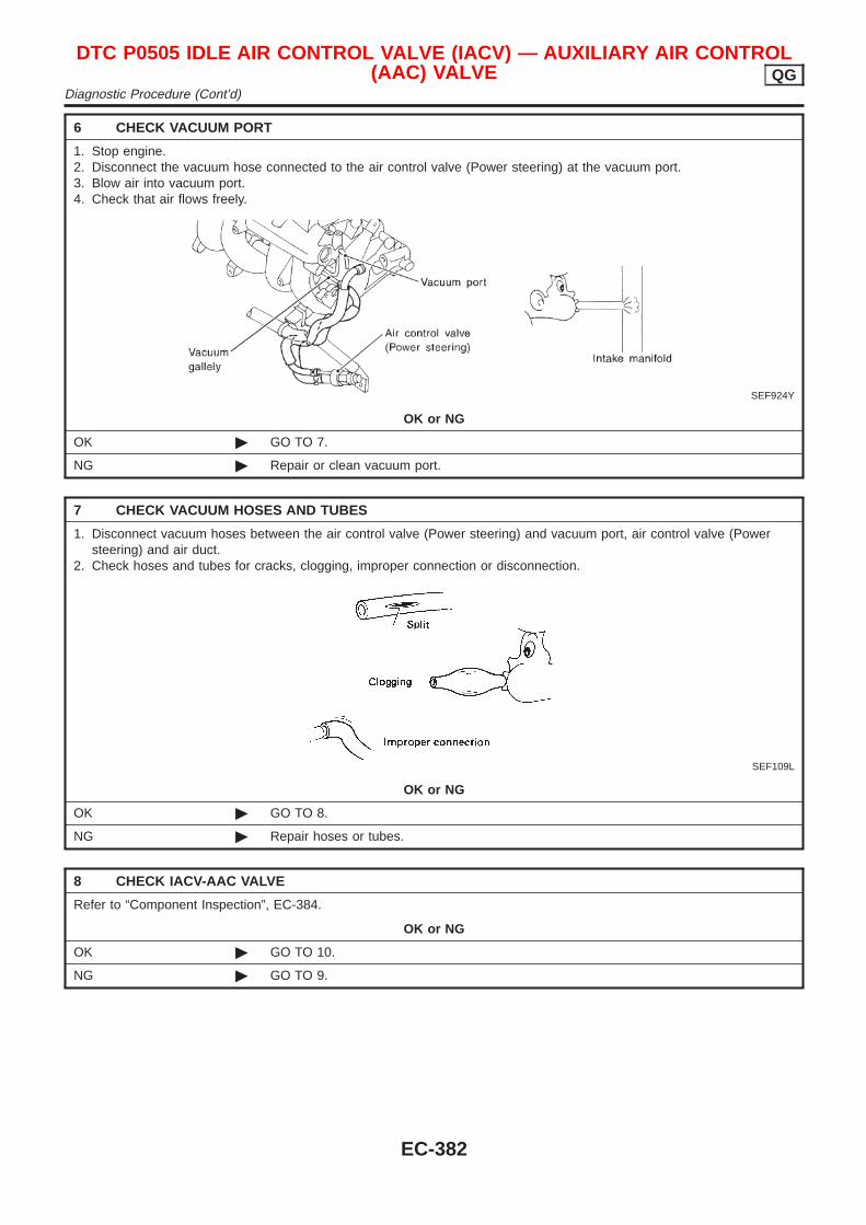
6 CHECK VACUUM PORT
1. Stop engine.2. Disconnect the vacuum hose connected to the air control valve (Power steering) at the vacuum port.3. Blow air into vacuum port.4. Check that air flows freely.
SEF924Y
OK or NG
OK © GO TO 7.
NG © Repair or clean vacuum port.
7 CHECK VACUUM HOSES AND TUBES
1. Disconnect vacuum hoses between the air control valve (Power steering) and vacuum port, air control valve (Powersteering) and air duct.
2. Check hoses and tubes for cracks, clogging, improper connection or disconnection.
SEF109L
OK or NG
OK © GO TO 8.
NG © Repair hoses or tubes.
8 CHECK IACV-AAC VALVE
Refer to “Component Inspection”, EC-384.
OK or NG
OK © GO TO 10.
NG © GO TO 9.
DTC P0505 IDLE AIR CONTROL VALVE (IACV) — AUXILIARY AIR CONTROL(AAC) VALVE QG
Diagnostic Procedure (Cont’d)
EC-382
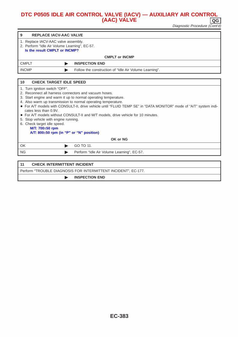
9 REPLACE IACV-AAC VALVE
1. Replace IACV-AAC valve assembly.2. Perform “Idle Air Volume Learning”, EC-57.
Is the result CMPLT or INCMP?
CMPLT or INCMP
CMPLT © INSPECTION END
INCMP © Follow the construction of “Idle Air Volume Learning”.
10 CHECK TARGET IDLE SPEED
1. Turn ignition switch “OFF”.2. Reconnect all harness connectors and vacuum hoses.3. Start engine and warm it up to normal operating temperature.4. Also warm up transmission to normal operating temperature.+ For A/T models with CONSULT-II, drive vehicle until “FLUID TEMP SE” in “DATA MONITOR” mode of “A/T” system indi-
cates less than 0.9V.+ For A/T models without CONSULT-II and M/T models, drive vehicle for 10 minutes.5. Stop vehicle with engine running.6. Check target idle speed.
M/T: 700±50 rpmA/T: 800±50 rpm (in “P” or “N” position)
OK or NG
OK © GO TO 11.
NG © Perform “Idle Air Volume Learning”, EC-57.
11 CHECK INTERMITTENT INCIDENT
Perform “TROUBLE DIAGNOSIS FOR INTERMITTENT INCIDENT”, EC-177.
© INSPECTION END
DTC P0505 IDLE AIR CONTROL VALVE (IACV) — AUXILIARY AIR CONTROL(AAC) VALVE QG
Diagnostic Procedure (Cont’d)
EC-383
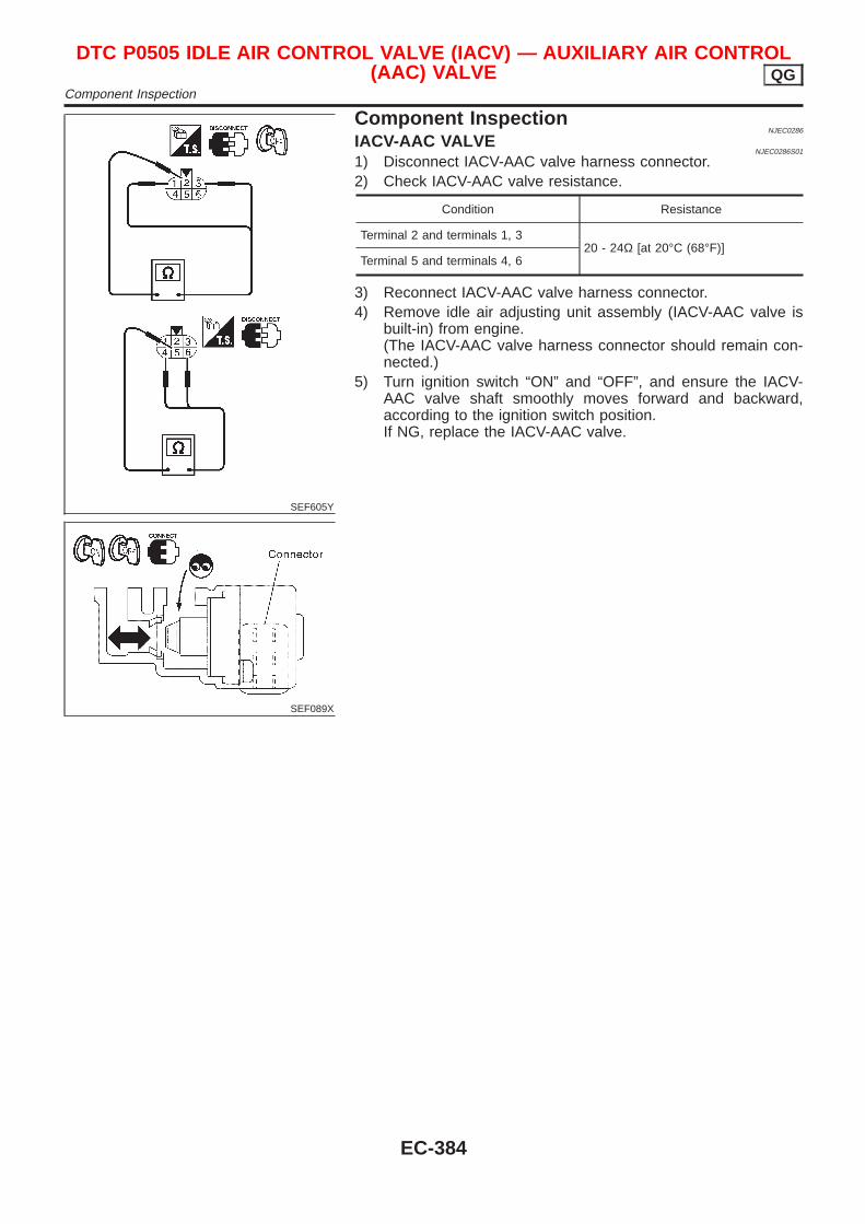
SEF605Y
SEF089X
Component InspectionNJEC0286
IACV-AAC VALVENJEC0286S01
1) Disconnect IACV-AAC valve harness connector.2) Check IACV-AAC valve resistance.
Condition Resistance
Terminal 2 and terminals 1, 320 - 24Ω [at 20°C (68°F)]
Terminal 5 and terminals 4, 6
3) Reconnect IACV-AAC valve harness connector.4) Remove idle air adjusting unit assembly (IACV-AAC valve is
built-in) from engine.(The IACV-AAC valve harness connector should remain con-nected.)
5) Turn ignition switch “ON” and “OFF”, and ensure the IACV-AAC valve shaft smoothly moves forward and backward,according to the ignition switch position.If NG, replace the IACV-AAC valve.
DTC P0505 IDLE AIR CONTROL VALVE (IACV) — AUXILIARY AIR CONTROL(AAC) VALVE QG
Component Inspection
EC-384
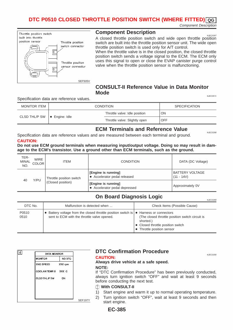
SEF505V
Component DescriptionNJEC0287
A closed throttle position switch and wide open throttle positionswitch are built into the throttle position sensor unit. The wide openthrottle position switch is used only for A/T control.When the throttle valve is in the closed position, the closed throttleposition switch sends a voltage signal to the ECM. The ECM onlyuses this signal to open or close the EVAP canister purge controlvalve when the throttle position sensor is malfunctioning.
CONSULT-II Reference Value in Data MonitorMode
NJEC0571
Specification data are reference values.
MONITOR ITEM CONDITION SPECIFICATION
CLSD THL/P SW + Engine: IdleThrottle valve: Idle position ON
Throttle valve: Slightly open OFF
ECM Terminals and Reference ValueNJEC0288
Specification data are reference values and are measured between each terminal and ground.CAUTION:Do not use ECM ground terminals when measuring input/output voltage. Doing so may result in dam-age to the ECM’s transistor. Use a ground other than ECM terminals, such as the ground.
TER-MINAL
NO.
WIRECOLOR
ITEM CONDITION DATA (DC Voltage)
40 Y/PUThrottle position switch(Closed position)
[Engine is running]+ Accelerator pedal released
BATTERY VOLTAGE(11 - 14V)
[Engine is running]+ Accelerator pedal depressed
Approximately 0V
On Board Diagnosis LogicNJEC0289
DTC No. Malfunction is detected when ... Check Items (Possible Cause)
P05100510
+ Battery voltage from the closed throttle position switch issent to ECM with the throttle valve opened.
+ Harness or connectors(The closed throttle position switch circuit isshorted.)
+ Closed throttle position switch+ Throttle position sensor
SEF197Y
DTC Confirmation ProcedureNJEC0290
CAUTION:Always drive vehicle at a safe speed.NOTE:If “DTC Confirmation Procedure” has been previously conducted,always turn ignition switch “OFF” and wait at least 9 secondsbefore conducting the next test.
With CONSULT-II1) Start engine and warm it up to normal operating temperature.2) Turn ignition switch “OFF”, wait at least 9 seconds and then
start engine.
DTC P0510 CLOSED THROTTLE POSITION SWITCH (WHERE FITTED) QGComponent Description
EC-385
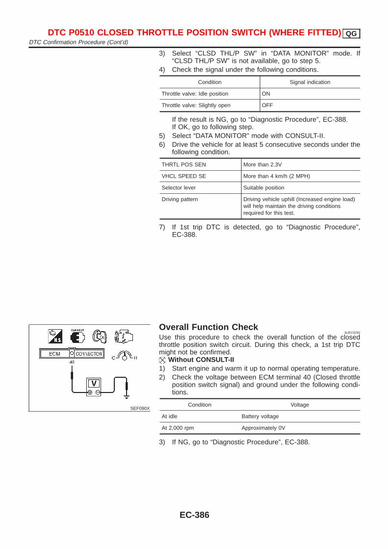
3) Select “CLSD THL/P SW” in “DATA MONITOR” mode. If“CLSD THL/P SW” is not available, go to step 5.
4) Check the signal under the following conditions.
Condition Signal indication
Throttle valve: Idle position ON
Throttle valve: Slightly open OFF
If the result is NG, go to “Diagnostic Procedure”, EC-388.If OK, go to following step.
5) Select “DATA MONITOR” mode with CONSULT-II.6) Drive the vehicle for at least 5 consecutive seconds under the
following condition.
THRTL POS SEN More than 2.3V
VHCL SPEED SE More than 4 km/h (2 MPH)
Selector lever Suitable position
Driving pattern Driving vehicle uphill (Increased engine load)will help maintain the driving conditionsrequired for this test.
7) If 1st trip DTC is detected, go to “Diagnostic Procedure”,EC-388.
SEF090X
Overall Function CheckNJEC0291
Use this procedure to check the overall function of the closedthrottle position switch circuit. During this check, a 1st trip DTCmight not be confirmed.
Without CONSULT-II1) Start engine and warm it up to normal operating temperature.2) Check the voltage between ECM terminal 40 (Closed throttle
position switch signal) and ground under the following condi-tions.
Condition Voltage
At idle Battery voltage
At 2,000 rpm Approximately 0V
3) If NG, go to “Diagnostic Procedure”, EC-388.
DTC P0510 CLOSED THROTTLE POSITION SWITCH (WHERE FITTED) QGDTC Confirmation Procedure (Cont’d)
EC-386
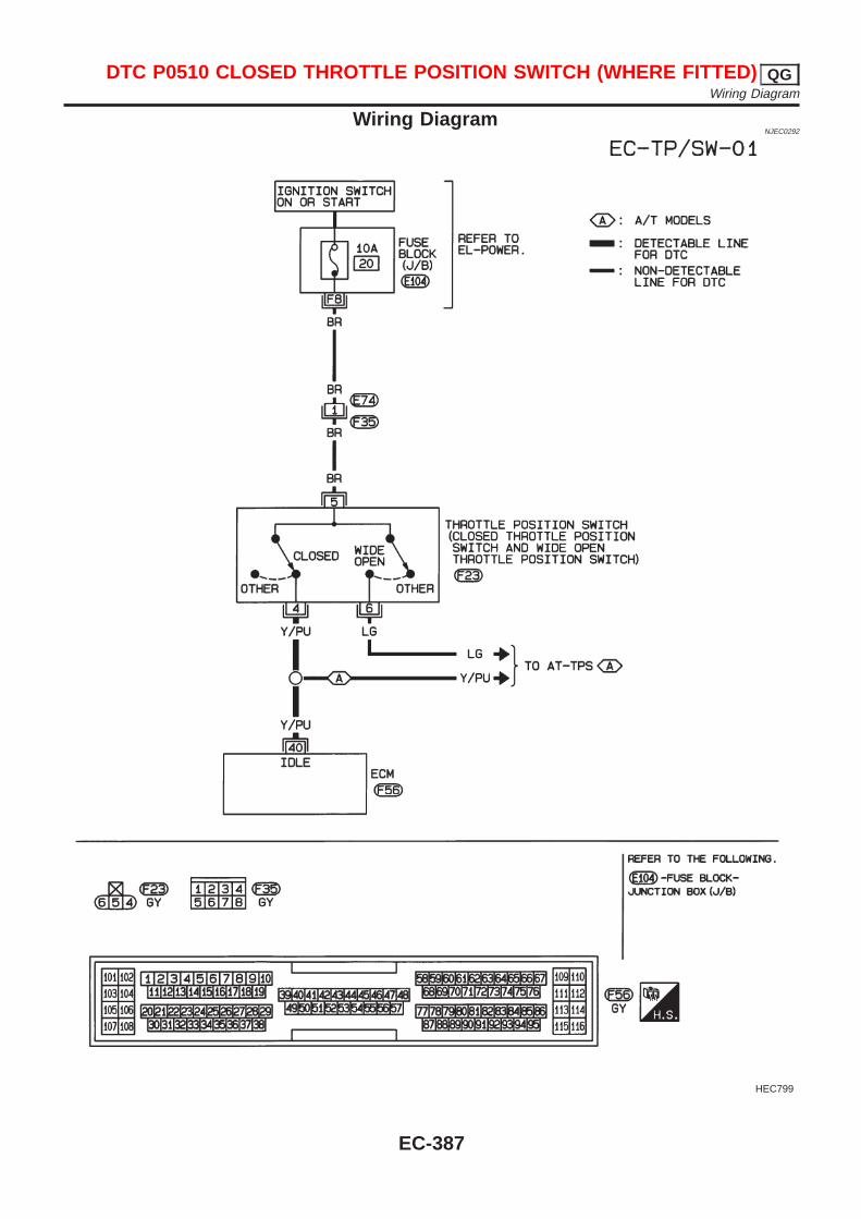
Wiring DiagramNJEC0292
HEC799
DTC P0510 CLOSED THROTTLE POSITION SWITCH (WHERE FITTED) QGWiring Diagram
EC-387
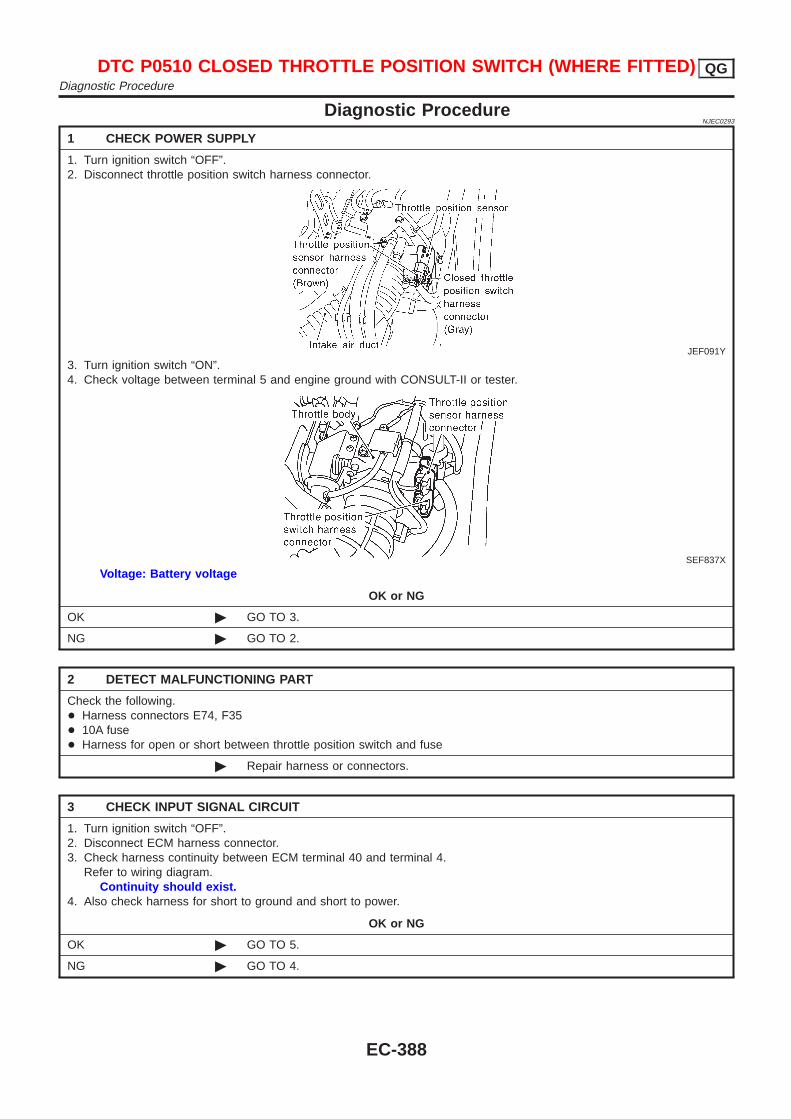
Diagnostic ProcedureNJEC0293
1 CHECK POWER SUPPLY
1. Turn ignition switch “OFF”.2. Disconnect throttle position switch harness connector.
JEF091Y
3. Turn ignition switch “ON”.4. Check voltage between terminal 5 and engine ground with CONSULT-II or tester.
SEF837X
Voltage: Battery voltage
OK or NG
OK © GO TO 3.
NG © GO TO 2.
2 DETECT MALFUNCTIONING PART
Check the following.+ Harness connectors E74, F35+ 10A fuse+ Harness for open or short between throttle position switch and fuse
© Repair harness or connectors.
3 CHECK INPUT SIGNAL CIRCUIT
1. Turn ignition switch “OFF”.2. Disconnect ECM harness connector.3. Check harness continuity between ECM terminal 40 and terminal 4.
Refer to wiring diagram.Continuity should exist.
4. Also check harness for short to ground and short to power.
OK or NG
OK © GO TO 5.
NG © GO TO 4.
DTC P0510 CLOSED THROTTLE POSITION SWITCH (WHERE FITTED) QGDiagnostic Procedure
EC-388
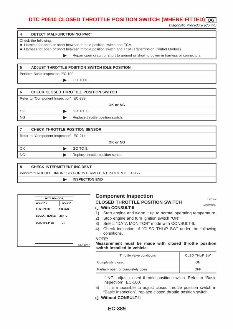
4 DETECT MALFUNCTIONING PART
Check the following.+ Harness for open or short between throttle position switch and ECM+ Harness for open or short between throttle position switch and TCM (Transmission Control Module)
© Repair open circuit or short to ground or short to power in harness or connectors.
5 ADJUST THROTTLE POSITION SWITCH IDLE POSITION
Perform Basic Inspection, EC-100.
© GO TO 6.
6 CHECK CLOSED THROTTLE POSITION SWITCH
Refer to “Component Inspection”, EC-389.
OK or NG
OK © GO TO 7.
NG © Replace throttle position switch.
7 CHECK THROTTLE POSITION SENSOR
Refer to “Component Inspection”, EC-214.
OK or NG
OK © GO TO 8.
NG © Replace throttle position sensor.
8 CHECK INTERMITTENT INCIDENT
Perform “TROUBLE DIAGNOSIS FOR INTERMITTENT INCIDENT”, EC-177.
© INSPECTION END
SEF197Y
Component InspectionNJEC0294
CLOSED THROTTLE POSITION SWITCHNJEC0294S01
With CONSULT-II1) Start engine and warm it up to normal operating temperature.2) Stop engine and turn ignition switch “ON”.3) Select “DATA MONITOR” mode with CONSULT-II.4) Check indication of “CLSD THL/P SW” under the following
conditions.NOTE:Measurement must be made with closed throttle positionswitch installed in vehicle.
Throttle valve conditions CLSD THL/P SW
Completely closed ON
Partially open or completely open OFF
If NG, adjust closed throttle position switch. Refer to “BasicInspection”, EC-100.
5) If it is impossible to adjust closed throttle position switch in“Basic Inspection”, replace closed throttle position switch.
Without CONSULT-II
DTC P0510 CLOSED THROTTLE POSITION SWITCH (WHERE FITTED) QGDiagnostic Procedure (Cont’d)
EC-389
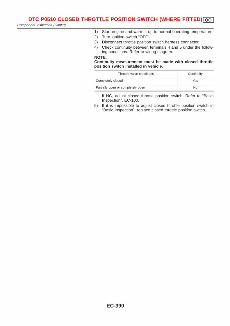
1) Start engine and warm it up to normal operating temperature.2) Turn ignition switch “OFF”.3) Disconnect throttle position switch harness connector.4) Check continuity between terminals 4 and 5 under the follow-
ing conditions. Refer to wiring diagram.NOTE:Continuity measurement must be made with closed throttleposition switch installed in vehicle.
Throttle valve conditions Continuity
Completely closed Yes
Partially open or completely open No
If NG, adjust closed throttle position switch. Refer to “BasicInspection”, EC-100.
5) If it is impossible to adjust closed throttle position switch in“Basic Inspection”, replace closed throttle position switch.
DTC P0510 CLOSED THROTTLE POSITION SWITCH (WHERE FITTED) QGComponent Inspection (Cont’d)
EC-390
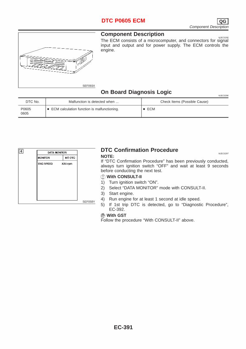
SEF093X
Component DescriptionNJEC0295
The ECM consists of a microcomputer, and connectors for signalinput and output and for power supply. The ECM controls theengine.
On Board Diagnosis LogicNJEC0296
DTC No. Malfunction is detected when ... Check Items (Possible Cause)
P06050605
+ ECM calculation function is malfunctioning. + ECM
SEF058Y
DTC Confirmation ProcedureNJEC0297
NOTE:If “DTC Confirmation Procedure” has been previously conducted,always turn ignition switch “OFF” and wait at least 9 secondsbefore conducting the next test.
With CONSULT-II1) Turn ignition switch “ON”.2) Select “DATA MONITOR” mode with CONSULT-II.3) Start engine.4) Run engine for at least 1 second at idle speed.5) If 1st trip DTC is detected, go to “Diagnostic Procedure”,
EC-392.With GST
Follow the procedure “With CONSULT-II” above.
DTC P0605 ECM QGComponent Description
EC-391
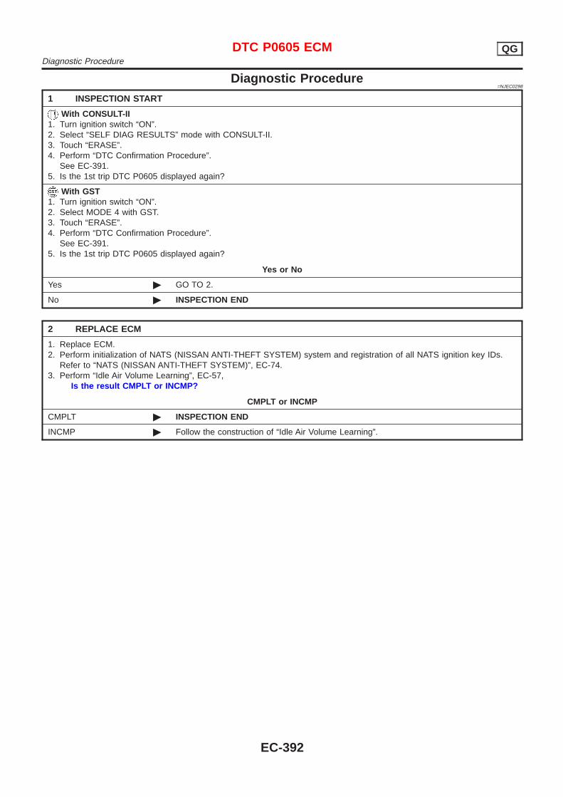
Diagnostic Procedure=NJEC0298
1 INSPECTION START
With CONSULT-II1. Turn ignition switch “ON”.2. Select “SELF DIAG RESULTS” mode with CONSULT-II.3. Touch “ERASE”.4. Perform “DTC Confirmation Procedure”.
See EC-391.5. Is the 1st trip DTC P0605 displayed again?
With GST1. Turn ignition switch “ON”.2. Select MODE 4 with GST.3. Touch “ERASE”.4. Perform “DTC Confirmation Procedure”.
See EC-391.5. Is the 1st trip DTC P0605 displayed again?
Yes or No
Yes © GO TO 2.
No © INSPECTION END
2 REPLACE ECM
1. Replace ECM.2. Perform initialization of NATS (NISSAN ANTI-THEFT SYSTEM) system and registration of all NATS ignition key IDs.
Refer to “NATS (NISSAN ANTI-THEFT SYSTEM)”, EC-74.3. Perform “Idle Air Volume Learning”, EC-57,
Is the result CMPLT or INCMP?
CMPLT or INCMP
CMPLT © INSPECTION END
INCMP © Follow the construction of “Idle Air Volume Learning”.
DTC P0605 ECM QGDiagnostic Procedure
EC-392
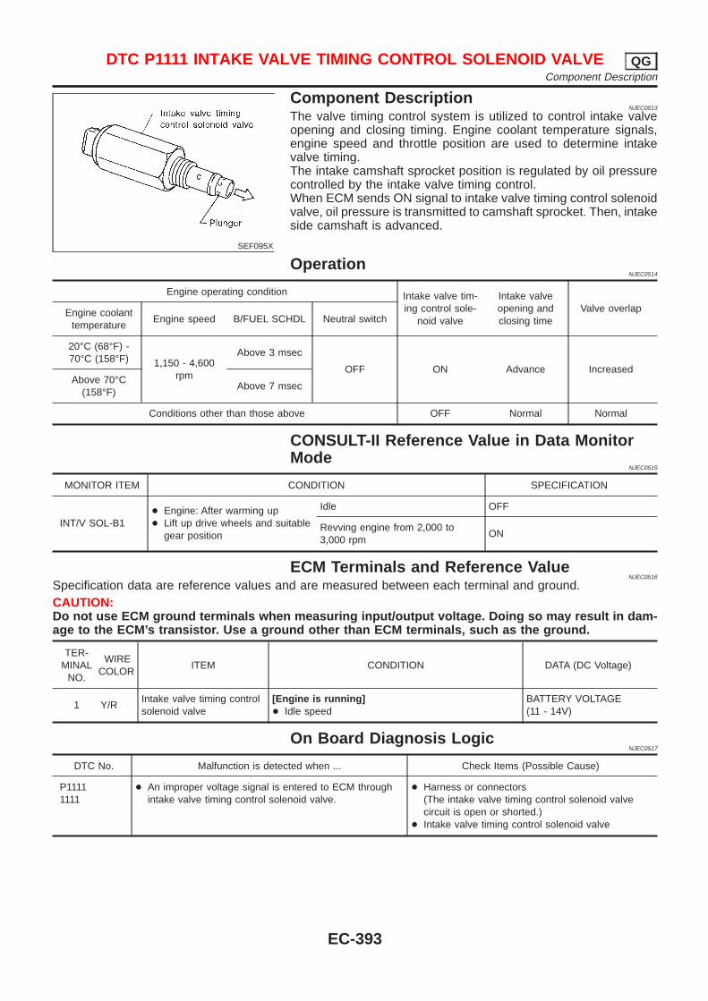
SEF095X
Component DescriptionNJEC0513
The valve timing control system is utilized to control intake valveopening and closing timing. Engine coolant temperature signals,engine speed and throttle position are used to determine intakevalve timing.The intake camshaft sprocket position is regulated by oil pressurecontrolled by the intake valve timing control.When ECM sends ON signal to intake valve timing control solenoidvalve, oil pressure is transmitted to camshaft sprocket. Then, intakeside camshaft is advanced.
OperationNJEC0514
Engine operating condition Intake valve tim-ing control sole-
noid valve
Intake valveopening andclosing time
Valve overlapEngine coolanttemperature
Engine speed B/FUEL SCHDL Neutral switch
20°C (68°F) -70°C (158°F) 1,150 - 4,600
rpm
Above 3 msec
OFF ON Advance IncreasedAbove 70°C
(158°F)Above 7 msec
Conditions other than those above OFF Normal Normal
CONSULT-II Reference Value in Data MonitorMode
NJEC0515
MONITOR ITEM CONDITION SPECIFICATION
INT/V SOL-B1+ Engine: After warming up+ Lift up drive wheels and suitable
gear position
Idle OFF
Revving engine from 2,000 to3,000 rpm
ON
ECM Terminals and Reference ValueNJEC0516
Specification data are reference values and are measured between each terminal and ground.CAUTION:Do not use ECM ground terminals when measuring input/output voltage. Doing so may result in dam-age to the ECM’s transistor. Use a ground other than ECM terminals, such as the ground.
TER-MINAL
NO.
WIRECOLOR
ITEM CONDITION DATA (DC Voltage)
1 Y/RIntake valve timing controlsolenoid valve
[Engine is running]+ Idle speed
BATTERY VOLTAGE(11 - 14V)
On Board Diagnosis LogicNJEC0517
DTC No. Malfunction is detected when ... Check Items (Possible Cause)
P11111111
+ An improper voltage signal is entered to ECM throughintake valve timing control solenoid valve.
+ Harness or connectors(The intake valve timing control solenoid valvecircuit is open or shorted.)
+ Intake valve timing control solenoid valve
DTC P1111 INTAKE VALVE TIMING CONTROL SOLENOID VALVE QGComponent Description
EC-393
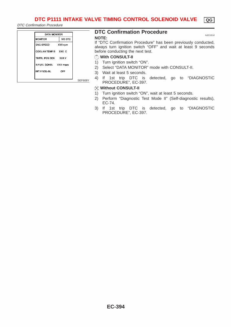
SEF608Y
DTC Confirmation ProcedureNJEC0518
NOTE:If “DTC Confirmation Procedure” has been previously conducted,always turn ignition switch “OFF” and wait at least 9 secondsbefore conducting the next test.
With CONSULT-II1) Turn ignition switch “ON”.2) Select “DATA MONITOR” mode with CONSULT-II.3) Wait at least 5 seconds.4) If 1st trip DTC is detected, go to “DIAGNOSTIC
PROCEDURE”, EC-397.Without CONSULT-II
1) Turn ignition switch “ON”, wait at least 5 seconds.2) Perform “Diagnostic Test Mode II” (Self-diagnostic results),
EC-74.3) If 1st trip DTC is detected, go to “DIAGNOSTIC
PROCEDURE”, EC-397.
DTC P1111 INTAKE VALVE TIMING CONTROL SOLENOID VALVE QGDTC Confirmation Procedure
EC-394
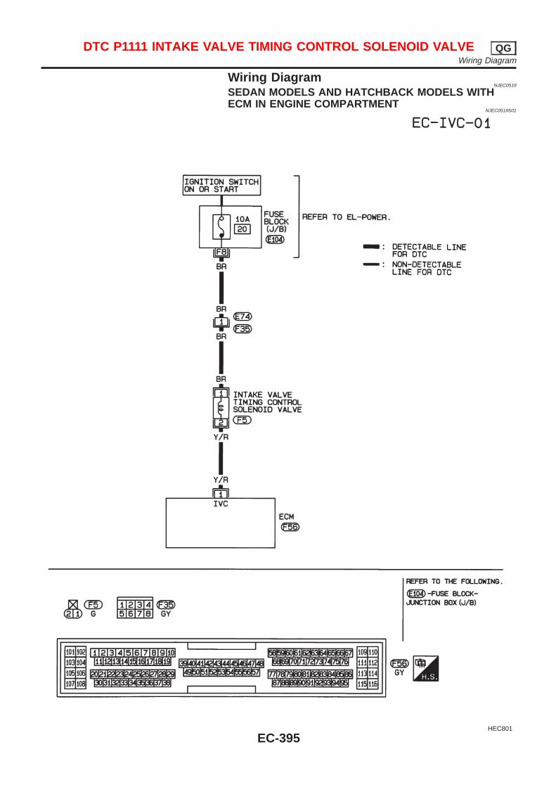
Wiring DiagramNJEC0519
SEDAN MODELS AND HATCHBACK MODELS WITHECM IN ENGINE COMPARTMENT
NJEC0519S01
HEC801
DTC P1111 INTAKE VALVE TIMING CONTROL SOLENOID VALVE QGWiring Diagram
EC-395
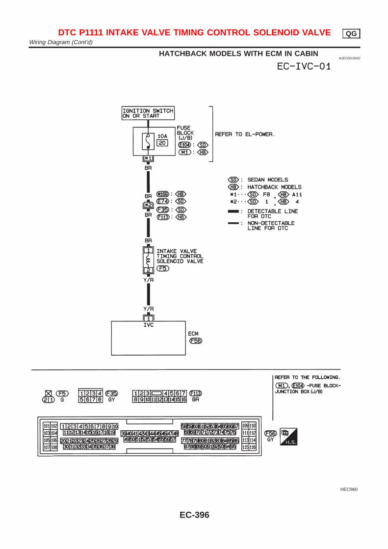
HATCHBACK MODELS WITH ECM IN CABINNJEC0519S02
HEC960
DTC P1111 INTAKE VALVE TIMING CONTROL SOLENOID VALVE QGWiring Diagram (Cont’d)
EC-396
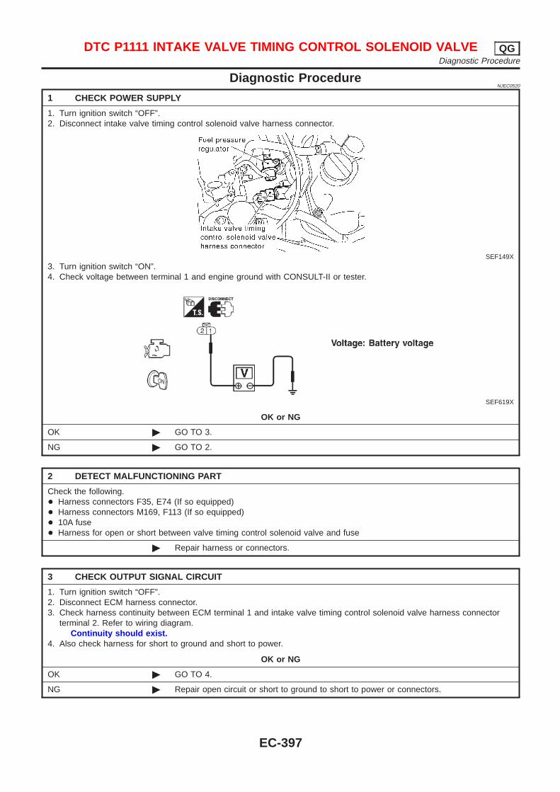
Diagnostic ProcedureNJEC0520
1 CHECK POWER SUPPLY
1. Turn ignition switch “OFF”.2. Disconnect intake valve timing control solenoid valve harness connector.
SEF149X
3. Turn ignition switch “ON”.4. Check voltage between terminal 1 and engine ground with CONSULT-II or tester.
SEF619X
OK or NG
OK © GO TO 3.
NG © GO TO 2.
2 DETECT MALFUNCTIONING PART
Check the following.+ Harness connectors F35, E74 (If so equipped)+ Harness connectors M169, F113 (If so equipped)+ 10A fuse+ Harness for open or short between valve timing control solenoid valve and fuse
© Repair harness or connectors.
3 CHECK OUTPUT SIGNAL CIRCUIT
1. Turn ignition switch “OFF”.2. Disconnect ECM harness connector.3. Check harness continuity between ECM terminal 1 and intake valve timing control solenoid valve harness connector
terminal 2. Refer to wiring diagram.Continuity should exist.
4. Also check harness for short to ground and short to power.
OK or NG
OK © GO TO 4.
NG © Repair open circuit or short to ground to short to power or connectors.
DTC P1111 INTAKE VALVE TIMING CONTROL SOLENOID VALVE QGDiagnostic Procedure
EC-397
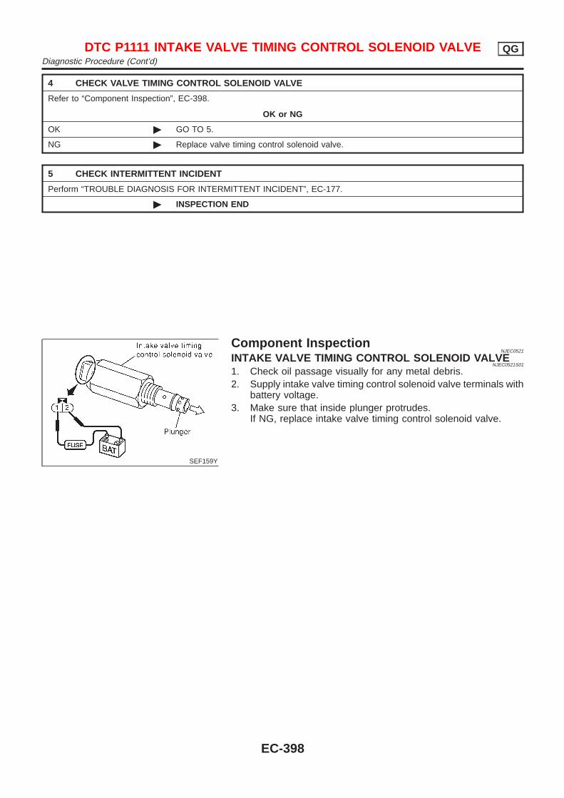
4 CHECK VALVE TIMING CONTROL SOLENOID VALVE
Refer to “Component Inspection”, EC-398.
OK or NG
OK © GO TO 5.
NG © Replace valve timing control solenoid valve.
5 CHECK INTERMITTENT INCIDENT
Perform “TROUBLE DIAGNOSIS FOR INTERMITTENT INCIDENT”, EC-177.
© INSPECTION END
SEF159Y
Component InspectionNJEC0521
INTAKE VALVE TIMING CONTROL SOLENOID VALVENJEC0521S01
1. Check oil passage visually for any metal debris.2. Supply intake valve timing control solenoid valve terminals with
battery voltage.3. Make sure that inside plunger protrudes.
If NG, replace intake valve timing control solenoid valve.
DTC P1111 INTAKE VALVE TIMING CONTROL SOLENOID VALVE QGDiagnostic Procedure (Cont’d)
EC-398

DescriptionNJEC0522
SYSTEM DESCRIPTIONNJEC0522S01
Sensor Input Signal to ECMECM func-
tionActuator
Throttle position sensor Throttle position
Swirl con-trol valvesystemcontrol
Swirl control valve control sole-noid valve via swirl controlvalve
Ignition switch Start signal
Crankshaft position sensor (POS) Engine speed
Camshaft position sensor (PHASE) Engine speed and cylinder number
Mass air flow sensor Amount of intake air
Engine coolant temperature sensor Engine coolant temperature
This system has a swirl control valve in the intake passage of each cylinder.While idling and during low engine speed operation, the swirl control valve closes. Thus the velocity of the airin the intake passage increases, promoting the vaporization of the fuel and producing a swirl in the combus-tion chamber.Because of this operation, this system tends to increase the burning speed of the gas mixture, improve fuelconsumption, and increase the stability in running conditions.Also, except when idling and during low engine speed operation, this system opens the swirl control valve.The solenoid valve controls swirl control valve’s shut/open condition. This solenoid valve is operated by theECM.
OPERATIONNJEC0522S02
Engine coolant tempera-ture
Throttle position sensor(Idle position)
Engine speedSwirl control valve con-
trol solenoid valveSwirl control valve
15 - 40°CON —
ON ClosedOFF Below 2,400 rpm*
Except above OFF Open
*: The value may vary according to accelerator pedal operation.
SEF081X
CONSULT-II Reference Value in Data MonitorMode
NJEC0523
Specification data are reference values.
MONITOR ITEM CONDITION SPECIFICATION
SWRL CONT S/V + Engine speed: Idle
Engine coolant temperature isbetween 15°C (59°F) to 40°C(104°F).
ON
Engine coolant temperature isabove 40°C (104°F).
OFF
DTC P1131 SWIRL CONTROL VALVE SOLENOID VALVE (CIRCUIT) (WHEREFITTED) QG
Description
EC-399
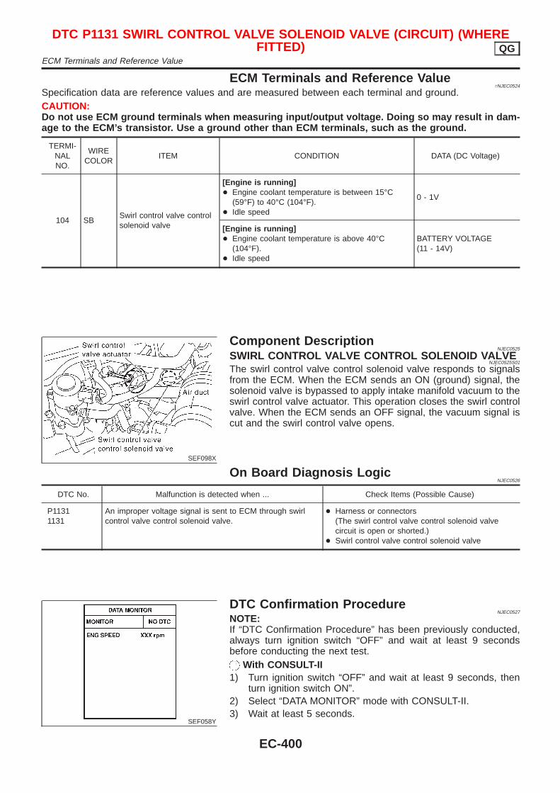
ECM Terminals and Reference Value=NJEC0524
Specification data are reference values and are measured between each terminal and ground.CAUTION:Do not use ECM ground terminals when measuring input/output voltage. Doing so may result in dam-age to the ECM’s transistor. Use a ground other than ECM terminals, such as the ground.
TERMI-NALNO.
WIRECOLOR
ITEM CONDITION DATA (DC Voltage)
104 SBSwirl control valve controlsolenoid valve
[Engine is running]+ Engine coolant temperature is between 15°C
(59°F) to 40°C (104°F).+ Idle speed
0 - 1V
[Engine is running]+ Engine coolant temperature is above 40°C
(104°F).+ Idle speed
BATTERY VOLTAGE(11 - 14V)
SEF098X
Component DescriptionNJEC0525
SWIRL CONTROL VALVE CONTROL SOLENOID VALVENJEC0525S01
The swirl control valve control solenoid valve responds to signalsfrom the ECM. When the ECM sends an ON (ground) signal, thesolenoid valve is bypassed to apply intake manifold vacuum to theswirl control valve actuator. This operation closes the swirl controlvalve. When the ECM sends an OFF signal, the vacuum signal iscut and the swirl control valve opens.
On Board Diagnosis LogicNJEC0526
DTC No. Malfunction is detected when ... Check Items (Possible Cause)
P11311131
An improper voltage signal is sent to ECM through swirlcontrol valve control solenoid valve.
+ Harness or connectors(The swirl control valve control solenoid valvecircuit is open or shorted.)
+ Swirl control valve control solenoid valve
SEF058Y
DTC Confirmation ProcedureNJEC0527
NOTE:If “DTC Confirmation Procedure” has been previously conducted,always turn ignition switch “OFF” and wait at least 9 secondsbefore conducting the next test.
With CONSULT-II1) Turn ignition switch “OFF” and wait at least 9 seconds, then
turn ignition switch ON”.2) Select “DATA MONITOR” mode with CONSULT-II.3) Wait at least 5 seconds.
DTC P1131 SWIRL CONTROL VALVE SOLENOID VALVE (CIRCUIT) (WHEREFITTED) QG
ECM Terminals and Reference Value
EC-400

If 1st trip DTC is detected, go to “DIAGNOSTICPROCEDURE”, EC-403.
With GSTFollow the procedure “With CONSULT-II” above.
DTC P1131 SWIRL CONTROL VALVE SOLENOID VALVE (CIRCUIT) (WHEREFITTED) QG
DTC Confirmation Procedure (Cont’d)
EC-401
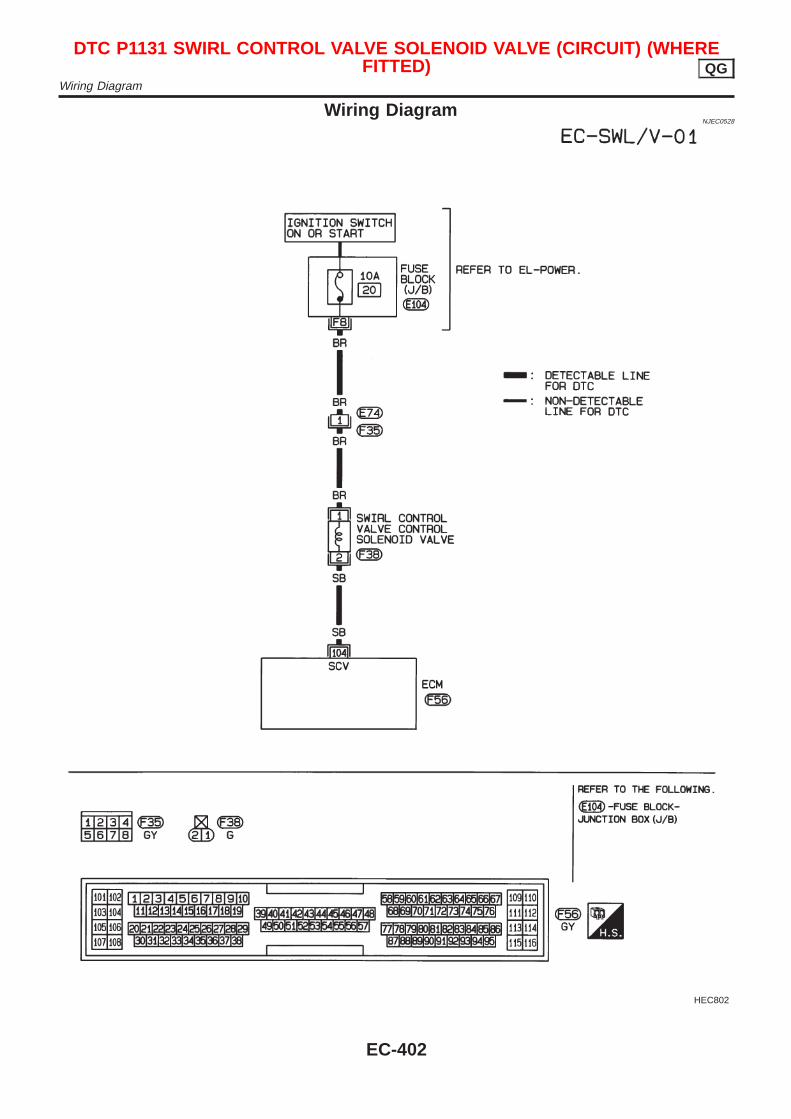
Wiring DiagramNJEC0528
HEC802
DTC P1131 SWIRL CONTROL VALVE SOLENOID VALVE (CIRCUIT) (WHEREFITTED) QG
Wiring Diagram
EC-402
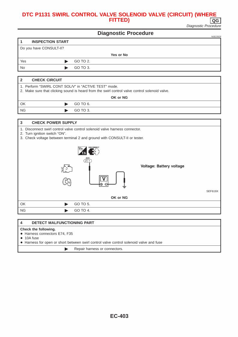
Diagnostic ProcedureNJEC0529
1 INSPECTION START
Do you have CONSULT-II?
Yes or No
Yes © GO TO 2.
No © GO TO 3.
2 CHECK CIRCUIT
1. Perform “SWIRL CONT SOL/V” in “ACTIVE TEST” mode.2. Make sure that clicking sound is heard from the swirl control valve control solenoid valve.
OK or NG
OK © GO TO 6.
NG © GO TO 3.
3 CHECK POWER SUPPLY
1. Disconnect swirl control valve control solenoid valve harness connector.2. Turn ignition switch “ON”.3. Check voltage between terminal 2 and ground with CONSULT-II or tester.
SEF619X
OK or NG
OK © GO TO 5.
NG © GO TO 4.
4 DETECT MALFUNCTIONING PART
Check the following.+ Harness connectors E74, F35+ 10A fuse+ Harness for open or short between swirl control valve control solenoid valve and fuse
© Repair harness or connectors.
DTC P1131 SWIRL CONTROL VALVE SOLENOID VALVE (CIRCUIT) (WHEREFITTED) QG
Diagnostic Procedure
EC-403
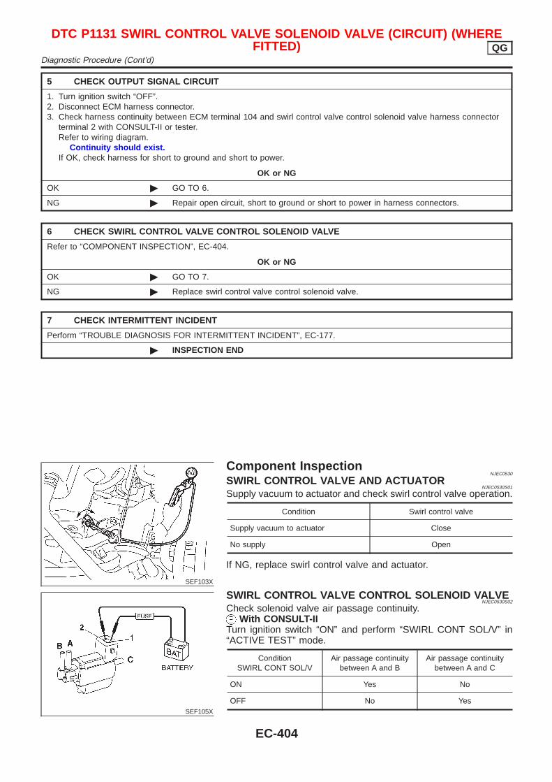
5 CHECK OUTPUT SIGNAL CIRCUIT
1. Turn ignition switch “OFF”.2. Disconnect ECM harness connector.3. Check harness continuity between ECM terminal 104 and swirl control valve control solenoid valve harness connector
terminal 2 with CONSULT-II or tester.Refer to wiring diagram.
Continuity should exist.If OK, check harness for short to ground and short to power.
OK or NG
OK © GO TO 6.
NG © Repair open circuit, short to ground or short to power in harness connectors.
6 CHECK SWIRL CONTROL VALVE CONTROL SOLENOID VALVE
Refer to “COMPONENT INSPECTION”, EC-404.
OK or NG
OK © GO TO 7.
NG © Replace swirl control valve control solenoid valve.
7 CHECK INTERMITTENT INCIDENT
Perform “TROUBLE DIAGNOSIS FOR INTERMITTENT INCIDENT”, EC-177.
© INSPECTION END
SEF103X
Component InspectionNJEC0530
SWIRL CONTROL VALVE AND ACTUATORNJEC0530S01
Supply vacuum to actuator and check swirl control valve operation.
Condition Swirl control valve
Supply vacuum to actuator Close
No supply Open
If NG, replace swirl control valve and actuator.
SEF105X
SWIRL CONTROL VALVE CONTROL SOLENOID VALVENJEC0530S02
Check solenoid valve air passage continuity.With CONSULT-II
Turn ignition switch “ON” and perform “SWIRL CONT SOL/V” in“ACTIVE TEST” mode.
ConditionSWIRL CONT SOL/V
Air passage continuitybetween A and B
Air passage continuitybetween A and C
ON Yes No
OFF No Yes
DTC P1131 SWIRL CONTROL VALVE SOLENOID VALVE (CIRCUIT) (WHEREFITTED) QG
Diagnostic Procedure (Cont’d)
EC-404
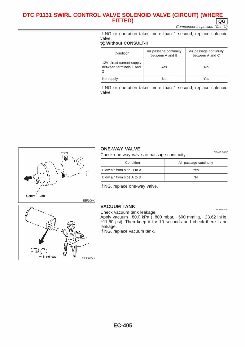
If NG or operation takes more than 1 second, replace solenoidvalve.
Without CONSULT-II
ConditionAir passage continuity
between A and BAir passage continuity
between A and C
12V direct current supplybetween terminals 1 and2
Yes No
No supply No Yes
If NG or operation takes more than 1 second, replace solenoidvalve.
SEF106X
ONE-WAY VALVENJEC0530S03
Check one-way valve air passage continuity.
Condition Air passage continuity
Blow air from side B to A Yes
Blow air from side A to B No
If NG, replace one-way valve.
SEF405S
VACUUM TANKNJEC0530S04
Check vacuum tank leakage.Apply vacuum −80.0 kPa (−800 mbar, −600 mmHg, −23.62 inHg,−11.60 psi). Then keep it for 10 seconds and check there is noleakage.If NG, replace vacuum tank.
DTC P1131 SWIRL CONTROL VALVE SOLENOID VALVE (CIRCUIT) (WHEREFITTED) QG
Component Inspection (Cont’d)
EC-405
System DescriptionNJEC0433
COOLING FAN CONTROLNJEC0433S01
Sensor Input Signal to ECMECM func-
tionActuator
Vehicle speed sensor Vehicle speed
Cooling fancontrol
Cooling fan relay(s)
Engine coolant temperature sensor Engine coolant temperature
Air conditioner switch Air conditioner “ON” signal
Ignition switch Start signal
Refrigerant pressure sensor Refrigerant pressure
The ECM controls the cooling fan corresponding to the vehicle speed, engine coolant temperature, refriger-ant pressure, and air conditioner ON signal. The control system has ON-OFF control.
OPERATIONNJEC0433S02
Engine coolant temperatures at which the cooling fan turns “ON” are indicated in the Table below.
Vehicle speed km/h (MPH)
Air conditioner switchHigh pressure of
refrigerantkPa (bar, kg/cm2, psi)
Less than 50 (30) 50 - 80 (30 - 50) More than 80 (50)
ON
More than 1,680(16.8, 17.14, 244)
Always Always More than 95°C (203°F)
Less than 1,680(16.8, 17.14, 244)
Always More than 95°C (203°F) More than 95°C (203°F)
OFFMore than 100°C
(212°F)More than 95°C (203°F) More than 95°C (203°F)
CONSULT-II Reference Value in Data MonitorMode
NJEC0486
Specification data are reference values.
MONITOR ITEM CONDITION SPECIFICATION
AIR COND SIG+ Engine: After warming up, idle
the engine
Air conditioner switch: OFF OFF
Air conditioner switch: ON(Compressor operates)
ON
COOLING FAN+ After warming up engine, idle
the engine.+ Air conditioner switch: OFF
Engine coolant temperature is lessthan 100°C (212°F)
OFF
Engine coolant temperature is100°C (212°F) or more
ON
DTC P1217 OVERHEAT (COOLING SYSTEM) QGSystem Description
EC-406
ECM Terminals and Reference Value=NJEC0487
Specification data are reference values and are measured between each terminal and ground.CAUTION:Do not use ECM ground terminals when measuring input/output voltage. Doing so may result in dam-age to the ECM’s transistor. Use a ground other than ECM terminals, such as the ground.
TERMI-NALNO.
WIRECOLOR
ITEM CONDITION DATA (DC Voltage)
13 LG/R Cooling fan relay
[Engine is running]+ Cooling fan is not operating
BATTERY VOLTAGE(11 - 14V)
[Engine is running]+ Cooling fan is operating
0 - 0.6V
23 L/W Air conditioner switch
[Engine is running]+ Both air conditioner switch and blower switch are
“ON” (Compressor operates)Approximately 0V
[Engine is running]+ Air conditioner switch is “OFF”
BATTERY VOLTAGE(11 - 14V)
On Board Diagnosis LogicNJEC0572
If the cooling fan or another component in the cooling system malfunctions, engine coolant temperature willrise.When the engine coolant temperature reaches an abnormally high temperature condition, a malfunction isindicated.
DTC No. Malfunction is detected when ... Check Items (Possible Cause)
P12171217
+ The engine coolant temperature is extraordinary high,even when the load is not heavy.
+ Harness or connectors(The cooling fan circuit is open or shorted)
+ Cooling fan+ Thermostat+ Improper ignition timing+ Engine coolant temperature sensor+ Blocked radiator+ Blocked front end (Improper fitting of nose mask)+ Crushed vehicle frontal area (Vehicle frontal is
collided but not repaired)+ Blocked air passage by improper installation of
front fog lamp or fog lamps.+ Improper mixture ratio of coolant+ Damaged bumperFor more information, refer to “MAIN 12 CAUSESOF OVERHEATING”, EC-416.
CAUTION:When a malfunction is indicated, be sure to replace the coolant following the procedure in the LC-18,“Changing Engine Coolant”. Also, replace the engine oil.1) Fill radiator with coolant up to specified level with a filling speed of 2 liters per minute. Be sure to use
coolant with the proper mixture ratio. Refer to MA-18, “Anti-freeze Coolant Mixture Ratio”, “RECOM-MENDED FLUIDS AND LUBRICANTS”.
2) After refilling coolant, run engine to ensure that no water-flow noise is emitted.
DTC P1217 OVERHEAT (COOLING SYSTEM) QGECM Terminals and Reference Value
EC-407
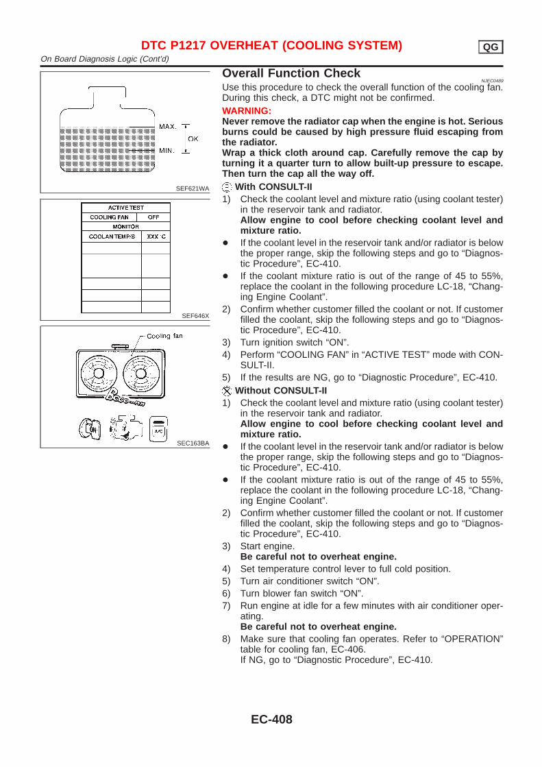
SEF621WA
SEF646X
SEC163BA
Overall Function CheckNJEC0489
Use this procedure to check the overall function of the cooling fan.During this check, a DTC might not be confirmed.WARNING:Never remove the radiator cap when the engine is hot. Seriousburns could be caused by high pressure fluid escaping fromthe radiator.Wrap a thick cloth around cap. Carefully remove the cap byturning it a quarter turn to allow built-up pressure to escape.Then turn the cap all the way off.
With CONSULT-II1) Check the coolant level and mixture ratio (using coolant tester)
in the reservoir tank and radiator.Allow engine to cool before checking coolant level andmixture ratio.
+ If the coolant level in the reservoir tank and/or radiator is belowthe proper range, skip the following steps and go to “Diagnos-tic Procedure”, EC-410.
+ If the coolant mixture ratio is out of the range of 45 to 55%,replace the coolant in the following procedure LC-18, “Chang-ing Engine Coolant”.
2) Confirm whether customer filled the coolant or not. If customerfilled the coolant, skip the following steps and go to “Diagnos-tic Procedure”, EC-410.
3) Turn ignition switch “ON”.4) Perform “COOLING FAN” in “ACTIVE TEST” mode with CON-
SULT-II.5) If the results are NG, go to “Diagnostic Procedure”, EC-410.
Without CONSULT-II1) Check the coolant level and mixture ratio (using coolant tester)
in the reservoir tank and radiator.Allow engine to cool before checking coolant level andmixture ratio.
+ If the coolant level in the reservoir tank and/or radiator is belowthe proper range, skip the following steps and go to “Diagnos-tic Procedure”, EC-410.
+ If the coolant mixture ratio is out of the range of 45 to 55%,replace the coolant in the following procedure LC-18, “Chang-ing Engine Coolant”.
2) Confirm whether customer filled the coolant or not. If customerfilled the coolant, skip the following steps and go to “Diagnos-tic Procedure”, EC-410.
3) Start engine.Be careful not to overheat engine.
4) Set temperature control lever to full cold position.5) Turn air conditioner switch “ON”.6) Turn blower fan switch “ON”.7) Run engine at idle for a few minutes with air conditioner oper-
ating.Be careful not to overheat engine.
8) Make sure that cooling fan operates. Refer to “OPERATION”table for cooling fan, EC-406.If NG, go to “Diagnostic Procedure”, EC-410.
DTC P1217 OVERHEAT (COOLING SYSTEM) QGOn Board Diagnosis Logic (Cont’d)
EC-408
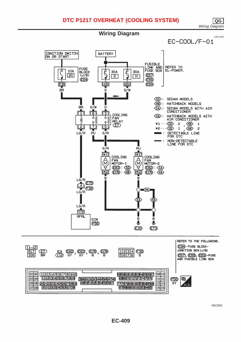
Wiring DiagramNJEC0490
HEC805
DTC P1217 OVERHEAT (COOLING SYSTEM) QGWiring Diagram
EC-409
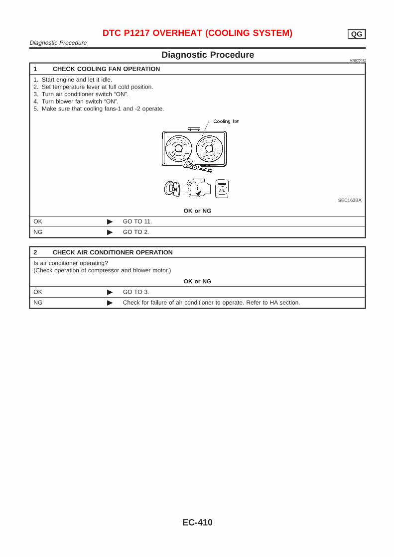
Diagnostic ProcedureNJEC0491
1 CHECK COOLING FAN OPERATION
1. Start engine and let it idle.2. Set temperature lever at full cold position.3. Turn air conditioner switch “ON”.4. Turn blower fan switch “ON”.5. Make sure that cooling fans-1 and -2 operate.
SEC163BA
OK or NG
OK © GO TO 11.
NG © GO TO 2.
2 CHECK AIR CONDITIONER OPERATION
Is air conditioner operating?(Check operation of compressor and blower motor.)
OK or NG
OK © GO TO 3.
NG © Check for failure of air conditioner to operate. Refer to HA section.
DTC P1217 OVERHEAT (COOLING SYSTEM) QGDiagnostic Procedure
EC-410

3 CHECK POWER SUPPLY
1. Turn ignition switch “OFF”.2. Disconnect cooling fan relay.
SEF628Y
3. Turn ignition switch “ON”.4. Check voltage between terminals 1, 3, 6 and ground with CONSULT-II or tester.
SEF590X
OK or NG
OK © GO TO 5.
NG © GO TO 4.
4 DETECT MALFUNCTIONING PART
Check the following.+ 10A fuse+ 30A fusible link+ Harness for open or short between cooling fan relay and fuse
© Repair open circuit or short to ground or short to power in harness or connectors.
DTC P1217 OVERHEAT (COOLING SYSTEM) QGDiagnostic Procedure (Cont’d)
EC-411
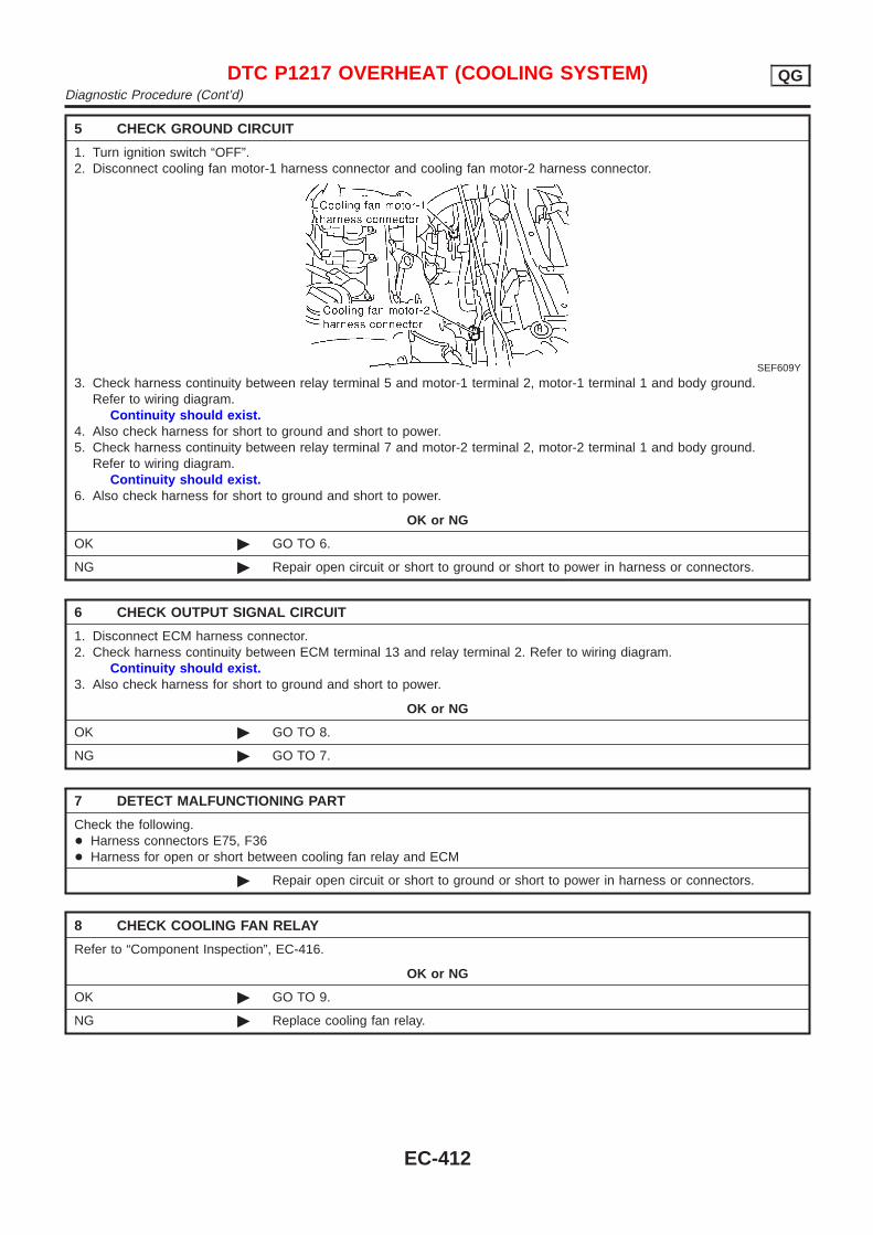
5 CHECK GROUND CIRCUIT
1. Turn ignition switch “OFF”.2. Disconnect cooling fan motor-1 harness connector and cooling fan motor-2 harness connector.
SEF609Y
3. Check harness continuity between relay terminal 5 and motor-1 terminal 2, motor-1 terminal 1 and body ground.Refer to wiring diagram.
Continuity should exist.4. Also check harness for short to ground and short to power.5. Check harness continuity between relay terminal 7 and motor-2 terminal 2, motor-2 terminal 1 and body ground.
Refer to wiring diagram.Continuity should exist.
6. Also check harness for short to ground and short to power.
OK or NG
OK © GO TO 6.
NG © Repair open circuit or short to ground or short to power in harness or connectors.
6 CHECK OUTPUT SIGNAL CIRCUIT
1. Disconnect ECM harness connector.2. Check harness continuity between ECM terminal 13 and relay terminal 2. Refer to wiring diagram.
Continuity should exist.3. Also check harness for short to ground and short to power.
OK or NG
OK © GO TO 8.
NG © GO TO 7.
7 DETECT MALFUNCTIONING PART
Check the following.+ Harness connectors E75, F36+ Harness for open or short between cooling fan relay and ECM
© Repair open circuit or short to ground or short to power in harness or connectors.
8 CHECK COOLING FAN RELAY
Refer to “Component Inspection”, EC-416.
OK or NG
OK © GO TO 9.
NG © Replace cooling fan relay.
DTC P1217 OVERHEAT (COOLING SYSTEM) QGDiagnostic Procedure (Cont’d)
EC-412
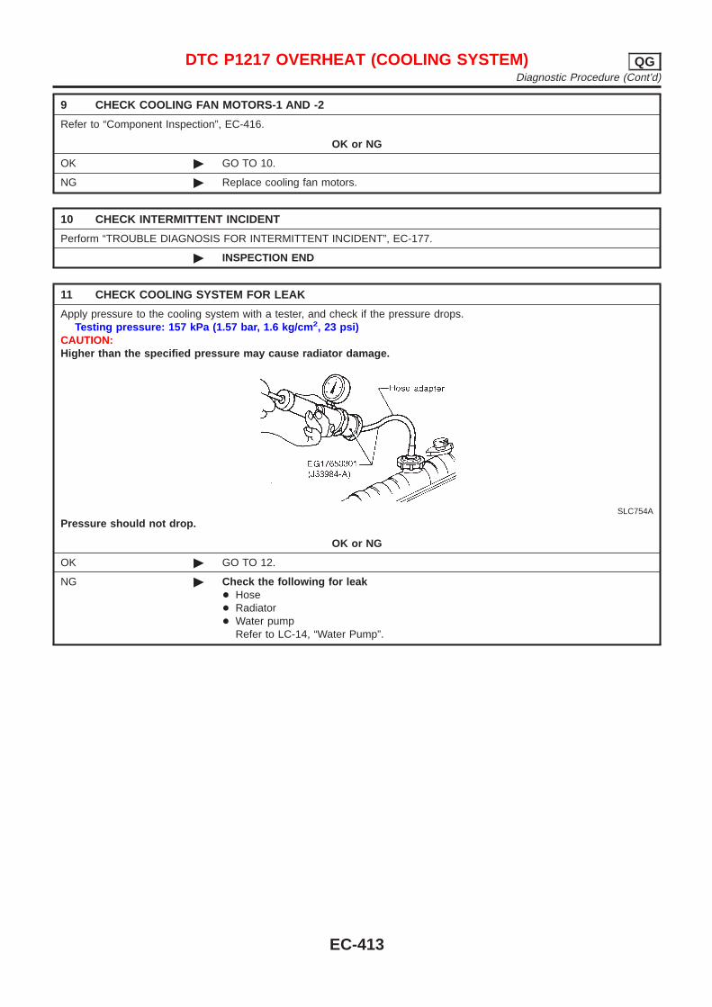
9 CHECK COOLING FAN MOTORS-1 AND -2
Refer to “Component Inspection”, EC-416.
OK or NG
OK © GO TO 10.
NG © Replace cooling fan motors.
10 CHECK INTERMITTENT INCIDENT
Perform “TROUBLE DIAGNOSIS FOR INTERMITTENT INCIDENT”, EC-177.
© INSPECTION END
11 CHECK COOLING SYSTEM FOR LEAK
Apply pressure to the cooling system with a tester, and check if the pressure drops.Testing pressure: 157 kPa (1.57 bar, 1.6 kg/cm 2, 23 psi)
CAUTION:Higher than the specified pressure may cause radiator damage.
SLC754A
Pressure should not drop.
OK or NG
OK © GO TO 12.
NG © Check the following for leak+ Hose+ Radiator+ Water pump
Refer to LC-14, “Water Pump”.
DTC P1217 OVERHEAT (COOLING SYSTEM) QGDiagnostic Procedure (Cont’d)
EC-413
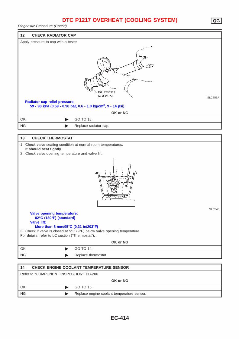
12 CHECK RADIATOR CAP
Apply pressure to cap with a tester.
SLC755A
Radiator cap relief pressure:59 - 98 kPa (0.59 - 0.98 bar, 0.6 - 1.0 kg/cm 2, 9 - 14 psi)
OK or NG
OK © GO TO 13.
NG © Replace radiator cap.
13 CHECK THERMOSTAT
1. Check valve seating condition at normal room temperatures.It should seat tightly.
2. Check valve opening temperature and valve lift.
SLC343
Valve opening temperature:82°C (180°F) [standard]
Valve lift:More than 8 mm/95°C (0.31 in/203°F)
3. Check if valve is closed at 5°C (9°F) below valve opening temperature.For details, refer to LC section (“Thermostat”).
OK or NG
OK © GO TO 14.
NG © Replace thermostat
14 CHECK ENGINE COOLANT TEMPERATURE SENSOR
Refer to “COMPONENT INSPECTION”, EC-206.
OK or NG
OK © GO TO 15.
NG © Replace engine coolant temperature sensor.
DTC P1217 OVERHEAT (COOLING SYSTEM) QGDiagnostic Procedure (Cont’d)
EC-414

15 CHECK MAIN 12 CAUSES
If the cause cannot be isolated, go to “MAIN 12 CAUSES OF OVERHEATING”, EC-416.
© INSPECTION END
DTC P1217 OVERHEAT (COOLING SYSTEM) QGDiagnostic Procedure (Cont’d)
EC-415
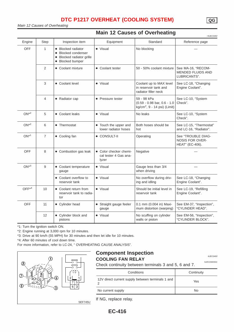
Main 12 Causes of Overheating=NJEC0492
Engine Step Inspection item Equipment Standard Reference page
OFF 1 + Blocked radiator+ Blocked condenser+ Blocked radiator grille+ Blocked bumper
+ Visual No blocking —
2 + Coolant mixture + Coolant tester 50 - 50% coolant mixture See MA-16, “RECOM-MENDED FLUIDS ANDLUBRICANTS”.
3 + Coolant level + Visual Coolant up to MAX levelin reservoir tank andradiator filler neck
See LC-18, “ChangingEngine Coolant”.
4 + Radiator cap + Pressure tester 59 - 98 kPa(0.59 - 0.98 bar, 0.6 - 1.0kg/cm2, 9 - 14 psi) (Limit)
See LC-10, “SystemCheck”.
ON*2 5 + Coolant leaks + Visual No leaks See LC-10, “SystemCheck”.
ON*2 6 + Thermostat + Touch the upper andlower radiator hoses
Both hoses should behot
See LC-15, “Thermostat”and LC-16, “Radiator”.
ON*1 7 + Cooling fan + CONSULT-II Operating See “TROUBLE DIAG-NOSIS FOR OVER-HEAT” (EC-406).
OFF 8 + Combustion gas leak + Color checker chemi-cal tester 4 Gas ana-lyzer
Negative —
ON*3 9 + Coolant temperaturegauge
+ Visual Gauge less than 3/4when driving
—
+ Coolant overflow toreservoir tank
+ Visual No overflow during driv-ing and idling
See LC-18, “ChangingEngine Coolant”.
OFF*4 10 + Coolant return fromreservoir tank to radia-tor
+ Visual Should be initial level inreservoir tank
See LC-19, “RefillingEngine Coolant”.
OFF 11 + Cylinder head + Straight gauge feelergauge
0.1 mm (0.004 in) Maxi-mum distortion (warping)
See EM-37, “Inspection”,“CYLINDER HEAD”.
12 + Cylinder block andpistons
+ Visual No scuffing on cylinderwalls or piston
See EM-56, “Inspection”,“CYLINDER BLOCK”.
*1: Turn the ignition switch ON.*2: Engine running at 3,000 rpm for 10 minutes.*3: Drive at 90 km/h (55 MPH) for 30 minutes and then let idle for 10 minutes.*4: After 60 minutes of cool down time.For more information, refer to LC-24, “ OVERHEATING CAUSE ANALYSIS”.
SEF745U
Component InspectionNJEC0493
COOLING FAN RELAYNJEC0493S01
Check continuity between terminals 3 and 5, 6 and 7.
Conditions Continuity
12V direct current supply between terminals 1 and2
Yes
No current supply No
If NG, replace relay.
DTC P1217 OVERHEAT (COOLING SYSTEM) QGMain 12 Causes of Overheating
EC-416
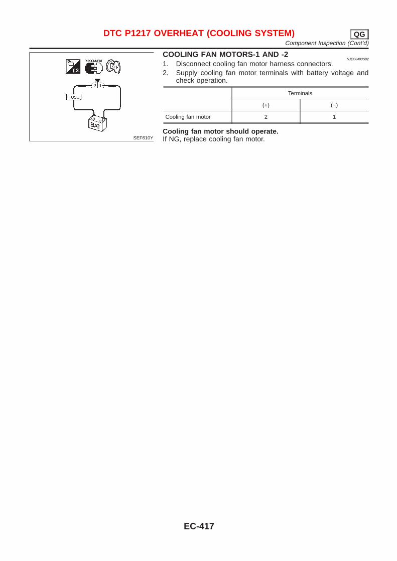
SEF610Y
COOLING FAN MOTORS-1 AND -2NJEC0493S02
1. Disconnect cooling fan motor harness connectors.2. Supply cooling fan motor terminals with battery voltage and
check operation.
Terminals
(+) (−)
Cooling fan motor 2 1
Cooling fan motor should operate.If NG, replace cooling fan motor.
DTC P1217 OVERHEAT (COOLING SYSTEM) QGComponent Inspection (Cont’d)
EC-417
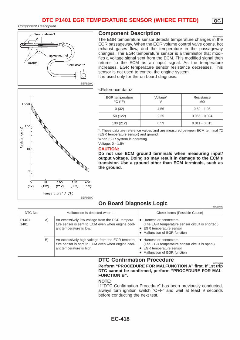
SEF599K
Component DescriptionNJEC0342
The EGR temperature sensor detects temperature changes in theEGR passageway. When the EGR volume control valve opens, hotexhaust gases flow, and the temperature in the passagewaychanges. The EGR temperature sensor is a thermistor that modi-fies a voltage signal sent from the ECM. This modified signal thenreturns to the ECM as an input signal. As the temperatureincreases, EGR temperature sensor resistance decreases. Thissensor is not used to control the engine system.It is used only for the on board diagnosis.
SEF068X
<Reference data>
EGR temperature°C (°F)
Voltage*V
ResistanceMΩ
0 (32) 4.56 0.62 - 1.05
50 (122) 2.25 0.065 - 0.094
100 (212) 0.59 0.011 - 0.015
*: These data are reference values and are measured between ECM terminal 72(EGR temperature sensor) and ground.When EGR system is operating.Voltage: 0 - 1.5V
CAUTION:Do not use ECM ground terminals when measuring input/output voltage. Doing so may result in damage to the ECM’stransistor. Use a ground other than ECM terminals, such asthe ground.
On Board Diagnosis LogicNJEC0343
DTC No. Malfunction is detected when ... Check Items (Possible Cause)
P14011401
A) An excessively low voltage from the EGR tempera-ture sensor is sent to ECM even when engine cool-ant temperature is low.
+ Harness or connectors(The EGR temperature sensor circuit is shorted.)
+ EGR temperature sensor+ Malfunction of EGR function
B) An excessively high voltage from the EGR tempera-ture sensor is sent to ECM even when engine cool-ant temperature is high.
+ Harness or connectors(The EGR temperature sensor circuit is open.)
+ EGR temperature sensor+ Malfunction of EGR function
DTC Confirmation ProcedureNJEC0344
Perform “PROCEDURE FOR MALFUNCTION A” first. If 1st tripDTC cannot be confirmed, perform “PROCEDURE FOR MAL-FUNCTION B”.NOTE:If “DTC Confirmation Procedure” has been previously conducted,always turn ignition switch “OFF” and wait at least 9 secondsbefore conducting the next test.
DTC P1401 EGR TEMPERATURE SENSOR (WHERE FITTED) QGComponent Description
EC-418
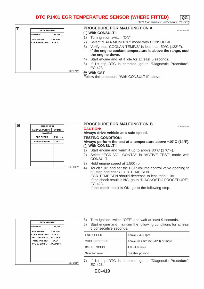
SEF174Y
PROCEDURE FOR MALFUNCTION A=NJEC0344S01
With CONSULT-II1) Turn ignition switch “ON”.2) Select “DATA MONITOR” mode with CONSULT-II.3) Verify that “COOLAN TEMP/S” is less than 50°C (122°F).
If the engine coolant temperature is above the range, coolthe engine down.
4) Start engine and let it idle for at least 5 seconds.5) If 1st trip DTC is detected, go to “Diagnostic Procedure”,
EC-423.With GST
Follow the procedure “With CONSULT-II” above.
SEF200Y
PROCEDURE FOR MALFUNCTION BNJEC0344S02
CAUTION:Always drive vehicle at a safe speed.TESTING CONDITION:Always perform the test at a temperature above −10°C (14°F).
With CONSULT-II1) Start engine and warm it up to above 80°C (176°F).2) Select “EGR VOL CONT/V” in “ACTIVE TEST” mode with
CONSULT.3) Hold engine speed at 1,500 rpm.4) Touch “Qu” and set the EGR volume control valve opening to
50 step and check EGR TEMP SEN.EGR TEMP SEN should decrease to less than 1.0V.If the check result is NG, go to “DIAGNOSTIC PROCEDURE”,EC-423.If the check result is OK, go to the following step.
SEF201Y
5) Turn ignition switch “OFF” and wait at least 9 seconds.6) Start engine and maintain the following conditions for at least
5 consecutive seconds.
ENG SPEED Above 2,400 rpm
VHCL SPEED SE Above 90 km/h (56 MPH) or more
B/FUEL SCHDL 4.0 - 4.8 msec
Selector lever Suitable position
7) If 1st trip DTC is detected, go to “Diagnostic Procedure”,EC-423.
DTC P1401 EGR TEMPERATURE SENSOR (WHERE FITTED) QGDTC Confirmation Procedure (Cont’d)
EC-419
With GST1) Start engine and warm it up to normal operating temperature.2) Turn ignition switch “OFF” and wait at least 9 seconds, then
turn “ON”.3) Select “MODE 1” with GST and maintain the following condi-
tions for at least 5 consecutive seconds.
Engine speed Above 2,400 rpm
Vehicle speed Above 90 km/h (56 MPH)
Selector lever 4th or 5th
4) Select “MODE 7” with GST5) If 1st trip DTC is detected, go to “Diagnostic Procedure”,
EC-423.
DTC P1401 EGR TEMPERATURE SENSOR (WHERE FITTED) QGDTC Confirmation Procedure (Cont’d)
EC-420
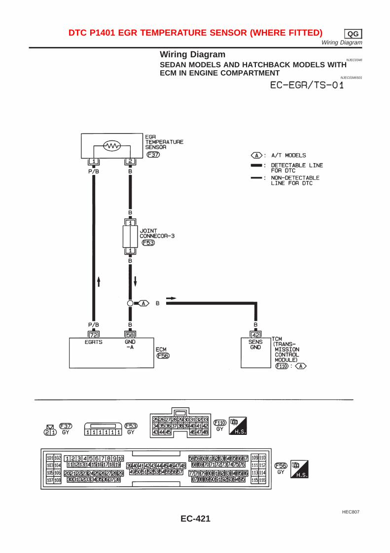
Wiring DiagramNJEC0346
SEDAN MODELS AND HATCHBACK MODELS WITHECM IN ENGINE COMPARTMENT
NJEC0346S01
HEC807
DTC P1401 EGR TEMPERATURE SENSOR (WHERE FITTED) QGWiring Diagram
EC-421
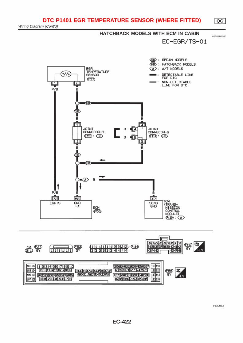
HATCHBACK MODELS WITH ECM IN CABINNJEC0346S02
HEC962
DTC P1401 EGR TEMPERATURE SENSOR (WHERE FITTED) QGWiring Diagram (Cont’d)
EC-422
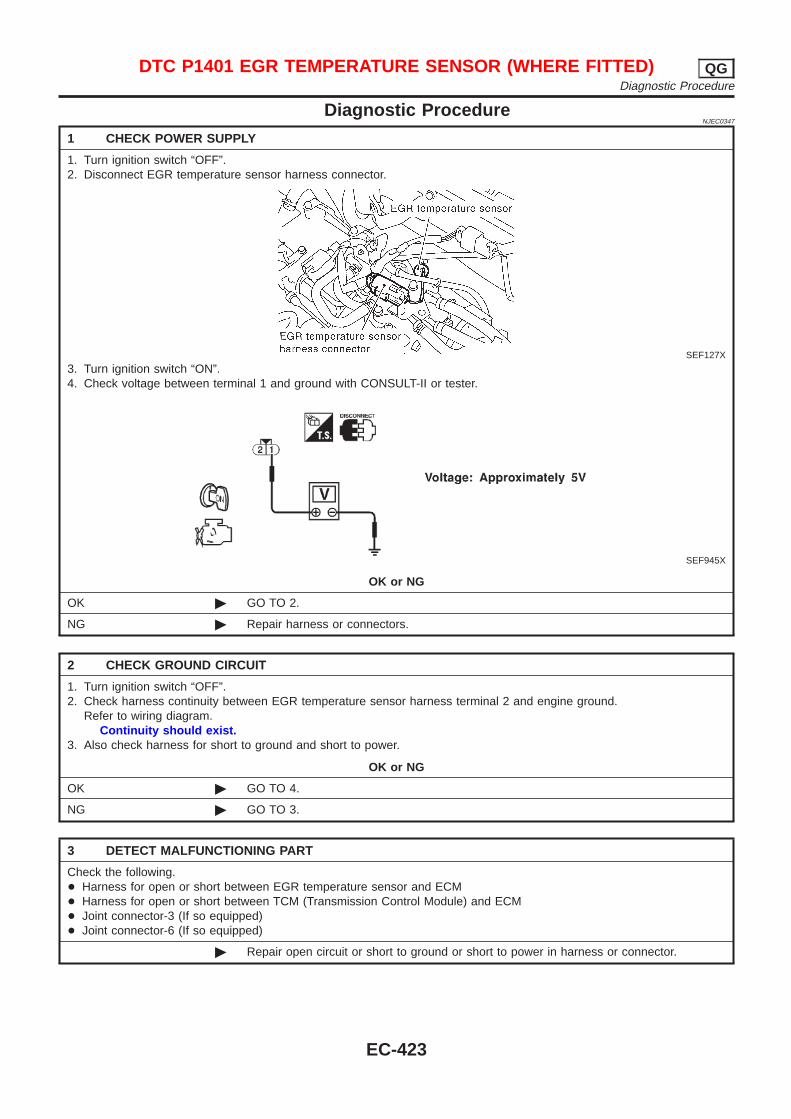
Diagnostic ProcedureNJEC0347
1 CHECK POWER SUPPLY
1. Turn ignition switch “OFF”.2. Disconnect EGR temperature sensor harness connector.
SEF127X
3. Turn ignition switch “ON”.4. Check voltage between terminal 1 and ground with CONSULT-II or tester.
SEF945X
OK or NG
OK © GO TO 2.
NG © Repair harness or connectors.
2 CHECK GROUND CIRCUIT
1. Turn ignition switch “OFF”.2. Check harness continuity between EGR temperature sensor harness terminal 2 and engine ground.
Refer to wiring diagram.Continuity should exist.
3. Also check harness for short to ground and short to power.
OK or NG
OK © GO TO 4.
NG © GO TO 3.
3 DETECT MALFUNCTIONING PART
Check the following.+ Harness for open or short between EGR temperature sensor and ECM+ Harness for open or short between TCM (Transmission Control Module) and ECM+ Joint connector-3 (If so equipped)+ Joint connector-6 (If so equipped)
© Repair open circuit or short to ground or short to power in harness or connector.
DTC P1401 EGR TEMPERATURE SENSOR (WHERE FITTED) QGDiagnostic Procedure
EC-423
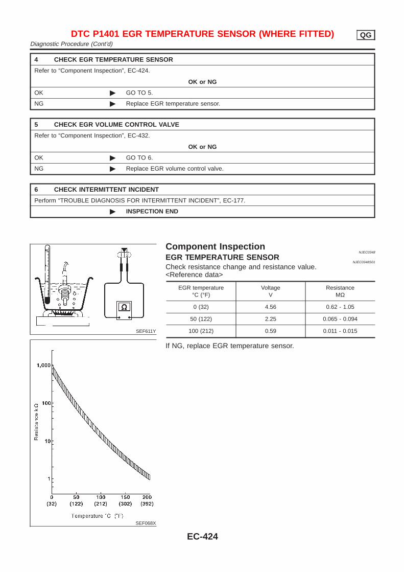
4 CHECK EGR TEMPERATURE SENSOR
Refer to “Component Inspection”, EC-424.
OK or NG
OK © GO TO 5.
NG © Replace EGR temperature sensor.
5 CHECK EGR VOLUME CONTROL VALVE
Refer to “Component Inspection”, EC-432.
OK or NG
OK © GO TO 6.
NG © Replace EGR volume control valve.
6 CHECK INTERMITTENT INCIDENT
Perform “TROUBLE DIAGNOSIS FOR INTERMITTENT INCIDENT”, EC-177.
© INSPECTION END
SEF611Y
SEF068X
Component InspectionNJEC0348
EGR TEMPERATURE SENSORNJEC0348S01
Check resistance change and resistance value.<Reference data>
EGR temperature°C (°F)
VoltageV
ResistanceMΩ
0 (32) 4.56 0.62 - 1.05
50 (122) 2.25 0.065 - 0.094
100 (212) 0.59 0.011 - 0.015
If NG, replace EGR temperature sensor.
DTC P1401 EGR TEMPERATURE SENSOR (WHERE FITTED) QGDiagnostic Procedure (Cont’d)
EC-424
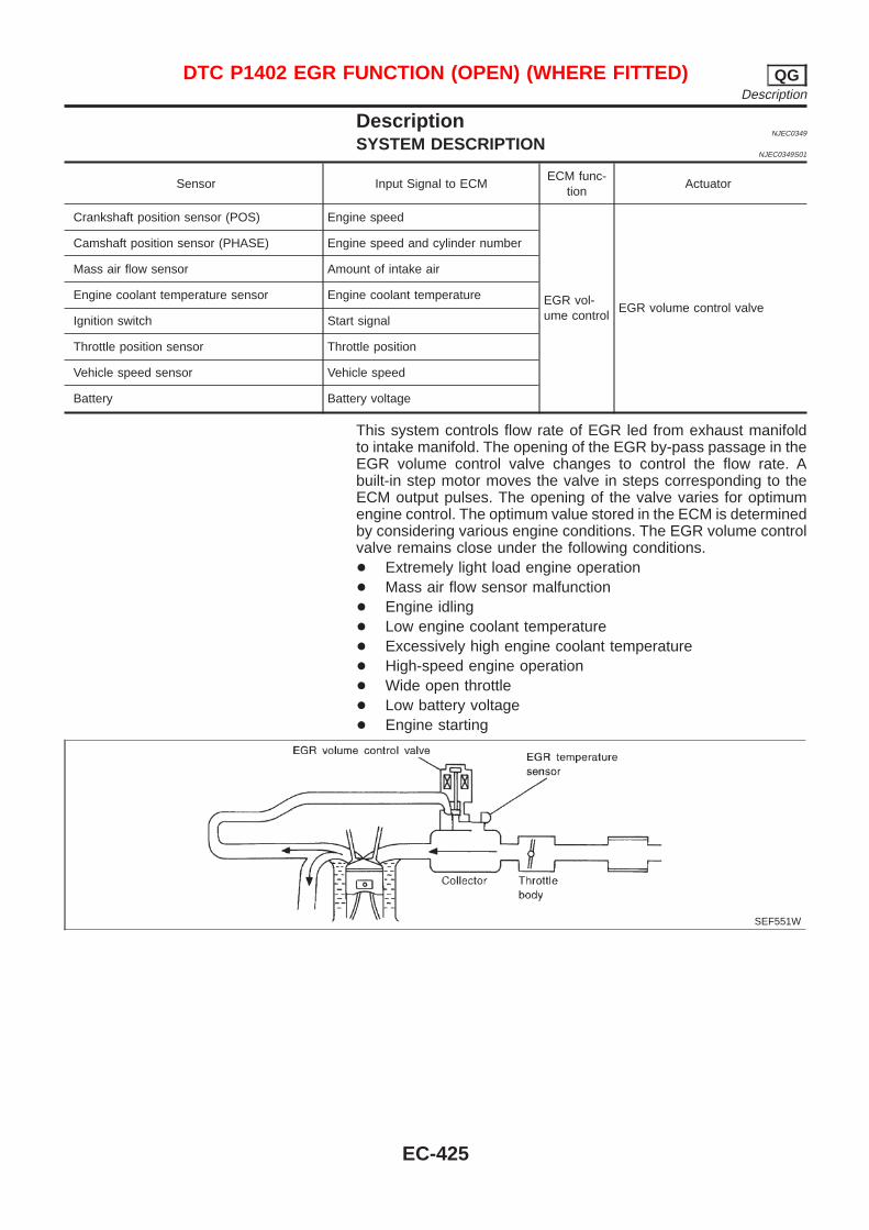
DescriptionNJEC0349
SYSTEM DESCRIPTIONNJEC0349S01
Sensor Input Signal to ECMECM func-
tionActuator
Crankshaft position sensor (POS) Engine speed
EGR vol-ume control
EGR volume control valve
Camshaft position sensor (PHASE) Engine speed and cylinder number
Mass air flow sensor Amount of intake air
Engine coolant temperature sensor Engine coolant temperature
Ignition switch Start signal
Throttle position sensor Throttle position
Vehicle speed sensor Vehicle speed
Battery Battery voltage
This system controls flow rate of EGR led from exhaust manifoldto intake manifold. The opening of the EGR by-pass passage in theEGR volume control valve changes to control the flow rate. Abuilt-in step motor moves the valve in steps corresponding to theECM output pulses. The opening of the valve varies for optimumengine control. The optimum value stored in the ECM is determinedby considering various engine conditions. The EGR volume controlvalve remains close under the following conditions.+ Extremely light load engine operation+ Mass air flow sensor malfunction+ Engine idling+ Low engine coolant temperature+ Excessively high engine coolant temperature+ High-speed engine operation+ Wide open throttle+ Low battery voltage+ Engine starting
SEF551W
DTC P1402 EGR FUNCTION (OPEN) (WHERE FITTED) QGDescription
EC-425
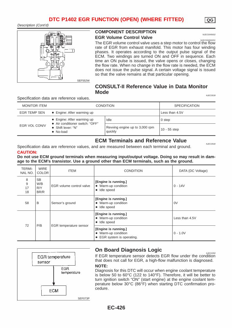
SEF552W
COMPONENT DESCRIPTIONNJEC0349S02
EGR Volume Control ValveNJEC0349S0201
The EGR volume control valve uses a step motor to control the flowrate of EGR from exhaust manifold. This motor has four windingphases. It operates according to the output pulse signal of theECM. Two windings are turned ON and OFF in sequence. Eachtime an ON pulse is issued, the valve opens or closes, changingthe flow rate. When no change in the flow rate is needed, the ECMdoes not issue the pulse signal. A certain voltage signal is issuedso that the valve remains at that particular opening.
CONSULT-II Reference Value in Data MonitorMode
NJEC0539
Specification data are reference values.
MONITOR ITEM CONDITION SPECIFICATION
EGR TEMP SEN + Engine: After warming up Less than 4.5V
EGR VOL CON/V
+ Engine: After warming up+ Air conditioner switch: “OFF”+ Shift lever: “N”+ No-load
Idle 0 step
Revving engine up to 3,000 rpmquickly
10 - 55 step
ECM Terminals and Reference ValueNJEC0540
Specification data are reference values, and are measured between each terminal and ground.CAUTION:Do not use ECM ground terminals when measuring input/output voltage. Doing so may result in dam-age to the ECM’s transistor. Use a ground other than ECM terminals, such as the ground.
TERMI-NAL NO.
WIRECOLOR
ITEM CONDITION DATA (DC Voltage)
891718
SBW/BR/YBR/R
EGR volume control valve[Engine is running.]+ Warm-up condition+ Idle speed
0 - 14V
58 B Sensor’s ground[Engine is running.]+ Warm-up condition+ Idle speed
0V
72 P/B EGR temperature sensor
[Engine is running.]+ Warm-up condition+ Idle speed
Less than 4.5V
[Engine is running.]+ Warm-up condition+ EGR system is operating.
0 - 1.0V
SEF073P
On Board Diagnosis LogicNJEC0350
If EGR temperature sensor detects EGR flow under the conditionthat does not call for EGR, a high-flow malfunction is diagnosed.NOTE:Diagnosis for this DTC will occur when engine coolant temperatureis below 50 to 60°C (122 to 140°F). Therefore, it will be better toturn ignition switch “ON” (start engine) at the engine coolant tem-perature below 30°C (86°F) when starting DTC confirmation pro-cedure.
DTC P1402 EGR FUNCTION (OPEN) (WHERE FITTED) QGDescription (Cont’d)
EC-426
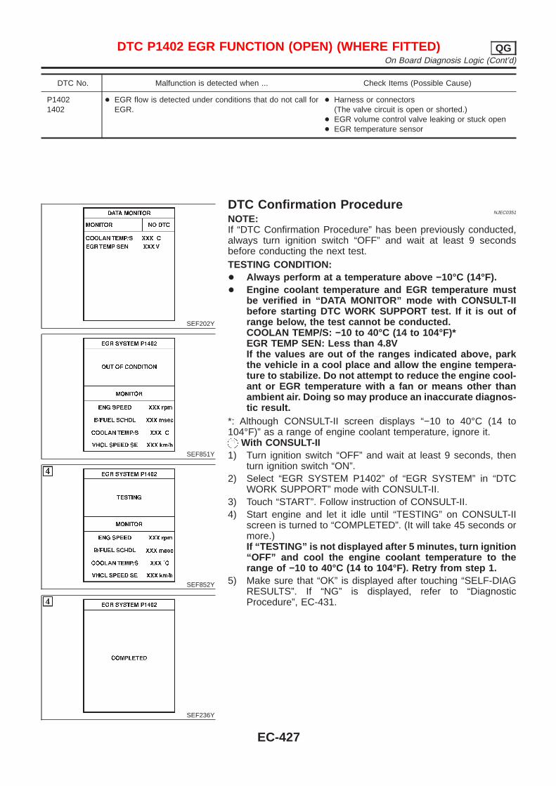
DTC No. Malfunction is detected when ... Check Items (Possible Cause)
P14021402
+ EGR flow is detected under conditions that do not call forEGR.
+ Harness or connectors(The valve circuit is open or shorted.)
+ EGR volume control valve leaking or stuck open+ EGR temperature sensor
SEF202Y
SEF851Y
SEF852Y
SEF236Y
DTC Confirmation ProcedureNJEC0351
NOTE:If “DTC Confirmation Procedure” has been previously conducted,always turn ignition switch “OFF” and wait at least 9 secondsbefore conducting the next test.TESTING CONDITION:+ Always perform at a temperature above −10°C (14°F).+ Engine coolant temperature and EGR temperature must
be verified in “DATA MONITOR” mode with CONSULT-IIbefore starting DTC WORK SUPPORT test. If it is out ofrange below, the test cannot be conducted.COOLAN TEMP/S: −10 to 40°C (14 to 104°F)*EGR TEMP SEN: Less than 4.8VIf the values are out of the ranges indicated above, parkthe vehicle in a cool place and allow the engine tempera-ture to stabilize. Do not attempt to reduce the engine cool-ant or EGR temperature with a fan or means other thanambient air. Doing so may produce an inaccurate diagnos-tic result.
*: Although CONSULT-II screen displays “−10 to 40°C (14 to104°F)” as a range of engine coolant temperature, ignore it.
With CONSULT-II1) Turn ignition switch “OFF” and wait at least 9 seconds, then
turn ignition switch “ON”.2) Select “EGR SYSTEM P1402” of “EGR SYSTEM” in “DTC
WORK SUPPORT” mode with CONSULT-II.3) Touch “START”. Follow instruction of CONSULT-II.4) Start engine and let it idle until “TESTING” on CONSULT-II
screen is turned to “COMPLETED”. (It will take 45 seconds ormore.)If “TESTING” is not displayed after 5 minutes, turn ignition“OFF” and cool the engine coolant temperature to therange of −10 to 40°C (14 to 104°F). Retry from step 1.
5) Make sure that “OK” is displayed after touching “SELF-DIAGRESULTS”. If “NG” is displayed, refer to “DiagnosticProcedure”, EC-431.
DTC P1402 EGR FUNCTION (OPEN) (WHERE FITTED) QGOn Board Diagnosis Logic (Cont’d)
EC-427
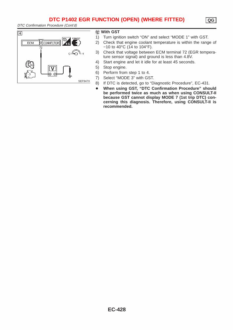
SEF947X
With GST1) Turn ignition switch “ON” and select “MODE 1” with GST.2) Check that engine coolant temperature is within the range of
−10 to 40°C (14 to 104°F).3) Check that voltage between ECM terminal 72 (EGR tempera-
ture sensor signal) and ground is less than 4.8V.4) Start engine and let it idle for at least 45 seconds.5) Stop engine.6) Perform from step 1 to 4.7) Select “MODE 3” with GST.8) If DTC is detected, go to “Diagnostic Procedure”, EC-431.+ When using GST, “DTC Confirmation Procedure” should
be performed twice as much as when using CONSULT-IIbecause GST cannot display MODE 7 (1st trip DTC) con-cerning this diagnosis. Therefore, using CONSULT-II isrecommended.
DTC P1402 EGR FUNCTION (OPEN) (WHERE FITTED) QGDTC Confirmation Procedure (Cont’d)
EC-428
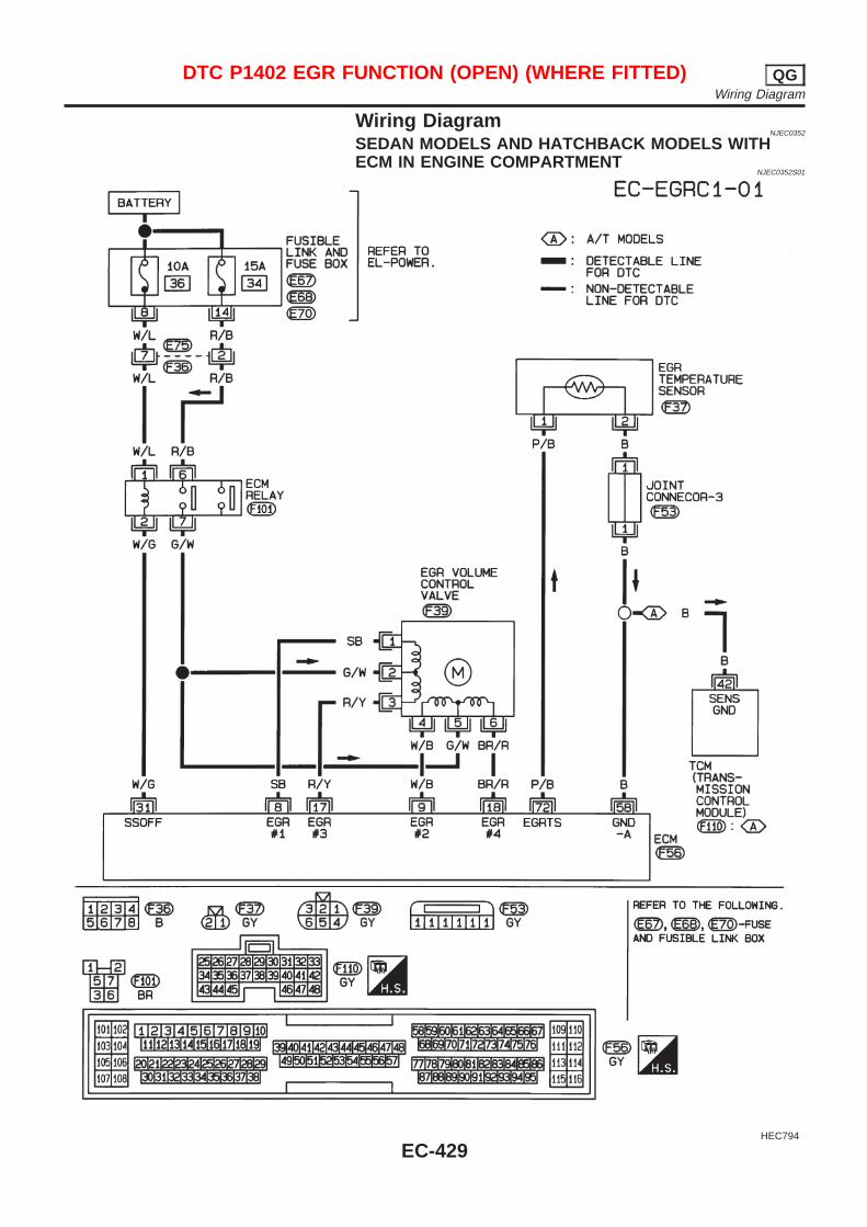
Wiring DiagramNJEC0352
SEDAN MODELS AND HATCHBACK MODELS WITHECM IN ENGINE COMPARTMENT
NJEC0352S01
HEC794
DTC P1402 EGR FUNCTION (OPEN) (WHERE FITTED) QGWiring Diagram
EC-429
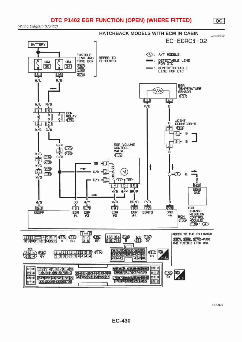
HATCHBACK MODELS WITH ECM IN CABINNJEC0352S02
HEC976
DTC P1402 EGR FUNCTION (OPEN) (WHERE FITTED) QGWiring Diagram (Cont’d)
EC-430
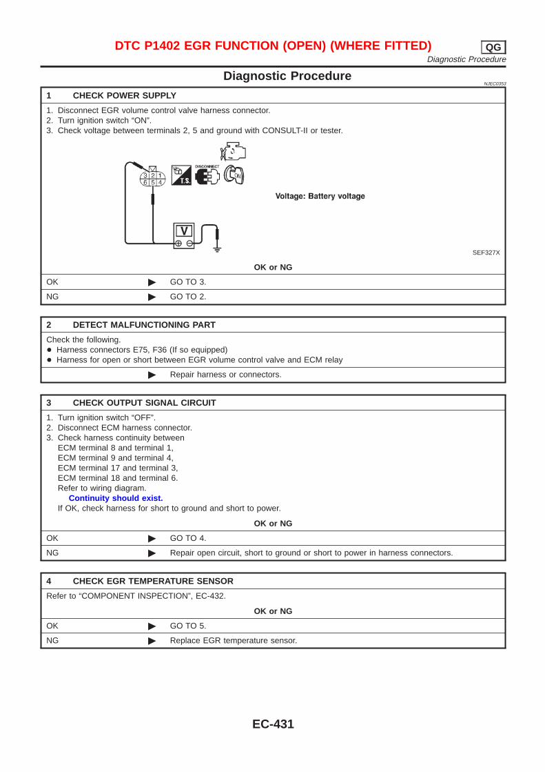
Diagnostic ProcedureNJEC0353
1 CHECK POWER SUPPLY
1. Disconnect EGR volume control valve harness connector.2. Turn ignition switch “ON”.3. Check voltage between terminals 2, 5 and ground with CONSULT-II or tester.
SEF327X
OK or NG
OK © GO TO 3.
NG © GO TO 2.
2 DETECT MALFUNCTIONING PART
Check the following.+ Harness connectors E75, F36 (If so equipped)+ Harness for open or short between EGR volume control valve and ECM relay
© Repair harness or connectors.
3 CHECK OUTPUT SIGNAL CIRCUIT
1. Turn ignition switch “OFF”.2. Disconnect ECM harness connector.3. Check harness continuity between
ECM terminal 8 and terminal 1,ECM terminal 9 and terminal 4,ECM terminal 17 and terminal 3,ECM terminal 18 and terminal 6.Refer to wiring diagram.
Continuity should exist.If OK, check harness for short to ground and short to power.
OK or NG
OK © GO TO 4.
NG © Repair open circuit, short to ground or short to power in harness connectors.
4 CHECK EGR TEMPERATURE SENSOR
Refer to “COMPONENT INSPECTION”, EC-432.
OK or NG
OK © GO TO 5.
NG © Replace EGR temperature sensor.
DTC P1402 EGR FUNCTION (OPEN) (WHERE FITTED) QGDiagnostic Procedure
EC-431
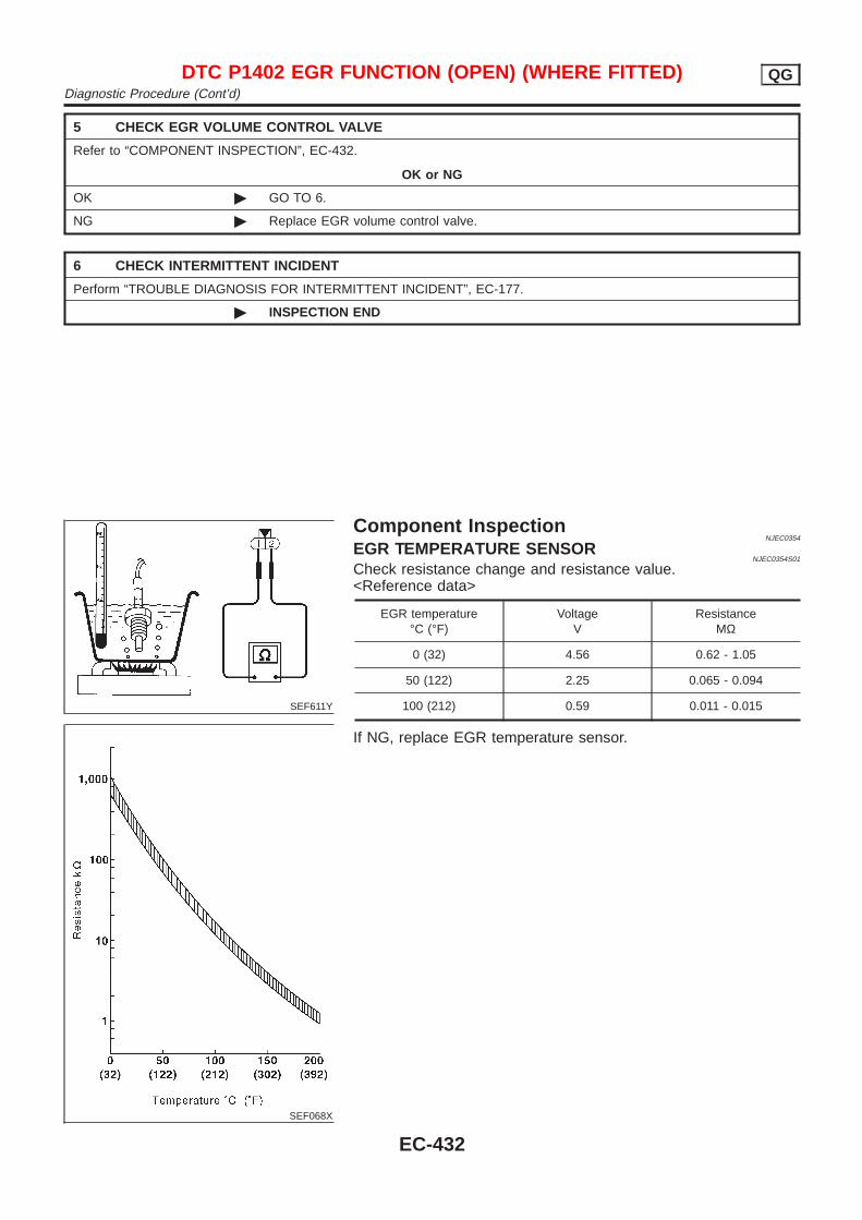
5 CHECK EGR VOLUME CONTROL VALVE
Refer to “COMPONENT INSPECTION”, EC-432.
OK or NG
OK © GO TO 6.
NG © Replace EGR volume control valve.
6 CHECK INTERMITTENT INCIDENT
Perform “TROUBLE DIAGNOSIS FOR INTERMITTENT INCIDENT”, EC-177.
© INSPECTION END
SEF611Y
SEF068X
Component InspectionNJEC0354
EGR TEMPERATURE SENSORNJEC0354S01
Check resistance change and resistance value.<Reference data>
EGR temperature°C (°F)
VoltageV
ResistanceMΩ
0 (32) 4.56 0.62 - 1.05
50 (122) 2.25 0.065 - 0.094
100 (212) 0.59 0.011 - 0.015
If NG, replace EGR temperature sensor.
DTC P1402 EGR FUNCTION (OPEN) (WHERE FITTED) QGDiagnostic Procedure (Cont’d)
EC-432
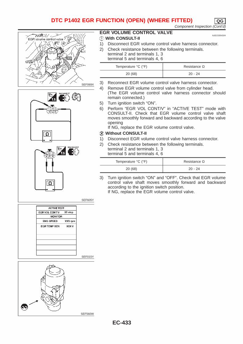
SEF069X
SEF605Y
SEF015Y
SEF560W
EGR VOLUME CONTROL VALVENJEC0354S04
With CONSULT-II1) Disconnect EGR volume control valve harness connector.2) Check resistance between the following terminals.
terminal 2 and terminals 1, 3terminal 5 and terminals 4, 6
Temperature °C (°F) Resistance Ω
20 (68) 20 - 24
3) Reconnect EGR volume control valve harness connector.4) Remove EGR volume control valve from cylinder head.
(The EGR volume control valve harness connector shouldremain connected.)
5) Turn ignition switch “ON”.6) Perform “EGR VOL CONT/V” in “ACTIVE TEST” mode with
CONSULT-II. Check that EGR volume control valve shaftmoves smoothly forward and backward according to the valveopeningIf NG, replace the EGR volume control valve.
Without CONSULT-II1) Disconnect EGR volume control valve harness connector.2) Check resistance between the following terminals.
terminal 2 and terminals 1, 3terminal 5 and terminals 4, 6
Temperature °C (°F) Resistance Ω
20 (68) 20 - 24
3) Turn ignition switch “ON” and “OFF”. Check that EGR volumecontrol valve shaft moves smoothly forward and backwardaccording to the ignition switch position.If NG, replace the EGR volume control valve.
DTC P1402 EGR FUNCTION (OPEN) (WHERE FITTED) QGComponent Inspection (Cont’d)
EC-433
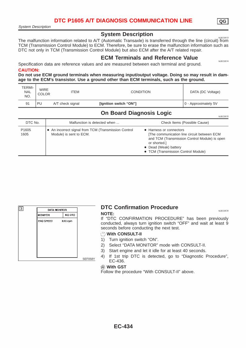
System DescriptionNJEC0573
The malfunction information related to A/T (Automatic Transaxle) is transferred through the line (circuit) fromTCM (Transmission Control Module) to ECM. Therefore, be sure to erase the malfunction information such asDTC not only in TCM (Transmission Control Module) but also ECM after the A/T related repair.
ECM Terminals and Reference ValueNJEC0574
Specification data are reference values and are measured between each terminal and ground.CAUTION:Do not use ECM ground terminals when measuring input/output voltage. Doing so may result in dam-age to the ECM’s transistor. Use a ground other than ECM terminals, such as the ground.
TERMI-NALNO.
WIRECOLOR
ITEM CONDITION DATA (DC Voltage)
91 PU A/T check signal [Ignition switch “ON”] 0 - Approximately 5V
On Board Diagnosis LogicNJEC0575
DTC No. Malfunction is detected when ... Check Items (Possible Cause)
P16051605
+ An incorrect signal from TCM (Transmission ControlModule) is sent to ECM.
+ Harness or connectors[The communication line circuit between ECMand TCM (Transmission Control Module) is openor shorted.]
+ Dead (Weak) battery+ TCM (Transmission Control Module)
SEF058Y
DTC Confirmation ProcedureNJEC0576
NOTE:If “DTC CONFIRMATION PROCEDURE” has been previouslyconducted, always turn ignition switch “OFF” and wait at least 9seconds before conducting the next test.
With CONSULT-II1) Turn ignition switch “ON”.2) Select “DATA MONITOR” mode with CONSULT-II.3) Start engine and let it idle for at least 40 seconds.4) If 1st trip DTC is detected, go to “Diagnostic Procedure”,
EC-436.With GST
Follow the procedure “With CONSULT-II” above.
DTC P1605 A/T DIAGNOSIS COMMUNICATION LINE QGSystem Description
EC-434

Wiring DiagramNJEC0577
HEC804
DTC P1605 A/T DIAGNOSIS COMMUNICATION LINE QGWiring Diagram
EC-435
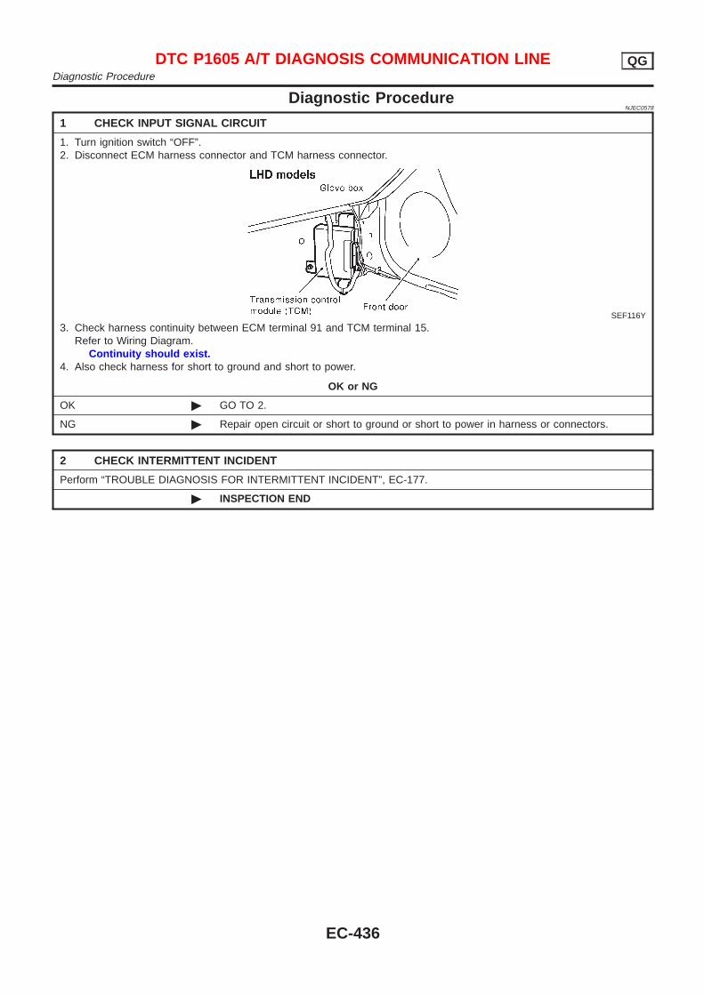
Diagnostic ProcedureNJEC0578
1 CHECK INPUT SIGNAL CIRCUIT
1. Turn ignition switch “OFF”.2. Disconnect ECM harness connector and TCM harness connector.
SEF116Y
3. Check harness continuity between ECM terminal 91 and TCM terminal 15.Refer to Wiring Diagram.
Continuity should exist.4. Also check harness for short to ground and short to power.
OK or NG
OK © GO TO 2.
NG © Repair open circuit or short to ground or short to power in harness or connectors.
2 CHECK INTERMITTENT INCIDENT
Perform “TROUBLE DIAGNOSIS FOR INTERMITTENT INCIDENT”, EC-177.
© INSPECTION END
DTC P1605 A/T DIAGNOSIS COMMUNICATION LINE QGDiagnostic Procedure
EC-436
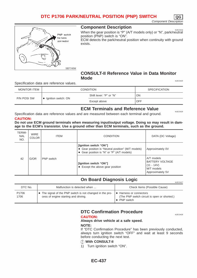
SEF740W
Component DescriptionNJEC0424
When the gear position is “P” (A/T models only) or “N”, park/neutralposition (PNP) switch is “ON”.ECM detects the park/neutral position when continuity with groundexists.
CONSULT-II Reference Value in Data MonitorMode
NJEC0425
Specification data are reference values.
MONITOR ITEM CONDITION SPECIFICATION
P/N POSI SW + Ignition switch: ONShift lever: “P” or “N” ON
Except above OFF
ECM Terminals and Reference ValueNJEC0426
Specification data are reference values and are measured between each terminal and ground.CAUTION:Do not use ECM ground terminals when measuring input/output voltage. Doing so may result in dam-age to the ECM’s transistor. Use a ground other than ECM terminals, such as the ground.
TERMI-NALNO.
WIRECOLOR
ITEM CONDITION DATA (DC Voltage)
42 G/OR PNP switch
[Ignition switch “ON”]+ Gear position is “Neutral position” (M/T models)+ Gear position is “N” or “P” (A/T models)
Approximately 0V
[Ignition switch “ON”]+ Except the above gear position
A/T modelsBATTERY VOLTAGE(11 - 14V)M/T modelsApproximately 5V
On Board Diagnosis LogicNJEC0427
DTC No. Malfunction is detected when ... Check Items (Possible Cause)
P17061706
+ The signal of the PNP switch is not changed in the pro-cess of engine starting and driving.
+ Harness or connectors(The PNP switch circuit is open or shorted.)
+ PNP switch
DTC Confirmation ProcedureNJEC0428
CAUTION:Always drive vehicle at a safe speed.NOTE:If “DTC Confirmation Procedure” has been previously conducted,always turn ignition switch “OFF” and wait at least 9 secondsbefore conducting the next test.
With CONSULT-II1) Turn ignition switch “ON”.
DTC P1706 PARK/NEUTRAL POSITION (PNP) SWITCH QGComponent Description
EC-437
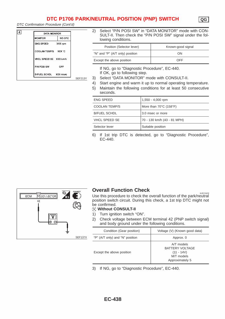
SEF213Y
2) Select “P/N POSI SW” in “DATA MONITOR” mode with CON-SULT-II. Then check the “P/N POSI SW” signal under the fol-lowing conditions.
Position (Selector lever) Known-good signal
“N” and “P” (A/T only) position ON
Except the above position OFF
If NG, go to “Diagnostic Procedure”, EC-440.If OK, go to following step.
3) Select “DATA MONITOR” mode with CONSULT-II.4) Start engine and warm it up to normal operating temperature.5) Maintain the following conditions for at least 50 consecutive
seconds.
ENG SPEED 1,550 - 4,000 rpm
COOLAN TEMP/S More than 70°C (158°F)
B/FUEL SCHDL 3.0 msec or more
VHCL SPEED SE 70 - 130 km/h (43 - 81 MPH)
Selector lever Suitable position
6) If 1st trip DTC is detected, go to “Diagnostic Procedure”,EC-440.
SEF137X
Overall Function CheckNJEC0429
Use this procedure to check the overall function of the park/neutralposition switch circuit. During this check, a 1st trip DTC might notbe confirmed.
Without CONSULT-II1) Turn ignition switch “ON”.2) Check voltage between ECM terminal 42 (PNP switch signal)
and body ground under the following conditions.
Condition (Gear position) Voltage (V) (Known good data)
“P” (A/T only) and “N” position Approx. 0
Except the above position
A/T modelsBATTERY VOLTAGE
(11 - 14V)M/T models
Approximately 5
3) If NG, go to “Diagnostic Procedure”, EC-440.
DTC P1706 PARK/NEUTRAL POSITION (PNP) SWITCH QGDTC Confirmation Procedure (Cont’d)
EC-438
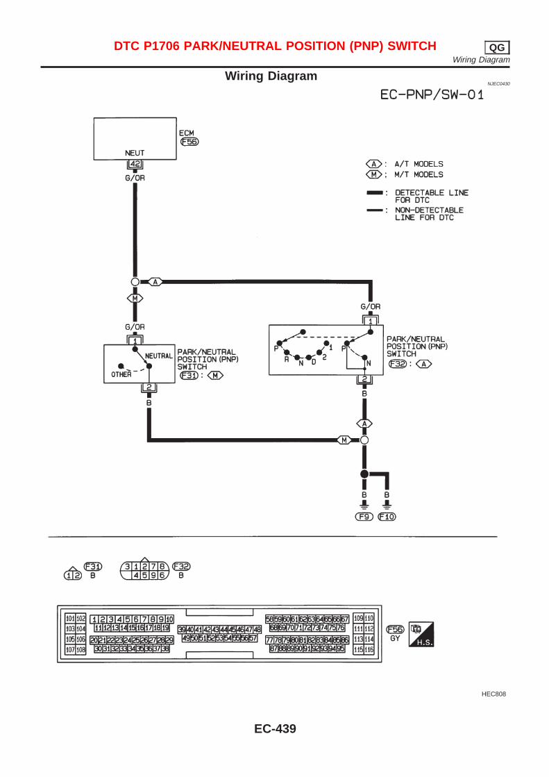
Wiring DiagramNJEC0430
HEC808
DTC P1706 PARK/NEUTRAL POSITION (PNP) SWITCH QGWiring Diagram
EC-439
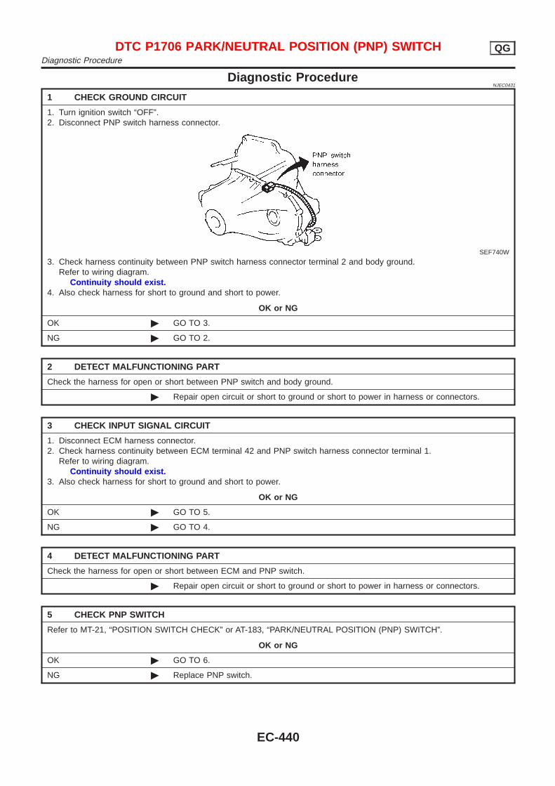
Diagnostic ProcedureNJEC0431
1 CHECK GROUND CIRCUIT
1. Turn ignition switch “OFF”.2. Disconnect PNP switch harness connector.
SEF740W
3. Check harness continuity between PNP switch harness connector terminal 2 and body ground.Refer to wiring diagram.
Continuity should exist.4. Also check harness for short to ground and short to power.
OK or NG
OK © GO TO 3.
NG © GO TO 2.
2 DETECT MALFUNCTIONING PART
Check the harness for open or short between PNP switch and body ground.
© Repair open circuit or short to ground or short to power in harness or connectors.
3 CHECK INPUT SIGNAL CIRCUIT
1. Disconnect ECM harness connector.2. Check harness continuity between ECM terminal 42 and PNP switch harness connector terminal 1.
Refer to wiring diagram.Continuity should exist.
3. Also check harness for short to ground and short to power.
OK or NG
OK © GO TO 5.
NG © GO TO 4.
4 DETECT MALFUNCTIONING PART
Check the harness for open or short between ECM and PNP switch.
© Repair open circuit or short to ground or short to power in harness or connectors.
5 CHECK PNP SWITCH
Refer to MT-21, “POSITION SWITCH CHECK” or AT-183, “PARK/NEUTRAL POSITION (PNP) SWITCH”.
OK or NG
OK © GO TO 6.
NG © Replace PNP switch.
DTC P1706 PARK/NEUTRAL POSITION (PNP) SWITCH QGDiagnostic Procedure
EC-440

6 CHECK INTERMITTENT INCIDENT
Perform “TROUBLE DIAGNOSIS FOR INTERMITTENT INCIDENT”, EC-177.
© INSPECTION END
DTC P1706 PARK/NEUTRAL POSITION (PNP) SWITCH QGDiagnostic Procedure (Cont’d)
EC-441
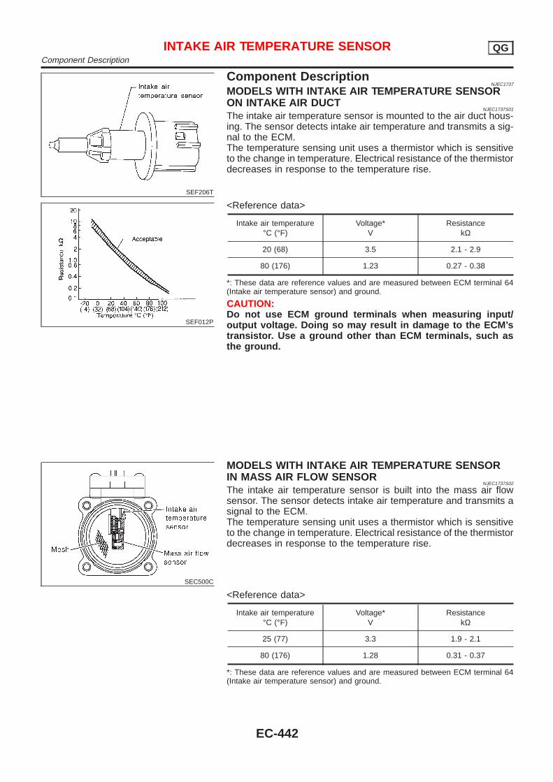
SEF206T
Component DescriptionNJEC1737
MODELS WITH INTAKE AIR TEMPERATURE SENSORON INTAKE AIR DUCT
NJEC1737S01
The intake air temperature sensor is mounted to the air duct hous-ing. The sensor detects intake air temperature and transmits a sig-nal to the ECM.The temperature sensing unit uses a thermistor which is sensitiveto the change in temperature. Electrical resistance of the thermistordecreases in response to the temperature rise.
SEF012P
<Reference data>
Intake air temperature°C (°F)
Voltage*V
ResistancekΩ
20 (68) 3.5 2.1 - 2.9
80 (176) 1.23 0.27 - 0.38
*: These data are reference values and are measured between ECM terminal 64(Intake air temperature sensor) and ground.
CAUTION:Do not use ECM ground terminals when measuring input/output voltage. Doing so may result in damage to the ECM’stransistor. Use a ground other than ECM terminals, such asthe ground.
SEC500C
MODELS WITH INTAKE AIR TEMPERATURE SENSORIN MASS AIR FLOW SENSOR
NJEC1737S02
The intake air temperature sensor is built into the mass air flowsensor. The sensor detects intake air temperature and transmits asignal to the ECM.The temperature sensing unit uses a thermistor which is sensitiveto the change in temperature. Electrical resistance of the thermistordecreases in response to the temperature rise.
<Reference data>
Intake air temperature°C (°F)
Voltage*V
ResistancekΩ
25 (77) 3.3 1.9 - 2.1
80 (176) 1.28 0.31 - 0.37
*: These data are reference values and are measured between ECM terminal 64(Intake air temperature sensor) and ground.
INTAKE AIR TEMPERATURE SENSOR QGComponent Description
EC-442

CAUTION:Do not use ECM ground terminals when measuring input/output voltage. Doing so may result in damage to the ECM’stransistor. Use a ground other than ECM terminals, such asthe ground.
INTAKE AIR TEMPERATURE SENSOR QGComponent Description (Cont’d)
EC-443
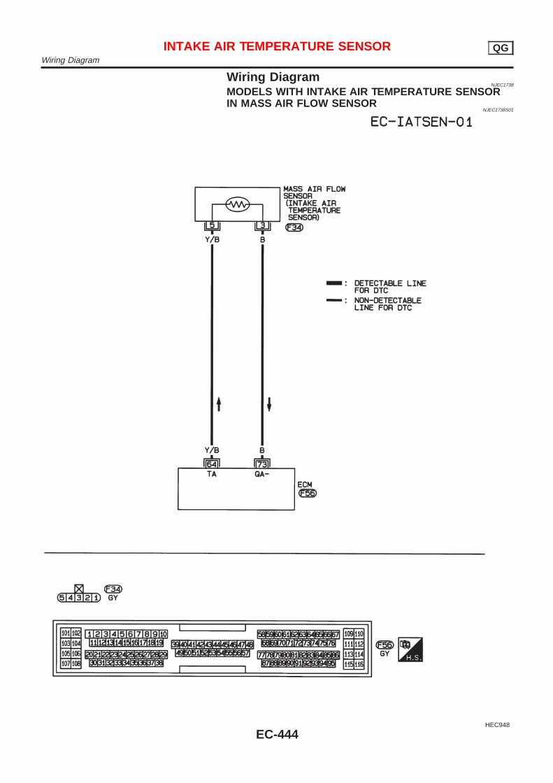
Wiring DiagramNJEC1738
MODELS WITH INTAKE AIR TEMPERATURE SENSORIN MASS AIR FLOW SENSOR
NJEC1738S01
HEC948
INTAKE AIR TEMPERATURE SENSOR QGWiring Diagram
EC-444
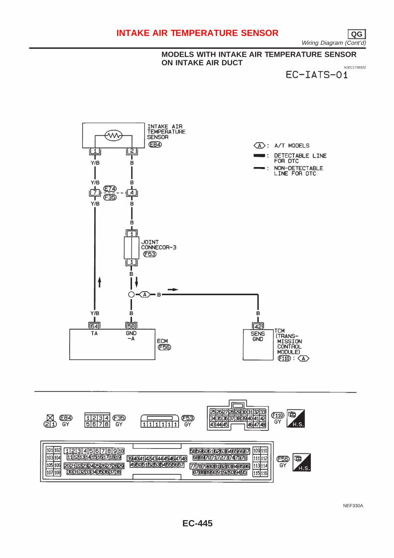
MODELS WITH INTAKE AIR TEMPERATURE SENSORON INTAKE AIR DUCT
NJEC1738S02
NEF330A
INTAKE AIR TEMPERATURE SENSOR QGWiring Diagram (Cont’d)
EC-445
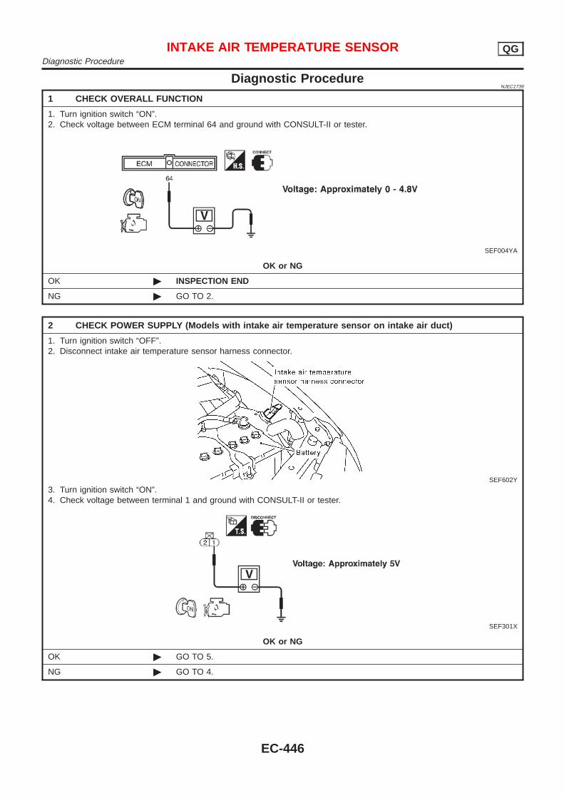
Diagnostic ProcedureNJEC1739
1 CHECK OVERALL FUNCTION
1. Turn ignition switch “ON”.2. Check voltage between ECM terminal 64 and ground with CONSULT-II or tester.
SEF004YA
OK or NG
OK © INSPECTION END
NG © GO TO 2.
2 CHECK POWER SUPPLY (Models with intake air temperature sensor on intake air duct)
1. Turn ignition switch “OFF”.2. Disconnect intake air temperature sensor harness connector.
SEF602Y
3. Turn ignition switch “ON”.4. Check voltage between terminal 1 and ground with CONSULT-II or tester.
SEF301X
OK or NG
OK © GO TO 5.
NG © GO TO 4.
INTAKE AIR TEMPERATURE SENSOR QGDiagnostic Procedure
EC-446

3 CHECK POWER SUPPLY (Models with intake air temperature sensor in mass air flow sensor)
1. Turn ignition switch “OFF”.2. Disconnect mass air flow sensor harness connector.
JEF105Y
3. Turn ignition switch “ON”.4. Check voltage between terminal 1 and ground with CONSULT-II or tester.
SEC503C
OK or NG
OK © GO TO 5.
NG © GO TO 4.
4 DETECT MALFUNCTIONING PART
Check harness for open or short between ECM and intake air temperature sensor.
© Repair harness or connectors.
5 CHECK GROUND CIRCUIT
1. Turn ignition switch “OFF”.2. Check harness continuity between mass air flow sensor harness connector terminal 3 and engine ground.
Refer to wiring diagram.Continuity should exist.
3. Also check harness for short to ground and short to power.
OK or NG
OK © GO TO 7.
NG © GO TO 6.
6 DETECT MALFUNCTIONING PART
Check harness for open or short between ECM and intake air temperature sensor.
© Repair open circuit or short to ground or short to power in harness or connectors.
INTAKE AIR TEMPERATURE SENSOR QGDiagnostic Procedure (Cont’d)
EC-447
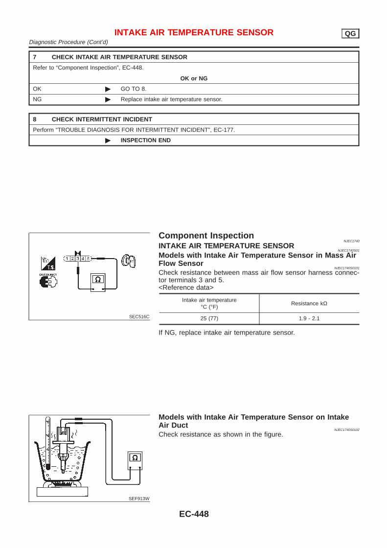
7 CHECK INTAKE AIR TEMPERATURE SENSOR
Refer to “Component Inspection”, EC-448.
OK or NG
OK © GO TO 8.
NG © Replace intake air temperature sensor.
8 CHECK INTERMITTENT INCIDENT
Perform “TROUBLE DIAGNOSIS FOR INTERMITTENT INCIDENT”, EC-177.
© INSPECTION END
SEC516C
Component InspectionNJEC1740
INTAKE AIR TEMPERATURE SENSORNJEC1740S01
Models with Intake Air Temperature Sensor in Mass AirFlow Sensor
NJEC1740S0101
Check resistance between mass air flow sensor harness connec-tor terminals 3 and 5.<Reference data>
Intake air temperature°C (°F)
Resistance kΩ
25 (77) 1.9 - 2.1
If NG, replace intake air temperature sensor.
SEF913W
Models with Intake Air Temperature Sensor on IntakeAir Duct
NJEC1740S0102
Check resistance as shown in the figure.
INTAKE AIR TEMPERATURE SENSOR QGDiagnostic Procedure (Cont’d)
EC-448
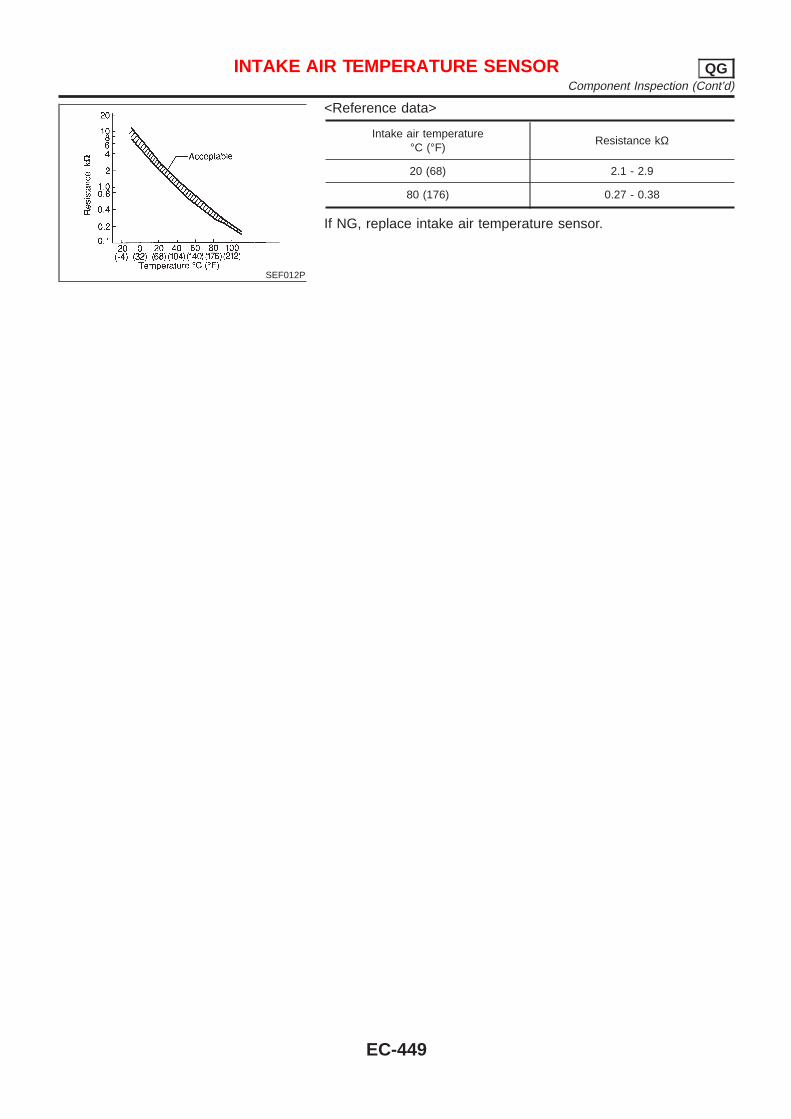
SEF012P
<Reference data>
Intake air temperature°C (°F)
Resistance kΩ
20 (68) 2.1 - 2.9
80 (176) 0.27 - 0.38
If NG, replace intake air temperature sensor.
INTAKE AIR TEMPERATURE SENSOR QGComponent Inspection (Cont’d)
EC-449
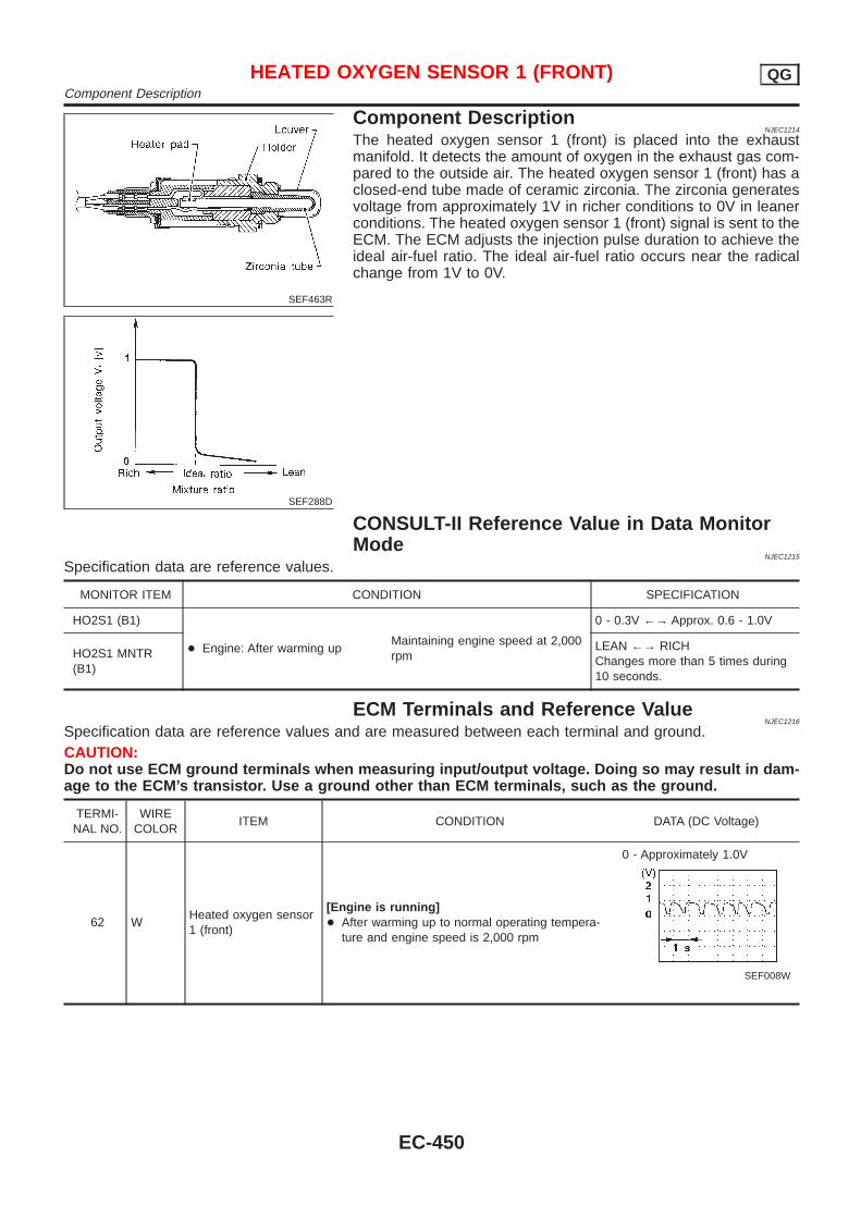
SEF463R
SEF288D
Component DescriptionNJEC1214
The heated oxygen sensor 1 (front) is placed into the exhaustmanifold. It detects the amount of oxygen in the exhaust gas com-pared to the outside air. The heated oxygen sensor 1 (front) has aclosed-end tube made of ceramic zirconia. The zirconia generatesvoltage from approximately 1V in richer conditions to 0V in leanerconditions. The heated oxygen sensor 1 (front) signal is sent to theECM. The ECM adjusts the injection pulse duration to achieve theideal air-fuel ratio. The ideal air-fuel ratio occurs near the radicalchange from 1V to 0V.
CONSULT-II Reference Value in Data MonitorMode
NJEC1215
Specification data are reference values.
MONITOR ITEM CONDITION SPECIFICATION
HO2S1 (B1)
+ Engine: After warming upMaintaining engine speed at 2,000rpm
0 - 0.3V ←→ Approx. 0.6 - 1.0V
HO2S1 MNTR(B1)
LEAN ←→ RICHChanges more than 5 times during10 seconds.
ECM Terminals and Reference ValueNJEC1216
Specification data are reference values and are measured between each terminal and ground.CAUTION:Do not use ECM ground terminals when measuring input/output voltage. Doing so may result in dam-age to the ECM’s transistor. Use a ground other than ECM terminals, such as the ground.
TERMI-NAL NO.
WIRECOLOR
ITEM CONDITION DATA (DC Voltage)
62 WHeated oxygen sensor1 (front)
[Engine is running]+ After warming up to normal operating tempera-
ture and engine speed is 2,000 rpm
0 - Approximately 1.0V
SEF008W
HEATED OXYGEN SENSOR 1 (FRONT) QGComponent Description
EC-450

Wiring DiagramNJEC1220
SEDAN MODELS AND HATCHBACK MODELS WITHECM IN ENGINE COMPARTMENT
NJEC1220S03
HEC851
HEATED OXYGEN SENSOR 1 (FRONT) QGWiring Diagram
EC-451

HATCHBACK MODELS WITH ECM IN CABINNJEC1220S04
HEC937
HEATED OXYGEN SENSOR 1 (FRONT) QGWiring Diagram (Cont’d)
EC-452
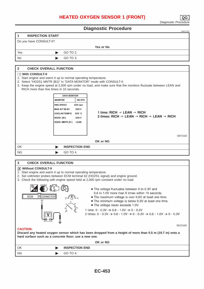
Diagnostic ProcedureNJEC1221
1 INSPECTION START
Do you have CONSULT-II?
Yes or No
Yes © GO TO 2.
No © GO TO 3.
2 CHECK OVERALL FUNCTION
With CONSULT-II1. Start engine and warm it up to normal operating temperature.2. Select “HO2S1 MNTR (B1)” in “DATA MONITOR” mode with CONSULT-II.3. Keep the engine speed at 2,000 rpm under no load, and make sure that the monitors fluctuate between LEAN and
RICH more than five times in 10 seconds.
SEF218Z
OK or NG
OK © INSPECTION END
NG © GO TO 4.
3 CHECK OVERALL FUNCTION
Without CONSULT-II1. Start engine and warm it up to normal operating temperature.2. Set voltmeter probes between ECM terminal 62 (HO2S1 signal) and engine ground.3. Check the following with engine speed held at 2,000 rpm constant under no load.
SEC518C
CAUTION:Discard any heated oxygen sensor which has been dropped from a height of more than 0.5 m (19.7 in) onto ahard surface such as a concrete floor; use a new one.
OK or NG
OK © INSPECTION END
NG © GO TO 4.
HEATED OXYGEN SENSOR 1 (FRONT) QGDiagnostic Procedure
EC-453
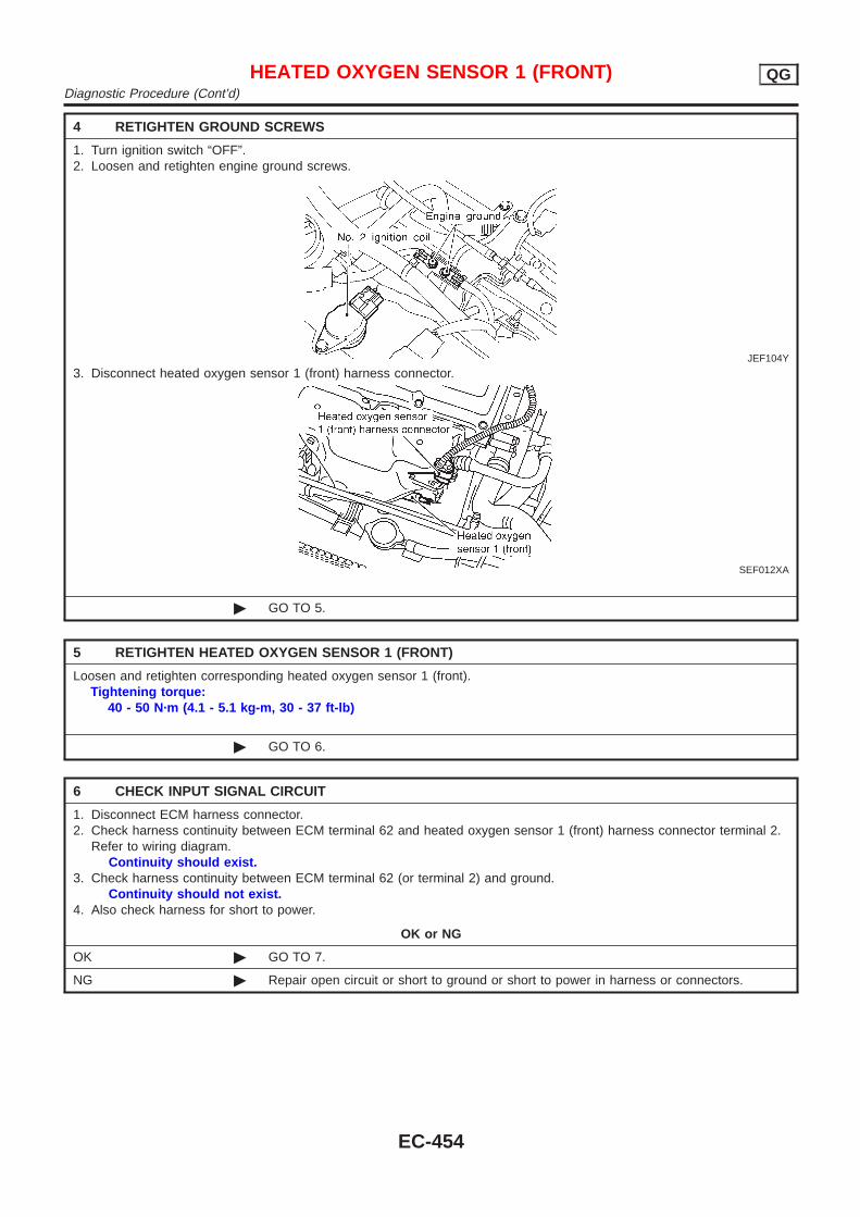
4 RETIGHTEN GROUND SCREWS
1. Turn ignition switch “OFF”.2. Loosen and retighten engine ground screws.
JEF104Y
3. Disconnect heated oxygen sensor 1 (front) harness connector.
SEF012XA
© GO TO 5.
5 RETIGHTEN HEATED OXYGEN SENSOR 1 (FRONT)
Loosen and retighten corresponding heated oxygen sensor 1 (front).Tightening torque:
40 - 50 N·m (4.1 - 5.1 kg-m, 30 - 37 ft-lb)
© GO TO 6.
6 CHECK INPUT SIGNAL CIRCUIT
1. Disconnect ECM harness connector.2. Check harness continuity between ECM terminal 62 and heated oxygen sensor 1 (front) harness connector terminal 2.
Refer to wiring diagram.Continuity should exist.
3. Check harness continuity between ECM terminal 62 (or terminal 2) and ground.Continuity should not exist.
4. Also check harness for short to power.
OK or NG
OK © GO TO 7.
NG © Repair open circuit or short to ground or short to power in harness or connectors.
HEATED OXYGEN SENSOR 1 (FRONT) QGDiagnostic Procedure (Cont’d)
EC-454
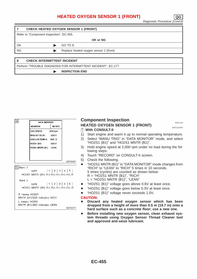
7 CHECK HEATED OXYGEN SENSOR 1 (FRONT)
Refer to “Component Inspection”, EC-455.
OK or NG
OK © GO TO 8.
NG © Replace heated oxygen sensor 1 (front).
8 CHECK INTERMITTENT INCIDENT
Perform “TROUBLE DIAGNOSIS FOR INTERMITTENT INCIDENT”, EC-177.
© INSPECTION END
SEF646Y
SEF647Y
Component InspectionNJEC1222
HEATED OXYGEN SENSOR 1 (FRONT)NJEC1222S01
With CONSULT-II1) Start engine and warm it up to normal operating temperature.2) Select “MANU TRIG” in “DATA MONITOR” mode, and select
“HO2S1 (B1)” and “HO2S1 MNTR (B1)”.3) Hold engine speed at 2,000 rpm under no load during the fol-
lowing steps.4) Touch “RECORD” on CONSULT-II screen.5) Check the following.+ “HO2S1 MNTR (B1)” in “DATA MONITOR” mode changes from
“RICH” to “LEAN” to “RICH” 5 times in 10 seconds.5 times (cycles) are counted as shown below:R = “HO2S1 MNTR (B1)”, “RICH”L = “HO2S1 MNTR (B1)”, “LEAN”
+ “HO2S1 (B1)” voltage goes above 0.6V at least once.+ “HO2S1 (B1)” voltage goes below 0.3V at least once.+ “HO2S1 (B1)” voltage never exceeds 1.0V.CAUTION:+ Discard any heated oxygen sensor which has been
dropped from a height of more than 0.5 m (19.7 in) onto ahard surface such as a concrete floor; use a new one.
+ Before installing new oxygen sensor, clean exhaust sys-tem threads using Oxygen Sensor Thread Cleaner tooland approved anti-seize lubricant.
HEATED OXYGEN SENSOR 1 (FRONT) QGDiagnostic Procedure (Cont’d)
EC-455
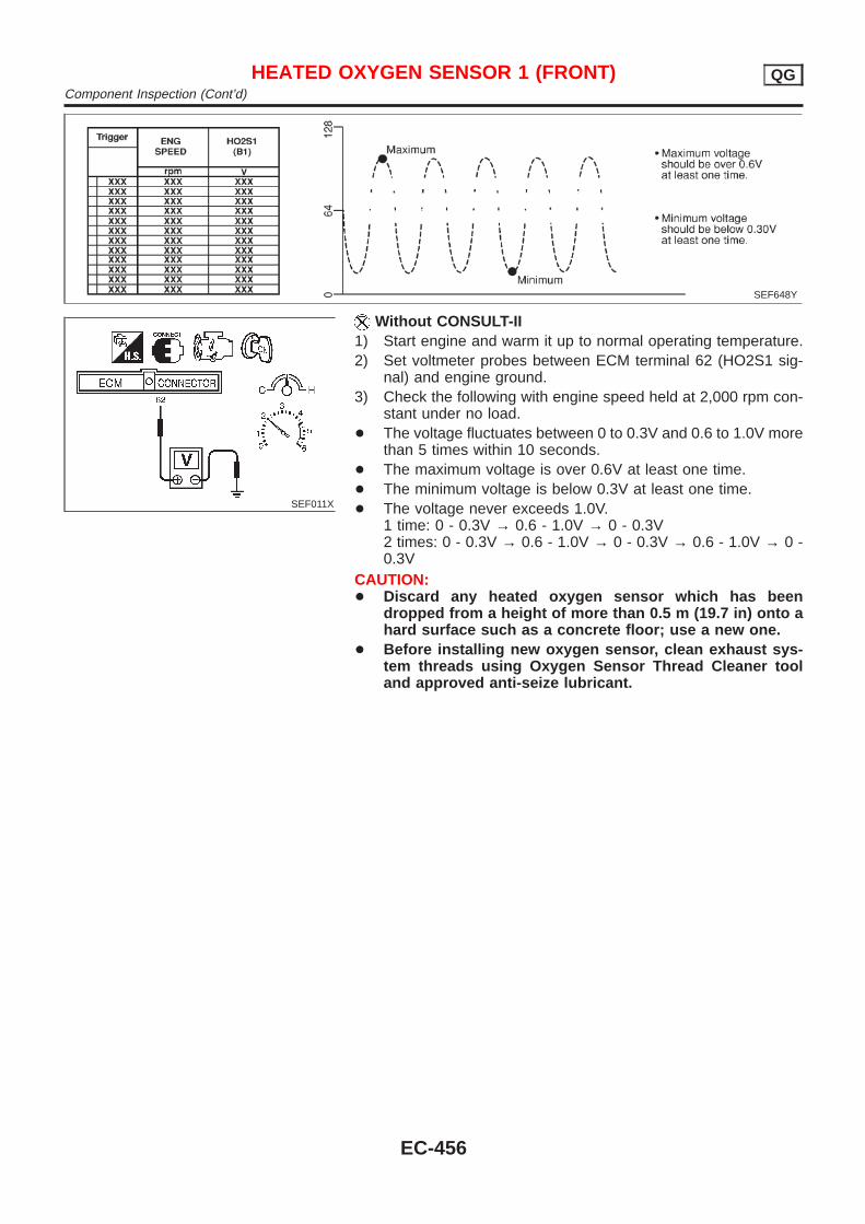
SEF648Y
SEF011X
Without CONSULT-II1) Start engine and warm it up to normal operating temperature.2) Set voltmeter probes between ECM terminal 62 (HO2S1 sig-
nal) and engine ground.3) Check the following with engine speed held at 2,000 rpm con-
stant under no load.+ The voltage fluctuates between 0 to 0.3V and 0.6 to 1.0V more
than 5 times within 10 seconds.+ The maximum voltage is over 0.6V at least one time.+ The minimum voltage is below 0.3V at least one time.+ The voltage never exceeds 1.0V.
1 time: 0 - 0.3V → 0.6 - 1.0V → 0 - 0.3V2 times: 0 - 0.3V → 0.6 - 1.0V → 0 - 0.3V → 0.6 - 1.0V → 0 -0.3V
CAUTION:+ Discard any heated oxygen sensor which has been
dropped from a height of more than 0.5 m (19.7 in) onto ahard surface such as a concrete floor; use a new one.
+ Before installing new oxygen sensor, clean exhaust sys-tem threads using Oxygen Sensor Thread Cleaner tooland approved anti-seize lubricant.
HEATED OXYGEN SENSOR 1 (FRONT) QGComponent Inspection (Cont’d)
EC-456
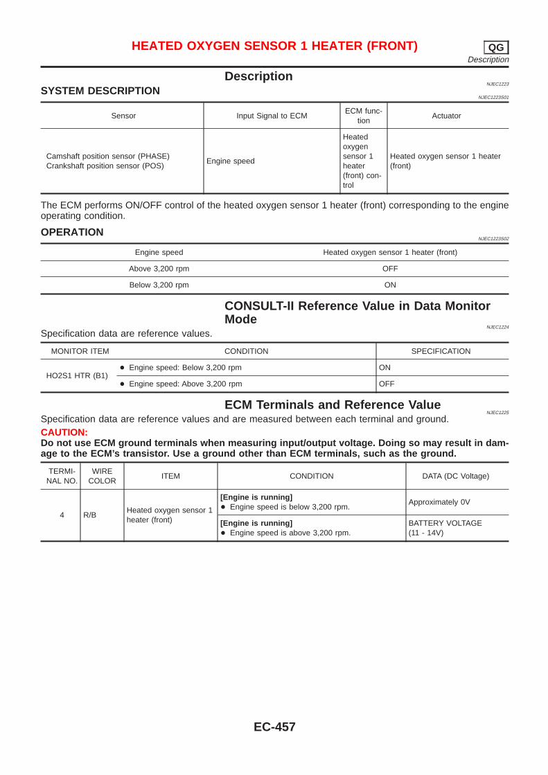
DescriptionNJEC1223
SYSTEM DESCRIPTIONNJEC1223S01
Sensor Input Signal to ECMECM func-
tionActuator
Camshaft position sensor (PHASE)Crankshaft position sensor (POS)
Engine speed
Heatedoxygensensor 1heater(front) con-trol
Heated oxygen sensor 1 heater(front)
The ECM performs ON/OFF control of the heated oxygen sensor 1 heater (front) corresponding to the engineoperating condition.
OPERATIONNJEC1223S02
Engine speed Heated oxygen sensor 1 heater (front)
Above 3,200 rpm OFF
Below 3,200 rpm ON
CONSULT-II Reference Value in Data MonitorMode
NJEC1224
Specification data are reference values.
MONITOR ITEM CONDITION SPECIFICATION
HO2S1 HTR (B1)+ Engine speed: Below 3,200 rpm ON
+ Engine speed: Above 3,200 rpm OFF
ECM Terminals and Reference ValueNJEC1225
Specification data are reference values and are measured between each terminal and ground.CAUTION:Do not use ECM ground terminals when measuring input/output voltage. Doing so may result in dam-age to the ECM’s transistor. Use a ground other than ECM terminals, such as the ground.
TERMI-NAL NO.
WIRECOLOR
ITEM CONDITION DATA (DC Voltage)
4 R/BHeated oxygen sensor 1heater (front)
[Engine is running]+ Engine speed is below 3,200 rpm.
Approximately 0V
[Engine is running]+ Engine speed is above 3,200 rpm.
BATTERY VOLTAGE(11 - 14V)
HEATED OXYGEN SENSOR 1 HEATER (FRONT) QGDescription
EC-457
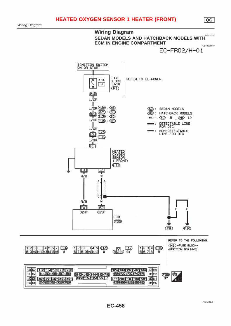
Wiring DiagramNJEC1228
SEDAN MODELS AND HATCHBACK MODELS WITHECM IN ENGINE COMPARTMENT
NJEC1228S03
HEC852
HEATED OXYGEN SENSOR 1 HEATER (FRONT) QGWiring Diagram
EC-458

HATCHBACK MODELS WITH ECM IN CABINNJEC1228S04
HEC939
HEATED OXYGEN SENSOR 1 HEATER (FRONT) QGWiring Diagram (Cont’d)
EC-459
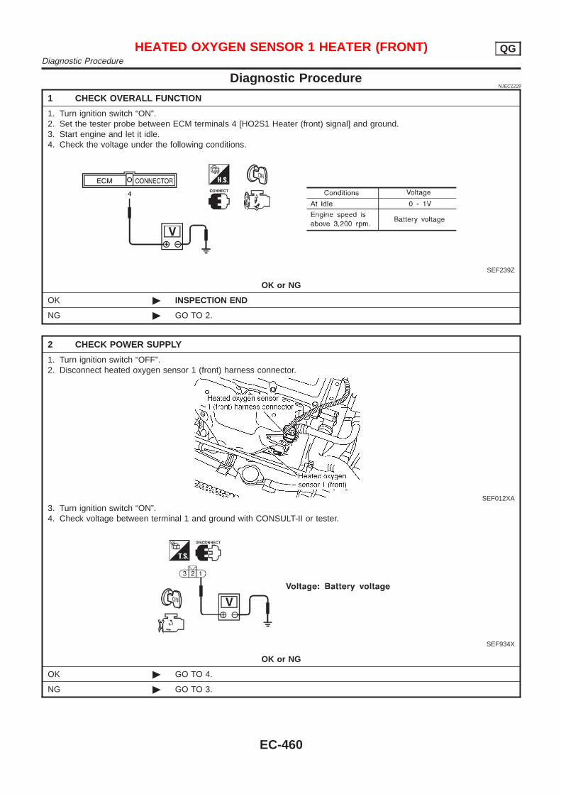
Diagnostic ProcedureNJEC1229
1 CHECK OVERALL FUNCTION
1. Turn ignition switch “ON”.2. Set the tester probe between ECM terminals 4 [HO2S1 Heater (front) signal] and ground.3. Start engine and let it idle.4. Check the voltage under the following conditions.
SEF239Z
OK or NG
OK © INSPECTION END
NG © GO TO 2.
2 CHECK POWER SUPPLY
1. Turn ignition switch “OFF”.2. Disconnect heated oxygen sensor 1 (front) harness connector.
SEF012XA
3. Turn ignition switch “ON”.4. Check voltage between terminal 1 and ground with CONSULT-II or tester.
SEF934X
OK or NG
OK © GO TO 4.
NG © GO TO 3.
HEATED OXYGEN SENSOR 1 HEATER (FRONT) QGDiagnostic Procedure
EC-460
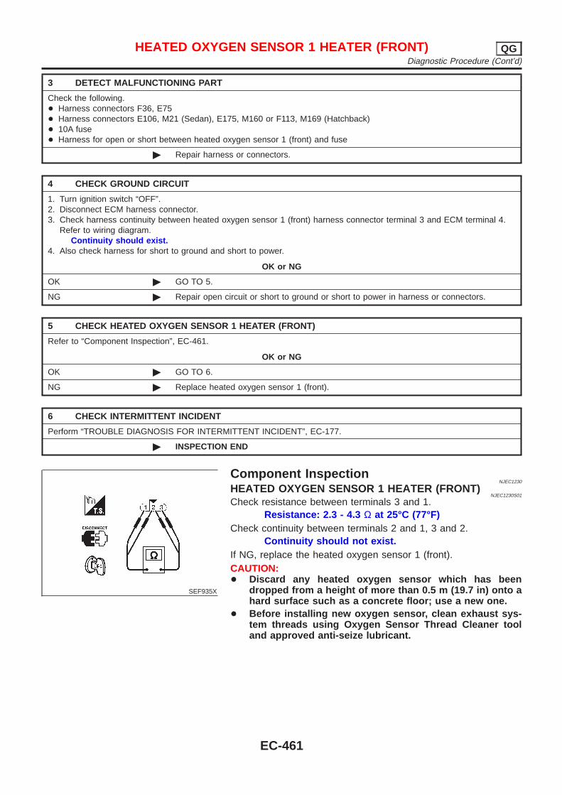
3 DETECT MALFUNCTIONING PART
Check the following.+ Harness connectors F36, E75+ Harness connectors E106, M21 (Sedan), E175, M160 or F113, M169 (Hatchback)+ 10A fuse+ Harness for open or short between heated oxygen sensor 1 (front) and fuse
© Repair harness or connectors.
4 CHECK GROUND CIRCUIT
1. Turn ignition switch “OFF”.2. Disconnect ECM harness connector.3. Check harness continuity between heated oxygen sensor 1 (front) harness connector terminal 3 and ECM terminal 4.
Refer to wiring diagram.Continuity should exist.
4. Also check harness for short to ground and short to power.
OK or NG
OK © GO TO 5.
NG © Repair open circuit or short to ground or short to power in harness or connectors.
5 CHECK HEATED OXYGEN SENSOR 1 HEATER (FRONT)
Refer to “Component Inspection”, EC-461.
OK or NG
OK © GO TO 6.
NG © Replace heated oxygen sensor 1 (front).
6 CHECK INTERMITTENT INCIDENT
Perform “TROUBLE DIAGNOSIS FOR INTERMITTENT INCIDENT”, EC-177.
© INSPECTION END
SEF935X
Component InspectionNJEC1230
HEATED OXYGEN SENSOR 1 HEATER (FRONT)NJEC1230S01
Check resistance between terminals 3 and 1.Resistance: 2.3 - 4.3 Ω at 25°C (77°F)
Check continuity between terminals 2 and 1, 3 and 2.Continuity should not exist.
If NG, replace the heated oxygen sensor 1 (front).CAUTION:+ Discard any heated oxygen sensor which has been
dropped from a height of more than 0.5 m (19.7 in) onto ahard surface such as a concrete floor; use a new one.
+ Before installing new oxygen sensor, clean exhaust sys-tem threads using Oxygen Sensor Thread Cleaner tooland approved anti-seize lubricant.
HEATED OXYGEN SENSOR 1 HEATER (FRONT) QGDiagnostic Procedure (Cont’d)
EC-461
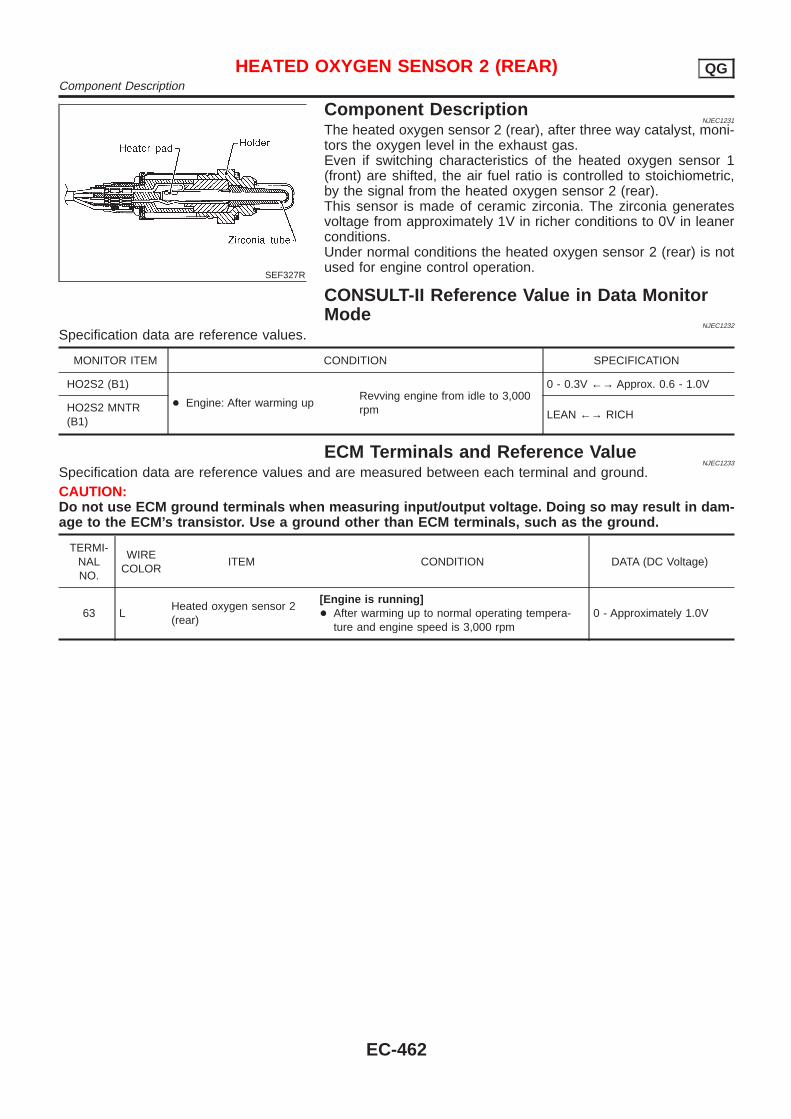
SEF327R
Component DescriptionNJEC1231
The heated oxygen sensor 2 (rear), after three way catalyst, moni-tors the oxygen level in the exhaust gas.Even if switching characteristics of the heated oxygen sensor 1(front) are shifted, the air fuel ratio is controlled to stoichiometric,by the signal from the heated oxygen sensor 2 (rear).This sensor is made of ceramic zirconia. The zirconia generatesvoltage from approximately 1V in richer conditions to 0V in leanerconditions.Under normal conditions the heated oxygen sensor 2 (rear) is notused for engine control operation.
CONSULT-II Reference Value in Data MonitorMode
NJEC1232
Specification data are reference values.
MONITOR ITEM CONDITION SPECIFICATION
HO2S2 (B1)
+ Engine: After warming upRevving engine from idle to 3,000rpm
0 - 0.3V ←→ Approx. 0.6 - 1.0V
HO2S2 MNTR(B1)
LEAN ←→ RICH
ECM Terminals and Reference ValueNJEC1233
Specification data are reference values and are measured between each terminal and ground.CAUTION:Do not use ECM ground terminals when measuring input/output voltage. Doing so may result in dam-age to the ECM’s transistor. Use a ground other than ECM terminals, such as the ground.
TERMI-NALNO.
WIRECOLOR
ITEM CONDITION DATA (DC Voltage)
63 LHeated oxygen sensor 2(rear)
[Engine is running]+ After warming up to normal operating tempera-
ture and engine speed is 3,000 rpm0 - Approximately 1.0V
HEATED OXYGEN SENSOR 2 (REAR) QGComponent Description
EC-462

Wiring DiagramNJEC1237
SEDAN MODELS AND HATCHBACK MODELS WITHECM IN ENGINE COMPARTMENT
NJEC1237S03
HEC853
HEATED OXYGEN SENSOR 2 (REAR) QGWiring Diagram
EC-463
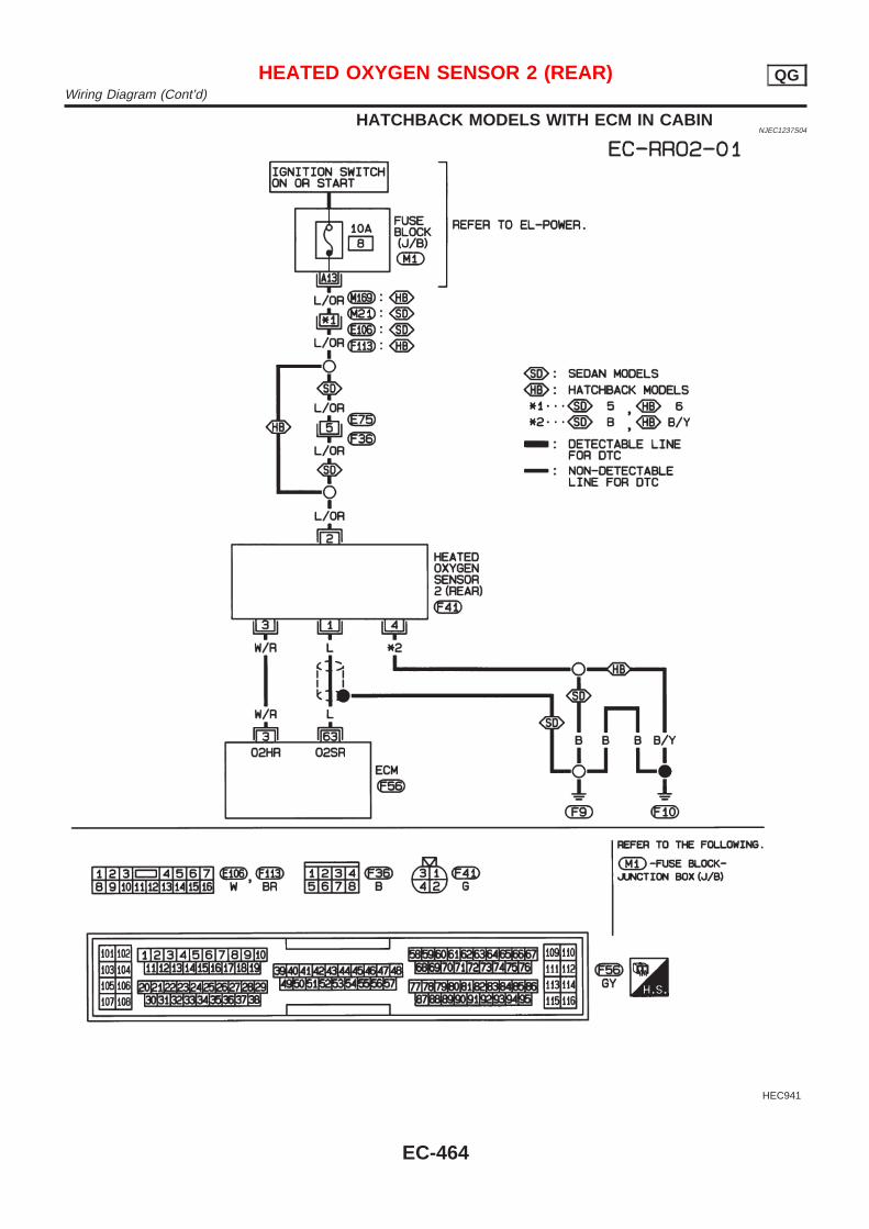
HATCHBACK MODELS WITH ECM IN CABINNJEC1237S04
HEC941
HEATED OXYGEN SENSOR 2 (REAR) QGWiring Diagram (Cont’d)
EC-464
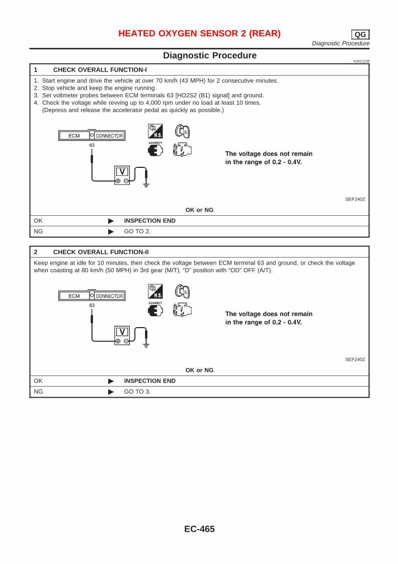
Diagnostic ProcedureNJEC1238
1 CHECK OVERALL FUNCTION-I
1. Start engine and drive the vehicle at over 70 km/h (43 MPH) for 2 consecutive minutes.2. Stop vehicle and keep the engine running.3. Set voltmeter probes between ECM terminals 63 [HO2S2 (B1) signal] and ground.4. Check the voltage while revving up to 4,000 rpm under no load at least 10 times.
(Depress and release the accelerator pedal as quickly as possible.)
SEF240Z
OK or NG
OK © INSPECTION END
NG © GO TO 2.
2 CHECK OVERALL FUNCTION-II
Keep engine at idle for 10 minutes, then check the voltage between ECM terminal 63 and ground, or check the voltagewhen coasting at 80 km/h (50 MPH) in 3rd gear (M/T), “D” position with “OD” OFF (A/T).
SEF240Z
OK or NG
OK © INSPECTION END
NG © GO TO 3.
HEATED OXYGEN SENSOR 2 (REAR) QGDiagnostic Procedure
EC-465

3 RETIGHTEN GROUND SCREWS
1. Turn ignition switch “OFF”.2. Loosen and retighten engine ground screws.
JEF104Y
© GO TO 4.
4 CHECK INPUT SIGNAL CIRCUIT
1. Turn ignition switch “OFF”.2. Disconnect heated oxygen sensor 2 (rear) harness connector and ECM harness connector.
SEF160Z
3. Check harness continuity between ECM terminal 63 and heated oxygen sensor 2 (rear) harness connector terminal 1.Refer to wiring diagram.
Continuity should exist.4. Check harness continuity between ECM terminal 63 [or heated oxygen sensor 2 (rear) harness connector terminal 1]
and ground.Continuity should not exist.
5. Also check harness for short to ground and short to power.
OK or NG
OK © GO TO 6.
NG © GO TO 5.
5 DETECT MALFUNCTIONING PART
Check the harness for open or short between heated oxygen sensor 2 (rear) and ECM.
© Repair open circuit or short to ground or short to power in harness or connectors.
HEATED OXYGEN SENSOR 2 (REAR) QGDiagnostic Procedure (Cont’d)
EC-466
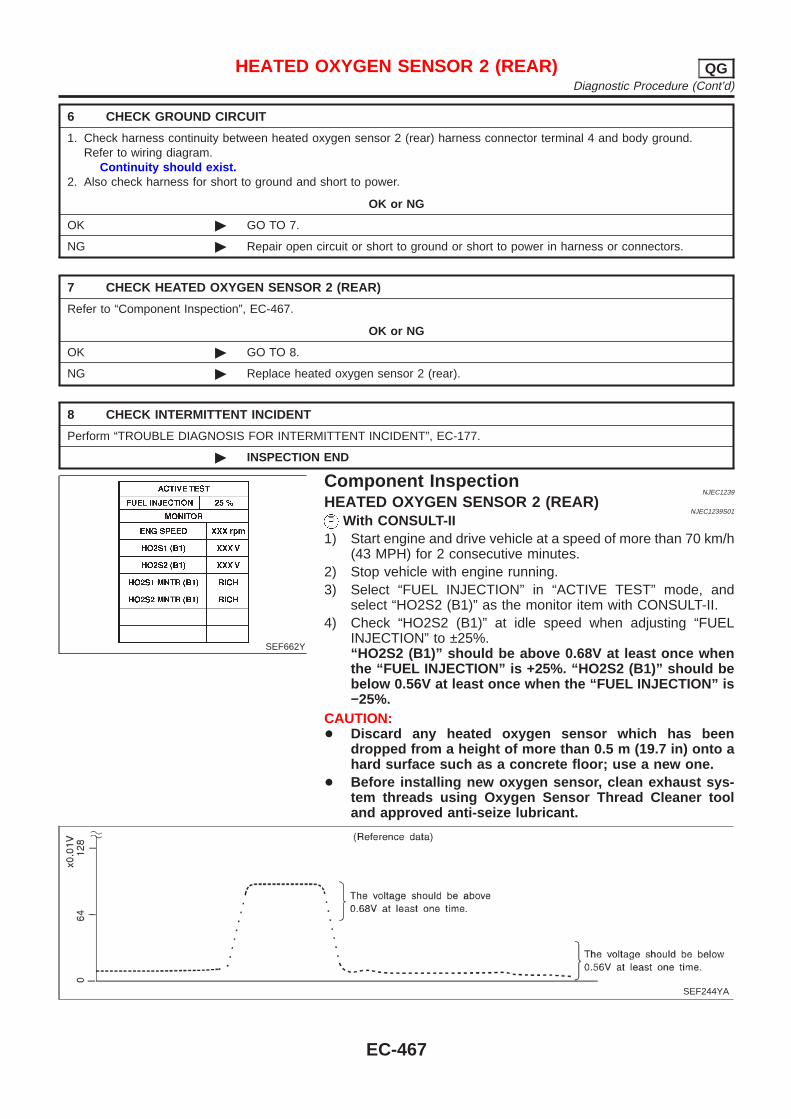
6 CHECK GROUND CIRCUIT
1. Check harness continuity between heated oxygen sensor 2 (rear) harness connector terminal 4 and body ground.Refer to wiring diagram.
Continuity should exist.2. Also check harness for short to ground and short to power.
OK or NG
OK © GO TO 7.
NG © Repair open circuit or short to ground or short to power in harness or connectors.
7 CHECK HEATED OXYGEN SENSOR 2 (REAR)
Refer to “Component Inspection”, EC-467.
OK or NG
OK © GO TO 8.
NG © Replace heated oxygen sensor 2 (rear).
8 CHECK INTERMITTENT INCIDENT
Perform “TROUBLE DIAGNOSIS FOR INTERMITTENT INCIDENT”, EC-177.
© INSPECTION END
SEF662Y
Component InspectionNJEC1239
HEATED OXYGEN SENSOR 2 (REAR)NJEC1239S01
With CONSULT-II1) Start engine and drive vehicle at a speed of more than 70 km/h
(43 MPH) for 2 consecutive minutes.2) Stop vehicle with engine running.3) Select “FUEL INJECTION” in “ACTIVE TEST” mode, and
select “HO2S2 (B1)” as the monitor item with CONSULT-II.4) Check “HO2S2 (B1)” at idle speed when adjusting “FUEL
INJECTION” to ±25%.“HO2S2 (B1)” should be above 0.68V at least once whenthe “FUEL INJECTION” is +25%. “HO2S2 (B1)” should bebelow 0.56V at least once when the “FUEL INJECTION” is−25%.
CAUTION:+ Discard any heated oxygen sensor which has been
dropped from a height of more than 0.5 m (19.7 in) onto ahard surface such as a concrete floor; use a new one.
+ Before installing new oxygen sensor, clean exhaust sys-tem threads using Oxygen Sensor Thread Cleaner tooland approved anti-seize lubricant.
SEF244YA
HEATED OXYGEN SENSOR 2 (REAR) QGDiagnostic Procedure (Cont’d)
EC-467
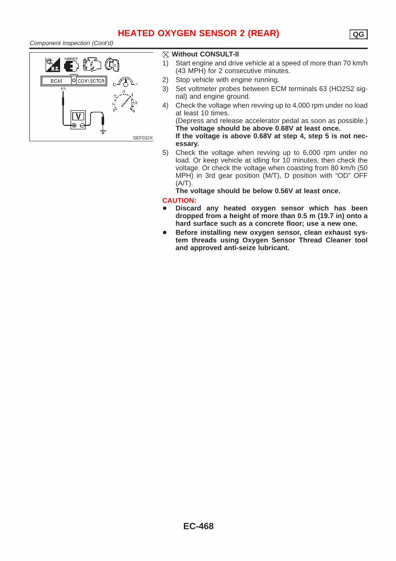
SEF032X
Without CONSULT-II1) Start engine and drive vehicle at a speed of more than 70 km/h
(43 MPH) for 2 consecutive minutes.2) Stop vehicle with engine running.3) Set voltmeter probes between ECM terminals 63 (HO2S2 sig-
nal) and engine ground.4) Check the voltage when revving up to 4,000 rpm under no load
at least 10 times.(Depress and release accelerator pedal as soon as possible.)The voltage should be above 0.68V at least once.If the voltage is above 0.68V at step 4, step 5 is not nec-essary.
5) Check the voltage when revving up to 6,000 rpm under noload. Or keep vehicle at idling for 10 minutes, then check thevoltage. Or check the voltage when coasting from 80 km/h (50MPH) in 3rd gear position (M/T), D position with “OD” OFF(A/T).The voltage should be below 0.56V at least once.
CAUTION:+ Discard any heated oxygen sensor which has been
dropped from a height of more than 0.5 m (19.7 in) onto ahard surface such as a concrete floor; use a new one.
+ Before installing new oxygen sensor, clean exhaust sys-tem threads using Oxygen Sensor Thread Cleaner tooland approved anti-seize lubricant.
HEATED OXYGEN SENSOR 2 (REAR) QGComponent Inspection (Cont’d)
EC-468
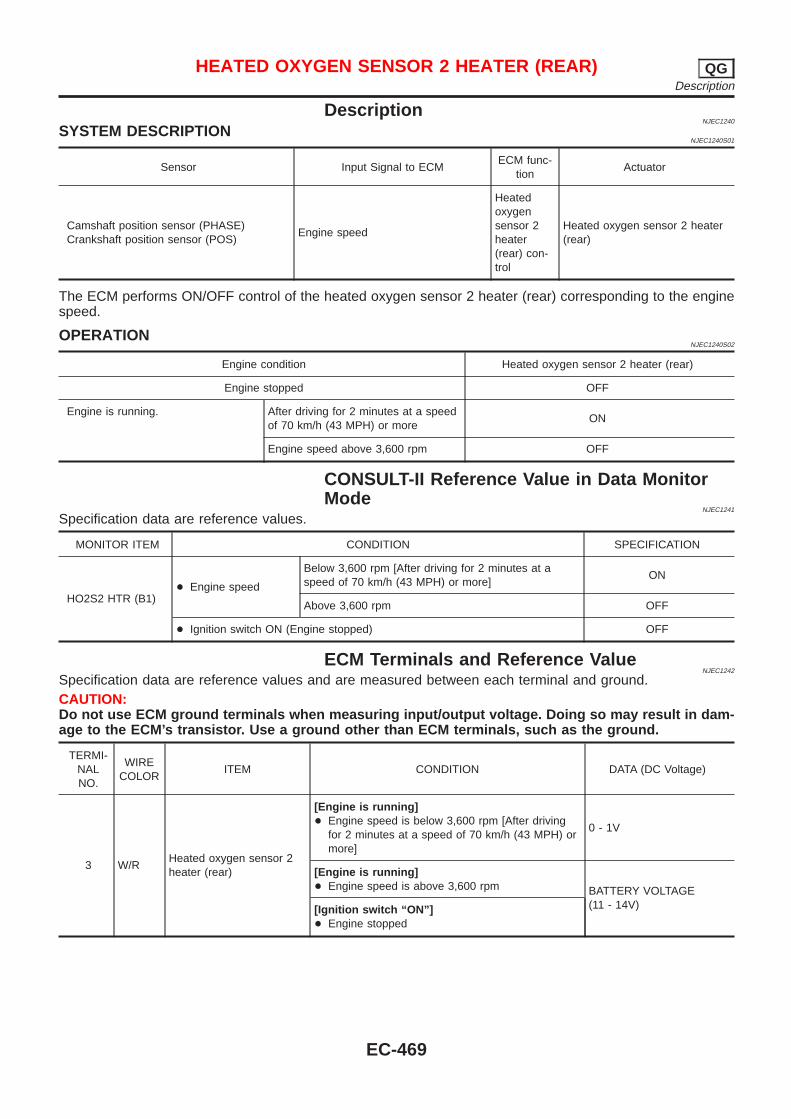
DescriptionNJEC1240
SYSTEM DESCRIPTIONNJEC1240S01
Sensor Input Signal to ECMECM func-
tionActuator
Camshaft position sensor (PHASE)Crankshaft position sensor (POS)
Engine speed
Heatedoxygensensor 2heater(rear) con-trol
Heated oxygen sensor 2 heater(rear)
The ECM performs ON/OFF control of the heated oxygen sensor 2 heater (rear) corresponding to the enginespeed.
OPERATIONNJEC1240S02
Engine condition Heated oxygen sensor 2 heater (rear)
Engine stopped OFF
Engine is running. After driving for 2 minutes at a speedof 70 km/h (43 MPH) or more
ON
Engine speed above 3,600 rpm OFF
CONSULT-II Reference Value in Data MonitorMode
NJEC1241
Specification data are reference values.
MONITOR ITEM CONDITION SPECIFICATION
HO2S2 HTR (B1)+ Engine speed
Below 3,600 rpm [After driving for 2 minutes at aspeed of 70 km/h (43 MPH) or more]
ON
Above 3,600 rpm OFF
+ Ignition switch ON (Engine stopped) OFF
ECM Terminals and Reference ValueNJEC1242
Specification data are reference values and are measured between each terminal and ground.CAUTION:Do not use ECM ground terminals when measuring input/output voltage. Doing so may result in dam-age to the ECM’s transistor. Use a ground other than ECM terminals, such as the ground.
TERMI-NALNO.
WIRECOLOR
ITEM CONDITION DATA (DC Voltage)
3 W/RHeated oxygen sensor 2heater (rear)
[Engine is running]+ Engine speed is below 3,600 rpm [After driving
for 2 minutes at a speed of 70 km/h (43 MPH) ormore]
0 - 1V
[Engine is running]+ Engine speed is above 3,600 rpm BATTERY VOLTAGE
(11 - 14V)[Ignition switch “ON”]+ Engine stopped
HEATED OXYGEN SENSOR 2 HEATER (REAR) QGDescription
EC-469

Wiring DiagramNJEC1245
SEDAN MODELS AND HATCHBACK MODELS WITHECM IN ENGINE COMPARTMENT
NJEC1245S03
HEC854
HEATED OXYGEN SENSOR 2 HEATER (REAR) QGWiring Diagram
EC-470
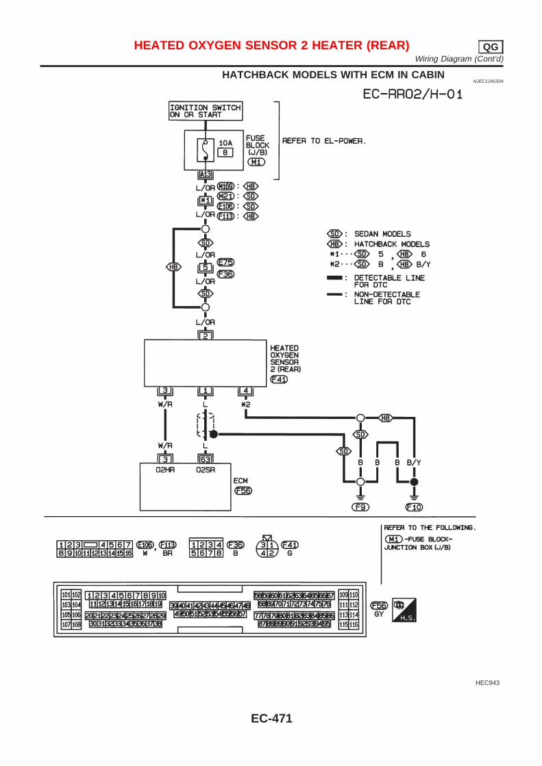
HATCHBACK MODELS WITH ECM IN CABINNJEC1245S04
HEC943
HEATED OXYGEN SENSOR 2 HEATER (REAR) QGWiring Diagram (Cont’d)
EC-471
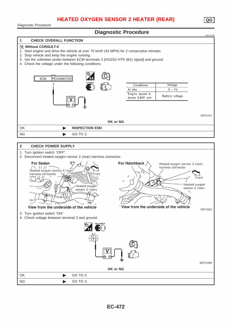
Diagnostic ProcedureNJEC1246
1 CHECK OVERALL FUNCTION
Without CONSULT-II1. Start engine and drive the vehicle at over 70 km/h (43 MPH) for 2 consecutive minutes.2. Stop vehicle and keep the engine running.3. Set the voltmeter probe between ECM terminals 3 [HO2S2 HTR (B1) signal] and ground.4. Check the voltage under the following conditions.
SEF241Z
OK or NG
OK © INSPECTION END
NG © GO TO 2.
2 CHECK POWER SUPPLY
1. Turn ignition switch “OFF”.2. Disconnect heated oxygen sensor 2 (rear) harness connector.
SEF160Z
3. Turn ignition switch “ON”.4. Check voltage between terminal 2 and ground.
SEF218W
OK or NG
OK © GO TO 4.
NG © GO TO 3.
HEATED OXYGEN SENSOR 2 HEATER (REAR) QGDiagnostic Procedure
EC-472
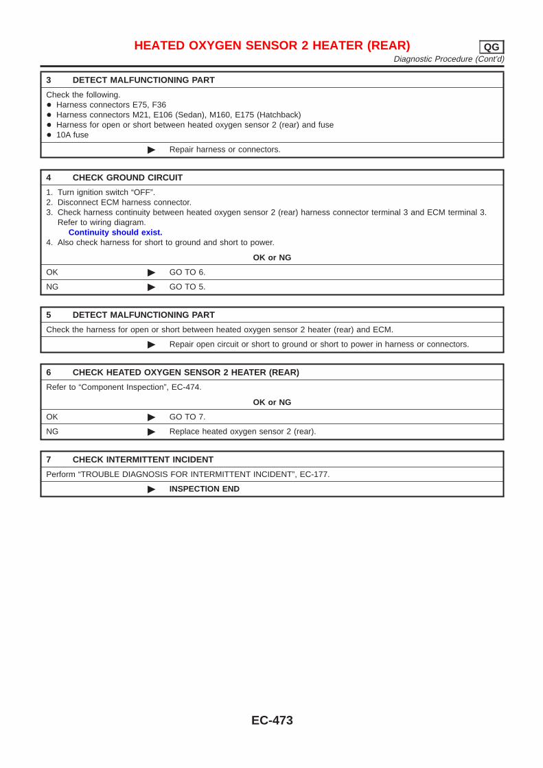
3 DETECT MALFUNCTIONING PART
Check the following.+ Harness connectors E75, F36+ Harness connectors M21, E106 (Sedan), M160, E175 (Hatchback)+ Harness for open or short between heated oxygen sensor 2 (rear) and fuse+ 10A fuse
© Repair harness or connectors.
4 CHECK GROUND CIRCUIT
1. Turn ignition switch “OFF”.2. Disconnect ECM harness connector.3. Check harness continuity between heated oxygen sensor 2 (rear) harness connector terminal 3 and ECM terminal 3.
Refer to wiring diagram.Continuity should exist.
4. Also check harness for short to ground and short to power.
OK or NG
OK © GO TO 6.
NG © GO TO 5.
5 DETECT MALFUNCTIONING PART
Check the harness for open or short between heated oxygen sensor 2 heater (rear) and ECM.
© Repair open circuit or short to ground or short to power in harness or connectors.
6 CHECK HEATED OXYGEN SENSOR 2 HEATER (REAR)
Refer to “Component Inspection”, EC-474.
OK or NG
OK © GO TO 7.
NG © Replace heated oxygen sensor 2 (rear).
7 CHECK INTERMITTENT INCIDENT
Perform “TROUBLE DIAGNOSIS FOR INTERMITTENT INCIDENT”, EC-177.
© INSPECTION END
HEATED OXYGEN SENSOR 2 HEATER (REAR) QGDiagnostic Procedure (Cont’d)
EC-473
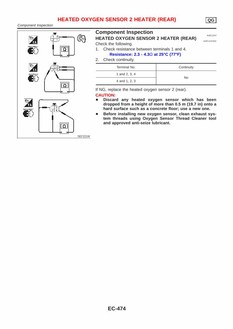
SEF221W
Component InspectionNJEC1247
HEATED OXYGEN SENSOR 2 HEATER (REAR)NJEC1247S01
Check the following.1. Check resistance between terminals 1 and 4.
Resistance: 2.3 - 4.3 Ω at 25°C (77°F)2. Check continuity.
Terminal No. Continuity
1 and 2, 3, 4No
4 and 1, 2, 3
If NG, replace the heated oxygen sensor 2 (rear).CAUTION:+ Discard any heated oxygen sensor which has been
dropped from a height of more than 0.5 m (19.7 in) onto ahard surface such as a concrete floor; use a new one.
+ Before installing new oxygen sensor, clean exhaust sys-tem threads using Oxygen Sensor Thread Cleaner tooland approved anti-seize lubricant.
HEATED OXYGEN SENSOR 2 HEATER (REAR) QGComponent Inspection
EC-474
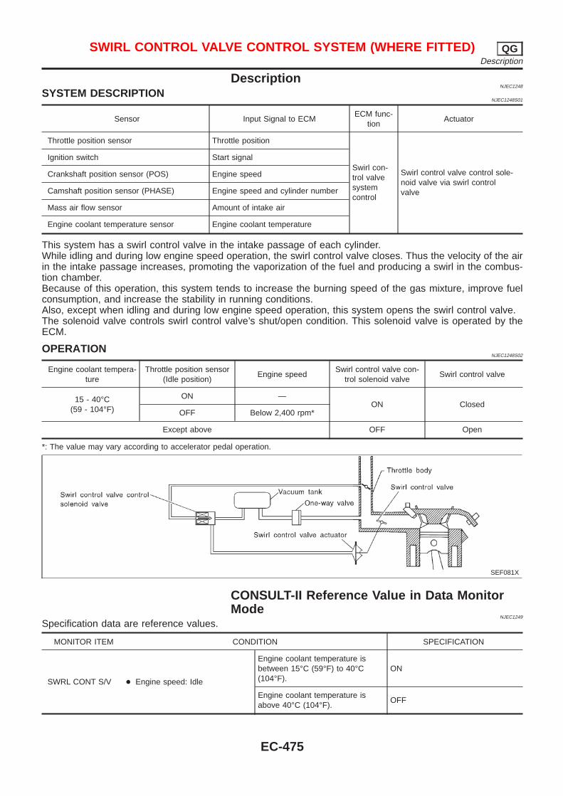
DescriptionNJEC1248
SYSTEM DESCRIPTIONNJEC1248S01
Sensor Input Signal to ECMECM func-
tionActuator
Throttle position sensor Throttle position
Swirl con-trol valvesystemcontrol
Swirl control valve control sole-noid valve via swirl controlvalve
Ignition switch Start signal
Crankshaft position sensor (POS) Engine speed
Camshaft position sensor (PHASE) Engine speed and cylinder number
Mass air flow sensor Amount of intake air
Engine coolant temperature sensor Engine coolant temperature
This system has a swirl control valve in the intake passage of each cylinder.While idling and during low engine speed operation, the swirl control valve closes. Thus the velocity of the airin the intake passage increases, promoting the vaporization of the fuel and producing a swirl in the combus-tion chamber.Because of this operation, this system tends to increase the burning speed of the gas mixture, improve fuelconsumption, and increase the stability in running conditions.Also, except when idling and during low engine speed operation, this system opens the swirl control valve.The solenoid valve controls swirl control valve’s shut/open condition. This solenoid valve is operated by theECM.
OPERATIONNJEC1248S02
Engine coolant tempera-ture
Throttle position sensor(Idle position)
Engine speedSwirl control valve con-
trol solenoid valveSwirl control valve
15 - 40°C(59 - 104°F)
ON —ON Closed
OFF Below 2,400 rpm*
Except above OFF Open
*: The value may vary according to accelerator pedal operation.
SEF081X
CONSULT-II Reference Value in Data MonitorMode
NJEC1249
Specification data are reference values.
MONITOR ITEM CONDITION SPECIFICATION
SWRL CONT S/V + Engine speed: Idle
Engine coolant temperature isbetween 15°C (59°F) to 40°C(104°F).
ON
Engine coolant temperature isabove 40°C (104°F).
OFF
SWIRL CONTROL VALVE CONTROL SYSTEM (WHERE FITTED) QGDescription
EC-475
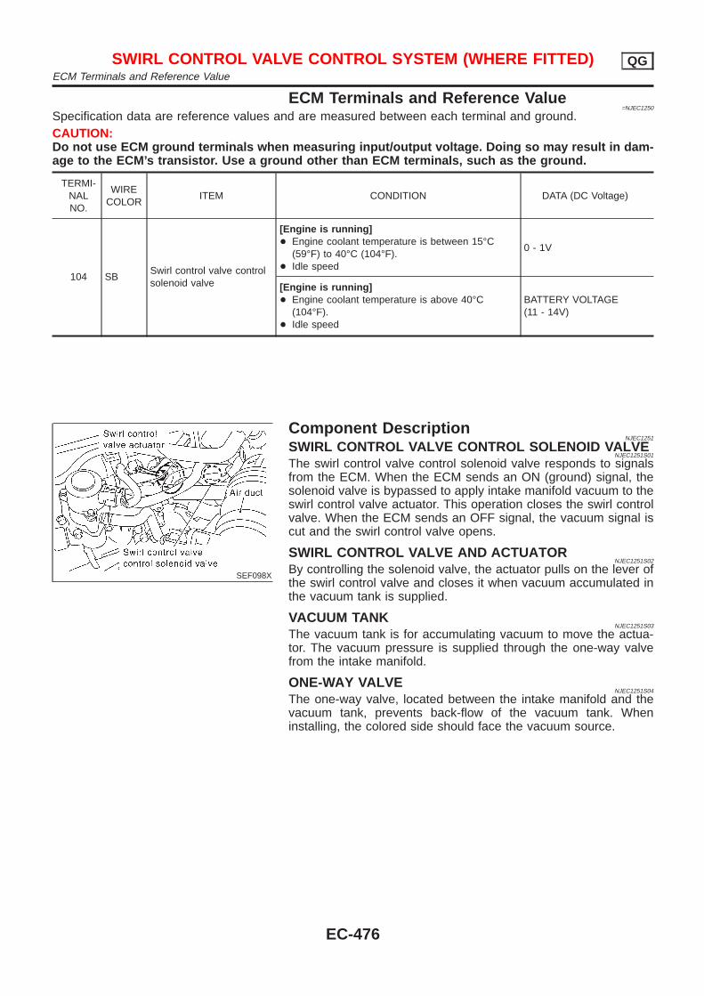
ECM Terminals and Reference Value=NJEC1250
Specification data are reference values and are measured between each terminal and ground.CAUTION:Do not use ECM ground terminals when measuring input/output voltage. Doing so may result in dam-age to the ECM’s transistor. Use a ground other than ECM terminals, such as the ground.
TERMI-NALNO.
WIRECOLOR
ITEM CONDITION DATA (DC Voltage)
104 SBSwirl control valve controlsolenoid valve
[Engine is running]+ Engine coolant temperature is between 15°C
(59°F) to 40°C (104°F).+ Idle speed
0 - 1V
[Engine is running]+ Engine coolant temperature is above 40°C
(104°F).+ Idle speed
BATTERY VOLTAGE(11 - 14V)
SEF098X
Component DescriptionNJEC1251
SWIRL CONTROL VALVE CONTROL SOLENOID VALVENJEC1251S01
The swirl control valve control solenoid valve responds to signalsfrom the ECM. When the ECM sends an ON (ground) signal, thesolenoid valve is bypassed to apply intake manifold vacuum to theswirl control valve actuator. This operation closes the swirl controlvalve. When the ECM sends an OFF signal, the vacuum signal iscut and the swirl control valve opens.
SWIRL CONTROL VALVE AND ACTUATORNJEC1251S02
By controlling the solenoid valve, the actuator pulls on the lever ofthe swirl control valve and closes it when vacuum accumulated inthe vacuum tank is supplied.
VACUUM TANKNJEC1251S03
The vacuum tank is for accumulating vacuum to move the actua-tor. The vacuum pressure is supplied through the one-way valvefrom the intake manifold.
ONE-WAY VALVENJEC1251S04
The one-way valve, located between the intake manifold and thevacuum tank, prevents back-flow of the vacuum tank. Wheninstalling, the colored side should face the vacuum source.
SWIRL CONTROL VALVE CONTROL SYSTEM (WHERE FITTED) QGECM Terminals and Reference Value
EC-476

Wiring DiagramNJEC1254
HEC855
SWIRL CONTROL VALVE CONTROL SYSTEM (WHERE FITTED) QGWiring Diagram
EC-477
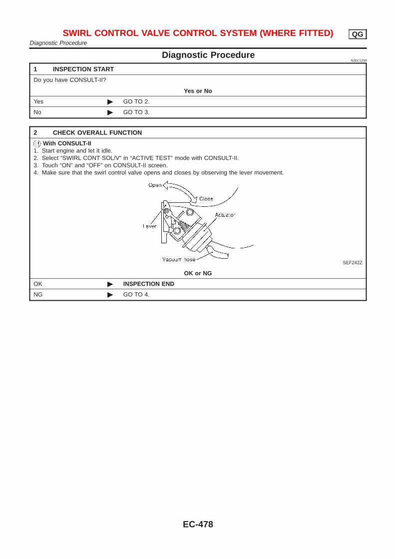
Diagnostic ProcedureNJEC1255
1 INSPECTION START
Do you have CONSULT-II?
Yes or No
Yes © GO TO 2.
No © GO TO 3.
2 CHECK OVERALL FUNCTION
With CONSULT-II1. Start engine and let it idle.2. Select “SWIRL CONT SOL/V” in “ACTIVE TEST” mode with CONSULT-II.3. Touch “ON” and “OFF” on CONSULT-II screen.4. Make sure that the swirl control valve opens and closes by observing the lever movement.
SEF242Z
OK or NG
OK © INSPECTION END
NG © GO TO 4.
SWIRL CONTROL VALVE CONTROL SYSTEM (WHERE FITTED) QGDiagnostic Procedure
EC-478
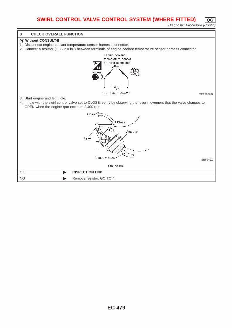
3 CHECK OVERALL FUNCTION
Without CONSULT-II1. Disconnect engine coolant temperature sensor harness connector.2. Connect a resistor (1.5 - 2.0 kΩ) between terminals of engine coolant temperature sensor harness connector.
SEF982UB
3. Start engine and let it idle.4. In idle with the swirl control valve set to CLOSE, verify by observing the lever movement that the valve changes to
OPEN when the engine rpm exceeds 2,400 rpm.
SEF242Z
OK or NG
OK © INSPECTION END
NG © Remove resistor. GO TO 4.
SWIRL CONTROL VALVE CONTROL SYSTEM (WHERE FITTED) QGDiagnostic Procedure (Cont’d)
EC-479
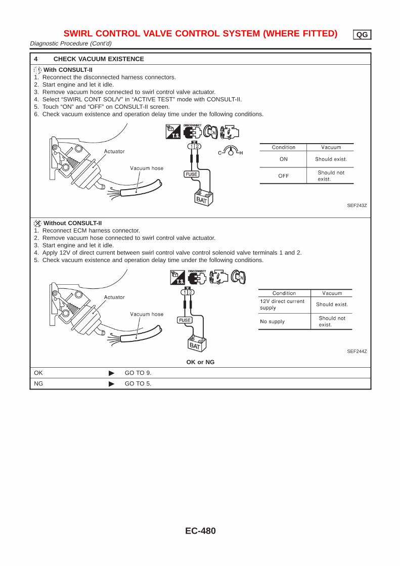
4 CHECK VACUUM EXISTENCE
With CONSULT-II1. Reconnect the disconnected harness connectors.2. Start engine and let it idle.3. Remove vacuum hose connected to swirl control valve actuator.4. Select “SWIRL CONT SOL/V” in “ACTIVE TEST” mode with CONSULT-II.5. Touch “ON” and “OFF” on CONSULT-II screen.6. Check vacuum existence and operation delay time under the following conditions.
SEF243Z
Without CONSULT-II1. Reconnect ECM harness connector.2. Remove vacuum hose connected to swirl control valve actuator.3. Start engine and let it idle.4. Apply 12V of direct current between swirl control valve control solenoid valve terminals 1 and 2.5. Check vacuum existence and operation delay time under the following conditions.
SEF244Z
OK or NG
OK © GO TO 9.
NG © GO TO 5.
SWIRL CONTROL VALVE CONTROL SYSTEM (WHERE FITTED) QGDiagnostic Procedure (Cont’d)
EC-480
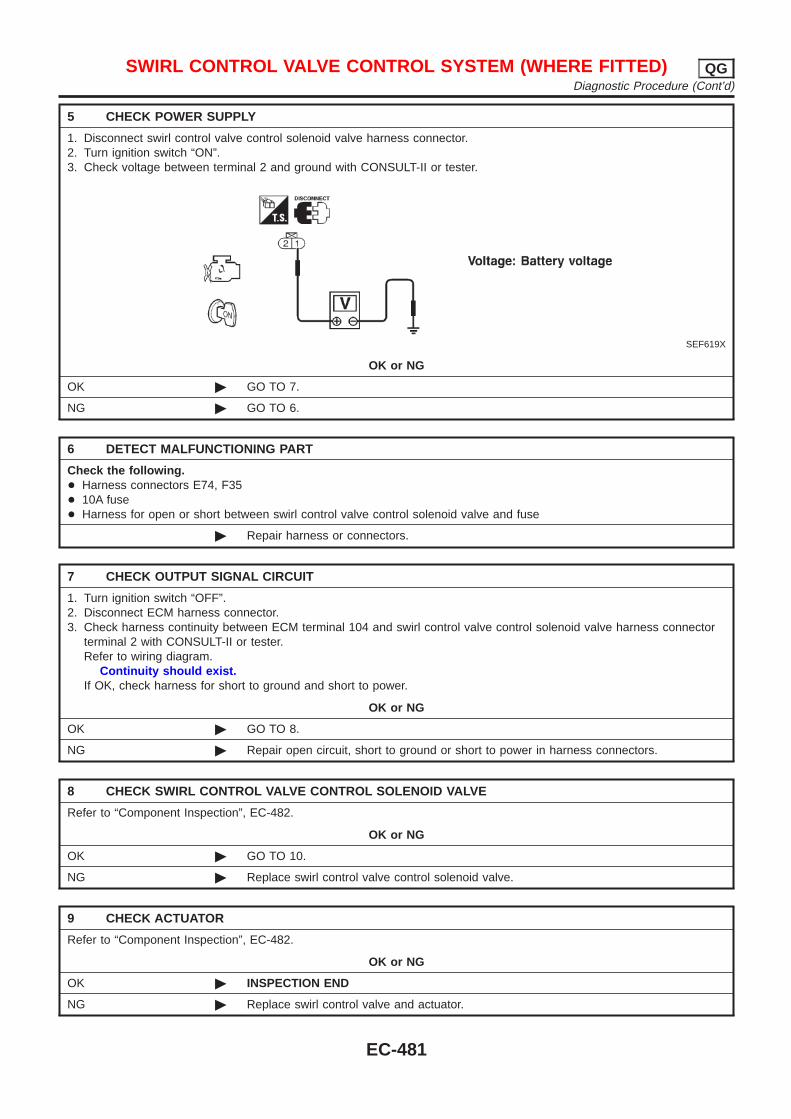
5 CHECK POWER SUPPLY
1. Disconnect swirl control valve control solenoid valve harness connector.2. Turn ignition switch “ON”.3. Check voltage between terminal 2 and ground with CONSULT-II or tester.
SEF619X
OK or NG
OK © GO TO 7.
NG © GO TO 6.
6 DETECT MALFUNCTIONING PART
Check the following.+ Harness connectors E74, F35+ 10A fuse+ Harness for open or short between swirl control valve control solenoid valve and fuse
© Repair harness or connectors.
7 CHECK OUTPUT SIGNAL CIRCUIT
1. Turn ignition switch “OFF”.2. Disconnect ECM harness connector.3. Check harness continuity between ECM terminal 104 and swirl control valve control solenoid valve harness connector
terminal 2 with CONSULT-II or tester.Refer to wiring diagram.
Continuity should exist.If OK, check harness for short to ground and short to power.
OK or NG
OK © GO TO 8.
NG © Repair open circuit, short to ground or short to power in harness connectors.
8 CHECK SWIRL CONTROL VALVE CONTROL SOLENOID VALVE
Refer to “Component Inspection”, EC-482.
OK or NG
OK © GO TO 10.
NG © Replace swirl control valve control solenoid valve.
9 CHECK ACTUATOR
Refer to “Component Inspection”, EC-482.
OK or NG
OK © INSPECTION END
NG © Replace swirl control valve and actuator.
SWIRL CONTROL VALVE CONTROL SYSTEM (WHERE FITTED) QGDiagnostic Procedure (Cont’d)
EC-481
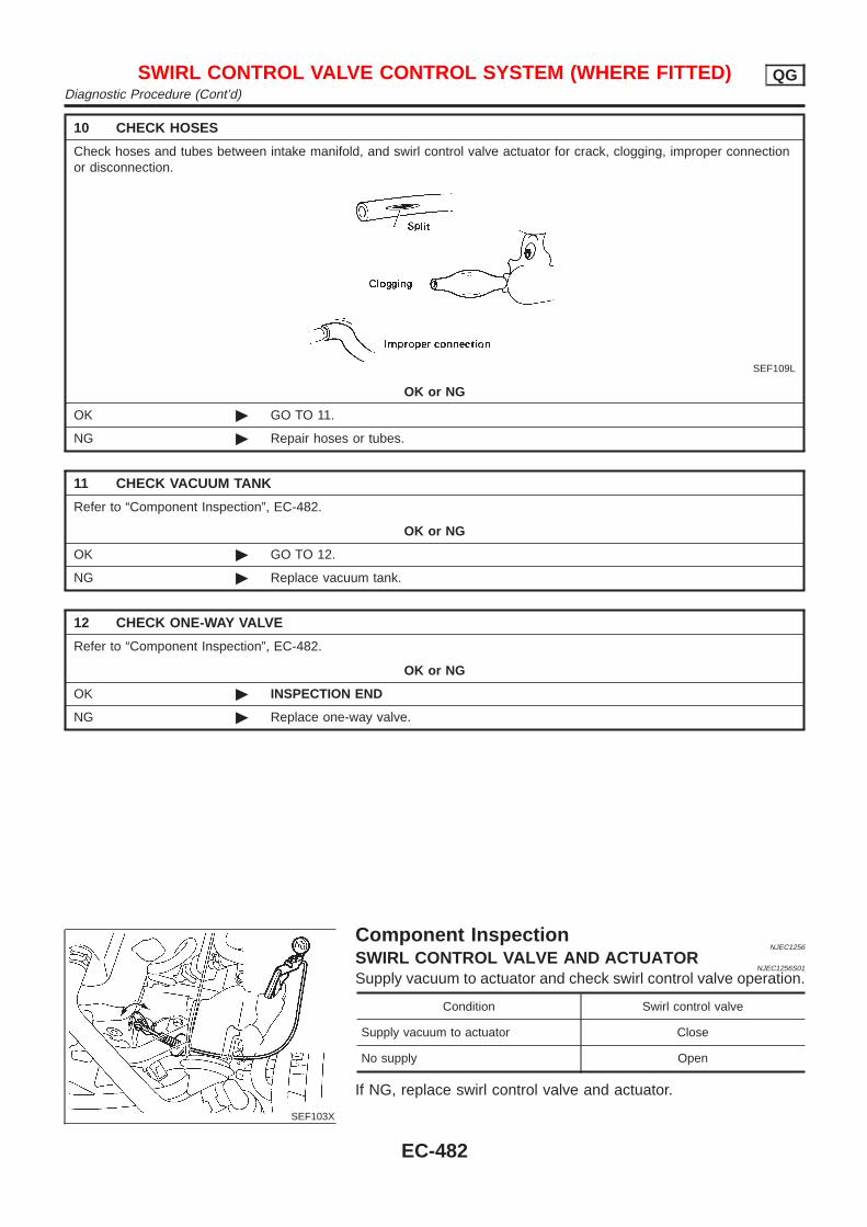
10 CHECK HOSES
Check hoses and tubes between intake manifold, and swirl control valve actuator for crack, clogging, improper connectionor disconnection.
SEF109L
OK or NG
OK © GO TO 11.
NG © Repair hoses or tubes.
11 CHECK VACUUM TANK
Refer to “Component Inspection”, EC-482.
OK or NG
OK © GO TO 12.
NG © Replace vacuum tank.
12 CHECK ONE-WAY VALVE
Refer to “Component Inspection”, EC-482.
OK or NG
OK © INSPECTION END
NG © Replace one-way valve.
SEF103X
Component InspectionNJEC1256
SWIRL CONTROL VALVE AND ACTUATORNJEC1256S01
Supply vacuum to actuator and check swirl control valve operation.
Condition Swirl control valve
Supply vacuum to actuator Close
No supply Open
If NG, replace swirl control valve and actuator.
SWIRL CONTROL VALVE CONTROL SYSTEM (WHERE FITTED) QGDiagnostic Procedure (Cont’d)
EC-482
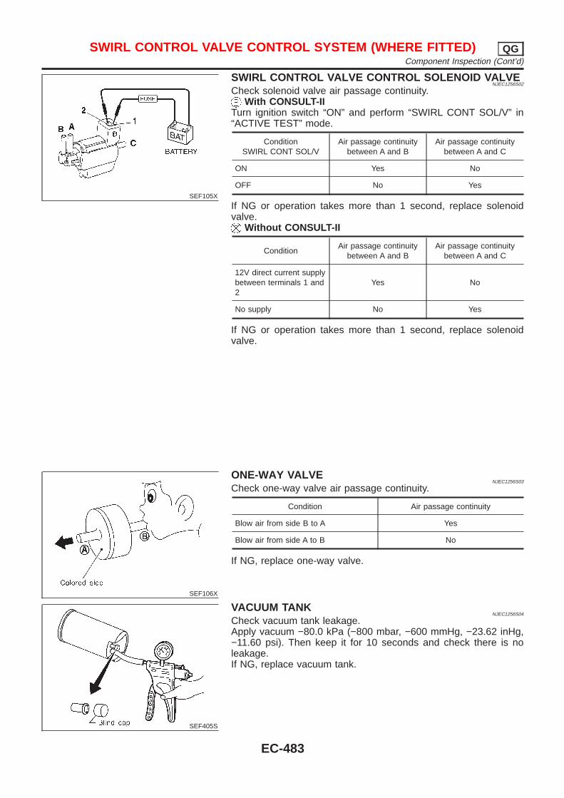
SEF105X
SWIRL CONTROL VALVE CONTROL SOLENOID VALVENJEC1256S02
Check solenoid valve air passage continuity.With CONSULT-II
Turn ignition switch “ON” and perform “SWIRL CONT SOL/V” in“ACTIVE TEST” mode.
ConditionSWIRL CONT SOL/V
Air passage continuitybetween A and B
Air passage continuitybetween A and C
ON Yes No
OFF No Yes
If NG or operation takes more than 1 second, replace solenoidvalve.
Without CONSULT-II
ConditionAir passage continuity
between A and BAir passage continuity
between A and C
12V direct current supplybetween terminals 1 and2
Yes No
No supply No Yes
If NG or operation takes more than 1 second, replace solenoidvalve.
SEF106X
ONE-WAY VALVENJEC1256S03
Check one-way valve air passage continuity.
Condition Air passage continuity
Blow air from side B to A Yes
Blow air from side A to B No
If NG, replace one-way valve.
SEF405S
VACUUM TANKNJEC1256S04
Check vacuum tank leakage.Apply vacuum −80.0 kPa (−800 mbar, −600 mmHg, −23.62 inHg,−11.60 psi). Then keep it for 10 seconds and check there is noleakage.If NG, replace vacuum tank.
SWIRL CONTROL VALVE CONTROL SYSTEM (WHERE FITTED) QGComponent Inspection (Cont’d)
EC-483
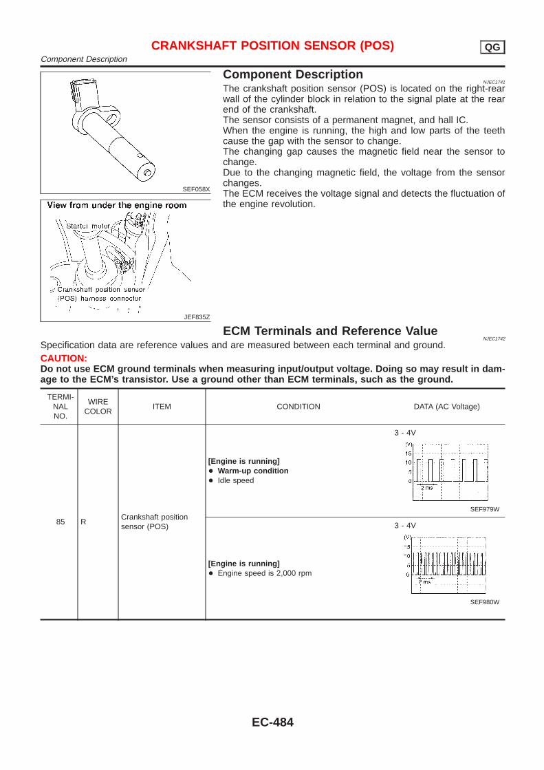
SEF058X
JEF835Z
Component DescriptionNJEC1741
The crankshaft position sensor (POS) is located on the right-rearwall of the cylinder block in relation to the signal plate at the rearend of the crankshaft.The sensor consists of a permanent magnet, and hall IC.When the engine is running, the high and low parts of the teethcause the gap with the sensor to change.The changing gap causes the magnetic field near the sensor tochange.Due to the changing magnetic field, the voltage from the sensorchanges.The ECM receives the voltage signal and detects the fluctuation ofthe engine revolution.
ECM Terminals and Reference ValueNJEC1742
Specification data are reference values and are measured between each terminal and ground.CAUTION:Do not use ECM ground terminals when measuring input/output voltage. Doing so may result in dam-age to the ECM’s transistor. Use a ground other than ECM terminals, such as the ground.
TERMI-NALNO.
WIRECOLOR
ITEM CONDITION DATA (AC Voltage)
85 RCrankshaft positionsensor (POS)
[Engine is running]+ Warm-up condition+ Idle speed
3 - 4V
SEF979W
[Engine is running]+ Engine speed is 2,000 rpm
3 - 4V
SEF980W
CRANKSHAFT POSITION SENSOR (POS) QGComponent Description
EC-484
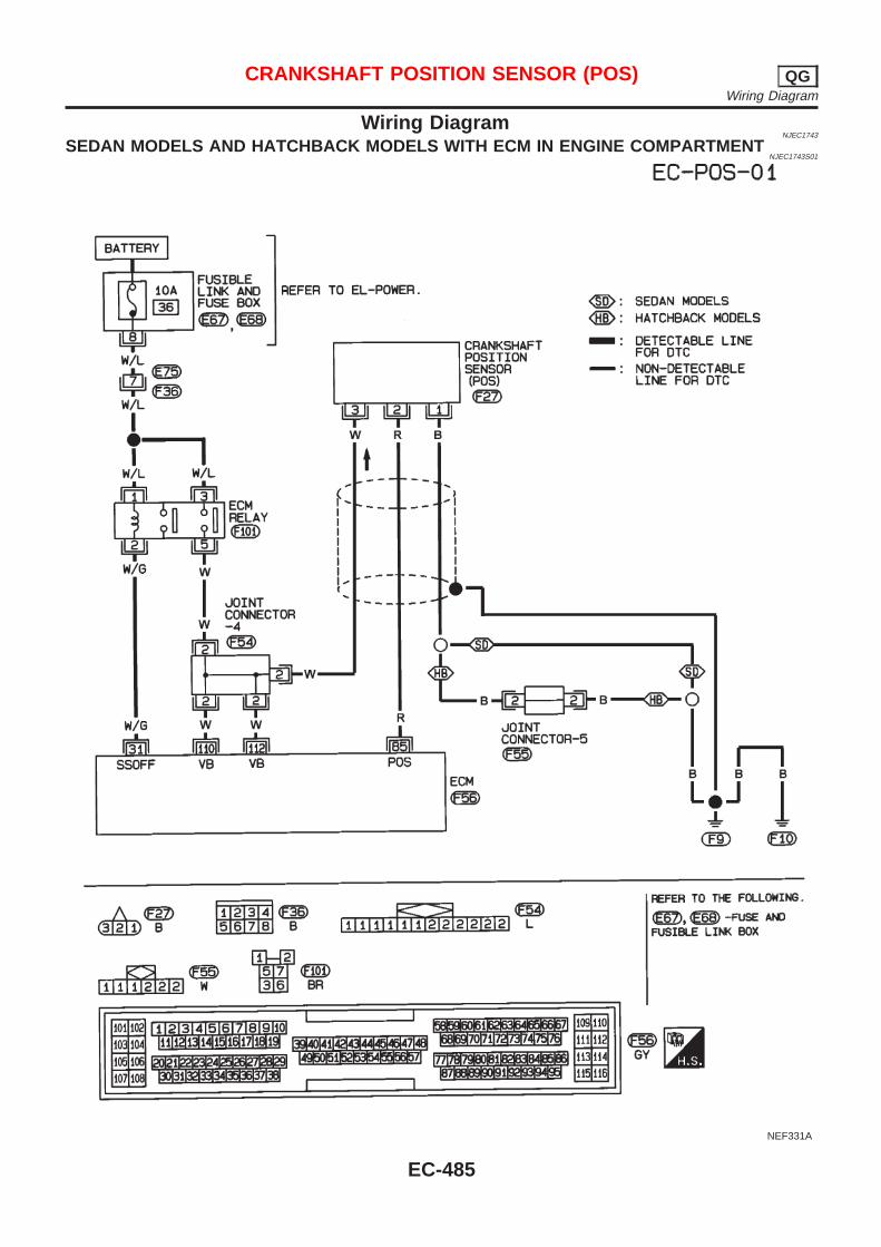
Wiring DiagramNJEC1743
SEDAN MODELS AND HATCHBACK MODELS WITH ECM IN ENGINE COMPARTMENTNJEC1743S01
NEF331A
CRANKSHAFT POSITION SENSOR (POS) QGWiring Diagram
EC-485
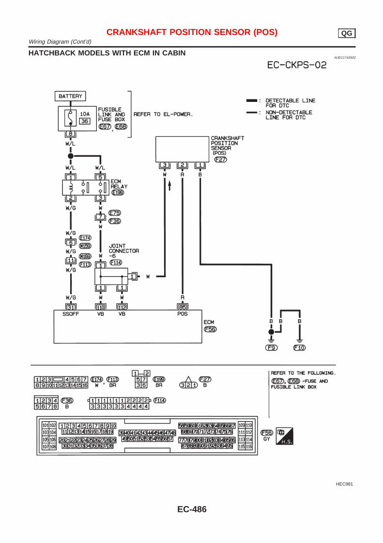
HATCHBACK MODELS WITH ECM IN CABINNJEC1743S02
HEC981
CRANKSHAFT POSITION SENSOR (POS) QGWiring Diagram (Cont’d)
EC-486
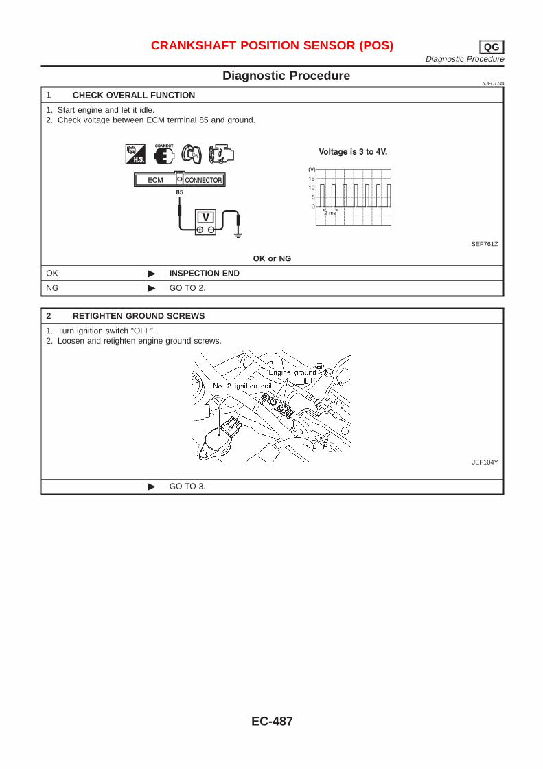
Diagnostic ProcedureNJEC1744
1 CHECK OVERALL FUNCTION
1. Start engine and let it idle.2. Check voltage between ECM terminal 85 and ground.
SEF761Z
OK or NG
OK © INSPECTION END
NG © GO TO 2.
2 RETIGHTEN GROUND SCREWS
1. Turn ignition switch “OFF”.2. Loosen and retighten engine ground screws.
JEF104Y
© GO TO 3.
CRANKSHAFT POSITION SENSOR (POS) QGDiagnostic Procedure
EC-487
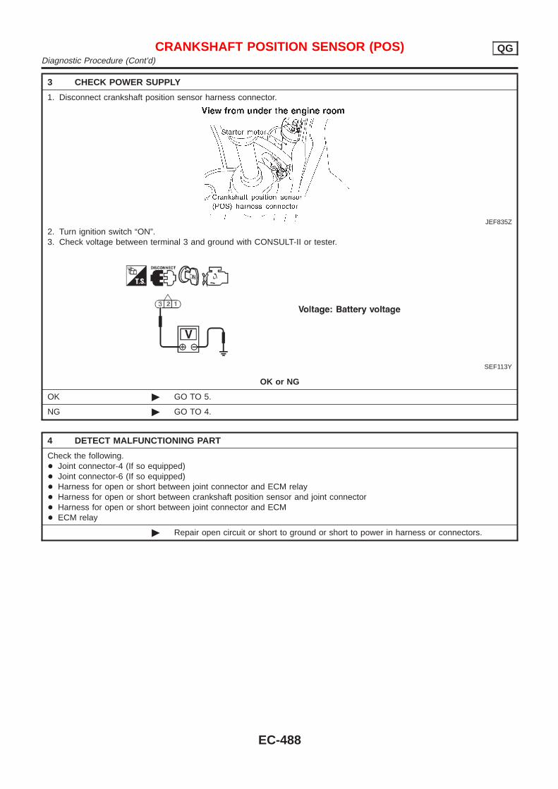
3 CHECK POWER SUPPLY
1. Disconnect crankshaft position sensor harness connector.
JEF835Z
2. Turn ignition switch “ON”.3. Check voltage between terminal 3 and ground with CONSULT-II or tester.
SEF113Y
OK or NG
OK © GO TO 5.
NG © GO TO 4.
4 DETECT MALFUNCTIONING PART
Check the following.+ Joint connector-4 (If so equipped)+ Joint connector-6 (If so equipped)+ Harness for open or short between joint connector and ECM relay+ Harness for open or short between crankshaft position sensor and joint connector+ Harness for open or short between joint connector and ECM+ ECM relay
© Repair open circuit or short to ground or short to power in harness or connectors.
CRANKSHAFT POSITION SENSOR (POS) QGDiagnostic Procedure (Cont’d)
EC-488
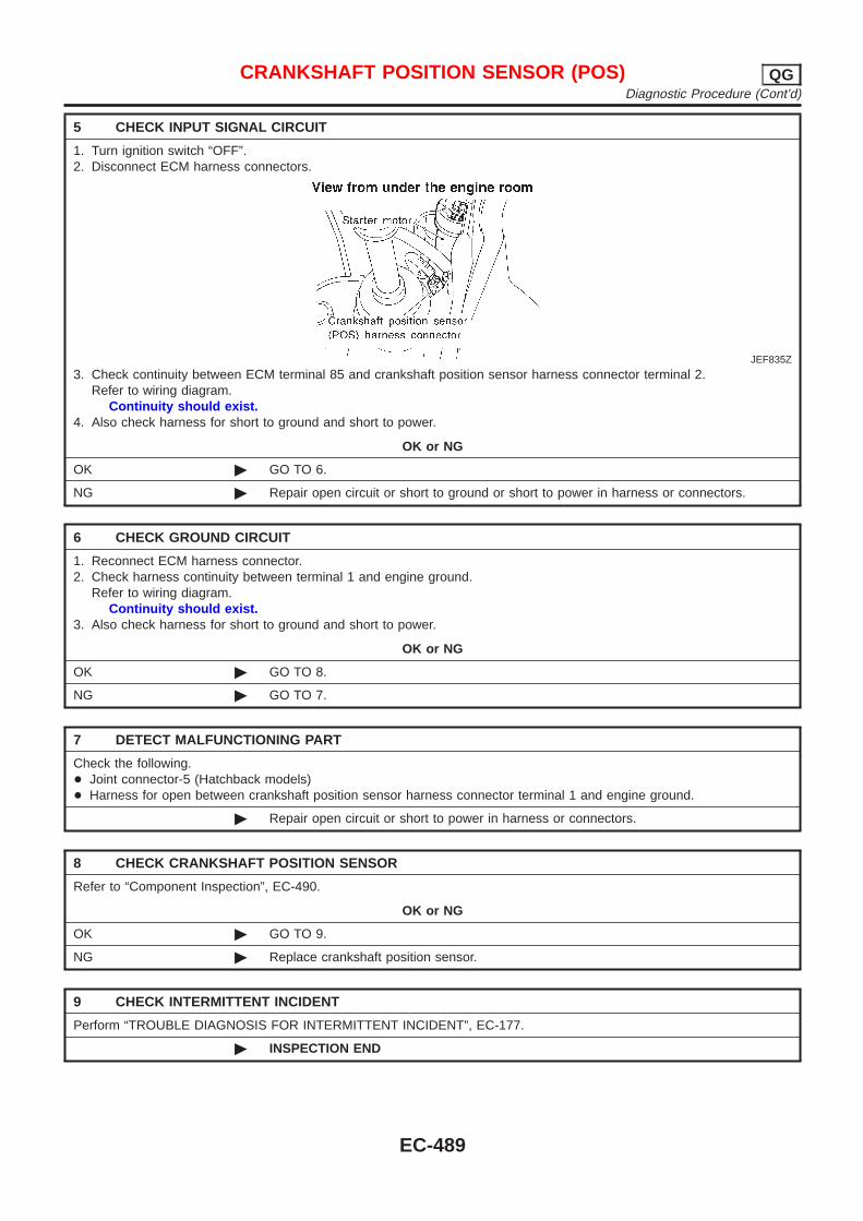
5 CHECK INPUT SIGNAL CIRCUIT
1. Turn ignition switch “OFF”.2. Disconnect ECM harness connectors.
JEF835Z
3. Check continuity between ECM terminal 85 and crankshaft position sensor harness connector terminal 2.Refer to wiring diagram.
Continuity should exist.4. Also check harness for short to ground and short to power.
OK or NG
OK © GO TO 6.
NG © Repair open circuit or short to ground or short to power in harness or connectors.
6 CHECK GROUND CIRCUIT
1. Reconnect ECM harness connector.2. Check harness continuity between terminal 1 and engine ground.
Refer to wiring diagram.Continuity should exist.
3. Also check harness for short to ground and short to power.
OK or NG
OK © GO TO 8.
NG © GO TO 7.
7 DETECT MALFUNCTIONING PART
Check the following.+ Joint connector-5 (Hatchback models)+ Harness for open between crankshaft position sensor harness connector terminal 1 and engine ground.
© Repair open circuit or short to power in harness or connectors.
8 CHECK CRANKSHAFT POSITION SENSOR
Refer to “Component Inspection”, EC-490.
OK or NG
OK © GO TO 9.
NG © Replace crankshaft position sensor.
9 CHECK INTERMITTENT INCIDENT
Perform “TROUBLE DIAGNOSIS FOR INTERMITTENT INCIDENT”, EC-177.
© INSPECTION END
CRANKSHAFT POSITION SENSOR (POS) QGDiagnostic Procedure (Cont’d)
EC-489
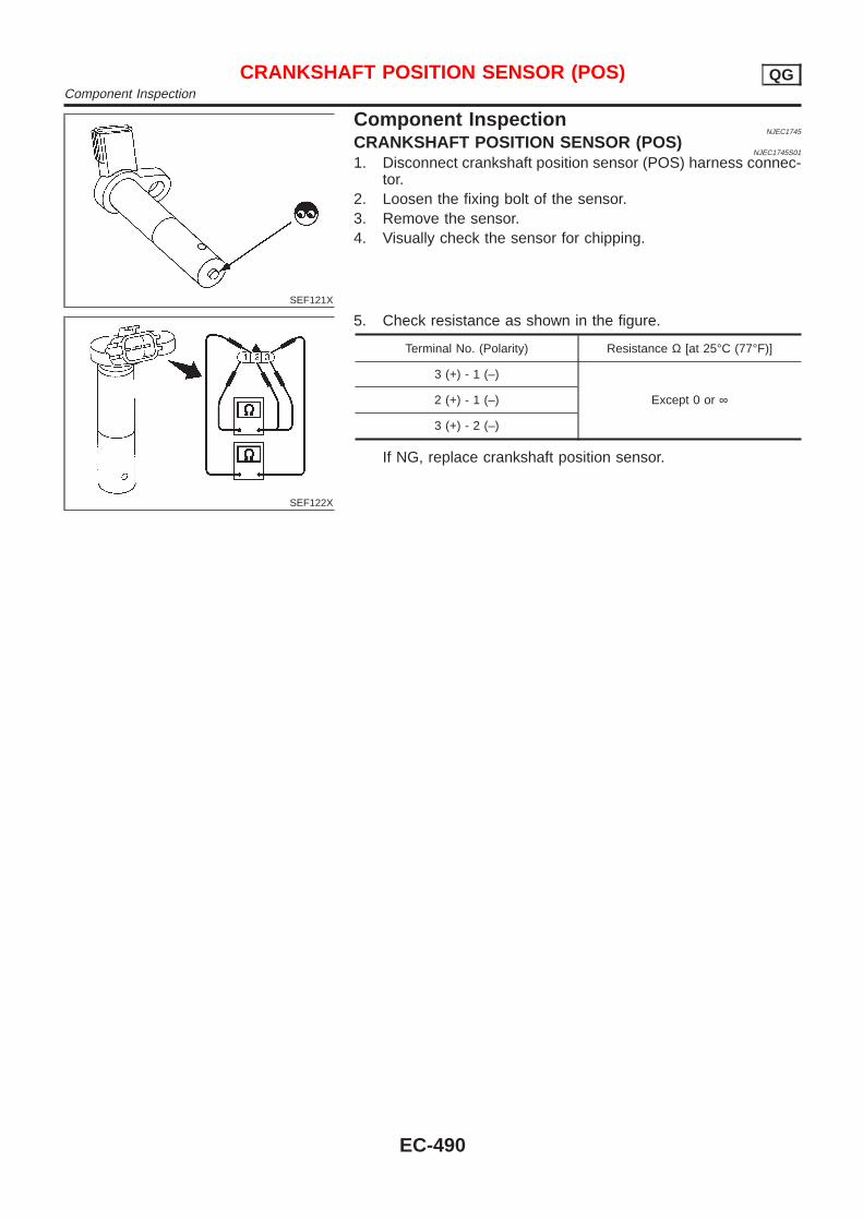
SEF121X
Component InspectionNJEC1745
CRANKSHAFT POSITION SENSOR (POS)NJEC1745S01
1. Disconnect crankshaft position sensor (POS) harness connec-tor.
2. Loosen the fixing bolt of the sensor.3. Remove the sensor.4. Visually check the sensor for chipping.
SEF122X
5. Check resistance as shown in the figure.
Terminal No. (Polarity) Resistance Ω [at 25°C (77°F)]
3 (+) - 1 (–)
Except 0 or ∞2 (+) - 1 (–)
3 (+) - 2 (–)
If NG, replace crankshaft position sensor.
CRANKSHAFT POSITION SENSOR (POS) QGComponent Inspection
EC-490
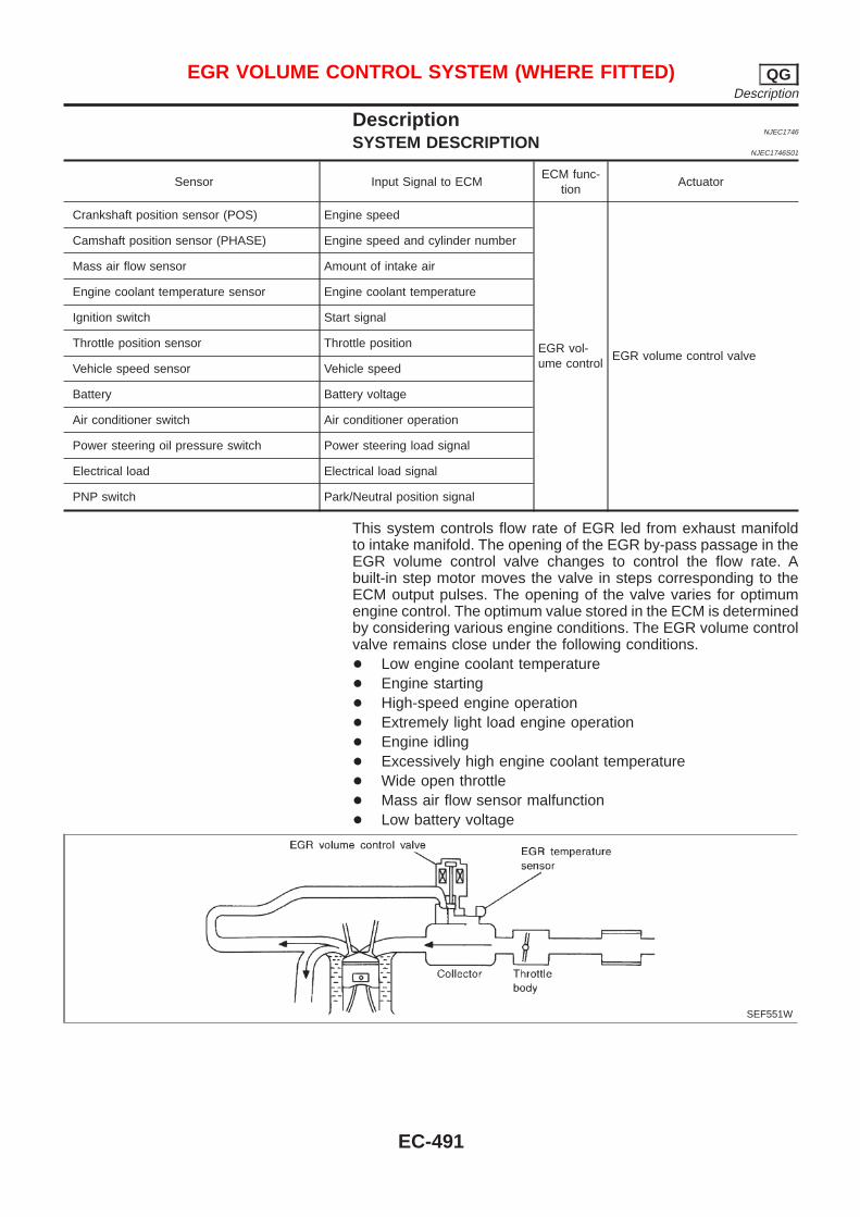
DescriptionNJEC1746
SYSTEM DESCRIPTIONNJEC1746S01
Sensor Input Signal to ECMECM func-
tionActuator
Crankshaft position sensor (POS) Engine speed
EGR vol-ume control
EGR volume control valve
Camshaft position sensor (PHASE) Engine speed and cylinder number
Mass air flow sensor Amount of intake air
Engine coolant temperature sensor Engine coolant temperature
Ignition switch Start signal
Throttle position sensor Throttle position
Vehicle speed sensor Vehicle speed
Battery Battery voltage
Air conditioner switch Air conditioner operation
Power steering oil pressure switch Power steering load signal
Electrical load Electrical load signal
PNP switch Park/Neutral position signal
This system controls flow rate of EGR led from exhaust manifoldto intake manifold. The opening of the EGR by-pass passage in theEGR volume control valve changes to control the flow rate. Abuilt-in step motor moves the valve in steps corresponding to theECM output pulses. The opening of the valve varies for optimumengine control. The optimum value stored in the ECM is determinedby considering various engine conditions. The EGR volume controlvalve remains close under the following conditions.+ Low engine coolant temperature+ Engine starting+ High-speed engine operation+ Extremely light load engine operation+ Engine idling+ Excessively high engine coolant temperature+ Wide open throttle+ Mass air flow sensor malfunction+ Low battery voltage
SEF551W
EGR VOLUME CONTROL SYSTEM (WHERE FITTED) QGDescription
EC-491
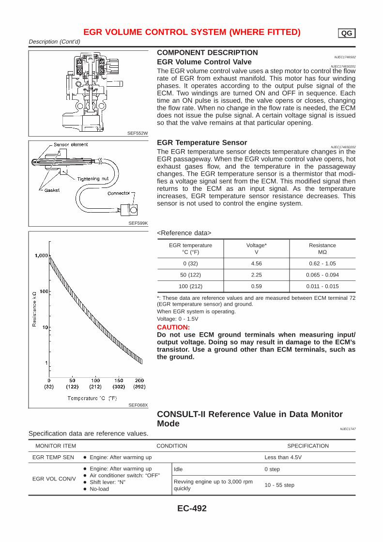
SEF552W
COMPONENT DESCRIPTIONNJEC1746S02
EGR Volume Control ValveNJEC1746S0201
The EGR volume control valve uses a step motor to control the flowrate of EGR from exhaust manifold. This motor has four windingphases. It operates according to the output pulse signal of theECM. Two windings are turned ON and OFF in sequence. Eachtime an ON pulse is issued, the valve opens or closes, changingthe flow rate. When no change in the flow rate is needed, the ECMdoes not issue the pulse signal. A certain voltage signal is issuedso that the valve remains at that particular opening.
SEF599K
EGR Temperature SensorNJEC1746S0202
The EGR temperature sensor detects temperature changes in theEGR passageway. When the EGR volume control valve opens, hotexhaust gases flow, and the temperature in the passagewaychanges. The EGR temperature sensor is a thermistor that modi-fies a voltage signal sent from the ECM. This modified signal thenreturns to the ECM as an input signal. As the temperatureincreases, EGR temperature sensor resistance decreases. Thissensor is not used to control the engine system.
SEF068X
<Reference data>
EGR temperature°C (°F)
Voltage*V
ResistanceMΩ
0 (32) 4.56 0.62 - 1.05
50 (122) 2.25 0.065 - 0.094
100 (212) 0.59 0.011 - 0.015
*: These data are reference values and are measured between ECM terminal 72(EGR temperature sensor) and ground.When EGR system is operating.Voltage: 0 - 1.5V
CAUTION:Do not use ECM ground terminals when measuring input/output voltage. Doing so may result in damage to the ECM’stransistor. Use a ground other than ECM terminals, such asthe ground.
CONSULT-II Reference Value in Data MonitorMode
NJEC1747
Specification data are reference values.
MONITOR ITEM CONDITION SPECIFICATION
EGR TEMP SEN + Engine: After warming up Less than 4.5V
EGR VOL CON/V
+ Engine: After warming up+ Air conditioner switch: “OFF”+ Shift lever: “N”+ No-load
Idle 0 step
Revving engine up to 3,000 rpmquickly
10 - 55 step
EGR VOLUME CONTROL SYSTEM (WHERE FITTED) QGDescription (Cont’d)
EC-492
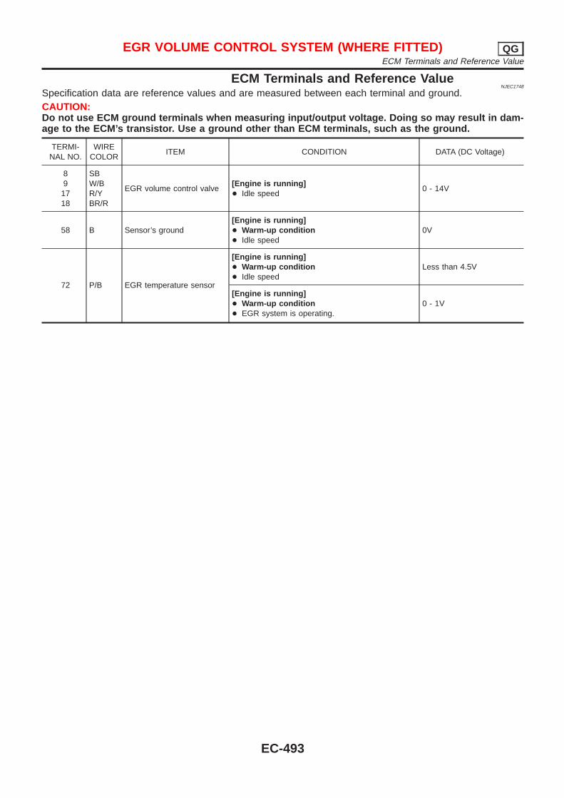
ECM Terminals and Reference ValueNJEC1748
Specification data are reference values and are measured between each terminal and ground.CAUTION:Do not use ECM ground terminals when measuring input/output voltage. Doing so may result in dam-age to the ECM’s transistor. Use a ground other than ECM terminals, such as the ground.
TERMI-NAL NO.
WIRECOLOR
ITEM CONDITION DATA (DC Voltage)
891718
SBW/BR/YBR/R
EGR volume control valve[Engine is running]+ Idle speed
0 - 14V
58 B Sensor’s ground[Engine is running]+ Warm-up condition+ Idle speed
0V
72 P/B EGR temperature sensor
[Engine is running]+ Warm-up condition+ Idle speed
Less than 4.5V
[Engine is running]+ Warm-up condition+ EGR system is operating.
0 - 1V
EGR VOLUME CONTROL SYSTEM (WHERE FITTED) QGECM Terminals and Reference Value
EC-493
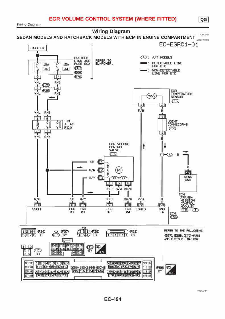
Wiring DiagramNJEC1749
SEDAN MODELS AND HATCHBACK MODELS WITH ECM IN ENGINE COMPARTMENTNJEC1749S01
HEC794
EGR VOLUME CONTROL SYSTEM (WHERE FITTED) QGWiring Diagram
EC-494
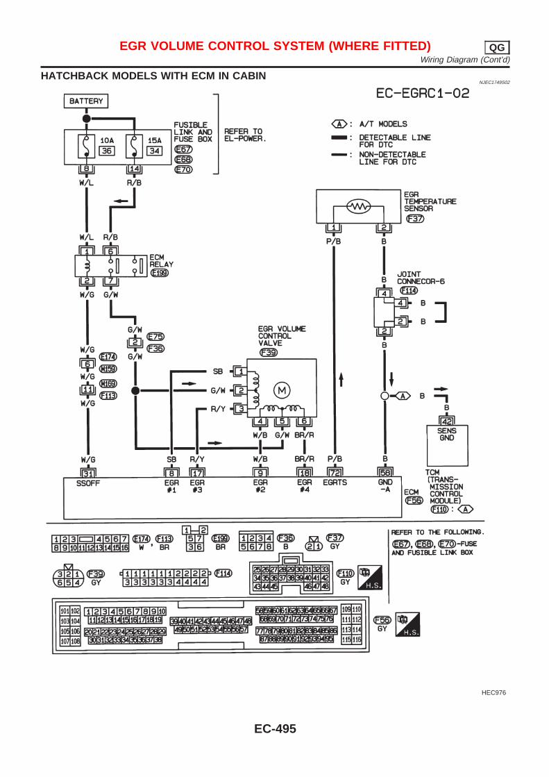
HATCHBACK MODELS WITH ECM IN CABINNJEC1749S02
HEC976
EGR VOLUME CONTROL SYSTEM (WHERE FITTED) QGWiring Diagram (Cont’d)
EC-495
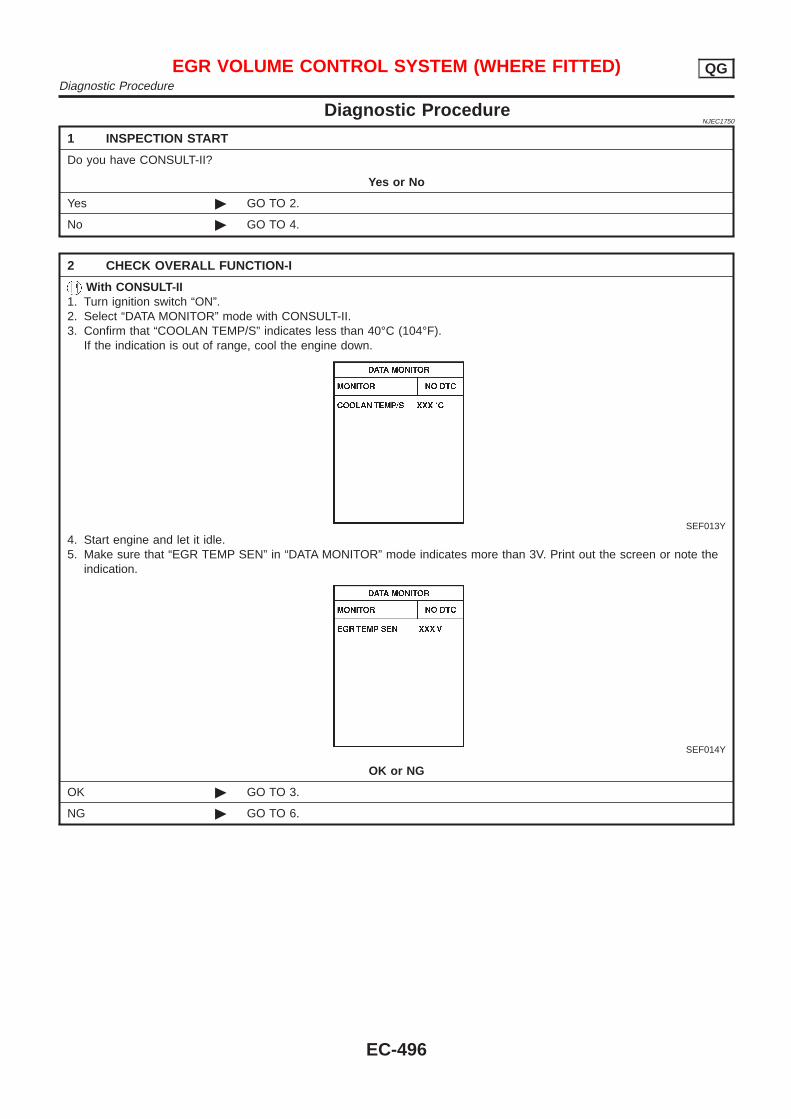
Diagnostic ProcedureNJEC1750
1 INSPECTION START
Do you have CONSULT-II?
Yes or No
Yes © GO TO 2.
No © GO TO 4.
2 CHECK OVERALL FUNCTION-I
With CONSULT-II1. Turn ignition switch “ON”.2. Select “DATA MONITOR” mode with CONSULT-II.3. Confirm that “COOLAN TEMP/S” indicates less than 40°C (104°F).
If the indication is out of range, cool the engine down.
SEF013Y
4. Start engine and let it idle.5. Make sure that “EGR TEMP SEN” in “DATA MONITOR” mode indicates more than 3V. Print out the screen or note the
indication.
SEF014Y
OK or NG
OK © GO TO 3.
NG © GO TO 6.
EGR VOLUME CONTROL SYSTEM (WHERE FITTED) QGDiagnostic Procedure
EC-496
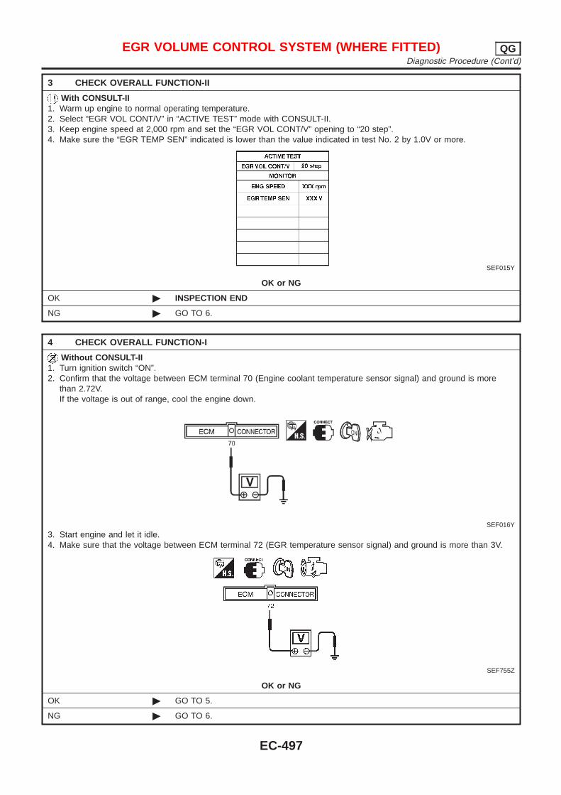
3 CHECK OVERALL FUNCTION-II
With CONSULT-II1. Warm up engine to normal operating temperature.2. Select “EGR VOL CONT/V” in “ACTIVE TEST” mode with CONSULT-II.3. Keep engine speed at 2,000 rpm and set the “EGR VOL CONT/V” opening to “20 step”.4. Make sure the “EGR TEMP SEN” indicated is lower than the value indicated in test No. 2 by 1.0V or more.
SEF015Y
OK or NG
OK © INSPECTION END
NG © GO TO 6.
4 CHECK OVERALL FUNCTION-I
Without CONSULT-II1. Turn ignition switch “ON”.2. Confirm that the voltage between ECM terminal 70 (Engine coolant temperature sensor signal) and ground is more
than 2.72V.If the voltage is out of range, cool the engine down.
SEF016Y
3. Start engine and let it idle.4. Make sure that the voltage between ECM terminal 72 (EGR temperature sensor signal) and ground is more than 3V.
SEF755Z
OK or NG
OK © GO TO 5.
NG © GO TO 6.
EGR VOLUME CONTROL SYSTEM (WHERE FITTED) QGDiagnostic Procedure (Cont’d)
EC-497
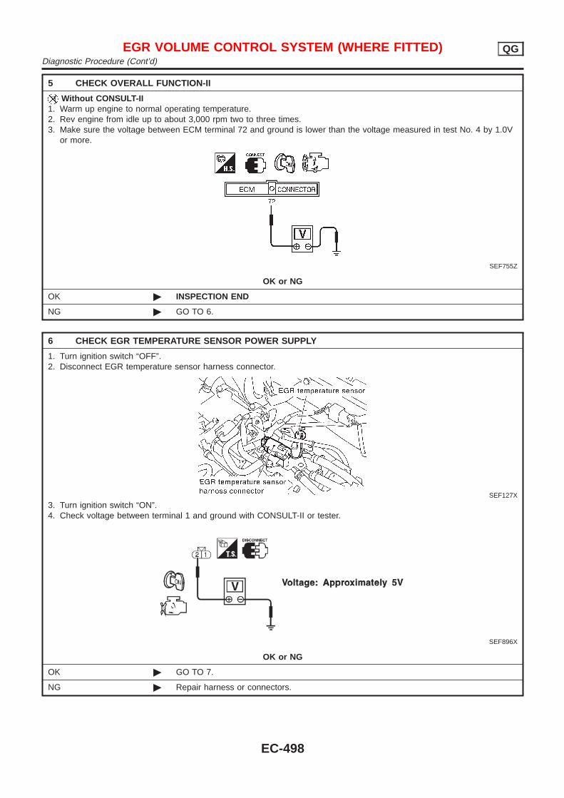
5 CHECK OVERALL FUNCTION-II
Without CONSULT-II1. Warm up engine to normal operating temperature.2. Rev engine from idle up to about 3,000 rpm two to three times.3. Make sure the voltage between ECM terminal 72 and ground is lower than the voltage measured in test No. 4 by 1.0V
or more.
SEF755Z
OK or NG
OK © INSPECTION END
NG © GO TO 6.
6 CHECK EGR TEMPERATURE SENSOR POWER SUPPLY
1. Turn ignition switch “OFF”.2. Disconnect EGR temperature sensor harness connector.
SEF127X
3. Turn ignition switch “ON”.4. Check voltage between terminal 1 and ground with CONSULT-II or tester.
SEF896X
OK or NG
OK © GO TO 7.
NG © Repair harness or connectors.
EGR VOLUME CONTROL SYSTEM (WHERE FITTED) QGDiagnostic Procedure (Cont’d)
EC-498
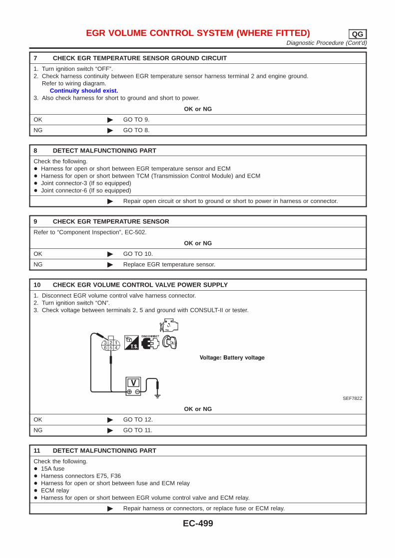
7 CHECK EGR TEMPERATURE SENSOR GROUND CIRCUIT
1. Turn ignition switch “OFF”.2. Check harness continuity between EGR temperature sensor harness terminal 2 and engine ground.
Refer to wiring diagram.Continuity should exist.
3. Also check harness for short to ground and short to power.
OK or NG
OK © GO TO 9.
NG © GO TO 8.
8 DETECT MALFUNCTIONING PART
Check the following.+ Harness for open or short between EGR temperature sensor and ECM+ Harness for open or short between TCM (Transmission Control Module) and ECM+ Joint connector-3 (If so equipped)+ Joint connector-6 (If so equipped)
© Repair open circuit or short to ground or short to power in harness or connector.
9 CHECK EGR TEMPERATURE SENSOR
Refer to “Component Inspection”, EC-502.
OK or NG
OK © GO TO 10.
NG © Replace EGR temperature sensor.
10 CHECK EGR VOLUME CONTROL VALVE POWER SUPPLY
1. Disconnect EGR volume control valve harness connector.2. Turn ignition switch “ON”.3. Check voltage between terminals 2, 5 and ground with CONSULT-II or tester.
SEF782Z
OK or NG
OK © GO TO 12.
NG © GO TO 11.
11 DETECT MALFUNCTIONING PART
Check the following.+ 15A fuse+ Harness connectors E75, F36+ Harness for open or short between fuse and ECM relay+ ECM relay+ Harness for open or short between EGR volume control valve and ECM relay.
© Repair harness or connectors, or replace fuse or ECM relay.
EGR VOLUME CONTROL SYSTEM (WHERE FITTED) QGDiagnostic Procedure (Cont’d)
EC-499
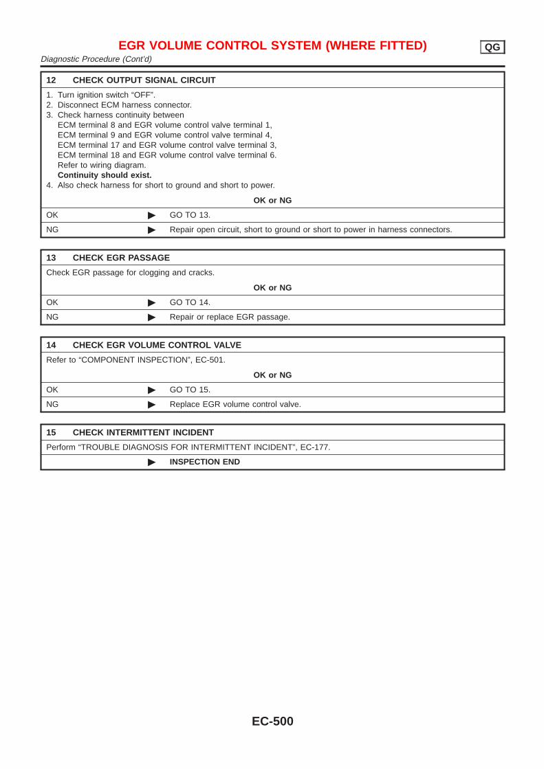
12 CHECK OUTPUT SIGNAL CIRCUIT
1. Turn ignition switch “OFF”.2. Disconnect ECM harness connector.3. Check harness continuity between
ECM terminal 8 and EGR volume control valve terminal 1,ECM terminal 9 and EGR volume control valve terminal 4,ECM terminal 17 and EGR volume control valve terminal 3,ECM terminal 18 and EGR volume control valve terminal 6.Refer to wiring diagram.Continuity should exist.
4. Also check harness for short to ground and short to power.
OK or NG
OK © GO TO 13.
NG © Repair open circuit, short to ground or short to power in harness connectors.
13 CHECK EGR PASSAGE
Check EGR passage for clogging and cracks.
OK or NG
OK © GO TO 14.
NG © Repair or replace EGR passage.
14 CHECK EGR VOLUME CONTROL VALVE
Refer to “COMPONENT INSPECTION”, EC-501.
OK or NG
OK © GO TO 15.
NG © Replace EGR volume control valve.
15 CHECK INTERMITTENT INCIDENT
Perform “TROUBLE DIAGNOSIS FOR INTERMITTENT INCIDENT”, EC-177.
© INSPECTION END
EGR VOLUME CONTROL SYSTEM (WHERE FITTED) QGDiagnostic Procedure (Cont’d)
EC-500
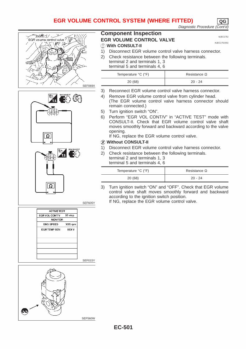
SEF069X
SEF605Y
SEF015Y
SEF560W
Component InspectionNJEC1751
EGR VOLUME CONTROL VALVENJEC1751S01
With CONSULT-II1) Disconnect EGR volume control valve harness connector.2) Check resistance between the following terminals.
terminal 2 and terminals 1, 3terminal 5 and terminals 4, 6
Temperature °C (°F) Resistance Ω
20 (68) 20 - 24
3) Reconnect EGR volume control valve harness connector.4) Remove EGR volume control valve from cylinder head.
(The EGR volume control valve harness connector shouldremain connected.)
5) Turn ignition switch “ON”.6) Perform “EGR VOL CONT/V” in “ACTIVE TEST” mode with
CONSULT-II. Check that EGR volume control valve shaftmoves smoothly forward and backward according to the valveopening.If NG, replace the EGR volume control valve.
Without CONSULT-II1) Disconnect EGR volume control valve harness connector.2) Check resistance between the following terminals.
terminal 2 and terminals 1, 3terminal 5 and terminals 4, 6
Temperature °C (°F) Resistance Ω
20 (68) 20 - 24
3) Turn ignition switch “ON” and “OFF”. Check that EGR volumecontrol valve shaft moves smoothly forward and backwardaccording to the ignition switch position.If NG, replace the EGR volume control valve.
EGR VOLUME CONTROL SYSTEM (WHERE FITTED) QGDiagnostic Procedure (Cont’d)
EC-501
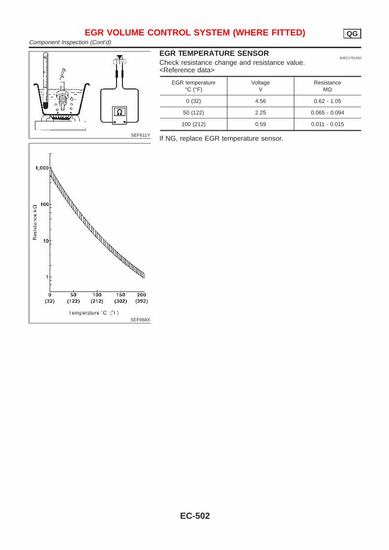
SEF611Y
SEF068X
EGR TEMPERATURE SENSORNJEC1751S02
Check resistance change and resistance value.<Reference data>
EGR temperature°C (°F)
VoltageV
ResistanceMΩ
0 (32) 4.56 0.62 - 1.05
50 (122) 2.25 0.065 - 0.094
100 (212) 0.59 0.011 - 0.015
If NG, replace EGR temperature sensor.
EGR VOLUME CONTROL SYSTEM (WHERE FITTED) QGComponent Inspection (Cont’d)
EC-502
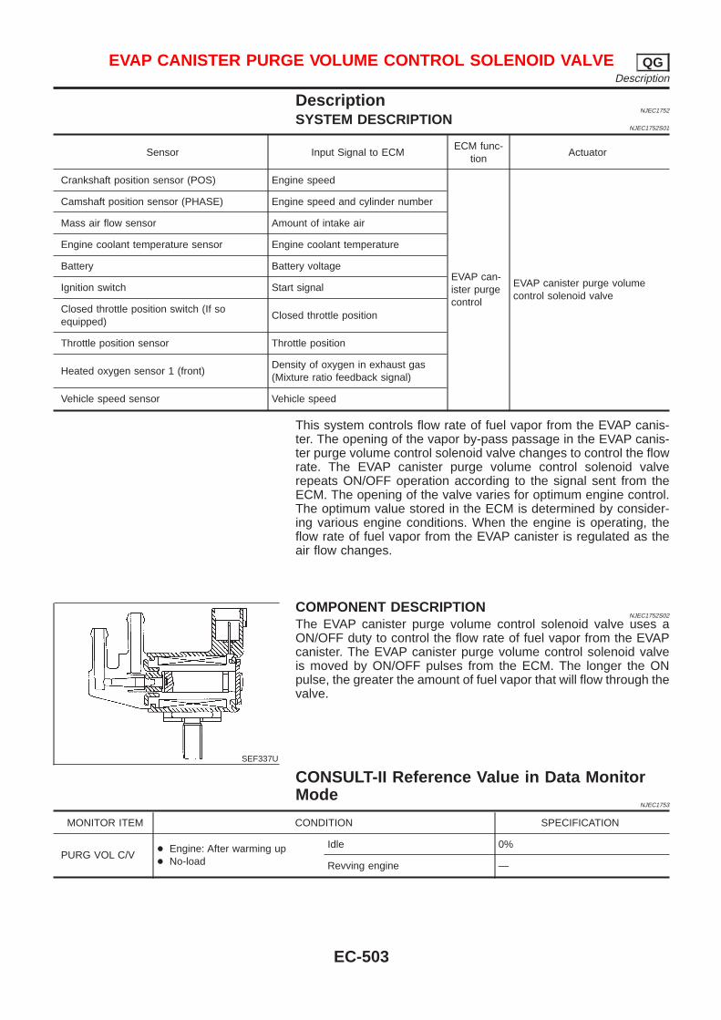
DescriptionNJEC1752
SYSTEM DESCRIPTIONNJEC1752S01
Sensor Input Signal to ECMECM func-
tionActuator
Crankshaft position sensor (POS) Engine speed
EVAP can-ister purgecontrol
EVAP canister purge volumecontrol solenoid valve
Camshaft position sensor (PHASE) Engine speed and cylinder number
Mass air flow sensor Amount of intake air
Engine coolant temperature sensor Engine coolant temperature
Battery Battery voltage
Ignition switch Start signal
Closed throttle position switch (If soequipped)
Closed throttle position
Throttle position sensor Throttle position
Heated oxygen sensor 1 (front)Density of oxygen in exhaust gas(Mixture ratio feedback signal)
Vehicle speed sensor Vehicle speed
This system controls flow rate of fuel vapor from the EVAP canis-ter. The opening of the vapor by-pass passage in the EVAP canis-ter purge volume control solenoid valve changes to control the flowrate. The EVAP canister purge volume control solenoid valverepeats ON/OFF operation according to the signal sent from theECM. The opening of the valve varies for optimum engine control.The optimum value stored in the ECM is determined by consider-ing various engine conditions. When the engine is operating, theflow rate of fuel vapor from the EVAP canister is regulated as theair flow changes.
SEF337U
COMPONENT DESCRIPTIONNJEC1752S02
The EVAP canister purge volume control solenoid valve uses aON/OFF duty to control the flow rate of fuel vapor from the EVAPcanister. The EVAP canister purge volume control solenoid valveis moved by ON/OFF pulses from the ECM. The longer the ONpulse, the greater the amount of fuel vapor that will flow through thevalve.
CONSULT-II Reference Value in Data MonitorMode
NJEC1753
MONITOR ITEM CONDITION SPECIFICATION
PURG VOL C/V+ Engine: After warming up+ No-load
Idle 0%
Revving engine —
EVAP CANISTER PURGE VOLUME CONTROL SOLENOID VALVE QGDescription
EC-503

ECM Terminals and Reference Value=NJEC1754
Specification data are reference values and are measured between each terminal and ground.CAUTION:Do not use ECM ground terminals when measuring input/output voltage. Doing so may result in dam-age to the ECM’s transistor. Use a ground other than ECM terminals, such as the ground.
TER-MINAL
NO.
WIRECOLOR
ITEM CONDITION DATA (DC Voltage)
14 GY/LEVAP canister purge vol-ume control solenoid valve
[Engine is running]+ Warm-up condition+ Idle speed
BATTERY VOLTAGE(11 - 14V)
[Engine is running]+ Warm-up condition+ 2,000 rpm
5 - 12V
SEF975W
EVAP CANISTER PURGE VOLUME CONTROL SOLENOID VALVE QGECM Terminals and Reference Value
EC-504
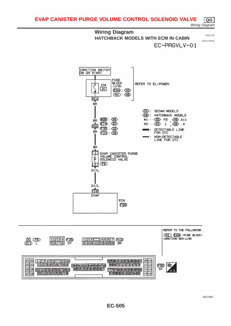
Wiring DiagramNJEC1755
HATCHBACK MODELS WITH ECM IN CABINNJEC1755S01
HEC969
EVAP CANISTER PURGE VOLUME CONTROL SOLENOID VALVE QGWiring Diagram
EC-505
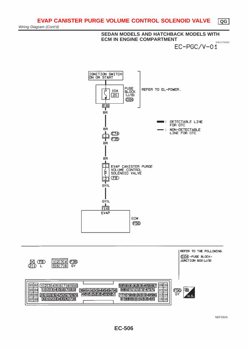
SEDAN MODELS AND HATCHBACK MODELS WITHECM IN ENGINE COMPARTMENT
NJEC1755S02
NEF332A
EVAP CANISTER PURGE VOLUME CONTROL SOLENOID VALVE QGWiring Diagram (Cont’d)
EC-506
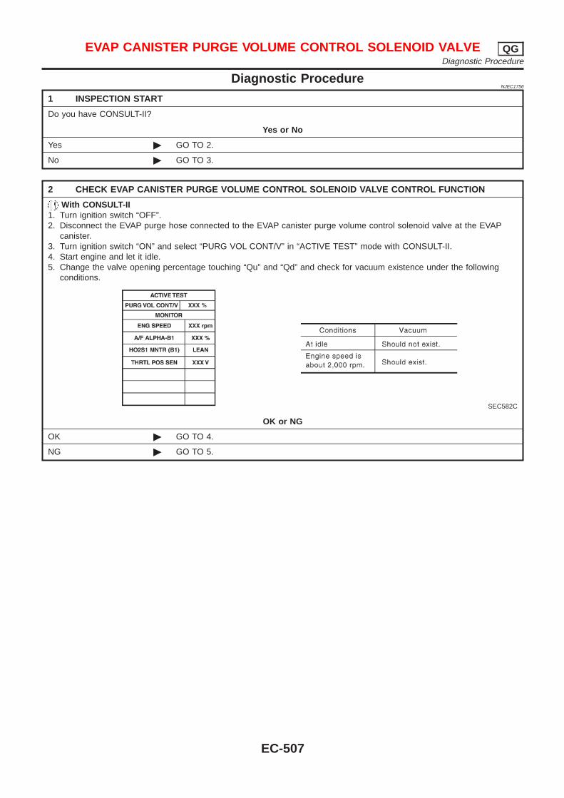
Diagnostic ProcedureNJEC1756
1 INSPECTION START
Do you have CONSULT-II?
Yes or No
Yes © GO TO 2.
No © GO TO 3.
2 CHECK EVAP CANISTER PURGE VOLUME CONTROL SOLENOID VALVE CONTROL FUNCTION
With CONSULT-II1. Turn ignition switch “OFF”.2. Disconnect the EVAP purge hose connected to the EVAP canister purge volume control solenoid valve at the EVAP
canister.3. Turn ignition switch “ON” and select “PURG VOL CONT/V” in “ACTIVE TEST” mode with CONSULT-II.4. Start engine and let it idle.5. Change the valve opening percentage touching “Qu” and “Qd” and check for vacuum existence under the following
conditions.
SEC582C
OK or NG
OK © GO TO 4.
NG © GO TO 5.
EVAP CANISTER PURGE VOLUME CONTROL SOLENOID VALVE QGDiagnostic Procedure
EC-507
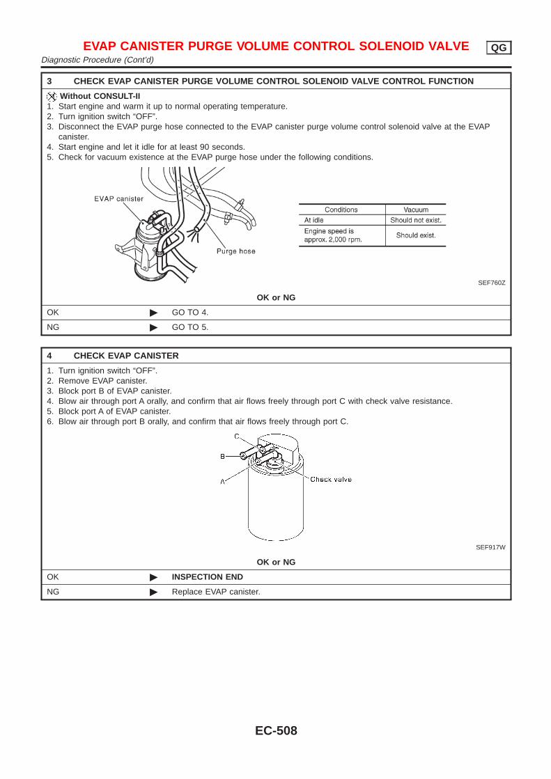
3 CHECK EVAP CANISTER PURGE VOLUME CONTROL SOLENOID VALVE CONTROL FUNCTION
Without CONSULT-II1. Start engine and warm it up to normal operating temperature.2. Turn ignition switch “OFF”.3. Disconnect the EVAP purge hose connected to the EVAP canister purge volume control solenoid valve at the EVAP
canister.4. Start engine and let it idle for at least 90 seconds.5. Check for vacuum existence at the EVAP purge hose under the following conditions.
SEF760Z
OK or NG
OK © GO TO 4.
NG © GO TO 5.
4 CHECK EVAP CANISTER
1. Turn ignition switch “OFF”.2. Remove EVAP canister.3. Block port B of EVAP canister.4. Blow air through port A orally, and confirm that air flows freely through port C with check valve resistance.5. Block port A of EVAP canister.6. Blow air through port B orally, and confirm that air flows freely through port C.
SEF917W
OK or NG
OK © INSPECTION END
NG © Replace EVAP canister.
EVAP CANISTER PURGE VOLUME CONTROL SOLENOID VALVE QGDiagnostic Procedure (Cont’d)
EC-508
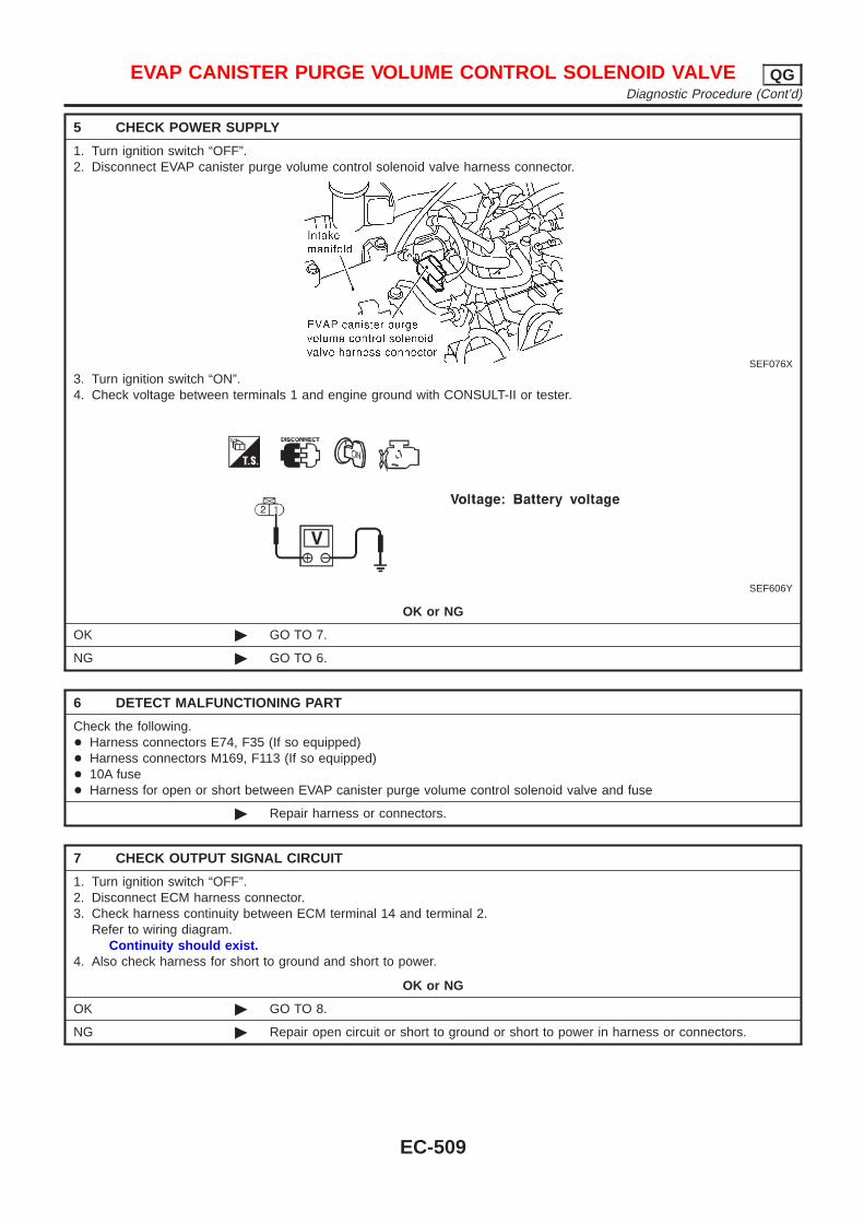
5 CHECK POWER SUPPLY
1. Turn ignition switch “OFF”.2. Disconnect EVAP canister purge volume control solenoid valve harness connector.
SEF076X
3. Turn ignition switch “ON”.4. Check voltage between terminals 1 and engine ground with CONSULT-II or tester.
SEF606Y
OK or NG
OK © GO TO 7.
NG © GO TO 6.
6 DETECT MALFUNCTIONING PART
Check the following.+ Harness connectors E74, F35 (If so equipped)+ Harness connectors M169, F113 (If so equipped)+ 10A fuse+ Harness for open or short between EVAP canister purge volume control solenoid valve and fuse
© Repair harness or connectors.
7 CHECK OUTPUT SIGNAL CIRCUIT
1. Turn ignition switch “OFF”.2. Disconnect ECM harness connector.3. Check harness continuity between ECM terminal 14 and terminal 2.
Refer to wiring diagram.Continuity should exist.
4. Also check harness for short to ground and short to power.
OK or NG
OK © GO TO 8.
NG © Repair open circuit or short to ground or short to power in harness or connectors.
EVAP CANISTER PURGE VOLUME CONTROL SOLENOID VALVE QGDiagnostic Procedure (Cont’d)
EC-509
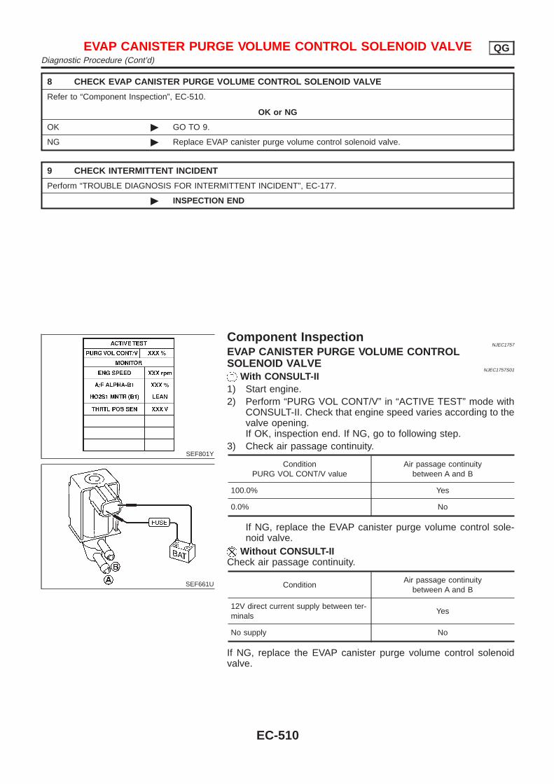
8 CHECK EVAP CANISTER PURGE VOLUME CONTROL SOLENOID VALVE
Refer to “Component Inspection”, EC-510.
OK or NG
OK © GO TO 9.
NG © Replace EVAP canister purge volume control solenoid valve.
9 CHECK INTERMITTENT INCIDENT
Perform “TROUBLE DIAGNOSIS FOR INTERMITTENT INCIDENT”, EC-177.
© INSPECTION END
SEF801Y
SEF661U
Component InspectionNJEC1757
EVAP CANISTER PURGE VOLUME CONTROLSOLENOID VALVE
NJEC1757S01
With CONSULT-II1) Start engine.2) Perform “PURG VOL CONT/V” in “ACTIVE TEST” mode with
CONSULT-II. Check that engine speed varies according to thevalve opening.If OK, inspection end. If NG, go to following step.
3) Check air passage continuity.
ConditionPURG VOL CONT/V value
Air passage continuitybetween A and B
100.0% Yes
0.0% No
If NG, replace the EVAP canister purge volume control sole-noid valve.
Without CONSULT-IICheck air passage continuity.
ConditionAir passage continuity
between A and B
12V direct current supply between ter-minals
Yes
No supply No
If NG, replace the EVAP canister purge volume control solenoidvalve.
EVAP CANISTER PURGE VOLUME CONTROL SOLENOID VALVE QGDiagnostic Procedure (Cont’d)
EC-510
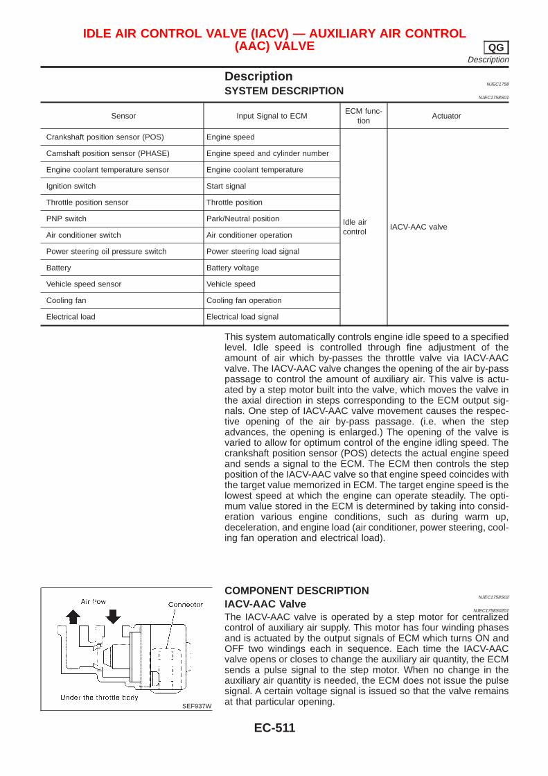
DescriptionNJEC1758
SYSTEM DESCRIPTIONNJEC1758S01
Sensor Input Signal to ECMECM func-
tionActuator
Crankshaft position sensor (POS) Engine speed
Idle aircontrol
IACV-AAC valve
Camshaft position sensor (PHASE) Engine speed and cylinder number
Engine coolant temperature sensor Engine coolant temperature
Ignition switch Start signal
Throttle position sensor Throttle position
PNP switch Park/Neutral position
Air conditioner switch Air conditioner operation
Power steering oil pressure switch Power steering load signal
Battery Battery voltage
Vehicle speed sensor Vehicle speed
Cooling fan Cooling fan operation
Electrical load Electrical load signal
This system automatically controls engine idle speed to a specifiedlevel. Idle speed is controlled through fine adjustment of theamount of air which by-passes the throttle valve via IACV-AACvalve. The IACV-AAC valve changes the opening of the air by-passpassage to control the amount of auxiliary air. This valve is actu-ated by a step motor built into the valve, which moves the valve inthe axial direction in steps corresponding to the ECM output sig-nals. One step of IACV-AAC valve movement causes the respec-tive opening of the air by-pass passage. (i.e. when the stepadvances, the opening is enlarged.) The opening of the valve isvaried to allow for optimum control of the engine idling speed. Thecrankshaft position sensor (POS) detects the actual engine speedand sends a signal to the ECM. The ECM then controls the stepposition of the IACV-AAC valve so that engine speed coincides withthe target value memorized in ECM. The target engine speed is thelowest speed at which the engine can operate steadily. The opti-mum value stored in the ECM is determined by taking into consid-eration various engine conditions, such as during warm up,deceleration, and engine load (air conditioner, power steering, cool-ing fan operation and electrical load).
SEF937W
COMPONENT DESCRIPTIONNJEC1758S02
IACV-AAC ValveNJEC1758S0201
The IACV-AAC valve is operated by a step motor for centralizedcontrol of auxiliary air supply. This motor has four winding phasesand is actuated by the output signals of ECM which turns ON andOFF two windings each in sequence. Each time the IACV-AACvalve opens or closes to change the auxiliary air quantity, the ECMsends a pulse signal to the step motor. When no change in theauxiliary air quantity is needed, the ECM does not issue the pulsesignal. A certain voltage signal is issued so that the valve remainsat that particular opening.
IDLE AIR CONTROL VALVE (IACV) — AUXILIARY AIR CONTROL(AAC) VALVE QG
Description
EC-511
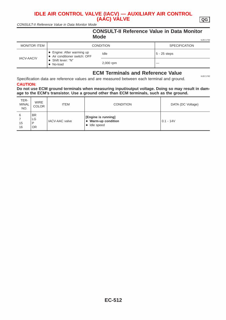
CONSULT-II Reference Value in Data MonitorMode
NJEC1759
MONITOR ITEM CONDITION SPECIFICATION
IACV-AAC/V
+ Engine: After warming up+ Air conditioner switch: OFF+ Shift lever: “N”+ No-load
Idle 5 - 25 steps
2,000 rpm —
ECM Terminals and Reference ValueNJEC1760
Specification data are reference values and are measured between each terminal and ground.CAUTION:Do not use ECM ground terminals when measuring input/output voltage. Doing so may result in dam-age to the ECM’s transistor. Use a ground other than ECM terminals, such as the ground.
TER-MINAL
NO.
WIRECOLOR
ITEM CONDITION DATA (DC Voltage)
671516
BRLGPOR
IACV-AAC valve[Engine is running]+ Warm-up condition+ Idle speed
0.1 - 14V
IDLE AIR CONTROL VALVE (IACV) — AUXILIARY AIR CONTROL(AAC) VALVE QG
CONSULT-II Reference Value in Data Monitor Mode
EC-512
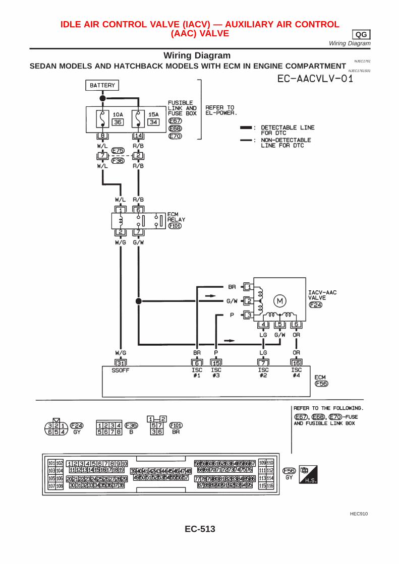
Wiring DiagramNJEC1761
SEDAN MODELS AND HATCHBACK MODELS WITH ECM IN ENGINE COMPARTMENTNJEC1761S01
HEC910
IDLE AIR CONTROL VALVE (IACV) — AUXILIARY AIR CONTROL(AAC) VALVE QG
Wiring Diagram
EC-513
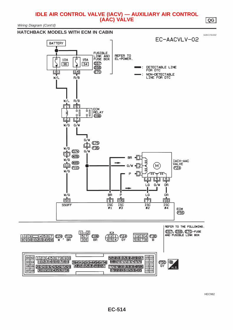
HATCHBACK MODELS WITH ECM IN CABINNJEC1761S02
HEC982
IDLE AIR CONTROL VALVE (IACV) — AUXILIARY AIR CONTROL(AAC) VALVE QG
Wiring Diagram (Cont’d)
EC-514
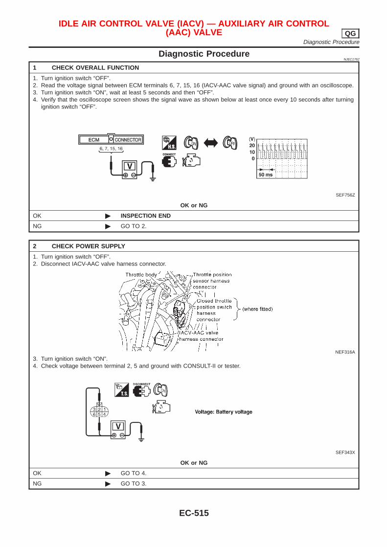
Diagnostic ProcedureNJEC1762
1 CHECK OVERALL FUNCTION
1. Turn ignition switch “OFF”.2. Read the voltage signal between ECM terminals 6, 7, 15, 16 (IACV-AAC valve signal) and ground with an oscilloscope.3. Turn ignition switch “ON”, wait at least 5 seconds and then “OFF”.4. Verify that the oscilloscope screen shows the signal wave as shown below at least once every 10 seconds after turning
ignition switch “OFF”.
SEF756Z
OK or NG
OK © INSPECTION END
NG © GO TO 2.
2 CHECK POWER SUPPLY
1. Turn ignition switch “OFF”.2. Disconnect IACV-AAC valve harness connector.
NEF316A
3. Turn ignition switch “ON”.4. Check voltage between terminal 2, 5 and ground with CONSULT-II or tester.
SEF343X
OK or NG
OK © GO TO 4.
NG © GO TO 3.
IDLE AIR CONTROL VALVE (IACV) — AUXILIARY AIR CONTROL(AAC) VALVE QG
Diagnostic Procedure
EC-515
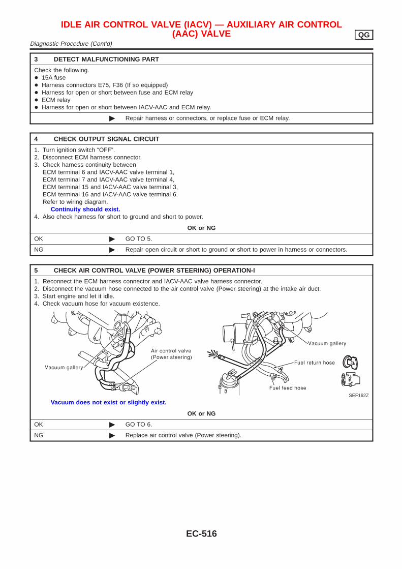
3 DETECT MALFUNCTIONING PART
Check the following.+ 15A fuse+ Harness connectors E75, F36 (If so equipped)+ Harness for open or short between fuse and ECM relay+ ECM relay+ Harness for open or short between IACV-AAC and ECM relay.
© Repair harness or connectors, or replace fuse or ECM relay.
4 CHECK OUTPUT SIGNAL CIRCUIT
1. Turn ignition switch “OFF”.2. Disconnect ECM harness connector.3. Check harness continuity between
ECM terminal 6 and IACV-AAC valve terminal 1,ECM terminal 7 and IACV-AAC valve terminal 4,ECM terminal 15 and IACV-AAC valve terminal 3,ECM terminal 16 and IACV-AAC valve terminal 6.Refer to wiring diagram.
Continuity should exist.4. Also check harness for short to ground and short to power.
OK or NG
OK © GO TO 5.
NG © Repair open circuit or short to ground or short to power in harness or connectors.
5 CHECK AIR CONTROL VALVE (POWER STEERING) OPERATION-I
1. Reconnect the ECM harness connector and IACV-AAC valve harness connector.2. Disconnect the vacuum hose connected to the air control valve (Power steering) at the intake air duct.3. Start engine and let it idle.4. Check vacuum hose for vacuum existence.
SEF162Z
Vacuum does not exist or slightly exist.
OK or NG
OK © GO TO 6.
NG © Replace air control valve (Power steering).
IDLE AIR CONTROL VALVE (IACV) — AUXILIARY AIR CONTROL(AAC) VALVE QG
Diagnostic Procedure (Cont’d)
EC-516
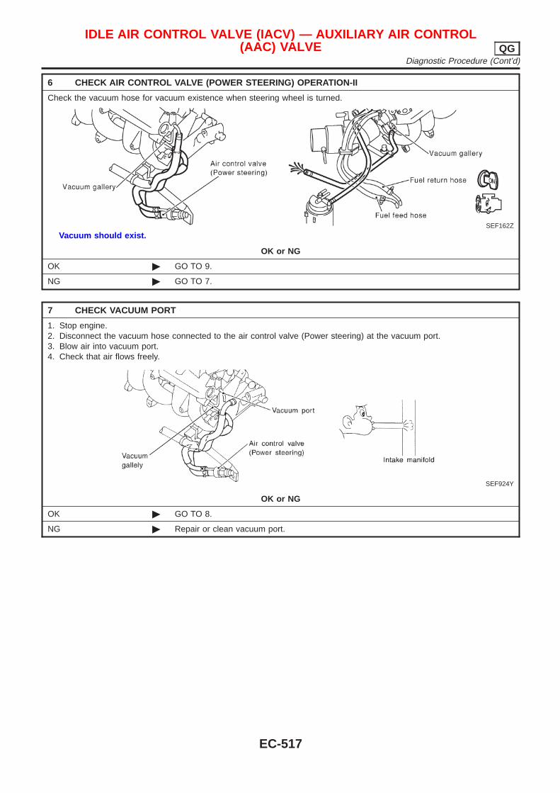
6 CHECK AIR CONTROL VALVE (POWER STEERING) OPERATION-II
Check the vacuum hose for vacuum existence when steering wheel is turned.
SEF162Z
Vacuum should exist.
OK or NG
OK © GO TO 9.
NG © GO TO 7.
7 CHECK VACUUM PORT
1. Stop engine.2. Disconnect the vacuum hose connected to the air control valve (Power steering) at the vacuum port.3. Blow air into vacuum port.4. Check that air flows freely.
SEF924Y
OK or NG
OK © GO TO 8.
NG © Repair or clean vacuum port.
IDLE AIR CONTROL VALVE (IACV) — AUXILIARY AIR CONTROL(AAC) VALVE QG
Diagnostic Procedure (Cont’d)
EC-517
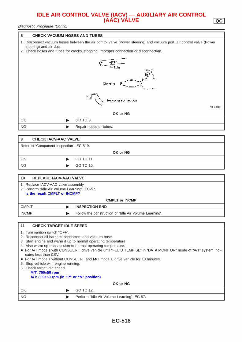
8 CHECK VACUUM HOSES AND TUBES
1. Disconnect vacuum hoses between the air control valve (Power steering) and vacuum port, air control valve (Powersteering) and air duct.
2. Check hoses and tubes for cracks, clogging, improper connection or disconnection.
SEF109L
OK or NG
OK © GO TO 9.
NG © Repair hoses or tubes.
9 CHECK IACV-AAC VALVE
Refer to “Component Inspection”, EC-519.
OK or NG
OK © GO TO 11.
NG © GO TO 10.
10 REPLACE IACV-AAC VALVE
1. Replace IACV-AAC valve assembly.2. Perform “Idle Air Volume Learning”, EC-57.
Is the result CMPLT or INCMP?
CMPLT or INCMP
CMPLT © INSPECTION END
INCMP © Follow the construction of “Idle Air Volume Learning”.
11 CHECK TARGET IDLE SPEED
1. Turn ignition switch “OFF”.2. Reconnect all harness connectors and vacuum hose.3. Start engine and warm it up to normal operating temperature.4. Also warm up transmission to normal operating temperature.+ For A/T models with CONSULT-II, drive vehicle until “FLUID TEMP SE” in “DATA MONITOR” mode of “A/T” system indi-
cates less than 0.9V.+ For A/T models without CONSULT-II and M/T models, drive vehicle for 10 minutes.5. Stop vehicle with engine running.6. Check target idle speed.
M/T: 700±50 rpmA/T: 800±50 rpm (in “P” or “N” position)
OK or NG
OK © GO TO 12.
NG © Perform “Idle Air Volume Learning”, EC-57.
IDLE AIR CONTROL VALVE (IACV) — AUXILIARY AIR CONTROL(AAC) VALVE QG
Diagnostic Procedure (Cont’d)
EC-518
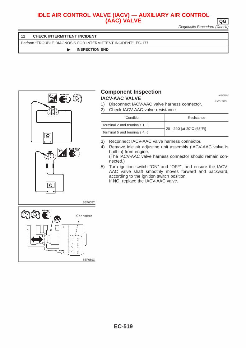
12 CHECK INTERMITTENT INCIDENT
Perform “TROUBLE DIAGNOSIS FOR INTERMITTENT INCIDENT”, EC-177.
© INSPECTION END
SEF605Y
SEF089X
Component InspectionNJEC1763
IACV-AAC VALVENJEC1763S01
1) Disconnect IACV-AAC valve harness connector.2) Check IACV-AAC valve resistance.
Condition Resistance
Terminal 2 and terminals 1, 320 - 24Ω [at 20°C (68°F)]
Terminal 5 and terminals 4, 6
3) Reconnect IACV-AAC valve harness connector.4) Remove idle air adjusting unit assembly (IACV-AAC valve is
built-in) from engine.(The IACV-AAC valve harness connector should remain con-nected.)
5) Turn ignition switch “ON” and “OFF”, and ensure the IACV-AAC valve shaft smoothly moves forward and backward,according to the ignition switch position.If NG, replace the IACV-AAC valve.
IDLE AIR CONTROL VALVE (IACV) — AUXILIARY AIR CONTROL(AAC) VALVE QG
Diagnostic Procedure (Cont’d)
EC-519
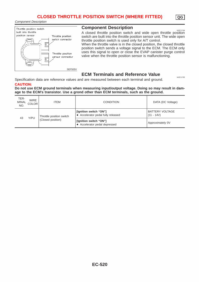
SEF505V
Component DescriptionNJEC1764
A closed throttle position switch and wide open throttle positionswitch are built into the throttle position sensor unit. The wide openthrottle position switch is used only for A/T control.When the throttle valve is in the closed position, the closed throttleposition switch sends a voltage signal to the ECM. The ECM onlyuses this signal to open or close the EVAP canister purge controlvalve when the throttle position sensor is malfunctioning.
ECM Terminals and Reference ValueNJEC1765
Specification data are reference values and are measured between each terminal and ground.CAUTION:Do not use ECM ground terminals when measuring input/output voltage. Doing so may result in dam-age to the ECM’s transistor. Use a grond other than ECM terminals, such as the ground.
TER-MINAL
NO.
WIRECOLOR
ITEM CONDITION DATA (DC Voltage)
43 Y/PUThrottle position switch(Closed position)
[Ignition switch “ON”]+ Accelerator pedal fully released
BATTERY VOLTAGE(11 - 14V)
[Ignition switch “ON”]+ Accelerator pedal depressed
Approximately 0V
CLOSED THROTTLE POSITION SWITCH (WHERE FITTED) QGComponent Description
EC-520
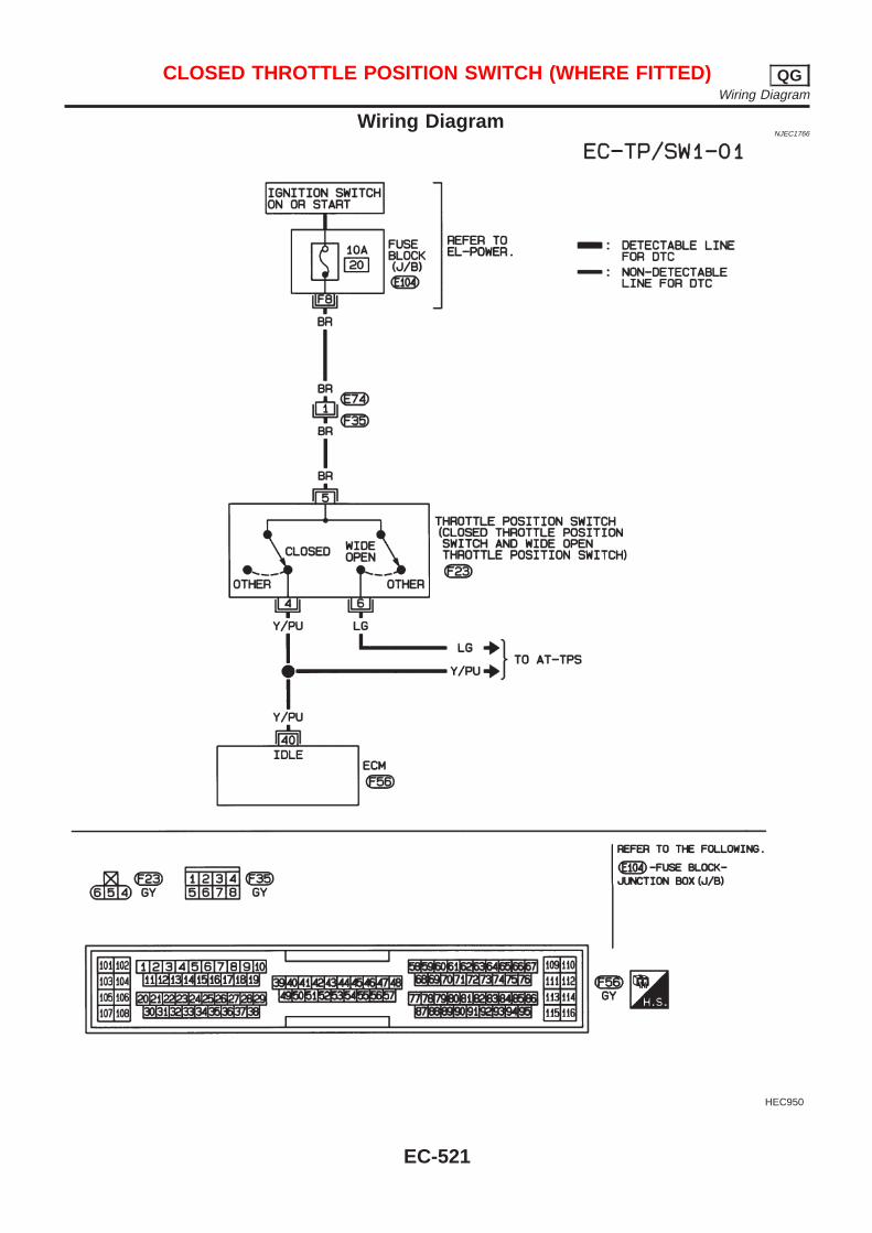
Wiring DiagramNJEC1766
HEC950
CLOSED THROTTLE POSITION SWITCH (WHERE FITTED) QGWiring Diagram
EC-521
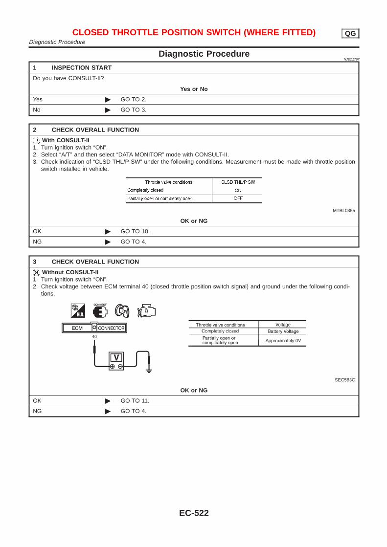
Diagnostic ProcedureNJEC1767
1 INSPECTION START
Do you have CONSULT-II?
Yes or No
Yes © GO TO 2.
No © GO TO 3.
2 CHECK OVERALL FUNCTION
With CONSULT-II1. Turn ignition switch “ON”.2. Select “A/T” and then select “DATA MONITOR” mode with CONSULT-II.3. Check indication of “CLSD THL/P SW” under the following conditions. Measurement must be made with throttle position
switch installed in vehicle.
MTBL0355
OK or NG
OK © GO TO 10.
NG © GO TO 4.
3 CHECK OVERALL FUNCTION
Without CONSULT-II1. Turn ignition switch “ON”.2. Check voltage between ECM terminal 40 (closed throttle position switch signal) and ground under the following condi-
tions.
SEC583C
OK or NG
OK © GO TO 11.
NG © GO TO 4.
CLOSED THROTTLE POSITION SWITCH (WHERE FITTED) QGDiagnostic Procedure
EC-522
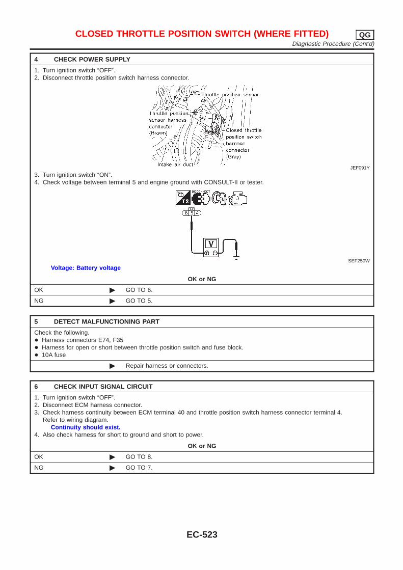
4 CHECK POWER SUPPLY
1. Turn ignition switch “OFF”.2. Disconnect throttle position switch harness connector.
JEF091Y
3. Turn ignition switch “ON”.4. Check voltage between terminal 5 and engine ground with CONSULT-II or tester.
SEF250W
Voltage: Battery voltage
OK or NG
OK © GO TO 6.
NG © GO TO 5.
5 DETECT MALFUNCTIONING PART
Check the following.+ Harness connectors E74, F35+ Harness for open or short between throttle position switch and fuse block.+ 10A fuse
© Repair harness or connectors.
6 CHECK INPUT SIGNAL CIRCUIT
1. Turn ignition switch “OFF”.2. Disconnect ECM harness connector.3. Check harness continuity between ECM terminal 40 and throttle position switch harness connector terminal 4.
Refer to wiring diagram.Continuity should exist.
4. Also check harness for short to ground and short to power.
OK or NG
OK © GO TO 8.
NG © GO TO 7.
CLOSED THROTTLE POSITION SWITCH (WHERE FITTED) QGDiagnostic Procedure (Cont’d)
EC-523
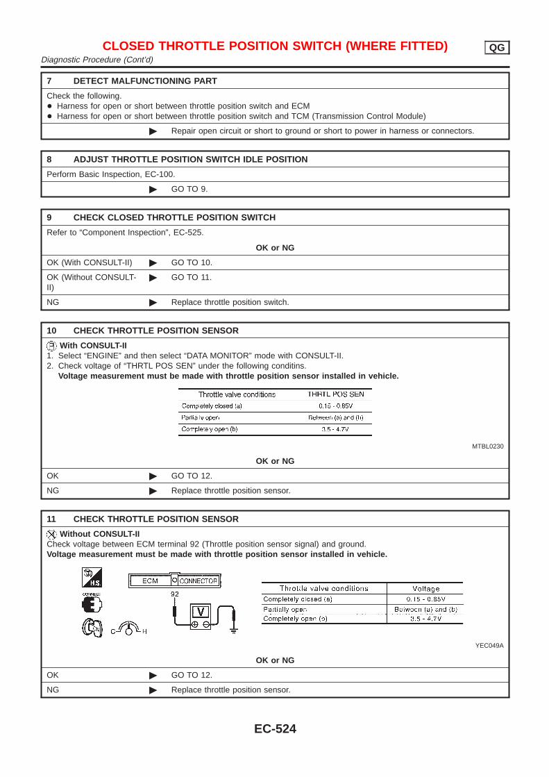
7 DETECT MALFUNCTIONING PART
Check the following.+ Harness for open or short between throttle position switch and ECM+ Harness for open or short between throttle position switch and TCM (Transmission Control Module)
© Repair open circuit or short to ground or short to power in harness or connectors.
8 ADJUST THROTTLE POSITION SWITCH IDLE POSITION
Perform Basic Inspection, EC-100.
© GO TO 9.
9 CHECK CLOSED THROTTLE POSITION SWITCH
Refer to “Component Inspection”, EC-525.
OK or NG
OK (With CONSULT-II) © GO TO 10.
OK (Without CONSULT-II)
© GO TO 11.
NG © Replace throttle position switch.
10 CHECK THROTTLE POSITION SENSOR
With CONSULT-II1. Select “ENGINE” and then select “DATA MONITOR” mode with CONSULT-II.2. Check voltage of “THRTL POS SEN” under the following conditins.
Voltage measurement must be made with throttle position sensor installed in vehicle.
MTBL0230
OK or NG
OK © GO TO 12.
NG © Replace throttle position sensor.
11 CHECK THROTTLE POSITION SENSOR
Without CONSULT-IICheck voltage between ECM terminal 92 (Throttle position sensor signal) and ground.Voltage measurement must be made with throttle position sensor installed in vehicle.
YEC049A
OK or NG
OK © GO TO 12.
NG © Replace throttle position sensor.
CLOSED THROTTLE POSITION SWITCH (WHERE FITTED) QGDiagnostic Procedure (Cont’d)
EC-524
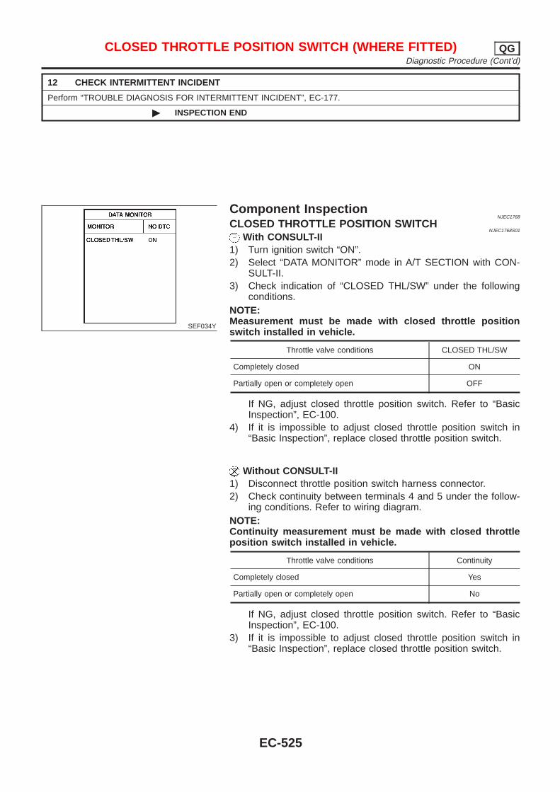
12 CHECK INTERMITTENT INCIDENT
Perform “TROUBLE DIAGNOSIS FOR INTERMITTENT INCIDENT”, EC-177.
© INSPECTION END
SEF034Y
Component InspectionNJEC1768
CLOSED THROTTLE POSITION SWITCHNJEC1768S01
With CONSULT-II1) Turn ignition switch “ON”.2) Select “DATA MONITOR” mode in A/T SECTION with CON-
SULT-II.3) Check indication of “CLOSED THL/SW” under the following
conditions.NOTE:Measurement must be made with closed throttle positionswitch installed in vehicle.
Throttle valve conditions CLOSED THL/SW
Completely closed ON
Partially open or completely open OFF
If NG, adjust closed throttle position switch. Refer to “BasicInspection”, EC-100.
4) If it is impossible to adjust closed throttle position switch in“Basic Inspection”, replace closed throttle position switch.
Without CONSULT-II1) Disconnect throttle position switch harness connector.2) Check continuity between terminals 4 and 5 under the follow-
ing conditions. Refer to wiring diagram.NOTE:Continuity measurement must be made with closed throttleposition switch installed in vehicle.
Throttle valve conditions Continuity
Completely closed Yes
Partially open or completely open No
If NG, adjust closed throttle position switch. Refer to “BasicInspection”, EC-100.
3) If it is impossible to adjust closed throttle position switch in“Basic Inspection”, replace closed throttle position switch.
CLOSED THROTTLE POSITION SWITCH (WHERE FITTED) QGDiagnostic Procedure (Cont’d)
EC-525
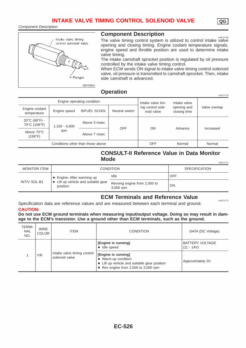
SEF095X
Component DescriptionNJEC1769
The valve timing control system is utilized to control intake valveopening and closing timing. Engine coolant temperature signals,engine speed and throttle position are used to determine intakevalve timing.The intake camshaft sprocket position is regulated by oil pressurecontrolled by the intake valve timing control.When ECM sends ON signal to intake valve timing control solenoidvalve, oil pressure is transmitted to camshaft sprocket. Then, intakeside camshaft is advanced.
OperationNJEC1770
Engine operating condition Intake valve tim-ing control sole-
noid valve
Intake valveopening andclosing time
Valve overlapEngine coolanttemperature
Engine speed B/FUEL SCHDL Neutral switch
20°C (68°F) -70°C (158°F) 1,150 - 4,600
rpm
Above 3 msec
OFF ON Advance IncreasedAbove 70°C
(158°F)Above 7 msec
Conditions other than those above OFF Normal Normal
CONSULT-II Reference Value in Data MonitorMode
NJEC1771
MONITOR ITEM CONDITION SPECIFICATION
INT/V SOL-B1+ Engine: After warming up+ Lift up vehicle and suitable gear
position
Idle OFF
Revving engine from 2,000 to3,000 rpm
ON
ECM Terminals and Reference ValueNJEC1772
Specification data are reference values and are measured between each terminal and ground.CAUTION:Do not use ECM ground terminals when measuring input/output voltage. Doing so may result in dam-age to the ECM’s transistor. Use a ground other than ECM terminals, such as the ground.
TERMI-NALNO.
WIRECOLOR
ITEM CONDITION DATA (DC Voltage)
1 Y/RIntake valve timing controlsolenoid valve
[Engine is running]+ Idle speed
BATTERY VOLTAGE(11 - 14V)
[Engine is running]+ Warm-up condition+ Lift up vehicle and suitable gear position+ Rev engine from 2,000 to 3,000 rpm
Approximately 0V
INTAKE VALVE TIMING CONTROL SOLENOID VALVE QGComponent Description
EC-526
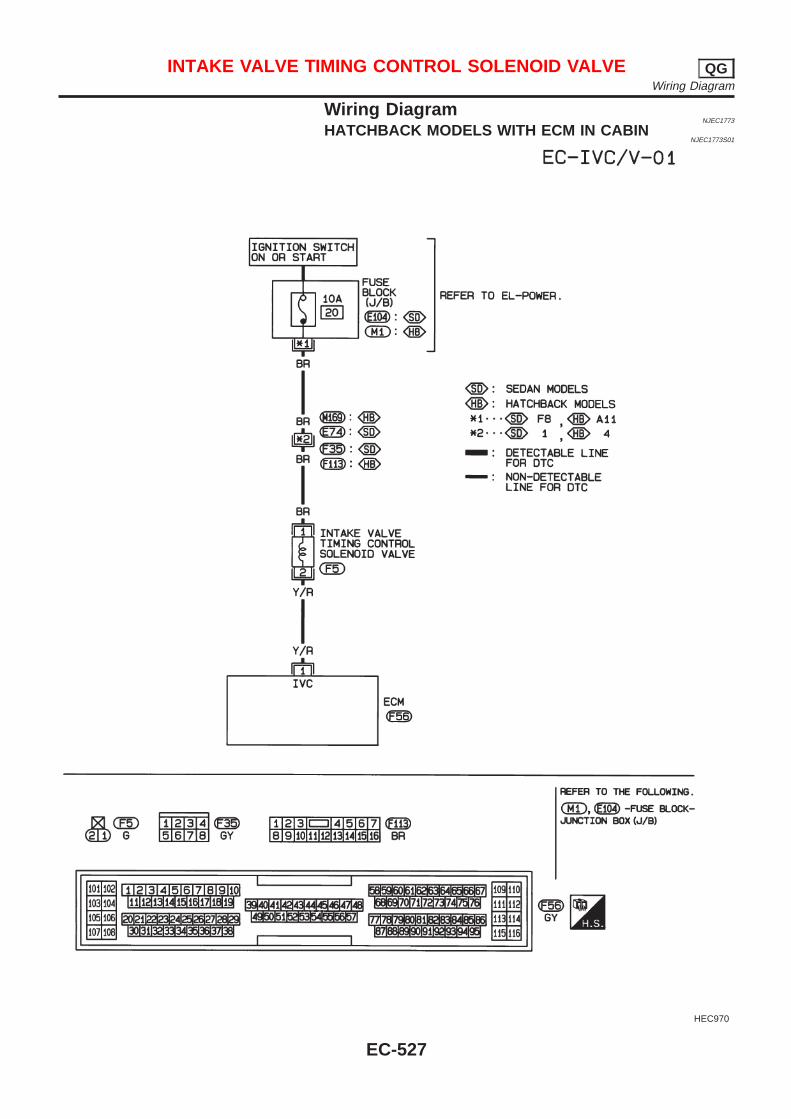
Wiring DiagramNJEC1773
HATCHBACK MODELS WITH ECM IN CABINNJEC1773S01
HEC970
INTAKE VALVE TIMING CONTROL SOLENOID VALVE QGWiring Diagram
EC-527
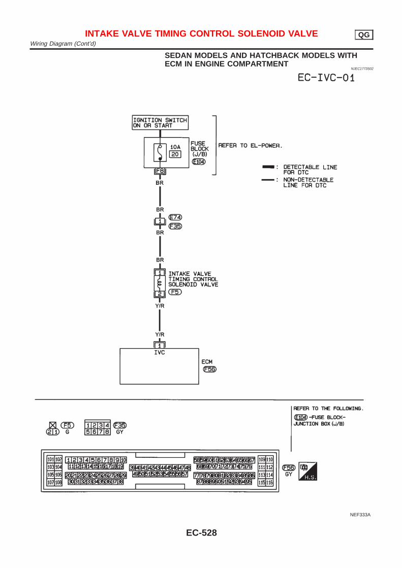
SEDAN MODELS AND HATCHBACK MODELS WITHECM IN ENGINE COMPARTMENT
NJEC1773S02
NEF333A
INTAKE VALVE TIMING CONTROL SOLENOID VALVE QGWiring Diagram (Cont’d)
EC-528
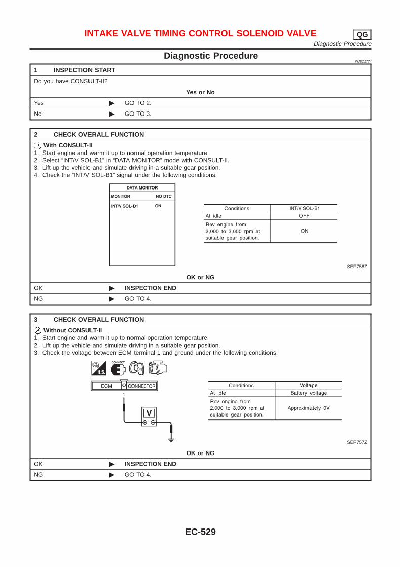
Diagnostic ProcedureNJEC1774
1 INSPECTION START
Do you have CONSULT-II?
Yes or No
Yes © GO TO 2.
No © GO TO 3.
2 CHECK OVERALL FUNCTION
With CONSULT-II1. Start engine and warm it up to normal operation temperature.2. Select “INT/V SOL-B1” in “DATA MONITOR” mode with CONSULT-II.3. Lift-up the vehicle and simulate driving in a suitable gear position.4. Check the “INT/V SOL-B1” signal under the following conditions.
SEF758Z
OK or NG
OK © INSPECTION END
NG © GO TO 4.
3 CHECK OVERALL FUNCTION
Without CONSULT-II1. Start engine and warm it up to normal operation temperature.2. Lift up the vehicle and simulate driving in a suitable gear position.3. Check the voltage between ECM terminal 1 and ground under the following conditions.
SEF757Z
OK or NG
OK © INSPECTION END
NG © GO TO 4.
INTAKE VALVE TIMING CONTROL SOLENOID VALVE QGDiagnostic Procedure
EC-529
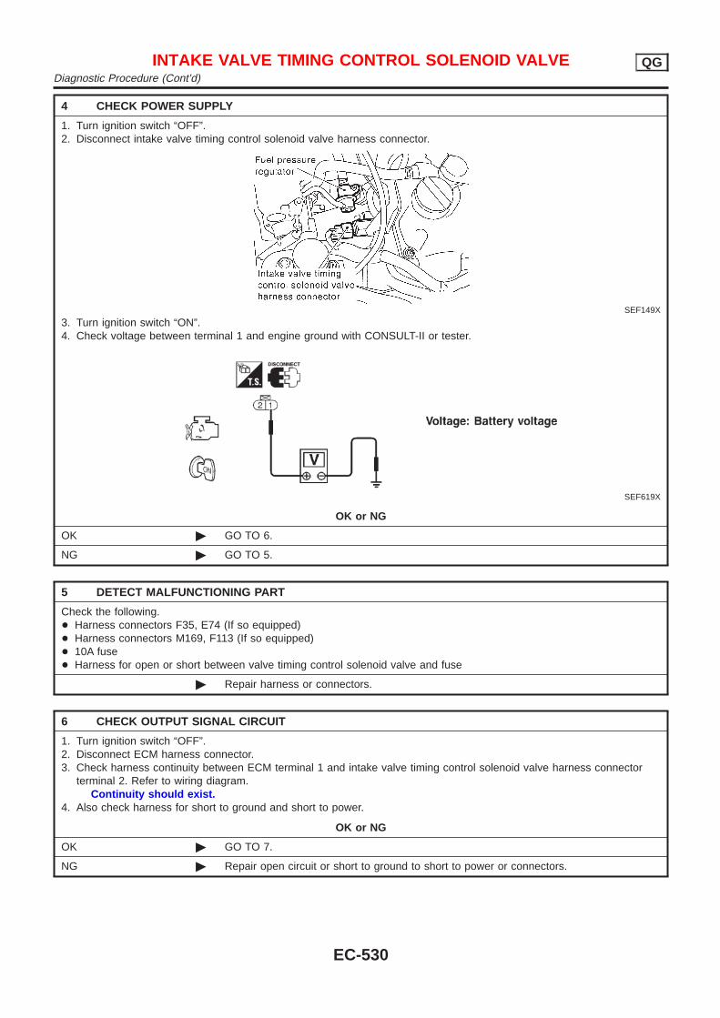
4 CHECK POWER SUPPLY
1. Turn ignition switch “OFF”.2. Disconnect intake valve timing control solenoid valve harness connector.
SEF149X
3. Turn ignition switch “ON”.4. Check voltage between terminal 1 and engine ground with CONSULT-II or tester.
SEF619X
OK or NG
OK © GO TO 6.
NG © GO TO 5.
5 DETECT MALFUNCTIONING PART
Check the following.+ Harness connectors F35, E74 (If so equipped)+ Harness connectors M169, F113 (If so equipped)+ 10A fuse+ Harness for open or short between valve timing control solenoid valve and fuse
© Repair harness or connectors.
6 CHECK OUTPUT SIGNAL CIRCUIT
1. Turn ignition switch “OFF”.2. Disconnect ECM harness connector.3. Check harness continuity between ECM terminal 1 and intake valve timing control solenoid valve harness connector
terminal 2. Refer to wiring diagram.Continuity should exist.
4. Also check harness for short to ground and short to power.
OK or NG
OK © GO TO 7.
NG © Repair open circuit or short to ground to short to power or connectors.
INTAKE VALVE TIMING CONTROL SOLENOID VALVE QGDiagnostic Procedure (Cont’d)
EC-530
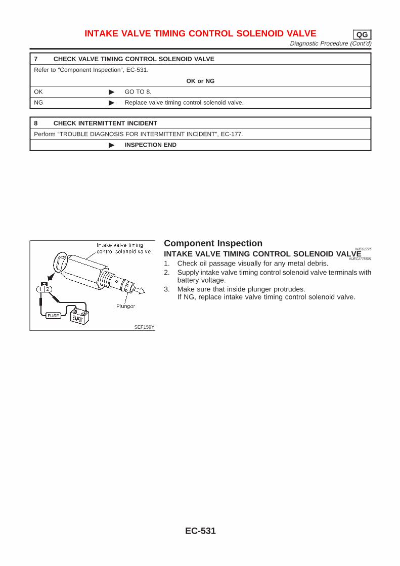
7 CHECK VALVE TIMING CONTROL SOLENOID VALVE
Refer to “Component Inspection”, EC-531.
OK or NG
OK © GO TO 8.
NG © Replace valve timing control solenoid valve.
8 CHECK INTERMITTENT INCIDENT
Perform “TROUBLE DIAGNOSIS FOR INTERMITTENT INCIDENT”, EC-177.
© INSPECTION END
SEF159Y
Component InspectionNJEC1775
INTAKE VALVE TIMING CONTROL SOLENOID VALVENJEC1775S01
1. Check oil passage visually for any metal debris.2. Supply intake valve timing control solenoid valve terminals with
battery voltage.3. Make sure that inside plunger protrudes.
If NG, replace intake valve timing control solenoid valve.
INTAKE VALVE TIMING CONTROL SOLENOID VALVE QGDiagnostic Procedure (Cont’d)
EC-531

System DescriptionNJEC1776
These circuit lines are used to control the smooth shifting up and down of A/T during the hard acceleration/deceleration.Voltage signals are exchanged between ECM and TCM (Transmission Control Module).
A/T COMMUNICATION LINE QGSystem Description
EC-532
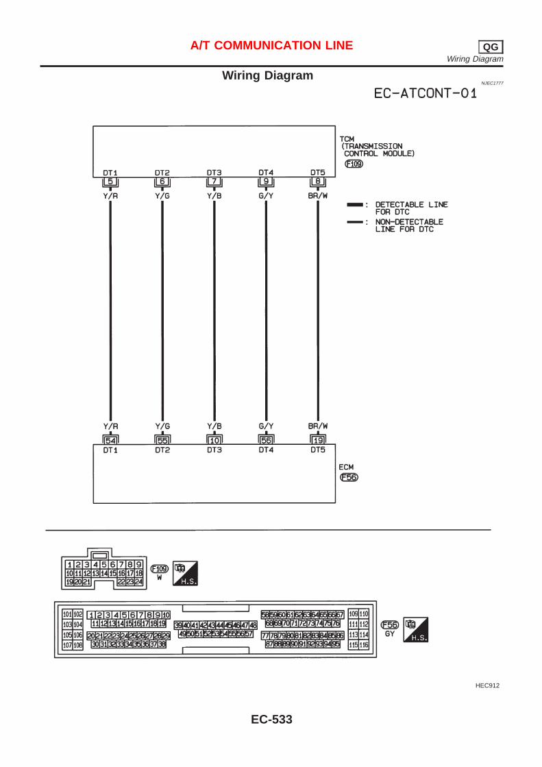
Wiring DiagramNJEC1777
HEC912
A/T COMMUNICATION LINE QGWiring Diagram
EC-533
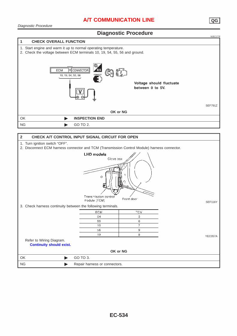
Diagnostic ProcedureNJEC1778
1 CHECK OVERALL FUNCTION
1. Start engine and warm it up to normal operating temperature.2. Check the voltage between ECM terminals 10, 19, 54, 55, 56 and ground.
SEF791Z
OK or NG
OK © INSPECTION END
NG © GO TO 2.
2 CHECK A/T CONTROL INPUT SIGNAL CIRCUIT FOR OPEN
1. Turn ignition switch “OFF”.2. Disconnect ECM harness connector and TCM (Transmission Control Module) harness connector.
SEF116Y
3. Check harness continuity between the following terminals.
YEC057A
Refer to Wiring Diagram.Continuity should exist.
OK or NG
OK © GO TO 3.
NG © Repair harness or connectors.
A/T COMMUNICATION LINE QGDiagnostic Procedure
EC-534
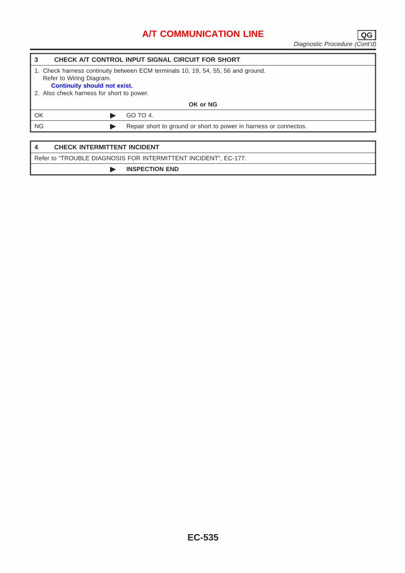
3 CHECK A/T CONTROL INPUT SIGNAL CIRCUIT FOR SHORT
1. Check harness continuity between ECM terminals 10, 19, 54, 55, 56 and ground.Refer to Wiring Diagram.
Continuity should not exist.2. Also check harness for short to power.
OK or NG
OK © GO TO 4.
NG © Repair short to ground or short to power in harness or connectos.
4 CHECK INTERMITTENT INCIDENT
Refer to “TROUBLE DIAGNOSIS FOR INTERMITTENT INCIDENT”, EC-177.
© INSPECTION END
A/T COMMUNICATION LINE QGDiagnostic Procedure (Cont’d)
EC-535
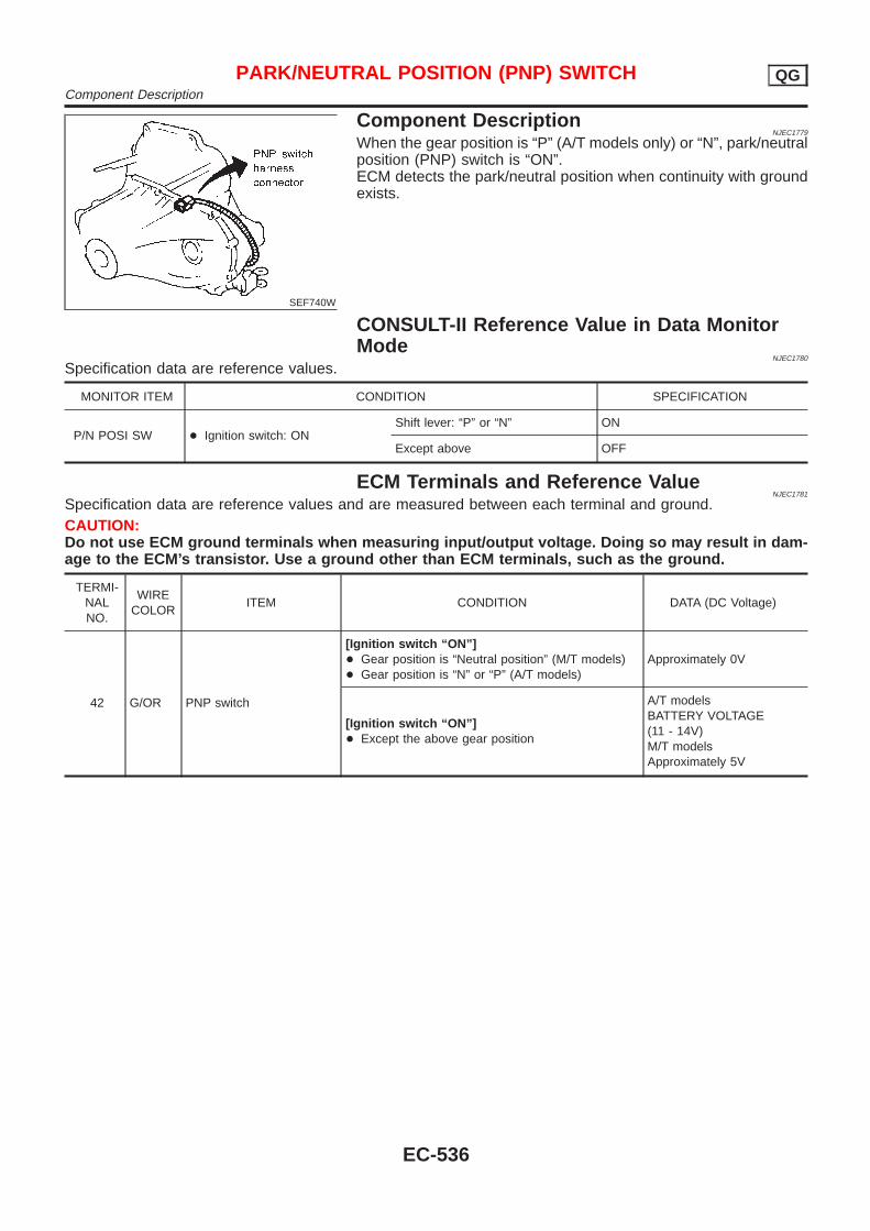
SEF740W
Component DescriptionNJEC1779
When the gear position is “P” (A/T models only) or “N”, park/neutralposition (PNP) switch is “ON”.ECM detects the park/neutral position when continuity with groundexists.
CONSULT-II Reference Value in Data MonitorMode
NJEC1780
Specification data are reference values.
MONITOR ITEM CONDITION SPECIFICATION
P/N POSI SW + Ignition switch: ONShift lever: “P” or “N” ON
Except above OFF
ECM Terminals and Reference ValueNJEC1781
Specification data are reference values and are measured between each terminal and ground.CAUTION:Do not use ECM ground terminals when measuring input/output voltage. Doing so may result in dam-age to the ECM’s transistor. Use a ground other than ECM terminals, such as the ground.
TERMI-NALNO.
WIRECOLOR
ITEM CONDITION DATA (DC Voltage)
42 G/OR PNP switch
[Ignition switch “ON”]+ Gear position is “Neutral position” (M/T models)+ Gear position is “N” or “P” (A/T models)
Approximately 0V
[Ignition switch “ON”]+ Except the above gear position
A/T modelsBATTERY VOLTAGE(11 - 14V)M/T modelsApproximately 5V
PARK/NEUTRAL POSITION (PNP) SWITCH QGComponent Description
EC-536
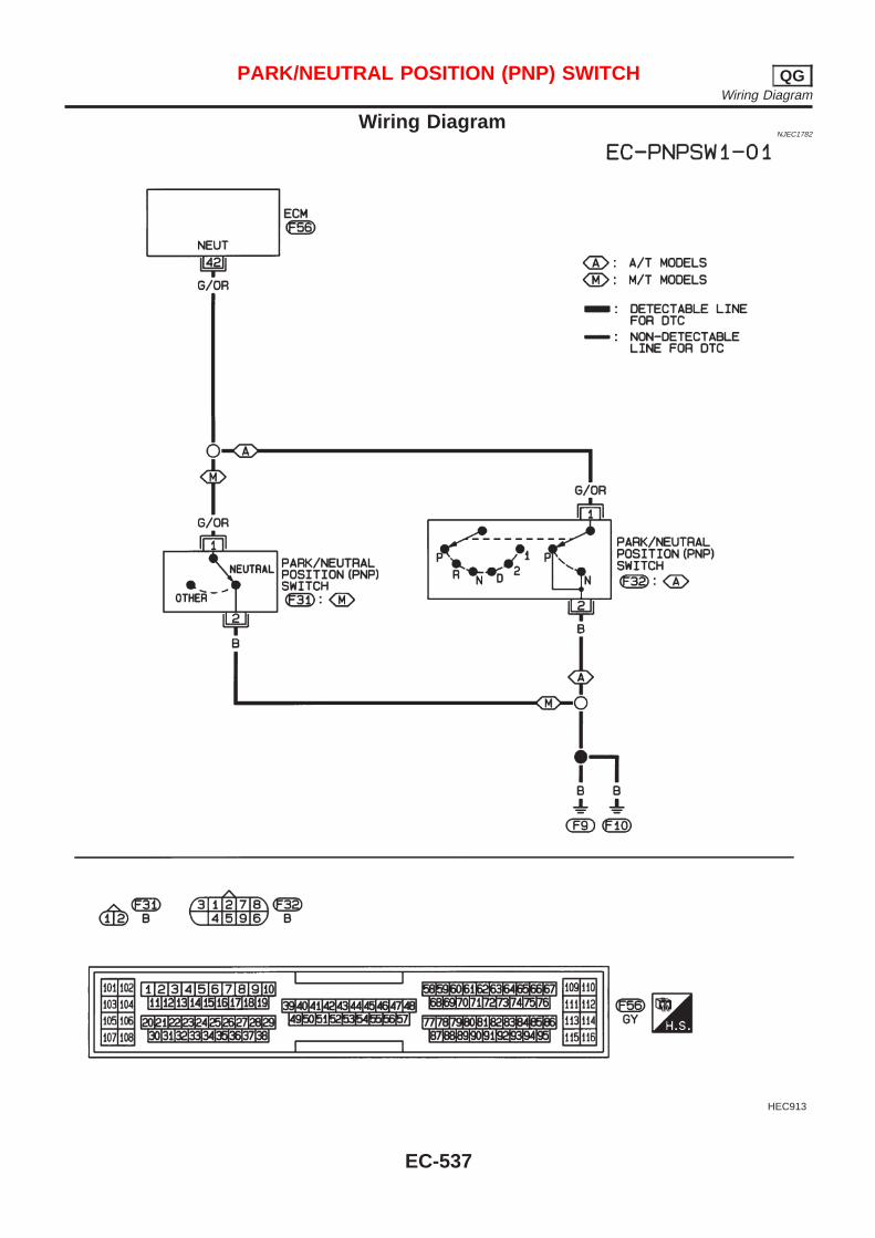
Wiring DiagramNJEC1782
HEC913
PARK/NEUTRAL POSITION (PNP) SWITCH QGWiring Diagram
EC-537
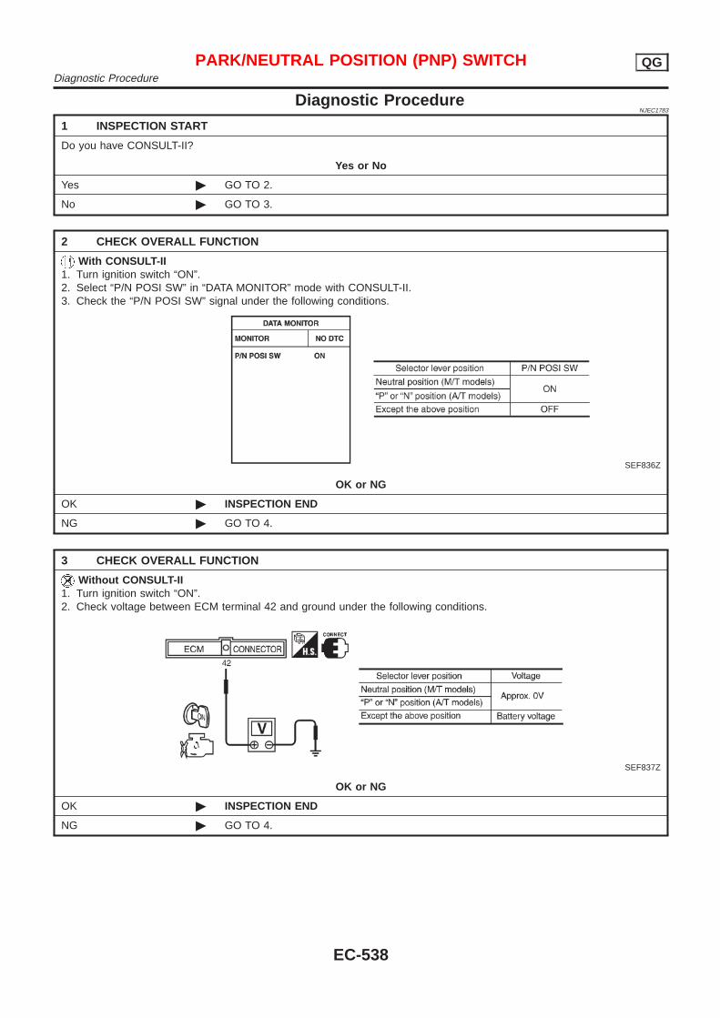
Diagnostic ProcedureNJEC1783
1 INSPECTION START
Do you have CONSULT-II?
Yes or No
Yes © GO TO 2.
No © GO TO 3.
2 CHECK OVERALL FUNCTION
With CONSULT-II1. Turn ignition switch “ON”.2. Select “P/N POSI SW” in “DATA MONITOR” mode with CONSULT-II.3. Check the “P/N POSI SW” signal under the following conditions.
SEF836Z
OK or NG
OK © INSPECTION END
NG © GO TO 4.
3 CHECK OVERALL FUNCTION
Without CONSULT-II1. Turn ignition switch “ON”.2. Check voltage between ECM terminal 42 and ground under the following conditions.
SEF837Z
OK or NG
OK © INSPECTION END
NG © GO TO 4.
PARK/NEUTRAL POSITION (PNP) SWITCH QGDiagnostic Procedure
EC-538
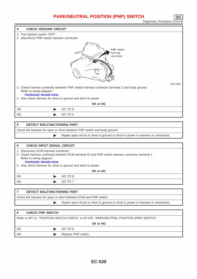
4 CHECK GROUND CIRCUIT
1. Turn ignition switch “OFF”.2. Disconnect PNP switch harness connector.
SEF740W
3. Check harness continuity between PNP switch harness connector terminal 2 and body ground.Refer to wiring diagram.
Continuity should exist.4. Also check harness for short to ground and short to power.
OK or NG
OK © GO TO 6.
NG © GO TO 5.
5 DETECT MALFUNCTIONING PART
Check the harness for open or short between PNP switch and body ground.
© Repair open circuit or short to ground or short to power in harness or connectors.
6 CHECK INPUT SIGNAL CIRCUIT
1. Disconnect ECM harness connector.2. Check harness continuity between ECM terminal 42 and PNP switch harness connector terminal 1.
Refer to wiring diagram.Continuity should exist.
3. Also check harness for short to ground and short to power.
OK or NG
OK © GO TO 8.
NG © GO TO 7.
7 DETECT MALFUNCTIONING PART
Check the harness for open or short between ECM and PNP switch.
© Repair open circuit or short to ground or short to power in harness or connectors.
8 CHECK PNP SWITCH
Refer to MT-21, “POSITION SWITCH CHECK” or AT-183, “PARK/NEUTRAL POSITION (PNP) SWITCH”.
OK or NG
OK © GO TO 9.
NG © Replace PNP switch.
PARK/NEUTRAL POSITION (PNP) SWITCH QGDiagnostic Procedure (Cont’d)
EC-539

9 CHECK INTERMITTENT INCIDENT
Perform “TROUBLE DIAGNOSIS FOR INTERMITTENT INCIDENT”, EC-177.
© INSPECTION END
PARK/NEUTRAL POSITION (PNP) SWITCH QGDiagnostic Procedure (Cont’d)
EC-540
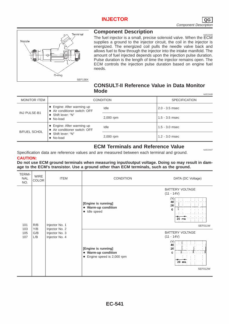
SEF138X
Component DescriptionNJEC0435
The fuel injector is a small, precise solenoid valve. When the ECMsupplies a ground to the injector circuit, the coil in the injector isenergized. The energized coil pulls the needle valve back andallows fuel to flow through the injector into the intake manifold. Theamount of fuel injected depends upon the injection pulse duration.Pulse duration is the length of time the injector remains open. TheECM controls the injection pulse duration based on engine fuelneeds.
CONSULT-II Reference Value in Data MonitorMode
NJEC0436
MONITOR ITEM CONDITION SPECIFICATION
INJ PULSE-B1
+ Engine: After warming up+ Air conditioner switch: OFF+ Shift lever: “N”+ No-load
Idle 2.0 - 3.5 msec
2,000 rpm 1.5 - 3.5 msec
B/FUEL SCHDL
+ Engine: After warming up+ Air conditioner switch: OFF+ Shift lever: “N”+ No-load
Idle 1.5 - 3.0 msec
2,000 rpm 1.2 - 3.0 msec
ECM Terminals and Reference ValueNJEC0437
Specification data are reference values and are measured between each terminal and ground.CAUTION:Do not use ECM ground terminals when measuring input/output voltage. Doing so may result in dam-age to the ECM’s transistor. Use a ground other than ECM terminals, such as the ground.
TERMI-NALNO.
WIRECOLOR
ITEM CONDITION DATA (DC Voltage)
101103105107
R/BY/BG/BL/B
Injector No. 1Injector No. 2Injector No. 3Injector No. 4
[Engine is running]+ Warm-up condition+ Idle speed
BATTERY VOLTAGE(11 - 14V)
SEF011W
[Engine is running]+ Warm-up condition+ Engine speed is 2,000 rpm
BATTERY VOLTAGE(11 - 14V)
SEF012W
INJECTOR QGComponent Description
EC-541
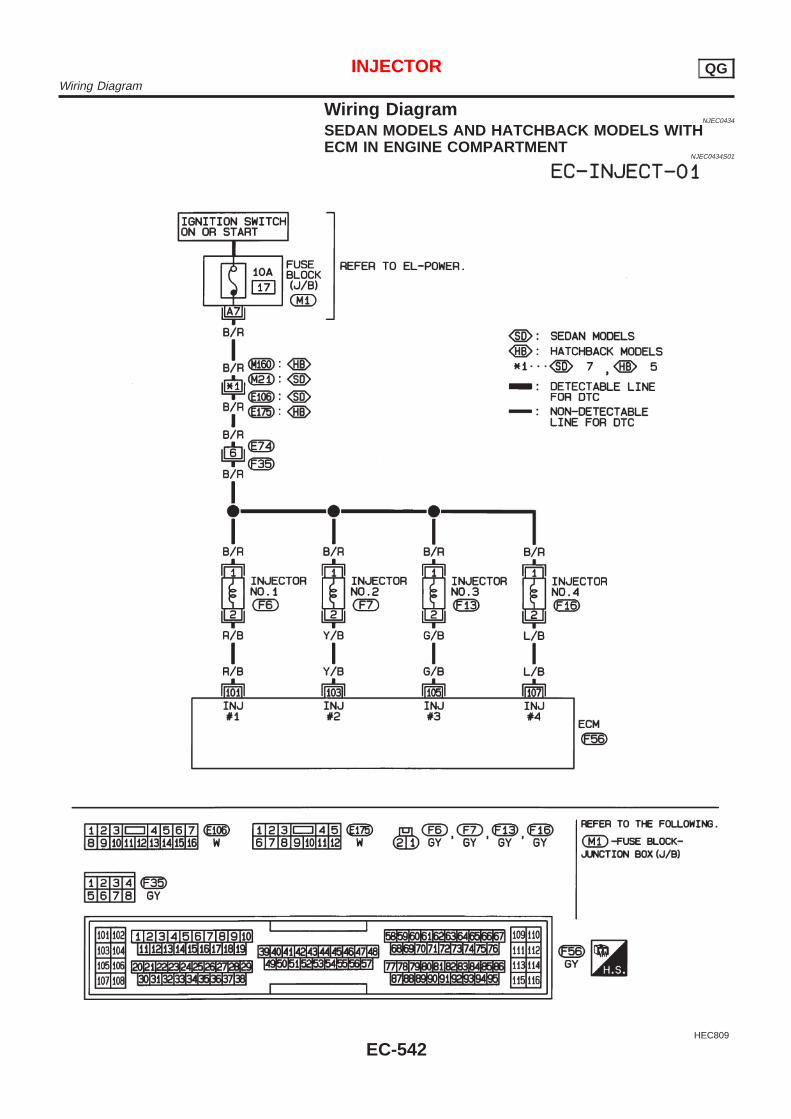
Wiring DiagramNJEC0434
SEDAN MODELS AND HATCHBACK MODELS WITHECM IN ENGINE COMPARTMENT
NJEC0434S01
HEC809
INJECTOR QGWiring Diagram
EC-542
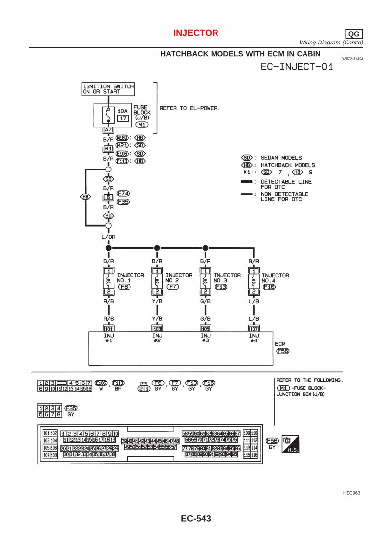
HATCHBACK MODELS WITH ECM IN CABINNJEC0434S02
HEC963
INJECTOR QGWiring Diagram (Cont’d)
EC-543
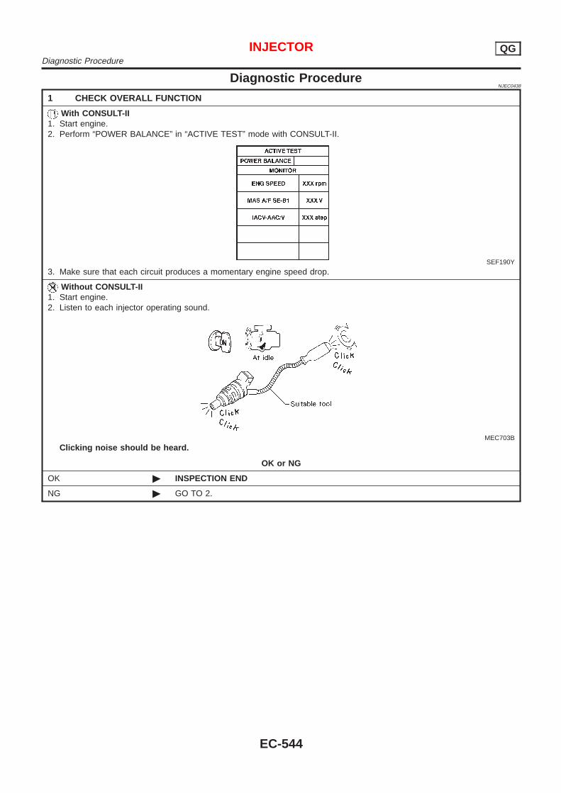
Diagnostic ProcedureNJEC0438
1 CHECK OVERALL FUNCTION
With CONSULT-II1. Start engine.2. Perform “POWER BALANCE” in “ACTIVE TEST” mode with CONSULT-II.
SEF190Y
3. Make sure that each circuit produces a momentary engine speed drop.
Without CONSULT-II1. Start engine.2. Listen to each injector operating sound.
MEC703B
Clicking noise should be heard.
OK or NG
OK © INSPECTION END
NG © GO TO 2.
INJECTOR QGDiagnostic Procedure
EC-544
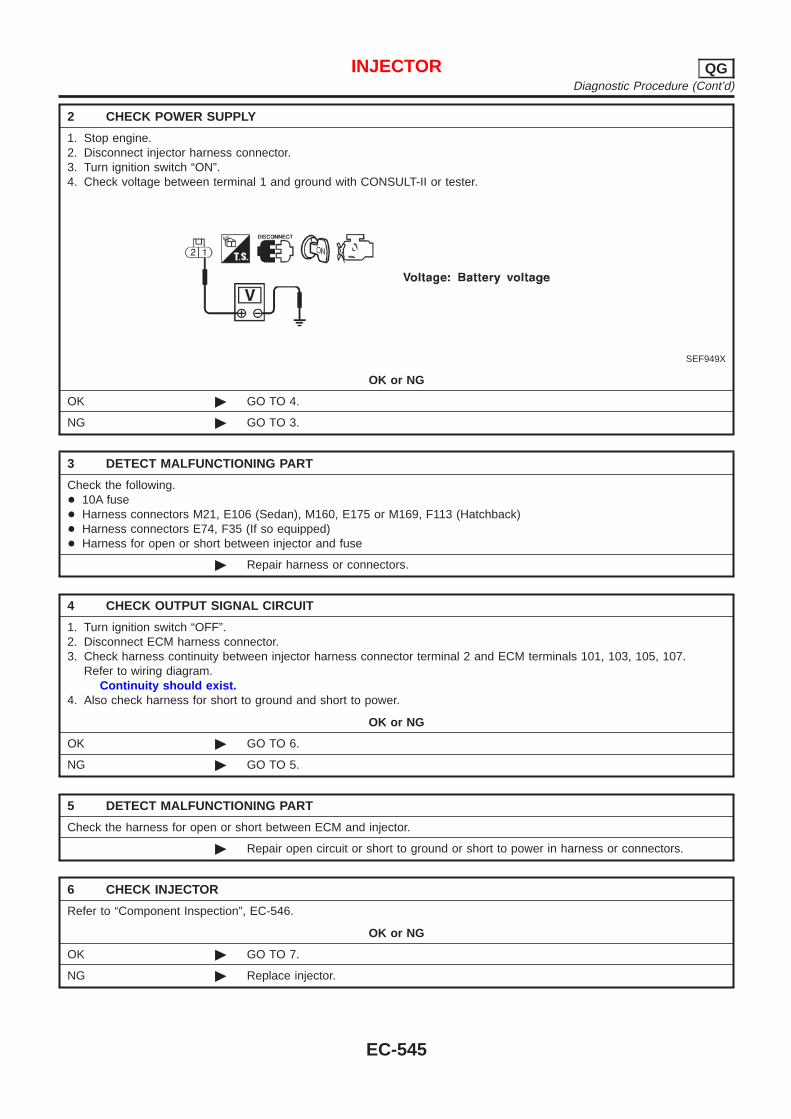
2 CHECK POWER SUPPLY
1. Stop engine.2. Disconnect injector harness connector.3. Turn ignition switch “ON”.4. Check voltage between terminal 1 and ground with CONSULT-II or tester.
SEF949X
OK or NG
OK © GO TO 4.
NG © GO TO 3.
3 DETECT MALFUNCTIONING PART
Check the following.+ 10A fuse+ Harness connectors M21, E106 (Sedan), M160, E175 or M169, F113 (Hatchback)+ Harness connectors E74, F35 (If so equipped)+ Harness for open or short between injector and fuse
© Repair harness or connectors.
4 CHECK OUTPUT SIGNAL CIRCUIT
1. Turn ignition switch “OFF”.2. Disconnect ECM harness connector.3. Check harness continuity between injector harness connector terminal 2 and ECM terminals 101, 103, 105, 107.
Refer to wiring diagram.Continuity should exist.
4. Also check harness for short to ground and short to power.
OK or NG
OK © GO TO 6.
NG © GO TO 5.
5 DETECT MALFUNCTIONING PART
Check the harness for open or short between ECM and injector.
© Repair open circuit or short to ground or short to power in harness or connectors.
6 CHECK INJECTOR
Refer to “Component Inspection”, EC-546.
OK or NG
OK © GO TO 7.
NG © Replace injector.
INJECTOR QGDiagnostic Procedure (Cont’d)
EC-545

7 CHECK INTERMITTENT INCIDENT
Perform “TROUBLE DIAGNOSIS FOR INTERMITTENT INCIDENT”, EC-177.
© INSPECTION END
SEF612Y
Component InspectionNJEC0439
INJECTORNJEC0439S01
1. Disconnect injector harness connector.2. Check resistance between terminals as shown in the figure.
Resistance: 13.5 - 17.5 Ω [at 25°C (77°F)]If NG, replace injector.
INJECTOR QGDiagnostic Procedure (Cont’d)
EC-546
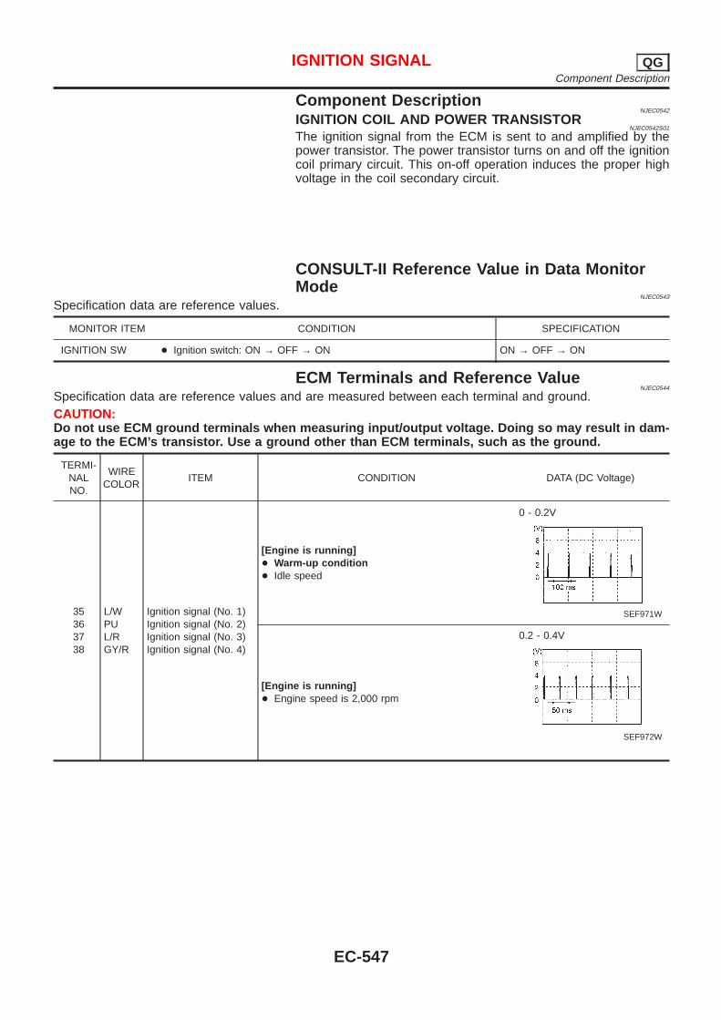
Component DescriptionNJEC0542
IGNITION COIL AND POWER TRANSISTORNJEC0542S01
The ignition signal from the ECM is sent to and amplified by thepower transistor. The power transistor turns on and off the ignitioncoil primary circuit. This on-off operation induces the proper highvoltage in the coil secondary circuit.
CONSULT-II Reference Value in Data MonitorMode
NJEC0543
Specification data are reference values.
MONITOR ITEM CONDITION SPECIFICATION
IGNITION SW + Ignition switch: ON → OFF → ON ON → OFF → ON
ECM Terminals and Reference ValueNJEC0544
Specification data are reference values and are measured between each terminal and ground.CAUTION:Do not use ECM ground terminals when measuring input/output voltage. Doing so may result in dam-age to the ECM’s transistor. Use a ground other than ECM terminals, such as the ground.
TERMI-NALNO.
WIRECOLOR
ITEM CONDITION DATA (DC Voltage)
35363738
L/WPUL/RGY/R
Ignition signal (No. 1)Ignition signal (No. 2)Ignition signal (No. 3)Ignition signal (No. 4)
[Engine is running]+ Warm-up condition+ Idle speed
0 - 0.2V
SEF971W
[Engine is running]+ Engine speed is 2,000 rpm
0.2 - 0.4V
SEF972W
IGNITION SIGNAL QGComponent Description
EC-547
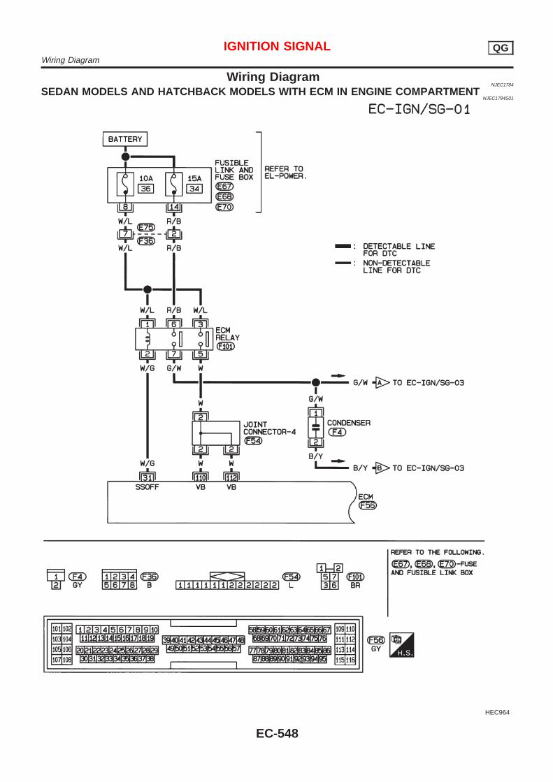
Wiring DiagramNJEC1784
SEDAN MODELS AND HATCHBACK MODELS WITH ECM IN ENGINE COMPARTMENTNJEC1784S01
HEC964
IGNITION SIGNAL QGWiring Diagram
EC-548
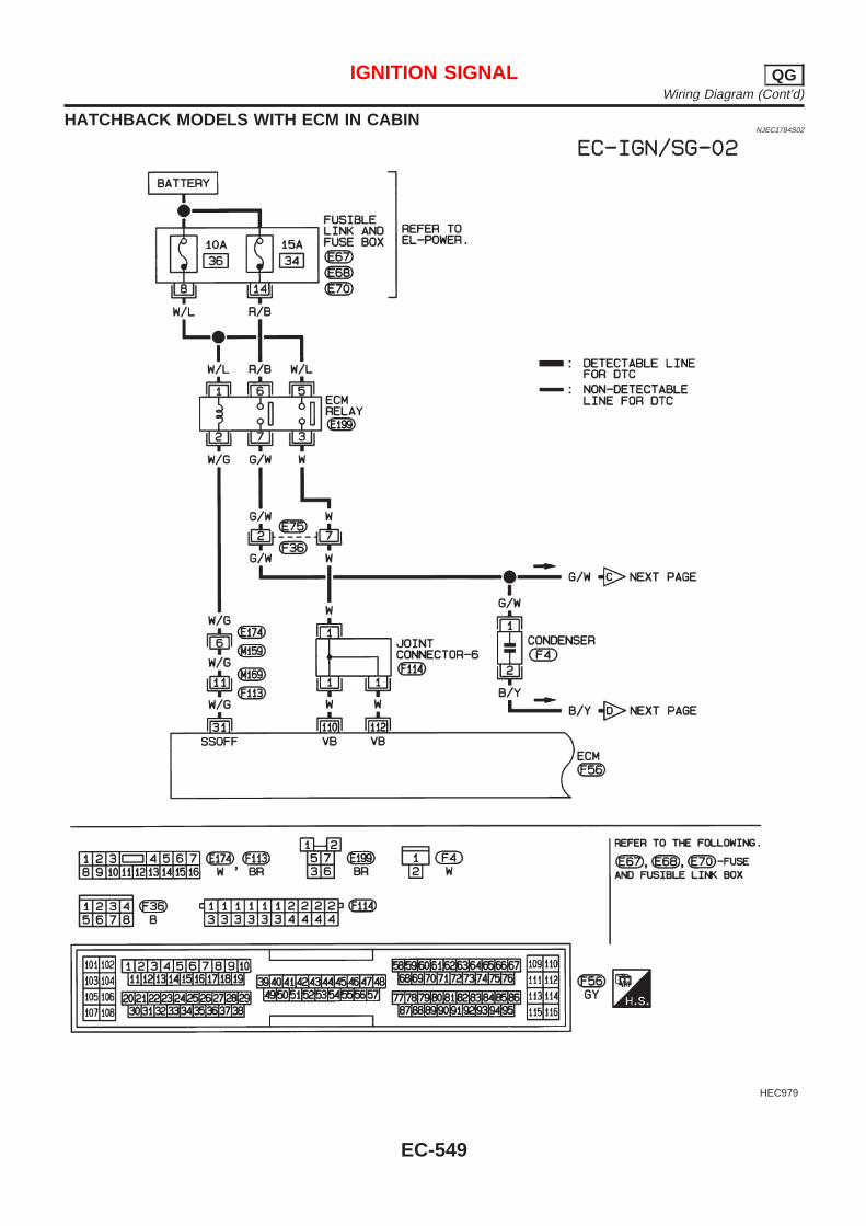
HATCHBACK MODELS WITH ECM IN CABINNJEC1784S02
HEC979
IGNITION SIGNAL QGWiring Diagram (Cont’d)
EC-549
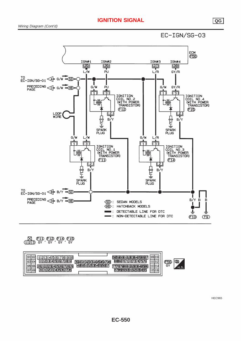
HEC965
IGNITION SIGNAL QGWiring Diagram (Cont’d)
EC-550
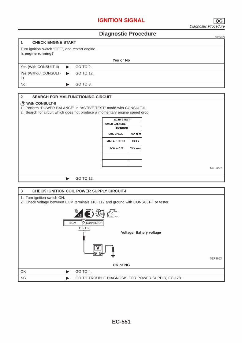
Diagnostic ProcedureNJEC0579
1 CHECK ENGINE START
Turn ignition switch “OFF”, and restart engine.Is engine running?
Yes or No
Yes (With CONSULT-II) © GO TO 2.
Yes (Without CONSULT-II)
© GO TO 12.
No © GO TO 3.
2 SEARCH FOR MALFUNCTIONING CIRCUIT
With CONSULT-II1. Perform “POWER BALANCE” in “ACTIVE TEST” mode with CONSULT-II.2. Search for circuit which does not produce a momentary engine speed drop.
SEF190Y
© GO TO 12.
3 CHECK IGNITION COIL POWER SUPPLY CIRCUIT-I
1. Turn ignition switch ON.2. Check voltage between ECM terminals 110, 112 and ground with CONSULT-II or tester.
SEF366X
OK or NG
OK © GO TO 4.
NG © GO TO TROUBLE DIAGNOSIS FOR POWER SUPPLY, EC-178.
IGNITION SIGNAL QGDiagnostic Procedure
EC-551
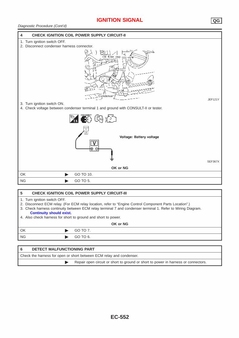
4 CHECK IGNITION COIL POWER SUPPLY CIRCUIT-II
1. Turn ignition switch OFF.2. Disconnect condenser harness connector.
JEF121Y
3. Turn ignition switch ON.4. Check voltage between condenser terminal 1 and ground with CONSULT-II or tester.
SEF367X
OK or NG
OK © GO TO 10.
NG © GO TO 5.
5 CHECK IGNITION COIL POWER SUPPLY CIRCUIT-III
1. Turn ignition switch OFF.2. Disconnect ECM relay. (For ECM relay location, refer to “Engine Control Component Parts Location”.)3. Check harness continuity between ECM relay terminal 7 and condenser terminal 1. Refer to Wiring Diagram.
Continuity should exist.4. Also check harness for short to ground and short to power.
OK or NG
OK © GO TO 7.
NG © GO TO 6.
6 DETECT MALFUNCTIONING PART
Check the harness for open or short between ECM relay and condenser.
© Repair open circuit or short to ground or short to power in harness or connectors.
IGNITION SIGNAL QGDiagnostic Procedure (Cont’d)
EC-552
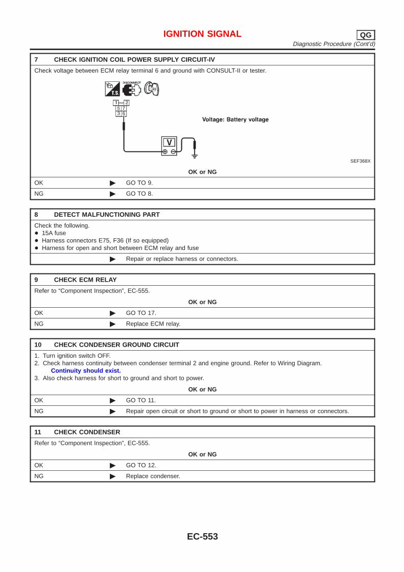
7 CHECK IGNITION COIL POWER SUPPLY CIRCUIT-IV
Check voltage between ECM relay terminal 6 and ground with CONSULT-II or tester.
SEF368X
OK or NG
OK © GO TO 9.
NG © GO TO 8.
8 DETECT MALFUNCTIONING PART
Check the following.+ 15A fuse+ Harness connectors E75, F36 (If so equipped)+ Harness for open and short between ECM relay and fuse
© Repair or replace harness or connectors.
9 CHECK ECM RELAY
Refer to “Component Inspection”, EC-555.
OK or NG
OK © GO TO 17.
NG © Replace ECM relay.
10 CHECK CONDENSER GROUND CIRCUIT
1. Turn ignition switch OFF.2. Check harness continuity between condenser terminal 2 and engine ground. Refer to Wiring Diagram.
Continuity should exist.3. Also check harness for short to ground and short to power.
OK or NG
OK © GO TO 11.
NG © Repair open circuit or short to ground or short to power in harness or connectors.
11 CHECK CONDENSER
Refer to “Component Inspection”, EC-555.
OK or NG
OK © GO TO 12.
NG © Replace condenser.
IGNITION SIGNAL QGDiagnostic Procedure (Cont’d)
EC-553
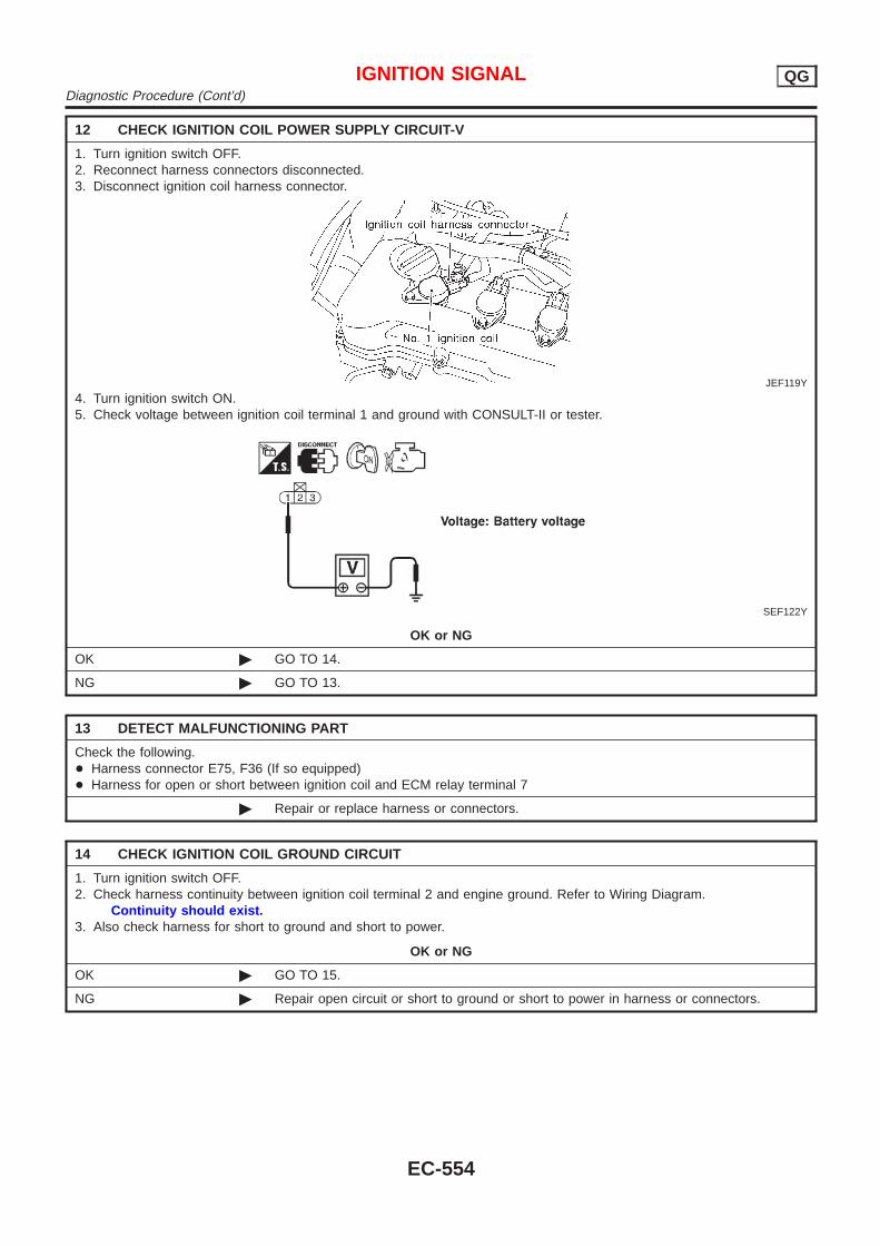
12 CHECK IGNITION COIL POWER SUPPLY CIRCUIT-V
1. Turn ignition switch OFF.2. Reconnect harness connectors disconnected.3. Disconnect ignition coil harness connector.
JEF119Y
4. Turn ignition switch ON.5. Check voltage between ignition coil terminal 1 and ground with CONSULT-II or tester.
SEF122Y
OK or NG
OK © GO TO 14.
NG © GO TO 13.
13 DETECT MALFUNCTIONING PART
Check the following.+ Harness connector E75, F36 (If so equipped)+ Harness for open or short between ignition coil and ECM relay terminal 7
© Repair or replace harness or connectors.
14 CHECK IGNITION COIL GROUND CIRCUIT
1. Turn ignition switch OFF.2. Check harness continuity between ignition coil terminal 2 and engine ground. Refer to Wiring Diagram.
Continuity should exist.3. Also check harness for short to ground and short to power.
OK or NG
OK © GO TO 15.
NG © Repair open circuit or short to ground or short to power in harness or connectors.
IGNITION SIGNAL QGDiagnostic Procedure (Cont’d)
EC-554
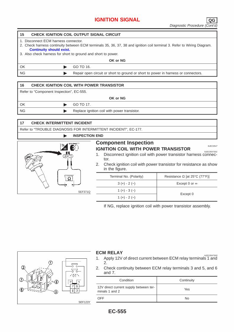
15 CHECK IGNITION COIL OUTPUT SIGNAL CIRCUIT
1. Disconnect ECM harness connector.2. Check harness continuity between ECM terminals 35, 36, 37, 38 and ignition coil terminal 3. Refer to Wiring Diagram.
Continuity should exist.3. Also check harness for short to ground and short to power.
OK or NG
OK © GO TO 16.
NG © Repair open circuit or short to ground or short to power in harness or connectors.
16 CHECK IGNITION COIL WITH POWER TRANSISTOR
Refer to “Component Inspection”, EC-555.
OK or NG
OK © GO TO 17.
NG © Replace ignition coil with power transistor.
17 CHECK INTERMITTENT INCIDENT
Refer to “TROUBLE DIAGNOSIS FOR INTERMITTENT INCIDENT”, EC-177.
© INSPECTION END
SEF371Q
Component InspectionNJEC0547
IGNITION COIL WITH POWER TRANSISTORNJEC0547S01
1. Disconnect ignition coil with power transistor harness connec-tor.
2. Check ignition coil with power transistor for resistance as showin the figure.
Terminal No. (Polarity) Resistance Ω [at 25°C (77°F)]
3 (+) - 2 (−) Except 0 or ∞
1 (+) - 3 (−)Except 0
1 (+) - 2 (−)
If NG, replace ignition coil with power transistor assembly.
SEF123Y
ECM RELAYNJEC0547S03
1. Apply 12V of direct current between ECM relay terminals 1 and2.
2. Check continuity between ECM relay terminals 3 and 5, and 6and 7.
Condition Continuity
12V direct current supply between ter-minals 1 and 2
Yes
OFF No
IGNITION SIGNAL QGDiagnostic Procedure (Cont’d)
EC-555
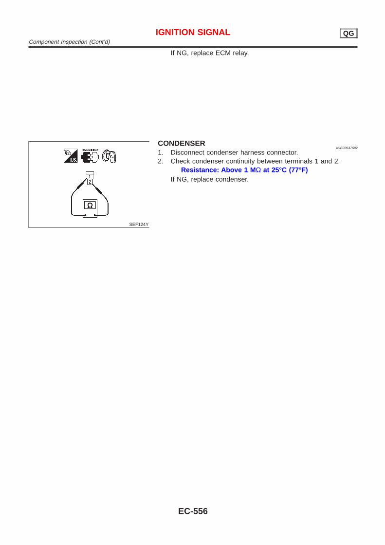
If NG, replace ECM relay.
SEF124Y
CONDENSERNJEC0547S02
1. Disconnect condenser harness connector.2. Check condenser continuity between terminals 1 and 2.
Resistance: Above 1 M Ω at 25°C (77°F)If NG, replace condenser.
IGNITION SIGNAL QGComponent Inspection (Cont’d)
EC-556

CONSULT-II Reference Value in Data MonitorMode
NJEC0441
Specification data are reference values.
MONITOR ITEM CONDITION SPECIFICATION
START SIGNAL + Ignition switch: ON → START → ON OFF → ON → OFF
ECM Terminals and Reference ValueNJEC0442
Specification data are reference values and are measured between each terminal and ground.CAUTION:Do not use ECM ground terminals when measuring input/output voltage. Doing so may result in dam-age to the ECM’s transistor. Use a ground other than ECM terminals, such as the ground.
TERMI-NALNO.
WIRECOLOR
ITEM CONDITION DATA (DC Voltage)
41 B/Y Start signal[Ignition switch “ON”] Approximately 0V
[Ignition switch “START”] 9 - 12V
START SIGNAL QGCONSULT-II Reference Value in Data Monitor Mode
EC-557
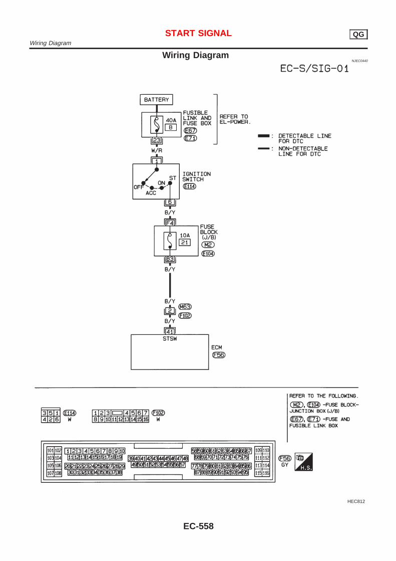
Wiring DiagramNJEC0440
HEC812
START SIGNAL QGWiring Diagram
EC-558
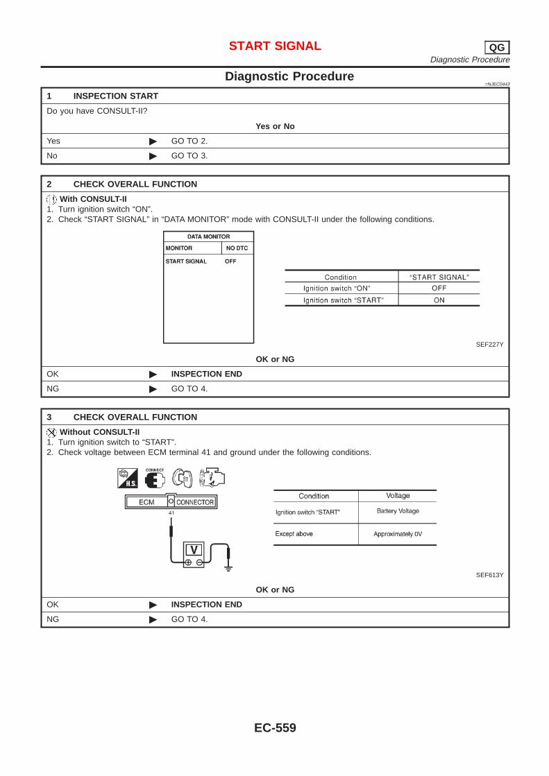
Diagnostic Procedure=NJEC0443
1 INSPECTION START
Do you have CONSULT-II?
Yes or No
Yes © GO TO 2.
No © GO TO 3.
2 CHECK OVERALL FUNCTION
With CONSULT-II1. Turn ignition switch “ON”.2. Check “START SIGNAL” in “DATA MONITOR” mode with CONSULT-II under the following conditions.
SEF227Y
OK or NG
OK © INSPECTION END
NG © GO TO 4.
3 CHECK OVERALL FUNCTION
Without CONSULT-II1. Turn ignition switch to “START”.2. Check voltage between ECM terminal 41 and ground under the following conditions.
SEF613Y
OK or NG
OK © INSPECTION END
NG © GO TO 4.
START SIGNAL QGDiagnostic Procedure
EC-559
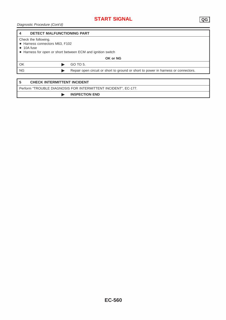
4 DETECT MALFUNCTIONING PART
Check the following.+ Harness connectors M63, F102+ 10A fuse+ Harness for open or short between ECM and ignition switch
OK or NG
OK © GO TO 5.
NG © Repair open circuit or short to ground or short to power in harness or connectors.
5 CHECK INTERMITTENT INCIDENT
Perform “TROUBLE DIAGNOSIS FOR INTERMITTENT INCIDENT”, EC-177.
© INSPECTION END
START SIGNAL QGDiagnostic Procedure (Cont’d)
EC-560
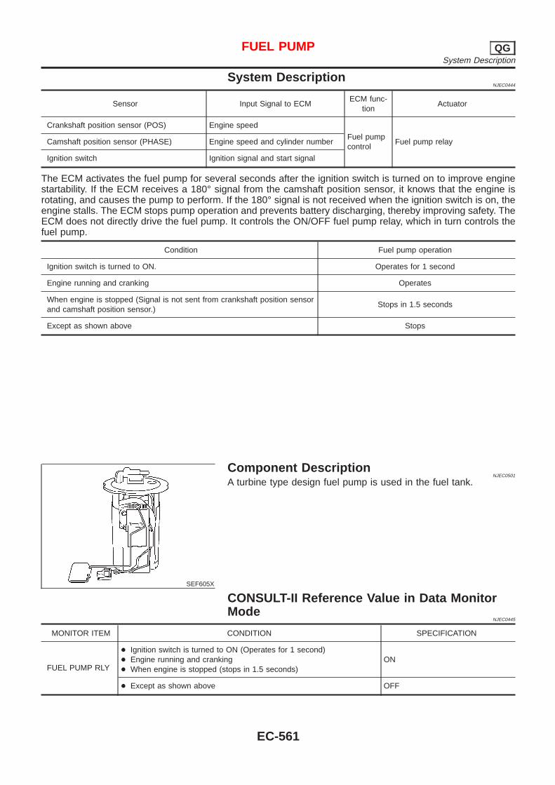
System DescriptionNJEC0444
Sensor Input Signal to ECMECM func-
tionActuator
Crankshaft position sensor (POS) Engine speed
Fuel pumpcontrol
Fuel pump relayCamshaft position sensor (PHASE) Engine speed and cylinder number
Ignition switch Ignition signal and start signal
The ECM activates the fuel pump for several seconds after the ignition switch is turned on to improve enginestartability. If the ECM receives a 180° signal from the camshaft position sensor, it knows that the engine isrotating, and causes the pump to perform. If the 180° signal is not received when the ignition switch is on, theengine stalls. The ECM stops pump operation and prevents battery discharging, thereby improving safety. TheECM does not directly drive the fuel pump. It controls the ON/OFF fuel pump relay, which in turn controls thefuel pump.
Condition Fuel pump operation
Ignition switch is turned to ON. Operates for 1 second
Engine running and cranking Operates
When engine is stopped (Signal is not sent from crankshaft position sensorand camshaft position sensor.)
Stops in 1.5 seconds
Except as shown above Stops
SEF605X
Component DescriptionNJEC0501
A turbine type design fuel pump is used in the fuel tank.
CONSULT-II Reference Value in Data MonitorMode
NJEC0445
MONITOR ITEM CONDITION SPECIFICATION
FUEL PUMP RLY
+ Ignition switch is turned to ON (Operates for 1 second)+ Engine running and cranking+ When engine is stopped (stops in 1.5 seconds)
ON
+ Except as shown above OFF
FUEL PUMP QGSystem Description
EC-561
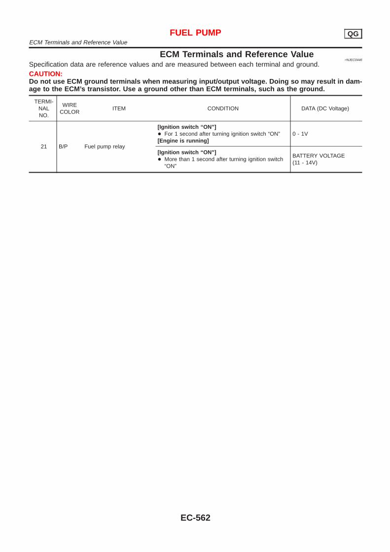
ECM Terminals and Reference Value=NJEC0446
Specification data are reference values and are measured between each terminal and ground.CAUTION:Do not use ECM ground terminals when measuring input/output voltage. Doing so may result in dam-age to the ECM’s transistor. Use a ground other than ECM terminals, such as the ground.
TERMI-NALNO.
WIRECOLOR
ITEM CONDITION DATA (DC Voltage)
21 B/P Fuel pump relay
[Ignition switch “ON”]+ For 1 second after turning ignition switch “ON”[Engine is running]
0 - 1V
[Ignition switch “ON”]+ More than 1 second after turning ignition switch
“ON”
BATTERY VOLTAGE(11 - 14V)
FUEL PUMP QGECM Terminals and Reference Value
EC-562
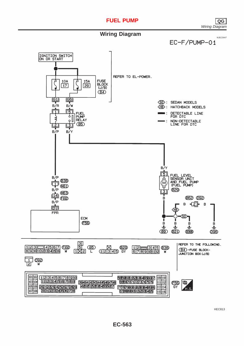
Wiring DiagramNJEC0447
HEC813
FUEL PUMP QGWiring Diagram
EC-563
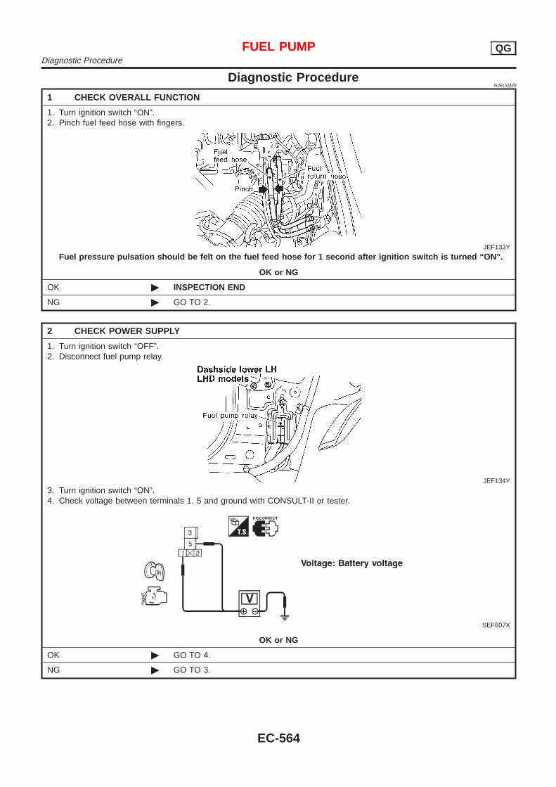
Diagnostic ProcedureNJEC0448
1 CHECK OVERALL FUNCTION
1. Turn ignition switch “ON”.2. Pinch fuel feed hose with fingers.
JEF133Y
Fuel pressure pulsation should be felt on the fuel feed hose for 1 second after ignition switch is turned “ON”.
OK or NG
OK © INSPECTION END
NG © GO TO 2.
2 CHECK POWER SUPPLY
1. Turn ignition switch “OFF”.2. Disconnect fuel pump relay.
JEF134Y
3. Turn ignition switch “ON”.4. Check voltage between terminals 1, 5 and ground with CONSULT-II or tester.
SEF607X
OK or NG
OK © GO TO 4.
NG © GO TO 3.
FUEL PUMP QGDiagnostic Procedure
EC-564

3 DETECT MALFUNCTIONING PART
Check the following.+ 10A fuse+ 15A fuse+ Harness for open or short between fuse and fuel pump relay
© Repair harness or connectors.
4 CHECK POWER GROUND CIRCUIT
1. Turn ignition switch “OFF”.2. Disconnect fuel level sensor unit and fuel pump harness connector.
JEF135Y
3. Check harness continuity between fuel level sensor unit and fuel pump harness connector terminal 3 and body ground,terminal 5 and fuel pump relay connector terminal 3.Refer to wiring diagram.
Continuity should exist.4. Also check harness for short to ground and short to power.
OK or NG
OK © GO TO 6.
NG © GO TO 5.
5 DETECT MALFUNCTIONING PART
Check the following.+ Harness for open or short between fuel pump and body ground+ Harness for open or short between fuel pump and fuel pump relay
© Repair open circuit or short to ground or short to power in harness or connectors.
6 CHECK OUTPUT SIGNAL CIRCUIT
1. Disconnect ECM harness connector.2. Check harness continuity between ECM terminal 21 and fuel pump relay connector terminal 2.
Refer to wiring diagram.Continuity should exist.
3. Also check harness for short to ground and short to power.
OK or NG
OK © GO TO 8.
NG © GO TO 7.
7 DETECT MALFUNCTIONING PART
Check the following.+ Harness connectors B38, M81+ Harness connectors M63, F102+ Harness for open or short between ECM and fuel pump relay
NG © Repair open circuit or short to ground or short to power in harness or connectors.
FUEL PUMP QGDiagnostic Procedure (Cont’d)
EC-565
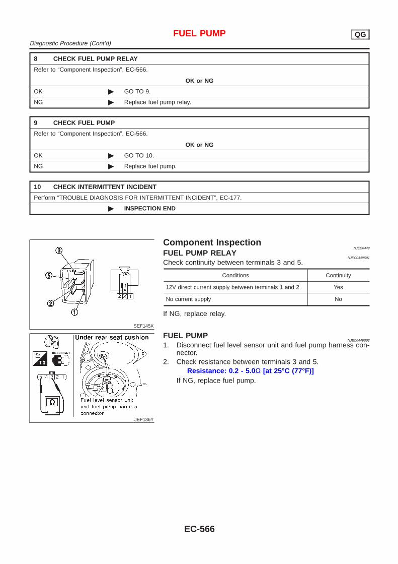
8 CHECK FUEL PUMP RELAY
Refer to “Component Inspection”, EC-566.
OK or NG
OK © GO TO 9.
NG © Replace fuel pump relay.
9 CHECK FUEL PUMP
Refer to “Component Inspection”, EC-566.
OK or NG
OK © GO TO 10.
NG © Replace fuel pump.
10 CHECK INTERMITTENT INCIDENT
Perform “TROUBLE DIAGNOSIS FOR INTERMITTENT INCIDENT”, EC-177.
© INSPECTION END
SEF145X
Component InspectionNJEC0449
FUEL PUMP RELAYNJEC0449S01
Check continuity between terminals 3 and 5.
Conditions Continuity
12V direct current supply between terminals 1 and 2 Yes
No current supply No
If NG, replace relay.
JEF136Y
FUEL PUMPNJEC0449S02
1. Disconnect fuel level sensor unit and fuel pump harness con-nector.
2. Check resistance between terminals 3 and 5.Resistance: 0.2 - 5.0 Ω [at 25°C (77°F)]
If NG, replace fuel pump.
FUEL PUMP QGDiagnostic Procedure (Cont’d)
EC-566
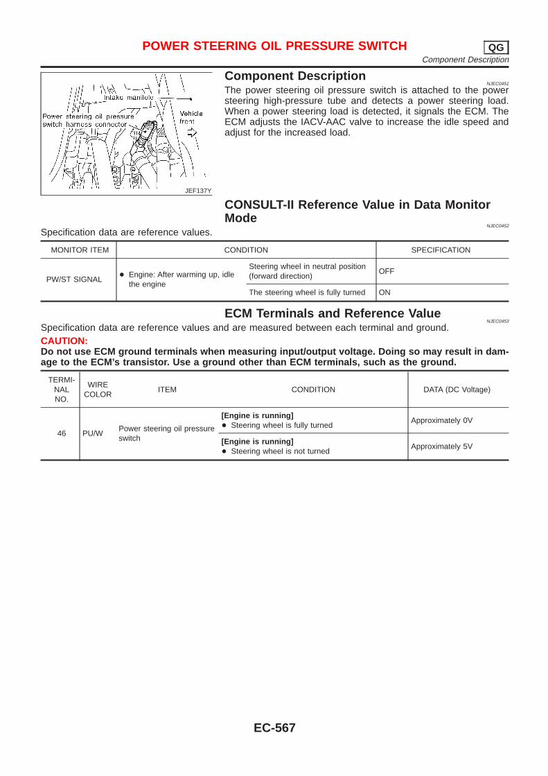
JEF137Y
Component DescriptionNJEC0451
The power steering oil pressure switch is attached to the powersteering high-pressure tube and detects a power steering load.When a power steering load is detected, it signals the ECM. TheECM adjusts the IACV-AAC valve to increase the idle speed andadjust for the increased load.
CONSULT-II Reference Value in Data MonitorMode
NJEC0452
Specification data are reference values.
MONITOR ITEM CONDITION SPECIFICATION
PW/ST SIGNAL+ Engine: After warming up, idle
the engine
Steering wheel in neutral position(forward direction)
OFF
The steering wheel is fully turned ON
ECM Terminals and Reference ValueNJEC0453
Specification data are reference values and are measured between each terminal and ground.CAUTION:Do not use ECM ground terminals when measuring input/output voltage. Doing so may result in dam-age to the ECM’s transistor. Use a ground other than ECM terminals, such as the ground.
TERMI-NALNO.
WIRECOLOR
ITEM CONDITION DATA (DC Voltage)
46 PU/WPower steering oil pressureswitch
[Engine is running]+ Steering wheel is fully turned
Approximately 0V
[Engine is running]+ Steering wheel is not turned
Approximately 5V
POWER STEERING OIL PRESSURE SWITCH QGComponent Description
EC-567
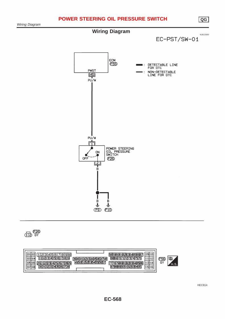
Wiring DiagramNJEC0450
HEC814
POWER STEERING OIL PRESSURE SWITCH QGWiring Diagram
EC-568
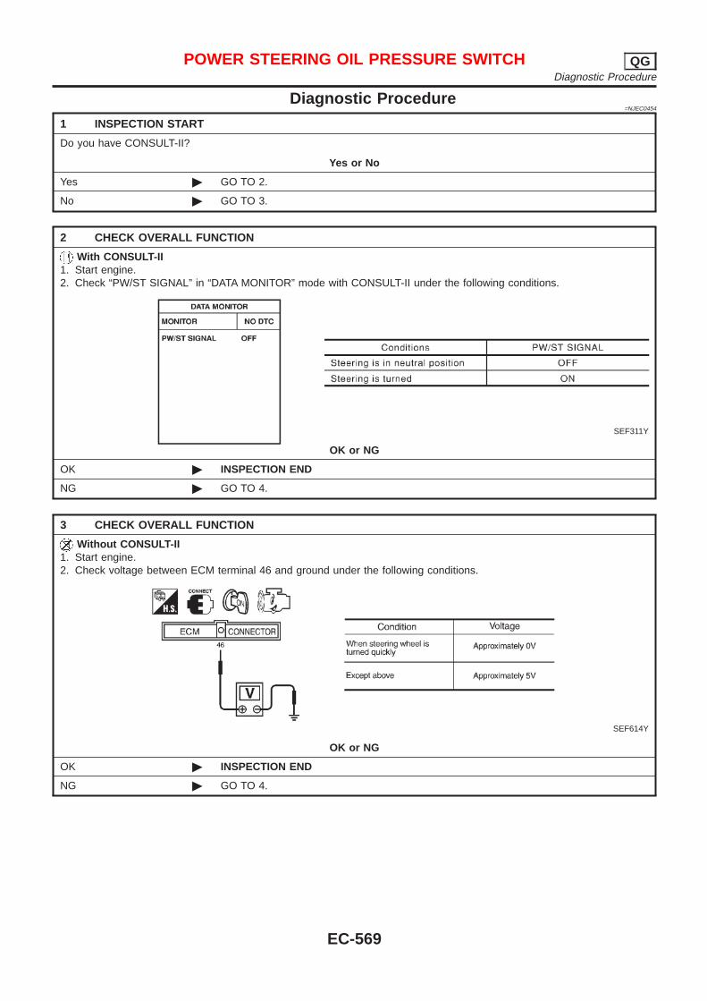
Diagnostic Procedure=NJEC0454
1 INSPECTION START
Do you have CONSULT-II?
Yes or No
Yes © GO TO 2.
No © GO TO 3.
2 CHECK OVERALL FUNCTION
With CONSULT-II1. Start engine.2. Check “PW/ST SIGNAL” in “DATA MONITOR” mode with CONSULT-II under the following conditions.
SEF311Y
OK or NG
OK © INSPECTION END
NG © GO TO 4.
3 CHECK OVERALL FUNCTION
Without CONSULT-II1. Start engine.2. Check voltage between ECM terminal 46 and ground under the following conditions.
SEF614Y
OK or NG
OK © INSPECTION END
NG © GO TO 4.
POWER STEERING OIL PRESSURE SWITCH QGDiagnostic Procedure
EC-569
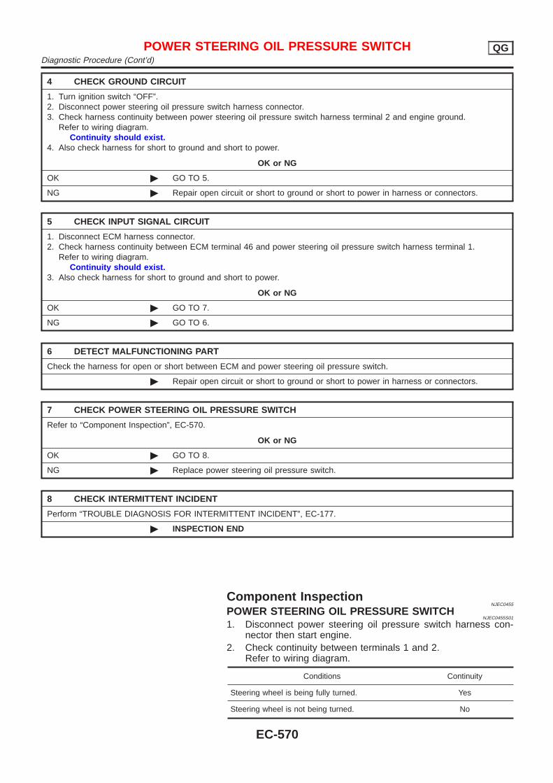
4 CHECK GROUND CIRCUIT
1. Turn ignition switch “OFF”.2. Disconnect power steering oil pressure switch harness connector.3. Check harness continuity between power steering oil pressure switch harness terminal 2 and engine ground.
Refer to wiring diagram.Continuity should exist.
4. Also check harness for short to ground and short to power.
OK or NG
OK © GO TO 5.
NG © Repair open circuit or short to ground or short to power in harness or connectors.
5 CHECK INPUT SIGNAL CIRCUIT
1. Disconnect ECM harness connector.2. Check harness continuity between ECM terminal 46 and power steering oil pressure switch harness terminal 1.
Refer to wiring diagram.Continuity should exist.
3. Also check harness for short to ground and short to power.
OK or NG
OK © GO TO 7.
NG © GO TO 6.
6 DETECT MALFUNCTIONING PART
Check the harness for open or short between ECM and power steering oil pressure switch.
© Repair open circuit or short to ground or short to power in harness or connectors.
7 CHECK POWER STEERING OIL PRESSURE SWITCH
Refer to “Component Inspection”, EC-570.
OK or NG
OK © GO TO 8.
NG © Replace power steering oil pressure switch.
8 CHECK INTERMITTENT INCIDENT
Perform “TROUBLE DIAGNOSIS FOR INTERMITTENT INCIDENT”, EC-177.
© INSPECTION END
Component InspectionNJEC0455
POWER STEERING OIL PRESSURE SWITCHNJEC0455S01
1. Disconnect power steering oil pressure switch harness con-nector then start engine.
2. Check continuity between terminals 1 and 2.Refer to wiring diagram.
Conditions Continuity
Steering wheel is being fully turned. Yes
Steering wheel is not being turned. No
POWER STEERING OIL PRESSURE SWITCH QGDiagnostic Procedure (Cont’d)
EC-570

If NG, replace power steering oil pressure switch.
POWER STEERING OIL PRESSURE SWITCH QGComponent Inspection (Cont’d)
EC-571
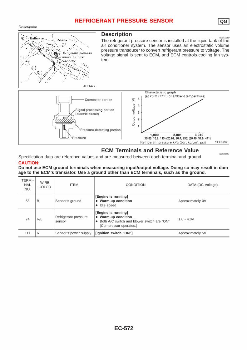
JEF147Y
DescriptionNJEC0580
The refrigerant pressure sensor is installed at the liquid tank of theair conditioner system. The sensor uses an electrostatic volumepressure transducer to convert refrigerant pressure to voltage. Thevoltage signal is sent to ECM, and ECM controls cooling fan sys-tem.
SEF099X
ECM Terminals and Reference ValueNJEC0581
Specification data are reference values and are measured between each terminal and ground.CAUTION:Do not use ECM ground terminals when measuring input/output voltage. Doing so may result in dam-age to the ECM’s transistor. Use a ground other than ECM terminals, such as the ground.
TERMI-NALNO.
WIRECOLOR
ITEM CONDITION DATA (DC Voltage)
58 B Sensor’s ground[Engine is running]+ Warm-up condition+ Idle speed
Approximately 0V
74 R/LRefrigerant pressuresensor
[Engine is running]+ Warm-up condition+ Both A/C switch and blower switch are “ON”
(Compressor operates.)
1.0 - 4.0V
111 R Sensor’s power supply [Ignition switch “ON”] Approximately 5V
REFRIGERANT PRESSURE SENSOR QGDescription
EC-572
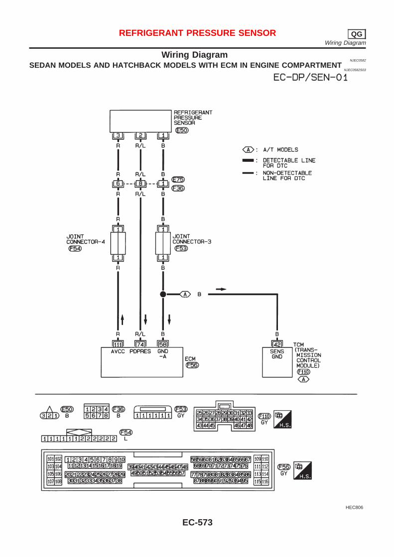
Wiring DiagramNJEC0582
SEDAN MODELS AND HATCHBACK MODELS WITH ECM IN ENGINE COMPARTMENTNJEC0582S03
HEC806
REFRIGERANT PRESSURE SENSOR QGWiring Diagram
EC-573
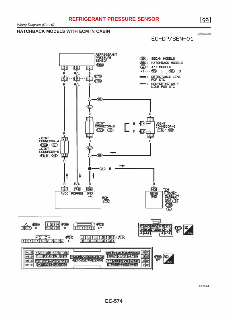
HATCHBACK MODELS WITH ECM IN CABINNJEC0582S04
HEC961
REFRIGERANT PRESSURE SENSOR QGWiring Diagram (Cont’d)
EC-574
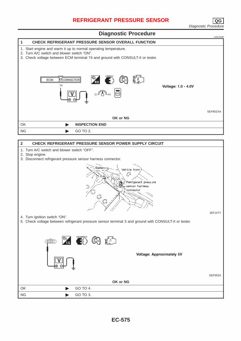
Diagnostic ProcedureNJEC0590
1 CHECK REFRIGERANT PRESSURE SENSOR OVERALL FUNCTION
1. Start engine and warm it up to normal operating temperature.2. Turn A/C switch and blower switch “ON”.3. Check voltage between ECM terminal 74 and ground with CONSULT-II or tester.
SEF952XA
OK or NG
OK © INSPECTION END
NG © GO TO 2.
2 CHECK REFRIGERANT PRESSURE SENSOR POWER SUPPLY CIRCUIT
1. Turn A/C switch and blower switch “OFF”.2. Stop engine.3. Disconnect refrigerant pressure sensor harness connector.
JEF147Y
4. Turn ignition switch “ON”.5. Check voltage between refrigerant pressure sensor terminal 3 and ground with CONSULT-II or tester.
SEF953X
OK or NG
OK © GO TO 4.
NG © GO TO 3.
REFRIGERANT PRESSURE SENSOR QGDiagnostic Procedure
EC-575
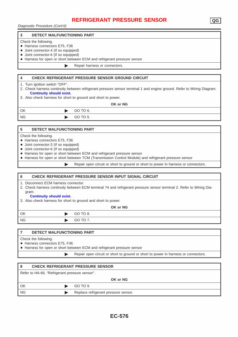
3 DETECT MALFUNCTIONING PART
Check the following.+ Harness connectors E75, F36+ Joint connector-4 (If so equipped)+ Joint connector-6 (If so equipped)+ Harness for open or short between ECM and refrigerant pressure sensor
© Repair harness or connectors.
4 CHECK REFRIGERANT PRESSURE SENSOR GROUND CIRCUIT
1. Turn ignition switch “OFF”.2. Check harness continuity between refrigerant pressure sensor terminal 1 and engine ground. Refer to Wiring Diagram.
Continuity should exist.3. Also check harness for short to ground and short to power.
OK or NG
OK © GO TO 6.
NG © GO TO 5.
5 DETECT MALFUNCTIONING PART
Check the following.+ Harness connectors E75, F36+ Joint connector-3 (If so equipped)+ Joint connector-6 (If so equipped)+ Harness for open or short between ECM and refrigerant pressure sensor+ Harness for open or short between TCM (Transmission Control Module) and refrigerant pressure sensor
© Repair open circuit or short to ground or short to power in harness or connectors.
6 CHECK REFRIGERANT PRESSURE SENSOR INPUT SIGNAL CIRCUIT
1. Disconnect ECM harness connector.2. Check harness continuity between ECM terminal 74 and refrigerant pressure sensor terminal 2. Refer to Wiring Dia-
gram.Continuity should exist.
3. Also check harness for short to ground and short to power.
OK or NG
OK © GO TO 8.
NG © GO TO 7.
7 DETECT MALFUNCTIONING PART
Check the following.+ Harness connectors E75, F36+ Harness for open or short between ECM and refrigerant pressure sensor
© Repair open circuit or short to ground or short to power in harness or connectors.
8 CHECK REFRIGERANT PRESSURE SENSOR
Refer to HA-66, “Refrigerant pressure sensor”.
OK or NG
OK © GO TO 9.
NG © Replace refrigerant pressure sensor.
REFRIGERANT PRESSURE SENSOR QGDiagnostic Procedure (Cont’d)
EC-576
9 CHECK INTERMITTENT INCIDENT
Refer to “TROUBLE DIAGNOSIS FOR INTERMITTENT INCIDENT”, EC-177.
© INSPECTION END
REFRIGERANT PRESSURE SENSOR QGDiagnostic Procedure (Cont’d)
EC-577
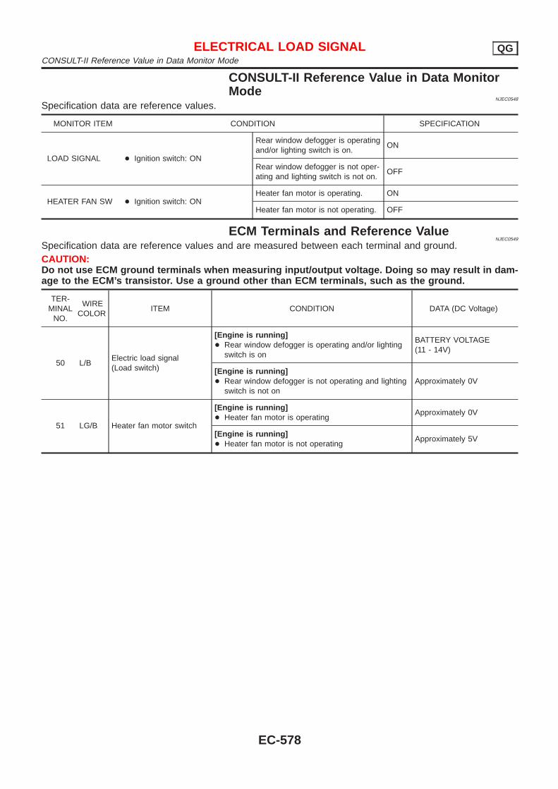
CONSULT-II Reference Value in Data MonitorMode
NJEC0548
Specification data are reference values.
MONITOR ITEM CONDITION SPECIFICATION
LOAD SIGNAL + Ignition switch: ON
Rear window defogger is operatingand/or lighting switch is on.
ON
Rear window defogger is not oper-ating and lighting switch is not on.
OFF
HEATER FAN SW + Ignition switch: ONHeater fan motor is operating. ON
Heater fan motor is not operating. OFF
ECM Terminals and Reference ValueNJEC0549
Specification data are reference values and are measured between each terminal and ground.CAUTION:Do not use ECM ground terminals when measuring input/output voltage. Doing so may result in dam-age to the ECM’s transistor. Use a ground other than ECM terminals, such as the ground.
TER-MINAL
NO.
WIRECOLOR
ITEM CONDITION DATA (DC Voltage)
50 L/BElectric load signal(Load switch)
[Engine is running]+ Rear window defogger is operating and/or lighting
switch is on
BATTERY VOLTAGE(11 - 14V)
[Engine is running]+ Rear window defogger is not operating and lighting
switch is not onApproximately 0V
51 LG/B Heater fan motor switch
[Engine is running]+ Heater fan motor is operating
Approximately 0V
[Engine is running]+ Heater fan motor is not operating
Approximately 5V
ELECTRICAL LOAD SIGNAL QGCONSULT-II Reference Value in Data Monitor Mode
EC-578
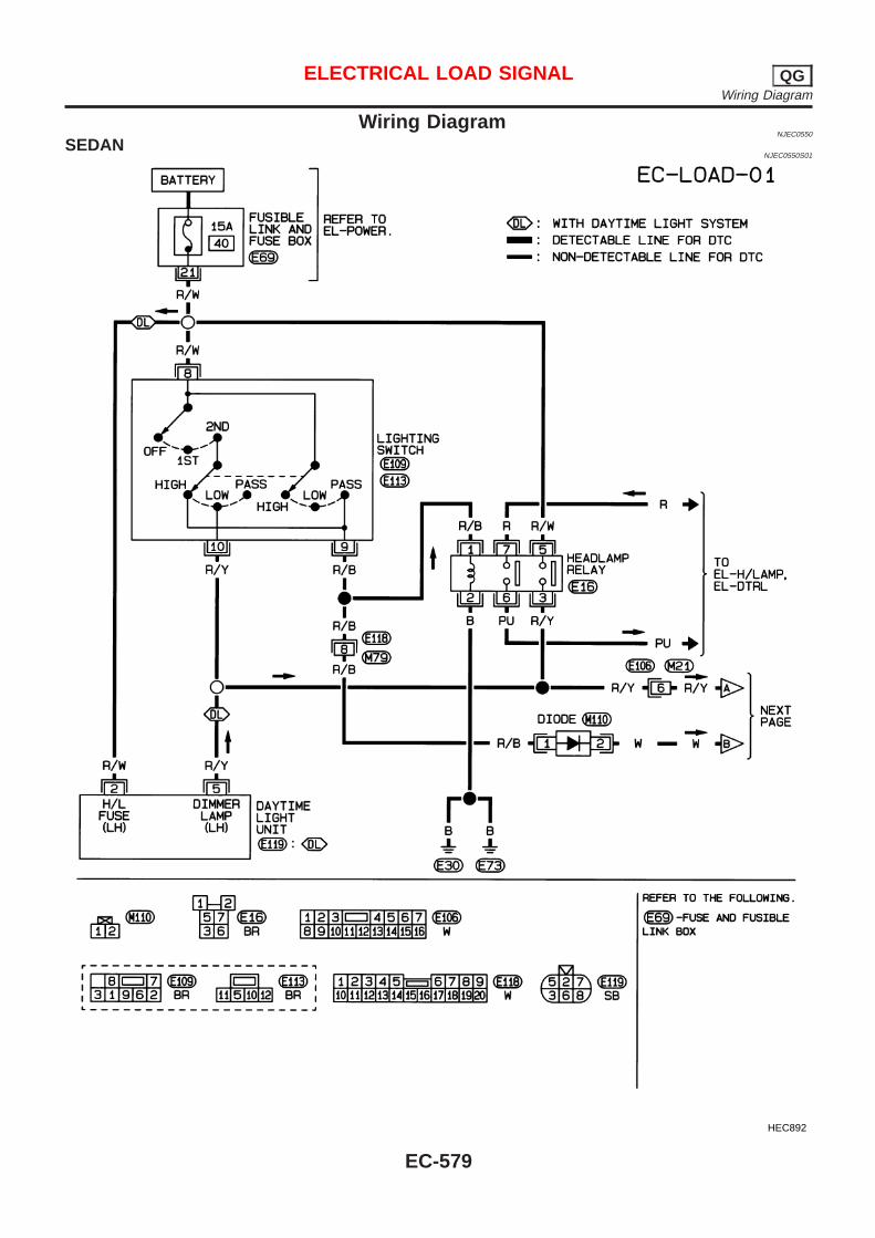
Wiring DiagramNJEC0550
SEDANNJEC0550S01
HEC892
ELECTRICAL LOAD SIGNAL QGWiring Diagram
EC-579
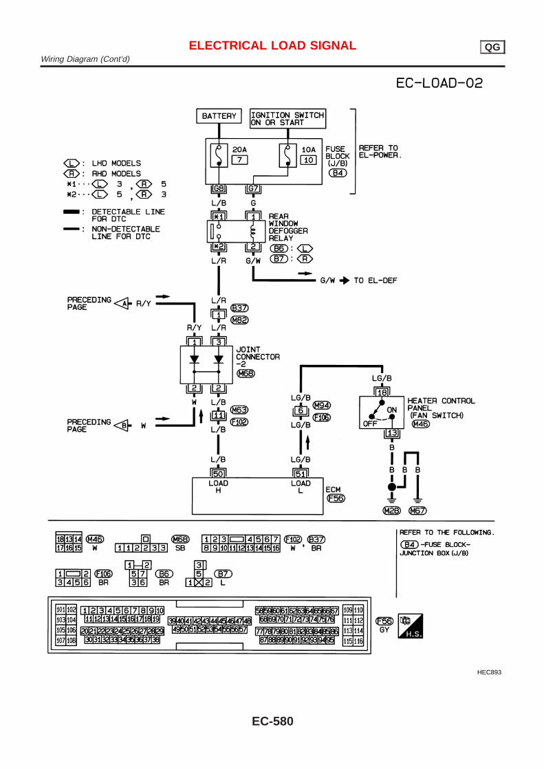
HEC893
ELECTRICAL LOAD SIGNAL QGWiring Diagram (Cont’d)
EC-580
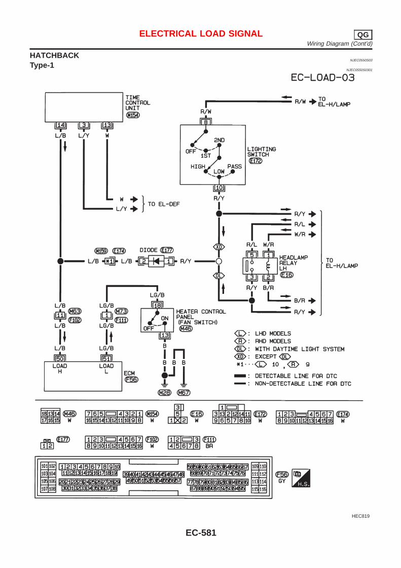
HATCHBACKNJEC0550S03
Type-1NJEC0550S0301
HEC819
ELECTRICAL LOAD SIGNAL QGWiring Diagram (Cont’d)
EC-581
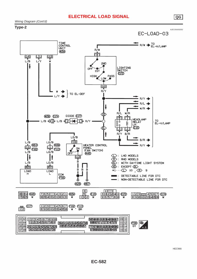
Type-2NJEC0550S0302
HEC966
ELECTRICAL LOAD SIGNAL QGWiring Diagram (Cont’d)
EC-582
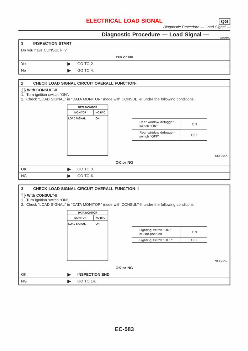
Diagnostic Procedure — Load Signal —NJEC0584
1 INSPECTION START
Do you have CONSULT-II?
Yes or No
Yes © GO TO 2.
No © GO TO 4.
2 CHECK LOAD SIGNAL CIRCUIT OVERALL FUNCTION-I
With CONSULT-II1. Turn ignition switch “ON”.2. Check “LOAD SIGNAL” in “DATA MONITOR” mode with CONSULT-II under the following conditions.
SEF954X
OK or NG
OK © GO TO 3.
NG © GO TO 6.
3 CHECK LOAD SIGNAL CIRCUIT OVERALL FUNCTION-II
With CONSULT-II1. Turn ignition switch “ON”.2. Check “LOAD SIGNAL” in “DATA MONITOR” mode with CONSULT-II under the following conditions.
SEF955X
OK or NG
OK © INSPECTION END
NG © GO TO 14.
ELECTRICAL LOAD SIGNAL QGDiagnostic Procedure — Load Signal —
EC-583
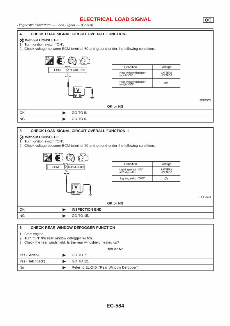
4 CHECK LOAD SIGNAL CIRCUIT OVERALL FUNCTION-I
Without CONSULT-II1. Turn ignition switch “ON”.2. Check voltage between ECM terminal 50 and ground under the following conditions.
SEF956X
OK or NG
OK © GO TO 5.
NG © GO TO 6.
5 CHECK LOAD SIGNAL CIRCUIT OVERALL FUNCTION-II
Without CONSULT-II1. Turn ignition switch “ON”.2. Check voltage between ECM terminal 50 and ground under the following conditions.
SEF957X
OK or NG
OK © INSPECTION END
NG © GO TO 15.
6 CHECK REAR WINDOW DEFOGGER FUNCTION
1. Start engine.2. Turn “ON” the rear window defogger switch.3. Check the rear windshield. Is the rear windshield heated up?
Yes or No
Yes (Sedan) © GO TO 7.
Yes (Hatchback) © GO TO 12.
No © Refer to EL-240, “Rear Window Defogger”.
ELECTRICAL LOAD SIGNAL QGDiagnostic Procedure — Load Signal — (Cont’d)
EC-584
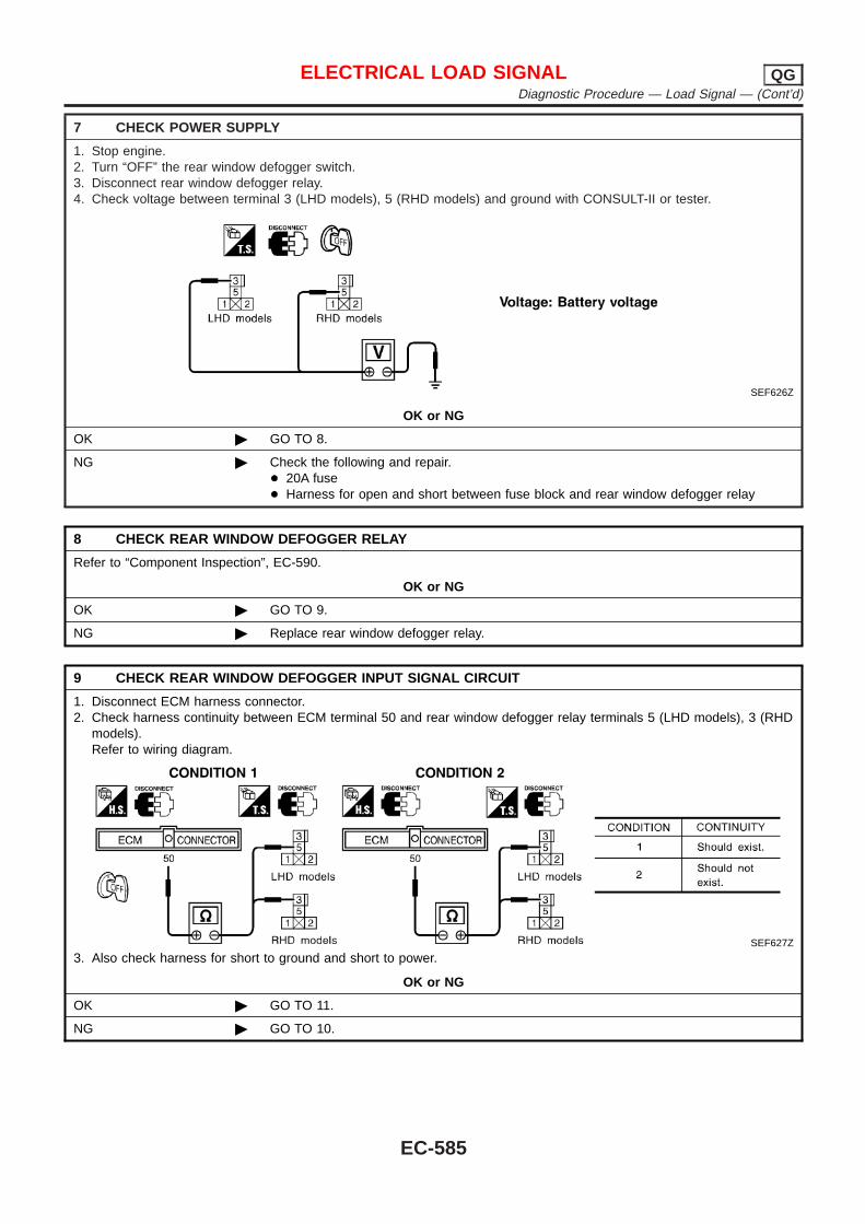
7 CHECK POWER SUPPLY
1. Stop engine.2. Turn “OFF” the rear window defogger switch.3. Disconnect rear window defogger relay.4. Check voltage between terminal 3 (LHD models), 5 (RHD models) and ground with CONSULT-II or tester.
SEF626Z
OK or NG
OK © GO TO 8.
NG © Check the following and repair.+ 20A fuse+ Harness for open and short between fuse block and rear window defogger relay
8 CHECK REAR WINDOW DEFOGGER RELAY
Refer to “Component Inspection”, EC-590.
OK or NG
OK © GO TO 9.
NG © Replace rear window defogger relay.
9 CHECK REAR WINDOW DEFOGGER INPUT SIGNAL CIRCUIT
1. Disconnect ECM harness connector.2. Check harness continuity between ECM terminal 50 and rear window defogger relay terminals 5 (LHD models), 3 (RHD
models).Refer to wiring diagram.
SEF627Z
3. Also check harness for short to ground and short to power.
OK or NG
OK © GO TO 11.
NG © GO TO 10.
ELECTRICAL LOAD SIGNAL QGDiagnostic Procedure — Load Signal — (Cont’d)
EC-585
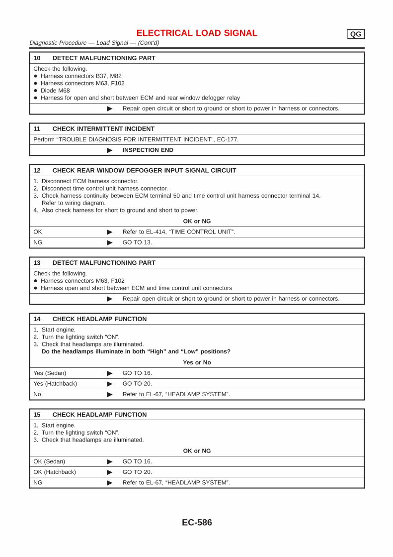
10 DETECT MALFUNCTIONING PART
Check the following.+ Harness connectors B37, M82+ Harness connectors M63, F102+ Diode M68+ Harness for open and short between ECM and rear window defogger relay
© Repair open circuit or short to ground or short to power in harness or connectors.
11 CHECK INTERMITTENT INCIDENT
Perform “TROUBLE DIAGNOSIS FOR INTERMITTENT INCIDENT”, EC-177.
© INSPECTION END
12 CHECK REAR WINDOW DEFOGGER INPUT SIGNAL CIRCUIT
1. Disconnect ECM harness connector.2. Disconnect time control unit harness connector.3. Check harness continuity between ECM terminal 50 and time control unit harness connector terminal 14.
Refer to wiring diagram.4. Also check harness for short to ground and short to power.
OK or NG
OK © Refer to EL-414, “TIME CONTROL UNIT”.
NG © GO TO 13.
13 DETECT MALFUNCTIONING PART
Check the following.+ Harness connectors M63, F102+ Harness open and short between ECM and time control unit connectors
© Repair open circuit or short to ground or short to power in harness or connectors.
14 CHECK HEADLAM P FUNCTION
1. Start engine.2. Turn the lighting switch “ON”.3. Check that headlamps are illuminated.
Do the headlamp s illuminat e in bot h “High ” and “Low ” positions?
Yes or No
Yes (Sedan) © GO TO 16.
Yes (Hatchback) © GO TO 20.
No © Refer to EL-67, “HEADLAMP SYSTEM”.
15 CHECK HEADLAM P FUNCTION
1. Start engine.2. Turn the lighting switch “ON”.3. Check that headlamps are illuminated.
OK or NG
OK (Sedan) © GO TO 16.
OK (Hatchback) © GO TO 20.
NG © Refer to EL-67, “HEADLAMP SYSTEM”.
ELECTRICAL LOAD SIGNAL QGDiagnostic Procedure — Load Signal — (Cont’d)
EC-586
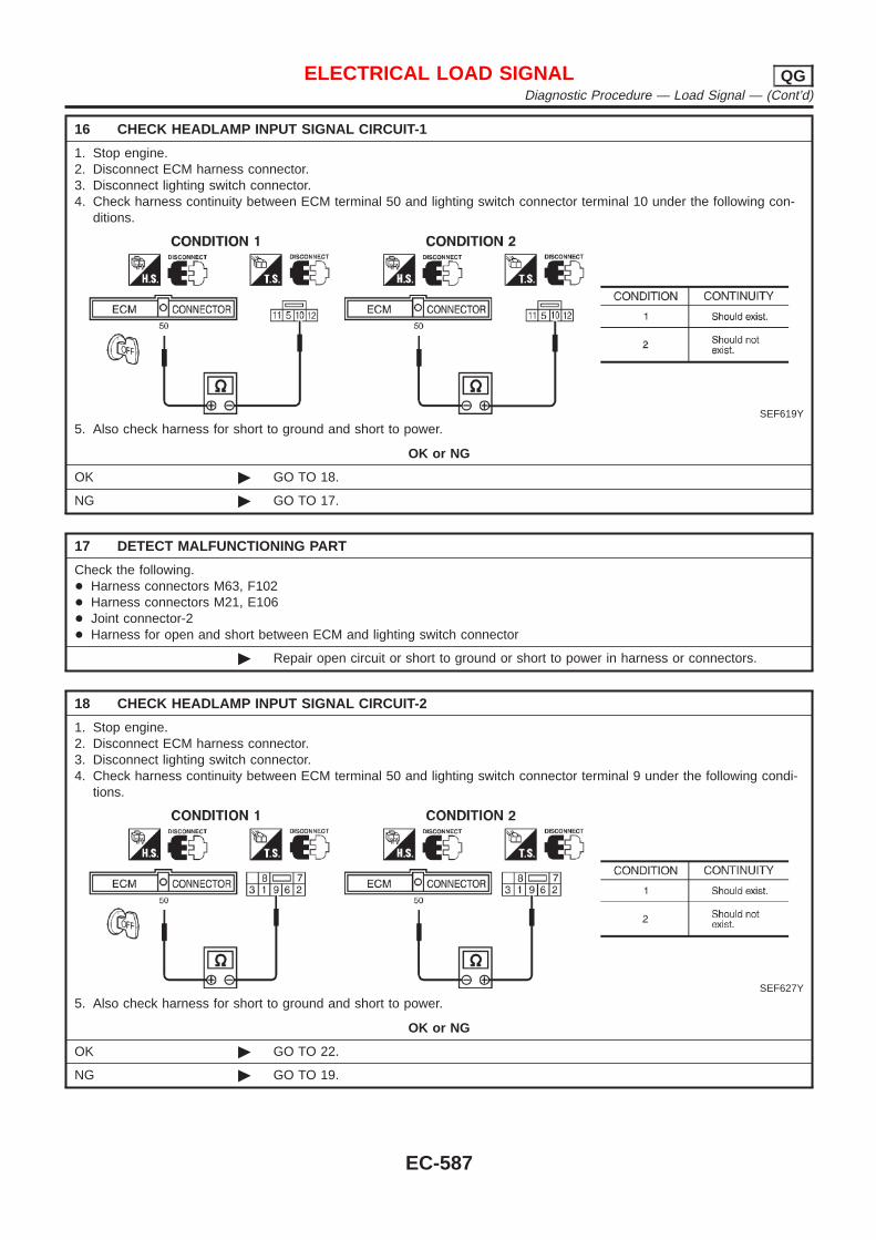
16 CHECK HEADLAMP INPUT SIGNAL CIRCUIT-1
1. Stop engine.2. Disconnect ECM harness connector.3. Disconnect lighting switch connector.4. Check harness continuity between ECM terminal 50 and lighting switch connector terminal 10 under the following con-
ditions.
SEF619Y
5. Also check harness for short to ground and short to power.
OK or NG
OK © GO TO 18.
NG © GO TO 17.
17 DETECT MALFUNCTIONING PART
Check the following.+ Harness connectors M63, F102+ Harness connectors M21, E106+ Joint connector-2+ Harness for open and short between ECM and lighting switch connector
© Repair open circuit or short to ground or short to power in harness or connectors.
18 CHECK HEADLAMP INPUT SIGNAL CIRCUIT-2
1. Stop engine.2. Disconnect ECM harness connector.3. Disconnect lighting switch connector.4. Check harness continuity between ECM terminal 50 and lighting switch connector terminal 9 under the following condi-
tions.
SEF627Y
5. Also check harness for short to ground and short to power.
OK or NG
OK © GO TO 22.
NG © GO TO 19.
ELECTRICAL LOAD SIGNAL QGDiagnostic Procedure — Load Signal — (Cont’d)
EC-587
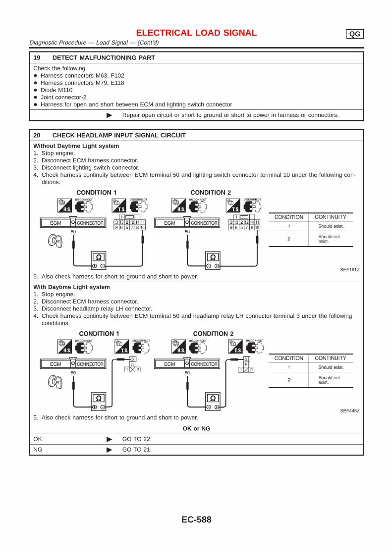
19 DETECT MALFUNCTIONING PART
Check the following.+ Harness connectors M63, F102+ Harness connectors M79, E118+ Diode M110+ Joint connector-2+ Harness for open and short between ECM and lighting switch connector
© Repair open circuit or short to ground or short to power in harness or connectors.
20 CHECK HEADLAMP INPUT SIGNAL CIRCUIT
Without Daytime Light system1. Stop engine.2. Disconnect ECM harness connector.3. Disconnect lighting switch connector.4. Check harness continuity between ECM terminal 50 and lighting switch connector terminal 10 under the following con-
ditions.
SEF161Z
5. Also check harness for short to ground and short to power.
With Daytime Light system1. Stop engine.2. Disconnect ECM harness connector.3. Disconnect headlamp relay LH connector.4. Check harness continuity between ECM terminal 50 and headlamp relay LH connector terminal 3 under the following
conditions.
SEF445Z
5. Also check harness for short to ground and short to power.
OK or NG
OK © GO TO 22.
NG © GO TO 21.
ELECTRICAL LOAD SIGNAL QGDiagnostic Procedure — Load Signal — (Cont’d)
EC-588
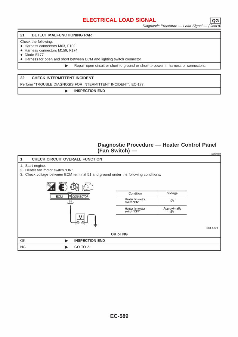
21 DETECT MALFUNCTIONING PART
Check the following.+ Harness connectors M63, F102+ Harness connectors M159, F174+ Diode E177+ Harness for open and short between ECM and lighting switch connector
© Repair open circuit or short to ground or short to power in harness or connectors.
22 CHECK INTERMITTENT INCIDENT
Perform “TROUBLE DIAGNOSIS FOR INTERMITTENT INCIDENT”, EC-177.
© INSPECTION END
Diagnostic Procedure — Heater Control Panel(Fan Switch) —
NJEC0585
1 CHECK CIRCUIT OVERALL FUNCTION
1. Start engine.2. Heater fan motor switch “ON”.3. Check voltage between ECM terminal 51 and ground under the following conditions.
SEF620Y
OK or NG
OK © INSPECTION END
NG © GO TO 2.
ELECTRICAL LOAD SIGNAL QGDiagnostic Procedure — Load Signal — (Cont’d)
EC-589
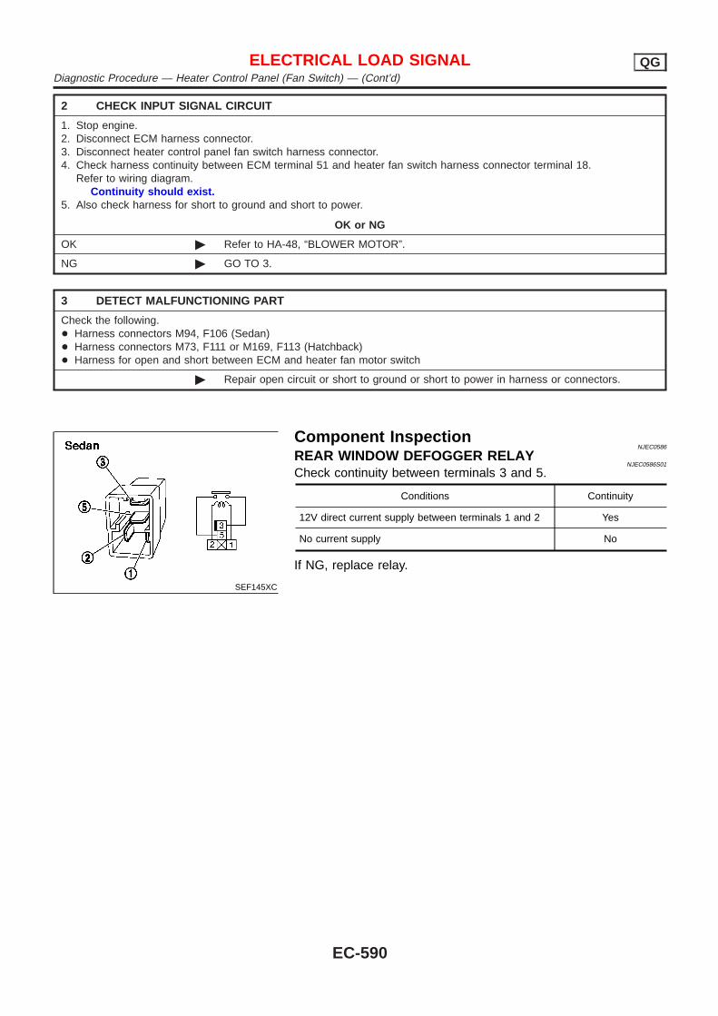
2 CHECK INPUT SIGNAL CIRCUIT
1. Stop engine.2. Disconnect ECM harness connector.3. Disconnect heater control panel fan switch harness connector.4. Check harness continuity between ECM terminal 51 and heater fan switch harness connector terminal 18.
Refer to wiring diagram.Continuity should exist.
5. Also check harness for short to ground and short to power.
OK or NG
OK © Refer to HA-48, “BLOWER MOTOR”.
NG © GO TO 3.
3 DETECT MALFUNCTIONING PART
Check the following.+ Harness connectors M94, F106 (Sedan)+ Harness connectors M73, F111 or M169, F113 (Hatchback)+ Harness for open and short between ECM and heater fan motor switch
© Repair open circuit or short to ground or short to power in harness or connectors.
SEF145XC
Component InspectionNJEC0586
REAR WINDOW DEFOGGER RELAYNJEC0586S01
Check continuity between terminals 3 and 5.
Conditions Continuity
12V direct current supply between terminals 1 and 2 Yes
No current supply No
If NG, replace relay.
ELECTRICAL LOAD SIGNAL QGDiagnostic Procedure — Heater Control Panel (Fan Switch) — (Cont’d)
EC-590
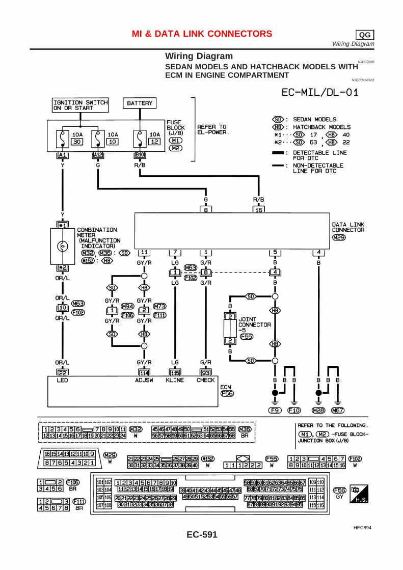
Wiring DiagramNJEC0466
SEDAN MODELS AND HATCHBACK MODELS WITHECM IN ENGINE COMPARTMENT
NJEC0466S01
HEC894
MI & DATA LINK CONNECTORS QGWiring Diagram
EC-591
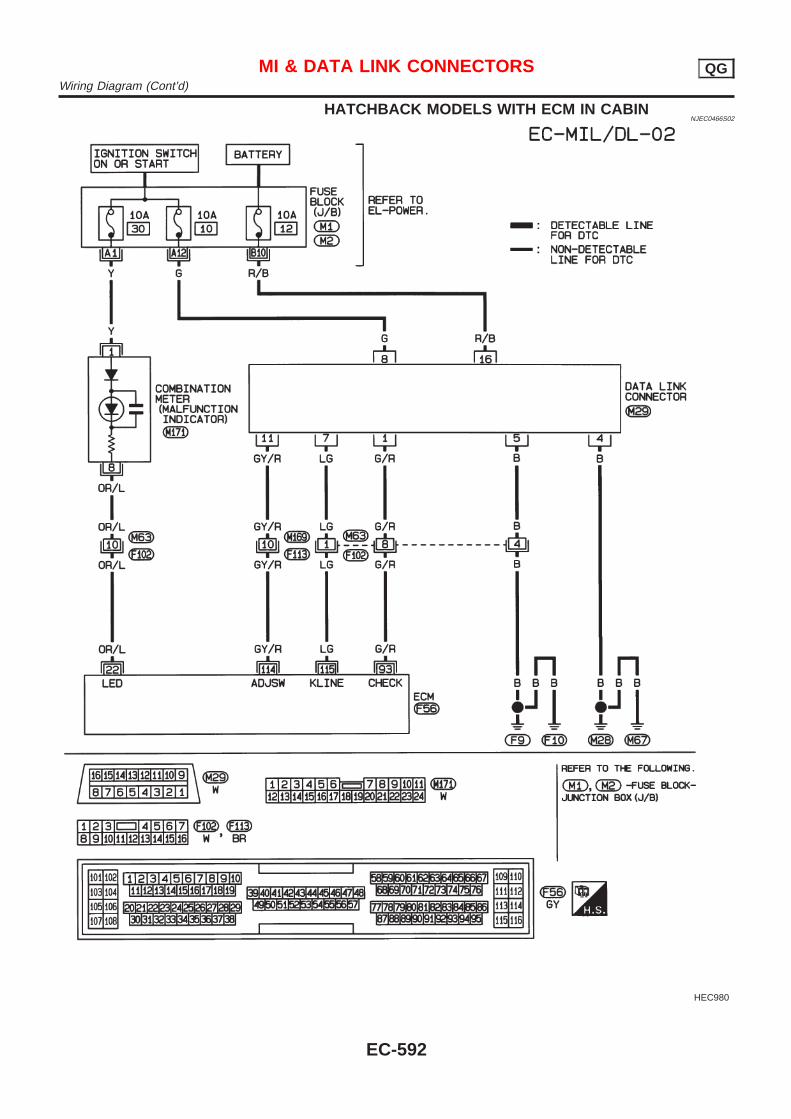
HATCHBACK MODELS WITH ECM IN CABINNJEC0466S02
HEC980
MI & DATA LINK CONNECTORS QGWiring Diagram (Cont’d)
EC-592
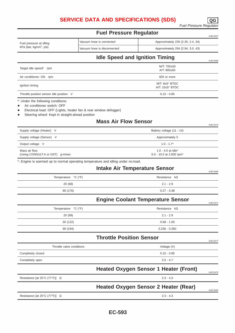
Fuel Pressure RegulatorNJEC0467
Fuel pressure at idlingkPa (bar, kg/cm2, psi)
Vacuum hose is connected Approximately 235 (2.35, 2.4, 34)
Vacuum hose is disconnected Approximately 294 (2.94, 3.0, 43)
Idle Speed and Ignition TimingNJEC0468
Target idle speed* rpmM/T: 700±50A/T: 800±50
Air conditioner: ON rpm 825 or more
Ignition timingM/T: 8±5° BTDCA/T: 10±5° BTDC
Throttle position sensor idle position V 0.15 - 0.85
*: Under the following conditions:+ Air conditioner switch: OFF+ Electrical load: OFF (Lights, heater fan & rear window defogger)+ Steering wheel: Kept in straight-ahead position
Mass Air Flow SensorNJEC0470
Supply voltage (Heater) V Battery voltage (11 - 14)
Supply voltage (Sensor) V Approximately 5
Output voltage V 1.0 - 1.7*
Mass air flow(Using CONSULT-II or GST) g·m/sec
1.0 - 4.0 at idle*5.0 - 10.0 at 2,500 rpm*
*: Engine is warmed up to normal operating temperature and idling under no-load.
Intake Air Temperature SensorNJEC0480
Temperature °C (°F) Resistance kΩ
20 (68) 2.1 - 2.9
80 (176) 0.27 - 0.38
Engine Coolant Temperature SensorNJEC0471
Temperature °C (°F) Resistance kΩ
20 (68) 2.1 - 2.9
50 (122) 0.68 - 1.00
90 (194) 0.236 - 0.260
Throttle Position SensorNJEC0477
Throttle valve conditions Voltage (V)
Completely closed 0.15 - 0.85
Completely open 3.5 - 4.7
Heated Oxygen Sensor 1 Heater (Front)NJEC0478
Resistance [at 25°C (77°F)] Ω 2.3 - 4.3
Heated Oxygen Sensor 2 Heater (Rear)NJEC0483
Resistance [at 25°C (77°F)] Ω 2.3 - 4.3
SERVICE DATA AND SPECIFICATIONS (SDS) QGFuel Pressure Regulator
EC-593
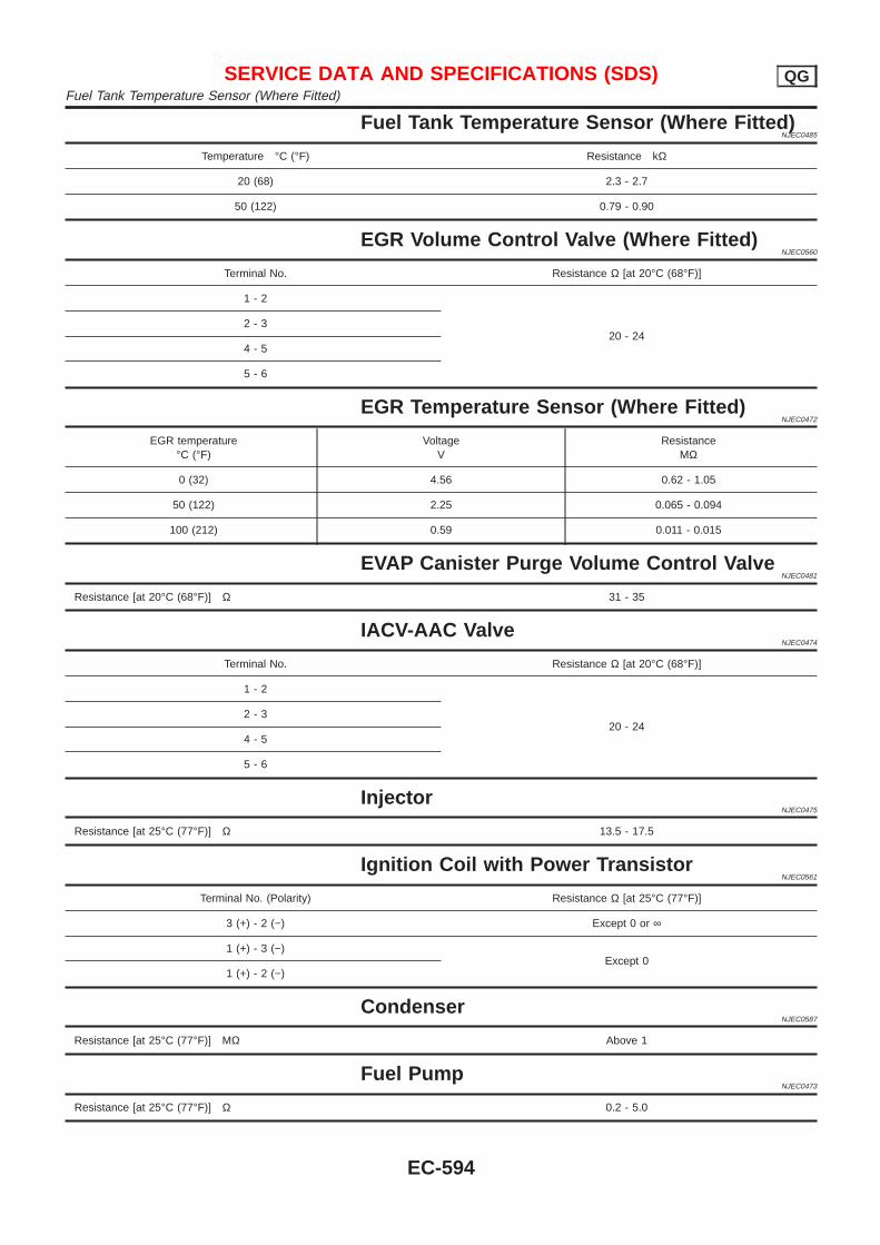
Fuel Tank Temperature Sensor (Where Fitted)NJEC0485
Temperature °C (°F) Resistance kΩ
20 (68) 2.3 - 2.7
50 (122) 0.79 - 0.90
EGR Volume Control Valve (Where Fitted)NJEC0560
Terminal No. Resistance Ω [at 20°C (68°F)]
1 - 2
20 - 242 - 3
4 - 5
5 - 6
EGR Temperature Sensor (Where Fitted)NJEC0472
EGR temperature°C (°F)
VoltageV
ResistanceMΩ
0 (32) 4.56 0.62 - 1.05
50 (122) 2.25 0.065 - 0.094
100 (212) 0.59 0.011 - 0.015
EVAP Canister Purge Volume Control ValveNJEC0481
Resistance [at 20°C (68°F)] Ω 31 - 35
IACV-AAC ValveNJEC0474
Terminal No. Resistance Ω [at 20°C (68°F)]
1 - 2
20 - 242 - 3
4 - 5
5 - 6
InjectorNJEC0475
Resistance [at 25°C (77°F)] Ω 13.5 - 17.5
Ignition Coil with Power TransistorNJEC0561
Terminal No. (Polarity) Resistance Ω [at 25°C (77°F)]
3 (+) - 2 (−) Except 0 or ∞
1 (+) - 3 (−)Except 0
1 (+) - 2 (−)
CondenserNJEC0587
Resistance [at 25°C (77°F)] MΩ Above 1
Fuel PumpNJEC0473
Resistance [at 25°C (77°F)] Ω 0.2 - 5.0
SERVICE DATA AND SPECIFICATIONS (SDS) QGFuel Tank Temperature Sensor (Where Fitted)
EC-594

Crankshaft Position Sensor (POS)NJEC0558
Refer to “Component Inspection”, EC-334.
Camshaft Position Sensor (PHASE)NJEC0559
Refer to “Component Inspection”, EC-342.
SERVICE DATA AND SPECIFICATIONS (SDS) QGCrankshaft Position Sensor (POS)
EC-595

Alphabetical & P No. Index for DTCNJEC0600
ALPHABETICAL INDEX FOR DTCNJEC0600S01
X: Applicable —: Not applicable
Items(CONSULT-II screen terms)
DTCMI illumination Reference page
CONSULT-II ECM
ACCEL POS SENSOR P0120 0403 X EC-685
BATTERY VOLTAGE P1660 0502 — EC-801
BRAKE SW P0571 0807 X EC-706
COOLANT TEMP SEN P0115 0103 X EC-680
CRANK POS SEN (TDC) P0335 0407 X EC-695
ECM RLY P1620 0902 X EC-794
ECM 2 P1607 0301 X EC-792
ECM 10 P1107 0802 X EC-714
ECM 12 P1603 0901 X EC-792
ECM 15 P1621 0903 — EC-799
FUEL CUT SYSTEM2 P1202 1002 X EC-723
MASS AIR FLOW SEN P0100 0102 X EC-673
NO DTC IS DETECTED.FURTHER TESTINGMAY BE REQUIRED.
P0000 0505 — —
OVER HEAT P1217 0208 X EC-730
P1·CAM POS SEN P1341 0701 X EC-778
P2·TDC PULSE SIG P1337 0702 X EC-771
P3·PUMP COMM LINE P1600 0703 X EC-785
P4·SPILL/V CIRC P1251 0704 X EC-764
P5·PUMP C/MODULE P1690 0705 X EC-803
P7·F/INJ TIMG FB P1241 0707 X EC-757
P9·FUEL TEMP SEN P1180 0402 X EC-716
VEHICLE SPEED SEN P0500 0104 X EC-701
TROUBLE DIAGNOSIS — INDEX YDAlphabetical & P No. Index for DTC
EC-596
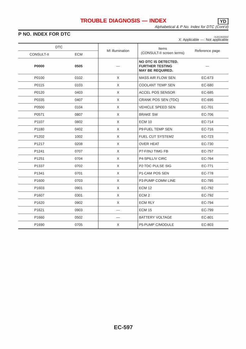
P NO. INDEX FOR DTC=NJEC0600S02
X: Applicable —: Not applicable
DTCMI illumination
Items(CONSULT-II screen terms)
Reference pageCONSULT-II ECM
P0000 0505 —NO DTC IS DETECTED.FURTHER TESTINGMAY BE REQUIRED.
—
P0100 0102 X MASS AIR FLOW SEN EC-673
P0115 0103 X COOLANT TEMP SEN EC-680
P0120 0403 X ACCEL POS SENSOR EC-685
P0335 0407 X CRANK POS SEN (TDC) EC-695
P0500 0104 X VEHICLE SPEED SEN EC-701
P0571 0807 X BRAKE SW EC-706
P1107 0802 X ECM 10 EC-714
P1180 0402 X P9·FUEL TEMP SEN EC-716
P1202 1002 X FUEL CUT SYSTEM2 EC-723
P1217 0208 X OVER HEAT EC-730
P1241 0707 X P7·F/INJ TIMG FB EC-757
P1251 0704 X P4·SPILL/V CIRC EC-764
P1337 0702 X P2·TDC PULSE SIG EC-771
P1341 0701 X P1·CAM POS SEN EC-778
P1600 0703 X P3·PUMP COMM LINE EC-785
P1603 0901 X ECM 12 EC-792
P1607 0301 X ECM 2 EC-792
P1620 0902 X ECM RLY EC-794
P1621 0903 — ECM 15 EC-799
P1660 0502 — BATTERY VOLTAGE EC-801
P1690 0705 X P5·PUMP C/MODULE EC-803
TROUBLE DIAGNOSIS — INDEX YDAlphabetical & P No. Index for DTC (Cont’d)
EC-597
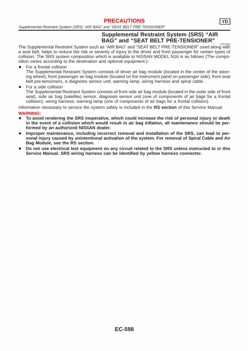
Supplemental Restraint System (SRS) “AIRBAG” and “SEAT BELT PRE-TENSIONER”
NJEC0601
The Supplemental Restraint System such as “AIR BAG” and “SEAT BELT PRE-TENSIONER” used along witha seat belt, helps to reduce the risk or severity of injury to the driver and front passenger for certain types ofcollision. The SRS system composition which is available to NISSAN MODEL N16 is as follows (The compo-sition varies according to the destination and optional equipment.):+ For a frontal collision
The Supplemental Restraint System consists of driver air bag module (located in the center of the steer-ing wheel), front passenger air bag module (located on the instrument panel on passenger side), front seatbelt pre-tensioners, a diagnosis sensor unit, warning lamp, wiring harness and spiral cable.
+ For a side collisionThe Supplemental Restraint System consists of front side air bag module (located in the outer side of frontseat), side air bag (satellite) sensor, diagnosis sensor unit (one of components of air bags for a frontalcollision), wiring harness, warning lamp (one of components of air bags for a frontal collision).
Information necessary to service the system safely is included in the RS section of this Service Manual.WARNING:+ To avoid rendering the SRS inoperative, which could increase the risk of personal injury or death
in the event of a collision which would result in air bag inflation, all maintenance should be per-formed by an authorized NISSAN dealer.
+ Improper maintenance, including incorrect removal and installation of the SRS, can lead to per-sonal injury caused by unintentional activation of the system. For removal of Spiral Cable and AirBag Module, see the RS section.
+ Do not use electrical test equipment on any circuit related to the SRS unless instructed to in thisService Manual. SRS wiring harness can be identified by yellow harness connector.
PRECAUTIONS YDSupplemental Restraint System (SRS) “AIR BAG” and “SEAT BELT PRE-TENSIONER”
EC-598
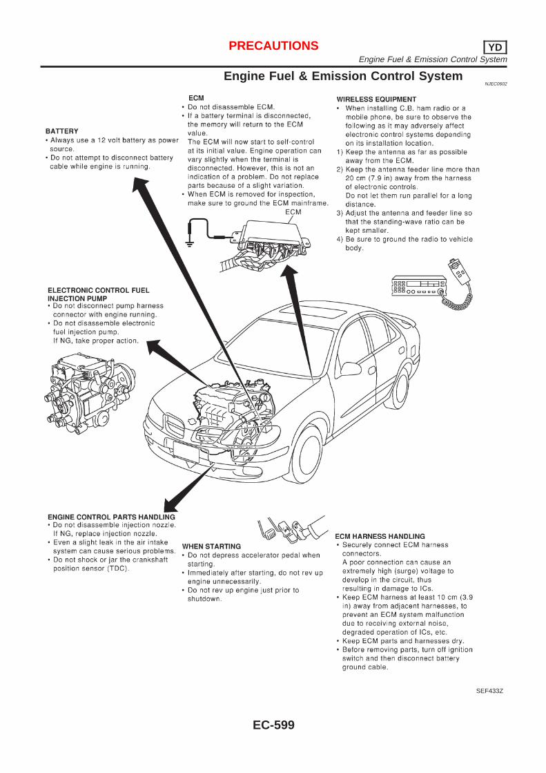
Engine Fuel & Emission Control SystemNJEC0602
SEF433Z
PRECAUTIONS YDEngine Fuel & Emission Control System
EC-599
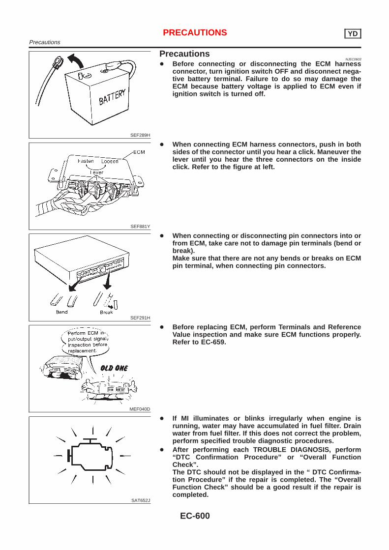
SEF289H
PrecautionsNJEC0603
+ Before connecting or disconnecting the ECM harnessconnector, turn ignition switch OFF and disconnect nega-tive battery terminal. Failure to do so may damage theECM because battery voltage is applied to ECM even ifignition switch is turned off.
SEF881Y
+ When connecting ECM harness connectors, push in bothsides of the connector until you hear a click. Maneuver thelever until you hear the three connectors on the insideclick. Refer to the figure at left.
SEF291H
+ When connecting or disconnecting pin connectors into orfrom ECM, take care not to damage pin terminals (bend orbreak).Make sure that there are not any bends or breaks on ECMpin terminal, when connecting pin connectors.
MEF040D
+ Before replacing ECM, perform Terminals and ReferenceValue inspection and make sure ECM functions properly.Refer to EC-659.
SAT652J
+ If MI illuminates or blinks irregularly when engine isrunning, water may have accumulated in fuel filter. Drainwater from fuel filter. If this does not correct the problem,perform specified trouble diagnostic procedures.
+ After performing each TROUBLE DIAGNOSIS, perform“DTC Confirmation Procedure” or “Overall FunctionCheck”.The DTC should not be displayed in the “ DTC Confirma-tion Procedure” if the repair is completed. The “OverallFunction Check” should be a good result if the repair iscompleted.
PRECAUTIONS YDPrecautions
EC-600
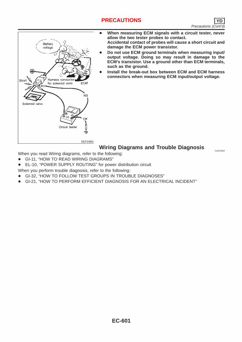
SEF348N
+ When measuring ECM signals with a circuit tester, neverallow the two tester probes to contact.Accidental contact of probes will cause a short circuit anddamage the ECM power transistor.
+ Do not use ECM ground terminals when measuring input/output voltage. Doing so may result in damage to theECM’s transistor. Use a ground other than ECM terminals,such as the ground.
+ Install the break-out box between ECM and ECM harnessconnectors when measuring ECM input/output voltage.
Wiring Diagrams and Trouble DiagnosisNJEC0604
When you read Wiring diagrams, refer to the following:+ GI-11, “HOW TO READ WIRING DIAGRAMS”+ EL-10, “POWER SUPPLY ROUTING” for power distribution circuitWhen you perform trouble diagnosis, refer to the following:+ GI-32, “HOW TO FOLLOW TEST GROUPS IN TROUBLE DIAGNOSES”+ GI-21, “HOW TO PERFORM EFFICIENT DIAGNOSIS FOR AN ELECTRICAL INCIDENT”
PRECAUTIONS YDPrecautions (Cont’d)
EC-601
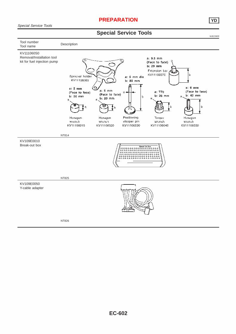
Special Service ToolsNJEC0605
Tool numberTool name
Description
KV111060S0Removal/Installation toolkit for fuel injection pump
NT814
KV109E0010Break-out box
NT825
KV109E0050Y-cable adapter
NT826
PREPARATION YDSpecial Service Tools
EC-602
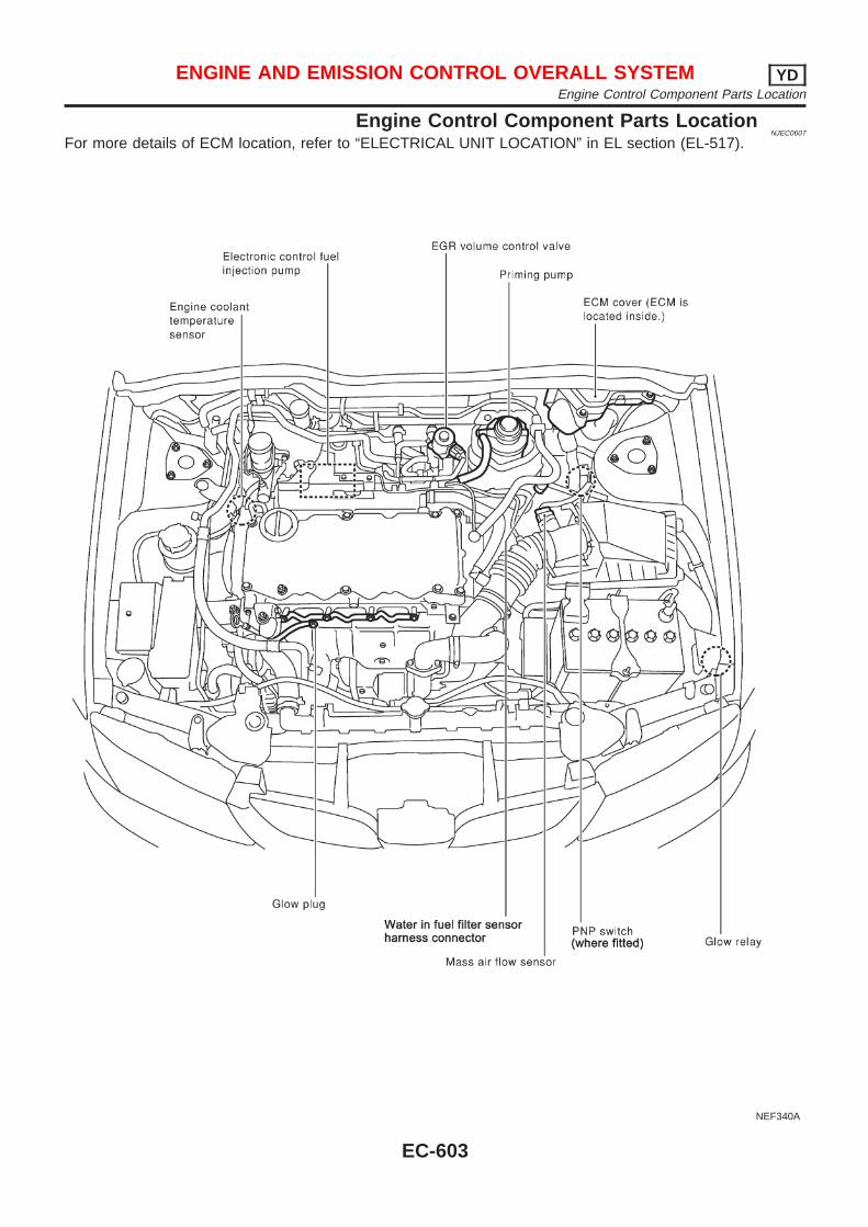
Engine Control Component Parts LocationNJEC0607
For more details of ECM location, refer to “ELECTRICAL UNIT LOCATION” in EL section (EL-517).
NEF340A
ENGINE AND EMISSION CONTROL OVERALL SYSTEM YDEngine Control Component Parts Location
EC-603
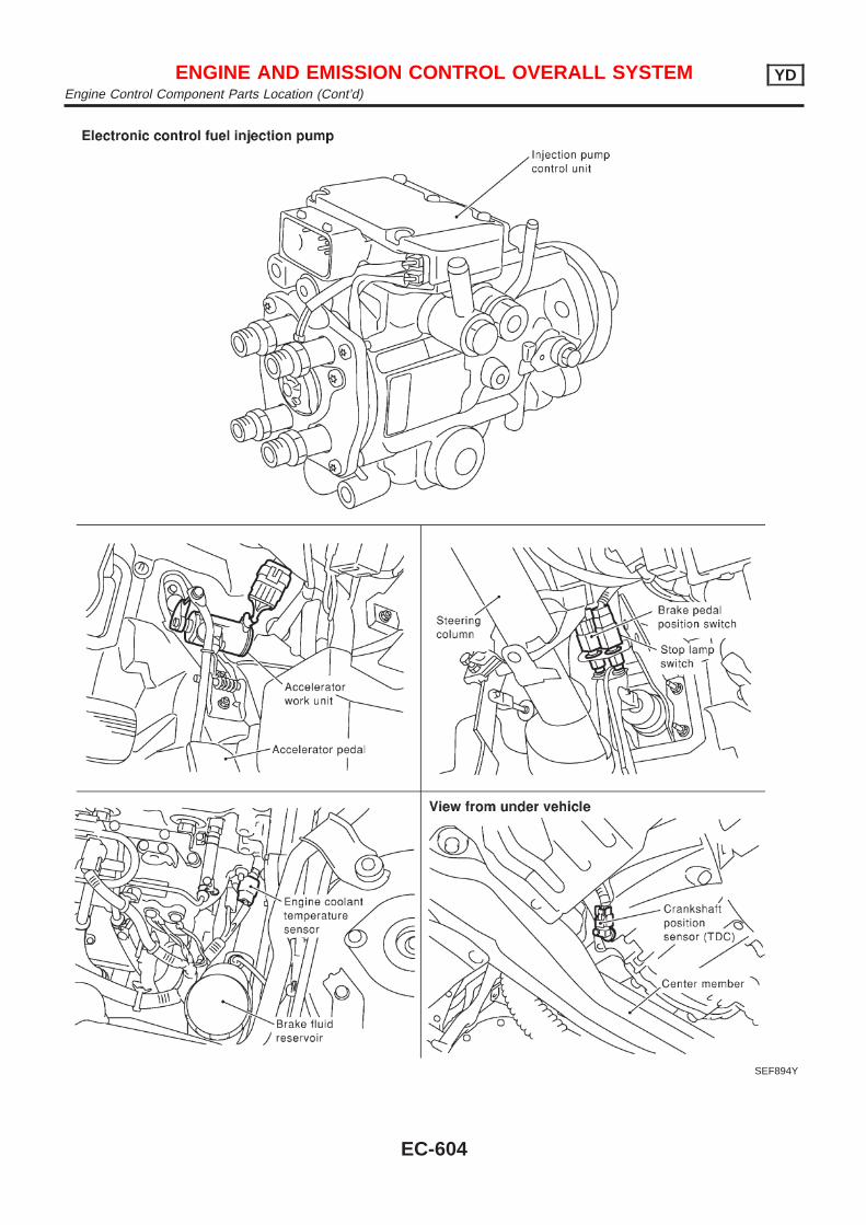
SEF894Y
ENGINE AND EMISSION CONTROL OVERALL SYSTEM YDEngine Control Component Parts Location (Cont’d)
EC-604
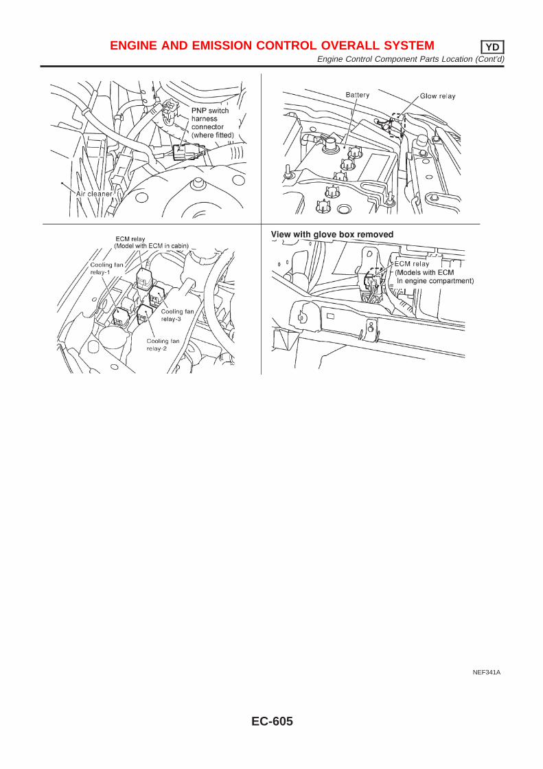
NEF341A
ENGINE AND EMISSION CONTROL OVERALL SYSTEM YDEngine Control Component Parts Location (Cont’d)
EC-605
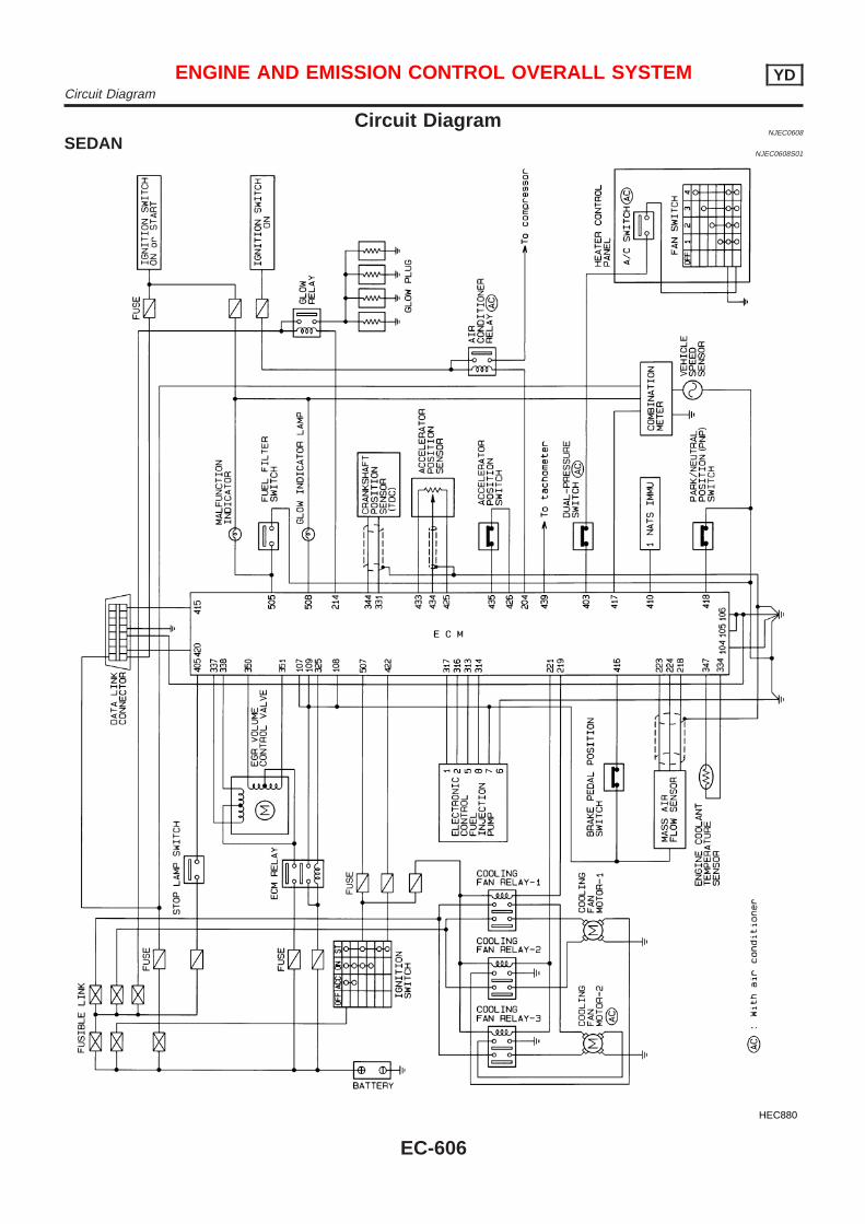
Circuit DiagramNJEC0608
SEDANNJEC0608S01
HEC880
ENGINE AND EMISSION CONTROL OVERALL SYSTEM YDCircuit Diagram
EC-606
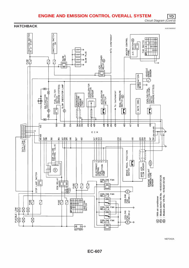
HATCHBACKNJEC0608S02
NEF342A
ENGINE AND EMISSION CONTROL OVERALL SYSTEM YDCircuit Diagram (Cont’d)
EC-607

System DiagramNJEC0609
NEF343A
ENGINE AND EMISSION CONTROL OVERALL SYSTEM YDSystem Diagram
EC-608
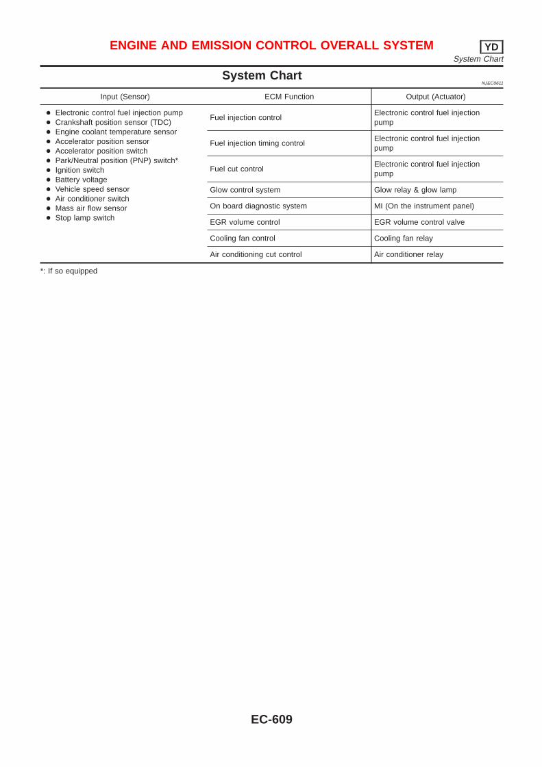
System ChartNJEC0611
Input (Sensor) ECM Function Output (Actuator)
+ Electronic control fuel injection pump+ Crankshaft position sensor (TDC)+ Engine coolant temperature sensor+ Accelerator position sensor+ Accelerator position switch+ Park/Neutral position (PNP) switch*+ Ignition switch+ Battery voltage+ Vehicle speed sensor+ Air conditioner switch+ Mass air flow sensor+ Stop lamp switch
Fuel injection controlElectronic control fuel injectionpump
Fuel injection timing controlElectronic control fuel injectionpump
Fuel cut controlElectronic control fuel injectionpump
Glow control system Glow relay & glow lamp
On board diagnostic system MI (On the instrument panel)
EGR volume control EGR volume control valve
Cooling fan control Cooling fan relay
Air conditioning cut control Air conditioner relay
*: If so equipped
ENGINE AND EMISSION CONTROL OVERALL SYSTEM YDSystem Chart
EC-609
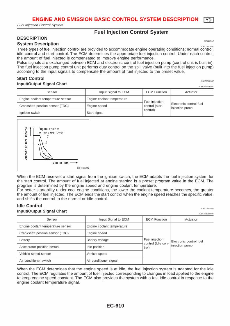
Fuel Injection Control SystemDESCRIPTION
NJEC0612
System DescriptionNJEC0612S01
Three types of fuel injection control are provided to accommodate engine operating conditions; normal control,idle control and start control. The ECM determines the appropriate fuel injection control. Under each control,the amount of fuel injected is compensated to improve engine performance.Pulse signals are exchanged between ECM and electronic control fuel injection pump (control unit is built-in).The fuel injection pump control unit performs duty control on the spill valve (built into the fuel injection pump)according to the input signals to compensate the amount of fuel injected to the preset value.
Start ControlNJEC0612S02
Input/Output Signal ChartNJEC0612S0201
Sensor Input Signal to ECM ECM Function Actuator
Engine coolant temperature sensor Engine coolant temperatureFuel injectioncontrol (startcontrol)
Electronic control fuelinjection pump
Crankshaft position sensor (TDC) Engine speed
Ignition switch Start signal
SEF648S
When the ECM receives a start signal from the ignition switch, the ECM adapts the fuel injection system forthe start control. The amount of fuel injected at engine starting is a preset program value in the ECM. Theprogram is determined by the engine speed and engine coolant temperature.For better startability under cool engine conditions, the lower the coolant temperature becomes, the greaterthe amount of fuel injected. The ECM ends the start control when the engine speed reaches the specific value,and shifts the control to the normal or idle control.
Idle ControlNJEC0612S03
Input/Output Signal ChartNJEC0612S0301
Sensor Input Signal to ECM ECM Function Actuator
Engine coolant temperature sensor Engine coolant temperature
Fuel injectioncontrol (Idle con-trol)
Electronic control fuelinjection pump
Crankshaft position sensor (TDC) Engine speed
Battery Battery voltage
Accelerator position switch Idle position
Vehicle speed sensor Vehicle speed
Air conditioner switch Air conditioner signal
When the ECM determines that the engine speed is at idle, the fuel injection system is adapted for the idlecontrol. The ECM regulates the amount of fuel injected corresponding to changes in load applied to the engineto keep engine speed constant. The ECM also provides the system with a fast idle control in response to theengine coolant temperature signal.
ENGINE AND EMISSION BASIC CONTROL SYSTEM DESCRIPTION YDFuel Injection Control System
EC-610
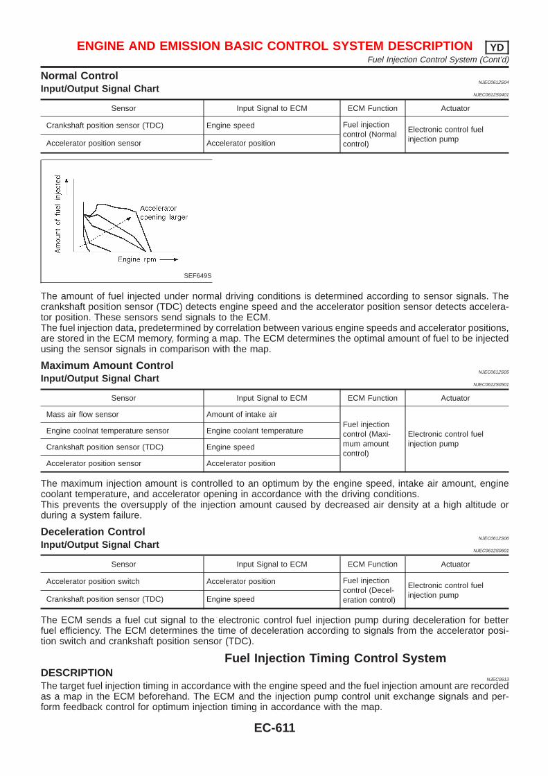
Normal ControlNJEC0612S04
Input/Output Signal ChartNJEC0612S0401
Sensor Input Signal to ECM ECM Function Actuator
Crankshaft position sensor (TDC) Engine speed Fuel injectioncontrol (Normalcontrol)
Electronic control fuelinjection pumpAccelerator position sensor Accelerator position
SEF649S
The amount of fuel injected under normal driving conditions is determined according to sensor signals. Thecrankshaft position sensor (TDC) detects engine speed and the accelerator position sensor detects accelera-tor position. These sensors send signals to the ECM.The fuel injection data, predetermined by correlation between various engine speeds and accelerator positions,are stored in the ECM memory, forming a map. The ECM determines the optimal amount of fuel to be injectedusing the sensor signals in comparison with the map.
Maximum Amount ControlNJEC0612S05
Input/Output Signal ChartNJEC0612S0501
Sensor Input Signal to ECM ECM Function Actuator
Mass air flow sensor Amount of intake airFuel injectioncontrol (Maxi-mum amountcontrol)
Electronic control fuelinjection pump
Engine coolnat temperature sensor Engine coolant temperature
Crankshaft position sensor (TDC) Engine speed
Accelerator position sensor Accelerator position
The maximum injection amount is controlled to an optimum by the engine speed, intake air amount, enginecoolant temperature, and accelerator opening in accordance with the driving conditions.This prevents the oversupply of the injection amount caused by decreased air density at a high altitude orduring a system failure.
Deceleration ControlNJEC0612S06
Input/Output Signal ChartNJEC0612S0601
Sensor Input Signal to ECM ECM Function Actuator
Accelerator position switch Accelerator position Fuel injectioncontrol (Decel-eration control)
Electronic control fuelinjection pumpCrankshaft position sensor (TDC) Engine speed
The ECM sends a fuel cut signal to the electronic control fuel injection pump during deceleration for betterfuel efficiency. The ECM determines the time of deceleration according to signals from the accelerator posi-tion switch and crankshaft position sensor (TDC).
Fuel Injection Timing Control SystemDESCRIPTION
NJEC0613
The target fuel injection timing in accordance with the engine speed and the fuel injection amount are recordedas a map in the ECM beforehand. The ECM and the injection pump control unit exchange signals and per-form feedback control for optimum injection timing in accordance with the map.
ENGINE AND EMISSION BASIC CONTROL SYSTEM DESCRIPTION YDFuel Injection Control System (Cont’d)
EC-611
Air Conditioning Cut ControlDESCRIPTION
NJEC0614
Input/Output Signal ChartNJEC0614S01
Sensor Input Signal to ECM ECM Function Actuator
Air conditioner switch Air conditioner “ON” signal
Air conditionercut control
Air conditioner relayAccelerator position sensor Accelerator valve opening angle
Vehicle speed sensor Vehicle speed
Engine coolant temperature sensor Engine coolant temperature
System DescriptionNJEC0614S02
This system improves acceleration when the air conditioner is used.When the accelerator pedal is fully depressed, the air conditioner is turned off for a few seconds.When engine coolant temperature becomes excessively high, the air conditioner is turned off. This continuesuntil the engine coolant temperature returns to normal.
Fuel Cut Control (at no load & high enginespeed)
DESCRIPTIONNJEC0615
Input/Output Signal ChartNJEC0615S01
Sensor Input Signal to ECM ECM Function Actuator
Vehicle speed sensor Vehicle speed
Fuel cut controlElectronic control fuelinjection pump
Accelerator position switch Accelerator position
Crankshaft position sensor (TDC) Engine speed
If the engine speed is above 2,800 rpm with no load (for example, in neutral and engine speed over 2,800rpm) fuel will be cut off after some time. The exact time when the fuel is cut off varies based on engine speed.Fuel cut will operate until the engine speed reaches 1,500 rpm, then fuel cut is cancelled.NOTE:This function is different from deceleration control listed under “Fuel Injection Control System”,EC-610.
ENGINE AND EMISSION BASIC CONTROL SYSTEM DESCRIPTION YDAir Conditioning Cut Control
EC-612
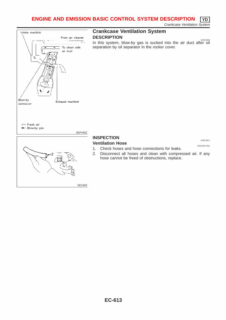
SEF440Z
Crankcase Ventilation SystemDESCRIPTION
NJEC0616
In this system, blow-by gas is sucked into the air duct after oilseparation by oil separator in the rocker cover.
SEC692
INSPECTIONNJEC0617
Ventilation HoseNJEC0617S01
1. Check hoses and hose connections for leaks.2. Disconnect all hoses and clean with compressed air. If any
hose cannot be freed of obstructions, replace.
ENGINE AND EMISSION BASIC CONTROL SYSTEM DESCRIPTION YDCrankcase Ventilation System
EC-613
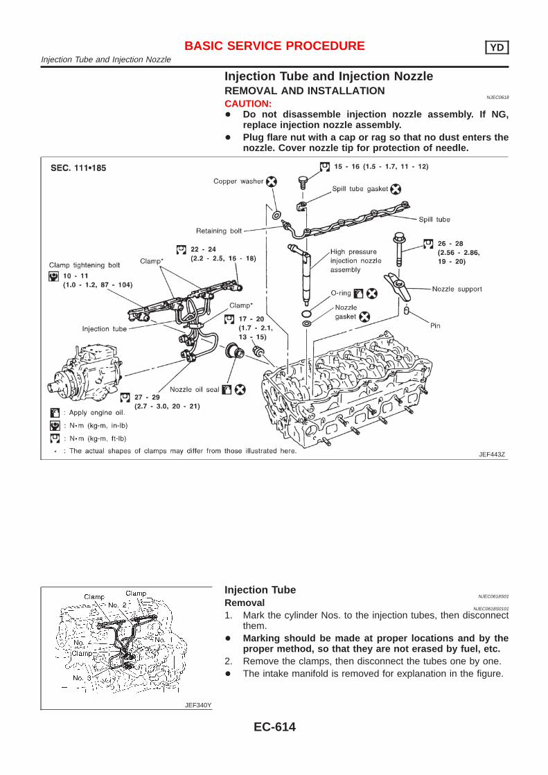
Injection Tube and Injection NozzleREMOVAL AND INSTALLATION
NJEC0618
CAUTION:+ Do not disassemble injection nozzle assembly. If NG,
replace injection nozzle assembly.+ Plug flare nut with a cap or rag so that no dust enters the
nozzle. Cover nozzle tip for protection of needle.
JEF443Z
JEF340Y
Injection TubeNJEC0618S01
RemovalNJEC0618S0101
1. Mark the cylinder Nos. to the injection tubes, then disconnectthem.
+ Marking should be made at proper locations and by theproper method, so that they are not erased by fuel, etc.
2. Remove the clamps, then disconnect the tubes one by one.+ The intake manifold is removed for explanation in the figure.
BASIC SERVICE PROCEDURE YDInjection Tube and Injection Nozzle
EC-614
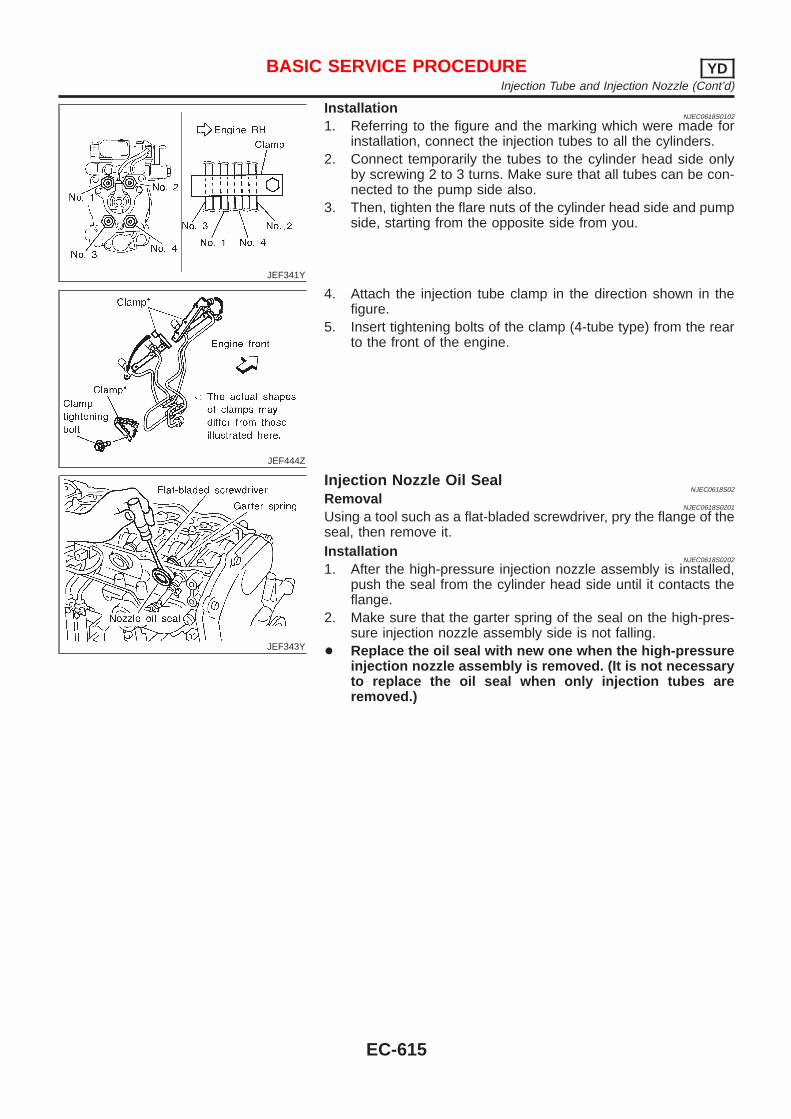
JEF341Y
InstallationNJEC0618S0102
1. Referring to the figure and the marking which were made forinstallation, connect the injection tubes to all the cylinders.
2. Connect temporarily the tubes to the cylinder head side onlyby screwing 2 to 3 turns. Make sure that all tubes can be con-nected to the pump side also.
3. Then, tighten the flare nuts of the cylinder head side and pumpside, starting from the opposite side from you.
JEF444Z
4. Attach the injection tube clamp in the direction shown in thefigure.
5. Insert tightening bolts of the clamp (4-tube type) from the rearto the front of the engine.
JEF343Y
Injection Nozzle Oil SealNJEC0618S02
RemovalNJEC0618S0201
Using a tool such as a flat-bladed screwdriver, pry the flange of theseal, then remove it.Installation
NJEC0618S0202
1. After the high-pressure injection nozzle assembly is installed,push the seal from the cylinder head side until it contacts theflange.
2. Make sure that the garter spring of the seal on the high-pres-sure injection nozzle assembly side is not falling.
+ Replace the oil seal with new one when the high-pressureinjection nozzle assembly is removed. (It is not necessaryto replace the oil seal when only injection tubes areremoved.)
BASIC SERVICE PROCEDURE YDInjection Tube and Injection Nozzle (Cont’d)
EC-615
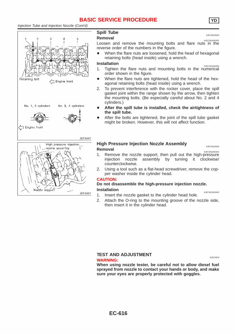
JEF344Y
Spill TubeNJEC0618S03
RemovalNJEC0618S0301
Loosen and remove the mounting bolts and flare nuts in thereverse order of the numbers in the figure.+ When the flare nuts are loosened, hold the head of hexagonal
retaining bolts (head inside) using a wrench.Installation
NJEC0618S0302
1. Tighten the flare nuts and mounting bolts in the numericalorder shown in the figure.
+ When the flare nuts are tightened, hold the head of the hex-agonal retaining bolts (head inside) using a wrench.
2. To prevent interference with the rocker cover, place the spillgasket joint within the range shown by the arrow, then tightenthe mounting bolts. (Be especially careful about No. 2 and 4cylinders.)
+ After the spill tube is installed, check the airtightness ofthe spill tube.
+ After the bolts are tightened, the joint of the spill tube gasketmight be broken. However, this will not affect function.
JEF345Y
High Pressure Injection Nozzle AssemblyNJEC0618S04
RemovalNJEC0618S0401
1. Remove the nozzle support, then pull out the high-pressureinjection nozzle assembly by turning it clockwise/counterclockwise.
2. Using a tool such as a flat-head screwdriver, remove the cop-per washer inside the cylinder head.
CAUTION:Do not disassemble the high-pressure injection nozzle.Installation
NJEC0618S0402
1. Insert the nozzle gasket to the cylinder head hole.2. Attach the O-ring to the mounting groove of the nozzle side,
then insert it in the cylinder head.
TEST AND ADJUSTMENTNJEC0619
WARNING:When using nozzle tester, be careful not to allow diesel fuelsprayed from nozzle to contact your hands or body, and makesure your eyes are properly protected with goggles.
BASIC SERVICE PROCEDURE YDInjection Tube and Injection Nozzle (Cont’d)
EC-616
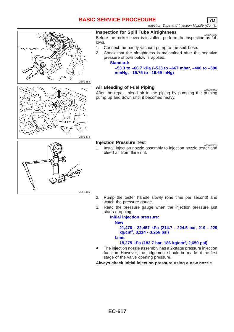
JEF346Y
Inspection for Spill Tube AirtightnessNJEC0619S01
Before the rocker cover is installed, perform the inspection as fol-lows.1. Connect the handy vacuum pump to the spill hose.2. Check that the airtightness is maintained after the negative
pressure shown below is applied.Standard:
–53.3 to –66.7 kPa (–533 to –667 mbar, –400 to –500mmHg, –15.75 to –19.69 inHg)
JEF347Y
Air Bleeding of Fuel PipingNJEC0619S02
After the repair, bleed air in the piping by pumping the primingpump up and down until it becomes heavy.
JEF348Y
Injection Pressure TestNJEC0619S03
1. Install injection nozzle assembly to injection nozzle tester andbleed air from flare nut.
2. Pump the tester handle slowly (one time per second) andwatch the pressure gauge.
3. Read the pressure gauge when the injection pressure juststarts dropping.
Initial injection pressure:New
21,476 - 22,457 kPa (214.7 - 224.5 bar, 219 - 229kg/cm 2, 3,114 - 3,256 psi)
Limit18,275 kPa (182.7 bar, 186 kg/cm 2, 2,650 psi)
+ The injection nozzle assembly has a 2-stage pressure injectionfunction. However, the judgement should be made at the firststage of the valve opening pressure.
Always check initial injection pressure using a new nozzle.
BASIC SERVICE PROCEDURE YDInjection Tube and Injection Nozzle (Cont’d)
EC-617
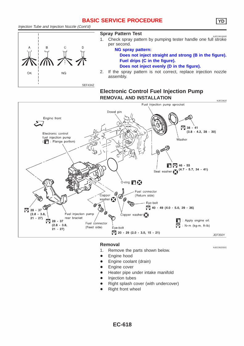
SEF434Z
Spray Pattern TestNJEC0619S05
1. Check spray pattern by pumping tester handle one full strokeper second.
NG spray pattern:Does not inject straight and strong (B in the figure).Fuel drips (C in the figure).Does not inject evenly (D in the figure).
2. If the spray pattern is not correct, replace injection nozzleassembly.
Electronic Control Fuel Injection PumpREMOVAL AND INSTALLATION
NJEC0620
JEF350Y
RemovalNJEC0620S01
1. Remove the parts shown below.+ Engine hood+ Engine coolant (drain)+ Engine cover+ Heater pipe under intake manifold+ Injection tubes+ Right splash cover (with undercover)+ Right front wheel
BASIC SERVICE PROCEDURE YDInjection Tube and Injection Nozzle (Cont’d)
EC-618
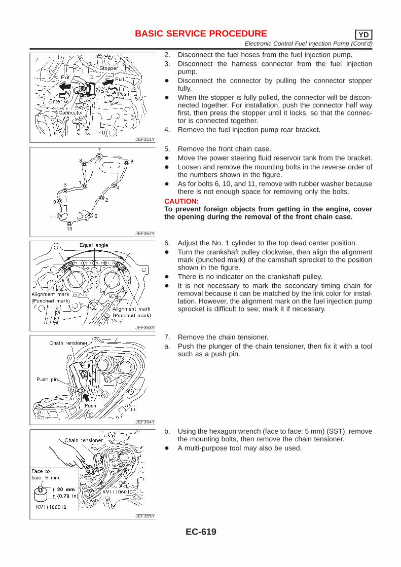
JEF351Y
2. Disconnect the fuel hoses from the fuel injection pump.3. Disconnect the harness connector from the fuel injection
pump.+ Disconnect the connector by pulling the connector stopper
fully.+ When the stopper is fully pulled, the connector will be discon-
nected together. For installation, push the connector half wayfirst, then press the stopper until it locks, so that the connec-tor is connected together.
4. Remove the fuel injection pump rear bracket.
JEF352Y
5. Remove the front chain case.+ Move the power steering fluid reservoir tank from the bracket.+ Loosen and remove the mounting bolts in the reverse order of
the numbers shown in the figure.+ As for bolts 6, 10, and 11, remove with rubber washer because
there is not enough space for removing only the bolts.CAUTION:To prevent foreign objects from getting in the engine, coverthe opening during the removal of the front chain case.
JEF353Y
6. Adjust the No. 1 cylinder to the top dead center position.+ Turn the crankshaft pulley clockwise, then align the alignment
mark (punched mark) of the camshaft sprocket to the positionshown in the figure.
+ There is no indicator on the crankshaft pulley.+ It is not necessary to mark the secondary timing chain for
removal because it can be matched by the link color for instal-lation. However, the alignment mark on the fuel injection pumpsprocket is difficult to see; mark it if necessary.
JEF354Y
7. Remove the chain tensioner.a. Push the plunger of the chain tensioner, then fix it with a tool
such as a push pin.
JEF355Y
b. Using the hexagon wrench (face to face: 5 mm) (SST), removethe mounting bolts, then remove the chain tensioner.
+ A multi-purpose tool may also be used.
BASIC SERVICE PROCEDURE YDElectronic Control Fuel Injection Pump (Cont’d)
EC-619
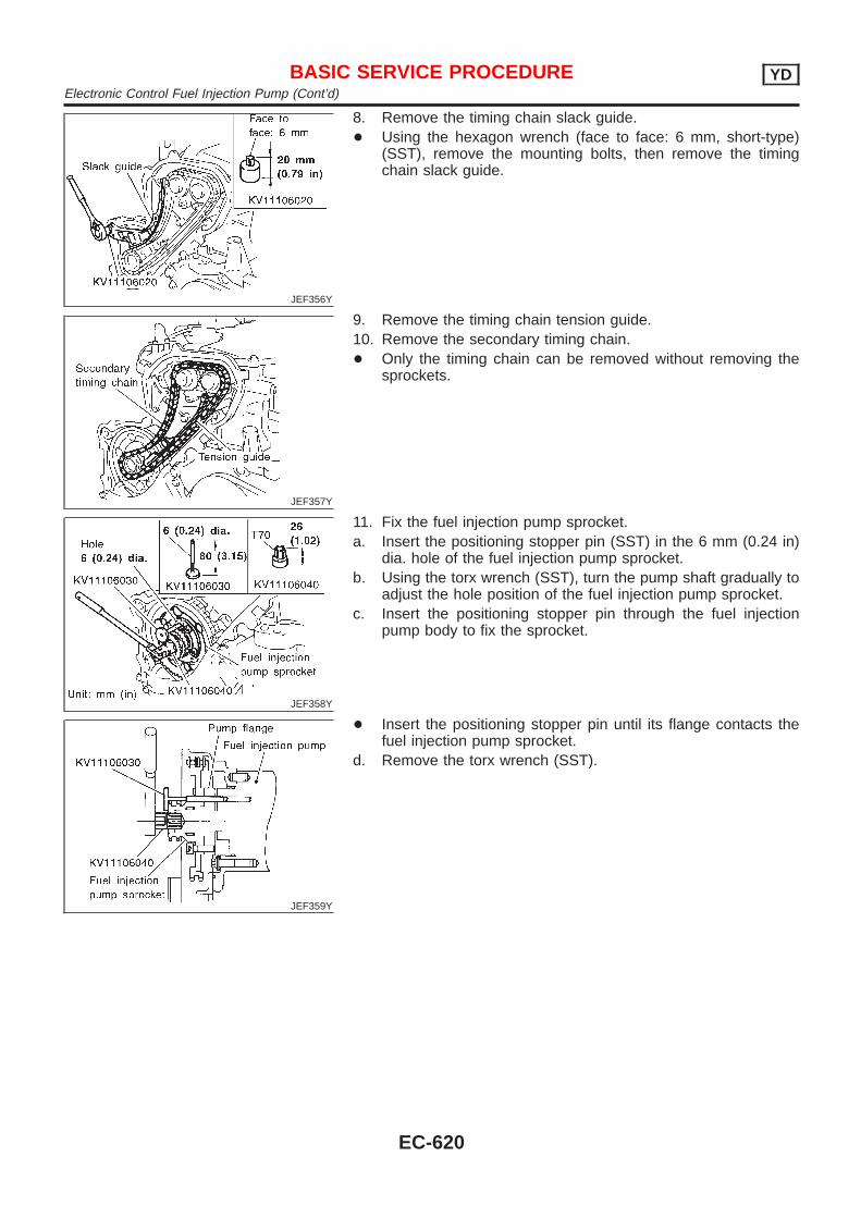
JEF356Y
8. Remove the timing chain slack guide.+ Using the hexagon wrench (face to face: 6 mm, short-type)
(SST), remove the mounting bolts, then remove the timingchain slack guide.
JEF357Y
9. Remove the timing chain tension guide.10. Remove the secondary timing chain.+ Only the timing chain can be removed without removing the
sprockets.
JEF358Y
11. Fix the fuel injection pump sprocket.a. Insert the positioning stopper pin (SST) in the 6 mm (0.24 in)
dia. hole of the fuel injection pump sprocket.b. Using the torx wrench (SST), turn the pump shaft gradually to
adjust the hole position of the fuel injection pump sprocket.c. Insert the positioning stopper pin through the fuel injection
pump body to fix the sprocket.
JEF359Y
+ Insert the positioning stopper pin until its flange contacts thefuel injection pump sprocket.
d. Remove the torx wrench (SST).
BASIC SERVICE PROCEDURE YDElectronic Control Fuel Injection Pump (Cont’d)
EC-620
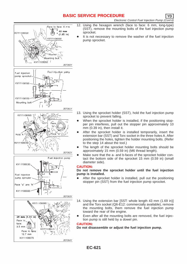
JEF360Y
JEF361Y
12. Using the hexagon wrench (face to face: 6 mm, long-type)(SST), remove the mounting bolts of the fuel injection pumpsprocket.
+ It is not necessary to remove the washer of the fuel injectionpump sprocket.
JEF362Y
JEF363Y
13. Using the sprocket holder (SST), hold the fuel injection pumpsprocket to prevent falling.
+ When the sprocket holder is installed, if the positioning stop-per pin interferes, pull out the stopper pin approximately 10mm (0.39 in), then install it.
+ After the sprocket holder is installed temporarily, insert theextension bar (SST) and Torx socket in the three holes A. Afterpositioning the holes, tighten the holder mounting bolts. (Referto the step 14 about the tool.)
+ The length of the sprocket holder mounting bolts should beapproximately 15 mm (0.59 in) (M6 thread length).
+ Make sure that the a- and b-faces of the sprocket holder con-tact the bottom side of the sprocket 15 mm (0.59 in) (smalldiameter side).
CAUTION:Do not remove the sprocket holder until the fuel injectionpump is installed.+ After the sprocket holder is installed, pull out the positioning
stopper pin (SST) from the fuel injection pump sprocket.
JEF364Y
14. Using the extension bar [SST: whole length 43 mm (1.69 in)]and the Torx socket (Q6-E12: commercially available), removethe mounting bolts, them remove the fuel injection pumptoward the rear of the engine.
+ Even after all the mounting bolts are removed, the fuel injec-tion pump is still held by a dowel pin.
CAUTION:Do not disassemble or adjust the fuel injection pump.
BASIC SERVICE PROCEDURE YDElectronic Control Fuel Injection Pump (Cont’d)
EC-621
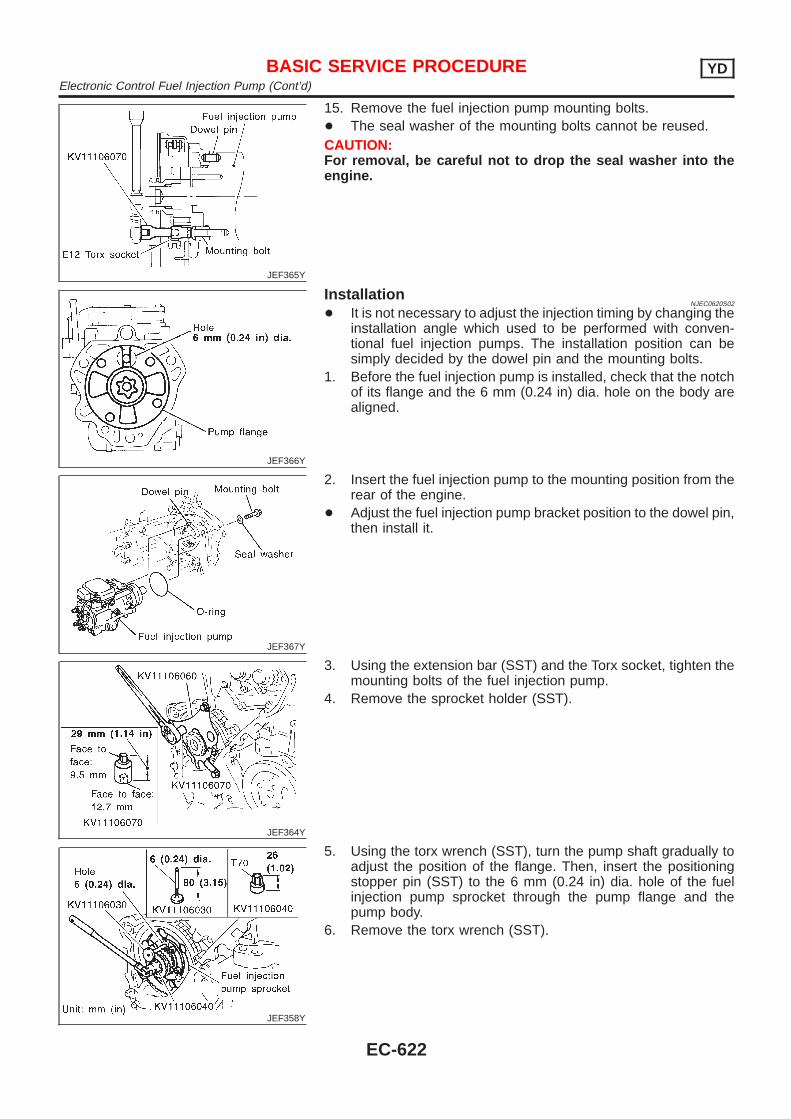
JEF365Y
15. Remove the fuel injection pump mounting bolts.+ The seal washer of the mounting bolts cannot be reused.CAUTION:For removal, be careful not to drop the seal washer into theengine.
JEF366Y
InstallationNJEC0620S02
+ It is not necessary to adjust the injection timing by changing theinstallation angle which used to be performed with conven-tional fuel injection pumps. The installation position can besimply decided by the dowel pin and the mounting bolts.
1. Before the fuel injection pump is installed, check that the notchof its flange and the 6 mm (0.24 in) dia. hole on the body arealigned.
JEF367Y
2. Insert the fuel injection pump to the mounting position from therear of the engine.
+ Adjust the fuel injection pump bracket position to the dowel pin,then install it.
JEF364Y
3. Using the extension bar (SST) and the Torx socket, tighten themounting bolts of the fuel injection pump.
4. Remove the sprocket holder (SST).
JEF358Y
5. Using the torx wrench (SST), turn the pump shaft gradually toadjust the position of the flange. Then, insert the positioningstopper pin (SST) to the 6 mm (0.24 in) dia. hole of the fuelinjection pump sprocket through the pump flange and thepump body.
6. Remove the torx wrench (SST).
BASIC SERVICE PROCEDURE YDElectronic Control Fuel Injection Pump (Cont’d)
EC-622
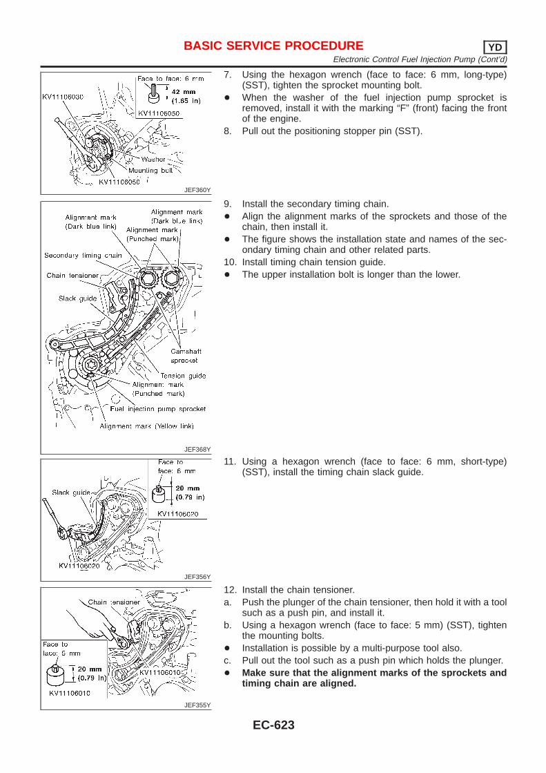
JEF360Y
7. Using the hexagon wrench (face to face: 6 mm, long-type)(SST), tighten the sprocket mounting bolt.
+ When the washer of the fuel injection pump sprocket isremoved, install it with the marking “F” (front) facing the frontof the engine.
8. Pull out the positioning stopper pin (SST).
JEF368Y
9. Install the secondary timing chain.+ Align the alignment marks of the sprockets and those of the
chain, then install it.+ The figure shows the installation state and names of the sec-
ondary timing chain and other related parts.10. Install timing chain tension guide.+ The upper installation bolt is longer than the lower.
JEF356Y
11. Using a hexagon wrench (face to face: 6 mm, short-type)(SST), install the timing chain slack guide.
JEF355Y
12. Install the chain tensioner.a. Push the plunger of the chain tensioner, then hold it with a tool
such as a push pin, and install it.b. Using a hexagon wrench (face to face: 5 mm) (SST), tighten
the mounting bolts.+ Installation is possible by a multi-purpose tool also.c. Pull out the tool such as a push pin which holds the plunger.+ Make sure that the alignment marks of the sprockets and
timing chain are aligned.
BASIC SERVICE PROCEDURE YDElectronic Control Fuel Injection Pump (Cont’d)
EC-623
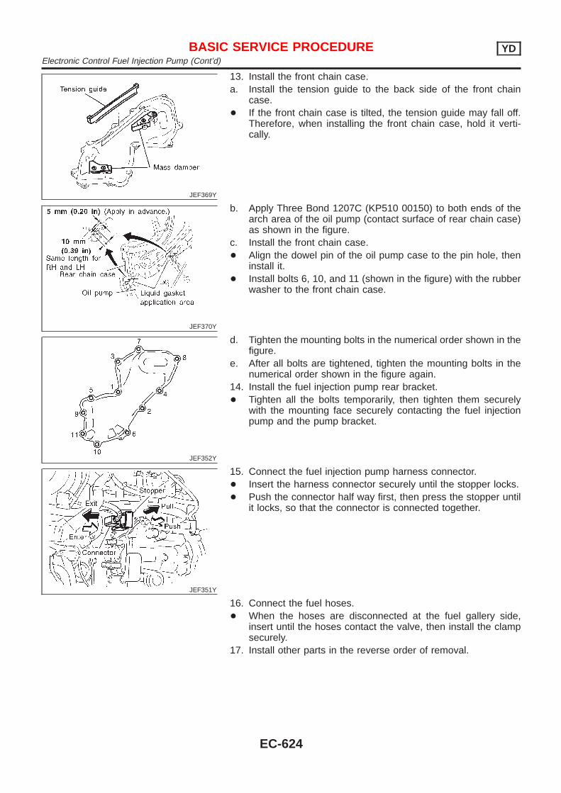
JEF369Y
13. Install the front chain case.a. Install the tension guide to the back side of the front chain
case.+ If the front chain case is tilted, the tension guide may fall off.
Therefore, when installing the front chain case, hold it verti-cally.
JEF370Y
b. Apply Three Bond 1207C (KP510 00150) to both ends of thearch area of the oil pump (contact surface of rear chain case)as shown in the figure.
c. Install the front chain case.+ Align the dowel pin of the oil pump case to the pin hole, then
install it.+ Install bolts 6, 10, and 11 (shown in the figure) with the rubber
washer to the front chain case.
JEF352Y
d. Tighten the mounting bolts in the numerical order shown in thefigure.
e. After all bolts are tightened, tighten the mounting bolts in thenumerical order shown in the figure again.
14. Install the fuel injection pump rear bracket.+ Tighten all the bolts temporarily, then tighten them securely
with the mounting face securely contacting the fuel injectionpump and the pump bracket.
JEF351Y
15. Connect the fuel injection pump harness connector.+ Insert the harness connector securely until the stopper locks.+ Push the connector half way first, then press the stopper until
it locks, so that the connector is connected together.
16. Connect the fuel hoses.+ When the hoses are disconnected at the fuel gallery side,
insert until the hoses contact the valve, then install the clampsecurely.
17. Install other parts in the reverse order of removal.
BASIC SERVICE PROCEDURE YDElectronic Control Fuel Injection Pump (Cont’d)
EC-624
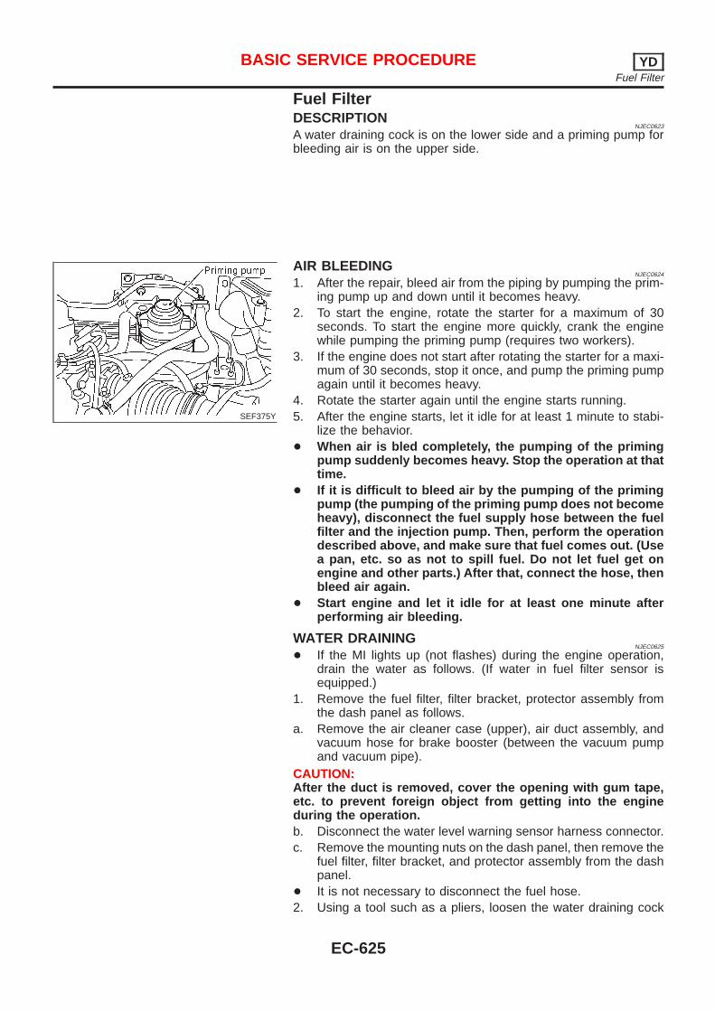
Fuel FilterDESCRIPTION
NJEC0623
A water draining cock is on the lower side and a priming pump forbleeding air is on the upper side.
SEF375Y
AIR BLEEDINGNJEC0624
1. After the repair, bleed air from the piping by pumping the prim-ing pump up and down until it becomes heavy.
2. To start the engine, rotate the starter for a maximum of 30seconds. To start the engine more quickly, crank the enginewhile pumping the priming pump (requires two workers).
3. If the engine does not start after rotating the starter for a maxi-mum of 30 seconds, stop it once, and pump the priming pumpagain until it becomes heavy.
4. Rotate the starter again until the engine starts running.5. After the engine starts, let it idle for at least 1 minute to stabi-
lize the behavior.+ When air is bled completely, the pumping of the priming
pump suddenly becomes heavy. Stop the operation at thattime.
+ If it is difficult to bleed air by the pumping of the primingpump (the pumping of the priming pump does not becomeheavy), disconnect the fuel supply hose between the fuelfilter and the injection pump. Then, perform the operationdescribed above, and make sure that fuel comes out. (Usea pan, etc. so as not to spill fuel. Do not let fuel get onengine and other parts.) After that, connect the hose, thenbleed air again.
+ Start engine and let it idle for at least one minute afterperforming air bleeding.
WATER DRAININGNJEC0625
+ If the MI lights up (not flashes) during the engine operation,drain the water as follows. (If water in fuel filter sensor isequipped.)
1. Remove the fuel filter, filter bracket, protector assembly fromthe dash panel as follows.
a. Remove the air cleaner case (upper), air duct assembly, andvacuum hose for brake booster (between the vacuum pumpand vacuum pipe).
CAUTION:After the duct is removed, cover the opening with gum tape,etc. to prevent foreign object from getting into the engineduring the operation.b. Disconnect the water level warning sensor harness connector.c. Remove the mounting nuts on the dash panel, then remove the
fuel filter, filter bracket, and protector assembly from the dashpanel.
+ It is not necessary to disconnect the fuel hose.2. Using a tool such as a pliers, loosen the water draining cock
BASIC SERVICE PROCEDURE YDFuel Filter
EC-625
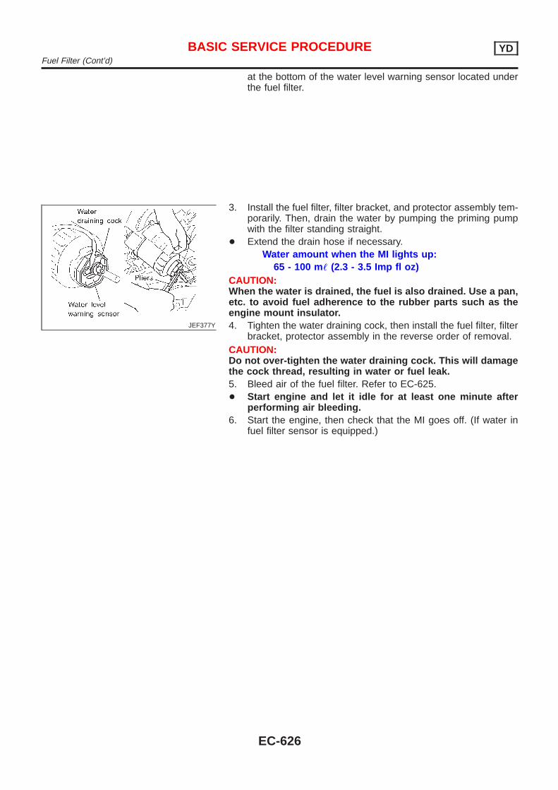
at the bottom of the water level warning sensor located underthe fuel filter.
JEF377Y
3. Install the fuel filter, filter bracket, and protector assembly tem-porarily. Then, drain the water by pumping the priming pumpwith the filter standing straight.
+ Extend the drain hose if necessary.Water amount when the MI lights up:
65 - 100 m! (2.3 - 3.5 Imp fl oz)CAUTION:When the water is drained, the fuel is also drained. Use a pan,etc. to avoid fuel adherence to the rubber parts such as theengine mount insulator.4. Tighten the water draining cock, then install the fuel filter, filter
bracket, protector assembly in the reverse order of removal.CAUTION:Do not over-tighten the water draining cock. This will damagethe cock thread, resulting in water or fuel leak.5. Bleed air of the fuel filter. Refer to EC-625.+ Start engine and let it idle for at least one minute after
performing air bleeding.6. Start the engine, then check that the MI goes off. (If water in
fuel filter sensor is equipped.)
BASIC SERVICE PROCEDURE YDFuel Filter (Cont’d)
EC-626
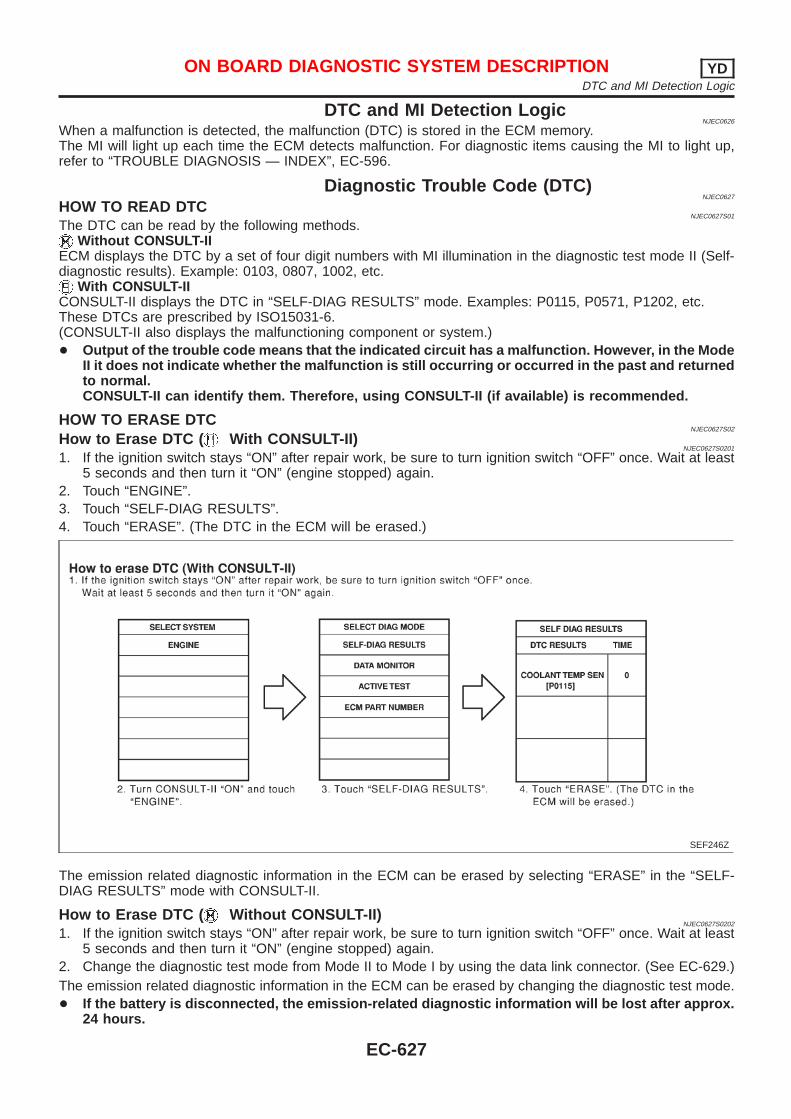
DTC and MI Detection LogicNJEC0626
When a malfunction is detected, the malfunction (DTC) is stored in the ECM memory.The MI will light up each time the ECM detects malfunction. For diagnostic items causing the MI to light up,refer to “TROUBLE DIAGNOSIS — INDEX”, EC-596.
Diagnostic Trouble Code (DTC)NJEC0627
HOW TO READ DTCNJEC0627S01
The DTC can be read by the following methods.Without CONSULT-II
ECM displays the DTC by a set of four digit numbers with MI illumination in the diagnostic test mode II (Self-diagnostic results). Example: 0103, 0807, 1002, etc.
With CONSULT-IICONSULT-II displays the DTC in “SELF-DIAG RESULTS” mode. Examples: P0115, P0571, P1202, etc.These DTCs are prescribed by ISO15031-6.(CONSULT-II also displays the malfunctioning component or system.)+ Output of the trouble code means that the indicated circuit has a malfunction. However, in the Mode
II it does not indicate whether the malfunction is still occurring or occurred in the past and returnedto normal.CONSULT-II can identify them. Therefore, using CONSULT-II (if available) is recommended.
HOW TO ERASE DTCNJEC0627S02
How to Erase DTC ( With CONSULT-II)NJEC0627S0201
1. If the ignition switch stays “ON” after repair work, be sure to turn ignition switch “OFF” once. Wait at least5 seconds and then turn it “ON” (engine stopped) again.
2. Touch “ENGINE”.3. Touch “SELF-DIAG RESULTS”.4. Touch “ERASE”. (The DTC in the ECM will be erased.)
SEF246Z
The emission related diagnostic information in the ECM can be erased by selecting “ERASE” in the “SELF-DIAG RESULTS” mode with CONSULT-II.
How to Erase DTC ( Without CONSULT-II)NJEC0627S0202
1. If the ignition switch stays “ON” after repair work, be sure to turn ignition switch “OFF” once. Wait at least5 seconds and then turn it “ON” (engine stopped) again.
2. Change the diagnostic test mode from Mode II to Mode I by using the data link connector. (See EC-629.)The emission related diagnostic information in the ECM can be erased by changing the diagnostic test mode.+ If the battery is disconnected, the emission-related diagnostic information will be lost after approx.
24 hours.
ON BOARD DIAGNOSTIC SYSTEM DESCRIPTION YDDTC and MI Detection Logic
EC-627
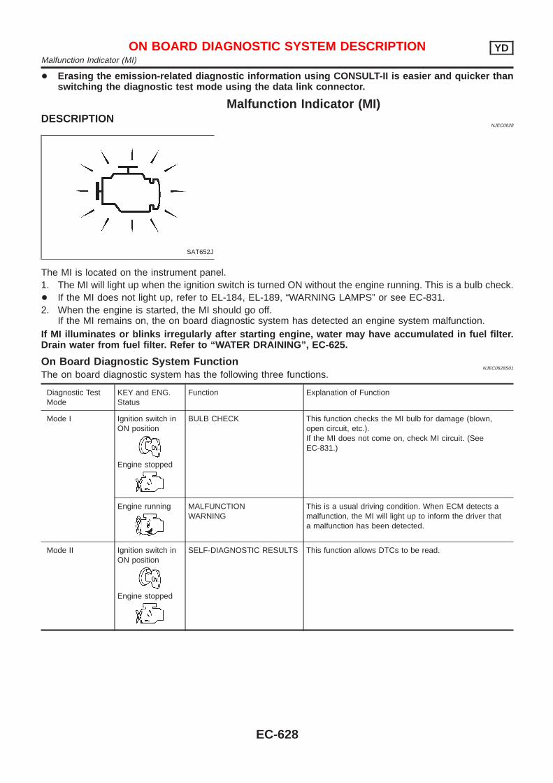
+ Erasing the emission-related diagnostic information using CONSULT-II is easier and quicker thanswitching the diagnostic test mode using the data link connector.
Malfunction Indicator (MI)DESCRIPTION
NJEC0628
SAT652J
The MI is located on the instrument panel.1. The MI will light up when the ignition switch is turned ON without the engine running. This is a bulb check.+ If the MI does not light up, refer to EL-184, EL-189, “WARNING LAMPS” or see EC-831.2. When the engine is started, the MI should go off.
If the MI remains on, the on board diagnostic system has detected an engine system malfunction.If MI illuminates or blinks irregularly after starting engine, water may have accumulated in fuel filter.Drain water from fuel filter. Refer to “WATER DRAINING”, EC-625.
On Board Diagnostic System FunctionNJEC0628S01
The on board diagnostic system has the following three functions.
Diagnostic TestMode
KEY and ENG.Status
Function Explanation of Function
Mode I Ignition switch inON position
Engine stopped
BULB CHECK This function checks the MI bulb for damage (blown,open circuit, etc.).If the MI does not come on, check MI circuit. (SeeEC-831.)
Engine running MALFUNCTIONWARNING
This is a usual driving condition. When ECM detects amalfunction, the MI will light up to inform the driver thata malfunction has been detected.
Mode II Ignition switch inON position
Engine stopped
SELF-DIAGNOSTIC RESULTS This function allows DTCs to be read.
ON BOARD DIAGNOSTIC SYSTEM DESCRIPTION YDMalfunction Indicator (MI)
EC-628
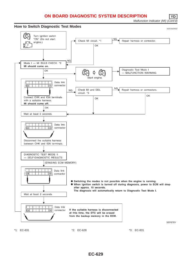
How to Switch Diagnostic Test ModesNJEC0628S02
SEF878Y
*1: EC-831 *2: EC-628 *3: EC-831
ON BOARD DIAGNOSTIC SYSTEM DESCRIPTION YDMalfunction Indicator (MI) (Cont’d)
EC-629
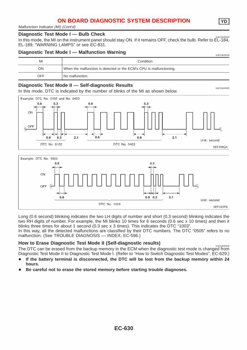
Diagnostic Test Mod e I — Bulb CheckNJEC0628S03
In this mode, the MI on the instrument panel should stay ON. If it remains OFF, check the bulb. Refer to EL-184,EL-189, “WARNING LAMPS” or see EC-831.
Diagnostic Test Mod e I — Malfunction WarningNJEC0628S04
MI Condition
ON When the malfunction is detected or the ECM’s CPU is malfunctioning.
OFF No malfunction.
Diagnostic Test Mode II — Self-diagnostic ResultsNJEC0628S05
In this mode, DTC is indicated by the number of blinks of the MI as shown below.
SEF298QA
SEF162PB
Long (0.6 second) blinking indicates the two LH digits of number and short (0.3 second) blinking indicates thetwo RH digits of number. For example, the MI blinks 10 times for 6 seconds (0.6 sec x 10 times) and then itblinks three times for about 1 second (0.3 sec x 3 times). This indicates the DTC “1003”.In this way, all the detected malfunctions are classified by their DTC numbers. The DTC “0505” refers to nomalfunction. (See TROUBLE DIAGNOSIS — INDEX, EC-596.)
How to Erase Diagnostic Test Mode II (Self-diagnostic results)NJEC0628S06
The DTC can be erased from the backup memory in the ECM when the diagnostic test mode is changed fromDiagnostic Test Mode II to Diagnostic Test Mode I. (Refer to “How to Switch Diagnostic Test Modes”, EC-629.)+ If the battery terminal is disconnected, the DTC will be lost from the backup memory within 24
hours.+ Be careful not to erase the stored memory before starting trouble diagnoses.
ON BOARD DIAGNOSTIC SYSTEM DESCRIPTION YDMalfunction Indicator (MI) (Cont’d)
EC-630
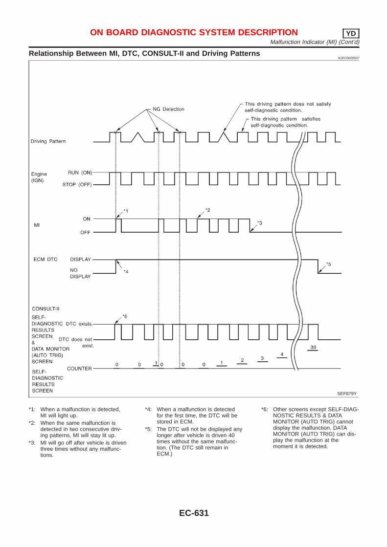
Relationship Between MI, DTC, CONSULT-II and Driving PatternsNJEC0628S07
SEF879Y
*1: When a malfunction is detected,MI will light up.
*2: When the same malfunction isdetected in two consecutive driv-ing patterns, MI will stay lit up.
*3: MI will go off after vehicle is driventhree times without any malfunc-tions.
*4: When a malfunction is detectedfor the first time, the DTC will bestored in ECM.
*5: The DTC will not be displayed anylonger after vehicle is driven 40times without the same malfunc-tion. (The DTC still remain inECM.)
*6: Other screens except SELF-DIAG-NOSTIC RESULTS & DATAMONITOR (AUTO TRIG) cannotdisplay the malfunction. DATAMONITOR (AUTO TRIG) can dis-play the malfunction at themoment it is detected.
ON BOARD DIAGNOSTIC SYSTEM DESCRIPTION YDMalfunction Indicator (MI) (Cont’d)
EC-631
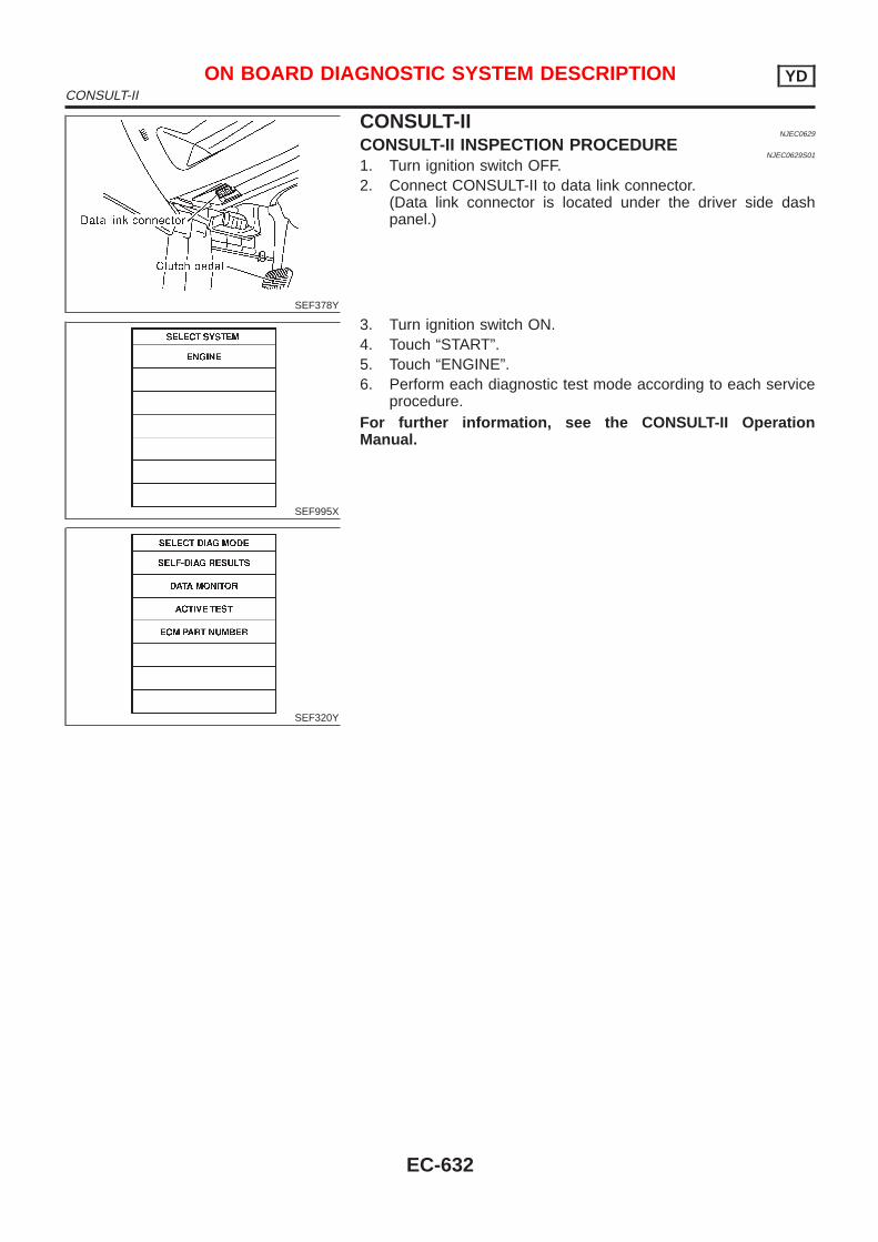
SEF378Y
CONSULT-IINJEC0629
CONSULT-II INSPECTION PROCEDURENJEC0629S01
1. Turn ignition switch OFF.2. Connect CONSULT-II to data link connector.
(Data link connector is located under the driver side dashpanel.)
SEF995X
SEF320Y
3. Turn ignition switch ON.4. Touch “START”.5. Touch “ENGINE”.6. Perform each diagnostic test mode according to each service
procedure.For further information, see the CONSULT-II OperationManual.
ON BOARD DIAGNOSTIC SYSTEM DESCRIPTION YDCONSULT-II
EC-632
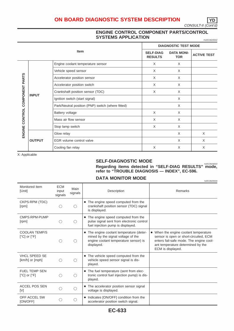
ENGINE CONTROL COMPONENT PARTS/CONTROLSYSTEMS APPLICATION
=NJEC0629S02
Item
DIAGNOSTIC TEST MODE
SELF-DIAGRESULTS
DATA MONI-TOR
ACTIVE TEST
EN
GIN
EC
ON
TR
OL
CO
MP
ON
EN
TPA
RT
S
INPUT
Engine coolant temperature sensor X X
Vehicle speed sensor X X
Accelerator position sensor X X
Accelerator position switch X X
Crankshaft position sensor (TDC) X X
Ignition switch (start signal) X
Park/Neutral position (PNP) switch (where fitted) X
Battery voltage X X
Mass air flow sensor X X
Stop lamp switch X X
OUTPUT
Glow relay X X
EGR volume control valve X X
Cooling fan relay X X X
X: Applicable
SELF-DIAGNOSTIC MODENJEC0629S03
Regarding items detected in “SELF-DIAG RESULTS” mode,refer to “TROUBLE DIAGNOSIS — INDEX”, EC-596.
DATA MONITOR MODENJEC0629S04
Monitored item[Unit]
ECMinput
signals
Mainsignals
Description Remarks
CKPS·RPM (TDC)[rpm] j j
+ The engine speed computed from thecrankshaft position sensor (TDC) signalis displayed.
CMPS·RPM·PUMP[rpm] j j
+ The engine speed computed from thepulse signal sent from electronic controlfuel injection pump is displayed.
COOLAN TEMP/S[°C] or [°F]
j j
+ The engine coolant temperature (deter-mined by the signal voltage of theengine coolant temperature sensor) isdisplayed.
+ When the engine coolant temperaturesensor is open or short-circuited, ECMenters fail-safe mode. The engine cool-ant temperature determined by theECM is displayed.
VHCL SPEED SE[km/h] or [mph] j j
+ The vehicle speed computed from thevehicle speed sensor signal is dis-played.
FUEL TEMP SEN[°C] or [°F] j j
+ The fuel temperature (sent from elec-tronic control fuel injection pump) is dis-played.
ACCEL POS SEN[V]
j j+ The accelerator position sensor signal
voltage is displayed.
OFF ACCEL SW[ON/OFF]
j j+ Indicates [ON/OFF] condition from the
accelerator position switch signal.
ON BOARD DIAGNOSTIC SYSTEM DESCRIPTION YDCONSULT-II (Cont’d)
EC-633
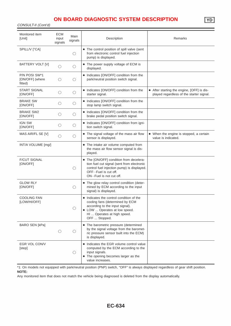
Monitored item[Unit]
ECMinput
signals
Mainsignals
Description Remarks
SPILL/V [°CA]j
+ The control position of spill valve (sentfrom electronic control fuel injectionpump) is displayed.
BATTERY VOLT [V]j j
+ The power supply voltage of ECM isdisplayed.
P/N POSI SW*1[ON/OFF] (wherefitted)
j j
+ Indicates [ON/OFF] condition from thepark/neutral position switch signal.
START SIGNAL[ON/OFF]
j j+ Indicates [ON/OFF] condition from the
starter signal.+ After starting the engine, [OFF] is dis-
played regardless of the starter signal.
BRAKE SW[ON/OFF]
j j+ Indicates [ON/OFF] condition from the
stop lamp switch signal.
BRAKE SW2[ON/OFF]
j j+ Indicates [ON/OFF] condition from the
brake pedal position switch signal.
IGN SW[ON/OFF]
j j+ Indicates [ON/OFF] condition from igni-
tion switch signal.
MAS AIR/FL SE [V]j j
+ The signal voltage of the mass air flowsensor is displayed.
+ When the engine is stopped, a certainvalue is indicated.
INT/A VOLUME [mg/] + The intake air volume computed fromthe mass air flow sensor signal is dis-played.
F/CUT SIGNAL[ON/OFF]
j
+ The [ON/OFF] condition from decelera-tion fuel cut signal (sent from electroniccontrol fuel injection pump) is displayed.OFF···Fuel is cut off.ON···Fuel is not cut off.
GLOW RLY[ON/OFF] j
+ The glow relay control condition (deter-mined by ECM according to the inputsignal) is displayed.
COOLING FAN[LOW/HI/OFF]
j
+ Indicates the control condition of thecooling fans (determined by ECMaccording to the input signal).
+ LOW ... Operates at low speed.HI ... Operates at high speed.OFF ... Stopped.
BARO SEN [kPa]
j j
+ The barometric pressure (determinedby the signal voltage from the baromet-ric pressure sensor built into the ECM)is displayed.
EGR VOL CON/V[step]
j
+ Indicates the EGR volume control valuecomputed by the ECM according to theinput signals.
+ The opening becomes larger as thevalue increases.
*1: On models not equipped with park/neutral position (PNP) switch, “OFF” is always displayed regardless of gear shift position.NOTE:Any monitored item that does not match the vehicle being diagnosed is deleted from the display automatically.
ON BOARD DIAGNOSTIC SYSTEM DESCRIPTION YDCONSULT-II (Cont’d)
EC-634
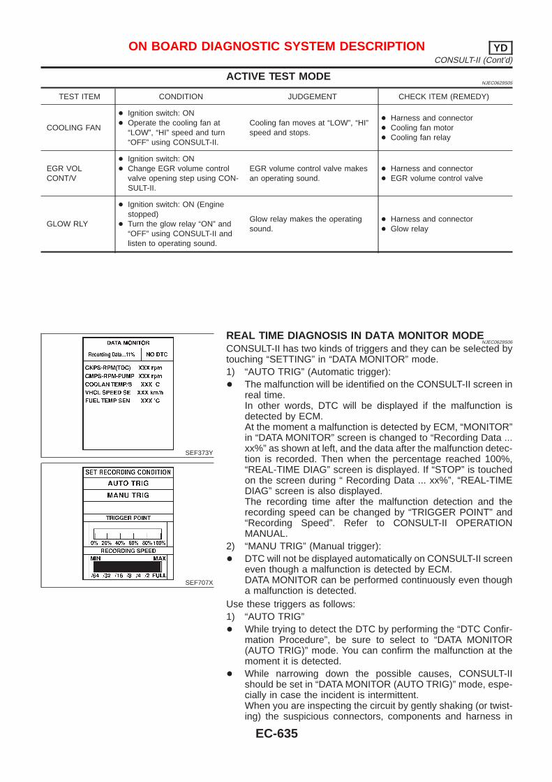
ACTIVE TEST MODENJEC0629S05
TEST ITEM CONDITION JUDGEMENT CHECK ITEM (REMEDY)
COOLING FAN
+ Ignition switch: ON+ Operate the cooling fan at
“LOW”, “HI” speed and turn“OFF” using CONSULT-II.
Cooling fan moves at “LOW”, “HI”speed and stops.
+ Harness and connector+ Cooling fan motor+ Cooling fan relay
EGR VOLCONT/V
+ Ignition switch: ON+ Change EGR volume control
valve opening step using CON-SULT-II.
EGR volume control valve makesan operating sound.
+ Harness and connector+ EGR volume control valve
GLOW RLY
+ Ignition switch: ON (Enginestopped)
+ Turn the glow relay “ON” and“OFF” using CONSULT-II andlisten to operating sound.
Glow relay makes the operatingsound.
+ Harness and connector+ Glow relay
SEF373Y
SEF707X
REAL TIME DIAGNOSIS IN DATA MONITOR MODENJEC0629S06
CONSULT-II has two kinds of triggers and they can be selected bytouching “SETTING” in “DATA MONITOR” mode.1) “AUTO TRIG” (Automatic trigger):+ The malfunction will be identified on the CONSULT-II screen in
real time.In other words, DTC will be displayed if the malfunction isdetected by ECM.At the moment a malfunction is detected by ECM, “MONITOR”in “DATA MONITOR” screen is changed to “Recording Data ...xx%” as shown at left, and the data after the malfunction detec-tion is recorded. Then when the percentage reached 100%,“REAL-TIME DIAG” screen is displayed. If “STOP” is touchedon the screen during “ Recording Data ... xx%”, “REAL-TIMEDIAG” screen is also displayed.The recording time after the malfunction detection and therecording speed can be changed by “TRIGGER POINT” and“Recording Speed”. Refer to CONSULT-II OPERATIONMANUAL.
2) “MANU TRIG” (Manual trigger):+ DTC will not be displayed automatically on CONSULT-II screen
even though a malfunction is detected by ECM.DATA MONITOR can be performed continuously even thougha malfunction is detected.
Use these triggers as follows:1) “AUTO TRIG”+ While trying to detect the DTC by performing the “DTC Confir-
mation Procedure”, be sure to select to “DATA MONITOR(AUTO TRIG)” mode. You can confirm the malfunction at themoment it is detected.
+ While narrowing down the possible causes, CONSULT-IIshould be set in “DATA MONITOR (AUTO TRIG)” mode, espe-cially in case the incident is intermittent.When you are inspecting the circuit by gently shaking (or twist-ing) the suspicious connectors, components and harness in
ON BOARD DIAGNOSTIC SYSTEM DESCRIPTION YDCONSULT-II (Cont’d)
EC-635
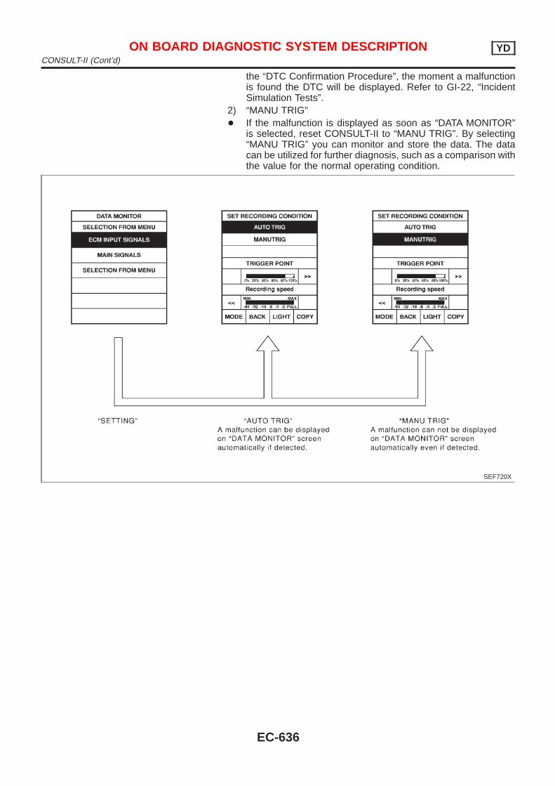
the “DTC Confirmation Procedure”, the moment a malfunctionis found the DTC will be displayed. Refer to GI-22, “IncidentSimulation Tests”.
2) “MANU TRIG”+ If the malfunction is displayed as soon as “DATA MONITOR”
is selected, reset CONSULT-II to “MANU TRIG”. By selecting“MANU TRIG” you can monitor and store the data. The datacan be utilized for further diagnosis, such as a comparison withthe value for the normal operating condition.
SEF720X
ON BOARD DIAGNOSTIC SYSTEM DESCRIPTION YDCONSULT-II (Cont’d)
EC-636
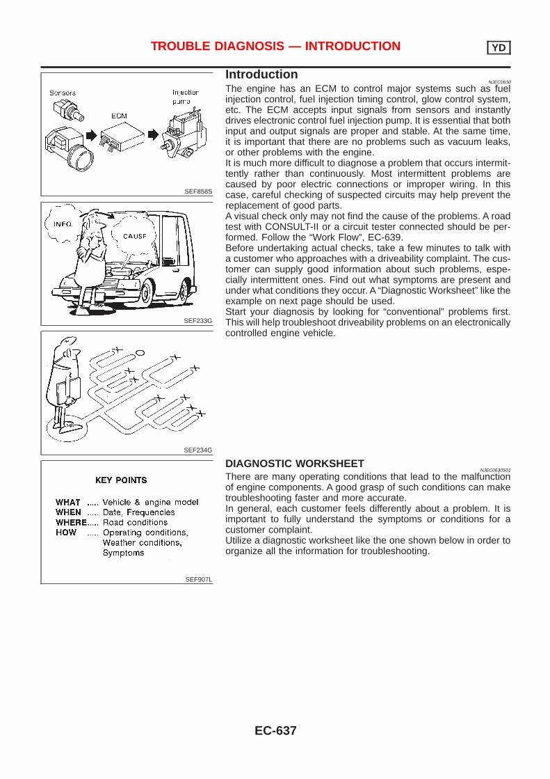
SEF858S
SEF233G
SEF234G
IntroductionNJEC0630
The engine has an ECM to control major systems such as fuelinjection control, fuel injection timing control, glow control system,etc. The ECM accepts input signals from sensors and instantlydrives electronic control fuel injection pump. It is essential that bothinput and output signals are proper and stable. At the same time,it is important that there are no problems such as vacuum leaks,or other problems with the engine.It is much more difficult to diagnose a problem that occurs intermit-tently rather than continuously. Most intermittent problems arecaused by poor electric connections or improper wiring. In thiscase, careful checking of suspected circuits may help prevent thereplacement of good parts.A visual check only may not find the cause of the problems. A roadtest with CONSULT-II or a circuit tester connected should be per-formed. Follow the “Work Flow”, EC-639.Before undertaking actual checks, take a few minutes to talk witha customer who approaches with a driveability complaint. The cus-tomer can supply good information about such problems, espe-cially intermittent ones. Find out what symptoms are present andunder what conditions they occur. A “Diagnostic Worksheet” like theexample on next page should be used.Start your diagnosis by looking for “conventional” problems first.This will help troubleshoot driveability problems on an electronicallycontrolled engine vehicle.
SEF907L
DIAGNOSTIC WORKSHEETNJEC0630S01
There are many operating conditions that lead to the malfunctionof engine components. A good grasp of such conditions can maketroubleshooting faster and more accurate.In general, each customer feels differently about a problem. It isimportant to fully understand the symptoms or conditions for acustomer complaint.Utilize a diagnostic worksheet like the one shown below in order toorganize all the information for troubleshooting.
TROUBLE DIAGNOSIS — INTRODUCTION YD
EC-637
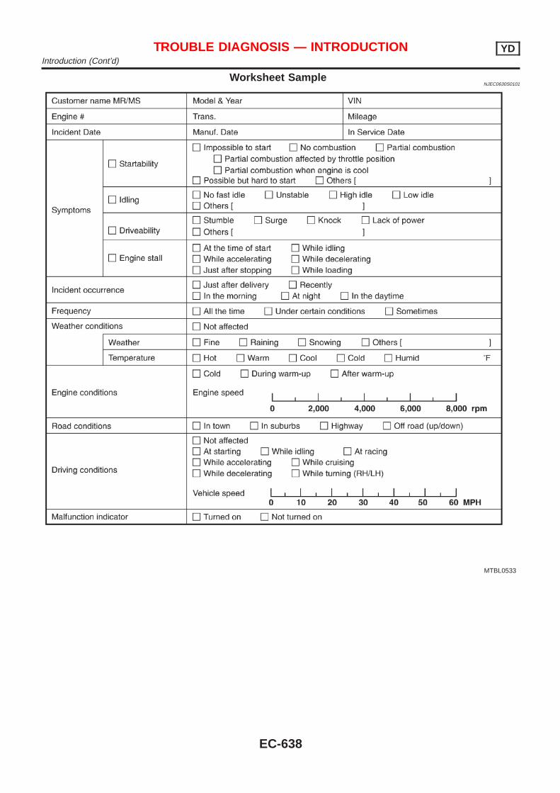
Worksheet SampleNJEC0630S0101
MTBL0533
TROUBLE DIAGNOSIS — INTRODUCTION YDIntroduction (Cont’d)
EC-638
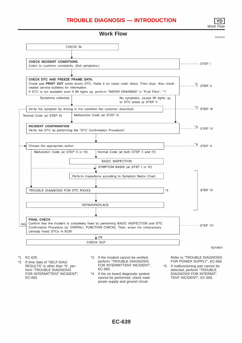
Work FlowNJEC0631
SEF880Y
*1 EC-625*2 If time data of “SELF-DIAG
RESULTS” is other than “0”, per-form “TROUBLE DIAGNOSISFOR INTERMITTENT INCIDENT”,EC-665.
*3 If the incident cannot be verified,perform “TROUBLE DIAGNOSISFOR INTERMITTENT INCIDENT”,EC-665.
*4 If the on board diagnostic systemcannot be performed, check mainpower supply and ground circuit.
Refer to “TROUBLE DIAGNOSISFOR POWER SUPPLY”, EC-666.
*5 If malfunctioning part cannot bedetected, perform “TROUBLEDIAGNOSIS FOR INTERMIT-TENT INCIDENT”, EC-665.
TROUBLE DIAGNOSIS — INTRODUCTION YDWork Flow
EC-639
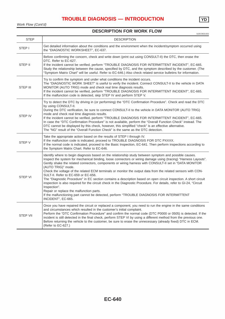
DESCRIPTION FOR WORK FLOWNJEC0631S01
STEP DESCRIPTION
STEP IGet detailed information about the conditions and the environment when the incident/symptom occurred usingthe “DIAGNOSTIC WORKSHEET”, EC-637.
STEP II
Before confirming the concern, check and write down (print out using CONSULT-II) the DTC, then erase theDTC. Refer to EC-627.If the incident cannot be verified, perform “TROUBLE DIAGNOSIS FOR INTERMITTENT INCIDENT”, EC-665.Study the relationship between the cause, specified by DTC, and the symptom described by the customer. (The“Symptom Matrix Chart” will be useful. Refer to EC-646.) Also check related service bulletins for information.
STEP III
Try to confirm the symptom and under what conditions the incident occurs.The “DIAGNOSTIC WORK SHEET” is useful to verify the incident. Connect CONSULT-II to the vehicle in DATAMONITOR (AUTO TRIG) mode and check real time diagnosis results.If the incident cannot be verified, perform “TROUBLE DIAGNOSIS FOR INTERMITTENT INCIDENT”, EC-665.If the malfunction code is detected, skip STEP IV and perform STEP V.
STEP IV
Try to detect the DTC by driving in (or performing) the “DTC Confirmation Procedure”. Check and read the DTCby using CONSULT-II.During the DTC verification, be sure to connect CONSULT-II to the vehicle in DATA MONITOR (AUTO TRIG)mode and check real time diagnosis results.If the incident cannot be verified, perform “TROUBLE DIAGNOSIS FOR INTERMITTENT INCIDENT”, EC-665.In case the “DTC Confirmation Procedure” is not available, perform the “Overall Function Check” instead. TheDTC cannot be displayed by this check, however, this simplified “check” is an effective alternative.The “NG” result of the “Overall Function Check” is the same as the DTC detection.
STEP V
Take the appropriate action based on the results of STEP I through IV.If the malfunction code is indicated, proceed to TROUBLE DIAGNOSIS FOR DTC PXXXX.If the normal code is indicated, proceed to the Basic Inspection, EC-641. Then perform inspections according tothe Symptom Matrix Chart. Refer to EC-646.
STEP VI
Identify where to begin diagnosis based on the relationship study between symptom and possible causes.Inspect the system for mechanical binding, loose connectors or wiring damage using (tracing) “Harness Layouts”.Gently shake the related connectors, components or wiring harness with CONSULT-II set in “DATA MONITOR(AUTO TRIG)” mode.Check the voltage of the related ECM terminals or monitor the output data from the related sensors with CON-SULT-II. Refer to EC-659 or EC-656.The “Diagnostic Procedure” in EC section contains a description based on open circuit inspection. A short circuitinspection is also required for the circuit check in the Diagnostic Procedure. For details, refer to GI-24, “CircuitInspection”.Repair or replace the malfunction parts.If the malfunctioning part cannot be detected, perform “TROUBLE DIAGNOSIS FOR INTERMITTENTINCIDENT”, EC-665.
STEP VII
Once you have repaired the circuit or replaced a component, you need to run the engine in the same conditionsand circumstances which resulted in the customer’s initial complaint.Perform the “DTC Confirmation Procedure” and confirm the normal code (DTC P0000 or 0505) is detected. If theincident is still detected in the final check, perform STEP VI by using a different method from the previous one.Before returning the vehicle to the customer, be sure to erase the unnecessary (already fixed) DTC in ECM.(Refer to EC-627.)
TROUBLE DIAGNOSIS — INTRODUCTION YDWork Flow (Cont’d)
EC-640
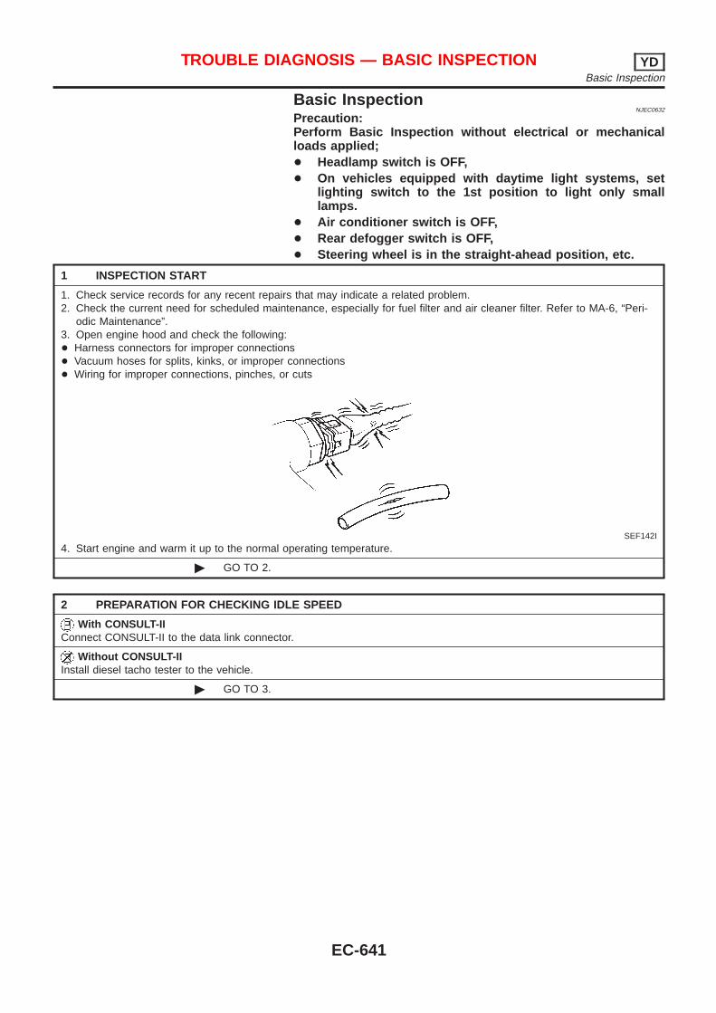
Basic InspectionNJEC0632
Precaution:Perform Basic Inspection without electrical or mechanicalloads applied;+ Headlamp switch is OFF,+ On vehicles equipped with daytime light systems, set
lighting switch to the 1st position to light only smalllamps.
+ Air conditioner switch is OFF,+ Rear defogger switch is OFF,+ Steering wheel is in the straight-ahead position, etc.
1 INSPECTION START
1. Check service records for any recent repairs that may indicate a related problem.2. Check the current need for scheduled maintenance, especially for fuel filter and air cleaner filter. Refer to MA-6, “Peri-
odic Maintenance”.3. Open engine hood and check the following:+ Harness connectors for improper connections+ Vacuum hoses for splits, kinks, or improper connections+ Wiring for improper connections, pinches, or cuts
SEF142I
4. Start engine and warm it up to the normal operating temperature.
© GO TO 2.
2 PREPARATION FOR CHECKING IDLE SPEED
With CONSULT-IIConnect CONSULT-II to the data link connector.
Without CONSULT-IIInstall diesel tacho tester to the vehicle.
© GO TO 3.
TROUBLE DIAGNOSIS — BASIC INSPECTION YDBasic Inspection
EC-641
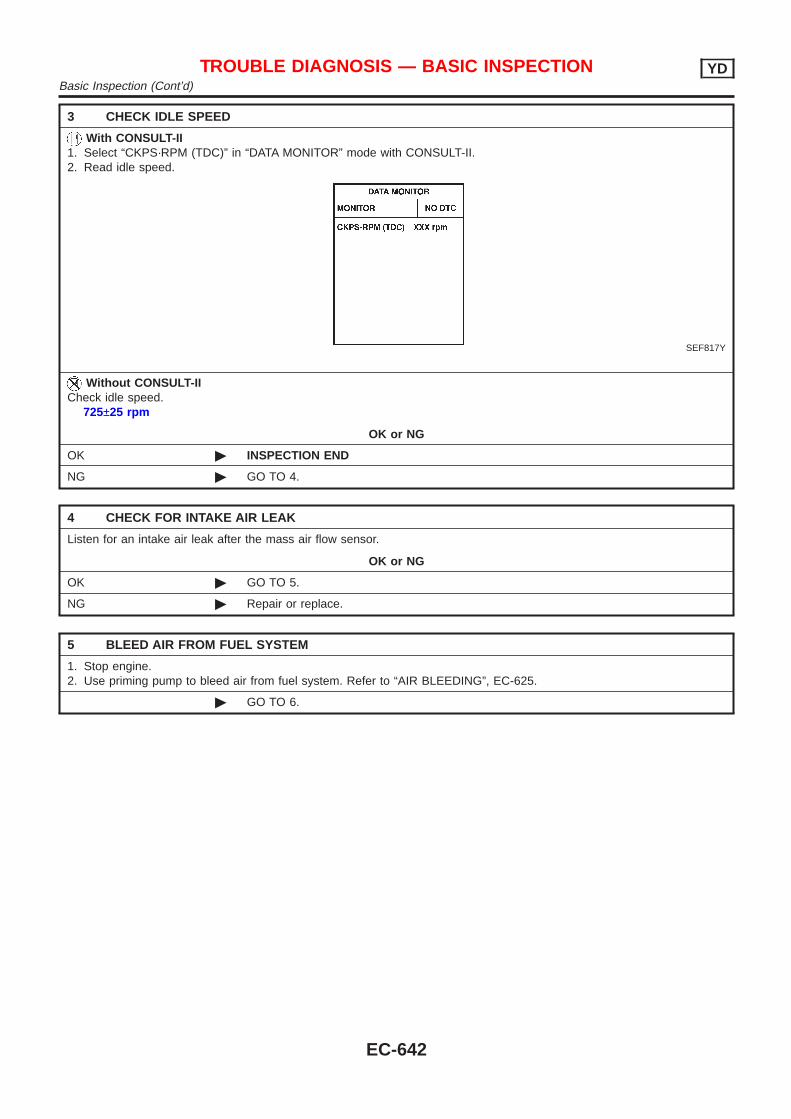
3 CHECK IDLE SPEED
With CONSULT-II1. Select “CKPS·RPM (TDC)” in “DATA MONITOR” mode with CONSULT-II.2. Read idle speed.
SEF817Y
Without CONSULT-IICheck idle speed.
725±25 rpm
OK or NG
OK © INSPECTION END
NG © GO TO 4.
4 CHECK FOR INTAKE AIR LEAK
Listen for an intake air leak after the mass air flow sensor.
OK or NG
OK © GO TO 5.
NG © Repair or replace.
5 BLEED AIR FROM FUEL SYSTEM
1. Stop engine.2. Use priming pump to bleed air from fuel system. Refer to “AIR BLEEDING”, EC-625.
© GO TO 6.
TROUBLE DIAGNOSIS — BASIC INSPECTION YDBasic Inspection (Cont’d)
EC-642
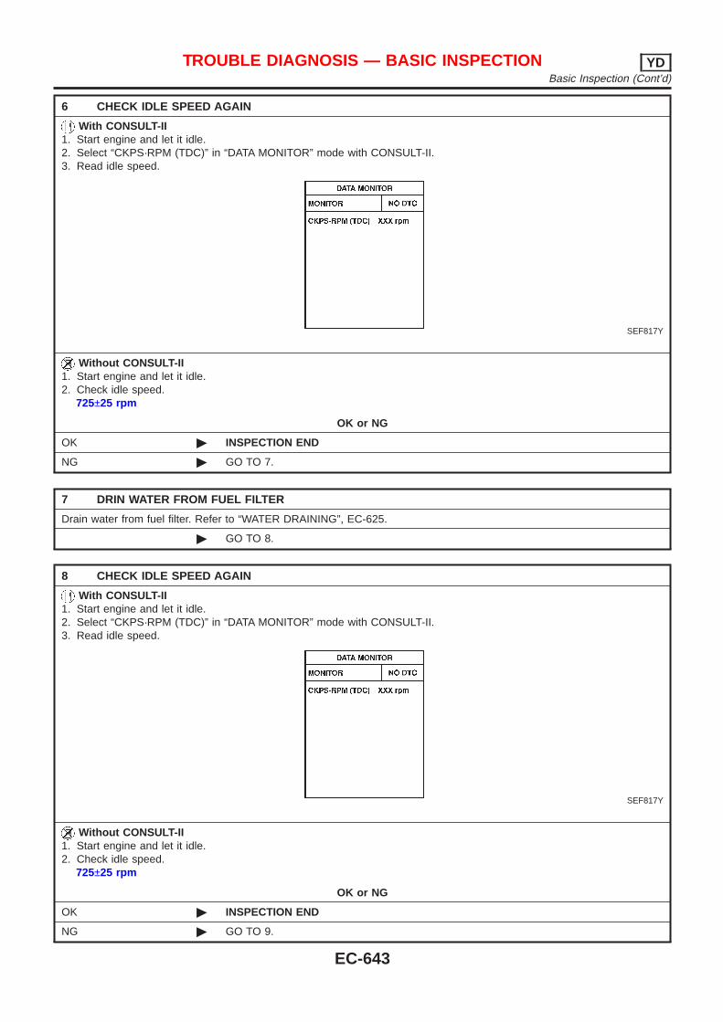
6 CHECK IDLE SPEED AGAIN
With CONSULT-II1. Start engine and let it idle.2. Select “CKPS·RPM (TDC)” in “DATA MONITOR” mode with CONSULT-II.3. Read idle speed.
SEF817Y
Without CONSULT-II1. Start engine and let it idle.2. Check idle speed.
725±25 rpm
OK or NG
OK © INSPECTION END
NG © GO TO 7.
7 DRIN WATER FROM FUEL FILTER
Drain water from fuel filter. Refer to “WATER DRAINING”, EC-625.
© GO TO 8.
8 CHECK IDLE SPEED AGAIN
With CONSULT-II1. Start engine and let it idle.2. Select “CKPS·RPM (TDC)” in “DATA MONITOR” mode with CONSULT-II.3. Read idle speed.
SEF817Y
Without CONSULT-II1. Start engine and let it idle.2. Check idle speed.
725±25 rpm
OK or NG
OK © INSPECTION END
NG © GO TO 9.
TROUBLE DIAGNOSIS — BASIC INSPECTION YDBasic Inspection (Cont’d)
EC-643
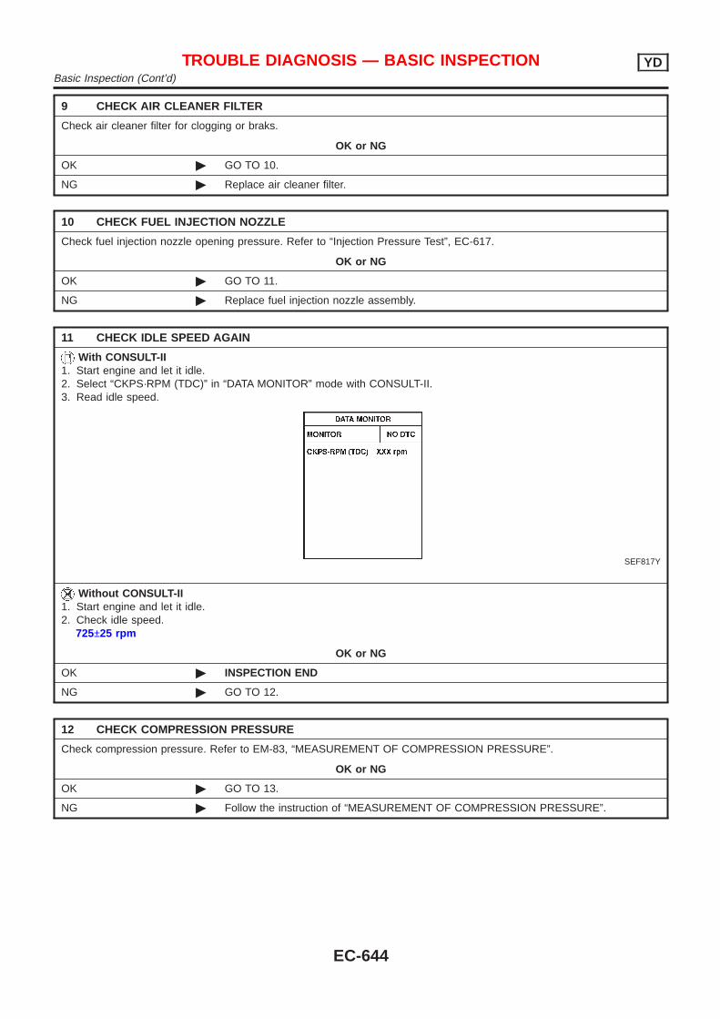
9 CHECK AIR CLEANER FILTER
Check air cleaner filter for clogging or braks.
OK or NG
OK © GO TO 10.
NG © Replace air cleaner filter.
10 CHECK FUEL INJECTION NOZZLE
Check fuel injection nozzle opening pressure. Refer to “Injection Pressure Test”, EC-617.
OK or NG
OK © GO TO 11.
NG © Replace fuel injection nozzle assembly.
11 CHECK IDLE SPEED AGAIN
With CONSULT-II1. Start engine and let it idle.2. Select “CKPS·RPM (TDC)” in “DATA MONITOR” mode with CONSULT-II.3. Read idle speed.
SEF817Y
Without CONSULT-II1. Start engine and let it idle.2. Check idle speed.
725±25 rpm
OK or NG
OK © INSPECTION END
NG © GO TO 12.
12 CHECK COMPRESSION PRESSURE
Check compression pressure. Refer to EM-83, “MEASUREMENT OF COMPRESSION PRESSURE”.
OK or NG
OK © GO TO 13.
NG © Follow the instruction of “MEASUREMENT OF COMPRESSION PRESSURE”.
TROUBLE DIAGNOSIS — BASIC INSPECTION YDBasic Inspection (Cont’d)
EC-644
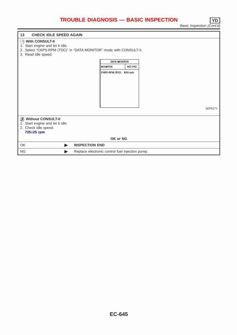
13 CHECK IDLE SPEED AGAIN
With CONSULT-II1. Start engine and let it idle.2. Select “CKPS·RPM (TDC)” in “DATA MONITOR” mode with CONSULT-II.3. Read idle speed.
SEF817Y
Without CONSULT-II1. Start engine and let it idle.2. Check idle speed.
725±25 rpm
OK or NG
OK © INSPECTION END
NG © Replace electronic control fuel injection pump.
TROUBLE DIAGNOSIS — BASIC INSPECTION YDBasic Inspection (Cont’d)
EC-645
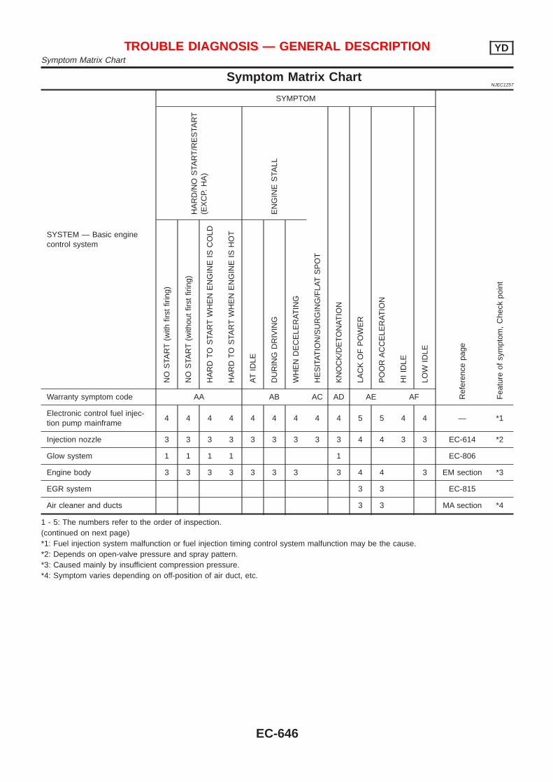
Symptom Matrix ChartNJEC1257
SYSTEM — Basic enginecontrol system
SYMPTOM
Ref
eren
cepa
ge
Fea
ture
ofsy
mpt
om,
Che
ckpo
int
HA
RD
/NO
STA
RT
/RE
STA
RT
(EX
CP.
HA
)
EN
GIN
ES
TALL
HE
SIT
AT
ION
/SU
RG
ING
/FLA
TS
PO
T
KN
OC
K/D
ET
ON
AT
ION
LAC
KO
FP
OW
ER
PO
OR
AC
CE
LER
AT
ION
HI
IDLE
LOW
IDLE
NO
STA
RT
(with
first
firin
g)
NO
STA
RT
(with
out
first
firin
g)
HA
RD
TO
STA
RT
WH
EN
EN
GIN
EIS
CO
LD
HA
RD
TO
STA
RT
WH
EN
EN
GIN
EIS
HO
T
AT
IDLE
DU
RIN
GD
RIV
ING
WH
EN
DE
CE
LER
AT
ING
Warranty symptom code AA AB AC AD AE AF
Electronic control fuel injec-tion pump mainframe
4 4 4 4 4 4 4 4 4 5 5 4 4 — *1
Injection nozzle 3 3 3 3 3 3 3 3 3 4 4 3 3 EC-614 *2
Glow system 1 1 1 1 1 EC-806
Engine body 3 3 3 3 3 3 3 3 4 4 3 EM section *3
EGR system 3 3 EC-815
Air cleaner and ducts 3 3 MA section *4
1 - 5: The numbers refer to the order of inspection.(continued on next page)*1: Fuel injection system malfunction or fuel injection timing control system malfunction may be the cause.*2: Depends on open-valve pressure and spray pattern.*3: Caused mainly by insufficient compression pressure.*4: Symptom varies depending on off-position of air duct, etc.
TROUBLE DIAGNOSIS — GENERAL DESCRIPTION YDSymptom Matrix Chart
EC-646
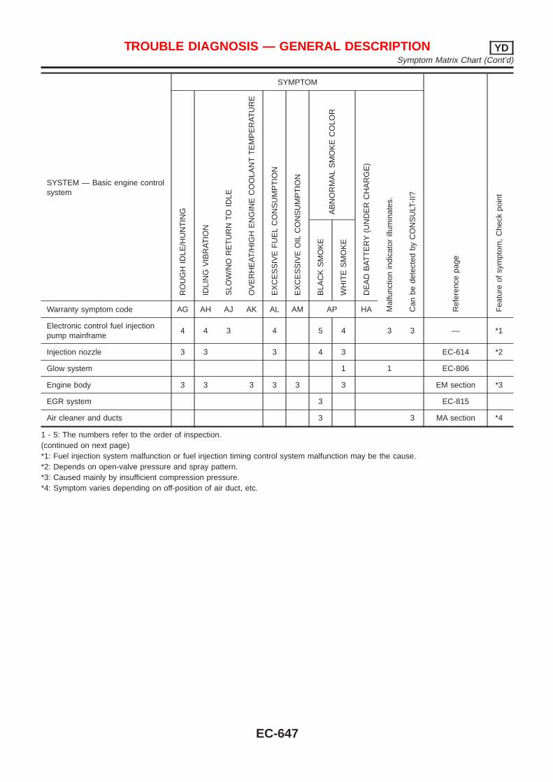
SYSTEM — Basic engine controlsystem
SYMPTOM
Ref
eren
cepa
ge
Fea
ture
ofsy
mpt
om,
Che
ckpo
int
RO
UG
HID
LE/H
UN
TIN
G
IDLI
NG
VIB
RA
TIO
N
SLO
W/N
OR
ET
UR
NT
OID
LE
OV
ER
HE
AT
/HIG
HE
NG
INE
CO
OLA
NT
TE
MP
ER
AT
UR
E
EX
CE
SS
IVE
FU
EL
CO
NS
UM
PT
ION
EX
CE
SS
IVE
OIL
CO
NS
UM
PT
ION
AB
NO
RM
AL
SM
OK
EC
OLO
R
DE
AD
BA
TT
ER
Y(U
ND
ER
CH
AR
GE
)
Mal
func
tion
indi
cato
rill
umin
ates
.
Can
bede
tect
edby
CO
NS
ULT
-II?
BLA
CK
SM
OK
E
WH
ITE
SM
OK
E
Warranty symptom code AG AH AJ AK AL AM AP HA
Electronic control fuel injectionpump mainframe
4 4 3 4 5 4 3 3 — *1
Injection nozzle 3 3 3 4 3 EC-614 *2
Glow system 1 1 EC-806
Engine body 3 3 3 3 3 3 EM section *3
EGR system 3 EC-815
Air cleaner and ducts 3 3 MA section *4
1 - 5: The numbers refer to the order of inspection.(continued on next page)*1: Fuel injection system malfunction or fuel injection timing control system malfunction may be the cause.*2: Depends on open-valve pressure and spray pattern.*3: Caused mainly by insufficient compression pressure.*4: Symptom varies depending on off-position of air duct, etc.
TROUBLE DIAGNOSIS — GENERAL DESCRIPTION YDSymptom Matrix Chart (Cont’d)
EC-647
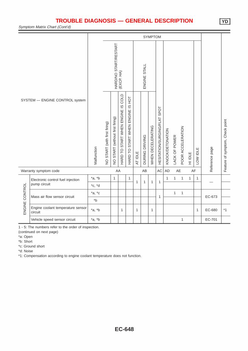
SYSTEM — ENGINE CONTROL systemM
alfu
nctio
n
SYMPTOM
Ref
eren
cepa
ge
Fea
ture
ofsy
mpt
om,
Che
ckpo
int
HA
RD
/NO
STA
RT
/RE
STA
RT
(EX
CP.
HA
)
EN
GIN
ES
TALL
HE
SIT
AT
ION
/SU
RG
ING
/FLA
TS
PO
T
KN
OC
K/D
ET
ON
AT
ION
LAC
KO
FP
OW
ER
PO
OR
AC
CE
LER
AT
ION
HI
IDLE
LOW
IDLE
NO
STA
RT
(with
first
firin
g)
NO
STA
RT
(with
out
first
firin
g)
HA
RD
TO
STA
RT
WH
EN
EN
GIN
EIS
CO
LD
HA
RD
TO
STA
RT
WH
EN
EN
GIN
EIS
HO
T
AT
IDLE
DU
RIN
GD
RIV
ING
WH
EN
DE
CE
LER
AT
ING
Warranty symptom code AA AB AC AD AE AF
EN
GIN
EC
ON
TR
OL
Electronic control fuel injectionpump circuit
*a, *b 1 11 1 1 1
1 1 1 1 1—
*c, *d
Mass air flow sensor circuit*a, *c
11 1
EC-673*b
Engine coolant temperature sensorcircuit
*a, *b 1 1 1 1 EC-680 *1
Vehicle speed sensor circuit *a, *b 1 EC-701
1 - 5: The numbers refer to the order of inspection.(continued on next page)*a: Open*b: Short*c: Ground short*d: Noise*1: Compensation according to engine coolant temperature does not function.
TROUBLE DIAGNOSIS — GENERAL DESCRIPTION YDSymptom Matrix Chart (Cont’d)
EC-648
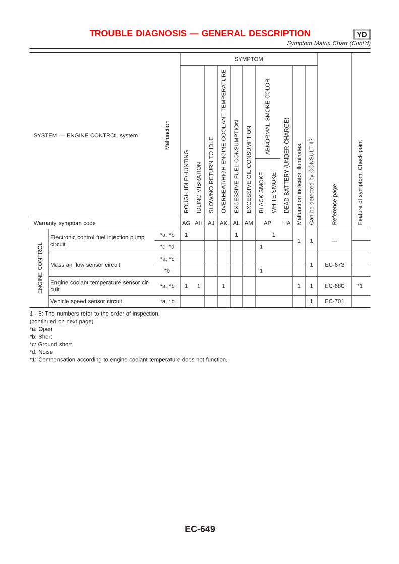
SYSTEM — ENGINE CONTROL system
Mal
func
tion
SYMPTOM
Ref
eren
cepa
ge
Fea
ture
ofsy
mpt
om,
Che
ckpo
int
RO
UG
HID
LE/H
UN
TIN
G
IDLI
NG
VIB
RA
TIO
N
SLO
W/N
OR
ET
UR
NT
OID
LE
OV
ER
HE
AT
/HIG
HE
NG
INE
CO
OLA
NT
TE
MP
ER
AT
UR
E
EX
CE
SS
IVE
FU
EL
CO
NS
UM
PT
ION
EX
CE
SS
IVE
OIL
CO
NS
UM
PT
ION
AB
NO
RM
AL
SM
OK
EC
OLO
R
DE
AD
BA
TT
ER
Y(U
ND
ER
CH
AR
GE
)
Mal
func
tion
indi
cato
rill
umin
ates
.
Can
bede
tect
edby
CO
NS
ULT
-II?
BLA
CK
SM
OK
E
WH
ITE
SM
OK
E
Warranty symptom code AG AH AJ AK AL AM AP HA
EN
GIN
EC
ON
TR
OL
Electronic control fuel injection pumpcircuit
*a, *b 1 1 11 1 —
*c, *d 1
Mass air flow sensor circuit*a, *c
1 EC-673*b 1
Engine coolant temperature sensor cir-cuit
*a, *b 1 1 1 1 1 EC-680 *1
Vehicle speed sensor circuit *a, *b 1 EC-701
1 - 5: The numbers refer to the order of inspection.(continued on next page)*a: Open*b: Short*c: Ground short*d: Noise*1: Compensation according to engine coolant temperature does not function.
TROUBLE DIAGNOSIS — GENERAL DESCRIPTION YDSymptom Matrix Chart (Cont’d)
EC-649
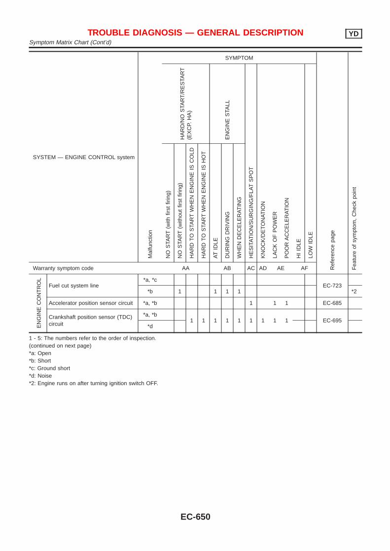
SYSTEM — ENGINE CONTROL systemM
alfu
nctio
n
SYMPTOM
Ref
eren
cepa
ge
Fea
ture
ofsy
mpt
om,
Che
ckpo
int
HA
RD
/NO
STA
RT
/RE
STA
RT
(EX
CP.
HA
)
EN
GIN
ES
TALL
HE
SIT
AT
ION
/SU
RG
ING
/FLA
TS
PO
T
KN
OC
K/D
ET
ON
AT
ION
LAC
KO
FP
OW
ER
PO
OR
AC
CE
LER
AT
ION
HI
IDLE
LOW
IDLE
NO
STA
RT
(with
first
firin
g)
NO
STA
RT
(with
out
first
firin
g)
HA
RD
TO
STA
RT
WH
EN
EN
GIN
EIS
CO
LD
HA
RD
TO
STA
RT
WH
EN
EN
GIN
EIS
HO
T
AT
IDLE
DU
RIN
GD
RIV
ING
WH
EN
DE
CE
LER
AT
ING
Warranty symptom code AA AB AC AD AE AF
EN
GIN
EC
ON
TR
OL
Fuel cut system line*a, *c
EC-723*b 1 1 1 1 *2
Accelerator position sensor circuit *a, *b 1 1 1 EC-685
Crankshaft position sensor (TDC)circuit
*a, *b1 1 1 1 1 1 1 1 1 EC-695
*d
1 - 5: The numbers refer to the order of inspection.(continued on next page)*a: Open*b: Short*c: Ground short*d: Noise*2: Engine runs on after turning ignition switch OFF.
TROUBLE DIAGNOSIS — GENERAL DESCRIPTION YDSymptom Matrix Chart (Cont’d)
EC-650
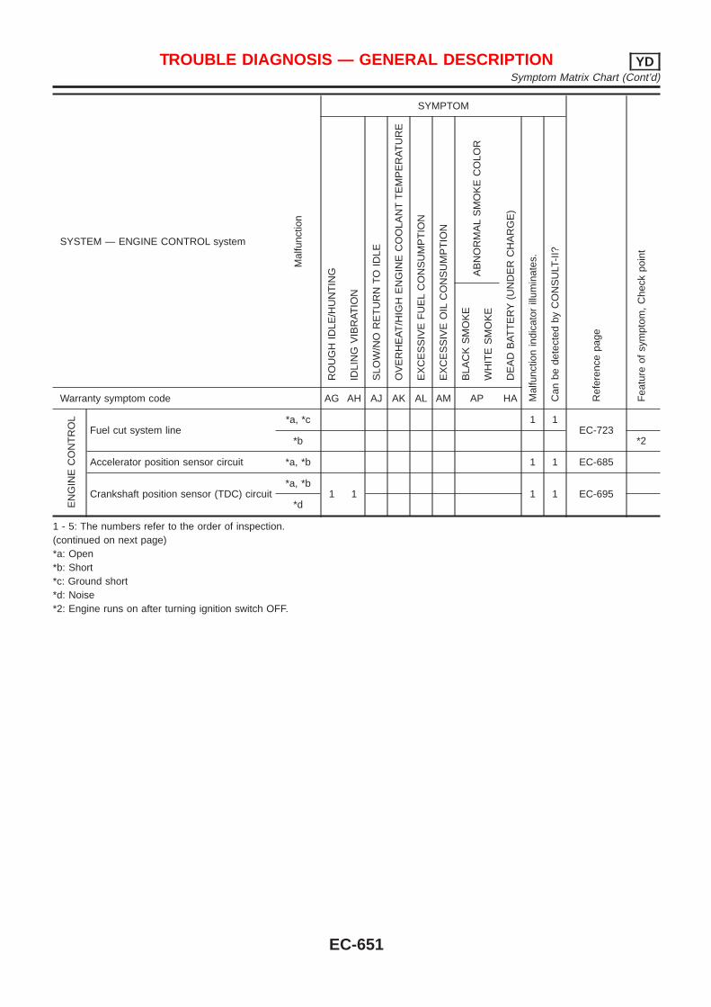
SYSTEM — ENGINE CONTROL system
Mal
func
tion
SYMPTOM
Ref
eren
cepa
ge
Fea
ture
ofsy
mpt
om,
Che
ckpo
int
RO
UG
HID
LE/H
UN
TIN
G
IDLI
NG
VIB
RA
TIO
N
SLO
W/N
OR
ET
UR
NT
OID
LE
OV
ER
HE
AT
/HIG
HE
NG
INE
CO
OLA
NT
TE
MP
ER
AT
UR
E
EX
CE
SS
IVE
FU
EL
CO
NS
UM
PT
ION
EX
CE
SS
IVE
OIL
CO
NS
UM
PT
ION
AB
NO
RM
AL
SM
OK
EC
OLO
R
DE
AD
BA
TT
ER
Y(U
ND
ER
CH
AR
GE
)
Mal
func
tion
indi
cato
rill
umin
ates
.
Can
bede
tect
edby
CO
NS
ULT
-II?
BLA
CK
SM
OK
E
WH
ITE
SM
OK
E
Warranty symptom code AG AH AJ AK AL AM AP HA
EN
GIN
EC
ON
TR
OL
Fuel cut system line*a, *c 1 1
EC-723*b *2
Accelerator position sensor circuit *a, *b 1 1 EC-685
Crankshaft position sensor (TDC) circuit*a, *b
1 1 1 1 EC-695*d
1 - 5: The numbers refer to the order of inspection.(continued on next page)*a: Open*b: Short*c: Ground short*d: Noise*2: Engine runs on after turning ignition switch OFF.
TROUBLE DIAGNOSIS — GENERAL DESCRIPTION YDSymptom Matrix Chart (Cont’d)
EC-651
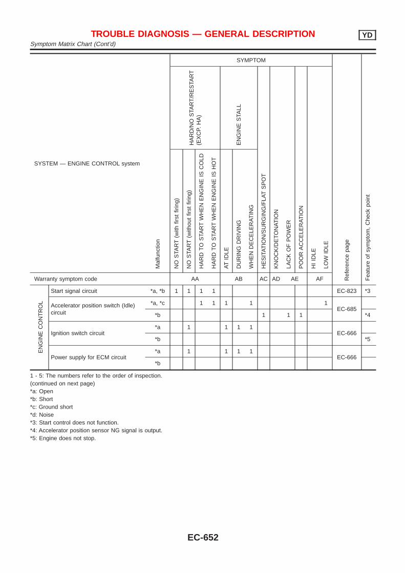
SYSTEM — ENGINE CONTROL systemM
alfu
nctio
n
SYMPTOM
Ref
eren
cepa
ge
Fea
ture
ofsy
mpt
om,
Che
ckpo
int
HA
RD
/NO
STA
RT
/RE
STA
RT
(EX
CP.
HA
)
EN
GIN
ES
TALL
HE
SIT
AT
ION
/SU
RG
ING
/FLA
TS
PO
T
KN
OC
K/D
ET
ON
AT
ION
LAC
KO
FP
OW
ER
PO
OR
AC
CE
LER
AT
ION
HI
IDLE
LOW
IDLE
NO
STA
RT
(with
first
firin
g)
NO
STA
RT
(with
out
first
firin
g)
HA
RD
TO
STA
RT
WH
EN
EN
GIN
EIS
CO
LD
HA
RD
TO
STA
RT
WH
EN
EN
GIN
EIS
HO
T
AT
IDLE
DU
RIN
GD
RIV
ING
WH
EN
DE
CE
LER
AT
ING
Warranty symptom code AA AB AC AD AE AF
EN
GIN
EC
ON
TR
OL
Start signal circuit *a, *b 1 1 1 1 EC-823 *3
Accelerator position switch (Idle)circuit
*a, *c 1 1 1 1 1EC-685
*b 1 1 1 *4
Ignition switch circuit*a 1 1 1 1
EC-666*b *5
Power supply for ECM circuit*a 1 1 1 1
EC-666*b
1 - 5: The numbers refer to the order of inspection.(continued on next page)*a: Open*b: Short*c: Ground short*d: Noise*3: Start control does not function.*4: Accelerator position sensor NG signal is output.*5: Engine does not stop.
TROUBLE DIAGNOSIS — GENERAL DESCRIPTION YDSymptom Matrix Chart (Cont’d)
EC-652
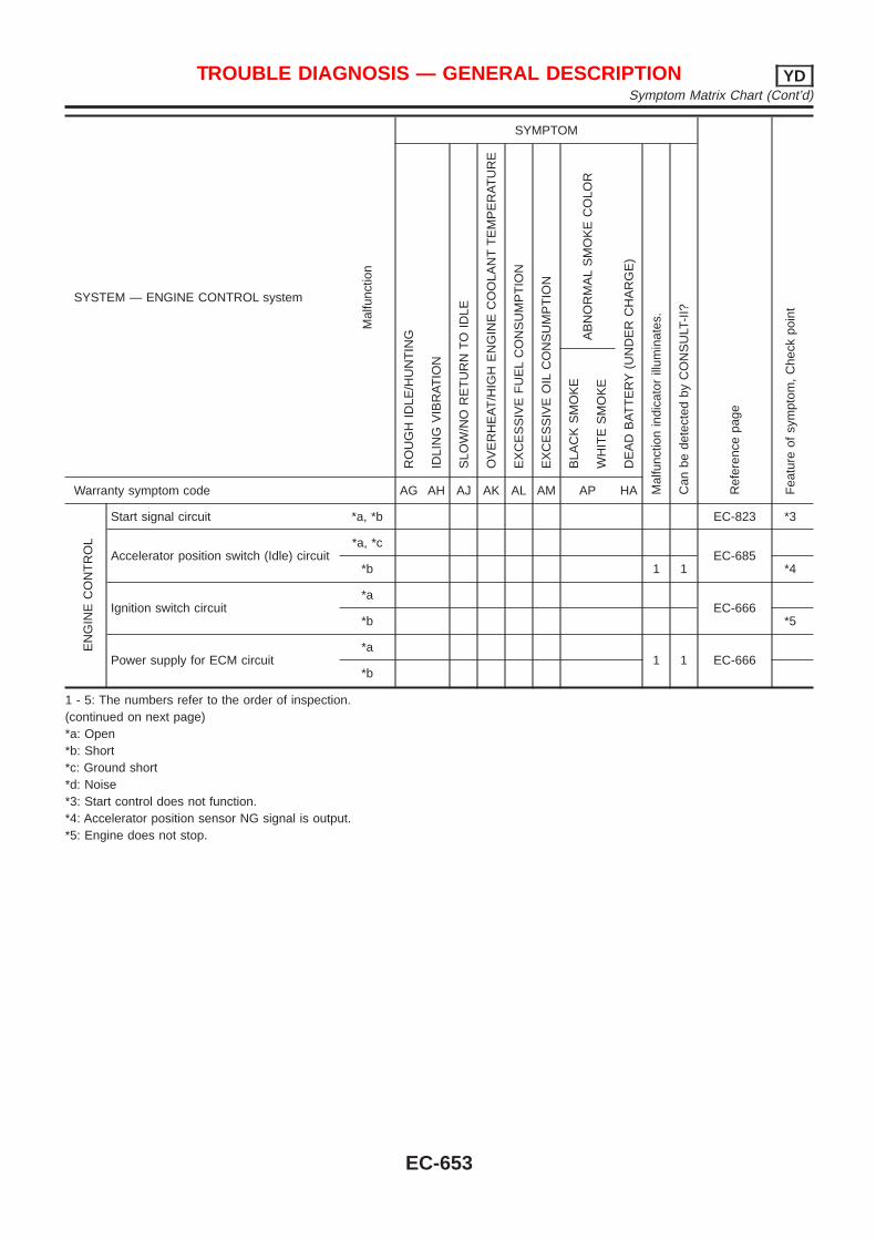
SYSTEM — ENGINE CONTROL system
Mal
func
tion
SYMPTOM
Ref
eren
cepa
ge
Fea
ture
ofsy
mpt
om,
Che
ckpo
int
RO
UG
HID
LE/H
UN
TIN
G
IDLI
NG
VIB
RA
TIO
N
SLO
W/N
OR
ET
UR
NT
OID
LE
OV
ER
HE
AT
/HIG
HE
NG
INE
CO
OLA
NT
TE
MP
ER
AT
UR
E
EX
CE
SS
IVE
FU
EL
CO
NS
UM
PT
ION
EX
CE
SS
IVE
OIL
CO
NS
UM
PT
ION
AB
NO
RM
AL
SM
OK
EC
OLO
R
DE
AD
BA
TT
ER
Y(U
ND
ER
CH
AR
GE
)
Mal
func
tion
indi
cato
rill
umin
ates
.
Can
bede
tect
edby
CO
NS
ULT
-II?
BLA
CK
SM
OK
E
WH
ITE
SM
OK
E
Warranty symptom code AG AH AJ AK AL AM AP HA
EN
GIN
EC
ON
TR
OL
Start signal circuit *a, *b EC-823 *3
Accelerator position switch (Idle) circuit*a, *c
EC-685*b 1 1 *4
Ignition switch circuit*a
EC-666*b *5
Power supply for ECM circuit*a
1 1 EC-666*b
1 - 5: The numbers refer to the order of inspection.(continued on next page)*a: Open*b: Short*c: Ground short*d: Noise*3: Start control does not function.*4: Accelerator position sensor NG signal is output.*5: Engine does not stop.
TROUBLE DIAGNOSIS — GENERAL DESCRIPTION YDSymptom Matrix Chart (Cont’d)
EC-653
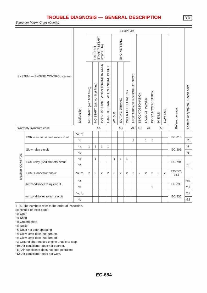
SYSTEM — ENGINE CONTROL systemM
alfu
nctio
n
SYMPTOM
Ref
eren
cepa
ge
Fea
ture
ofsy
mpt
om,
Che
ckpo
int
HA
RD
/NO
STA
RT
/RE
STA
RT
(EX
CP.
HA
)
EN
GIN
ES
TALL
HE
SIT
AT
ION
/SU
RG
ING
/FLA
TS
PO
T
KN
OC
K/D
ET
ON
AT
ION
LAC
KO
FP
OW
ER
PO
OR
AC
CE
LER
AT
ION
HI
IDLE
LOW
IDLE
NO
STA
RT
(with
first
firin
g)
NO
STA
RT
(with
out
first
firin
g)
HA
RD
TO
STA
RT
WH
EN
EN
GIN
EIS
CO
LD
HA
RD
TO
STA
RT
WH
EN
EN
GIN
EIS
HO
T
AT
IDLE
DU
RIN
GD
RIV
ING
WH
EN
DE
CE
LER
AT
ING
Warranty symptom code AA AB AC AD AE AF
EN
GIN
EC
ON
TR
OL
EGR volume control valve circuit*a, *b
EC-815*c 1 1 1 *6
Glow relay circuit*a 1 1 1 1
EC-806*7
*b *8
ECM relay (Self-shutoff) circuit*a 1 1 1 1
EC-794*b *9
ECM, Connector circuit *a, *b 2 2 2 2 2 2 2 2 2 2 2 2 2EC-792,
714
Air conditioner relay circuit*a
EC-830*10
*b 1 *11
Air conditioner switch circuit*a, *c
EC-830*11
*b *12
1 - 5: The numbers refer to the order of inspection.(continued on next page)*a: Open*b: Short*c: Ground short*d: Noise*6: Does not stop operating.*7: Glow lamp does not turn on.*8: Glow lamp does not turn off.*9: Ground short makes engine unable to stop.*10: Air conditioner does not operate.*11: Air conditioner does not stop operating.*12: Air conditioner does not work.
TROUBLE DIAGNOSIS — GENERAL DESCRIPTION YDSymptom Matrix Chart (Cont’d)
EC-654
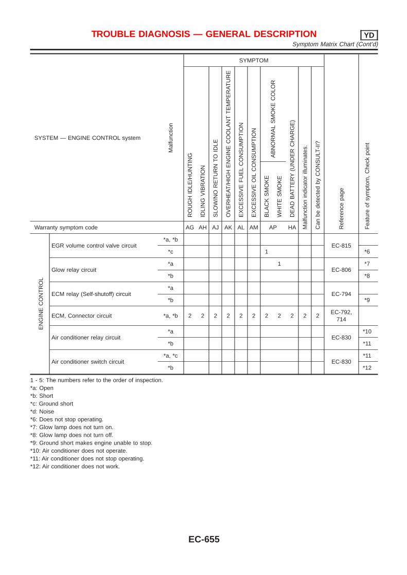
SYSTEM — ENGINE CONTROL system
Mal
func
tion
SYMPTOM
Ref
eren
cepa
ge
Fea
ture
ofsy
mpt
om,
Che
ckpo
int
RO
UG
HID
LE/H
UN
TIN
G
IDLI
NG
VIB
RA
TIO
N
SLO
W/N
OR
ET
UR
NT
OID
LE
OV
ER
HE
AT
/HIG
HE
NG
INE
CO
OLA
NT
TE
MP
ER
AT
UR
E
EX
CE
SS
IVE
FU
EL
CO
NS
UM
PT
ION
EX
CE
SS
IVE
OIL
CO
NS
UM
PT
ION
AB
NO
RM
AL
SM
OK
EC
OLO
R
DE
AD
BA
TT
ER
Y(U
ND
ER
CH
AR
GE
)
Mal
func
tion
indi
cato
rill
umin
ates
.
Can
bede
tect
edby
CO
NS
ULT
-II?
BLA
CK
SM
OK
E
WH
ITE
SM
OK
E
Warranty symptom code AG AH AJ AK AL AM AP HA
EN
GIN
EC
ON
TR
OL
EGR volume control valve circuit*a, *b
EC-815*c 1 *6
Glow relay circuit*a 1
EC-806*7
*b *8
ECM relay (Self-shutoff) circuit*a
EC-794*b *9
ECM, Connector circuit *a, *b 2 2 2 2 2 2 2 2 2 2 2EC-792,
714
Air conditioner relay circuit*a
EC-830*10
*b *11
Air conditioner switch circuit*a, *c
EC-830*11
*b *12
1 - 5: The numbers refer to the order of inspection.*a: Open*b: Short*c: Ground short*d: Noise*6: Does not stop operating.*7: Glow lamp does not turn on.*8: Glow lamp does not turn off.*9: Ground short makes engine unable to stop.*10: Air conditioner does not operate.*11: Air conditioner does not stop operating.*12: Air conditioner does not work.
TROUBLE DIAGNOSIS — GENERAL DESCRIPTION YDSymptom Matrix Chart (Cont’d)
EC-655
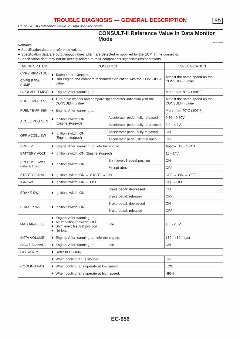
CONSULT-II Reference Value in Data MonitorMode
NJEC0634
Remarks:+ Specification data are reference values.+ Specification data are output/input values which are detected or supplied by the ECM at the connector.* Specification data may not be directly related to their components signals/values/operations.
MONITOR ITEM CONDITION SPECIFICATION
CKPS·RPM (TDC) + Tachometer: Connect+ Run engine and compare tachometer indication with the CONSULT-II
value.
Almost the same speed as theCONSULT-II value.CMPS·RPM-
PUMP
COOLAN TEMP/S + Engine: After warming up More than 70°C (158°F)
VHCL SPEED SE+ Turn drive wheels and compare speedometer indication with the
CONSULT-II valueAlmost the same speed as theCONSULT-II value
FUEL TEMP SEN + Engine: After warming up More than 40°C (104°F)
ACCEL POS SEN+ Ignition switch: ON
(Engine stopped)
Accelerator pedal: fully released 0.30 - 0.50V
Accelerator pedal: fully depressed 3.0 - 4.3V
OFF ACCEL SW+ Ignition switch: ON
(Engine stopped)
Accelerator pedal: fully released ON
Accelerator pedal: slightly open OFF
SPILL/V + Engine: After warming up, idle the engine. Approx. 12 - 13°CA
BATTERY VOLT + Ignition switch: ON (Engine stopped) 11 - 14V
P/N POSI SW*1(where fitted)
+ Ignition switch: ONShift lever: Neutral position ON
Except above OFF
START SIGNAL + Ignition switch: ON → START → ON OFF → ON → OFF
IGN SW + Ignition switch: ON → OFF ON → OFF
BRAKE SW + Ignition switch: ONBrake pedal: depressed ON
Brake pedal: released OFF
BRAKE SW2 + Ignition switch: ONBrake pedal: depressed ON
Brake pedal: released OFF
MAS AIR/FL SE
+ Engine: After warming up+ Air conditioner switch: OFF+ Shift lever: Neutral position+ No-load
Idle 1.5 - 2.0V
INT/A VOLUME + Engine: After warming up, idle the engine. 150 - 450 mg/st
F/CUT SIGNAL + Engine: After warming up Idle ON
GLOW RLY + Refer to EC-806.
COOLING FAN
+ When cooling fan is stopped. OFF
+ When cooling fans operate at low speed. LOW
+ When cooling fans operate at high speed. HIGH
TROUBLE DIAGNOSIS — GENERAL DESCRIPTION YDCONSULT-II Reference Value in Data Monitor Mode
EC-656
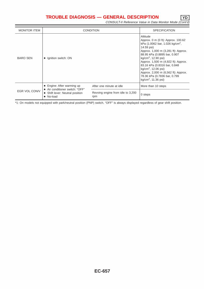
MONITOR ITEM CONDITION SPECIFICATION
BARO SEN + Ignition switch: ON
AltitudeApprox. 0 m (0 ft): Approx. 100.62kPa (1.0062 bar, 1.026 kg/cm2,14.59 psi)Approx. 1,000 m (3,281 ft): Approx.88.95 kPa (0.8895 bar, 0.907kg/cm2, 12.90 psi)Approx. 1,500 m (4,922 ft): Approx.83.16 kPa (0.8316 bar, 0.848kg/cm2, 12.06 psi)Approx. 2,000 m (6,562 ft): Approx.78.36 kPa (0.7836 bar, 0.799kg/cm2, 11.36 psi)
EGR VOL CON/V
+ Engine: After warming up+ Air conditioner switch: “OFF”+ Shift lever: Neutral position+ No-load
After one minute at idle More than 10 steps
Revving engine from idle to 3,200rpm
0 steps
*1: On models not equipped with park/neutral position (PNP) switch, “OFF” is always displayed regardless of gear shift position.
TROUBLE DIAGNOSIS — GENERAL DESCRIPTION YDCONSULT-II Reference Value in Data Monitor Mode (Cont’d)
EC-657
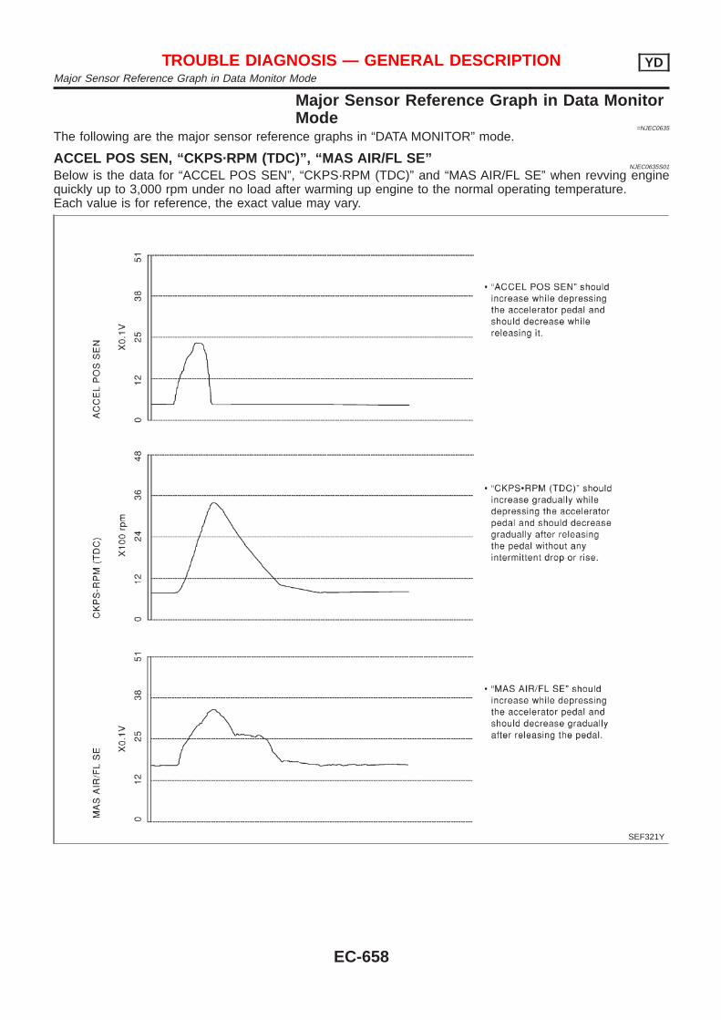
Major Sensor Reference Graph in Data MonitorMode
=NJEC0635
The following are the major sensor reference graphs in “DATA MONITOR” mode.
ACCEL POS SEN, “CKPS·RPM (TDC)”, “MAS AIR/FL SE”NJEC0635S01
Below is the data for “ACCEL POS SEN”, “CKPS·RPM (TDC)” and “MAS AIR/FL SE” when revving enginequickly up to 3,000 rpm under no load after warming up engine to the normal operating temperature.Each value is for reference, the exact value may vary.
SEF321Y
TROUBLE DIAGNOSIS — GENERAL DESCRIPTION YDMajor Sensor Reference Graph in Data Monitor Mode
EC-658
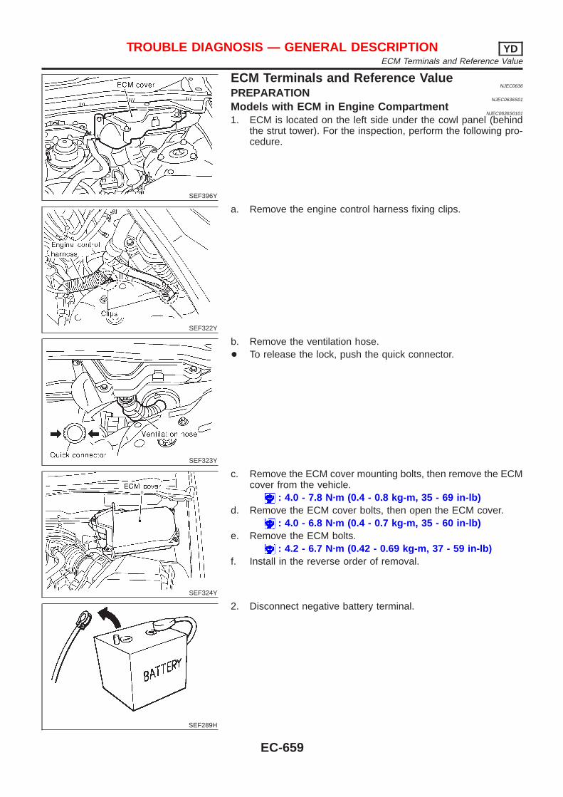
SEF396Y
ECM Terminals and Reference ValueNJEC0636
PREPARATIONNJEC0636S01
Models with ECM in Engine CompartmentNJEC0636S0101
1. ECM is located on the left side under the cowl panel (behindthe strut tower). For the inspection, perform the following pro-cedure.
SEF322Y
a. Remove the engine control harness fixing clips.
SEF323Y
b. Remove the ventilation hose.+ To release the lock, push the quick connector.
SEF324Y
c. Remove the ECM cover mounting bolts, then remove the ECMcover from the vehicle.
: 4.0 - 7.8 N·m (0.4 - 0.8 kg-m, 35 - 69 in-lb)d. Remove the ECM cover bolts, then open the ECM cover.
: 4.0 - 6.8 N·m (0.4 - 0.7 kg-m, 35 - 60 in-lb)e. Remove the ECM bolts.
: 4.2 - 6.7 N·m (0.42 - 0.69 kg-m, 37 - 59 in-lb)f. Install in the reverse order of removal.
SEF289H
2. Disconnect negative battery terminal.
TROUBLE DIAGNOSIS — GENERAL DESCRIPTION YDECM Terminals and Reference Value
EC-659
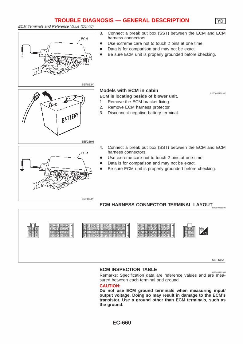
SEF883Y
3. Connect a break out box (SST) between the ECM and ECMharness connectors.
+ Use extreme care not to touch 2 pins at one time.+ Data is for comparison and may not be exact.+ Be sure ECM unit is properly grounded before checking.
SEF289H
Models with ECM in cabinNJEC0636S0102
ECM is locating beside of blower unit.1. Remove the ECM bracket fixing.2. Remove ECM harness protector.3. Disconnect negative battery terminal.
SEF883Y
4. Connect a break out box (SST) between the ECM and ECMharness connectors.
+ Use extreme care not to touch 2 pins at one time.+ Data is for comparison and may not be exact.+ Be sure ECM unit is properly grounded before checking.
ECM HARNESS CONNECTOR TERMINAL LAYOUTNJEC0636S02
SEF435Z
ECM INSPECTION TABLENJEC0636S03
Remarks: Specification data are reference values and are mea-sured between each terminal and ground.CAUTION:Do not use ECM ground terminals when measuring input/output voltage. Doing so may result in damage to the ECM’stransistor. Use a ground other than ECM terminals, such asthe ground.
TROUBLE DIAGNOSIS — GENERAL DESCRIPTION YDECM Terminals and Reference Value (Cont’d)
EC-660
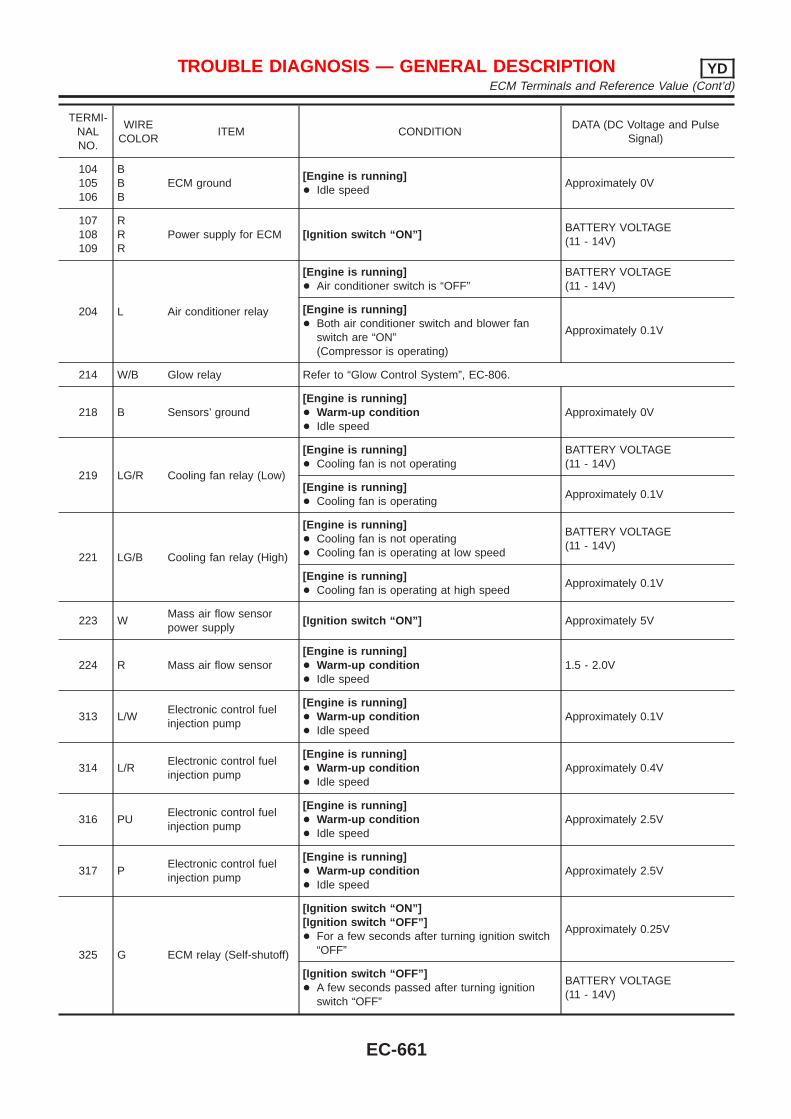
TERMI-NALNO.
WIRECOLOR
ITEM CONDITIONDATA (DC Voltage and Pulse
Signal)
104105106
BBB
ECM ground[Engine is running]+ Idle speed
Approximately 0V
107108109
RRR
Power supply for ECM [Ignition switch “ON”]BATTERY VOLTAGE(11 - 14V)
204 L Air conditioner relay
[Engine is running]+ Air conditioner switch is “OFF”
BATTERY VOLTAGE(11 - 14V)
[Engine is running]+ Both air conditioner switch and blower fan
switch are “ON”(Compressor is operating)
Approximately 0.1V
214 W/B Glow relay Refer to “Glow Control System”, EC-806.
218 B Sensors’ ground[Engine is running]+ Warm-up condition+ Idle speed
Approximately 0V
219 LG/R Cooling fan relay (Low)
[Engine is running]+ Cooling fan is not operating
BATTERY VOLTAGE(11 - 14V)
[Engine is running]+ Cooling fan is operating
Approximately 0.1V
221 LG/B Cooling fan relay (High)
[Engine is running]+ Cooling fan is not operating+ Cooling fan is operating at low speed
BATTERY VOLTAGE(11 - 14V)
[Engine is running]+ Cooling fan is operating at high speed
Approximately 0.1V
223 WMass air flow sensorpower supply
[Ignition switch “ON”] Approximately 5V
224 R Mass air flow sensor[Engine is running]+ Warm-up condition+ Idle speed
1.5 - 2.0V
313 L/WElectronic control fuelinjection pump
[Engine is running]+ Warm-up condition+ Idle speed
Approximately 0.1V
314 L/RElectronic control fuelinjection pump
[Engine is running]+ Warm-up condition+ Idle speed
Approximately 0.4V
316 PUElectronic control fuelinjection pump
[Engine is running]+ Warm-up condition+ Idle speed
Approximately 2.5V
317 PElectronic control fuelinjection pump
[Engine is running]+ Warm-up condition+ Idle speed
Approximately 2.5V
325 G ECM relay (Self-shutoff)
[Ignition switch “ON”][Ignition switch “OFF”]+ For a few seconds after turning ignition switch
“OFF”
Approximately 0.25V
[Ignition switch “OFF”]+ A few seconds passed after turning ignition
switch “OFF”
BATTERY VOLTAGE(11 - 14V)
TROUBLE DIAGNOSIS — GENERAL DESCRIPTION YDECM Terminals and Reference Value (Cont’d)
EC-661
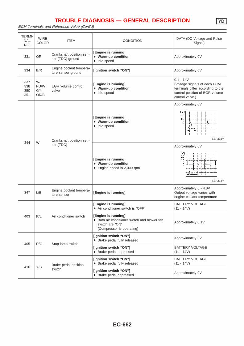
TERMI-NALNO.
WIRECOLOR
ITEM CONDITIONDATA (DC Voltage and Pulse
Signal)
331 ORCrankshaft position sen-sor (TDC) ground
[Engine is running]+ Warm-up condition+ Idle speed
Approximately 0V
334 B/REngine coolant tempera-ture sensor ground
[Ignition switch “ON”] Approximately 0V
337338350351
W/LPU/WGYOR/B
EGR volume controlvalve
[Engine is running]+ Warm-up condition+ Idle speed
0.1 - 14V(Voltage signals of each ECMterminals differ according to thecontrol position of EGR volumecontrol valve.)
344 WCrankshaft position sen-sor (TDC)
[Engine is running]+ Warm-up condition+ Idle speed
Approximately 0V
SEF333Y
[Engine is running]+ Warm-up condition+ Engine speed is 2,000 rpm
Approximately 0V
SEF334Y
347 L/BEngine coolant tempera-ture sensor
[Engine is running]Approximately 0 - 4.8VOutput voltage varies withengine coolant temperature
403 R/L Air conditioner switch
[Engine is running]+ Air conditioner switch is “OFF”
BATTERY VOLTAGE(11 - 14V)
[Engine is running]+ Both air conditioner switch and blower fan
switch are “ON”(Compressor is operating)
Approximately 0.1V
405 R/G Stop lamp switch
[Ignition switch “ON”]+ Brake pedal fully released
Approximately 0V
[Ignition switch “ON”]+ Brake pedal depressed
BATTERY VOLTAGE(11 - 14V)
416 Y/BBrake pedal positionswitch
[Ignition switch “ON”]+ Brake pedal fully released
BATTERY VOLTAGE(11 - 14V)
[Ignition switch “ON”]+ Brake pedal depressed
Approximately 0V
TROUBLE DIAGNOSIS — GENERAL DESCRIPTION YDECM Terminals and Reference Value (Cont’d)
EC-662
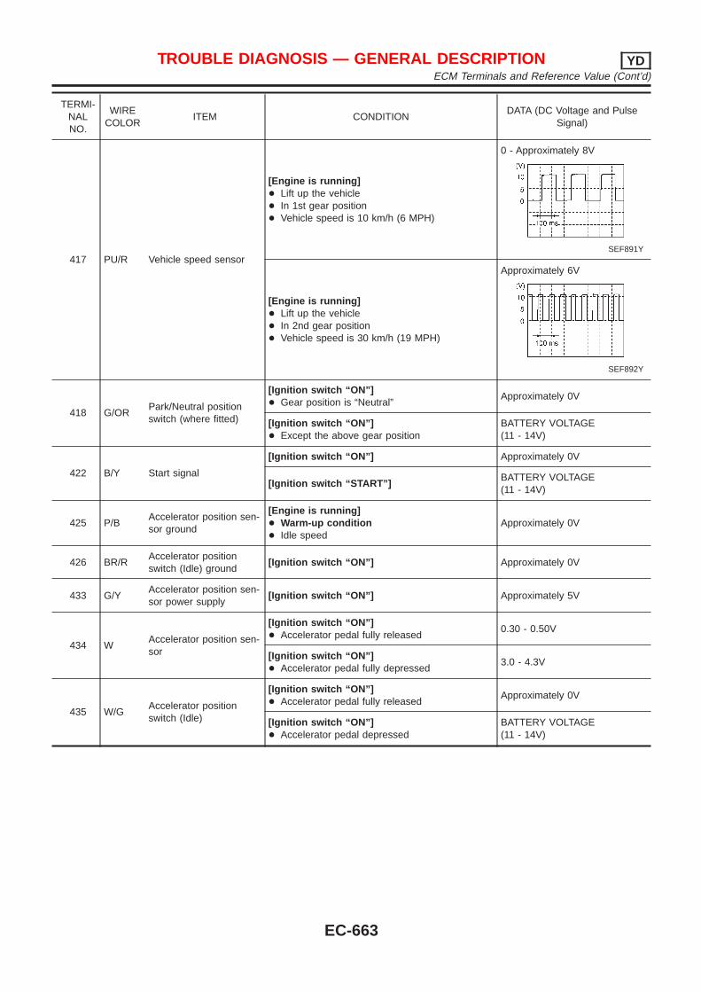
TERMI-NALNO.
WIRECOLOR
ITEM CONDITIONDATA (DC Voltage and Pulse
Signal)
417 PU/R Vehicle speed sensor
[Engine is running]+ Lift up the vehicle+ In 1st gear position+ Vehicle speed is 10 km/h (6 MPH)
0 - Approximately 8V
SEF891Y
[Engine is running]+ Lift up the vehicle+ In 2nd gear position+ Vehicle speed is 30 km/h (19 MPH)
Approximately 6V
SEF892Y
418 G/ORPark/Neutral positionswitch (where fitted)
[Ignition switch “ON”]+ Gear position is “Neutral”
Approximately 0V
[Ignition switch “ON”]+ Except the above gear position
BATTERY VOLTAGE(11 - 14V)
422 B/Y Start signal
[Ignition switch “ON”] Approximately 0V
[Ignition switch “START”]BATTERY VOLTAGE(11 - 14V)
425 P/BAccelerator position sen-sor ground
[Engine is running]+ Warm-up condition+ Idle speed
Approximately 0V
426 BR/RAccelerator positionswitch (Idle) ground
[Ignition switch “ON”] Approximately 0V
433 G/YAccelerator position sen-sor power supply
[Ignition switch “ON”] Approximately 5V
434 WAccelerator position sen-sor
[Ignition switch “ON”]+ Accelerator pedal fully released
0.30 - 0.50V
[Ignition switch “ON”]+ Accelerator pedal fully depressed
3.0 - 4.3V
435 W/GAccelerator positionswitch (Idle)
[Ignition switch “ON”]+ Accelerator pedal fully released
Approximately 0V
[Ignition switch “ON”]+ Accelerator pedal depressed
BATTERY VOLTAGE(11 - 14V)
TROUBLE DIAGNOSIS — GENERAL DESCRIPTION YDECM Terminals and Reference Value (Cont’d)
EC-663
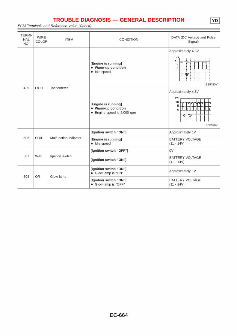
TERMI-NALNO.
WIRECOLOR
ITEM CONDITIONDATA (DC Voltage and Pulse
Signal)
439 L/OR Tachometer
[Engine is running]+ Warm-up condition+ Idle speed
Approximately 4.8V
SEF325Y
[Engine is running]+ Warm-up condition+ Engine speed is 2,000 rpm
Approximately 4.6V
SEF326Y
505 OR/L Malfunction indicator
[Ignition switch “ON”] Approximately 1V
[Engine is running]+ Idle speed
BATTERY VOLTAGE(11 - 14V)
507 W/R Ignition switch
[Ignition switch “OFF”] 0V
[Ignition switch “ON”]BATTERY VOLTAGE(11 - 14V)
508 OR Glow lamp
[Ignition switch “ON”]+ Glow lamp is “ON”
Approximately 1V
[Ignition switch “ON”]+ Glow lamp is “OFF”
BATTERY VOLTAGE(11 - 14V)
TROUBLE DIAGNOSIS — GENERAL DESCRIPTION YDECM Terminals and Reference Value (Cont’d)
EC-664
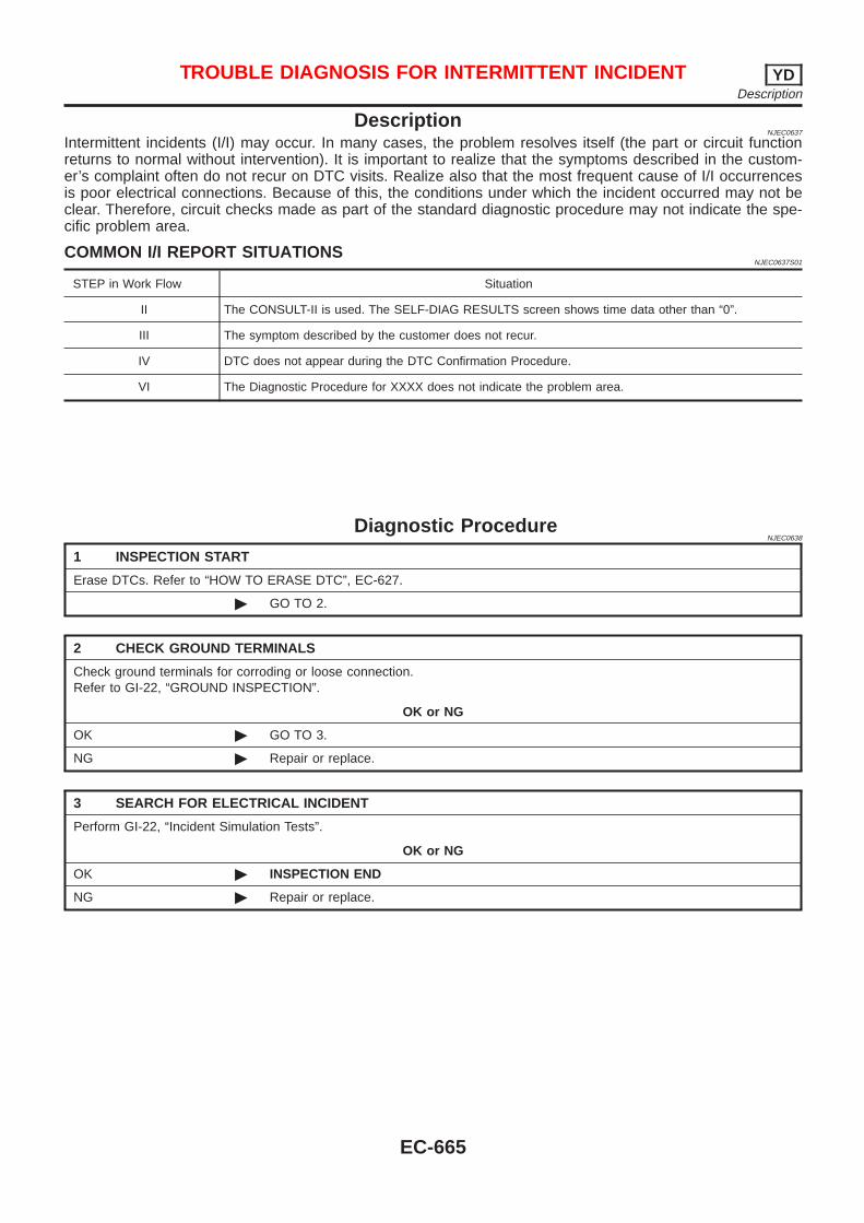
DescriptionNJEC0637
Intermittent incidents (I/I) may occur. In many cases, the problem resolves itself (the part or circuit functionreturns to normal without intervention). It is important to realize that the symptoms described in the custom-er’s complaint often do not recur on DTC visits. Realize also that the most frequent cause of I/I occurrencesis poor electrical connections. Because of this, the conditions under which the incident occurred may not beclear. Therefore, circuit checks made as part of the standard diagnostic procedure may not indicate the spe-cific problem area.
COMMON I/I REPORT SITUATIONSNJEC0637S01
STEP in Work Flow Situation
II The CONSULT-II is used. The SELF-DIAG RESULTS screen shows time data other than “0”.
III The symptom described by the customer does not recur.
IV DTC does not appear during the DTC Confirmation Procedure.
VI The Diagnostic Procedure for XXXX does not indicate the problem area.
Diagnostic ProcedureNJEC0638
1 INSPECTION START
Erase DTCs. Refer to “HOW TO ERASE DTC”, EC-627.
© GO TO 2.
2 CHECK GROUND TERMINALS
Check ground terminals for corroding or loose connection.Refer to GI-22, “GROUND INSPECTION”.
OK or NG
OK © GO TO 3.
NG © Repair or replace.
3 SEARCH FOR ELECTRICAL INCIDENT
Perform GI-22, “Incident Simulation Tests”.
OK or NG
OK © INSPECTION END
NG © Repair or replace.
TROUBLE DIAGNOSIS FOR INTERMITTENT INCIDENT YDDescription
EC-665
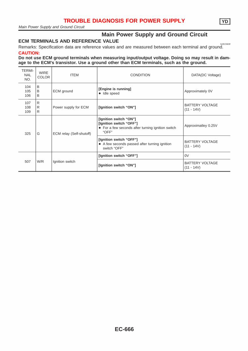
Main Power Supply and Ground CircuitECM TERMINALS AND REFERENCE VALUE
NJEC0639
Remarks: Specification data are reference values and are measured between each terminal and ground.CAUTION:Do not use ECM ground terminals when measuring input/output voltage. Doing so may result in dam-age to the ECM’s transistor. Use a ground other than ECM terminals, such as the ground.
TERMI-NALNO.
WIRECOLOR
ITEM CONDITION DATA(DC Voltage)
104105106
BBB
ECM ground[Engine is running]+ Idle speed
Approximately 0V
107108109
RRR
Power supply for ECM [Ignition switch “ON”]BATTERY VOLTAGE(11 - 14V)
325 G ECM relay (Self-shutoff)
[Ignition switch “ON”][Ignition switch “OFF”]+ For a few seconds after turning ignition switch
“OFF”
Approximatley 0.25V
[Ignition switch “OFF”]+ A few seconds passed after turning ignition
switch “OFF”
BATTERY VOLTAGE(11 - 14V)
507 W/R Ignition switch
[Ignition switch “OFF”] 0V
[Ignition switch “ON”]BATTERY VOLTAGE(11 - 14V)
TROUBLE DIAGNOSIS FOR POWER SUPPLY YDMain Power Supply and Ground Circuit
EC-666
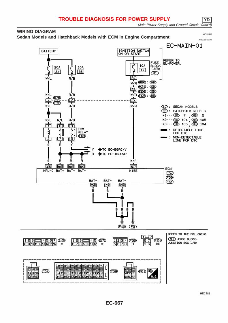
WIRING DIAGRAMNJEC0640
Sedan Models and Hatchback Models with ECM in Engine CompartmentNJEC0640S01
HEC881
TROUBLE DIAGNOSIS FOR POWER SUPPLY YDMain Power Supply and Ground Circuit (Cont’d)
EC-667
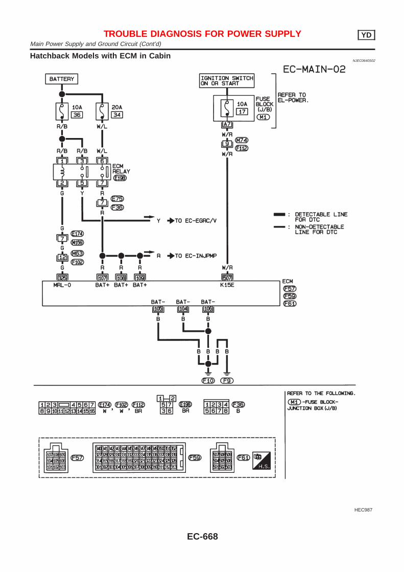
Hatchback Models with ECM in CabinNJEC0640S02
HEC987
TROUBLE DIAGNOSIS FOR POWER SUPPLY YDMain Power Supply and Ground Circuit (Cont’d)
EC-668
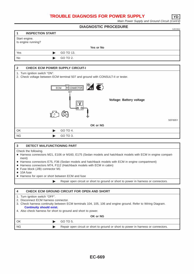
DIAGNOSTIC PROCEDURENJEC0641
1 INSPECTION START
Start engine.Is engine running?
Yes or No
Yes © GO TO 13.
No © GO TO 2.
2 CHECK ECM POWER SUPPLY CIRCUIT-I
1. Turn ignition switch “ON”.2. Check voltage between ECM terminal 507 and ground with CONSULT-II or tester.
SEF895Y
OK or NG
OK © GO TO 4.
NG © GO TO 3.
3 DETECT MALFUNCTIONING PART
Check the following.+ Harness connectors M21, E106 or M160, E175 (Sedan models and hatchback models with ECM in engine compart-
ment)+ Harness connectors E75, F36 (Sedan models and hatchback models with ECM in engine compartment)+ Harness connectors M74, F112 (Hatchback models with ECM in cabin)+ Fuse block (J/B) connector M1+ 10A fuse+ Harness for open or short between ECM and fuse
© Repair open circuit or short to ground or short to power in harness or connectors.
4 CHECK ECM GROUND CIRCUIT FOR OPEN AND SHORT
1. Turn ignition switch “OFF”.2. Disconnect ECM harness connector.3. Check harness continuity between ECM terminals 104, 105, 106 and engine ground. Refer to Wiring Diagram.
Continuity should exist.4. Also check harness for short to ground and short to power.
OK or NG
OK © GO TO 5.
NG © Repair open circuit or short to ground or short to power in harness or connectors.
TROUBLE DIAGNOSIS FOR POWER SUPPLY YDMain Power Supply and Ground Circuit (Cont’d)
EC-669
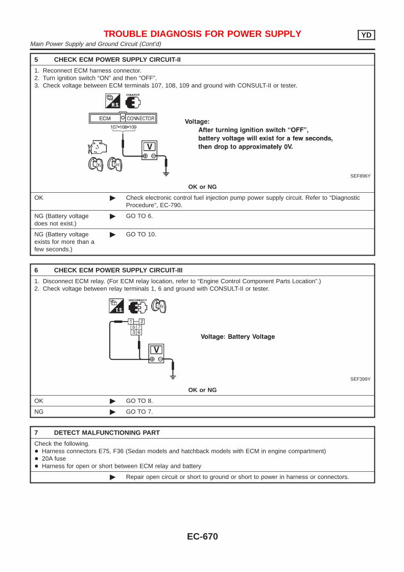
5 CHECK ECM POWER SUPPLY CIRCUIT-II
1. Reconnect ECM harness connector.2. Turn ignition switch “ON” and then “OFF”.3. Check voltage between ECM terminals 107, 108, 109 and ground with CONSULT-II or tester.
SEF896Y
OK or NG
OK © Check electronic control fuel injection pump power supply circuit. Refer to “DiagnosticProcedure”, EC-790.
NG (Battery voltagedoes not exist.)
© GO TO 6.
NG (Battery voltageexists for more than afew seconds.)
© GO TO 10.
6 CHECK ECM POWER SUPPLY CIRCUIT-III
1. Disconnect ECM relay. (For ECM relay location, refer to “Engine Control Component Parts Location”.)2. Check voltage between relay terminals 1, 6 and ground with CONSULT-II or tester.
SEF399Y
OK or NG
OK © GO TO 8.
NG © GO TO 7.
7 DETECT MALFUNCTIONING PART
Check the following.+ Harness connectors E75, F36 (Sedan models and hatchback models with ECM in engine compartment)+ 20A fuse+ Harness for open or short between ECM relay and battery
© Repair open circuit or short to ground or short to power in harness or connectors.
TROUBLE DIAGNOSIS FOR POWER SUPPLY YDMain Power Supply and Ground Circuit (Cont’d)
EC-670
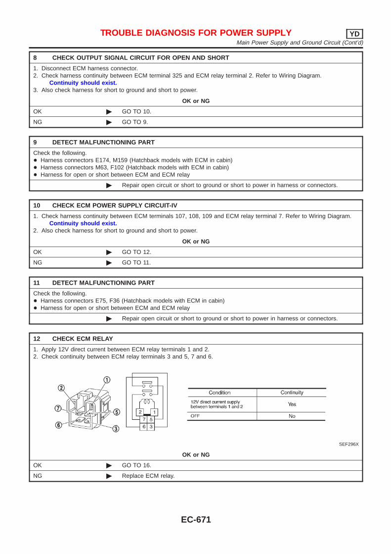
8 CHECK OUTPUT SIGNAL CIRCUIT FOR OPEN AND SHORT
1. Disconnect ECM harness connector.2. Check harness continuity between ECM terminal 325 and ECM relay terminal 2. Refer to Wiring Diagram.
Continuity should exist.3. Also check harness for short to ground and short to power.
OK or NG
OK © GO TO 10.
NG © GO TO 9.
9 DETECT MALFUNCTIONING PART
Check the following.+ Harness connectors E174, M159 (Hatchback models with ECM in cabin)+ Harness connectors M63, F102 (Hatchback models with ECM in cabin)+ Harness for open or short between ECM and ECM relay
© Repair open circuit or short to ground or short to power in harness or connectors.
10 CHECK ECM POWER SUPPLY CIRCUIT-IV
1. Check harness continuity between ECM terminals 107, 108, 109 and ECM relay terminal 7. Refer to Wiring Diagram.Continuity should exist.
2. Also check harness for short to ground and short to power.
OK or NG
OK © GO TO 12.
NG © GO TO 11.
11 DETECT MALFUNCTIONING PART
Check the following.+ Harness connectors E75, F36 (Hatchback models with ECM in cabin)+ Harness for open or short between ECM and ECM relay
© Repair open circuit or short to ground or short to power in harness or connectors.
12 CHECK ECM RELAY
1. Apply 12V direct current between ECM relay terminals 1 and 2.2. Check continuity between ECM relay terminals 3 and 5, 7 and 6.
SEF296X
OK or NG
OK © GO TO 16.
NG © Replace ECM relay.
TROUBLE DIAGNOSIS FOR POWER SUPPLY YDMain Power Supply and Ground Circuit (Cont’d)
EC-671
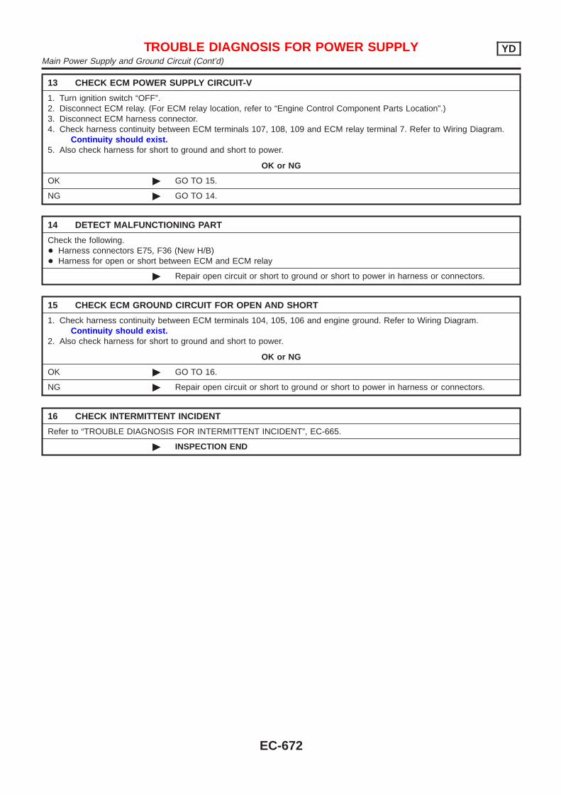
13 CHECK ECM POWER SUPPLY CIRCUIT-V
1. Turn ignition switch “OFF”.2. Disconnect ECM relay. (For ECM relay location, refer to “Engine Control Component Parts Location”.)3. Disconnect ECM harness connector.4. Check harness continuity between ECM terminals 107, 108, 109 and ECM relay terminal 7. Refer to Wiring Diagram.
Continuity should exist.5. Also check harness for short to ground and short to power.
OK or NG
OK © GO TO 15.
NG © GO TO 14.
14 DETECT MALFUNCTIONING PART
Check the following.+ Harness connectors E75, F36 (New H/B)+ Harness for open or short between ECM and ECM relay
© Repair open circuit or short to ground or short to power in harness or connectors.
15 CHECK ECM GROUND CIRCUIT FOR OPEN AND SHORT
1. Check harness continuity between ECM terminals 104, 105, 106 and engine ground. Refer to Wiring Diagram.Continuity should exist.
2. Also check harness for short to ground and short to power.
OK or NG
OK © GO TO 16.
NG © Repair open circuit or short to ground or short to power in harness or connectors.
16 CHECK INTERMITTENT INCIDENT
Refer to “TROUBLE DIAGNOSIS FOR INTERMITTENT INCIDENT”, EC-665.
© INSPECTION END
TROUBLE DIAGNOSIS FOR POWER SUPPLY YDMain Power Supply and Ground Circuit (Cont’d)
EC-672
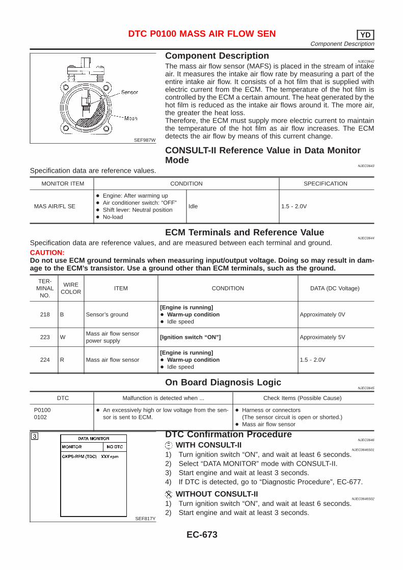
SEF987W
Component DescriptionNJEC0642
The mass air flow sensor (MAFS) is placed in the stream of intakeair. It measures the intake air flow rate by measuring a part of theentire intake air flow. It consists of a hot film that is supplied withelectric current from the ECM. The temperature of the hot film iscontrolled by the ECM a certain amount. The heat generated by thehot film is reduced as the intake air flows around it. The more air,the greater the heat loss.Therefore, the ECM must supply more electric current to maintainthe temperature of the hot film as air flow increases. The ECMdetects the air flow by means of this current change.
CONSULT-II Reference Value in Data MonitorMode
NJEC0643
Specification data are reference values.
MONITOR ITEM CONDITION SPECIFICATION
MAS AIR/FL SE
+ Engine: After warming up+ Air conditioner switch: “OFF”+ Shift lever: Neutral position+ No-load
Idle 1.5 - 2.0V
ECM Terminals and Reference ValueNJEC0644
Specification data are reference values, and are measured between each terminal and ground.CAUTION:Do not use ECM ground terminals when measuring input/output voltage. Doing so may result in dam-age to the ECM’s transistor. Use a ground other than ECM terminals, such as the ground.
TER-MINAL
NO.
WIRECOLOR
ITEM CONDITION DATA (DC Voltage)
218 B Sensor’s ground[Engine is running]+ Warm-up condition+ Idle speed
Approximately 0V
223 WMass air flow sensorpower supply
[Ignition switch “ON”] Approximately 5V
224 R Mass air flow sensor[Engine is running]+ Warm-up condition+ Idle speed
1.5 - 2.0V
On Board Diagnosis LogicNJEC0645
DTC Malfunction is detected when ... Check Items (Possible Cause)
P01000102
+ An excessively high or low voltage from the sen-sor is sent to ECM.
+ Harness or connectors(The sensor circuit is open or shorted.)
+ Mass air flow sensor
SEF817Y
DTC Confirmation ProcedureNJEC0646
WITH CONSULT-IINJEC0646S01
1) Turn ignition switch “ON”, and wait at least 6 seconds.2) Select “DATA MONITOR” mode with CONSULT-II.3) Start engine and wait at least 3 seconds.4) If DTC is detected, go to “Diagnostic Procedure”, EC-677.
WITHOUT CONSULT-IINJEC0646S02
1) Turn ignition switch “ON”, and wait at least 6 seconds.2) Start engine and wait at least 3 seconds.
DTC P0100 MASS AIR FLOW SEN YDComponent Description
EC-673
3) Turn ignition switch “OFF”, wait at least 5 seconds and thenturn “ON”.
4) Perform “Diagnostic Test Mode II (Self-diagnostic results)” withECM.
5) If DTC is detected, go to “Diagnostic Procedure”, EC-677.
DTC P0100 MASS AIR FLOW SEN YDDTC Confirmation Procedure (Cont’d)
EC-674
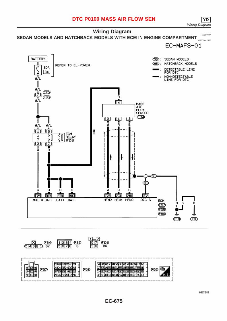
Wiring DiagramNJEC0647
SEDAN MODELS AND HATCHBACK MODELS WITH ECM IN ENGINE COMPARTMENTNJEC0647S01
HEC883
DTC P0100 MASS AIR FLOW SEN YDWiring Diagram
EC-675
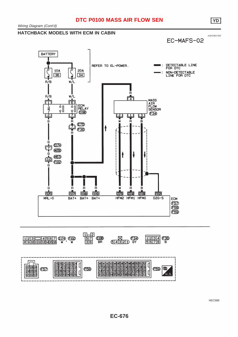
HATCHBACK MODELS WITH ECM IN CABINNJEC0647S02
HEC988
DTC P0100 MASS AIR FLOW SEN YDWiring Diagram (Cont’d)
EC-676
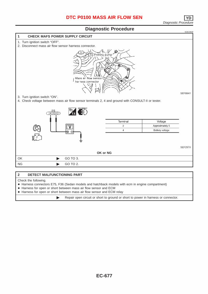
Diagnostic ProcedureNJEC0648
1 CHECK MAFS POWER SUPPLY CIRCUIT
1. Turn ignition switch “OFF”.2. Disconnect mass air flow sensor harness connector.
SEF884Y
3. Turn ignition switch “ON”.4. Check voltage between mass air flow sensor terminals 2, 4 and ground with CONSULT-II or tester.
SEF297X
OK or NG
OK © GO TO 3.
NG © GO TO 2.
2 DETECT MALFUNCTIONING PART
Check the following.+ Harness connectors E75, F36 (Sedan models and hatchback models with ecm in engine compartment)+ Harness for open or short between mass air flow sensor and ECM+ Harness for open or short between mass air flow sensor and ECM relay
© Repair open circuit or short to ground or short to power in harness or connector.
DTC P0100 MASS AIR FLOW SEN YDDiagnostic Procedure
EC-677
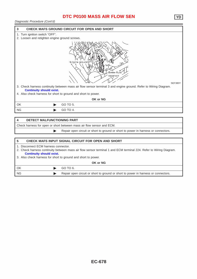
3 CHECK MAFS GROUND CIRCUIT FOR OPEN AND SHORT
1. Turn ignition switch “OFF”.2. Loosen and retighten engine ground screws.
SEF380Y
3. Check harness continuity between mass air flow sensor terminal 3 and engine ground. Refer to Wiring Diagram.Continuity should exist.
4. Also check harness for short to ground and short to power.
OK or NG
OK © GO TO 5.
NG © GO TO 4.
4 DETECT MALFUNCTIONING PART
Check harness for open or short between mass air flow sensor and ECM.
© Repair open circuit or short to ground or short to power in harness or connectors.
5 CHECK MAFS INPUT SIGNAL CIRCUIT FOR OPEN AND SHORT
1. Disconnect ECM harness connector.2. Check harness continuity between mass air flow sensor terminal 1 and ECM terminal 224. Refer to Wiring Diagram.
Continuity should exist.3. Also check harness for short to ground and short to power.
OK or NG
OK © GO TO 6.
NG © Repair open circuit or short to ground or short to power in harness or connectors.
DTC P0100 MASS AIR FLOW SEN YDDiagnostic Procedure (Cont’d)
EC-678
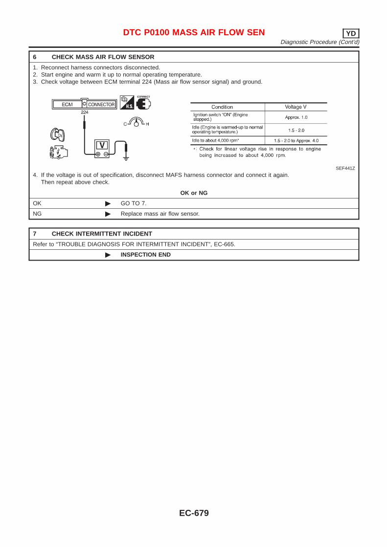
6 CHECK MASS AIR FLOW SENSOR
1. Reconnect harness connectors disconnected.2. Start engine and warm it up to normal operating temperature.3. Check voltage between ECM terminal 224 (Mass air flow sensor signal) and ground.
SEF441Z
4. If the voltage is out of specification, disconnect MAFS harness connector and connect it again.Then repeat above check.
OK or NG
OK © GO TO 7.
NG © Replace mass air flow sensor.
7 CHECK INTERMITTENT INCIDENT
Refer to “TROUBLE DIAGNOSIS FOR INTERMITTENT INCIDENT”, EC-665.
© INSPECTION END
DTC P0100 MASS AIR FLOW SEN YDDiagnostic Procedure (Cont’d)
EC-679
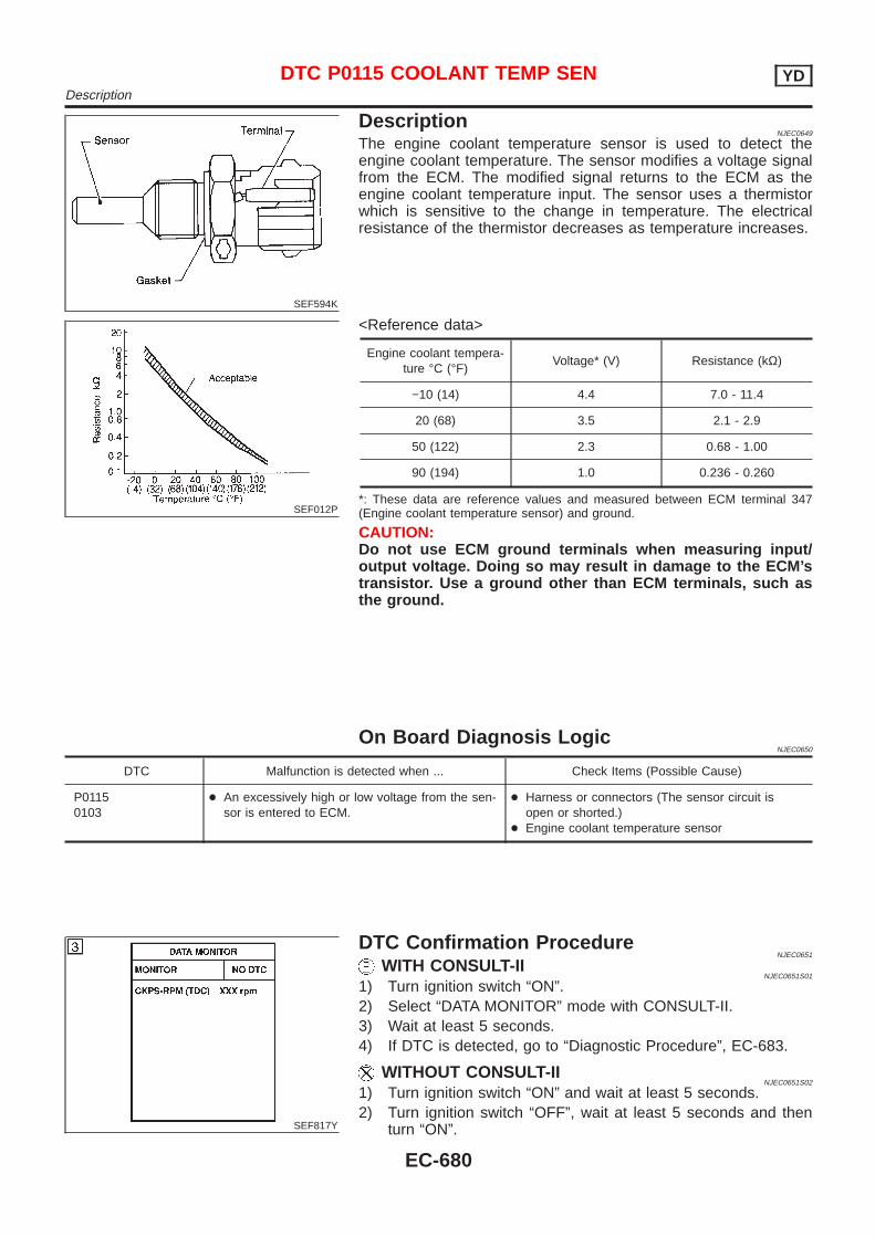
SEF594K
DescriptionNJEC0649
The engine coolant temperature sensor is used to detect theengine coolant temperature. The sensor modifies a voltage signalfrom the ECM. The modified signal returns to the ECM as theengine coolant temperature input. The sensor uses a thermistorwhich is sensitive to the change in temperature. The electricalresistance of the thermistor decreases as temperature increases.
SEF012P
<Reference data>
Engine coolant tempera-ture °C (°F)
Voltage* (V) Resistance (kΩ)
−10 (14) 4.4 7.0 - 11.4
20 (68) 3.5 2.1 - 2.9
50 (122) 2.3 0.68 - 1.00
90 (194) 1.0 0.236 - 0.260
*: These data are reference values and measured between ECM terminal 347(Engine coolant temperature sensor) and ground.
CAUTION:Do not use ECM ground terminals when measuring input/output voltage. Doing so may result in damage to the ECM’stransistor. Use a ground other than ECM terminals, such asthe ground.
On Board Diagnosis LogicNJEC0650
DTC Malfunction is detected when ... Check Items (Possible Cause)
P01150103
+ An excessively high or low voltage from the sen-sor is entered to ECM.
+ Harness or connectors (The sensor circuit isopen or shorted.)
+ Engine coolant temperature sensor
SEF817Y
DTC Confirmation ProcedureNJEC0651
WITH CONSULT-IINJEC0651S01
1) Turn ignition switch “ON”.2) Select “DATA MONITOR” mode with CONSULT-II.3) Wait at least 5 seconds.4) If DTC is detected, go to “Diagnostic Procedure”, EC-683.
WITHOUT CONSULT-IINJEC0651S02
1) Turn ignition switch “ON” and wait at least 5 seconds.2) Turn ignition switch “OFF”, wait at least 5 seconds and then
turn “ON”.
DTC P0115 COOLANT TEMP SEN YDDescription
EC-680

3) Perform “Diagnostic Test Mode II (Self-diagnostic results)” withECM.
4) If DTC is detected, go to “Diagnostic Procedure”, EC-683.
DTC P0115 COOLANT TEMP SEN YDDTC Confirmation Procedure (Cont’d)
EC-681
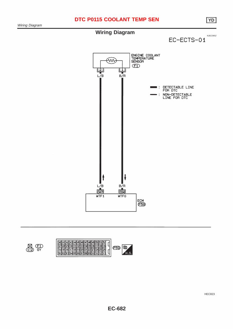
Wiring DiagramNJEC0652
HEC823
DTC P0115 COOLANT TEMP SEN YDWiring Diagram
EC-682
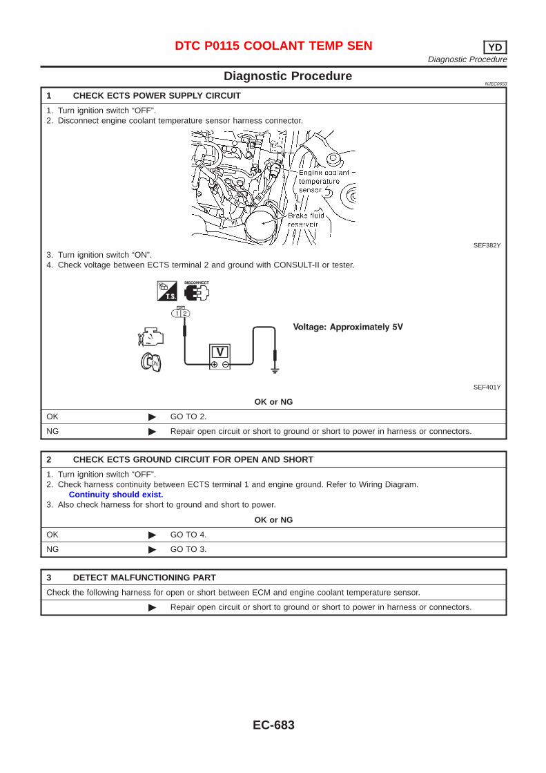
Diagnostic ProcedureNJEC0653
1 CHECK ECTS POWER SUPPLY CIRCUIT
1. Turn ignition switch “OFF”.2. Disconnect engine coolant temperature sensor harness connector.
SEF382Y
3. Turn ignition switch “ON”.4. Check voltage between ECTS terminal 2 and ground with CONSULT-II or tester.
SEF401Y
OK or NG
OK © GO TO 2.
NG © Repair open circuit or short to ground or short to power in harness or connectors.
2 CHECK ECTS GROUND CIRCUIT FOR OPEN AND SHORT
1. Turn ignition switch “OFF”.2. Check harness continuity between ECTS terminal 1 and engine ground. Refer to Wiring Diagram.
Continuity should exist.3. Also check harness for short to ground and short to power.
OK or NG
OK © GO TO 4.
NG © GO TO 3.
3 DETECT MALFUNCTIONING PART
Check the following harness for open or short between ECM and engine coolant temperature sensor.
© Repair open circuit or short to ground or short to power in harness or connectors.
DTC P0115 COOLANT TEMP SEN YDDiagnostic Procedure
EC-683
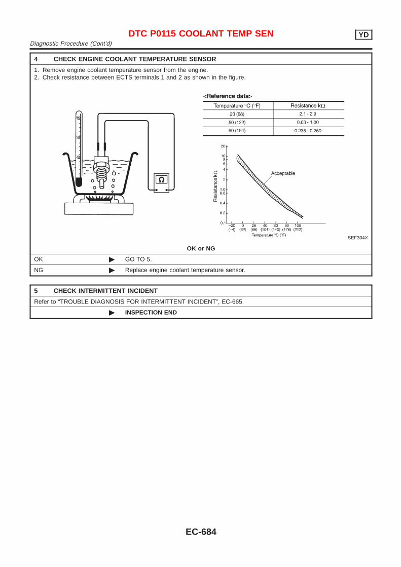
4 CHECK ENGINE COOLANT TEMPERATURE SENSOR
1. Remove engine coolant temperature sensor from the engine.2. Check resistance between ECTS terminals 1 and 2 as shown in the figure.
SEF304X
OK or NG
OK © GO TO 5.
NG © Replace engine coolant temperature sensor.
5 CHECK INTERMITTENT INCIDENT
Refer to “TROUBLE DIAGNOSIS FOR INTERMITTENT INCIDENT”, EC-665.
© INSPECTION END
DTC P0115 COOLANT TEMP SEN YDDiagnostic Procedure (Cont’d)
EC-684
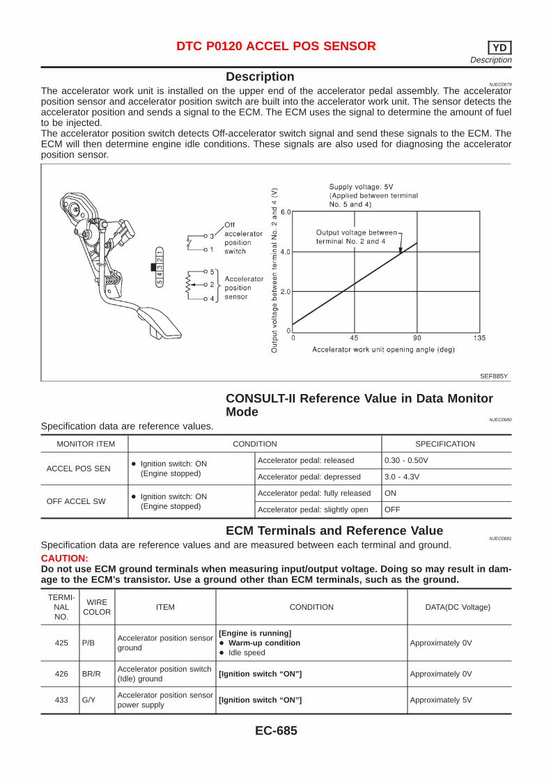
DescriptionNJEC0679
The accelerator work unit is installed on the upper end of the accelerator pedal assembly. The acceleratorposition sensor and accelerator position switch are built into the accelerator work unit. The sensor detects theaccelerator position and sends a signal to the ECM. The ECM uses the signal to determine the amount of fuelto be injected.The accelerator position switch detects Off-accelerator switch signal and send these signals to the ECM. TheECM will then determine engine idle conditions. These signals are also used for diagnosing the acceleratorposition sensor.
SEF885Y
CONSULT-II Reference Value in Data MonitorMode
NJEC0680
Specification data are reference values.
MONITOR ITEM CONDITION SPECIFICATION
ACCEL POS SEN+ Ignition switch: ON
(Engine stopped)
Accelerator pedal: released 0.30 - 0.50V
Accelerator pedal: depressed 3.0 - 4.3V
OFF ACCEL SW+ Ignition switch: ON
(Engine stopped)
Accelerator pedal: fully released ON
Accelerator pedal: slightly open OFF
ECM Terminals and Reference ValueNJEC0681
Specification data are reference values and are measured between each terminal and ground.CAUTION:Do not use ECM ground terminals when measuring input/output voltage. Doing so may result in dam-age to the ECM’s transistor. Use a ground other than ECM terminals, such as the ground.
TERMI-NALNO.
WIRECOLOR
ITEM CONDITION DATA(DC Voltage)
425 P/BAccelerator position sensorground
[Engine is running]+ Warm-up condition+ Idle speed
Approximately 0V
426 BR/RAccelerator position switch(Idle) ground
[Ignition switch “ON”] Approximately 0V
433 G/YAccelerator position sensorpower supply
[Ignition switch “ON”] Approximately 5V
DTC P0120 ACCEL POS SENSOR YDDescription
EC-685
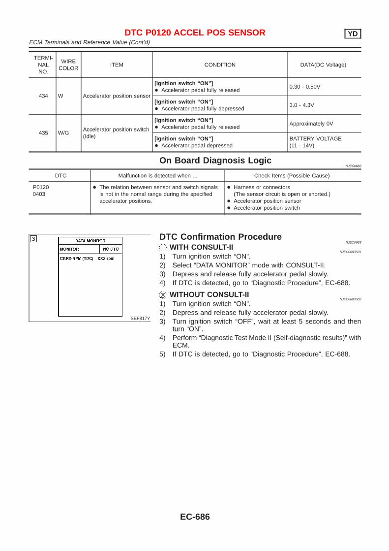
TERMI-NALNO.
WIRECOLOR
ITEM CONDITION DATA(DC Voltage)
434 W Accelerator position sensor
[Ignition switch “ON”]+ Accelerator pedal fully released
0.30 - 0.50V
[Ignition switch “ON”]+ Accelerator pedal fully depressed
3.0 - 4.3V
435 W/GAccelerator position switch(Idle)
[Ignition switch “ON”]+ Accelerator pedal fully released
Approximately 0V
[Ignition switch “ON”]+ Accelerator pedal depressed
BATTERY VOLTAGE(11 - 14V)
On Board Diagnosis LogicNJEC0682
DTC Malfunction is detected when ... Check Items (Possible Cause)
P01200403
+ The relation between sensor and switch signalsis not in the nomal range during the specifiedaccelerator positions.
+ Harness or connectors(The sensor circuit is open or shorted.)
+ Accelerator position sensor+ Accelerator position switch
SEF817Y
DTC Confirmation ProcedureNJEC0683
WITH CONSULT-IINJEC0683S01
1) Turn ignition switch “ON”.2) Select “DATA MONITOR” mode with CONSULT-II.3) Depress and release fully accelerator pedal slowly.4) If DTC is detected, go to “Diagnostic Procedure”, EC-688.
WITHOUT CONSULT-IINJEC0683S02
1) Turn ignition switch “ON”.2) Depress and release fully accelerator pedal slowly.3) Turn ignition switch “OFF”, wait at least 5 seconds and then
turn “ON”.4) Perform “Diagnostic Test Mode II (Self-diagnostic results)” with
ECM.5) If DTC is detected, go to “Diagnostic Procedure”, EC-688.
DTC P0120 ACCEL POS SENSOR YDECM Terminals and Reference Value (Cont’d)
EC-686
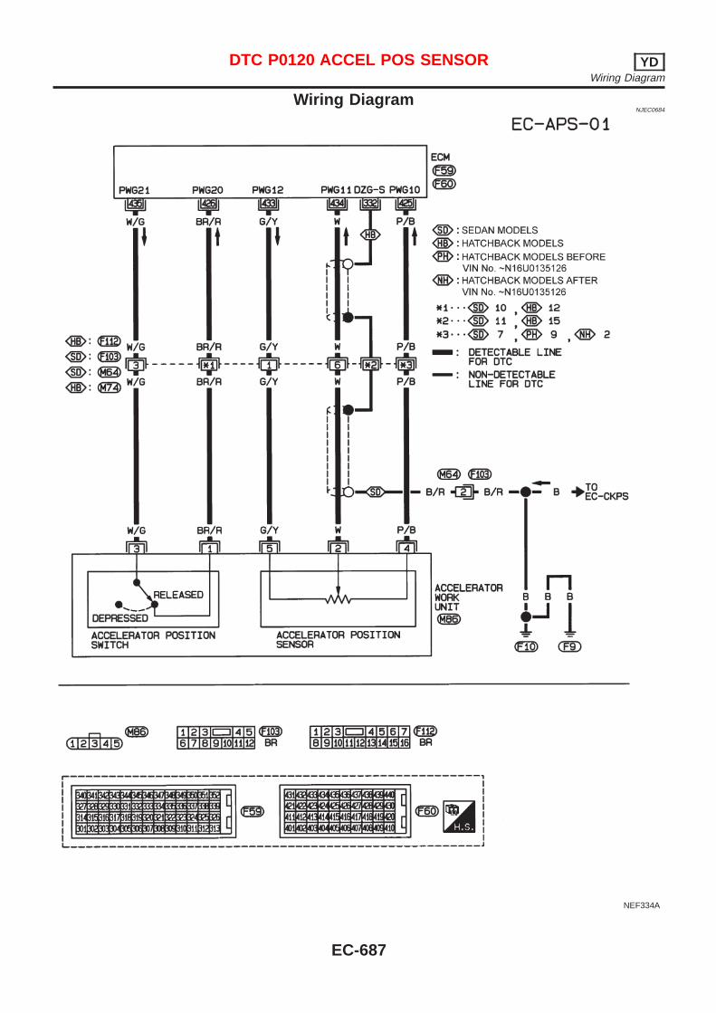
Wiring DiagramNJEC0684
NEF334A
DTC P0120 ACCEL POS SENSOR YDWiring Diagram
EC-687
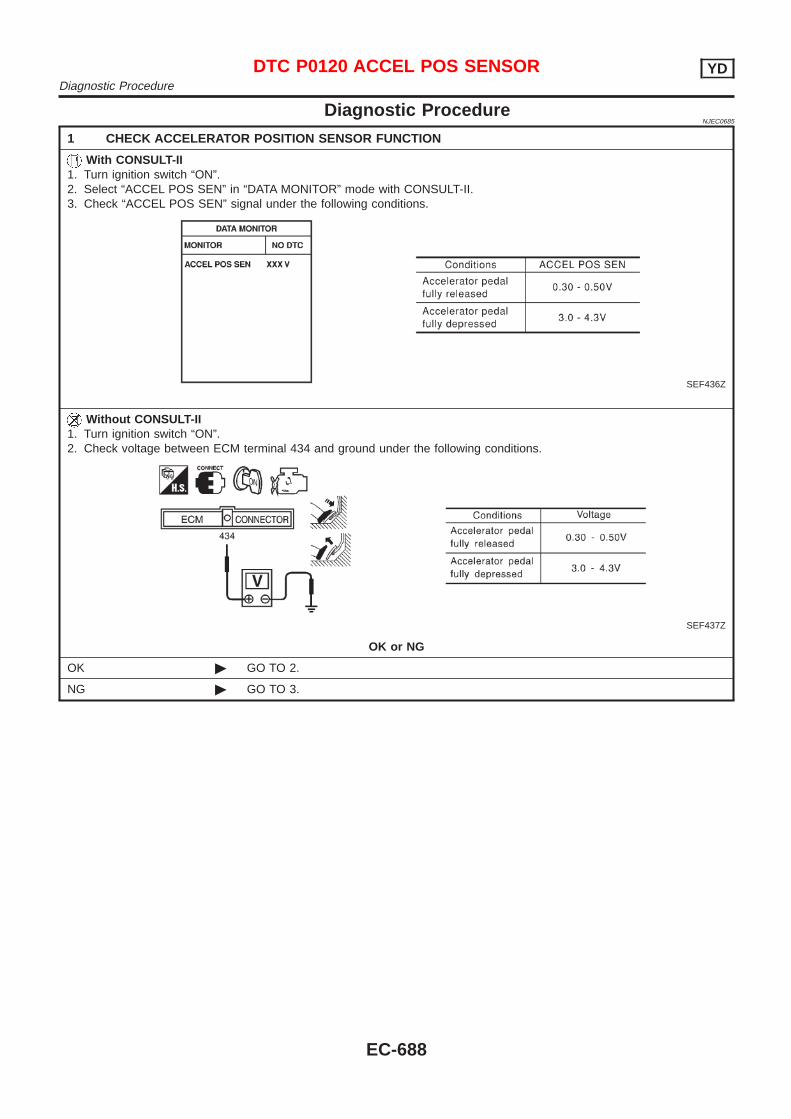
Diagnostic ProcedureNJEC0685
1 CHECK ACCELERATOR POSITION SENSOR FUNCTION
With CONSULT-II1. Turn ignition switch “ON”.2. Select “ACCEL POS SEN” in “DATA MONITOR” mode with CONSULT-II.3. Check “ACCEL POS SEN” signal under the following conditions.
SEF436Z
Without CONSULT-II1. Turn ignition switch “ON”.2. Check voltage between ECM terminal 434 and ground under the following conditions.
SEF437Z
OK or NG
OK © GO TO 2.
NG © GO TO 3.
DTC P0120 ACCEL POS SENSOR YDDiagnostic Procedure
EC-688
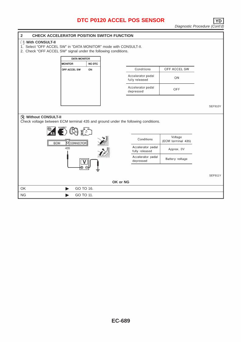
2 CHECK ACCELERATOR POSITION SWITCH FUNCTION
With CONSULT-II1. Select “OFF ACCEL SW” in “DATA MONITOR” mode with CONSULT-II.2. Check “OFF ACCEL SW” signal under the following conditions.
SEF910Y
Without CONSULT-IICheck voltage between ECM terminal 435 and ground under the following conditions.
SEF911Y
OK or NG
OK © GO TO 16.
NG © GO TO 11.
DTC P0120 ACCEL POS SENSOR YDDiagnostic Procedure (Cont’d)
EC-689
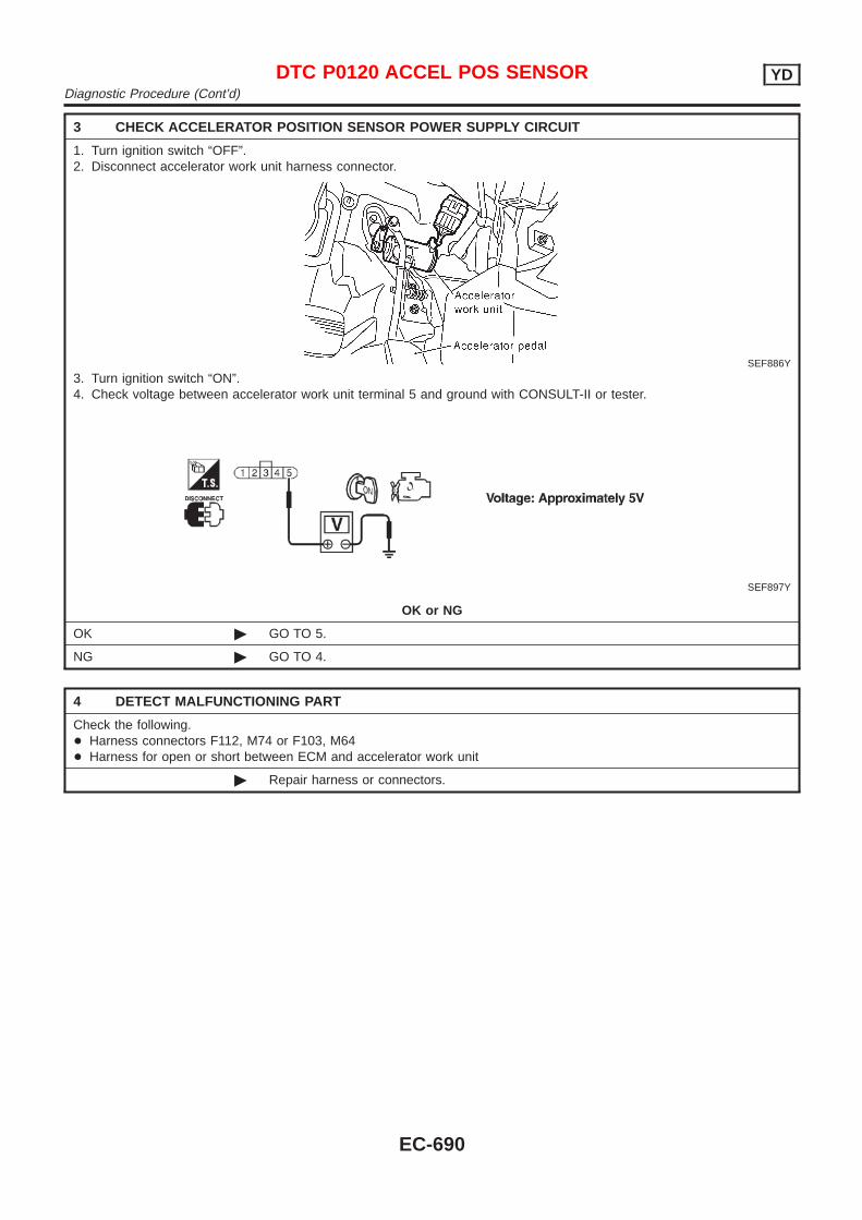
3 CHECK ACCELERATOR POSITION SENSOR POWER SUPPLY CIRCUIT
1. Turn ignition switch “OFF”.2. Disconnect accelerator work unit harness connector.
SEF886Y
3. Turn ignition switch “ON”.4. Check voltage between accelerator work unit terminal 5 and ground with CONSULT-II or tester.
SEF897Y
OK or NG
OK © GO TO 5.
NG © GO TO 4.
4 DETECT MALFUNCTIONING PART
Check the following.+ Harness connectors F112, M74 or F103, M64+ Harness for open or short between ECM and accelerator work unit
© Repair harness or connectors.
DTC P0120 ACCEL POS SENSOR YDDiagnostic Procedure (Cont’d)
EC-690

5 CHECK ACCELERATOR POSITION SENSOR GROUND CIRCUIT FOR OPEN AND SHORT
1. Turn ignition switch “OFF”.2. Loosen and retighten engine ground screw.
SEF380Y
3. Check harness continuity between accelerator work unit terminal 4 and engine ground. Refer to Wiring Diagram.Continuity should exist.
4. Also check harness for short to ground and short to power.
OK or NG
OK © GO TO 7.
NG © GO TO 6.
6 DETECT MALFUNCTIONING PART
Check the following.+ Harness connectors F112, M74 or F103, M64+ Harness for open or short between ECM and accelerator work unit
© Repair open circuit or short to ground or short to power in harness or connectors.
7 CHECK ACCELERATOR POSITION SENSOR INPUT SIGNAL CIRCUIT FOR OPEN AND SHORT
1. Disconnect ECM harness connector.2. Check harness continuity between ECM terminal 434 and accelerator work unit terminal 2. Refer to Wiring Diagram.
Continuity should exist.3. Also check harness for short to ground and short to power.
OK or NG
OK © GO TO 9.
NG © GO TO 8.
8 DETECT MALFUNCTIONING PART
Check the following.+ Harness connectors F112, M74 or F103, M64+ Harness for open or short between ECM and accelerator work unit
© Repair open circuit or short to ground or short to power in harness or connectors.
DTC P0120 ACCEL POS SENSOR YDDiagnostic Procedure (Cont’d)
EC-691
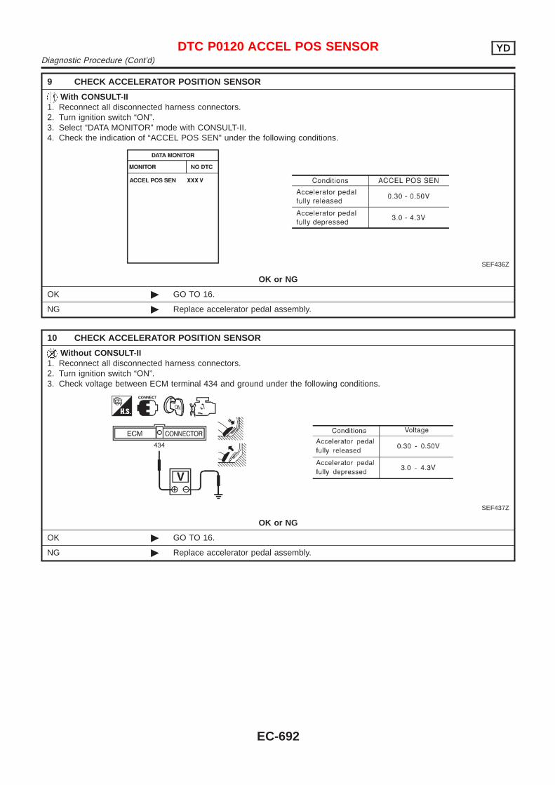
9 CHECK ACCELERATOR POSITION SENSOR
With CONSULT-II1. Reconnect all disconnected harness connectors.2. Turn ignition switch “ON”.3. Select “DATA MONITOR” mode with CONSULT-II.4. Check the indication of “ACCEL POS SEN” under the following conditions.
SEF436Z
OK or NG
OK © GO TO 16.
NG © Replace accelerator pedal assembly.
10 CHECK ACCELERATOR POSITION SENSOR
Without CONSULT-II1. Reconnect all disconnected harness connectors.2. Turn ignition switch “ON”.3. Check voltage between ECM terminal 434 and ground under the following conditions.
SEF437Z
OK or NG
OK © GO TO 16.
NG © Replace accelerator pedal assembly.
DTC P0120 ACCEL POS SENSOR YDDiagnostic Procedure (Cont’d)
EC-692
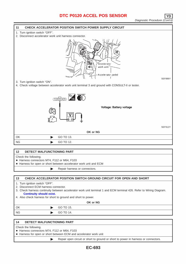
11 CHECK ACCELERATOR POSITION SWITCH POWER SUPPLY CIRCUIT
1. Turn ignition switch “OFF”.2. Disconnect accelerator work unit harness connector.
SEF886Y
3. Turn ignition switch “ON”.4. Check voltage between accelerator work unit terminal 3 and ground with CONSULT-II or tester.
SEF912Y
OK or NG
OK © GO TO 13.
NG © GO TO 12.
12 DETECT MALFUNCTIONING PART
Check the following.+ Harness connectors M74, F112 or M64, F103+ Harness for open or short between accelerator work unit and ECM
© Repair harness or connectors.
13 CHECK ACCELERATOR POSITION SWITCH GROUND CIRCUIT FOR OPEN AND SHORT
1. Turn ignition switch “OFF”.2. Disconnect ECM harness connector.3. Check harness continuity between accelerator work unit terminal 1 and ECM terminal 426. Refer to Wiring Diagram.
Continuity should exist.4. Also check harness for short to ground and short to power.
OK or NG
OK © GO TO 15.
NG © GO TO 14.
14 DETECT MALFUNCTIONING PART
Check the following.+ Harness connectors M74, F112 or M64, F103+ Harness for open or short between ECM and accelerator work unit
© Repair open circuit or short to ground or short to power in harness or connectors.
DTC P0120 ACCEL POS SENSOR YDDiagnostic Procedure (Cont’d)
EC-693
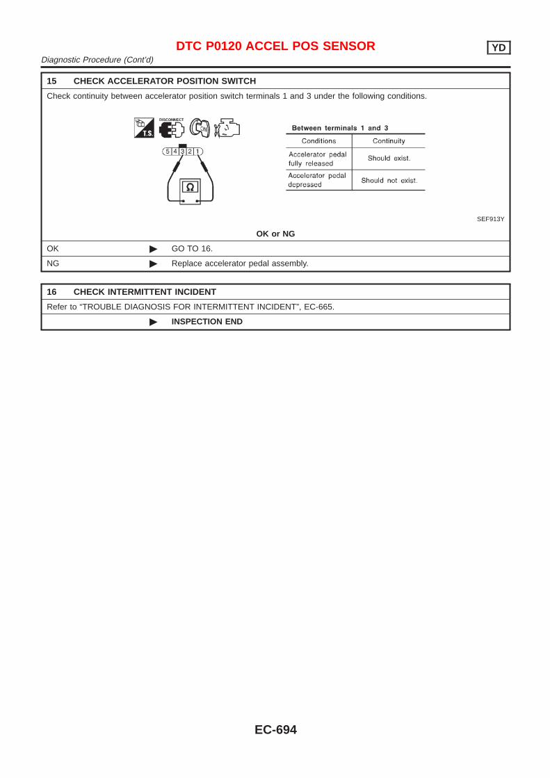
15 CHECK ACCELERATOR POSITION SWITCH
Check continuity between accelerator position switch terminals 1 and 3 under the following conditions.
SEF913Y
OK or NG
OK © GO TO 16.
NG © Replace accelerator pedal assembly.
16 CHECK INTERMITTENT INCIDENT
Refer to “TROUBLE DIAGNOSIS FOR INTERMITTENT INCIDENT”, EC-665.
© INSPECTION END
DTC P0120 ACCEL POS SENSOR YDDiagnostic Procedure (Cont’d)
EC-694
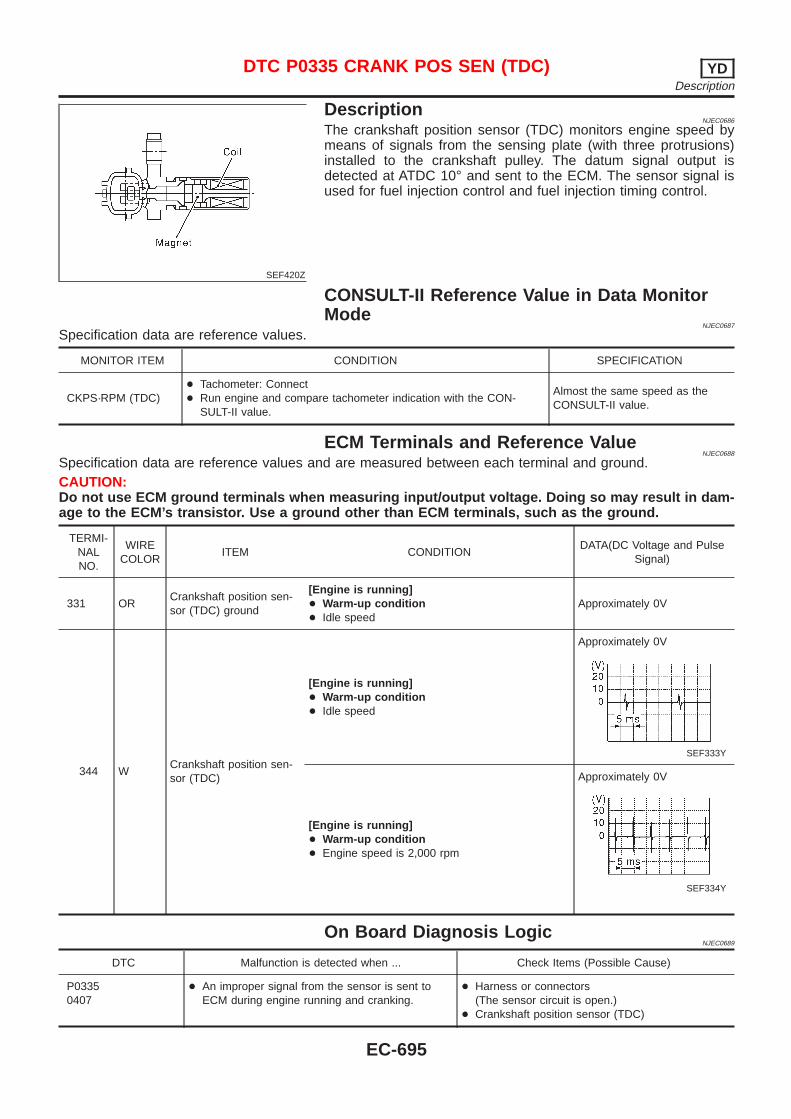
SEF420Z
DescriptionNJEC0686
The crankshaft position sensor (TDC) monitors engine speed bymeans of signals from the sensing plate (with three protrusions)installed to the crankshaft pulley. The datum signal output isdetected at ATDC 10° and sent to the ECM. The sensor signal isused for fuel injection control and fuel injection timing control.
CONSULT-II Reference Value in Data MonitorMode
NJEC0687
Specification data are reference values.
MONITOR ITEM CONDITION SPECIFICATION
CKPS·RPM (TDC)+ Tachometer: Connect+ Run engine and compare tachometer indication with the CON-
SULT-II value.
Almost the same speed as theCONSULT-II value.
ECM Terminals and Reference ValueNJEC0688
Specification data are reference values and are measured between each terminal and ground.CAUTION:Do not use ECM ground terminals when measuring input/output voltage. Doing so may result in dam-age to the ECM’s transistor. Use a ground other than ECM terminals, such as the ground.
TERMI-NALNO.
WIRECOLOR
ITEM CONDITIONDATA(DC Voltage and Pulse
Signal)
331 ORCrankshaft position sen-sor (TDC) ground
[Engine is running]+ Warm-up condition+ Idle speed
Approximately 0V
344 WCrankshaft position sen-sor (TDC)
[Engine is running]+ Warm-up condition+ Idle speed
Approximately 0V
SEF333Y
[Engine is running]+ Warm-up condition+ Engine speed is 2,000 rpm
Approximately 0V
SEF334Y
On Board Diagnosis LogicNJEC0689
DTC Malfunction is detected when ... Check Items (Possible Cause)
P03350407
+ An improper signal from the sensor is sent toECM during engine running and cranking.
+ Harness or connectors(The sensor circuit is open.)
+ Crankshaft position sensor (TDC)
DTC P0335 CRANK POS SEN (TDC) YDDescription
EC-695
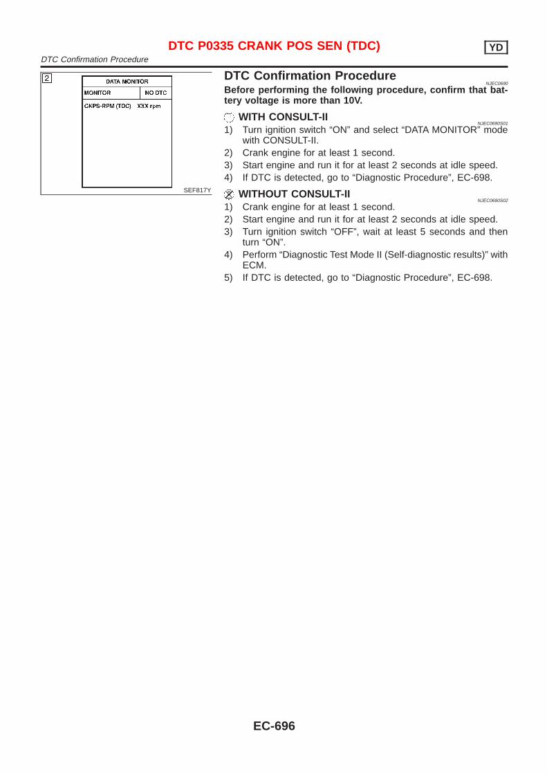
SEF817Y
DTC Confirmation ProcedureNJEC0690
Before performing the following procedure, confirm that bat-tery voltage is more than 10V.
WITH CONSULT-IINJEC0690S01
1) Turn ignition switch “ON” and select “DATA MONITOR” modewith CONSULT-II.
2) Crank engine for at least 1 second.3) Start engine and run it for at least 2 seconds at idle speed.4) If DTC is detected, go to “Diagnostic Procedure”, EC-698.
WITHOUT CONSULT-IINJEC0690S02
1) Crank engine for at least 1 second.2) Start engine and run it for at least 2 seconds at idle speed.3) Turn ignition switch “OFF”, wait at least 5 seconds and then
turn “ON”.4) Perform “Diagnostic Test Mode II (Self-diagnostic results)” with
ECM.5) If DTC is detected, go to “Diagnostic Procedure”, EC-698.
DTC P0335 CRANK POS SEN (TDC) YDDTC Confirmation Procedure
EC-696
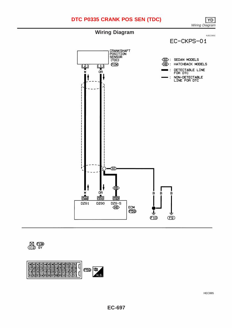
Wiring DiagramNJEC0691
HEC885
DTC P0335 CRANK POS SEN (TDC) YDWiring Diagram
EC-697
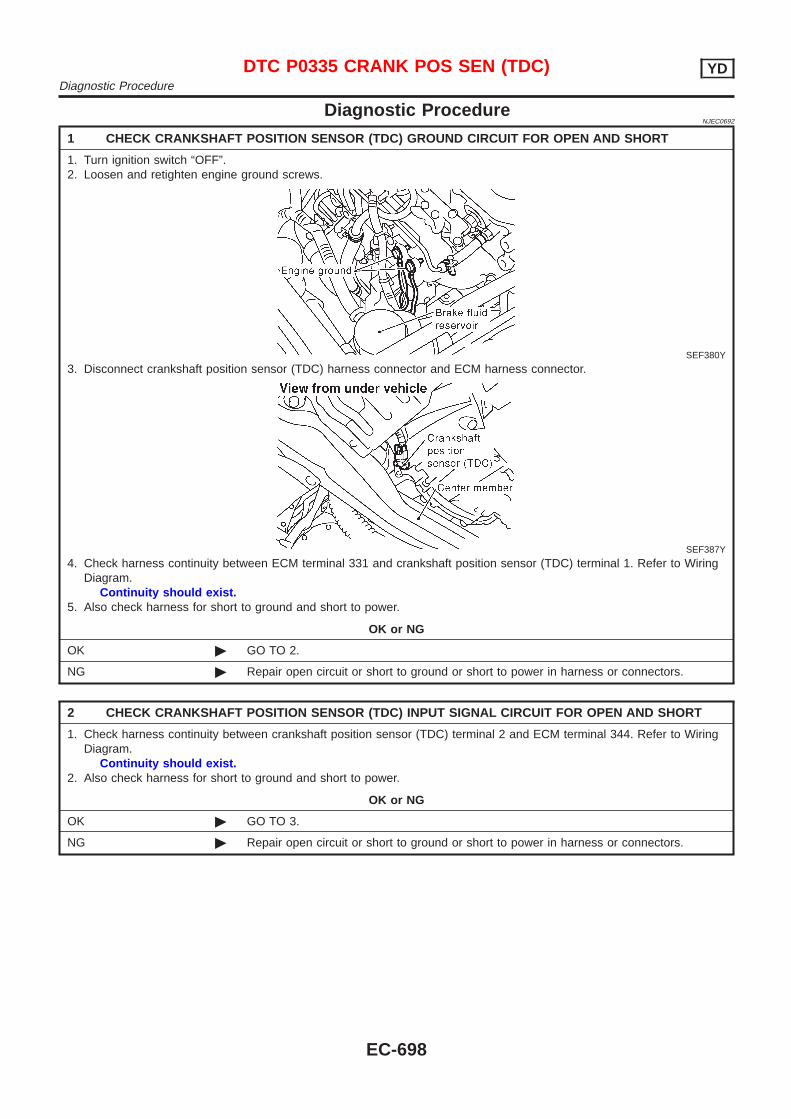
Diagnostic ProcedureNJEC0692
1 CHECK CRANKSHAFT POSITION SENSOR (TDC) GROUND CIRCUIT FOR OPEN AND SHORT
1. Turn ignition switch “OFF”.2. Loosen and retighten engine ground screws.
SEF380Y
3. Disconnect crankshaft position sensor (TDC) harness connector and ECM harness connector.
SEF387Y
4. Check harness continuity between ECM terminal 331 and crankshaft position sensor (TDC) terminal 1. Refer to WiringDiagram.
Continuity should exist.5. Also check harness for short to ground and short to power.
OK or NG
OK © GO TO 2.
NG © Repair open circuit or short to ground or short to power in harness or connectors.
2 CHECK CRANKSHAFT POSITION SENSOR (TDC) INPUT SIGNAL CIRCUIT FOR OPEN AND SHORT
1. Check harness continuity between crankshaft position sensor (TDC) terminal 2 and ECM terminal 344. Refer to WiringDiagram.
Continuity should exist.2. Also check harness for short to ground and short to power.
OK or NG
OK © GO TO 3.
NG © Repair open circuit or short to ground or short to power in harness or connectors.
DTC P0335 CRANK POS SEN (TDC) YDDiagnostic Procedure
EC-698

3 CHECK CRANKSHAFT POSITION SENSOR (TDC)-I
1. Loosen the fixing bolt and remove the crankshaft position sensor (TDC).2. Visually check the sensor for chipping.
SEF620S
OK or NG
OK © GO TO 4.
NG © Replace crankshaft position sensor (TDC).
4 CHECK CRANKSHAFT POSITION SENSOR (TDC)-II
1. Disconnect crankshaft position sensor (TDC) harness connector.2. Check resistance between crankshaft position sensor (TDC) terminals 1 and 2.
SEF408Y
OK or NG
OK © GO TO 5.
NG © Replace crankshaft position sensor (TDC).
DTC P0335 CRANK POS SEN (TDC) YDDiagnostic Procedure (Cont’d)
EC-699
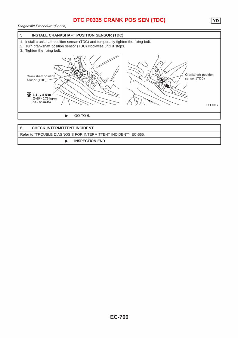
5 INSTALL CRANKSHAFT POSITION SENSOR (TDC)
1. Install crankshaft position sensor (TDC) and temporarily tighten the fixing bolt.2. Turn crankshaft position sensor (TDC) clockwise until it stops.3. Tighten the fixing bolt.
SEF409Y
© GO TO 6.
6 CHECK INTERMITTENT INCIDENT
Refer to “TROUBLE DIAGNOSIS FOR INTERMITTENT INCIDENT”, EC-665.
© INSPECTION END
DTC P0335 CRANK POS SEN (TDC) YDDiagnostic Procedure (Cont’d)
EC-700
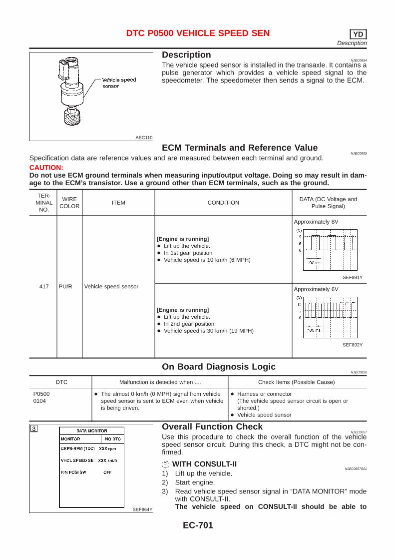
AEC110
DescriptionNJEC0654
The vehicle speed sensor is installed in the transaxle. It contains apulse generator which provides a vehicle speed signal to thespeedometer. The speedometer then sends a signal to the ECM.
ECM Terminals and Reference ValueNJEC0655
Specification data are reference values and are measured between each terminal and ground.CAUTION:Do not use ECM ground terminals when measuring input/output voltage. Doing so may result in dam-age to the ECM’s transistor. Use a ground other than ECM terminals, such as the ground.
TER-MINAL
NO.
WIRECOLOR
ITEM CONDITIONDATA (DC Voltage and
Pulse Signal)
417 PU/R Vehicle speed sensor
[Engine is running]+ Lift up the vehicle.+ In 1st gear position+ Vehicle speed is 10 km/h (6 MPH)
Approximately 8V
SEF891Y
[Engine is running]+ Lift up the vehicle.+ In 2nd gear position+ Vehicle speed is 30 km/h (19 MPH)
Approximately 6V
SEF892Y
On Board Diagnosis LogicNJEC0656
DTC Malfunction is detected when .... Check Items (Possible Cause)
P05000104
+ The almost 0 km/h (0 MPH) signal from vehiclespeed sensor is sent to ECM even when vehicleis being driven.
+ Harness or connector(The vehicle speed sensor circuit is open orshorted.)
+ Vehicle speed sensor
SEF864Y
Overall Function CheckNJEC0657
Use this procedure to check the overall function of the vehiclespeed sensor circuit. During this check, a DTC might not be con-firmed.
WITH CONSULT-IINJEC0657S01
1) Lift up the vehicle.2) Start engine.3) Read vehicle speed sensor signal in “DATA MONITOR” mode
with CONSULT-II.The vehicle speed on CONSULT-II should be able to
DTC P0500 VEHICLE SPEED SEN YDDescription
EC-701
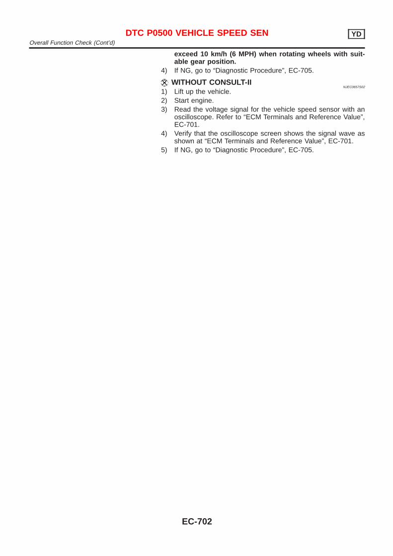
exceed 10 km/h (6 MPH) when rotating wheels with suit-able gear position.
4) If NG, go to “Diagnostic Procedure”, EC-705.
WITHOUT CONSULT-IINJEC0657S02
1) Lift up the vehicle.2) Start engine.3) Read the voltage signal for the vehicle speed sensor with an
oscilloscope. Refer to “ECM Terminals and Reference Value”,EC-701.
4) Verify that the oscilloscope screen shows the signal wave asshown at “ECM Terminals and Reference Value”, EC-701.
5) If NG, go to “Diagnostic Procedure”, EC-705.
DTC P0500 VEHICLE SPEED SEN YDOverall Function Check (Cont’d)
EC-702
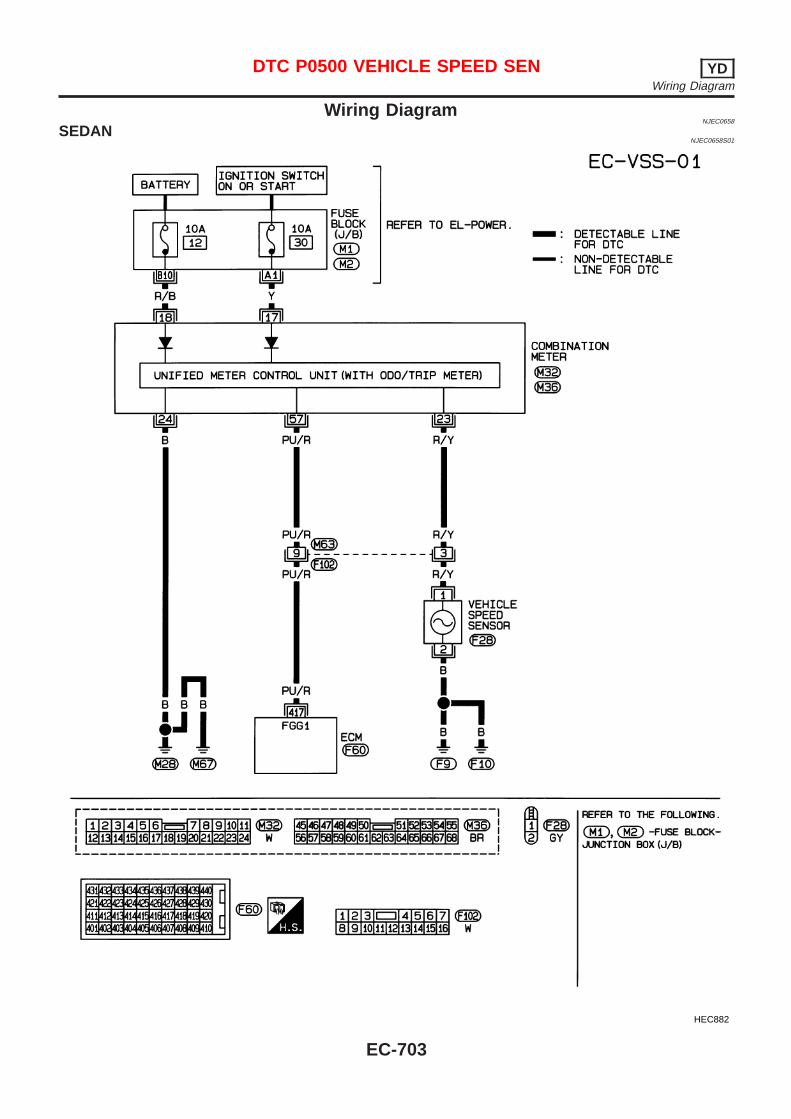
Wiring DiagramNJEC0658
SEDANNJEC0658S01
HEC882
DTC P0500 VEHICLE SPEED SEN YDWiring Diagram
EC-703
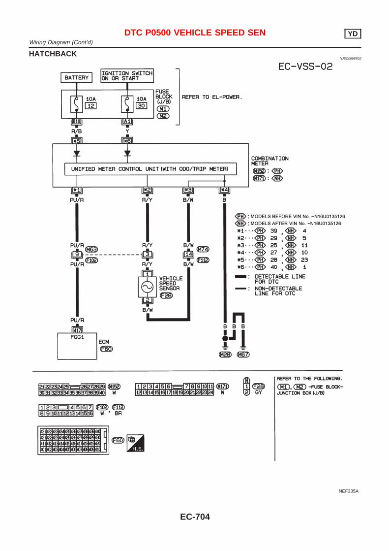
HATCHBACKNJEC0658S02
NEF335A
DTC P0500 VEHICLE SPEED SEN YDWiring Diagram (Cont’d)
EC-704
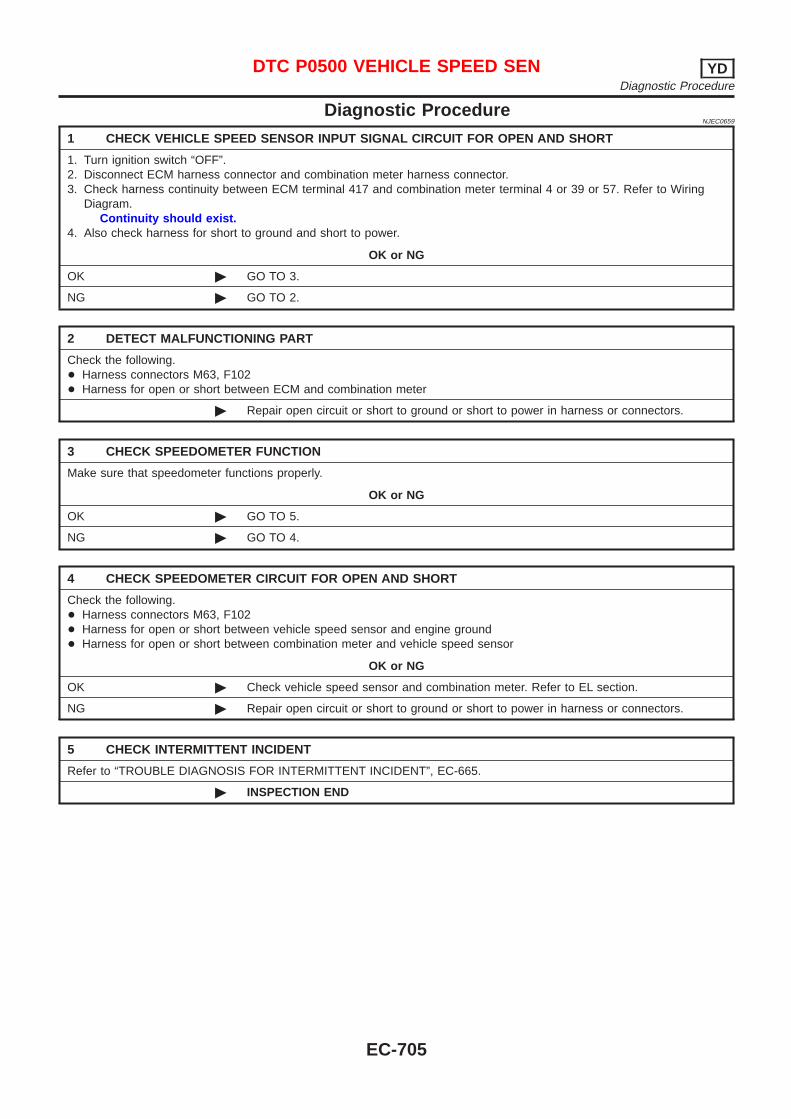
Diagnostic ProcedureNJEC0659
1 CHECK VEHICLE SPEED SENSOR INPUT SIGNAL CIRCUIT FOR OPEN AND SHORT
1. Turn ignition switch “OFF”.2. Disconnect ECM harness connector and combination meter harness connector.3. Check harness continuity between ECM terminal 417 and combination meter terminal 4 or 39 or 57. Refer to Wiring
Diagram.Continuity should exist.
4. Also check harness for short to ground and short to power.
OK or NG
OK © GO TO 3.
NG © GO TO 2.
2 DETECT MALFUNCTIONING PART
Check the following.+ Harness connectors M63, F102+ Harness for open or short between ECM and combination meter
© Repair open circuit or short to ground or short to power in harness or connectors.
3 CHECK SPEEDOMETER FUNCTION
Make sure that speedometer functions properly.
OK or NG
OK © GO TO 5.
NG © GO TO 4.
4 CHECK SPEEDOMETER CIRCUIT FOR OPEN AND SHORT
Check the following.+ Harness connectors M63, F102+ Harness for open or short between vehicle speed sensor and engine ground+ Harness for open or short between combination meter and vehicle speed sensor
OK or NG
OK © Check vehicle speed sensor and combination meter. Refer to EL section.
NG © Repair open circuit or short to ground or short to power in harness or connectors.
5 CHECK INTERMITTENT INCIDENT
Refer to “TROUBLE DIAGNOSIS FOR INTERMITTENT INCIDENT”, EC-665.
© INSPECTION END
DTC P0500 VEHICLE SPEED SEN YDDiagnostic Procedure
EC-705
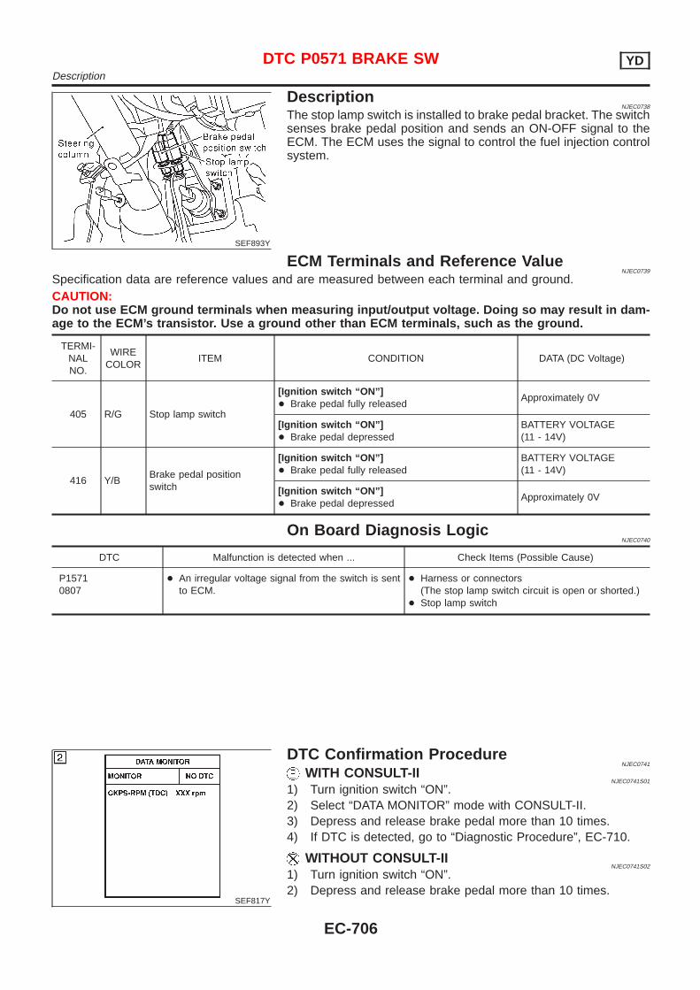
SEF893Y
DescriptionNJEC0738
The stop lamp switch is installed to brake pedal bracket. The switchsenses brake pedal position and sends an ON-OFF signal to theECM. The ECM uses the signal to control the fuel injection controlsystem.
ECM Terminals and Reference ValueNJEC0739
Specification data are reference values and are measured between each terminal and ground.CAUTION:Do not use ECM ground terminals when measuring input/output voltage. Doing so may result in dam-age to the ECM’s transistor. Use a ground other than ECM terminals, such as the ground.
TERMI-NALNO.
WIRECOLOR
ITEM CONDITION DATA (DC Voltage)
405 R/G Stop lamp switch
[Ignition switch “ON”]+ Brake pedal fully released
Approximately 0V
[Ignition switch “ON”]+ Brake pedal depressed
BATTERY VOLTAGE(11 - 14V)
416 Y/BBrake pedal positionswitch
[Ignition switch “ON”]+ Brake pedal fully released
BATTERY VOLTAGE(11 - 14V)
[Ignition switch “ON”]+ Brake pedal depressed
Approximately 0V
On Board Diagnosis LogicNJEC0740
DTC Malfunction is detected when ... Check Items (Possible Cause)
P15710807
+ An irregular voltage signal from the switch is sentto ECM.
+ Harness or connectors(The stop lamp switch circuit is open or shorted.)
+ Stop lamp switch
SEF817Y
DTC Confirmation ProcedureNJEC0741
WITH CONSULT-IINJEC0741S01
1) Turn ignition switch “ON”.2) Select “DATA MONITOR” mode with CONSULT-II.3) Depress and release brake pedal more than 10 times.4) If DTC is detected, go to “Diagnostic Procedure”, EC-710.
WITHOUT CONSULT-IINJEC0741S02
1) Turn ignition switch “ON”.2) Depress and release brake pedal more than 10 times.
DTC P0571 BRAKE SW YDDescription
EC-706

3) Turn ignition switch “OFF”, wait at least 5 seconds and thenturn “ON”.
4) Perform “Diagnostic Test Mode II (Self-diagnostic results)” withECM.
5) If DTC is detected, go to “Diagnostic Procedure”, EC-710.
DTC P0571 BRAKE SW YDDTC Confirmation Procedure (Cont’d)
EC-707
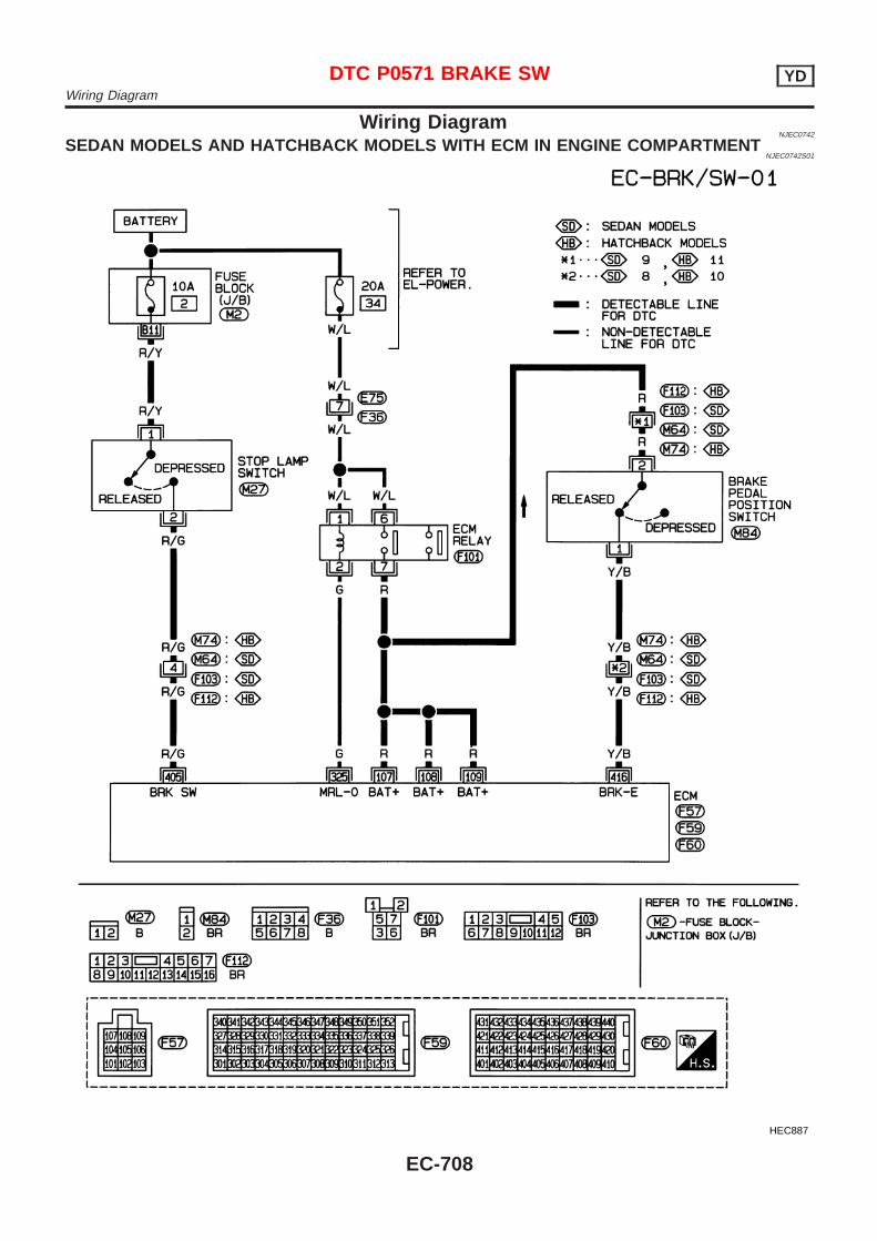
Wiring DiagramNJEC0742
SEDAN MODELS AND HATCHBACK MODELS WITH ECM IN ENGINE COMPARTMENTNJEC0742S01
HEC887
DTC P0571 BRAKE SW YDWiring Diagram
EC-708
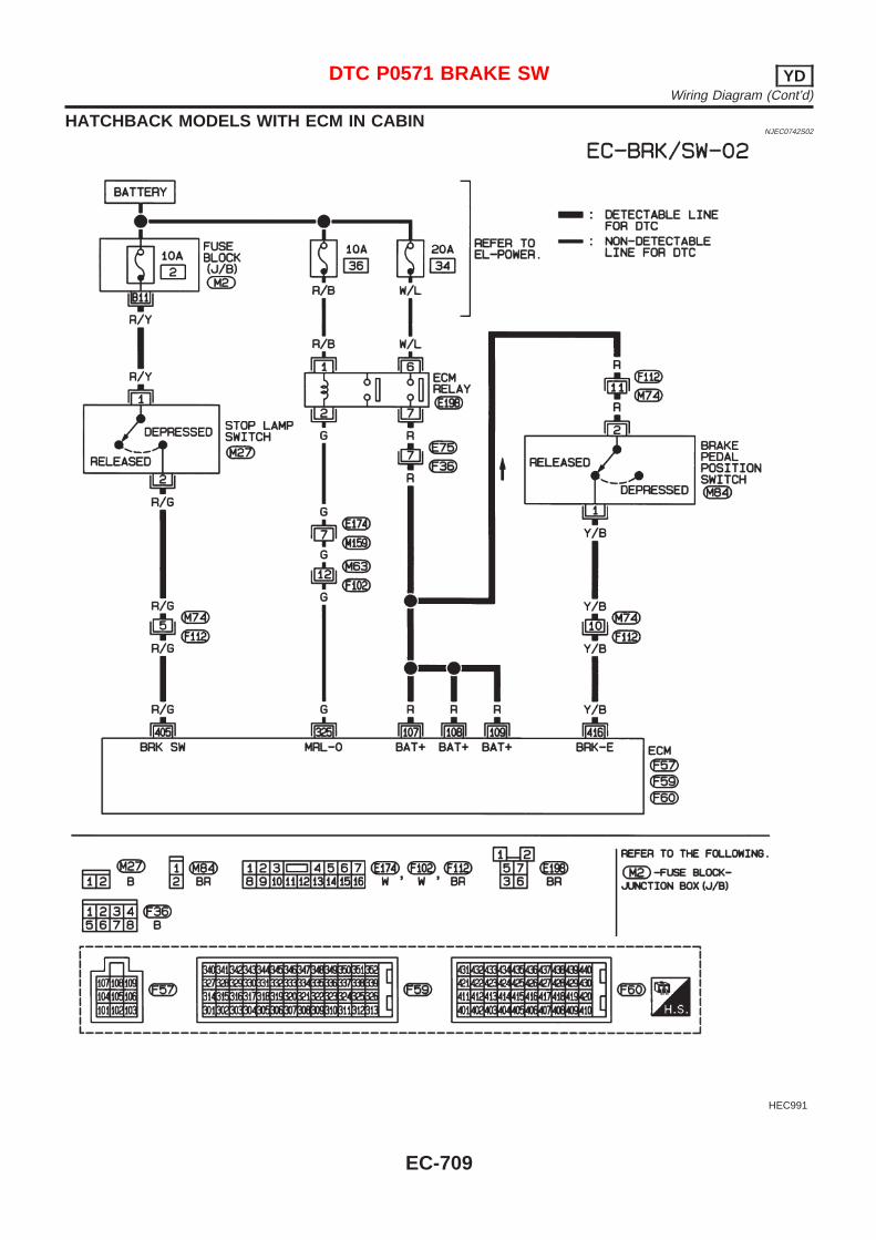
HATCHBACK MODELS WITH ECM IN CABINNJEC0742S02
HEC991
DTC P0571 BRAKE SW YDWiring Diagram (Cont’d)
EC-709
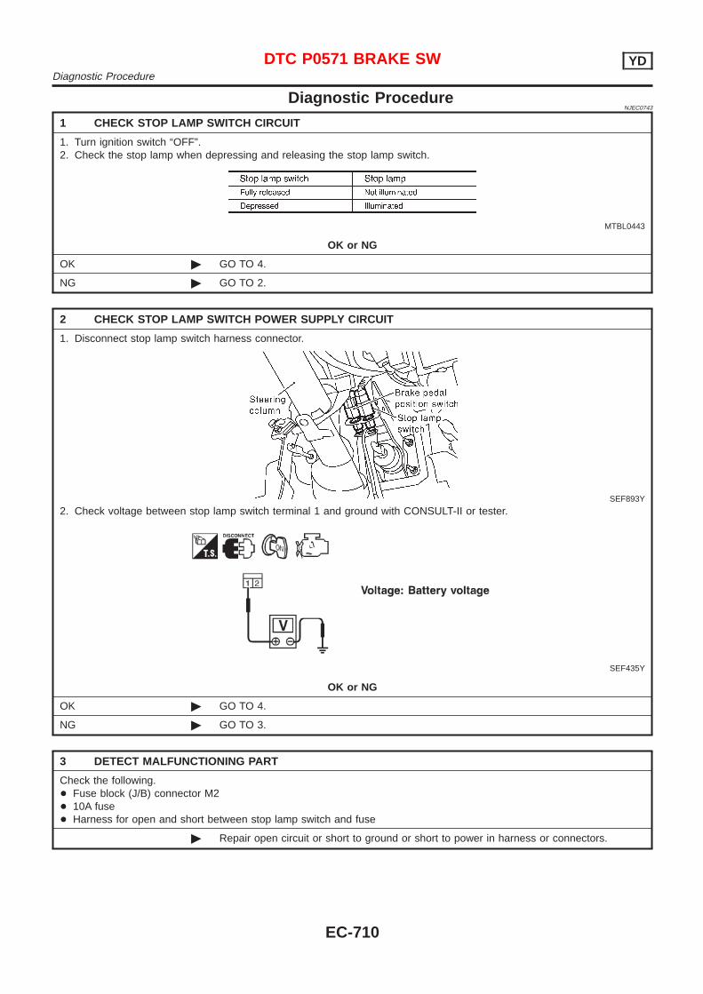
Diagnostic ProcedureNJEC0743
1 CHECK STOP LAMP SWITCH CIRCUIT
1. Turn ignition switch “OFF”.2. Check the stop lamp when depressing and releasing the stop lamp switch.
MTBL0443
OK or NG
OK © GO TO 4.
NG © GO TO 2.
2 CHECK STOP LAMP SWITCH POWER SUPPLY CIRCUIT
1. Disconnect stop lamp switch harness connector.
SEF893Y
2. Check voltage between stop lamp switch terminal 1 and ground with CONSULT-II or tester.
SEF435Y
OK or NG
OK © GO TO 4.
NG © GO TO 3.
3 DETECT MALFUNCTIONING PART
Check the following.+ Fuse block (J/B) connector M2+ 10A fuse+ Harness for open and short between stop lamp switch and fuse
© Repair open circuit or short to ground or short to power in harness or connectors.
DTC P0571 BRAKE SW YDDiagnostic Procedure
EC-710
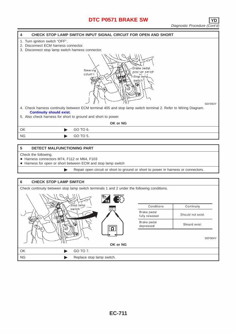
4 CHECK STOP LAMP SWITCH INPUT SIGNAL CIRCUIT FOR OPEN AND SHORT
1. Turn ignition switch “OFF”.2. Disconnect ECM harness connector.3. Disconnect stop lamp switch harness connector.
SEF893Y
4. Check harness continuity between ECM terminal 405 and stop lamp switch terminal 2. Refer to Wiring Diagram.Continuity should exist.
5. Also check harness for short to ground and short to power.
OK or NG
OK © GO TO 6.
NG © GO TO 5.
5 DETECT MALFUNCTIONING PART
Check the following.+ Harness connectors M74, F112 or M64, F103+ Harness for open or short between ECM and stop lamp switch
© Repair open circuit or short to ground or short to power in harness or connectors.
6 CHECK STOP LAMP SWITCH
Check continuity between stop lamp switch terminals 1 and 2 under the following conditions.
SEF904Y
OK or NG
OK © GO TO 7.
NG © Replace stop lamp switch.
DTC P0571 BRAKE SW YDDiagnostic Procedure (Cont’d)
EC-711
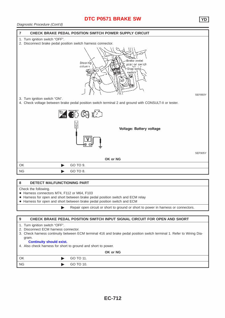
7 CHECK BRAKE PEDAL POSITION SWITCH POWER SUPPLY CIRCUIT
1. Turn ignition switch “OFF”.2. Disconnect brake pedal position switch harness connector.
SEF893Y
3. Turn ignition switch “ON”.4. Check voltage between brake pedal position switch terminal 2 and ground with CONSULT-II or tester.
SEF905Y
OK or NG
OK © GO TO 9.
NG © GO TO 8.
8 DETECT MALFUNCTIONING PART
Check the following.+ Harness connectors M74, F112 or M64, F103+ Harness for open and short between brake pedal position switch and ECM relay+ Harness for open and short between brake pedal position switch and ECM
© Repair open circuit or short to ground or short to power in harness or connectors.
9 CHECK BRAKE PEDAL POSITION SWITCH INPUT SIGNAL CIRCUIT FOR OPEN AND SHORT
1. Turn ignition switch “OFF”.2. Disconnect ECM harness connector.3. Check harness continuity between ECM terminal 416 and brake pedal position switch terminal 1. Refer to Wiring Dia-
gram.Continuity should exist.
4. Also check harness for short to ground and short to power.
OK or NG
OK © GO TO 11.
NG © GO TO 10.
DTC P0571 BRAKE SW YDDiagnostic Procedure (Cont’d)
EC-712
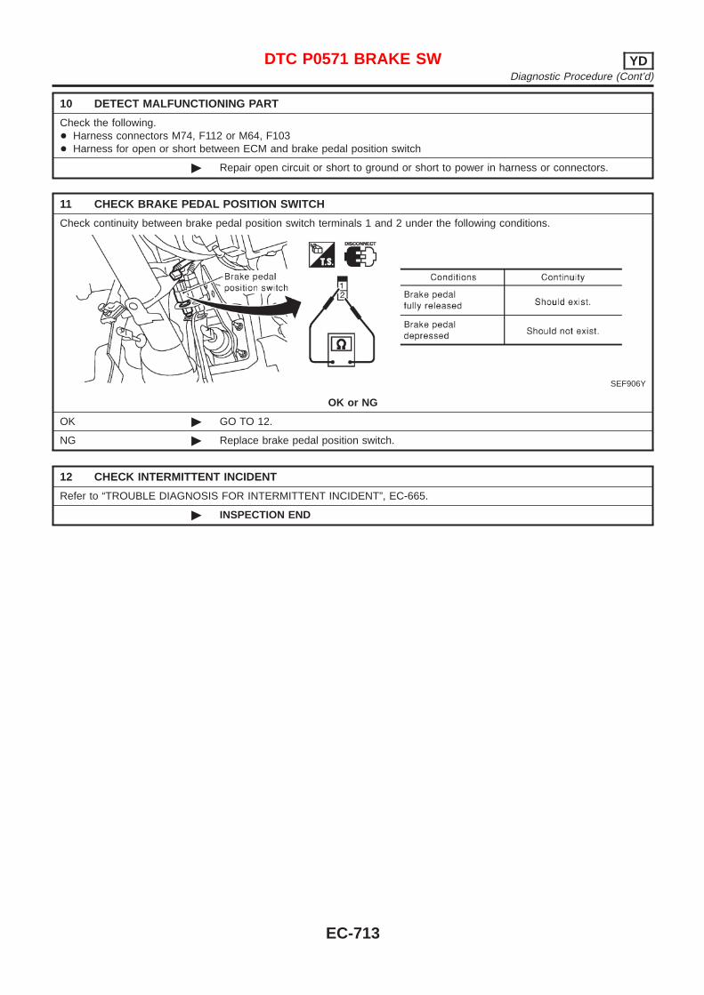
10 DETECT MALFUNCTIONING PART
Check the following.+ Harness connectors M74, F112 or M64, F103+ Harness for open or short between ECM and brake pedal position switch
© Repair open circuit or short to ground or short to power in harness or connectors.
11 CHECK BRAKE PEDAL POSITION SWITCH
Check continuity between brake pedal position switch terminals 1 and 2 under the following conditions.
SEF906Y
OK or NG
OK © GO TO 12.
NG © Replace brake pedal position switch.
12 CHECK INTERMITTENT INCIDENT
Refer to “TROUBLE DIAGNOSIS FOR INTERMITTENT INCIDENT”, EC-665.
© INSPECTION END
DTC P0571 BRAKE SW YDDiagnostic Procedure (Cont’d)
EC-713
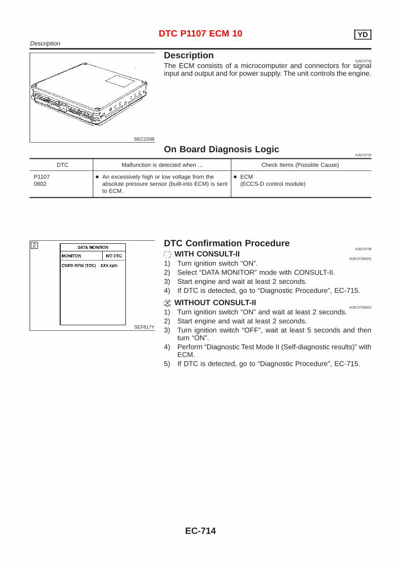
SEC220B
DescriptionNJEC0734
The ECM consists of a microcomputer and connectors for signalinput and output and for power supply. The unit controls the engine.
On Board Diagnosis LogicNJEC0735
DTC Malfunction is detected when ... Check Items (Possible Cause)
P11070802
+ An excessively high or low voltage from theabsolute pressure sensor (built-into ECM) is sentto ECM.
+ ECM(ECCS-D control module)
SEF817Y
DTC Confirmation ProcedureNJEC0736
WITH CONSULT-IINJEC0736S01
1) Turn ignition switch “ON”.2) Select “DATA MONITOR” mode with CONSULT-II.3) Start engine and wait at least 2 seconds.4) If DTC is detected, go to “Diagnostic Procedure”, EC-715.
WITHOUT CONSULT-IINJEC0736S02
1) Turn ignition switch “ON” and wait at least 2 seconds.2) Start engine and wait at least 2 seconds.3) Turn ignition switch “OFF”, wait at least 5 seconds and then
turn “ON”.4) Perform “Diagnostic Test Mode II (Self-diagnostic results)” with
ECM.5) If DTC is detected, go to “Diagnostic Procedure”, EC-715.
DTC P1107 ECM 10 YDDescription
EC-714
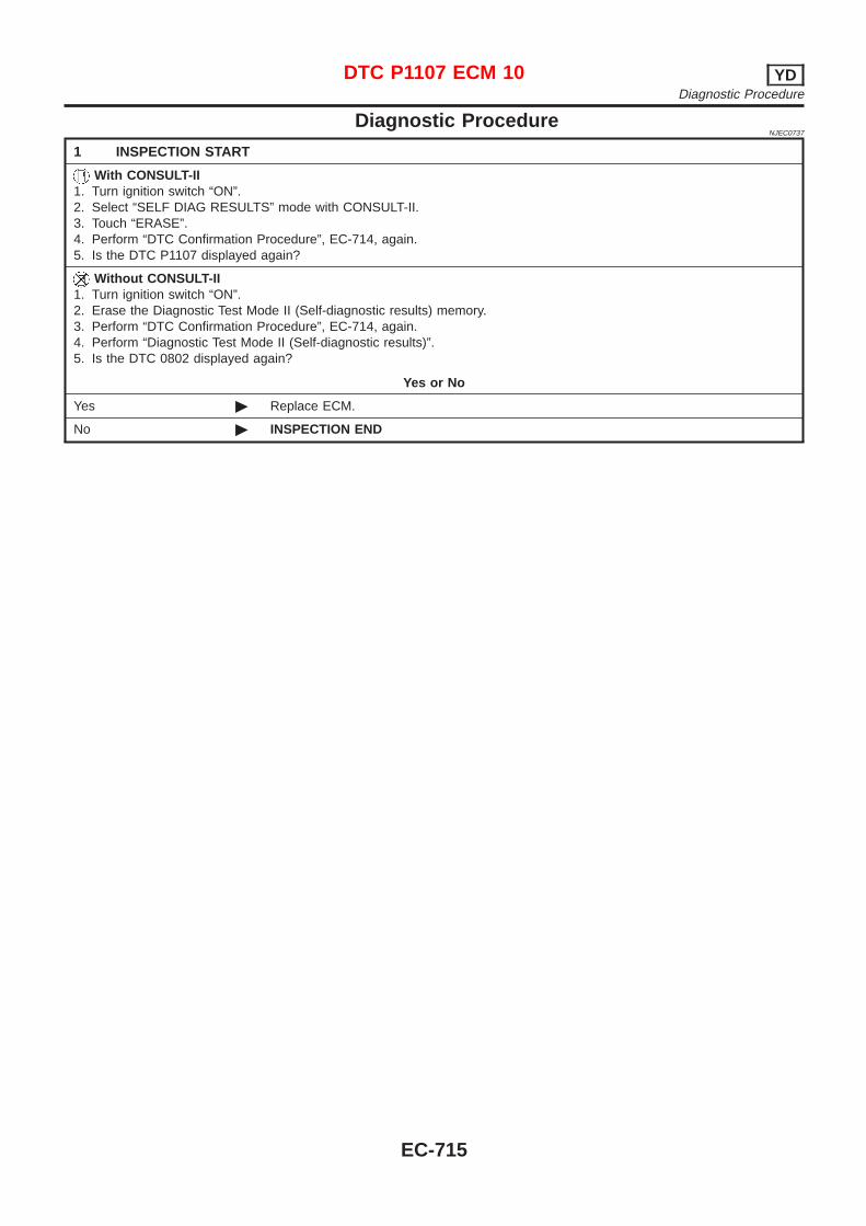
Diagnostic ProcedureNJEC0737
1 INSPECTION START
With CONSULT-II1. Turn ignition switch “ON”.2. Select “SELF DIAG RESULTS” mode with CONSULT-II.3. Touch “ERASE”.4. Perform “DTC Confirmation Procedure”, EC-714, again.5. Is the DTC P1107 displayed again?
Without CONSULT-II1. Turn ignition switch “ON”.2. Erase the Diagnostic Test Mode II (Self-diagnostic results) memory.3. Perform “DTC Confirmation Procedure”, EC-714, again.4. Perform “Diagnostic Test Mode II (Self-diagnostic results)”.5. Is the DTC 0802 displayed again?
Yes or No
Yes © Replace ECM.
No © INSPECTION END
DTC P1107 ECM 10 YDDiagnostic Procedure
EC-715

SEF437Y
DescriptionNJEC0672
SYSTEM DESCRIPTIONNJEC0672S01
The ECM and the electronic control fuel injection pump control unit(abbreviated as the injection pump control unit) perform the realtime communication (signal exchange).The ECM transmits the signals of the target fuel injection amount,target fuel injection timing, and engine speed, etc., and receivesthe signals of the pump speed and fuel temperature, etc. from theinjection pump control unit.By those signals, the injection pump controls the optimum fuelinjection amount and injection timing of the spill valve and timingcontrol valve.Injection pump control unit has an on board diagnostic system,which detects malfunctions related to sensors or actuators built-intoelectronic control fuel injection pump. These malfunction informa-tion are transferred through the line (circuit) from injection pumpcontrol unit to ECM.
FUEL INJECTION AMOUNT CONTROLNJEC0672S02
In accordance with the target fuel injection amount signal from theECM, the injection amount is controlled by controlling the spill valvein the injection pump and by changing the needle opening time.
FUEL INJECTION TIMING CONTROLNJEC0672S03
Based on the target fuel injection timing signal from the ECM, theinjection timing is controlled in accordance with the timer spring byperforming the duty control of the timing control valve in the injec-tion pump and by adjusting the pressure of the timer piston highpressure chamber.
FUEL TEMPERATURE SENSORNJEC0672S04
The sensor detects the fuel temperature in the injection pump andcalibrates the injection amount change by the fuel temperature.
CAMSHAFT POSITION SENSORNJEC0672S05
The sensor detects the passing of the protrusion on the sensorwheel in the injection pump by the semiconductor magnetic resis-tance element sensor. The camshaft position sensor synchronizeswith the cam ring, and detects the actual advance amount. Theinjection pump control unit measures the injection pump revolutionby the signal of the camshaft position sensor.
CONSULT-II Reference Value in Data MonitorMode
NJEC0673
Remarks: Specification data are reference values.
MONITOR ITEM CONDITION SPECIFICATION
FUEL TEMP SEN + Engine: After warming up More than 40°C (104°F)
SPILL/V + Engine: After warming up, idle the engine. Approx. 12 - 13°CA
INT/A VOLUME + Engine: After warming up, idle the engine. Approx. 150 - 450 mg/st
F/CUT SIGNAL + Engine: After warming up Idle ON
DTC P1180 P9·FUEL TEMP SEN YDDescription
EC-716
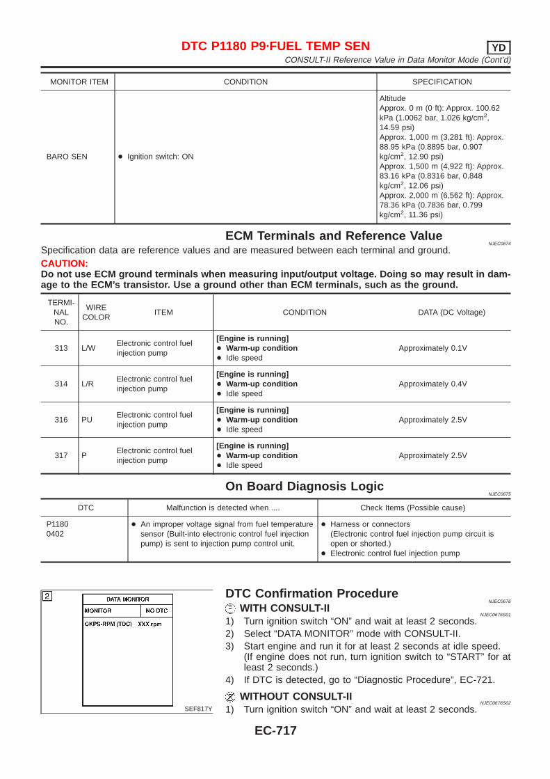
MONITOR ITEM CONDITION SPECIFICATION
BARO SEN + Ignition switch: ON
AltitudeApprox. 0 m (0 ft): Approx. 100.62kPa (1.0062 bar, 1.026 kg/cm2,14.59 psi)Approx. 1,000 m (3,281 ft): Approx.88.95 kPa (0.8895 bar, 0.907kg/cm2, 12.90 psi)Approx. 1,500 m (4,922 ft): Approx.83.16 kPa (0.8316 bar, 0.848kg/cm2, 12.06 psi)Approx. 2,000 m (6,562 ft): Approx.78.36 kPa (0.7836 bar, 0.799kg/cm2, 11.36 psi)
ECM Terminals and Reference ValueNJEC0674
Specification data are reference values and are measured between each terminal and ground.CAUTION:Do not use ECM ground terminals when measuring input/output voltage. Doing so may result in dam-age to the ECM’s transistor. Use a ground other than ECM terminals, such as the ground.
TERMI-NALNO.
WIRECOLOR
ITEM CONDITION DATA (DC Voltage)
313 L/WElectronic control fuelinjection pump
[Engine is running]+ Warm-up condition+ Idle speed
Approximately 0.1V
314 L/RElectronic control fuelinjection pump
[Engine is running]+ Warm-up condition+ Idle speed
Approximately 0.4V
316 PUElectronic control fuelinjection pump
[Engine is running]+ Warm-up condition+ Idle speed
Approximately 2.5V
317 PElectronic control fuelinjection pump
[Engine is running]+ Warm-up condition+ Idle speed
Approximately 2.5V
On Board Diagnosis LogicNJEC0675
DTC Malfunction is detected when .... Check Items (Possible cause)
P11800402
+ An improper voltage signal from fuel temperaturesensor (Built-into electronic control fuel injectionpump) is sent to injection pump control unit.
+ Harness or connectors(Electronic control fuel injection pump circuit isopen or shorted.)
+ Electronic control fuel injection pump
SEF817Y
DTC Confirmation ProcedureNJEC0676
WITH CONSULT-IINJEC0676S01
1) Turn ignition switch “ON” and wait at least 2 seconds.2) Select “DATA MONITOR” mode with CONSULT-II.3) Start engine and run it for at least 2 seconds at idle speed.
(If engine does not run, turn ignition switch to “START” for atleast 2 seconds.)
4) If DTC is detected, go to “Diagnostic Procedure”, EC-721.
WITHOUT CONSULT-IINJEC0676S02
1) Turn ignition switch “ON” and wait at least 2 seconds.
DTC P1180 P9·FUEL TEMP SEN YDCONSULT-II Reference Value in Data Monitor Mode (Cont’d)
EC-717

2) Start engine and run it for at least 2 seconds at idle speed.(If engine does not run, turn ignition switch to “START” for atleast 2 seconds.)
3) Turn ignition switch “OFF”, wait at least 5 seconds and thenturn “ON”.
4) Perform “Diagnostic Test Mode II (Self-diagnostic results)” withECM.
5) If DTC is detected, go to “Diagnostic Procedure”, EC-721.
DTC P1180 P9·FUEL TEMP SEN YDDTC Confirmation Procedure (Cont’d)
EC-718
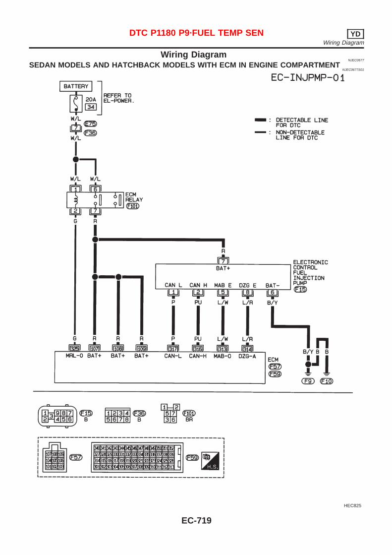
Wiring DiagramNJEC0677
SEDAN MODELS AND HATCHBACK MODELS WITH ECM IN ENGINE COMPARTMENTNJEC0677S01
HEC825
DTC P1180 P9·FUEL TEMP SEN YDWiring Diagram
EC-719

HATCHBACK MODELS WITH ECM IN CABINNJEC0677S02
HEC993
DTC P1180 P9·FUEL TEMP SEN YDWiring Diagram (Cont’d)
EC-720
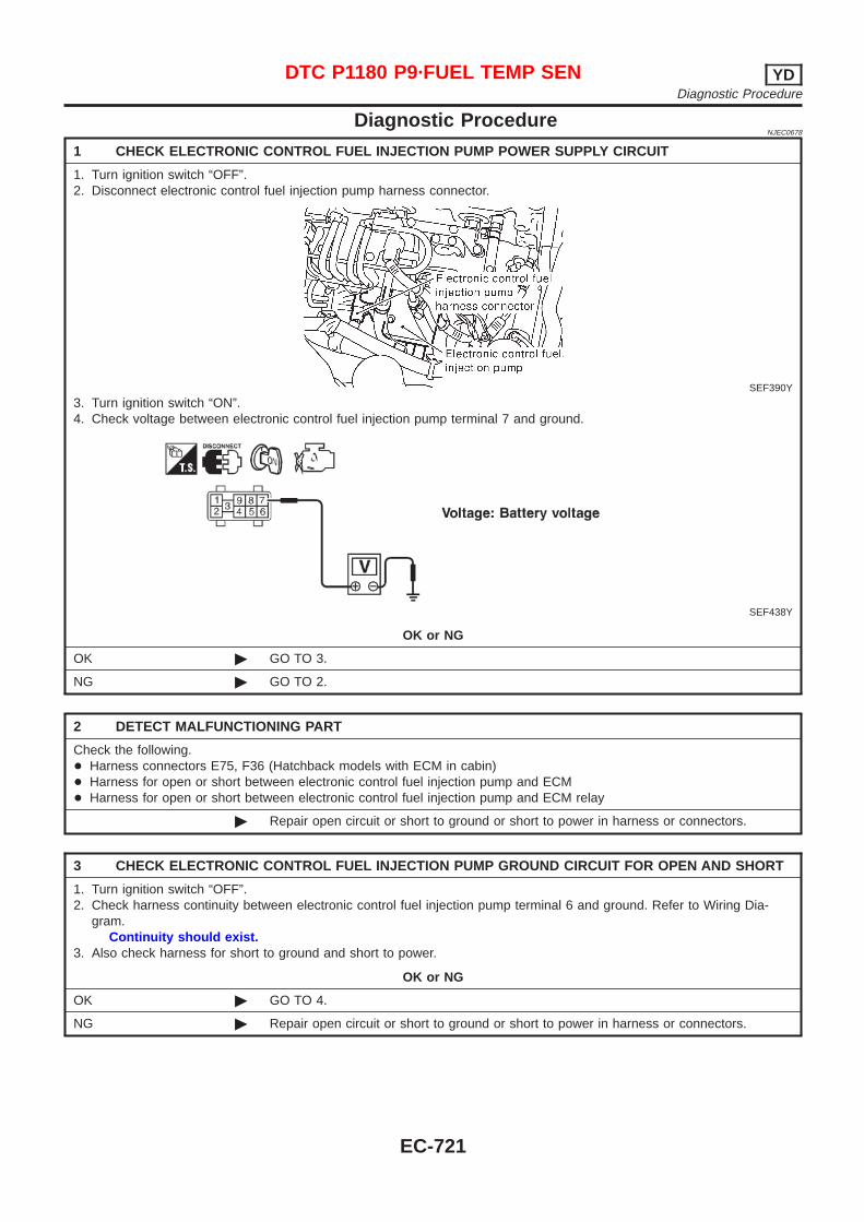
Diagnostic ProcedureNJEC0678
1 CHECK ELECTRONIC CONTROL FUEL INJECTION PUMP POWER SUPPLY CIRCUIT
1. Turn ignition switch “OFF”.2. Disconnect electronic control fuel injection pump harness connector.
SEF390Y
3. Turn ignition switch “ON”.4. Check voltage between electronic control fuel injection pump terminal 7 and ground.
SEF438Y
OK or NG
OK © GO TO 3.
NG © GO TO 2.
2 DETECT MALFUNCTIONING PART
Check the following.+ Harness connectors E75, F36 (Hatchback models with ECM in cabin)+ Harness for open or short between electronic control fuel injection pump and ECM+ Harness for open or short between electronic control fuel injection pump and ECM relay
© Repair open circuit or short to ground or short to power in harness or connectors.
3 CHECK ELECTRONIC CONTROL FUEL INJECTION PUMP GROUND CIRCUIT FOR OPEN AND SHORT
1. Turn ignition switch “OFF”.2. Check harness continuity between electronic control fuel injection pump terminal 6 and ground. Refer to Wiring Dia-
gram.Continuity should exist.
3. Also check harness for short to ground and short to power.
OK or NG
OK © GO TO 4.
NG © Repair open circuit or short to ground or short to power in harness or connectors.
DTC P1180 P9·FUEL TEMP SEN YDDiagnostic Procedure
EC-721
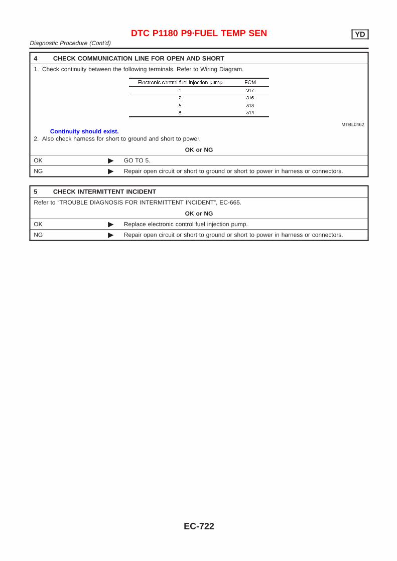
4 CHECK COMMUNICATION LINE FOR OPEN AND SHORT
1. Check continuity between the following terminals. Refer to Wiring Diagram.
MTBL0462
Continuity should exist.2. Also check harness for short to ground and short to power.
OK or NG
OK © GO TO 5.
NG © Repair open circuit or short to ground or short to power in harness or connectors.
5 CHECK INTERMITTENT INCIDENT
Refer to “TROUBLE DIAGNOSIS FOR INTERMITTENT INCIDENT”, EC-665.
OK or NG
OK © Replace electronic control fuel injection pump.
NG © Repair open circuit or short to ground or short to power in harness or connectors.
DTC P1180 P9·FUEL TEMP SEN YDDiagnostic Procedure (Cont’d)
EC-722
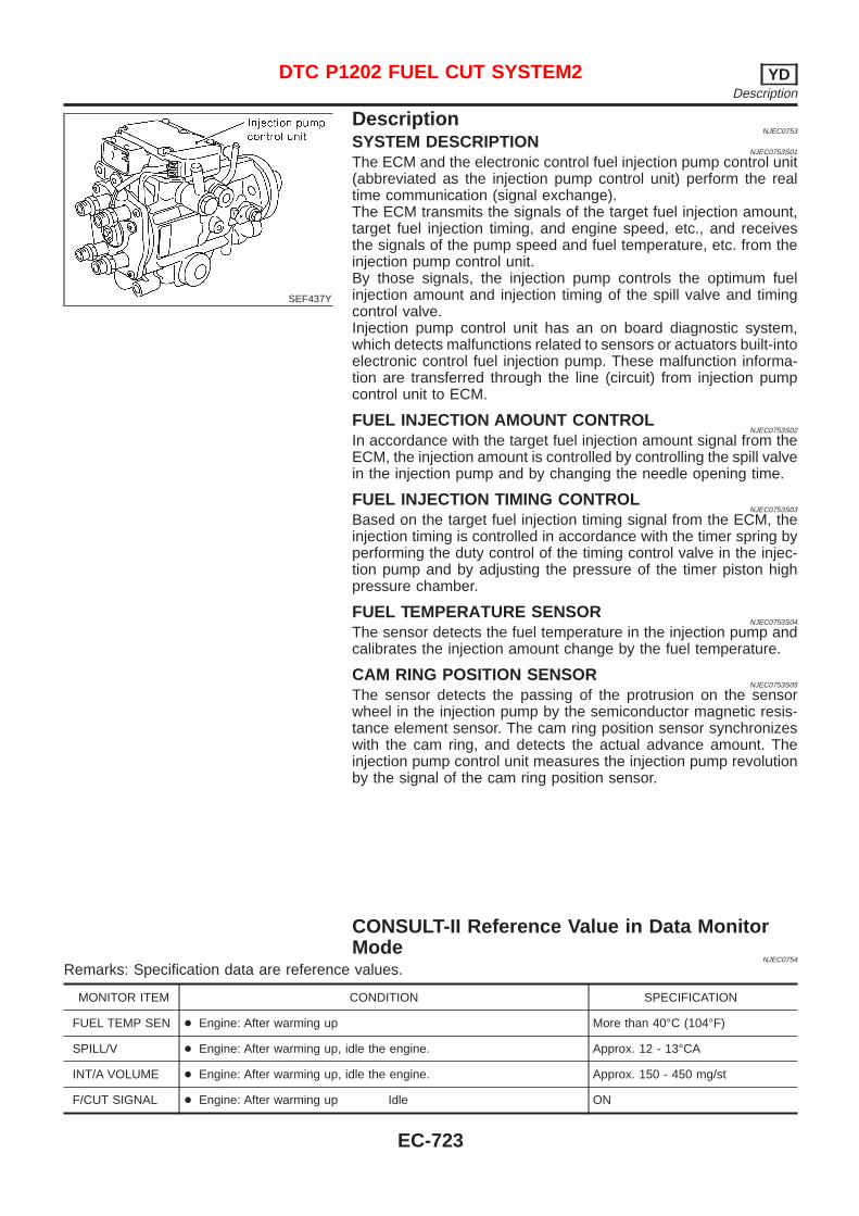
SEF437Y
DescriptionNJEC0753
SYSTEM DESCRIPTIONNJEC0753S01
The ECM and the electronic control fuel injection pump control unit(abbreviated as the injection pump control unit) perform the realtime communication (signal exchange).The ECM transmits the signals of the target fuel injection amount,target fuel injection timing, and engine speed, etc., and receivesthe signals of the pump speed and fuel temperature, etc. from theinjection pump control unit.By those signals, the injection pump controls the optimum fuelinjection amount and injection timing of the spill valve and timingcontrol valve.Injection pump control unit has an on board diagnostic system,which detects malfunctions related to sensors or actuators built-intoelectronic control fuel injection pump. These malfunction informa-tion are transferred through the line (circuit) from injection pumpcontrol unit to ECM.
FUEL INJECTION AMOUNT CONTROLNJEC0753S02
In accordance with the target fuel injection amount signal from theECM, the injection amount is controlled by controlling the spill valvein the injection pump and by changing the needle opening time.
FUEL INJECTION TIMING CONTROLNJEC0753S03
Based on the target fuel injection timing signal from the ECM, theinjection timing is controlled in accordance with the timer spring byperforming the duty control of the timing control valve in the injec-tion pump and by adjusting the pressure of the timer piston highpressure chamber.
FUEL TEMPERATURE SENSORNJEC0753S04
The sensor detects the fuel temperature in the injection pump andcalibrates the injection amount change by the fuel temperature.
CAM RING POSITION SENSORNJEC0753S05
The sensor detects the passing of the protrusion on the sensorwheel in the injection pump by the semiconductor magnetic resis-tance element sensor. The cam ring position sensor synchronizeswith the cam ring, and detects the actual advance amount. Theinjection pump control unit measures the injection pump revolutionby the signal of the cam ring position sensor.
CONSULT-II Reference Value in Data MonitorMode
NJEC0754
Remarks: Specification data are reference values.
MONITOR ITEM CONDITION SPECIFICATION
FUEL TEMP SEN + Engine: After warming up More than 40°C (104°F)
SPILL/V + Engine: After warming up, idle the engine. Approx. 12 - 13°CA
INT/A VOLUME + Engine: After warming up, idle the engine. Approx. 150 - 450 mg/st
F/CUT SIGNAL + Engine: After warming up Idle ON
DTC P1202 FUEL CUT SYSTEM2 YDDescription
EC-723
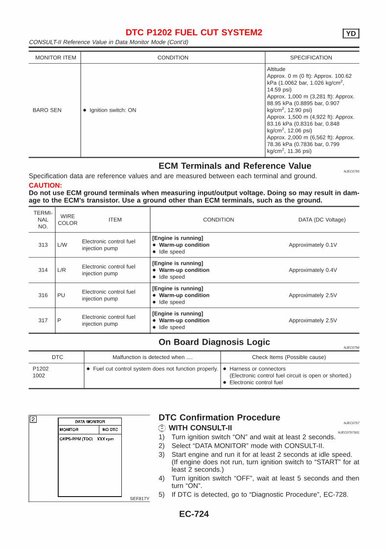
MONITOR ITEM CONDITION SPECIFICATION
BARO SEN + Ignition switch: ON
AltitudeApprox. 0 m (0 ft): Approx. 100.62kPa (1.0062 bar, 1.026 kg/cm2,14.59 psi)Approx. 1,000 m (3,281 ft): Approx.88.95 kPa (0.8895 bar, 0.907kg/cm2, 12.90 psi)Approx. 1,500 m (4,922 ft): Approx.83.16 kPa (0.8316 bar, 0.848kg/cm2, 12.06 psi)Approx. 2,000 m (6,562 ft): Approx.78.36 kPa (0.7836 bar, 0.799kg/cm2, 11.36 psi)
ECM Terminals and Reference ValueNJEC0755
Specification data are reference values and are measured between each terminal and ground.CAUTION:Do not use ECM ground terminals when measuring input/output voltage. Doing so may result in dam-age to the ECM’s transistor. Use a ground other than ECM terminals, such as the ground.
TERMI-NALNO.
WIRECOLOR
ITEM CONDITION DATA (DC Voltage)
313 L/WElectronic control fuelinjection pump
[Engine is running]+ Warm-up condition+ Idle speed
Approximately 0.1V
314 L/RElectronic control fuelinjection pump
[Engine is running]+ Warm-up condition+ Idle speed
Approximately 0.4V
316 PUElectronic control fuelinjection pump
[Engine is running]+ Warm-up condition+ Idle speed
Approximately 2.5V
317 PElectronic control fuelinjection pump
[Engine is running]+ Warm-up condition+ Idle speed
Approximately 2.5V
On Board Diagnosis LogicNJEC0756
DTC Malfunction is detected when .... Check Items (Possible cause)
P12021002
+ Fuel cut control system does not function properly. + Harness or connectors(Electronic control fuel circuit is open or shorted.)
+ Electronic control fuel
SEF817Y
DTC Confirmation ProcedureNJEC0757
WITH CONSULT-IINJEC0757S01
1) Turn ignition switch “ON” and wait at least 2 seconds.2) Select “DATA MONITOR” mode with CONSULT-II.3) Start engine and run it for at least 2 seconds at idle speed.
(If engine does not run, turn ignition switch to “START” for atleast 2 seconds.)
4) Turn ignition switch “OFF”, wait at least 5 seconds and thenturn “ON”.
5) If DTC is detected, go to “Diagnostic Procedure”, EC-728.
DTC P1202 FUEL CUT SYSTEM2 YDCONSULT-II Reference Value in Data Monitor Mode (Cont’d)
EC-724
WITHOUT CONSULT-IINJEC0757S02
1) Turn ignition switch “ON” and wait at least 2 seconds.2) Start engine and run it for at least 2 seconds at idle speed.
(If engine does not run, turn ignition switch to “START” for atleast 2 seconds.)
3) Turn ignition switch “OFF”, wait at least 5 seconds and thenturn “ON”.
4) Perform “Diagnostic Test Mode II (Self-diagnostic results)” withECM.
5) If DTC is detected, go to “Diagnostic Procedure”, EC-728.
DTC P1202 FUEL CUT SYSTEM2 YDDTC Confirmation Procedure (Cont’d)
EC-725
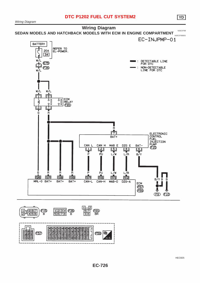
Wiring DiagramNJEC0758
SEDAN MODELS AND HATCHBACK MODELS WITH ECM IN ENGINE COMPARTMENTNJEC0758S01
HEC825
DTC P1202 FUEL CUT SYSTEM2 YDWiring Diagram
EC-726
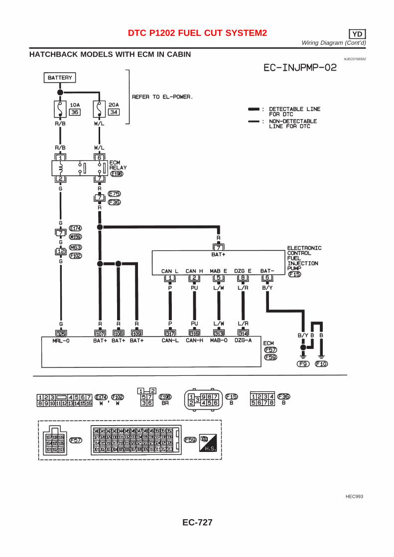
HATCHBACK MODELS WITH ECM IN CABINNJEC0758S02
HEC993
DTC P1202 FUEL CUT SYSTEM2 YDWiring Diagram (Cont’d)
EC-727
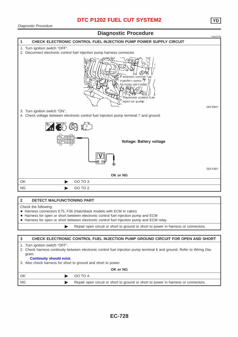
Diagnostic ProcedureNJEC0759
1 CHECK ELECTRONIC CONTROL FUEL INJECTION PUMP POWER SUPPLY CIRCUIT
1. Turn ignition switch “OFF”.2. Disconnect electronic control fuel injection pump harness connector.
SEF390Y
3. Turn ignition switch “ON”.4. Check voltage between electronic control fuel injection pump terminal 7 and ground.
SEF438Y
OK or NG
OK © GO TO 3.
NG © GO TO 2.
2 DETECT MALFUNCTIONING PART
Check the following.+ Harness connectors E75, F36 (Hatchback models with ECM in cabin)+ Harness for open or short between electronic control fuel injection pump and ECM+ Harness for open or short between electronic control fuel injection pump and ECM relay
© Repair open circuit or short to ground or short to power in harness or connectors.
3 CHECK ELECTRONIC CONTROL FUEL INJECTION PUMP GROUND CIRCUIT FOR OPEN AND SHORT
1. Turn ignition switch “OFF”.2. Check harness continuity between electronic control fuel injection pump terminal 6 and ground. Refer to Wiring Dia-
gram.Continuity should exist.
3. Also check harness for short to ground and short to power.
OK or NG
OK © GO TO 4.
NG © Repair open circuit or short to ground or short to power in harness or connectors.
DTC P1202 FUEL CUT SYSTEM2 YDDiagnostic Procedure
EC-728
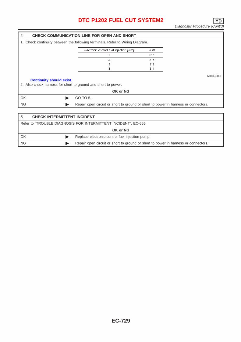
4 CHECK COMMUNICATION LINE FOR OPEN AND SHORT
1. Check continuity between the following terminals. Refer to Wiring Diagram.
MTBL0462
Continuity should exist.2. Also check harness for short to ground and short to power.
OK or NG
OK © GO TO 5.
NG © Repair open circuit or short to ground or short to power in harness or connectors.
5 CHECK INTERMITTENT INCIDENT
Refer to “TROUBLE DIAGNOSIS FOR INTERMITTENT INCIDENT”, EC-665.
OK or NG
OK © Replace electronic control fuel injection pump.
NG © Repair open circuit or short to ground or short to power in harness or connectors.
DTC P1202 FUEL CUT SYSTEM2 YDDiagnostic Procedure (Cont’d)
EC-729
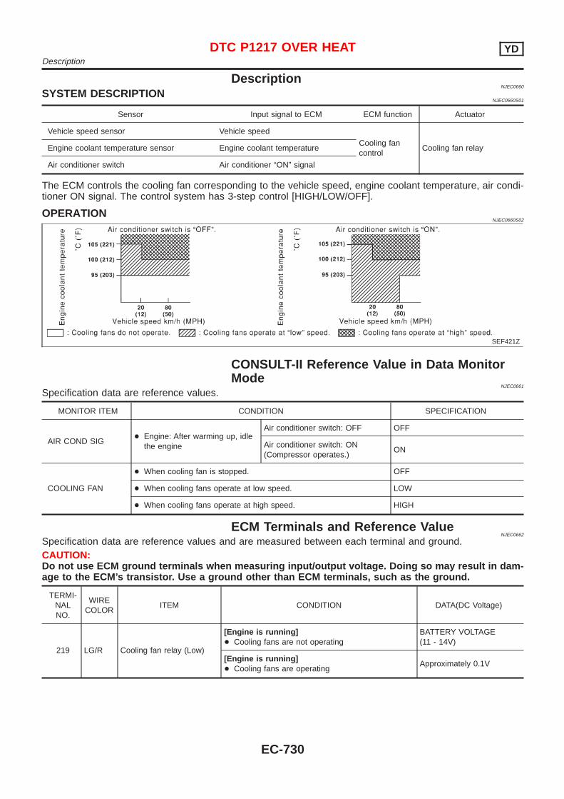
DescriptionNJEC0660
SYSTEM DESCRIPTIONNJEC0660S01
Sensor Input signal to ECM ECM function Actuator
Vehicle speed sensor Vehicle speed
Cooling fancontrol
Cooling fan relayEngine coolant temperature sensor Engine coolant temperature
Air conditioner switch Air conditioner “ON” signal
The ECM controls the cooling fan corresponding to the vehicle speed, engine coolant temperature, air condi-tioner ON signal. The control system has 3-step control [HIGH/LOW/OFF].
OPERATIONNJEC0660S02
SEF421Z
CONSULT-II Reference Value in Data MonitorMode
NJEC0661
Specification data are reference values.
MONITOR ITEM CONDITION SPECIFICATION
AIR COND SIG+ Engine: After warming up, idle
the engine
Air conditioner switch: OFF OFF
Air conditioner switch: ON(Compressor operates.)
ON
COOLING FAN
+ When cooling fan is stopped. OFF
+ When cooling fans operate at low speed. LOW
+ When cooling fans operate at high speed. HIGH
ECM Terminals and Reference ValueNJEC0662
Specification data are reference values and are measured between each terminal and ground.CAUTION:Do not use ECM ground terminals when measuring input/output voltage. Doing so may result in dam-age to the ECM’s transistor. Use a ground other than ECM terminals, such as the ground.
TERMI-NALNO.
WIRECOLOR
ITEM CONDITION DATA(DC Voltage)
219 LG/R Cooling fan relay (Low)
[Engine is running]+ Cooling fans are not operating
BATTERY VOLTAGE(11 - 14V)
[Engine is running]+ Cooling fans are operating
Approximately 0.1V
DTC P1217 OVER HEAT YDDescription
EC-730
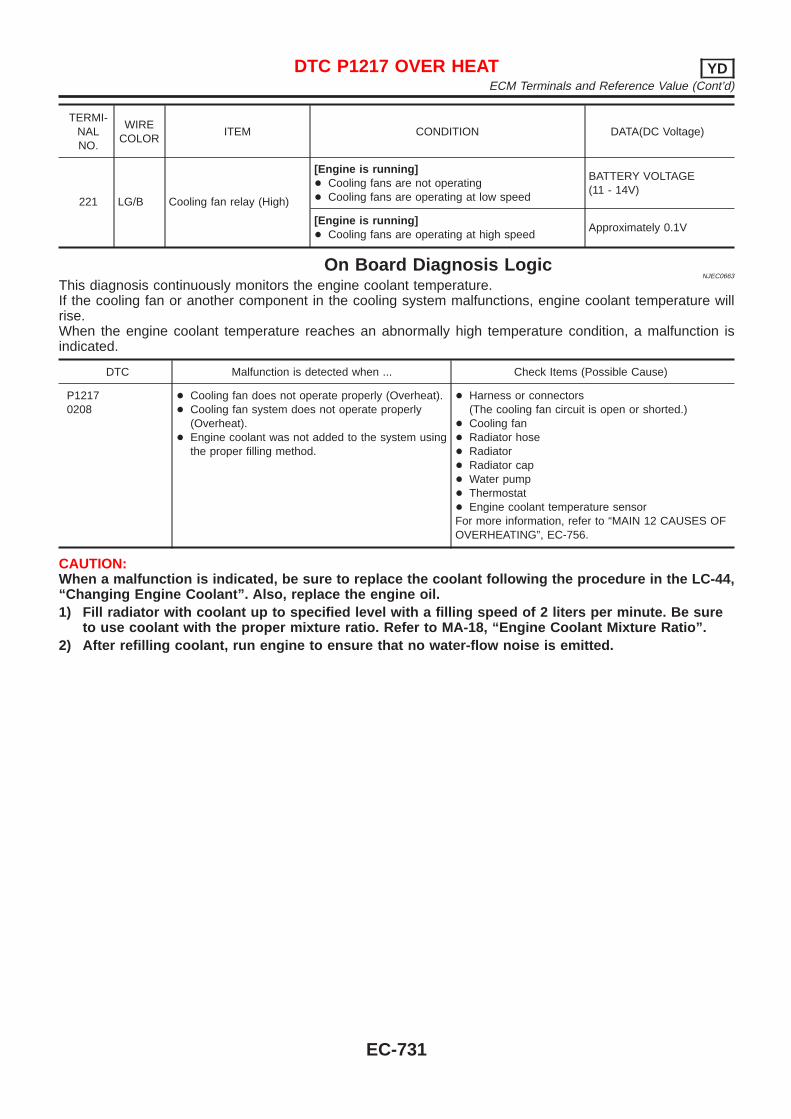
TERMI-NALNO.
WIRECOLOR
ITEM CONDITION DATA(DC Voltage)
221 LG/B Cooling fan relay (High)
[Engine is running]+ Cooling fans are not operating+ Cooling fans are operating at low speed
BATTERY VOLTAGE(11 - 14V)
[Engine is running]+ Cooling fans are operating at high speed
Approximately 0.1V
On Board Diagnosis LogicNJEC0663
This diagnosis continuously monitors the engine coolant temperature.If the cooling fan or another component in the cooling system malfunctions, engine coolant temperature willrise.When the engine coolant temperature reaches an abnormally high temperature condition, a malfunction isindicated.
DTC Malfunction is detected when ... Check Items (Possible Cause)
P12170208
+ Cooling fan does not operate properly (Overheat).+ Cooling fan system does not operate properly
(Overheat).+ Engine coolant was not added to the system using
the proper filling method.
+ Harness or connectors(The cooling fan circuit is open or shorted.)
+ Cooling fan+ Radiator hose+ Radiator+ Radiator cap+ Water pump+ Thermostat+ Engine coolant temperature sensorFor more information, refer to “MAIN 12 CAUSES OFOVERHEATING”, EC-756.
CAUTION:When a malfunction is indicated, be sure to replace the coolant following the procedure in the LC-44,“Changing Engine Coolant”. Also, replace the engine oil.1) Fill radiator with coolant up to specified level with a filling speed of 2 liters per minute. Be sure
to use coolant with the proper mixture ratio. Refer to MA-18, “Engine Coolant Mixture Ratio”.2) After refilling coolant, run engine to ensure that no water-flow noise is emitted.
DTC P1217 OVER HEAT YDECM Terminals and Reference Value (Cont’d)
EC-731
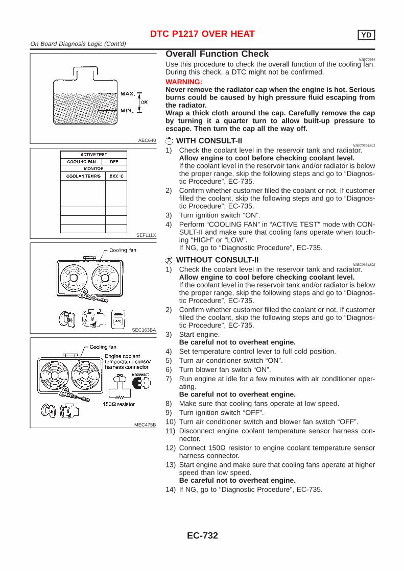
AEC640
SEF111X
SEC163BA
MEC475B
Overall Function CheckNJEC0664
Use this procedure to check the overall function of the cooling fan.During this check, a DTC might not be confirmed.WARNING:Never remove the radiator cap when the engine is hot. Seriousburns could be caused by high pressure fluid escaping fromthe radiator.Wrap a thick cloth around the cap. Carefully remove the capby turning it a quarter turn to allow built-up pressure toescape. Then turn the cap all the way off.
WITH CONSULT-IINJEC0664S01
1) Check the coolant level in the reservoir tank and radiator.Allow engine to cool before checking coolant level.If the coolant level in the reservoir tank and/or radiator is belowthe proper range, skip the following steps and go to “Diagnos-tic Procedure”, EC-735.
2) Confirm whether customer filled the coolant or not. If customerfilled the coolant, skip the following steps and go to “Diagnos-tic Procedure”, EC-735.
3) Turn ignition switch “ON”.4) Perform “COOLING FAN” in “ACTIVE TEST” mode with CON-
SULT-II and make sure that cooling fans operate when touch-ing “HIGH” or “LOW”.If NG, go to “Diagnostic Procedure”, EC-735.
WITHOUT CONSULT-IINJEC0664S02
1) Check the coolant level in the reservoir tank and radiator.Allow engine to cool before checking coolant level.If the coolant level in the reservoir tank and/or radiator is belowthe proper range, skip the following steps and go to “Diagnos-tic Procedure”, EC-735.
2) Confirm whether customer filled the coolant or not. If customerfilled the coolant, skip the following steps and go to “Diagnos-tic Procedure”, EC-735.
3) Start engine.Be careful not to overheat engine.
4) Set temperature control lever to full cold position.5) Turn air conditioner switch “ON”.6) Turn blower fan switch “ON”.7) Run engine at idle for a few minutes with air conditioner oper-
ating.Be careful not to overheat engine.
8) Make sure that cooling fans operate at low speed.9) Turn ignition switch “OFF”.10) Turn air conditioner switch and blower fan switch “OFF”.11) Disconnect engine coolant temperature sensor harness con-
nector.12) Connect 150Ω resistor to engine coolant temperature sensor
harness connector.13) Start engine and make sure that cooling fans operate at higher
speed than low speed.Be careful not to overheat engine.
14) If NG, go to “Diagnostic Procedure”, EC-735.
DTC P1217 OVER HEAT YDOn Board Diagnosis Logic (Cont’d)
EC-732
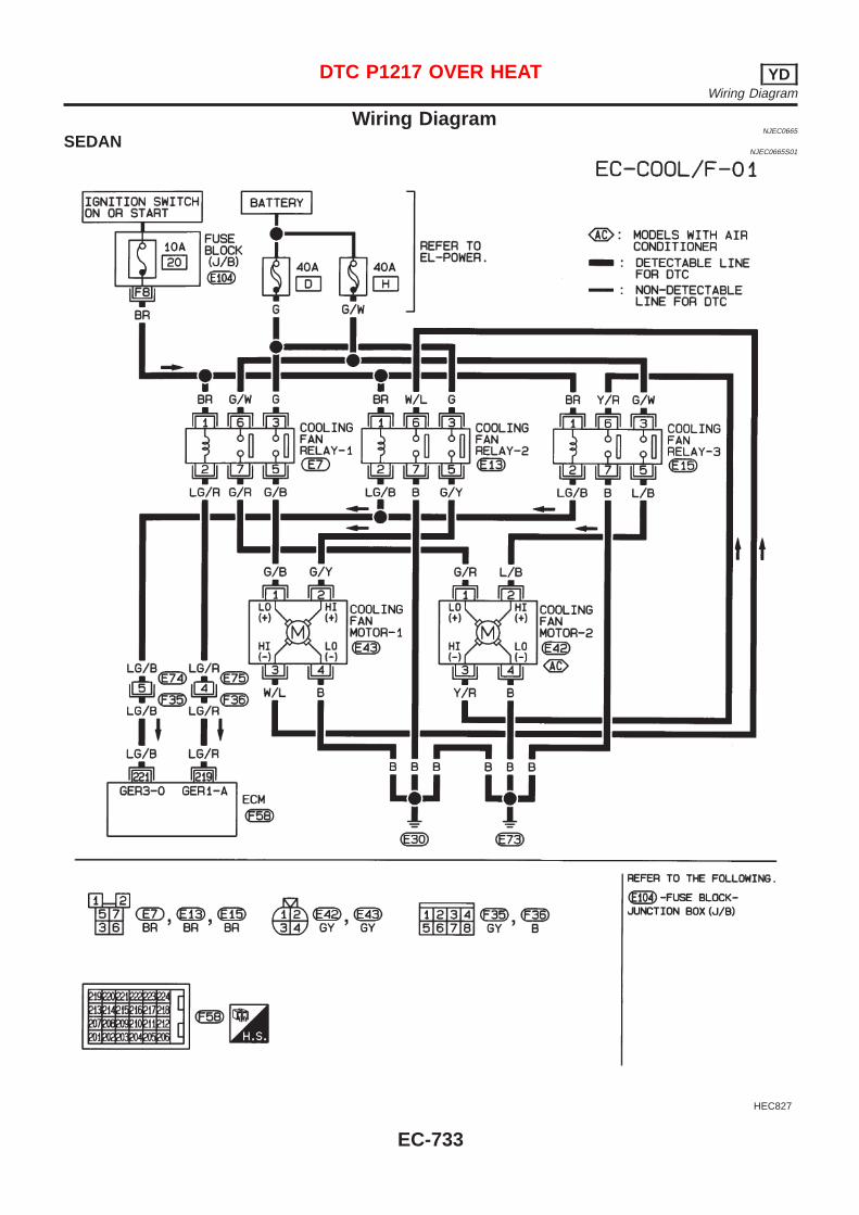
Wiring DiagramNJEC0665
SEDANNJEC0665S01
HEC827
DTC P1217 OVER HEAT YDWiring Diagram
EC-733
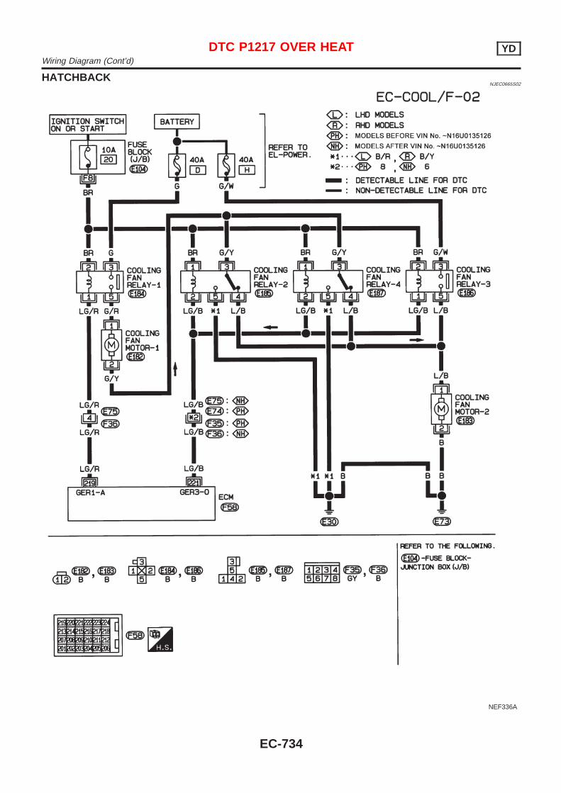
HATCHBACKNJEC0665S02
NEF336A
DTC P1217 OVER HEAT YDWiring Diagram (Cont’d)
EC-734
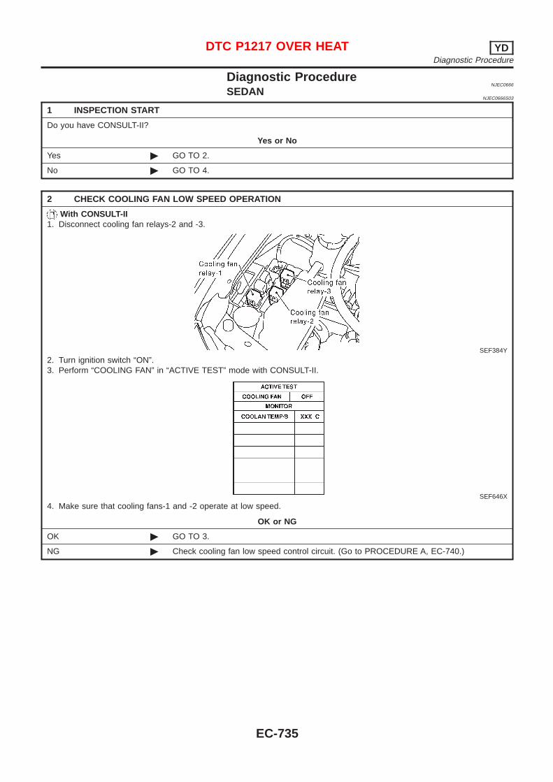
Diagnostic ProcedureNJEC0666
SEDANNJEC0666S03
1 INSPECTION START
Do you have CONSULT-II?
Yes or No
Yes © GO TO 2.
No © GO TO 4.
2 CHECK COOLING FAN LOW SPEED OPERATION
With CONSULT-II1. Disconnect cooling fan relays-2 and -3.
SEF384Y
2. Turn ignition switch “ON”.3. Perform “COOLING FAN” in “ACTIVE TEST” mode with CONSULT-II.
SEF646X
4. Make sure that cooling fans-1 and -2 operate at low speed.
OK or NG
OK © GO TO 3.
NG © Check cooling fan low speed control circuit. (Go to PROCEDURE A, EC-740.)
DTC P1217 OVER HEAT YDDiagnostic Procedure
EC-735
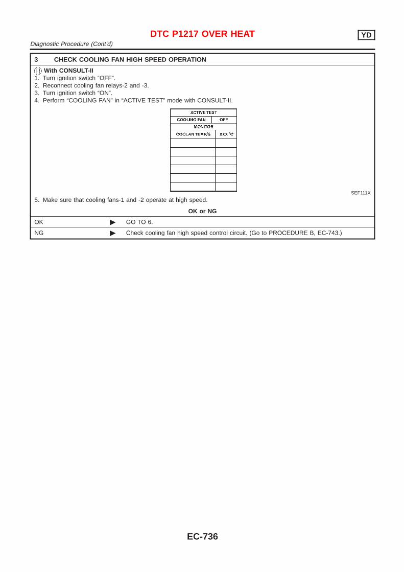
3 CHECK COOLING FAN HIGH SPEED OPERATION
With CONSULT-II1. Turn ignition switch “OFF”.2. Reconnect cooling fan relays-2 and -3.3. Turn ignition switch “ON”.4. Perform “COOLING FAN” in “ACTIVE TEST” mode with CONSULT-II.
SEF111X
5. Make sure that cooling fans-1 and -2 operate at high speed.
OK or NG
OK © GO TO 6.
NG © Check cooling fan high speed control circuit. (Go to PROCEDURE B, EC-743.)
DTC P1217 OVER HEAT YDDiagnostic Procedure (Cont’d)
EC-736

4 CHECK COOLING FAN LOW SPEED OPERATION
Without CONSULT-II1. Disconnect cooling fan relays-2 and -3.
SEF384Y
2. Start engine and let it idle.3. Set temperature lever at full cold position.4. Turn air conditioner switch “ON”.5. Turn blower fan switch “ON”.6. Make sure that cooling fans-1 and -2 operate at low speed.
SEC163BA
OK or NG
OK © GO TO 5.
NG © Check cooling fan low speed control circuit. (Go to PROCEDURE A, EC-740.)
DTC P1217 OVER HEAT YDDiagnostic Procedure (Cont’d)
EC-737
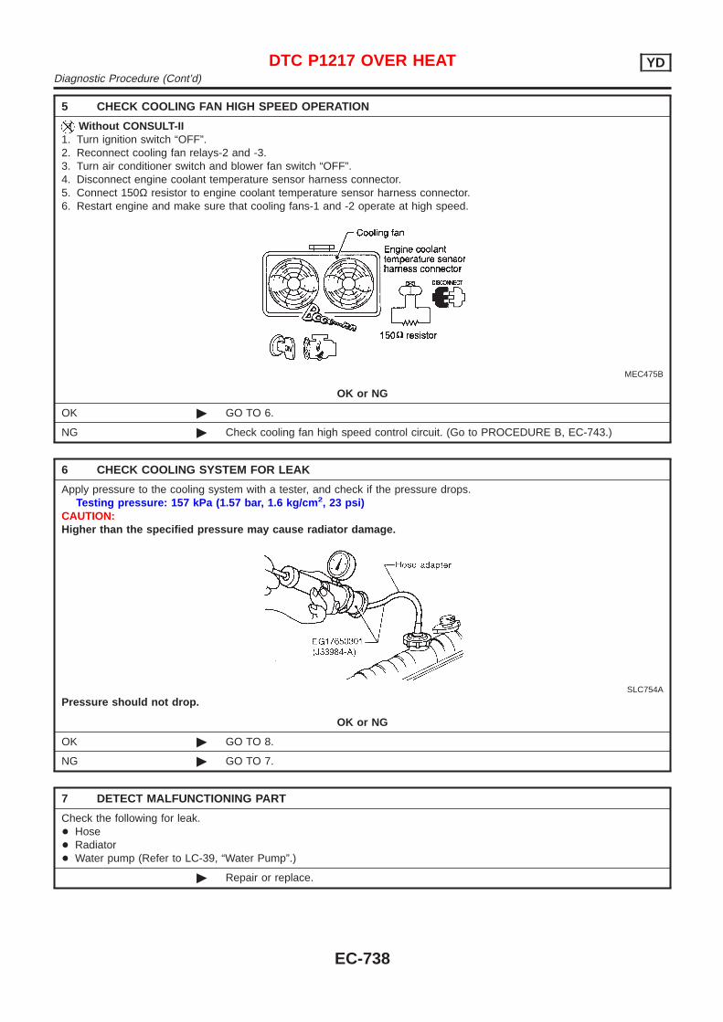
5 CHECK COOLING FAN HIGH SPEED OPERATION
Without CONSULT-II1. Turn ignition switch “OFF”.2. Reconnect cooling fan relays-2 and -3.3. Turn air conditioner switch and blower fan switch “OFF”.4. Disconnect engine coolant temperature sensor harness connector.5. Connect 150Ω resistor to engine coolant temperature sensor harness connector.6. Restart engine and make sure that cooling fans-1 and -2 operate at high speed.
MEC475B
OK or NG
OK © GO TO 6.
NG © Check cooling fan high speed control circuit. (Go to PROCEDURE B, EC-743.)
6 CHECK COOLING SYSTEM FOR LEAK
Apply pressure to the cooling system with a tester, and check if the pressure drops.Testing pressure: 157 kPa (1.57 bar, 1.6 kg/cm 2, 23 psi)
CAUTION:Higher than the specified pressure may cause radiator damage.
SLC754A
Pressure should not drop.
OK or NG
OK © GO TO 8.
NG © GO TO 7.
7 DETECT MALFUNCTIONING PART
Check the following for leak.+ Hose+ Radiator+ Water pump (Refer to LC-39, “Water Pump”.)
© Repair or replace.
DTC P1217 OVER HEAT YDDiagnostic Procedure (Cont’d)
EC-738
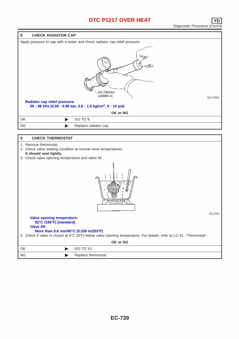
8 CHECK RADIATOR CAP
Apply pressure to cap with a tester and check radiator cap relief pressure.
SLC755A
Radiator cap relief pressure:59 - 98 kPa (0.59 - 0.98 bar, 0.6 - 1.0 kg/cm 2, 9 - 14 psi)
OK or NG
OK © GO TO 9.
NG © Replace radiator cap.
9 CHECK THERMOSTAT
1. Remove thermostat.2. Check valve seating condition at normal room temperatures.
It should seat tightly.3. Check valve opening temperature and valve lift.
SLC343
Valve opening temperature:82°C (180°F) [standard]
Valve lift:More than 8.6 mm/95°C (0.339 in/203°F)
4. Check if valve is closed at 5°C (9°F) below valve opening temperature. For details, refer to LC-41, “Thermostat”.
OK or NG
OK © GO TO 10.
NG © Replace thermostat.
DTC P1217 OVER HEAT YDDiagnostic Procedure (Cont’d)
EC-739
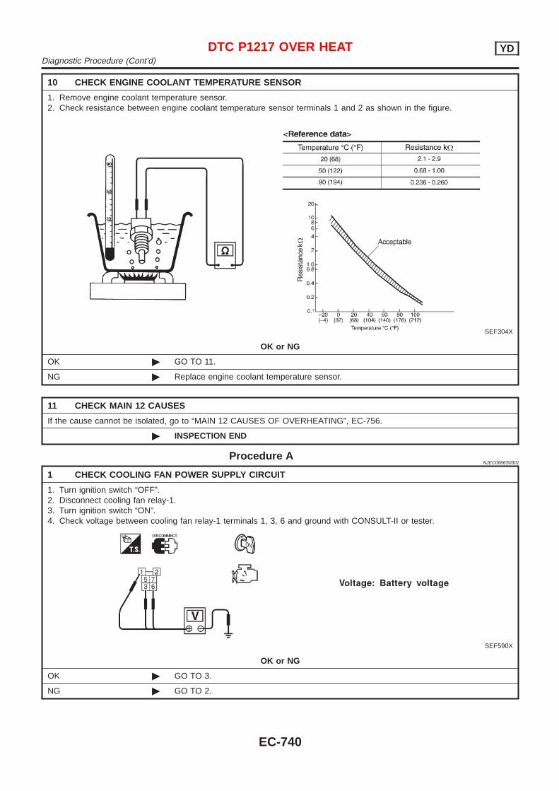
10 CHECK ENGINE COOLANT TEMPERATURE SENSOR
1. Remove engine coolant temperature sensor.2. Check resistance between engine coolant temperature sensor terminals 1 and 2 as shown in the figure.
SEF304X
OK or NG
OK © GO TO 11.
NG © Replace engine coolant temperature sensor.
11 CHECK MAIN 12 CAUSES
If the cause cannot be isolated, go to “MAIN 12 CAUSES OF OVERHEATING”, EC-756.
© INSPECTION END
Procedure ANJEC0666S0301
1 CHECK COOLING FAN POWER SUPPLY CIRCUIT
1. Turn ignition switch “OFF”.2. Disconnect cooling fan relay-1.3. Turn ignition switch “ON”.4. Check voltage between cooling fan relay-1 terminals 1, 3, 6 and ground with CONSULT-II or tester.
SEF590X
OK or NG
OK © GO TO 3.
NG © GO TO 2.
DTC P1217 OVER HEAT YDDiagnostic Procedure (Cont’d)
EC-740
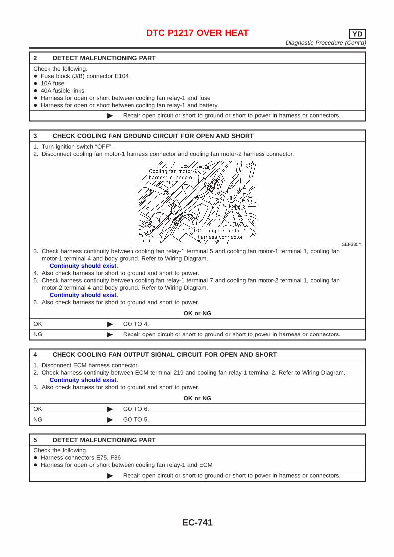
2 DETECT MALFUNCTIONING PART
Check the following.+ Fuse block (J/B) connector E104+ 10A fuse+ 40A fusible links+ Harness for open or short between cooling fan relay-1 and fuse+ Harness for open or short between cooling fan relay-1 and battery
© Repair open circuit or short to ground or short to power in harness or connectors.
3 CHECK COOLING FAN GROUND CIRCUIT FOR OPEN AND SHORT
1. Turn ignition switch “OFF”.2. Disconnect cooling fan motor-1 harness connector and cooling fan motor-2 harness connector.
SEF385Y
3. Check harness continuity between cooling fan relay-1 terminal 5 and cooling fan motor-1 terminal 1, cooling fanmotor-1 terminal 4 and body ground. Refer to Wiring Diagram.
Continuity should exist.4. Also check harness for short to ground and short to power.5. Check harness continuity between cooling fan relay-1 terminal 7 and cooling fan motor-2 terminal 1, cooling fan
motor-2 terminal 4 and body ground. Refer to Wiring Diagram.Continuity should exist.
6. Also check harness for short to ground and short to power.
OK or NG
OK © GO TO 4.
NG © Repair open circuit or short to ground or short to power in harness or connectors.
4 CHECK COOLING FAN OUTPUT SIGNAL CIRCUIT FOR OPEN AND SHORT
1. Disconnect ECM harness connector.2. Check harness continuity between ECM terminal 219 and cooling fan relay-1 terminal 2. Refer to Wiring Diagram.
Continuity should exist.3. Also check harness for short to ground and short to power.
OK or NG
OK © GO TO 6.
NG © GO TO 5.
5 DETECT MALFUNCTIONING PART
Check the following.+ Harness connectors E75, F36+ Harness for open or short between cooling fan relay-1 and ECM
© Repair open circuit or short to ground or short to power in harness or connectors.
DTC P1217 OVER HEAT YDDiagnostic Procedure (Cont’d)
EC-741
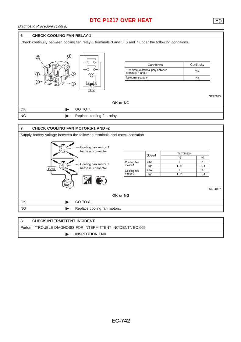
6 CHECK COOLING FAN RELAY-1
Check continuity between cooling fan relay-1 terminals 3 and 5, 6 and 7 under the following conditions.
SEF591X
OK or NG
OK © GO TO 7.
NG © Replace cooling fan relay.
7 CHECK COOLING FAN MOTORS-1 AND -2
Supply battery voltage between the following terminals and check operation.
SEF405Y
OK or NG
OK © GO TO 8.
NG © Replace cooling fan motors.
8 CHECK INTERMITTENT INCIDENT
Perform “TROUBLE DIAGNOSIS FOR INTERMITTENT INCIDENT”, EC-665.
© INSPECTION END
DTC P1217 OVER HEAT YDDiagnostic Procedure (Cont’d)
EC-742
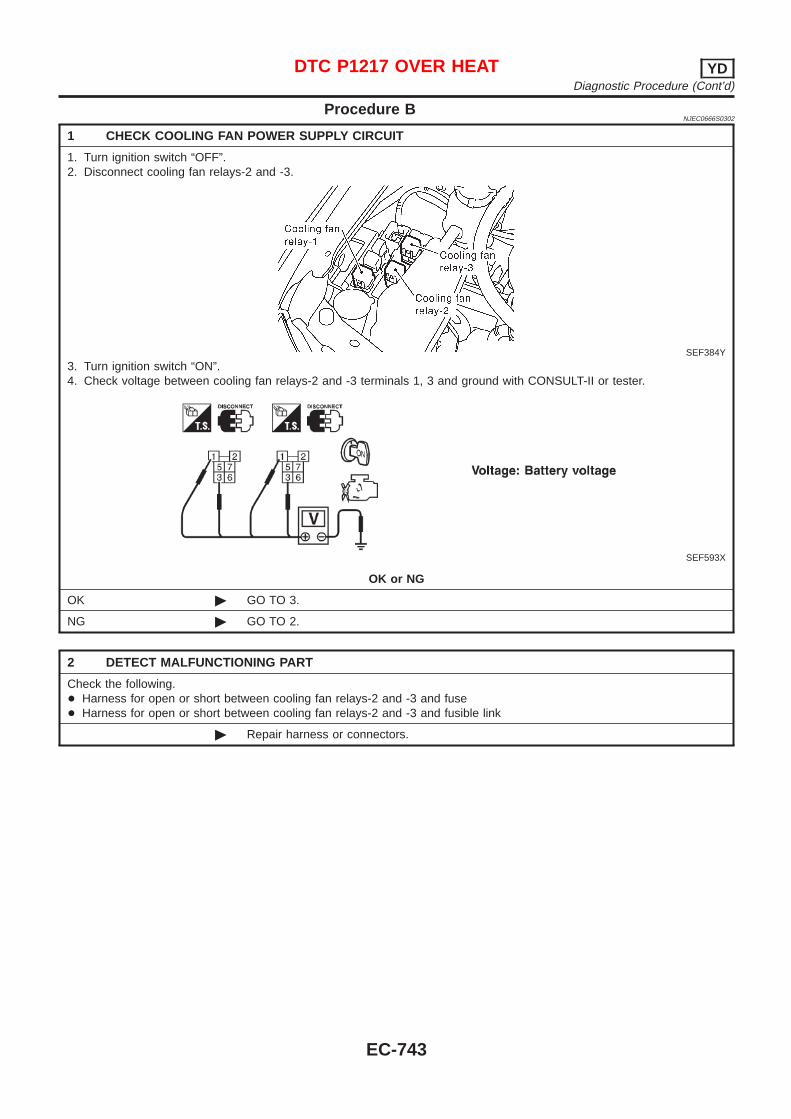
Procedure BNJEC0666S0302
1 CHECK COOLING FAN POWER SUPPLY CIRCUIT
1. Turn ignition switch “OFF”.2. Disconnect cooling fan relays-2 and -3.
SEF384Y
3. Turn ignition switch “ON”.4. Check voltage between cooling fan relays-2 and -3 terminals 1, 3 and ground with CONSULT-II or tester.
SEF593X
OK or NG
OK © GO TO 3.
NG © GO TO 2.
2 DETECT MALFUNCTIONING PART
Check the following.+ Harness for open or short between cooling fan relays-2 and -3 and fuse+ Harness for open or short between cooling fan relays-2 and -3 and fusible link
© Repair harness or connectors.
DTC P1217 OVER HEAT YDDiagnostic Procedure (Cont’d)
EC-743
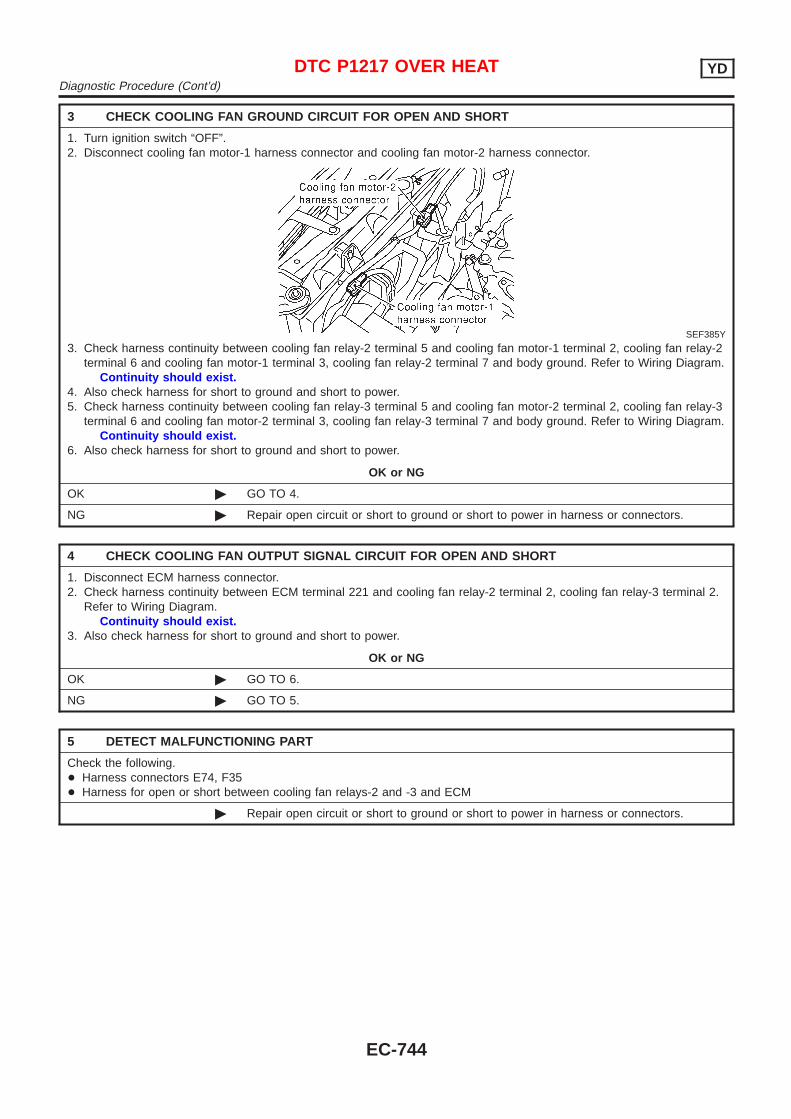
3 CHECK COOLING FAN GROUND CIRCUIT FOR OPEN AND SHORT
1. Turn ignition switch “OFF”.2. Disconnect cooling fan motor-1 harness connector and cooling fan motor-2 harness connector.
SEF385Y
3. Check harness continuity between cooling fan relay-2 terminal 5 and cooling fan motor-1 terminal 2, cooling fan relay-2terminal 6 and cooling fan motor-1 terminal 3, cooling fan relay-2 terminal 7 and body ground. Refer to Wiring Diagram.
Continuity should exist.4. Also check harness for short to ground and short to power.5. Check harness continuity between cooling fan relay-3 terminal 5 and cooling fan motor-2 terminal 2, cooling fan relay-3
terminal 6 and cooling fan motor-2 terminal 3, cooling fan relay-3 terminal 7 and body ground. Refer to Wiring Diagram.Continuity should exist.
6. Also check harness for short to ground and short to power.
OK or NG
OK © GO TO 4.
NG © Repair open circuit or short to ground or short to power in harness or connectors.
4 CHECK COOLING FAN OUTPUT SIGNAL CIRCUIT FOR OPEN AND SHORT
1. Disconnect ECM harness connector.2. Check harness continuity between ECM terminal 221 and cooling fan relay-2 terminal 2, cooling fan relay-3 terminal 2.
Refer to Wiring Diagram.Continuity should exist.
3. Also check harness for short to ground and short to power.
OK or NG
OK © GO TO 6.
NG © GO TO 5.
5 DETECT MALFUNCTIONING PART
Check the following.+ Harness connectors E74, F35+ Harness for open or short between cooling fan relays-2 and -3 and ECM
© Repair open circuit or short to ground or short to power in harness or connectors.
DTC P1217 OVER HEAT YDDiagnostic Procedure (Cont’d)
EC-744
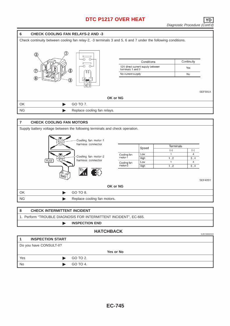
6 CHECK COOLING FAN RELAYS-2 AND -3
Check continuity between cooling fan relay-2, -3 terminals 3 and 5, 6 and 7 under the following conditions.
SEF591X
OK or NG
OK © GO TO 7.
NG © Replace cooling fan relays.
7 CHECK COOLING FAN MOTORS
Supply battery voltage between the following terminals and check operation.
SEF405Y
OK or NG
OK © GO TO 8.
NG © Replace cooling fan motors.
8 CHECK INTERMITTENT INCIDENT
1. Perform “TROUBLE DIAGNOSIS FOR INTERMITTENT INCIDENT”, EC-665.
© INSPECTION END
HATCHBACKNJEC0666S04
1 INSPECTION START
Do you have CONSULT-II?
Yes or No
Yes © GO TO 2.
No © GO TO 4.
DTC P1217 OVER HEAT YDDiagnostic Procedure (Cont’d)
EC-745
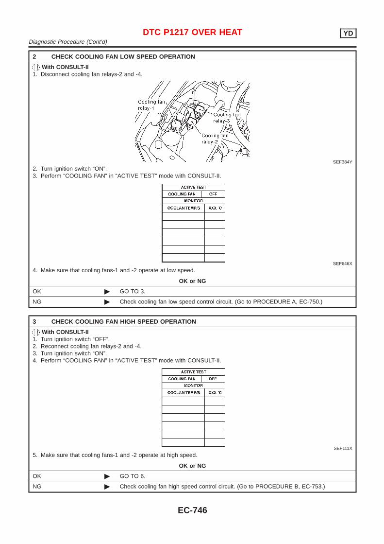
2 CHECK COOLING FAN LOW SPEED OPERATION
With CONSULT-II1. Disconnect cooling fan relays-2 and -4.
SEF384Y
2. Turn ignition switch “ON”.3. Perform “COOLING FAN” in “ACTIVE TEST” mode with CONSULT-II.
SEF646X
4. Make sure that cooling fans-1 and -2 operate at low speed.
OK or NG
OK © GO TO 3.
NG © Check cooling fan low speed control circuit. (Go to PROCEDURE A, EC-750.)
3 CHECK COOLING FAN HIGH SPEED OPERATION
With CONSULT-II1. Turn ignition switch “OFF”.2. Reconnect cooling fan relays-2 and -4.3. Turn ignition switch “ON”.4. Perform “COOLING FAN” in “ACTIVE TEST” mode with CONSULT-II.
SEF111X
5. Make sure that cooling fans-1 and -2 operate at high speed.
OK or NG
OK © GO TO 6.
NG © Check cooling fan high speed control circuit. (Go to PROCEDURE B, EC-753.)
DTC P1217 OVER HEAT YDDiagnostic Procedure (Cont’d)
EC-746
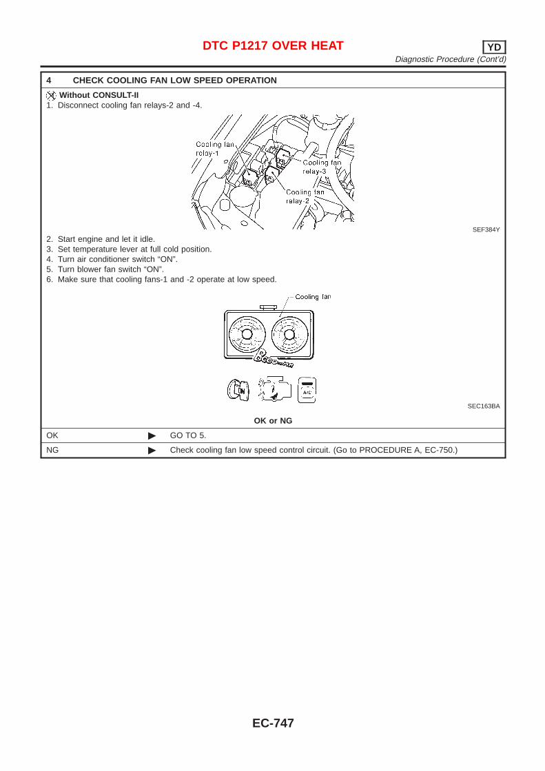
4 CHECK COOLING FAN LOW SPEED OPERATION
Without CONSULT-II1. Disconnect cooling fan relays-2 and -4.
SEF384Y
2. Start engine and let it idle.3. Set temperature lever at full cold position.4. Turn air conditioner switch “ON”.5. Turn blower fan switch “ON”.6. Make sure that cooling fans-1 and -2 operate at low speed.
SEC163BA
OK or NG
OK © GO TO 5.
NG © Check cooling fan low speed control circuit. (Go to PROCEDURE A, EC-750.)
DTC P1217 OVER HEAT YDDiagnostic Procedure (Cont’d)
EC-747

5 CHECK COOLING FAN HIGH SPEED OPERATION
Without CONSULT-II1. Turn ignition switch “OFF”.2. Reconnect cooling fan relays-2 and -4.3. Turn air conditioner switch and blower fan switch “OFF”.4. Disconnect engine coolant temperature sensor harness connector.5. Connect 150Ω resistor to engine coolant temperature sensor harness connector.6. Restart engine and make sure that cooling fans-1 and -2 operate at high speed.
MEC475B
OK or NG
OK © GO TO 6.
NG © Check cooling fan high speed control circuit. (Go to PROCEDURE B, EC-753.)
6 CHECK COOLING SYSTEM FOR LEAK
Apply pressure to the cooling system with a tester, and check if the pressure drops.Testing pressure: 157 kPa (1.57 bar, 1.6 kg/cm 2, 23 psi)
CAUTION:Higher than the specified pressure may cause radiator damage.
SLC754A
Pressure should not drop.
OK or NG
OK © GO TO 8.
NG © GO TO 7.
7 DETECT MALFUNCTIONING PART
Check the following for leak.+ Hose+ Radiator+ Water pump (Refer to LC-39, “Water Pump”.)
© Repair or replace.
DTC P1217 OVER HEAT YDDiagnostic Procedure (Cont’d)
EC-748

8 CHECK RADIATOR CAP
Apply pressure to cap with a tester and check radiator cap relief pressure.
SLC755A
Radiator cap relief pressure:59 - 98 kPa (0.59 - 0.98 bar, 0.6 - 1.0 kg/cm 2, 9 - 14 psi)
OK or NG
OK © GO TO 9.
NG © Replace radiator cap.
9 CHECK THERMOSTAT
1. Remove thermostat.2. Check valve seating condition at normal room temperatures.
It should seat tightly.3. Check valve opening temperature and valve lift.
SLC343
Valve opening temperature:82°C (180°F) [standard]
Valve lift:More than 8.6 mm/95°C (0.339 in/203°F)
4. Check if valve is closed at 5°C (9°F) below valve opening temperature. For details, refer to LC-41, “Thermostat”.
OK or NG
OK © GO TO 10.
NG © Replace thermostat.
DTC P1217 OVER HEAT YDDiagnostic Procedure (Cont’d)
EC-749
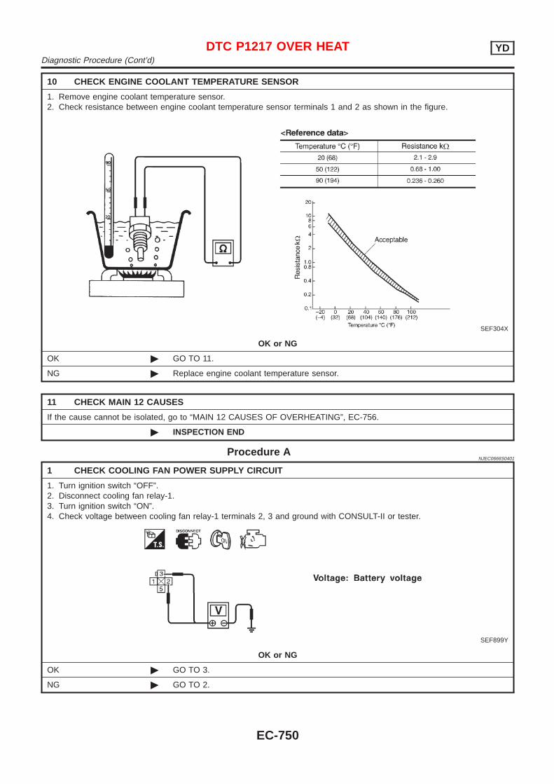
10 CHECK ENGINE COOLANT TEMPERATURE SENSOR
1. Remove engine coolant temperature sensor.2. Check resistance between engine coolant temperature sensor terminals 1 and 2 as shown in the figure.
SEF304X
OK or NG
OK © GO TO 11.
NG © Replace engine coolant temperature sensor.
11 CHECK MAIN 12 CAUSES
If the cause cannot be isolated, go to “MAIN 12 CAUSES OF OVERHEATING”, EC-756.
© INSPECTION END
Procedure ANJEC0666S0401
1 CHECK COOLING FAN POWER SUPPLY CIRCUIT
1. Turn ignition switch “OFF”.2. Disconnect cooling fan relay-1.3. Turn ignition switch “ON”.4. Check voltage between cooling fan relay-1 terminals 2, 3 and ground with CONSULT-II or tester.
SEF899Y
OK or NG
OK © GO TO 3.
NG © GO TO 2.
DTC P1217 OVER HEAT YDDiagnostic Procedure (Cont’d)
EC-750
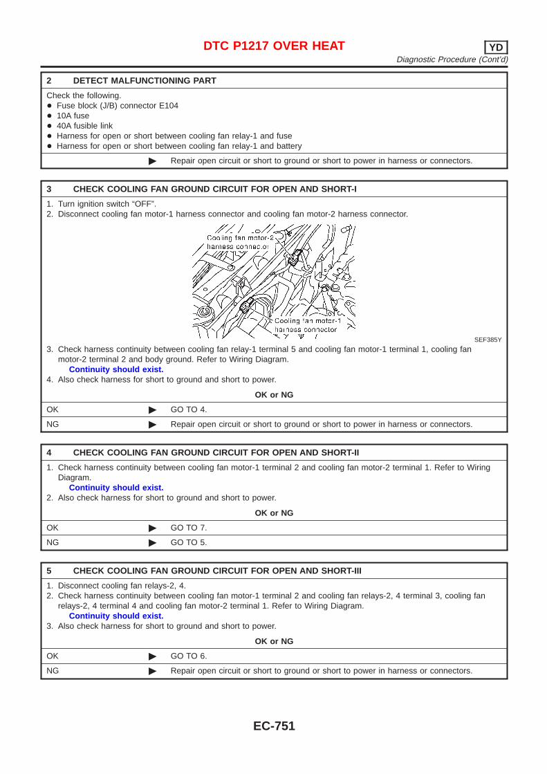
2 DETECT MALFUNCTIONING PART
Check the following.+ Fuse block (J/B) connector E104+ 10A fuse+ 40A fusible link+ Harness for open or short between cooling fan relay-1 and fuse+ Harness for open or short between cooling fan relay-1 and battery
© Repair open circuit or short to ground or short to power in harness or connectors.
3 CHECK COOLING FAN GROUND CIRCUIT FOR OPEN AND SHORT-I
1. Turn ignition switch “OFF”.2. Disconnect cooling fan motor-1 harness connector and cooling fan motor-2 harness connector.
SEF385Y
3. Check harness continuity between cooling fan relay-1 terminal 5 and cooling fan motor-1 terminal 1, cooling fanmotor-2 terminal 2 and body ground. Refer to Wiring Diagram.
Continuity should exist.4. Also check harness for short to ground and short to power.
OK or NG
OK © GO TO 4.
NG © Repair open circuit or short to ground or short to power in harness or connectors.
4 CHECK COOLING FAN GROUND CIRCUIT FOR OPEN AND SHORT-II
1. Check harness continuity between cooling fan motor-1 terminal 2 and cooling fan motor-2 terminal 1. Refer to WiringDiagram.
Continuity should exist.2. Also check harness for short to ground and short to power.
OK or NG
OK © GO TO 7.
NG © GO TO 5.
5 CHECK COOLING FAN GROUND CIRCUIT FOR OPEN AND SHORT-III
1. Disconnect cooling fan relays-2, 4.2. Check harness continuity between cooling fan motor-1 terminal 2 and cooling fan relays-2, 4 terminal 3, cooling fan
relays-2, 4 terminal 4 and cooling fan motor-2 terminal 1. Refer to Wiring Diagram.Continuity should exist.
3. Also check harness for short to ground and short to power.
OK or NG
OK © GO TO 6.
NG © Repair open circuit or short to ground or short to power in harness or connectors.
DTC P1217 OVER HEAT YDDiagnostic Procedure (Cont’d)
EC-751
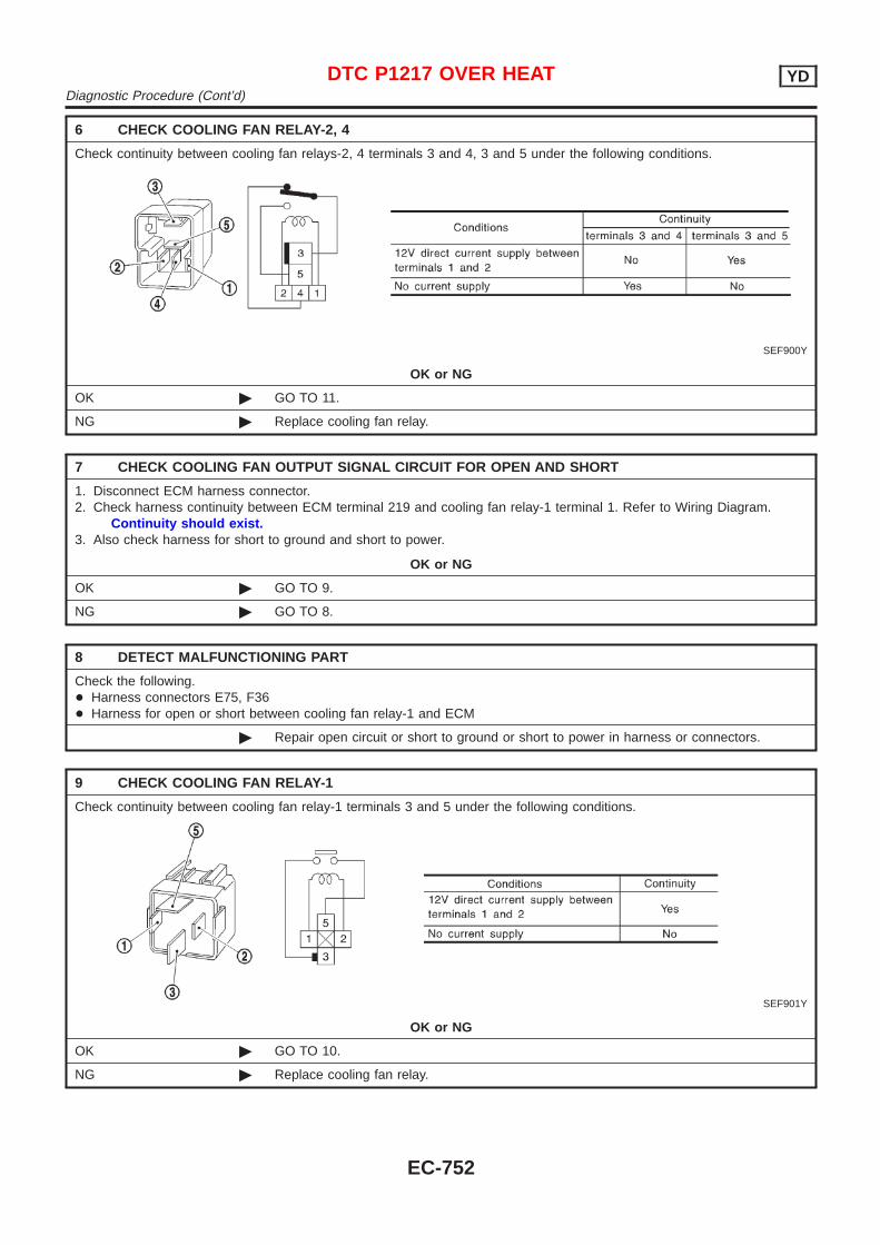
6 CHECK COOLING FAN RELAY-2, 4
Check continuity between cooling fan relays-2, 4 terminals 3 and 4, 3 and 5 under the following conditions.
SEF900Y
OK or NG
OK © GO TO 11.
NG © Replace cooling fan relay.
7 CHECK COOLING FAN OUTPUT SIGNAL CIRCUIT FOR OPEN AND SHORT
1. Disconnect ECM harness connector.2. Check harness continuity between ECM terminal 219 and cooling fan relay-1 terminal 1. Refer to Wiring Diagram.
Continuity should exist.3. Also check harness for short to ground and short to power.
OK or NG
OK © GO TO 9.
NG © GO TO 8.
8 DETECT MALFUNCTIONING PART
Check the following.+ Harness connectors E75, F36+ Harness for open or short between cooling fan relay-1 and ECM
© Repair open circuit or short to ground or short to power in harness or connectors.
9 CHECK COOLING FAN RELAY-1
Check continuity between cooling fan relay-1 terminals 3 and 5 under the following conditions.
SEF901Y
OK or NG
OK © GO TO 10.
NG © Replace cooling fan relay.
DTC P1217 OVER HEAT YDDiagnostic Procedure (Cont’d)
EC-752
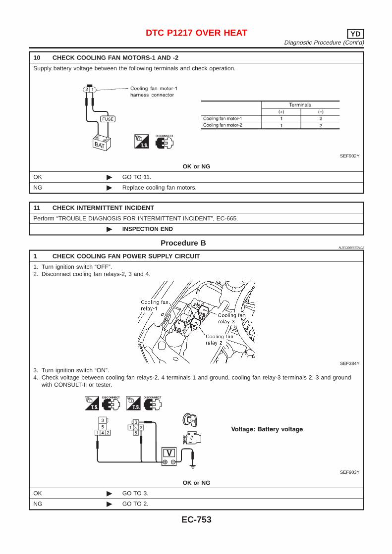
10 CHECK COOLING FAN MOTORS-1 AND -2
Supply battery voltage between the following terminals and check operation.
SEF902Y
OK or NG
OK © GO TO 11.
NG © Replace cooling fan motors.
11 CHECK INTERMITTENT INCIDENT
Perform “TROUBLE DIAGNOSIS FOR INTERMITTENT INCIDENT”, EC-665.
© INSPECTION END
Procedure BNJEC0666S0402
1 CHECK COOLING FAN POWER SUPPLY CIRCUIT
1. Turn ignition switch “OFF”.2. Disconnect cooling fan relays-2, 3 and 4.
SEF384Y
3. Turn ignition switch “ON”.4. Check voltage between cooling fan relays-2, 4 terminals 1 and ground, cooling fan relay-3 terminals 2, 3 and ground
with CONSULT-II or tester.
SEF903Y
OK or NG
OK © GO TO 3.
NG © GO TO 2.
DTC P1217 OVER HEAT YDDiagnostic Procedure (Cont’d)
EC-753
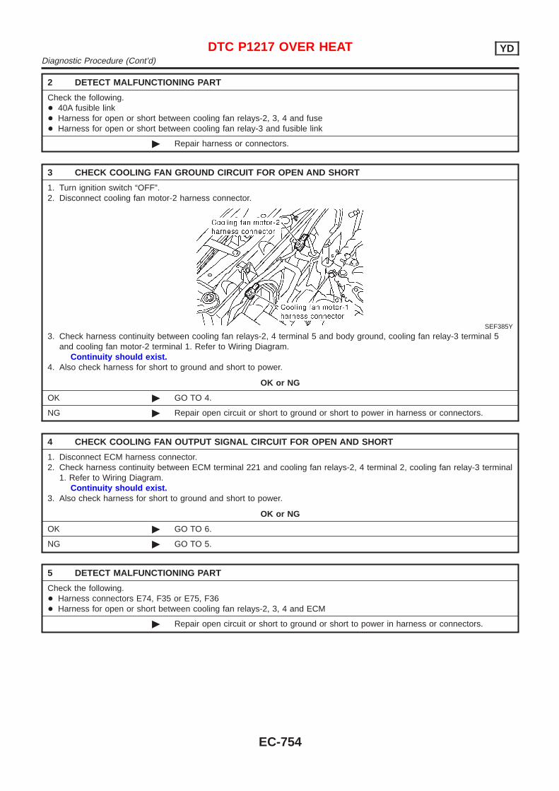
2 DETECT MALFUNCTIONING PART
Check the following.+ 40A fusible link+ Harness for open or short between cooling fan relays-2, 3, 4 and fuse+ Harness for open or short between cooling fan relay-3 and fusible link
© Repair harness or connectors.
3 CHECK COOLING FAN GROUND CIRCUIT FOR OPEN AND SHORT
1. Turn ignition switch “OFF”.2. Disconnect cooling fan motor-2 harness connector.
SEF385Y
3. Check harness continuity between cooling fan relays-2, 4 terminal 5 and body ground, cooling fan relay-3 terminal 5and cooling fan motor-2 terminal 1. Refer to Wiring Diagram.
Continuity should exist.4. Also check harness for short to ground and short to power.
OK or NG
OK © GO TO 4.
NG © Repair open circuit or short to ground or short to power in harness or connectors.
4 CHECK COOLING FAN OUTPUT SIGNAL CIRCUIT FOR OPEN AND SHORT
1. Disconnect ECM harness connector.2. Check harness continuity between ECM terminal 221 and cooling fan relays-2, 4 terminal 2, cooling fan relay-3 terminal
1. Refer to Wiring Diagram.Continuity should exist.
3. Also check harness for short to ground and short to power.
OK or NG
OK © GO TO 6.
NG © GO TO 5.
5 DETECT MALFUNCTIONING PART
Check the following.+ Harness connectors E74, F35 or E75, F36+ Harness for open or short between cooling fan relays-2, 3, 4 and ECM
© Repair open circuit or short to ground or short to power in harness or connectors.
DTC P1217 OVER HEAT YDDiagnostic Procedure (Cont’d)
EC-754
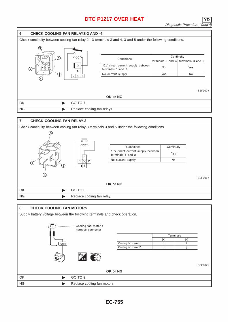
6 CHECK COOLING FAN RELAYS-2 AND -4
Check continuity between cooling fan relay-2, -3 terminals 3 and 4, 3 and 5 under the following conditions.
SEF900Y
OK or NG
OK © GO TO 7.
NG © Replace cooling fan relays.
7 CHECK COOLING FAN RELAY-3
Check continuity between cooling fan relay-3 terminals 3 and 5 under the following conditions.
SEF901Y
OK or NG
OK © GO TO 8.
NG © Replace cooling fan relay.
8 CHECK COOLING FAN MOTORS
Supply battery voltage between the following terminals and check operation.
SEF902Y
OK or NG
OK © GO TO 9.
NG © Replace cooling fan motors.
DTC P1217 OVER HEAT YDDiagnostic Procedure (Cont’d)
EC-755
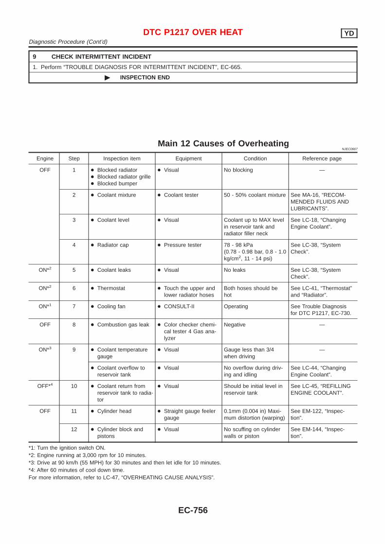
9 CHECK INTERMITTENT INCIDENT
1. Perform “TROUBLE DIAGNOSIS FOR INTERMITTENT INCIDENT”, EC-665.
© INSPECTION END
Main 12 Causes of OverheatingNJEC0667
Engine Step Inspection item Equipment Condition Reference page
OFF 1 + Blocked radiator+ Blocked radiator grille+ Blocked bumper
+ Visual No blocking —
2 + Coolant mixture + Coolant tester 50 - 50% coolant mixture See MA-16, “RECOM-MENDED FLUIDS ANDLUBRICANTS”.
3 + Coolant level + Visual Coolant up to MAX levelin reservoir tank andradiator filler neck
See LC-18, “ChangingEngine Coolant”.
4 + Radiator cap + Pressure tester 78 - 98 kPa(0.78 - 0.98 bar, 0.8 - 1.0kg/cm2, 11 - 14 psi)
See LC-38, “SystemCheck”.
ON*2 5 + Coolant leaks + Visual No leaks See LC-38, “SystemCheck”.
ON*2 6 + Thermostat + Touch the upper andlower radiator hoses
Both hoses should behot
See LC-41, “Thermostat”and “Radiator”.
ON*1 7 + Cooling fan + CONSULT-II Operating See Trouble Diagnosisfor DTC P1217, EC-730.
OFF 8 + Combustion gas leak + Color checker chemi-cal tester 4 Gas ana-lyzer
Negative —
ON*3 9 + Coolant temperaturegauge
+ Visual Gauge less than 3/4when driving
—
+ Coolant overflow toreservoir tank
+ Visual No overflow during driv-ing and idling
See LC-44, “ChangingEngine Coolant”.
OFF*4 10 + Coolant return fromreservoir tank to radia-tor
+ Visual Should be initial level inreservoir tank
See LC-45, “REFILLINGENGINE COOLANT”.
OFF 11 + Cylinder head + Straight gauge feelergauge
0.1mm (0.004 in) Maxi-mum distortion (warping)
See EM-122, “Inspec-tion”.
12 + Cylinder block andpistons
+ Visual No scuffing on cylinderwalls or piston
See EM-144, “Inspec-tion”.
*1: Turn the ignition switch ON.*2: Engine running at 3,000 rpm for 10 minutes.*3: Drive at 90 km/h (55 MPH) for 30 minutes and then let idle for 10 minutes.*4: After 60 minutes of cool down time.For more information, refer to LC-47, “OVERHEATING CAUSE ANALYSIS”.
DTC P1217 OVER HEAT YDDiagnostic Procedure (Cont’d)
EC-756
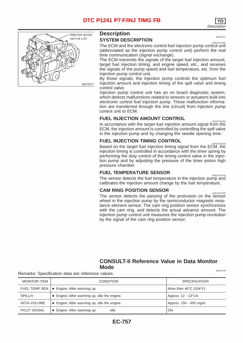
SEF437Y
DescriptionNJEC0727
SYSTEM DESCRIPTIONNJEC0727S01
The ECM and the electronic control fuel injection pump control unit(abbreviated as the injection pump control unit) perform the realtime communication (signal exchange).The ECM transmits the signals of the target fuel injection amount,target fuel injection timing, and engine speed, etc., and receivesthe signals of the pump speed and fuel temperature, etc. from theinjection pump control unit.By those signals, the injection pump controls the optimum fuelinjection amount and injection timing of the spill valve and timingcontrol valve.Injection pump control unit has an on board diagnostic system,which detects malfunctions related to sensors or actuators built-intoelectronic control fuel injection pump. These malfunction informa-tion are transferred through the line (circuit) from injection pumpcontrol unit to ECM.
FUEL INJECTION AMOUNT CONTROLNJEC0727S02
In accordance with the target fuel injection amount signal from theECM, the injection amount is controlled by controlling the spill valvein the injection pump and by changing the needle opening time.
FUEL INJECTION TIMING CONTROLNJEC0727S03
Based on the target fuel injection timing signal from the ECM, theinjection timing is controlled in accordance with the timer spring byperforming the duty control of the timing control valve in the injec-tion pump and by adjusting the pressure of the timer piston highpressure chamber.
FUEL TEMPERATURE SENSORNJEC0727S04
The sensor detects the fuel temperature in the injection pump andcalibrates the injection amount change by the fuel temperature.
CAM RING POSITION SENSORNJEC0727S05
The sensor detects the passing of the protrusion on the sensorwheel in the injection pump by the semiconductor magnetic resis-tance element sensor. The cam ring position sensor synchronizeswith the cam ring, and detects the actual advance amount. Theinjection pump control unit measures the injection pump revolutionby the signal of the cam ring position sensor.
CONSULT-II Reference Value in Data MonitorMode
NJEC0728
Remarks: Specification data are reference values.
MONITOR ITEM CONDITION SPECIFICATION
FUEL TEMP SEN + Engine: After warming up More than 40°C (104°F)
SPILL/V + Engine: After warming up, idle the engine. Approx. 12 - 13°CA
INT/A VOLUME + Engine: After warming up, idle the engine. Approx. 150 - 450 mg/st
F/CUT SIGNAL + Engine: After warming up Idle ON
DTC P1241 P7·F/INJ TIMG FB YDDescription
EC-757
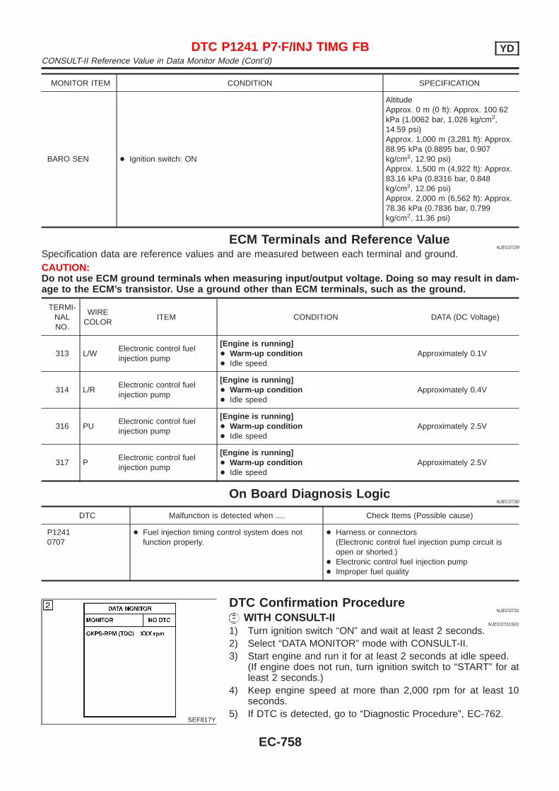
MONITOR ITEM CONDITION SPECIFICATION
BARO SEN + Ignition switch: ON
AltitudeApprox. 0 m (0 ft): Approx. 100.62kPa (1.0062 bar, 1.026 kg/cm2,14.59 psi)Approx. 1,000 m (3,281 ft): Approx.88.95 kPa (0.8895 bar, 0.907kg/cm2, 12.90 psi)Approx. 1,500 m (4,922 ft): Approx.83.16 kPa (0.8316 bar, 0.848kg/cm2, 12.06 psi)Approx. 2,000 m (6,562 ft): Approx.78.36 kPa (0.7836 bar, 0.799kg/cm2, 11.36 psi)
ECM Terminals and Reference ValueNJEC0729
Specification data are reference values and are measured between each terminal and ground.CAUTION:Do not use ECM ground terminals when measuring input/output voltage. Doing so may result in dam-age to the ECM’s transistor. Use a ground other than ECM terminals, such as the ground.
TERMI-NALNO.
WIRECOLOR
ITEM CONDITION DATA (DC Voltage)
313 L/WElectronic control fuelinjection pump
[Engine is running]+ Warm-up condition+ Idle speed
Approximately 0.1V
314 L/RElectronic control fuelinjection pump
[Engine is running]+ Warm-up condition+ Idle speed
Approximately 0.4V
316 PUElectronic control fuelinjection pump
[Engine is running]+ Warm-up condition+ Idle speed
Approximately 2.5V
317 PElectronic control fuelinjection pump
[Engine is running]+ Warm-up condition+ Idle speed
Approximately 2.5V
On Board Diagnosis LogicNJEC0730
DTC Malfunction is detected when .... Check Items (Possible cause)
P12410707
+ Fuel injection timing control system does notfunction properly.
+ Harness or connectors(Electronic control fuel injection pump circuit isopen or shorted.)
+ Electronic control fuel injection pump+ Improper fuel quality
SEF817Y
DTC Confirmation ProcedureNJEC0731
WITH CONSULT-IINJEC0731S01
1) Turn ignition switch “ON” and wait at least 2 seconds.2) Select “DATA MONITOR” mode with CONSULT-II.3) Start engine and run it for at least 2 seconds at idle speed.
(If engine does not run, turn ignition switch to “START” for atleast 2 seconds.)
4) Keep engine speed at more than 2,000 rpm for at least 10seconds.
5) If DTC is detected, go to “Diagnostic Procedure”, EC-762.
DTC P1241 P7·F/INJ TIMG FB YDCONSULT-II Reference Value in Data Monitor Mode (Cont’d)
EC-758
WITHOUT CONSULT-IINJEC0731S02
1) Turn ignition switch “ON” and wait at least 2 seconds.2) Start engine and run it for at least 2 seconds at idle speed.
(If engine does not run, turn ignition switch to “START” for atleast 2 seconds.)
3) Keep engine speed at more than 2,000 rpm for at least 10seconds.
4) Turn ignition switch “OFF”, wait at least 5 seconds and thenturn “ON”.
5) Perform “Diagnostic Test Mode II (Self-diagnostic results)” withECM.
6) If DTC is detected, go to “Diagnostic Procedure”, EC-762.
DTC P1241 P7·F/INJ TIMG FB YDDTC Confirmation Procedure (Cont’d)
EC-759
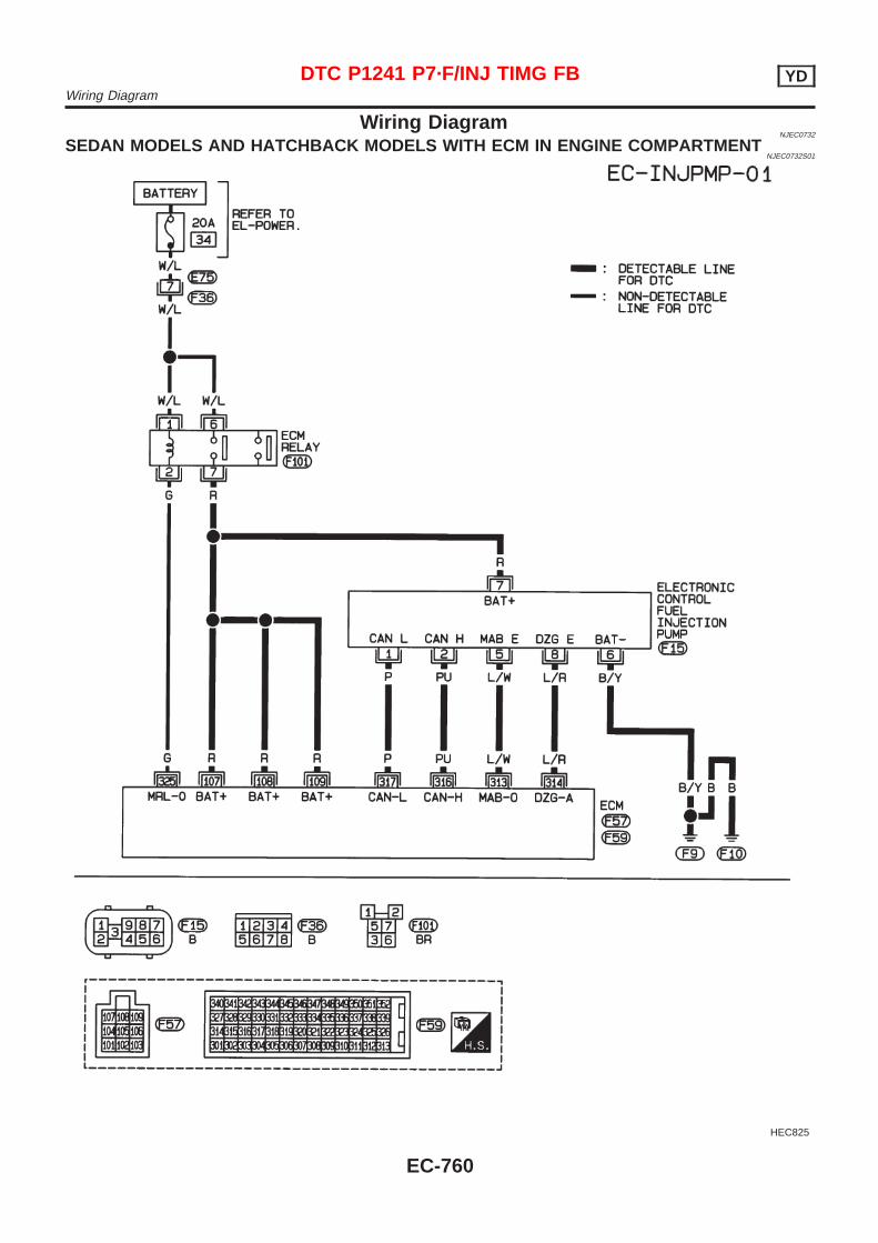
Wiring DiagramNJEC0732
SEDAN MODELS AND HATCHBACK MODELS WITH ECM IN ENGINE COMPARTMENTNJEC0732S01
HEC825
DTC P1241 P7·F/INJ TIMG FB YDWiring Diagram
EC-760
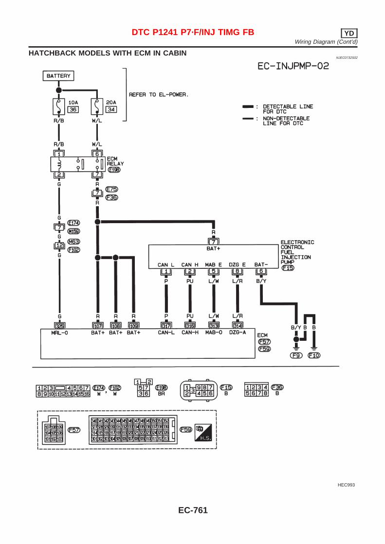
HATCHBACK MODELS WITH ECM IN CABINNJEC0732S02
HEC993
DTC P1241 P7·F/INJ TIMG FB YDWiring Diagram (Cont’d)
EC-761
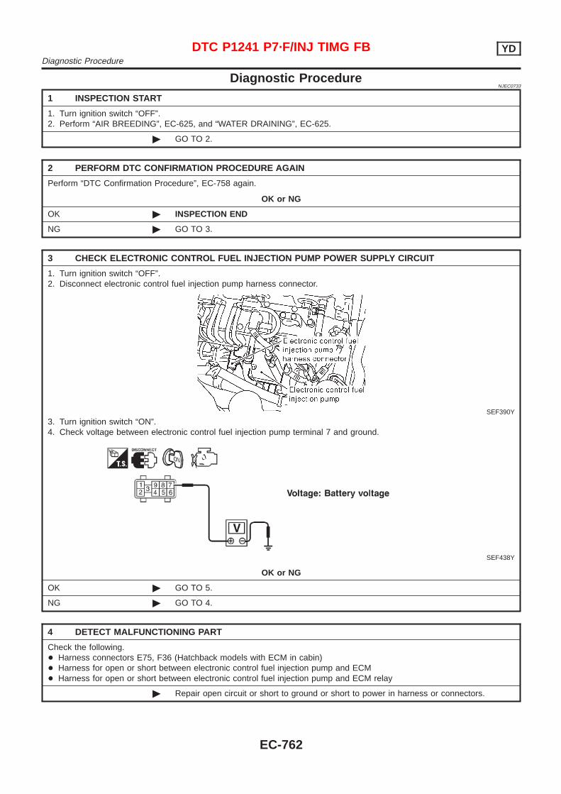
Diagnostic ProcedureNJEC0733
1 INSPECTION START
1. Turn ignition switch “OFF”.2. Perform “AIR BREEDING”, EC-625, and “WATER DRAINING”, EC-625.
© GO TO 2.
2 PERFORM DTC CONFIRMATION PROCEDURE AGAIN
Perform “DTC Confirmation Procedure”, EC-758 again.
OK or NG
OK © INSPECTION END
NG © GO TO 3.
3 CHECK ELECTRONIC CONTROL FUEL INJECTION PUMP POWER SUPPLY CIRCUIT
1. Turn ignition switch “OFF”.2. Disconnect electronic control fuel injection pump harness connector.
SEF390Y
3. Turn ignition switch “ON”.4. Check voltage between electronic control fuel injection pump terminal 7 and ground.
SEF438Y
OK or NG
OK © GO TO 5.
NG © GO TO 4.
4 DETECT MALFUNCTIONING PART
Check the following.+ Harness connectors E75, F36 (Hatchback models with ECM in cabin)+ Harness for open or short between electronic control fuel injection pump and ECM+ Harness for open or short between electronic control fuel injection pump and ECM relay
© Repair open circuit or short to ground or short to power in harness or connectors.
DTC P1241 P7·F/INJ TIMG FB YDDiagnostic Procedure
EC-762
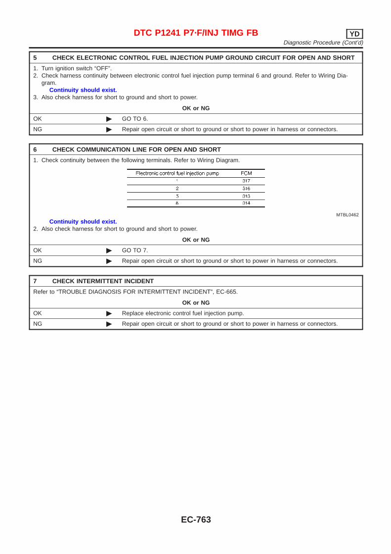
5 CHECK ELECTRONIC CONTROL FUEL INJECTION PUMP GROUND CIRCUIT FOR OPEN AND SHORT
1. Turn ignition switch “OFF”.2. Check harness continuity between electronic control fuel injection pump terminal 6 and ground. Refer to Wiring Dia-
gram.Continuity should exist.
3. Also check harness for short to ground and short to power.
OK or NG
OK © GO TO 6.
NG © Repair open circuit or short to ground or short to power in harness or connectors.
6 CHECK COMMUNICATION LINE FOR OPEN AND SHORT
1. Check continuity between the following terminals. Refer to Wiring Diagram.
MTBL0462
Continuity should exist.2. Also check harness for short to ground and short to power.
OK or NG
OK © GO TO 7.
NG © Repair open circuit or short to ground or short to power in harness or connectors.
7 CHECK INTERMITTENT INCIDENT
Refer to “TROUBLE DIAGNOSIS FOR INTERMITTENT INCIDENT”, EC-665.
OK or NG
OK © Replace electronic control fuel injection pump.
NG © Repair open circuit or short to ground or short to power in harness or connectors.
DTC P1241 P7·F/INJ TIMG FB YDDiagnostic Procedure (Cont’d)
EC-763
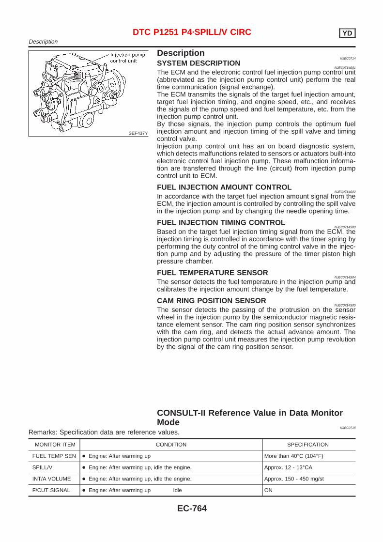
SEF437Y
DescriptionNJEC0714
SYSTEM DESCRIPTIONNJEC0714S01
The ECM and the electronic control fuel injection pump control unit(abbreviated as the injection pump control unit) perform the realtime communication (signal exchange).The ECM transmits the signals of the target fuel injection amount,target fuel injection timing, and engine speed, etc., and receivesthe signals of the pump speed and fuel temperature, etc. from theinjection pump control unit.By those signals, the injection pump controls the optimum fuelinjection amount and injection timing of the spill valve and timingcontrol valve.Injection pump control unit has an on board diagnostic system,which detects malfunctions related to sensors or actuators built-intoelectronic control fuel injection pump. These malfunction informa-tion are transferred through the line (circuit) from injection pumpcontrol unit to ECM.
FUEL INJECTION AMOUNT CONTROLNJEC0714S02
In accordance with the target fuel injection amount signal from theECM, the injection amount is controlled by controlling the spill valvein the injection pump and by changing the needle opening time.
FUEL INJECTION TIMING CONTROLNJEC0714S03
Based on the target fuel injection timing signal from the ECM, theinjection timing is controlled in accordance with the timer spring byperforming the duty control of the timing control valve in the injec-tion pump and by adjusting the pressure of the timer piston highpressure chamber.
FUEL TEMPERATURE SENSORNJEC0714S04
The sensor detects the fuel temperature in the injection pump andcalibrates the injection amount change by the fuel temperature.
CAM RING POSITION SENSORNJEC0714S05
The sensor detects the passing of the protrusion on the sensorwheel in the injection pump by the semiconductor magnetic resis-tance element sensor. The cam ring position sensor synchronizeswith the cam ring, and detects the actual advance amount. Theinjection pump control unit measures the injection pump revolutionby the signal of the cam ring position sensor.
CONSULT-II Reference Value in Data MonitorMode
NJEC0715
Remarks: Specification data are reference values.
MONITOR ITEM CONDITION SPECIFICATION
FUEL TEMP SEN + Engine: After warming up More than 40°C (104°F)
SPILL/V + Engine: After warming up, idle the engine. Approx. 12 - 13°CA
INT/A VOLUME + Engine: After warming up, idle the engine. Approx. 150 - 450 mg/st
F/CUT SIGNAL + Engine: After warming up Idle ON
DTC P1251 P4·SPILL/V CIRC YDDescription
EC-764
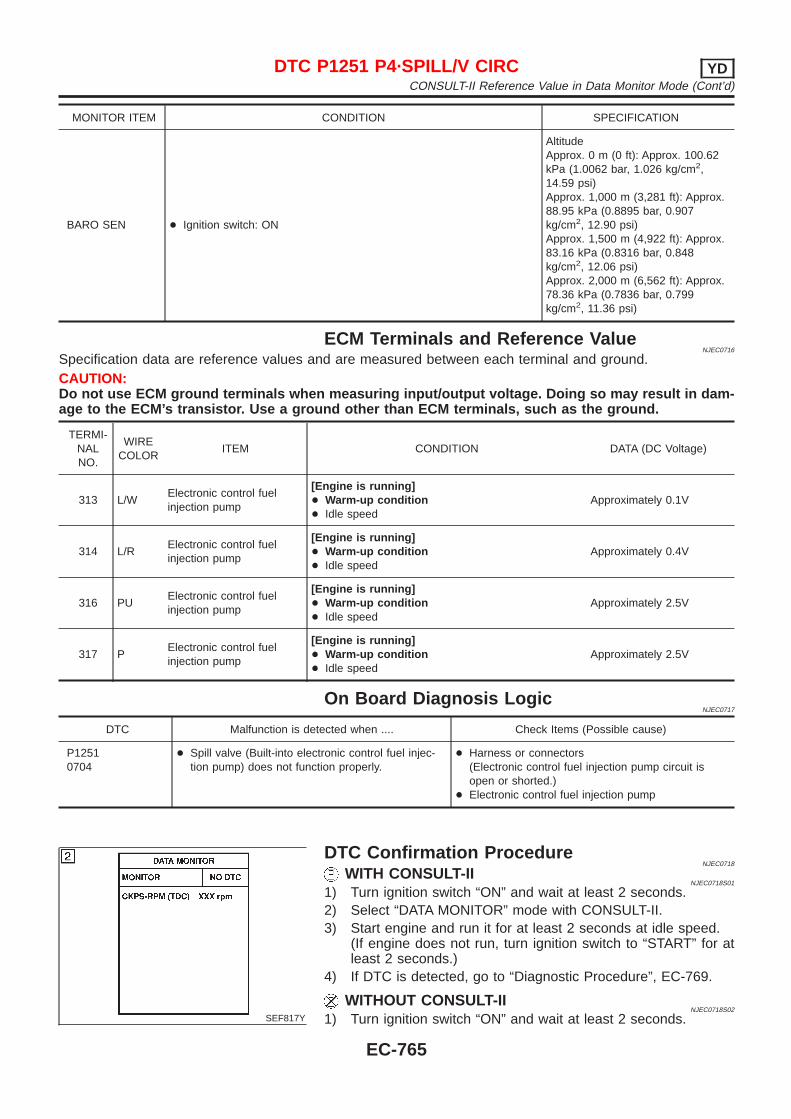
MONITOR ITEM CONDITION SPECIFICATION
BARO SEN + Ignition switch: ON
AltitudeApprox. 0 m (0 ft): Approx. 100.62kPa (1.0062 bar, 1.026 kg/cm2,14.59 psi)Approx. 1,000 m (3,281 ft): Approx.88.95 kPa (0.8895 bar, 0.907kg/cm2, 12.90 psi)Approx. 1,500 m (4,922 ft): Approx.83.16 kPa (0.8316 bar, 0.848kg/cm2, 12.06 psi)Approx. 2,000 m (6,562 ft): Approx.78.36 kPa (0.7836 bar, 0.799kg/cm2, 11.36 psi)
ECM Terminals and Reference ValueNJEC0716
Specification data are reference values and are measured between each terminal and ground.CAUTION:Do not use ECM ground terminals when measuring input/output voltage. Doing so may result in dam-age to the ECM’s transistor. Use a ground other than ECM terminals, such as the ground.
TERMI-NALNO.
WIRECOLOR
ITEM CONDITION DATA (DC Voltage)
313 L/WElectronic control fuelinjection pump
[Engine is running]+ Warm-up condition+ Idle speed
Approximately 0.1V
314 L/RElectronic control fuelinjection pump
[Engine is running]+ Warm-up condition+ Idle speed
Approximately 0.4V
316 PUElectronic control fuelinjection pump
[Engine is running]+ Warm-up condition+ Idle speed
Approximately 2.5V
317 PElectronic control fuelinjection pump
[Engine is running]+ Warm-up condition+ Idle speed
Approximately 2.5V
On Board Diagnosis LogicNJEC0717
DTC Malfunction is detected when .... Check Items (Possible cause)
P12510704
+ Spill valve (Built-into electronic control fuel injec-tion pump) does not function properly.
+ Harness or connectors(Electronic control fuel injection pump circuit isopen or shorted.)
+ Electronic control fuel injection pump
SEF817Y
DTC Confirmation ProcedureNJEC0718
WITH CONSULT-IINJEC0718S01
1) Turn ignition switch “ON” and wait at least 2 seconds.2) Select “DATA MONITOR” mode with CONSULT-II.3) Start engine and run it for at least 2 seconds at idle speed.
(If engine does not run, turn ignition switch to “START” for atleast 2 seconds.)
4) If DTC is detected, go to “Diagnostic Procedure”, EC-769.
WITHOUT CONSULT-IINJEC0718S02
1) Turn ignition switch “ON” and wait at least 2 seconds.
DTC P1251 P4·SPILL/V CIRC YDCONSULT-II Reference Value in Data Monitor Mode (Cont’d)
EC-765
2) Start engine and run it for at least 2 seconds at idle speed.(If engine does not run, turn ignition switch to “START” for atleast 2 seconds.)
3) Turn ignition switch “OFF”, wait at least 5 seconds and thenturn “ON”.
4) Perform “Diagnostic Test Mode II (Self-diagnostic results)” withECM.
5) If DTC is detected, go to “Diagnostic Procedure”, EC-769.
DTC P1251 P4·SPILL/V CIRC YDDTC Confirmation Procedure (Cont’d)
EC-766

Wiring DiagramNJEC0719
SEDAN MODELS AND HATCHBACK MODELS WITH ECM IN ENGINE COMPARTMENTNJEC0719S01
HEC825
DTC P1251 P4·SPILL/V CIRC YDWiring Diagram
EC-767

HATCHBACK MODELS WITH ECM IN CABINNJEC0719S02
HEC993
DTC P1251 P4·SPILL/V CIRC YDWiring Diagram (Cont’d)
EC-768
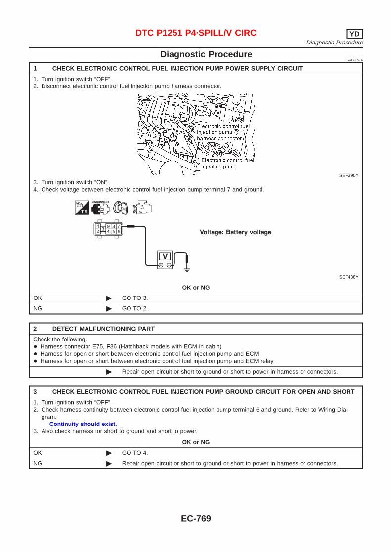
Diagnostic ProcedureNJEC0720
1 CHECK ELECTRONIC CONTROL FUEL INJECTION PUMP POWER SUPPLY CIRCUIT
1. Turn ignition switch “OFF”.2. Disconnect electronic control fuel injection pump harness connector.
SEF390Y
3. Turn ignition switch “ON”.4. Check voltage between electronic control fuel injection pump terminal 7 and ground.
SEF438Y
OK or NG
OK © GO TO 3.
NG © GO TO 2.
2 DETECT MALFUNCTIONING PART
Check the following.+ Harness connector E75, F36 (Hatchback models with ECM in cabin)+ Harness for open or short between electronic control fuel injection pump and ECM+ Harness for open or short between electronic control fuel injection pump and ECM relay
© Repair open circuit or short to ground or short to power in harness or connectors.
3 CHECK ELECTRONIC CONTROL FUEL INJECTION PUMP GROUND CIRCUIT FOR OPEN AND SHORT
1. Turn ignition switch “OFF”.2. Check harness continuity between electronic control fuel injection pump terminal 6 and ground. Refer to Wiring Dia-
gram.Continuity should exist.
3. Also check harness for short to ground and short to power.
OK or NG
OK © GO TO 4.
NG © Repair open circuit or short to ground or short to power in harness or connectors.
DTC P1251 P4·SPILL/V CIRC YDDiagnostic Procedure
EC-769
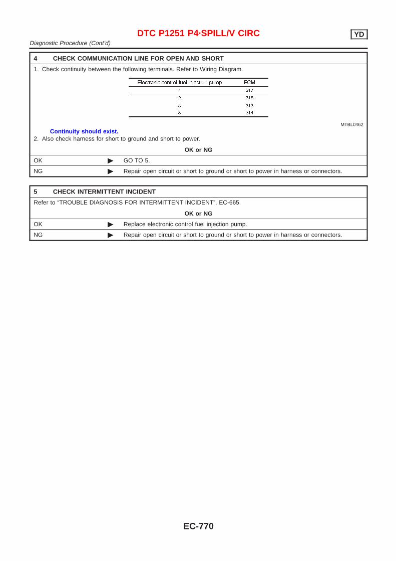
4 CHECK COMMUNICATION LINE FOR OPEN AND SHORT
1. Check continuity between the following terminals. Refer to Wiring Diagram.
MTBL0462
Continuity should exist.2. Also check harness for short to ground and short to power.
OK or NG
OK © GO TO 5.
NG © Repair open circuit or short to ground or short to power in harness or connectors.
5 CHECK INTERMITTENT INCIDENT
Refer to “TROUBLE DIAGNOSIS FOR INTERMITTENT INCIDENT”, EC-665.
OK or NG
OK © Replace electronic control fuel injection pump.
NG © Repair open circuit or short to ground or short to power in harness or connectors.
DTC P1251 P4·SPILL/V CIRC YDDiagnostic Procedure (Cont’d)
EC-770
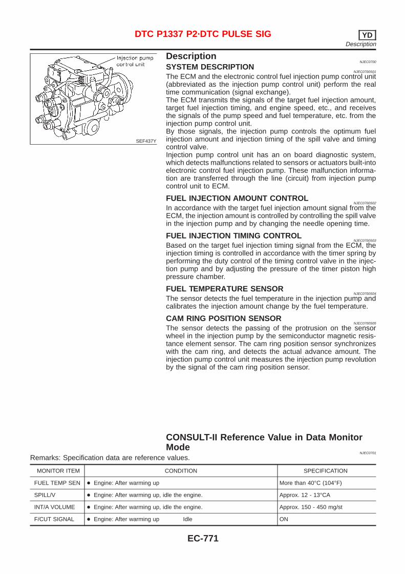
SEF437Y
DescriptionNJEC0700
SYSTEM DESCRIPTIONNJEC0700S01
The ECM and the electronic control fuel injection pump control unit(abbreviated as the injection pump control unit) perform the realtime communication (signal exchange).The ECM transmits the signals of the target fuel injection amount,target fuel injection timing, and engine speed, etc., and receivesthe signals of the pump speed and fuel temperature, etc. from theinjection pump control unit.By those signals, the injection pump controls the optimum fuelinjection amount and injection timing of the spill valve and timingcontrol valve.Injection pump control unit has an on board diagnostic system,which detects malfunctions related to sensors or actuators built-intoelectronic control fuel injection pump. These malfunction informa-tion are transferred through the line (circuit) from injection pumpcontrol unit to ECM.
FUEL INJECTION AMOUNT CONTROLNJEC0700S02
In accordance with the target fuel injection amount signal from theECM, the injection amount is controlled by controlling the spill valvein the injection pump and by changing the needle opening time.
FUEL INJECTION TIMING CONTROLNJEC0700S03
Based on the target fuel injection timing signal from the ECM, theinjection timing is controlled in accordance with the timer spring byperforming the duty control of the timing control valve in the injec-tion pump and by adjusting the pressure of the timer piston highpressure chamber.
FUEL TEMPERATURE SENSORNJEC0700S04
The sensor detects the fuel temperature in the injection pump andcalibrates the injection amount change by the fuel temperature.
CAM RING POSITION SENSORNJEC0700S05
The sensor detects the passing of the protrusion on the sensorwheel in the injection pump by the semiconductor magnetic resis-tance element sensor. The cam ring position sensor synchronizeswith the cam ring, and detects the actual advance amount. Theinjection pump control unit measures the injection pump revolutionby the signal of the cam ring position sensor.
CONSULT-II Reference Value in Data MonitorMode
NJEC0701
Remarks: Specification data are reference values.
MONITOR ITEM CONDITION SPECIFICATION
FUEL TEMP SEN + Engine: After warming up More than 40°C (104°F)
SPILL/V + Engine: After warming up, idle the engine. Approx. 12 - 13°CA
INT/A VOLUME + Engine: After warming up, idle the engine. Approx. 150 - 450 mg/st
F/CUT SIGNAL + Engine: After warming up Idle ON
DTC P1337 P2·DTC PULSE SIG YDDescription
EC-771
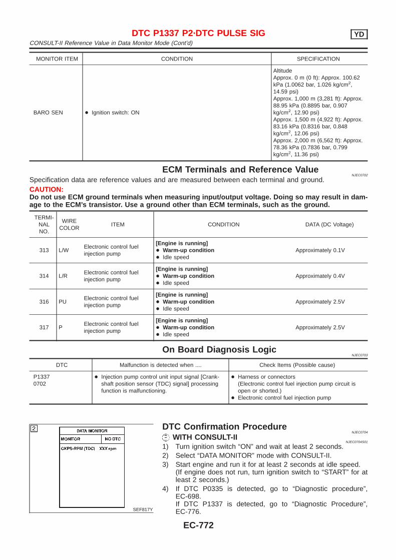
MONITOR ITEM CONDITION SPECIFICATION
BARO SEN + Ignition switch: ON
AltitudeApprox. 0 m (0 ft): Approx. 100.62kPa (1.0062 bar, 1.026 kg/cm2,14.59 psi)Approx. 1,000 m (3,281 ft): Approx.88.95 kPa (0.8895 bar, 0.907kg/cm2, 12.90 psi)Approx. 1,500 m (4,922 ft): Approx.83.16 kPa (0.8316 bar, 0.848kg/cm2, 12.06 psi)Approx. 2,000 m (6,562 ft): Approx.78.36 kPa (0.7836 bar, 0.799kg/cm2, 11.36 psi)
ECM Terminals and Reference ValueNJEC0702
Specification data are reference values and are measured between each terminal and ground.CAUTION:Do not use ECM ground terminals when measuring input/output voltage. Doing so may result in dam-age to the ECM’s transistor. Use a ground other than ECM terminals, such as the ground.
TERMI-NALNO.
WIRECOLOR
ITEM CONDITION DATA (DC Voltage)
313 L/WElectronic control fuelinjection pump
[Engine is running]+ Warm-up condition+ Idle speed
Approximately 0.1V
314 L/RElectronic control fuelinjection pump
[Engine is running]+ Warm-up condition+ Idle speed
Approximately 0.4V
316 PUElectronic control fuelinjection pump
[Engine is running]+ Warm-up condition+ Idle speed
Approximately 2.5V
317 PElectronic control fuelinjection pump
[Engine is running]+ Warm-up condition+ Idle speed
Approximately 2.5V
On Board Diagnosis LogicNJEC0703
DTC Malfunction is detected when .... Check Items (Possible cause)
P13370702
+ Injection pump control unit input signal [Crank-shaft position sensor (TDC) signal] processingfunction is malfunctioning.
+ Harness or connectors(Electronic control fuel injection pump circuit isopen or shorted.)
+ Electronic control fuel injection pump
SEF817Y
DTC Confirmation ProcedureNJEC0704
WITH CONSULT-IINJEC0704S01
1) Turn ignition switch “ON” and wait at least 2 seconds.2) Select “DATA MONITOR” mode with CONSULT-II.3) Start engine and run it for at least 2 seconds at idle speed.
(If engine does not run, turn ignition switch to “START” for atleast 2 seconds.)
4) If DTC P0335 is detected, go to “Diagnostic procedure”,EC-698.If DTC P1337 is detected, go to “Diagnostic Procedure”,EC-776.
DTC P1337 P2·DTC PULSE SIG YDCONSULT-II Reference Value in Data Monitor Mode (Cont’d)
EC-772
WITHOUT CONSULT-IINJEC0704S02
1) Turn ignition switch “ON” and wait at least 2 seconds.2) Start engine and run it for at least 2 seconds at idle speed.
(If engine does not run, turn ignition switch to “START” for atleast 2 seconds.)
3) Turn ignition switch “OFF”, wait at least 5 seconds and thenturn “ON”.
4) Perform “Diagnostic Test Mode II (Self-diagnostic results)” withECM.
5) If DTC P0335 is detected, go to “Diagnostic Procedure”,EC-698.If DTC P1337 is detected, go to “Diagnostic Procedure”,EC-776.
DTC P1337 P2·DTC PULSE SIG YDDTC Confirmation Procedure (Cont’d)
EC-773

Wiring DiagramNJEC0705
SEDAN MODELS AND HATCHBACK MODELS WITH ECM IN ENGINE COMPARTMENTNJEC0705S01
HEC825
DTC P1337 P2·DTC PULSE SIG YDWiring Diagram
EC-774
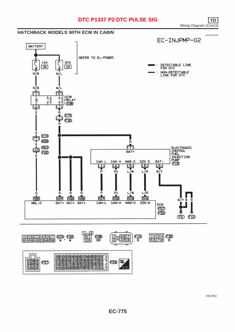
HATCHBACK MODELS WITH ECM IN CABINNJEC0705S02
HEC993
DTC P1337 P2·DTC PULSE SIG YDWiring Diagram (Cont’d)
EC-775
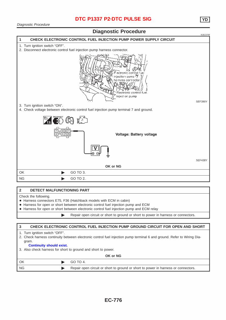
Diagnostic ProcedureNJEC0706
1 CHECK ELECTRONIC CONTROL FUEL INJECTION PUMP POWER SUPPLY CIRCUIT
1. Turn ignition switch “OFF”.2. Disconnect electronic control fuel injection pump harness connector.
SEF390Y
3. Turn ignition switch “ON”.4. Check voltage between electronic control fuel injection pump terminal 7 and ground.
SEF438Y
OK or NG
OK © GO TO 3.
NG © GO TO 2.
2 DETECT MALFUNCTIONING PART
Check the following.+ Harness connectors E75, F36 (Hatchback models with ECM in cabin)+ Harness for open or short between electronic control fuel injection pump and ECM+ Harness for open or short between electronic control fuel injection pump and ECM relay
© Repair open circuit or short to ground or short to power in harness or connectors.
3 CHECK ELECTRONIC CONTROL FUEL INJECTION PUMP GROUND CIRCUIT FOR OPEN AND SHORT
1. Turn ignition switch “OFF”.2. Check harness continuity between electronic control fuel injection pump terminal 6 and ground. Refer to Wiring Dia-
gram.Continuity should exist.
3. Also check harness for short to ground and short to power.
OK or NG
OK © GO TO 4.
NG © Repair open circuit or short to ground or short to power in harness or connectors.
DTC P1337 P2·DTC PULSE SIG YDDiagnostic Procedure
EC-776
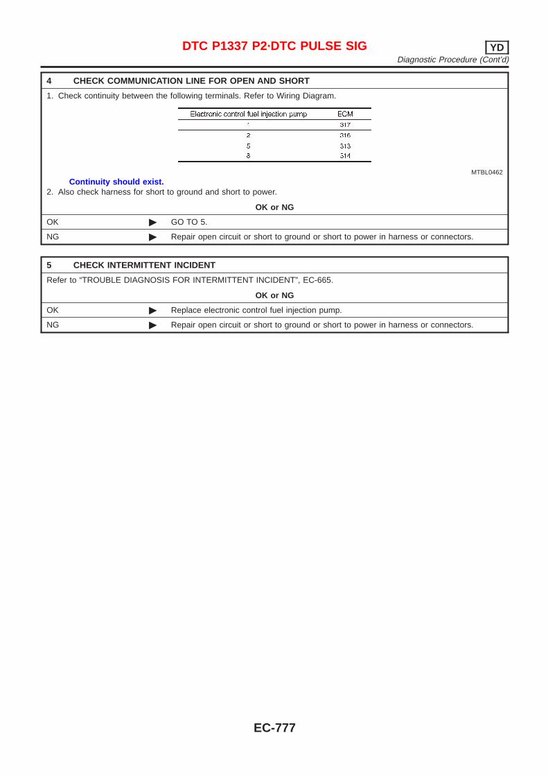
4 CHECK COMMUNICATION LINE FOR OPEN AND SHORT
1. Check continuity between the following terminals. Refer to Wiring Diagram.
MTBL0462
Continuity should exist.2. Also check harness for short to ground and short to power.
OK or NG
OK © GO TO 5.
NG © Repair open circuit or short to ground or short to power in harness or connectors.
5 CHECK INTERMITTENT INCIDENT
Refer to “TROUBLE DIAGNOSIS FOR INTERMITTENT INCIDENT”, EC-665.
OK or NG
OK © Replace electronic control fuel injection pump.
NG © Repair open circuit or short to ground or short to power in harness or connectors.
DTC P1337 P2·DTC PULSE SIG YDDiagnostic Procedure (Cont’d)
EC-777
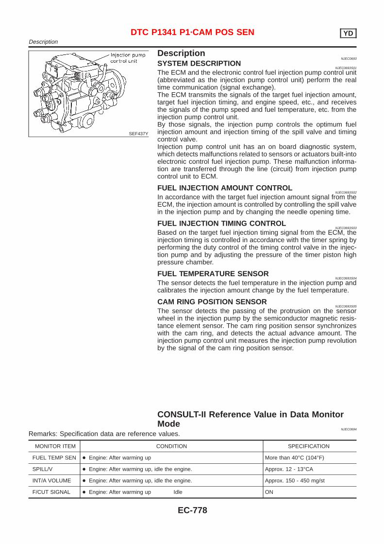
SEF437Y
DescriptionNJEC0693
SYSTEM DESCRIPTIONNJEC0693S01
The ECM and the electronic control fuel injection pump control unit(abbreviated as the injection pump control unit) perform the realtime communication (signal exchange).The ECM transmits the signals of the target fuel injection amount,target fuel injection timing, and engine speed, etc., and receivesthe signals of the pump speed and fuel temperature, etc. from theinjection pump control unit.By those signals, the injection pump controls the optimum fuelinjection amount and injection timing of the spill valve and timingcontrol valve.Injection pump control unit has an on board diagnostic system,which detects malfunctions related to sensors or actuators built-intoelectronic control fuel injection pump. These malfunction informa-tion are transferred through the line (circuit) from injection pumpcontrol unit to ECM.
FUEL INJECTION AMOUNT CONTROLNJEC0693S02
In accordance with the target fuel injection amount signal from theECM, the injection amount is controlled by controlling the spill valvein the injection pump and by changing the needle opening time.
FUEL INJECTION TIMING CONTROLNJEC0693S03
Based on the target fuel injection timing signal from the ECM, theinjection timing is controlled in accordance with the timer spring byperforming the duty control of the timing control valve in the injec-tion pump and by adjusting the pressure of the timer piston highpressure chamber.
FUEL TEMPERATURE SENSORNJEC0693S04
The sensor detects the fuel temperature in the injection pump andcalibrates the injection amount change by the fuel temperature.
CAM RING POSITION SENSORNJEC0693S05
The sensor detects the passing of the protrusion on the sensorwheel in the injection pump by the semiconductor magnetic resis-tance element sensor. The cam ring position sensor synchronizeswith the cam ring, and detects the actual advance amount. Theinjection pump control unit measures the injection pump revolutionby the signal of the cam ring position sensor.
CONSULT-II Reference Value in Data MonitorMode
NJEC0694
Remarks: Specification data are reference values.
MONITOR ITEM CONDITION SPECIFICATION
FUEL TEMP SEN + Engine: After warming up More than 40°C (104°F)
SPILL/V + Engine: After warming up, idle the engine. Approx. 12 - 13°CA
INT/A VOLUME + Engine: After warming up, idle the engine. Approx. 150 - 450 mg/st
F/CUT SIGNAL + Engine: After warming up Idle ON
DTC P1341 P1·CAM POS SEN YDDescription
EC-778
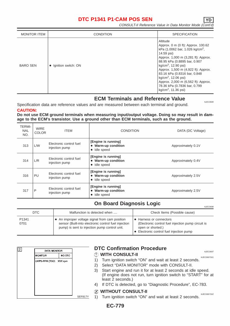
MONITOR ITEM CONDITION SPECIFICATION
BARO SEN + Ignition switch: ON
AltitudeApprox. 0 m (0 ft): Approx. 100.62kPa (1.0062 bar, 1.026 kg/cm2,14.59 psi)Approx. 1,000 m (3,281 ft): Approx.88.95 kPa (0.8895 bar, 0.907kg/cm2, 12.90 psi)Approx. 1,500 m (4,922 ft): Approx.83.16 kPa (0.8316 bar, 0.848kg/cm2, 12.06 psi)Approx. 2,000 m (6,562 ft): Approx.78.36 kPa (0.7836 bar, 0.799kg/cm2, 11.36 psi)
ECM Terminals and Reference ValueNJEC0695
Specification data are reference values and are measured between each terminal and ground.CAUTION:Do not use ECM ground terminals when measuring input/output voltage. Doing so may result in dam-age to the ECM’s transistor. Use a ground other than ECM terminals, such as the ground.
TERMI-NALNO.
WIRECOLOR
ITEM CONDITION DATA (DC Voltage)
313 L/WElectronic control fuelinjection pump
[Engine is running]+ Warm-up condition+ Idle speed
Approximately 0.1V
314 L/RElectronic control fuelinjection pump
[Engine is running]+ Warm-up condition+ Idle speed
Approximately 0.4V
316 PUElectronic control fuelinjection pump
[Engine is running]+ Warm-up condition+ Idle speed
Approximately 2.5V
317 PElectronic control fuelinjection pump
[Engine is running]+ Warm-up condition+ Idle speed
Approximately 2.5V
On Board Diagnosis LogicNJEC0696
DTC Malfunction is detected when .... Check Items (Possible cause)
P13410701
+ An improper voltage signal from cam positionsensor (Built-into electronic control fuel injectionpump) is sent to injection pump control unit.
+ Harness or connectors(Electronic control fuel injection pump circuit isopen or shorted.)
+ Electronic control fuel injection pump
SEF817Y
DTC Confirmation ProcedureNJEC0697
WITH CONSULT-IINJEC0697S01
1) Turn ignition switch “ON” and wait at least 2 seconds.2) Select “DATA MONITOR” mode with CONSULT-II.3) Start engine and run it for at least 2 seconds at idle speed.
(If engine does not run, turn ignition switch to “START” for atleast 2 seconds.)
4) If DTC is detected, go to “Diagnostic Procedure”, EC-783.
WITHOUT CONSULT-IINJEC0697S02
1) Turn ignition switch “ON” and wait at least 2 seconds.
DTC P1341 P1·CAM POS SEN YDCONSULT-II Reference Value in Data Monitor Mode (Cont’d)
EC-779
2) Start engine and run it for at least 2 seconds at idle speed.(If engine does not run, turn ignition switch to “START” for atleast 2 seconds.)
3) Turn ignition switch “OFF”, wait at least 5 seconds and thenturn “ON”.
4) Perform “Diagnostic Test Mode II (Self-diagnostic results)” withECM.
5) If DTC is detected, go to “Diagnostic Procedure”, EC-783.
DTC P1341 P1·CAM POS SEN YDDTC Confirmation Procedure (Cont’d)
EC-780

Wiring DiagramNJEC0698
SEDAN MODELS AND HATCHBACK MODELS WITH ECM IN ENGINE COMPARTMENTNJEC0698S01
HEC825
DTC P1341 P1·CAM POS SEN YDWiring Diagram
EC-781
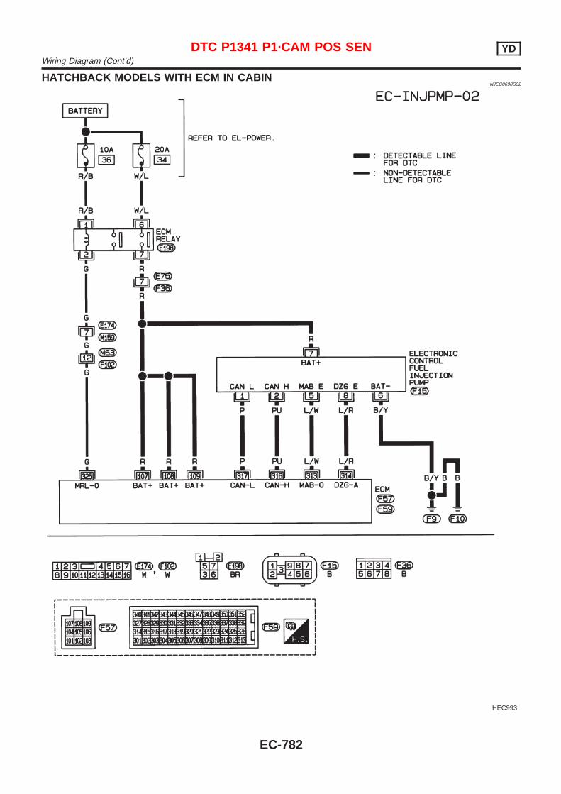
HATCHBACK MODELS WITH ECM IN CABINNJEC0698S02
HEC993
DTC P1341 P1·CAM POS SEN YDWiring Diagram (Cont’d)
EC-782
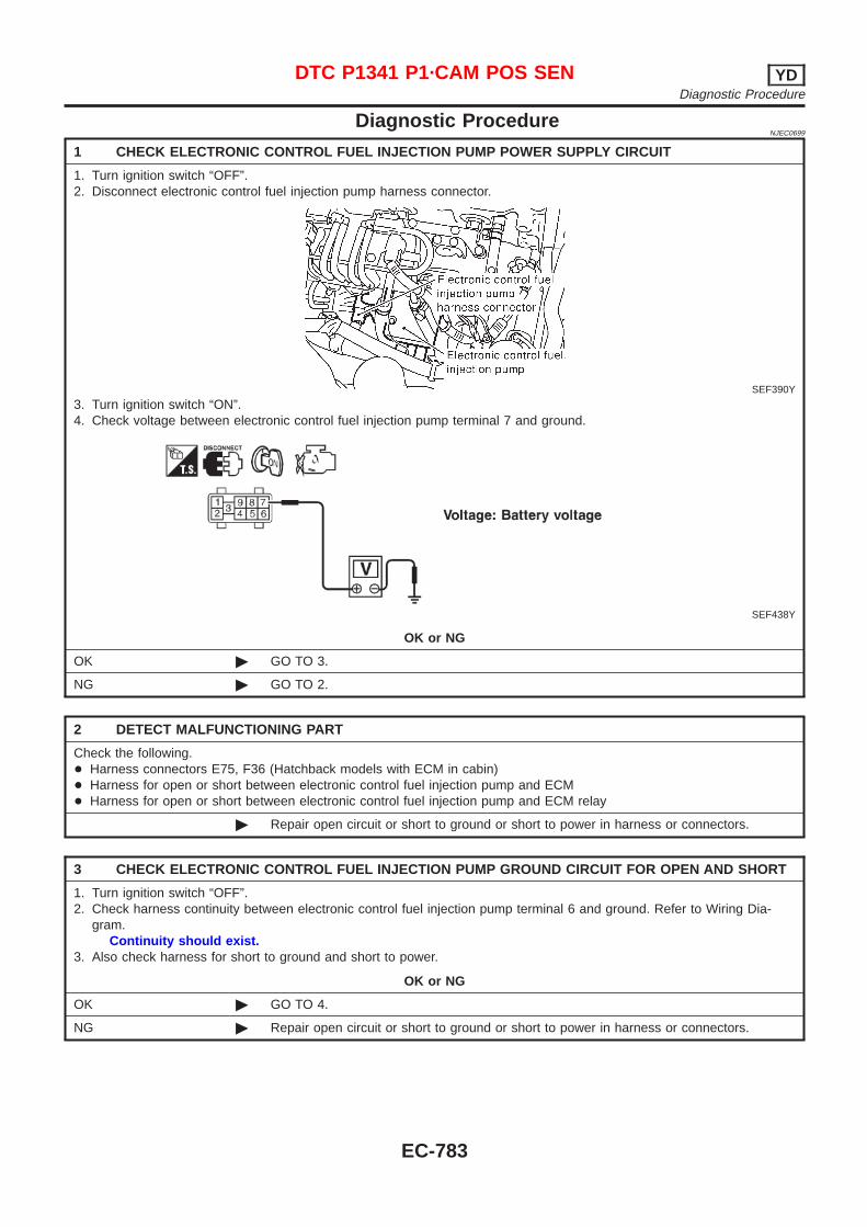
Diagnostic ProcedureNJEC0699
1 CHECK ELECTRONIC CONTROL FUEL INJECTION PUMP POWER SUPPLY CIRCUIT
1. Turn ignition switch “OFF”.2. Disconnect electronic control fuel injection pump harness connector.
SEF390Y
3. Turn ignition switch “ON”.4. Check voltage between electronic control fuel injection pump terminal 7 and ground.
SEF438Y
OK or NG
OK © GO TO 3.
NG © GO TO 2.
2 DETECT MALFUNCTIONING PART
Check the following.+ Harness connectors E75, F36 (Hatchback models with ECM in cabin)+ Harness for open or short between electronic control fuel injection pump and ECM+ Harness for open or short between electronic control fuel injection pump and ECM relay
© Repair open circuit or short to ground or short to power in harness or connectors.
3 CHECK ELECTRONIC CONTROL FUEL INJECTION PUMP GROUND CIRCUIT FOR OPEN AND SHORT
1. Turn ignition switch “OFF”.2. Check harness continuity between electronic control fuel injection pump terminal 6 and ground. Refer to Wiring Dia-
gram.Continuity should exist.
3. Also check harness for short to ground and short to power.
OK or NG
OK © GO TO 4.
NG © Repair open circuit or short to ground or short to power in harness or connectors.
DTC P1341 P1·CAM POS SEN YDDiagnostic Procedure
EC-783
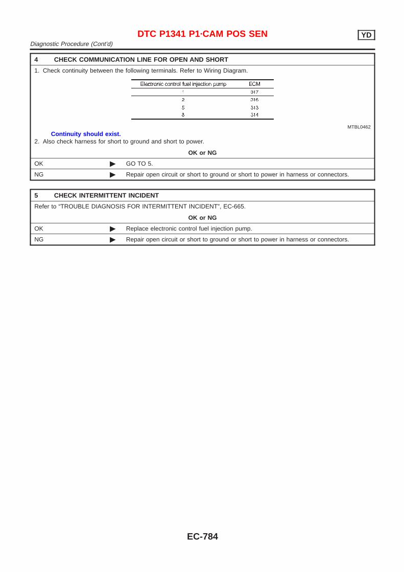
4 CHECK COMMUNICATION LINE FOR OPEN AND SHORT
1. Check continuity between the following terminals. Refer to Wiring Diagram.
MTBL0462
Continuity should exist.2. Also check harness for short to ground and short to power.
OK or NG
OK © GO TO 5.
NG © Repair open circuit or short to ground or short to power in harness or connectors.
5 CHECK INTERMITTENT INCIDENT
Refer to “TROUBLE DIAGNOSIS FOR INTERMITTENT INCIDENT”, EC-665.
OK or NG
OK © Replace electronic control fuel injection pump.
NG © Repair open circuit or short to ground or short to power in harness or connectors.
DTC P1341 P1·CAM POS SEN YDDiagnostic Procedure (Cont’d)
EC-784
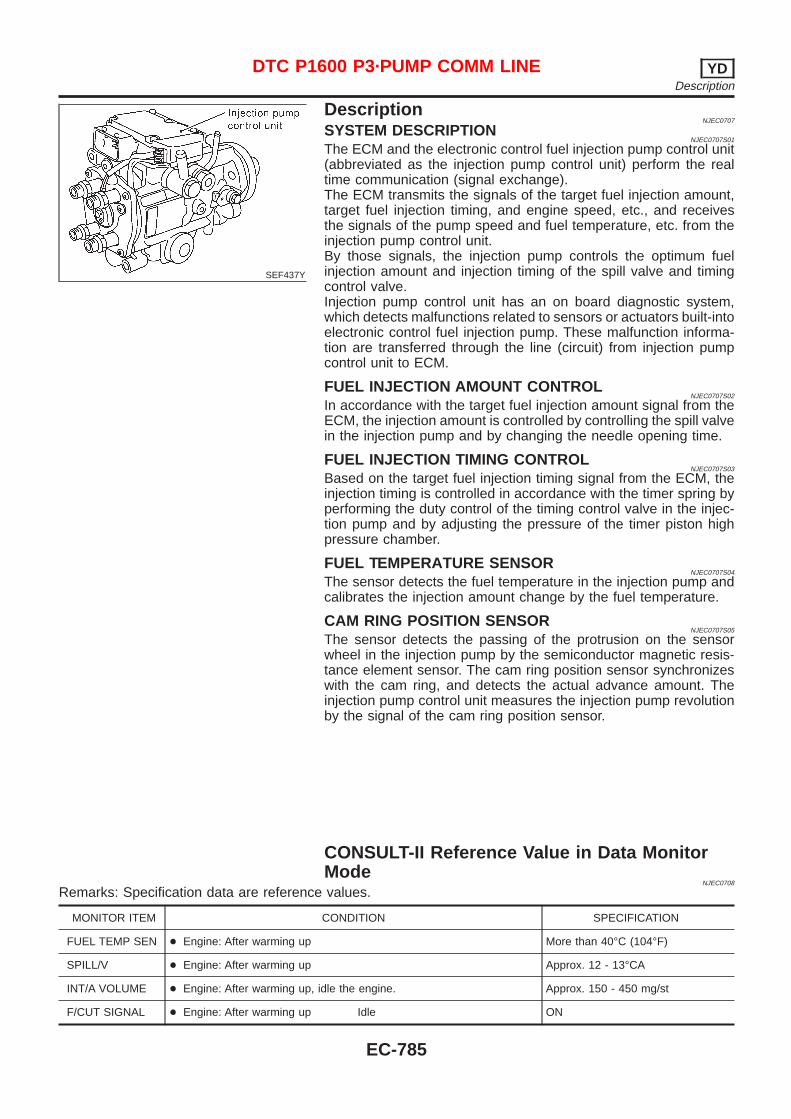
SEF437Y
DescriptionNJEC0707
SYSTEM DESCRIPTIONNJEC0707S01
The ECM and the electronic control fuel injection pump control unit(abbreviated as the injection pump control unit) perform the realtime communication (signal exchange).The ECM transmits the signals of the target fuel injection amount,target fuel injection timing, and engine speed, etc., and receivesthe signals of the pump speed and fuel temperature, etc. from theinjection pump control unit.By those signals, the injection pump controls the optimum fuelinjection amount and injection timing of the spill valve and timingcontrol valve.Injection pump control unit has an on board diagnostic system,which detects malfunctions related to sensors or actuators built-intoelectronic control fuel injection pump. These malfunction informa-tion are transferred through the line (circuit) from injection pumpcontrol unit to ECM.
FUEL INJECTION AMOUNT CONTROLNJEC0707S02
In accordance with the target fuel injection amount signal from theECM, the injection amount is controlled by controlling the spill valvein the injection pump and by changing the needle opening time.
FUEL INJECTION TIMING CONTROLNJEC0707S03
Based on the target fuel injection timing signal from the ECM, theinjection timing is controlled in accordance with the timer spring byperforming the duty control of the timing control valve in the injec-tion pump and by adjusting the pressure of the timer piston highpressure chamber.
FUEL TEMPERATURE SENSORNJEC0707S04
The sensor detects the fuel temperature in the injection pump andcalibrates the injection amount change by the fuel temperature.
CAM RING POSITION SENSORNJEC0707S05
The sensor detects the passing of the protrusion on the sensorwheel in the injection pump by the semiconductor magnetic resis-tance element sensor. The cam ring position sensor synchronizeswith the cam ring, and detects the actual advance amount. Theinjection pump control unit measures the injection pump revolutionby the signal of the cam ring position sensor.
CONSULT-II Reference Value in Data MonitorMode
NJEC0708
Remarks: Specification data are reference values.
MONITOR ITEM CONDITION SPECIFICATION
FUEL TEMP SEN + Engine: After warming up More than 40°C (104°F)
SPILL/V + Engine: After warming up Approx. 12 - 13°CA
INT/A VOLUME + Engine: After warming up, idle the engine. Approx. 150 - 450 mg/st
F/CUT SIGNAL + Engine: After warming up Idle ON
DTC P1600 P3·PUMP COMM LINE YDDescription
EC-785
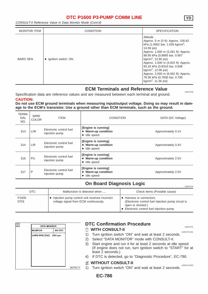
MONITOR ITEM CONDITION SPECIFICATION
BARO SEN + Ignition switch: ON
AltitudeApprox. 0 m (0 ft): Approx. 100.62kPa (1.0062 bar, 1.026 kg/cm2,14.59 psi)Approx. 1,000 m (3,281 ft): Approx.88.95 kPa (0.8895 bar, 0.907kg/cm2, 12.90 psi)Approx. 1,500 m (4,922 ft): Approx.83.16 kPa (0.8316 bar, 0.848kg/cm2, 12.06 psi)Approx. 2,000 m (6,562 ft): Approx.78.36 kPa (0.7836 bar, 0.799kg/cm2, 11.36 psi)
ECM Terminals and Reference ValueNJEC0709
Specification data are reference values and are measured between each terminal and ground.CAUTION:Do not use ECM ground terminals when measuring input/output voltage. Doing so may result in dam-age to the ECM’s transistor. Use a ground other than ECM terminals, such as the ground.
TERMI-NALNO.
WIRECOLOR
ITEM CONDITION DATA (DC Voltage)
313 L/WElectronic control fuelinjection pump
[Engine is running]+ Warm-up condition+ Idle speed
Approximately 0.1V
314 L/RElectronic control fuelinjection pump
[Engine is running]+ Warm-up condition+ Idle speed
Approximately 0.4V
316 PUElectronic control fuelinjection pump
[Engine is running]+ Warm-up condition+ Idle speed
Approximately 2.5V
317 PElectronic control fuelinjection pump
[Engine is running]+ Warm-up condition+ Idle speed
Approximately 2.5V
On Board Diagnosis LogicNJEC0710
DTC Malfunction is detected when .... Check Items (Possible cause)
P16000703
+ Injection pump control unit receives incorrectvoltage signal from ECM continuously.
+ Harness or connectors(Electronic control fuel injection pump circuit isopen or shorted.)
+ Electronic control fuel injection pump
SEF817Y
DTC Confirmation ProcedureNJEC0711
WITH CONSULT-IINJEC0711S01
1) Turn ignition switch “ON” and wait at least 2 seconds.2) Select “DATA MONITOR” mode with CONSULT-II.3) Start engine and run it for at least 2 seconds at idle speed.
(If engine does not run, turn ignition switch to “START” for atleast 2 seconds.)
4) If DTC is detected, go to “Diagnostic Procedure”, EC-790.
WITHOUT CONSULT-IINJEC0711S02
1) Turn ignition switch “ON” and wait at least 2 seconds.
DTC P1600 P3·PUMP COMM LINE YDCONSULT-II Reference Value in Data Monitor Mode (Cont’d)
EC-786
2) Start engine and run it for at least 2 seconds at idle speed.(If engine does not run, turn ignition switch to “START” for atleast 2 seconds.)
3) Turn ignition switch “OFF”, wait at least 5 seconds and thenturn “ON”.
4) Perform “Diagnostic Test Mode II (Self-diagnostic results)” withECM.
5) If DTC is detected, go to “Diagnostic Procedure”, EC-790.
DTC P1600 P3·PUMP COMM LINE YDDTC Confirmation Procedure (Cont’d)
EC-787

Wiring DiagramNJEC0712
SEDAN MODELS AND HATCHBACK MODELS WITH ECM IN ENGINE COMPARTMENTNJEC0712S01
HEC825
DTC P1600 P3·PUMP COMM LINE YDWiring Diagram
EC-788

HATCHBACK MODELS WITH ECM IN CABINNJEC0712S02
HEC993
DTC P1600 P3·PUMP COMM LINE YDWiring Diagram (Cont’d)
EC-789
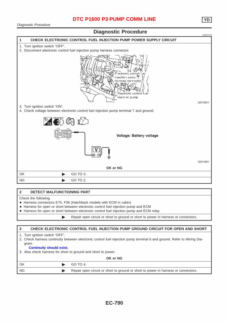
Diagnostic ProcedureNJEC0713
1 CHECK ELECTRONIC CONTROL FUEL INJECTION PUMP POWER SUPPLY CIRCUIT
1. Turn ignition switch “OFF”.2. Disconnect electronic control fuel injection pump harness connector.
SEF390Y
3. Turn ignition switch “ON”.4. Check voltage between electronic control fuel injection pump terminal 7 and ground.
SEF438Y
OK or NG
OK © GO TO 3.
NG © GO TO 2.
2 DETECT MALFUNCTIONING PART
Check the following.+ Harness connectors E75, F36 (Hatchback models with ECM in cabin)+ Harness for open or short between electronic control fuel injection pump and ECM+ Harness for open or short between electronic control fuel injection pump and ECM relay
© Repair open circuit or short to ground or short to power in harness or connectors.
3 CHECK ELECTRONIC CONTROL FUEL INJECTION PUMP GROUND CIRCUIT FOR OPEN AND SHORT
1. Turn ignition switch “OFF”.2. Check harness continuity between electronic control fuel injection pump terminal 6 and ground. Refer to Wiring Dia-
gram.Continuity should exist.
3. Also check harness for short to ground and short to power.
OK or NG
OK © GO TO 4.
NG © Repair open circuit or short to ground or short to power in harness or connectors.
DTC P1600 P3·PUMP COMM LINE YDDiagnostic Procedure
EC-790
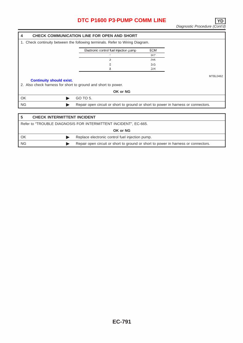
4 CHECK COMMUNICATION LINE FOR OPEN AND SHORT
1. Check continuity between the following terminals. Refer to Wiring Diagram.
MTBL0462
Continuity should exist.2. Also check harness for short to ground and short to power.
OK or NG
OK © GO TO 5.
NG © Repair open circuit or short to ground or short to power in harness or connectors.
5 CHECK INTERMITTENT INCIDENT
Refer to “TROUBLE DIAGNOSIS FOR INTERMITTENT INCIDENT”, EC-665.
OK or NG
OK © Replace electronic control fuel injection pump.
NG © Repair open circuit or short to ground or short to power in harness or connectors.
DTC P1600 P3·PUMP COMM LINE YDDiagnostic Procedure (Cont’d)
EC-791
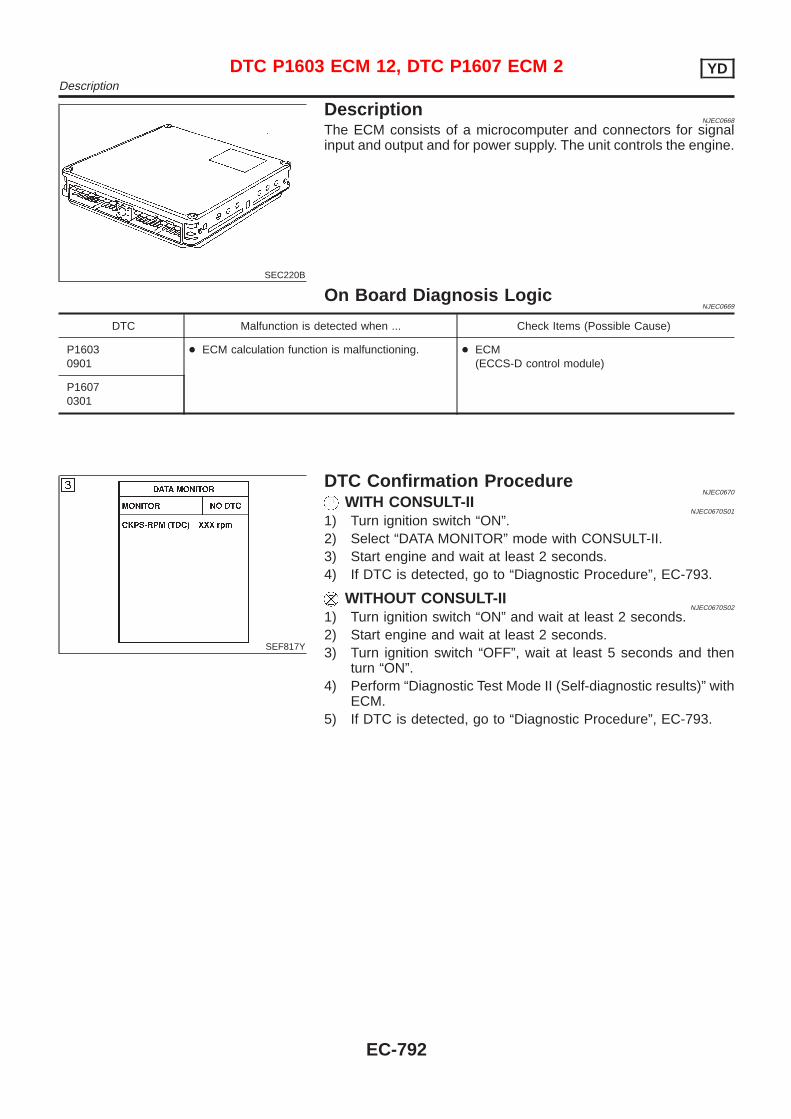
SEC220B
DescriptionNJEC0668
The ECM consists of a microcomputer and connectors for signalinput and output and for power supply. The unit controls the engine.
On Board Diagnosis LogicNJEC0669
DTC Malfunction is detected when ... Check Items (Possible Cause)
P16030901
+ ECM calculation function is malfunctioning. + ECM(ECCS-D control module)
P16070301
SEF817Y
DTC Confirmation ProcedureNJEC0670
WITH CONSULT-IINJEC0670S01
1) Turn ignition switch “ON”.2) Select “DATA MONITOR” mode with CONSULT-II.3) Start engine and wait at least 2 seconds.4) If DTC is detected, go to “Diagnostic Procedure”, EC-793.
WITHOUT CONSULT-IINJEC0670S02
1) Turn ignition switch “ON” and wait at least 2 seconds.2) Start engine and wait at least 2 seconds.3) Turn ignition switch “OFF”, wait at least 5 seconds and then
turn “ON”.4) Perform “Diagnostic Test Mode II (Self-diagnostic results)” with
ECM.5) If DTC is detected, go to “Diagnostic Procedure”, EC-793.
DTC P1603 ECM 12, DTC P1607 ECM 2 YDDescription
EC-792
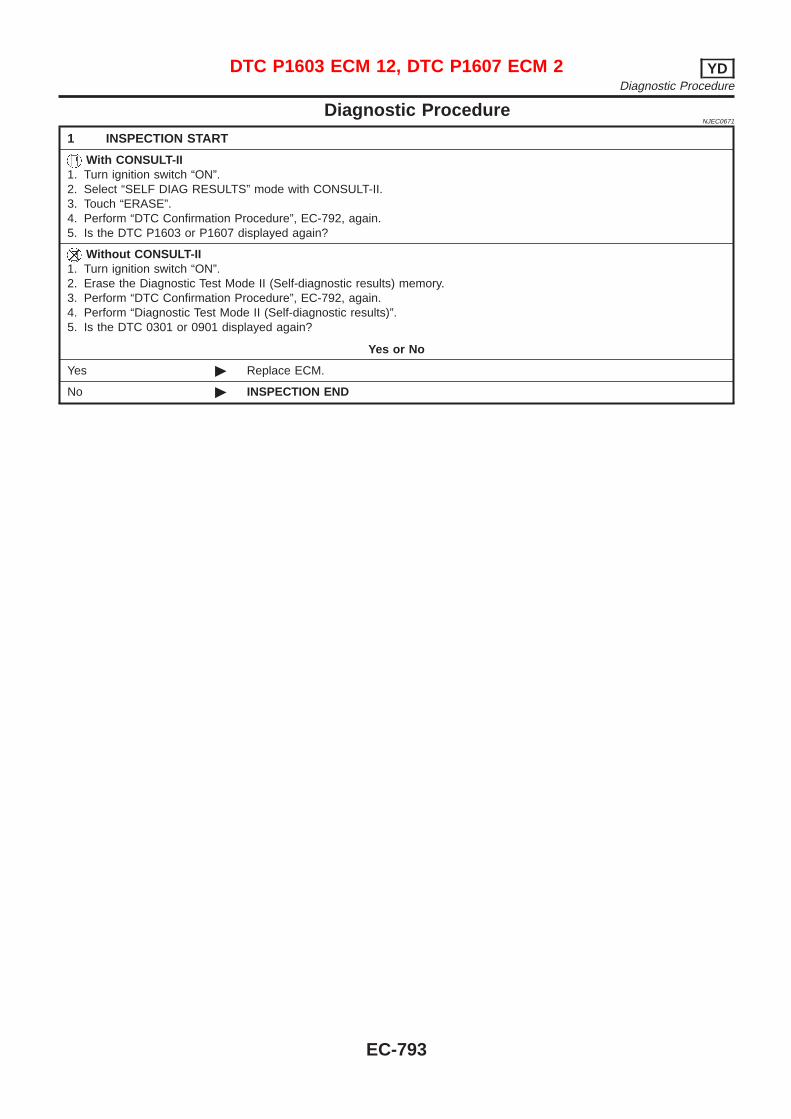
Diagnostic ProcedureNJEC0671
1 INSPECTION START
With CONSULT-II1. Turn ignition switch “ON”.2. Select “SELF DIAG RESULTS” mode with CONSULT-II.3. Touch “ERASE”.4. Perform “DTC Confirmation Procedure”, EC-792, again.5. Is the DTC P1603 or P1607 displayed again?
Without CONSULT-II1. Turn ignition switch “ON”.2. Erase the Diagnostic Test Mode II (Self-diagnostic results) memory.3. Perform “DTC Confirmation Procedure”, EC-792, again.4. Perform “Diagnostic Test Mode II (Self-diagnostic results)”.5. Is the DTC 0301 or 0901 displayed again?
Yes or No
Yes © Replace ECM.
No © INSPECTION END
DTC P1603 ECM 12, DTC P1607 ECM 2 YDDiagnostic Procedure
EC-793
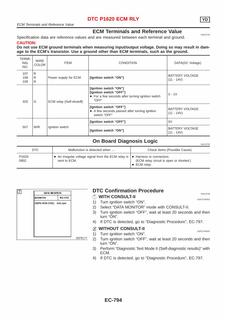
ECM Terminals and Reference ValueNJEC0744
Specification data are reference values and are measured between each terminal and ground.CAUTION:Do not use ECM ground terminals when measuring input/output voltage. Doing so may result in dam-age to the ECM’s transistor. Use a ground other than ECM terminals, such as the ground.
TERMI-NALNO.
WIRECOLOR
ITEM CONDITION DATA(DC Voltage)
107108109
RRR
Power supply for ECM [Ignition switch “ON”]BATTERY VOLTAGE(11 - 14V)
325 G ECM relay (Self-shutoff)
[Ignition switch “ON”][Ignition switch “OFF”]+ For a few seconds after turning ignition switch
“OFF”
0 - 1V
[Ignition switch “OFF”]+ A few seconds passed after turning ignition
switch “OFF”
BATTERY VOLTAGE(11 - 14V)
507 W/R Ignition switch
[Ignition switch “OFF”] 0V
[Ignition switch “ON”]BATTERY VOLTAGE(11 - 14V)
On Board Diagnosis LogicNJEC0745
DTC Malfunction is detected when .... Check Items (Possible Cause)
P16200902
+ An irregular voltage signal from the ECM relay issent to ECM.
+ Harness or connectors(ECM relay circuit is open or shorted.)
+ ECM relay
SEF817Y
DTC Confirmation ProcedureNJEC0746
WITH CONSULT-IINJEC0746S01
1) Turn ignition switch “ON”.2) Select “DATA MONITOR” mode with CONSULT-II.3) Turn ignition switch “OFF”, wait at least 20 seconds and then
turn “ON”.4) If DTC is detected, go to “Diagnostic Procedure”, EC-797.
WITHOUT CONSULT-IINJEC0746S02
1) Turn ignition switch “ON”.2) Turn ignition switch “OFF”, wait at least 20 seconds and then
turn “ON”.3) Perform “Diagnostic Test Mode II (Self-diagnostic results)” with
ECM.4) If DTC is detected, go to “Diagnostic Procedure”, EC-797.
DTC P1620 ECM RLY YDECM Terminals and Reference Value
EC-794
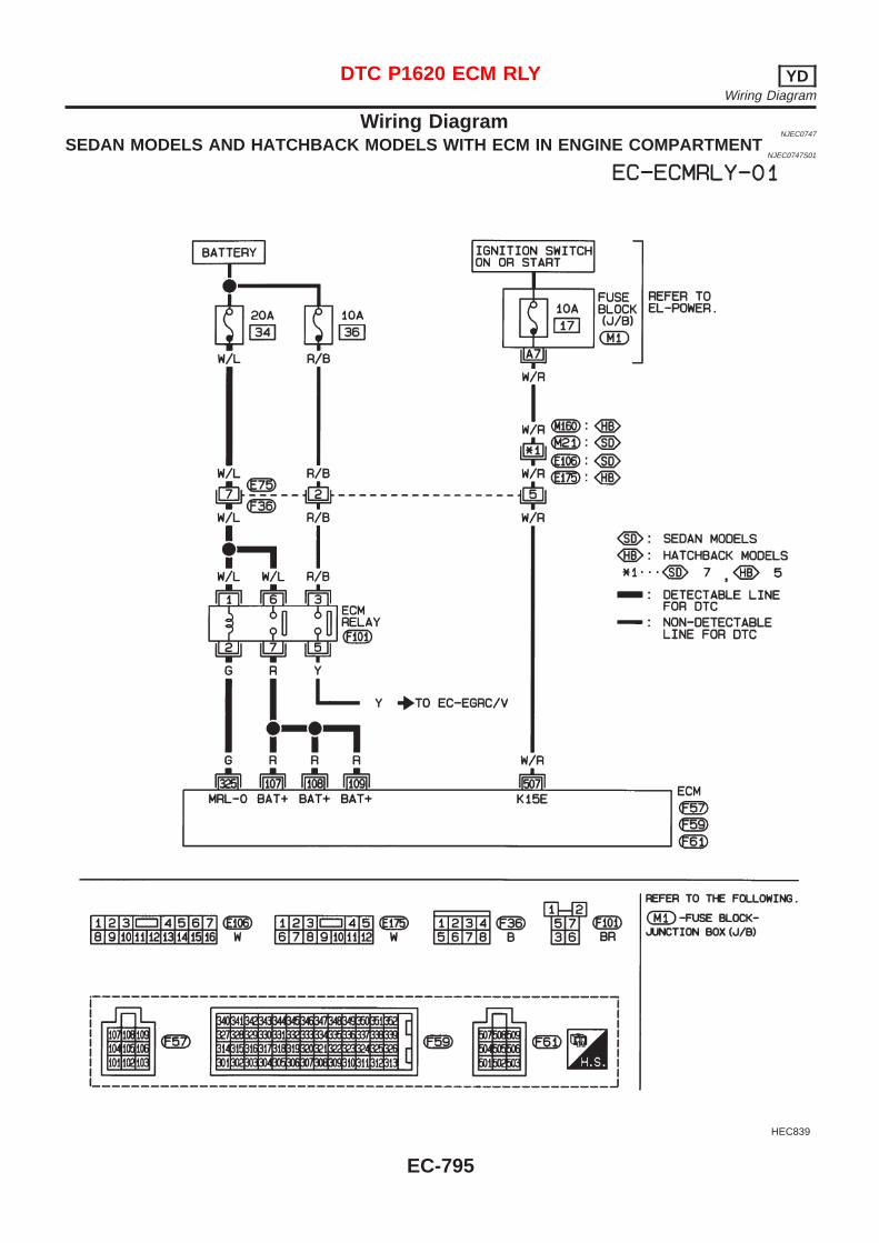
Wiring DiagramNJEC0747
SEDAN MODELS AND HATCHBACK MODELS WITH ECM IN ENGINE COMPARTMENTNJEC0747S01
HEC839
DTC P1620 ECM RLY YDWiring Diagram
EC-795
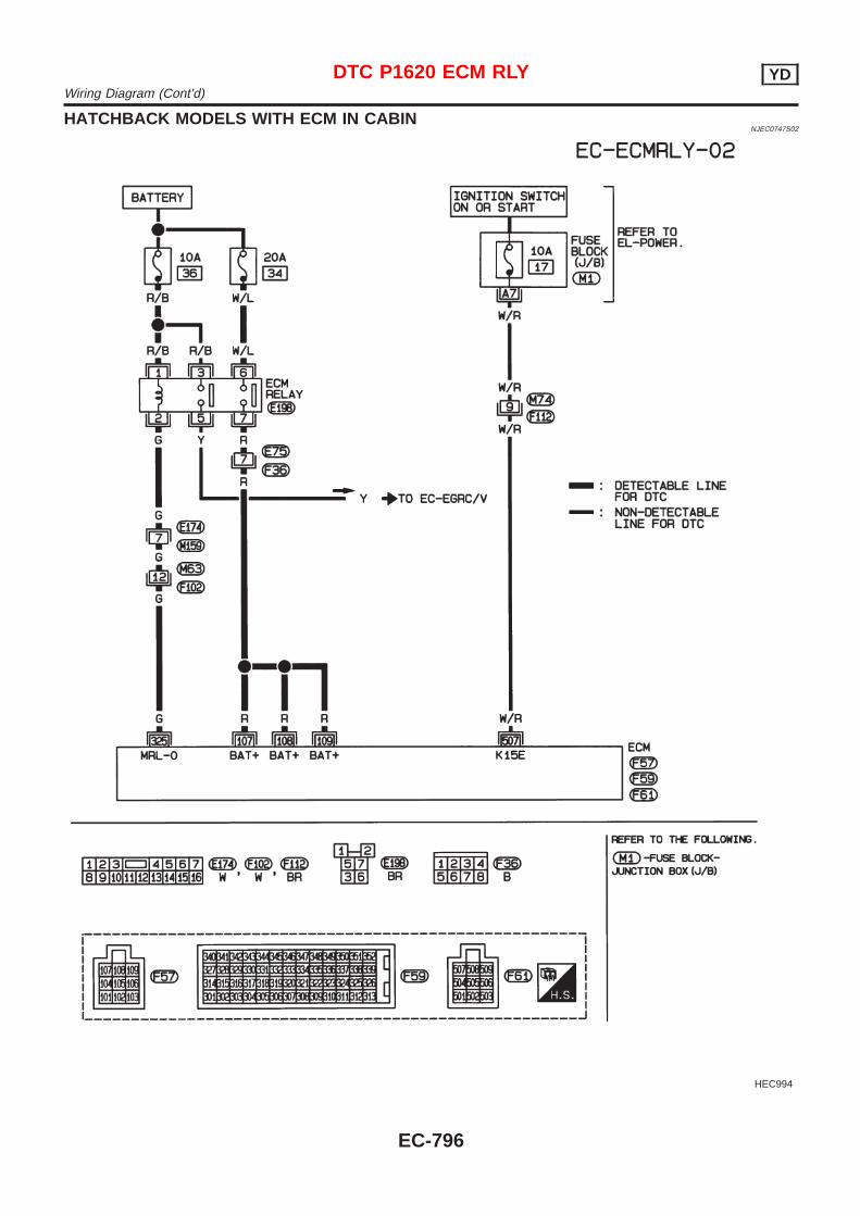
HATCHBACK MODELS WITH ECM IN CABINNJEC0747S02
HEC994
DTC P1620 ECM RLY YDWiring Diagram (Cont’d)
EC-796
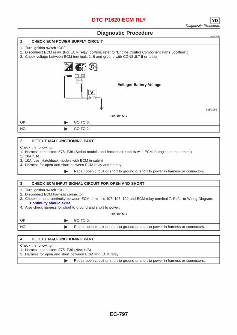
Diagnostic ProcedureNJEC0748
1 CHECK ECM POWER SUPPLY CIRCUIT
1. Turn ignition switch “OFF”.2. Disconnect ECM relay. (For ECM relay location, refer to “Engine Control Component Parts Location”.)3. Check voltage between ECM terminals 1, 6 and ground with CONSULT-II or tester.
SEF399Y
OK or NG
OK © GO TO 3.
NG © GO TO 2.
2 DETECT MALFUNCTIONING PART
Check the following.1. Harness connectors E75, F36 (Sedan models and hatchback models with ECM in engine compartment)2. 20A fuse3. 10A fuse (Hatchback models with ECM in cabin)4. Harness for open and short between ECM relay and battery
© Repair open circuit or short to ground or short to power in harness or connectors.
3 CHECK ECM INPUT SIGNAL CIRCUIT FOR OPEN AND SHORT
1. Turn ignition switch “OFF”.2. Disconnect ECM harness connector.3. Check harness continuity between ECM terminals 107, 108, 109 and ECM relay terminal 7. Refer to Wiring Diagram.
Continuity should exist.4. Also check harness for short to ground and short to power.
OK or NG
OK © GO TO 5.
NG © Repair open circuit or short to ground or short to power in harness or connectors.
4 DETECT MALFUNCTIONING PART
Check the following.1. Harness connectors E75, F36 (New H/B)2. Harness for open and short between ECM and ECM relay
© Repair open circuit or short to ground or short to power in harness or connectors.
DTC P1620 ECM RLY YDDiagnostic Procedure
EC-797
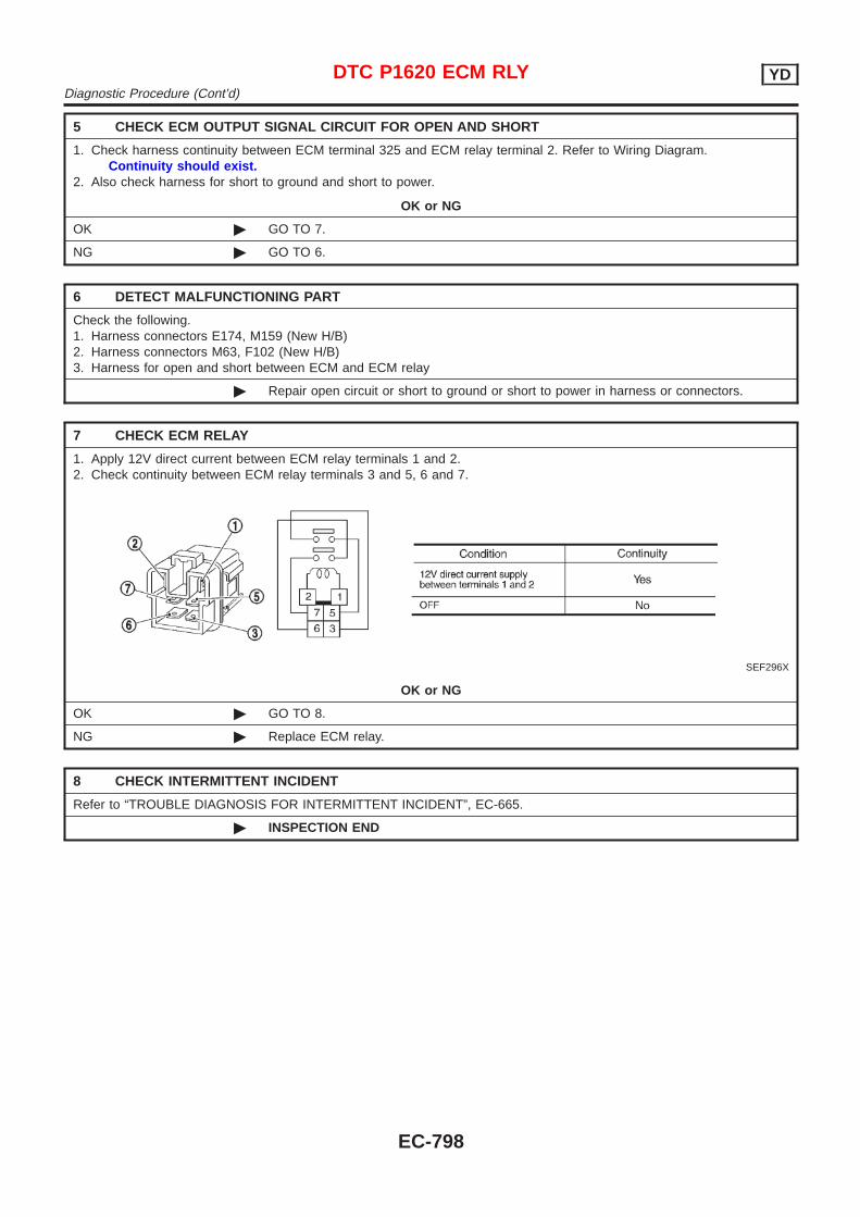
5 CHECK ECM OUTPUT SIGNAL CIRCUIT FOR OPEN AND SHORT
1. Check harness continuity between ECM terminal 325 and ECM relay terminal 2. Refer to Wiring Diagram.Continuity should exist.
2. Also check harness for short to ground and short to power.
OK or NG
OK © GO TO 7.
NG © GO TO 6.
6 DETECT MALFUNCTIONING PART
Check the following.1. Harness connectors E174, M159 (New H/B)2. Harness connectors M63, F102 (New H/B)3. Harness for open and short between ECM and ECM relay
© Repair open circuit or short to ground or short to power in harness or connectors.
7 CHECK ECM RELAY
1. Apply 12V direct current between ECM relay terminals 1 and 2.2. Check continuity between ECM relay terminals 3 and 5, 6 and 7.
SEF296X
OK or NG
OK © GO TO 8.
NG © Replace ECM relay.
8 CHECK INTERMITTENT INCIDENT
Refer to “TROUBLE DIAGNOSIS FOR INTERMITTENT INCIDENT”, EC-665.
© INSPECTION END
DTC P1620 ECM RLY YDDiagnostic Procedure (Cont’d)
EC-798
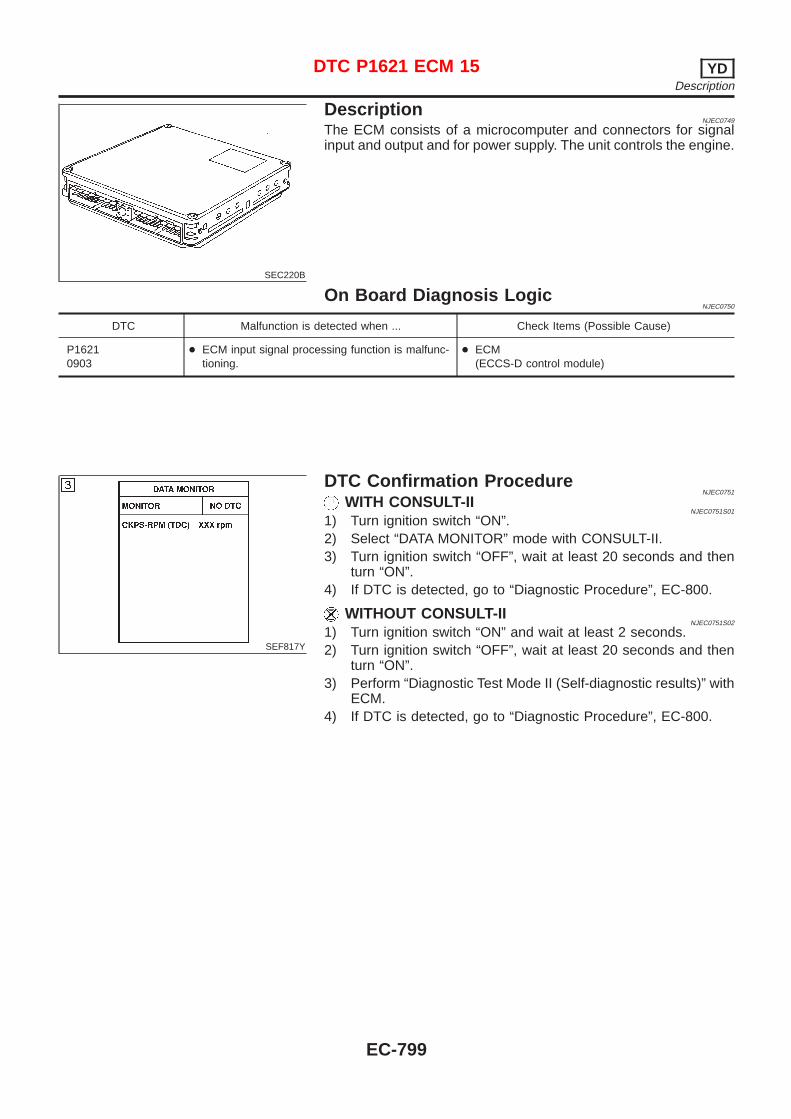
SEC220B
DescriptionNJEC0749
The ECM consists of a microcomputer and connectors for signalinput and output and for power supply. The unit controls the engine.
On Board Diagnosis LogicNJEC0750
DTC Malfunction is detected when ... Check Items (Possible Cause)
P16210903
+ ECM input signal processing function is malfunc-tioning.
+ ECM(ECCS-D control module)
SEF817Y
DTC Confirmation ProcedureNJEC0751
WITH CONSULT-IINJEC0751S01
1) Turn ignition switch “ON”.2) Select “DATA MONITOR” mode with CONSULT-II.3) Turn ignition switch “OFF”, wait at least 20 seconds and then
turn “ON”.4) If DTC is detected, go to “Diagnostic Procedure”, EC-800.
WITHOUT CONSULT-IINJEC0751S02
1) Turn ignition switch “ON” and wait at least 2 seconds.2) Turn ignition switch “OFF”, wait at least 20 seconds and then
turn “ON”.3) Perform “Diagnostic Test Mode II (Self-diagnostic results)” with
ECM.4) If DTC is detected, go to “Diagnostic Procedure”, EC-800.
DTC P1621 ECM 15 YDDescription
EC-799
Diagnostic ProcedureNJEC0752
1 INSPECTION START
With CONSULT-II1. Turn ignition switch “ON”.2. Select “SELF DIAG RESULTS” mode with CONSULT-II.3. Touch “ERASE”.4. Perform “DTC Confirmation Procedure”, EC-799, again.5. Is the DTC P1621 displayed again?
Without CONSULT-II1. Turn ignition switch “ON”.2. Erase the Diagnostic Test Mode II (Self-diagnostic results) memory.3. Perform “DTC Confirmation Procedure”, EC-799, again.4. Perform “Diagnostic Test Mode II (Self-diagnostic results)”.5. Is the DTC 0903 displayed again?
Yes or No
Yes © Replace ECM.
No © INSPECTION END
DTC P1621 ECM 15 YDDiagnostic Procedure
EC-800
On Board Diagnosis LogicNJEC1258
The ECM checks if battery voltage is within the tolerance range for the engine control system.
DTC Malfunction is detected when ... Check Items (Possible Cause)
P16600502
+ An abnormally high or low voltage from the batteryis sent to ECM.
+ Incorrect jump starting+ Battery+ Alternator+ ECM
DTC Confirmation ProcedureNJEC1259
With CONSULT-II1) Check the following.+ Jumper cables are connected for jump starting.+ Battery or alternator has been replaced.
If the result is “Yes” for one item or more, skip the following steps and go to “Diagnostic Procedure”,EC-801.
2) Check that the positive battery terminal is connected to battery properly. If NG, reconnect it properly.3) Check that the alternator functions properly. Refer to SC-30, “Trouble Diagnosis”.4) Turn ignition switch “ON” and select “DATA MONITOR” mode with CONSULT-II.5) Wait one minute.6) If DTC is detected, go to “Diagnostic Procedure”, EC-801.
If DTC is not detected, go to next step.7) Start engine and wait one minute at idle.8) If DTC is detected, go to “Diagnostic Procedure”, EC-801.
Without CONSULT-II1) Check the following.+ Jumper cables are connected for jump starting.+ Battery or alternator has been replaced.
If the result is “Yes” for one item or more, skip the following steps and go to “Diagnostic Procedure”,EC-801.
2) Check that the positive battery terminal is connected to battery properly. If NG, reconnect it properly.3) Check that the alternator functions properly. Refer to SC-30, “Trouble Diagnosis”.4) Turn ignition switch “ON” and wait one minute.5) Turn ignition switch “OFF”, wait 5 seconds and then turn “ON”.6) Perform “Diagnostic Test Mode II (Self-diagnostic result)” with ECM.7) If DTC is detected, go to “Diagnostic Procedure”, EC-801.
If DTC is not detected, go to next step.8) Start engine and wait one minute at idle.9) Turn ignition switch “OFF”, wait 5 seconds and then turn “ON”.10) Perform “Diagnostic Test Mode II (Self-diagnostic result)” with ECM.11) If DTC is detected, go to “Diagnostic Procedure”, EC-801.
Diagnostic ProcedureNJEC1260
1 INSPECTION START
Are jumper cables connected for the jump starting?
Yes or No
Yes © GO TO 3.
No © GO TO 2.
DTC P1660 BATTERY VOLTAGE YDOn Board Diagnosis Logic
EC-801
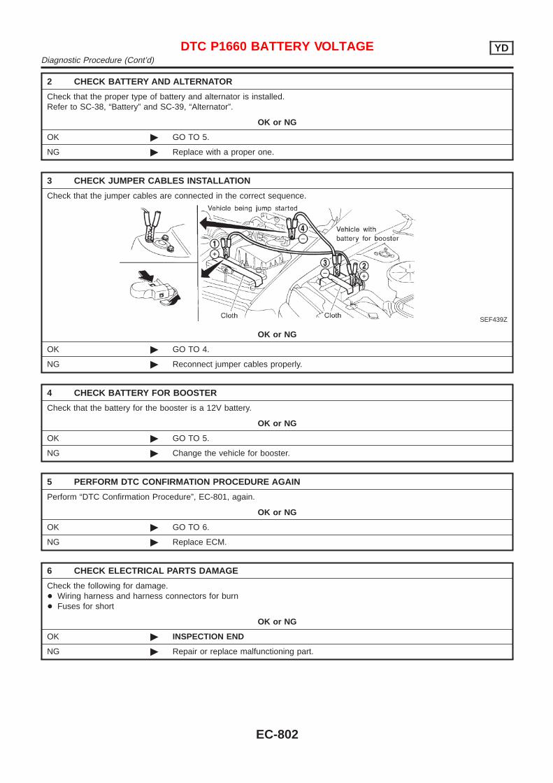
2 CHECK BATTERY AND ALTERNATOR
Check that the proper type of battery and alternator is installed.Refer to SC-38, “Battery” and SC-39, “Alternator”.
OK or NG
OK © GO TO 5.
NG © Replace with a proper one.
3 CHECK JUMPER CABLES INSTALLATION
Check that the jumper cables are connected in the correct sequence.
SEF439Z
OK or NG
OK © GO TO 4.
NG © Reconnect jumper cables properly.
4 CHECK BATTERY FOR BOOSTER
Check that the battery for the booster is a 12V battery.
OK or NG
OK © GO TO 5.
NG © Change the vehicle for booster.
5 PERFORM DTC CONFIRMATION PROCEDURE AGAIN
Perform “DTC Confirmation Procedure”, EC-801, again.
OK or NG
OK © GO TO 6.
NG © Replace ECM.
6 CHECK ELECTRICAL PARTS DAMAGE
Check the following for damage.+ Wiring harness and harness connectors for burn+ Fuses for short
OK or NG
OK © INSPECTION END
NG © Repair or replace malfunctioning part.
DTC P1660 BATTERY VOLTAGE YDDiagnostic Procedure (Cont’d)
EC-802

SEF437Y
DescriptionNJEC0721
SYSTEM DESCRIPTIONNJEC0721S01
The ECM and the electronic control fuel injection pump control unit(abbreviated as the injection pump control unit) perform the realtime communication (signal exchange).The ECM transmits the signals of the target fuel injection amount,target fuel injection timing, and engine speed, etc., and receivesthe signals of the pump speed and fuel temperature, etc. from theinjection pump control unit.By those signals, the injection pump controls the optimum fuelinjection amount and injection timing of the spill valve and timingcontrol valve.Injection pump control unit has an on board diagnostic system,which detects malfunctions related to sensors or actuators built-intoelectronic control fuel injection pump. These malfunction informa-tion are transferred through the line (circuit) from injection pumpcontrol unit to ECM.
FUEL INJECTION AMOUNT CONTROLNJEC0721S02
In accordance with the target fuel injection amount signal from theECM, the injection amount is controlled by controlling the spill valvein the injection pump and by changing the needle opening time.
FUEL INJECTION TIMING CONTROLNJEC0721S03
Based on the target fuel injection timing signal from the ECM, theinjection timing is controlled in accordance with the timer spring byperforming the duty control of the timing control valve in the injec-tion pump and by adjusting the pressure of the timer piston highpressure chamber.
FUEL TEMPERATURE SENSORNJEC0721S04
The sensor detects the fuel temperature in the injection pump andcalibrates the injection amount change by the fuel temperature.
CAM RING POSITION SENSORNJEC0721S05
The sensor detects the passing of the protrusion on the sensorwheel in the injection pump by the semiconductor magnetic resis-tance element sensor. The cam ring position sensor synchronizeswith the cam ring, and detects the actual advance amount. Theinjection pump control unit measures the injection pump revolutionby the signal of the cam ring position sensor.
CONSULT-II Reference Value in Data MonitorMode
NJEC0722
Remarks: Specification data are reference values.
MONITOR ITEM CONDITION SPECIFICATION
FUEL TEMP SEN + Engine: After warming up More than 40°C (104°F)
SPILL/V + Engine: After warming up, idle the engine. Approx. 12 - 13°CA
INT/A VOLUME + Engine: After warming up, idle the engine. Approx. 150 - 450 mg/st
F/CUT SIGNAL + Engine: After warming up Idle ON
DTC P1690 P5·PUMP C/MODULE YDDescription
EC-803
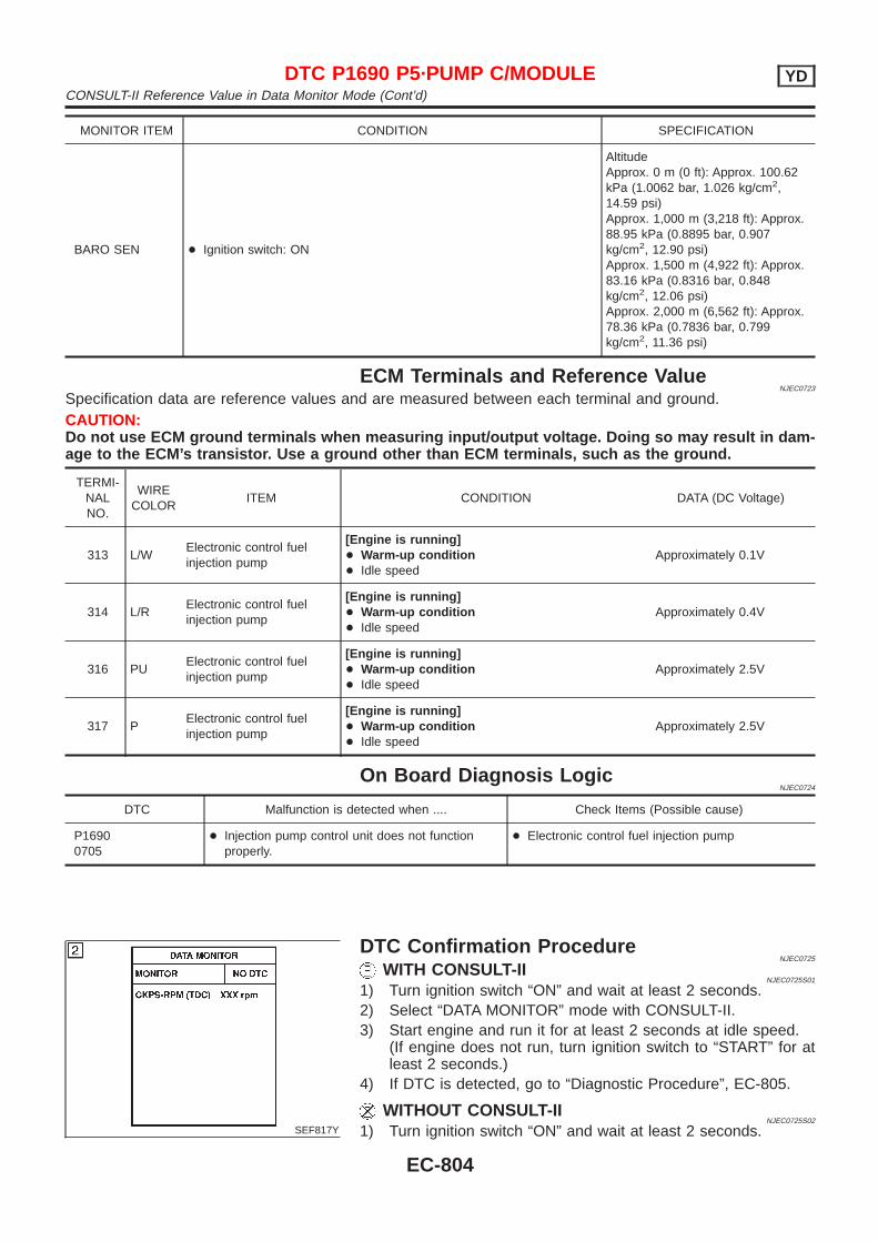
MONITOR ITEM CONDITION SPECIFICATION
BARO SEN + Ignition switch: ON
AltitudeApprox. 0 m (0 ft): Approx. 100.62kPa (1.0062 bar, 1.026 kg/cm2,14.59 psi)Approx. 1,000 m (3,218 ft): Approx.88.95 kPa (0.8895 bar, 0.907kg/cm2, 12.90 psi)Approx. 1,500 m (4,922 ft): Approx.83.16 kPa (0.8316 bar, 0.848kg/cm2, 12.06 psi)Approx. 2,000 m (6,562 ft): Approx.78.36 kPa (0.7836 bar, 0.799kg/cm2, 11.36 psi)
ECM Terminals and Reference ValueNJEC0723
Specification data are reference values and are measured between each terminal and ground.CAUTION:Do not use ECM ground terminals when measuring input/output voltage. Doing so may result in dam-age to the ECM’s transistor. Use a ground other than ECM terminals, such as the ground.
TERMI-NALNO.
WIRECOLOR
ITEM CONDITION DATA (DC Voltage)
313 L/WElectronic control fuelinjection pump
[Engine is running]+ Warm-up condition+ Idle speed
Approximately 0.1V
314 L/RElectronic control fuelinjection pump
[Engine is running]+ Warm-up condition+ Idle speed
Approximately 0.4V
316 PUElectronic control fuelinjection pump
[Engine is running]+ Warm-up condition+ Idle speed
Approximately 2.5V
317 PElectronic control fuelinjection pump
[Engine is running]+ Warm-up condition+ Idle speed
Approximately 2.5V
On Board Diagnosis LogicNJEC0724
DTC Malfunction is detected when .... Check Items (Possible cause)
P16900705
+ Injection pump control unit does not functionproperly.
+ Electronic control fuel injection pump
SEF817Y
DTC Confirmation ProcedureNJEC0725
WITH CONSULT-IINJEC0725S01
1) Turn ignition switch “ON” and wait at least 2 seconds.2) Select “DATA MONITOR” mode with CONSULT-II.3) Start engine and run it for at least 2 seconds at idle speed.
(If engine does not run, turn ignition switch to “START” for atleast 2 seconds.)
4) If DTC is detected, go to “Diagnostic Procedure”, EC-805.
WITHOUT CONSULT-IINJEC0725S02
1) Turn ignition switch “ON” and wait at least 2 seconds.
DTC P1690 P5·PUMP C/MODULE YDCONSULT-II Reference Value in Data Monitor Mode (Cont’d)
EC-804
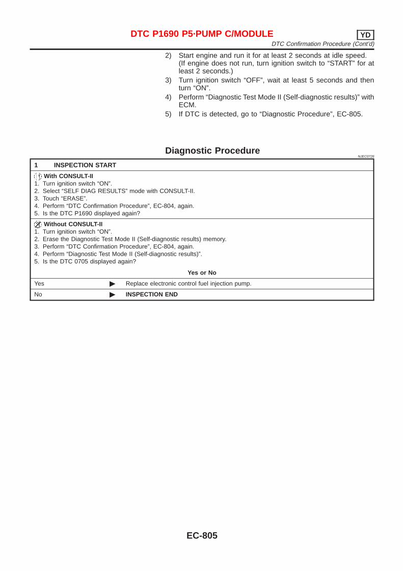
2) Start engine and run it for at least 2 seconds at idle speed.(If engine does not run, turn ignition switch to “START” for atleast 2 seconds.)
3) Turn ignition switch “OFF”, wait at least 5 seconds and thenturn “ON”.
4) Perform “Diagnostic Test Mode II (Self-diagnostic results)” withECM.
5) If DTC is detected, go to “Diagnostic Procedure”, EC-805.
Diagnostic ProcedureNJEC0726
1 INSPECTION START
With CONSULT-II1. Turn ignition switch “ON”.2. Select “SELF DIAG RESULTS” mode with CONSULT-II.3. Touch “ERASE”.4. Perform “DTC Confirmation Procedure”, EC-804, again.5. Is the DTC P1690 displayed again?
Without CONSULT-II1. Turn ignition switch “ON”.2. Erase the Diagnostic Test Mode II (Self-diagnostic results) memory.3. Perform “DTC Confirmation Procedure”, EC-804, again.4. Perform “Diagnostic Test Mode II (Self-diagnostic results)”.5. Is the DTC 0705 displayed again?
Yes or No
Yes © Replace electronic control fuel injection pump.
No © INSPECTION END
DTC P1690 P5·PUMP C/MODULE YDDTC Confirmation Procedure (Cont’d)
EC-805
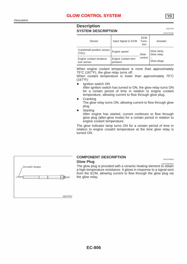
DescriptionNJEC0760
SYSTEM DESCRIPTIONNJEC0760S01
Sensor Input Signal to ECMECMFunc-tion
Actuator
Crankshaft position sensor(TDC)
Engine speedGlowcontrol
Glow lamp,Glow relay↓Glow plugs
Engine coolant tempera-ture sensor
Engine coolant tem-perature
When engine coolant temperature is more than approximately75°C (167°F), the glow relay turns off.When coolant temperature is lower than approximately 75°C(167°F):+ Ignition switch ON
After ignition switch has turned to ON, the glow relay turns ONfor a certain period of time in relation to engine coolanttemperature, allowing current to flow through glow plug.
+ CrankingThe glow relay turns ON, allowing current to flow through glowplug.
+ StartingAfter engine has started, current continues to flow throughglow plug (after-glow mode) for a certain period in relation toengine coolant temperature.
The glow indicator lamp turns ON for a certain period of time inrelation to engine cooalnt temperature at the time glow relay isturned ON.
SEF376Y
COMPONENT DESCRIPTIONNJEC0760S02
Glow PlugNJEC0760S0201
The glow plug is provided with a ceramic heating element to obtaina high-temperature resistance. It glows in response to a signal sentfrom the ECM, allowing current to flow through the glow plug viathe glow relay.
GLOW CONTROL SYSTEM YDDescription
EC-806
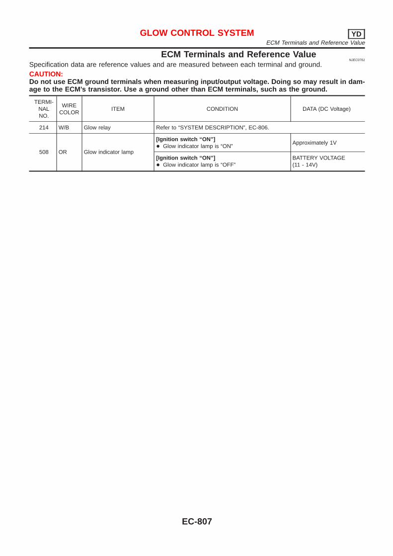
ECM Terminals and Reference ValueNJEC0761
Specification data are reference values and are measured between each terminal and ground.CAUTION:Do not use ECM ground terminals when measuring input/output voltage. Doing so may result in dam-age to the ECM’s transistor. Use a ground other than ECM terminals, such as the ground.
TERMI-NALNO.
WIRECOLOR
ITEM CONDITION DATA (DC Voltage)
214 W/B Glow relay Refer to “SYSTEM DESCRIPTION”, EC-806.
508 OR Glow indicator lamp
[Ignition switch “ON”]+ Glow indicator lamp is “ON”
Approximately 1V
[Ignition switch “ON”]+ Glow indicator lamp is “OFF”
BATTERY VOLTAGE(11 - 14V)
GLOW CONTROL SYSTEM YDECM Terminals and Reference Value
EC-807
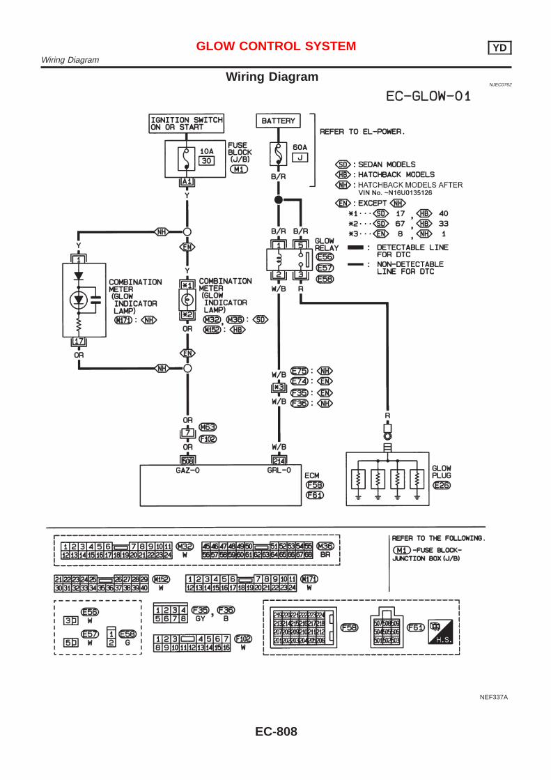
Wiring DiagramNJEC0762
NEF337A
GLOW CONTROL SYSTEM YDWiring Diagram
EC-808
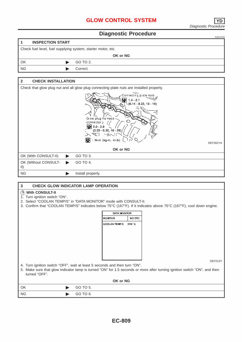
Diagnostic ProcedureNJEC0763
1 INSPECTION START
Check fuel level, fuel supplying system, starter motor, etc.
OK or NG
OK © GO TO 2.
NG © Correct.
2 CHECK INSTALLATION
Check that glow plug nut and all glow plug connecting plate nuts are installed properly.
SEF392YA
OK or NG
OK (With CONSULT-II) © GO TO 3.
OK (Without CONSULT-II)
© GO TO 4.
NG © Install properly.
3 CHECK GLOW INDICATOR LAMP OPERATION
With CONSULT-II1. Turn ignition switch “ON”.2. Select “COOLAN TEMP/S” in “DATA MONITOR” mode with CONSULT-II.3. Confirm that “COOLAN TEMP/S” indicates below 75°C (167°F). If it indicates above 75°C (167°F), cool down engine.
SEF013Y
4. Turn ignition switch “OFF”, wait at least 5 seconds and then turn “ON”.5. Make sure that glow indicator lamp is turned “ON” for 1.5 seconds or more after turning ignition switch “ON”, and then
turned “OFF”.
OK or NG
OK © GO TO 5.
NG © GO TO 6.
GLOW CONTROL SYSTEM YDDiagnostic Procedure
EC-809
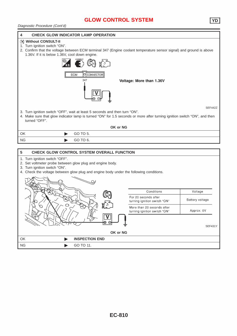
4 CHECK GLOW INDICATOR LAMP OPERATION
Without CONSULT-II1. Turn ignition switch “ON”.2. Confirm that the voltage between ECM terminal 347 (Engine coolant temperature sensor signal) and ground is above
1.36V. If it is below 1.36V, cool down engine.
SEF442Z
3. Turn ignition switch “OFF”, wait at least 5 seconds and then turn “ON”.4. Make sure that glow indicator lamp is turned “ON” for 1.5 seconds or more after turning ignition switch “ON”, and then
turned “OFF”.
OK or NG
OK © GO TO 5.
NG © GO TO 6.
5 CHECK GLOW CONTROL SYSTEM OVERALL FUNCTION
1. Turn ignition switch “OFF”.2. Set voltmeter probe between glow plug and engine body.3. Turn ignition switch “ON”.4. Check the voltage between glow plug and engine body under the following conditions.
SEF431Y
OK or NG
OK © INSPECTION END
NG © GO TO 11.
GLOW CONTROL SYSTEM YDDiagnostic Procedure (Cont’d)
EC-810
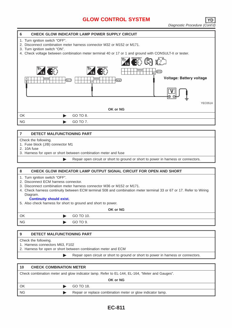
6 CHECK GLOW INDICATOR LAMP POWER SUPPLY CIRCUIT
1. Turn ignition switch “OFF”.2. Disconnect combination meter harness connector M32 or M152 or M171.3. Turn ignition switch “ON”.4. Check voltage between combination meter terminal 40 or 17 or 1 and ground with CONSULT-II or tester.
YEC051A
OK or NG
OK © GO TO 8.
NG © GO TO 7.
7 DETECT MALFUNCTIONING PART
Check the following.1. Fuse block (J/B) connector M12. 10A fuse3. Harness for open or short between combination meter and fuse
© Repair open circuit or short to ground or short to power in harness or connectors.
8 CHECK GLOW INDICATOR LAMP OUTPUT SIGNAL CIRCUIT FOR OPEN AND SHORT
1. Turn ignition switch “OFF”.2. Disconnect ECM harness connector.3. Disconnect combination meter harness connector M36 or M152 or M171.4. Check harness continuity between ECM terminal 508 and combination meter terminal 33 or 67 or 17. Refer to Wiring
Diagram.Continuity should exist.
5. Also check harness for short to ground and short to power.
OK or NG
OK © GO TO 10.
NG © GO TO 9.
9 DETECT MALFUNCTIONING PART
Check the following.1. Harness connectors M63, F1022. Harness for open or short between combination meter and ECM
© Repair open circuit or short to ground or short to power in harness or connectors.
10 CHECK COMBINATION METER
Check combination meter and glow indicator lamp. Refer to EL-144, EL-164, “Meter and Gauges”.
OK or NG
OK © GO TO 18.
NG © Repair or replace combination meter or glow indicator lamp.
GLOW CONTROL SYSTEM YDDiagnostic Procedure (Cont’d)
EC-811

11 CHECK GLOW RELAY POWER SUPPLY CIRCUIT
1. Turn ignition switch “OFF”.2. Disconnect glow relay.
SEF391Y
3. Check voltage between glow relay terminals 1, 5 and ground with CONSULT-II or tester.
SEF420Y
OK or NG
OK © GO TO 13.
NG © GO TO 12.
12 DETECT MALFUNCTIONING PART
Check the following.+ 60A fusible link+ Harness for open or short between glow relay and battery
© Repair harness or connectors.
13 CHECK GLOW RELAY OUTPUT SIGNAL CIRCUIT FOR OPEN AND SHORT
1. Disconnect ECM harness connector.2. Check harness continuity between ECM terminal 214 and glow relay terminal 2. Refer to Wiring Diagram.
Continuity should exist.3. Also check harness for short to ground and short to power.
OK or NG
OK © GO TO 15.
NG © GO TO 14.
14 DETECT MALFUNCTIONING PART
Check the following.+ Harness connectors E74, F35 or E75, F36+ Harness for open or short between glow relay and ECM
© Repair open circuit or short to ground or short to power in harness or connectors.
GLOW CONTROL SYSTEM YDDiagnostic Procedure (Cont’d)
EC-812
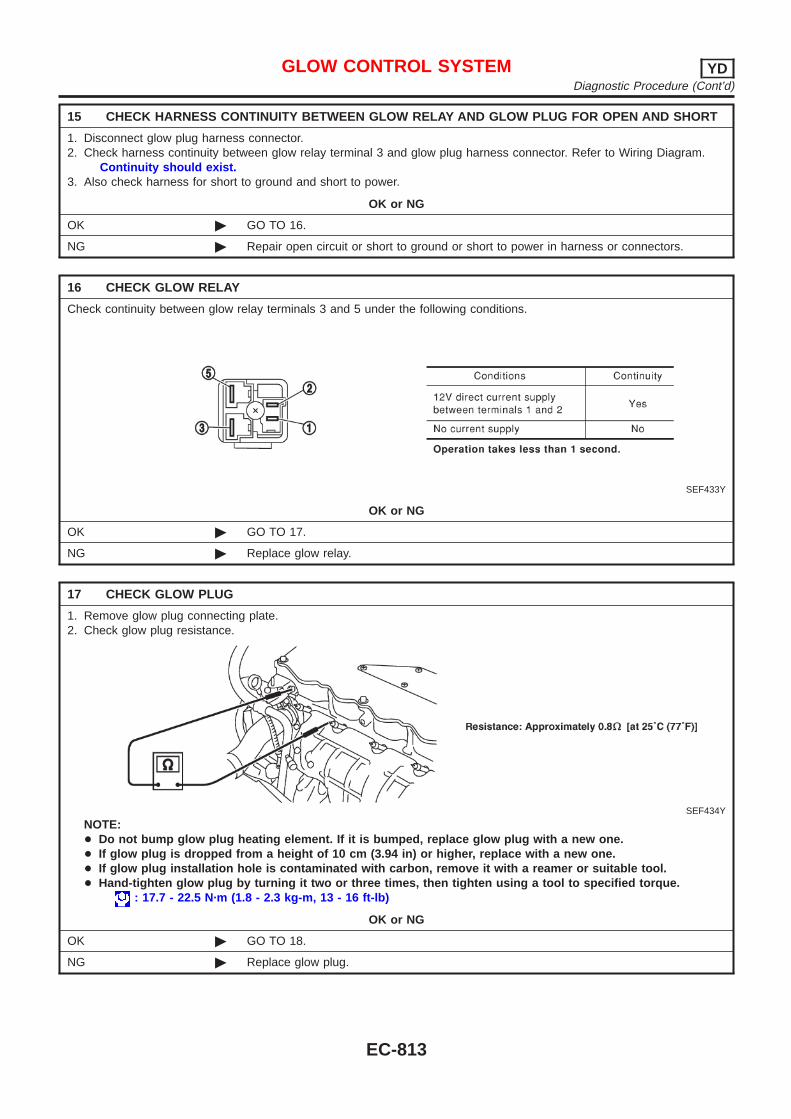
15 CHECK HARNESS CONTINUITY BETWEEN GLOW RELAY AND GLOW PLUG FOR OPEN AND SHORT
1. Disconnect glow plug harness connector.2. Check harness continuity between glow relay terminal 3 and glow plug harness connector. Refer to Wiring Diagram.
Continuity should exist.3. Also check harness for short to ground and short to power.
OK or NG
OK © GO TO 16.
NG © Repair open circuit or short to ground or short to power in harness or connectors.
16 CHECK GLOW RELAY
Check continuity between glow relay terminals 3 and 5 under the following conditions.
SEF433Y
OK or NG
OK © GO TO 17.
NG © Replace glow relay.
17 CHECK GLOW PLUG
1. Remove glow plug connecting plate.2. Check glow plug resistance.
SEF434Y
NOTE:+ Do not bump glow plug heating element. If it is bumped, replace glow plug with a new one.+ If glow plug is dropped from a height of 10 cm (3.94 in) or higher, replace with a new one.+ If glow plug installation hole is contaminated with carbon, remove it with a reamer or suitable tool.+ Hand-tighten glow plug by turning it two or three times, then tighten using a tool to specified torque.
: 17.7 - 22.5 N·m (1.8 - 2.3 kg-m, 13 - 16 ft-lb)
OK or NG
OK © GO TO 18.
NG © Replace glow plug.
GLOW CONTROL SYSTEM YDDiagnostic Procedure (Cont’d)
EC-813
18 CHECK INTERMITTENT INCIDENT
Refer to “TROUBLE DIAGNOSIS FOR INTERMITTENT INCIDENT”, EC-665.
© INSPECTION END
GLOW CONTROL SYSTEM YDDiagnostic Procedure (Cont’d)
EC-814

DescriptionNJEC0764
SYSTEM DESCRIPTIONNJEC0764S01
Sensor Input Signal to ECM ECM Function Actuator
Electronic controlled fuel injection pump Fuel injection signal
EGR volume con-trol
EGR volume controlvalve
Crankshaft position sensor (TDC) Engine speed
Vehicle speed sensor Vehicle speed
Engine coolant temperature sensor Engine coolant temperature
Ignition switch Start signal
Accelerator position sensor Accelerator position
Mass air flow sensor Amount of intake air
Air conditioner switch Air conditioner operation
Electrical load Electrical load signal
This system controls flow rate of EGR led from exhaust manifoldto intake manifold. The opening of the EGR by-pass passage in theEGR volume control valve changes to control the flow rate. Abuilt-in step motor moves the valve in steps corresponding to theECM output pulses. The opening of the valve varies for optimumengine control. The optimum value stored in the ECM is determinedby considering various engine conditions.The EGR volume control valve remains close under the followingconditions.+ Engine stopped+ Engine starting+ Low engine coolant temperature+ Excessively high engine coolant temperature+ High engine speed+ Wide open throttle
SEF908Y
SEF411Y
COMPONENT DESCRIPTIONNJEC0764S02
EGR Volume Control ValveNJEC0764S0201
The EGR volume control valve uses a step motor to control the flowrate of EGR from exhaust manifold. This motor has four windingphases. It operates according to the output pulse signal of theECM. Two windings are turned ON and OFF in sequence. Eachtime an ON pulse is issued, the valve opens or closes, changingthe flow rate. When no change in the flow rate is needed, the ECMdoes not issue the pulse signal. A certain voltage signal is issuedso that the valve remains at that particular opening.
EGR VOLUME CONTROL SYSTEM YDDescription
EC-815
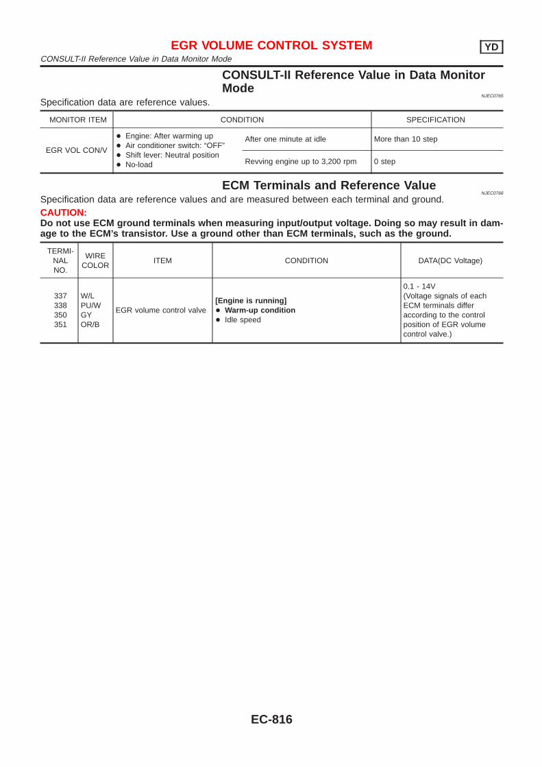
CONSULT-II Reference Value in Data MonitorMode
NJEC0765
Specification data are reference values.
MONITOR ITEM CONDITION SPECIFICATION
EGR VOL CON/V
+ Engine: After warming up+ Air conditioner switch: “OFF”+ Shift lever: Neutral position+ No-load
After one minute at idle More than 10 step
Revving engine up to 3,200 rpm 0 step
ECM Terminals and Reference ValueNJEC0766
Specification data are reference values and are measured between each terminal and ground.CAUTION:Do not use ECM ground terminals when measuring input/output voltage. Doing so may result in dam-age to the ECM’s transistor. Use a ground other than ECM terminals, such as the ground.
TERMI-NALNO.
WIRECOLOR
ITEM CONDITION DATA(DC Voltage)
337338350351
W/LPU/WGYOR/B
EGR volume control valve[Engine is running]+ Warm-up condition+ Idle speed
0.1 - 14V(Voltage signals of eachECM terminals differaccording to the controlposition of EGR volumecontrol valve.)
EGR VOLUME CONTROL SYSTEM YDCONSULT-II Reference Value in Data Monitor Mode
EC-816
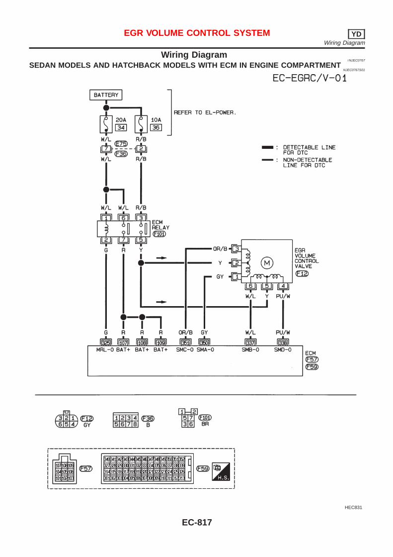
Wiring Diagram=NJEC0767
SEDAN MODELS AND HATCHBACK MODELS WITH ECM IN ENGINE COMPARTMENTNJEC0767S01
HEC831
EGR VOLUME CONTROL SYSTEM YDWiring Diagram
EC-817
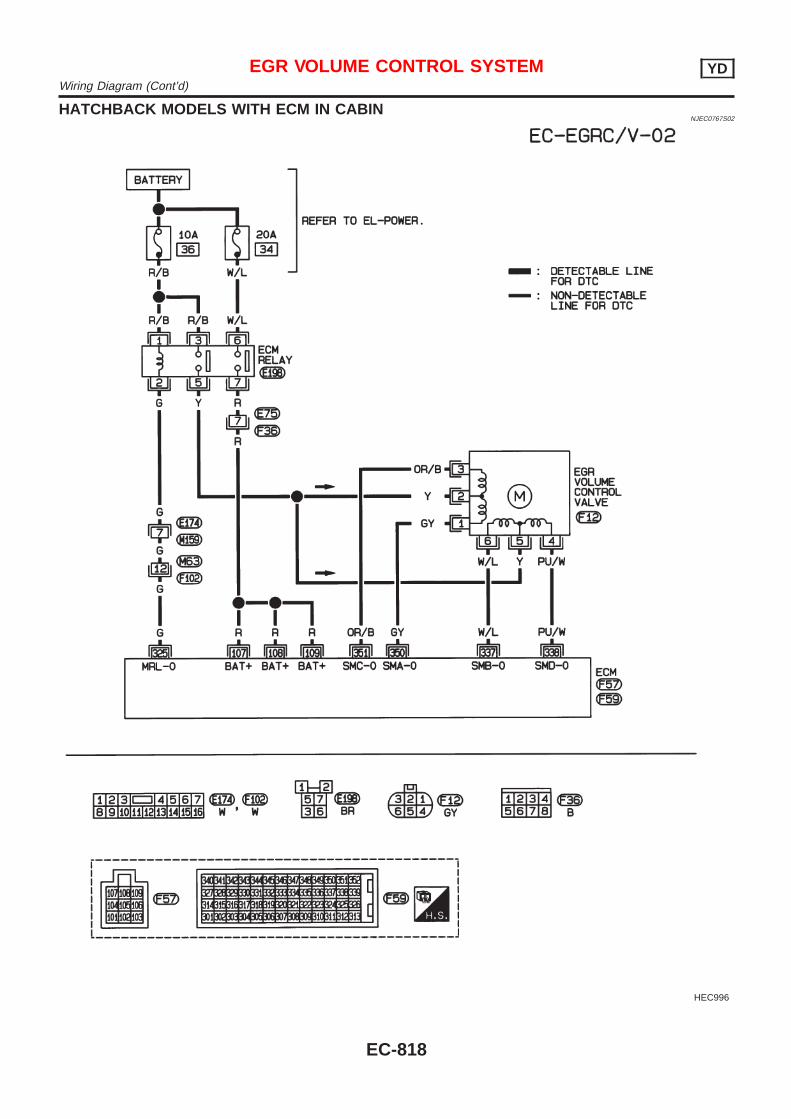
HATCHBACK MODELS WITH ECM IN CABINNJEC0767S02
HEC996
EGR VOLUME CONTROL SYSTEM YDWiring Diagram (Cont’d)
EC-818
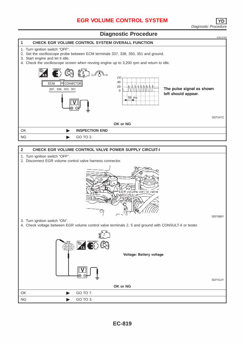
Diagnostic ProcedureNJEC0768
1 CHECK EGR VOLUME CONTROL SYSTEM OVERALL FUNCTION
1. Turn ignition switch “OFF”.2. Set the oscilloscope probe between ECM terminals 337, 338, 350, 351 and ground.3. Start engine and let it idle.4. Check the oscilloscope screen when revving engine up to 3,200 rpm and return to idle.
SEF247Z
OK or NG
OK © INSPECTION END
NG © GO TO 2.
2 CHECK EGR VOLUME CONTROL VALVE POWER SUPPLY CIRCUIT-I
1. Turn ignition switch “OFF”.2. Disconnect EGR volume control valve harness connector.
SEF388Y
3. Turn ignition switch “ON”.4. Check voltage between EGR volume control valve terminals 2, 5 and ground with CONSULT-II or tester.
SEF412Y
OK or NG
OK © GO TO 7.
NG © GO TO 3.
EGR VOLUME CONTROL SYSTEM YDDiagnostic Procedure
EC-819
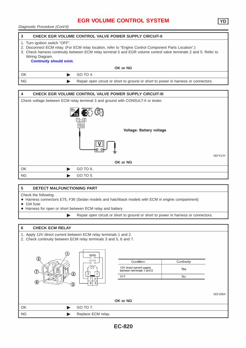
3 CHECK EGR VOLUME CONTROL VALVE POWER SUPPLY CIRCUIT-II
1. Turn ignition switch “OFF”.2. Disconnect ECM relay. (For ECM relay location, refer to “Engine Control Component Parts Location”.)3. Check harness continuity between ECM relay terminal 5 and EGR volume control valve terminals 2 and 5. Refer to
Wiring Diagram.Continuity should exist.
OK or NG
OK © GO TO 4.
NG © Repair open circuit or short to ground or short to power in harness or connectors.
4 CHECK EGR VOLUME CONTROL VALVE POWER SUPPLY CIRCUIT-III
Check voltage between ECM relay terminal 3 and ground with CONSULT-II or tester.
SEF413Y
OK or NG
OK © GO TO 6.
NG © GO TO 5.
5 DETECT MALFUNCTIONING PART
Check the following.+ Harness connectors E75, F36 (Sedan models and hatchback models with ECM in engine compartment)+ 10A fuse+ Harness for open or short between ECM relay and battery
© Repair open circuit or short to ground or short to power in harness or connectors.
6 CHECK ECM RELAY
1. Apply 12V direct current between ECM relay terminals 1 and 2.2. Check continuity between ECM relay terminals 3 and 5, 6 and 7.
SEF296X
OK or NG
OK © GO TO 7.
NG © Replace ECM relay.
EGR VOLUME CONTROL SYSTEM YDDiagnostic Procedure (Cont’d)
EC-820
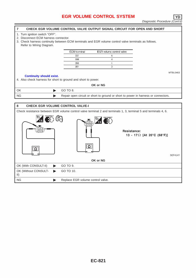
7 CHECK EGR VOLUME CONTROL VALVE OUTPUT SIGNAL CIRCUIT FOR OPEN AND SHORT
1. Turn ignition switch “OFF”.2. Disconnect ECM harness connector.3. Check harness continuity between ECM terminals and EGR volume control valve terminals as follows.
Refer to Wiring Diagram.
MTBL0463
Continuity should exist.4. Also check harness for short to ground and short to power.
OK or NG
OK © GO TO 8.
NG © Repair open circuit or short to ground or short to power in harness or connectors.
8 CHECK EGR VOLUME CONTROL VALVE-I
Check resistance between EGR volume control valve terminal 2 and terminals 1, 3, terminal 5 and terminals 4, 6.
SEF414Y
OK or NG
OK (With CONSULT-II) © GO TO 9.
OK (Without CONSULT-II)
© GO TO 10.
NG © Replace EGR volume control valve.
EGR VOLUME CONTROL SYSTEM YDDiagnostic Procedure (Cont’d)
EC-821
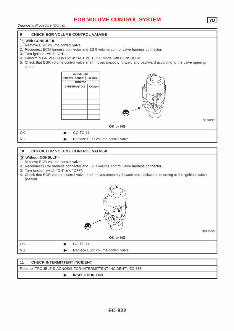
9 CHECK EGR VOLUME CONTROL VALVE-II
With CONSULT-II1. Remove EGR volume control valve.2. Reconnect ECM harness connector and EGR volume control valve harness connector.3. Turn ignition switch “ON”.4. Perform “EGR VOL CONT/V” in “ACTIVE TEST” mode with CONSULT-II.5. Check that EGR volume control valve shaft moves smoothy forward and backward according to the valve opening
steps.
SEF819Y
OK or NG
OK © GO TO 11.
NG © Replace EGR volume control valve.
10 CHECK EGR VOLUME CONTROL VALVE-II
Without CONSULT-II1. Remove EGR volume control valve.2. Reconnect ECM harness connector and EGR volume control valve harness connector.3. Turn ignition switch “ON” and “OFF”.4. Check that EGR volume control valve shaft moves smoothly forward and backward according to the ignition switch
position.
SEF560W
OK or NG
OK © GO TO 11.
NG © Replace EGR volume control valve.
11 CHECK INTERMITTENT INCIDENT
Refer to “TROUBLE DIAGNOSIS FOR INTERMITTENT INCIDENT”, EC-665.
© INSPECTION END
EGR VOLUME CONTROL SYSTEM YDDiagnostic Procedure (Cont’d)
EC-822
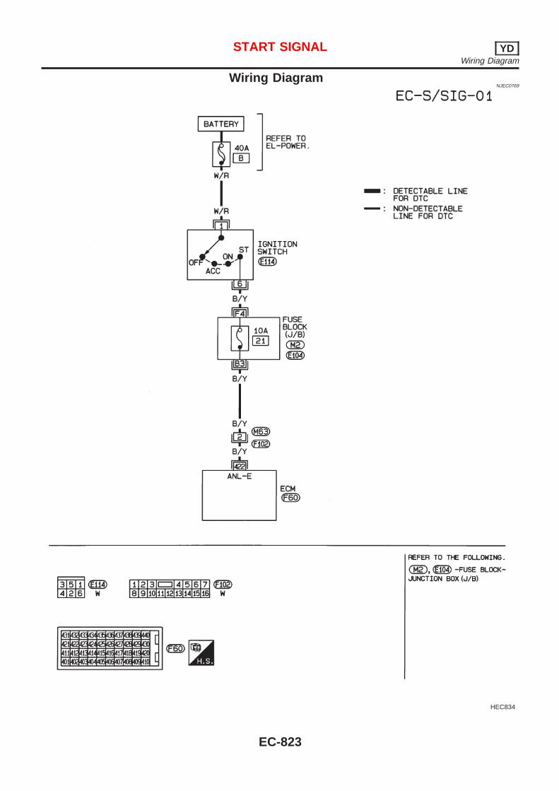
Wiring DiagramNJEC0769
HEC834
START SIGNAL YDWiring Diagram
EC-823
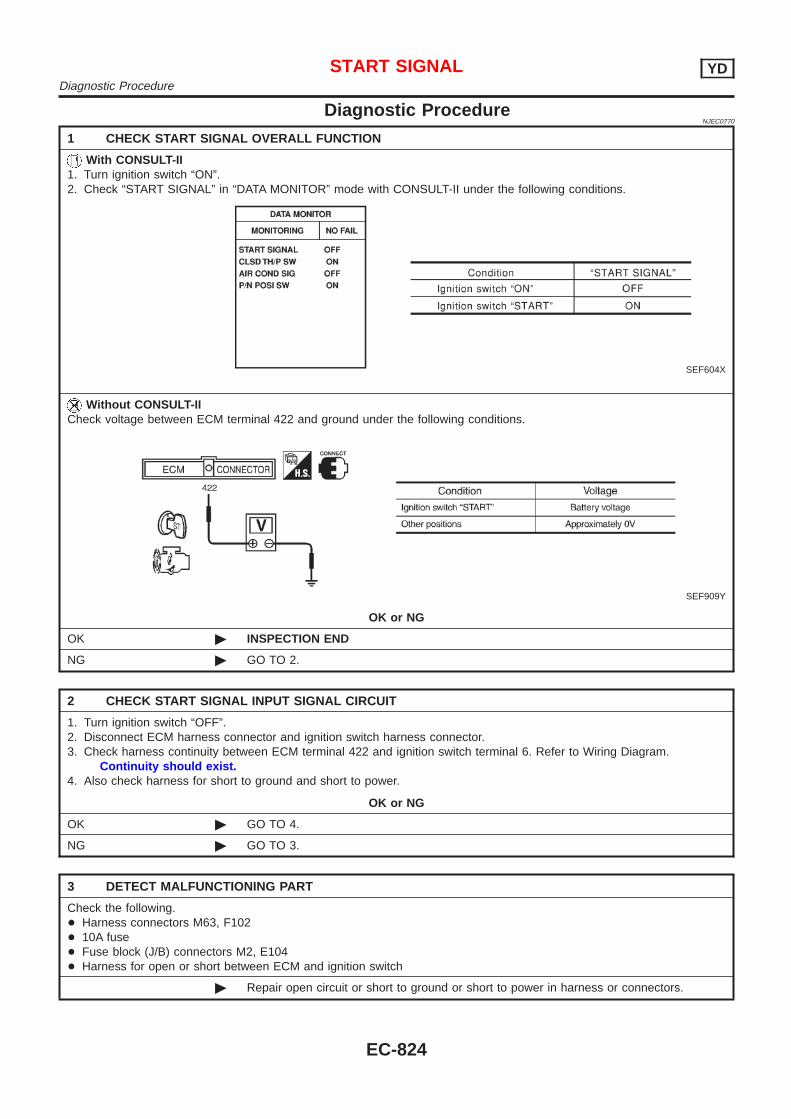
Diagnostic ProcedureNJEC0770
1 CHECK START SIGNAL OVERALL FUNCTION
With CONSULT-II1. Turn ignition switch “ON”.2. Check “START SIGNAL” in “DATA MONITOR” mode with CONSULT-II under the following conditions.
SEF604X
Without CONSULT-IICheck voltage between ECM terminal 422 and ground under the following conditions.
SEF909Y
OK or NG
OK © INSPECTION END
NG © GO TO 2.
2 CHECK START SIGNAL INPUT SIGNAL CIRCUIT
1. Turn ignition switch “OFF”.2. Disconnect ECM harness connector and ignition switch harness connector.3. Check harness continuity between ECM terminal 422 and ignition switch terminal 6. Refer to Wiring Diagram.
Continuity should exist.4. Also check harness for short to ground and short to power.
OK or NG
OK © GO TO 4.
NG © GO TO 3.
3 DETECT MALFUNCTIONING PART
Check the following.+ Harness connectors M63, F102+ 10A fuse+ Fuse block (J/B) connectors M2, E104+ Harness for open or short between ECM and ignition switch
© Repair open circuit or short to ground or short to power in harness or connectors.
START SIGNAL YDDiagnostic Procedure
EC-824
4 CHECK INTERMITTENT INCIDENT
Refer to “TROUBLE DIAGNOSIS FOR INTERMITTENT INCIDENT”, EC-665.
© INSPECTION END
START SIGNAL YDDiagnostic Procedure (Cont’d)
EC-825
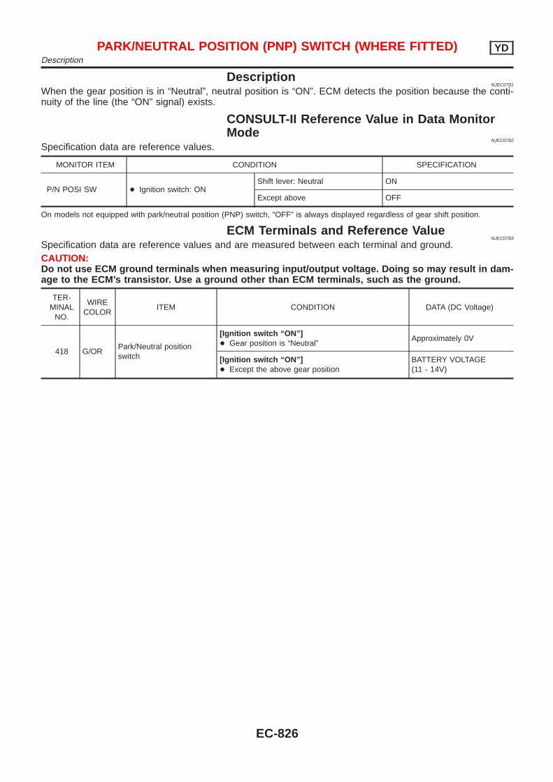
DescriptionNJEC0781
When the gear position is in “Neutral”, neutral position is “ON”. ECM detects the position because the conti-nuity of the line (the “ON” signal) exists.
CONSULT-II Reference Value in Data MonitorMode
NJEC0782
Specification data are reference values.
MONITOR ITEM CONDITION SPECIFICATION
P/N POSI SW + Ignition switch: ONShift lever: Neutral ON
Except above OFF
On models not equipped with park/neutral position (PNP) switch, “OFF” is always displayed regardless of gear shift position.
ECM Terminals and Reference ValueNJEC0783
Specification data are reference values and are measured between each terminal and ground.CAUTION:Do not use ECM ground terminals when measuring input/output voltage. Doing so may result in dam-age to the ECM’s transistor. Use a ground other than ECM terminals, such as the ground.
TER-MINAL
NO.
WIRECOLOR
ITEM CONDITION DATA (DC Voltage)
418 G/ORPark/Neutral positionswitch
[Ignition switch “ON”]+ Gear position is “Neutral”
Approximately 0V
[Ignition switch “ON”]+ Except the above gear position
BATTERY VOLTAGE(11 - 14V)
PARK/NEUTRAL POSITION (PNP) SWITCH (WHERE FITTED) YDDescription
EC-826
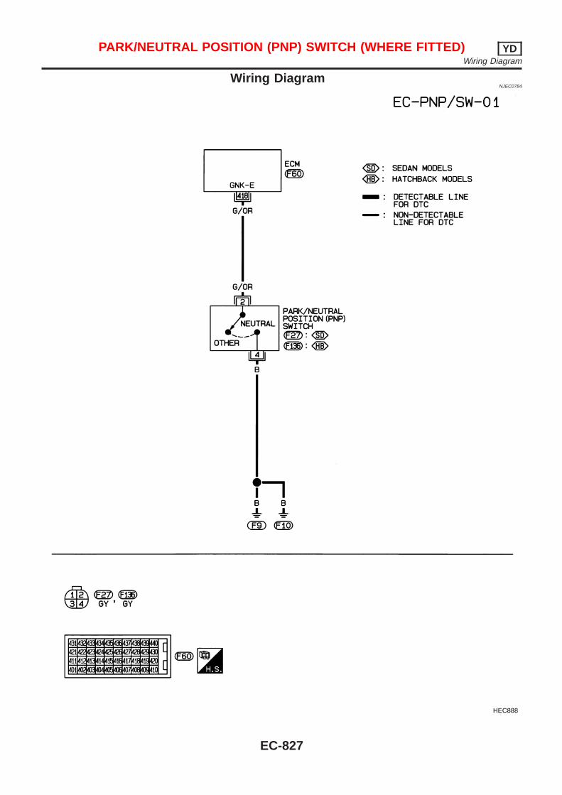
Wiring DiagramNJEC0784
HEC888
PARK/NEUTRAL POSITION (PNP) SWITCH (WHERE FITTED) YDWiring Diagram
EC-827
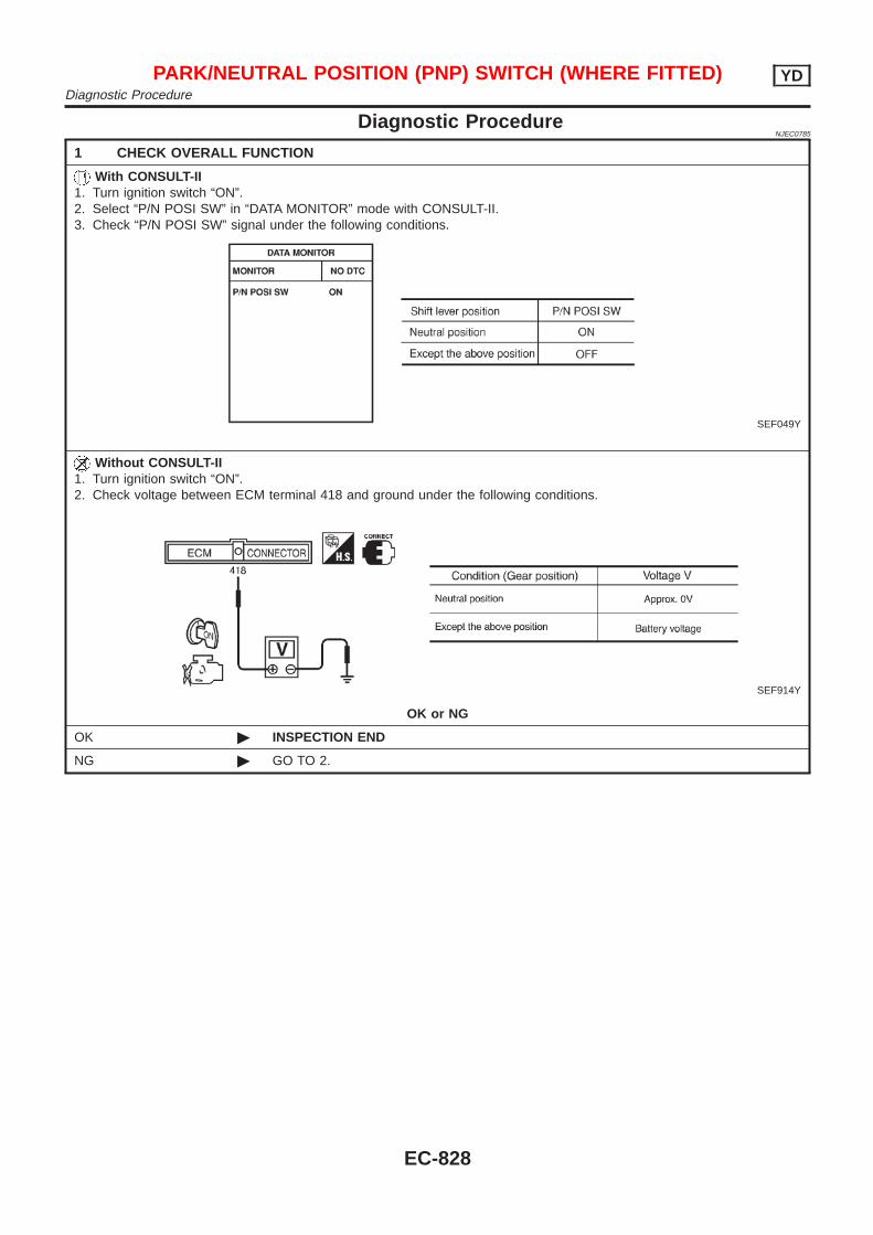
Diagnostic ProcedureNJEC0785
1 CHECK OVERALL FUNCTION
With CONSULT-II1. Turn ignition switch “ON”.2. Select “P/N POSI SW” in “DATA MONITOR” mode with CONSULT-II.3. Check “P/N POSI SW” signal under the following conditions.
SEF049Y
Without CONSULT-II1. Turn ignition switch “ON”.2. Check voltage between ECM terminal 418 and ground under the following conditions.
SEF914Y
OK or NG
OK © INSPECTION END
NG © GO TO 2.
PARK/NEUTRAL POSITION (PNP) SWITCH (WHERE FITTED) YDDiagnostic Procedure
EC-828
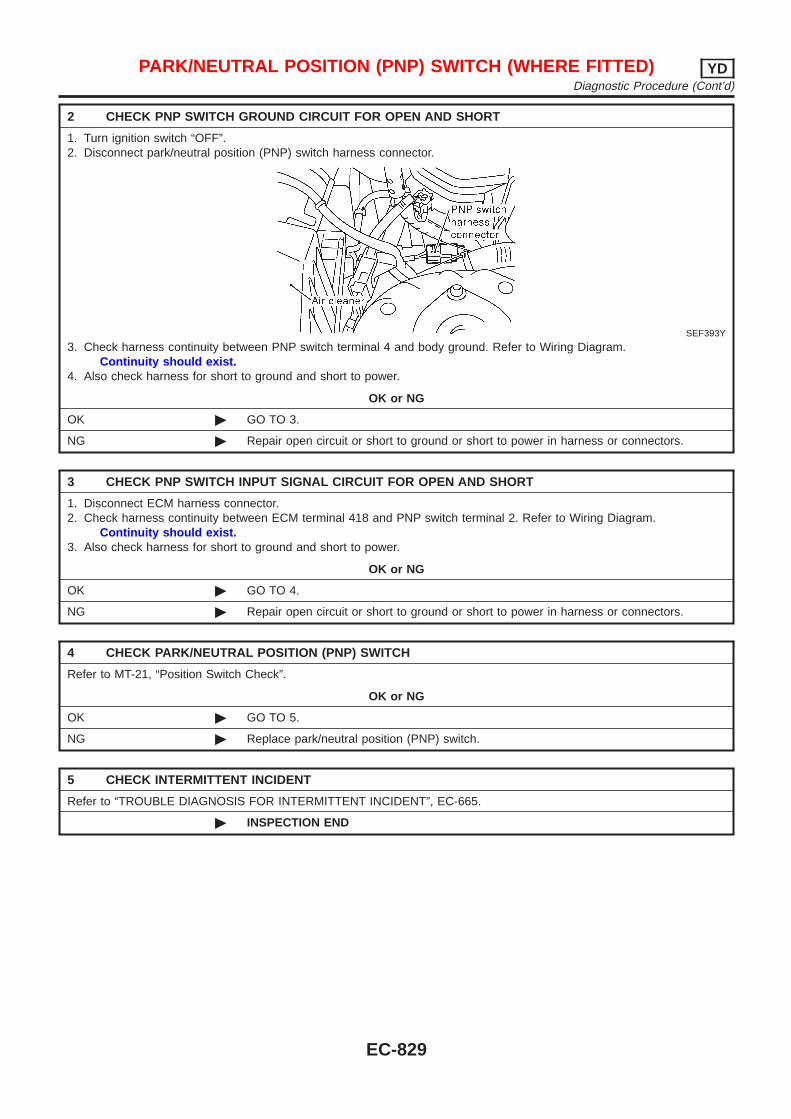
2 CHECK PNP SWITCH GROUND CIRCUIT FOR OPEN AND SHORT
1. Turn ignition switch “OFF”.2. Disconnect park/neutral position (PNP) switch harness connector.
SEF393Y
3. Check harness continuity between PNP switch terminal 4 and body ground. Refer to Wiring Diagram.Continuity should exist.
4. Also check harness for short to ground and short to power.
OK or NG
OK © GO TO 3.
NG © Repair open circuit or short to ground or short to power in harness or connectors.
3 CHECK PNP SWITCH INPUT SIGNAL CIRCUIT FOR OPEN AND SHORT
1. Disconnect ECM harness connector.2. Check harness continuity between ECM terminal 418 and PNP switch terminal 2. Refer to Wiring Diagram.
Continuity should exist.3. Also check harness for short to ground and short to power.
OK or NG
OK © GO TO 4.
NG © Repair open circuit or short to ground or short to power in harness or connectors.
4 CHECK PARK/NEUTRAL POSITION (PNP) SWITCH
Refer to MT-21, “Position Switch Check”.
OK or NG
OK © GO TO 5.
NG © Replace park/neutral position (PNP) switch.
5 CHECK INTERMITTENT INCIDENT
Refer to “TROUBLE DIAGNOSIS FOR INTERMITTENT INCIDENT”, EC-665.
© INSPECTION END
PARK/NEUTRAL POSITION (PNP) SWITCH (WHERE FITTED) YDDiagnostic Procedure (Cont’d)
EC-829
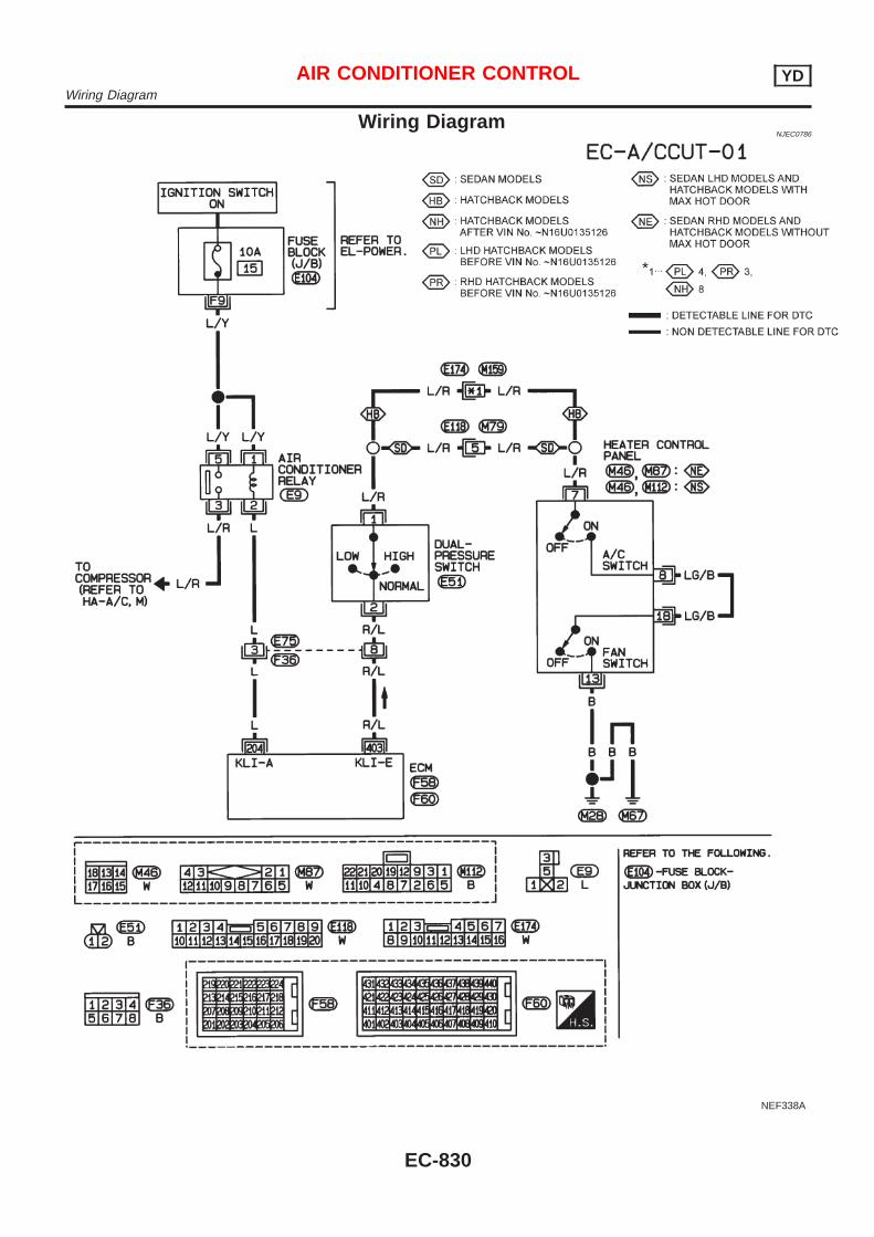
Wiring DiagramNJEC0786
NEF338A
AIR CONDITIONER CONTROL YDWiring Diagram
EC-830
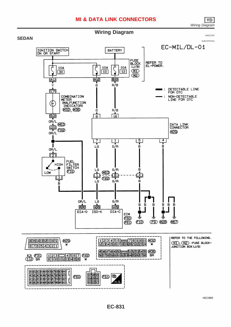
Wiring DiagramNJEC0787
SEDANNJEC0787S01
HEC889
MI & DATA LINK CONNECTORS YDWiring Diagram
EC-831
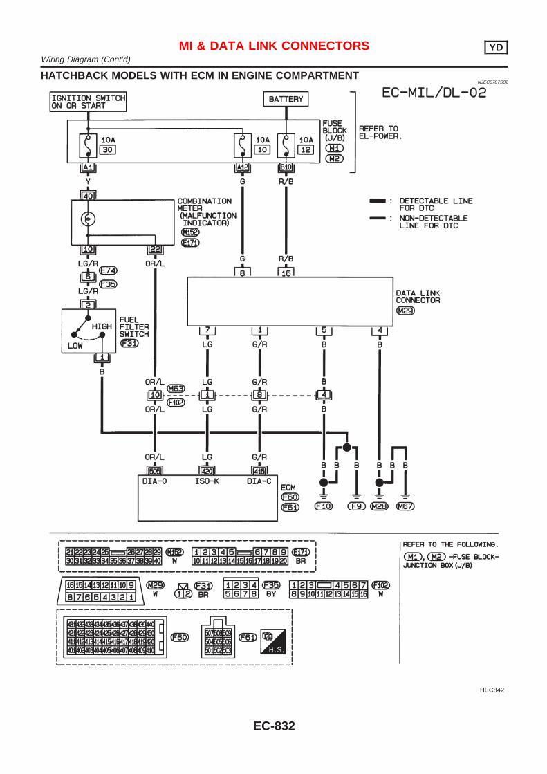
HATCHBACK MODELS WITH ECM IN ENGINE COMPARTMENTNJEC0787S02
HEC842
MI & DATA LINK CONNECTORS YDWiring Diagram (Cont’d)
EC-832
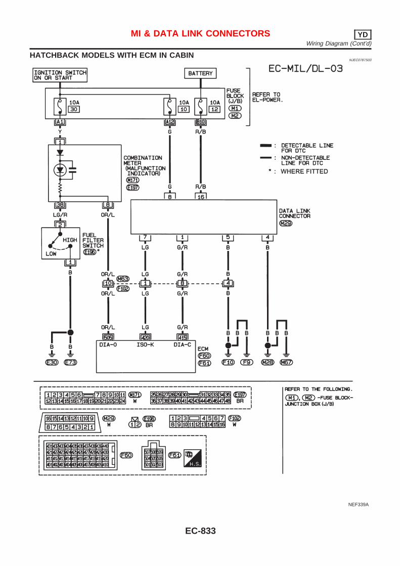
HATCHBACK MODELS WITH ECM IN CABINNJEC0787S03
NEF339A
MI & DATA LINK CONNECTORS YDWiring Diagram (Cont’d)
EC-833
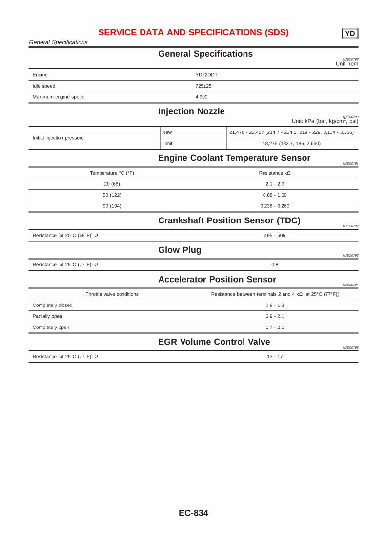
General SpecificationsNJEC0788
Unit: rpm
Engine YD22DDT
Idle speed 725±25
Maximum engine speed 4,900
Injection NozzleNJEC0790
Unit: kPa (bar, kg/cm2, psi)
Initial injection pressureNew 21,476 - 22,457 (214.7 - 224.5, 219 - 229, 3,114 - 3,256)
Limit 18,275 (182.7, 186, 2,650)
Engine Coolant Temperature SensorNJEC0791
Temperature °C (°F) Resistance kΩ
20 (68) 2.1 - 2.9
50 (122) 0.68 - 1.00
90 (194) 0.236 - 0.260
Crankshaft Position Sensor (TDC)NJEC0792
Resistance [at 20°C (68°F)] Ω 495 - 605
Glow PlugNJEC0793
Resistance [at 25°C (77°F)] Ω 0.8
Accelerator Position SensorNJEC0794
Throttle valve conditions Resistance between terminals 2 and 4 kΩ [at 25°C (77°F)]
Completely closed 0.9 - 1.3
Partially open 0.9 - 2.1
Completely open 1.7 - 2.1
EGR Volume Control ValveNJEC0795
Resistance [at 25°C (77°F)] Ω 13 - 17
SERVICE DATA AND SPECIFICATIONS (SDS) YDGeneral Specifications
EC-834