dtsi engine
TRANSCRIPT
1
ABSRTACT: The latest trend of new generation bikes and cars is to use new technology and high speed. It has become a fashion for the people especially living in urban areas to ride such vehicles. Now the companies even want to launch such vehicles that attract the younger generation. This can be achieved by technology known as DTS-i (digital twin spark ignition) system whichcombines strong performance and fuel efficiency. The improved engine efficiency modes have also resulted in lower fuel consumption. DTS-i systems meet the Government of India’s emission norms for 2005 right.Spark ignition is one of the most vital systems of an petrol engine. Any variation in the spark timing and number of sparks per minute affects the engine performance severely. Thus a good design and control of the system parameters becomes most essential for optimum performance of an engine. Due to Digital Twin Spark Ignition System it is possible to combine strong performance and higher fuel efficiency. DTS-i offers many advantages over conventional mechanical spark ignition system.
2
1. INTRODUCTION
Rapid combustion is the basic requirement for knock free operation of an S.I engine. The important attributes of rapid combustion are improved tradeoff betweenefficiency and NOX emissions, greater tolerance towards EGR (exhaust gas recirculation) or excess air, which can improve vehicle drivability and greater knock resistance, thereby allowing fuel economy with higher compression ratios. Multiple ignition system is one of the techniques to achieve rapid combustion. Multiple spark plug engines often use the initiation of flame propagation at two or more number of points in the combustion chamber depending on the number of spark plugs employed. If two plugs are employed the flame front travels from two points in the cylinder and the effective distance to be travelled by each flame is reduced. The concept of dual plug spark ignition is under consideration for more than three decades. Several experimental studies were made in the area of dual ignition engines regarding optimization of spark plug location and to prove their efficient operation at part loads, extended EGR tolerance, extended lean misfire limit and relatively clean burning compared with single spark ignition systems.
2. Digital Twin Spark Ignition System: DTS-i stands for Digital Twin Spark Ignition. Bajaj developed a few years ago and has incorporated in many of its current engines, takes care of the slow rate of combustion in a simple but novel way. The cylinder head is equipped with two spark plugs, instead of the usual one. By generating two sparks at either ends of the combustion chamber, (approximately 90° to the valve axis) the air-fuel mixture gets ignited in a way that creates two flame fronts and, therefore, a reduction in flame travel of the order of 40 per cent is achieved. A fast rate of combustion is achieved leading to faster rise in pressure. The obvious outcome of this is more torque, better fuel efficiency and lower emissions.
What does the Digital, Twin, Spark Ignition means Digital - Since the spark generation will be initiated by a microchip. Twin - Since two spark plugs will be used. Spark-ignition - Since the ignition will be done via a spark.
3
3. Main characteristics
• Digital electronic ignition with two plugs per cylinder and two ignition distributors.• Ignition with a Digital C.D.I.• Injection fuel feed with integrated electronic twin spark ignition.• A high specific power.• Compact design and Superior balance.
4. HISTORY: DTS-i stands for Digital Twin Spark Ignition, a Bajaj Auto trademark. Bajaj Autoholds an Indian patent for the DTS-i technology. The Alfa Romeo Twin-Spark engines, the BMW F650 Funduro which was sold in India from 1995 to 1997 also had a twin-spark plug technology, and the Rotax motorcycle engines, more recently Honda's iDSI Vehicle engines use a similar arrangement of two spark-plugs. However very few small capacity engines did eventually implement such a scheme in their production prototypes.
DIFFERENCE BETWEEN SINGLE SPARK PLUG AND TWIN SPARK PLUGCHARACTERISTICS SINGLE SPARK PLUG TWIN SPARK PLUG
( Hero Honda CBZ) (Pulsar 180 cc)
1. Power 12.08PS at 8000rpm 16PS at 8000rpm 2. Torque 12.03Nm at 6500rpm 14.72Nm at6500rpm 3. Speed 100 kmph 118 kmph4. Mileage 50-55 kmpl 50-55 kmpl5. Fuel Control System Transient power fuel control Electronic Control Unit
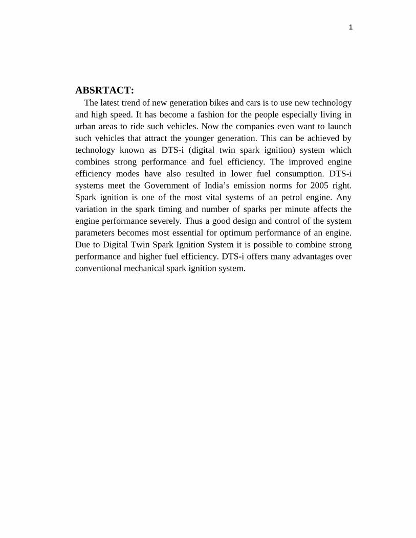
5. Construction of DTS-I Engine:
Digital spark technology is currently used in Bajaj motor cycles in India, because they have the patent right. Digital twin spark ignition technology powered engine has two spark plugs. It is located at opposite sides of combustion chamber. This DTS-I technology will have greater combustion rate because of twin spark plug located around it. The engine combust fuel at double rate than normal. This enhances both engine life and fuel efficiency. It is mapped by the digital electronic control box which also handles fuel ignition and valve timing.
Microprocessors continuously senses speed and load of the engine and respond by altering the ignition timing there by optimizing power and fuel economy.The main components of DTS-i engine
5.1 Cylinder
4
5.2 Crank Shaft5.3 Connecting rod5.4 Fly wheel 5.5 Carburetor 5.6 2-sparkplug5.72-ports & 2- Valves
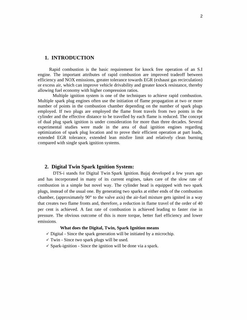
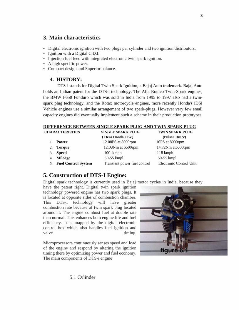
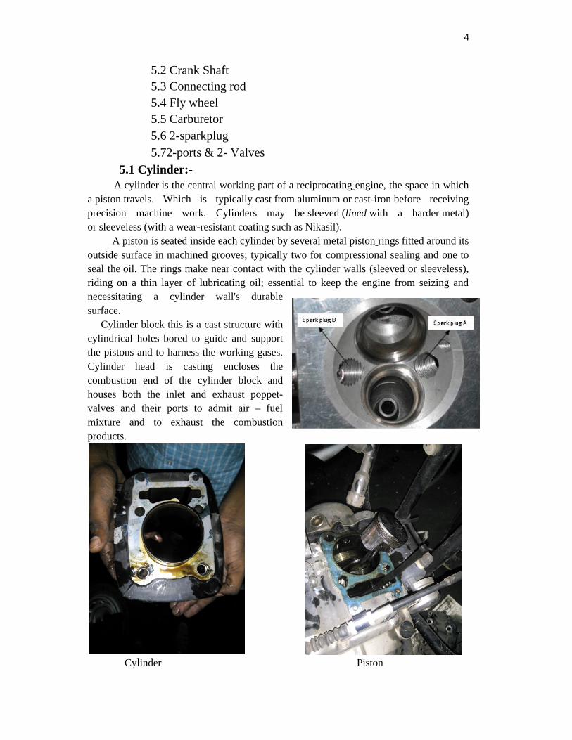
5.1 Cylinder:- A cylinder is the central working part of a reciprocating engine, the space in which a piston travels. Which is typically cast from aluminum or cast-iron before receiving precision machine work. Cylinders may be sleeved (lined with a harder metal) or sleeveless (with a wear-resistant coating such as Nikasil). A piston is seated inside each cylinder by several metal piston rings fitted around its outside surface in machined grooves; typically two for compressional sealing and one to seal the oil. The rings make near contact with the cylinder walls (sleeved or sleeveless), riding on a thin layer of lubricating oil; essential to keep the engine from seizing and necessitating a cylinder wall's durable surface. Cylinder block this is a cast structure with cylindrical holes bored to guide and support the pistons and to harness the working gases.Cylinder head is casting encloses the combustion end of the cylinder block and houses both the inlet and exhaust poppet-valves and their ports to admit air – fuel mixture and to exhaust the combustion products.
Cylinder Piston
5
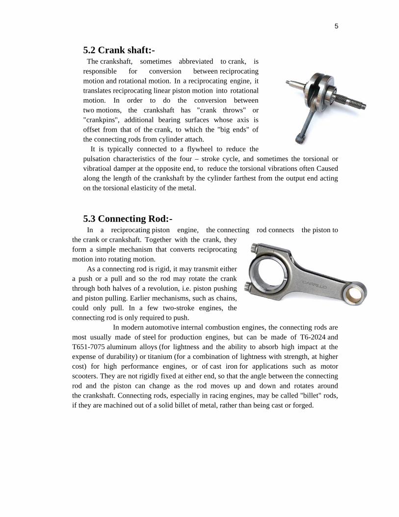
5.2 Crank shaft:- The crankshaft, sometimes abbreviated to crank, is responsible for conversion between reciprocating motion and rotational motion. In a reciprocating engine, it translates reciprocating linear piston motion into rotational motion. In order to do the conversion between two motions, the crankshaft has "crank throws" or "crankpins", additional bearing surfaces whose axis is offset from that of the crank, to which the "big ends" of the connecting rods from cylinder attach. It is typically connected to a flywheel to reduce the pulsation characteristics of the four – stroke cycle, and sometimes the torsional or vibratioal damper at the opposite end, to reduce the torsional vibrations often Caused along the length of the crankshaft by the cylinder farthest from the output end acting on the torsional elasticity of the metal.
5.3 Connecting Rod:- In a reciprocating piston engine, the connecting rod connects the piston to the crank or crankshaft. Together with the crank, they form a simple mechanism that converts reciprocating motion into rotating motion. As a connecting rod is rigid, it may transmit either a push or a pull and so the rod may rotate the crank through both halves of a revolution, i.e. piston pushing and piston pulling. Earlier mechanisms, such as chains, could only pull. In a few two-stroke engines, the connecting rod is only required to push. In modern automotive internal combustion engines, the connecting rods are most usually made of steel for production engines, but can be made of T6-2024 and T651-7075 aluminum alloys (for lightness and the ability to absorb high impact at the expense of durability) or titanium (for a combination of lightness with strength, at higher cost) for high performance engines, or of cast iron for applications such as motor scooters. They are not rigidly fixed at either end, so that the angle between the connecting rod and the piston can change as the rod moves up and down and rotates around the crankshaft. Connecting rods, especially in racing engines, may be called "billet" rods, if they are machined out of a solid billet of metal, rather than being cast or forged.
6
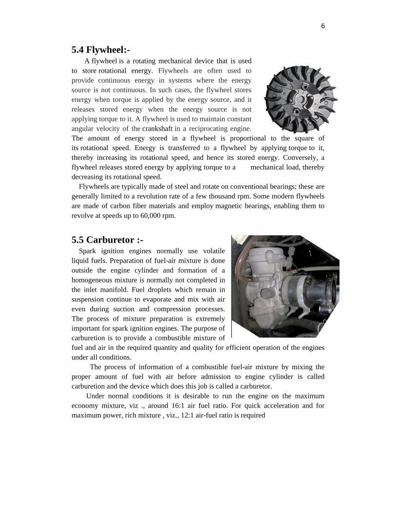
5.4 Flywheel:- A flywheel is a rotating mechanical device that is used to store rotational energy. Flywheels are often used to provide continuous energy in systems where the energy source is not continuous. In such cases, the flywheel stores energy when torque is applied by the energy source, and it releases stored energy when the energy source is not applying torque to it. A flywheel is used to maintain constant angular velocity of the crankshaft in a reciprocating engine.The amount of energy stored in a flywheel is proportional to the square of its rotational speed. Energy is transferred to a flywheel by applying torque to it, thereby increasing its rotational speed, and hence its stored energy. Conversely, a flywheel releases stored energy by applying torque to a mechanical load, thereby decreasing its rotational speed. Flywheels are typically made of steel and rotate on conventional bearings; these are generally limited to a revolution rate of a few thousand rpm. Some modern flywheels are made of carbon fiber materials and employ magnetic bearings, enabling them to revolve at speeds up to 60,000 rpm.
5.5 Carburetor :- Spark ignition engines normally use volatile liquid fuels. Preparation of fuel-air mixture is done outside the engine cylinder and formation of a homogeneous mixture is normally not completed in the inlet manifold. Fuel droplets which remain in suspension continue to evaporate and mix with air even during suction and compression processes. The process of mixture preparation is extremely important for spark ignition engines. The purpose of carburetion is to provide a combustible mixture of fuel and air in the required quantity and quality for efficient operation of the engines under all conditions. The process of information of a combustible fuel-air mixture by mixing the proper amount of fuel with air before admission to engine cylinder is called carburetion and the device which does this job is called a carburetor. Under normal conditions it is desirable to run the engine on the maximum economy mixture, viz ., around 16:1 air fuel ratio. For quick acceleration and for maximum power, rich mixture , viz., 12:1 air-fuel ratio is required
7
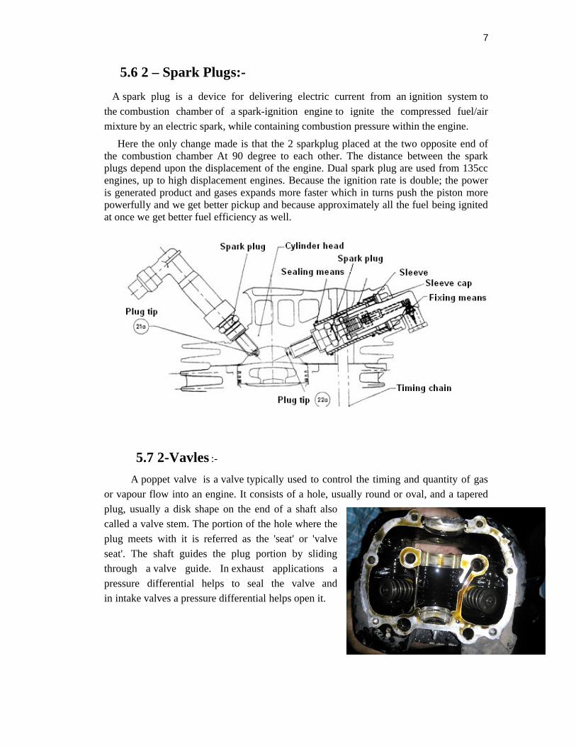
5.6 2 – Spark Plugs:-
A spark plug is a device for delivering electric current from an ignition system to
the combustion chamber of a spark-ignition engine to ignite the compressed fuel/air
mixture by an electric spark, while containing combustion pressure within the engine.
Here the only change made is that the 2 sparkplug placed at the two opposite end of the combustion chamber At 90 degree to each other. The distance between the spark plugs depend upon the displacement of the engine. Dual spark plug are used from 135cc engines, up to high displacement engines. Because the ignition rate is double; the power is generated product and gases expands more faster which in turns push the piston more powerfully and we get better pickup and because approximately all the fuel being ignited at once we get better fuel efficiency as well.
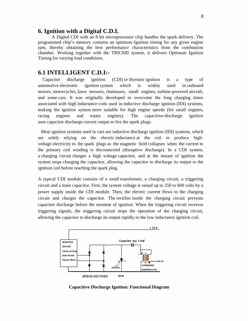
5.7 2-Vavles :-
A poppet valve is a valve typically used to control the timing and quantity of gas
or vapour flow into an engine. It consists of a hole, usually round or oval, and a tapered
plug, usually a disk shape on the end of a shaft also
called a valve stem. The portion of the hole where the
plug meets with it is referred as the 'seat' or 'valve
seat'. The shaft guides the plug portion by sliding
through a valve guide. In exhaust applications a
pressure differential helps to seal the valve and
in intake valves a pressure differential helps open it.
8
6. Ignition with a Digital C.D.I. A Digital CDI with an 8 bit microprocessor chip handles the spark delivery. The programmed chip’s memory contains an optimum Ignition timing for any given engine rpm, thereby obtaining the best performance characteristics from the combustion chamber. Working together with the TRICSIII system, it delivers Optimum Ignition Timing for varying load conditions.
6.1 INTELLIGENT C.D.I:- Capacitor discharge ignition (CDI) or thyristor ignition is a type of automotive electronic ignition system which is widely used in outboard motors, motorcycles, lawn mowers, chainsaws, small engines, turbine-powered aircraft, and some cars. It was originally developed to overcome the long charging times associated with high inductance coils used in inductive discharge ignition (IDI) systems, making the ignition system more suitable for high engine speeds (for small engines, racing engines and rotary engines). The capacitive-discharge ignition uses capacitor discharge current output to fire the spark plugs.
Most ignition systems used in cars are inductive discharge ignition (IDI) systems, which are solely relying on the electric inductance at the coil to produce high-voltage electricity to the spark plugs as the magnetic field collapses when the current to the primary coil winding is disconnected (disruptive discharge). In a CDI system, a charging circuit charges a high voltage capacitor, and at the instant of ignition the system stops charging the capacitor, allowing the capacitor to discharge its output to the ignition coil before reaching the spark plug.
A typical CDI module consists of a small transformer, a charging circuit, a triggering
circuit and a main capacitor. First, the system voltage is raised up to 250 to 600 volts by a
power supply inside the CDI module. Then, the electric current flows to the charging
circuit and charges the capacitor. The rectifier inside the charging circuit prevents
capacitor discharge before the moment of ignition. When the triggering circuit receives
triggering signals, the triggering circuit stops the operation of the charging circuit,
allowing the capacitor to discharge its output rapidly to the low inductance ignition coil.
Capacitive Discharge Ignition: Functional Diagram

9
6.2 TRICS III:-Throttle Response Ignition Control System III Generation. It is a means of controlling the ignition by operating the throttle. Depending on the needs of the rider whether it be cruising, acceleration or max speed, the ignition requirements constantly change. Based on a particular amount of throttle opening, the magnetic field generated by the magnet opens or closes the reed switch. The reed switch is connected to the Digital C.D.I., which signals the C.D.I. to change / switch, the desired ignition advance timing maps. This helps in achieving a good balance between drive ability and optimum ignition spark advance, resulting in an almost perfect ignition spark advance for every throttle opening and engine rpm.
Figure 1
7. WORKING OF DTS-i ENGINE:- The working of DTS-i engine is very similar to 4-stroke engine but here the only modification done is we are using two spark plug at two ends of the combustion chamber. Which require less time to reach the farthest position of the combustion chamber and optimize the combustion chamber characteristics.There are some advance technology used in DTS-i engine which makes it more powerful than the conventional single sparkplug 4-stroke engine like 1.CDI technology 2.Tricks iii technology.
The cycle of operation in a four stroke engine is completed in two revolutions of crank shaft or four strokes of piston. Stroke is defined as the distance traveled by the piston from one of the dead centers to the other dead centre. It is also equal to two times the crank radius. Hence in a four stroke engine work is obtained only during one stroke out of the four strokes of the piston required to complete one cycle.

10
7.1 Suction stroke: To start with the piston is at or very near T.D.C. and the inlet valve isopen and exhaust valve is closed. As the piston moves from T.D.C. to B.D.C. rarefaction is formed in the cylinder which causes the charge to rush in and fill the space vacated by the piston. The charge consists of a mixture of air and petrol prepared by the carburetor. The admission of charge inside the engine cylinder continues until the inlet valve closes at B.D.C.7.2 Compression stroke: Both the valves are closed and the piston moves from B.D.C. toT.D.C. The charge is compressed up to a compression ratio of 5:1 to 9:1 and pressure and temperature at the end of compression are about 6 to 12 bar and 250º C to 300º C respectively.7.3 Working, Power or Expansion stroke: When the piston reaches T.D.C. position, or just at the end of compression stroke, the charge is ignited by causing an electric sparkbetween the electrodes of two spark plug, which is located 90 degrees each other in the walls of cylinder head. During combustion the chemical energy of fuel is released and there is rise in temperature and pressure of gases. The air-fuel mixture gets ignited in a way that creates two flame fronts and, therefore, a reduction in flame travel of the order of 40 per cent is achieved. A fast rate of combustion is achieved leading to faster rise in pressure. The obvious outcome of this is more torque, better fuel efficiency and lower emission. Now the combustion products expand and push the piston down the cylinder. The reciprocating piston motion is converted into rotary motion of crankshaft by a connecting rod and crank. During expansion the pressure drops due to increase in the volume of gases and absorption of heat by cylinder walls. 7.4 Exhaust stroke: Theoretically exhaust valve opens at the end of working stroke whenthe piston is at B.D.C. position. But actually exhaust valve begins to open when about85% of the working stroke is completed. A pressure at this instant forces about complete the burnt gases into the exhaust manifold at high speed. During this stroke the pressure in side the cylinder is slightly above the atmospheric value. Some of the burnt gases are however left in the clearance space. The exhaust valve closes shortly after the piston reaches T.D.C. The inlet valve opens slightly before the end of exhaust stroke and the cycle repeats.
7.5 Detonation in DTS-i engine.... In petrol engine major problem is DETONATION. Detonation occurs when the flame travel time from center to the side walls increases the self ignition temp. time. It happens often in the engines having single spark plug. This is overcome by the DTS-i by having 2 spark sources on the opposite sides which reduces the flame travel as stated above. Hence no detonation.
EXAMPLE:- Pulsar DTS-i delivers out class performance in its class of vehicles. The performance characteristics are – High Speed 180cc = 16.01 Ps (11.77kw) at 8000rpm 150cc = 13.02 Ps (9.57kw) at 8500rpm
Greater torque 180cc = 14.72 N- m at 6500rpm 150cc = 11.68 N-m at 6500rpm
11
Max. Speed 180cc = 127 Kmph 150cc = 120 Kmph
7.6 Advantages:-
Less vibrations and noise Long life of the engine parts such as piston rings and valve stem Decrease in the specific fuel consumption No over heating Increase the Thermal Efficiency of the Engine & even bear high loads on it. Better starting of engine even in winter season & cold climatic conditions or at
very low temperatures because of increased Compression ratio. Because of twin Sparks the diameter of the flame increases rapidly that would
result in instantaneous burning of fuels. Thus force exerted on the piston would increase leading to better work output.
7.7 Disadvantages:-
There is high NOx emission If one spark plug get damaged then we have to replace both The cost is relatively more
7.8 Applications:-
It uses in automotive engines. In India Bajaj has patented for dts-i technology. At present platina, xcd125, 135, discover150, pulsar135, 150, 180, 200, 220 etc. are using the dts-i(digital twin spark ignition system). Which means the petrol enters into the cylinder burns more efficiently.
Hence the application of these technologies in the present day automobiles will give the present generation what they want i.e. power bikes with fuel efficiency. Since these technologies also minimize the fuel consumption and harmful emission levels, they can also be considered as one of the solutions for increasing fuel costs and increasing effect of global warming.
The perfect Combustion in Internal Combustion engine is not possible. So for the instantaneous burning of fuels in I.C. engine twin spark system can be used which producing twin sparks at regular interval can help to complete the combustion.
12
12
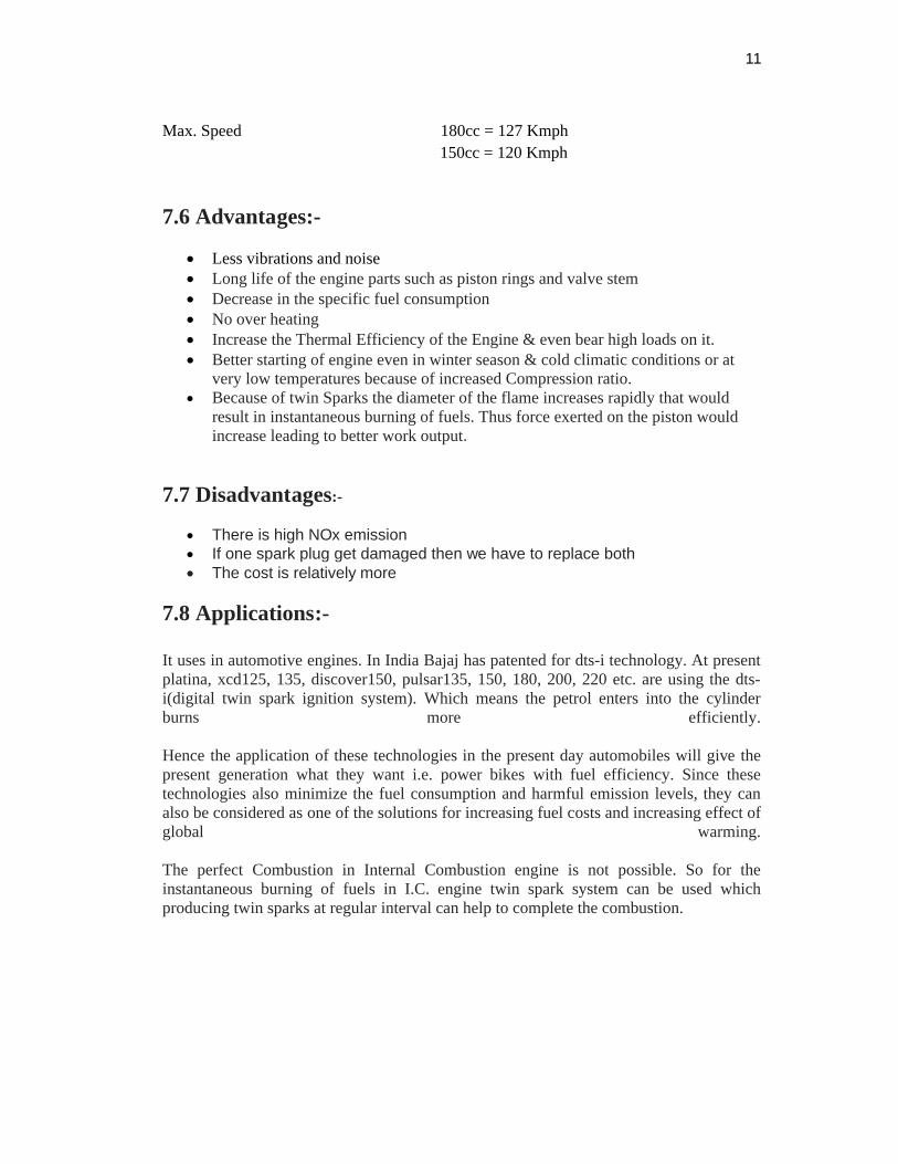
Figure 3
8.0 CONCLUSION:-
In the world of new high-speed cars and bikes to achieve maximum engine power, top fuel efficiency and minimum emission levels during all type of operating condition. The digital spark ignition is the best alternative for conventional ignition control. Electronic control Unit gives accurate timing for all operating condition. At the same time use of two spark plug improves thermodynamic efficiency and power available. At the same time it reduces the maintenance cost due to fewer moving parts in turn less friction and wear. It also good solution to reduce pollution since it minimizes emission levels. Also it is flexible enough in mounting location. This is important because today’s smaller engine compartment. Thus, it is better in all areas like power, speed, efficiency and clean emission and hence it has brought a new evolution in automobile industry.
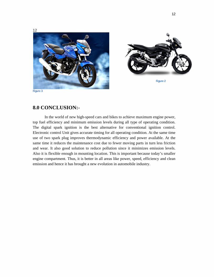
Figure 2