engine - mark shinn
TRANSCRIPT
ENGINE
EG–1
ENGINE MECHANICALDESCRIPTION
EG0EF–01
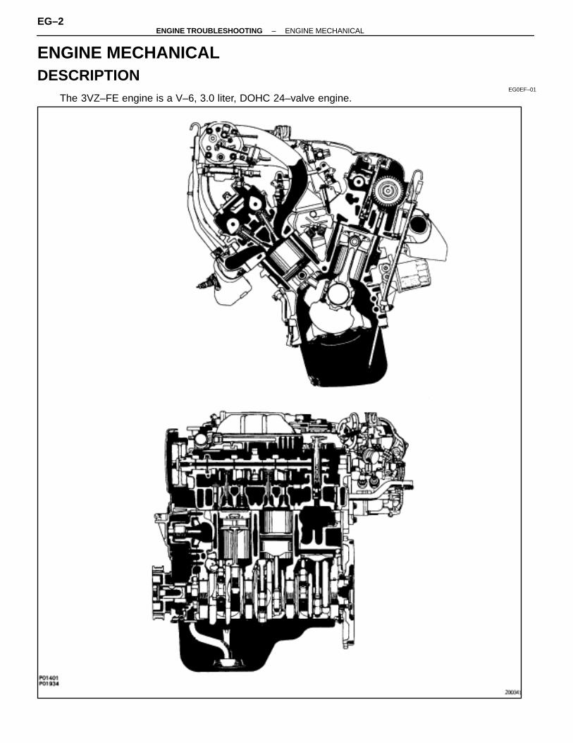
The 3VZ–FE engine is a V–6, 3.0 liter, DOHC 24–valve engine.
EG–2–ENGINE TROUBLESHOOTING ENGINE MECHANICAL
The 3VZ–FE engine has 6 cylinder in a V arrangement at a bank angle of 60°. From the front of the RH bankcylinders are numbered 1–3–5, and from the front of the LH bank cylinders are numbered 2–4–6. The crankshaftis supported by 4 bearings inside the crankcase. These bearings are made of copper and lead alloy.The crankshaft is integrated with semi 9 counter weights for balance. Oil holes are placed in the center of thecrankshaft for supplying oil to the connecting rods, pistons and other components.This engine’s firing order is 1–2–3–4–5–6. The cylinder head is made of aluminum alloy, with a cross flow typeintake and exhaust layout and with pent–roof type combustion chambers. The spark plugs are located in thecenter of the combustion chambers.At the front and rear of the intake port of the intake manifold, a water passage has been provided which connectsthe RH and LH cylinder heads.Exhaust and intake valves are equipped with irregular pitch springs made of special valve spring carbon steelwhich are capable of functioning no matter what the engine speed.The RH and LH intake camshafts are driven by a single timing belt, and a gear on the intake camshaft engageswith a gear on the exhaust camshaft to drive it. The camshaft journal is supported at 5 (intake) or 4 (exhaust)places between the valve lifters of each cylinder and on the front end of the cylinder head. Lubrication of thecam journals and gears is accomplished by oil being supplied through the oiler port in the center of the camshaft.Adjustment of the valve clearance is done by means of an outer shim type system, in which valve adjustingshims are located above the valve lifters. This permits replacement of the shims without removal of the cam-shafts.The timing belt cover is composed of the resin type No.2 and No.1 above and below the engine RH mountingbracket.Pistons are made of high temperature–resistant aluminum alloy, and a depression is built into the piston headto prevent interference with the valves.Piston pins are the full–floating type, with the pins fastened to neither the piston boss nor the connecting rods.Instead, snap rings are fitted on both ends of the pins, preventing the pins from falling out.The No.1 compression ring is made of steel and the No.2 compression ring is made of cast iron.The oil ring is made of a combination of steel and stainless steel. The outer diameter of each piston ring is slightlylarger than the diameter of the piston and the flexibility of the rings allows them to hub the cylinder walls whenthey are mounted on the piston. Compression rings No.1 and No.2 work to prevent gas leakage from the cylinderand the oil ring works to clear oil off the cylinder walls to prevent it from entering the combustion chamber.The cylinder block is made of cast iron with a bank angle of 60°. It has 6 cylinders which are approximately 1.6times the length of the piston stroke. The top of the cylinders is closed off by the cylinder heads and the lowerend of the cylinders becomes the crankcase, in which the crankshaft is installed. In addition, the cylinder blockcontains a water jacket, through which engine coolant is pumped to cool the cylinders.The oil pan is bolted onto the bottom of the cylinder block. The oil pan is an oil reservoir made of pressed steelsheet.
–ENGINE TROUBLESHOOTING ENGINE MECHANICALEG–3
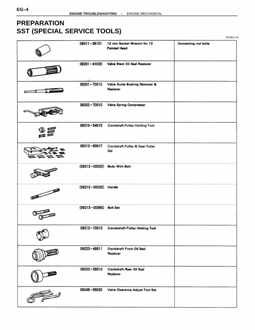
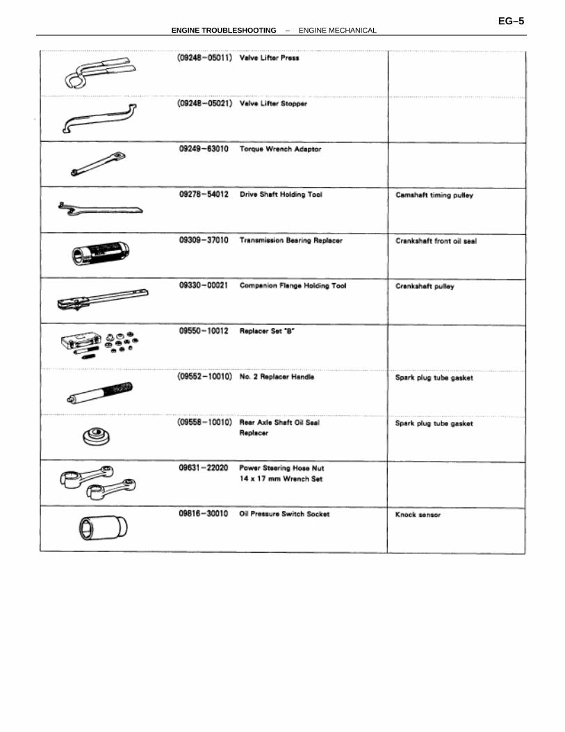
PREPARATIONSST (SPECIAL SERVICE TOOLS)
EG0EG–01
EG–4–ENGINE TROUBLESHOOTING ENGINE MECHANICAL
–ENGINE TROUBLESHOOTING ENGINE MECHANICALEG–5
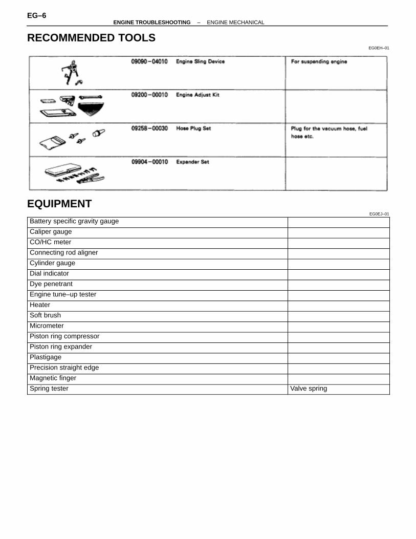
RECOMMENDED TOOLSEG0EH–01
EQUIPMENTEG0EJ–01ÑÑÑÑÑÑÑÑÑÑÑÑÑÑÑÑÑÑÑÑÑÑÑÑÑÑ
ÑÑÑÑÑÑÑÑÑÑÑÑÑÑÑÑÑÑÑÑÑÑÑÑÑÑBattery specific gravity gauge ÑÑÑÑÑÑÑÑÑÑÑ
ÑÑÑÑÑÑÑÑÑÑÑÑÑÑÑÑÑÑÑÑÑÑÑÑÑÑÑÑÑÑÑÑÑÑÑÑÑÑÑÑÑÑÑÑÑÑÑÑÑÑÑÑÑÑÑÑÑÑÑÑÑÑÑ
Caliper gauge ÑÑÑÑÑÑÑÑÑÑÑÑÑÑÑÑÑÑÑÑÑÑÑÑÑÑÑÑÑÑÑÑÑÑÑÑÑÑÑÑÑÑÑÑÑÑÑÑ
ÑÑÑÑÑÑÑÑÑÑÑÑÑÑÑÑÑÑÑÑÑÑÑÑÑÑCO/HC meter ÑÑÑÑÑÑÑÑÑÑÑ
ÑÑÑÑÑÑÑÑÑÑÑÑÑÑÑÑÑÑÑÑÑÑÑÑÑÑÑÑÑÑÑÑÑÑÑÑÑÑÑÑÑÑÑÑÑÑÑÑÑÑÑÑÑÑÑÑÑÑÑÑÑÑÑ
Connecting rod aligner ÑÑÑÑÑÑÑÑÑÑÑÑÑÑÑÑÑÑÑÑÑÑÑÑÑÑÑÑÑÑÑÑÑÑÑÑÑÑÑÑÑÑÑÑÑÑÑÑ
ÑÑÑÑÑÑÑÑÑÑÑÑÑÑÑÑÑÑÑÑÑÑÑÑÑÑCylinder gauge ÑÑÑÑÑÑÑÑÑÑÑ
ÑÑÑÑÑÑÑÑÑÑÑÑÑÑÑÑÑÑÑÑÑÑÑÑÑÑÑÑÑÑÑÑÑÑÑÑÑÑÑÑÑÑÑÑÑÑÑÑÑÑÑÑÑÑÑÑÑÑÑÑÑÑÑ
Dial indicator ÑÑÑÑÑÑÑÑÑÑÑÑÑÑÑÑÑÑÑÑÑÑÑÑÑÑÑÑÑÑÑÑÑÑÑÑÑÑÑÑÑÑÑÑÑÑÑÑ
ÑÑÑÑÑÑÑÑÑÑÑÑÑÑÑÑÑÑÑÑÑÑÑÑÑÑDye penetrant ÑÑÑÑÑÑÑÑÑÑÑ
ÑÑÑÑÑÑÑÑÑÑÑÑÑÑÑÑÑÑÑÑÑÑÑÑÑÑÑÑÑÑÑÑÑÑÑÑÑÑÑÑÑÑÑÑÑÑÑÑÑÑÑÑÑÑÑÑÑÑÑÑÑÑÑ
Engine tune–up tester ÑÑÑÑÑÑÑÑÑÑÑÑÑÑÑÑÑÑÑÑÑÑÑÑÑÑÑÑÑÑÑÑÑÑÑÑÑÑÑÑÑÑÑÑÑÑÑÑ
ÑÑÑÑÑÑÑÑÑÑÑÑÑÑÑÑÑÑÑÑÑÑÑÑÑÑHeater ÑÑÑÑÑÑÑÑÑÑÑ
ÑÑÑÑÑÑÑÑÑÑÑÑÑÑÑÑÑÑÑÑÑÑÑÑÑÑÑÑÑÑÑÑÑÑÑÑÑÑÑÑÑÑÑÑÑÑÑÑÑÑÑÑÑÑÑÑÑÑÑÑÑÑÑ
Soft brush ÑÑÑÑÑÑÑÑÑÑÑÑÑÑÑÑÑÑÑÑÑÑÑÑÑÑÑÑÑÑÑÑÑÑÑÑÑÑÑÑÑÑÑÑÑÑÑÑ
ÑÑÑÑÑÑÑÑÑÑÑÑÑÑÑÑÑÑÑÑÑÑÑÑÑÑMicrometer ÑÑÑÑÑÑÑÑÑÑÑ
ÑÑÑÑÑÑÑÑÑÑÑÑÑÑÑÑÑÑÑÑÑÑÑÑÑÑÑÑÑÑÑÑÑÑÑÑÑÑÑÑÑÑÑÑÑÑÑÑÑÑÑÑÑÑÑÑÑÑÑÑÑÑÑ
Piston ring compressor ÑÑÑÑÑÑÑÑÑÑÑÑÑÑÑÑÑÑÑÑÑÑÑÑÑÑÑÑÑÑÑÑÑÑÑÑÑÑÑÑÑÑÑÑÑÑÑÑ
ÑÑÑÑÑÑÑÑÑÑÑÑÑÑÑÑÑÑÑÑÑÑÑÑÑÑPiston ring expander ÑÑÑÑÑÑÑÑÑÑÑ
ÑÑÑÑÑÑÑÑÑÑÑÑÑÑÑÑÑÑÑÑÑÑÑÑÑÑÑÑÑÑÑÑÑÑÑÑÑÑÑÑÑÑÑÑÑÑÑÑÑÑÑÑÑÑÑÑÑÑÑÑÑÑÑ
Plastigage ÑÑÑÑÑÑÑÑÑÑÑÑÑÑÑÑÑÑÑÑÑÑÑÑÑÑÑÑÑÑÑÑÑÑÑÑÑÑÑÑÑÑÑÑÑÑÑÑ
ÑÑÑÑÑÑÑÑÑÑÑÑÑÑÑÑÑÑÑÑÑÑÑÑÑÑPrecision straight edge ÑÑÑÑÑÑÑÑÑÑÑ
ÑÑÑÑÑÑÑÑÑÑÑÑÑÑÑÑÑÑÑÑÑÑÑÑÑÑÑÑÑÑÑÑÑÑÑÑÑÑÑÑÑÑÑÑÑÑÑÑÑÑÑÑÑÑÑÑÑÑÑÑÑÑÑ
Magnetic finger ÑÑÑÑÑÑÑÑÑÑÑÑÑÑÑÑÑÑÑÑÑÑÑÑÑÑÑÑÑÑÑÑÑÑÑÑÑÑÑÑÑÑÑÑÑÑÑÑ
ÑÑÑÑÑÑÑÑÑÑÑÑÑÑÑÑÑÑÑÑÑÑÑÑÑÑSpring tester ÑÑÑÑÑÑÑÑÑÑÑ
ÑÑÑÑÑÑÑÑÑÑÑValve spring
EG–6–ENGINE TROUBLESHOOTING ENGINE MECHANICAL
ÑÑÑÑÑÑÑÑÑÑÑÑÑÑÑÑÑÑÑÑÑÑÑÑÑÑÑÑÑÑÑÑÑÑÑÑÑÑÑÑÑÑÑÑÑÑÑÑÑÑÑÑ
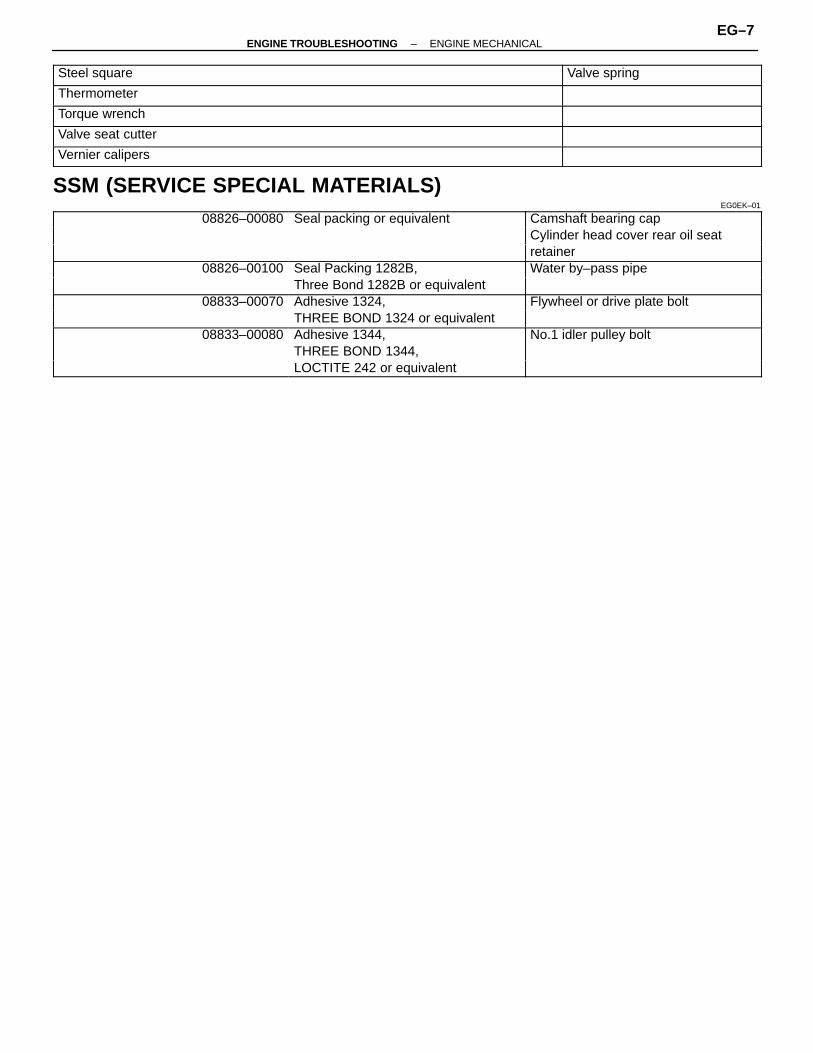
Steel square ÑÑÑÑÑÑÑÑÑÑÑÑÑÑÑÑÑÑÑÑÑÑ
Valve spring
ÑÑÑÑÑÑÑÑÑÑÑÑÑÑÑÑÑÑÑÑÑÑÑÑÑÑÑÑÑÑÑÑÑÑÑÑÑÑÑÑÑÑÑÑÑÑÑÑÑÑÑÑ
Thermometer ÑÑÑÑÑÑÑÑÑÑÑÑÑÑÑÑÑÑÑÑÑÑÑÑÑÑÑÑÑÑÑÑÑÑÑÑÑÑÑÑÑÑÑÑÑÑÑÑ
ÑÑÑÑÑÑÑÑÑÑÑÑÑÑÑÑÑÑÑÑÑÑÑÑÑÑTorque wrench ÑÑÑÑÑÑÑÑÑÑÑ
ÑÑÑÑÑÑÑÑÑÑÑÑÑÑÑÑÑÑÑÑÑÑÑÑÑÑÑÑÑÑÑÑÑÑÑÑÑÑÑÑÑÑÑÑÑÑÑÑÑÑÑÑÑÑÑÑÑÑÑÑÑÑÑ
Valve seat cutter ÑÑÑÑÑÑÑÑÑÑÑÑÑÑÑÑÑÑÑÑÑÑÑÑÑÑÑÑÑÑÑÑÑÑÑÑÑÑÑÑÑÑÑÑÑÑÑÑ
ÑÑÑÑÑÑÑÑÑÑÑÑÑÑÑÑÑÑÑÑÑÑÑÑÑÑVernier calipers ÑÑÑÑÑÑÑÑÑÑÑ
ÑÑÑÑÑÑÑÑÑÑÑSSM (SERVICE SPECIAL MATERIALS)EG0EK–01
ÑÑÑÑÑÑÑÑÑÑÑÑÑÑÑÑÑÑÑÑÑÑÑÑÑÑ
08826–00080ÑÑÑÑÑÑÑÑÑÑÑÑÑÑÑÑÑÑÑÑÑÑÑÑ
Seal packing or equivalent ÑÑÑÑÑÑÑÑÑÑÑÑÑÑÑÑÑÑÑÑÑÑÑÑÑÑ
Camshaft bearing cap
ÑÑÑÑÑÑÑÑÑÑÑÑÑÑÑÑÑÑÑÑÑÑÑÑÑÑÑÑÑÑÑÑÑÑÑÑÑÑCylinder head cover rear oil seatÑÑÑÑÑÑÑÑÑÑÑÑÑÑÑÑÑÑÑÑÑÑÑÑÑÑ
ÑÑÑÑÑÑÑÑÑÑÑÑÑÑÑÑÑÑÑÑÑÑÑÑ
ÑÑÑÑÑÑÑÑÑÑÑÑÑÑÑÑÑÑÑÑÑÑÑÑÑÑretainerÑÑÑÑÑÑÑÑÑÑÑÑÑ
ÑÑÑÑÑÑÑÑÑÑÑÑÑ08826–00100ÑÑÑÑÑÑÑÑÑÑÑÑ
ÑÑÑÑÑÑÑÑÑÑÑÑSeal Packing 1282B, ÑÑÑÑÑÑÑÑÑÑÑÑÑ
ÑÑÑÑÑÑÑÑÑÑÑÑÑWater by–pass pipe
ÑÑÑÑÑÑÑÑÑÑÑÑÑÑÑÑÑÑÑÑÑÑÑÑÑÑ
ÑÑÑÑÑÑÑÑÑÑÑÑÑÑÑÑÑÑÑÑÑÑÑÑ
Three Bond 1282B or equivalent ÑÑÑÑÑÑÑÑÑÑÑÑÑÑÑÑÑÑÑÑÑÑÑÑÑÑÑÑÑÑÑÑÑÑÑÑÑÑÑ
ÑÑÑÑÑÑÑÑÑÑÑÑÑ08833–00070ÑÑÑÑÑÑÑÑÑÑÑÑ
ÑÑÑÑÑÑÑÑÑÑÑÑAdhesive 1324, ÑÑÑÑÑÑÑÑÑÑÑÑÑ
ÑÑÑÑÑÑÑÑÑÑÑÑÑFlywheel or drive plate bolt
ÑÑÑÑÑÑÑÑÑÑÑÑÑÑÑÑÑÑÑÑÑÑÑÑÑÑ
ÑÑÑÑÑÑÑÑÑÑÑÑÑÑÑÑÑÑÑÑÑÑÑÑ
THREE BOND 1324 or equivalent ÑÑÑÑÑÑÑÑÑÑÑÑÑÑÑÑÑÑÑÑÑÑÑÑÑÑÑÑÑÑÑÑÑÑÑÑÑÑÑ08833–00080ÑÑÑÑÑÑÑÑÑÑÑÑAdhesive 1344, ÑÑÑÑÑÑÑÑÑÑÑÑÑNo.1 idler pulley boltÑÑÑÑÑÑÑÑÑÑÑÑÑ
ÑÑÑÑÑÑÑÑÑÑÑÑÑÑÑÑÑÑÑÑÑÑÑÑÑÑÑÑÑÑÑÑÑÑÑÑÑ
THREE BOND 1344,ÑÑÑÑÑÑÑÑÑÑÑÑÑÑÑÑÑÑÑÑÑÑÑÑÑÑÑÑÑÑÑÑÑÑÑÑÑÑÑ
ÑÑÑÑÑÑÑÑÑÑÑÑÑÑÑÑÑÑÑÑÑÑÑÑÑÑÑÑÑÑÑÑÑÑÑÑÑ
LOCTITE 242 or equivalent ÑÑÑÑÑÑÑÑÑÑÑÑÑÑÑÑÑÑÑÑÑÑÑÑÑÑ
–ENGINE TROUBLESHOOTING ENGINE MECHANICALEG–7
EG
–228
EG
–224
EG
–230
EG
–200
EG
–203
EG
–170
EG
–183
EG
–160
EG
–186
EG
–179
EG
–223
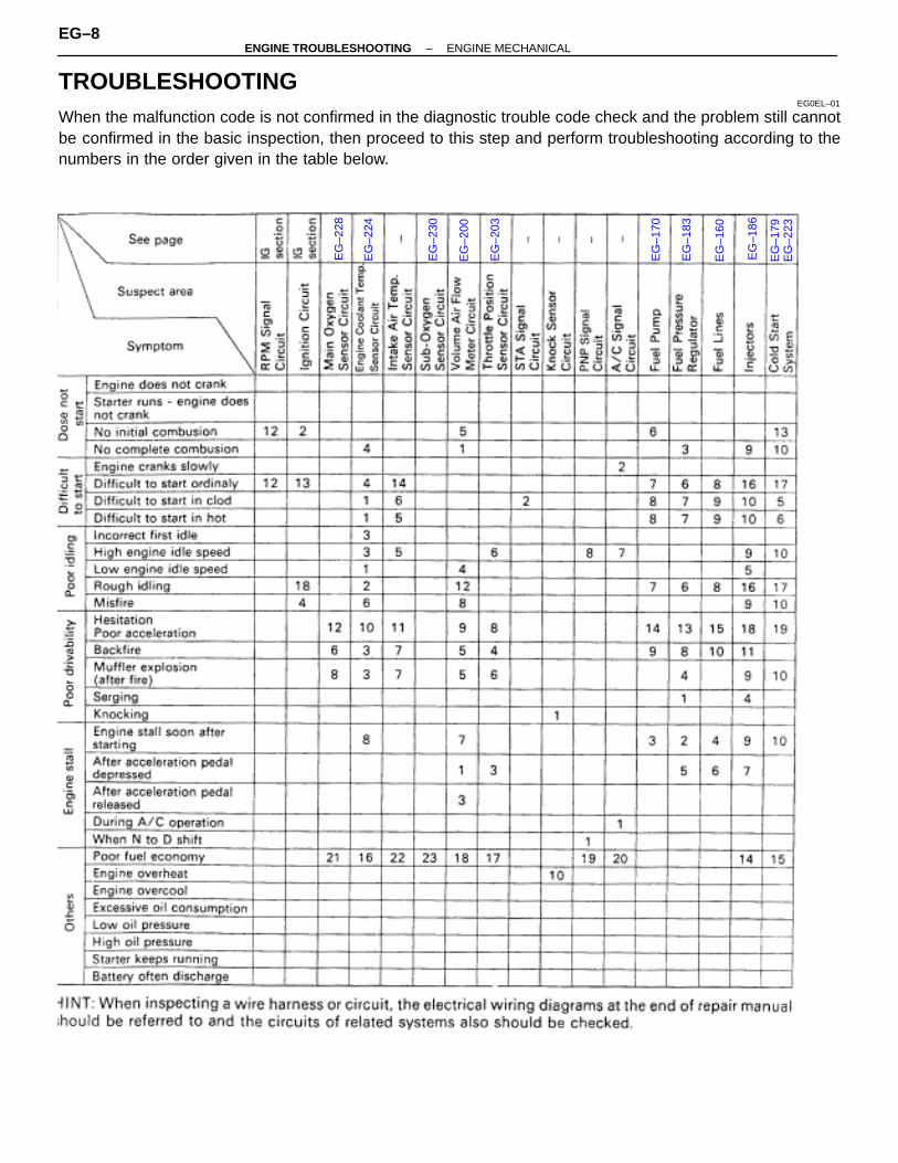
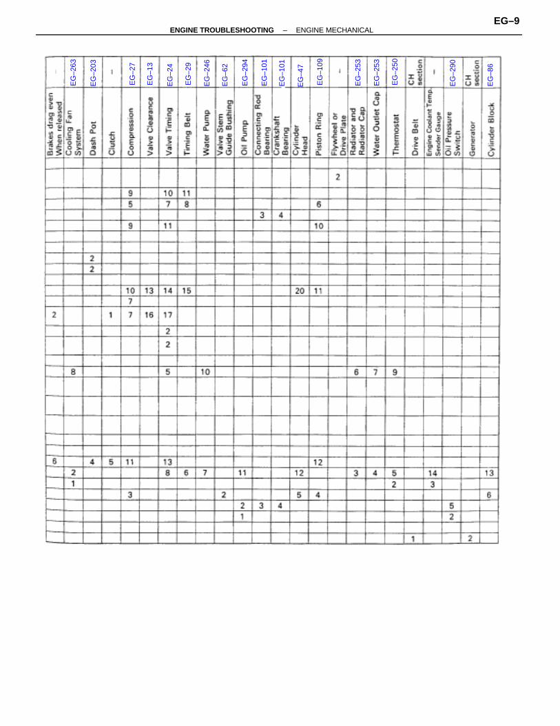
TROUBLESHOOTINGEG0EL–01
When the malfunction code is not confirmed in the diagnostic trouble code check and the problem still cannotbe confirmed in the basic inspection, then proceed to this step and perform troubleshooting according to thenumbers in the order given in the table below.
EG–8–ENGINE TROUBLESHOOTING ENGINE MECHANICAL
EG
–263
EG
–203
EG
–27
EG
–13
EG
–24
EG
–29
EG
–246
EG
–62
EG
–294
EG
–101
EG
–101
EG
–47
EG
–109
EG
–253
EG
–253
EG
–250
EG
–290
EG
–86
–ENGINE TROUBLESHOOTING ENGINE MECHANICALEG–9

EG
–210
EG
–220
EG
–221
EG
–236
EG
–225
EG
–231
EG
–151
EG–10–ENGINE TROUBLESHOOTING ENGINE MECHANICAL
TUNE–UPENGINE COOLANT INSPECTION
EG0EM–01
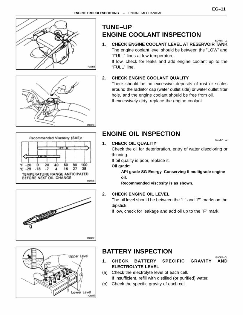
1. CHECK ENGINE COOLANT LEVEL AT RESERVOIR TANKThe engine coolant level should be between the ”LOW” and”FULL” lines at low temperature.If low, check for leaks and add engine coolant up to the”FULL” line.
2. CHECK ENGINE COOLANT QUALITYThere should be no excessive deposits of rust or scalesaround the radiator cap (water outlet side) or water outlet filterhole, and the engine coolant should be free from oil.If excessively dirty, replace the engine coolant.
ENGINE OIL INSPECTIONEG0EN–02
1. CHECK OIL QUALITYCheck the oil for deterioration, entry of water discoloring orthinning.If oil quality is poor, replace it.Oil grade:
API grade SG Energy–Conserving II multigrade engineoil.Recommended viscosity is as shown.
2. CHECK ENGINE OIL LEVELThe oil level should be between the ”L” and ”F” marks on thedipstick.If low, check for leakage and add oil up to the ”F” mark.
BATTERY INSPECTIONEG0EP–01
1. CHECK BATTERY SPECIFIC GRAVITY ANDELECTROLYTE LEVEL
(a) Check the electrolyte level of each cell.If insufficient, refill with distilled (or purified) water.
(b) Check the specific gravity of each cell.
–ENGINE TROUBLESHOOTING ENGINE MECHANICALEG–11
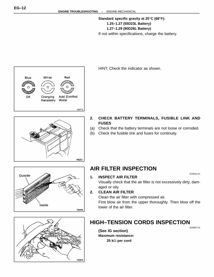
Standard specific gravity at 20 °C (68°F):1.25–1.27 (55D23L Battery)1.27–1.29 (80D26L Battery)
If not within specifications, charge the battery.
HINT: Check the indicator as shown.
2. CHECK BATTERY TERMINALS, FUSIBLE LINK ANDFUSES
(a) Check that the battery terminals are not loose or corroded.(b) Check the fusible link and fuses for continuity.
AIR FILTER INSPECTIONEG0EQ–01
1. INSPECT AIR FILTERVisually check that the air filter is not excessively dirty, dam-aged or oily.
2. CLEAN AIR FILTERClean the air filter with compressed air.First blow air from the upper thoroughly. Then blow off thelower of the air filter.
HIGH–TENSION CORDS INSPECTIONEG0ER–01
(See IG section)Maximum resistance:
25 k� per cord
EG–12–ENGINE TROUBLESHOOTING ENGINE MECHANICAL
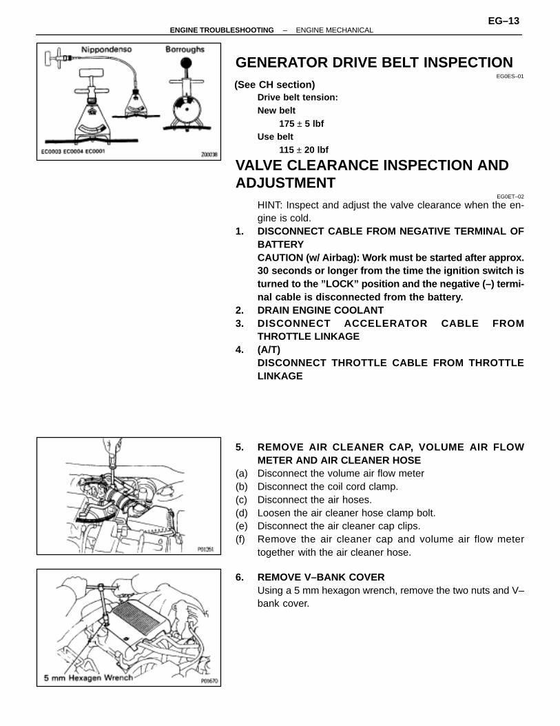
GENERATOR DRIVE BELT INSPECTIONEG0ES–01
(See CH section)Drive belt tension:New belt
175 ± 5 lbfUse belt
115 ± 20 lbf
VALVE CLEARANCE INSPECTION ANDADJUSTMENT
EG0ET–02
HINT: Inspect and adjust the valve clearance when the en-gine is cold.
1. DISCONNECT CABLE FROM NEGATIVE TERMINAL OFBATTERYCAUTION (w/ Airbag): Work must be started after approx.30 seconds or longer from the time the ignition switch isturned to the ”LOCK” position and the negative (–) termi-nal cable is disconnected from the battery.
2. DRAIN ENGINE COOLANT3. DISCONNECT ACCELERATOR CABLE FROM
THROTTLE LINKAGE4. (A/T)
DISCONNECT THROTTLE CABLE FROM THROTTLELINKAGE
5. REMOVE AIR CLEANER CAP, VOLUME AIR FLOWMETER AND AIR CLEANER HOSE
(a) Disconnect the volume air flow meter(b) Disconnect the coil cord clamp.(c) Disconnect the air hoses.(d) Loosen the air cleaner hose clamp bolt.(e) Disconnect the air cleaner cap clips.(f) Remove the air cleaner cap and volume air flow meter
together with the air cleaner hose.
6. REMOVE V–BANK COVERUsing a 5 mm hexagon wrench, remove the two nuts and V–bank cover.
–ENGINE TROUBLESHOOTING ENGINE MECHANICALEG–13
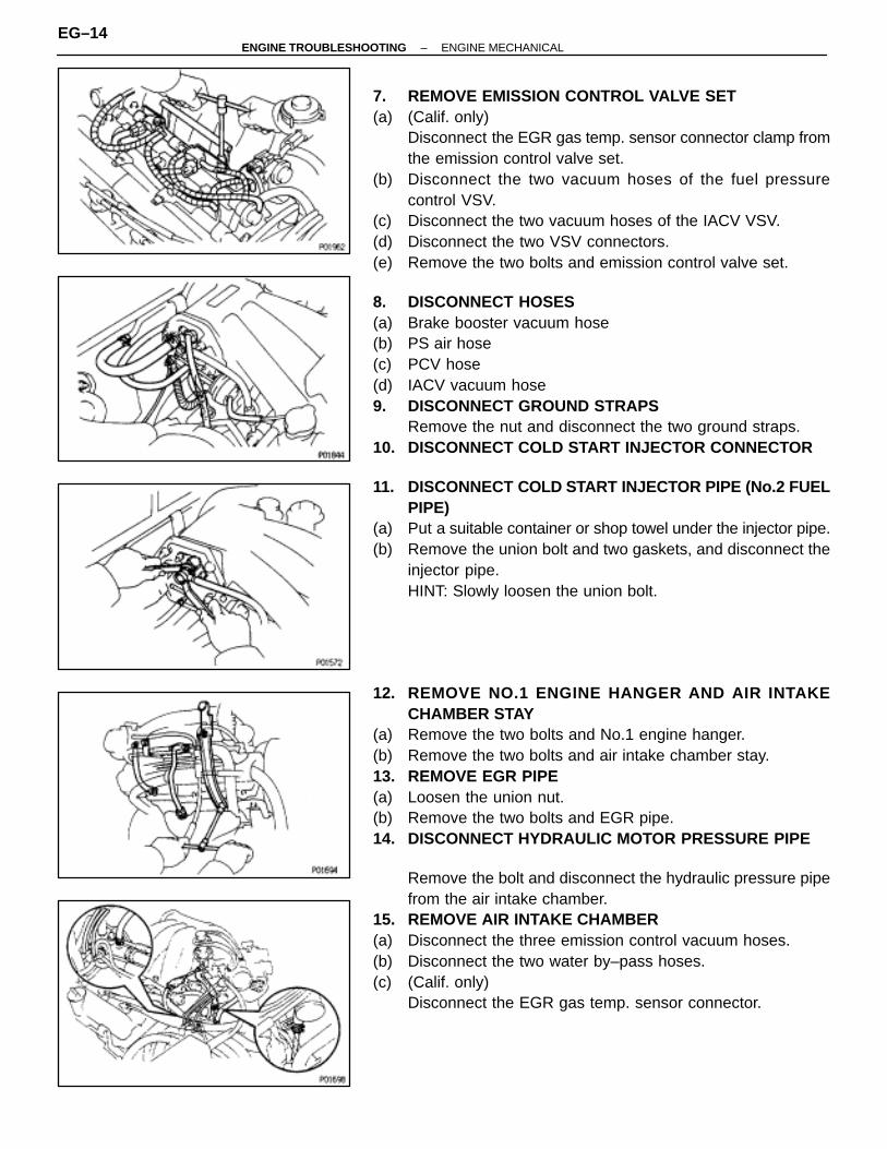
7. REMOVE EMISSION CONTROL VALVE SET(a) (Calif. only)
Disconnect the EGR gas temp. sensor connector clamp fromthe emission control valve set.
(b) Disconnect the two vacuum hoses of the fuel pressurecontrol VSV.
(c) Disconnect the two vacuum hoses of the IACV VSV.(d) Disconnect the two VSV connectors.(e) Remove the two bolts and emission control valve set.
8. DISCONNECT HOSES(a) Brake booster vacuum hose(b) PS air hose(c) PCV hose(d) IACV vacuum hose9. DISCONNECT GROUND STRAPS
Remove the nut and disconnect the two ground straps.10. DISCONNECT COLD START INJECTOR CONNECTOR
11. DISCONNECT COLD START INJECTOR PIPE (No.2 FUELPIPE)
(a) Put a suitable container or shop towel under the injector pipe.(b) Remove the union bolt and two gaskets, and disconnect the
injector pipe.HINT: Slowly loosen the union bolt.
12. REMOVE NO.1 ENGINE HANGER AND AIR INTAKECHAMBER STAY
(a) Remove the two bolts and No.1 engine hanger.(b) Remove the two bolts and air intake chamber stay.13. REMOVE EGR PIPE(a) Loosen the union nut.(b) Remove the two bolts and EGR pipe.14. DISCONNECT HYDRAULIC MOTOR PRESSURE PIPE
Remove the bolt and disconnect the hydraulic pressure pipefrom the air intake chamber.
15. REMOVE AIR INTAKE CHAMBER(a) Disconnect the three emission control vacuum hoses.(b) Disconnect the two water by–pass hoses.(c) (Calif. only)
Disconnect the EGR gas temp. sensor connector.
EG–14–ENGINE TROUBLESHOOTING ENGINE MECHANICAL
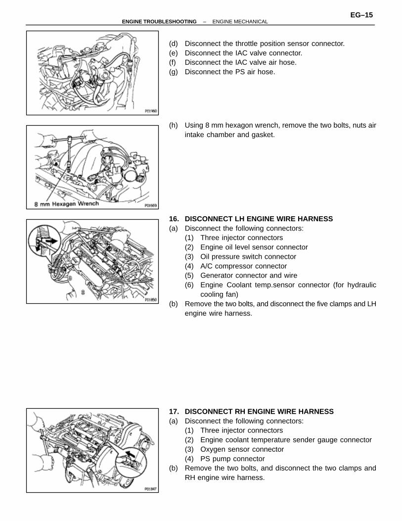
(d) Disconnect the throttle position sensor connector.(e) Disconnect the IAC valve connector.(f) Disconnect the IAC valve air hose.(g) Disconnect the PS air hose.
(h) Using 8 mm hexagon wrench, remove the two bolts, nuts airintake chamber and gasket.
16. DISCONNECT LH ENGINE WIRE HARNESS(a) Disconnect the following connectors:
(1) Three injector connectors(2) Engine oil level sensor connector(3) Oil pressure switch connector(4) A/C compressor connector(5) Generator connector and wire(6) Engine Coolant temp.sensor connector (for hydraulic
cooling fan)(b) Remove the two bolts, and disconnect the five clamps and LH
engine wire harness.
17. DISCONNECT RH ENGINE WIRE HARNESS(a) Disconnect the following connectors:
(1) Three injector connectors(2) Engine coolant temperature sender gauge connector(3) Oxygen sensor connector(4) PS pump connector
(b) Remove the two bolts, and disconnect the two clamps andRH engine wire harness.
–ENGINE TROUBLESHOOTING ENGINE MECHANICALEG–15
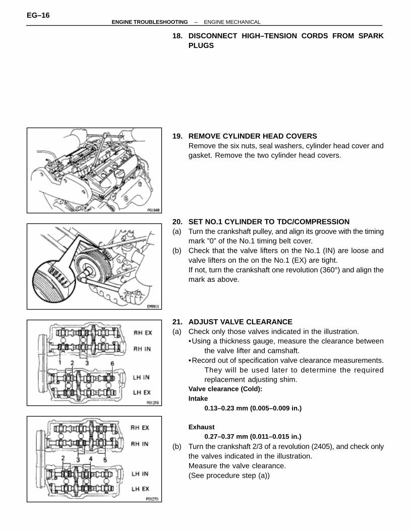
18. DISCONNECT HIGH–TENSION CORDS FROM SPARKPLUGS
19. REMOVE CYLINDER HEAD COVERSRemove the six nuts, seal washers, cylinder head cover andgasket. Remove the two cylinder head covers.
20. SET NO.1 CYLINDER TO TDC/COMPRESSION(a) Turn the crankshaft pulley, and align its groove with the timing
mark ”0” of the No.1 timing belt cover.(b) Check that the valve lifters on the No.1 (IN) are loose and
valve lifters on the on the No.1 (EX) are tight.If not, turn the crankshaft one revolution (360°) and align themark as above.
21. ADJUST VALVE CLEARANCE(a) Check only those valves indicated in the illustration.
•Using a thickness gauge, measure the clearance betweenthe valve lifter and camshaft.
•Record out of specification valve clearance measurements.They will be used later to determine the requiredreplacement adjusting shim.
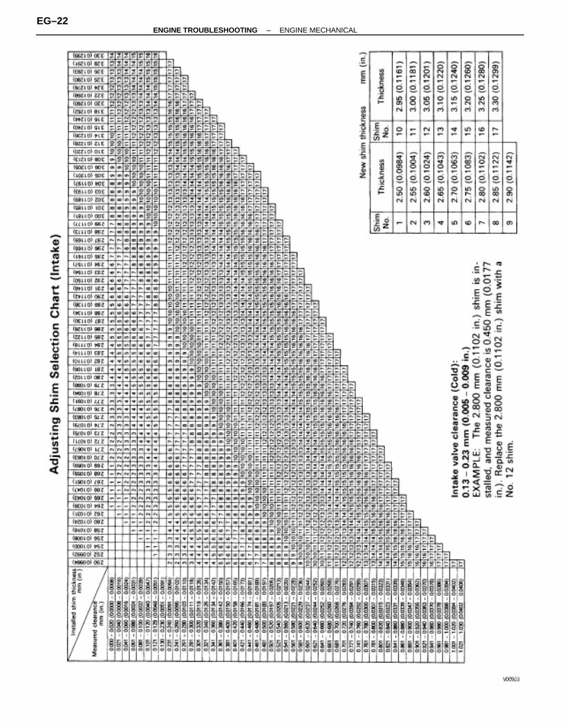
Valve clearance (Cold):Intake
0.13–0.23 mm (0.005–0.009 in.)
Exhaust0.27–0.37 mm (0.011–0.015 in.)
(b) Turn the crankshaft 2/3 of a revolution (2405), and check onlythe valves indicated in the illustration.Measure the valve clearance.(See procedure step (a))
EG–16–ENGINE TROUBLESHOOTING ENGINE MECHANICAL
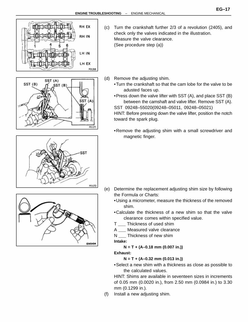
(c) Turn the crankshaft further 2/3 of a revolution (2405), andcheck only the valves indicated in the illustration.Measure the valve clearance.(See procedure step (a))
(d) Remove the adjusting shim.•Turn the crankshaft so that the cam lobe for the valve to be
adusted faces up.•Press down the valve lifter with SST (A), and place SST (B)
between the camshaft and valve lifter. Remove SST (A).SST 09248–55020(09248–05011, 09248–05021)HINT: Before pressing down the valve lifter, position the notchtoward the spark plug.
•Remove the adjusting shim with a small screwdriver andmagnetic finger.
(e) Determine the replacement adjusting shim size by followingthe Formula or Charts:•Using a micrometer, measure the thickness of the removed
shim.•Calculate the thickness of a new shim so that the valve
clearance comes within specified value.T Thickness of used shimA Measured valve clearanceN Thickness of new shimIntake:
N = T + (A–0.18 mm (0.007 in.))Exhaust:
N = T + (A–0.32 mm (0.013 in.))
•Select a new shim with a thickness as close as possible tothe calculated values.
HINT: Shims are available in seventeen sizes in incrementsof 0.05 mm (0.0020 in.), from 2.50 mm (0.0984 in.) to 3.30mm (0.1299 in.).
(f) Install a new adjusting shim.
–ENGINE TROUBLESHOOTING ENGINE MECHANICALEG–17

•Place a new adjusting shim on the valve lifter.•Press down the valve lifter with SST (A), and remove SST
(B).SST 09248–55020(09248–05011, 09248–05021)
(g) Recheck the valve clearance.
22. REINSTALL CYLINDER HEAD COVERS(a) Apply seal packing to the cylinder heads as shown in the
illustration.Seal packing:
Part No.08826–00080 or equivalent
(b) Install the gasket to the cylinder head cover.(c) Install the cylinder head cover with the six seal washers and
nuts. Uniformly tighten the nuts in several passes. Install thetwo cylinder head covers.Torque: 5.9 N ⋅m (60 kgf ⋅cm, 52 in. ⋅lbf)
23. RECONNECT HIGH–TENSION CORDS TO SPARKPLUGS
24. RECONNECT RH ENGINE WIRE HARNESS(a) Connect the two clamps of the RH engine wire harness and
install the wire harness with the two bolts.(b) Connect the following connectors:
(1) Three injector connectors(2) Engine coolant temperature sender gauge connector(3) Oxygen sensor connector(4) PS pump connector
EG–18–ENGINE TROUBLESHOOTING ENGINE MECHANICAL
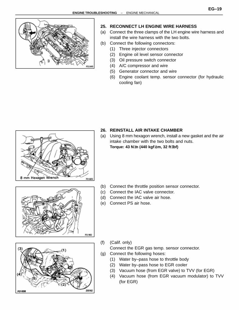
25. RECONNECT LH ENGINE WIRE HARNESS(a) Connect the three clamps of the LH engine wire harness and
install the wire harness with the two bolts.(b) Connect the following connectors:
(1) Three injector connectors(2) Engine oil level sensor connector(3) Oil pressure switch connector(4) A/C compressor and wire(5) Generator connector and wire(6) Engine coolant temp. sensor connector (for hydraulic
cooling fan)
26. REINSTALL AIR INTAKE CHAMBER(a) Using 8 mm hexagon wrench, install a new gasket and the air
intake chamber with the two bolts and nuts.Torque: 43 N ⋅m (440 kgf ⋅cm, 32 ft ⋅lbf)
(b) Connect the throttle position sensor connector.(c) Connect the IAC valve connector.(d) Connect the IAC valve air hose.(e) Connect PS air hose.
(f) (Calif. only)Connect the EGR gas temp. sensor connector.
(g) Connect the following hoses:(1) Water by–pass hose to throttle body(2) Water by–pass hose to EGR cooler(3) Vacuum hose (from EGR valve) to TVV (for EGR)(4) Vacuum hose (from EGR vacuum modulator) to TVV
(for EGR)
–ENGINE TROUBLESHOOTING ENGINE MECHANICALEG–19
(5) Vacuum hose (from throttle body) to TVV (for EVAP)
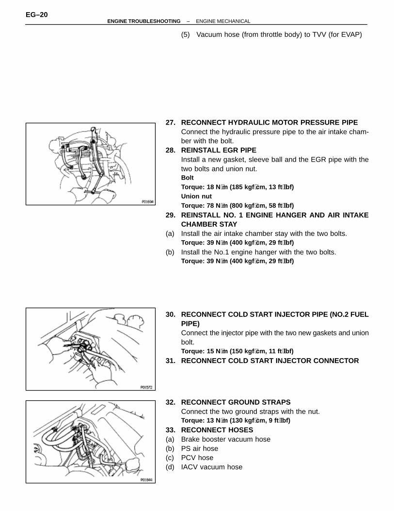
27. RECONNECT HYDRAULIC MOTOR PRESSURE PIPEConnect the hydraulic pressure pipe to the air intake cham-ber with the bolt.
28. REINSTALL EGR PIPEInstall a new gasket, sleeve ball and the EGR pipe with thetwo bolts and union nut.BoltTorque: 18 N ⋅m (185 kgf ⋅cm, 13 ft ⋅lbf)Union nutTorque: 78 N ⋅m (800 kgf ⋅cm, 58 ft ⋅lbf)
29. REINSTALL NO. 1 ENGINE HANGER AND AIR INTAKECHAMBER STAY
(a) Install the air intake chamber stay with the two bolts.Torque: 39 N ⋅m (400 kgf ⋅cm, 29 ft ⋅lbf)
(b) Install the No.1 engine hanger with the two bolts.Torque: 39 N ⋅m (400 kgf ⋅cm, 29 ft ⋅lbf)
30. RECONNECT COLD START INJECTOR PIPE (NO.2 FUELPIPE)Connect the injector pipe with the two new gaskets and unionbolt.Torque: 15 N ⋅m (150 kgf ⋅cm, 11 ft ⋅lbf)
31. RECONNECT COLD START INJECTOR CONNECTOR
32. RECONNECT GROUND STRAPSConnect the two ground straps with the nut.Torque: 13 N ⋅m (130 kgf ⋅cm, 9 ft ⋅lbf)
33. RECONNECT HOSES(a) Brake booster vacuum hose(b) PS air hose(c) PCV hose(d) IACV vacuum hose
EG–20–ENGINE TROUBLESHOOTING ENGINE MECHANICAL

34. REINSTALL EMISSION CONTROL VALVE SET(a) Install the emission control valve set with the two bolts.(b) Connect the two VSV connectors.(c) Connect the two vacuum hoses of the IACV VSV.(d) Connect the two vacuum hoses of the fuel pressure control
VSV.(e) (Calif. only)
Connect the EGR gas temp. sensor connector clamp to theemission control valve set.
35. REINSTALL V–BANK COVERUsing a 5 mm hexagon wrench, install the V–bank cover withthe two nuts.
36. INSTALL AIR CLEANER CAP, VOLUME AIR FLOWMETER AND AIR CLEANER HOSE
(a) Connect the air cleaner hose, and install the air cleaner capand volume air flow meter with the four clips.
(b) Tighten the air cleaner hose clamp bolt.(c) Connect the air hoses.(d) Connect the coil cord clamp.(e) Connect the volume air flow meter connector.
37. (A/T)CONNECT THROTTLE CABLE, AND ADJUST IT
38. CONNECT ACCELERATOR CABLE, AND ADJUST IT39. FILL WITH ENGINE COOLANT40. CONNECT CABLE TO NEGATIVE TERMINAL OF
BATTERY
–ENGINE TROUBLESHOOTING ENGINE MECHANICALEG–21
EG–22–ENGINE TROUBLESHOOTING ENGINE MECHANICAL

–ENGINE TROUBLESHOOTING ENGINE MECHANICALEG–23

IGNITION TIMING INSPECTION ANDADJUSTMENT
EG0EU–01
(See IG section)Ignition timing:
10° BTDC @ idle(w/ Terminals TE1 and E1 connected)
IDLE SPEED INSPECTIONEG0EV–01
Idle speed:700±50 rpm
EG–24–ENGINE TROUBLESHOOTING ENGINE MECHANICAL
IDLE AND/OR 2,500 RPM CO/HC CHECKEG0EW–02
HINT: This check is used only to determine whether or not theidle CO/HC complies with regulations.
1. INITIAL CONDITIONS(a) Engine at normal operating temperature(b) Air cleaner installed(c) All pipes and hoses of air induction system connected(d) All operating accessories switched OFF(e) All vacuum lines properly connected
HINT: All vacuum hoses for EGR systems, etc. should beproperly connected.
(f) SFI system wiring connectors fully plugged in(g) Transmission in neutral position(h) Tachometer and CO/HC meter calibrated by hand
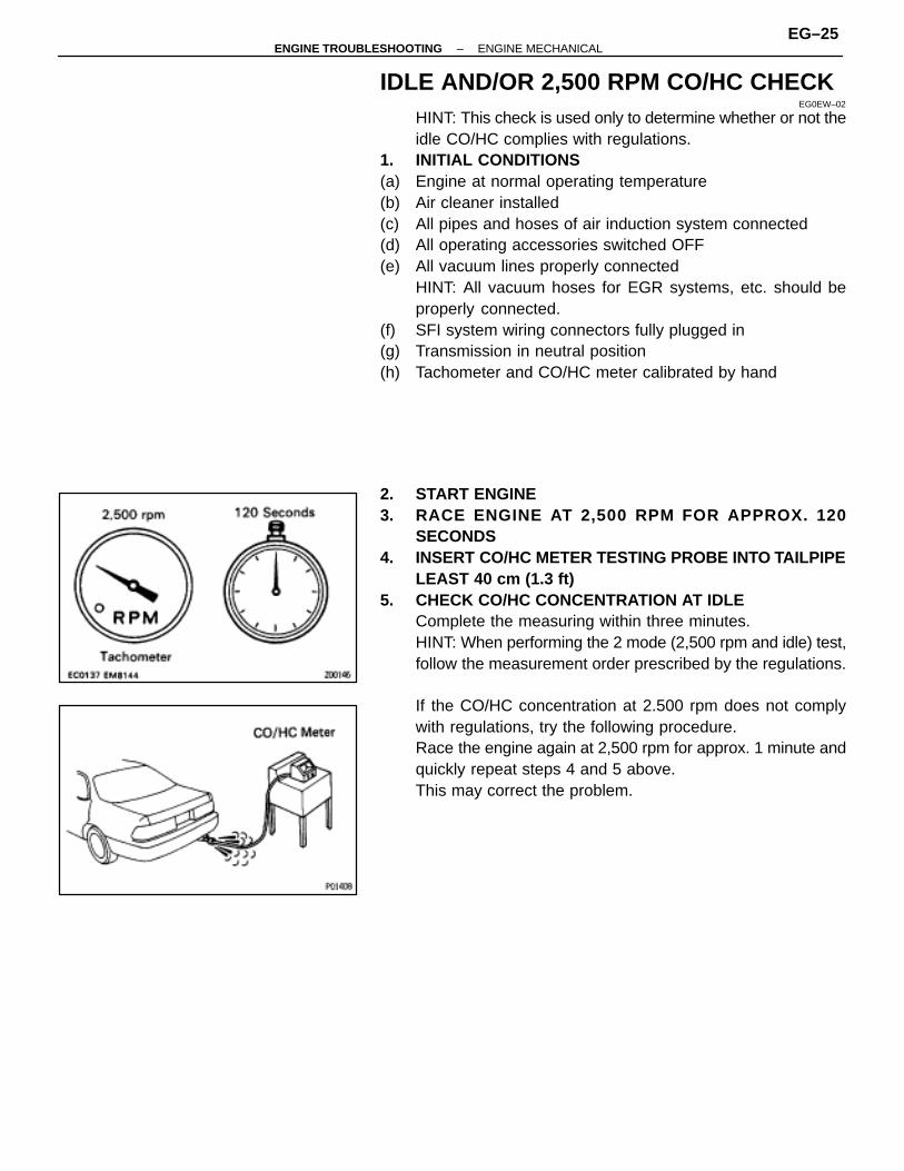
2. START ENGINE3. RACE ENGINE AT 2,500 RPM FOR APPROX. 120
SECONDS4. INSERT CO/HC METER TESTING PROBE INTO TAILPIPE
LEAST 40 cm (1.3 ft)5. CHECK CO/HC CONCENTRATION AT IDLE
Complete the measuring within three minutes.HINT: When performing the 2 mode (2,500 rpm and idle) test,follow the measurement order prescribed by the regulations.
If the CO/HC concentration at 2.500 rpm does not complywith regulations, try the following procedure.Race the engine again at 2,500 rpm for approx. 1 minute andquickly repeat steps 4 and 5 above.This may correct the problem.
–ENGINE TROUBLESHOOTING ENGINE MECHANICALEG–25

TroubleshootingEG0EX–01
If the CO/HC concentration does not comply with regulations,perform troubleshooting in the order given below.
(a) Check oxygen sensor operation.(See page EG–228)
(b) See the table below for possible causes, and then inspectand correct the applicable causes if necessary.
ÑÑÑÑÑÑÑÑÑÑ
HC ÑÑÑÑÑÑÑÑ
CO ÑÑÑÑÑÑÑÑÑÑÑÑÑÑÑÑÑÑÑÑ
Problem ÑÑÑÑÑÑÑÑÑÑÑÑÑÑÑÑÑÑÑÑÑÑÑÑÑÑÑÑÑÑÑÑÑÑÑÑÑÑ
CauseÑÑÑÑÑÑÑÑÑÑ
High ÑÑÑÑÑÑÑÑNormal ÑÑÑÑÑÑÑÑÑÑ
ÑÑÑÑÑÑÑÑÑÑRough idle ÑÑÑÑÑÑÑÑÑÑÑÑÑÑÑÑÑÑÑ
ÑÑÑÑÑÑÑÑÑÑÑÑÑÑÑÑÑÑÑ1. Faulty ignition:
ÑÑÑÑÑÑÑÑÑÑ
ÑÑÑÑÑÑÑÑ
ÑÑÑÑÑÑÑÑÑÑÑÑÑÑÑÑÑÑÑÑ
ÑÑÑÑÑÑÑÑÑÑÑÑÑÑÑÑÑÑÑÑÑÑÑÑÑÑÑÑÑÑÑÑÑÑÑÑÑÑ
�Incorrect timing
ÑÑÑÑÑÑÑÑÑÑ
ÑÑÑÑÑÑÑÑ
ÑÑÑÑÑÑÑÑÑÑÑÑÑÑÑÑÑÑÑÑ
ÑÑÑÑÑÑÑÑÑÑÑÑÑÑÑÑÑÑÑÑÑÑÑÑÑÑÑÑÑÑÑÑÑÑÑÑÑÑ
�Fouled, shorted or improperly gapped plugs
ÑÑÑÑÑÑÑÑÑÑ
ÑÑÑÑÑÑÑÑ
ÑÑÑÑÑÑÑÑÑÑÑÑÑÑÑÑÑÑÑÑ
ÑÑÑÑÑÑÑÑÑÑÑÑÑÑÑÑÑÑÑÑÑÑÑÑÑÑÑÑÑÑÑÑÑÑÑÑÑÑ
�Open or crossed high–tension cords
ÑÑÑÑÑÑÑÑÑÑÑÑÑÑÑÑÑÑÑÑÑÑÑÑÑÑÑÑÑÑÑÑÑÑÑÑÑÑ�Cracked distributor capÑÑÑÑÑÑÑÑÑÑ
ÑÑÑÑÑÑÑÑ
ÑÑÑÑÑÑÑÑÑÑÑÑÑÑÑÑÑÑÑÑ
ÑÑÑÑÑÑÑÑÑÑÑÑÑÑÑÑÑÑÑÑÑÑÑÑÑÑÑÑÑÑÑÑÑÑÑÑÑÑ2. Incorrect valve clearanceÑÑÑÑÑ
ÑÑÑÑÑÑÑÑÑÑÑÑÑ
ÑÑÑÑÑÑÑÑÑÑÑÑÑÑÑÑÑÑÑÑ
ÑÑÑÑÑÑÑÑÑÑÑÑÑÑÑÑÑÑÑÑÑÑÑÑÑÑÑÑÑÑÑÑÑÑÑÑÑÑ3. Leaky EGR valve
ÑÑÑÑÑÑÑÑÑÑ
ÑÑÑÑÑÑÑÑ
ÑÑÑÑÑÑÑÑÑÑÑÑÑÑÑÑÑÑÑÑ
ÑÑÑÑÑÑÑÑÑÑÑÑÑÑÑÑÑÑÑÑÑÑÑÑÑÑÑÑÑÑÑÑÑÑÑÑÑÑ4. Leaky intake and exhaust valves
ÑÑÑÑÑÑÑÑÑÑ
ÑÑÑÑÑÑÑÑ
ÑÑÑÑÑÑÑÑÑÑÑÑÑÑÑÑÑÑÑÑ
ÑÑÑÑÑÑÑÑÑÑÑÑÑÑÑÑÑÑÑÑÑÑÑÑÑÑÑÑÑÑÑÑÑÑÑÑÑÑ5. Leaky cylinder
ÑÑÑÑÑÑÑÑÑÑ
High ÑÑÑÑÑÑÑÑLow ÑÑÑÑÑÑÑÑÑÑ
ÑÑÑÑÑÑÑÑÑÑRough idle ÑÑÑÑÑÑÑÑÑÑÑÑÑÑÑÑÑÑÑ
ÑÑÑÑÑÑÑÑÑÑÑÑÑÑÑÑÑÑÑ1. Vacuum leaks:
ÑÑÑÑÑÑÑÑÑÑ
ÑÑÑÑÑÑÑÑ
ÑÑÑÑÑÑÑÑÑÑÑÑÑÑÑÑÑÑÑÑ
(Fluctuating HC reading) ÑÑÑÑÑÑÑÑÑÑÑÑÑÑÑÑÑÑÑÑÑÑÑÑÑÑÑÑÑÑÑÑÑÑÑÑÑÑ
�PCV hoseÑÑÑÑÑÑÑÑÑÑ
ÑÑÑÑÑÑÑÑ
ÑÑÑÑÑÑÑÑÑÑÑÑÑÑÑÑÑÑÑÑ
ÑÑÑÑÑÑÑÑÑÑÑÑÑÑÑÑÑÑÑÑÑÑÑÑÑÑÑÑÑÑÑÑÑÑÑÑÑÑ
�EGR valve
ÑÑÑÑÑÑÑÑÑÑ
ÑÑÑÑÑÑÑÑ
ÑÑÑÑÑÑÑÑÑÑÑÑÑÑÑÑÑÑÑÑ
ÑÑÑÑÑÑÑÑÑÑÑÑÑÑÑÑÑÑÑÑÑÑÑÑÑÑÑÑÑÑÑÑÑÑÑÑÑÑ
�Intake manifold
ÑÑÑÑÑÑÑÑÑÑ
ÑÑÑÑÑÑÑÑ
ÑÑÑÑÑÑÑÑÑÑÑÑÑÑÑÑÑÑÑÑ
ÑÑÑÑÑÑÑÑÑÑÑÑÑÑÑÑÑÑÑÑÑÑÑÑÑÑÑÑÑÑÑÑÑÑÑÑÑÑ
�Air intake chamber
ÑÑÑÑÑÑÑÑÑÑÑÑÑÑÑÑÑÑÑÑÑÑÑÑÑÑÑÑÑÑÑÑÑÑÑÑÑÑ�Throttle bodyÑÑÑÑÑÑÑÑÑÑ
ÑÑÑÑÑÑÑÑ
ÑÑÑÑÑÑÑÑÑÑÑÑÑÑÑÑÑÑÑÑ
ÑÑÑÑÑÑÑÑÑÑÑÑÑÑÑÑÑÑÑÑÑÑÑÑÑÑÑÑÑÑÑÑÑÑÑÑÑÑ�IAC valveÑÑÑÑÑ
ÑÑÑÑÑÑÑÑÑÑÑÑÑ
ÑÑÑÑÑÑÑÑÑÑÑÑÑÑÑÑÑÑÑÑ
ÑÑÑÑÑÑÑÑÑÑÑÑÑÑÑÑÑÑÑÑÑÑÑÑÑÑÑÑÑÑÑÑÑÑÑÑÑÑ�Brake booster lineÑÑÑÑÑ
ÑÑÑÑÑÑÑÑÑÑÑÑÑ
ÑÑÑÑÑÑÑÑÑÑÑÑÑÑÑÑÑÑÑÑ
ÑÑÑÑÑÑÑÑÑÑÑÑÑÑÑÑÑÑÑÑÑÑÑÑÑÑÑÑÑÑÑÑÑÑÑÑÑÑ2. Lean mixture causing misfire
ÑÑÑÑÑÑÑÑÑÑ
High ÑÑÑÑÑÑÑÑHigh ÑÑÑÑÑÑÑÑÑÑ
ÑÑÑÑÑÑÑÑÑÑRough idle ÑÑÑÑÑÑÑÑÑÑÑÑÑÑÑÑÑÑÑ
ÑÑÑÑÑÑÑÑÑÑÑÑÑÑÑÑÑÑÑ1. Clogged air filter
ÑÑÑÑÑÑÑÑÑÑ
ÑÑÑÑÑÑÑÑ
ÑÑÑÑÑÑÑÑÑÑÑÑÑÑÑÑÑÑÑÑ
(Black smoke from exhaust) ÑÑÑÑÑÑÑÑÑÑÑÑÑÑÑÑÑÑÑÑÑÑÑÑÑÑÑÑÑÑÑÑÑÑÑÑÑÑ2. Faulty SFI system
ÑÑÑÑÑÑÑÑÑÑ
ÑÑÑÑÑÑÑÑ
ÑÑÑÑÑÑÑÑÑÑÑÑÑÑÑÑÑÑÑÑ
ÑÑÑÑÑÑÑÑÑÑÑÑÑÑÑÑÑÑÑÑÑÑÑÑÑÑÑÑÑÑÑÑÑÑÑÑÑÑ
�Faulty pressure regulatorÑÑÑÑÑÑÑÑÑÑ
ÑÑÑÑÑÑÑÑ
ÑÑÑÑÑÑÑÑÑÑÑÑÑÑÑÑÑÑÑÑ
ÑÑÑÑÑÑÑÑÑÑÑÑÑÑÑÑÑÑÑÑÑÑÑÑÑÑÑÑÑÑÑÑÑÑÑÑÑÑ
�Clogged fuel return line
ÑÑÑÑÑÑÑÑÑÑ
ÑÑÑÑÑÑÑÑ
ÑÑÑÑÑÑÑÑÑÑÑÑÑÑÑÑÑÑÑÑ
ÑÑÑÑÑÑÑÑÑÑÑÑÑÑÑÑÑÑÑÑÑÑÑÑÑÑÑÑÑÑÑÑÑÑÑÑÑÑ
�Defective engine coolant temp. sensor
ÑÑÑÑÑÑÑÑÑÑ
ÑÑÑÑÑÑÑÑ
ÑÑÑÑÑÑÑÑÑÑÑÑÑÑÑÑÑÑÑÑ
ÑÑÑÑÑÑÑÑÑÑÑÑÑÑÑÑÑÑÑÑÑÑÑÑÑÑÑÑÑÑÑÑÑÑÑÑÑÑ
�Defective air temp. sensor
ÑÑÑÑÑÑÑÑÑÑ
ÑÑÑÑÑÑÑÑ
ÑÑÑÑÑÑÑÑÑÑÑÑÑÑÑÑÑÑÑÑ
ÑÑÑÑÑÑÑÑÑÑÑÑÑÑÑÑÑÑÑÑÑÑÑÑÑÑÑÑÑÑÑÑÑÑÑÑÑÑ
�Faulty ECM
ÑÑÑÑÑÑÑÑÑÑÑÑÑÑÑÑÑÑÑÑÑÑÑÑÑÑÑÑÑÑÑÑÑÑÑÑÑÑ�Faulty injectorÑÑÑÑÑÑÑÑÑÑ
ÑÑÑÑÑÑÑÑ
ÑÑÑÑÑÑÑÑÑÑÑÑÑÑÑÑÑÑÑÑ
ÑÑÑÑÑÑÑÑÑÑÑÑÑÑÑÑÑÑÑÑÑÑÑÑÑÑÑÑÑÑÑÑÑÑÑÑÑÑ�Faulty cold start injectorÑÑÑÑÑ
ÑÑÑÑÑÑÑÑÑÑÑÑÑ
ÑÑÑÑÑÑÑÑÑÑÑÑÑÑÑÑÑÑÑÑ
ÑÑÑÑÑÑÑÑÑÑÑÑÑÑÑÑÑÑÑÑÑÑÑÑÑÑÑÑÑÑÑÑÑÑÑÑÑÑ
�Faulty throttle position sensorÑÑÑÑÑÑÑÑÑÑ
ÑÑÑÑÑÑÑÑ
ÑÑÑÑÑÑÑÑÑÑÑÑÑÑÑÑÑÑÑÑ
ÑÑÑÑÑÑÑÑÑÑÑÑÑÑÑÑÑÑÑÑÑÑÑÑÑÑÑÑÑÑÑÑÑÑÑÑÑÑ
�Volume air flow meter
EG–26–ENGINE TROUBLESHOOTING ENGINE MECHANICAL

COMPRESSION CHECKEG0EY–01
HINT: If there is lack of power, excessive oil consumption orpoor fuel economy, measure the compression pressure.
1. WARM UP AND STOP ENGINEAllow the engine to warm up to normal operating tempera-ture.
2. DISCONNECT DISTRIBUTOR CONNECTOR
3. REMOVE V–BANK COVERUsing a 5 mm hexagon wrench, remove the two nuts and V–bank cover.
4. DISCONNECT HIGH–TENSION CORDS FROM SPARKPLUGSDisconnect the high–tension cords at the rubber boot. DONOT pull on the cords.NOTICE: Pulling on or bending the cords may damagethe conductor inside.
5. REMOVE SPARK PLUGSUsing a 16 mm plug wrench, remove the spark plug.
6. CHECK CYLINDER COMPRESSION PRESSURE(a) Insert a compression gauge into the spark plug hole.(b) Fully open the throttle.(c) While cranking the engine, measure the compression
pressure.HINT: Always use a fully charged battery to obtain enginespeed of 250 rpm or more.
–ENGINE TROUBLESHOOTING ENGINE MECHANICALEG–27

(d) Repeat steps (a) through (c) for each cylinder.NOTICE: This measurement must be done in as short atime as possible.Compression pressure:
1,226 kPa (12.5 kgf/cm 2, 178 psi) or moreMinimum pressure:
981 kPa (10.0 kgf/cm 2, 142 psi)Difference between each cylinder:
98 kPa (1.0 kgf/cm 2, 14 psi) or less
(e) If the cylinder compression in one or more cylinders is low,pour a small amount of engine oil into the cylinder through thespark plug hole and repeat steps (a) through (c) for cylinderswith low compression.• If adding oil helps the compression chances are that the
piston rings and/or cylinder bore are worn or damaged.• If pressure stays low, a valve may be sticking or seating is
improper, or there may be leakage past the gasket.
7. REINSTALL SPARK PLUGSUsing a 16 mm plug wrench, install the spark plug.Torque: 18 N ⋅m (180 kgf ⋅cm, 13 ft ⋅lbf)
8. RECONNECT HIGH–TENSION CORDS TO SPARKPLUGS
9. REINSTALL V–BANK COVERUsing a 5 mm hexagon wrench, install the V–bank cover withthe two nuts.
10. RECONNECT DISTRIBUTOR CONNECTOR
EG–28–ENGINE TROUBLESHOOTING ENGINE MECHANICAL

TIMING BELTCOMPONENTS
EG0EZ–02
–ENGINE TROUBLESHOOTING ENGINE MECHANICALEG–29

TIMING BELT REMOVALEG0F0–02
1. DISCONNECT CABLE FROM NEGATIVE TERMINAL OFBATTERYCAUTION (w/ Airbag): Work must be started after approx.30 seconds or longer from the time the ignition switch isturned to the ”LOCK” position and the negative (–) termi-nal cable is disconnected from the battery.
2. DISCONNECT ENGINE COOLANT RESERVOIR HOSERemove the bolt and disconnect the reservoir hose.
3. REMOVE WASHER TANK(a) Remove the three washer tank mounting bolts.(b) Disconnect the connector and hose, and remove the washer
tank.
4. REMOVE ENGINE COOLANT RESERVOIR TANKUsing a screwdriver, remove the reservoir tank.
5. REMOVE NO.2 AND NO.3 RH MOUNTING STAYS(a) Remove the two bolts and No.3 RH engine mounting stay.(b) Remove the bolt, nut and No.2 RH engine mounting stay.
EG–30–ENGINE TROUBLESHOOTING ENGINE MECHANICAL
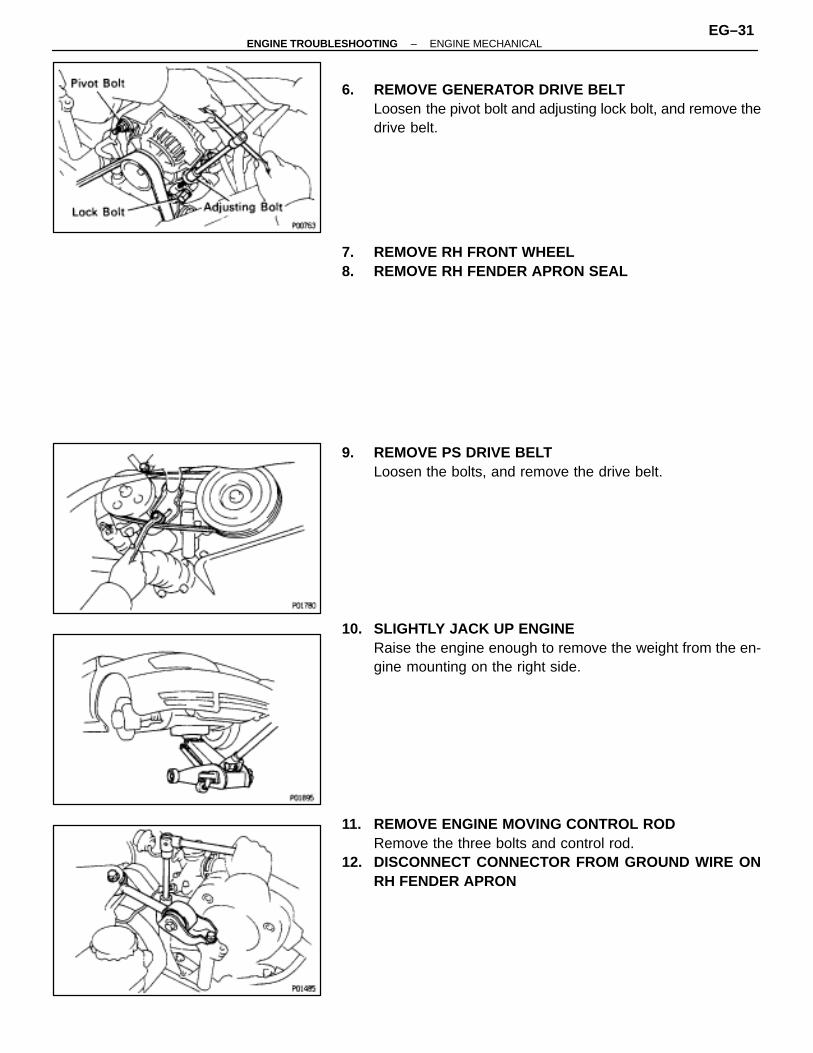
6. REMOVE GENERATOR DRIVE BELTLoosen the pivot bolt and adjusting lock bolt, and remove thedrive belt.
7. REMOVE RH FRONT WHEEL8. REMOVE RH FENDER APRON SEAL
9. REMOVE PS DRIVE BELTLoosen the bolts, and remove the drive belt.
10. SLIGHTLY JACK UP ENGINERaise the engine enough to remove the weight from the en-gine mounting on the right side.
11. REMOVE ENGINE MOVING CONTROL RODRemove the three bolts and control rod.
12. DISCONNECT CONNECTOR FROM GROUND WIRE ONRH FENDER APRON
–ENGINE TROUBLESHOOTING ENGINE MECHANICALEG–31
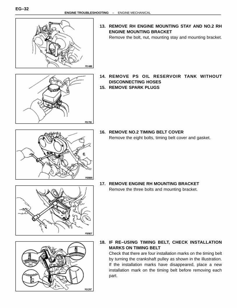
13. REMOVE RH ENGINE MOUNTING STAY AND NO.2 RHENGINE MOUNTING BRACKETRemove the bolt, nut, mounting stay and mounting bracket.
14. REMOVE PS OIL RESERVOIR TANK WITHOUTDISCONNECTING HOSES
15. REMOVE SPARK PLUGS
16. REMOVE NO.2 TIMING BELT COVERRemove the eight bolts, timing belt cover and gasket.
17. REMOVE ENGINE RH MOUNTING BRACKETRemove the three bolts and mounting bracket.
18. IF RE–USING TIMING BELT, CHECK INSTALLATIONMARKS ON TIMING BELTCheck that there are four installation marks on the timing beltby turning the crankshaft pulley as shown in the illustration.If the installation marks have disappeared, place a newinstallation mark on the timing belt before removing eachpart.
EG–32–ENGINE TROUBLESHOOTING ENGINE MECHANICAL
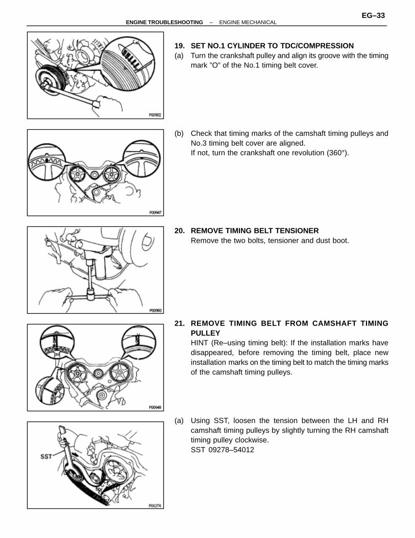
19. SET NO.1 CYLINDER TO TDC/COMPRESSION(a) Turn the crankshaft pulley and align its groove with the timing
mark ”O” of the No.1 timing belt cover.
(b) Check that timing marks of the camshaft timing pulleys andNo.3 timing belt cover are aligned.If not, turn the crankshaft one revolution (360°).
20. REMOVE TIMING BELT TENSIONERRemove the two bolts, tensioner and dust boot.
21. REMOVE TIMING BELT FROM CAMSHAFT TIMINGPULLEYHINT (Re–using timing belt): If the installation marks havedisappeared, before removing the timing belt, place newinstallation marks on the timing belt to match the timing marksof the camshaft timing pulleys.
(a) Using SST, loosen the tension between the LH and RHcamshaft timing pulleys by slightly turning the RH camshafttiming pulley clockwise.SST 09278–54012
–ENGINE TROUBLESHOOTING ENGINE MECHANICALEG–33
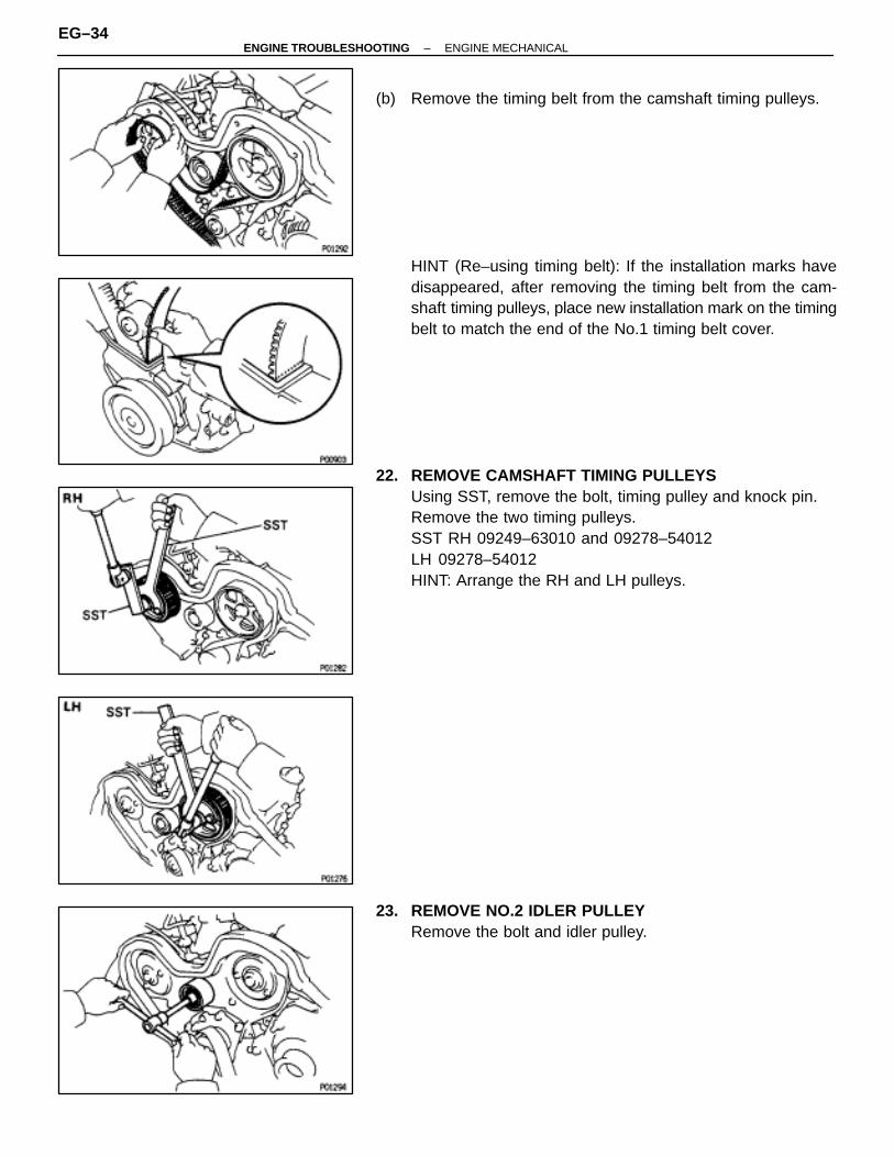
(b) Remove the timing belt from the camshaft timing pulleys.
HINT (Re–using timing belt): If the installation marks havedisappeared, after removing the timing belt from the cam-shaft timing pulleys, place new installation mark on the timingbelt to match the end of the No.1 timing belt cover.
22. REMOVE CAMSHAFT TIMING PULLEYSUsing SST, remove the bolt, timing pulley and knock pin.Remove the two timing pulleys.SST RH 09249–63010 and 09278–54012LH 09278–54012HINT: Arrange the RH and LH pulleys.
23. REMOVE NO.2 IDLER PULLEYRemove the bolt and idler pulley.
EG–34–ENGINE TROUBLESHOOTING ENGINE MECHANICAL
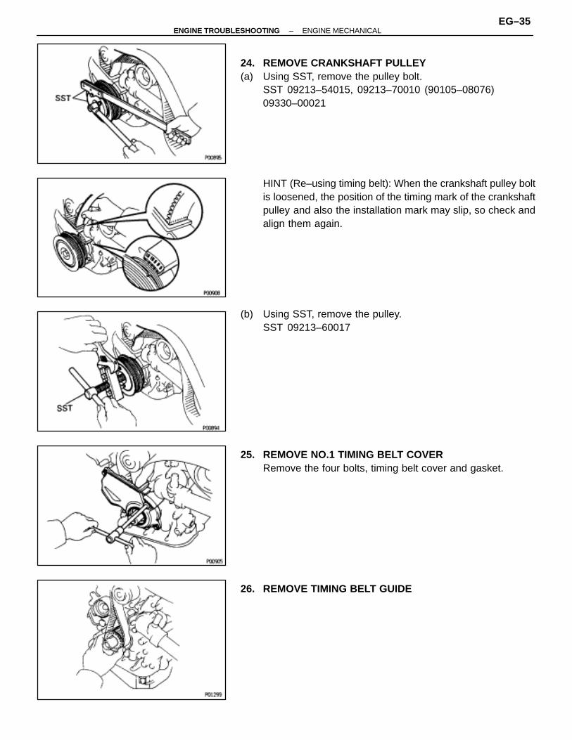
24. REMOVE CRANKSHAFT PULLEY(a) Using SST, remove the pulley bolt.
SST 09213–54015, 09213–70010 (90105–08076)09330–00021
HINT (Re–using timing belt): When the crankshaft pulley boltis loosened, the position of the timing mark of the crankshaftpulley and also the installation mark may slip, so check andalign them again.
(b) Using SST, remove the pulley.SST 09213–60017
25. REMOVE NO.1 TIMING BELT COVERRemove the four bolts, timing belt cover and gasket.
26. REMOVE TIMING BELT GUIDE
–ENGINE TROUBLESHOOTING ENGINE MECHANICALEG–35
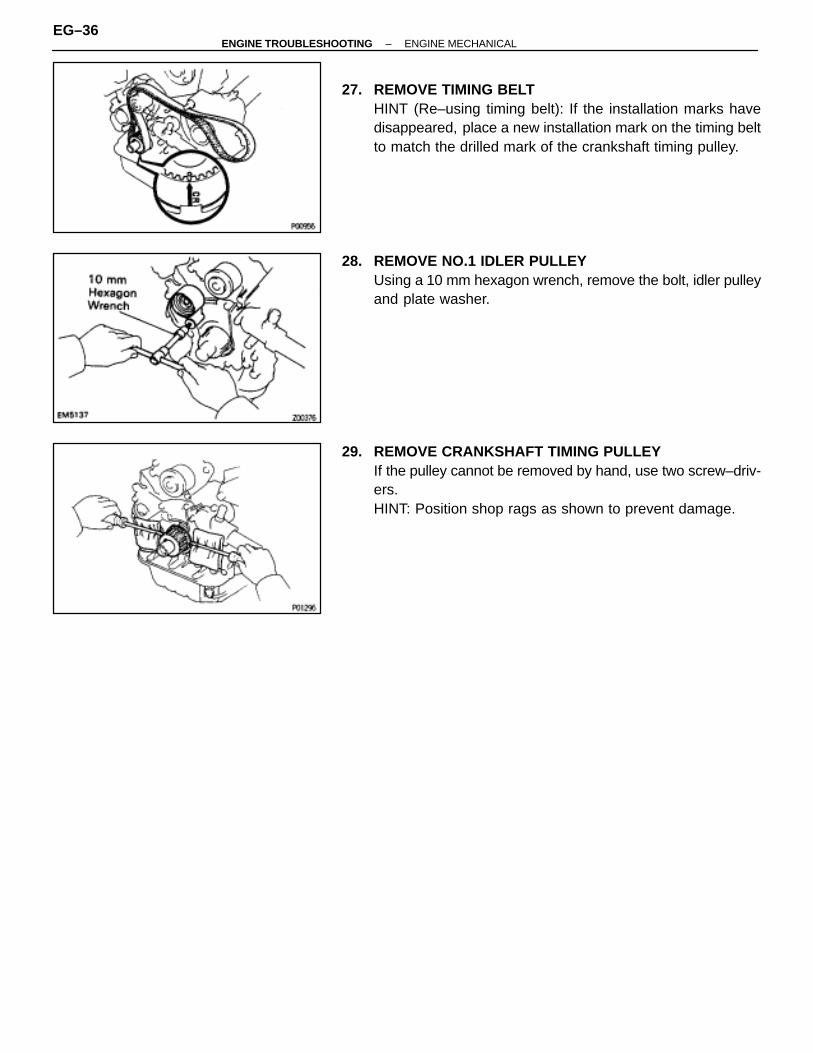
27. REMOVE TIMING BELTHINT (Re–using timing belt): If the installation marks havedisappeared, place a new installation mark on the timing beltto match the drilled mark of the crankshaft timing pulley.
28. REMOVE NO.1 IDLER PULLEYUsing a 10 mm hexagon wrench, remove the bolt, idler pulleyand plate washer.
29. REMOVE CRANKSHAFT TIMING PULLEYIf the pulley cannot be removed by hand, use two screw–driv-ers.HINT: Position shop rags as shown to prevent damage.
EG–36–ENGINE TROUBLESHOOTING ENGINE MECHANICAL
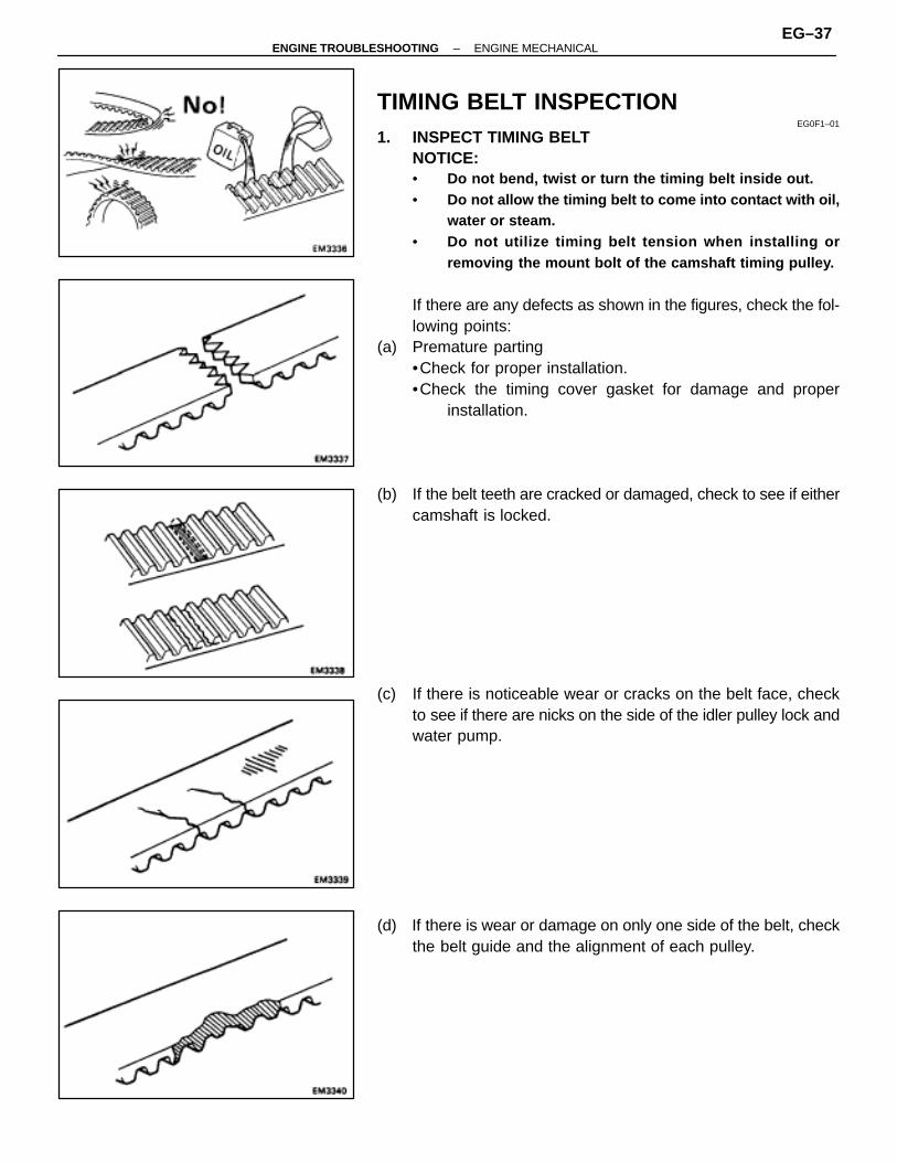
TIMING BELT INSPECTIONEG0F1–01
1. INSPECT TIMING BELTNOTICE:• Do not bend, twist or turn the timing belt inside out.• Do not allow the timing belt to come into contact with oil,
water or steam.• Do not utilize timing belt tension when installing or
removing the mount bolt of the camshaft timing pulley.
If there are any defects as shown in the figures, check the fol-lowing points:
(a) Premature parting•Check for proper installation.•Check the timing cover gasket for damage and proper
installation.
(b) If the belt teeth are cracked or damaged, check to see if eithercamshaft is locked.
(c) If there is noticeable wear or cracks on the belt face, checkto see if there are nicks on the side of the idler pulley lock andwater pump.
(d) If there is wear or damage on only one side of the belt, checkthe belt guide and the alignment of each pulley.
–ENGINE TROUBLESHOOTING ENGINE MECHANICALEG–37
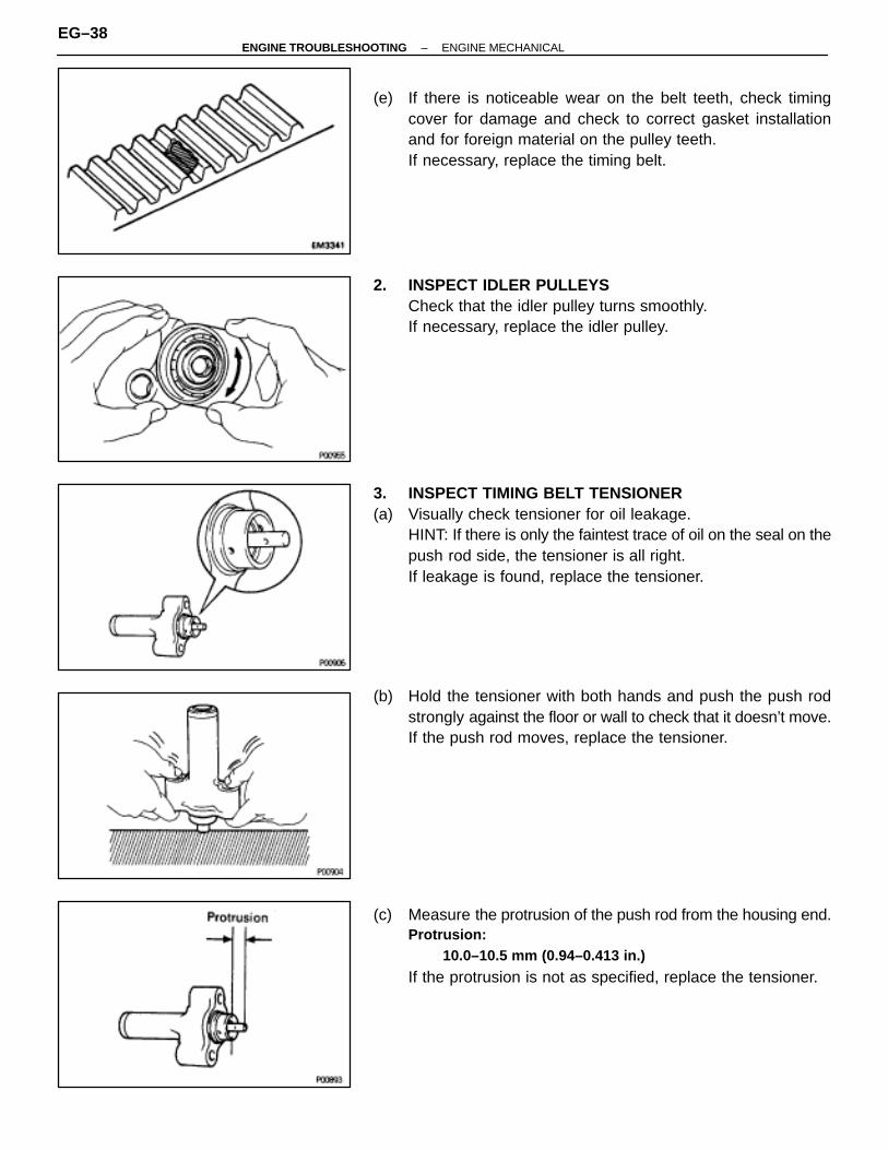
(e) If there is noticeable wear on the belt teeth, check timingcover for damage and check to correct gasket installationand for foreign material on the pulley teeth.If necessary, replace the timing belt.
2. INSPECT IDLER PULLEYSCheck that the idler pulley turns smoothly.If necessary, replace the idler pulley.
3. INSPECT TIMING BELT TENSIONER(a) Visually check tensioner for oil leakage.
HINT: If there is only the faintest trace of oil on the seal on thepush rod side, the tensioner is all right.If leakage is found, replace the tensioner.
(b) Hold the tensioner with both hands and push the push rodstrongly against the floor or wall to check that it doesn’t move.If the push rod moves, replace the tensioner.
(c) Measure the protrusion of the push rod from the housing end.Protrusion:
10.0–10.5 mm (0.94–0.413 in.)
If the protrusion is not as specified, replace the tensioner.
EG–38–ENGINE TROUBLESHOOTING ENGINE MECHANICAL

TIMING BELT INSTALLATIONEG0F2–01
(See page EG–29)1. INSTALL CRANKSHAFT TIMING PULLEY(a) Align the pulley set key with the key groove of the timing
pulley.(b) Slide on the timing pulley, facing the flange side inward.
2. INSTALL NO.1 IDLER PULLEY(a) Apply adhesive to two or three threads of the mount bolt end.
Adhesive:Part No.08833–00080, THREE BOND 1344, LOCTITE 242or equivalent
(b) Using a 10 mm hexagon wrench, install the idler pulley withthe plate washer and bolt. Torque the bolt.Torque: 34 N ⋅m (350 kgf ⋅cm, 25 ft ⋅lbf)
(c) Check that the pulley bracket moves smoothly.
3. TEMPORARILY INSTALL TIMING BELTNOTICE: The engine should be cold.
(a) Remove any oil or water on the crankshaft timing, No. 1 idlerand water pump pulleys, and keep them clean.
(b) Align the installation mark on the timing belt with the drilledmark of the crankshaft timing pulley.
(c) Install the timing belt on the crankshaft timing, No.1 idler andwater pump pulleys.
4. INSTALL TIMING BELT GUIDEInstall the belt guide, facing the cup side outward.
5. INSTALL NO.1 TIMING BELT COVER(a) Install the gasket to the timing belt cover.(b) Install the timing belt cover with the four bolts.
–ENGINE TROUBLESHOOTING ENGINE MECHANICALEG–39
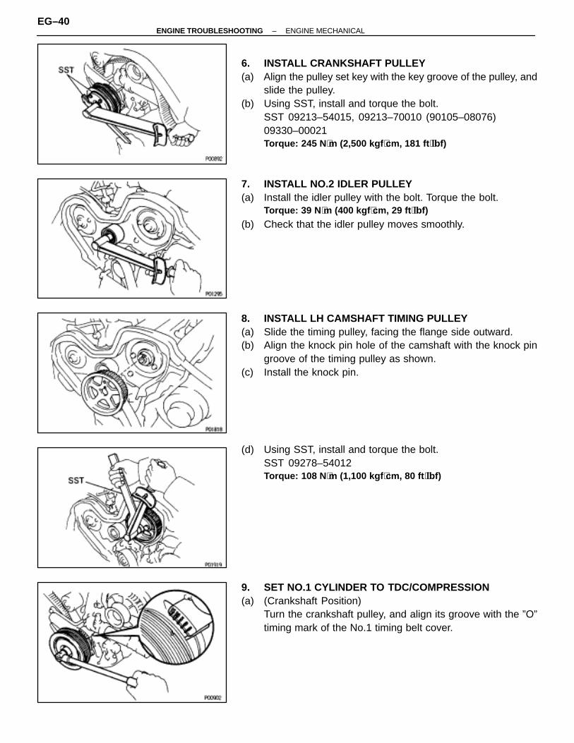
6. INSTALL CRANKSHAFT PULLEY(a) Align the pulley set key with the key groove of the pulley, and
slide the pulley.(b) Using SST, install and torque the bolt.
SST 09213–54015, 09213–70010 (90105–08076)09330–00021Torque: 245 N ⋅m (2,500 kgf ⋅cm, 181 ft ⋅lbf)
7. INSTALL NO.2 IDLER PULLEY(a) Install the idler pulley with the bolt. Torque the bolt.
Torque: 39 N ⋅m (400 kgf ⋅cm, 29 ft ⋅lbf)
(b) Check that the idler pulley moves smoothly.
8. INSTALL LH CAMSHAFT TIMING PULLEY(a) Slide the timing pulley, facing the flange side outward.(b) Align the knock pin hole of the camshaft with the knock pin
groove of the timing pulley as shown.(c) Install the knock pin.
(d) Using SST, install and torque the bolt.SST 09278–54012Torque: 108 N ⋅m (1,100 kgf ⋅cm, 80 ft ⋅lbf)
9. SET NO.1 CYLINDER TO TDC/COMPRESSION(a) (Crankshaft Position)
Turn the crankshaft pulley, and align its groove with the ”O”timing mark of the No.1 timing belt cover.
EG–40–ENGINE TROUBLESHOOTING ENGINE MECHANICAL
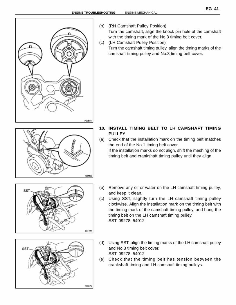
(b) (RH Camshaft Pulley Position)Turn the camshaft, align the knock pin hole of the camshaftwith the timing mark of the No.3 timing belt cover.
(c) (LH Camshaft Pulley Position)Turn the camshaft timing pulley, align the timing marks of thecamshaft timing pulley and No.3 timing belt cover.
10. INSTALL TIMING BELT TO LH CAMSHAFT TIMINGPULLEY
(a) Check that the installation mark on the timing belt matchesthe end of the No.1 timing belt cover.If the installation marks do not align, shift the meshing of thetiming belt and crankshaft timing pulley until they align.
(b) Remove any oil or water on the LH camshaft timing pulley,and keep it clean.
(c) Using SST, slightly turn the LH camshaft timing pulleyclockwise. Align the installation mark on the timing belt withthe timing mark of the camshaft timing pulley, and hang thetiming belt on the LH camshaft timing pulley.SST 09278–54012
(d) Using SST, align the timing marks of the LH camshaft pulleyand No.3 timing belt cover.SST 09278–54012
(e) Check that the timing belt has tension between thecrankshaft timing and LH camshaft timing pulleys.
–ENGINE TROUBLESHOOTING ENGINE MECHANICALEG–41
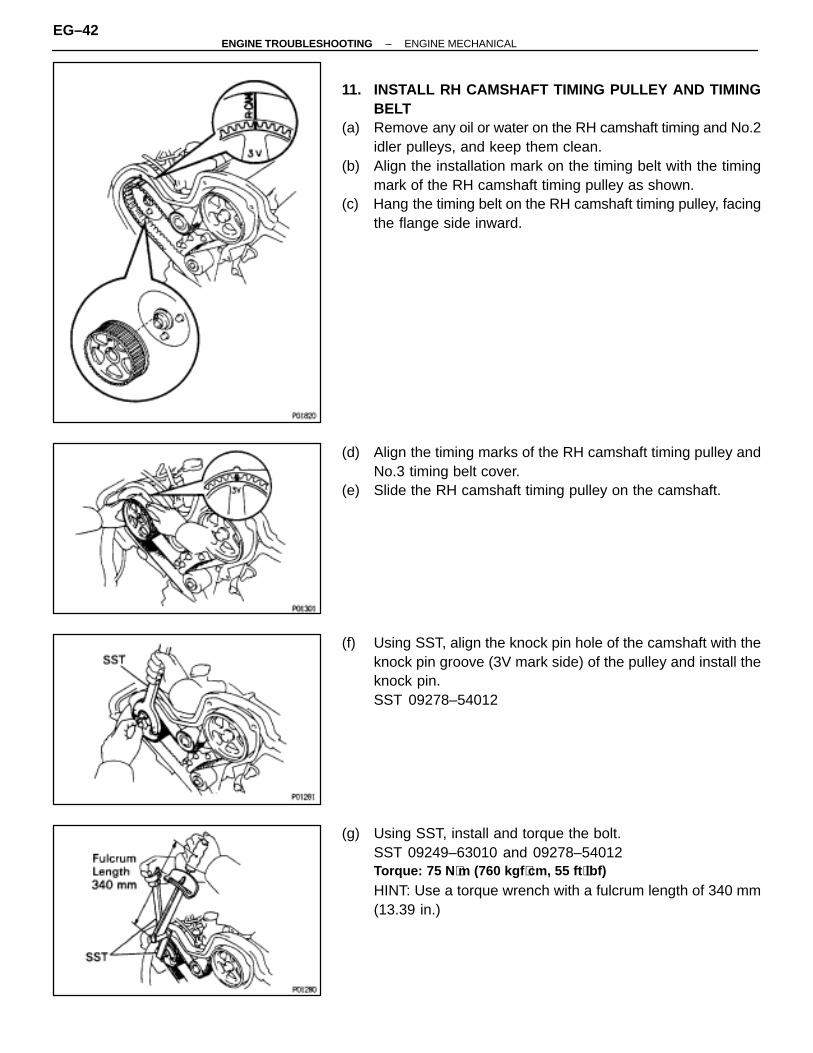
11. INSTALL RH CAMSHAFT TIMING PULLEY AND TIMINGBELT
(a) Remove any oil or water on the RH camshaft timing and No.2idler pulleys, and keep them clean.
(b) Align the installation mark on the timing belt with the timingmark of the RH camshaft timing pulley as shown.
(c) Hang the timing belt on the RH camshaft timing pulley, facingthe flange side inward.
(d) Align the timing marks of the RH camshaft timing pulley andNo.3 timing belt cover.
(e) Slide the RH camshaft timing pulley on the camshaft.
(f) Using SST, align the knock pin hole of the camshaft with theknock pin groove (3V mark side) of the pulley and install theknock pin.SST 09278–54012
(g) Using SST, install and torque the bolt.SST 09249–63010 and 09278–54012Torque: 75 N ⋅m (760 kgf ⋅cm, 55 ft ⋅lbf)
HINT: Use a torque wrench with a fulcrum length of 340 mm(13.39 in.)
EG–42–ENGINE TROUBLESHOOTING ENGINE MECHANICAL
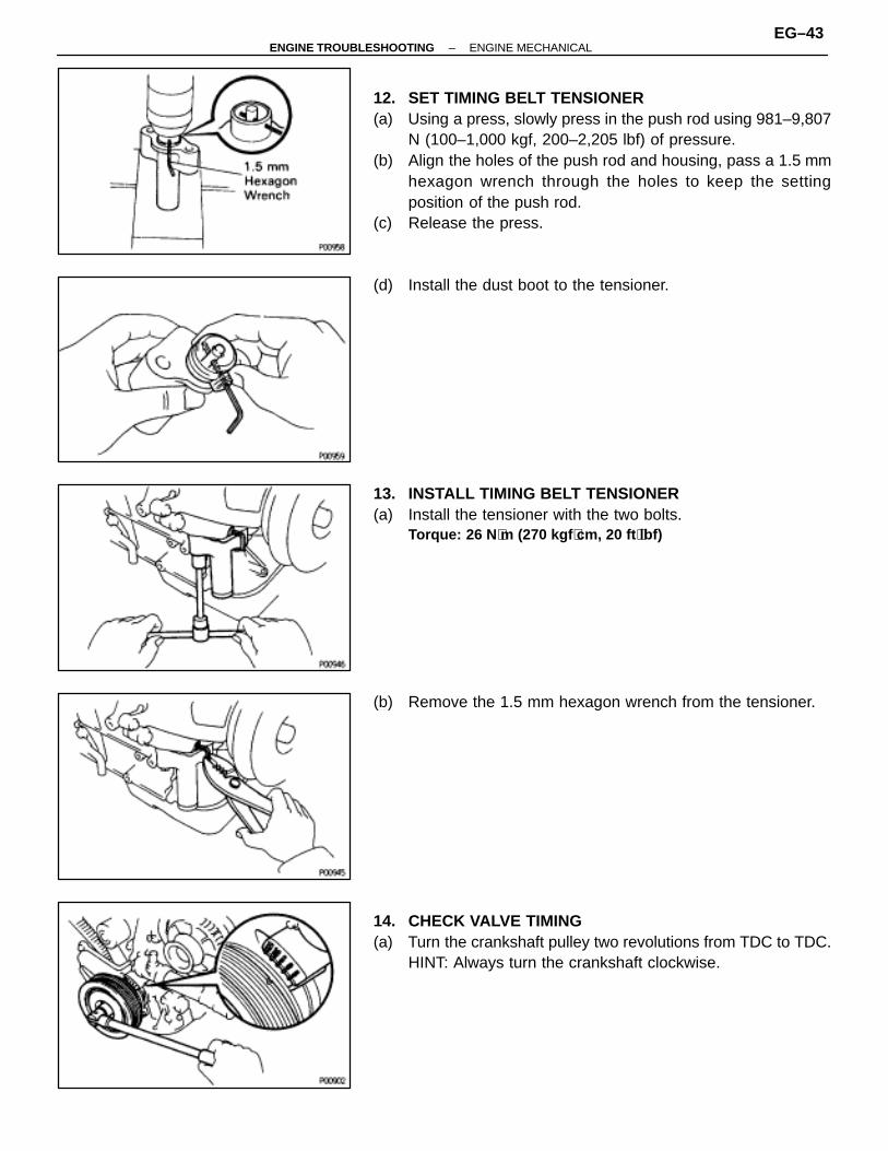
12. SET TIMING BELT TENSIONER(a) Using a press, slowly press in the push rod using 981–9,807
N (100–1,000 kgf, 200–2,205 lbf) of pressure.(b) Align the holes of the push rod and housing, pass a 1.5 mm
hexagon wrench through the holes to keep the settingposition of the push rod.
(c) Release the press.
(d) Install the dust boot to the tensioner.
13. INSTALL TIMING BELT TENSIONER(a) Install the tensioner with the two bolts.
Torque: 26 N ⋅m (270 kgf ⋅cm, 20 ft ⋅lbf)
(b) Remove the 1.5 mm hexagon wrench from the tensioner.
14. CHECK VALVE TIMING(a) Turn the crankshaft pulley two revolutions from TDC to TDC.
HINT: Always turn the crankshaft clockwise.
–ENGINE TROUBLESHOOTING ENGINE MECHANICALEG–43

(b) CHeck that each pulley aligns with the timing marks as shownin the illustration.If the marks do not align, remove the timing belt and reinstallit.
15. INSTALL ENGINE RH MOUNTING BRACKETInstall the mounting bracket with the three bolt.Torque: 39 N ⋅m (410 kgf ⋅cm, 30 ft ⋅lbf)
16. INSTALL NO.2 TIMING BELT COVER(a) Install the gasket to the timing belt cover.(b) Install the timing belt cover with the eight bolts.
HINT: Use the bolts indicated by A, B and C.
17. INSTALL SPARK PLUGSTorque: 18 N ⋅m (180 kgf ⋅cm, 13 ft ⋅lbf)
18. INSTALL PS OIL RESERVOIR TANK
19. INSTALL NO.2 RH ENGINE MOUNTING BRACKET ANDENGINE MOVING CONTROL ROD
(a) Temporarily install the No.2 RH engine mounting bracket andengine moving control rod with the three bolts in thesequence shown.
EG–44–ENGINE TROUBLESHOOTING ENGINE MECHANICAL
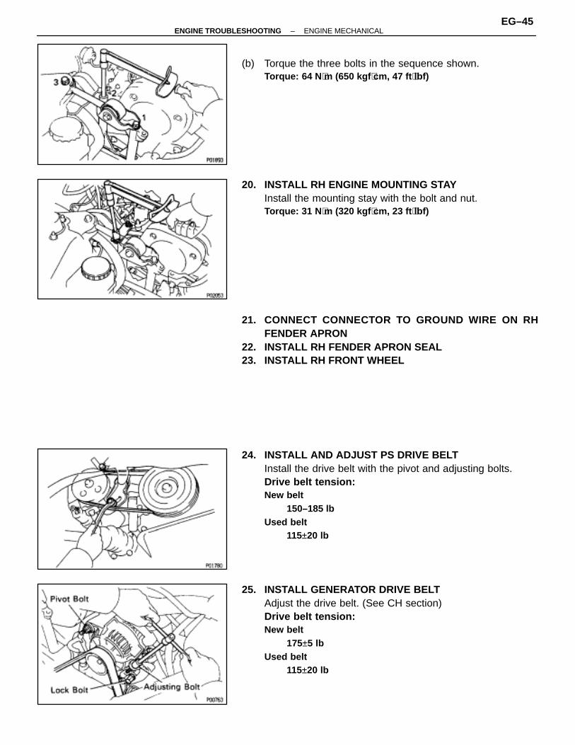
(b) Torque the three bolts in the sequence shown.Torque: 64 N ⋅m (650 kgf ⋅cm, 47 ft ⋅lbf)
20. INSTALL RH ENGINE MOUNTING STAYInstall the mounting stay with the bolt and nut.Torque: 31 N ⋅m (320 kgf ⋅cm, 23 ft ⋅lbf)
21. CONNECT CONNECTOR TO GROUND WIRE ON RHFENDER APRON
22. INSTALL RH FENDER APRON SEAL23. INSTALL RH FRONT WHEEL
24. INSTALL AND ADJUST PS DRIVE BELTInstall the drive belt with the pivot and adjusting bolts.Drive belt tension:New belt
150–185 lbUsed belt
115±20 lb
25. INSTALL GENERATOR DRIVE BELTAdjust the drive belt. (See CH section)Drive belt tension:New belt
175±5 lbUsed belt
115±20 lb
–ENGINE TROUBLESHOOTING ENGINE MECHANICALEG–45
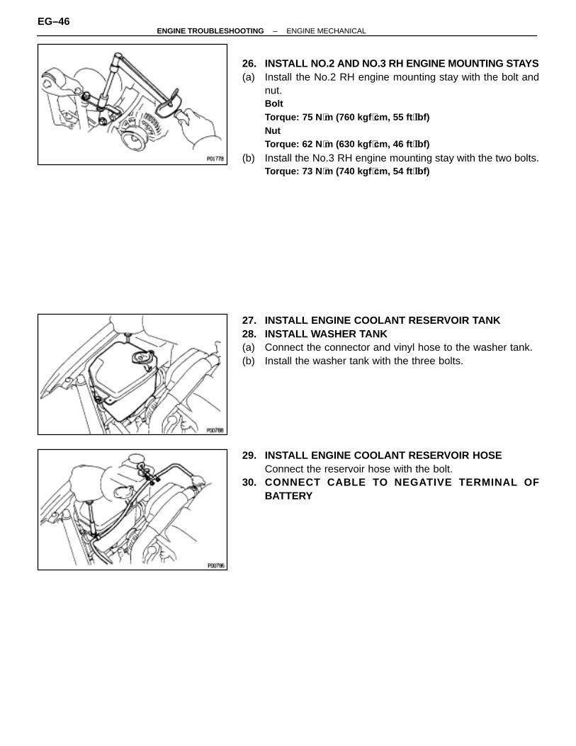
26. INSTALL NO.2 AND NO.3 RH ENGINE MOUNTING STAYS(a) Install the No.2 RH engine mounting stay with the bolt and
nut.BoltTorque: 75 N ⋅m (760 kgf ⋅cm, 55 ft ⋅lbf)NutTorque: 62 N ⋅m (630 kgf ⋅cm, 46 ft ⋅lbf)
(b) Install the No.3 RH engine mounting stay with the two bolts.Torque: 73 N ⋅m (740 kgf ⋅cm, 54 ft ⋅lbf)
27. INSTALL ENGINE COOLANT RESERVOIR TANK28. INSTALL WASHER TANK(a) Connect the connector and vinyl hose to the washer tank.(b) Install the washer tank with the three bolts.
29. INSTALL ENGINE COOLANT RESERVOIR HOSEConnect the reservoir hose with the bolt.
30. CONNECT CABLE TO NEGATIVE TERMINAL OFBATTERY
EG–46–ENGINE TROUBLESHOOTING ENGINE MECHANICAL
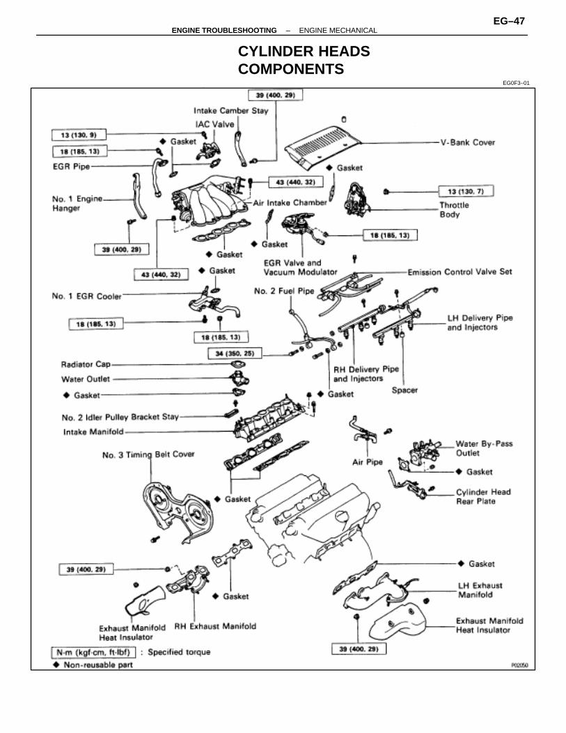
CYLINDER HEADSCOMPONENTS
EG0F3–01
–ENGINE TROUBLESHOOTING ENGINE MECHANICALEG–47
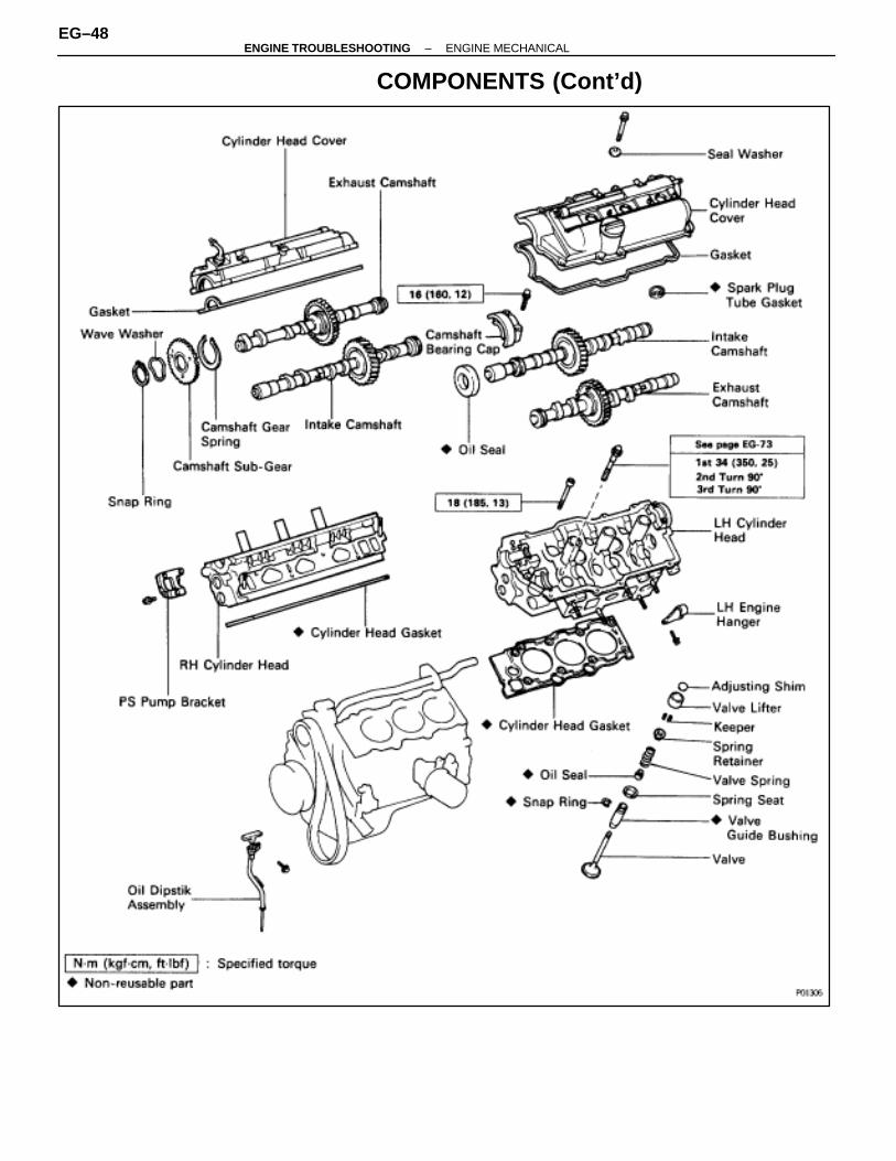
COMPONENTS (Cont’d)
EG–48–ENGINE TROUBLESHOOTING ENGINE MECHANICAL
CYLINDER HEADS REMOVALEG0F4–02
(See page EG–47)1. DISCONNECT CABLE FROM NEGATIVE TERMINAL OF
BATTERYCAUTION (w / Airbag): Work must be started afterapprox. 30 seconds or longer from the time the ignitionswitch is turned to the ”LOCK” position and the negative(–) terminal cable is disconnected from the battery.
2. DRAIN ENGINE COOLANT3. DISCONNECT ACCELERATOR CABLE FROM
THROTTLE BODY4. (A/T)
DISCONNECT THROTTLE CABLE FROM THROTTLEBODY
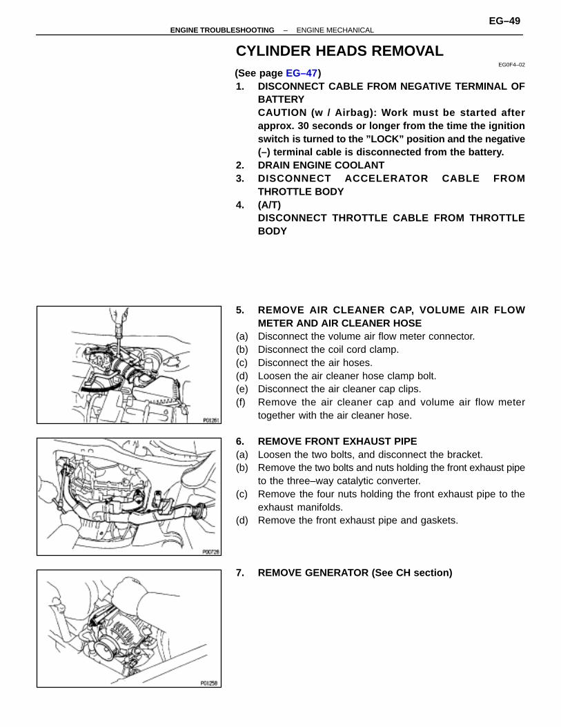
5. REMOVE AIR CLEANER CAP, VOLUME AIR FLOWMETER AND AIR CLEANER HOSE
(a) Disconnect the volume air flow meter connector.(b) Disconnect the coil cord clamp.(c) Disconnect the air hoses.(d) Loosen the air cleaner hose clamp bolt.(e) Disconnect the air cleaner cap clips.(f) Remove the air cleaner cap and volume air flow meter
together with the air cleaner hose.
6. REMOVE FRONT EXHAUST PIPE(a) Loosen the two bolts, and disconnect the bracket.(b) Remove the two bolts and nuts holding the front exhaust pipe
to the three–way catalytic converter.(c) Remove the four nuts holding the front exhaust pipe to the
exhaust manifolds.(d) Remove the front exhaust pipe and gaskets.
7. REMOVE GENERATOR (See CH section)
–ENGINE TROUBLESHOOTING ENGINE MECHANICALEG–49
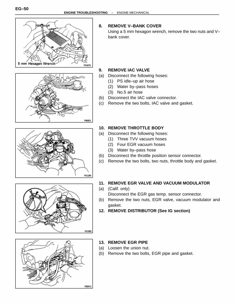
8. REMOVE V–BANK COVERUsing a 5 mm hexagon wrench, remove the two nuts and V–bank cover.
9. REMOVE IAC VALVE(a) Disconnect the following hoses:
(1) PS idle–up air hose(2) Water by–pass hoses(3) No.5 air hose
(b) Disconnect the IAC valve connector.(c) Remove the two bolts, IAC valve and gasket.
10. REMOVE THROTTLE BODY(a) Disconnect the following hoses:
(1) Three TVV vacuum hoses(2) Four EGR vacuum hoses(3) Water by–pass hose
(b) Disconnect the throttle position sensor connector.(c) Remove the two bolts, two nuts, throttle body and gasket.
11. REMOVE EGR VALVE AND VACUUM MODULATOR(a) (Calif. only)
Disconnect the EGR gas temp. sensor connector.(b) Remove the two nuts, EGR valve, vacuum modulator and
gasket.12. REMOVE DISTRIBUTOR (See IG section)
13. REMOVE EGR PIPE(a) Loosen the union nut.(b) Remove the two bolts, EGR pipe and gasket.
EG–50–ENGINE TROUBLESHOOTING ENGINE MECHANICAL
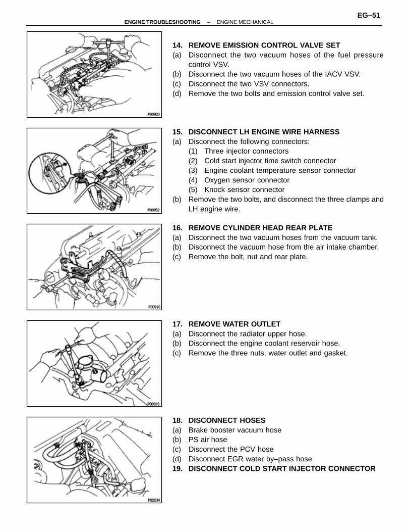
14. REMOVE EMISSION CONTROL VALVE SET(a) Disconnect the two vacuum hoses of the fuel pressure
control VSV.(b) Disconnect the two vacuum hoses of the IACV VSV.(c) Disconnect the two VSV connectors.(d) Remove the two bolts and emission control valve set.
15. DISCONNECT LH ENGINE WIRE HARNESS(a) Disconnect the following connectors:
(1) Three injector connectors(2) Cold start injector time switch connector(3) Engine coolant temperature sensor connector(4) Oxygen sensor connector(5) Knock sensor connector
(b) Remove the two bolts, and disconnect the three clamps andLH engine wire.
16. REMOVE CYLINDER HEAD REAR PLATE(a) Disconnect the two vacuum hoses from the vacuum tank.(b) Disconnect the vacuum hose from the air intake chamber.(c) Remove the bolt, nut and rear plate.
17. REMOVE WATER OUTLET(a) Disconnect the radiator upper hose.(b) Disconnect the engine coolant reservoir hose.(c) Remove the three nuts, water outlet and gasket.
18. DISCONNECT HOSES(a) Brake booster vacuum hose(b) PS air hose(c) Disconnect the PCV hose(d) Disconnect EGR water by–pass hose19. DISCONNECT COLD START INJECTOR CONNECTOR
–ENGINE TROUBLESHOOTING ENGINE MECHANICALEG–51
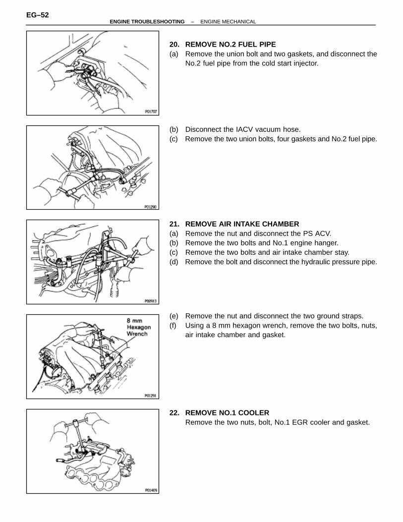
20. REMOVE NO.2 FUEL PIPE(a) Remove the union bolt and two gaskets, and disconnect the
No.2 fuel pipe from the cold start injector.
(b) Disconnect the IACV vacuum hose.(c) Remove the two union bolts, four gaskets and No.2 fuel pipe.
21. REMOVE AIR INTAKE CHAMBER(a) Remove the nut and disconnect the PS ACV.(b) Remove the two bolts and No.1 engine hanger.(c) Remove the two bolts and air intake chamber stay.(d) Remove the bolt and disconnect the hydraulic pressure pipe.
(e) Remove the nut and disconnect the two ground straps.(f) Using a 8 mm hexagon wrench, remove the two bolts, nuts,
air intake chamber and gasket.
22. REMOVE NO.1 COOLERRemove the two nuts, bolt, No.1 EGR cooler and gasket.
EG–52–ENGINE TROUBLESHOOTING ENGINE MECHANICAL
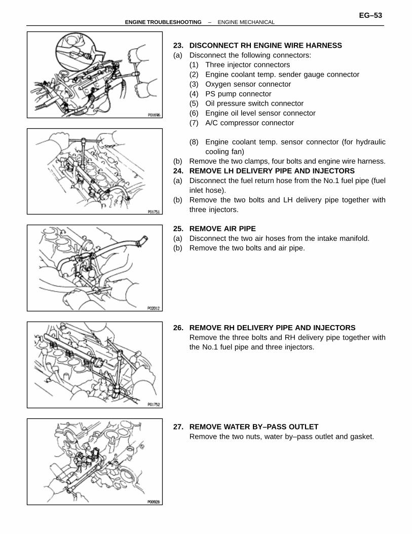
23. DISCONNECT RH ENGINE WIRE HARNESS(a) Disconnect the following connectors:
(1) Three injector connectors(2) Engine coolant temp. sender gauge connector(3) Oxygen sensor connector(4) PS pump connector(5) Oil pressure switch connector(6) Engine oil level sensor connector(7) A/C compressor connector
(8) Engine coolant temp. sensor connector (for hydrauliccooling fan)
(b) Remove the two clamps, four bolts and engine wire harness.24. REMOVE LH DELIVERY PIPE AND INJECTORS(a) Disconnect the fuel return hose from the No.1 fuel pipe (fuel
inlet hose).(b) Remove the two bolts and LH delivery pipe together with
three injectors.
25. REMOVE AIR PIPE(a) Disconnect the two air hoses from the intake manifold.(b) Remove the two bolts and air pipe.
26. REMOVE RH DELIVERY PIPE AND INJECTORSRemove the three bolts and RH delivery pipe together withthe No.1 fuel pipe and three injectors.
27. REMOVE WATER BY–PASS OUTLETRemove the two nuts, water by–pass outlet and gasket.
–ENGINE TROUBLESHOOTING ENGINE MECHANICALEG–53
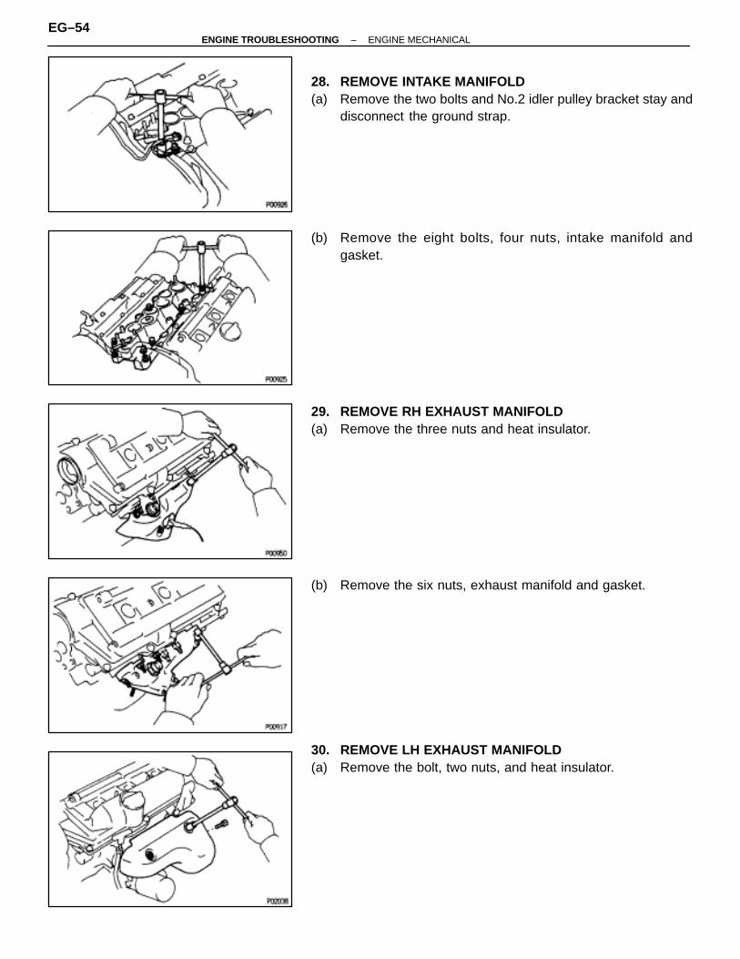
28. REMOVE INTAKE MANIFOLD(a) Remove the two bolts and No.2 idler pulley bracket stay and
disconnect the ground strap.
(b) Remove the eight bolts, four nuts, intake manifold andgasket.
29. REMOVE RH EXHAUST MANIFOLD(a) Remove the three nuts and heat insulator.
(b) Remove the six nuts, exhaust manifold and gasket.
30. REMOVE LH EXHAUST MANIFOLD(a) Remove the bolt, two nuts, and heat insulator.
EG–54–ENGINE TROUBLESHOOTING ENGINE MECHANICAL

(b) Remove the six nuts, exhaust manifold and gasket.
31. REMOVE OIL DIPSTICK ASSEMBLYRemove the bolt and oil dipstick assembly.
32. REMOVE SPARK PLUGS33. REMOVE TIMING BELT, CAMSHAFT TIMING PULLEYS
AND NO.2 IDLER PULLEY(See page EG–29)
34. REMOVE No.3 TIMING BELT COVERRemove the six bolts and timing belt cover.NOTICE:• Support the belt, so the meshing of the crankshaft timing
pulley and timing belt does not shift.• Be careful not to drop anything inside of the timing belt
cover.• Do not allow the belt to come into contact with oil, water
or dust.
35. REMOVE CYLINDER HEAD COVERSRemove the eight nuts, seal washers, cylinder head coverand gasket. Remove the two cylinder head covers.
36. REMOVE CAMSHAFTSNOTICE: Since the thrust clearance of the camshaft issmall, the camshaft must be held level while it is beingremoved. If the camshaft is not kept level, the portion ofthe cylinder head receiving the shaft thrust may crack orbe damaged, causing the camshaft to seize or break. Toavoid this, the following steps should be carried out.
–ENGINE TROUBLESHOOTING ENGINE MECHANICALEG–55
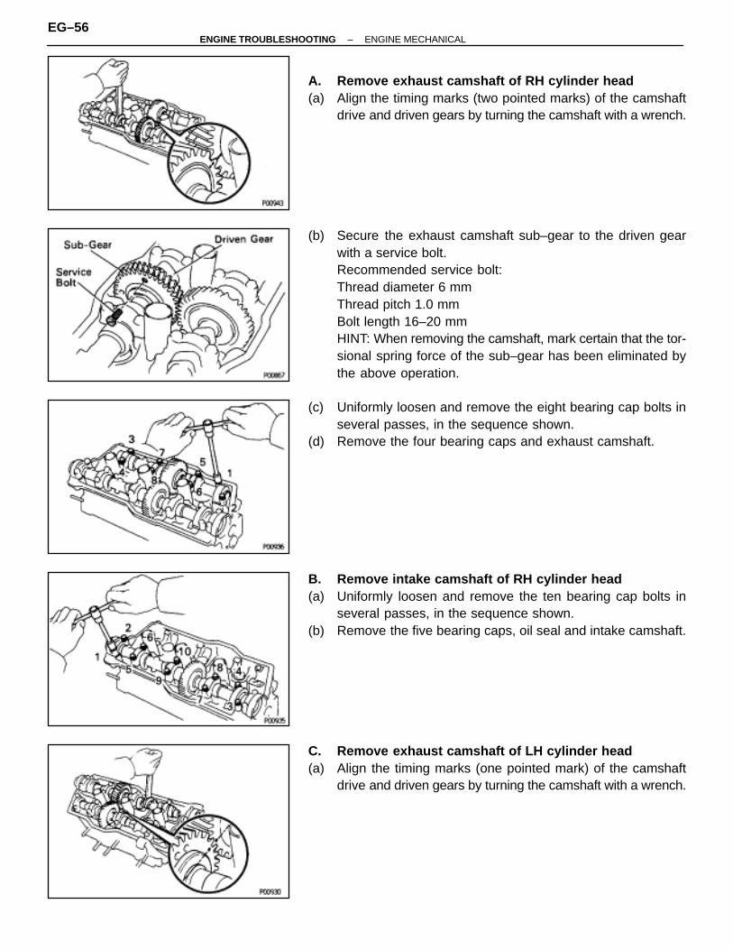
A. Remove exhaust camshaft of RH cylinder head(a) Align the timing marks (two pointed marks) of the camshaft
drive and driven gears by turning the camshaft with a wrench.
(b) Secure the exhaust camshaft sub–gear to the driven gearwith a service bolt.Recommended service bolt:Thread diameter 6 mmThread pitch 1.0 mmBolt length 16–20 mmHINT: When removing the camshaft, mark certain that the tor-sional spring force of the sub–gear has been eliminated bythe above operation.
(c) Uniformly loosen and remove the eight bearing cap bolts inseveral passes, in the sequence shown.
(d) Remove the four bearing caps and exhaust camshaft.
B. Remove intake camshaft of RH cylinder head(a) Uniformly loosen and remove the ten bearing cap bolts in
several passes, in the sequence shown.(b) Remove the five bearing caps, oil seal and intake camshaft.
C. Remove exhaust camshaft of LH cylinder head(a) Align the timing marks (one pointed mark) of the camshaft
drive and driven gears by turning the camshaft with a wrench.
EG–56–ENGINE TROUBLESHOOTING ENGINE MECHANICAL
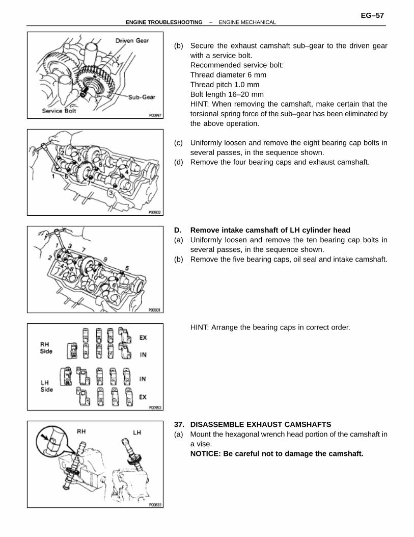
(b) Secure the exhaust camshaft sub–gear to the driven gearwith a service bolt.Recommended service bolt:Thread diameter 6 mmThread pitch 1.0 mmBolt length 16–20 mmHINT: When removing the camshaft, make certain that thetorsional spring force of the sub–gear has been eliminated bythe above operation.
(c) Uniformly loosen and remove the eight bearing cap bolts inseveral passes, in the sequence shown.
(d) Remove the four bearing caps and exhaust camshaft.
D. Remove intake camshaft of LH cylinder head(a) Uniformly loosen and remove the ten bearing cap bolts in
several passes, in the sequence shown.(b) Remove the five bearing caps, oil seal and intake camshaft.
HINT: Arrange the bearing caps in correct order.
37. DISASSEMBLE EXHAUST CAMSHAFTS(a) Mount the hexagonal wrench head portion of the camshaft in
a vise.NOTICE: Be careful not to damage the camshaft.
–ENGINE TROUBLESHOOTING ENGINE MECHANICALEG–57
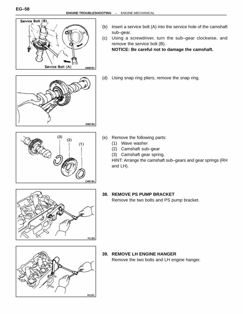
(b) Insert a service bolt (A) into the service hole of the camshaftsub–gear.
(c) Using a screwdriver, turn the sub–gear clockwise, andremove the service bolt (B).NOTICE: Be careful not to damage the camshaft.
(d) Using snap ring pliers, remove the snap ring.
(e) Remove the following parts:(1) Wave washer(2) Camshaft sub–gear(3) Camshaft gear spring.HINT: Arrange the camshaft sub–gears and gear springs (RHand LH).
38. REMOVE PS PUMP BRACKETRemove the two bolts and PS pump bracket.
39. REMOVE LH ENGINE HANGERRemove the two bolts and LH engine hanger.
EG–58–ENGINE TROUBLESHOOTING ENGINE MECHANICAL

40. REMOVE CYLINDER HEADS(a) Using a 8 mm hexagon wrench, remove the cylinder head
(recessed head) bolts.
(b) Uniformly loosen and remove the cylinder head (12 pointedhead) bolts in several passes, in the sequence shown.NOTICE: Head warpage or cracking could result from re-moving bolts in an incorrect order.
(c) Lift the cylinder head from the dowels on the cylinder blockand place the two cylinder heads on wooden blocks on abench.HINT: If the cylinder head is difficult to lift off, pry with a screw-driver between the cylinder head and cylinder block.NOTICE: Be careful not to damage the contact surfacesof the cylinder head and cylinder block.
–ENGINE TROUBLESHOOTING ENGINE MECHANICALEG–59
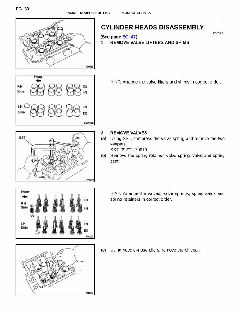
CYLINDER HEADS DISASSEMBLYEG0F5–01
(See page EG–47)1. REMOVE VALVE LIFTERS AND SHIMS
HINT: Arrange the valve lifters and shims in correct order.
2. REMOVE VALVES(a) Using SST, compress the valve spring and remove the two
keepers.SST 09202–70010
(b) Remove the spring retainer, valve spring, valve and springseat.
HINT: Arrange the valves, valve springs, spring seats andspring retainers in correct order.
(c) Using needle–nose pliers, remove the oil seal.
EG–60–ENGINE TROUBLESHOOTING ENGINE MECHANICAL
CYLINDER HEAD COMPONENTSINSPECTION, CLEANING AND REPAIR
EG0F6–01
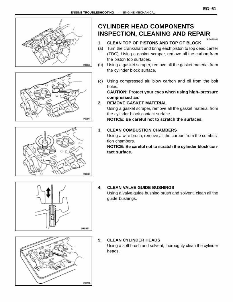
1. CLEAN TOP OF PISTONS AND TOP OF BLOCK(a) Turn the crankshaft and bring each piston to top dead center
(TDC). Using a gasket scraper, remove all the carbon fromthe piston top surfaces.
(b) Using a gasket scraper, remove all the gasket material fromthe cylinder block surface.
(c) Using compressed air, blow carbon and oil from the boltholes.CAUTION: Protect your eyes when using high–pressurecompressed air.
2. REMOVE GASKET MATERIALUsing a gasket scraper, remove all the gasket material fromthe cylinder block contact surface.NOTICE: Be careful not to scratch the surfaces.
3. CLEAN COMBUSTION CHAMBERSUsing a wire brush, remove all the carbon from the combus-tion chambers.NOTICE: Be careful not to scratch the cylinder block con-tact surface.
4. CLEAN VALVE GUIDE BUSHINGSUsing a valve guide bushing brush and solvent, clean all theguide bushings.
5. CLEAN CYLINDER HEADSUsing a soft brush and solvent, thoroughly clean the cylinderheads.
–ENGINE TROUBLESHOOTING ENGINE MECHANICALEG–61

6. INSPECT CYLINDER HEADS FOR FLATNESSUsing precision straight edge and feeler gauge, measure thesurfaces contacting the cylinder block and manifolds for war-page.Maximum warpage:
0.10 mm (0.0039 in.)
If warpage is greater than maximum, replace the cylinderhead.
7. INSPECT CYLINDER HEAD FOR CRACKSUsing a dye penetrant, check the combustion chamber, in-take ports, exhaust ports and cylinder block surface forcracks.If cracked, replace the cylinder head.
8. CLEAN VALVES(a) Using a gasket scraper, chip off any carbon from the valve
head.(b) Using a wire brush, thoroughly clean the valve.
9. INSPECT VALVE STEMS AND GUIDE BUSHINGS(a) Using a caliper gauge, measure the inside diameter of the
guide bushing.Bushing inside diameter:
6.010–6.030 mm (0.2366–0.2374 in.)
EG–62–ENGINE TROUBLESHOOTING ENGINE MECHANICAL
(b) Using a micrometer, measure the diameter of the valve stem.Valve stem diameter:Intake
5.970–5.985 mm (0.2350–0.2356 in.)Exhaust
5.965–5.980 mm (0.2348–0.2354 in.)
(c) Subtract the valve stem diameter measurement from theguide bushing inside diameter measurement.Standard oil clearance:Intake
0.025–0.060 mm (0.0010–0.0024 in.)Exhaust
0.030–0.065 mm (0.0012–0.0026 in.)Maximum oil clearance:Intake
0.08 mm (0.0031 in.)Exhaust
0.10 mm (0.0039 in.)
If the clearance is greater than maximum, replace the valveand guide bushing.
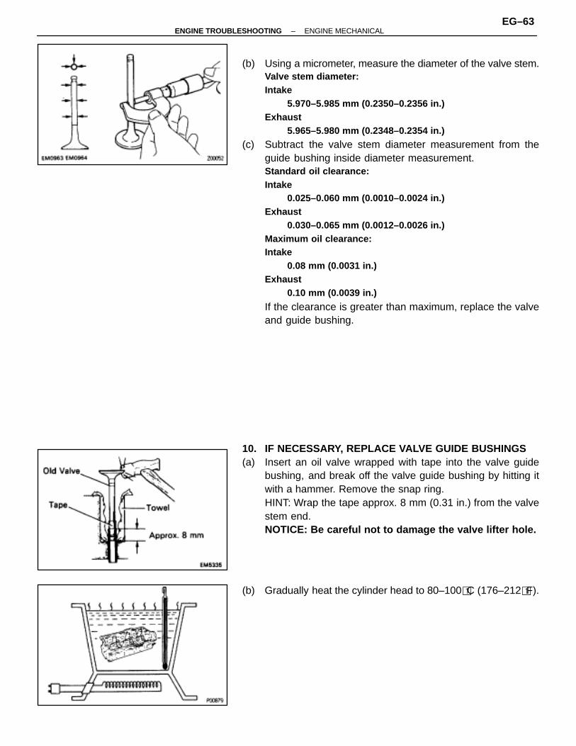
10. IF NECESSARY, REPLACE VALVE GUIDE BUSHINGS(a) Insert an oil valve wrapped with tape into the valve guide
bushing, and break off the valve guide bushing by hitting itwith a hammer. Remove the snap ring.HINT: Wrap the tape approx. 8 mm (0.31 in.) from the valvestem end.NOTICE: Be careful not to damage the valve lifter hole.
(b) Gradually heat the cylinder head to 80–100�C (176–212�F).
–ENGINE TROUBLESHOOTING ENGINE MECHANICALEG–63

(c) Using SST and a hammer, tap out the guide bushing.SST 09201–70010
(d) Using a caliper gauge, measure the bushing bore diameterof the cylinder head.Both intake and exhaust
(e) Select a new guide bushing (STD size or O/S 0.05).
ÑÑÑÑÑÑÑÑÑÑÑÑÑÑÑÑ
Bushing bore diametermm (in.)
ÑÑÑÑÑÑÑÑÑÑÑÑ
Bushing sizeÑÑÑÑÑÑÑÑÑÑÑÑÑÑÑÑ
11.000–11.027Use STDÑÑÑÑÑÑÑÑ
ÑÑÑÑÑÑÑÑ(0.4331–0.4342) Use STD
ÑÑÑÑÑÑÑÑÑÑÑÑÑÑÑÑ
11.050–11.077Use O/S 0 05
ÑÑÑÑÑÑÑÑÑÑÑÑÑÑÑÑ
(0.4350–0.4361) Use O/S 0.05
If the bushing bore diameter of the cylinder head is greaterthan 11.027 mm (0.4341 in.), machine the bushing bore tothe following dimension:11.050–11.077 mm (0.4350–0.4361 in.)
If the bushing bore diameter of the cylinder head is greaterthan 11.077 mm (0.4361 in.), replace the cylinder head.
(f) Gradually heat the cylinder head to 80–100�C (176–212�F).(g) Using SST and a hammer, tap in a new guide bushing until
the snap ring makes contact with the cylinder head.SST 09201–70010
(h) Using a sharp 6 mm reamer, ream the guide bushing to obtainthe standard specified clearance (See page EG–63)between the guide bushing and valve stem.
EG–64–ENGINE TROUBLESHOOTING ENGINE MECHANICAL
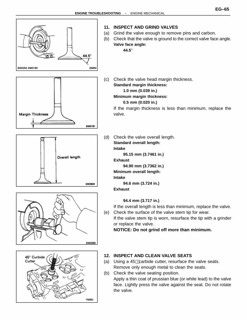
11. INSPECT AND GRIND VALVES(a) Grind the valve enough to remove pins and carbon.(b) Check that the valve is ground to the correct valve face angle.
Valve face angle:44.5°
(c) Check the valve head margin thickness.Standard margin thickness:
1.0 mm (0.039 in.)Minimum margin thickness:
0.5 mm (0.020 in.)
If the margin thickness is less than minimum, replace thevalve.
(d) Check the valve overall length.Standard overall length:Intake
95.15 mm (3.7461 in.)Exhaust
94.90 mm (3.7362 in.)Minimum overall length:Intake
94.6 mm (3.724 in.)Exhaust
94.4 mm (3.717 in.)
If the overall length is less than minimum, replace the valve.(e) Check the surface of the valve stem tip for wear.
If the valve stem tip is worn, resurface the tip with a grinderor replace the valve.NOTICE: Do not grind off more than minimum.
12. INSPECT AND CLEAN VALVE SEATS(a) Using a 45� carbide cutter, resurface the valve seats.
Remove only enough metal to clean the seats.(b) Check the valve seating position.
Apply a thin coat of prussian blue (or white lead) to the valveface. Lightly press the valve against the seat. Do not rotatethe valve.
–ENGINE TROUBLESHOOTING ENGINE MECHANICALEG–65
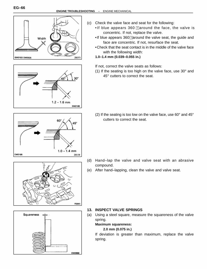
(c) Check the valve face and seat for the following:• If blue appears 360 � around the face, the valve is
concentric. If not, replace the valve.• If blue appears 360� around the valve seat, the guide and
face are concentric. If not, resurface the seat.•Check that the seat contact is in the middle of the valve face
with the following width:1.0–1.4 mm (0.039–0.055 in.)
If not, correct the valve seats as follows:(1) If the seating is too high on the valve face, use 30° and
45° cutters to correct the seat.
(2) If the seating is too low on the valve face, use 60° and 45°cutters to correct the seat.
(d) Hand–lap the valve and valve seat with an abrasivecompound.
(e) After hand–lapping, clean the valve and valve seat.
13. INSPECT VALVE SPRINGS(a) Using a steel square, measure the squareness of the valve
spring.Maximum squareness:
2.0 mm (0.075 in.)
If deviation is greater than maximum, replace the valvespring.
EG–66–ENGINE TROUBLESHOOTING ENGINE MECHANICAL

(b) Using a vernier caliper, measure the free length of the valvespring.Free length:
41.4 mm (1.630 in.)
If the free length is not as specified, replace the valve spring.
(c) Using a spring tester, measure the tension of the valve springat the specified installed length.Installed tension:
186–206 N (19.0–21.0 kgf, 38.4–42.4 lbf) at 33.3 mm(1.311 in.)
If the installed tension is not as specified, replace the valvespring.
14. INSPECT CAMSHAFTS AND BEARINGSA. Inspect camshaft for runout(a) Place the camshaft on V–blocks.(b) Using a dial indicator, measure the circle runout at the center
journal.Maximum circle runout:
0.06 mm (0.0024 in.)
If the circuit runout is greater than maximum, replace thecamshaft.
B. Inspect cam lobesUsing a micrometer, measure the cam lobe height.Standard cam lobe height:Intake
42.160–42.260 mm (1.6598–1.6638 in.)Exhaust
41.960–42.060 mm (1.6520–1.6559 in.)Minimum cam lobe height:Intake
42.01 mm (1.6539 in.)Exhaust
41.81 mm (1.6461 in.)
If the cam lobe height is less than minimum, replace the cam-shaft.
–ENGINE TROUBLESHOOTING ENGINE MECHANICALEG–67

C. Inspect camshaft journalsUsing micrometer, measure the journal diameter.Journal diameter:
26.949–26.965 mm (1.0610–1.0616 in.)
If the journal diameter is not as specified, check the oil clear-ance.
D. Inspect camshaft bearingsCheck the bearings for flaking and scoring.If the bearings are damaged, replace the bearing caps andcylinder head as a set.
E. Inspect camshaft gear springUsing a vernier caliper, measure the free distance betweenthe spring end.Free distance:
18.2–18.8 mm (0.712–0.740 in.)
If the free distance is not as specified, replace the gearspring.
F. Inspect camshaft journal oil clearance(a) Clean the bearing caps and camshaft journals.(b) Place the camshafts on the cylinder head.(c) Lay a strip of Plastigage across each of the camshaft
journals.
(d) Install the bearing caps.(See step 5 on page EG–73)Torque: 16 N ⋅m (160 kgf ⋅cm, 12 ft ⋅lbf)
NOTICE: Do not turn the camshaft.
EG–68–ENGINE TROUBLESHOOTING ENGINE MECHANICAL

(e) Remove the bearing caps.(f) Measure the Plastigage at its widest point.
Standard oil clearance:0.035–0.072 mm (0.0014–0.0028 in.)
Maximum oil clearance:0.10 mm (0.0039 in.)
If the oil clearance is greater than maximum, replace the cam-shaft. If necessary, replace the bearing caps and cylinderhead as a set.
(g) Completely remove the Plastigage.G. Inspect camshaft thrust clearance(a) Install the camshafts.
(See step 5 on page EG–73)
(b) Using a dial indicator, measure the thrust clearance whilemoving the camshaft back and forth.Standard thrust clearance:
0.033–0.080 mm (0.0013–0.0031 in.)Maximum thrust clearance:
0.12 mm (0.0047 in.)
If the thrust clearance is greater than maximum, replace thecamshaft. If necessary, replace the bearing caps and cylin-der head as a set.
H. Inspect camshaft gear backlash(a) Install the camshafts without installing the exhaust camshaft
sub–gear.(See step 5 on page EG–73)
(b) Using a dial indicator, measure the backlash.Standard backlash:
0.020–0.200 mm (0.0008–0.0079 in.)Maximum backlash:
0.30 mm (0.0188 in.)
If the backlash is greater than maximum, replace the cam-shafts.
15. INSPECT VALVE LIFTERS AND LIFTER BORES(a) Using a caliper gauge, measure the lifter bore diameter of the
cylinder head.Lifter bore diameter:
31.000–31.018 mm (1.2204–1.2212 in.)
–ENGINE TROUBLESHOOTING ENGINE MECHANICALEG–69
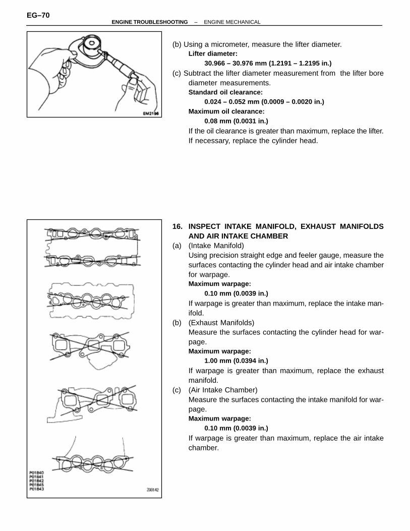
(b) Using a micrometer, measure the lifter diameter.Lifter diameter:
30.966 – 30.976 mm (1.2191 – 1.2195 in.)
(c) Subtract the lifter diameter measurement from the lifter borediameter measurements.Standard oil clearance:
0.024 – 0.052 mm (0.0009 – 0.0020 in.)Maximum oil clearance:
0.08 mm (0.0031 in.)
If the oil clearance is greater than maximum, replace the lifter.If necessary, replace the cylinder head.
16. INSPECT INTAKE MANIFOLD, EXHAUST MANIFOLDSAND AIR INTAKE CHAMBER
(a) (Intake Manifold)Using precision straight edge and feeler gauge, measure thesurfaces contacting the cylinder head and air intake chamberfor warpage.Maximum warpage:
0.10 mm (0.0039 in.)
If warpage is greater than maximum, replace the intake man-ifold.
(b) (Exhaust Manifolds)Measure the surfaces contacting the cylinder head for war-page.Maximum warpage:
1.00 mm (0.0394 in.)
If warpage is greater than maximum, replace the exhaustmanifold.
(c) (Air Intake Chamber)Measure the surfaces contacting the intake manifold for war-page.Maximum warpage:
0.10 mm (0.0039 in.)
If warpage is greater than maximum, replace the air intakechamber.
EG–70–ENGINE TROUBLESHOOTING ENGINE MECHANICAL
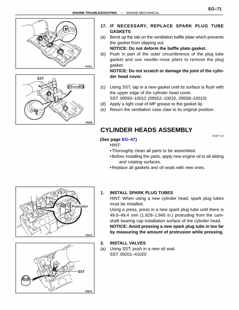
17. IF NECESSARY, REPLACE SPARK PLUG TUBEGASKETS
(a) Bend up the tab on the ventilation baffle plate which preventsthe gasket from slipping out.NOTICE: Do not deform the baffle plate gasket.
(b) Push in part of the outer circumference of the plug tubegasket and use needle–nose pliers to remove the pluggasket.NOTICE: Do not scratch or damage the joint of the cylin-der head cover.
(c) Using SST, tap in a new gasket until its surface is flush withthe upper edge of the cylinder head cover.SST 09550–10012 (09552–10010, 09558–10010)
(d) Apply a light coat of MP grease to the gasket lip.(e) Return the ventilation case claw to its original position.
CYLINDER HEADS ASSEMBLYEG0F7–02
(See page EG–47)HINT:•Thoroughly clean all parts to be assembled.•Before installing the parts, apply new engine oil to all sliding
and rotating surfaces.•Replace all gaskets and oil seals with new ones.
1. INSTALL SPARK PLUG TUBESHINT: When using a new cylinder head, spark plug tubesmust be installed.Using a press, press in a new spark plug tube until there is49.0–49.4 mm (1.929–1.945 in.) protruding from the cam-shaft bearing cap installation surface of the cylinder head.NOTICE: Avoid pressing a new spark plug tube in too farby measuring the amount of protrusion while pressing.
2. INSTALL VALVES(a) Using SST, push in a new oil seal.
SST 09201–41020
–ENGINE TROUBLESHOOTING ENGINE MECHANICALEG–71
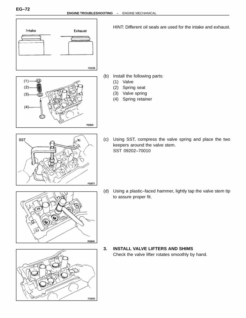
HINT: Different oil seals are used for the intake and exhaust.
(b) Install the following parts:(1) Valve(2) Spring seat(3) Valve spring(4) Spring retainer
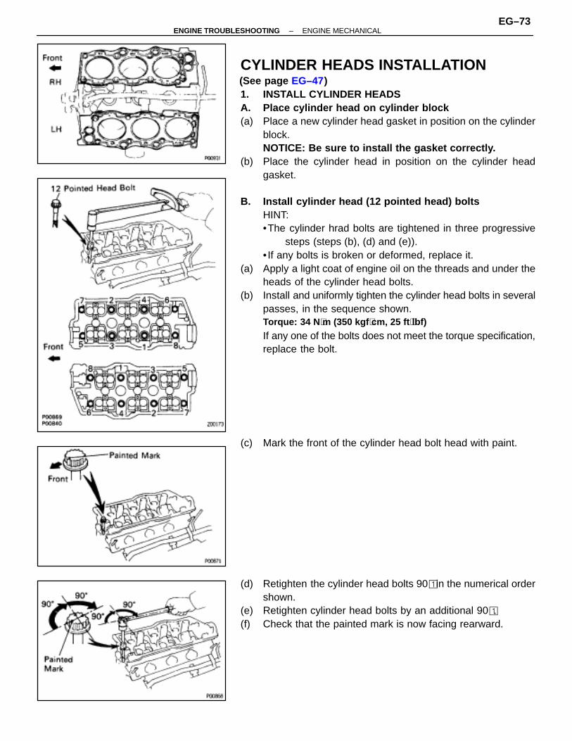
(c) Using SST, compress the valve spring and place the twokeepers around the valve stem.SST 09202–70010
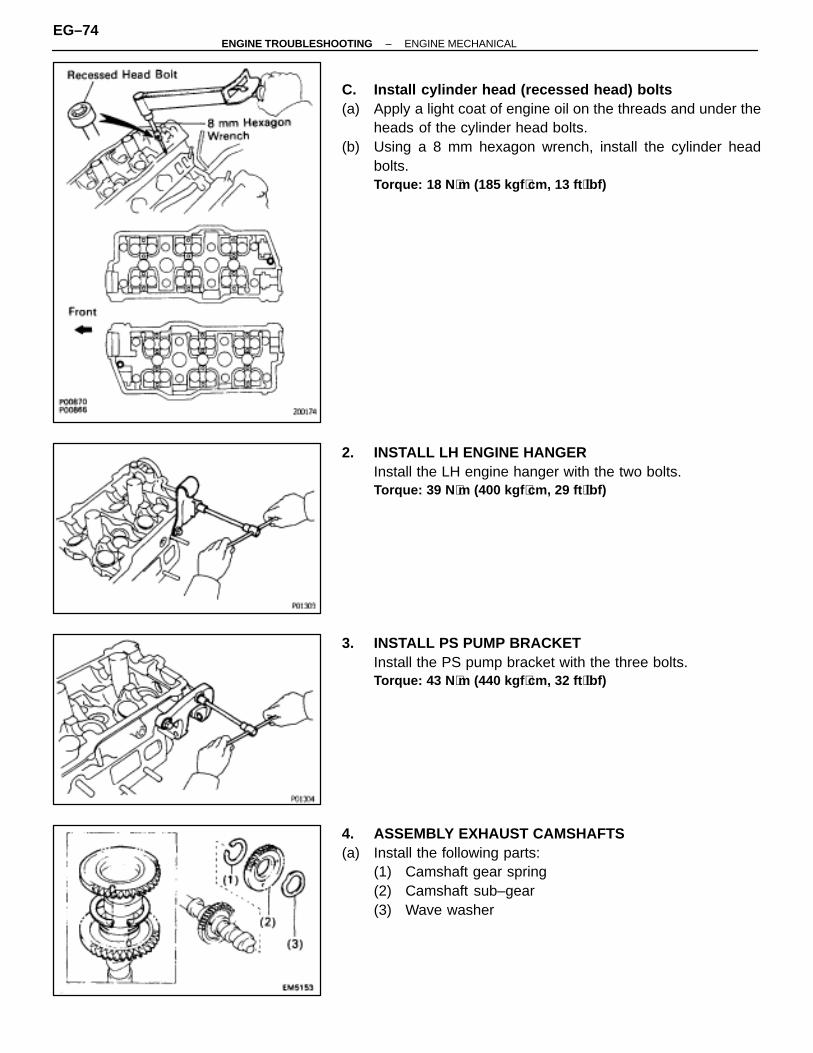
(d) Using a plastic–faced hammer, lightly tap the valve stem tipto assure proper fit.
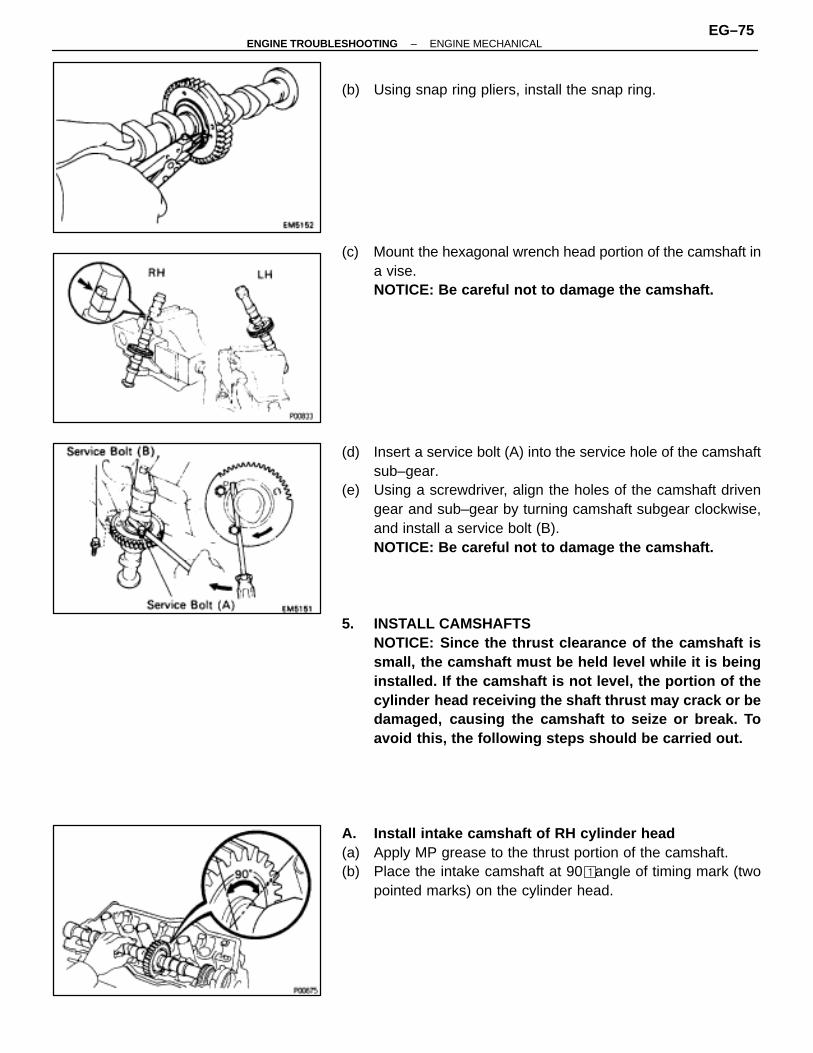
3. INSTALL VALVE LIFTERS AND SHIMSCheck the valve lifter rotates smoothly by hand.
EG–72–ENGINE TROUBLESHOOTING ENGINE MECHANICAL
CYLINDER HEADS INSTALLATION(See page EG–47)1. INSTALL CYLINDER HEADSA. Place cylinder head on cylinder block(a) Place a new cylinder head gasket in position on the cylinder
block.NOTICE: Be sure to install the gasket correctly.
(b) Place the cylinder head in position on the cylinder headgasket.
B. Install cylinder head (12 pointed head) boltsHINT:•The cylinder hrad bolts are tightened in three progressive
steps (steps (b), (d) and (e)).• If any bolts is broken or deformed, replace it.
(a) Apply a light coat of engine oil on the threads and under theheads of the cylinder head bolts.
(b) Install and uniformly tighten the cylinder head bolts in severalpasses, in the sequence shown.Torque: 34 N ⋅m (350 kgf ⋅cm, 25 ft ⋅lbf)
If any one of the bolts does not meet the torque specification,replace the bolt.
(c) Mark the front of the cylinder head bolt head with paint.
(d) Retighten the cylinder head bolts 90� in the numerical ordershown.
(e) Retighten cylinder head bolts by an additional 90�.(f) Check that the painted mark is now facing rearward.
–ENGINE TROUBLESHOOTING ENGINE MECHANICALEG–73
C. Install cylinder head (recessed head) bolts(a) Apply a light coat of engine oil on the threads and under the
heads of the cylinder head bolts.(b) Using a 8 mm hexagon wrench, install the cylinder head
bolts.Torque: 18 N ⋅m (185 kgf ⋅cm, 13 ft ⋅lbf)
2. INSTALL LH ENGINE HANGERInstall the LH engine hanger with the two bolts.Torque: 39 N ⋅m (400 kgf ⋅cm, 29 ft ⋅lbf)
3. INSTALL PS PUMP BRACKETInstall the PS pump bracket with the three bolts.Torque: 43 N ⋅m (440 kgf ⋅cm, 32 ft ⋅lbf)
4. ASSEMBLY EXHAUST CAMSHAFTS(a) Install the following parts:
(1) Camshaft gear spring(2) Camshaft sub–gear(3) Wave washer
EG–74–ENGINE TROUBLESHOOTING ENGINE MECHANICAL
(b) Using snap ring pliers, install the snap ring.
(c) Mount the hexagonal wrench head portion of the camshaft ina vise.NOTICE: Be careful not to damage the camshaft.
(d) Insert a service bolt (A) into the service hole of the camshaftsub–gear.
(e) Using a screwdriver, align the holes of the camshaft drivengear and sub–gear by turning camshaft subgear clockwise,and install a service bolt (B).NOTICE: Be careful not to damage the camshaft.
5. INSTALL CAMSHAFTSNOTICE: Since the thrust clearance of the camshaft issmall, the camshaft must be held level while it is beinginstalled. If the camshaft is not level, the portion of thecylinder head receiving the shaft thrust may crack or bedamaged, causing the camshaft to seize or break. Toavoid this, the following steps should be carried out.
A. Install intake camshaft of RH cylinder head(a) Apply MP grease to the thrust portion of the camshaft.(b) Place the intake camshaft at 90� angle of timing mark (two
pointed marks) on the cylinder head.
–ENGINE TROUBLESHOOTING ENGINE MECHANICALEG–75
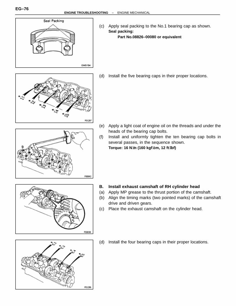
(c) Apply seal packing to the No.1 bearing cap as shown.Seal packing:
Part No.08826–00080 or equivalent
(d) Install the five bearing caps in their proper locations.
(e) Apply a light coat of engine oil on the threads and under theheads of the bearing cap bolts.
(f) Install and uniformly tighten the ten bearing cap bolts inseveral passes, in the sequence shown.Torque: 16 N ⋅m (160 kgf ⋅cm, 12 ft ⋅lbf)
B. Install exhaust camshaft of RH cylinder head(a) Apply MP grease to the thrust portion of the camshaft.(b) Align the timing marks (two pointed marks) of the camshaft
drive and driven gears.(c) Place the exhaust camshaft on the cylinder head.
(d) Install the four bearing caps in their proper locations.
EG–76–ENGINE TROUBLESHOOTING ENGINE MECHANICAL
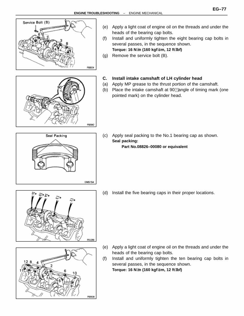
(e) Apply a light coat of engine oil on the threads and under theheads of the bearing cap bolts.
(f) Install and uniformly tighten the eight bearing cap bolts inseveral passes, in the sequence shown.Torque: 16 N ⋅m (160 kgf ⋅cm, 12 ft ⋅lbf)
(g) Remove the service bolt (B).
C. Install intake camshaft of LH cylinder head(a) Apply MP grease to the thrust portion of the camshaft.(b) Place the intake camshaft at 90� angle of timing mark (one
pointed mark) on the cylinder head.
(c) Apply seal packing to the No.1 bearing cap as shown.Seal packing:
Part No.08826–00080 or equivalent
(d) Install the five bearing caps in their proper locations.
(e) Apply a light coat of engine oil on the threads and under theheads of the bearing cap bolts.
(f) Install and uniformly tighten the ten bearing cap bolts inseveral passes, in the sequence shown.Torque: 16 N ⋅m (160 kgf ⋅cm, 12 ft ⋅lbf)
–ENGINE TROUBLESHOOTING ENGINE MECHANICALEG–77
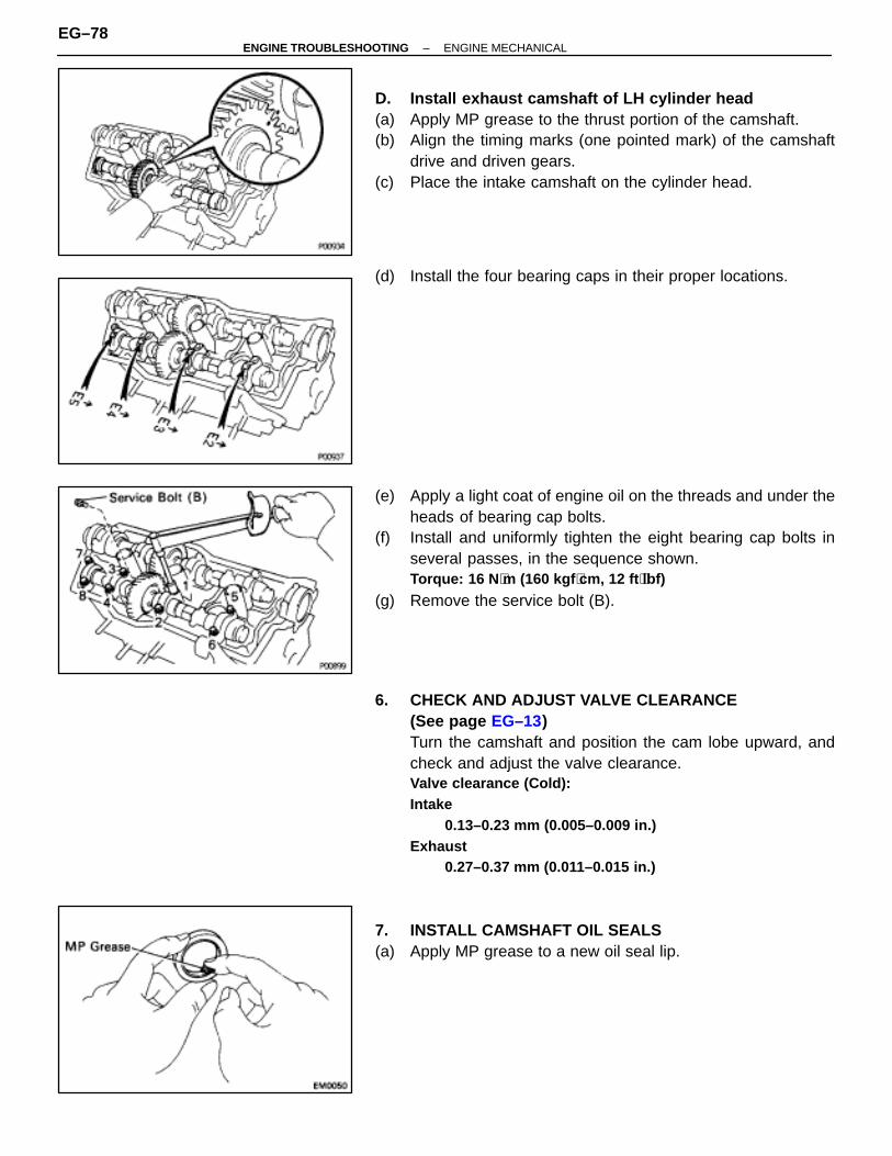
D. Install exhaust camshaft of LH cylinder head(a) Apply MP grease to the thrust portion of the camshaft.(b) Align the timing marks (one pointed mark) of the camshaft
drive and driven gears.(c) Place the intake camshaft on the cylinder head.
(d) Install the four bearing caps in their proper locations.
(e) Apply a light coat of engine oil on the threads and under theheads of bearing cap bolts.
(f) Install and uniformly tighten the eight bearing cap bolts inseveral passes, in the sequence shown.Torque: 16 N ⋅m (160 kgf ⋅cm, 12 ft ⋅lbf)
(g) Remove the service bolt (B).
6. CHECK AND ADJUST VALVE CLEARANCE(See page EG–13)Turn the camshaft and position the cam lobe upward, andcheck and adjust the valve clearance.Valve clearance (Cold):Intake
0.13–0.23 mm (0.005–0.009 in.)Exhaust
0.27–0.37 mm (0.011–0.015 in.)
7. INSTALL CAMSHAFT OIL SEALS(a) Apply MP grease to a new oil seal lip.
EG–78–ENGINE TROUBLESHOOTING ENGINE MECHANICAL
(b) Using SST, tap in the oil seals.SST 09223–46011
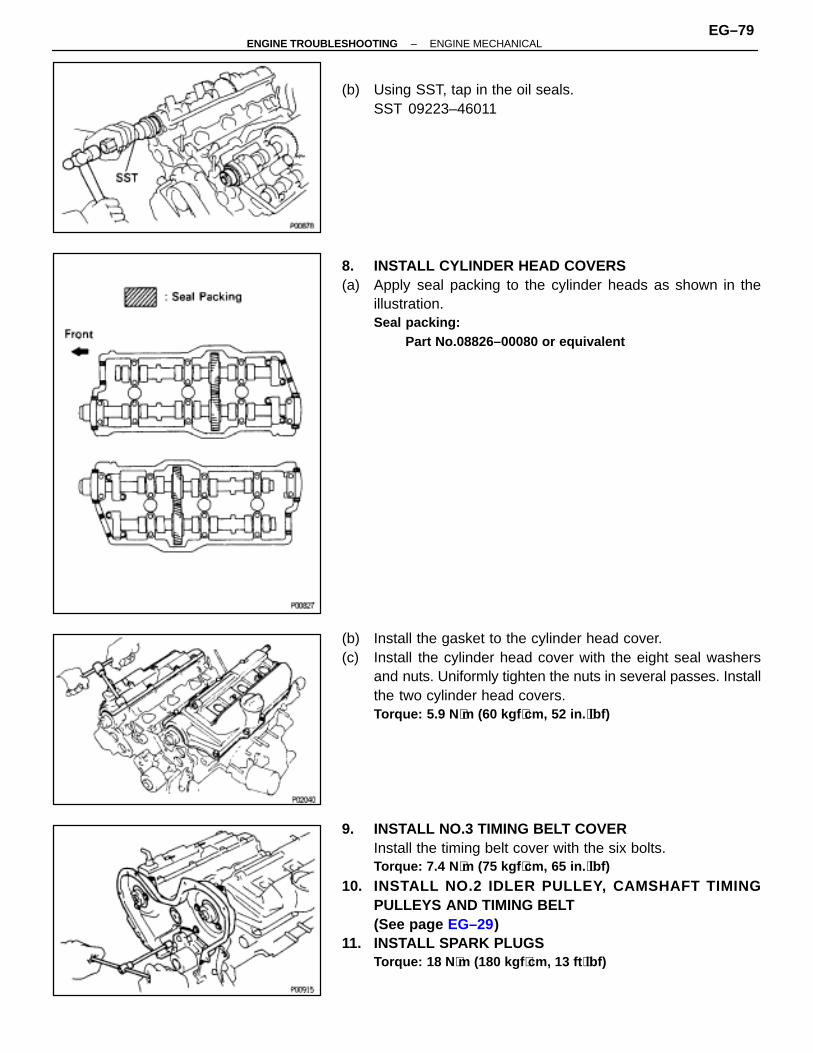
8. INSTALL CYLINDER HEAD COVERS(a) Apply seal packing to the cylinder heads as shown in the
illustration.Seal packing:
Part No.08826–00080 or equivalent
(b) Install the gasket to the cylinder head cover.(c) Install the cylinder head cover with the eight seal washers
and nuts. Uniformly tighten the nuts in several passes. Installthe two cylinder head covers.Torque: 5.9 N ⋅m (60 kgf ⋅cm, 52 in. ⋅lbf)
9. INSTALL NO.3 TIMING BELT COVERInstall the timing belt cover with the six bolts.Torque: 7.4 N ⋅m (75 kgf ⋅cm, 65 in. ⋅lbf)
10. INSTALL NO.2 IDLER PULLEY, CAMSHAFT TIMINGPULLEYS AND TIMING BELT(See page EG–29)
11. INSTALL SPARK PLUGSTorque: 18 N ⋅m (180 kgf ⋅cm, 13 ft ⋅lbf)
–ENGINE TROUBLESHOOTING ENGINE MECHANICALEG–79
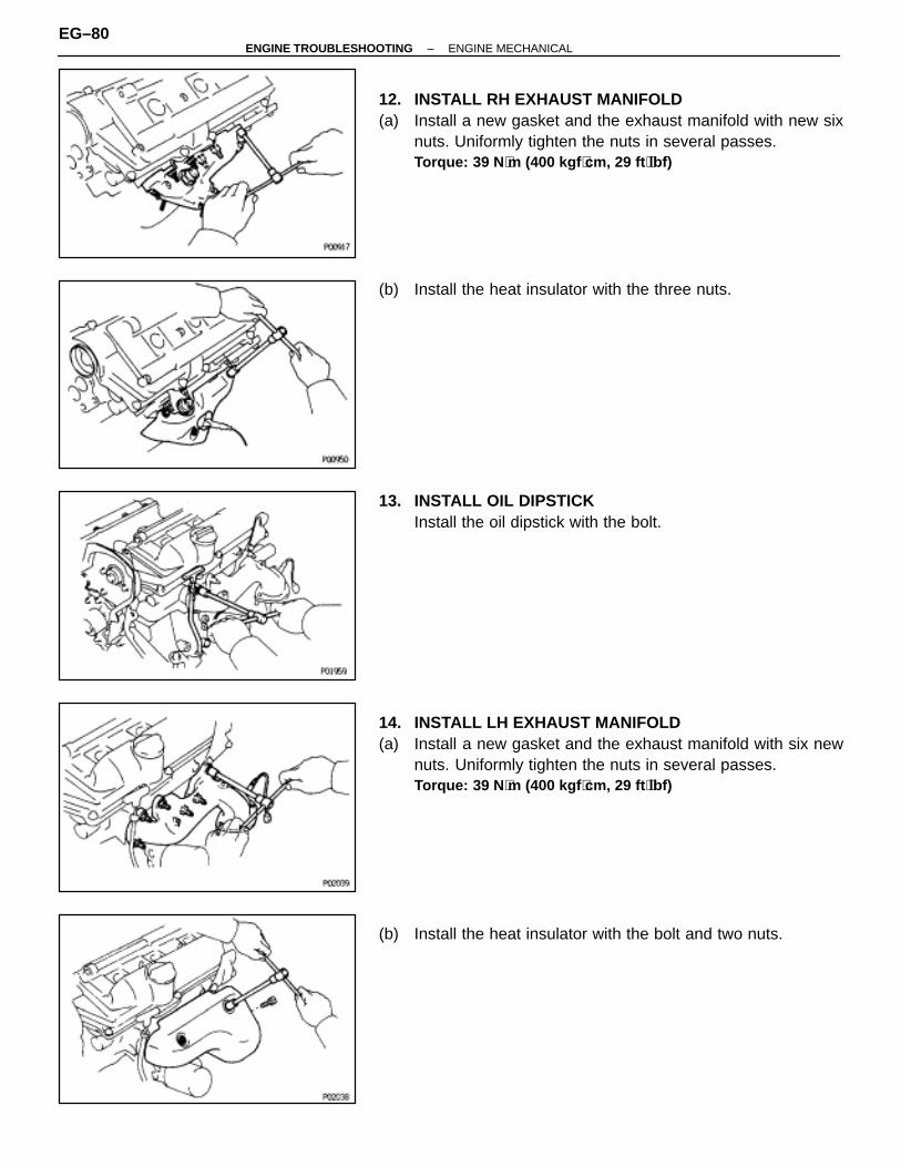
12. INSTALL RH EXHAUST MANIFOLD(a) Install a new gasket and the exhaust manifold with new six
nuts. Uniformly tighten the nuts in several passes.Torque: 39 N ⋅m (400 kgf ⋅cm, 29 ft ⋅lbf)
(b) Install the heat insulator with the three nuts.
13. INSTALL OIL DIPSTICKInstall the oil dipstick with the bolt.
14. INSTALL LH EXHAUST MANIFOLD(a) Install a new gasket and the exhaust manifold with six new
nuts. Uniformly tighten the nuts in several passes.Torque: 39 N ⋅m (400 kgf ⋅cm, 29 ft ⋅lbf)
(b) Install the heat insulator with the bolt and two nuts.
EG–80–ENGINE TROUBLESHOOTING ENGINE MECHANICAL
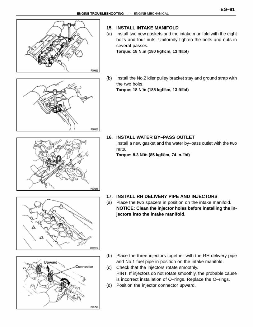
15. INSTALL INTAKE MANIFOLD(a) Install two new gaskets and the intake manifold with the eight
bolts and four nuts. Uniformly tighten the bolts and nuts inseveral passes.Torque: 18 N ⋅m (180 kgf ⋅cm, 13 ft ⋅lbf)
(b) Install the No.2 idler pulley bracket stay and ground strap withthe two bolts.Torque: 18 N ⋅m (185 kgf ⋅cm, 13 ft ⋅lbf)
16. INSTALL WATER BY–PASS OUTLETInstall a new gasket and the water by–pass outlet with the twonuts.Torque: 8.3 N ⋅m (85 kgf ⋅cm, 74 in. ⋅lbf)
17. INSTALL RH DELIVERY PIPE AND INJECTORS(a) Place the two spacers in position on the intake manifold.
NOTICE: Clean the injector holes before installing the in-jectors into the intake manifold.
(b) Place the three injectors together with the RH delivery pipeand No.1 fuel pipe in position on the intake manifold.
(c) Check that the injectors rotate smoothly.HINT: If injectors do not rotate smoothly, the probable causeis incorrect installation of O–rings. Replace the O–rings.
(d) Position the injector connector upward.
–ENGINE TROUBLESHOOTING ENGINE MECHANICALEG–81
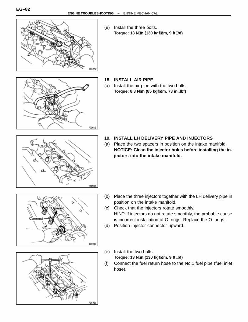
(e) Install the three bolts.Torque: 13 N ⋅m (130 kgf ⋅cm, 9 ft ⋅lbf)
18. INSTALL AIR PIPE(a) Install the air pipe with the two bolts.
Torque: 8.3 N ⋅m (85 kgf ⋅cm, 73 in. ⋅lbf)
19. INSTALL LH DELIVERY PIPE AND INJECTORS(a) Place the two spacers in position on the intake manifold.
NOTICE: Clean the injector holes before installing the in-jectors into the intake manifold.
(b) Place the three injectors together with the LH delivery pipe inposition on the intake manifold.
(c) Check that the injectors rotate smoothly.HINT: If injectors do not rotate smoothly, the probable causeis incorrect installation of O–rings. Replace the O–rings.
(d) Position injector connector upward.
(e) Install the two bolts.Torque: 13 N ⋅m (130 kgf ⋅cm, 9 ft ⋅lbf)
(f) Connect the fuel return hose to the No.1 fuel pipe (fuel inlethose).
EG–82–ENGINE TROUBLESHOOTING ENGINE MECHANICAL
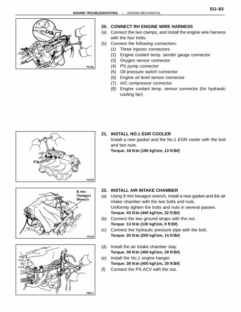
20. CONNECT RH ENGINE WIRE HARNESS(a) Connect the two clamps, and install the engine wire harness
with the four bolts.(b) Connect the following connectors:
(1) Three injector connectors(2) Engine coolant temp. sender gauge connector(3) Oxygen sensor connector(4) PS pump connector(5) Oil pressure switch connector(6) Engine oil level sensor connector(7) A/C compressor connector(8) Engine coolant temp. sensor connector (for hydraulic
cooling fan)
21. INSTALL NO.1 EGR COOLERInstall a new gasket and the No.1 EGR cooler with the boltand two nuts.Torque: 18 N ⋅m (185 kgf ⋅cm, 13 ft ⋅lbf)
22. INSTALL AIR INTAKE CHAMBER(a) Using 8 mm hexagon wrench, install a new gasket and the air
intake chamber with the two bolts and nuts.Uniformly tighten the bolts and nuts in several passes.Torque: 43 N ⋅m (440 kgf ⋅cm, 32 ft ⋅lbf)
(b) Connect the two ground straps with the nut.Torque: 13 N ⋅m (130 kgf ⋅cm, 9 ft ⋅lbf)
(c) Connect the hydraulic pressure pipe with the bolt.Torque: 20 N ⋅m (200 kgf ⋅cm, 14 ft ⋅lbf)
(d) Install the air intake chamber stay.Torque: 39 N ⋅m (400 kgf ⋅cm, 29 ft ⋅lbf)
(e) Install the No.1 engine hanger.Torque: 39 N ⋅m (400 kgf ⋅cm, 29 ft ⋅lbf)
(f) Connect the PS ACV with the nut.
–ENGINE TROUBLESHOOTING ENGINE MECHANICALEG–83
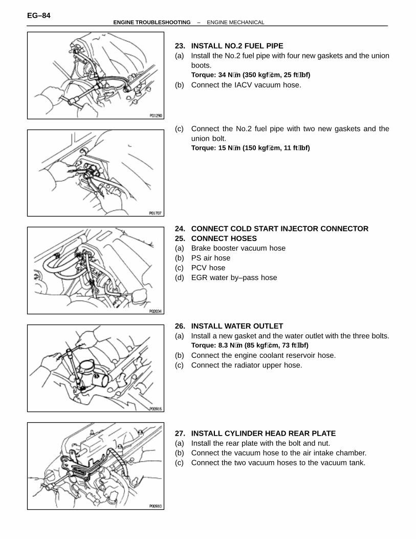
23. INSTALL NO.2 FUEL PIPE(a) Install the No.2 fuel pipe with four new gaskets and the union
boots.Torque: 34 N ⋅m (350 kgf ⋅cm, 25 ft ⋅lbf)
(b) Connect the IACV vacuum hose.
(c) Connect the No.2 fuel pipe with two new gaskets and theunion bolt.Torque: 15 N ⋅m (150 kgf ⋅cm, 11 ft ⋅lbf)
24. CONNECT COLD START INJECTOR CONNECTOR25. CONNECT HOSES(a) Brake booster vacuum hose(b) PS air hose(c) PCV hose(d) EGR water by–pass hose
26. INSTALL WATER OUTLET(a) Install a new gasket and the water outlet with the three bolts.
Torque: 8.3 N ⋅m (85 kgf ⋅cm, 73 ft ⋅lbf)
(b) Connect the engine coolant reservoir hose.(c) Connect the radiator upper hose.
27. INSTALL CYLINDER HEAD REAR PLATE(a) Install the rear plate with the bolt and nut.(b) Connect the vacuum hose to the air intake chamber.(c) Connect the two vacuum hoses to the vacuum tank.
EG–84–ENGINE TROUBLESHOOTING ENGINE MECHANICAL

28. CONNECT LH ENGINE WIRE HARNESS(a) Connect the three clamps of the LH engine wire harness and
install the wire harness with the two bolts.(b) Connect the following connectors:
(1) Three injector connectors(2) Cold start injector time switch connector(3) Engine coolant temperature sensor connector(4) Oxygen sensor connector(5) Knock sensor connector
29. INSTALL EMISSION CONTROL VALVE SET(a) Install the emission control valve set with the two bolts.
Torque: 8.3 N ⋅m (85 kgf ⋅cm, 73 in. ⋅lbf)
(b) Connect the two VSV connectors.(c) Connect the two vacuum hoses to the IACV VSV.(d) Connect the two vacuum hoses to the fuel pressure control
VSV.
30. INSTALL EGR PIPEInstall a new gasket, sleeve ball and the EGR pipe with thetwo bolts and union nut.BoltTorque: 18 N ⋅m (185 kgf ⋅cm, 13 ft ⋅lbf)Union nutTorque: 78 N ⋅m (800 kgf ⋅cm, 58 ft ⋅lbf)
31. INSTALL DISTRIBUTOR (See IG section)
32. INSTALL EGR VALVE AND VACUUM MODULATOR(a) Install a new gasket and the EGR valve and vacuum
modulator with the two nuts.Torque: 18 N ⋅m (185 kgf ⋅cm, 13 ft ⋅lbf)
(b) (Calif. only)Connect the EGR gas temp. sensor connector.
33. INSTALL THROTTLE BODY(a) Install a new gasket and the throttle body with the two bolts
and two nuts.Torque: 13 N ⋅m (130 kgf ⋅cm, 9 ft ⋅lbf)
(b) Connect the throttle position sensor connector.(c) Connect the following hoses:
(1) Three TVV vacuum hoses(2) Four EGR vacuum hoses(3) Water by–pass hose
–ENGINE TROUBLESHOOTING ENGINE MECHANICALEG–85
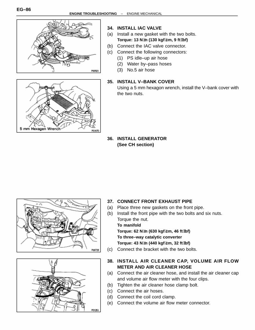
34. INSTALL IAC VALVE(a) Install a new gasket with the two bolts.
Torque: 13 N ⋅m (130 kgf ⋅cm, 9 ft ⋅lbf)
(b) Connect the IAC valve connector.(c) Connect the following connectors:
(1) PS idle–up air hose(2) Water by–pass hoses(3) No.5 air hose
35. INSTALL V–BANK COVERUsing a 5 mm hexagon wrench, install the V–bank cover withthe two nuts.
36. INSTALL GENERATOR(See CH section)
37. CONNECT FRONT EXHAUST PIPE(a) Place three new gaskets on the front pipe.(b) Install the front pipe with the two bolts and six nuts.
Torque the nut.To manifoldTorque: 62 N ⋅m (630 kgf ⋅cm, 46 ft ⋅lbf)To three–way catalytic converterTorque: 43 N ⋅m (440 kgf ⋅cm, 32 ft ⋅lbf)
(c) Connect the bracket with the two bolts.
38. INSTALL AIR CLEANER CAP, VOLUME AIR FLOWMETER AND AIR CLEANER HOSE
(a) Connect the air cleaner hose, and install the air cleaner capand volume air flow meter with the four clips.
(b) Tighten the air cleaner hose clamp bolt.(c) Connect the air hoses.(d) Connect the coil cord clamp.(e) Connect the volume air flow meter connector.
EG–86–ENGINE TROUBLESHOOTING ENGINE MECHANICAL
39. (A/T)CONNECT THROTTLE CABLE, AND ADJUST IT
40. INSTALL ACCELERATOR CABLE, AND ADJUST IT41. FILL WITH ENGINE COOLANT42. CONNECT CABLE TO NEGATIVE TERMINAL OF
BATTERY43. START ENGINE AND CHECK FOR LEAKS44. ADJUST IGNITION TIMING (See IG section)
Ignition timing:10° BTDC @ idle(w/ Terminals TE1 and E1 connected)
45. PERFORM ROAD TESTCheck for abnormal noise, shock, slippage, correct shiftpoints and smooth operation.
46. RECHECK ENGINE COOLANT LEVEL AND OIL LEVEL
–ENGINE TROUBLESHOOTING ENGINE MECHANICALEG–87

CYLINDER BLOCKENGINE REMOVAL
EG0F8–02
EG–88–ENGINE TROUBLESHOOTING ENGINE MECHANICAL

–ENGINE TROUBLESHOOTING ENGINE MECHANICALEG–89
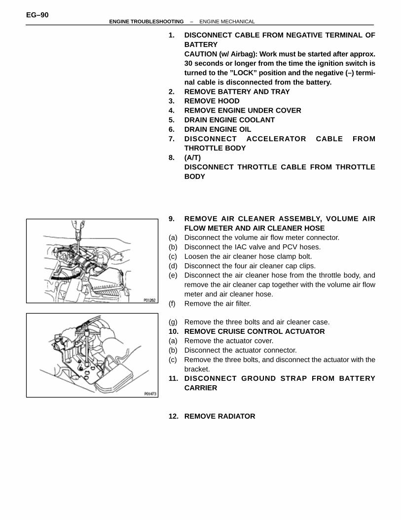
1. DISCONNECT CABLE FROM NEGATIVE TERMINAL OFBATTERYCAUTION (w/ Airbag): Work must be started after approx.30 seconds or longer from the time the ignition switch isturned to the ”LOCK” position and the negative (–) termi-nal cable is disconnected from the battery.
2. REMOVE BATTERY AND TRAY3. REMOVE HOOD4. REMOVE ENGINE UNDER COVER5. DRAIN ENGINE COOLANT6. DRAIN ENGINE OIL7. DISCONNECT ACCELERATOR CABLE FROM
THROTTLE BODY8. (A/T)
DISCONNECT THROTTLE CABLE FROM THROTTLEBODY
9. REMOVE AIR CLEANER ASSEMBLY, VOLUME AIRFLOW METER AND AIR CLEANER HOSE
(a) Disconnect the volume air flow meter connector.(b) Disconnect the IAC valve and PCV hoses.(c) Loosen the air cleaner hose clamp bolt.(d) Disconnect the four air cleaner cap clips.(e) Disconnect the air cleaner hose from the throttle body, and
remove the air cleaner cap together with the volume air flowmeter and air cleaner hose.
(f) Remove the air filter.
(g) Remove the three bolts and air cleaner case.10. REMOVE CRUISE CONTROL ACTUATOR(a) Remove the actuator cover.(b) Disconnect the actuator connector.(c) Remove the three bolts, and disconnect the actuator with the
bracket.11. DISCONNECT GROUND STRAP FROM BATTERY
CARRIER
12. REMOVE RADIATOR
EG–90–ENGINE TROUBLESHOOTING ENGINE MECHANICAL

13. DISCONNECT ENGINE COOLANT RESERVOIR HOSERemove the bolt and disconnect the reservoir hose.
14. REMOVE WASHER TANK(a) Remove the three washer tank mounting bolts.(b) Disconnect the connector and hose, and remove the washer
tank.
15. REMOVE ENGINE COOLANT RESERVOIR TANKUsing a screwdriver, remove the reservoir tank.
16. DISCONNECT WIRES AND CONNECTORS(a) Remove the engine relay box, and disconnect the three
connectors.(b) Two connectors from LH fender apron
(c) Igniter connector(d) Ignition coil connector(e) High–tension cord from ignition coil(f) Noise filter connector(g) Connector from fender apron
–ENGINE TROUBLESHOOTING ENGINE MECHANICALEG–91
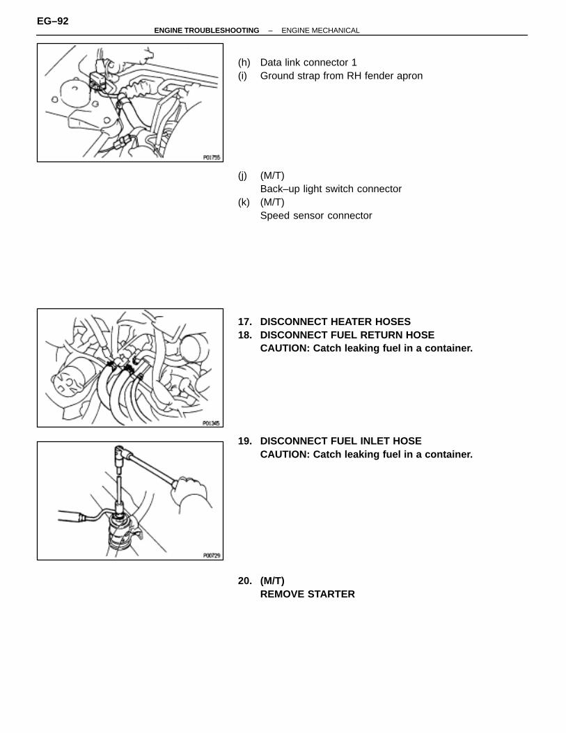
(h) Data link connector 1(i) Ground strap from RH fender apron
(j) (M/T)Back–up light switch connector
(k) (M/T)Speed sensor connector
17. DISCONNECT HEATER HOSES18. DISCONNECT FUEL RETURN HOSE
CAUTION: Catch leaking fuel in a container.
19. DISCONNECT FUEL INLET HOSECAUTION: Catch leaking fuel in a container.
20. (M/T)REMOVE STARTER
EG–92–ENGINE TROUBLESHOOTING ENGINE MECHANICAL
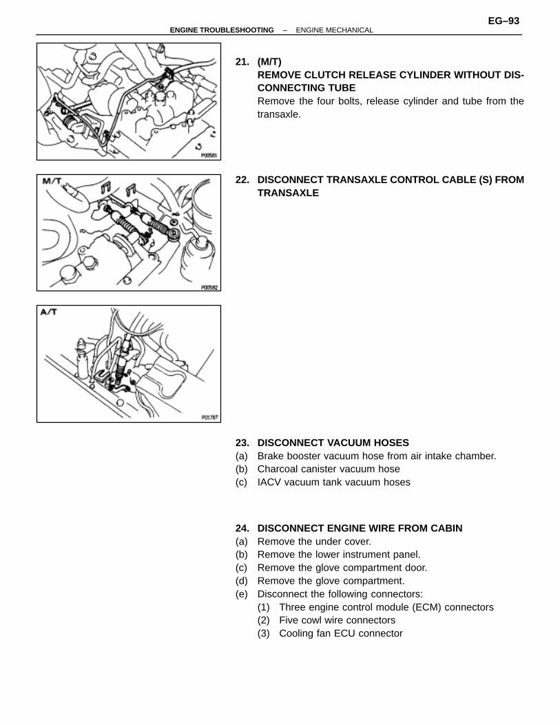
21. (M/T)REMOVE CLUTCH RELEASE CYLINDER WITHOUT DIS-CONNECTING TUBERemove the four bolts, release cylinder and tube from thetransaxle.
22. DISCONNECT TRANSAXLE CONTROL CABLE (S) FROMTRANSAXLE
23. DISCONNECT VACUUM HOSES(a) Brake booster vacuum hose from air intake chamber.(b) Charcoal canister vacuum hose(c) IACV vacuum tank vacuum hoses
24. DISCONNECT ENGINE WIRE FROM CABIN(a) Remove the under cover.(b) Remove the lower instrument panel.(c) Remove the glove compartment door.(d) Remove the glove compartment.(e) Disconnect the following connectors:
(1) Three engine control module (ECM) connectors(2) Five cowl wire connectors(3) Cooling fan ECU connector
–ENGINE TROUBLESHOOTING ENGINE MECHANICALEG–93
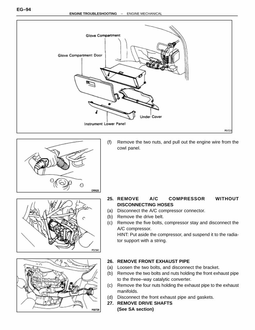
(f) Remove the two nuts, and pull out the engine wire from thecowl panel.
25. REMOVE A/C COMPRESSOR WITHOUTDISCONNECTING HOSES
(a) Disconnect the A/C compressor connector.(b) Remove the drive belt.(c) Remove the five bolts, compressor stay and disconnect the
A/C compressor.HINT: Put aside the compressor, and suspend it to the radia-tor support with a string.
26. REMOVE FRONT EXHAUST PIPE(a) Loosen the two bolts, and disconnect the bracket.(b) Remove the two bolts and nuts holding the front exhaust pipe
to the three–way catalytic converter.(c) Remove the four nuts holding the exhaust pipe to the exhaust
manifolds.(d) Disconnect the front exhaust pipe and gaskets.27. REMOVE DRIVE SHAFTS
(See SA section)
EG–94–ENGINE TROUBLESHOOTING ENGINE MECHANICAL
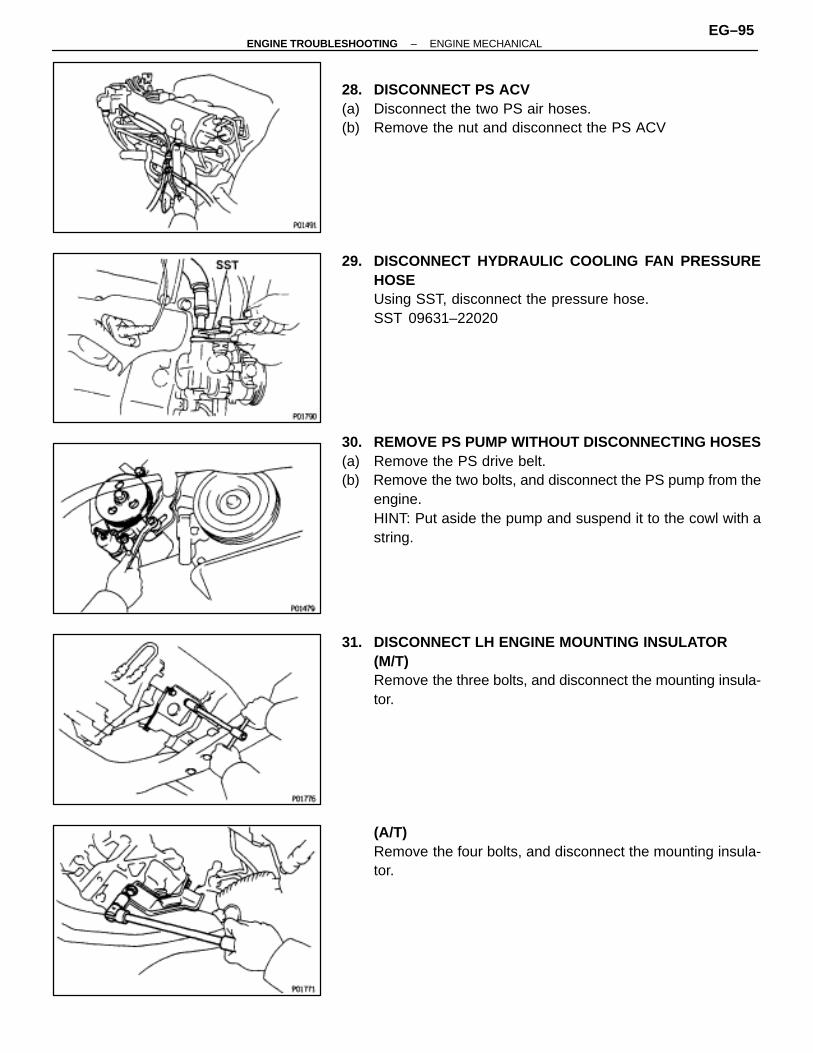
28. DISCONNECT PS ACV(a) Disconnect the two PS air hoses.(b) Remove the nut and disconnect the PS ACV
29. DISCONNECT HYDRAULIC COOLING FAN PRESSUREHOSEUsing SST, disconnect the pressure hose.SST 09631–22020
30. REMOVE PS PUMP WITHOUT DISCONNECTING HOSES(a) Remove the PS drive belt.(b) Remove the two bolts, and disconnect the PS pump from the
engine.HINT: Put aside the pump and suspend it to the cowl with astring.
31. DISCONNECT LH ENGINE MOUNTING INSULATOR(M/T)Remove the three bolts, and disconnect the mounting insula-tor.
(A/T)Remove the four bolts, and disconnect the mounting insula-tor.
–ENGINE TROUBLESHOOTING ENGINE MECHANICALEG–95

32. DISCONNECT RR ENGINE MOUNTING INSULATOR(a) Remove the hole plugs.(b) Remove the four nuts, and disconnect the mounting
insulator.
33. REMOVE ENGINE MOUNTING ABSORBERRemove the four bolts and engine mounting absorber.
34. DISCONNECT FR ENGINE MOUNTING INSULATORRemove the three bolts, and disconnect the mounting insula-tor.
35. ATTACH ENGINE SLING DEVICE TO ENGINE HANGERS
36. REMOVE ENGINE MOVING CONTROL RODRemove the three bolts and control rod.
EG–96–ENGINE TROUBLESHOOTING ENGINE MECHANICAL
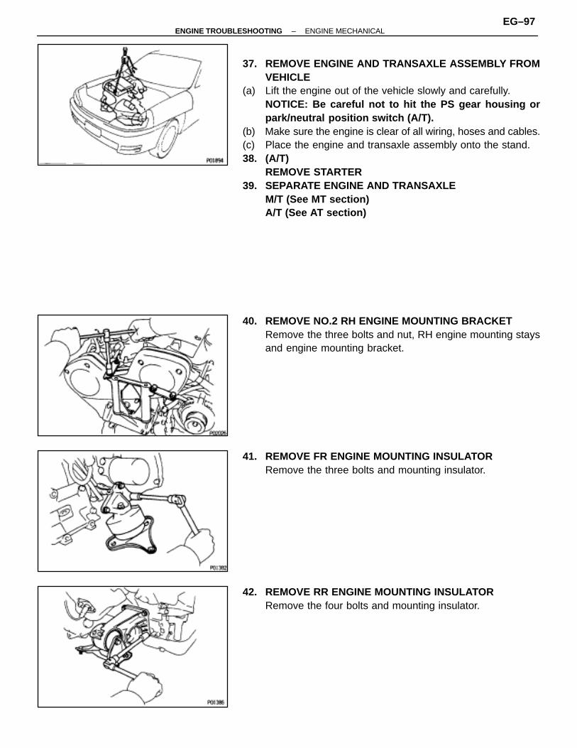
37. REMOVE ENGINE AND TRANSAXLE ASSEMBLY FROMVEHICLE
(a) Lift the engine out of the vehicle slowly and carefully.NOTICE: Be careful not to hit the PS gear housing orpark/neutral position switch (A/T).
(b) Make sure the engine is clear of all wiring, hoses and cables.(c) Place the engine and transaxle assembly onto the stand.38. (A/T)
REMOVE STARTER39. SEPARATE ENGINE AND TRANSAXLE
M/T (See MT section)A/T (See AT section)
40. REMOVE NO.2 RH ENGINE MOUNTING BRACKETRemove the three bolts and nut, RH engine mounting staysand engine mounting bracket.
41. REMOVE FR ENGINE MOUNTING INSULATORRemove the three bolts and mounting insulator.
42. REMOVE RR ENGINE MOUNTING INSULATORRemove the four bolts and mounting insulator.
–ENGINE TROUBLESHOOTING ENGINE MECHANICALEG–97
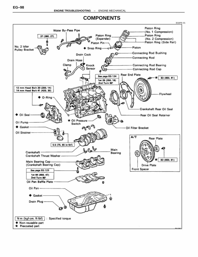
COMPONENTSEG0F9–01
EG–98–ENGINE TROUBLESHOOTING ENGINE MECHANICAL
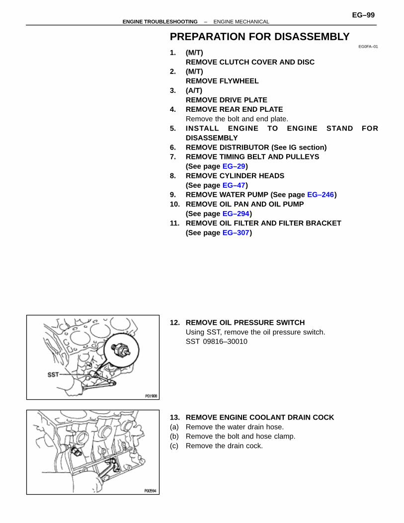
PREPARATION FOR DISASSEMBLYEG0FA–01
1. (M/T)REMOVE CLUTCH COVER AND DISC
2. (M/T)REMOVE FLYWHEEL
3. (A/T)REMOVE DRIVE PLATE
4. REMOVE REAR END PLATERemove the bolt and end plate.
5. INSTALL ENGINE TO ENGINE STAND FORDISASSEMBLY
6. REMOVE DISTRIBUTOR (See IG section)7. REMOVE TIMING BELT AND PULLEYS
(See page EG–29)8. REMOVE CYLINDER HEADS
(See page EG–47)9. REMOVE WATER PUMP (See page EG–246)10. REMOVE OIL PAN AND OIL PUMP
(See page EG–294)11. REMOVE OIL FILTER AND FILTER BRACKET
(See page EG–307)
12. REMOVE OIL PRESSURE SWITCHUsing SST, remove the oil pressure switch.SST 09816–30010
13. REMOVE ENGINE COOLANT DRAIN COCK(a) Remove the water drain hose.(b) Remove the bolt and hose clamp.(c) Remove the drain cock.
–ENGINE TROUBLESHOOTING ENGINE MECHANICALEG–99

14. REMOVE WATER BY–PASS PIPE(a) Disconnect the two knock sensor connectors.(b) Remove the two bolts, nut and water by–pass pipe.
15. REMOVE KNOCK SENSORSUsing SST, remove the two knock sensors.SST 09816–30010
16. REMOVE NO.2 IDLER PULLEY BRACKETRemove the three bolts and idler pulley bracket.
EG–100–ENGINE TROUBLESHOOTING ENGINE MECHANICAL

CYLINDER BLOCK DISASSEMBLYEG0FB–01
(See page EG–98)1. REMOVE REAR OIL SEAL RETAINER
Remove the six bolts and retainer.
2. CHECK CONNECTING ROD THRUST CLEARANCEUsing a dial indicator, measure the thrust clearance whilemoving the connecting rod back and forth.Standard thrust clearance:
0.150–0.330 mm (0.0059–0.0130 in.)Maximum thrust clearance:
0.38 mm (0.0150 in.)
If the thrust clearance is greater than maximum, replace theconnecting rod assembly. If necessary, replace the crank-shaft.
3. REMOVE CONNECTING ROD CAPS AND CHECK OILCLEARANCE
(a) Using a punch or numbering stamp, mark the connecting rodand cap to ensure correct reassembly.
(b) Using SST, remove the connecting rod cap nuts.SST 09011–38121
(c) Using a plastic–faced hammer, lightly tap the connecting rodbolts and lift off the connecting rod cap.HINT: Keep the lower bearing inserted with the connectingcap.
–ENGINE TROUBLESHOOTING ENGINE MECHANICALEG–101
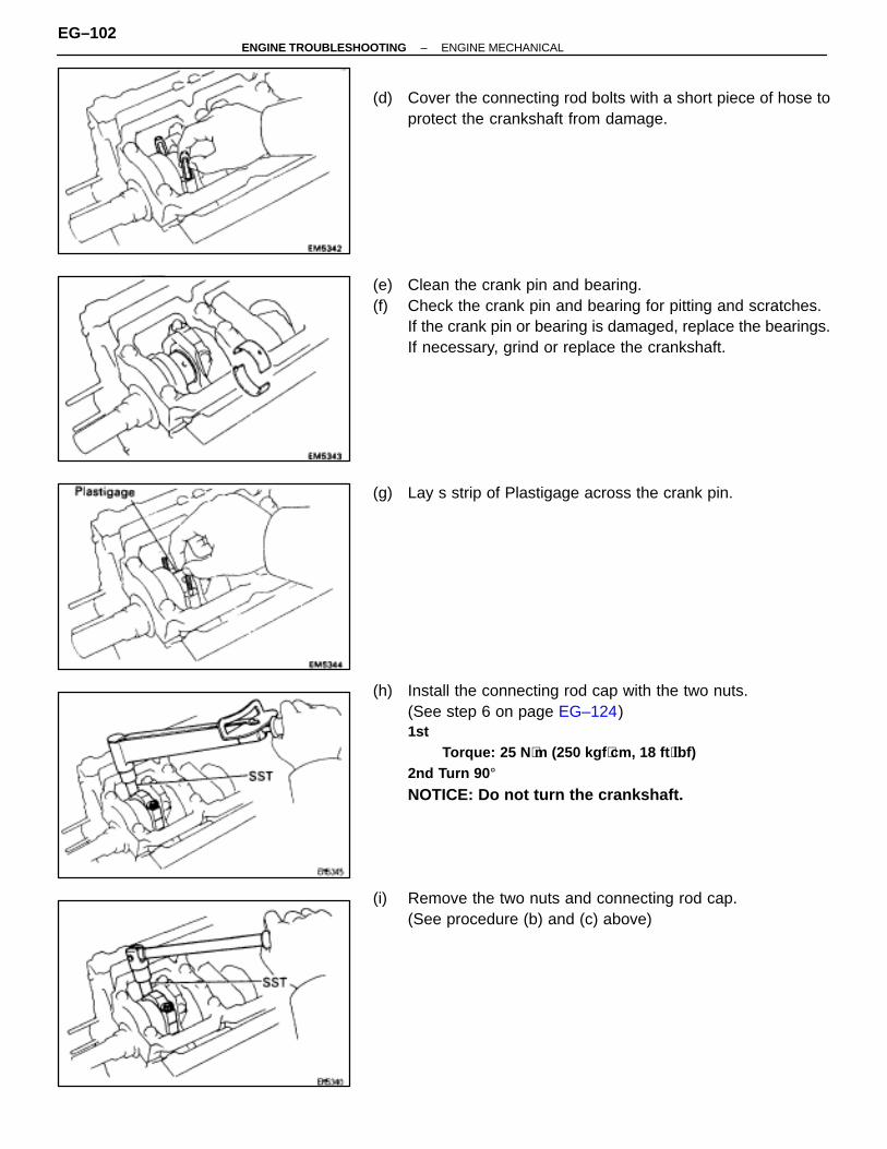
(d) Cover the connecting rod bolts with a short piece of hose toprotect the crankshaft from damage.
(e) Clean the crank pin and bearing.(f) Check the crank pin and bearing for pitting and scratches.
If the crank pin or bearing is damaged, replace the bearings.If necessary, grind or replace the crankshaft.
(g) Lay s strip of Plastigage across the crank pin.
(h) Install the connecting rod cap with the two nuts.(See step 6 on page EG–124)1st
Torque: 25 N ⋅m (250 kgf ⋅cm, 18 ft ⋅lbf)2nd Turn 90 °NOTICE: Do not turn the crankshaft.
(i) Remove the two nuts and connecting rod cap.(See procedure (b) and (c) above)
EG–102–ENGINE TROUBLESHOOTING ENGINE MECHANICAL

(j) Measure the Plastigage at its widest point.Standard oil clearance:STD
0.028–0.065 mm (0.0011–0.0026 in.)U/S 0.25
0.027–0.080 mm (0.0011–0.0031 in.)Maximum oil clearance:
0.08 mm (0.0031 in.)
If the oil clearance is greater than maximum, replace thebearings. If necessary, grind or replace the crankshaft.
HINT: If using a standard bearing, replace with one havingthe same number marked on the connecting rod cap. Thereare three sizes of standard bearings, marked ”1”, ”2” and ”3”accordingly.(Reference)Standard sized bearing center wall thickness:Mark ”1”
1.484–1.488 mm (0.0584–0.0586 in.)Mark ”2”
1.488–1.492 mm (0.0586–0.0587 in.)Mark ”3”
1.492–1.496 mm (0.0587–0.0589 in.)
(k) Completely remove the Plastigage.
4. REMOVE PISTON AND CONNECTING RODASSEMBLIES
(a) Using a ridge reamer, remove the all carbon from the top ofthe cylinder.
(b) Push the piston, connecting rod assembly and upper bearingthrough the top of the cylinder block.
–ENGINE TROUBLESHOOTING ENGINE MECHANICALEG–103

HINT:•Keep the bearings, connecting rod and cap together.•Arrange the piston and connecting rod assemblies in correct
order.
5. CHECK CRANKSHAFT THRUST CLEARANCEUsing a dial indicator, measure the thrust clearance while pry-ing the crankshaft back and forth with a screwdriver.Standard thrust clearance:
0.020–0.220 mm (0.0008–0.0087 in.)Maximum thrust clearance:
0.30 mm (0.0118 in.)
If the thrust clearance is greater than maximum, replace thethrust washers as a set.Thrust washer thickness:
2.440–2.490 mm (0.0961–0.0980 in.)
6. REMOVE MAIN BEARING CAP AND CHECK OILCLEARANCE
(a) Uniformly loosen and remove the main bearing cap bolts inseveral passes, in the sequence shown.
(b) Using a screwdriver, pry up the main bearing cap, andremove the main bearing cap, lower main bearings and lowerthrust washers (No.2 journal position of main bearing caponly).HINT: Keep the lower main bearings and lower thrust wash-ers together with the main bearing cap.
(c) Lift out the crankshaft.HINT: Keep the upper main bearings and upper thrust wash-ers together with the cylinder block.
EG–104–ENGINE TROUBLESHOOTING ENGINE MECHANICAL
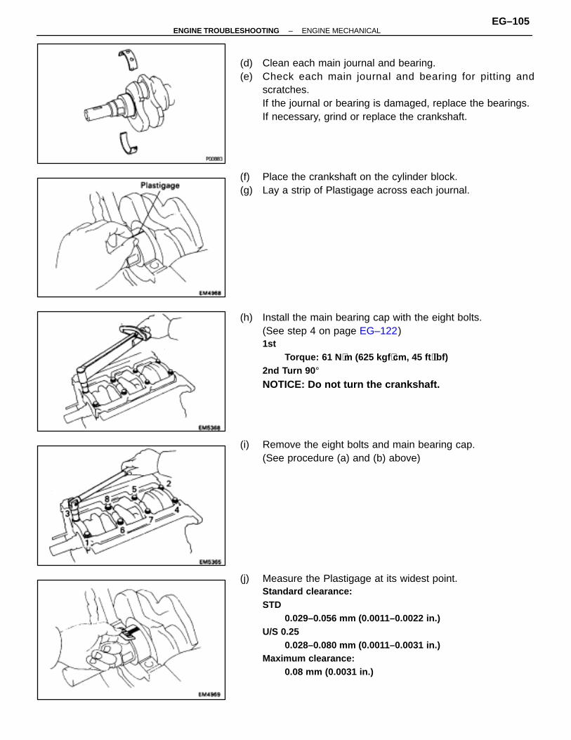
(d) Clean each main journal and bearing.(e) Check each main journal and bearing for pitting and
scratches.If the journal or bearing is damaged, replace the bearings.If necessary, grind or replace the crankshaft.
(f) Place the crankshaft on the cylinder block.(g) Lay a strip of Plastigage across each journal.
(h) Install the main bearing cap with the eight bolts.(See step 4 on page EG–122)1st
Torque: 61 N ⋅m (625 kgf ⋅cm, 45 ft ⋅lbf)2nd Turn 90 °NOTICE: Do not turn the crankshaft.
(i) Remove the eight bolts and main bearing cap.(See procedure (a) and (b) above)
(j) Measure the Plastigage at its widest point.Standard clearance:STD
0.029–0.056 mm (0.0011–0.0022 in.)U/S 0.25
0.028–0.080 mm (0.0011–0.0031 in.)Maximum clearance:
0.08 mm (0.0031 in.)
–ENGINE TROUBLESHOOTING ENGINE MECHANICALEG–105
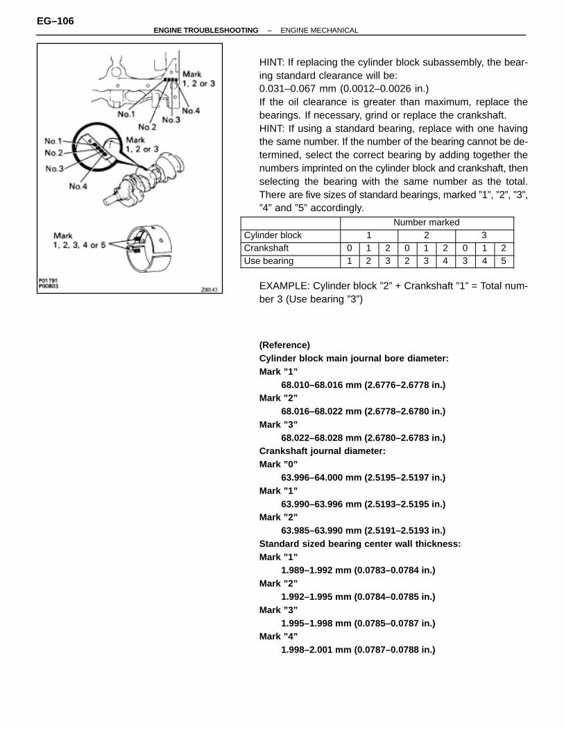
HINT: If replacing the cylinder block subassembly, the bear-ing standard clearance will be:0.031–0.067 mm (0.0012–0.0026 in.)If the oil clearance is greater than maximum, replace thebearings. If necessary, grind or replace the crankshaft.HINT: If using a standard bearing, replace with one havingthe same number. If the number of the bearing cannot be de-termined, select the correct bearing by adding together thenumbers imprinted on the cylinder block and crankshaft, thenselecting the bearing with the same number as the total.There are five sizes of standard bearings, marked ”1”, ”2”, ”3”,”4” and ”5” accordingly.
ÑÑÑÑÑÑÑÑÑÑÑÑÑÑÑÑ
ÑÑÑÑÑÑÑÑÑÑÑÑÑÑÑÑÑÑÑÑÑÑÑÑÑÑ
Number marked
ÑÑÑÑÑÑÑÑÑÑÑÑÑÑÑÑ
Cylinder block ÑÑÑÑÑÑÑÑÑÑ
1 ÑÑÑÑÑÑÑÑÑÑ
2 ÑÑÑÑÑÑÑÑÑÑ
3
ÑÑÑÑÑÑÑÑÑÑÑÑÑÑÑÑ
Crankshaft ÑÑÑÑ
0ÑÑÑÑ
1ÑÑÑÑÑÑ
2 ÑÑÑÑ
0ÑÑÑÑ
1ÑÑÑÑÑÑ
2 ÑÑÑÑ
0ÑÑÑÑ
1ÑÑÑÑÑÑ
2
ÑÑÑÑÑÑÑÑUse bearing ÑÑ1ÑÑ2ÑÑÑ3 ÑÑ2ÑÑ3ÑÑÑ4 ÑÑ3ÑÑ4ÑÑÑ5
EXAMPLE: Cylinder block ”2” + Crankshaft ”1” = Total num-ber 3 (Use bearing ”3”)
(Reference)Cylinder block main journal bore diameter:Mark ”1”
68.010–68.016 mm (2.6776–2.6778 in.)Mark ”2”
68.016–68.022 mm (2.6778–2.6780 in.)Mark ”3”
68.022–68.028 mm (2.6780–2.6783 in.)Crankshaft journal diameter:Mark ”0”
63.996–64.000 mm (2.5195–2.5197 in.)Mark ”1”
63.990–63.996 mm (2.5193–2.5195 in.)Mark ”2”
63.985–63.990 mm (2.5191–2.5193 in.)Standard sized bearing center wall thickness:Mark ”1”
1.989–1.992 mm (0.0783–0.0784 in.)Mark ”2”
1.992–1.995 mm (0.0784–0.0785 in.)Mark ”3”
1.995–1.998 mm (0.0785–0.0787 in.)Mark ”4”
1.998–2.001 mm (0.0787–0.0788 in.)
EG–106–ENGINE TROUBLESHOOTING ENGINE MECHANICAL
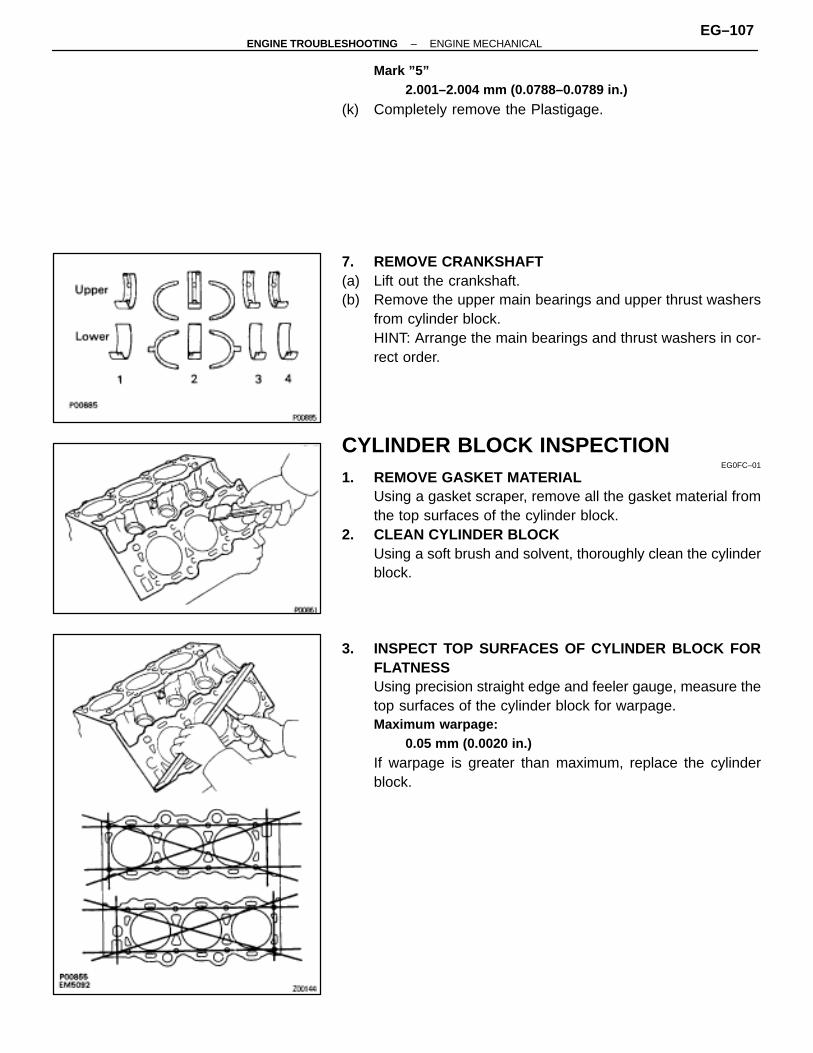
Mark ”5”2.001–2.004 mm (0.0788–0.0789 in.)
(k) Completely remove the Plastigage.
7. REMOVE CRANKSHAFT(a) Lift out the crankshaft.(b) Remove the upper main bearings and upper thrust washers
from cylinder block.HINT: Arrange the main bearings and thrust washers in cor-rect order.
CYLINDER BLOCK INSPECTIONEG0FC–01
1. REMOVE GASKET MATERIALUsing a gasket scraper, remove all the gasket material fromthe top surfaces of the cylinder block.
2. CLEAN CYLINDER BLOCKUsing a soft brush and solvent, thoroughly clean the cylinderblock.
3. INSPECT TOP SURFACES OF CYLINDER BLOCK FORFLATNESSUsing precision straight edge and feeler gauge, measure thetop surfaces of the cylinder block for warpage.Maximum warpage:
0.05 mm (0.0020 in.)
If warpage is greater than maximum, replace the cylinderblock.
–ENGINE TROUBLESHOOTING ENGINE MECHANICALEG–107

4. INSPECT CYLINDER FOR VERTICAL SCRATCHESVisually check the cylinder for vertical scratches.If deep scratches are present, rebore all the six cylinders orreplace the cylinder block.
5. INSPECT CYLINDER BORE DIAMETERHINT: There are three sizes of the standard cylinder bore di-ameter, marked ”1”, ”2” and ”3” accordingly, The mark isstamped on the top of the cylinder block.
Using a cylinder gauge, measure the cylinder bore diameterat positions A, B and C in the thrust and axial directions.Standard diameter:STDMark ”1”
87.500–87.510 mm (3.4449–3.4453 in.)Mark ”2”
87.510–87.520 mm (3.4453–3.4457 in.)Mark ”3”
87.520–87.530 mm (3.4457–3.4461 in.)Maximum diameter:STD
87.73 mm (3.4539 in.)O/S 0.50
88.23 mm (3.4736 in.)
If the diameter is greater than maximum, rebore all the six cyl-inders or replace the cylinder block.
6. REMOVE CYLINDER RIDGEIf the wear is less than 0.2 mm (0.008 in.), using a ridge ream-er, grind the top of the cylinder.
EG–108–ENGINE TROUBLESHOOTING ENGINE MECHANICAL

PISTON AND CONNECTING ROD ASSYDISASSEMBLY
EG0FD–01
1. CHECK FIT BETWEEN PISTON AND PISTON PINTry to move the piston back and forth on the piston pin.If any movement is felt, replace the piston and pin as a set.
2. REMOVE PISTON RINGS(a) Using a piston ring expander, remove the two compression
rings.
(b) Remove the two side rails and oil ring expander by hand.HINT: Arrange the rings in correct order only.
3. DISCONNECT CONNECTING ROD FROM PISTON(a) Using a small screwdriver, pry off the snap ring from the
piston.
(b) Gradually heat the piston to approx. 605C (1405F).
–ENGINE TROUBLESHOOTING ENGINE MECHANICALEG–109
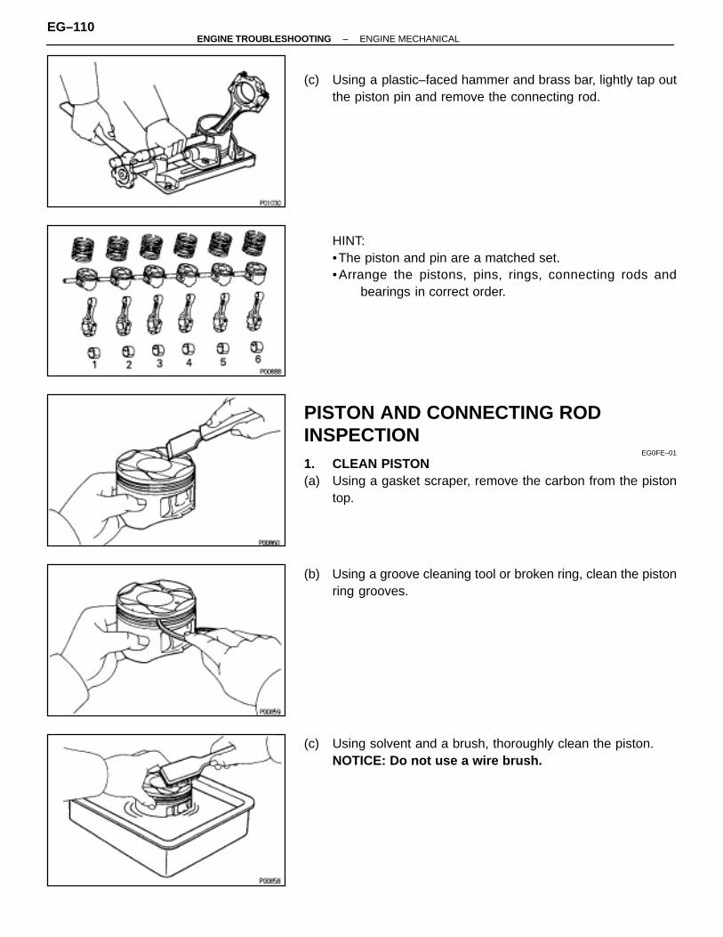
(c) Using a plastic–faced hammer and brass bar, lightly tap outthe piston pin and remove the connecting rod.
HINT:•The piston and pin are a matched set.•Arrange the pistons, pins, rings, connecting rods and
bearings in correct order.
PISTON AND CONNECTING RODINSPECTION
EG0FE–01
1. CLEAN PISTON(a) Using a gasket scraper, remove the carbon from the piston
top.
(b) Using a groove cleaning tool or broken ring, clean the pistonring grooves.
(c) Using solvent and a brush, thoroughly clean the piston.NOTICE: Do not use a wire brush.
EG–110–ENGINE TROUBLESHOOTING ENGINE MECHANICAL
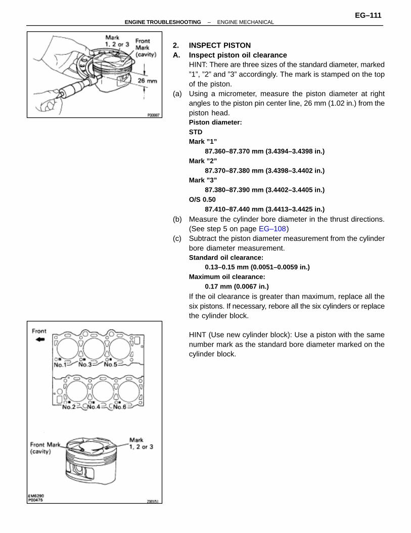
2. INSPECT PISTONA. Inspect piston oil clearance
HINT: There are three sizes of the standard diameter, marked”1”, ”2” and ”3” accordingly. The mark is stamped on the topof the piston.
(a) Using a micrometer, measure the piston diameter at rightangles to the piston pin center line, 26 mm (1.02 in.) from thepiston head.Piston diameter:STDMark ”1”
87.360–87.370 mm (3.4394–3.4398 in.)Mark ”2”
87.370–87.380 mm (3.4398–3.4402 in.)Mark ”3”
87.380–87.390 mm (3.4402–3.4405 in.)O/S 0.50
87.410–87.440 mm (3.4413–3.4425 in.)
(b) Measure the cylinder bore diameter in the thrust directions.(See step 5 on page EG–108)
(c) Subtract the piston diameter measurement from the cylinderbore diameter measurement.Standard oil clearance:
0.13–0.15 mm (0.0051–0.0059 in.)Maximum oil clearance:
0.17 mm (0.0067 in.)
If the oil clearance is greater than maximum, replace all thesix pistons. If necessary, rebore all the six cylinders or replacethe cylinder block.
HINT (Use new cylinder block): Use a piston with the samenumber mark as the standard bore diameter marked on thecylinder block.
–ENGINE TROUBLESHOOTING ENGINE MECHANICALEG–111
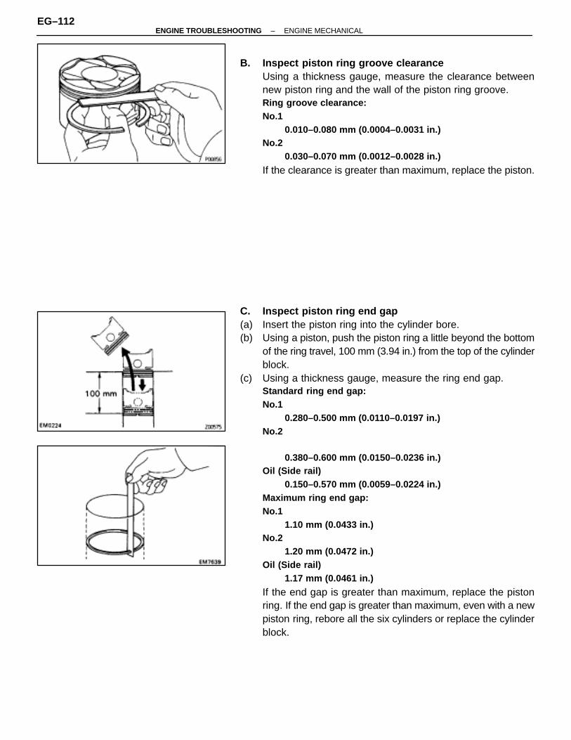
B. Inspect piston ring groove clearanceUsing a thickness gauge, measure the clearance betweennew piston ring and the wall of the piston ring groove.Ring groove clearance:No.1
0.010–0.080 mm (0.0004–0.0031 in.)No.2
0.030–0.070 mm (0.0012–0.0028 in.)
If the clearance is greater than maximum, replace the piston.
C. Inspect piston ring end gap(a) Insert the piston ring into the cylinder bore.(b) Using a piston, push the piston ring a little beyond the bottom
of the ring travel, 100 mm (3.94 in.) from the top of the cylinderblock.
(c) Using a thickness gauge, measure the ring end gap.Standard ring end gap:No.1
0.280–0.500 mm (0.0110–0.0197 in.)No.2
0.380–0.600 mm (0.0150–0.0236 in.)Oil (Side rail)
0.150–0.570 mm (0.0059–0.0224 in.)Maximum ring end gap:No.1
1.10 mm (0.0433 in.)No.2
1.20 mm (0.0472 in.)Oil (Side rail)
1.17 mm (0.0461 in.)
If the end gap is greater than maximum, replace the pistonring. If the end gap is greater than maximum, even with a newpiston ring, rebore all the six cylinders or replace the cylinderblock.
EG–112–ENGINE TROUBLESHOOTING ENGINE MECHANICAL
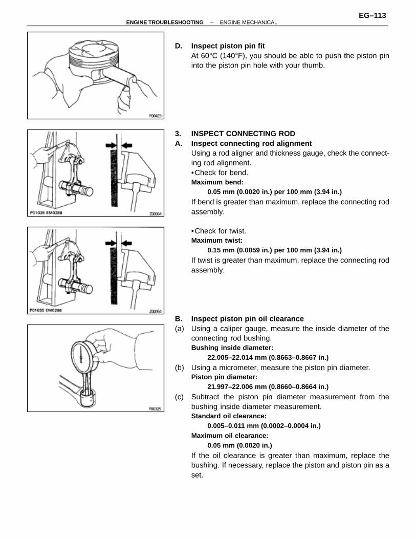
D. Inspect piston pin fitAt 60°C (140°F), you should be able to push the piston pininto the piston pin hole with your thumb.
3. INSPECT CONNECTING RODA. Inspect connecting rod alignment
Using a rod aligner and thickness gauge, check the connect-ing rod alignment.•Check for bend.Maximum bend:
0.05 mm (0.0020 in.) per 100 mm (3.94 in.)
If bend is greater than maximum, replace the connecting rodassembly.
•Check for twist.Maximum twist:
0.15 mm (0.0059 in.) per 100 mm (3.94 in.)
If twist is greater than maximum, replace the connecting rodassembly.
B. Inspect piston pin oil clearance(a) Using a caliper gauge, measure the inside diameter of the
connecting rod bushing.Bushing inside diameter:
22.005–22.014 mm (0.8663–0.8667 in.)
(b) Using a micrometer, measure the piston pin diameter.Piston pin diameter:
21.997–22.006 mm (0.8660–0.8664 in.)
(c) Subtract the piston pin diameter measurement from thebushing inside diameter measurement.Standard oil clearance:
0.005–0.011 mm (0.0002–0.0004 in.)Maximum oil clearance:
0.05 mm (0.0020 in.)
If the oil clearance is greater than maximum, replace thebushing. If necessary, replace the piston and piston pin as aset.
–ENGINE TROUBLESHOOTING ENGINE MECHANICALEG–113
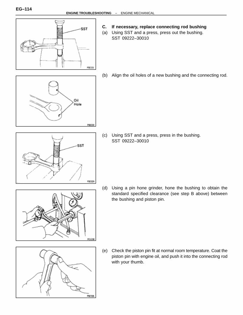
C. If necessary, replace connecting rod bushing(a) Using SST and a press, press out the bushing.
SST 09222–30010
(b) Align the oil holes of a new bushing and the connecting rod.
(c) Using SST and a press, press in the bushing.SST 09222–30010
(d) Using a pin hone grinder, hone the bushing to obtain thestandard specified clearance (see step B above) betweenthe bushing and piston pin.
(e) Check the piston pin fit at normal room temperature. Coat thepiston pin with engine oil, and push it into the connecting rodwith your thumb.
EG–114–ENGINE TROUBLESHOOTING ENGINE MECHANICAL
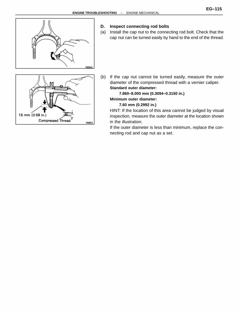
D. Inspect connecting rod bolts(a) Install the cap nut to the connecting rod bolt. Check that the
cap nut can be turned easily by hand to the end of the thread.
(b) If the cap nut cannot be turned easily, measure the outerdiameter of the compressed thread with a vernier caliper.Standard outer diameter:
7.860–8.000 mm (0.3094–0.3150 in.)Minimum outer diameter:
7.60 mm (0.2992 in.)
HINT: If the location of this area cannot be judged by visualinspection, measure the outer diameter at the location shownin the illustration.If the outer diameter is less than minimum, replace the con-necting rod and cap nut as a set.
–ENGINE TROUBLESHOOTING ENGINE MECHANICALEG–115
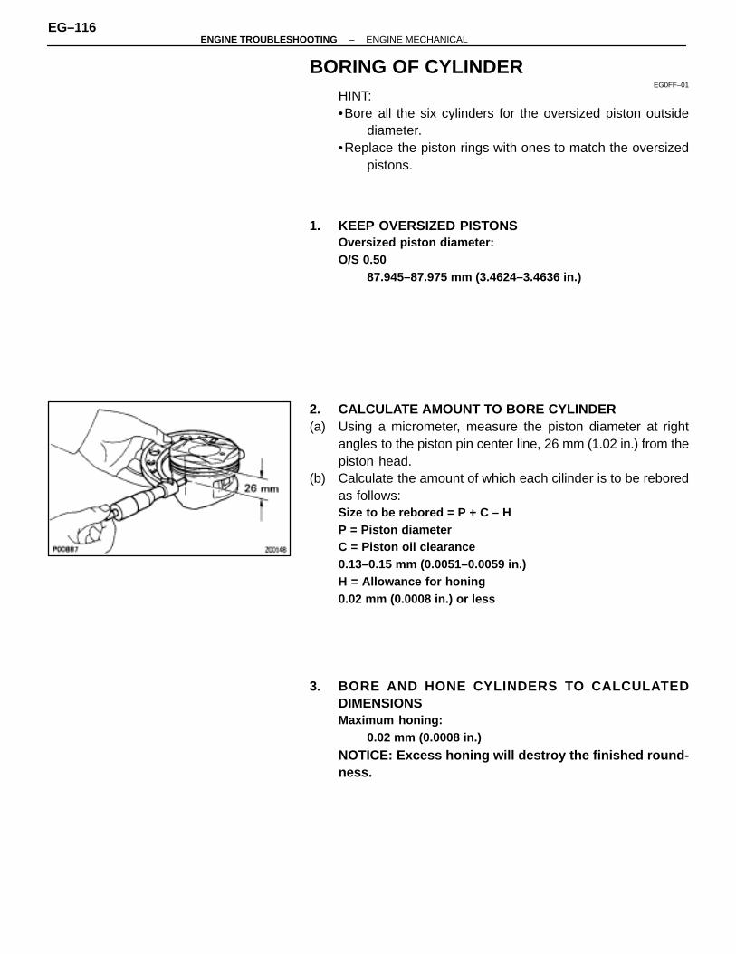
BORING OF CYLINDEREG0FF–01
HINT:•Bore all the six cylinders for the oversized piston outside
diameter.•Replace the piston rings with ones to match the oversized
pistons.
1. KEEP OVERSIZED PISTONSOversized piston diameter:O/S 0.50
87.945–87.975 mm (3.4624–3.4636 in.)
2. CALCULATE AMOUNT TO BORE CYLINDER(a) Using a micrometer, measure the piston diameter at right
angles to the piston pin center line, 26 mm (1.02 in.) from thepiston head.
(b) Calculate the amount of which each cilinder is to be reboredas follows:Size to be rebored = P + C – HP = Piston diameterC = Piston oil clearance0.13–0.15 mm (0.0051–0.0059 in.)H = Allowance for honing0.02 mm (0.0008 in.) or less
3. BORE AND HONE CYLINDERS TO CALCULATEDDIMENSIONSMaximum honing:
0.02 mm (0.0008 in.)
NOTICE: Excess honing will destroy the finished round-ness.
EG–116–ENGINE TROUBLESHOOTING ENGINE MECHANICAL

CRANKSHAFT INSPECTION ANDREPAIR
EGOFG–01
1. INSPECT CRANKSHAFT FOR RUNOUT(a) Place the crankshaft on V–blocks.(b) Using a dial indicator, measure the circle runout at the center
journal.Maximum circle runout:
0.06 mm (0.0024 in.)
If the circle runout is greater than maximum, replace thecrankshaft.
2. INSPECT MAIN JOURNALS AND CRANK PINS(a) Using a micrometer, measure the diameter of each main
journal and crank pin.Main journal diameter:STD
63.985–64.00 mm (2.5191–2.5197 in.)U/S 0.25
63.745–63.755 mm (2.5096–2.5100 in.)Crank pin diameter:STD
54.987–55.000 mm (2.1648–2.1654 in.)U/S 0.25
54.745–54.755 mm (2.1553–2.1557 in.)
If the diameter is not as specified, check the oil clearance.(See page EG–104)
(b) Check each main journal and crank pin for taper andout–of–round as shown.Maximum taper and out–of–round:
0.02 mm (0.0008 in.)
If the taper or out–of–round is greater than maximum, grindor replace the crankshaft.
3. IF NECESSARY, GRIND AND HONE MAIN JOURNALSAND/OR CRANK PINSGrind and hone the main journals and/or crank pins to the fin-ished undersized diameter (See procedure step 2).Install new main journal and/or crank pin undersized bear-ings.
–ENGINE TROUBLESHOOTING ENGINE MECHANICALEG–117
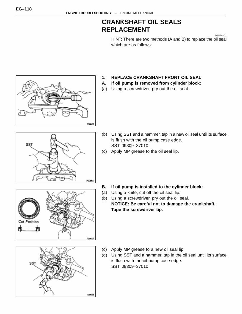
CRANKSHAFT OIL SEALSREPLACEMENT
EG0FH–01
HINT: There are two methods (A and B) to replace the oil sealwhich are as follows:
1. REPLACE CRANKSHAFT FRONT OIL SEALA. If oil pump is removed from cylinder block:(a) Using a screwdriver, pry out the oil seal.
(b) Using SST and a hammer, tap in a new oil seal until its surfaceis flush with the oil pump case edge.SST 09309–37010
(c) Apply MP grease to the oil seal lip.
B. If oil pump is installed to the cylinder block:(a) Using a knife, cut off the oil seal lip.(b) Using a screwdriver, pry out the oil seal.
NOTICE: Be careful not to damage the crankshaft.Tape the screwdriver tip.
(c) Apply MP grease to a new oil seal lip.(d) Using SST and a hammer, tap in the oil seal until its surface
is flush with the oil pump case edge.SST 09309–37010
EG–118–ENGINE TROUBLESHOOTING ENGINE MECHANICAL
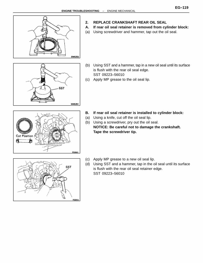
2. REPLACE CRANKSHAFT REAR OIL SEALA. If rear oil seal retainer is removed from cylinder block:(a) Using screwdriver and hammer, tap out the oil seal.
(b) Using SST and a hammer, tap in a new oil seal until its surfaceis flush with the rear oil seal edge.SST 09223–56010
(c) Apply MP grease to the oil seal lip.
B. If rear oil seal retainer is installed to cylinder block:(a) Using a knife, cut off the oil seal lip.(b) Using a screwdriver, pry out the oil seal.
NOTICE: Be careful not to damage the crankshaft.Tape the screwdriver tip.
(c) Apply MP grease to a new oil seal lip.(d) Using SST and a hammer, tap in the oil seal until its surface
is flush with the rear oil seal retainer edge.SST 09223–56010
–ENGINE TROUBLESHOOTING ENGINE MECHANICALEG–119
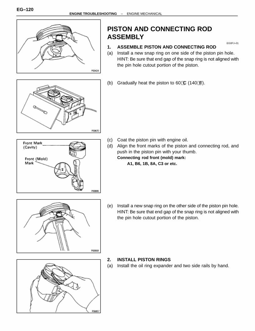
PISTON AND CONNECTING RODASSEMBLY
EG0FJ–01
1. ASSEMBLE PISTON AND CONNECTING ROD(a) Install a new snap ring on one side of the piston pin hole.
HINT: Be sure that end gap of the snap ring is not aligned withthe pin hole cutout portion of the piston.
(b) Gradually heat the piston to 60�C (140�F).
(c) Coat the piston pin with engine oil.(d) Align the front marks of the piston and connecting rod, and
push in the piston pin with your thumb.Connecting rod front (mold) mark:
A1, B6, 1B, 8A, C3 or etc.
(e) Install a new snap ring on the other side of the piston pin hole.HINT: Be sure that end gap of the snap ring is not aligned withthe pin hole cutout portion of the piston.
2. INSTALL PISTON RINGS(a) Install the oil ring expander and two side rails by hand.
EG–120–ENGINE TROUBLESHOOTING ENGINE MECHANICAL
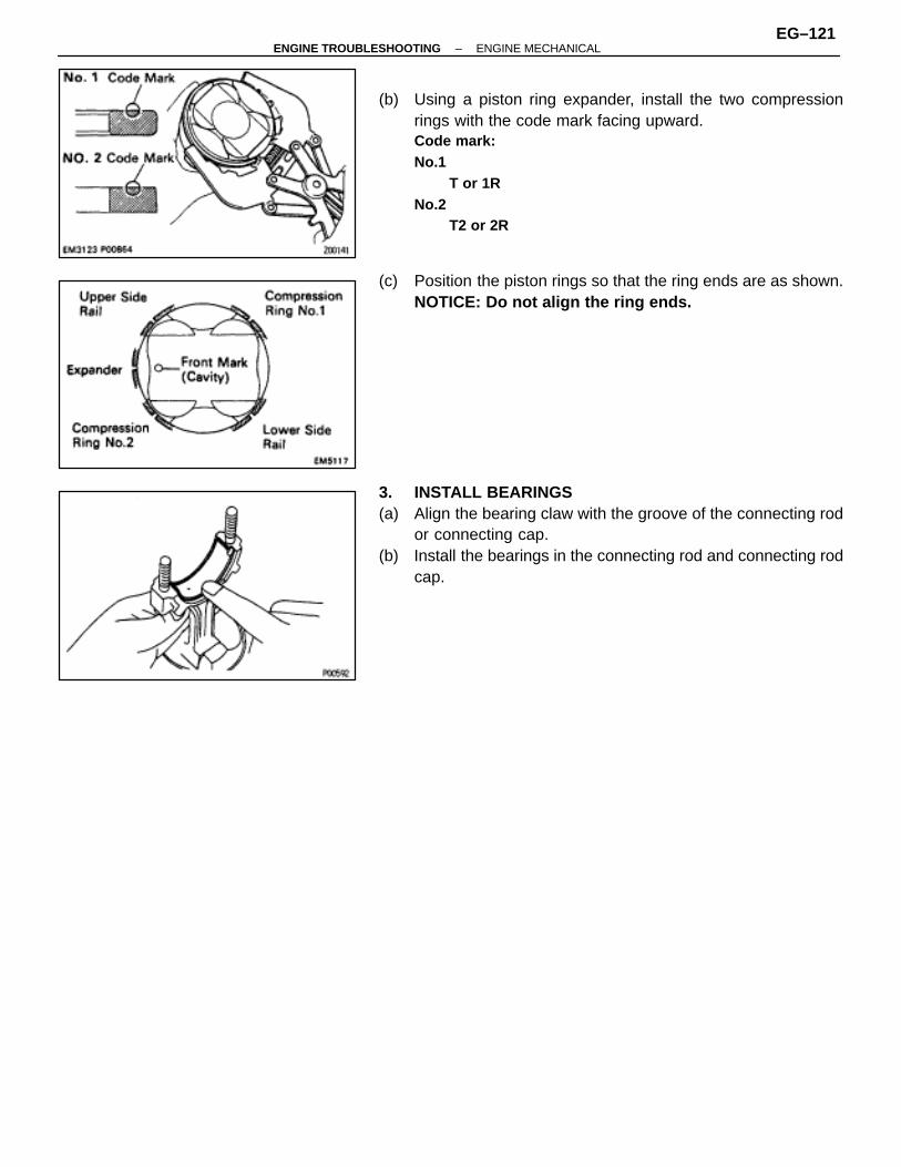
(b) Using a piston ring expander, install the two compressionrings with the code mark facing upward.Code mark:No.1
T or 1RNo.2
T2 or 2R
(c) Position the piston rings so that the ring ends are as shown.NOTICE: Do not align the ring ends.
3. INSTALL BEARINGS(a) Align the bearing claw with the groove of the connecting rod
or connecting cap.(b) Install the bearings in the connecting rod and connecting rod
cap.
–ENGINE TROUBLESHOOTING ENGINE MECHANICALEG–121
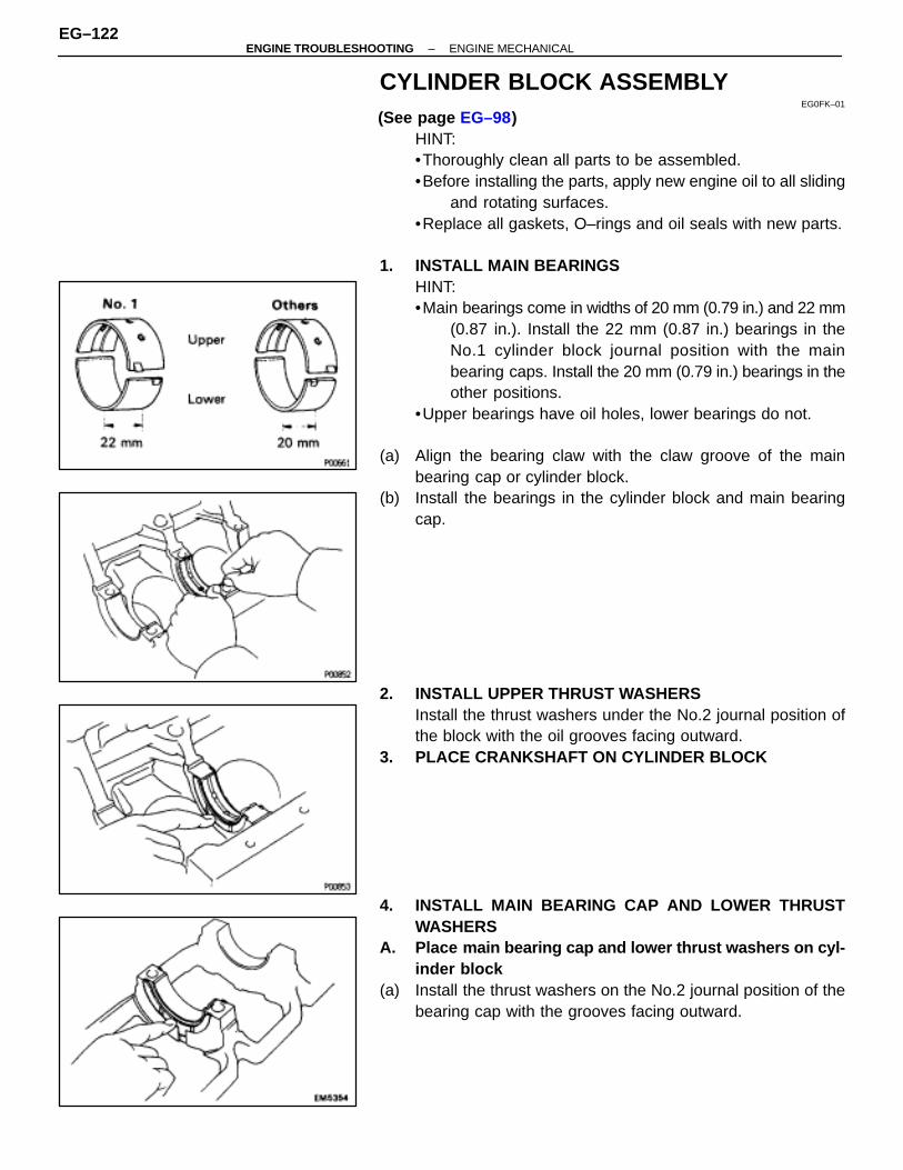
CYLINDER BLOCK ASSEMBLYEG0FK–01
(See page EG–98)HINT:•Thoroughly clean all parts to be assembled.•Before installing the parts, apply new engine oil to all sliding
and rotating surfaces.•Replace all gaskets, O–rings and oil seals with new parts.
1. INSTALL MAIN BEARINGSHINT:•Main bearings come in widths of 20 mm (0.79 in.) and 22 mm
(0.87 in.). Install the 22 mm (0.87 in.) bearings in theNo.1 cylinder block journal position with the mainbearing caps. Install the 20 mm (0.79 in.) bearings in theother positions.
•Upper bearings have oil holes, lower bearings do not.
(a) Align the bearing claw with the claw groove of the mainbearing cap or cylinder block.
(b) Install the bearings in the cylinder block and main bearingcap.
2. INSTALL UPPER THRUST WASHERSInstall the thrust washers under the No.2 journal position ofthe block with the oil grooves facing outward.
3. PLACE CRANKSHAFT ON CYLINDER BLOCK
4. INSTALL MAIN BEARING CAP AND LOWER THRUSTWASHERS
A. Place main bearing cap and lower thrust washers on cyl-inder block
(a) Install the thrust washers on the No.2 journal position of thebearing cap with the grooves facing outward.
EG–122–ENGINE TROUBLESHOOTING ENGINE MECHANICAL
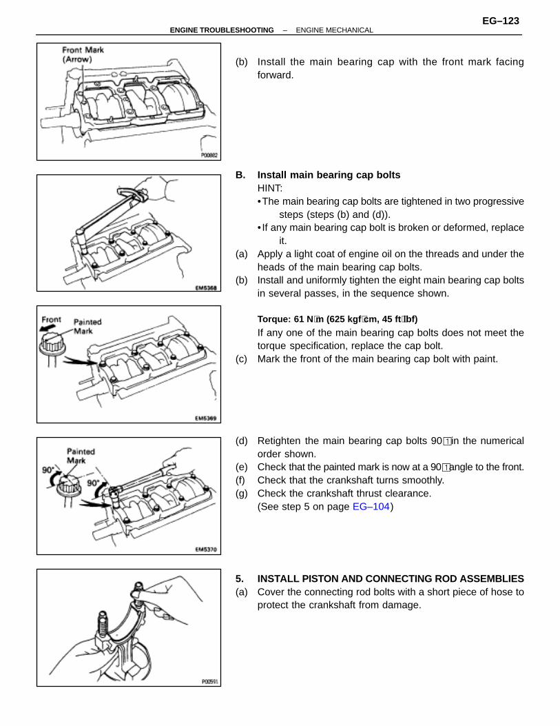
(b) Install the main bearing cap with the front mark facingforward.
B. Install main bearing cap boltsHINT:•The main bearing cap bolts are tightened in two progressive
steps (steps (b) and (d)).• If any main bearing cap bolt is broken or deformed, replace
it.(a) Apply a light coat of engine oil on the threads and under the
heads of the main bearing cap bolts.(b) Install and uniformly tighten the eight main bearing cap bolts
in several passes, in the sequence shown.
Torque: 61 N ⋅m (625 kgf ⋅cm, 45 ft ⋅lbf)
If any one of the main bearing cap bolts does not meet thetorque specification, replace the cap bolt.
(c) Mark the front of the main bearing cap bolt with paint.
(d) Retighten the main bearing cap bolts 90� in the numericalorder shown.
(e) Check that the painted mark is now at a 90� angle to the front.(f) Check that the crankshaft turns smoothly.(g) Check the crankshaft thrust clearance.
(See step 5 on page EG–104)
5. INSTALL PISTON AND CONNECTING ROD ASSEMBLIES(a) Cover the connecting rod bolts with a short piece of hose to
protect the crankshaft from damage.
–ENGINE TROUBLESHOOTING ENGINE MECHANICALEG–123

(b) Using a piston ring compressor, push the correctly numberedpiston and connecting rod assemblies into each cylinder withthe front mark of the piston facing forward.
6. INSTALL CONNECTING ROD CAPSA. Place connecting rod cap on connecting rod(a) Match the numbered connecting rod cap with the connecting
rod.(b) Install the connecting rod cap with the front mark facing
forward.
B. Install connecting rod cap nutsHINT:• The connecting rod cap nuts are tightened in two
progressive steps (steps (b) and (d)).• If any connecting rod bolt is broken or deformed, replace
them.
(a) Apply a light of engine oil on the threads and under the nutsof the connecting rod cap.
(b) Using SST, install and alternately tighten the nuts of theconnecting rod cap in several passes.SST 09011–38121Torque: 25 N ⋅m (250 kgf ⋅cm, 18 ft ⋅lbf)
If any one of the connecting rod cap nuts does not meet thetorque specification, replace the cap nut.
(c) Mark the front of the connecting rod cap nut and bolt withpaint.
EG–124–ENGINE TROUBLESHOOTING ENGINE MECHANICAL

(d) Retighten the connecting rod cap nuts 905 as shown.(e) Check that the painted mark is now at a 905 angle to the front.(f) Check that the crankshaft turns smoothly.(g) Check the connecting rod thrust clearance.
(See step 2 on page EG–101)
7. INSTALL REAR OIL SEAL RETAINER(a) Remove any old packing (FIPG) material and be careful not
to drop any oil on the contact surfaces of the retainer andcylinder block.•Using a razor blade and gasket scraper, remove all the old
packing (FIPG) material from the gasket surfaces andsealing groove.
•Thoroughly clean all components to remove all the loosematerial.
•Using a non–residue solvent, clean both sealing surfaces.
(b) Apply seal packing to the retainer as shown in the illustration.Seal packing:
Part No.08826–00080 or equivalent
• Install a nozzle that has been cut to a 2–3 mm (0.08–0.12in.) opening.
HINT: Avoid applying an excessive amount to the surface.•Parts must be assembled within 5 minutes of application.
Otherwise the material must be removed and reapplied.• Immediately remove nozzle from the tube and reinstall cap.
(c) Install the retainer with the six bolts.Torque: 7.8 N ⋅m (80 kgf ⋅cm, 69 in. ⋅lbf)
–ENGINE TROUBLESHOOTING ENGINE MECHANICALEG–125
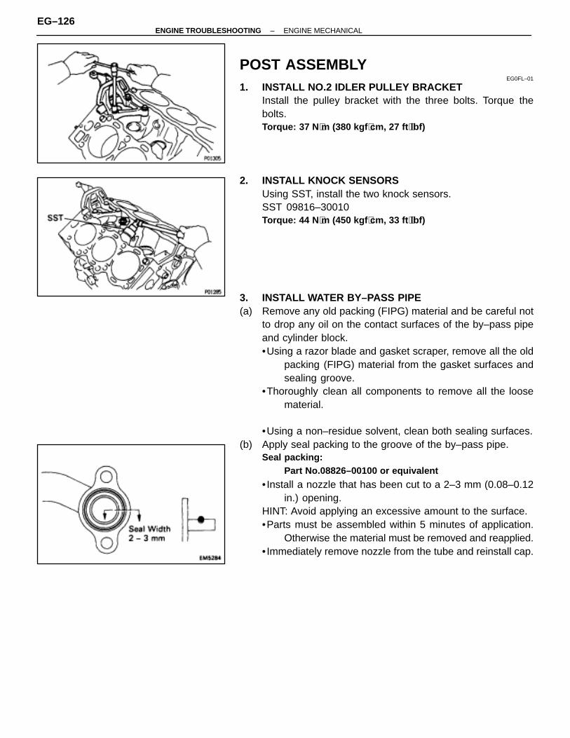
POST ASSEMBLYEG0FL–01
1. INSTALL NO.2 IDLER PULLEY BRACKETInstall the pulley bracket with the three bolts. Torque thebolts.Torque: 37 N ⋅m (380 kgf ⋅cm, 27 ft ⋅lbf)
2. INSTALL KNOCK SENSORSUsing SST, install the two knock sensors.SST 09816–30010Torque: 44 N ⋅m (450 kgf ⋅cm, 33 ft ⋅lbf)
3. INSTALL WATER BY–PASS PIPE(a) Remove any old packing (FIPG) material and be careful not
to drop any oil on the contact surfaces of the by–pass pipeand cylinder block.•Using a razor blade and gasket scraper, remove all the old
packing (FIPG) material from the gasket surfaces andsealing groove.
•Thoroughly clean all components to remove all the loosematerial.
•Using a non–residue solvent, clean both sealing surfaces.(b) Apply seal packing to the groove of the by–pass pipe.
Seal packing:Part No.08826–00100 or equivalent
• Install a nozzle that has been cut to a 2–3 mm (0.08–0.12in.) opening.
HINT: Avoid applying an excessive amount to the surface.•Parts must be assembled within 5 minutes of application.
Otherwise the material must be removed and reapplied.• Immediately remove nozzle from the tube and reinstall cap.
EG–126–ENGINE TROUBLESHOOTING ENGINE MECHANICAL
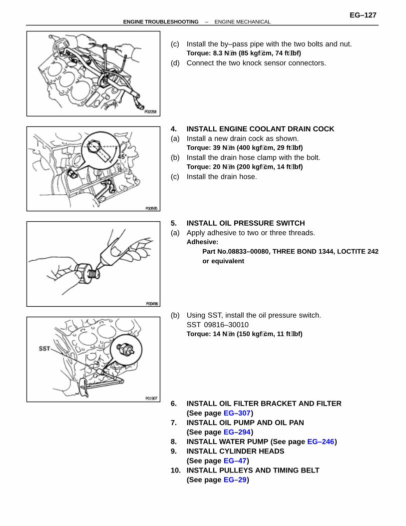
(c) Install the by–pass pipe with the two bolts and nut.Torque: 8.3 N ⋅m (85 kgf ⋅cm, 74 ft ⋅lbf)
(d) Connect the two knock sensor connectors.
4. INSTALL ENGINE COOLANT DRAIN COCK(a) Install a new drain cock as shown.
Torque: 39 N ⋅m (400 kgf ⋅cm, 29 ft ⋅lbf)
(b) Install the drain hose clamp with the bolt.Torque: 20 N ⋅m (200 kgf ⋅cm, 14 ft ⋅lbf)
(c) Install the drain hose.
5. INSTALL OIL PRESSURE SWITCH(a) Apply adhesive to two or three threads.
Adhesive:Part No.08833–00080, THREE BOND 1344, LOCTITE 242or equivalent
(b) Using SST, install the oil pressure switch.SST 09816–30010Torque: 14 N ⋅m (150 kgf ⋅cm, 11 ft ⋅lbf)
6. INSTALL OIL FILTER BRACKET AND FILTER(See page EG–307)
7. INSTALL OIL PUMP AND OIL PAN(See page EG–294)
8. INSTALL WATER PUMP (See page EG–246)9. INSTALL CYLINDER HEADS
(See page EG–47)10. INSTALL PULLEYS AND TIMING BELT
(See page EG–29)
–ENGINE TROUBLESHOOTING ENGINE MECHANICALEG–127
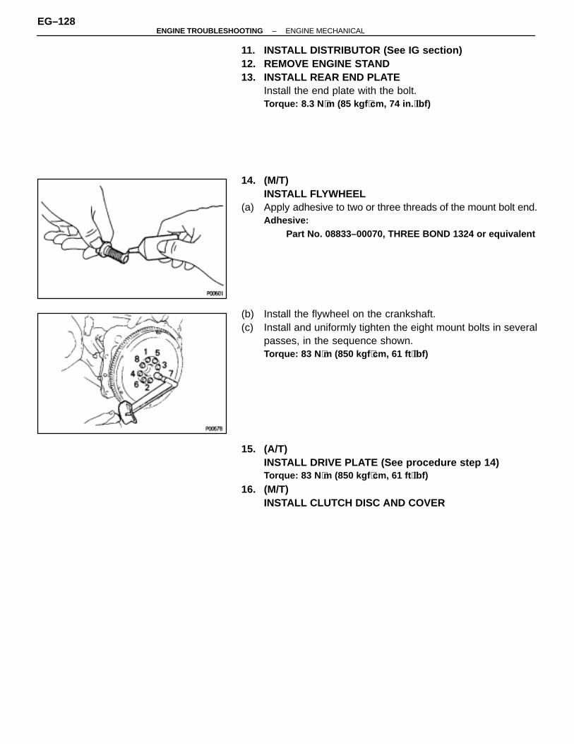
11. INSTALL DISTRIBUTOR (See IG section)12. REMOVE ENGINE STAND13. INSTALL REAR END PLATE
Install the end plate with the bolt.Torque: 8.3 N ⋅m (85 kgf ⋅cm, 74 in. ⋅lbf)
14. (M/T)INSTALL FLYWHEEL
(a) Apply adhesive to two or three threads of the mount bolt end.Adhesive:
Part No. 08833–00070, THREE BOND 1324 or equivalent
(b) Install the flywheel on the crankshaft.(c) Install and uniformly tighten the eight mount bolts in several
passes, in the sequence shown.Torque: 83 N ⋅m (850 kgf ⋅cm, 61 ft ⋅lbf)
15. (A/T)INSTALL DRIVE PLATE (See procedure step 14)Torque: 83 N ⋅m (850 kgf ⋅cm, 61 ft ⋅lbf)
16. (M/T)INSTALL CLUTCH DISC AND COVER
EG–128–ENGINE TROUBLESHOOTING ENGINE MECHANICAL
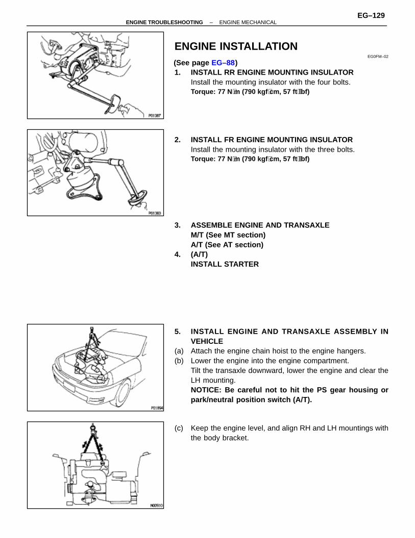
ENGINE INSTALLATIONEG0FM–02
(See page EG–88)1. INSTALL RR ENGINE MOUNTING INSULATOR
Install the mounting insulator with the four bolts.Torque: 77 N ⋅m (790 kgf ⋅cm, 57 ft ⋅lbf)
2. INSTALL FR ENGINE MOUNTING INSULATORInstall the mounting insulator with the three bolts.Torque: 77 N ⋅m (790 kgf ⋅cm, 57 ft ⋅lbf)
3. ASSEMBLE ENGINE AND TRANSAXLEM/T (See MT section)A/T (See AT section)
4. (A/T)INSTALL STARTER
5. INSTALL ENGINE AND TRANSAXLE A SSEMBLY INVEHICLE
(a) Attach the engine chain hoist to the engine hangers.(b) Lower the engine into the engine compartment.
Tilt the transaxle downward, lower the engine and clear theLH mounting.NOTICE: Be careful not to hit the PS gear housing orpark/neutral position switch (A/T).
(c) Keep the engine level, and align RH and LH mountings withthe body bracket.
–ENGINE TROUBLESHOOTING ENGINE MECHANICALEG–129
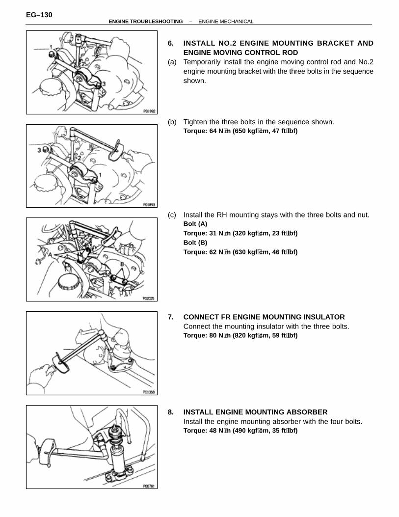
6. INSTALL NO.2 ENGINE MOUNTING BRACKET ANDENGINE MOVING CONTROL ROD
(a) Temporarily install the engine moving control rod and No.2engine mounting bracket with the three bolts in the sequenceshown.
(b) Tighten the three bolts in the sequence shown.Torque: 64 N ⋅m (650 kgf ⋅cm, 47 ft ⋅lbf)
(c) Install the RH mounting stays with the three bolts and nut.Bolt (A)Torque: 31 N ⋅m (320 kgf ⋅cm, 23 ft ⋅lbf)Bolt (B)Torque: 62 N ⋅m (630 kgf ⋅cm, 46 ft ⋅lbf)
7. CONNECT FR ENGINE MOUNTING INSULATORConnect the mounting insulator with the three bolts.Torque: 80 N ⋅m (820 kgf ⋅cm, 59 ft ⋅lbf)
8. INSTALL ENGINE MOUNTING ABSORBERInstall the engine mounting absorber with the four bolts.Torque: 48 N ⋅m (490 kgf ⋅cm, 35 ft ⋅lbf)
EG–130–ENGINE TROUBLESHOOTING ENGINE MECHANICAL
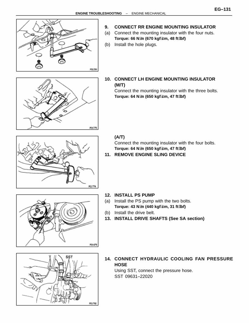
9. CONNECT RR ENGINE MOUNTING INSULATOR(a) Connect the mounting insulator with the four nuts.
Torque: 66 N ⋅m (670 kgf ⋅cm, 48 ft ⋅lbf)
(b) Install the hole plugs.
10. CONNECT LH ENGINE MOUNTING INSULATOR(M/T)Connect the mounting insulator with the three bolts.Torque: 64 N ⋅m (650 kgf ⋅cm, 47 ft ⋅lbf)
(A/T)Connect the mounting insulator with the four bolts.Torque: 64 N ⋅m (650 kgf ⋅cm, 47 ft ⋅lbf)
11. REMOVE ENGINE SLING DEVICE
12. INSTALL PS PUMP(a) Install the PS pump with the two bolts.
Torque: 43 N ⋅m (440 kgf ⋅cm, 31 ft ⋅lbf)
(b) Install the drive belt.13. INSTALL DRIVE SHAFTS (See SA section)
14. CONNECT HYDRAULIC COOLING FAN PR ESSUREHOSEUsing SST, connect the pressure hose.SST 09631–22020
–ENGINE TROUBLESHOOTING ENGINE MECHANICALEG–131
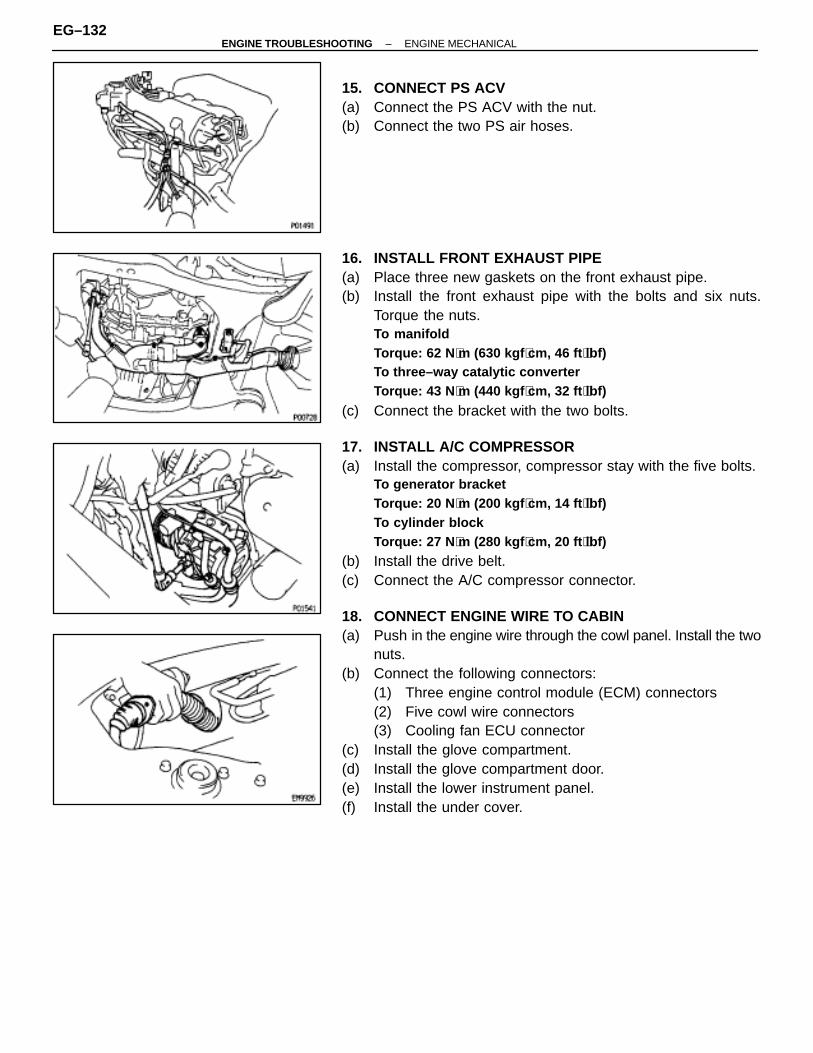
15. CONNECT PS ACV(a) Connect the PS ACV with the nut.(b) Connect the two PS air hoses.
16. INSTALL FRONT EXHAUST PIPE(a) Place three new gaskets on the front exhaust pipe.(b) Install the front exhaust pipe with the bolts and six nuts.
Torque the nuts.To manifoldTorque: 62 N ⋅m (630 kgf ⋅cm, 46 ft ⋅lbf)To three–way catalytic converterTorque: 43 N ⋅m (440 kgf ⋅cm, 32 ft ⋅lbf)
(c) Connect the bracket with the two bolts.
17. INSTALL A/C COMPRESSOR(a) Install the compressor, compressor stay with the five bolts.
To generator bracketTorque: 20 N ⋅m (200 kgf ⋅cm, 14 ft ⋅lbf)To cylinder blockTorque: 27 N ⋅m (280 kgf ⋅cm, 20 ft ⋅lbf)
(b) Install the drive belt.(c) Connect the A/C compressor connector.
18. CONNECT ENGINE WIRE TO CABIN(a) Push in the engine wire through the cowl panel. Install the two
nuts.(b) Connect the following connectors:
(1) Three engine control module (ECM) connectors(2) Five cowl wire connectors(3) Cooling fan ECU connector
(c) Install the glove compartment.(d) Install the glove compartment door.(e) Install the lower instrument panel.(f) Install the under cover.
EG–132–ENGINE TROUBLESHOOTING ENGINE MECHANICAL
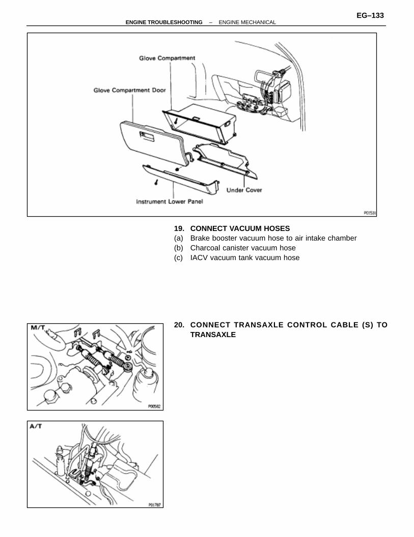
19. CONNECT VACUUM HOSES(a) Brake booster vacuum hose to air intake chamber(b) Charcoal canister vacuum hose(c) IACV vacuum tank vacuum hose
20. CONNECT TRANSAXLE CONTROL CABLE (S) TOTRANSAXLE
–ENGINE TROUBLESHOOTING ENGINE MECHANICALEG–133
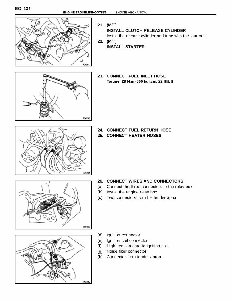
21. (M/T)INSTALL CLUTCH RELEASE CYLINDERInstall the release cylinder and tube with the four bolts.
22. (M/T)INSTALL STARTER
23. CONNECT FUEL INLET HOSETorque: 29 N ⋅m (300 kgf ⋅cm, 22 ft ⋅lbf)
24. CONNECT FUEL RETURN HOSE25. CONNECT HEATER HOSES
26. CONNECT WIRES AND CONNECTORS(a) Connect the three connectors to the relay box.(b) Install the engine relay box.(c) Two connectors from LH fender apron
(d) Ignition connector(e) Ignition coil connector(f) High–tension cord to ignition coil(g) Noise filter connector(h) Connector from fender apron
EG–134–ENGINE TROUBLESHOOTING ENGINE MECHANICAL
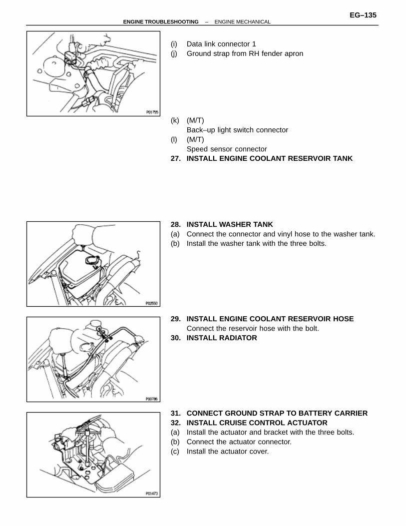
(i) Data link connector 1(j) Ground strap from RH fender apron
(k) (M/T)Back–up light switch connector
(l) (M/T)Speed sensor connector
27. INSTALL ENGINE COOLANT RESERVOIR TANK
28. INSTALL WASHER TANK(a) Connect the connector and vinyl hose to the washer tank.(b) Install the washer tank with the three bolts.
29. INSTALL ENGINE COOLANT RESERVOIR HOSEConnect the reservoir hose with the bolt.
30. INSTALL RADIATOR
31. CONNECT GROUND STRAP TO BATTERY CARRIER32. INSTALL CRUISE CONTROL ACTUATOR(a) Install the actuator and bracket with the three bolts.(b) Connect the actuator connector.(c) Install the actuator cover.
–ENGINE TROUBLESHOOTING ENGINE MECHANICALEG–135
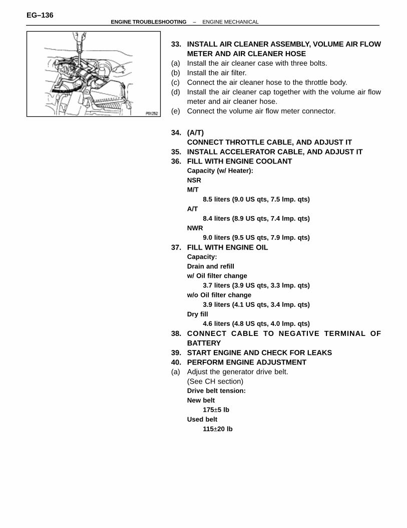
33. INSTALL AIR CLEANER ASSEMBLY, VOLUME AIR FLOWMETER AND AIR CLEANER HOSE
(a) Install the air cleaner case with three bolts.(b) Install the air filter.(c) Connect the air cleaner hose to the throttle body.(d) Install the air cleaner cap together with the volume air flow
meter and air cleaner hose.(e) Connect the volume air flow meter connector.
34. (A/T)CONNECT THROTTLE CABLE, AND ADJUST IT
35. INSTALL ACCELERATOR CABLE, AND ADJUST IT36. FILL WITH ENGINE COOLANT
Capacity (w/ Heater):NSRM/T
8.5 liters (9.0 US qts, 7.5 lmp. qts)A/T
8.4 liters (8.9 US qts, 7.4 lmp. qts)NWR
9.0 liters (9.5 US qts, 7.9 lmp. qts)
37. FILL WITH ENGINE OILCapacity:Drain and refillw/ Oil filter change
3.7 liters (3.9 US qts, 3.3 lmp. qts)w/o Oil filter change
3.9 liters (4.1 US qts, 3.4 lmp. qts)Dry fill
4.6 liters (4.8 US qts, 4.0 lmp. qts)
38. CONNECT CABLE TO NEGATIVE TERMINAL OFBATTERY
39. START ENGINE AND CHECK FOR LEAKS40. PERFORM ENGINE ADJUSTMENT(a) Adjust the generator drive belt.
(See CH section)Drive belt tension:New belt
175±5 lbUsed belt
115±20 lb
EG–136–ENGINE TROUBLESHOOTING ENGINE MECHANICAL
(b) Adjust the PS drive belt.(See SR section)Drive belt tension:New belt
150–185 lbUsed belt
115±20 lb
(c) Adjust the ignition timing.(See IG section)Ignition timing:
10° ± BTDC @ idle(w/ Terminals TE1 and E1 connected)
41. INSTALL ENGINE UNDER COVERS42. INSTALL HOOD43. PREFORM ROAD TEST
Check for abnormal noise, shock, slippage, correct shiftpoints and smooth operation.
44. RECHECK ENGINE COOLANT AND ENGINE OIL LEVELS
–ENGINE TROUBLESHOOTING ENGINE MECHANICALEG–137

EXHAUST SYSTEMCOMPONENTS
EG0FN–01
EG–138–ENGINE TROUBLESHOOTING ENGINE MECHANICAL
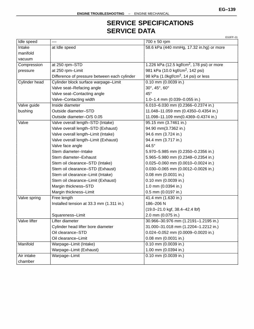
SERVICE SPECIFICATIONSSERVICE DATA
EG0FP–01
ÑÑÑÑÑÑÑÑÑÑÑÑ
Idle speed ÑÑÑÑÑÑÑÑÑÑÑÑÑÑÑÑÑÑÑÑÑÑÑÑÑÑÑÑÑÑÑÑ
–– ÑÑÑÑÑÑÑÑÑÑÑÑÑÑÑÑÑÑÑÑÑÑÑÑÑÑÑÑÑÑÑÑ
700 ± 50 rpm
ÑÑÑÑÑÑIntake ÑÑÑÑÑÑÑÑÑÑÑÑÑÑÑÑat Idle speed ÑÑÑÑÑÑÑÑÑÑÑÑÑÑÑÑ58.6 kPa (440 mmHg, 17.32 in.hg) or moreÑÑÑÑÑÑÑÑÑÑÑÑmanifold
ÑÑÑÑÑÑÑÑÑÑÑÑÑÑÑÑÑÑÑÑÑÑÑÑÑÑÑÑÑÑÑÑ
ÑÑÑÑÑÑÑÑÑÑÑÑÑÑÑÑÑÑÑÑÑÑÑÑÑÑÑÑÑÑÑÑÑÑÑÑÑÑ
ÑÑÑÑÑÑvacuum
ÑÑÑÑÑÑÑÑÑÑÑÑÑÑÑÑÑÑÑÑÑÑÑÑÑÑÑÑÑÑÑÑ
ÑÑÑÑÑÑÑÑÑÑÑÑÑÑÑÑÑÑÑÑÑÑÑÑÑÑÑÑÑÑÑÑÑÑÑÑÑÑ
ÑÑÑÑÑÑCompression ÑÑÑÑÑÑÑÑÑÑÑÑÑÑÑÑ
ÑÑÑÑÑÑÑÑÑÑÑÑÑÑÑÑat 250 rpm–STD ÑÑÑÑÑÑÑÑÑÑÑÑÑÑÑÑ
ÑÑÑÑÑÑÑÑÑÑÑÑÑÑÑÑ1.226 kPa (12.5 kgf/cm2, 178 psi) or more
ÑÑÑÑÑÑÑÑÑÑÑÑ
pressure ÑÑÑÑÑÑÑÑÑÑÑÑÑÑÑÑÑÑÑÑÑÑÑÑÑÑÑÑÑÑÑÑ
at 250 rpm–Limit ÑÑÑÑÑÑÑÑÑÑÑÑÑÑÑÑÑÑÑÑÑÑÑÑÑÑÑÑÑÑÑÑ
981 kPa (10.0 kgf/cm2, 142 psi)ÑÑÑÑÑÑÑÑÑÑÑÑ
ÑÑÑÑÑÑÑÑÑÑÑÑÑÑÑÑÑÑÑÑÑÑÑÑÑÑÑÑÑÑÑÑ
Difference of pressure between each cylinder ÑÑÑÑÑÑÑÑÑÑÑÑÑÑÑÑÑÑÑÑÑÑÑÑÑÑÑÑÑÑÑÑ
98 kPa (1.0kgf/cm2, 14 psi) or lessÑÑÑÑÑÑÑÑÑÑÑÑ
Cylinder headÑÑÑÑÑÑÑÑÑÑÑÑÑÑÑÑÑÑÑÑÑÑÑÑÑÑÑÑÑÑÑÑ
Cylinder block surface warpage–Limit ÑÑÑÑÑÑÑÑÑÑÑÑÑÑÑÑÑÑÑÑÑÑÑÑÑÑÑÑÑÑÑÑ
0.10 mm (0.0039 in.)ÑÑÑÑÑÑÑÑÑÑÑÑ
ÑÑÑÑÑÑÑÑÑÑÑÑÑÑÑÑÑÑÑÑÑÑÑÑÑÑÑÑÑÑÑÑ
Valve seat–Refacing angle ÑÑÑÑÑÑÑÑÑÑÑÑÑÑÑÑÑÑÑÑÑÑÑÑÑÑÑÑÑÑÑÑ
30°, 45°, 60°ÑÑÑÑÑÑÑÑÑÑÑÑ
ÑÑÑÑÑÑÑÑÑÑÑÑÑÑÑÑÑÑÑÑÑÑÑÑÑÑÑÑÑÑÑÑ
Valve seat–Contacting angle ÑÑÑÑÑÑÑÑÑÑÑÑÑÑÑÑÑÑÑÑÑÑÑÑÑÑÑÑÑÑÑÑ
45°
ÑÑÑÑÑÑÑÑÑÑÑÑ
ÑÑÑÑÑÑÑÑÑÑÑÑÑÑÑÑÑÑÑÑÑÑÑÑÑÑÑÑÑÑÑÑ
Valve–Contacting width ÑÑÑÑÑÑÑÑÑÑÑÑÑÑÑÑÑÑÑÑÑÑÑÑÑÑÑÑÑÑÑÑ
1.0–1.4 mm (0.039–0.055 in.)
ÑÑÑÑÑÑÑÑÑÑÑÑ
Valve guide ÑÑÑÑÑÑÑÑÑÑÑÑÑÑÑÑÑÑÑÑÑÑÑÑÑÑÑÑÑÑÑÑ
Inside diameter ÑÑÑÑÑÑÑÑÑÑÑÑÑÑÑÑÑÑÑÑÑÑÑÑÑÑÑÑÑÑÑÑ
6.010–6.030 mm (0.2366–0.2374 in.)
ÑÑÑÑÑÑbushing ÑÑÑÑÑÑÑÑÑÑÑÑÑÑÑÑOutside diameter–STD ÑÑÑÑÑÑÑÑÑÑÑÑÑÑÑÑ11.048–11.059 mm (0.4350–0.4354 in.)ÑÑÑÑÑÑÑÑÑÑÑÑ
ÑÑÑÑÑÑÑÑÑÑÑÑÑÑÑÑÑÑÑÑÑÑÑÑÑÑÑÑÑÑÑÑOutside diameter–O/S 0.05
ÑÑÑÑÑÑÑÑÑÑÑÑÑÑÑÑÑÑÑÑÑÑÑÑÑÑÑÑÑÑÑÑ11.098–11.109 mm(0.4369–0.4374 in.)ÑÑÑÑÑÑ
ÑÑÑÑÑÑValve
ÑÑÑÑÑÑÑÑÑÑÑÑÑÑÑÑÑÑÑÑÑÑÑÑÑÑÑÑÑÑÑÑ
Valve overall length–STD (Intake)ÑÑÑÑÑÑÑÑÑÑÑÑÑÑÑÑÑÑÑÑÑÑÑÑÑÑÑÑÑÑÑÑ
95.15 mm (3.7461 in.)ÑÑÑÑÑÑÑÑÑÑÑÑ
ÑÑÑÑÑÑÑÑÑÑÑÑÑÑÑÑÑÑÑÑÑÑÑÑÑÑÑÑÑÑÑÑ
Valve overall length–STD (Exhaust) ÑÑÑÑÑÑÑÑÑÑÑÑÑÑÑÑÑÑÑÑÑÑÑÑÑÑÑÑÑÑÑÑ
94.90 mm(3.7362 in.)ÑÑÑÑÑÑÑÑÑÑÑÑ
ÑÑÑÑÑÑÑÑÑÑÑÑÑÑÑÑÑÑÑÑÑÑÑÑÑÑÑÑÑÑÑÑ
Valve overall length–Limit (Intake) ÑÑÑÑÑÑÑÑÑÑÑÑÑÑÑÑÑÑÑÑÑÑÑÑÑÑÑÑÑÑÑÑ
94.6 mm (3.724 in.)ÑÑÑÑÑÑÑÑÑÑÑÑ
ÑÑÑÑÑÑÑÑÑÑÑÑÑÑÑÑÑÑÑÑÑÑÑÑÑÑÑÑÑÑÑÑ
Valve overall length–Limit (Exhaust) ÑÑÑÑÑÑÑÑÑÑÑÑÑÑÑÑÑÑÑÑÑÑÑÑÑÑÑÑÑÑÑÑ
94.4 mm (3.717 in.)ÑÑÑÑÑÑÑÑÑÑÑÑ
ÑÑÑÑÑÑÑÑÑÑÑÑÑÑÑÑÑÑÑÑÑÑÑÑÑÑÑÑÑÑÑÑ
Valve face angle ÑÑÑÑÑÑÑÑÑÑÑÑÑÑÑÑÑÑÑÑÑÑÑÑÑÑÑÑÑÑÑÑ
44.5°ÑÑÑÑÑÑÑÑÑÑÑÑ
ÑÑÑÑÑÑÑÑÑÑÑÑÑÑÑÑÑÑÑÑÑÑÑÑÑÑÑÑÑÑÑÑ
Stem diameter–Intake ÑÑÑÑÑÑÑÑÑÑÑÑÑÑÑÑÑÑÑÑÑÑÑÑÑÑÑÑÑÑÑÑ
5.970–5.985 mm (0.2350–0.2356 in.)
ÑÑÑÑÑÑÑÑÑÑÑÑ
ÑÑÑÑÑÑÑÑÑÑÑÑÑÑÑÑÑÑÑÑÑÑÑÑÑÑÑÑÑÑÑÑ
Stem diameter–Exhaust ÑÑÑÑÑÑÑÑÑÑÑÑÑÑÑÑÑÑÑÑÑÑÑÑÑÑÑÑÑÑÑÑ
5.965–5.980 mm (0.2348–0.2354 in.)
ÑÑÑÑÑÑÑÑÑÑÑÑ
ÑÑÑÑÑÑÑÑÑÑÑÑÑÑÑÑÑÑÑÑÑÑÑÑÑÑÑÑÑÑÑÑ
Stem oil clearance–STD (Intake) ÑÑÑÑÑÑÑÑÑÑÑÑÑÑÑÑÑÑÑÑÑÑÑÑÑÑÑÑÑÑÑÑ
0.025–0.060 mm (0.0010–0.0024 in.)
ÑÑÑÑÑÑÑÑÑÑÑÑÑÑÑÑÑÑÑÑÑÑStem oil clearance–STD (Exhaust) ÑÑÑÑÑÑÑÑÑÑÑÑÑÑÑÑ0.030–0.065 mm (0.0012–0.0026 in.)ÑÑÑÑÑÑÑÑÑÑÑÑ
ÑÑÑÑÑÑÑÑÑÑÑÑÑÑÑÑÑÑÑÑÑÑÑÑÑÑÑÑÑÑÑÑStem oil clearance–Limit (Intake)
ÑÑÑÑÑÑÑÑÑÑÑÑÑÑÑÑÑÑÑÑÑÑÑÑÑÑÑÑÑÑÑÑ0.08 mm (0.0031 in.)ÑÑÑÑÑÑ
ÑÑÑÑÑÑÑÑÑÑÑÑÑÑÑÑÑÑÑÑÑÑÑÑÑÑÑÑÑÑÑÑÑÑÑÑÑÑStem oil clearance–Limit (Exhaust)
ÑÑÑÑÑÑÑÑÑÑÑÑÑÑÑÑÑÑÑÑÑÑÑÑÑÑÑÑÑÑÑÑ0.10 mm (0.0039 in.)ÑÑÑÑÑÑ
ÑÑÑÑÑÑÑÑÑÑÑÑÑÑÑÑÑÑÑÑÑÑÑÑÑÑÑÑÑÑÑÑÑÑÑÑÑÑ
Margin thickness–STDÑÑÑÑÑÑÑÑÑÑÑÑÑÑÑÑÑÑÑÑÑÑÑÑÑÑÑÑÑÑÑÑ
1.0 mm (0.0394 in.)ÑÑÑÑÑÑÑÑÑÑÑÑ
ÑÑÑÑÑÑÑÑÑÑÑÑÑÑÑÑÑÑÑÑÑÑÑÑÑÑÑÑÑÑÑÑ
Margin thickness–Limit ÑÑÑÑÑÑÑÑÑÑÑÑÑÑÑÑÑÑÑÑÑÑÑÑÑÑÑÑÑÑÑÑ
0.5 mm (0.0197 in.)ÑÑÑÑÑÑÑÑÑÑÑÑ
Valve spring ÑÑÑÑÑÑÑÑÑÑÑÑÑÑÑÑÑÑÑÑÑÑÑÑÑÑÑÑÑÑÑÑ
Free length ÑÑÑÑÑÑÑÑÑÑÑÑÑÑÑÑÑÑÑÑÑÑÑÑÑÑÑÑÑÑÑÑ
41.4 mm (1.630 in.)ÑÑÑÑÑÑÑÑÑÑÑÑ
ÑÑÑÑÑÑÑÑÑÑÑÑÑÑÑÑÑÑÑÑÑÑÑÑÑÑÑÑÑÑÑÑ
Installed tension at 33.3 mm (1.311 in.) ÑÑÑÑÑÑÑÑÑÑÑÑÑÑÑÑÑÑÑÑÑÑÑÑÑÑÑÑÑÑÑÑ
186–206 NÑÑÑÑÑÑÑÑÑÑÑÑ
ÑÑÑÑÑÑÑÑÑÑÑÑÑÑÑÑÑÑÑÑÑÑÑÑÑÑÑÑÑÑÑÑ
ÑÑÑÑÑÑÑÑÑÑÑÑÑÑÑÑÑÑÑÑÑÑÑÑÑÑÑÑÑÑÑÑ
(19.0–21.0 kgf, 38.4–42.4 lbf)
ÑÑÑÑÑÑÑÑÑÑÑÑ
ÑÑÑÑÑÑÑÑÑÑÑÑÑÑÑÑÑÑÑÑÑÑÑÑÑÑÑÑÑÑÑÑ
Squareness–Limit ÑÑÑÑÑÑÑÑÑÑÑÑÑÑÑÑÑÑÑÑÑÑÑÑÑÑÑÑÑÑÑÑ
2.0 mm (0.075 in.)
ÑÑÑÑÑÑÑÑÑÑÑÑ
Valve lifter ÑÑÑÑÑÑÑÑÑÑÑÑÑÑÑÑÑÑÑÑÑÑÑÑÑÑÑÑÑÑÑÑ
Lifter diameter ÑÑÑÑÑÑÑÑÑÑÑÑÑÑÑÑÑÑÑÑÑÑÑÑÑÑÑÑÑÑÑÑ
30.966–30.976 mm (1.2191–1.2195 in.)
ÑÑÑÑÑÑÑÑÑÑÑÑ
ÑÑÑÑÑÑÑÑÑÑÑÑÑÑÑÑÑÑÑÑÑÑÑÑÑÑÑÑÑÑÑÑ
Cylinder head lifter bore diameter ÑÑÑÑÑÑÑÑÑÑÑÑÑÑÑÑÑÑÑÑÑÑÑÑÑÑÑÑÑÑÑÑ
31.000–31.018 mm (1.2204–1.2212 in.)
ÑÑÑÑÑÑÑÑÑÑÑÑÑÑÑÑÑÑÑÑÑÑOil clearance–STD ÑÑÑÑÑÑÑÑÑÑÑÑÑÑÑÑ0.024–0.052 mm (0.0009–0.0020 in.)ÑÑÑÑÑÑÑÑÑÑÑÑ
ÑÑÑÑÑÑÑÑÑÑÑÑÑÑÑÑÑÑÑÑÑÑÑÑÑÑÑÑÑÑÑÑOil clearance–Limit
ÑÑÑÑÑÑÑÑÑÑÑÑÑÑÑÑÑÑÑÑÑÑÑÑÑÑÑÑÑÑÑÑ0.08 mm (0.0031 in.)ÑÑÑÑÑÑ
ÑÑÑÑÑÑManifold
ÑÑÑÑÑÑÑÑÑÑÑÑÑÑÑÑÑÑÑÑÑÑÑÑÑÑÑÑÑÑÑÑ
Warpage–Limit (Intake)ÑÑÑÑÑÑÑÑÑÑÑÑÑÑÑÑÑÑÑÑÑÑÑÑÑÑÑÑÑÑÑÑ
0.10 mm (0.0039 in.)ÑÑÑÑÑÑÑÑÑÑÑÑ
ÑÑÑÑÑÑÑÑÑÑÑÑÑÑÑÑÑÑÑÑÑÑÑÑÑÑÑÑÑÑÑÑ
Warpage–Limit (Exhaust) ÑÑÑÑÑÑÑÑÑÑÑÑÑÑÑÑÑÑÑÑÑÑÑÑÑÑÑÑÑÑÑÑ
1.00 mm (0.0394 in.)ÑÑÑÑÑÑÑÑÑÑÑÑ
Air intake ÑÑÑÑÑÑÑÑÑÑÑÑÑÑÑÑÑÑÑÑÑÑÑÑÑÑÑÑÑÑÑÑ
Warpage–Limit ÑÑÑÑÑÑÑÑÑÑÑÑÑÑÑÑÑÑÑÑÑÑÑÑÑÑÑÑÑÑÑÑ
0.10 mm (0.0039 in.)ÑÑÑÑÑÑÑÑÑÑÑÑ
chamber ÑÑÑÑÑÑÑÑÑÑÑÑÑÑÑÑÑÑÑÑÑÑÑÑÑÑÑÑÑÑÑÑ
ÑÑÑÑÑÑÑÑÑÑÑÑÑÑÑÑÑÑÑÑÑÑÑÑÑÑÑÑÑÑÑÑ
–ENGINE TROUBLESHOOTING ENGINE MECHANICALEG–139
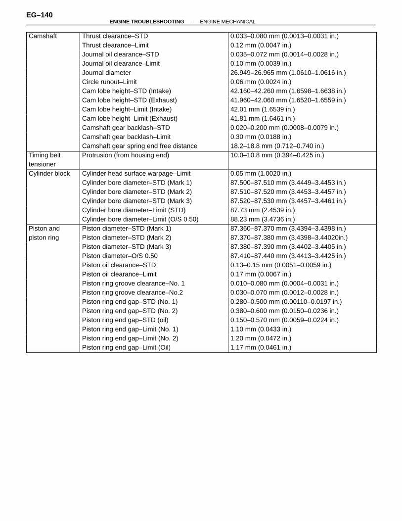
ÑÑÑÑÑÑÑÑÑÑÑÑ
Camshaft ÑÑÑÑÑÑÑÑÑÑÑÑÑÑÑÑÑÑÑÑÑÑÑÑÑÑÑÑÑÑÑÑ
Thrust clearance–STD ÑÑÑÑÑÑÑÑÑÑÑÑÑÑÑÑÑÑÑÑÑÑÑÑÑÑÑÑÑÑÑÑ
0.033–0.080 mm (0.0013–0.0031 in.)
ÑÑÑÑÑÑÑÑÑÑÑÑ
ÑÑÑÑÑÑÑÑÑÑÑÑÑÑÑÑÑÑÑÑÑÑÑÑÑÑÑÑÑÑÑÑ
Thrust clearance–Limit ÑÑÑÑÑÑÑÑÑÑÑÑÑÑÑÑÑÑÑÑÑÑÑÑÑÑÑÑÑÑÑÑ
0.12 mm (0.0047 in.)ÑÑÑÑÑÑÑÑÑÑÑÑ
ÑÑÑÑÑÑÑÑÑÑÑÑÑÑÑÑÑÑÑÑÑÑÑÑÑÑÑÑÑÑÑÑJournal oil clearance–STD
ÑÑÑÑÑÑÑÑÑÑÑÑÑÑÑÑÑÑÑÑÑÑÑÑÑÑÑÑÑÑÑÑ0.035–0.072 mm (0.0014–0.0028 in.)ÑÑÑÑÑÑ
ÑÑÑÑÑÑÑÑÑÑÑÑÑÑÑÑÑÑÑÑÑÑÑÑÑÑÑÑÑÑÑÑÑÑÑÑÑÑJournal oil clearance–Limit
ÑÑÑÑÑÑÑÑÑÑÑÑÑÑÑÑÑÑÑÑÑÑÑÑÑÑÑÑÑÑÑÑ0.10 mm (0.0039 in.)ÑÑÑÑÑÑ
ÑÑÑÑÑÑÑÑÑÑÑÑÑÑÑÑÑÑÑÑÑÑÑÑÑÑÑÑÑÑÑÑÑÑÑÑÑÑ
Journal diameterÑÑÑÑÑÑÑÑÑÑÑÑÑÑÑÑÑÑÑÑÑÑÑÑÑÑÑÑÑÑÑÑ
26.949–26.965 mm (1.0610–1.0616 in.)ÑÑÑÑÑÑÑÑÑÑÑÑ
ÑÑÑÑÑÑÑÑÑÑÑÑÑÑÑÑÑÑÑÑÑÑÑÑÑÑÑÑÑÑÑÑ
Circle runout–Limit ÑÑÑÑÑÑÑÑÑÑÑÑÑÑÑÑÑÑÑÑÑÑÑÑÑÑÑÑÑÑÑÑ
0.06 mm (0.0024 in.)ÑÑÑÑÑÑÑÑÑÑÑÑ
ÑÑÑÑÑÑÑÑÑÑÑÑÑÑÑÑÑÑÑÑÑÑÑÑÑÑÑÑÑÑÑÑ
Cam lobe height–STD (Intake) ÑÑÑÑÑÑÑÑÑÑÑÑÑÑÑÑÑÑÑÑÑÑÑÑÑÑÑÑÑÑÑÑ
42.160–42.260 mm (1.6598–1.6638 in.)ÑÑÑÑÑÑÑÑÑÑÑÑ
ÑÑÑÑÑÑÑÑÑÑÑÑÑÑÑÑÑÑÑÑÑÑÑÑÑÑÑÑÑÑÑÑ
Cam lobe height–STD (Exhaust) ÑÑÑÑÑÑÑÑÑÑÑÑÑÑÑÑÑÑÑÑÑÑÑÑÑÑÑÑÑÑÑÑ
41.960–42.060 mm (1.6520–1.6559 in.)ÑÑÑÑÑÑÑÑÑÑÑÑ
ÑÑÑÑÑÑÑÑÑÑÑÑÑÑÑÑÑÑÑÑÑÑÑÑÑÑÑÑÑÑÑÑ
Cam lobe height–Limit (Intake) ÑÑÑÑÑÑÑÑÑÑÑÑÑÑÑÑÑÑÑÑÑÑÑÑÑÑÑÑÑÑÑÑ
42.01 mm (1.6539 in.)
ÑÑÑÑÑÑÑÑÑÑÑÑ
ÑÑÑÑÑÑÑÑÑÑÑÑÑÑÑÑÑÑÑÑÑÑÑÑÑÑÑÑÑÑÑÑ
Cam lobe height–Limit (Exhaust) ÑÑÑÑÑÑÑÑÑÑÑÑÑÑÑÑÑÑÑÑÑÑÑÑÑÑÑÑÑÑÑÑ
41.81 mm (1.6461 in.)
ÑÑÑÑÑÑÑÑÑÑÑÑ
ÑÑÑÑÑÑÑÑÑÑÑÑÑÑÑÑÑÑÑÑÑÑÑÑÑÑÑÑÑÑÑÑ
Camshaft gear backlash–STD ÑÑÑÑÑÑÑÑÑÑÑÑÑÑÑÑÑÑÑÑÑÑÑÑÑÑÑÑÑÑÑÑ
0.020–0.200 mm (0.0008–0.0079 in.)
ÑÑÑÑÑÑÑÑÑÑÑÑ
ÑÑÑÑÑÑÑÑÑÑÑÑÑÑÑÑÑÑÑÑÑÑÑÑÑÑÑÑÑÑÑÑ
Camshaft gear backlash–Limit ÑÑÑÑÑÑÑÑÑÑÑÑÑÑÑÑÑÑÑÑÑÑÑÑÑÑÑÑÑÑÑÑ
0.30 mm (0.0188 in.)
ÑÑÑÑÑÑÑÑÑÑÑÑÑÑÑÑÑÑÑÑÑÑCamshaft gear spring end free distance ÑÑÑÑÑÑÑÑÑÑÑÑÑÑÑÑ18.2–18.8 mm (0.712–0.740 in.)ÑÑÑÑÑÑÑÑÑÑÑÑTiming belt
ÑÑÑÑÑÑÑÑÑÑÑÑÑÑÑÑÑÑÑÑÑÑÑÑÑÑÑÑÑÑÑÑProtrusion (from housing end)
ÑÑÑÑÑÑÑÑÑÑÑÑÑÑÑÑÑÑÑÑÑÑÑÑÑÑÑÑÑÑÑÑ10.0–10.8 mm (0.394–0.425 in.)ÑÑÑÑÑÑ
ÑÑÑÑÑÑtensioner
ÑÑÑÑÑÑÑÑÑÑÑÑÑÑÑÑÑÑÑÑÑÑÑÑÑÑÑÑÑÑÑÑ
ÑÑÑÑÑÑÑÑÑÑÑÑÑÑÑÑÑÑÑÑÑÑÑÑÑÑÑÑÑÑÑÑÑÑÑÑÑÑ
ÑÑÑÑÑÑCylinder block
ÑÑÑÑÑÑÑÑÑÑÑÑÑÑÑÑÑÑÑÑÑÑÑÑÑÑÑÑÑÑÑÑ
Cylinder head surface warpage–LimitÑÑÑÑÑÑÑÑÑÑÑÑÑÑÑÑÑÑÑÑÑÑÑÑÑÑÑÑÑÑÑÑ
0.05 mm (1.0020 in.)ÑÑÑÑÑÑÑÑÑÑÑÑ
ÑÑÑÑÑÑÑÑÑÑÑÑÑÑÑÑÑÑÑÑÑÑÑÑÑÑÑÑÑÑÑÑ
Cylinder bore diameter–STD (Mark 1) ÑÑÑÑÑÑÑÑÑÑÑÑÑÑÑÑÑÑÑÑÑÑÑÑÑÑÑÑÑÑÑÑ
87.500–87.510 mm (3.4449–3.4453 in.)ÑÑÑÑÑÑÑÑÑÑÑÑ
ÑÑÑÑÑÑÑÑÑÑÑÑÑÑÑÑÑÑÑÑÑÑÑÑÑÑÑÑÑÑÑÑ
Cylinder bore diameter–STD (Mark 2) ÑÑÑÑÑÑÑÑÑÑÑÑÑÑÑÑÑÑÑÑÑÑÑÑÑÑÑÑÑÑÑÑ
87.510–87.520 mm (3.4453–3.4457 in.)ÑÑÑÑÑÑÑÑÑÑÑÑ
ÑÑÑÑÑÑÑÑÑÑÑÑÑÑÑÑÑÑÑÑÑÑÑÑÑÑÑÑÑÑÑÑ
Cylinder bore diameter–STD (Mark 3) ÑÑÑÑÑÑÑÑÑÑÑÑÑÑÑÑÑÑÑÑÑÑÑÑÑÑÑÑÑÑÑÑ
87.520–87.530 mm (3.4457–3.4461 in.)ÑÑÑÑÑÑÑÑÑÑÑÑ
ÑÑÑÑÑÑÑÑÑÑÑÑÑÑÑÑÑÑÑÑÑÑÑÑÑÑÑÑÑÑÑÑ
Cylinder bore diameter–Limit (STD) ÑÑÑÑÑÑÑÑÑÑÑÑÑÑÑÑÑÑÑÑÑÑÑÑÑÑÑÑÑÑÑÑ
87.73 mm (2.4539 in.)
ÑÑÑÑÑÑÑÑÑÑÑÑ
ÑÑÑÑÑÑÑÑÑÑÑÑÑÑÑÑÑÑÑÑÑÑÑÑÑÑÑÑÑÑÑÑ
Cylinder bore diameter–Limit (O/S 0.50) ÑÑÑÑÑÑÑÑÑÑÑÑÑÑÑÑÑÑÑÑÑÑÑÑÑÑÑÑÑÑÑÑ
88.23 mm (3.4736 in.)
ÑÑÑÑÑÑÑÑÑÑÑÑ
Piston and ÑÑÑÑÑÑÑÑÑÑÑÑÑÑÑÑÑÑÑÑÑÑÑÑÑÑÑÑÑÑÑÑ
Piston diameter–STD (Mark 1) ÑÑÑÑÑÑÑÑÑÑÑÑÑÑÑÑÑÑÑÑÑÑÑÑÑÑÑÑÑÑÑÑ
87.360–87.370 mm (3.4394–3.4398 in.)
ÑÑÑÑÑÑÑÑÑÑÑÑ
piston ring ÑÑÑÑÑÑÑÑÑÑÑÑÑÑÑÑÑÑÑÑÑÑÑÑÑÑÑÑÑÑÑÑ
Piston diameter–STD (Mark 2) ÑÑÑÑÑÑÑÑÑÑÑÑÑÑÑÑÑÑÑÑÑÑÑÑÑÑÑÑÑÑÑÑ
87.370–87.380 mm (3.4398–3.44020in.)
ÑÑÑÑÑÑÑÑÑÑÑÑÑÑÑÑÑÑÑÑÑÑPiston diameter–STD (Mark 3) ÑÑÑÑÑÑÑÑÑÑÑÑÑÑÑÑ87.380–87.390 mm (3.4402–3.4405 in.)ÑÑÑÑÑÑÑÑÑÑÑÑ
ÑÑÑÑÑÑÑÑÑÑÑÑÑÑÑÑÑÑÑÑÑÑÑÑÑÑÑÑÑÑÑÑPiston diameter–O/S 0.50
ÑÑÑÑÑÑÑÑÑÑÑÑÑÑÑÑÑÑÑÑÑÑÑÑÑÑÑÑÑÑÑÑ87.410–87.440 mm (3.4413–3.4425 in.)ÑÑÑÑÑÑ
ÑÑÑÑÑÑÑÑÑÑÑÑÑÑÑÑÑÑÑÑÑÑÑÑÑÑÑÑÑÑÑÑÑÑÑÑÑÑ
Piston oil clearance–STDÑÑÑÑÑÑÑÑÑÑÑÑÑÑÑÑÑÑÑÑÑÑÑÑÑÑÑÑÑÑÑÑ
0.13–0.15 mm (0.0051–0.0059 in.)ÑÑÑÑÑÑÑÑÑÑÑÑ
ÑÑÑÑÑÑÑÑÑÑÑÑÑÑÑÑÑÑÑÑÑÑÑÑÑÑÑÑÑÑÑÑ
Piston oil clearance–Limit ÑÑÑÑÑÑÑÑÑÑÑÑÑÑÑÑÑÑÑÑÑÑÑÑÑÑÑÑÑÑÑÑ
0.17 mm (0.0067 in.)ÑÑÑÑÑÑÑÑÑÑÑÑ
ÑÑÑÑÑÑÑÑÑÑÑÑÑÑÑÑÑÑÑÑÑÑÑÑÑÑÑÑÑÑÑÑ
Piston ring groove clearance–No. 1 ÑÑÑÑÑÑÑÑÑÑÑÑÑÑÑÑÑÑÑÑÑÑÑÑÑÑÑÑÑÑÑÑ
0.010–0.080 mm (0.0004–0.0031 in.)ÑÑÑÑÑÑÑÑÑÑÑÑ
ÑÑÑÑÑÑÑÑÑÑÑÑÑÑÑÑÑÑÑÑÑÑÑÑÑÑÑÑÑÑÑÑ
Piston ring groove clearance–No.2 ÑÑÑÑÑÑÑÑÑÑÑÑÑÑÑÑÑÑÑÑÑÑÑÑÑÑÑÑÑÑÑÑ
0.030–0.070 mm (0.0012–0.0028 in.)ÑÑÑÑÑÑÑÑÑÑÑÑ
ÑÑÑÑÑÑÑÑÑÑÑÑÑÑÑÑÑÑÑÑÑÑÑÑÑÑÑÑÑÑÑÑ
Piston ring end gap–STD (No. 1) ÑÑÑÑÑÑÑÑÑÑÑÑÑÑÑÑÑÑÑÑÑÑÑÑÑÑÑÑÑÑÑÑ
0.280–0.500 mm (0.00110–0.0197 in.)ÑÑÑÑÑÑÑÑÑÑÑÑ
ÑÑÑÑÑÑÑÑÑÑÑÑÑÑÑÑÑÑÑÑÑÑÑÑÑÑÑÑÑÑÑÑ
Piston ring end gap–STD (No. 2) ÑÑÑÑÑÑÑÑÑÑÑÑÑÑÑÑÑÑÑÑÑÑÑÑÑÑÑÑÑÑÑÑ
0.380–0.600 mm (0.0150–0.0236 in.)
ÑÑÑÑÑÑÑÑÑÑÑÑ
ÑÑÑÑÑÑÑÑÑÑÑÑÑÑÑÑÑÑÑÑÑÑÑÑÑÑÑÑÑÑÑÑ
Piston ring end gap–STD (oil) ÑÑÑÑÑÑÑÑÑÑÑÑÑÑÑÑÑÑÑÑÑÑÑÑÑÑÑÑÑÑÑÑ
0.150–0.570 mm (0.0059–0.0224 in.)
ÑÑÑÑÑÑÑÑÑÑÑÑ
ÑÑÑÑÑÑÑÑÑÑÑÑÑÑÑÑÑÑÑÑÑÑÑÑÑÑÑÑÑÑÑÑ
Piston ring end gap–Limit (No. 1) ÑÑÑÑÑÑÑÑÑÑÑÑÑÑÑÑÑÑÑÑÑÑÑÑÑÑÑÑÑÑÑÑ
1.10 mm (0.0433 in.)
ÑÑÑÑÑÑÑÑÑÑÑÑÑÑÑÑÑÑÑÑÑÑPiston ring end gap–Limit (No. 2) ÑÑÑÑÑÑÑÑÑÑÑÑÑÑÑÑ1.20 mm (0.0472 in.)ÑÑÑÑÑÑÑÑÑÑÑÑ
ÑÑÑÑÑÑÑÑÑÑÑÑÑÑÑÑÑÑÑÑÑÑÑÑÑÑÑÑÑÑÑÑPiston ring end gap–Limit (Oil)
ÑÑÑÑÑÑÑÑÑÑÑÑÑÑÑÑÑÑÑÑÑÑÑÑÑÑÑÑÑÑÑÑ1.17 mm (0.0461 in.)
EG–140–ENGINE TROUBLESHOOTING ENGINE MECHANICAL

ÑÑÑÑÑÑÑÑÑÑÑÑ
Connecting ÑÑÑÑÑÑÑÑÑÑÑÑÑÑÑÑÑÑÑÑÑÑÑÑÑÑÑÑÑÑÑÑ
Thrust clearance–STD ÑÑÑÑÑÑÑÑÑÑÑÑÑÑÑÑÑÑÑÑÑÑÑÑÑÑÑÑÑÑÑÑ
0.150–0.330 mm (0.0059–0.0130 in.)
ÑÑÑÑÑÑÑÑÑÑÑÑ
rod ÑÑÑÑÑÑÑÑÑÑÑÑÑÑÑÑÑÑÑÑÑÑÑÑÑÑÑÑÑÑÑÑ
Thrust clearance–Limit ÑÑÑÑÑÑÑÑÑÑÑÑÑÑÑÑÑÑÑÑÑÑÑÑÑÑÑÑÑÑÑÑ
0.38 mm (0.0150 in.)ÑÑÑÑÑÑÑÑÑÑÑÑ
ÑÑÑÑÑÑÑÑÑÑÑÑÑÑÑÑÑÑÑÑÑÑÑÑÑÑÑÑÑÑÑÑConnecting rod oil clearance–STD (STD)
ÑÑÑÑÑÑÑÑÑÑÑÑÑÑÑÑÑÑÑÑÑÑÑÑÑÑÑÑÑÑÑÑ0.028–0.065 mm (0.0011–0.0026 in.)ÑÑÑÑÑÑ
ÑÑÑÑÑÑÑÑÑÑÑÑÑÑÑÑÑÑÑÑÑÑÑÑÑÑÑÑÑÑÑÑÑÑÑÑÑÑConnecting rod oil clearance–STD (U/S 0.25)
ÑÑÑÑÑÑÑÑÑÑÑÑÑÑÑÑÑÑÑÑÑÑÑÑÑÑÑÑÑÑÑÑ0.027–0.080 mm (0.0011–0.0031 in.)ÑÑÑÑÑÑ
ÑÑÑÑÑÑÑÑÑÑÑÑÑÑÑÑÑÑÑÑÑÑÑÑÑÑÑÑÑÑÑÑÑÑÑÑÑÑ
Connecting rod oil clearance–LimitÑÑÑÑÑÑÑÑÑÑÑÑÑÑÑÑÑÑÑÑÑÑÑÑÑÑÑÑÑÑÑÑ
0.08 mm (0.0031 in.)ÑÑÑÑÑÑÑÑÑÑÑÑ
ÑÑÑÑÑÑÑÑÑÑÑÑÑÑÑÑÑÑÑÑÑÑÑÑÑÑÑÑÑÑÑÑ
Connecting rod bearing center wall thickness ÑÑÑÑÑÑÑÑÑÑÑÑÑÑÑÑÑÑÑÑÑÑÑÑÑÑÑÑÑÑÑÑÑÑÑÑÑÑ
ÑÑÑÑÑÑÑÑÑÑÑÑÑÑÑÑÑÑÑÑÑÑÑÑÑÑÑÑÑÑÑÑÑÑÑÑÑÑ
–Mark 1 ÑÑÑÑÑÑÑÑÑÑÑÑÑÑÑÑÑÑÑÑÑÑÑÑÑÑÑÑÑÑÑÑ
1.484–1.488 mm (0.0584–0.0586 in.)ÑÑÑÑÑÑÑÑÑÑÑÑ
ÑÑÑÑÑÑÑÑÑÑÑÑÑÑÑÑÑÑÑÑÑÑÑÑÑÑÑÑÑÑÑÑ
–Mark 2 ÑÑÑÑÑÑÑÑÑÑÑÑÑÑÑÑÑÑÑÑÑÑÑÑÑÑÑÑÑÑÑÑ
1.488–1.492 mm (0.0586–0.0587 in.)ÑÑÑÑÑÑÑÑÑÑÑÑ
ÑÑÑÑÑÑÑÑÑÑÑÑÑÑÑÑÑÑÑÑÑÑÑÑÑÑÑÑÑÑÑÑ
–Mark 3 ÑÑÑÑÑÑÑÑÑÑÑÑÑÑÑÑÑÑÑÑÑÑÑÑÑÑÑÑÑÑÑÑ
1.492–1.496 mm (0.0587–0.589 in.)
ÑÑÑÑÑÑÑÑÑÑÑÑ
ÑÑÑÑÑÑÑÑÑÑÑÑÑÑÑÑÑÑÑÑÑÑÑÑÑÑÑÑÑÑÑÑ
Rod bending per 100 mm (3.94 in.)–Limit ÑÑÑÑÑÑÑÑÑÑÑÑÑÑÑÑÑÑÑÑÑÑÑÑÑÑÑÑÑÑÑÑ
0.05 mm (0.0020 in.)
ÑÑÑÑÑÑÑÑÑÑÑÑ
ÑÑÑÑÑÑÑÑÑÑÑÑÑÑÑÑÑÑÑÑÑÑÑÑÑÑÑÑÑÑÑÑ
Rod twist per 100 mm (3.94 in.)–Limit ÑÑÑÑÑÑÑÑÑÑÑÑÑÑÑÑÑÑÑÑÑÑÑÑÑÑÑÑÑÑÑÑ
0.15 mm (0.0059 in.)
ÑÑÑÑÑÑÑÑÑÑÑÑ
ÑÑÑÑÑÑÑÑÑÑÑÑÑÑÑÑÑÑÑÑÑÑÑÑÑÑÑÑÑÑÑÑ
Connecting rod bushing inside diameter ÑÑÑÑÑÑÑÑÑÑÑÑÑÑÑÑÑÑÑÑÑÑÑÑÑÑÑÑÑÑÑÑ
22.005–22.014 mm (0.8663–0.8667 in.)
ÑÑÑÑÑÑÑÑÑÑÑÑÑÑÑÑÑÑÑÑÑÑPiston pin diameter ÑÑÑÑÑÑÑÑÑÑÑÑÑÑÑÑ21.997–22.006 mm (0.8860–0.8664 in.)ÑÑÑÑÑÑÑÑÑÑÑÑ
ÑÑÑÑÑÑÑÑÑÑÑÑÑÑÑÑÑÑÑÑÑÑÑÑÑÑÑÑÑÑÑÑConnecting rod bushing oil clearance–STD
ÑÑÑÑÑÑÑÑÑÑÑÑÑÑÑÑÑÑÑÑÑÑÑÑÑÑÑÑÑÑÑÑ0.005–0.011 mm (0.0002–0.0004 in.)ÑÑÑÑÑÑ
ÑÑÑÑÑÑÑÑÑÑÑÑÑÑÑÑÑÑÑÑÑÑÑÑÑÑÑÑÑÑÑÑÑÑÑÑÑÑ
Connecting rod bushing oil clearance–LimitÑÑÑÑÑÑÑÑÑÑÑÑÑÑÑÑÑÑÑÑÑÑÑÑÑÑÑÑÑÑÑÑ
0.05 mm (0.0020 in.)ÑÑÑÑÑÑÑÑÑÑÑÑ
ÑÑÑÑÑÑÑÑÑÑÑÑÑÑÑÑÑÑÑÑÑÑÑÑÑÑÑÑÑÑÑÑ
Connecting rod bolt outer diameter–STDÑÑÑÑÑÑÑÑÑÑÑÑÑÑÑÑÑÑÑÑÑÑÑÑÑÑÑÑÑÑÑÑ
7.860–8.000 mm (0.3094–0.3150 in.)ÑÑÑÑÑÑÑÑÑÑÑÑ
ÑÑÑÑÑÑÑÑÑÑÑÑÑÑÑÑÑÑÑÑÑÑÑÑÑÑÑÑÑÑÑÑ
Connecting rod bolt outer diameter–Limit ÑÑÑÑÑÑÑÑÑÑÑÑÑÑÑÑÑÑÑÑÑÑÑÑÑÑÑÑÑÑÑÑ
7.60 mm (0.2992 in.)ÑÑÑÑÑÑÑÑÑÑÑÑ
Crankshaft ÑÑÑÑÑÑÑÑÑÑÑÑÑÑÑÑÑÑÑÑÑÑÑÑÑÑÑÑÑÑÑÑ
Thrust clearance–STD ÑÑÑÑÑÑÑÑÑÑÑÑÑÑÑÑÑÑÑÑÑÑÑÑÑÑÑÑÑÑÑÑ
0.020–0.220 mm (0.0008–0.0087 in.)ÑÑÑÑÑÑÑÑÑÑÑÑ
ÑÑÑÑÑÑÑÑÑÑÑÑÑÑÑÑÑÑÑÑÑÑÑÑÑÑÑÑÑÑÑÑ
Thrust clearance–Limit ÑÑÑÑÑÑÑÑÑÑÑÑÑÑÑÑÑÑÑÑÑÑÑÑÑÑÑÑÑÑÑÑ
0.30 mm (0.0118 in.)ÑÑÑÑÑÑÑÑÑÑÑÑ
ÑÑÑÑÑÑÑÑÑÑÑÑÑÑÑÑÑÑÑÑÑÑÑÑÑÑÑÑÑÑÑÑ
Thrust washer thickness ÑÑÑÑÑÑÑÑÑÑÑÑÑÑÑÑÑÑÑÑÑÑÑÑÑÑÑÑÑÑÑÑ
2.440–2.490 mm (0.0961–0.0980 in.)
ÑÑÑÑÑÑÑÑÑÑÑÑ
ÑÑÑÑÑÑÑÑÑÑÑÑÑÑÑÑÑÑÑÑÑÑÑÑÑÑÑÑÑÑÑÑ
Main journal oil clearance–STD (STD) ÑÑÑÑÑÑÑÑÑÑÑÑÑÑÑÑÑÑÑÑÑÑÑÑÑÑÑÑÑÑÑÑ
0.029–0.056 mm (0.0011–0.0022 in.)
ÑÑÑÑÑÑÑÑÑÑÑÑ
ÑÑÑÑÑÑÑÑÑÑÑÑÑÑÑÑÑÑÑÑÑÑÑÑÑÑÑÑÑÑÑÑ
Main journal oil clearance–STD (U/S 0.25) ÑÑÑÑÑÑÑÑÑÑÑÑÑÑÑÑÑÑÑÑÑÑÑÑÑÑÑÑÑÑÑÑ
0.028–0.080 mm (0.0011–0.0031 in.)
ÑÑÑÑÑÑÑÑÑÑÑÑ
ÑÑÑÑÑÑÑÑÑÑÑÑÑÑÑÑÑÑÑÑÑÑÑÑÑÑÑÑÑÑÑÑ
Main journal oil clearance–Limit ÑÑÑÑÑÑÑÑÑÑÑÑÑÑÑÑÑÑÑÑÑÑÑÑÑÑÑÑÑÑÑÑ
0.08 mm (0.0031 in.)
ÑÑÑÑÑÑÑÑÑÑÑÑÑÑÑÑÑÑÑÑÑÑMain journal diameter–STD ÑÑÑÑÑÑÑÑÑÑÑÑÑÑÑÑ63.985–64.000 mm (2.5191–2.5197 in.)ÑÑÑÑÑÑÑÑÑÑÑÑ
ÑÑÑÑÑÑÑÑÑÑÑÑÑÑÑÑÑÑÑÑÑÑÑÑÑÑÑÑÑÑÑÑMain journal diameter–U/S 0.25
ÑÑÑÑÑÑÑÑÑÑÑÑÑÑÑÑÑÑÑÑÑÑÑÑÑÑÑÑÑÑÑÑ63.745–63.755 mm (2.5096–2.5100 in.)ÑÑÑÑÑÑ
ÑÑÑÑÑÑÑÑÑÑÑÑÑÑÑÑÑÑÑÑÑÑÑÑÑÑÑÑÑÑÑÑÑÑÑÑÑÑ
Main bearing center wall thickness–Mark 1ÑÑÑÑÑÑÑÑÑÑÑÑÑÑÑÑÑÑÑÑÑÑÑÑÑÑÑÑÑÑÑÑ
1.989–1.992 mm (0.0783–0.0784 in.)ÑÑÑÑÑÑÑÑÑÑÑÑ
ÑÑÑÑÑÑÑÑÑÑÑÑÑÑÑÑÑÑÑÑÑÑÑÑÑÑÑÑÑÑÑÑ
Main bearing center wall thickness–Mark 2 ÑÑÑÑÑÑÑÑÑÑÑÑÑÑÑÑÑÑÑÑÑÑÑÑÑÑÑÑÑÑÑÑ
1.992–1.995 mm (0.0784–0.0785 in.)ÑÑÑÑÑÑÑÑÑÑÑÑ
ÑÑÑÑÑÑÑÑÑÑÑÑÑÑÑÑÑÑÑÑÑÑÑÑÑÑÑÑÑÑÑÑ
Main bearing center wall thickness–Mark 3 ÑÑÑÑÑÑÑÑÑÑÑÑÑÑÑÑÑÑÑÑÑÑÑÑÑÑÑÑÑÑÑÑ
1.995–1.998 mm (0.0785–0.0787 in.)ÑÑÑÑÑÑÑÑÑÑÑÑ
ÑÑÑÑÑÑÑÑÑÑÑÑÑÑÑÑÑÑÑÑÑÑÑÑÑÑÑÑÑÑÑÑ
Main bearing center wall thickness–Mark 4 ÑÑÑÑÑÑÑÑÑÑÑÑÑÑÑÑÑÑÑÑÑÑÑÑÑÑÑÑÑÑÑÑ
1.998–2.001 mm (0.0787–0.0788 in.)ÑÑÑÑÑÑÑÑÑÑÑÑ
ÑÑÑÑÑÑÑÑÑÑÑÑÑÑÑÑÑÑÑÑÑÑÑÑÑÑÑÑÑÑÑÑ
Main bearing center wall thickness–Mark 5 ÑÑÑÑÑÑÑÑÑÑÑÑÑÑÑÑÑÑÑÑÑÑÑÑÑÑÑÑÑÑÑÑ
2.001–2.004 mm (0.0788–0.0789 in.)ÑÑÑÑÑÑÑÑÑÑÑÑ
ÑÑÑÑÑÑÑÑÑÑÑÑÑÑÑÑÑÑÑÑÑÑÑÑÑÑÑÑÑÑÑÑ
Crank pin diameter–STD ÑÑÑÑÑÑÑÑÑÑÑÑÑÑÑÑÑÑÑÑÑÑÑÑÑÑÑÑÑÑÑÑ
54.987–55.000 mm (2.1648–2.1654 in.)
ÑÑÑÑÑÑÑÑÑÑÑÑ
ÑÑÑÑÑÑÑÑÑÑÑÑÑÑÑÑÑÑÑÑÑÑÑÑÑÑÑÑÑÑÑÑ
Crank pin diameter–U/S 0.25 ÑÑÑÑÑÑÑÑÑÑÑÑÑÑÑÑÑÑÑÑÑÑÑÑÑÑÑÑÑÑÑÑ
54.745–54.755 mm (2.1553–2.1557 in.)
ÑÑÑÑÑÑÑÑÑÑÑÑ
ÑÑÑÑÑÑÑÑÑÑÑÑÑÑÑÑÑÑÑÑÑÑÑÑÑÑÑÑÑÑÑÑ
Circle runout–Limit ÑÑÑÑÑÑÑÑÑÑÑÑÑÑÑÑÑÑÑÑÑÑÑÑÑÑÑÑÑÑÑÑ
0.06 mm (0.0024 in.)
ÑÑÑÑÑÑÑÑÑÑÑÑÑÑÑÑÑÑÑÑÑÑMain journal taper and out–of–round–Limit ÑÑÑÑÑÑÑÑÑÑÑÑÑÑÑÑ0.02 mm (0.0008 in.)ÑÑÑÑÑÑÑÑÑÑÑÑ
ÑÑÑÑÑÑÑÑÑÑÑÑÑÑÑÑÑÑÑÑÑÑÑÑÑÑÑÑÑÑÑÑCrank pin taper and out–of–round–Limit
ÑÑÑÑÑÑÑÑÑÑÑÑÑÑÑÑÑÑÑÑÑÑÑÑÑÑÑÑÑÑÑÑ0.02 mm (0.0008 in.)
TORQUE SPECIFICATIONSEG0FQ–01
ÑÑÑÑÑÑÑÑÑÑÑÑÑÑÑÑÑÑÑÑÑÑPart tightened ÑÑÑÑÑÑN⋅m ÑÑÑÑÑkgf⋅cm ÑÑÑÑÑÑft⋅lbfÑÑÑÑÑÑÑÑÑÑÑÑÑÑÑÑÑÑÑÑÑÑÑÑÑÑÑÑÑÑÑÑÑÑÑÑÑÑÑÑÑÑÑÑCylinder head cover X Cylinder head
ÑÑÑÑÑÑÑÑÑÑÑÑ5.9
ÑÑÑÑÑÑÑÑÑÑ60
ÑÑÑÑÑÑÑÑÑÑÑÑ52 in.⋅lbfÑÑÑÑÑÑÑÑÑÑÑÑÑÑÑÑÑÑÑÑÑÑ
ÑÑÑÑÑÑÑÑÑÑÑÑÑÑÑÑÑÑÑÑÑÑAir intake chamber X Intake manifold
ÑÑÑÑÑÑÑÑÑÑÑÑ
43ÑÑÑÑÑÑÑÑÑÑ
440ÑÑÑÑÑÑÑÑÑÑÑÑ
32ÑÑÑÑÑÑÑÑÑÑÑÑÑÑÑÑÑÑÑÑÑÑÑÑÑÑÑÑÑÑÑÑÑÑÑÑÑÑÑÑÑÑÑÑ
EGR pipe X Exhaust manifoldÑÑÑÑÑÑÑÑÑÑÑÑ
78ÑÑÑÑÑÑÑÑÑÑ
800ÑÑÑÑÑÑÑÑÑÑÑÑ
58ÑÑÑÑÑÑÑÑÑÑÑÑÑÑÑÑÑÑÑÑÑÑÑÑÑÑÑÑÑÑÑÑÑÑÑÑÑÑÑÑÑÑÑÑ
EGR pipe X Air intake chamber ÑÑÑÑÑÑÑÑÑÑÑÑ
18 ÑÑÑÑÑÑÑÑÑÑ
180 ÑÑÑÑÑÑÑÑÑÑÑÑ
13ÑÑÑÑÑÑÑÑÑÑÑÑÑÑÑÑÑÑÑÑÑÑÑÑÑÑÑÑÑÑÑÑÑÑÑÑÑÑÑÑÑÑÑÑ
Hydraulic pressure pipe X Air intake chamber ÑÑÑÑÑÑÑÑÑÑÑÑ
20 ÑÑÑÑÑÑÑÑÑÑ
200 ÑÑÑÑÑÑÑÑÑÑÑÑ
14ÑÑÑÑÑÑÑÑÑÑÑÑÑÑÑÑÑÑÑÑÑÑÑÑÑÑÑÑÑÑÑÑÑÑÑÑÑÑÑÑÑÑÑÑ
Air intake chamber stay X Air intake chamber ÑÑÑÑÑÑÑÑÑÑÑÑ
39 ÑÑÑÑÑÑÑÑÑÑ
400 ÑÑÑÑÑÑÑÑÑÑÑÑ
29ÑÑÑÑÑÑÑÑÑÑÑÑÑÑÑÑÑÑÑÑÑÑÑÑÑÑÑÑÑÑÑÑÑÑÑÑÑÑÑÑÑÑÑÑ
Air intake chamber stay X Cylinder head ÑÑÑÑÑÑÑÑÑÑÑÑ
39 ÑÑÑÑÑÑÑÑÑÑ
400 ÑÑÑÑÑÑÑÑÑÑÑÑ
29
ÑÑÑÑÑÑÑÑÑÑÑÑÑÑÑÑÑÑÑÑÑÑÑÑÑÑÑÑÑÑÑÑÑÑÑÑÑÑÑÑÑÑÑÑ
No. 1 engine hanger X Air intake chamber ÑÑÑÑÑÑÑÑÑÑÑÑ
39 ÑÑÑÑÑÑÑÑÑÑ
400 ÑÑÑÑÑÑÑÑÑÑÑÑ
29
ÑÑÑÑÑÑÑÑÑÑÑÑÑÑÑÑÑÑÑÑÑÑÑÑÑÑÑÑÑÑÑÑÑÑÑÑÑÑÑÑÑÑÑÑ
No. 1 engine hanger X Cylinder head ÑÑÑÑÑÑÑÑÑÑÑÑ
39 ÑÑÑÑÑÑÑÑÑÑ
400 ÑÑÑÑÑÑÑÑÑÑÑÑ
29
ÑÑÑÑÑÑÑÑÑÑÑÑÑÑÑÑÑÑÑÑÑÑÑÑÑÑÑÑÑÑÑÑÑÑÑÑÑÑÑÑÑÑÑÑ
Cold start injector pipe (No. 2 fuel pipe) X Cold start injector ÑÑÑÑÑÑÑÑÑÑÑÑ
15 ÑÑÑÑÑÑÑÑÑÑ
150 ÑÑÑÑÑÑÑÑÑÑÑÑ
11
ÑÑÑÑÑÑÑÑÑÑÑÑÑÑÑÑÑÑÑÑÑÑSpark plug X Cylinder head ÑÑÑÑÑÑ18 ÑÑÑÑÑ180 ÑÑÑÑÑÑ13
–ENGINE TROUBLESHOOTING ENGINE MECHANICALEG–141

ÑÑÑÑÑÑÑÑÑÑÑÑÑÑÑÑÑÑÑÑÑÑÑÑÑÑÑÑÑÑÑÑÑÑÑÑÑÑÑÑÑÑÑÑ
No. 1 idler pulley X Oil pump ÑÑÑÑÑÑÑÑÑÑÑÑ
34 ÑÑÑÑÑÑÑÑÑÑ
350 ÑÑÑÑÑÑÑÑÑÑÑÑ
25
ÑÑÑÑÑÑÑÑÑÑÑÑÑÑÑÑÑÑÑÑÑÑÑÑÑÑÑÑÑÑÑÑÑÑÑÑÑÑÑÑÑÑÑÑ
Crankshaft pulley X crankshaft ÑÑÑÑÑÑÑÑÑÑÑÑ
245 ÑÑÑÑÑÑÑÑÑÑ
2,500 ÑÑÑÑÑÑÑÑÑÑÑÑ
181ÑÑÑÑÑÑÑÑÑÑÑÑÑÑÑÑÑÑÑÑÑÑÑÑÑÑÑÑÑÑÑÑÑÑÑÑÑÑÑÑÑÑÑÑNo. 2 idler pulley X No. 2 idler pulley bracket
ÑÑÑÑÑÑÑÑÑÑÑÑ39
ÑÑÑÑÑÑÑÑÑÑ400
ÑÑÑÑÑÑÑÑÑÑÑÑ29ÑÑÑÑÑÑÑÑÑÑÑÑÑÑÑÑÑÑÑÑÑÑ
ÑÑÑÑÑÑÑÑÑÑÑÑÑÑÑÑÑÑÑÑÑÑCamshaft timing pulley X CamshaftÑÑÑÑÑÑÑÑÑÑÑÑ108
ÑÑÑÑÑÑÑÑÑÑ1,100
ÑÑÑÑÑÑÑÑÑÑÑÑ80ÑÑÑÑÑÑÑÑÑÑÑÑÑÑÑÑÑÑÑÑÑÑ
ÑÑÑÑÑÑÑÑÑÑÑÑÑÑÑÑÑÑÑÑÑÑCamshaft timing pulley X Camshaft (For use with SST)
ÑÑÑÑÑÑÑÑÑÑÑÑ
75ÑÑÑÑÑÑÑÑÑÑ
760ÑÑÑÑÑÑÑÑÑÑÑÑ
55ÑÑÑÑÑÑÑÑÑÑÑÑÑÑÑÑÑÑÑÑÑÑÑÑÑÑÑÑÑÑÑÑÑÑÑÑÑÑÑÑÑÑÑÑ
Timing belt tensioner X Oil pump ÑÑÑÑÑÑÑÑÑÑÑÑ
26 ÑÑÑÑÑÑÑÑÑÑ
270 ÑÑÑÑÑÑÑÑÑÑÑÑ
20ÑÑÑÑÑÑÑÑÑÑÑÑÑÑÑÑÑÑÑÑÑÑÑÑÑÑÑÑÑÑÑÑÑÑÑÑÑÑÑÑÑÑÑÑ
Engine RH mounting bracket X Cylinder block ÑÑÑÑÑÑÑÑÑÑÑÑ
39 ÑÑÑÑÑÑÑÑÑÑ
410 ÑÑÑÑÑÑÑÑÑÑÑÑ
30ÑÑÑÑÑÑÑÑÑÑÑÑÑÑÑÑÑÑÑÑÑÑÑÑÑÑÑÑÑÑÑÑÑÑÑÑÑÑÑÑÑÑÑÑ
Engine moving control rod X No. 2 RH engine mounting bracket ÑÑÑÑÑÑÑÑÑÑÑÑ
64 ÑÑÑÑÑÑÑÑÑÑ
650 ÑÑÑÑÑÑÑÑÑÑÑÑ
47ÑÑÑÑÑÑÑÑÑÑÑÑÑÑÑÑÑÑÑÑÑÑÑÑÑÑÑÑÑÑÑÑÑÑÑÑÑÑÑÑÑÑÑÑ
RH engine mounting stay X Intake manifold ÑÑÑÑÑÑÑÑÑÑÑÑ
31 ÑÑÑÑÑÑÑÑÑÑ
320 ÑÑÑÑÑÑÑÑÑÑÑÑ
23
ÑÑÑÑÑÑÑÑÑÑÑÑÑÑÑÑÑÑÑÑÑÑÑÑÑÑÑÑÑÑÑÑÑÑÑÑÑÑÑÑÑÑÑÑ
RH engine mounting stay X No. 2 RH engine mounting bracket ÑÑÑÑÑÑÑÑÑÑÑÑ
31 ÑÑÑÑÑÑÑÑÑÑ
320 ÑÑÑÑÑÑÑÑÑÑÑÑ
23
ÑÑÑÑÑÑÑÑÑÑÑÑÑÑÑÑÑÑÑÑÑÑÑÑÑÑÑÑÑÑÑÑÑÑÑÑÑÑÑÑÑÑÑÑ
No. 2 RH engine mounting stay bolt ÑÑÑÑÑÑÑÑÑÑÑÑ
75 ÑÑÑÑÑÑÑÑÑÑ
760 ÑÑÑÑÑÑÑÑÑÑÑÑ
55
ÑÑÑÑÑÑÑÑÑÑÑÑÑÑÑÑÑÑÑÑÑÑÑÑÑÑÑÑÑÑÑÑÑÑÑÑÑÑÑÑÑÑÑÑ
No. 2 RH engine mounting stay nut ÑÑÑÑÑÑÑÑÑÑÑÑ
62 ÑÑÑÑÑÑÑÑÑÑ
630 ÑÑÑÑÑÑÑÑÑÑÑÑ
46
ÑÑÑÑÑÑÑÑÑÑÑÑÑÑÑÑÑÑÑÑÑÑNo. 3 RH engine mounting stay bolt ÑÑÑÑÑÑ73 ÑÑÑÑÑ740 ÑÑÑÑÑÑ54ÑÑÑÑÑÑÑÑÑÑÑÑÑÑÑÑÑÑÑÑÑÑÑÑÑÑÑÑÑÑÑÑÑÑÑÑÑÑÑÑÑÑÑÑCylinder head X Cylinder block–12–pointed head bolt (1st)
ÑÑÑÑÑÑÑÑÑÑÑÑ34
ÑÑÑÑÑÑÑÑÑÑ350
ÑÑÑÑÑÑÑÑÑÑÑÑ25ÑÑÑÑÑÑÑÑÑÑÑÑÑÑÑÑÑÑÑÑÑÑ
ÑÑÑÑÑÑÑÑÑÑÑÑÑÑÑÑÑÑÑÑÑÑCylinder head X Cylinder block–12–pointed head bolt (2nd)
ÑÑÑÑÑÑÑÑÑÑÑÑ
Turn 90°ÑÑÑÑÑÑÑÑÑÑ
ÑÑÑÑÑÑÑÑÑÑÑÑÑÑÑÑÑÑÑÑÑÑÑÑÑÑÑÑÑÑÑÑÑÑ
ÑÑÑÑÑÑÑÑÑÑÑÑÑÑÑÑÑÑÑÑÑÑCylinder head X Cylinder block–12–pointed head bolt (3rd)
ÑÑÑÑÑÑÑÑÑÑÑÑ
Turn 90° ÑÑÑÑÑÑÑÑÑÑ
ÑÑÑÑÑÑÑÑÑÑÑÑÑÑÑÑÑÑÑÑÑÑÑÑÑÑÑÑÑÑÑÑÑÑ
ÑÑÑÑÑÑÑÑÑÑÑÑÑÑÑÑÑÑÑÑÑÑCylinder head X Cylinder block–Recessed head bolt ÑÑÑÑÑÑ
ÑÑÑÑÑÑ18 ÑÑÑÑÑ
ÑÑÑÑÑ185 ÑÑÑÑÑÑ
ÑÑÑÑÑÑ13
ÑÑÑÑÑÑÑÑÑÑÑÑÑÑÑÑÑÑÑÑÑÑÑÑÑÑÑÑÑÑÑÑÑÑÑÑÑÑÑÑÑÑÑÑ
LH engine hanger X LH cylinder head ÑÑÑÑÑÑÑÑÑÑÑÑ
39 ÑÑÑÑÑÑÑÑÑÑ
400 ÑÑÑÑÑÑÑÑÑÑÑÑ
29ÑÑÑÑÑÑÑÑÑÑÑÑÑÑÑÑÑÑÑÑÑÑÑÑÑÑÑÑÑÑÑÑÑÑÑÑÑÑÑÑÑÑÑÑ
PS pump bracket X RH cylinder head ÑÑÑÑÑÑÑÑÑÑÑÑ
43 ÑÑÑÑÑÑÑÑÑÑ
440 ÑÑÑÑÑÑÑÑÑÑÑÑ
32ÑÑÑÑÑÑÑÑÑÑÑÑÑÑÑÑÑÑÑÑÑÑÑÑÑÑÑÑÑÑÑÑÑÑÑÑÑÑÑÑÑÑÑÑ
Camshaft bearing cap X Cylinder head ÑÑÑÑÑÑÑÑÑÑÑÑ
16 ÑÑÑÑÑÑÑÑÑÑ
160 ÑÑÑÑÑÑÑÑÑÑÑÑ
12
ÑÑÑÑÑÑÑÑÑÑÑÑÑÑÑÑÑÑÑÑÑÑÑÑÑÑÑÑÑÑÑÑÑÑÑÑÑÑÑÑÑÑÑÑ
No. 3 timing belt cover X Cylinder head ÑÑÑÑÑÑÑÑÑÑÑÑ
7.4 ÑÑÑÑÑÑÑÑÑÑ
75 ÑÑÑÑÑÑÑÑÑÑÑÑ
65 in.⋅lbf
ÑÑÑÑÑÑÑÑÑÑÑÑÑÑÑÑÑÑÑÑÑÑÑÑÑÑÑÑÑÑÑÑÑÑÑÑÑÑÑÑÑÑÑÑ
No. 3 timing belt cover X Cylinder block ÑÑÑÑÑÑÑÑÑÑÑÑ
7.4 ÑÑÑÑÑÑÑÑÑÑ
75 ÑÑÑÑÑÑÑÑÑÑÑÑ
65 in.⋅lbf
ÑÑÑÑÑÑÑÑÑÑÑÑÑÑÑÑÑÑÑÑÑÑÑÑÑÑÑÑÑÑÑÑÑÑÑÑÑÑÑÑÑÑÑÑ
Exhaust manifold X Cylinder head ÑÑÑÑÑÑÑÑÑÑÑÑ
39 ÑÑÑÑÑÑÑÑÑÑ
400 ÑÑÑÑÑÑÑÑÑÑÑÑ
29
ÑÑÑÑÑÑÑÑÑÑÑÑÑÑÑÑÑÑÑÑÑÑIntake manifold X Cylinder head ÑÑÑÑÑÑ18 ÑÑÑÑÑ185 ÑÑÑÑÑÑ13ÑÑÑÑÑÑÑÑÑÑÑÑÑÑÑÑÑÑÑÑÑÑÑÑÑÑÑÑÑÑÑÑÑÑÑÑÑÑÑÑÑÑÑÑAir pipe X Intake manifold
ÑÑÑÑÑÑÑÑÑÑÑÑ8.3
ÑÑÑÑÑÑÑÑÑÑ85
ÑÑÑÑÑÑÑÑÑÑÑÑ74 in.⋅lbfÑÑÑÑÑÑÑÑÑÑÑÑÑÑÑÑÑÑÑÑÑÑ
ÑÑÑÑÑÑÑÑÑÑÑÑÑÑÑÑÑÑÑÑÑÑNo. 2 idler pulley bracket stay X Intake manifold
ÑÑÑÑÑÑÑÑÑÑÑÑ
18ÑÑÑÑÑÑÑÑÑÑ
185ÑÑÑÑÑÑÑÑÑÑÑÑ
13ÑÑÑÑÑÑÑÑÑÑÑÑÑÑÑÑÑÑÑÑÑÑÑÑÑÑÑÑÑÑÑÑÑÑÑÑÑÑÑÑÑÑÑÑ
No. 2 idler pulley bracket stay X No. 2 idler pulley bracket ÑÑÑÑÑÑÑÑÑÑÑÑ
18 ÑÑÑÑÑÑÑÑÑÑ
185 ÑÑÑÑÑÑÑÑÑÑÑÑ
13ÑÑÑÑÑÑÑÑÑÑÑÑÑÑÑÑÑÑÑÑÑÑÑÑÑÑÑÑÑÑÑÑÑÑÑÑÑÑÑÑÑÑÑÑ
Water by–pass outlet X Intake manifold ÑÑÑÑÑÑÑÑÑÑÑÑ
8.3 ÑÑÑÑÑÑÑÑÑÑ
85 ÑÑÑÑÑÑÑÑÑÑÑÑ
74 in.⋅lbfÑÑÑÑÑÑÑÑÑÑÑÑÑÑÑÑÑÑÑÑÑÑÑÑÑÑÑÑÑÑÑÑÑÑÑÑÑÑÑÑÑÑÑÑ
Delivery pipe X Intake manifold ÑÑÑÑÑÑÑÑÑÑÑÑ
13 ÑÑÑÑÑÑÑÑÑÑ
130 ÑÑÑÑÑÑÑÑÑÑÑÑ
9ÑÑÑÑÑÑÑÑÑÑÑÑÑÑÑÑÑÑÑÑÑÑÑÑÑÑÑÑÑÑÑÑÑÑÑÑÑÑÑÑÑÑÑÑ
No. 1 EGR cooler X Air intake chamber ÑÑÑÑÑÑÑÑÑÑÑÑ
18 ÑÑÑÑÑÑÑÑÑÑ
185 ÑÑÑÑÑÑÑÑÑÑÑÑ
13ÑÑÑÑÑÑÑÑÑÑÑÑÑÑÑÑÑÑÑÑÑÑÑÑÑÑÑÑÑÑÑÑÑÑÑÑÑÑÑÑÑÑÑÑ
Water outlet X Intake manifold ÑÑÑÑÑÑÑÑÑÑÑÑ
8.3 ÑÑÑÑÑÑÑÑÑÑ
85 ÑÑÑÑÑÑÑÑÑÑÑÑ
74 in.⋅lbf
ÑÑÑÑÑÑÑÑÑÑÑÑÑÑÑÑÑÑÑÑÑÑÑÑÑÑÑÑÑÑÑÑÑÑÑÑÑÑÑÑÑÑÑÑ
Emission control valve set X Air intake chamber ÑÑÑÑÑÑÑÑÑÑÑÑ
8.3 ÑÑÑÑÑÑÑÑÑÑ
85 ÑÑÑÑÑÑÑÑÑÑÑÑ
74 in.⋅lbf
ÑÑÑÑÑÑÑÑÑÑÑÑÑÑÑÑÑÑÑÑÑÑÑÑÑÑÑÑÑÑÑÑÑÑÑÑÑÑÑÑÑÑÑÑ
EGR valve X Air intake chamber ÑÑÑÑÑÑÑÑÑÑÑÑ
18 ÑÑÑÑÑÑÑÑÑÑ
185 ÑÑÑÑÑÑÑÑÑÑÑÑ
13
ÑÑÑÑÑÑÑÑÑÑÑÑÑÑÑÑÑÑÑÑÑÑThrottle body X Air intake chamber ÑÑÑÑÑÑ13 ÑÑÑÑÑ130 ÑÑÑÑÑÑ9ÑÑÑÑÑÑÑÑÑÑÑÑÑÑÑÑÑÑÑÑÑÑÑÑÑÑÑÑÑÑÑÑÑÑÑÑÑÑÑÑÑÑÑÑFront exhaust pipe X Exhaust manifold
ÑÑÑÑÑÑÑÑÑÑÑÑ62
ÑÑÑÑÑÑÑÑÑÑ630
ÑÑÑÑÑÑÑÑÑÑÑÑ46ÑÑÑÑÑÑÑÑÑÑÑÑÑÑÑÑÑÑÑÑÑÑ
ÑÑÑÑÑÑÑÑÑÑÑÑÑÑÑÑÑÑÑÑÑÑFront exhaust manifold X Three–way catalytic converterÑÑÑÑÑÑÑÑÑÑÑÑ43
ÑÑÑÑÑÑÑÑÑÑ440
ÑÑÑÑÑÑÑÑÑÑÑÑ32ÑÑÑÑÑÑÑÑÑÑÑÑÑÑÑÑÑÑÑÑÑÑ
ÑÑÑÑÑÑÑÑÑÑÑÑÑÑÑÑÑÑÑÑÑÑMain bearing cap X Cylinder block–1st
ÑÑÑÑÑÑÑÑÑÑÑÑ
61ÑÑÑÑÑÑÑÑÑÑ
625ÑÑÑÑÑÑÑÑÑÑÑÑ
45ÑÑÑÑÑÑÑÑÑÑÑÑÑÑÑÑÑÑÑÑÑÑÑÑÑÑÑÑÑÑÑÑÑÑÑÑÑÑÑÑÑÑÑÑ
Main bearing cap X Cylinder block–2nd ÑÑÑÑÑÑÑÑÑÑÑÑ
Turn 90° ÑÑÑÑÑÑÑÑÑÑ
ÑÑÑÑÑÑÑÑÑÑÑÑÑÑÑÑÑÑÑÑÑÑÑÑÑÑÑÑÑÑÑÑÑÑ
ÑÑÑÑÑÑÑÑÑÑÑÑÑÑÑÑÑÑÑÑÑÑConnecting rod cap X Connecting rod–1st ÑÑÑÑÑÑ
ÑÑÑÑÑÑ25 ÑÑÑÑÑ
ÑÑÑÑÑ250 ÑÑÑÑÑÑ
ÑÑÑÑÑÑ18
ÑÑÑÑÑÑÑÑÑÑÑÑÑÑÑÑÑÑÑÑÑÑÑÑÑÑÑÑÑÑÑÑÑÑÑÑÑÑÑÑÑÑÑÑ
Connecting rod cap X Connecting rod–2nd ÑÑÑÑÑÑÑÑÑÑÑÑ
Turn 90° ÑÑÑÑÑÑÑÑÑÑ
ÑÑÑÑÑÑÑÑÑÑÑÑÑÑÑÑÑÑÑÑÑÑÑÑÑÑÑÑÑÑÑÑÑÑ
ÑÑÑÑÑÑÑÑÑÑÑÑÑÑÑÑÑÑÑÑÑÑRear oil seal retainer X Cylinder block ÑÑÑÑÑÑ
ÑÑÑÑÑÑ7.8 ÑÑÑÑÑ
ÑÑÑÑÑ80 ÑÑÑÑÑÑÑÑÑÑÑÑ
69 in.⋅lbf
ÑÑÑÑÑÑÑÑÑÑÑÑÑÑÑÑÑÑÑÑÑÑÑÑÑÑÑÑÑÑÑÑÑÑÑÑÑÑÑÑÑÑÑÑ
No. 2 idler pulley bracket X Cylinder block ÑÑÑÑÑÑÑÑÑÑÑÑ
37 ÑÑÑÑÑÑÑÑÑÑ
380 ÑÑÑÑÑÑÑÑÑÑÑÑ
27
ÑÑÑÑÑÑÑÑÑÑÑÑÑÑÑÑÑÑÑÑÑÑÑÑÑÑÑÑÑÑÑÑÑÑÑÑÑÑÑÑÑÑÑÑ
Knock sensor X Cylinder block ÑÑÑÑÑÑÑÑÑÑÑÑ
44 ÑÑÑÑÑÑÑÑÑÑ
450 ÑÑÑÑÑÑÑÑÑÑÑÑ
33
ÑÑÑÑÑÑÑÑÑÑÑÑÑÑÑÑÑÑÑÑÑÑÑÑÑÑÑÑÑÑÑÑÑÑÑÑÑÑÑÑÑÑÑÑ
Water by–pass pipe X Cylinder block ÑÑÑÑÑÑÑÑÑÑÑÑ
8.3 ÑÑÑÑÑÑÑÑÑÑ
85 ÑÑÑÑÑÑÑÑÑÑÑÑ
74
ÑÑÑÑÑÑÑÑÑÑÑÑÑÑÑÑÑÑÑÑÑÑCoolant drain cock X Cylinder block ÑÑÑÑÑÑ39 ÑÑÑÑÑ400 ÑÑÑÑÑÑ29ÑÑÑÑÑÑÑÑÑÑÑÑÑÑÑÑÑÑÑÑÑÑÑÑÑÑÑÑÑÑÑÑÑÑÑÑÑÑÑÑÑÑÑÑDrain hose clamp X Cylinder block
ÑÑÑÑÑÑÑÑÑÑÑÑ20
ÑÑÑÑÑÑÑÑÑÑ200
ÑÑÑÑÑÑÑÑÑÑÑÑ14ÑÑÑÑÑÑÑÑÑÑÑÑÑÑÑÑÑÑÑÑÑÑ
ÑÑÑÑÑÑÑÑÑÑÑÑÑÑÑÑÑÑÑÑÑÑRear end plate X Cylinder block
ÑÑÑÑÑÑÑÑÑÑÑÑ
8.3ÑÑÑÑÑÑÑÑÑÑ
85ÑÑÑÑÑÑÑÑÑÑÑÑ
74 in.⋅lbfÑÑÑÑÑÑÑÑÑÑÑÑÑÑÑÑÑÑÑÑÑÑÑÑÑÑÑÑÑÑÑÑÑÑÑÑÑÑÑÑÑÑÑÑ
Flywheel X Crankshaft (M/T)ÑÑÑÑÑÑÑÑÑÑÑÑ
83ÑÑÑÑÑÑÑÑÑÑ
850ÑÑÑÑÑÑÑÑÑÑÑÑ
61ÑÑÑÑÑÑÑÑÑÑÑÑÑÑÑÑÑÑÑÑÑÑÑÑÑÑÑÑÑÑÑÑÑÑÑÑÑÑÑÑÑÑÑÑ
Drive plate X Crankshaft (A/T) ÑÑÑÑÑÑÑÑÑÑÑÑ
83 ÑÑÑÑÑÑÑÑÑÑ
850 ÑÑÑÑÑÑÑÑÑÑÑÑ
61
EG–142–ENGINE TROUBLESHOOTING ENGINE MECHANICAL
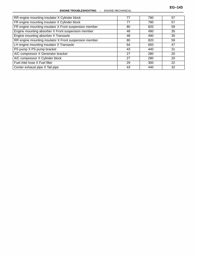
ÑÑÑÑÑÑÑÑÑÑÑÑÑÑÑÑÑÑÑÑÑÑÑÑÑÑÑÑÑÑÑÑÑÑÑÑÑÑÑÑÑÑÑÑ
RR engine mounting insulator X Cylinder block ÑÑÑÑÑÑÑÑÑÑÑÑ
77 ÑÑÑÑÑÑÑÑÑÑ
790 ÑÑÑÑÑÑÑÑÑÑÑÑ
57
ÑÑÑÑÑÑÑÑÑÑÑÑÑÑÑÑÑÑÑÑÑÑÑÑÑÑÑÑÑÑÑÑÑÑÑÑÑÑÑÑÑÑÑÑ
FR engine mounting insulator X Cylinder block ÑÑÑÑÑÑÑÑÑÑÑÑ
77 ÑÑÑÑÑÑÑÑÑÑ
790 ÑÑÑÑÑÑÑÑÑÑÑÑ
57ÑÑÑÑÑÑÑÑÑÑÑÑÑÑÑÑÑÑÑÑÑÑÑÑÑÑÑÑÑÑÑÑÑÑÑÑÑÑÑÑÑÑÑÑFR engine mounting insulator X Front suspension member
ÑÑÑÑÑÑÑÑÑÑÑÑ80
ÑÑÑÑÑÑÑÑÑÑ820
ÑÑÑÑÑÑÑÑÑÑÑÑ59ÑÑÑÑÑÑÑÑÑÑÑÑÑÑÑÑÑÑÑÑÑÑ
ÑÑÑÑÑÑÑÑÑÑÑÑÑÑÑÑÑÑÑÑÑÑEngine mounting absorber X Front suspension memberÑÑÑÑÑÑÑÑÑÑÑÑ48
ÑÑÑÑÑÑÑÑÑÑ490
ÑÑÑÑÑÑÑÑÑÑÑÑ35ÑÑÑÑÑÑÑÑÑÑÑÑÑÑÑÑÑÑÑÑÑÑ
ÑÑÑÑÑÑÑÑÑÑÑÑÑÑÑÑÑÑÑÑÑÑEngine mounting absorber X Transaxle
ÑÑÑÑÑÑÑÑÑÑÑÑ
48ÑÑÑÑÑÑÑÑÑÑ
490ÑÑÑÑÑÑÑÑÑÑÑÑ
35ÑÑÑÑÑÑÑÑÑÑÑÑÑÑÑÑÑÑÑÑÑÑÑÑÑÑÑÑÑÑÑÑÑÑÑÑÑÑÑÑÑÑÑÑ
RR engine mounting insulator X Front suspension member ÑÑÑÑÑÑÑÑÑÑÑÑ
80 ÑÑÑÑÑÑÑÑÑÑ
820 ÑÑÑÑÑÑÑÑÑÑÑÑ
59ÑÑÑÑÑÑÑÑÑÑÑÑÑÑÑÑÑÑÑÑÑÑÑÑÑÑÑÑÑÑÑÑÑÑÑÑÑÑÑÑÑÑÑÑ
LH engine mounting insulator X Transaxle ÑÑÑÑÑÑÑÑÑÑÑÑ
64 ÑÑÑÑÑÑÑÑÑÑ
650 ÑÑÑÑÑÑÑÑÑÑÑÑ
47ÑÑÑÑÑÑÑÑÑÑÑÑÑÑÑÑÑÑÑÑÑÑÑÑÑÑÑÑÑÑÑÑÑÑÑÑÑÑÑÑÑÑÑÑ
PS pump X PS pump bracket ÑÑÑÑÑÑÑÑÑÑÑÑ
43 ÑÑÑÑÑÑÑÑÑÑ
440 ÑÑÑÑÑÑÑÑÑÑÑÑ
31ÑÑÑÑÑÑÑÑÑÑÑÑÑÑÑÑÑÑÑÑÑÑÑÑÑÑÑÑÑÑÑÑÑÑÑÑÑÑÑÑÑÑÑÑ
A/C compressor X Generator bracket ÑÑÑÑÑÑÑÑÑÑÑÑ
27 ÑÑÑÑÑÑÑÑÑÑ
280 ÑÑÑÑÑÑÑÑÑÑÑÑ
20
ÑÑÑÑÑÑÑÑÑÑÑÑÑÑÑÑÑÑÑÑÑÑÑÑÑÑÑÑÑÑÑÑÑÑÑÑÑÑÑÑÑÑÑÑ
A/C compressor X Cylinder block ÑÑÑÑÑÑÑÑÑÑÑÑ
27 ÑÑÑÑÑÑÑÑÑÑ
280 ÑÑÑÑÑÑÑÑÑÑÑÑ
20
ÑÑÑÑÑÑÑÑÑÑÑÑÑÑÑÑÑÑÑÑÑÑÑÑÑÑÑÑÑÑÑÑÑÑÑÑÑÑÑÑÑÑÑÑ
Fuel inlet hose X Fuel filter ÑÑÑÑÑÑÑÑÑÑÑÑ
29 ÑÑÑÑÑÑÑÑÑÑ
300 ÑÑÑÑÑÑÑÑÑÑÑÑ
22
ÑÑÑÑÑÑÑÑÑÑÑÑÑÑÑÑÑÑÑÑÑÑÑÑÑÑÑÑÑÑÑÑÑÑÑÑÑÑÑÑÑÑÑÑ
Center exhaust pipe X Tail pipe ÑÑÑÑÑÑÑÑÑÑÑÑ
43 ÑÑÑÑÑÑÑÑÑÑ
440 ÑÑÑÑÑÑÑÑÑÑÑÑ
32
–ENGINE TROUBLESHOOTING ENGINE MECHANICALEG–143

EMISSION CONTROL SYSTEMSSYSTEM PURPOSE
EG08A–01
ÑÑÑÑÑÑÑÑÑÑÑÑÑÑÑÑÑÑÑÑÑÑÑÑÑÑÑÑÑÑ
System ÑÑÑÑÑÑÑÑÑÑÑÑÑÑ
Abbreviation ÑÑÑÑÑÑÑÑÑÑÑÑÑÑÑÑÑÑÑÑÑÑÑÑÑÑÑÑÑÑÑÑ
PurposeÑÑÑÑÑÑÑÑÑÑÑÑÑÑÑÑÑÑÑÑÑÑÑÑÑÑÑÑÑÑ
Positive crankcase ventilation ÑÑÑÑÑÑÑÑÑÑÑÑÑÑ
PCV ÑÑÑÑÑÑÑÑÑÑÑÑÑÑÑÑÑÑÑÑÑÑÑÑÑÑÑÑÑÑÑÑ
Reduces blow–by gas (HC)
ÑÑÑÑÑÑÑÑÑÑÑÑÑÑÑEvaporative emission control ÑÑÑÑÑÑÑEVAP ÑÑÑÑÑÑÑÑÑÑÑÑÑÑÑÑReduces evaporative HCÑÑÑÑÑÑÑÑÑÑÑÑÑÑÑÑÑÑÑÑÑÑÑÑÑÑÑÑÑÑExhaust gas recirculation
ÑÑÑÑÑÑÑÑÑÑÑÑÑÑEGR
ÑÑÑÑÑÑÑÑÑÑÑÑÑÑÑÑÑÑÑÑÑÑÑÑÑÑÑÑÑÑÑÑReduces NOxÑÑÑÑÑÑÑÑÑÑÑÑÑÑÑ
ÑÑÑÑÑÑÑÑÑÑÑÑÑÑÑThree–way catalytic converter ÑÑÑÑÑÑÑ
ÑÑÑÑÑÑÑTWC ÑÑÑÑÑÑÑÑÑÑÑÑÑÑÑÑ
ÑÑÑÑÑÑÑÑÑÑÑÑÑÑÑÑReduces HC, CO and NOx
ÑÑÑÑÑÑÑÑÑÑÑÑÑÑÑÑÑÑÑÑÑÑÑÑÑÑÑÑÑÑ
Sequential Multiport Fuel Injection* ÑÑÑÑÑÑÑÑÑÑÑÑÑÑ
SFI ÑÑÑÑÑÑÑÑÑÑÑÑÑÑÑÑÑÑÑÑÑÑÑÑÑÑÑÑÑÑÑÑ
Regulates all engine conditions for reductionÑÑÑÑÑÑÑÑÑÑÑÑÑÑÑÑÑÑÑÑÑÑÑÑÑÑÑÑÑÑ
ÑÑÑÑÑÑÑÑÑÑÑÑÑÑ
ÑÑÑÑÑÑÑÑÑÑÑÑÑÑÑÑÑÑÑÑÑÑÑÑÑÑÑÑÑÑÑÑ
of exhaust emissions.* For inspection and repair of the SFI system, refer to SFI Section.
PREPARATIONRECOMMENDED TOOLS
EG08B–01
EQUIPMENTEG08C–01
ÑÑÑÑÑÑÑÑÑÑÑÑÑÑÑÑÑÑÑÑÑÑÑÑÑÑÑÑÑÑÑÑÑÑÑÑÑÑÑÑÑÑÑÑÑÑÑÑ
Heater ÑÑÑÑÑÑÑÑÑÑÑÑÑÑÑÑÑÑÑÑÑÑÑÑÑÑ
TVVÑÑÑÑÑÑÑÑÑÑÑÑÑÑÑÑÑÑÑÑÑÑÑÑÑÑÑÑÑÑÑÑÑÑÑÑÑÑÑÑÑÑÑÑÑÑÑÑ
Belt tension gauge ÑÑÑÑÑÑÑÑÑÑÑÑÑÑÑÑÑÑÑÑÑÑÑÑÑÑÑÑÑÑÑÑÑÑÑÑÑÑÑÑÑÑÑÑÑÑÑÑÑÑ
ÑÑÑÑÑÑÑÑÑÑÑÑÑÑÑÑÑÑÑÑÑÑÑÑTachometer ÑÑÑÑÑÑÑÑÑÑÑÑÑ
ÑÑÑÑÑÑÑÑÑÑÑÑÑTVV
ÑÑÑÑÑÑÑÑÑÑÑÑÑÑÑÑÑÑÑÑÑÑÑÑÑÑÑÑÑÑÑÑÑÑÑÑÑÑÑÑÑÑÑÑÑÑÑÑ
Torque wrench ÑÑÑÑÑÑÑÑÑÑÑÑÑÑÑÑÑÑÑÑÑÑÑÑÑÑÑÑÑÑÑÑÑÑÑÑÑÑÑÑÑÑÑÑÑÑÑÑÑÑ
ÑÑÑÑÑÑÑÑÑÑÑÑÑÑÑÑÑÑÑÑÑÑÑÑVacuum gauge ÑÑÑÑÑÑÑÑÑÑÑÑÑ
ÑÑÑÑÑÑÑÑÑÑÑÑÑSSM (SPECIAL SERVICE MATERIALS)
EG08D–01ÑÑÑÑÑÑÑÑÑÑÑÑÑÑÑÑÑÑÑÑÑÑÑÑÑÑÑÑ
08833–00070ÑÑÑÑÑÑÑÑÑÑÑÑÑÑÑÑÑÑÑÑÑÑÑÑÑÑ
Adhesive 1324,ÑÑÑÑÑÑÑÑÑÑÑÑÑÑÑÑÑÑÑÑÑÑ
TVVÑÑÑÑÑÑÑÑÑÑÑÑÑÑÑÑÑÑÑÑÑÑÑÑÑÑÑÑÑÑÑÑÑÑÑÑÑÑÑÑÑÑ
ÑÑÑÑÑÑÑÑÑÑÑÑÑÑÑÑÑÑÑÑÑÑÑÑÑÑÑÑÑÑÑÑÑÑÑÑÑÑÑ
THREE BOND 1324 or equivalent ÑÑÑÑÑÑÑÑÑÑÑÑÑÑÑÑÑÑÑÑÑÑÑÑÑÑÑÑÑÑÑÑÑ
EG–144–ENGINE TROUBLESHOOTING EMISSION CONTROL SYSTEMS
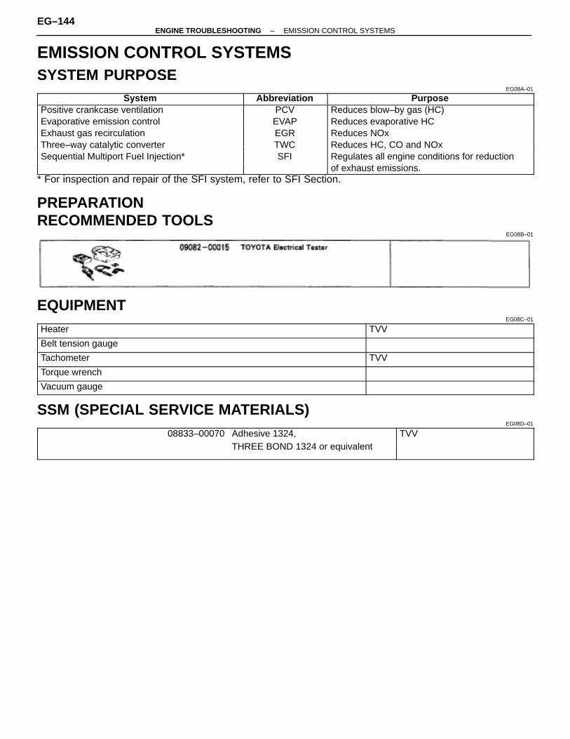
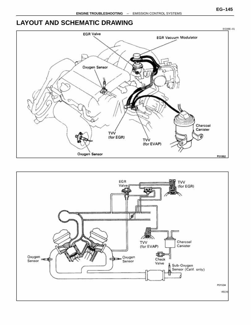
LAYOUT AND SCHEMATIC DRAWINGEG08E–01
–ENGINE TROUBLESHOOTING EMISSION CONTROL SYSTEMSEG–145
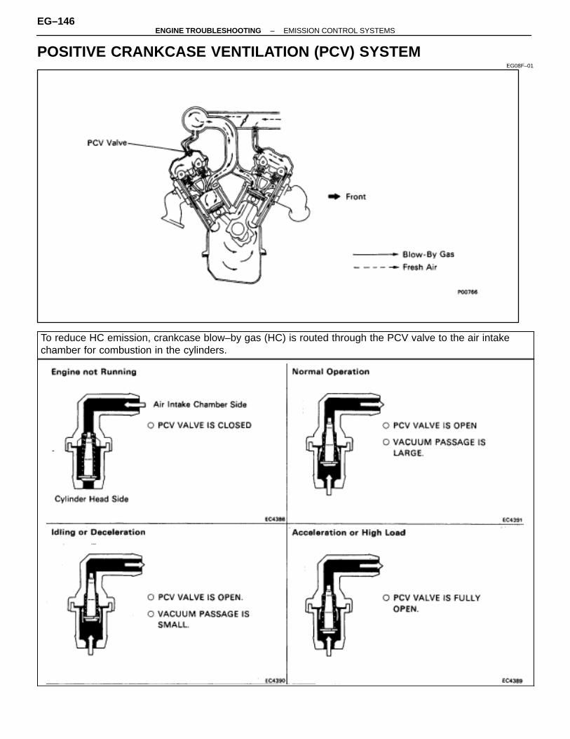
POSITIVE CRANKCASE VENTILATION (PCV) SYSTEMEG08F–01
To reduce HC emission, crankcase blow–by gas (HC) is routed through the PCV valve to the air intakechamber for combustion in the cylinders.
EG–146–ENGINE TROUBLESHOOTING EMISSION CONTROL SYSTEMS
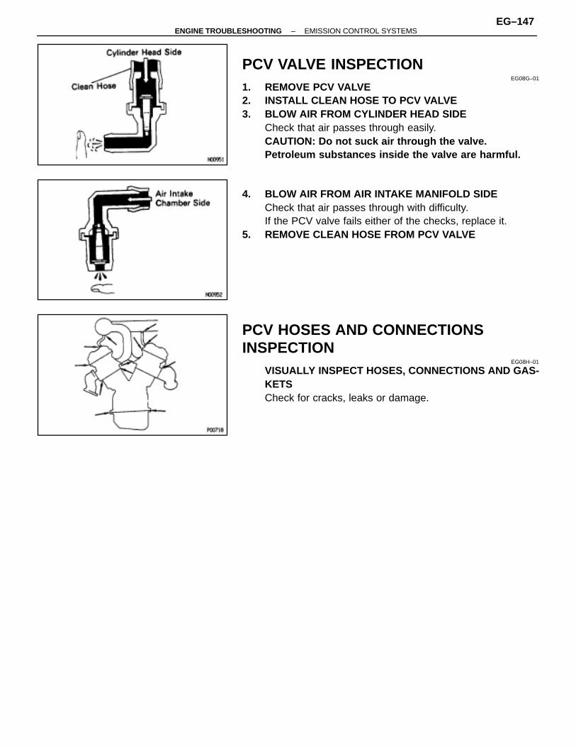
PCV VALVE INSPECTIONEG08G–01
1. REMOVE PCV VALVE2. INSTALL CLEAN HOSE TO PCV VALVE3. BLOW AIR FROM CYLINDER HEAD SIDE
Check that air passes through easily.CAUTION: Do not suck air through the valve.Petroleum substances inside the valve are harmful.
4. BLOW AIR FROM AIR INTAKE MANIFOLD SIDECheck that air passes through with difficulty.If the PCV valve fails either of the checks, replace it.
5. REMOVE CLEAN HOSE FROM PCV VALVE
PCV HOSES AND CONNECTIONSINSPECTION
EG08H–01
VISUALLY INSPECT HOSES, CONNECTIONS AND GAS-KETSCheck for cracks, leaks or damage.
–ENGINE TROUBLESHOOTING EMISSION CONTROL SYSTEMSEG–147

EVAPORATIVE (EVAP) EMISSION CONTROL SYSTEMEG08J–01
ÑÑÑÑÑÑÑÑÑÑÑÑÑÑÑÑÑÑÑÑÑÑÑÑÑÑÑÑÑÑÑÑÑÑÑÑÑÑÑÑÑÑÑÑÑÑÑÑÑÑÑÑÑÑÑÑÑÑÑÑÑÑÑÑÑÑÑÑÑÑÑÑÑÑÑÑÑÑÑÑÑÑÑÑÑÑÑÑÑÑÑÑÑÑÑÑÑÑÑÑÑÑÑÑÑÑÑÑ
To reduce HC emissions, evaporated fuel from the fuel tank is routed through the charcoal canister to theintake manifold for combustion in the cylinders.
ÑÑÑÑÑÑEngine ÑÑÑÑÑÑÑÑÑÑÑThrottle Valve ÑÑÑÑÑÑÑÑÑÑCanister Check Valve ÑÑÑÑCheck ÑÑÑÑÑÑÑÑÑÑÑÑÑÑÑÑÑÑÑÑÑ
gCoolant
ÑÑÑÑÑÑÑÑTVV
ÑÑÑÑÑÑÑÑÑÑÑÑÑÑ
Throttl e ValveOpening
ÑÑÑÑÑÑÑÑÑÑÑÑÑÑÑÑÑÑÑÑ
Canister Check Valve ÑÑÑÑÑÑÑÑValve in
ÑÑÑÑÑÑÑÑÑÑÑÑÑÑÑÑÑÑEvaporated Fuel (HC)ÑÑÑÑÑÑ
ÑÑÑÑÑÑTemp.
ÑÑÑÑÑÑÑÑ
ÑÑÑÑÑÑÑÑÑÑÑÑÑÑ
Opening ÑÑÑÑÑÑÑÑ
(1)ÑÑÑÑÑÑÑÑ
(2)ÑÑÑÑÑÑÑÑ
(3)ÑÑÑÑÑÑÑÑ
CapÑÑÑÑÑÑÑÑÑÑÑÑÑÑÑÑÑÑ
p ( )
ÑÑÑÑÑÑÑÑÑÑÑÑ
Below ÑÑÑÑÑÑÑÑCLOSED
ÑÑÑÑÑÑÑÑÑÑÑÑÑÑ–
ÑÑÑÑÑÑÑÑ–
ÑÑÑÑÑÑÑÑ–
ÑÑÑÑÑÑÑÑ–
ÑÑÑÑÑÑÑÑ–
ÑÑÑÑÑÑÑÑÑÑÑÑÑÑÑÑÑÑÑÑÑÑÑÑ
ÑÑÑÑÑÑ35°C (95°F) ÑÑÑÑ
ÑÑÑÑ
CLOSEDÑÑÑÑÑÑÑÑÑÑÑÑÑÑ
– ÑÑÑÑÑÑÑÑ
– ÑÑÑÑÑÑÑÑ
– ÑÑÑÑÑÑÑÑ
– ÑÑÑÑÑÑÑÑ
– ÑÑÑÑÑÑÑÑÑÑÑÑÑÑÑÑÑÑ
HC from tank is absorbedÑÑÑÑÑÑÑÑÑÑÑÑ
ÑÑÑÑÑÑÑÑ
ÑÑÑÑÑÑÑÑÑÑÑÑÑÑ
Positioned belowÑÑÑÑÑÑÑÑ
CLOSEDÑÑÑÑÑÑÑÑ
–ÑÑÑÑÑÑÑÑ
–ÑÑÑÑÑÑÑÑ
–ÑÑÑÑÑÑÑÑÑÑÑÑÑÑÑÑÑÑ
into the canister
ÑÑÑÑÑÑÑÑÑÑÑÑ
Above ÑÑÑÑÑÑÑÑ
OPENÑÑÑÑÑÑÑÑÑÑÑÑÑÑ
port P ÑÑÑÑÑÑÑÑ
CLOSEDÑÑÑÑÑÑÑÑ
–ÑÑÑÑÑÑÑÑ
–ÑÑÑÑÑÑÑÑ
–ÑÑÑÑÑÑÑÑÑÑÑÑÑÑÑÑÑÑÑÑÑÑÑÑ54°C (129°F) ÑÑÑÑ
OPENÑÑÑÑÑÑÑPositioned aboveÑÑÑÑOPEN ÑÑÑÑ– ÑÑÑÑ– ÑÑÑÑ– ÑÑÑÑÑÑÑÑÑHC from canister is ledÑÑÑÑÑÑ
ÑÑÑÑÑÑ
54 C (129 F) ÑÑÑÑÑÑÑÑ
ÑÑÑÑÑÑÑÑÑÑÑÑÑÑ
port PÑÑÑÑÑÑÑÑ
OPEN ÑÑÑÑÑÑÑÑ
– ÑÑÑÑÑÑÑÑ
– ÑÑÑÑÑÑÑÑ
– ÑÑÑÑÑÑÑÑÑÑÑÑÑÑÑÑÑÑ
into air intake chamber.ÑÑÑÑÑÑÑÑÑÑÑÑ
High pressureÑÑÑÑÑÑÑÑ
ÑÑÑÑÑÑÑÑÑÑÑÑÑÑ
ÑÑÑÑÑÑÑÑ
ÑÑÑÑÑÑÑÑOPEN
ÑÑÑÑÑÑÑÑCLOSED
ÑÑÑÑÑÑÑÑCLOSED
ÑÑÑÑÑÑÑÑÑÑÑÑÑÑÑÑÑÑ
HC from tank is absorbedÑÑÑÑÑÑÑÑÑÑÑÑ
in tank ÑÑÑÑÑÑÑÑ
– ÑÑÑÑÑÑÑÑÑÑÑÑÑÑ
– ÑÑÑÑÑÑÑÑ
– ÑÑÑÑÑÑÑÑ
OPENÑÑÑÑÑÑÑÑ
CLOSED ÑÑÑÑÑÑÑÑCLOSEDÑÑÑÑÑÑÑÑÑ
ÑÑÑÑÑÑÑÑÑinto the canister.
ÑÑÑÑÑÑÑÑÑÑÑÑ
High vacuum ÑÑÑÑÑÑÑÑ
–ÑÑÑÑÑÑÑÑÑÑÑÑÑÑ
–ÑÑÑÑÑÑÑÑ
–ÑÑÑÑÑÑÑÑ
CLOSEDÑÑÑÑÑÑÑÑ
OPENÑÑÑÑÑÑÑÑ
OPENÑÑÑÑÑÑÑÑÑÑÑÑÑÑÑÑÑÑ
Air is led into the fuel
ÑÑÑÑÑÑÑÑÑÑÑÑ
in take ÑÑÑÑÑÑÑÑ
–ÑÑÑÑÑÑÑÑÑÑÑÑÑÑ
–ÑÑÑÑÑÑÑÑ
–ÑÑÑÑÑÑÑÑ
CLOSEDÑÑÑÑÑÑÑÑ
OPENÑÑÑÑÑÑÑÑ
OPENÑÑÑÑÑÑÑÑÑÑÑÑÑÑÑÑÑÑ
tank.
EG–148–ENGINE TROUBLESHOOTING EMISSION CONTROL SYSTEMS
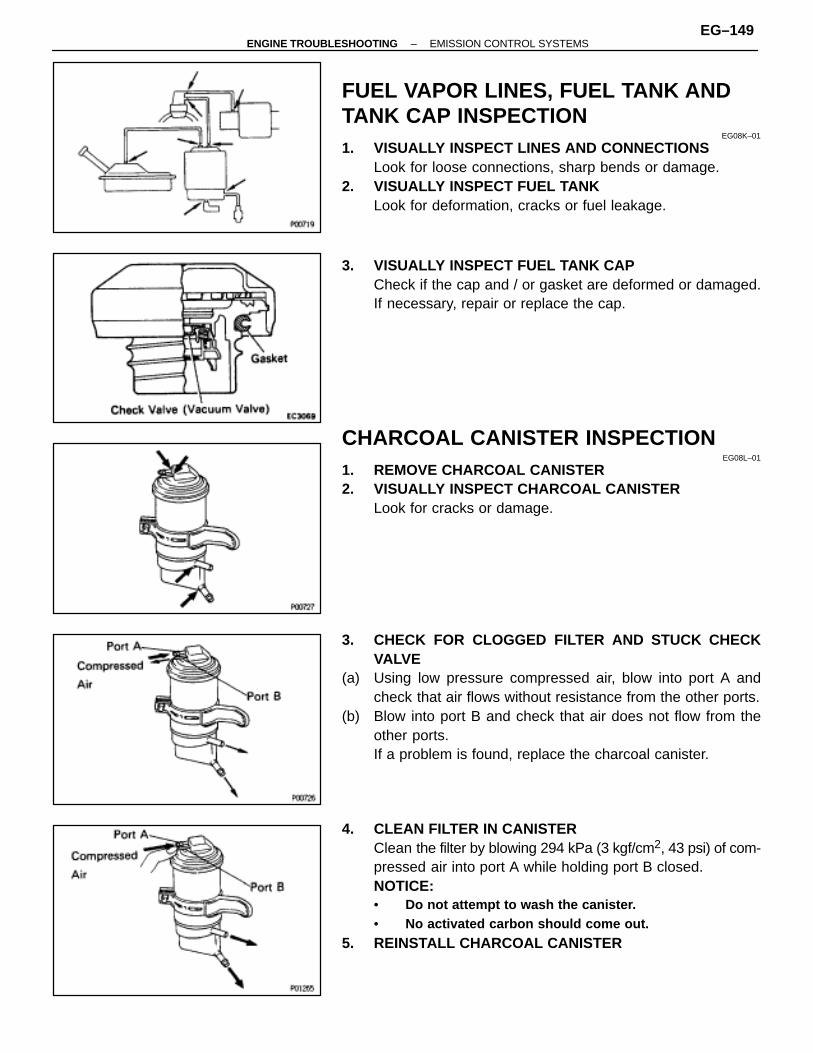
FUEL VAPOR LINES, FUEL TANK ANDTANK CAP INSPECTION
EG08K–01
1. VISUALLY INSPECT LINES AND CONNECTIONSLook for loose connections, sharp bends or damage.
2. VISUALLY INSPECT FUEL TANKLook for deformation, cracks or fuel leakage.
3. VISUALLY INSPECT FUEL TANK CAPCheck if the cap and / or gasket are deformed or damaged.If necessary, repair or replace the cap.
CHARCOAL CANISTER INSPECTIONEG08L–01
1. REMOVE CHARCOAL CANISTER2. VISUALLY INSPECT CHARCOAL CANISTER
Look for cracks or damage.
3. CHECK FOR CLOGGED FILTER AND STUCK CHECKVALVE
(a) Using low pressure compressed air, blow into port A andcheck that air flows without resistance from the other ports.
(b) Blow into port B and check that air does not flow from theother ports.If a problem is found, replace the charcoal canister.
4. CLEAN FILTER IN CANISTERClean the filter by blowing 294 kPa (3 kgf/cm2, 43 psi) of com-pressed air into port A while holding port B closed.NOTICE:• Do not attempt to wash the canister.• No activated carbon should come out.
5. REINSTALL CHARCOAL CANISTER
–ENGINE TROUBLESHOOTING EMISSION CONTROL SYSTEMSEG–149
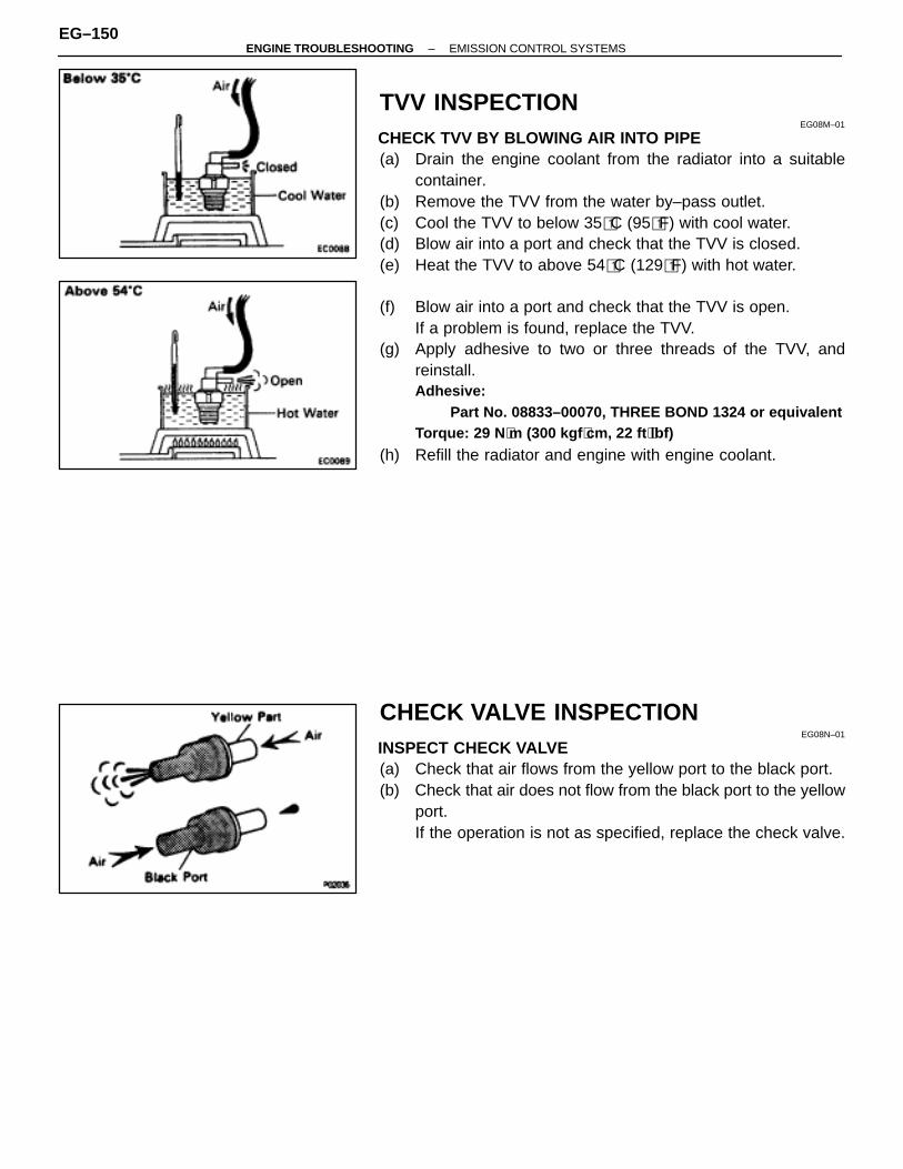
TVV INSPECTIONEG08M–01
CHECK TVV BY BLOWING AIR INTO PIPE(a) Drain the engine coolant from the radiator into a suitable
container.(b) Remove the TVV from the water by–pass outlet.(c) Cool the TVV to below 35�C (95�F) with cool water.(d) Blow air into a port and check that the TVV is closed.(e) Heat the TVV to above 54�C (129�F) with hot water.
(f) Blow air into a port and check that the TVV is open.If a problem is found, replace the TVV.
(g) Apply adhesive to two or three threads of the TVV, andreinstall.Adhesive:
Part No. 08833–00070, THREE BOND 1324 or equivalentTorque: 29 N ⋅m (300 kgf ⋅cm, 22 ft ⋅lbf)
(h) Refill the radiator and engine with engine coolant.
CHECK VALVE INSPECTIONEG08N–01
INSPECT CHECK VALVE(a) Check that air flows from the yellow port to the black port.(b) Check that air does not flow from the black port to the yellow
port.If the operation is not as specified, replace the check valve.
EG–150–ENGINE TROUBLESHOOTING EMISSION CONTROL SYSTEMS
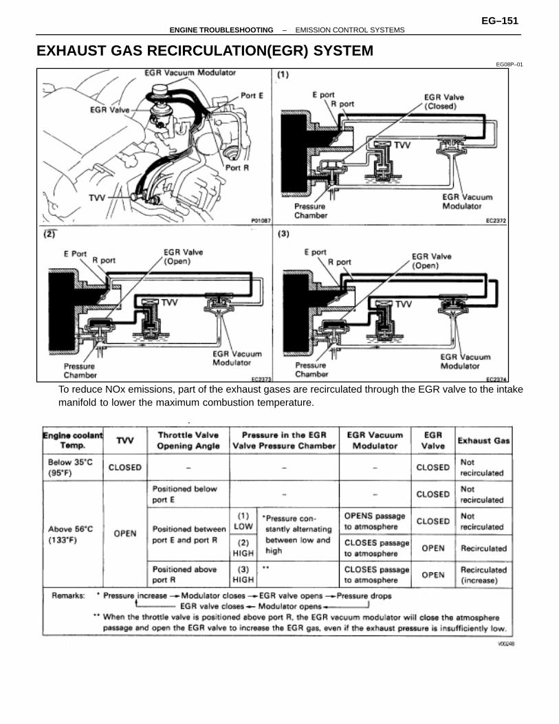
EXHAUST GAS RECIRCULATION(EGR) SYSTEMEG08P–01
To reduce NOx emissions, part of the exhaust gases are recirculated through the EGR valve to the intakemanifold to lower the maximum combustion temperature.
–ENGINE TROUBLESHOOTING EMISSION CONTROL SYSTEMSEG–151
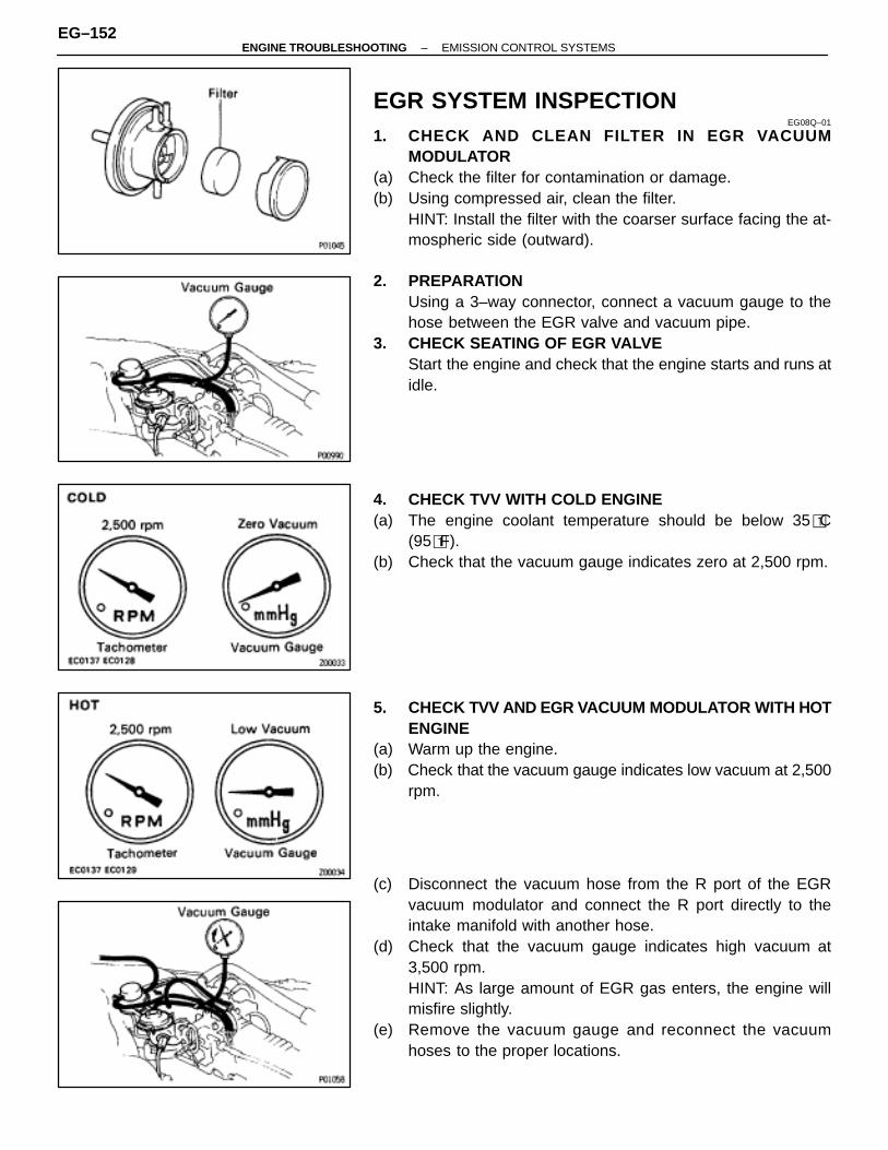
EGR SYSTEM INSPECTIONEG08Q–01
1. CHECK AND CLEAN FILTER IN EGR VACUUMMODULATOR
(a) Check the filter for contamination or damage.(b) Using compressed air, clean the filter.
HINT: Install the filter with the coarser surface facing the at-mospheric side (outward).
2. PREPARATIONUsing a 3–way connector, connect a vacuum gauge to thehose between the EGR valve and vacuum pipe.
3. CHECK SEATING OF EGR VALVEStart the engine and check that the engine starts and runs atidle.
4. CHECK TVV WITH COLD ENGINE(a) The engine coolant temperature should be below 35�C
(95�F).(b) Check that the vacuum gauge indicates zero at 2,500 rpm.
5. CHECK TVV AND EGR VACUUM MODULATOR WITH HOTENGINE
(a) Warm up the engine.(b) Check that the vacuum gauge indicates low vacuum at 2,500
rpm.
(c) Disconnect the vacuum hose from the R port of the EGRvacuum modulator and connect the R port directly to theintake manifold with another hose.
(d) Check that the vacuum gauge indicates high vacuum at3,500 rpm.HINT: As large amount of EGR gas enters, the engine willmisfire slightly.
(e) Remove the vacuum gauge and reconnect the vacuumhoses to the proper locations.
EG–152–ENGINE TROUBLESHOOTING EMISSION CONTROL SYSTEMS
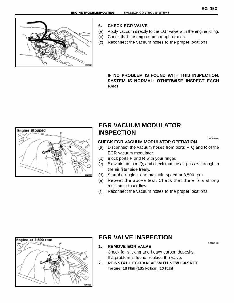
6. CHECK EGR VALVE(a) Apply vacuum directly to the EGr valve with the engine idling.(b) Check that the engine runs rough or dies.(c) Reconnect the vacuum hoses to the proper locations.
IF NO PROBLEM IS FOUND WITH THIS INSPECTION,SYSTEM IS NORMAL; OTHERWISE INSPECT EACHPART
EGR VACUUM MODULATORINSPECTION
EG08R–01
CHECK EGR VACUUM MODULATOR OPERATION(a) Disconnect the vacuum hoses from ports P, Q and R of the
EGR vacuum modulator.(b) Block ports P and R with your finger.(c) Blow air into port Q, and check that the air passes through to
the air filter side freely.(d) Start the engine, and maintain speed at 3,500 rpm.(e) Repeat the above test. Check that there is a strong
resistance to air flow.(f) Reconnect the vacuum hoses to the proper locations.
EGR VALVE INSPECTIONEG08S–01
1. REMOVE EGR VALVECheck for sticking and heavy carbon deposits.If a problem is found, replace the valve.
2. REINSTALL EGR VALVE WITH NEW GASKETTorque: 18 N ⋅m (185 kgf ⋅cm, 13 ft ⋅lbf)
–ENGINE TROUBLESHOOTING EMISSION CONTROL SYSTEMSEG–153

TVV INSPECTIONEG08T–01
CHECK TVV BY BLOWING AIR INTO PIPE(a) Drain the engine coolant from the radiator into a suitable
container.(b) Remove the TVV from the water by–pass outlet.(c) Cool the TVV to below 35�C (95�F) with cool water.(d) Blow air into the pipe, and check that the TVV is closed.
(e) Heat the TVV to above 56�C (133�F) with hot water.(f) Blow air into the pipe, and check that the TVV is open.
If a problem is found, replace the TVV.(g) Apply adhesive to two or three threads of the TVV, and
reinstall.Adhesive:
Part No. 08833–00070, THREE BOND 1324 or equivalentTorque: 29 N ⋅m (300 kgf ⋅cm, 22 ft ⋅lbf)
(h) Refill the radiator with engine coolant.
EG–154–ENGINE TROUBLESHOOTING EMISSION CONTROL SYSTEMS
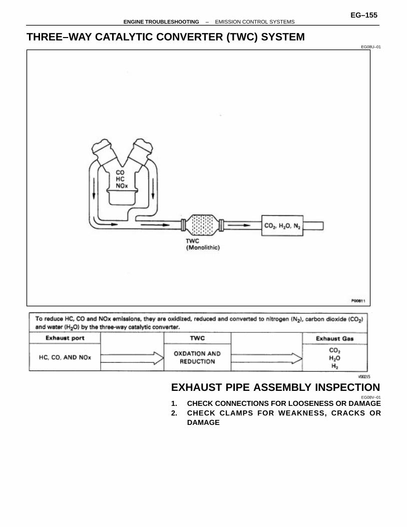
THREE–WAY CATALYTIC CONVERTER (TWC) SYSTEMEG08U–01
EXHAUST PIPE ASSEMBLY INSPECTIONEG08V–01
1. CHECK CONNECTIONS FOR LOOSENESS OR DAMAGE2. CHECK CLAMPS FOR WEAKNESS, C RACKS OR
DAMAGE
–ENGINE TROUBLESHOOTING EMISSION CONTROL SYSTEMSEG–155

THREE–WAY CATALYTIC CONVERTERINSPECTION
EG08W–01
CHECK FOR DENTS OR DAMAGEIf any part of protector is damaged or dented to the extent thatit contacts the three–way catalytic converter, repair or re-place it.
HEAT INSULATOR INSPECTIONEG08X–01
1. CHECK HEAT INSULATOR FOR DAMAGE2. CHECK FOR ADEQUATE CLEARANCE BETWEEN
THREE–WAY CATALYTIC CONVERTER AND HEATINSULATOR
THREE–WAY CATALYTIC CONVERTERREPLACEMENT
EG08Y–01
1. REMOVE THREE–WAY CATALYTIC CONVERTER(a) Jack up the vehicle.(b) Check that the three–way catalytic converter is cool.(c) Remove the four bolts and nuts holding the pipes to the
three–way catalytic converter.(d) Remove the three–way catalytic converter and two gaskets.2. REINSTALL THREE–WAY CATALYTIC CONVERTER(a) Place new two gaskets on the front and rear pipes.(b) Install the three–way catalytic converter with the bolts and
nuts. Torque the bolts and nuts.Torque: 43 N ⋅m (440 kgf ⋅cm, 32 ft ⋅lbf)
EG–156–ENGINE TROUBLESHOOTING EMISSION CONTROL SYSTEMS
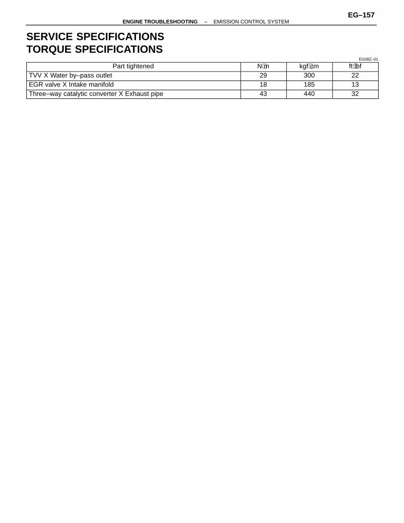
SERVICE SPECIFICATIONSTORQUE SPECIFICATIONS
EG08Z–01
ÑÑÑÑÑÑÑÑÑÑÑÑÑÑÑÑÑÑÑÑÑÑÑÑÑÑÑÑÑÑÑÑÑÑÑÑÑÑÑÑÑÑÑÑ
Part tightened ÑÑÑÑÑÑÑÑÑÑÑÑ
N⋅m ÑÑÑÑÑÑÑÑÑÑ
kgf⋅cm ÑÑÑÑÑÑÑÑÑÑÑÑ
ft⋅lbf
ÑÑÑÑÑÑÑÑÑÑÑÑÑÑÑÑÑÑÑÑÑÑTVV X Water by–pass outlet ÑÑÑÑÑÑ29 ÑÑÑÑÑ300 ÑÑÑÑÑÑ22ÑÑÑÑÑÑÑÑÑÑÑÑÑÑÑÑÑÑÑÑÑÑÑÑÑÑÑÑÑÑÑÑÑÑÑÑÑÑÑÑÑÑÑÑEGR valve X Intake manifold
ÑÑÑÑÑÑÑÑÑÑÑÑ18
ÑÑÑÑÑÑÑÑÑÑ185
ÑÑÑÑÑÑÑÑÑÑÑÑ13ÑÑÑÑÑÑÑÑÑÑÑÑÑÑÑÑÑÑÑÑÑÑ
ÑÑÑÑÑÑÑÑÑÑÑÑÑÑÑÑÑÑÑÑÑÑThree–way catalytic converter X Exhaust pipe
ÑÑÑÑÑÑÑÑÑÑÑÑ
43ÑÑÑÑÑÑÑÑÑÑ
440ÑÑÑÑÑÑÑÑÑÑÑÑ
32
–ENGINE TROUBLESHOOTING EMISSION CONTROL SYSTEMEG–157
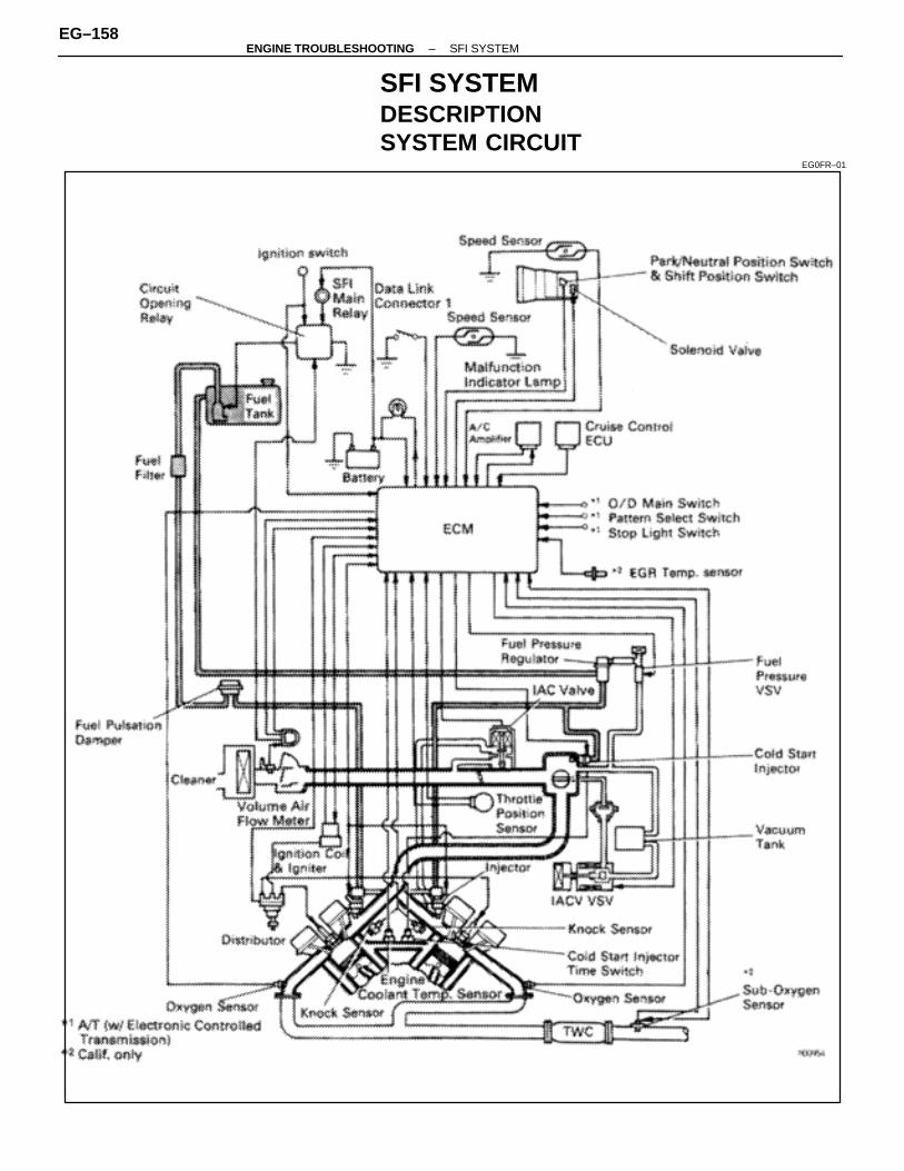
SFI SYSTEMDESCRIPTIONSYSTEM CIRCUIT
EG0FR–01
EG–158–ENGINE TROUBLESHOOTING SFI SYSTEM
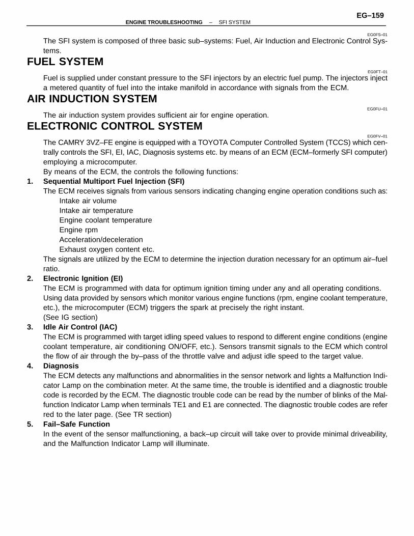
EG0FS–01
The SFI system is composed of three basic sub–systems: Fuel, Air Induction and Electronic Control Sys-tems.
FUEL SYSTEMEG0FT–01
Fuel is supplied under constant pressure to the SFI injectors by an electric fuel pump. The injectors injecta metered quantity of fuel into the intake manifold in accordance with signals from the ECM.
AIR INDUCTION SYSTEMEG0FU–01
The air induction system provides sufficient air for engine operation.
ELECTRONIC CONTROL SYSTEMEG0FV–01
The CAMRY 3VZ–FE engine is equipped with a TOYOTA Computer Controlled System (TCCS) which cen-trally controls the SFI, EI, IAC, Diagnosis systems etc. by means of an ECM (ECM–formerly SFI computer)employing a microcomputer.By means of the ECM, the controls the following functions:
1. Sequential Multiport Fuel Injection (SFI)The ECM receives signals from various sensors indicating changing engine operation conditions such as:
Intake air volumeIntake air temperatureEngine coolant temperatureEngine rpmAcceleration/decelerationExhaust oxygen content etc.
The signals are utilized by the ECM to determine the injection duration necessary for an optimum air–fuelratio.
2. Electronic Ignition (EI)The ECM is programmed with data for optimum ignition timing under any and all operating conditions.Using data provided by sensors which monitor various engine functions (rpm, engine coolant temperature,etc.), the microcomputer (ECM) triggers the spark at precisely the right instant.(See IG section)
3. Idle Air Control (IAC)The ECM is programmed with target idling speed values to respond to different engine conditions (enginecoolant temperature, air conditioning ON/OFF, etc.). Sensors transmit signals to the ECM which controlthe flow of air through the by–pass of the throttle valve and adjust idle speed to the target value.
4. DiagnosisThe ECM detects any malfunctions and abnormalities in the sensor network and lights a Malfunction Indi-cator Lamp on the combination meter. At the same time, the trouble is identified and a diagnostic troublecode is recorded by the ECM. The diagnostic trouble code can be read by the number of blinks of the Mal-function Indicator Lamp when terminals TE1 and E1 are connected. The diagnostic trouble codes are referred to the later page. (See TR section)
5. Fail–Safe FunctionIn the event of the sensor malfunctioning, a back–up circuit will take over to provide minimal driveability,and the Malfunction Indicator Lamp will illuminate.
–ENGINE TROUBLESHOOTING SFI SYSTEMEG–159
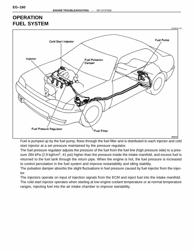
OPERATIONFUEL SYSTEM
EG0FW–02
Fuel is pumped up by the fuel pump, flows through the fuel filter and is distributed to each injector and coldstart injector at a set pressure maintained by the pressure regulator.The fuel pressure regulator adjusts the pressure of the fuel from the fuel line (high pressure side) to a pres-sure 284 kPa (2.9 kgf/cm2, 41 psi) higher than the pressure inside the intake manifold, and excess fuel isreturned to the fuel tank through the return pipe. When the engine is hot, the fuel pressure is increasedto control percolation in the fuel system and improve restartability and idling stability.The pulsation damper absorbs the slight fluctuations in fuel pressure caused by fuel injector from the injec-tor.The injectors operate on input of injection signals from the ECM and inject fuel into the intake manifold.The cold start injector operates when starting at low engine coolant temperature or at normal temperatureranges, injecting fuel into the air intake chamber to improve startability.
EG–160–ENGINE TROUBLESHOOTING SFI SYSTEM
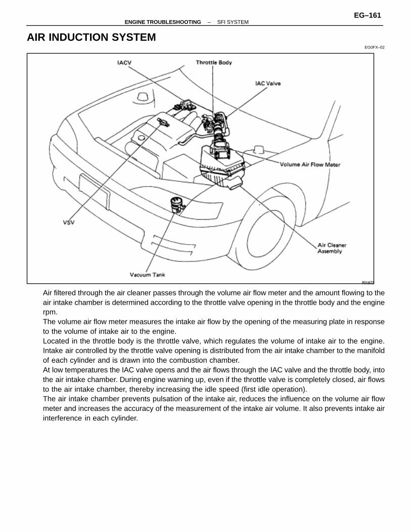
AIR INDUCTION SYSTEMEG0FX–02
Air filtered through the air cleaner passes through the volume air flow meter and the amount flowing to theair intake chamber is determined according to the throttle valve opening in the throttle body and the enginerpm.The volume air flow meter measures the intake air flow by the opening of the measuring plate in responseto the volume of intake air to the engine.Located in the throttle body is the throttle valve, which regulates the volume of intake air to the engine.Intake air controlled by the throttle valve opening is distributed from the air intake chamber to the manifoldof each cylinder and is drawn into the combustion chamber.At low temperatures the IAC valve opens and the air flows through the IAC valve and the throttle body, intothe air intake chamber. During engine warning up, even if the throttle valve is completely closed, air flowsto the air intake chamber, thereby increasing the idle speed (first idle operation).The air intake chamber prevents pulsation of the intake air, reduces the influence on the volume air flowmeter and increases the accuracy of the measurement of the intake air volume. It also prevents intake airinterference in each cylinder.
–ENGINE TROUBLESHOOTING SFI SYSTEMEG–161
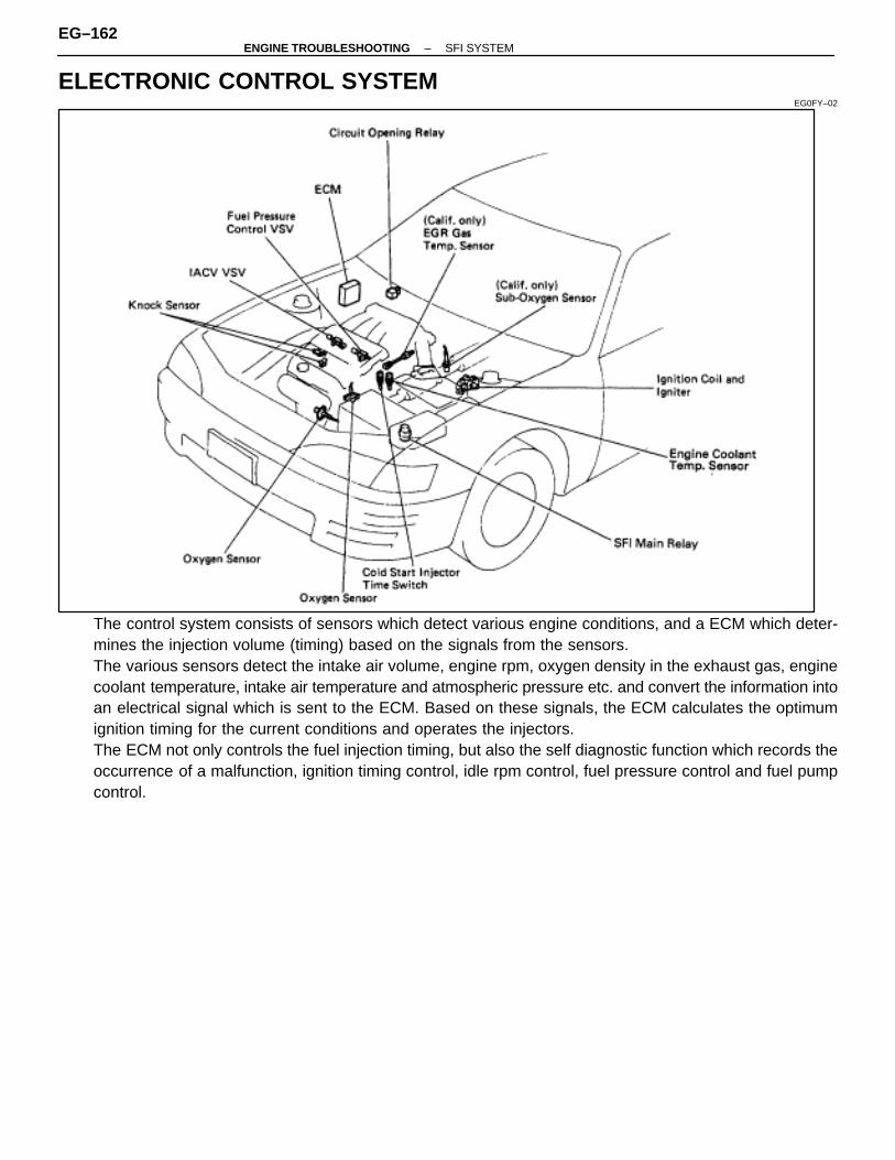
ELECTRONIC CONTROL SYSTEMEG0FY–02
The control system consists of sensors which detect various engine conditions, and a ECM which deter-mines the injection volume (timing) based on the signals from the sensors.The various sensors detect the intake air volume, engine rpm, oxygen density in the exhaust gas, enginecoolant temperature, intake air temperature and atmospheric pressure etc. and convert the information intoan electrical signal which is sent to the ECM. Based on these signals, the ECM calculates the optimumignition timing for the current conditions and operates the injectors.The ECM not only controls the fuel injection timing, but also the self diagnostic function which records theoccurrence of a malfunction, ignition timing control, idle rpm control, fuel pressure control and fuel pumpcontrol.
EG–162–ENGINE TROUBLESHOOTING SFI SYSTEM

PREPARATIONSST (SPECIAL SERVICE TOOLS)
EG0FZ–01
RECOMMENDED TOOLSEG0G0–01
–ENGINE TROUBLESHOOTING SFI SYSTEMEG–163
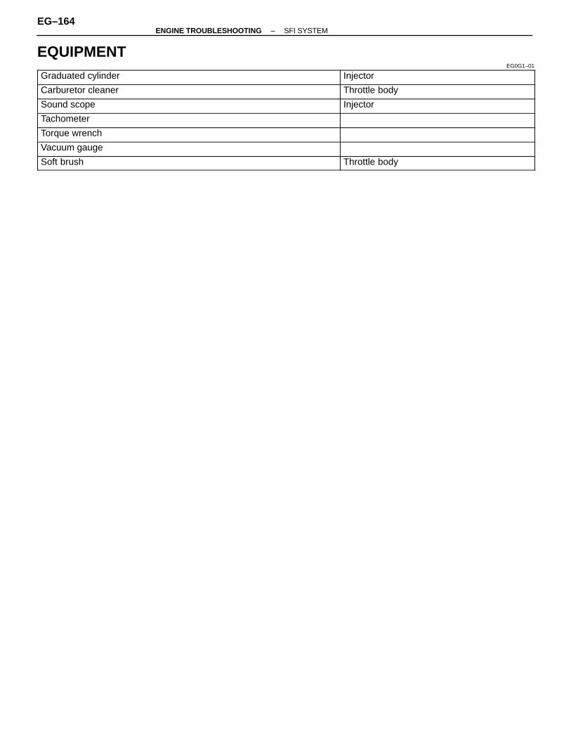
EQUIPMENTEG0G1–01ÑÑÑÑÑÑÑÑÑÑÑÑÑÑÑÑÑÑÑÑÑÑ
ÑÑÑÑÑÑÑÑÑÑÑÑÑÑÑÑÑÑÑÑÑÑGraduated cylinderÑÑÑÑÑÑÑÑÑÑÑÑÑÑÑÑÑÑÑÑÑÑÑÑÑÑÑÑÑÑInjectorÑÑÑÑÑÑÑÑÑÑÑÑÑÑÑÑÑÑÑÑÑÑ
ÑÑÑÑÑÑÑÑÑÑÑÑÑÑÑÑÑÑÑÑÑÑCarburetor cleaner Throttle bodyÑÑÑÑÑÑÑÑÑÑÑÑÑÑÑÑÑÑÑÑÑÑÑÑÑÑÑÑÑÑÑÑÑÑÑÑÑÑÑÑÑÑÑÑSound scope InjectorÑÑÑÑÑÑÑÑÑÑÑÑÑÑÑÑÑÑÑÑÑÑÑÑÑÑÑÑÑÑÑÑÑÑÑÑÑÑÑÑÑÑÑÑTachometerÑÑÑÑÑÑÑÑÑÑÑÑÑÑÑÑÑÑÑÑÑÑÑÑÑÑÑÑÑÑÑÑÑÑÑÑÑÑÑÑÑÑÑÑTorque wrenchÑÑÑÑÑÑÑÑÑÑÑÑÑÑÑÑÑÑÑÑÑÑÑÑÑÑÑÑÑÑÑÑÑÑÑÑÑÑÑÑÑÑÑÑVacuum gaugeÑÑÑÑÑÑÑÑÑÑÑÑÑÑÑÑÑÑÑÑÑÑÑÑÑÑÑÑÑÑÑÑÑÑÑÑÑÑÑÑÑÑÑÑSoft brush Throttle body
EG–164–ENGINE TROUBLESHOOTING SFI SYSTEM

PRECAUTIONSEG0G2–01
1. Before working on the fuel system, disconnect the cablefrom negative (–) terminal of the battery.HINT: Any diagnostic trouble code retained by the computerwill be erased when the battery terminal is removed. There-fore, if necessary, read the diagnosis before removing thebattery terminal.
2. Do not smoke or work near an open flame when workingon the fuel system.
3. Keep gasoline away from rubber or leather parts.
MAINTENANCE PRECAUTIONSEG0G3–01
1. CHECK CORRECT ENGINE TUNE–UP(See page EG–11)
2. PRECAUTIONS WHEN CONNECTING GAUGE(a) Use the battery as the power source for the timing light,
tachometer, etc.(b) Connect the tester probe of a tachometer to the terminal IG�
of the data link connector 1.
3. IN EVENT OF ENGINE MISFIRE, FOLLOWINGPRECAUTIONS SHOULD BE TAKEN
(a) Check proper connection of battery terminals, etc.(b) Handle high–tension cords carefully.(c) After repair work, check that the ignition coil terminals and all
other ignition system lines are reconnected securely.(d) When cleaning the engine compartment, be especially
careful to protect the electrical system from water.4. PRECAUTIONS WHEN HANDLING OXYGEN SENSOR(a) Do not allow oxygen sensor to drop or hit against an object.(b) Do not allow the sensor to come into contact with water.
–ENGINE TROUBLESHOOTING SFI SYSTEMEG–165
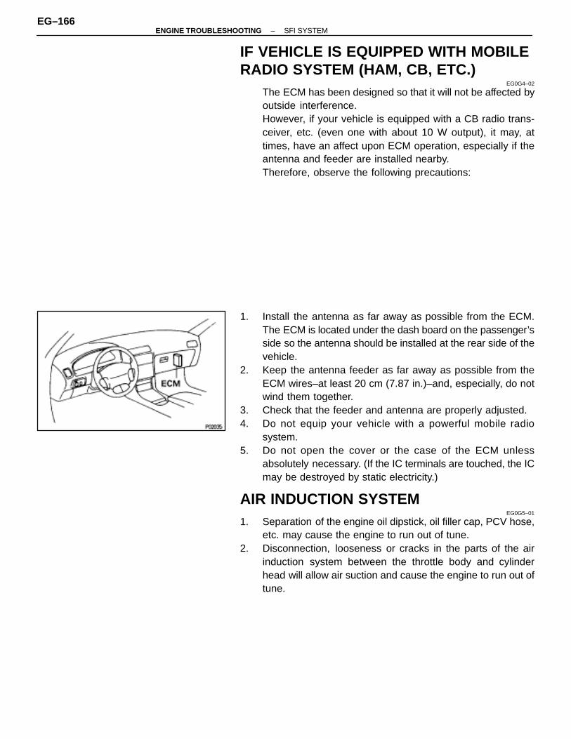
IF VEHICLE IS EQUIPPED WITH MOBILERADIO SYSTEM (HAM, CB, ETC.)
EG0G4–02
The ECM has been designed so that it will not be affected byoutside interference.However, if your vehicle is equipped with a CB radio trans-ceiver, etc. (even one with about 10 W output), it may, attimes, have an affect upon ECM operation, especially if theantenna and feeder are installed nearby.Therefore, observe the following precautions:
1. Install the antenna as far away as possible from the ECM.The ECM is located under the dash board on the passenger’sside so the antenna should be installed at the rear side of thevehicle.
2. Keep the antenna feeder as far away as possible from theECM wires–at least 20 cm (7.87 in.)–and, especially, do notwind them together.
3. Check that the feeder and antenna are properly adjusted.4. Do not equip your vehicle with a powerful mobile radio
system.5. Do not open the cover or the case of the ECM unless
absolutely necessary. (If the IC terminals are touched, the ICmay be destroyed by static electricity.)
AIR INDUCTION SYSTEMEG0G5–01
1. Separation of the engine oil dipstick, oil filler cap, PCV hose,etc. may cause the engine to run out of tune.
2. Disconnection, looseness or cracks in the parts of the airinduction system between the throttle body and cylinderhead will allow air suction and cause the engine to run out oftune.
EG–166–ENGINE TROUBLESHOOTING SFI SYSTEM
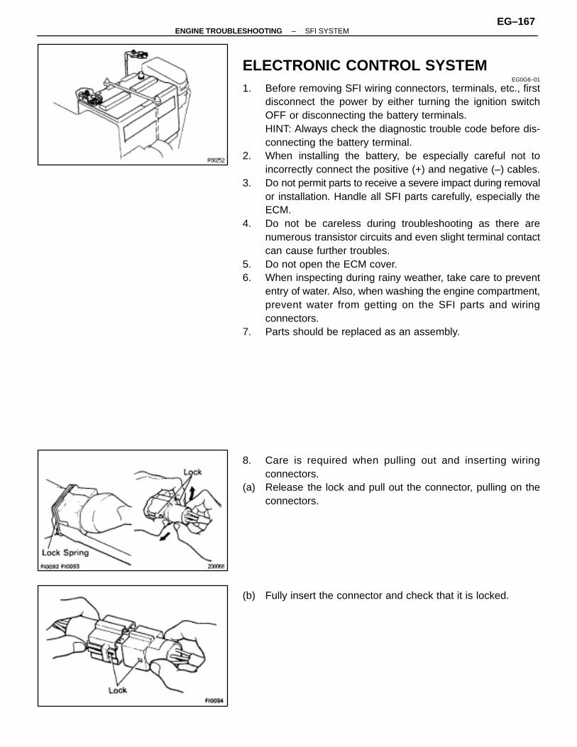
ELECTRONIC CONTROL SYSTEMEG0G6–01
1. Before removing SFI wiring connectors, terminals, etc., firstdisconnect the power by either turning the ignition switchOFF or disconnecting the battery terminals.HINT: Always check the diagnostic trouble code before dis-connecting the battery terminal.
2. When installing the battery, be especially careful not toincorrectly connect the positive (+) and negative (–) cables.
3. Do not permit parts to receive a severe impact during removalor installation. Handle all SFI parts carefully, especially theECM.
4. Do not be careless during troubleshooting as there arenumerous transistor circuits and even slight terminal contactcan cause further troubles.
5. Do not open the ECM cover.6. When inspecting during rainy weather, take care to prevent
entry of water. Also, when washing the engine compartment,prevent water from getting on the SFI parts and wiringconnectors.
7. Parts should be replaced as an assembly.
8. Care is required when pulling out and inserting wiringconnectors.
(a) Release the lock and pull out the connector, pulling on theconnectors.
(b) Fully insert the connector and check that it is locked.
–ENGINE TROUBLESHOOTING SFI SYSTEMEG–167

9. When inspecting a connector with a volt/ohmmeter.(a) Carefully take out the water–proofing rubber if it is a
water–proof type connector.
(b) Insert the test probe into the connector from wiring side whenchecking the continuity, amperage or voltage.
(c) Do not apply unnecessary force to the terminal.(d) After checking, install the water–proofing rubber on the
connector securely.
10. Use SST for inspection or test of the injector, cold startinjector or its wiring connector.SST 09842–30055 (A)SST 09842–30070 (B)
FUEL SYSTEMEG0G7–01
1. When disconnecting the high fuel pressure line, a largeamount of gasoline will spill out, so observe the followingprocedures:
(a) Put a container under the connection.(b) Slowly loosen the connection.(c) Disconnect the connection.(d) Plug the connection with a rubber plug.
2. When connecting the flare nut or union bolt on the highpressure pipe union, observe the following procedures:(Union Bolt Type)
(a) Always use a new gasket.(b) Tighten the union bolt by hand.(c) Tighten the union bolt to the specified torque.
Torque: 29 N ⋅m (300 kgf ⋅cm, 22 ft ⋅lbf)
EG–168–ENGINE TROUBLESHOOTING SFI SYSTEM
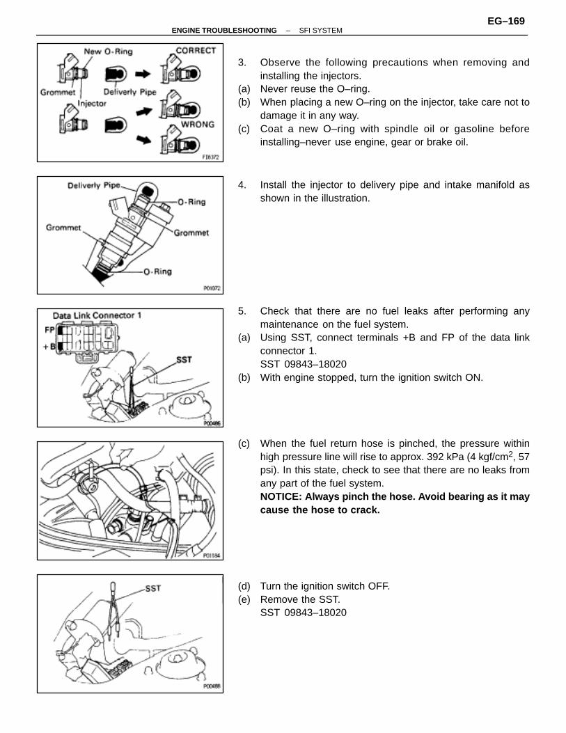
3. Observe the following precautions when removing andinstalling the injectors.
(a) Never reuse the O–ring.(b) When placing a new O–ring on the injector, take care not to
damage it in any way.(c) Coat a new O–ring with spindle oil or gasoline before
installing–never use engine, gear or brake oil.
4. Install the injector to delivery pipe and intake manifold asshown in the illustration.
5. Check that there are no fuel leaks after performing anymaintenance on the fuel system.
(a) Using SST, connect terminals +B and FP of the data linkconnector 1.SST 09843–18020
(b) With engine stopped, turn the ignition switch ON.
(c) When the fuel return hose is pinched, the pressure withinhigh pressure line will rise to approx. 392 kPa (4 kgf/cm2, 57psi). In this state, check to see that there are no leaks fromany part of the fuel system.NOTICE: Always pinch the hose. Avoid bearing as it maycause the hose to crack.
(d) Turn the ignition switch OFF.(e) Remove the SST.
SST 09843–18020
–ENGINE TROUBLESHOOTING SFI SYSTEMEG–169

FUEL PUMPSYSTEM CIRCUIT
EG0GD–01
ON–VEHICLE INSPECTIONEG0GE–01
1. CHECK FUEL PUMP OPERATION(a) Using SST, connect terminals +B and FP of the data link
connector 1.SST 09843–18020
(b) Turn the ignition switch ON.NOTICE: Do not start the engine.
(c) Check that there is pressure in the hose from the fuel filter.HINT: At this time, you will hear fuel return noise.
EG–170–ENGINE TROUBLESHOOTING SFI SYSTEM
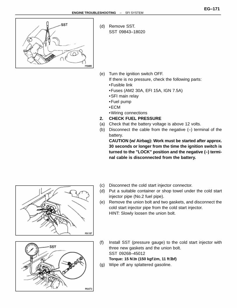
(d) Remove SST.SST 09843–18020
(e) Turn the ignition switch OFF.If there is no pressure, check the following parts:•Fusible link•Fuses (AM2 30A, EFI 15A, IGN 7.5A)•SFI main relay•Fuel pump•ECM•Wiring connections
2. CHECK FUEL PRESSURE(a) Check that the battery voltage is above 12 volts.(b) Disconnect the cable from the negative (–) terminal of the
battery.CAUTION (w/ Airbag): Work must be started after approx.30 seconds or longer from the time the ignition switch isturned to the ”LOCK” position and the negative (–) termi-nal cable is disconnected from the battery.
(c) Disconnect the cold start injector connector.(d) Put a suitable container or shop towel under the cold start
injector pipe (No.2 fuel pipe).(e) Remove the union bolt and two gaskets, and disconnect the
cold start injector pipe from the cold start injector.HINT: Slowly loosen the union bolt.
(f) Install SST (pressure gauge) to the cold start injector withthree new gaskets and the union bolt.SST 09268–45012Torque: 15 N ⋅m (150 kgf ⋅cm, 11 ft ⋅lbf)
(g) Wipe off any splattered gasoline.
–ENGINE TROUBLESHOOTING SFI SYSTEMEG–171
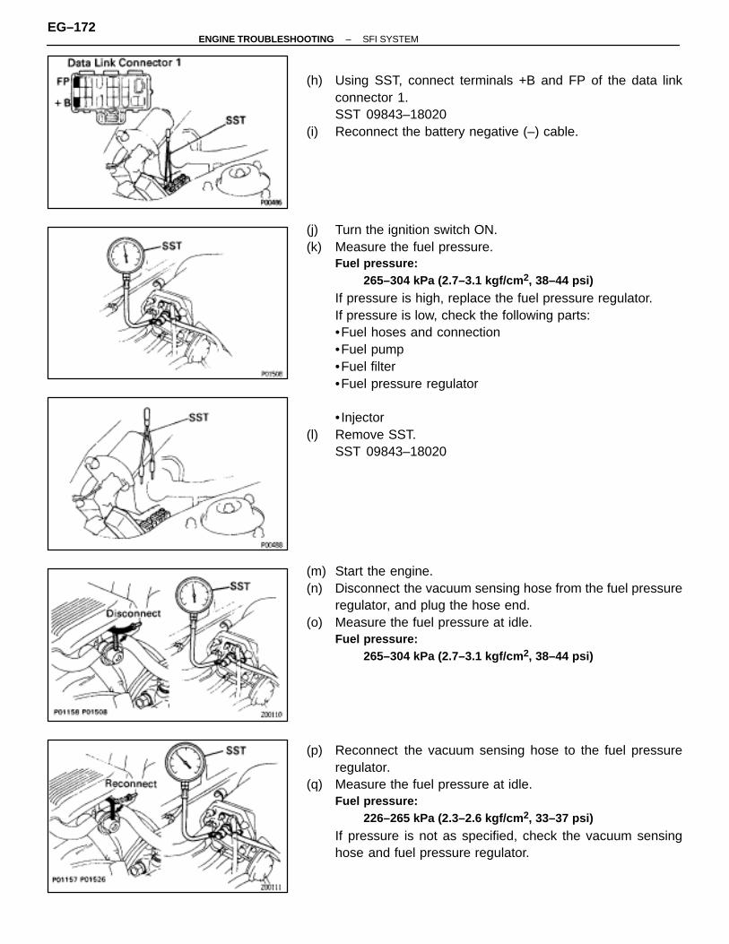
(h) Using SST, connect terminals +B and FP of the data linkconnector 1.SST 09843–18020
(i) Reconnect the battery negative (–) cable.
(j) Turn the ignition switch ON.(k) Measure the fuel pressure.
Fuel pressure:265–304 kPa (2.7–3.1 kgf/cm 2, 38–44 psi)
If pressure is high, replace the fuel pressure regulator.If pressure is low, check the following parts:•Fuel hoses and connection•Fuel pump•Fuel filter•Fuel pressure regulator
• Injector(l) Remove SST.
SST 09843–18020
(m) Start the engine.(n) Disconnect the vacuum sensing hose from the fuel pressure
regulator, and plug the hose end.(o) Measure the fuel pressure at idle.
Fuel pressure:265–304 kPa (2.7–3.1 kgf/cm 2, 38–44 psi)
(p) Reconnect the vacuum sensing hose to the fuel pressureregulator.
(q) Measure the fuel pressure at idle.Fuel pressure:
226–265 kPa (2.3–2.6 kgf/cm 2, 33–37 psi)
If pressure is not as specified, check the vacuum sensinghose and fuel pressure regulator.
EG–172–ENGINE TROUBLESHOOTING SFI SYSTEM

(r) Stop the engine. Check that the fuel pressure remains 147kPa (1.5 kgf/cm2, 21 psi) or more for 5 minutes after theengine is turned off.If pressure is not as specified, check the fuel pump, pressureregulator and/or injector.
(s) After checking fuel pressure, disconnect the battery negative(–) cable and carefully remove the SST to prevent gasolinefrom splashing.SST 09268–45012
(t) Connect the cold start injector pipe (No.2 fuel pipe) with twonew gaskets and the union bolt.Torque: 15 N ⋅m (150 kgf ⋅cm, 11 ft ⋅lbf)
(u) Reconnect the cold start injector connector.(v) Reconnect the cable to the negative (–) terminal of the
battery.(w) Check for fuel leakage.
–ENGINE TROUBLESHOOTING SFI SYSTEMEG–173
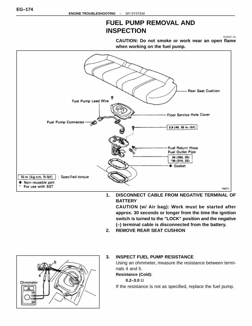
FUEL PUMP REMOVAL ANDINSPECTION
EG0GF–01
CAUTION: Do not smoke or work near an open flamewhen working on the fuel pump.
1. DISCONNECT CABLE FROM NEGATIVE TERMINAL OFBATTERYCAUTION (w/ Air bag): Work must be started afterapprox. 30 seconds or longer from the time the ignitionswitch is turned to the ”LOCK” position and the negative(–) terminal cable is disconnected from the battery.
2. REMOVE REAR SEAT CUSHION
3. INSPECT FUEL PUMP RESISTANCEUsing an ohmmeter, measure the resistance between termi-nals 4 and 5.Resistance (Cold):
0.2–3.0 �
If the resistance is not as specified, replace the fuel pump.
EG–174–ENGINE TROUBLESHOOTING SFI SYSTEM
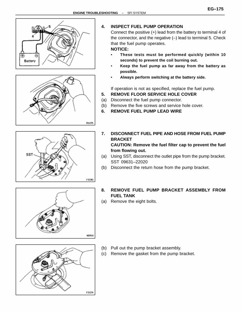
4. INSPECT FUEL PUMP OPERATIONConnect the positive (+) lead from the battery to terminal 4 ofthe connector, and the negative (–) lead to terminal 5. Checkthat the fuel pump operates.NOTICE:• These tests must be performed quickly (within 10
seconds) to prevent the coil burning out.• Keep the fuel pump as far away from the battery as
possible.• Always perform switching at the battery side.
If operation is not as specified, replace the fuel pump.5. REMOVE FLOOR SERVICE HOLE COVER(a) Disconnect the fuel pump connector.(b) Remove the five screws and service hole cover.6. REMOVE FUEL PUMP LEAD WIRE
7. DISCONNECT FUEL PIPE AND HOSE FROM FUEL PUMPBRACKETCAUTION: Remove the fuel filter cap to prevent the fuelfrom flowing out.
(a) Using SST, disconnect the outlet pipe from the pump bracket.SST 09631–22020
(b) Disconnect the return hose from the pump bracket.
8. REMOVE FUEL PUMP BRACKET A SSEMBLY FROMFUEL TANK
(a) Remove the eight bolts.
(b) Pull out the pump bracket assembly.(c) Remove the gasket from the pump bracket.
–ENGINE TROUBLESHOOTING SFI SYSTEMEG–175

COMPONENTSEG0GG–01
FUEL PUMP DISASSEMBLYEG0GH–01
1. REMOVE FUEL PUMP FROM FUEL PUMP BRACKET(a) Remove the fuel pump lead wire.(b) Pull off the lower side of the fuel pump from the pump bracket.(c) Disconnect the fuel hose from the fuel pump, and remove the
fuel pump.(d) Remove the rubber cushion from the fuel pump.
2. REMOVE FUEL SENDER GAUGE FROM FUEL PUMPBRACKET
(a) Disconnect the fuel sender gauge connector.(b) Remove the two screws and sender gauge.
EG–176–ENGINE TROUBLESHOOTING SFI SYSTEM
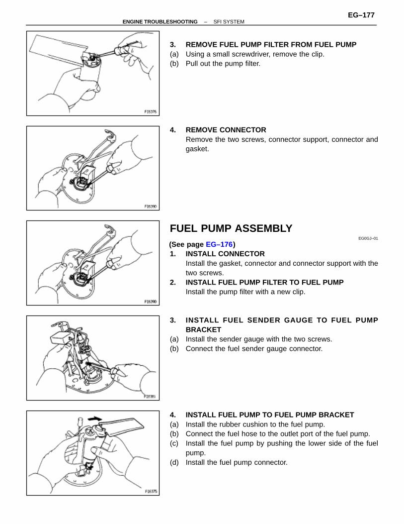
3. REMOVE FUEL PUMP FILTER FROM FUEL PUMP(a) Using a small screwdriver, remove the clip.(b) Pull out the pump filter.
4. REMOVE CONNECTORRemove the two screws, connector support, connector andgasket.
FUEL PUMP ASSEMBLYEG0GJ–01
(See page EG–176)1. INSTALL CONNECTOR
Install the gasket, connector and connector support with thetwo screws.
2. INSTALL FUEL PUMP FILTER TO FUEL PUMPInstall the pump filter with a new clip.
3. INSTALL FUEL SENDER GAUGE TO FUEL PUMPBRACKET
(a) Install the sender gauge with the two screws.(b) Connect the fuel sender gauge connector.
4. INSTALL FUEL PUMP TO FUEL PUMP BRACKET(a) Install the rubber cushion to the fuel pump.(b) Connect the fuel hose to the outlet port of the fuel pump.(c) Install the fuel pump by pushing the lower side of the fuel
pump.(d) Install the fuel pump connector.
–ENGINE TROUBLESHOOTING SFI SYSTEMEG–177
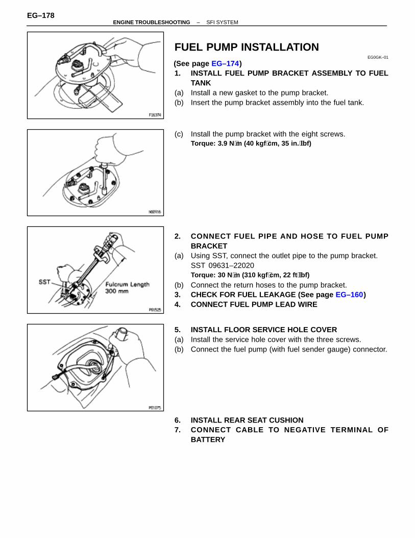
FUEL PUMP INSTALLATIONEG0GK–01
(See page EG–174)1. INSTALL FUEL PUMP BRACKET ASSEMBLY TO FUEL
TANK(a) Install a new gasket to the pump bracket.(b) Insert the pump bracket assembly into the fuel tank.
(c) Install the pump bracket with the eight screws.Torque: 3.9 N ⋅m (40 kgf ⋅cm, 35 in. ⋅lbf)
2. CONNECT FUEL PIPE AND HOSE TO FUEL PUMPBRACKET
(a) Using SST, connect the outlet pipe to the pump bracket.SST 09631–22020Torque: 30 N ⋅m (310 kgf ⋅cm, 22 ft ⋅lbf)
(b) Connect the return hoses to the pump bracket.3. CHECK FOR FUEL LEAKAGE (See page EG–160)4. CONNECT FUEL PUMP LEAD WIRE
5. INSTALL FLOOR SERVICE HOLE COVER(a) Install the service hole cover with the three screws.(b) Connect the fuel pump (with fuel sender gauge) connector.
6. INSTALL REAR SEAT CUSHION7. CONNECT CABLE TO NEGATIVE TERMINAL OF
BATTERY
EG–178–ENGINE TROUBLESHOOTING SFI SYSTEM

COLD START INJECTORON–VEHICLE INSPECTION
EG0GL–01
INSPECT RESISTANCE OF COLD START INJECTOR(a) Disconnect the cold start injector connector.(b) Using an ohmmeter, measure the resistance between the
terminals.Resistance:
2–4 �
If the resistance is not as specified, replace the cold start in-jector.
(c) Reconnect the cold start injector connector.
COLD START INJECTOR REMOVALEG0GM–01
–ENGINE TROUBLESHOOTING SFI SYSTEMEG–179
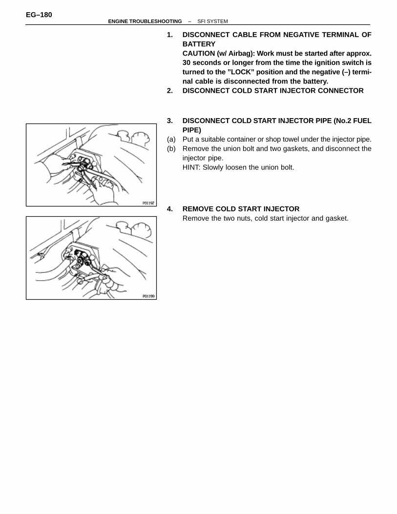
1. DISCONNECT CABLE FROM NEGATIVE TERMINAL OFBATTERYCAUTION (w/ Airbag): Work must be started after approx.30 seconds or longer from the time the ignition switch isturned to the ”LOCK” position and the negative (–) termi-nal cable is disconnected from the battery.
2. DISCONNECT COLD START INJECTOR CONNECTOR
3. DISCONNECT COLD START INJECTOR PIPE (No.2 FUELPIPE)
(a) Put a suitable container or shop towel under the injector pipe.(b) Remove the union bolt and two gaskets, and disconnect the
injector pipe.HINT: Slowly loosen the union bolt.
4. REMOVE COLD START INJECTORRemove the two nuts, cold start injector and gasket.
EG–180–ENGINE TROUBLESHOOTING SFI SYSTEM
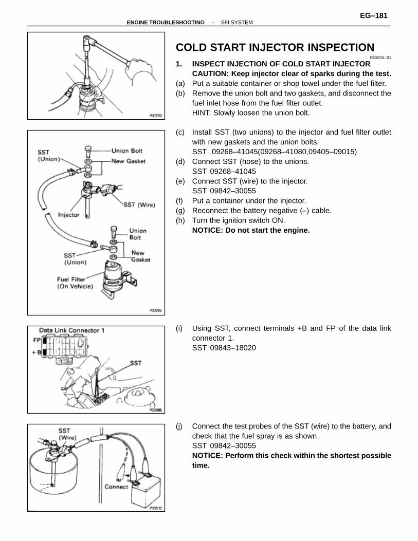
COLD START INJECTOR INSPECTIONEG0GN–01
1. INSPECT INJECTION OF COLD START INJECTORCAUTION: Keep injector clear of sparks during the test.
(a) Put a suitable container or shop towel under the fuel filter.(b) Remove the union bolt and two gaskets, and disconnect the
fuel inlet hose from the fuel filter outlet.HINT: Slowly loosen the union bolt.
(c) Install SST (two unions) to the injector and fuel filter outletwith new gaskets and the union bolts.SST 09268–41045(09268–41080,09405–09015)
(d) Connect SST (hose) to the unions.SST 09268–41045
(e) Connect SST (wire) to the injector.SST 09842–30055
(f) Put a container under the injector.(g) Reconnect the battery negative (–) cable.(h) Turn the ignition switch ON.
NOTICE: Do not start the engine.
(i) Using SST, connect terminals +B and FP of the data linkconnector 1.SST 09843–18020
(j) Connect the test probes of the SST (wire) to the battery, andcheck that the fuel spray is as shown.SST 09842–30055NOTICE: Perform this check within the shortest possibletime.
–ENGINE TROUBLESHOOTING SFI SYSTEMEG–181

2. INSPECT LEAKAGE(a) In the condition above, disconnect the test probes of SST
(wire) from the battery and check fuel leakage from theinjector.SST 09842–30050Fuel drop:
One drop or less per minute
(b) Disconnect the battery negative (–) cable.(c) Remove SST.
SST 09268–41045, 09842–30050 and 09843–18020
(d) Connect the fuel inlet hose with two new gaskets and theunion bolt.Torque: 29 N ⋅m (300 kgf ⋅cm, 22 ft ⋅lbf)
COLD START INJECTOR INSTALLATIONEG0GP–01
(See page EG–179)1. INSTALL COLD START INJECTOR
Install a new gasket and the injector with the two nuts.Torque: 8.3 N ⋅m (85 kgf ⋅cm, 74 in. ⋅lbf)
2. CONNECT COLD START INJECTOR PIPE (NO. 2 FUELPIPE)Connect the injector pipe with two new gaskets and the unionbolt.Torque: 15 N ⋅m (150 kgf ⋅cm, 11 ft ⋅lbf)
3. CONNECT COLD START INJECTOR CONNECTOR4. CONNECT CABLE TO NEGATIVE TERMINAL OF
BATTERY5. CHECK FOR FUEL LEAKAGE (See page EG–160)
EG–182–ENGINE TROUBLESHOOTING SFI SYSTEM
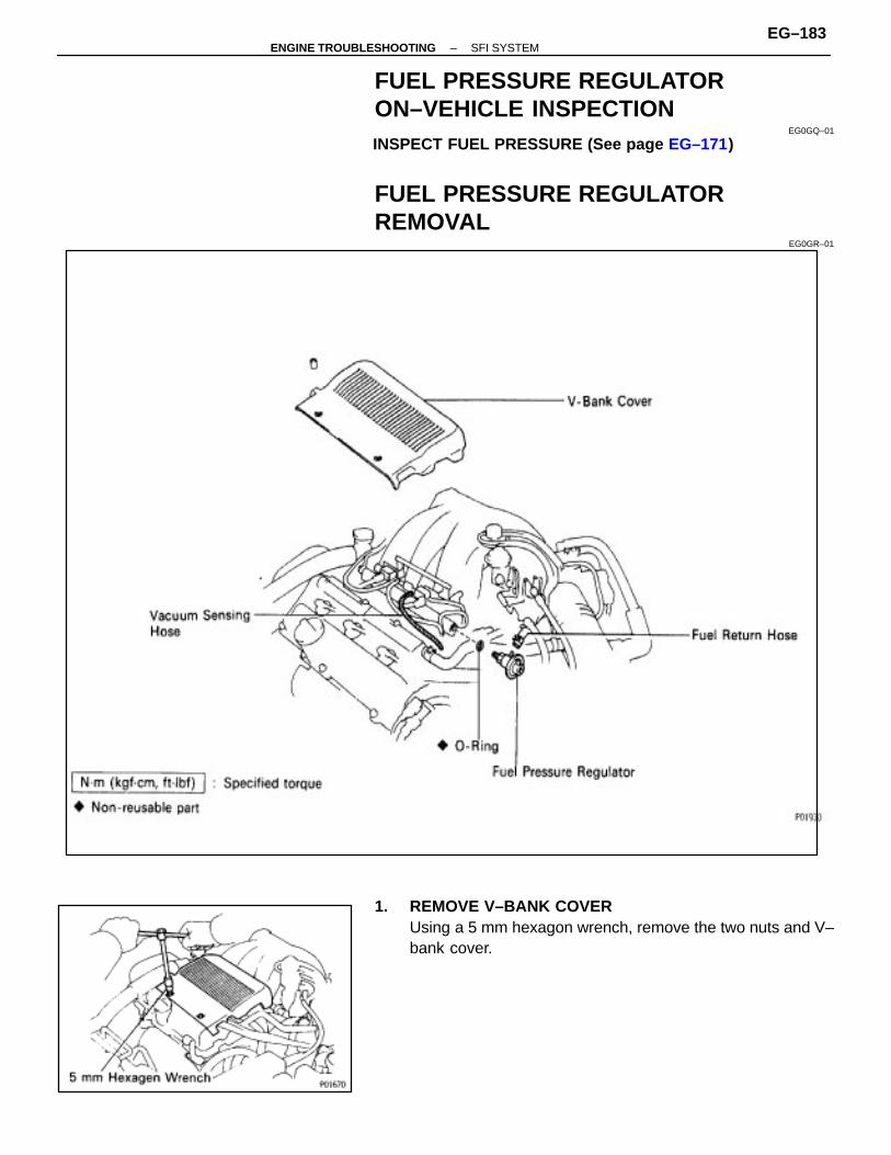
FUEL PRESSURE REGULATORON–VEHICLE INSPECTION
EG0GQ–01
INSPECT FUEL PRESSURE (See page EG–171)
FUEL PRESSURE REGULATORREMOVAL
EG0GR–01
1. REMOVE V–BANK COVERUsing a 5 mm hexagon wrench, remove the two nuts and V–bank cover.
–ENGINE TROUBLESHOOTING SFI SYSTEMEG–183
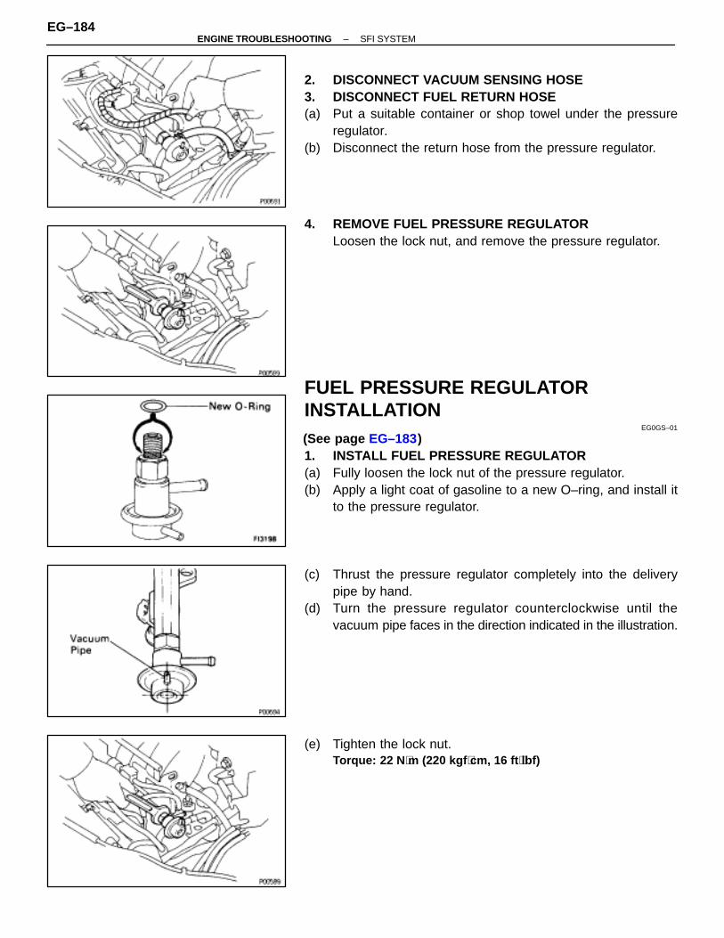
2. DISCONNECT VACUUM SENSING HOSE3. DISCONNECT FUEL RETURN HOSE(a) Put a suitable container or shop towel under the pressure
regulator.(b) Disconnect the return hose from the pressure regulator.
4. REMOVE FUEL PRESSURE REGULATORLoosen the lock nut, and remove the pressure regulator.
FUEL PRESSURE REGULATORINSTALLATION
EG0GS–01
(See page EG–183)1. INSTALL FUEL PRESSURE REGULATOR(a) Fully loosen the lock nut of the pressure regulator.(b) Apply a light coat of gasoline to a new O–ring, and install it
to the pressure regulator.
(c) Thrust the pressure regulator completely into the deliverypipe by hand.
(d) Turn the pressure regulator counterclockwise until thevacuum pipe faces in the direction indicated in the illustration.
(e) Tighten the lock nut.Torque: 22 N ⋅m (220 kgf ⋅cm, 16 ft ⋅lbf)
EG–184–ENGINE TROUBLESHOOTING SFI SYSTEM

2. CONNECT FUEL RETURN HOSE3. CONNECT VACUUM SENSING HOSE
4. CHECK FOR FUEL LEAKAGE (See page EG–160)
5. INSTALL V–BANK COVERUsing a 5 mm hexagon wrench, install the V–bank cover withthe two nuts.
–ENGINE TROUBLESHOOTING SFI SYSTEMEG–185

INJECTORSON–VEHICLE INSPECTION
EG0GT–01
1. INSPECT INJECTOR OPERATIONCheck operation sound from each injector.
(a) With the engine running or cranking, use a sound scope tocheck that there is normal operating noise in proportion toengine rpm.
(b) If you have no sound scope, you can check the injectortransmission operation with your finger.If no sound or unusual sound is heard, check the wiring con-nector, injector or injection signal from the ECM.
2. INSPECT INJECTOR RESISTANCE(a) Disconnect the injector connector.(b) Using an ohmmeter, measure the resistance between the
terminals.Resistance:
Approx. 13.8 �
If the resistance is not as specified, replace the injector.(c) Reconnect the injector connector.
EG–186–ENGINE TROUBLESHOOTING SFI SYSTEM
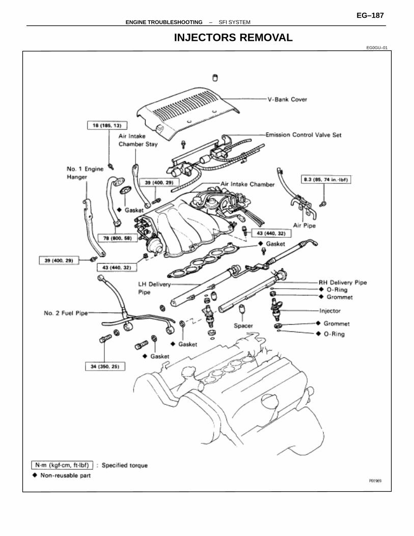
INJECTORS REMOVALEG0GU–01
–ENGINE TROUBLESHOOTING SFI SYSTEMEG–187
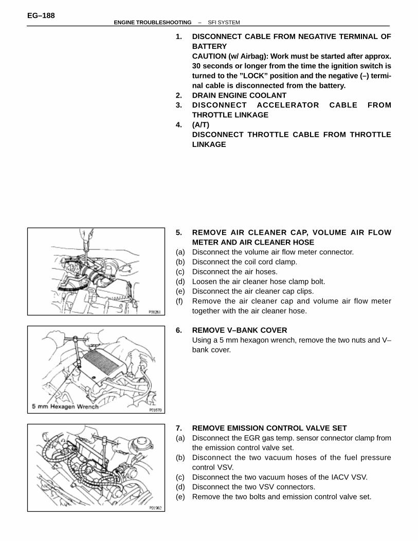
1. DISCONNECT CABLE FROM NEGATIVE TERMINAL OFBATTERYCAUTION (w/ Airbag): Work must be started after approx.30 seconds or longer from the time the ignition switch isturned to the ”LOCK” position and the negative (–) termi-nal cable is disconnected from the battery.
2. DRAIN ENGINE COOLANT3. DISCONNECT ACCELERATOR CABLE FROM
THROTTLE LINKAGE4. (A/T)
DISCONNECT THROTTLE CABLE FROM THROTTLELINKAGE
5. REMOVE AIR CLEANER CAP, VOLUME AIR FLOWMETER AND AIR CLEANER HOSE
(a) Disconnect the volume air flow meter connector.(b) Disconnect the coil cord clamp.(c) Disconnect the air hoses.(d) Loosen the air cleaner hose clamp bolt.(e) Disconnect the air cleaner cap clips.(f) Remove the air cleaner cap and volume air flow meter
together with the air cleaner hose.
6. REMOVE V–BANK COVERUsing a 5 mm hexagon wrench, remove the two nuts and V–bank cover.
7. REMOVE EMISSION CONTROL VALVE SET(a) Disconnect the EGR gas temp. sensor connector clamp from
the emission control valve set.(b) Disconnect the two vacuum hoses of the fuel pressure
control VSV.(c) Disconnect the two vacuum hoses of the IACV VSV.(d) Disconnect the two VSV connectors.(e) Remove the two bolts and emission control valve set.
EG–188–ENGINE TROUBLESHOOTING SFI SYSTEM
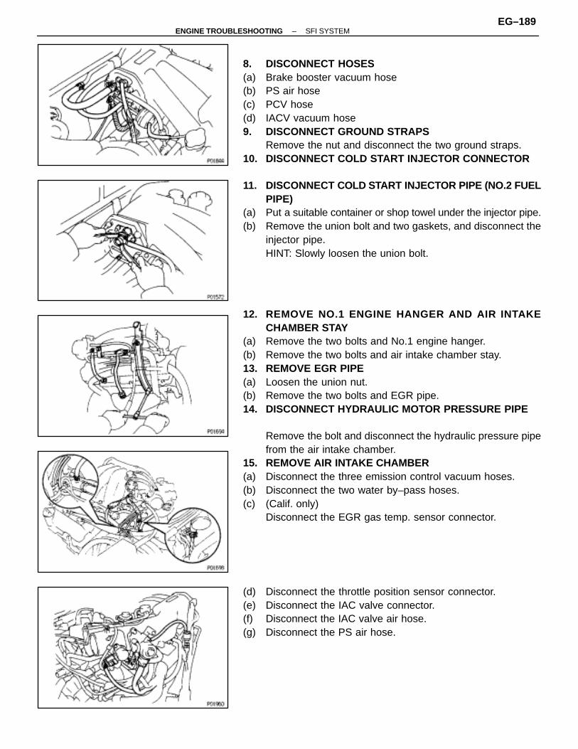
8. DISCONNECT HOSES(a) Brake booster vacuum hose(b) PS air hose(c) PCV hose(d) IACV vacuum hose9. DISCONNECT GROUND STRAPS
Remove the nut and disconnect the two ground straps.10. DISCONNECT COLD START INJECTOR CONNECTOR
11. DISCONNECT COLD START INJECTOR PIPE (NO.2 FUELPIPE)
(a) Put a suitable container or shop towel under the injector pipe.(b) Remove the union bolt and two gaskets, and disconnect the
injector pipe.HINT: Slowly loosen the union bolt.
12. REMOVE NO.1 ENGINE HANGER AND AIR INTAKECHAMBER STAY
(a) Remove the two bolts and No.1 engine hanger.(b) Remove the two bolts and air intake chamber stay.13. REMOVE EGR PIPE(a) Loosen the union nut.(b) Remove the two bolts and EGR pipe.14. DISCONNECT HYDRAULIC MOTOR PRESSURE PIPE
Remove the bolt and disconnect the hydraulic pressure pipefrom the air intake chamber.
15. REMOVE AIR INTAKE CHAMBER(a) Disconnect the three emission control vacuum hoses.(b) Disconnect the two water by–pass hoses.(c) (Calif. only)
Disconnect the EGR gas temp. sensor connector.
(d) Disconnect the throttle position sensor connector.(e) Disconnect the IAC valve connector.(f) Disconnect the IAC valve air hose.(g) Disconnect the PS air hose.
–ENGINE TROUBLESHOOTING SFI SYSTEMEG–189
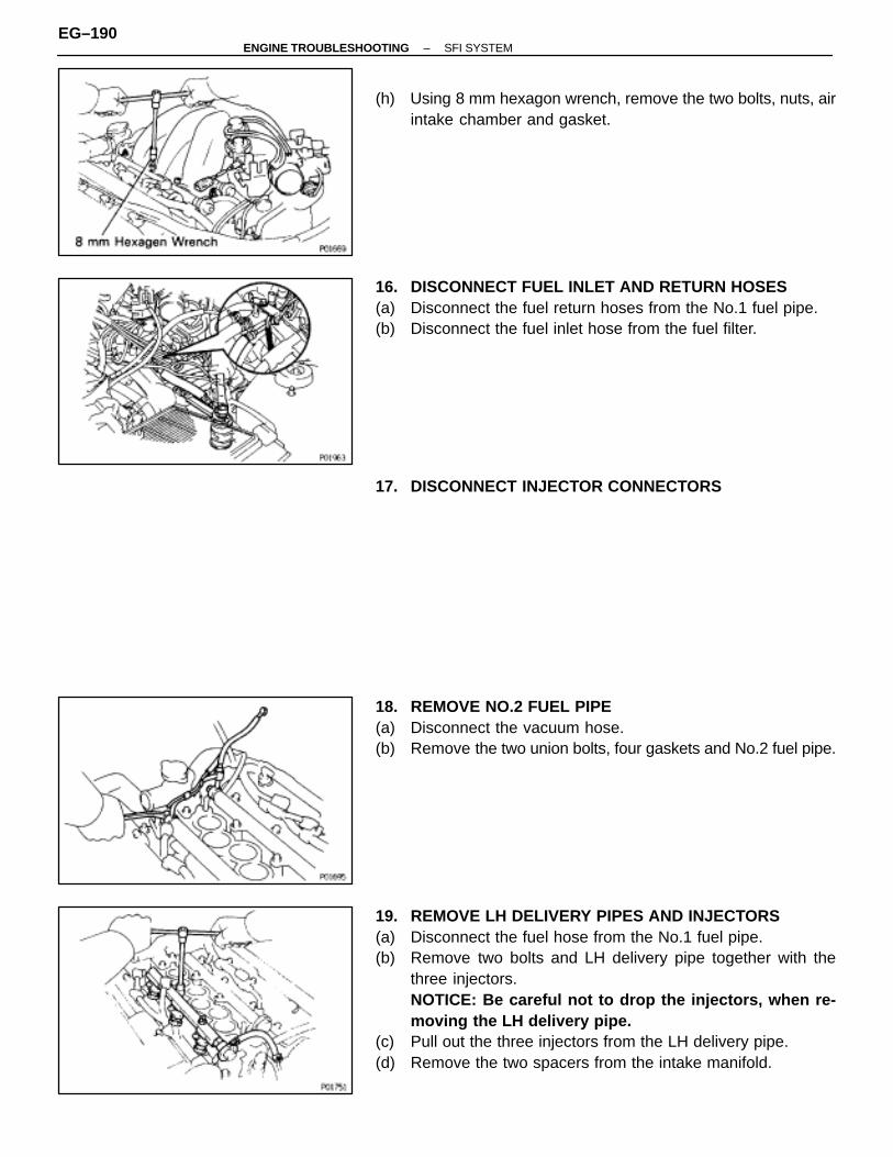
(h) Using 8 mm hexagon wrench, remove the two bolts, nuts, airintake chamber and gasket.
16. DISCONNECT FUEL INLET AND RETURN HOSES(a) Disconnect the fuel return hoses from the No.1 fuel pipe.(b) Disconnect the fuel inlet hose from the fuel filter.
17. DISCONNECT INJECTOR CONNECTORS
18. REMOVE NO.2 FUEL PIPE(a) Disconnect the vacuum hose.(b) Remove the two union bolts, four gaskets and No.2 fuel pipe.
19. REMOVE LH DELIVERY PIPES AND INJECTORS(a) Disconnect the fuel hose from the No.1 fuel pipe.(b) Remove two bolts and LH delivery pipe together with the
three injectors.NOTICE: Be careful not to drop the injectors, when re-moving the LH delivery pipe.
(c) Pull out the three injectors from the LH delivery pipe.(d) Remove the two spacers from the intake manifold.
EG–190–ENGINE TROUBLESHOOTING SFI SYSTEM

20. REMOVE AIR PIPE WITH HOSES(a) Disconnect the two air hoses.(b) Remove the bolts and air pipe with hoses.
21. REMOVE RH DELIVERY PIPE AND INJECTORS(a) Remove three bolts and RH delivery pipe together with the
three injectors.NOTICE: Be careful not to drop the injectors, when re-moving the LH delivery pipe.
(b) Pull out the three injectors from the RH delivery pipe.(c) Remove the two spacers from the intake manifold.
INJECTORS INSPECTIONEG0GV–01
1. INSPECT INJECTOR INJECTIONCAUTION: Keep clear of sparks during the test.
(a) Disconnect the fuel hose from the fuel filter outlet.(b) Connect SST (union an hose) to the fuel filter outlet with two
new gaskets and the union bolt.SST 09268–41045(90405–09015)HINT: Use the vehicle’s fuel filter.
(c) Remove the pressure regulator. (See page EG–183)(d) Connect the fuel return hose and SST (hose) to the pressure
regulator with SST (union).SST 09268–41045(09268–41060)
–ENGINE TROUBLESHOOTING SFI SYSTEMEG–191
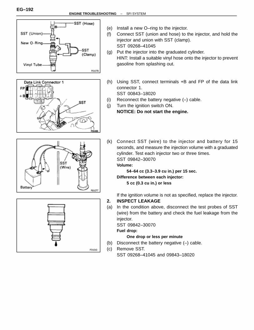
(e) Install a new O–ring to the injector.(f) Connect SST (union and hose) to the injector, and hold the
injector and union with SST (clamp).SST 09268–41045
(g) Put the injector into the graduated cylinder.HINT: Install a suitable vinyl hose onto the injector to preventgasoline from splashing out.
(h) Using SST, connect terminals +B and FP of the data linkconnector 1.SST 00843–18020
(i) Reconnect the battery negative (–) cable.(j) Turn the ignition switch ON.
NOTICE: Do not start the engine.
(k) Connect SST (wire) to the injector and battery for 15seconds, and measure the injection volume with a graduatedcylinder. Test each injector two or three times.SST 09842–30070Volume:
54–64 cc (3.3–3.9 cu in.) per 15 sec.Difference between each injector:
5 cc (0.3 cu in.) or less
If the ignition volume is not as specified, replace the injector.2. INSPECT LEAKAGE(a) In the condition above, disconnect the test probes of SST
(wire) from the battery and check the fuel leakage from theinjector.SST 09842–30070Fuel drop:
One drop or less per minute
(b) Disconnect the battery negative (–) cable.(c) Remove SST.
SST 09268–41045 and 09843–18020
EG–192–ENGINE TROUBLESHOOTING SFI SYSTEM

INJECTORS INSTALLATIONEG0GW–02
(See page EG–187)1. INSTALL INJECTORS TO DELIVERY PIPES(a) Install two new grommets to the injector.(b) Apply a light coat of gasoline to two new O–rings and install
them to the injector.
(c) When turning the injector left and right, install it to the deliverypipes. Install the six injectors.
2. INSTALL RH DELIVERY PIPE AND INJECTORS(a) Place the two spacers in position on the intake manifold.
Clean the injector holes before installing the injectorsinto the intake manifold.
(b) Place the three injectors together with the RH delivery pipeand No.1 fuel pipe in position on the intake manifold.
(c) Check that the injectors rotate smoothly.HINT: If the injectors do not rotate smoothly, the probablecause is incorrect installation of O–rings.Replace the O–rings.
(d) Position the injector connector upward.
(e) Install and tighten the three bolts.Torque: 13 N ⋅m (130 kgf ⋅cm, 9 ft ⋅lbf)
–ENGINE TROUBLESHOOTING SFI SYSTEMEG–193
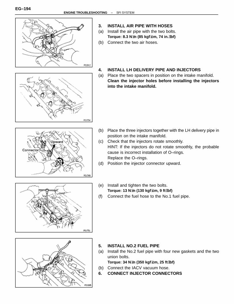
3. INSTALL AIR PIPE WITH HOSES(a) Install the air pipe with the two bolts.
Torque: 8.3 N ⋅m (85 kgf ⋅cm, 74 in. ⋅lbf)
(b) Connect the two air hoses.
4. INSTALL LH DELIVERY PIPE AND INJECTORS(a) Place the two spacers in position on the intake manifold.
Clean the injector holes before installing the injectorsinto the intake manifold.
(b) Place the three injectors together with the LH delivery pipe inposition on the intake manifold.
(c) Check that the injectors rotate smoothly.HINT: If the injectors do not rotate smoothly, the probablecause is incorrect installation of O–rings.Replace the O–rings.
(d) Position the injector connector upward.
(e) Install and tighten the two bolts.Torque: 13 N ⋅m (130 kgf ⋅cm, 9 ft ⋅lbf)
(f) Connect the fuel hose to the No.1 fuel pipe.
5. INSTALL NO.2 FUEL PIPE(a) Install the No.2 fuel pipe with four new gaskets and the two
union bolts.Torque: 34 N ⋅m (350 kgf ⋅cm, 25 ft ⋅lbf)
(b) Connect the IACV vacuum hose.6. CONNECT INJECTOR CONNECTORS
EG–194–ENGINE TROUBLESHOOTING SFI SYSTEM

7. CONNECT FUEL INLET AND RETURN HOSES(a) Connect the inlet hose to the fuel filter with two new gaskets
and union bolt.Torque: 29 N ⋅m (300 kgf ⋅cm, 22 ft ⋅lbf)
(b) Connect the return hose to the No.1 fuel pipe.
8. INSTALL AIR INTAKE CHAMBER(a) Using 8 mm hexagon wrench, install a new gasket and the air
intake number with the two bolts and nuts.Torque: 43 N ⋅m (440 kgf ⋅cm, 32 ft ⋅lbf)
(b) Connect the throttle position sensor connector.(c) Connect the IAC valve connector.(d) Connect the IAC valve air hose.(e) Connect PS air hose.
(f) (Calif. only)Connect the EGR gas temp. sensor connector.
(g) Connect the following hoses:(1) Water by–pass hose to throttle body(2) Water by–pass hose to EGR cooler(3) Vacuum hose (from EGR valve) to TVV (for EGR)(4) Vacuum hose (from EGR vacuum modulator) to TVV (for
EGR)(5) Vacuum hose (from throttle body) to TVV (for EVAP)
–ENGINE TROUBLESHOOTING SFI SYSTEMEG–195
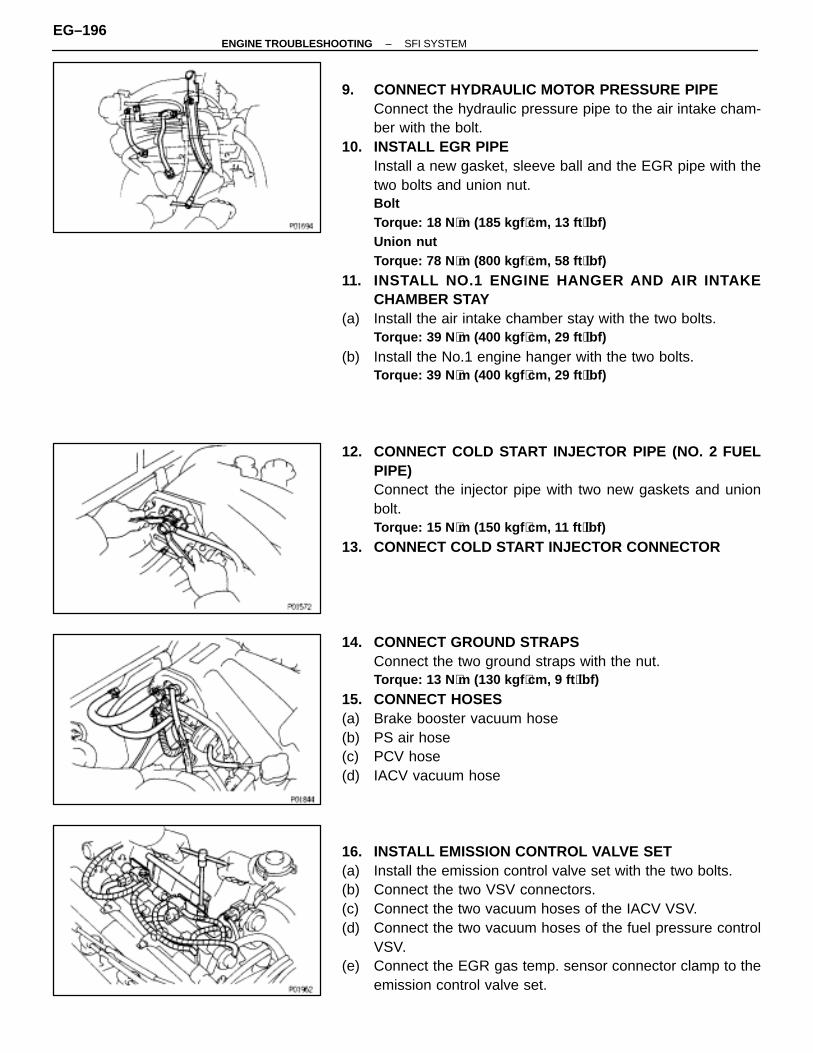
9. CONNECT HYDRAULIC MOTOR PRESSURE PIPEConnect the hydraulic pressure pipe to the air intake cham-ber with the bolt.
10. INSTALL EGR PIPEInstall a new gasket, sleeve ball and the EGR pipe with thetwo bolts and union nut.BoltTorque: 18 N ⋅m (185 kgf ⋅cm, 13 ft ⋅lbf)Union nutTorque: 78 N ⋅m (800 kgf ⋅cm, 58 ft ⋅lbf)
11. INSTALL NO.1 ENGINE HANGER AND AIR INTAKECHAMBER STAY
(a) Install the air intake chamber stay with the two bolts.Torque: 39 N ⋅m (400 kgf ⋅cm, 29 ft ⋅lbf)
(b) Install the No.1 engine hanger with the two bolts.Torque: 39 N ⋅m (400 kgf ⋅cm, 29 ft ⋅lbf)
12. CONNECT COLD START INJECTOR PIPE (NO. 2 FUELPIPE)Connect the injector pipe with two new gaskets and unionbolt.Torque: 15 N ⋅m (150 kgf ⋅cm, 11 ft ⋅lbf)
13. CONNECT COLD START INJECTOR CONNECTOR
14. CONNECT GROUND STRAPSConnect the two ground straps with the nut.Torque: 13 N ⋅m (130 kgf ⋅cm, 9 ft ⋅lbf)
15. CONNECT HOSES(a) Brake booster vacuum hose(b) PS air hose(c) PCV hose(d) IACV vacuum hose
16. INSTALL EMISSION CONTROL VALVE SET(a) Install the emission control valve set with the two bolts.(b) Connect the two VSV connectors.(c) Connect the two vacuum hoses of the IACV VSV.(d) Connect the two vacuum hoses of the fuel pressure control
VSV.(e) Connect the EGR gas temp. sensor connector clamp to the
emission control valve set.
EG–196–ENGINE TROUBLESHOOTING SFI SYSTEM
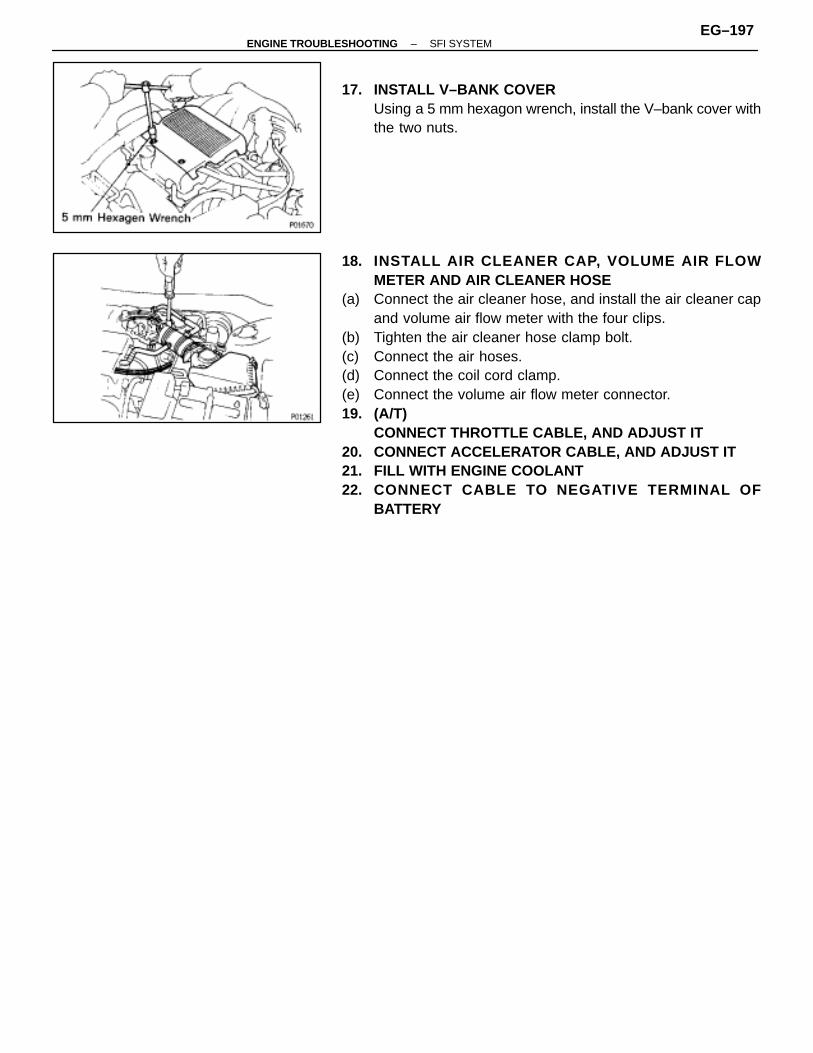
17. INSTALL V–BANK COVERUsing a 5 mm hexagon wrench, install the V–bank cover withthe two nuts.
18. INSTALL AIR CLEANER CAP, VOLUME AIR FLOWMETER AND AIR CLEANER HOSE
(a) Connect the air cleaner hose, and install the air cleaner capand volume air flow meter with the four clips.
(b) Tighten the air cleaner hose clamp bolt.(c) Connect the air hoses.(d) Connect the coil cord clamp.(e) Connect the volume air flow meter connector.19. (A/T)
CONNECT THROTTLE CABLE, AND ADJUST IT20. CONNECT ACCELERATOR CABLE, AND ADJUST IT21. FILL WITH ENGINE COOLANT22. CONNECT CABLE TO NEGATIVE TERMINAL OF
BATTERY
–ENGINE TROUBLESHOOTING SFI SYSTEMEG–197

FUEL TANK AND LINESCOMPONENTS
EG0GX–01
EG–198–ENGINE TROUBLESHOOTING SFI SYSTEM
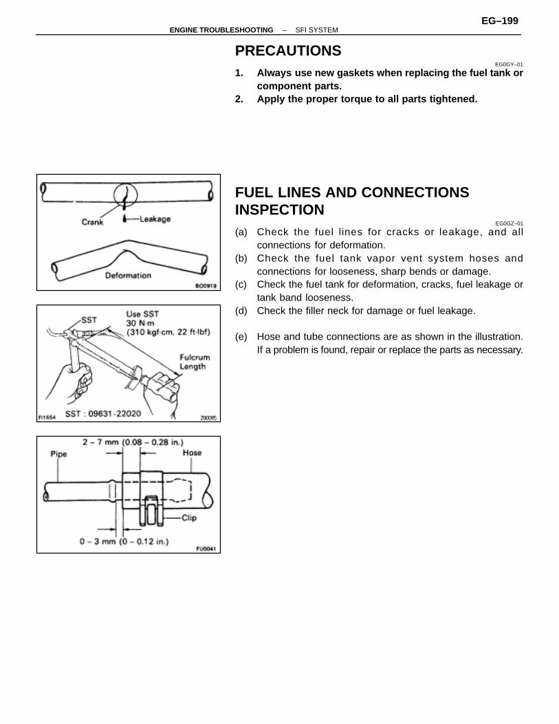
PRECAUTIONSEG0GY–01
1. Always use new gaskets when replacing the fuel tank orcomponent parts.
2. Apply the proper torque to all parts tightened.
FUEL LINES AND CONNECTIONSINSPECTION
EG0GZ–01
(a) Check the fuel lines for cracks or leakage, and allconnections for deformation.
(b) Check the fuel tank vapor vent system hoses andconnections for looseness, sharp bends or damage.
(c) Check the fuel tank for deformation, cracks, fuel leakage ortank band looseness.
(d) Check the filler neck for damage or fuel leakage.
(e) Hose and tube connections are as shown in the illustration.If a problem is found, repair or replace the parts as necessary.
–ENGINE TROUBLESHOOTING SFI SYSTEMEG–199
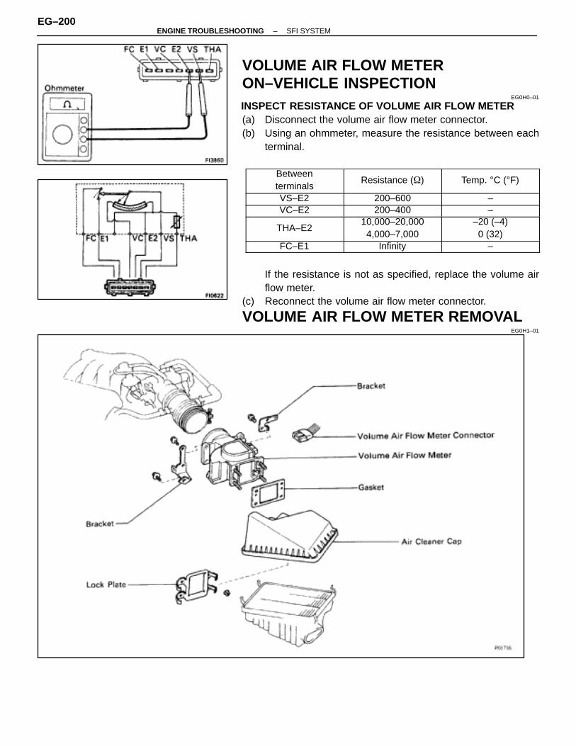
VOLUME AIR FLOW METERON–VEHICLE INSPECTION
EG0H0–01
INSPECT RESISTANCE OF VOLUME AIR FLOW METER(a) Disconnect the volume air flow meter connector.(b) Using an ohmmeter, measure the resistance between each
terminal.
ÑÑÑÑÑÑÑÑÑÑÑÑÑÑÑÑÑÑÑÑÑÑÑÑ
Betweenterminals
ÑÑÑÑÑÑÑÑÑÑÑÑÑÑÑÑÑÑÑÑÑÑÑÑ
Resistance (�)ÑÑÑÑÑÑÑÑÑÑÑÑÑÑÑÑÑÑÑÑÑÑÑÑ
Temp. °C (°F)
ÑÑÑÑÑÑÑÑÑÑÑÑÑÑÑÑ
VS–E2 ÑÑÑÑÑÑÑÑÑÑÑÑÑÑÑÑ
200–600 ÑÑÑÑÑÑÑÑÑÑÑÑÑÑÑÑ
–
ÑÑÑÑÑÑÑÑVC–E2 ÑÑÑÑÑÑÑÑ200–400 ÑÑÑÑÑÑÑÑ–ÑÑÑÑÑÑÑÑÑÑÑÑÑÑÑÑÑÑÑÑÑÑÑÑ
THA–E2
ÑÑÑÑÑÑÑÑÑÑÑÑÑÑÑÑÑÑÑÑÑÑÑÑ
10,000–20,0004,000–7,000
ÑÑÑÑÑÑÑÑÑÑÑÑÑÑÑÑÑÑÑÑÑÑÑÑ
–20 (–4)0 (32)
ÑÑÑÑÑÑÑÑÑÑÑÑÑÑÑÑ
FC–E1 ÑÑÑÑÑÑÑÑÑÑÑÑÑÑÑÑ
Infinity ÑÑÑÑÑÑÑÑÑÑÑÑÑÑÑÑ
–
If the resistance is not as specified, replace the volume airflow meter.
(c) Reconnect the volume air flow meter connector.
VOLUME AIR FLOW METER REMOVALEG0H1–01
EG–200–ENGINE TROUBLESHOOTING SFI SYSTEM

1. DISCONNECT CABLE FROM NEGATIVE TERMINAL OFBATTERYCAUTION (w/Airbag): Work must be started after approx.30 seconds or longer from the time the ignition switch isturned to the ”LOCK” position and the negative (–) termi-nal cable disconnected from the battery.
2. DISCONNECT COIL CORD CLAMP3. DISCONNECT VOLUME AIR FLOW METER CONNECTOR4. DISCONNECT AIR CLEANER HOSE
5. REMOVE AIR CLEANER CAP AND VOLUME AIR FLOWMETER ASSEMBLY
6. REMOVE VOLUME AIR FLOW METER FROM AIRCLEANER CAP
(a) Remove the screw and wire bracket.(b) Remove the bolt, two screws and bracket.
(c) Pry off the lock plate, and remove the four nuts, lock plate,volume air flow meter and gasket.
VOLUME AIR FLOW METERINSPECTION
EG0H2–01
INSPECT RESISTANCE OF VOLUME AIR FLOW METERUsing an ohmmeter, measure the resistance between eachterminal by moving the measuring plate.
ÑÑÑÑÑÑÑÑÑÑÑÑÑÑÑÑÑÑÑÑÑÑÑÑ
Betweenterminals
ÑÑÑÑÑÑÑÑÑÑÑÑÑÑÑÑÑÑÑÑÑÑÑÑ
Resistance (�)ÑÑÑÑÑÑÑÑÑÑÑÑÑÑÑÑÑÑÑÑÑÑÑÑ
Measuring plateopening
ÑÑÑÑÑÑÑÑÑÑÑÑÑÑÑÑ
FC–E1 ÑÑÑÑÑÑÑÑÑÑÑÑÑÑÑÑ
Infinity ÑÑÑÑÑÑÑÑÑÑÑÑÑÑÑÑ
Fully closedÑÑÑÑÑÑÑÑÑÑÑÑÑÑÑÑ
FC–E1 ÑÑÑÑÑÑÑÑÑÑÑÑÑÑÑÑ
Zero ÑÑÑÑÑÑÑÑÑÑÑÑÑÑÑÑ
Other than closed
ÑÑÑÑÑÑÑÑVS–E2 ÑÑÑÑÑÑÑÑ200–600 ÑÑÑÑÑÑÑÑFully closedÑÑÑÑÑÑÑÑÑÑÑÑÑÑÑÑVS–E2
ÑÑÑÑÑÑÑÑÑÑÑÑÑÑÑÑ20–1,200
ÑÑÑÑÑÑÑÑÑÑÑÑÑÑÑÑFully open
HINT: Resistance between terminals E2 and VS will changein a wave pattern as the measuring plate slowly opens.If the resistance is not as specified, replace the volume airflow meter.
–ENGINE TROUBLESHOOTING SFI SYSTEMEG–201
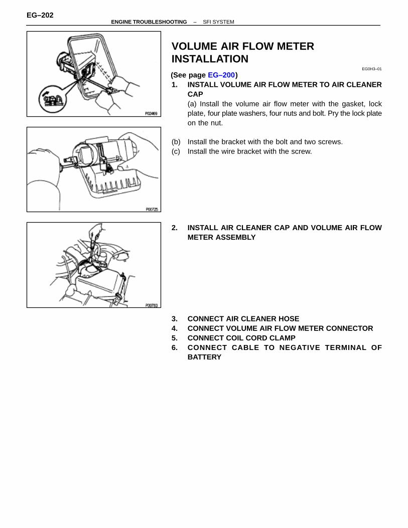
VOLUME AIR FLOW METERINSTALLATION
EG0H3–01
(See page EG–200)1. INSTALL VOLUME AIR FLOW METER TO AIR CLEANER
CAP(a) Install the volume air flow meter with the gasket, lockplate, four plate washers, four nuts and bolt. Pry the lock plateon the nut.
(b) Install the bracket with the bolt and two screws.(c) Install the wire bracket with the screw.
2. INSTALL AIR CLEANER CAP AND VOLUME AIR FLOWMETER ASSEMBLY
3. CONNECT AIR CLEANER HOSE4. CONNECT VOLUME AIR FLOW METER CONNECTOR5. CONNECT COIL CORD CLAMP6. CONNECT CABLE TO NEGATIVE TERMINAL OF
BATTERY
EG–202–ENGINE TROUBLESHOOTING SFI SYSTEM
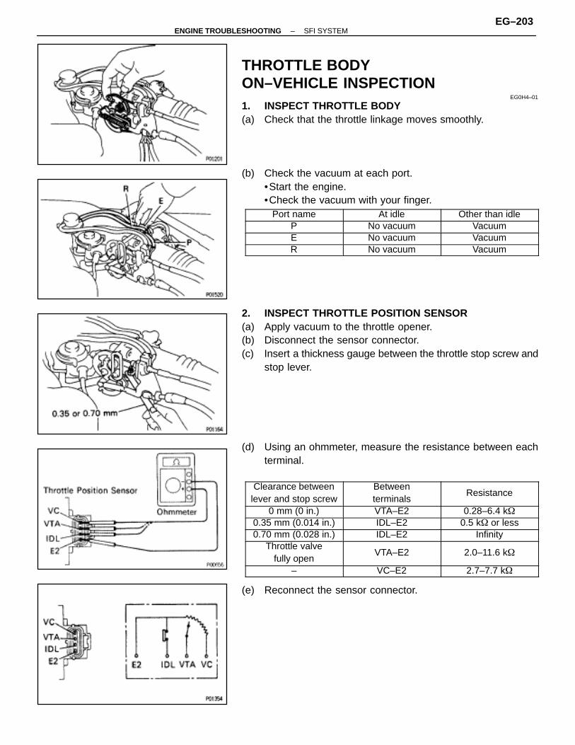
THROTTLE BODYON–VEHICLE INSPECTION
EG0H4–01
1. INSPECT THROTTLE BODY(a) Check that the throttle linkage moves smoothly.
(b) Check the vacuum at each port.•Start the engine.•Check the vacuum with your finger.
ÑÑÑÑÑÑÑÑÑÑÑÑÑÑÑÑ
Port name ÑÑÑÑÑÑÑÑÑÑÑÑÑÑÑÑ
At idle ÑÑÑÑÑÑÑÑÑÑÑÑÑÑÑÑ
Other than idle
ÑÑÑÑÑÑÑÑÑÑÑÑÑÑÑÑ
P ÑÑÑÑÑÑÑÑÑÑÑÑÑÑÑÑ
No vacuum ÑÑÑÑÑÑÑÑÑÑÑÑÑÑÑÑ
Vacuum
ÑÑÑÑÑÑÑÑE ÑÑÑÑÑÑÑÑNo vacuum ÑÑÑÑÑÑÑÑVacuumÑÑÑÑÑÑÑÑÑÑÑÑÑÑÑÑ
RÑÑÑÑÑÑÑÑÑÑÑÑÑÑÑÑ
No vacuumÑÑÑÑÑÑÑÑÑÑÑÑÑÑÑÑ
Vacuum
2. INSPECT THROTTLE POSITION SENSOR(a) Apply vacuum to the throttle opener.(b) Disconnect the sensor connector.(c) Insert a thickness gauge between the throttle stop screw and
stop lever.
(d) Using an ohmmeter, measure the resistance between eachterminal.
ÑÑÑÑÑÑÑÑÑÑÑÑÑÑÑÑÑÑÑÑÑÑÑÑ
Clearance betweenlever and stop screw
ÑÑÑÑÑÑÑÑÑÑÑÑÑÑÑÑÑÑÑÑÑÑÑÑ
Betweenterminals
ÑÑÑÑÑÑÑÑÑÑÑÑÑÑÑÑÑÑÑÑÑÑÑÑ
Resistance
ÑÑÑÑÑÑÑÑ0 mm (0 in.) ÑÑÑÑÑÑÑÑVTA–E2 ÑÑÑÑÑÑÑÑ0.28–6.4 k�ÑÑÑÑÑÑÑÑÑÑÑÑÑÑÑÑ
0.35 mm (0.014 in.)ÑÑÑÑÑÑÑÑÑÑÑÑÑÑÑÑ
IDL–E2ÑÑÑÑÑÑÑÑÑÑÑÑÑÑÑÑ
0.5 k� or lessÑÑÑÑÑÑÑÑÑÑÑÑÑÑÑÑ
0.70 mm (0.028 in.)ÑÑÑÑÑÑÑÑÑÑÑÑÑÑÑÑ
IDL–E2 ÑÑÑÑÑÑÑÑÑÑÑÑÑÑÑÑ
InfinityÑÑÑÑÑÑÑÑÑÑÑÑÑÑÑÑÑÑÑÑÑÑÑÑ
Throttle valvefully open
ÑÑÑÑÑÑÑÑÑÑÑÑÑÑÑÑÑÑÑÑÑÑÑÑ
VTA–E2ÑÑÑÑÑÑÑÑÑÑÑÑÑÑÑÑÑÑÑÑÑÑÑÑ
2.0–11.6 k�
ÑÑÑÑÑÑÑÑ– ÑÑÑÑÑÑÑÑVC–E2 ÑÑÑÑÑÑÑÑ2.7–7.7 k�
(e) Reconnect the sensor connector.
–ENGINE TROUBLESHOOTING SFI SYSTEMEG–203

3. INSPECT AND ADJUST DASH POT (DP)A. Warm up engine
Allow the engine to warm up to normal operating tempera-ture.
B. Check idle speedIdle speed:
700 ± 50 rpm
C. Remove cap, filter and separator from DP
D. Check and adjust DP setting speed(a) Maintain the engine at 3,000 rpm.(b) Plug the VTV hole with your finger.
(c) Release the throttle valve.(d) Check that the DP is set.
DP setting speed:2,000 rpm
If not as specified, adjust with the DP adjusting screw.E. Reinstall DP separator, filter and cap
HINT: Install the filter with the coarser surface facing the at-mospheric side (outward).
EG–204–ENGINE TROUBLESHOOTING SFI SYSTEM

4. INSPECT THROTTLE OPENERA. Warm up engine
Allow the engine to warm up to normal operating tempera-ture.
B. Check idle speedIdle speed:
700 ± 50 rpm
C. Check throttle opener setting speed(a) Disconnect the vacuum hose from the throttle opener, and
plug the hose end.
(b) Check the throttle opener setting speed.Throttle opener setting speed:
900–1,950 rpm
If the throttle opener setting is not as specified, replace thethrottle body.
(c) Stop the engine.
(d) Reconnect the vacuum hose to the throttle opener.(e) Start the engine and check that the idle rpm returns to the
correct speed.
–ENGINE TROUBLESHOOTING SFI SYSTEMEG–205

THROTTLE BODY REMOVALEG0H5–01
1. DISCONNECT CABLE FROM NEGATIVE TERMINAL OFBATTERYCAUTION (w / Airbag): Work must be started afterapprox. 30 seconds or longer from the time the ignitionswitch is turned to the ”LOCK” position and the negative(–) terminal cable is disconnected from the battery.
2. DRAIN ENGINE COOLANT3. DISCONNECT ACCELERATOR CABLE FROM
THROTTLE LINKAGE4. (A/T)
DISCONNECT THROTTLE CABLE FROM THROTTLELINKAGE
EG–206–ENGINE TROUBLESHOOTING SFI SYSTEM

5. REMOVE AIR CLEANER CAP, VOLUME AIR FLOWMETER AND AIR CLEANER HOSE
(a) Disconnect the volume air flow meter connector.(b) Disconnect the coil cord clamp.(c) Disconnect the air hoses.(d) Loosen the air cleaner hose clamp bolt.(e) Disconnect the air cleaner cap clips.(f) Remove the air cleaner cap and volume air flow meter
together with the air cleaner hose.
6. DISCONNECT THROTTLE POSITION SENSORCONNECTOR
7. DISCONNECT HOSES FROM THROTTLE BODY(a) Water by–pass hoses(b) Emission control vacuum hoses
8. REMOVE THROTTLE BODYRemove the two bolts and two nuts, throttle body and gasket.
THROTTLE BODY INSPECTIONEG0H6–01
1. CLEAN THROTTLE BODY(a) Using a soft brush and carburetor cleaner, clean the cast
parts.(b) Using compressed air, clean all the passages and apertures.
NOTICE: To prevent deterioration, do not clean the throttleposition sensor.
2. INSPECT THROTTLE VALVE(a) Apply vacuum to the throttle opener.(b) Check that there is no clearance between the throttle stop
screw and throttle lever when the throttle valve is fully closed.
–ENGINE TROUBLESHOOTING SFI SYSTEMEG–207

3. INSPECT THROTTLE POSITION SENSOR(a) Apply vacuum to the throttle opener.(b) Insert a thickness gauge between the throttle stop screw and
stop lever.(c) Using an ohmmeter, measure the resistance between each
terminal.
ÑÑÑÑÑÑÑÑÑÑÑÑÑÑÑÑÑÑÑÑÑÑÑÑ
Clearance betweenlever and stop screw
ÑÑÑÑÑÑÑÑÑÑÑÑÑÑÑÑÑÑÑÑÑÑÑÑ
Betweenterminals
ÑÑÑÑÑÑÑÑÑÑÑÑÑÑÑÑÑÑÑÑÑÑÑÑ
Resistance
ÑÑÑÑÑÑÑÑ0 mm (0 in.) ÑÑÑÑÑÑÑÑVTA–E2 ÑÑÑÑÑÑÑÑ0.28–6.4 k�ÑÑÑÑÑÑÑÑÑÑÑÑÑÑÑÑ0.35 mm (0.014 in.)
ÑÑÑÑÑÑÑÑÑÑÑÑÑÑÑÑIDL–E2
ÑÑÑÑÑÑÑÑÑÑÑÑÑÑÑÑ0.5 k� or lessÑÑÑÑÑÑÑÑ
ÑÑÑÑÑÑÑÑ0.70 mm (0.028 in.)ÑÑÑÑÑÑÑÑ
ÑÑÑÑÑÑÑÑIDL–E2 ÑÑÑÑÑÑÑÑ
ÑÑÑÑÑÑÑÑInfinity
ÑÑÑÑÑÑÑÑÑÑÑÑÑÑÑÑÑÑÑÑÑÑÑÑ
Throttle valve fullyopen
ÑÑÑÑÑÑÑÑÑÑÑÑÑÑÑÑÑÑÑÑÑÑÑÑ
VTA–E2ÑÑÑÑÑÑÑÑÑÑÑÑÑÑÑÑÑÑÑÑÑÑÑÑ
2.0–11.6 k�
ÑÑÑÑÑÑÑÑÑÑÑÑÑÑÑÑ
– ÑÑÑÑÑÑÑÑÑÑÑÑÑÑÑÑ
VC–E2 ÑÑÑÑÑÑÑÑÑÑÑÑÑÑÑÑ
2.7–7.7 k�
4. IF NECESSARY, ADJUST THROTTLE POSITIONSENSOR
(a) Loosen the two set screws of the sensor.
(b) Apply vacuum to the throttle opener.(c) Insert a 0.54 mm (0.021 in.) thickness gauge, between the
throttle stop screw and stop lever.(d) Connect the test probe of an ohmmeter to the terminals IDL
and E2 of the sensor.(e) Gradually turn the sensor clockwise until the ohmmeter
deflects, and secure it with the two set screws.
(f) Recheck the continuity between terminals IDL and E2.
ÑÑÑÑÑÑÑÑÑÑÑÑÑÑÑÑÑÑÑÑÑÑÑÑ
Clearance betweenlever and stop screw
ÑÑÑÑÑÑÑÑÑÑÑÑÑÑÑÑÑÑÑÑÑÑ
Continuity (IDL–E2)
ÑÑÑÑÑÑÑÑÑÑÑÑ0.35 mm (0.014 in.) ÑÑÑÑÑÑÑÑÑÑÑContinuityÑÑÑÑÑÑÑÑÑÑÑÑÑÑÑÑÑÑÑÑÑÑÑÑ
0.70 mm (0.028 in.)ÑÑÑÑÑÑÑÑÑÑÑÑÑÑÑÑÑÑÑÑÑÑ
No continuity
EG–208–ENGINE TROUBLESHOOTING SFI SYSTEM
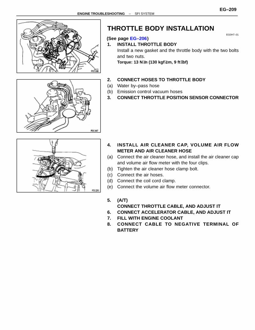
THROTTLE BODY INSTALLATIONEG0H7–01
(See page EG–206)1. INSTALL THROTTLE BODY
Install a new gasket and the throttle body with the two boltsand two nuts.Torque: 13 N ⋅m (130 kgf ⋅cm, 9 ft ⋅lbf)
2. CONNECT HOSES TO THROTTLE BODY(a) Water by–pass hose(b) Emission control vacuum hoses3. CONNECT THROTTLE POSITION SENSOR CONNECTOR
4. INSTALL AIR CLEANER CAP, VOLUME AIR FLOWMETER AND AIR CLEANER HOSE
(a) Connect the air cleaner hose, and install the air cleaner capand volume air flow meter with the four clips.
(b) Tighten the air cleaner hose clamp bolt.(c) Connect the air hoses.(d) Connect the coil cord clamp.(e) Connect the volume air flow meter connector.
5. (A/T)CONNECT THROTTLE CABLE, AND ADJUST IT
6. CONNECT ACCELERATOR CABLE, AND ADJUST IT7. FILL WITH ENGINE COOLANT8. CONNECT CABLE TO NEGATIVE TERMINAL OF
BATTERY
–ENGINE TROUBLESHOOTING SFI SYSTEMEG–209
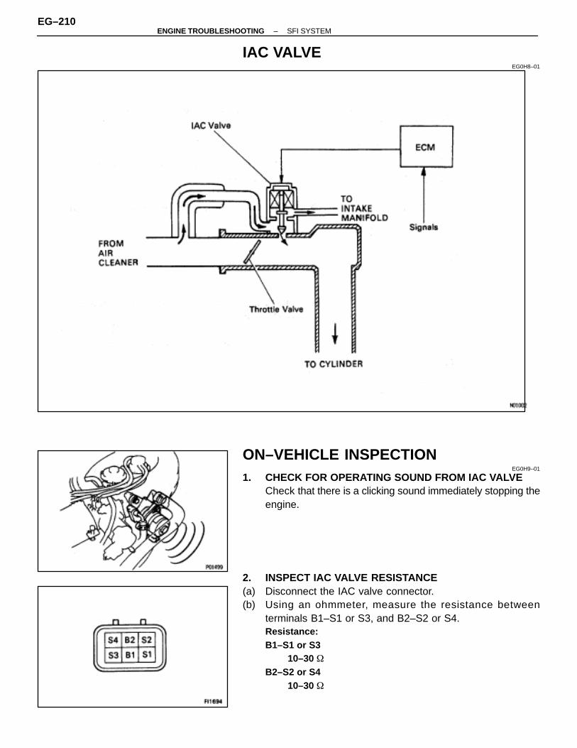
IAC VALVEEG0H8–01
ON–VEHICLE INSPECTIONEG0H9–01
1. CHECK FOR OPERATING SOUND FROM IAC VALVECheck that there is a clicking sound immediately stopping theengine.
2. INSPECT IAC VALVE RESISTANCE(a) Disconnect the IAC valve connector.(b) Using an ohmmeter, measure the resistance between
terminals B1–S1 or S3, and B2–S2 or S4.Resistance:B1–S1 or S3
10–30 �B2–S2 or S4
10–30 �
EG–210–ENGINE TROUBLESHOOTING SFI SYSTEM
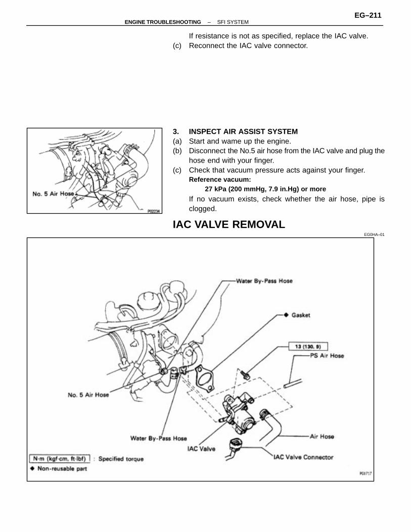
If resistance is not as specified, replace the IAC valve.(c) Reconnect the IAC valve connector.
3. INSPECT AIR ASSIST SYSTEM(a) Start and wame up the engine.(b) Disconnect the No.5 air hose from the IAC valve and plug the
hose end with your finger.(c) Check that vacuum pressure acts against your finger.
Reference vacuum:27 kPa (200 mmHg, 7.9 in.Hg) or more
If no vacuum exists, check whether the air hose, pipe isclogged.
IAC VALVE REMOVALEG0HA–01
–ENGINE TROUBLESHOOTING SFI SYSTEMEG–211
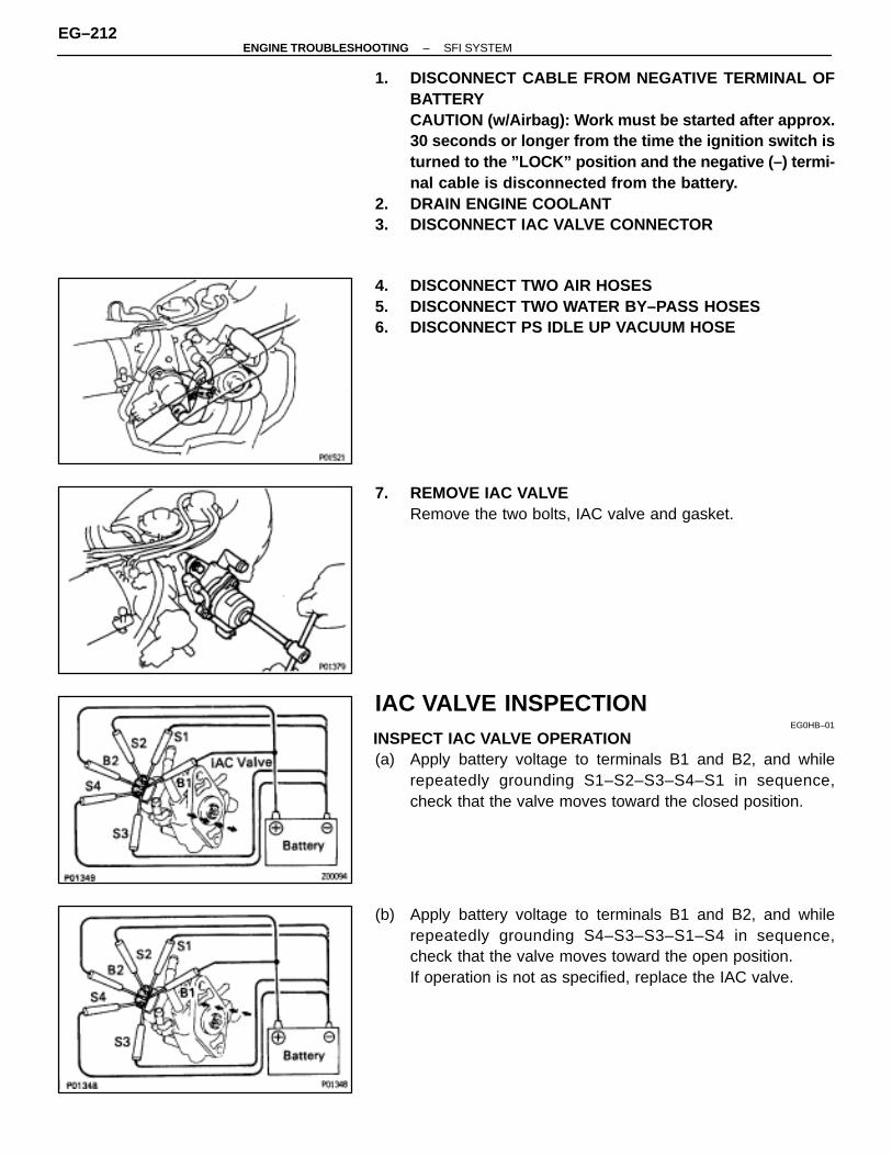
1. DISCONNECT CABLE FROM NEGATIVE TERMINAL OFBATTERYCAUTION (w/Airbag): Work must be started after approx.30 seconds or longer from the time the ignition switch isturned to the ”LOCK” position and the negative (–) termi-nal cable is disconnected from the battery.
2. DRAIN ENGINE COOLANT3. DISCONNECT IAC VALVE CONNECTOR
4. DISCONNECT TWO AIR HOSES5. DISCONNECT TWO WATER BY–PASS HOSES6. DISCONNECT PS IDLE UP VACUUM HOSE
7. REMOVE IAC VALVERemove the two bolts, IAC valve and gasket.
IAC VALVE INSPECTIONEG0HB–01
INSPECT IAC VALVE OPERATION(a) Apply battery voltage to terminals B1 and B2, and while
repeatedly grounding S1–S2–S3–S4–S1 in sequence,check that the valve moves toward the closed position.
(b) Apply battery voltage to terminals B1 and B2, and whilerepeatedly grounding S4–S3–S3–S1–S4 in sequence,check that the valve moves toward the open position.If operation is not as specified, replace the IAC valve.
EG–212–ENGINE TROUBLESHOOTING SFI SYSTEM
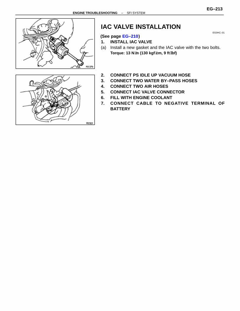
IAC VALVE INSTALLATIONEG0HC–01
(See page EG–210)1. INSTALL IAC VALVE(a) Install a new gasket and the IAC valve with the two bolts.
Torque: 13 N ⋅m (130 kgf ⋅cm, 9 ft ⋅lbf)
2. CONNECT PS IDLE UP VACUUM HOSE3. CONNECT TWO WATER BY–PASS HOSES4. CONNECT TWO AIR HOSES5. CONNECT IAC VALVE CONNECTOR6. FILL WITH ENGINE COOLANT7. CONNECT CABLE TO NEGATIVE TERMINAL OF
BATTERY
–ENGINE TROUBLESHOOTING SFI SYSTEMEG–213
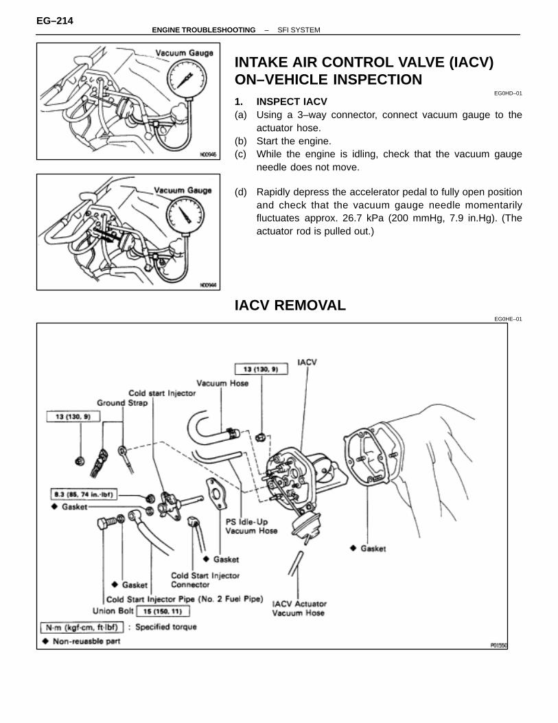
INTAKE AIR CONTROL VALVE (IACV)ON–VEHICLE INSPECTION
EG0HD–01
1. INSPECT IACV(a) Using a 3–way connector, connect vacuum gauge to the
actuator hose.(b) Start the engine.(c) While the engine is idling, check that the vacuum gauge
needle does not move.
(d) Rapidly depress the accelerator pedal to fully open positionand check that the vacuum gauge needle momentarilyfluctuates approx. 26.7 kPa (200 mmHg, 7.9 in.Hg). (Theactuator rod is pulled out.)
IACV REMOVALEG0HE–01
EG–214–ENGINE TROUBLESHOOTING SFI SYSTEM
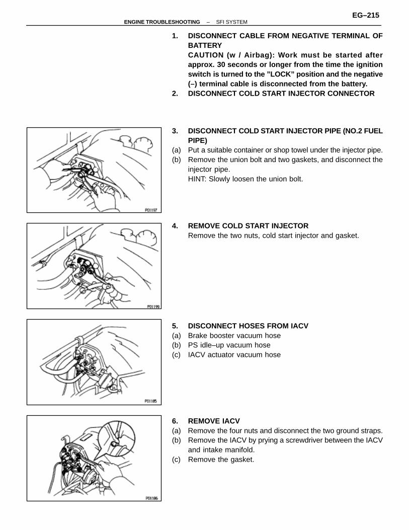
1. DISCONNECT CABLE FROM NEGATIVE TERMINAL OFBATTERYCAUTION (w / Airbag): Work must be started afterapprox. 30 seconds or longer from the time the ignitionswitch is turned to the ”LOCK” position and the negative(–) terminal cable is disconnected from the battery.
2. DISCONNECT COLD START INJECTOR CONNECTOR
3. DISCONNECT COLD START INJECTOR PIPE (NO.2 FUELPIPE)
(a) Put a suitable container or shop towel under the injector pipe.(b) Remove the union bolt and two gaskets, and disconnect the
injector pipe.HINT: Slowly loosen the union bolt.
4. REMOVE COLD START INJECTORRemove the two nuts, cold start injector and gasket.
5. DISCONNECT HOSES FROM IACV(a) Brake booster vacuum hose(b) PS idle–up vacuum hose(c) IACV actuator vacuum hose
6. REMOVE IACV(a) Remove the four nuts and disconnect the two ground straps.(b) Remove the IACV by prying a screwdriver between the IACV
and intake manifold.(c) Remove the gasket.
–ENGINE TROUBLESHOOTING SFI SYSTEMEG–215
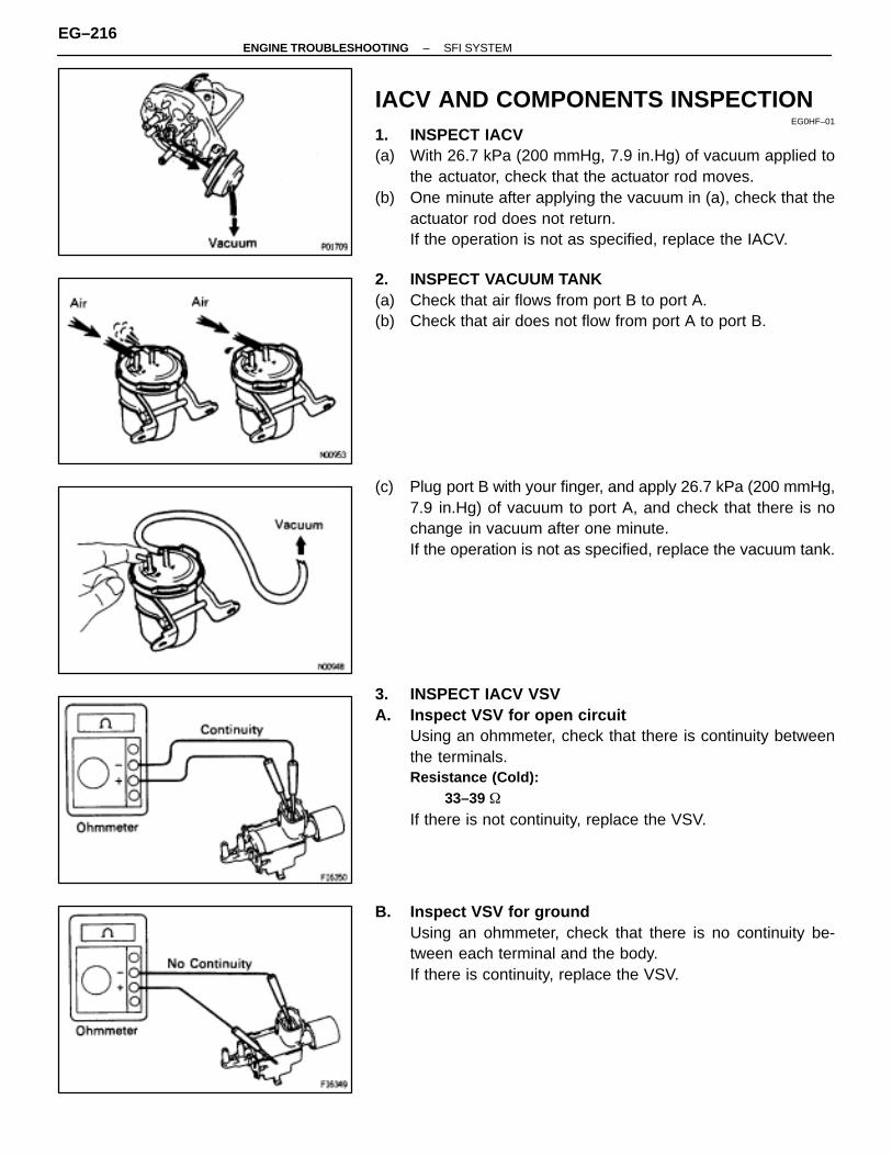
IACV AND COMPONENTS INSPECTIONEG0HF–01
1. INSPECT IACV(a) With 26.7 kPa (200 mmHg, 7.9 in.Hg) of vacuum applied to
the actuator, check that the actuator rod moves.(b) One minute after applying the vacuum in (a), check that the
actuator rod does not return.If the operation is not as specified, replace the IACV.
2. INSPECT VACUUM TANK(a) Check that air flows from port B to port A.(b) Check that air does not flow from port A to port B.
(c) Plug port B with your finger, and apply 26.7 kPa (200 mmHg,7.9 in.Hg) of vacuum to port A, and check that there is nochange in vacuum after one minute.If the operation is not as specified, replace the vacuum tank.
3. INSPECT IACV VSVA. Inspect VSV for open circuit
Using an ohmmeter, check that there is continuity betweenthe terminals.Resistance (Cold):
33–39 �
If there is not continuity, replace the VSV.
B. Inspect VSV for groundUsing an ohmmeter, check that there is no continuity be-tween each terminal and the body.If there is continuity, replace the VSV.
EG–216–ENGINE TROUBLESHOOTING SFI SYSTEM
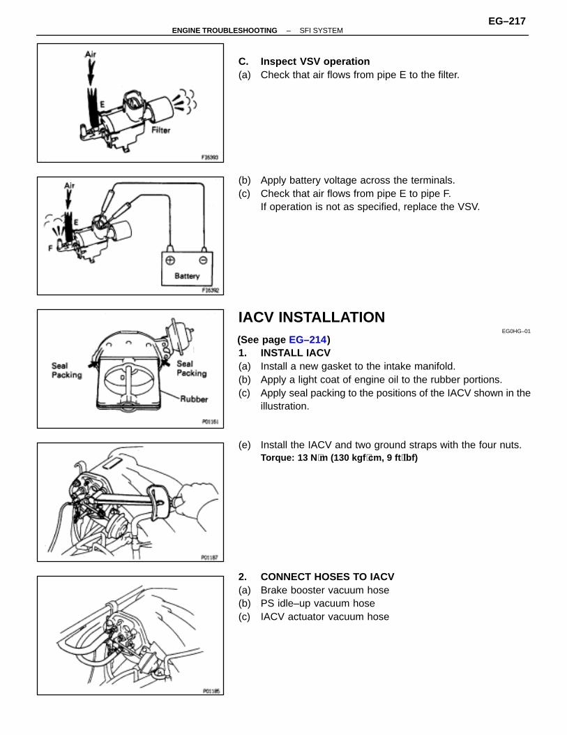
C. Inspect VSV operation(a) Check that air flows from pipe E to the filter.
(b) Apply battery voltage across the terminals.(c) Check that air flows from pipe E to pipe F.
If operation is not as specified, replace the VSV.
IACV INSTALLATIONEG0HG–01
(See page EG–214)1. INSTALL IACV(a) Install a new gasket to the intake manifold.(b) Apply a light coat of engine oil to the rubber portions.(c) Apply seal packing to the positions of the IACV shown in the
illustration.
(e) Install the IACV and two ground straps with the four nuts.Torque: 13 N ⋅m (130 kgf ⋅cm, 9 ft ⋅lbf)
2. CONNECT HOSES TO IACV(a) Brake booster vacuum hose(b) PS idle–up vacuum hose(c) IACV actuator vacuum hose
–ENGINE TROUBLESHOOTING SFI SYSTEMEG–217
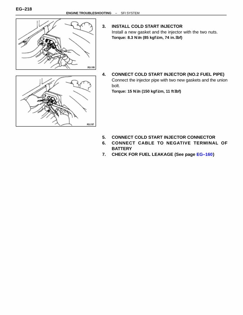
3. INSTALL COLD START INJECTORInstall a new gasket and the injector with the two nuts.Torque: 8.3 N ⋅m (85 kgf ⋅cm, 74 in. ⋅lbf)
4. CONNECT COLD START INJECTOR (NO.2 FUEL PIPE)Connect the injector pipe with two new gaskets and the unionbolt.Torque: 15 N ⋅m (150 kgf ⋅cm, 11 ft ⋅lbf)
5. CONNECT COLD START INJECTOR CONNECTOR6. CONNECT CABLE TO NEGATIVE TERMINAL OF
BATTERY7. CHECK FOR FUEL LEAKAGE (See page EG–160)
EG–218–ENGINE TROUBLESHOOTING SFI SYSTEM
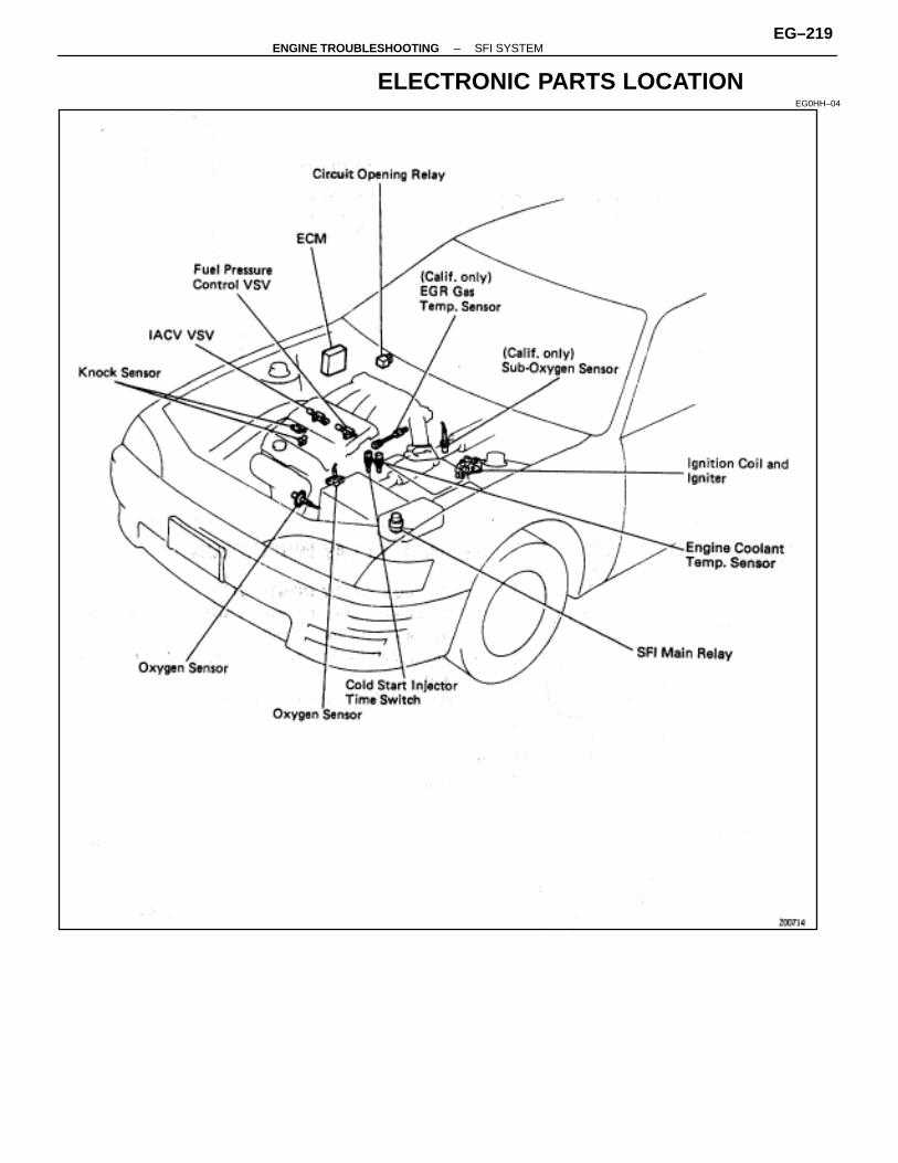
ELECTRONIC PARTS LOCATIONEG0HH–04
–ENGINE TROUBLESHOOTING SFI SYSTEMEG–219
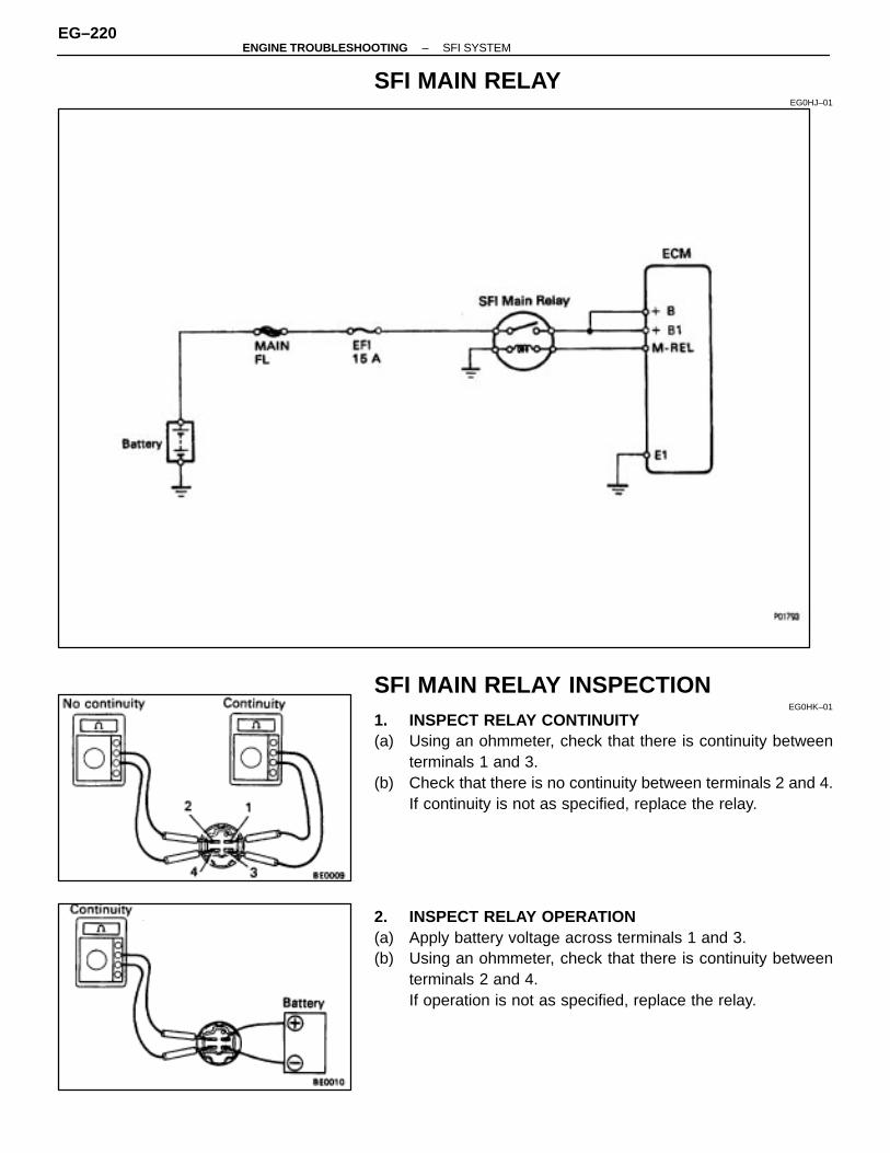
SFI MAIN RELAYEG0HJ–01
SFI MAIN RELAY INSPECTIONEG0HK–01
1. INSPECT RELAY CONTINUITY(a) Using an ohmmeter, check that there is continuity between
terminals 1 and 3.(b) Check that there is no continuity between terminals 2 and 4.
If continuity is not as specified, replace the relay.
2. INSPECT RELAY OPERATION(a) Apply battery voltage across terminals 1 and 3.(b) Using an ohmmeter, check that there is continuity between
terminals 2 and 4.If operation is not as specified, replace the relay.
EG–220–ENGINE TROUBLESHOOTING SFI SYSTEM
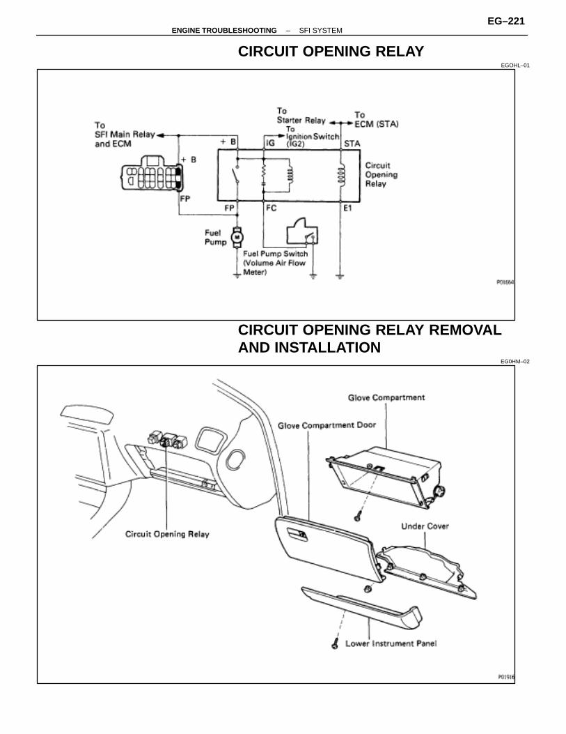
CIRCUIT OPENING RELAYEGOHL–01
CIRCUIT OPENING RELAY REMOVALAND INSTALLATION
EG0HM–02
–ENGINE TROUBLESHOOTING SFI SYSTEMEG–221
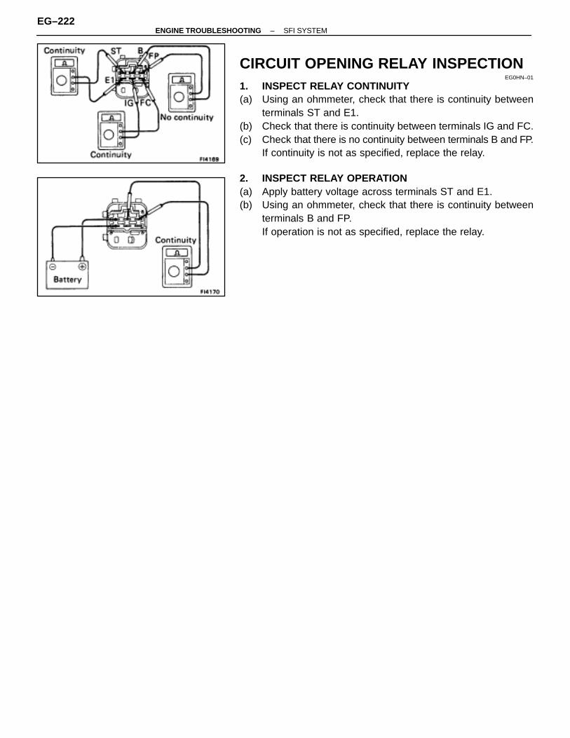
CIRCUIT OPENING RELAY INSPECTIONEG0HN–01
1. INSPECT RELAY CONTINUITY(a) Using an ohmmeter, check that there is continuity between
terminals ST and E1.(b) Check that there is continuity between terminals IG and FC.(c) Check that there is no continuity between terminals B and FP.
If continuity is not as specified, replace the relay.
2. INSPECT RELAY OPERATION(a) Apply battery voltage across terminals ST and E1.(b) Using an ohmmeter, check that there is continuity between
terminals B and FP.If operation is not as specified, replace the relay.
EG–222–ENGINE TROUBLESHOOTING SFI SYSTEM
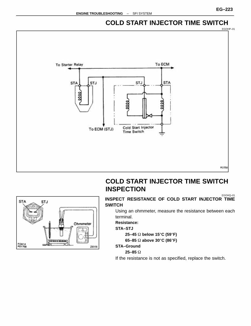
COLD START INJECTOR TIME SWITCHEGOHP–01
COLD START INJECTOR TIME SWITCHINSPECTION
EGOHQ–01
INSPECT RESISTANCE OF COLD START INJECTOR TIMESWITCH
Using an ohmmeter, measure the resistance between eachterminal.Resistance:STA–STJ
25–45 � below 15 °C (59°F)65–85 � above 30 °C (86°F)
STA–Ground25–85 �
If the resistance is not as specified, replace the switch.
–ENGINE TROUBLESHOOTING SFI SYSTEMEG–223

ENGINE COOLANT TEMPERATURESENSOR
EGOHR–01
ENGINE COOLANT TEMPERATURESENSOR INSPECTION
EGOHS–01
INSPECT RESISTANCE OF ENGINE COOLANT TEMPERA-TURE SENSOR
Using an ohmmeter, measure the resistance between the ter-minals.Resistance:
Refer to the chart above
If the resistance is not as specified, replace the sensor.
EG–224–ENGINE TROUBLESHOOTING SFI SYSTEM
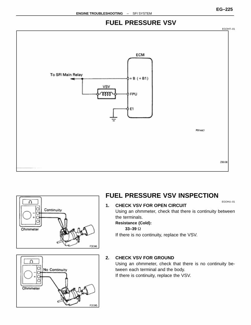
FUEL PRESSURE VSVEGOHT–01
FUEL PRESSURE VSV INSPECTIONEGOHU–01
1. CHECK VSV FOR OPEN CIRCUITUsing an ohmmeter, check that there is continuity betweenthe terminals.Resistance (Cold):
33–39 �
If there is no continuity, replace the VSV.
2. CHECK VSV FOR GROUNDUsing an ohmmeter, check that there is no continuity be-tween each terminal and the body.If there is continuity, replace the VSV.
–ENGINE TROUBLESHOOTING SFI SYSTEMEG–225
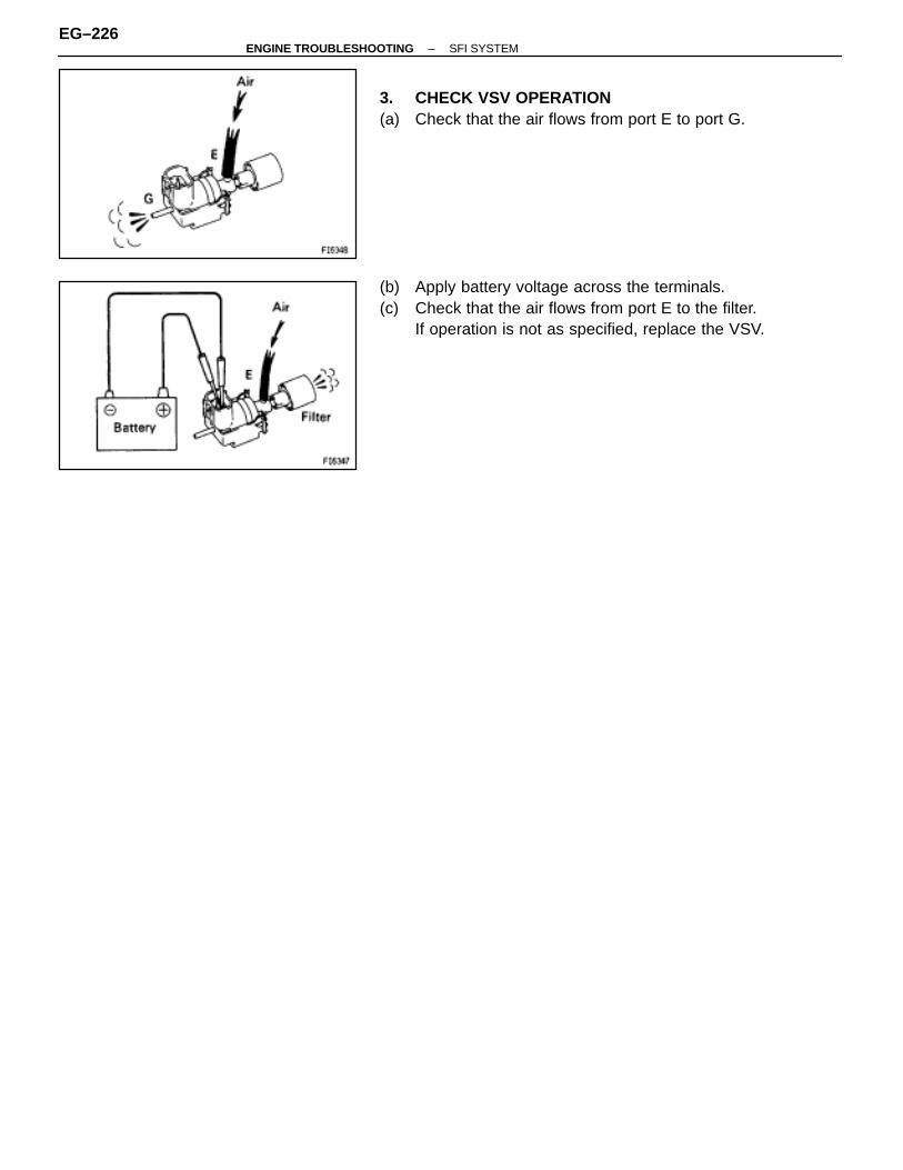
3. CHECK VSV OPERATION(a) Check that the air flows from port E to port G.
(b) Apply battery voltage across the terminals.(c) Check that the air flows from port E to the filter.
If operation is not as specified, replace the VSV.
EG–226–ENGINE TROUBLESHOOTING SFI SYSTEM

EGR GAS TEMPERATURE SENSOR(CALIFORNIA ONLY)
EGOHV–01
EGR GAS TEMPERATURE SENSORINSPECTION
EG0HW–01
INSPECT EGR GAS TEMPERATURE SENSORUsing an ohmmeter, measure the resistance between the ter-minals.Resistance:
69–89 k� at 50°C (112°F)11 –15 k� at 100�C (212�F)2 – 4 K k� at 150�C (302�F)
If the resistance is not as specified, replace the sensor.
–ENGINE TROUBLESHOOTING SFI SYSTEMEG–227
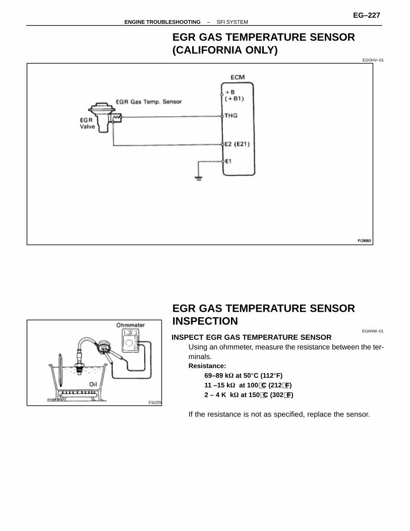
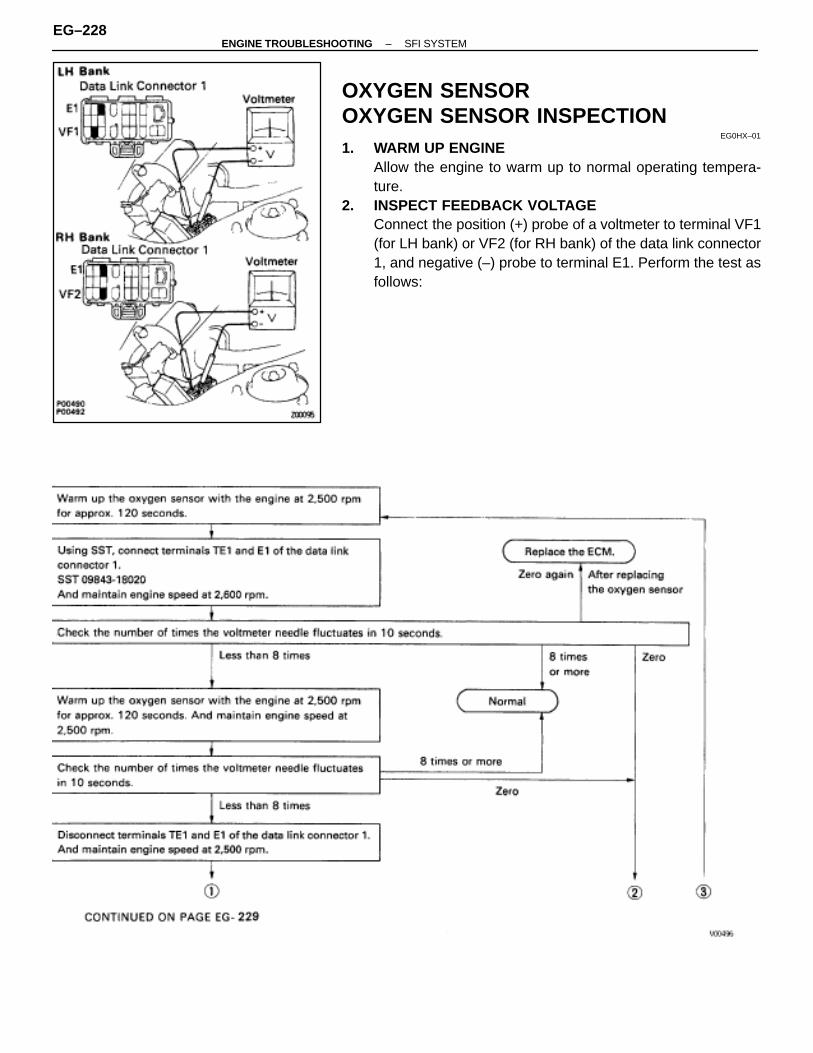
OXYGEN SENSOROXYGEN SENSOR INSPECTION
EG0HX–01
1. WARM UP ENGINEAllow the engine to warm up to normal operating tempera-ture.
2. INSPECT FEEDBACK VOLTAGEConnect the position (+) probe of a voltmeter to terminal VF1(for LH bank) or VF2 (for RH bank) of the data link connector1, and negative (–) probe to terminal E1. Perform the test asfollows:
EG–228–ENGINE TROUBLESHOOTING SFI SYSTEM

–ENGINE TROUBLESHOOTING SFI SYSTEMEG–229
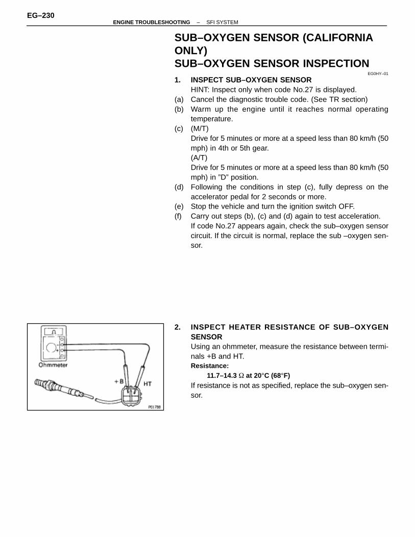
SUB–OXYGEN SENSOR (CALIFORNIAONLY)SUB–OXYGEN SENSOR INSPECTION
EG0HY–01
1. INSPECT SUB–OXYGEN SENSORHINT: Inspect only when code No.27 is displayed.
(a) Cancel the diagnostic trouble code. (See TR section)(b) Warm up the engine until it reaches normal operating
temperature.(c) (M/T)
Drive for 5 minutes or more at a speed less than 80 km/h (50mph) in 4th or 5th gear.(A/T)Drive for 5 minutes or more at a speed less than 80 km/h (50mph) in ”D” position.
(d) Following the conditions in step (c), fully depress on theaccelerator pedal for 2 seconds or more.
(e) Stop the vehicle and turn the ignition switch OFF.(f) Carry out steps (b), (c) and (d) again to test acceleration.
If code No.27 appears again, check the sub–oxygen sensorcircuit. If the circuit is normal, replace the sub –oxygen sen-sor.
2. INSPECT HEATER RESISTANCE OF SUB–OXYGENSENSORUsing an ohmmeter, measure the resistance between termi-nals +B and HT.Resistance:
11.7–14.3 � at 20°C (68°F)
If resistance is not as specified, replace the sub–oxygen sen-sor.
EG–230–ENGINE TROUBLESHOOTING SFI SYSTEM
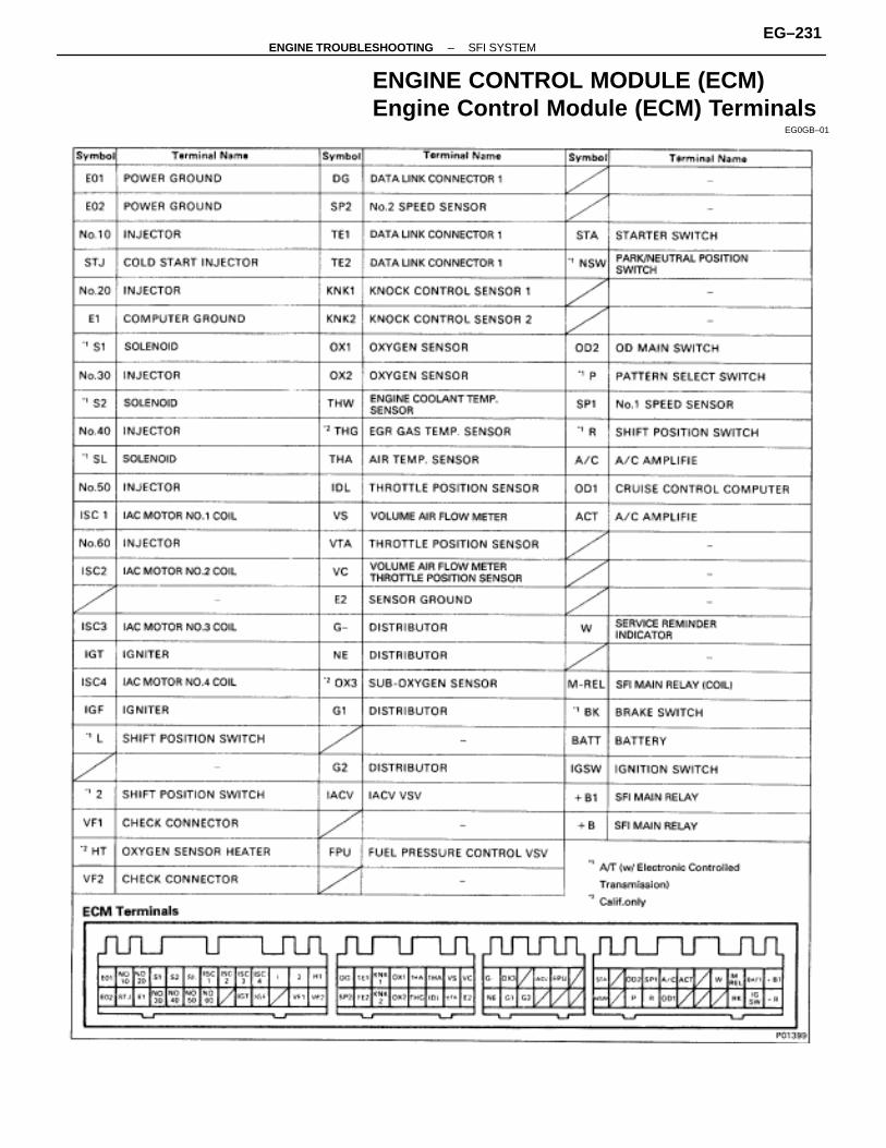
ENGINE CONTROL MODULE (ECM)Engine Control Module (ECM) Terminals
EG0GB–01
–ENGINE TROUBLESHOOTING SFI SYSTEMEG–231
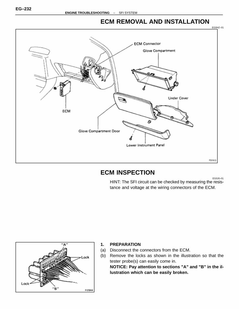
ECM REMOVAL AND INSTALLATIONEG0HZ–01
ECM INSPECTIONEG0J0–01
HINT: The SFI circuit can be checked by measuring the resis-tance and voltage at the wiring connectors of the ECM.
1. PREPARATION(a) Disconnect the connectors from the ECM.(b) Remove the locks as shown in the illustration so that the
tester probe(s) can easily come in.NOTICE: Pay attention to sections ”A” and ”B” in the il-lustration which can be easily broken.
EG–232–ENGINE TROUBLESHOOTING SFI SYSTEM
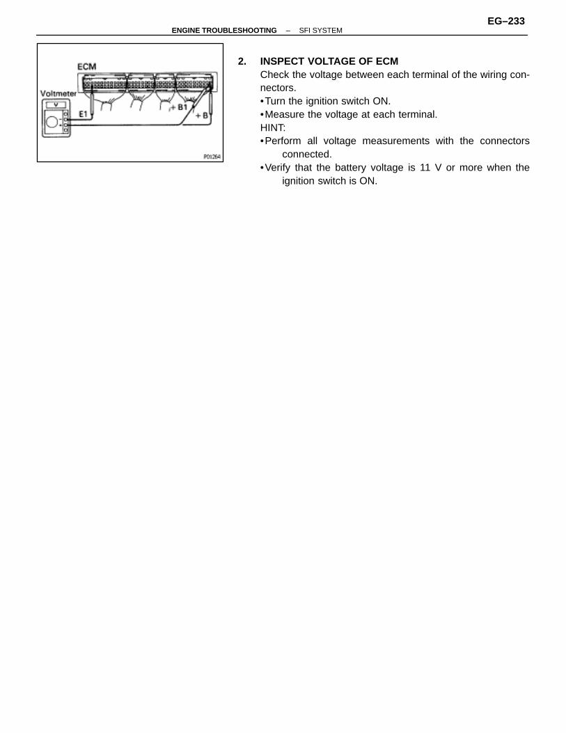
2. INSPECT VOLTAGE OF ECMCheck the voltage between each terminal of the wiring con-nectors.•Turn the ignition switch ON.•Measure the voltage at each terminal.HINT:•Perform all voltage measurements with the connectors
connected.•Verify that the battery voltage is 11 V or more when the
ignition switch is ON.
–ENGINE TROUBLESHOOTING SFI SYSTEMEG–233
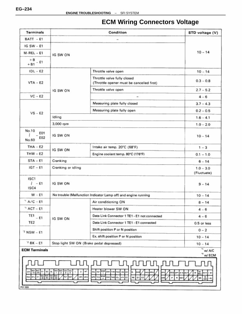
ECM Wiring Connectors Voltage
EG–234–ENGINE TROUBLESHOOTING SFI SYSTEM
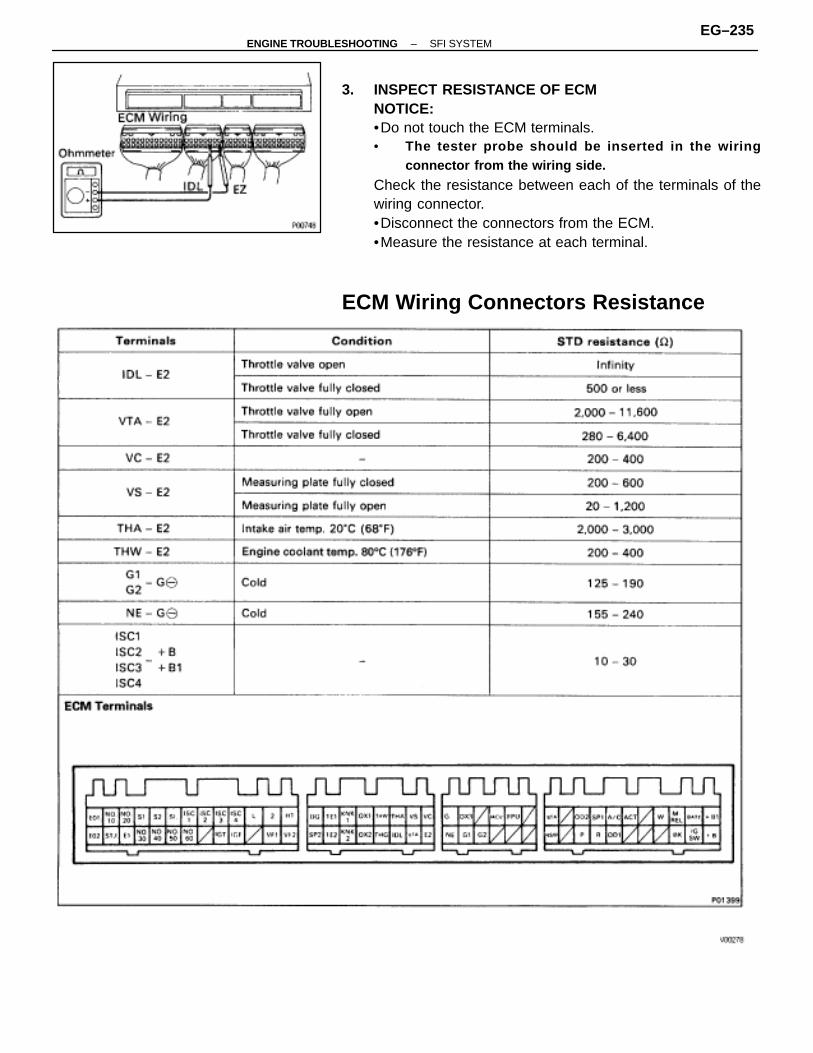
3. INSPECT RESISTANCE OF ECMNOTICE:•Do not touch the ECM terminals.• The tester probe should be inserted in the wiring
connector from the wiring side.
Check the resistance between each of the terminals of thewiring connector.•Disconnect the connectors from the ECM.•Measure the resistance at each terminal.
ECM Wiring Connectors Resistance
–ENGINE TROUBLESHOOTING SFI SYSTEMEG–235
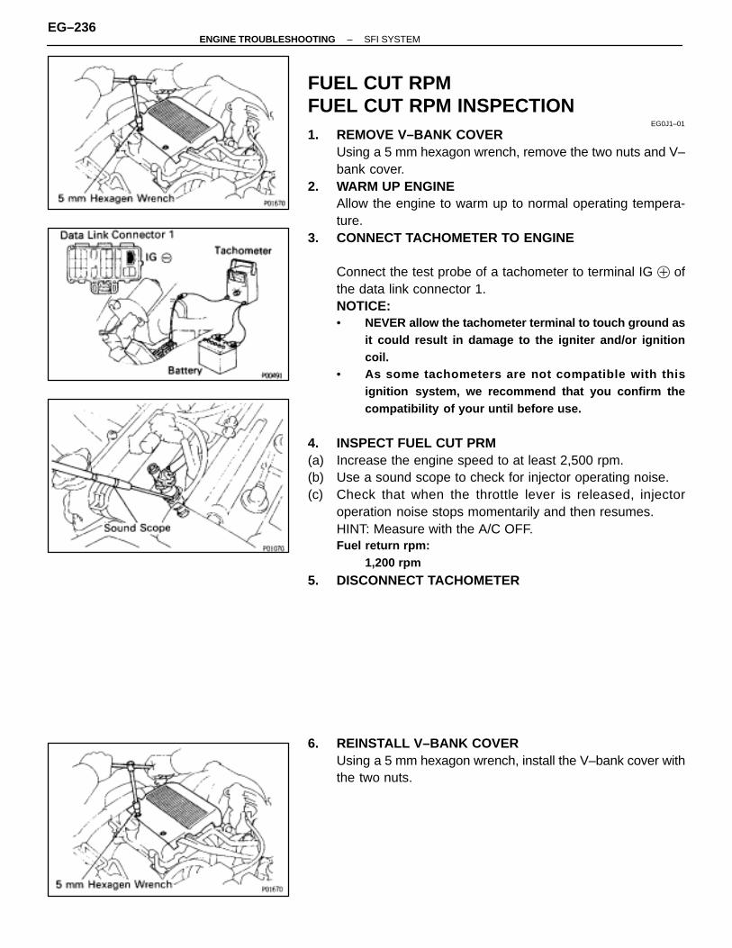
FUEL CUT RPMFUEL CUT RPM INSPECTION
EG0J1–01
1. REMOVE V–BANK COVERUsing a 5 mm hexagon wrench, remove the two nuts and V–bank cover.
2. WARM UP ENGINEAllow the engine to warm up to normal operating tempera-ture.
3. CONNECT TACHOMETER TO ENGINE
Connect the test probe of a tachometer to terminal IG � ofthe data link connector 1.NOTICE:• NEVER allow the tachometer terminal to touch ground as
it could result in damage to the igniter and/or ignitioncoil.
• As some tachometers are not compatible with thisignition system, we recommend that you confirm thecompatibility of your until before use.
4. INSPECT FUEL CUT PRM(a) Increase the engine speed to at least 2,500 rpm.(b) Use a sound scope to check for injector operating noise.(c) Check that when the throttle lever is released, injector
operation noise stops momentarily and then resumes.HINT: Measure with the A/C OFF.Fuel return rpm:
1,200 rpm
5. DISCONNECT TACHOMETER
6. REINSTALL V–BANK COVERUsing a 5 mm hexagon wrench, install the V–bank cover withthe two nuts.
EG–236–ENGINE TROUBLESHOOTING SFI SYSTEM
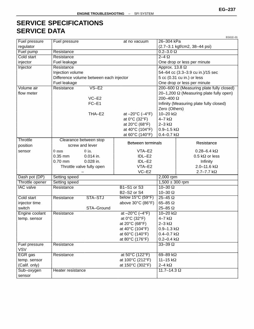
SERVICE SPECIFICATIONSSERVICE DATA
EG0J2–01
ÑÑÑÑÑÑÑFuel pressure ÑÑÑÑÑÑÑÑÑÑÑÑFuel pressure ÑÑÑÑÑÑat no vacuum ÑÑÑÑÑÑÑÑÑÑÑÑÑÑ26–304 kPaÑÑÑÑÑÑÑÑÑÑÑÑÑÑregulator
ÑÑÑÑÑÑÑÑÑÑÑÑ
ÑÑÑÑÑÑÑÑÑÑÑÑÑÑ
ÑÑÑÑÑÑÑÑÑÑÑÑ
ÑÑÑÑÑÑÑÑÑÑÑÑÑÑÑÑÑÑÑÑÑÑÑÑÑÑÑÑ(2.7–3.1 kgf/cm2, 38–44 psi)ÑÑÑÑÑÑÑ
ÑÑÑÑÑÑÑFuel pump ÑÑÑÑÑÑÑÑÑÑÑÑÑÑÑÑÑ
ÑÑÑÑÑÑÑÑÑÑÑÑÑÑÑÑÑResistance 0.2–3.0 �
ÑÑÑÑÑÑÑÑÑÑÑÑÑÑ
Cold start ÑÑÑÑÑÑÑÑÑÑÑÑÑÑÑÑÑÑÑÑÑÑÑÑÑÑÑÑÑÑÑÑÑÑResistance 2–4 �
ÑÑÑÑÑÑÑÑÑÑÑÑÑÑ
injector ÑÑÑÑÑÑÑÑÑÑÑÑÑÑÑÑÑÑÑÑÑÑÑÑÑÑÑÑÑÑÑÑÑÑFuel leakage ÑÑÑÑÑÑÑÑÑÑÑÑÑÑ
ÑÑÑÑÑÑÑÑÑÑÑÑÑÑOne drop or less per minute
ÑÑÑÑÑÑÑÑÑÑÑÑÑÑ
Injector ÑÑÑÑÑÑÑÑÑÑÑÑÑÑÑÑÑÑÑÑÑÑÑÑÑÑÑÑÑÑÑÑÑÑResistance ÑÑÑÑÑÑÑÑÑÑÑÑÑÑ
ÑÑÑÑÑÑÑÑÑÑÑÑÑÑApprox. 13.8 �
ÑÑÑÑÑÑÑÑÑÑÑÑÑÑÑÑÑÑÑÑÑÑÑÑInjection volume 54–64 cc (3.3–3.9 cu in.)/15 secÑÑÑÑÑÑÑÑÑÑÑÑÑÑ
ÑÑÑÑÑÑÑÑÑÑÑÑÑÑÑÑÑÑÑÑÑÑÑÑÑÑÑÑÑÑÑÑÑÑDifference volume between each injector 5 cc (0.31 cu in.) or less
ÑÑÑÑÑÑÑÑÑÑÑÑÑÑ
ÑÑÑÑÑÑÑÑÑÑÑÑÑÑÑÑÑÑÑÑÑÑÑÑÑÑÑÑÑÑÑÑÑÑFuel leakage ÑÑÑÑÑÑÑÑÑÑÑÑÑÑ
ÑÑÑÑÑÑÑÑÑÑÑÑÑÑOne drop or less per minute
ÑÑÑÑÑÑÑÑÑÑÑÑÑÑ
Volume air ÑÑÑÑÑÑÑÑÑÑÑÑResistance ÑÑÑÑÑÑÑ
ÑÑÑÑÑÑÑ VS–E2 ÑÑÑÑÑÑ
ÑÑÑÑÑÑÑÑÑÑÑÑÑÑÑÑÑÑÑÑÑÑÑÑÑÑÑÑÑÑÑÑÑÑ
200–600 � (Measuring plate fully closed)
ÑÑÑÑÑÑÑÑÑÑÑÑÑÑ
flow meter ÑÑÑÑÑÑÑÑÑÑÑÑ
ÑÑÑÑÑÑÑÑÑÑÑÑÑÑ
ÑÑÑÑÑÑÑÑÑÑÑÑ
ÑÑÑÑÑÑÑÑÑÑÑÑÑÑÑÑÑÑÑÑÑÑÑÑÑÑÑÑ
20–1,200 � (Measuring plate fully open)
ÑÑÑÑÑÑÑÑÑÑÑÑÑÑÑÑÑÑÑÑVC–E2 200–400 �ÑÑÑÑÑÑÑÑÑÑÑÑÑÑ
ÑÑÑÑÑÑÑÑÑÑÑÑ
ÑÑÑÑÑÑÑÑÑÑÑÑÑÑ
FC–E1ÑÑÑÑÑÑÑÑÑÑÑÑ
ÑÑÑÑÑÑÑÑÑÑÑÑÑÑÑÑÑÑÑÑÑÑÑÑÑÑÑÑ
Infinity (Measuring plate fully closed)ÑÑÑÑÑÑÑÑÑÑÑÑÑÑ
ÑÑÑÑÑÑÑÑÑÑÑÑ
ÑÑÑÑÑÑÑÑÑÑÑÑÑÑ
Zero (Others)ÑÑÑÑÑÑÑÑÑÑÑÑÑÑ
ÑÑÑÑÑÑÑÑÑÑÑÑ
ÑÑÑÑÑÑÑÑÑÑÑÑÑÑ
THA–E2 ÑÑÑÑÑÑÑÑÑÑÑÑat –20°C (–4°F)ÑÑÑÑÑÑÑÑÑÑÑÑÑÑ
ÑÑÑÑÑÑÑÑÑÑÑÑÑÑ10–20 k�
ÑÑÑÑÑÑÑÑÑÑÑÑÑÑ
ÑÑÑÑÑÑÑÑÑÑÑÑ
ÑÑÑÑÑÑÑÑÑÑÑÑÑÑ
at 0°C (32°F) 4–7 k�
ÑÑÑÑÑÑÑÑÑÑÑÑÑÑÑÑÑÑÑÑat 20°C (68°F) 2–3 k�ÑÑÑÑÑÑÑÑÑÑÑÑÑÑ
ÑÑÑÑÑÑÑÑÑÑÑÑ
ÑÑÑÑÑÑÑÑÑÑÑÑÑÑ
ÑÑÑÑÑÑÑÑÑÑÑÑat 40°C (104°F)
ÑÑÑÑÑÑÑÑÑÑÑÑÑÑÑÑÑÑÑÑÑÑÑÑÑÑÑÑ0.9–1.5 k�ÑÑÑÑÑÑÑ
ÑÑÑÑÑÑÑÑÑÑÑÑÑÑÑÑÑÑÑ
ÑÑÑÑÑÑÑÑÑÑÑÑÑÑ
ÑÑÑÑÑÑÑÑÑÑÑÑat 60°C (140°F)ÑÑÑÑÑÑÑÑÑÑÑÑÑÑ
ÑÑÑÑÑÑÑÑÑÑÑÑÑÑ0.4–0.7 k�
ÑÑÑÑÑÑÑÑÑÑÑÑÑÑ
Throttle ÑÑÑÑÑÑÑÑÑÑÑÑÑÑÑÑÑÑÑÑ
Clearance between stop ÑÑÑÑÑÑÑÑÑÑÑÑÑÑÑÑÑÑÑÑÑÑBetween terminals ResistanceÑÑÑÑÑÑÑ
ÑÑÑÑÑÑÑposition ÑÑÑÑÑÑÑÑÑÑ
ÑÑÑÑÑÑÑÑÑÑscrew and lever ÑÑÑÑÑÑÑÑÑÑÑ
ÑÑÑÑÑÑÑÑÑÑÑ
Between terminals Resistance
ÑÑÑÑÑÑÑÑÑÑÑÑÑÑ
sensor ÑÑÑÑÑÑÑÑÑÑ0 mm ÑÑÑÑÑÑ
ÑÑÑÑÑÑ0 in. ÑÑÑÑÑÑÑÑÑÑÑ
ÑÑÑÑÑÑÑÑÑÑÑVTA–E2 0.28–6.4 k�
ÑÑÑÑÑÑÑÑÑÑÑÑ0.35 mm ÑÑÑÑÑÑ0.014 in. ÑÑÑÑÑÑÑÑÑÑÑIDL–E2 0.5 k� or lessÑÑÑÑÑÑÑÑÑÑÑÑÑÑ
ÑÑÑÑÑÑÑÑÑÑ0.70 mm
ÑÑÑÑÑÑÑÑÑÑÑÑ0.028 in.
ÑÑÑÑÑÑÑÑÑÑÑÑÑÑÑÑÑÑÑÑÑÑIDL–E2
ÑÑÑÑÑÑÑÑÑÑÑÑÑÑÑÑÑÑÑÑÑÑInfinityÑÑÑÑÑÑÑ
ÑÑÑÑÑÑÑÑÑÑÑÑÑÑÑÑÑÑÑÑÑÑÑÑÑÑÑ
Throttle valve fully open ÑÑÑÑÑÑÑÑÑÑÑÑÑÑÑÑÑÑÑÑÑÑ
VTA–E2 2.0–11.6 k�ÑÑÑÑÑÑÑÑÑÑÑÑÑÑ
ÑÑÑÑÑÑÑÑÑÑÑÑÑÑÑÑÑÑÑÑ
– ÑÑÑÑÑÑÑÑÑÑÑÑÑÑÑÑÑÑÑÑÑÑ
VC–E2 ÑÑÑÑÑÑÑÑÑÑÑÑÑÑÑÑÑÑÑÑÑÑ
2.7–7.7 k�ÑÑÑÑÑÑÑÑÑÑÑÑÑÑ
Dash pot (DP) ÑÑÑÑÑÑÑÑÑÑÑÑÑÑÑÑÑÑÑÑÑÑÑÑÑÑÑÑÑÑÑÑÑÑSetting speed 2,000 rpm
ÑÑÑÑÑÑÑÑÑÑÑÑÑÑ
Throttle opener ÑÑÑÑÑÑÑÑÑÑÑÑÑÑÑÑÑÑÑÑÑÑÑÑÑÑÑÑÑÑÑÑÑÑSetting speed ÑÑÑÑÑÑÑÑÑÑÑÑÑÑ
ÑÑÑÑÑÑÑÑÑÑÑÑÑÑ1,500 ± 300 rpm
ÑÑÑÑÑÑÑIAC valve ÑÑÑÑÑÑÑÑÑÑÑResistance B1–S1 or S3 10–30 �ÑÑÑÑÑÑÑÑÑÑÑÑÑÑ
ÑÑÑÑÑÑÑÑÑÑÑÑÑÑÑÑÑÑÑÑÑÑ
B2–S2 or S4 10–30 �ÑÑÑÑÑÑÑÑÑÑÑÑÑÑ
Cold start ÑÑÑÑÑÑÑÑÑÑÑÑResistance ÑÑÑÑÑÑ
ÑÑÑÑÑÑSTA–STJ ÑÑÑÑÑÑÑ
ÑÑÑÑÑÑÑbelow 15°C (59°F)ÑÑÑÑÑÑÑÑÑÑÑÑÑÑ
ÑÑÑÑÑÑÑÑÑÑÑÑÑÑ25–45 �
ÑÑÑÑÑÑÑÑÑÑÑÑÑÑ
injector time ÑÑÑÑÑÑÑÑÑÑÑÑ
ÑÑÑÑÑÑÑÑÑÑÑÑ
ÑÑÑÑÑÑÑÑÑÑÑÑÑÑ
above 30°C (86°F)ÑÑÑÑÑÑÑÑÑÑÑÑÑÑÑÑÑÑÑÑÑÑÑÑÑÑÑÑ
65–85 �
ÑÑÑÑÑÑÑÑÑÑÑÑÑÑ
switch ÑÑÑÑÑÑÑÑÑÑÑÑ
ÑÑÑÑÑÑÑÑÑÑÑÑ
STA–Ground 25–85 �
ÑÑÑÑÑÑÑEngine coolant ÑÑÑÑÑÑResistance ÑÑÑÑÑÑÑÑÑÑÑÑÑ at –20°C (–4°F) ÑÑÑÑÑÑÑÑÑÑÑÑÑÑ10–20 k�ÑÑÑÑÑÑÑÑÑÑÑÑÑÑ
temp. sensorÑÑÑÑÑÑÑÑÑÑÑÑ
ÑÑÑÑÑÑÑÑÑÑÑÑ
ÑÑÑÑÑÑÑÑÑÑÑÑÑÑ
at 0°C (32°F)ÑÑÑÑÑÑÑÑÑÑÑÑÑÑÑÑ
4–7 k�ÑÑÑÑÑÑÑÑÑÑÑÑÑÑÑÑÑÑÑÑÑ
ÑÑÑÑÑÑÑÑÑÑÑÑÑÑÑÑÑÑÑ
ÑÑÑÑÑÑÑÑÑÑÑÑ
at 20°C (68°F) 2–3 k�ÑÑÑÑÑÑÑÑÑÑÑÑÑÑ
ÑÑÑÑÑÑÑÑÑÑÑÑ
ÑÑÑÑÑÑÑÑÑÑÑÑ
at 40°C (104°F) 0.9–1.3 k�ÑÑÑÑÑÑÑÑÑÑÑÑÑÑ
ÑÑÑÑÑÑÑÑÑÑÑÑ
ÑÑÑÑÑÑÑÑÑÑÑÑ
ÑÑÑÑÑÑÑÑÑÑÑÑÑÑ
at 60°C (140°F) ÑÑÑÑÑÑÑÑÑÑÑÑÑÑÑÑ
0.4–0.7 k� ÑÑÑÑÑÑÑÑÑÑÑÑÑÑÑÑÑÑÑÑÑÑÑÑÑÑÑÑÑÑÑÑÑat 80°C (176°F) 0.2–0.4 k�ÑÑÑÑÑÑÑ
ÑÑÑÑÑÑÑFuel pressureÑÑÑÑÑÑÑÑÑÑÑÑResistance
ÑÑÑÑÑÑÑÑÑÑÑÑ 33–39 �ÑÑÑÑÑÑÑ
ÑÑÑÑÑÑÑVSV ÑÑÑÑÑÑ
ÑÑÑÑÑÑÑÑÑÑÑÑÑÑÑÑÑÑÑÑÑÑÑÑÑ
ÑÑÑÑÑÑÑEGR gas ÑÑÑÑÑÑ
ÑÑÑÑÑÑResistance ÑÑÑÑÑÑ
ÑÑÑÑÑÑ at 50°C (122°F) 69–89 k�
ÑÑÑÑÑÑÑÑÑÑÑÑÑÑ
temp. sensor ÑÑÑÑÑÑÑÑÑÑÑÑ
ÑÑÑÑÑÑÑÑÑÑÑÑ
ÑÑÑÑÑÑÑÑÑÑÑÑÑÑ
at 100°C (212°F) ÑÑÑÑÑÑÑÑÑÑÑÑÑÑÑÑ
11–15 k� ÑÑÑÑÑÑÑÑÑÑÑÑÑÑÑÑÑÑÑÑÑ
ÑÑÑÑÑÑÑ(Calif. only) ÑÑÑÑÑÑ
ÑÑÑÑÑÑÑÑÑÑÑÑÑÑÑÑÑÑ
at 150°C (302°F) 2–4 k�
ÑÑÑÑÑÑÑSub–oxygen ÑÑÑÑÑÑÑÑÑÑÑHeater resistance 11.7–14.3 �ÑÑÑÑÑÑÑÑÑÑÑÑÑÑ
sensorÑÑÑÑÑÑÑÑÑÑÑÑ
ÑÑÑÑÑÑÑÑÑÑÑÑ
ÑÑÑÑÑÑÑÑÑÑÑÑÑÑ
ÑÑÑÑÑÑÑÑÑÑÑÑÑÑÑÑ
ÑÑÑÑÑÑÑÑÑÑÑÑÑÑ
–ENGINE TROUBLESHOOTING SFI SYSTEMEG–237

SERVICE DATA (Cont’d)ÑÑÑÑÑÑÑÑÑÑÑÑÑÑÑÑÑÑÑÑÑÑÑÑ
ECM ÑÑÑÑÑÑÑÑÑÑÑÑÑÑÑÑÑÑÑÑÑÑÑÑÑÑÑÑÑÑÑÑÑÑÑÑÑÑÑÑÑÑÑÑÑÑÑÑÑÑÑÑÑÑÑÑÑÑÑÑÑÑÑÑÑÑÑÑÑÑÑÑÑÑÑÑÑÑÑÑÑÑÑÑÑÑÑÑÑÑÑÑÑÑÑÑÑÑÑÑÑÑÑÑÑÑÑÑÑÑÑÑÑÑÑÑÑÑÑÑÑÑÑÑ
HINT: Perform all voltage and resistance measurements with the ECM connected. Verify that the battery voltage is 11 V or above with the ignition switch is ON.ÑÑÑÑÑÑ
ÑÑÑÑÑÑÑÑÑÑÑÑÑÑÑÑÑÑÑÑÑÑÑÑÑÑÑÑÑÑÑÑÑÑÑÑÑÑÑÑÑÑÑÑÑÑÑÑÑÑÑÑÑÑÑÑÑÑÑÑÑÑÑÑÑÑÑÑVoltageÑÑÑÑÑÑ
ÑÑÑÑÑÑÑÑÑÑÑÑ
ÑÑÑÑÑÑÑÑÑÑÑÑÑÑÑÑÑÑ
Terminals ÑÑÑÑÑÑÑÑÑÑÑÑÑÑÑÑÑÑÑÑÑÑÑÑÑÑÑÑÑÑÑÑÑÑÑÑÑÑÑÑÑÑÑÑÑÑÑÑÑÑÑÑÑÑÑÑÑÑÑÑÑÑÑ
Condition STD voltage(V)
ÑÑÑÑÑÑÑÑÑÑÑÑ
ÑÑÑÑÑÑÑÑÑÑÑÑ
BATT–E1 ÑÑÑÑÑÑÑÑÑÑÑÑÑÑÑÑÑÑÑÑÑÑÑÑÑÑÑÑÑÑÑÑÑÑÑÑÑÑÑÑÑÑ
–ÑÑÑÑÑÑÑÑÑÑÑÑ
ÑÑÑÑÑÑÑÑÑÑÑÑ
IG SW–E1 ÑÑÑÑÑÑÑÑÑÑÑÑÑÑÑÑÑÑÑÑÑÑÑÑÑÑÑÑÑÑÑÑÑÑÑÑÑÑÑÑÑÑÑÑÑÑÑÑÑÑÑÑÑÑM–REL–E1 ÑÑÑÑÑÑÑÑÑÑÑÑÑÑÑÑÑÑÑÑÑIG SW ON 10–14ÑÑÑÑÑÑ
ÑÑÑÑÑÑÑÑÑÑÑÑÑÑÑÑÑÑ+B
–E1
ÑÑÑÑÑÑÑÑÑÑÑÑÑÑÑÑÑÑÑÑÑÑÑÑÑÑÑÑÑÑÑÑÑÑÑÑÑÑÑÑÑÑ
IG SW ON 10 14
ÑÑÑÑÑÑÑÑÑÑÑÑ
ÑÑÑÑÑÑÑÑÑÑÑÑ
+B1 –E1 ÑÑÑÑÑÑÑÑÑÑÑÑÑÑÑÑÑÑÑÑÑÑÑÑÑÑÑÑÑÑÑÑÑÑÑÑÑÑÑÑÑÑÑÑÑÑÑÑ
ÑÑÑÑÑÑÑÑÑÑÑÑÑÑÑÑÑÑ
IDL–E2 ÑÑÑÑÑÑÑÑÑÑÑÑÑÑ
ÑÑÑÑÑÑÑÑÑÑÑÑÑÑÑÑÑÑÑÑÑÑÑÑÑÑÑÑÑÑThrottle valve open 10–14
ÑÑÑÑÑÑÑÑÑÑÑÑ
ÑÑÑÑÑÑÑÑÑÑÑÑ
ÑÑÑÑÑÑÑÑÑÑÑÑÑÑ
ÑÑÑÑÑÑÑÑÑÑÑÑÑÑÑÑÑÑÑÑÑÑÑÑÑÑÑÑÑÑThrottle valve fully closed
0 3–0 8ÑÑÑÑÑÑÑÑÑÑÑÑ
ÑÑÑÑÑÑÑÑÑÑÑÑ
VATA–E2 ÑÑÑÑÑÑÑÑÑÑÑÑÑÑ
ÑÑÑÑÑÑÑÑÑÑÑÑÑÑÑÑÑÑÑÑÑÑÑÑÑÑÑÑÑÑ(Throttle opener must be cancelled first) 0.3–0.8
ÑÑÑÑÑÑÑÑÑÑÑÑVATA E2
ÑÑÑÑÑÑÑIG SW ON ÑÑÑÑÑÑÑÑÑÑÑÑÑÑÑThrottle valve open 2.7–5.2ÑÑÑÑÑÑÑÑÑÑÑÑ
ÑÑÑÑÑÑÑÑÑÑÑÑVC–E2
ÑÑÑÑÑÑÑÑÑÑÑÑÑÑ
IG SW ON ÑÑÑÑÑÑÑÑÑÑÑÑÑÑÑÑÑÑÑÑÑÑÑÑÑÑÑÑÑÑ– 4–6ÑÑÑÑÑÑ
ÑÑÑÑÑÑÑÑÑÑÑÑÑÑÑÑÑÑ
ÑÑÑÑÑÑÑÑÑÑÑÑÑÑ
ÑÑÑÑÑÑÑÑÑÑÑÑÑÑÑÑÑÑÑÑÑÑÑÑÑÑÑÑÑÑMeasuring plate fully closed 3.7–4.3
ÑÑÑÑÑÑÑÑÑÑÑÑ
ÑÑÑÑÑÑÑÑÑÑÑÑVS–E2
ÑÑÑÑÑÑÑÑÑÑÑÑÑÑ
ÑÑÑÑÑÑÑÑÑÑÑÑÑÑÑÑÑÑÑÑÑÑÑÑÑÑÑÑÑÑMeasuring plate fully open 0.2–0.5
ÑÑÑÑÑÑÑÑÑÑÑÑ
ÑÑÑÑÑÑÑÑÑÑÑÑ
VS–E2 ÑÑÑÑÑÑÑÑÑÑÑÑÑÑÑÑÑÑÑÑÑÑÑÑÑÑÑÑÑÑÑÑÑÑÑÑÑÑÑÑÑÑ
Idling 1.6–4.1
ÑÑÑÑÑÑÑÑÑÑÑÑÑÑÑÑÑÑÑÑÑÑÑÑÑÑÑÑÑÑÑÑÑ3,000 rpm 1.0–2.0ÑÑÑÑÑÑÑÑÑÑÑÑÑÑÑÑÑÑ
ÑÑÑÑÑÑÑÑÑÑÑÑÑÑÑÑÑÑ
No.10–E01
ÑÑÑÑÑÑÑÑÑÑÑÑÑÑÑÑÑÑÑÑÑÑÑÑÑÑÑÑÑÑÑÑÑÑÑÑÑÑÑÑÑÑÑÑÑÑÑÑÑÑÑÑÑÑÑÑÑÑÑÑÑÑÑ
IG SW ON 10–14ÑÑÑÑÑÑÑÑÑÑÑÑ
ÑÑÑÑÑÑÑÑÑÑÑÑ
No.60
E01–E02 ÑÑÑÑÑÑÑÑÑÑÑÑÑÑÑÑÑÑÑÑÑ
ÑÑÑÑÑÑÑÑÑÑÑÑÑÑÑÑÑÑÑÑÑ
IG SW ON 10–14
ÑÑÑÑÑÑÑÑÑÑÑÑ
ÑÑÑÑÑÑÑÑÑÑÑÑ
THA–E2 ÑÑÑÑÑÑÑÑÑÑÑÑÑÑIG SW ON
ÑÑÑÑÑÑÑÑÑÑÑÑÑÑÑÑÑÑÑÑÑÑÑÑÑÑÑÑÑÑIntake air temp. 20°C (68°F) 1–3
ÑÑÑÑÑÑÑÑÑÑÑÑ
ÑÑÑÑÑÑÑÑÑÑÑÑ
THW–E2 ÑÑÑÑÑÑÑÑÑÑÑÑÑÑ
IG SW ON ÑÑÑÑÑÑÑÑÑÑÑÑÑÑÑÑÑÑÑÑÑÑÑÑÑÑÑÑÑÑEngine coolant temp. 80°C (176°F) 0.1–1.0
ÑÑÑÑÑÑÑÑÑÑÑÑ
ÑÑÑÑÑÑÑÑÑÑÑÑ
STA–E1 ÑÑÑÑÑÑÑÑÑÑÑÑÑÑÑÑÑÑÑÑÑÑÑÑÑÑÑÑÑÑÑÑÑÑÑÑÑÑÑÑÑÑ
Cranking 6–14
ÑÑÑÑÑÑÑÑÑÑÑÑIGT–E1 ÑÑÑÑÑÑÑÑÑÑÑÑÑÑÑÑÑÑÑÑÑCranking or idling1.0–3.0ÑÑÑÑÑÑ
ÑÑÑÑÑÑÑÑÑÑÑÑÑÑÑÑÑÑ
IGT–E1 ÑÑÑÑÑÑÑÑÑÑÑÑÑÑÑÑÑÑÑÑÑÑÑÑÑÑÑÑÑÑÑÑÑÑÑÑÑÑÑÑÑÑ
Cranking or idling (Fluctuate)ÑÑÑÑÑÑÑÑÑÑÑÑ
ÑÑÑÑÑÑÑÑÑÑÑÑ
ISC1 –E1ÑÑÑÑÑÑÑÑÑÑÑÑÑÑÑÑÑÑÑÑÑÑÑÑÑÑÑÑÑÑÑÑÑÑÑÑÑÑÑÑÑÑIG SW ON 9–14ÑÑÑÑÑÑ
ÑÑÑÑÑÑÑÑÑÑÑÑÑÑÑÑÑÑ
ISC4–E1 ÑÑÑÑÑÑÑÑÑÑÑÑÑÑÑÑÑÑÑÑÑ
ÑÑÑÑÑÑÑÑÑÑÑÑÑÑÑÑÑÑÑÑÑIG SW ON 9–14
ÑÑÑÑÑÑÑÑÑÑÑÑ
ÑÑÑÑÑÑÑÑÑÑÑÑ
W–E1ÑÑÑÑÑÑÑÑÑÑÑÑÑÑÑÑÑÑÑÑÑÑÑÑÑÑÑÑÑÑÑÑÑÑÑÑÑÑÑÑÑÑ
No trouble (Malfunction Indicator Lamp off) and10–14
ÑÑÑÑÑÑÑÑÑÑÑÑ
ÑÑÑÑÑÑÑÑÑÑÑÑ
W–E1ÑÑÑÑÑÑÑÑÑÑÑÑÑÑÑÑÑÑÑÑÑÑÑÑÑÑÑÑÑÑÑÑÑÑÑÑÑÑÑÑÑÑ
engine running 10–14
ÑÑÑÑÑÑÑÑÑÑÑÑ*1A/C–E1 ÑÑÑÑÑÑÑÑÑÑÑÑÑÑÑÑÑÑÑÑÑÑAir conditioning ON 10–14ÑÑÑÑÑÑÑÑÑÑÑÑ
ÑÑÑÑÑÑÑÑÑÑÑÑ
*1ACT–E1ÑÑÑÑÑÑÑÑÑÑÑÑÑÑ
ÑÑÑÑÑÑÑÑÑÑÑÑÑÑÑÑÑÑÑÑÑÑÑÑÑÑÑÑÑÑHeater blower SW ON 4–6
ÑÑÑÑÑÑÑÑÑÑÑÑ
ÑÑÑÑÑÑÑÑÑÑÑÑ
TE1–E1
ÑÑÑÑÑÑÑÑÑÑÑÑÑÑIG SW ON
ÑÑÑÑÑÑÑÑÑÑÑÑÑÑÑÑÑÑÑÑÑÑÑÑÑÑÑÑÑÑData Link Connector 1 TE1–E1 not connected 4–6
ÑÑÑÑÑÑÑÑÑÑÑÑ
ÑÑÑÑÑÑÑÑÑÑÑÑ
TE2 –E1 ÑÑÑÑÑÑÑÑÑÑÑÑÑÑ
IG SW ON ÑÑÑÑÑÑÑÑÑÑÑÑÑÑÑÑÑÑÑÑÑÑÑÑÑÑÑÑÑÑData Link Connector 1 TE1–E1 connected 0.5 or less
ÑÑÑÑÑÑÑÑÑÑÑÑ
ÑÑÑÑÑÑÑÑÑÑÑÑ
*2NSW–E1ÑÑÑÑÑÑÑÑÑÑÑÑÑÑ
ÑÑÑÑÑÑÑÑÑÑÑÑÑÑÑÑÑÑÑÑÑÑÑÑÑÑÑÑÑÑShift position P or N position 0–2
ÑÑÑÑÑÑÑÑÑÑÑÑ
ÑÑÑÑÑÑÑÑÑÑÑÑ
*2NSW–E1ÑÑÑÑÑÑÑÑÑÑÑÑÑÑ
ÑÑÑÑÑÑÑÑÑÑÑÑÑÑÑÑÑÑÑÑÑÑÑÑÑÑÑÑÑÑEx. shift position P or N position 10–14
ÑÑÑÑÑÑÑÑÑÑÑÑ*2BK–E1 ÑÑÑÑÑÑÑÑÑÑÑÑÑÑÑÑÑÑÑÑÑStop light SW ON (Brake pedal depressed) 10–14*1 w/ A/C *2 w/ECM
EG–238–ENGINE TROUBLESHOOTING SFI SYSTEM

SERVICE DATA (Cont’d)ÑÑÑÑÑÑÑÑÑÑÑÑ
ECM (cont’d)
ÑÑÑÑÑÑÑÑÑÑÑÑ
ÑÑÑÑÑÑÑÑÑÑÑÑÑÑ
Terminals ÑÑÑÑÑÑÑÑÑÑÑÑÑÑÑÑÑÑÑÑÑÑÑÑÑÑÑÑÑÑÑÑÑÑÑÑÑÑ
Condition ÑÑÑÑÑÑÑÑÑÑÑÑÑÑ
STD resistance(�)ÑÑÑÑÑÑ
ÑÑÑÑÑÑÑÑÑÑÑÑÑÑÑÑÑÑÑÑ
ÑÑÑÑÑÑÑÑÑÑÑÑÑÑÑÑÑÑÑÑÑÑÑÑÑÑÑÑÑÑÑÑÑÑÑÑÑÑThrottle valve open
ÑÑÑÑÑÑÑÑÑÑÑÑÑÑInfinityÑÑÑÑÑÑ
ÑÑÑÑÑÑÑÑÑÑÑÑ
ÑÑÑÑÑÑÑÑÑÑÑÑÑÑÑÑÑÑÑÑÑ
IDL–E2 ÑÑÑÑÑÑÑÑÑÑÑÑÑÑÑÑÑÑÑÑÑÑÑÑÑÑÑÑÑÑÑÑÑÑÑÑÑÑÑÑÑÑÑÑÑÑÑÑÑÑÑÑÑÑÑÑÑ
Throttle valve fully closed(Throttle opener must be cancelled first)
ÑÑÑÑÑÑÑÑÑÑÑÑÑÑÑÑÑÑÑÑÑ
500 or less
ÑÑÑÑÑÑÑÑÑÑÑÑ
ÑÑÑÑÑÑÑÑÑÑÑÑÑÑ
ÑÑÑÑÑÑÑÑÑÑÑÑÑÑÑÑÑÑÑÑÑÑÑÑÑÑÑÑÑÑÑÑÑÑÑÑÑÑ
Throttle valve fully open ÑÑÑÑÑÑÑÑÑÑÑÑÑÑ
2,000–11,600
ÑÑÑÑÑÑÑÑÑÑÑÑ
ÑÑÑÑÑÑÑÑÑÑÑÑÑÑ
VTA–E2 ÑÑÑÑÑÑÑÑÑÑÑÑÑÑÑÑÑÑÑÑÑÑÑÑÑÑÑÑÑÑÑÑÑÑÑÑÑÑ
Throttle valve fully closed(Throttle opener must be cancelled first)
ÑÑÑÑÑÑÑÑÑÑÑÑÑÑ
280–6,400ÑÑÑÑÑÑÑÑÑÑÑÑ
ÑÑÑÑÑÑÑÑÑÑÑÑÑÑVC–E2
ÑÑÑÑÑÑÑÑÑÑÑÑÑÑÑÑÑÑÑÑÑÑÑÑÑÑÑÑÑÑÑÑÑÑÑÑÑÑ–
ÑÑÑÑÑÑÑÑÑÑÑÑÑÑ200–400ÑÑÑÑÑÑ
ÑÑÑÑÑÑÑÑÑÑÑÑÑÑÑÑÑÑÑÑVS–E2
ÑÑÑÑÑÑÑÑÑÑÑÑÑÑÑÑÑÑÑÑÑÑÑÑÑÑÑÑÑÑÑÑÑÑÑÑÑÑ
Measuring plate fully closed ÑÑÑÑÑÑÑÑÑÑÑÑÑÑ
200–600ÑÑÑÑÑÑÑÑÑÑÑÑ
ÑÑÑÑÑÑÑÑÑÑÑÑÑÑ
VS–E2 ÑÑÑÑÑÑÑÑÑÑÑÑÑÑÑÑÑÑÑÑÑÑÑÑÑÑÑÑÑÑÑÑÑÑÑÑÑÑ
Measuring plate fully open ÑÑÑÑÑÑÑÑÑÑÑÑÑÑ
20–1,200ÑÑÑÑÑÑÑÑÑÑÑÑ
ÑÑÑÑÑÑÑÑÑÑÑÑÑÑ
THA–E2 ÑÑÑÑÑÑÑÑÑÑÑÑÑÑÑÑÑÑÑÑÑÑÑÑÑÑÑÑÑÑÑÑÑÑÑÑÑÑ
Intake air temp. 20°C (68°F) ÑÑÑÑÑÑÑÑÑÑÑÑÑÑ
2,000–3,000
ÑÑÑÑÑÑÑÑÑÑÑÑÑTHW–E2 ÑÑÑÑÑÑÑÑÑÑÑÑÑÑÑÑÑÑÑEngine coolant temp. 80°C (176°F) ÑÑÑÑÑÑÑ200–400ÑÑÑÑÑÑÑÑÑÑÑÑÑÑÑÑÑÑÑÑÑÑÑÑ
ÑÑÑÑÑÑÑÑÑÑÑÑÑÑÑÑÑÑÑÑÑÑÑÑÑÑÑÑ
G1–G �
G2
ÑÑÑÑÑÑÑÑÑÑÑÑÑÑÑÑÑÑÑÑÑÑÑÑÑÑÑÑÑÑÑÑÑÑÑÑÑÑÑÑÑÑÑÑÑÑÑÑÑÑÑÑÑÑÑÑÑÑÑÑÑÑÑÑÑÑÑÑÑÑÑÑÑÑÑÑ
Cold
ÑÑÑÑÑÑÑÑÑÑÑÑÑÑÑÑÑÑÑÑÑÑÑÑÑÑÑÑ
125–190
ÑÑÑÑÑÑÑÑÑÑÑÑ
ÑÑÑÑÑÑÑÑÑÑÑÑÑÑ
NE–G � ÑÑÑÑÑÑÑÑÑÑÑÑÑÑÑÑÑÑÑÑÑÑÑÑÑÑÑÑÑÑÑÑÑÑÑÑÑÑ
Cold ÑÑÑÑÑÑÑÑÑÑÑÑÑÑ
155–240ÑÑÑÑÑÑÑÑÑÑÑÑÑÑÑÑÑÑÑÑÑÑÑÑÑÑÑÑÑÑ
ÑÑÑÑÑÑÑÑÑÑÑÑÑÑÑÑÑÑÑÑÑÑÑÑÑÑÑÑÑÑÑÑÑÑÑ
ISC1ISC2 +B–ISC3 +B1ISC4
ÑÑÑÑÑÑÑÑÑÑÑÑÑÑÑÑÑÑÑÑÑÑÑÑÑÑÑÑÑÑÑÑÑÑÑÑÑÑÑÑÑÑÑÑÑÑÑÑÑÑÑÑÑÑÑÑÑÑÑÑÑÑÑÑÑÑÑÑÑÑÑÑÑÑÑÑÑÑÑÑÑÑÑÑÑÑÑÑÑÑÑÑÑÑÑ
–
ÑÑÑÑÑÑÑÑÑÑÑÑÑÑÑÑÑÑÑÑÑÑÑÑÑÑÑÑÑÑÑÑÑÑÑ
10–30
ÑÑÑÑÑÑÑÑÑÑÑÑ
Fuel cut rpm Fuel return rpm 1,200 rpm
TORQUE SPECIFICATIONSEG0J3–01ÑÑÑÑÑÑÑÑÑÑÑÑÑÑÑÑÑÑÑÑ
ÑÑÑÑÑÑÑÑÑÑÑÑÑÑÑÑÑÑÑÑPart tightened ÑÑÑÑÑÑ
ÑÑÑÑÑÑN⋅m ÑÑÑÑÑÑ
ÑÑÑÑÑÑkgf⋅cm ÑÑÑÑÑÑÑ
ÑÑÑÑÑÑÑft⋅lbf
ÑÑÑÑÑÑÑÑÑÑÑÑÑÑÑÑÑÑÑÑÑÑÑÑÑÑÑÑÑÑÑÑÑÑÑÑÑÑÑÑ
Fuel line (Union bolt type) ÑÑÑÑÑÑÑÑÑÑÑÑ
29 ÑÑÑÑÑÑÑÑÑÑÑÑ
300 ÑÑÑÑÑÑÑÑÑÑÑÑÑÑ
22ÑÑÑÑÑÑÑÑÑÑÑÑÑÑÑÑÑÑÑÑÑÑÑÑÑÑÑÑÑÑÑÑÑÑÑÑÑÑÑÑ
Fuel line (Flare nut type) ÑÑÑÑÑÑÑÑÑÑÑÑ
30 ÑÑÑÑÑÑÑÑÑÑÑÑ
310 ÑÑÑÑÑÑÑÑÑÑÑÑÑÑ
22
ÑÑÑÑÑÑÑÑÑÑÑÑÑÑÑÑÑÑÑÑÑÑÑÑÑÑÑÑÑÑÑÑÑÑÑÑÑÑÑÑ
Fuel tank band X Body ÑÑÑÑÑÑÑÑÑÑÑÑ
39 ÑÑÑÑÑÑÑÑÑÑÑÑ
400 ÑÑÑÑÑÑÑÑÑÑÑÑÑÑ
29
ÑÑÑÑÑÑÑÑÑÑÑÑÑÑÑÑÑÑÑÑFuel pump X Fuel tank ÑÑÑÑÑÑ3.9 ÑÑÑÑÑÑ40 ÑÑÑÑÑÑÑ35 in.⋅lbfÑÑÑÑÑÑÑÑÑÑÑÑÑÑÑÑÑÑÑÑÑÑÑÑÑÑÑÑÑÑÑÑÑÑÑÑÑÑÑÑ
Fuel pressure regulator X Delivery pipeÑÑÑÑÑÑÑÑÑÑÑÑ
5.4ÑÑÑÑÑÑÑÑÑÑÑÑ
55ÑÑÑÑÑÑÑÑÑÑÑÑÑÑ
48 in.⋅lbfÑÑÑÑÑÑÑÑÑÑÑÑÑÑÑÑÑÑÑÑÑÑÑÑÑÑÑÑÑÑÑÑÑÑÑÑÑÑÑÑ
Fuel return pipe X Fuel pressure regulator ÑÑÑÑÑÑÑÑÑÑÑÑ
19 ÑÑÑÑÑÑÑÑÑÑÑÑ
195 ÑÑÑÑÑÑÑÑÑÑÑÑÑÑ
14ÑÑÑÑÑÑÑÑÑÑÑÑÑÑÑÑÑÑÑÑÑÑÑÑÑÑÑÑÑÑÑÑÑÑÑÑÑÑÑÑ
Delivery pipe X Cylinder head ÑÑÑÑÑÑÑÑÑÑÑÑ
13 ÑÑÑÑÑÑÑÑÑÑÑÑ
130 ÑÑÑÑÑÑÑÑÑÑÑÑÑÑ
9
ÑÑÑÑÑÑÑÑÑÑÑÑÑÑÑÑÑÑÑÑÑÑÑÑÑÑÑÑÑÑÑÑÑÑÑÑÑÑÑÑ
Fuel pulsation damper X Delivery pipe ÑÑÑÑÑÑÑÑÑÑÑÑ
34 ÑÑÑÑÑÑÑÑÑÑÑÑ
350 ÑÑÑÑÑÑÑÑÑÑÑÑÑÑ
25
ÑÑÑÑÑÑÑÑÑÑÑÑÑÑÑÑÑÑÑÑIntake manifold X Cylinder head ÑÑÑÑÑÑ19 ÑÑÑÑÑÑ195 ÑÑÑÑÑÑÑ14ÑÑÑÑÑÑÑÑÑÑÑÑÑÑÑÑÑÑÑÑÑÑÑÑÑÑÑÑÑÑÑÑÑÑÑÑÑÑÑÑ
Intake manifold stay X Intake manifoldÑÑÑÑÑÑÑÑÑÑÑÑ
22ÑÑÑÑÑÑÑÑÑÑÑÑ
220ÑÑÑÑÑÑÑÑÑÑÑÑÑÑ
16ÑÑÑÑÑÑÑÑÑÑÑÑÑÑÑÑÑÑÑÑÑÑÑÑÑÑÑÑÑÑÑÑÑÑÑÑÑÑÑÑ
Intake manifold stay X Cylinder block ÑÑÑÑÑÑÑÑÑÑÑÑ
42 ÑÑÑÑÑÑÑÑÑÑÑÑ
425 ÑÑÑÑÑÑÑÑÑÑÑÑÑÑ
31ÑÑÑÑÑÑÑÑÑÑÑÑÑÑÑÑÑÑÑÑÑÑÑÑÑÑÑÑÑÑÑÑÑÑÑÑÑÑÑÑ
No.1 air intake chamber stay X Intake manifold ÑÑÑÑÑÑÑÑÑÑÑÑ
42 ÑÑÑÑÑÑÑÑÑÑÑÑ
425 ÑÑÑÑÑÑÑÑÑÑÑÑÑÑ
31ÑÑÑÑÑÑÑÑÑÑÑÑÑÑÑÑÑÑÑÑÑÑÑÑÑÑÑÑÑÑÑÑÑÑÑÑÑÑÑÑ
No.1 air intake chamber stay X Cylinder head ÑÑÑÑÑÑÑÑÑÑÑÑ
42 ÑÑÑÑÑÑÑÑÑÑÑÑ
425 ÑÑÑÑÑÑÑÑÑÑÑÑÑÑ
31
ÑÑÑÑÑÑÑÑÑÑÑÑÑÑÑÑÑÑÑÑEGR pipe union nut ÑÑÑÑÑÑ59 ÑÑÑÑÑÑ600 ÑÑÑÑÑÑÑ43ÑÑÑÑÑÑÑÑÑÑÑÑÑÑÑÑÑÑÑÑÑÑÑÑÑÑÑÑÑÑÑÑÑÑÑÑÑÑÑÑEGR pipe X Intake manifold
ÑÑÑÑÑÑÑÑÑÑÑÑ13
ÑÑÑÑÑÑÑÑÑÑÑÑ130
ÑÑÑÑÑÑÑÑÑÑÑÑÑÑ9ÑÑÑÑÑÑÑÑÑÑÑÑÑÑÑÑÑÑÑÑ
ÑÑÑÑÑÑÑÑÑÑÑÑÑÑÑÑÑÑÑÑThrottle body X Intake manifold ÑÑÑÑÑÑ
ÑÑÑÑÑÑ42 ÑÑÑÑÑÑ
ÑÑÑÑÑÑ425 ÑÑÑÑÑÑÑ
ÑÑÑÑÑÑÑ31
–ENGINE TROUBLESHOOTING SFI SYSTEMEG–239

COOLING SYSTEMDESCRIPTION
EG09K–01
This engine utilizes a pressurized forced circulation cooling system which includes a thermostat equippedwith a by–pass valve mounted on the inlet side.
The cooling system is composed of the water jacket (inside the cylinder block and cylinder head), radiator,water pump, thermostat, electronically controlled hydraulic cooling fan, hoses and other components.Engine coolant which is heated in the water jacket is pumped to the radiator, through which a cooling fanblows air to cool the engine coolant as it passes through. Engine coolant which has been cooled is thensent back to the engine by the water pump, where it cools the engine.The water jacket is a network of channels in the shell of the cylinder block and cylinder head through whichengine coolant passes. It is designed to provide adequate cooling of the cylinders and combustion cham-bers which become heated during engine operation.
EG–240–ENGINE TROUBLESHOOTING COOLING SYSTEM
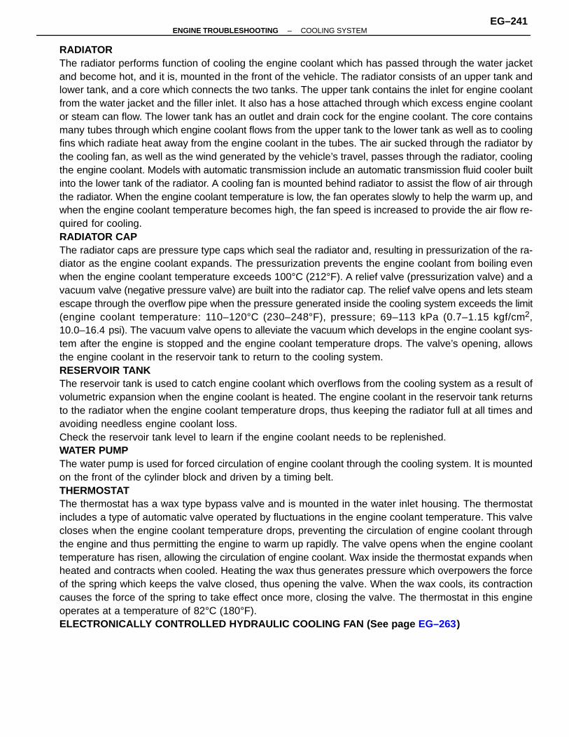
RADIATORThe radiator performs function of cooling the engine coolant which has passed through the water jacketand become hot, and it is, mounted in the front of the vehicle. The radiator consists of an upper tank andlower tank, and a core which connects the two tanks. The upper tank contains the inlet for engine coolantfrom the water jacket and the filler inlet. It also has a hose attached through which excess engine coolantor steam can flow. The lower tank has an outlet and drain cock for the engine coolant. The core containsmany tubes through which engine coolant flows from the upper tank to the lower tank as well as to coolingfins which radiate heat away from the engine coolant in the tubes. The air sucked through the radiator bythe cooling fan, as well as the wind generated by the vehicle’s travel, passes through the radiator, coolingthe engine coolant. Models with automatic transmission include an automatic transmission fluid cooler builtinto the lower tank of the radiator. A cooling fan is mounted behind radiator to assist the flow of air throughthe radiator. When the engine coolant temperature is low, the fan operates slowly to help the warm up, andwhen the engine coolant temperature becomes high, the fan speed is increased to provide the air flow re-quired for cooling.RADIATOR CAPThe radiator caps are pressure type caps which seal the radiator and, resulting in pressurization of the ra-diator as the engine coolant expands. The pressurization prevents the engine coolant from boiling evenwhen the engine coolant temperature exceeds 100°C (212°F). A relief valve (pressurization valve) and avacuum valve (negative pressure valve) are built into the radiator cap. The relief valve opens and lets steamescape through the overflow pipe when the pressure generated inside the cooling system exceeds the limit(engine coolant temperature: 110–120°C (230–248°F), pressure; 69–113 kPa (0.7–1.15 kgf/cm2,10.0–16.4 psi). The vacuum valve opens to alleviate the vacuum which develops in the engine coolant sys-tem after the engine is stopped and the engine coolant temperature drops. The valve’s opening, allowsthe engine coolant in the reservoir tank to return to the cooling system.RESERVOIR TANKThe reservoir tank is used to catch engine coolant which overflows from the cooling system as a result ofvolumetric expansion when the engine coolant is heated. The engine coolant in the reservoir tank returnsto the radiator when the engine coolant temperature drops, thus keeping the radiator full at all times andavoiding needless engine coolant loss.Check the reservoir tank level to learn if the engine coolant needs to be replenished.WATER PUMPThe water pump is used for forced circulation of engine coolant through the cooling system. It is mountedon the front of the cylinder block and driven by a timing belt.THERMOSTATThe thermostat has a wax type bypass valve and is mounted in the water inlet housing. The thermostatincludes a type of automatic valve operated by fluctuations in the engine coolant temperature. This valvecloses when the engine coolant temperature drops, preventing the circulation of engine coolant throughthe engine and thus permitting the engine to warm up rapidly. The valve opens when the engine coolanttemperature has risen, allowing the circulation of engine coolant. Wax inside the thermostat expands whenheated and contracts when cooled. Heating the wax thus generates pressure which overpowers the forceof the spring which keeps the valve closed, thus opening the valve. When the wax cools, its contractioncauses the force of the spring to take effect once more, closing the valve. The thermostat in this engineoperates at a temperature of 82°C (180°F).ELECTRONICALLY CONTROLLED HYDRAULIC COOLING FAN (See page EG–263)
–ENGINE TROUBLESHOOTING COOLING SYSTEMEG–241
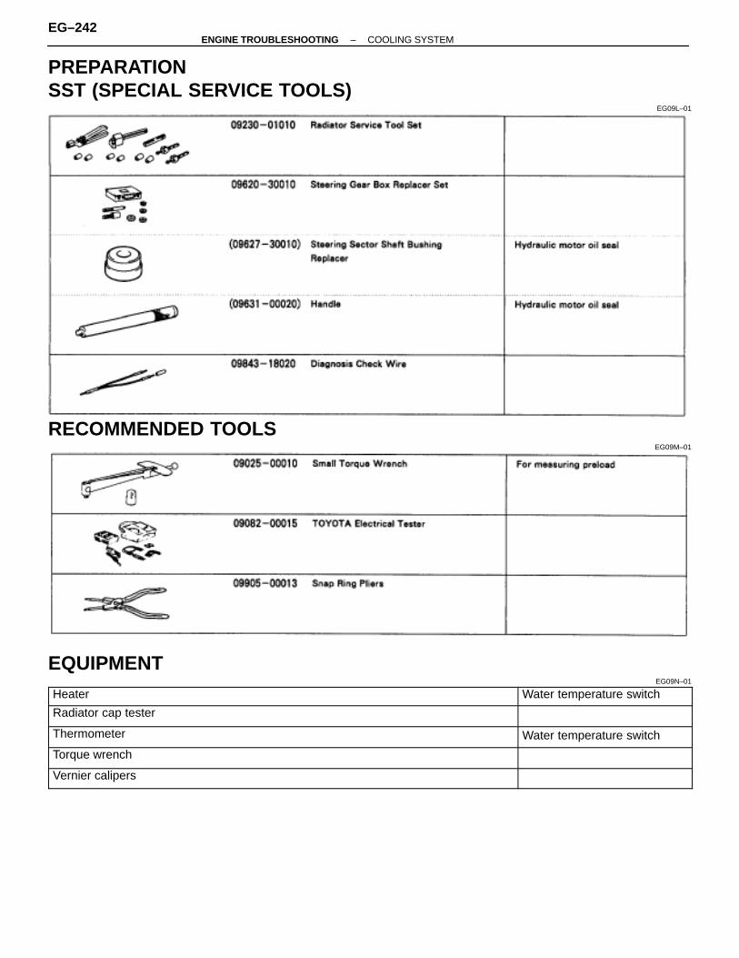
PREPARATIONSST (SPECIAL SERVICE TOOLS)
EG09L–01
RECOMMENDED TOOLSEG09M–01
EQUIPMENTEG09N–01ÑÑÑÑÑÑÑÑÑÑÑÑÑÑÑÑÑÑÑÑÑÑÑÑÑÑ
ÑÑÑÑÑÑÑÑÑÑÑÑÑÑÑÑÑÑÑÑÑÑÑÑÑÑHeaterÑÑÑÑÑÑÑÑÑÑÑÑÑÑÑÑÑÑÑÑÑÑWater temperature switchÑÑÑÑÑÑÑÑÑÑÑÑÑÑÑÑÑÑÑÑÑÑÑÑÑÑ
ÑÑÑÑÑÑÑÑÑÑÑÑÑÑÑÑÑÑÑÑÑÑÑÑÑÑÑÑÑÑÑÑÑÑÑÑÑÑÑÑÑÑÑÑÑÑÑÑÑÑÑÑ
Radiator cap tester
ÑÑÑÑÑÑÑÑÑÑÑÑÑÑÑÑÑÑÑÑÑÑÑÑÑÑÑÑÑÑÑÑÑÑÑÑÑÑÑÑÑÑÑÑÑÑÑÑÑÑÑÑ
Thermometer Water temperature switch
ÑÑÑÑÑÑÑÑÑÑÑÑÑÑÑÑÑÑÑÑÑÑÑÑÑÑÑÑÑÑÑÑÑÑÑÑÑÑÑÑÑÑÑÑÑÑÑÑÑÑÑÑ
Torque wrench
ÑÑÑÑÑÑÑÑÑÑÑÑÑÑÑÑÑÑÑÑÑÑÑÑÑÑÑÑÑÑÑÑÑÑÑÑÑÑÑÑÑÑÑÑÑÑÑÑÑÑÑÑ
Vernier calipers
EG–242–ENGINE TROUBLESHOOTING COOLING SYSTEM
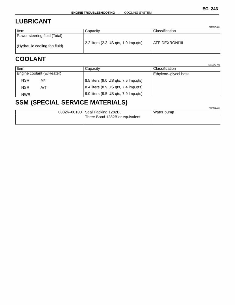
LUBRICANTEG09P–01ÑÑÑÑÑÑÑÑÑÑÑÑÑ
ÑÑÑÑÑÑÑÑÑÑÑÑÑItem
ÑÑÑÑÑÑÑÑÑÑÑÑÑÑÑÑÑÑÑÑÑÑÑÑ
CapacityÑÑÑÑÑÑÑÑÑÑÑÑÑÑÑÑÑÑÑÑÑÑÑÑÑÑ
ClassificationÑÑÑÑÑÑÑÑÑÑÑÑÑÑÑÑÑÑÑÑÑÑÑÑÑÑÑÑÑÑÑÑÑÑÑÑÑÑÑÑÑÑÑÑÑÑÑÑÑÑÑÑ
Power steering fluid (Total)
(Hydraulic cooling fan fluid)2.2 liters (2.3 US qts, 1.9 lmp.qts) ATF DEXRON II
ÑÑÑÑÑÑÑÑÑÑÑÑÑÑÑÑÑÑÑÑÑÑÑÑÑÑ
ÑÑÑÑÑÑÑÑÑÑÑÑÑÑÑÑÑÑÑÑÑÑÑÑ
ÑÑÑÑÑÑÑÑÑÑÑÑÑÑÑÑÑÑÑÑÑÑÑÑÑÑCOOLANT
EG09Q–01
ÑÑÑÑÑÑÑÑÑÑÑÑÑÑÑÑÑÑÑÑÑÑÑÑÑÑ
Item ÑÑÑÑÑÑÑÑÑÑÑÑÑÑÑÑÑÑÑÑÑÑÑÑ
Capacity ÑÑÑÑÑÑÑÑÑÑÑÑÑÑÑÑÑÑÑÑÑÑÑÑÑÑ
Classification
ÑÑÑÑÑÑÑÑÑÑÑÑÑÑÑÑÑÑÑÑÑÑÑÑÑÑÑÑÑÑÑÑÑÑÑÑÑÑÑÑÑÑÑÑÑÑÑÑÑÑÑÑÑÑÑÑÑÑÑÑÑÑÑÑÑ
Engine coolant (w/Heater)
NSR M/T
NSR A/T
NWR
8.5 liters (9.0 US qts, 7.5 lmp.qts)
8.4 liters (8.9 US qts, 7.4 lmp.qts)
9.0 liters (9.5 US qts, 7.9 lmp.qts)
Ethylene–glycol base
SSM (SPECIAL SERVICE MATERIALS)EG09R–01
ÑÑÑÑÑÑÑÑÑÑÑÑÑÑÑÑÑÑÑÑÑÑÑÑÑÑ
08826–00100ÑÑÑÑÑÑÑÑÑÑÑÑÑÑÑÑÑÑÑÑÑÑÑÑ
Seal Packing 1282B, ÑÑÑÑÑÑÑÑÑÑÑÑÑÑÑÑÑÑÑÑÑÑÑÑÑÑ
Water pumpÑÑÑÑÑÑÑÑÑÑÑÑÑÑÑÑÑÑÑÑÑÑÑÑÑÑ
Three Bond 1282B or equivalent
ÑÑÑÑÑÑÑÑÑÑÑÑÑÑÑÑÑÑÑÑÑÑÑÑÑÑ
ÑÑÑÑÑÑÑÑÑÑÑÑÑÑÑÑÑÑÑÑÑÑÑÑ
ÑÑÑÑÑÑÑÑÑÑÑÑÑÑÑÑÑÑÑÑÑÑÑÑÑÑ
–ENGINE TROUBLESHOOTING COOLING SYSTEMEG–243

COOLANT CHECK AND REPLACEMENTEG09S–01
1. CHECK ENGINE COOLANT LEVEL AT RESERVE TANKThe engine coolant level should be between the ”LOW” and”FULL” lines.If low, check for leaks and add engine coolant up to the”FULL” line.
2. CHECK ENGINE COOLANT QUALITYThere should not be any excessive deposits of rust or scalesaround the radiator cap (water outlet side) or water outlet fillerhole, and the engine coolant should be free from oil.If excessively dirty, replace the engine coolant.
3. REPLACE ENGINE COOLANT(a) Remove the radiator cap from the water outlet.
CAUTION: To avoid the danger of being burned, do notremove it while the engine and radiator are still hot, asfluid and steam can be blown out under pressure.
(b) Drain the engine coolant from the radiator drain cock andengine drain plug (Engine drain plug at the right of engineblock.)
(c) Close the drain cock.Torque (Engine drain plug):
29 N⋅m (300 kgf ⋅cm, 22 ft ⋅lbf)
(d) Slowly fill the system with engine coolant from the wateroutlet.•Use a good brand of ethylene–glycol base engine coolant
and mix it according to the manufacturer’s directions.•Using engine coolant which includes more than 50%
ethylene–glycol (but not more than 70%) isrecommended.
EG–244–ENGINE TROUBLESHOOTING COOLING SYSTEM
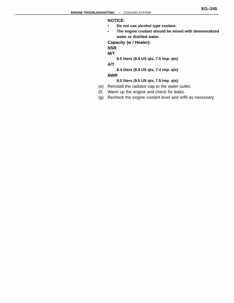
NOTICE:• Do not use alcohol type coolant.• The engine coolant should be mixed with demineralized
water or distilled water.
Capacity (w / Heater):NSRM/T
8.5 liters (9.0 US qts, 7.5 lmp. qts)
A/T8.4 liters (8.9 US qts, 7.4 lmp. qts)
NWR9.0 liters (9.5 US qts, 7.9 lmp. qts)
(e) Reinstall the radiator cap to the water outlet.(f) Warm up the engine and check for leaks.(g) Recheck the engine coolant level and refill as necessary.
–ENGINE TROUBLESHOOTING COOLING SYSTEMEG–245
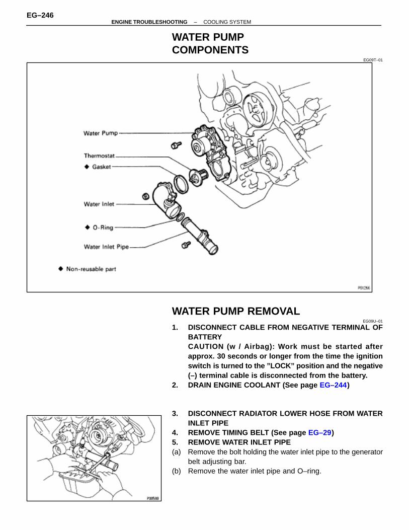
WATER PUMPCOMPONENTS
EG09T–01
WATER PUMP REMOVALEG09U–01
1. DISCONNECT CABLE FROM NEGATIVE TERMINAL OFBATTERYCAUTION (w / Airbag): Work must be started afterapprox. 30 seconds or longer from the time the ignitionswitch is turned to the ”LOCK” position and the negative(–) terminal cable is disconnected from the battery.
2. DRAIN ENGINE COOLANT (See page EG–244)
3. DISCONNECT RADIATOR LOWER HOSE FROM WATERINLET PIPE
4. REMOVE TIMING BELT (See page EG–29)5. REMOVE WATER INLET PIPE(a) Remove the bolt holding the water inlet pipe to the generator
belt adjusting bar.(b) Remove the water inlet pipe and O–ring.
EG–246–ENGINE TROUBLESHOOTING COOLING SYSTEM
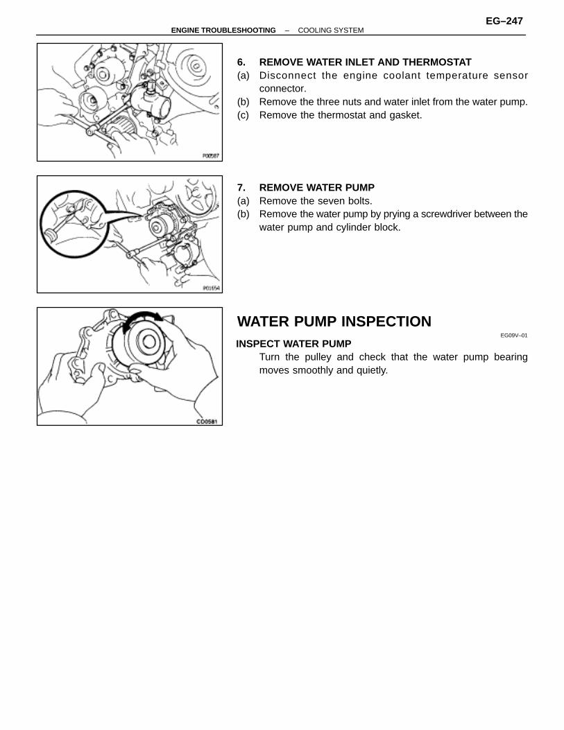
6. REMOVE WATER INLET AND THERMOSTAT(a) Disconnect the engine coolant temperature sensor
connector.(b) Remove the three nuts and water inlet from the water pump.(c) Remove the thermostat and gasket.
7. REMOVE WATER PUMP(a) Remove the seven bolts.(b) Remove the water pump by prying a screwdriver between the
water pump and cylinder block.
WATER PUMP INSPECTIONEG09V–01
INSPECT WATER PUMPTurn the pulley and check that the water pump bearingmoves smoothly and quietly.
–ENGINE TROUBLESHOOTING COOLING SYSTEMEG–247
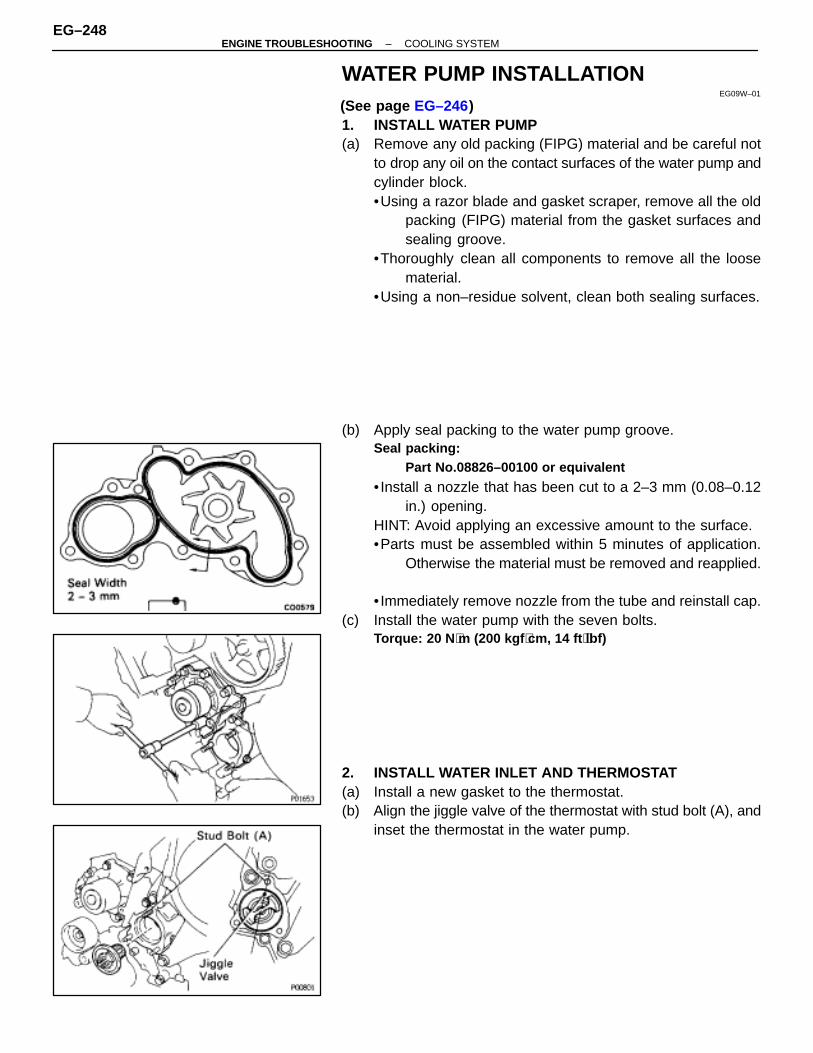
WATER PUMP INSTALLATIONEG09W–01
(See page EG–246)1. INSTALL WATER PUMP(a) Remove any old packing (FIPG) material and be careful not
to drop any oil on the contact surfaces of the water pump andcylinder block.•Using a razor blade and gasket scraper, remove all the old
packing (FIPG) material from the gasket surfaces andsealing groove.
•Thoroughly clean all components to remove all the loosematerial.
•Using a non–residue solvent, clean both sealing surfaces.
(b) Apply seal packing to the water pump groove.Seal packing:
Part No.08826–00100 or equivalent
• Install a nozzle that has been cut to a 2–3 mm (0.08–0.12in.) opening.
HINT: Avoid applying an excessive amount to the surface.•Parts must be assembled within 5 minutes of application.
Otherwise the material must be removed and reapplied.
• Immediately remove nozzle from the tube and reinstall cap.(c) Install the water pump with the seven bolts.
Torque: 20 N ⋅m (200 kgf ⋅cm, 14 ft ⋅lbf)
2. INSTALL WATER INLET AND THERMOSTAT(a) Install a new gasket to the thermostat.(b) Align the jiggle valve of the thermostat with stud bolt (A), and
inset the thermostat in the water pump.
EG–248–ENGINE TROUBLESHOOTING COOLING SYSTEM

(c) Install the water inlet with the three nuts.Torque: 20 N ⋅m (200 kgf ⋅cm, 14 ft ⋅lbf)
3. INSTALL WATER INLET PIPE(a) Install a new O–ring to the water inlet pipe.
(b) Apply soapy water to the O–ring.(c) Connect the water inlet pipe to the water inlet.(d) Install the bolt holding the water inlet pipe to the generator
belt adjusting bar.Torque: 20 N ⋅m (200 kgf ⋅cm, 14 ft ⋅lbf)
4. INSTALL TIMING BELT (See page EG–29)5. CONNECT RADIATOR LOWER HOSE6. CONNECT CABLE TO NEGATIVE TERMINAL OF
BATTERY7. FILL WITH ENGINE COOLANT (See page EG–244)
–ENGINE TROUBLESHOOTING COOLING SYSTEMEG–249
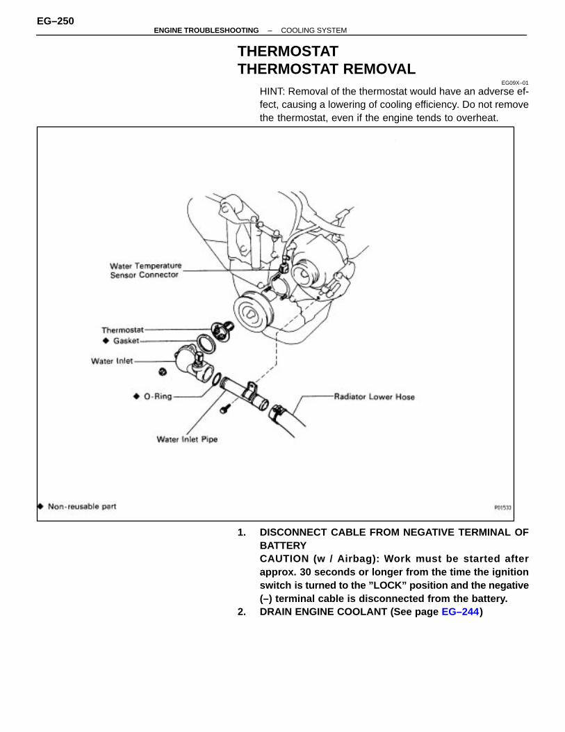
THERMOSTATTHERMOSTAT REMOVAL
EG09X–01
HINT: Removal of the thermostat would have an adverse ef-fect, causing a lowering of cooling efficiency. Do not removethe thermostat, even if the engine tends to overheat.
1. DISCONNECT CABLE FROM NEGATIVE TERMINAL OFBATTERYCAUTION (w / Airbag): Work must be started afterapprox. 30 seconds or longer from the time the ignitionswitch is turned to the ”LOCK” position and the negative(–) terminal cable is disconnected from the battery.
2. DRAIN ENGINE COOLANT (See page EG–244)
EG–250–ENGINE TROUBLESHOOTING COOLING SYSTEM

3. REMOVE WATER INLET PIPE(a) Remove the bolt holding the water inlet pipe to the generator
belt adjusting bar.(b) Remove the water inlet pipe and O–ring.4. DISCONNECT ENGINE COOLANT TEMPERATURE
SENSOR CONNECTOR
5. REMOVE WATER INLETRemove the three nuts and water inlet from water pump.
6. REMOVE THERMOSTAT AND GASKET
THERMOSTAT INSPECTIONEG09Y–01
INSPECT THERMOSTATHINT: The thermostat is numbered with the valve openingtemperature.
(a) Immerse the thermostat in water and gradually heat thewater.
(b) Check the valve opening temperature.Valve opening temperature:
80–84°C (176–183°F)
If the valve opening temperature is not as specified, replacethe thermostat.
(c) Check the valve lift.Valve lift:
8.5 mm (0.335 in.) or more at 95 °C (203°F)
If the valve lift is not as specified, replace the thermostat.(d) Check that the valve spring is tight when the thermostat is
fully closed.If not closed, replace the thermostat.
–ENGINE TROUBLESHOOTING COOLING SYSTEMEG–251
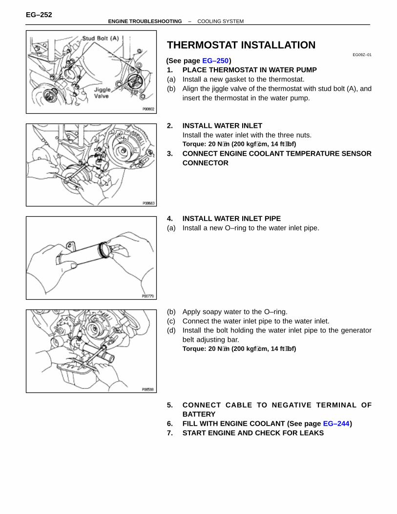
THERMOSTAT INSTALLATIONEG09Z–01
(See page EG–250)1. PLACE THERMOSTAT IN WATER PUMP(a) Install a new gasket to the thermostat.(b) Align the jiggle valve of the thermostat with stud bolt (A), and
insert the thermostat in the water pump.
2. INSTALL WATER INLETInstall the water inlet with the three nuts.Torque: 20 N ⋅m (200 kgf ⋅cm, 14 ft ⋅lbf)
3. CONNECT ENGINE COOLANT TEMPERATURE SENSORCONNECTOR
4. INSTALL WATER INLET PIPE(a) Install a new O–ring to the water inlet pipe.
(b) Apply soapy water to the O–ring.(c) Connect the water inlet pipe to the water inlet.(d) Install the bolt holding the water inlet pipe to the generator
belt adjusting bar.Torque: 20 N ⋅m (200 kgf ⋅cm, 14 ft ⋅lbf)
5. CONNECT CABLE TO NEGATIVE TERMINAL OFBATTERY
6. FILL WITH ENGINE COOLANT (See page EG–244)7. START ENGINE AND CHECK FOR LEAKS
EG–252–ENGINE TROUBLESHOOTING COOLING SYSTEM
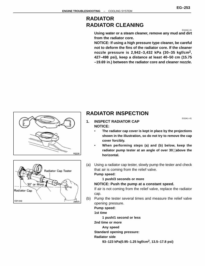
RADIATORRADIATOR CLEANING
EG0A0–01
Using water or a steam cleaner, remove any mud and dirtfrom the radiator core.NOTICE: If using a high pressure type cleaner, be carefulnot to deform the fins of the radiator core. If the cleanernozzle pressure is 2,942–3,432 kPa (30–35 kgf/cm 2,427–498 psi), keep a distance at least 40–50 cm (15.75–19.69 in.) between the radiator core and cleaner nozzle.
RADIATOR INSPECTIONEG0A1–01
1. INSPECT RADIATOR CAPNOTICE:• The radiator cap cover is kept in place by the projections
shown in the illustration, so do not try to remove the capcover forcibly.
• When performing steps (a) and (b) below, keep theradiator pump tester at an angle of over 30 � above thehorizontal.
(a) Using a radiator cap tester, slowly pump the tester and checkthat air is coming from the relief valve.Pump speed:
1 push/3 seconds or more
NOTICE: Push the pump at a constant speed.If air is not coming from the relief valve, replace the radiatorcap.
(b) Pump the tester several times and measure the relief valveopening pressure.Pump speed:1st time
1 push/1 second or less2nd time or more
Any speedStandard opening pressure:Radiator side
93–123 kPa(0.95–1.25 kgf/cm 2, 13.5–17.8 psi)
–ENGINE TROUBLESHOOTING COOLING SYSTEMEG–253

Water outlet side83–113 kPa(0.85–1.15 kgf/cm 2, 12.1–16.4 psi)
Minimum opening pressure:Radiator side
78 kPa (0.8 kgf/cm 2, 11.4 psi)Water outlet side
69 kPa (0.7 kgf/cm 2, 10.0 psi)
If the opening pressure is less than minimum, replace the ra-diator cap.
2. INSPECT COOLING SYSTEM FOR LEAKS(a) Fill the radiator and engine with engine coolant and attach a
radiator cap tester to the water outlet.(b) Warm up the engine.(c) Disconnect the reservoir hose from the radiator overflow
pipe.(d) Install a rubber cap onto the radiator overflow pipe, then fix
the rubber cap in place with a clip.
(e) Pump it to 127 kPa (1.3 kgf/cm2, 18.5 psi) and check that thepressure does not drop.If the pressure drops, check for leaks from the hoses, radiatoror water pump. If no external leaks are found, check the heat-er core, cylinder block and head.
(f) Remove the radiator cap tester and install the radiator cap tothe water outlet.
(g) Remove the clip and rubber cap from the radiator overflowpipe.
(h) Connect the reservoir hose to the radiator overflow pipe.
EG–254–ENGINE TROUBLESHOOTING COOLING SYSTEM

RADIATOR REMOVALEG0A2–01
1. DISCONNECT CABLE FROM NEGATIVE TERMINAL OFBATTERYCAUTION (w / Airbag): Work must be started afterapprox. 30 seconds or longer from the time the ignitionswitch is turned to the ”LOCK” position and the negative(–) terminal cable is disconnected from the battery.
2. DRAIN ENGINE COOLANT (See page EG–244)3. REMOVE CRUISE CONTROL ACTUATOR COVER
4. DISCONNECT PRESSURE HOSERemove the union bolt and gasket, and disconnect the pres-sure hose from the hydraulic motor.NOTICE: Catch leaking oil in a container.
–ENGINE TROUBLESHOOTING COOLING SYSTEMEG–255
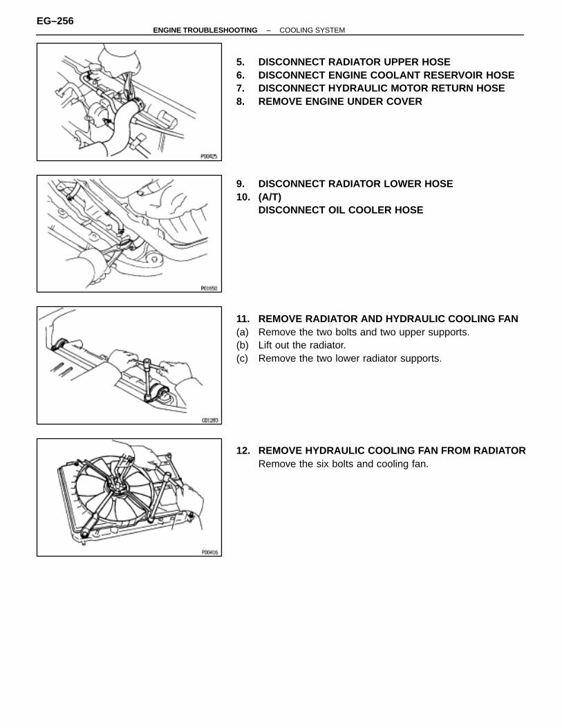
5. DISCONNECT RADIATOR UPPER HOSE6. DISCONNECT ENGINE COOLANT RESERVOIR HOSE7. DISCONNECT HYDRAULIC MOTOR RETURN HOSE8. REMOVE ENGINE UNDER COVER
9. DISCONNECT RADIATOR LOWER HOSE10. (A/T)
DISCONNECT OIL COOLER HOSE
11. REMOVE RADIATOR AND HYDRAULIC COOLING FAN(a) Remove the two bolts and two upper supports.(b) Lift out the radiator.(c) Remove the two lower radiator supports.
12. REMOVE HYDRAULIC COOLING FAN FROM RADIATORRemove the six bolts and cooling fan.
EG–256–ENGINE TROUBLESHOOTING COOLING SYSTEM

COMPONENTSEG0A3–01
RADIATOR DISASSEMBLYEG0A4–01
1. ASSEMBLY OF SSTSST 09230–01010
(a) Install the claw to the overhaul handle, inserting it in the holein part ”A” as shown in the diagram.
(b) While gripping the handle, adjust the stopper bolt so thatdimension ”B” shown in the diagram is 0.2–0.5 mm(0.008–0.020 in.).
NOTICE: If this adjustment is not performed, the clawmay be damaged.
2. UNCAULK LOCK PLATESUsing SST to release the caulking, squeeze the handle untilstopped by the stopper bolt.SST 09230–01010
–ENGINE TROUBLESHOOTING COOLING SYSTEMEG–257

3. REMOVE TANKS AND O–RINGS(a) Lightly tap the radiator hose inlet (or outlet) with a soft–faced
hammer and remove the tank.(b) Remove the O–ring.
4. (A/T)REMOVE OIL COOLER FROM LOWER TANK
(a) Remove the pipes.HINT: Make a note of the direction to face the pipes.
(b) Remove the nuts, and plate washers.(c) Remove the oil cooler and O–rings.
RADIATOR ASSEMBLYEG0A5–01
(See page EG–257)1. (A/T)
INSTALL OIL COOLANT TO LOWER TANK(a) Clean the O–ring contact surface of the lower tank and oil
cooler.(b) Install new O–rings (1) to the oil cooler (2).(c) Install the oil cooler (2) with the O–rings (1) to the lower tank
(3).
(d) Install the plate washers (4), and nuts (5). Torque the nuts (5).Torque: 8.3 N ⋅m (85 kgf ⋅cm, 74 ft ⋅lbf)
(e) Install the pipes (6).Torque: 22 N ⋅m (220 kgf ⋅cm, 16 ft ⋅lbf)
HINT: Face the pipes in the same direction as before disas-sembly.
2. INSPECT LOCK PLATEInspect the lock plate for damage.HINT:• If the sides of the lock plate groove are deformed,
reassembly of the tank will be impossible.
EG–258–ENGINE TROUBLESHOOTING COOLING SYSTEM

•Therefore, first correct any deformation with pliers or likeobject. Water leakage will result if the bottom of the lockplate groove is damaged or dented, Therefore, repair orreplace if necessary.
3. INSTALL NEW O–RINGS AND TANKS(a) After checking that there are no foreign objects in the lock
plate groove, install the new O–ring without twisting it.HINT: When cleaning the lock plate groove, lightly rub it withsand paper without scratching it.
(b) Install the tank without damaging the O–ring.(c) Tap the lock plate with a soft–faced hammer so that there is
no gap between it and the tank.
4. ASSEMBLY OF SSTSST 09230–01010
(a) Install the punch assembly to the overhaul handle, insertingit in the hole in part ”A” as shown in the illustration.
(b) While gripping the handle, adjust the stopper bolt so thatdimension ”B” shown in the diagram is 7.7 mm (0.30 in.).
5. CAULK LOCK PLATE(a) Lightly press SST against the lock plate in the order shown
in the illustration. After repeating this a few times, fully caulkthe lock plate by squeezing the handle until stopped by thestopper plate.SST 09230–01010
–ENGINE TROUBLESHOOTING COOLING SYSTEMEG–259
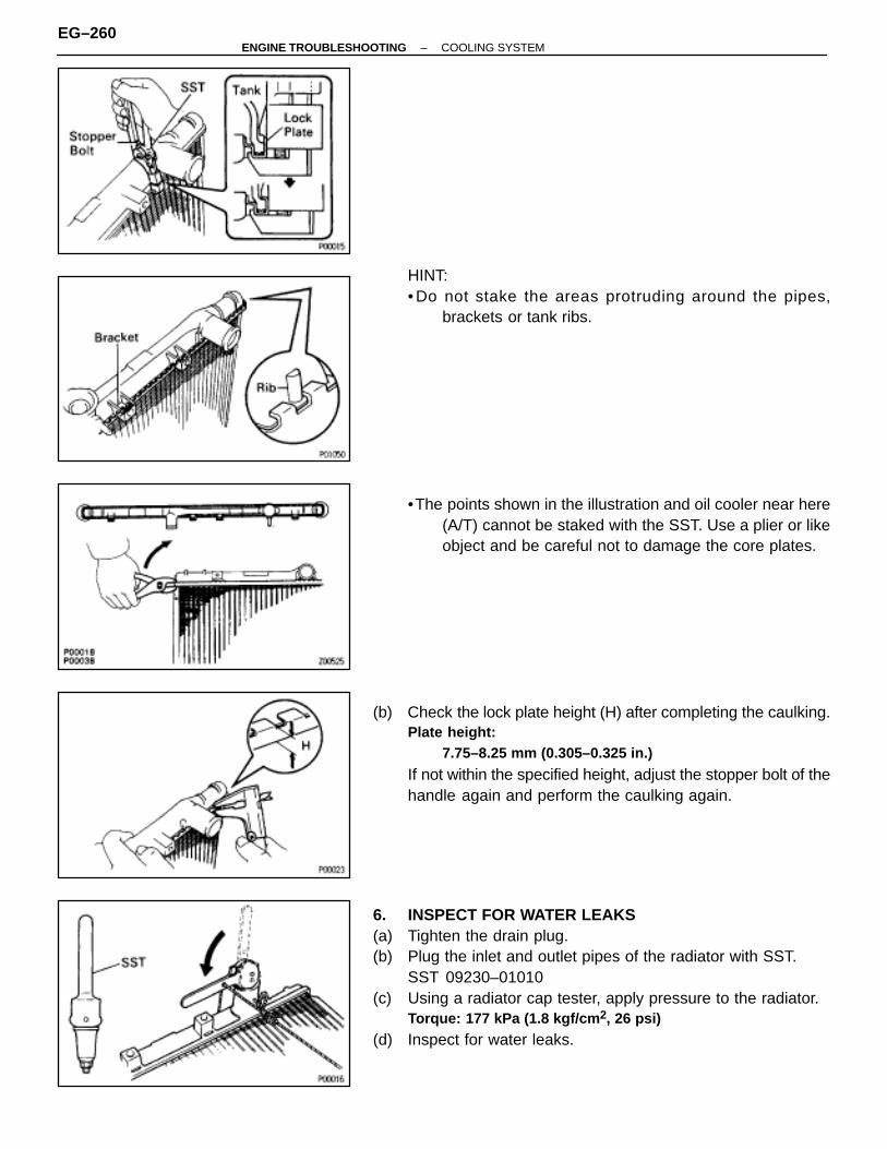
HINT:• Do not stake the areas protruding around the pipes,
brackets or tank ribs.
•The points shown in the illustration and oil cooler near here(A/T) cannot be staked with the SST. Use a plier or likeobject and be careful not to damage the core plates.
(b) Check the lock plate height (H) after completing the caulking.Plate height:
7.75–8.25 mm (0.305–0.325 in.)
If not within the specified height, adjust the stopper bolt of thehandle again and perform the caulking again.
6. INSPECT FOR WATER LEAKS(a) Tighten the drain plug.(b) Plug the inlet and outlet pipes of the radiator with SST.
SST 09230–01010(c) Using a radiator cap tester, apply pressure to the radiator.
Torque: 177 kPa (1.8 kgf/cm 2, 26 psi)
(d) Inspect for water leaks.
EG–260–ENGINE TROUBLESHOOTING COOLING SYSTEM
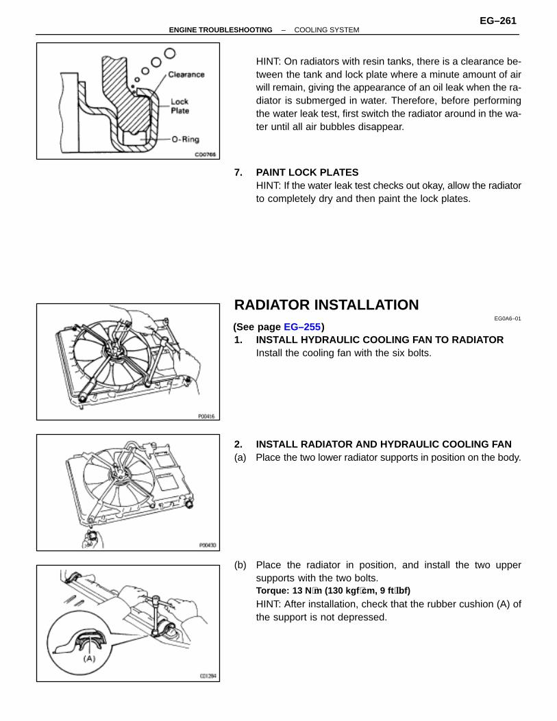
HINT: On radiators with resin tanks, there is a clearance be-tween the tank and lock plate where a minute amount of airwill remain, giving the appearance of an oil leak when the ra-diator is submerged in water. Therefore, before performingthe water leak test, first switch the radiator around in the wa-ter until all air bubbles disappear.
7. PAINT LOCK PLATESHINT: If the water leak test checks out okay, allow the radiatorto completely dry and then paint the lock plates.
RADIATOR INSTALLATIONEG0A6–01
(See page EG–255)1. INSTALL HYDRAULIC COOLING FAN TO RADIATOR
Install the cooling fan with the six bolts.
2. INSTALL RADIATOR AND HYDRAULIC COOLING FAN(a) Place the two lower radiator supports in position on the body.
(b) Place the radiator in position, and install the two uppersupports with the two bolts.Torque: 13 N ⋅m (130 kgf ⋅cm, 9 ft ⋅lbf)
HINT: After installation, check that the rubber cushion (A) ofthe support is not depressed.
–ENGINE TROUBLESHOOTING COOLING SYSTEMEG–261
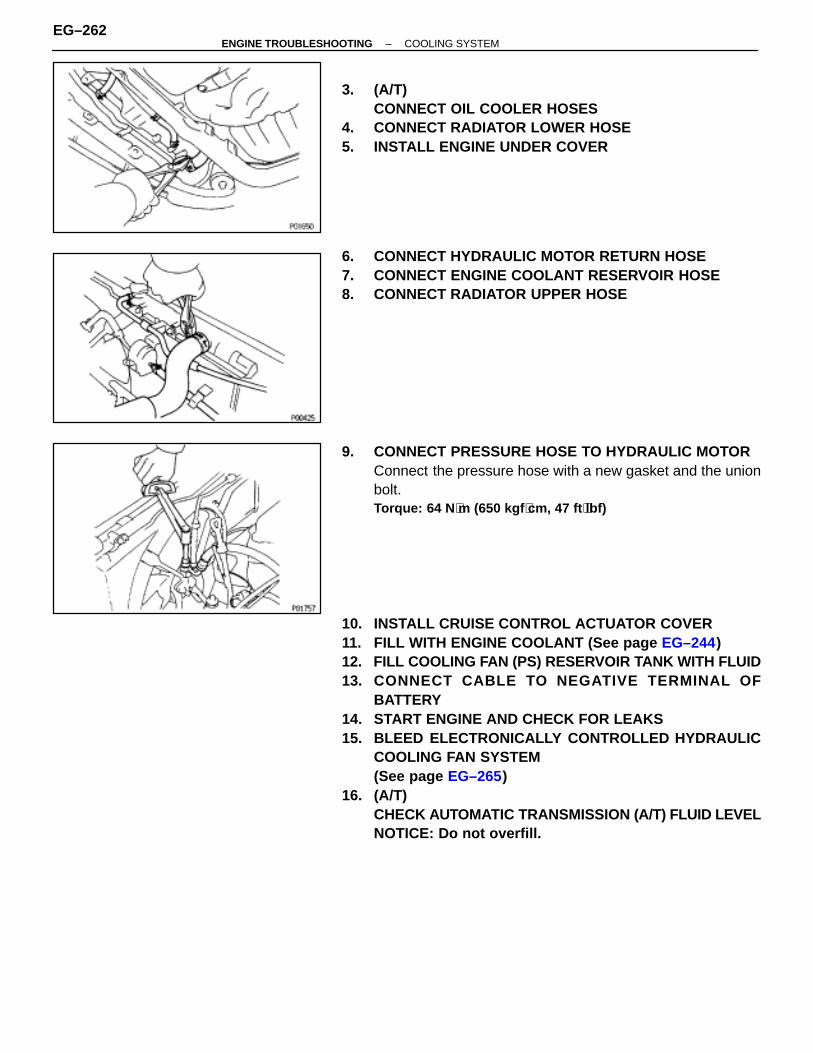
3. (A/T)CONNECT OIL COOLER HOSES
4. CONNECT RADIATOR LOWER HOSE5. INSTALL ENGINE UNDER COVER
6. CONNECT HYDRAULIC MOTOR RETURN HOSE7. CONNECT ENGINE COOLANT RESERVOIR HOSE8. CONNECT RADIATOR UPPER HOSE
9. CONNECT PRESSURE HOSE TO HYDRAULIC MOTORConnect the pressure hose with a new gasket and the unionbolt.Torque: 64 N ⋅m (650 kgf ⋅cm, 47 ft ⋅lbf)
10. INSTALL CRUISE CONTROL ACTUATOR COVER11. FILL WITH ENGINE COOLANT (See page EG–244)12. FILL COOLING FAN (PS) RESERVOIR TANK WITH FLUID13. CONNECT CABLE TO NEGATIVE TERMINAL OF
BATTERY14. START ENGINE AND CHECK FOR LEAKS15. BLEED ELECTRONICALLY CONTROLLED HYDRAULIC
COOLING FAN SYSTEM(See page EG–265)
16. (A/T)CHECK AUTOMATIC TRANSMISSION (A/T) FLUID LEVELNOTICE: Do not overfill.
EG–262–ENGINE TROUBLESHOOTING COOLING SYSTEM

ELECTRONICALLY CONTROLLED HYDRAULIC COOLING FANSYSTEMDESCRIPTION
EG0A7–01
In this system, the cooling fan ECU controls the hydraulic pressure acting on the hydraulic motor, thus con-trolling the speed of the cooling fan steplessly in response to the condition of the engine and air condition-ing.
OPERATIONEG0A8–01
The hydraulic pump integrated with PS pump is driven by the PS pump drive belt. The solenoid valve ad-justs the volume of oil sent from the hydraulic pump to the hydraulic motor which drives the fan directly,thereby controlling the fan speed.Oil which has passed through the hydraulic motor is cooled by the oil cooler before returning to the PS pumpreservoir tank.The solenoid valve is controlled by the computer in accordance with the engine rpm, engine coolant temp.and A/C signals.
–ENGINE TROUBLESHOOTING COOLING SYSTEMEG–263

ON–VEHICLE INSPECTIONFLUID LEVEL INSPECTION
EG0A9–01
1. KEEP VEHICLE LEVEL
2. INSPECT FLUID LEVEL(a) Using SST, connect terminals OP1 and E1 of the data link
connector 1.SST 09843–18020
(b) Keep the engine speed at 2,000 rpm until the fluidtemperature reaches the specified temperature.Fluid temperature:
70–90°C (158–195°F)
(c) Check that there is no foaming and emulsification of the fluidin the reservoir tank.
(d) Measure the fluid level with the engine running.(e) Stop the engine, and measure the fluid level.(f) Subtract (d) from (e).
Maximum stroke:5 mm (0.20 in.)
(g) Check the fluid level.If low, add fluid.Fluid:
ATF DEXRON II
HINT: Check that fluid level is within the ”HOT” level on reser-voir tank. If the fluid is cold, check that it is within the ”COLD”level on the tank.
(h) Remove the SST from the data link connector 1.SST 09843–19020
EG–264–ENGINE TROUBLESHOOTING COOLING SYSTEM
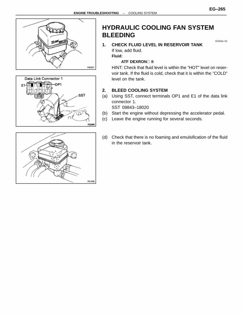
HYDRAULIC COOLING FAN SYSTEMBLEEDING
EG0AA–01
1. CHECK FLUID LEVEL IN RESERVOIR TANKIf low, add fluid.Fluid:
ATF DEXRON II
HINT: Check that fluid level is within the ”HOT” level on reser-voir tank. If the fluid is cold, check that it is within the ”COLD”level on the tank.
2. BLEED COOLING SYSTEM(a) Using SST, connect terminals OP1 and E1 of the data link
connector 1.SST 09843–18020
(b) Start the engine without depressing the accelerator pedal.(c) Leave the engine running for several seconds.
(d) Check that there is no foaming and emulsification of the fluidin the reservoir tank.
–ENGINE TROUBLESHOOTING COOLING SYSTEMEG–265
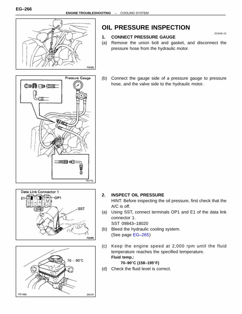
OIL PRESSURE INSPECTIONEG0AB–01
1. CONNECT PRESSURE GAUGE(a) Remove the union bolt and gasket, and disconnect the
pressure hose from the hydraulic motor.
(b) Connect the gauge side of a pressure gauge to pressurehose, and the valve side to the hydraulic motor.
2. INSPECT OIL PRESSUREHINT: Before inspecting the oil pressure, first check that theA/C is off.
(a) Using SST, connect terminals OP1 and E1 of the data linkconnector 1.SST 09843–18020
(b) Bleed the hydraulic cooling system.(See page EG–265)
(c) Keep the engine speed at 2,000 rpm until the fluidtemperature reaches the specified temperature.Fluid temp.:
70–90°C (158–195°F)
(d) Check the fluid level is correct.
EG–266–ENGINE TROUBLESHOOTING COOLING SYSTEM

(e) Measure the oil pressure at idling.Oil pressure:
981–1,961 kPa (10–20 kgf/cm 2, 142–284 psi)
(f) Remove the SST from the data link connector 1.SST 09843–18020
(g) Check that the oil pressure decreases.
–ENGINE TROUBLESHOOTING COOLING SYSTEMEG–267
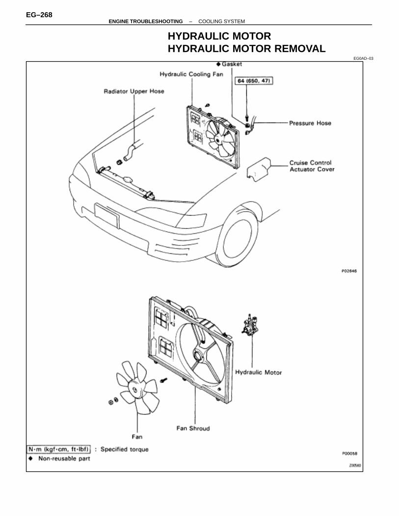
HYDRAULIC MOTORHYDRAULIC MOTOR REMOVAL
EG0AD–03
EG–268–ENGINE TROUBLESHOOTING COOLING SYSTEM
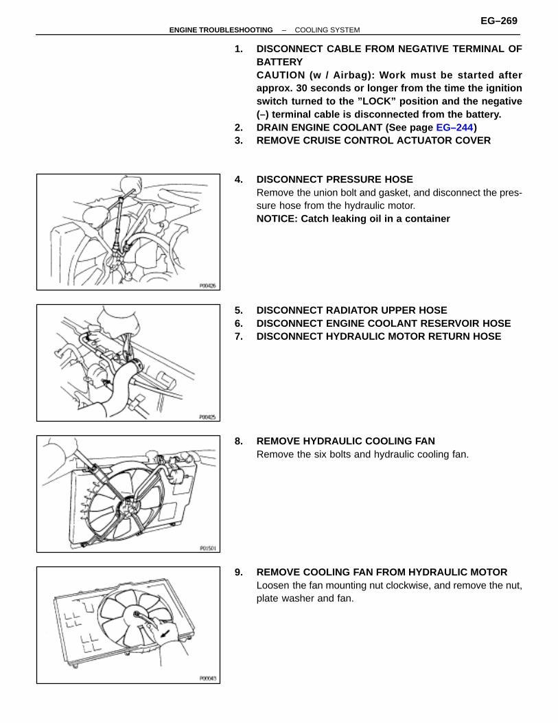
1. DISCONNECT CABLE FROM NEGATIVE TERMINAL OFBATTERYCAUTION (w / Airbag): Work must be started afterapprox. 30 seconds or longer from the time the ignitionswitch turned to the ”LOCK” position and the negative(–) terminal cable is disconnected from the battery.
2. DRAIN ENGINE COOLANT (See page EG–244)3. REMOVE CRUISE CONTROL ACTUATOR COVER
4. DISCONNECT PRESSURE HOSERemove the union bolt and gasket, and disconnect the pres-sure hose from the hydraulic motor.NOTICE: Catch leaking oil in a container
5. DISCONNECT RADIATOR UPPER HOSE6. DISCONNECT ENGINE COOLANT RESERVOIR HOSE7. DISCONNECT HYDRAULIC MOTOR RETURN HOSE
8. REMOVE HYDRAULIC COOLING FANRemove the six bolts and hydraulic cooling fan.
9. REMOVE COOLING FAN FROM HYDRAULIC MOTORLoosen the fan mounting nut clockwise, and remove the nut,plate washer and fan.
–ENGINE TROUBLESHOOTING COOLING SYSTEMEG–269

10. REMOVE HYDRAULIC MOTOR FROM FAN SHROUDRemove the three bolts and hydraulic motor.
COMPONENTSEG0AE–01
HYDRAULIC MOTOR DISASSEMBLYEG0AF–01
1. MOUNT MOTOR HOUSINGSlightly mount the motor housing in a vise.NOTICE: Be careful not to damage the motor housing.
2. REMOVE MOTOR COVER(a) Remove the four bolts and motor cover.(b) Remove the O–ring from the motor cover.
EG–270–ENGINE TROUBLESHOOTING COOLING SYSTEM

3. REMOVE REAR THRUST WASHER AND DRIVE SHAFT
4. REMOVE DRIVE AND DRIVEN ROTORS5. REMOVE FRONT THRUST WASHER
HYDRAULIC MOTOR INSPECTIONEG0AG–01
1. INSPECT DRIVE AND DRIVEN ROTORS(a) Install the drive and driven rotor to the motor housing with the
dot mark facing upward.
(b) Using a thickness gauge and precision straight edge,measure the side clearance between the rotor and precisionstraight edge.Standard side clearance:
0.01–0.04 mm (0.0004–0.0016 in.)Maximum side clearance:
0.05 mm (0.0020 in.)
If the clearance is greater than maximum, replace the rotorsas a set. If necessary, replace the motor assembly.
HINT: When replacing the rotors, select the new rotor set ac-cording to the imprinted mark on the motor housing.
ÑÑÑÑÑÑÑÑÑÑÑÑÑÑÑÑÑÑÑÑÑÑÑÑ
Imprinted mark on housing ÑÑÑÑÑÑÑÑÑÑÑÑÑÑÑÑÑÑÑÑÑÑ
Rotor setÑÑÑÑÑÑÑÑÑÑÑÑÑÑÑÑÑÑÑÑÑÑÑÑ
1 ÑÑÑÑÑÑÑÑÑÑÑÑÑÑÑÑÑÑÑÑÑÑ
16906–50010ÑÑÑÑÑÑÑÑÑÑÑÑÑÑÑÑÑÑÑÑÑÑÑÑ
2 ÑÑÑÑÑÑÑÑÑÑÑÑÑÑÑÑÑÑÑÑÑÑ
16906–50020ÑÑÑÑÑÑÑÑÑÑÑÑÑÑÑÑÑÑÑÑÑÑÑÑ
3 ÑÑÑÑÑÑÑÑÑÑÑÑÑÑÑÑÑÑÑÑÑÑ
16906–50030
–ENGINE TROUBLESHOOTING COOLING SYSTEMEG–271
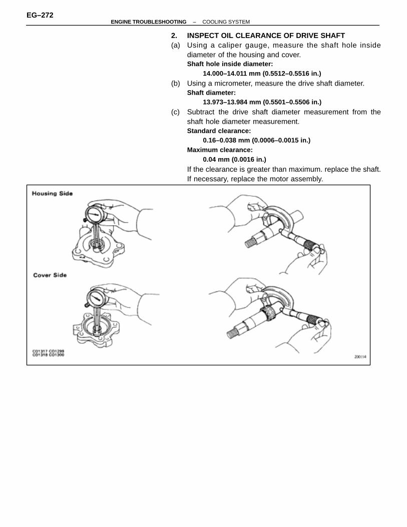
2. INSPECT OIL CLEARANCE OF DRIVE SHAFT(a) Using a caliper gauge, measure the shaft hole inside
diameter of the housing and cover.Shaft hole inside diameter:
14.000–14.011 mm (0.5512–0.5516 in.)
(b) Using a micrometer, measure the drive shaft diameter.Shaft diameter:
13.973–13.984 mm (0.5501–0.5506 in.)
(c) Subtract the drive shaft diameter measurement from theshaft hole diameter measurement.Standard clearance:
0.16–0.038 mm (0.0006–0.0015 in.)Maximum clearance:
0.04 mm (0.0016 in.)
If the clearance is greater than maximum. replace the shaft.If necessary, replace the motor assembly.
EG–272–ENGINE TROUBLESHOOTING COOLING SYSTEM
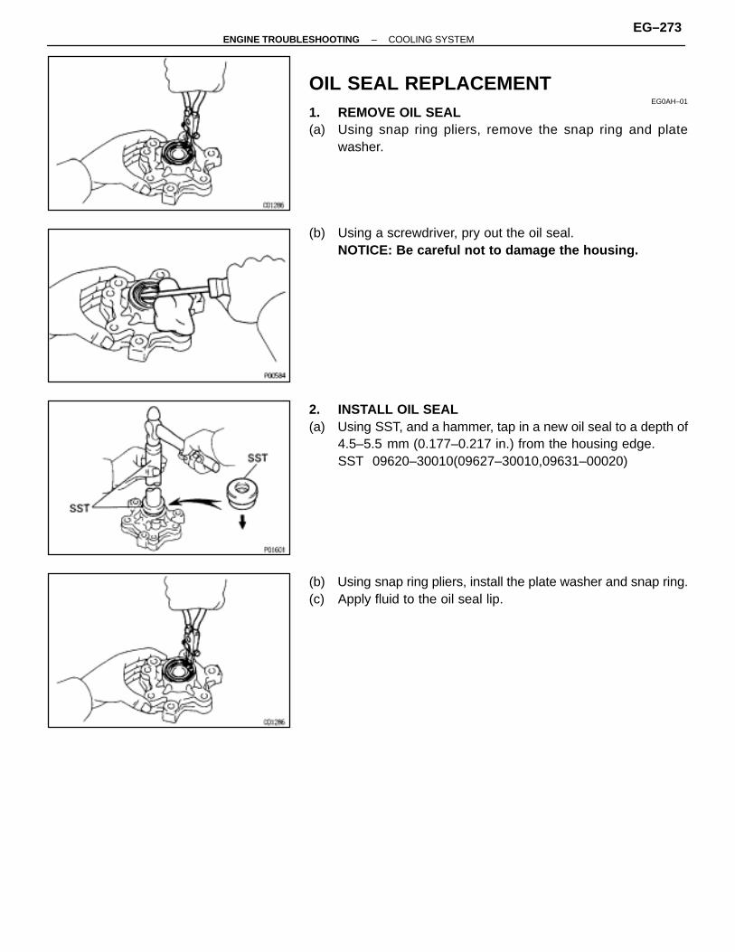
OIL SEAL REPLACEMENTEG0AH–01
1. REMOVE OIL SEAL(a) Using snap ring pliers, remove the snap ring and plate
washer.
(b) Using a screwdriver, pry out the oil seal.NOTICE: Be careful not to damage the housing.
2. INSTALL OIL SEAL(a) Using SST, and a hammer, tap in a new oil seal to a depth of
4.5–5.5 mm (0.177–0.217 in.) from the housing edge.SST 09620–30010(09627–30010,09631–00020)
(b) Using snap ring pliers, install the plate washer and snap ring.(c) Apply fluid to the oil seal lip.
–ENGINE TROUBLESHOOTING COOLING SYSTEMEG–273
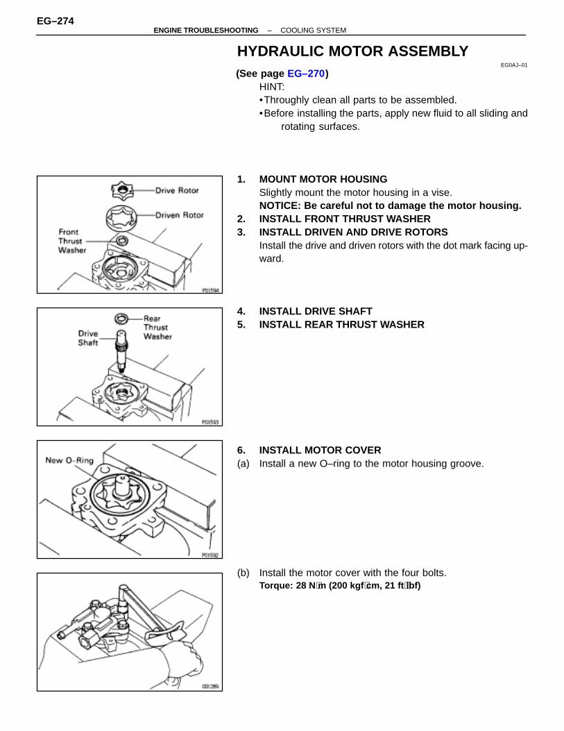
HYDRAULIC MOTOR ASSEMBLYEG0AJ–01
(See page EG–270)HINT:•Throughly clean all parts to be assembled.•Before installing the parts, apply new fluid to all sliding and
rotating surfaces.
1. MOUNT MOTOR HOUSINGSlightly mount the motor housing in a vise.NOTICE: Be careful not to damage the motor housing.
2. INSTALL FRONT THRUST WASHER3. INSTALL DRIVEN AND DRIVE ROTORS
Install the drive and driven rotors with the dot mark facing up-ward.
4. INSTALL DRIVE SHAFT5. INSTALL REAR THRUST WASHER
6. INSTALL MOTOR COVER(a) Install a new O–ring to the motor housing groove.
(b) Install the motor cover with the four bolts.Torque: 28 N ⋅m (200 kgf ⋅cm, 21 ft ⋅lbf)
EG–274–ENGINE TROUBLESHOOTING COOLING SYSTEM
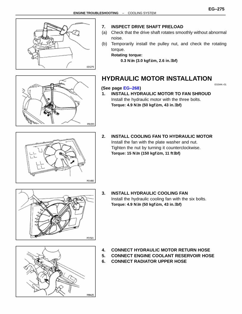
7. INSPECT DRIVE SHAFT PRELOAD(a) Check that the drive shaft rotates smoothly without abnormal
noise.(b) Temporarily install the pulley nut, and check the rotating
torque.Rotating torque:
0.3 N⋅m (3.0 kgf ⋅cm, 2.6 in. ⋅lbf)
HYDRAULIC MOTOR INSTALLATIONEG0AK–01
(See page EG–268)1. INSTALL HYDRAULIC MOTOR TO FAN SHROUD
Install the hydraulic motor with the three bolts.Torque: 4.9 N ⋅m (50 kgf ⋅cm, 43 in. ⋅lbf)
2. INSTALL COOLING FAN TO HYDRAULIC MOTORInstall the fan with the plate washer and nut.Tighten the nut by turning it counterclockwise.Torque: 15 N ⋅m (150 kgf ⋅cm, 11 ft ⋅lbf)
3. INSTALL HYDRAULIC COOLING FANInstall the hydraulic cooling fan with the six bolts.Torque: 4.9 N ⋅m (50 kgf ⋅cm, 43 in. ⋅lbf)
4. CONNECT HYDRAULIC MOTOR RETURN HOSE5. CONNECT ENGINE COOLANT RESERVOIR HOSE6. CONNECT RADIATOR UPPER HOSE
–ENGINE TROUBLESHOOTING COOLING SYSTEMEG–275
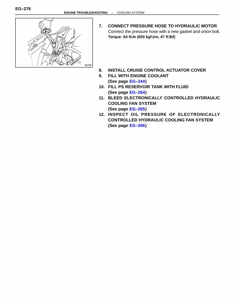
7. CONNECT PRESSURE HOSE TO HYDRAULIC MOTORConnect the pressure hose with a new gasket and union bolt.Torque: 64 N ⋅m (650 kgf ⋅cm, 47 ft ⋅lbf)
8. INSTALL CRUISE CONTROL ACTUATOR COVER9. FILL WITH ENGINE COOLANT
(See page EG–244)10. FILL PS RESERVOIR TANK WITH FLUID
(See page EG–264)11. BLEED ELECTRONICALLY CONTROLLED HYDRAULIC
COOLING FAN SYSTEM(See page EG–265)
12. INSPECT OIL PRESSURE OF ELECTRONICALLYCONTROLLED HYDRAULIC COOLING FAN SYSTEM(See page EG–266)
EG–276–ENGINE TROUBLESHOOTING COOLING SYSTEM
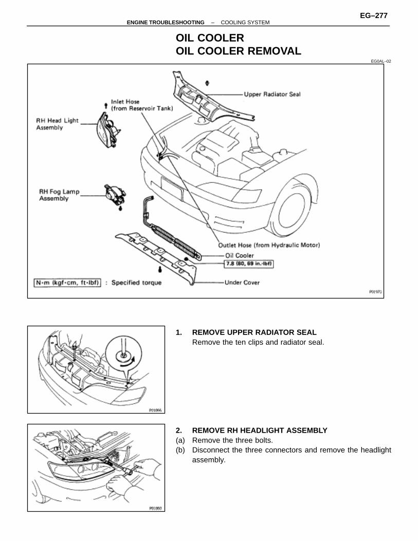
OIL COOLEROIL COOLER REMOVAL
EG0AL–02
1. REMOVE UPPER RADIATOR SEALRemove the ten clips and radiator seal.
2. REMOVE RH HEADLIGHT ASSEMBLY(a) Remove the three bolts.(b) Disconnect the three connectors and remove the headlight
assembly.
–ENGINE TROUBLESHOOTING COOLING SYSTEMEG–277

3. DISCONNECT HOSES FROM OIL COOLERDisconnect the following hoses:(1) Outlet hose (to reservoir tank)(2) Inlet hose (from hydraulic motor)
4. REMOVE UNDER COVERRemove the five bolts and under cover.
5. REMOVE RH FOG LAMP ASSEMBLY(a) Remove the two bolts.(b) Disconnect the connector and remove the fog lamp
assembly.
6. REMOVE OIL COOLER(a) Pull aside the shroud to expose the bolt in the stay. Remove
the bolt.
(b) Remove the two nuts and remove the oil cooler.
EG–278–ENGINE TROUBLESHOOTING COOLING SYSTEM
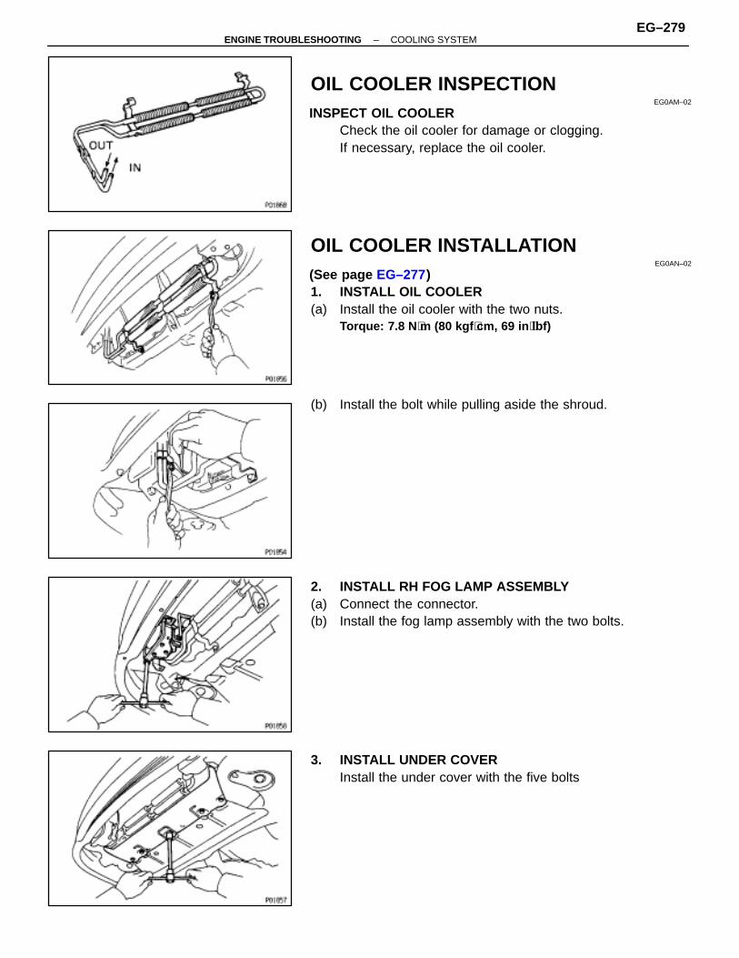
OIL COOLER INSPECTIONEG0AM–02
INSPECT OIL COOLERCheck the oil cooler for damage or clogging.If necessary, replace the oil cooler.
OIL COOLER INSTALLATIONEG0AN–02
(See page EG–277)1. INSTALL OIL COOLER(a) Install the oil cooler with the two nuts.
Torque: 7.8 N ⋅m (80 kgf ⋅cm, 69 in ⋅lbf)
(b) Install the bolt while pulling aside the shroud.
2. INSTALL RH FOG LAMP ASSEMBLY(a) Connect the connector.(b) Install the fog lamp assembly with the two bolts.
3. INSTALL UNDER COVERInstall the under cover with the five bolts
–ENGINE TROUBLESHOOTING COOLING SYSTEMEG–279

4. CONNECT HOSES TO OIL COOLERConnect the following hoses:(1) Outlet hose (to reservoir)(2) Inlet hose (from hydraulic motor)
5. INSTALL RH HEADLIGHT ASSEMBLY(a) Connect the three connectors.(b) Install the headlight assembly with the three bolts.
6. INSTALL UPPER RADIATOR SUPPORT SEALInstall the support seal with the ten clips.
7. FILL PS RESERVOIR TANK WITH FLUID(See page EG–264)
8. BLEED ELECTRONICALLY CONTROLLED HYDRAULICCOOLING FAN SYSTEM(See page EG–265)
EG–280–ENGINE TROUBLESHOOTING COOLING SYSTEM
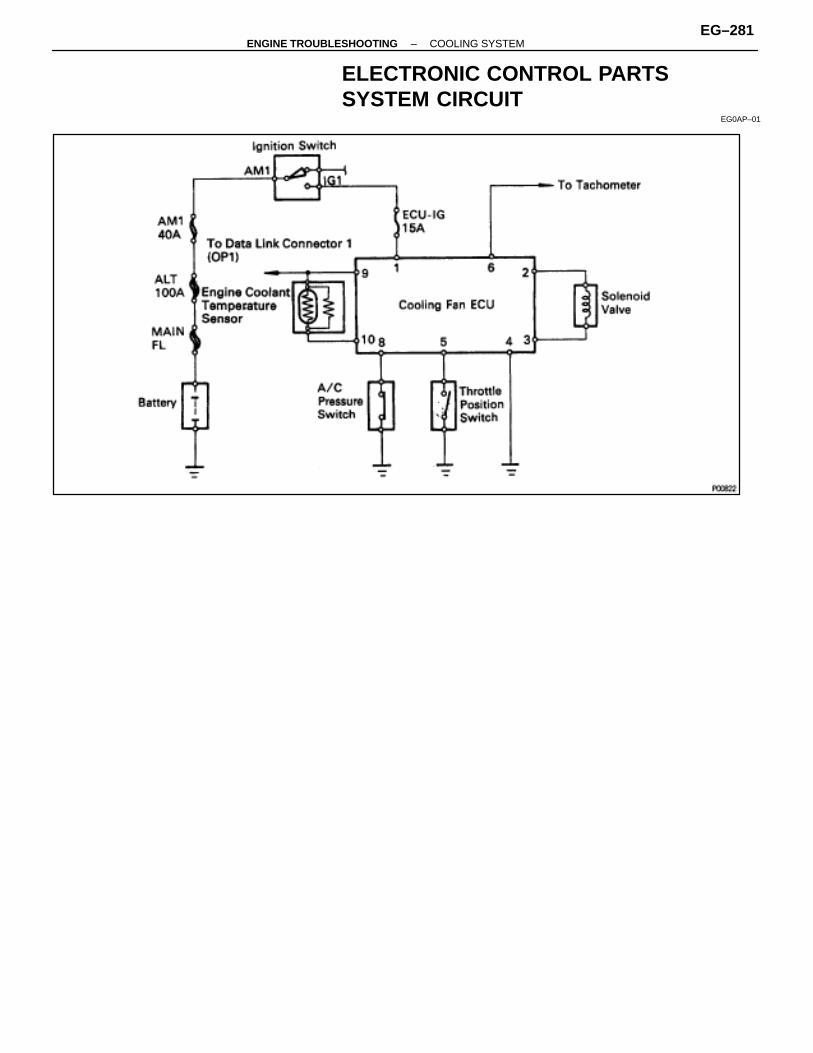
ELECTRONIC CONTROL PARTSSYSTEM CIRCUIT
EG0AP–01
–ENGINE TROUBLESHOOTING COOLING SYSTEMEG–281

COOLING FAN ECUCOOLING FAN ECU REMOVAL ANDINSTALLATION
EG0AQ–01
COOLING FAN ECU INSPECTIONEG0AR–01
INSPECT COOLING FAN ECUCheck the connector on the wiring harness side as shown inthe chart.
ÑÑÑÑÑÑÑÑÑÑÑÑÑÑÑÑ
Check forÑÑÑÑÑÑÑÑÑÑÑÑÑÑÑÑ
Tester connectionÑÑÑÑÑÑÑÑÑÑÑÑÑÑÑÑÑÑÑÑÑÑÑÑÑÑÑÑÑÑ
ConditionÑÑÑÑÑÑÑÑÑÑÑÑÑÑÑÑ
Specified valueÑÑÑÑÑÑÑÑÑÑÑÑÑÑÑÑ
Voltage ÑÑÑÑÑÑÑÑÑÑÑÑÑÑÑÑ
1–Ground ÑÑÑÑÑÑÑÑÑÑÑÑÑÑÑÑÑÑÑÑÑÑÑÑÑÑÑÑÑÑ
Ignition switch ON ÑÑÑÑÑÑÑÑÑÑÑÑÑÑÑÑ
Battery voltageÑÑÑÑÑÑÑÑÑÑÑÑÑÑÑÑ
Resistance ÑÑÑÑÑÑÑÑÑÑÑÑÑÑÑÑ
2–3 ÑÑÑÑÑÑÑÑÑÑÑÑÑÑÑÑÑÑÑÑÑÑÑÑÑÑÑÑÑÑ
Solenoid valve at cold (25°C (77°F)) ÑÑÑÑÑÑÑÑÑÑÑÑÑÑÑÑ
7.6�8.0 �ÑÑÑÑÑÑÑÑÑÑÑÑÑÑÑÑ
Continuity ÑÑÑÑÑÑÑÑÑÑÑÑÑÑÑÑ
4–Ground ÑÑÑÑÑÑÑÑÑÑÑÑÑÑÑÑÑÑÑÑÑÑÑÑÑÑÑÑÑÑ
– ÑÑÑÑÑÑÑÑÑÑÑÑÑÑÑÑ
Continuity
ÑÑÑÑÑÑÑÑContinuity ÑÑÑÑÑÑÑÑ5–Ground ÑÑÑÑÑÑÑÑÑÑÑÑÑÑÑThrottle valve open ÑÑÑÑÑÑÑÑNo continuityÑÑÑÑÑÑÑÑÑÑÑÑÑÑÑÑ
y ÑÑÑÑÑÑÑÑÑÑÑÑÑÑÑÑ
ÑÑÑÑÑÑÑÑÑÑÑÑÑÑÑÑÑÑÑÑÑÑÑÑÑÑÑÑÑÑThrottle valve closed
ÑÑÑÑÑÑÑÑÑÑÑÑÑÑÑÑContinuityÑÑÑÑÑÑÑÑ
ÑÑÑÑÑÑÑÑContinuity ÑÑÑÑÑÑÑÑ
ÑÑÑÑÑÑÑÑ8–Ground ÑÑÑÑÑÑÑÑÑÑÑÑÑÑÑ
ÑÑÑÑÑÑÑÑÑÑÑÑÑÑÑA/C pressure SW connector disconnected ÑÑÑÑÑÑÑÑ
ÑÑÑÑÑÑÑÑNo continuity
ÑÑÑÑÑÑÑÑÑÑÑÑÑÑÑÑ
yÑÑÑÑÑÑÑÑÑÑÑÑÑÑÑÑ
ÑÑÑÑÑÑÑÑÑÑÑÑÑÑÑÑÑÑÑÑÑÑÑÑÑÑÑÑÑÑ
A/C pressure SW connector connected ÑÑÑÑÑÑÑÑÑÑÑÑÑÑÑÑ
ContinuityÑÑÑÑÑÑÑÑÑÑÑÑÑÑÑÑ
Resistance ÑÑÑÑÑÑÑÑÑÑÑÑÑÑÑÑ
9–10 ÑÑÑÑÑÑÑÑÑÑÑÑÑÑÑÑÑÑÑÑÑÑÑÑÑÑÑÑÑÑ
Engine coolant temperature at 80°C (176°F) ÑÑÑÑÑÑÑÑÑÑÑÑÑÑÑÑ
1.48–1.58 k�
EG–282–ENGINE TROUBLESHOOTING COOLING SYSTEM
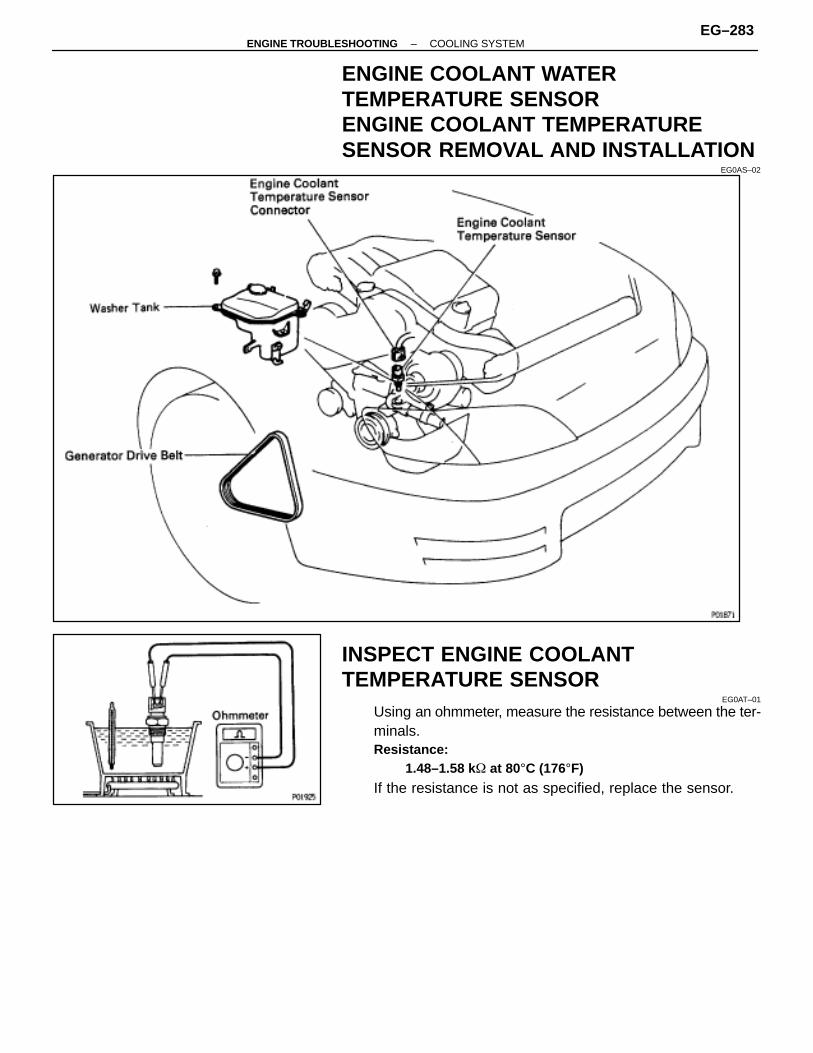
ENGINE COOLANT WATERTEMPERATURE SENSORENGINE COOLANT TEMPERATURESENSOR REMOVAL AND INSTALLATION
EG0AS–02
INSPECT ENGINE COOLANTTEMPERATURE SENSOR
EG0AT–01
Using an ohmmeter, measure the resistance between the ter-minals.Resistance:
1.48–1.58 k� at 80°C (176°F)
If the resistance is not as specified, replace the sensor.
–ENGINE TROUBLESHOOTING COOLING SYSTEMEG–283
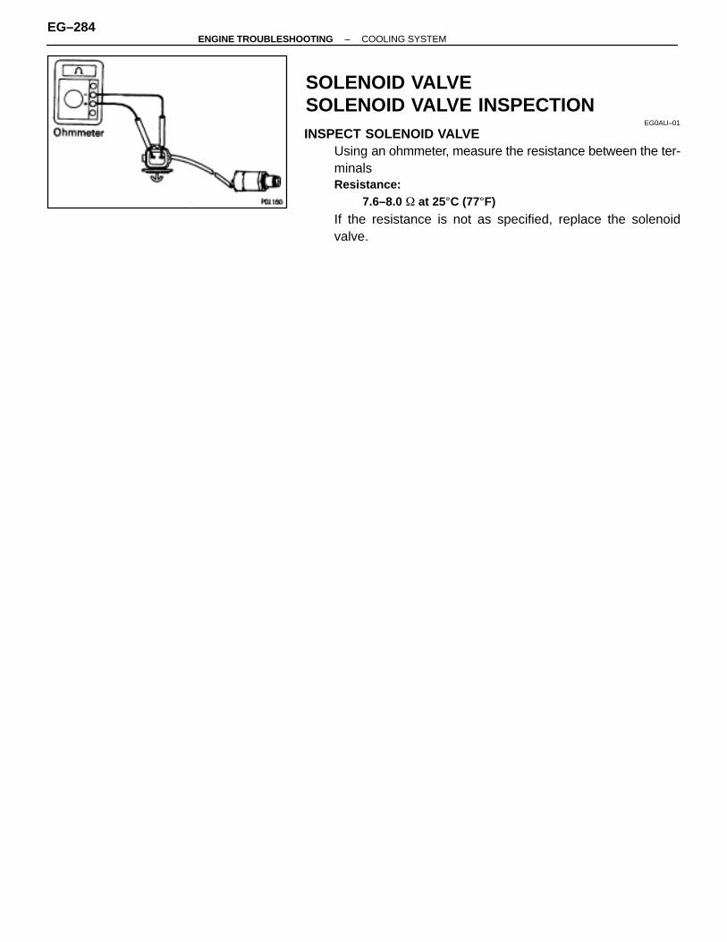
SOLENOID VALVESOLENOID VALVE INSPECTION
EG0AU–01
INSPECT SOLENOID VALVEUsing an ohmmeter, measure the resistance between the ter-minalsResistance:
7.6–8.0 � at 25°C (77°F)
If the resistance is not as specified, replace the solenoidvalve.
EG–284–ENGINE TROUBLESHOOTING COOLING SYSTEM
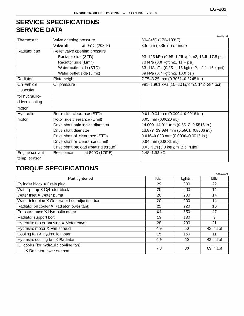
SERVICE SPECIFICATIONSSERVICE DATA
EG0AV–01
ÑÑÑÑÑÑÑÑÑÑÑÑÑÑ
Thermostat ÑÑÑÑÑÑÑÑÑÑÑÑÑÑÑÑÑÑÑÑÑÑÑÑÑÑÑÑÑÑ
Valve opening pressure ÑÑÑÑÑÑÑÑÑÑÑÑÑÑÑÑÑÑÑÑÑÑÑÑÑÑÑÑÑÑÑÑ
80–84°C (176–183°F)
ÑÑÑÑÑÑÑÑÑÑÑÑÑÑÑÑÑÑÑÑÑÑValve lift at 95°C (203°F) ÑÑÑÑÑÑÑÑÑÑÑÑÑÑÑÑ8.5 mm (0.35 in.) or moreÑÑÑÑÑÑÑÑÑÑÑÑÑÑRadiator cap
ÑÑÑÑÑÑÑÑÑÑÑÑÑÑÑÑÑÑÑÑÑÑÑÑÑÑÑÑÑÑRelief valve opening pressure
ÑÑÑÑÑÑÑÑÑÑÑÑÑÑÑÑÑÑÑÑÑÑÑÑÑÑÑÑÑÑÑÑÑÑÑÑÑÑÑ
ÑÑÑÑÑÑÑÑÑÑÑÑÑÑÑÑÑÑÑÑÑÑÑÑÑÑÑÑÑÑÑÑÑÑÑÑÑ
Radiator side (STD)ÑÑÑÑÑÑÑÑÑÑÑÑÑÑÑÑÑÑÑÑÑÑÑÑÑÑÑÑÑÑÑÑ
93–123 kPa (0.95–1.25 kgfcm2, 13.5–17.8 psi)ÑÑÑÑÑÑÑÑÑÑÑÑÑÑ
ÑÑÑÑÑÑÑÑÑÑÑÑÑÑÑÑÑÑÑÑÑÑÑÑÑÑÑÑÑÑ
Radiator side (Limit) ÑÑÑÑÑÑÑÑÑÑÑÑÑÑÑÑÑÑÑÑÑÑÑÑÑÑÑÑÑÑÑÑ
78 kPa (0.8 kgfcm2, 11.4 psi)ÑÑÑÑÑÑÑÑÑÑÑÑÑÑ
ÑÑÑÑÑÑÑÑÑÑÑÑÑÑÑÑÑÑÑÑÑÑÑÑÑÑÑÑÑÑ
Water outlet side (STD) ÑÑÑÑÑÑÑÑÑÑÑÑÑÑÑÑÑÑÑÑÑÑÑÑÑÑÑÑÑÑÑÑ
83–113 kPa (0.85–1.15 kgfcm2, 12.1–16.4 psi)ÑÑÑÑÑÑÑÑÑÑÑÑÑÑ
ÑÑÑÑÑÑÑÑÑÑÑÑÑÑÑÑÑÑÑÑÑÑÑÑÑÑÑÑÑÑ
Water outlet side (Limit) ÑÑÑÑÑÑÑÑÑÑÑÑÑÑÑÑÑÑÑÑÑÑÑÑÑÑÑÑÑÑÑÑ
69 kPa (0.7 kgfcm2, 10.0 psi)ÑÑÑÑÑÑÑÑÑÑÑÑÑÑ
Radiator ÑÑÑÑÑÑÑÑÑÑÑÑÑÑÑÑÑÑÑÑÑÑÑÑÑÑÑÑÑÑ
Plate height ÑÑÑÑÑÑÑÑÑÑÑÑÑÑÑÑÑÑÑÑÑÑÑÑÑÑÑÑÑÑÑÑ
7.75–8.25 mm (0.3051–0.3248 in.)ÑÑÑÑÑÑÑÑÑÑÑÑÑÑ
On–vehicle ÑÑÑÑÑÑÑÑÑÑÑÑÑÑÑÑÑÑÑÑÑÑÑÑÑÑÑÑÑÑ
Oil pressure ÑÑÑÑÑÑÑÑÑÑÑÑÑÑÑÑÑÑÑÑÑÑÑÑÑÑÑÑÑÑÑÑ
981–1,961 kPa (10–20 kgfcm2, 142–284 psi)
ÑÑÑÑÑÑÑÑÑÑÑÑÑÑ
inspection
ÑÑÑÑÑÑÑÑÑÑÑÑÑÑ
for hydraulic– ÑÑÑÑÑÑÑÑÑÑÑÑÑÑÑÑÑÑÑÑÑÑÑÑÑÑÑÑÑÑ
ÑÑÑÑÑÑÑÑÑÑÑÑÑÑÑÑÑÑÑÑÑÑÑÑÑÑÑÑÑÑÑÑÑÑÑÑÑÑÑ
ÑÑÑÑÑÑÑdriven cooling
ÑÑÑÑÑÑÑÑÑÑÑÑÑÑ
motor ÑÑÑÑÑÑÑÑÑÑÑÑÑÑÑÑÑÑÑÑÑÑÑÑÑÑÑÑÑÑ
ÑÑÑÑÑÑÑÑÑÑÑÑÑÑÑÑÑÑÑÑÑÑÑÑÑÑÑÑÑÑÑÑÑÑÑÑÑÑÑ
ÑÑÑÑÑÑÑHydraulic ÑÑÑÑÑÑÑÑÑÑÑÑÑÑÑ
ÑÑÑÑÑÑÑÑÑÑÑÑÑÑÑRotor side clearance (STD) ÑÑÑÑÑÑÑÑÑÑÑÑÑÑÑÑ
ÑÑÑÑÑÑÑÑÑÑÑÑÑÑÑÑ0.01–0.04 mm (0.0004–0.0016 in.)
ÑÑÑÑÑÑÑmotor ÑÑÑÑÑÑÑÑÑÑÑÑÑÑÑRotor side clearance (Limit) ÑÑÑÑÑÑÑÑÑÑÑÑÑÑÑÑ0.05 mm (0.0020 in.)ÑÑÑÑÑÑÑÑÑÑÑÑÑÑ
ÑÑÑÑÑÑÑÑÑÑÑÑÑÑÑÑÑÑÑÑÑÑÑÑÑÑÑÑÑÑDrive shaft hole inside diameter
ÑÑÑÑÑÑÑÑÑÑÑÑÑÑÑÑÑÑÑÑÑÑÑÑÑÑÑÑÑÑÑÑ14.000–14.011 mm (0.5512–0.5516 in.)ÑÑÑÑÑÑÑ
ÑÑÑÑÑÑÑÑÑÑÑÑÑÑÑÑÑÑÑÑÑÑÑÑÑÑÑÑÑÑÑÑÑÑÑÑÑDrive shaft diameter
ÑÑÑÑÑÑÑÑÑÑÑÑÑÑÑÑÑÑÑÑÑÑÑÑÑÑÑÑÑÑÑÑ13.973–13.984 mm (0.5501–0.5506 in.)
ÑÑÑÑÑÑÑÑÑÑÑÑÑÑ
ÑÑÑÑÑÑÑÑÑÑÑÑÑÑÑÑÑÑÑÑÑÑÑÑÑÑÑÑÑÑ
Drive shaft oil clearance (STD)ÑÑÑÑÑÑÑÑÑÑÑÑÑÑÑÑÑÑÑÑÑÑÑÑÑÑÑÑÑÑÑÑ
0.016–0.038 mm (0.0006–0.0015 in.)ÑÑÑÑÑÑÑÑÑÑÑÑÑÑ
ÑÑÑÑÑÑÑÑÑÑÑÑÑÑÑÑÑÑÑÑÑÑÑÑÑÑÑÑÑÑ
Drive shaft oil clearance (Limit) ÑÑÑÑÑÑÑÑÑÑÑÑÑÑÑÑÑÑÑÑÑÑÑÑÑÑÑÑÑÑÑÑ
0.04 mm (0.0031 in.)ÑÑÑÑÑÑÑÑÑÑÑÑÑÑ
ÑÑÑÑÑÑÑÑÑÑÑÑÑÑÑÑÑÑÑÑÑÑÑÑÑÑÑÑÑÑ
Drive shaft preload (rotating torque) ÑÑÑÑÑÑÑÑÑÑÑÑÑÑÑÑÑÑÑÑÑÑÑÑÑÑÑÑÑÑÑÑ
0.03 N⋅m (3.0 kgf⋅cm, 2.6 in.⋅lbf)ÑÑÑÑÑÑÑÑÑÑÑÑÑÑ
Engine coolant ÑÑÑÑÑÑÑÑÑÑÑÑÑÑÑÑÑÑÑÑÑÑÑÑÑÑÑÑÑÑ
Resistance at 80°C (176°F) ÑÑÑÑÑÑÑÑÑÑÑÑÑÑÑÑÑÑÑÑÑÑÑÑÑÑÑÑÑÑÑÑ
1.48–1.58 k�ÑÑÑÑÑÑÑÑÑÑÑÑÑÑ
temp. sensor
TORQUE SPECIFICATIONSEG0AW–01ÑÑÑÑÑÑÑÑÑÑÑÑÑÑÑÑÑÑÑÑÑÑ
ÑÑÑÑÑÑÑÑÑÑÑÑÑÑÑÑÑÑÑÑÑÑPart tightened ÑÑÑÑÑÑ
ÑÑÑÑÑÑN⋅m ÑÑÑÑÑ
ÑÑÑÑÑkgf⋅cm ÑÑÑÑÑÑ
ÑÑÑÑÑÑft⋅lbf
ÑÑÑÑÑÑÑÑÑÑÑÑÑÑÑÑÑÑÑÑÑÑÑÑÑÑÑÑÑÑÑÑÑÑÑÑÑÑÑÑÑÑÑÑ
Cylinder block X Drain plug ÑÑÑÑÑÑÑÑÑÑÑÑ
29 ÑÑÑÑÑÑÑÑÑÑ
300 ÑÑÑÑÑÑÑÑÑÑÑÑ
22ÑÑÑÑÑÑÑÑÑÑÑÑÑÑÑÑÑÑÑÑÑÑÑÑÑÑÑÑÑÑÑÑÑÑÑÑÑÑÑÑÑÑÑÑ
Water pump X Cylinder block ÑÑÑÑÑÑÑÑÑÑÑÑ
20 ÑÑÑÑÑÑÑÑÑÑ
200 ÑÑÑÑÑÑÑÑÑÑÑÑ
14ÑÑÑÑÑÑÑÑÑÑÑÑÑÑÑÑÑÑÑÑÑÑÑÑÑÑÑÑÑÑÑÑÑÑÑÑÑÑÑÑÑÑÑÑ
Water inlet X Water pump ÑÑÑÑÑÑÑÑÑÑÑÑ
20 ÑÑÑÑÑÑÑÑÑÑ
200 ÑÑÑÑÑÑÑÑÑÑÑÑ
14ÑÑÑÑÑÑÑÑÑÑÑÑÑÑÑÑÑÑÑÑÑÑÑÑÑÑÑÑÑÑÑÑÑÑÑÑÑÑÑÑÑÑÑÑ
Water inlet pipe X Generator belt adjusting bar ÑÑÑÑÑÑÑÑÑÑÑÑ
20 ÑÑÑÑÑÑÑÑÑÑ
200 ÑÑÑÑÑÑÑÑÑÑÑÑ
14
ÑÑÑÑÑÑÑÑÑÑÑÑÑÑÑÑÑÑÑÑÑÑÑÑÑÑÑÑÑÑÑÑÑÑÑÑÑÑÑÑÑÑÑÑ
Radiator oil cooler X Radiator lower tank ÑÑÑÑÑÑÑÑÑÑÑÑ
22 ÑÑÑÑÑÑÑÑÑÑ
220 ÑÑÑÑÑÑÑÑÑÑÑÑ
16
ÑÑÑÑÑÑÑÑÑÑÑÑÑÑÑÑÑÑÑÑÑÑÑÑÑÑÑÑÑÑÑÑÑÑÑÑÑÑÑÑÑÑÑÑ
Pressure hose X Hydraulic motor ÑÑÑÑÑÑÑÑÑÑÑÑ
64 ÑÑÑÑÑÑÑÑÑÑ
650 ÑÑÑÑÑÑÑÑÑÑÑÑ
47
ÑÑÑÑÑÑÑÑÑÑÑÑÑÑÑÑÑÑÑÑÑÑRadiator support bolt ÑÑÑÑÑÑ13 ÑÑÑÑÑ130 ÑÑÑÑÑÑ9ÑÑÑÑÑÑÑÑÑÑÑÑÑÑÑÑÑÑÑÑÑÑÑÑÑÑÑÑÑÑÑÑÑÑÑÑÑÑÑÑÑÑÑÑHydraulic motor housing X Motor cover
ÑÑÑÑÑÑÑÑÑÑÑÑ28
ÑÑÑÑÑÑÑÑÑÑ290
ÑÑÑÑÑÑÑÑÑÑÑÑ21ÑÑÑÑÑÑÑÑÑÑÑÑÑÑÑÑÑÑÑÑÑÑ
ÑÑÑÑÑÑÑÑÑÑÑÑÑÑÑÑÑÑÑÑÑÑHydraulic motor X Fan shroudÑÑÑÑÑÑÑÑÑÑÑÑ4.9
ÑÑÑÑÑÑÑÑÑÑ50
ÑÑÑÑÑÑÑÑÑÑÑÑ43 in.⋅lbfÑÑÑÑÑÑÑÑÑÑÑÑÑÑÑÑÑÑÑÑÑÑ
ÑÑÑÑÑÑÑÑÑÑÑÑÑÑÑÑÑÑÑÑÑÑCooling fan X Hydraulic motor
ÑÑÑÑÑÑÑÑÑÑÑÑ
15ÑÑÑÑÑÑÑÑÑÑ
150ÑÑÑÑÑÑÑÑÑÑÑÑ
11ÑÑÑÑÑÑÑÑÑÑÑÑÑÑÑÑÑÑÑÑÑÑÑÑÑÑÑÑÑÑÑÑÑÑÑÑÑÑÑÑÑÑÑÑ
Hydraulic cooling fan X Radiator ÑÑÑÑÑÑÑÑÑÑÑÑ
4.9 ÑÑÑÑÑÑÑÑÑÑ
50 ÑÑÑÑÑÑÑÑÑÑÑÑ
43 in.⋅lbfÑÑÑÑÑÑÑÑÑÑÑÑÑÑÑÑÑÑÑÑÑÑÑÑÑÑÑÑÑÑÑÑÑÑÑÑÑÑÑÑÑÑÑÑ
Oil cooler (for hydraulic cooling fan)7 8 80 69 in ⋅lbfÑÑÑÑÑÑÑÑÑÑÑÑÑÑÑÑÑÑÑÑÑÑ
ÑÑÑÑÑÑÑÑÑÑÑÑÑÑÑÑÑÑÑÑÑÑ X Radiator lower support
7.8 80 69 in.⋅lbf
–ENGINE TROUBLESHOOTING COOLING SYSTEMEG–285

LUBRICATION SYSTEMDESCRIPTION
EG090–01
A fully pressurized, fully filtered lubrication system has been adopted for this engine.
EG–286–ENGINE TROUBLESHOOTING LUBRICATION SYSTEM
A pressure feeding lubrication system has been adopted to supply oil to the moving parts of this engine.The lubrication system consists of an oil pan, oil pump, oil filter and other external parts which supply oilto the moving parts in the engine block. The oil circuit is shown in the illustration at the top of the previouspage. Oil from the oil pan is pumped up by the oil pump. After it passes through the oil filter, it is fed throughthe various oil holes in the crankshaft and cylinder block. After passing through the cylinder block and per-forming its lubricating function, the oil is returned by gravity to the oil pan. A dipstick on the center left sideof the cylinder block is provided to check the oil level.
OIL PUMPThe oil pump pumps up oil from the oil pan and feeds it under pressure to the various parts of the engine.An oil strainer is mounted in front of the inlet to the oil pump. The oil pump itself is a trochoid type pump,inside of which there is a drive rotor and a driven rotor. When the drive rotor rotates, the driven rotor rotatesin the same direction, and since the axis of the drive rotor shaft is different from the center of the drivenrotor, the space between the two rotors is changes as they rotate. Oil is drawn in when the space is wideand is discharged when the space in narrow.
OIL PRESSURE REGULATORAt high engine speeds, the engine oil supplied by the oil pump exceeds the capacity of the engine to utilizeit. For that reason, the oil pressure regulator works to prevent an oversupply of oil. During normal oil supply,a coil spring and valve keep the bypass closed, but when too much oil is being fed, the pressure becomeextremely high, overpowering the force of the spring and opening the valves. This allows the excess oilto flow through the relief valve and return to the oil pan.
OIL FILTERThe oil filter is a full flow type filter with a built–in paper filter element. Particles of metal from wear, air bornedirt, carbon and other impurities can get into the oil during use a could cause accelerated wear or sizingif allowed to circulate through the engine. The oil filter, integrated into the oil line, removes these impuritiesas the oil passes through it. The filter is mounted outside the engine to simplify replacement of the filterelement. A relief valve is also included ahead of the filter element to relieve the high oil pressure in casethat the filter element becomes clogged with impurities. The relief valve opens when the oil pressure over-powers the force of the spring. Oil passing through the relief valve by–passes the oil filter and flows directlyinto the main oil hole in the engine.
–ENGINE TROUBLESHOOTING LUBRICATION SYSTEMEG–287
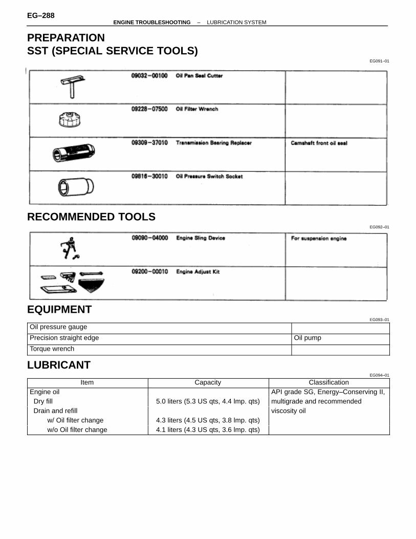
PREPARATIONSST (SPECIAL SERVICE TOOLS)
EG091–01
RECOMMENDED TOOLSEG092–01
EQUIPMENTEG093–01ÑÑÑÑÑÑÑÑÑÑÑÑÑÑÑÑÑÑÑÑÑÑÑÑÑÑ
ÑÑÑÑÑÑÑÑÑÑÑÑÑÑÑÑÑÑÑÑÑÑÑÑÑÑOil pressure gauge
ÑÑÑÑÑÑÑÑÑÑÑÑÑÑÑÑÑÑÑÑÑÑÑÑÑÑÑÑÑÑÑÑÑÑÑÑÑÑÑÑÑÑÑÑÑÑÑÑ
ÑÑÑÑÑÑÑÑÑÑÑÑÑÑÑÑÑÑÑÑÑÑÑÑÑÑPrecision straight edge Oil pumpÑÑÑÑÑÑÑÑÑÑÑÑÑÑÑÑÑÑÑÑÑÑÑÑÑÑÑÑÑÑÑÑÑÑÑÑÑÑÑÑÑÑÑÑÑÑÑÑÑÑÑÑÑÑÑÑÑÑÑÑÑÑÑÑÑÑÑÑÑÑÑÑÑÑÑÑÑÑ
Torque wrench
LUBRICANTEG094–01
ÑÑÑÑÑÑÑÑÑÑÑÑÑÑÑÑÑÑÑÑÑÑÑÑÑÑ
Item ÑÑÑÑÑÑÑÑÑÑÑÑÑÑÑÑÑÑÑÑÑÑÑÑ
Capacity ÑÑÑÑÑÑÑÑÑÑÑÑÑÑÑÑÑÑÑÑÑÑÑÑÑÑ
Classification
ÑÑÑÑÑÑÑÑÑÑÑÑÑEngine oil ÑÑÑÑÑÑÑÑÑÑÑÑÑÑÑÑÑÑÑÑÑÑÑÑÑAPI grade SG, Energy–Conserving II,ÑÑÑÑÑÑÑÑÑÑÑÑÑÑÑÑÑÑÑÑÑÑÑÑÑÑ Dry fill
ÑÑÑÑÑÑÑÑÑÑÑÑÑÑÑÑÑÑÑÑÑÑÑÑ5.0 liters (5.3 US qts, 4.4 lmp. qts)
ÑÑÑÑÑÑÑÑÑÑÑÑÑÑÑÑÑÑÑÑÑÑÑÑÑÑmultigrade and recommendedÑÑÑÑÑÑÑÑÑÑÑÑÑ
ÑÑÑÑÑÑÑÑÑÑÑÑÑ Drain and refillÑÑÑÑÑÑÑÑÑÑÑÑÑÑÑÑÑÑÑÑÑÑÑÑ
ÑÑÑÑÑÑÑÑÑÑÑÑÑÑÑÑÑÑÑÑÑÑÑÑÑÑviscosity oilÑÑÑÑÑÑÑÑÑÑÑÑÑ
ÑÑÑÑÑÑÑÑÑÑÑÑÑ w/ Oil filter change
ÑÑÑÑÑÑÑÑÑÑÑÑÑÑÑÑÑÑÑÑÑÑÑÑ
4.3 liters (4.5 US qts, 3.8 lmp. qts)ÑÑÑÑÑÑÑÑÑÑÑÑÑÑÑÑÑÑÑÑÑÑÑÑÑÑÑÑÑÑÑÑÑÑÑÑÑÑÑ
ÑÑÑÑÑÑÑÑÑÑÑÑÑ w/o Oil filter change ÑÑÑÑÑÑÑÑÑÑÑÑ
ÑÑÑÑÑÑÑÑÑÑÑÑ4.1 liters (4.3 US qts, 3.6 lmp. qts)ÑÑÑÑÑÑÑÑÑÑÑÑÑ
ÑÑÑÑÑÑÑÑÑÑÑÑÑ
EG–288–ENGINE TROUBLESHOOTING LUBRICATION SYSTEM
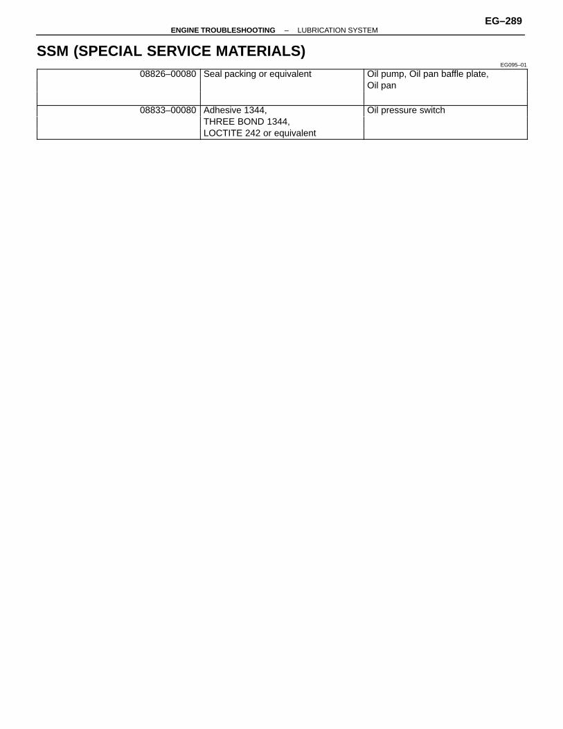
SSM (SPECIAL SERVICE MATERIALS)EG095–01ÑÑÑÑÑÑÑÑÑÑÑÑÑ
ÑÑÑÑÑÑÑÑÑÑÑÑÑ08826–00080
ÑÑÑÑÑÑÑÑÑÑÑÑÑÑÑÑÑÑÑÑÑÑÑÑ
Seal packing or equivalentÑÑÑÑÑÑÑÑÑÑÑÑÑÑÑÑÑÑÑÑÑÑÑÑÑÑ
Oil pump, Oil pan baffle plate,ÑÑÑÑÑÑÑÑÑÑÑÑÑÑÑÑÑÑÑÑÑÑÑÑÑÑ
ÑÑÑÑÑÑÑÑÑÑÑÑÑÑÑÑÑÑÑÑÑÑÑÑ
ÑÑÑÑÑÑÑÑÑÑÑÑÑÑÑÑÑÑÑÑÑÑÑÑÑÑ
Oil panÑÑÑÑÑÑÑÑÑÑÑÑÑÑÑÑÑÑÑÑÑÑÑÑÑÑÑÑÑÑÑÑÑÑÑÑÑÑÑÑÑÑÑÑÑÑÑÑÑÑÑÑ
08833–00080ÑÑÑÑÑÑÑÑÑÑÑÑÑÑÑÑÑÑÑÑÑÑÑÑ
Adhesive 1344, ÑÑÑÑÑÑÑÑÑÑÑÑÑÑÑÑÑÑÑÑÑÑÑÑÑÑ
Oil pressure switch
ÑÑÑÑÑÑÑÑÑÑÑÑÑÑÑÑÑÑÑÑÑÑÑÑÑÑ
ÑÑÑÑÑÑÑÑÑÑÑÑÑÑÑÑÑÑÑÑÑÑÑÑ
THREE BOND 1344, ÑÑÑÑÑÑÑÑÑÑÑÑÑÑÑÑÑÑÑÑÑÑÑÑÑÑÑÑÑÑÑÑÑÑÑÑÑÑÑÑÑÑÑÑÑÑÑÑÑÑÑLOCTITE 242 or equivalent ÑÑÑÑÑÑÑÑÑÑÑÑÑ
–ENGINE TROUBLESHOOTING LUBRICATION SYSTEMEG–289
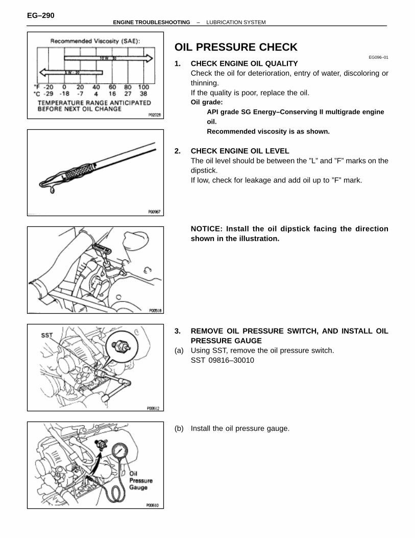
OIL PRESSURE CHECKEG096–01
1. CHECK ENGINE OIL QUALITYCheck the oil for deterioration, entry of water, discoloring orthinning.If the quality is poor, replace the oil.Oil grade:
API grade SG Energy–Conserving II multigrade engineoil.Recommended viscosity is as shown.
2. CHECK ENGINE OIL LEVELThe oil level should be between the ”L” and ”F” marks on thedipstick.If low, check for leakage and add oil up to ”F” mark.
NOTICE: Install the oil dipstick facing the directionshown in the illustration.
3. REMOVE OIL PRESSURE SWITCH, AND INSTALL OILPRESSURE GAUGE
(a) Using SST, remove the oil pressure switch.SST 09816–30010
(b) Install the oil pressure gauge.
EG–290–ENGINE TROUBLESHOOTING LUBRICATION SYSTEM

4. WARM UP ENGINEAllow the engine to warm up to normal operating tempera-ture.
5. CHECK OIL PRESSUREOil pressure:At idle
29 kPa (0.3 kgf/cm 2, 4.3 psi) or moreAt 3,000 rpm
294–539 kPa (3.0–5.5 kgf/cm 2, 43–78 psi)
6. REMOVE OIL PRESSURE GAUGE AND REINSTALL OILPRESSURE SWITCH
(a) Remove the oil pressure gauge.(b) Apply adhesive to two or three threads of the oil pressure
switch.Adhesive:Part No.08833–00080, THREE BOND 1344, LOCTITE 242 orequivalent
(c) Using SST, reinstall the oil pressure switch.SST 09816–30010Torque: 14 N ⋅m (150 kgf ⋅cm, 11 ft ⋅lbf)
7. START ENGINE AND CHECK FOR LEAKS
–ENGINE TROUBLESHOOTING LUBRICATION SYSTEMEG–291
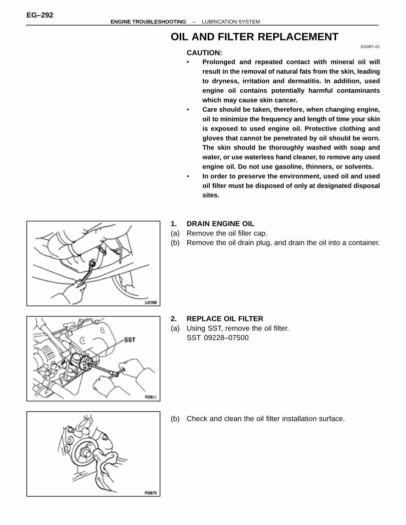
OIL AND FILTER REPLACEMENTEG097–01
CAUTION:• Prolonged and repeated contact with mineral oil will
result in the removal of natural fats from the skin, leadingto dryness, irritation and dermatitis. In addition, usedengine oil contains potentially harmful contaminantswhich may cause skin cancer.
• Care should be taken, therefore, when changing engine,oil to minimize the frequency and length of time your skinis exposed to used engine oil. Protective clothing andgloves that cannot be penetrated by oil should be worn.The skin should be thoroughly washed with soap andwater, or use waterless hand cleaner, to remove any usedengine oil. Do not use gasoline, thinners, or solvents.
• In order to preserve the environment, used oil and usedoil filter must be disposed of only at designated disposalsites.
1. DRAIN ENGINE OIL(a) Remove the oil filler cap.(b) Remove the oil drain plug, and drain the oil into a container.
2. REPLACE OIL FILTER(a) Using SST, remove the oil filter.
SST 09228–07500
(b) Check and clean the oil filter installation surface.
EG–292–ENGINE TROUBLESHOOTING LUBRICATION SYSTEM

(c) Apply clean engine oil to the gasket of a new oil filter.
(d) Lightly screw the oil filter into place, and tighten it until thegasket contacts the seat.
(e) Using SST, tighten it an additional 3/4 turn.SST 09228–07500
3. FILL WITH ENGINE OIL(a) Clean the install the oil drain plug with a new gasket.
Torque: 37 N ⋅m (375 kgf ⋅cm, 27 ft ⋅lbf)
(b) Fill with new engine oil (API grade SG Energy–conserving IImultigrade and recommended viscosity oil).Capacity:Drain and refillw/ Oil filter change
4.3 liters (4.5 US qts, 3.8 lmp.qts)w/o Oil filter change
4.1 liters (4.3 US qts, 3.6 lmp. qts)Dry fill
5.0 liters (5.3 US qts, 4.4 lmp. qts)
(c) Reinstall the oil filler cap.4. START ENGINE AND CHECK FOR LEAKS5. RECHECK ENGINE OIL LEVEL (See page EG–290)
–ENGINE TROUBLESHOOTING LUBRICATION SYSTEMEG–293

OIL PUMPOIL PUMP REMOVAL
EG098–02
HINT: When repairing the oil pump, the oil pan and strainershould be removed and cleaned.
1. DISCONNECT CABLE FROM NEGATIVE TERMINAL OFBATTERYCAUTION (w / Airbag): Work must be started afterapprox. 30 seconds or longer from the time the ignitionswitch is turned to the ”LOCK” position and the negative(–) terminal cable is disconnected from the battery.
2. REMOVE HOOD3. DRAIN ENGINE COOLANT4. DRAIN ENGINE OIL
EG–294–ENGINE TROUBLESHOOTING LUBRICATION SYSTEM
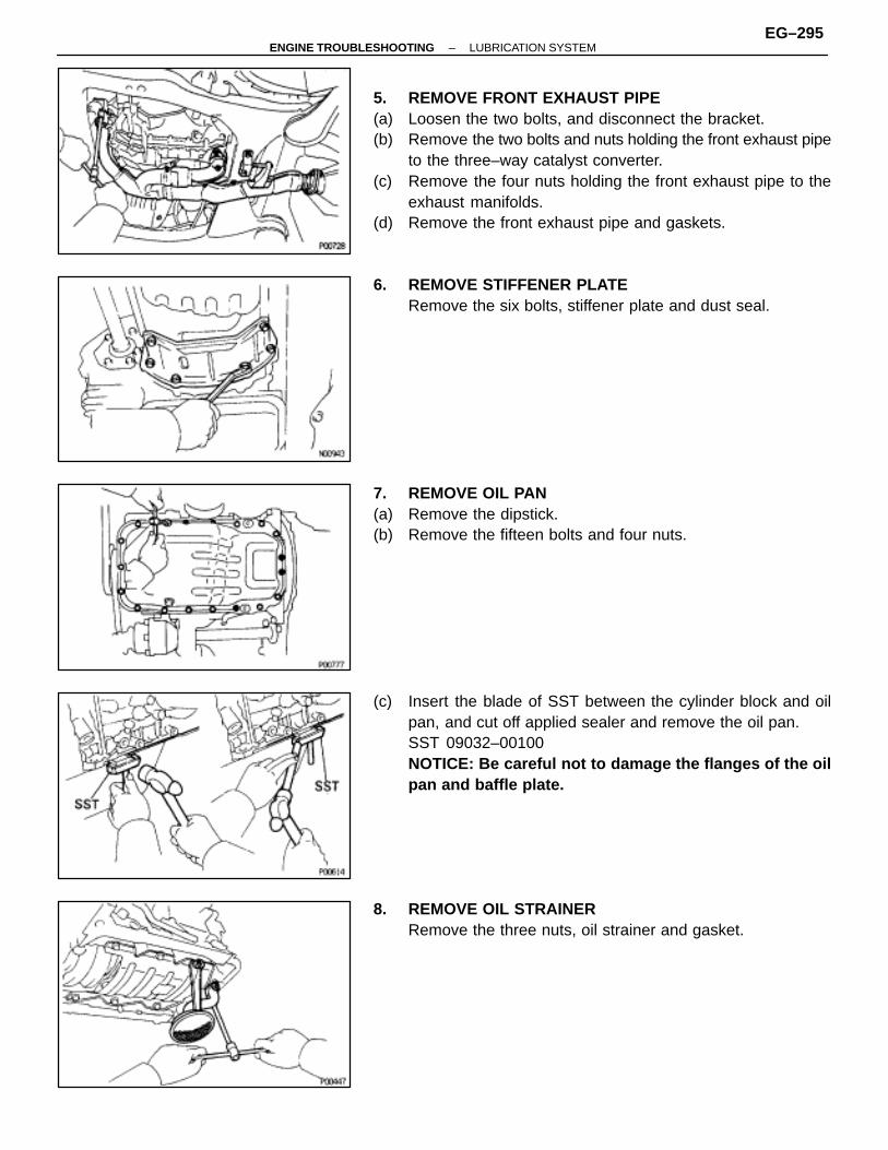
5. REMOVE FRONT EXHAUST PIPE(a) Loosen the two bolts, and disconnect the bracket.(b) Remove the two bolts and nuts holding the front exhaust pipe
to the three–way catalyst converter.(c) Remove the four nuts holding the front exhaust pipe to the
exhaust manifolds.(d) Remove the front exhaust pipe and gaskets.
6. REMOVE STIFFENER PLATERemove the six bolts, stiffener plate and dust seal.
7. REMOVE OIL PAN(a) Remove the dipstick.(b) Remove the fifteen bolts and four nuts.
(c) Insert the blade of SST between the cylinder block and oilpan, and cut off applied sealer and remove the oil pan.SST 09032–00100NOTICE: Be careful not to damage the flanges of the oilpan and baffle plate.
8. REMOVE OIL STRAINERRemove the three nuts, oil strainer and gasket.
–ENGINE TROUBLESHOOTING LUBRICATION SYSTEMEG–295
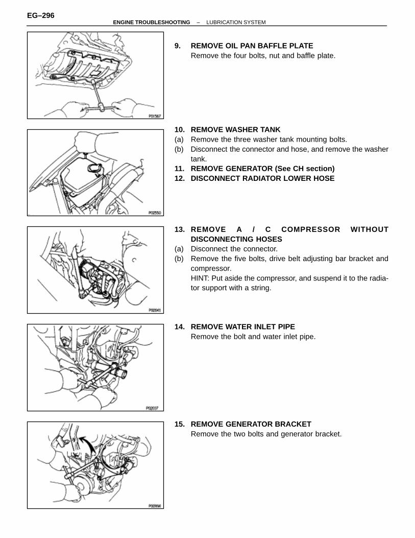
9. REMOVE OIL PAN BAFFLE PLATERemove the four bolts, nut and baffle plate.
10. REMOVE WASHER TANK(a) Remove the three washer tank mounting bolts.(b) Disconnect the connector and hose, and remove the washer
tank.11. REMOVE GENERATOR (See CH section)12. DISCONNECT RADIATOR LOWER HOSE
13. REMOVE A / C COMPRESSOR WITHOUTDISCONNECTING HOSES
(a) Disconnect the connector.(b) Remove the five bolts, drive belt adjusting bar bracket and
compressor.HINT: Put aside the compressor, and suspend it to the radia-tor support with a string.
14. REMOVE WATER INLET PIPERemove the bolt and water inlet pipe.
15. REMOVE GENERATOR BRACKETRemove the two bolts and generator bracket.
EG–296–ENGINE TROUBLESHOOTING LUBRICATION SYSTEM
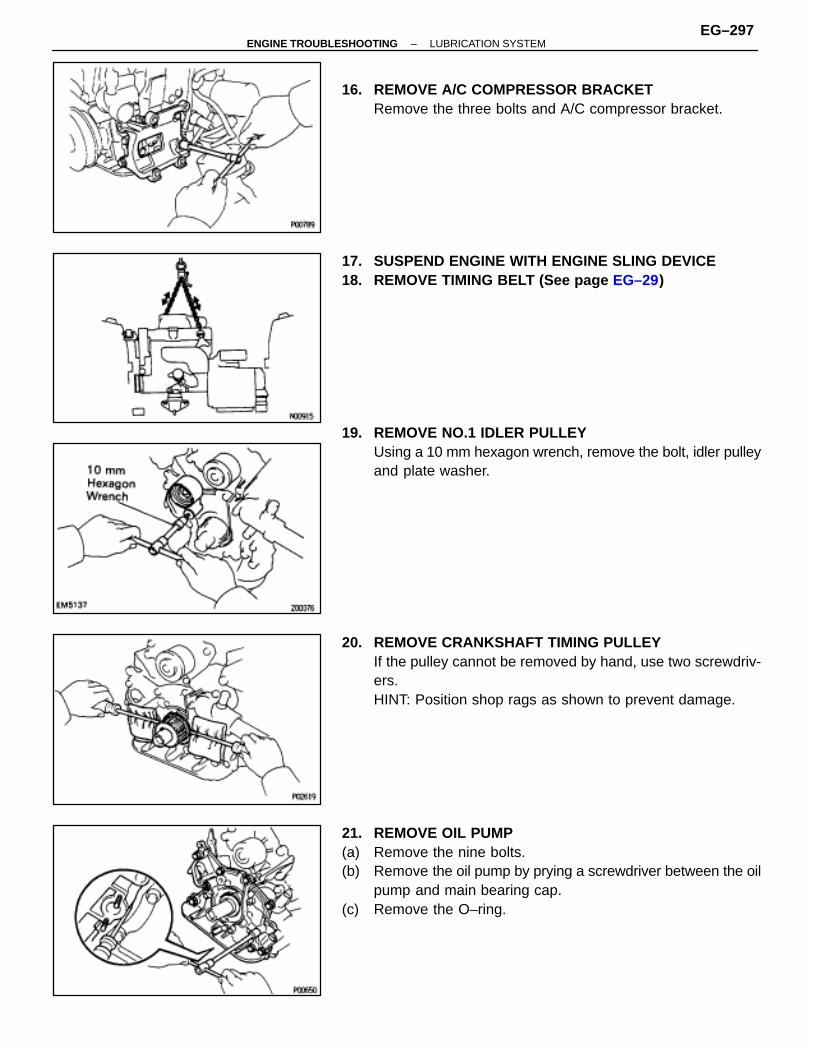
16. REMOVE A/C COMPRESSOR BRACKETRemove the three bolts and A/C compressor bracket.
17. SUSPEND ENGINE WITH ENGINE SLING DEVICE18. REMOVE TIMING BELT (See page EG–29)
19. REMOVE NO.1 IDLER PULLEYUsing a 10 mm hexagon wrench, remove the bolt, idler pulleyand plate washer.
20. REMOVE CRANKSHAFT TIMING PULLEYIf the pulley cannot be removed by hand, use two screwdriv-ers.HINT: Position shop rags as shown to prevent damage.
21. REMOVE OIL PUMP(a) Remove the nine bolts.(b) Remove the oil pump by prying a screwdriver between the oil
pump and main bearing cap.(c) Remove the O–ring.
–ENGINE TROUBLESHOOTING LUBRICATION SYSTEMEG–297
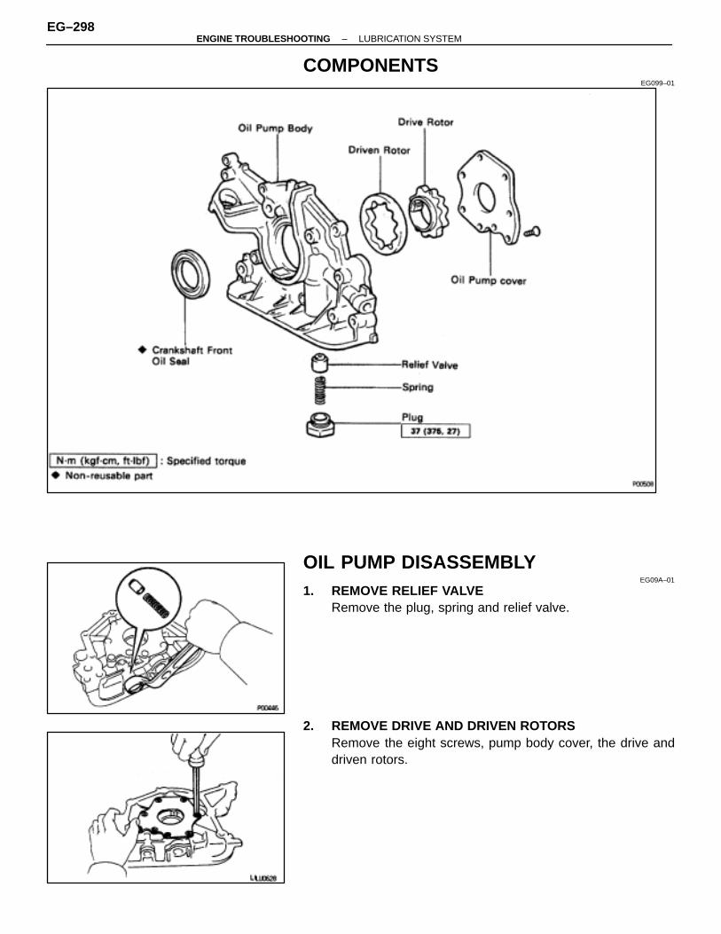
COMPONENTSEG099–01
OIL PUMP DISASSEMBLYEG09A–01
1. REMOVE RELIEF VALVERemove the plug, spring and relief valve.
2. REMOVE DRIVE AND DRIVEN ROTORSRemove the eight screws, pump body cover, the drive anddriven rotors.
EG–298–ENGINE TROUBLESHOOTING LUBRICATION SYSTEM

OIL PUMP INSPECTIONEG09B–01
1. INSPECT RELIEF VALVECoat the valve with engine oil and check that it falls smoothlyinto the valve hole by its own weight.If it does not, replace the relief valve. If necessary, replace theoil pump assembly.
2. INSPECT DRIVE AND DRIVEN ROTORSA. Inspect rotor body clearance
Using a thickness gauge, measure the clearance betweenthe driven rotor and body.Standard body clearance:
0.100–0.175 mm (0.0039–0.0069 in.)Maximum body clearance:
0.30 mm (0.0118 in.)
If the body clearance is greater than maximum, replace therotors as a set. If necessary, replace the oil pump assembly.
B. Inspect rotor side clearanceUsing a thickness gauge and precision straight edge, mea-sure the clearance between the rotors and precision straightedge.Standard side clearance:
0.030–0.090 mm (0.0012–0.0035 in.)Maximum side clearance:
0.15 mm (0.0059 in.)
If the side clearance is greater than maximum, replace the ro-tors as a set. If necessary, replace the oil pump assembly.
–ENGINE TROUBLESHOOTING LUBRICATION SYSTEMEG–299

C. Inspect rotor tip clearanceUsing thickness gauge, measure the clearance between thedrive and driven rotors.Standard tip clearance:
0.110–0.240 mm (0.0043–0.0094 in.)Maximum tip clearance:
0.35 mm (0.0138 in.)
If the tip clearance is greater than maximum, replace the ro-tors as a set.
CRANKSHAFT FRONT OIL SEALREPLACEMENT
EG09C–01
HINT: There are two methods (A and B) to replace the oil sealwhich are as follows:
REPLACE CRANKSHAFT FRONT OIL SEALA. If oil pump is removed from cylinder block:(a) Using a screwdriver, pry out the oil seal.
(b) Using SST and a hammer, tap in a new oil seal until its surfaceis flush with the oil pump case edge.SST 09309–37010
(c) Apply MP grease to the oil seal lip.
B. If oil pump is installed to the cylinder block:(a) Using a knife, cut off the oil seal lip.(b) Using a screwdriver, pry out the oil seal.
NOTICE: Be careful not to damage the crankshaft. Tapethe screwdriver tip.
EG–300–ENGINE TROUBLESHOOTING LUBRICATION SYSTEM
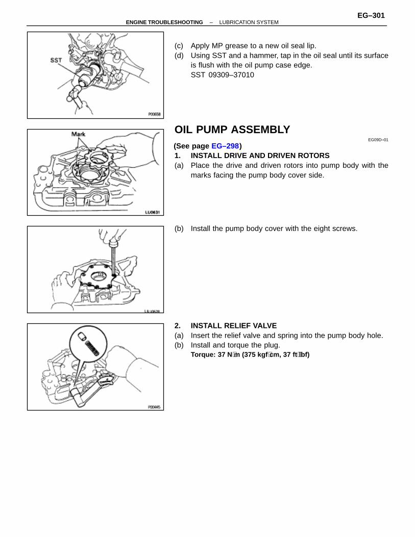
(c) Apply MP grease to a new oil seal lip.(d) Using SST and a hammer, tap in the oil seal until its surface
is flush with the oil pump case edge.SST 09309–37010
OIL PUMP ASSEMBLYEG09D–01
(See page EG–298)1. INSTALL DRIVE AND DRIVEN ROTORS(a) Place the drive and driven rotors into pump body with the
marks facing the pump body cover side.
(b) Install the pump body cover with the eight screws.
2. INSTALL RELIEF VALVE(a) Insert the relief valve and spring into the pump body hole.(b) Install and torque the plug.
Torque: 37 N ⋅m (375 kgf ⋅cm, 37 ft ⋅lbf)
–ENGINE TROUBLESHOOTING LUBRICATION SYSTEMEG–301
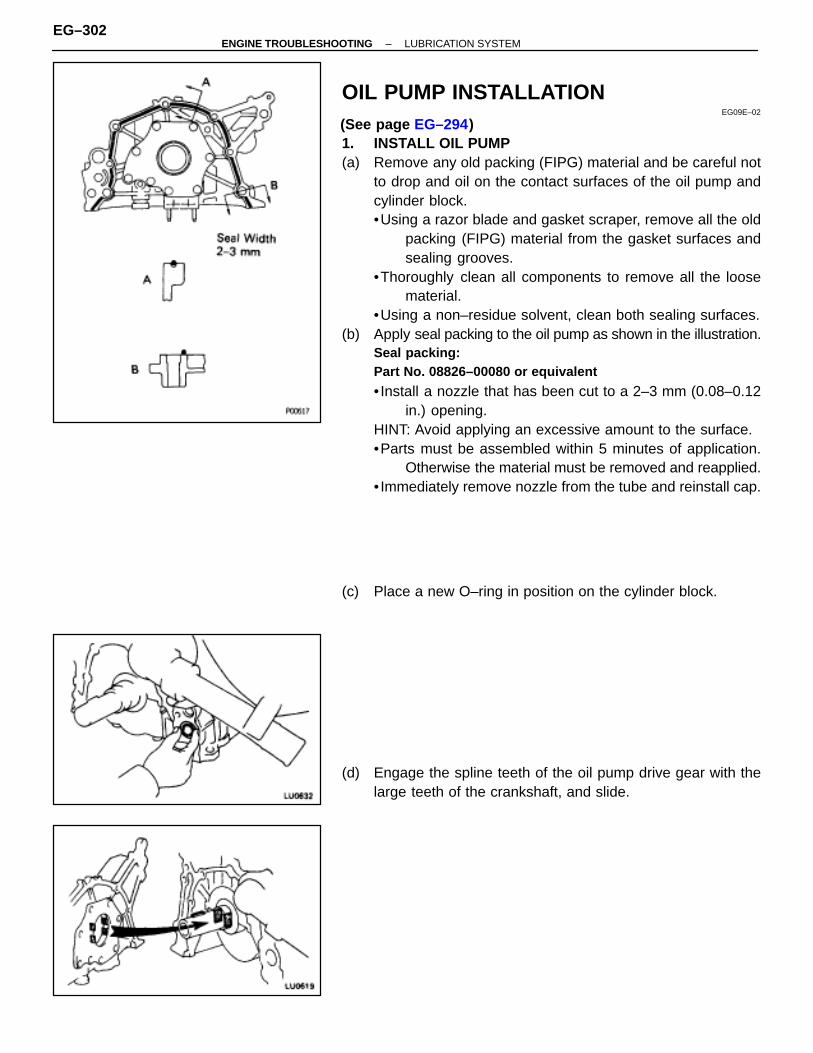
OIL PUMP INSTALLATIONEG09E–02
(See page EG–294)1. INSTALL OIL PUMP(a) Remove any old packing (FIPG) material and be careful not
to drop and oil on the contact surfaces of the oil pump andcylinder block.•Using a razor blade and gasket scraper, remove all the old
packing (FIPG) material from the gasket surfaces andsealing grooves.
•Thoroughly clean all components to remove all the loosematerial.
•Using a non–residue solvent, clean both sealing surfaces.(b) Apply seal packing to the oil pump as shown in the illustration.
Seal packing:Part No. 08826–00080 or equivalent
• Install a nozzle that has been cut to a 2–3 mm (0.08–0.12in.) opening.
HINT: Avoid applying an excessive amount to the surface.•Parts must be assembled within 5 minutes of application.
Otherwise the material must be removed and reapplied.• Immediately remove nozzle from the tube and reinstall cap.
(c) Place a new O–ring in position on the cylinder block.
(d) Engage the spline teeth of the oil pump drive gear with thelarge teeth of the crankshaft, and slide.
EG–302–ENGINE TROUBLESHOOTING LUBRICATION SYSTEM

(e) Install the oil pump with the nine bolts.12 mm head bolt (C and D)Torque: 20 N ⋅m (200 kgf ⋅cm, 14 ft ⋅lbf)14 mm head bolt (A and B)Torque: 41 N ⋅m (420 kgf ⋅cm, 30 ft ⋅lbf)
HINT: On vehicles with A/C, tighten bolt A together with theA/C bracket.
2. INSTALL CRANKSHAFT TIMING PULLEY(a) Align the pulley set key with the key groove of the timing
pulley.(b) Slide on the timing pulley, facing the flange side inward.
3. INSTALL NO.1 IDLER PULLEY(a) Apply adhesive to two or three threads of the mount bolt end.
Adhesive: Part No.08833–00080, THREE BOND 1344, LOCTITE242 or equivalent
(b) Using a 10 mm hexagon wrench, install the idler pulley withthe plate washer and bolt. Torque the bolt.Torque: 350 N ⋅m (25 kgf ⋅cm, 34 ft ⋅lbf)
(c) Check that the pulley bracket moves smoothly.4. INSTALL TIMING BELT (See page EG–29)5. REMOVE ENGINE SLING DEVICE FROM ENGINE
6. INSTALL A/C COMPRESSOR BRACKETInstall the A/C compressor bracket with the three bolts.
–ENGINE TROUBLESHOOTING LUBRICATION SYSTEMEG–303

7. INSTALL GENERATOR BRACKETInstall the generator bracket with the two bolts.
8. INSTALL WATER INLET PIPE(a) Install a new O–ring to the water inlet pipe.
(b) Install the water inlet with the the bolt.
9. INSTALL A/C COMPRESSOR(a) Install the A/C compressor and drive belt adjusting bar
bracket with the five bolts.(b) Connect the connector.10. CONNECT RADIATOR LOWER HOSE11. INSTALL GENERATOR (See CH section)
12. INSTALL WASHER TANK(a) Connect the connector and vinyl hose to the washer tank.(b) Install the washer tank with the three bolts.
EG–304–ENGINE TROUBLESHOOTING LUBRICATION SYSTEM
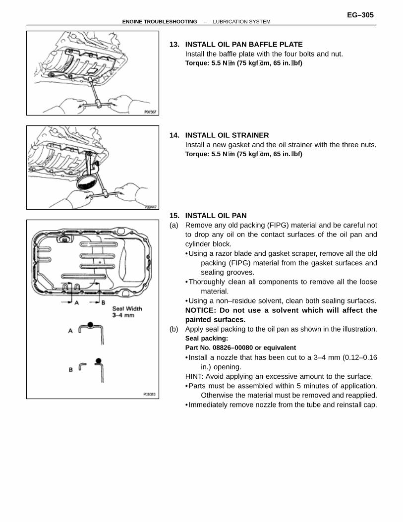
13. INSTALL OIL PAN BAFFLE PLATEInstall the baffle plate with the four bolts and nut.Torque: 5.5 N ⋅m (75 kgf ⋅cm, 65 in. ⋅lbf)
14. INSTALL OIL STRAINERInstall a new gasket and the oil strainer with the three nuts.Torque: 5.5 N ⋅m (75 kgf ⋅cm, 65 in. ⋅lbf)
15. INSTALL OIL PAN(a) Remove any old packing (FIPG) material and be careful not
to drop any oil on the contact surfaces of the oil pan andcylinder block.•Using a razor blade and gasket scraper, remove all the old
packing (FIPG) material from the gasket surfaces andsealing grooves.
•Thoroughly clean all components to remove all the loosematerial.
•Using a non–residue solvent, clean both sealing surfaces.NOTICE: Do not use a solvent which will affect thepainted surfaces.
(b) Apply seal packing to the oil pan as shown in the illustration.Seal packing:Part No. 08826–00080 or equivalent
• Install a nozzle that has been cut to a 3–4 mm (0.12–0.16in.) opening.
HINT: Avoid applying an excessive amount to the surface.•Parts must be assembled within 5 minutes of application.
Otherwise the material must be removed and reapplied.• Immediately remove nozzle from the tube and reinstall cap.
–ENGINE TROUBLESHOOTING LUBRICATION SYSTEMEG–305
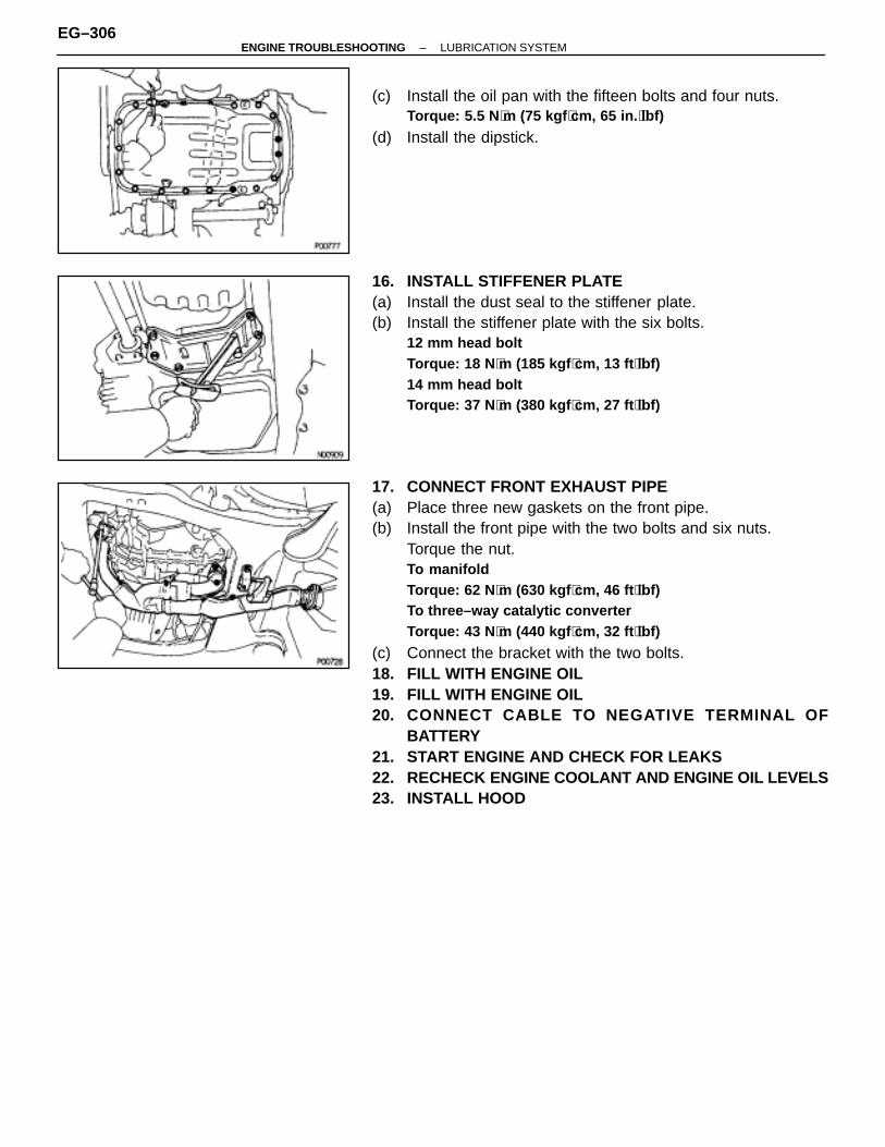
(c) Install the oil pan with the fifteen bolts and four nuts.Torque: 5.5 N ⋅m (75 kgf ⋅cm, 65 in. ⋅lbf)
(d) Install the dipstick.
16. INSTALL STIFFENER PLATE(a) Install the dust seal to the stiffener plate.(b) Install the stiffener plate with the six bolts.
12 mm head boltTorque: 18 N ⋅m (185 kgf ⋅cm, 13 ft ⋅lbf)14 mm head boltTorque: 37 N ⋅m (380 kgf ⋅cm, 27 ft ⋅lbf)
17. CONNECT FRONT EXHAUST PIPE(a) Place three new gaskets on the front pipe.(b) Install the front pipe with the two bolts and six nuts.
Torque the nut.To manifoldTorque: 62 N ⋅m (630 kgf ⋅cm, 46 ft ⋅lbf)To three–way catalytic converterTorque: 43 N ⋅m (440 kgf ⋅cm, 32 ft ⋅lbf)
(c) Connect the bracket with the two bolts.18. FILL WITH ENGINE OIL19. FILL WITH ENGINE OIL20. CONNECT CABLE TO NEGATIVE TERMINAL OF
BATTERY21. START ENGINE AND CHECK FOR LEAKS22. RECHECK ENGINE COOLANT AND ENGINE OIL LEVELS23. INSTALL HOOD
EG–306–ENGINE TROUBLESHOOTING LUBRICATION SYSTEM
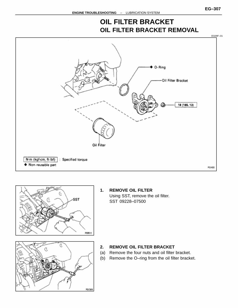
OIL FILTER BRACKETOIL FILTER BRACKET REMOVAL
EG09F–01
1. REMOVE OIL FILTERUsing SST, remove the oil filter.SST 09228–07500
2. REMOVE OIL FILTER BRACKET(a) Remove the four nuts and oil filter bracket.(b) Remove the O–ring from the oil filter bracket.
–ENGINE TROUBLESHOOTING LUBRICATION SYSTEMEG–307

OIL FILTER BRACKET INSTALLATIONEG09G–01
(See page EG–307)1. INSTALL OIL FILTER BRACKET(a) Install a new O–ring to the oil filter bracket.(b) Apply a light coat of engine oil on the O–ring.
(c) Install the oil filter bracket with the four nuts.Torque: 19 N ⋅m (195 kgf ⋅cm, 14 ft ⋅lbf)
2. INSTALL OIL FILTER(a) Clean the filter contact surface on the filter mounting.
(b) Lubricate the filter rubber gasket with engine oil.
(c) Tighten filter until the gasket contacts seat of the filtermounting. Then using SST, give it an additional 3/4 turn toseat the filter.SST 09228–07500
3. START ENGINE AND CHECK FOR LEAKS4. CHECK ENGINE OIL LEVEL
EG–308–ENGINE TROUBLESHOOTING LUBRICATION SYSTEM
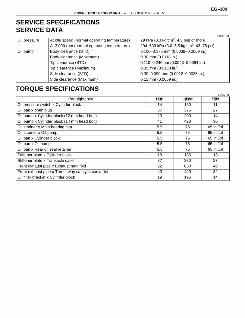
SERVICE SPECIFICATIONSSERVICE DATA
EG09H–01
ÑÑÑÑÑÑÑÑÑÑÑÑ
Oil pressure ÑÑÑÑÑÑÑÑÑÑÑÑÑÑÑÑÑÑÑÑÑÑÑÑÑÑÑÑÑÑÑÑ
At idle speed (normal operating temperature) ÑÑÑÑÑÑÑÑÑÑÑÑÑÑÑÑÑÑÑÑÑÑÑÑÑÑÑÑÑÑÑÑ
29 kPa (0.3 kgfcm2, 4.3 psi) or more
ÑÑÑÑÑÑÑÑÑÑÑÑÑÑÑÑÑÑÑÑÑÑAt 3,000 rpm (normal operating temperature) ÑÑÑÑÑÑÑÑÑÑÑÑÑÑÑÑ294–539 kPa (3.0–5.5 kgfcm2, 43–78 psi)ÑÑÑÑÑÑÑÑÑÑÑÑOil pump
ÑÑÑÑÑÑÑÑÑÑÑÑÑÑÑÑÑÑÑÑÑÑÑÑÑÑÑÑÑÑÑÑBody clearance (STD)
ÑÑÑÑÑÑÑÑÑÑÑÑÑÑÑÑÑÑÑÑÑÑÑÑÑÑÑÑÑÑÑÑ0.100–0.175 mm (0.0039–0.0069 in.)ÑÑÑÑÑÑ
ÑÑÑÑÑÑÑÑÑÑÑÑÑÑÑÑÑÑÑÑÑÑÑÑÑÑÑÑÑÑÑÑÑÑÑÑÑÑ
Body clearance (Maximum)ÑÑÑÑÑÑÑÑÑÑÑÑÑÑÑÑÑÑÑÑÑÑÑÑÑÑÑÑÑÑÑÑ
0.30 mm (0.0118 in.)ÑÑÑÑÑÑÑÑÑÑÑÑ
ÑÑÑÑÑÑÑÑÑÑÑÑÑÑÑÑÑÑÑÑÑÑÑÑÑÑÑÑÑÑÑÑ
Tip clearance (STD) ÑÑÑÑÑÑÑÑÑÑÑÑÑÑÑÑÑÑÑÑÑÑÑÑÑÑÑÑÑÑÑÑ
0.110–0.240mm (0.0043–0.0094 in.)ÑÑÑÑÑÑÑÑÑÑÑÑ
ÑÑÑÑÑÑÑÑÑÑÑÑÑÑÑÑÑÑÑÑÑÑÑÑÑÑÑÑÑÑÑÑ
Tip clearance (Maximum) ÑÑÑÑÑÑÑÑÑÑÑÑÑÑÑÑÑÑÑÑÑÑÑÑÑÑÑÑÑÑÑÑ
0.35 mm (0.0138 in.)ÑÑÑÑÑÑÑÑÑÑÑÑ
ÑÑÑÑÑÑÑÑÑÑÑÑÑÑÑÑÑÑÑÑÑÑÑÑÑÑÑÑÑÑÑÑ
Side clearance (STD) ÑÑÑÑÑÑÑÑÑÑÑÑÑÑÑÑÑÑÑÑÑÑÑÑÑÑÑÑÑÑÑÑ
0.30–0.090 mm (0.0012–0.0035 in.)ÑÑÑÑÑÑÑÑÑÑÑÑ
ÑÑÑÑÑÑÑÑÑÑÑÑÑÑÑÑÑÑÑÑÑÑÑÑÑÑÑÑÑÑÑÑ
Side clearance (Maximum) ÑÑÑÑÑÑÑÑÑÑÑÑÑÑÑÑÑÑÑÑÑÑÑÑÑÑÑÑÑÑÑÑ
0.15 mm (0.0059 in.)
TORQUE SPECIFICATIONSEG09J–01ÑÑÑÑÑÑÑÑÑÑÑÑÑÑÑÑÑÑÑÑÑÑ
ÑÑÑÑÑÑÑÑÑÑÑÑÑÑÑÑÑÑÑÑÑÑPart tightened ÑÑÑÑÑÑ
ÑÑÑÑÑÑN⋅m ÑÑÑÑÑ
ÑÑÑÑÑkgf⋅cm ÑÑÑÑÑÑ
ÑÑÑÑÑÑft⋅lbf
ÑÑÑÑÑÑÑÑÑÑÑÑÑÑÑÑÑÑÑÑÑÑÑÑÑÑÑÑÑÑÑÑÑÑÑÑÑÑÑÑÑÑÑÑ
Oil pressure switch x Cylinder block ÑÑÑÑÑÑÑÑÑÑÑÑ
14 ÑÑÑÑÑÑÑÑÑÑ
150 ÑÑÑÑÑÑÑÑÑÑÑÑ
11ÑÑÑÑÑÑÑÑÑÑÑÑÑÑÑÑÑÑÑÑÑÑÑÑÑÑÑÑÑÑÑÑÑÑÑÑÑÑÑÑÑÑÑÑ
Oil pan x drain plug ÑÑÑÑÑÑÑÑÑÑÑÑ
37 ÑÑÑÑÑÑÑÑÑÑ
375 ÑÑÑÑÑÑÑÑÑÑÑÑ
27ÑÑÑÑÑÑÑÑÑÑÑÑÑÑÑÑÑÑÑÑÑÑÑÑÑÑÑÑÑÑÑÑÑÑÑÑÑÑÑÑÑÑÑÑ
Oil pump x Cylinder block (12 mm head bolt) ÑÑÑÑÑÑÑÑÑÑÑÑ
20 ÑÑÑÑÑÑÑÑÑÑ
200 ÑÑÑÑÑÑÑÑÑÑÑÑ
14
ÑÑÑÑÑÑÑÑÑÑÑÑÑÑÑÑÑÑÑÑÑÑÑÑÑÑÑÑÑÑÑÑÑÑÑÑÑÑÑÑÑÑÑÑ
Oil pump x Cylinder block (14 mm head bolt) ÑÑÑÑÑÑÑÑÑÑÑÑ
41 ÑÑÑÑÑÑÑÑÑÑ
420 ÑÑÑÑÑÑÑÑÑÑÑÑ
30
ÑÑÑÑÑÑÑÑÑÑÑÑÑÑÑÑÑÑÑÑÑÑÑÑÑÑÑÑÑÑÑÑÑÑÑÑÑÑÑÑÑÑÑÑ
Oil strainer x Main bearing cap ÑÑÑÑÑÑÑÑÑÑÑÑ
5.5 ÑÑÑÑÑÑÑÑÑÑ
75 ÑÑÑÑÑÑÑÑÑÑÑÑ
65 in.⋅lbf
ÑÑÑÑÑÑÑÑÑÑÑÑÑÑÑÑÑÑÑÑÑÑÑÑÑÑÑÑÑÑÑÑÑÑÑÑÑÑÑÑÑÑÑÑ
Oil strainer x Oil pump ÑÑÑÑÑÑÑÑÑÑÑÑ
5.5 ÑÑÑÑÑÑÑÑÑÑ
75 ÑÑÑÑÑÑÑÑÑÑÑÑ
65 in.⋅lbf
ÑÑÑÑÑÑÑÑÑÑÑÑÑÑÑÑÑÑÑÑÑÑOil pan x Cylinder block ÑÑÑÑÑÑ5.5 ÑÑÑÑÑ75 ÑÑÑÑÑÑ65 in.⋅lbfÑÑÑÑÑÑÑÑÑÑÑÑÑÑÑÑÑÑÑÑÑÑÑÑÑÑÑÑÑÑÑÑÑÑÑÑÑÑÑÑÑÑÑÑOil pan x Oil pump
ÑÑÑÑÑÑÑÑÑÑÑÑ5.5
ÑÑÑÑÑÑÑÑÑÑ75
ÑÑÑÑÑÑÑÑÑÑÑÑ65 in.⋅lbfÑÑÑÑÑÑÑÑÑÑÑÑÑÑÑÑÑÑÑÑÑÑ
ÑÑÑÑÑÑÑÑÑÑÑÑÑÑÑÑÑÑÑÑÑÑOil pan x Rear oil seal retainer
ÑÑÑÑÑÑÑÑÑÑÑÑ
5.5ÑÑÑÑÑÑÑÑÑÑ
75ÑÑÑÑÑÑÑÑÑÑÑÑ
65 in.⋅lbfÑÑÑÑÑÑÑÑÑÑÑÑÑÑÑÑÑÑÑÑÑÑÑÑÑÑÑÑÑÑÑÑÑÑÑÑÑÑÑÑÑÑÑÑ
Stiffener plate x Cylinder block ÑÑÑÑÑÑÑÑÑÑÑÑ
18 ÑÑÑÑÑÑÑÑÑÑ
185 ÑÑÑÑÑÑÑÑÑÑÑÑ
13ÑÑÑÑÑÑÑÑÑÑÑÑÑÑÑÑÑÑÑÑÑÑÑÑÑÑÑÑÑÑÑÑÑÑÑÑÑÑÑÑÑÑÑÑ
Stiffener plate x Transaxle case ÑÑÑÑÑÑÑÑÑÑÑÑ
37 ÑÑÑÑÑÑÑÑÑÑ
380 ÑÑÑÑÑÑÑÑÑÑÑÑ
27ÑÑÑÑÑÑÑÑÑÑÑÑÑÑÑÑÑÑÑÑÑÑÑÑÑÑÑÑÑÑÑÑÑÑÑÑÑÑÑÑÑÑÑÑ
Front exhaust pipe x Exhaust manifold ÑÑÑÑÑÑÑÑÑÑÑÑ
62 ÑÑÑÑÑÑÑÑÑÑ
630 ÑÑÑÑÑÑÑÑÑÑÑÑ
46ÑÑÑÑÑÑÑÑÑÑÑÑÑÑÑÑÑÑÑÑÑÑÑÑÑÑÑÑÑÑÑÑÑÑÑÑÑÑÑÑÑÑÑÑ
Front exhaust pipe x Three–way catalytic converter ÑÑÑÑÑÑÑÑÑÑÑÑ
43 ÑÑÑÑÑÑÑÑÑÑ
440 ÑÑÑÑÑÑÑÑÑÑÑÑ
32ÑÑÑÑÑÑÑÑÑÑÑÑÑÑÑÑÑÑÑÑÑÑÑÑÑÑÑÑÑÑÑÑÑÑÑÑÑÑÑÑÑÑÑÑ
Oil filter bracket x Cylinder block ÑÑÑÑÑÑÑÑÑÑÑÑ
19 ÑÑÑÑÑÑÑÑÑÑ
195 ÑÑÑÑÑÑÑÑÑÑÑÑ
14
–ENGINE TROUBLESHOOTING LUBRICATION SYSTEMEG–309

–MEMO–
EG–310–ENGINE TROUBLESHOOTING LUBRICATION SYSTEM

ENGINE TROUBLESHOOTING
EG–311
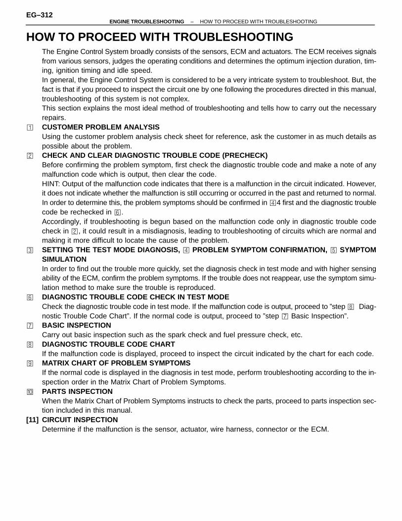
HOW TO PROCEED WITH TROUBLESHOOTINGThe Engine Control System broadly consists of the sensors, ECM and actuators. The ECM receives signalsfrom various sensors, judges the operating conditions and determines the optimum injection duration, tim-ing, ignition timing and idle speed.In general, the Engine Control System is considered to be a very intricate system to troubleshoot. But, thefact is that if you proceed to inspect the circuit one by one following the procedures directed in this manual,troubleshooting of this system is not complex.This section explains the most ideal method of troubleshooting and tells how to carry out the necessaryrepairs.
� CUSTOMER PROBLEM ANALYSISUsing the customer problem analysis check sheet for reference, ask the customer in as much details aspossible about the problem.
CHECK AND CLEAR DIAGNOSTIC TROUBLE CODE (PRECHECK)Before confirming the problem symptom, first check the diagnostic trouble code and make a note of anymalfunction code which is output, then clear the code.HINT: Output of the malfunction code indicates that there is a malfunction in the circuit indicated. However,it does not indicate whether the malfunction is still occurring or occurred in the past and returned to normal.In order to determine this, the problem symptoms should be confirmed in �4 first and the diagnostic troublecode be rechecked in �.Accordingly, if troubleshooting is begun based on the malfunction code only in diagnostic trouble codecheck in , it could result in a misdiagnosis, leading to troubleshooting of circuits which are normal andmaking it more difficult to locate the cause of the problem.
� SETTING THE TEST MODE DIAGNOSIS, � PROBLEM SYMPTOM CONFIRMATION, � SYMPTOMSIMULATIONIn order to find out the trouble more quickly, set the diagnosis check in test mode and with higher sensingability of the ECM, confirm the problem symptoms. If the trouble does not reappear, use the symptom simu-lation method to make sure the trouble is reproduced.
� DIAGNOSTIC TROUBLE CODE CHECK IN TEST MODECheck the diagnostic trouble code in test mode. If the malfunction code is output, proceed to ”step � Diag-nostic Trouble Code Chart”. If the normal code is output, proceed to ”step � Basic Inspection”.
� BASIC INSPECTIONCarry out basic inspection such as the spark check and fuel pressure check, etc.
� DIAGNOSTIC TROUBLE CODE CHARTIf the malfunction code is displayed, proceed to inspect the circuit indicated by the chart for each code.
� MATRIX CHART OF PROBLEM SYMPTOMSIf the normal code is displayed in the diagnosis in test mode, perform troubleshooting according to the in-spection order in the Matrix Chart of Problem Symptoms.
� PARTS INSPECTIONWhen the Matrix Chart of Problem Symptoms instructs to check the parts, proceed to parts inspection sec-tion included in this manual.
[11] CIRCUIT INSPECTIONDetermine if the malfunction is the sensor, actuator, wire harness, connector or the ECM.
EG–312–ENGINE TROUBLESHOOTING HOW TO PROCEED WITH TROUBLESHOOTING
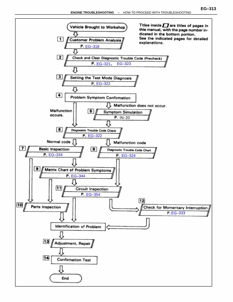
EG–318
EG–321 EG–323
EG–322
IN–20
EG–322
EG–334 EG–324
EG–344
EG–354
EG–333
–ENGINE TROUBLESHOOTING HOW TO PROCEED WITH TROUBLESHOOTINGEG–313

[12].CHECK FOR MOMENTARY INTERRUPTIONBy performing the check for momentary interruption, the place where momentary interruptions or momen-tary shorts are occurring due to poor contacts can be isolated.
[13] ADJUSTMENT, REPAIRAfter the cause of the problem is located, perform adjustment or repairs by following the inspection andreplacement procedures in this manual.
[14] CONFIRMATION TESTAfter completing adjustment or repairs, confirm not only that the malfunction is eliminated, but also conducta test drive, etc., to make sure the entire Engine Control System is operating normally.
EG–314–ENGINE TROUBLESHOOTING HOW TO PROCEED WITH TROUBLESHOOTING

–MEMO–
ENGINE TROUBLESHOOTINGEG–315

How to Proceed with Troubleshooting Using Volt/Ohm Meter andTCCS Checker
For the explanation of steps � � �, � and � � [16], see the explanation of steps with the sametitle on page EG–312.
�� CIRCUIT INSPECTION BY CHECKERIf the Normal code is displayed in the diagnostic trouble code check, connect the checker to the vehicleand check all the circuits which can be inspected using the checker.If a malfunctioning circuit is then detected, proceed to ”Circuit Inspection by Volt/Ohm Meter” and checkthe applicable circuit using a volt/ohm meter. Determine if the malfunction is in the sensor, actuator, wireharness, connector or the ECM. If the malfunctioning circuit cannot be detected using the checker, proceedto ”Basic Inspection” and perform troubleshooting.If a malfunction code is displayed in the diagnostic trouble code check, use the checker to inspect the circuitindicated by the diagnostic trouble code chart for the displayed code.For instructions on how to connect the checker to the vehicle and how to use the checker, please refer tothe Instruction Manual for TCCS checker.
EG–316–ENGINE TROUBLESHOOTING HOW TO PROCEED WITH TROUBLESHOOTING
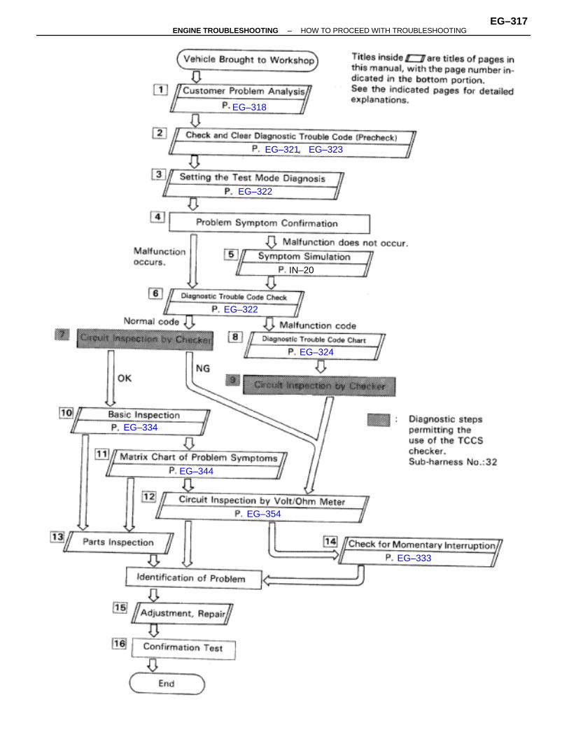
EG–318
EG–321 EG–323
EG–322
IN–20
EG–322
EG–324
EG–334
EG–344
EG–354
EG–333
–ENGINE TROUBLESHOOTING HOW TO PROCEED WITH TROUBLESHOOTINGEG–317

CUSTOMER PROBLEM ANALYSIS CHECK SHEET
EG–318–ENGINE TROUBLESHOOTING CUSTOMER PROBLEM ANALYSIS CHECK SHEET

–MEMO–
ENGINE TROUBLESHOOTINGEG–319

DIAGNOSIS SYSTEMDESCRIPTIONThe ECM contains a built–in self–diagnosis system by whichtroubles with the engine signal network are detected and a Mal-function Indicator Lamp on the instrument panel lights up.By analyzing various signals as shown in the later table (See pageEG–324) the ECM detects system malfunctions relating to thesensors or actuators.In the normal mode, the self–diagnosis system monitors 21(California specification vehicles) or 18 (Other than Californiaspecification vehicles) items, indicated by code No. as shown inEG–324. A Malfunction Indicator Lamp informs the driver that amalfunction has been detected. The light goes off automaticallywhen the malfunction has been repaired. But the diagnostictrouble code(s) remains stored in the ECM memory (except forcode Nos. 16 and 53). The ECM stores the code(s) until it iscleared by removing the EFI fuse with the ignition switch off.The diagnostic trouble code can be read by the number of blinksof the Malfunction Indicator Lamp when TE1 and E1 terminals onthe data link connector 2 or data link connector 1 are connected.When 2 or more codes are indicated, the lowest number (code) willappear first.In the test mode, 13 (California specification vehicles) or 10 (Otherthan California specification vehicles) items, indicated by code No.as shown in EG–324 are monitored. If a malfunction is detectedin any one of the systems indicated by code Nos. 13, 21, 22, 24,25, 26, 27, 28, 31, 32, 41, 42, and 71 (California specification ve-hicles) or 13, 21, 22, 24, 25, 28, 31, 32, 41 and 42 (Other thanCalifornia specification vehicles) the ECM lights the MalfunctionIndicator Lamp to warn the technician that malfunction has beendetected. In this case, TE2 and E1 terminals on the data link con-nector 2 or data link connector 1 should be connected as shownlater. (See page EG–322)In the test mode, even if the malfunction is corrected, the malfunc-tion code is stored in the ECM memory even when the ignitionswitch is off (except code Nos. 43 and 51). This also applies in thenormal mode. The diagnostic mode (normal or test) and the outputof the Malfunction Indicator Lamp can be selected by connectingthe TE1, TE2 and E1 terminals on the data link connector 1 or datalink connector 2, as shown later.A test mode function has been added to the functions of the self–diagnosis system of the normal mode for the purpose of detectingmalfunctions such as poor contact, which are difficult to detect inthe normal mode. This function fills up the self–diagnosis system.The test mode can be implemented by the technician following theappropriate procedures of check terminal connection and opera-tion described later. (See page EG–322)
EG–320–ENGINE TROUBLESHOOTING DIAGNOSIS SYSTEM
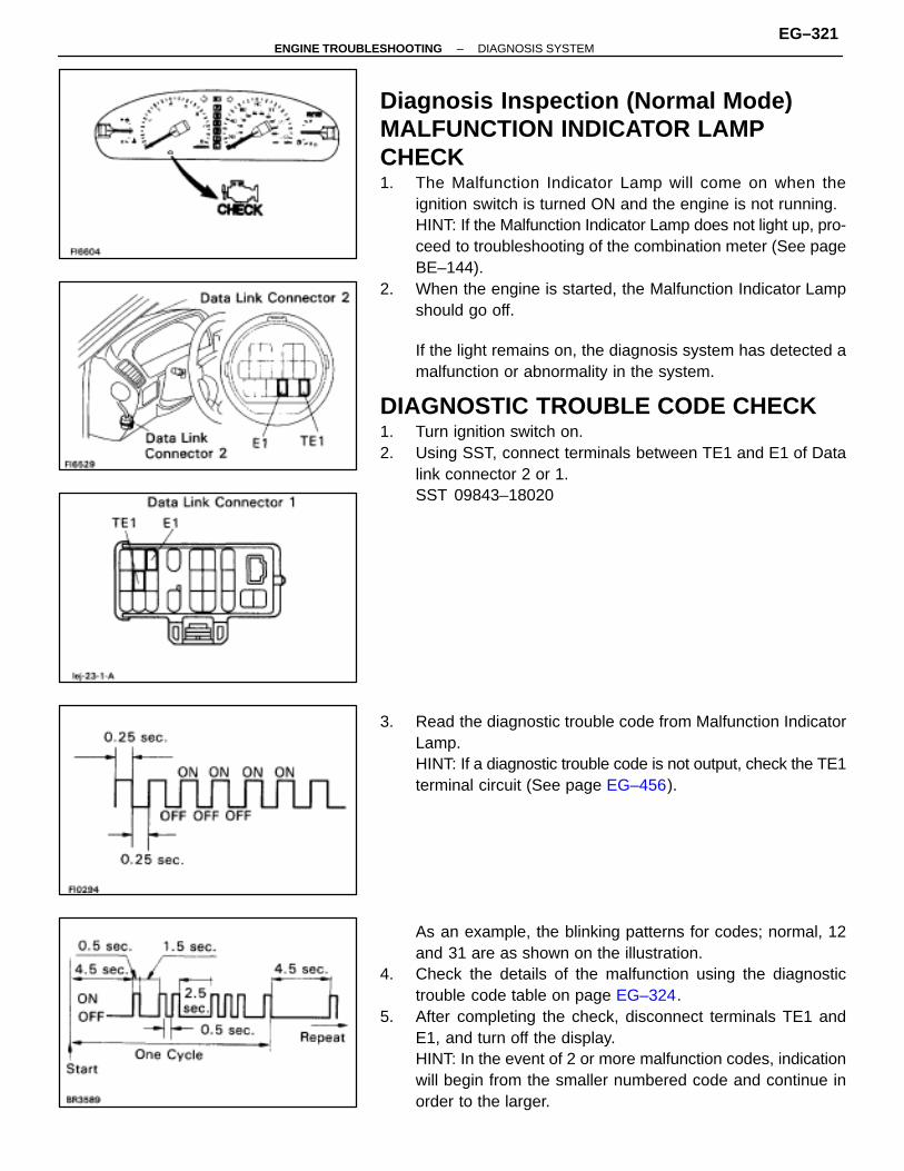
Diagnosis Inspection (Normal Mode)MALFUNCTION INDICATOR LAMPCHECK1. The Malfunction Indicator Lamp will come on when the
ignition switch is turned ON and the engine is not running.HINT: If the Malfunction Indicator Lamp does not light up, pro-ceed to troubleshooting of the combination meter (See pageBE–144).
2. When the engine is started, the Malfunction Indicator Lampshould go off.
If the light remains on, the diagnosis system has detected amalfunction or abnormality in the system.
DIAGNOSTIC TROUBLE CODE CHECK1. Turn ignition switch on.2. Using SST, connect terminals between TE1 and E1 of Data
link connector 2 or 1.SST 09843–18020
3. Read the diagnostic trouble code from Malfunction IndicatorLamp.HINT: If a diagnostic trouble code is not output, check the TE1terminal circuit (See page EG–456).
As an example, the blinking patterns for codes; normal, 12and 31 are as shown on the illustration.
4. Check the details of the malfunction using the diagnostictrouble code table on page EG–324.
5. After completing the check, disconnect terminals TE1 andE1, and turn off the display.HINT: In the event of 2 or more malfunction codes, indicationwill begin from the smaller numbered code and continue inorder to the larger.
–ENGINE TROUBLESHOOTING DIAGNOSIS SYSTEMEG–321
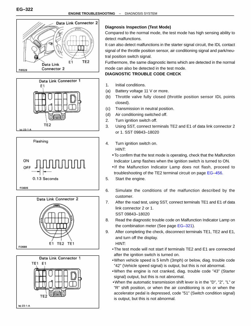
Diagnosis Inspection (Test Mode)Compared to the normal mode, the test mode has high sensing ability todetect malfunctions.It can also detect malfunctions in the starter signal circuit, the IDL contactsignal of the throttle position sensor, air conditioning signal and park/neu-tral position switch signal.Furthermore, the same diagnostic items which are detected in the normalmode can also be detected in the test mode.DIAGNOSTIC TROUBLE CODE CHECK
1. Initial conditions.(a) Battery voltage 11 V or more.(b) Throttle valve fully closed (throttle position sensor IDL points
closed).(c) Transmission in neutral position.(d) Air conditioning switched off.2. Turn ignition switch off.3. Using SST, connect terminals TE2 and E1 of data link connector 2
or 1. SST 09843–18020
4. Turn ignition switch on.HINT:
•To confirm that the test mode is operating, check that the MalfunctionIndicator Lamp flashes when the ignition switch is turned to ON.
• If the Malfunction Indicator Lamp does not flash, proceed totroubleshooting of the TE2 terminal circuit on page EG–456.
5. Start the engine.
6. Simulate the conditions of the malfunction described by thecustomer.
7. After the road test, using SST, connect terminals TE1 and E1 of datalink connector 2 or 1.SST 09843–18020
8. Read the diagnostic trouble code on Malfunction Indicator Lamp onthe combination meter (See page EG–321).
9. After completing the check, disconnect terminals TE1, TE2 and E1,and turn off the display.HINT:
•The test mode will not start if terminals TE2 and E1 are connectedafter the ignition switch is turned on.
•When vehicle speed is 5 km/h (3mph) or below, diag. trouble code”42” (Vehicle speed signal) is output, but this is not abnormal.
•When the engine is not cranked, diag. trouble code ”43” (Startersignal) output, but this is not abnormal.
•When the automatic transmission shift lever is in the ”D”, ”2”, ”L” or”R” shift position, or when the air conditioning is on or when theaccelerator pedal is depressed, code ”51” (Switch condition signal)is output, but this is not abnormal.
EG–322–ENGINE TROUBLESHOOTING DIAGNOSIS SYSTEM
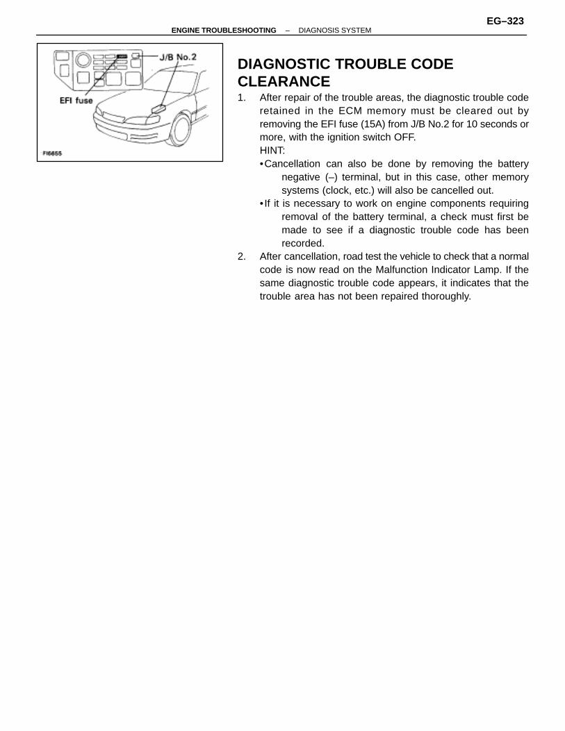
DIAGNOSTIC TROUBLE CODECLEARANCE1. After repair of the trouble areas, the diagnostic trouble code
retained in the ECM memory must be cleared out byremoving the EFI fuse (15A) from J/B No.2 for 10 seconds ormore, with the ignition switch OFF.HINT:•Cancellation can also be done by removing the battery
negative (–) terminal, but in this case, other memorysystems (clock, etc.) will also be cancelled out.
• If it is necessary to work on engine components requiringremoval of the battery terminal, a check must first bemade to see if a diagnostic trouble code has beenrecorded.
2. After cancellation, road test the vehicle to check that a normalcode is now read on the Malfunction Indicator Lamp. If thesame diagnostic trouble code appears, it indicates that thetrouble area has not been repaired thoroughly.
–ENGINE TROUBLESHOOTING DIAGNOSIS SYSTEMEG–323
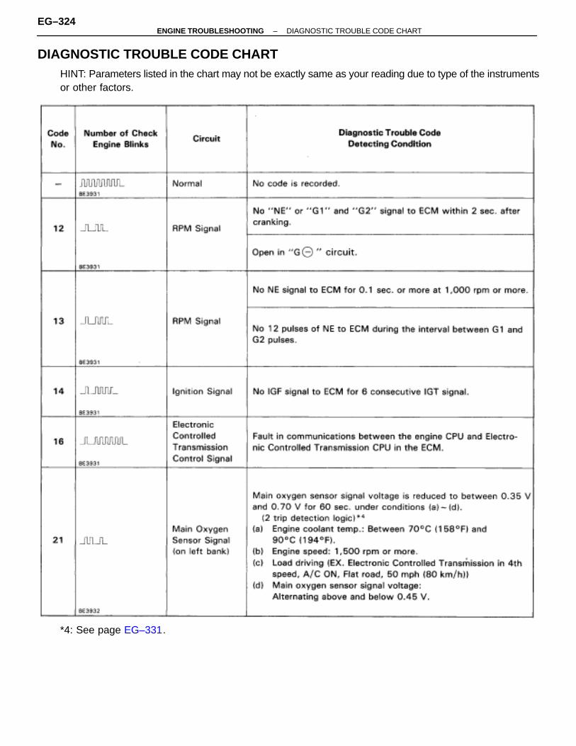
DIAGNOSTIC TROUBLE CODE CHARTHINT: Parameters listed in the chart may not be exactly same as your reading due to type of the instrumentsor other factors.
*4: See page EG–331.
EG–324–ENGINE TROUBLESHOOTING DIAGNOSTIC TROUBLE CODE CHART
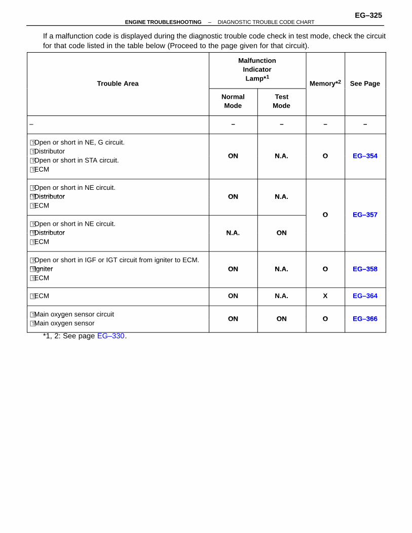
If a malfunction code is displayed during the diagnostic trouble code check in test mode, check the circuitfor that code listed in the table below (Proceed to the page given for that circuit).
ÑÑÑÑÑÑÑÑÑÑÑÑÑÑÑÑÑÑÑÑÑÑÑÑÑÑÑÑÑÑÑÑÑÑÑÑÑÑÑÑÑÑÑÑÑÑÑÑÑÑÑÑÑÑÑÑÑÑÑÑÑÑÑÑÑÑÑÑÑÑÑÑÑÑÑÑ
Trouble Area
ÑÑÑÑÑÑÑÑÑÑÑÑÑÑÑÑÑÑÑÑÑÑÑÑÑÑÑÑÑÑÑÑÑÑÑÑÑÑÑÑ
MalfunctionIndicatorLamp* 1
ÑÑÑÑÑÑÑÑÑÑÑÑÑÑÑÑÑÑÑÑ
Memory* 2
ÑÑÑÑÑÑÑÑÑÑÑÑÑÑÑÑÑÑÑÑ
See PageÑÑÑÑÑÑÑÑÑÑÑÑÑÑÑÑÑÑÑÑÑÑÑÑÑÑÑÑÑÑÑÑÑÑÑÑÑÑÑÑÑÑÑÑÑÑÑÑÑÑÑÑÑÑÑÑÑÑÑÑÑÑÑÑÑÑÑÑÑÑÑÑÑÑÑÑ
ÑÑÑÑÑÑÑÑÑÑÑÑÑÑÑÑÑÑÑÑ
NormalMode
ÑÑÑÑÑÑÑÑÑÑÑÑÑÑÑÑÑÑÑÑÑÑÑÑ
TestMode
ÑÑÑÑÑÑÑÑÑÑÑÑÑÑÑÑÑÑÑÑ
yÑÑÑÑÑÑÑÑÑÑÑÑÑÑÑÑÑÑÑÑ
g
ÑÑÑÑÑÑÑÑÑÑÑÑÑÑÑÑÑÑÑÑÑÑÑÑÑÑÑÑÑÑÑÑÑÑÑÑÑÑ
– ÑÑÑÑÑÑÑÑÑÑ
– ÑÑÑÑÑÑÑÑÑÑÑÑ
– ÑÑÑÑÑÑÑÑÑÑ
– ÑÑÑÑÑÑÑÑÑÑ
–ÑÑÑÑÑÑÑÑÑÑÑÑÑÑÑÑÑÑÑÑÑÑÑÑÑÑÑÑÑÑÑÑÑÑÑÑÑÑÑÑÑÑÑÑÑÑÑÑÑÑÑÑÑÑÑÑÑÑÑÑÑÑÑÑÑÑÑÑÑÑÑÑÑÑÑÑ
� Open or short in NE, G circuit.� Distributor
ON N A O EG–354ÑÑÑÑÑÑÑÑÑÑÑÑÑÑÑÑÑÑÑÑÑÑÑÑÑÑÑÑÑÑÑÑÑÑÑÑÑÑÑÑÑÑÑÑÑÑÑÑÑÑÑÑÑÑÑÑÑ
� Open or short in STA circuit.� ECM
ON N.A. O EG–354
ÑÑÑÑÑÑÑÑÑÑÑÑÑÑÑÑÑÑÑÑÑÑÑÑÑÑÑÑÑÑÑÑÑÑÑÑÑÑÑÑÑÑÑÑÑÑÑÑÑÑÑÑÑÑÑÑÑ
� Open or short in NE circuit.� Distributor ON N AÑÑÑÑÑÑÑÑÑÑÑÑÑÑÑÑÑÑÑÑÑÑÑÑÑÑÑÑÑÑÑÑÑÑÑÑÑÑ
� Distributor� ECM
ON N.A.
O EG–357ÑÑÑÑÑÑÑÑÑÑÑÑÑÑÑÑÑÑÑÑÑÑÑÑÑÑÑÑÑÑÑÑÑÑÑÑÑÑÑÑÑÑÑÑÑÑÑÑÑÑÑÑÑÑÑÑÑ
� Open or short in NE circuit.� Distributor N A ON
O EG–357
ÑÑÑÑÑÑÑÑÑÑÑÑÑÑÑÑÑÑÑÑÑÑÑÑÑÑÑÑÑÑÑÑÑÑÑÑÑÑÑÑÑÑÑÑÑÑÑÑÑÑÑÑÑÑÑÑÑ
� Distributor� ECM
N.A. ON
ÑÑÑÑÑÑÑÑÑÑÑÑÑÑÑÑÑÑÑÑÑÑÑÑÑÑÑÑÑÑÑÑÑÑÑÑÑÑÑÑÑÑÑÑÑÑÑÑÑÑÑÑÑÑÑÑÑ
� Open or short in IGF or IGT circuit from igniter to ECM.� Igniter ON N A O EG–358ÑÑÑÑÑÑÑÑÑÑÑÑÑÑÑÑÑÑÑÑÑÑÑÑÑÑÑÑÑÑÑÑÑÑÑÑÑÑ
� Igniter� ECM
ON N.A. O EG–358
ÑÑÑÑÑÑÑÑÑÑÑÑÑÑÑÑÑÑÑÑÑÑÑÑÑÑÑÑÑÑÑÑÑÑÑÑÑÑÑÑÑÑÑÑÑÑÑÑÑÑÑÑÑÑÑÑÑ
� ECM ON N.A. X EG–364
ÑÑÑÑÑÑÑÑÑÑÑÑÑÑÑÑÑÑÑÑÑÑÑÑÑÑÑÑÑÑÑÑÑÑÑÑÑÑ� Main oxygen sensor circuit
ON ON O EG–366ÑÑÑÑÑÑÑÑÑÑÑÑÑÑÑÑÑÑÑÑÑÑÑÑÑÑÑÑÑÑÑÑÑÑÑÑÑÑÑÑÑÑÑÑÑÑÑÑÑÑÑÑÑÑÑÑÑ
yg� Main oxygen sensor
ON ON O EG–366
*1, 2: See page EG–330.
–ENGINE TROUBLESHOOTING DIAGNOSTIC TROUBLE CODE CHARTEG–325
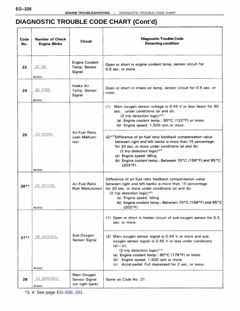
DIAGNOSTIC TROUBLE CODE CHART (Cont’d)
*3, 4: See page EG–330, 331.
EG–326–ENGINE TROUBLESHOOTING DIAGNOSTIC TROUBLE CODE CHART
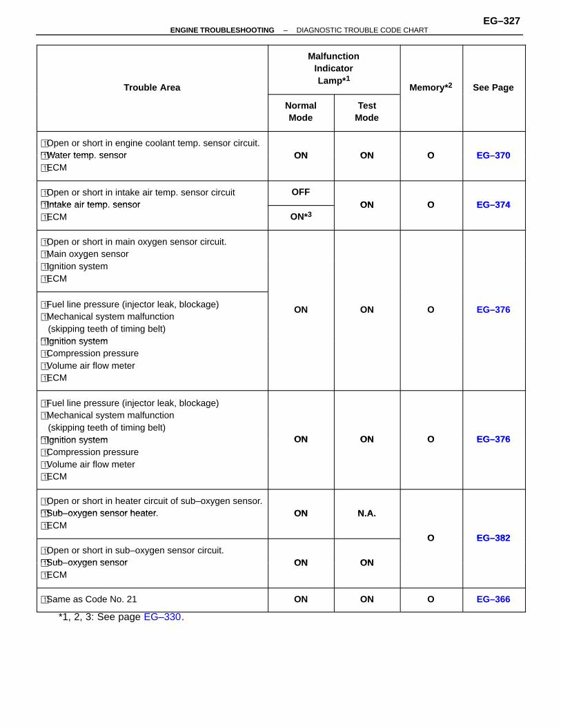
ÑÑÑÑÑÑÑÑÑÑÑÑÑÑÑÑÑÑÑÑÑÑÑÑÑÑÑÑÑÑÑÑÑÑÑÑÑÑÑÑÑÑÑÑÑÑÑÑÑÑÑÑÑÑÑÑÑÑÑÑÑÑÑÑÑÑÑÑ
Trouble Area
ÑÑÑÑÑÑÑÑÑÑÑÑÑÑÑÑÑÑÑÑÑÑÑÑÑÑÑÑÑÑÑÑÑÑÑÑÑÑÑÑ
MalfunctionIndicatorLamp* 1
ÑÑÑÑÑÑÑÑÑÑÑÑÑÑÑÑÑÑÑÑ
Memory* 2
ÑÑÑÑÑÑÑÑÑÑÑÑÑÑÑÑÑÑÑÑÑÑÑÑ
See PageÑÑÑÑÑÑÑÑÑÑÑÑÑÑÑÑÑÑÑÑÑÑÑÑÑÑÑÑÑÑÑÑÑÑÑÑÑÑÑÑÑÑÑÑÑÑÑÑÑÑÑÑÑÑÑÑÑÑÑÑÑÑÑÑÑÑÑÑ
ÑÑÑÑÑÑÑÑÑÑÑÑÑÑÑÑÑÑÑÑ
NormalMode
ÑÑÑÑÑÑÑÑÑÑÑÑÑÑÑÑÑÑÑÑÑÑÑÑ
TestMode
ÑÑÑÑÑÑÑÑÑÑÑÑÑÑÑÑÑÑÑÑ
yÑÑÑÑÑÑÑÑÑÑÑÑÑÑÑÑÑÑÑÑÑÑÑÑ
g
ÑÑÑÑÑÑÑÑÑÑÑÑÑÑÑÑÑÑÑÑÑÑÑÑÑÑÑÑÑÑÑÑÑÑÑÑÑÑÑÑÑÑÑÑÑÑÑÑÑÑÑ
� Open or short in engine coolant temp. sensor circuit.� Water temp sensor ON ON O EG–370ÑÑÑÑÑÑÑÑÑÑÑÑÑÑÑÑÑÑÑÑÑÑÑÑÑÑÑÑÑÑÑÑÑÑ
� Water temp. sensor� ECM
ON ON O EG–370
ÑÑÑÑÑÑÑÑÑÑÑÑÑÑÑÑÑÑÑÑÑÑÑÑÑÑÑÑÑÑÑÑÑÑÑÑÑÑÑÑÑÑÑÑÑÑÑÑÑÑÑ
� Open or short in intake air temp. sensor circuit� Intake air temp sensor
OFFON O EG–374ÑÑÑÑÑÑÑÑÑÑÑÑÑÑÑÑÑ
ÑÑÑÑÑÑÑÑÑÑÑÑÑÑÑÑÑÑÑÑÑÑÑÑÑÑÑÑÑÑÑÑÑÑ
� Intake air temp. sensor� ECM
ÑÑÑÑÑÑÑÑÑÑÑÑÑÑÑ
ON*3ON O EG–374
ÑÑÑÑÑÑÑÑÑÑÑÑÑÑÑÑÑÑÑÑÑÑÑÑÑÑÑÑÑÑÑÑÑÑÑÑÑÑÑÑÑÑÑÑÑÑÑÑÑÑÑ
� Open or short in main oxygen sensor circuit.� Main oxygen sensorÑÑÑÑÑÑÑÑÑÑÑÑÑÑÑÑÑÑÑÑÑÑÑÑÑÑÑÑÑÑÑÑÑÑÑÑÑÑÑÑÑÑÑÑÑÑÑÑÑÑÑ
yg� Ignition system� ECM
ÑÑÑÑÑÑÑÑÑÑÑÑÑÑÑÑÑÑÑÑÑÑÑÑÑÑÑÑÑÑÑÑÑÑÑÑÑÑÑÑÑÑÑÑÑÑÑÑÑÑÑÑÑÑÑÑÑÑÑÑÑÑÑÑÑÑÑÑÑÑÑÑÑÑÑÑÑÑÑÑÑÑÑÑÑ
� Fuel line pressure (injector leak, blockage)� Mechanical system malfunction (skipping teeth of timing belt)� Ignition system
ON ON O EG–376
ÑÑÑÑÑÑÑÑÑÑÑÑÑÑÑÑÑÑÑÑÑÑÑÑÑÑÑÑÑÑÑÑÑÑÑÑÑÑÑÑÑÑÑÑÑÑÑÑÑÑÑÑÑÑÑÑÑÑÑÑÑÑÑÑÑÑÑÑ
� Ignition system� Compression pressure� Volume air flow meter� ECM
ÑÑÑÑÑÑÑÑÑÑÑÑÑÑÑÑÑÑÑÑÑÑÑÑÑÑÑÑÑÑÑÑÑÑÑÑÑÑÑÑÑÑÑÑÑÑÑÑÑÑÑÑÑÑÑÑÑÑÑÑÑÑÑÑÑÑÑÑÑÑÑÑÑÑÑÑÑÑÑÑÑÑÑÑÑ
� Fuel line pressure (injector leak, blockage)� Mechanical system malfunction (skipping teeth of timing belt)� Ignition system ON ON O EG–376ÑÑÑÑÑÑÑÑÑÑÑÑÑÑÑÑÑÑÑÑÑÑÑÑÑÑÑÑÑÑÑÑÑÑÑÑÑÑÑÑÑÑÑÑÑÑÑÑÑÑÑÑÑÑÑÑÑÑÑÑÑÑÑÑÑÑÑÑ
� Ignition system� Compression pressure� Volume air flow meter� ECM
ON ON O EG–376
ÑÑÑÑÑÑÑÑÑÑÑÑÑÑÑÑÑÑÑÑÑÑÑÑÑÑÑÑÑÑÑÑÑÑÑÑÑÑÑÑÑÑÑÑÑÑÑÑÑÑÑ
� Open or short in heater circuit of sub–oxygen sensor.� Sub–oxygen sensor heater ON N AÑÑÑÑÑÑÑÑÑÑÑÑÑÑÑÑÑÑÑÑÑÑÑÑÑÑÑÑÑÑÑÑÑÑÑÑÑÑÑÑÑÑÑÑÑÑÑÑÑÑÑ
� Sub–oxygen sensor heater.� ECM
ON N.A.
O EG–382ÑÑÑÑÑÑÑÑÑÑÑÑÑÑÑÑÑÑÑÑÑÑÑÑÑÑÑÑÑÑÑÑÑÑ
� Open or short in sub–oxygen sensor circuit.� Sub–oxygen sensor ON ON
O EG–382
ÑÑÑÑÑÑÑÑÑÑÑÑÑÑÑÑÑÑÑÑÑÑÑÑÑÑÑÑÑÑÑÑÑÑÑÑÑÑÑÑÑÑÑÑÑÑÑÑÑÑÑ
� Sub–oxygen sensor� ECM
ON ON
ÑÑÑÑÑÑÑÑÑÑÑÑÑÑÑÑÑÑÑÑÑÑÑÑÑÑÑÑÑÑÑÑÑÑÑÑÑÑÑÑÑÑÑÑÑÑÑÑÑÑÑ
� Same as Code No. 21ÑÑÑÑÑÑÑÑÑÑÑÑÑÑÑ
ONÑÑÑÑÑÑÑÑÑÑÑÑÑÑÑÑÑÑ
ONÑÑÑÑÑÑÑÑÑÑÑÑÑÑÑ
OÑÑÑÑÑÑÑÑÑÑÑÑÑÑÑÑÑÑ
EG–366
*1, 2, 3: See page EG–330.
–ENGINE TROUBLESHOOTING DIAGNOSTIC TROUBLE CODE CHARTEG–327
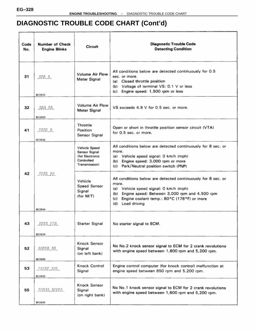
DIAGNOSTIC TROUBLE CODE CHART (Cont’d)
EG–328–ENGINE TROUBLESHOOTING DIAGNOSTIC TROUBLE CODE CHART
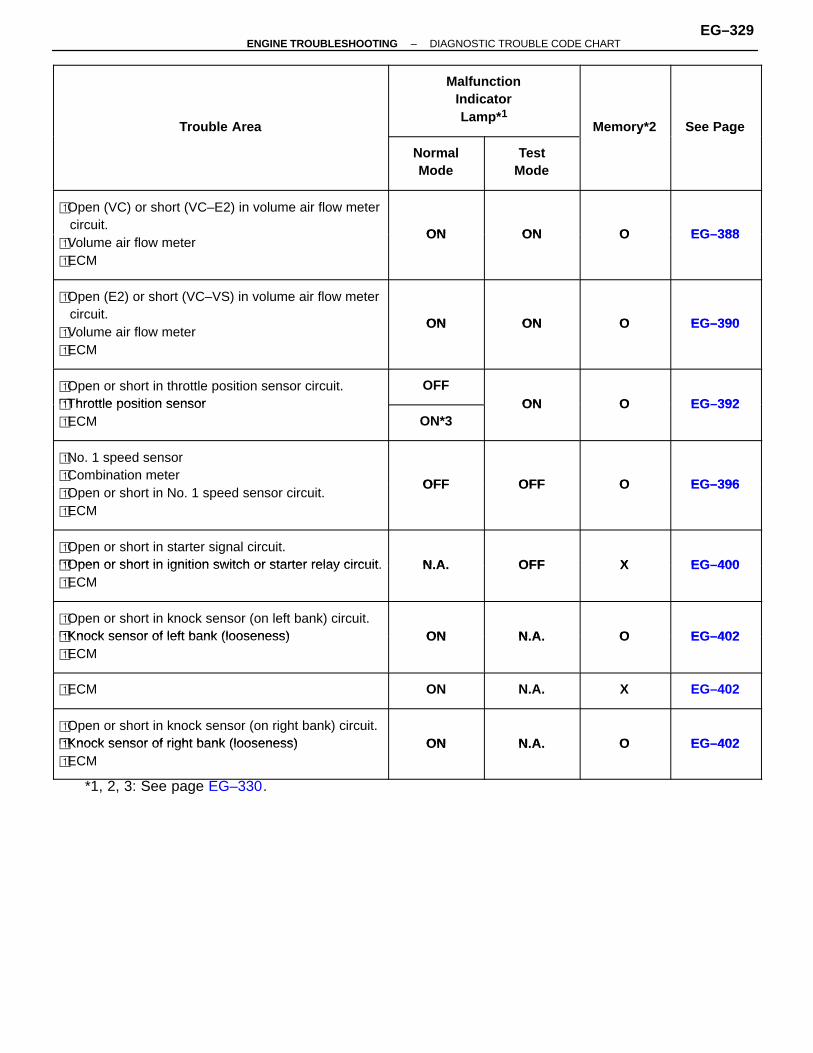
ÑÑÑÑÑÑÑÑÑÑÑÑÑÑÑÑÑÑÑÑÑÑÑÑÑÑÑÑÑÑÑÑÑÑÑÑÑÑÑÑÑÑÑÑÑÑÑÑÑÑÑÑÑÑÑÑÑÑÑÑÑÑÑÑÑÑÑÑ
Trouble Area
ÑÑÑÑÑÑÑÑÑÑÑÑÑÑÑÑÑÑÑÑÑÑÑÑÑÑÑÑÑÑÑÑÑÑÑÑÑÑÑÑ
MalfunctionIndicatorLamp* 1
ÑÑÑÑÑÑÑÑÑÑÑÑÑÑÑÑÑÑÑÑ
Memory*2
ÑÑÑÑÑÑÑÑÑÑÑÑÑÑÑÑÑÑÑÑÑÑÑÑ
See PageÑÑÑÑÑÑÑÑÑÑÑÑÑÑÑÑÑÑÑÑÑÑÑÑÑÑÑÑÑÑÑÑÑÑÑÑÑÑÑÑÑÑÑÑÑÑÑÑÑÑÑÑÑÑÑÑÑÑÑÑÑÑÑÑÑÑÑÑ
ÑÑÑÑÑÑÑÑÑÑÑÑÑÑÑÑÑÑÑÑ
NormalMode
ÑÑÑÑÑÑÑÑÑÑÑÑÑÑÑÑÑÑÑÑÑÑÑÑ
TestMode
ÑÑÑÑÑÑÑÑÑÑÑÑÑÑÑÑÑÑÑÑ
yÑÑÑÑÑÑÑÑÑÑÑÑÑÑÑÑÑÑÑÑÑÑÑÑ
g
ÑÑÑÑÑÑÑÑÑÑÑÑÑÑÑÑÑÑÑÑÑÑÑÑÑÑÑÑÑÑÑÑÑÑÑÑÑÑÑÑÑÑÑÑÑÑÑÑÑÑÑ
� Open (VC) or short (VC–E2) in volume air flow meter circuit.
ON ON O EG–388ÑÑÑÑÑÑÑÑÑÑÑÑÑÑÑÑÑÑÑÑÑÑÑÑÑÑÑÑÑÑÑÑÑÑÑÑÑÑÑÑÑÑÑÑÑÑÑÑÑÑÑ
� Volume air flow meter� ECM
ON ON O EG–388
ÑÑÑÑÑÑÑÑÑÑÑÑÑÑÑÑÑÑÑÑÑÑÑÑÑÑÑÑÑÑÑÑÑÑÑÑÑÑÑÑÑÑÑÑÑÑÑÑÑÑÑ
� Open (E2) or short (VC–VS) in volume air flow meter circuit.
ON ON O EG–390ÑÑÑÑÑÑÑÑÑÑÑÑÑÑÑÑÑÑÑÑÑÑÑÑÑÑÑÑÑÑÑÑÑÑÑÑÑÑÑÑÑÑÑÑÑÑÑÑÑÑÑÑÑÑÑÑÑÑÑÑÑÑÑÑÑÑÑÑ
� Volume air flow meter� ECM
ON ON O EG–390
ÑÑÑÑÑÑÑÑÑÑÑÑÑÑÑÑÑÑÑÑÑÑÑÑÑÑÑÑÑÑÑÑÑÑ
� Open or short in throttle position sensor circuit.� Throttle position sensor
OFFON O EG–392ÑÑÑÑÑÑÑÑÑÑÑÑÑÑÑÑÑ
ÑÑÑÑÑÑÑÑÑÑÑÑÑÑÑÑÑÑÑÑÑÑÑÑÑÑÑÑÑÑÑÑÑÑ
� Throttle position sensor� ECM
ÑÑÑÑÑÑÑÑÑÑÑÑÑÑÑ
ON*3ON O EG–392
ÑÑÑÑÑÑÑÑÑÑÑÑÑÑÑÑÑÑÑÑÑÑÑÑÑÑÑÑÑÑÑÑÑÑÑÑÑÑÑÑÑÑÑÑÑÑÑÑÑÑÑ
� No. 1 speed sensor� Combination meter
OFF OFF O EG–396ÑÑÑÑÑÑÑÑÑÑÑÑÑÑÑÑÑÑÑÑÑÑÑÑÑÑÑÑÑÑÑÑÑÑÑÑÑÑÑÑÑÑÑÑÑÑÑÑÑÑÑ
� Open or short in No. 1 speed sensor circuit.� ECM
OFF OFF O EG–396
ÑÑÑÑÑÑÑÑÑÑÑÑÑÑÑÑÑÑÑÑÑÑÑÑÑÑÑÑÑÑÑÑÑÑÑÑÑÑÑÑÑÑÑÑÑÑÑÑÑÑÑ
� Open or short in starter signal circuit.� Open or short in ignition switch or starter relay circuit N A OFF X EG–400ÑÑÑÑÑÑÑÑÑÑÑÑÑÑÑÑÑÑÑÑÑÑÑÑÑÑÑÑÑÑÑÑÑÑÑÑÑÑÑÑÑÑÑÑÑÑÑÑÑÑÑ
� Open or short in ignition switch or starter relay circuit.� ECM
N.A. OFF X EG–400
ÑÑÑÑÑÑÑÑÑÑÑÑÑÑÑÑÑÑÑÑÑÑÑÑÑÑÑÑÑÑÑÑÑÑÑÑÑÑÑÑÑÑÑÑÑÑÑÑÑÑÑ
� Open or short in knock sensor (on left bank) circuit.� Knock sensor of left bank (looseness) ON N A O EG–402ÑÑÑÑÑÑÑÑÑÑÑÑÑÑÑÑÑÑÑÑÑÑÑÑÑÑÑÑÑÑÑÑÑÑ
� Knock sensor of left bank (looseness)� ECM
ON N.A. O EG–402
ÑÑÑÑÑÑÑÑÑÑÑÑÑÑÑÑÑÑÑÑÑÑÑÑÑÑÑÑÑÑÑÑÑÑÑÑÑÑÑÑÑÑÑÑÑÑÑÑÑÑÑ
� ECM
ÑÑÑÑÑÑÑÑÑÑÑÑÑÑÑ
ON
ÑÑÑÑÑÑÑÑÑÑÑÑÑÑÑÑÑÑ
N.A.
ÑÑÑÑÑÑÑÑÑÑÑÑÑÑÑ
X
ÑÑÑÑÑÑÑÑÑÑÑÑÑÑÑÑÑÑ
EG–402
ÑÑÑÑÑÑÑÑÑÑÑÑÑÑÑÑÑÑÑÑÑÑÑÑÑÑÑÑÑÑÑÑÑÑÑÑÑÑÑÑÑÑÑÑÑÑÑÑÑÑÑ
� Open or short in knock sensor (on right bank) circuit.� Knock sensor of right bank (looseness) ON N A O EG–402ÑÑÑÑÑÑÑÑÑÑÑÑÑÑÑÑÑÑÑÑÑÑÑÑÑÑÑÑÑÑÑÑÑÑÑÑÑÑÑÑÑÑÑÑÑÑÑÑÑÑÑ
� Knock sensor of right bank (looseness)� ECM
ON N.A. O EG–402
*1, 2, 3: See page EG–330.
–ENGINE TROUBLESHOOTING DIAGNOSTIC TROUBLE CODE CHARTEG–329
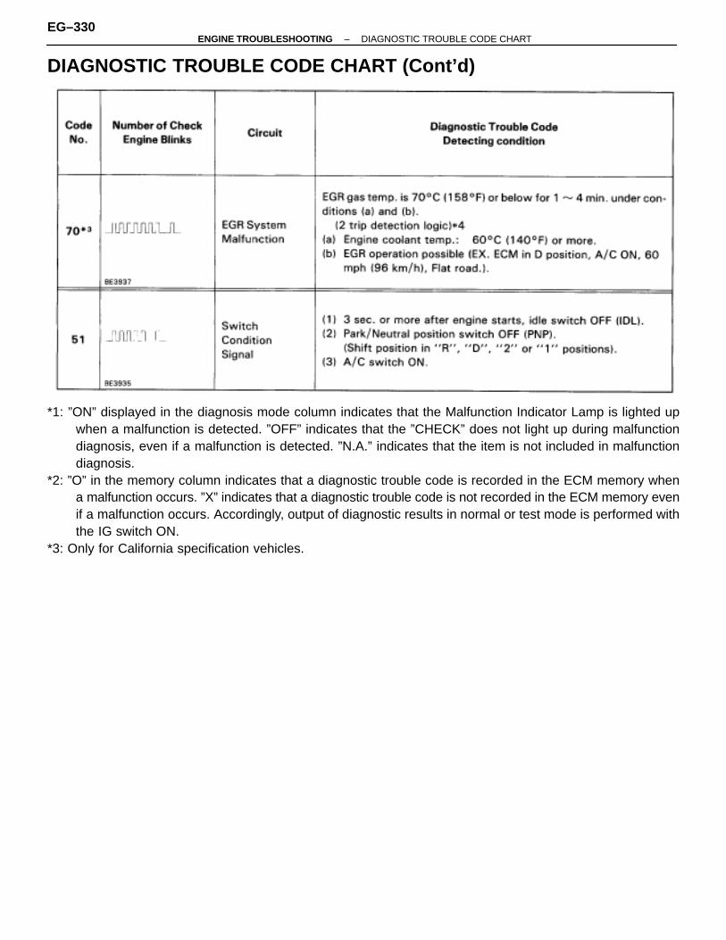
DIAGNOSTIC TROUBLE CODE CHART (Cont’d)
*1: ”ON” displayed in the diagnosis mode column indicates that the Malfunction Indicator Lamp is lighted upwhen a malfunction is detected. ”OFF” indicates that the ”CHECK” does not light up during malfunctiondiagnosis, even if a malfunction is detected. ”N.A.” indicates that the item is not included in malfunctiondiagnosis.
*2: ”O” in the memory column indicates that a diagnostic trouble code is recorded in the ECM memory whena malfunction occurs. ”X” indicates that a diagnostic trouble code is not recorded in the ECM memory evenif a malfunction occurs. Accordingly, output of diagnostic results in normal or test mode is performed withthe IG switch ON.
*3: Only for California specification vehicles.
EG–330–ENGINE TROUBLESHOOTING DIAGNOSTIC TROUBLE CODE CHART
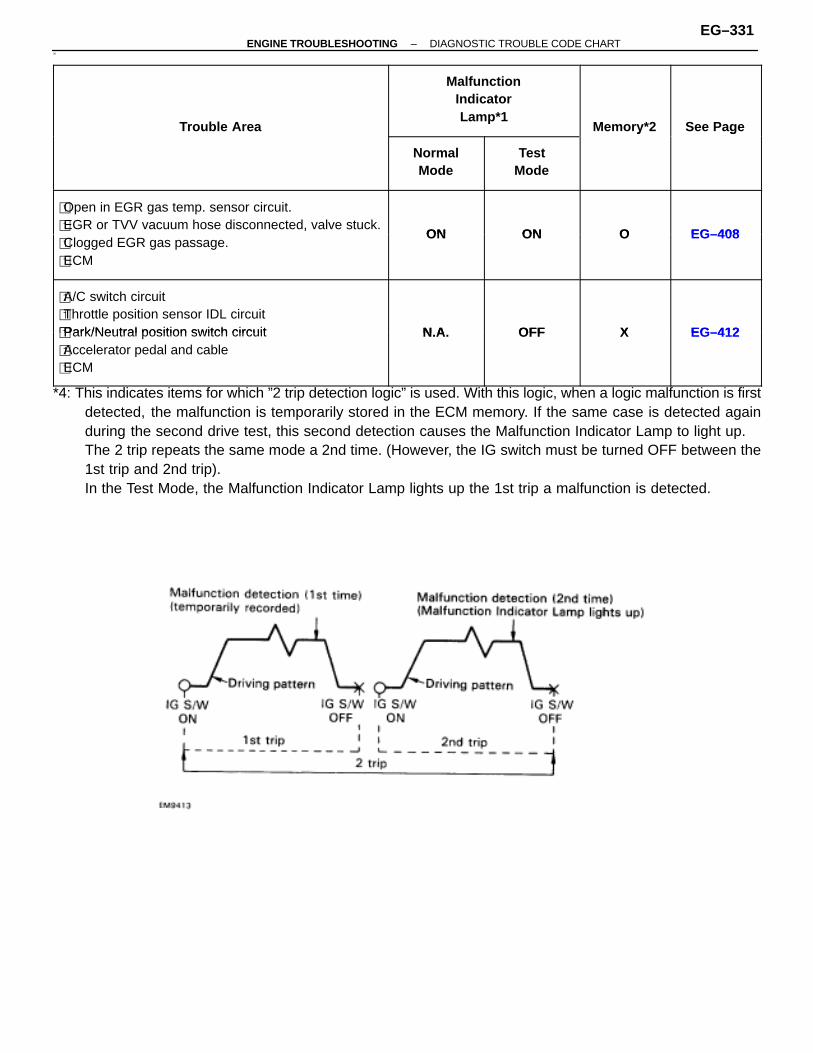
30
ÑÑÑÑÑÑÑÑÑÑÑÑÑÑÑÑÑÑÑÑÑÑÑÑÑÑÑÑÑÑÑÑÑÑÑÑÑÑÑÑÑÑÑÑÑÑÑÑÑÑÑÑÑÑÑÑÑÑÑÑÑÑÑÑÑÑÑÑ
Trouble Area
ÑÑÑÑÑÑÑÑÑÑÑÑÑÑÑÑÑÑÑÑÑÑÑÑÑÑÑÑÑÑÑÑÑÑÑÑÑÑÑÑ
MalfunctionIndicatorLamp*1
ÑÑÑÑÑÑÑÑÑÑÑÑÑÑÑÑÑÑÑÑ
Memory*2
ÑÑÑÑÑÑÑÑÑÑÑÑÑÑÑÑÑÑÑÑÑÑÑÑ
See PageÑÑÑÑÑÑÑÑÑÑÑÑÑÑÑÑÑÑÑÑÑÑÑÑÑÑÑÑÑÑÑÑÑÑÑÑÑÑÑÑÑÑÑÑÑÑÑÑÑÑÑÑÑÑÑÑÑÑÑÑÑÑÑÑÑÑÑÑ
ÑÑÑÑÑÑÑÑÑÑÑÑÑÑÑÑÑÑÑÑ
NormalMode
ÑÑÑÑÑÑÑÑÑÑÑÑÑÑÑÑÑÑÑÑÑÑÑÑ
TestMode
ÑÑÑÑÑÑÑÑÑÑÑÑÑÑÑÑÑÑÑÑ
yÑÑÑÑÑÑÑÑÑÑÑÑÑÑÑÑÑÑÑÑÑÑÑÑ
g
ÑÑÑÑÑÑÑÑÑÑÑÑÑÑÑÑÑÑÑÑÑÑÑÑÑÑÑÑÑÑÑÑÑÑÑÑÑÑÑÑÑÑÑÑÑÑÑÑÑÑÑ
�Open in EGR gas temp. sensor circuit.�EGR or TVV vacuum hose disconnected, valve stuck.
ON ON O EG–408ÑÑÑÑÑÑÑÑÑÑÑÑÑÑÑÑÑÑÑÑÑÑÑÑÑÑÑÑÑÑÑÑÑÑÑÑÑÑÑÑÑÑÑÑÑÑÑÑÑÑÑ
,�Clogged EGR gas passage.�ECM
ON ON O EG–408
ÑÑÑÑÑÑÑÑÑÑÑÑÑÑÑÑÑÑÑÑÑÑÑÑÑÑÑÑÑÑÑÑÑÑÑÑÑÑÑÑÑÑÑÑÑÑÑÑÑÑÑÑÑÑÑÑÑÑÑÑÑÑÑÑÑÑÑÑ
�A/C switch circuit�Throttle position sensor IDL circuit�Park/Neutral position switch circuit N A OFF X EG–412ÑÑÑÑÑÑÑÑÑÑÑÑÑÑÑÑÑÑÑÑÑÑÑÑÑÑÑÑÑÑÑÑÑÑÑÑÑÑÑÑÑÑÑÑÑÑÑÑÑÑÑ
�Park/Neutral position switch circuit�Accelerator pedal and cable�ECM
N.A. OFF X EG–412
*4: This indicates items for which ”2 trip detection logic” is used. With this logic, when a logic malfunction is firstdetected, the malfunction is temporarily stored in the ECM memory. If the same case is detected againduring the second drive test, this second detection causes the Malfunction Indicator Lamp to light up.The 2 trip repeats the same mode a 2nd time. (However, the IG switch must be turned OFF between the1st trip and 2nd trip).In the Test Mode, the Malfunction Indicator Lamp lights up the 1st trip a malfunction is detected.
–ENGINE TROUBLESHOOTING DIAGNOSTIC TROUBLE CODE CHARTEG–331
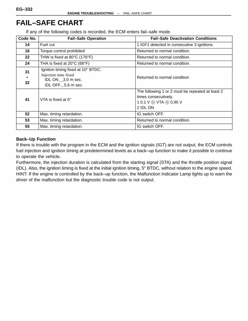
FAIL–SAFE CHARTIf any of the following codes is recorded, the ECM enters fail–safe mode.
ÑÑÑÑÑÑÑÑÑÑ
Code No.ÑÑÑÑÑÑÑÑÑÑÑÑÑÑÑÑÑÑÑÑÑÑÑÑÑÑÑÑÑÑÑÑ
Fail–Safe OperationÑÑÑÑÑÑÑÑÑÑÑÑÑÑÑÑÑÑÑÑÑÑÑÑÑÑÑÑÑÑÑÑÑÑ
Fail–Safe Deactivation ConditionsÑÑÑÑÑÑÑÑÑÑ
14ÑÑÑÑÑÑÑÑÑÑÑÑÑÑÑÑÑÑÑÑÑÑÑÑÑÑÑÑÑÑÑÑ
Fuel cutÑÑÑÑÑÑÑÑÑÑÑÑÑÑÑÑÑÑÑÑÑÑÑÑÑÑÑÑÑÑÑÑÑÑ
1 IGF1 detected in consecutive 3 ignitions.ÑÑÑÑÑÑÑÑÑÑ
16ÑÑÑÑÑÑÑÑÑÑÑÑÑÑÑÑÑÑÑÑÑÑÑÑÑÑÑÑÑÑÑÑ
Torque control prohibitedÑÑÑÑÑÑÑÑÑÑÑÑÑÑÑÑÑÑÑÑÑÑÑÑÑÑÑÑÑÑÑÑÑÑ
Returned to normal condition.ÑÑÑÑÑÑÑÑÑÑ
22ÑÑÑÑÑÑÑÑÑÑÑÑÑÑÑÑÑÑÑÑÑÑÑÑÑÑÑÑÑÑÑÑ
THW is fixed at 80°C (176°F)ÑÑÑÑÑÑÑÑÑÑÑÑÑÑÑÑÑÑÑÑÑÑÑÑÑÑÑÑÑÑÑÑÑÑ
Returned to normal condition.ÑÑÑÑÑÑÑÑÑÑ
24ÑÑÑÑÑÑÑÑÑÑÑÑÑÑÑÑÑÑÑÑÑÑÑÑÑÑÑÑÑÑÑÑ
THA is fixed at 20°C (68°F)ÑÑÑÑÑÑÑÑÑÑÑÑÑÑÑÑÑÑÑÑÑÑÑÑÑÑÑÑÑÑÑÑÑÑ
Returned to normal condition.ÑÑÑÑÑÑÑÑÑÑÑÑÑÑÑÑÑÑÑÑÑÑÑÑÑ
31•
32
ÑÑÑÑÑÑÑÑÑÑÑÑÑÑÑÑÑÑÑÑÑÑÑÑÑÑÑÑÑÑÑÑÑÑÑÑÑÑÑÑÑÑÑÑÑÑÑÑÑÑÑÑÑÑÑÑÑÑÑÑÑÑÑÑÑÑÑÑÑÑÑÑÑÑÑÑÑÑÑÑ
Ignition timing fixed at 10° BTDC. Injection time fixed IDL ON 3.0 m sec. IDL OFF 5.6 m sec.
ÑÑÑÑÑÑÑÑÑÑÑÑÑÑÑÑÑÑÑÑÑÑÑÑÑÑÑÑÑÑÑÑÑÑÑÑÑÑÑÑÑÑÑÑÑÑÑÑÑÑÑÑÑÑÑÑÑÑÑÑÑÑÑÑÑÑÑÑÑÑÑÑÑÑÑÑÑÑÑÑÑÑÑÑÑ
Returned to normal condition
ÑÑÑÑÑÑÑÑÑÑÑÑÑÑÑÑÑÑÑÑ
41
ÑÑÑÑÑÑÑÑÑÑÑÑÑÑÑÑÑÑÑÑÑÑÑÑÑÑÑÑÑÑÑÑÑÑÑÑÑÑÑÑÑÑÑÑÑÑÑÑÑÑÑÑÑÑÑÑÑÑÑÑÑÑÑÑ
VTA is fixed at 0°
ÑÑÑÑÑÑÑÑÑÑÑÑÑÑÑÑÑÑÑÑÑÑÑÑÑÑÑÑÑÑÑÑÑÑÑÑÑÑÑÑÑÑÑÑÑÑÑÑÑÑÑÑÑÑÑÑÑÑÑÑÑÑÑÑÑÑÑÑ
The following 1 or 2 must be repeated at least 2times consecutively.1 0.1 V � VTA � 0.95 V2 IDL ONÑÑÑÑÑ
ÑÑÑÑÑ52ÑÑÑÑÑÑÑÑÑÑÑÑÑÑÑÑÑÑÑÑÑÑÑÑÑÑÑÑÑÑÑÑMax. timing retardation.
ÑÑÑÑÑÑÑÑÑÑÑÑÑÑÑÑÑÑÑÑÑÑÑÑÑÑÑÑÑÑÑÑÑÑIG switch OFF.ÑÑÑÑÑ
ÑÑÑÑÑ53ÑÑÑÑÑÑÑÑÑÑÑÑÑÑÑÑÑÑÑÑÑÑÑÑÑÑÑÑÑÑÑÑMax. timing retardation.
ÑÑÑÑÑÑÑÑÑÑÑÑÑÑÑÑÑÑÑÑÑÑÑÑÑÑÑÑÑÑÑÑÑÑReturned to normal condition.ÑÑÑÑÑ
ÑÑÑÑÑ55ÑÑÑÑÑÑÑÑÑÑÑÑÑÑÑÑÑÑÑÑÑÑÑÑÑÑÑÑÑÑÑÑMax. timing retardation.
ÑÑÑÑÑÑÑÑÑÑÑÑÑÑÑÑÑÑÑÑÑÑÑÑÑÑÑÑÑÑÑÑÑÑIG switch OFF.
Back–Up FunctionIf there is trouble with the program in the ECM and the ignition signals (IGT) are not output, the ECM controlsfuel injection and ignition timing at predetermined levels as a back–up function to make it possible to continueto operate the vehicle.Furthermore, the injection duration is calculated from the starting signal (STA) and the throttle position signal(IDL). Also, the ignition timing is fixed at the initial ignition timing, 5° BTDC, without relation to the engine speed.HINT: If the engine is controlled by the back–up function, the Malfunction Indicator Lamp lights up to warn thedriver of the malfunction but the diagnostic trouble code is not output.
EG–332–ENGINE TROUBLESHOOTING FAIL–SAFE CHART

CHECK FOR MOMENTARYINTERRUPTIONAs described in the preceding paragraph, abnormality detectionability in the test mode is increased compared to that in the normalmode, so that when momentary interruptions or momentary shortsoccur in the ECM signal circuits (G1, G2, NE, THW, THA, VS, VTA)shown in the table below, the appropriate diagnostic trouble codeis output. Accordingly, when the diagnostic trouble codes shown in the tablebelow (13, 22, 24, 31, 32, 41) are output during the diagnostictrouble code check, and inspection of the appropriate circuits re-veals no abnormality, perform the check for momentary interrup-tion as described below. By performing the check for momentary interruption, the placewhere momentary interruptions or momentary shorts are occur-ring due to poor contacts can be isolated.
ÑÑÑÑÑDiag. CodeÑÑÑÑÑÑÑÑÑÑCircuitÑÑÑÑÑÑÑÑÑÑ13
ÑÑÑÑÑÑÑÑÑÑÑÑÑÑÑÑÑÑÑÑRPM signal circuit (No.2)ÑÑÑÑÑ
ÑÑÑÑÑÑÑÑÑÑ
22 ÑÑÑÑÑÑÑÑÑÑÑÑÑÑÑÑÑÑÑÑÑÑÑÑÑÑÑÑÑÑ
Engine coolant temp. sensorcircuit
ÑÑÑÑÑÑÑÑÑÑ
24 ÑÑÑÑÑÑÑÑÑÑÑÑÑÑÑÑÑÑÑÑ
Intake air temp. sensor circuit
ÑÑÑÑÑÑÑÑÑÑ
31⋅32 Volume air flow meter circuit
ÑÑÑÑÑ41 Throttle position sensor circuit
CLEAR DIAGNOSTIC TROUBLE CODESSee page EG–323.
SET TEST MODE1. With the ignition switch off, using SST, connect the
terminals TE2 and E1 of the Data link connector 2 or 1.SST 09843–18020
2. Start the engine and check to see the MalfunctionIndicator Lamp to go off.
PERFORM A SIMULATION TESTUsing the symptom simulation (See page IN–20), apply vibrationto and pull lightly on the wire harness, connector or terminals in thecircuit indicated by the malfunction code. In this test, if the Malfunc-tion Indicator Lamp lights up, it indicates that the place where thewire harness, connector or terminals being pulled or vibrated hasfaulty contact. Check that point for loose connections, dirt on theterminals, poor fit or other problems and repair as necessary.HINT: After cancelling out the diagnostic trouble code in memoryand set the test mode, if the Malfunction Indicator Lamp does notgo off after the engine is started, check thoroughly for faulty con-tact, etc., then try the check again. If the Malfunction IndicatorLamp still does not go off, check and replace ECM.
–ENGINE TROUBLESHOOTING CHECK FOR MOMENTARY INTERRUPTIONEG–333

YES NO
YES NO
YES NO
OK NG
BASIC INSPECTIONWhen the normal code is displayed in the diagnostic trouble code check, troubleshooting should be performedin the order for all possible circuits to be considered as the causes of the problems.In many cases, by carrying out the basic engine check shown in the following flow chart, the location causingthe problem can be found quickly and efficiently. Therefore, use of this check is essential in engine troubleshoot-ing.
1 Is battery voltage 11 V or more when engine is stopped?
Charge or replace battery.
2 Is engine cranked?
Proceed to matrix chart of problem symptoms on pageEG–344.
3 Does engine start?
Go to step �.
4 Check air filter.
C
Hint
P Remove air filter.
Visually check that the air filter is not excessively dam-aged or oily.
If necessary, clean the air filter with compressed air. Firstblow from inside thoroughly, then blow off outside of theair filter.
Repair or replace.
Go to step �.
EG–334–ENGINE TROUBLESHOOTING BASIC INSPECTION

OK NG
OK NG
5 Check idle speed.
C
OK
P 1. Shift transmission into “N” position or neutral.2. Warm up engine at normal operating temperature.
3. Switched off all accessories.4. Switched off air conditioning.5. Connect tachometer test probe to terminal IG � of
data link connector 1.
Check idle speed.
Idle speed: 650 � 750 rpm
Caution:�NEVER allow tachometer test probe to touchground as it could result in damage to igniter and/orignition coil.�As some tachometers are not compatible with thisignition system, we recommend that you confirmcompatibility of your unit before use.
Proceed to matrix chart of problem symptoms on pageEG–344.
6 Check ignition timing.
C
OK
P 1. Shift transmission into “N” position or neutral.2. Warm up engine at normal operating temperature.
3. Keep the engine speed at idle.4. Using SST, connect terminals TE1 and E 1 of data
link connector 1.
SST 09843–180205. Using a timing light, connect the tester to No. 4
high–tension cord.
Check ignition timing.
Ignition timing: 10 � BTDC at idle.
Proceed to page IG–19 and continue to troubleshoot.
Proceed to matrix chart of problem symptoms onpage EG–344.
–ENGINE TROUBLESHOOTING BASIC INSPECTIONEG–335
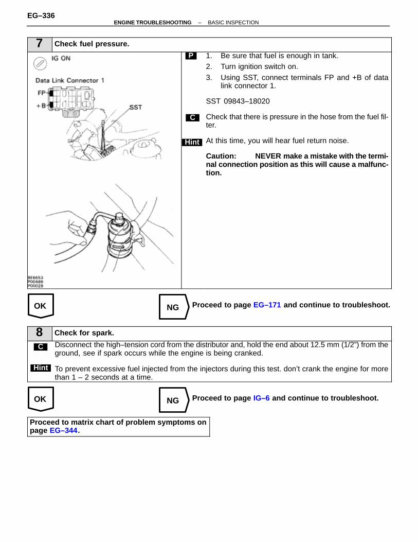
OK NG
OK NG
7 Check fuel pressure.
C
Hint
P 1. Be sure that fuel is enough in tank.2. Turn ignition switch on.
3. Using SST, connect terminals FP and +B of datalink connector 1.
SST 09843–18020
Check that there is pressure in the hose from the fuel fil-ter.
At this time, you will hear fuel return noise.
Caution: NEVER make a m istake with the termi-nal connection position as this will cause a malfunc-tion.
Proceed to page EG–171 and continue to troubleshoot.
8 Check for spark.
C Disconnect the high–tension cord from the distributor and, hold the end about 12.5 mm (1/2”) from theground, see if spark occurs while the engine is being cranked.
To prevent excessive fuel injected from the injectors during this test. don’t crank the engine for morethan 1 – 2 seconds at a time.
Hint
Proceed to page IG–6 and continue to troubleshoot.
Proceed to matrix chart of problem symptoms onpage EG–344.
EG–336–ENGINE TROUBLESHOOTING BASIC INSPECTION

PARTS LOCATION–ENGINE TROUBLESHOOTING PARTS LOCATION
EG–337
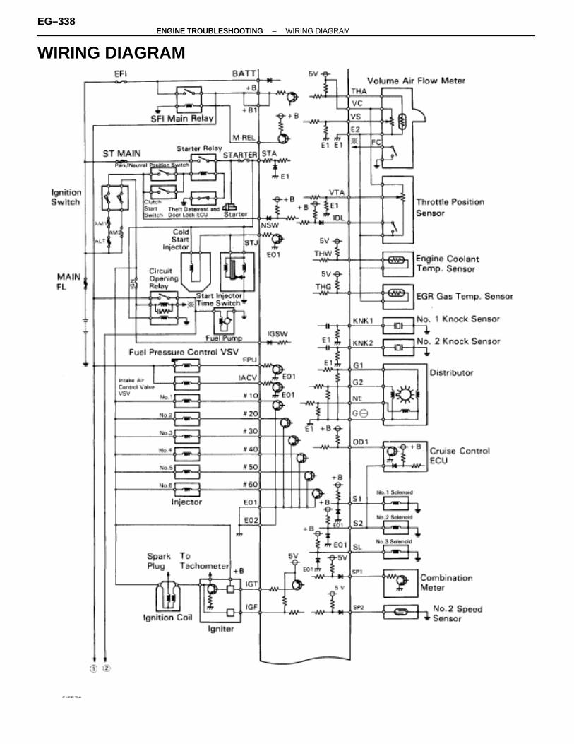
WIRING DIAGRAM
EG–338–ENGINE TROUBLESHOOTING WIRING DIAGRAM
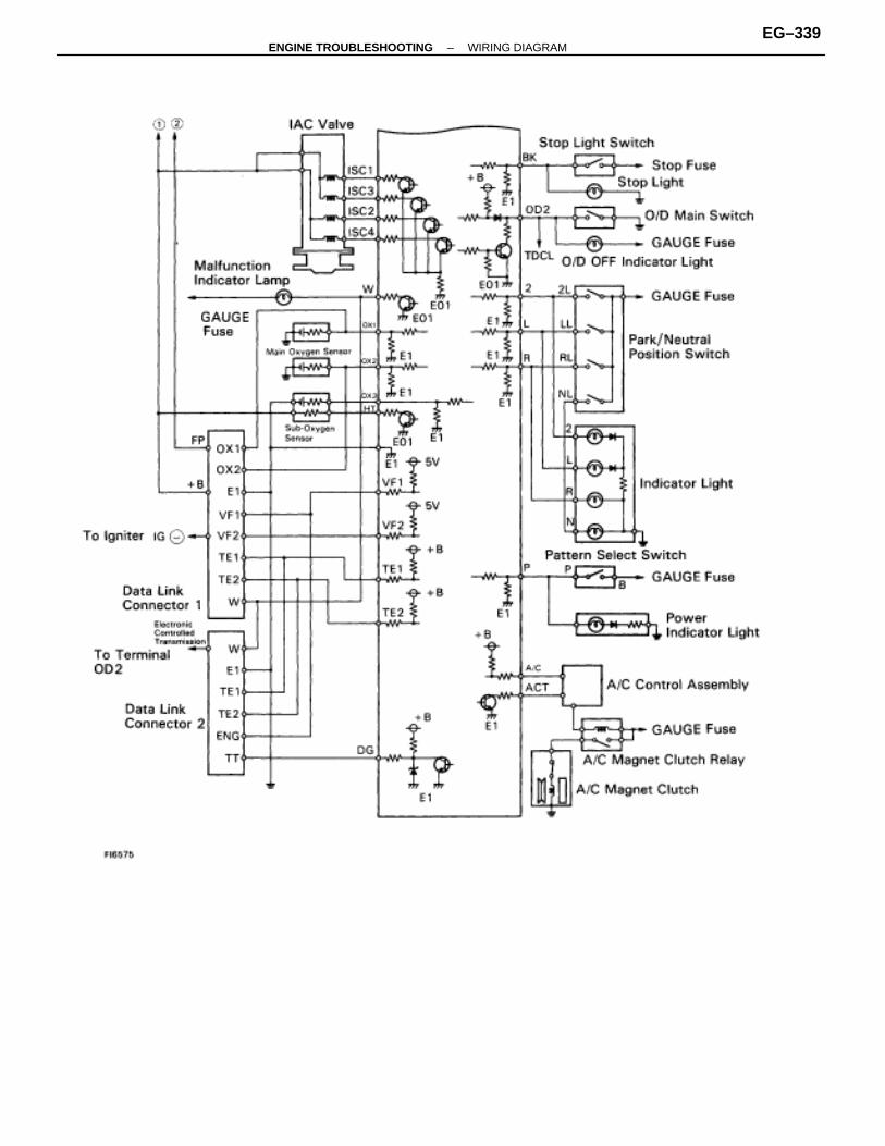
–ENGINE TROUBLESHOOTING WIRING DIAGRAMEG–339
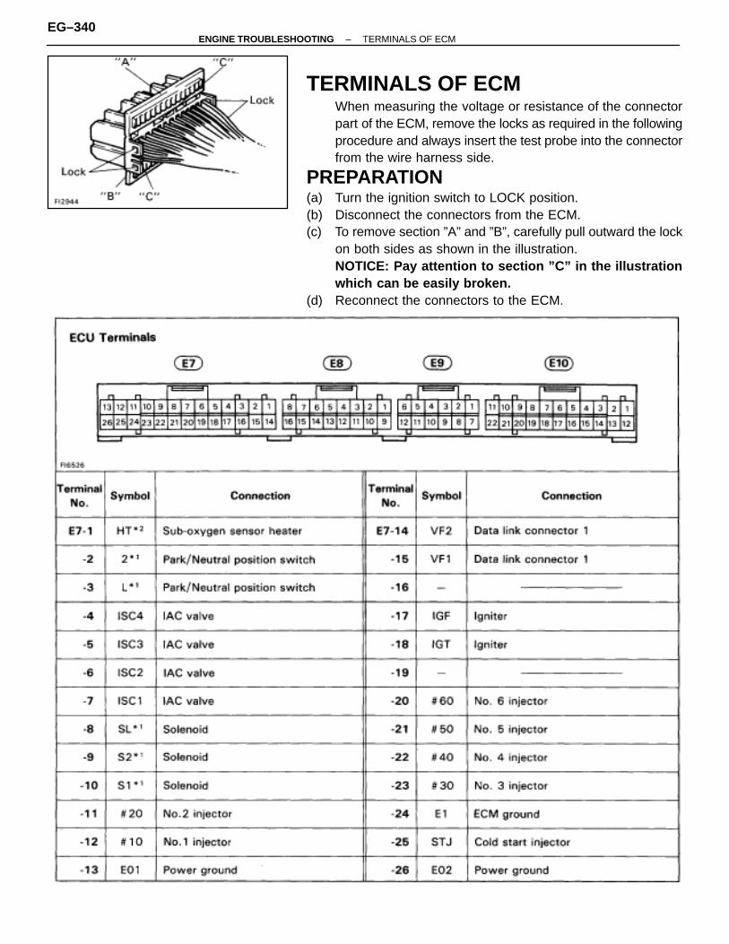
TERMINALS OF ECMWhen measuring the voltage or resistance of the connectorpart of the ECM, remove the locks as required in the followingprocedure and always insert the test probe into the connectorfrom the wire harness side.
PREPARATION(a) Turn the ignition switch to LOCK position.(b) Disconnect the connectors from the ECM.(c) To remove section ”A” and ”B”, carefully pull outward the lock
on both sides as shown in the illustration.NOTICE: Pay attention to section ”C” in the illustrationwhich can be easily broken.
(d) Reconnect the connectors to the ECM.
EG–340–ENGINE TROUBLESHOOTING TERMINALS OF ECM

ÑÑÑÑÑÑÑÑÑÑÑÑ
TerminalNo.ÑÑÑÑÑÑÑÑÑÑÑÑÑÑÑ
Symbol ÑÑÑÑÑÑÑÑÑÑÑÑÑÑÑÑÑÑÑÑÑÑÑÑÑÑÑÑÑÑÑÑÑ
Connection ÑÑÑÑÑÑÑÑÑÑÑÑÑÑÑ
Termi-nalNo.
ÑÑÑÑÑÑÑÑÑÑÑÑ
SymbolÑÑÑÑÑÑÑÑÑÑÑÑÑÑÑÑÑÑÑÑÑÑÑÑÑÑÑÑÑÑÑÑÑÑÑÑ
Connection
ÑÑÑÑÑÑÑÑÑÑÑÑ
E8–1ÑÑÑÑÑÑÑÑÑÑÑÑÑÑÑ
VCÑÑÑÑÑÑÑÑÑÑÑÑÑÑÑÑÑÑÑÑÑÑÑÑÑÑÑÑÑÑÑÑÑ
Throttle position sensorVolume air flow meter
ÑÑÑÑÑÑÑÑÑÑÑÑÑÑÑ
E9–10ÑÑÑÑÑÑÑÑÑÑÑÑ
G2ÑÑÑÑÑÑÑÑÑÑÑÑÑÑÑÑÑÑÑÑÑÑÑÑÑÑÑÑÑÑÑÑÑÑÑÑ
Distributor
ÑÑÑÑÑÑÑÑ
–2ÑÑÑÑÑÑÑÑÑÑ
VSÑÑÑÑÑÑÑÑÑÑÑÑÑÑÑÑÑÑÑÑÑÑ
Volume air flow meterÑÑÑÑÑÑÑÑÑÑ
–11ÑÑÑÑÑÑÑÑ
G1ÑÑÑÑÑÑÑÑÑÑÑÑÑÑÑÑÑÑÑÑÑÑÑÑ
DistributorÑÑÑÑÑÑÑÑ
–3ÑÑÑÑÑÑÑÑÑÑ
THAÑÑÑÑÑÑÑÑÑÑÑÑÑÑÑÑÑÑÑÑÑÑ
Intake air temp. sensorÑÑÑÑÑÑÑÑÑÑ
–12ÑÑÑÑÑÑÑÑ
NEÑÑÑÑÑÑÑÑÑÑÑÑÑÑÑÑÑÑÑÑÑÑÑÑ
DistributorÑÑÑÑÑÑÑÑ
–4ÑÑÑÑÑÑÑÑÑÑ
THWÑÑÑÑÑÑÑÑÑÑÑÑÑÑÑÑÑÑÑÑÑÑ
Engine coolant temp. sensorÑÑÑÑÑÑÑÑÑÑ
E10–1ÑÑÑÑÑÑÑÑ
+B1ÑÑÑÑÑÑÑÑÑÑÑÑÑÑÑÑÑÑÑÑÑÑÑÑ
SFI main relayÑÑÑÑÑÑÑÑ
–5ÑÑÑÑÑÑÑÑÑÑ
OX1ÑÑÑÑÑÑÑÑÑÑÑÑÑÑÑÑÑÑÑÑÑÑ
Main oxygen sensor (on right bank)ÑÑÑÑÑÑÑÑÑÑ
–2ÑÑÑÑÑÑÑÑ
BATTÑÑÑÑÑÑÑÑÑÑÑÑÑÑÑÑÑÑÑÑÑÑÑÑ
BatteryÑÑÑÑÑÑÑÑ
–6ÑÑÑÑÑÑÑÑÑÑ
KNK1ÑÑÑÑÑÑÑÑÑÑÑÑÑÑÑÑÑÑÑÑÑÑ
No. 1 knock sensorÑÑÑÑÑÑÑÑÑÑ
–3ÑÑÑÑÑÑÑÑ
M–RELÑÑÑÑÑÑÑÑÑÑÑÑÑÑÑÑÑÑÑÑÑÑÑÑ
SFI main relayÑÑÑÑÑÑÑÑ
–7ÑÑÑÑÑÑÑÑÑÑ
TE1ÑÑÑÑÑÑÑÑÑÑÑÑÑÑÑÑÑÑÑÑÑÑ
Data link connector 1ÑÑÑÑÑÑÑÑÑÑ
–4ÑÑÑÑÑÑÑÑ
WÑÑÑÑÑÑÑÑÑÑÑÑÑÑÑÑÑÑÑÑÑÑÑÑ
Malfunction Indicator LampÑÑÑÑÑÑÑÑ
–8ÑÑÑÑÑÑÑÑÑÑ
DGÑÑÑÑÑÑÑÑÑÑÑÑÑÑÑÑÑÑÑÑÑÑ
Data link connector 1ÑÑÑÑÑÑÑÑÑÑ
–5ÑÑÑÑÑÑÑÑ
–ÑÑÑÑÑÑÑÑÑÑÑÑÑÑÑÑÑÑÑÑÑÑÑÑ
–ÑÑÑÑÑÑÑÑ
–9ÑÑÑÑÑÑÑÑÑÑ
E2ÑÑÑÑÑÑÑÑÑÑÑÑÑÑÑÑÑÑÑÑÑÑ
Sensor groundÑÑÑÑÑÑÑÑÑÑ
–6ÑÑÑÑÑÑÑÑ
ACTÑÑÑÑÑÑÑÑÑÑÑÑÑÑÑÑÑÑÑÑÑÑÑÑ
A/C control assemblyÑÑÑÑÑÑÑÑ
–10ÑÑÑÑÑÑÑÑÑÑ
VTAÑÑÑÑÑÑÑÑÑÑÑÑÑÑÑÑÑÑÑÑÑÑ
Throttle position sensorÑÑÑÑÑÑÑÑÑÑ
–7ÑÑÑÑÑÑÑÑ
A/CÑÑÑÑÑÑÑÑÑÑÑÑÑÑÑÑÑÑÑÑÑÑÑÑ
A/C control assemblyÑÑÑÑÑÑÑÑ
–11ÑÑÑÑÑÑÑÑÑÑ
IDLÑÑÑÑÑÑÑÑÑÑÑÑÑÑÑÑÑÑÑÑÑÑ
Throttle position sensorÑÑÑÑÑÑÑÑÑÑ
–8ÑÑÑÑÑÑÑÑ
SP1ÑÑÑÑÑÑÑÑÑÑÑÑÑÑÑÑÑÑÑÑÑÑÑÑ
Speed sensor No.1ÑÑÑÑÑÑÑÑ
–12ÑÑÑÑÑÑÑÑÑÑ
THG*2 ÑÑÑÑÑÑÑÑÑÑÑÑÑÑÑÑÑÑÑÑÑÑ
EGR gas temp. sensorÑÑÑÑÑÑÑÑÑÑ
–9ÑÑÑÑÑÑÑÑ
OD2*1ÑÑÑÑÑÑÑÑÑÑÑÑÑÑÑÑÑÑÑÑÑÑÑÑ
O/D main switchÑÑÑÑÑÑÑÑ
–13ÑÑÑÑÑÑÑÑÑÑ
OX2ÑÑÑÑÑÑÑÑÑÑÑÑÑÑÑÑÑÑÑÑÑÑ
Main oxygen sensor (on left bank)ÑÑÑÑÑÑÑÑÑÑ
–10ÑÑÑÑÑÑÑÑ
–ÑÑÑÑÑÑÑÑÑÑÑÑÑÑÑÑÑÑÑÑÑÑÑÑ
–ÑÑÑÑÑÑÑÑ
–14ÑÑÑÑÑÑÑÑÑÑ
KNK2ÑÑÑÑÑÑÑÑÑÑÑÑÑÑÑÑÑÑÑÑÑÑ
No. 2 knock sensorÑÑÑÑÑÑÑÑÑÑ
–11ÑÑÑÑÑÑÑÑ
STAÑÑÑÑÑÑÑÑÑÑÑÑÑÑÑÑÑÑÑÑÑÑÑÑ
Starter relayÑÑÑÑÑÑÑÑ
–15ÑÑÑÑÑÑÑÑÑÑ
TE2ÑÑÑÑÑÑÑÑÑÑÑÑÑÑÑÑÑÑÑÑÑÑ
Data link connector 1ÑÑÑÑÑÑÑÑÑÑ
–12ÑÑÑÑÑÑÑÑ
+BÑÑÑÑÑÑÑÑÑÑÑÑÑÑÑÑÑÑÑÑÑÑÑÑ
SFI main relayÑÑÑÑÑÑÑÑ
–16ÑÑÑÑÑÑÑÑÑÑ
SP2*1 ÑÑÑÑÑÑÑÑÑÑÑÑÑÑÑÑÑÑÑÑÑÑ
Speed sensor No. 2 (for ECT)ÑÑÑÑÑÑÑÑÑÑ
–13ÑÑÑÑÑÑÑÑ
IGSWÑÑÑÑÑÑÑÑÑÑÑÑÑÑÑÑÑÑÑÑÑÑÑÑ
Ignition switchÑÑÑÑÑÑÑÑÑÑÑÑ
E9–1ÑÑÑÑÑÑÑÑÑÑÑÑÑÑÑ
–ÑÑÑÑÑÑÑÑÑÑÑÑÑÑÑÑÑÑÑÑÑÑÑÑÑÑÑÑÑÑÑÑÑ
–ÑÑÑÑÑÑÑÑÑÑÑÑÑÑÑ
–14ÑÑÑÑÑÑÑÑÑÑÑÑ
BK*1 ÑÑÑÑÑÑÑÑÑÑÑÑÑÑÑÑÑÑÑÑÑÑÑÑÑÑÑÑÑÑÑÑÑÑÑÑ
Stop light switchStop light
ÑÑÑÑÑÑÑÑ
–2ÑÑÑÑÑÑÑÑÑÑ
FPU ÑÑÑÑÑÑÑÑÑÑÑÑÑÑÑÑÑÑÑÑÑÑ
Fuel pressure up VSV ÑÑÑÑÑÑÑÑÑÑ
–15 ÑÑÑÑÑÑÑÑ
– ÑÑÑÑÑÑÑÑÑÑÑÑÑÑÑÑÑÑÑÑÑÑÑÑ
–ÑÑÑÑÑÑÑÑ
–3ÑÑÑÑÑÑÑÑÑÑ
IACV ÑÑÑÑÑÑÑÑÑÑÑÑÑÑÑÑÑÑÑÑÑÑ
VSV (intake air control valve) ÑÑÑÑÑÑÑÑÑÑ
–16 ÑÑÑÑÑÑÑÑ
– ÑÑÑÑÑÑÑÑÑÑÑÑÑÑÑÑÑÑÑÑÑÑÑÑ
–ÑÑÑÑÑÑÑÑ
–4ÑÑÑÑÑÑÑÑÑÑ
– ÑÑÑÑÑÑÑÑÑÑÑÑÑÑÑÑÑÑÑÑÑÑ
– ÑÑÑÑÑÑÑÑÑÑ
–17 ÑÑÑÑÑÑÑÑ
– ÑÑÑÑÑÑÑÑÑÑÑÑÑÑÑÑÑÑÑÑÑÑÑÑ
–ÑÑÑÑÑÑÑÑ
–5ÑÑÑÑÑÑÑÑÑÑ
OX3*2 ÑÑÑÑÑÑÑÑÑÑÑÑÑÑÑÑÑÑÑÑÑÑ
Sub–oxygen sensor ÑÑÑÑÑÑÑÑÑÑ
–18 ÑÑÑÑÑÑÑÑ
OD1*1ÑÑÑÑÑÑÑÑÑÑÑÑÑÑÑÑÑÑÑÑÑÑÑÑ
Cruise control ECUÑÑÑÑÑÑÑÑ
–6ÑÑÑÑÑÑÑÑÑÑ
G � ÑÑÑÑÑÑÑÑÑÑÑÑÑÑÑÑÑÑÑÑÑÑ
Distributor ÑÑÑÑÑÑÑÑÑÑ
–19 ÑÑÑÑÑÑÑÑ
R*1 ÑÑÑÑÑÑÑÑÑÑÑÑÑÑÑÑÑÑÑÑÑÑÑÑ
Neutral start switchÑÑÑÑÑÑÑÑÑÑÑÑ
–7ÑÑÑÑÑÑÑÑÑÑÑÑÑÑÑ
– ÑÑÑÑÑÑÑÑÑÑÑÑÑÑÑÑÑÑÑÑÑÑÑÑÑÑÑÑÑÑÑÑÑ
– ÑÑÑÑÑÑÑÑÑÑÑÑÑÑÑ
–20 ÑÑÑÑÑÑÑÑÑÑÑÑ
P*1 ÑÑÑÑÑÑÑÑÑÑÑÑÑÑÑÑÑÑÑÑÑÑÑÑÑÑÑÑÑÑÑÑÑÑÑÑ
Electronic Controlled Transmissionpattern select switch
ÑÑÑÑÑÑÑÑ
–8ÑÑÑÑÑÑÑÑÑÑ
– ÑÑÑÑÑÑÑÑÑÑÑÑÑÑÑÑÑÑÑÑÑÑ
– ÑÑÑÑÑÑÑÑÑÑ
–21 ÑÑÑÑÑÑÑÑ
– ÑÑÑÑÑÑÑÑÑÑÑÑÑÑÑÑÑÑÑÑÑÑÑÑ
–ÑÑÑÑÑÑÑÑ
–9ÑÑÑÑÑÑÑÑÑÑ
– ÑÑÑÑÑÑÑÑÑÑÑÑÑÑÑÑÑÑÑÑÑÑ
– ÑÑÑÑÑÑÑÑÑÑ
–22 ÑÑÑÑÑÑÑÑ
NSW*1ÑÑÑÑÑÑÑÑÑÑÑÑÑÑÑÑÑÑÑÑÑÑÑÑ
Park/Neutral position switch*1: Only vehicles with Electronic Controlled Transmission.*2: Only for California specification vehicles.
–ENGINE TROUBLESHOOTING TERMINALS OF ECMEG–341
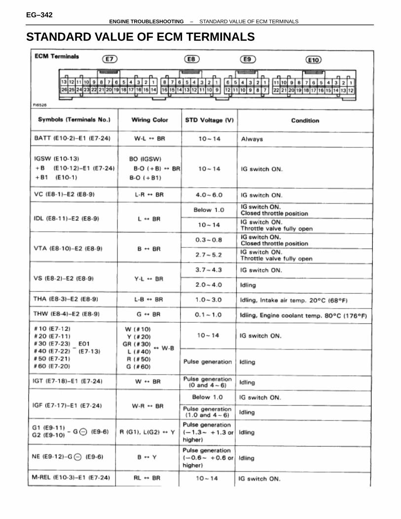
STANDARD VALUE OF ECM TERMINALS
EG–342–ENGINE TROUBLESHOOTING STANDARD VALUE OF ECM TERMINALS

–ENGINE TROUBLESHOOTING STANDARD VALUE OF ECM TERMINALSEG–343

EG
–388
, 390
EG
–400
,
EG
–408
,
EG
–412
,
EG
–416
,
EG
–420
,
EG
–426
EG
–428
EG
–432
EG
–436
EG
–440
EG
–446
EG
–450
AC
–84,
ST
–17–
19
IG–6
IG–9
IG–1
1
IG–1
1
EG
–27
AX
–66
BE
–278
IN–3
2
MATRIX CHART OF PROBLEM SYMPTOMSWhen the malfunction code is not confirmed in the diagnostic trouble code check and the problem still can notbe confirmed in the basic inspection, then proceed to this step and perform troubleshooting according to thenumbered order given in the table below.The circuits indicated by on the matrix chart can be inspected using the TCCS checker.
EG–344–ENGINE TROUBLESHOOTING MATRIX CHART OF PROBLEM SYMPTOMS

–MEMO–
ENGINE TROUBLESHOOTING
EG–345
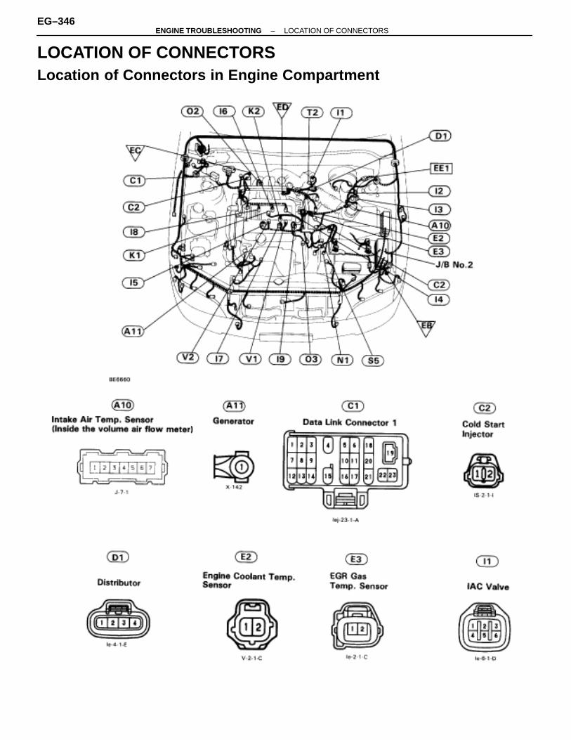
LOCATION OF CONNECTORSLocation of Connectors in Engine Compartment
EG–346–ENGINE TROUBLESHOOTING LOCATION OF CONNECTORS

–ENGINE TROUBLESHOOTING LOCATION OF CONNECTORSEG–347
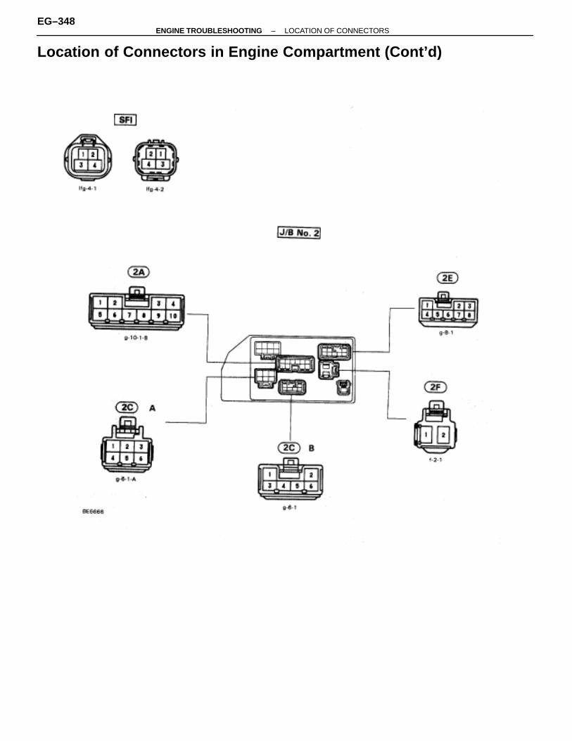
Location of Connectors in Engine Compartment (Cont’d)
EG–348–ENGINE TROUBLESHOOTING LOCATION OF CONNECTORS
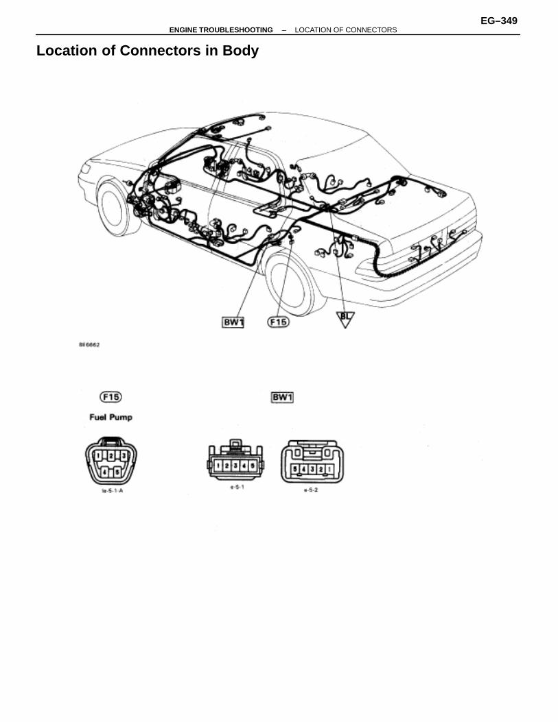
Location of Connectors in Body
–ENGINE TROUBLESHOOTING LOCATION OF CONNECTORSEG–349
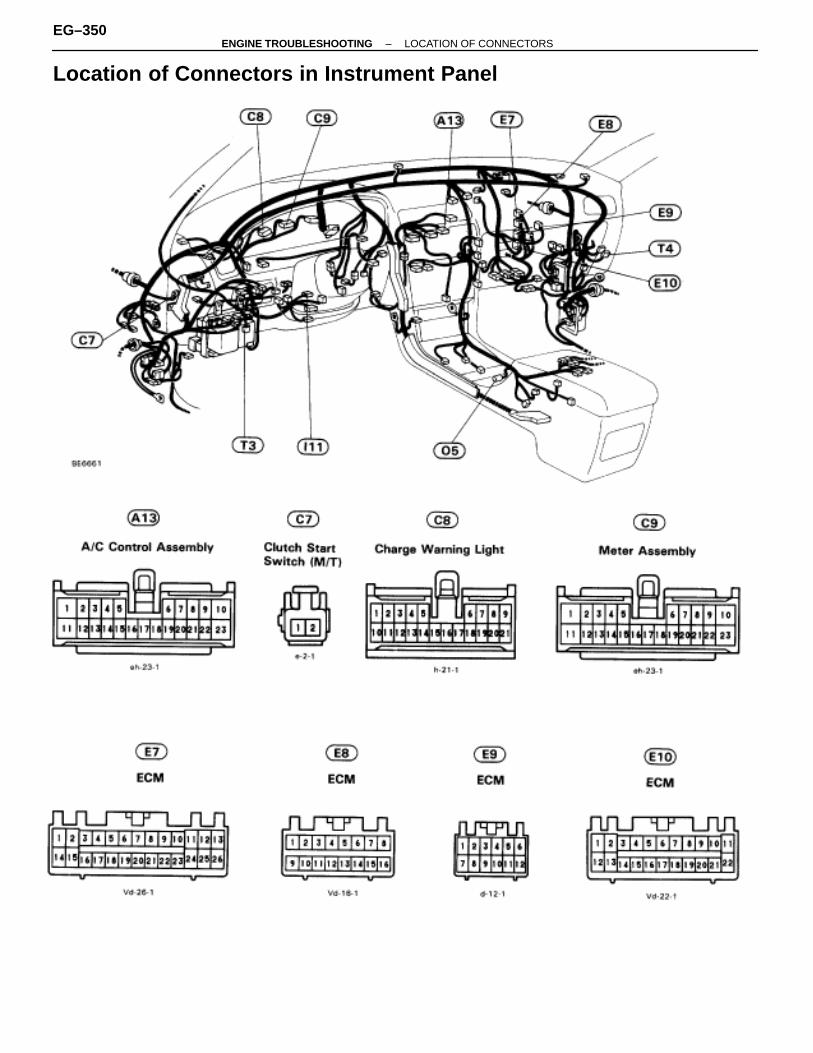
Location of Connectors in Instrument Panel
EG–350–ENGINE TROUBLESHOOTING LOCATION OF CONNECTORS
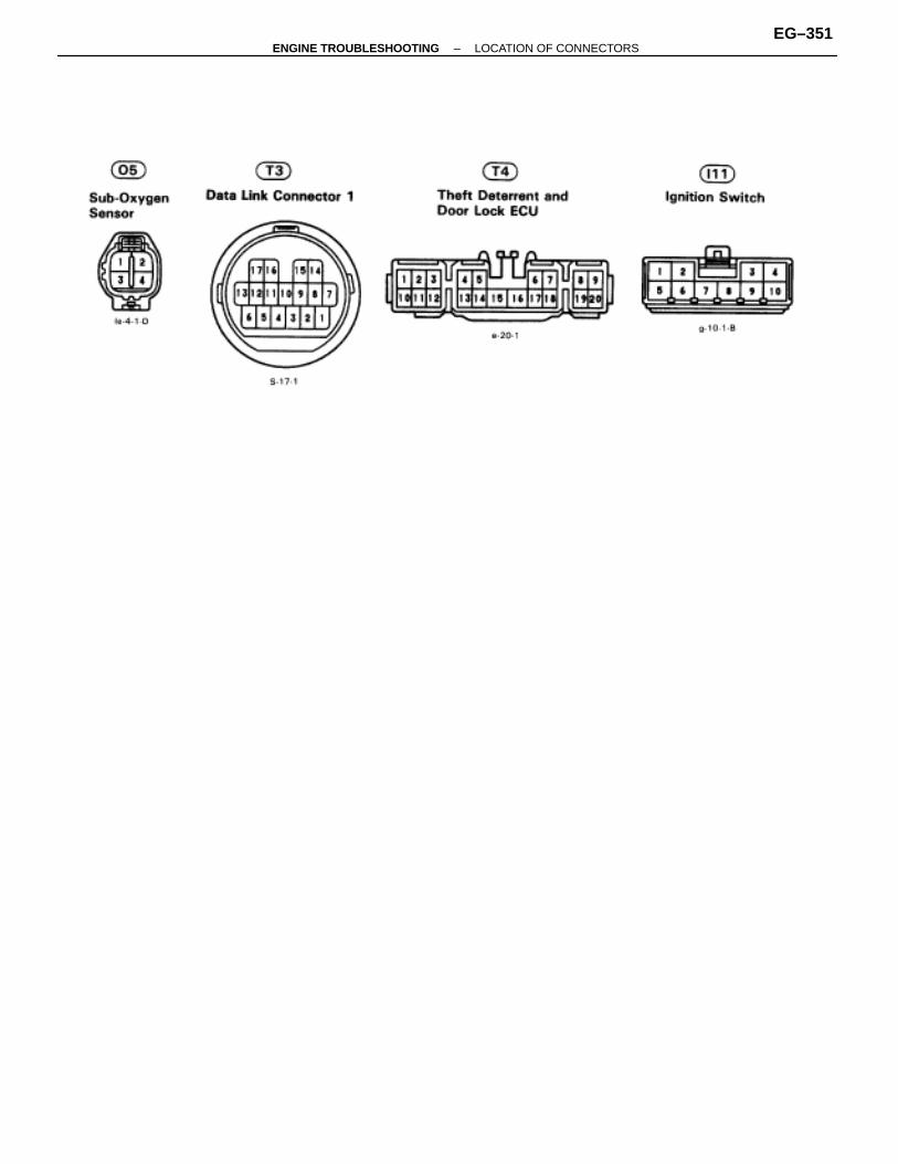
–ENGINE TROUBLESHOOTING LOCATION OF CONNECTORSEG–351

Location of Connectors in Instrument Panel (Cont’d)
EG–352–ENGINE TROUBLESHOOTING LOCATION OF CONNECTORS
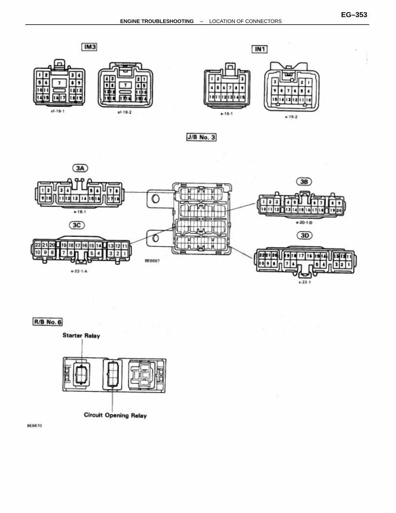
–ENGINE TROUBLESHOOTING LOCATION OF CONNECTORSEG–353
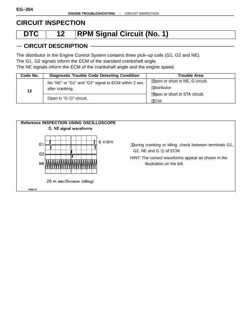
CIRCUIT INSPECTION
DTC 12 RPM Signal Circuit (No. 1)
CIRCUIT DESCRIPTION
The distributor in the Engine Control System contains three pick–up coils (G1, G2 and NE).The G1, G2 signals inform the ECM of the standard crankshaft angle.The NE signals inform the ECM of the crankshaft angle and the engine speed.
Code No. Diagnostic Trouble Code Detecting Condition Trouble Area
12
No “NE” or “G1” and “G2” signal to ECM within 2 sec.after cranking.
�Open or short in NE, G circuit.
�Distributor
�Open or short in STA circuitOpen in “G �” circuit.
�Open or short in STA circuit.
�ECM
Reference INSPECTION USING OSCILLOSCOPE
�During cranking or idling, check between terminals G1,G2, NE and G � of ECM.
HINT: The correct waveforms appear as shown in the illustration on the left.
EG–354–ENGINE TROUBLESHOOTING CIRCUIT INSPECTION

WIRING DIAGRAM
DIAGNOSTIC CHARTDIAGNOSTIC CHART
–ENGINE TROUBLESHOOTING CIRCUIT INSPECTIONEG–355
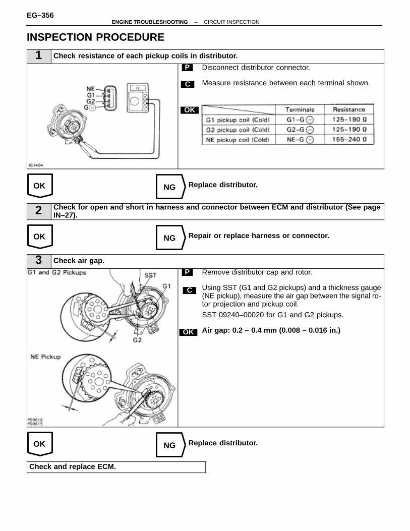
OK NG
OK NG
OK NG
INSPECTION PROCEDURE
1 Check resistance of each pickup coils in distributor.
C
OK
P Disconnect distributor connector.
Measure resistance between each terminal shown.
Replace distributor.
2 Check for open and short in harness and connector between ECM and distributor (See pageIN–27).
Repair or replace harness or connector.
3 Check air gap.
C
OK
P Remove distributor cap and rotor.
Using SST (G1 and G2 pickups) and a thickness gauge(NE pickup), measure the air gap between the signal ro-tor projection and pickup coil.
SST 09240–00020 for G1 and G2 pickups.
Air gap: 0.2 – 0.4 mm (0.008 – 0.016 in.)
Replace distributor.
Check and replace ECM.
EG–356–ENGINE TROUBLESHOOTING CIRCUIT INSPECTION
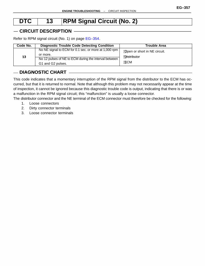
DTC 13 RPM Signal Circuit (No. 2)
CIRCUIT DESCRIPTION
Refer to RPM signal circuit (No. 1) on page EG–354.
Code No. Diagnostic Trouble Code Detecting Condition Trouble Area
13
No NE signal to ECM for 0.1 sec. or more at 1,000 rpmor more.
�Open or short in NE circuit.
�Distributor13 No 12 pulses of NE to ECM during the interval betweenG1 and G2 pulses.
�Distributor
�ECM
DIAGNOSTIC CHARTDIAGNOSTIC CHARTThis code indicates that a momentary interruption of the RPM signal from the distributor to the ECM has oc-curred, but that it is returned to normal. Note that although this problem may not necessarily appear at the timeof inspection, it cannot be ignored because this diagnostic trouble code is output, indicating that there is or wasa malfunction in the RPM signal circuit; this “malfunction” is usually a loose connector.The distributor connector and the NE terminal of the ECM connector must therefore be checked for the following:
1. Loose connectors2. Dirty connector terminals3. Loose connector terminals
–ENGINE TROUBLESHOOTING CIRCUIT INSPECTIONEG–357
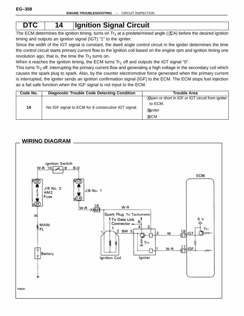
WIRING DIAGRAM
DTC 14 Ignition Signal CircuitThe ECM determines the ignition timing, turns on Tr1 at a predetermined angle (�CA) before the desired ignitiontiming and outputs an ignition signal (IGT) “1” to the igniter.Since the width of the IGT signal is constant, the dwell angle control circuit in the igniter determines the timethe control circuit starts primary current flow to the ignition coil based on the engine rpm and ignition timing onerevolution ago, that is, the time the Tr2 turns on.When it reaches the ignition timing, the ECM turns Tr1 off and outputs the IGT signal “0”.This turns Tr2 off, interrupting the primary current flow and generating a high voltage in the secondary coil whichcauses the spark plug to spark. Also, by the counter electromotive force generated when the primary currentis interrupted, the igniter sends an ignition confirmation signal (IGF) to the ECM. The ECM stops fuel injectionas a fail safe function when the IGF signal is not input to the ECM.
Code No. Diagnostic Trouble Code Detecting Condition Trouble Area
14 No IGF signal to ECM for 6 consecutive IGT signal.
�Open or short in IGF or IGT circuit from igniterto ECM.
�Igniter
�ECM
EG–358–ENGINE TROUBLESHOOTING CIRCUIT INSPECTION
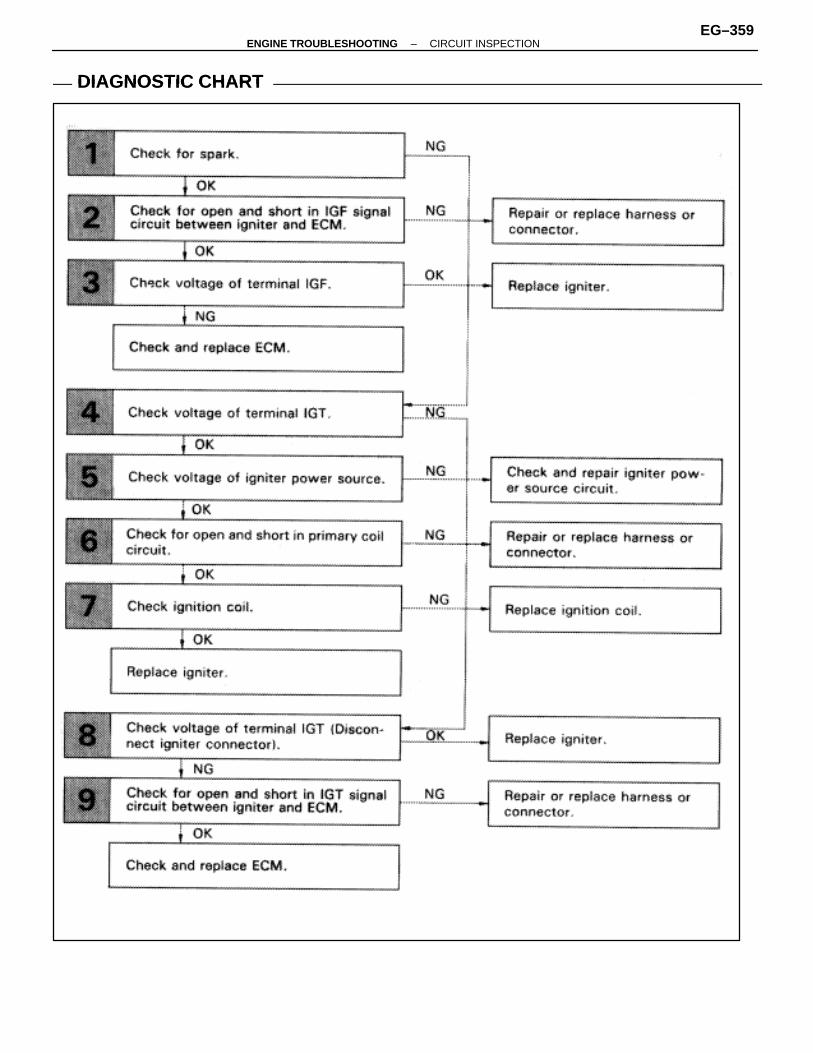
DIAGNOSTIC CHARTDIAGNOSTIC CHART
–ENGINE TROUBLESHOOTING CIRCUIT INSPECTIONEG–359
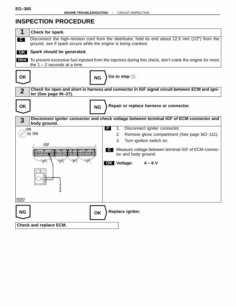
OK NG
OK NG
NG OK
INSPECTION PROCEDURE
1 Check for spark.
C Disconnect the high–tension cord from the distributor, hold its end about 12.5 mm (1/2”) from theground, see if spark occurs while the engine is being cranked.
Spark should be generated.
To prevent excessive fuel injected from the injectors during this check, don’t crank the engine for morethe 1 – 2 seconds at a time.
OK
Hint
Go to step �.
2 Check for open and short in harness and connector in IGF signal circuit between ECM and igni-ter (See page IN–27).
Repair or replace harness or connector.
3 Disconnect igniter connector and check voltage between terminal IGF of ECM connector andbody ground.
C
OK
P 1. Disconnect igniter connector.2. Remove glove compartment (See page BO–111).
3. Turn ignition switch on.
Measure voltage between terminal IGF of ECM connec-tor and body ground.
Voltage: 4 – 6 V
Replace igniter.
Check and replace ECM.
EG–360–ENGINE TROUBLESHOOTING CIRCUIT INSPECTION
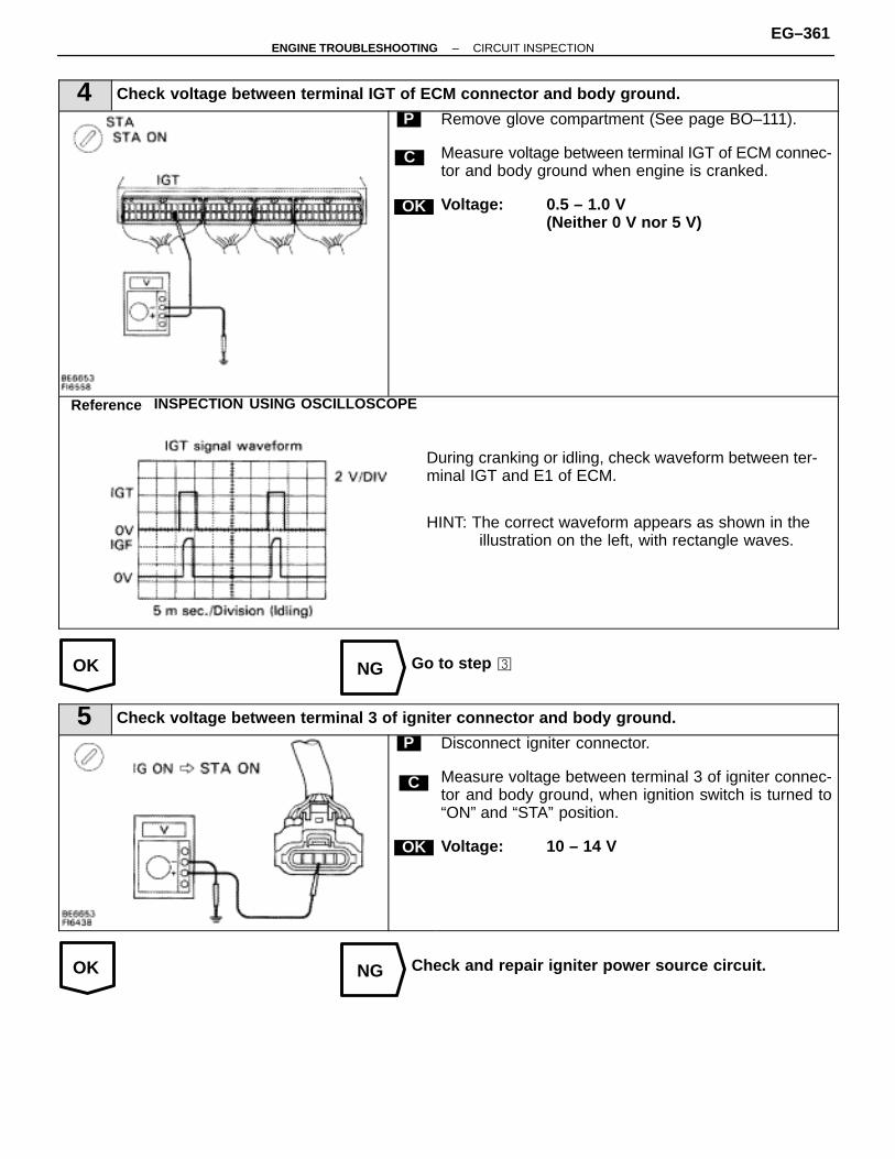
OK NG
OK NG
4 Check voltage between terminal IGT of ECM connector and body ground.
C
OK
P Remove glove compartment (See page BO–111).
Measure voltage between terminal IGT of ECM connec-tor and body ground when engine is cranked.
Voltage: 0.5 – 1.0 V(Neither 0 V nor 5 V)
During cranking or idling, check waveform between ter-minal IGT and E1 of ECM.
HINT: The correct waveform appears as shown in the illustration on the left, with rectangle waves.
Reference INSPECTION USING OSCILLOSCOPE
Go to step �
5 Check voltage between terminal 3 of igniter connector and body ground.
C
OK
P Disconnect igniter connector.
Measure voltage between terminal 3 of igniter connec-tor and body ground, when ignition switch is turned to“ON” and “STA” position.
Voltage: 10 – 14 V
Check and repair igniter power source circuit.
–ENGINE TROUBLESHOOTING CIRCUIT INSPECTIONEG–361
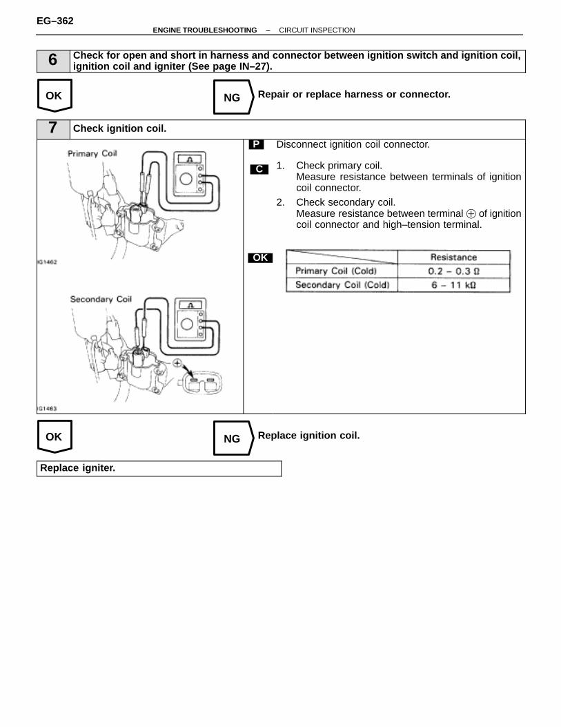
OK NG
OK NG
6 Check for open and short in harness and connector between ignition switch and ignition coil,ignition coil and igniter (See page IN–27).
Repair or replace harness or connector.
7 Check ignition coil.
C
OK
P Disconnect ignition coil connector.
1. Check primary coil. Measure resistance between terminals of ignitioncoil connector.
2. Check secondary coil. Measure resistance between terminal � of ignitioncoil connector and high–tension terminal.
Replace ignition coil.
Replace igniter.
EG–362–ENGINE TROUBLESHOOTING CIRCUIT INSPECTION
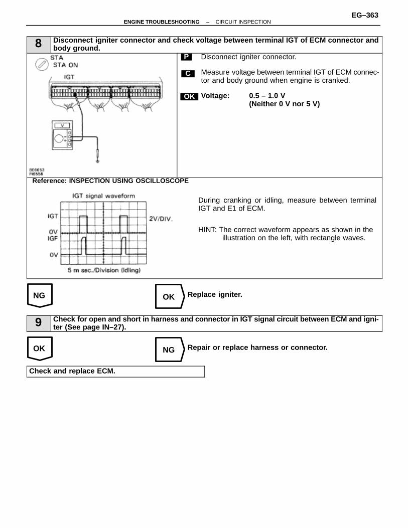
NG OK
OK NG
8 Disconnect igniter connector and check voltage between terminal IGT of ECM connector andbody ground.
C
OK
P Disconnect igniter connector.
Measure voltage between terminal IGT of ECM connec-tor and body ground when engine is cranked.
Voltage: 0.5 – 1.0 V(Neither 0 V nor 5 V)
During cranking or idling, measure between terminalIGT and E1 of ECM.
HINT: The correct waveform appears as shown in the illustration on the left, with rectangle waves.
Reference: INSPECTION USING OSCILLOSCOPE
Replace igniter.
9 Check for open and short in harness and connector in IGT signal circuit between ECM and igni-ter (See page IN–27).
Repair or replace harness or connector.
Check and replace ECM.
–ENGINE TROUBLESHOOTING CIRCUIT INSPECTIONEG–363
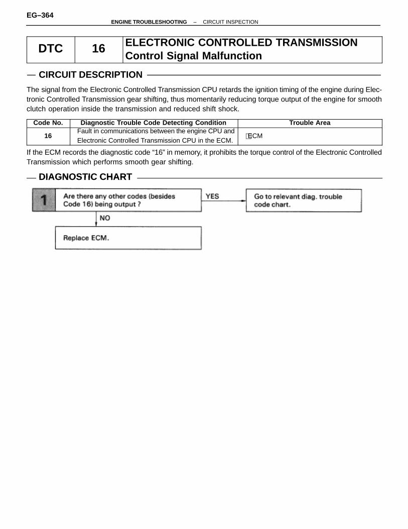
DTC 16 ELECTRONIC CONTROLLED TRANSMISSIONControl Signal Malfunction
CIRCUIT DESCRIPTION
The signal from the Electronic Controlled Transmission CPU retards the ignition timing of the engine during Elec-tronic Controlled Transmission gear shifting, thus momentarily reducing torque output of the engine for smoothclutch operation inside the transmission and reduced shift shock.
Code No. Diagnostic Trouble Code Detecting Condition Trouble Area
16Fault in communications between the engine CPU andElectronic Controlled Transmission CPU in the ECM.
�ECM
If the ECM records the diagnostic code “16” in memory, it prohibits the torque control of the Electronic ControlledTransmission which performs smooth gear shifting.
DIAGNOSTIC CHARTDIAGNOSTIC CHART
EG–364–ENGINE TROUBLESHOOTING CIRCUIT INSPECTION

–MEMO–
–ENGINE TROUBLESHOOTING CIRCUIT INSPECTIONEG–365
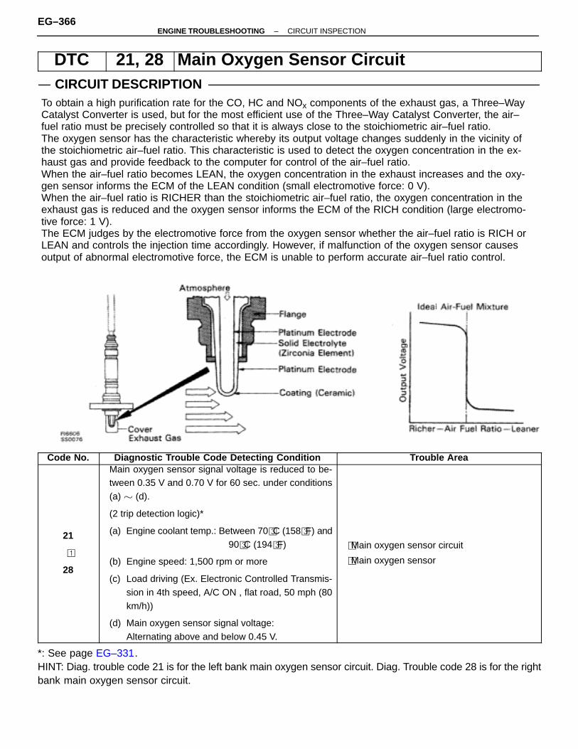
DTC 21, 28 Main Oxygen Sensor CircuitCIRCUIT DESCRIPTION
ÑÑÑÑÑÑÑÑÑÑÑÑÑÑÑÑÑÑÑÑÑÑÑÑÑÑÑÑÑÑÑÑÑÑÑÑÑÑÑÑÑÑÑÑÑÑÑÑÑÑÑÑÑÑÑÑÑÑÑÑÑÑÑÑÑÑÑÑÑÑÑÑÑÑÑÑÑÑÑÑÑÑÑÑÑÑÑÑÑÑÑÑÑÑÑÑÑÑÑÑÑÑÑÑÑÑÑÑÑÑÑÑÑÑÑÑÑÑÑÑÑÑÑÑÑÑÑÑÑÑÑÑÑÑÑÑÑÑÑÑÑÑÑÑÑÑÑÑÑÑÑÑÑÑÑÑÑÑÑÑÑÑÑÑÑÑÑÑÑÑÑÑÑÑÑÑÑÑÑÑÑÑÑÑÑÑÑÑÑÑÑÑÑÑÑÑÑÑÑÑÑÑÑÑÑÑÑÑÑÑÑÑÑÑÑÑÑÑÑÑÑÑÑÑÑÑÑÑÑÑÑÑÑÑÑÑÑÑÑÑÑÑÑÑÑÑÑÑÑÑÑÑÑÑÑÑÑÑÑÑÑÑÑÑÑÑÑÑÑÑÑÑÑÑÑÑÑÑÑÑÑÑÑÑÑÑÑÑÑÑÑÑÑÑÑÑÑÑÑÑÑÑÑÑÑÑÑÑÑÑÑÑÑÑÑÑÑÑÑÑÑÑÑÑÑÑÑÑÑÑÑÑÑÑÑÑÑÑÑÑÑÑÑÑÑÑÑÑÑÑÑÑÑÑÑÑÑÑÑÑÑÑÑÑÑÑÑÑÑÑÑÑÑÑÑÑÑÑÑÑÑÑÑÑÑÑÑÑÑÑÑÑÑÑÑÑÑÑÑÑÑÑÑÑÑÑÑÑÑÑÑÑÑÑÑÑÑÑÑÑÑÑÑÑÑÑÑÑÑÑÑÑÑÑÑÑÑÑÑÑÑÑÑÑÑÑÑÑÑÑÑÑÑÑÑÑÑÑÑÑÑÑÑÑÑÑÑÑÑÑÑÑÑÑÑÑÑÑÑÑÑÑÑÑÑÑÑÑÑÑÑÑÑÑÑÑÑÑÑÑÑÑÑÑÑÑÑÑÑÑÑÑÑÑÑÑÑÑÑÑÑÑÑÑÑÑÑÑÑÑÑÑÑÑÑÑÑÑÑÑÑÑÑÑÑÑÑÑÑÑÑÑÑÑÑÑÑÑÑÑÑÑÑÑÑÑÑÑÑÑÑÑÑÑÑÑÑÑÑÑÑÑÑÑÑÑÑÑÑÑÑÑÑÑÑÑÑÑÑÑÑÑÑÑÑÑÑÑÑÑÑÑÑÑÑÑÑÑÑÑÑÑÑÑÑÑÑÑÑÑÑÑÑÑÑÑÑÑÑÑÑÑÑÑÑÑÑÑÑÑÑÑÑÑÑÑÑÑÑÑÑÑÑÑÑÑÑÑÑÑÑÑÑÑÑÑÑÑÑÑÑÑÑÑÑÑÑÑÑÑÑÑÑÑÑÑÑÑÑÑÑÑÑÑÑÑÑÑÑÑÑÑÑÑÑÑÑÑÑÑÑÑÑÑÑÑÑÑÑÑÑÑÑÑÑÑÑÑÑÑÑÑÑÑÑÑÑÑÑÑÑÑÑÑÑÑÑÑÑÑÑÑÑÑÑÑÑÑÑÑÑÑÑÑÑÑÑÑÑÑÑÑÑÑÑÑÑÑÑÑÑÑÑÑÑÑÑÑÑÑÑÑÑÑÑÑÑÑÑÑÑÑÑÑÑÑÑÑÑÑÑÑÑÑÑÑÑÑÑÑÑÑÑÑÑÑÑÑÑÑÑÑÑÑÑÑÑÑÑÑÑÑÑÑÑÑÑÑÑÑÑÑÑÑÑÑÑÑÑÑÑÑÑÑÑÑÑÑÑÑÑÑÑÑÑÑÑÑÑÑÑÑÑÑÑÑÑÑÑÑ
To obtain a high purification rate for the CO, HC and NOx components of the exhaust gas, a Three–WayCatalyst Converter is used, but for the most efficient use of the Three–Way Catalyst Converter, the air–fuel ratio must be precisely controlled so that it is always close to the stoichiometric air–fuel ratio.The oxygen sensor has the characteristic whereby its output voltage changes suddenly in the vicinity ofthe stoichiometric air–fuel ratio. This characteristic is used to detect the oxygen concentration in the ex-haust gas and provide feedback to the computer for control of the air–fuel ratio.When the air–fuel ratio becomes LEAN, the oxygen concentration in the exhaust increases and the oxy-gen sensor informs the ECM of the LEAN condition (small electromotive force: 0 V).When the air–fuel ratio is RICHER than the stoichiometric air–fuel ratio, the oxygen concentration in theexhaust gas is reduced and the oxygen sensor informs the ECM of the RICH condition (large electromo-tive force: 1 V).The ECM judges by the electromotive force from the oxygen sensor whether the air–fuel ratio is RICH orLEAN and controls the injection time accordingly. However, if malfunction of the oxygen sensor causesoutput of abnormal electromotive force, the ECM is unable to perform accurate air–fuel ratio control.
Code No. Diagnostic Trouble Code Detecting Condition Trouble Area
21
�
28
Main oxygen sensor signal voltage is reduced to be-tween 0.35 V and 0.70 V for 60 sec. under conditions(a) � (d).
(2 trip detection logic)*
(a) Engine coolant temp.: Between 70�C (158�F) and90�C (194�F)
(b) Engine speed: 1,500 rpm or more
(c) Load driving (Ex. Electronic Controlled Transmis-sion in 4th speed, A/C ON , flat road, 50 mph (80km/h))
(d) Main oxygen sensor signal voltage:Alternating above and below 0.45 V.
�Main oxygen sensor circuit
�Main oxygen sensor
*: See page EG–331.HINT: Diag. trouble code 21 is for the left bank main oxygen sensor circuit. Diag. Trouble code 28 is for the rightbank main oxygen sensor circuit.
EG–366–ENGINE TROUBLESHOOTING CIRCUIT INSPECTION

CIRCUIT DESCRIPTION (Cont’d)
DIAGNOSTIC TROUBLE CODE DETECTION DRIVING PATTERNPurpose of the driving pattern(a) To simulate diag. trouble code detecting condition after diag. trouble code is recorded.(b) To check that the malfunction is corrected when the repair is completed confirming that diag. trouble code
is no longer detected.ÑÑÑÑÑÑÑÑÑÑÑÑÑÑÑÑÑÑÑÑÑÑÑÑÑÑÑÑÑÑÑÑÑÑÑÑÑÑÑÑÑÑÑÑÑÑÑÑÑÑÑÑÑÑÑÑÑÑÑÑÑÑÑÑÑÑÑÑÑÑÑÑÑÑÑÑÑÑÑÑÑÑÑÑÑÑÑÑÑÑÑÑÑÑÑÑÑÑÑÑÑÑÑÑÑÑÑÑÑÑÑÑÑÑÑÑÑÑÑÑÑÑÑÑÑÑÑÑÑÑÑÑÑÑÑÑÑÑÑÑÑÑÑÑÑÑÑÑÑÑÑÑÑÑÑÑÑÑÑÑÑÑÑÑÑÑÑÑÑÑÑÑÑÑÑÑÑÑÑÑÑÑÑÑÑÑÑÑÑÑÑÑÑÑÑÑÑÑÑÑÑÑÑÑÑÑÑÑÑÑÑÑÑÑÑÑÑÑÑÑÑÑÑÑÑÑÑÑÑÑÑÑÑÑÑÑÑÑÑÑÑÑÑÑÑÑÑÑÑÑÑÑÑÑÑÑÑÑÑÑÑÑÑÑÑÑÑÑÑÑÑÑÑÑÑÑÑÑÑÑÑÑÑÑÑÑÑÑÑÑÑÑÑÑÑÑÑÑÑÑÑÑÑÑÑÑÑÑÑÑÑÑÑÑÑÑÑÑÑÑÑÑÑÑÑÑÑÑÑÑÑÑÑÑÑÑÑÑÑÑÑÑÑÑÑÑÑÑÑÑÑÑÑÑÑÑÑÑÑÑÑÑÑÑÑÑÑÑÑÑÑÑÑÑÑÑÑÑÑÑÑÑÑÑÑÑÑÑÑÑÑÑÑÑÑÑÑÑÑÑÑÑÑÑÑÑÑÑÑÑÑÑÑÑÑÑÑÑÑÑÑÑÑÑÑÑÑÑÑÑÑÑÑÑÑÑÑÑÑÑÑÑÑÑÑÑÑÑÑÑÑÑÑÑÑÑÑÑÑÑÑÑÑÑÑÑÑÑÑÑÑÑÑÑÑÑÑÑÑÑÑÑÑÑÑÑÑÑÑÑÑÑÑÑÑÑÑÑÑÑÑÑÑÑÑÑÑÑÑÑÑÑÑÑÑÑÑÑÑÑÑÑÑÑÑÑÑÑÑÑÑÑÑÑÑÑÑÑÑÑÑÑÑÑÑÑÑÑÑÑÑÑÑÑÑÑÑÑÑÑÑÑÑÑÑÑÑÑÑÑÑÑÑÑÑÑÑÑÑÑÑÑÑÑÑÑÑÑÑÑÑÑÑÑÑÑÑÑÑÑÑÑÑÑÑÑÑÑÑÑÑÑÑÑÑÑÑÑÑÑÑÑÑÑÑÑÑÑÑÑÑÑÑÑÑÑÑÑÑÑÑÑÑÑÑÑÑÑÑÑÑÑÑÑÑÑÑÑÑÑÑÑÑÑÑÑÑÑÑÑÑÑÑÑÑÑÑÑÑÑÑÑÑÑÑÑÑÑÑÑÑÑÑÑÑÑÑÑÑÑÑÑÑÑÑÑÑÑÑÑÑÑÑÑÑÑÑÑÑÑÑÑÑÑÑÑÑÑÑÑÑÑÑÑÑÑÑÑÑÑÑÑÑÑÑÑÑÑÑÑÑÑÑÑÑÑÑÑÑÑÑÑÑÑÑÑÑÑÑÑÑÑÑÑÑÑÑÑÑÑÑÑÑÑÑÑÑÑÑÑÑÑÑÑÑÑÑÑÑÑÑÑÑÑÑÑÑÑÑÑÑÑÑÑÑÑÑÑÑÑÑÑÑÑÑÑÑÑÑÑÑÑÑÑÑÑÑÑÑÑÑÑÑÑÑÑÑÑÑÑÑÑÑÑÑÑÑÑÑÑÑÑÑÑÑÑÑÑÑÑÑÑÑÑÑÑÑÑÑÑÑÑÑÑÑÑÑÑÑÑÑÑÑÑÑÑÑÑÑÑÑÑÑÑÑÑÑÑÑÑÑÑÑÑÑÑÑÑÑÑÑÑÑÑÑÑÑÑÑÑÑÑÑÑÑÑÑÑÑÑÑÑÑÑÑÑÑÑÑÑÑÑÑÑÑÑÑÑÑÑÑÑÑÑÑÑÑÑÑÑÑÑÑÑÑÑÑÑÑÑÑÑÑÑÑÑÑÑÑÑÑÑÑÑÑÑÑÑÑÑÑÑÑÑÑÑÑÑÑÑÑÑÑÑÑÑÑÑÑÑÑÑÑÑÑÑÑÑÑÑÑÑÑÑÑÑÑÑÑÑÑÑÑÑÑÑÑÑÑÑÑÑÑÑÑÑÑÑÑÑÑÑÑÑÑÑÑÑÑÑÑÑÑÑÑÑÑÑÑÑÑÑÑÑÑÑÑÑÑÑÑÑÑÑÑÑÑÑÑÑÑÑÑÑÑÑÑÑÑÑÑÑÑÑÑÑÑÑÑÑÑÑÑÑÑÑÑÑÑÑÑÑÑÑÑÑÑÑÑÑÑÑÑÑÑÑÑÑÑÑÑÑ
1 Disconnect the EFI fuse (15 A) for 10 sec. or more, with IG switch OFF. Initiate test mode (Connect terminal TE2 and E1 of data link connector 1 or 2 with IG switch OFF).
2 Start the engine and warm up with all ACC switch OFF.3 After the engine is warmed up, let it idle for 3 min.4 After performing the idling in 3, perform gradual acceleration with in the range 1,300 1,700 rpm (cen-
tered around 1,500 rpm) with the A/C switch ON and D position for A/T (5th for M/T). (Take care thatthe engine speed does not fall below 1,200 rpm when shifting. Gradually depress the acceleratorpedal and keep it steady to that engine braking does not occur).
5 Maintain the vehicle speed at 40 – 50 mph (64 – 80 km/h).6 Keep the vehicle running for 1 – 2 min. after starting acceleration.
HINT: If a malfunction exists, the Malfunction Indicator Lamp will light up after approx. 60 sec. from the startof acceleration.
NOTICE: If the conditions in this test are not strictly followed, detection of the malfunction will not bepossible.
Malfunction: Main Oxygen Sensor Deterioration
–ENGINE TROUBLESHOOTING CIRCUIT INSPECTIONEG–367
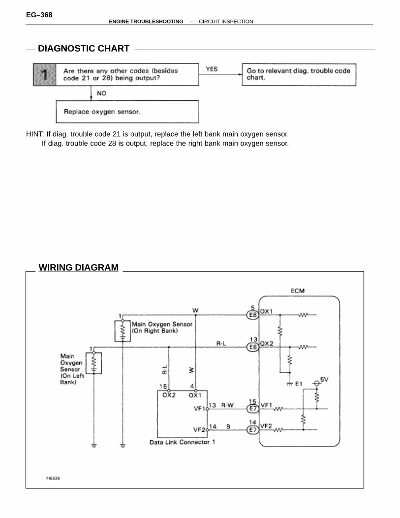
WIRING DIAGRAM
DIAGNOSTIC CHARTDIAGNOSTIC CHART
HINT: If diag. trouble code 21 is output, replace the left bank main oxygen sensor.If diag. trouble code 28 is output, replace the right bank main oxygen sensor.
EG–368–ENGINE TROUBLESHOOTING CIRCUIT INSPECTION
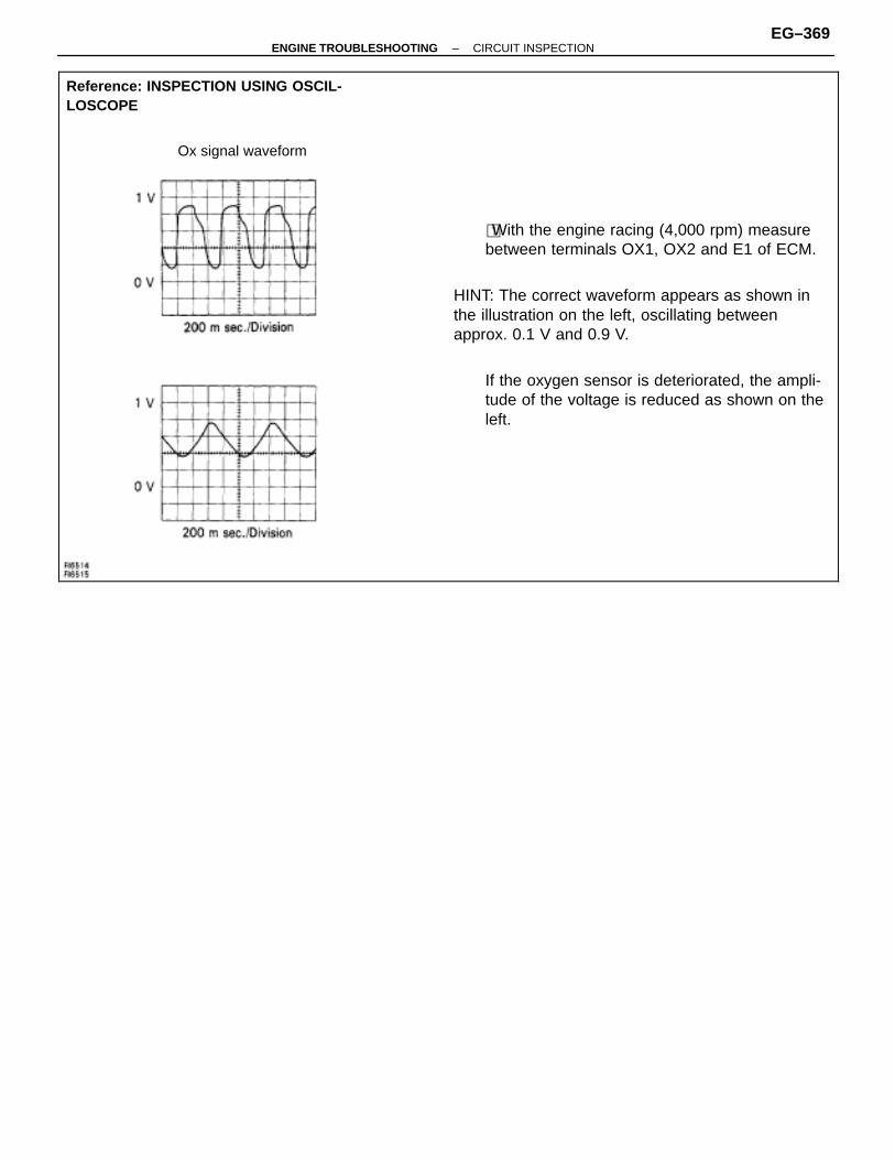
ÑÑÑÑÑÑÑÑÑÑÑÑÑÑÑÑÑÑÑÑÑÑÑÑÑÑÑÑÑÑÑÑÑÑÑÑÑÑÑÑÑÑÑÑÑÑÑÑÑÑÑÑÑÑÑÑÑÑÑÑÑÑÑÑÑÑÑÑÑÑÑÑÑÑÑÑÑÑÑÑÑÑÑÑÑÑÑÑÑÑÑÑÑÑÑÑÑÑÑÑÑÑÑÑÑÑÑÑÑÑÑÑÑÑÑÑÑÑÑÑÑÑÑÑÑÑÑÑÑÑÑÑÑÑÑÑÑÑÑÑÑÑÑÑÑÑÑÑÑÑÑÑÑÑÑÑÑÑÑÑÑÑÑÑÑÑÑÑÑÑÑÑÑÑÑÑÑÑÑÑÑÑÑÑÑÑÑÑÑÑÑÑÑÑÑÑÑÑÑÑÑÑÑÑÑÑÑÑÑÑÑÑÑÑÑÑÑÑÑÑÑÑÑÑÑÑÑÑÑÑÑÑÑÑÑÑÑÑÑÑÑÑÑÑÑÑÑÑÑÑÑÑÑÑÑÑÑÑÑÑÑÑÑÑÑÑÑÑÑÑÑÑÑÑÑÑÑÑÑÑÑÑÑÑÑÑÑÑÑÑÑÑÑÑÑÑÑÑÑÑÑÑÑÑÑÑÑÑÑÑÑÑÑÑÑÑÑÑÑÑÑÑÑÑÑÑÑÑÑÑÑÑÑÑÑÑÑÑÑÑÑÑÑÑÑÑÑÑÑÑÑÑÑÑÑÑÑÑÑÑÑÑÑÑÑÑÑÑÑÑÑÑÑÑÑÑÑÑÑÑÑÑÑÑÑÑÑÑÑÑÑÑÑÑÑÑÑÑÑÑÑÑÑÑÑÑÑÑÑÑÑÑÑÑ
Reference: INSPECTION USING OSCIL-LOSCOPE
Ox signal waveform
ÑÑÑÑÑÑÑÑÑÑÑÑÑÑÑÑÑÑÑÑÑÑÑÑÑÑÑÑÑÑÑÑÑÑÑÑÑÑÑÑÑÑÑÑÑÑÑÑÑÑÑÑÑÑÑÑÑÑÑÑÑÑÑÑÑÑÑÑÑÑÑÑÑÑÑÑÑÑÑÑÑÑÑÑÑÑÑÑÑÑÑÑÑÑÑÑÑÑÑÑÑÑÑÑÑÑÑÑÑÑÑÑÑÑÑÑÑÑÑÑÑÑÑÑÑÑÑÑÑÑÑÑÑÑÑÑÑÑÑÑÑÑÑÑÑÑÑÑÑÑÑÑÑÑÑÑÑÑÑÑÑÑÑÑÑÑÑÑÑÑÑÑÑÑÑÑÑÑÑÑÑÑÑÑÑÑÑÑÑÑÑÑÑÑÑÑÑÑÑÑÑÑÑÑÑÑÑÑÑÑÑÑÑÑÑÑÑÑÑÑÑÑÑÑÑÑÑÑÑÑÑÑÑÑÑÑÑÑÑÑÑÑÑÑÑÑÑÑÑÑÑÑÑÑÑÑÑÑÑÑÑÑÑÑÑÑÑÑÑÑÑÑÑÑÑÑÑÑÑÑÑÑÑÑÑÑÑÑÑÑÑÑÑÑÑÑÑÑÑÑÑÑÑÑÑÑÑÑÑÑÑÑÑÑÑÑÑÑÑÑÑÑÑÑÑÑÑÑÑÑÑÑÑÑÑÑÑÑÑÑÑÑÑÑÑÑÑÑÑÑÑÑÑÑÑÑÑÑÑÑÑÑÑÑÑÑÑÑÑÑÑÑÑÑÑÑÑÑÑÑÑÑÑÑÑÑÑÑÑÑÑÑÑÑÑÑÑÑÑÑÑÑÑÑÑÑÑÑÑÑÑÑÑÑÑÑÑÑÑÑÑÑÑÑÑÑÑÑÑÑÑÑÑÑÑÑÑ
�With the engine racing (4,000 rpm) measurebetween terminals OX1, OX2 and E1 of ECM.
HINT: The correct waveform appears as shown inthe illustration on the left, oscillating betweenapprox. 0.1 V and 0.9 V.
If the oxygen sensor is deteriorated, the ampli-tude of the voltage is reduced as shown on theleft.
–ENGINE TROUBLESHOOTING CIRCUIT INSPECTIONEG–369
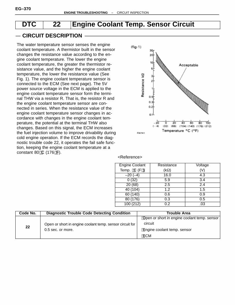
DTC 22 Engine Coolant Temp. Sensor Circuit
CIRCUIT DESCRIPTION
ÑÑÑÑÑÑÑÑÑÑÑÑÑÑÑÑÑÑÑÑÑÑÑÑÑÑÑÑÑÑÑÑÑÑÑÑÑÑÑÑÑÑÑÑÑÑÑÑÑÑÑÑÑÑÑÑÑÑÑÑÑÑÑÑÑÑÑÑÑÑÑÑÑÑÑÑÑÑÑÑÑÑÑÑÑÑÑÑÑÑÑÑÑÑÑÑÑÑÑÑÑÑÑÑÑÑÑÑÑÑÑÑÑÑÑÑÑÑÑÑÑÑÑÑÑÑÑÑÑÑÑÑÑÑÑÑÑÑÑÑÑÑÑÑÑÑÑÑÑÑÑÑÑÑÑÑÑÑÑÑÑÑÑÑÑÑÑÑÑÑÑÑÑÑÑÑÑÑÑÑÑÑÑÑÑÑÑÑÑÑÑÑÑÑÑÑÑÑÑÑÑÑÑÑÑÑÑÑÑÑÑÑÑÑÑÑÑÑÑÑÑÑÑÑÑÑÑÑÑÑÑÑÑÑÑÑÑÑÑÑÑÑÑÑÑÑÑÑÑÑÑÑÑÑÑÑÑÑÑÑÑÑÑÑÑÑÑÑÑÑÑÑÑÑÑÑÑÑÑÑÑÑÑÑÑÑÑÑÑÑÑÑÑÑÑÑÑÑÑÑÑÑÑÑÑÑÑÑÑÑÑÑÑÑÑÑÑÑÑÑÑÑÑÑÑÑÑÑÑÑÑÑÑÑÑÑÑÑÑÑÑÑÑÑÑÑÑÑÑÑÑÑÑÑÑÑÑÑÑÑ
The water temperature sensor senses the enginecoolant temperature. A thermistor built in the sensorchanges the resistance value according to the en-gine coolant temperature. The lower the enginecoolant temperature, the greater the thermistor re-sistance value, and the higher the engine coolanttemperature, the lower the resistance value (SeeFig. 1). The engine coolant temperature sensor isconnected to the ECM (See next page). The 5Vpower source voltage in the ECM is applied to theengine coolant temperature sensor form the termi-nal THW via a resistor R. That is, the resistor R andthe engine coolant temperature sensor are con-nected in series. When the resistance value of theengine coolant temperature sensor changes in ac-cordance with changes in the engine coolant tem-perature, the potential at the terminal THW alsochanges. Based on this signal, the ECM increasesthe fuel injection volume to improve drivability duringcold engine operation. If the ECM records the diag-nostic trouble code 22, it operates the fail safe func-tion, keeping the engine coolant temperature at aconstant 80�C (176�F).
ÑÑÑÑÑÑÑÑÑÑÑÑÑÑÑÑÑÑÑÑÑÑÑÑÑÑÑÑÑÑÑÑÑÑÑÑÑÑÑÑÑÑÑÑÑÑÑÑÑÑÑÑÑÑÑÑÑÑÑÑÑÑÑÑÑÑÑÑÑÑÑÑÑÑÑÑÑÑÑÑÑÑÑÑÑÑÑÑÑÑÑÑÑÑÑÑÑÑÑÑÑÑÑÑÑÑÑÑÑÑÑÑÑÑÑÑÑÑÑÑÑÑÑÑÑÑÑÑÑÑÑÑÑÑÑÑÑÑÑÑÑÑÑÑÑÑÑÑÑÑÑÑÑÑÑÑÑÑÑÑÑÑÑÑÑÑÑÑÑÑÑÑÑÑÑÑÑÑÑÑÑÑÑÑÑÑÑÑÑÑÑÑÑÑÑÑÑÑÑÑÑÑÑÑÑÑÑÑÑÑÑÑÑÑÑÑÑÑÑÑÑÑÑÑÑÑÑÑÑÑÑÑÑÑÑÑÑÑÑÑÑÑÑÑÑÑÑÑÑÑÑÑÑÑÑÑÑÑÑÑÑÑÑÑÑÑÑÑÑÑÑÑÑÑÑÑÑÑÑÑÑÑÑÑÑÑÑÑÑÑÑÑÑÑÑÑÑÑÑÑÑÑÑÑÑÑÑÑÑÑÑÑÑÑÑÑÑÑÑÑÑÑÑÑÑÑÑÑÑÑÑÑÑÑÑÑÑÑÑÑÑÑÑÑÑÑÑÑÑÑÑÑÑÑÑÑÑÑÑÑÑÑÑÑÑÑÑÑÑÑÑÑÑÑÑÑÑÑÑÑ<Reference>
ÑÑÑÑÑÑÑÑÑÑÑÑÑÑÑÑÑÑÑÑÑ
Engine CoolantTemp. �C (F�)
ÑÑÑÑÑÑÑÑÑÑÑÑÑÑÑÑÑÑÑÑÑ
Resistance(k�)
ÑÑÑÑÑÑÑÑÑÑÑÑÑÑÑÑÑÑÑÑÑ
Voltage(V)
ÑÑÑÑÑÑÑÑÑÑÑÑÑÑ
–20 (–4) ÑÑÑÑÑÑÑÑÑÑÑÑÑÑ
16.0 ÑÑÑÑÑÑÑÑÑÑÑÑÑÑ
4.3
ÑÑÑÑÑÑÑ0 (32) ÑÑÑÑÑÑÑ5.9 ÑÑÑÑÑÑÑ3.4ÑÑÑÑÑÑÑÑÑÑÑÑÑÑ
20 (68)ÑÑÑÑÑÑÑÑÑÑÑÑÑÑ
2.5ÑÑÑÑÑÑÑÑÑÑÑÑÑÑ
2.4ÑÑÑÑÑÑÑÑÑÑÑÑÑÑ
40 (104) ÑÑÑÑÑÑÑÑÑÑÑÑÑÑ
1.2 ÑÑÑÑÑÑÑÑÑÑÑÑÑÑ
1.5ÑÑÑÑÑÑÑÑÑÑÑÑÑÑ
60 (140) ÑÑÑÑÑÑÑÑÑÑÑÑÑÑ
0.6 ÑÑÑÑÑÑÑÑÑÑÑÑÑÑ
0.9ÑÑÑÑÑÑÑÑÑÑÑÑÑÑ
80 (176) ÑÑÑÑÑÑÑÑÑÑÑÑÑÑ
0.3 ÑÑÑÑÑÑÑÑÑÑÑÑÑÑ
0.5
ÑÑÑÑÑÑÑ100 (212) ÑÑÑÑÑÑÑ0.2 ÑÑÑÑÑÑÑ.03
Code No. Diagnostic Trouble Code Detecting Condition Trouble Area
22Open or short in engine coolant temp. sensor circuit for0.5 sec. or more.
�Open or short in engine coolant temp. sensorcircuit
�Engine coolant temp. sensor
�ECM
EG–370–ENGINE TROUBLESHOOTING CIRCUIT INSPECTION
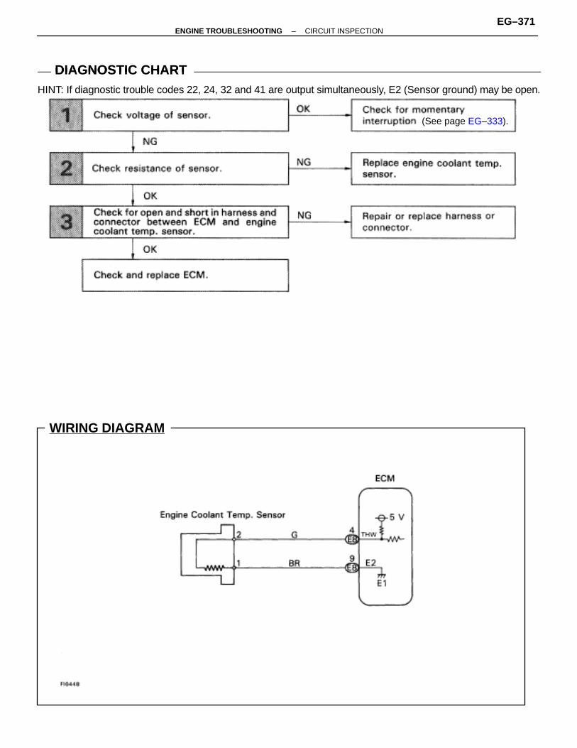
WIRING DIAGRAM
DIAGNOSTIC CHARTDIAGNOSTIC CHARTHINT: If diagnostic trouble codes 22, 24, 32 and 41 are output simultaneously, E2 (Sensor ground) may be open.
(See page EG–333).
–ENGINE TROUBLESHOOTING CIRCUIT INSPECTIONEG–371

NG OK
OK NG
OK NG
INSPECTION PROCEDUREHINT: If diagnostic trouble codes 22, 24, 32 and 41 are output simultaneously, E2 (sensor ground) may be open.
1 Check voltage between terminals THW and E2 of ECM connector.
C
OK
P 1. Remove glove compartment (See page BO–111).2. Turn ignition switch on.
Measure voltage between terminals THW and E2 ofECM connector.
Check for momentary interruption (See page EG–333).
2 Check engine coolant temp. sensor.
C
OK
P Disconnect the engine coolant temp. sensor connector,(See page EG–224).
Measure resistance between terminals.
Resistance is within Acceptable Zone on chart.
Replace engine coolant temp. sensor.
3 Check for open and short in harness and connector between ECM and water temp. sensor (Seepage IN–27).
Repair or replace harness or connector.
Check and replace ECM.
EG–372–ENGINE TROUBLESHOOTING CIRCUIT INSPECTION

–MEMO–
–ENGINE TROUBLESHOOTING CIRCUIT INSPECTIONEG–373
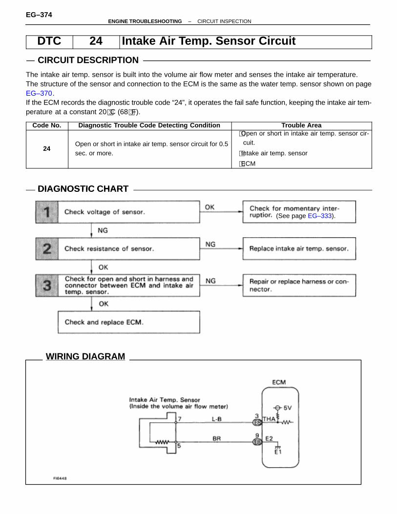
WIRING DIAGRAM
DTC 24 Intake Air Temp. Sensor Circuit
CIRCUIT DESCRIPTION
The intake air temp. sensor is built into the volume air flow meter and senses the intake air temperature.The structure of the sensor and connection to the ECM is the same as the water temp. sensor shown on pageEG–370.If the ECM records the diagnostic trouble code “24”, it operates the fail safe function, keeping the intake air tem-perature at a constant 20�C (68�F).
Code No. Diagnostic Trouble Code Detecting Condition Trouble Area
24Open or short in intake air temp. sensor circuit for 0.5sec. or more.
�Open or short in intake air temp. sensor cir-cuit.
�Intake air temp. sensor
�ECM
DIAGNOSTIC CHARTDIAGNOSTIC CHART
(See page EG–333).
EG–374–ENGINE TROUBLESHOOTING CIRCUIT INSPECTION
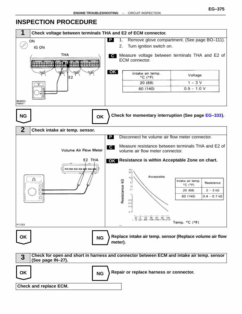
NG OK
OK NG
OK NG
INSPECTION PROCEDURE
1 Check voltage between terminals THA and E2 of ECM connector.
C
OK
P 1. Remove glove compartment. (See page BO–111).2. Turn ignition switch on.
Measure voltage between terminals THA and E2 ofECM connector.
Check for momentary interruption (See page EG–333).
2 Check intake air temp. sensor.
C
OK
P Disconnect he volume air flow meter connector.
Measure resistance between terminals THA and E2 ofvolume air flow meter connector.
Resistance is within Acceptable Zone on chart.
Replace intake air temp. sensor (Replace volume air flowmeter).
3 Check for open and short in harness and connector between ECM and intake air temp. sensor(See page IN–27).
Repair or replace harness or connector.
Check and replace ECM.
–ENGINE TROUBLESHOOTING CIRCUIT INSPECTIONEG–375
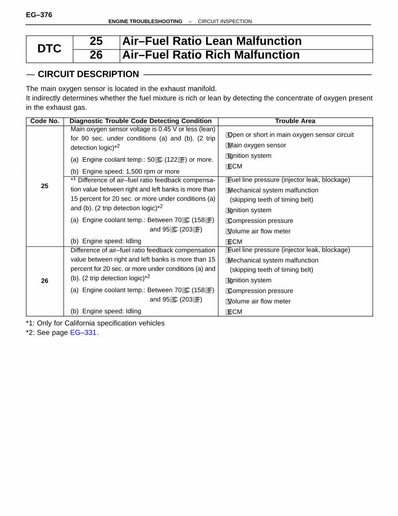
DTC25 Air–Fuel Ratio Lean Malfunction
DTC 26 Air–Fuel Ratio Rich Malfunction
CIRCUIT DESCRIPTION
The main oxygen sensor is located in the exhaust manifold.It indirectly determines whether the fuel mixture is rich or lean by detecting the concentrate of oxygen presentin the exhaust gas.
Code No. Diagnostic Trouble Code Detecting Condition Trouble AreaMain oxygen sensor voltage is 0.45 V or less (lean)for 90 sec. under conditions (a) and (b). (2 tripdetection logic)*2
(a) Engine coolant temp.: 50�C (122�F) or more.
(b) Engine speed: 1,500 rpm or more
�Open or short in main oxygen sensor circuit
�Main oxygen sensor
�Ignition system
�ECM
25*1 Difference of air–fuel ratio feedback compensa-tion value between right and left banks is more than15 percent for 20 sec. or more under conditions (a)and (b). (2 trip detection logic)*2
(a) Engine coolant temp.: Between 70�C (158�F) and 95�C (203�F)
(b) Engine speed: Idling
�Fuel line pressure (injector leak, blockage)
�Mechanical system malfunction(skipping teeth of timing belt)
�Ignition system
�Compression pressure
�Volume air flow meter
�ECM
26
Difference of air–fuel ratio feedback compensationvalue between right and left banks is more than 15percent for 20 sec. or more under conditions (a) and(b). (2 trip detection logic)*2
(a) Engine coolant temp.: Between 70�C (158�F) and 95�C (203�F)
(b) Engine speed: Idling
�Fuel line pressure (injector leak, blockage)
�Mechanical system malfunction(skipping teeth of timing belt)
�Ignition system
�Compression pressure
�Volume air flow meter
�ECM
*1: Only for California specification vehicles*2: See page EG–331.
EG–376–ENGINE TROUBLESHOOTING CIRCUIT INSPECTION
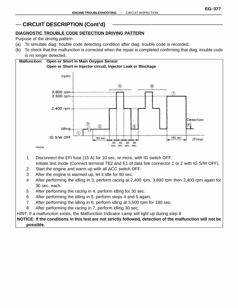
CIRCUIT DESCRIPTION (Cont’d)
DIAGNOSTIC TROUBLE CODE DETECTION DRIVING PATTERNPurpose of the driving pattern(a) To simulate diag. trouble code detecting condition after diag. trouble code is recorded.(b) To check that the malfunction is corrected when the repair is completed confirming that diag. trouble code
is no longer detected.ÑÑÑÑÑÑÑÑÑÑÑÑÑÑÑÑÑÑÑÑÑÑÑÑÑÑÑÑÑÑÑÑÑÑÑÑÑÑÑÑÑÑÑÑÑÑÑÑÑÑÑÑÑÑÑÑÑÑÑÑÑÑÑÑÑÑÑÑÑÑÑÑÑÑÑÑÑÑÑÑÑÑÑÑÑÑÑÑÑÑÑÑÑÑÑÑÑÑÑÑÑÑÑÑÑÑÑÑÑÑÑÑÑÑÑÑÑÑÑÑÑÑÑÑÑÑÑÑÑÑÑÑÑÑÑÑÑÑÑÑÑÑÑÑÑÑÑÑÑÑÑÑÑÑÑÑÑÑÑÑÑÑÑÑÑÑÑÑÑÑÑÑÑÑÑÑÑÑÑÑÑÑÑÑÑÑÑÑÑÑÑÑÑÑÑÑÑÑÑÑÑÑÑÑÑÑÑÑÑÑÑÑÑÑÑÑÑÑÑÑÑÑÑÑÑÑÑÑÑÑÑÑÑÑÑÑÑÑÑÑÑÑÑÑÑÑÑÑÑÑÑÑÑÑÑÑÑÑÑÑÑÑÑÑÑÑÑÑÑÑÑÑÑÑÑÑÑÑÑÑÑÑÑÑÑÑÑÑÑÑÑÑÑÑÑÑÑÑÑÑÑÑÑÑÑÑÑÑÑÑÑÑÑÑÑÑÑÑÑÑÑÑÑÑÑÑÑÑÑÑÑÑÑÑÑÑÑÑÑÑÑÑÑÑÑÑÑÑÑÑÑÑÑÑÑÑÑÑÑÑÑÑÑÑÑÑÑÑÑÑÑÑÑÑÑÑÑÑÑÑÑÑÑÑÑÑÑÑÑÑÑÑÑÑÑÑÑÑÑÑÑÑÑÑÑÑÑÑÑÑÑÑÑÑÑÑÑÑÑÑÑÑÑÑÑÑÑÑÑÑÑÑÑÑÑÑÑÑÑÑÑÑÑÑÑÑÑÑÑÑÑÑÑÑÑÑÑÑÑÑÑÑÑÑÑÑÑÑÑÑÑÑÑÑÑÑÑÑÑÑÑÑÑÑÑÑÑÑÑÑÑÑÑÑÑÑÑÑÑÑÑÑÑÑÑÑÑÑÑÑÑÑÑÑÑÑÑÑÑÑÑÑÑÑÑÑÑÑÑÑÑÑÑÑÑÑÑÑÑÑÑÑÑÑÑÑÑÑÑÑÑÑÑÑÑÑÑÑÑÑÑÑÑÑÑÑÑÑÑÑÑÑÑÑÑÑÑÑÑÑÑÑÑÑÑÑÑÑÑÑÑÑÑÑÑÑÑÑÑÑÑÑÑÑÑÑÑÑÑÑÑÑÑÑÑÑÑÑÑÑÑÑÑÑÑÑÑÑÑÑÑÑÑÑÑÑÑÑÑÑÑÑÑÑÑÑÑÑÑÑÑÑÑÑÑÑÑÑÑÑÑÑÑÑÑÑÑÑÑÑÑÑÑÑÑÑÑÑÑÑÑÑÑÑÑÑÑÑÑÑÑÑÑÑÑÑÑÑÑÑÑÑÑÑÑÑÑÑÑÑÑÑÑÑÑÑÑÑÑÑÑÑÑÑÑÑÑÑÑÑÑÑÑÑÑÑÑÑÑÑÑÑÑÑÑÑÑÑÑÑÑÑÑÑÑÑÑÑÑÑÑÑÑÑÑÑÑÑÑÑÑÑÑÑÑÑÑÑÑÑÑÑÑÑÑÑÑÑÑÑÑÑÑÑÑÑÑÑÑÑÑÑÑÑÑÑÑÑÑÑÑÑÑÑÑÑÑÑÑÑÑÑÑÑÑÑÑÑÑÑÑÑÑÑÑÑÑÑÑÑÑÑÑÑÑÑÑÑÑÑÑÑÑÑÑÑÑÑÑÑÑÑÑÑÑÑÑÑÑÑÑÑÑÑÑÑÑÑÑÑÑÑÑÑÑÑÑÑÑÑÑÑÑÑÑÑÑÑÑÑÑÑÑÑÑÑÑÑÑÑÑÑÑÑÑÑÑÑÑÑÑÑÑÑÑÑÑÑÑÑÑÑÑÑÑÑÑÑÑÑÑÑÑÑÑÑÑÑÑÑÑÑÑÑÑÑÑÑÑÑÑÑÑÑÑÑÑÑÑÑÑÑÑÑÑÑÑÑÑÑÑÑÑÑÑÑÑÑÑÑÑÑÑÑÑÑÑÑÑÑÑÑÑÑÑÑÑÑÑÑÑÑÑÑÑÑÑÑÑÑÑÑÑÑÑÑÑÑÑÑÑÑÑÑÑÑÑÑÑÑÑÑÑÑÑÑÑÑÑÑÑÑÑÑÑÑÑÑÑÑÑÑÑÑÑÑÑÑÑÑÑÑÑÑÑÑÑÑÑÑ
1 Disconnect the EFI fuse (15 A) for 10 sec. or more, with IG switch OFF. Initiate test mode (Connect terminal TE2 and E1 of data link connector 1 or 2 with IG S/W OFF).
2 Start the engine and warm up with all ACC switch OFF.3 After the engine is warmed up, let it idle for 60 sec.4 After performing the idling in 3, perform racing at 2,400 rpm, 3,800 rpm then 2,400 rpm again for
30 sec. each.5 After performing the racing in 4, perform idling for 30 sec.6 After performing the idling in 5, perform steps 4 and 5 again.7 After performing the idling in 6, perform idling at 3,500 rpm for 180 sec.8 After performing the racing in 7, perform idling 30 sec.
HINT: If a malfunction exists, the Malfunction Indicator Lamp will light up during step 8NOTICE: If the conditions in this test are not strictly followed, detection of the malfunction will not be
possible.
Malfunction: Open or Short in Main Oxygen SensorOpen or Short in Injector circuit, Injector Leak or Blockage
–ENGINE TROUBLESHOOTING CIRCUIT INSPECTIONEG–377
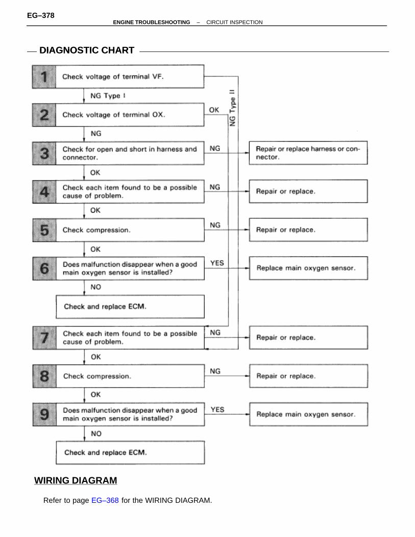
WIRING DIAGRAM
DIAGNOSTIC CHARTDIAGNOSTIC CHART
Refer to page EG–368 for the WIRING DIAGRAM.
EG–378–ENGINE TROUBLESHOOTING CIRCUIT INSPECTION
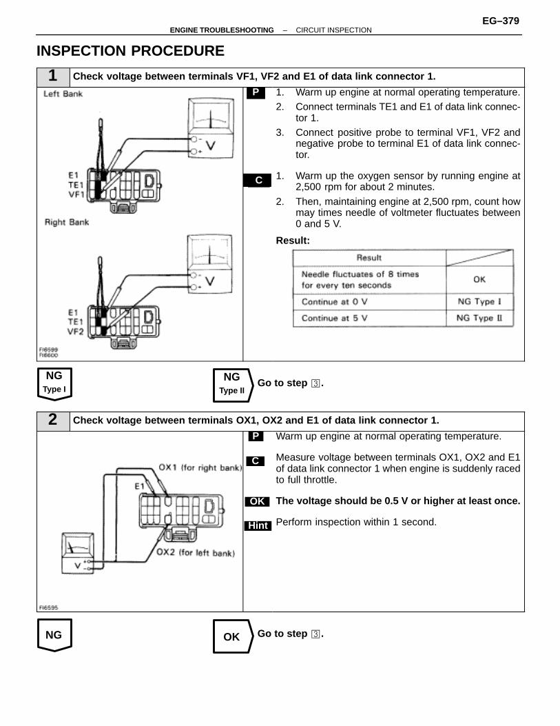
NGType I
NGType II
NG OK
INSPECTION PROCEDURE
1 Check voltage between terminals VF1, VF2 and E1 of data link connector 1.
C
P 1. Warm up engine at normal operating temperature.2. Connect terminals TE1 and E1 of data link connec-
tor 1.3. Connect positive probe to terminal VF1, VF2 and
negative probe to terminal E1 of data link connec-tor.
1. Warm up the oxygen sensor by running engine at2,500 rpm for about 2 minutes.
2. Then, maintaining engine at 2,500 rpm, count howmay times needle of voltmeter fluctuates between0 and 5 V.
Result:
Go to step �.
2 Check voltage between terminals OX1, OX2 and E1 of data link connector 1.
C
OK
Hint
P Warm up engine at normal operating temperature.
Measure voltage between terminals OX1, OX2 and E1of data link connector 1 when engine is suddenly racedto full throttle.
The voltage should be 0.5 V or higher at least once.
Perform inspection within 1 second.
Go to step �.
–ENGINE TROUBLESHOOTING CIRCUIT INSPECTIONEG–379

OK NG
OK NG
OK NG
NO YES
3 Check for open and short in harness and connector between ECM and main oxygen sensor,ECM and data link connector 1 (See page IN–27).
Repair or replace harness or connector.
4 Check each item found to be a possible cause of problem.
Check each circuit found to be a possible cause of trouble according to the results of the check in � or �. Thenumbers in the table below show the order in which the checks should be performed.
ÑÑÑÑÑÑÑÑÑÑÑÑÑÑÑÑÑÑÑÑÑÑÑÑÑÑÑÑÑÑÑÑÑ
Main oxygen sensorsignal from either side
continues at 0 V.
ÑÑÑÑÑÑÑÑÑÑÑÑÑÑÑÑÑÑÑÑÑÑÑÑÑÑÑÑÑÑÑÑÑ
Main oxygen sensorsignals from both sides
continue at 0 V.
ÑÑÑÑÑÑÑÑÑÑÑÑÑÑÑÑÑÑÑÑÑÑÑÑÑÑÑÑÑÑÑÑÑ
Possible CauseÑÑÑÑÑÑÑÑÑÑÑÑÑÑÑÑÑÑ
See page
ÑÑÑÑÑÑÑÑÑÑÑÑÑÑÑÑÑÑÑÑÑÑ
1 ÑÑÑÑÑÑÑÑÑÑÑÑÑÑÑÑÑÑÑÑÑÑ
ÑÑÑÑÑÑÑÑÑÑÑÑÑÑÑÑÑÑÑÑÑÑ
Faulty sensor installation. ÑÑÑÑÑÑÑÑÑÑÑÑ
–ÑÑÑÑÑÑÑÑÑÑÑÑÑÑÑÑÑÑÑÑÑÑ
3 ÑÑÑÑÑÑÑÑÑÑÑÑÑÑÑÑÑÑÑÑÑÑ
ÑÑÑÑÑÑÑÑÑÑÑÑÑÑÑÑÑÑÑÑÑÑ
Injector circuit ÑÑÑÑÑÑÑÑÑÑÑÑ
EG–428ÑÑÑÑÑÑÑÑÑÑÑÑÑÑÑÑÑÑÑÑÑÑ
2 ÑÑÑÑÑÑÑÑÑÑÑÑÑÑÑÑÑÑÑÑÑÑ
3 ÑÑÑÑÑÑÑÑÑÑÑÑÑÑÑÑÑÑÑÑÑÑ
Misfire ÑÑÑÑÑÑÑÑÑÑÑÑ
IG–6ÑÑÑÑÑÑÑÑÑÑÑÑÑÑÑÑÑÑÑÑÑÑ
4 ÑÑÑÑÑÑÑÑÑÑÑÑÑÑÑÑÑÑÑÑÑÑ
ÑÑÑÑÑÑÑÑÑÑÑÑÑÑÑÑÑÑÑÑÑÑ
Valve timing ÑÑÑÑÑÑÑÑÑÑÑÑ
EG–43ÑÑÑÑÑÑÑÑÑÑÑÑÑÑÑÑÑÑÑÑÑÑ
ÑÑÑÑÑÑÑÑÑÑÑÑÑÑÑÑÑÑÑÑÑÑ
1 ÑÑÑÑÑÑÑÑÑÑÑÑÑÑÑÑÑÑÑÑÑÑ
Air leakage ÑÑÑÑÑÑÑÑÑÑÑÑ
EG–166ÑÑÑÑÑÑÑÑÑÑÑÑÑÑÑÑÑÑÑÑÑÑ
ÑÑÑÑÑÑÑÑÑÑÑÑÑÑÑÑÑÑÑÑÑÑ
2 ÑÑÑÑÑÑÑÑÑÑÑÑÑÑÑÑÑÑÑÑÑÑ
Fuel system ÑÑÑÑÑÑÑÑÑÑÑÑ
EG–440ÑÑÑÑÑÑÑÑÑÑÑÑÑÑÑÑÑÑÑÑÑÑÑÑÑÑÑÑÑÑÑÑÑ
ÑÑÑÑÑÑÑÑÑÑÑÑÑÑÑÑÑÑÑÑÑÑÑÑÑÑÑÑÑÑÑÑÑ
6ÑÑÑÑÑÑÑÑÑÑÑÑÑÑÑÑÑÑÑÑÑÑÑÑÑÑÑÑÑÑÑÑÑ
Characteristic deviation in vol-ume air flow meter
ÑÑÑÑÑÑÑÑÑÑÑÑÑÑÑÑÑÑ
EG–388 390
ÑÑÑÑÑÑÑÑÑÑÑÑÑÑÑÑÑÑÑÑÑÑÑÑÑÑÑÑÑÑÑÑÑ
ÑÑÑÑÑÑÑÑÑÑÑÑÑÑÑÑÑÑÑÑÑÑÑÑÑÑÑÑÑÑÑÑÑ
4ÑÑÑÑÑÑÑÑÑÑÑÑÑÑÑÑÑÑÑÑÑÑÑÑÑÑÑÑÑÑÑÑÑ
Characteristic deviation in en-gine coolant temp.. sensor
ÑÑÑÑÑÑÑÑÑÑÑÑÑÑÑÑÑÑ
EG–370
ÑÑÑÑÑÑÑÑÑÑÑÑÑÑÑÑÑÑÑÑÑÑ
ÑÑÑÑÑÑÑÑÑÑÑÑÑÑÑÑÑÑÑÑÑÑ
5 ÑÑÑÑÑÑÑÑÑÑÑÑÑÑÑÑÑÑÑÑÑÑ
Characteristic deviation in intakeair temp. sensor
ÑÑÑÑÑÑÑÑÑÑÑÑ
EG–374
Repair or replace.
5 Check compression (See page EG–27).
Repair or replace.
6 Does malfunction disappear when a good main oxygen sensor is installed?
Replace main oxygen sensor.
Check and replace ECM.
EG–380–ENGINE TROUBLESHOOTING CIRCUIT INSPECTION
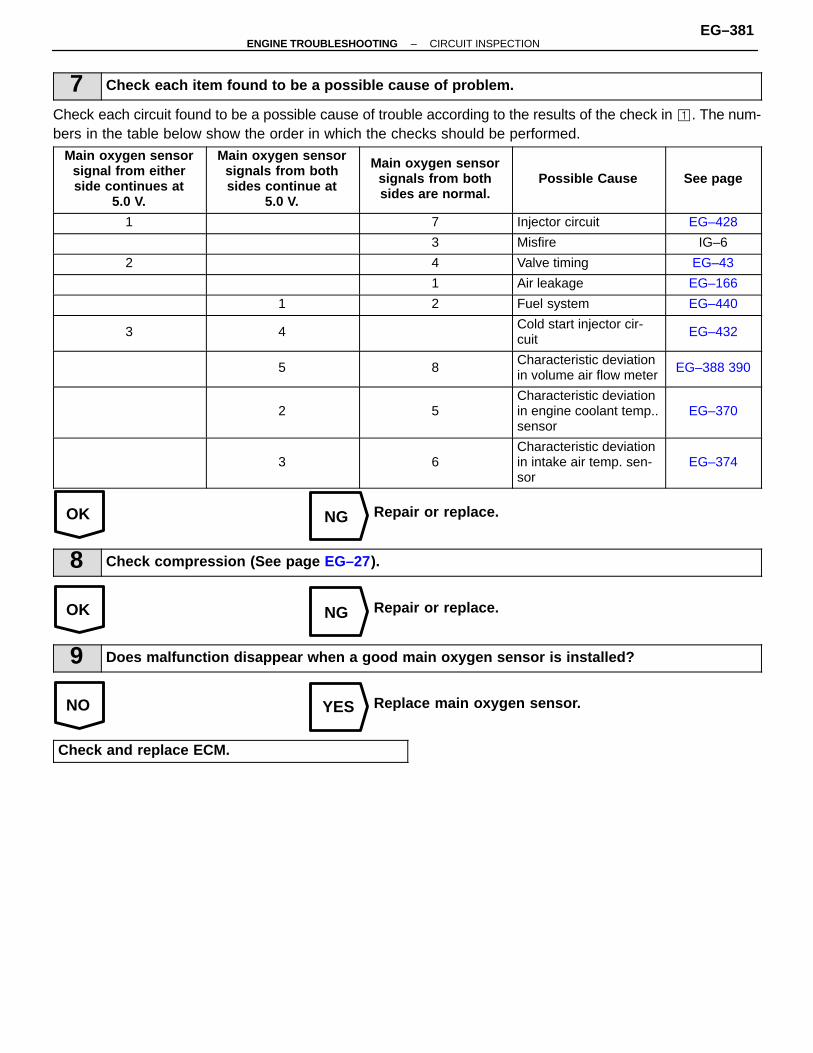
OK NG
OK NG
NO YES
7 Check each item found to be a possible cause of problem.
Check each circuit found to be a possible cause of trouble according to the results of the check in �. The num-bers in the table below show the order in which the checks should be performed.
ÑÑÑÑÑÑÑÑÑÑÑÑÑÑÑÑÑÑÑÑÑÑÑÑÑÑÑÑÑÑÑÑÑÑÑÑ
Main oxygen sensorsignal from eitherside continues at
5.0 V.
ÑÑÑÑÑÑÑÑÑÑÑÑÑÑÑÑÑÑÑÑÑÑÑÑÑÑÑÑÑÑÑÑ
Main oxygen sensorsignals from bothsides continue at
5.0 V.
ÑÑÑÑÑÑÑÑÑÑÑÑÑÑÑÑÑÑÑÑÑÑÑÑÑÑÑÑÑÑÑÑÑÑÑÑ
Main oxygen sensorsignals from bothsides are normal.
ÑÑÑÑÑÑÑÑÑÑÑÑÑÑÑÑÑÑÑÑÑÑÑÑÑÑÑÑÑÑÑÑ
Possible Cause
ÑÑÑÑÑÑÑÑÑÑÑÑÑÑÑÑÑÑÑÑÑÑÑÑ
See page
ÑÑÑÑÑÑÑÑÑÑÑÑÑÑÑÑÑÑ
1 ÑÑÑÑÑÑÑÑÑÑÑÑÑÑÑÑ
ÑÑÑÑÑÑÑÑÑÑÑÑÑÑÑÑÑÑ
7 ÑÑÑÑÑÑÑÑÑÑÑÑÑÑÑÑInjector circuit ÑÑÑÑÑÑ
ÑÑÑÑÑÑEG–428
ÑÑÑÑÑÑÑÑÑÑÑÑÑÑÑÑÑÑ
ÑÑÑÑÑÑÑÑÑÑÑÑÑÑÑÑ
ÑÑÑÑÑÑÑÑÑÑÑÑÑÑÑÑÑÑ
3 ÑÑÑÑÑÑÑÑÑÑÑÑÑÑÑÑMisfire ÑÑÑÑÑÑ
ÑÑÑÑÑÑIG–6
ÑÑÑÑÑÑÑÑÑÑÑÑÑÑÑÑÑÑ
2 ÑÑÑÑÑÑÑÑÑÑÑÑÑÑÑÑ
ÑÑÑÑÑÑÑÑÑÑÑÑÑÑÑÑÑÑ
4 ÑÑÑÑÑÑÑÑÑÑÑÑÑÑÑÑValve timing ÑÑÑÑÑÑ
ÑÑÑÑÑÑEG–43
ÑÑÑÑÑÑÑÑÑÑÑÑÑÑÑÑÑÑ
ÑÑÑÑÑÑÑÑÑÑÑÑÑÑÑÑ
ÑÑÑÑÑÑÑÑÑÑÑÑÑÑÑÑÑÑ
1 ÑÑÑÑÑÑÑÑÑÑÑÑÑÑÑÑAir leakage ÑÑÑÑÑÑ
ÑÑÑÑÑÑEG–166
ÑÑÑÑÑÑÑÑÑÑÑÑÑÑÑÑÑÑ
ÑÑÑÑÑÑÑÑÑÑÑÑÑÑÑÑ
1 ÑÑÑÑÑÑÑÑÑÑÑÑÑÑÑÑÑÑ
2 ÑÑÑÑÑÑÑÑÑÑÑÑÑÑÑÑFuel system ÑÑÑÑÑÑ
ÑÑÑÑÑÑEG–440
ÑÑÑÑÑÑÑÑÑÑÑÑÑÑÑÑÑÑÑÑÑÑÑÑÑÑÑ
3ÑÑÑÑÑÑÑÑÑÑÑÑÑÑÑÑÑÑÑÑÑÑÑÑ
4ÑÑÑÑÑÑÑÑÑÑÑÑÑÑÑÑÑÑÑÑÑÑÑÑÑÑÑ
ÑÑÑÑÑÑÑÑÑÑÑÑÑÑÑÑÑÑÑÑÑÑÑÑ
Cold start injector cir-cuit
ÑÑÑÑÑÑÑÑÑÑÑÑÑÑÑÑÑÑ
EG–432
ÑÑÑÑÑÑÑÑÑÑÑÑÑÑÑÑÑÑ
ÑÑÑÑÑÑÑÑÑÑÑÑÑÑÑÑ
5 ÑÑÑÑÑÑÑÑÑÑÑÑÑÑÑÑÑÑ
8 ÑÑÑÑÑÑÑÑÑÑÑÑÑÑÑÑCharacteristic deviationin volume air flow meter
ÑÑÑÑÑÑÑÑÑÑÑÑ
EG–388 390ÑÑÑÑÑÑÑÑÑÑÑÑÑÑÑÑÑÑÑÑÑÑÑÑÑÑÑÑÑÑÑÑÑÑÑÑ
ÑÑÑÑÑÑÑÑÑÑÑÑÑÑÑÑÑÑÑÑÑÑÑÑÑÑÑÑÑÑÑÑ
2
ÑÑÑÑÑÑÑÑÑÑÑÑÑÑÑÑÑÑÑÑÑÑÑÑÑÑÑÑÑÑÑÑÑÑÑÑ
5
ÑÑÑÑÑÑÑÑÑÑÑÑÑÑÑÑÑÑÑÑÑÑÑÑÑÑÑÑÑÑÑÑ
Characteristic deviationin engine coolant temp..sensor
ÑÑÑÑÑÑÑÑÑÑÑÑÑÑÑÑÑÑÑÑÑÑÑÑ
EG–370
ÑÑÑÑÑÑÑÑÑÑÑÑÑÑÑÑÑÑÑÑÑÑÑÑÑÑÑ
ÑÑÑÑÑÑÑÑÑÑÑÑÑÑÑÑÑÑÑÑÑÑÑÑ
3ÑÑÑÑÑÑÑÑÑÑÑÑÑÑÑÑÑÑÑÑÑÑÑÑÑÑÑ
6ÑÑÑÑÑÑÑÑÑÑÑÑÑÑÑÑÑÑÑÑÑÑÑÑ
Characteristic deviationin intake air temp. sen-sor
ÑÑÑÑÑÑÑÑÑÑÑÑÑÑÑÑÑÑ
EG–374
Repair or replace.
8 Check compression (See page EG–27).
Repair or replace.
9 Does malfunction disappear when a good main oxygen sensor is installed?
Replace main oxygen sensor.
Check and replace ECM.
–ENGINE TROUBLESHOOTING CIRCUIT INSPECTIONEG–381
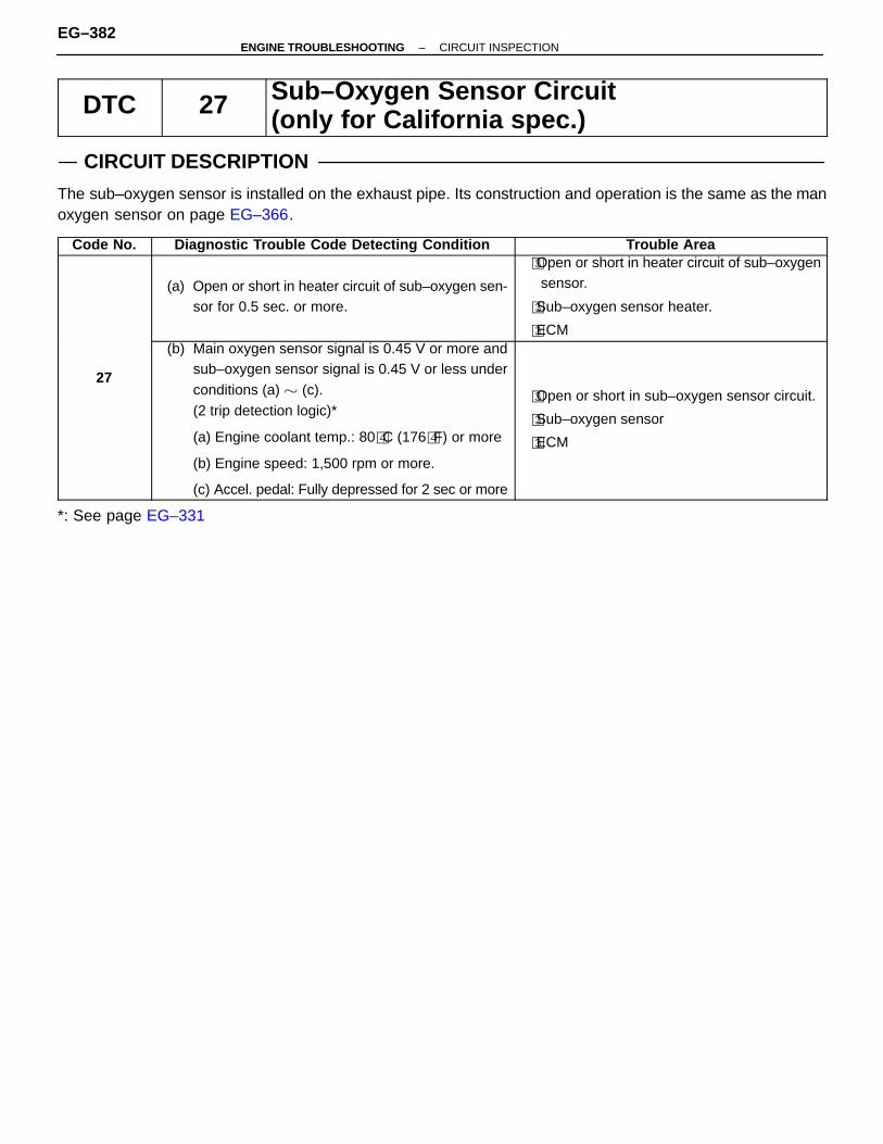
DTC 27 Sub–Oxygen Sensor Circuit(only for California spec.)
CIRCUIT DESCRIPTION
The sub–oxygen sensor is installed on the exhaust pipe. Its construction and operation is the same as the manoxygen sensor on page EG–366.
Code No. Diagnostic Trouble Code Detecting Condition Trouble Area
(a) Open or short in heater circuit of sub–oxygen sen-sor for 0.5 sec. or more.
�Open or short in heater circuit of sub–oxygensensor.
�Sub–oxygen sensor heater.
�ECM
27
(b) Main oxygen sensor signal is 0.45 V or more andsub–oxygen sensor signal is 0.45 V or less underconditions (a) � (c). (2 trip detection logic)*
(a) Engine coolant temp.: 80�C (176�F) or more
(b) Engine speed: 1,500 rpm or more.
(c) Accel. pedal: Fully depressed for 2 sec or more
�Open or short in sub–oxygen sensor circuit.
�Sub–oxygen sensor
�ECM
*: See page EG–331
EG–382–ENGINE TROUBLESHOOTING CIRCUIT INSPECTION
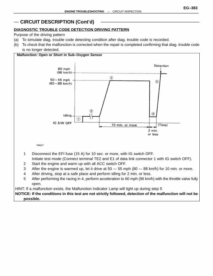
CIRCUIT DESCRIPTION (Cont’d)
DIAGNOSTIC TROUBLE CODE DETECTION DRIVING PATTERNPurpose of the driving pattern(a) To simulate diag. trouble code detecting condition after diag. trouble code is recorded.(b) To check that the malfunction is corrected when the repair is completed confirming that diag. trouble code
is no longer detected.ÑÑÑÑÑÑÑÑÑÑÑÑÑÑÑÑÑÑÑÑÑÑÑÑÑÑÑÑÑÑÑÑÑÑÑÑÑÑÑÑÑÑÑÑÑÑÑÑÑÑÑÑÑÑÑÑÑÑÑÑÑÑÑÑÑÑÑÑÑÑÑÑÑÑÑÑÑÑÑÑÑÑÑÑÑÑÑÑÑÑÑÑÑÑÑÑÑÑÑÑÑÑÑÑÑÑÑÑÑÑÑÑÑÑÑÑÑÑÑÑÑÑÑÑÑÑÑÑÑÑÑÑÑÑÑÑÑÑÑÑÑÑÑÑÑÑÑÑÑÑÑÑÑÑÑÑÑÑÑÑÑÑÑÑÑÑÑÑÑÑÑÑÑÑÑÑÑÑÑÑÑÑÑÑÑÑÑÑÑÑÑÑÑÑÑÑÑÑÑÑÑÑÑÑÑÑÑÑÑÑÑÑÑÑÑÑÑÑÑÑÑÑÑÑÑÑÑÑÑÑÑÑÑÑÑÑÑÑÑÑÑÑÑÑÑÑÑÑÑÑÑÑÑÑÑÑÑÑÑÑÑÑÑÑÑÑÑÑÑÑÑÑÑÑÑÑÑÑÑÑÑÑÑÑÑÑÑÑÑÑÑÑÑÑÑÑÑÑÑÑÑÑÑÑÑÑÑÑÑÑÑÑÑÑÑÑÑÑÑÑÑÑÑÑÑÑÑÑÑÑÑÑÑÑÑÑÑÑÑÑÑÑÑÑÑÑÑÑÑÑÑÑÑÑÑÑÑÑÑÑÑÑÑÑÑÑÑÑÑÑÑÑÑÑÑÑÑÑÑÑÑÑÑÑÑÑÑÑÑÑÑÑÑÑÑÑÑÑÑÑÑÑÑÑÑÑÑÑÑÑÑÑÑÑÑÑÑÑÑÑÑÑÑÑÑÑÑÑÑÑÑÑÑÑÑÑÑÑÑÑÑÑÑÑÑÑÑÑÑÑÑÑÑÑÑÑÑÑÑÑÑÑÑÑÑÑÑÑÑÑÑÑÑÑÑÑÑÑÑÑÑÑÑÑÑÑÑÑÑÑÑÑÑÑÑÑÑÑÑÑÑÑÑÑÑÑÑÑÑÑÑÑÑÑÑÑÑÑÑÑÑÑÑÑÑÑÑÑÑÑÑÑÑÑÑÑÑÑÑÑÑÑÑÑÑÑÑÑÑÑÑÑÑÑÑÑÑÑÑÑÑÑÑÑÑÑÑÑÑÑÑÑÑÑÑÑÑÑÑÑÑÑÑÑÑÑÑÑÑÑÑÑÑÑÑÑÑÑÑÑÑÑÑÑÑÑÑÑÑÑÑÑÑÑÑÑÑÑÑÑÑÑÑÑÑÑÑÑÑÑÑÑÑÑÑÑÑÑÑÑÑÑÑÑÑÑÑÑÑÑÑÑÑÑÑÑÑÑÑÑÑÑÑÑÑÑÑÑÑÑÑÑÑÑÑÑÑÑÑÑÑÑÑÑÑÑÑÑÑÑÑÑÑÑÑÑÑÑÑÑÑÑÑÑÑÑÑÑÑÑÑÑÑÑÑÑÑÑÑÑÑÑÑÑÑÑÑÑÑÑÑÑÑÑÑÑÑÑÑÑÑÑÑÑÑÑÑÑÑÑÑÑÑÑÑÑÑÑÑÑÑÑÑÑÑÑÑÑÑÑÑÑÑÑÑÑÑÑÑÑÑÑÑÑÑÑÑÑÑÑÑÑÑÑÑÑÑÑÑÑÑÑÑÑÑÑÑÑÑÑÑÑÑÑÑÑÑÑÑÑÑÑÑÑÑÑÑÑÑÑÑÑÑÑÑÑÑÑÑÑÑÑÑÑÑÑÑÑÑÑÑÑÑÑÑÑÑÑÑÑÑÑÑÑÑÑÑÑÑÑÑÑÑÑÑÑÑÑÑÑÑÑÑÑÑÑÑÑÑÑÑÑÑÑÑÑÑÑÑÑÑÑÑÑÑÑÑÑÑÑÑÑÑÑÑÑÑÑÑÑÑÑÑÑÑÑÑÑÑÑÑÑÑÑÑÑÑÑÑÑÑÑÑÑÑÑÑÑÑÑÑÑÑÑÑÑÑÑÑÑÑÑÑÑÑÑÑÑÑÑÑÑÑÑÑÑÑÑÑÑÑÑÑÑÑÑÑÑÑÑÑÑÑÑÑÑÑÑÑÑÑÑÑÑÑÑÑÑÑÑÑÑÑÑÑÑÑÑÑÑÑÑÑÑÑÑÑÑÑÑÑÑÑÑÑÑÑÑÑÑÑÑÑÑ
1 Disconnect the EFI fuse (15 A) for 10 sec. or more, with IG switch OFF. Initiate test mode (Connect terminal TE2 and E1 of data link connector 1 with IG switch OFF).
2 Start the engine and warm up with all ACC switch OFF.3 After the engine is warmed up, let it drive at 50 � 55 mph (80 � 88 km/h) for 10 min. or more.4 After driving, stop at a safe place and perform idling for 2 min. or less.5 After performing the racing in 4, perform acceleration to 60 mph (96 km/h) with the throttle valve fully
open.HINT: If a malfunction exists, the Malfunction Indicator Lamp will light up during step 5NOTICE: If the conditions in this test are not strictly followed, detection of the malfunction will not be
possible.
Malfunction: Open or Short in Sub–Oxygen Sensor
–ENGINE TROUBLESHOOTING CIRCUIT INSPECTIONEG–383
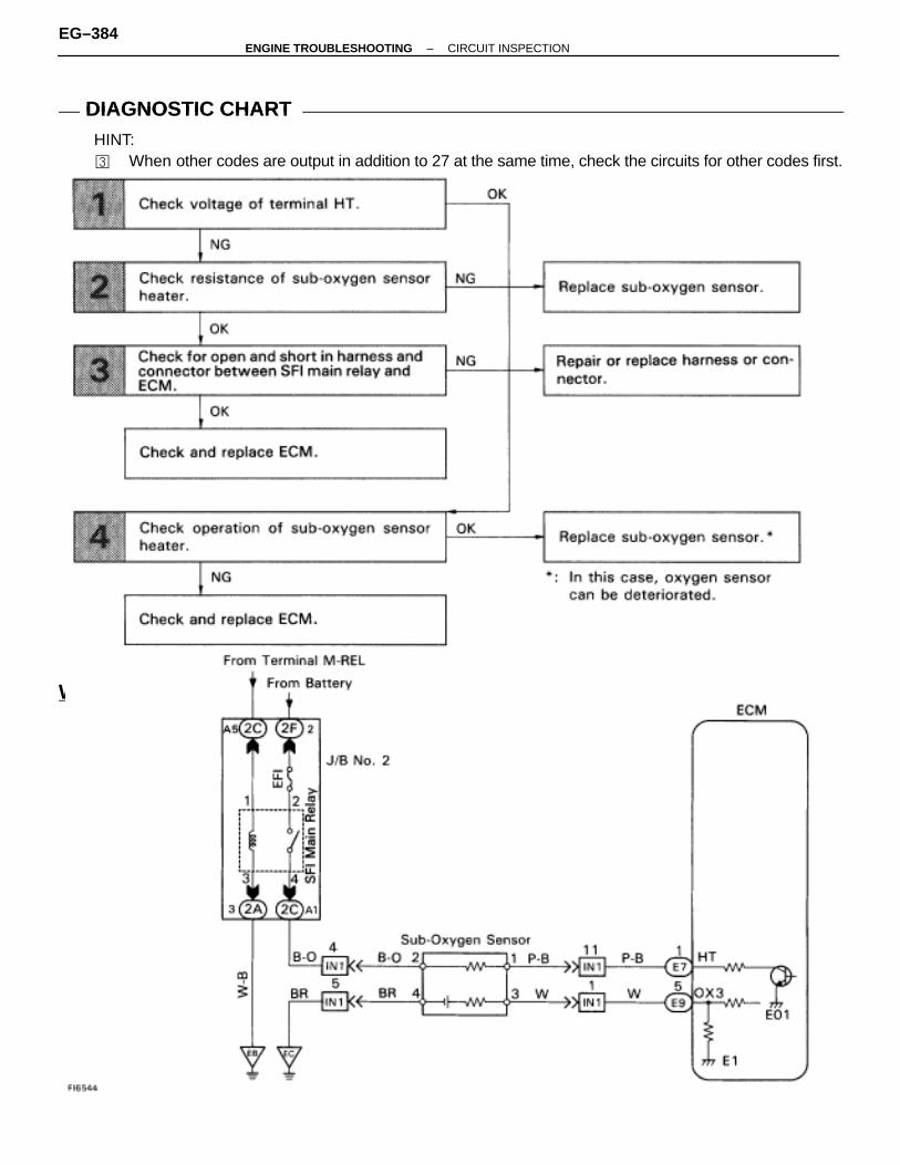
WIRING DIAGRAM
DIAGNOSTIC CHARTDIAGNOSTIC CHARTHINT:� When other codes are output in addition to 27 at the same time, check the circuits for other codes first.
EG–384–ENGINE TROUBLESHOOTING CIRCUIT INSPECTION

NG OK
OK NG
OK NG
INSPECTION PROCEDURE
1 Check voltage between terminal HT of ECM connector and body ground.
C
OK
P 1. Remove glove compartment. (See page BO–111).2. Turn ignition switch on.
Measure voltage between terminal HT of ECM connec-tor and body ground.
Voltage: 10 – 14 V
Go to step �.
2 Check sub–oxygen sensor heater.
C
OK
P Disconnect sub–oxygen sensor connector.
Measure resistance between terminals 1 and 2 of sub–oxygen sensor connector.
Resistance: 11.7 – 14.3 � 20�C (68�F)
Replace sub–oxygen sensor.
3 Check for open and short in harness and connector between SFI main relay and ECM (See pageIN–27).
Repair or replace harness or connector.
Check and replace ECM.
–ENGINE TROUBLESHOOTING CIRCUIT INSPECTIONEG–385
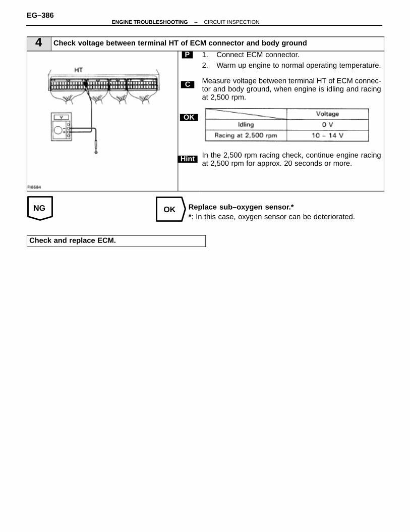
NG OK
4 Check voltage between terminal HT of ECM connector and body ground
C
OK
Hint
P 1. Connect ECM connector.2. Warm up engine to normal operating temperature.
Measure voltage between terminal HT of ECM connec-tor and body ground, when engine is idling and racingat 2,500 rpm.
In the 2,500 rpm racing check, continue engine racingat 2,500 rpm for approx. 20 seconds or more.
Replace sub–oxygen sensor.**: In this case, oxygen sensor can be deteriorated.
Check and replace ECM.
EG–386–ENGINE TROUBLESHOOTING CIRCUIT INSPECTION

–MEMO–
–ENGINE TROUBLESHOOTING CIRCUIT INSPECTIONEG–387
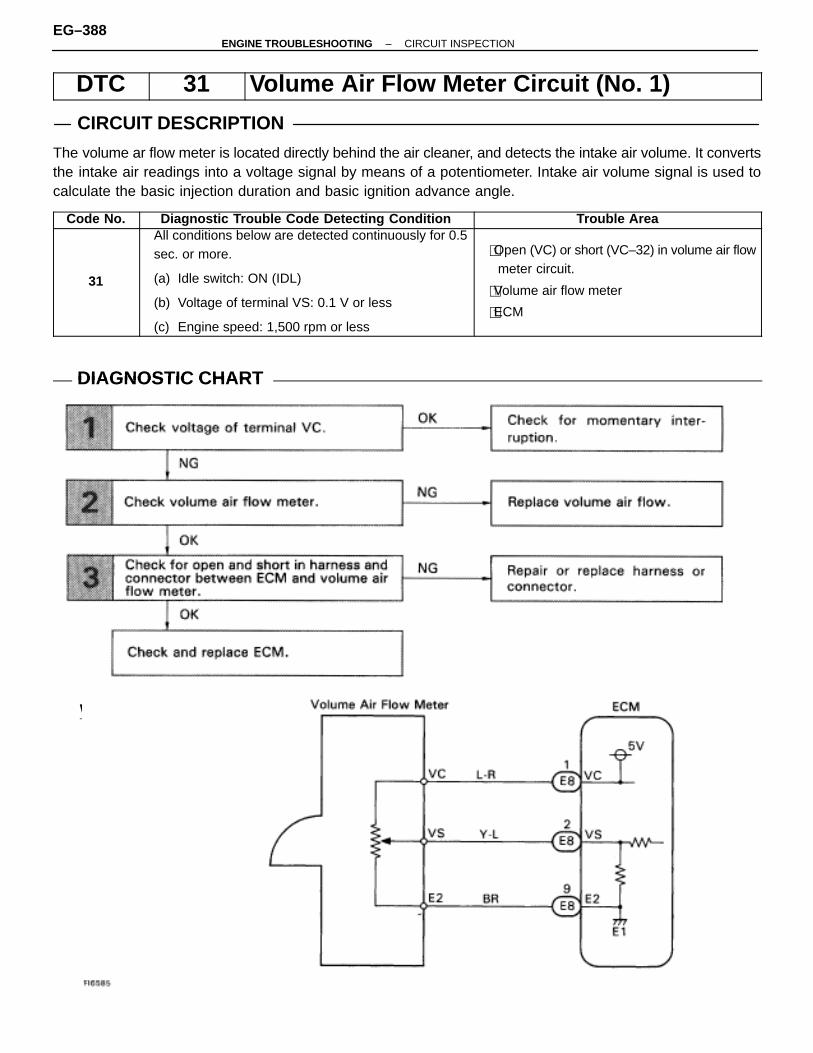
WIRING DIAGRAM
DTC 31 Volume Air Flow Meter Circuit (No. 1)
CIRCUIT DESCRIPTION
The volume ar flow meter is located directly behind the air cleaner, and detects the intake air volume. It convertsthe intake air readings into a voltage signal by means of a potentiometer. Intake air volume signal is used tocalculate the basic injection duration and basic ignition advance angle.
Code No. Diagnostic Trouble Code Detecting Condition Trouble Area
31
All conditions below are detected continuously for 0.5sec. or more.
(a) Idle switch: ON (IDL)
(b) Voltage of terminal VS: 0.1 V or less
(c) Engine speed: 1,500 rpm or less
�Open (VC) or short (VC–32) in volume air flowmeter circuit.
�Volume air flow meter
�ECM
DIAGNOSTIC CHARTDIAGNOSTIC CHART
EG–388–ENGINE TROUBLESHOOTING CIRCUIT INSPECTION

NG OK
OK NG
OK NG
INSPECTION PROCEDURE
1 Check voltage between terminals VC and E2 of ECM
C
OK
P 1. Remove glove compartment. (See page BO–111).2. Turn ignition switch ON.
Measure voltage between terminals VC and E2 of ECM.
Voltage: 4 – 6 V
Check for momentary interruption (See page EG–333)
2 Check resistance between terminals VC and E2 of volume air flow meter.
C
OK
P Disconnect the volume air flow meter connector.
Measure resistance between terminals VC and E2 ofvolume air flow meter.
Resistance: 200 – 400 �
Replace volume air flow meter.
3 Check for open and short in harness and connector between ECM and volume air flow meter(See page IN–27).
Repair or replace harness or connector.
Check and replace ECM.
–ENGINE TROUBLESHOOTING CIRCUIT INSPECTIONEG–389

WIRING DIAGRAM
DTC 32 Volume Air Flow Meter Circuit (No. 2)
CIRCUIT DESCRIPTION
The volume ar flow meter is located directly behind the air cleaner, and detects the intake air volume. It convertsthe intake air readings into a voltage signal by means of a potentiometer. Intake air volume signal is used tocalculate the basic injection duration and basic ignition advance angle.
Code No. Diagnostic Trouble Code Detecting Condition Trouble Area
32 VS exceeds 4.9 V for 0.5 sec. or more.
�Open (E2) or short (VS–VS) in volume air flowmeter circuit.
�Volume air flow meter
�ECM
DIAGNOSTIC CHARTDIAGNOSTIC CHART
EG–390–ENGINE TROUBLESHOOTING CIRCUIT INSPECTION

NG OK
OK NG
OK NG
INSPECTION PROCEDURE
1 Check voltage between terminals VS and E2 of ECM
C
OK
P 1. Remove air cleaner cap.2. Remove glove compartment. (See page BO–111).
3. Turn ignition switch ON.
Measure voltage between terminals VS and E2 of ECM.
Check for momentary interruption (See page EG–333)
2 Check resistance between terminals VS and E2 of volume air flow meter.
C
OK
P Disconnect the volume air flow meter connector.
Measure resistance between terminals VS and E2 ofvolume air flow meter.
Replace volume air flow meter.
3 Check for open and short in harness and connector between ECM and volume air flow meter(See page IN–27).
Repair or replace harness or connector.
Check and replace ECM.
–ENGINE TROUBLESHOOTING CIRCUIT INSPECTIONEG–391

DTC 41 Throttle Position Sensor Circuit
CIRCUIT DESCRIPTION
ÑÑÑÑÑÑÑÑÑÑÑÑÑÑÑÑÑÑÑÑÑÑÑÑÑÑÑÑÑÑÑÑÑÑÑÑÑÑÑÑÑÑÑÑÑÑÑÑÑÑÑÑÑÑÑÑÑÑÑÑÑÑÑÑÑÑÑÑÑÑÑÑÑÑÑÑÑÑÑÑÑÑÑÑÑÑÑÑÑÑÑÑÑÑÑÑÑÑÑÑÑÑÑÑÑÑÑÑÑÑÑÑÑÑÑÑÑÑÑÑÑÑÑÑÑÑÑÑÑÑÑÑÑÑÑÑÑÑÑÑÑÑÑÑÑÑÑÑÑÑÑÑÑÑÑÑÑÑÑÑÑÑÑÑÑÑÑÑÑÑÑÑÑÑÑÑÑÑÑÑÑÑÑÑÑÑÑÑÑÑÑÑÑÑÑÑÑÑÑÑÑÑÑÑÑÑÑÑÑÑÑÑÑÑÑÑÑÑÑÑÑÑÑÑÑÑÑÑÑÑÑÑÑÑÑÑÑÑÑÑÑÑÑÑÑÑÑÑÑÑÑÑÑÑÑÑÑÑÑÑÑÑÑÑÑÑÑÑÑÑÑÑÑÑÑÑÑÑÑÑÑÑÑÑÑÑÑÑ
The throttle position sensor is mounted in thethrottle body and detects the throttle valve openingangle. When the throttle valve is fully closed, theIDL contacts in the throttle position sensor are on,so the voltage at the terminal IDL of the ECM be-come 0 V. At this time, a voltage of approximately0.7 is applied to the terminal VTA of the ECM. Whenthe throttle valve is opened, the IDL contacts go offand thus the power source voltage of approximately12 V in the ECM is applied to the terminal VTA ofthe ECM increases in proportion to the openingangle of the throttle valve and becomes approxi-mately 3.5 0 5.0 V when the throttle valve is fullyopened. The ECM judges the vehicle driving condi-tions from these signals input from the terminalsVTA and IDL, and uses them as one of the condi-tions for deciding the air–fuel ratio correction, powerincrease correction and fuel–cut control etc.
ÑÑÑÑÑÑÑÑÑÑÑÑÑÑÑÑÑÑÑÑÑÑÑÑÑÑÑÑÑÑÑÑÑÑÑÑÑÑÑÑÑÑÑÑÑÑÑÑÑÑÑÑÑÑÑÑÑÑÑÑÑÑÑÑÑÑÑÑÑÑÑÑÑÑÑÑÑÑÑÑÑÑÑÑÑÑÑÑÑÑÑÑÑÑÑÑÑÑÑÑÑÑÑÑÑÑÑÑÑÑÑÑÑÑÑÑÑÑÑÑÑÑÑÑÑÑÑÑÑÑÑÑÑÑÑÑÑÑÑÑÑÑÑÑÑÑÑÑÑÑÑÑÑÑÑÑÑÑÑÑÑÑÑÑÑÑÑÑÑÑÑÑÑÑÑÑÑÑÑÑÑÑÑÑÑÑÑÑÑÑÑÑÑÑÑÑÑÑÑÑÑÑÑÑÑÑÑÑÑÑÑÑÑÑÑÑÑÑÑÑÑÑÑÑÑÑÑÑÑÑÑÑÑÑÑÑÑÑÑÑÑÑÑÑÑÑÑÑÑÑÑÑÑÑÑÑÑÑÑÑÑÑÑÑÑÑÑÑÑÑÑÑÑÑÑÑÑÑÑÑÑÑÑÑÑÑÑÑÑÑÑÑÑÑÑÑÑÑÑÑÑÑÑÑText
Code No. Diagnostic Trouble Code Detecting Condition Trouble Area
41Open or short in throttle position sensor circuit (VTA)for 0.5 sec. or more.
�Open or short in throttle position sensor circuit
�Throttle position sensor
�ECM
HINT: When the connector for the throttle position sensor is disconnected, diagnostic trouble code 41 is not dis-played, Diagnostic trouble code 41 is displayed only when there is an open or short in the VTA signal circuitof the throttle position sensor.
EG–392–ENGINE TROUBLESHOOTING CIRCUIT INSPECTION

WIRING DIAGRAM
DIAGNOSTIC CHARTDIAGNOSTIC CHARTHINT: If diagnostic trouble codes 22, 24, 32 and 41 are output simultaneously, E2 (sensor ground) may be open.
–ENGINE TROUBLESHOOTING CIRCUIT INSPECTIONEG–393
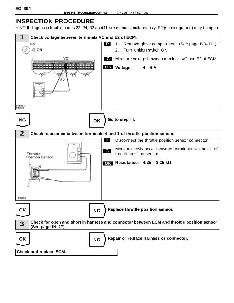
NG OK
OK NG
OK NG
INSPECTION PROCEDUREHINT: If diagnostic trouble codes 22, 24, 32 an d41 are output simultaneously, E2 (sensor ground) may be open.
1 Check voltage between terminals VC and E2 of ECM.
C
OK
P 1. Remove glove compartment. (See page BO–111).2. Turn ignition switch ON.
Measure voltage between terminals VC and E2 of ECM.
Voltage: 4 – 6 V
Go to step �.
2 Check resistance between terminals 4 and 1 of throttle position sensor.
C
OK
P Disconnect the throttle position sensor connector.
Measure resistance between terminals 4 and 1 ofthrottle position sensor.
Resistance: 4.25 – 8.25 k �
Replace throttle position sensor.
3 Check for open and short in harness and connector between ECM and throttle position sensor(See page IN–27).
Repair or replace harness or connector.
Check and replace ECM.
EG–394–ENGINE TROUBLESHOOTING CIRCUIT INSPECTION
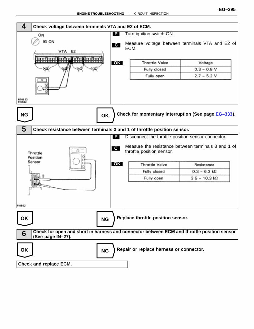
NG OK
OK NG
OK NG
4 Check voltage between terminals VTA and E2 of ECM.
C
OK
P Turn ignition switch ON.
Measure voltage between terminals VTA and E2 ofECM.
Check for momentary interruption (See page EG–333).
5 Check resistance between terminals 3 and 1 of throttle position sensor.
C
OK
P Disconnect the throttle position sensor connector.
Measure the resistance between terminals 3 and 1 ofthrottle position sensor.
Replace throttle position sensor.
6 Check for open and short in harness and connector between ECM and throttle position sensor(See page IN–27).
Repair or replace harness or connector.
Check and replace ECM.
–ENGINE TROUBLESHOOTING CIRCUIT INSPECTIONEG–395
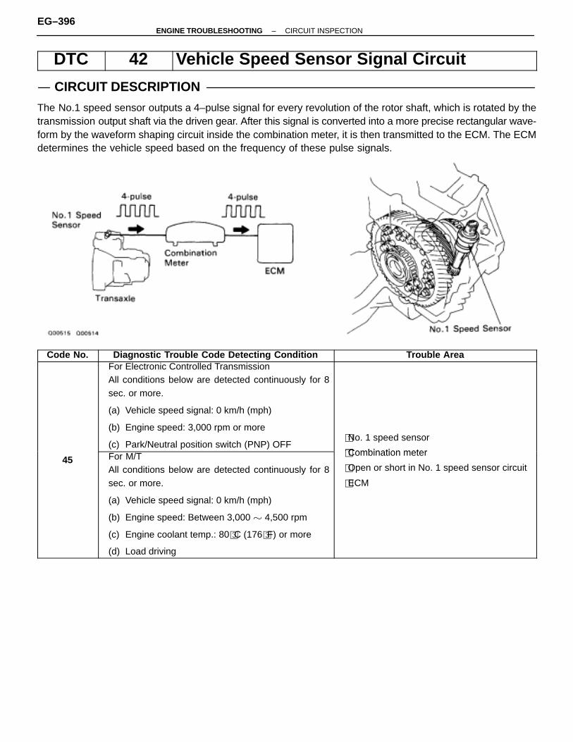
DTC 42 Vehicle Speed Sensor Signal Circuit
CIRCUIT DESCRIPTION
The No.1 speed sensor outputs a 4–pulse signal for every revolution of the rotor shaft, which is rotated by thetransmission output shaft via the driven gear. After this signal is converted into a more precise rectangular wave-form by the waveform shaping circuit inside the combination meter, it is then transmitted to the ECM. The ECMdetermines the vehicle speed based on the frequency of these pulse signals.
Code No. Diagnostic Trouble Code Detecting Condition Trouble AreaFor Electronic Controlled TransmissionAll conditions below are detected continuously for 8sec. or more.
(a) Vehicle speed signal: 0 km/h (mph)
(b) Engine speed: 3,000 rpm or more
(c) Park/Neutral position switch (PNP) OFF�No. 1 speed sensor
�Combination meter45 For M/T
All conditions below are detected continuously for 8sec. or more.
(a) Vehicle speed signal: 0 km/h (mph)
(b) Engine speed: Between 3,000 � 4,500 rpm
(c) Engine coolant temp.: 80�C (176�F) or more
(d) Load driving
�Combination meter
�Open or short in No. 1 speed sensor circuit
�ECM
EG–396–ENGINE TROUBLESHOOTING CIRCUIT INSPECTION

WIRING DIAGRAM
DIAGNOSTIC CHARTDIAGNOSTIC CHART
(See page BE–125).
(See page BE–125).
–ENGINE TROUBLESHOOTING CIRCUIT INSPECTIONEG–397

OK NG
OK NG
INSPECTION PROCEDURE
1 Check operation of speedometer.
C Drive the vehicle and check if the operation of the speedometer in the combination meter is normal.
The No. 1 speed sensor is operating normally if the speedometer display is normal.Hint
Check speedometer circuit. See combination meter trou-bleshooting on page BE–125.
2 Check voltage between terminal SP1 of ECM connector and body ground.
C
OK
P 1. Remove glove compartment. (See page BO–111).2. Disconnect power steering ECU connector and
cruise control ECU connector.3. Shift the shift lever to N position or neutral.4. Jack up a front wheel o one side.
5. Turn ignition switch on.
Measure voltage between terminal SP1 of ECM con-nector and body ground when the wheel is turned slow-ly.
Voltage is generated intermittently.
Check speedometer circuit. See combination meter trou-bleshooting on page BE–125.
Check and replace ECM.
EG–398–ENGINE TROUBLESHOOTING CIRCUIT INSPECTION

–MEMO–
–ENGINE TROUBLESHOOTING CIRCUIT INSPECTIONEG–399
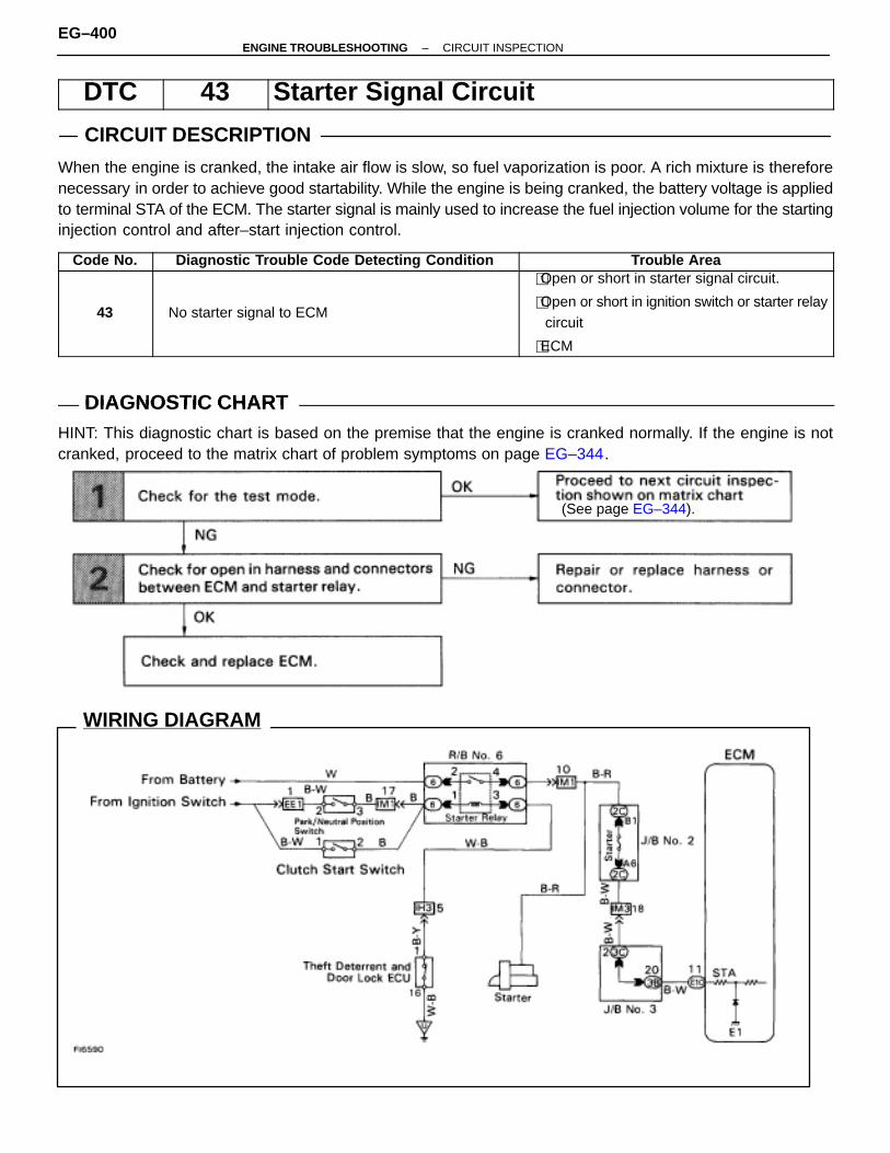
WIRING DIAGRAM
DTC 43 Starter Signal Circuit
CIRCUIT DESCRIPTION
When the engine is cranked, the intake air flow is slow, so fuel vaporization is poor. A rich mixture is thereforenecessary in order to achieve good startability. While the engine is being cranked, the battery voltage is appliedto terminal STA of the ECM. The starter signal is mainly used to increase the fuel injection volume for the startinginjection control and after–start injection control.
Code No. Diagnostic Trouble Code Detecting Condition Trouble Area
43 No starter signal to ECM
�Open or short in starter signal circuit.
�Open or short in ignition switch or starter relaycircuit
�ECM
DIAGNOSTIC CHARTDIAGNOSTIC CHARTHINT: This diagnostic chart is based on the premise that the engine is cranked normally. If the engine is notcranked, proceed to the matrix chart of problem symptoms on page EG–344.
(See page EG–344).
EG–400–ENGINE TROUBLESHOOTING CIRCUIT INSPECTION
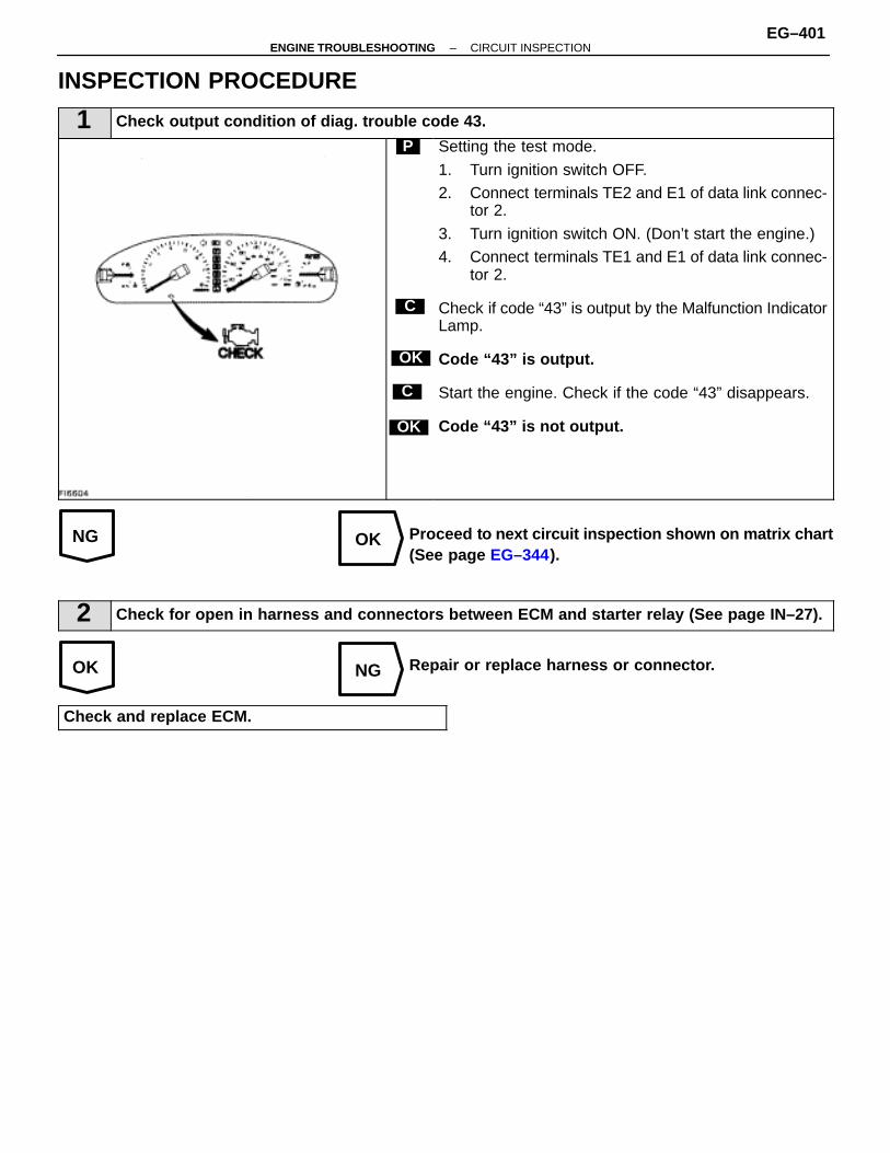
NG OK
OK NG
INSPECTION PROCEDURE
1 Check output condition of diag. trouble code 43.
C
OK
P
OK
C
Setting the test mode.
1. Turn ignition switch OFF.2. Connect terminals TE2 and E1 of data link connec-
tor 2.
3. Turn ignition switch ON. (Don’t start the engine.)4. Connect terminals TE1 and E1 of data link connec-
tor 2.
Check if code “43” is output by the Malfunction IndicatorLamp.
Code “43” is output.
Start the engine. Check if the code “43” disappears.
Code “43” is not output.
Proceed to next circuit inspection shown on matrix chart(See page EG–344).
2 Check for open in harness and connectors between ECM and starter relay (See page IN–27).
Repair or replace harness or connector.
Check and replace ECM.
–ENGINE TROUBLESHOOTING CIRCUIT INSPECTIONEG–401
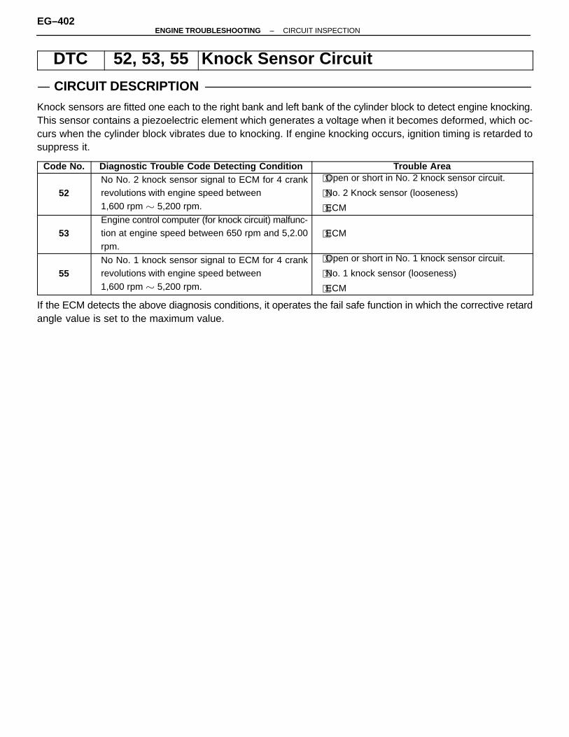
DTC 52, 53, 55 Knock Sensor Circuit
CIRCUIT DESCRIPTION
Knock sensors are fitted one each to the right bank and left bank of the cylinder block to detect engine knocking.This sensor contains a piezoelectric element which generates a voltage when it becomes deformed, which oc-curs when the cylinder block vibrates due to knocking. If engine knocking occurs, ignition timing is retarded tosuppress it.
Code No. Diagnostic Trouble Code Detecting Condition Trouble Area
52No No. 2 knock sensor signal to ECM for 4 crankrevolutions with engine speed between 1,600 rpm � 5,200 rpm.
�Open or short in No. 2 knock sensor circuit.
�No. 2 Knock sensor (looseness)
�ECM
53Engine control computer (for knock circuit) malfunc-tion at engine speed between 650 rpm and 5,2.00rpm.
�ECM
55No No. 1 knock sensor signal to ECM for 4 crankrevolutions with engine speed between 1,600 rpm � 5,200 rpm.
�Open or short in No. 1 knock sensor circuit.
�No. 1 knock sensor (looseness)
�ECM
If the ECM detects the above diagnosis conditions, it operates the fail safe function in which the corrective retardangle value is set to the maximum value.
EG–402–ENGINE TROUBLESHOOTING CIRCUIT INSPECTION
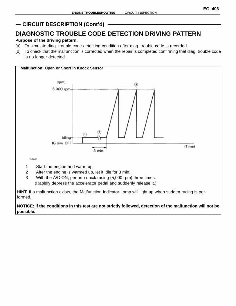
CIRCUIT DESCRIPTION (Cont’d)
DIAGNOSTIC TROUBLE CODE DETECTION DRIVING PATTERNPurpose of the driving pattern.(a) To simulate diag. trouble code detecting condition after diag. trouble code is recorded.(b) To check that the malfunction is corrected when the repair is completed confirming that diag. trouble code
is no longer detected.
ÑÑÑÑÑÑÑÑÑÑÑÑÑÑÑÑÑÑÑÑÑÑÑÑÑÑÑÑÑÑÑÑÑÑÑÑÑÑÑÑÑÑÑÑÑÑÑÑÑÑÑÑÑÑÑÑÑÑÑÑÑÑÑÑÑÑÑÑÑÑÑÑÑÑÑÑÑÑÑÑÑÑÑÑÑÑÑÑÑÑÑÑÑÑÑÑÑÑÑÑÑÑÑÑÑÑÑÑÑÑÑÑÑÑÑÑÑÑÑÑÑÑÑÑÑÑÑÑÑÑÑÑÑÑÑÑÑÑÑÑÑÑÑÑÑÑÑÑÑÑÑÑÑÑÑÑÑÑÑÑÑÑÑÑÑÑÑÑÑÑÑÑÑÑÑÑÑÑÑÑÑÑÑÑÑÑÑÑÑÑÑÑÑÑÑÑÑÑÑÑÑÑÑÑÑÑÑÑÑÑÑÑÑÑÑÑÑÑÑÑÑÑÑÑÑÑÑÑÑÑÑÑÑÑÑÑÑÑÑÑÑÑÑÑÑÑÑÑÑÑÑÑÑÑÑÑÑÑÑÑÑÑÑÑÑÑÑÑÑÑÑÑÑÑÑÑÑÑÑÑÑÑÑÑÑÑÑÑÑÑÑÑÑÑÑÑÑÑÑÑÑÑÑÑÑÑÑÑÑÑÑÑÑÑÑÑÑÑÑÑÑÑÑÑÑÑÑÑÑÑÑÑÑÑÑÑÑÑÑÑÑÑÑÑÑÑÑÑÑÑÑÑÑÑÑÑÑÑÑÑÑÑÑÑÑÑÑÑÑÑÑÑÑÑÑÑÑÑÑÑÑÑÑÑÑÑÑÑÑÑÑÑÑÑÑÑÑÑÑÑÑÑÑÑÑÑÑÑÑÑÑÑÑÑÑÑÑÑÑÑÑÑÑÑÑÑÑÑÑÑÑÑÑÑÑÑÑÑÑÑÑÑÑÑÑÑÑÑÑÑÑÑÑÑÑÑÑÑÑÑÑÑÑÑÑÑÑÑÑÑÑÑÑÑÑÑÑÑÑÑÑÑÑÑÑÑÑÑÑÑÑÑÑÑÑÑÑÑÑÑÑÑÑÑÑÑÑÑÑÑÑÑÑÑÑÑÑÑÑÑÑÑÑÑÑÑÑÑÑÑÑÑÑÑÑÑÑÑÑÑÑÑÑÑÑÑÑÑÑÑÑÑÑÑÑÑÑÑÑÑÑÑÑÑÑÑÑÑÑÑÑÑÑÑÑÑÑÑÑÑÑÑÑÑÑÑÑÑÑÑÑÑÑÑÑÑÑÑÑÑÑÑÑÑÑÑÑÑÑÑÑÑÑÑÑÑÑÑÑÑÑÑÑÑÑÑÑÑÑÑÑÑÑÑÑÑÑÑÑÑÑÑÑÑÑÑÑÑÑÑÑÑÑÑÑÑÑÑÑÑÑÑÑÑÑÑÑÑÑÑÑÑÑÑÑÑÑÑÑÑÑÑÑÑÑÑÑÑÑÑÑÑÑÑÑÑÑÑÑÑÑÑÑÑÑÑÑÑÑÑÑÑÑÑÑÑÑÑÑÑÑÑÑÑÑÑÑÑÑÑÑÑÑÑÑÑÑÑÑÑÑÑÑÑÑÑÑÑÑÑÑÑÑÑÑÑÑÑÑÑÑÑÑÑÑÑÑÑÑÑÑÑÑÑÑÑÑÑÑÑÑÑÑÑÑÑÑÑÑÑÑÑÑÑÑÑÑÑÑÑÑÑÑÑÑÑÑÑÑÑÑÑÑÑÑÑÑÑÑÑÑÑÑÑÑÑÑÑÑÑÑÑÑÑÑÑÑÑÑÑÑÑÑÑÑÑÑÑÑÑÑÑÑÑÑÑÑÑÑÑÑÑÑÑÑÑÑÑÑÑÑÑÑÑÑÑÑÑÑÑÑÑÑÑÑÑÑÑÑÑÑÑÑÑÑÑÑÑÑÑÑÑÑÑÑÑÑÑÑÑÑÑÑÑÑÑÑÑÑÑÑÑÑÑÑÑÑÑÑÑÑÑÑÑÑÑ
1 Start the engine and warm up.2 After the engine is warmed up, let it idle for 3 min.3 With the A/C ON, perform quick racing (5,000 rpm) three times.
(Rapidly depress the accelerator pedal and suddenly release it.)
HINT: If a malfunction exists, the Malfunction Indicator Lamp will light up when sudden racing is per-formed.
NOTICE: If the conditions in this test are not strictly followed, detection of the malfunction will not bepossible.
Malfunction: Open or Short in Knock Sensor
–ENGINE TROUBLESHOOTING CIRCUIT INSPECTIONEG–403
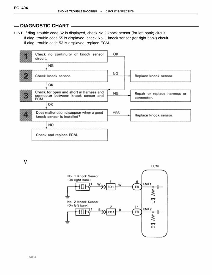
WIRING DIAGRAM
DIAGNOSTIC CHARTDIAGNOSTIC CHARTHINT: If diag. trouble code 52 is displayed, check No.2 knock sensor (for left bank) circuit.
If diag. trouble code 55 is displayed, check No. 1 knock sensor (for right bank) circuit.If diag. trouble code 53 is displayed, replace ECM.
EG–404–ENGINE TROUBLESHOOTING CIRCUIT INSPECTION
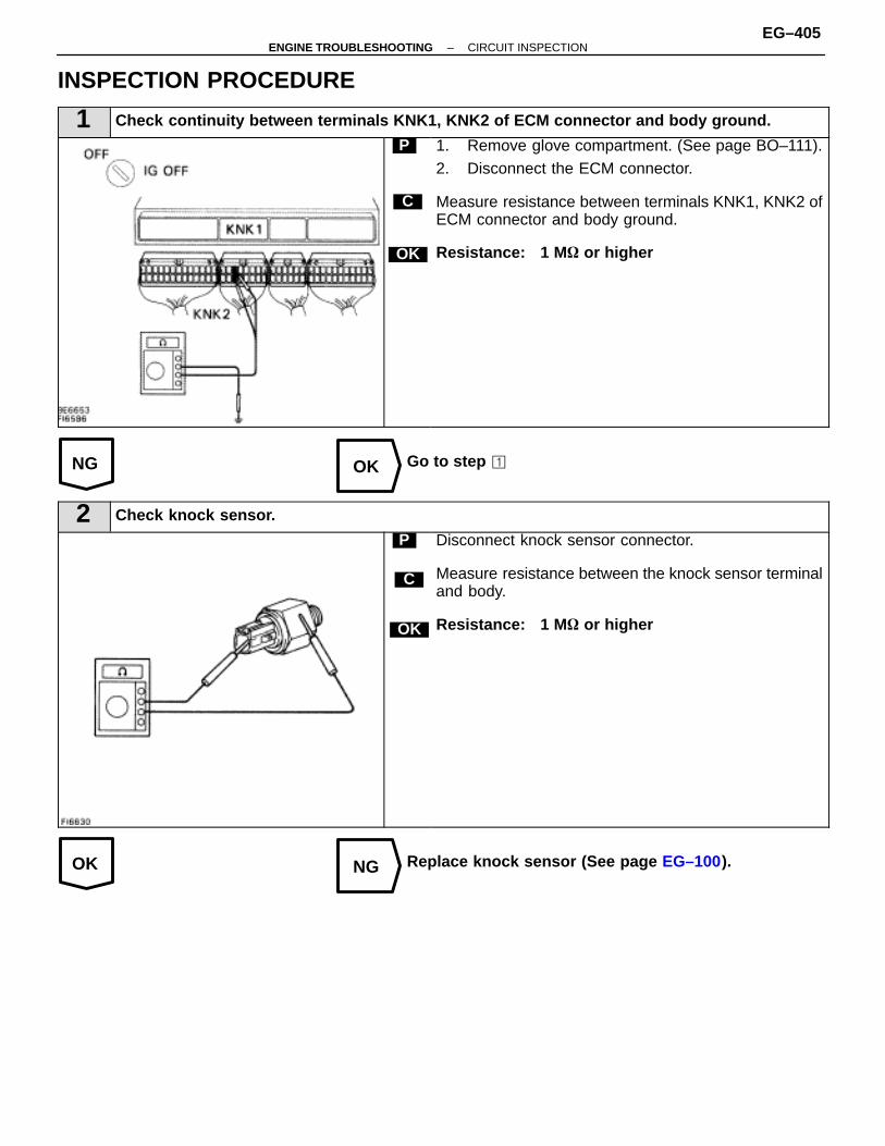
NG OK
OK NG
INSPECTION PROCEDURE
1 Check continuity between terminals KNK1, KNK2 of ECM connector and body ground.
C
OK
P 1. Remove glove compartment. (See page BO–111).2. Disconnect the ECM connector.
Measure resistance between terminals KNK1, KNK2 ofECM connector and body ground.
Resistance: 1 M � or higher
Go to step �
2 Check knock sensor.
C
OK
P Disconnect knock sensor connector.
Measure resistance between the knock sensor terminaland body.
Resistance: 1 M � or higher
Replace knock sensor (See page EG–100).
–ENGINE TROUBLESHOOTING CIRCUIT INSPECTIONEG–405
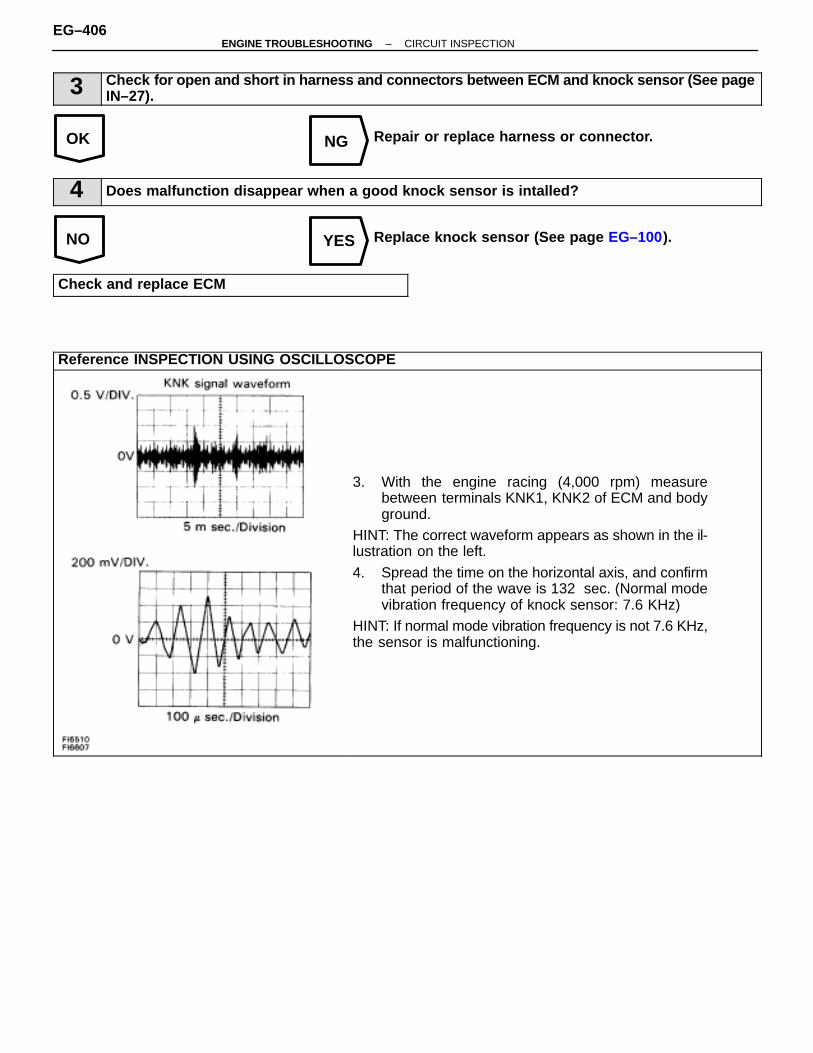
OK NG
NO YES
3 Check for open and short in harness and connectors between ECM and knock sensor (See pageIN–27).
Repair or replace harness or connector.
4 Does malfunction disappear when a good knock sensor is intalled?
Replace knock sensor (See page EG–100).
Check and replace ECM
Reference INSPECTION USING OSCILLOSCOPE
3. With the engine racing (4,000 rpm) measurebetween terminals KNK1, KNK2 of ECM and bodyground.
HINT: The correct waveform appears as shown in the il-lustration on the left.
4. Spread the time on the horizontal axis, and confirmthat period of the wave is 132 sec. (Normal modevibration frequency of knock sensor: 7.6 KHz)
HINT: If normal mode vibration frequency is not 7.6 KHz,the sensor is malfunctioning.
EG–406–ENGINE TROUBLESHOOTING CIRCUIT INSPECTION

–MEMO–
–ENGINE TROUBLESHOOTING CIRCUIT INSPECTIONEG–407
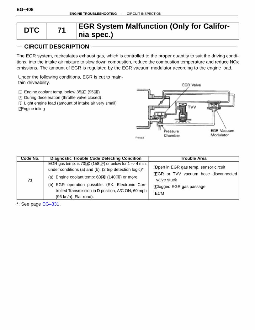
DTC 71 EGR System Malfunction (Only for Califor-nia spec.)
CIRCUIT DESCRIPTION
The EGR system, recirculates exhaust gas, which is controlled to the proper quantity to suit the driving condi-tions, into the intake air mixture to slow down combustion, reduce the combustion temperature and reduce NOxemissions. The amount of EGR is regulated by the EGR vacuum modulator according to the engine load.
ÑÑÑÑÑÑÑÑÑÑÑÑÑÑÑÑÑÑÑÑÑÑÑÑÑÑÑÑÑÑÑÑÑÑÑÑÑÑÑÑÑÑÑÑÑÑÑÑÑÑÑÑÑÑÑÑÑÑÑÑÑÑÑÑÑÑÑÑÑÑÑÑÑÑÑÑÑÑÑÑÑÑÑÑÑÑÑÑÑÑÑÑÑÑÑÑÑÑÑÑÑÑÑÑÑÑÑÑÑÑÑÑÑÑÑÑÑÑÑÑÑÑÑÑÑÑÑÑÑÑÑÑÑÑÑÑÑÑÑÑÑÑÑÑÑÑÑÑÑÑÑÑÑÑÑÑÑÑÑÑÑÑÑÑÑÑÑÑÑÑÑÑÑÑÑÑÑÑÑÑÑÑÑÑÑÑÑÑÑÑÑÑÑÑÑÑÑÑÑÑÑÑÑÑÑÑÑÑÑÑÑÑÑÑÑÑÑÑÑÑÑÑÑÑÑÑÑÑÑÑÑÑÑÑÑÑÑÑÑÑÑÑÑÑÑÑÑÑÑÑÑÑ
Under the following conditions, EGR is cut to main-tain driveability.
� Engine coolant temp. below 35�C (95�F)� During deceleration (throttle valve closed)� Light engine load (amount of intake air very small)� Engine idling
ÑÑÑÑÑÑÑÑÑÑÑÑÑÑÑÑÑÑÑÑÑÑÑÑÑÑÑÑÑÑÑÑÑÑÑÑÑÑÑÑÑÑÑÑÑÑÑÑÑÑÑÑÑÑÑÑÑÑÑÑÑÑÑÑÑÑÑÑÑÑÑÑÑÑÑÑÑÑÑÑÑÑÑÑÑÑÑÑÑÑÑÑÑÑÑÑÑÑÑÑÑÑÑÑÑÑÑÑÑÑÑÑÑÑÑÑÑÑÑÑÑÑÑÑÑÑÑÑÑÑÑÑÑÑÑÑÑÑÑÑÑÑÑÑÑÑÑÑÑÑÑÑÑÑÑÑÑÑÑÑÑÑÑÑÑÑÑÑÑÑÑÑÑÑÑÑÑÑÑÑÑÑÑÑÑÑÑÑÑÑÑÑÑÑÑÑÑÑÑÑÑÑÑÑÑÑÑÑÑÑÑÑÑÑÑÑÑÑÑÑÑÑÑÑÑÑÑÑÑÑÑÑÑÑÑÑÑÑÑÑÑÑÑÑÑÑÑÑÑÑÑÑÑÑÑÑÑÑÑÑÑÑÑÑÑÑCode No. Diagnostic Trouble Code Detecting Condition Trouble Area
71
EGR gas temp. is 70�C (158�F) or below for 1 � 4 min.under conditions (a) and (b). (2 trip detection logic)*
(a) Engine coolant temp: 60�C (140�F) or more
(b) EGR operation possible. (EX. Electronic Con-trolled Transmission in D position, A/C ON, 60 mph(96 kn/h), Flat road).
�Open in EGR gas temp. sensor circuit
�EGR or TVV vacuum hose disconnectedvalve stuck
�Clogged EGR gas passage
�ECM
*: See page EG–331.
EG–408–ENGINE TROUBLESHOOTING CIRCUIT INSPECTION
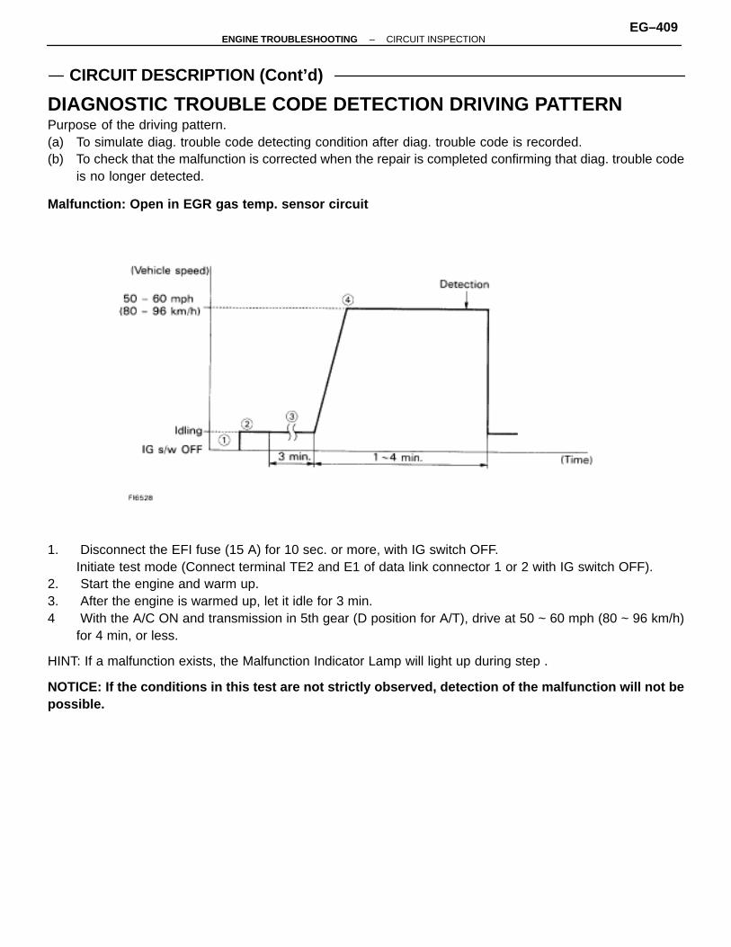
CIRCUIT DESCRIPTION (Cont’d)
DIAGNOSTIC TROUBLE CODE DETECTION DRIVING PATTERNPurpose of the driving pattern.(a) To simulate diag. trouble code detecting condition after diag. trouble code is recorded.(b) To check that the malfunction is corrected when the repair is completed confirming that diag. trouble code
is no longer detected.
Malfunction: Open in EGR gas temp. sensor circuit
1. Disconnect the EFI fuse (15 A) for 10 sec. or more, with IG switch OFF.Initiate test mode (Connect terminal TE2 and E1 of data link connector 1 or 2 with IG switch OFF).
2. Start the engine and warm up.3. After the engine is warmed up, let it idle for 3 min.4 With the A/C ON and transmission in 5th gear (D position for A/T), drive at 50 ~ 60 mph (80 ~ 96 km/h)
for 4 min, or less.
HINT: If a malfunction exists, the Malfunction Indicator Lamp will light up during step .
NOTICE: If the conditions in this test are not strictly observed, detection of the malfunction will not bepossible.
–ENGINE TROUBLESHOOTING CIRCUIT INSPECTIONEG–409

WIRING DIAGRAM
DIAGNOSTIC CHARTDIAGNOSTIC CHART
EG–410–ENGINE TROUBLESHOOTING CIRCUIT INSPECTION
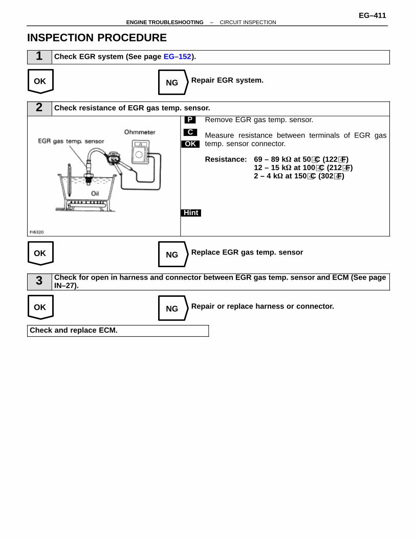
OK NG
OK NG
OK NG
INSPECTION PROCEDURE
1 Check EGR system (See page EG–152).
Repair EGR system.
2 Check resistance of EGR gas temp. sensor.
C
OK
Hint
P Remove EGR gas temp. sensor.
Measure resistance between terminals of EGR gastemp. sensor connector.
Resistance: 69 – 89 k � at 50�C (122�F)12 – 15 k� at 100�C (212�F)2 – 4 k� at 150�C (302�F)
Replace EGR gas temp. sensor
3 Check for open in harness and connector between EGR gas temp. sensor and ECM (See pageIN–27).
Repair or replace harness or connector.
Check and replace ECM.
–ENGINE TROUBLESHOOTING CIRCUIT INSPECTIONEG–411
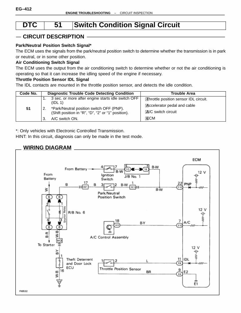
WIRING DIAGRAM
DTC 51 Switch Condition Signal Circuit
CIRCUIT DESCRIPTION
Park/Neutral Position Switch Signal*The ECM uses the signals from the park/neutral position switch to determine whether the transmission is in parkor neutral, or in some other position.Air Conditioning Switch SignalThe ECM uses the output from the air conditioning switch to determine whether or not the air conditioning isoperating so that it can increase the idling speed of the engine if necessary.Throttle Position Sensor IDL SignalThe IDL contacts are mounted in the throttle position sensor, and detects the idle condition.
Code No. Diagnostic Trouble Code Detecting Condition Trouble Area
51
1. 3 sec. or more after engine starts idle switch OFF(IDL 1)
2. *Park/Neutral position switch OFF (PNP).(Shift position in “R”, “D”, “2” or “1” position).
3. A/C switch ON.
�Throttle position sensor IDL circuit.
�Accelerator pedal and cable
�A/C switch circuit
�ECM
*: Only vehicles with Electronic Controlled Transmission.HINT: In this circuit, diagnosis can only be made in the test mode.
EG–412–ENGINE TROUBLESHOOTING CIRCUIT INSPECTION

DIAGNOSTIC CHARTDIAGNOSTIC CHART
See page EG–416
(See page EG–207)
(See page EG–344)
–ENGINE TROUBLESHOOTING CIRCUIT INSPECTIONEG–413
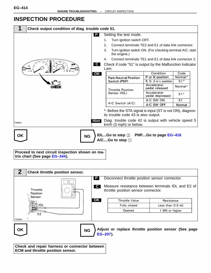
OK NG
OK NG
INSPECTION PROCEDURE
1 Check output condition of diag. trouble code 51.
C
OK
Hint
P Setting the test mode.1. Turn ignition switch OFF.
2. Connect terminals TE2 and E1 of data link connector.
3. Turn ignition switch ON. (For checking terminal A/C, startthe engine.)
4. Connect terminals TE1 and E1 of data link connector 2.
Check if code “51” is output by the Malfunction IndicatorLam.
*: Before the STA signal is input (ST is not ON), diagnos-tic trouble code 43 is also output.
Diag. trouble code 42 is output with vehicle speed 5km/h (3 mph) or below.
IDL...Go to step � PNP....Go to page EG–416A/C....Go to step �
Proceed to next circuit inspection shown on ma-trix chart (See page EG–344).
2 Check throttle position sensor.
C
OK
P Disconnect throttle position sensor connector.
Measure resistance between terminals IDL and E2 ofthrottle position sensor connector.
Adjust or replace throttle position sensor (See pageEG–207).
Check and repair harness or connector betweenECM and throttle position sensor.
EG–414–ENGINE TROUBLESHOOTING CIRCUIT INSPECTION
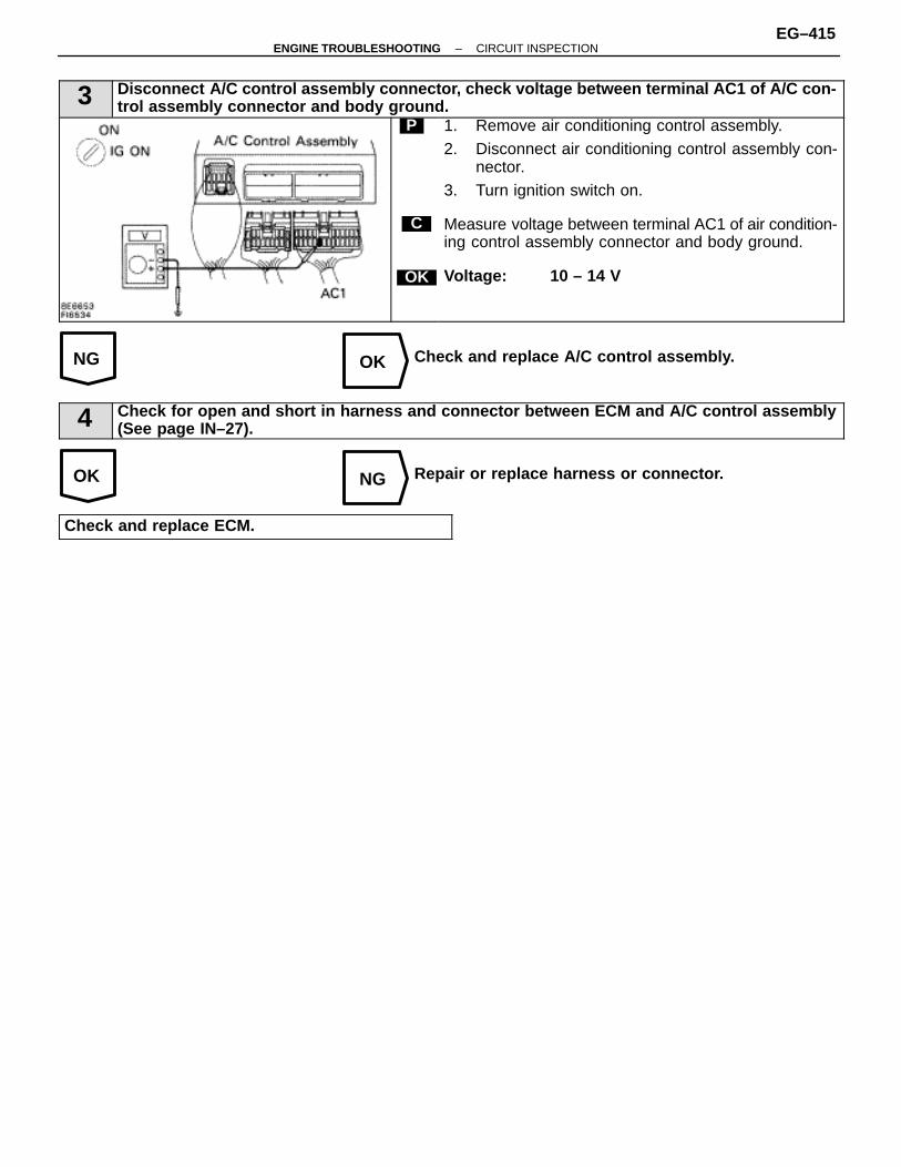
NG OK
OK NG
3 Disconnect A/C control assembly connector, check voltage between terminal AC1 of A/C con-trol assembly connector and body ground.
C
OK
P 1. Remove air conditioning control assembly.2. Disconnect air conditioning control assembly con-
nector.3. Turn ignition switch on.
Measure voltage between terminal AC1 of air condition-ing control assembly connector and body ground.
Voltage: 10 – 14 V
Check and replace A/C control assembly.
4 Check for open and short in harness and connector between ECM and A/C control assembly(See page IN–27).
Repair or replace harness or connector.
Check and replace ECM.
–ENGINE TROUBLESHOOTING CIRCUIT INSPECTIONEG–415

Park/Neutral Position Switch Circuit (Only vehicles withELECTRONIC CONTROLLED TRANSMISSION)
CIRCUIT DESCRIPTION
The park/neutral position switch goes on when the shift lever is in the N or P shift position. When it goes on theterminal PNP of the ECM is grounded to body ground via the starter relay and theft deterrent ECU, thus theterminal PNP voltage becomes O V. When the shift lever is in the D, 2, L or R position, the park/neutral positionswitch goes off, so the voltage of ECM terminal PNP becomes battery voltage, the voltage of the ECM internalpower source.If the shift lever is moved from the N position to the D position, this signal is used for air–fuel ratio correctionand for idle speed control (estimated control), etc.When the park/neutral position switch is off, code ”51” is output in the test mode diagnosis. (This is not abnor-mal.)
DIAGNOSTIC CHARTDIAGNOSTIC CHARTHINT: This diagnosis chart is based on premise that the engine is cranked normally. If the engine is not cranked,proceed to the matrix chart of problem symptoms on page EG–344.
(See page EG–344).
(See page AX–90).
EG–416–ENGINE TROUBLESHOOTING CIRCUIT INSPECTION

WIRING DIAGRAM
–ENGINE TROUBLESHOOTING CIRCUIT INSPECTIONEG–417
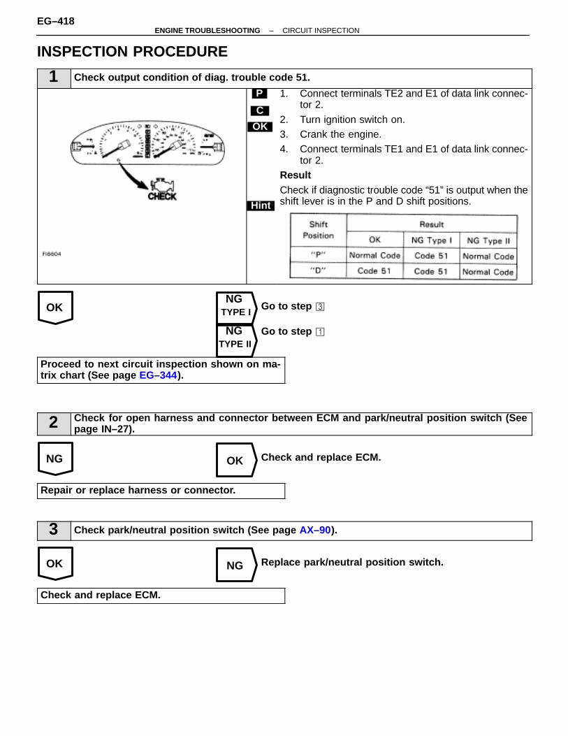
OKNG
TYPE I
NGTYPE II
NG OK
OK NG
INSPECTION PROCEDURE
1 Check output condition of diag. trouble code 51.
C
OK
Hint
P 1. Connect terminals TE2 and E1 of data link connec-tor 2.
2. Turn ignition switch on.3. Crank the engine.4. Connect terminals TE1 and E1 of data link connec-
tor 2.ResultCheck if diagnostic trouble code “51” is output when theshift lever is in the P and D shift positions.
Go to step �
Go to step �
Proceed to next circuit inspection shown on ma-trix chart (See page EG–344).
2 Check for open harness and connector between ECM and park/neutral position switch (Seepage IN–27).
Check and replace ECM.
Repair or replace harness or connector.
3 Check park/neutral position switch (See page AX–90).
Replace park/neutral position switch.
Check and replace ECM.
EG–418–ENGINE TROUBLESHOOTING CIRCUIT INSPECTION

–MEMO–
–ENGINE TROUBLESHOOTING CIRCUIT INSPECTIONEG–419
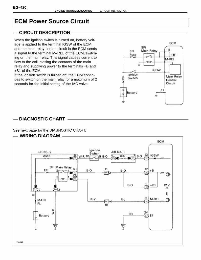
WIRING DIAGRAM
ECM Power Source Circuit
CIRCUIT DESCRIPTIONÑÑÑÑÑÑÑÑÑÑÑÑÑÑÑÑÑÑÑÑÑÑÑÑÑÑÑÑÑÑÑÑÑÑÑÑÑÑÑÑÑÑÑÑÑÑÑÑÑÑÑÑÑÑÑÑÑÑÑÑÑÑÑÑÑÑÑÑÑÑÑÑÑÑÑÑÑÑÑÑÑÑÑÑÑÑÑÑÑÑÑÑÑÑÑÑÑÑÑÑÑÑÑÑÑÑÑÑÑÑÑÑÑÑÑÑÑÑÑÑÑÑÑÑÑÑÑÑÑÑÑÑÑÑÑÑÑÑÑÑÑÑÑÑÑÑÑÑÑÑÑÑÑÑÑÑÑÑÑÑÑÑÑÑÑÑÑÑÑÑÑÑÑÑÑÑÑÑÑÑÑÑÑÑÑÑÑÑÑÑÑÑÑÑÑÑÑÑÑÑÑÑÑÑÑÑÑÑÑÑÑÑÑÑÑÑÑÑÑÑÑÑÑÑÑÑÑÑÑÑÑÑÑÑÑÑÑÑÑÑÑÑÑÑÑÑÑÑÑÑÑÑÑÑÑÑÑÑÑÑÑÑÑÑÑÑÑÑÑÑ
When the ignition switch is turned on, battery volt-age is applied to the terminal IGSW of the ECM,and the main relay control circuit in the ECM sendsa signal to the terminal M–REL of the ECM, switch-ing on the main relay. This signal causes current toflow to the coil, closing the contacts of the mainrelay and supplying power to the terminals +B and+B1 of the ECM.If the ignition switch is turned off, the ECM contin-ues to switch on the main relay for a maximum of 2seconds for the initial setting of the IAC valve.
ÑÑÑÑÑÑÑÑÑÑÑÑÑÑÑÑÑÑÑÑÑÑÑÑÑÑÑÑÑÑÑÑÑÑÑÑÑÑÑÑÑÑÑÑÑÑÑÑÑÑÑÑÑÑÑÑÑÑÑÑÑÑÑÑÑÑÑÑÑÑÑÑÑÑÑÑÑÑÑÑÑÑÑÑÑÑÑÑÑÑÑÑÑÑÑÑÑÑÑÑÑÑÑÑÑÑÑÑÑÑÑÑÑÑÑÑÑÑÑÑÑÑÑÑÑÑÑÑÑÑÑÑÑÑÑÑÑÑÑÑÑÑÑÑÑÑÑÑÑÑÑÑÑÑÑÑÑÑÑÑÑÑÑÑÑÑÑÑÑÑÑÑÑÑÑÑÑÑÑÑÑÑÑÑÑÑÑÑÑÑÑÑÑÑÑÑÑÑÑÑÑÑÑÑÑÑÑÑÑÑÑÑÑÑÑÑÑÑÑÑÑÑÑÑÑÑÑÑÑÑÑÑÑÑÑÑÑÑÑÑÑÑÑÑÑÑÑÑÑÑÑÑÑÑÑÑÑÑÑÑÑÑÑÑÑÑÑÑÑÑÑÑÑÑÑÑÑÑÑÑÑÑÑÑÑ
DIAGNOSTIC CHARTDIAGNOSTIC CHART
See next page for the DIAGNOSTIC CHART.
EG–420–ENGINE TROUBLESHOOTING CIRCUIT INSPECTION
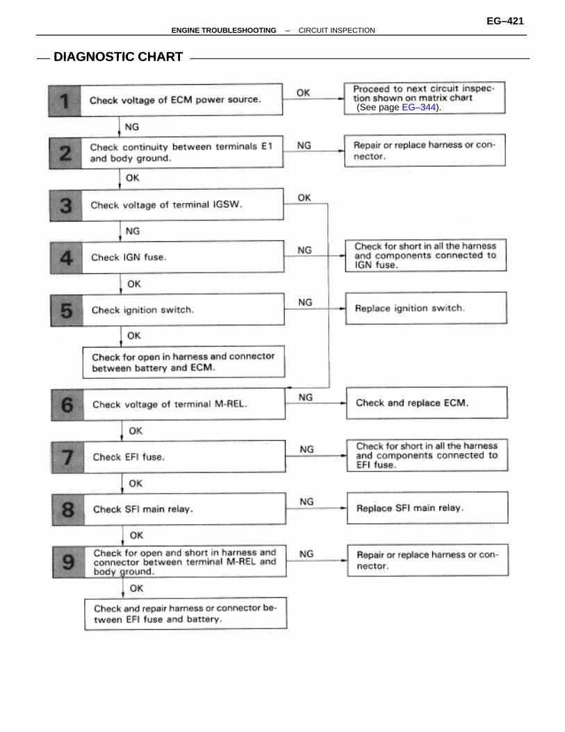
DIAGNOSTIC CHARTDIAGNOSTIC CHART
(See page EG–344).
–ENGINE TROUBLESHOOTING CIRCUIT INSPECTIONEG–421
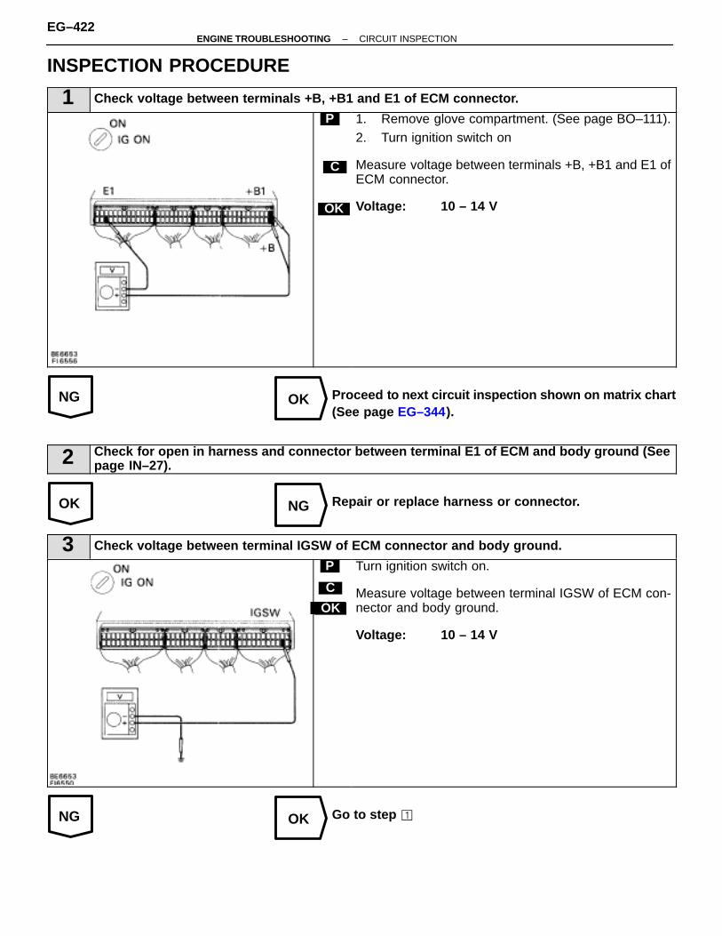
NG OK
OK NG
NG OK
INSPECTION PROCEDURE
1 Check voltage between terminals +B, +B1 and E1 of ECM connector.
C
OK
P 1. Remove glove compartment. (See page BO–111).2. Turn ignition switch on
Measure voltage between terminals +B, +B1 and E1 ofECM connector.
Voltage: 10 – 14 V
Proceed to next circuit inspection shown on matrix chart(See page EG–344).
2 Check for open in harness and connector between terminal E1 of ECM and body ground (Seepage IN–27).
Repair or replace harness or connector.
3 Check voltage between terminal IGSW of ECM connector and body ground.
Hint
C
OK
P Turn ignition switch on.
Measure voltage between terminal IGSW of ECM con-nector and body ground.
Voltage: 10 – 14 V
Go to step �
EG–422–ENGINE TROUBLESHOOTING CIRCUIT INSPECTION
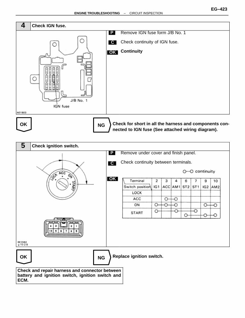
OK NG
OK NG
4 Check IGN fuse.
C
OK
P Remove IGN fuse form J/B No. 1
Check continuity of IGN fuse.
Continuity
Check for short in all the harness and components con-nected to IGN fuse (See attached wiring diagram).
5 Check ignition switch.
C
OK
P Remove under cover and finish panel.
Check continuity between terminals.
Replace ignition switch.
Check and repair harness and connector betweenbattery and ignition switch, ignition switch andECM.
–ENGINE TROUBLESHOOTING CIRCUIT INSPECTIONEG–423
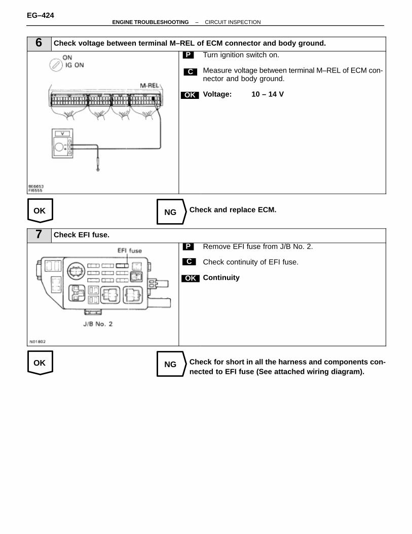
OK NG
OK NG
6 Check voltage between terminal M–REL of ECM connector and body ground.
C
OK
P Turn ignition switch on.
Measure voltage between terminal M–REL of ECM con-nector and body ground.
Voltage: 10 – 14 V
Check and replace ECM.
7 Check EFI fuse.
C
OK
P Remove EFI fuse from J/B No. 2.
Check continuity of EFI fuse.
Continuity
Check for short in all the harness and components con-nected to EFI fuse (See attached wiring diagram).
EG–424–ENGINE TROUBLESHOOTING CIRCUIT INSPECTION
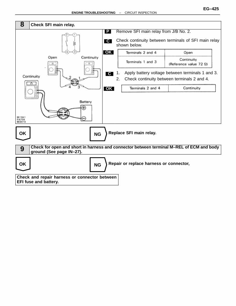
OK NG
OK NG
8 Check SFI main relay.
C
OK
P
OK
C
Remove SFI main relay from J/B No. 2.
Check continuity between terminals of SFI main relayshown below.
1. Apply battery voltage between terminals 1 and 3.2. Check continuity between terminals 2 and 4.
Replace SFI main relay.
9 Check for open and short in harness and connector between terminal M–REL of ECM and bodyground (See page IN–27).
Repair or replace harness or connector,
Check and repair harness or connector betweenEFI fuse and battery.
–ENGINE TROUBLESHOOTING CIRCUIT INSPECTIONEG–425

WIRING DIAGRAM
Back Up Power Source Circuit
CIRCUIT DESCRIPTION
Battery voltage is supplied to terminal BATT of the ECM even when the ignition switch is off for use by the diag-nostic trouble code memory and air–fuel ratio adaptive control value memory, etc.
DIAGNOSTIC CHARTDIAGNOSTIC CHART
(See page EG–344).
EG–426–ENGINE TROUBLESHOOTING CIRCUIT INSPECTION
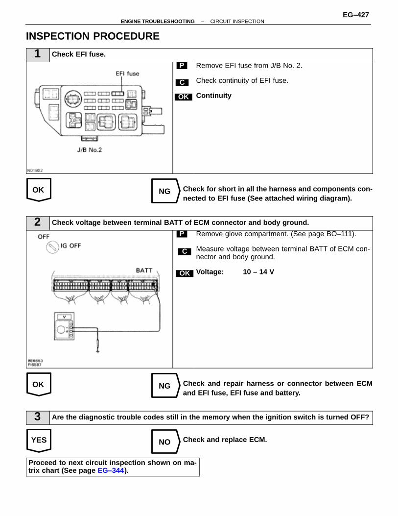
OK NG
OK NG
YES NO
INSPECTION PROCEDURE
1 Check EFI fuse.
C
OK
P Remove EFI fuse from J/B No. 2.
Check continuity of EFI fuse.
Continuity
Check for short in all the harness and components con-nected to EFI fuse (See attached wiring diagram).
2 Check voltage between terminal BATT of ECM connector and body ground.
C
OK
P Remove glove compartment. (See page BO–111).
Measure voltage between terminal BATT of ECM con-nector and body ground.
Voltage: 10 – 14 V
Check and repair harness or connector between ECMand EFI fuse, EFI fuse and battery.
3 Are the diagnostic trouble codes still in the memory when the ignition switch is turned OFF?
Check and replace ECM.
Proceed to next circuit inspection shown on ma-trix chart (See page EG–344).
–ENGINE TROUBLESHOOTING CIRCUIT INSPECTIONEG–427
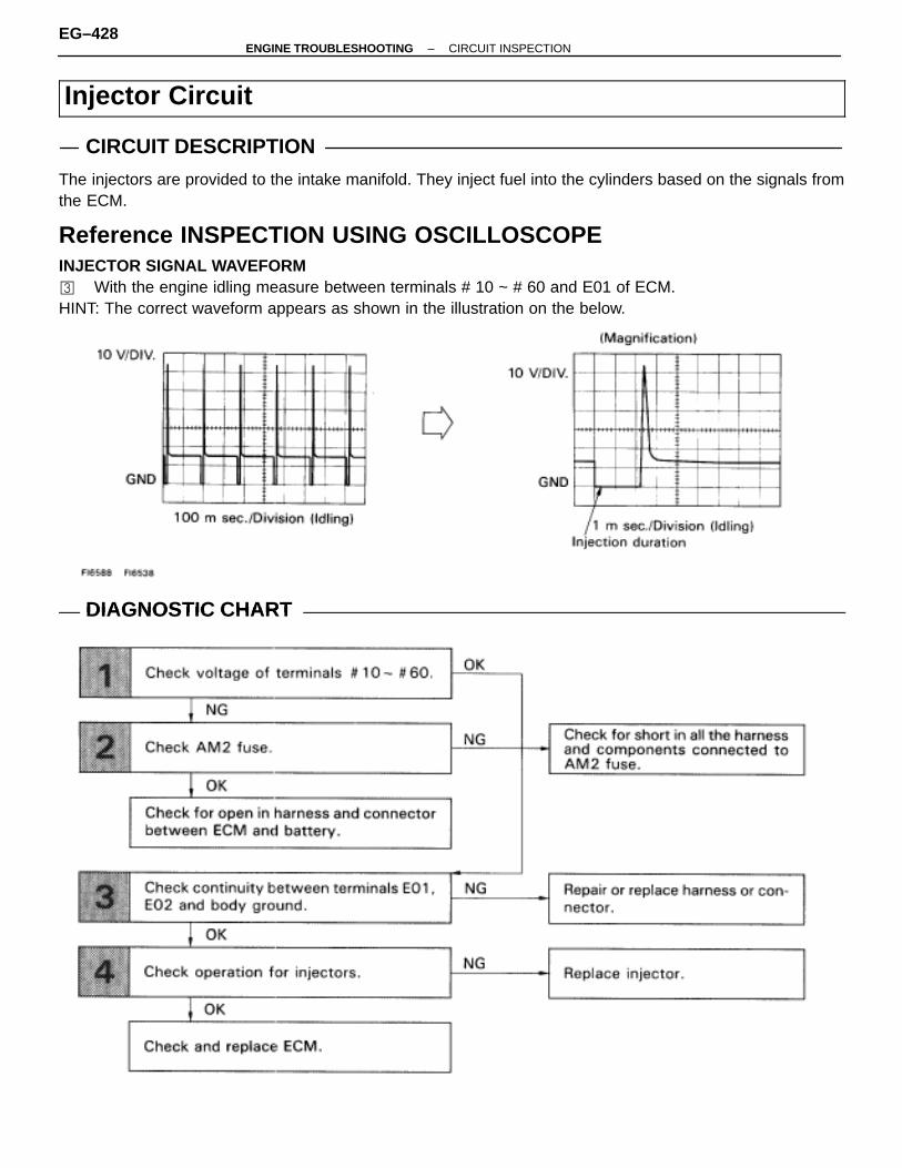
Injector Circuit
CIRCUIT DESCRIPTION
The injectors are provided to the intake manifold. They inject fuel into the cylinders based on the signals fromthe ECM.
Reference INSPECTION USING OSCILLOSCOPEINJECTOR SIGNAL WAVEFORM� With the engine idling measure between terminals # 10 ~ # 60 and E01 of ECM.HINT: The correct waveform appears as shown in the illustration on the below.
DIAGNOSTIC CHARTDIAGNOSTIC CHART
EG–428–ENGINE TROUBLESHOOTING CIRCUIT INSPECTION
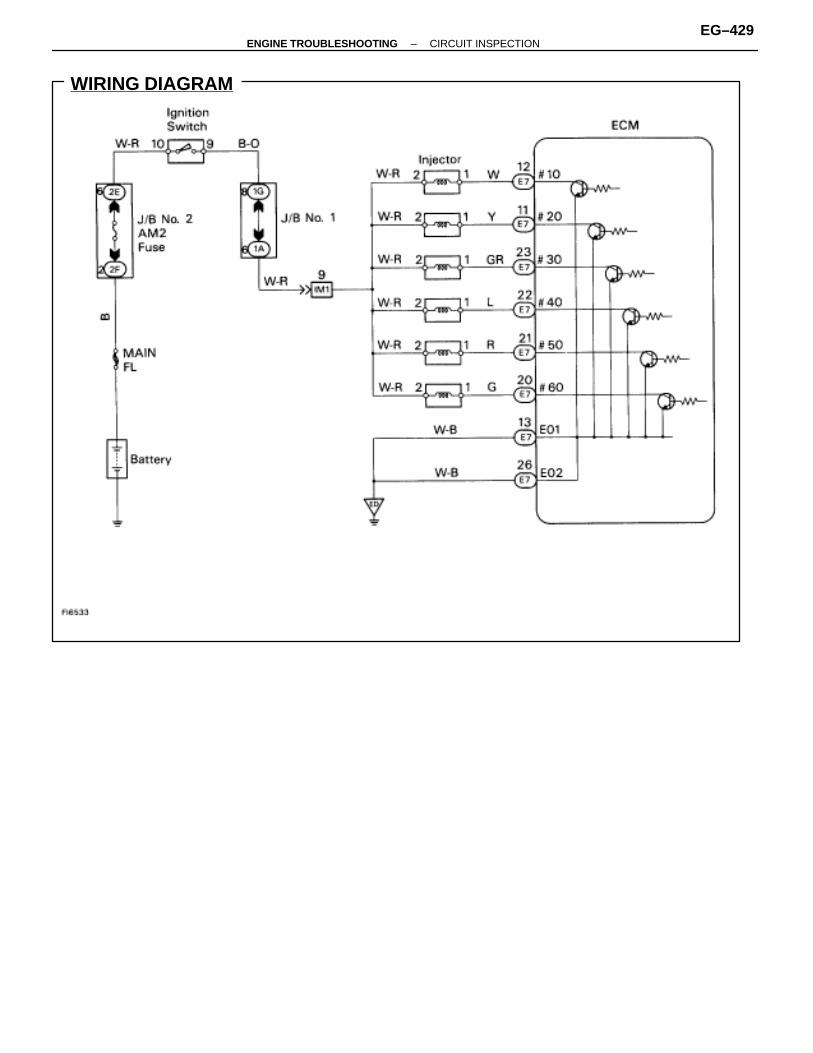
WIRING DIAGRAM
–ENGINE TROUBLESHOOTING CIRCUIT INSPECTIONEG–429

NG OK
OK NG
INSPECTION PROCEDURE
1 Check voltage between terminals #10 � 60 of ECM and body ground.
C
OK
P 1. Remove glove compartment. (See page BO–111).2. Turn ignition switch on.
Measure voltage between terminals #10 � 60 of ECMand body ground.
Voltage: 10 – 14 V
Go to step �
2 Check AM2 fuse.
C
OK
P Remove AM2 fuse from J/B No. 2.
Check continuity of AM2 fuse.
Continuity
Check for short in all the harness and components con-nected to AM2 fuse.
Check for open in harness and connector betweenECM and battery.
EG–430–ENGINE TROUBLESHOOTING CIRCUIT INSPECTION

OK NG
OK NG
3 Check for open in harness and connector between terminal E01, E02 of ECM connector andbody ground (See page IN–27).
Repair or replace harness or connector.
4 Check injectors.
C
OK
P
OK
C
Disconnect injector connector (See page EG–187).
Measure resistance of injector.
Resistance: 13.4 – 14.2 � at 20�C (68�F)
Check injection volume of injector (See page EG–191).
� Injection volume58 – 68 cc/15 sec. (3.5 – 4.1 cu in.)Difference between each injector:Less than 5 cc (0.3 cu in.)
� LeakageFuel drop: One drop or less per minute
Replace injector.
Check and replace ECM.
–ENGINE TROUBLESHOOTING CIRCUIT INSPECTIONEG–431
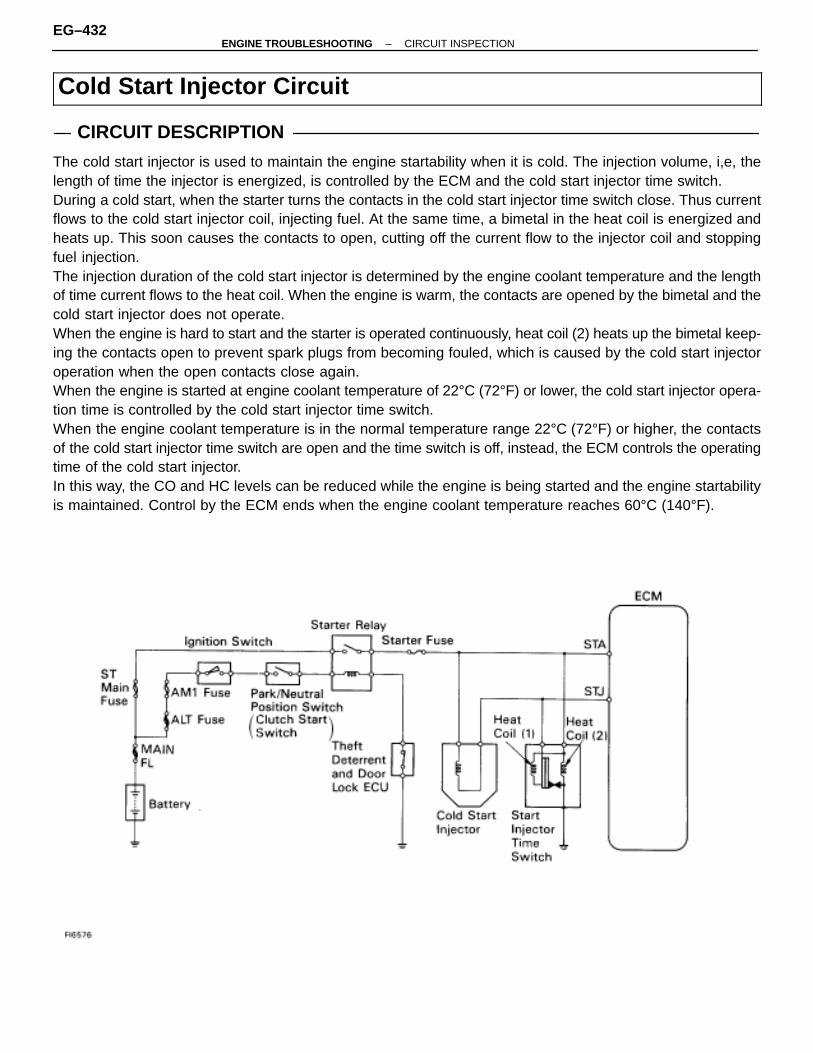
Cold Start Injector Circuit
CIRCUIT DESCRIPTION
The cold start injector is used to maintain the engine startability when it is cold. The injection volume, i,e, thelength of time the injector is energized, is controlled by the ECM and the cold start injector time switch.During a cold start, when the starter turns the contacts in the cold start injector time switch close. Thus currentflows to the cold start injector coil, injecting fuel. At the same time, a bimetal in the heat coil is energized andheats up. This soon causes the contacts to open, cutting off the current flow to the injector coil and stoppingfuel injection.The injection duration of the cold start injector is determined by the engine coolant temperature and the lengthof time current flows to the heat coil. When the engine is warm, the contacts are opened by the bimetal and thecold start injector does not operate.When the engine is hard to start and the starter is operated continuously, heat coil (2) heats up the bimetal keep-ing the contacts open to prevent spark plugs from becoming fouled, which is caused by the cold start injectoroperation when the open contacts close again.When the engine is started at engine coolant temperature of 22°C (72°F) or lower, the cold start injector opera-tion time is controlled by the cold start injector time switch.When the engine coolant temperature is in the normal temperature range 22°C (72°F) or higher, the contactsof the cold start injector time switch are open and the time switch is off, instead, the ECM controls the operatingtime of the cold start injector.In this way, the CO and HC levels can be reduced while the engine is being started and the engine startabilityis maintained. Control by the ECM ends when the engine coolant temperature reaches 60°C (140°F).
EG–432–ENGINE TROUBLESHOOTING CIRCUIT INSPECTION

WIRING DIAGRAM
DIAGNOSTIC CHARTDIAGNOSTIC CHART
(See page EG–344).
–ENGINE TROUBLESHOOTING CIRCUIT INSPECTIONEG–433
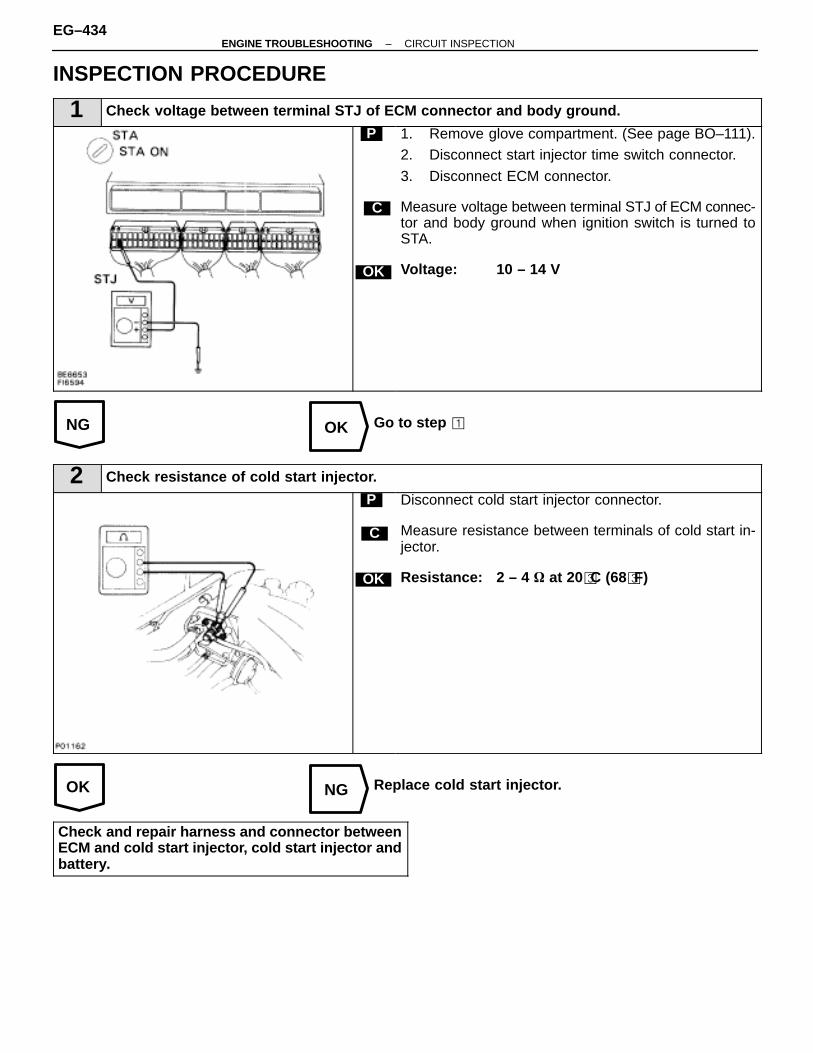
NG OK
OK NG
INSPECTION PROCEDURE
1 Check voltage between terminal STJ of ECM connector and body ground.
C
OK
P 1. Remove glove compartment. (See page BO–111).2. Disconnect start injector time switch connector.
3. Disconnect ECM connector.
Measure voltage between terminal STJ of ECM connec-tor and body ground when ignition switch is turned toSTA.
Voltage: 10 – 14 V
Go to step �
2 Check resistance of cold start injector.
C
OK
P Disconnect cold start injector connector.
Measure resistance between terminals of cold start in-jector.
Resistance: 2 – 4 � at 20�C (68�F)
Replace cold start injector.
Check and repair harness and connector betweenECM and cold start injector, cold start injector andbattery.
EG–434–ENGINE TROUBLESHOOTING CIRCUIT INSPECTION
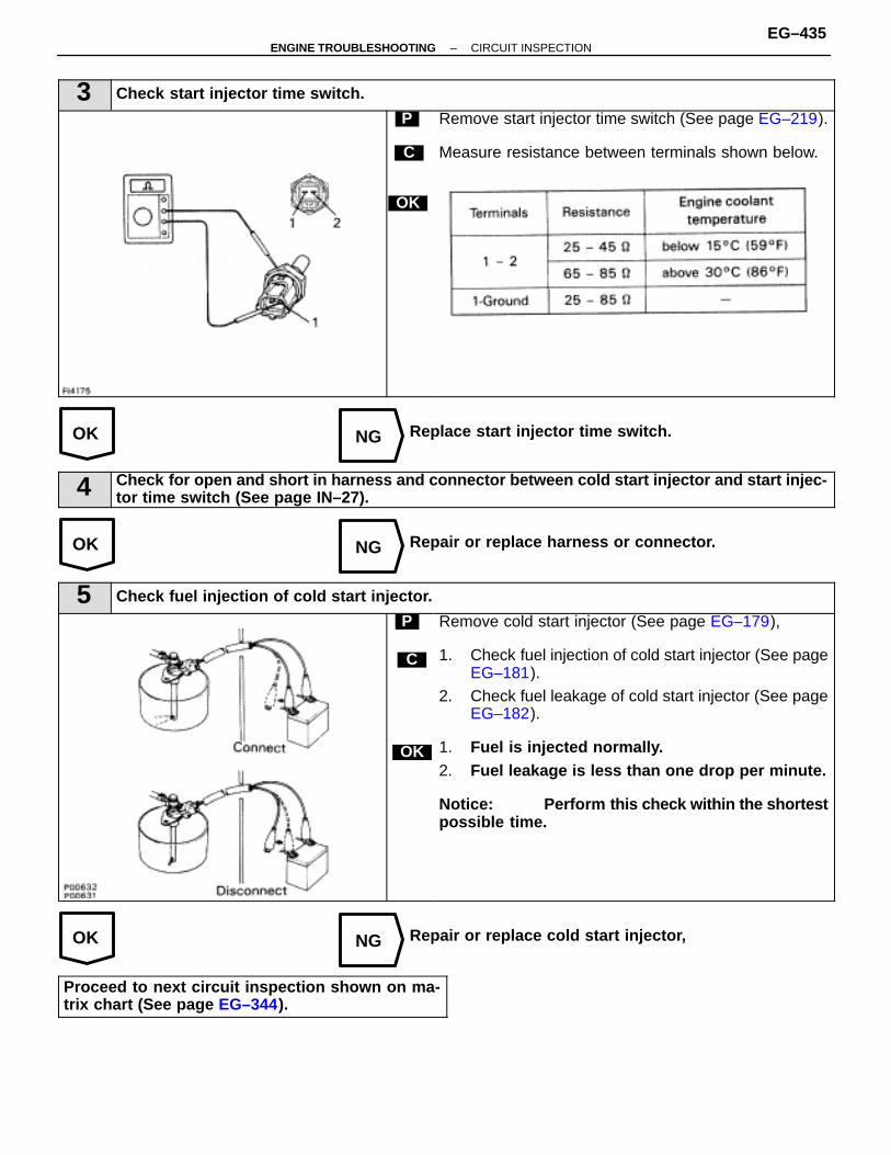
OK NG
OK NG
OK NG
3 Check start injector time switch.
C
OK
P Remove start injector time switch (See page EG–219).
Measure resistance between terminals shown below.
Replace start injector time switch.
4 Check for open and short in harness and connector between cold start injector and start injec-tor time switch (See page IN–27).
Repair or replace harness or connector.
5 Check fuel injection of cold start injector.
C
OK
P Remove cold start injector (See page EG–179),
1. Check fuel injection of cold start injector (See pageEG–181).
2. Check fuel leakage of cold start injector (See pageEG–182).
1. Fuel is injected normally.2. Fuel leakage is less than one drop per minute.
Notice: Perform this check within the shortestpossible time.
Repair or replace cold start injector,
Proceed to next circuit inspection shown on ma-trix chart (See page EG–344).
–ENGINE TROUBLESHOOTING CIRCUIT INSPECTIONEG–435
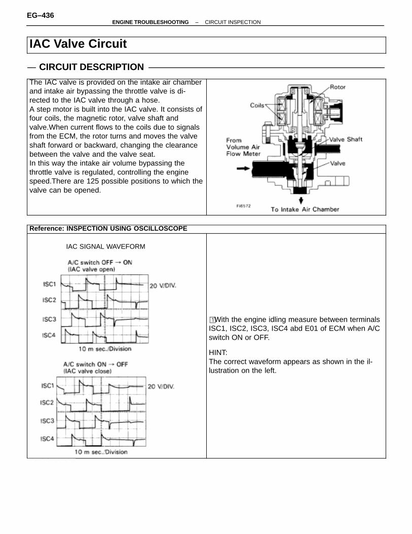
IAC Valve Circuit
CIRCUIT DESCRIPTIONÑÑÑÑÑÑÑÑÑÑÑÑÑÑÑÑÑÑÑÑÑÑÑÑÑÑÑÑÑÑÑÑÑÑÑÑÑÑÑÑÑÑÑÑÑÑÑÑÑÑÑÑÑÑÑÑÑÑÑÑÑÑÑÑÑÑÑÑÑÑÑÑÑÑÑÑÑÑÑÑÑÑÑÑÑÑÑÑÑÑÑÑÑÑÑÑÑÑÑÑÑÑÑÑÑÑÑÑÑÑÑÑÑÑÑÑÑÑÑÑÑÑÑÑÑÑÑÑÑÑÑÑÑÑÑÑÑÑÑÑÑÑÑÑÑÑÑÑÑÑÑÑÑÑÑÑÑÑÑÑÑÑÑÑÑÑÑÑÑÑÑÑÑÑÑÑÑÑÑÑÑÑÑÑÑÑÑÑÑÑÑÑÑÑÑÑÑÑÑÑÑÑÑÑÑÑÑÑÑÑÑÑÑÑÑÑÑÑÑÑÑÑÑÑÑÑÑÑÑÑÑÑÑÑÑÑÑÑÑÑÑÑÑÑÑÑÑÑÑÑÑÑ
The IAC valve is provided on the intake air chamberand intake air bypassing the throttle valve is di-rected to the IAC valve through a hose.A step motor is built into the IAC valve. It consists offour coils, the magnetic rotor, valve shaft andvalve.When current flows to the coils due to signalsfrom the ECM, the rotor turns and moves the valveshaft forward or backward, changing the clearancebetween the valve and the valve seat.In this way the intake air volume bypassing thethrottle valve is regulated, controlling the enginespeed.There are 125 possible positions to which thevalve can be opened.
ÑÑÑÑÑÑÑÑÑÑÑÑÑÑÑÑÑÑÑÑÑÑÑÑÑÑÑÑÑÑÑÑÑÑÑÑÑÑÑÑÑÑÑÑÑÑÑÑÑÑÑÑÑÑÑÑÑÑÑÑÑÑÑÑÑÑÑÑÑÑÑÑÑÑÑÑÑÑÑÑÑÑÑÑÑÑÑÑÑÑÑÑÑÑÑÑÑÑÑÑÑÑÑÑÑÑÑÑÑÑÑÑÑÑÑÑÑÑÑÑÑÑÑÑÑÑÑÑÑÑÑÑÑÑÑÑÑÑÑÑÑÑÑÑÑÑÑÑÑÑÑÑÑÑÑÑÑÑÑÑÑÑÑÑÑÑÑÑÑÑÑÑÑÑÑÑÑÑÑÑÑÑÑÑÑÑÑÑÑÑÑÑÑÑÑÑÑÑÑÑÑÑÑÑÑÑÑÑÑÑÑÑÑÑÑÑÑÑÑÑÑÑÑÑÑÑÑÑÑÑÑÑÑÑÑÑÑÑÑÑÑÑÑÑÑÑÑÑÑÑÑÑÑÑÑÑÑÑÑÑÑÑÑÑÑÑ
ÑÑÑÑÑÑÑÑÑÑÑÑÑÑÑÑÑÑÑÑÑÑÑÑÑÑÑÑÑÑÑÑÑÑÑÑÑÑÑÑÑÑÑÑÑÑÑÑÑÑÑÑÑÑÑÑÑÑÑÑÑÑÑÑÑÑÑÑÑÑÑÑ
Reference: INSPECTION USING OSCILLOSCOPEÑÑÑÑÑÑÑÑÑÑÑÑÑÑÑÑÑÑÑÑÑÑÑÑÑÑÑÑÑÑÑÑÑÑÑÑÑÑÑÑÑÑÑÑÑÑÑÑÑÑÑÑÑÑÑÑÑÑÑÑÑÑÑÑÑÑÑÑÑÑÑÑÑÑÑÑÑÑÑÑÑÑÑÑÑÑÑÑÑÑÑÑÑÑÑÑÑÑÑÑÑÑÑÑÑÑÑÑÑÑÑÑÑÑÑÑÑÑÑÑÑÑÑÑÑÑÑÑÑÑÑÑÑÑÑÑÑÑÑÑÑÑÑÑÑÑÑÑÑÑÑÑÑÑÑÑÑÑÑÑÑÑÑÑÑÑÑÑÑÑÑÑÑÑÑÑÑÑÑÑÑÑÑÑÑÑÑÑÑÑÑÑÑÑÑÑÑÑÑÑÑÑÑÑÑÑÑÑÑÑÑÑÑÑÑÑÑÑÑÑÑÑÑÑÑÑÑÑÑÑÑÑÑÑÑÑÑÑÑÑÑÑÑÑÑÑÑÑÑÑÑÑÑÑÑÑÑÑÑÑÑÑÑÑÑÑÑÑÑÑÑÑÑÑÑÑÑÑÑÑÑÑÑÑÑÑÑÑÑÑÑÑÑÑÑÑÑÑÑÑÑÑÑÑÑÑÑÑÑÑÑÑÑÑÑÑÑÑÑÑÑÑÑÑÑÑÑÑÑÑÑÑÑÑÑÑÑÑÑÑÑÑÑÑÑÑÑÑÑÑÑÑÑÑÑÑÑÑÑÑÑÑÑÑÑÑÑÑÑÑÑÑÑÑÑÑÑÑÑÑÑÑÑÑÑÑÑÑÑÑÑÑÑÑÑÑÑÑÑÑÑÑÑÑÑÑÑÑÑÑÑÑÑÑ
IAC SIGNAL WAVEFORM
ÑÑÑÑÑÑÑÑÑÑÑÑÑÑÑÑÑÑÑÑÑÑÑÑÑÑÑÑÑÑÑÑÑÑÑÑÑÑÑÑÑÑÑÑÑÑÑÑÑÑÑÑÑÑÑÑÑÑÑÑÑÑÑÑÑÑÑÑÑÑÑÑÑÑÑÑÑÑÑÑÑÑÑÑÑÑÑÑÑÑÑÑÑÑÑÑÑÑÑÑÑÑÑÑÑÑÑÑÑÑÑÑÑÑÑÑÑÑÑÑÑÑÑÑÑÑÑÑÑÑÑÑÑÑÑÑÑÑÑÑÑÑÑÑÑÑÑÑÑÑÑÑÑÑÑÑÑÑÑÑÑÑÑÑÑÑÑÑÑÑÑÑÑÑÑÑÑÑÑÑÑÑÑÑÑÑÑÑÑÑÑÑÑÑÑÑÑÑÑÑÑÑÑÑÑÑÑÑÑÑÑÑÑÑÑÑÑÑÑÑÑÑÑÑÑÑÑÑÑÑÑÑÑÑÑÑÑÑÑÑÑÑÑÑÑÑÑÑÑÑÑÑÑÑÑÑÑÑÑÑÑÑÑÑÑÑÑÑÑÑÑÑÑÑÑÑÑÑÑÑÑÑÑÑÑÑÑÑÑÑÑÑÑÑÑÑÑÑÑÑÑÑÑÑÑÑÑÑÑÑÑÑÑÑÑÑÑÑÑÑÑÑÑÑÑÑÑÑÑÑÑÑÑÑÑÑÑÑÑÑÑÑÑÑÑÑÑÑÑÑÑÑÑÑÑÑÑÑÑÑÑÑÑÑÑÑÑÑÑÑÑÑÑÑÑÑÑÑÑÑÑÑÑÑÑÑÑÑÑÑÑÑÑÑÑÑÑÑÑÑÑÑÑÑÑÑÑÑÑÑÑÑÑÑÑÑÑÑÑÑÑÑÑÑÑÑÑÑÑÑÑÑÑÑÑÑÑ
� With the engine idling measure between terminalsISC1, ISC2, ISC3, ISC4 abd E01 of ECM when A/Cswitch ON or OFF.
HINT:The correct waveform appears as shown in the il-lustration on the left.
ÑÑÑÑÑÑÑÑÑÑÑÑ
EG–436–ENGINE TROUBLESHOOTING CIRCUIT INSPECTION
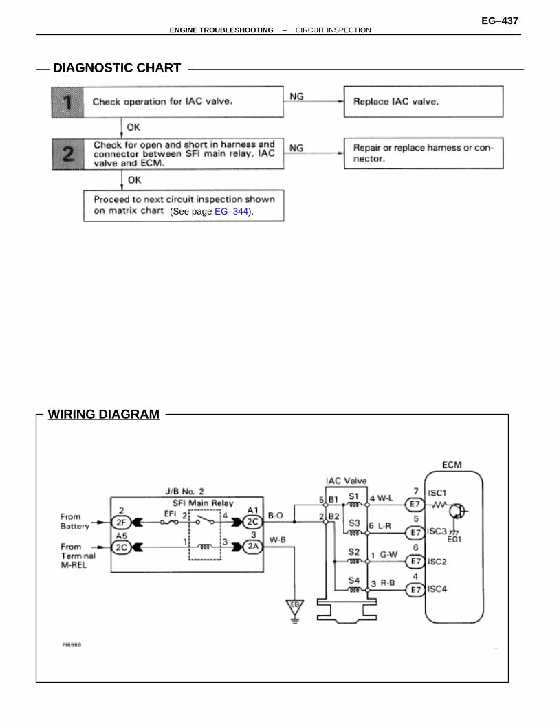
WIRING DIAGRAM
DIAGNOSTIC CHARTDIAGNOSTIC CHART
(See page EG–344).
–ENGINE TROUBLESHOOTING CIRCUIT INSPECTIONEG–437

OK NG
OK NG
INSPECTION PROCEDURE
1 Check IAC valve.
C
OK
P
OK
C
P
Disconnect IAC valve connector.
Measure resistance between terminals shown below.
Remove IAC valve.
1. Connect the battery positive lead to terminals B1and B2, and the negative lead to terminalsS1–S2–S3–S4 in that order.
2. Connect the battery positive lead to terminals B1and B2, and the negative lead to terminalsS4–S3–S2–S1 in that order.
1. The valve moves in the closing direction.2. The valve moves in the opening direction.
Replace IAC valve.
2 Check for open and short in harness and connector between SFI main relay and IAC valve, IACvalve and ECM (See page IN–27).
Repair or replace harness or connector.
Proceed to next circuit inspection shown on ma-trix chart (See page EG–344).
EG–438–ENGINE TROUBLESHOOTING CIRCUIT INSPECTION

–MEMO–
–ENGINE TROUBLESHOOTING CIRCUIT INSPECTIONEG–439
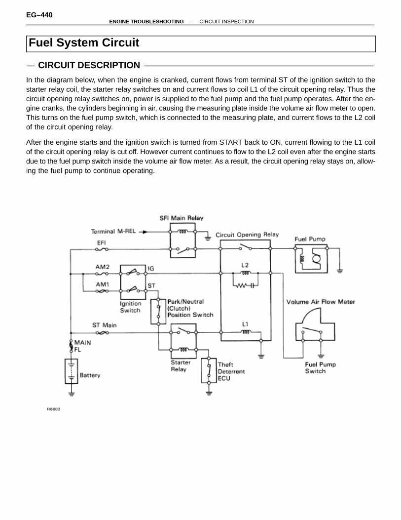
Fuel System Circuit
CIRCUIT DESCRIPTION
In the diagram below, when the engine is cranked, current flows from terminal ST of the ignition switch to thestarter relay coil, the starter relay switches on and current flows to coil L1 of the circuit opening relay. Thus thecircuit opening relay switches on, power is supplied to the fuel pump and the fuel pump operates. After the en-gine cranks, the cylinders beginning in air, causing the measuring plate inside the volume air flow meter to open.This turns on the fuel pump switch, which is connected to the measuring plate, and current flows to the L2 coilof the circuit opening relay.
After the engine starts and the ignition switch is turned from START back to ON, current flowing to the L1 coilof the circuit opening relay is cut off. However current continues to flow to the L2 coil even after the engine startsdue to the fuel pump switch inside the volume air flow meter. As a result, the circuit opening relay stays on, allow-ing the fuel pump to continue operating.
EG–440–ENGINE TROUBLESHOOTING CIRCUIT INSPECTION

DIAGNOSTIC CHARTDIAGNOSTIC CHART
–ENGINE TROUBLESHOOTING CIRCUIT INSPECTIONEG–441
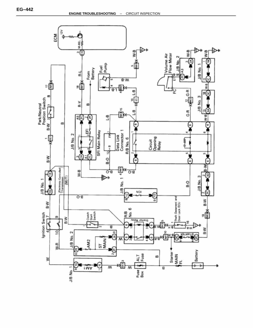
WIRING DIAGRAM
EG–442–ENGINE TROUBLESHOOTING CIRCUIT INSPECTION
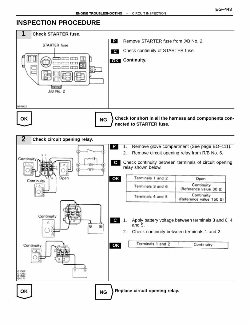
OK NG
OK NG
INSPECTION PROCEDURE
1 Check STARTER fuse.
C
OK
P Remove STARTER fuse from J/B No. 2.
Check continuity of STARTER fuse.
Continuity.
Check for short in all the harness and components con-nected to STARTER fuse.
2 Check circuit opening relay.
C
OK
P
OK
C
1. Remove glove compartment (See page BO–111).2. Remove circuit opening relay from R/B No. 6.
Check continuity between terminals of circuit openingrelay shown below.
1. Apply battery voltage between terminals 3 and 6, 4and 5.
2. Check continuity between terminals 1 and 2.
Replace circuit opening relay.
–ENGINE TROUBLESHOOTING CIRCUIT INSPECTIONEG–443
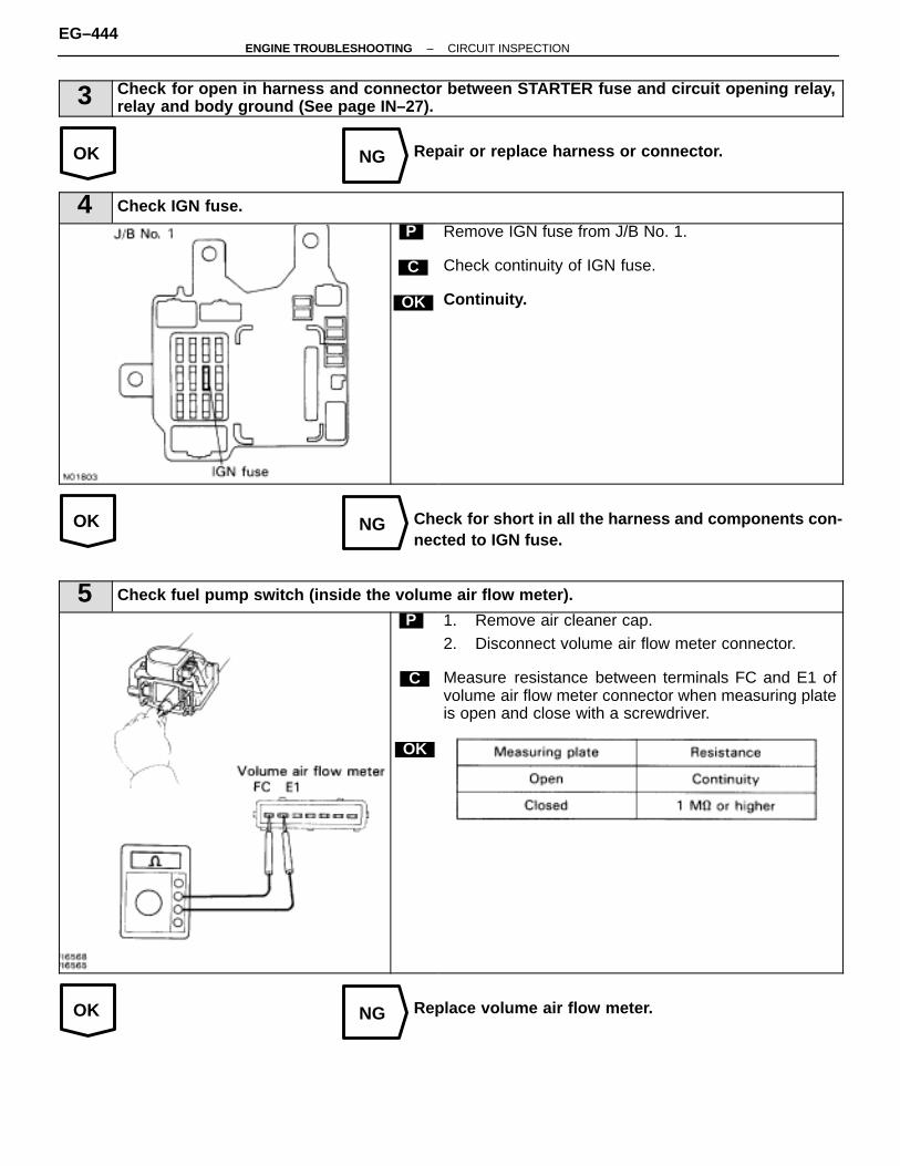
OK NG
OK NG
OK NG
3 Check for open in harness and connector between STARTER fuse and circuit opening relay,relay and body ground (See page IN–27).
Repair or replace harness or connector.
4 Check IGN fuse.
C
OK
P Remove IGN fuse from J/B No. 1.
Check continuity of IGN fuse.
Continuity.
Check for short in all the harness and components con-nected to IGN fuse.
5 Check fuel pump switch (inside the volume air flow meter).
C
OK
P 1. Remove air cleaner cap.2. Disconnect volume air flow meter connector.
Measure resistance between terminals FC and E1 ofvolume air flow meter connector when measuring plateis open and close with a screwdriver.
Replace volume air flow meter.
EG–444–ENGINE TROUBLESHOOTING CIRCUIT INSPECTION

OK NG
OK NG
OK NG
6 Check for open in harness and connector between IGN fuse and circuit opening relay, relay andbody ground (See page IN–27).
Repair or replace harness or connector.
7 Check ECM power source circuit (See page EG–420).
Repair or replace.
8 Check fuel pump (See page EG–170).
Replace fuel pump.
Check for open in harness and connector betweenJ/B No. 2 and circuit opening relay, relay and bodyground (See page IN–27).
–ENGINE TROUBLESHOOTING CIRCUIT INSPECTIONEG–445
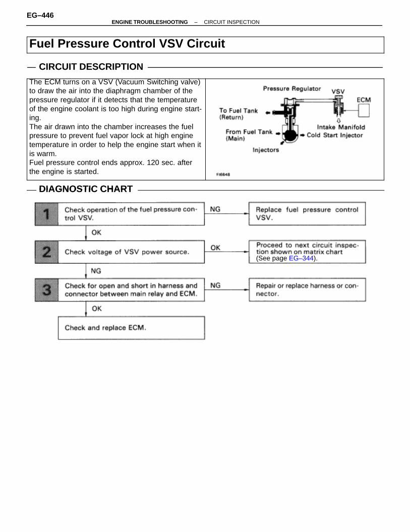
Fuel Pressure Control VSV Circuit
CIRCUIT DESCRIPTIONÑÑÑÑÑÑÑÑÑÑÑÑÑÑÑÑÑÑÑÑÑÑÑÑÑÑÑÑÑÑÑÑÑÑÑÑÑÑÑÑÑÑÑÑÑÑÑÑÑÑÑÑÑÑÑÑÑÑÑÑÑÑÑÑÑÑÑÑÑÑÑÑÑÑÑÑÑÑÑÑÑÑÑÑÑÑÑÑÑÑÑÑÑÑÑÑÑÑÑÑÑÑÑÑÑÑÑÑÑÑÑÑÑÑÑÑÑÑÑÑÑÑÑÑÑÑÑÑÑÑÑÑÑÑÑÑÑÑÑÑÑÑÑÑÑÑÑÑÑÑÑÑÑÑÑÑÑÑÑÑÑÑÑÑÑÑÑÑÑÑÑÑÑÑÑÑÑÑÑÑÑÑÑÑÑÑÑÑÑÑÑÑÑÑÑÑÑÑ
The ECM turns on a VSV (Vacuum Switching valve)to draw the air into the diaphragm chamber of thepressure regulator if it detects that the temperatureof the engine coolant is too high during engine start-ing.The air drawn into the chamber increases the fuelpressure to prevent fuel vapor lock at high enginetemperature in order to help the engine start when itis warm.Fuel pressure control ends approx. 120 sec. afterthe engine is started.
ÑÑÑÑÑÑÑÑÑÑÑÑÑÑÑÑÑÑÑÑÑÑÑÑÑÑÑÑÑÑÑÑÑÑÑÑÑÑÑÑÑÑÑÑÑÑÑÑÑÑÑÑÑÑÑÑÑÑÑÑÑÑÑÑÑÑÑÑÑÑÑÑÑÑÑÑÑÑÑÑÑÑÑÑÑÑÑÑÑÑÑÑÑÑÑÑÑÑÑÑÑÑÑÑÑÑÑÑÑÑÑÑÑÑÑÑÑÑÑÑÑÑÑÑÑÑÑÑÑÑÑÑÑÑÑÑÑÑÑÑÑÑÑÑÑÑÑÑÑÑÑÑÑÑÑÑÑÑÑÑÑÑÑÑÑÑÑÑÑÑÑÑÑÑÑÑÑÑÑÑÑÑÑÑÑÑÑÑÑÑÑÑÑÑÑÑÑÑÑÑÑÑÑÑÑÑÑÑÑ
DIAGNOSTIC CHARTDIAGNOSTIC CHART
(See page EG–344).
EG–446–ENGINE TROUBLESHOOTING CIRCUIT INSPECTION
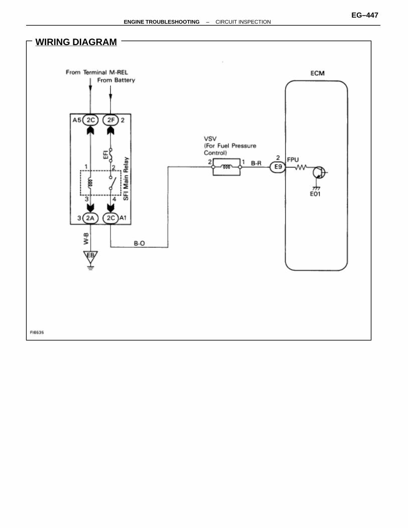
WIRING DIAGRAM
–ENGINE TROUBLESHOOTING CIRCUIT INSPECTIONEG–447

OK NG
INSPECTION PROCEDURE
1 Check fuel pressure control VSV.
C
OK
P
OK
C
1. Remove fuel pressure control VSV.2. Disconnect fuel pressure control VSV connector.
1. Measure resistance between terminals.
2. Measure resistance between each terminal and thebody.
1. Resistance: 30 – 50 � at 20�C (68�F)2. Resistance: 1 M � or higher
Check operation of fuel pressure control VSV when bat-tery voltage is applied to the terminals of fuel pressurecontrol VSV connector or not.
Battery voltage is applied:The air from pipe E is flowing out through the air fil-ter.
Battery voltage is not applied:The air from pipe E is flowing out through pipe C.
Replace fuel pressure control VSV.
Go to step �
EG–448–ENGINE TROUBLESHOOTING CIRCUIT INSPECTION
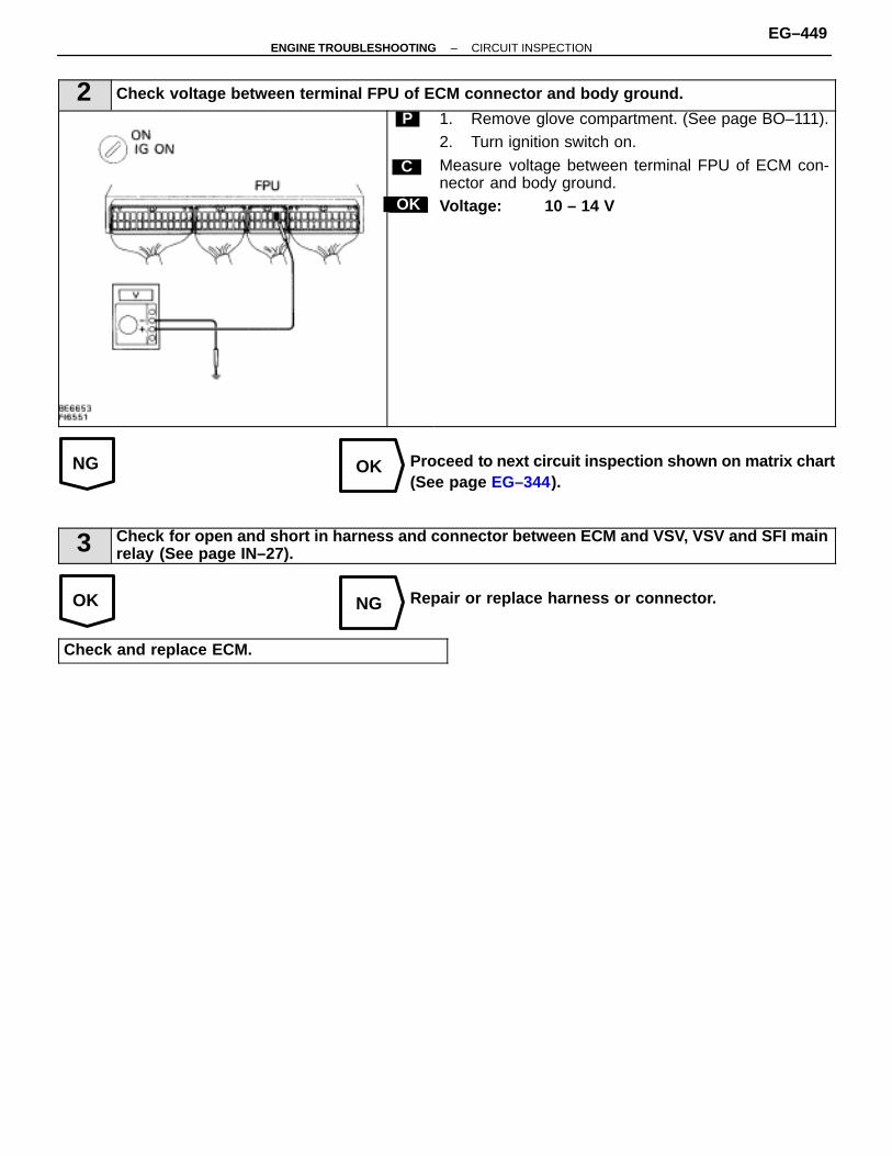
NG OK
OK NG
2 Check voltage between terminal FPU of ECM connector and body ground.
Hint
C
OK
P 1. Remove glove compartment. (See page BO–111).2. Turn ignition switch on.
Measure voltage between terminal FPU of ECM con-nector and body ground.Voltage: 10 – 14 V
Proceed to next circuit inspection shown on matrix chart(See page EG–344).
3 Check for open and short in harness and connector between ECM and VSV, VSV and SFI mainrelay (See page IN–27).
Repair or replace harness or connector.
Check and replace ECM.
–ENGINE TROUBLESHOOTING CIRCUIT INSPECTIONEG–449

WIRING DIAGRAM
Air Conditioning Cut Control Circuit
CIRCUIT DESCRIPTION
This circuit cuts air conditioning operation during vehicle acceleration in order to increase acceleration perfor-mance. During acceleration with the vehicle speed at 25 km/h (16 mph) or less, engine speed at 1,600 rpm orless and throttle valve opening angle at 60° or more, the A/C magnet switch is turned OFF for several seconds.
DIAGNOSTIC CHARTDIAGNOSTIC CHART
EG–450–ENGINE TROUBLESHOOTING CIRCUIT INSPECTION
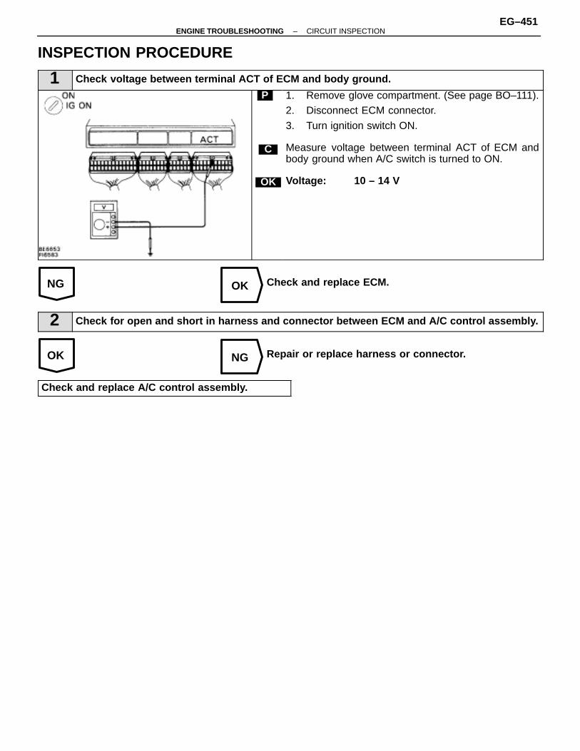
NG OK
OK NG
INSPECTION PROCEDURE
1 Check voltage between terminal ACT of ECM and body ground.
C
OK
P 1. Remove glove compartment. (See page BO–111).2. Disconnect ECM connector.
3. Turn ignition switch ON.
Measure voltage between terminal ACT of ECM andbody ground when A/C switch is turned to ON.
Voltage: 10 – 14 V
Check and replace ECM.
2 Check for open and short in harness and connector between ECM and A/C control assembly.
Repair or replace harness or connector.
Check and replace A/C control assembly.
–ENGINE TROUBLESHOOTING CIRCUIT INSPECTIONEG–451
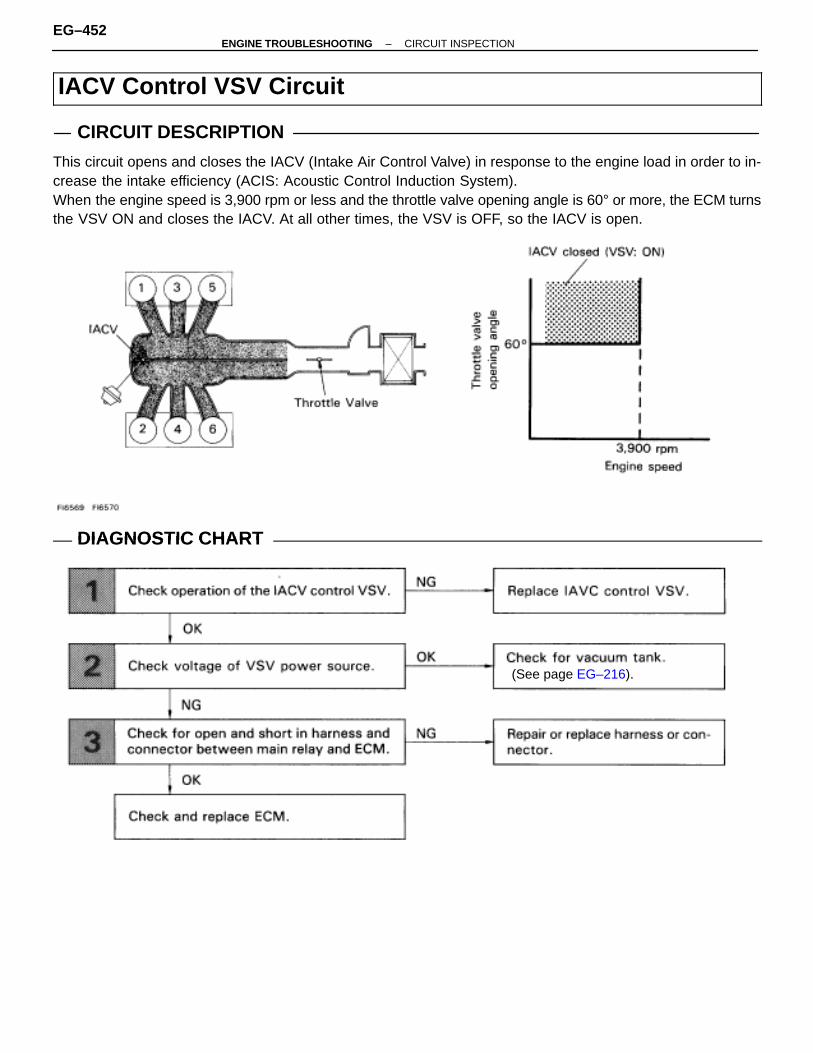
IACV Control VSV Circuit
CIRCUIT DESCRIPTION
This circuit opens and closes the IACV (Intake Air Control Valve) in response to the engine load in order to in-crease the intake efficiency (ACIS: Acoustic Control Induction System).When the engine speed is 3,900 rpm or less and the throttle valve opening angle is 60° or more, the ECM turnsthe VSV ON and closes the IACV. At all other times, the VSV is OFF, so the IACV is open.
DIAGNOSTIC CHARTDIAGNOSTIC CHART
(See page EG–216).
EG–452–ENGINE TROUBLESHOOTING CIRCUIT INSPECTION
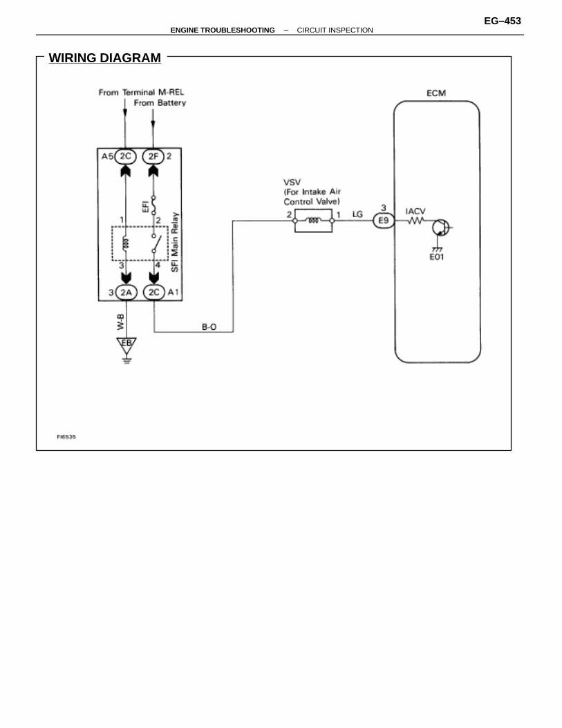
WIRING DIAGRAM
–ENGINE TROUBLESHOOTING CIRCUIT INSPECTIONEG–453

OK NG
INSPECTION PROCEDURE
1 Check IACV control VSV.
C
OK
P
OK
C
1. Remove IACV control VSV.2. Disconnect IACV control VSV connector.
1. Measure resistance between terminals.
2. Measure resistance between each terminal and thebody.
1. Resistance: 33 – 39 � at 20�C (68�F)2. Resistance: 1 M � or higher
Check operation of IACV control VSV when battery volt-age is applied to the terminals of IACV control VSV con-nector or not.
Battery voltage is applied:The air from pipe E is flowing out through pipe F.Battery voltage is not applied:The air form pipe E is flowing out through the air fil-ter.
Replace IACV control VSV.
Go to step �
EG–454–ENGINE TROUBLESHOOTING CIRCUIT INSPECTION
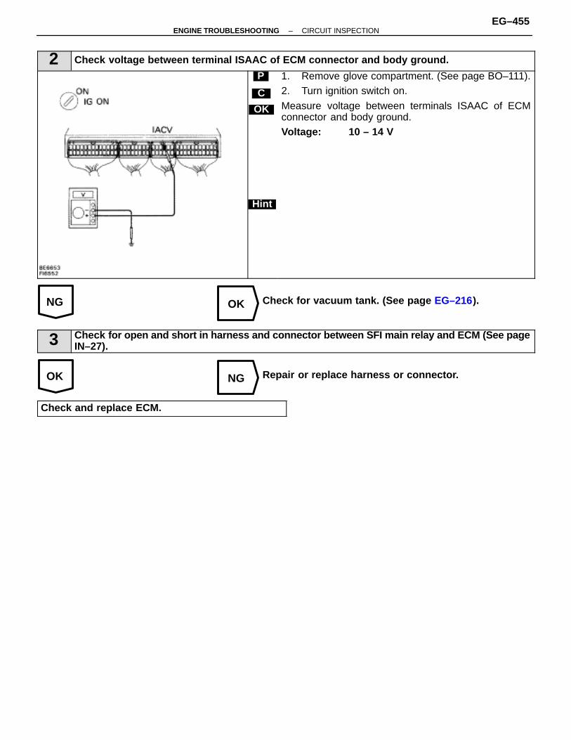
NG OK
OK NG
2 Check voltage between terminal ISAAC of ECM connector and body ground.
C
OK
Hint
P 1. Remove glove compartment. (See page BO–111).2. Turn ignition switch on.
Measure voltage between terminals ISAAC of ECMconnector and body ground.Voltage: 10 – 14 V
Check for vacuum tank. (See page EG–216).
3 Check for open and short in harness and connector between SFI main relay and ECM (See pageIN–27).
Repair or replace harness or connector.
Check and replace ECM.
–ENGINE TROUBLESHOOTING CIRCUIT INSPECTIONEG–455

WIRING DIAGRAM
TE1, TE2 Terminal Circuit
CIRCUIT DESCRIPTION
Terminals TE1 and TE2 are located in the data link connectors 1 and 2. The data link connector 1 located inthe engine compartment and the data link connector 2 located in the cabin. When these terminals are connectedwith the E1 terminal, diagnostic trouble codes in normal mode or test mode can be read from the MalfunctionIndicator Lamp on the combination meter.
DIAGNOSTIC CHARTDIAGNOSTIC CHARTHINT: If terminals TE1 and TE2 are connected with terminal E1, diagnostic trouble code is not output or testmode is not activated.Even though terminal TE1 is not connected with terminal E1, the Malfunction Indicator Lamp blinks.For the above phenomenon, the likely cause is an open or short in the wire harness, or malfunction inside theECM.
EG–456–ENGINE TROUBLESHOOTING CIRCUIT INSPECTION
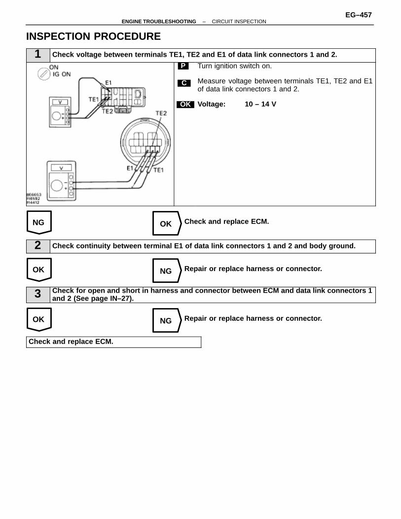
NG OK
OK NG
OK NG
INSPECTION PROCEDURE
1 Check voltage between terminals TE1, TE2 and E1 of data link connectors 1 and 2.
C
OK
P Turn ignition switch on.
Measure voltage between terminals TE1, TE2 and E1of data link connectors 1 and 2.
Voltage: 10 – 14 V
Check and replace ECM.
2 Check continuity between terminal E1 of data link connectors 1 and 2 and body ground.
Repair or replace harness or connector.
3 Check for open and short in harness and connector between ECM and data link connectors 1and 2 (See page IN–27).
Repair or replace harness or connector.
Check and replace ECM.
–ENGINE TROUBLESHOOTING CIRCUIT INSPECTIONEG–457

IGNITION SYSTEM
IG–1
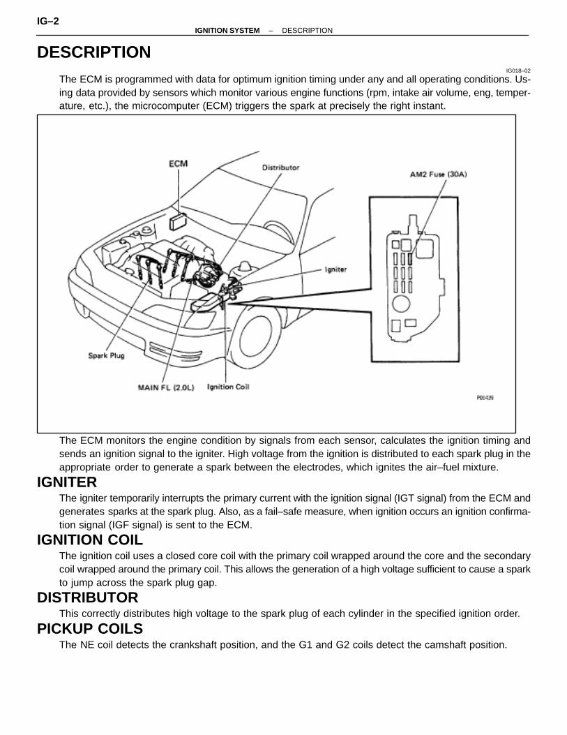
DESCRIPTIONIG018–02
The ECM is programmed with data for optimum ignition timing under any and all operating conditions. Us-ing data provided by sensors which monitor various engine functions (rpm, intake air volume, eng, temper-ature, etc.), the microcomputer (ECM) triggers the spark at precisely the right instant.
The ECM monitors the engine condition by signals from each sensor, calculates the ignition timing andsends an ignition signal to the igniter. High voltage from the ignition is distributed to each spark plug in theappropriate order to generate a spark between the electrodes, which ignites the air–fuel mixture.
IGNITERThe igniter temporarily interrupts the primary current with the ignition signal (IGT signal) from the ECM andgenerates sparks at the spark plug. Also, as a fail–safe measure, when ignition occurs an ignition confirma-tion signal (IGF signal) is sent to the ECM.
IGNITION COILThe ignition coil uses a closed core coil with the primary coil wrapped around the core and the secondarycoil wrapped around the primary coil. This allows the generation of a high voltage sufficient to cause a sparkto jump across the spark plug gap.
DISTRIBUTORThis correctly distributes high voltage to the spark plug of each cylinder in the specified ignition order.
PICKUP COILSThe NE coil detects the crankshaft position, and the G1 and G2 coils detect the camshaft position.
IG–2–IGNITION SYSTEM DESCRIPTION

PRECAUTIONSIG019–01
1. Do not leave the ignition switch on for more than 10minutes if the engine does not start.
2. With a tachometer connected to the system. Connect thetest probe of the tachometer to terminal IG � of theDLC1.
3. As some tachometers are not compatible with thisignition system, we recommend that you confirm thecompatibility of your before use.
4. NEVER allow the tachometer terminals to touch groundas it could result in damage to the igniter and/or ignitioncoil.
5. Do not disconnect the battery while the engine isrunning.
6. Check that the igniter is properly grounded to the body.
–IGNITION SYSTEM PRECAUTIONSIG–3

SYSTEM CIRCUITIG01A–01
OPERATIONIG01B–01
To maintain the most appropriate ignition timing, the ECM sends a control signal so that the igniter sendscurrent to the ignition coil and the spark plugs produce a spark.
IG–4–IGNITION SYSTEM OPERATION
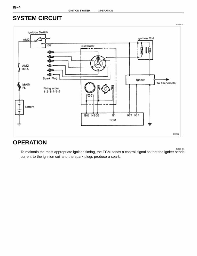
SYSTEM CIRCUITIG01A–01
OPERATIONIG01B–01
To maintain the most appropriate ignition timing, the ECM sends a control signal so that the igniter sendscurrent to the ignition coil and the spark plugs produce a spark.
IG–4–IGNITION SYSTEM OPERATION
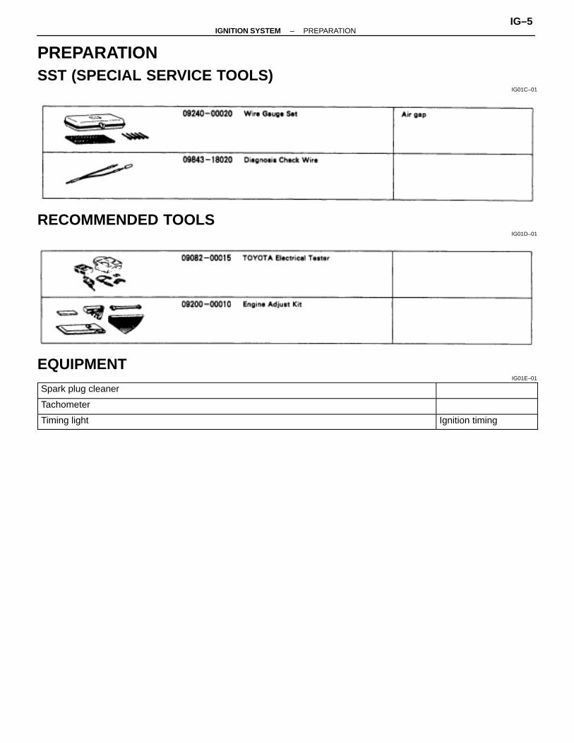
PREPARATIONSST (SPECIAL SERVICE TOOLS)
IG01C–01
RECOMMENDED TOOLSIG01D–01
EQUIPMENTIG01E–01
ÑÑÑÑÑÑÑÑÑÑÑÑÑÑÑÑÑÑÑÑÑÑÑÑÑÑÑÑÑÑÑÑÑÑÑÑÑÑÑÑÑÑÑÑÑÑÑÑÑÑÑÑÑÑÑÑÑÑ
Spark plug cleaner ÑÑÑÑÑÑÑÑÑÑÑÑÑÑÑÑÑÑÑÑÑÑÑÑÑÑÑÑÑÑÑÑÑÑÑÑÑÑÑÑÑÑÑÑÑ
ÑÑÑÑÑÑÑÑÑÑÑÑÑÑÑÑÑÑÑÑÑÑÑÑÑÑÑÑÑTachometer ÑÑÑÑÑÑÑÑ
ÑÑÑÑÑÑÑÑÑÑÑÑÑÑÑÑÑÑÑÑÑÑÑÑÑÑÑÑÑÑÑÑÑÑÑÑÑÑÑÑÑÑÑÑÑÑÑÑÑÑÑÑÑÑÑÑÑÑÑÑÑÑÑÑÑÑ
Timing lightÑÑÑÑÑÑÑÑÑÑÑÑÑÑÑÑ
Ignition timing
–IGNITION SYSTEM PREPARATIONIG–5

ON–VEHICLE INSPECTIONSPARK TEST
IG01R–02
CHECK THAT SPARK OCCURS(a) Disconnect the high–tension cord from the distributor. (See
page IG–7)(b) Hold the end approx. 12.5 mm (0.50 in.) from the body of
vehicle.(c) See if spark occurs while engine is being cranked.
HINT: To prevent gasoline from being injected from injectorsduring this test, crank the engine for no more than 1–2 se-conds at time.If the spark does not occur, perform the test as follows:
(See page IG–7)
(See page IG–11)
(See page IG–11)
(See page IG–11)
IG–6–IGNITION SYSTEM ON–VEHICLE INSPECTION
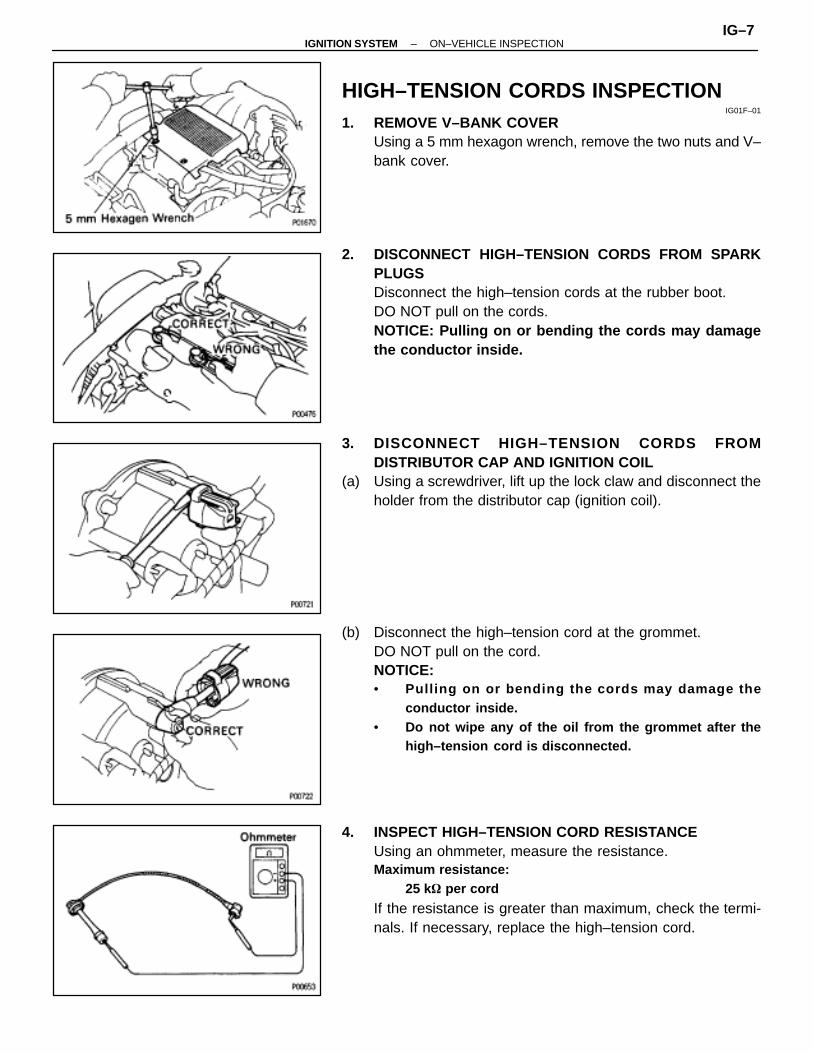
HIGH–TENSION CORDS INSPECTIONIG01F–01
1. REMOVE V–BANK COVERUsing a 5 mm hexagon wrench, remove the two nuts and V–bank cover.
2. DISCONNECT HIGH–TENSION CORDS FROM SPARKPLUGSDisconnect the high–tension cords at the rubber boot.DO NOT pull on the cords.NOTICE: Pulling on or bending the cords may damagethe conductor inside.
3. DISCONNECT HIGH–TENSION CORDS FROMDISTRIBUTOR CAP AND IGNITION COIL
(a) Using a screwdriver, lift up the lock claw and disconnect theholder from the distributor cap (ignition coil).
(b) Disconnect the high–tension cord at the grommet.DO NOT pull on the cord.NOTICE:• Pull ing on or bending the cords may damage the
conductor inside.• Do not wipe any of the oil from the grommet after the
high–tension cord is disconnected.
4. INSPECT HIGH–TENSION CORD RESISTANCEUsing an ohmmeter, measure the resistance.Maximum resistance:
25 k� per cord
If the resistance is greater than maximum, check the termi-nals. If necessary, replace the high–tension cord.
–IGNITION SYSTEM ON–VEHICLE INSPECTIONIG–7
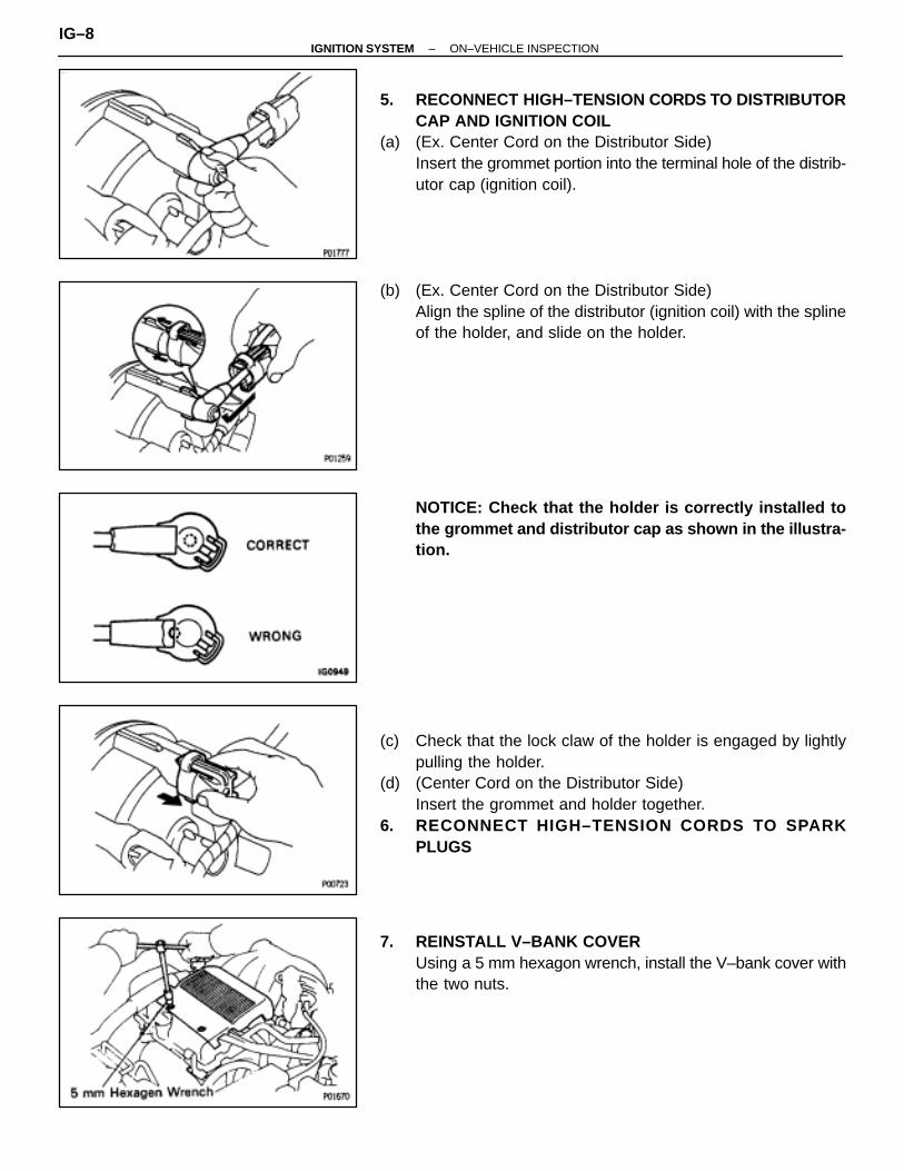
5. RECONNECT HIGH–TENSION CORDS TO DISTRIBUTORCAP AND IGNITION COIL
(a) (Ex. Center Cord on the Distributor Side)Insert the grommet portion into the terminal hole of the distrib-utor cap (ignition coil).
(b) (Ex. Center Cord on the Distributor Side)Align the spline of the distributor (ignition coil) with the splineof the holder, and slide on the holder.
NOTICE: Check that the holder is correctly installed tothe grommet and distributor cap as shown in the illustra-tion.
(c) Check that the lock claw of the holder is engaged by lightlypulling the holder.
(d) (Center Cord on the Distributor Side)Insert the grommet and holder together.
6. RECONNECT HIGH–TENSION CORDS TO SPARKPLUGS
7. REINSTALL V–BANK COVERUsing a 5 mm hexagon wrench, install the V–bank cover withthe two nuts.
IG–8–IGNITION SYSTEM ON–VEHICLE INSPECTION
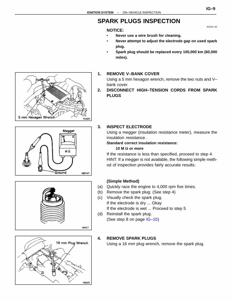
SPARK PLUGS INSPECTIONIG01G–02
NOTICE:• Never use a wire brush for cleaning.• Never attempt to adjust the electrode gap on used spark
plug.• Spark plug should be replaced every 100,000 km (60,000
miles).
1. REMOVE V–BANK COVERUsing a 5 mm hexagon wrench, remove the two nuts and V–bank cover.
2. DISCONNECT HIGH–TENSION CORDS FROM SPARKPLUGS
3. INSPECT ELECTRODEUsing a megger (insulation resistance meter), measure theinsulation resistance.Standard correct insulation resistance:
10 M � or more
If the resistance is less than specified, proceed to step 4.HINT: If a megger is not available, the following simple meth-od of inspection provides fairly accurate results.
(Simple Method)(a) Quickly race the engine to 4,000 rpm five times.(b) Remove the spark plug. (See step 4)(c) Visually check the spark plug.
If the electrode is dry ... OkayIf the electrode is wet ... Proceed to step 5
(d) Reinstall the spark plug.(See step 8 on page IG–10)
4. REMOVE SPARK PLUGSUsing a 16 mm plug wrench, remove the spark plug.
–IGNITION SYSTEM ON–VEHICLE INSPECTIONIG–9
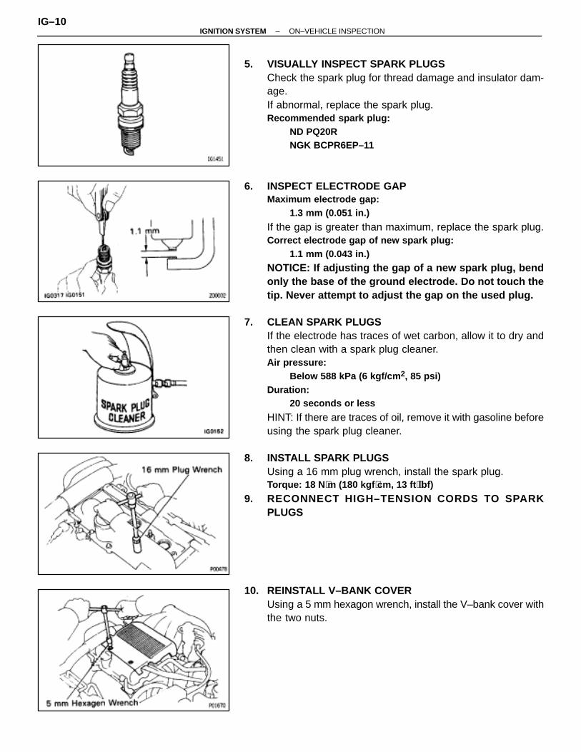
5. VISUALLY INSPECT SPARK PLUGSCheck the spark plug for thread damage and insulator dam-age.If abnormal, replace the spark plug.Recommended spark plug:
ND PQ20RNGK BCPR6EP–11
6. INSPECT ELECTRODE GAPMaximum electrode gap:
1.3 mm (0.051 in.)
If the gap is greater than maximum, replace the spark plug.Correct electrode gap of new spark plug:
1.1 mm (0.043 in.)
NOTICE: If adjusting the gap of a new spark plug, bendonly the base of the ground electrode. Do not touch thetip. Never attempt to adjust the gap on the used plug.
7. CLEAN SPARK PLUGSIf the electrode has traces of wet carbon, allow it to dry andthen clean with a spark plug cleaner.Air pressure:
Below 588 kPa (6 kgf/cm 2, 85 psi)Duration:
20 seconds or less
HINT: If there are traces of oil, remove it with gasoline beforeusing the spark plug cleaner.
8. INSTALL SPARK PLUGSUsing a 16 mm plug wrench, install the spark plug.Torque: 18 N ⋅m (180 kgf ⋅cm, 13 ft ⋅lbf)
9. RECONNECT HIGH–TENSION CORDS TO SPARKPLUGS
10. REINSTALL V–BANK COVERUsing a 5 mm hexagon wrench, install the V–bank cover withthe two nuts.
IG–10–IGNITION SYSTEM ON–VEHICLE INSPECTION
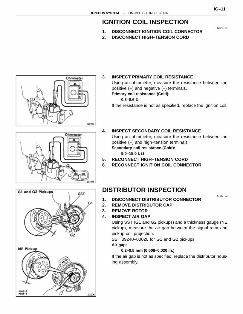
IGNITION COIL INSPECTIONIG02G–01
1. DISCONNECT IGNITION COIL CONNECTOR2. DISCONNECT HIGH–TENSION CORD
3. INSPECT PRIMARY COIL RESISTANCEUsing an ohmmeter, measure the resistance between thepositive (+) and negative (–) terminals.Primary coil resistance (Cold):
0.3–0.6 �
If the resistance is not as specified, replace the ignition coil.
4. INSPECT SECONDARY COIL RESISTANCEUsing an ohmmeter, measure the resistance between thepositive (+) and high–tension terminalsSecondary coil resistance (Cold):
9.0–15.0 k �
5. RECONNECT HIGH–TENSION CORD6. RECONNECT IGNITION COIL CONNECTOR
DISTRIBUTOR INSPECTIONIG01J–02
1. DISCONNECT DISTRIBUTOR CONNECTOR2. REMOVE DISTRIBUTOR CAP3. REMOVE ROTOR4. INSPECT AIR GAP
Using SST (G1 and G2 pickups) and a thickness gauge (NEpickup), measure the air gap between the signal rotor andpickup coil projection.SST 09240–00020 for G1 and G2 pickupsAir gap:
0.2–0.5 mm (0.008–0.020 in.)
If the air gap is not as specified, replace the distributor hous-ing assembly.
–IGNITION SYSTEM ON–VEHICLE INSPECTIONIG–11
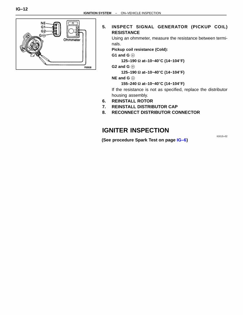
5. INSPECT SIGNAL GENERATOR (PI CKUP COIL)RESISTANCEUsing an ohmmeter, measure the resistance between termi-nals.Pickup coil resistance (Cold):G1 and G �
125–190 � at–10~40°C (14~104°F)G2 and G �
125–190 � at–10~40°C (14~104°F)NE and G �
155–240 � at–10~40°C (14~104°F)
If the resistance is not as specified, replace the distributorhousing assembly.
6. REINSTALL ROTOR7. REINSTALL DISTRIBUTOR CAP8. RECONNECT DISTRIBUTOR CONNECTOR
IGNITER INSPECTIONIG01S–02
(See procedure Spark Test on page IG–6)
IG–12–IGNITION SYSTEM ON–VEHICLE INSPECTION
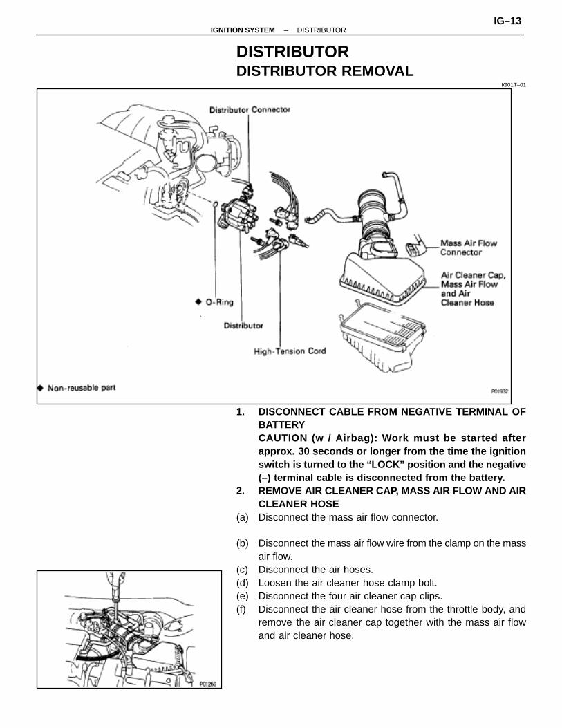
DISTRIBUTORDISTRIBUTOR REMOVAL
IG01T–01
1. DISCONNECT CABLE FROM NEGATIVE TERMINAL OFBATTERYCAUTION (w / Airbag): Work must be started afterapprox. 30 seconds or longer from the time the ignitionswitch is turned to the “LOCK” position and the negative(–) terminal cable is disconnected from the battery.
2. REMOVE AIR CLEANER CAP, MASS AIR FLOW AND AIRCLEANER HOSE
(a) Disconnect the mass air flow connector.
(b) Disconnect the mass air flow wire from the clamp on the massair flow.
(c) Disconnect the air hoses.(d) Loosen the air cleaner hose clamp bolt.(e) Disconnect the four air cleaner cap clips.(f) Disconnect the air cleaner hose from the throttle body, and
remove the air cleaner cap together with the mass air flowand air cleaner hose.
–IGNITION SYSTEM DISTRIBUTORIG–13
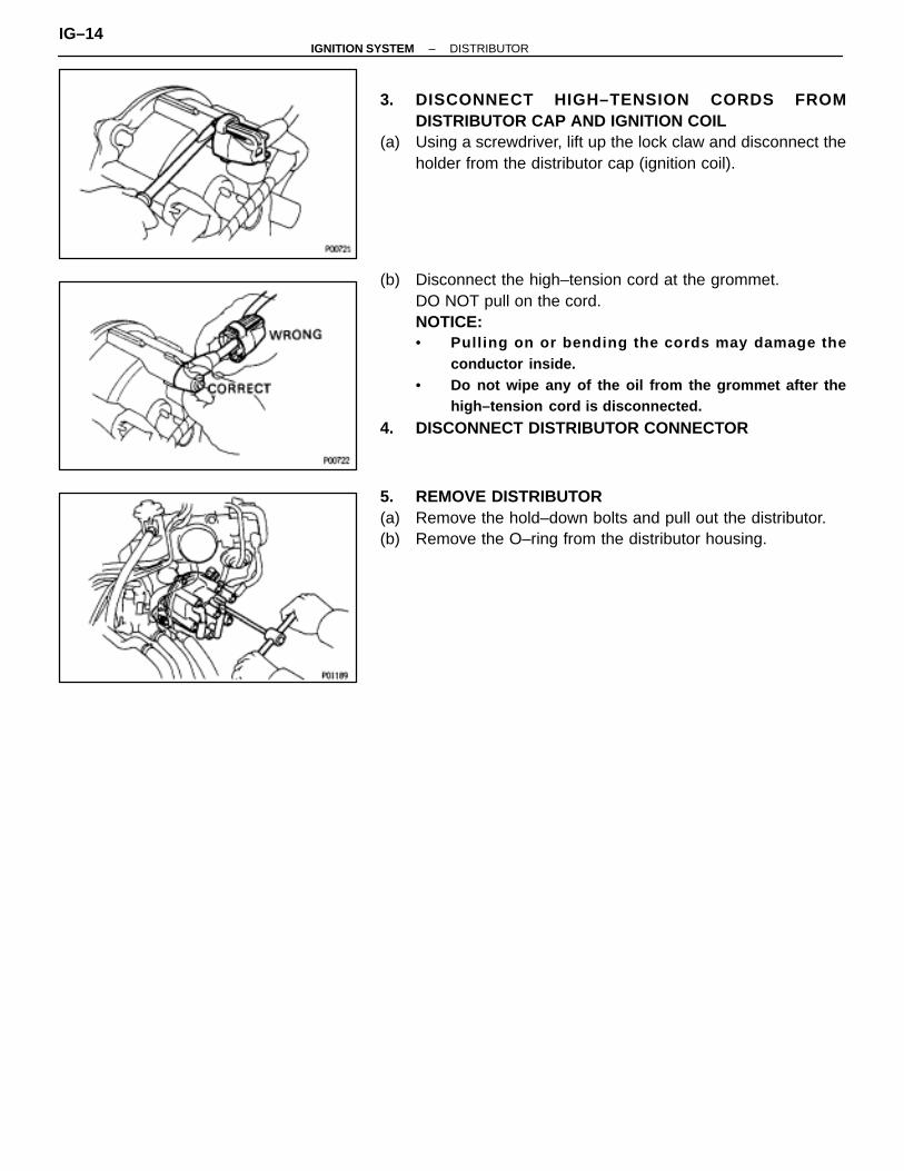
3. DISCONNECT HIGH–TENSION CORDS FROMDISTRIBUTOR CAP AND IGNITION COIL
(a) Using a screwdriver, lift up the lock claw and disconnect theholder from the distributor cap (ignition coil).
(b) Disconnect the high–tension cord at the grommet.DO NOT pull on the cord.NOTICE:• Pull ing on or bending the cords may damage the
conductor inside.• Do not wipe any of the oil from the grommet after the
high–tension cord is disconnected.
4. DISCONNECT DISTRIBUTOR CONNECTOR
5. REMOVE DISTRIBUTOR(a) Remove the hold–down bolts and pull out the distributor.(b) Remove the O–ring from the distributor housing.
IG–14–IGNITION SYSTEM DISTRIBUTOR

COMPONENTSIG01K–01
DISTRIBUTOR DISASSEMBLYIG01L–01
1. REMOVE WIRE HARNESS CLAMP CLIPRemove the screw and clip.
2. REMOVE DISTRIBUTOR CAPRemove the three bolts and distributor cap.
–IGNITION SYSTEM DISTRIBUTORIG–15

3. REMOVE ROTORRemove the two screws and rotor.
DISTRIBUTOR ASSEMBLYIG01M–02
(See page IG–15)1. INSTALL ROTOR(a) Align the hollow of the signal rotor with the protrusion of the
rotor.
(b) Install the rotor with the two screws.
2. INSTALL DISTRIBUTOR CAPInstall the distributor cap with the three screws.
3. INSTALL WIRE HARNESS CLAMP CLIPInstall the clip with the screw.
IG–16–IGNITION SYSTEM DISTRIBUTOR

DISTRIBUTOR INSTALLATIONIG01N–02
(See page IG–13)1. SET NO. 1 CYLINDER TO TDC/COMPRESSION
Turn the crankshaft clockwise, and position the slit of the in-take camshaft (RH cylinder head) as shown.Look at the distributor attachment hole to set.
2. INSTALL DISTRIBUTOR(a) Install a new O–ring to the housing.(b) Apply a light coat of engine oil on the O–ring.
(c) Align the cutout marks of the coupling and housing.
(d) Insert the distributor, aligning the line of the housing with thecutout of the distributor attachment bearing cap.
(e) Lightly tighten the two hold–down bolts.
3. CONNECT HIGH–TENSION CORDS TO DISTRIBUTORCAP
(a) (Ex. Center Cord)First, insert the grommet part only.
–IGNITION SYSTEM DISTRIBUTORIG–17
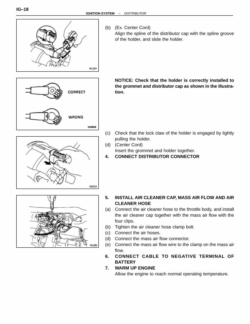
(b) (Ex. Center Cord)Align the spline of the distributor cap with the spline grooveof the holder, and slide the holder.
NOTICE: Check that the holder is correctly installed tothe grommet and distributor cap as shown in the illustra-tion.
(c) Check that the lock claw of the holder is engaged by lightlypulling the holder.
(d) (Center Cord)Insert the grommet and holder together.
4. CONNECT DISTRIBUTOR CONNECTOR
5. INSTALL AIR CLEANER CAP, MASS AIR FLOW AND AIRCLEANER HOSE
(a) Connect the air cleaner hose to the throttle body, and installthe air cleaner cap together with the mass air flow with thefour clips.
(b) Tighten the air cleaner hose clamp bolt.(c) Connect the air hoses.(d) Connect the mass air flow connector.(e) Connect the mass air flow wire to the clamp on the mass air
flow.6. CONNECT CABLE TO NEGATIVE TERMINAL OF
BATTERY7. WARM UP ENGINE
Allow the engine to reach normal operating temperature.
IG–18–IGNITION SYSTEM DISTRIBUTOR
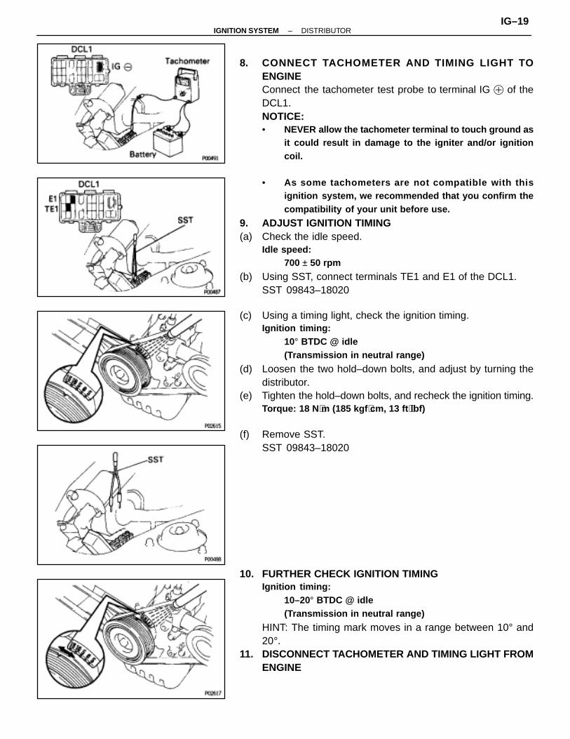
8. CONNECT TACHOMETER AND TIMING LIGHT TOENGINEConnect the tachometer test probe to terminal IG � of theDCL1.NOTICE:• NEVER allow the tachometer terminal to touch ground as
it could result in damage to the igniter and/or ignitioncoil.
• As some tachometers are not compatible with thisignition system, we recommended that you confirm thecompatibility of your unit before use.
9. ADJUST IGNITION TIMING(a) Check the idle speed.
Idle speed:700 ± 50 rpm
(b) Using SST, connect terminals TE1 and E1 of the DCL1.SST 09843–18020
(c) Using a timing light, check the ignition timing.Ignition timing:
10° BTDC @ idle(Transmission in neutral range)
(d) Loosen the two hold–down bolts, and adjust by turning thedistributor.
(e) Tighten the hold–down bolts, and recheck the ignition timing.Torque: 18 N ⋅m (185 kgf ⋅cm, 13 ft ⋅lbf)
(f) Remove SST.SST 09843–18020
10. FURTHER CHECK IGNITION TIMINGIgnition timing:
10–20° BTDC @ idle(Transmission in neutral range)
HINT: The timing mark moves in a range between 10° and20°.
11. DISCONNECT TACHOMETER AND TIMING LIGHT FROMENGINE
–IGNITION SYSTEM DISTRIBUTORIG–19

SERVICE SPECIFICATIONSSERVICE DATA
IG01P–01
ÑÑÑÑÑÑÑÑÑÑÑÑ
Ignition timingÑÑÑÑÑÑÑÑÑÑÑÑÑÑÑÑÑÑÑÑÑÑÑÑÑÑÑÑ
w/ Terminals TE1 and E1 connected ÑÑÑÑÑÑÑÑÑÑ
ÑÑÑÑÑÑÑÑÑÑÑÑÑÑÑÑÑÑÑÑÑÑÑÑÑÑÑÑ
10° BTDC @ idleÑÑÑÑÑÑÑÑÑÑÑÑ
Firing order ÑÑÑÑÑÑÑÑÑÑÑÑÑÑÑÑÑÑÑÑÑÑÑÑÑÑÑÑ
– ÑÑÑÑÑÑÑÑÑÑ
ÑÑÑÑÑÑÑÑÑÑÑÑÑÑÑÑÑÑÑÑÑÑÑÑÑÑÑÑ
1–2–3–4–5–6ÑÑÑÑÑÑÑÑÑÑÑÑÑÑÑÑÑÑ
High–tensioncord
ÑÑÑÑÑÑÑÑÑÑÑÑÑÑÑÑÑÑÑÑÑÑÑÑÑÑÑÑÑÑÑÑÑÑÑÑÑÑÑÑÑÑ
Resistance (Maximum) ÑÑÑÑÑÑÑÑÑÑÑÑÑÑÑ
ÑÑÑÑÑÑÑÑÑÑÑÑÑÑÑÑÑÑÑÑÑÑÑÑÑÑÑÑÑÑÑÑÑÑÑÑÑÑÑÑÑÑ
25 k� per cord
ÑÑÑÑÑÑÑÑÑÑÑÑ
Spark plug ÑÑÑÑÑÑÑÑÑÑÑÑÑÑÑÑÑÑÑÑÑÑÑÑÑÑÑÑ
Recommended spark plug ÑÑÑÑÑÑÑÑÑÑ
ND ÑÑÑÑÑÑÑÑÑÑÑÑÑÑÑÑÑÑÑÑÑÑÑÑÑÑÑÑ
PQ20R
ÑÑÑÑÑÑÑÑÑÑÑÑ
ÑÑÑÑÑÑÑÑÑÑÑÑÑÑÑÑÑÑÑÑÑÑÑÑÑÑÑÑ
Recommended spark plug ÑÑÑÑÑÑÑÑÑÑ
NGK ÑÑÑÑÑÑÑÑÑÑÑÑÑÑÑÑÑÑÑÑÑÑÑÑÑÑÑÑ
BCPR6EP–11
ÑÑÑÑÑÑÑÑÑÑÑÑ
ÑÑÑÑÑÑÑÑÑÑÑÑÑÑÑÑÑÑÑÑÑÑÑÑÑÑÑÑ
Correct electrode gap ÑÑÑÑÑÑÑÑÑÑ
ÑÑÑÑÑÑÑÑÑÑÑÑÑÑÑÑÑÑÑÑÑÑÑÑÑÑÑÑ
1.1 mm (0.043 in.)
ÑÑÑÑÑÑÑÑÑÑÑÑ
Ignition coil ÑÑÑÑÑÑÑÑÑÑÑÑÑÑÑÑÑÑÑÑÑÑÑÑÑÑÑÑ
Primary coil resistance (Cold) ÑÑÑÑÑÑÑÑÑÑ
ÑÑÑÑÑÑÑÑÑÑÑÑÑÑÑÑÑÑÑÑÑÑÑÑÑÑÑÑ
0.3–0.6 �
ÑÑÑÑÑÑÑÑÑÑÑÑ
ÑÑÑÑÑÑÑÑÑÑÑÑÑÑÑÑÑÑÑÑÑÑÑÑÑÑÑÑ
Secondary coil resistance (Cold) ÑÑÑÑÑÑÑÑÑÑ
ÑÑÑÑÑÑÑÑÑÑÑÑÑÑÑÑÑÑÑÑÑÑÑÑÑÑÑÑ
9.0–15.0 k�
ÑÑÑÑÑÑÑÑÑÑÑÑ
Distributor ÑÑÑÑÑÑÑÑÑÑÑÑÑÑÑÑÑÑÑÑÑÑÑÑÑÑÑÑ
Air gap ÑÑÑÑÑÑÑÑÑÑ
ÑÑÑÑÑÑÑÑÑÑÑÑÑÑÑÑÑÑÑÑÑÑÑÑÑÑÑÑ
0.2–0.5 mm (0.08–0.020 in.)
ÑÑÑÑÑÑÑÑÑÑÑÑ
ÑÑÑÑÑÑÑÑÑÑÑÑÑÑÑÑÑÑÑÑÑÑÑÑÑÑÑÑÑÑÑÑÑÑÑÑ
Signal generator (pickup coil) resistance (Cold) ÑÑÑÑÑÑÑÑÑÑÑÑÑÑÑÑÑÑÑÑÑÑÑÑÑÑÑÑÑÑÑÑÑÑ
ÑÑÑÑÑÑÑÑÑÑÑÑÑÑÑÑÑÑÑÑÑÑÑÑÑÑÑÑÑÑÑÑÑÑ
G1–G� ÑÑÑÑÑÑÑÑÑÑ
ÑÑÑÑÑÑÑÑÑÑÑÑÑÑÑÑÑÑÑÑÑÑÑÑÑÑÑÑ
125–190 �
ÑÑÑÑÑÑÑÑÑÑÑÑ
ÑÑÑÑÑÑÑÑÑÑÑÑÑÑÑÑÑÑÑÑÑÑÑÑÑÑÑÑ
G2–G� ÑÑÑÑÑÑÑÑÑÑ
ÑÑÑÑÑÑÑÑÑÑÑÑÑÑÑÑÑÑÑÑÑÑÑÑÑÑÑÑ
125–190 �
ÑÑÑÑÑÑÑÑÑÑÑÑ
ÑÑÑÑÑÑÑÑÑÑÑÑÑÑÑÑÑÑÑÑÑÑÑÑÑÑÑÑ
NE–G� ÑÑÑÑÑÑÑÑÑÑ
ÑÑÑÑÑÑÑÑÑÑÑÑÑÑÑÑÑÑÑÑÑÑÑÑÑÑÑÑ
155–240 �
TORQUE SPECIFICATIONSIG01Q–01ÑÑÑÑÑÑÑÑÑÑÑÑÑÑÑÑÑÑÑÑÑÑ
ÑÑÑÑÑÑÑÑÑÑÑÑÑÑÑÑÑÑÑÑÑÑPart tightened ÑÑÑÑÑÑ
ÑÑÑÑÑÑN⋅m ÑÑÑÑÑ
ÑÑÑÑÑkgf⋅cm ÑÑÑÑÑÑ
ÑÑÑÑÑÑft⋅lbf
ÑÑÑÑÑÑÑÑÑÑÑÑÑÑÑÑÑÑÑÑÑÑÑÑÑÑÑÑÑÑÑÑÑÑÑÑÑÑÑÑÑÑÑÑ
Spark plug X Cylinder head ÑÑÑÑÑÑÑÑÑÑÑÑ
18 ÑÑÑÑÑÑÑÑÑÑ
180 ÑÑÑÑÑÑÑÑÑÑÑÑ
13ÑÑÑÑÑÑÑÑÑÑÑÑÑÑÑÑÑÑÑÑÑÑÑÑÑÑÑÑÑÑÑÑÑÑÑÑÑÑÑÑÑÑÑÑ
Distributor X Cylinder head ÑÑÑÑÑÑÑÑÑÑÑÑ
18 ÑÑÑÑÑÑÑÑÑÑ
185 ÑÑÑÑÑÑÑÑÑÑÑÑ
13
IG–20–IGNITION SYSTEM SERVICE SPECIFICATIONS

STARTING SYSTEM
ST–1
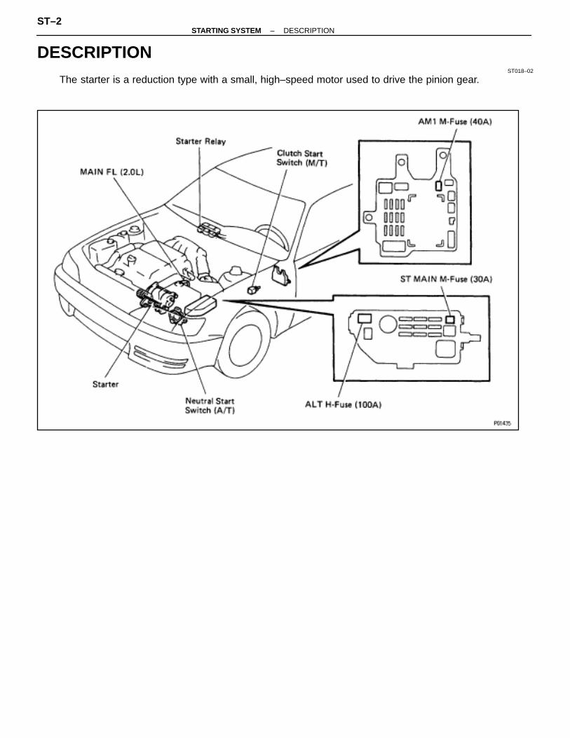
DESCRIPTIONST018–02
The starter is a reduction type with a small, high–speed motor used to drive the pinion gear.
ST–2–STARTING SYSTEM DESCRIPTION
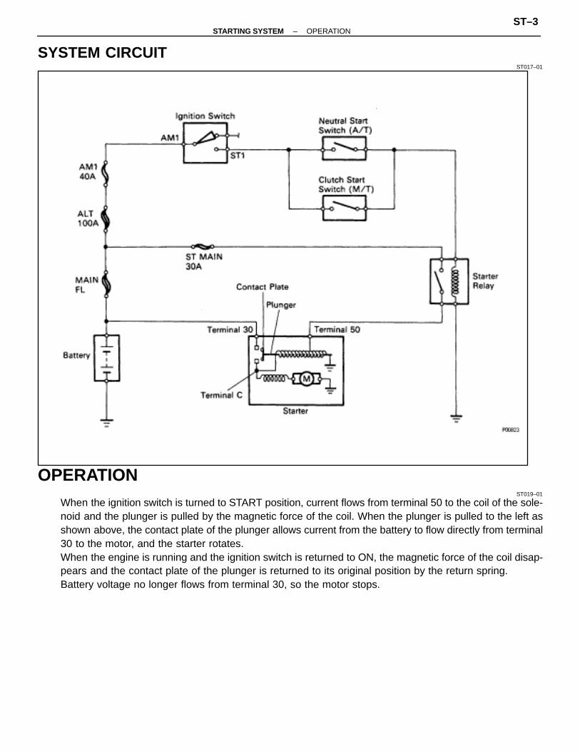
SYSTEM CIRCUITST017–01
OPERATIONST019–01
When the ignition switch is turned to START position, current flows from terminal 50 to the coil of the sole-noid and the plunger is pulled by the magnetic force of the coil. When the plunger is pulled to the left asshown above, the contact plate of the plunger allows current from the battery to flow directly from terminal30 to the motor, and the starter rotates.When the engine is running and the ignition switch is returned to ON, the magnetic force of the coil disap-pears and the contact plate of the plunger is returned to its original position by the return spring.Battery voltage no longer flows from terminal 30, so the motor stops.
–STARTING SYSTEM OPERATIONST–3

PREPARATIONSST (SPECIAL SERVICE TOOLS)
ST01A–01
RECOMMENDED TOOLSST01C–01
EQUIPMENTST01E–01
ÑÑÑÑÑÑÑÑÑÑÑÑÑÑÑÑÑÑÑÑÑÑÑÑÑÑÑÑÑÑÑÑÑÑÑÑÑÑÑÑÑÑÑÑÑÑ
Dial indicator ÑÑÑÑÑÑÑÑÑÑÑÑÑÑÑÑÑÑÑÑÑÑÑÑÑÑÑÑ
Commutator
ÑÑÑÑÑÑÑÑÑÑÑÑÑÑÑÑÑÑÑÑÑÑÑÑÑÑÑÑÑÑÑÑÑÑÑÑÑÑÑÑÑÑÑÑÑÑ
Magnetic finger ÑÑÑÑÑÑÑÑÑÑÑÑÑÑÑÑÑÑÑÑÑÑÑÑÑÑÑÑ
Steel ball
ÑÑÑÑÑÑÑÑÑÑÑÑÑÑÑÑÑÑÑÑÑÑÑÑÑÑÑÑÑÑÑÑÑÑÑÑÑÑÑÑÑÑÑÑÑÑ
Pull scale ÑÑÑÑÑÑÑÑÑÑÑÑÑÑÑÑÑÑÑÑÑÑÑÑÑÑÑÑ
Brush spring
ÑÑÑÑÑÑÑÑÑÑÑÑÑÑÑÑÑÑÑÑÑÑÑÑÑÑÑÑÑÑÑÑÑÑÑÑÑÑÑÑÑÑÑÑÑÑ
Sandpaper ÑÑÑÑÑÑÑÑÑÑÑÑÑÑÑÑÑÑÑÑÑÑÑÑÑÑÑÑ
Commutator
ÑÑÑÑÑÑÑÑÑÑÑÑÑÑÑÑÑÑÑÑÑÑÑÑÑÑÑÑÑÑÑÑÑÑÑÑÑÑÑÑÑÑÑÑÑÑ
Torque wrench ÑÑÑÑÑÑÑÑÑÑÑÑÑÑÑÑÑÑÑÑÑÑÑÑÑÑÑÑÑÑÑÑÑÑÑÑÑÑÑÑÑÑÑÑÑÑÑÑÑÑÑ
ÑÑÑÑÑÑÑÑÑÑÑÑÑÑÑÑÑÑÑÑÑÑÑV–block ÑÑÑÑÑÑÑÑÑÑÑÑÑÑ
ÑÑÑÑÑÑÑÑÑÑÑÑÑÑCommutator
ÑÑÑÑÑÑÑÑÑÑÑÑÑÑÑÑÑÑÑÑÑÑÑÑÑÑÑÑÑÑÑÑÑÑÑÑÑÑÑÑÑÑÑÑÑÑ
Vernier calipers ÑÑÑÑÑÑÑÑÑÑÑÑÑÑÑÑÑÑÑÑÑÑÑÑÑÑÑÑ
Commutator, Brush
ST–4–STARTING SYSTEM PREPARATION

STARTERSTARTER REMOVAL
ST01B–02
1. DISCONNECT CABLE FROM NEGATIVE TERMINAL OFBATTERYCAUTION (w/ Airbag): Work must be started after approx.30 seconds or longer from the time the ignition switch isturned to the “LOCK” position and the negative (–) termi-nal cable is disconnected from the battery.
2. REMOVE BATTERY
3. REMOVE CRUISE CONTROL ACTUATOR(a) Remove the actuator cover.(b) Disconnect the actuator connector.(c) Remove the three bolts and cruise control actuator.
–STARTING SYSTEM STARTERST–5
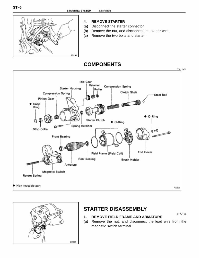
4. REMOVE STARTER(a) Disconnect the starter connector.(b) Remove the nut, and disconnect the starter wire.(c) Remove the two bolts and starter.
COMPONENTSST01D–01
STARTER DISASSEMBLYST01F–01
1. REMOVE FIELD FRAME AND ARMATURE(a) Remove the nut, and disconnect the lead wire from the
magnetic switch terminal.
ST–6–STARTING SYSTEM STARTER
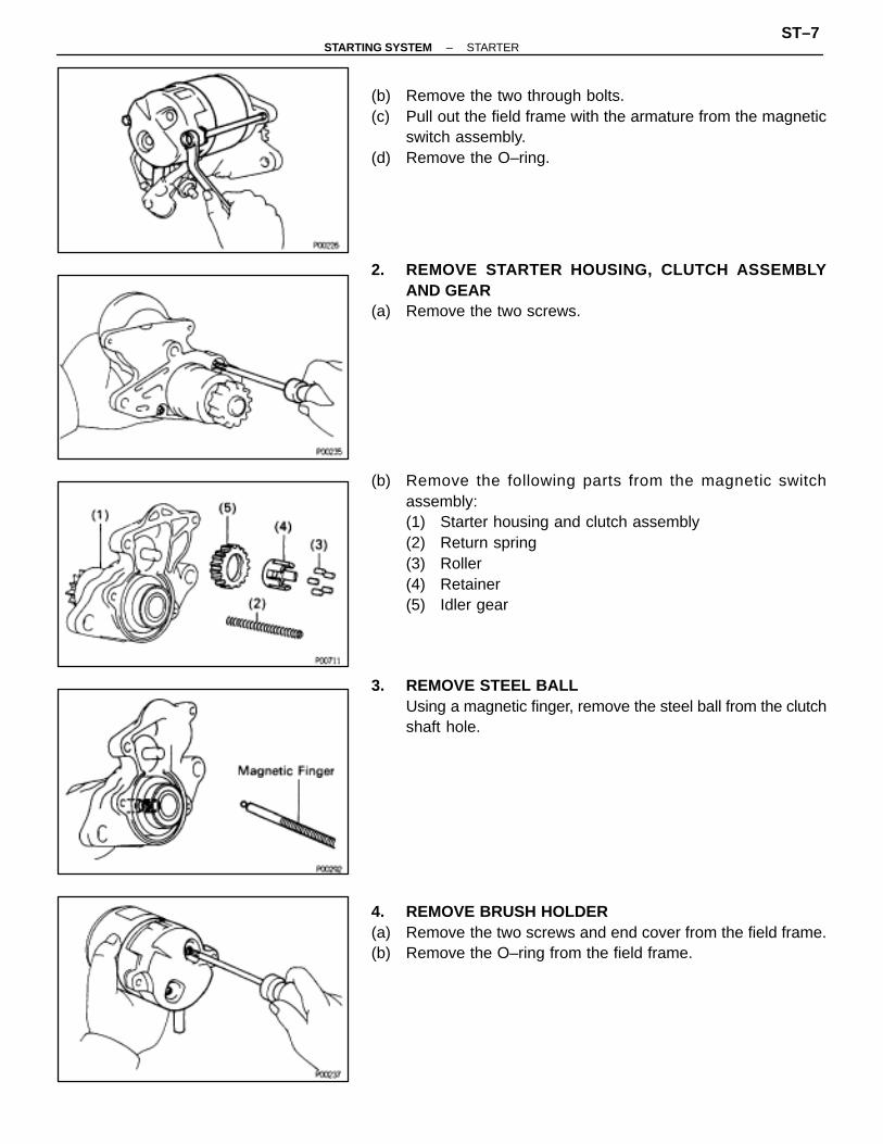
(b) Remove the two through bolts.(c) Pull out the field frame with the armature from the magnetic
switch assembly.(d) Remove the O–ring.
2. REMOVE STARTER HOUSING, CLUTCH ASSEMBLYAND GEAR
(a) Remove the two screws.
(b) Remove the following parts from the magnetic switchassembly:(1) Starter housing and clutch assembly(2) Return spring(3) Roller(4) Retainer(5) Idler gear
3. REMOVE STEEL BALLUsing a magnetic finger, remove the steel ball from the clutchshaft hole.
4. REMOVE BRUSH HOLDER(a) Remove the two screws and end cover from the field frame.(b) Remove the O–ring from the field frame.
–STARTING SYSTEM STARTERST–7

(c) Using a screwdriver, hold the spring back and disconnect thebrush from the brush holder. Disconnect the four brushes andremove the brush holder.
5. REMOVE ARMATURE FROM FIELD FRAME
STARTER INSPECTION AND REPAIRST01G–01
Armature Coil1. INSPECT COMMUTATOR FOR OPEN CIRCUIT
Using an ohmmeter, check that there is continuity betweenthe segments of the commutator.If there is no continuity between any segment, replace the ar-mature.
2. INSPECT COMMUTATOR FOR GROUNDUsing an ohmmeter, check that there is no continuity be-tween the commutator and armature coil core.If there is continuity, replace the armature.
Commutator1. INSPECT COMMUTATOR FOR DIRTY AND BURNT
SURFACESIf the surface is dirty or burnt, correct it with sandpaper(No.400) or on a lathe.
2. INSPECT COMMUTATOR CIRCLE RUNOUT(a) Place the commutator on V–blocks.(b) Using a dial gauge, measure the circle runout.
Maximum circle runout:0.05 mm (0.0020 in.)
If the circle runout is greater than maximum, correct it on alathe.
ST–8–STARTING SYSTEM STARTER
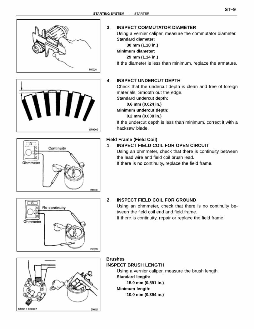
3. INSPECT COMMUTATOR DIAMETERUsing a vernier caliper, measure the commutator diameter.Standard diameter:
30 mm (1.18 in.)Minimum diameter:
29 mm (1.14 in.)
If the diameter is less than minimum, replace the armature.
4. INSPECT UNDERCUT DEPTHCheck that the undercut depth is clean and free of foreignmaterials. Smooth out the edge.Standard undercut depth:
0.6 mm (0.024 in.)Minimum undercut depth:
0.2 mm (0.008 in.)
If the undercut depth is less than minimum, correct it with ahacksaw blade.
Field Frame (Field Coil)1. INSPECT FIELD COIL FOR OPEN CIRCUIT
Using an ohmmeter, check that there is continuity betweenthe lead wire and field coil brush lead.If there is no continuity, replace the field frame.
2. INSPECT FIELD COIL FOR GROUNDUsing an ohmmeter, check that there is no continuity be-tween the field coil end and field frame.If there is continuity, repair or replace the field frame.
BrushesINSPECT BRUSH LENGTH
Using a vernier caliper, measure the brush length.Standard length:
15.0 mm (0.591 in.)Minimum length:
10.0 mm (0.394 in.)
–STARTING SYSTEM STARTERST–9
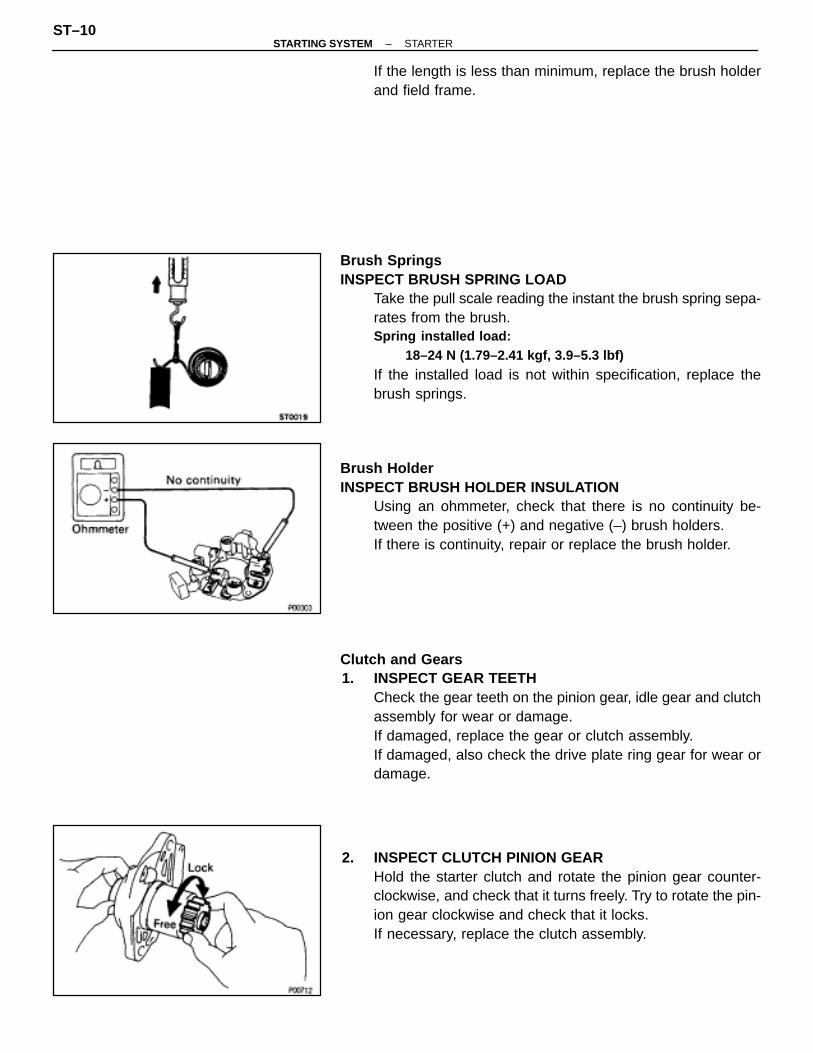
If the length is less than minimum, replace the brush holderand field frame.
Brush SpringsINSPECT BRUSH SPRING LOAD
Take the pull scale reading the instant the brush spring sepa-rates from the brush.Spring installed load:
18–24 N (1.79–2.41 kgf, 3.9–5.3 lbf)
If the installed load is not within specification, replace thebrush springs.
Brush HolderINSPECT BRUSH HOLDER INSULATION
Using an ohmmeter, check that there is no continuity be-tween the positive (+) and negative (–) brush holders.If there is continuity, repair or replace the brush holder.
Clutch and Gears1. INSPECT GEAR TEETH
Check the gear teeth on the pinion gear, idle gear and clutchassembly for wear or damage.If damaged, replace the gear or clutch assembly.If damaged, also check the drive plate ring gear for wear ordamage.
2. INSPECT CLUTCH PINION GEARHold the starter clutch and rotate the pinion gear counter-clockwise, and check that it turns freely. Try to rotate the pin-ion gear clockwise and check that it locks.If necessary, replace the clutch assembly.
ST–10–STARTING SYSTEM STARTER

3. IF NECESSARY, REPLACE CLUTCH ASSEMBLYA. Disassembly of starter housing and clutch assembly(a) Mount a brass bar in a vise, and install the starter housing and
clutch assembly to the brass bar.
(b) Push down the pinion gear(c) Using a plastic–faced hammer, tap down the stop collar.
(d) Using a screwdriver, pry out the snap ring.
(e) Remove the following parts:(1) Stop collar(2) Pinion gear(3) Compression spring
(f) Push down the starter housing, and remove the springretainer.
–STARTING SYSTEM STARTERST–11
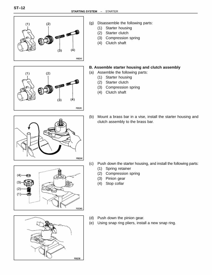
(g) Disassemble the following parts:(1) Starter housing(2) Starter clutch(3) Compression spring(4) Clutch shaft
B. Assemble starter housing and clutch assembly(a) Assemble the following parts:
(1) Starter housing(2) Starter clutch(3) Compression spring(4) Clutch shaft
(b) Mount a brass bar in a vise, install the starter housing andclutch assembly to the brass bar.
(c) Push down the starter housing, and install the following parts:(1) Spring retainer(2) Compression spring(3) Pinion gear(4) Stop collar
(d) Push down the pinion gear.(e) Using snap ring pliers, install a new snap ring.
ST–12–STARTING SYSTEM STARTER
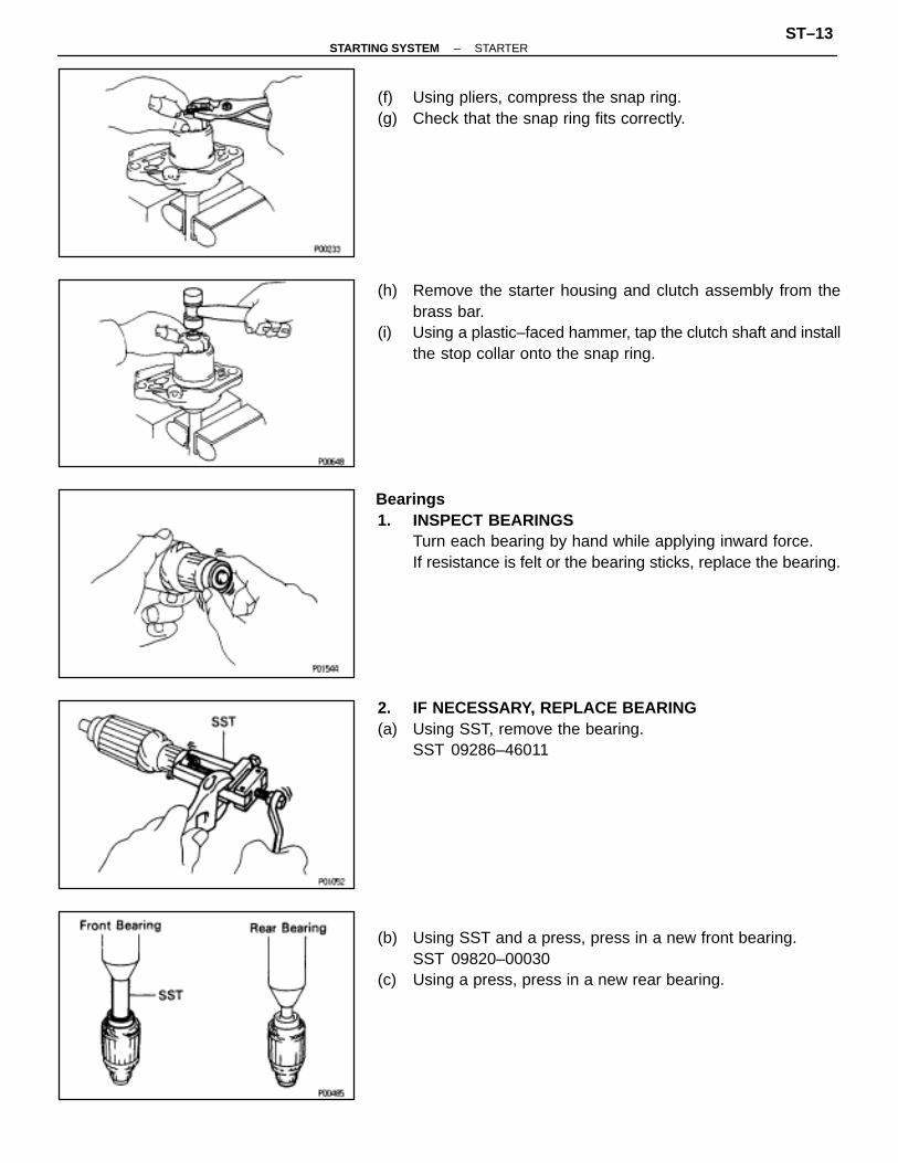
(f) Using pliers, compress the snap ring.(g) Check that the snap ring fits correctly.
(h) Remove the starter housing and clutch assembly from thebrass bar.
(i) Using a plastic–faced hammer, tap the clutch shaft and installthe stop collar onto the snap ring.
Bearings1. INSPECT BEARINGS
Turn each bearing by hand while applying inward force.If resistance is felt or the bearing sticks, replace the bearing.
2. IF NECESSARY, REPLACE BEARING(a) Using SST, remove the bearing.
SST 09286–46011
(b) Using SST and a press, press in a new front bearing.SST 09820–00030
(c) Using a press, press in a new rear bearing.
–STARTING SYSTEM STARTERST–13

Magnetic Switch1. PERFORM PULL–IN COIL OPEN CIRCUIT TEST
Using an ohmmeter, check that there is continuity betweenterminals 50 and C.If there is no continuity, replace the magnetic switch.
2. PERFORM HOLD–IN COIL OPEN CIRCUIT TESTUsing an ohmmeter, check that there is continuity betweenterminal 50 and the switch body.If there is no continuity, replace the magnetic switch.
STARTER ASSEMBLYST01J–02
(See page ST–6)HINT: Use high–temperature grease to lubricate the bearingsand gears when assembling the starter.
1. PLACE ARMATURE INTO FIELD FRAMEApply grease to the armature bearings, and insert the arma-ture into the field frame.
2. INSTALL BRUSH HOLDER(a) Place the brush holder on the armature.(b) Using a screwdriver, hold the brush spring back, and connect
the brush into the brush holder. Connect the four brushes.NOTICE: Check that the positive (+) lead wires are notgrounded.
(c) Place a new O–ring in position on the field frame.
ST–14–STARTING SYSTEM STARTER

(d) Install a new O–ring to the end cover screw.(e) Install the end cover to the field frame with the two screws.
3. INSERT STEEL BALL INTO CLUTCH SHAFT HOLE(a) Apply grease to the steel ball.(b) Insert the steel ball into the clutch shaft hole.
4. INSTALL STARTER HOUSING, CLUTCH ASSEMBLY ANDGEAR
(a) Apply grease to the return spring.(b) Insert the return spring into the magnetic switch hole.
(c) Place the following parts in position on the starter housing:(1) Idler gear(2) Retainer(3) Roller
(d) Assemble the starter housing and magnetic switch assemblyand install the two screws.
–STARTING SYSTEM STARTERST–15
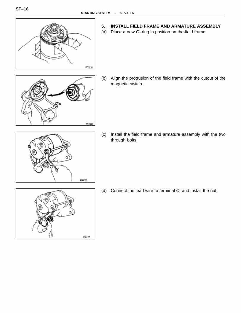
5. INSTALL FIELD FRAME AND ARMATURE ASSEMBLY(a) Place a new O–ring in position on the field frame.
(b) Align the protrusion of the field frame with the cutout of themagnetic switch.
(c) Install the field frame and armature assembly with the twothrough bolts.
(d) Connect the lead wire to terminal C, and install the nut.
ST–16–STARTING SYSTEM STARTER
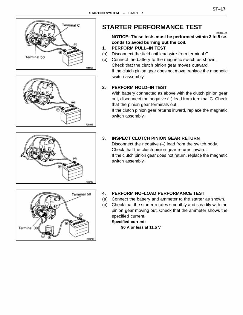
STARTER PERFORMANCE TESTST01L–01
NOTICE: These tests must be performed within 3 to 5 se-conds to avoid burning out the coil.
1. PERFORM PULL–IN TEST(a) Disconnect the field coil lead wire from terminal C.(b) Connect the battery to the magnetic switch as shown.
Check that the clutch pinion gear moves outward.If the clutch pinion gear does not move, replace the magneticswitch assembly.
2. PERFORM HOLD–IN TESTWith battery connected as above with the clutch pinion gearout, disconnect the negative (–) lead from terminal C. Checkthat the pinion gear terminals out.If the clutch pinion gear returns inward, replace the magneticswitch assembly.
3. INSPECT CLUTCH PINION GEAR RETURNDisconnect the negative (–) lead from the switch body.Check that the clutch pinion gear returns inward.If the clutch pinion gear does not return, replace the magneticswitch assembly.
4. PERFORM NO–LOAD PERFORMANCE TEST(a) Connect the battery and ammeter to the starter as shown.(b) Check that the starter rotates smoothly and steadily with the
pinion gear moving out. Check that the ammeter shows thespecified current.Specified current:
90 A or less at 11.5 V
–STARTING SYSTEM STARTERST–17
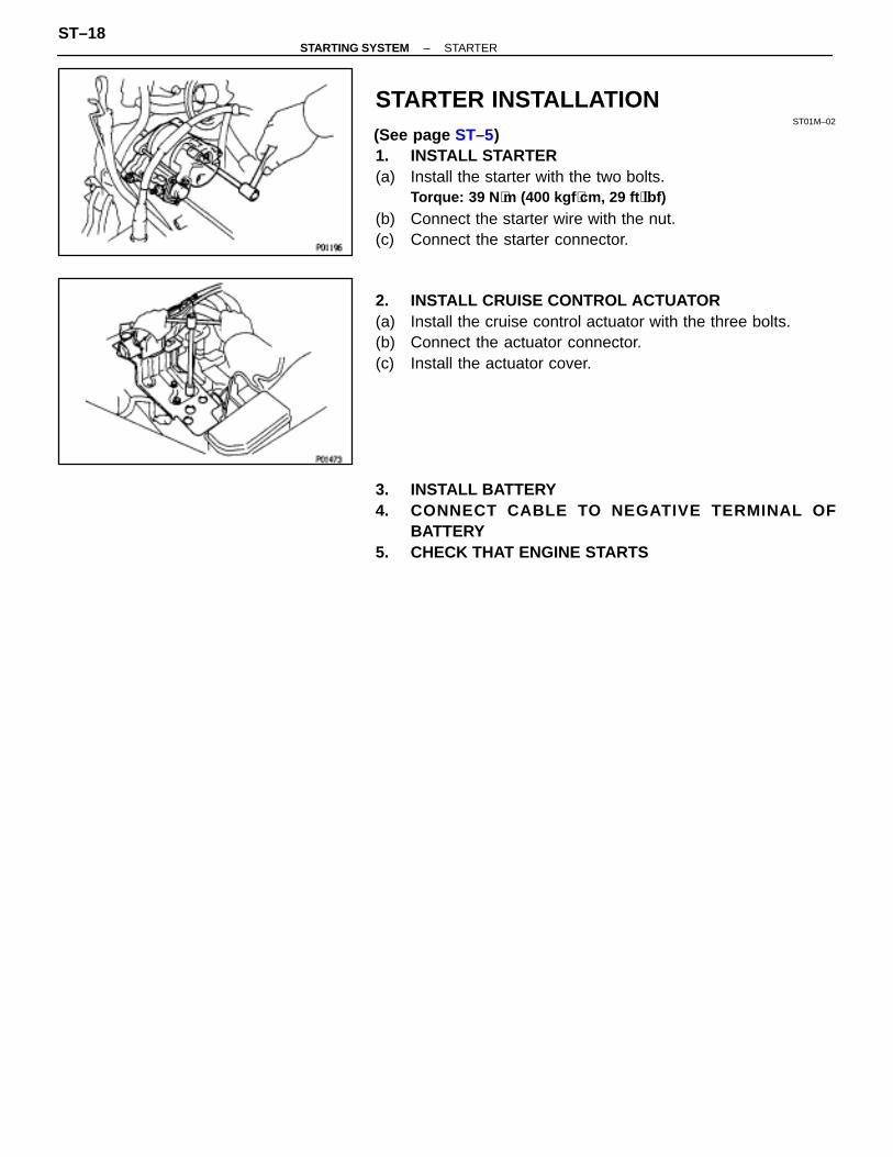
STARTER INSTALLATIONST01M–02
(See page ST–5)1. INSTALL STARTER(a) Install the starter with the two bolts.
Torque: 39 N ⋅m (400 kgf ⋅cm, 29 ft ⋅lbf)
(b) Connect the starter wire with the nut.(c) Connect the starter connector.
2. INSTALL CRUISE CONTROL ACTUATOR(a) Install the cruise control actuator with the three bolts.(b) Connect the actuator connector.(c) Install the actuator cover.
3. INSTALL BATTERY4. CONNECT CABLE TO NEGATIVE TERMINAL OF
BATTERY5. CHECK THAT ENGINE STARTS
ST–18–STARTING SYSTEM STARTER

STARTER RELAYSTARTER RELAY INSPECTION
ST01H–02
LOCATION: (See page ST–2)
1. INSPECTION RELAY CONTINUITY(a) Using an ohmmeter, check that there is continuity between
terminals 1 and 3.(b) Check that there is no continuity between terminals 2 and 4.
If continuity is not as specified, replace the relay.
2. INSPECT RELAY OPERATION(a) Apply battery voltage across terminals 1 and 3.(b) Using an ohmmeter, check that there is continuity between
terminals 2 and 4.If operation is not as specified, replace the relay.
CLUTCH START SWITCHST01K–01
(See MX section)
NEUTRAL START SWITCHST01N–01
(See AX section)
–STARTING SYSTEM NEUTRAL START SWITCHST–19
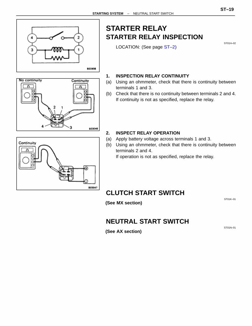

SERVICE SPECIFICATIONSSERVICE DATA
ST01P–01
ÑÑÑÑÑÑÑÑÑÑÑÑÑÑÑÑÑÑÑÑÑÑÑÑÑÑ
Starter ÑÑÑÑÑÑÑÑÑÑÑÑÑÑÑÑÑÑÑÑÑÑÑÑ
Rated voltage and output power ÑÑÑÑÑÑÑÑÑÑÑÑÑÑÑÑÑÑÑÑÑÑÑÑÑÑ
12 V 1.4 kWÑÑÑÑÑÑÑÑÑÑÑÑÑÑÑÑÑÑÑÑÑÑÑÑÑÑ
ÑÑÑÑÑÑÑÑÑÑÑÑÑÑÑÑÑÑÑÑÑÑÑÑ
No–load characteristics (Current) ÑÑÑÑÑÑÑÑÑÑÑÑÑÑÑÑÑÑÑÑÑÑÑÑÑÑ
90 A or less at 11.5 VÑÑÑÑÑÑÑÑÑÑÑÑÑÑÑÑÑÑÑÑÑÑÑÑÑÑ
ÑÑÑÑÑÑÑÑÑÑÑÑÑÑÑÑÑÑÑÑÑÑÑÑ
No–load characteristics (rpm) ÑÑÑÑÑÑÑÑÑÑÑÑÑÑÑÑÑÑÑÑÑÑÑÑÑÑ
3,000 rpm or moreÑÑÑÑÑÑÑÑÑÑÑÑÑÑÑÑÑÑÑÑÑÑÑÑÑÑ
ÑÑÑÑÑÑÑÑÑÑÑÑÑÑÑÑÑÑÑÑÑÑÑÑ
Brush length (STD) ÑÑÑÑÑÑÑÑÑÑÑÑÑÑÑÑÑÑÑÑÑÑÑÑÑÑ
15.0 mm (0.591 in.)ÑÑÑÑÑÑÑÑÑÑÑÑÑÑÑÑÑÑÑÑÑÑÑÑÑÑ
ÑÑÑÑÑÑÑÑÑÑÑÑÑÑÑÑÑÑÑÑÑÑÑÑ
Brush length (Minimum) ÑÑÑÑÑÑÑÑÑÑÑÑÑÑÑÑÑÑÑÑÑÑÑÑÑÑ
10.0 mm (0.394 in.)ÑÑÑÑÑÑÑÑÑÑÑÑÑÑÑÑÑÑÑÑÑÑÑÑÑÑ
ÑÑÑÑÑÑÑÑÑÑÑÑÑÑÑÑÑÑÑÑÑÑÑÑ
Spring installed load ÑÑÑÑÑÑÑÑÑÑÑÑÑÑÑÑÑÑÑÑÑÑÑÑÑÑ
18–24 N (1.79–2.41 kgf, 3.9–5.3 lbf)ÑÑÑÑÑÑÑÑÑÑÑÑÑÑÑÑÑÑÑÑÑÑÑÑÑÑ
ÑÑÑÑÑÑÑÑÑÑÑÑÑÑÑÑÑÑÑÑÑÑÑÑ
Commutator ÑÑÑÑÑÑÑÑÑÑÑÑÑÑÑÑÑÑÑÑÑÑÑÑÑÑÑÑÑÑÑÑÑÑÑÑÑÑÑ
ÑÑÑÑÑÑÑÑÑÑÑÑÑÑÑÑÑÑÑÑÑÑÑÑÑÑÑÑÑÑÑÑÑÑÑÑÑ
Diameter (STD) ÑÑÑÑÑÑÑÑÑÑÑÑÑÑÑÑÑÑÑÑÑÑÑÑÑÑ
30 mm (1.18 in.)ÑÑÑÑÑÑÑÑÑÑÑÑÑÑÑÑÑÑÑÑÑÑÑÑÑÑ
ÑÑÑÑÑÑÑÑÑÑÑÑÑÑÑÑÑÑÑÑÑÑÑÑ
Diameter (Minimum) ÑÑÑÑÑÑÑÑÑÑÑÑÑÑÑÑÑÑÑÑÑÑÑÑÑÑ
29 mm (1.14 in.)ÑÑÑÑÑÑÑÑÑÑÑÑÑÑÑÑÑÑÑÑÑÑÑÑÑÑ
ÑÑÑÑÑÑÑÑÑÑÑÑÑÑÑÑÑÑÑÑÑÑÑÑ
Undercut depth (STD) ÑÑÑÑÑÑÑÑÑÑÑÑÑÑÑÑÑÑÑÑÑÑÑÑÑÑ
0.6 mm (0.024 in.)ÑÑÑÑÑÑÑÑÑÑÑÑÑÑÑÑÑÑÑÑÑÑÑÑÑÑ
ÑÑÑÑÑÑÑÑÑÑÑÑÑÑÑÑÑÑÑÑÑÑÑÑ
Undercut depth (Minimum) ÑÑÑÑÑÑÑÑÑÑÑÑÑÑÑÑÑÑÑÑÑÑÑÑÑÑ
0.2 mm (0.008 in.)ÑÑÑÑÑÑÑÑÑÑÑÑÑÑÑÑÑÑÑÑÑÑÑÑÑÑ
ÑÑÑÑÑÑÑÑÑÑÑÑÑÑÑÑÑÑÑÑÑÑÑÑ
Circle runout (Maximum) ÑÑÑÑÑÑÑÑÑÑÑÑÑÑÑÑÑÑÑÑÑÑÑÑÑÑ
0.05 mm (0.0020 in.)
TORQUE SPECIFICATIONSST01Q–01ÑÑÑÑÑÑÑÑÑÑÑÑÑÑÑÑÑ
ÑÑÑÑÑÑÑÑÑÑÑÑÑÑÑÑÑPart tightened ÑÑÑÑÑÑÑ
ÑÑÑÑÑÑÑN⋅m ÑÑÑÑÑÑÑ
ÑÑÑÑÑÑÑkgf⋅cm ÑÑÑÑÑÑÑ
ÑÑÑÑÑÑÑft⋅lbf
ÑÑÑÑÑÑÑÑÑÑÑÑÑÑÑÑÑÑÑÑÑÑÑÑÑÑÑÑÑÑÑÑÑÑ
Starter mounting bolt ÑÑÑÑÑÑÑÑÑÑÑÑÑÑ
39 ÑÑÑÑÑÑÑÑÑÑÑÑÑÑ
400 ÑÑÑÑÑÑÑÑÑÑÑÑÑÑ
29
ST–20–STARTING SYSTEM SERVICE SPECIFICATIONS

CHARGING SYSTEM
CH–1

DESCRIPTIONCH00H–02
The generator is a small, high rpm, high performance type with an IC regulator incorporated.The IC regulator uses integrated circuits and controls the voltage produced by the generator.
PRECAUTIONSCH00K–01
1. Check that the battery cables are connected to the correct terminals.2. Disconnect the battery cables when the battery is given a quick charge.3. Do not perform tests with a high voltage insulation resistance tester.4. Never disconnect the battery while the engine is running.
CH–2–CHARGING SYSTEM PRECAUTIONS
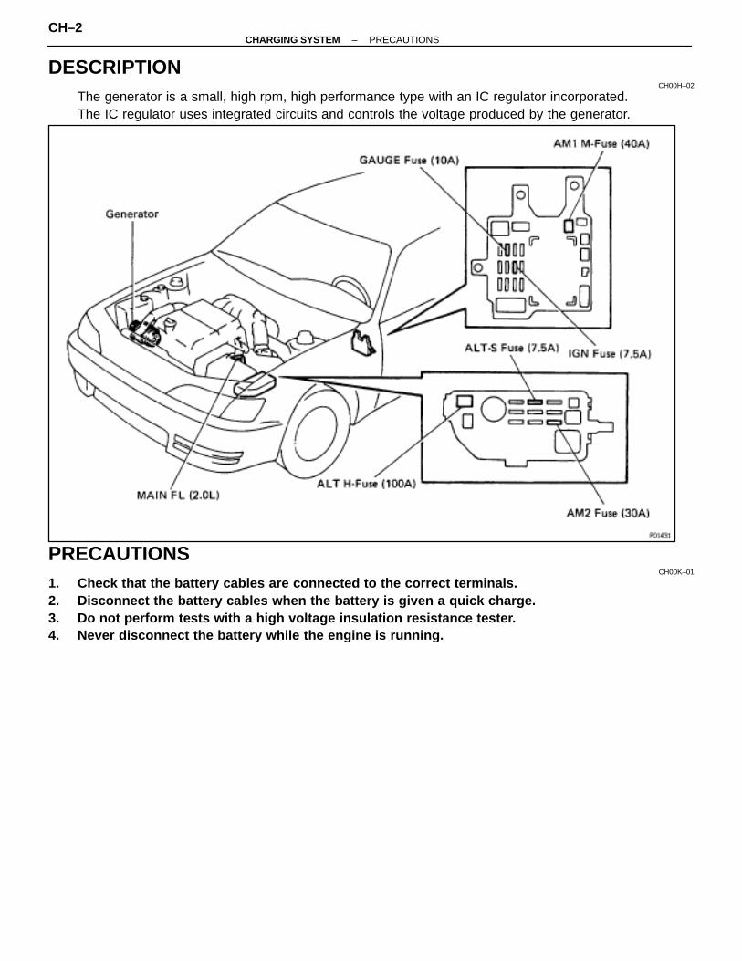
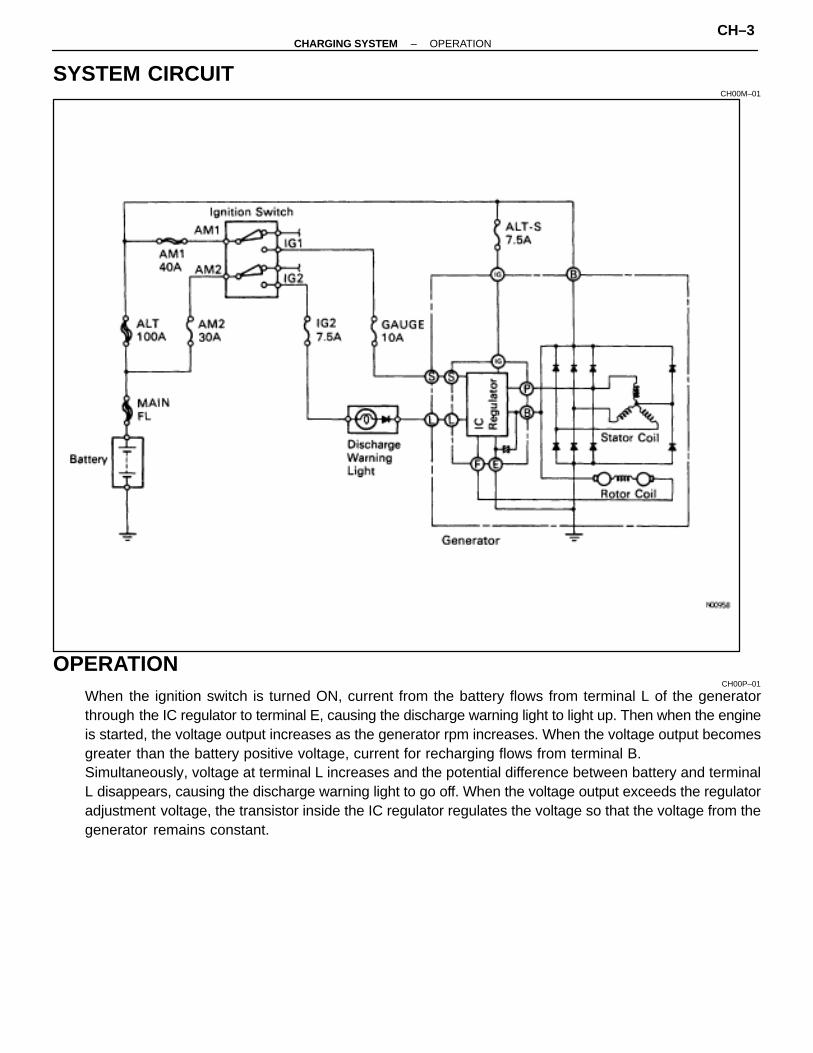
SYSTEM CIRCUITCH00M–01
OPERATIONCH00P–01
When the ignition switch is turned ON, current from the battery flows from terminal L of the generatorthrough the IC regulator to terminal E, causing the discharge warning light to light up. Then when the engineis started, the voltage output increases as the generator rpm increases. When the voltage output becomesgreater than the battery positive voltage, current for recharging flows from terminal B.Simultaneously, voltage at terminal L increases and the potential difference between battery and terminalL disappears, causing the discharge warning light to go off. When the voltage output exceeds the regulatoradjustment voltage, the transistor inside the IC regulator regulates the voltage so that the voltage from thegenerator remains constant.
–CHARGING SYSTEM OPERATIONCH–3
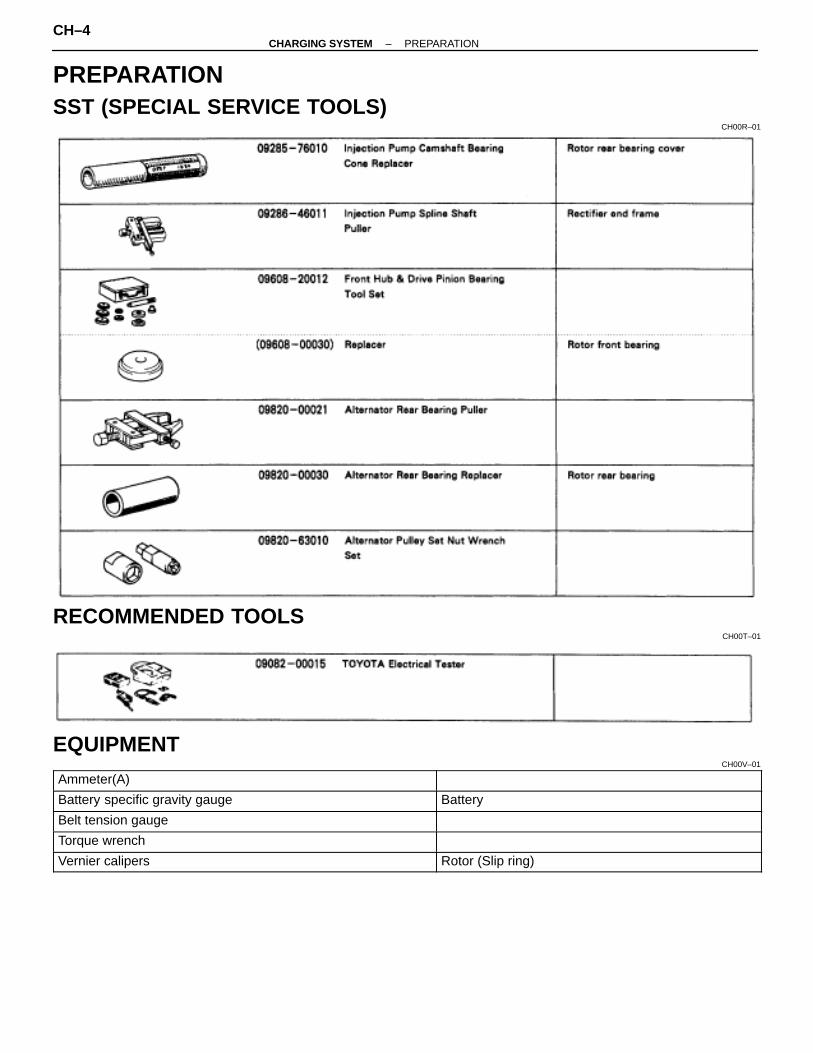
PREPARATIONSST (SPECIAL SERVICE TOOLS)
CH00R–01
RECOMMENDED TOOLSCH00T–01
EQUIPMENTCH00V–01ÑÑÑÑÑÑÑÑÑÑÑÑÑÑÑÑÑÑÑÑ
ÑÑÑÑÑÑÑÑÑÑÑÑÑÑÑÑÑÑÑÑAmmeter(A) ÑÑÑÑÑÑÑÑÑÑÑÑÑÑÑÑÑ
ÑÑÑÑÑÑÑÑÑÑÑÑÑÑÑÑÑÑÑÑÑÑÑÑÑÑÑÑÑÑÑÑÑÑÑÑÑÑÑÑÑÑÑÑÑÑÑÑÑÑÑÑÑÑÑÑÑ
Battery specific gravity gauge ÑÑÑÑÑÑÑÑÑÑÑÑÑÑÑÑÑÑÑÑÑÑÑÑÑÑÑÑÑÑÑÑÑÑ
BatteryÑÑÑÑÑÑÑÑÑÑÑÑÑÑÑÑÑÑÑÑÑÑÑÑÑÑÑÑÑÑÑÑÑÑÑÑÑÑÑÑ
Belt tension gauge ÑÑÑÑÑÑÑÑÑÑÑÑÑÑÑÑÑÑÑÑÑÑÑÑÑÑÑÑÑÑÑÑÑÑÑÑÑÑÑÑÑÑÑÑÑÑÑÑÑÑÑÑÑÑ
ÑÑÑÑÑÑÑÑÑÑÑÑÑÑÑÑÑÑÑÑTorque wrench ÑÑÑÑÑÑÑÑÑÑÑÑÑÑÑÑÑ
ÑÑÑÑÑÑÑÑÑÑÑÑÑÑÑÑÑÑÑÑÑÑÑÑÑÑÑÑÑÑÑÑÑÑÑÑÑÑÑÑÑÑÑÑÑÑÑÑÑÑÑÑÑÑÑÑÑ
Vernier calipers ÑÑÑÑÑÑÑÑÑÑÑÑÑÑÑÑÑÑÑÑÑÑÑÑÑÑÑÑÑÑÑÑÑÑ
Rotor (Slip ring)
CH–4–CHARGING SYSTEM PREPARATION

ON–VEHICLE INSPECTIONCH00X–01
1. CHECK BATTERY SPECIFIC GRAVITY ANDELECTROLYTE LEVEL
(a) Check the electrolyte level of each cell.If insufficient, refill with distilled (or purified) water.
(b) Check the specific gravity of each cell.Standard specific gravity at 20 °C (68°F):
1.25–1.27 (55D23L Battery)1.27–1.29 (80D26L Battery)
If not within specifications, charge the battery.HINT: Check the indicator as shown.
2. CHECK BATTERY TERMINALS, FUSIBLE LINK ANDFUSES
(a) Check that the battery terminals are not loose or corroded.(b) Check the fusible link and fuses for continuity.
Fusible link:MAIN 2.0 L
H–Fuse:ALT 100 A
M–Fuse:AM1 40 A
Fuse:AM2 30 AIG2 7.5 AGAUGE 10 AALI–S 7.5 A
3. INSPECT DRIVE BELT(a) Visually check the belt for excessive wear, frayed cords etc.
If any defect has been found, replace the drive belt.HINT: Cranks on the rib side of a belt are considered accept-able. If the belt has chunks missing from the ribs, it should bereplaced.
–CHARGING SYSTEM ON–VEHICLE INSPECTIONCH–5
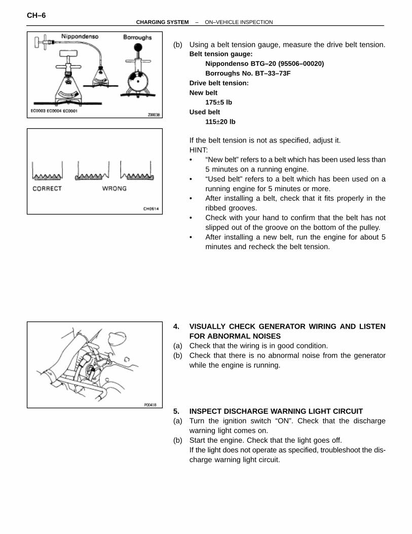
(b) Using a belt tension gauge, measure the drive belt tension.Belt tension gauge:
Nippondenso BTG–20 (95506–00020)Borroughs No. BT–33–73F
Drive belt tension:New belt
175±5 lbUsed belt
115±20 lb
If the belt tension is not as specified, adjust it.HINT:• “New belt” refers to a belt which has been used less than
5 minutes on a running engine.• “Used belt” refers to a belt which has been used on a
running engine for 5 minutes or more.• After installing a belt, check that it fits properly in the
ribbed grooves.• Check with your hand to confirm that the belt has not
slipped out of the groove on the bottom of the pulley.• After installing a new belt, run the engine for about 5
minutes and recheck the belt tension.
4. VISUALLY CHECK GENERATOR WIRING AND LISTENFOR ABNORMAL NOISES
(a) Check that the wiring is in good condition.(b) Check that there is no abnormal noise from the generator
while the engine is running.
5. INSPECT DISCHARGE WARNING LIGHT CIRCUIT(a) Turn the ignition switch “ON”. Check that the discharge
warning light comes on.(b) Start the engine. Check that the light goes off.
If the light does not operate as specified, troubleshoot the dis-charge warning light circuit.
CH–6–CHARGING SYSTEM ON–VEHICLE INSPECTION
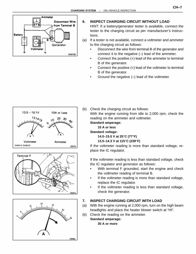
6. INSPECT CHARGING CIRCUIT WITHOUT LOADHINT: If a battery/generator tester is available, connect thetester to the charging circuit as per manufacturer’s instruc-tions.
(a) If a tester is not available, connect a voltmeter and ammeterto the charging circuit as follows:• Disconnect the wire from terminal B of the generator and
connect it to the negative (–) lead of the ammeter.• Connect the positive (+) lead of the ammeter to terminal
B of the generator.• Connect the positive (+) lead of the voltmeter to terminal
B of the generator.• Ground the negative (–) lead of the voltmeter.
(b) Check the charging circuit as follows:With the engine running from idle to 2,000 rpm, check thereading on the ammeter and voltmeter.Standard amperage:
10 A or lessStandard voltage:
14.0–15.0 V at 25°C (77°F)13.5–14.3 V at 115°C (239°F)
If the voltmeter reading is more than standard voltage, re-place the IC regulator.
If the voltmeter reading is less than standard voltage, checkthe IC regulator and generator as follows:• With terminal F grounded, start the engine and check
the voltmeter reading of terminal B.• If the voltmeter reading is more than standard voltage,
replace the IC regulator.• If the voltmeter reading is less than standard voltage,
check the generator.
7. INSPECT CHARGING CIRCUIT WITH LOAD(a) With the engine running at 2,000 rpm, turn on the high beam
headlights and place the heater blower switch at “HI”.(b) Check the reading on the ammeter.
Standard amperage:30 A or more
–CHARGING SYSTEM ON–VEHICLE INSPECTIONCH–7
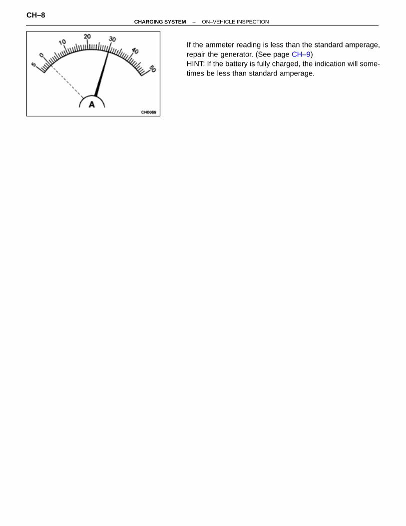
If the ammeter reading is less than the standard amperage,repair the generator. (See page CH–9)HINT: If the battery is fully charged, the indication will some-times be less than standard amperage.
CH–8–CHARGING SYSTEM ON–VEHICLE INSPECTION
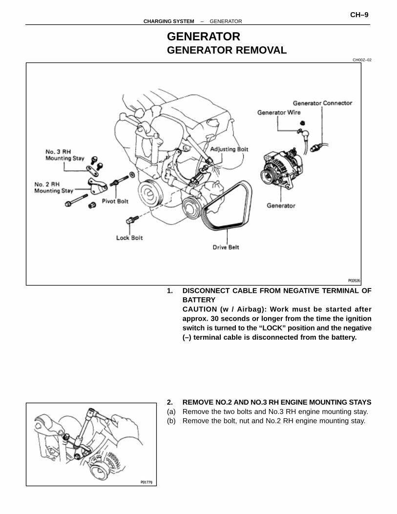
GENERATORGENERATOR REMOVAL
CH00Z–02
1. DISCONNECT CABLE FROM NEGATIVE TERMINAL OFBATTERYCAUTION (w / Airbag): Work must be started afterapprox. 30 seconds or longer from the time the ignitionswitch is turned to the “LOCK” position and the negative(–) terminal cable is disconnected from the battery.
2. REMOVE NO.2 AND NO.3 RH ENGINE MOUNTING STAYS(a) Remove the two bolts and No.3 RH engine mounting stay.(b) Remove the bolt, nut and No.2 RH engine mounting stay.
–CHARGING SYSTEM GENERATORCH–9
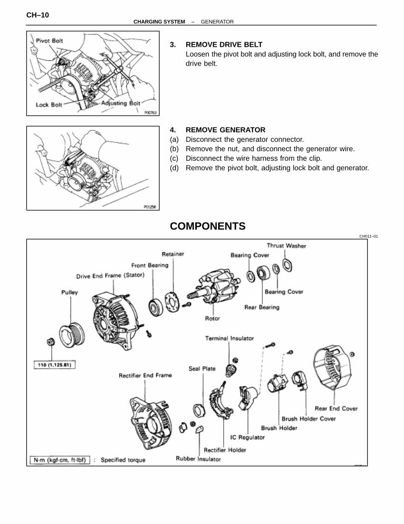
3. REMOVE DRIVE BELTLoosen the pivot bolt and adjusting lock bolt, and remove thedrive belt.
4. REMOVE GENERATOR(a) Disconnect the generator connector.(b) Remove the nut, and disconnect the generator wire.(c) Disconnect the wire harness from the clip.(d) Remove the pivot bolt, adjusting lock bolt and generator.
COMPONENTSCH011–01
CH–10–CHARGING SYSTEM GENERATOR
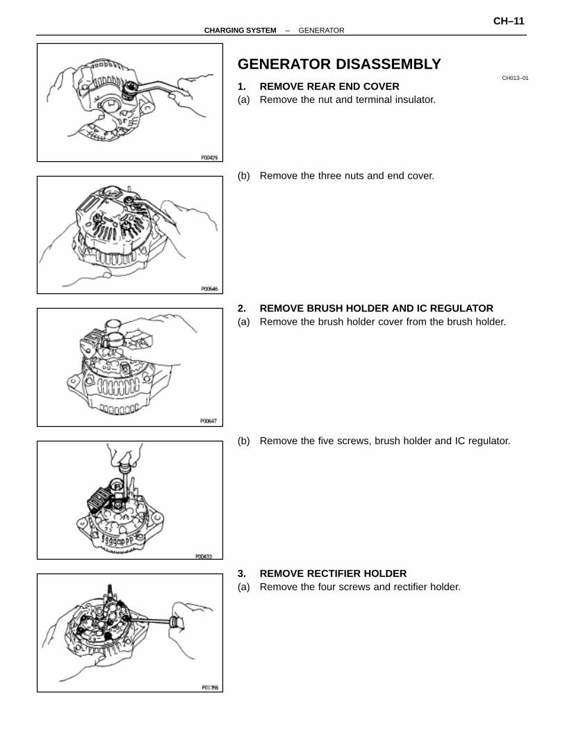
GENERATOR DISASSEMBLYCH013–01
1. REMOVE REAR END COVER(a) Remove the nut and terminal insulator.
(b) Remove the three nuts and end cover.
2. REMOVE BRUSH HOLDER AND IC REGULATOR(a) Remove the brush holder cover from the brush holder.
(b) Remove the five screws, brush holder and IC regulator.
3. REMOVE RECTIFIER HOLDER(a) Remove the four screws and rectifier holder.
–CHARGING SYSTEM GENERATORCH–11

(b) Remove the four rubber insulators.
(c) Remove the seal plate.
4. REMOVE PULLEY(a) Hold SST (a) with a torque wrench, and tighten SST (B)
clockwise to the specified torque.SST 09820–63010Torque: 39 N ⋅m (400 kgf ⋅cm, 29 ft ⋅lbf)
(b) Check that SST (A) is secured to the rotor shaft.
(c) As shown in the illustration, mount SST (c) in a vise, and install the generator to SST (C).
(d) To loosen the pulley nut, turn SST (A) in the direction shownin the illustration.NOTICE: To prevent damage to the rotor shaft, do notloosen the pulley nut more than one–half of a turn.
(e) Remove the generator from SST (C).(f) Turn SST (B) and remove SST (A and B).(g) Remove the pulley nut and pulley.
5. REMOVE RECTIFIER END FRAME(a) Remove the four nuts and cord clip.
CH–12–CHARGING SYSTEM GENERATOR

(b) Using SST, remove the rectifier end frame.SST 09286–46011
(c) Remove the thrust washer.
6. REMOVE ROTOR FROM DRIVE END FRAME
GENERATOR INSPECTION AND REPAIRCH015–01
Rotor1. INSPECT ROTOR FOR OPEN CIRCUIT
Using an ohmmeter, check that there is continuity betweenthe slip rings.Standard resistance (Cold):
2.8–3.0 �
If there is no continuity, replace the rotor.
2. INSPECT ROTOR FOR GROUNDUsing an ohmmeter, check that there is no continuity be-tween the slip ring and rotor.If there is continuity, replace the rotor.
–CHARGING SYSTEM GENERATORCH–13
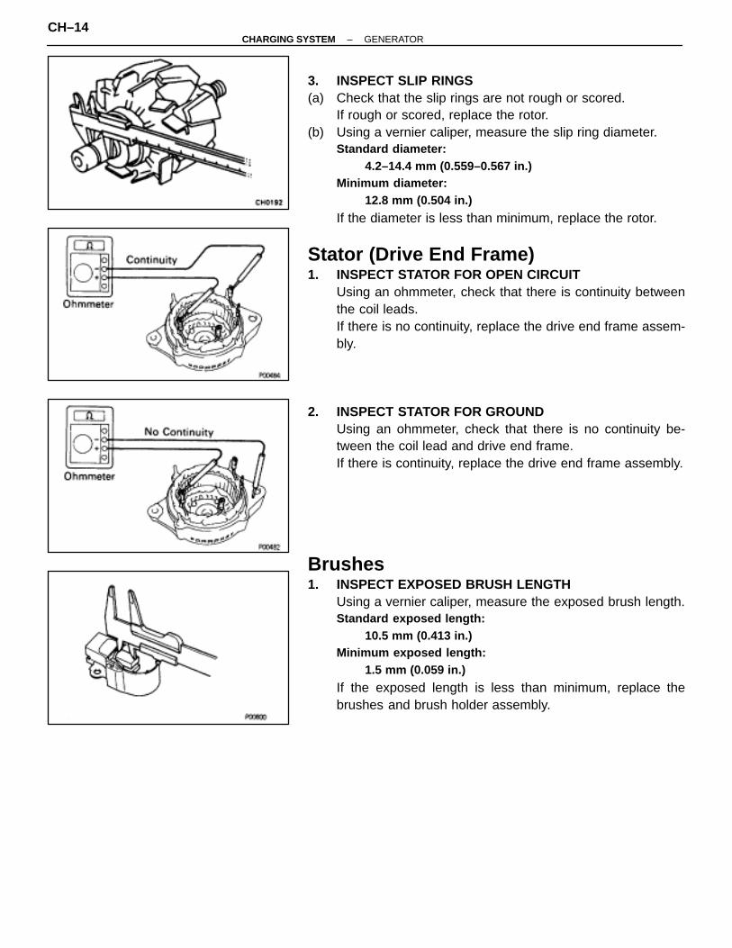
3. INSPECT SLIP RINGS(a) Check that the slip rings are not rough or scored.
If rough or scored, replace the rotor.(b) Using a vernier caliper, measure the slip ring diameter.
Standard diameter:4.2–14.4 mm (0.559–0.567 in.)
Minimum diameter:12.8 mm (0.504 in.)
If the diameter is less than minimum, replace the rotor.
Stator (Drive End Frame)1. INSPECT STATOR FOR OPEN CIRCUIT
Using an ohmmeter, check that there is continuity betweenthe coil leads.If there is no continuity, replace the drive end frame assem-bly.
2. INSPECT STATOR FOR GROUNDUsing an ohmmeter, check that there is no continuity be-tween the coil lead and drive end frame.If there is continuity, replace the drive end frame assembly.
Brushes1. INSPECT EXPOSED BRUSH LENGTH
Using a vernier caliper, measure the exposed brush length.Standard exposed length:
10.5 mm (0.413 in.)Minimum exposed length:
1.5 mm (0.059 in.)
If the exposed length is less than minimum, replace thebrushes and brush holder assembly.
CH–14–CHARGING SYSTEM GENERATOR
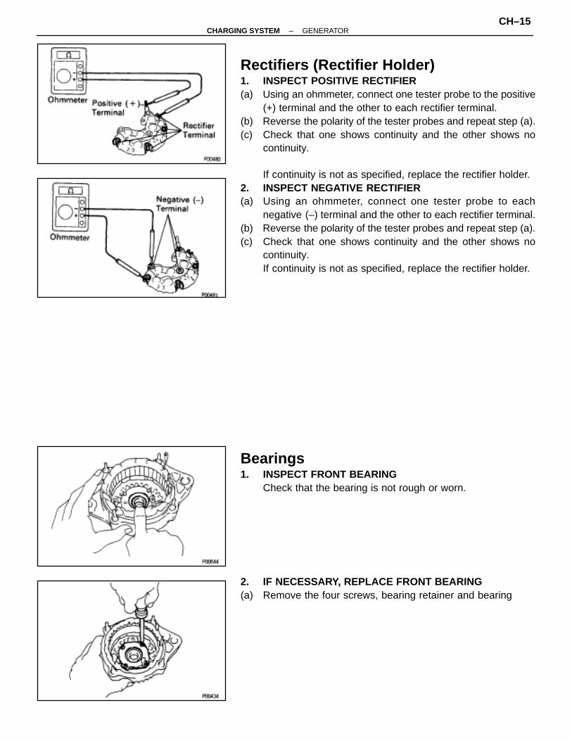
Rectifiers (Rectifier Holder)1. INSPECT POSITIVE RECTIFIER(a) Using an ohmmeter, connect one tester probe to the positive
(+) terminal and the other to each rectifier terminal.(b) Reverse the polarity of the tester probes and repeat step (a).(c) Check that one shows continuity and the other shows no
continuity.
If continuity is not as specified, replace the rectifier holder.2. INSPECT NEGATIVE RECTIFIER(a) Using an ohmmeter, connect one tester probe to each
negative (–) terminal and the other to each rectifier terminal.(b) Reverse the polarity of the tester probes and repeat step (a).(c) Check that one shows continuity and the other shows no
continuity.If continuity is not as specified, replace the rectifier holder.
Bearings1. INSPECT FRONT BEARING
Check that the bearing is not rough or worn.
2. IF NECESSARY, REPLACE FRONT BEARING(a) Remove the four screws, bearing retainer and bearing
–CHARGING SYSTEM GENERATORCH–15
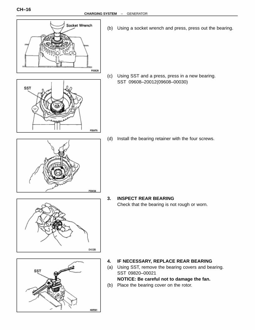
(b) Using a socket wrench and press, press out the bearing.
(c) Using SST and a press, press in a new bearing.SST 09608–20012(09608–00030)
(d) Install the bearing retainer with the four screws.
3. INSPECT REAR BEARINGCheck that the bearing is not rough or worn.
4. IF NECESSARY, REPLACE REAR BEARING(a) Using SST, remove the bearing covers and bearing.
SST 09820–00021NOTICE: Be careful not to damage the fan.
(b) Place the bearing cover on the rotor.
CH–16–CHARGING SYSTEM GENERATOR
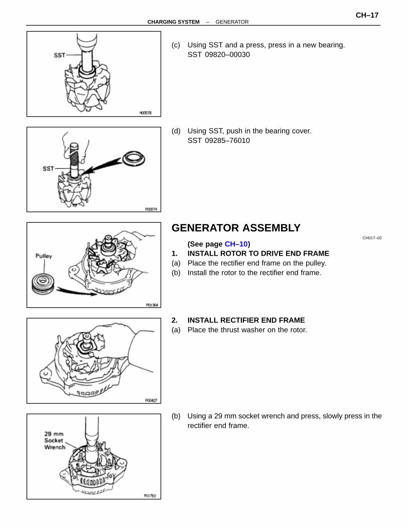
(c) Using SST and a press, press in a new bearing.SST 09820–00030
(d) Using SST, push in the bearing cover.SST 09285–76010
GENERATOR ASSEMBLYCH017–02
(See page CH–10)1. INSTALL ROTOR TO DRIVE END FRAME(a) Place the rectifier end frame on the pulley.(b) Install the rotor to the rectifier end frame.
2. INSTALL RECTIFIER END FRAME(a) Place the thrust washer on the rotor.
(b) Using a 29 mm socket wrench and press, slowly press in therectifier end frame.
–CHARGING SYSTEM GENERATORCH–17
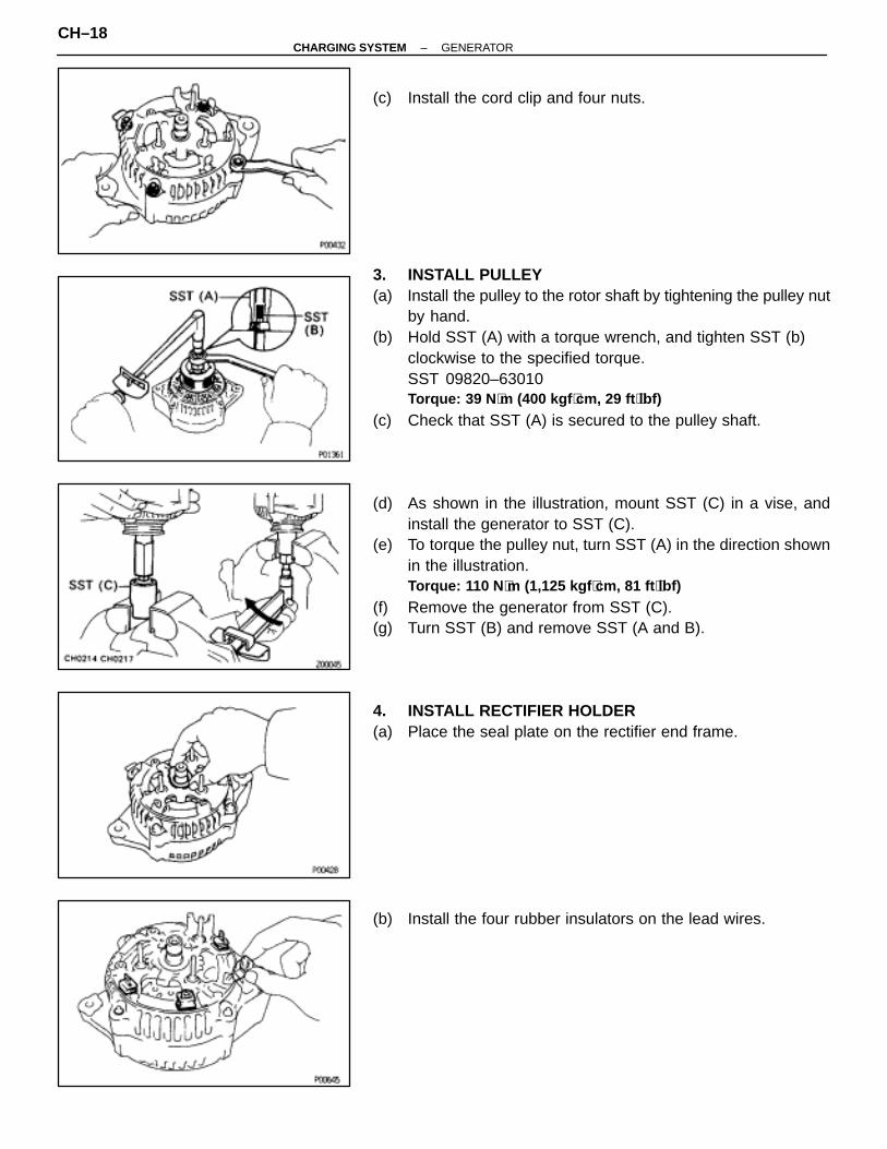
(c) Install the cord clip and four nuts.
3. INSTALL PULLEY(a) Install the pulley to the rotor shaft by tightening the pulley nut
by hand.(b) Hold SST (A) with a torque wrench, and tighten SST (b)
clockwise to the specified torque.SST 09820–63010Torque: 39 N ⋅m (400 kgf ⋅cm, 29 ft ⋅lbf)
(c) Check that SST (A) is secured to the pulley shaft.
(d) As shown in the illustration, mount SST (C) in a vise, andinstall the generator to SST (C).
(e) To torque the pulley nut, turn SST (A) in the direction shownin the illustration.Torque: 110 N ⋅m (1,125 kgf ⋅cm, 81 ft ⋅lbf)
(f) Remove the generator from SST (C).(g) Turn SST (B) and remove SST (A and B).
4. INSTALL RECTIFIER HOLDER(a) Place the seal plate on the rectifier end frame.
(b) Install the four rubber insulators on the lead wires.
CH–18–CHARGING SYSTEM GENERATOR

(c) Install the rectifier holder with the four screws.
5. INSTALL IC REGULATOR AND BRUSH HOLDER(a) Place the IC regulator and brush holder on the rectifier end
frame.NOTICE: Be careful of the holder installation direction.
(b) Install the five screws until there is a clearance of approx. 1mm (0.04 in.) between the brush holder and connector.
(c) Place the brush holder cover on the brush holder.
6. INSTALL REAR END COVER(a) Install the end cover with the three nuts.
(b) Install the terminal insulator with the nut.
–CHARGING SYSTEM GENERATORCH–19

7. CHECK THAT ROTOR ROTATES SMOOTHLY
GENERATOR INSTALLATIONCH019–02
(See page CH–9)1. INSTALL GENERATOR(a) Mount generator on the generator bracket with the pivot bolt
and adjusting lock bolt. Do not tighten the bolts yet.(b) Connect the generator connector.(c) Connect the generator wire with the nut.
2. INSTALL DRIVE BELT(a) Install the drive belt.(b) Using a belt tension gauge, measure the drive belt tension.
Belt tension gauge:Nippondenso BTG–20 (95506–00020)Borroughs No. BT–33–73F
Drive belt tension:New belt
175±5 lb
Used belt115±20 lb
(c) Tighten the pivot and adjusting lock bolt.HINT:• “New belt” refers to a belt which has been used less than
5 minutes on a running engine.• “Used belt” refers to a belt which has been used on a
running engine for 5 minutes or more.• After installing a belt, check that it fits properly in the
ribbed grooves.• Check by hand to confirm that the belt has not slipped
out of the groove on the bottom of the pulley.• After installing a new belt, run the engine for about 5
minutes and recheck the belt tension.
CH–20–CHARGING SYSTEM GENERATOR
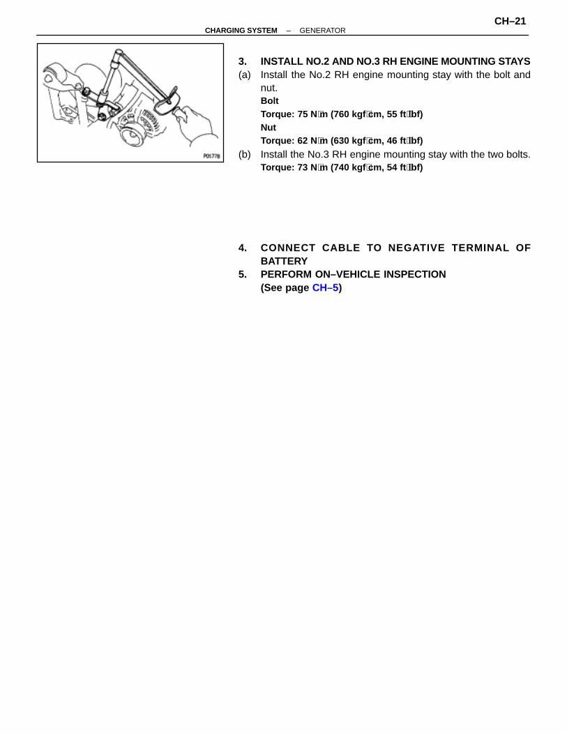
3. INSTALL NO.2 AND NO.3 RH ENGINE MOUNTING STAYS(a) Install the No.2 RH engine mounting stay with the bolt and
nut.BoltTorque: 75 N ⋅m (760 kgf ⋅cm, 55 ft ⋅lbf)NutTorque: 62 N ⋅m (630 kgf ⋅cm, 46 ft ⋅lbf)
(b) Install the No.3 RH engine mounting stay with the two bolts.Torque: 73 N ⋅m (740 kgf ⋅cm, 54 ft ⋅lbf)
4. CONNECT CABLE TO NEGATIVE TERMINAL OFBATTERY
5. PERFORM ON–VEHICLE INSPECTION(See page CH–5)
–CHARGING SYSTEM GENERATORCH–21
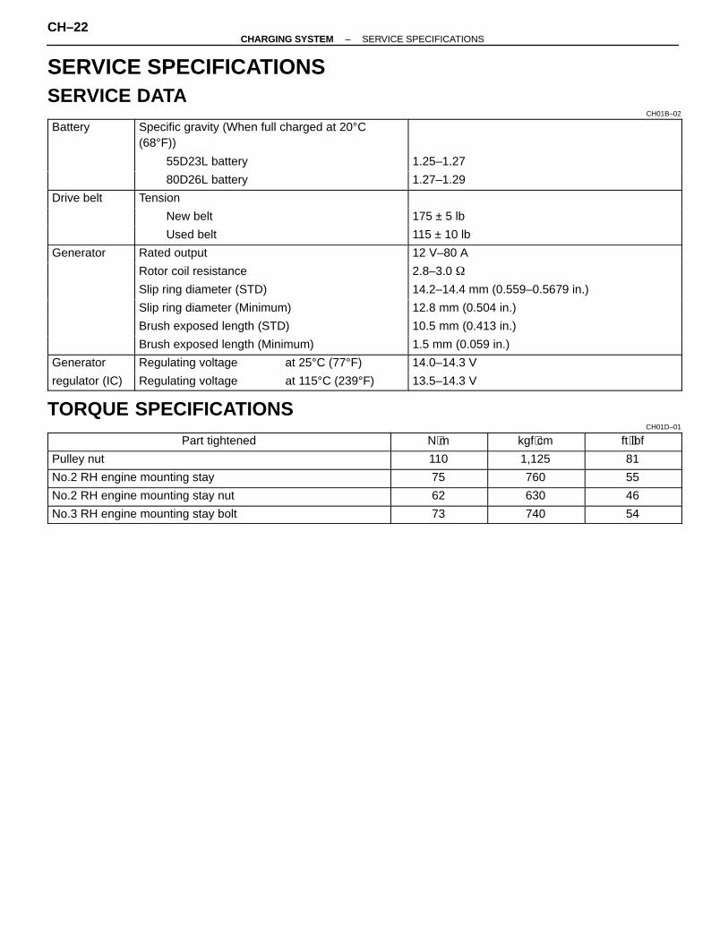
SERVICE SPECIFICATIONSSERVICE DATA
CH01B–02
ÑÑÑÑÑÑÑÑÑÑÑÑÑÑÑÑÑÑ
Battery ÑÑÑÑÑÑÑÑÑÑÑÑÑÑÑÑÑÑÑÑÑÑÑÑÑÑÑÑÑÑÑÑÑÑÑÑÑÑÑÑÑÑÑÑÑÑÑÑ
Specific gravity (When full charged at 20°C(68°F))
ÑÑÑÑÑÑÑÑÑÑÑÑÑÑÑÑÑÑÑÑÑÑÑÑÑÑÑÑÑÑÑÑÑÑÑÑÑÑÑÑÑÑÑÑÑÑÑÑÑÑÑÑÑÑ
ÑÑÑÑÑÑÑÑÑÑÑÑÑÑÑÑÑÑÑÑÑÑÑÑÑÑÑÑÑÑÑÑÑÑÑÑÑÑ
55D23L battery ÑÑÑÑÑÑÑÑÑÑÑÑÑÑÑÑÑÑÑÑÑÑÑÑÑÑÑÑÑÑÑÑ
1.25–1.27
ÑÑÑÑÑÑÑÑÑÑÑÑ
ÑÑÑÑÑÑÑÑÑÑÑÑÑÑÑÑÑÑÑÑÑÑÑÑÑÑÑÑÑÑÑÑ
80D26L battery ÑÑÑÑÑÑÑÑÑÑÑÑÑÑÑÑÑÑÑÑÑÑÑÑÑÑÑÑÑÑÑÑ
1.27–1.29
ÑÑÑÑÑÑÑÑÑÑÑÑ
Drive belt ÑÑÑÑÑÑÑÑÑÑÑÑÑÑÑÑÑÑÑÑÑÑÑÑÑÑÑÑÑÑÑÑ
Tension ÑÑÑÑÑÑÑÑÑÑÑÑÑÑÑÑÑÑÑÑÑÑÑÑÑÑÑÑÑÑÑÑÑÑÑÑÑÑ
ÑÑÑÑÑÑÑÑÑÑÑÑÑÑÑÑÑÑÑÑÑÑÑÑÑÑÑÑÑÑÑÑÑÑÑÑÑÑ
New belt ÑÑÑÑÑÑÑÑÑÑÑÑÑÑÑÑÑÑÑÑÑÑÑÑÑÑÑÑÑÑÑÑ
175 ± 5 lb
ÑÑÑÑÑÑÑÑÑÑÑÑ
ÑÑÑÑÑÑÑÑÑÑÑÑÑÑÑÑÑÑÑÑÑÑÑÑÑÑÑÑÑÑÑÑ
Used belt ÑÑÑÑÑÑÑÑÑÑÑÑÑÑÑÑÑÑÑÑÑÑÑÑÑÑÑÑÑÑÑÑ
115 ± 10 lb
ÑÑÑÑÑÑÑÑÑÑÑÑ
Generator ÑÑÑÑÑÑÑÑÑÑÑÑÑÑÑÑÑÑÑÑÑÑÑÑÑÑÑÑÑÑÑÑ
Rated output ÑÑÑÑÑÑÑÑÑÑÑÑÑÑÑÑÑÑÑÑÑÑÑÑÑÑÑÑÑÑÑÑ
12 V–80 A
ÑÑÑÑÑÑÑÑÑÑÑÑ
ÑÑÑÑÑÑÑÑÑÑÑÑÑÑÑÑÑÑÑÑÑÑÑÑÑÑÑÑÑÑÑÑ
Rotor coil resistance ÑÑÑÑÑÑÑÑÑÑÑÑÑÑÑÑÑÑÑÑÑÑÑÑÑÑÑÑÑÑÑÑ
2.8–3.0 �
ÑÑÑÑÑÑÑÑÑÑÑÑ
ÑÑÑÑÑÑÑÑÑÑÑÑÑÑÑÑÑÑÑÑÑÑÑÑÑÑÑÑÑÑÑÑ
Slip ring diameter (STD) ÑÑÑÑÑÑÑÑÑÑÑÑÑÑÑÑÑÑÑÑÑÑÑÑÑÑÑÑÑÑÑÑ
14.2–14.4 mm (0.559–0.5679 in.)
ÑÑÑÑÑÑÑÑÑÑÑÑ
ÑÑÑÑÑÑÑÑÑÑÑÑÑÑÑÑÑÑÑÑÑÑÑÑÑÑÑÑÑÑÑÑ
Slip ring diameter (Minimum) ÑÑÑÑÑÑÑÑÑÑÑÑÑÑÑÑÑÑÑÑÑÑÑÑÑÑÑÑÑÑÑÑ
12.8 mm (0.504 in.)
ÑÑÑÑÑÑÑÑÑÑÑÑ
ÑÑÑÑÑÑÑÑÑÑÑÑÑÑÑÑÑÑÑÑÑÑÑÑÑÑÑÑÑÑÑÑ
Brush exposed length (STD) ÑÑÑÑÑÑÑÑÑÑÑÑÑÑÑÑÑÑÑÑÑÑÑÑÑÑÑÑÑÑÑÑ
10.5 mm (0.413 in.)
ÑÑÑÑÑÑÑÑÑÑÑÑ
ÑÑÑÑÑÑÑÑÑÑÑÑÑÑÑÑÑÑÑÑÑÑÑÑÑÑÑÑÑÑÑÑ
Brush exposed length (Minimum) ÑÑÑÑÑÑÑÑÑÑÑÑÑÑÑÑÑÑÑÑÑÑÑÑÑÑÑÑÑÑÑÑ
1.5 mm (0.059 in.)
ÑÑÑÑÑÑÑÑÑÑÑÑ
Generator ÑÑÑÑÑÑÑÑÑÑÑÑÑÑÑÑÑÑÑÑÑÑÑÑÑÑÑÑÑÑÑÑ
Regulating voltage at 25°C (77°F) ÑÑÑÑÑÑÑÑÑÑÑÑÑÑÑÑÑÑÑÑÑÑÑÑÑÑÑÑÑÑÑÑ
14.0–14.3 V
ÑÑÑÑÑÑÑÑÑÑÑÑ
regulator (IC) ÑÑÑÑÑÑÑÑÑÑÑÑÑÑÑÑÑÑÑÑÑÑÑÑÑÑÑÑÑÑÑÑ
Regulating voltage at 115°C (239°F) ÑÑÑÑÑÑÑÑÑÑÑÑÑÑÑÑÑÑÑÑÑÑÑÑÑÑÑÑÑÑÑÑ
13.5–14.3 V
TORQUE SPECIFICATIONSCH01D–01
ÑÑÑÑÑÑÑÑÑÑÑÑÑÑÑÑÑÑÑÑÑÑÑÑÑÑÑÑÑÑÑÑÑÑÑÑÑÑÑÑ
Part tightened ÑÑÑÑÑÑÑÑÑÑÑÑ
N⋅m ÑÑÑÑÑÑÑÑÑÑÑÑ
kgf⋅cm ÑÑÑÑÑÑÑÑÑÑÑÑÑÑ
ft⋅lbfÑÑÑÑÑÑÑÑÑÑÑÑÑÑÑÑÑÑÑÑÑÑÑÑÑÑÑÑÑÑÑÑÑÑÑÑÑÑÑÑ
Pulley nut ÑÑÑÑÑÑÑÑÑÑÑÑ
110 ÑÑÑÑÑÑÑÑÑÑÑÑ
1,125 ÑÑÑÑÑÑÑÑÑÑÑÑÑÑ
81ÑÑÑÑÑÑÑÑÑÑÑÑÑÑÑÑÑÑÑÑÑÑÑÑÑÑÑÑÑÑÑÑÑÑÑÑÑÑÑÑ
No.2 RH engine mounting stay ÑÑÑÑÑÑÑÑÑÑÑÑ
75 ÑÑÑÑÑÑÑÑÑÑÑÑ
760 ÑÑÑÑÑÑÑÑÑÑÑÑÑÑ
55ÑÑÑÑÑÑÑÑÑÑÑÑÑÑÑÑÑÑÑÑÑÑÑÑÑÑÑÑÑÑÑÑÑÑÑÑÑÑÑÑ
No.2 RH engine mounting stay nut ÑÑÑÑÑÑÑÑÑÑÑÑ
62 ÑÑÑÑÑÑÑÑÑÑÑÑ
630 ÑÑÑÑÑÑÑÑÑÑÑÑÑÑ
46ÑÑÑÑÑÑÑÑÑÑÑÑÑÑÑÑÑÑÑÑÑÑÑÑÑÑÑÑÑÑÑÑÑÑÑÑÑÑÑÑ
No.3 RH engine mounting stay bolt ÑÑÑÑÑÑÑÑÑÑÑÑ
73 ÑÑÑÑÑÑÑÑÑÑÑÑ
740 ÑÑÑÑÑÑÑÑÑÑÑÑÑÑ
54
CH–22–CHARGING SYSTEM SERVICE SPECIFICATIONS