engine - angel marine
TRANSCRIPT
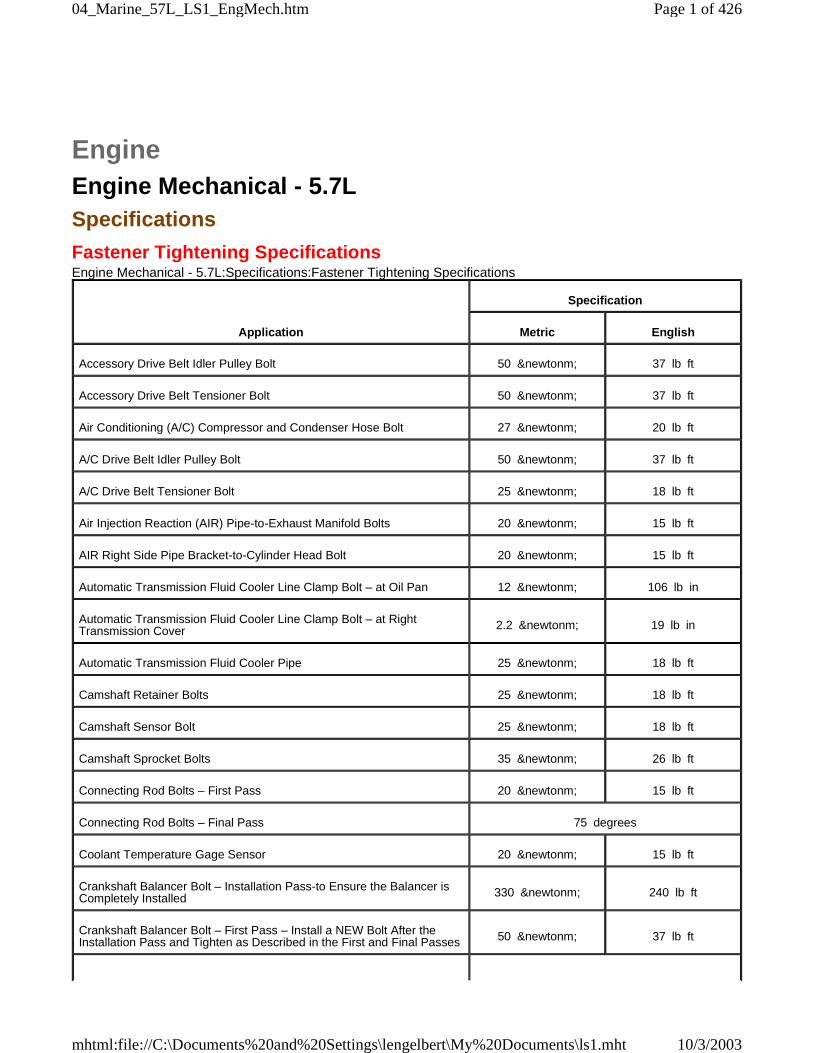
EngineEngine Mechanical - 5.7LSpecifications
Fastener Tightening SpecificationsEngine Mechanical - 5.7L:Specifications:Fastener Tightening Specifications
Application
Specification
Metric English
Accessory Drive Belt Idler Pulley Bolt 50 &newtonm; 37 lb ft
Accessory Drive Belt Tensioner Bolt 50 &newtonm; 37 lb ft
Air Conditioning (A/C) Compressor and Condenser Hose Bolt 27 &newtonm; 20 lb ft
A/C Drive Belt Idler Pulley Bolt 50 &newtonm; 37 lb ft
A/C Drive Belt Tensioner Bolt 25 &newtonm; 18 lb ft
Air Injection Reaction (AIR) Pipe-to-Exhaust Manifold Bolts 20 &newtonm; 15 lb ft
AIR Right Side Pipe Bracket-to-Cylinder Head Bolt 20 &newtonm; 15 lb ft
Automatic Transmission Fluid Cooler Line Clamp Bolt – at Oil Pan 12 &newtonm; 106 lb in
Automatic Transmission Fluid Cooler Line Clamp Bolt – at RightTransmission Cover 2.2 &newtonm; 19 lb in
Automatic Transmission Fluid Cooler Pipe 25 &newtonm; 18 lb ft
Camshaft Retainer Bolts 25 &newtonm; 18 lb ft
Camshaft Sensor Bolt 25 &newtonm; 18 lb ft
Camshaft Sprocket Bolts 35 &newtonm; 26 lb ft
Connecting Rod Bolts – First Pass 20 &newtonm; 15 lb ft
Connecting Rod Bolts – Final Pass 75 degrees
Coolant Temperature Gage Sensor 20 &newtonm; 15 lb ft
Crankshaft Balancer Bolt – Installation Pass-to Ensure the Balancer isCompletely Installed 330 &newtonm; 240 lb ft
Crankshaft Balancer Bolt – First Pass – Install a NEW Bolt After theInstallation Pass and Tighten as Described in the First and Final Passes 50 &newtonm; 37 lb ft
Page 1 of 42604_Marine_57L_LS1_EngMech.htm
10/3/2003mhtml:file://C:\Documents%20and%20Settings\lengelbert\My%20Documents\ls1.mht
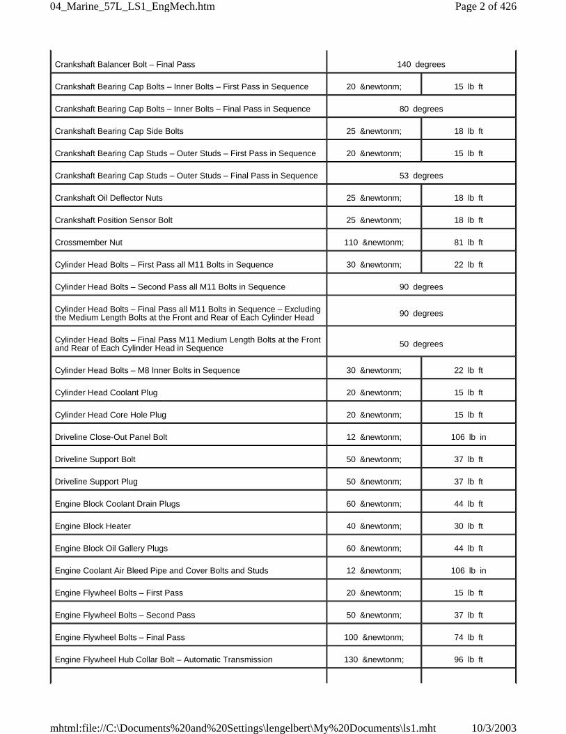
Crankshaft Balancer Bolt – Final Pass 140 degrees
Crankshaft Bearing Cap Bolts – Inner Bolts – First Pass in Sequence 20 &newtonm; 15 lb ft
Crankshaft Bearing Cap Bolts – Inner Bolts – Final Pass in Sequence 80 degrees
Crankshaft Bearing Cap Side Bolts 25 &newtonm; 18 lb ft
Crankshaft Bearing Cap Studs – Outer Studs – First Pass in Sequence 20 &newtonm; 15 lb ft
Crankshaft Bearing Cap Studs – Outer Studs – Final Pass in Sequence 53 degrees
Crankshaft Oil Deflector Nuts 25 &newtonm; 18 lb ft
Crankshaft Position Sensor Bolt 25 &newtonm; 18 lb ft
Crossmember Nut 110 &newtonm; 81 lb ft
Cylinder Head Bolts – First Pass all M11 Bolts in Sequence 30 &newtonm; 22 lb ft
Cylinder Head Bolts – Second Pass all M11 Bolts in Sequence 90 degrees
Cylinder Head Bolts – Final Pass all M11 Bolts in Sequence – Excludingthe Medium Length Bolts at the Front and Rear of Each Cylinder Head 90 degrees
Cylinder Head Bolts – Final Pass M11 Medium Length Bolts at the Frontand Rear of Each Cylinder Head in Sequence 50 degrees
Cylinder Head Bolts – M8 Inner Bolts in Sequence 30 &newtonm; 22 lb ft
Cylinder Head Coolant Plug 20 &newtonm; 15 lb ft
Cylinder Head Core Hole Plug 20 &newtonm; 15 lb ft
Driveline Close-Out Panel Bolt 12 &newtonm; 106 lb in
Driveline Support Bolt 50 &newtonm; 37 lb ft
Driveline Support Plug 50 &newtonm; 37 lb ft
Engine Block Coolant Drain Plugs 60 &newtonm; 44 lb ft
Engine Block Heater 40 &newtonm; 30 lb ft
Engine Block Oil Gallery Plugs 60 &newtonm; 44 lb ft
Engine Coolant Air Bleed Pipe and Cover Bolts and Studs 12 &newtonm; 106 lb in
Engine Flywheel Bolts – First Pass 20 &newtonm; 15 lb ft
Engine Flywheel Bolts – Second Pass 50 &newtonm; 37 lb ft
Engine Flywheel Bolts – Final Pass 100 &newtonm; 74 lb ft
Engine Flywheel Hub Collar Bolt – Automatic Transmission 130 &newtonm; 96 lb ft
Page 2 of 42604_Marine_57L_LS1_EngMech.htm
10/3/2003mhtml:file://C:\Documents%20and%20Settings\lengelbert\My%20Documents\ls1.mht
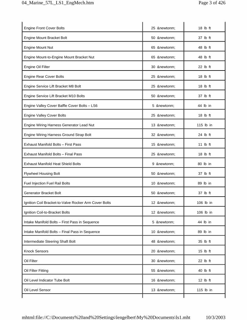
Engine Front Cover Bolts 25 &newtonm; 18 lb ft
Engine Mount Bracket Bolt 50 &newtonm; 37 lb ft
Engine Mount Nut 65 &newtonm; 48 lb ft
Engine Mount-to-Engine Mount Bracket Nut 65 &newtonm; 48 lb ft
Engine Oil Filter 30 &newtonm; 22 lb ft
Engine Rear Cover Bolts 25 &newtonm; 18 lb ft
Engine Service Lift Bracket M8 Bolt 25 &newtonm; 18 lb ft
Engine Service Lift Bracket M10 Bolts 50 &newtonm; 37 lb ft
Engine Valley Cover Baffle Cover Bolts – LS6 5 &newtonm; 44 lb in
Engine Valley Cover Bolts 25 &newtonm; 18 lb ft
Engine Wiring Harness Generator Lead Nut 13 &newtonm; 115 lb in
Engine Wiring Harness Ground Strap Bolt 32 &newtonm; 24 lb ft
Exhaust Manifold Bolts – First Pass 15 &newtonm; 11 lb ft
Exhaust Manifold Bolts – Final Pass 25 &newtonm; 18 lb ft
Exhaust Manifold Heat Shield Bolts 9 &newtonm; 80 lb in
Flywheel Housing Bolt 50 &newtonm; 37 lb ft
Fuel Injection Fuel Rail Bolts 10 &newtonm; 89 lb in
Generator Bracket Bolt 50 &newtonm; 37 lb ft
Ignition Coil Bracket-to-Valve Rocker Arm Cover Bolts 12 &newtonm; 106 lb in
Ignition Coil-to-Bracket Bolts 12 &newtonm; 106 lb in
Intake Manifold Bolts – First Pass in Sequence 5 &newtonm; 44 lb in
Intake Manifold Bolts – Final Pass in Sequence 10 &newtonm; 89 lb in
Intermediate Steering Shaft Bolt 48 &newtonm; 35 lb ft
Knock Sensors 20 &newtonm; 15 lb ft
Oil Filter 30 &newtonm; 22 lb ft
Oil Filter Fitting 55 &newtonm; 40 lb ft
Oil Level Indicator Tube Bolt 16 &newtonm; 12 lb ft
Oil Level Sensor 13 &newtonm; 115 lb in
Page 3 of 42604_Marine_57L_LS1_EngMech.htm
10/3/2003mhtml:file://C:\Documents%20and%20Settings\lengelbert\My%20Documents\ls1.mht
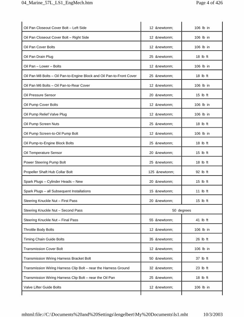
Oil Pan Closeout Cover Bolt – Left Side 12 &newtonm; 106 lb in
Oil Pan Closeout Cover Bolt – Right Side 12 &newtonm; 106 lb in
Oil Pan Cover Bolts 12 &newtonm; 106 lb in
Oil Pan Drain Plug 25 &newtonm; 18 lb ft
Oil Pan – Lower – Bolts 12 &newtonm; 106 lb in
Oil Pan M8 Bolts – Oil Pan-to-Engine Block and Oil Pan-to-Front Cover 25 &newtonm; 18 lb ft
Oil Pan M6 Bolts – Oil Pan-to-Rear Cover 12 &newtonm; 106 lb in
Oil Pressure Sensor 20 &newtonm; 15 lb ft
Oil Pump Cover Bolts 12 &newtonm; 106 lb in
Oil Pump Relief Valve Plug 12 &newtonm; 106 lb in
Oil Pump Screen Nuts 25 &newtonm; 18 lb ft
Oil Pump Screen-to-Oil Pump Bolt 12 &newtonm; 106 lb in
Oil Pump-to-Engine Block Bolts 25 &newtonm; 18 lb ft
Oil Temperature Sensor 20 &newtonm; 15 lb ft
Power Steering Pump Bolt 25 &newtonm; 18 lb ft
Propeller Shaft Hub Collar Bolt 125 &newtonm; 92 lb ft
Spark Plugs – Cylinder Heads – New 20 &newtonm; 15 lb ft
Spark Plugs – all Subsequent Installations 15 &newtonm; 11 lb ft
Steering Knuckle Nut – First Pass 20 &newtonm; 15 lb ft
Steering Knuckle Nut – Second Pass 50 degrees
Steering Knuckle Nut – Final Pass 55 &newtonm; 41 lb ft
Throttle Body Bolts 12 &newtonm; 106 lb in
Timing Chain Guide Bolts 35 &newtonm; 26 lb ft
Transmission Cover Bolt 12 &newtonm; 106 lb in
Transmission Wiring Harness Bracket Bolt 50 &newtonm; 37 lb ft
Transmission Wiring Harness Clip Bolt – near the Harness Ground 32 &newtonm; 23 lb ft
Transmission Wiring Harness Clip Bolt – near the Oil Pan 25 &newtonm; 18 lb ft
Valve Lifter Guide Bolts 12 &newtonm; 106 lb in
Page 4 of 42604_Marine_57L_LS1_EngMech.htm
10/3/2003mhtml:file://C:\Documents%20and%20Settings\lengelbert\My%20Documents\ls1.mht
Specifications
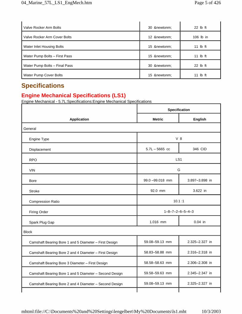
Engine Mechanical Specifications (LS1)Engine Mechanical - 5.7L:Specifications:Engine Mechanical Specifications
Valve Rocker Arm Bolts 30 &newtonm; 22 lb ft
Valve Rocker Arm Cover Bolts 12 &newtonm; 106 lb in
Water Inlet Housing Bolts 15 &newtonm; 11 lb ft
Water Pump Bolts – First Pass 15 &newtonm; 11 lb ft
Water Pump Bolts – Final Pass 30 &newtonm; 22 lb ft
Water Pump Cover Bolts 15 &newtonm; 11 lb ft
Application
Specification
Metric English
General
Engine Type V 8
Displacement 5.7L – 5665 cc 346 CID
RPO LS1
VIN G
Bore 99.0 –99.018 mm 3.897–3.898 in
Stroke 92.0 mm 3.622 in
Compression Ratio 10.1 :1
Firing Order 1–8–7–2–6–5–4–3
Spark Plug Gap 1.016 mm 0.04 in
Block
Camshaft Bearing Bore 1 and 5 Diameter – First Design 59.08–59.13 mm 2.325–2.327 in
Camshaft Bearing Bore 2 and 4 Diameter – First Design 58.83–58.88 mm 2.316–2.318 in
Camshaft Bearing Bore 3 Diameter – First Design 58.58–58.63 mm 2.306–2.308 in
Camshaft Bearing Bore 1 and 5 Diameter – Second Design 59.58–59.63 mm 2.345–2.347 in
Camshaft Bearing Bore 2 and 4 Diameter – Second Design 59.08–59.13 mm 2.325–2.327 in
Page 5 of 42604_Marine_57L_LS1_EngMech.htm
10/3/2003mhtml:file://C:\Documents%20and%20Settings\lengelbert\My%20Documents\ls1.mht
Camshaft Bearing Bore 3 Diameter – Second Design 58.58–58.63 mm 2.306–2.308 in
Crankshaft Main Bearing Bore Diameter 69.871–69.889 mm 2.75–2.751 in
Crankshaft Main Bearing Bore Out-of-Round 0.005 mm 0.0002 in
Cylinder Bore Diameter 99.0–99.018 mm 3.897–3.898 in
Cylinder Bore Taper – Thrust Side 0.018 mm 0.0007 in
Cylinder Head Deck Height – Measuring from the Centerline ofCrankshaft to the Deck Face
234.57–234.82 mm 9.235–9.245 in
Cylinder Head Deck Surface Flatness – Measured Within a152.4 mm (6.0 in) Area
0.08 mm 0.003 in
Cylinder Head Deck Surface Flatness – Measuring the OverallLength of the Block Deck
0.22 mm 0.008 in
Valve Lifter Bore Diameter 21.417–21.443 mm 0.843–0.844 in
Camshaft
Camshaft End Play 0.025–0.305 mm 0.001–0.012 in
Camshaft Journal Diameter 54.99–55.04 mm 2.164–2.166 in
Camshaft Journal Out-of-Round 0.025 mm 0.001 in
Camshaft Lobe Lift – Exhaust 7.13 mm 0.281 in
Camshaft Lobe Lift – Intake 6.96 mm 0.274 in
Camshaft Runout – Measured at the Intermediate Journals 0.05 mm 0.002 in
Connecting Rod
Connecting Rod Bearing Clearance – Production 0.023–0.065 mm 0.0009–0.0025 in
Connecting Rod Bearing Clearance – Service 0.023–0.076 mm 0.0009–0.003 in
Connecting Rod Bore Diameter – Bearing End 56.505–56.525 mm 2.224–2.225 in
Connecting Rod Bore Out-of-Round – Bearing End – Production 0.006 mm 0.00023 in
Connecting Rod Bore Out-of-Round – Bearing End – Service 0.006 mm 0.00023 in
Connecting Rod Side Clearance 0.11–0.51 mm 0.00433–0.02 in
Crankshaft
Connecting Rod Journal Diameter – Production 53.318–53.338 mm 2.0991–2.0999 in
Page 6 of 42604_Marine_57L_LS1_EngMech.htm
10/3/2003mhtml:file://C:\Documents%20and%20Settings\lengelbert\My%20Documents\ls1.mht
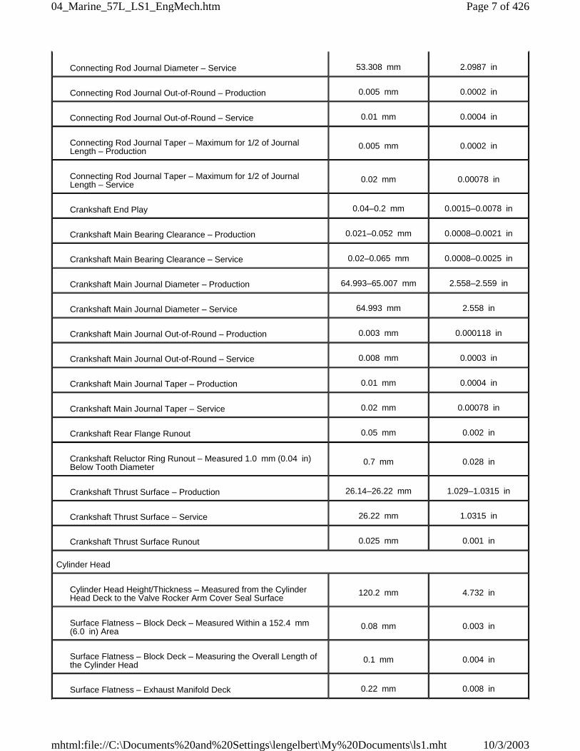
Connecting Rod Journal Diameter – Service 53.308 mm 2.0987 in
Connecting Rod Journal Out-of-Round – Production 0.005 mm 0.0002 in
Connecting Rod Journal Out-of-Round – Service 0.01 mm 0.0004 in
Connecting Rod Journal Taper – Maximum for 1/2 of JournalLength – Production
0.005 mm 0.0002 in
Connecting Rod Journal Taper – Maximum for 1/2 of JournalLength – Service
0.02 mm 0.00078 in
Crankshaft End Play 0.04–0.2 mm 0.0015–0.0078 in
Crankshaft Main Bearing Clearance – Production 0.021–0.052 mm 0.0008–0.0021 in
Crankshaft Main Bearing Clearance – Service 0.02–0.065 mm 0.0008–0.0025 in
Crankshaft Main Journal Diameter – Production 64.993–65.007 mm 2.558–2.559 in
Crankshaft Main Journal Diameter – Service 64.993 mm 2.558 in
Crankshaft Main Journal Out-of-Round – Production 0.003 mm 0.000118 in
Crankshaft Main Journal Out-of-Round – Service 0.008 mm 0.0003 in
Crankshaft Main Journal Taper – Production 0.01 mm 0.0004 in
Crankshaft Main Journal Taper – Service 0.02 mm 0.00078 in
Crankshaft Rear Flange Runout 0.05 mm 0.002 in
Crankshaft Reluctor Ring Runout – Measured 1.0 mm (0.04 in)Below Tooth Diameter
0.7 mm 0.028 in
Crankshaft Thrust Surface – Production 26.14–26.22 mm 1.029–1.0315 in
Crankshaft Thrust Surface – Service 26.22 mm 1.0315 in
Crankshaft Thrust Surface Runout 0.025 mm 0.001 in
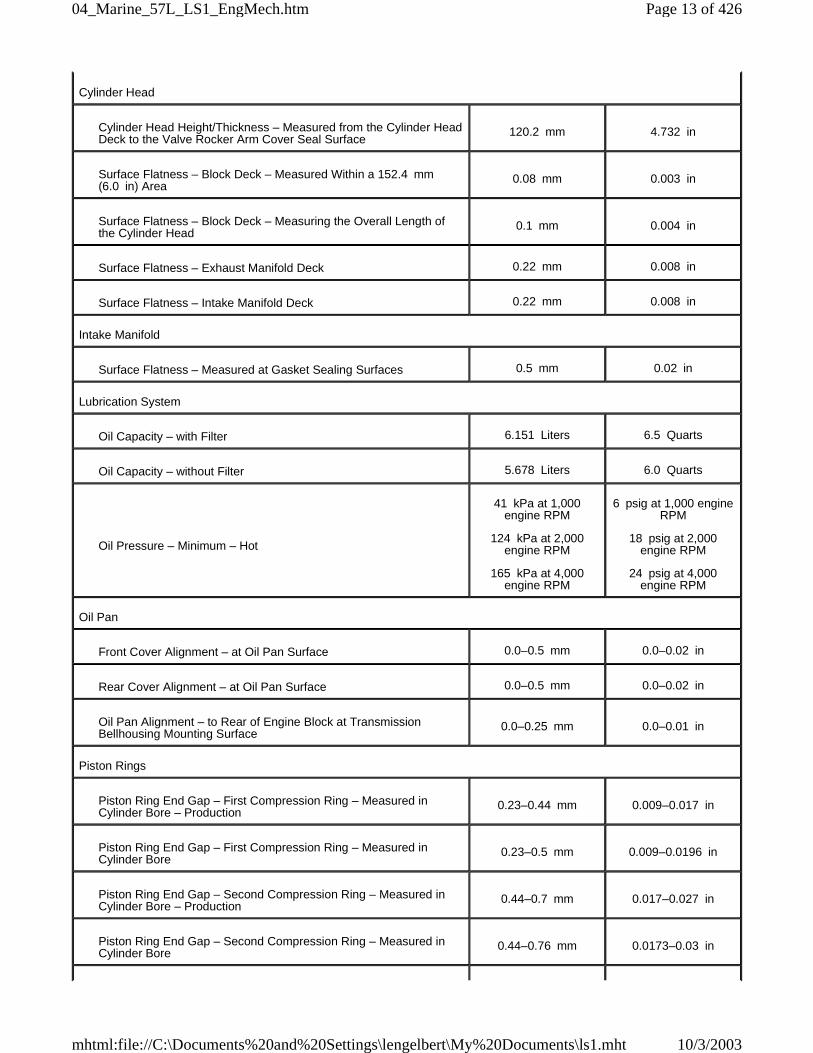
Cylinder Head
Cylinder Head Height/Thickness – Measured from the CylinderHead Deck to the Valve Rocker Arm Cover Seal Surface
120.2 mm 4.732 in
Surface Flatness – Block Deck – Measured Within a 152.4 mm(6.0 in) Area
0.08 mm 0.003 in
Surface Flatness – Block Deck – Measuring the Overall Length ofthe Cylinder Head
0.1 mm 0.004 in
Surface Flatness – Exhaust Manifold Deck 0.22 mm 0.008 in
Page 7 of 42604_Marine_57L_LS1_EngMech.htm
10/3/2003mhtml:file://C:\Documents%20and%20Settings\lengelbert\My%20Documents\ls1.mht
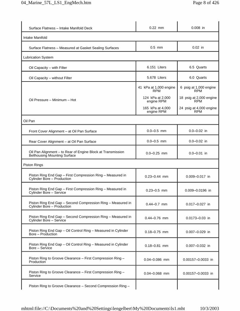
Surface Flatness – Intake Manifold Deck 0.22 mm 0.008 in
Intake Manifold
Surface Flatness – Measured at Gasket Sealing Surfaces 0.5 mm 0.02 in
Lubrication System
Oil Capacity – with Filter 6.151 Liters 6.5 Quarts
Oil Capacity – without Filter 5.678 Liters 6.0 Quarts
Oil Pressure – Minimum – Hot
41 kPa at 1,000 engineRPM
124 kPa at 2,000engine RPM
165 kPa at 4,000engine RPM
6 psig at 1,000 engineRPM
18 psig at 2,000 engineRPM
24 psig at 4,000 engineRPM
Oil Pan
Front Cover Alignment – at Oil Pan Surface 0.0–0.5 mm 0.0–0.02 in
Rear Cover Alignment – at Oil Pan Surface 0.0–0.5 mm 0.0–0.02 in
Oil Pan Alignment – to Rear of Engine Block at TransmissionBellhousing Mounting Surface
0.0–0.25 mm 0.0–0.01 in
Piston Rings
Piston Ring End Gap – First Compression Ring – Measured inCylinder Bore – Production
0.23–0.44 mm 0.009–0.017 in
Piston Ring End Gap – First Compression Ring – Measured inCylinder Bore – Service
0.23–0.5 mm 0.009–0.0196 in
Piston Ring End Gap – Second Compression Ring – Measured inCylinder Bore – Production
0.44–0.7 mm 0.017–0.027 in
Piston Ring End Gap – Second Compression Ring – Measured inCylinder Bore – Service
0.44–0.76 mm 0.0173–0.03 in
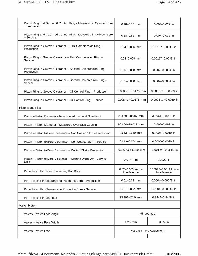
Piston Ring End Gap – Oil Control Ring – Measured in CylinderBore – Production
0.18–0.75 mm 0.007–0.029 in
Piston Ring End Gap – Oil Control Ring – Measured in CylinderBore – Service
0.18–0.81 mm 0.007–0.032 in
Piston Ring to Groove Clearance – First Compression Ring –Production
0.04–0.086 mm 0.00157–0.0033 in
Piston Ring to Groove Clearance – First Compression Ring –Service
0.04–0.068 mm 0.00157–0.0033 in
Piston Ring to Groove Clearance – Second Compression Ring –
Page 8 of 42604_Marine_57L_LS1_EngMech.htm
10/3/2003mhtml:file://C:\Documents%20and%20Settings\lengelbert\My%20Documents\ls1.mht
Production0.05–0.088 mm 0.002–0.0034 in
Piston Ring to Groove Clearance – Second Compression Ring –Service
0.05–0.088 mm 0.002–0.0034 in
Piston Ring to Groove Clearance – Oil Control Ring – Production 0.008 to +0.176 mm 0.0003 to +0.0069 in
Piston Ring to Groove Clearance – Oil Control Ring – Service 0.008 to +0.176 mm 0.0003 to +0.0069 in
Pistons and Pins
Piston – Piston Diameter– Non Coated Skirt – at Size Point 98.969–98.987 mm 3.8964–3.8997 in
Piston – Piston Diameter– Measured Over Skirt Coating 98.984–99.027 mm 3.897–3.899 in
Piston – Piston to Bore Clearance – Non Coated Skirt – Production 0.013–0.049 mm 0.0005–0.0019 in
Piston – Piston to Bore Clearance – Non Coated Skirt – Service 0.013–0.074 mm 0.0005–0.0029 in
Piston – Piston to Bore Clearance – Coated Skirt – Production 0.027 to +0.029 mm 0.001 to +0.0011 in
Piston – Piston to Bore Clearance – Coating Worn Off – ServiceLimit
0.074 mm 0.0029 in
Pin – Piston Pin Fit in Connecting Rod Bore0.02–0.043 mm –
Interference0.00078–0.00169 in –
Interference
Pin – Piston Pin Clearance to Piston Pin Bore – Production 0.01–0.02 mm 0.0004–0.00078 in
Pin – Piston Pin Clearance to Piston Pin Bore – Service 0.01–0.022 mm 0.0004–0.00086 in
Pin – Piston Pin Diameter 23.997–24.0 mm 0.9447–0.9488 in
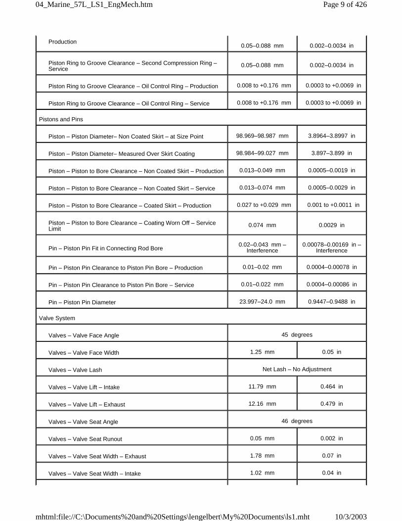
Valve System
Valves – Valve Face Angle 45 degrees
Valves – Valve Face Width 1.25 mm 0.05 in
Valves – Valve Lash Net Lash – No Adjustment
Valves – Valve Lift – Intake 11.79 mm 0.464 in
Valves – Valve Lift – Exhaust 12.16 mm 0.479 in
Valves – Valve Seat Angle 46 degrees
Valves – Valve Seat Runout 0.05 mm 0.002 in
Valves – Valve Seat Width – Exhaust 1.78 mm 0.07 in
Valves – Valve Seat Width – Intake 1.02 mm 0.04 in
Page 9 of 42604_Marine_57L_LS1_EngMech.htm
10/3/2003mhtml:file://C:\Documents%20and%20Settings\lengelbert\My%20Documents\ls1.mht
Specifications
Engine Mechanical Specifications (LS6)Engine Mechanical - 5.7L:Specifications:Engine Mechanical Specifications
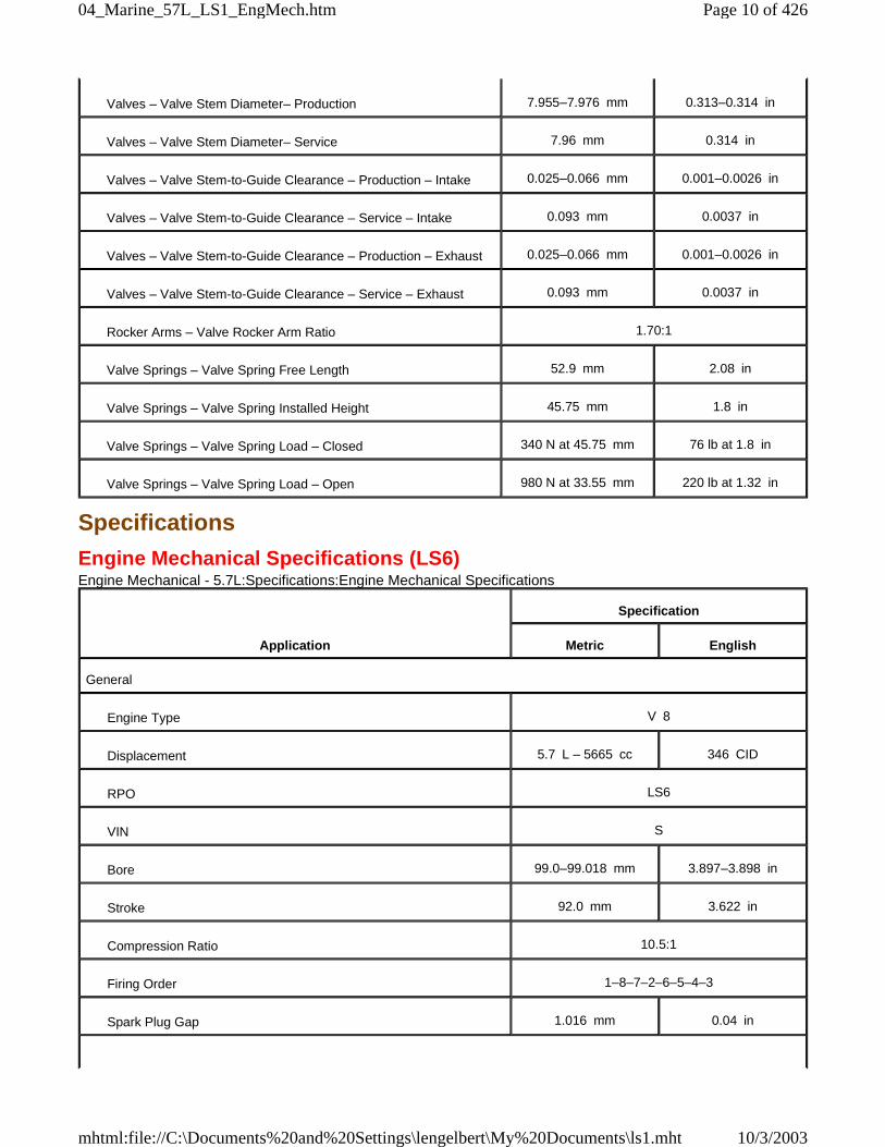
Valves – Valve Stem Diameter– Production 7.955–7.976 mm 0.313–0.314 in
Valves – Valve Stem Diameter– Service 7.96 mm 0.314 in
Valves – Valve Stem-to-Guide Clearance – Production – Intake 0.025–0.066 mm 0.001–0.0026 in
Valves – Valve Stem-to-Guide Clearance – Service – Intake 0.093 mm 0.0037 in
Valves – Valve Stem-to-Guide Clearance – Production – Exhaust 0.025–0.066 mm 0.001–0.0026 in
Valves – Valve Stem-to-Guide Clearance – Service – Exhaust 0.093 mm 0.0037 in
Rocker Arms – Valve Rocker Arm Ratio 1.70:1
Valve Springs – Valve Spring Free Length 52.9 mm 2.08 in
Valve Springs – Valve Spring Installed Height 45.75 mm 1.8 in
Valve Springs – Valve Spring Load – Closed 340 N at 45.75 mm 76 lb at 1.8 in
Valve Springs – Valve Spring Load – Open 980 N at 33.55 mm 220 lb at 1.32 in
Application
Specification
Metric English
General
Engine Type V 8
Displacement 5.7 L – 5665 cc 346 CID
RPO LS6
VIN S
Bore 99.0–99.018 mm 3.897–3.898 in
Stroke 92.0 mm 3.622 in
Compression Ratio 10.5:1
Firing Order 1–8–7–2–6–5–4–3
Spark Plug Gap 1.016 mm 0.04 in
Page 10 of 42604_Marine_57L_LS1_EngMech.htm
10/3/2003mhtml:file://C:\Documents%20and%20Settings\lengelbert\My%20Documents\ls1.mht
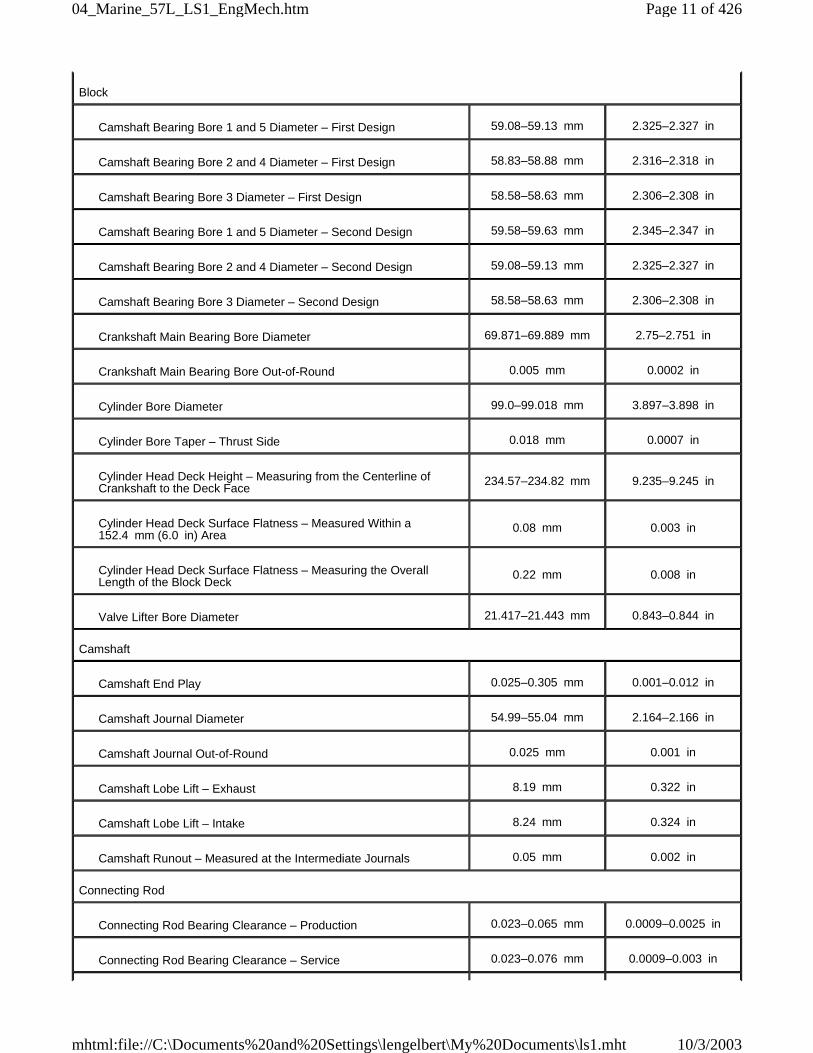
Block
Camshaft Bearing Bore 1 and 5 Diameter – First Design 59.08–59.13 mm 2.325–2.327 in
Camshaft Bearing Bore 2 and 4 Diameter – First Design 58.83–58.88 mm 2.316–2.318 in
Camshaft Bearing Bore 3 Diameter – First Design 58.58–58.63 mm 2.306–2.308 in
Camshaft Bearing Bore 1 and 5 Diameter – Second Design 59.58–59.63 mm 2.345–2.347 in
Camshaft Bearing Bore 2 and 4 Diameter – Second Design 59.08–59.13 mm 2.325–2.327 in
Camshaft Bearing Bore 3 Diameter – Second Design 58.58–58.63 mm 2.306–2.308 in
Crankshaft Main Bearing Bore Diameter 69.871–69.889 mm 2.75–2.751 in
Crankshaft Main Bearing Bore Out-of-Round 0.005 mm 0.0002 in
Cylinder Bore Diameter 99.0–99.018 mm 3.897–3.898 in
Cylinder Bore Taper – Thrust Side 0.018 mm 0.0007 in
Cylinder Head Deck Height – Measuring from the Centerline ofCrankshaft to the Deck Face
234.57–234.82 mm 9.235–9.245 in
Cylinder Head Deck Surface Flatness – Measured Within a152.4 mm (6.0 in) Area
0.08 mm 0.003 in
Cylinder Head Deck Surface Flatness – Measuring the OverallLength of the Block Deck
0.22 mm 0.008 in
Valve Lifter Bore Diameter 21.417–21.443 mm 0.843–0.844 in
Camshaft
Camshaft End Play 0.025–0.305 mm 0.001–0.012 in
Camshaft Journal Diameter 54.99–55.04 mm 2.164–2.166 in
Camshaft Journal Out-of-Round 0.025 mm 0.001 in
Camshaft Lobe Lift – Exhaust 8.19 mm 0.322 in
Camshaft Lobe Lift – Intake 8.24 mm 0.324 in
Camshaft Runout – Measured at the Intermediate Journals 0.05 mm 0.002 in
Connecting Rod
Connecting Rod Bearing Clearance – Production 0.023–0.065 mm 0.0009–0.0025 in
Connecting Rod Bearing Clearance – Service 0.023–0.076 mm 0.0009–0.003 in
Page 11 of 42604_Marine_57L_LS1_EngMech.htm
10/3/2003mhtml:file://C:\Documents%20and%20Settings\lengelbert\My%20Documents\ls1.mht
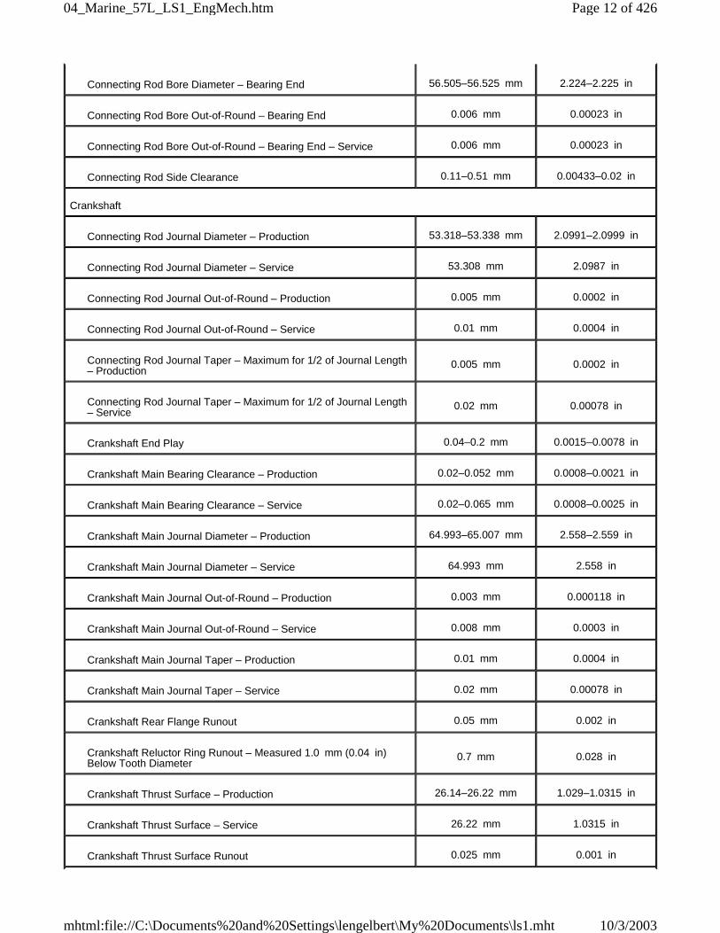
Connecting Rod Bore Diameter – Bearing End 56.505–56.525 mm 2.224–2.225 in
Connecting Rod Bore Out-of-Round – Bearing End 0.006 mm 0.00023 in
Connecting Rod Bore Out-of-Round – Bearing End – Service 0.006 mm 0.00023 in
Connecting Rod Side Clearance 0.11–0.51 mm 0.00433–0.02 in
Crankshaft
Connecting Rod Journal Diameter – Production 53.318–53.338 mm 2.0991–2.0999 in
Connecting Rod Journal Diameter – Service 53.308 mm 2.0987 in
Connecting Rod Journal Out-of-Round – Production 0.005 mm 0.0002 in
Connecting Rod Journal Out-of-Round – Service 0.01 mm 0.0004 in
Connecting Rod Journal Taper – Maximum for 1/2 of Journal Length– Production
0.005 mm 0.0002 in
Connecting Rod Journal Taper – Maximum for 1/2 of Journal Length– Service
0.02 mm 0.00078 in
Crankshaft End Play 0.04–0.2 mm 0.0015–0.0078 in
Crankshaft Main Bearing Clearance – Production 0.02–0.052 mm 0.0008–0.0021 in
Crankshaft Main Bearing Clearance – Service 0.02–0.065 mm 0.0008–0.0025 in
Crankshaft Main Journal Diameter – Production 64.993–65.007 mm 2.558–2.559 in
Crankshaft Main Journal Diameter – Service 64.993 mm 2.558 in
Crankshaft Main Journal Out-of-Round – Production 0.003 mm 0.000118 in
Crankshaft Main Journal Out-of-Round – Service 0.008 mm 0.0003 in
Crankshaft Main Journal Taper – Production 0.01 mm 0.0004 in
Crankshaft Main Journal Taper – Service 0.02 mm 0.00078 in
Crankshaft Rear Flange Runout 0.05 mm 0.002 in
Crankshaft Reluctor Ring Runout – Measured 1.0 mm (0.04 in)Below Tooth Diameter
0.7 mm 0.028 in
Crankshaft Thrust Surface – Production 26.14–26.22 mm 1.029–1.0315 in
Crankshaft Thrust Surface – Service 26.22 mm 1.0315 in
Crankshaft Thrust Surface Runout 0.025 mm 0.001 in
Page 12 of 42604_Marine_57L_LS1_EngMech.htm
10/3/2003mhtml:file://C:\Documents%20and%20Settings\lengelbert\My%20Documents\ls1.mht
Cylinder Head
Cylinder Head Height/Thickness – Measured from the Cylinder HeadDeck to the Valve Rocker Arm Cover Seal Surface
120.2 mm 4.732 in
Surface Flatness – Block Deck – Measured Within a 152.4 mm(6.0 in) Area
0.08 mm 0.003 in
Surface Flatness – Block Deck – Measuring the Overall Length ofthe Cylinder Head
0.1 mm 0.004 in
Surface Flatness – Exhaust Manifold Deck 0.22 mm 0.008 in
Surface Flatness – Intake Manifold Deck 0.22 mm 0.008 in
Intake Manifold
Surface Flatness – Measured at Gasket Sealing Surfaces 0.5 mm 0.02 in
Lubrication System
Oil Capacity – with Filter 6.151 Liters 6.5 Quarts
Oil Capacity – without Filter 5.678 Liters 6.0 Quarts
Oil Pressure – Minimum – Hot
41 kPa at 1,000engine RPM
124 kPa at 2,000engine RPM
165 kPa at 4,000engine RPM
6 psig at 1,000 engineRPM
18 psig at 2,000engine RPM
24 psig at 4,000engine RPM
Oil Pan
Front Cover Alignment – at Oil Pan Surface 0.0–0.5 mm 0.0–0.02 in
Rear Cover Alignment – at Oil Pan Surface 0.0–0.5 mm 0.0–0.02 in
Oil Pan Alignment – to Rear of Engine Block at TransmissionBellhousing Mounting Surface
0.0–0.25 mm 0.0–0.01 in
Piston Rings
Piston Ring End Gap – First Compression Ring – Measured inCylinder Bore – Production
0.23–0.44 mm 0.009–0.017 in
Piston Ring End Gap – First Compression Ring – Measured inCylinder Bore
0.23–0.5 mm 0.009–0.0196 in
Piston Ring End Gap – Second Compression Ring – Measured inCylinder Bore – Production
0.44–0.7 mm 0.017–0.027 in
Piston Ring End Gap – Second Compression Ring – Measured inCylinder Bore
0.44–0.76 mm 0.0173–0.03 in
Page 13 of 42604_Marine_57L_LS1_EngMech.htm
10/3/2003mhtml:file://C:\Documents%20and%20Settings\lengelbert\My%20Documents\ls1.mht
Piston Ring End Gap – Oil Control Ring – Measured in Cylinder Bore– Production
0.18–0.75 mm 0.007–0.029 in
Piston Ring End Gap – Oil Control Ring – Measured in Cylinder Bore– Service
0.18–0.81 mm 0.007–0.032 in
Piston Ring to Groove Clearance – First Compression Ring –Production
0.04–0.086 mm 0.00157–0.0033 in
Piston Ring to Groove Clearance – First Compression Ring –Service
0.04–0.068 mm 0.00157–0.0033 in
Piston Ring to Groove Clearance – Second Compression Ring –Production
0.05–0.088 mm 0.002–0.0034 in
Piston Ring to Groove Clearance – Second Compression Ring –Service
0.05–0.088 mm 0.002–0.0034 in
Piston Ring to Groove Clearance – Oil Control Ring – Production 0.008 to +0.0176 mm 0.0003 to +0.0069 in
Piston Ring to Groove Clearance – Oil Control Ring – Service 0.008 to +0.0176 mm 0.0003 to +0.0069 in
Pistons and Pins
Piston – Piston Diameter – Non Coated Skirt – at Size Point 98.969–98.987 mm 3.8964–3.8997 in
Piston – Piston Diameter – Measured Over Skirt Coating 98.984–99.027 mm 3.897–3.899 in
Piston – Piston to Bore Clearance – Non Coated Skirt – Production 0.013–0.049 mm 0.0005–0.0019 in
Piston – Piston to Bore Clearance – Non Coated Skirt – Service 0.013–0.074 mm 0.0005–0.0029 in
Piston – Piston to Bore Clearance – Coated Skirt – Production 0.027 to +0.029 mm 0.001 to +0.0011 in
Piston – Piston to Bore Clearance – Coating Worn Off – ServiceLimit
0.074 mm 0.0029 in
Pin – Piston Pin Fit in Connecting Rod Bore0.02–0.043 mm –
Interference0.00078–0.00169 in –
Interference
Pin – Piston Pin Clearance to Piston Pin Bore – Production 0.01–0.02 mm 0.0004–0.00078 in
Pin – Piston Pin Clearance to Piston Pin Bore – Service 0.01–0.022 mm 0.0004–0.00086 in
Pin – Piston Pin Diameter 23.997–24.0 mm 0.9447–0.9448 in
Valve System
Valves – Valve Face Angle 45 degrees
Valves – Valve Face Width 1.25 mm 0.05 in
Valves – Valve Lash Net Lash – No Adjustment
Page 14 of 42604_Marine_57L_LS1_EngMech.htm
10/3/2003mhtml:file://C:\Documents%20and%20Settings\lengelbert\My%20Documents\ls1.mht
Specifications
Sealers, Adhesives, and LubricantsEngine Mechanical - 5.7L:Specifications:Sealers, Adhesives, and Lubricants
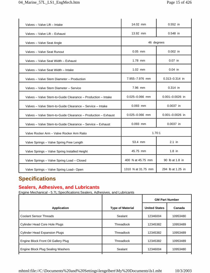
Valves – Valve Lift – Intake 14.02 mm 0.552 in
Valves – Valve Lift – Exhaust 13.92 mm 0.548 in
Valves – Valve Seat Angle 46 degrees
Valves – Valve Seat Runout 0.05 mm 0.002 in
Valves – Valve Seat Width – Exhaust 1.78 mm 0.07 in
Valves – Valve Seat Width – Intake 1.02 mm 0.04 in
Valves – Valve Stem Diameter – Production 7.955–7.976 mm 0.313–0.314 in
Valves – Valve Stem Diameter – Service 7.96 mm 0.314 in
Valves – Valve Stem-to-Guide Clearance – Production – Intake 0.025–0.066 mm 0.001–0.0026 in
Valves – Valve Stem-to-Guide Clearance – Service – Intake 0.093 mm 0.0037 in
Valves – Valve Stem-to-Guide Clearance – Production – Exhaust 0.025–0.066 mm 0.001–0.0026 in
Valves – Valve Stem-to-Guide Clearance – Service – Exhaust 0.093 mm 0.0037 in
Valve Rocker Arm – Valve Rocker Arm Ratio 1.70:1
Valve Springs – Valve Spring Free Length 53.4 mm 2.1 in
Valve Springs – Valve Spring Installed Height 45.75 mm 1.8 in
Valve Springs – Valve Spring Load – Closed 400 N at 45.75 mm 90 lb at 1.8 in
Valve Springs – Valve Spring Load– Open 1310 N at 31.75 mm 294 lb at 1.25 in
Application Type of Material
GM Part Number
United States Canada
Coolant Sensor Threads Sealant 12346004 10953480
Cylinder Head Core Hole Plugs Threadlock 12345382 10953489
Cylinder Head Expansion Plugs Threadlock 12345382 10953489
Engine Block Front Oil Gallery Plug Threadlock 12345382 10953489
Engine Block Plug Sealing Washers Sealant 12346004 10953480
Page 15 of 42604_Marine_57L_LS1_EngMech.htm
10/3/2003mhtml:file://C:\Documents%20and%20Settings\lengelbert\My%20Documents\ls1.mht
Specifications
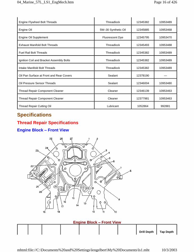
Thread Repair Specifications
Engine Block – Front View
Engine Block – Front View
Engine Flywheel Bolt Threads Threadlock 12345382 10953489
Engine Oil 5W–30 Synthetic Oil 12345885 10953468
Engine Oil Supplement Fluorescent Dye 12345795 10953470
Exhaust Manifold Bolt Threads Threadlock 12345493 10953488
Fuel Rail Bolt Threads Threadlock 12345382 10953489
Ignition Coil and Bracket Assembly Bolts Threadlock 12345382 10953489
Intake Manifold Bolt Threads Threadlock 12345382 10953489
Oil Pan Surface at Front and Rear Covers Sealant 12378190 —
Oil Pressure Sensor Threads Sealant 12346004 10953480
Thread Repair Component Cleaner Cleaner 12346139 10953463
Thread Repair Component Cleaner Cleaner 12377981 10953463
Thread Repair Cutting Oil Lubricant 1052864 992881
Drill Depth Tap Depth
Page 16 of 42604_Marine_57L_LS1_EngMech.htm
10/3/2003mhtml:file://C:\Documents%20and%20Settings\lengelbert\My%20Documents\ls1.mht
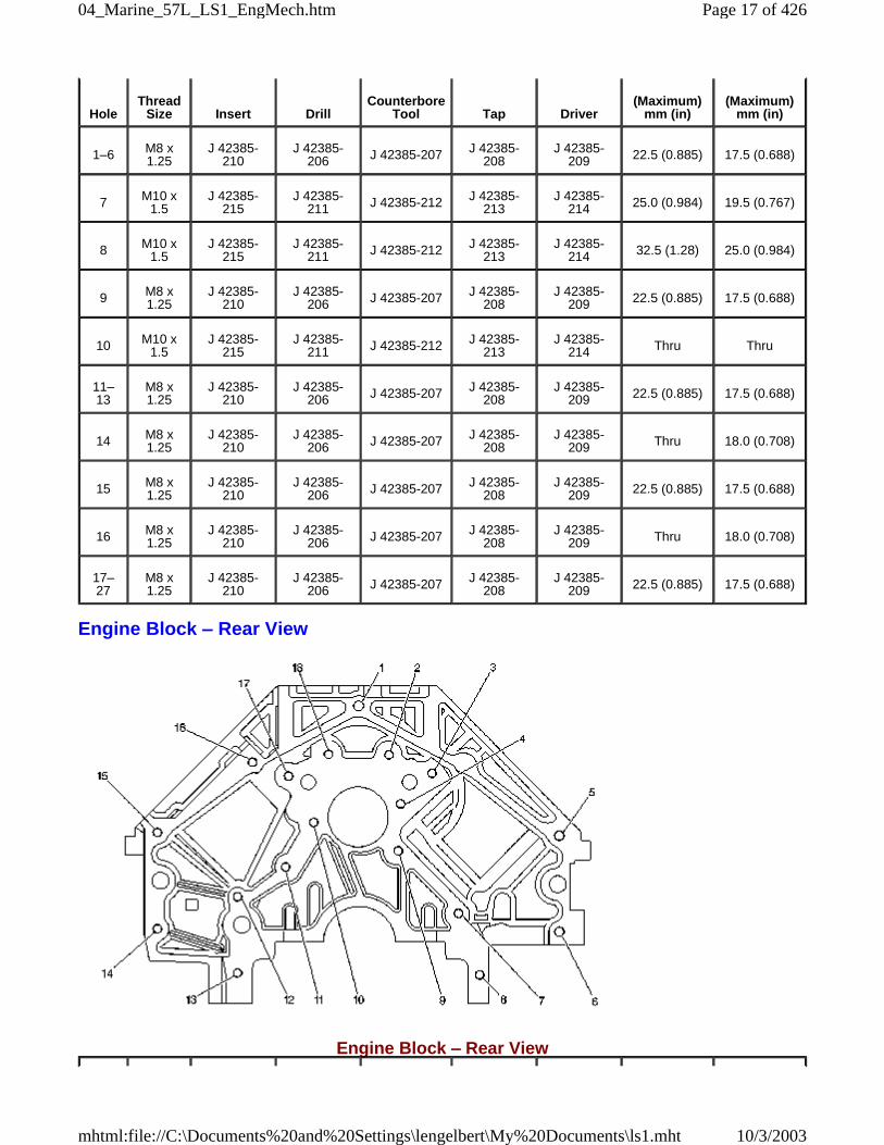
Engine Block – Rear View
Engine Block – Rear View
HoleThread
Size Insert DrillCounterbore
Tool Tap Driver(Maximum)
mm (in)(Maximum)
mm (in)
1–6 M8 x1.25
J 42385-210
J 42385-206 J 42385-207 J 42385-
208J 42385-
209 22.5 (0.885) 17.5 (0.688)
7 M10 x1.5
J 42385-215
J 42385-211 J 42385-212 J 42385-
213J 42385-
214 25.0 (0.984) 19.5 (0.767)
8 M10 x1.5
J 42385-215
J 42385-211 J 42385-212 J 42385-
213J 42385-
214 32.5 (1.28) 25.0 (0.984)
9 M8 x1.25
J 42385-210
J 42385-206 J 42385-207 J 42385-
208J 42385-
209 22.5 (0.885) 17.5 (0.688)
10 M10 x1.5
J 42385-215
J 42385-211 J 42385-212 J 42385-
213J 42385-
214 Thru Thru
11–13
M8 x1.25
J 42385-210
J 42385-206 J 42385-207 J 42385-
208J 42385-
209 22.5 (0.885) 17.5 (0.688)
14 M8 x1.25
J 42385-210
J 42385-206 J 42385-207 J 42385-
208J 42385-
209 Thru 18.0 (0.708)
15 M8 x1.25
J 42385-210
J 42385-206 J 42385-207 J 42385-
208J 42385-
209 22.5 (0.885) 17.5 (0.688)
16 M8 x1.25
J 42385-210
J 42385-206 J 42385-207 J 42385-
208J 42385-
209 Thru 18.0 (0.708)
17–27
M8 x1.25
J 42385-210
J 42385-206 J 42385-207 J 42385-
208J 42385-
209 22.5 (0.885) 17.5 (0.688)
Page 17 of 42604_Marine_57L_LS1_EngMech.htm
10/3/2003mhtml:file://C:\Documents%20and%20Settings\lengelbert\My%20Documents\ls1.mht
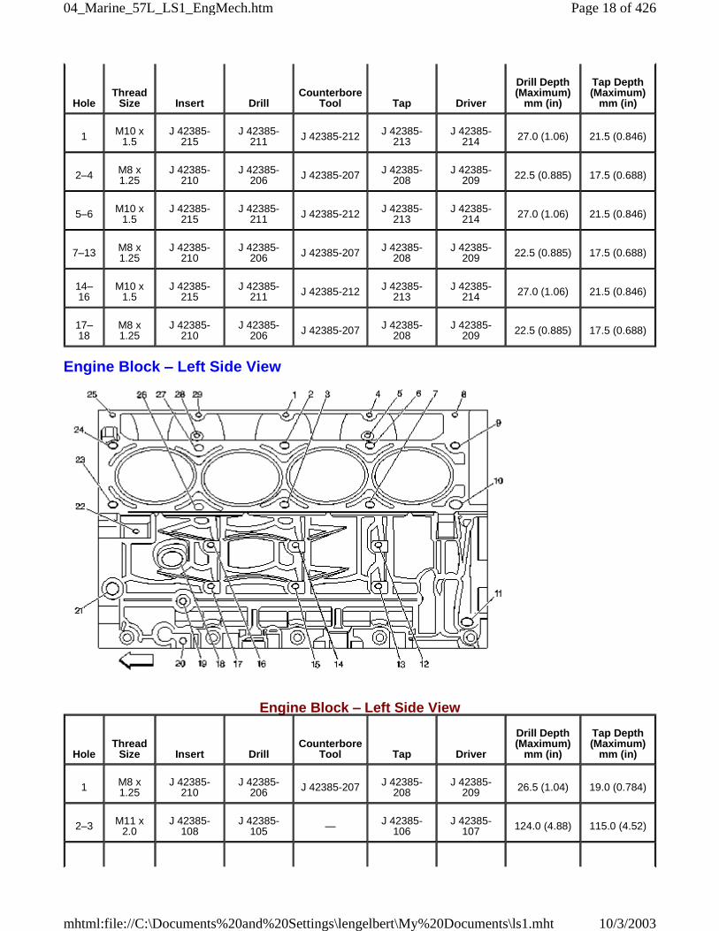
Engine Block – Left Side View
Engine Block – Left Side View
HoleThread
Size Insert DrillCounterbore
Tool Tap Driver
Drill Depth(Maximum)
mm (in)
Tap Depth(Maximum)
mm (in)
1 M10 x1.5
J 42385-215
J 42385-211 J 42385-212 J 42385-
213J 42385-
214 27.0 (1.06) 21.5 (0.846)
2–4 M8 x1.25
J 42385-210
J 42385-206 J 42385-207 J 42385-
208J 42385-
209 22.5 (0.885) 17.5 (0.688)
5–6 M10 x1.5
J 42385-215
J 42385-211 J 42385-212 J 42385-
213J 42385-
214 27.0 (1.06) 21.5 (0.846)
7–13 M8 x1.25
J 42385-210
J 42385-206 J 42385-207 J 42385-
208J 42385-
209 22.5 (0.885) 17.5 (0.688)
14–16
M10 x1.5
J 42385-215
J 42385-211 J 42385-212 J 42385-
213J 42385-
214 27.0 (1.06) 21.5 (0.846)
17–18
M8 x1.25
J 42385-210
J 42385-206 J 42385-207 J 42385-
208J 42385-
209 22.5 (0.885) 17.5 (0.688)
HoleThread
Size Insert DrillCounterbore
Tool Tap Driver
Drill Depth(Maximum)
mm (in)
Tap Depth(Maximum)
mm (in)
1 M8 x1.25
J 42385-210
J 42385-206 J 42385-207 J 42385-
208J 42385-
209 26.5 (1.04) 19.0 (0.784)
2–3 M11 x2.0
J 42385-108
J 42385-105 — J 42385-
106J 42385-
107 124.0 (4.88) 115.0 (4.52)
Page 18 of 42604_Marine_57L_LS1_EngMech.htm
10/3/2003mhtml:file://C:\Documents%20and%20Settings\lengelbert\My%20Documents\ls1.mht
4 M8 x1.25
J 42385-210
J 42385-206 J 42385-207 J 42385-
208J 42385-
209 26.5 (1.04) 19.0 (0.784)
5 M6 x 1.0 J 42385-205
J 42385-201 J 42385-202 J 42385-
203J 42385-
204 22.5 (0.885) 16.0 (0.629)
6–7 M11 x2.0
J 42385-108
J 42385-105 — J 42385-
106J 42385-
107 124.0 (4.88) 115.0 (4.52)
8 M8 x1.25
J 42385-210
J 42385-206 J 42385-207 J 42385-
208J 42385-
209 26.5 (1.04) 19.0 (0.784)
9 M11 x2.0
J 42385-108
J 42385-105 — J 42385-
106J 42385-
107 69.0 (2.72) 60.0 (2.36)
10 M11 x2.0
J 42385-108
J 42385-105 — J 42385-
106J 42385-
107 124.0 (4.88) 115.0 (4.52)
11 M16 x1.5 — — — — — — —
12–17
M10 x1.5
J 42385-215
J 42385-211 J 42385-212 J 42385-
213J 42385-
214 29.0 (1.14) 23.0 (0.905)
18 M28 x1.25 — — — — — — —
19–20
M8 x1.25
J 42385-210
J 42385-206 J 42385-207 J 42385-
208J 42385-
209 21.0 (0.826) 16.0 (0.629)
21 M16 x1.5 — — — — — — —
22 M10 x1.5
J 42385-215
J 42385-211 J 42385-212 J 42385-
213J 42385-
214 27.0 (1.06) 21.5 (0.846)
23 M11 x2.0
J 42385-108
J 42385-105 — J 42385-
106J 42385-
107 124.0 (4.88) 115.0 (4.52)
24 M11 x2.0
J 42385-108
J 42385-105 — J 42385-
106J 42385-
107 69.0 (2.72) 60.0 (2.36)
25 M8 x1.25
J 42385-210
J 42385-206 J 42385-207 J 42385-
208J 42385-
209 26.5 (1.04) 19.0 (0.784)
26–27
M11 x2.0
J 42385-108
J 42385-105 — J 42385-
106J 42385-
107 124.0 (4.88) 115.0 (4.52)
28 M6 x 1.0 J 42385-205
J 42385-201 J 42385-202 J 42385-
203J 42385-
204 22.5 (0.885) 16.0 (0.629)
29 M8 x1.25
J 42385-210
J 42385-206 J 42385-207 J 42385-
208J 42385-
209 26.5 (1.04) 19.0 (0.784)
• Bolt holes 2, 3, 6, 7, 10, 23, 26, and 27 have a 85 mm (3.34 in) counterbore included in the 124.0 mm (4.88 in) drilldepth.
• Bolt holes 9 and 24 have a 30 mm (1.18 in) counterbore included in the 69.0 mm (2.72 in) drill depth. Use sleeve J42385-315 with the drill and tap.
Page 19 of 42604_Marine_57L_LS1_EngMech.htm
10/3/2003mhtml:file://C:\Documents%20and%20Settings\lengelbert\My%20Documents\ls1.mht
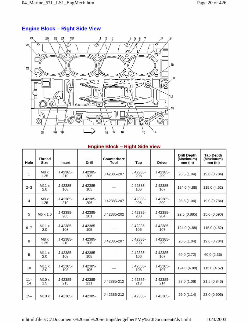
Engine Block – Right Side View
Engine Block – Right Side View
HoleThread
Size Insert DrillCounterbore
Tool Tap Driver
Drill Depth(Maximum)
mm (in)
Tap Depth(Maximum)
mm (in)
1 M8 x1.25
J 42385-210
J 42385-206 J 42385-207 J 42385-
208J 42385-
209 26.5 (1.04) 19.0 (0.784)
2–3 M11 x2.0
J 42385-108
J 42385-105 — J 42385-
106J 42385-
107 124.0 (4.88) 115.0 (4.52)
4 M8 x1.25
J 42385-210
J 42385-206 J 42385-207 J 42385-
208J 42385-
209 26.5 (1.04) 19.0 (0.784)
5 M6 x 1.0 J 42385-205
J 42385-201 J 42385-202 J 42385-
203J 42385-
204 22.5 (0.885) 15.0 (0.590)
6–7 M11 x2.0
J 42385-108
J 42385-105 — J 42385-
106J 42385-
107 124.0 (4.88) 115.0 (4.52)
8 M8 x1.25
J 42385-210
J 42385-206 J 42385-207 J 42385-
208J 42385-
209 26.5 (1.04) 19.0 (0.784)
9 M11 x2.0
J 42385-108
J 42385-105 — J 42385-
106J 42385-
107 69.0 (2.72) 60.0 (2.36)
10 M11 x2.0
J 42385-108
J 42385-105 — J 42385-
106J 42385-
107 124.0 (4.88) 115.0 (4.52)
11–14
M10 x1.5
J 42385-215
J 42385-211 J 42385-212 J 42385-
213J 42385-
214 27.0 (1.06) 21.5 (0.846)
15– M10 x J 42385- J 42385- J 42385-212 J 42385- J 42385- 29.0 (1.14) 23.0 (0.905)
Page 20 of 42604_Marine_57L_LS1_EngMech.htm
10/3/2003mhtml:file://C:\Documents%20and%20Settings\lengelbert\My%20Documents\ls1.mht
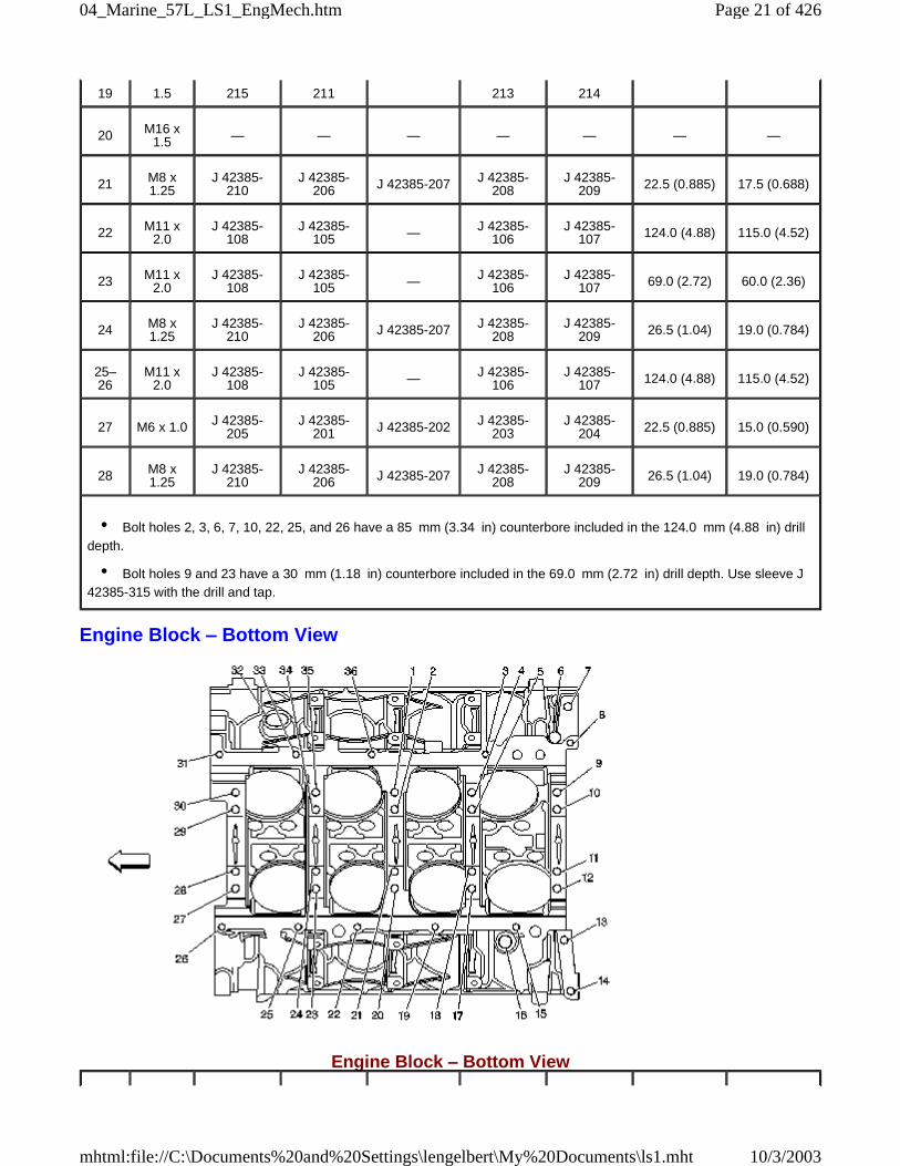
Engine Block – Bottom View
Engine Block – Bottom View
19 1.5 215 211 213 214
20 M16 x1.5 — — — — — — —
21 M8 x1.25
J 42385-210
J 42385-206 J 42385-207 J 42385-
208J 42385-
209 22.5 (0.885) 17.5 (0.688)
22 M11 x2.0
J 42385-108
J 42385-105 — J 42385-
106J 42385-
107 124.0 (4.88) 115.0 (4.52)
23 M11 x2.0
J 42385-108
J 42385-105 — J 42385-
106J 42385-
107 69.0 (2.72) 60.0 (2.36)
24 M8 x1.25
J 42385-210
J 42385-206 J 42385-207 J 42385-
208J 42385-
209 26.5 (1.04) 19.0 (0.784)
25–26
M11 x2.0
J 42385-108
J 42385-105 — J 42385-
106J 42385-
107 124.0 (4.88) 115.0 (4.52)
27 M6 x 1.0 J 42385-205
J 42385-201 J 42385-202 J 42385-
203J 42385-
204 22.5 (0.885) 15.0 (0.590)
28 M8 x1.25
J 42385-210
J 42385-206 J 42385-207 J 42385-
208J 42385-
209 26.5 (1.04) 19.0 (0.784)
• Bolt holes 2, 3, 6, 7, 10, 22, 25, and 26 have a 85 mm (3.34 in) counterbore included in the 124.0 mm (4.88 in) drilldepth.
• Bolt holes 9 and 23 have a 30 mm (1.18 in) counterbore included in the 69.0 mm (2.72 in) drill depth. Use sleeve J42385-315 with the drill and tap.
Page 21 of 42604_Marine_57L_LS1_EngMech.htm
10/3/2003mhtml:file://C:\Documents%20and%20Settings\lengelbert\My%20Documents\ls1.mht
HoleThread
Size Insert DrillCounterbore
Tool Tap Driver
Drill Depth(Maximum)
mm (in)
Tap Depth(Maximum)
mm (in)
1 M10 x2.0
J 42385-104
J 42385-101 — J 42385-
102J 42385-
103 31.0 (1.22) 25.5 (1.0)
2 M10 x2.0
J 42385-104
J 42385-101 — J 42385-
102J 42385-
103 53.5 (2.10) 44.0 (1.73)
3 M8 x1.25
J 42385-210
J 42385-206 J 42385-207 J 42385-
208J 42385-
209 22.5 (0.885) 17.5 (0.688)
4 M10 x2.0
J 42385-104
J 42385-101 — J 42385-
102J 42385-
103 31.0 (1.22) 25.5 (1.0)
5 M10 x2.0
J 42385-104
J 42385-101 — J 42385-
102J 42385-
103 53.5 (2.10) 44.0 (1.73)
6 M16 x1.5 — — — — — — —
7 N/A — — — — — — —
8 M8 x1.25
J 42385-210
J 42385-206 J 42385-207 J 42385-
208J 42385-
209 22.5 (0.885) 17.5 (0.688)
9 M10 x2.0
J 42385-104
J 42385-101 — J 42385-
102J 42385-
103 31.0 (1.22) 25.5 (1.0)
10–11
M10 x2.0
J 42385-104
J 42385-101 — J 42385-
102J 42385-
103 53.5 (2.10) 44.0 (1.73)
12 M10 x2.0
J 42385-104
J 42385-101 — J 42385-
102J 42385-
103 31.0 (1.22) 25.5 (1.0)
13–14
M10 x1.5
J 42385-215
J 42385-101 — J 42385-
213J 42385-
214 42.5 (1.67) 37.0 (1.45)
15 M8 x1.25
J 42385-210
J 42385-206 J 42385-207 J 42385-
208J 42385-
209 22.5 (0.885) 17.5 (0.688)
16 M16 x1.5 — — — — — — —
17 M10 x2.0
J 42385-104
J 42385-101 — J 42385-
102J 42385-
103 53.5 (2.10) 44.0 (1.73)
18 M10 x2.0
J 42385-104
J 42385-101 — J 42385-
102J 42385-
103 31.0 (1.22) 25.5 (1.0)
19 M8 x1.25
J 42385-210
J 42385-206 J 42385-207 J 42385-
208J 42385-
209 22.5 (0.885) 17.5 (0.688)
20 M10 x2.0
J 42385-104
J 42385-101 — J 42385-
102J 42385-
103 53.5 (2.10) 44.0 (1.73)
21 M10 x2.0
J 42385-104
J 42385-101 — J 42385-
102J 42385-
103 31.0 (1.22) 25.5 (1.0)
Page 22 of 42604_Marine_57L_LS1_EngMech.htm
10/3/2003mhtml:file://C:\Documents%20and%20Settings\lengelbert\My%20Documents\ls1.mht
Engine Block – Top View
22 M8 x1.25
J 42385-210
J 42385-206 J 42385-207 J 42385-
208J 42385-
209 22.5 (0.885) 17.5 (0.688)
23 M10 x2.0
J 42385-104
J 42385-101 — J 42385-
102J 42385-
103 31.0 (1.22) 25.5 (1.0)
24 M10 x2.0
J 42385-104
J 42385-101 — J 42385-
102J 42385-
103 53.5 (2.10) 44.0 (1.73)
25–26
M8 x1.25
J 42385-210
J 42385-206 J 42385-207 J 42385-
208J 42385-
209 22.5 (0.885) 17.5 (0.688)
27 M10 x2.0
J 42385-104
J 42385-101 — J 42385-
102J 42385-
103 31.0 (1.22) 25.5 (1.0)
28–29
M10 x2.0
J 42385-104
J 42385-101 — J 42385-
102J 42385-
103 53.5 (2.10) 44.0 (1.73)
30 M10 x2.0
J 42385-104
J 42385-101 — J 42385-
102J 42385-
103 31.0 (1.22) 25.5 (1.0)
31 M8 x1.25
J 42385-210
J 42385-206 J 42385-207 J 42385-
208J 42385-
209 22.5 (0.885) 17.5 (0.688)
32 M28 x1.25 — — — — — — —
33 M8 x1.25
J 42385-210
J 42385-206 J 42385-207 J 42385-
208J 42385-
209 22.5 (0.885) 17.5 (0.688)
34 M10 x2.0
J 42385-104
J 42385-101 — J 42385-
102J 42385-
103 53.5 (2.10) 44.0 (1.73)
35 M10 x2.0
J 42385-104
J 42385-101 — J 42385-
102J 42385-
103 31.0 (1.22) 25.5 (1.0)
36 M8 x1.25
J 42385-210
J 42385-206 J 42385-207 J 42385-
208J 42385-
209 22.5 (0.885) 17.5 (0.688)
• Bolt holes 2, 5, 10, 11, 18, 21, 24, 28, 29, and 34 have a 20.5 mm (0.807 in) counterbore included in the 53.5 mm(2.10 in) drill depth.
• Bolt holes 1, 4, 9, 12, 17, 20, 23, 27, 30, and 35 have a 1.5 mm (0.059 in) counterbore included in the 31.0 mm(1.22 in) drill depth. Use sleeve J 42385-316 with the drill and tap.
• Bolt holes 13 and 14 have a 11.5 mm (0.452 in) counterbore included in the 42.5 mm (1.67 in) drill depth. Usesleeve J 42385-311 with the drill and tap.
Page 23 of 42604_Marine_57L_LS1_EngMech.htm
10/3/2003mhtml:file://C:\Documents%20and%20Settings\lengelbert\My%20Documents\ls1.mht
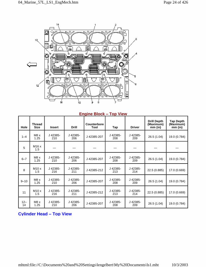
Engine Block – Top View
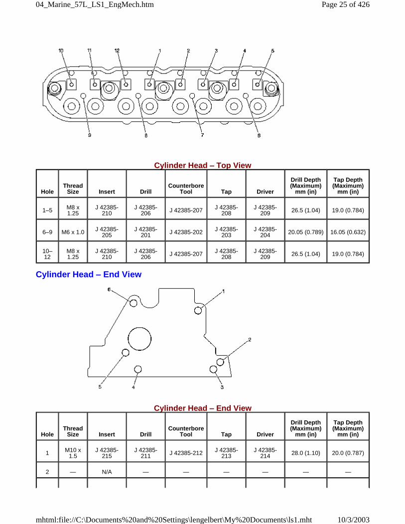
Cylinder Head – Top View
HoleThread
Size Insert DrillCounterbore
Tool Tap Driver
Drill Depth(Maximum)
mm (in)
Tap Depth(Maximum)
mm (in)
1–4 M8 x1.25
J 42385-210
J 42385-206 J 42385-207 J 42385-
208J 42385-
209 26.5 (1.04) 19.0 (0.784)
5 M16 x1.5 — — — — — — —
6–7 M8 x1.25
J 42385-210
J 42385-206 J 42385-207 J 42385-
208J 42385-
209 26.5 (1.04) 19.0 (0.784)
8 M10 x1.5
J 42385-216
J 42385-211 J 42385-212 J 42385-
213J 42385-
214 22.5 (0.885) 17.0 (0.669)
9–10 M8 x1.25
J 42385-210
J 42385-206 J 42385-207 J 42385-
208J 42385-
209 26.5 (1.04) 19.0 (0.784)
11 M10 x1.5
J 42385-216
J 42385-211 J 42385-212 J 42385-
213J 42385-
214 22.5 (0.885) 17.0 (0.669)
12–14
M8 x1.25
J 42385-210
J 42385-206 J 42385-207 J 42385-
208J 42385-
209 26.5 (1.04) 19.0 (0.784)
Page 24 of 42604_Marine_57L_LS1_EngMech.htm
10/3/2003mhtml:file://C:\Documents%20and%20Settings\lengelbert\My%20Documents\ls1.mht
Cylinder Head – Top View
Cylinder Head – End View
Cylinder Head – End View
HoleThread
Size Insert DrillCounterbore
Tool Tap Driver
Drill Depth(Maximum)
mm (in)
Tap Depth(Maximum)
mm (in)
1–5 M8 x1.25
J 42385-210
J 42385-206 J 42385-207 J 42385-
208J 42385-
209 26.5 (1.04) 19.0 (0.784)
6–9 M6 x 1.0 J 42385-205
J 42385-201 J 42385-202 J 42385-
203J 42385-
204 20.05 (0.789) 16.05 (0.632)
10–12
M8 x1.25
J 42385-210
J 42385-206 J 42385-207 J 42385-
208J 42385-
209 26.5 (1.04) 19.0 (0.784)
HoleThread
Size Insert DrillCounterbore
Tool Tap Driver
Drill Depth(Maximum)
mm (in)
Tap Depth(Maximum)
mm (in)
1 M10 x1.5
J 42385-215
J 42385-211 J 42385-212 J 42385-
213J 42385-
214 28.0 (1.10) 20.0 (0.787)
2 — N/A — — — — — —
Page 25 of 42604_Marine_57L_LS1_EngMech.htm
10/3/2003mhtml:file://C:\Documents%20and%20Settings\lengelbert\My%20Documents\ls1.mht
Cylinder Head – Exhaust Manifold Deck View
Cylinder Head – Exhaust Manifold Deck View
3 M10 x1.5
J 42385-215
J 42385-211 J 42385-212 J 42385-
213J 42385-
214 28.0 (1.10) 20.0 (0.787)
4 N/A — — — — — — —
5–6 M10 x1.5
J 42385-215
J 42385-211 J 42385-212 J 42385-
213J 42385-
214 28.0 (1.10) 20.0 (0.787)
HoleThread
Size Insert DrillCounterbore
Tool Tap Driver
Drill Depth(Maximum)
mm (in)
Tap Depth(Maximum)
mm (in)
1–2 M10 x1.5
J 42385-215
J 42385-211 J 42385-212 J 42385-
213J 42385-
214 28.0 (1.10) 20.0 (0.787)
3 M8 x1.25
J 42385-210
J 42385-206 J 42385-207 J 42385-
208J 42385-
209 21.0 (0.826) 16.0 (0.629)
4 M14 x1.25 — — — — — — —
5 M8 x1.25
J 42385-210
J 42385-206 J 42385-207 J 42385-
208J 42385-
209 21.0 (0.826) 16.0 (0.629)
6 M14 x1.25 — — — — — — —
7–8 M8 x1.25
J 42385-210
J 42385-206 J 42385-207 J 42385-
208J 42385-
209 21.0 (0.826) 16.0 (0.629)
9 M14 x1.25 — — — — — — —
10 M8 x1.25
J 42385-210
J 42385-206 J 42385-207 J 42385-
208J 42385-
209 21.0 (0.826) 16.0 (0.629)
11 M14 x1.25 — — — — — — —
M8 x J 42385- J 42385- J 42385- J 42385-
Page 26 of 42604_Marine_57L_LS1_EngMech.htm
10/3/2003mhtml:file://C:\Documents%20and%20Settings\lengelbert\My%20Documents\ls1.mht
Cylinder Head – Intake Manifold Deck View
Cylinder Head – Intake Manifold Deck View
Component Locator
Disassembled ViewsIntake Manifold/Upper Engine
121.25 210 206
J 42385-207208 209
21.0 (0.826) 16.0 (0.629)
13 M12 x1.5 — — — — — — —
14–15
M10 x1.5
J 42385-215
J 42385-211 J 42385-212 J 42385-
213J 42385-
214 28.0 (1.10) 20.0 (0.787)
HoleThread
Size Insert DrillCounterbore
Tool Tap Driver
Drill Depth(Maximum)
mm (in)
Tap Depth(Maximum)
mm (in)
1–2 M6 x 1.0 J 42385-205
J 42385-201 J 42385-202 J 42385-
203J 42385-
204 Thru Thru
3–4 M6 x 1.0 J 42385-205
J 42385-201 J 42385-202 J 42385-
203J 42385-
204 22.5 (0.885) 15.0 (0.688)
5–7 M6 x 1.0 J 42385-205
J 42385-201 J 42385-202 J 42385-
203J 42385-
204 Thru Thru
Page 27 of 42604_Marine_57L_LS1_EngMech.htm
10/3/2003mhtml:file://C:\Documents%20and%20Settings\lengelbert\My%20Documents\ls1.mht
307. Engine Coolant Air Bleed Pipe 308. Engine Coolant Air Bleed Pipe/Cover Gasket 308. Engine Coolant Air Bleed Pipe/Cover Gasket 309. Engine Coolant Air Bleed Pipe Stud 310. Engine Coolant Air Bleed Hose Clamp 311. Engine Coolant Air Bleed Hose 312. Engine Coolant Air Bleed Cover Bolt 313. Engine Coolant Air Bleed Cover 500. Intake Manifold 506. Valley Cover Bolt 507. Throttle Body Bolt 508. Throttle Body 509. Throttle Body Gasket 510. Fuel Rail with Injectors 511. Fuel Rail Bolt 512. Intake Manifold Bolt 513. Intake Manifold Insulator 514. Intake Manifold Gaskets 520. Knock Sensor Oil Seals 550. Fuel Rail Ground Strap 555. Valley Cover 556. Valley Cover Gasket 708. EVAP Purge Valve 712. Fuel Rail Stop Bracket 713. Intake Manifold Bolt 714. MAP Sensor 715. MAP Sensor Grommet
Page 28 of 42604_Marine_57L_LS1_EngMech.htm
10/3/2003mhtml:file://C:\Documents%20and%20Settings\lengelbert\My%20Documents\ls1.mht
716. PCV Hose 717. Knock Sensor Wire Harness 718. Knock Sensor 729. EVAP Purge Valve Hose 730. EVAP Purge Valve Bracket 731. EVAP Purge Valve Hose
Cylinder Head/Upper Engine
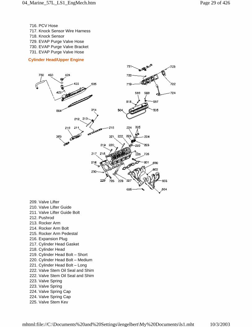
209. Valve Lifter 210. Valve Lifter Guide 211. Valve Lifter Guide Bolt 212. Pushrod 213. Rocker Arm 214. Rocker Arm Bolt 215. Rocker Arm Pedestal 216. Expansion Plug 217. Cylinder Head Gasket 218. Cylinder Head 219. Cylinder Head Bolt – Short 220. Cylinder Head Bolt – Medium 221. Cylinder Head Bolt – Long 222. Valve Stem Oil Seal and Shim 222. Valve Stem Oil Seal and Shim 223. Valve Spring 223. Valve Spring 224. Valve Spring Cap 224. Valve Spring Cap 225. Valve Stem Key
Page 29 of 42604_Marine_57L_LS1_EngMech.htm
10/3/2003mhtml:file://C:\Documents%20and%20Settings\lengelbert\My%20Documents\ls1.mht
226. Expansion Plug 227. Intake Valve 228. Exhaust Valve 229. Cylinder Head Coolant Plug 230. Cylinder Head Locating Pin 422. Oil Fill Tube O-Ring 423. Oil Fill Tube 424. Oil Fill Cap 450. Oil Fill Cap O-Ring 504. Valve Cover Gasket 504. Valve Cover Gasket 505. Valve Cover 505. Valve Cover 515. Valve Cover Bolt Grommet 516. Valve Cover Bolt 557. Valve Cover Grommet 558. Valve Cover Grommet Plug 600. Exhaust Manifold 601. Exhaust Manifold Gasket 602. Exhaust Manifold Bolt 603. Exhaust Manifold Heat Shield 604. Exhaust Manifold Heat Shield Bolt 605. Takedown Pipe Stud 700. Fresh Air Hose 719. Ignition Coil and Bracket Assembly 720. Ignition Coil and Bracket Assembly Bolt 721. Ignition Coil Wire Harness 722. Ignition Coil 723. Ignition Coil Bolt 724. Spark Plug Wire 725. Coolant Temperature Sensor 726. Spark Plug
Front of Engine
Page 30 of 42604_Marine_57L_LS1_EngMech.htm
10/3/2003mhtml:file://C:\Documents%20and%20Settings\lengelbert\My%20Documents\ls1.mht
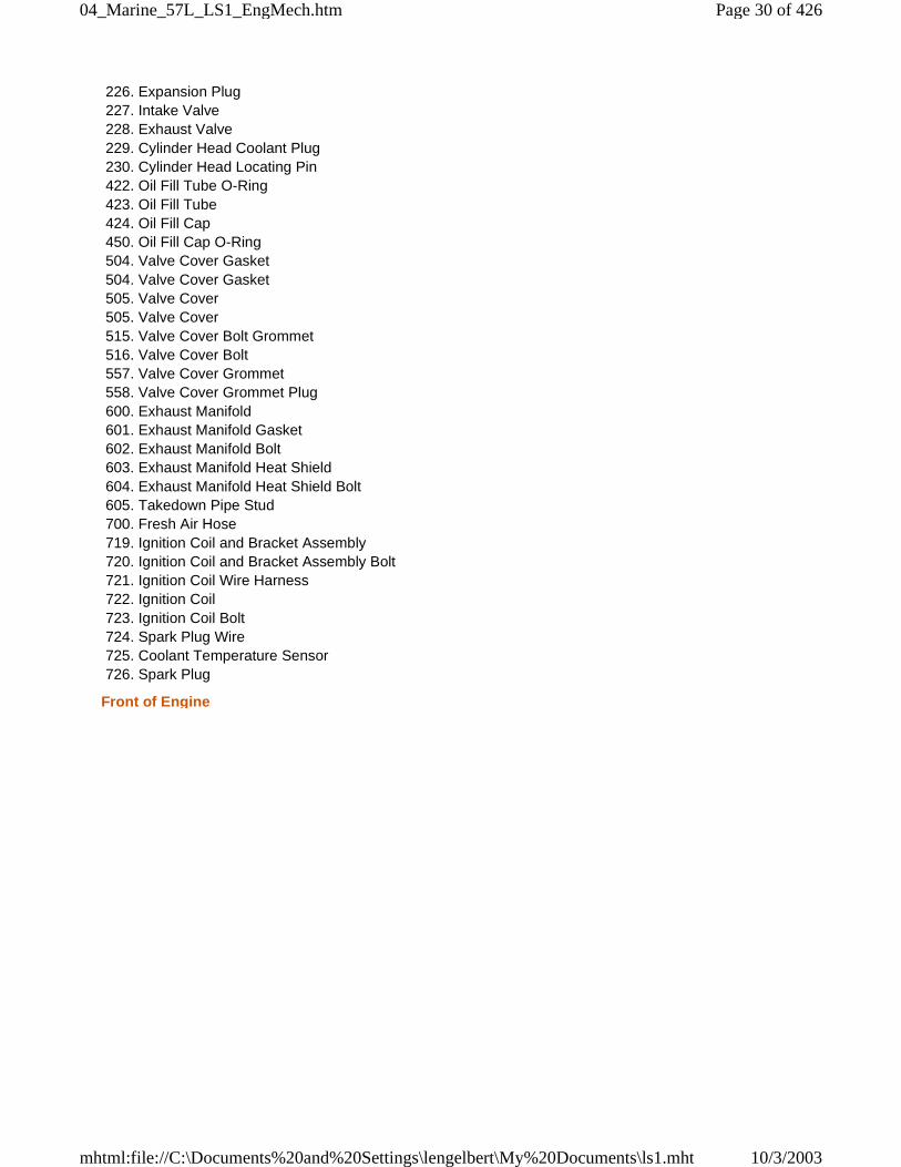
100. Engine Block 138. Crankshaft Balancer 139. Crankshaft Balancer Bolt 140. Crankshaft Front Oil Seal 143. Balance Weight – Manual Transmission 200. Camshaft 201. Camshaft Bearings 202. Camshaft Sprocket Locating Pin 203. Camshaft Retainer Plate 204. Camshaft Retainer Plate Bolt 205. Camshaft Sprocket 206. Camshaft Sprocket Bolt 207. Crankshaft Sprocket 208. Timing Chain 231. Timing Chain Guide Bolt 232. Timing Chain Guide 300. Water Pump 301. Water Pump Bolt 302. Thermostat Housing Bolt 303. Thermostat Housing 304. O-Ring 305. Thermostat 306. Water Pump Gaskets 404. Crankshaft Oil Deflector Nut 405. Oil Pump Screen Bolt 406. Oil Pump Screen O-Ring 407. Oil Pump Screen
Page 31 of 42604_Marine_57L_LS1_EngMech.htm
10/3/2003mhtml:file://C:\Documents%20and%20Settings\lengelbert\My%20Documents\ls1.mht
408. Oil Pump Cover Bolt 409. Oil Pump Cover 410. Drive Gear 411. Oil Pump Bolt 412. Driven Gear 413. Oil Pump Assembly 414. Pressure Relief Valve 415. Pressure Relief Valve Spring 416. Plug 417. Oil Level Indicator O-Ring 418. Oil Level Indicator 419. Oil Level Indicator Tube Bolt 420. Oil Level Indicator Tube 421. Oil Level Indicator Tube O-Ring 501. Engine Front Cover Bolt 502. Engine Front Cover 503. Engine Front Cover Gasket
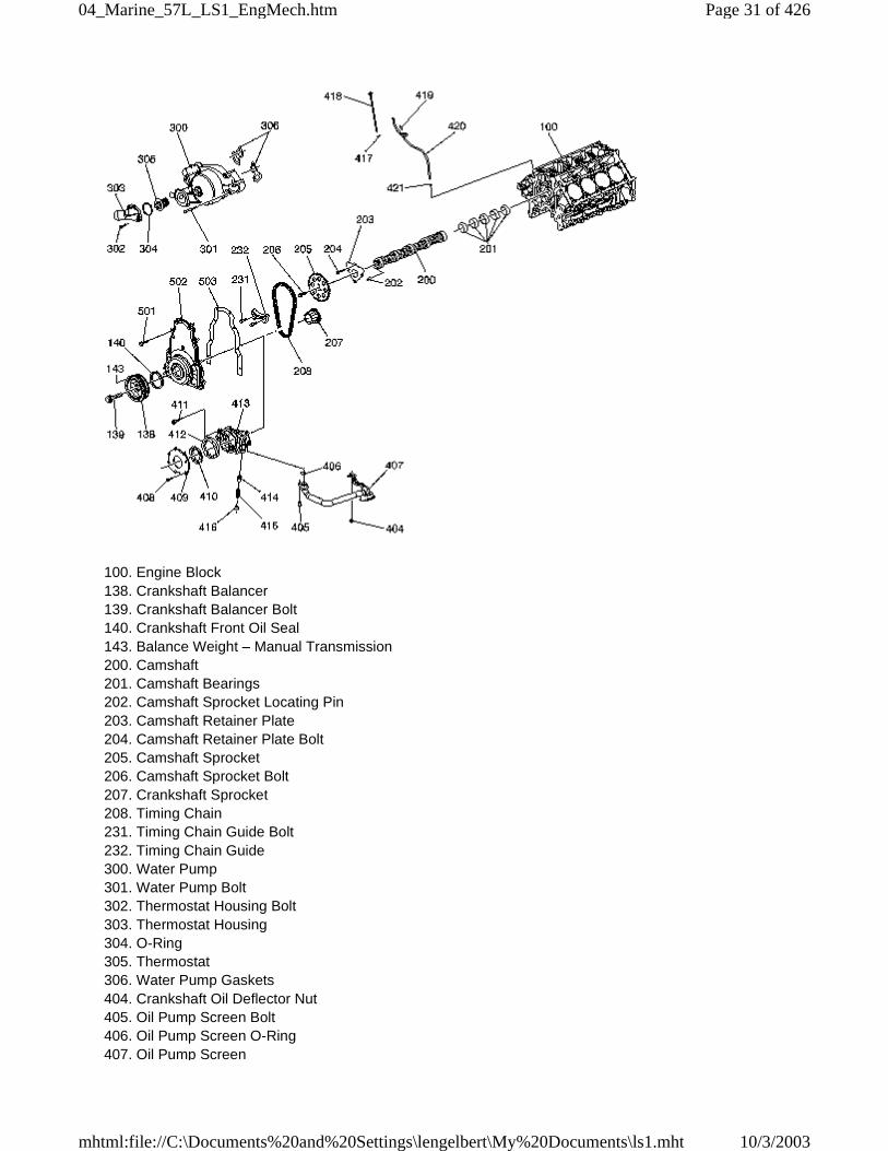
Rear of Engine
100. Engine Block 123. Clutch Pilot Bearing – Manual Transmission 132. Flywheel – Automatic Transmission 133. Flywheel Bolt 134. Flywheel – Manual Transmission 135. Clutch Disc – Manual Transmission 136. Pressure Plate – Manual Transmission 137. Pressure Plate Bolt – Manual Transmission 141. Crankshaft Rear Oil Seal
Page 32 of 42604_Marine_57L_LS1_EngMech.htm
10/3/2003mhtml:file://C:\Documents%20and%20Settings\lengelbert\My%20Documents\ls1.mht
142. Pressure Plate Locating Pin – Manual Transmission 144. Balance Weight – Manual Transmission 517. Rear Cover Bolt 518. Rear Cover 519. Rear Cover Gasket
Lower Engine Assembly
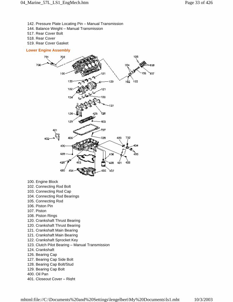
100. Engine Block 102. Connecting Rod Bolt 103. Connecting Rod Cap 104. Connecting Rod Bearings 105. Connecting Rod 106. Piston Pin 107. Piston 108. Piston Rings 120. Crankshaft Thrust Bearing 120. Crankshaft Thrust Bearing 121. Crankshaft Main Bearing 121. Crankshaft Main Bearing 122. Crankshaft Sprocket Key 123. Clutch Pilot Bearing – Manual Transmission 124. Crankshaft 126. Bearing Cap 127. Bearing Cap Side Bolt 128. Bearing Cap Bolt/Stud 129. Bearing Cap Bolt 400. Oil Pan 401. Closeout Cover – Right
Page 33 of 42604_Marine_57L_LS1_EngMech.htm
10/3/2003mhtml:file://C:\Documents%20and%20Settings\lengelbert\My%20Documents\ls1.mht
402. Closeout Cover Bolt – Right 403. Crankshaft Oil Deflector Nut 425. Crankshaft Oil Deflector 426. Oil Pan Gasket 429. Oil Pan Drain Plug O-Ring 430. Oil Pan Drain Plug 431. Closeout Cover – Left 432. Closeout Cover Bolt – Left 433. Oil Pan Cover Gasket 434. Oil Pan Cover 435. Oil Pan Cover Bolts 436. Oil Filter Bypass Valve 437. Oil Filter 438. Oil Filter Fitting 439. Oil Pan Bolt 453. Oil Pan Gasket – Lower 454. Oil Pan – Lower 455. Oil Pan Bolt – Lower 700. Crankshaft Position Sensor Bolt 701. Crankshaft Position Sensor 702. Crankshaft Position Sensor O-Ring 727. Oil Level Sensor 728. Oil Level Sensor O-Ring 732. Oil Temperature Sensor
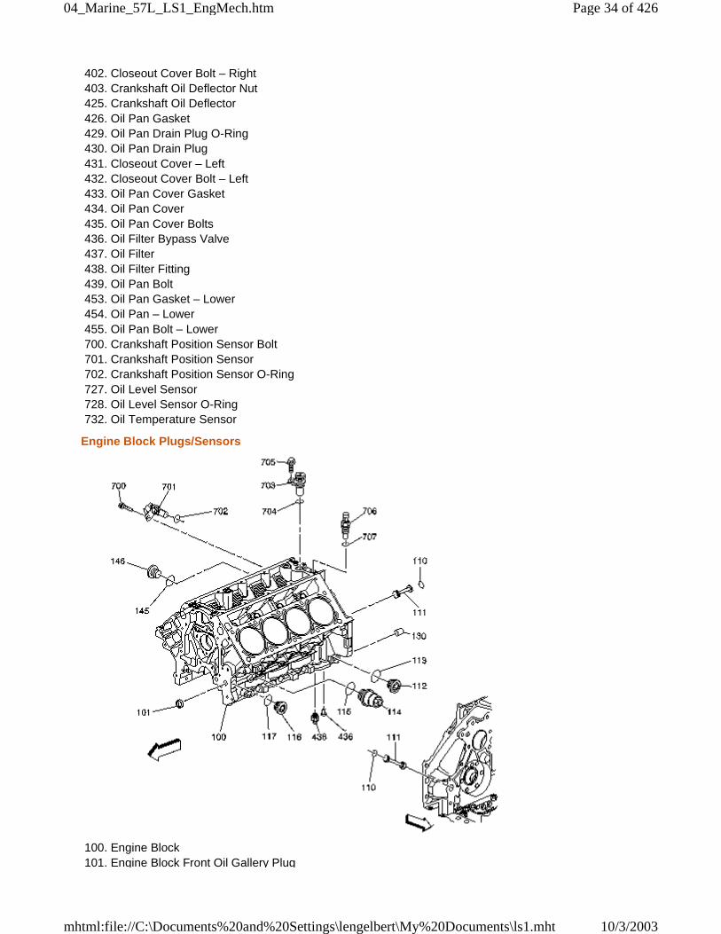
Engine Block Plugs/Sensors
100. Engine Block 101. Engine Block Front Oil Gallery Plug
Page 34 of 42604_Marine_57L_LS1_EngMech.htm
10/3/2003mhtml:file://C:\Documents%20and%20Settings\lengelbert\My%20Documents\ls1.mht
110. Engine Block Rear Oil Gallery Plug O-Ring 110. Engine Block Rear Oil Gallery Plug O-Ring 111. Engine Block Rear Oil Gallery Plug 111. Engine Block Rear Oil Gallery Plug 112. Oil Gallery Plug 113. Oil Gallery Plug Washer 114. Coolant Heater 115. Coolant Heater Washer 116. Oil Gallery Plug 117. Oil Gallery Plug Washer 130. Transmission Housing Locating Pin 145. Coolant Drain Plug Washer – Right 146. Coolant Drain Plug – Right 436. Oil Filter Bypass Valve 438. Oil Filter Fitting 700. Crankshaft Position Sensor Bolt 701. Crankshaft Position Sensor 702. Crankshaft Position Sensor O-Ring 703. Camshaft Position Sensor 704. Camshaft Position Sensor O-Ring 705. Camshaft Position Sensor Bolt 706. Oil Pressure Sensor 707. Oil Pressure Sensor Washer
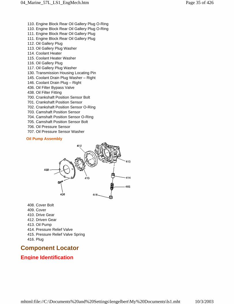
Oil Pump Assembly
408. Cover Bolt 409. Cover 410. Drive Gear 412. Driven Gear 413. Oil Pump 414. Pressure Relief Valve 415. Pressure Relief Valve Spring 416. Plug
Component Locator
Engine Identification
Page 35 of 42604_Marine_57L_LS1_EngMech.htm
10/3/2003mhtml:file://C:\Documents%20and%20Settings\lengelbert\My%20Documents\ls1.mht
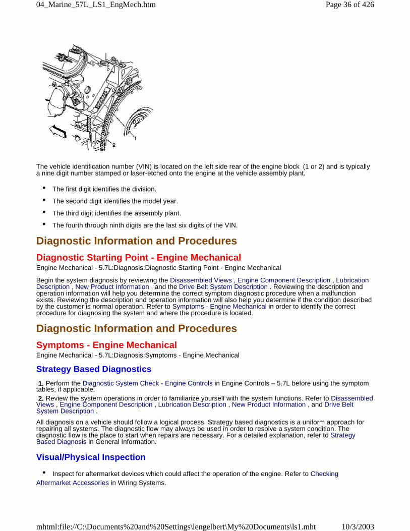
The vehicle identification number (VIN) is located on the left side rear of the engine block (1 or 2) and is typicallya nine digit number stamped or laser-etched onto the engine at the vehicle assembly plant.
• The first digit identifies the division.
• The second digit identifies the model year.
• The third digit identifies the assembly plant.
• The fourth through ninth digits are the last six digits of the VIN.
Diagnostic Information and Procedures
Diagnostic Starting Point - Engine MechanicalEngine Mechanical - 5.7L:Diagnosis:Diagnostic Starting Point - Engine Mechanical
Begin the system diagnosis by reviewing the Disassembled Views , Engine Component Description , LubricationDescription , New Product Information , and the Drive Belt System Description . Reviewing the description andoperation information will help you determine the correct symptom diagnostic procedure when a malfunctionexists. Reviewing the description and operation information will also help you determine if the condition describedby the customer is normal operation. Refer to Symptoms - Engine Mechanical in order to identify the correctprocedure for diagnosing the system and where the procedure is located.
Diagnostic Information and Procedures
Symptoms - Engine MechanicalEngine Mechanical - 5.7L:Diagnosis:Symptoms - Engine Mechanical
Strategy Based Diagnostics
1. Perform the Diagnostic System Check - Engine Controls in Engine Controls – 5.7L before using the symptomtables, if applicable. 2. Review the system operations in order to familiarize yourself with the system functions. Refer to DisassembledViews , Engine Component Description , Lubrication Description , New Product Information , and Drive BeltSystem Description .
All diagnosis on a vehicle should follow a logical process. Strategy based diagnostics is a uniform approach forrepairing all systems. The diagnostic flow may always be used in order to resolve a system condition. Thediagnostic flow is the place to start when repairs are necessary. For a detailed explanation, refer to StrategyBased Diagnosis in General Information.
Visual/Physical Inspection
• Inspect for aftermarket devices which could affect the operation of the engine. Refer to CheckingAftermarket Accessories in Wiring Systems.
Page 36 of 42604_Marine_57L_LS1_EngMech.htm
10/3/2003mhtml:file://C:\Documents%20and%20Settings\lengelbert\My%20Documents\ls1.mht
• Inspect the easily accessible or visible system components for obvious damage or conditions which couldcause the symptom.
• Check for the correct oil level, proper oil viscosity, and correct filter application.
• Verify the exact operating conditions under which the concern exists. Note factors such as engine RPM,ambient temperature, engine temperature, amount of engine warm-up time, and other specifics.
• Compare the engine sounds, if applicable, to a known good engine and make sure you are not trying tocorrect a normal condition.
IntermittentTest the vehicle under the same conditions that the customer reported in order to verify the system is operatingproperly.
Symptom ListRefer to a symptom diagnostic procedure from the following list in order to diagnose the symptom:
• Base Engine Misfire without Internal Engine Noises
• Base Engine Misfire with Abnormal Internal Lower Engine Noises
• Base Engine Misfire with Abnormal Valve Train Noise
• Base Engine Misfire with Coolant Consumption
• Base Engine Misfire with Excessive Oil Consumption
• Engine Compression Test
• Engine Noise on Start-Up, but Only Lasting a Few Seconds
• Upper Engine Noise, Regardless of Engine Speed
• Lower Engine Noise, Regardless of Engine Speed
• Engine Noise Under Load
• Engine Will Not Crank - Crankshaft Will Not Rotate
• Coolant in Combustion Chamber
• Coolant in Engine Oil
• Oil Consumption Diagnosis
• Oil Pressure Diagnosis and Testing
• Oil Leak Diagnosis
• Cylinder Leakage Test
• Drive Belt Chirping Diagnosis
• Drive Belt Squeal Diagnosis
• Drive Belt Whine Diagnosis
• Drive Belt Rumbling Diagnosis
• Drive Belt Vibration Diagnosis
• Drive Belt Falls Off Diagnosis
• Drive Belt Excessive Wear Diagnosis
• Drive Belt Tensioner Diagnosis
Page 37 of 42604_Marine_57L_LS1_EngMech.htm
10/3/2003mhtml:file://C:\Documents%20and%20Settings\lengelbert\My%20Documents\ls1.mht
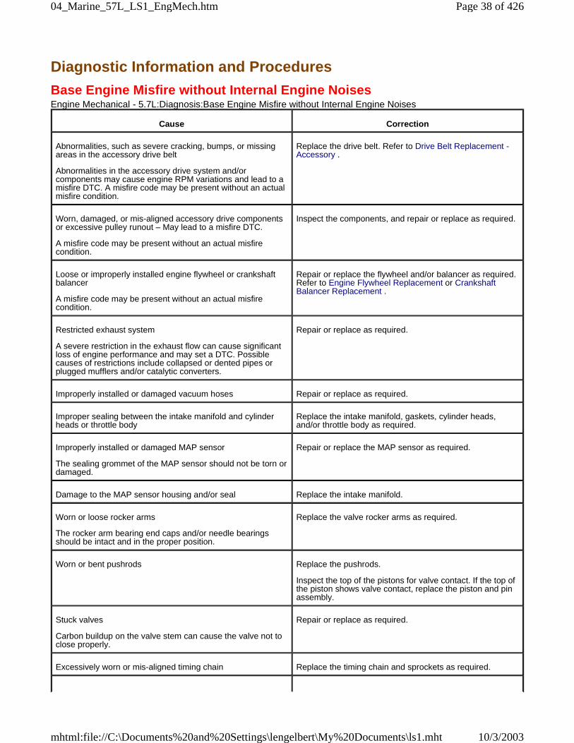
Diagnostic Information and Procedures
Base Engine Misfire without Internal Engine NoisesEngine Mechanical - 5.7L:Diagnosis:Base Engine Misfire without Internal Engine Noises
Cause Correction
Abnormalities, such as severe cracking, bumps, or missingareas in the accessory drive belt
Abnormalities in the accessory drive system and/orcomponents may cause engine RPM variations and lead to amisfire DTC. A misfire code may be present without an actualmisfire condition.
Replace the drive belt. Refer to Drive Belt Replacement -Accessory .
Worn, damaged, or mis-aligned accessory drive componentsor excessive pulley runout – May lead to a misfire DTC.
A misfire code may be present without an actual misfirecondition.
Inspect the components, and repair or replace as required.
Loose or improperly installed engine flywheel or crankshaftbalancer
A misfire code may be present without an actual misfirecondition.
Repair or replace the flywheel and/or balancer as required.Refer to Engine Flywheel Replacement or CrankshaftBalancer Replacement .
Restricted exhaust system
A severe restriction in the exhaust flow can cause significantloss of engine performance and may set a DTC. Possiblecauses of restrictions include collapsed or dented pipes orplugged mufflers and/or catalytic converters.
Repair or replace as required.
Improperly installed or damaged vacuum hoses Repair or replace as required.
Improper sealing between the intake manifold and cylinderheads or throttle body
Replace the intake manifold, gaskets, cylinder heads,and/or throttle body as required.
Improperly installed or damaged MAP sensor
The sealing grommet of the MAP sensor should not be torn ordamaged.
Repair or replace the MAP sensor as required.
Damage to the MAP sensor housing and/or seal Replace the intake manifold.
Worn or loose rocker arms
The rocker arm bearing end caps and/or needle bearingsshould be intact and in the proper position.
Replace the valve rocker arms as required.
Worn or bent pushrods Replace the pushrods.
Inspect the top of the pistons for valve contact. If the top ofthe piston shows valve contact, replace the piston and pinassembly.
Stuck valves
Carbon buildup on the valve stem can cause the valve not toclose properly.
Repair or replace as required.
Excessively worn or mis-aligned timing chain Replace the timing chain and sprockets as required.
Page 38 of 42604_Marine_57L_LS1_EngMech.htm
10/3/2003mhtml:file://C:\Documents%20and%20Settings\lengelbert\My%20Documents\ls1.mht
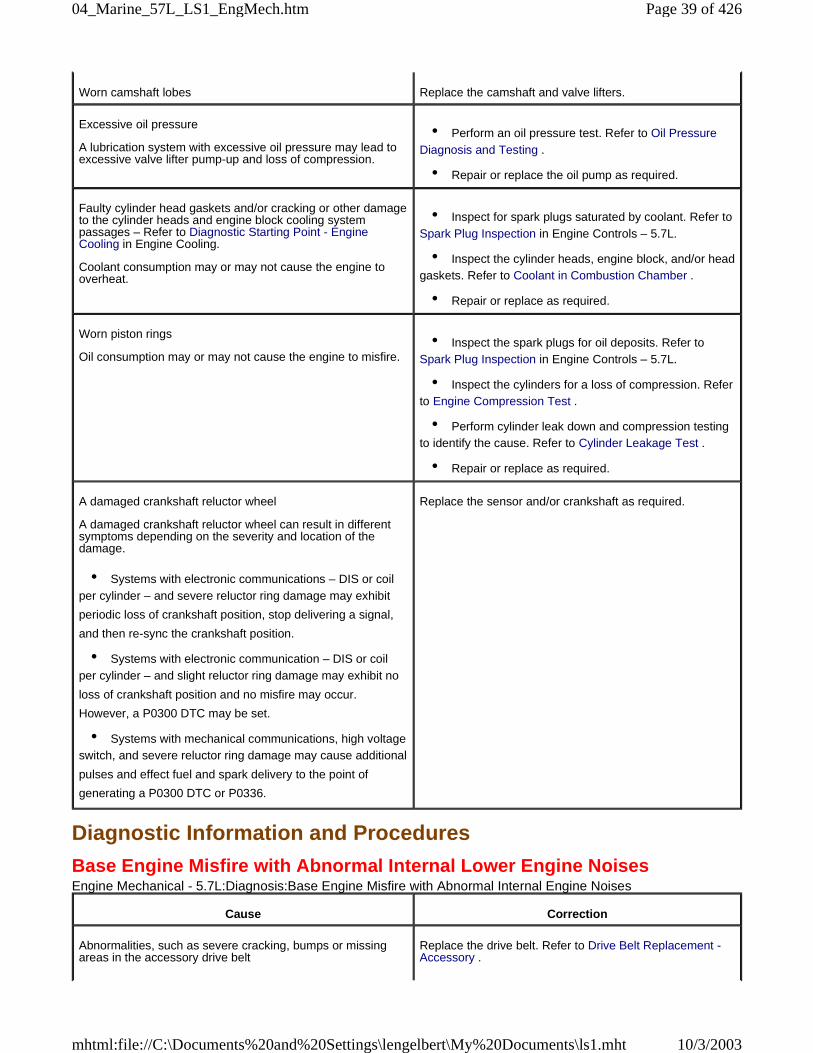
Diagnostic Information and Procedures
Base Engine Misfire with Abnormal Internal Lower Engine NoisesEngine Mechanical - 5.7L:Diagnosis:Base Engine Misfire with Abnormal Internal Engine Noises
Worn camshaft lobes Replace the camshaft and valve lifters.
Excessive oil pressure
A lubrication system with excessive oil pressure may lead toexcessive valve lifter pump-up and loss of compression.
• Perform an oil pressure test. Refer to Oil PressureDiagnosis and Testing .
• Repair or replace the oil pump as required.
Faulty cylinder head gaskets and/or cracking or other damageto the cylinder heads and engine block cooling systempassages – Refer to Diagnostic Starting Point - EngineCooling in Engine Cooling.
Coolant consumption may or may not cause the engine tooverheat.
• Inspect for spark plugs saturated by coolant. Refer toSpark Plug Inspection in Engine Controls – 5.7L.
• Inspect the cylinder heads, engine block, and/or headgaskets. Refer to Coolant in Combustion Chamber .
• Repair or replace as required.
Worn piston rings
Oil consumption may or may not cause the engine to misfire. • Inspect the spark plugs for oil deposits. Refer toSpark Plug Inspection in Engine Controls – 5.7L.
• Inspect the cylinders for a loss of compression. Referto Engine Compression Test .
• Perform cylinder leak down and compression testingto identify the cause. Refer to Cylinder Leakage Test .
• Repair or replace as required.
A damaged crankshaft reluctor wheel
A damaged crankshaft reluctor wheel can result in differentsymptoms depending on the severity and location of thedamage.
• Systems with electronic communications – DIS or coilper cylinder – and severe reluctor ring damage may exhibit
periodic loss of crankshaft position, stop delivering a signal,
and then re-sync the crankshaft position.
• Systems with electronic communication – DIS or coilper cylinder – and slight reluctor ring damage may exhibit no
loss of crankshaft position and no misfire may occur.
However, a P0300 DTC may be set.
• Systems with mechanical communications, high voltageswitch, and severe reluctor ring damage may cause additional
pulses and effect fuel and spark delivery to the point of
generating a P0300 DTC or P0336.
Replace the sensor and/or crankshaft as required.
Cause Correction
Abnormalities, such as severe cracking, bumps or missingareas in the accessory drive belt
Replace the drive belt. Refer to Drive Belt Replacement -Accessory .
Page 39 of 42604_Marine_57L_LS1_EngMech.htm
10/3/2003mhtml:file://C:\Documents%20and%20Settings\lengelbert\My%20Documents\ls1.mht
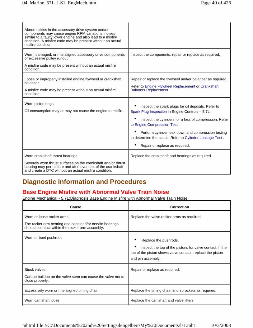
Diagnostic Information and Procedures
Base Engine Misfire with Abnormal Valve Train NoiseEngine Mechanical - 5.7L:Diagnosis:Base Engine Misfire with Abnormal Valve Train Noise
Abnormalities in the accessory drive system and/orcomponents may cause engine RPM variations, noisessimilar to a faulty lower engine and also lead to a misfirecondition. A misfire code may be present without an actualmisfire condition.
Worn, damaged, or mis-aligned accessory drive componentsor excessive pulley runout
A misfire code may be present without an actual misfirecondition.
Inspect the components, repair or replace as required.
Loose or improperly installed engine flywheel or crankshaftbalancer
A misfire code may be present without an actual misfirecondition.
Repair or replace the flywheel and/or balancer as required.
Refer to Engine Flywheel Replacement or CrankshaftBalancer Replacement .
Worn piston rings
Oil consumption may or may not cause the engine to misfire. • Inspect the spark plugs for oil deposits. Refer toSpark Plug Inspection in Engine Controls – 5.7L.
• Inspect the cylinders for a loss of compression. Referto Engine Compression Test .
• Perform cylinder leak down and compression testingto determine the cause. Refer to Cylinder Leakage Test .
• Repair or replace as required.
Worn crankshaft thrust bearings
Severely worn thrust surfaces on the crankshaft and/or thrustbearing may permit fore and aft movement of the crankshaftand create a DTC without an actual misfire condition.
Replace the crankshaft and bearings as required.
Cause Correction
Worn or loose rocker arms
The rocker arm bearing end caps and/or needle bearingsshould be intact within the rocker arm assembly.
Replace the valve rocker arms as required.
Worn or bent pushrods • Replace the pushrods.
• Inspect the top of the pistons for valve contact. If thetop of the piston shows valve contact, replace the piston
and pin assembly.
Stuck valves
Carbon buildup on the valve stem can cause the valve not toclose properly.
Repair or replace as required.
Excessively worn or mis-aligned timing chain Replace the timing chain and sprockets as required.
Worn camshaft lobes Replace the camshaft and valve lifters.
Page 40 of 42604_Marine_57L_LS1_EngMech.htm
10/3/2003mhtml:file://C:\Documents%20and%20Settings\lengelbert\My%20Documents\ls1.mht
Diagnostic Information and Procedures
Base Engine Misfire with Coolant ConsumptionEngine Mechanical - 5.7L:Diagnosis:Base Engine Misfire with Coolant Consumption
Diagnostic Information and Procedures
Base Engine Misfire with Excessive Oil ConsumptionEngine Mechanical - 5.7L:Diagnosis:Base Engine Misfire with Excessive Oil Consumption
Diagnostic Information and Procedures
Engine Noise on Start-Up, but Only Lasting a Few SecondsEngine Mechanical - 5.7L:Diagnosis:Engine Noise on Start-Up, but Only Lasting a Few Seconds
Sticking lifters Replace as required.
Cause Correction
Faulty cylinder head gaskets and/or cracking or other damageto the cylinder heads and engine block cooling systempassages – Refer to Diagnostic Starting Point - EngineCooling in Engine Cooling.
Coolant consumption may or may not cause the engine tooverheat.
• Inspect for spark plugs saturated by coolant. Refer toSpark Plug Inspection in Engine Controls – 5.7L.
• Perform a cylinder leak down test. Refer to CylinderLeakage Test .
• Inspect the cylinder heads and engine block fordamage to the coolant passages and/or a faulty head
gasket. Refer to Coolant in Combustion Chamber .
• Repair or replace as required.
Cause Correction
Worn valves, valve guides and/or valve stem oil seals • Inspect the spark plugs for oil deposits. Refer toSpark Plug Inspection in Engine Controls – 5.7L.
• Repair or replace as required.
Worn piston rings
Oil consumption may or may not cause the engine to misfire. • Inspect the spark plugs for oil deposits. Refer toSpark Plug Inspection in Engine Controls – 5.7L.
• Inspect the cylinders for a loss of compression. Referto Engine Compression Test .
• Perform cylinder leak down and compression testingto determine the cause. Refer to Cylinder Leakage Test .
• Repair or replace as required.
Cause Correction
Important: A cold piston knock which disappears in 1.5 minutes should be considered acceptable. A cold engine knockusually disappears when the specific cylinder’s secondary ignition circuit is grounded out during diagnosis.A light rattle/tapping noise may indicate a valve train, upper engine concern, or a low rumble/knocking may indicate acrankshaft or piston, lower engine concern.
Page 41 of 42604_Marine_57L_LS1_EngMech.htm
10/3/2003mhtml:file://C:\Documents%20and%20Settings\lengelbert\My%20Documents\ls1.mht
Diagnostic Information and Procedures
Upper Engine Noise, Regardless of Engine SpeedEngine Mechanical - 5.7L:Diagnosis:Upper Engine Noise, Regardless of Engine Speed
Incorrect oil filter without anti-drainback feature Install the correct oil filter.
Incorrect oil viscosity 1. Drain the oil. 2. Install the correct viscosity oil.
High valve lifter leak down rate Replace the lifters as required.
Worn crankshaft thrust bearing 1. Check the crankshaft end play. 2. Inspect the thrust bearing and crankshaft. 3. Repair or replace as required.
Damaged or faulty oil filter by-pass valve • Inspect the oil filter by-pass valve for properoperation.
• Repair or replace as required.
Cause Correction
Important: A cold piston knock which disappears in 1.5 minutes should be considered acceptable. A cold engine knockusually disappears when the specific cylinder’s secondary ignition circuit is grounded out during diagnosis.A light rattle/tapping noise may indicate a valve train, upper engine concern.
Low oil pressure • Perform an oil pressure test. Refer to Oil PressureDiagnosis and Testing .
• Repair or replace as required.
Loose and/or worn valve rocker arm attachments • Inspect the valve rocker arm, bolt, and pedestal.
• Repair or replace as required.
Worn or damaged valve rocker arm • Inspect the rocker arm for wear or missing needlebearings.
• Replace the valve rocker arms as required.
Bent or damaged push rod Inspect the following components, and replace as required:
• The valve rocker arm
• The valve push rod
• The valve lifter
• The valve lifter guide
• The piston
Inspect the top of the pistons for valve contact. If the top ofthe piston shows valve contact, replace the piston and pinassembly.
Improper lubrication to the valve rocker arms Inspect the following components, and repair or replace as
Page 42 of 42604_Marine_57L_LS1_EngMech.htm
10/3/2003mhtml:file://C:\Documents%20and%20Settings\lengelbert\My%20Documents\ls1.mht
Diagnostic Information and Procedures
Lower Engine Noise, Regardless of Engine SpeedEngine Mechanical - 5.7L:Diagnosis:Lower Engine Noise, Regardless of Engine Speed
required:
• Restricted oil filter
• The valve rocker arm
• The valve push rod
• The valve lifter
• The oil filter bypass valve
• The oil pump and pump screen
• The engine block oil galleries
Broken valve spring Replace the valve spring.
Loose or broken valve lifter guide Repair or replace as required.
Worn or dirty valve lifters Replace the valve lifters.
Stretched or broken timing chain and/or damaged sprocketteeth
Replace the timing chain and sprockets.
Worn engine camshaft lobes • Inspect the engine camshaft lobes.
• Replace the camshaft and valve lifters as required.
Worn valve guides or valve stems Inspect the following components, and repair as required:
• The valves
• The valve guides
Stuck valves
Carbon on the valve stem or valve seat may cause the valveto stay open.
Inspect the following components, and repair as required:
• The valves
• The valve guides
Cause Correction
Important: A cold piston knock which disappears in 1.5 minutes should be considered acceptable. A cold engine knockusually disappears when the specific cylinder’s secondary ignition circuit is grounded out during diagnosis.A low rumble/knocking may indicate a crankshaft or piston, lower engine concern.
Low oil pressure • Perform an oil pressure test. Refer to Oil PressureDiagnosis and Testing .
• Repair or replace damaged components as required.
Worn accessory drive components
Abnormalities, such as severe cracking, bumps or missingareas in the accessory drive belt and/or misalignment ofsystem components.
• Inspect the accessory drive system.
• Repair or replace as required.
Page 43 of 42604_Marine_57L_LS1_EngMech.htm
10/3/2003mhtml:file://C:\Documents%20and%20Settings\lengelbert\My%20Documents\ls1.mht
Diagnostic Information and Procedures
Engine Noise Under LoadEngine Mechanical - 5.7L:Diagnosis:Engine Noise Under Load
Loose or damaged crankshaft balancer • Inspect the crankshaft balancer.
• Repair or replace as required.
Detonation or spark knock Verify the correct operation of the ignition controls system.Refer to Detonation/Spark Knock in Engine Controls –5.7L.
Loose torque converter bolts • Inspect the torque converter bolts and flywheel.
• Repair or replace as required.
Loose or damaged flywheel Repair or replace the flywheel.
Oil pump screen loose, damaged or restricted • Inspect the oil pump screen.
• Repair or replace as required.
Excessive piston-to-cylinder bore clearance • Inspect the piston and cylinder bore.
• Repair as required.
Excessive piston pin-to-bore clearance • Inspect the piston, pin, and connecting rod.
• Replace the piston, pin and connecting rod as anassembly, as required.
Excessive connecting rod bearing clearance Inspect the following components, and repair as required:
• The connecting rod bearings
• The connecting rods
• The crankshaft
• The crankshaft journals
Excessive crankshaft bearing clearance Inspect the following components, and repair as required:
• The crankshaft bearings
• The crankshaft journals
Incorrect piston, piston pin and connecting rod installation
Pistons must be installed with the mark or dimple on the topof the piston facing the front of the engine. Piston pins mustbe centered in the connecting rod pin bore.
• Verify the pistons, piston pins and connecting rodsare installed correctly. Refer to Piston, Connecting Rod,
and Bearing Installation .
• Repair as required.
Cause Correction
Important: A cold piston knock which disappears in 1.5 minutes should be considered acceptable. A cold engine knock
Page 44 of 42604_Marine_57L_LS1_EngMech.htm
10/3/2003mhtml:file://C:\Documents%20and%20Settings\lengelbert\My%20Documents\ls1.mht
Diagnostic Information and Procedures
Engine Will Not Crank - Crankshaft Will Not RotateEngine Mechanical - 5.7L:Diagnosis:Engine Will Not Crank - Crankshaft Will Not Rotate
usually disappears when the specific cylinder’s secondary ignition circuit is grounded out during diagnosis.A low rumble/knocking may indicate a crankshaft or piston, lower engine concern.
Low oil pressure • Perform an oil pressure test. Refer to Oil PressureDiagnosis and Testing .
• Repair or replace as required.
Detonation or spark knock Verify the correct operation of the ignition controls. Refer toDetonation/Spark Knock in Engine Controls – 5.7L.
Loose torque converter bolts • Inspect the torque converter bolts and flywheel.
• Repair as required.
Cracked flywheel – automatic transmission • Inspect the flywheel bolts and flywheel.
• Repair as required.
Excessive connecting rod bearing clearance Inspect the following components, and repair as required:
• The connecting rod bearings
• The connecting rods
• The crankshaft
Excessive crankshaft bearing clearance Inspect the following components, and repair as required:
• The crankshaft bearings
• The crankshaft journals
• The cylinder block crankshaft bearing bore
Cause Correction
Seized accessory drive system component 1. Remove the accessory drive belts. 2. Confirm that the engine will rotate. Rotate thecrankshaft by hand at the crankshaft balancer or flywheellocation.
3. Repair or replace the components as required.
Seized driveline/propshaft assembly – Corvette automatictransmission application
1. Separate the engine flywheel from the input shaft of thepropshaft.
2. Confirm that the engine will rotate. Rotate thecrankshaft by hand at the crankshaft balancer or flywheellocation.
3. Repair or replace the components as required.
Seized automatic transmission torque converter 1. Remove the torque converter-to-flywheel bolts. 2. Confirm that the engine will rotate. Rotate thecrankshaft by hand at the crankshaft balancer or flywheellocation.
Page 45 of 42604_Marine_57L_LS1_EngMech.htm
10/3/2003mhtml:file://C:\Documents%20and%20Settings\lengelbert\My%20Documents\ls1.mht
3. Repair or replace the components as required.
Seized manual transmission 1. Disengage the clutch by depressing the clutch pedal. 2. Confirm that the engine will rotate. Rotate thecrankshaft by hand at the crankshaft balancer or flywheellocation.
Refer to Transmission/Transaxle Unit RepairManual.
Broken timing chain • Inspect the timing chain and gears.
• Repair or replace the components as required.
Seized timing chain or timing gears • Inspect the timing chain and gears for foreignmaterial or a seized chain.
• Repair or replace the components as required.
Seized or broken camshaft • Inspect the camshaft and the camshaft bearings.
• Repair or replace the components as required.
Bent valve in the cylinder head • Inspect the valves and the cylinder heads.
• Repair or replace the components as required.
Seized oil pump • Inspect the oil pump assembly.
• Repair or replace as required.
Hydraulically locked cylinder
• Coolant/antifreeze in the cylinder
• Oil in the cylinder
• Fuel in the cylinder
1. Remove the spark plugs and check for fluid in thecylinder. When rotating the engine with the spark plugsremoved, the piston, on compression stroke, will push fluidfrom the combustion chamber.
2. Inspect for failed/broken head gaskets. Refer to Coolantin Combustion Chamber .
3. Inspect for a cracked engine block or cylinder head. 4. Inspect for a sticking fuel injector. 5. Repair or replace the components as required.
Material in the cylinder
• Broken valve
• Broken piston rings
• Piston material
• Foreign material
• Inspect the cylinder for damaged components and/orforeign materials.
• Repair or replace the components as required.
Seized crankshaft or connecting rod bearings • Inspect crankshaft and connecting rod bearings.
• Repair or replace the components as required.
Bent or broken connecting rod • Inspect the connecting rods.
• Replace the piston, pin and connecting rod as anassembly, as required.
Page 46 of 42604_Marine_57L_LS1_EngMech.htm
10/3/2003mhtml:file://C:\Documents%20and%20Settings\lengelbert\My%20Documents\ls1.mht
Diagnostic Information and Procedures
Coolant in Combustion Chamber
Diagnostic Information and Procedures
Coolant in Engine Oil
Broken crankshaft • Inspect the crankshaft.
• Repair or replace the components as required.
Cause Correction
DEFINITION: Excessive white smoke and/or coolant type odor coming from the exhaust pipe may indicate coolant in thecombustion chamber. Low coolant levels, an inoperative cooling fan, or a faulty thermostat may lead to an"overtemperature" condition which may cause engine component damage.
1. A slower than normal cranking speed may indicate coolant entering the combustion chamber. Refer to Engine Will NotCrank - Crankshaft Will Not Rotate .
2. Remove the spark plugs and inspect for spark plugs saturated by coolant or coolant in the cylinder bore. 3. Inspect by performing a cylinder leak-down test. During this test, excessive air bubbles within the coolant may indicate afaulty gasket or damaged component.
4. Inspect by performing a cylinder compression test. Two cylinders "side-by-side" on the engine block, with lowcompression, may indicate a failed cylinder head gasket. Refer to Engine Compression Test .
Cracked intake manifold or failed gasket Replace the components as required.
Faulty cylinder head gasket Replace the head gasket and components as required.Refer to Cylinder Head Cleaning and Inspection , CylinderHead Replacement - Left and Cylinder Head Replacement- Right .
Warped cylinder head Machine the cylinder head to the proper flatness, ifapplicable and replace the cylinder head gasket. Refer toCylinder Head Cleaning and Inspection .
Cracked cylinder head Replace the cylinder head and gasket.
Cracked cylinder liner or engine block Replace the components as required.
Cylinder head or engine block porosity Replace the components as required.
Cause Correction
DEFINITION: Foamy or discolored oil or an engine oil "overfill" condition may indicate coolant entering the enginecrankcase. Low coolant levels, an inoperative cooling fan, or a faulty thermostat may lead to an "overtemperature" conditionwhich may cause engine component damage. Contaminated engine oil and oil filter should be changed.
1. Inspect the oil for excessive foaming or an overfill condition. Oil diluted by coolant may not properly lubricate thecrankshaft bearings and may lead to component damage. Refer to Lower Engine Noise, Regardless of Engine Speed .
2. Inspect by performing a cylinder leak-down test. During this test, excessive air bubbles within the cooling system mayindicate a faulty gasket or damaged component.
3. Inspect by performing a cylinder compression test. Two cylinders "side-by-side" on the engine block with lowcompression may indicate a failed cylinder head gasket. Refer to Engine Compression Test .
Faulty external engine oil cooler Replace the components as required.
Faulty cylinder head gasket Replace the head gasket and components as required.Refer to Cylinder Head Cleaning and Inspection , Cylinder
Page 47 of 42604_Marine_57L_LS1_EngMech.htm
10/3/2003mhtml:file://C:\Documents%20and%20Settings\lengelbert\My%20Documents\ls1.mht
Diagnostic Information and Procedures
Engine Compression TestEngine Mechanical - 5.7L:Diagnosis:Engine Compression Test
1. Charge the battery if the battery is not fully charged. 2. Disable the ignition system. 3. Disable the fuel injection system. 4. Remove all the spark plugs. 5. Turn the ignition to the ON position. 6. Depress the accelerator pedal to position the throttle plate wide open. 7. Start with the compression gauge at zero and crank the engine through four compression strokes, 4 puffs. 8. Check the compression for each cylinder. Record the readings. 9. If a cylinder has low compression, inject approximately 15 ml (1 tablespoon) of engine oil into the combustionchamber through the spark plug hole. Recheck the compression and record the reading. 10. The minimum compression in any one cylinder should not be less than 70 percent of the highest cylinder. Nocylinder should read less than 690 kPa (100 psi). For example, if the highest pressure in any one cylinder is1 035 kPa (150 psi), the lowest allowable pressure for any other cylinder would be 725 kPa (105 psi).(1 035 x 70% = 725) (150 x 70% = 105).
• Normal — Compression builds up quickly and evenly to the specified compression for each cylinder.
• Piston Rings Leaking — Compression is low on the first stroke. Then compression builds up with thefollowing strokes but does not reach normal. Compression improves considerably when you add oil.
• Valves Leaking — Compression is low on the first stroke. Compression usually does not build up onthe following strokes. Compression does not improve much when you add oil.
• If 2 adjacent cylinders have lower than normal compression, and injecting oil into the cylinders doesnot increase the compression, the cause may be a head gasket leaking between the cylinders.
Diagnostic Information and Procedures
Engine BalancingEngine Mechanical - 5.7L:Diagnosis:Engine Balancing
The 1997–2004 5.7L LS1/LS6 engine with crankshaft balancer is a balanced assembly. On manual transmissionapplications, the flywheel, clutch, and pressure plate is also a balanced assembly. During the powertrain buildprocess, balance weights may be added to the crankshaft balancer and/or flywheel as required.
In order to maintain engine/clutch assembly balance, it may be necessary to install or remove balance weights asdetailed below:
Crankshaft Balancer
• Existing balancer onto existing engine:
Head Replacement - Left and Cylinder Head Replacement- Right .
Warped cylinder head Machine the cylinder head to proper flatness, if applicable,and replace the cylinder head gasket. Refer to CylinderHead Cleaning and Inspection .
Cracked cylinder head Replace the cylinder head and gasket.
Cracked cylinder liner or engine block Replace the components as required.
Cylinder head, block, or manifold porosity Replace the components as required.
Page 48 of 42604_Marine_57L_LS1_EngMech.htm
10/3/2003mhtml:file://C:\Documents%20and%20Settings\lengelbert\My%20Documents\ls1.mht
The balancer position must be marked prior to removal and installed to the original position. Refer toCrankshaft Balancer Removal .
• New balancer onto an existing engine:
Install the same size balance weights into the new balancer in the same location as the old component.Refer to Crankshaft Balancer Cleaning and Inspection .
Engine FlywheelImportant: The flywheel, clutch, and pressure plate are a balanced assembly and are not available asindividual components. The pressure plate mounts or locates onto the flywheel via two dowel pins in theflywheel. If the pressure plate is not aligned properly onto the dowel pins and tightened down, the pins maybend and the plate may be incorrectly positioned which will effect component balance. Refer to ClutchAssembly Replacement .
• Existing flywheel, clutch, and pressure plate assembly onto the existing engine:
Flywheel position must be marked prior to removal and installed to the original position. Refer to EngineFlywheel Removal .
• Existing flywheel, clutch, and pressure plate onto a new engine:
Remove balance weights, if applicable from the flywheel.
• New flywheel, clutch, and pressure plate assembly onto an existing engine:
Do not transfer or install balance weights.
• New flywheel, clutch, and pressure plate assembly onto a new engine:
Do not install balance weights.
Diagnostic Information and Procedures
Cylinder Leakage Test
Tools Required
J 35667-A Cylinder Head Leakdown Tester or equivalent
Caution: Refer to Battery Disconnect Caution in Cautions and Notices.
Important: A leakage test may be performed in order to measure cylinder/combustion chamber leakage.High cylinder leakage may indicate one or more of the following:
• Worn or burnt valves
• Broken valve springs
• Stuck valve lifters
• Incorrect valve lash
• Damaged piston
• Worn piston rings
• Worn or scored cylinder bore
• Damaged cylinder head gasket
• Cracked or damaged cylinder head
• Cracked or damaged engine block
1. Disconnect the battery ground negative cable. 2. Remove the spark plugs. 3. Rotate the crankshaft to place the piston in the cylinder being tested at top dead center (TDC) of the
Page 49 of 42604_Marine_57L_LS1_EngMech.htm
10/3/2003mhtml:file://C:\Documents%20and%20Settings\lengelbert\My%20Documents\ls1.mht
compression stroke. 4. Install the J 35667-A or equivalent.
Important: It may be necessary to hold the crankshaft balancer bolt to prevent the crankshaft fromrotating.
5. Apply shop air pressure to the J 35667-A and adjust according to the manufacturers instructions. 6. Record the cylinder leakage value. Cylinder leakage that exceeds 25 percent is considered excessive andmay require component service. In excessive leakage situations, inspect for the following conditions:
• Air leakage noise at the throttle body or air inlet hose that may indicate a worn or burnt intake valve ora broken valve spring.
• Air leakage noise at the exhaust system tailpipe that may indicate a worn or burnt exhaust valve or abroken valve spring.
• Air leakage noise from the crankcase, oil level indicator tube, or oil fill tube that may indicate wornpiston rings, a damaged piston, a worn or scored cylinder bore, a damaged engine block or a damaged
cylinder head.
• Air bubbles in the cooling system may indicate a damaged cylinder head or a damaged cylinder headgasket.
7. Perform the leakage test on the remaining cylinders and record the values.
Diagnostic Information and Procedures
Oil Consumption DiagnosisEngine Mechanical - 5.7L:Diagnosis:Oil Consumption
Checks Causes
DEFINITION: Excessive oil consumption, not due to leaks, is the use of 0.95 liters (1.0 qt) or more of engine oil within2 414 kilometers (1,500 miles).
The causes of excessive oil consumption may include the following conditions:
Preliminary • External oil leaks
Refer to Oil Leak Diagnosis .
• Incorrect oil level or improper reading of the oil level indicator
With the vehicle on a level surface, run the engine for a few minutes, allowadequate drain down time of 2–3 minutes and check for the correct engine oillevel.
• Improper oil viscosity
Refer to the vehicle owners manual and use the recommended SAE grade andviscosity for the prevailing temperatures.
• Continuous high speed driving and/or severe usage
• Crankcase ventilation system restrictions or malfunctioning components
• Worn valve guides and/or valve stems
• Worn or improperly installed valve stem oil seals
• Piston rings broken, worn, not seated properly
Allow adequate time for the rings to seat.
Replace worn piston rings as necessary.
• Piston and rings improperly installed or miss-fitted to the cylinder bore
Page 50 of 42604_Marine_57L_LS1_EngMech.htm
10/3/2003mhtml:file://C:\Documents%20and%20Settings\lengelbert\My%20Documents\ls1.mht
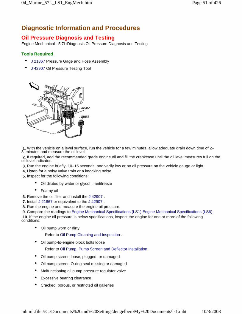
Diagnostic Information and Procedures
Oil Pressure Diagnosis and TestingEngine Mechanical - 5.7L:Diagnosis:Oil Pressure Diagnosis and Testing
Tools Required
• J 21867 Pressure Gage and Hose Assembly
• J 42907 Oil Pressure Testing Tool
1. With the vehicle on a level surface, run the vehicle for a few minutes, allow adequate drain down time of 2–3 minutes and measure the oil level. 2. If required, add the recommended grade engine oil and fill the crankcase until the oil level measures full on theoil level indicator. 3. Run the engine briefly, 10–15 seconds, and verify low or no oil pressure on the vehicle gauge or light. 4. Listen for a noisy valve train or a knocking noise. 5. Inspect for the following conditions:
• Oil diluted by water or glycol – antifreeze
• Foamy oil
6. Remove the oil filter and install the J 42907 . 7. Install J 21867 or equivalent to the J 42907 . 8. Run the engine and measure the engine oil pressure. 9. Compare the readings to Engine Mechanical Specifications (LS1) Engine Mechanical Specifications (LS6) . 10. If the engine oil pressure is below specifications, inspect the engine for one or more of the followingconditions:
• Oil pump worn or dirty
Refer to Oil Pump Cleaning and Inspection .
• Oil pump-to-engine block bolts loose
Refer to Oil Pump, Pump Screen and Deflector Installation .
• Oil pump screen loose, plugged, or damaged
• Oil pump screen O-ring seal missing or damaged
• Malfunctioning oil pump pressure regulator valve
• Excessive bearing clearance
• Cracked, porous, or restricted oil galleries
Page 51 of 42604_Marine_57L_LS1_EngMech.htm
10/3/2003mhtml:file://C:\Documents%20and%20Settings\lengelbert\My%20Documents\ls1.mht
• Oil gallery plugs missing or incorrectly installed
Refer to Engine Block Plug Installation .
• Broken valve lifters
Repair as necessary
11. If the oil pressure reading on the J 21867 or equivalent is within specifications, inspect for the followingconditions:
• Plugged or incorrect oil filter and/or malfunctioning oil bypass valve
• Malfunctioning oil pressure gage or sensor
Repair as necessary.
Diagnostic Information and Procedures
Oil Leak DiagnosisEngine Mechanical - 5.7L:Diagnosis:Oil Leak
Step Action Yes No
Important: You can repair most fluid leaks by first visually locating the leak, repairing or replacing the component, or byresealing the gasket surface. Once the leak is identified, determine the cause of the leak. Repair the cause of the leak aswell as the leak itself.
1
1. Operate the vehicle until it reaches normal operatingtemperature.
2. Park the vehicle on a level surface, over a large sheet of paperor other clean surface.
3. Wait 15 minutes. 4. Check for drippings.
Are drippings present? Go to Step 2 System OK
2 Can you identify the type of fluid and the approximate location ofthe leak? Go to Step 10 Go to Step 3
3
1. Visually inspect the suspected area. Use a small mirror toassist in looking at hard to see areas.
2. Check for leaks at the following locations:
• Sealing surfaces
• Fittings
• Cracked or damaged components
Can you identify the type of fluid and the approximate location ofthe leak? Go to Step 10 Go to Step 4
4
1. Completely clean the entire engine and surroundingcomponents.
2. Operate the vehicle for several kilometers – miles at normaloperating temperature and at varying speeds.
3. Park the vehicle on a level surface, over a large sheet of paperor other clean surface.
4. Wait 15 minutes. 5. Identify the type of fluid, and the approximate location of theleak.
Can you identify the type of fluid and the approximate location ofthe leak? Go to Step 10 Go to Step 5
Page 52 of 42604_Marine_57L_LS1_EngMech.htm
10/3/2003mhtml:file://C:\Documents%20and%20Settings\lengelbert\My%20Documents\ls1.mht
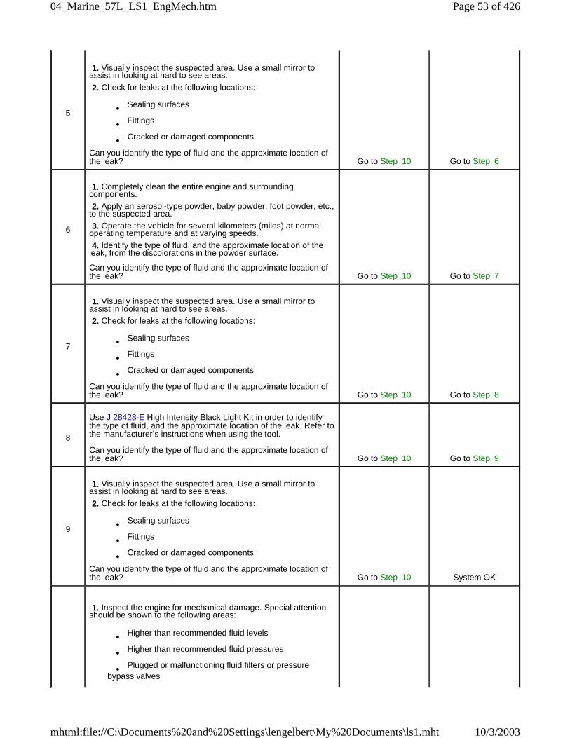
5
1. Visually inspect the suspected area. Use a small mirror toassist in looking at hard to see areas.
2. Check for leaks at the following locations:
• Sealing surfaces
• Fittings
• Cracked or damaged components
Can you identify the type of fluid and the approximate location ofthe leak? Go to Step 10 Go to Step 6
6
1. Completely clean the entire engine and surroundingcomponents.
2. Apply an aerosol-type powder, baby powder, foot powder, etc.,to the suspected area.
3. Operate the vehicle for several kilometers (miles) at normaloperating temperature and at varying speeds.
4. Identify the type of fluid, and the approximate location of theleak, from the discolorations in the powder surface.
Can you identify the type of fluid and the approximate location ofthe leak? Go to Step 10 Go to Step 7
7
1. Visually inspect the suspected area. Use a small mirror toassist in looking at hard to see areas.
2. Check for leaks at the following locations:
• Sealing surfaces
• Fittings
• Cracked or damaged components
Can you identify the type of fluid and the approximate location ofthe leak? Go to Step 10 Go to Step 8
8
Use J 28428-E High Intensity Black Light Kit in order to identifythe type of fluid, and the approximate location of the leak. Refer tothe manufacturer’s instructions when using the tool.
Can you identify the type of fluid and the approximate location ofthe leak? Go to Step 10 Go to Step 9
9
1. Visually inspect the suspected area. Use a small mirror toassist in looking at hard to see areas.
2. Check for leaks at the following locations:
• Sealing surfaces
• Fittings
• Cracked or damaged components
Can you identify the type of fluid and the approximate location ofthe leak? Go to Step 10 System OK
1. Inspect the engine for mechanical damage. Special attentionshould be shown to the following areas:
• Higher than recommended fluid levels
• Higher than recommended fluid pressures
• Plugged or malfunctioning fluid filters or pressurebypass valves
Page 53 of 42604_Marine_57L_LS1_EngMech.htm
10/3/2003mhtml:file://C:\Documents%20and%20Settings\lengelbert\My%20Documents\ls1.mht
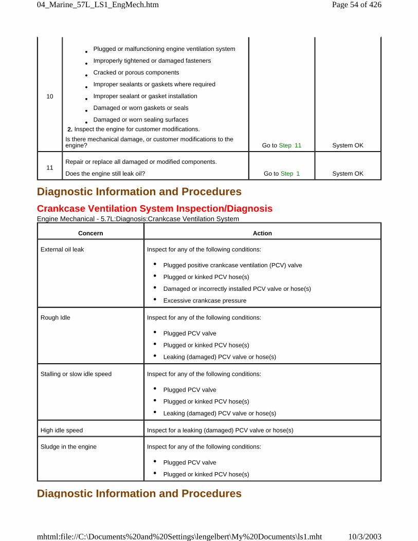
Diagnostic Information and Procedures
Crankcase Ventilation System Inspection/DiagnosisEngine Mechanical - 5.7L:Diagnosis:Crankcase Ventilation System
Diagnostic Information and Procedures
10
• Plugged or malfunctioning engine ventilation system
• Improperly tightened or damaged fasteners
• Cracked or porous components
• Improper sealants or gaskets where required
• Improper sealant or gasket installation
• Damaged or worn gaskets or seals
• Damaged or worn sealing surfaces
2. Inspect the engine for customer modifications.
Is there mechanical damage, or customer modifications to theengine? Go to Step 11 System OK
11Repair or replace all damaged or modified components.
Does the engine still leak oil? Go to Step 1 System OK
Concern Action
External oil leak Inspect for any of the following conditions:
• Plugged positive crankcase ventilation (PCV) valve
• Plugged or kinked PCV hose(s)
• Damaged or incorrectly installed PCV valve or hose(s)
• Excessive crankcase pressure
Rough Idle Inspect for any of the following conditions:
• Plugged PCV valve
• Plugged or kinked PCV hose(s)
• Leaking (damaged) PCV valve or hose(s)
Stalling or slow idle speed Inspect for any of the following conditions:
• Plugged PCV valve
• Plugged or kinked PCV hose(s)
• Leaking (damaged) PCV valve or hose(s)
High idle speed Inspect for a leaking (damaged) PCV valve or hose(s)
Sludge in the engine Inspect for any of the following conditions:
• Plugged PCV valve
• Plugged or kinked PCV hose(s)
Page 54 of 42604_Marine_57L_LS1_EngMech.htm
10/3/2003mhtml:file://C:\Documents%20and%20Settings\lengelbert\My%20Documents\ls1.mht
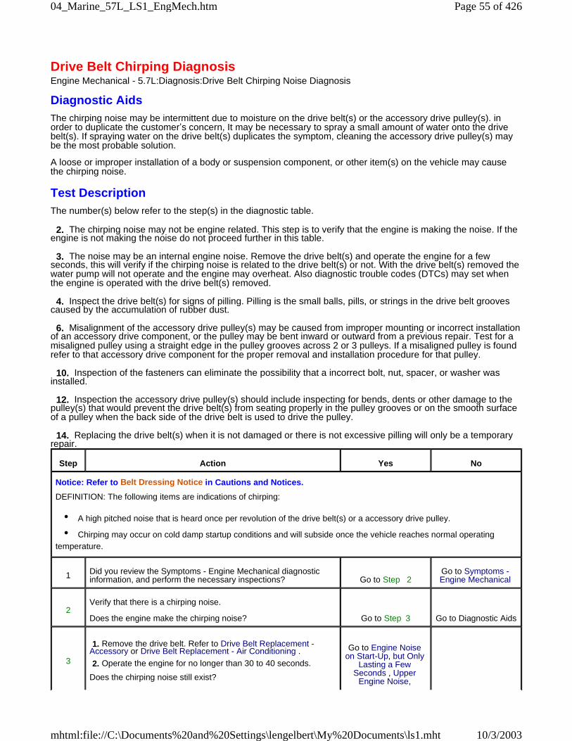
Drive Belt Chirping DiagnosisEngine Mechanical - 5.7L:Diagnosis:Drive Belt Chirping Noise Diagnosis
Diagnostic AidsThe chirping noise may be intermittent due to moisture on the drive belt(s) or the accessory drive pulley(s). inorder to duplicate the customer’s concern, It may be necessary to spray a small amount of water onto the drivebelt(s). If spraying water on the drive belt(s) duplicates the symptom, cleaning the accessory drive pulley(s) maybe the most probable solution.
A loose or improper installation of a body or suspension component, or other item(s) on the vehicle may causethe chirping noise.
Test DescriptionThe number(s) below refer to the step(s) in the diagnostic table.
2. The chirping noise may not be engine related. This step is to verify that the engine is making the noise. If theengine is not making the noise do not proceed further in this table.
3. The noise may be an internal engine noise. Remove the drive belt(s) and operate the engine for a fewseconds, this will verify if the chirping noise is related to the drive belt(s) or not. With the drive belt(s) removed thewater pump will not operate and the engine may overheat. Also diagnostic trouble codes (DTCs) may set whenthe engine is operated with the drive belt(s) removed.
4. Inspect the drive belt(s) for signs of pilling. Pilling is the small balls, pills, or strings in the drive belt groovescaused by the accumulation of rubber dust.
6. Misalignment of the accessory drive pulley(s) may be caused from improper mounting or incorrect installationof an accessory drive component, or the pulley may be bent inward or outward from a previous repair. Test for amisaligned pulley using a straight edge in the pulley grooves across 2 or 3 pulleys. If a misaligned pulley is foundrefer to that accessory drive component for the proper removal and installation procedure for that pulley.
10. Inspection of the fasteners can eliminate the possibility that a incorrect bolt, nut, spacer, or washer wasinstalled.
12. Inspection the accessory drive pulley(s) should include inspecting for bends, dents or other damage to thepulley(s) that would prevent the drive belt(s) from seating properly in the pulley grooves or on the smooth surfaceof a pulley when the back side of the drive belt is used to drive the pulley.
14. Replacing the drive belt(s) when it is not damaged or there is not excessive pilling will only be a temporaryrepair.
Step Action Yes No
Notice: Refer to Belt Dressing Notice in Cautions and Notices.
DEFINITION: The following items are indications of chirping:
• A high pitched noise that is heard once per revolution of the drive belt(s) or a accessory drive pulley.
• Chirping may occur on cold damp startup conditions and will subside once the vehicle reaches normal operatingtemperature.
1 Did you review the Symptoms - Engine Mechanical diagnosticinformation, and perform the necessary inspections? Go to Step 2
Go to Symptoms -Engine Mechanical
2Verify that there is a chirping noise.
Does the engine make the chirping noise? Go to Step 3 Go to Diagnostic Aids
3
1. Remove the drive belt. Refer to Drive Belt Replacement -Accessory or Drive Belt Replacement - Air Conditioning .
2. Operate the engine for no longer than 30 to 40 seconds.
Does the chirping noise still exist?
Go to Engine Noiseon Start-Up, but Only
Lasting a FewSeconds , Upper
Engine Noise,
Page 55 of 42604_Marine_57L_LS1_EngMech.htm
10/3/2003mhtml:file://C:\Documents%20and%20Settings\lengelbert\My%20Documents\ls1.mht
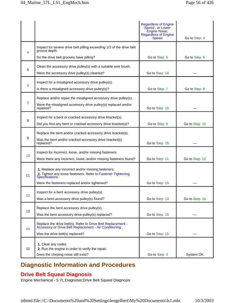
Diagnostic Information and Procedures
Drive Belt Squeal DiagnosisEngine Mechanical - 5.7L:Diagnosis:Drive Belt Squeal Diagnosis
Regardless of EngineSpeed , or Lower
Engine Noise,Regardless of Engine
Speed Go to Step 4
4
Inspect for severe drive belt pilling exceeding 1/3 of the drive beltgroove depth.
Do the drive belt grooves have pilling? Go to Step 5 Go to Step 6
5Clean the accessory drive pulley(s) with a suitable wire brush.
Were the accessory drive pulley(s) cleaned? Go to Step 14 —
6Inspect for a misaligned accessory drive pulley(s).
Is there a misaligned accessory drive pulley(s)? Go to Step 7 Go to Step 8
7
Replace and/or repair the misaligned accessory drive pulley(s).
Were the misaligned accessory drive pulley(s) replaced and/orrepaired? Go to Step 15 —
8Inspect for a bent or cracked accessory drive bracket(s).
Did you find any bent or cracked accessory drive bracket(s)? Go to Step 9 Go to Step 10
9
Replace the bent and/or cracked accessory drive bracket(s).
Was the bent and/or cracked accessory drive bracket(s)replaced? Go to Step 15 —
10Inspect for incorrect, loose, and/or missing fasteners.
Were there any incorrect, loose, and/or missing fasteners found? Go to Step 11 Go to Step 12
11
1. Replace any incorrect and/or missing fasteners. 2. Tighten any loose fasteners. Refer to Fastener TighteningSpecifications .
Were the fasteners replaced and/or tightened? Go to Step 15 —
12Inspect for a bent accessory drive pulley(s).
Was a bent accessory drive pulley(s) found? Go to Step 13 Go to Step 14
13Replace the bent accessory drive pulley(s).
Was the bent accessory drive pulley(s) replaced? Go to Step 15 —
14
Replace the drive belt(s). Refer to Drive Belt Replacement -Accessory or Drive Belt Replacement - Air Conditioning .
Was the drive belt(s) replaced? Go to Step 15 —
15 1. Clear any codes 2. Run the engine in order to verify the repair.
Does the chirping noise still exist? Go to Step 3 System OK
Page 56 of 42604_Marine_57L_LS1_EngMech.htm
10/3/2003mhtml:file://C:\Documents%20and%20Settings\lengelbert\My%20Documents\ls1.mht
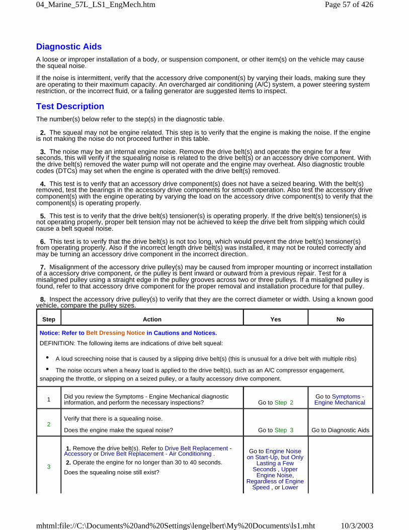
Diagnostic AidsA loose or improper installation of a body, or suspension component, or other item(s) on the vehicle may causethe squeal noise.
If the noise is intermittent, verify that the accessory drive component(s) by varying their loads, making sure theyare operating to their maximum capacity. An overcharged air conditioning (A/C) system, a power steering systemrestriction, or the incorrect fluid, or a failing generator are suggested items to inspect.
Test DescriptionThe number(s) below refer to the step(s) in the diagnostic table.
2. The squeal may not be engine related. This step is to verify that the engine is making the noise. If the engineis not making the noise do not proceed further in this table.
3. The noise may be an internal engine noise. Remove the drive belt(s) and operate the engine for a fewseconds, this will verify if the squealing noise is related to the drive belt(s) or an accessory drive component. Withthe drive belt(s) removed the water pump will not operate and the engine may overheat. Also diagnostic troublecodes (DTCs) may set when the engine is operated with the drive belt(s) removed.
4. This test is to verify that an accessory drive component(s) does not have a seized bearing. With the belt(s)removed, test the bearings in the accessory drive components for smooth operation. Also test the accessory drivecomponent(s) with the engine operating by varying the load on the accessory drive component(s) to verify that thecomponent(s) is operating properly.
5. This test is to verify that the drive belt(s) tensioner(s) is operating properly. If the drive belt(s) tensioner(s) isnot operating properly, proper belt tension may not be achieved to keep the drive belt from slipping which couldcause a belt squeal noise.
6. This test is to verify that the drive belt(s) is not too long, which would prevent the drive belt(s) tensioner(s)from operating properly. Also if the incorrect length drive belt(s) was installed, it may not be routed correctly andmay be turning an accessory drive component in the incorrect direction.
7. Misalignment of the accessory drive pulley(s) may be caused from improper mounting or incorrect installationof a accessory drive component, or the pulley is bent inward or outward from a previous repair. Test for amisaligned pulley using a straight edge in the pulley grooves across two or three pulleys. If a misaligned pulley isfound, refer to that accessory drive component for the proper removal and installation procedure for that pulley.
8. Inspect the accessory drive pulley(s) to verify that they are the correct diameter or width. Using a known goodvehicle, compare the pulley sizes.
Step Action Yes No
Notice: Refer to Belt Dressing Notice in Cautions and Notices.
DEFINITION: The following items are indications of drive belt squeal:
• A loud screeching noise that is caused by a slipping drive belt(s) (this is unusual for a drive belt with multiple ribs)
• The noise occurs when a heavy load is applied to the drive belt(s), such as an A/C compressor engagement,snapping the throttle, or slipping on a seized pulley, or a faulty accessory drive component.
1 Did you review the Symptoms - Engine Mechanical diagnosticinformation, and perform the necessary inspections? Go to Step 2
Go to Symptoms -Engine Mechanical
2Verify that there is a squealing noise.
Does the engine make the squeal noise? Go to Step 3 Go to Diagnostic Aids
3
1. Remove the drive belt(s). Refer to Drive Belt Replacement -Accessory or Drive Belt Replacement - Air Conditioning .
2. Operate the engine for no longer than 30 to 40 seconds.
Does the squealing noise still exist?
Go to Engine Noiseon Start-Up, but Only
Lasting a FewSeconds , Upper
Engine Noise,Regardless of Engine
Speed , or Lower
Page 57 of 42604_Marine_57L_LS1_EngMech.htm
10/3/2003mhtml:file://C:\Documents%20and%20Settings\lengelbert\My%20Documents\ls1.mht
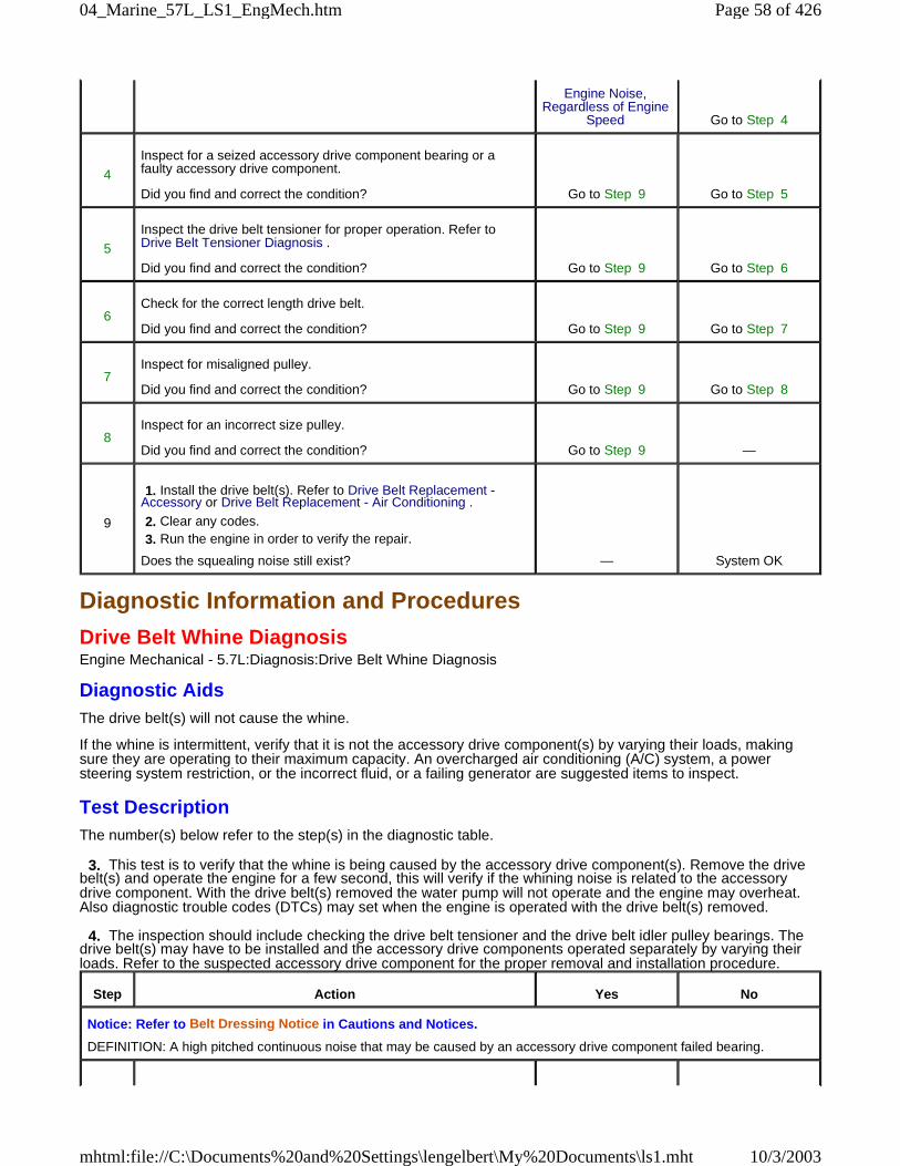
Diagnostic Information and Procedures
Drive Belt Whine DiagnosisEngine Mechanical - 5.7L:Diagnosis:Drive Belt Whine Diagnosis
Diagnostic AidsThe drive belt(s) will not cause the whine.
If the whine is intermittent, verify that it is not the accessory drive component(s) by varying their loads, makingsure they are operating to their maximum capacity. An overcharged air conditioning (A/C) system, a powersteering system restriction, or the incorrect fluid, or a failing generator are suggested items to inspect.
Test DescriptionThe number(s) below refer to the step(s) in the diagnostic table.
3. This test is to verify that the whine is being caused by the accessory drive component(s). Remove the drivebelt(s) and operate the engine for a few second, this will verify if the whining noise is related to the accessorydrive component. With the drive belt(s) removed the water pump will not operate and the engine may overheat.Also diagnostic trouble codes (DTCs) may set when the engine is operated with the drive belt(s) removed.
4. The inspection should include checking the drive belt tensioner and the drive belt idler pulley bearings. Thedrive belt(s) may have to be installed and the accessory drive components operated separately by varying theirloads. Refer to the suspected accessory drive component for the proper removal and installation procedure.
Engine Noise,Regardless of Engine
Speed Go to Step 4
4
Inspect for a seized accessory drive component bearing or afaulty accessory drive component.
Did you find and correct the condition? Go to Step 9 Go to Step 5
5
Inspect the drive belt tensioner for proper operation. Refer toDrive Belt Tensioner Diagnosis .
Did you find and correct the condition? Go to Step 9 Go to Step 6
6Check for the correct length drive belt.
Did you find and correct the condition? Go to Step 9 Go to Step 7
7Inspect for misaligned pulley.
Did you find and correct the condition? Go to Step 9 Go to Step 8
8Inspect for an incorrect size pulley.
Did you find and correct the condition? Go to Step 9 —
9
1. Install the drive belt(s). Refer to Drive Belt Replacement -Accessory or Drive Belt Replacement - Air Conditioning .
2. Clear any codes. 3. Run the engine in order to verify the repair.
Does the squealing noise still exist? — System OK
Step Action Yes No
Notice: Refer to Belt Dressing Notice in Cautions and Notices.
DEFINITION: A high pitched continuous noise that may be caused by an accessory drive component failed bearing.
Page 58 of 42604_Marine_57L_LS1_EngMech.htm
10/3/2003mhtml:file://C:\Documents%20and%20Settings\lengelbert\My%20Documents\ls1.mht
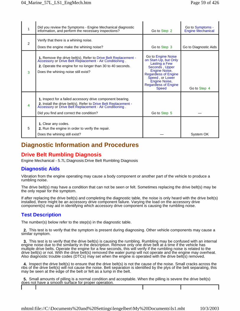
Diagnostic Information and Procedures
Drive Belt Rumbling DiagnosisEngine Mechanical - 5.7L:Diagnosis:Drive Belt Rumbling Diagnosis
Diagnostic AidsVibration from the engine operating may cause a body component or another part of the vehicle to produce arumbling noise.
The drive belt(s) may have a condition that can not be seen or felt. Sometimes replacing the drive belt(s) may bethe only repair for the symptom.
If after replacing the drive belt(s) and completing the diagnostic table, the noise is only heard with the drive belt(s)installed, there might be an accessory drive component failure. Varying the load on the accessory drivecomponent(s) may aid in identifying which accessory drive component is causing the rumbling noise.
Test DescriptionThe number(s) below refer to the step(s) in the diagnostic table.
2. This test is to verify that the symptom is present during diagnosing. Other vehicle components may cause asimilar symptom.
3. This test is to verify that the drive belt(s) is causing the rumbling. Rumbling may be confused with an internalengine noise due to the similarity in the description. Remove only one drive belt at a time if the vehicle hasmultiple drive belts. Operate the engine for a few seconds, this will verify if the rumbling noise is related to thedrive belt(s) or not. With the drive belt(s) removed the water pump will not operate and the engine may overheat.Also diagnostic trouble codes (DTCs) may set when the engine is operated with the drive belt(s) removed.
4. Inspect the drive belt(s) to ensure that the drive belt(s) is not the cause of the noise. Small cracks across theribs of the drive belt(s) will not cause the noise. Belt separation is identified by the plys of the belt separating, thismay be seen at the edge of the belt or felt as a lump in the belt.
5. Small amounts of pilling is a normal condition and acceptable. When the pilling is severe the drive belt(s)does not have a smooth surface for proper operation.
1 Did you review the Symptoms - Engine Mechanical diagnosticinformation, and perform the necessary inspections? Go to Step 2
Go to Symptoms -Engine Mechanical
2Verify that there is a whining noise.
Does the engine make the whining noise? Go to Step 3 Go to Diagnostic Aids
3
1. Remove the drive belt(s). Refer to Drive Belt Replacement -Accessory or Drive Belt Replacement - Air Conditioning .
2. Operate the engine for no longer than 30 to 40 seconds.
Does the whining noise still exist?
Go to Engine Noiseon Start-Up, but Only
Lasting a FewSeconds , Upper
Engine Noise,Regardless of Engine
Speed , or LowerEngine Noise,
Regardless of EngineSpeed Go to Step 4
4
1. Inspect for a failed accessory drive component bearing. 2. Install the drive belt(s). Refer to Drive Belt Replacement -Accessory or Drive Belt Replacement - Air Conditioning .
Did you find and correct the condition? Go to Step 5 —
5 1. Clear any codes. 2. Run the engine in order to verify the repair.
Does the whining still exist? — System OK
Page 59 of 42604_Marine_57L_LS1_EngMech.htm
10/3/2003mhtml:file://C:\Documents%20and%20Settings\lengelbert\My%20Documents\ls1.mht
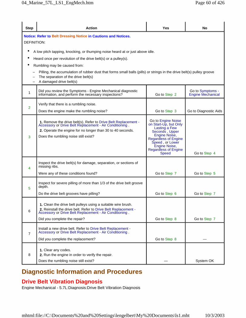
Diagnostic Information and Procedures
Drive Belt Vibration DiagnosisEngine Mechanical - 5.7L:Diagnosis:Drive Belt Vibration Diagnosis
Step Action Yes No
Notice: Refer to Belt Dressing Notice in Cautions and Notices.
DEFINITION:
• A low pitch tapping, knocking, or thumping noise heard at or just above idle.
• Heard once per revolution of the drive belt(s) or a pulley(s).
• Rumbling may be caused from:
– Pilling, the accumulation of rubber dust that forms small balls (pills) or strings in the drive belt(s) pulley groove – The separation of the drive belt(s) – A damaged drive belt(s)
1 Did you review the Symptoms - Engine Mechanical diagnosticinformation, and perform the necessary inspections? Go to Step 2
Go to Symptoms -Engine Mechanical
2Verify that there is a rumbling noise.
Does the engine make the rumbling noise? Go to Step 3 Go to Diagnostic Aids
3
1. Remove the drive belt(s). Refer to Drive Belt Replacement -Accessory or Drive Belt Replacement - Air Conditioning .
2. Operate the engine for no longer than 30 to 40 seconds.
Does the rumbling noise still exist?
Go to Engine Noiseon Start-Up, but Only
Lasting a FewSeconds , Upper
Engine Noise,Regardless of Engine
Speed , or LowerEngine Noise,
Regardless of EngineSpeed Go to Step 4
4
Inspect the drive belt(s) for damage, separation, or sections ofmissing ribs.
Were any of these conditions found? Go to Step 7 Go to Step 5
5
Inspect for severe pilling of more than 1/3 of the drive belt groovedepth.
Do the drive belt grooves have pilling? Go to Step 6 Go to Step 7
6
1. Clean the drive belt pulleys using a suitable wire brush. 2. Reinstall the drive belt. Refer to Drive Belt Replacement -Accessory or Drive Belt Replacement - Air Conditioning .
Did you complete the repair? Go to Step 8 Go to Step 7
7
Install a new drive belt. Refer to Drive Belt Replacement -Accessory or Drive Belt Replacement - Air Conditioning .
Did you complete the replacement? Go to Step 8 —
8 1. Clear any codes. 2. Run the engine in order to verify the repair.
Does the rumbling noise still exist? — System OK
Page 60 of 42604_Marine_57L_LS1_EngMech.htm
10/3/2003mhtml:file://C:\Documents%20and%20Settings\lengelbert\My%20Documents\ls1.mht
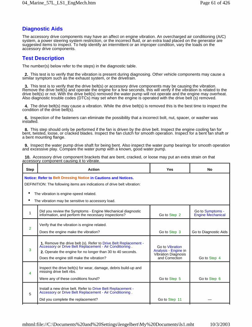
Diagnostic AidsThe accessory drive components may have an affect on engine vibration. An overcharged air conditioning (A/C)system, a power steering system restriction, or the incorrect fluid, or an extra load placed on the generator aresuggested items to inspect. To help identify an intermittent or an improper condition, vary the loads on theaccessory drive components.
Test DescriptionThe number(s) below refer to the steps) in the diagnostic table.
2. This test is to verify that the vibration is present during diagnosing. Other vehicle components may cause asimilar symptom such as the exhaust system, or the drivetrain.
3. This test is to verify that the drive belt(s) or accessory drive components may be causing the vibration.Remove the drive belt(s) and operate the engine for a few seconds, this will verify if the vibration is related to thedrive belt(s) or not. With the drive belt(s) removed the water pump will not operate and the engine may overheat.Also diagnostic trouble codes (DTCs) may set when the engine is operated with the drive belt (s) removed.
4. The drive belt(s) may cause a vibration. While the drive belt(s) is removed this is the best time to inspect thecondition of the drive belt(s).
6. Inspection of the fasteners can eliminate the possibility that a incorrect bolt, nut, spacer, or washer wasinstalled.
8. This step should only be performed if the fan is driven by the drive belt. Inspect the engine cooling fan forbent, twisted, loose, or cracked blades. Inspect the fan clutch for smooth operation. Inspect for a bent fan shaft ora bent mounting flange.
9. Inspect the water pump drive shaft for being bent. Also inspect the water pump bearings for smooth operationand excessive play. Compare the water pump with a known, good water pump.
10. Accessory drive component brackets that are bent, cracked, or loose may put an extra strain on thataccessory component causing it to vibrate.
Step Action Yes No
Notice: Refer to Belt Dressing Notice in Cautions and Notices.
DEFINITION: The following items are indications of drive belt vibration:
• The vibration is engine-speed related.
• The vibration may be sensitive to accessory load.
1 Did you review the Symptoms - Engine Mechanical diagnosticinformation, and perform the necessary inspections? Go to Step 2
Go to Symptoms -Engine Mechanical
2Verify that the vibration is engine related.
Does the engine make the vibration? Go to Step 3 Go to Diagnostic Aids
3
1. Remove the drive belt (s). Refer to Drive Belt Replacement -Accessory or Drive Belt Replacement - Air Conditioning .
2. Operate the engine for no longer than 30 to 40 seconds.
Does the engine still make the vibration?
Go to VibrationAnalysis - Engine inVibration Diagnosis
and Correction Go to Step 4
4
Inspect the drive belt(s) for wear, damage, debris build-up andmissing drive belt ribs.
Were any of these conditions found? Go to Step 5 Go to Step 6
5
Install a new drive belt. Refer to Drive Belt Replacement -Accessory or Drive Belt Replacement - Air Conditioning .
Did you complete the replacement? Go to Step 11 —
Page 61 of 42604_Marine_57L_LS1_EngMech.htm
10/3/2003mhtml:file://C:\Documents%20and%20Settings\lengelbert\My%20Documents\ls1.mht
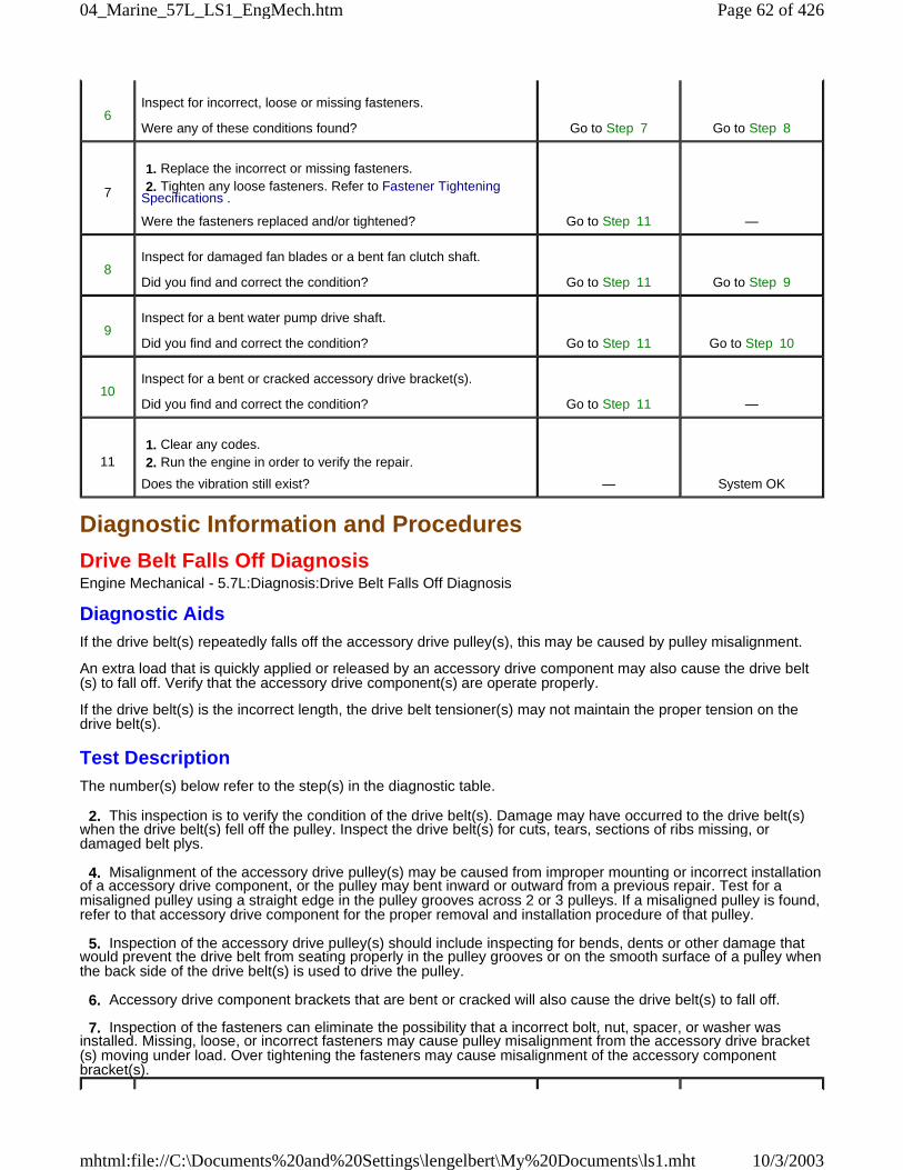
Diagnostic Information and Procedures
Drive Belt Falls Off DiagnosisEngine Mechanical - 5.7L:Diagnosis:Drive Belt Falls Off Diagnosis
Diagnostic AidsIf the drive belt(s) repeatedly falls off the accessory drive pulley(s), this may be caused by pulley misalignment.
An extra load that is quickly applied or released by an accessory drive component may also cause the drive belt(s) to fall off. Verify that the accessory drive component(s) are operate properly.
If the drive belt(s) is the incorrect length, the drive belt tensioner(s) may not maintain the proper tension on thedrive belt(s).
Test DescriptionThe number(s) below refer to the step(s) in the diagnostic table.
2. This inspection is to verify the condition of the drive belt(s). Damage may have occurred to the drive belt(s)when the drive belt(s) fell off the pulley. Inspect the drive belt(s) for cuts, tears, sections of ribs missing, ordamaged belt plys.
4. Misalignment of the accessory drive pulley(s) may be caused from improper mounting or incorrect installationof a accessory drive component, or the pulley may bent inward or outward from a previous repair. Test for amisaligned pulley using a straight edge in the pulley grooves across 2 or 3 pulleys. If a misaligned pulley is found,refer to that accessory drive component for the proper removal and installation procedure of that pulley.
5. Inspection of the accessory drive pulley(s) should include inspecting for bends, dents or other damage thatwould prevent the drive belt from seating properly in the pulley grooves or on the smooth surface of a pulley whenthe back side of the drive belt(s) is used to drive the pulley.
6. Accessory drive component brackets that are bent or cracked will also cause the drive belt(s) to fall off.
7. Inspection of the fasteners can eliminate the possibility that a incorrect bolt, nut, spacer, or washer wasinstalled. Missing, loose, or incorrect fasteners may cause pulley misalignment from the accessory drive bracket(s) moving under load. Over tightening the fasteners may cause misalignment of the accessory componentbracket(s).
6Inspect for incorrect, loose or missing fasteners.
Were any of these conditions found? Go to Step 7 Go to Step 8
7
1. Replace the incorrect or missing fasteners. 2. Tighten any loose fasteners. Refer to Fastener TighteningSpecifications .
Were the fasteners replaced and/or tightened? Go to Step 11 —
8Inspect for damaged fan blades or a bent fan clutch shaft.
Did you find and correct the condition? Go to Step 11 Go to Step 9
9Inspect for a bent water pump drive shaft.
Did you find and correct the condition? Go to Step 11 Go to Step 10
10Inspect for a bent or cracked accessory drive bracket(s).
Did you find and correct the condition? Go to Step 11 —
11 1. Clear any codes. 2. Run the engine in order to verify the repair.
Does the vibration still exist? — System OK
Page 62 of 42604_Marine_57L_LS1_EngMech.htm
10/3/2003mhtml:file://C:\Documents%20and%20Settings\lengelbert\My%20Documents\ls1.mht
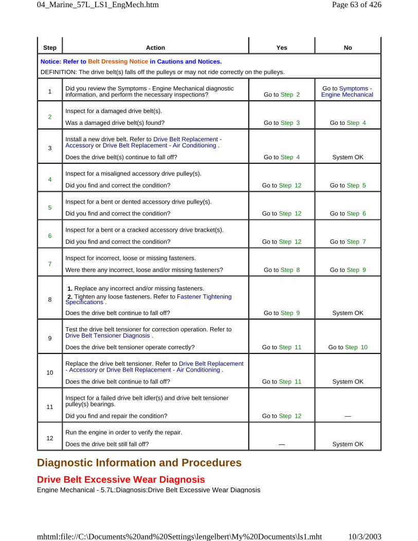
Diagnostic Information and Procedures
Drive Belt Excessive Wear DiagnosisEngine Mechanical - 5.7L:Diagnosis:Drive Belt Excessive Wear Diagnosis
Step Action Yes No
Notice: Refer to Belt Dressing Notice in Cautions and Notices.
DEFINITION: The drive belt(s) falls off the pulleys or may not ride correctly on the pulleys.
1 Did you review the Symptoms - Engine Mechanical diagnosticinformation, and perform the necessary inspections? Go to Step 2
Go to Symptoms -Engine Mechanical
2Inspect for a damaged drive belt(s).
Was a damaged drive belt(s) found? Go to Step 3 Go to Step 4
3
Install a new drive belt. Refer to Drive Belt Replacement -Accessory or Drive Belt Replacement - Air Conditioning .
Does the drive belt(s) continue to fall off? Go to Step 4 System OK
4Inspect for a misaligned accessory drive pulley(s).
Did you find and correct the condition? Go to Step 12 Go to Step 5
5Inspect for a bent or dented accessory drive pulley(s).
Did you find and correct the condition? Go to Step 12 Go to Step 6
6Inspect for a bent or a cracked accessory drive bracket(s).
Did you find and correct the condition? Go to Step 12 Go to Step 7
7Inspect for incorrect, loose or missing fasteners.
Were there any incorrect, loose and/or missing fasteners? Go to Step 8 Go to Step 9
8
1. Replace any incorrect and/or missing fasteners. 2. Tighten any loose fasteners. Refer to Fastener TighteningSpecifications .
Does the drive belt continue to fall off? Go to Step 9 System OK
9
Test the drive belt tensioner for correction operation. Refer toDrive Belt Tensioner Diagnosis .
Does the drive belt tensioner operate correctly? Go to Step 11 Go to Step 10
10
Replace the drive belt tensioner. Refer to Drive Belt Replacement- Accessory or Drive Belt Replacement - Air Conditioning .
Does the drive belt continue to fall off? Go to Step 11 System OK
11
Inspect for a failed drive belt idler(s) and drive belt tensionerpulley(s) bearings.
Did you find and repair the condition? Go to Step 12 —
12Run the engine in order to verify the repair.
Does the drive belt still fall off? — System OK
Page 63 of 42604_Marine_57L_LS1_EngMech.htm
10/3/2003mhtml:file://C:\Documents%20and%20Settings\lengelbert\My%20Documents\ls1.mht
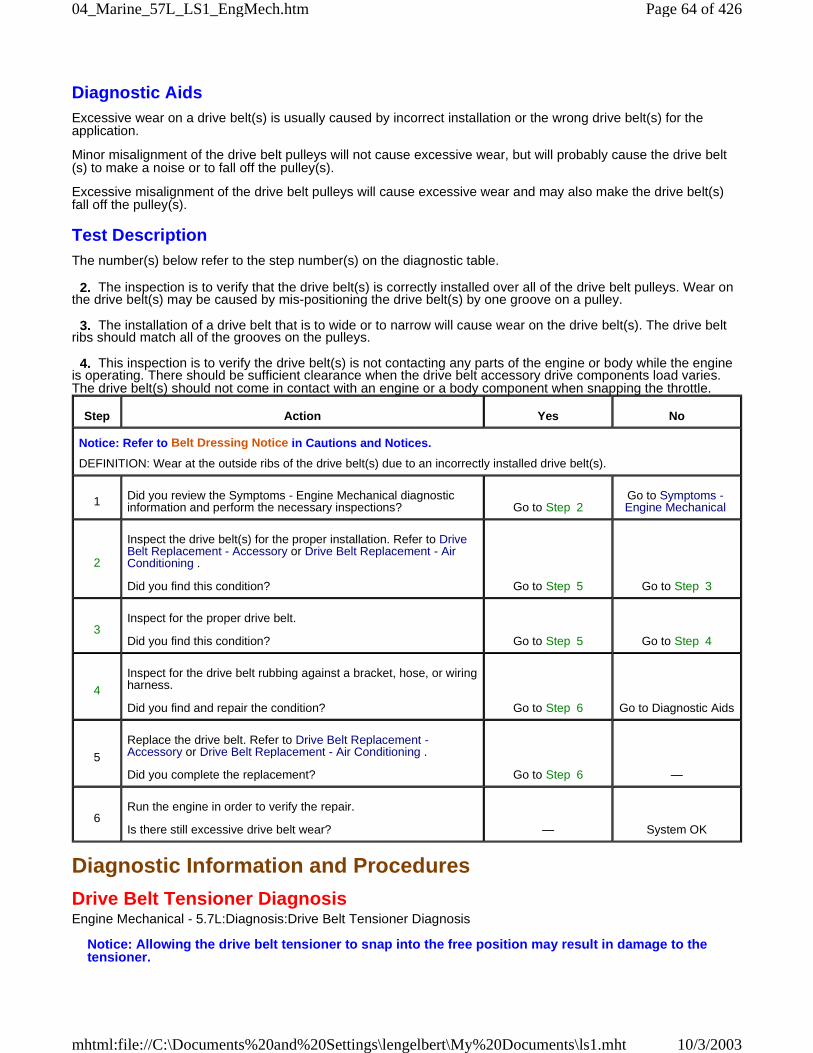
Diagnostic AidsExcessive wear on a drive belt(s) is usually caused by incorrect installation or the wrong drive belt(s) for theapplication.
Minor misalignment of the drive belt pulleys will not cause excessive wear, but will probably cause the drive belt(s) to make a noise or to fall off the pulley(s).
Excessive misalignment of the drive belt pulleys will cause excessive wear and may also make the drive belt(s)fall off the pulley(s).
Test DescriptionThe number(s) below refer to the step number(s) on the diagnostic table.
2. The inspection is to verify that the drive belt(s) is correctly installed over all of the drive belt pulleys. Wear onthe drive belt(s) may be caused by mis-positioning the drive belt(s) by one groove on a pulley.
3. The installation of a drive belt that is to wide or to narrow will cause wear on the drive belt(s). The drive beltribs should match all of the grooves on the pulleys.
4. This inspection is to verify the drive belt(s) is not contacting any parts of the engine or body while the engineis operating. There should be sufficient clearance when the drive belt accessory drive components load varies.The drive belt(s) should not come in contact with an engine or a body component when snapping the throttle.
Diagnostic Information and Procedures
Drive Belt Tensioner DiagnosisEngine Mechanical - 5.7L:Diagnosis:Drive Belt Tensioner Diagnosis
Notice: Allowing the drive belt tensioner to snap into the free position may result in damage to thetensioner.
Step Action Yes No
Notice: Refer to Belt Dressing Notice in Cautions and Notices.
DEFINITION: Wear at the outside ribs of the drive belt(s) due to an incorrectly installed drive belt(s).
1 Did you review the Symptoms - Engine Mechanical diagnosticinformation and perform the necessary inspections? Go to Step 2
Go to Symptoms -Engine Mechanical
2
Inspect the drive belt(s) for the proper installation. Refer to DriveBelt Replacement - Accessory or Drive Belt Replacement - AirConditioning .
Did you find this condition? Go to Step 5 Go to Step 3
3Inspect for the proper drive belt.
Did you find this condition? Go to Step 5 Go to Step 4
4
Inspect for the drive belt rubbing against a bracket, hose, or wiringharness.
Did you find and repair the condition? Go to Step 6 Go to Diagnostic Aids
5
Replace the drive belt. Refer to Drive Belt Replacement -Accessory or Drive Belt Replacement - Air Conditioning .
Did you complete the replacement? Go to Step 6 —
6Run the engine in order to verify the repair.
Is there still excessive drive belt wear? — System OK
Page 64 of 42604_Marine_57L_LS1_EngMech.htm
10/3/2003mhtml:file://C:\Documents%20and%20Settings\lengelbert\My%20Documents\ls1.mht
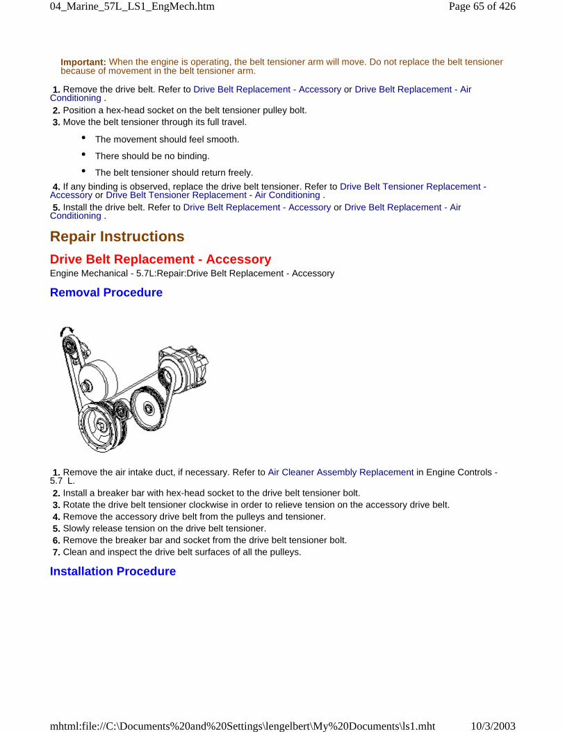
Important: When the engine is operating, the belt tensioner arm will move. Do not replace the belt tensionerbecause of movement in the belt tensioner arm.
1. Remove the drive belt. Refer to Drive Belt Replacement - Accessory or Drive Belt Replacement - AirConditioning . 2. Position a hex-head socket on the belt tensioner pulley bolt. 3. Move the belt tensioner through its full travel.
• The movement should feel smooth.
• There should be no binding.
• The belt tensioner should return freely.
4. If any binding is observed, replace the drive belt tensioner. Refer to Drive Belt Tensioner Replacement -Accessory or Drive Belt Tensioner Replacement - Air Conditioning . 5. Install the drive belt. Refer to Drive Belt Replacement - Accessory or Drive Belt Replacement - AirConditioning .
Repair Instructions
Drive Belt Replacement - AccessoryEngine Mechanical - 5.7L:Repair:Drive Belt Replacement - Accessory
Removal Procedure
1. Remove the air intake duct, if necessary. Refer to Air Cleaner Assembly Replacement in Engine Controls -5.7 L. 2. Install a breaker bar with hex-head socket to the drive belt tensioner bolt. 3. Rotate the drive belt tensioner clockwise in order to relieve tension on the accessory drive belt. 4. Remove the accessory drive belt from the pulleys and tensioner. 5. Slowly release tension on the drive belt tensioner. 6. Remove the breaker bar and socket from the drive belt tensioner bolt. 7. Clean and inspect the drive belt surfaces of all the pulleys.
Installation Procedure
Page 65 of 42604_Marine_57L_LS1_EngMech.htm
10/3/2003mhtml:file://C:\Documents%20and%20Settings\lengelbert\My%20Documents\ls1.mht
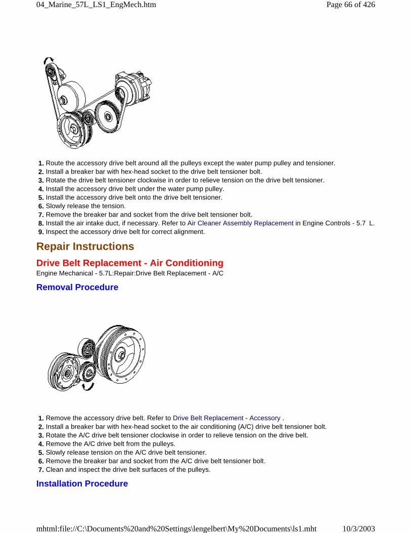
1. Route the accessory drive belt around all the pulleys except the water pump pulley and tensioner. 2. Install a breaker bar with hex-head socket to the drive belt tensioner bolt. 3. Rotate the drive belt tensioner clockwise in order to relieve tension on the drive belt tensioner. 4. Install the accessory drive belt under the water pump pulley. 5. Install the accessory drive belt onto the drive belt tensioner. 6. Slowly release the tension. 7. Remove the breaker bar and socket from the drive belt tensioner bolt. 8. Install the air intake duct, if necessary. Refer to Air Cleaner Assembly Replacement in Engine Controls - 5.7 L. 9. Inspect the accessory drive belt for correct alignment.
Repair Instructions
Drive Belt Replacement - Air ConditioningEngine Mechanical - 5.7L:Repair:Drive Belt Replacement - A/C
Removal Procedure
1. Remove the accessory drive belt. Refer to Drive Belt Replacement - Accessory . 2. Install a breaker bar with hex-head socket to the air conditioning (A/C) drive belt tensioner bolt. 3. Rotate the A/C drive belt tensioner clockwise in order to relieve tension on the drive belt. 4. Remove the A/C drive belt from the pulleys. 5. Slowly release tension on the A/C drive belt tensioner. 6. Remove the breaker bar and socket from the A/C drive belt tensioner bolt. 7. Clean and inspect the drive belt surfaces of the pulleys.
Installation Procedure
Page 66 of 42604_Marine_57L_LS1_EngMech.htm
10/3/2003mhtml:file://C:\Documents%20and%20Settings\lengelbert\My%20Documents\ls1.mht
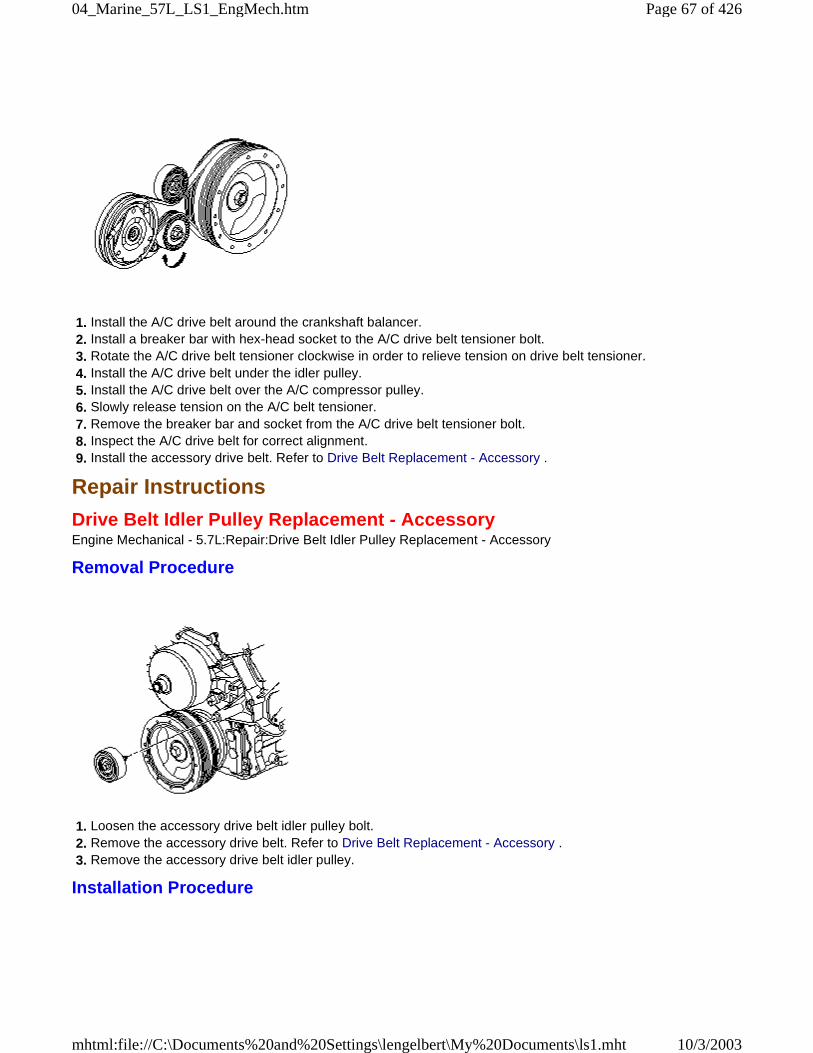
1. Install the A/C drive belt around the crankshaft balancer. 2. Install a breaker bar with hex-head socket to the A/C drive belt tensioner bolt. 3. Rotate the A/C drive belt tensioner clockwise in order to relieve tension on drive belt tensioner. 4. Install the A/C drive belt under the idler pulley. 5. Install the A/C drive belt over the A/C compressor pulley. 6. Slowly release tension on the A/C belt tensioner. 7. Remove the breaker bar and socket from the A/C drive belt tensioner bolt. 8. Inspect the A/C drive belt for correct alignment. 9. Install the accessory drive belt. Refer to Drive Belt Replacement - Accessory .
Repair Instructions
Drive Belt Idler Pulley Replacement - AccessoryEngine Mechanical - 5.7L:Repair:Drive Belt Idler Pulley Replacement - Accessory
Removal Procedure
1. Loosen the accessory drive belt idler pulley bolt. 2. Remove the accessory drive belt. Refer to Drive Belt Replacement - Accessory . 3. Remove the accessory drive belt idler pulley.
Installation Procedure
Page 67 of 42604_Marine_57L_LS1_EngMech.htm
10/3/2003mhtml:file://C:\Documents%20and%20Settings\lengelbert\My%20Documents\ls1.mht
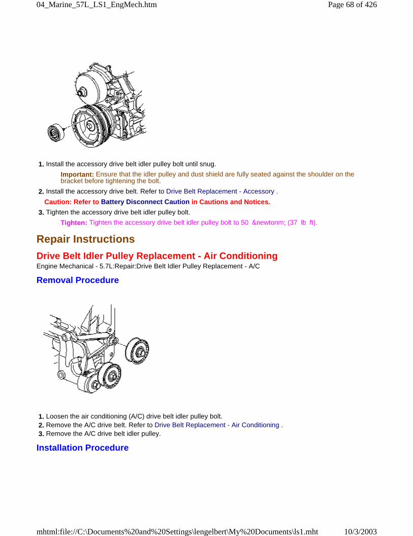
1. Install the accessory drive belt idler pulley bolt until snug.
Important: Ensure that the idler pulley and dust shield are fully seated against the shoulder on thebracket before tightening the bolt.
2. Install the accessory drive belt. Refer to Drive Belt Replacement - Accessory .
Caution: Refer to Battery Disconnect Caution in Cautions and Notices.
3. Tighten the accessory drive belt idler pulley bolt.
Tighten: Tighten the accessory drive belt idler pulley bolt to 50 &newtonm; (37 lb ft).
Repair Instructions
Drive Belt Idler Pulley Replacement - Air ConditioningEngine Mechanical - 5.7L:Repair:Drive Belt Idler Pulley Replacement - A/C
Removal Procedure
1. Loosen the air conditioning (A/C) drive belt idler pulley bolt. 2. Remove the A/C drive belt. Refer to Drive Belt Replacement - Air Conditioning . 3. Remove the A/C drive belt idler pulley.
Installation Procedure
Page 68 of 42604_Marine_57L_LS1_EngMech.htm
10/3/2003mhtml:file://C:\Documents%20and%20Settings\lengelbert\My%20Documents\ls1.mht
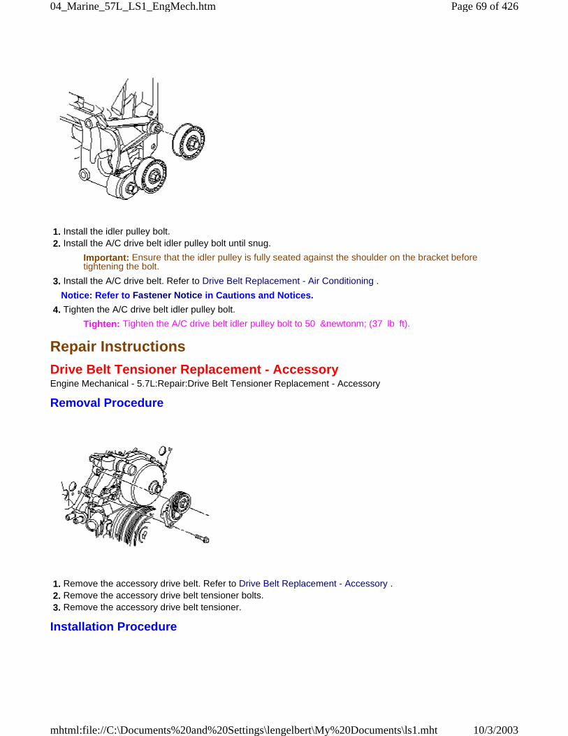
1. Install the idler pulley bolt. 2. Install the A/C drive belt idler pulley bolt until snug.
Important: Ensure that the idler pulley is fully seated against the shoulder on the bracket beforetightening the bolt.
3. Install the A/C drive belt. Refer to Drive Belt Replacement - Air Conditioning .
Notice: Refer to Fastener Notice in Cautions and Notices.
4. Tighten the A/C drive belt idler pulley bolt.
Tighten: Tighten the A/C drive belt idler pulley bolt to 50 &newtonm; (37 lb ft).
Repair Instructions
Drive Belt Tensioner Replacement - AccessoryEngine Mechanical - 5.7L:Repair:Drive Belt Tensioner Replacement - Accessory
Removal Procedure
1. Remove the accessory drive belt. Refer to Drive Belt Replacement - Accessory . 2. Remove the accessory drive belt tensioner bolts. 3. Remove the accessory drive belt tensioner.
Installation Procedure
Page 69 of 42604_Marine_57L_LS1_EngMech.htm
10/3/2003mhtml:file://C:\Documents%20and%20Settings\lengelbert\My%20Documents\ls1.mht
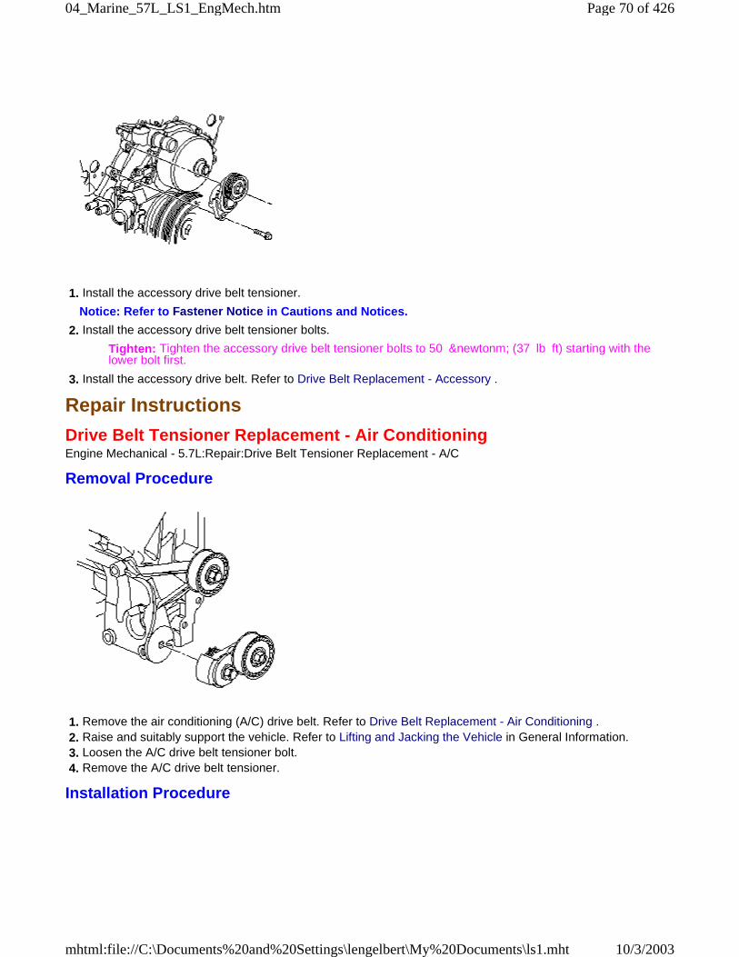
1. Install the accessory drive belt tensioner.
Notice: Refer to Fastener Notice in Cautions and Notices.
2. Install the accessory drive belt tensioner bolts.
Tighten: Tighten the accessory drive belt tensioner bolts to 50 &newtonm; (37 lb ft) starting with thelower bolt first.
3. Install the accessory drive belt. Refer to Drive Belt Replacement - Accessory .
Repair Instructions
Drive Belt Tensioner Replacement - Air ConditioningEngine Mechanical - 5.7L:Repair:Drive Belt Tensioner Replacement - A/C
Removal Procedure
1. Remove the air conditioning (A/C) drive belt. Refer to Drive Belt Replacement - Air Conditioning . 2. Raise and suitably support the vehicle. Refer to Lifting and Jacking the Vehicle in General Information. 3. Loosen the A/C drive belt tensioner bolt. 4. Remove the A/C drive belt tensioner.
Installation Procedure
Page 70 of 42604_Marine_57L_LS1_EngMech.htm
10/3/2003mhtml:file://C:\Documents%20and%20Settings\lengelbert\My%20Documents\ls1.mht
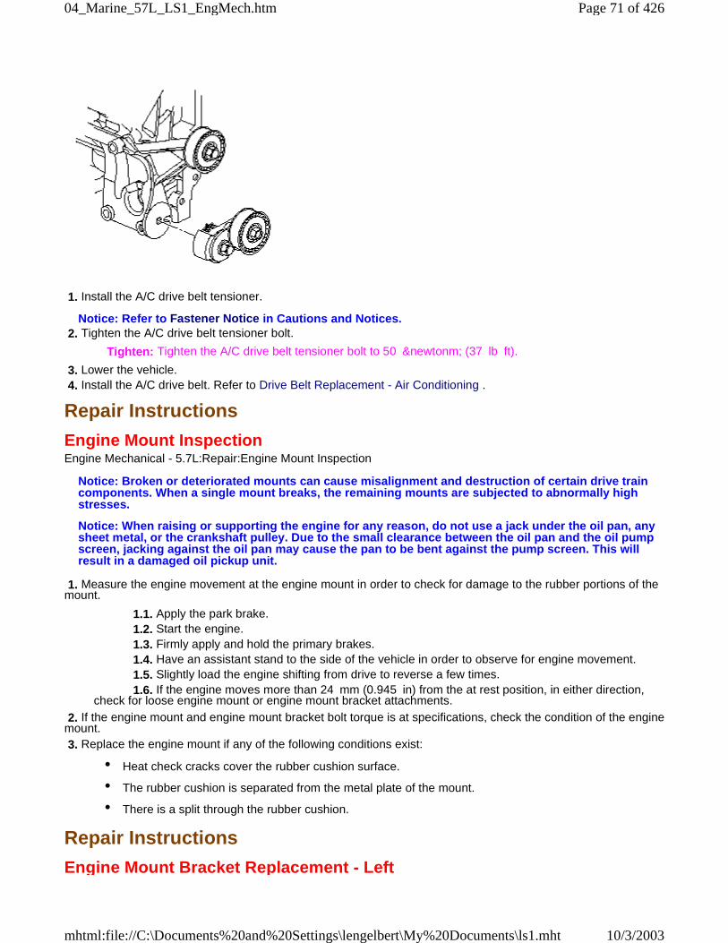
1. Install the A/C drive belt tensioner.
Notice: Refer to Fastener Notice in Cautions and Notices. 2. Tighten the A/C drive belt tensioner bolt.
Tighten: Tighten the A/C drive belt tensioner bolt to 50 &newtonm; (37 lb ft).
3. Lower the vehicle. 4. Install the A/C drive belt. Refer to Drive Belt Replacement - Air Conditioning .
Repair Instructions
Engine Mount InspectionEngine Mechanical - 5.7L:Repair:Engine Mount Inspection
Notice: Broken or deteriorated mounts can cause misalignment and destruction of certain drive traincomponents. When a single mount breaks, the remaining mounts are subjected to abnormally highstresses.
Notice: When raising or supporting the engine for any reason, do not use a jack under the oil pan, anysheet metal, or the crankshaft pulley. Due to the small clearance between the oil pan and the oil pumpscreen, jacking against the oil pan may cause the pan to be bent against the pump screen. This willresult in a damaged oil pickup unit.
1. Measure the engine movement at the engine mount in order to check for damage to the rubber portions of themount.
1.1. Apply the park brake. 1.2. Start the engine. 1.3. Firmly apply and hold the primary brakes. 1.4. Have an assistant stand to the side of the vehicle in order to observe for engine movement. 1.5. Slightly load the engine shifting from drive to reverse a few times. 1.6. If the engine moves more than 24 mm (0.945 in) from the at rest position, in either direction,check for loose engine mount or engine mount bracket attachments.
2. If the engine mount and engine mount bracket bolt torque is at specifications, check the condition of the enginemount. 3. Replace the engine mount if any of the following conditions exist:
• Heat check cracks cover the rubber cushion surface.
• The rubber cushion is separated from the metal plate of the mount.
• There is a split through the rubber cushion.
Repair Instructions
Engine Mount Bracket Replacement - Left
Page 71 of 42604_Marine_57L_LS1_EngMech.htm
10/3/2003mhtml:file://C:\Documents%20and%20Settings\lengelbert\My%20Documents\ls1.mht
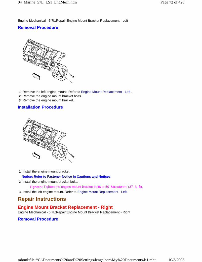
Engine Mechanical - 5.7L:Repair:Engine Mount Bracket Replacement - Left
Removal Procedure
1. Remove the left engine mount. Refer to Engine Mount Replacement - Left . 2. Remove the engine mount bracket bolts. 3. Remove the engine mount bracket.
Installation Procedure
1. Install the engine mount bracket.
Notice: Refer to Fastener Notice in Cautions and Notices.
2. Install the engine mount bracket bolts.
Tighten: Tighten the engine mount bracket bolts to 50 &newtonm; (37 lb ft).
3. Install the left engine mount. Refer to Engine Mount Replacement - Left .
Repair Instructions
Engine Mount Bracket Replacement - RightEngine Mechanical - 5.7L:Repair:Engine Mount Bracket Replacement - Right
Removal Procedure
Page 72 of 42604_Marine_57L_LS1_EngMech.htm
10/3/2003mhtml:file://C:\Documents%20and%20Settings\lengelbert\My%20Documents\ls1.mht
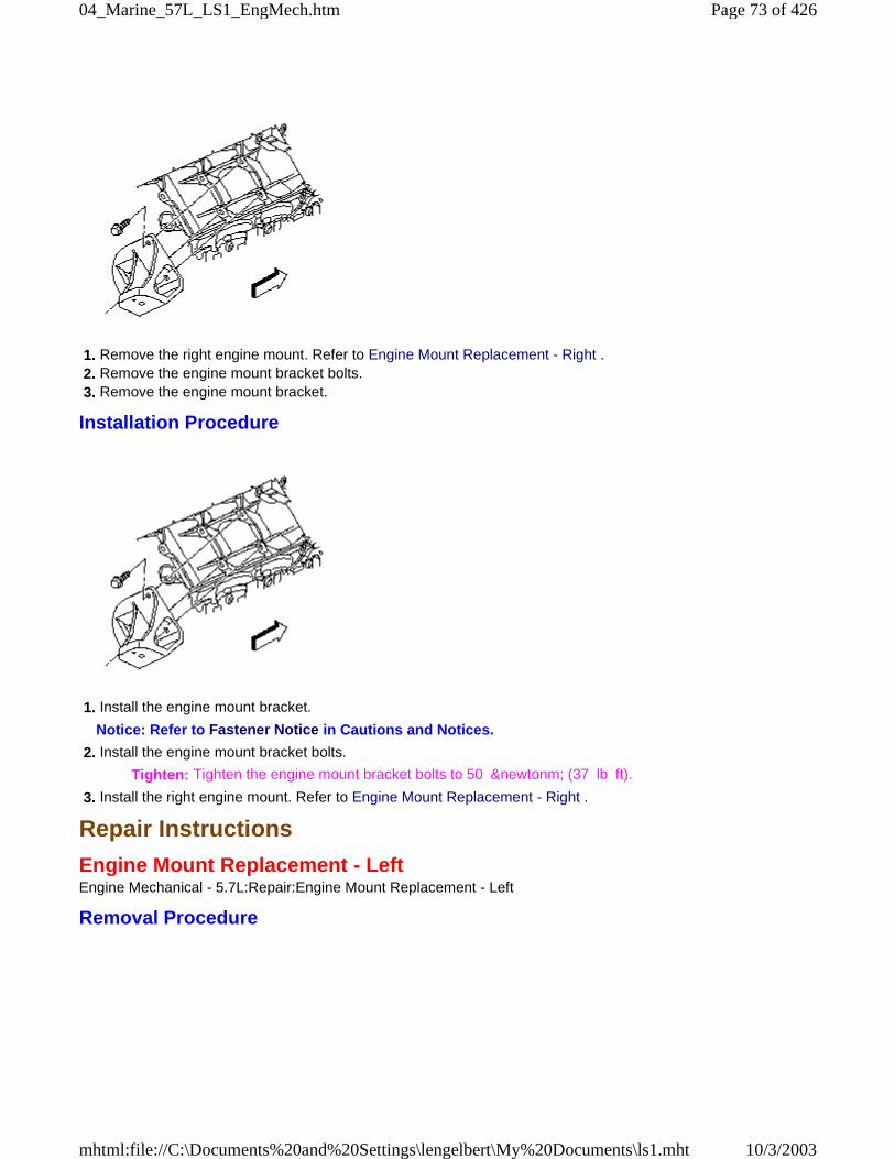
1. Remove the right engine mount. Refer to Engine Mount Replacement - Right . 2. Remove the engine mount bracket bolts. 3. Remove the engine mount bracket.
Installation Procedure
1. Install the engine mount bracket.
Notice: Refer to Fastener Notice in Cautions and Notices.
2. Install the engine mount bracket bolts.
Tighten: Tighten the engine mount bracket bolts to 50 &newtonm; (37 lb ft).
3. Install the right engine mount. Refer to Engine Mount Replacement - Right .
Repair Instructions
Engine Mount Replacement - LeftEngine Mechanical - 5.7L:Repair:Engine Mount Replacement - Left
Removal Procedure
Page 73 of 42604_Marine_57L_LS1_EngMech.htm
10/3/2003mhtml:file://C:\Documents%20and%20Settings\lengelbert\My%20Documents\ls1.mht

1. Remove the front suspension crossmember. Refer to Crossmember Replacement - Front Suspension in FrontSuspension. 2. Remove the engine mount-to-engine mount bracket nut. 3. Remove the engine mount. 4. Remove the engine mount heat shield from the engine mount, if necessary.
Installation Procedure
1. Install the engine mount heat shield to the engine mount, if necessary. 2. Install the engine mount.
Notice: Refer to Fastener Notice in Cautions and Notices.
3. Install the engine mount-to-engine mount bracket nut.
Tighten: Tighten the nut to 65 &newtonm; (48 lb ft).
4. Install the front suspension crossmember. Refer to Crossmember Replacement - Front Suspension in FrontSuspension.
Repair Instructions
Engine Mount Replacement - RightEngine Mechanical - 5.7L:Repair:Engine Mount Replacement - Right
Removal Procedure
Page 74 of 42604_Marine_57L_LS1_EngMech.htm
10/3/2003mhtml:file://C:\Documents%20and%20Settings\lengelbert\My%20Documents\ls1.mht
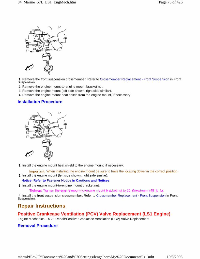
1. Remove the front suspension crossmember. Refer to Crossmember Replacement - Front Suspension in FrontSuspension. 2. Remove the engine mount-to-engine mount bracket nut. 3. Remove the engine mount (left side shown, right side similar). 4. Remove the engine mount heat shield from the engine mount, if necessary.
Installation Procedure
1. Install the engine mount heat shield to the engine mount, if necessary.
Important: When installing the engine mount be sure to have the locating dowel in the correct position. 2. Install the engine mount (left side shown, right side similar).
Notice: Refer to Fastener Notice in Cautions and Notices.
3. Install the engine mount-to-engine mount bracket nut.
Tighten: Tighten the engine mount-to-engine mount bracket nut to 65 &newtonm; (48 lb ft).
4. Install the front suspension crossmember. Refer to Crossmember Replacement - Front Suspension in FrontSuspension.
Repair Instructions
Positive Crankcase Ventilation (PCV) Valve Replacement (LS1 Engine)Engine Mechanical - 5.7L:Repair:Positive Crankcase Ventilation (PCV) Valve Replacement
Removal Procedure
Page 75 of 42604_Marine_57L_LS1_EngMech.htm
10/3/2003mhtml:file://C:\Documents%20and%20Settings\lengelbert\My%20Documents\ls1.mht
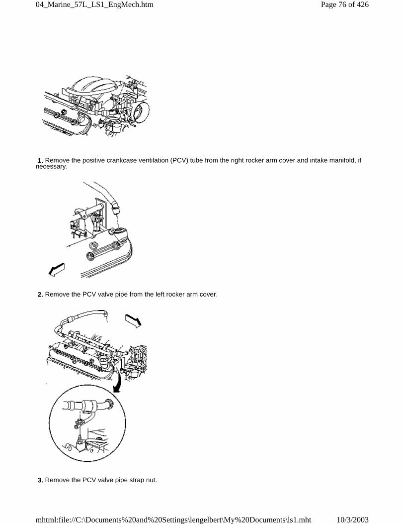
1. Remove the positive crankcase ventilation (PCV) tube from the right rocker arm cover and intake manifold, ifnecessary.
2. Remove the PCV valve pipe from the left rocker arm cover.
3. Remove the PCV valve pipe strap nut.
Page 76 of 42604_Marine_57L_LS1_EngMech.htm
10/3/2003mhtml:file://C:\Documents%20and%20Settings\lengelbert\My%20Documents\ls1.mht
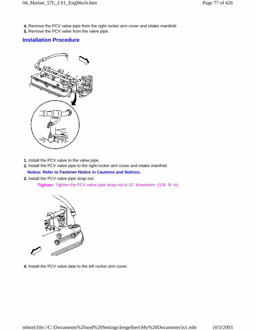
4. Remove the PCV valve pipe from the right rocker arm cover and intake manifold. 5. Remove the PCV valve from the valve pipe.
Installation Procedure
1. Install the PCV valve to the valve pipe. 2. Install the PCV valve pipe to the right rocker arm cover and intake manifold.
Notice: Refer to Fastener Notice in Cautions and Notices.
3. Install the PCV valve pipe strap nut.
Tighten: Tighten the PCV valve pipe strap nut to 12 &newtonm; (106 lb in).
4. Install the PCV valve pipe to the left rocker arm cover.
Page 77 of 42604_Marine_57L_LS1_EngMech.htm
10/3/2003mhtml:file://C:\Documents%20and%20Settings\lengelbert\My%20Documents\ls1.mht
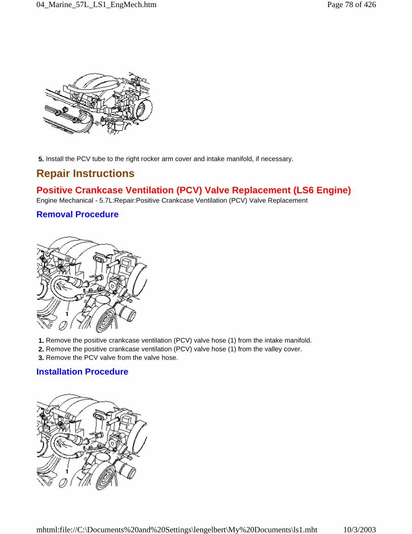
5. Install the PCV tube to the right rocker arm cover and intake manifold, if necessary.
Repair Instructions
Positive Crankcase Ventilation (PCV) Valve Replacement (LS6 Engine)Engine Mechanical - 5.7L:Repair:Positive Crankcase Ventilation (PCV) Valve Replacement
Removal Procedure
1. Remove the positive crankcase ventilation (PCV) valve hose (1) from the intake manifold. 2. Remove the positive crankcase ventilation (PCV) valve hose (1) from the valley cover. 3. Remove the PCV valve from the valve hose.
Installation Procedure
Page 78 of 42604_Marine_57L_LS1_EngMech.htm
10/3/2003mhtml:file://C:\Documents%20and%20Settings\lengelbert\My%20Documents\ls1.mht
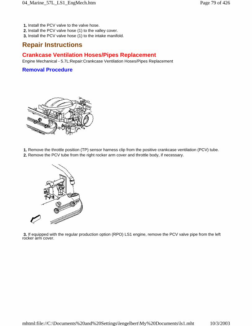
1. Install the PCV valve to the valve hose. 2. Install the PCV valve hose (1) to the valley cover. 3. Install the PCV valve hose (1) to the intake manifold.
Repair Instructions
Crankcase Ventilation Hoses/Pipes ReplacementEngine Mechanical - 5.7L:Repair:Crankcase Ventilation Hoses/Pipes Replacement
Removal Procedure
1. Remove the throttle position (TP) sensor harness clip from the positive crankcase ventilation (PCV) tube. 2. Remove the PCV tube from the right rocker arm cover and throttle body, if necessary.
3. If equipped with the regular production option (RPO) LS1 engine, remove the PCV valve pipe from the leftrocker arm cover.
Page 79 of 42604_Marine_57L_LS1_EngMech.htm
10/3/2003mhtml:file://C:\Documents%20and%20Settings\lengelbert\My%20Documents\ls1.mht
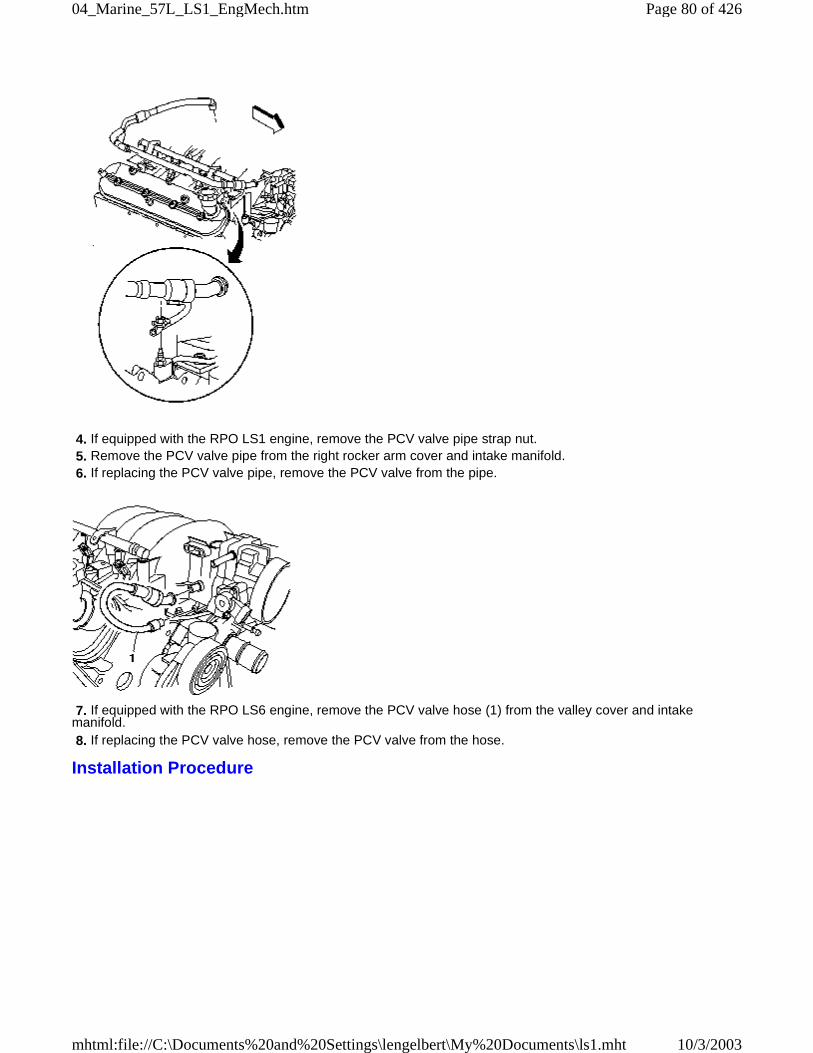
4. If equipped with the RPO LS1 engine, remove the PCV valve pipe strap nut. 5. Remove the PCV valve pipe from the right rocker arm cover and intake manifold. 6. If replacing the PCV valve pipe, remove the PCV valve from the pipe.
7. If equipped with the RPO LS6 engine, remove the PCV valve hose (1) from the valley cover and intakemanifold. 8. If replacing the PCV valve hose, remove the PCV valve from the hose.
Installation Procedure
Page 80 of 42604_Marine_57L_LS1_EngMech.htm
10/3/2003mhtml:file://C:\Documents%20and%20Settings\lengelbert\My%20Documents\ls1.mht
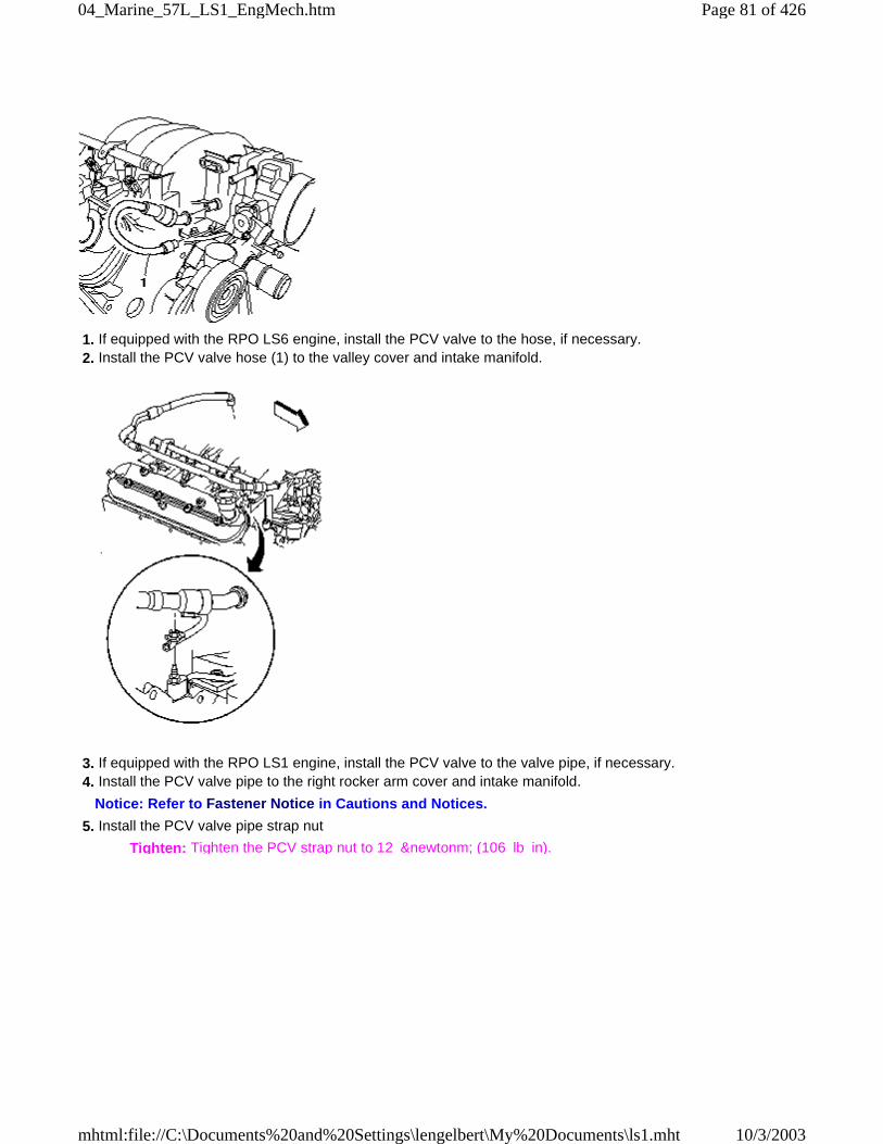
1. If equipped with the RPO LS6 engine, install the PCV valve to the hose, if necessary. 2. Install the PCV valve hose (1) to the valley cover and intake manifold.
3. If equipped with the RPO LS1 engine, install the PCV valve to the valve pipe, if necessary. 4. Install the PCV valve pipe to the right rocker arm cover and intake manifold.
Notice: Refer to Fastener Notice in Cautions and Notices.
5. Install the PCV valve pipe strap nut
Tighten: Tighten the PCV strap nut to 12 &newtonm; (106 lb in).
Page 81 of 42604_Marine_57L_LS1_EngMech.htm
10/3/2003mhtml:file://C:\Documents%20and%20Settings\lengelbert\My%20Documents\ls1.mht
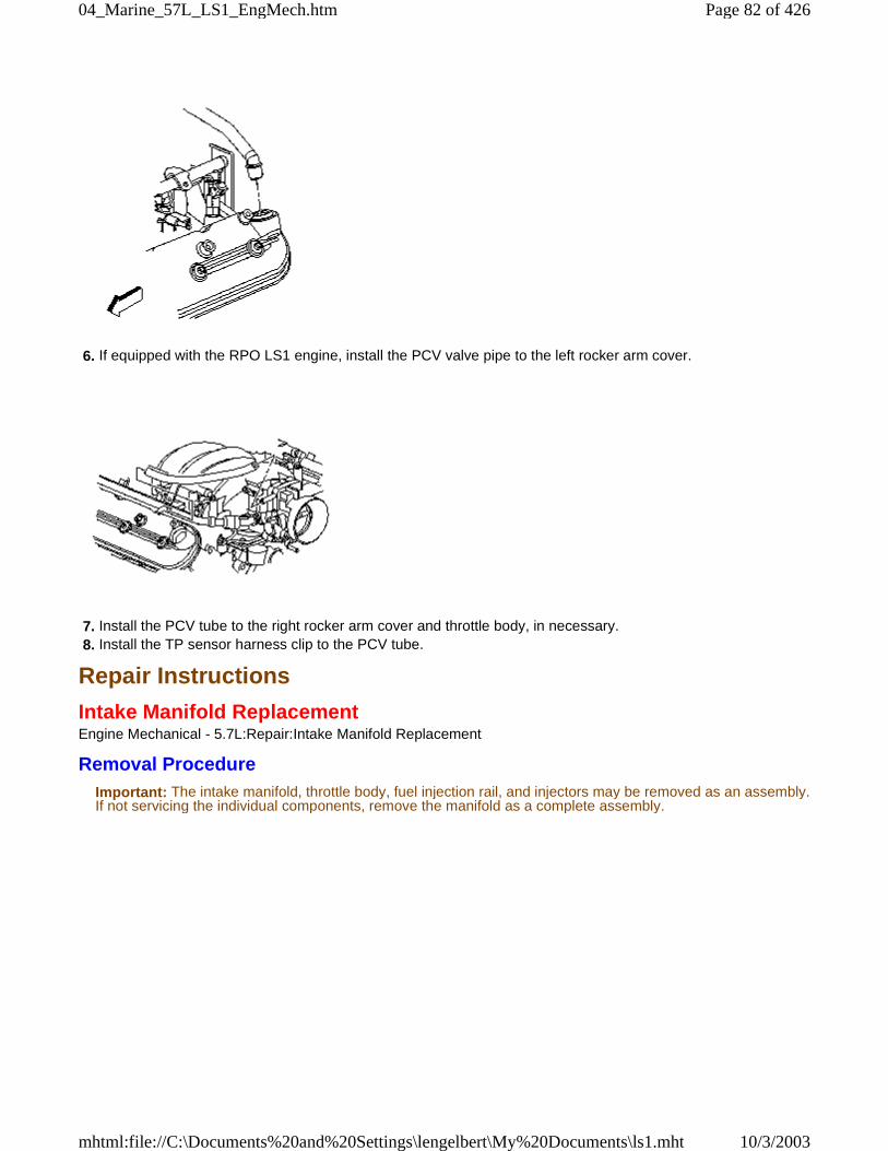
6. If equipped with the RPO LS1 engine, install the PCV valve pipe to the left rocker arm cover.
7. Install the PCV tube to the right rocker arm cover and throttle body, in necessary. 8. Install the TP sensor harness clip to the PCV tube.
Repair Instructions
Intake Manifold ReplacementEngine Mechanical - 5.7L:Repair:Intake Manifold Replacement
Removal ProcedureImportant: The intake manifold, throttle body, fuel injection rail, and injectors may be removed as an assembly.If not servicing the individual components, remove the manifold as a complete assembly.
Page 82 of 42604_Marine_57L_LS1_EngMech.htm
10/3/2003mhtml:file://C:\Documents%20and%20Settings\lengelbert\My%20Documents\ls1.mht
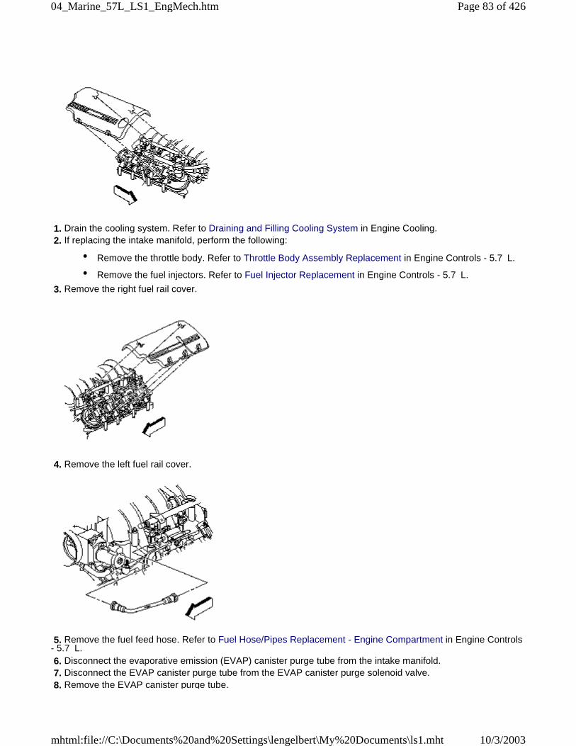
1. Drain the cooling system. Refer to Draining and Filling Cooling System in Engine Cooling. 2. If replacing the intake manifold, perform the following:
• Remove the throttle body. Refer to Throttle Body Assembly Replacement in Engine Controls - 5.7 L.
• Remove the fuel injectors. Refer to Fuel Injector Replacement in Engine Controls - 5.7 L.
3. Remove the right fuel rail cover.
4. Remove the left fuel rail cover.
5. Remove the fuel feed hose. Refer to Fuel Hose/Pipes Replacement - Engine Compartment in Engine Controls- 5.7 L. 6. Disconnect the evaporative emission (EVAP) canister purge tube from the intake manifold. 7. Disconnect the EVAP canister purge tube from the EVAP canister purge solenoid valve. 8. Remove the EVAP canister purge tube.
Page 83 of 42604_Marine_57L_LS1_EngMech.htm
10/3/2003mhtml:file://C:\Documents%20and%20Settings\lengelbert\My%20Documents\ls1.mht
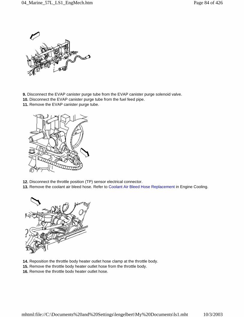
9. Disconnect the EVAP canister purge tube from the EVAP canister purge solenoid valve. 10. Disconnect the EVAP canister purge tube from the fuel feed pipe. 11. Remove the EVAP canister purge tube.
12. Disconnect the throttle position (TP) sensor electrical connector. 13. Remove the coolant air bleed hose. Refer to Coolant Air Bleed Hose Replacement in Engine Cooling.
14. Reposition the throttle body heater outlet hose clamp at the throttle body. 15. Remove the throttle body heater outlet hose from the throttle body. 16. Remove the throttle body heater outlet hose.
Page 84 of 42604_Marine_57L_LS1_EngMech.htm
10/3/2003mhtml:file://C:\Documents%20and%20Settings\lengelbert\My%20Documents\ls1.mht
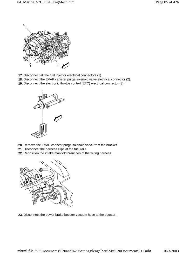
17. Disconnect all the fuel injector electrical connectors (1). 18. Disconnect the EVAP canister purge solenoid valve electrical connector (2). 19. Disconnect the electronic throttle control (ETC) electrical connector (3).
20. Remove the EVAP canister purge solenoid valve from the bracket. 21. Disconnect the harness clips at the fuel rails. 22. Reposition the intake manifold branches of the wiring harness.
23. Disconnect the power brake booster vacuum hose at the booster.
Page 85 of 42604_Marine_57L_LS1_EngMech.htm
10/3/2003mhtml:file://C:\Documents%20and%20Settings\lengelbert\My%20Documents\ls1.mht
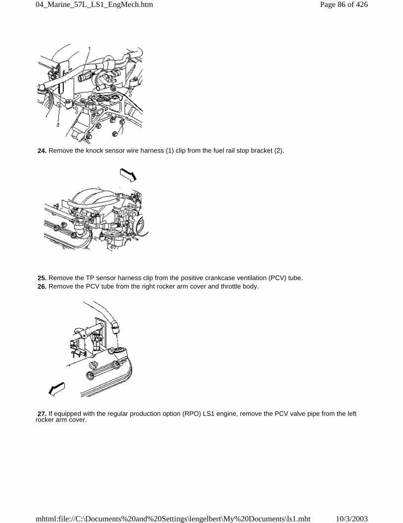
24. Remove the knock sensor wire harness (1) clip from the fuel rail stop bracket (2).
25. Remove the TP sensor harness clip from the positive crankcase ventilation (PCV) tube. 26. Remove the PCV tube from the right rocker arm cover and throttle body.
27. If equipped with the regular production option (RPO) LS1 engine, remove the PCV valve pipe from the leftrocker arm cover.
Page 86 of 42604_Marine_57L_LS1_EngMech.htm
10/3/2003mhtml:file://C:\Documents%20and%20Settings\lengelbert\My%20Documents\ls1.mht
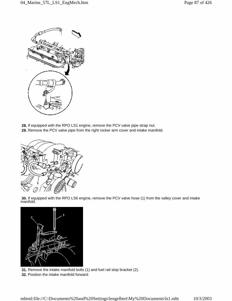
28. If equipped with the RPO LS1 engine, remove the PCV valve pipe strap nut. 29. Remove the PCV valve pipe from the right rocker arm cover and intake manifold.
30. If equipped with the RPO LS6 engine, remove the PCV valve hose (1) from the valley cover and intakemanifold.
31. Remove the intake manifold bolts (1) and fuel rail stop bracket (2). 32. Position the intake manifold forward.
Page 87 of 42604_Marine_57L_LS1_EngMech.htm
10/3/2003mhtml:file://C:\Documents%20and%20Settings\lengelbert\My%20Documents\ls1.mht
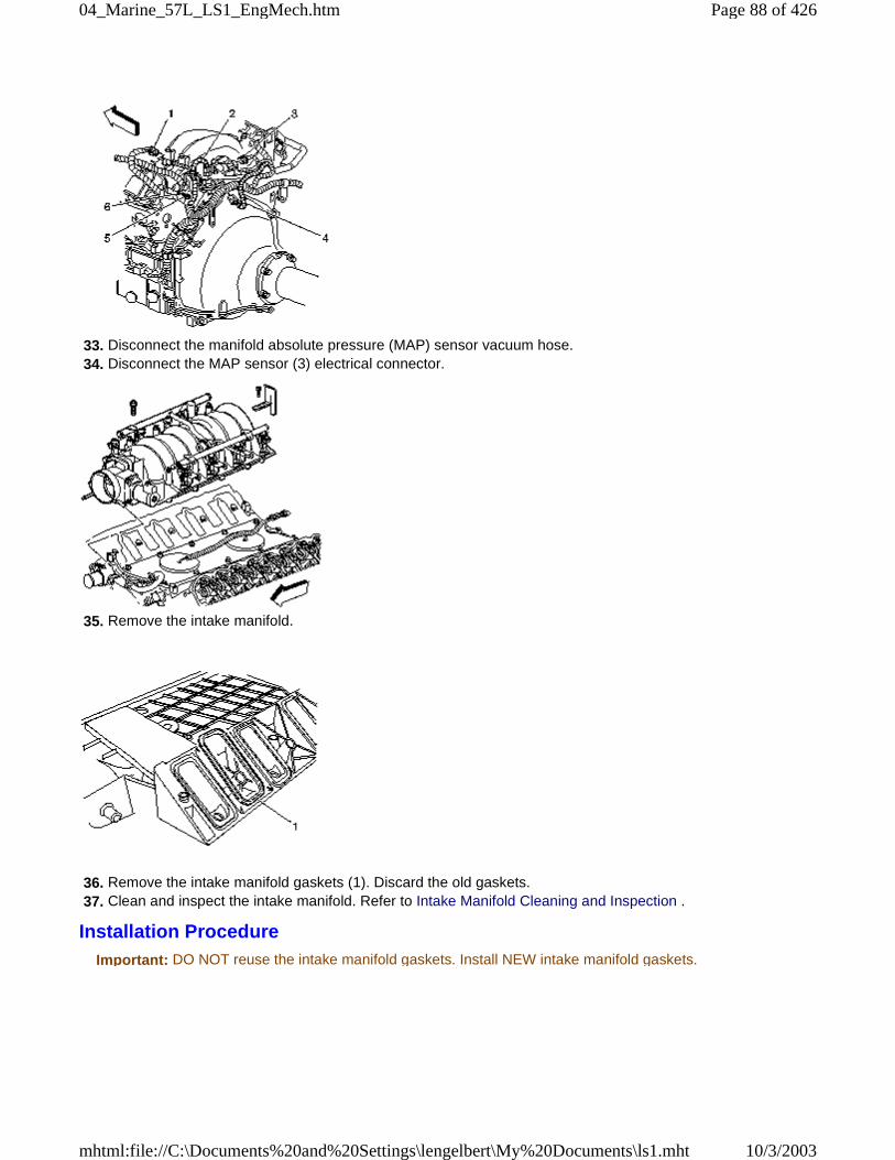
33. Disconnect the manifold absolute pressure (MAP) sensor vacuum hose. 34. Disconnect the MAP sensor (3) electrical connector.
35. Remove the intake manifold.
36. Remove the intake manifold gaskets (1). Discard the old gaskets. 37. Clean and inspect the intake manifold. Refer to Intake Manifold Cleaning and Inspection .
Installation ProcedureImportant: DO NOT reuse the intake manifold gaskets. Install NEW intake manifold gaskets.
Page 88 of 42604_Marine_57L_LS1_EngMech.htm
10/3/2003mhtml:file://C:\Documents%20and%20Settings\lengelbert\My%20Documents\ls1.mht
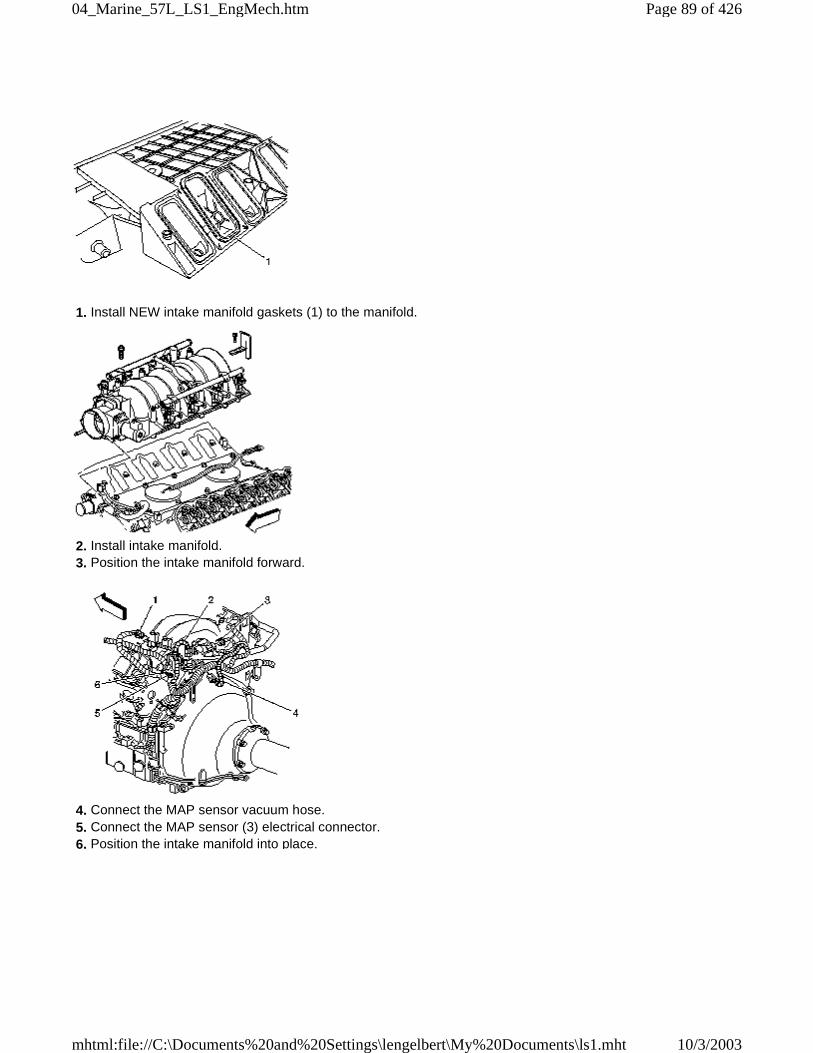
1. Install NEW intake manifold gaskets (1) to the manifold.
2. Install intake manifold. 3. Position the intake manifold forward.
4. Connect the MAP sensor vacuum hose. 5. Connect the MAP sensor (3) electrical connector. 6. Position the intake manifold into place.
Page 89 of 42604_Marine_57L_LS1_EngMech.htm
10/3/2003mhtml:file://C:\Documents%20and%20Settings\lengelbert\My%20Documents\ls1.mht
7. Apply threadlock GM P/N 12345382 (Canadian P/N 10953489), or equivalent to the threads of the intakemanifold bolts (1).
Caution: The fuel rail stop bracket must be installed onto the engine assembly. The stop bracket servesas a protective shield for the fuel rail in the event of a vehicle frontal crash. If the fuel rail stop bracketis not installed and the vehicle is involved in a frontal crash, fuel could be sprayed possibly causing afire and personal injury from burns.
8. Install the fuel rail stop bracket (2). 9. Install the intake manifold bolts (1).
Notice: Refer to Fastener Notice in Cautions and Notices. 10. Tighten the intake manifold bolts.
Tighten:
11. Tighten the intake manifold bolts a first pass in sequence to 5 &newtonm; (44 lb in). 12. Tighten the intake manifold bolts a final pass in sequence to 10 &newtonm; (89 lb in).
Page 90 of 42604_Marine_57L_LS1_EngMech.htm
10/3/2003mhtml:file://C:\Documents%20and%20Settings\lengelbert\My%20Documents\ls1.mht
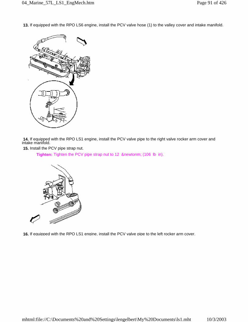
13. If equipped with the RPO LS6 engine, install the PCV valve hose (1) to the valley cover and intake manifold.
14. If equipped with the RPO LS1 engine, install the PCV valve pipe to the right valve rocker arm cover andintake manifold. 15. Install the PCV pipe strap nut.
Tighten: Tighten the PCV pipe strap nut to 12 &newtonm; (106 lb in).
16. If equipped with the RPO LS1 engine, install the PCV valve pipe to the left rocker arm cover.
Page 91 of 42604_Marine_57L_LS1_EngMech.htm
10/3/2003mhtml:file://C:\Documents%20and%20Settings\lengelbert\My%20Documents\ls1.mht
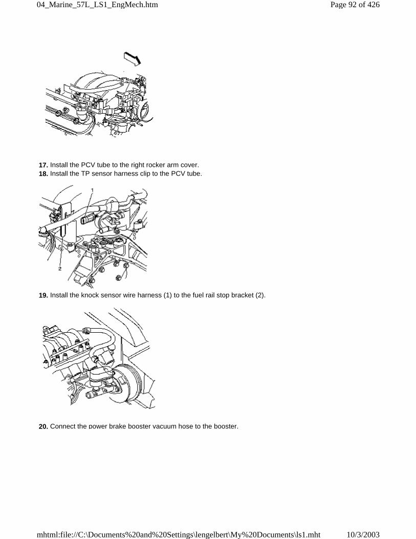
17. Install the PCV tube to the right rocker arm cover. 18. Install the TP sensor harness clip to the PCV tube.
19. Install the knock sensor wire harness (1) to the fuel rail stop bracket (2).
20. Connect the power brake booster vacuum hose to the booster.
Page 92 of 42604_Marine_57L_LS1_EngMech.htm
10/3/2003mhtml:file://C:\Documents%20and%20Settings\lengelbert\My%20Documents\ls1.mht
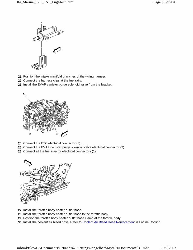
21. Position the intake manifold branches of the wiring harness. 22. Connect the harness clips at the fuel rails. 23. Install the EVAP canister purge solenoid valve from the bracket.
24. Connect the ETC electrical connector (3). 25. Connect the EVAP canister purge solenoid valve electrical connector (2). 26. Connect all the fuel injector electrical connectors (1).
27. Install the throttle body heater outlet hose. 28. Install the throttle body heater outlet hose to the throttle body. 29. Position the throttle body heater outlet hose clamp at the throttle body. 30. Install the coolant air bleed hose. Refer to Coolant Air Bleed Hose Replacement in Engine Cooling.
Page 93 of 42604_Marine_57L_LS1_EngMech.htm
10/3/2003mhtml:file://C:\Documents%20and%20Settings\lengelbert\My%20Documents\ls1.mht
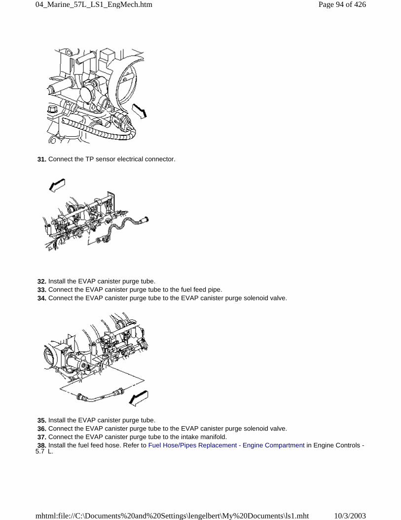
31. Connect the TP sensor electrical connector.
32. Install the EVAP canister purge tube. 33. Connect the EVAP canister purge tube to the fuel feed pipe. 34. Connect the EVAP canister purge tube to the EVAP canister purge solenoid valve.
35. Install the EVAP canister purge tube. 36. Connect the EVAP canister purge tube to the EVAP canister purge solenoid valve. 37. Connect the EVAP canister purge tube to the intake manifold. 38. Install the fuel feed hose. Refer to Fuel Hose/Pipes Replacement - Engine Compartment in Engine Controls -5.7 L.
Page 94 of 42604_Marine_57L_LS1_EngMech.htm
10/3/2003mhtml:file://C:\Documents%20and%20Settings\lengelbert\My%20Documents\ls1.mht
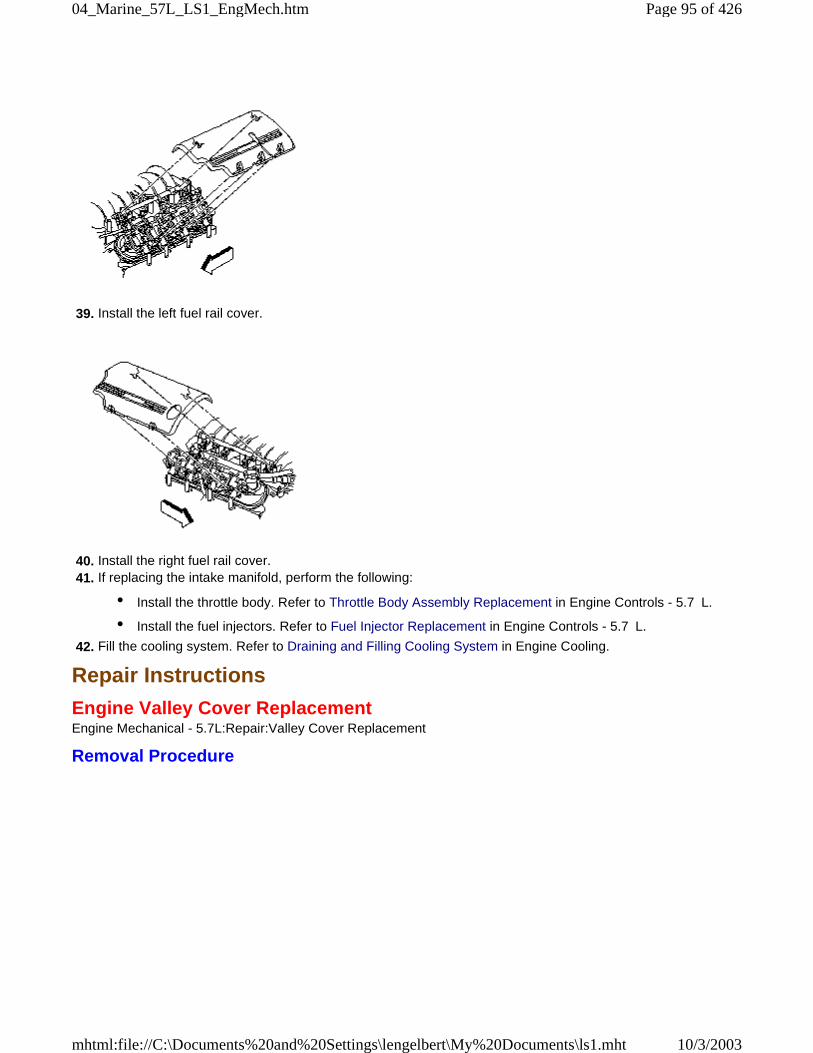
39. Install the left fuel rail cover.
40. Install the right fuel rail cover. 41. If replacing the intake manifold, perform the following:
• Install the throttle body. Refer to Throttle Body Assembly Replacement in Engine Controls - 5.7 L.
• Install the fuel injectors. Refer to Fuel Injector Replacement in Engine Controls - 5.7 L.
42. Fill the cooling system. Refer to Draining and Filling Cooling System in Engine Cooling.
Repair Instructions
Engine Valley Cover ReplacementEngine Mechanical - 5.7L:Repair:Valley Cover Replacement
Removal Procedure
Page 95 of 42604_Marine_57L_LS1_EngMech.htm
10/3/2003mhtml:file://C:\Documents%20and%20Settings\lengelbert\My%20Documents\ls1.mht
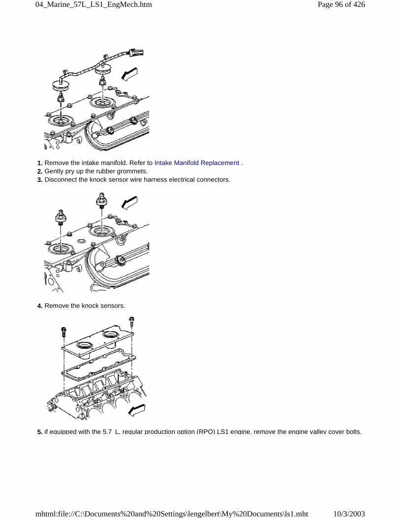
1. Remove the intake manifold. Refer to Intake Manifold Replacement . 2. Gently pry up the rubber grommets. 3. Disconnect the knock sensor wire harness electrical connectors.
4. Remove the knock sensors.
5. if equipped with the 5.7 L, regular production option (RPO) LS1 engine, remove the engine valley cover bolts.
Page 96 of 42604_Marine_57L_LS1_EngMech.htm
10/3/2003mhtml:file://C:\Documents%20and%20Settings\lengelbert\My%20Documents\ls1.mht
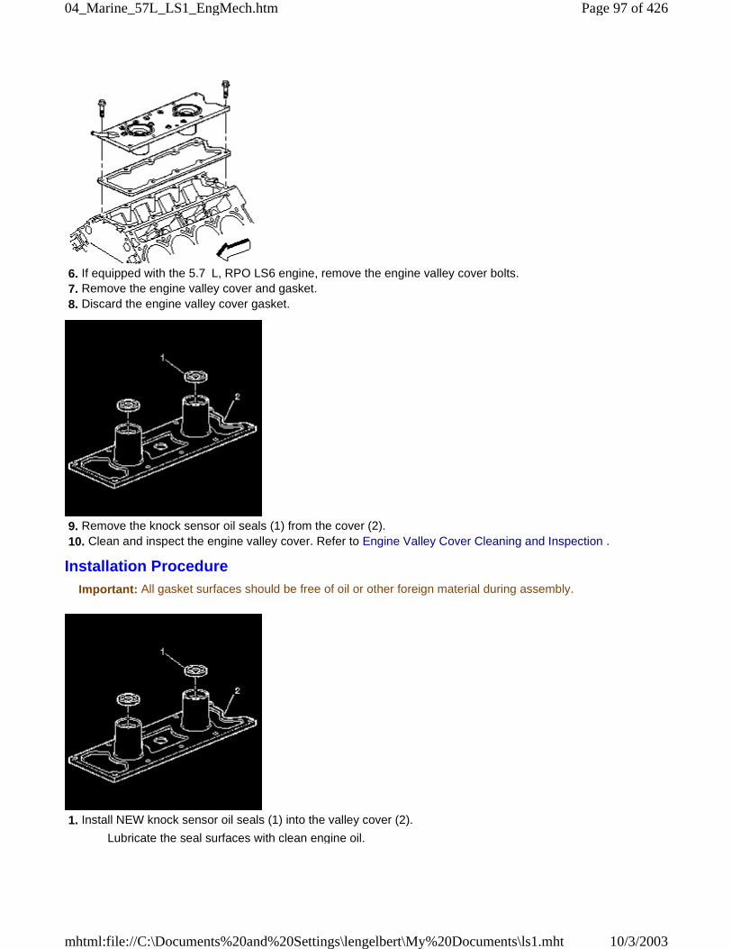
6. If equipped with the 5.7 L, RPO LS6 engine, remove the engine valley cover bolts. 7. Remove the engine valley cover and gasket. 8. Discard the engine valley cover gasket.
9. Remove the knock sensor oil seals (1) from the cover (2). 10. Clean and inspect the engine valley cover. Refer to Engine Valley Cover Cleaning and Inspection .
Installation ProcedureImportant: All gasket surfaces should be free of oil or other foreign material during assembly.
1. Install NEW knock sensor oil seals (1) into the valley cover (2).
Lubricate the seal surfaces with clean engine oil.
Page 97 of 42604_Marine_57L_LS1_EngMech.htm
10/3/2003mhtml:file://C:\Documents%20and%20Settings\lengelbert\My%20Documents\ls1.mht
2. If equipped with the 5.7 L, RPO LS6 engine, install the engine valley cover and a NEW gasket.
3. If equipped with the 5.7 L, RPO LS1 engine, install the engine valley cover and NEW gasket.
Notice: Refer to Fastener Notice in Cautions and Notices.
4. Install the engine valley cover bolts.
Tighten: Tighten the engine valley cover bolts to 25 &newtonm; (18 lb ft).
5. Install the knock sensors.
Tighten: Tighten the knock sensors to 20 &newtonm; (15 lb ft).
Page 98 of 42604_Marine_57L_LS1_EngMech.htm
10/3/2003mhtml:file://C:\Documents%20and%20Settings\lengelbert\My%20Documents\ls1.mht
6. Connect the knock sensor wire harness electrical connectors. 7. Install the rubber grommets into the valley cover. 8. Install the intake manifold. Refer to Intake Manifold Replacement .
Repair Instructions
Valve Rocker Arm Cover Replacement - LeftEngine Mechanical - 5.7L:Repair:Valve Rocker Arm Cover Replacement - Left
Removal Procedure
1. Remove the fuel feed hose. Refer to Fuel Hose/Pipes Replacement - Engine Compartment in Engine Controls- 5.7 L. 2. Disconnect the generator electrical connector (1). 3. Remove the engine wiring harness generator lead nut (3) and lead.
Page 99 of 42604_Marine_57L_LS1_EngMech.htm
10/3/2003mhtml:file://C:\Documents%20and%20Settings\lengelbert\My%20Documents\ls1.mht
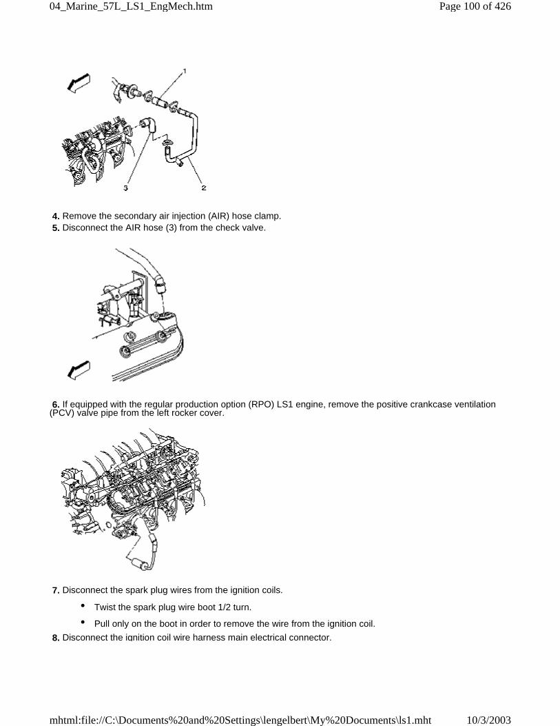
4. Remove the secondary air injection (AIR) hose clamp. 5. Disconnect the AIR hose (3) from the check valve.
6. If equipped with the regular production option (RPO) LS1 engine, remove the positive crankcase ventilation(PCV) valve pipe from the left rocker cover.
7. Disconnect the spark plug wires from the ignition coils.
• Twist the spark plug wire boot 1/2 turn.
• Pull only on the boot in order to remove the wire from the ignition coil.
8. Disconnect the ignition coil wire harness main electrical connector.
Page 100 of 42604_Marine_57L_LS1_EngMech.htm
10/3/2003mhtml:file://C:\Documents%20and%20Settings\lengelbert\My%20Documents\ls1.mht
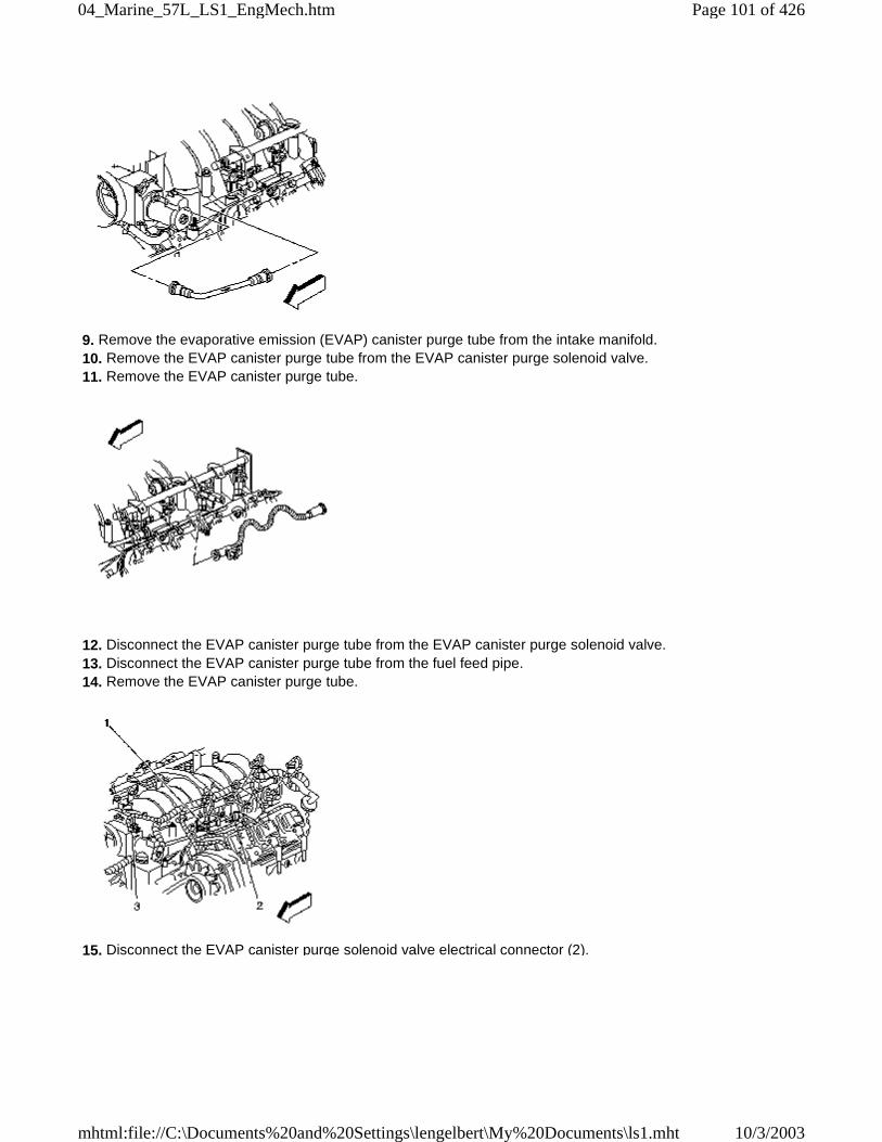
9. Remove the evaporative emission (EVAP) canister purge tube from the intake manifold. 10. Remove the EVAP canister purge tube from the EVAP canister purge solenoid valve. 11. Remove the EVAP canister purge tube.
12. Disconnect the EVAP canister purge tube from the EVAP canister purge solenoid valve. 13. Disconnect the EVAP canister purge tube from the fuel feed pipe. 14. Remove the EVAP canister purge tube.
15. Disconnect the EVAP canister purge solenoid valve electrical connector (2).
Page 101 of 42604_Marine_57L_LS1_EngMech.htm
10/3/2003mhtml:file://C:\Documents%20and%20Settings\lengelbert\My%20Documents\ls1.mht
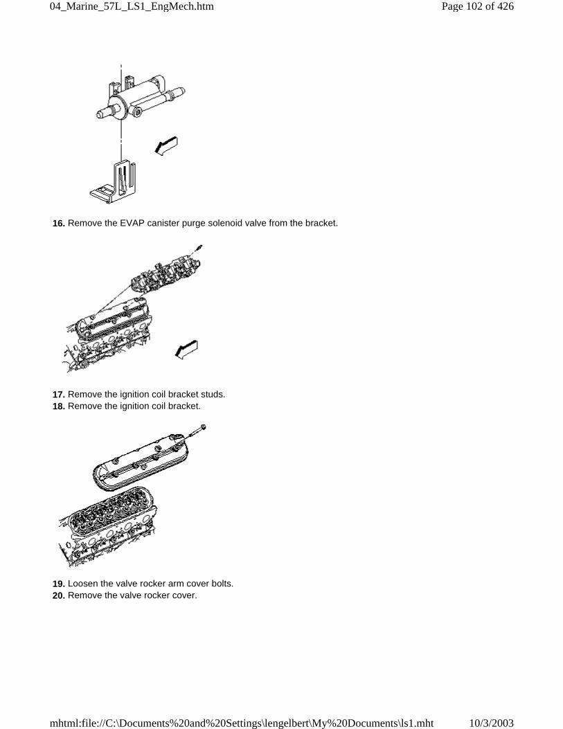
16. Remove the EVAP canister purge solenoid valve from the bracket.
17. Remove the ignition coil bracket studs. 18. Remove the ignition coil bracket.
19. Loosen the valve rocker arm cover bolts. 20. Remove the valve rocker cover.
Page 102 of 42604_Marine_57L_LS1_EngMech.htm
10/3/2003mhtml:file://C:\Documents%20and%20Settings\lengelbert\My%20Documents\ls1.mht
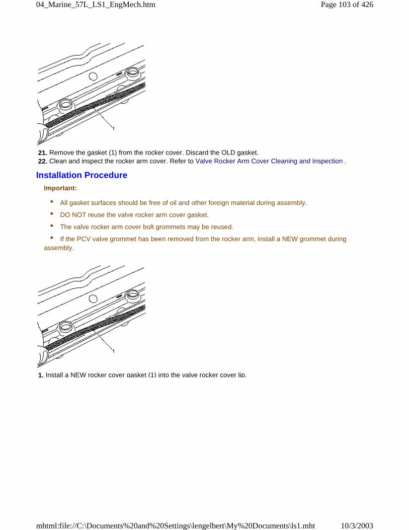
21. Remove the gasket (1) from the rocker cover. Discard the OLD gasket. 22. Clean and inspect the rocker arm cover. Refer to Valve Rocker Arm Cover Cleaning and Inspection .
Installation ProcedureImportant:
• All gasket surfaces should be free of oil and other foreign material during assembly.
• DO NOT reuse the valve rocker arm cover gasket.
• The valve rocker arm cover bolt grommets may be reused.
• If the PCV valve grommet has been removed from the rocker arm, install a NEW grommet duringassembly.
1. Install a NEW rocker cover gasket (1) into the valve rocker cover lip.
Page 103 of 42604_Marine_57L_LS1_EngMech.htm
10/3/2003mhtml:file://C:\Documents%20and%20Settings\lengelbert\My%20Documents\ls1.mht
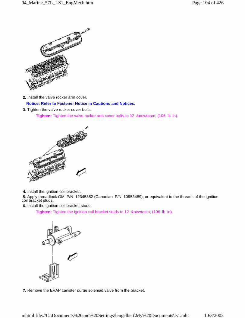
2. Install the valve rocker arm cover.
Notice: Refer to Fastener Notice in Cautions and Notices.
3. Tighten the valve rocker cover bolts.
Tighten: Tighten the valve rocker arm cover bolts to 12 &newtonm; (106 lb in).
4. Install the ignition coil bracket. 5. Apply threadlock GM P/N 12345382 (Canadian P/N 10953489), or equivalent to the threads of the ignitioncoil bracket studs. 6. Install the ignition coil bracket studs.
Tighten: Tighten the ignition coil bracket studs to 12 &newtonm; (106 lb in).
7. Remove the EVAP canister purge solenoid valve from the bracket.
Page 104 of 42604_Marine_57L_LS1_EngMech.htm
10/3/2003mhtml:file://C:\Documents%20and%20Settings\lengelbert\My%20Documents\ls1.mht
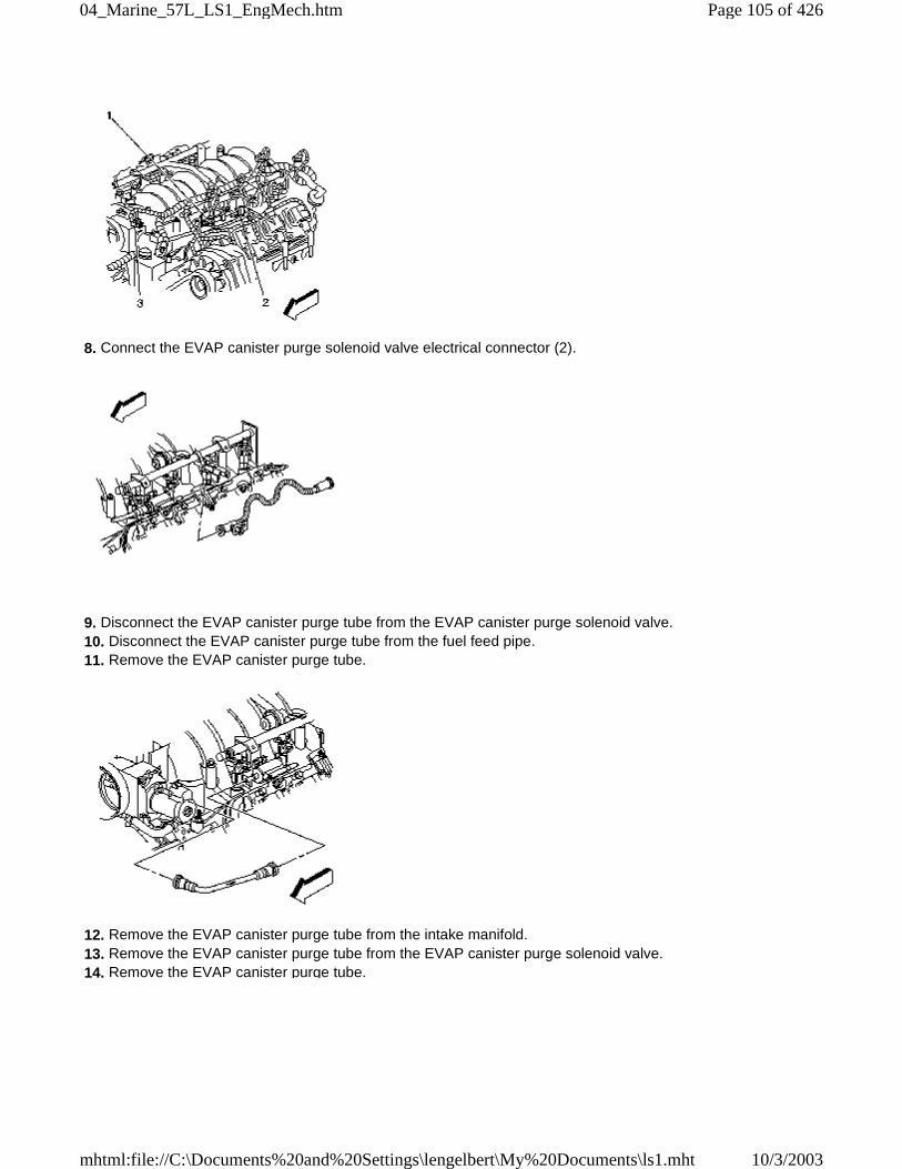
8. Connect the EVAP canister purge solenoid valve electrical connector (2).
9. Disconnect the EVAP canister purge tube from the EVAP canister purge solenoid valve. 10. Disconnect the EVAP canister purge tube from the fuel feed pipe. 11. Remove the EVAP canister purge tube.
12. Remove the EVAP canister purge tube from the intake manifold. 13. Remove the EVAP canister purge tube from the EVAP canister purge solenoid valve. 14. Remove the EVAP canister purge tube.
Page 105 of 42604_Marine_57L_LS1_EngMech.htm
10/3/2003mhtml:file://C:\Documents%20and%20Settings\lengelbert\My%20Documents\ls1.mht
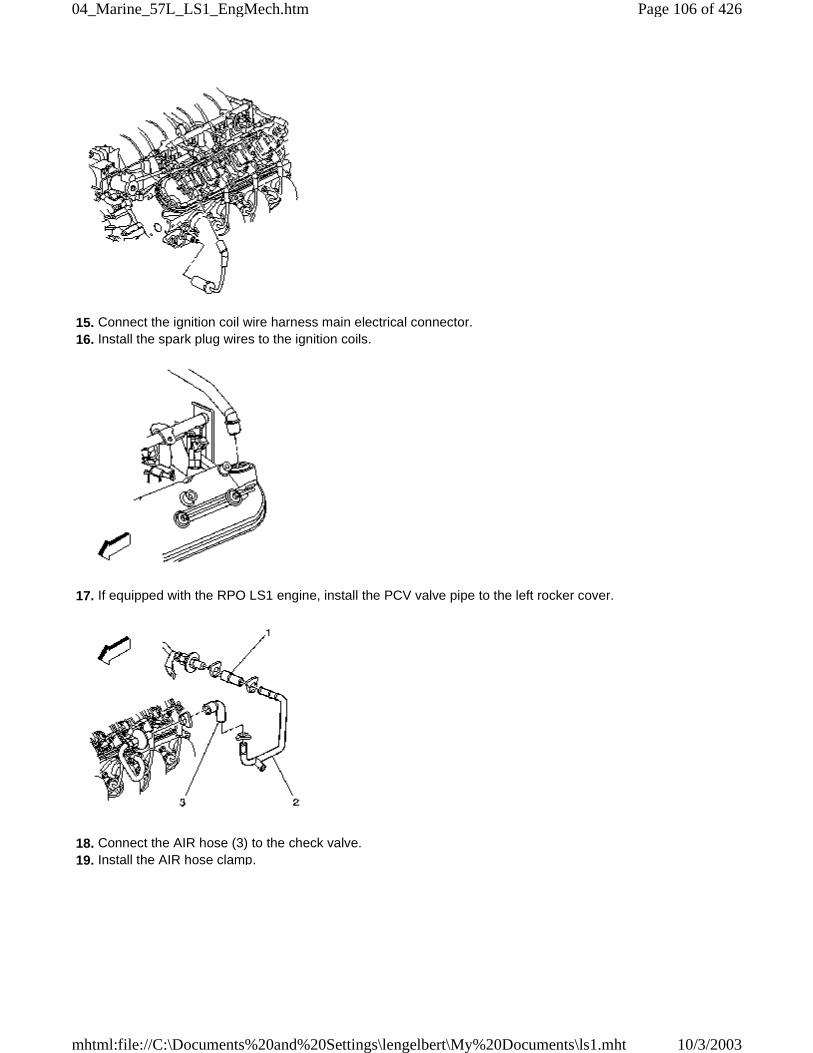
15. Connect the ignition coil wire harness main electrical connector. 16. Install the spark plug wires to the ignition coils.
17. If equipped with the RPO LS1 engine, install the PCV valve pipe to the left rocker cover.
18. Connect the AIR hose (3) to the check valve. 19. Install the AIR hose clamp.
Page 106 of 42604_Marine_57L_LS1_EngMech.htm
10/3/2003mhtml:file://C:\Documents%20and%20Settings\lengelbert\My%20Documents\ls1.mht
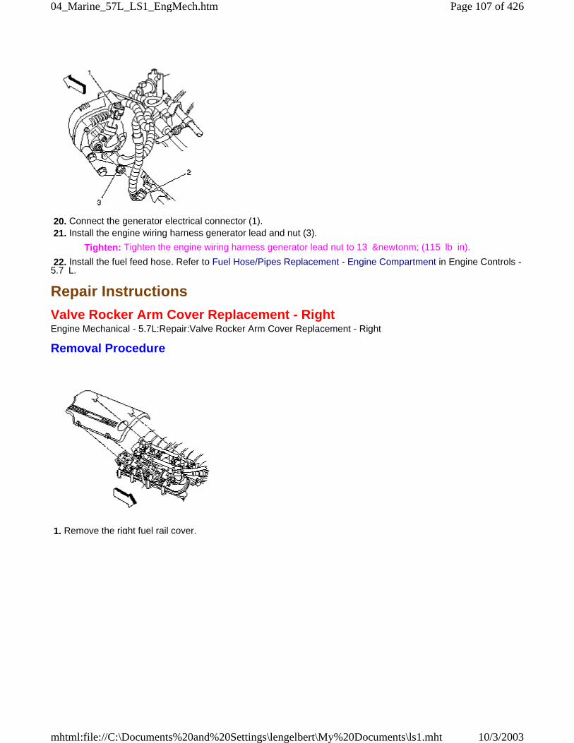
20. Connect the generator electrical connector (1). 21. Install the engine wiring harness generator lead and nut (3).
Tighten: Tighten the engine wiring harness generator lead nut to 13 &newtonm; (115 lb in).
22. Install the fuel feed hose. Refer to Fuel Hose/Pipes Replacement - Engine Compartment in Engine Controls -5.7 L.
Repair Instructions
Valve Rocker Arm Cover Replacement - RightEngine Mechanical - 5.7L:Repair:Valve Rocker Arm Cover Replacement - Right
Removal Procedure
1. Remove the right fuel rail cover.
Page 107 of 42604_Marine_57L_LS1_EngMech.htm
10/3/2003mhtml:file://C:\Documents%20and%20Settings\lengelbert\My%20Documents\ls1.mht
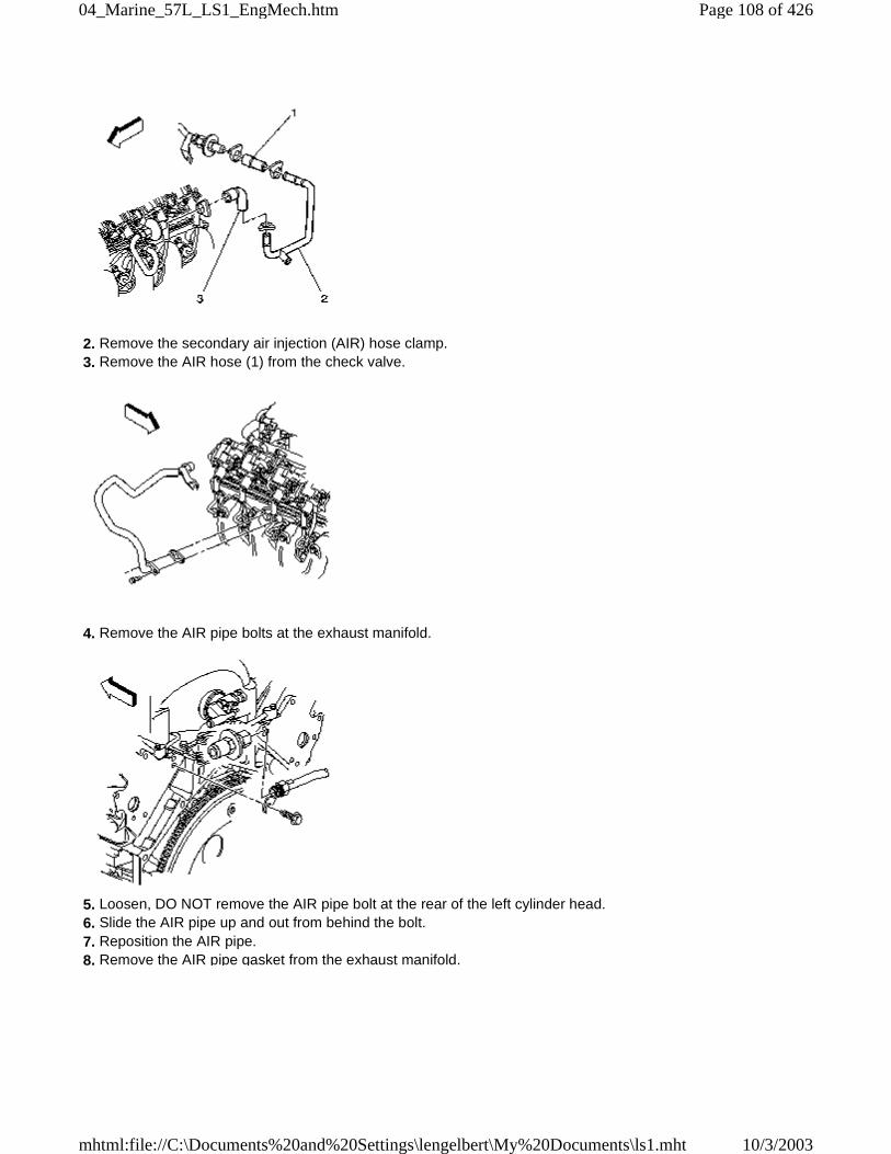
2. Remove the secondary air injection (AIR) hose clamp. 3. Remove the AIR hose (1) from the check valve.
4. Remove the AIR pipe bolts at the exhaust manifold.
5. Loosen, DO NOT remove the AIR pipe bolt at the rear of the left cylinder head. 6. Slide the AIR pipe up and out from behind the bolt. 7. Reposition the AIR pipe. 8. Remove the AIR pipe gasket from the exhaust manifold.
Page 108 of 42604_Marine_57L_LS1_EngMech.htm
10/3/2003mhtml:file://C:\Documents%20and%20Settings\lengelbert\My%20Documents\ls1.mht
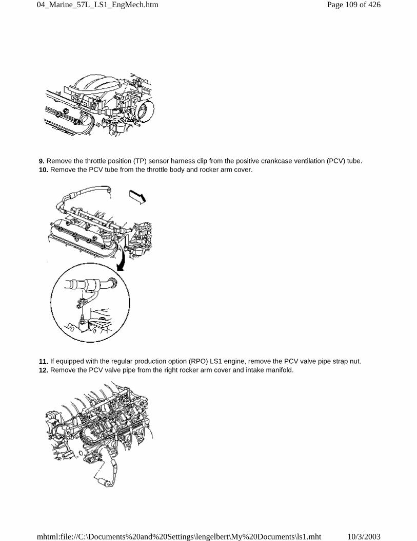
9. Remove the throttle position (TP) sensor harness clip from the positive crankcase ventilation (PCV) tube. 10. Remove the PCV tube from the throttle body and rocker arm cover.
11. If equipped with the regular production option (RPO) LS1 engine, remove the PCV valve pipe strap nut. 12. Remove the PCV valve pipe from the right rocker arm cover and intake manifold.
Page 109 of 42604_Marine_57L_LS1_EngMech.htm
10/3/2003mhtml:file://C:\Documents%20and%20Settings\lengelbert\My%20Documents\ls1.mht
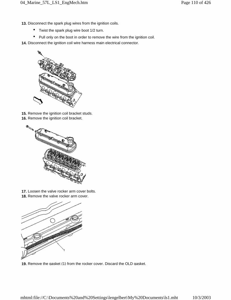
13. Disconnect the spark plug wires from the ignition coils.
• Twist the spark plug wire boot 1/2 turn.
• Pull only on the boot in order to remove the wire from the ignition coil.
14. Disconnect the ignition coil wire harness main electrical connector.
15. Remove the ignition coil bracket studs. 16. Remove the ignition coil bracket.
17. Loosen the valve rocker arm cover bolts. 18. Remove the valve rocker arm cover.
19. Remove the gasket (1) from the rocker cover. Discard the OLD gasket.
Page 110 of 42604_Marine_57L_LS1_EngMech.htm
10/3/2003mhtml:file://C:\Documents%20and%20Settings\lengelbert\My%20Documents\ls1.mht
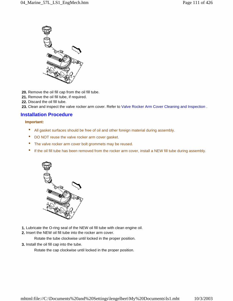
20. Remove the oil fill cap from the oil fill tube. 21. Remove the oil fill tube, if required. 22. Discard the oil fill tube. 23. Clean and inspect the valve rocker arm cover. Refer to Valve Rocker Arm Cover Cleaning and Inspection .
Installation ProcedureImportant:
• All gasket surfaces should be free of oil and other foreign material during assembly.
• DO NOT reuse the valve rocker arm cover gasket.
• The valve rocker arm cover bolt grommets may be reused.
• If the oil fill tube has been removed from the rocker arm cover, install a NEW fill tube during assembly.
1. Lubricate the O-ring seal of the NEW oil fill tube with clean engine oil. 2. Insert the NEW oil fill tube into the rocker arm cover.
Rotate the tube clockwise until locked in the proper position.
3. Install the oil fill cap into the tube.
Rotate the cap clockwise until locked in the proper position.
Page 111 of 42604_Marine_57L_LS1_EngMech.htm
10/3/2003mhtml:file://C:\Documents%20and%20Settings\lengelbert\My%20Documents\ls1.mht
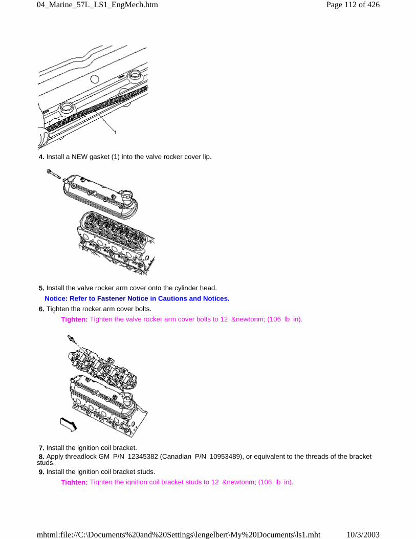
4. Install a NEW gasket (1) into the valve rocker cover lip.
5. Install the valve rocker arm cover onto the cylinder head.
Notice: Refer to Fastener Notice in Cautions and Notices.
6. Tighten the rocker arm cover bolts.
Tighten: Tighten the valve rocker arm cover bolts to 12 &newtonm; (106 lb in).
7. Install the ignition coil bracket. 8. Apply threadlock GM P/N 12345382 (Canadian P/N 10953489), or equivalent to the threads of the bracketstuds. 9. Install the ignition coil bracket studs.
Tighten: Tighten the ignition coil bracket studs to 12 &newtonm; (106 lb in).
Page 112 of 42604_Marine_57L_LS1_EngMech.htm
10/3/2003mhtml:file://C:\Documents%20and%20Settings\lengelbert\My%20Documents\ls1.mht
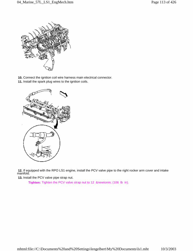
10. Connect the ignition coil wire harness main electrical connector. 11. Install the spark plug wires to the ignition coils.
12. If equipped with the RPO LS1 engine, install the PCV valve pipe to the right rocker arm cover and intakemanifold. 13. Install the PCV valve pipe strap nut.
Tighten: Tighten the PCV valve strap nut to 12 &newtonm; (106 lb in).
Page 113 of 42604_Marine_57L_LS1_EngMech.htm
10/3/2003mhtml:file://C:\Documents%20and%20Settings\lengelbert\My%20Documents\ls1.mht
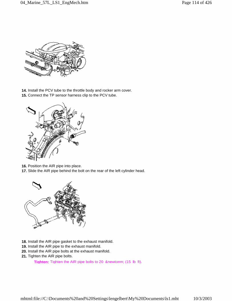
14. Install the PCV tube to the throttle body and rocker arm cover. 15. Connect the TP sensor harness clip to the PCV tube.
16. Position the AIR pipe into place. 17. Slide the AIR pipe behind the bolt on the rear of the left cylinder head.
18. Install the AIR pipe gasket to the exhaust manifold. 19. Install the AIR pipe to the exhaust manifold. 20. Install the AIR pipe bolts at the exhaust manifold. 21. Tighten the AIR pipe bolts.
Tighten: Tighten the AIR pipe bolts to 20 &newtonm; (15 lb ft).
Page 114 of 42604_Marine_57L_LS1_EngMech.htm
10/3/2003mhtml:file://C:\Documents%20and%20Settings\lengelbert\My%20Documents\ls1.mht
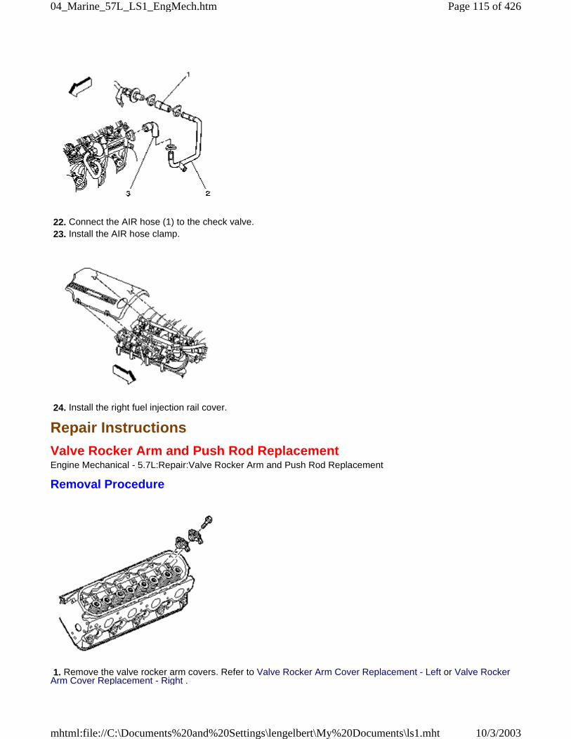
22. Connect the AIR hose (1) to the check valve. 23. Install the AIR hose clamp.
24. Install the right fuel injection rail cover.
Repair Instructions
Valve Rocker Arm and Push Rod ReplacementEngine Mechanical - 5.7L:Repair:Valve Rocker Arm and Push Rod Replacement
Removal Procedure
1. Remove the valve rocker arm covers. Refer to Valve Rocker Arm Cover Replacement - Left or Valve RockerArm Cover Replacement - Right .
Page 115 of 42604_Marine_57L_LS1_EngMech.htm
10/3/2003mhtml:file://C:\Documents%20and%20Settings\lengelbert\My%20Documents\ls1.mht
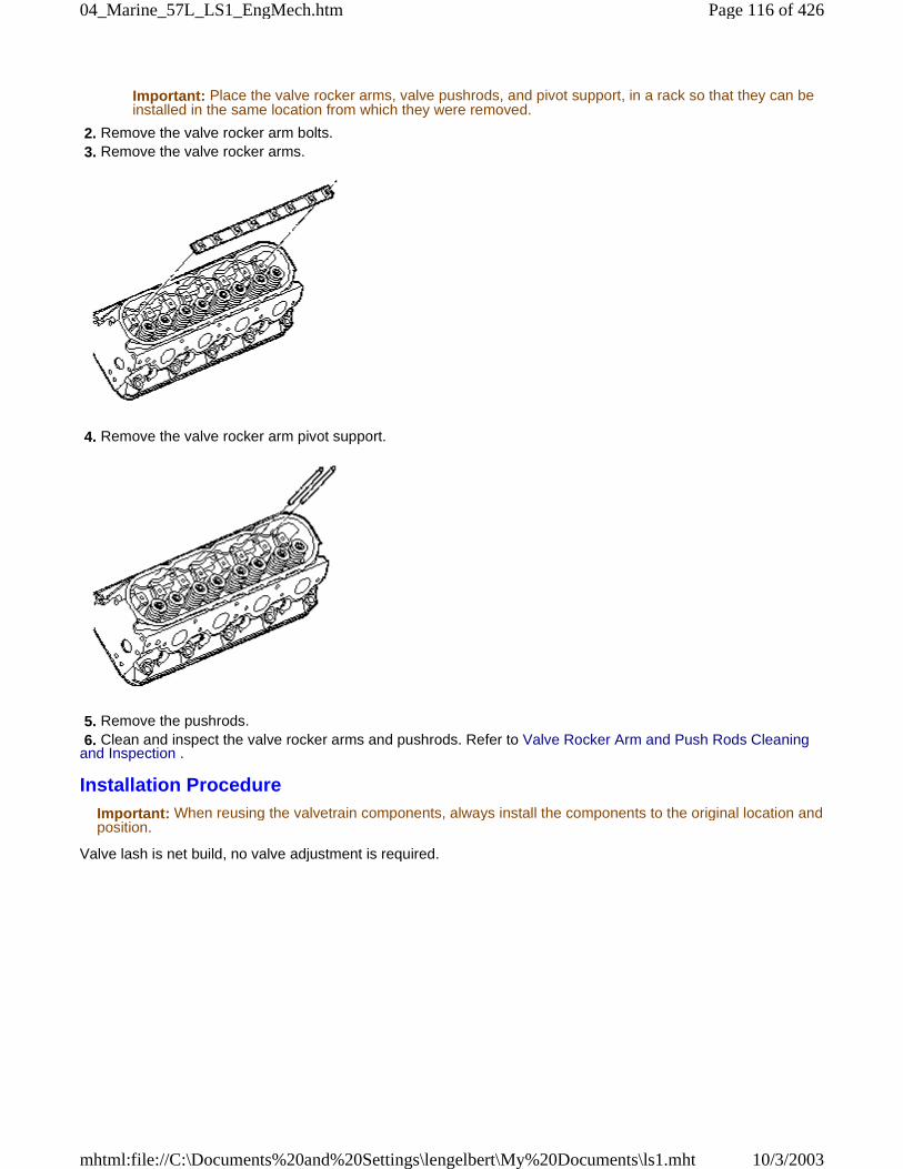
Important: Place the valve rocker arms, valve pushrods, and pivot support, in a rack so that they can beinstalled in the same location from which they were removed.
2. Remove the valve rocker arm bolts. 3. Remove the valve rocker arms.
4. Remove the valve rocker arm pivot support.
5. Remove the pushrods. 6. Clean and inspect the valve rocker arms and pushrods. Refer to Valve Rocker Arm and Push Rods Cleaningand Inspection .
Installation ProcedureImportant: When reusing the valvetrain components, always install the components to the original location andposition.
Valve lash is net build, no valve adjustment is required.
Page 116 of 42604_Marine_57L_LS1_EngMech.htm
10/3/2003mhtml:file://C:\Documents%20and%20Settings\lengelbert\My%20Documents\ls1.mht

1. Lubricate the valve rocker arms and pushrods with clean engine oil. 2. Lubricate the flange of the valve rocker arm bolts with clean engine oil.
Lubricate the flange or washer surface of the bolt that will contact the valve rocker arm.
3. Install the valve rocker arm pivot support.
Important: Make sure that the pushrods seat properly to the valve lifter sockets. 4. Install the pushrods.
Important: Make sure that the pushrods seat properly to the ends of the rocker arms. 5. Install the rocker arms and bolts.
DO NOT tighten the rocker arm bolts at this time.
Page 117 of 42604_Marine_57L_LS1_EngMech.htm
10/3/2003mhtml:file://C:\Documents%20and%20Settings\lengelbert\My%20Documents\ls1.mht
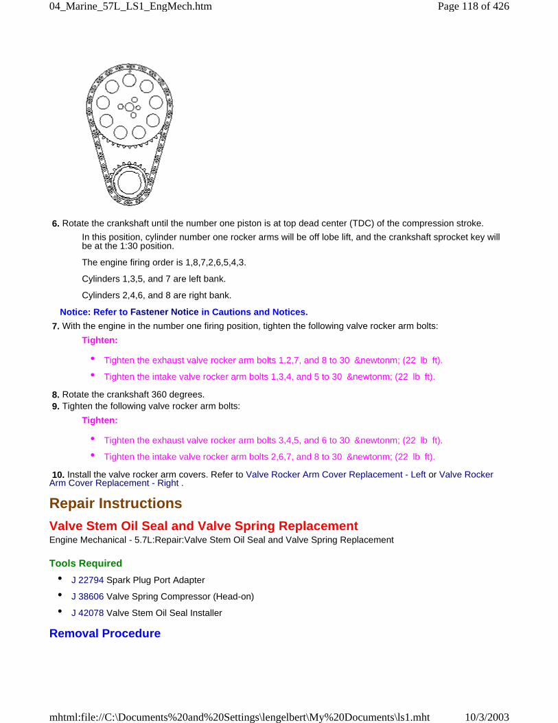
6. Rotate the crankshaft until the number one piston is at top dead center (TDC) of the compression stroke.
In this position, cylinder number one rocker arms will be off lobe lift, and the crankshaft sprocket key willbe at the 1:30 position.
The engine firing order is 1,8,7,2,6,5,4,3.
Cylinders 1,3,5, and 7 are left bank.
Cylinders 2,4,6, and 8 are right bank.
Notice: Refer to Fastener Notice in Cautions and Notices.
7. With the engine in the number one firing position, tighten the following valve rocker arm bolts:
Tighten:
• Tighten the exhaust valve rocker arm bolts 1,2,7, and 8 to 30 &newtonm; (22 lb ft).
• Tighten the intake valve rocker arm bolts 1,3,4, and 5 to 30 &newtonm; (22 lb ft).
8. Rotate the crankshaft 360 degrees. 9. Tighten the following valve rocker arm bolts:
Tighten:
• Tighten the exhaust valve rocker arm bolts 3,4,5, and 6 to 30 &newtonm; (22 lb ft).
• Tighten the intake valve rocker arm bolts 2,6,7, and 8 to 30 &newtonm; (22 lb ft).
10. Install the valve rocker arm covers. Refer to Valve Rocker Arm Cover Replacement - Left or Valve RockerArm Cover Replacement - Right .
Repair Instructions
Valve Stem Oil Seal and Valve Spring ReplacementEngine Mechanical - 5.7L:Repair:Valve Stem Oil Seal and Valve Spring Replacement
Tools Required
• J 22794 Spark Plug Port Adapter
• J 38606 Valve Spring Compressor (Head-on)
• J 42078 Valve Stem Oil Seal Installer
Removal Procedure
Page 118 of 42604_Marine_57L_LS1_EngMech.htm
10/3/2003mhtml:file://C:\Documents%20and%20Settings\lengelbert\My%20Documents\ls1.mht
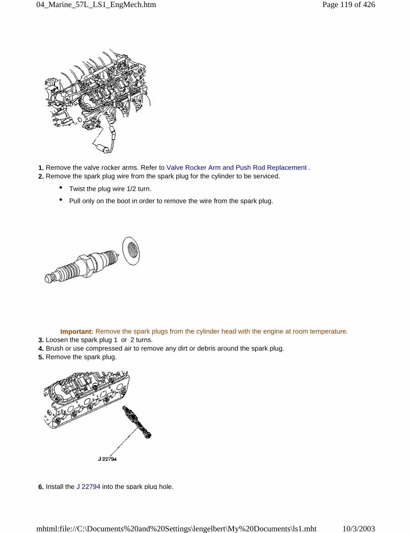
1. Remove the valve rocker arms. Refer to Valve Rocker Arm and Push Rod Replacement . 2. Remove the spark plug wire from the spark plug for the cylinder to be serviced.
• Twist the plug wire 1/2 turn.
• Pull only on the boot in order to remove the wire from the spark plug.
Important: Remove the spark plugs from the cylinder head with the engine at room temperature. 3. Loosen the spark plug 1 or 2 turns. 4. Brush or use compressed air to remove any dirt or debris around the spark plug. 5. Remove the spark plug.
6. Install the J 22794 into the spark plug hole.
Page 119 of 42604_Marine_57L_LS1_EngMech.htm
10/3/2003mhtml:file://C:\Documents%20and%20Settings\lengelbert\My%20Documents\ls1.mht
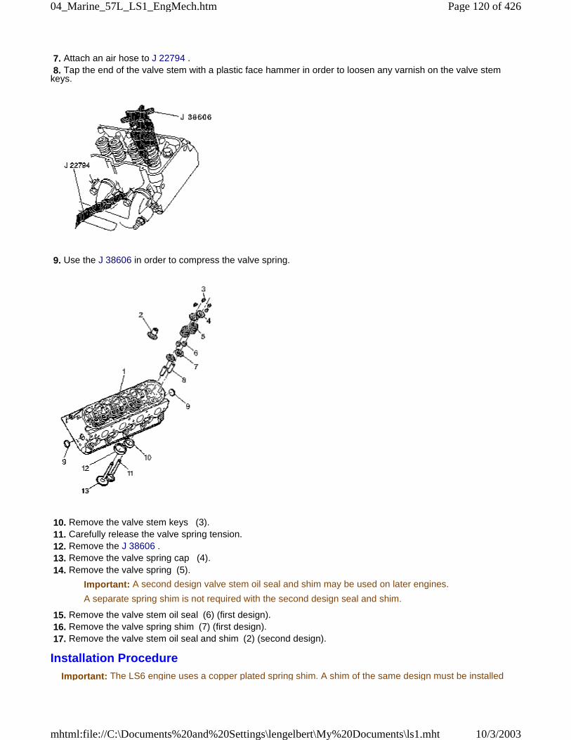
7. Attach an air hose to J 22794 . 8. Tap the end of the valve stem with a plastic face hammer in order to loosen any varnish on the valve stemkeys.
9. Use the J 38606 in order to compress the valve spring.
10. Remove the valve stem keys (3). 11. Carefully release the valve spring tension. 12. Remove the J 38606 . 13. Remove the valve spring cap (4). 14. Remove the valve spring (5).
Important: A second design valve stem oil seal and shim may be used on later engines.
A separate spring shim is not required with the second design seal and shim.
15. Remove the valve stem oil seal (6) (first design). 16. Remove the valve spring shim (7) (first design). 17. Remove the valve stem oil seal and shim (2) (second design).
Installation ProcedureImportant: The LS6 engine uses a copper plated spring shim. A shim of the same design must be installed
Page 120 of 42604_Marine_57L_LS1_EngMech.htm
10/3/2003mhtml:file://C:\Documents%20and%20Settings\lengelbert\My%20Documents\ls1.mht
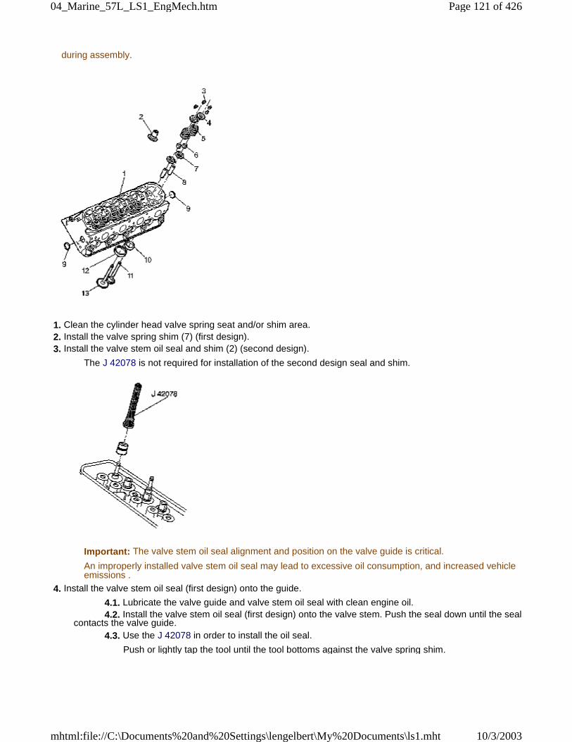
during assembly.
1. Clean the cylinder head valve spring seat and/or shim area. 2. Install the valve spring shim (7) (first design). 3. Install the valve stem oil seal and shim (2) (second design).
The J 42078 is not required for installation of the second design seal and shim.
Important: The valve stem oil seal alignment and position on the valve guide is critical.
An improperly installed valve stem oil seal may lead to excessive oil consumption, and increased vehicleemissions .
4. Install the valve stem oil seal (first design) onto the guide.
4.1. Lubricate the valve guide and valve stem oil seal with clean engine oil. 4.2. Install the valve stem oil seal (first design) onto the valve stem. Push the seal down until the sealcontacts the valve guide. 4.3. Use the J 42078 in order to install the oil seal.
Push or lightly tap the tool until the tool bottoms against the valve spring shim.
Page 121 of 42604_Marine_57L_LS1_EngMech.htm
10/3/2003mhtml:file://C:\Documents%20and%20Settings\lengelbert\My%20Documents\ls1.mht
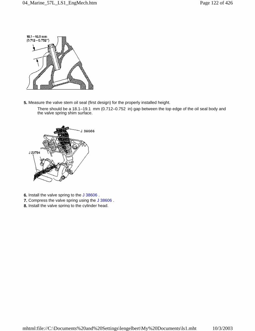
5. Measure the valve stem oil seal (first design) for the properly installed height.
There should be a 18.1–19.1 mm (0.712–0.752 in) gap between the top edge of the oil seal body andthe valve spring shim surface.
6. Install the valve spring to the J 38606 . 7. Compress the valve spring using the J 38606 . 8. Install the valve spring to the cylinder head.
Page 122 of 42604_Marine_57L_LS1_EngMech.htm
10/3/2003mhtml:file://C:\Documents%20and%20Settings\lengelbert\My%20Documents\ls1.mht
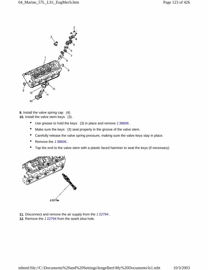
9. Install the valve spring cap (4). 10. Install the valve stem keys (3).
• Use grease to hold the keys (3) in place and remove J 38606 .
• Make sure the keys (3) seat properly in the groove of the valve stem.
• Carefully release the valve spring pressure, making sure the valve keys stay in place.
• Remove the J 38606 .
• Tap the end to the valve stem with a plastic faced hammer to seat the keys (if necessary).
11. Disconnect and remove the air supply from the J 22794 . 12. Remove the J 22794 from the spark plug hole.
Page 123 of 42604_Marine_57L_LS1_EngMech.htm
10/3/2003mhtml:file://C:\Documents%20and%20Settings\lengelbert\My%20Documents\ls1.mht
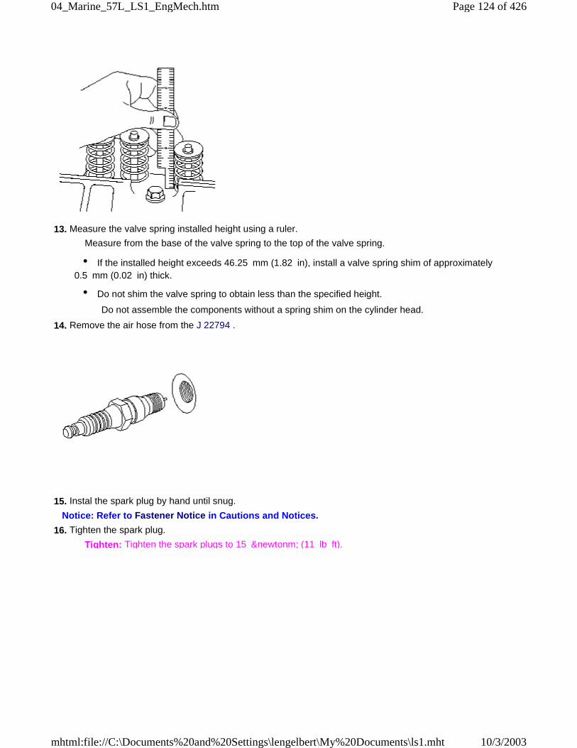
13. Measure the valve spring installed height using a ruler.
Measure from the base of the valve spring to the top of the valve spring.
• If the installed height exceeds 46.25 mm (1.82 in), install a valve spring shim of approximately0.5 mm (0.02 in) thick.
• Do not shim the valve spring to obtain less than the specified height.
Do not assemble the components without a spring shim on the cylinder head.
14. Remove the air hose from the J 22794 .
15. Instal the spark plug by hand until snug.
Notice: Refer to Fastener Notice in Cautions and Notices.
16. Tighten the spark plug.
Tighten: Tighten the spark plugs to 15 &newtonm; (11 lb ft).
Page 124 of 42604_Marine_57L_LS1_EngMech.htm
10/3/2003mhtml:file://C:\Documents%20and%20Settings\lengelbert\My%20Documents\ls1.mht
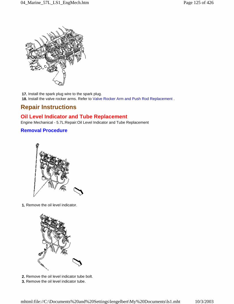
17. Install the spark plug wire to the spark plug. 18. Install the valve rocker arms. Refer to Valve Rocker Arm and Push Rod Replacement .
Repair Instructions
Oil Level Indicator and Tube ReplacementEngine Mechanical - 5.7L:Repair:Oil Level Indicator and Tube Replacement
Removal Procedure
1. Remove the oil level indicator.
2. Remove the oil level indicator tube bolt. 3. Remove the oil level indicator tube.
Page 125 of 42604_Marine_57L_LS1_EngMech.htm
10/3/2003mhtml:file://C:\Documents%20and%20Settings\lengelbert\My%20Documents\ls1.mht
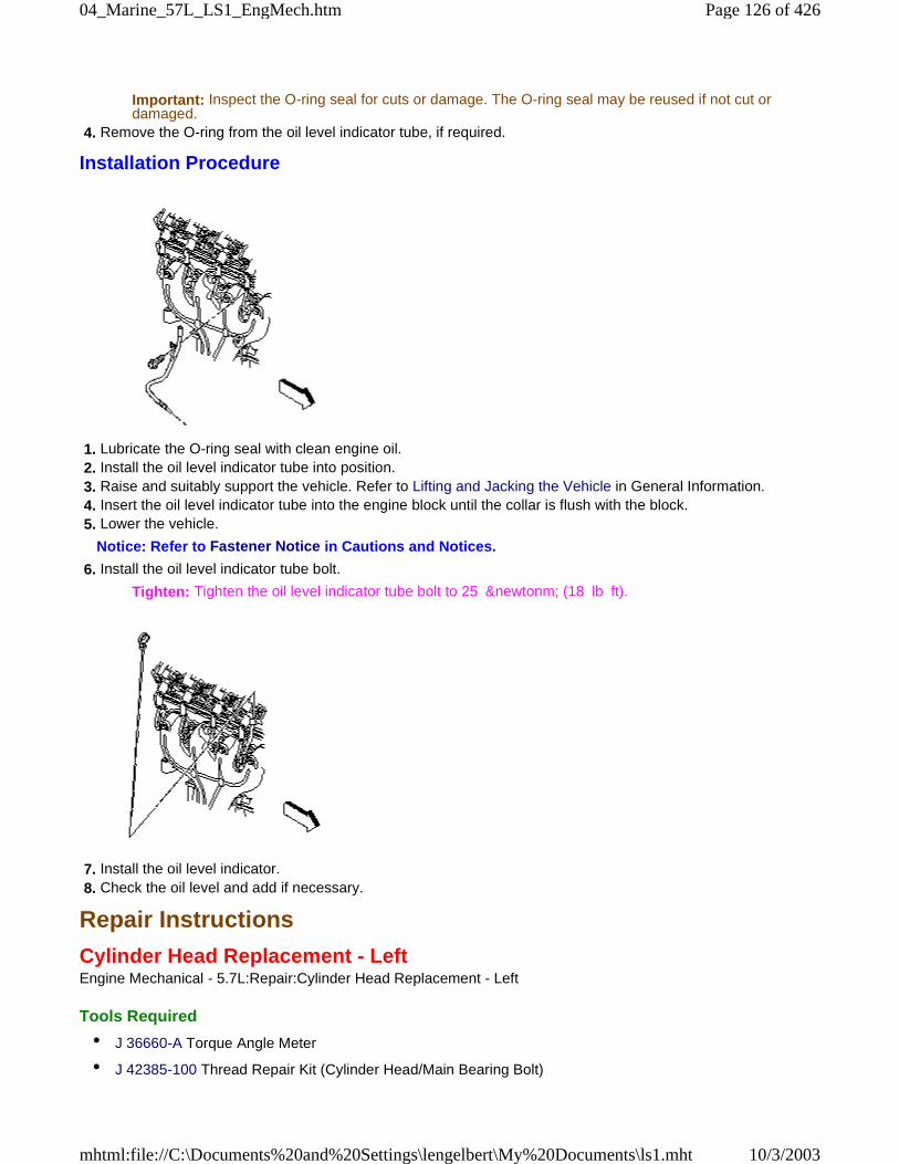
Important: Inspect the O-ring seal for cuts or damage. The O-ring seal may be reused if not cut ordamaged.
4. Remove the O-ring from the oil level indicator tube, if required.
Installation Procedure
1. Lubricate the O-ring seal with clean engine oil. 2. Install the oil level indicator tube into position. 3. Raise and suitably support the vehicle. Refer to Lifting and Jacking the Vehicle in General Information. 4. Insert the oil level indicator tube into the engine block until the collar is flush with the block. 5. Lower the vehicle.
Notice: Refer to Fastener Notice in Cautions and Notices.
6. Install the oil level indicator tube bolt.
Tighten: Tighten the oil level indicator tube bolt to 25 &newtonm; (18 lb ft).
7. Install the oil level indicator. 8. Check the oil level and add if necessary.
Repair Instructions
Cylinder Head Replacement - LeftEngine Mechanical - 5.7L:Repair:Cylinder Head Replacement - Left
Tools Required
• J 36660-A Torque Angle Meter
• J 42385-100 Thread Repair Kit (Cylinder Head/Main Bearing Bolt)
Page 126 of 42604_Marine_57L_LS1_EngMech.htm
10/3/2003mhtml:file://C:\Documents%20and%20Settings\lengelbert\My%20Documents\ls1.mht
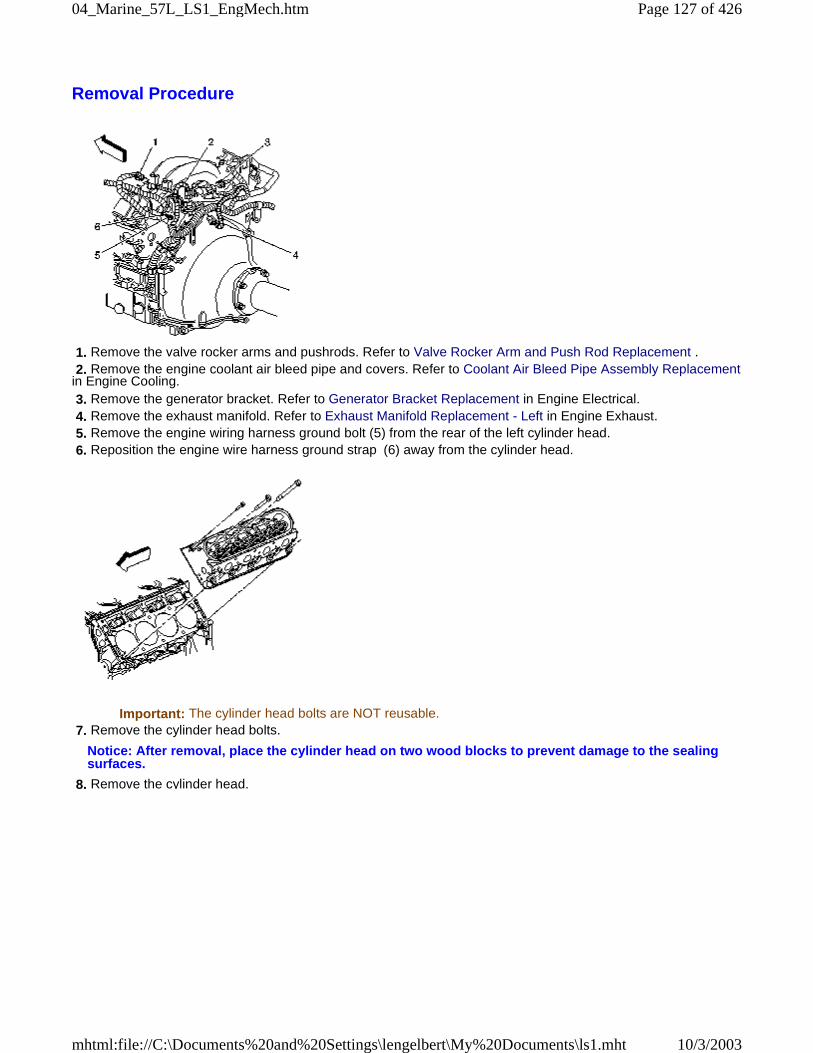
Removal Procedure
1. Remove the valve rocker arms and pushrods. Refer to Valve Rocker Arm and Push Rod Replacement . 2. Remove the engine coolant air bleed pipe and covers. Refer to Coolant Air Bleed Pipe Assembly Replacementin Engine Cooling. 3. Remove the generator bracket. Refer to Generator Bracket Replacement in Engine Electrical. 4. Remove the exhaust manifold. Refer to Exhaust Manifold Replacement - Left in Engine Exhaust. 5. Remove the engine wiring harness ground bolt (5) from the rear of the left cylinder head. 6. Reposition the engine wire harness ground strap (6) away from the cylinder head.
Important: The cylinder head bolts are NOT reusable. 7. Remove the cylinder head bolts.
Notice: After removal, place the cylinder head on two wood blocks to prevent damage to the sealingsurfaces.
8. Remove the cylinder head.
Page 127 of 42604_Marine_57L_LS1_EngMech.htm
10/3/2003mhtml:file://C:\Documents%20and%20Settings\lengelbert\My%20Documents\ls1.mht
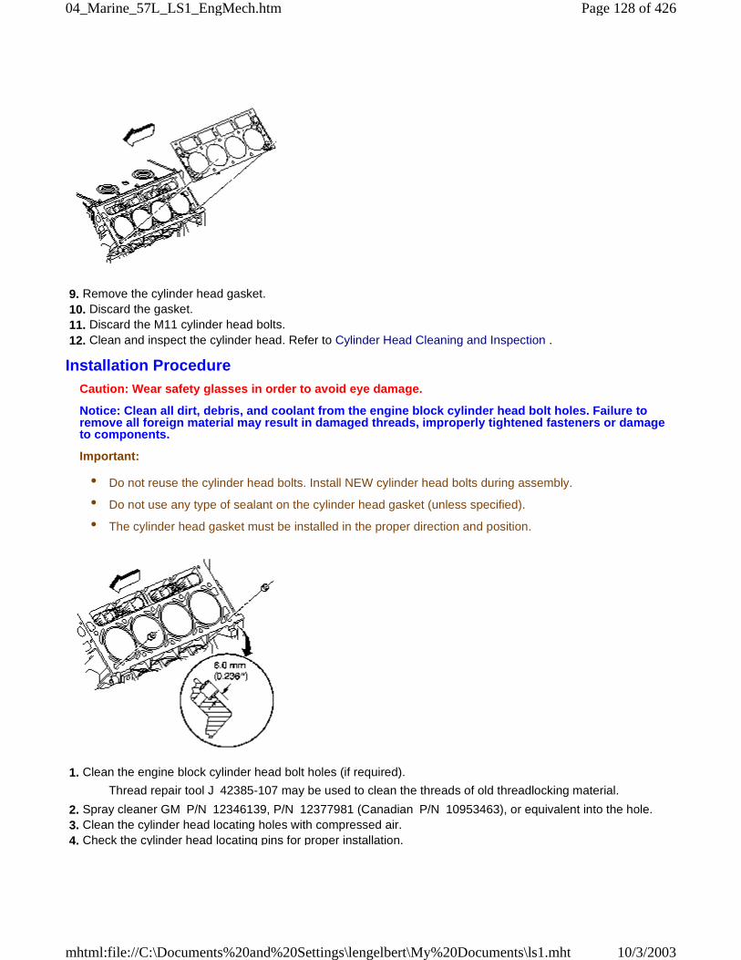
9. Remove the cylinder head gasket. 10. Discard the gasket. 11. Discard the M11 cylinder head bolts. 12. Clean and inspect the cylinder head. Refer to Cylinder Head Cleaning and Inspection .
Installation ProcedureCaution: Wear safety glasses in order to avoid eye damage.
Notice: Clean all dirt, debris, and coolant from the engine block cylinder head bolt holes. Failure toremove all foreign material may result in damaged threads, improperly tightened fasteners or damageto components.
Important:
• Do not reuse the cylinder head bolts. Install NEW cylinder head bolts during assembly.
• Do not use any type of sealant on the cylinder head gasket (unless specified).
• The cylinder head gasket must be installed in the proper direction and position.
1. Clean the engine block cylinder head bolt holes (if required).
Thread repair tool J 42385-107 may be used to clean the threads of old threadlocking material.
2. Spray cleaner GM P/N 12346139, P/N 12377981 (Canadian P/N 10953463), or equivalent into the hole. 3. Clean the cylinder head locating holes with compressed air. 4. Check the cylinder head locating pins for proper installation.
Page 128 of 42604_Marine_57L_LS1_EngMech.htm
10/3/2003mhtml:file://C:\Documents%20and%20Settings\lengelbert\My%20Documents\ls1.mht
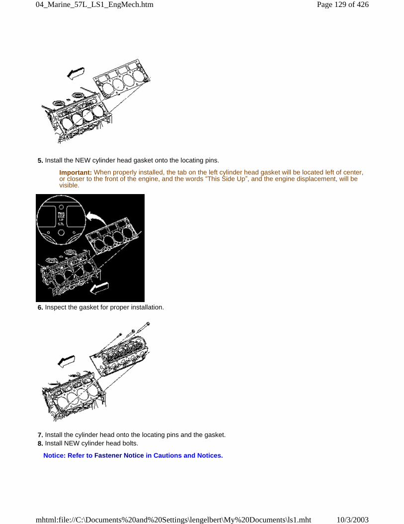
5. Install the NEW cylinder head gasket onto the locating pins.
Important: When properly installed, the tab on the left cylinder head gasket will be located left of center,or closer to the front of the engine, and the words “This Side Up”, and the engine displacement, will bevisible.
6. Inspect the gasket for proper installation.
7. Install the cylinder head onto the locating pins and the gasket. 8. Install NEW cylinder head bolts.
Notice: Refer to Fastener Notice in Cautions and Notices.
Page 129 of 42604_Marine_57L_LS1_EngMech.htm
10/3/2003mhtml:file://C:\Documents%20and%20Settings\lengelbert\My%20Documents\ls1.mht
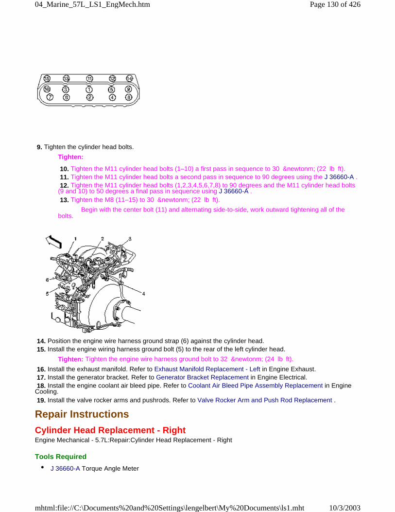
9. Tighten the cylinder head bolts.
Tighten:
10. Tighten the M11 cylinder head bolts (1–10) a first pass in sequence to 30 &newtonm; (22 lb ft). 11. Tighten the M11 cylinder head bolts a second pass in sequence to 90 degrees using the J 36660-A . 12. Tighten the M11 cylinder head bolts (1,2,3,4,5,6,7,8) to 90 degrees and the M11 cylinder head bolts(9 and 10) to 50 degrees a final pass in sequence using J 36660-A . 13. Tighten the M8 (11–15) to 30 &newtonm; (22 lb ft).
Begin with the center bolt (11) and alternating side-to-side, work outward tightening all of thebolts.
14. Position the engine wire harness ground strap (6) against the cylinder head. 15. Install the engine wiring harness ground bolt (5) to the rear of the left cylinder head.
Tighten: Tighten the engine wire harness ground bolt to 32 &newtonm; (24 lb ft).
16. Install the exhaust manifold. Refer to Exhaust Manifold Replacement - Left in Engine Exhaust. 17. Install the generator bracket. Refer to Generator Bracket Replacement in Engine Electrical. 18. Install the engine coolant air bleed pipe. Refer to Coolant Air Bleed Pipe Assembly Replacement in EngineCooling. 19. Install the valve rocker arms and pushrods. Refer to Valve Rocker Arm and Push Rod Replacement .
Repair Instructions
Cylinder Head Replacement - RightEngine Mechanical - 5.7L:Repair:Cylinder Head Replacement - Right
Tools Required
• J 36660-A Torque Angle Meter
Page 130 of 42604_Marine_57L_LS1_EngMech.htm
10/3/2003mhtml:file://C:\Documents%20and%20Settings\lengelbert\My%20Documents\ls1.mht
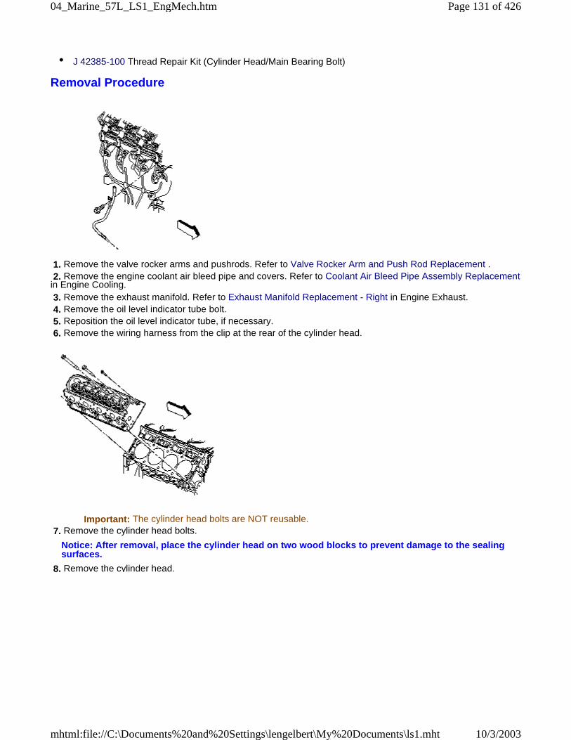
• J 42385-100 Thread Repair Kit (Cylinder Head/Main Bearing Bolt)
Removal Procedure
1. Remove the valve rocker arms and pushrods. Refer to Valve Rocker Arm and Push Rod Replacement . 2. Remove the engine coolant air bleed pipe and covers. Refer to Coolant Air Bleed Pipe Assembly Replacementin Engine Cooling. 3. Remove the exhaust manifold. Refer to Exhaust Manifold Replacement - Right in Engine Exhaust. 4. Remove the oil level indicator tube bolt. 5. Reposition the oil level indicator tube, if necessary. 6. Remove the wiring harness from the clip at the rear of the cylinder head.
Important: The cylinder head bolts are NOT reusable. 7. Remove the cylinder head bolts.
Notice: After removal, place the cylinder head on two wood blocks to prevent damage to the sealingsurfaces.
8. Remove the cylinder head.
Page 131 of 42604_Marine_57L_LS1_EngMech.htm
10/3/2003mhtml:file://C:\Documents%20and%20Settings\lengelbert\My%20Documents\ls1.mht
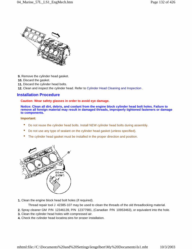
9. Remove the cylinder head gasket. 10. Discard the gasket. 11. Discard the cylinder head bolts. 12. Clean and inspect the cylinder head. Refer to Cylinder Head Cleaning and Inspection .
Installation ProcedureCaution: Wear safety glasses in order to avoid eye damage.
Notice: Clean all dirt, debris, and coolant from the engine block cylinder head bolt holes. Failure toremove all foreign material may result in damaged threads, improperly tightened fasteners or damageto components.
Important:
• Do not reuse the cylinder head bolts. Install NEW cylinder head bolts during assembly.
• Do not use any type of sealant on the cylinder head gasket (unless specified).
• The cylinder head gasket must be installed in the proper direction and position.
1. Clean the engine block head bolt holes (if required).
Thread repair tool J 42385-107 may be used to clean the threads of the old threadlocking material.
2. Spray cleaner GM P/N 12346139, P/N 12377981, (Canadian P/N 10953463), or equivalent into the hole. 3. Clean the cylinder head holes with compressed air. 4. Check the cylinder head locating pins for proper installation.
Page 132 of 42604_Marine_57L_LS1_EngMech.htm
10/3/2003mhtml:file://C:\Documents%20and%20Settings\lengelbert\My%20Documents\ls1.mht
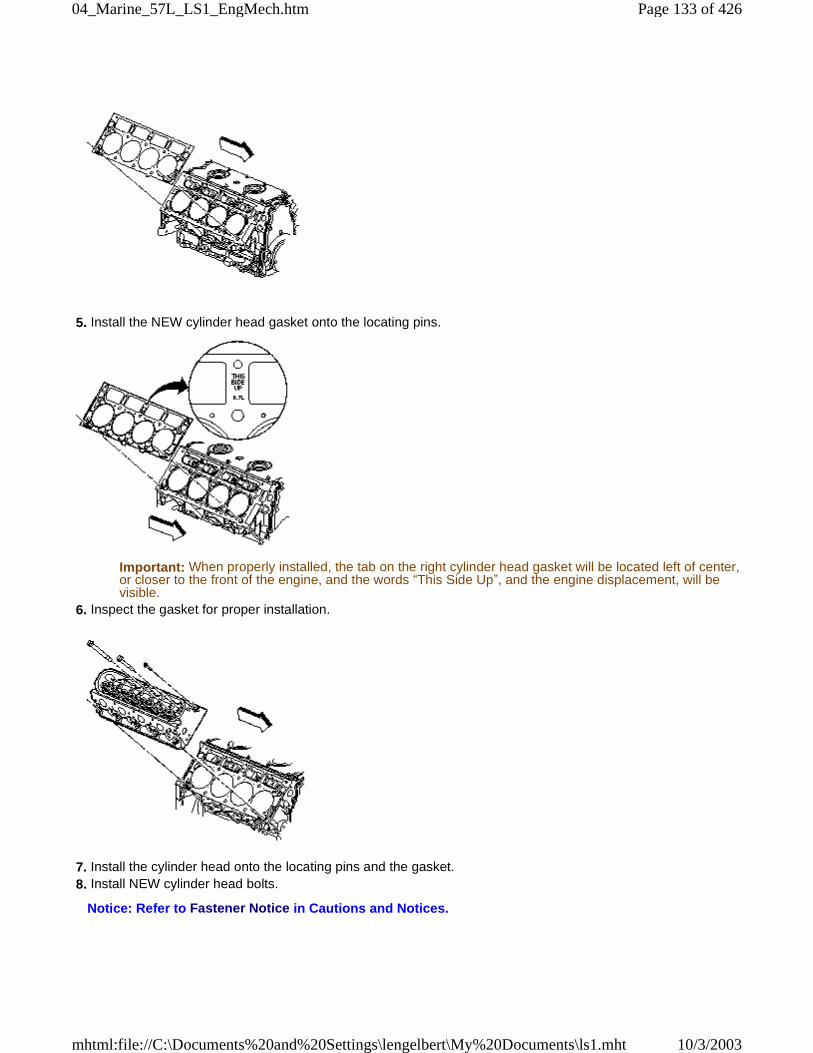
5. Install the NEW cylinder head gasket onto the locating pins.
Important: When properly installed, the tab on the right cylinder head gasket will be located left of center,or closer to the front of the engine, and the words “This Side Up”, and the engine displacement, will bevisible.
6. Inspect the gasket for proper installation.
7. Install the cylinder head onto the locating pins and the gasket. 8. Install NEW cylinder head bolts.
Notice: Refer to Fastener Notice in Cautions and Notices.
Page 133 of 42604_Marine_57L_LS1_EngMech.htm
10/3/2003mhtml:file://C:\Documents%20and%20Settings\lengelbert\My%20Documents\ls1.mht
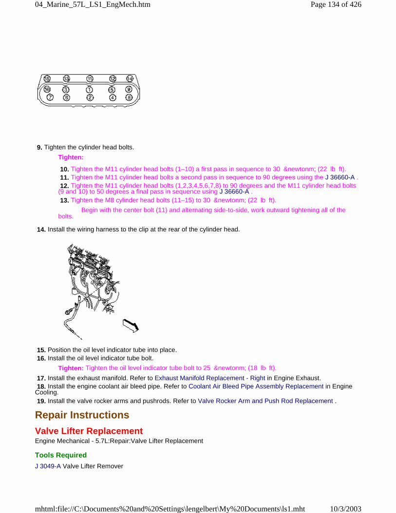
9. Tighten the cylinder head bolts.
Tighten:
10. Tighten the M11 cylinder head bolts (1–10) a first pass in sequence to 30 &newtonm; (22 lb ft). 11. Tighten the M11 cylinder head bolts a second pass in sequence to 90 degrees using the J 36660-A . 12. Tighten the M11 cylinder head bolts (1,2,3,4,5,6,7,8) to 90 degrees and the M11 cylinder head bolts(9 and 10) to 50 degrees a final pass in sequence using J 36660-A . 13. Tighten the M8 cylinder head bolts (11–15) to 30 &newtonm; (22 lb ft).
Begin with the center bolt (11) and alternating side-to-side, work outward tightening all of thebolts.
14. Install the wiring harness to the clip at the rear of the cylinder head.
15. Position the oil level indicator tube into place. 16. Install the oil level indicator tube bolt.
Tighten: Tighten the oil level indicator tube bolt to 25 &newtonm; (18 lb ft).
17. Install the exhaust manifold. Refer to Exhaust Manifold Replacement - Right in Engine Exhaust. 18. Install the engine coolant air bleed pipe. Refer to Coolant Air Bleed Pipe Assembly Replacement in EngineCooling. 19. Install the valve rocker arms and pushrods. Refer to Valve Rocker Arm and Push Rod Replacement .
Repair Instructions
Valve Lifter ReplacementEngine Mechanical - 5.7L:Repair:Valve Lifter Replacement
Tools Required
J 3049-A Valve Lifter Remover
Page 134 of 42604_Marine_57L_LS1_EngMech.htm
10/3/2003mhtml:file://C:\Documents%20and%20Settings\lengelbert\My%20Documents\ls1.mht
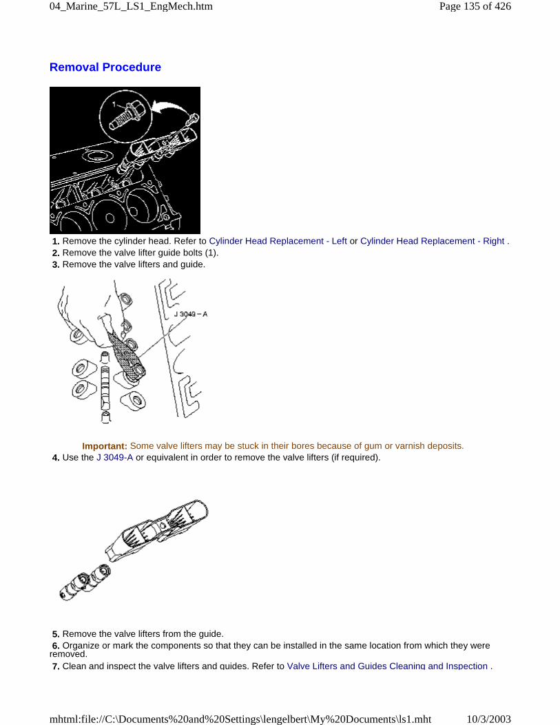
Removal Procedure
1. Remove the cylinder head. Refer to Cylinder Head Replacement - Left or Cylinder Head Replacement - Right . 2. Remove the valve lifter guide bolts (1). 3. Remove the valve lifters and guide.
Important: Some valve lifters may be stuck in their bores because of gum or varnish deposits. 4. Use the J 3049-A or equivalent in order to remove the valve lifters (if required).
5. Remove the valve lifters from the guide. 6. Organize or mark the components so that they can be installed in the same location from which they wereremoved. 7. Clean and inspect the valve lifters and guides. Refer to Valve Lifters and Guides Cleaning and Inspection .
Page 135 of 42604_Marine_57L_LS1_EngMech.htm
10/3/2003mhtml:file://C:\Documents%20and%20Settings\lengelbert\My%20Documents\ls1.mht
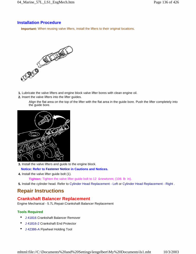
Installation ProcedureImportant: When reusing valve lifters, install the lifters to their original locations.
1. Lubricate the valve lifters and engine block valve lifter bores with clean engine oil. 2. Insert the valve lifters into the lifter guides.
Align the flat area on the top of the lifter with the flat area in the guide bore. Push the lifter completely intothe guide bore.
3. Install the valve lifters and guide to the engine block.
Notice: Refer to Fastener Notice in Cautions and Notices.
4. Install the valve lifter guide bolt (1).
Tighten: Tighten the valve lifter guide bolt to 12 &newtonm; (106 lb in).
5. Install the cylinder head. Refer to Cylinder Head Replacement - Left or Cylinder Head Replacement - Right .
Repair Instructions
Crankshaft Balancer ReplacementEngine Mechanical - 5.7L:Repair:Crankshaft Balancer Replacement
Tools Required
• J 41816 Crankshaft Balancer Remover
• J 41816-2 Crankshaft End Protector
• J 42386-A Flywheel Holding Tool
Page 136 of 42604_Marine_57L_LS1_EngMech.htm
10/3/2003mhtml:file://C:\Documents%20and%20Settings\lengelbert\My%20Documents\ls1.mht
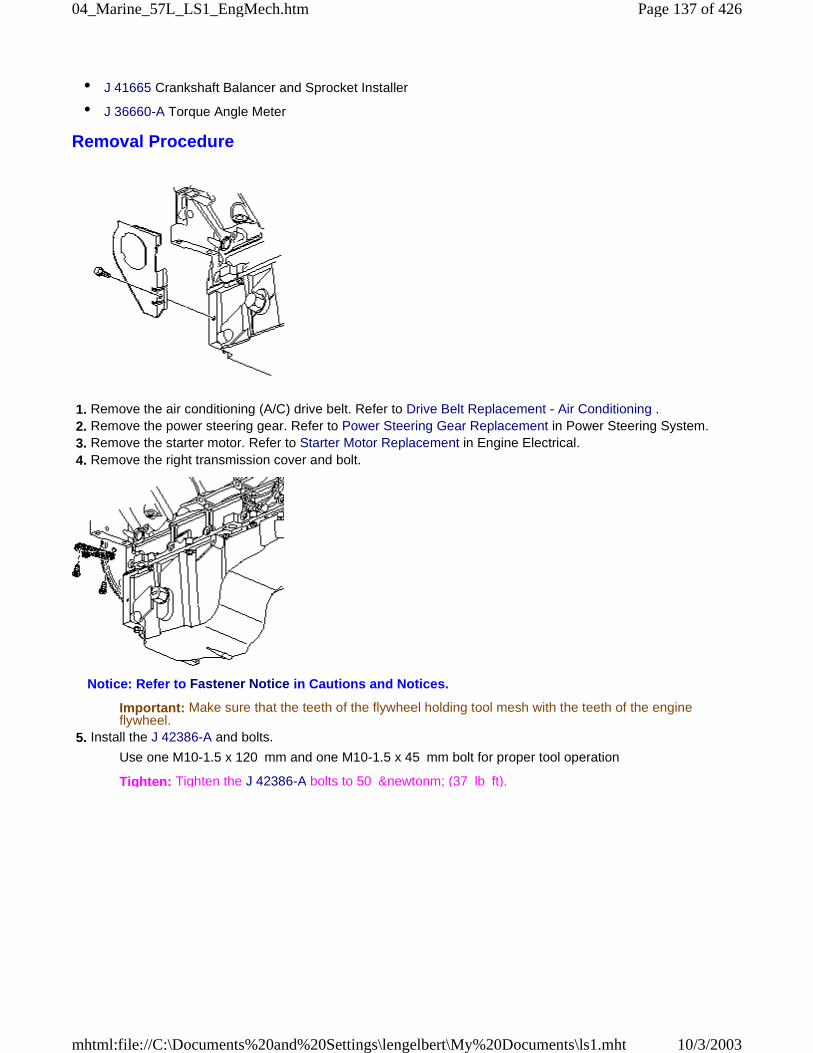
• J 41665 Crankshaft Balancer and Sprocket Installer
• J 36660-A Torque Angle Meter
Removal Procedure
1. Remove the air conditioning (A/C) drive belt. Refer to Drive Belt Replacement - Air Conditioning . 2. Remove the power steering gear. Refer to Power Steering Gear Replacement in Power Steering System. 3. Remove the starter motor. Refer to Starter Motor Replacement in Engine Electrical. 4. Remove the right transmission cover and bolt.
Notice: Refer to Fastener Notice in Cautions and Notices.
Important: Make sure that the teeth of the flywheel holding tool mesh with the teeth of the engineflywheel.
5. Install the J 42386-A and bolts.
Use one M10-1.5 x 120 mm and one M10-1.5 x 45 mm bolt for proper tool operation
Tighten: Tighten the J 42386-A bolts to 50 &newtonm; (37 lb ft).
Page 137 of 42604_Marine_57L_LS1_EngMech.htm
10/3/2003mhtml:file://C:\Documents%20and%20Settings\lengelbert\My%20Documents\ls1.mht

6. Remove the crankshaft balancer bolt.
Do not discard the crankshaft balancer bolt. The balancer bolt will be used during the balancer installationprocedure.
Important: For manual transmission applications, note the position of the crankshaft balancer beforeremoval. The balancer does not use a key or keyway for positioning. Mark or scribe the end of thecrankshaft and the balancer before removal. If replacing the crankshaft balancer, note the location of anyexisting balance weights (if applicable). Install new balance weights into the new crankshaft balancer (ifapplicable) in the same location as the old balancer. A properly installed balance weight will be eitherflush or below flush with the face of the balancer.
7. Mark or scribe the crankshaft balancer and the end of the crankshaft.
Note the balancer installed position on the crankshaft for assembly.
Refer to Engine Balancing
Page 138 of 42604_Marine_57L_LS1_EngMech.htm
10/3/2003mhtml:file://C:\Documents%20and%20Settings\lengelbert\My%20Documents\ls1.mht
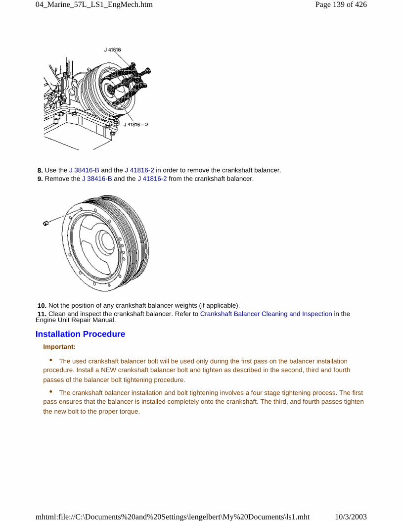
8. Use the J 38416-B and the J 41816-2 in order to remove the crankshaft balancer. 9. Remove the J 38416-B and the J 41816-2 from the crankshaft balancer.
10. Not the position of any crankshaft balancer weights (if applicable). 11. Clean and inspect the crankshaft balancer. Refer to Crankshaft Balancer Cleaning and Inspection in theEngine Unit Repair Manual.
Installation ProcedureImportant:
• The used crankshaft balancer bolt will be used only during the first pass on the balancer installationprocedure. Install a NEW crankshaft balancer bolt and tighten as described in the second, third and fourth
passes of the balancer bolt tightening procedure.
• The crankshaft balancer installation and bolt tightening involves a four stage tightening process. The firstpass ensures that the balancer is installed completely onto the crankshaft. The third, and fourth passes tighten
the new bolt to the proper torque.
Page 139 of 42604_Marine_57L_LS1_EngMech.htm
10/3/2003mhtml:file://C:\Documents%20and%20Settings\lengelbert\My%20Documents\ls1.mht
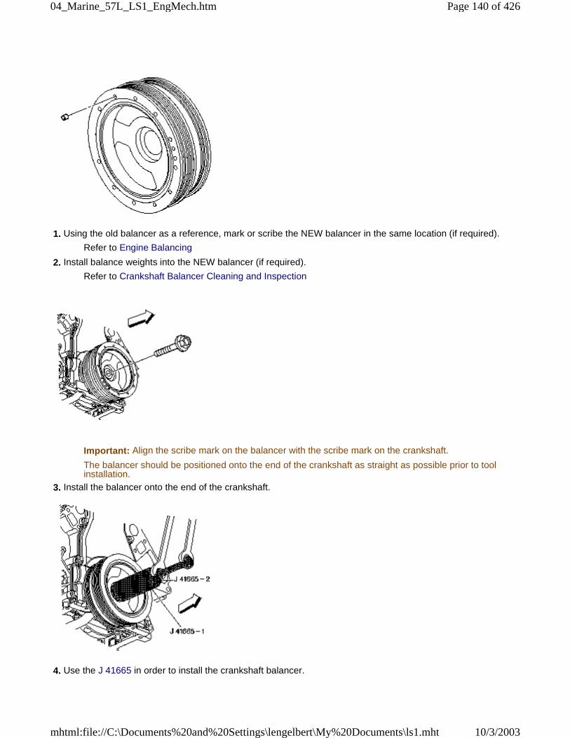
1. Using the old balancer as a reference, mark or scribe the NEW balancer in the same location (if required).
Refer to Engine Balancing
2. Install balance weights into the NEW balancer (if required).
Refer to Crankshaft Balancer Cleaning and Inspection
Important: Align the scribe mark on the balancer with the scribe mark on the crankshaft.
The balancer should be positioned onto the end of the crankshaft as straight as possible prior to toolinstallation.
3. Install the balancer onto the end of the crankshaft.
4. Use the J 41665 in order to install the crankshaft balancer.
Page 140 of 42604_Marine_57L_LS1_EngMech.htm
10/3/2003mhtml:file://C:\Documents%20and%20Settings\lengelbert\My%20Documents\ls1.mht
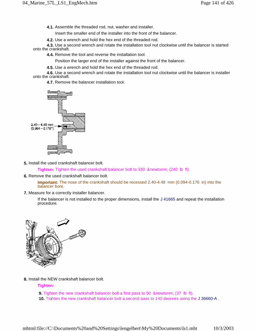
4.1. Assemble the threaded rod, nut, washer and installer.
Insert the smaller end of the installer into the front of the balancer.
4.2. Use a wrench and hold the hex end of the threaded rod. 4.3. Use a second wrench and rotate the installation tool nut clockwise until the balancer is startedonto the crankshaft. 4.4. Remove the tool and reverse the installation tool.
Position the larger end of the installer against the front of the balancer.
4.5. Use a wrench and hold the hex end of the threaded rod. 4.6. Use a second wrench and rotate the installation tool nut clockwise until the balancer is installeronto the crankshaft. 4.7. Remove the balancer installation tool.
5. Install the used crankshaft balancer bolt.
Tighten: Tighten the used crankshaft balancer bolt to 330 &newtonm; (240 lb ft).
6. Remove the used crankshaft balancer bolt.
Important: The nose of the crankshaft should be recessed 2.40-4.48 mm (0.094-0.176 in) into thebalancer bore.
7. Measure for a correctly installer balancer.
If the balancer is not installed to the proper dimensions, install the J 41665 and repeat the installationprocedure.
8. Install the NEW crankshaft balancer bolt.
Tighten:
9. Tighten the new crankshaft balancer bolt a first pass to 50 &newtonm; (37 lb ft). 10. Tighten the new crankshaft balancer bolt a second pass to 140 degrees using the J 36660-A .
Page 141 of 42604_Marine_57L_LS1_EngMech.htm
10/3/2003mhtml:file://C:\Documents%20and%20Settings\lengelbert\My%20Documents\ls1.mht
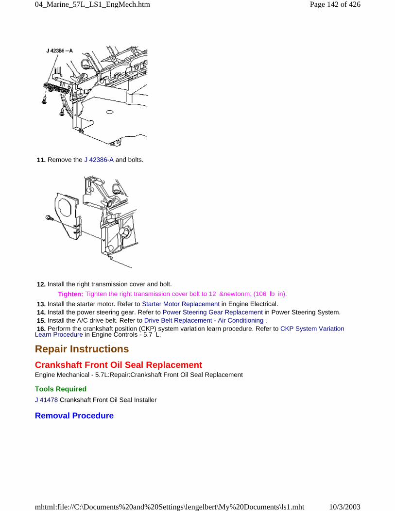
11. Remove the J 42386-A and bolts.
12. Install the right transmission cover and bolt.
Tighten: Tighten the right transmission cover bolt to 12 &newtonm; (106 lb in).
13. Install the starter motor. Refer to Starter Motor Replacement in Engine Electrical. 14. Install the power steering gear. Refer to Power Steering Gear Replacement in Power Steering System. 15. Install the A/C drive belt. Refer to Drive Belt Replacement - Air Conditioning . 16. Perform the crankshaft position (CKP) system variation learn procedure. Refer to CKP System VariationLearn Procedure in Engine Controls - 5.7 L.
Repair Instructions
Crankshaft Front Oil Seal ReplacementEngine Mechanical - 5.7L:Repair:Crankshaft Front Oil Seal Replacement
Tools Required
J 41478 Crankshaft Front Oil Seal Installer
Removal Procedure
Page 142 of 42604_Marine_57L_LS1_EngMech.htm
10/3/2003mhtml:file://C:\Documents%20and%20Settings\lengelbert\My%20Documents\ls1.mht
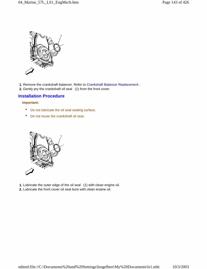
1. Remove the crankshaft balancer. Refer to Crankshaft Balancer Replacement . 2. Gently pry the crankshaft oil seal (1) from the front cover.
Installation ProcedureImportant:
• Do not lubricate the oil seal sealing surface.
• Do not reuse the crankshaft oil seal.
1. Lubricate the outer edge of the oil seal (1) with clean engine oil. 2. Lubricate the front cover oil seal bore with clean engine oil.
Page 143 of 42604_Marine_57L_LS1_EngMech.htm
10/3/2003mhtml:file://C:\Documents%20and%20Settings\lengelbert\My%20Documents\ls1.mht
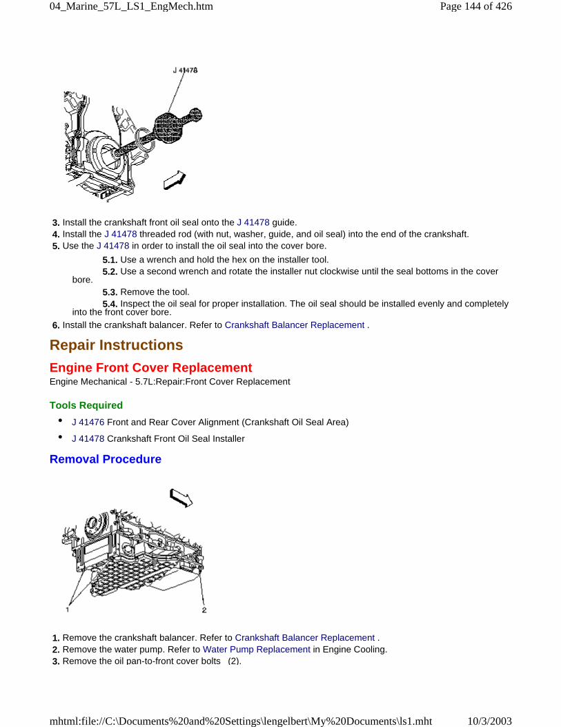
3. Install the crankshaft front oil seal onto the J 41478 guide. 4. Install the J 41478 threaded rod (with nut, washer, guide, and oil seal) into the end of the crankshaft. 5. Use the J 41478 in order to install the oil seal into the cover bore.
5.1. Use a wrench and hold the hex on the installer tool. 5.2. Use a second wrench and rotate the installer nut clockwise until the seal bottoms in the coverbore. 5.3. Remove the tool. 5.4. Inspect the oil seal for proper installation. The oil seal should be installed evenly and completelyinto the front cover bore.
6. Install the crankshaft balancer. Refer to Crankshaft Balancer Replacement .
Repair Instructions
Engine Front Cover ReplacementEngine Mechanical - 5.7L:Repair:Front Cover Replacement
Tools Required
• J 41476 Front and Rear Cover Alignment (Crankshaft Oil Seal Area)
• J 41478 Crankshaft Front Oil Seal Installer
Removal Procedure
1. Remove the crankshaft balancer. Refer to Crankshaft Balancer Replacement . 2. Remove the water pump. Refer to Water Pump Replacement in Engine Cooling. 3. Remove the oil pan-to-front cover bolts (2).
Page 144 of 42604_Marine_57L_LS1_EngMech.htm
10/3/2003mhtml:file://C:\Documents%20and%20Settings\lengelbert\My%20Documents\ls1.mht
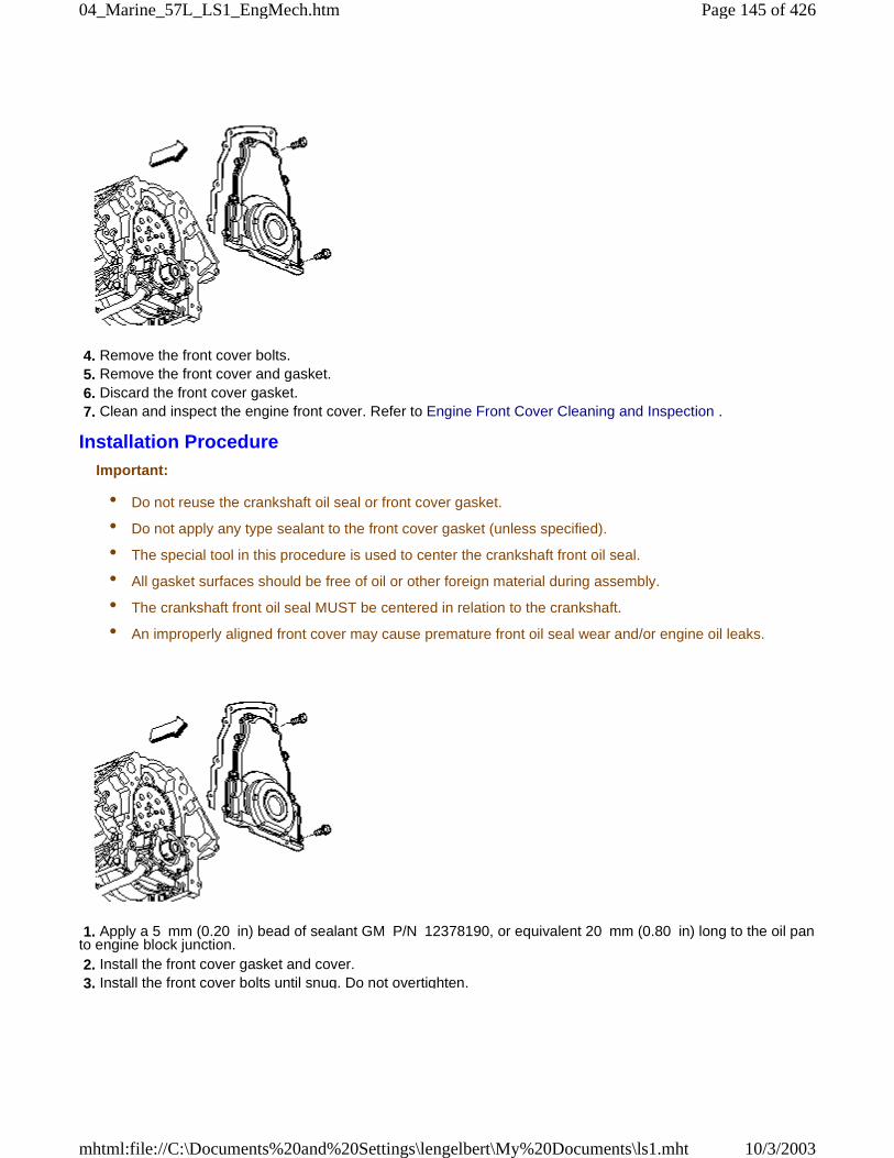
4. Remove the front cover bolts. 5. Remove the front cover and gasket. 6. Discard the front cover gasket. 7. Clean and inspect the engine front cover. Refer to Engine Front Cover Cleaning and Inspection .
Installation ProcedureImportant:
• Do not reuse the crankshaft oil seal or front cover gasket.
• Do not apply any type sealant to the front cover gasket (unless specified).
• The special tool in this procedure is used to center the crankshaft front oil seal.
• All gasket surfaces should be free of oil or other foreign material during assembly.
• The crankshaft front oil seal MUST be centered in relation to the crankshaft.
• An improperly aligned front cover may cause premature front oil seal wear and/or engine oil leaks.
1. Apply a 5 mm (0.20 in) bead of sealant GM P/N 12378190, or equivalent 20 mm (0.80 in) long to the oil panto engine block junction. 2. Install the front cover gasket and cover. 3. Install the front cover bolts until snug. Do not overtighten.
Page 145 of 42604_Marine_57L_LS1_EngMech.htm
10/3/2003mhtml:file://C:\Documents%20and%20Settings\lengelbert\My%20Documents\ls1.mht
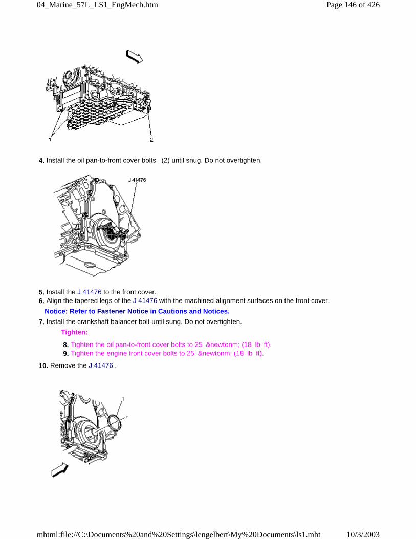
4. Install the oil pan-to-front cover bolts (2) until snug. Do not overtighten.
5. Install the J 41476 to the front cover. 6. Align the tapered legs of the J 41476 with the machined alignment surfaces on the front cover.
Notice: Refer to Fastener Notice in Cautions and Notices.
7. Install the crankshaft balancer bolt until sung. Do not overtighten.
Tighten:
8. Tighten the oil pan-to-front cover bolts to 25 &newtonm; (18 lb ft). 9. Tighten the engine front cover bolts to 25 &newtonm; (18 lb ft).
10. Remove the J 41476 .
Page 146 of 42604_Marine_57L_LS1_EngMech.htm
10/3/2003mhtml:file://C:\Documents%20and%20Settings\lengelbert\My%20Documents\ls1.mht
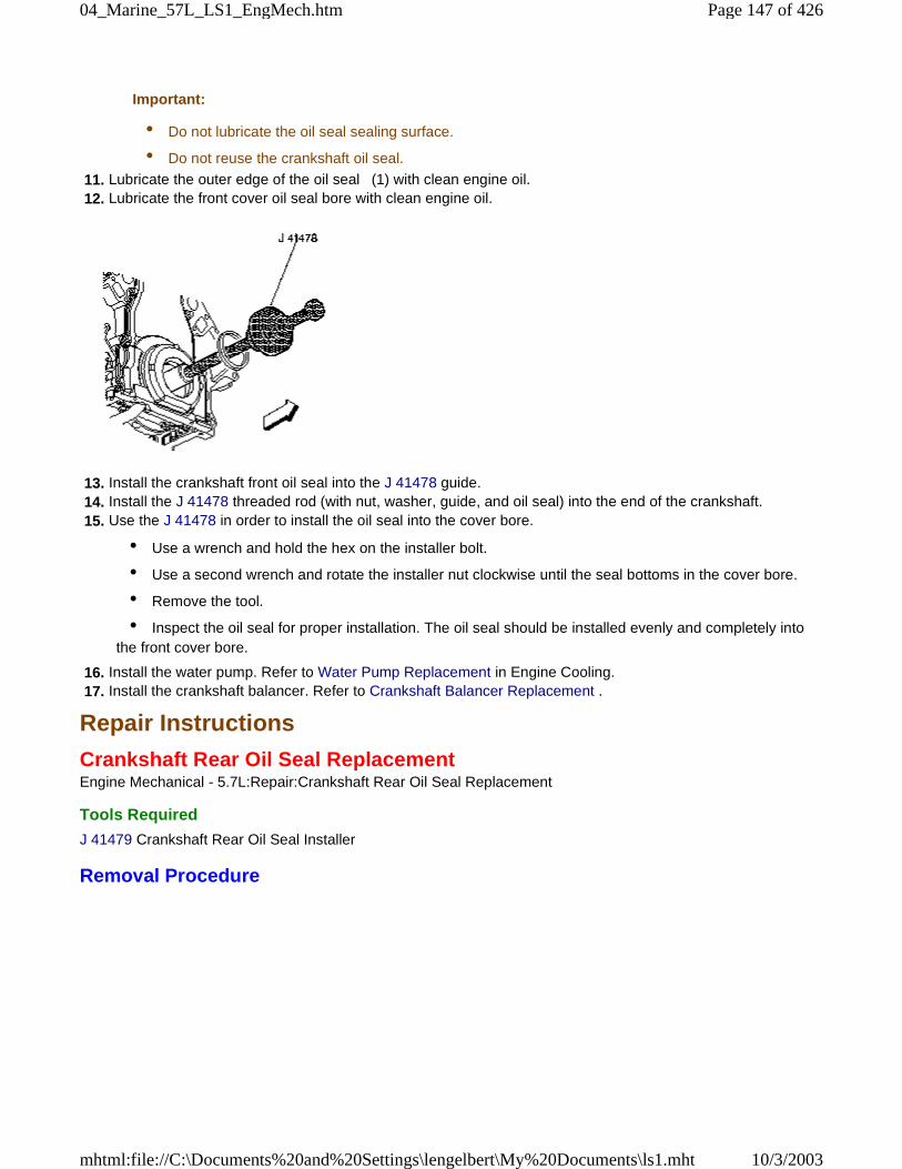
Important:
• Do not lubricate the oil seal sealing surface.
• Do not reuse the crankshaft oil seal.
11. Lubricate the outer edge of the oil seal (1) with clean engine oil. 12. Lubricate the front cover oil seal bore with clean engine oil.
13. Install the crankshaft front oil seal into the J 41478 guide. 14. Install the J 41478 threaded rod (with nut, washer, guide, and oil seal) into the end of the crankshaft. 15. Use the J 41478 in order to install the oil seal into the cover bore.
• Use a wrench and hold the hex on the installer bolt.
• Use a second wrench and rotate the installer nut clockwise until the seal bottoms in the cover bore.
• Remove the tool.
• Inspect the oil seal for proper installation. The oil seal should be installed evenly and completely intothe front cover bore.
16. Install the water pump. Refer to Water Pump Replacement in Engine Cooling. 17. Install the crankshaft balancer. Refer to Crankshaft Balancer Replacement .
Repair Instructions
Crankshaft Rear Oil Seal ReplacementEngine Mechanical - 5.7L:Repair:Crankshaft Rear Oil Seal Replacement
Tools Required
J 41479 Crankshaft Rear Oil Seal Installer
Removal Procedure
Page 147 of 42604_Marine_57L_LS1_EngMech.htm
10/3/2003mhtml:file://C:\Documents%20and%20Settings\lengelbert\My%20Documents\ls1.mht
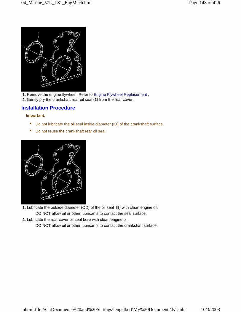
1. Remove the engine flywheel. Refer to Engine Flywheel Replacement . 2. Gently pry the crankshaft rear oil seal (1) from the rear cover.
Installation ProcedureImportant:
• Do not lubricate the oil seal inside diameter (ID) of the crankshaft surface.
• Do not reuse the crankshaft rear oil seal.
1. Lubricate the outside diameter (OD) of the oil seal (1) with clean engine oil.
DO NOT allow oil or other lubricants to contact the seal surface.
2. Lubricate the rear cover oil seal bore with clean engine oil.
DO NOT allow oil or other lubricants to contact the crankshaft surface.
Page 148 of 42604_Marine_57L_LS1_EngMech.htm
10/3/2003mhtml:file://C:\Documents%20and%20Settings\lengelbert\My%20Documents\ls1.mht
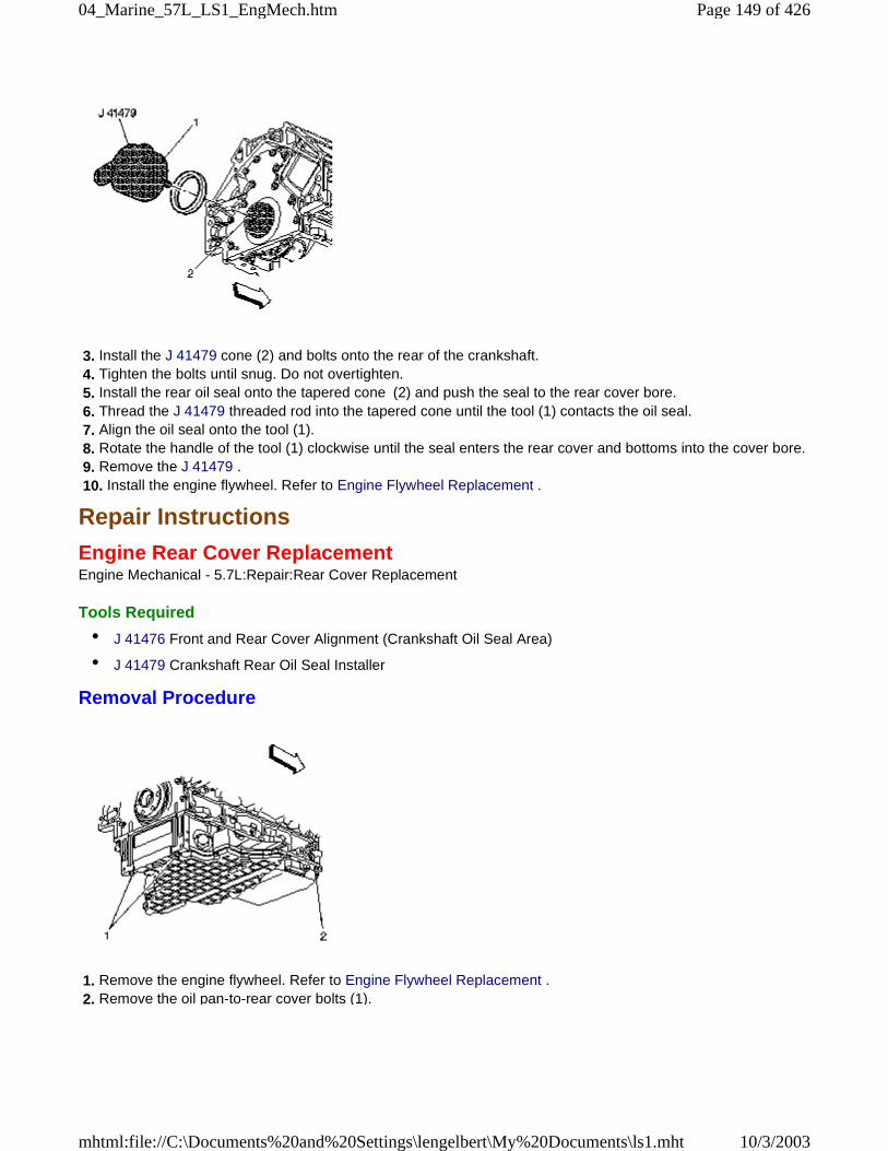
3. Install the J 41479 cone (2) and bolts onto the rear of the crankshaft. 4. Tighten the bolts until snug. Do not overtighten. 5. Install the rear oil seal onto the tapered cone (2) and push the seal to the rear cover bore. 6. Thread the J 41479 threaded rod into the tapered cone until the tool (1) contacts the oil seal. 7. Align the oil seal onto the tool (1). 8. Rotate the handle of the tool (1) clockwise until the seal enters the rear cover and bottoms into the cover bore. 9. Remove the J 41479 . 10. Install the engine flywheel. Refer to Engine Flywheel Replacement .
Repair Instructions
Engine Rear Cover ReplacementEngine Mechanical - 5.7L:Repair:Rear Cover Replacement
Tools Required
• J 41476 Front and Rear Cover Alignment (Crankshaft Oil Seal Area)
• J 41479 Crankshaft Rear Oil Seal Installer
Removal Procedure
1. Remove the engine flywheel. Refer to Engine Flywheel Replacement . 2. Remove the oil pan-to-rear cover bolts (1).
Page 149 of 42604_Marine_57L_LS1_EngMech.htm
10/3/2003mhtml:file://C:\Documents%20and%20Settings\lengelbert\My%20Documents\ls1.mht
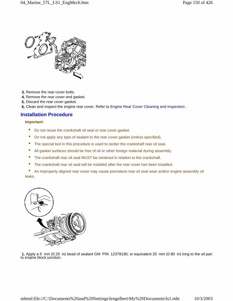
3. Remove the rear cover bolts. 4. Remove the rear cover and gasket. 5. Discard the rear cover gasket. 6. Clean and inspect the engine rear cover. Refer to Engine Rear Cover Cleaning and Inspection .
Installation ProcedureImportant:
• Do not reuse the crankshaft oil seal or rear cover gasket.
• Do not apply any type of sealant to the rear cover gasket (unless specified).
• The special tool in this procedure is used to center the crankshaft rear oil seal.
• All gasket surfaces should be free of oil or other foreign material during assembly.
• The crankshaft rear oil seal MUST be centered in relation to the crankshaft.
• The crankshaft rear oil seal will be installed after the rear cover has been installed.
• An improperly aligned rear cover may cause premature rear oil seal wear and/or engine assembly oilleaks.
1. Apply a 5 mm (0.20 in) bead of sealant GM P/N 12378190, or equivalent 20 mm (0.80 in) long to the oil panto engine block junction.
Page 150 of 42604_Marine_57L_LS1_EngMech.htm
10/3/2003mhtml:file://C:\Documents%20and%20Settings\lengelbert\My%20Documents\ls1.mht
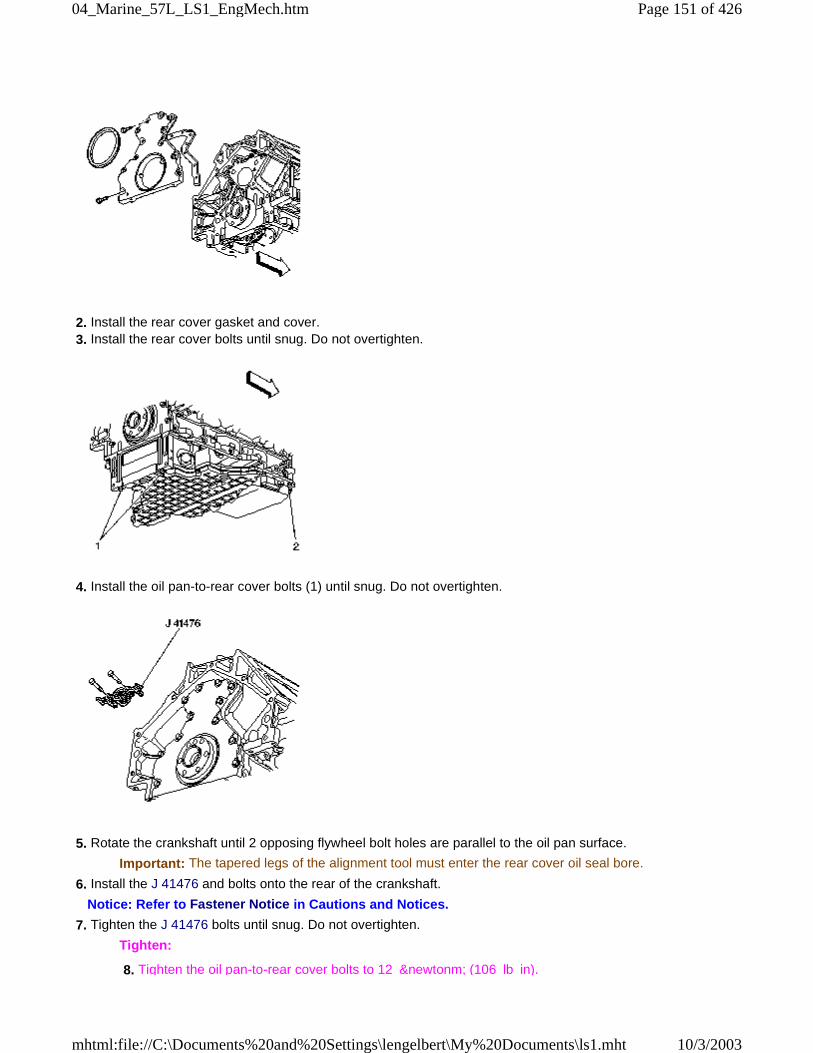
2. Install the rear cover gasket and cover. 3. Install the rear cover bolts until snug. Do not overtighten.
4. Install the oil pan-to-rear cover bolts (1) until snug. Do not overtighten.
5. Rotate the crankshaft until 2 opposing flywheel bolt holes are parallel to the oil pan surface.
Important: The tapered legs of the alignment tool must enter the rear cover oil seal bore.
6. Install the J 41476 and bolts onto the rear of the crankshaft.
Notice: Refer to Fastener Notice in Cautions and Notices.
7. Tighten the J 41476 bolts until snug. Do not overtighten.
Tighten:
8. Tighten the oil pan-to-rear cover bolts to 12 &newtonm; (106 lb in).
Page 151 of 42604_Marine_57L_LS1_EngMech.htm
10/3/2003mhtml:file://C:\Documents%20and%20Settings\lengelbert\My%20Documents\ls1.mht
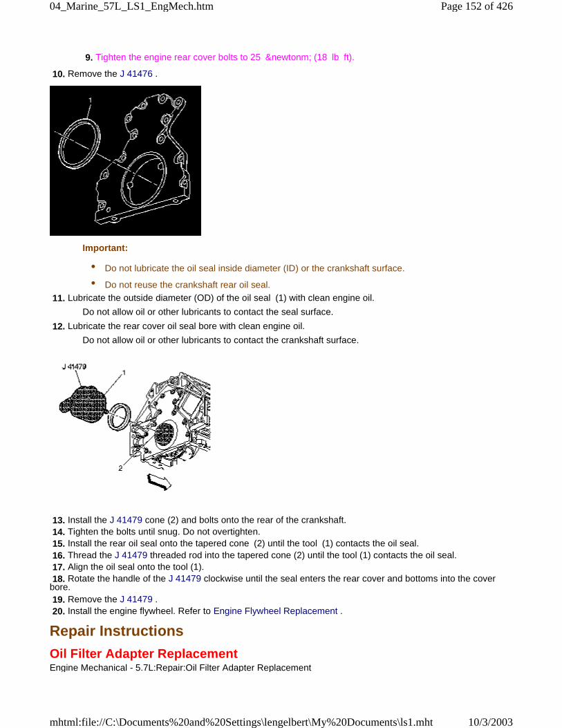
9. Tighten the engine rear cover bolts to 25 &newtonm; (18 lb ft).
10. Remove the J 41476 .
Important:
• Do not lubricate the oil seal inside diameter (ID) or the crankshaft surface.
• Do not reuse the crankshaft rear oil seal.
11. Lubricate the outside diameter (OD) of the oil seal (1) with clean engine oil.
Do not allow oil or other lubricants to contact the seal surface.
12. Lubricate the rear cover oil seal bore with clean engine oil.
Do not allow oil or other lubricants to contact the crankshaft surface.
13. Install the J 41479 cone (2) and bolts onto the rear of the crankshaft. 14. Tighten the bolts until snug. Do not overtighten. 15. Install the rear oil seal onto the tapered cone (2) until the tool (1) contacts the oil seal. 16. Thread the J 41479 threaded rod into the tapered cone (2) until the tool (1) contacts the oil seal. 17. Align the oil seal onto the tool (1). 18. Rotate the handle of the J 41479 clockwise until the seal enters the rear cover and bottoms into the coverbore. 19. Remove the J 41479 . 20. Install the engine flywheel. Refer to Engine Flywheel Replacement .
Repair Instructions
Oil Filter Adapter ReplacementEngine Mechanical - 5.7L:Repair:Oil Filter Adapter Replacement
Page 152 of 42604_Marine_57L_LS1_EngMech.htm
10/3/2003mhtml:file://C:\Documents%20and%20Settings\lengelbert\My%20Documents\ls1.mht
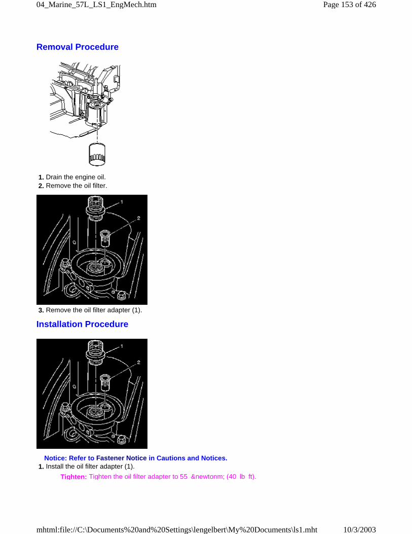
Removal Procedure
1. Drain the engine oil. 2. Remove the oil filter.
3. Remove the oil filter adapter (1).
Installation Procedure
Notice: Refer to Fastener Notice in Cautions and Notices. 1. Install the oil filter adapter (1).
Tighten: Tighten the oil filter adapter to 55 &newtonm; (40 lb ft).
Page 153 of 42604_Marine_57L_LS1_EngMech.htm
10/3/2003mhtml:file://C:\Documents%20and%20Settings\lengelbert\My%20Documents\ls1.mht
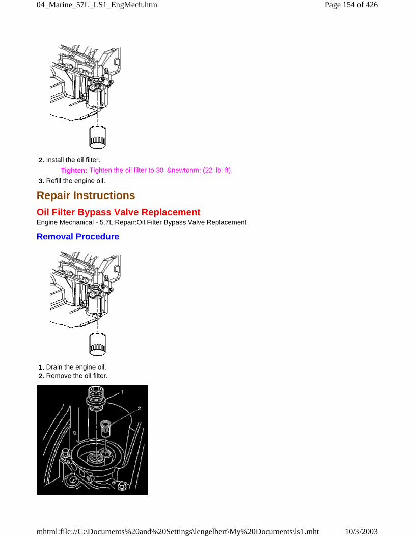
2. Install the oil filter.
Tighten: Tighten the oil filter to 30 &newtonm; (22 lb ft).
3. Refill the engine oil.
Repair Instructions
Oil Filter Bypass Valve ReplacementEngine Mechanical - 5.7L:Repair:Oil Filter Bypass Valve Replacement
Removal Procedure
1. Drain the engine oil. 2. Remove the oil filter.
Page 154 of 42604_Marine_57L_LS1_EngMech.htm
10/3/2003mhtml:file://C:\Documents%20and%20Settings\lengelbert\My%20Documents\ls1.mht
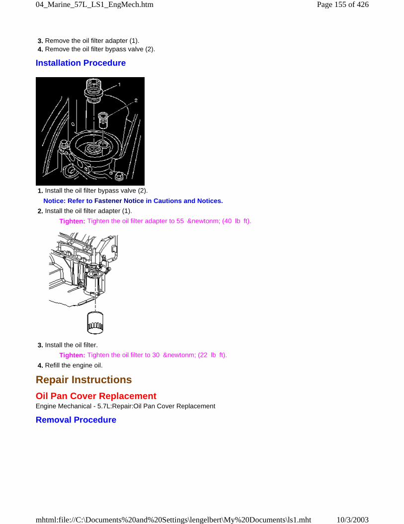
3. Remove the oil filter adapter (1). 4. Remove the oil filter bypass valve (2).
Installation Procedure
1. Install the oil filter bypass valve (2).
Notice: Refer to Fastener Notice in Cautions and Notices.
2. Install the oil filter adapter (1).
Tighten: Tighten the oil filter adapter to 55 &newtonm; (40 lb ft).
3. Install the oil filter.
Tighten: Tighten the oil filter to 30 &newtonm; (22 lb ft).
4. Refill the engine oil.
Repair Instructions
Oil Pan Cover ReplacementEngine Mechanical - 5.7L:Repair:Oil Pan Cover Replacement
Removal Procedure
Page 155 of 42604_Marine_57L_LS1_EngMech.htm
10/3/2003mhtml:file://C:\Documents%20and%20Settings\lengelbert\My%20Documents\ls1.mht
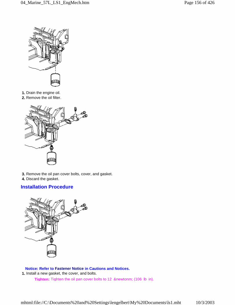
1. Drain the engine oil. 2. Remove the oil filter.
3. Remove the oil pan cover bolts, cover, and gasket. 4. Discard the gasket.
Installation Procedure
Notice: Refer to Fastener Notice in Cautions and Notices. 1. Install a new gasket, the cover, and bolts.
Tighten: Tighten the oil pan cover bolts to 12 &newtonm; (106 lb in).
Page 156 of 42604_Marine_57L_LS1_EngMech.htm
10/3/2003mhtml:file://C:\Documents%20and%20Settings\lengelbert\My%20Documents\ls1.mht
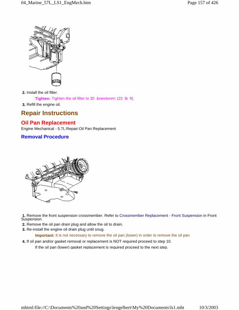
2. Install the oil filter.
Tighten: Tighten the oil filter to 30 &newtonm; (22 lb ft).
3. Refill the engine oil.
Repair Instructions
Oil Pan ReplacementEngine Mechanical - 5.7L:Repair:Oil Pan Replacement
Removal Procedure
1. Remove the front suspension crossmember. Refer to Crossmember Replacement - Front Suspension in FrontSuspension. 2. Remove the oil pan drain plug and allow the oil to drain. 3. Re-install the engine oil drain plug until snug.
Important: It is not necessary to remove the oil pan (lower) in order to remove the oil pan.
4. If oil pan and/or gasket removal or replacement is NOT required proceed to step 10.
If the oil pan (lower) gasket replacement is required proceed to the next step.
Page 157 of 42604_Marine_57L_LS1_EngMech.htm
10/3/2003mhtml:file://C:\Documents%20and%20Settings\lengelbert\My%20Documents\ls1.mht
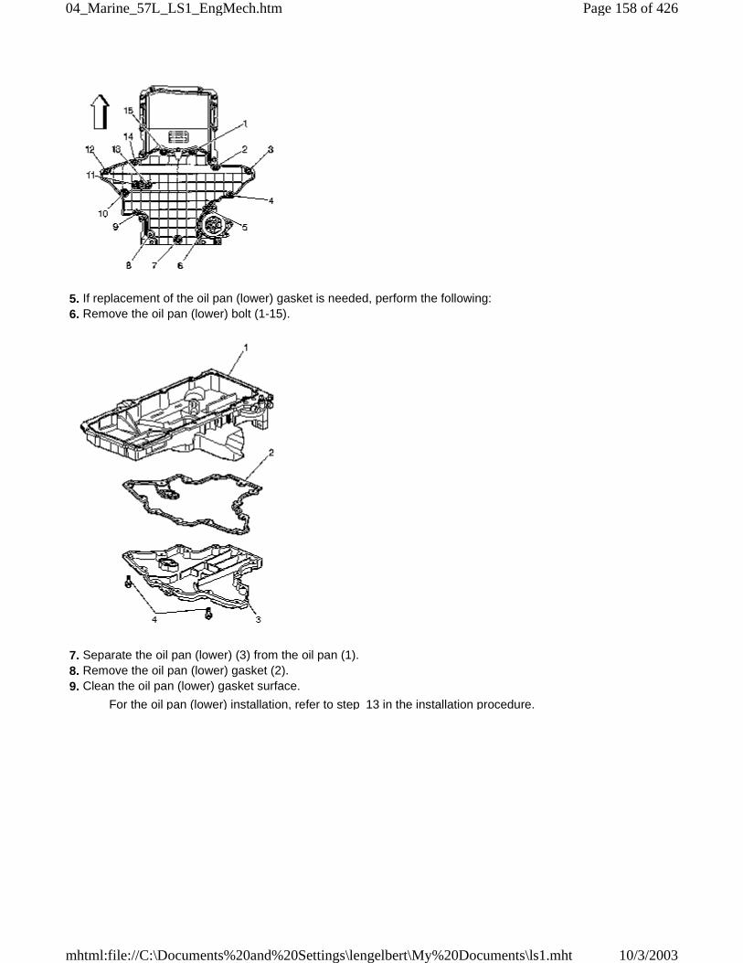
5. If replacement of the oil pan (lower) gasket is needed, perform the following: 6. Remove the oil pan (lower) bolt (1-15).
7. Separate the oil pan (lower) (3) from the oil pan (1). 8. Remove the oil pan (lower) gasket (2). 9. Clean the oil pan (lower) gasket surface.
For the oil pan (lower) installation, refer to step 13 in the installation procedure.
Page 158 of 42604_Marine_57L_LS1_EngMech.htm
10/3/2003mhtml:file://C:\Documents%20and%20Settings\lengelbert\My%20Documents\ls1.mht
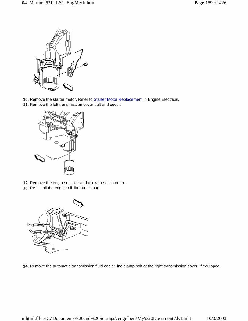
10. Remove the starter motor. Refer to Starter Motor Replacement in Engine Electrical. 11. Remove the left transmission cover bolt and cover.
12. Remove the engine oil filter and allow the oil to drain. 13. Re-install the engine oil filter until snug.
14. Remove the automatic transmission fluid cooler line clamp bolt at the right transmission cover, if equipped.
Page 159 of 42604_Marine_57L_LS1_EngMech.htm
10/3/2003mhtml:file://C:\Documents%20and%20Settings\lengelbert\My%20Documents\ls1.mht
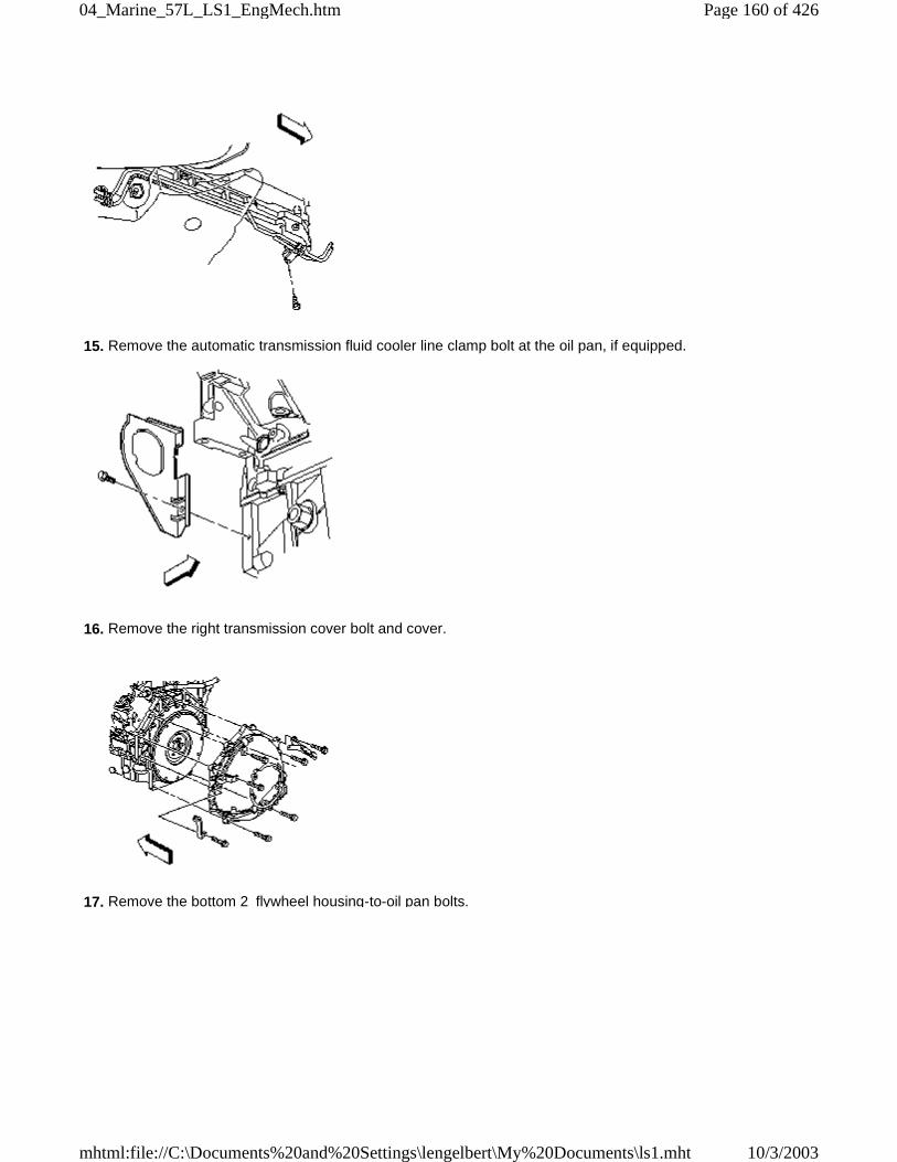
15. Remove the automatic transmission fluid cooler line clamp bolt at the oil pan, if equipped.
16. Remove the right transmission cover bolt and cover.
17. Remove the bottom 2 flywheel housing-to-oil pan bolts.
Page 160 of 42604_Marine_57L_LS1_EngMech.htm
10/3/2003mhtml:file://C:\Documents%20and%20Settings\lengelbert\My%20Documents\ls1.mht
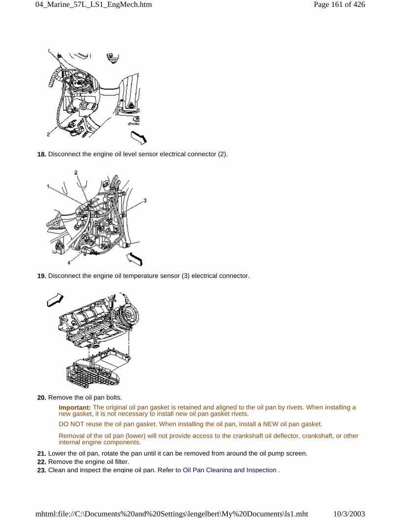
18. Disconnect the engine oil level sensor electrical connector (2).
19. Disconnect the engine oil temperature sensor (3) electrical connector.
20. Remove the oil pan bolts.
Important: The original oil pan gasket is retained and aligned to the oil pan by rivets. When installing anew gasket, it is not necessary to install new oil pan gasket rivets.
DO NOT reuse the oil pan gasket. When installing the oil pan, install a NEW oil pan gasket.
Removal of the oil pan (lower) will not provide access to the crankshaft oil deflector, crankshaft, or otherinternal engine components.
21. Lower the oil pan, rotate the pan until it can be removed from around the oil pump screen. 22. Remove the engine oil filter. 23. Clean and inspect the engine oil pan. Refer to Oil Pan Cleaning and Inspection .
Page 161 of 42604_Marine_57L_LS1_EngMech.htm
10/3/2003mhtml:file://C:\Documents%20and%20Settings\lengelbert\My%20Documents\ls1.mht
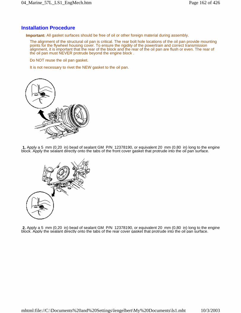
Installation ProcedureImportant: All gasket surfaces should be free of oil or other foreign material during assembly.
The alignment of the structural oil pan is critical. The rear bolt hole locations of the oil pan provide mountingpoints for the flywheel housing cover. To ensure the rigidity of the powertrain and correct transmissionalignment, it is important that the rear of the block and the rear of the oil pan are flush or even. The rear ofthe oil pan must NEVER protrude beyond the engine block .
Do NOT reuse the oil pan gasket.
It is not necessary to rivet the NEW gasket to the oil pan.
1. Apply a 5 mm (0.20 in) bead of sealant GM P/N 12378190, or equivalent 20 mm (0.80 in) long to the engineblock. Apply the sealant directly onto the tabs of the front cover gasket that protrude into the oil pan surface.
2. Apply a 5 mm (0.20 in) bead of sealant GM P/N 12378190, or equivalent 20 mm (0.80 in) long to the engineblock. Apply the sealant directly onto the tabs of the rear cover gasket that protrude into the oil pan surface.
Page 162 of 42604_Marine_57L_LS1_EngMech.htm
10/3/2003mhtml:file://C:\Documents%20and%20Settings\lengelbert\My%20Documents\ls1.mht
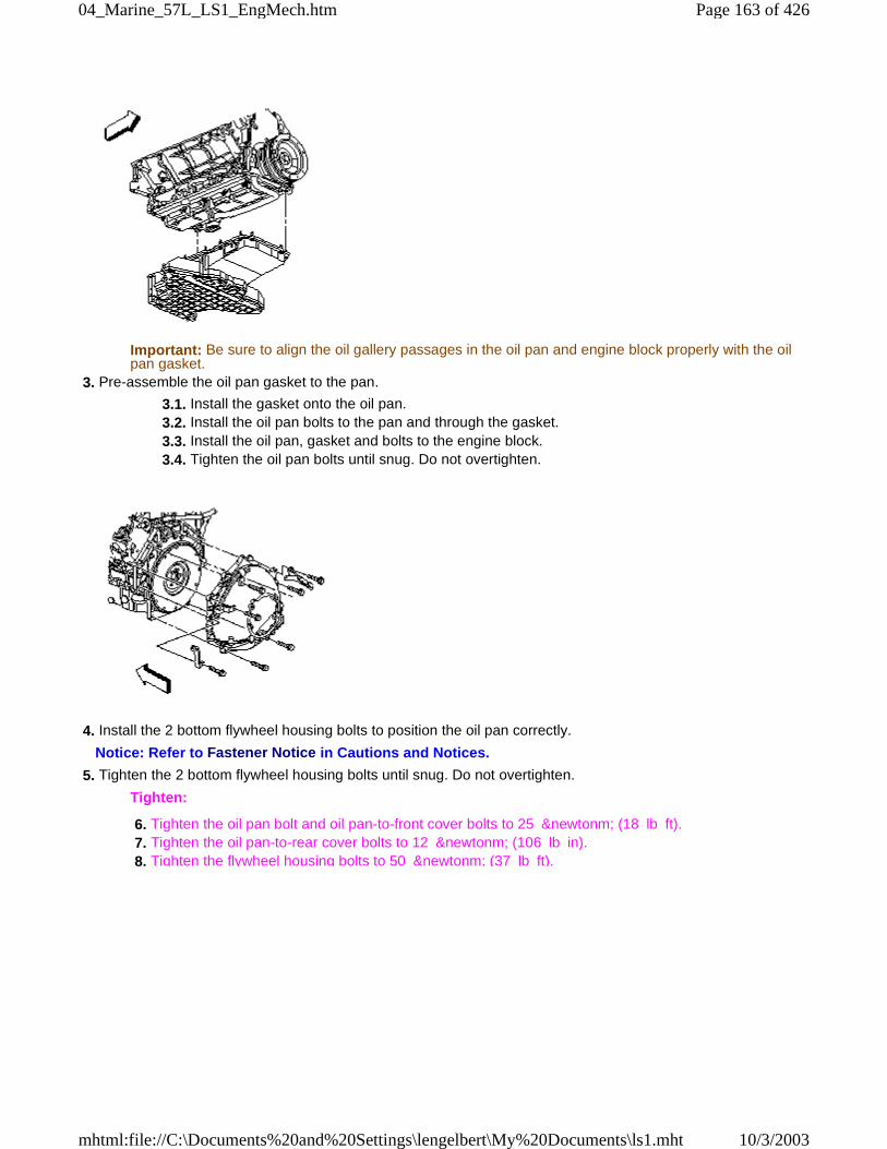
Important: Be sure to align the oil gallery passages in the oil pan and engine block properly with the oilpan gasket.
3. Pre-assemble the oil pan gasket to the pan.
3.1. Install the gasket onto the oil pan. 3.2. Install the oil pan bolts to the pan and through the gasket. 3.3. Install the oil pan, gasket and bolts to the engine block. 3.4. Tighten the oil pan bolts until snug. Do not overtighten.
4. Install the 2 bottom flywheel housing bolts to position the oil pan correctly.
Notice: Refer to Fastener Notice in Cautions and Notices.
5. Tighten the 2 bottom flywheel housing bolts until snug. Do not overtighten.
Tighten:
6. Tighten the oil pan bolt and oil pan-to-front cover bolts to 25 &newtonm; (18 lb ft). 7. Tighten the oil pan-to-rear cover bolts to 12 &newtonm; (106 lb in). 8. Tighten the flywheel housing bolts to 50 &newtonm; (37 lb ft).
Page 163 of 42604_Marine_57L_LS1_EngMech.htm
10/3/2003mhtml:file://C:\Documents%20and%20Settings\lengelbert\My%20Documents\ls1.mht
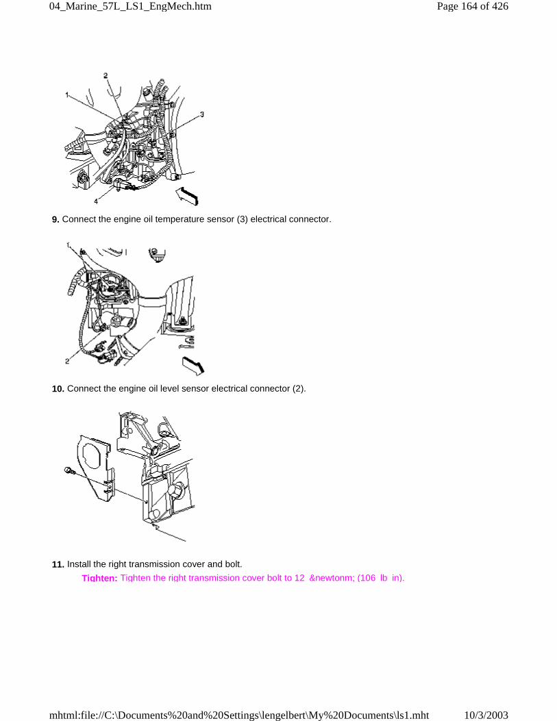
9. Connect the engine oil temperature sensor (3) electrical connector.
10. Connect the engine oil level sensor electrical connector (2).
11. Install the right transmission cover and bolt.
Tighten: Tighten the right transmission cover bolt to 12 &newtonm; (106 lb in).
Page 164 of 42604_Marine_57L_LS1_EngMech.htm
10/3/2003mhtml:file://C:\Documents%20and%20Settings\lengelbert\My%20Documents\ls1.mht
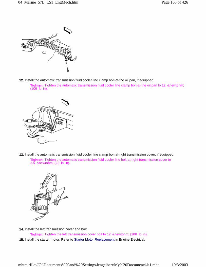
12. Install the automatic transmission fluid cooler line clamp bolt-at-the oil pan, if equipped.
Tighten: Tighten the automatic transmission fluid cooler line clamp bolt-at-the oil pan to 12 &newtonm;(106 lb in).
13. Install the automatic transmission fluid cooler line clamp bolt-at-right transmission cover, if equipped.
Tighten: Tighten the automatic transmission fluid cooler line bolt-at-right transmission cover to2.5 &newtonm; (22 lb in).
14. Install the left transmission cover and bolt.
Tighten: Tighten the left transmission cover bolt to 12 &newtonm; (106 lb in).
15. Install the starter motor. Refer to Starter Motor Replacement in Engine Electrical.
Page 165 of 42604_Marine_57L_LS1_EngMech.htm
10/3/2003mhtml:file://C:\Documents%20and%20Settings\lengelbert\My%20Documents\ls1.mht
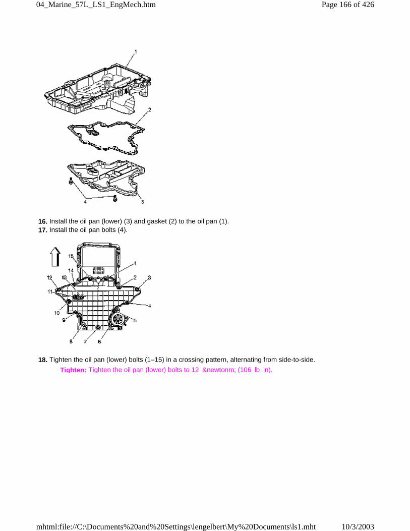
16. Install the oil pan (lower) (3) and gasket (2) to the oil pan (1). 17. Install the oil pan bolts (4).
18. Tighten the oil pan (lower) bolts (1–15) in a crossing pattern, alternating from side-to-side.
Tighten: Tighten the oil pan (lower) bolts to 12 &newtonm; (106 lb in).
Page 166 of 42604_Marine_57L_LS1_EngMech.htm
10/3/2003mhtml:file://C:\Documents%20and%20Settings\lengelbert\My%20Documents\ls1.mht
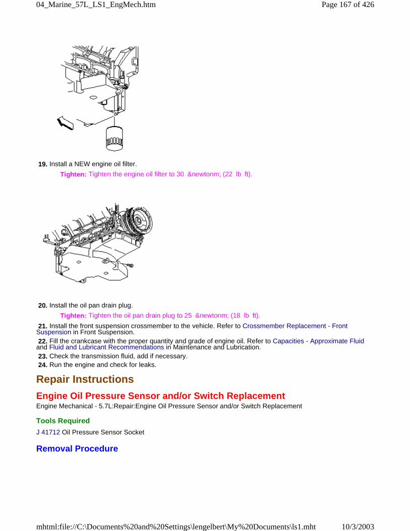
19. Install a NEW engine oil filter.
Tighten: Tighten the engine oil filter to 30 &newtonm; (22 lb ft).
20. Install the oil pan drain plug.
Tighten: Tighten the oil pan drain plug to 25 &newtonm; (18 lb ft).
21. Install the front suspension crossmember to the vehicle. Refer to Crossmember Replacement - FrontSuspension in Front Suspension. 22. Fill the crankcase with the proper quantity and grade of engine oil. Refer to Capacities - Approximate Fluidand Fluid and Lubricant Recommendations in Maintenance and Lubrication. 23. Check the transmission fluid, add if necessary. 24. Run the engine and check for leaks.
Repair Instructions
Engine Oil Pressure Sensor and/or Switch ReplacementEngine Mechanical - 5.7L:Repair:Engine Oil Pressure Sensor and/or Switch Replacement
Tools Required
J 41712 Oil Pressure Sensor Socket
Removal Procedure
Page 167 of 42604_Marine_57L_LS1_EngMech.htm
10/3/2003mhtml:file://C:\Documents%20and%20Settings\lengelbert\My%20Documents\ls1.mht

1. Remove the intake manifold. Refer to Intake Manifold Replacement . 2. Disconnect the oil pressure sensor electrical connector (2).
Important: Clean the area around the sensor before removal. This avoids debris from entering theengine.
3. Use J 41712 to remove the oil pressure sensor from the engine block.
Installation Procedure
1. If installing the old sensor, apply thread sealant GM P/N 12346004 (Canadian P/N 10953480), or equivalent.
Notice: Refer to Fastener Notice in Cautions and Notices.
2. Use J 41712 to install the oil pressure sensor to the engine block.
Tighten: Tighten the engine oil pressure sensor to 20 &newtonm; (15 lb ft).
Page 168 of 42604_Marine_57L_LS1_EngMech.htm
10/3/2003mhtml:file://C:\Documents%20and%20Settings\lengelbert\My%20Documents\ls1.mht
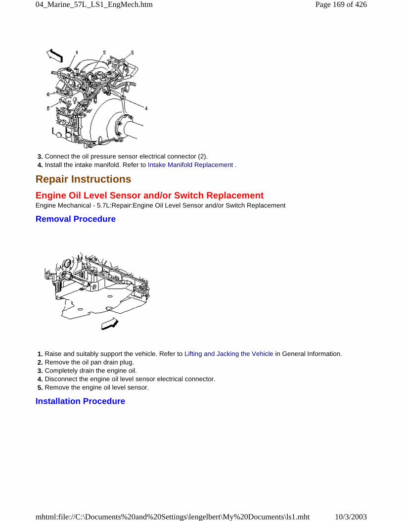
3. Connect the oil pressure sensor electrical connector (2). 4. Install the intake manifold. Refer to Intake Manifold Replacement .
Repair Instructions
Engine Oil Level Sensor and/or Switch ReplacementEngine Mechanical - 5.7L:Repair:Engine Oil Level Sensor and/or Switch Replacement
Removal Procedure
1. Raise and suitably support the vehicle. Refer to Lifting and Jacking the Vehicle in General Information. 2. Remove the oil pan drain plug. 3. Completely drain the engine oil. 4. Disconnect the engine oil level sensor electrical connector. 5. Remove the engine oil level sensor.
Installation Procedure
Page 169 of 42604_Marine_57L_LS1_EngMech.htm
10/3/2003mhtml:file://C:\Documents%20and%20Settings\lengelbert\My%20Documents\ls1.mht
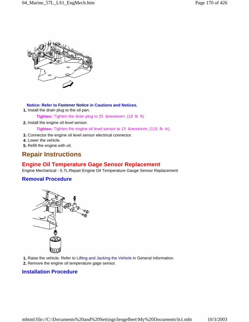
Notice: Refer to Fastener Notice in Cautions and Notices. 1. Install the drain plug to the oil pan.
Tighten: Tighten the drain plug to 25 &newtonm; (18 lb ft).
2. Install the engine oil level sensor.
Tighten: Tighten the engine oil level sensor to 13 &newtonm; (115 lb in).
3. Connector the engine oil level sensor electrical connector. 4. Lower the vehicle. 5. Refill the engine with oil.
Repair Instructions
Engine Oil Temperature Gage Sensor ReplacementEngine Mechanical - 5.7L:Repair:Engine Oil Temperature Gauge Sensor Replacement
Removal Procedure
1. Raise the vehicle. Refer to Lifting and Jacking the Vehicle in General Information. 2. Remove the engine oil temperature gage sensor.
Installation Procedure
Page 170 of 42604_Marine_57L_LS1_EngMech.htm
10/3/2003mhtml:file://C:\Documents%20and%20Settings\lengelbert\My%20Documents\ls1.mht
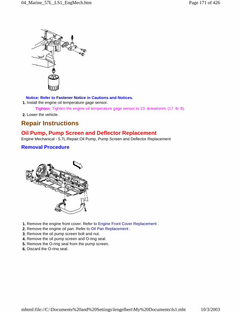
Notice: Refer to Fastener Notice in Cautions and Notices. 1. Install the engine oil temperature gage sensor.
Tighten: Tighten the engine oil temperature gage sensor to 23 &newtonm; (17 lb ft).
2. Lower the vehicle.
Repair Instructions
Oil Pump, Pump Screen and Deflector ReplacementEngine Mechanical - 5.7L:Repair:Oil Pump, Pump Screen and Deflector Replacement
Removal Procedure
1. Remove the engine front cover. Refer to Engine Front Cover Replacement . 2. Remove the engine oil pan. Refer to Oil Pan Replacement . 3. Remove the oil pump screen bolt and nut. 4. Remove the oil pump screen and O-ring seal. 5. Remove the O-ring seal from the pump screen. 6. Discard the O-ring seal.
Page 171 of 42604_Marine_57L_LS1_EngMech.htm
10/3/2003mhtml:file://C:\Documents%20and%20Settings\lengelbert\My%20Documents\ls1.mht
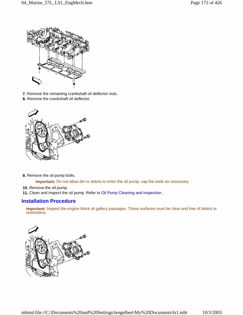
7. Remove the remaining crankshaft oil deflector nuts. 8. Remove the crankshaft oil deflector.
9. Remove the oil pump bolts.
Important: Do not allow dirt or debris to enter the oil pump, cap the ends as necessary.
10. Remove the oil pump. 11. Clean and inspect the oil pump. Refer to Oil Pump Cleaning and Inspection .
Installation ProcedureImportant: Inspect the engine block oil gallery passages. These surfaces must be clear and free of debris orrestrictions.
Page 172 of 42604_Marine_57L_LS1_EngMech.htm
10/3/2003mhtml:file://C:\Documents%20and%20Settings\lengelbert\My%20Documents\ls1.mht
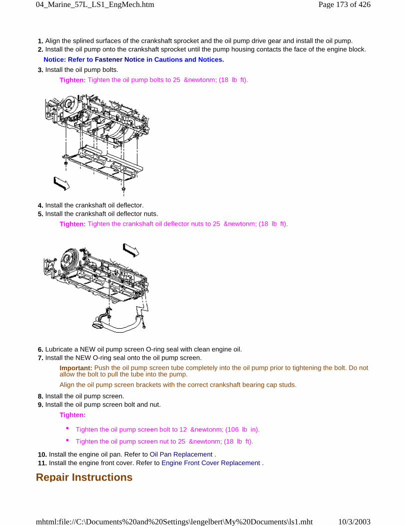
1. Align the splined surfaces of the crankshaft sprocket and the oil pump drive gear and install the oil pump. 2. Install the oil pump onto the crankshaft sprocket until the pump housing contacts the face of the engine block.
Notice: Refer to Fastener Notice in Cautions and Notices.
3. Install the oil pump bolts.
Tighten: Tighten the oil pump bolts to 25 &newtonm; (18 lb ft).
4. Install the crankshaft oil deflector. 5. Install the crankshaft oil deflector nuts.
Tighten: Tighten the crankshaft oil deflector nuts to 25 &newtonm; (18 lb ft).
6. Lubricate a NEW oil pump screen O-ring seal with clean engine oil. 7. Install the NEW O-ring seal onto the oil pump screen.
Important: Push the oil pump screen tube completely into the oil pump prior to tightening the bolt. Do notallow the bolt to pull the tube into the pump.
Align the oil pump screen brackets with the correct crankshaft bearing cap studs.
8. Install the oil pump screen. 9. Install the oil pump screen bolt and nut.
Tighten:
• Tighten the oil pump screen bolt to 12 &newtonm; (106 lb in).
• Tighten the oil pump screen nut to 25 &newtonm; (18 lb ft).
10. Install the engine oil pan. Refer to Oil Pan Replacement . 11. Install the engine front cover. Refer to Engine Front Cover Replacement .
Repair Instructions
Page 173 of 42604_Marine_57L_LS1_EngMech.htm
10/3/2003mhtml:file://C:\Documents%20and%20Settings\lengelbert\My%20Documents\ls1.mht
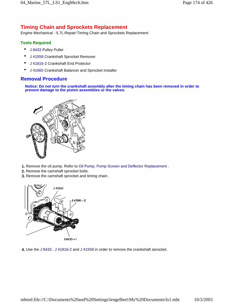
Timing Chain and Sprockets ReplacementEngine Mechanical - 5.7L:Repair:Timing Chain and Sprockets Replacement
Tools Required
• J 8433 Pulley Puller
• J 41558 Crankshaft Sprocket Remover
• J 41816-2 Crankshaft End Protector
• J 41665 Crankshaft Balancer and Sprocket Installer
Removal ProcedureNotice: Do not turn the crankshaft assembly after the timing chain has been removed in order toprevent damage to the piston assemblies or the valves.
1. Remove the oil pump. Refer to Oil Pump, Pump Screen and Deflector Replacement . 2. Remove the camshaft sprocket bolts. 3. Remove the camshaft sprocket and timing chain.
4. Use the J 8433 , J 41816-2 and J 41558 in order to remove the crankshaft sprocket.
Page 174 of 42604_Marine_57L_LS1_EngMech.htm
10/3/2003mhtml:file://C:\Documents%20and%20Settings\lengelbert\My%20Documents\ls1.mht
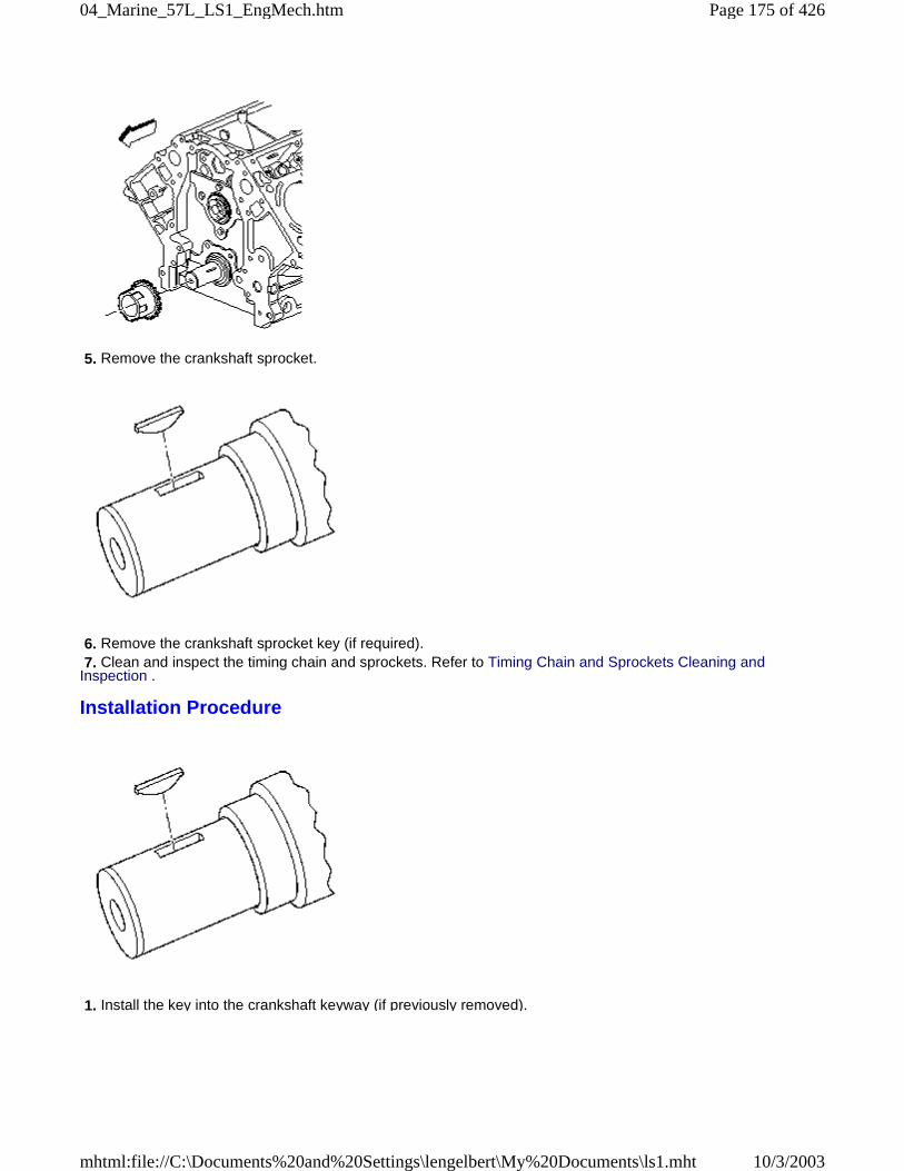
5. Remove the crankshaft sprocket.
6. Remove the crankshaft sprocket key (if required). 7. Clean and inspect the timing chain and sprockets. Refer to Timing Chain and Sprockets Cleaning andInspection .
Installation Procedure
1. Install the key into the crankshaft keyway (if previously removed).
Page 175 of 42604_Marine_57L_LS1_EngMech.htm
10/3/2003mhtml:file://C:\Documents%20and%20Settings\lengelbert\My%20Documents\ls1.mht
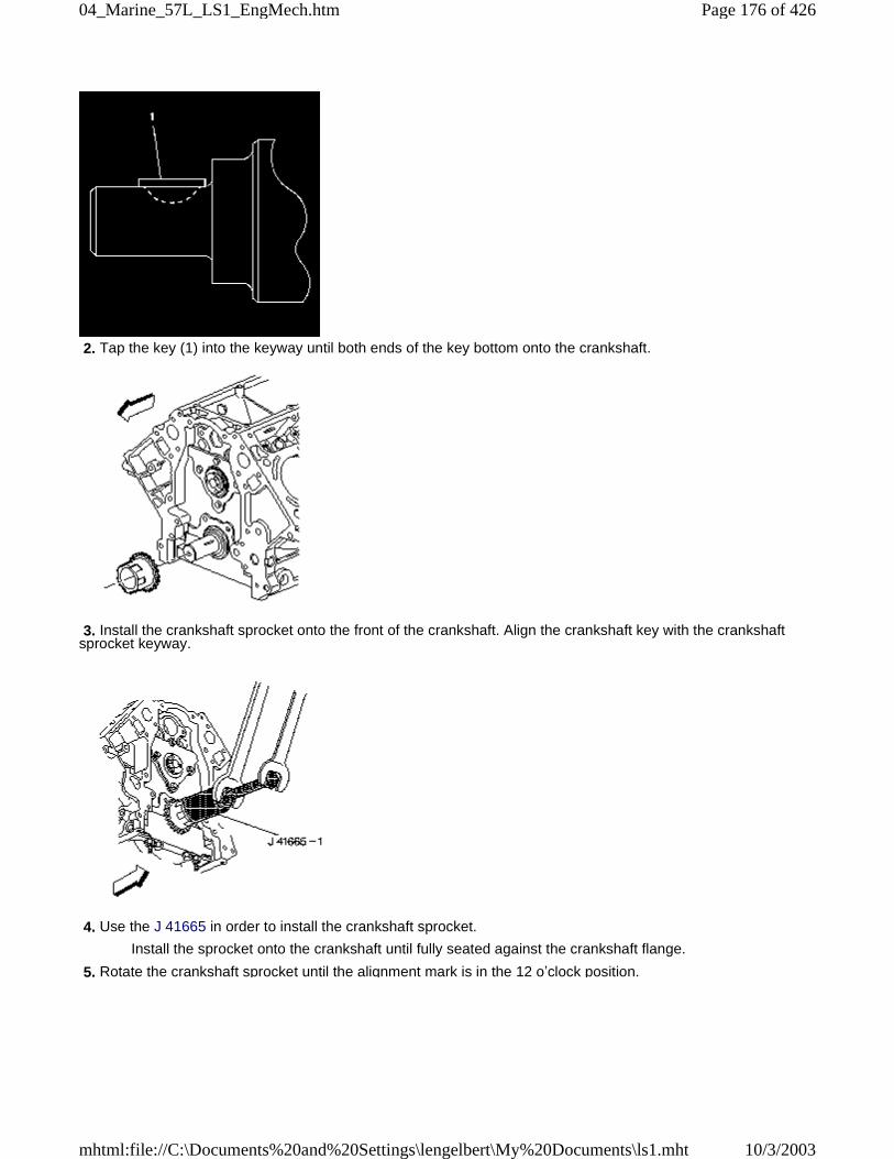
2. Tap the key (1) into the keyway until both ends of the key bottom onto the crankshaft.
3. Install the crankshaft sprocket onto the front of the crankshaft. Align the crankshaft key with the crankshaftsprocket keyway.
4. Use the J 41665 in order to install the crankshaft sprocket.
Install the sprocket onto the crankshaft until fully seated against the crankshaft flange.
5. Rotate the crankshaft sprocket until the alignment mark is in the 12 o’clock position.
Page 176 of 42604_Marine_57L_LS1_EngMech.htm
10/3/2003mhtml:file://C:\Documents%20and%20Settings\lengelbert\My%20Documents\ls1.mht
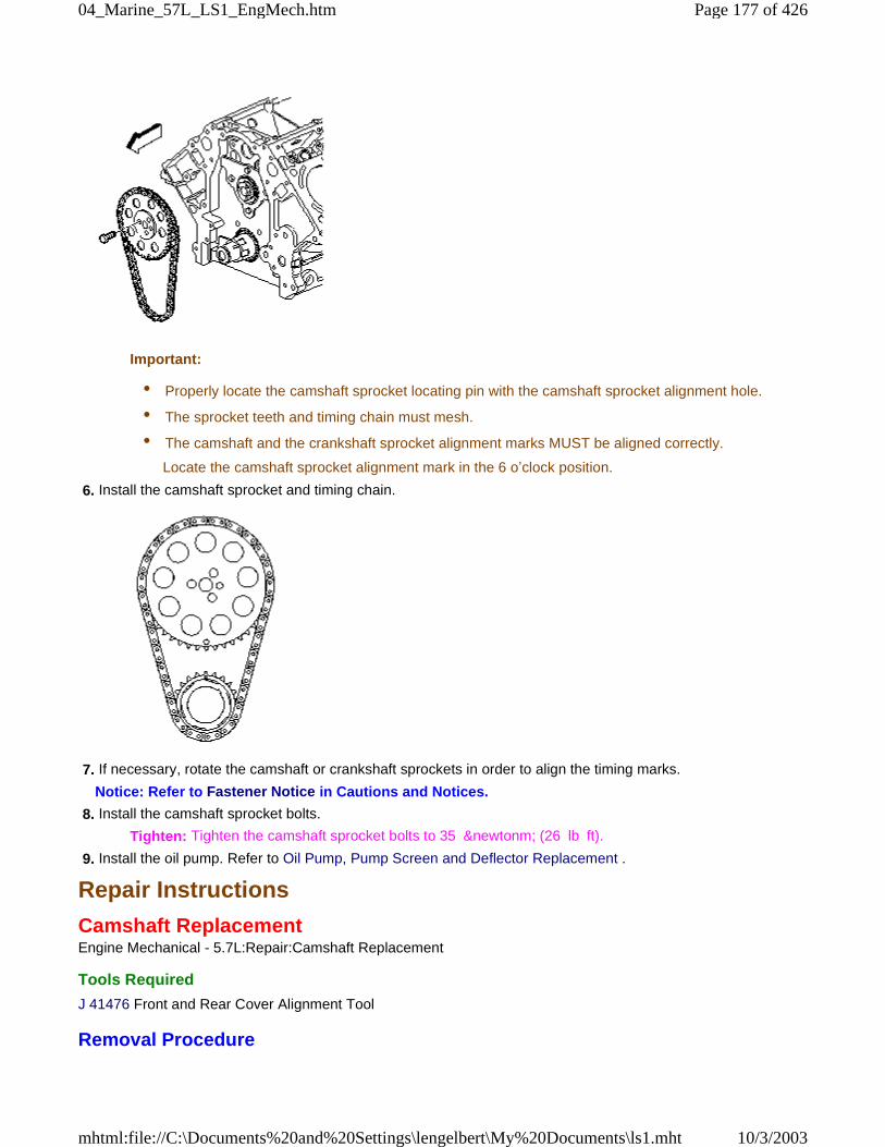
Important:
• Properly locate the camshaft sprocket locating pin with the camshaft sprocket alignment hole.
• The sprocket teeth and timing chain must mesh.
• The camshaft and the crankshaft sprocket alignment marks MUST be aligned correctly.
Locate the camshaft sprocket alignment mark in the 6 o’clock position.
6. Install the camshaft sprocket and timing chain.
7. If necessary, rotate the camshaft or crankshaft sprockets in order to align the timing marks.
Notice: Refer to Fastener Notice in Cautions and Notices.
8. Install the camshaft sprocket bolts.
Tighten: Tighten the camshaft sprocket bolts to 35 &newtonm; (26 lb ft).
9. Install the oil pump. Refer to Oil Pump, Pump Screen and Deflector Replacement .
Repair Instructions
Camshaft ReplacementEngine Mechanical - 5.7L:Repair:Camshaft Replacement
Tools Required
J 41476 Front and Rear Cover Alignment Tool
Removal Procedure
Page 177 of 42604_Marine_57L_LS1_EngMech.htm
10/3/2003mhtml:file://C:\Documents%20and%20Settings\lengelbert\My%20Documents\ls1.mht
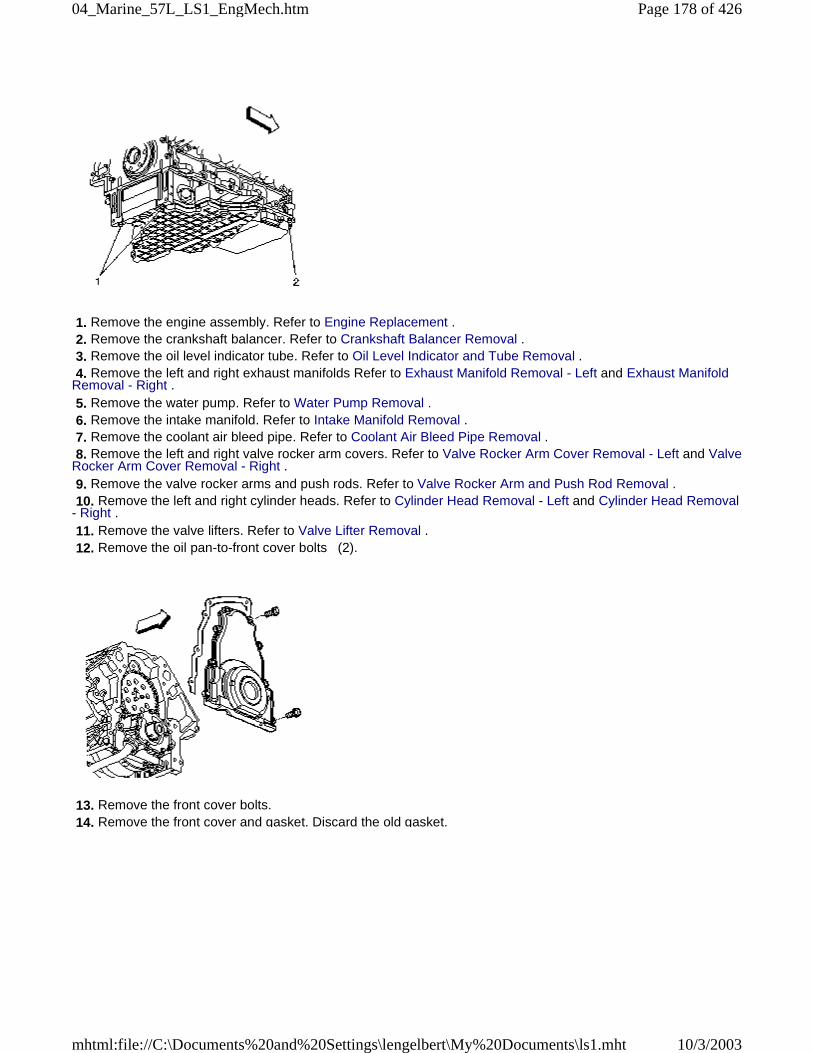
1. Remove the engine assembly. Refer to Engine Replacement . 2. Remove the crankshaft balancer. Refer to Crankshaft Balancer Removal . 3. Remove the oil level indicator tube. Refer to Oil Level Indicator and Tube Removal . 4. Remove the left and right exhaust manifolds Refer to Exhaust Manifold Removal - Left and Exhaust ManifoldRemoval - Right . 5. Remove the water pump. Refer to Water Pump Removal . 6. Remove the intake manifold. Refer to Intake Manifold Removal . 7. Remove the coolant air bleed pipe. Refer to Coolant Air Bleed Pipe Removal . 8. Remove the left and right valve rocker arm covers. Refer to Valve Rocker Arm Cover Removal - Left and ValveRocker Arm Cover Removal - Right . 9. Remove the valve rocker arms and push rods. Refer to Valve Rocker Arm and Push Rod Removal . 10. Remove the left and right cylinder heads. Refer to Cylinder Head Removal - Left and Cylinder Head Removal- Right . 11. Remove the valve lifters. Refer to Valve Lifter Removal . 12. Remove the oil pan-to-front cover bolts (2).
13. Remove the front cover bolts. 14. Remove the front cover and gasket. Discard the old gasket.
Page 178 of 42604_Marine_57L_LS1_EngMech.htm
10/3/2003mhtml:file://C:\Documents%20and%20Settings\lengelbert\My%20Documents\ls1.mht
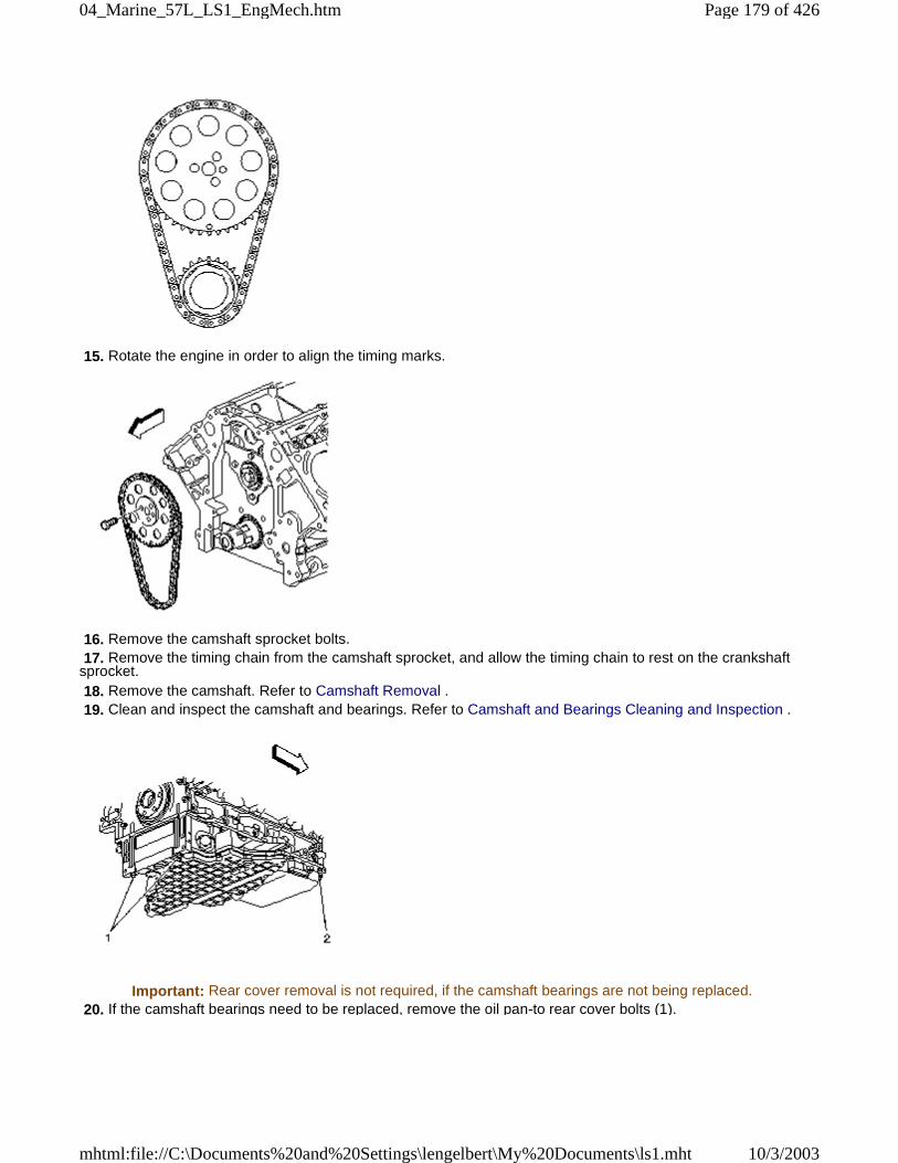
15. Rotate the engine in order to align the timing marks.
16. Remove the camshaft sprocket bolts. 17. Remove the timing chain from the camshaft sprocket, and allow the timing chain to rest on the crankshaftsprocket. 18. Remove the camshaft. Refer to Camshaft Removal . 19. Clean and inspect the camshaft and bearings. Refer to Camshaft and Bearings Cleaning and Inspection .
Important: Rear cover removal is not required, if the camshaft bearings are not being replaced. 20. If the camshaft bearings need to be replaced, remove the oil pan-to rear cover bolts (1).
Page 179 of 42604_Marine_57L_LS1_EngMech.htm
10/3/2003mhtml:file://C:\Documents%20and%20Settings\lengelbert\My%20Documents\ls1.mht
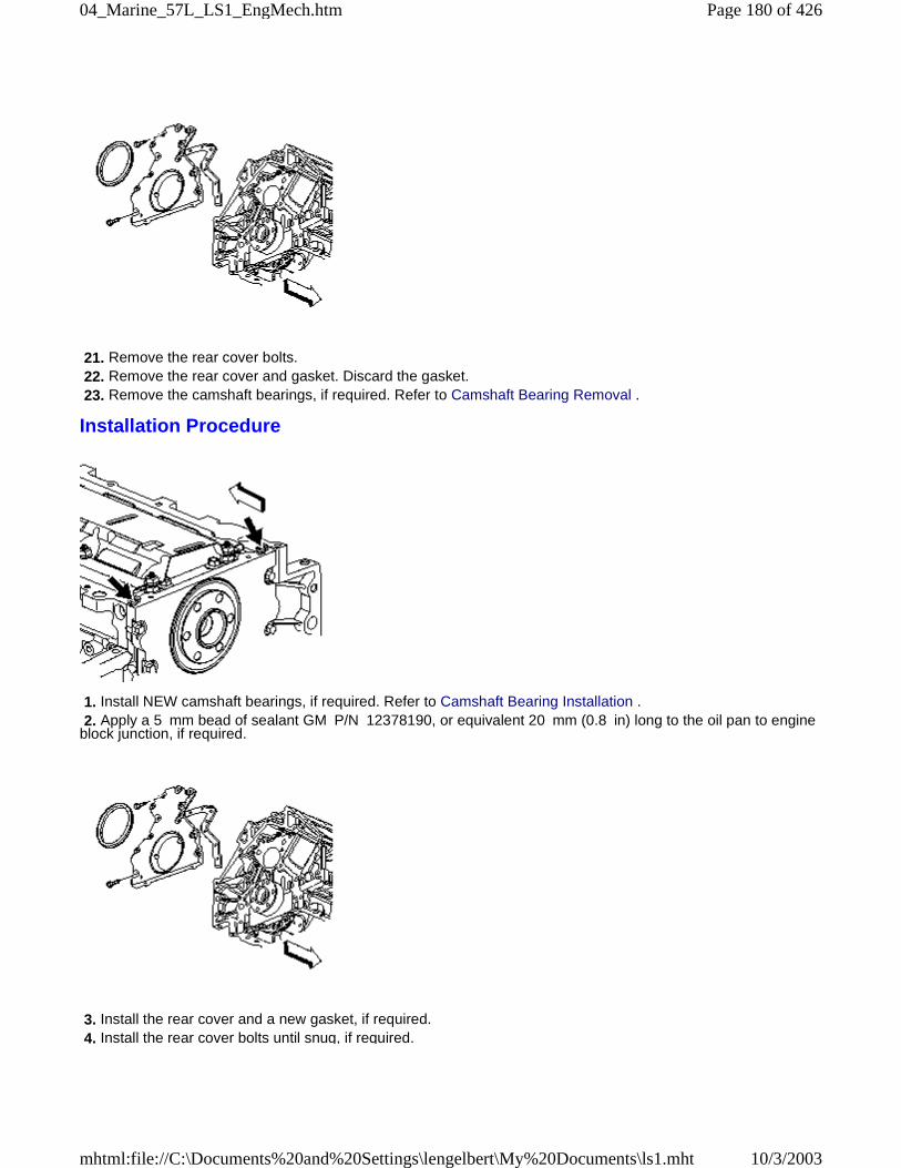
21. Remove the rear cover bolts. 22. Remove the rear cover and gasket. Discard the gasket. 23. Remove the camshaft bearings, if required. Refer to Camshaft Bearing Removal .
Installation Procedure
1. Install NEW camshaft bearings, if required. Refer to Camshaft Bearing Installation . 2. Apply a 5 mm bead of sealant GM P/N 12378190, or equivalent 20 mm (0.8 in) long to the oil pan to engineblock junction, if required.
3. Install the rear cover and a new gasket, if required. 4. Install the rear cover bolts until snug, if required.
Page 180 of 42604_Marine_57L_LS1_EngMech.htm
10/3/2003mhtml:file://C:\Documents%20and%20Settings\lengelbert\My%20Documents\ls1.mht
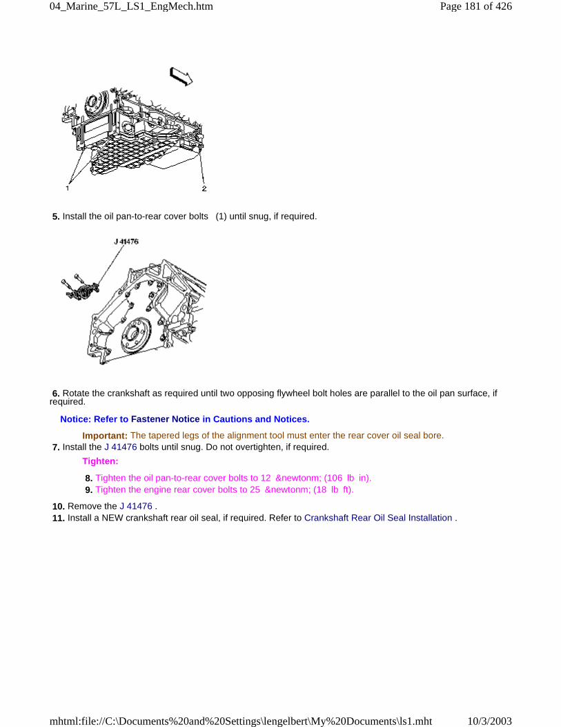
5. Install the oil pan-to-rear cover bolts (1) until snug, if required.
6. Rotate the crankshaft as required until two opposing flywheel bolt holes are parallel to the oil pan surface, ifrequired.
Notice: Refer to Fastener Notice in Cautions and Notices.
Important: The tapered legs of the alignment tool must enter the rear cover oil seal bore. 7. Install the J 41476 bolts until snug. Do not overtighten, if required.
Tighten:
8. Tighten the oil pan-to-rear cover bolts to 12 &newtonm; (106 lb in). 9. Tighten the engine rear cover bolts to 25 &newtonm; (18 lb ft).
10. Remove the J 41476 . 11. Install a NEW crankshaft rear oil seal, if required. Refer to Crankshaft Rear Oil Seal Installation .
Page 181 of 42604_Marine_57L_LS1_EngMech.htm
10/3/2003mhtml:file://C:\Documents%20and%20Settings\lengelbert\My%20Documents\ls1.mht
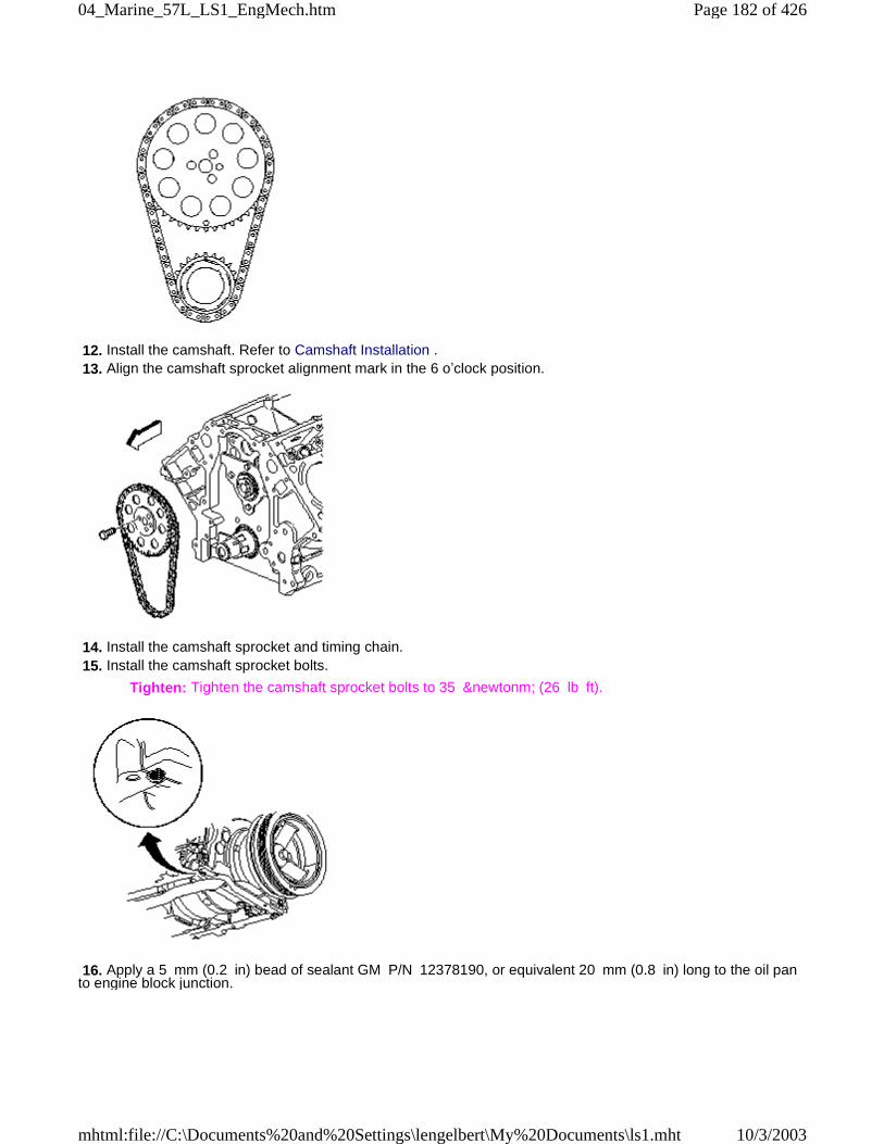
12. Install the camshaft. Refer to Camshaft Installation . 13. Align the camshaft sprocket alignment mark in the 6 o’clock position.
14. Install the camshaft sprocket and timing chain. 15. Install the camshaft sprocket bolts.
Tighten: Tighten the camshaft sprocket bolts to 35 &newtonm; (26 lb ft).
16. Apply a 5 mm (0.2 in) bead of sealant GM P/N 12378190, or equivalent 20 mm (0.8 in) long to the oil panto engine block junction.
Page 182 of 42604_Marine_57L_LS1_EngMech.htm
10/3/2003mhtml:file://C:\Documents%20and%20Settings\lengelbert\My%20Documents\ls1.mht
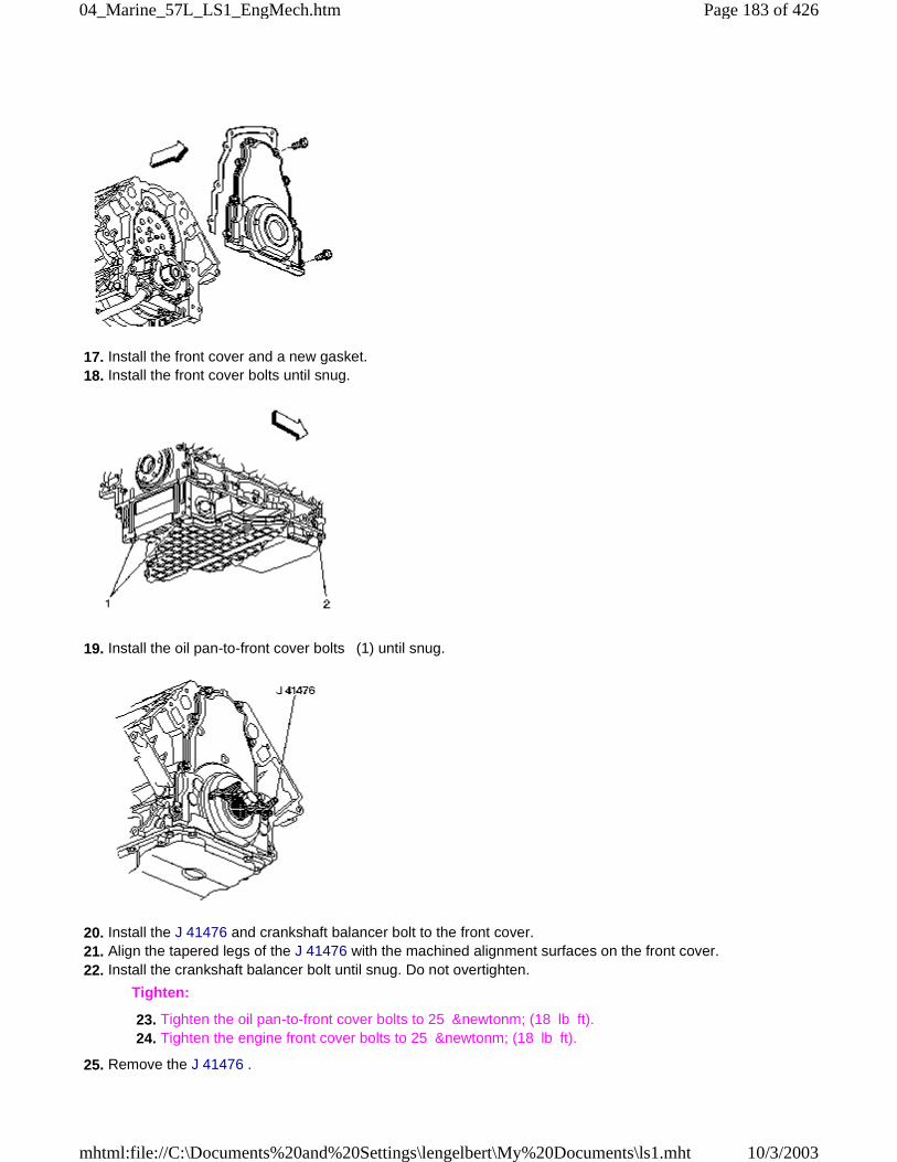
17. Install the front cover and a new gasket. 18. Install the front cover bolts until snug.
19. Install the oil pan-to-front cover bolts (1) until snug.
20. Install the J 41476 and crankshaft balancer bolt to the front cover. 21. Align the tapered legs of the J 41476 with the machined alignment surfaces on the front cover. 22. Install the crankshaft balancer bolt until snug. Do not overtighten.
Tighten:
23. Tighten the oil pan-to-front cover bolts to 25 &newtonm; (18 lb ft). 24. Tighten the engine front cover bolts to 25 &newtonm; (18 lb ft).
25. Remove the J 41476 .
Page 183 of 42604_Marine_57L_LS1_EngMech.htm
10/3/2003mhtml:file://C:\Documents%20and%20Settings\lengelbert\My%20Documents\ls1.mht
26. Install a NEW crankshaft front oil seal. Refer to Crankshaft Front Oil Seal Installation . 27. Install the valve lifters. Refer to Valve Lifter Installation . 28. Install the right and left cylinder heads. Refer to Cylinder Head Installation - Right and Cylinder HeadInstallation - Left . 29. Install the valve rocker arms and push rods. Refer to Valve Rocker Arm and Push Rod Installation . 30. Install the right and left valve rocker arm covers. Refer to Valve Rocker Arm Cover Installation - Right andValve Rocker Arm Cover Installation - Left . 31. Install the coolant air bleed pipe. Refer to Coolant Air Bleed Pipe Installation . 32. Install the intake manifold. Refer to Intake Manifold Installation . 33. Install the water pump. Refer to Water Pump Installation . 34. Install the left and right exhaust manifolds. Refer to Exhaust Manifold Installation - Left and Exhaust ManifoldInstallation - Right . 35. Install the oil level indicator tube. Refer to Oil Level Indicator and Tube Installation . 36. Install the crankshaft balancer. Refer to Crankshaft Balancer Installation . 37. Install the engine assembly. Refer to Engine Replacement .
Repair Instructions
Engine Flywheel ReplacementEngine Mechanical - 5.7L:Repair:Engine Flywheel Replacement
Removal ProcedureNotice: Failure to follow the proper removal and installation procedures may result in damage to theengine crankshaft thrust bearing.
Notice: When tilting down the rear of the driveline, observe the clearance between the rear of theengine and the composite dash panel. Do not allow the engine to rest unsupported against thecomposite dash panel, or vehicle damage may result.
Notice: When lowering and removing the rear of the driveline, observe the clearance between the rearof the transaxle assembly and the underbody to prevent damage.
Important:
• For manual transmission applications, note the position and direction of the engine flywheel beforeremoval. The flywheel does not use a locating pin for alignment. Mark or scribe the end of the crankshaft and
the flywheel before component removal. The engine flywheel must be reinstalled to the original position and
direction. The engine flywheel will not initially seat against the crankshaft flange, but will be pulled onto the
crankshaft by the engine flywheel bolts. This procedure requires a 3 stage tightening process.
• DO NOT remove the prop shaft hub or flex plate from the automatic transmission engine flywheel. Theflywheel, prop shaft hub, and flex plate are balanced as an assembly. If service is required, the entire flywheel
assembly should be replaced.
Page 184 of 42604_Marine_57L_LS1_EngMech.htm
10/3/2003mhtml:file://C:\Documents%20and%20Settings\lengelbert\My%20Documents\ls1.mht
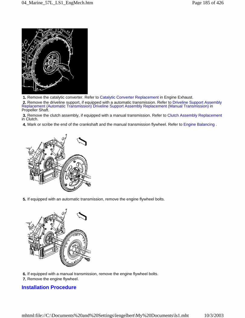
1. Remove the catalytic converter. Refer to Catalytic Converter Replacement in Engine Exhaust. 2. Remove the driveline support, if equipped with a automatic transmission. Refer to Driveline Support AssemblyReplacement (Automatic Transmission) Driveline Support Assembly Replacement (Manual Transmission) inPropeller Shaft. 3. Remove the clutch assembly, if equipped with a manual transmission. Refer to Clutch Assembly Replacementin Clutch. 4. Mark or scribe the end of the crankshaft and the manual transmission flywheel. Refer to Engine Balancing .
5. If equipped with an automatic transmission, remove the engine flywheel bolts.
6. If equipped with a manual transmission, remove the engine flywheel bolts. 7. Remove the engine flywheel.
Installation Procedure
Page 185 of 42604_Marine_57L_LS1_EngMech.htm
10/3/2003mhtml:file://C:\Documents%20and%20Settings\lengelbert\My%20Documents\ls1.mht
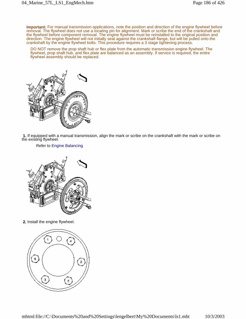
Important: For manual transmission applications, note the position and direction of the engine flywheel beforeremoval. The flywheel does not use a locating pin for alignment. Mark or scribe the end of the crankshaft andthe flywheel before component removal. The engine flywheel must be reinstalled to the original position anddirection. The engine flywheel will not initially seat against the crankshaft flange, but will be pulled onto thecrankshaft by the engine flywheel bolts. This procedure requires a 3 stage tightening process.
DO NOT remove the prop shaft hub or flex plate from the automatic transmission engine flywheel. Theflywheel, prop shaft hub, and flex plate are balanced as an assembly. If service is required, the entireflywheel assembly should be replaced.
1. If equipped with a manual transmission, align the mark or scribe on the crankshaft with the mark or scribe onthe existing flywheel.
Refer to Engine Balancing
2. Install the engine flywheel.
Page 186 of 42604_Marine_57L_LS1_EngMech.htm
10/3/2003mhtml:file://C:\Documents%20and%20Settings\lengelbert\My%20Documents\ls1.mht
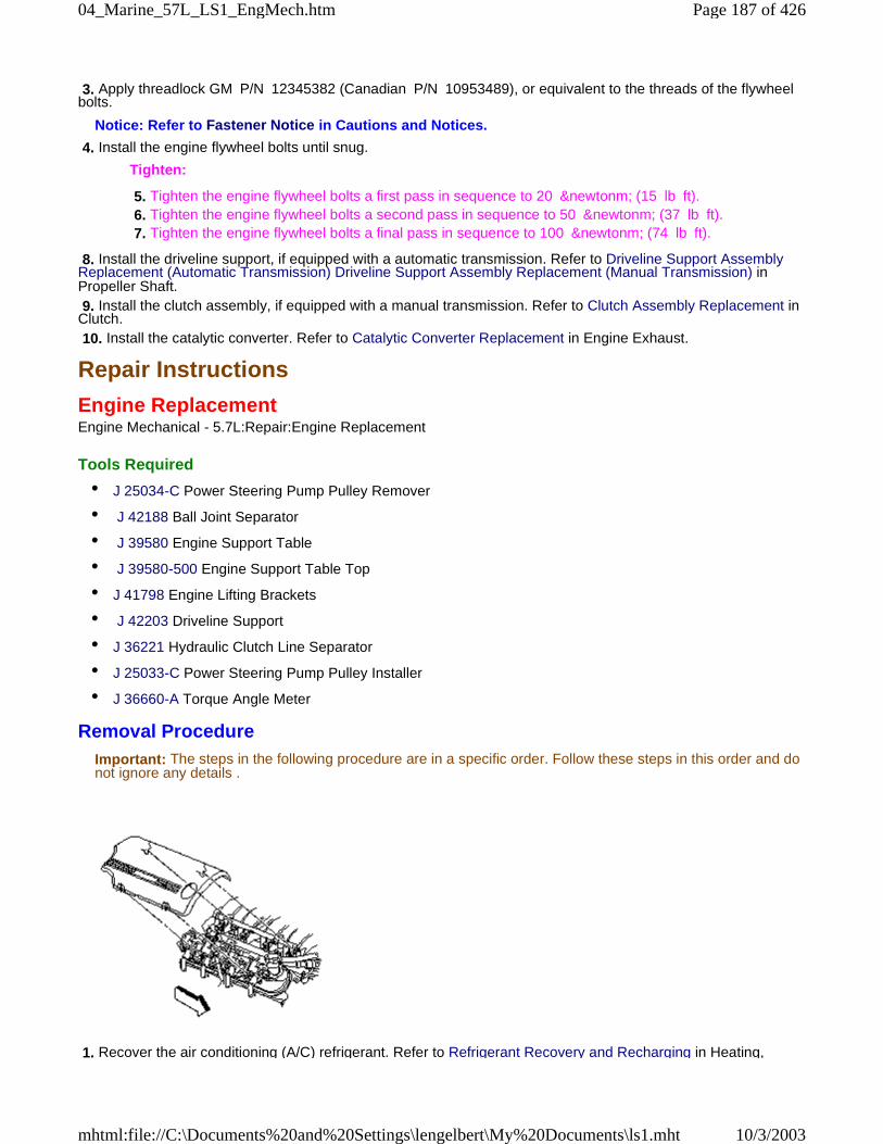
3. Apply threadlock GM P/N 12345382 (Canadian P/N 10953489), or equivalent to the threads of the flywheelbolts.
Notice: Refer to Fastener Notice in Cautions and Notices.
4. Install the engine flywheel bolts until snug.
Tighten:
5. Tighten the engine flywheel bolts a first pass in sequence to 20 &newtonm; (15 lb ft). 6. Tighten the engine flywheel bolts a second pass in sequence to 50 &newtonm; (37 lb ft). 7. Tighten the engine flywheel bolts a final pass in sequence to 100 &newtonm; (74 lb ft).
8. Install the driveline support, if equipped with a automatic transmission. Refer to Driveline Support AssemblyReplacement (Automatic Transmission) Driveline Support Assembly Replacement (Manual Transmission) inPropeller Shaft. 9. Install the clutch assembly, if equipped with a manual transmission. Refer to Clutch Assembly Replacement inClutch. 10. Install the catalytic converter. Refer to Catalytic Converter Replacement in Engine Exhaust.
Repair Instructions
Engine ReplacementEngine Mechanical - 5.7L:Repair:Engine Replacement
Tools Required
• J 25034-C Power Steering Pump Pulley Remover
• J 42188 Ball Joint Separator
• J 39580 Engine Support Table
• J 39580-500 Engine Support Table Top
• J 41798 Engine Lifting Brackets
• J 42203 Driveline Support
• J 36221 Hydraulic Clutch Line Separator
• J 25033-C Power Steering Pump Pulley Installer
• J 36660-A Torque Angle Meter
Removal ProcedureImportant: The steps in the following procedure are in a specific order. Follow these steps in this order and donot ignore any details .
1. Recover the air conditioning (A/C) refrigerant. Refer to Refrigerant Recovery and Recharging in Heating,
Page 187 of 42604_Marine_57L_LS1_EngMech.htm
10/3/2003mhtml:file://C:\Documents%20and%20Settings\lengelbert\My%20Documents\ls1.mht
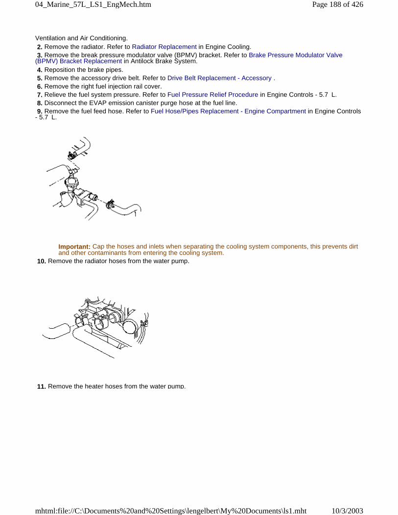
Ventilation and Air Conditioning. 2. Remove the radiator. Refer to Radiator Replacement in Engine Cooling. 3. Remove the break pressure modulator valve (BPMV) bracket. Refer to Brake Pressure Modulator Valve(BPMV) Bracket Replacement in Antilock Brake System. 4. Reposition the brake pipes. 5. Remove the accessory drive belt. Refer to Drive Belt Replacement - Accessory . 6. Remove the right fuel injection rail cover. 7. Relieve the fuel system pressure. Refer to Fuel Pressure Relief Procedure in Engine Controls - 5.7 L. 8. Disconnect the EVAP emission canister purge hose at the fuel line. 9. Remove the fuel feed hose. Refer to Fuel Hose/Pipes Replacement - Engine Compartment in Engine Controls- 5.7 L.
Important: Cap the hoses and inlets when separating the cooling system components, this prevents dirtand other contaminants from entering the cooling system.
10. Remove the radiator hoses from the water pump.
11. Remove the heater hoses from the water pump.
Page 188 of 42604_Marine_57L_LS1_EngMech.htm
10/3/2003mhtml:file://C:\Documents%20and%20Settings\lengelbert\My%20Documents\ls1.mht
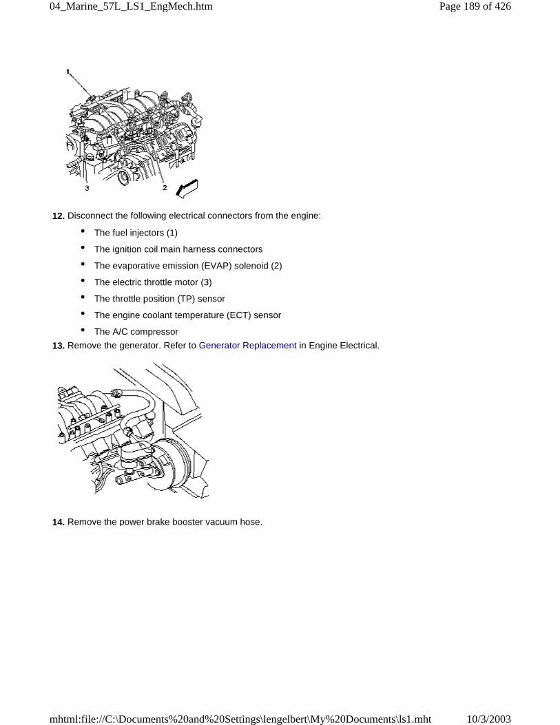
12. Disconnect the following electrical connectors from the engine:
• The fuel injectors (1)
• The ignition coil main harness connectors
• The evaporative emission (EVAP) solenoid (2)
• The electric throttle motor (3)
• The throttle position (TP) sensor
• The engine coolant temperature (ECT) sensor
• The A/C compressor
13. Remove the generator. Refer to Generator Replacement in Engine Electrical.
14. Remove the power brake booster vacuum hose.
Page 189 of 42604_Marine_57L_LS1_EngMech.htm
10/3/2003mhtml:file://C:\Documents%20and%20Settings\lengelbert\My%20Documents\ls1.mht
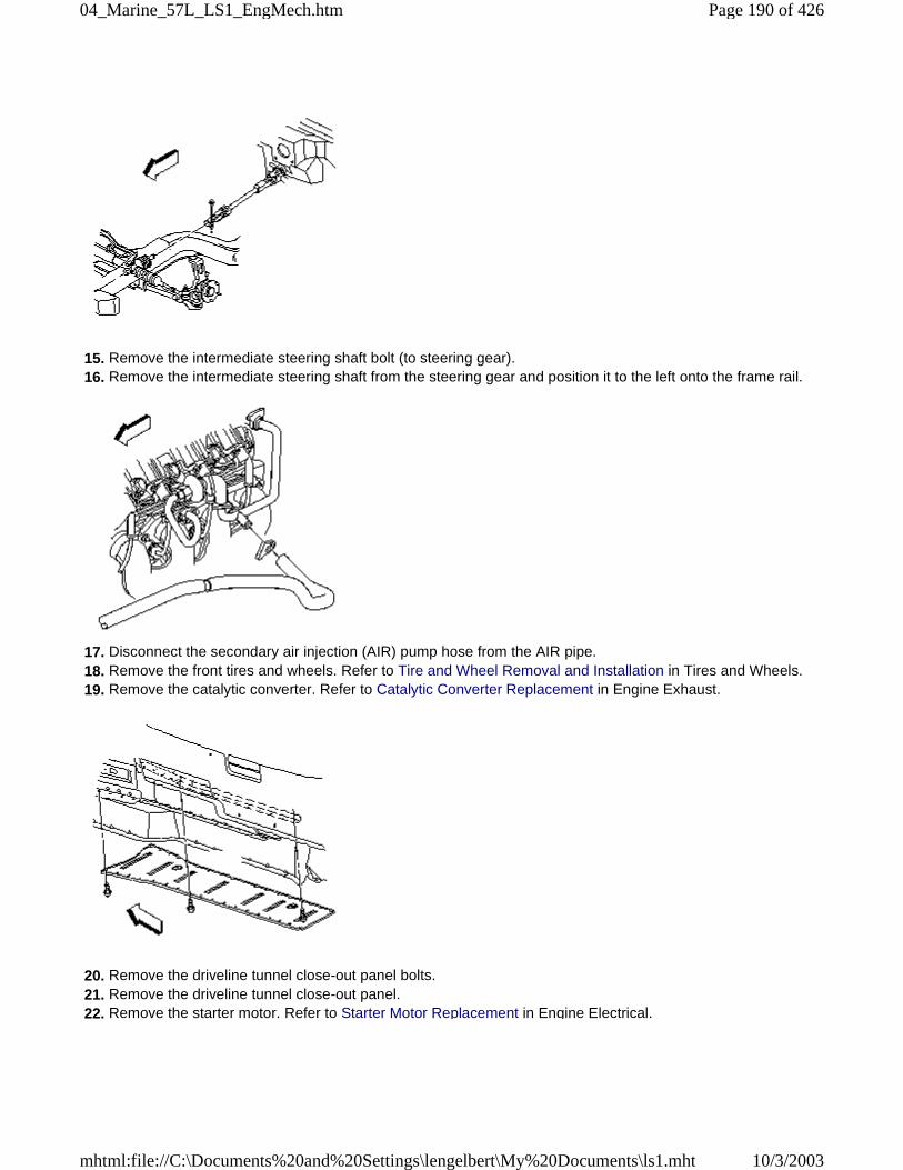
15. Remove the intermediate steering shaft bolt (to steering gear). 16. Remove the intermediate steering shaft from the steering gear and position it to the left onto the frame rail.
17. Disconnect the secondary air injection (AIR) pump hose from the AIR pipe. 18. Remove the front tires and wheels. Refer to Tire and Wheel Removal and Installation in Tires and Wheels. 19. Remove the catalytic converter. Refer to Catalytic Converter Replacement in Engine Exhaust.
20. Remove the driveline tunnel close-out panel bolts. 21. Remove the driveline tunnel close-out panel. 22. Remove the starter motor. Refer to Starter Motor Replacement in Engine Electrical.
Page 190 of 42604_Marine_57L_LS1_EngMech.htm
10/3/2003mhtml:file://C:\Documents%20and%20Settings\lengelbert\My%20Documents\ls1.mht
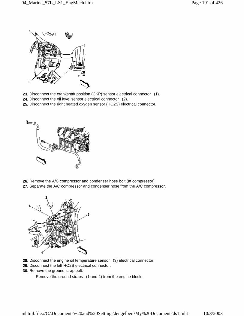
23. Disconnect the crankshaft position (CKP) sensor electrical connector (1). 24. Disconnect the oil level sensor electrical connector (2). 25. Disconnect the right heated oxygen sensor (HO2S) electrical connector.
26. Remove the A/C compressor and condenser hose bolt (at compressor). 27. Separate the A/C compressor and condenser hose from the A/C compressor.
28. Disconnect the engine oil temperature sensor (3) electrical connector. 29. Disconnect the left HO2S electrical connector. 30. Remove the ground strap bolt.
Remove the ground straps (1 and 2) from the engine block.
Page 191 of 42604_Marine_57L_LS1_EngMech.htm
10/3/2003mhtml:file://C:\Documents%20and%20Settings\lengelbert\My%20Documents\ls1.mht
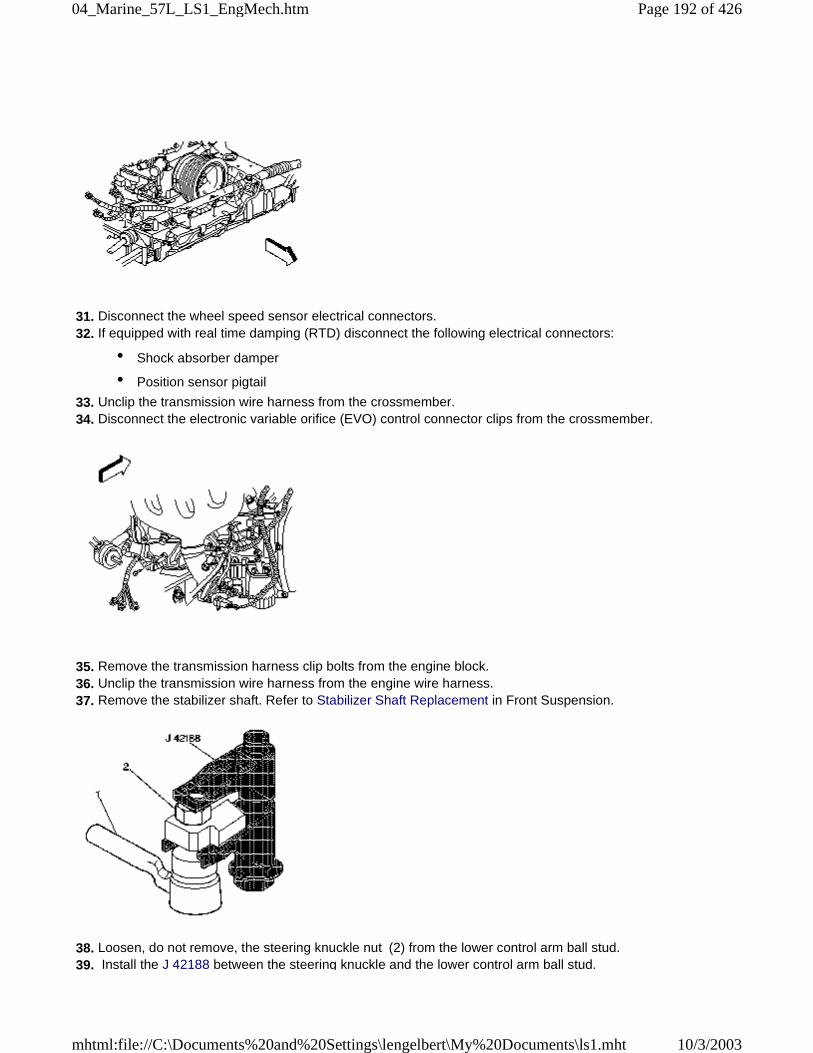
31. Disconnect the wheel speed sensor electrical connectors. 32. If equipped with real time damping (RTD) disconnect the following electrical connectors:
• Shock absorber damper
• Position sensor pigtail
33. Unclip the transmission wire harness from the crossmember. 34. Disconnect the electronic variable orifice (EVO) control connector clips from the crossmember.
35. Remove the transmission harness clip bolts from the engine block. 36. Unclip the transmission wire harness from the engine wire harness. 37. Remove the stabilizer shaft. Refer to Stabilizer Shaft Replacement in Front Suspension.
38. Loosen, do not remove, the steering knuckle nut (2) from the lower control arm ball stud. 39. Install the J 42188 between the steering knuckle and the lower control arm ball stud.
Page 192 of 42604_Marine_57L_LS1_EngMech.htm
10/3/2003mhtml:file://C:\Documents%20and%20Settings\lengelbert\My%20Documents\ls1.mht
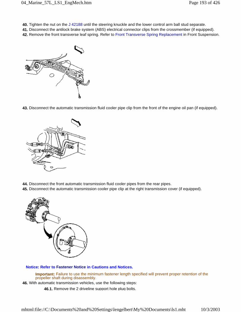
40. Tighten the nut on the J 42188 until the steering knuckle and the lower control arm ball stud separate. 41. Disconnect the antilock brake system (ABS) electrical connector clips from the crossmember (if equipped). 42. Remove the front transverse leaf spring. Refer to Front Transverse Spring Replacement in Front Suspension.
43. Disconnect the automatic transmission fluid cooler pipe clip from the front of the engine oil pan (if equipped).
44. Disconnect the front automatic transmission fluid cooler pipes from the rear pipes. 45. Disconnect the automatic transmission cooler pipe clip at the right transmission cover (if equipped).
Notice: Refer to Fastener Notice in Cautions and Notices.
Important: Failure to use the minimum fastener length specified will prevent proper retention of thepropeller shaft during disassembly.
46. With automatic transmission vehicles, use the following steps:
46.1. Remove the 2 driveline support hole plug bolts.
Page 193 of 42604_Marine_57L_LS1_EngMech.htm
10/3/2003mhtml:file://C:\Documents%20and%20Settings\lengelbert\My%20Documents\ls1.mht
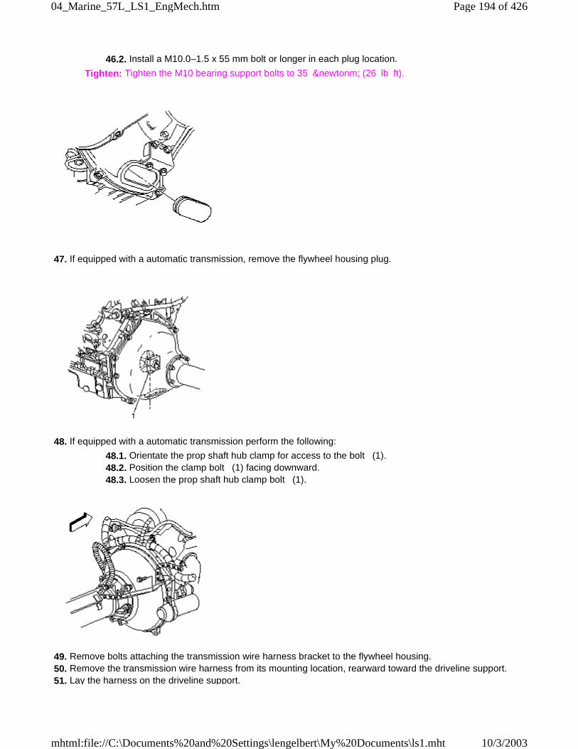
46.2. Install a M10.0–1.5 x 55 mm bolt or longer in each plug location.
Tighten: Tighten the M10 bearing support bolts to 35 &newtonm; (26 lb ft).
47. If equipped with a automatic transmission, remove the flywheel housing plug.
48. If equipped with a automatic transmission perform the following:
48.1. Orientate the prop shaft hub clamp for access to the bolt (1). 48.2. Position the clamp bolt (1) facing downward. 48.3. Loosen the prop shaft hub clamp bolt (1).
49. Remove bolts attaching the transmission wire harness bracket to the flywheel housing. 50. Remove the transmission wire harness from its mounting location, rearward toward the driveline support. 51. Lay the harness on the driveline support.
Page 194 of 42604_Marine_57L_LS1_EngMech.htm
10/3/2003mhtml:file://C:\Documents%20and%20Settings\lengelbert\My%20Documents\ls1.mht
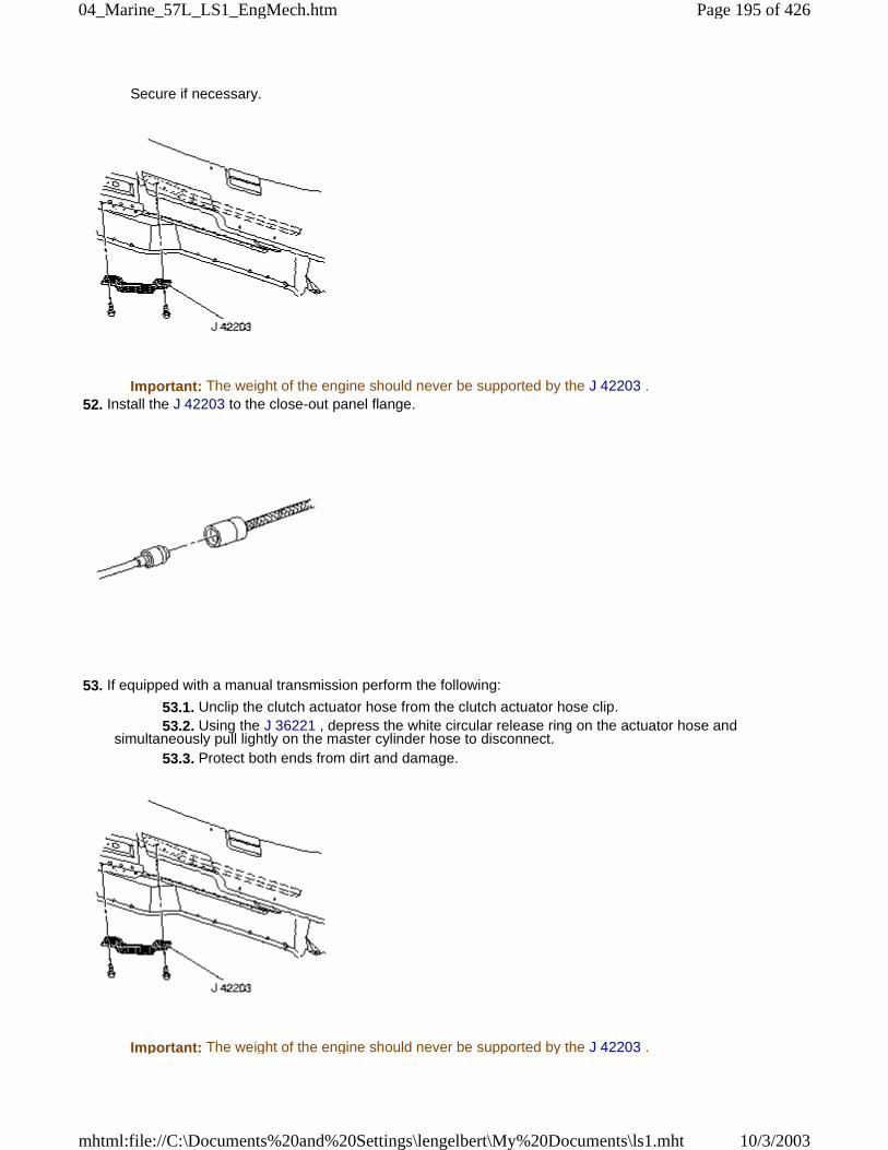
Secure if necessary.
Important: The weight of the engine should never be supported by the J 42203 . 52. Install the J 42203 to the close-out panel flange.
53. If equipped with a manual transmission perform the following:
53.1. Unclip the clutch actuator hose from the clutch actuator hose clip. 53.2. Using the J 36221 , depress the white circular release ring on the actuator hose andsimultaneously pull lightly on the master cylinder hose to disconnect. 53.3. Protect both ends from dirt and damage.
Important: The weight of the engine should never be supported by the J 42203 .
Page 195 of 42604_Marine_57L_LS1_EngMech.htm
10/3/2003mhtml:file://C:\Documents%20and%20Settings\lengelbert\My%20Documents\ls1.mht
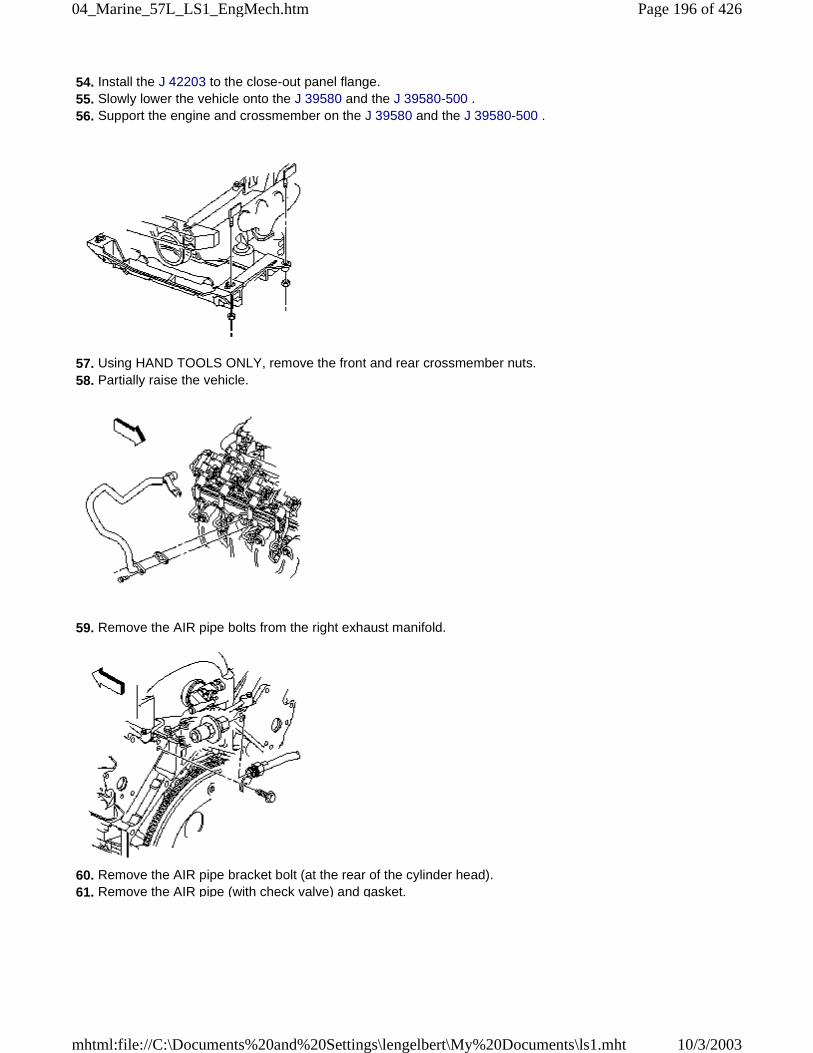
54. Install the J 42203 to the close-out panel flange. 55. Slowly lower the vehicle onto the J 39580 and the J 39580-500 . 56. Support the engine and crossmember on the J 39580 and the J 39580-500 .
57. Using HAND TOOLS ONLY, remove the front and rear crossmember nuts. 58. Partially raise the vehicle.
59. Remove the AIR pipe bolts from the right exhaust manifold.
60. Remove the AIR pipe bracket bolt (at the rear of the cylinder head). 61. Remove the AIR pipe (with check valve) and gasket.
Page 196 of 42604_Marine_57L_LS1_EngMech.htm
10/3/2003mhtml:file://C:\Documents%20and%20Settings\lengelbert\My%20Documents\ls1.mht
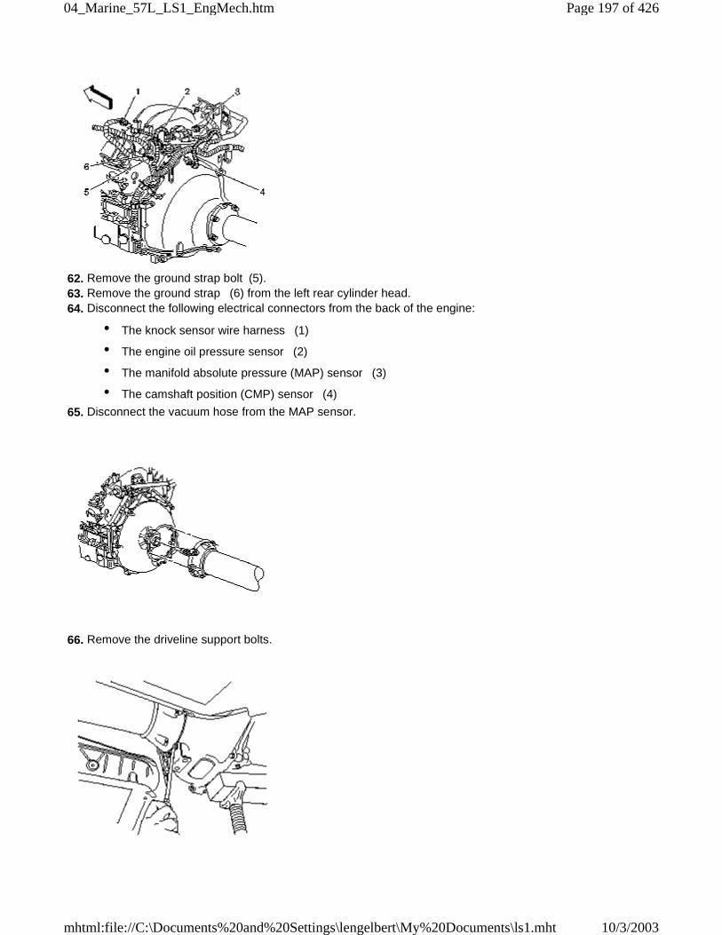
62. Remove the ground strap bolt (5). 63. Remove the ground strap (6) from the left rear cylinder head. 64. Disconnect the following electrical connectors from the back of the engine:
• The knock sensor wire harness (1)
• The engine oil pressure sensor (2)
• The manifold absolute pressure (MAP) sensor (3)
• The camshaft position (CMP) sensor (4)
65. Disconnect the vacuum hose from the MAP sensor.
66. Remove the driveline support bolts.
Page 197 of 42604_Marine_57L_LS1_EngMech.htm
10/3/2003mhtml:file://C:\Documents%20and%20Settings\lengelbert\My%20Documents\ls1.mht
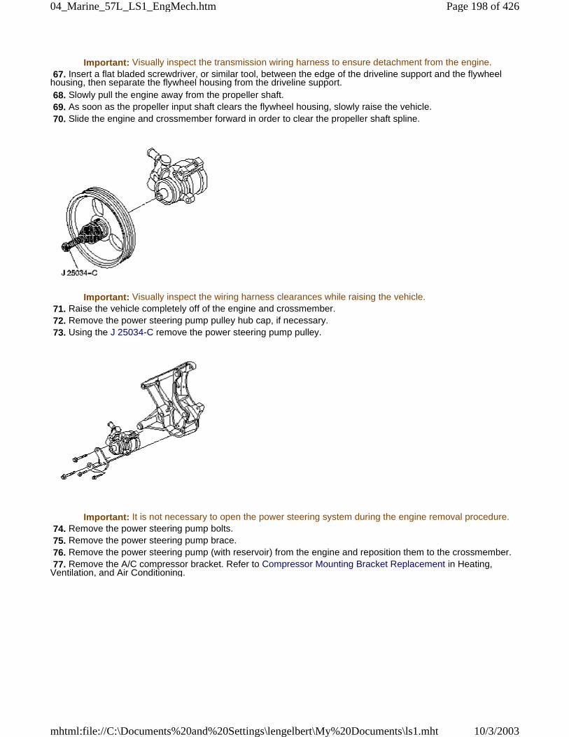
Important: Visually inspect the transmission wiring harness to ensure detachment from the engine. 67. Insert a flat bladed screwdriver, or similar tool, between the edge of the driveline support and the flywheelhousing, then separate the flywheel housing from the driveline support. 68. Slowly pull the engine away from the propeller shaft. 69. As soon as the propeller input shaft clears the flywheel housing, slowly raise the vehicle. 70. Slide the engine and crossmember forward in order to clear the propeller shaft spline.
Important: Visually inspect the wiring harness clearances while raising the vehicle. 71. Raise the vehicle completely off of the engine and crossmember. 72. Remove the power steering pump pulley hub cap, if necessary. 73. Using the J 25034-C remove the power steering pump pulley.
Important: It is not necessary to open the power steering system during the engine removal procedure. 74. Remove the power steering pump bolts. 75. Remove the power steering pump brace. 76. Remove the power steering pump (with reservoir) from the engine and reposition them to the crossmember. 77. Remove the A/C compressor bracket. Refer to Compressor Mounting Bracket Replacement in Heating,Ventilation, and Air Conditioning.
Page 198 of 42604_Marine_57L_LS1_EngMech.htm
10/3/2003mhtml:file://C:\Documents%20and%20Settings\lengelbert\My%20Documents\ls1.mht
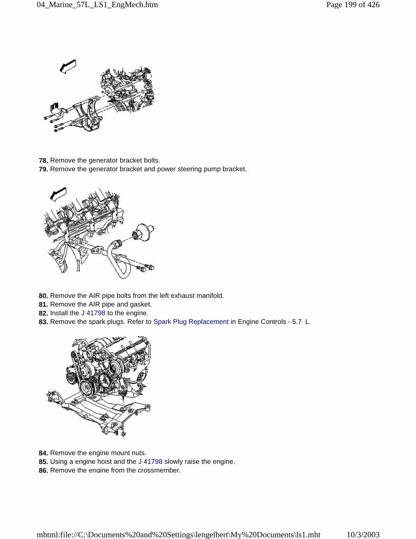
78. Remove the generator bracket bolts. 79. Remove the generator bracket and power steering pump bracket.
80. Remove the AIR pipe bolts from the left exhaust manifold. 81. Remove the AIR pipe and gasket. 82. Install the J 41798 to the engine. 83. Remove the spark plugs. Refer to Spark Plug Replacement in Engine Controls - 5.7 L.
84. Remove the engine mount nuts. 85. Using a engine hoist and the J 41798 slowly raise the engine. 86. Remove the engine from the crossmember.
Page 199 of 42604_Marine_57L_LS1_EngMech.htm
10/3/2003mhtml:file://C:\Documents%20and%20Settings\lengelbert\My%20Documents\ls1.mht
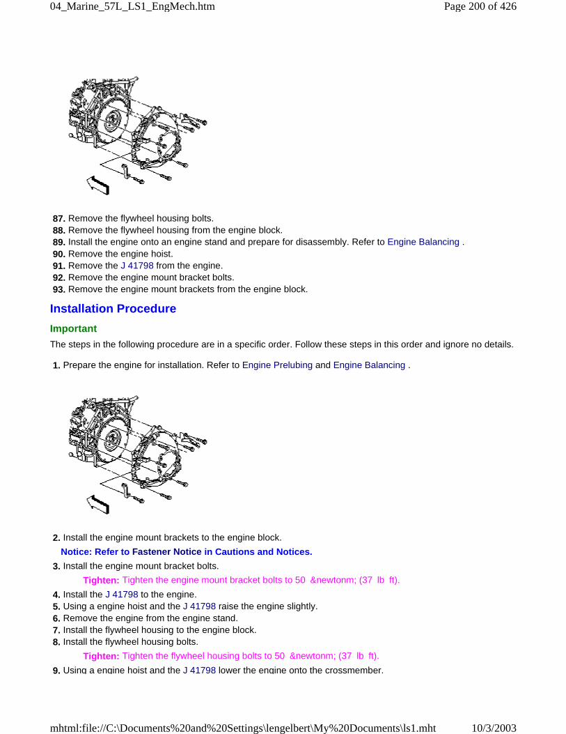
87. Remove the flywheel housing bolts. 88. Remove the flywheel housing from the engine block. 89. Install the engine onto an engine stand and prepare for disassembly. Refer to Engine Balancing . 90. Remove the engine hoist. 91. Remove the J 41798 from the engine. 92. Remove the engine mount bracket bolts. 93. Remove the engine mount brackets from the engine block.
Installation Procedure
Important
The steps in the following procedure are in a specific order. Follow these steps in this order and ignore no details.
1. Prepare the engine for installation. Refer to Engine Prelubing and Engine Balancing .
2. Install the engine mount brackets to the engine block.
Notice: Refer to Fastener Notice in Cautions and Notices.
3. Install the engine mount bracket bolts.
Tighten: Tighten the engine mount bracket bolts to 50 &newtonm; (37 lb ft).
4. Install the J 41798 to the engine. 5. Using a engine hoist and the J 41798 raise the engine slightly. 6. Remove the engine from the engine stand. 7. Install the flywheel housing to the engine block. 8. Install the flywheel housing bolts.
Tighten: Tighten the flywheel housing bolts to 50 &newtonm; (37 lb ft).
9. Using a engine hoist and the J 41798 lower the engine onto the crossmember.
Page 200 of 42604_Marine_57L_LS1_EngMech.htm
10/3/2003mhtml:file://C:\Documents%20and%20Settings\lengelbert\My%20Documents\ls1.mht
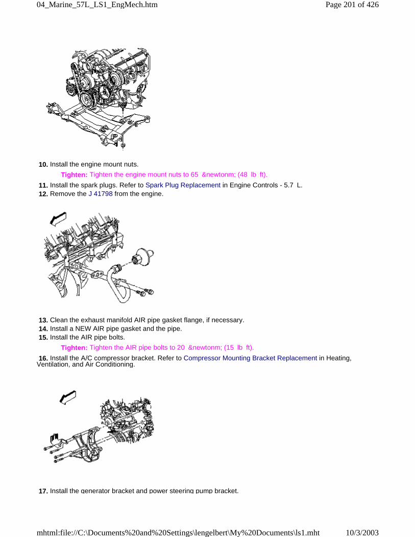
10. Install the engine mount nuts.
Tighten: Tighten the engine mount nuts to 65 &newtonm; (48 lb ft).
11. Install the spark plugs. Refer to Spark Plug Replacement in Engine Controls - 5.7 L. 12. Remove the J 41798 from the engine.
13. Clean the exhaust manifold AIR pipe gasket flange, if necessary. 14. Install a NEW AIR pipe gasket and the pipe. 15. Install the AIR pipe bolts.
Tighten: Tighten the AIR pipe bolts to 20 &newtonm; (15 lb ft).
16. Install the A/C compressor bracket. Refer to Compressor Mounting Bracket Replacement in Heating,Ventilation, and Air Conditioning.
17. Install the generator bracket and power steering pump bracket.
Page 201 of 42604_Marine_57L_LS1_EngMech.htm
10/3/2003mhtml:file://C:\Documents%20and%20Settings\lengelbert\My%20Documents\ls1.mht
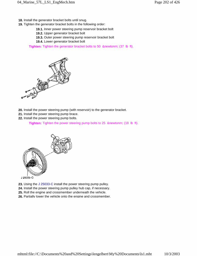
18. Install the generator bracket bolts until snug. 19. Tighten the generator bracket bolts in the following order:
19.1. Inner power steering pump reservoir bracket bolt 19.2. Upper generator bracket bolt 19.3. Outer power steering pump reservoir bracket bolt 19.4. Lower generator bracket bolt
Tighten: Tighten the generator bracket bolts to 50 &newtonm; (37 lb ft).
20. Install the power steering pump (with reservoir) to the generator bracket. 21. Install the power steering pump brace. 22. Install the power steering pump bolts.
Tighten: Tighten the power steering pump bolts to 25 &newtonm; (18 lb ft).
23. Using the J 25033-C install the power steering pump pulley. 24. Install the power steering pump pulley hub cap, if necessary. 25. Roll the engine and crossmember underneath the vehicle. 26. Partially lower the vehicle onto the engine and crossmember.
Page 202 of 42604_Marine_57L_LS1_EngMech.htm
10/3/2003mhtml:file://C:\Documents%20and%20Settings\lengelbert\My%20Documents\ls1.mht
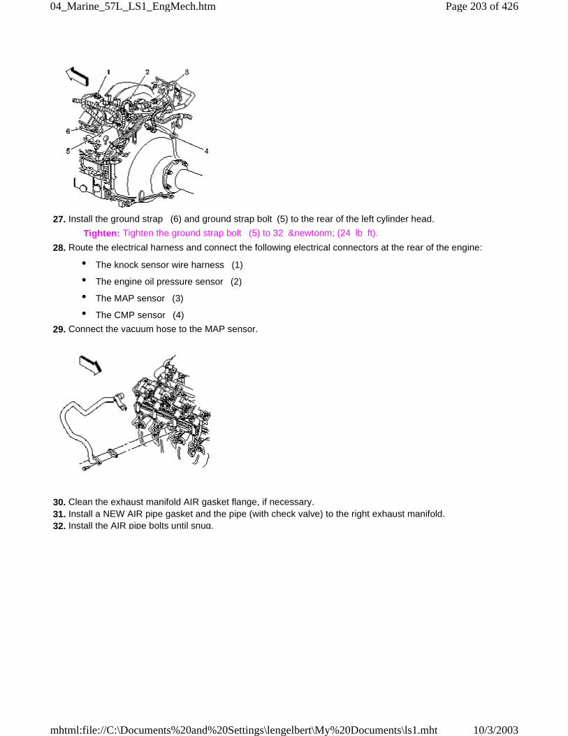
27. Install the ground strap (6) and ground strap bolt (5) to the rear of the left cylinder head.
Tighten: Tighten the ground strap bolt (5) to 32 &newtonm; (24 lb ft).
28. Route the electrical harness and connect the following electrical connectors at the rear of the engine:
• The knock sensor wire harness (1)
• The engine oil pressure sensor (2)
• The MAP sensor (3)
• The CMP sensor (4)
29. Connect the vacuum hose to the MAP sensor.
30. Clean the exhaust manifold AIR gasket flange, if necessary. 31. Install a NEW AIR pipe gasket and the pipe (with check valve) to the right exhaust manifold. 32. Install the AIR pipe bolts until snug.
Page 203 of 42604_Marine_57L_LS1_EngMech.htm
10/3/2003mhtml:file://C:\Documents%20and%20Settings\lengelbert\My%20Documents\ls1.mht
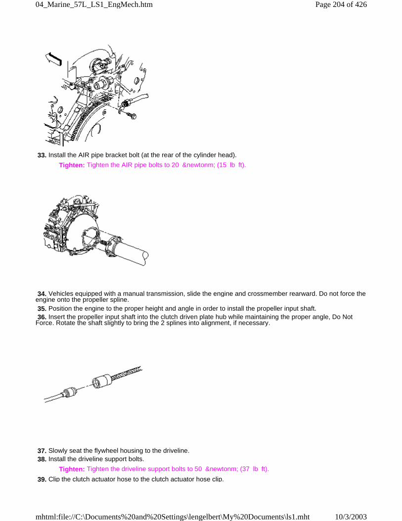
33. Install the AIR pipe bracket bolt (at the rear of the cylinder head).
Tighten: Tighten the AIR pipe bolts to 20 &newtonm; (15 lb ft).
34. Vehicles equipped with a manual transmission, slide the engine and crossmember rearward. Do not force theengine onto the propeller spline. 35. Position the engine to the proper height and angle in order to install the propeller input shaft. 36. Insert the propeller input shaft into the clutch driven plate hub while maintaining the proper angle, Do NotForce. Rotate the shaft slightly to bring the 2 splines into alignment, if necessary.
37. Slowly seat the flywheel housing to the driveline. 38. Install the driveline support bolts.
Tighten: Tighten the driveline support bolts to 50 &newtonm; (37 lb ft).
39. Clip the clutch actuator hose to the clutch actuator hose clip.
Page 204 of 42604_Marine_57L_LS1_EngMech.htm
10/3/2003mhtml:file://C:\Documents%20and%20Settings\lengelbert\My%20Documents\ls1.mht
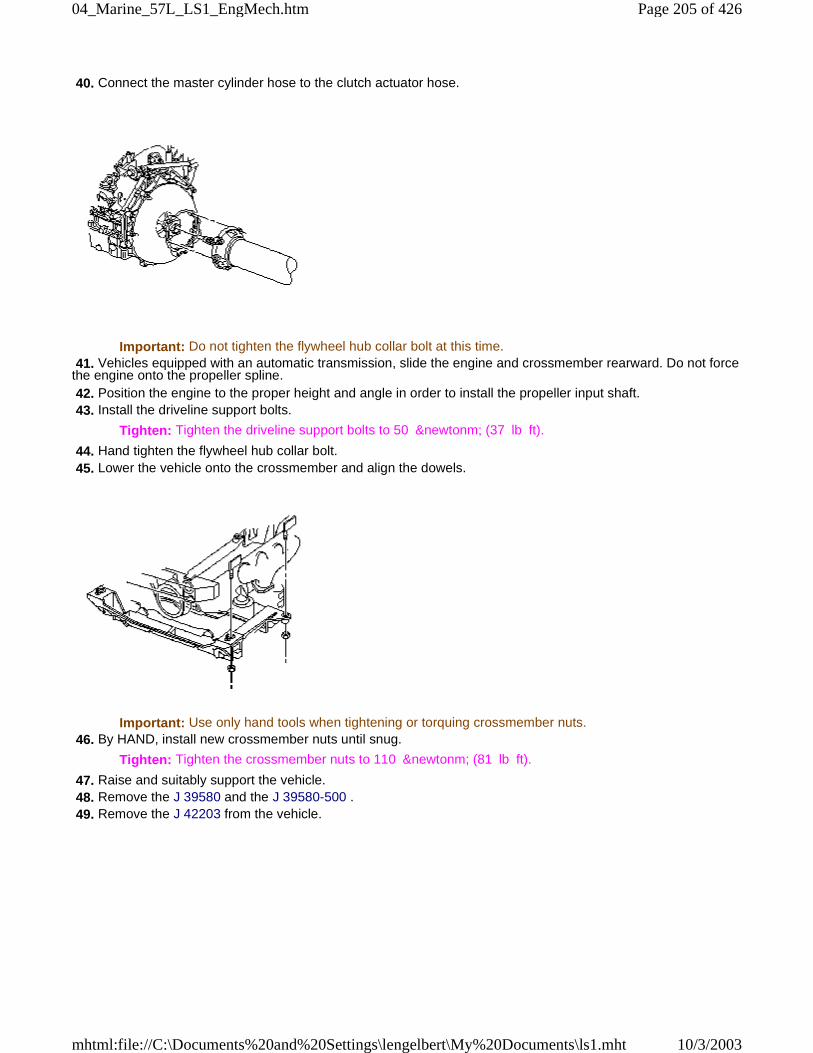
40. Connect the master cylinder hose to the clutch actuator hose.
Important: Do not tighten the flywheel hub collar bolt at this time. 41. Vehicles equipped with an automatic transmission, slide the engine and crossmember rearward. Do not forcethe engine onto the propeller spline. 42. Position the engine to the proper height and angle in order to install the propeller input shaft. 43. Install the driveline support bolts.
Tighten: Tighten the driveline support bolts to 50 &newtonm; (37 lb ft).
44. Hand tighten the flywheel hub collar bolt. 45. Lower the vehicle onto the crossmember and align the dowels.
Important: Use only hand tools when tightening or torquing crossmember nuts. 46. By HAND, install new crossmember nuts until snug.
Tighten: Tighten the crossmember nuts to 110 &newtonm; (81 lb ft).
47. Raise and suitably support the vehicle. 48. Remove the J 39580 and the J 39580-500 . 49. Remove the J 42203 from the vehicle.
Page 205 of 42604_Marine_57L_LS1_EngMech.htm
10/3/2003mhtml:file://C:\Documents%20and%20Settings\lengelbert\My%20Documents\ls1.mht
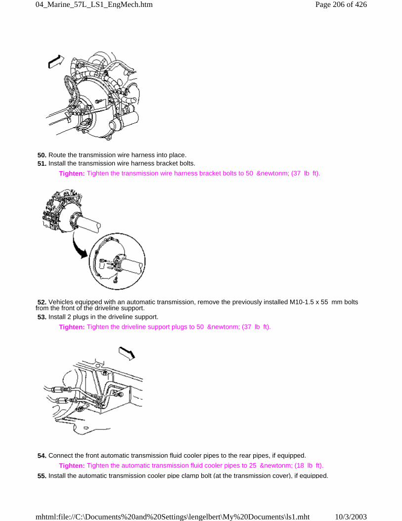
50. Route the transmission wire harness into place. 51. Install the transmission wire harness bracket bolts.
Tighten: Tighten the transmission wire harness bracket bolts to 50 &newtonm; (37 lb ft).
52. Vehicles equipped with an automatic transmission, remove the previously installed M10-1.5 x 55 mm boltsfrom the front of the driveline support. 53. Install 2 plugs in the driveline support.
Tighten: Tighten the driveline support plugs to 50 &newtonm; (37 lb ft).
54. Connect the front automatic transmission fluid cooler pipes to the rear pipes, if equipped.
Tighten: Tighten the automatic transmission fluid cooler pipes to 25 &newtonm; (18 lb ft).
55. Install the automatic transmission cooler pipe clamp bolt (at the transmission cover), if equipped.
Page 206 of 42604_Marine_57L_LS1_EngMech.htm
10/3/2003mhtml:file://C:\Documents%20and%20Settings\lengelbert\My%20Documents\ls1.mht
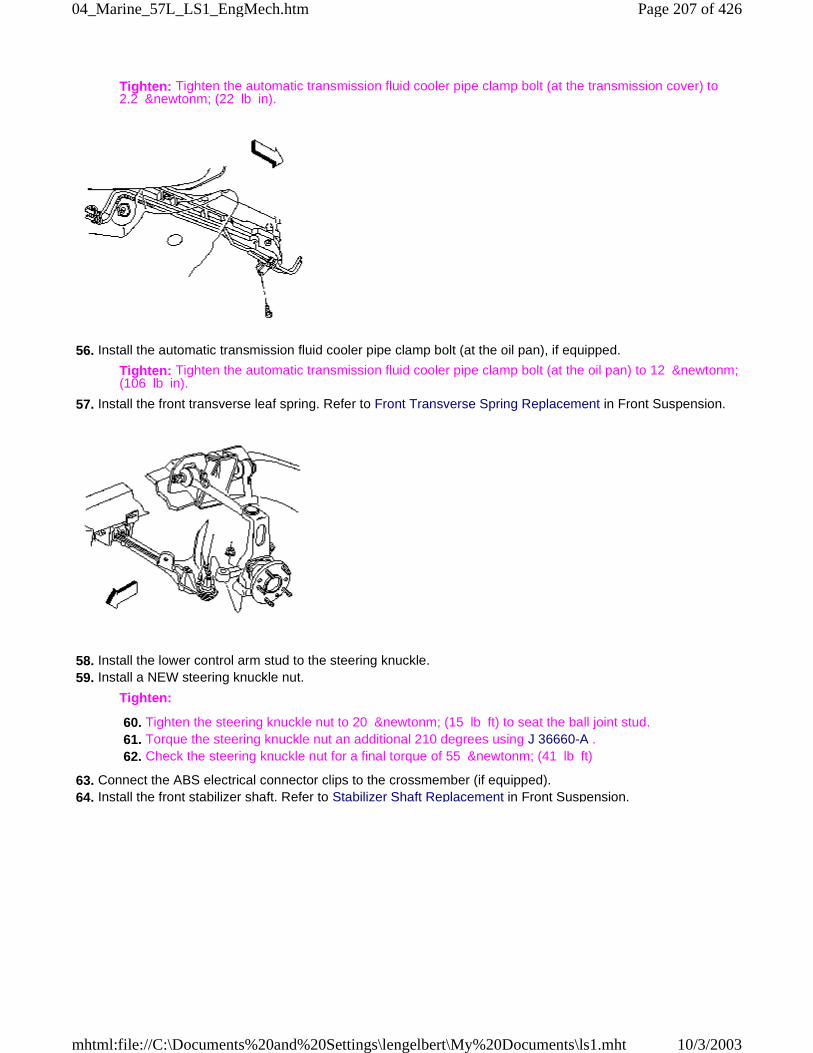
Tighten: Tighten the automatic transmission fluid cooler pipe clamp bolt (at the transmission cover) to2.2 &newtonm; (22 lb in).
56. Install the automatic transmission fluid cooler pipe clamp bolt (at the oil pan), if equipped.
Tighten: Tighten the automatic transmission fluid cooler pipe clamp bolt (at the oil pan) to 12 &newtonm;(106 lb in).
57. Install the front transverse leaf spring. Refer to Front Transverse Spring Replacement in Front Suspension.
58. Install the lower control arm stud to the steering knuckle. 59. Install a NEW steering knuckle nut.
Tighten:
60. Tighten the steering knuckle nut to 20 &newtonm; (15 lb ft) to seat the ball joint stud. 61. Torque the steering knuckle nut an additional 210 degrees using J 36660-A . 62. Check the steering knuckle nut for a final torque of 55 &newtonm; (41 lb ft)
63. Connect the ABS electrical connector clips to the crossmember (if equipped). 64. Install the front stabilizer shaft. Refer to Stabilizer Shaft Replacement in Front Suspension.
Page 207 of 42604_Marine_57L_LS1_EngMech.htm
10/3/2003mhtml:file://C:\Documents%20and%20Settings\lengelbert\My%20Documents\ls1.mht
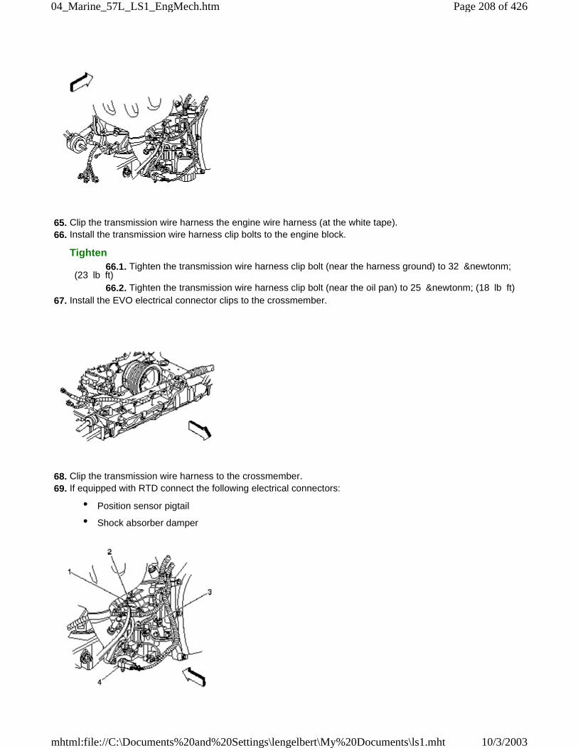
65. Clip the transmission wire harness the engine wire harness (at the white tape). 66. Install the transmission wire harness clip bolts to the engine block.
Tighten 66.1. Tighten the transmission wire harness clip bolt (near the harness ground) to 32 &newtonm;(23 lb ft) 66.2. Tighten the transmission wire harness clip bolt (near the oil pan) to 25 &newtonm; (18 lb ft)
67. Install the EVO electrical connector clips to the crossmember.
68. Clip the transmission wire harness to the crossmember. 69. If equipped with RTD connect the following electrical connectors:
• Position sensor pigtail
• Shock absorber damper
Page 208 of 42604_Marine_57L_LS1_EngMech.htm
10/3/2003mhtml:file://C:\Documents%20and%20Settings\lengelbert\My%20Documents\ls1.mht
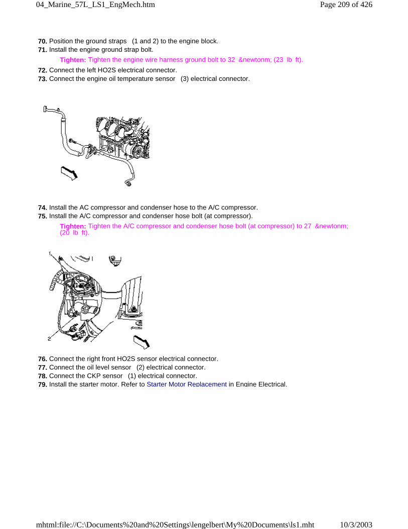
70. Position the ground straps (1 and 2) to the engine block. 71. Install the engine ground strap bolt.
Tighten: Tighten the engine wire harness ground bolt to 32 &newtonm; (23 lb ft).
72. Connect the left HO2S electrical connector. 73. Connect the engine oil temperature sensor (3) electrical connector.
74. Install the AC compressor and condenser hose to the A/C compressor. 75. Install the A/C compressor and condenser hose bolt (at compressor).
Tighten: Tighten the A/C compressor and condenser hose bolt (at compressor) to 27 &newtonm;(20 lb ft).
76. Connect the right front HO2S sensor electrical connector. 77. Connect the oil level sensor (2) electrical connector. 78. Connect the CKP sensor (1) electrical connector. 79. Install the starter motor. Refer to Starter Motor Replacement in Engine Electrical.
Page 209 of 42604_Marine_57L_LS1_EngMech.htm
10/3/2003mhtml:file://C:\Documents%20and%20Settings\lengelbert\My%20Documents\ls1.mht
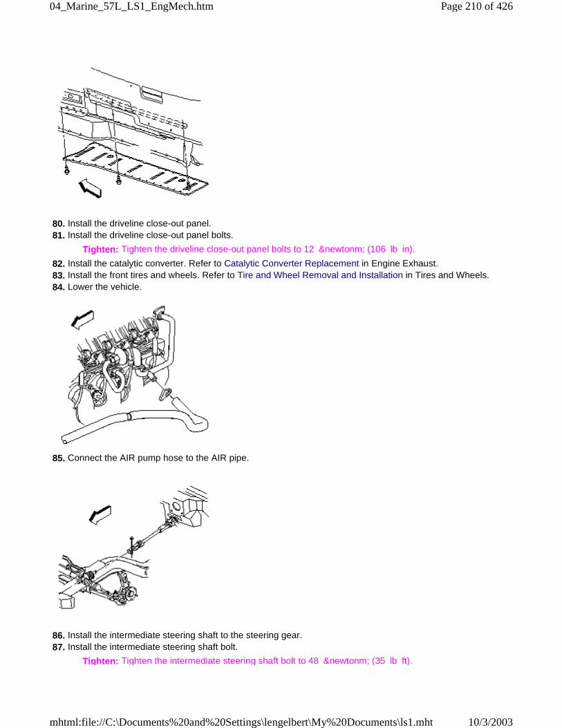
80. Install the driveline close-out panel. 81. Install the driveline close-out panel bolts.
Tighten: Tighten the driveline close-out panel bolts to 12 &newtonm; (106 lb in).
82. Install the catalytic converter. Refer to Catalytic Converter Replacement in Engine Exhaust. 83. Install the front tires and wheels. Refer to Tire and Wheel Removal and Installation in Tires and Wheels. 84. Lower the vehicle.
85. Connect the AIR pump hose to the AIR pipe.
86. Install the intermediate steering shaft to the steering gear. 87. Install the intermediate steering shaft bolt.
Tighten: Tighten the intermediate steering shaft bolt to 48 &newtonm; (35 lb ft).
Page 210 of 42604_Marine_57L_LS1_EngMech.htm
10/3/2003mhtml:file://C:\Documents%20and%20Settings\lengelbert\My%20Documents\ls1.mht
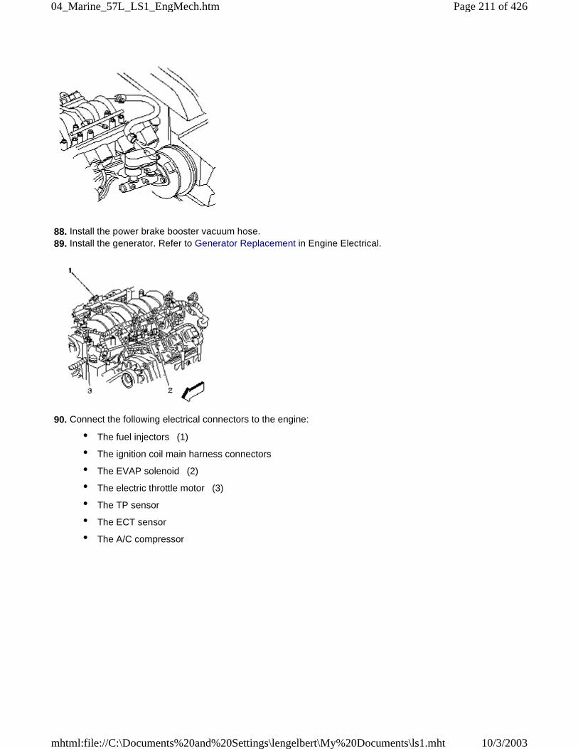
88. Install the power brake booster vacuum hose. 89. Install the generator. Refer to Generator Replacement in Engine Electrical.
90. Connect the following electrical connectors to the engine:
• The fuel injectors (1)
• The ignition coil main harness connectors
• The EVAP solenoid (2)
• The electric throttle motor (3)
• The TP sensor
• The ECT sensor
• The A/C compressor
Page 211 of 42604_Marine_57L_LS1_EngMech.htm
10/3/2003mhtml:file://C:\Documents%20and%20Settings\lengelbert\My%20Documents\ls1.mht
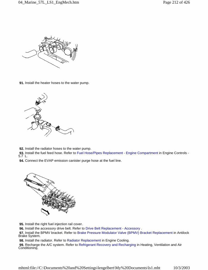
91. Install the heater hoses to the water pump.
92. Install the radiator hoses to the water pump. 93. Install the fuel feed hose. Refer to Fuel Hose/Pipes Replacement - Engine Compartment in Engine Controls -5.7 L. 94. Connect the EVAP emission canister purge hose at the fuel line.
95. Install the right fuel injection rail cover. 96. Install the accessory drive belt. Refer to Drive Belt Replacement - Accessory . 97. Install the BPMV bracket. Refer to Brake Pressure Modulator Valve (BPMV) Bracket Replacement in AntilockBrake System. 98. Install the radiator. Refer to Radiator Replacement in Engine Cooling. 99. Recharge the A/C system. Refer to Refrigerant Recovery and Recharging in Heating, Ventilation and AirConditioning.
Page 212 of 42604_Marine_57L_LS1_EngMech.htm
10/3/2003mhtml:file://C:\Documents%20and%20Settings\lengelbert\My%20Documents\ls1.mht
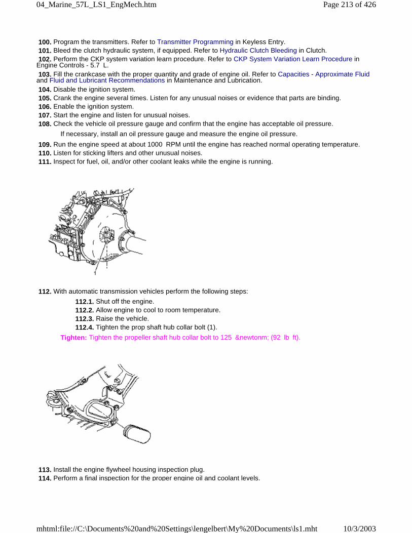
100. Program the transmitters. Refer to Transmitter Programming in Keyless Entry. 101. Bleed the clutch hydraulic system, if equipped. Refer to Hydraulic Clutch Bleeding in Clutch. 102. Perform the CKP system variation learn procedure. Refer to CKP System Variation Learn Procedure inEngine Controls - 5.7 L. 103. Fill the crankcase with the proper quantity and grade of engine oil. Refer to Capacities - Approximate Fluidand Fluid and Lubricant Recommendations in Maintenance and Lubrication. 104. Disable the ignition system. 105. Crank the engine several times. Listen for any unusual noises or evidence that parts are binding. 106. Enable the ignition system. 107. Start the engine and listen for unusual noises. 108. Check the vehicle oil pressure gauge and confirm that the engine has acceptable oil pressure.
If necessary, install an oil pressure gauge and measure the engine oil pressure.
109. Run the engine speed at about 1000 RPM until the engine has reached normal operating temperature. 110. Listen for sticking lifters and other unusual noises. 111. Inspect for fuel, oil, and/or other coolant leaks while the engine is running.
112. With automatic transmission vehicles perform the following steps:
112.1. Shut off the engine. 112.2. Allow engine to cool to room temperature. 112.3. Raise the vehicle. 112.4. Tighten the prop shaft hub collar bolt (1).
Tighten: Tighten the propeller shaft hub collar bolt to 125 &newtonm; (92 lb ft).
113. Install the engine flywheel housing inspection plug. 114. Perform a final inspection for the proper engine oil and coolant levels.
Page 213 of 42604_Marine_57L_LS1_EngMech.htm
10/3/2003mhtml:file://C:\Documents%20and%20Settings\lengelbert\My%20Documents\ls1.mht
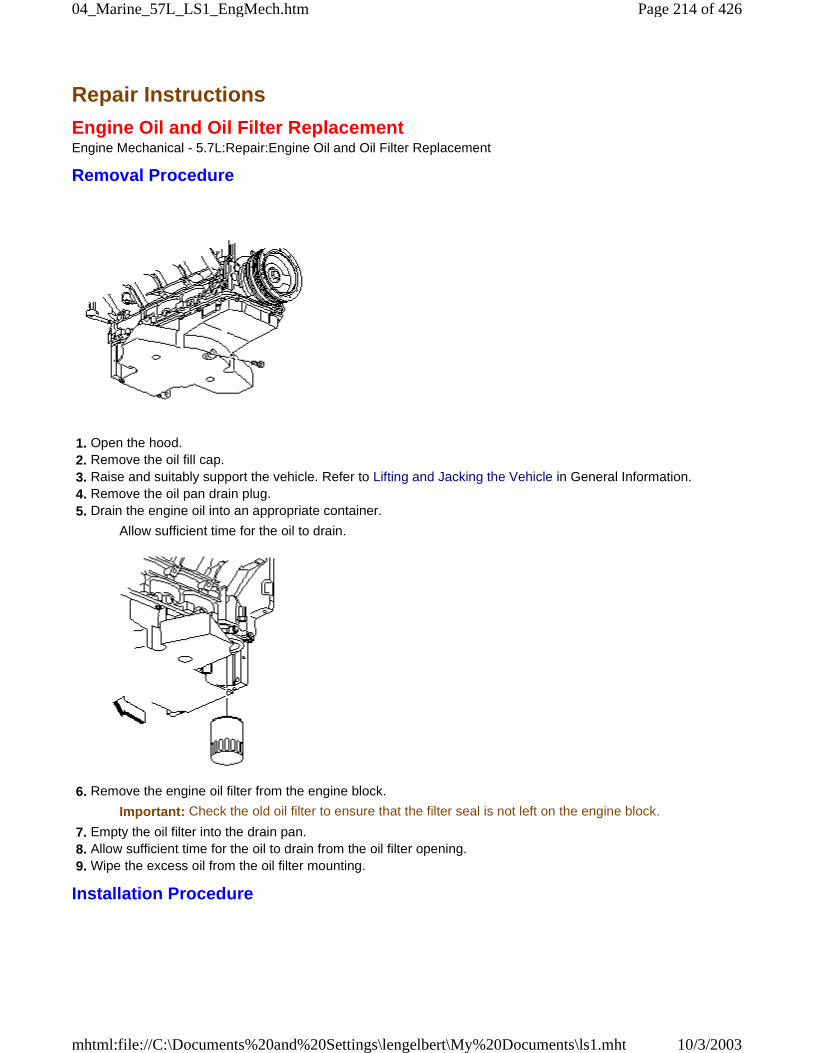
Repair Instructions
Engine Oil and Oil Filter ReplacementEngine Mechanical - 5.7L:Repair:Engine Oil and Oil Filter Replacement
Removal Procedure
1. Open the hood. 2. Remove the oil fill cap. 3. Raise and suitably support the vehicle. Refer to Lifting and Jacking the Vehicle in General Information. 4. Remove the oil pan drain plug. 5. Drain the engine oil into an appropriate container.
Allow sufficient time for the oil to drain.
6. Remove the engine oil filter from the engine block.
Important: Check the old oil filter to ensure that the filter seal is not left on the engine block.
7. Empty the oil filter into the drain pan. 8. Allow sufficient time for the oil to drain from the oil filter opening. 9. Wipe the excess oil from the oil filter mounting.
Installation Procedure
Page 214 of 42604_Marine_57L_LS1_EngMech.htm
10/3/2003mhtml:file://C:\Documents%20and%20Settings\lengelbert\My%20Documents\ls1.mht
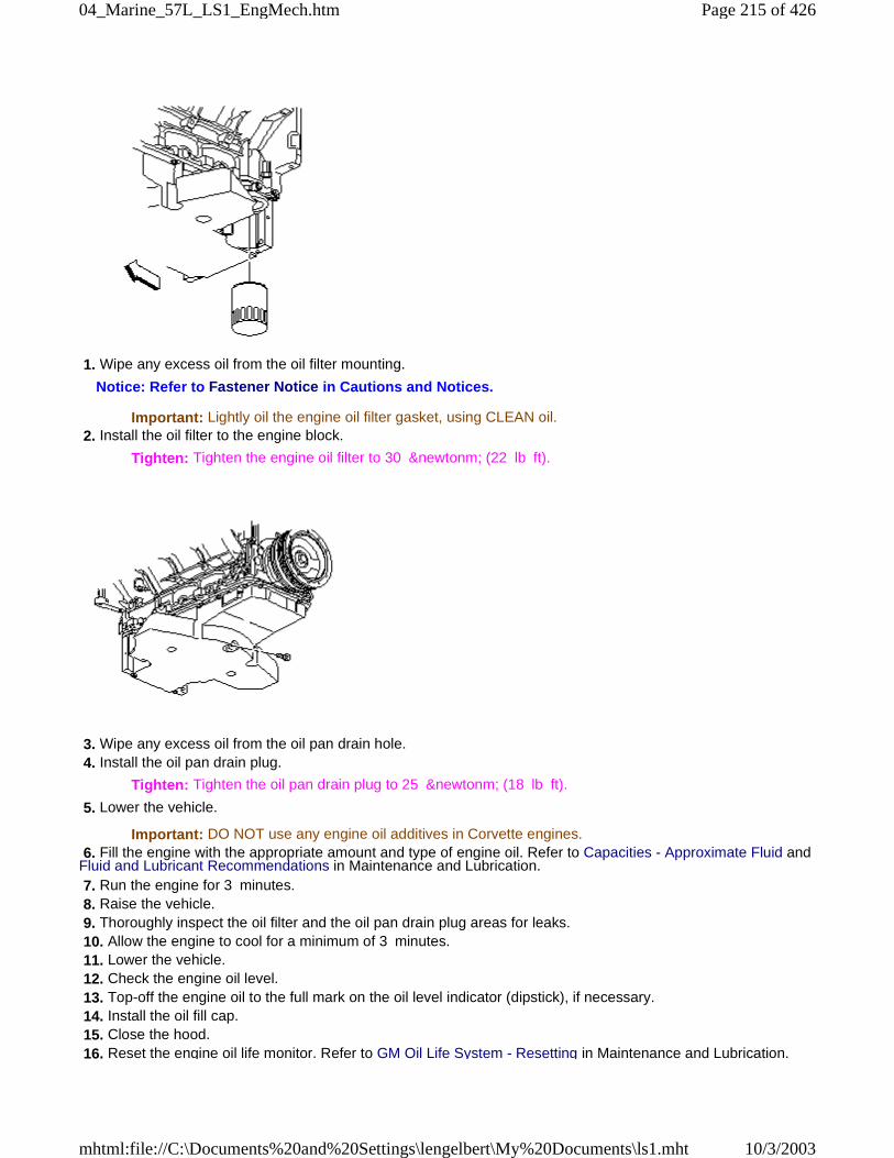
1. Wipe any excess oil from the oil filter mounting.
Notice: Refer to Fastener Notice in Cautions and Notices.
Important: Lightly oil the engine oil filter gasket, using CLEAN oil. 2. Install the oil filter to the engine block.
Tighten: Tighten the engine oil filter to 30 &newtonm; (22 lb ft).
3. Wipe any excess oil from the oil pan drain hole. 4. Install the oil pan drain plug.
Tighten: Tighten the oil pan drain plug to 25 &newtonm; (18 lb ft).
5. Lower the vehicle.
Important: DO NOT use any engine oil additives in Corvette engines. 6. Fill the engine with the appropriate amount and type of engine oil. Refer to Capacities - Approximate Fluid andFluid and Lubricant Recommendations in Maintenance and Lubrication. 7. Run the engine for 3 minutes. 8. Raise the vehicle. 9. Thoroughly inspect the oil filter and the oil pan drain plug areas for leaks. 10. Allow the engine to cool for a minimum of 3 minutes. 11. Lower the vehicle. 12. Check the engine oil level. 13. Top-off the engine oil to the full mark on the oil level indicator (dipstick), if necessary. 14. Install the oil fill cap. 15. Close the hood. 16. Reset the engine oil life monitor. Refer to GM Oil Life System - Resetting in Maintenance and Lubrication.
Page 215 of 42604_Marine_57L_LS1_EngMech.htm
10/3/2003mhtml:file://C:\Documents%20and%20Settings\lengelbert\My%20Documents\ls1.mht
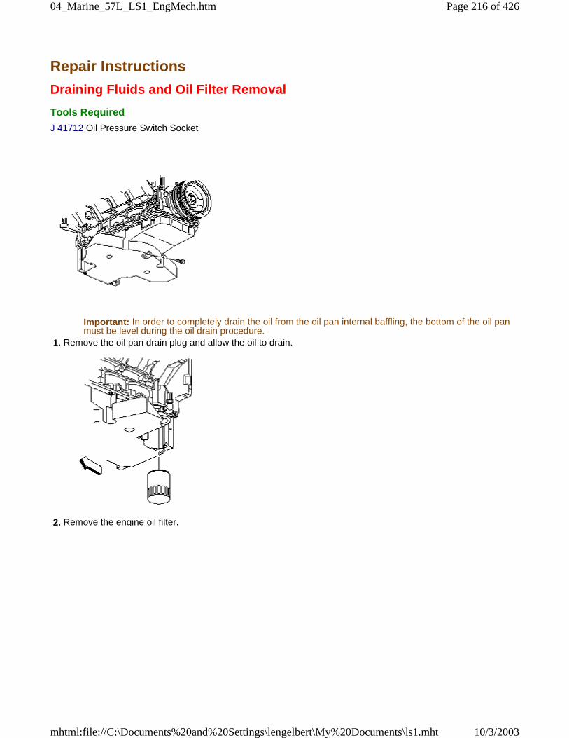
Repair Instructions
Draining Fluids and Oil Filter Removal
Tools Required
J 41712 Oil Pressure Switch Socket
Important: In order to completely drain the oil from the oil pan internal baffling, the bottom of the oil panmust be level during the oil drain procedure.
1. Remove the oil pan drain plug and allow the oil to drain.
2. Remove the engine oil filter.
Page 216 of 42604_Marine_57L_LS1_EngMech.htm
10/3/2003mhtml:file://C:\Documents%20and%20Settings\lengelbert\My%20Documents\ls1.mht
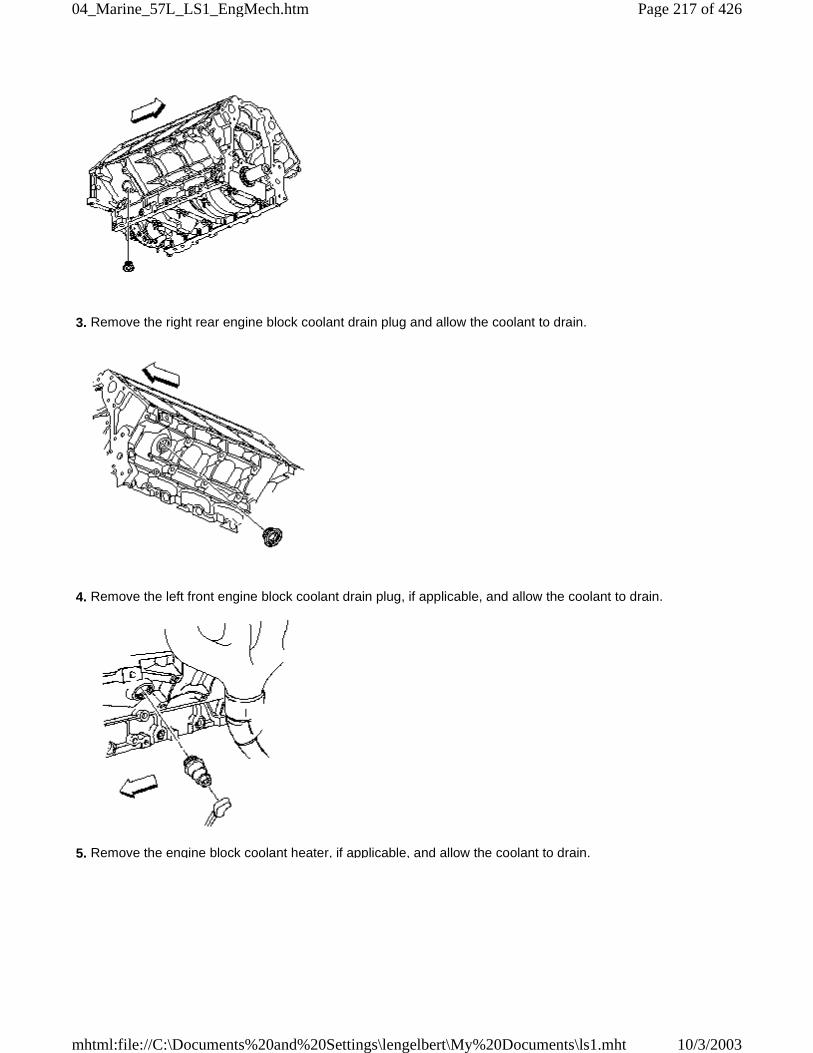
3. Remove the right rear engine block coolant drain plug and allow the coolant to drain.
4. Remove the left front engine block coolant drain plug, if applicable, and allow the coolant to drain.
5. Remove the engine block coolant heater, if applicable, and allow the coolant to drain.
Page 217 of 42604_Marine_57L_LS1_EngMech.htm
10/3/2003mhtml:file://C:\Documents%20and%20Settings\lengelbert\My%20Documents\ls1.mht
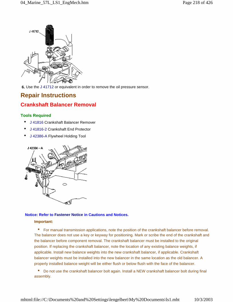
6. Use the J 41712 or equivalent in order to remove the oil pressure sensor.
Repair Instructions
Crankshaft Balancer Removal
Tools Required
• J 41816 Crankshaft Balancer Remover
• J 41816-2 Crankshaft End Protector
• J 42386-A Flywheel Holding Tool
Notice: Refer to Fastener Notice in Cautions and Notices.
Important:
• For manual transmission applications, note the position of the crankshaft balancer before removal.The balancer does not use a key or keyway for positioning. Mark or scribe the end of the crankshaft and
the balancer before component removal. The crankshaft balancer must be installed to the original
position. If replacing the crankshaft balancer, note the location of any existing balance weights, if
applicable. Install new balance weights into the new crankshaft balancer, if applicable. Crankshaft
balancer weights must be installed into the new balancer in the same location as the old balancer. A
properly installed balance weight will be either flush or below flush with the face of the balancer.
• Do not use the crankshaft balancer bolt again. Install a NEW crankshaft balancer bolt during finalassembly.
Page 218 of 42604_Marine_57L_LS1_EngMech.htm
10/3/2003mhtml:file://C:\Documents%20and%20Settings\lengelbert\My%20Documents\ls1.mht
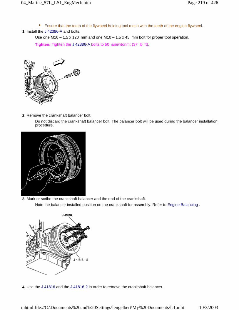
• Ensure that the teeth of the flywheel holding tool mesh with the teeth of the engine flywheel.
1. Install the J 42386-A and bolts.
Use one M10 – 1.5 x 120 mm and one M10 – 1.5 x 45 mm bolt for proper tool operation.
Tighten: Tighten the J 42386-A bolts to 50 &newtonm; (37 lb ft).
2. Remove the crankshaft balancer bolt.
Do not discard the crankshaft balancer bolt. The balancer bolt will be used during the balancer installationprocedure.
3. Mark or scribe the crankshaft balancer and the end of the crankshaft.
Note the balancer installed position on the crankshaft for assembly. Refer to Engine Balancing .
4. Use the J 41816 and the J 41816-2 in order to remove the crankshaft balancer.
Page 219 of 42604_Marine_57L_LS1_EngMech.htm
10/3/2003mhtml:file://C:\Documents%20and%20Settings\lengelbert\My%20Documents\ls1.mht
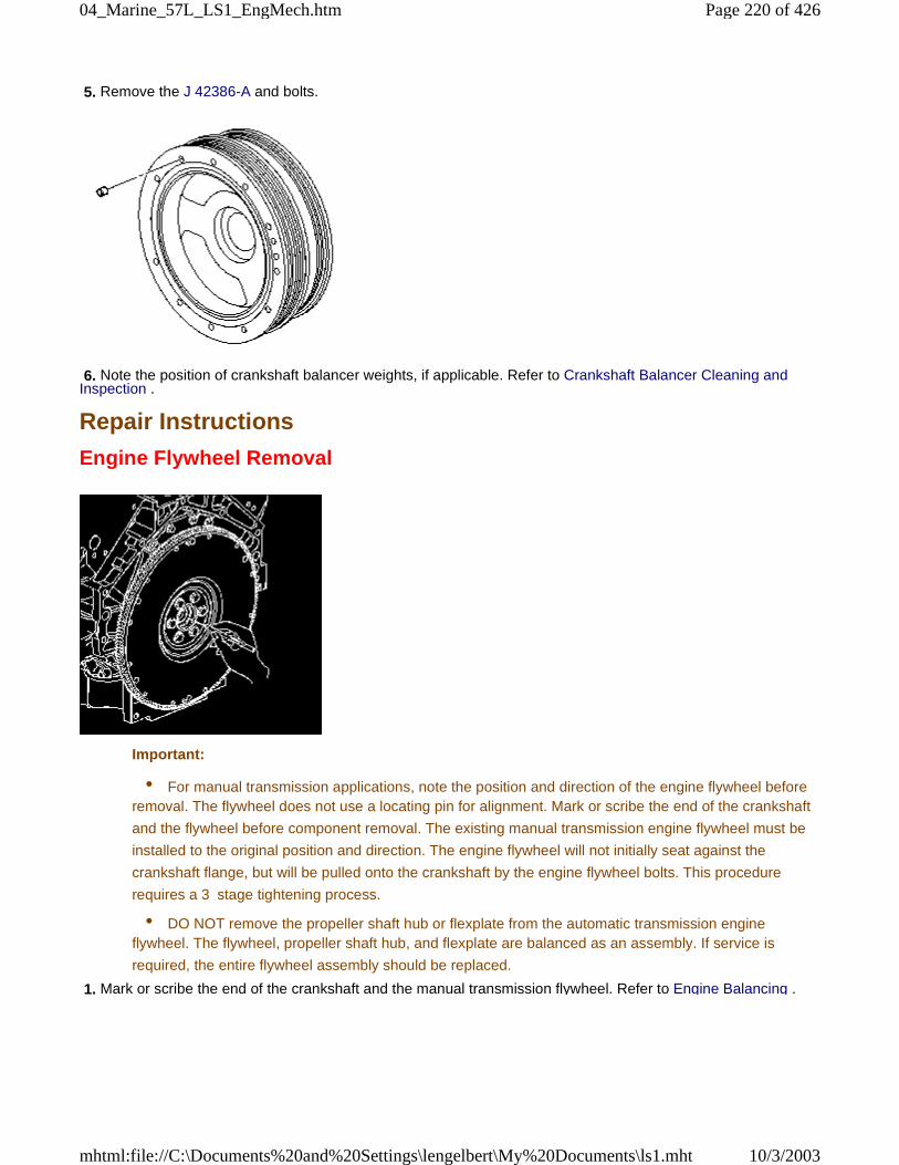
5. Remove the J 42386-A and bolts.
6. Note the position of crankshaft balancer weights, if applicable. Refer to Crankshaft Balancer Cleaning andInspection .
Repair Instructions
Engine Flywheel Removal
Important:
• For manual transmission applications, note the position and direction of the engine flywheel beforeremoval. The flywheel does not use a locating pin for alignment. Mark or scribe the end of the crankshaft
and the flywheel before component removal. The existing manual transmission engine flywheel must be
installed to the original position and direction. The engine flywheel will not initially seat against the
crankshaft flange, but will be pulled onto the crankshaft by the engine flywheel bolts. This procedure
requires a 3 stage tightening process.
• DO NOT remove the propeller shaft hub or flexplate from the automatic transmission engineflywheel. The flywheel, propeller shaft hub, and flexplate are balanced as an assembly. If service is
required, the entire flywheel assembly should be replaced.
1. Mark or scribe the end of the crankshaft and the manual transmission flywheel. Refer to Engine Balancing .
Page 220 of 42604_Marine_57L_LS1_EngMech.htm
10/3/2003mhtml:file://C:\Documents%20and%20Settings\lengelbert\My%20Documents\ls1.mht
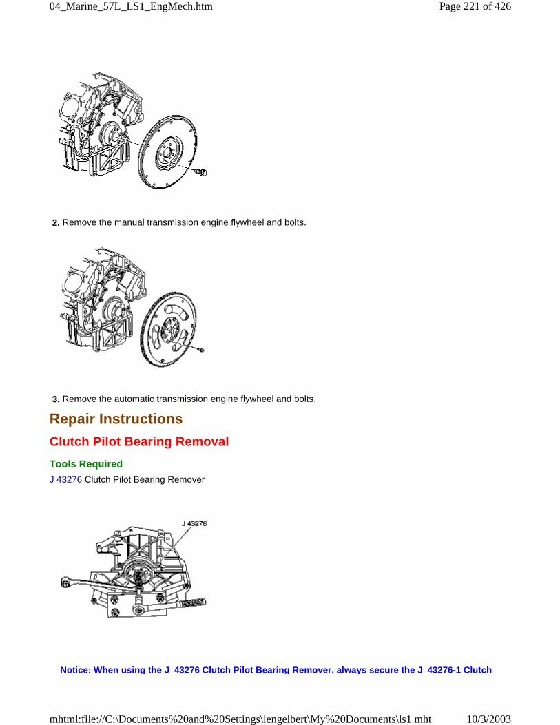
2. Remove the manual transmission engine flywheel and bolts.
3. Remove the automatic transmission engine flywheel and bolts.
Repair Instructions
Clutch Pilot Bearing Removal
Tools Required
J 43276 Clutch Pilot Bearing Remover
Notice: When using the J 43276 Clutch Pilot Bearing Remover, always secure the J 43276-1 Clutch
Page 221 of 42604_Marine_57L_LS1_EngMech.htm
10/3/2003mhtml:file://C:\Documents%20and%20Settings\lengelbert\My%20Documents\ls1.mht
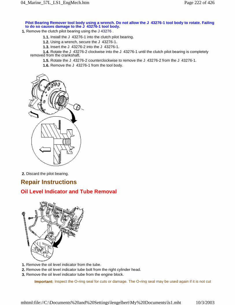
Pilot Bearing Remover tool body using a wrench. Do not allow the J 43276-1 tool body to rotate. Failingto do so causes damage to the J 43276-1 tool body.
1. Remove the clutch pilot bearing using the J 43276 .
1.1. Install the J 43276-1 into the clutch pilot bearing. 1.2. Using a wrench, secure the J 43276-1. 1.3. Insert the J 43276-2 into the J 43276-1. 1.4. Rotate the J 43276-2 clockwise into the J 43276-1 until the clutch pilot bearing is completelyremoved from the crankshaft. 1.5. Rotate the J 43276-2 counterclockwise to remove the J 43276-2 from the J 43276-1. 1.6. Remove the J 43276-1 from the tool body.
2. Discard the pilot bearing.
Repair Instructions
Oil Level Indicator and Tube Removal
1. Remove the oil level indicator from the tube. 2. Remove the oil level indicator tube bolt from the right cylinder head. 3. Remove the oil level indicator tube from the engine block.
Important: Inspect the O-ring seal for cuts or damage. The O-ring seal may be used again if it is not cut
Page 222 of 42604_Marine_57L_LS1_EngMech.htm
10/3/2003mhtml:file://C:\Documents%20and%20Settings\lengelbert\My%20Documents\ls1.mht
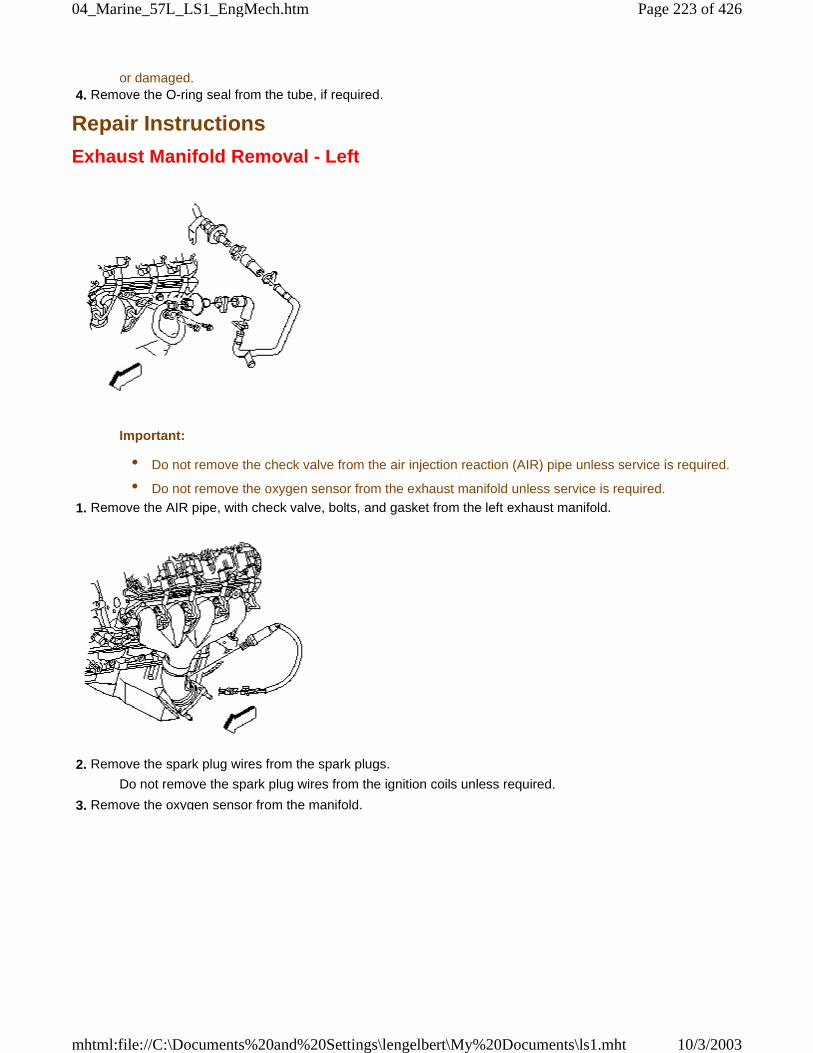
or damaged. 4. Remove the O-ring seal from the tube, if required.
Repair Instructions
Exhaust Manifold Removal - Left
Important:
• Do not remove the check valve from the air injection reaction (AIR) pipe unless service is required.
• Do not remove the oxygen sensor from the exhaust manifold unless service is required.
1. Remove the AIR pipe, with check valve, bolts, and gasket from the left exhaust manifold.
2. Remove the spark plug wires from the spark plugs.
Do not remove the spark plug wires from the ignition coils unless required.
3. Remove the oxygen sensor from the manifold.
Page 223 of 42604_Marine_57L_LS1_EngMech.htm
10/3/2003mhtml:file://C:\Documents%20and%20Settings\lengelbert\My%20Documents\ls1.mht
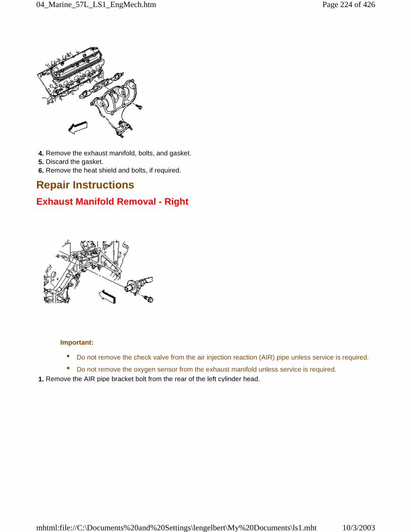
4. Remove the exhaust manifold, bolts, and gasket. 5. Discard the gasket. 6. Remove the heat shield and bolts, if required.
Repair Instructions
Exhaust Manifold Removal - Right
Important:
• Do not remove the check valve from the air injection reaction (AIR) pipe unless service is required.
• Do not remove the oxygen sensor from the exhaust manifold unless service is required.
1. Remove the AIR pipe bracket bolt from the rear of the left cylinder head.
Page 224 of 42604_Marine_57L_LS1_EngMech.htm
10/3/2003mhtml:file://C:\Documents%20and%20Settings\lengelbert\My%20Documents\ls1.mht
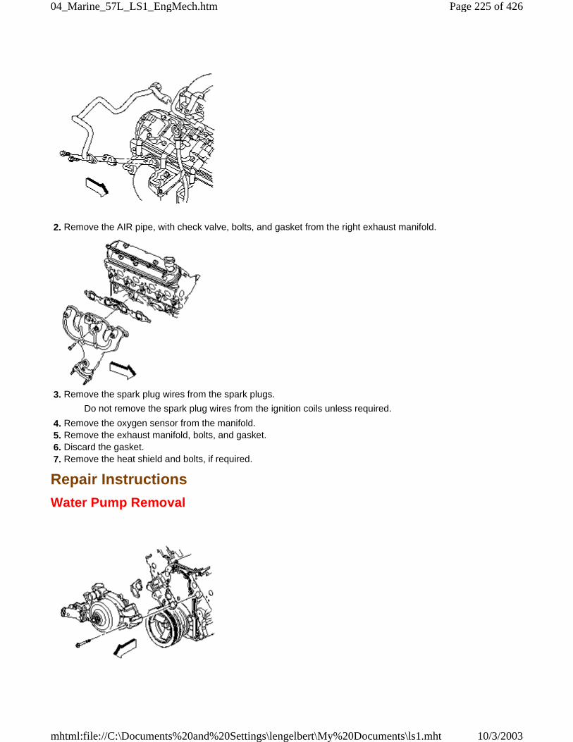
2. Remove the AIR pipe, with check valve, bolts, and gasket from the right exhaust manifold.
3. Remove the spark plug wires from the spark plugs.
Do not remove the spark plug wires from the ignition coils unless required.
4. Remove the oxygen sensor from the manifold. 5. Remove the exhaust manifold, bolts, and gasket. 6. Discard the gasket. 7. Remove the heat shield and bolts, if required.
Repair Instructions
Water Pump Removal
Page 225 of 42604_Marine_57L_LS1_EngMech.htm
10/3/2003mhtml:file://C:\Documents%20and%20Settings\lengelbert\My%20Documents\ls1.mht
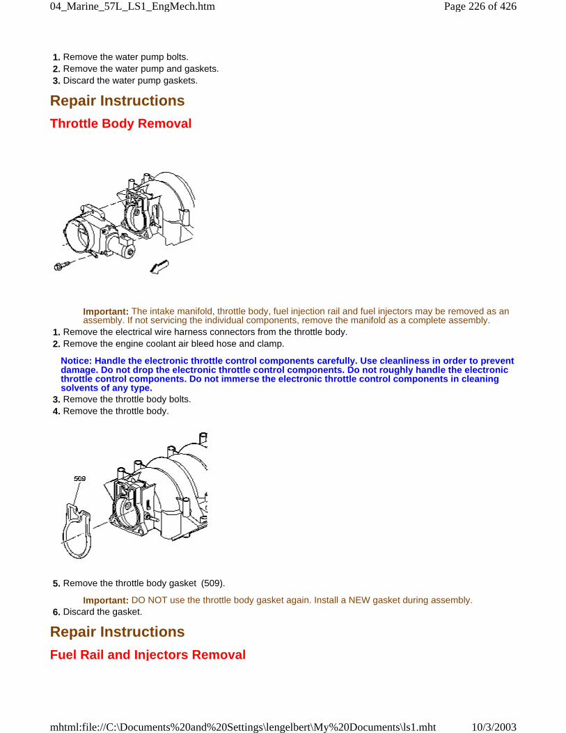
1. Remove the water pump bolts. 2. Remove the water pump and gaskets. 3. Discard the water pump gaskets.
Repair Instructions
Throttle Body Removal
Important: The intake manifold, throttle body, fuel injection rail and fuel injectors may be removed as anassembly. If not servicing the individual components, remove the manifold as a complete assembly.
1. Remove the electrical wire harness connectors from the throttle body. 2. Remove the engine coolant air bleed hose and clamp.
Notice: Handle the electronic throttle control components carefully. Use cleanliness in order to preventdamage. Do not drop the electronic throttle control components. Do not roughly handle the electronicthrottle control components. Do not immerse the electronic throttle control components in cleaningsolvents of any type.
3. Remove the throttle body bolts. 4. Remove the throttle body.
5. Remove the throttle body gasket (509).
Important: DO NOT use the throttle body gasket again. Install a NEW gasket during assembly. 6. Discard the gasket.
Repair Instructions
Fuel Rail and Injectors Removal
Page 226 of 42604_Marine_57L_LS1_EngMech.htm
10/3/2003mhtml:file://C:\Documents%20and%20Settings\lengelbert\My%20Documents\ls1.mht
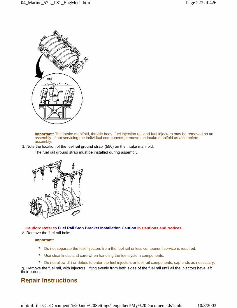
Important: The intake manifold, throttle body, fuel injection rail and fuel injectors may be removed as anassembly. If not servicing the individual components, remove the intake manifold as a completeassembly.
1. Note the location of the fuel rail ground strap (550) on the intake manifold.
The fuel rail ground strap must be installed during assembly.
Caution: Refer to Fuel Rail Stop Bracket Installation Caution in Cautions and Notices. 2. Remove the fuel rail bolts.
Important:
• Do not separate the fuel injectors from the fuel rail unless component service is required.
• Use cleanliness and care when handling the fuel system components.
• Do not allow dirt or debris to enter the fuel injectors or fuel rail components, cap ends as necessary.
3. Remove the fuel rail, with injectors, lifting evenly from both sides of the fuel rail until all the injectors have lefttheir bores.
Repair Instructions
Page 227 of 42604_Marine_57L_LS1_EngMech.htm
10/3/2003mhtml:file://C:\Documents%20and%20Settings\lengelbert\My%20Documents\ls1.mht
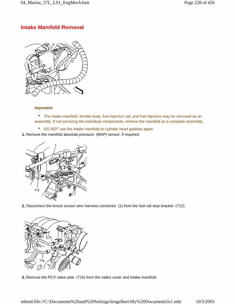
Intake Manifold Removal
Important:
• The intake manifold, throttle body, fuel injection rail, and fuel injectors may be removed as anassembly. If not servicing the individual components, remove the manifold as a complete assembly.
• DO NOT use the intake manifold-to-cylinder head gaskets again.
1. Remove the manifold absolute pressure (MAP) sensor, if required.
2. Disconnect the knock sensor wire harness connector (1) from the fuel rail stop bracket (712).
3. Remove the PCV valve pipe (716) from the valley cover and intake manifold.
Page 228 of 42604_Marine_57L_LS1_EngMech.htm
10/3/2003mhtml:file://C:\Documents%20and%20Settings\lengelbert\My%20Documents\ls1.mht
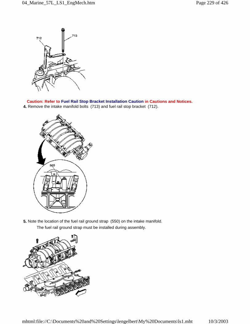
Caution: Refer to Fuel Rail Stop Bracket Installation Caution in Cautions and Notices. 4. Remove the intake manifold bolts (713) and fuel rail stop bracket (712).
5. Note the location of the fuel rail ground strap (550) on the intake manifold.
The fuel rail ground strap must be installed during assembly.
Page 229 of 42604_Marine_57L_LS1_EngMech.htm
10/3/2003mhtml:file://C:\Documents%20and%20Settings\lengelbert\My%20Documents\ls1.mht
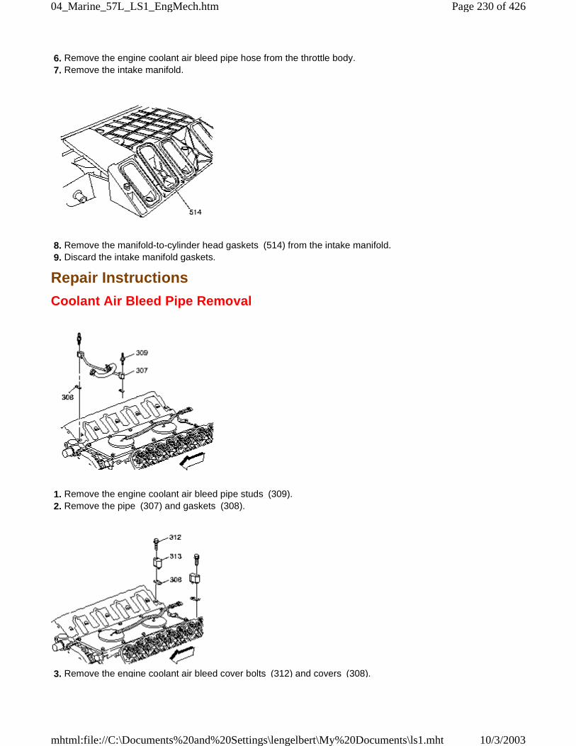
6. Remove the engine coolant air bleed pipe hose from the throttle body. 7. Remove the intake manifold.
8. Remove the manifold-to-cylinder head gaskets (514) from the intake manifold. 9. Discard the intake manifold gaskets.
Repair Instructions
Coolant Air Bleed Pipe Removal
1. Remove the engine coolant air bleed pipe studs (309). 2. Remove the pipe (307) and gaskets (308).
3. Remove the engine coolant air bleed cover bolts (312) and covers (308).
Page 230 of 42604_Marine_57L_LS1_EngMech.htm
10/3/2003mhtml:file://C:\Documents%20and%20Settings\lengelbert\My%20Documents\ls1.mht
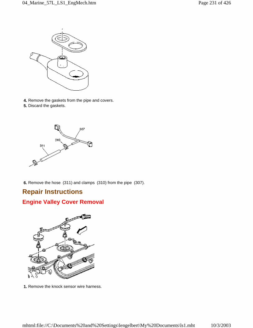
4. Remove the gaskets from the pipe and covers. 5. Discard the gaskets.
6. Remove the hose (311) and clamps (310) from the pipe (307).
Repair Instructions
Engine Valley Cover Removal
1. Remove the knock sensor wire harness.
Page 231 of 42604_Marine_57L_LS1_EngMech.htm
10/3/2003mhtml:file://C:\Documents%20and%20Settings\lengelbert\My%20Documents\ls1.mht
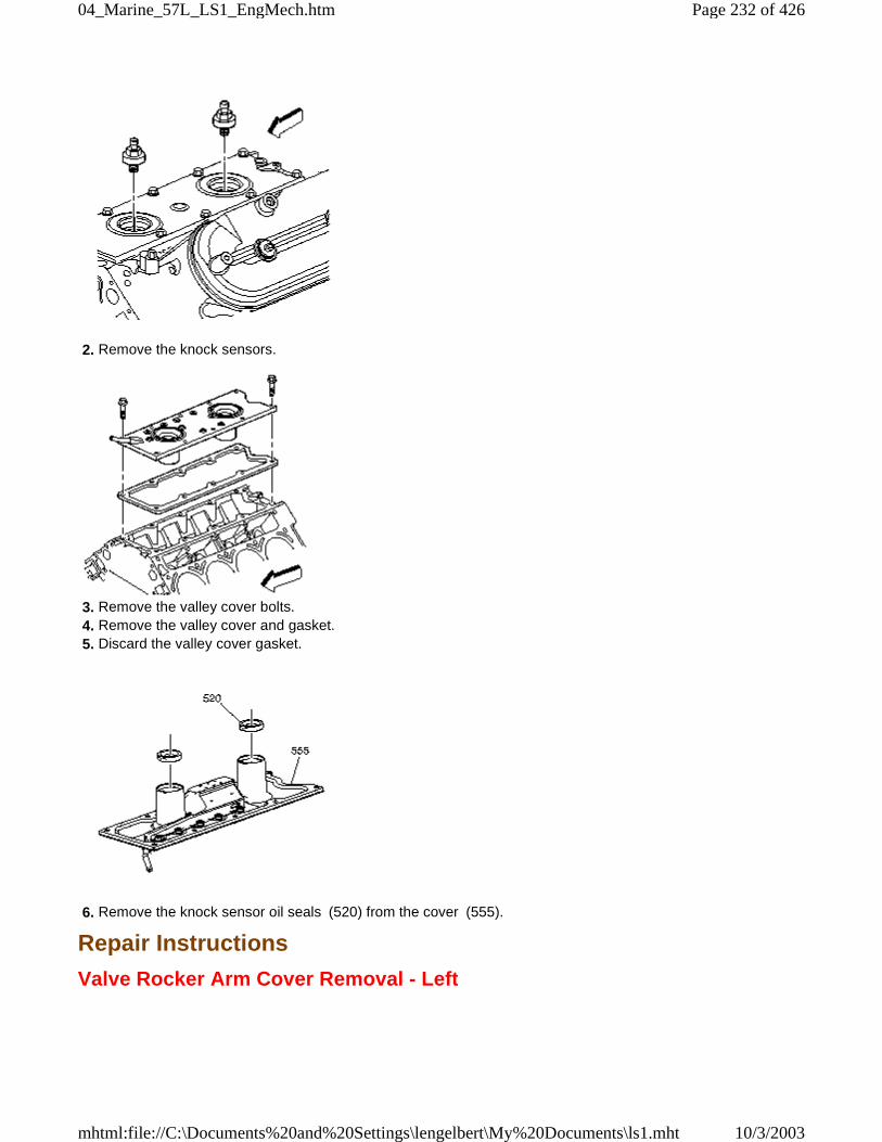
2. Remove the knock sensors.
3. Remove the valley cover bolts. 4. Remove the valley cover and gasket. 5. Discard the valley cover gasket.
6. Remove the knock sensor oil seals (520) from the cover (555).
Repair Instructions
Valve Rocker Arm Cover Removal - Left
Page 232 of 42604_Marine_57L_LS1_EngMech.htm
10/3/2003mhtml:file://C:\Documents%20and%20Settings\lengelbert\My%20Documents\ls1.mht
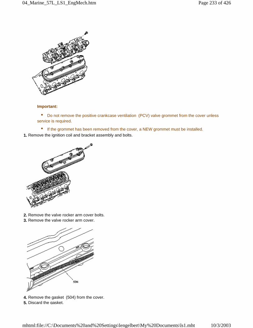
Important:
• Do not remove the positive crankcase ventilation (PCV) valve grommet from the cover unlessservice is required.
• If the grommet has been removed from the cover, a NEW grommet must be installed.
1. Remove the ignition coil and bracket assembly and bolts.
2. Remove the valve rocker arm cover bolts. 3. Remove the valve rocker arm cover.
4. Remove the gasket (504) from the cover. 5. Discard the gasket.
Page 233 of 42604_Marine_57L_LS1_EngMech.htm
10/3/2003mhtml:file://C:\Documents%20and%20Settings\lengelbert\My%20Documents\ls1.mht
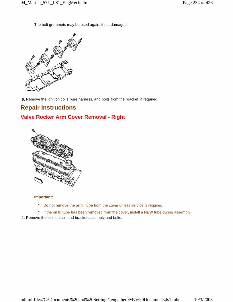
The bolt grommets may be used again, if not damaged.
6. Remove the ignition coils, wire harness, and bolts from the bracket, if required.
Repair Instructions
Valve Rocker Arm Cover Removal - Right
Important:
• Do not remove the oil fill tube from the cover unless service is required.
• If the oil fill tube has been removed from the cover, install a NEW tube during assembly.
1. Remove the ignition coil and bracket assembly and bolts.
Page 234 of 42604_Marine_57L_LS1_EngMech.htm
10/3/2003mhtml:file://C:\Documents%20and%20Settings\lengelbert\My%20Documents\ls1.mht
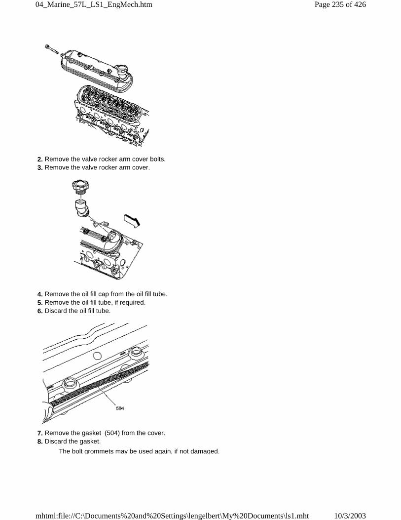
2. Remove the valve rocker arm cover bolts. 3. Remove the valve rocker arm cover.
4. Remove the oil fill cap from the oil fill tube. 5. Remove the oil fill tube, if required. 6. Discard the oil fill tube.
7. Remove the gasket (504) from the cover. 8. Discard the gasket.
The bolt grommets may be used again, if not damaged.
Page 235 of 42604_Marine_57L_LS1_EngMech.htm
10/3/2003mhtml:file://C:\Documents%20and%20Settings\lengelbert\My%20Documents\ls1.mht
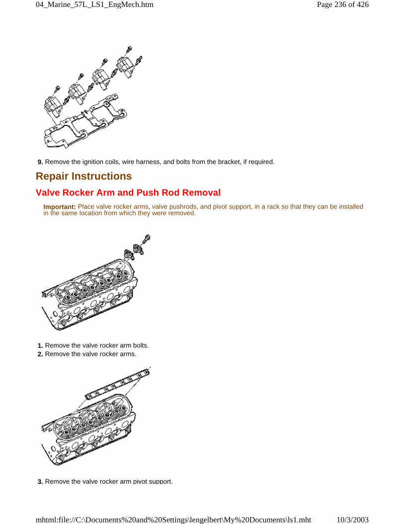
9. Remove the ignition coils, wire harness, and bolts from the bracket, if required.
Repair Instructions
Valve Rocker Arm and Push Rod RemovalImportant: Place valve rocker arms, valve pushrods, and pivot support, in a rack so that they can be installedin the same location from which they were removed.
1. Remove the valve rocker arm bolts. 2. Remove the valve rocker arms.
3. Remove the valve rocker arm pivot support.
Page 236 of 42604_Marine_57L_LS1_EngMech.htm
10/3/2003mhtml:file://C:\Documents%20and%20Settings\lengelbert\My%20Documents\ls1.mht
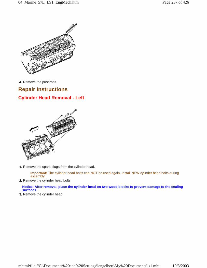
4. Remove the pushrods.
Repair Instructions
Cylinder Head Removal - Left
1. Remove the spark plugs from the cylinder head.
Important: The cylinder head bolts can NOT be used again. Install NEW cylinder head bolts duringassembly.
2. Remove the cylinder head bolts.
Notice: After removal, place the cylinder head on two wood blocks to prevent damage to the sealingsurfaces.
3. Remove the cylinder head.
Page 237 of 42604_Marine_57L_LS1_EngMech.htm
10/3/2003mhtml:file://C:\Documents%20and%20Settings\lengelbert\My%20Documents\ls1.mht
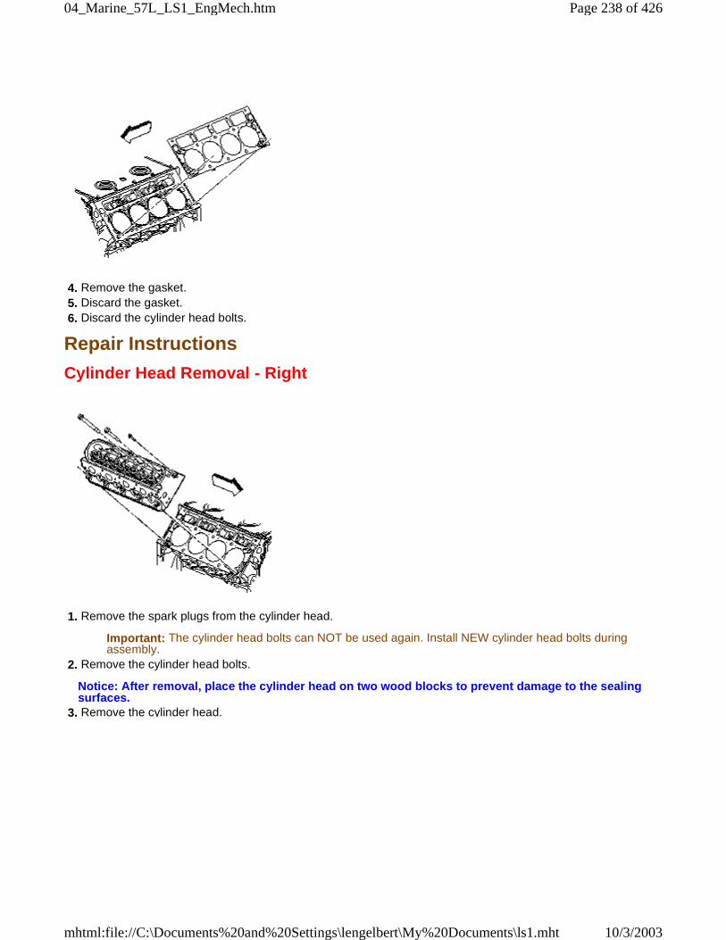
4. Remove the gasket. 5. Discard the gasket. 6. Discard the cylinder head bolts.
Repair Instructions
Cylinder Head Removal - Right
1. Remove the spark plugs from the cylinder head.
Important: The cylinder head bolts can NOT be used again. Install NEW cylinder head bolts duringassembly.
2. Remove the cylinder head bolts.
Notice: After removal, place the cylinder head on two wood blocks to prevent damage to the sealingsurfaces.
3. Remove the cylinder head.
Page 238 of 42604_Marine_57L_LS1_EngMech.htm
10/3/2003mhtml:file://C:\Documents%20and%20Settings\lengelbert\My%20Documents\ls1.mht
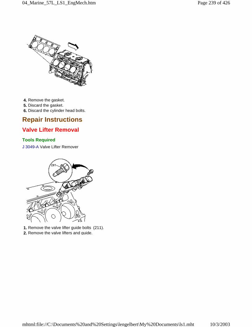
4. Remove the gasket. 5. Discard the gasket. 6. Discard the cylinder head bolts.
Repair Instructions
Valve Lifter Removal
Tools Required
J 3049-A Valve Lifter Remover
1. Remove the valve lifter guide bolts (211). 2. Remove the valve lifters and guide.
Page 239 of 42604_Marine_57L_LS1_EngMech.htm
10/3/2003mhtml:file://C:\Documents%20and%20Settings\lengelbert\My%20Documents\ls1.mht
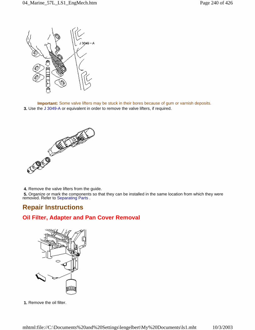
Important: Some valve lifters may be stuck in their bores because of gum or varnish deposits. 3. Use the J 3049-A or equivalent in order to remove the valve lifters, if required.
4. Remove the valve lifters from the guide. 5. Organize or mark the components so that they can be installed in the same location from which they wereremoved. Refer to Separating Parts .
Repair Instructions
Oil Filter, Adapter and Pan Cover Removal
1. Remove the oil filter.
Page 240 of 42604_Marine_57L_LS1_EngMech.htm
10/3/2003mhtml:file://C:\Documents%20and%20Settings\lengelbert\My%20Documents\ls1.mht
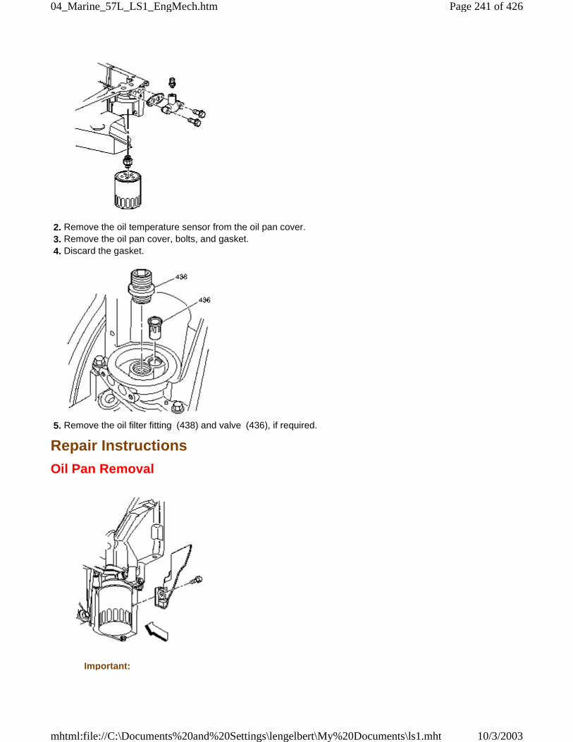
2. Remove the oil temperature sensor from the oil pan cover. 3. Remove the oil pan cover, bolts, and gasket. 4. Discard the gasket.
5. Remove the oil filter fitting (438) and valve (436), if required.
Repair Instructions
Oil Pan Removal
Important:
Page 241 of 42604_Marine_57L_LS1_EngMech.htm
10/3/2003mhtml:file://C:\Documents%20and%20Settings\lengelbert\My%20Documents\ls1.mht
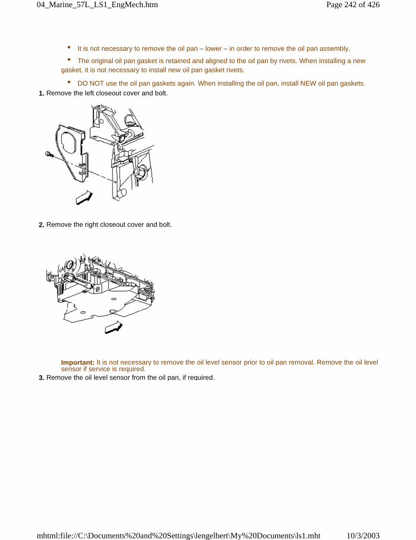
• It is not necessary to remove the oil pan – lower – in order to remove the oil pan assembly.
• The original oil pan gasket is retained and aligned to the oil pan by rivets. When installing a newgasket, it is not necessary to install new oil pan gasket rivets.
• DO NOT use the oil pan gaskets again. When installing the oil pan, install NEW oil pan gaskets.
1. Remove the left closeout cover and bolt.
2. Remove the right closeout cover and bolt.
Important: It is not necessary to remove the oil level sensor prior to oil pan removal. Remove the oil levelsensor if service is required.
3. Remove the oil level sensor from the oil pan, if required.
Page 242 of 42604_Marine_57L_LS1_EngMech.htm
10/3/2003mhtml:file://C:\Documents%20and%20Settings\lengelbert\My%20Documents\ls1.mht
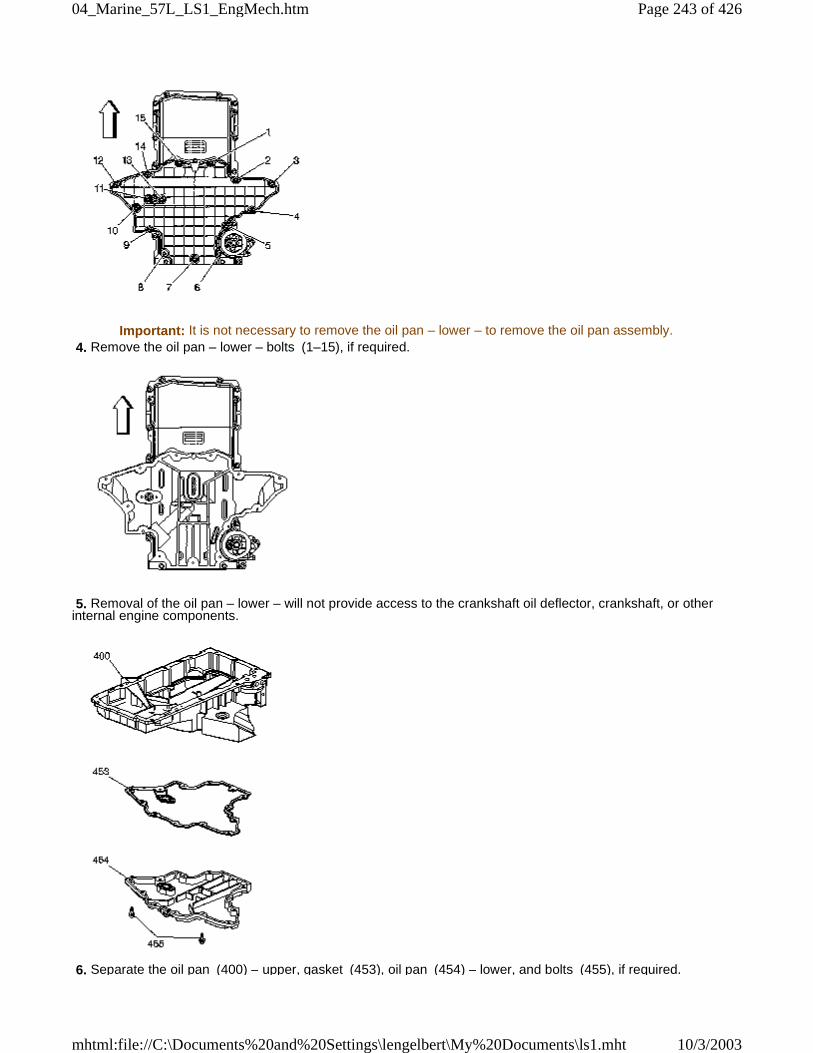
Important: It is not necessary to remove the oil pan – lower – to remove the oil pan assembly. 4. Remove the oil pan – lower – bolts (1–15), if required.
5. Removal of the oil pan – lower – will not provide access to the crankshaft oil deflector, crankshaft, or otherinternal engine components.
6. Separate the oil pan (400) – upper, gasket (453), oil pan (454) – lower, and bolts (455), if required.
Page 243 of 42604_Marine_57L_LS1_EngMech.htm
10/3/2003mhtml:file://C:\Documents%20and%20Settings\lengelbert\My%20Documents\ls1.mht
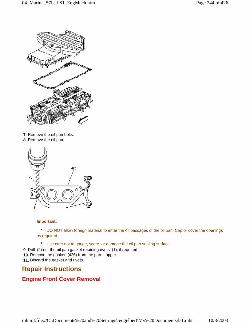
7. Remove the oil pan bolts. 8. Remove the oil pan.
Important:
• DO NOT allow foreign material to enter the oil passages of the oil pan. Cap or cover the openingsas required.
• Use care not to gouge, score, or damage the oil pan sealing surface.
9. Drill (2) out the oil pan gasket retaining rivets (1), if required. 10. Remove the gasket (426) from the pan – upper. 11. Discard the gasket and rivets.
Repair Instructions
Engine Front Cover Removal
Page 244 of 42604_Marine_57L_LS1_EngMech.htm
10/3/2003mhtml:file://C:\Documents%20and%20Settings\lengelbert\My%20Documents\ls1.mht
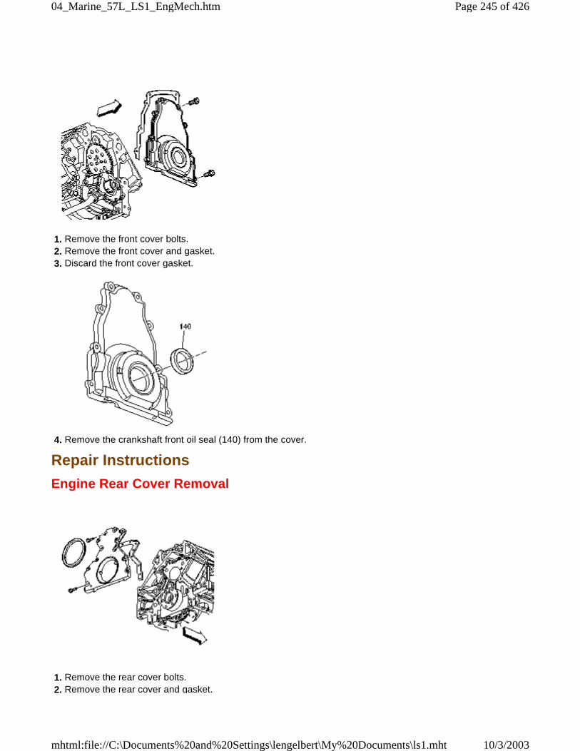
1. Remove the front cover bolts. 2. Remove the front cover and gasket. 3. Discard the front cover gasket.
4. Remove the crankshaft front oil seal (140) from the cover.
Repair Instructions
Engine Rear Cover Removal
1. Remove the rear cover bolts. 2. Remove the rear cover and gasket.
Page 245 of 42604_Marine_57L_LS1_EngMech.htm
10/3/2003mhtml:file://C:\Documents%20and%20Settings\lengelbert\My%20Documents\ls1.mht
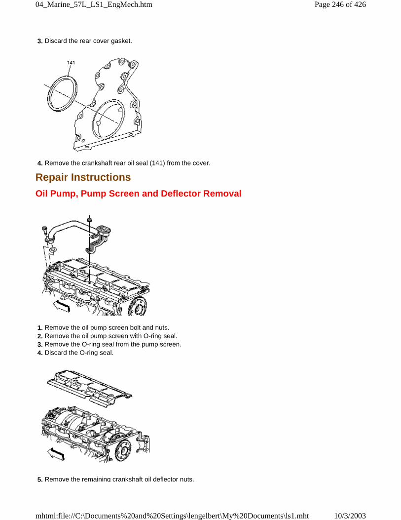
3. Discard the rear cover gasket.
4. Remove the crankshaft rear oil seal (141) from the cover.
Repair Instructions
Oil Pump, Pump Screen and Deflector Removal
1. Remove the oil pump screen bolt and nuts. 2. Remove the oil pump screen with O-ring seal. 3. Remove the O-ring seal from the pump screen. 4. Discard the O-ring seal.
5. Remove the remaining crankshaft oil deflector nuts.
Page 246 of 42604_Marine_57L_LS1_EngMech.htm
10/3/2003mhtml:file://C:\Documents%20and%20Settings\lengelbert\My%20Documents\ls1.mht
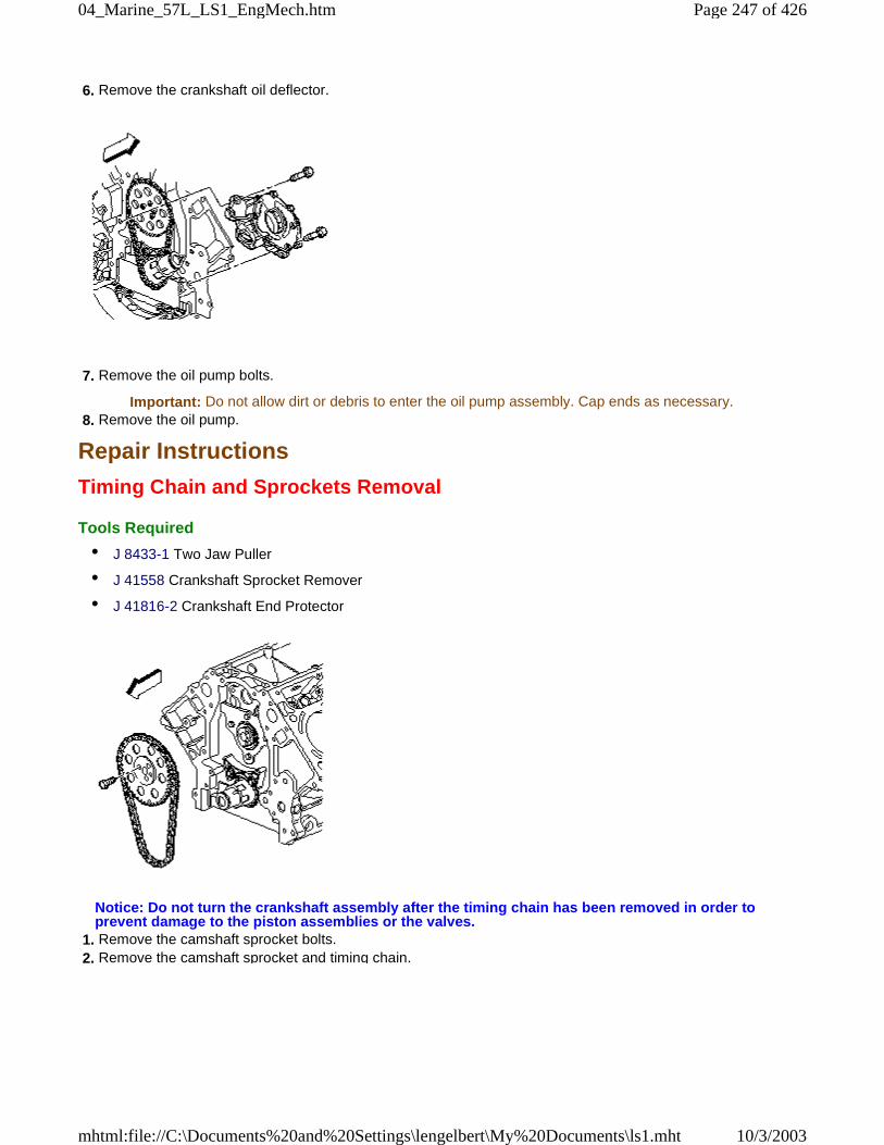
6. Remove the crankshaft oil deflector.
7. Remove the oil pump bolts.
Important: Do not allow dirt or debris to enter the oil pump assembly. Cap ends as necessary. 8. Remove the oil pump.
Repair Instructions
Timing Chain and Sprockets Removal
Tools Required
• J 8433-1 Two Jaw Puller
• J 41558 Crankshaft Sprocket Remover
• J 41816-2 Crankshaft End Protector
Notice: Do not turn the crankshaft assembly after the timing chain has been removed in order toprevent damage to the piston assemblies or the valves.
1. Remove the camshaft sprocket bolts. 2. Remove the camshaft sprocket and timing chain.
Page 247 of 42604_Marine_57L_LS1_EngMech.htm
10/3/2003mhtml:file://C:\Documents%20and%20Settings\lengelbert\My%20Documents\ls1.mht
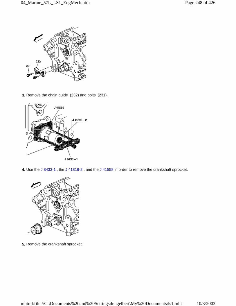
3. Remove the chain guide (232) and bolts (231).
4. Use the J 8433-1 , the J 41816-2 , and the J 41558 in order to remove the crankshaft sprocket.
5. Remove the crankshaft sprocket.
Page 248 of 42604_Marine_57L_LS1_EngMech.htm
10/3/2003mhtml:file://C:\Documents%20and%20Settings\lengelbert\My%20Documents\ls1.mht
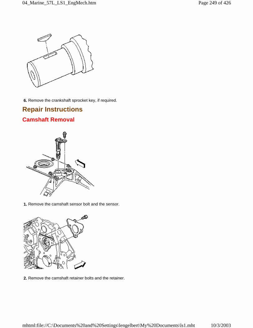
6. Remove the crankshaft sprocket key, if required.
Repair Instructions
Camshaft Removal
1. Remove the camshaft sensor bolt and the sensor.
2. Remove the camshaft retainer bolts and the retainer.
Page 249 of 42604_Marine_57L_LS1_EngMech.htm
10/3/2003mhtml:file://C:\Documents%20and%20Settings\lengelbert\My%20Documents\ls1.mht
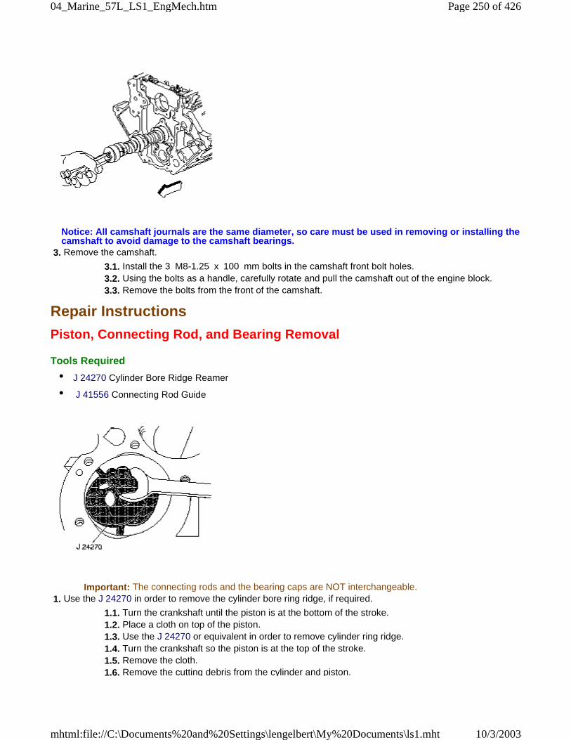
Notice: All camshaft journals are the same diameter, so care must be used in removing or installing thecamshaft to avoid damage to the camshaft bearings.
3. Remove the camshaft.
3.1. Install the 3 M8-1.25 x 100 mm bolts in the camshaft front bolt holes. 3.2. Using the bolts as a handle, carefully rotate and pull the camshaft out of the engine block. 3.3. Remove the bolts from the front of the camshaft.
Repair Instructions
Piston, Connecting Rod, and Bearing Removal
Tools Required
• J 24270 Cylinder Bore Ridge Reamer
• J 41556 Connecting Rod Guide
Important: The connecting rods and the bearing caps are NOT interchangeable. 1. Use the J 24270 in order to remove the cylinder bore ring ridge, if required.
1.1. Turn the crankshaft until the piston is at the bottom of the stroke. 1.2. Place a cloth on top of the piston. 1.3. Use the J 24270 or equivalent in order to remove cylinder ring ridge. 1.4. Turn the crankshaft so the piston is at the top of the stroke. 1.5. Remove the cloth. 1.6. Remove the cutting debris from the cylinder and piston.
Page 250 of 42604_Marine_57L_LS1_EngMech.htm
10/3/2003mhtml:file://C:\Documents%20and%20Settings\lengelbert\My%20Documents\ls1.mht
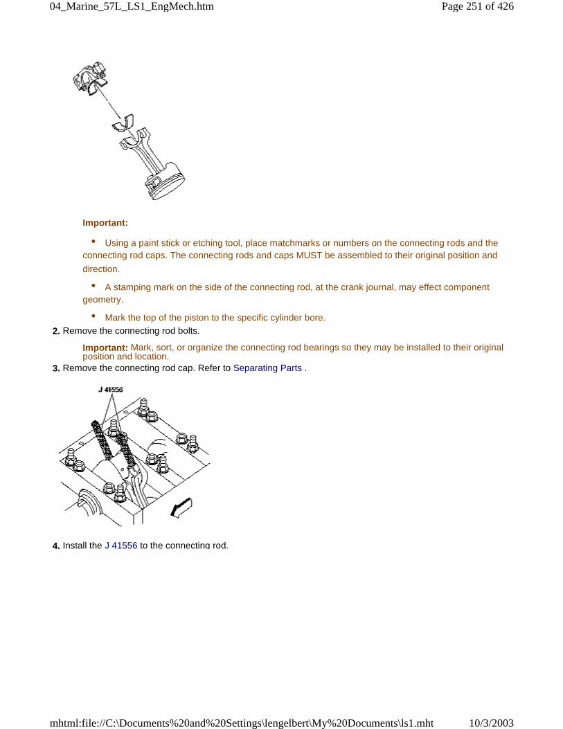
Important:
• Using a paint stick or etching tool, place matchmarks or numbers on the connecting rods and theconnecting rod caps. The connecting rods and caps MUST be assembled to their original position and
direction.
• A stamping mark on the side of the connecting rod, at the crank journal, may effect componentgeometry.
• Mark the top of the piston to the specific cylinder bore.
2. Remove the connecting rod bolts.
Important: Mark, sort, or organize the connecting rod bearings so they may be installed to their originalposition and location.
3. Remove the connecting rod cap. Refer to Separating Parts .
4. Install the J 41556 to the connecting rod.
Page 251 of 42604_Marine_57L_LS1_EngMech.htm
10/3/2003mhtml:file://C:\Documents%20and%20Settings\lengelbert\My%20Documents\ls1.mht
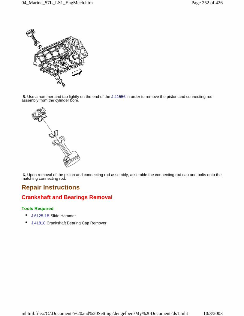
5. Use a hammer and tap lightly on the end of the J 41556 in order to remove the piston and connecting rodassembly from the cylinder bore.
6. Upon removal of the piston and connecting rod assembly, assemble the connecting rod cap and bolts onto thematching connecting rod.
Repair Instructions
Crankshaft and Bearings Removal
Tools Required
• J 6125-1B Slide Hammer
• J 41818 Crankshaft Bearing Cap Remover
Page 252 of 42604_Marine_57L_LS1_EngMech.htm
10/3/2003mhtml:file://C:\Documents%20and%20Settings\lengelbert\My%20Documents\ls1.mht
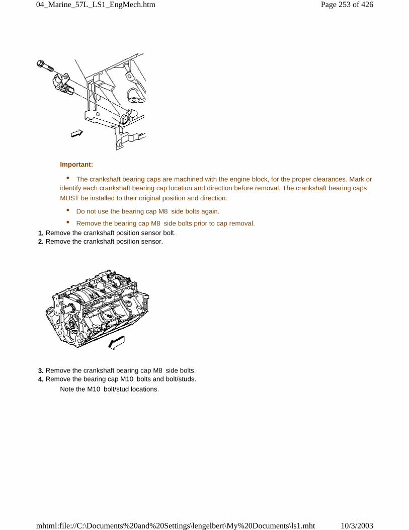
Important:
• The crankshaft bearing caps are machined with the engine block, for the proper clearances. Mark oridentify each crankshaft bearing cap location and direction before removal. The crankshaft bearing caps
MUST be installed to their original position and direction.
• Do not use the bearing cap M8 side bolts again.
• Remove the bearing cap M8 side bolts prior to cap removal.
1. Remove the crankshaft position sensor bolt. 2. Remove the crankshaft position sensor.
3. Remove the crankshaft bearing cap M8 side bolts. 4. Remove the bearing cap M10 bolts and bolt/studs.
Note the M10 bolt/stud locations.
Page 253 of 42604_Marine_57L_LS1_EngMech.htm
10/3/2003mhtml:file://C:\Documents%20and%20Settings\lengelbert\My%20Documents\ls1.mht
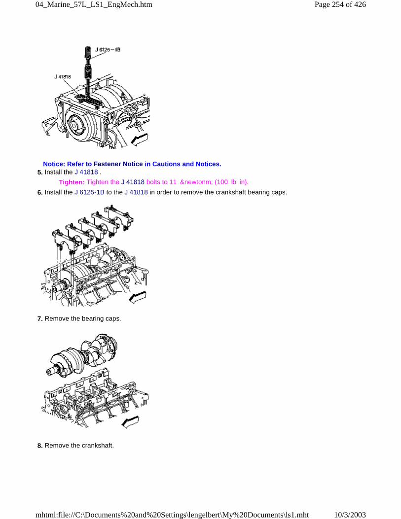
Notice: Refer to Fastener Notice in Cautions and Notices. 5. Install the J 41818 .
Tighten: Tighten the J 41818 bolts to 11 &newtonm; (100 lb in).
6. Install the J 6125-1B to the J 41818 in order to remove the crankshaft bearing caps.
7. Remove the bearing caps.
8. Remove the crankshaft.
Page 254 of 42604_Marine_57L_LS1_EngMech.htm
10/3/2003mhtml:file://C:\Documents%20and%20Settings\lengelbert\My%20Documents\ls1.mht
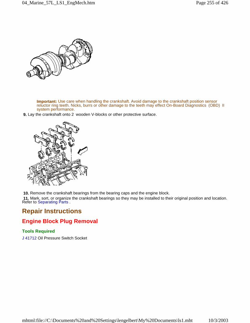
Important: Use care when handling the crankshaft. Avoid damage to the crankshaft position sensorreluctor ring teeth. Nicks, burrs or other damage to the teeth may effect On-Board Diagnostics (OBD) IIsystem performance.
9. Lay the crankshaft onto 2 wooden V-blocks or other protective surface.
10. Remove the crankshaft bearings from the bearing caps and the engine block. 11. Mark, sort, or organize the crankshaft bearings so they may be installed to their original position and location.Refer to Separating Parts .
Repair Instructions
Engine Block Plug Removal
Tools Required
J 41712 Oil Pressure Switch Socket
Page 255 of 42604_Marine_57L_LS1_EngMech.htm
10/3/2003mhtml:file://C:\Documents%20and%20Settings\lengelbert\My%20Documents\ls1.mht
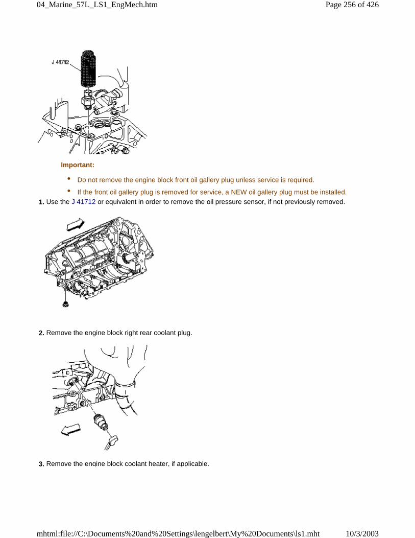
Important:
• Do not remove the engine block front oil gallery plug unless service is required.
• If the front oil gallery plug is removed for service, a NEW oil gallery plug must be installed.
1. Use the J 41712 or equivalent in order to remove the oil pressure sensor, if not previously removed.
2. Remove the engine block right rear coolant plug.
3. Remove the engine block coolant heater, if applicable.
Page 256 of 42604_Marine_57L_LS1_EngMech.htm
10/3/2003mhtml:file://C:\Documents%20and%20Settings\lengelbert\My%20Documents\ls1.mht
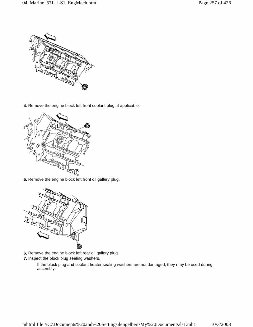
4. Remove the engine block left front coolant plug, if applicable.
5. Remove the engine block left front oil gallery plug.
6. Remove the engine block left rear oil gallery plug. 7. Inspect the block plug sealing washers.
If the block plug and coolant heater sealing washers are not damaged, they may be used duringassembly.
Page 257 of 42604_Marine_57L_LS1_EngMech.htm
10/3/2003mhtml:file://C:\Documents%20and%20Settings\lengelbert\My%20Documents\ls1.mht
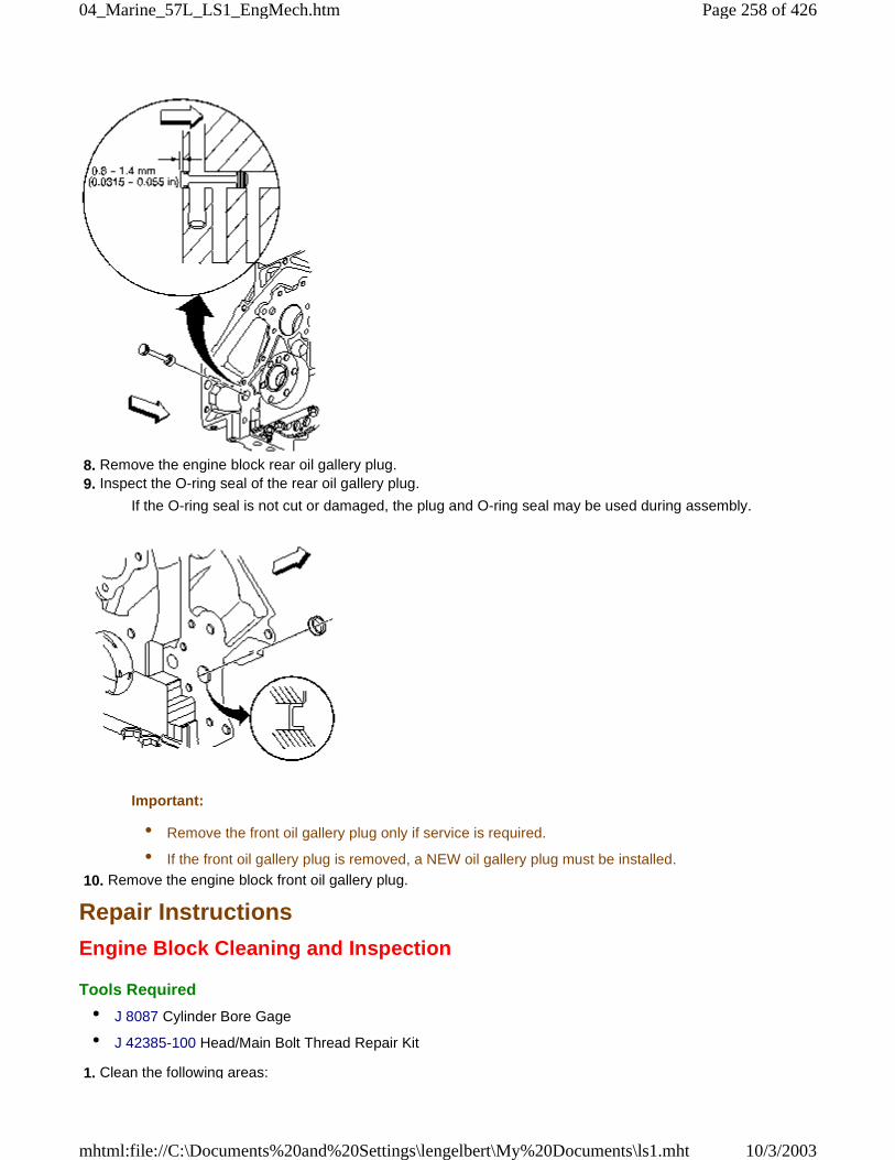
8. Remove the engine block rear oil gallery plug. 9. Inspect the O-ring seal of the rear oil gallery plug.
If the O-ring seal is not cut or damaged, the plug and O-ring seal may be used during assembly.
Important:
• Remove the front oil gallery plug only if service is required.
• If the front oil gallery plug is removed, a NEW oil gallery plug must be installed.
10. Remove the engine block front oil gallery plug.
Repair Instructions
Engine Block Cleaning and Inspection
Tools Required
• J 8087 Cylinder Bore Gage
• J 42385-100 Head/Main Bolt Thread Repair Kit
1. Clean the following areas:
Page 258 of 42604_Marine_57L_LS1_EngMech.htm
10/3/2003mhtml:file://C:\Documents%20and%20Settings\lengelbert\My%20Documents\ls1.mht
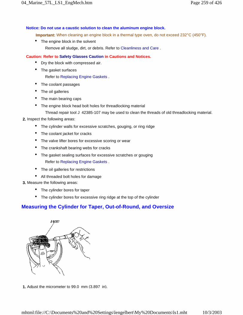
Notice: Do not use a caustic solution to clean the aluminum engine block.
Important: When cleaning an engine block in a thermal type oven, do not exceed 232°C (450°F).
• The engine block in the solvent
Remove all sludge, dirt, or debris. Refer to Cleanliness and Care .
Caution: Refer to Safety Glasses Caution in Cautions and Notices.
• Dry the block with compressed air.
• The gasket surfaces
Refer to Replacing Engine Gaskets .
• The coolant passages
• The oil galleries
• The main bearing caps
• The engine block head bolt holes for threadlocking material
Thread repair tool J 42385-107 may be used to clean the threads of old threadlocking material.
2. Inspect the following areas:
• The cylinder walls for excessive scratches, gouging, or ring ridge
• The coolant jacket for cracks
• The valve lifter bores for excessive scoring or wear
• The crankshaft bearing webs for cracks
• The gasket sealing surfaces for excessive scratches or gouging
Refer to Replacing Engine Gaskets .
• The oil galleries for restrictions
• All threaded bolt holes for damage
3. Measure the following areas:
• The cylinder bores for taper
• The cylinder bores for excessive ring ridge at the top of the cylinder
Measuring the Cylinder for Taper, Out-of-Round, and Oversize
1. Adjust the micrometer to 99.0 mm (3.897 in).
Page 259 of 42604_Marine_57L_LS1_EngMech.htm
10/3/2003mhtml:file://C:\Documents%20and%20Settings\lengelbert\My%20Documents\ls1.mht
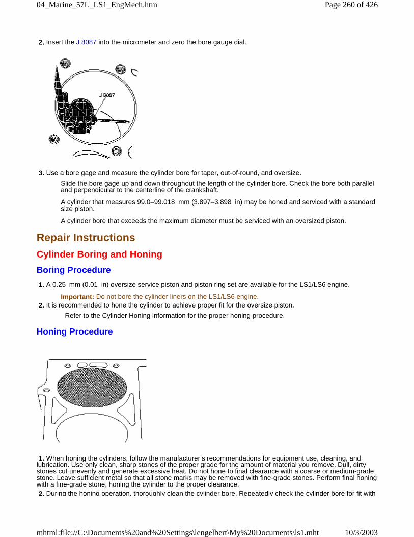
2. Insert the J 8087 into the micrometer and zero the bore gauge dial.
3. Use a bore gage and measure the cylinder bore for taper, out-of-round, and oversize.
Slide the bore gage up and down throughout the length of the cylinder bore. Check the bore both paralleland perpendicular to the centerline of the crankshaft.
A cylinder that measures 99.0–99.018 mm (3.897–3.898 in) may be honed and serviced with a standardsize piston.
A cylinder bore that exceeds the maximum diameter must be serviced with an oversized piston.
Repair Instructions
Cylinder Boring and Honing
Boring Procedure
1. A 0.25 mm (0.01 in) oversize service piston and piston ring set are available for the LS1/LS6 engine.
Important: Do not bore the cylinder liners on the LS1/LS6 engine. 2. It is recommended to hone the cylinder to achieve proper fit for the oversize piston.
Refer to the Cylinder Honing information for the proper honing procedure.
Honing Procedure
1. When honing the cylinders, follow the manufacturer’s recommendations for equipment use, cleaning, andlubrication. Use only clean, sharp stones of the proper grade for the amount of material you remove. Dull, dirtystones cut unevenly and generate excessive heat. Do not hone to final clearance with a coarse or medium-gradestone. Leave sufficient metal so that all stone marks may be removed with fine-grade stones. Perform final honingwith a fine-grade stone, honing the cylinder to the proper clearance. 2. During the honing operation, thoroughly clean the cylinder bore. Repeatedly check the cylinder bore for fit with
Page 260 of 42604_Marine_57L_LS1_EngMech.htm
10/3/2003mhtml:file://C:\Documents%20and%20Settings\lengelbert\My%20Documents\ls1.mht
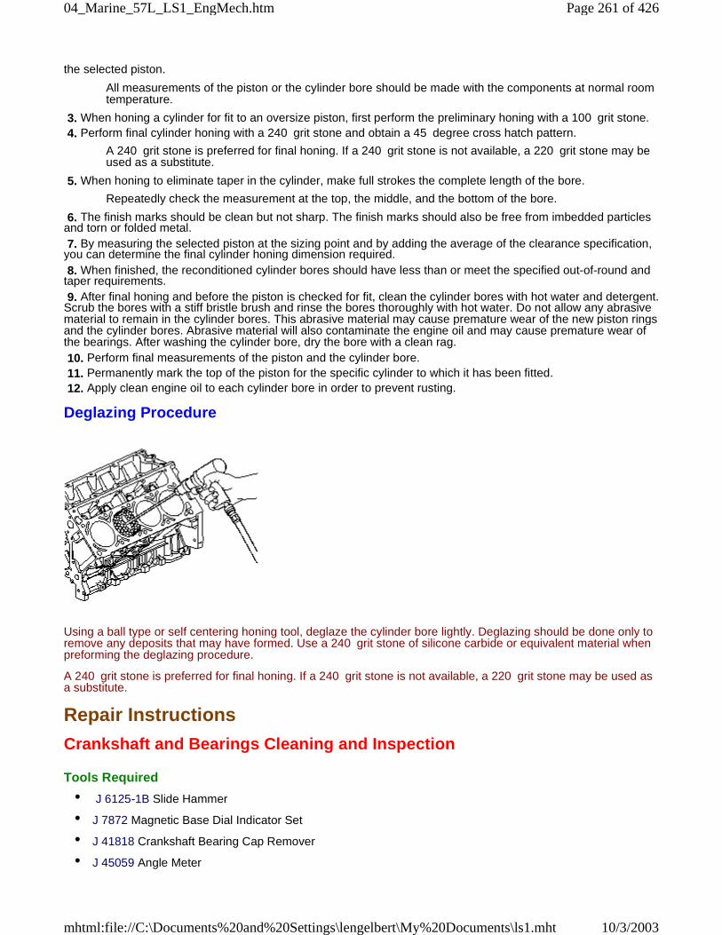
the selected piston.
All measurements of the piston or the cylinder bore should be made with the components at normal roomtemperature.
3. When honing a cylinder for fit to an oversize piston, first perform the preliminary honing with a 100 grit stone. 4. Perform final cylinder honing with a 240 grit stone and obtain a 45 degree cross hatch pattern.
A 240 grit stone is preferred for final honing. If a 240 grit stone is not available, a 220 grit stone may beused as a substitute.
5. When honing to eliminate taper in the cylinder, make full strokes the complete length of the bore.
Repeatedly check the measurement at the top, the middle, and the bottom of the bore.
6. The finish marks should be clean but not sharp. The finish marks should also be free from imbedded particlesand torn or folded metal. 7. By measuring the selected piston at the sizing point and by adding the average of the clearance specification,you can determine the final cylinder honing dimension required. 8. When finished, the reconditioned cylinder bores should have less than or meet the specified out-of-round andtaper requirements. 9. After final honing and before the piston is checked for fit, clean the cylinder bores with hot water and detergent.Scrub the bores with a stiff bristle brush and rinse the bores thoroughly with hot water. Do not allow any abrasivematerial to remain in the cylinder bores. This abrasive material may cause premature wear of the new piston ringsand the cylinder bores. Abrasive material will also contaminate the engine oil and may cause premature wear ofthe bearings. After washing the cylinder bore, dry the bore with a clean rag. 10. Perform final measurements of the piston and the cylinder bore. 11. Permanently mark the top of the piston for the specific cylinder to which it has been fitted. 12. Apply clean engine oil to each cylinder bore in order to prevent rusting.
Deglazing Procedure
Using a ball type or self centering honing tool, deglaze the cylinder bore lightly. Deglazing should be done only toremove any deposits that may have formed. Use a 240 grit stone of silicone carbide or equivalent material whenpreforming the deglazing procedure.
A 240 grit stone is preferred for final honing. If a 240 grit stone is not available, a 220 grit stone may be used asa substitute.
Repair Instructions
Crankshaft and Bearings Cleaning and Inspection
Tools Required
• J 6125-1B Slide Hammer
• J 7872 Magnetic Base Dial Indicator Set
• J 41818 Crankshaft Bearing Cap Remover
• J 45059 Angle Meter
Page 261 of 42604_Marine_57L_LS1_EngMech.htm
10/3/2003mhtml:file://C:\Documents%20and%20Settings\lengelbert\My%20Documents\ls1.mht
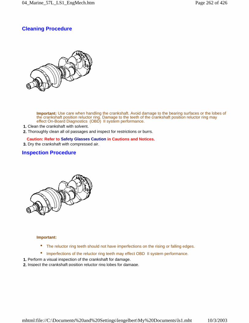
Cleaning Procedure
Important: Use care when handling the crankshaft. Avoid damage to the bearing surfaces or the lobes ofthe crankshaft position reluctor ring. Damage to the teeth of the crankshaft position reluctor ring mayeffect On-Board Diagnostics (OBD) II system performance.
1. Clean the crankshaft with solvent. 2. Thoroughly clean all oil passages and inspect for restrictions or burrs.
Caution: Refer to Safety Glasses Caution in Cautions and Notices. 3. Dry the crankshaft with compressed air.
Inspection Procedure
Important:
• The reluctor ring teeth should not have imperfections on the rising or falling edges.
• Imperfections of the reluctor ring teeth may effect OBD II system performance.
1. Perform a visual inspection of the crankshaft for damage. 2. Inspect the crankshaft position reluctor ring lobes for damage.
Page 262 of 42604_Marine_57L_LS1_EngMech.htm
10/3/2003mhtml:file://C:\Documents%20and%20Settings\lengelbert\My%20Documents\ls1.mht
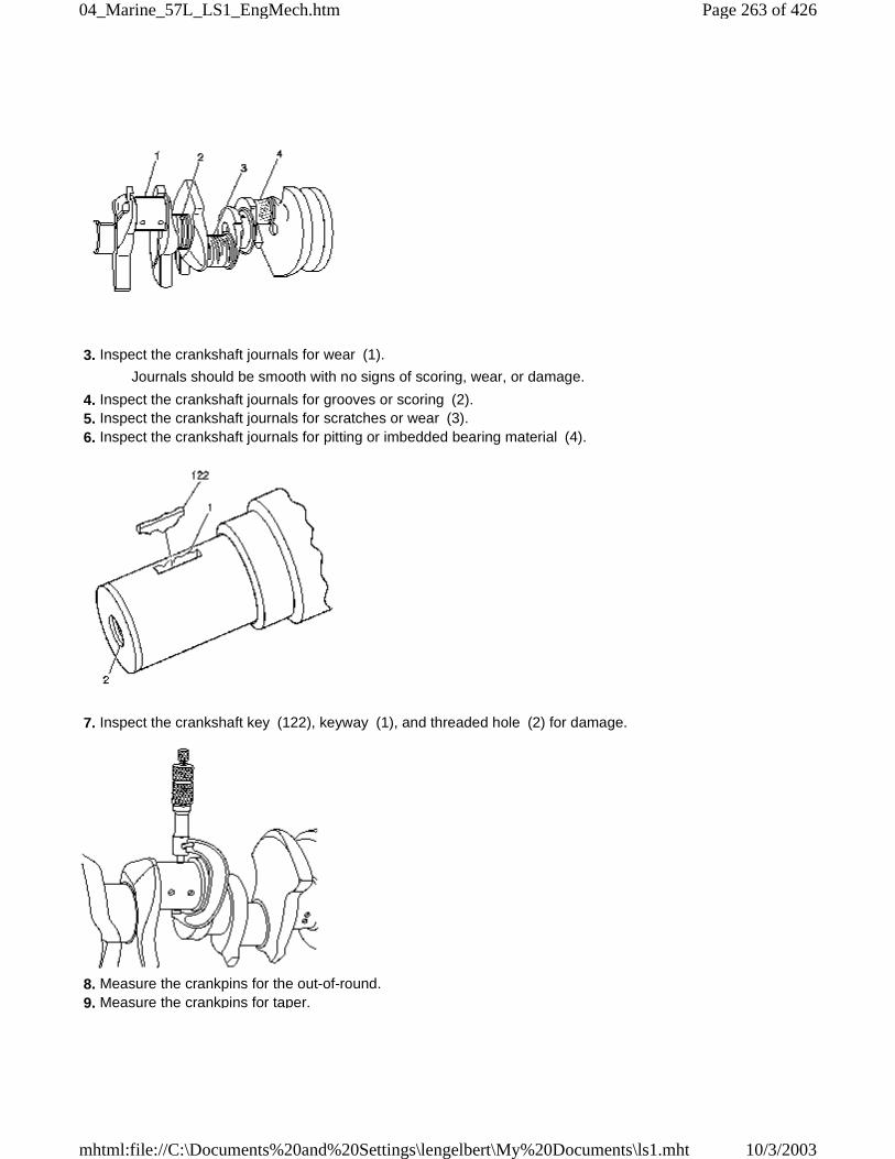
3. Inspect the crankshaft journals for wear (1).
Journals should be smooth with no signs of scoring, wear, or damage.
4. Inspect the crankshaft journals for grooves or scoring (2). 5. Inspect the crankshaft journals for scratches or wear (3). 6. Inspect the crankshaft journals for pitting or imbedded bearing material (4).
7. Inspect the crankshaft key (122), keyway (1), and threaded hole (2) for damage.
8. Measure the crankpins for the out-of-round. 9. Measure the crankpins for taper.
Page 263 of 42604_Marine_57L_LS1_EngMech.htm
10/3/2003mhtml:file://C:\Documents%20and%20Settings\lengelbert\My%20Documents\ls1.mht
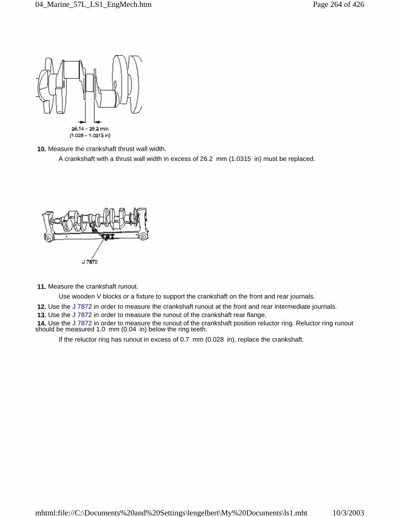
10. Measure the crankshaft thrust wall width.
A crankshaft with a thrust wall width in excess of 26.2 mm (1.0315 in) must be replaced.
11. Measure the crankshaft runout.
Use wooden V blocks or a fixture to support the crankshaft on the front and rear journals.
12. Use the J 7872 in order to measure the crankshaft runout at the front and rear intermediate journals. 13. Use the J 7872 in order to measure the runout of the crankshaft rear flange. 14. Use the J 7872 in order to measure the runout of the crankshaft position reluctor ring. Reluctor ring runoutshould be measured 1.0 mm (0.04 in) below the ring teeth.
If the reluctor ring has runout in excess of 0.7 mm (0.028 in), replace the crankshaft.
Page 264 of 42604_Marine_57L_LS1_EngMech.htm
10/3/2003mhtml:file://C:\Documents%20and%20Settings\lengelbert\My%20Documents\ls1.mht
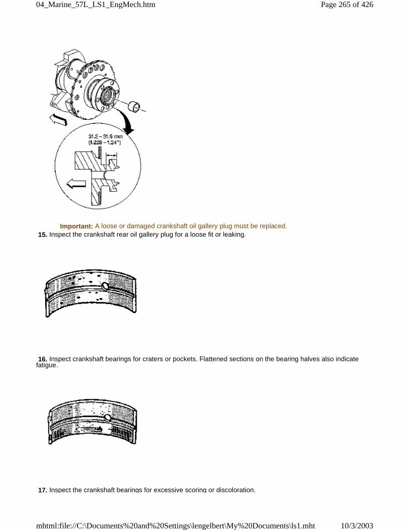
Important: A loose or damaged crankshaft oil gallery plug must be replaced. 15. Inspect the crankshaft rear oil gallery plug for a loose fit or leaking.
16. Inspect crankshaft bearings for craters or pockets. Flattened sections on the bearing halves also indicatefatigue.
17. Inspect the crankshaft bearings for excessive scoring or discoloration.
Page 265 of 42604_Marine_57L_LS1_EngMech.htm
10/3/2003mhtml:file://C:\Documents%20and%20Settings\lengelbert\My%20Documents\ls1.mht
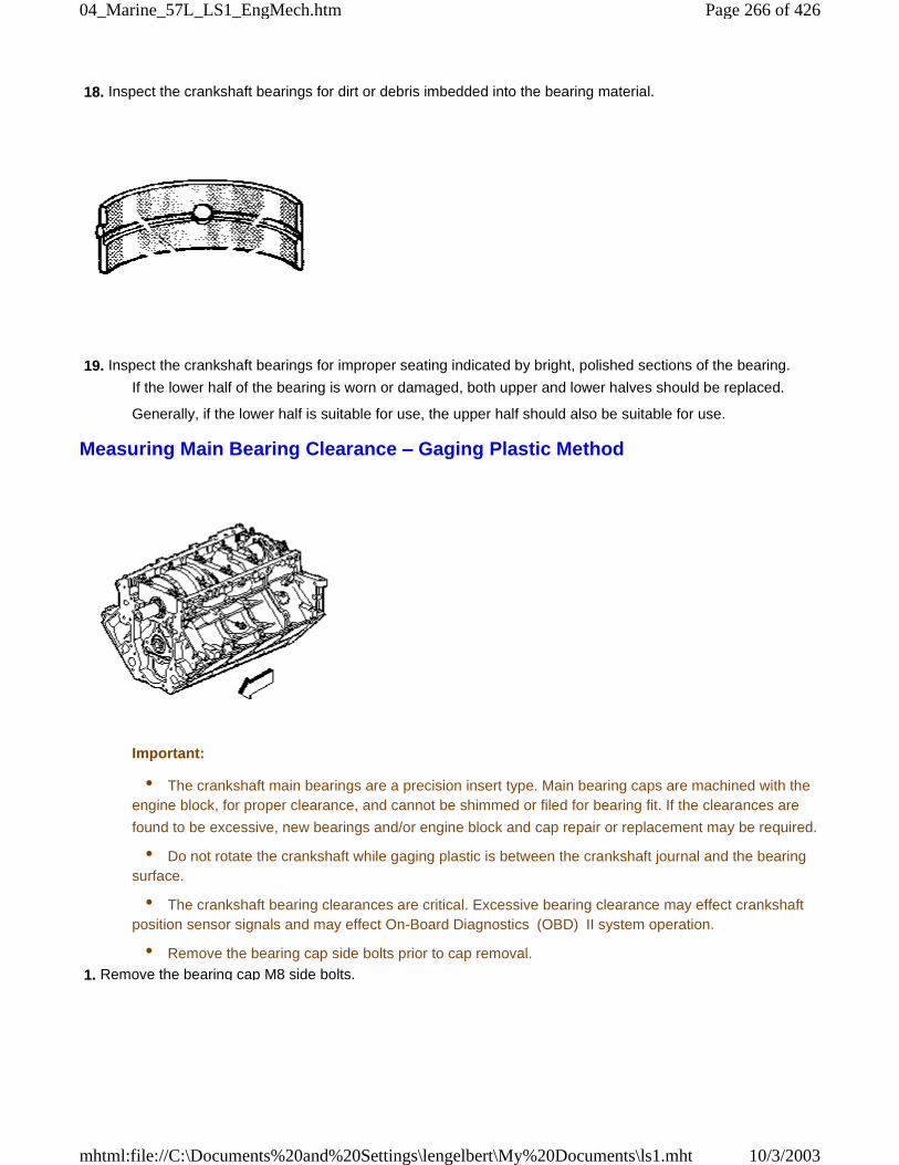
18. Inspect the crankshaft bearings for dirt or debris imbedded into the bearing material.
19. Inspect the crankshaft bearings for improper seating indicated by bright, polished sections of the bearing.
If the lower half of the bearing is worn or damaged, both upper and lower halves should be replaced.
Generally, if the lower half is suitable for use, the upper half should also be suitable for use.
Measuring Main Bearing Clearance – Gaging Plastic Method
Important:
• The crankshaft main bearings are a precision insert type. Main bearing caps are machined with theengine block, for proper clearance, and cannot be shimmed or filed for bearing fit. If the clearances are
found to be excessive, new bearings and/or engine block and cap repair or replacement may be required.
• Do not rotate the crankshaft while gaging plastic is between the crankshaft journal and the bearingsurface.
• The crankshaft bearing clearances are critical. Excessive bearing clearance may effect crankshaftposition sensor signals and may effect On-Board Diagnostics (OBD) II system operation.
• Remove the bearing cap side bolts prior to cap removal.
1. Remove the bearing cap M8 side bolts.
Page 266 of 42604_Marine_57L_LS1_EngMech.htm
10/3/2003mhtml:file://C:\Documents%20and%20Settings\lengelbert\My%20Documents\ls1.mht
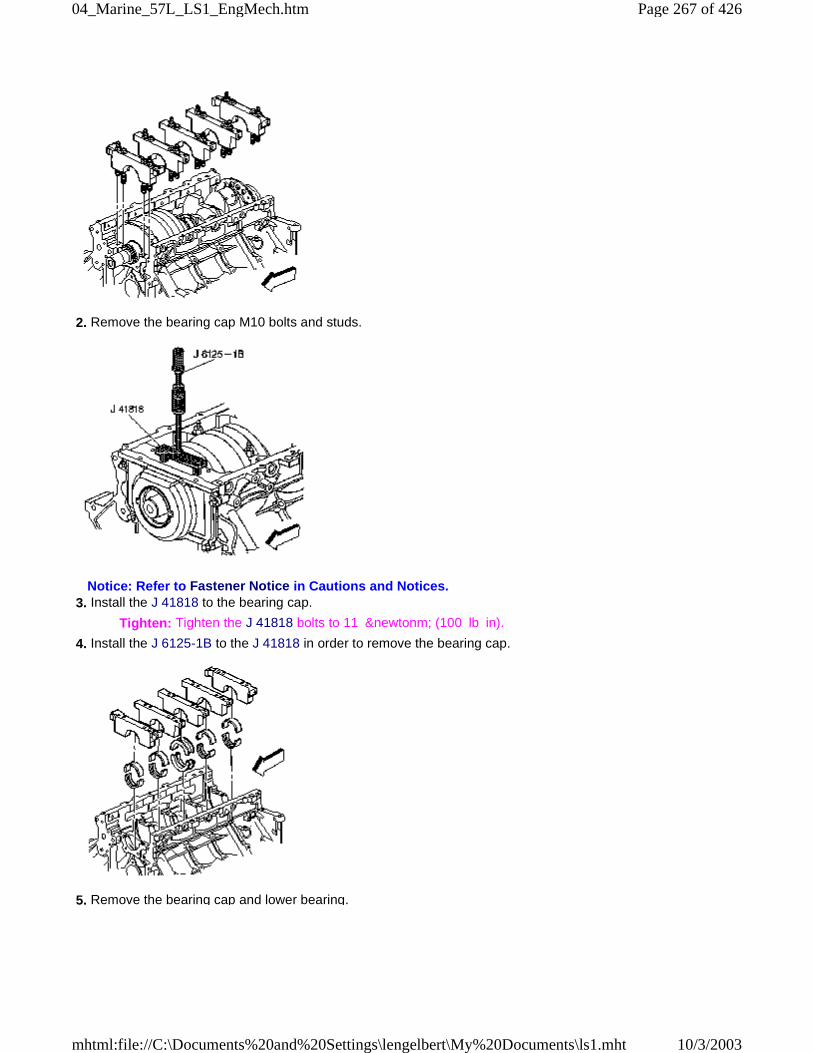
2. Remove the bearing cap M10 bolts and studs.
Notice: Refer to Fastener Notice in Cautions and Notices. 3. Install the J 41818 to the bearing cap.
Tighten: Tighten the J 41818 bolts to 11 &newtonm; (100 lb in).
4. Install the J 6125-1B to the J 41818 in order to remove the bearing cap.
5. Remove the bearing cap and lower bearing.
Page 267 of 42604_Marine_57L_LS1_EngMech.htm
10/3/2003mhtml:file://C:\Documents%20and%20Settings\lengelbert\My%20Documents\ls1.mht
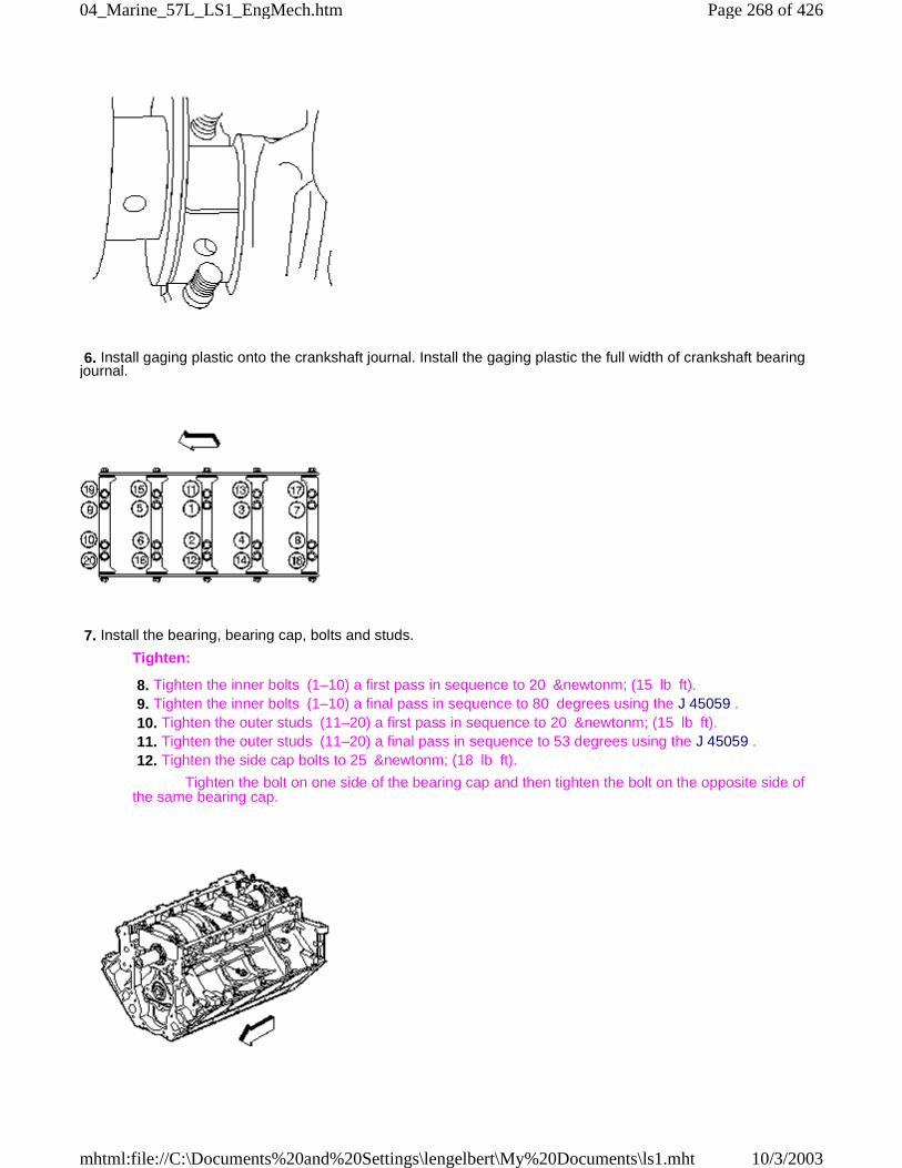
6. Install gaging plastic onto the crankshaft journal. Install the gaging plastic the full width of crankshaft bearingjournal.
7. Install the bearing, bearing cap, bolts and studs.
Tighten:
8. Tighten the inner bolts (1–10) a first pass in sequence to 20 &newtonm; (15 lb ft). 9. Tighten the inner bolts (1–10) a final pass in sequence to 80 degrees using the J 45059 . 10. Tighten the outer studs (11–20) a first pass in sequence to 20 &newtonm; (15 lb ft). 11. Tighten the outer studs (11–20) a final pass in sequence to 53 degrees using the J 45059 . 12. Tighten the side cap bolts to 25 &newtonm; (18 lb ft).
Tighten the bolt on one side of the bearing cap and then tighten the bolt on the opposite side ofthe same bearing cap.
Page 268 of 42604_Marine_57L_LS1_EngMech.htm
10/3/2003mhtml:file://C:\Documents%20and%20Settings\lengelbert\My%20Documents\ls1.mht
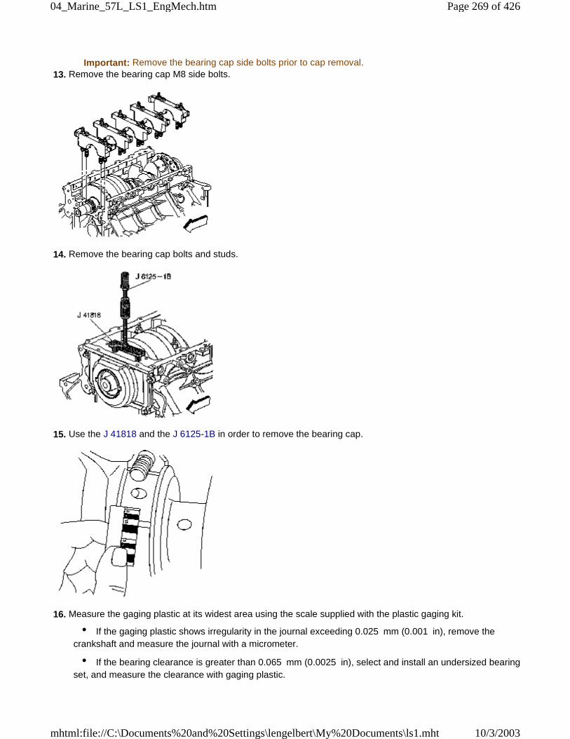
Important: Remove the bearing cap side bolts prior to cap removal. 13. Remove the bearing cap M8 side bolts.
14. Remove the bearing cap bolts and studs.
15. Use the J 41818 and the J 6125-1B in order to remove the bearing cap.
16. Measure the gaging plastic at its widest area using the scale supplied with the plastic gaging kit.
• If the gaging plastic shows irregularity in the journal exceeding 0.025 mm (0.001 in), remove thecrankshaft and measure the journal with a micrometer.
• If the bearing clearance is greater than 0.065 mm (0.0025 in), select and install an undersized bearingset, and measure the clearance with gaging plastic.
Page 269 of 42604_Marine_57L_LS1_EngMech.htm
10/3/2003mhtml:file://C:\Documents%20and%20Settings\lengelbert\My%20Documents\ls1.mht
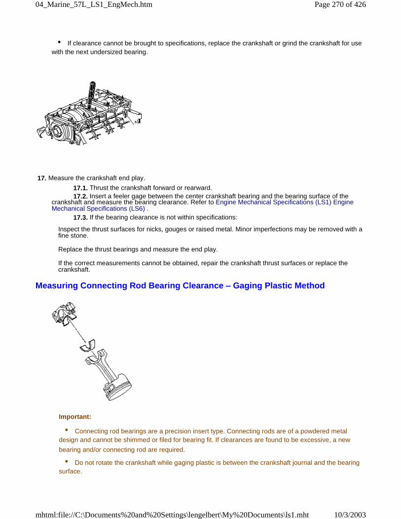
• If clearance cannot be brought to specifications, replace the crankshaft or grind the crankshaft for usewith the next undersized bearing.
17. Measure the crankshaft end play.
17.1. Thrust the crankshaft forward or rearward. 17.2. Insert a feeler gage between the center crankshaft bearing and the bearing surface of thecrankshaft and measure the bearing clearance. Refer to Engine Mechanical Specifications (LS1) EngineMechanical Specifications (LS6) . 17.3. If the bearing clearance is not within specifications:
Inspect the thrust surfaces for nicks, gouges or raised metal. Minor imperfections may be removed with afine stone.
Replace the thrust bearings and measure the end play.
If the correct measurements cannot be obtained, repair the crankshaft thrust surfaces or replace thecrankshaft.
Measuring Connecting Rod Bearing Clearance – Gaging Plastic Method
Important:
• Connecting rod bearings are a precision insert type. Connecting rods are of a powdered metaldesign and cannot be shimmed or filed for bearing fit. If clearances are found to be excessive, a new
bearing and/or connecting rod are required.
• Do not rotate the crankshaft while gaging plastic is between the crankshaft journal and the bearingsurface.
Page 270 of 42604_Marine_57L_LS1_EngMech.htm
10/3/2003mhtml:file://C:\Documents%20and%20Settings\lengelbert\My%20Documents\ls1.mht
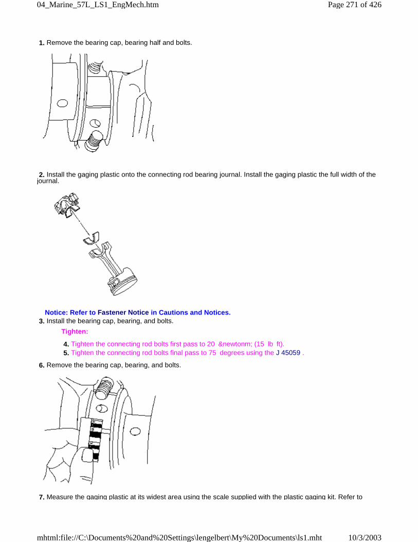
1. Remove the bearing cap, bearing half and bolts.
2. Install the gaging plastic onto the connecting rod bearing journal. Install the gaging plastic the full width of thejournal.
Notice: Refer to Fastener Notice in Cautions and Notices. 3. Install the bearing cap, bearing, and bolts.
Tighten:
4. Tighten the connecting rod bolts first pass to 20 &newtonm; (15 lb ft). 5. Tighten the connecting rod bolts final pass to 75 degrees using the J 45059 .
6. Remove the bearing cap, bearing, and bolts.
7. Measure the gaging plastic at its widest area using the scale supplied with the plastic gaging kit. Refer to
Page 271 of 42604_Marine_57L_LS1_EngMech.htm
10/3/2003mhtml:file://C:\Documents%20and%20Settings\lengelbert\My%20Documents\ls1.mht
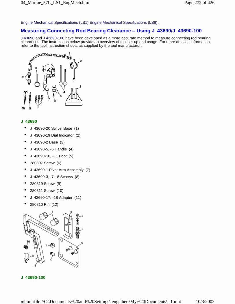
Engine Mechanical Specifications (LS1) Engine Mechanical Specifications (LS6) .
Measuring Connecting Rod Bearing Clearance – Using J 43690/J 43690-100J 43690 and J 43690-100 have been developed as a more accurate method to measure connecting rod bearingclearances. The instructions below provide an overview of tool set-up and usage. For more detailed information,refer to the tool instruction sheets as supplied by the tool manufacturer.
J 43690
• J 43690-20 Swivel Base (1)
• J 43690-19 Dial Indicator (2)
• J 43690-2 Base (3)
• J 43690-5, -6 Handle (4)
• J 43690-10, -11 Foot (5)
• 280307 Screw (6)
• J 43690-1 Pivot Arm Assembly (7)
• J 43690-3, -7, -8 Screws (8)
• 280319 Screw (9)
• 280311 Screw (10)
• J 43690-17, -18 Adapter (11)
• 280310 Pin (12)
J 43690-100
Page 272 of 42604_Marine_57L_LS1_EngMech.htm
10/3/2003mhtml:file://C:\Documents%20and%20Settings\lengelbert\My%20Documents\ls1.mht
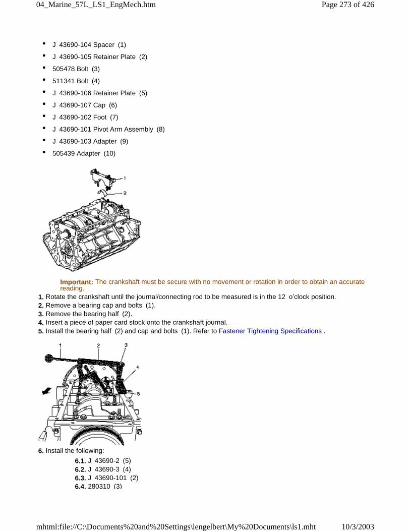
• J 43690-104 Spacer (1)
• J 43690-105 Retainer Plate (2)
• 505478 Bolt (3)
• 511341 Bolt (4)
• J 43690-106 Retainer Plate (5)
• J 43690-107 Cap (6)
• J 43690-102 Foot (7)
• J 43690-101 Pivot Arm Assembly (8)
• J 43690-103 Adapter (9)
• 505439 Adapter (10)
Important: The crankshaft must be secure with no movement or rotation in order to obtain an accuratereading.
1. Rotate the crankshaft until the journal/connecting rod to be measured is in the 12 o’clock position. 2. Remove a bearing cap and bolts (1). 3. Remove the bearing half (2). 4. Insert a piece of paper card stock onto the crankshaft journal. 5. Install the bearing half (2) and cap and bolts (1). Refer to Fastener Tightening Specifications .
6. Install the following:
6.1. J 43690-2 (5) 6.2. J 43690-3 (4) 6.3. J 43690-101 (2) 6.4. 280310 (3)
Page 273 of 42604_Marine_57L_LS1_EngMech.htm
10/3/2003mhtml:file://C:\Documents%20and%20Settings\lengelbert\My%20Documents\ls1.mht
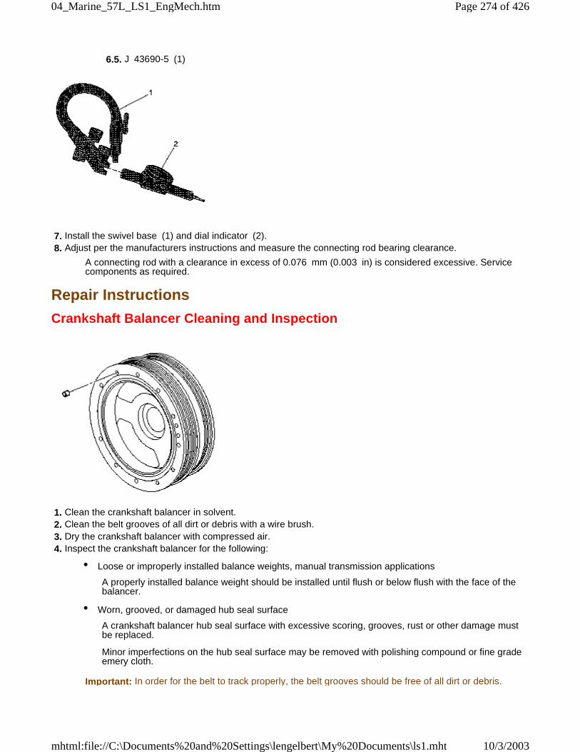
6.5. J 43690-5 (1)
7. Install the swivel base (1) and dial indicator (2). 8. Adjust per the manufacturers instructions and measure the connecting rod bearing clearance.
A connecting rod with a clearance in excess of 0.076 mm (0.003 in) is considered excessive. Servicecomponents as required.
Repair Instructions
Crankshaft Balancer Cleaning and Inspection
1. Clean the crankshaft balancer in solvent. 2. Clean the belt grooves of all dirt or debris with a wire brush. 3. Dry the crankshaft balancer with compressed air. 4. Inspect the crankshaft balancer for the following:
• Loose or improperly installed balance weights, manual transmission applications
A properly installed balance weight should be installed until flush or below flush with the face of thebalancer.
• Worn, grooved, or damaged hub seal surface
A crankshaft balancer hub seal surface with excessive scoring, grooves, rust or other damage mustbe replaced.
Minor imperfections on the hub seal surface may be removed with polishing compound or fine gradeemery cloth.
Important: In order for the belt to track properly, the belt grooves should be free of all dirt or debris.
Page 274 of 42604_Marine_57L_LS1_EngMech.htm
10/3/2003mhtml:file://C:\Documents%20and%20Settings\lengelbert\My%20Documents\ls1.mht
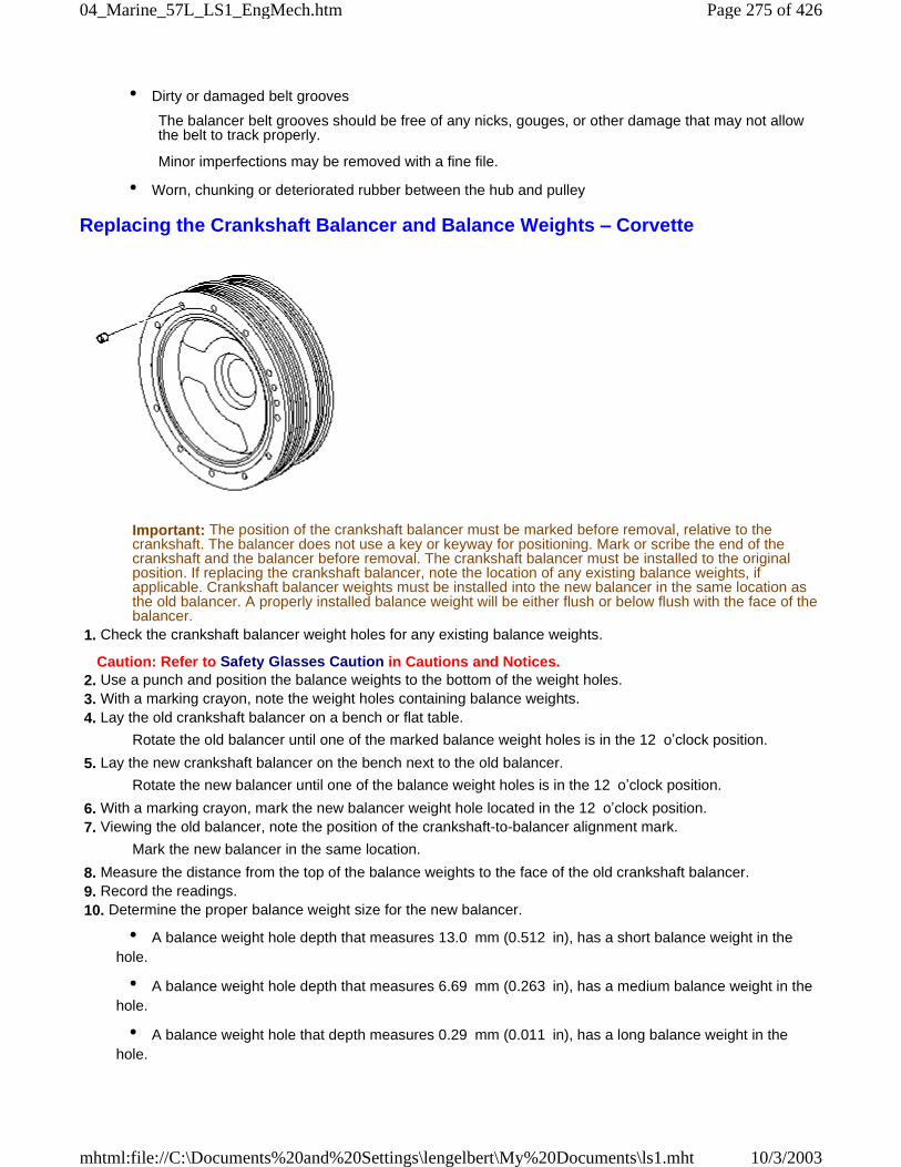
• Dirty or damaged belt grooves
The balancer belt grooves should be free of any nicks, gouges, or other damage that may not allowthe belt to track properly.
Minor imperfections may be removed with a fine file.
• Worn, chunking or deteriorated rubber between the hub and pulley
Replacing the Crankshaft Balancer and Balance Weights – Corvette
Important: The position of the crankshaft balancer must be marked before removal, relative to thecrankshaft. The balancer does not use a key or keyway for positioning. Mark or scribe the end of thecrankshaft and the balancer before removal. The crankshaft balancer must be installed to the originalposition. If replacing the crankshaft balancer, note the location of any existing balance weights, ifapplicable. Crankshaft balancer weights must be installed into the new balancer in the same location asthe old balancer. A properly installed balance weight will be either flush or below flush with the face of thebalancer.
1. Check the crankshaft balancer weight holes for any existing balance weights.
Caution: Refer to Safety Glasses Caution in Cautions and Notices. 2. Use a punch and position the balance weights to the bottom of the weight holes. 3. With a marking crayon, note the weight holes containing balance weights. 4. Lay the old crankshaft balancer on a bench or flat table.
Rotate the old balancer until one of the marked balance weight holes is in the 12 o’clock position.
5. Lay the new crankshaft balancer on the bench next to the old balancer.
Rotate the new balancer until one of the balance weight holes is in the 12 o’clock position.
6. With a marking crayon, mark the new balancer weight hole located in the 12 o’clock position. 7. Viewing the old balancer, note the position of the crankshaft-to-balancer alignment mark.
Mark the new balancer in the same location.
8. Measure the distance from the top of the balance weights to the face of the old crankshaft balancer. 9. Record the readings. 10. Determine the proper balance weight size for the new balancer.
• A balance weight hole depth that measures 13.0 mm (0.512 in), has a short balance weight in thehole.
• A balance weight hole depth that measures 6.69 mm (0.263 in), has a medium balance weight in thehole.
• A balance weight hole that depth measures 0.29 mm (0.011 in), has a long balance weight in thehole.
Page 275 of 42604_Marine_57L_LS1_EngMech.htm
10/3/2003mhtml:file://C:\Documents%20and%20Settings\lengelbert\My%20Documents\ls1.mht
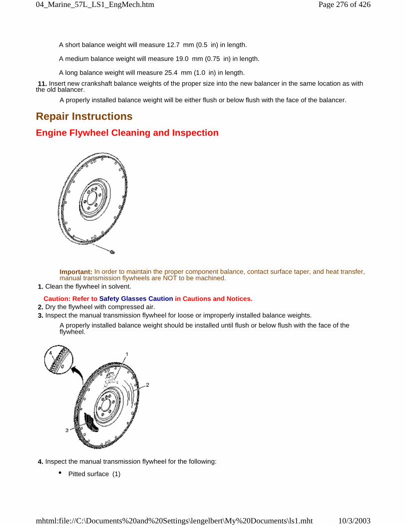
A short balance weight will measure 12.7 mm (0.5 in) in length.
A medium balance weight will measure 19.0 mm (0.75 in) in length.
A long balance weight will measure 25.4 mm (1.0 in) in length.
11. Insert new crankshaft balance weights of the proper size into the new balancer in the same location as withthe old balancer.
A properly installed balance weight will be either flush or below flush with the face of the balancer.
Repair Instructions
Engine Flywheel Cleaning and Inspection
Important: In order to maintain the proper component balance, contact surface taper, and heat transfer,manual transmission flywheels are NOT to be machined.
1. Clean the flywheel in solvent.
Caution: Refer to Safety Glasses Caution in Cautions and Notices. 2. Dry the flywheel with compressed air. 3. Inspect the manual transmission flywheel for loose or improperly installed balance weights.
A properly installed balance weight should be installed until flush or below flush with the face of theflywheel.
4. Inspect the manual transmission flywheel for the following:
• Pitted surface (1)
Page 276 of 42604_Marine_57L_LS1_EngMech.htm
10/3/2003mhtml:file://C:\Documents%20and%20Settings\lengelbert\My%20Documents\ls1.mht
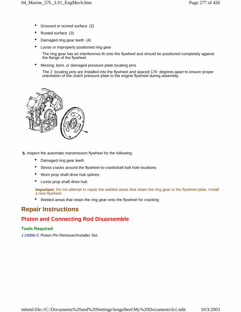
• Grooved or scored surface (2)
• Rusted surface (3)
• Damaged ring gear teeth (4)
• Loose or improperly positioned ring gear
The ring gear has an interference fit onto the flywheel and should be positioned completely againstthe flange of the flywheel.
• Missing, bent, or damaged pressure plate locating pins
The 2 locating pins are installed into the flywheel and spaced 170 degrees apart to ensure properorientation of the clutch pressure plate to the engine flywheel during assembly.
5. Inspect the automatic transmission flywheel for the following:
• Damaged ring gear teeth
• Stress cracks around the flywheel-to-crankshaft bolt hole locations
• Worn prop shaft drive hub splines
• Loose prop shaft drive hub
Important: Do not attempt to repair the welded areas that retain the ring gear to the flywheel plate. Installa new flywheel.
• Welded areas that retain the ring gear onto the flywheel for cracking
Repair Instructions
Piston and Connecting Rod Disassemble
Tools Required
J 24086-C Piston Pin Remover/Installer Set
Page 277 of 42604_Marine_57L_LS1_EngMech.htm
10/3/2003mhtml:file://C:\Documents%20and%20Settings\lengelbert\My%20Documents\ls1.mht
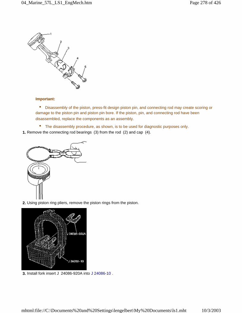
Important:
• Disassembly of the piston, press-fit design piston pin, and connecting rod may create scoring ordamage to the piston pin and piston pin bore. If the piston, pin, and connecting rod have been
disassembled, replace the components as an assembly.
• The disassembly procedure, as shown, is to be used for diagnostic purposes only.
1. Remove the connecting rod bearings (3) from the rod (2) and cap (4).
2. Using piston ring pliers, remove the piston rings from the piston.
3. Install fork insert J 24086-920A into J 24086-10 .
Page 278 of 42604_Marine_57L_LS1_EngMech.htm
10/3/2003mhtml:file://C:\Documents%20and%20Settings\lengelbert\My%20Documents\ls1.mht
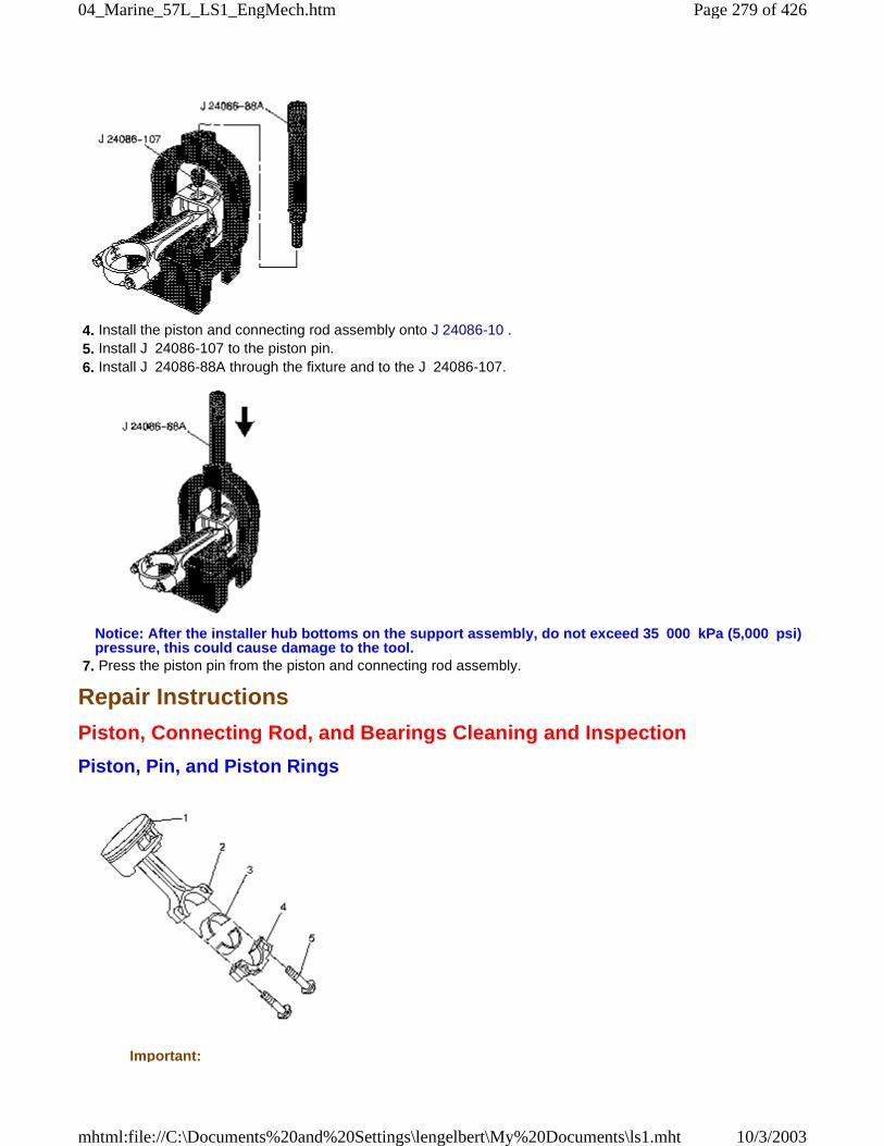
4. Install the piston and connecting rod assembly onto J 24086-10 . 5. Install J 24086-107 to the piston pin. 6. Install J 24086-88A through the fixture and to the J 24086-107.
Notice: After the installer hub bottoms on the support assembly, do not exceed 35 000 kPa (5,000 psi)pressure, this could cause damage to the tool.
7. Press the piston pin from the piston and connecting rod assembly.
Repair Instructions
Piston, Connecting Rod, and Bearings Cleaning and Inspection
Piston, Pin, and Piston Rings
Important:
Page 279 of 42604_Marine_57L_LS1_EngMech.htm
10/3/2003mhtml:file://C:\Documents%20and%20Settings\lengelbert\My%20Documents\ls1.mht
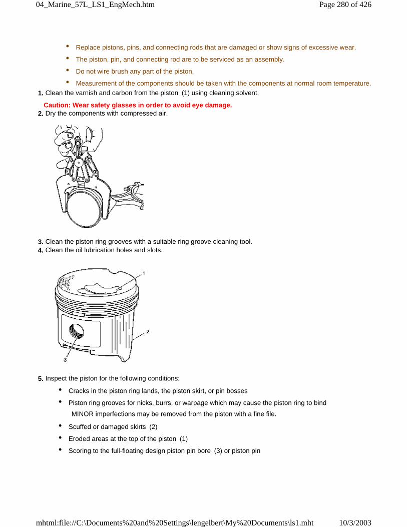
• Replace pistons, pins, and connecting rods that are damaged or show signs of excessive wear.
• The piston, pin, and connecting rod are to be serviced as an assembly.
• Do not wire brush any part of the piston.
• Measurement of the components should be taken with the components at normal room temperature.
1. Clean the varnish and carbon from the piston (1) using cleaning solvent.
Caution: Wear safety glasses in order to avoid eye damage. 2. Dry the components with compressed air.
3. Clean the piston ring grooves with a suitable ring groove cleaning tool. 4. Clean the oil lubrication holes and slots.
5. Inspect the piston for the following conditions:
• Cracks in the piston ring lands, the piston skirt, or pin bosses
• Piston ring grooves for nicks, burrs, or warpage which may cause the piston ring to bind
MINOR imperfections may be removed from the piston with a fine file.
• Scuffed or damaged skirts (2)
• Eroded areas at the top of the piston (1)
• Scoring to the full-floating design piston pin bore (3) or piston pin
Page 280 of 42604_Marine_57L_LS1_EngMech.htm
10/3/2003mhtml:file://C:\Documents%20and%20Settings\lengelbert\My%20Documents\ls1.mht
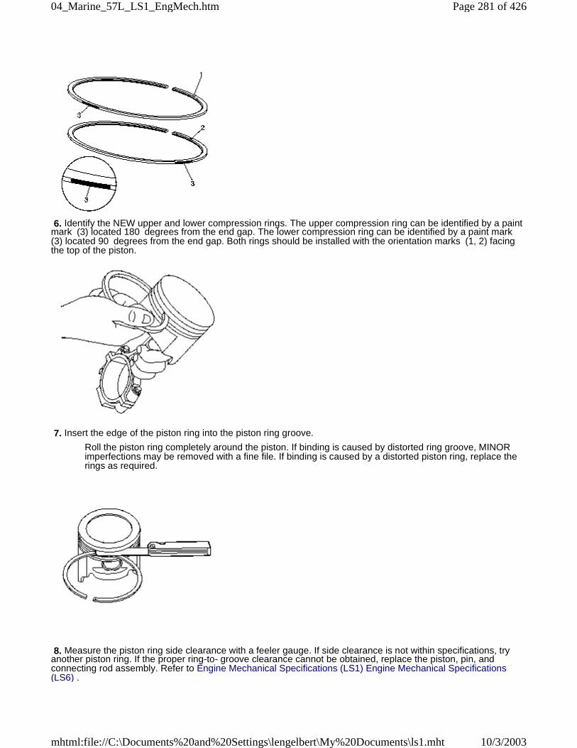
6. Identify the NEW upper and lower compression rings. The upper compression ring can be identified by a paintmark (3) located 180 degrees from the end gap. The lower compression ring can be identified by a paint mark(3) located 90 degrees from the end gap. Both rings should be installed with the orientation marks (1, 2) facingthe top of the piston.
7. Insert the edge of the piston ring into the piston ring groove.
Roll the piston ring completely around the piston. If binding is caused by distorted ring groove, MINORimperfections may be removed with a fine file. If binding is caused by a distorted piston ring, replace therings as required.
8. Measure the piston ring side clearance with a feeler gauge. If side clearance is not within specifications, tryanother piston ring. If the proper ring-to- groove clearance cannot be obtained, replace the piston, pin, andconnecting rod assembly. Refer to Engine Mechanical Specifications (LS1) Engine Mechanical Specifications(LS6) .
Page 281 of 42604_Marine_57L_LS1_EngMech.htm
10/3/2003mhtml:file://C:\Documents%20and%20Settings\lengelbert\My%20Documents\ls1.mht
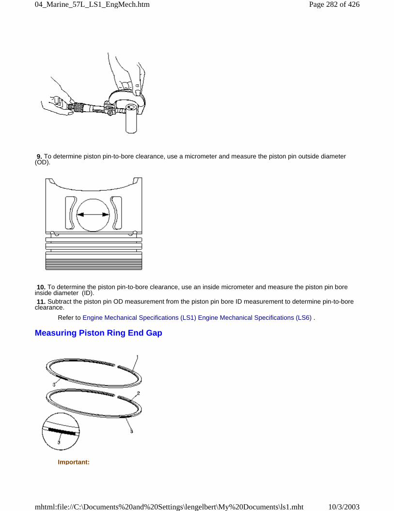
9. To determine piston pin-to-bore clearance, use a micrometer and measure the piston pin outside diameter(OD).
10. To determine the piston pin-to-bore clearance, use an inside micrometer and measure the piston pin boreinside diameter (ID). 11. Subtract the piston pin OD measurement from the piston pin bore ID measurement to determine pin-to-boreclearance.
Refer to Engine Mechanical Specifications (LS1) Engine Mechanical Specifications (LS6) .
Measuring Piston Ring End Gap
Important:
Page 282 of 42604_Marine_57L_LS1_EngMech.htm
10/3/2003mhtml:file://C:\Documents%20and%20Settings\lengelbert\My%20Documents\ls1.mht
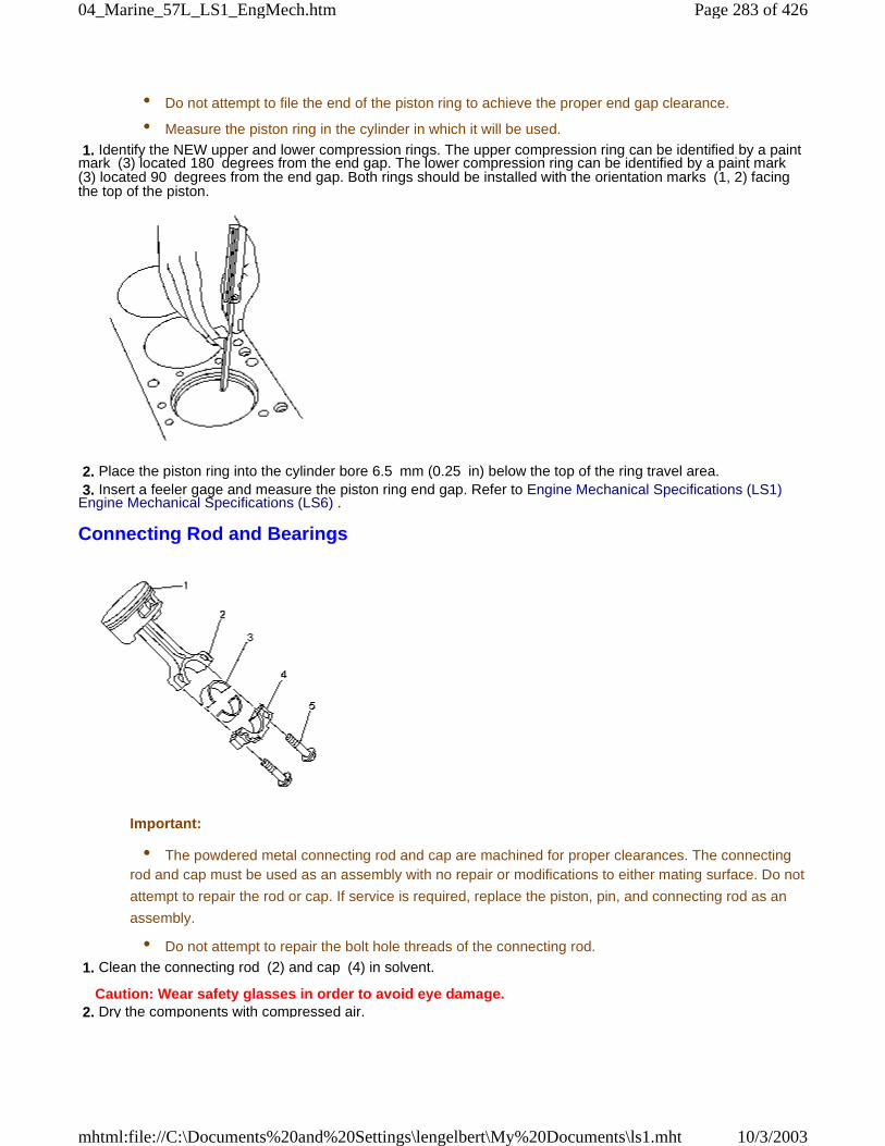
• Do not attempt to file the end of the piston ring to achieve the proper end gap clearance.
• Measure the piston ring in the cylinder in which it will be used.
1. Identify the NEW upper and lower compression rings. The upper compression ring can be identified by a paintmark (3) located 180 degrees from the end gap. The lower compression ring can be identified by a paint mark(3) located 90 degrees from the end gap. Both rings should be installed with the orientation marks (1, 2) facingthe top of the piston.
2. Place the piston ring into the cylinder bore 6.5 mm (0.25 in) below the top of the ring travel area. 3. Insert a feeler gage and measure the piston ring end gap. Refer to Engine Mechanical Specifications (LS1)Engine Mechanical Specifications (LS6) .
Connecting Rod and Bearings
Important:
• The powdered metal connecting rod and cap are machined for proper clearances. The connectingrod and cap must be used as an assembly with no repair or modifications to either mating surface. Do not
attempt to repair the rod or cap. If service is required, replace the piston, pin, and connecting rod as an
assembly.
• Do not attempt to repair the bolt hole threads of the connecting rod.
1. Clean the connecting rod (2) and cap (4) in solvent.
Caution: Wear safety glasses in order to avoid eye damage. 2. Dry the components with compressed air.
Page 283 of 42604_Marine_57L_LS1_EngMech.htm
10/3/2003mhtml:file://C:\Documents%20and%20Settings\lengelbert\My%20Documents\ls1.mht
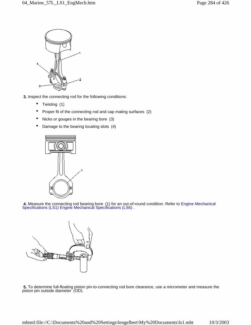
3. Inspect the connecting rod for the following conditions:
• Twisting (1)
• Proper fit of the connecting rod and cap mating surfaces (2)
• Nicks or gouges in the bearing bore (3)
• Damage to the bearing locating slots (4)
4. Measure the connecting rod bearing bore (1) for an out-of-round condition. Refer to Engine MechanicalSpecifications (LS1) Engine Mechanical Specifications (LS6) .
5. To determine full-floating piston pin-to-connecting rod bore clearance, use a micrometer and measure thepiston pin outside diameter (OD).
Page 284 of 42604_Marine_57L_LS1_EngMech.htm
10/3/2003mhtml:file://C:\Documents%20and%20Settings\lengelbert\My%20Documents\ls1.mht
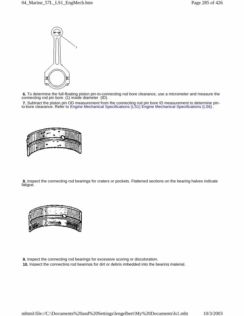
6. To determine the full-floating piston pin-to-connecting rod bore clearance, use a micrometer and measure theconnecting rod pin bore (1) inside diameter (ID). 7. Subtract the piston pin OD measurement from the connecting rod pin bore ID measurement to determine pin-to-bore clearance. Refer to Engine Mechanical Specifications (LS1) Engine Mechanical Specifications (LS6) .
8. Inspect the connecting rod bearings for craters or pockets. Flattened sections on the bearing halves indicatefatigue.
9. Inspect the connecting rod bearings for excessive scoring or discoloration. 10. Inspect the connecting rod bearings for dirt or debris imbedded into the bearing material.
Page 285 of 42604_Marine_57L_LS1_EngMech.htm
10/3/2003mhtml:file://C:\Documents%20and%20Settings\lengelbert\My%20Documents\ls1.mht
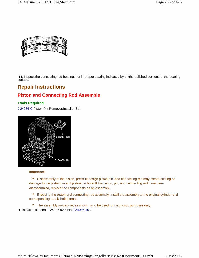
11. Inspect the connecting rod bearings for improper seating indicated by bright, polished sections of the bearingsurface.
Repair Instructions
Piston and Connecting Rod Assemble
Tools Required
J 24086-C Piston Pin Remover/Installer Set
Important:
• Disassembly of the piston, press-fit design piston pin, and connecting rod may create scoring ordamage to the piston pin and piston pin bore. If the piston, pin, and connecting rod have been
disassembled, replace the components as an assembly.
• If reusing the piston and connecting rod assembly, install the assembly to the original cylinder andcorresponding crankshaft journal.
• The assembly procedure, as shown, is to be used for diagnostic purposes only.
1. Install fork insert J 24086-920 into J 24086-10 .
Page 286 of 42604_Marine_57L_LS1_EngMech.htm
10/3/2003mhtml:file://C:\Documents%20and%20Settings\lengelbert\My%20Documents\ls1.mht
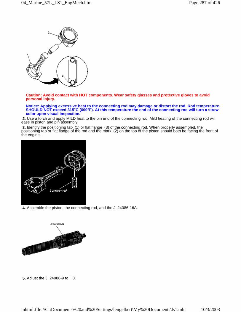
Caution: Avoid contact with HOT components. Wear safety glasses and protective gloves to avoidpersonal injury.
Notice: Applying excessive heat to the connecting rod may damage or distort the rod. Rod temperatureSHOULD NOT exceed 315°C (600°F). At this temperature the end of the connecting rod will turn a strawcolor upon visual inspection.
2. Use a torch and apply MILD heat to the pin end of the connecting rod. Mild heating of the connecting rod willease in piston and pin assembly. 3. Identify the positioning tab (1) or flat flange (3) of the connecting rod. When properly assembled, thepositioning tab or flat flange of the rod and the mark (2) on the top of the piston should both be facing the front ofthe engine.
4. Assemble the piston, the connecting rod, and the J 24086-16A.
5. Adjust the J 24086-9 to I 8.
Page 287 of 42604_Marine_57L_LS1_EngMech.htm
10/3/2003mhtml:file://C:\Documents%20and%20Settings\lengelbert\My%20Documents\ls1.mht
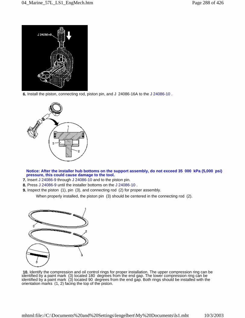
6. Install the piston, connecting rod, piston pin, and J 24086-16A to the J 24086-10 .
Notice: After the installer hub bottoms on the support assembly, do not exceed 35 000 kPa (5,000 psi)pressure, this could cause damage to the tool.
7. Insert J 24086-9 through J 24086-10 and to the piston pin. 8. Press J 24086-9 until the installer bottoms on the J 24086-10 . 9. Inspect the piston (1), pin (3), and connecting rod (2) for proper assembly.
When properly installed, the piston pin (3) should be centered in the connecting rod (2).
10. Identify the compression and oil control rings for proper installation. The upper compression ring can beidentified by a paint mark (3) located 180 degrees from the end gap. The lower compression ring can beidentified by a paint mark (3) located 90 degrees from the end gap. Both rings should be installed with theorientation marks (1, 2) facing the top of the piston.
Page 288 of 42604_Marine_57L_LS1_EngMech.htm
10/3/2003mhtml:file://C:\Documents%20and%20Settings\lengelbert\My%20Documents\ls1.mht
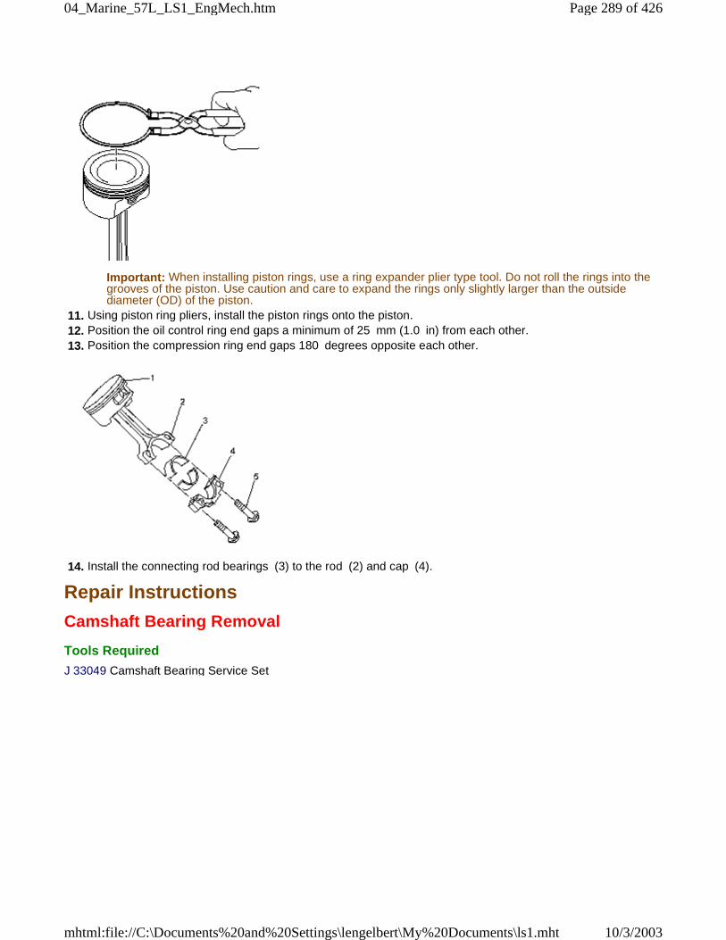
Important: When installing piston rings, use a ring expander plier type tool. Do not roll the rings into thegrooves of the piston. Use caution and care to expand the rings only slightly larger than the outsidediameter (OD) of the piston.
11. Using piston ring pliers, install the piston rings onto the piston. 12. Position the oil control ring end gaps a minimum of 25 mm (1.0 in) from each other. 13. Position the compression ring end gaps 180 degrees opposite each other.
14. Install the connecting rod bearings (3) to the rod (2) and cap (4).
Repair Instructions
Camshaft Bearing Removal
Tools Required
J 33049 Camshaft Bearing Service Set
Page 289 of 42604_Marine_57L_LS1_EngMech.htm
10/3/2003mhtml:file://C:\Documents%20and%20Settings\lengelbert\My%20Documents\ls1.mht
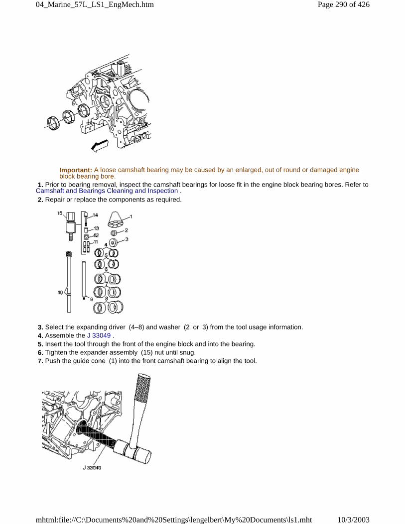
Important: A loose camshaft bearing may be caused by an enlarged, out of round or damaged engineblock bearing bore.
1. Prior to bearing removal, inspect the camshaft bearings for loose fit in the engine block bearing bores. Refer toCamshaft and Bearings Cleaning and Inspection . 2. Repair or replace the components as required.
3. Select the expanding driver (4–8) and washer (2 or 3) from the tool usage information. 4. Assemble the J 33049 . 5. Insert the tool through the front of the engine block and into the bearing. 6. Tighten the expander assembly (15) nut until snug. 7. Push the guide cone (1) into the front camshaft bearing to align the tool.
Page 290 of 42604_Marine_57L_LS1_EngMech.htm
10/3/2003mhtml:file://C:\Documents%20and%20Settings\lengelbert\My%20Documents\ls1.mht
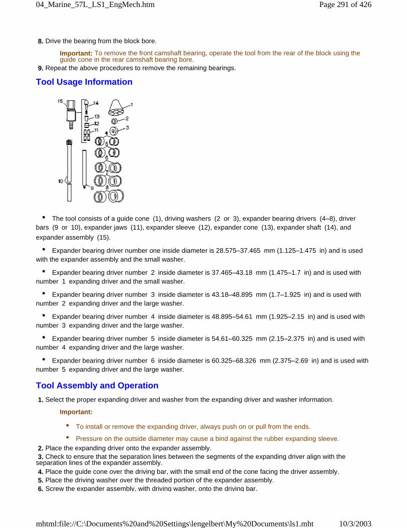
8. Drive the bearing from the block bore.
Important: To remove the front camshaft bearing, operate the tool from the rear of the block using theguide cone in the rear camshaft bearing bore.
9. Repeat the above procedures to remove the remaining bearings.
Tool Usage Information
• The tool consists of a guide cone (1), driving washers (2 or 3), expander bearing drivers (4–8), driverbars (9 or 10), expander jaws (11), expander sleeve (12), expander cone (13), expander shaft (14), and
expander assembly (15).
• Expander bearing driver number one inside diameter is 28.575–37.465 mm (1.125–1.475 in) and is usedwith the expander assembly and the small washer.
• Expander bearing driver number 2 inside diameter is 37.465–43.18 mm (1.475–1.7 in) and is used withnumber 1 expanding driver and the small washer.
• Expander bearing driver number 3 inside diameter is 43.18–48.895 mm (1.7–1.925 in) and is used withnumber 2 expanding driver and the large washer.
• Expander bearing driver number 4 inside diameter is 48.895–54.61 mm (1.925–2.15 in) and is used withnumber 3 expanding driver and the large washer.
• Expander bearing driver number 5 inside diameter is 54.61–60.325 mm (2.15–2.375 in) and is used withnumber 4 expanding driver and the large washer.
• Expander bearing driver number 6 inside diameter is 60.325–68.326 mm (2.375–2.69 in) and is used withnumber 5 expanding driver and the large washer.
Tool Assembly and Operation
1. Select the proper expanding driver and washer from the expanding driver and washer information.
Important:
• To install or remove the expanding driver, always push on or pull from the ends.
• Pressure on the outside diameter may cause a bind against the rubber expanding sleeve.
2. Place the expanding driver onto the expander assembly. 3. Check to ensure that the separation lines between the segments of the expanding driver align with theseparation lines of the expander assembly. 4. Place the guide cone over the driving bar, with the small end of the cone facing the driver assembly. 5. Place the driving washer over the threaded portion of the expander assembly. 6. Screw the expander assembly, with driving washer, onto the driving bar.
Page 291 of 42604_Marine_57L_LS1_EngMech.htm
10/3/2003mhtml:file://C:\Documents%20and%20Settings\lengelbert\My%20Documents\ls1.mht
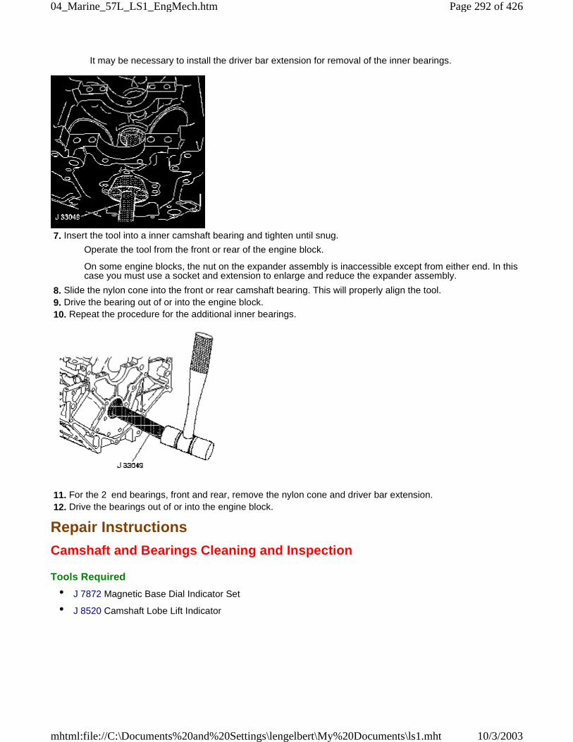
It may be necessary to install the driver bar extension for removal of the inner bearings.
7. Insert the tool into a inner camshaft bearing and tighten until snug.
Operate the tool from the front or rear of the engine block.
On some engine blocks, the nut on the expander assembly is inaccessible except from either end. In thiscase you must use a socket and extension to enlarge and reduce the expander assembly.
8. Slide the nylon cone into the front or rear camshaft bearing. This will properly align the tool. 9. Drive the bearing out of or into the engine block. 10. Repeat the procedure for the additional inner bearings.
11. For the 2 end bearings, front and rear, remove the nylon cone and driver bar extension. 12. Drive the bearings out of or into the engine block.
Repair Instructions
Camshaft and Bearings Cleaning and Inspection
Tools Required
• J 7872 Magnetic Base Dial Indicator Set
• J 8520 Camshaft Lobe Lift Indicator
Page 292 of 42604_Marine_57L_LS1_EngMech.htm
10/3/2003mhtml:file://C:\Documents%20and%20Settings\lengelbert\My%20Documents\ls1.mht
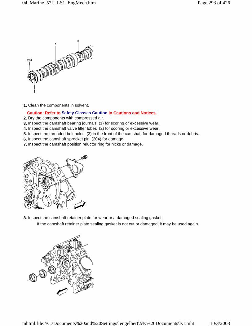
1. Clean the components in solvent.
Caution: Refer to Safety Glasses Caution in Cautions and Notices. 2. Dry the components with compressed air. 3. Inspect the camshaft bearing journals (1) for scoring or excessive wear. 4. Inspect the camshaft valve lifter lobes (2) for scoring or excessive wear. 5. Inspect the threaded bolt holes (3) in the front of the camshaft for damaged threads or debris. 6. Inspect the camshaft sprocket pin (204) for damage. 7. Inspect the camshaft position reluctor ring for nicks or damage.
8. Inspect the camshaft retainer plate for wear or a damaged sealing gasket.
If the camshaft retainer plate sealing gasket is not cut or damaged, it may be used again.
Page 293 of 42604_Marine_57L_LS1_EngMech.htm
10/3/2003mhtml:file://C:\Documents%20and%20Settings\lengelbert\My%20Documents\ls1.mht
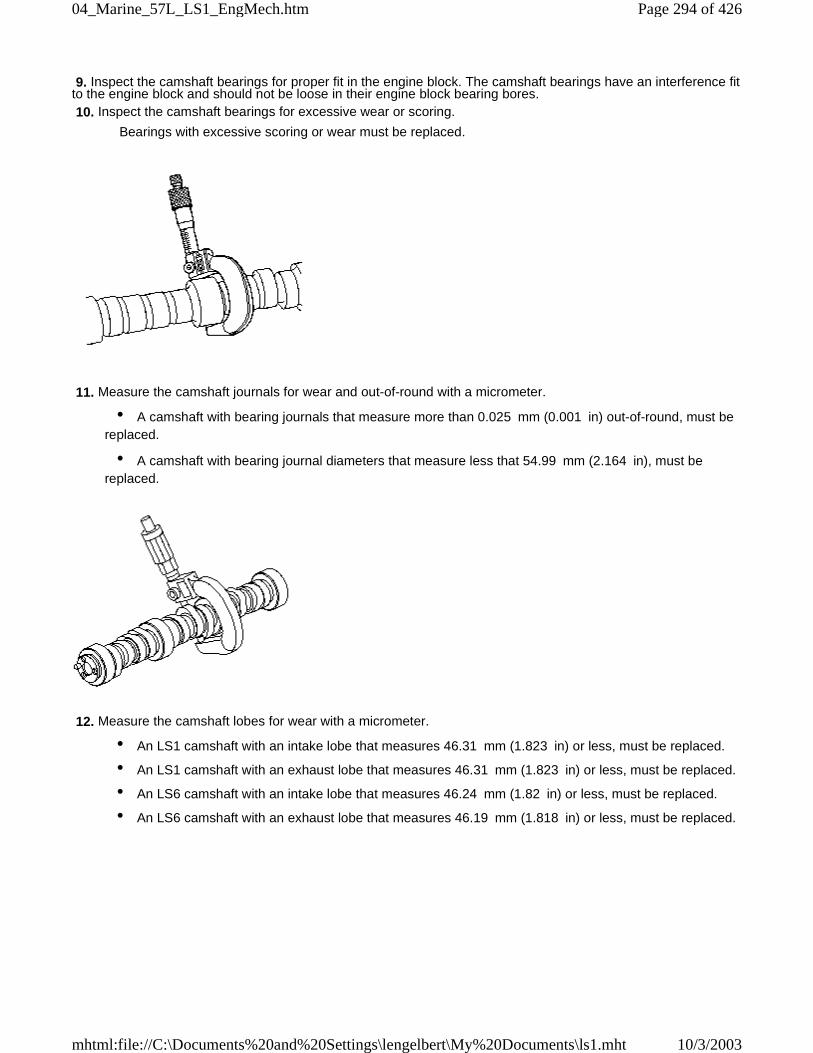
9. Inspect the camshaft bearings for proper fit in the engine block. The camshaft bearings have an interference fitto the engine block and should not be loose in their engine block bearing bores. 10. Inspect the camshaft bearings for excessive wear or scoring.
Bearings with excessive scoring or wear must be replaced.
11. Measure the camshaft journals for wear and out-of-round with a micrometer.
• A camshaft with bearing journals that measure more than 0.025 mm (0.001 in) out-of-round, must bereplaced.
• A camshaft with bearing journal diameters that measure less that 54.99 mm (2.164 in), must bereplaced.
12. Measure the camshaft lobes for wear with a micrometer.
• An LS1 camshaft with an intake lobe that measures 46.31 mm (1.823 in) or less, must be replaced.
• An LS1 camshaft with an exhaust lobe that measures 46.31 mm (1.823 in) or less, must be replaced.
• An LS6 camshaft with an intake lobe that measures 46.24 mm (1.82 in) or less, must be replaced.
• An LS6 camshaft with an exhaust lobe that measures 46.19 mm (1.818 in) or less, must be replaced.
Page 294 of 42604_Marine_57L_LS1_EngMech.htm
10/3/2003mhtml:file://C:\Documents%20and%20Settings\lengelbert\My%20Documents\ls1.mht
13. Measure the camshaft runout.
13.1. Mount the camshaft in wooden V-blocks or between centers on a fixture. 13.2. Check the runout of the intermediate camshaft bearing journals using the J 7872. 13.3. If camshaft runout exceeds 0.05 mm (0.002 in), the camshaft is bent and should be replaced.
Measuring Camshaft Lobe Lift
Important: Measuring camshaft lobe lift is a procedure used to determine if the camshaft lobes haveworn. This test is to be performed prior to engine disassembly and with the camshaft and valve traincomponents installed in the engine.
1. Measure camshaft lobe lift using J 8520.
1.1. Remove the valve rocker arms and bolts 1.2. Install the dial indicator mounting stud into the valve rocker arm bolt hole. 1.3. Assemble the components of the J 8520and position onto the stud. 1.4. Position the shaft of the dial indicator onto the end of the pushrod. 1.5. Rotate the face of the dial indicator to zero. 1.6. Slowly rotate the crankshaft clockwise until the dial indicator obtains its highest and lowestreadings.
Page 295 of 42604_Marine_57L_LS1_EngMech.htm
10/3/2003mhtml:file://C:\Documents%20and%20Settings\lengelbert\My%20Documents\ls1.mht
1.7. Compare the total lift shown to specifications.
The proper lobe lift for the LS1 intake lobes is 6.96 mm (0.274 in).
The proper lobe lift for the LS1 exhaust lobes is 7.13 mm (0.281 in).
The proper lobe lift for the LS6 intake lobes is 8.24 mm (0.324 in).
The proper lobe lift for the LS6 exhaust lobes is 8.19 mm (0.322 in).
1.8. Remove the tool. 2. Compare measurements to specifications.
If the readings are not within specifications, remove the camshaft. Inspect and/or replace components asrequired.
Repair Instructions
Camshaft Bearing Installation
Tools Required
J 33049 Camshaft Bearing Service Set
Important: The engine block camshaft bearing bores are machined for 3 different OD size bearings.Positions 1 and 5 are the largest diameter bores. Position 3 is the smallest diameter bore. Positions 2 and4 are the intermediate size bores. The ID for all camshaft bearings is the same size.
1. Measure the engine block camshaft bearing bores (1–5) to identify the correct OD size bearing for eachposition. Refer to Engine Mechanical Specifications (LS1) Engine Mechanical Specifications (LS6) .
2. Select the expanding driver (4–8) and washer (2 or 3) from the J 33049 . Refer to Camshaft Bearing
Page 296 of 42604_Marine_57L_LS1_EngMech.htm
10/3/2003mhtml:file://C:\Documents%20and%20Settings\lengelbert\My%20Documents\ls1.mht
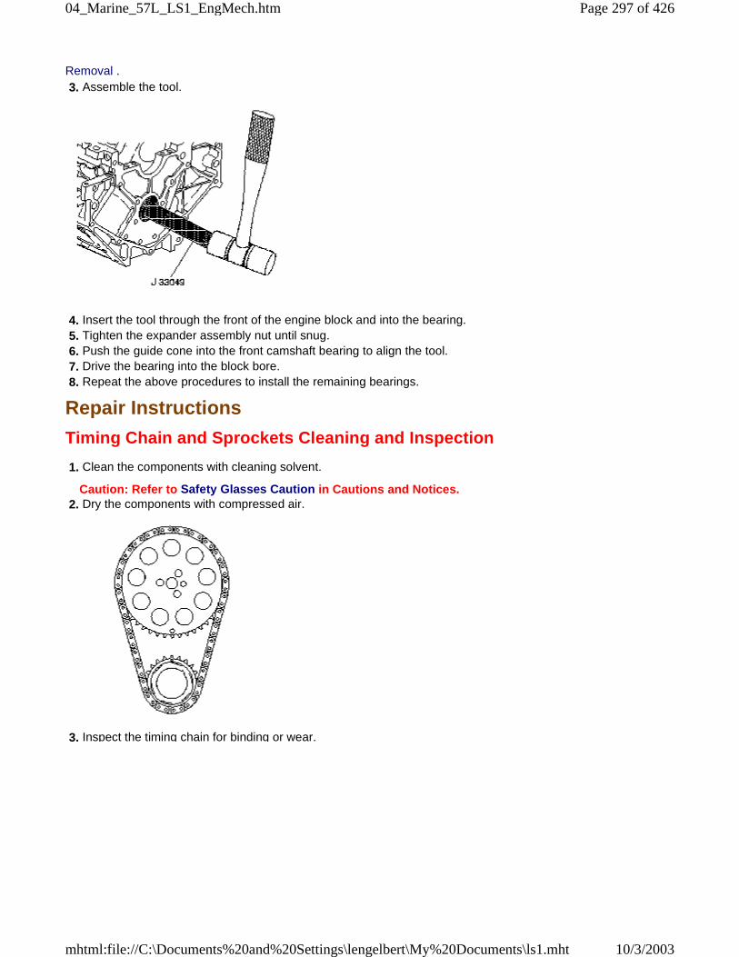
Removal . 3. Assemble the tool.
4. Insert the tool through the front of the engine block and into the bearing. 5. Tighten the expander assembly nut until snug. 6. Push the guide cone into the front camshaft bearing to align the tool. 7. Drive the bearing into the block bore. 8. Repeat the above procedures to install the remaining bearings.
Repair Instructions
Timing Chain and Sprockets Cleaning and Inspection
1. Clean the components with cleaning solvent.
Caution: Refer to Safety Glasses Caution in Cautions and Notices. 2. Dry the components with compressed air.
3. Inspect the timing chain for binding or wear.
Page 297 of 42604_Marine_57L_LS1_EngMech.htm
10/3/2003mhtml:file://C:\Documents%20and%20Settings\lengelbert\My%20Documents\ls1.mht
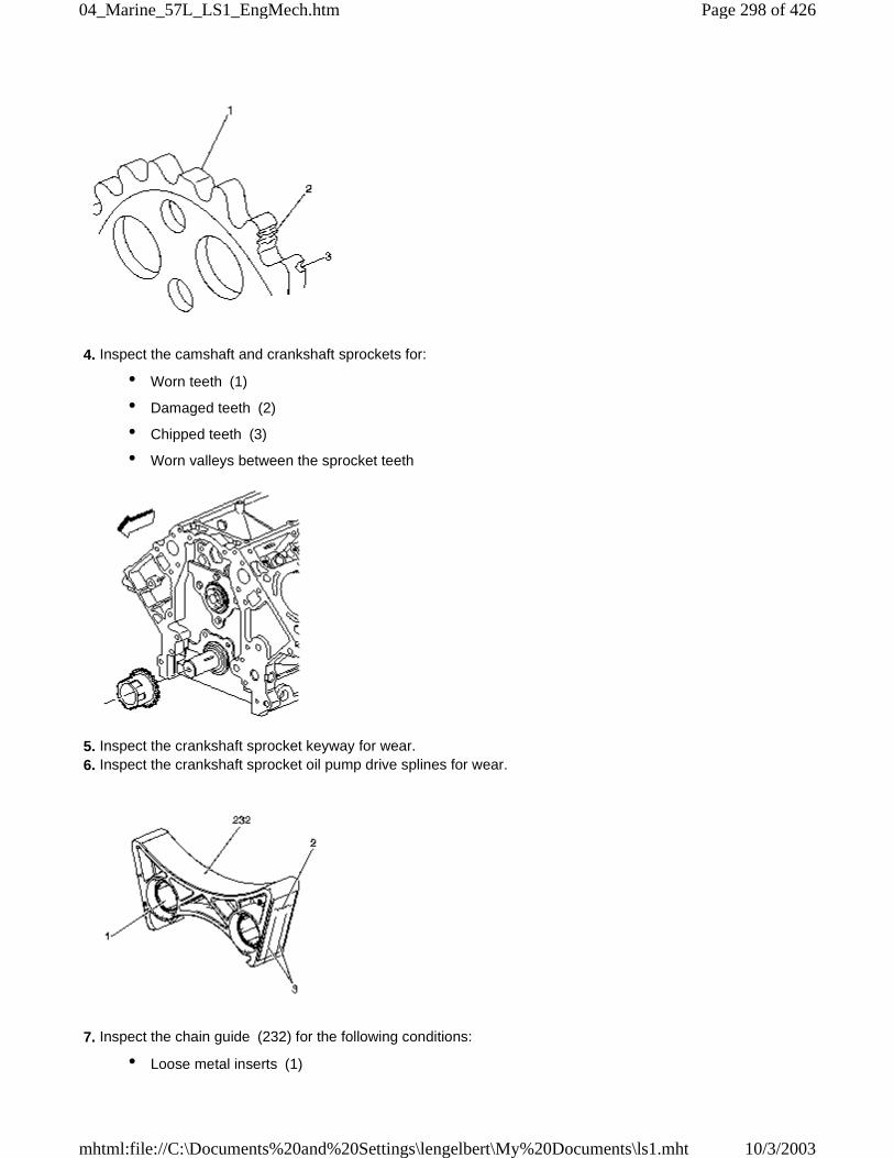
4. Inspect the camshaft and crankshaft sprockets for:
• Worn teeth (1)
• Damaged teeth (2)
• Chipped teeth (3)
• Worn valleys between the sprocket teeth
5. Inspect the crankshaft sprocket keyway for wear. 6. Inspect the crankshaft sprocket oil pump drive splines for wear.
7. Inspect the chain guide (232) for the following conditions:
• Loose metal inserts (1)
Page 298 of 42604_Marine_57L_LS1_EngMech.htm
10/3/2003mhtml:file://C:\Documents%20and%20Settings\lengelbert\My%20Documents\ls1.mht
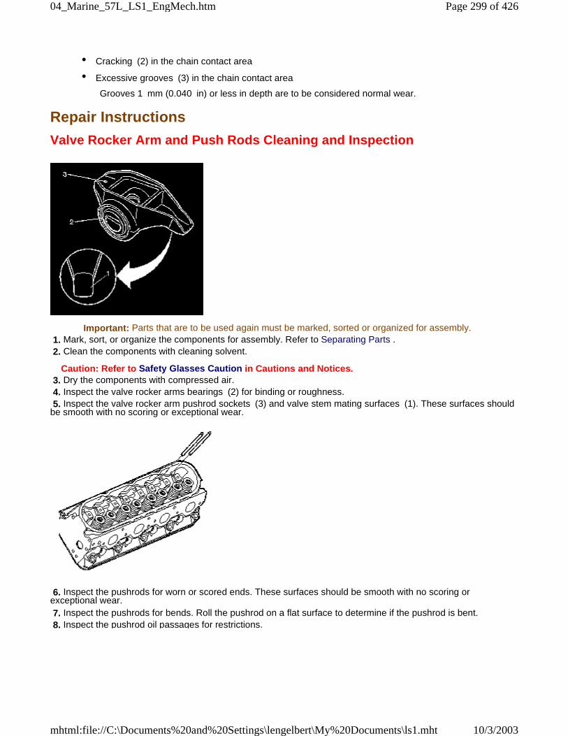
• Cracking (2) in the chain contact area
• Excessive grooves (3) in the chain contact area
Grooves 1 mm (0.040 in) or less in depth are to be considered normal wear.
Repair Instructions
Valve Rocker Arm and Push Rods Cleaning and Inspection
Important: Parts that are to be used again must be marked, sorted or organized for assembly. 1. Mark, sort, or organize the components for assembly. Refer to Separating Parts . 2. Clean the components with cleaning solvent.
Caution: Refer to Safety Glasses Caution in Cautions and Notices. 3. Dry the components with compressed air. 4. Inspect the valve rocker arms bearings (2) for binding or roughness. 5. Inspect the valve rocker arm pushrod sockets (3) and valve stem mating surfaces (1). These surfaces shouldbe smooth with no scoring or exceptional wear.
6. Inspect the pushrods for worn or scored ends. These surfaces should be smooth with no scoring orexceptional wear. 7. Inspect the pushrods for bends. Roll the pushrod on a flat surface to determine if the pushrod is bent. 8. Inspect the pushrod oil passages for restrictions.
Page 299 of 42604_Marine_57L_LS1_EngMech.htm
10/3/2003mhtml:file://C:\Documents%20and%20Settings\lengelbert\My%20Documents\ls1.mht
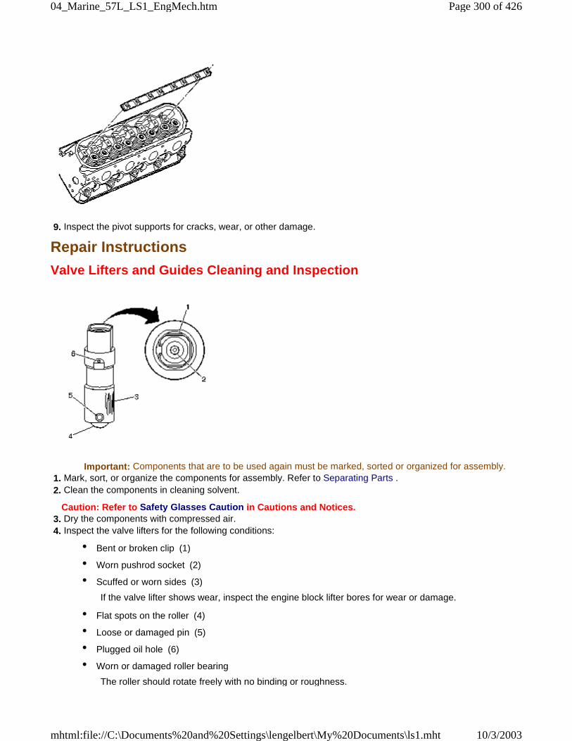
9. Inspect the pivot supports for cracks, wear, or other damage.
Repair Instructions
Valve Lifters and Guides Cleaning and Inspection
Important: Components that are to be used again must be marked, sorted or organized for assembly. 1. Mark, sort, or organize the components for assembly. Refer to Separating Parts . 2. Clean the components in cleaning solvent.
Caution: Refer to Safety Glasses Caution in Cautions and Notices. 3. Dry the components with compressed air. 4. Inspect the valve lifters for the following conditions:
• Bent or broken clip (1)
• Worn pushrod socket (2)
• Scuffed or worn sides (3)
If the valve lifter shows wear, inspect the engine block lifter bores for wear or damage.
• Flat spots on the roller (4)
• Loose or damaged pin (5)
• Plugged oil hole (6)
• Worn or damaged roller bearing
The roller should rotate freely with no binding or roughness.
Page 300 of 42604_Marine_57L_LS1_EngMech.htm
10/3/2003mhtml:file://C:\Documents%20and%20Settings\lengelbert\My%20Documents\ls1.mht
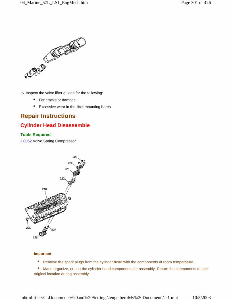
5. Inspect the valve lifter guides for the following:
• For cracks or damage
• Excessive wear in the lifter mounting bores
Repair Instructions
Cylinder Head Disassemble
Tools Required
J 8062 Valve Spring Compressor
Important:
• Remove the spark plugs from the cylinder head with the components at room temperature.
• Mark, organize, or sort the cylinder head components for assembly. Return the components to theiroriginal location during assembly.
Page 301 of 42604_Marine_57L_LS1_EngMech.htm
10/3/2003mhtml:file://C:\Documents%20and%20Settings\lengelbert\My%20Documents\ls1.mht
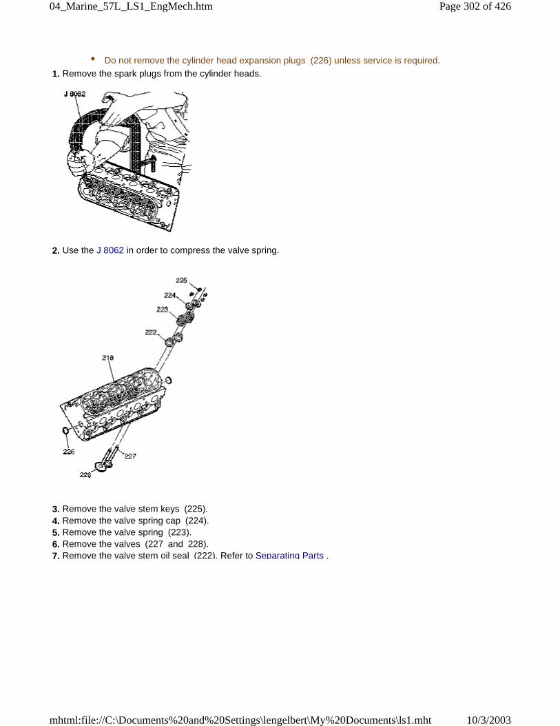
• Do not remove the cylinder head expansion plugs (226) unless service is required.
1. Remove the spark plugs from the cylinder heads.
2. Use the J 8062 in order to compress the valve spring.
3. Remove the valve stem keys (225). 4. Remove the valve spring cap (224). 5. Remove the valve spring (223). 6. Remove the valves (227 and 228). 7. Remove the valve stem oil seal (222). Refer to Separating Parts .
Page 302 of 42604_Marine_57L_LS1_EngMech.htm
10/3/2003mhtml:file://C:\Documents%20and%20Settings\lengelbert\My%20Documents\ls1.mht
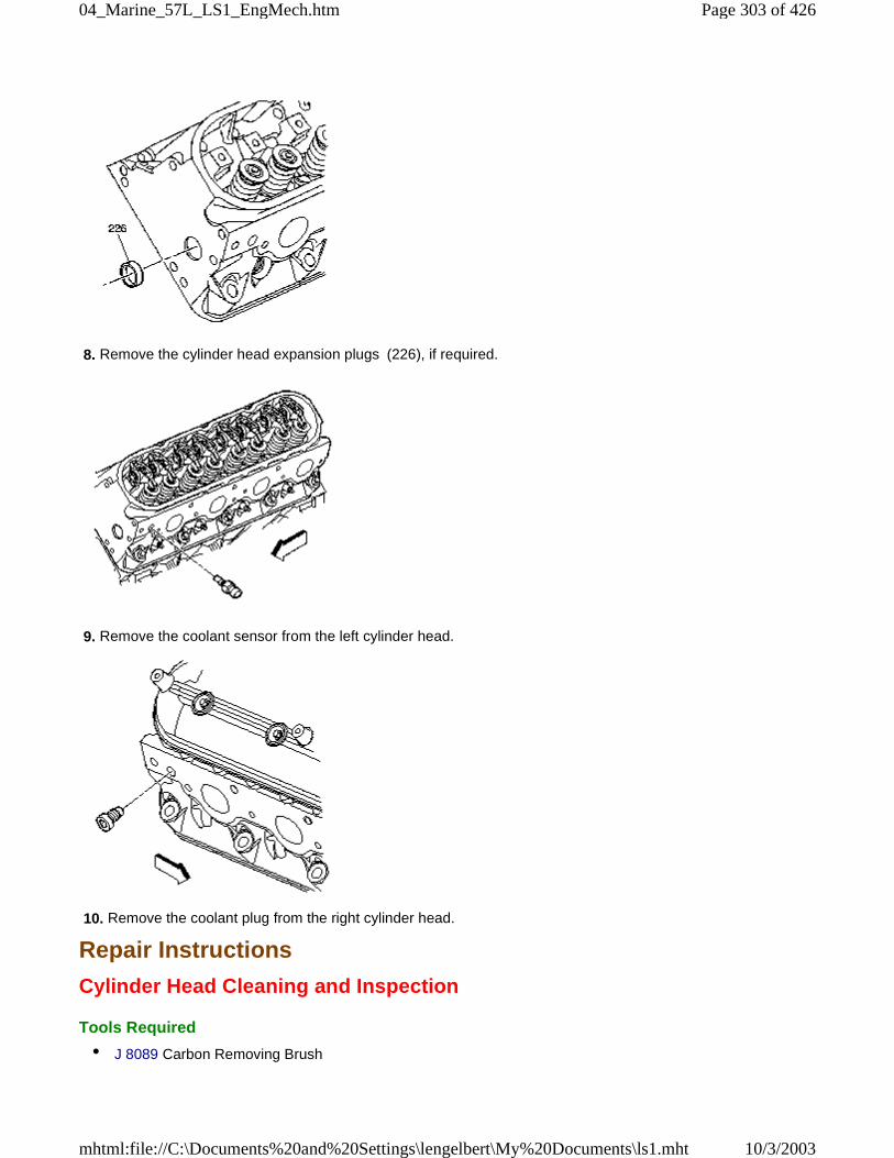
8. Remove the cylinder head expansion plugs (226), if required.
9. Remove the coolant sensor from the left cylinder head.
10. Remove the coolant plug from the right cylinder head.
Repair Instructions
Cylinder Head Cleaning and Inspection
Tools Required
• J 8089 Carbon Removing Brush
Page 303 of 42604_Marine_57L_LS1_EngMech.htm
10/3/2003mhtml:file://C:\Documents%20and%20Settings\lengelbert\My%20Documents\ls1.mht
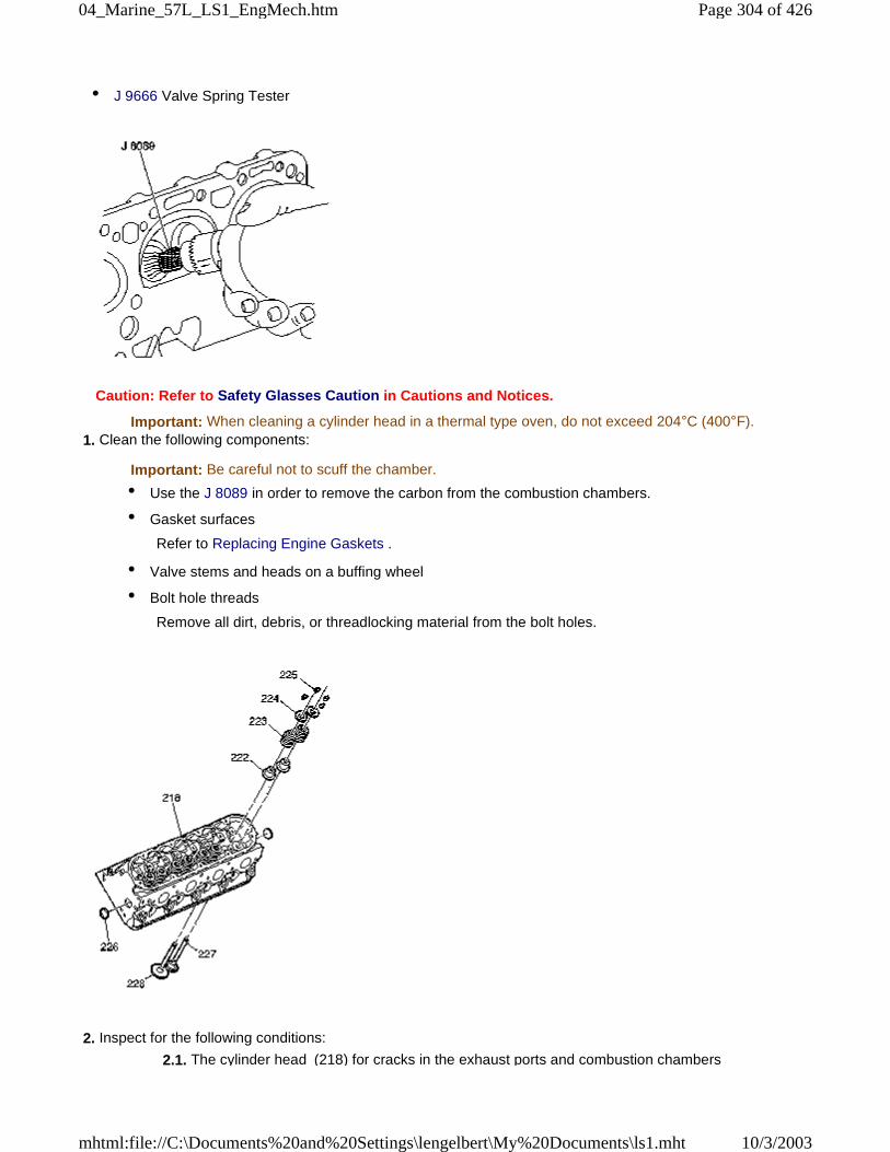
• J 9666 Valve Spring Tester
Caution: Refer to Safety Glasses Caution in Cautions and Notices.
Important: When cleaning a cylinder head in a thermal type oven, do not exceed 204°C (400°F). 1. Clean the following components:
Important: Be careful not to scuff the chamber.
• Use the J 8089 in order to remove the carbon from the combustion chambers.
• Gasket surfaces
Refer to Replacing Engine Gaskets .
• Valve stems and heads on a buffing wheel
• Bolt hole threads
Remove all dirt, debris, or threadlocking material from the bolt holes.
2. Inspect for the following conditions:
2.1. The cylinder head (218) for cracks in the exhaust ports and combustion chambers
Page 304 of 42604_Marine_57L_LS1_EngMech.htm
10/3/2003mhtml:file://C:\Documents%20and%20Settings\lengelbert\My%20Documents\ls1.mht
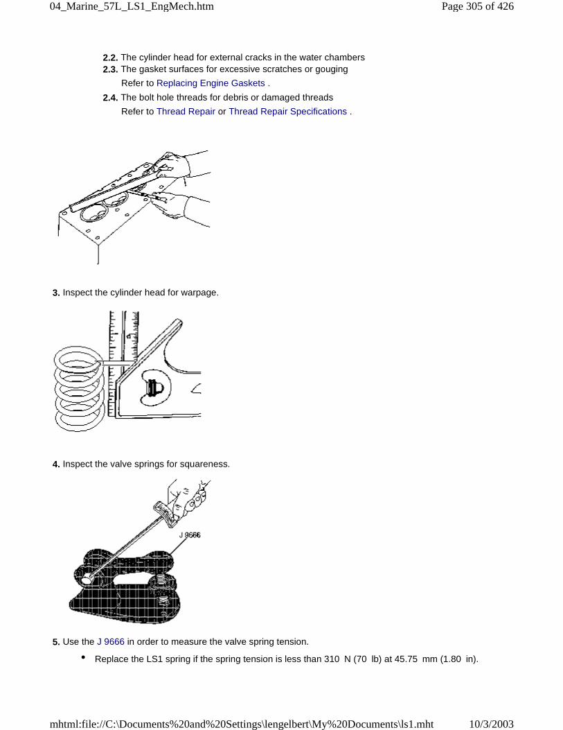
2.2. The cylinder head for external cracks in the water chambers 2.3. The gasket surfaces for excessive scratches or gouging
Refer to Replacing Engine Gaskets .
2.4. The bolt hole threads for debris or damaged threads
Refer to Thread Repair or Thread Repair Specifications .
3. Inspect the cylinder head for warpage.
4. Inspect the valve springs for squareness.
5. Use the J 9666 in order to measure the valve spring tension.
• Replace the LS1 spring if the spring tension is less than 310 N (70 lb) at 45.75 mm (1.80 in).
Page 305 of 42604_Marine_57L_LS1_EngMech.htm
10/3/2003mhtml:file://C:\Documents%20and%20Settings\lengelbert\My%20Documents\ls1.mht
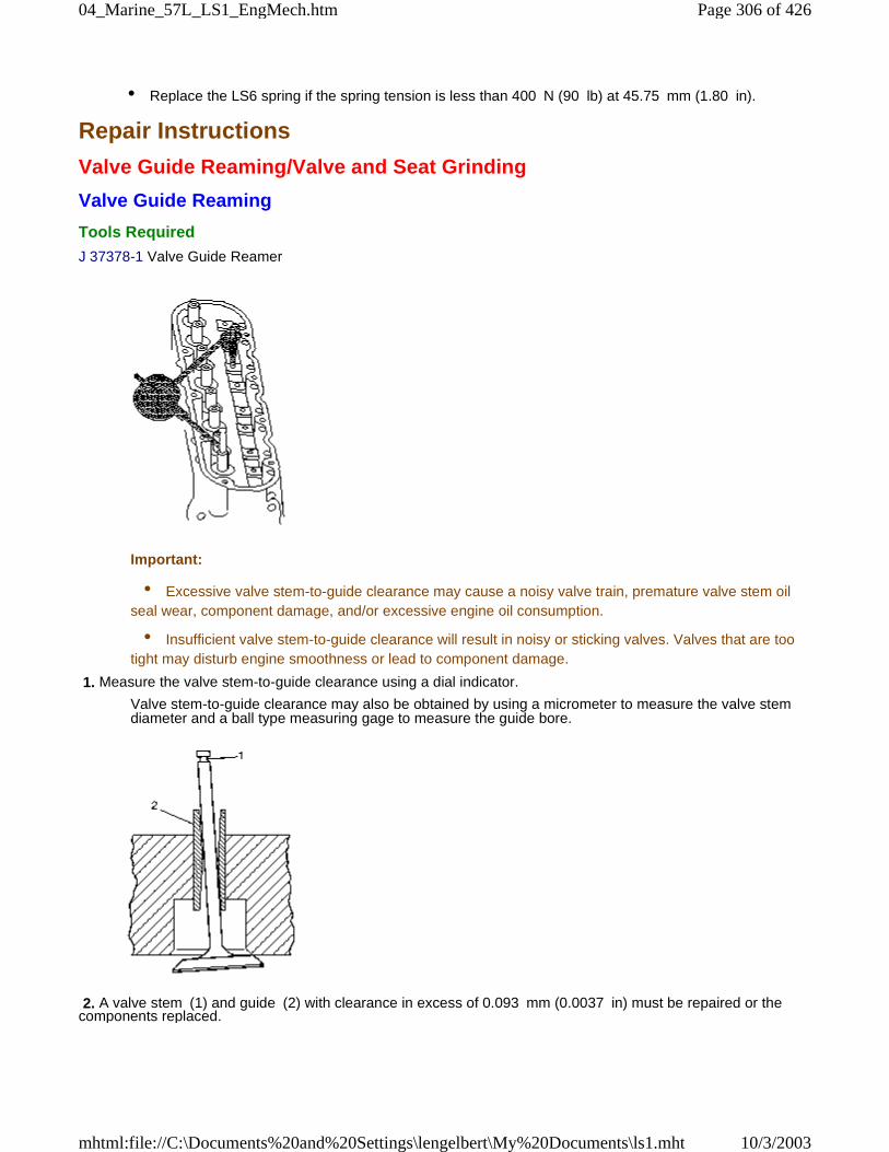
• Replace the LS6 spring if the spring tension is less than 400 N (90 lb) at 45.75 mm (1.80 in).
Repair Instructions
Valve Guide Reaming/Valve and Seat Grinding
Valve Guide Reaming
Tools Required
J 37378-1 Valve Guide Reamer
Important:
• Excessive valve stem-to-guide clearance may cause a noisy valve train, premature valve stem oilseal wear, component damage, and/or excessive engine oil consumption.
• Insufficient valve stem-to-guide clearance will result in noisy or sticking valves. Valves that are tootight may disturb engine smoothness or lead to component damage.
1. Measure the valve stem-to-guide clearance using a dial indicator.
Valve stem-to-guide clearance may also be obtained by using a micrometer to measure the valve stemdiameter and a ball type measuring gage to measure the guide bore.
2. A valve stem (1) and guide (2) with clearance in excess of 0.093 mm (0.0037 in) must be repaired or thecomponents replaced.
Page 306 of 42604_Marine_57L_LS1_EngMech.htm
10/3/2003mhtml:file://C:\Documents%20and%20Settings\lengelbert\My%20Documents\ls1.mht
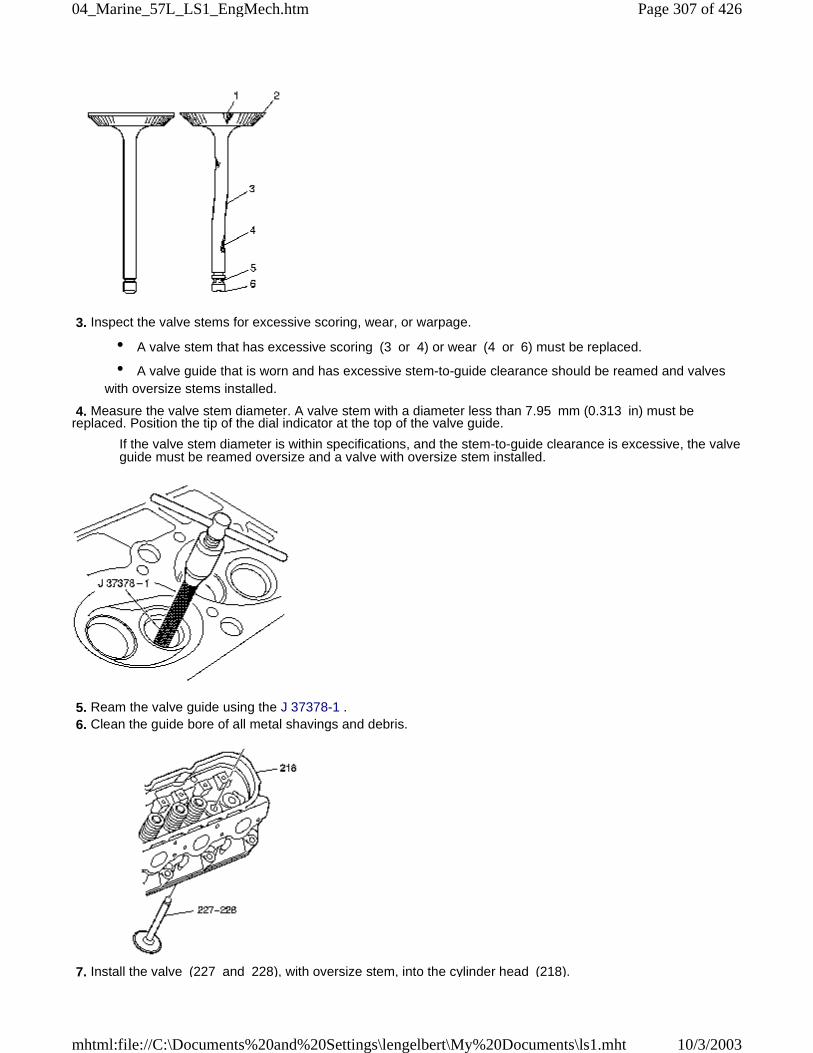
3. Inspect the valve stems for excessive scoring, wear, or warpage.
• A valve stem that has excessive scoring (3 or 4) or wear (4 or 6) must be replaced.
• A valve guide that is worn and has excessive stem-to-guide clearance should be reamed and valveswith oversize stems installed.
4. Measure the valve stem diameter. A valve stem with a diameter less than 7.95 mm (0.313 in) must bereplaced. Position the tip of the dial indicator at the top of the valve guide.
If the valve stem diameter is within specifications, and the stem-to-guide clearance is excessive, the valveguide must be reamed oversize and a valve with oversize stem installed.
5. Ream the valve guide using the J 37378-1 . 6. Clean the guide bore of all metal shavings and debris.
7. Install the valve (227 and 228), with oversize stem, into the cylinder head (218).
Page 307 of 42604_Marine_57L_LS1_EngMech.htm
10/3/2003mhtml:file://C:\Documents%20and%20Settings\lengelbert\My%20Documents\ls1.mht
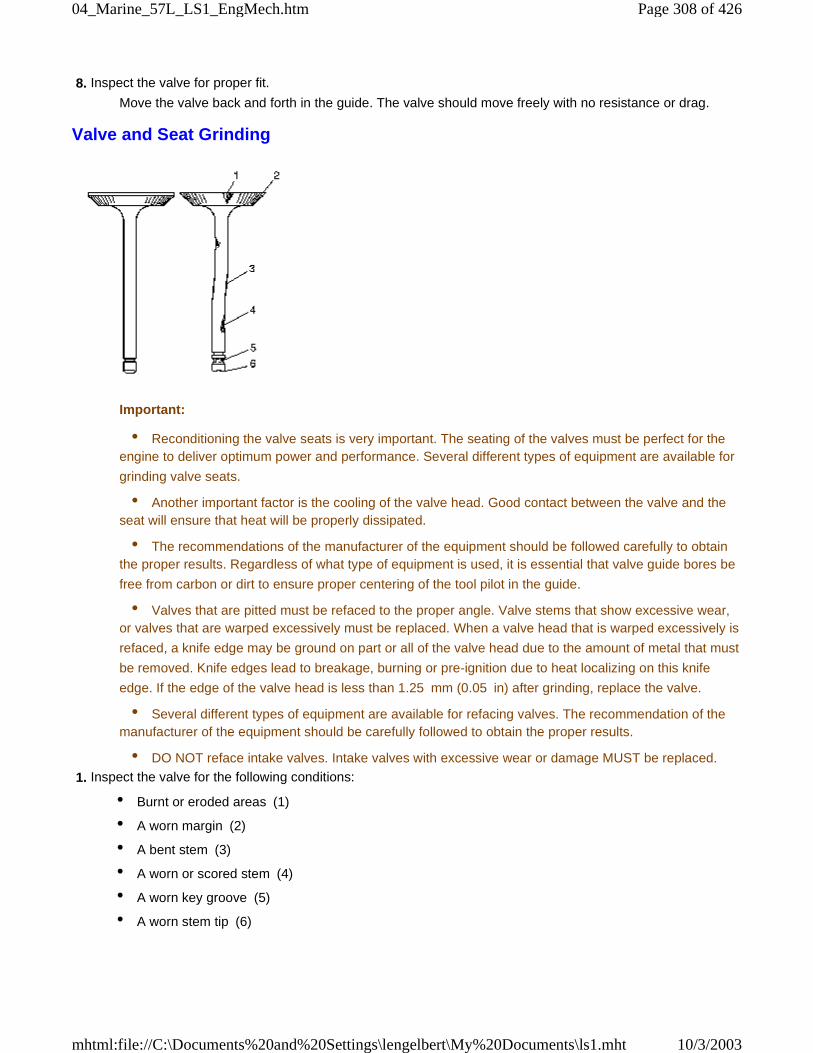
8. Inspect the valve for proper fit.
Move the valve back and forth in the guide. The valve should move freely with no resistance or drag.
Valve and Seat Grinding
Important:
• Reconditioning the valve seats is very important. The seating of the valves must be perfect for theengine to deliver optimum power and performance. Several different types of equipment are available for
grinding valve seats.
• Another important factor is the cooling of the valve head. Good contact between the valve and theseat will ensure that heat will be properly dissipated.
• The recommendations of the manufacturer of the equipment should be followed carefully to obtainthe proper results. Regardless of what type of equipment is used, it is essential that valve guide bores be
free from carbon or dirt to ensure proper centering of the tool pilot in the guide.
• Valves that are pitted must be refaced to the proper angle. Valve stems that show excessive wear,or valves that are warped excessively must be replaced. When a valve head that is warped excessively is
refaced, a knife edge may be ground on part or all of the valve head due to the amount of metal that must
be removed. Knife edges lead to breakage, burning or pre-ignition due to heat localizing on this knife
edge. If the edge of the valve head is less than 1.25 mm (0.05 in) after grinding, replace the valve.
• Several different types of equipment are available for refacing valves. The recommendation of themanufacturer of the equipment should be carefully followed to obtain the proper results.
• DO NOT reface intake valves. Intake valves with excessive wear or damage MUST be replaced.
1. Inspect the valve for the following conditions:
• Burnt or eroded areas (1)
• A worn margin (2)
• A bent stem (3)
• A worn or scored stem (4)
• A worn key groove (5)
• A worn stem tip (6)
Page 308 of 42604_Marine_57L_LS1_EngMech.htm
10/3/2003mhtml:file://C:\Documents%20and%20Settings\lengelbert\My%20Documents\ls1.mht
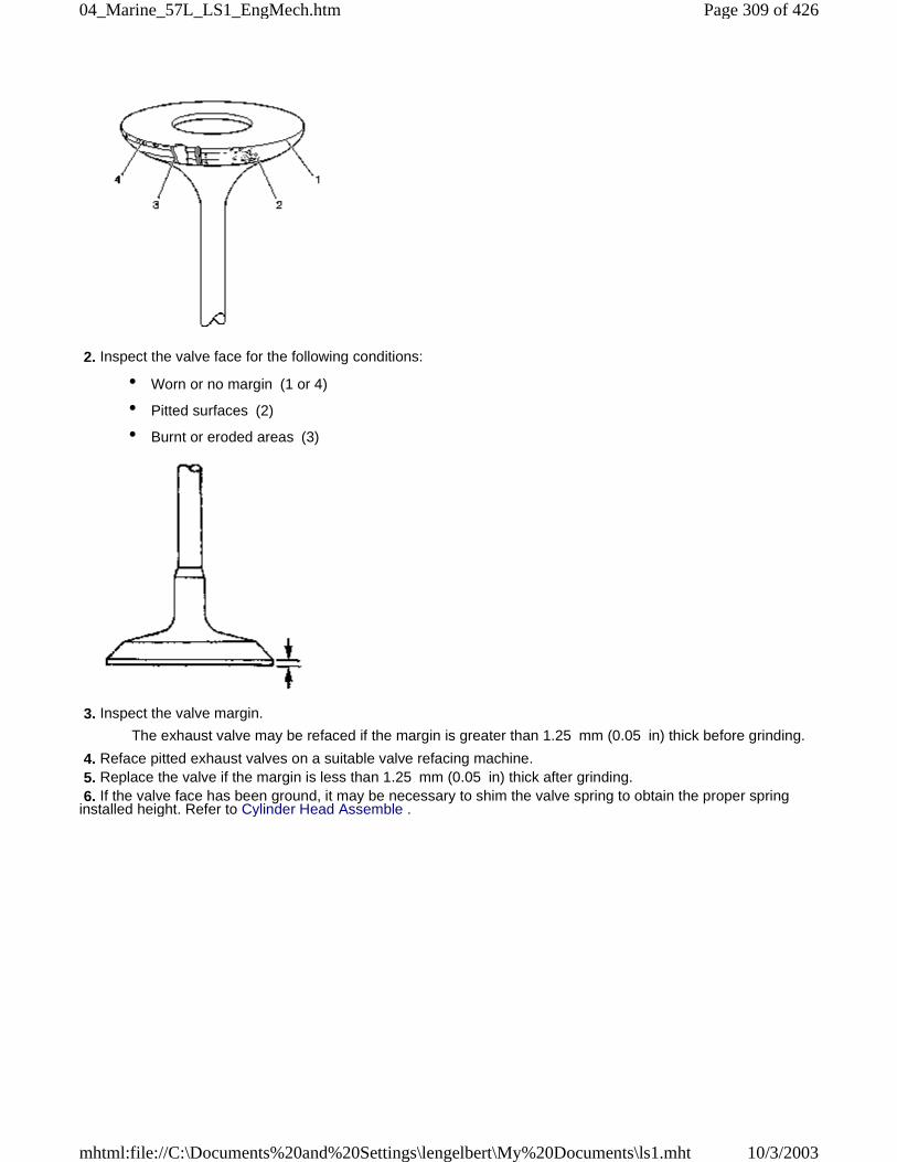
2. Inspect the valve face for the following conditions:
• Worn or no margin (1 or 4)
• Pitted surfaces (2)
• Burnt or eroded areas (3)
3. Inspect the valve margin.
The exhaust valve may be refaced if the margin is greater than 1.25 mm (0.05 in) thick before grinding.
4. Reface pitted exhaust valves on a suitable valve refacing machine. 5. Replace the valve if the margin is less than 1.25 mm (0.05 in) thick after grinding. 6. If the valve face has been ground, it may be necessary to shim the valve spring to obtain the proper springinstalled height. Refer to Cylinder Head Assemble .
Page 309 of 42604_Marine_57L_LS1_EngMech.htm
10/3/2003mhtml:file://C:\Documents%20and%20Settings\lengelbert\My%20Documents\ls1.mht
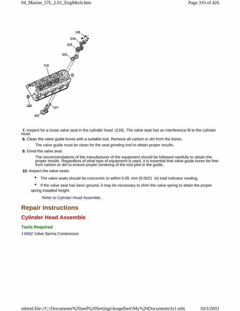
7. Inspect for a loose valve seat in the cylinder head (218). The valve seat has an interference fit to the cylinderhead. 8. Clean the valve guide bores with a suitable tool. Remove all carbon or dirt from the bores.
The valve guide must be clean for the seat grinding tool to obtain proper results.
9. Grind the valve seat.
The recommendations of the manufacturer of the equipment should be followed carefully to obtain theproper results. Regardless of what type of equipment is used, it is essential that valve guide bores be freefrom carbon or dirt to ensure proper centering of the tool pilot in the guide.
10. Inspect the valve seats.
• The valve seats should be concentric to within 0.05 mm (0.0021 in) total indicator reading.
• If the valve seat has been ground, it may be necessary to shim the valve spring to attain the properspring installed height.
Refer to Cylinder Head Assemble .
Repair Instructions
Cylinder Head Assemble
Tools Required
J 8062 Valve Spring Compressor
Page 310 of 42604_Marine_57L_LS1_EngMech.htm
10/3/2003mhtml:file://C:\Documents%20and%20Settings\lengelbert\My%20Documents\ls1.mht
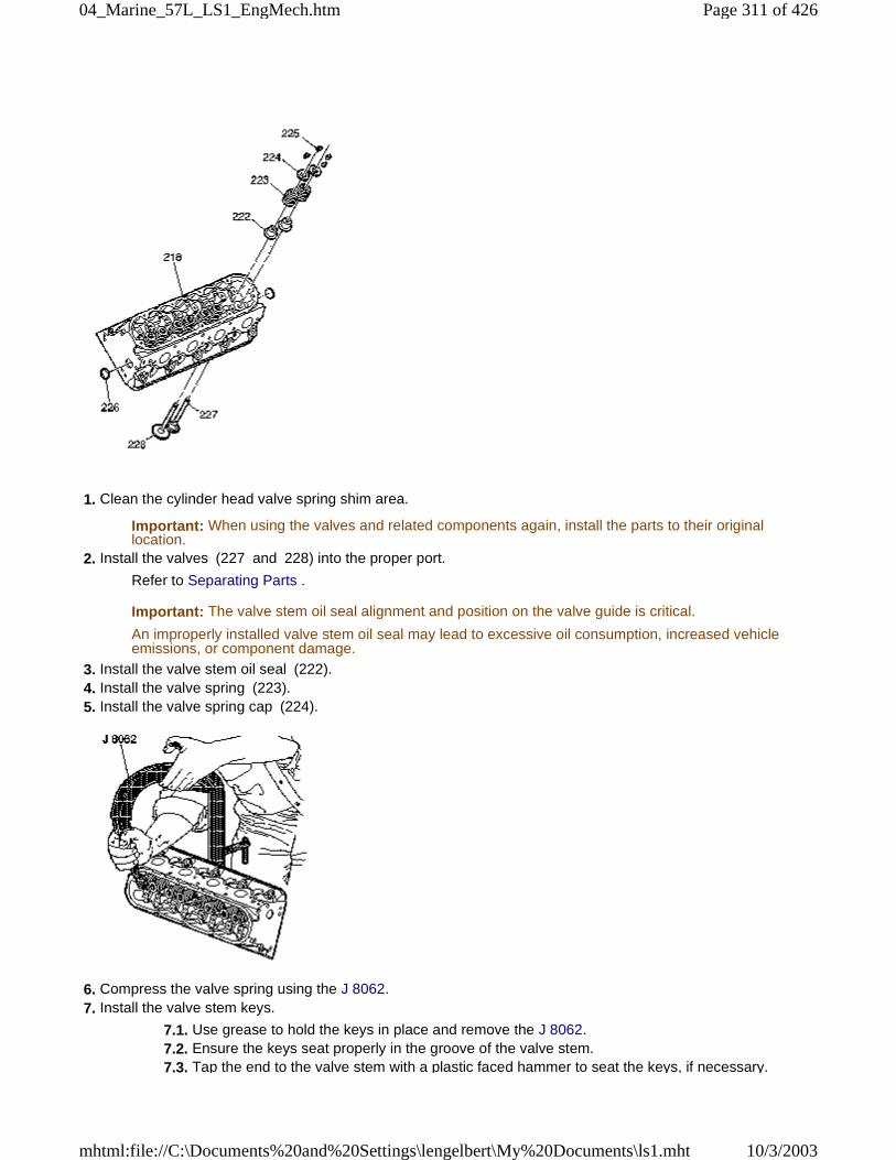
1. Clean the cylinder head valve spring shim area.
Important: When using the valves and related components again, install the parts to their originallocation.
2. Install the valves (227 and 228) into the proper port.
Refer to Separating Parts .
Important: The valve stem oil seal alignment and position on the valve guide is critical.
An improperly installed valve stem oil seal may lead to excessive oil consumption, increased vehicleemissions, or component damage.
3. Install the valve stem oil seal (222). 4. Install the valve spring (223). 5. Install the valve spring cap (224).
6. Compress the valve spring using the J 8062. 7. Install the valve stem keys.
7.1. Use grease to hold the keys in place and remove the J 8062. 7.2. Ensure the keys seat properly in the groove of the valve stem. 7.3. Tap the end to the valve stem with a plastic faced hammer to seat the keys, if necessary.
Page 311 of 42604_Marine_57L_LS1_EngMech.htm
10/3/2003mhtml:file://C:\Documents%20and%20Settings\lengelbert\My%20Documents\ls1.mht
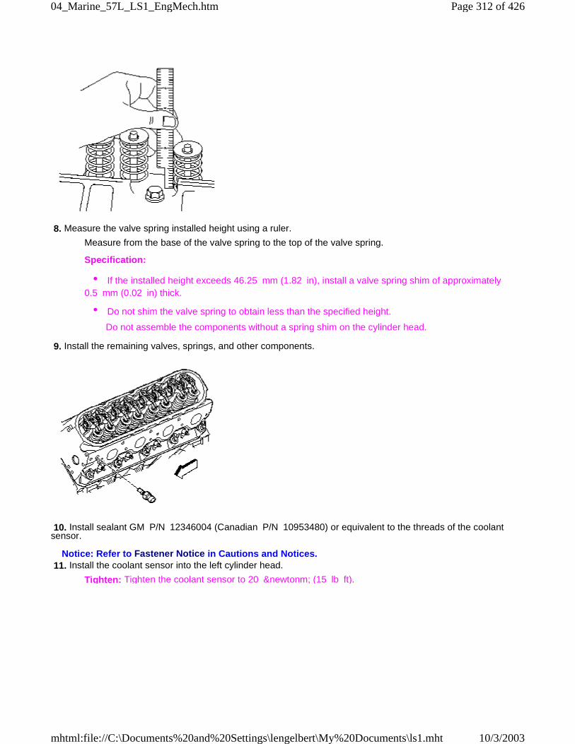
8. Measure the valve spring installed height using a ruler.
Measure from the base of the valve spring to the top of the valve spring.
Specification:
• If the installed height exceeds 46.25 mm (1.82 in), install a valve spring shim of approximately0.5 mm (0.02 in) thick.
• Do not shim the valve spring to obtain less than the specified height.
Do not assemble the components without a spring shim on the cylinder head.
9. Install the remaining valves, springs, and other components.
10. Install sealant GM P/N 12346004 (Canadian P/N 10953480) or equivalent to the threads of the coolantsensor.
Notice: Refer to Fastener Notice in Cautions and Notices. 11. Install the coolant sensor into the left cylinder head.
Tighten: Tighten the coolant sensor to 20 &newtonm; (15 lb ft).
Page 312 of 42604_Marine_57L_LS1_EngMech.htm
10/3/2003mhtml:file://C:\Documents%20and%20Settings\lengelbert\My%20Documents\ls1.mht
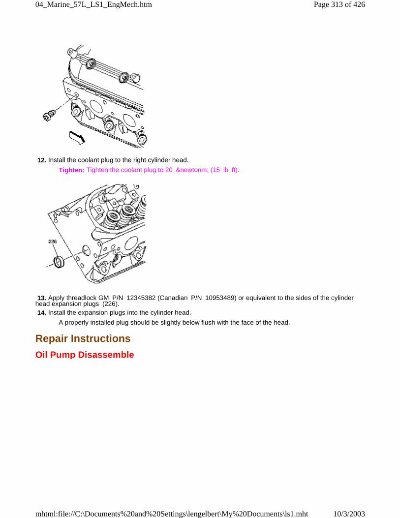
12. Install the coolant plug to the right cylinder head.
Tighten: Tighten the coolant plug to 20 &newtonm; (15 lb ft).
13. Apply threadlock GM P/N 12345382 (Canadian P/N 10953489) or equivalent to the sides of the cylinderhead expansion plugs (226). 14. Install the expansion plugs into the cylinder head.
A properly installed plug should be slightly below flush with the face of the head.
Repair Instructions
Oil Pump Disassemble
Page 313 of 42604_Marine_57L_LS1_EngMech.htm
10/3/2003mhtml:file://C:\Documents%20and%20Settings\lengelbert\My%20Documents\ls1.mht
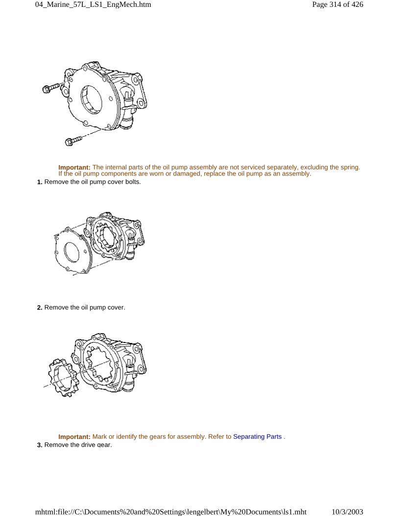
Important: The internal parts of the oil pump assembly are not serviced separately, excluding the spring.If the oil pump components are worn or damaged, replace the oil pump as an assembly.
1. Remove the oil pump cover bolts.
2. Remove the oil pump cover.
Important: Mark or identify the gears for assembly. Refer to Separating Parts . 3. Remove the drive gear.
Page 314 of 42604_Marine_57L_LS1_EngMech.htm
10/3/2003mhtml:file://C:\Documents%20and%20Settings\lengelbert\My%20Documents\ls1.mht
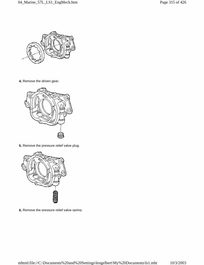
4. Remove the driven gear.
5. Remove the pressure relief valve plug.
6. Remove the pressure relief valve spring.
Page 315 of 42604_Marine_57L_LS1_EngMech.htm
10/3/2003mhtml:file://C:\Documents%20and%20Settings\lengelbert\My%20Documents\ls1.mht
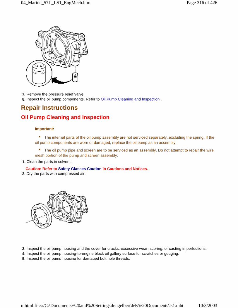
7. Remove the pressure relief valve. 8. Inspect the oil pump components. Refer to Oil Pump Cleaning and Inspection .
Repair Instructions
Oil Pump Cleaning and Inspection
Important:
• The internal parts of the oil pump assembly are not serviced separately, excluding the spring. If theoil pump components are worn or damaged, replace the oil pump as an assembly.
• The oil pump pipe and screen are to be serviced as an assembly. Do not attempt to repair the wiremesh portion of the pump and screen assembly.
1. Clean the parts in solvent.
Caution: Refer to Safety Glasses Caution in Cautions and Notices. 2. Dry the parts with compressed air.
3. Inspect the oil pump housing and the cover for cracks, excessive wear, scoring, or casting imperfections. 4. Inspect the oil pump housing-to-engine block oil gallery surface for scratches or gouging. 5. Inspect the oil pump housing for damaged bolt hole threads.
Page 316 of 42604_Marine_57L_LS1_EngMech.htm
10/3/2003mhtml:file://C:\Documents%20and%20Settings\lengelbert\My%20Documents\ls1.mht
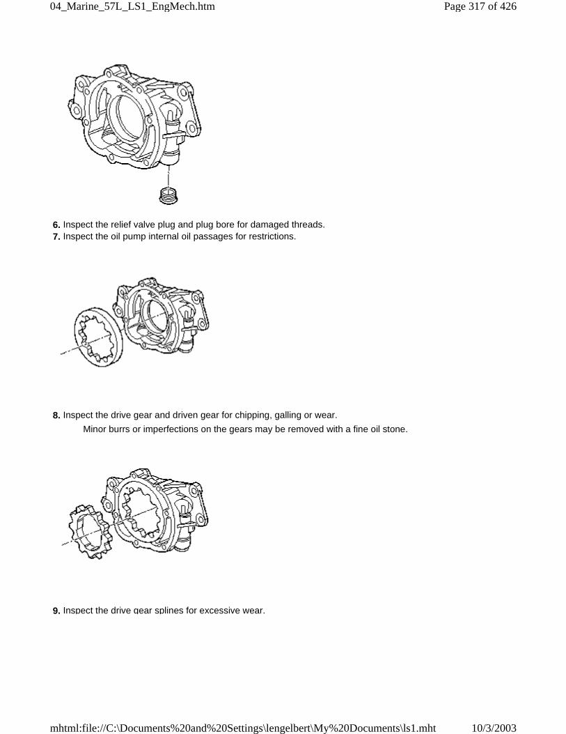
6. Inspect the relief valve plug and plug bore for damaged threads. 7. Inspect the oil pump internal oil passages for restrictions.
8. Inspect the drive gear and driven gear for chipping, galling or wear.
Minor burrs or imperfections on the gears may be removed with a fine oil stone.
9. Inspect the drive gear splines for excessive wear.
Page 317 of 42604_Marine_57L_LS1_EngMech.htm
10/3/2003mhtml:file://C:\Documents%20and%20Settings\lengelbert\My%20Documents\ls1.mht
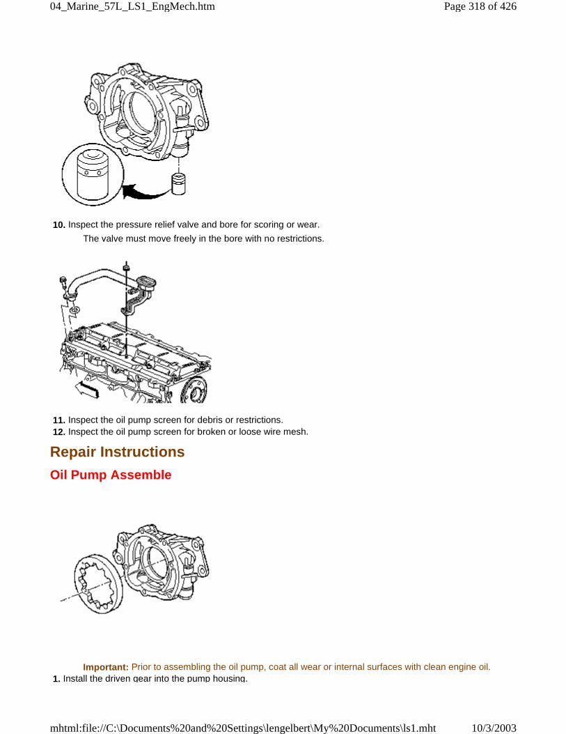
10. Inspect the pressure relief valve and bore for scoring or wear.
The valve must move freely in the bore with no restrictions.
11. Inspect the oil pump screen for debris or restrictions. 12. Inspect the oil pump screen for broken or loose wire mesh.
Repair Instructions
Oil Pump Assemble
Important: Prior to assembling the oil pump, coat all wear or internal surfaces with clean engine oil. 1. Install the driven gear into the pump housing.
Page 318 of 42604_Marine_57L_LS1_EngMech.htm
10/3/2003mhtml:file://C:\Documents%20and%20Settings\lengelbert\My%20Documents\ls1.mht
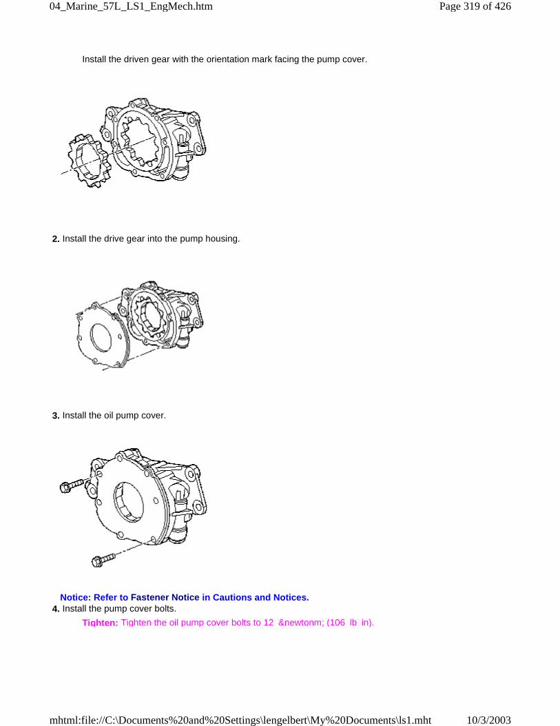
Install the driven gear with the orientation mark facing the pump cover.
2. Install the drive gear into the pump housing.
3. Install the oil pump cover.
Notice: Refer to Fastener Notice in Cautions and Notices. 4. Install the pump cover bolts.
Tighten: Tighten the oil pump cover bolts to 12 &newtonm; (106 lb in).
Page 319 of 42604_Marine_57L_LS1_EngMech.htm
10/3/2003mhtml:file://C:\Documents%20and%20Settings\lengelbert\My%20Documents\ls1.mht
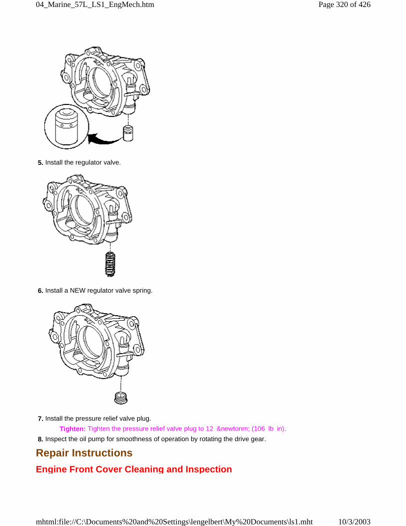
5. Install the regulator valve.
6. Install a NEW regulator valve spring.
7. Install the pressure relief valve plug.
Tighten: Tighten the pressure relief valve plug to 12 &newtonm; (106 lb in).
8. Inspect the oil pump for smoothness of operation by rotating the drive gear.
Repair Instructions
Engine Front Cover Cleaning and Inspection
Page 320 of 42604_Marine_57L_LS1_EngMech.htm
10/3/2003mhtml:file://C:\Documents%20and%20Settings\lengelbert\My%20Documents\ls1.mht
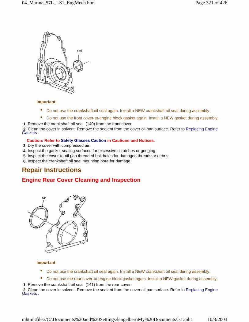
Important:
• Do not use the crankshaft oil seal again. Install a NEW crankshaft oil seal during assembly.
• Do not use the front cover-to-engine block gasket again. Install a NEW gasket during assembly.
1. Remove the crankshaft oil seal (140) from the front cover. 2. Clean the cover in solvent. Remove the sealant from the cover oil pan surface. Refer to Replacing EngineGaskets .
Caution: Refer to Safety Glasses Caution in Cautions and Notices. 3. Dry the cover with compressed air. 4. Inspect the gasket sealing surfaces for excessive scratches or gouging. 5. Inspect the cover-to-oil pan threaded bolt holes for damaged threads or debris. 6. Inspect the crankshaft oil seal mounting bore for damage.
Repair Instructions
Engine Rear Cover Cleaning and Inspection
Important:
• Do not use the crankshaft oil seal again. Install a NEW crankshaft oil seal during assembly.
• Do not use the rear cover-to-engine block gasket again. Install a NEW gasket during assembly.
1. Remove the crankshaft oil seal (141) from the rear cover. 2. Clean the cover in solvent. Remove the sealant from the cover oil pan surface. Refer to Replacing EngineGaskets .
Page 321 of 42604_Marine_57L_LS1_EngMech.htm
10/3/2003mhtml:file://C:\Documents%20and%20Settings\lengelbert\My%20Documents\ls1.mht
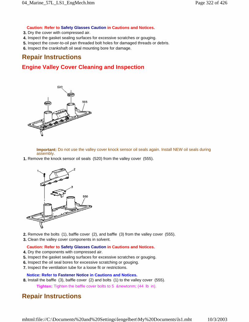
Caution: Refer to Safety Glasses Caution in Cautions and Notices. 3. Dry the cover with compressed air. 4. Inspect the gasket sealing surfaces for excessive scratches or gouging. 5. Inspect the cover-to-oil pan threaded bolt holes for damaged threads or debris. 6. Inspect the crankshaft oil seal mounting bore for damage.
Repair Instructions
Engine Valley Cover Cleaning and Inspection
Important: Do not use the valley cover knock sensor oil seals again. Install NEW oil seals duringassembly.
1. Remove the knock sensor oil seals (520) from the valley cover (555).
2. Remove the bolts (1), baffle cover (2), and baffle (3) from the valley cover (555). 3. Clean the valley cover components in solvent.
Caution: Refer to Safety Glasses Caution in Cautions and Notices. 4. Dry the components with compressed air. 5. Inspect the gasket sealing surfaces for excessive scratches or gouging. 6. Inspect the oil seal bores for excessive scratching or gouging. 7. Inspect the ventilation tube for a loose fit or restrictions.
Notice: Refer to Fastener Notice in Cautions and Notices. 8. Install the baffle (3), baffle cover (2) and bolts (1) to the valley cover (555).
Tighten: Tighten the baffle cover bolts to 5 &newtonm; (44 lb in).
Repair Instructions
Page 322 of 42604_Marine_57L_LS1_EngMech.htm
10/3/2003mhtml:file://C:\Documents%20and%20Settings\lengelbert\My%20Documents\ls1.mht
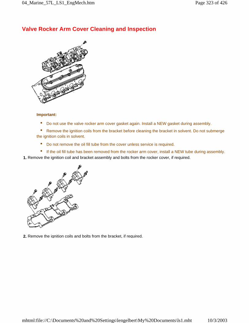
Valve Rocker Arm Cover Cleaning and Inspection
Important:
• Do not use the valve rocker arm cover gasket again. Install a NEW gasket during assembly.
• Remove the ignition coils from the bracket before cleaning the bracket in solvent. Do not submergethe ignition coils in solvent.
• Do not remove the oil fill tube from the cover unless service is required.
• If the oil fill tube has been removed from the rocker arm cover, install a NEW tube during assembly.
1. Remove the ignition coil and bracket assembly and bolts from the rocker cover, if required.
2. Remove the ignition coils and bolts from the bracket, if required.
Page 323 of 42604_Marine_57L_LS1_EngMech.htm
10/3/2003mhtml:file://C:\Documents%20and%20Settings\lengelbert\My%20Documents\ls1.mht
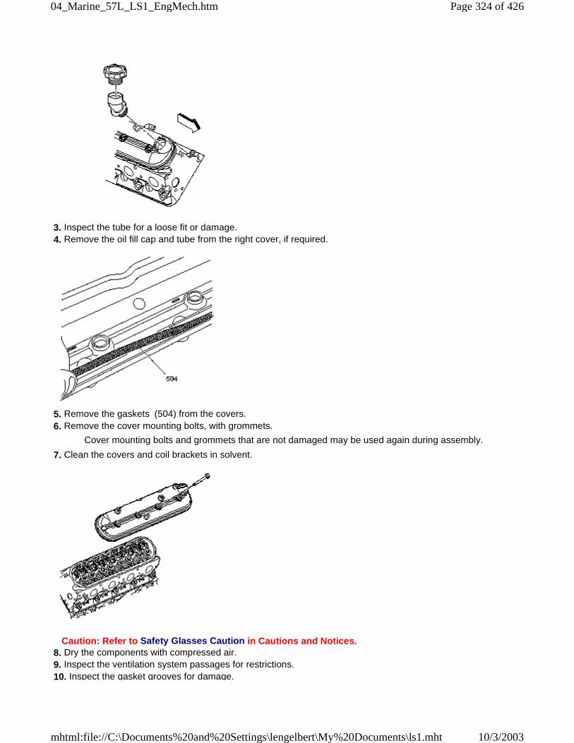
3. Inspect the tube for a loose fit or damage. 4. Remove the oil fill cap and tube from the right cover, if required.
5. Remove the gaskets (504) from the covers. 6. Remove the cover mounting bolts, with grommets.
Cover mounting bolts and grommets that are not damaged may be used again during assembly.
7. Clean the covers and coil brackets in solvent.
Caution: Refer to Safety Glasses Caution in Cautions and Notices. 8. Dry the components with compressed air. 9. Inspect the ventilation system passages for restrictions. 10. Inspect the gasket grooves for damage.
Page 324 of 42604_Marine_57L_LS1_EngMech.htm
10/3/2003mhtml:file://C:\Documents%20and%20Settings\lengelbert\My%20Documents\ls1.mht
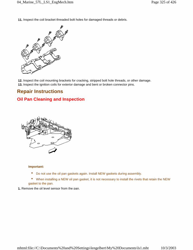
11. Inspect the coil bracket threaded bolt holes for damaged threads or debris.
12. Inspect the coil mounting brackets for cracking, stripped bolt hole threads, or other damage. 13. Inspect the ignition coils for exterior damage and bent or broken connector pins.
Repair Instructions
Oil Pan Cleaning and Inspection
Important:
• Do not use the oil pan gaskets again. Install NEW gaskets during assembly.
• When installing a NEW oil pan gasket, it is not necessary to install the rivets that retain the NEWgasket to the pan.
1. Remove the oil level sensor from the pan.
Page 325 of 42604_Marine_57L_LS1_EngMech.htm
10/3/2003mhtml:file://C:\Documents%20and%20Settings\lengelbert\My%20Documents\ls1.mht
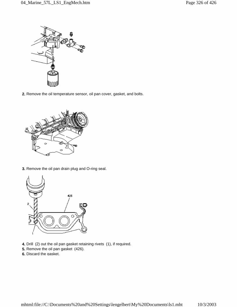
2. Remove the oil temperature sensor, oil pan cover, gasket, and bolts.
3. Remove the oil pan drain plug and O-ring seal.
4. Drill (2) out the oil pan gasket retaining rivets (1), if required. 5. Remove the oil pan gasket (426). 6. Discard the gasket.
Page 326 of 42604_Marine_57L_LS1_EngMech.htm
10/3/2003mhtml:file://C:\Documents%20and%20Settings\lengelbert\My%20Documents\ls1.mht
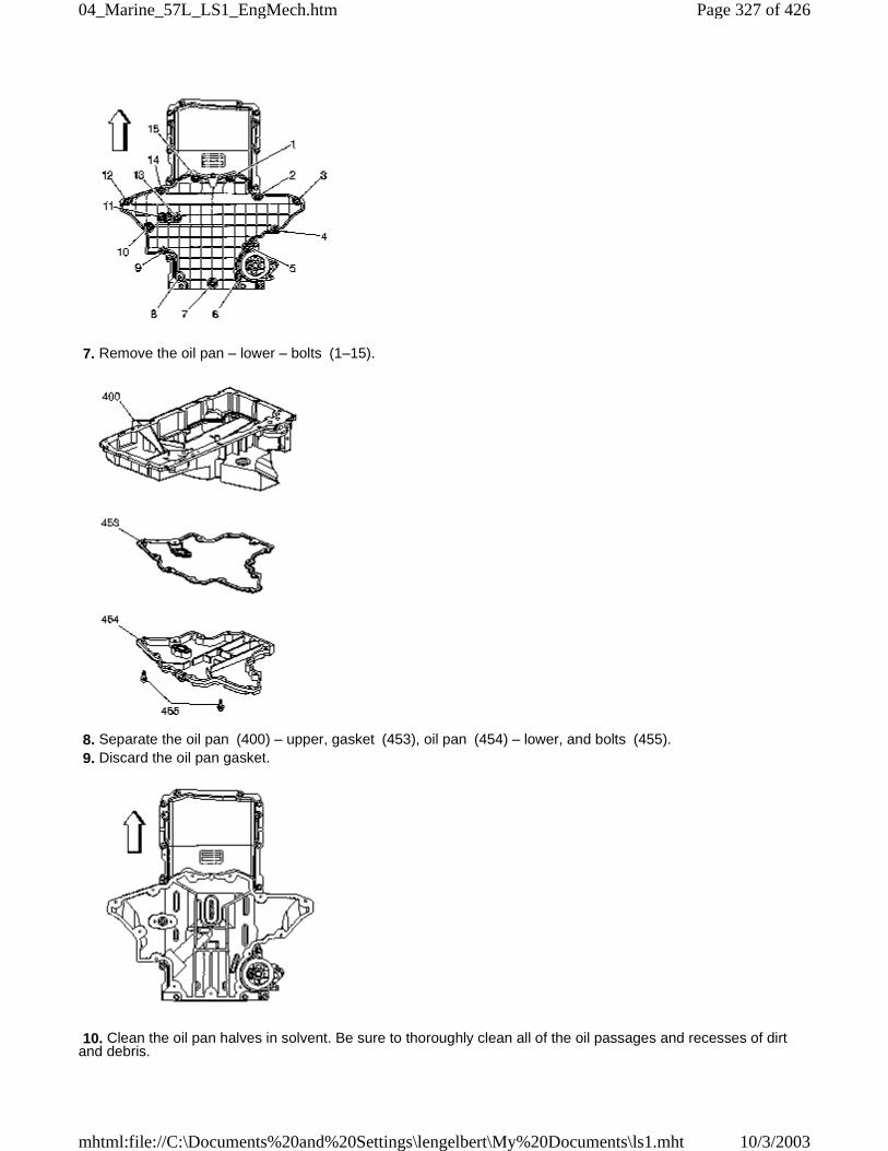
7. Remove the oil pan – lower – bolts (1–15).
8. Separate the oil pan (400) – upper, gasket (453), oil pan (454) – lower, and bolts (455). 9. Discard the oil pan gasket.
10. Clean the oil pan halves in solvent. Be sure to thoroughly clean all of the oil passages and recesses of dirtand debris.
Page 327 of 42604_Marine_57L_LS1_EngMech.htm
10/3/2003mhtml:file://C:\Documents%20and%20Settings\lengelbert\My%20Documents\ls1.mht
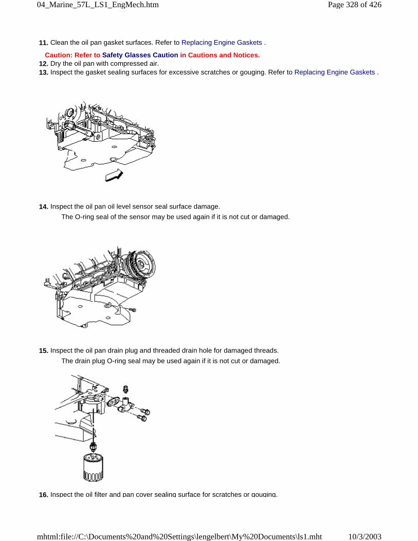
11. Clean the oil pan gasket surfaces. Refer to Replacing Engine Gaskets .
Caution: Refer to Safety Glasses Caution in Cautions and Notices. 12. Dry the oil pan with compressed air. 13. Inspect the gasket sealing surfaces for excessive scratches or gouging. Refer to Replacing Engine Gaskets .
14. Inspect the oil pan oil level sensor seal surface damage.
The O-ring seal of the sensor may be used again if it is not cut or damaged.
15. Inspect the oil pan drain plug and threaded drain hole for damaged threads.
The drain plug O-ring seal may be used again if it is not cut or damaged.
16. Inspect the oil filter and pan cover sealing surface for scratches or gouging.
Page 328 of 42604_Marine_57L_LS1_EngMech.htm
10/3/2003mhtml:file://C:\Documents%20and%20Settings\lengelbert\My%20Documents\ls1.mht
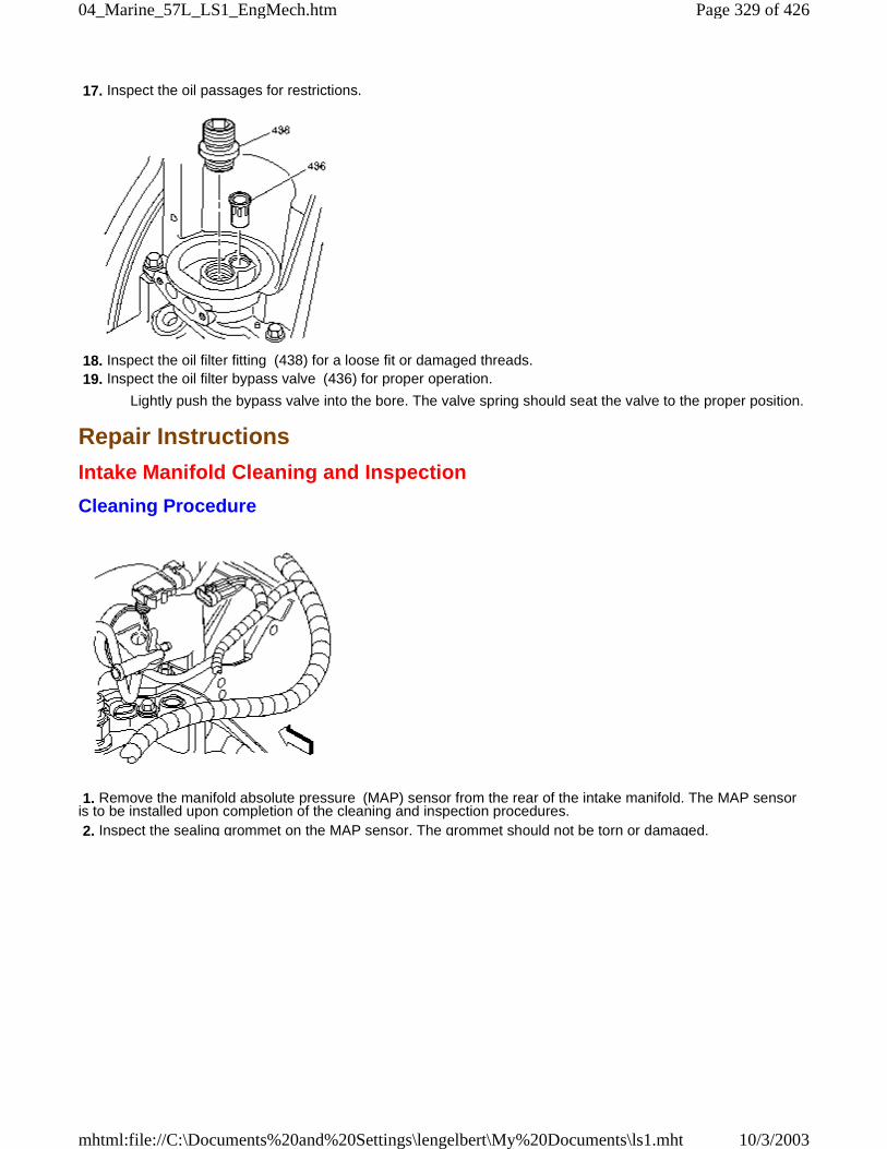
17. Inspect the oil passages for restrictions.
18. Inspect the oil filter fitting (438) for a loose fit or damaged threads. 19. Inspect the oil filter bypass valve (436) for proper operation.
Lightly push the bypass valve into the bore. The valve spring should seat the valve to the proper position.
Repair Instructions
Intake Manifold Cleaning and Inspection
Cleaning Procedure
1. Remove the manifold absolute pressure (MAP) sensor from the rear of the intake manifold. The MAP sensoris to be installed upon completion of the cleaning and inspection procedures. 2. Inspect the sealing grommet on the MAP sensor. The grommet should not be torn or damaged.
Page 329 of 42604_Marine_57L_LS1_EngMech.htm
10/3/2003mhtml:file://C:\Documents%20and%20Settings\lengelbert\My%20Documents\ls1.mht
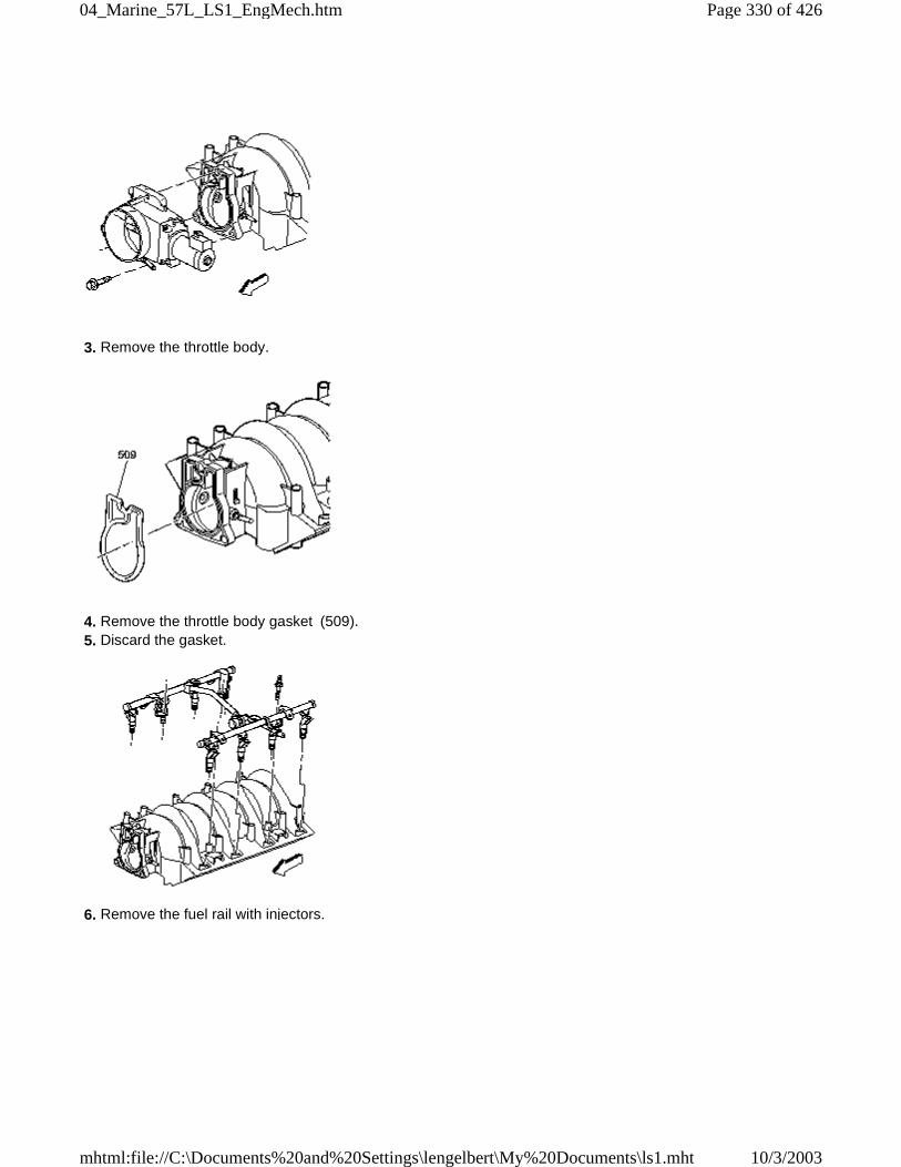
3. Remove the throttle body.
4. Remove the throttle body gasket (509). 5. Discard the gasket.
6. Remove the fuel rail with injectors.
Page 330 of 42604_Marine_57L_LS1_EngMech.htm
10/3/2003mhtml:file://C:\Documents%20and%20Settings\lengelbert\My%20Documents\ls1.mht
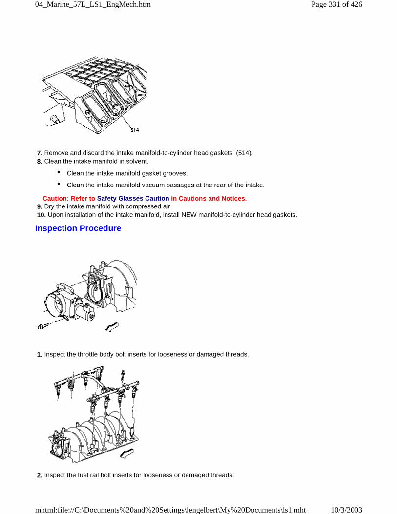
7. Remove and discard the intake manifold-to-cylinder head gaskets (514). 8. Clean the intake manifold in solvent.
• Clean the intake manifold gasket grooves.
• Clean the intake manifold vacuum passages at the rear of the intake.
Caution: Refer to Safety Glasses Caution in Cautions and Notices. 9. Dry the intake manifold with compressed air. 10. Upon installation of the intake manifold, install NEW manifold-to-cylinder head gaskets.
Inspection Procedure
1. Inspect the throttle body bolt inserts for looseness or damaged threads.
2. Inspect the fuel rail bolt inserts for looseness or damaged threads.
Page 331 of 42604_Marine_57L_LS1_EngMech.htm
10/3/2003mhtml:file://C:\Documents%20and%20Settings\lengelbert\My%20Documents\ls1.mht
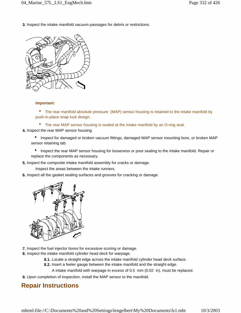
3. Inspect the intake manifold vacuum passages for debris or restrictions.
Important:
• The rear manifold absolute pressure (MAP) sensor housing is retained to the intake manifold bypush-in-place snap lock design.
• The rear MAP sensor housing is sealed at the intake manifold by an O-ring seal.
4. Inspect the rear MAP sensor housing.
• Inspect for damaged or broken vacuum fittings, damaged MAP sensor mounting bore, or broken MAPsensor retaining tab.
• Inspect the rear MAP sensor housing for looseness or poor sealing to the intake manifold. Repair orreplace the components as necessary.
5. Inspect the composite intake manifold assembly for cracks or damage.
Inspect the areas between the intake runners.
6. Inspect all the gasket sealing surfaces and grooves for cracking or damage.
7. Inspect the fuel injector bores for excessive scoring or damage. 8. Inspect the intake manifold cylinder head deck for warpage.
8.1. Locate a straight edge across the intake manifold cylinder head deck surface. 8.2. Insert a feeler gauge between the intake manifold and the straight edge.
A intake manifold with warpage in excess of 0.5 mm (0.02 in), must be replaced.
9. Upon completion of inspection, install the MAP sensor to the manifold.
Repair Instructions
Page 332 of 42604_Marine_57L_LS1_EngMech.htm
10/3/2003mhtml:file://C:\Documents%20and%20Settings\lengelbert\My%20Documents\ls1.mht
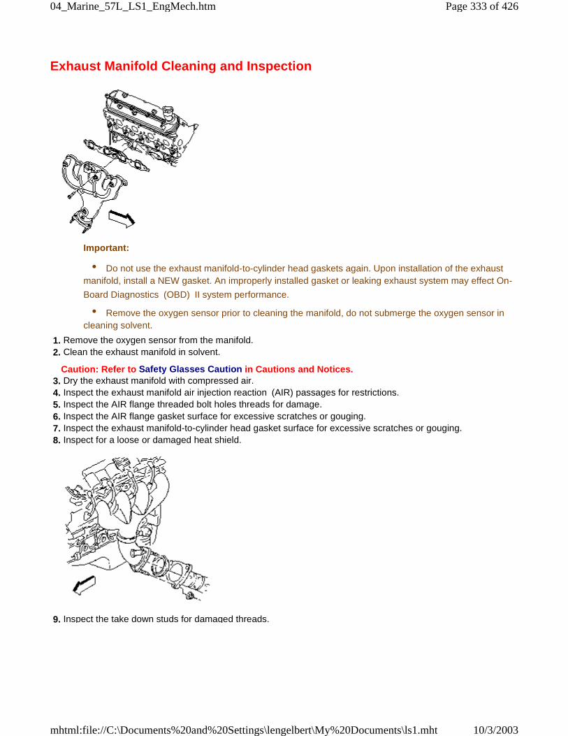
Exhaust Manifold Cleaning and Inspection
Important:
• Do not use the exhaust manifold-to-cylinder head gaskets again. Upon installation of the exhaustmanifold, install a NEW gasket. An improperly installed gasket or leaking exhaust system may effect On-
Board Diagnostics (OBD) II system performance.
• Remove the oxygen sensor prior to cleaning the manifold, do not submerge the oxygen sensor incleaning solvent.
1. Remove the oxygen sensor from the manifold. 2. Clean the exhaust manifold in solvent.
Caution: Refer to Safety Glasses Caution in Cautions and Notices. 3. Dry the exhaust manifold with compressed air. 4. Inspect the exhaust manifold air injection reaction (AIR) passages for restrictions. 5. Inspect the AIR flange threaded bolt holes threads for damage. 6. Inspect the AIR flange gasket surface for excessive scratches or gouging. 7. Inspect the exhaust manifold-to-cylinder head gasket surface for excessive scratches or gouging. 8. Inspect for a loose or damaged heat shield.
9. Inspect the take down studs for damaged threads.
Page 333 of 42604_Marine_57L_LS1_EngMech.htm
10/3/2003mhtml:file://C:\Documents%20and%20Settings\lengelbert\My%20Documents\ls1.mht
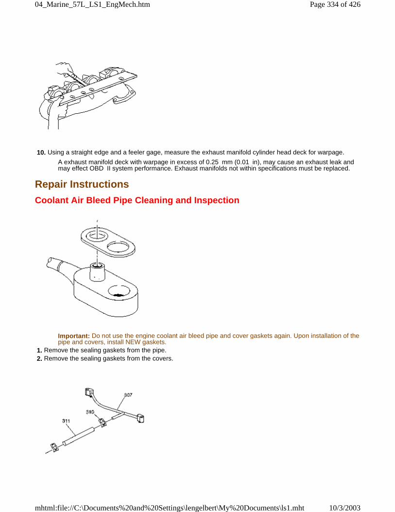
10. Using a straight edge and a feeler gage, measure the exhaust manifold cylinder head deck for warpage.
A exhaust manifold deck with warpage in excess of 0.25 mm (0.01 in), may cause an exhaust leak andmay effect OBD II system performance. Exhaust manifolds not within specifications must be replaced.
Repair Instructions
Coolant Air Bleed Pipe Cleaning and Inspection
Important: Do not use the engine coolant air bleed pipe and cover gaskets again. Upon installation of thepipe and covers, install NEW gaskets.
1. Remove the sealing gaskets from the pipe. 2. Remove the sealing gaskets from the covers.
Page 334 of 42604_Marine_57L_LS1_EngMech.htm
10/3/2003mhtml:file://C:\Documents%20and%20Settings\lengelbert\My%20Documents\ls1.mht
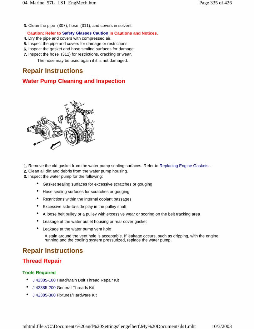
3. Clean the pipe (307), hose (311), and covers in solvent.
Caution: Refer to Safety Glasses Caution in Cautions and Notices. 4. Dry the pipe and covers with compressed air. 5. Inspect the pipe and covers for damage or restrictions. 6. Inspect the gasket and hose sealing surfaces for damage. 7. Inspect the hose (311) for restrictions, cracking or wear.
The hose may be used again if it is not damaged.
Repair Instructions
Water Pump Cleaning and Inspection
1. Remove the old gasket from the water pump sealing surfaces. Refer to Replacing Engine Gaskets . 2. Clean all dirt and debris from the water pump housing. 3. Inspect the water pump for the following:
• Gasket sealing surfaces for excessive scratches or gouging
• Hose sealing surfaces for scratches or gouging
• Restrictions within the internal coolant passages
• Excessive side-to-side play in the pulley shaft
• A loose belt pulley or a pulley with excessive wear or scoring on the belt tracking area
• Leakage at the water outlet housing or rear cover gasket
• Leakage at the water pump vent hole
A stain around the vent hole is acceptable. If leakage occurs, such as dripping, with the enginerunning and the cooling system pressurized, replace the water pump.
Repair Instructions
Thread Repair
Tools Required
• J 42385-100 Head/Main Bolt Thread Repair Kit
• J 42385-200 General Threads Kit
• J 42385-300 Fixtures/Hardware Kit
Page 335 of 42604_Marine_57L_LS1_EngMech.htm
10/3/2003mhtml:file://C:\Documents%20and%20Settings\lengelbert\My%20Documents\ls1.mht
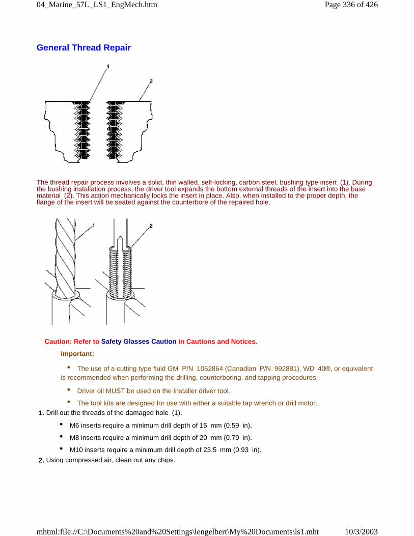
General Thread Repair
The thread repair process involves a solid, thin walled, self-locking, carbon steel, bushing type insert (1). Duringthe bushing installation process, the driver tool expands the bottom external threads of the insert into the basematerial (2). This action mechanically locks the insert in place. Also, when installed to the proper depth, theflange of the insert will be seated against the counterbore of the repaired hole.
Caution: Refer to Safety Glasses Caution in Cautions and Notices.
Important:
• The use of a cutting type fluid GM P/N 1052864 (Canadian P/N 992881), WD 40®, or equivalentis recommended when performing the drilling, counterboring, and tapping procedures.
• Driver oil MUST be used on the installer driver tool.
• The tool kits are designed for use with either a suitable tap wrench or drill motor.
1. Drill out the threads of the damaged hole (1).
• M6 inserts require a minimum drill depth of 15 mm (0.59 in).
• M8 inserts require a minimum drill depth of 20 mm (0.79 in).
• M10 inserts require a minimum drill depth of 23.5 mm (0.93 in).
2. Using compressed air, clean out any chips.
Page 336 of 42604_Marine_57L_LS1_EngMech.htm
10/3/2003mhtml:file://C:\Documents%20and%20Settings\lengelbert\My%20Documents\ls1.mht
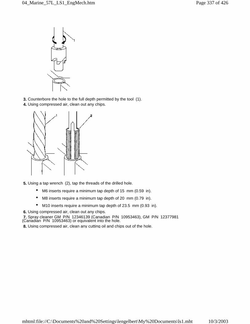
3. Counterbore the hole to the full depth permitted by the tool (1). 4. Using compressed air, clean out any chips.
5. Using a tap wrench (2), tap the threads of the drilled hole.
• M6 inserts require a minimum tap depth of 15 mm (0.59 in).
• M8 inserts require a minimum tap depth of 20 mm (0.79 in).
• M10 inserts require a minimum tap depth of 23.5 mm (0.93 in).
6. Using compressed air, clean out any chips. 7. Spray cleaner GM P/N 12346139 (Canadian P/N 10953463), GM P/N 12377981(Canadian P/N 10953463) or equivalent into the hole. 8. Using compressed air, clean any cutting oil and chips out of the hole.
Page 337 of 42604_Marine_57L_LS1_EngMech.htm
10/3/2003mhtml:file://C:\Documents%20and%20Settings\lengelbert\My%20Documents\ls1.mht
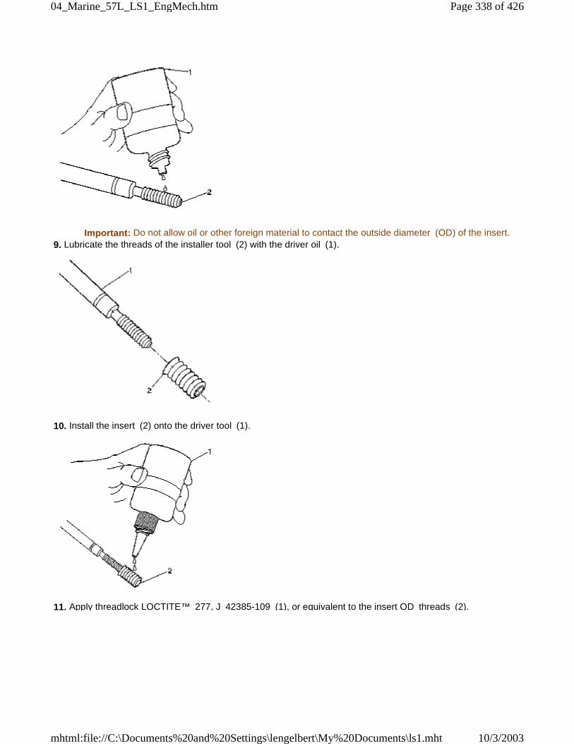
Important: Do not allow oil or other foreign material to contact the outside diameter (OD) of the insert. 9. Lubricate the threads of the installer tool (2) with the driver oil (1).
10. Install the insert (2) onto the driver tool (1).
11. Apply threadlock LOCTITE™ 277, J 42385-109 (1), or equivalent to the insert OD threads (2).
Page 338 of 42604_Marine_57L_LS1_EngMech.htm
10/3/2003mhtml:file://C:\Documents%20and%20Settings\lengelbert\My%20Documents\ls1.mht
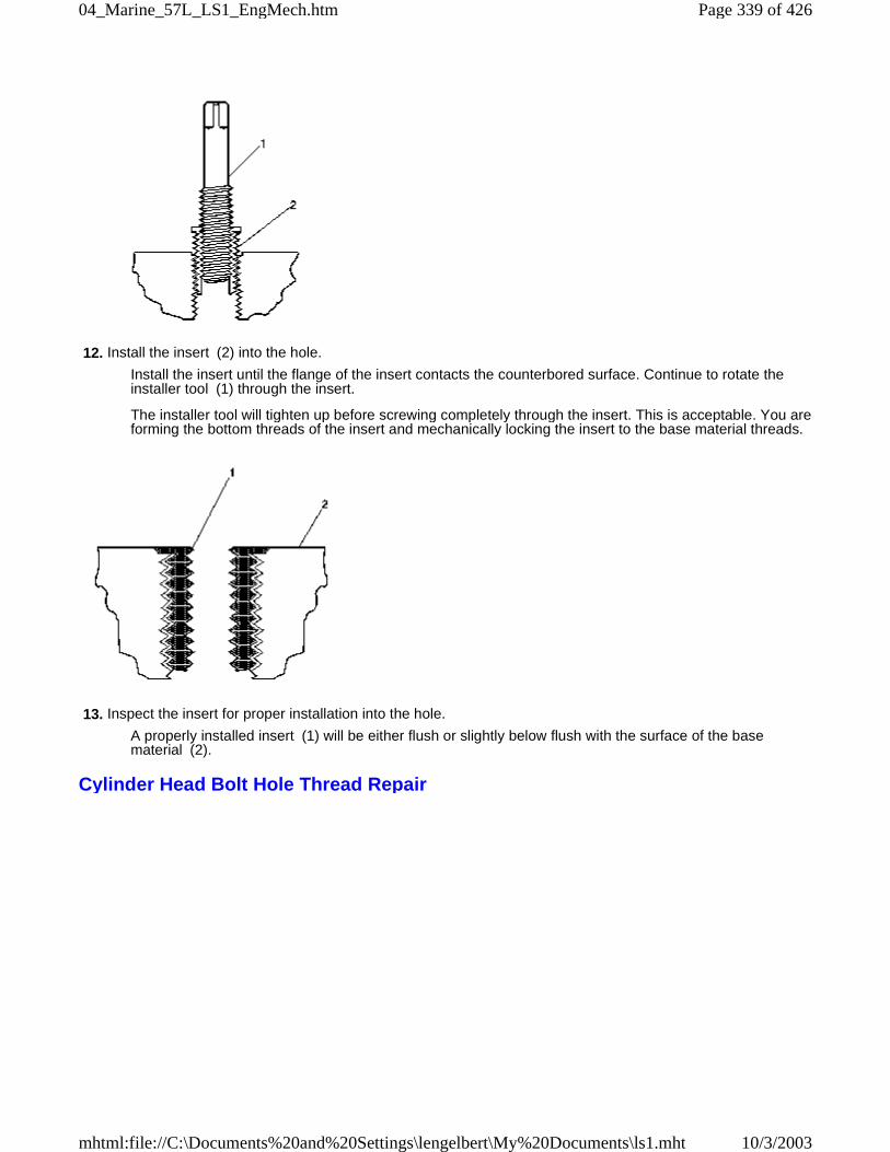
12. Install the insert (2) into the hole.
Install the insert until the flange of the insert contacts the counterbored surface. Continue to rotate theinstaller tool (1) through the insert.
The installer tool will tighten up before screwing completely through the insert. This is acceptable. You areforming the bottom threads of the insert and mechanically locking the insert to the base material threads.
13. Inspect the insert for proper installation into the hole.
A properly installed insert (1) will be either flush or slightly below flush with the surface of the basematerial (2).
Cylinder Head Bolt Hole Thread Repair
Page 339 of 42604_Marine_57L_LS1_EngMech.htm
10/3/2003mhtml:file://C:\Documents%20and%20Settings\lengelbert\My%20Documents\ls1.mht
1. The cylinder head bolt hole thread repair kit consists of the following items:
• The drill (1)
• The tap (2)
• The installer (3)
• The sleeve (4)
• The alignment pin (5)
• The bushing (6)
• The bolts (7)
• The fixture plate (8)
Caution: Refer to Safety Glasses Caution in Cautions and Notices.
Important:
• The use of a cutting type fluid GM P/N 1052864 (Canadian P/N 992881), WD 40®, or equivalent
Page 340 of 42604_Marine_57L_LS1_EngMech.htm
10/3/2003mhtml:file://C:\Documents%20and%20Settings\lengelbert\My%20Documents\ls1.mht
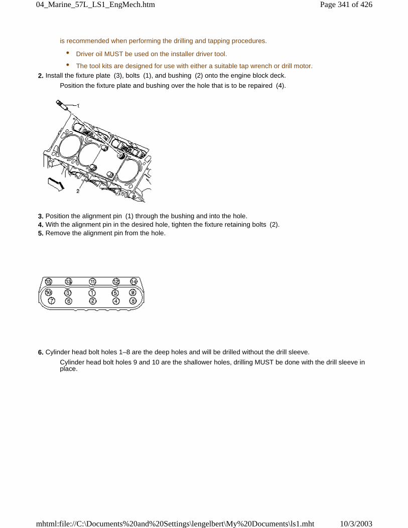
is recommended when performing the drilling and tapping procedures.
• Driver oil MUST be used on the installer driver tool.
• The tool kits are designed for use with either a suitable tap wrench or drill motor.
2. Install the fixture plate (3), bolts (1), and bushing (2) onto the engine block deck.
Position the fixture plate and bushing over the hole that is to be repaired (4).
3. Position the alignment pin (1) through the bushing and into the hole. 4. With the alignment pin in the desired hole, tighten the fixture retaining bolts (2). 5. Remove the alignment pin from the hole.
6. Cylinder head bolt holes 1–8 are the deep holes and will be drilled without the drill sleeve.
Cylinder head bolt holes 9 and 10 are the shallower holes, drilling MUST be done with the drill sleeve inplace.
Page 341 of 42604_Marine_57L_LS1_EngMech.htm
10/3/2003mhtml:file://C:\Documents%20and%20Settings\lengelbert\My%20Documents\ls1.mht
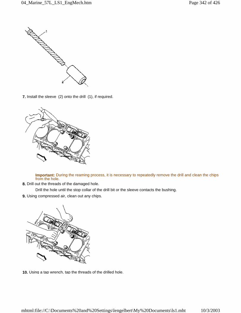
7. Install the sleeve (2) onto the drill (1), if required.
Important: During the reaming process, it is necessary to repeatedly remove the drill and clean the chipsfrom the hole.
8. Drill out the threads of the damaged hole.
Drill the hole until the stop collar of the drill bit or the sleeve contacts the bushing.
9. Using compressed air, clean out any chips.
10. Using a tap wrench, tap the threads of the drilled hole.
Page 342 of 42604_Marine_57L_LS1_EngMech.htm
10/3/2003mhtml:file://C:\Documents%20and%20Settings\lengelbert\My%20Documents\ls1.mht
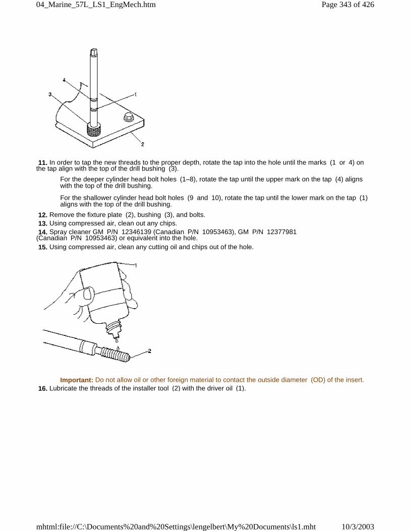
11. In order to tap the new threads to the proper depth, rotate the tap into the hole until the marks (1 or 4) onthe tap align with the top of the drill bushing (3).
For the deeper cylinder head bolt holes (1–8), rotate the tap until the upper mark on the tap (4) alignswith the top of the drill bushing.
For the shallower cylinder head bolt holes (9 and 10), rotate the tap until the lower mark on the tap (1)aligns with the top of the drill bushing.
12. Remove the fixture plate (2), bushing (3), and bolts. 13. Using compressed air, clean out any chips. 14. Spray cleaner GM P/N 12346139 (Canadian P/N 10953463), GM P/N 12377981(Canadian P/N 10953463) or equivalent into the hole. 15. Using compressed air, clean any cutting oil and chips out of the hole.
Important: Do not allow oil or other foreign material to contact the outside diameter (OD) of the insert. 16. Lubricate the threads of the installer tool (2) with the driver oil (1).
Page 343 of 42604_Marine_57L_LS1_EngMech.htm
10/3/2003mhtml:file://C:\Documents%20and%20Settings\lengelbert\My%20Documents\ls1.mht
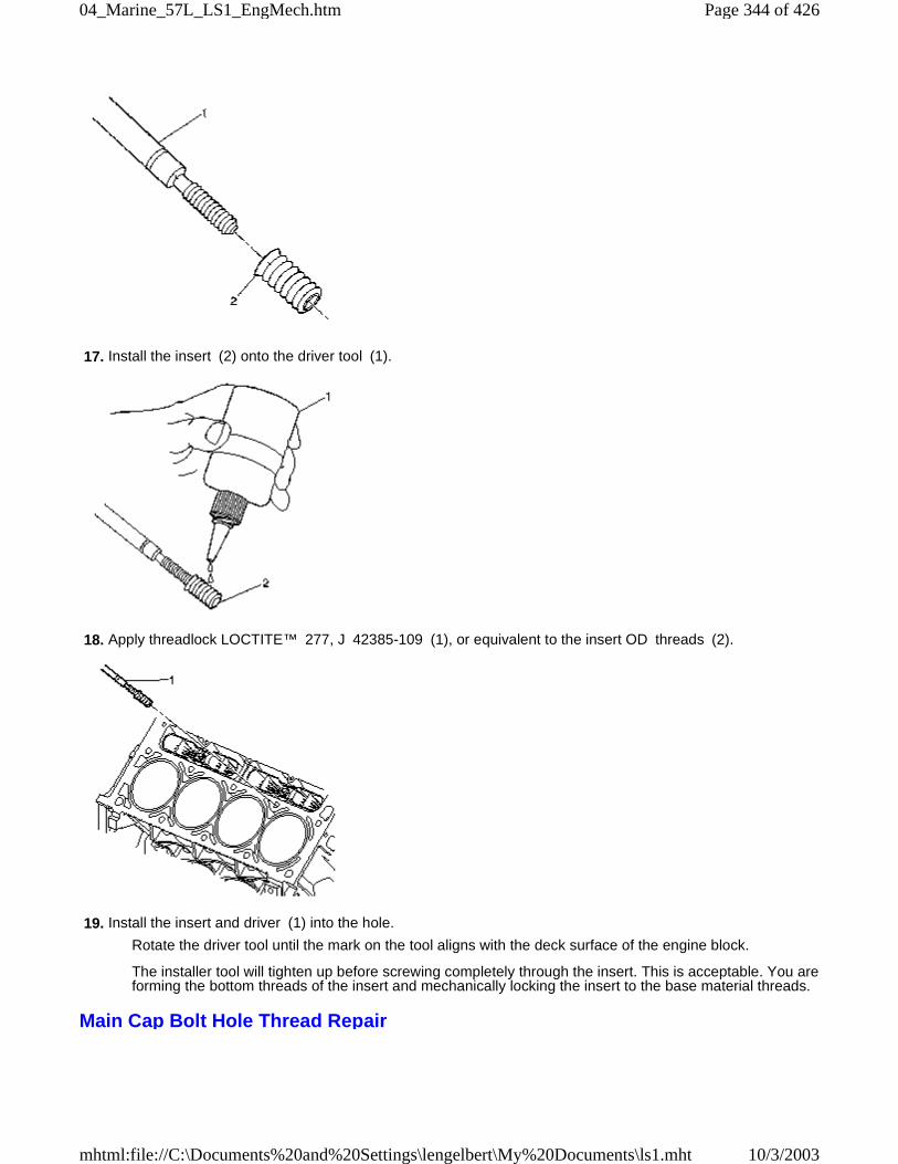
17. Install the insert (2) onto the driver tool (1).
18. Apply threadlock LOCTITE™ 277, J 42385-109 (1), or equivalent to the insert OD threads (2).
19. Install the insert and driver (1) into the hole.
Rotate the driver tool until the mark on the tool aligns with the deck surface of the engine block.
The installer tool will tighten up before screwing completely through the insert. This is acceptable. You areforming the bottom threads of the insert and mechanically locking the insert to the base material threads.
Main Cap Bolt Hole Thread Repair
Page 344 of 42604_Marine_57L_LS1_EngMech.htm
10/3/2003mhtml:file://C:\Documents%20and%20Settings\lengelbert\My%20Documents\ls1.mht
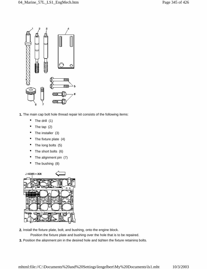
1. The main cap bolt hole thread repair kit consists of the following items:
• The drill (1)
• The tap (2)
• The installer (3)
• The fixture plate (4)
• The long bolts (5)
• The short bolts (6)
• The alignment pin (7)
• The bushing (8)
2. Install the fixture plate, bolt, and bushing, onto the engine block.
Position the fixture plate and bushing over the hole that is to be repaired.
3. Position the alignment pin in the desired hole and tighten the fixture retaining bolts.
Page 345 of 42604_Marine_57L_LS1_EngMech.htm
10/3/2003mhtml:file://C:\Documents%20and%20Settings\lengelbert\My%20Documents\ls1.mht
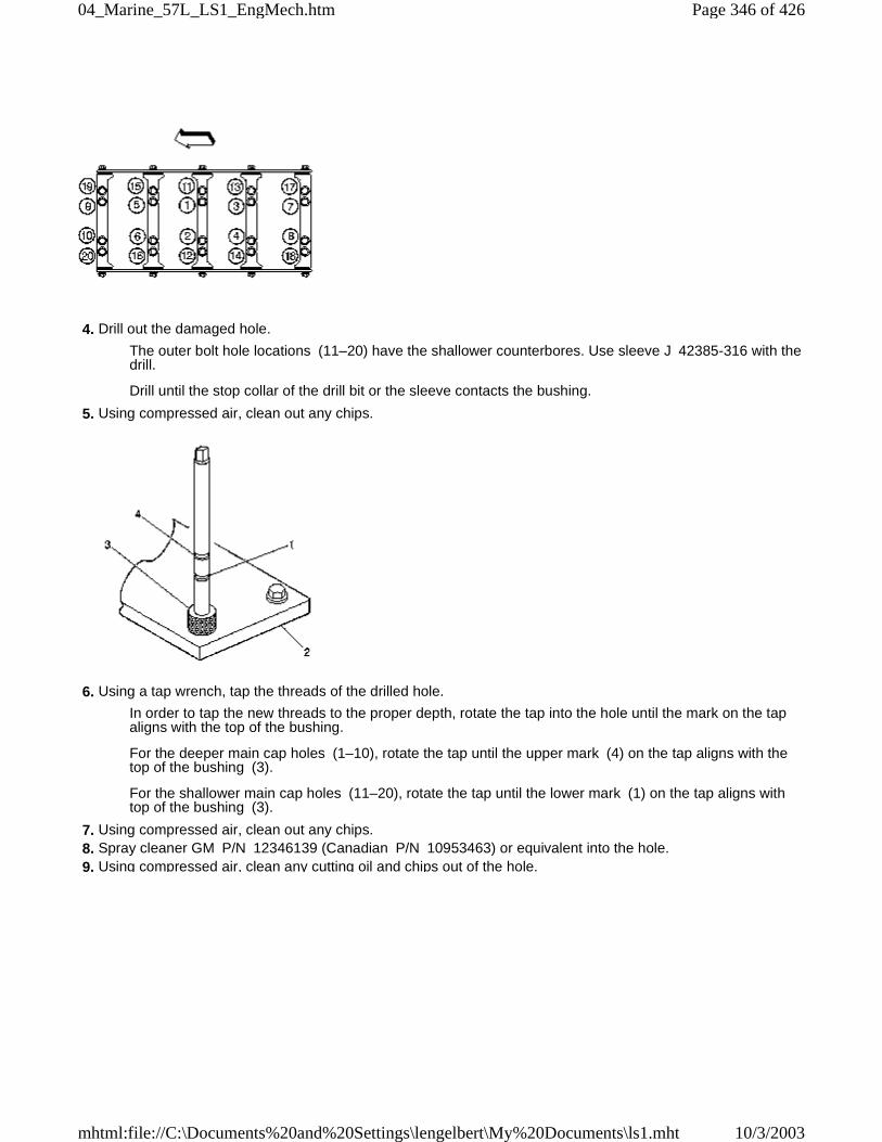
4. Drill out the damaged hole.
The outer bolt hole locations (11–20) have the shallower counterbores. Use sleeve J 42385-316 with thedrill.
Drill until the stop collar of the drill bit or the sleeve contacts the bushing.
5. Using compressed air, clean out any chips.
6. Using a tap wrench, tap the threads of the drilled hole.
In order to tap the new threads to the proper depth, rotate the tap into the hole until the mark on the tapaligns with the top of the bushing.
For the deeper main cap holes (1–10), rotate the tap until the upper mark (4) on the tap aligns with thetop of the bushing (3).
For the shallower main cap holes (11–20), rotate the tap until the lower mark (1) on the tap aligns withtop of the bushing (3).
7. Using compressed air, clean out any chips. 8. Spray cleaner GM P/N 12346139 (Canadian P/N 10953463) or equivalent into the hole. 9. Using compressed air, clean any cutting oil and chips out of the hole.
Page 346 of 42604_Marine_57L_LS1_EngMech.htm
10/3/2003mhtml:file://C:\Documents%20and%20Settings\lengelbert\My%20Documents\ls1.mht

Important: Do not allow oil or other foreign material to contact the outside diameter (OD) of the insert. 10. Lubricate the threads of the installer tool (2) with the driver oil (1).
11. Install the insert (2) onto the driver tool (1).
12. Apply threadlock LOCTITE™ 277, J 42385-109 (1), or equivalent to the insert OD threads (2).
Page 347 of 42604_Marine_57L_LS1_EngMech.htm
10/3/2003mhtml:file://C:\Documents%20and%20Settings\lengelbert\My%20Documents\ls1.mht
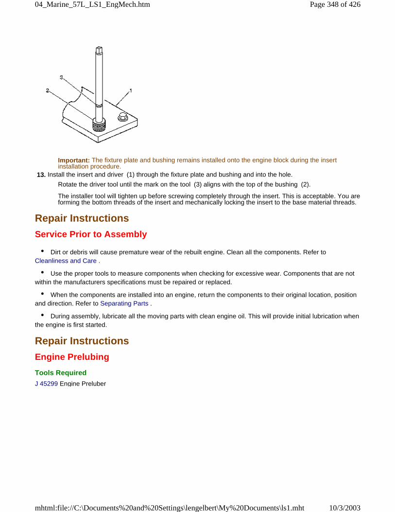
Important: The fixture plate and bushing remains installed onto the engine block during the insertinstallation procedure.
13. Install the insert and driver (1) through the fixture plate and bushing and into the hole.
Rotate the driver tool until the mark on the tool (3) aligns with the top of the bushing (2).
The installer tool will tighten up before screwing completely through the insert. This is acceptable. You areforming the bottom threads of the insert and mechanically locking the insert to the base material threads.
Repair Instructions
Service Prior to Assembly
• Dirt or debris will cause premature wear of the rebuilt engine. Clean all the components. Refer toCleanliness and Care .
• Use the proper tools to measure components when checking for excessive wear. Components that are notwithin the manufacturers specifications must be repaired or replaced.
• When the components are installed into an engine, return the components to their original location, positionand direction. Refer to Separating Parts .
• During assembly, lubricate all the moving parts with clean engine oil. This will provide initial lubrication whenthe engine is first started.
Repair Instructions
Engine Prelubing
Tools Required
J 45299 Engine Preluber
Page 348 of 42604_Marine_57L_LS1_EngMech.htm
10/3/2003mhtml:file://C:\Documents%20and%20Settings\lengelbert\My%20Documents\ls1.mht
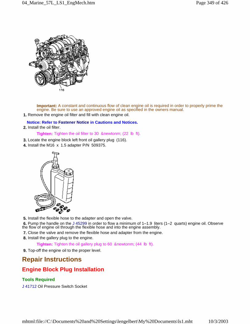
Important: A constant and continuous flow of clean engine oil is required in order to properly prime theengine. Be sure to use an approved engine oil as specified in the owners manual.
1. Remove the engine oil filter and fill with clean engine oil.
Notice: Refer to Fastener Notice in Cautions and Notices. 2. Install the oil filter.
Tighten: Tighten the oil filter to 30 &newtonm; (22 lb ft).
3. Locate the engine block left front oil gallery plug (116). 4. Install the M16 x 1.5 adapter P/N 509375.
5. Install the flexible hose to the adapter and open the valve. 6. Pump the handle on the J 45299 in order to flow a minimum of 1–1.9 liters (1–2 quarts) engine oil. Observethe flow of engine oil through the flexible hose and into the engine assembly. 7. Close the valve and remove the flexible hose and adapter from the engine. 8. Install the gallery plug to the engine.
Tighten: Tighten the oil gallery plug to 60 &newtonm; (44 lb ft).
9. Top-off the engine oil to the proper level.
Repair Instructions
Engine Block Plug Installation
Tools Required
J 41712 Oil Pressure Switch Socket
Page 349 of 42604_Marine_57L_LS1_EngMech.htm
10/3/2003mhtml:file://C:\Documents%20and%20Settings\lengelbert\My%20Documents\ls1.mht
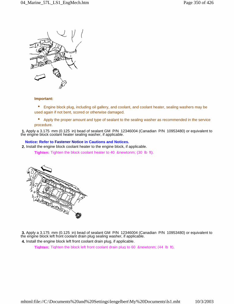
Important:
• Engine block plug, including oil gallery, and coolant, and coolant heater, sealing washers may beused again if not bent, scored or otherwise damaged.
• Apply the proper amount and type of sealant to the sealing washer as recommended in the serviceprocedure.
1. Apply a 3.175 mm (0.125 in) bead of sealant GM P/N 12346004 (Canadian P/N 10953480) or equivalent tothe engine block coolant heater sealing washer, if applicable.
Notice: Refer to Fastener Notice in Cautions and Notices. 2. Install the engine block coolant heater to the engine block, if applicable.
Tighten: Tighten the block coolant heater to 40 &newtonm; (30 lb ft).
3. Apply a 3.175 mm (0.125 in) bead of sealant GM P/N 12346004 (Canadian P/N 10953480) or equivalent tothe engine block left front coolant drain plug sealing washer, if applicable. 4. Install the engine block left front coolant drain plug, if applicable.
Tighten: Tighten the block left front coolant drain plug to 60 &newtonm; (44 lb ft).
Page 350 of 42604_Marine_57L_LS1_EngMech.htm
10/3/2003mhtml:file://C:\Documents%20and%20Settings\lengelbert\My%20Documents\ls1.mht
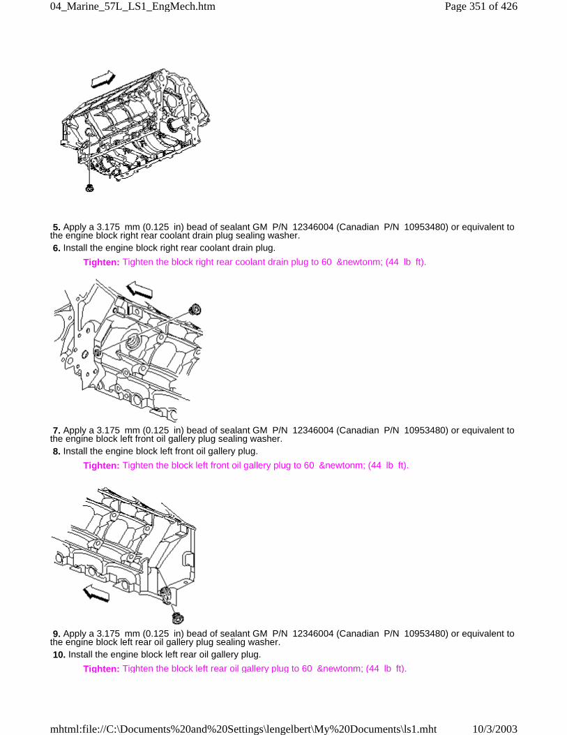
5. Apply a 3.175 mm (0.125 in) bead of sealant GM P/N 12346004 (Canadian P/N 10953480) or equivalent tothe engine block right rear coolant drain plug sealing washer. 6. Install the engine block right rear coolant drain plug.
Tighten: Tighten the block right rear coolant drain plug to 60 &newtonm; (44 lb ft).
7. Apply a 3.175 mm (0.125 in) bead of sealant GM P/N 12346004 (Canadian P/N 10953480) or equivalent tothe engine block left front oil gallery plug sealing washer. 8. Install the engine block left front oil gallery plug.
Tighten: Tighten the block left front oil gallery plug to 60 &newtonm; (44 lb ft).
9. Apply a 3.175 mm (0.125 in) bead of sealant GM P/N 12346004 (Canadian P/N 10953480) or equivalent tothe engine block left rear oil gallery plug sealing washer. 10. Install the engine block left rear oil gallery plug.
Tighten: Tighten the block left rear oil gallery plug to 60 &newtonm; (44 lb ft).
Page 351 of 42604_Marine_57L_LS1_EngMech.htm
10/3/2003mhtml:file://C:\Documents%20and%20Settings\lengelbert\My%20Documents\ls1.mht
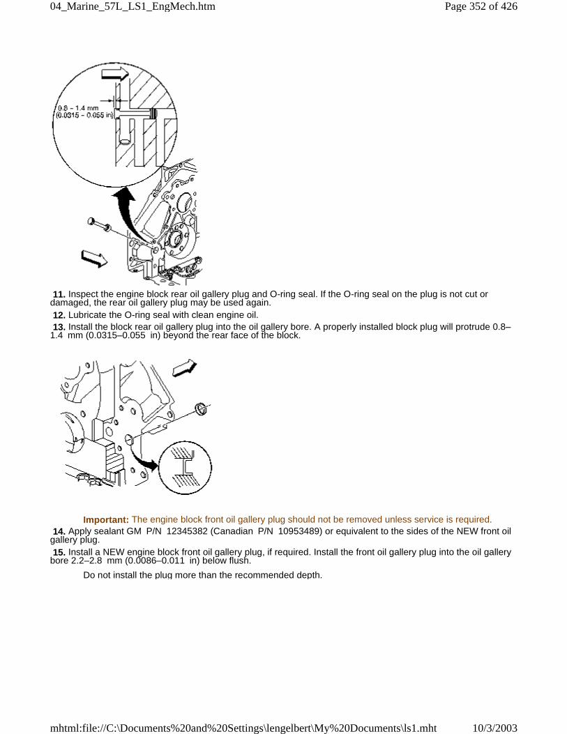
11. Inspect the engine block rear oil gallery plug and O-ring seal. If the O-ring seal on the plug is not cut ordamaged, the rear oil gallery plug may be used again. 12. Lubricate the O-ring seal with clean engine oil. 13. Install the block rear oil gallery plug into the oil gallery bore. A properly installed block plug will protrude 0.8–1.4 mm (0.0315–0.055 in) beyond the rear face of the block.
Important: The engine block front oil gallery plug should not be removed unless service is required. 14. Apply sealant GM P/N 12345382 (Canadian P/N 10953489) or equivalent to the sides of the NEW front oilgallery plug. 15. Install a NEW engine block front oil gallery plug, if required. Install the front oil gallery plug into the oil gallerybore 2.2–2.8 mm (0.0086–0.011 in) below flush.
Do not install the plug more than the recommended depth.
Page 352 of 42604_Marine_57L_LS1_EngMech.htm
10/3/2003mhtml:file://C:\Documents%20and%20Settings\lengelbert\My%20Documents\ls1.mht
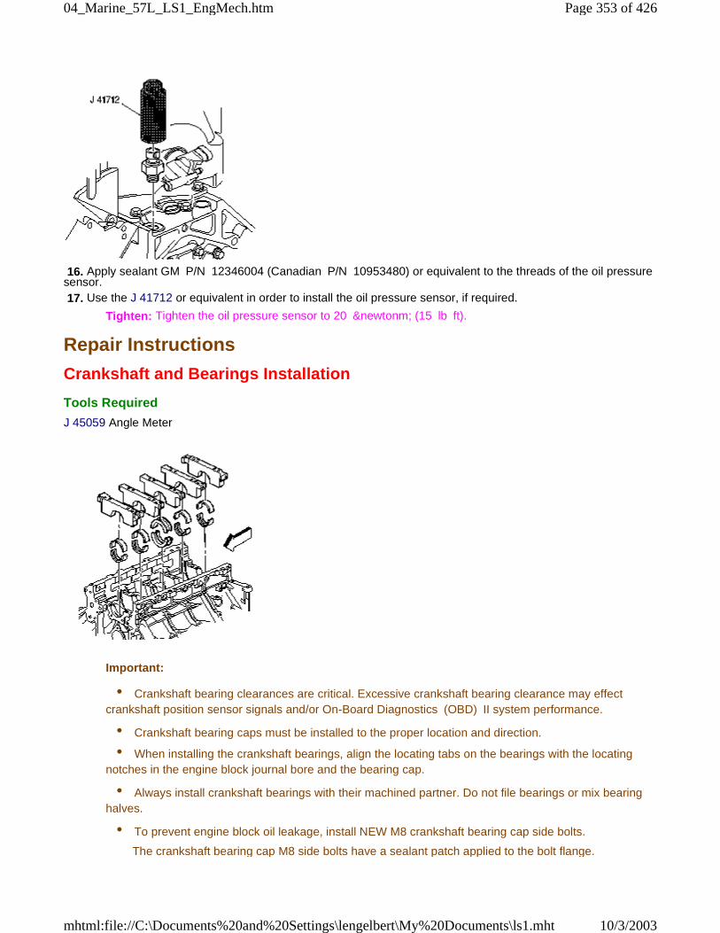
16. Apply sealant GM P/N 12346004 (Canadian P/N 10953480) or equivalent to the threads of the oil pressuresensor. 17. Use the J 41712 or equivalent in order to install the oil pressure sensor, if required.
Tighten: Tighten the oil pressure sensor to 20 &newtonm; (15 lb ft).
Repair Instructions
Crankshaft and Bearings Installation
Tools Required
J 45059 Angle Meter
Important:
• Crankshaft bearing clearances are critical. Excessive crankshaft bearing clearance may effectcrankshaft position sensor signals and/or On-Board Diagnostics (OBD) II system performance.
• Crankshaft bearing caps must be installed to the proper location and direction.
• When installing the crankshaft bearings, align the locating tabs on the bearings with the locatingnotches in the engine block journal bore and the bearing cap.
• Always install crankshaft bearings with their machined partner. Do not file bearings or mix bearinghalves.
• To prevent engine block oil leakage, install NEW M8 crankshaft bearing cap side bolts.
The crankshaft bearing cap M8 side bolts have a sealant patch applied to the bolt flange.
Page 353 of 42604_Marine_57L_LS1_EngMech.htm
10/3/2003mhtml:file://C:\Documents%20and%20Settings\lengelbert\My%20Documents\ls1.mht
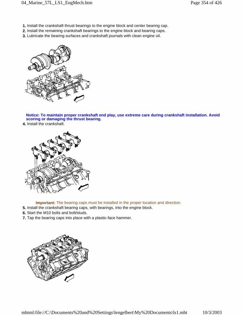
1. Install the crankshaft thrust bearings to the engine block and center bearing cap. 2. Install the remaining crankshaft bearings to the engine block and bearing caps. 3. Lubricate the bearing surfaces and crankshaft journals with clean engine oil.
Notice: To maintain proper crankshaft end play, use extreme care during crankshaft installation. Avoidscoring or damaging the thrust bearing.
4. Install the crankshaft.
Important: The bearing caps must be installed in the proper location and direction. 5. Install the crankshaft bearing caps, with bearings, into the engine block. 6. Start the M10 bolts and bolt/studs. 7. Tap the bearing caps into place with a plastic-face hammer.
Page 354 of 42604_Marine_57L_LS1_EngMech.htm
10/3/2003mhtml:file://C:\Documents%20and%20Settings\lengelbert\My%20Documents\ls1.mht
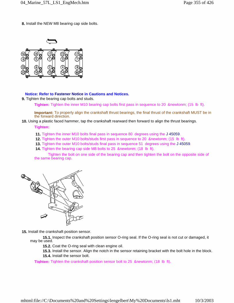
8. Install the NEW M8 bearing cap side bolts.
Notice: Refer to Fastener Notice in Cautions and Notices. 9. Tighten the bearing cap bolts and studs.
Tighten: Tighten the inner M10 bearing cap bolts first pass in sequence to 20 &newtonm; (15 lb ft).
Important: To properly align the crankshaft thrust bearings, the final thrust of the crankshaft MUST be inthe forward direction.
10. Using a plastic faced hammer, tap the crankshaft rearward then forward to align the thrust bearings.
Tighten:
11. Tighten the inner M10 bolts final pass in sequence 80 degrees using the J 45059. 12. Tighten the outer M10 bolts/studs first pass in sequence to 20 &newtonm; (15 lb ft). 13. Tighten the outer M10 bolts/studs final pass in sequence 51 degrees using the J 45059. 14. Tighten the bearing cap side M8 bolts to 25 &newtonm; (18 lb ft).
Tighten the bolt on one side of the bearing cap and then tighten the bolt on the opposite side ofthe same bearing cap.
15. Install the crankshaft position sensor.
15.1. Inspect the crankshaft position sensor O-ring seal. If the O-ring seal is not cut or damaged, itmay be used. 15.2. Coat the O-ring seal with clean engine oil. 15.3. Install the sensor. Align the notch in the sensor retaining bracket with the bolt hole in the block. 15.4. Install the sensor bolt.
Tighten: Tighten the crankshaft position sensor bolt to 25 &newtonm; (18 lb ft).
Page 355 of 42604_Marine_57L_LS1_EngMech.htm
10/3/2003mhtml:file://C:\Documents%20and%20Settings\lengelbert\My%20Documents\ls1.mht
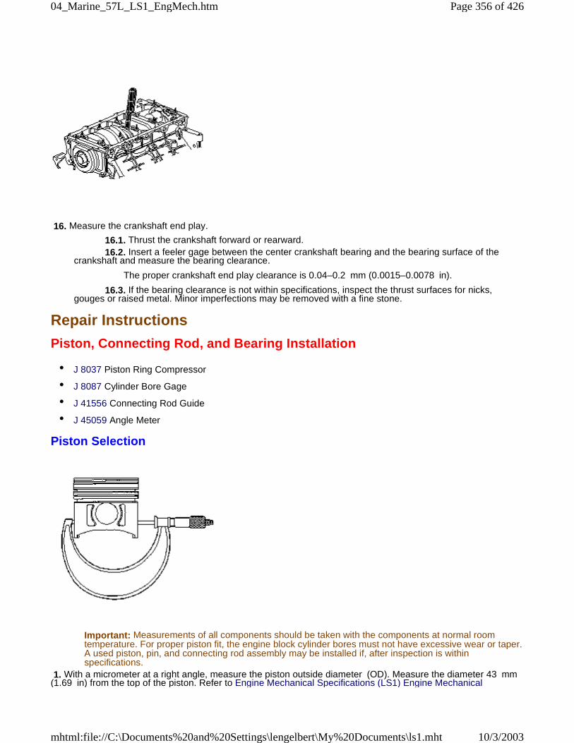
16. Measure the crankshaft end play.
16.1. Thrust the crankshaft forward or rearward. 16.2. Insert a feeler gage between the center crankshaft bearing and the bearing surface of thecrankshaft and measure the bearing clearance.
The proper crankshaft end play clearance is 0.04–0.2 mm (0.0015–0.0078 in).
16.3. If the bearing clearance is not within specifications, inspect the thrust surfaces for nicks,gouges or raised metal. Minor imperfections may be removed with a fine stone.
Repair Instructions
Piston, Connecting Rod, and Bearing Installation
• J 8037 Piston Ring Compressor
• J 8087 Cylinder Bore Gage
• J 41556 Connecting Rod Guide
• J 45059 Angle Meter
Piston Selection
Important: Measurements of all components should be taken with the components at normal roomtemperature. For proper piston fit, the engine block cylinder bores must not have excessive wear or taper.A used piston, pin, and connecting rod assembly may be installed if, after inspection is withinspecifications.
1. With a micrometer at a right angle, measure the piston outside diameter (OD). Measure the diameter 43 mm(1.69 in) from the top of the piston. Refer to Engine Mechanical Specifications (LS1) Engine Mechanical
Page 356 of 42604_Marine_57L_LS1_EngMech.htm
10/3/2003mhtml:file://C:\Documents%20and%20Settings\lengelbert\My%20Documents\ls1.mht
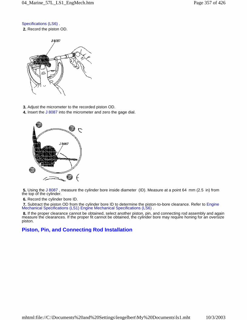
Specifications (LS6) . 2. Record the piston OD.
3. Adjust the micrometer to the recorded piston OD. 4. Insert the J 8087 into the micrometer and zero the gage dial.
5. Using the J 8087 , measure the cylinder bore inside diameter (ID). Measure at a point 64 mm (2.5 in) fromthe top of the cylinder. 6. Record the cylinder bore ID. 7. Subtract the piston OD from the cylinder bore ID to determine the piston-to-bore clearance. Refer to EngineMechanical Specifications (LS1) Engine Mechanical Specifications (LS6) . 8. If the proper clearance cannot be obtained, select another piston, pin, and connecting rod assembly and againmeasure the clearances. If the proper fit cannot be obtained, the cylinder bore may require honing for an oversizepiston.
Piston, Pin, and Connecting Rod Installation
Page 357 of 42604_Marine_57L_LS1_EngMech.htm
10/3/2003mhtml:file://C:\Documents%20and%20Settings\lengelbert\My%20Documents\ls1.mht
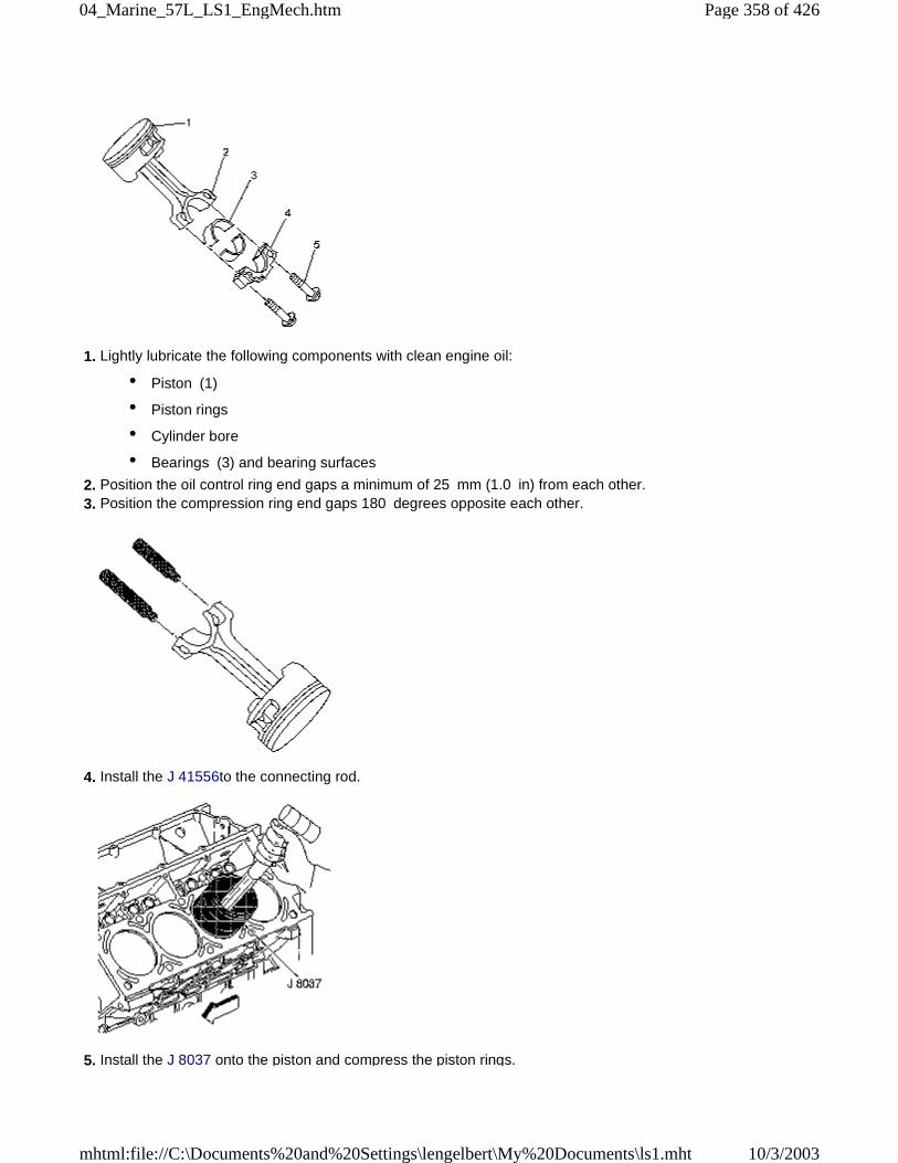
1. Lightly lubricate the following components with clean engine oil:
• Piston (1)
• Piston rings
• Cylinder bore
• Bearings (3) and bearing surfaces
2. Position the oil control ring end gaps a minimum of 25 mm (1.0 in) from each other. 3. Position the compression ring end gaps 180 degrees opposite each other.
4. Install the J 41556to the connecting rod.
5. Install the J 8037 onto the piston and compress the piston rings.
Page 358 of 42604_Marine_57L_LS1_EngMech.htm
10/3/2003mhtml:file://C:\Documents%20and%20Settings\lengelbert\My%20Documents\ls1.mht
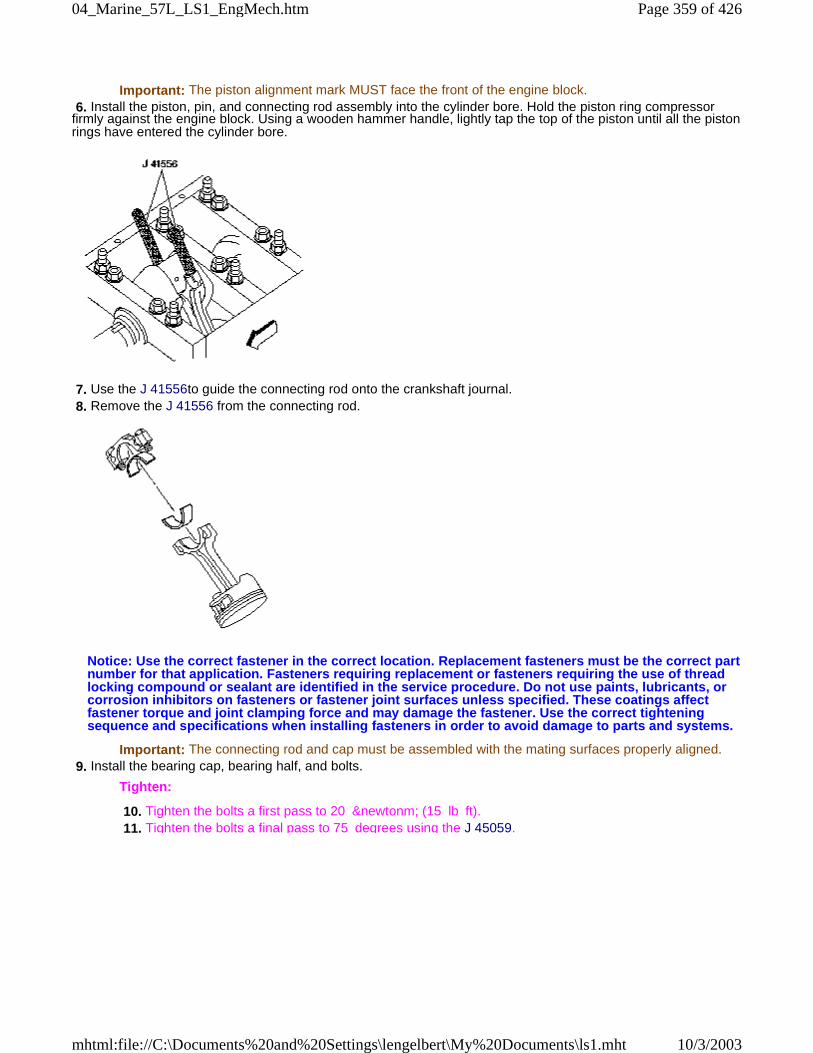
Important: The piston alignment mark MUST face the front of the engine block. 6. Install the piston, pin, and connecting rod assembly into the cylinder bore. Hold the piston ring compressorfirmly against the engine block. Using a wooden hammer handle, lightly tap the top of the piston until all the pistonrings have entered the cylinder bore.
7. Use the J 41556to guide the connecting rod onto the crankshaft journal. 8. Remove the J 41556 from the connecting rod.
Notice: Use the correct fastener in the correct location. Replacement fasteners must be the correct partnumber for that application. Fasteners requiring replacement or fasteners requiring the use of threadlocking compound or sealant are identified in the service procedure. Do not use paints, lubricants, orcorrosion inhibitors on fasteners or fastener joint surfaces unless specified. These coatings affectfastener torque and joint clamping force and may damage the fastener. Use the correct tighteningsequence and specifications when installing fasteners in order to avoid damage to parts and systems.
Important: The connecting rod and cap must be assembled with the mating surfaces properly aligned. 9. Install the bearing cap, bearing half, and bolts.
Tighten:
10. Tighten the bolts a first pass to 20 &newtonm; (15 lb ft). 11. Tighten the bolts a final pass to 75 degrees using the J 45059.
Page 359 of 42604_Marine_57L_LS1_EngMech.htm
10/3/2003mhtml:file://C:\Documents%20and%20Settings\lengelbert\My%20Documents\ls1.mht
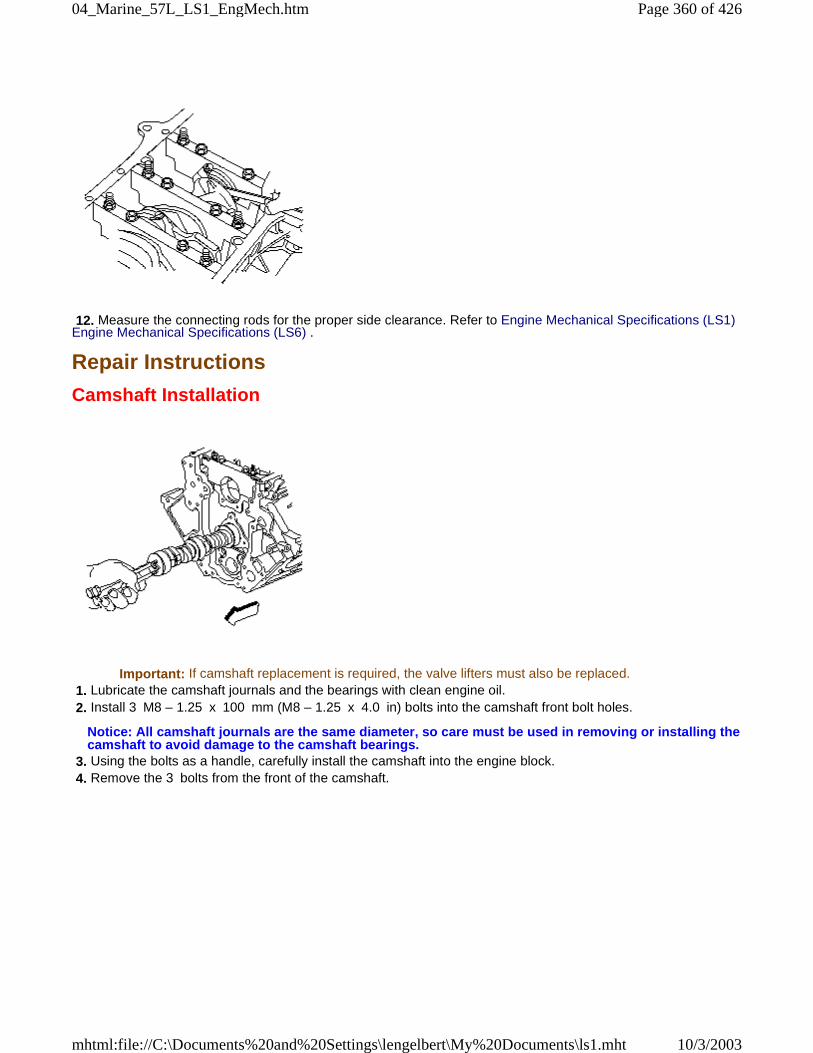
12. Measure the connecting rods for the proper side clearance. Refer to Engine Mechanical Specifications (LS1)Engine Mechanical Specifications (LS6) .
Repair Instructions
Camshaft Installation
Important: If camshaft replacement is required, the valve lifters must also be replaced. 1. Lubricate the camshaft journals and the bearings with clean engine oil. 2. Install 3 M8 – 1.25 x 100 mm (M8 – 1.25 x 4.0 in) bolts into the camshaft front bolt holes.
Notice: All camshaft journals are the same diameter, so care must be used in removing or installing thecamshaft to avoid damage to the camshaft bearings.
3. Using the bolts as a handle, carefully install the camshaft into the engine block. 4. Remove the 3 bolts from the front of the camshaft.
Page 360 of 42604_Marine_57L_LS1_EngMech.htm
10/3/2003mhtml:file://C:\Documents%20and%20Settings\lengelbert\My%20Documents\ls1.mht
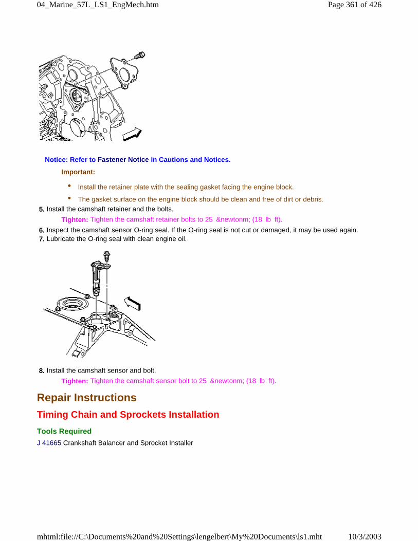
Notice: Refer to Fastener Notice in Cautions and Notices.
Important:
• Install the retainer plate with the sealing gasket facing the engine block.
• The gasket surface on the engine block should be clean and free of dirt or debris.
5. Install the camshaft retainer and the bolts.
Tighten: Tighten the camshaft retainer bolts to 25 &newtonm; (18 lb ft).
6. Inspect the camshaft sensor O-ring seal. If the O-ring seal is not cut or damaged, it may be used again. 7. Lubricate the O-ring seal with clean engine oil.
8. Install the camshaft sensor and bolt.
Tighten: Tighten the camshaft sensor bolt to 25 &newtonm; (18 lb ft).
Repair Instructions
Timing Chain and Sprockets Installation
Tools Required
J 41665 Crankshaft Balancer and Sprocket Installer
Page 361 of 42604_Marine_57L_LS1_EngMech.htm
10/3/2003mhtml:file://C:\Documents%20and%20Settings\lengelbert\My%20Documents\ls1.mht
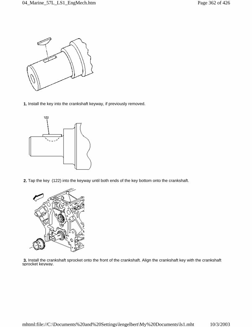
1. Install the key into the crankshaft keyway, if previously removed.
2. Tap the key (122) into the keyway until both ends of the key bottom onto the crankshaft.
3. Install the crankshaft sprocket onto the front of the crankshaft. Align the crankshaft key with the crankshaftsprocket keyway.
Page 362 of 42604_Marine_57L_LS1_EngMech.htm
10/3/2003mhtml:file://C:\Documents%20and%20Settings\lengelbert\My%20Documents\ls1.mht
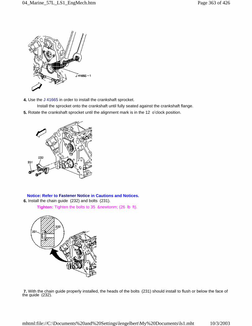
4. Use the J 41665 in order to install the crankshaft sprocket.
Install the sprocket onto the crankshaft until fully seated against the crankshaft flange.
5. Rotate the crankshaft sprocket until the alignment mark is in the 12 o’clock position.
Notice: Refer to Fastener Notice in Cautions and Notices. 6. Install the chain guide (232) and bolts (231).
Tighten: Tighten the bolts to 35 &newtonm; (26 lb ft).
7. With the chain guide properly installed, the heads of the bolts (231) should install to flush or below the face ofthe guide (232).
Page 363 of 42604_Marine_57L_LS1_EngMech.htm
10/3/2003mhtml:file://C:\Documents%20and%20Settings\lengelbert\My%20Documents\ls1.mht
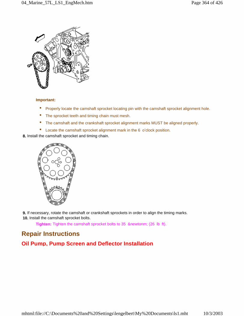
Important:
• Properly locate the camshaft sprocket locating pin with the camshaft sprocket alignment hole.
• The sprocket teeth and timing chain must mesh.
• The camshaft and the crankshaft sprocket alignment marks MUST be aligned properly.
• Locate the camshaft sprocket alignment mark in the 6 o’clock position.
8. Install the camshaft sprocket and timing chain.
9. If necessary, rotate the camshaft or crankshaft sprockets in order to align the timing marks. 10. Install the camshaft sprocket bolts.
Tighten: Tighten the camshaft sprocket bolts to 35 &newtonm; (26 lb ft).
Repair Instructions
Oil Pump, Pump Screen and Deflector Installation
Page 364 of 42604_Marine_57L_LS1_EngMech.htm
10/3/2003mhtml:file://C:\Documents%20and%20Settings\lengelbert\My%20Documents\ls1.mht
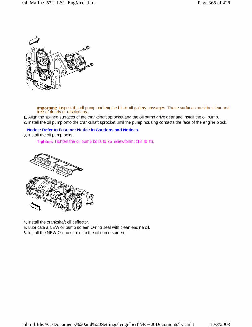
Important: Inspect the oil pump and engine block oil gallery passages. These surfaces must be clear andfree of debris or restrictions.
1. Align the splined surfaces of the crankshaft sprocket and the oil pump drive gear and install the oil pump. 2. Install the oil pump onto the crankshaft sprocket until the pump housing contacts the face of the engine block.
Notice: Refer to Fastener Notice in Cautions and Notices. 3. Install the oil pump bolts.
Tighten: Tighten the oil pump bolts to 25 &newtonm; (18 lb ft).
4. Install the crankshaft oil deflector. 5. Lubricate a NEW oil pump screen O-ring seal with clean engine oil. 6. Install the NEW O-ring seal onto the oil pump screen.
Page 365 of 42604_Marine_57L_LS1_EngMech.htm
10/3/2003mhtml:file://C:\Documents%20and%20Settings\lengelbert\My%20Documents\ls1.mht
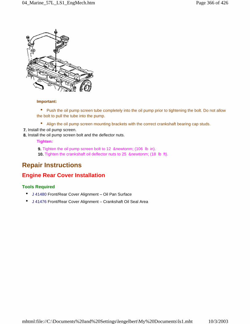
Important:
• Push the oil pump screen tube completely into the oil pump prior to tightening the bolt. Do not allowthe bolt to pull the tube into the pump.
• Align the oil pump screen mounting brackets with the correct crankshaft bearing cap studs.
7. Install the oil pump screen. 8. Install the oil pump screen bolt and the deflector nuts.
Tighten:
9. Tighten the oil pump screen bolt to 12 &newtonm; (106 lb in). 10. Tighten the crankshaft oil deflector nuts to 25 &newtonm; (18 lb ft).
Repair Instructions
Engine Rear Cover Installation
Tools Required
• J 41480 Front/Rear Cover Alignment – Oil Pan Surface
• J 41476 Front/Rear Cover Alignment – Crankshaft Oil Seal Area
Page 366 of 42604_Marine_57L_LS1_EngMech.htm
10/3/2003mhtml:file://C:\Documents%20and%20Settings\lengelbert\My%20Documents\ls1.mht
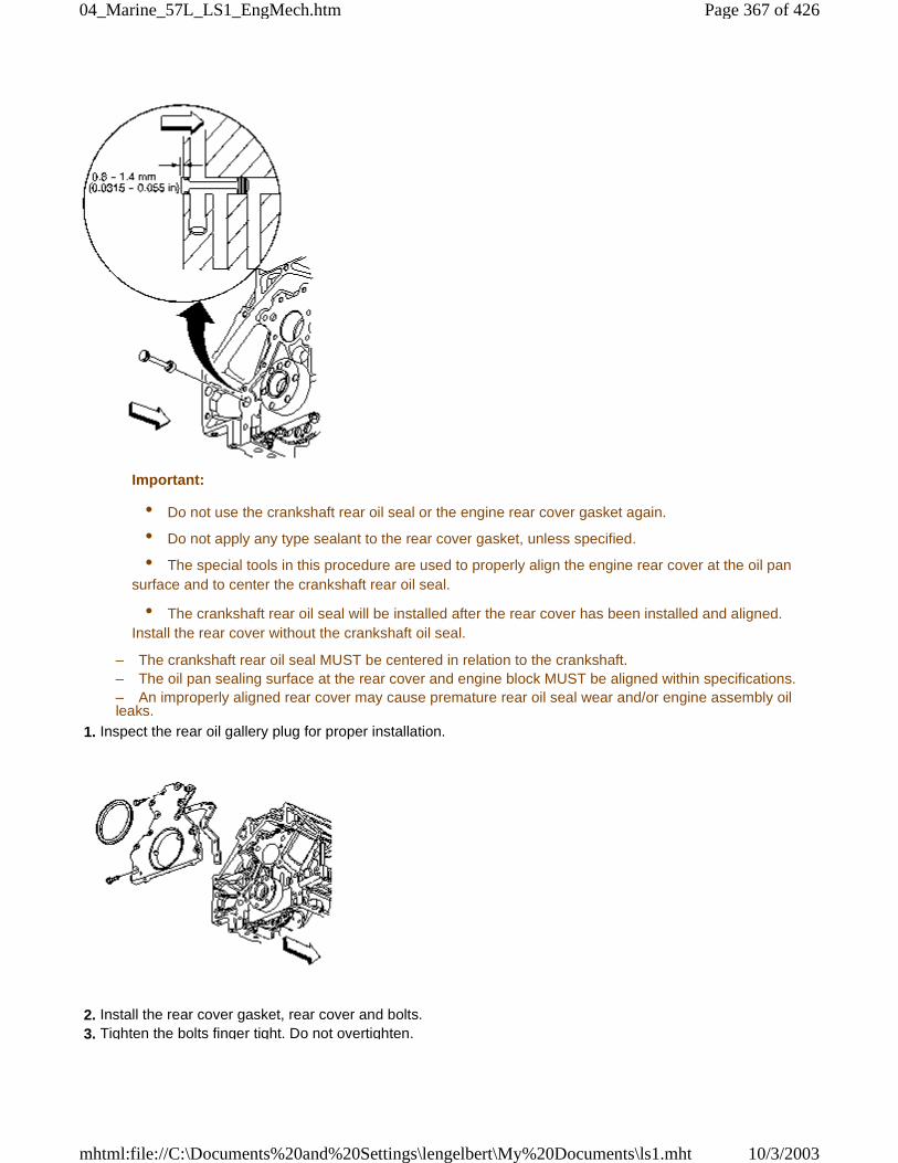
Important:
• Do not use the crankshaft rear oil seal or the engine rear cover gasket again.
• Do not apply any type sealant to the rear cover gasket, unless specified.
• The special tools in this procedure are used to properly align the engine rear cover at the oil pansurface and to center the crankshaft rear oil seal.
• The crankshaft rear oil seal will be installed after the rear cover has been installed and aligned.Install the rear cover without the crankshaft oil seal.
– The crankshaft rear oil seal MUST be centered in relation to the crankshaft.– The oil pan sealing surface at the rear cover and engine block MUST be aligned within specifications.– An improperly aligned rear cover may cause premature rear oil seal wear and/or engine assembly oilleaks.
1. Inspect the rear oil gallery plug for proper installation.
2. Install the rear cover gasket, rear cover and bolts. 3. Tighten the bolts finger tight. Do not overtighten.
Page 367 of 42604_Marine_57L_LS1_EngMech.htm
10/3/2003mhtml:file://C:\Documents%20and%20Settings\lengelbert\My%20Documents\ls1.mht
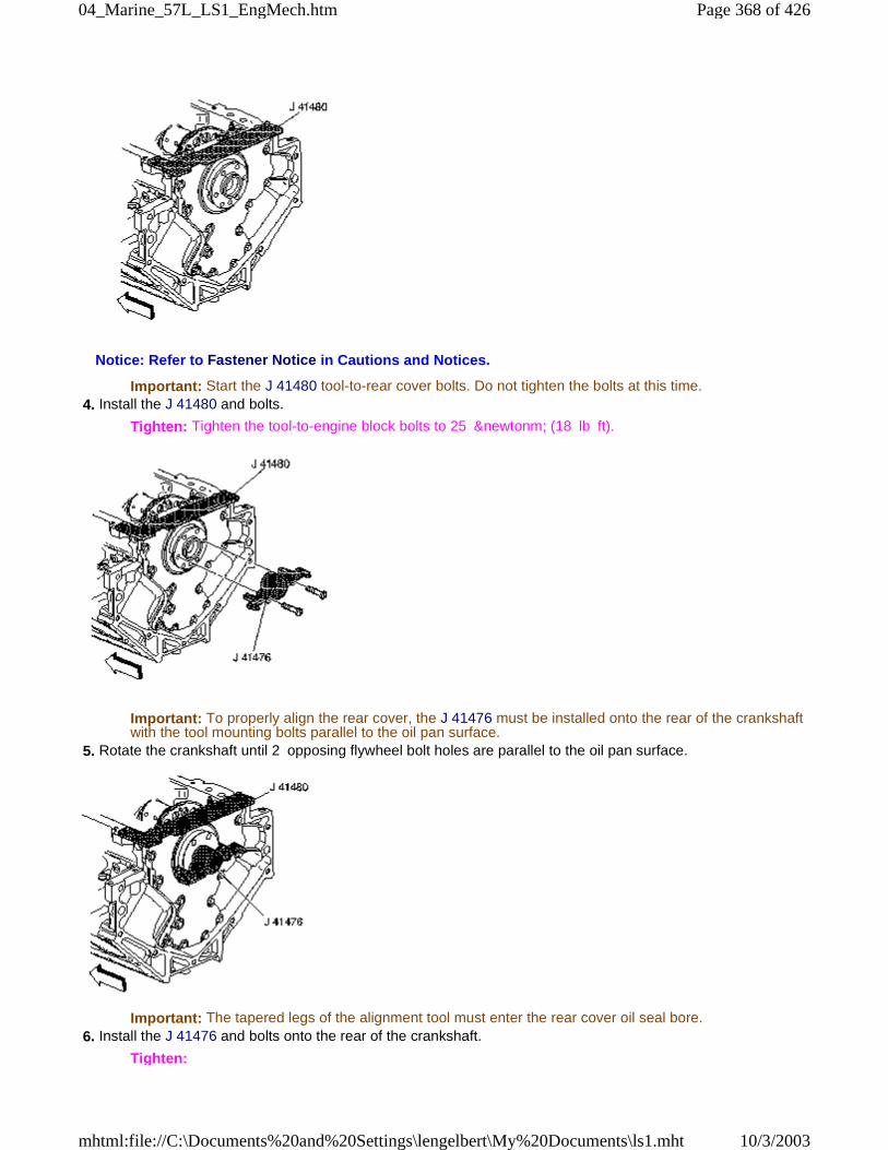
Notice: Refer to Fastener Notice in Cautions and Notices.
Important: Start the J 41480 tool-to-rear cover bolts. Do not tighten the bolts at this time. 4. Install the J 41480 and bolts.
Tighten: Tighten the tool-to-engine block bolts to 25 &newtonm; (18 lb ft).
Important: To properly align the rear cover, the J 41476 must be installed onto the rear of the crankshaftwith the tool mounting bolts parallel to the oil pan surface.
5. Rotate the crankshaft until 2 opposing flywheel bolt holes are parallel to the oil pan surface.
Important: The tapered legs of the alignment tool must enter the rear cover oil seal bore. 6. Install the J 41476 and bolts onto the rear of the crankshaft.
Tighten:
Page 368 of 42604_Marine_57L_LS1_EngMech.htm
10/3/2003mhtml:file://C:\Documents%20and%20Settings\lengelbert\My%20Documents\ls1.mht
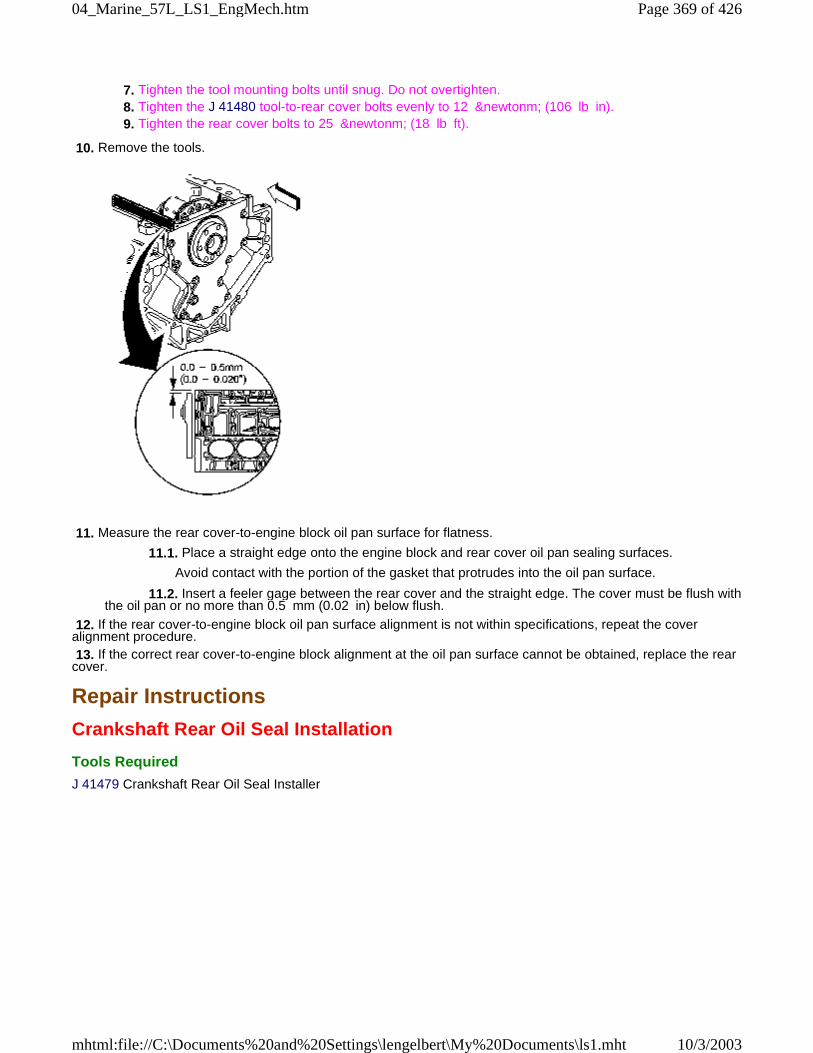
7. Tighten the tool mounting bolts until snug. Do not overtighten. 8. Tighten the J 41480 tool-to-rear cover bolts evenly to 12 &newtonm; (106 lb in). 9. Tighten the rear cover bolts to 25 &newtonm; (18 lb ft).
10. Remove the tools.
11. Measure the rear cover-to-engine block oil pan surface for flatness.
11.1. Place a straight edge onto the engine block and rear cover oil pan sealing surfaces.
Avoid contact with the portion of the gasket that protrudes into the oil pan surface.
11.2. Insert a feeler gage between the rear cover and the straight edge. The cover must be flush withthe oil pan or no more than 0.5 mm (0.02 in) below flush.
12. If the rear cover-to-engine block oil pan surface alignment is not within specifications, repeat the coveralignment procedure. 13. If the correct rear cover-to-engine block alignment at the oil pan surface cannot be obtained, replace the rearcover.
Repair Instructions
Crankshaft Rear Oil Seal Installation
Tools Required
J 41479 Crankshaft Rear Oil Seal Installer
Page 369 of 42604_Marine_57L_LS1_EngMech.htm
10/3/2003mhtml:file://C:\Documents%20and%20Settings\lengelbert\My%20Documents\ls1.mht
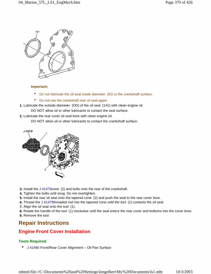
Important:
• Do not lubricate the oil seal inside diameter (ID) or the crankshaft surface.
• Do not use the crankshaft rear oil seal again.
1. Lubricate the outside diameter (OD) of the oil seal (141) with clean engine oil.
DO NOT allow oil or other lubricants to contact the seal surface.
2. Lubricate the rear cover oil seal bore with clean engine oil.
DO NOT allow oil or other lubricants to contact the crankshaft surface.
3. Install the J 41479cone (2) and bolts onto the rear of the crankshaft. 4. Tighten the bolts until snug. Do not overtighten. 5. Install the rear oil seal onto the tapered cone (2) and push the seal to the rear cover bore. 6. Thread the J 41479threaded rod into the tapered cone until the tool (1) contacts the oil seal. 7. Align the oil seal onto the tool (1). 8. Rotate the handle of the tool (1) clockwise until the seal enters the rear cover and bottoms into the cover bore. 9. Remove the tool.
Repair Instructions
Engine Front Cover Installation
Tools Required
• J 41480 Front/Rear Cover Alignment – Oil Pan Surface
Page 370 of 42604_Marine_57L_LS1_EngMech.htm
10/3/2003mhtml:file://C:\Documents%20and%20Settings\lengelbert\My%20Documents\ls1.mht
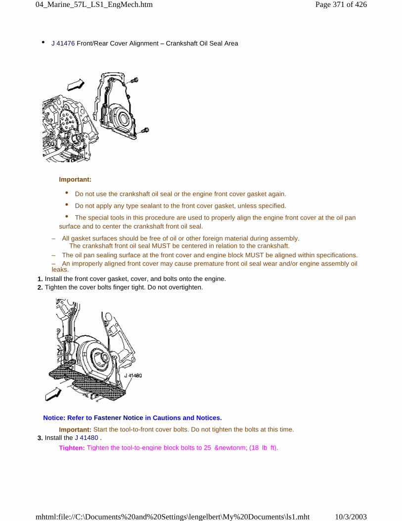
• J 41476 Front/Rear Cover Alignment – Crankshaft Oil Seal Area
Important:
• Do not use the crankshaft oil seal or the engine front cover gasket again.
• Do not apply any type sealant to the front cover gasket, unless specified.
• The special tools in this procedure are used to properly align the engine front cover at the oil pansurface and to center the crankshaft front oil seal.
– All gasket surfaces should be free of oil or other foreign material during assembly.The crankshaft front oil seal MUST be centered in relation to the crankshaft.
– The oil pan sealing surface at the front cover and engine block MUST be aligned within specifications.– An improperly aligned front cover may cause premature front oil seal wear and/or engine assembly oilleaks.
1. Install the front cover gasket, cover, and bolts onto the engine. 2. Tighten the cover bolts finger tight. Do not overtighten.
Notice: Refer to Fastener Notice in Cautions and Notices.
Important: Start the tool-to-front cover bolts. Do not tighten the bolts at this time. 3. Install the J 41480 .
Tighten: Tighten the tool-to-engine block bolts to 25 &newtonm; (18 lb ft).
Page 371 of 42604_Marine_57L_LS1_EngMech.htm
10/3/2003mhtml:file://C:\Documents%20and%20Settings\lengelbert\My%20Documents\ls1.mht
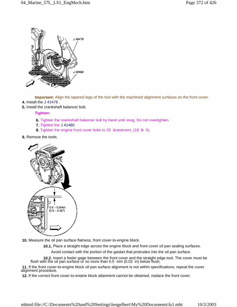
Important: Align the tapered legs of the tool with the machined alignment surfaces on the front cover. 4. Install the J 41476 . 5. Install the crankshaft balancer bolt.
Tighten:
6. Tighten the crankshaft balancer bolt by hand until snug. Do not overtighten. 7. Tighten the J 41480 . 8. Tighten the engine front cover bolts to 25 &newtonm; (18 lb ft).
9. Remove the tools.
10. Measure the oil pan surface flatness, front cover-to-engine block.
10.1. Place a straight edge across the engine block and front cover oil pan sealing surfaces.
Avoid contact with the portion of the gasket that protrudes into the oil pan surface.
10.2. Insert a feeler gage between the front cover and the straight edge tool. The cover must beflush with the oil pan surface or no more than 0.5 mm (0.02 in) below flush.
11. If the front cover-to-engine block oil pan surface alignment is not within specifications, repeat the coveralignment procedure. 12. If the correct front cover-to-engine block alignment cannot be obtained, replace the front cover.
Page 372 of 42604_Marine_57L_LS1_EngMech.htm
10/3/2003mhtml:file://C:\Documents%20and%20Settings\lengelbert\My%20Documents\ls1.mht
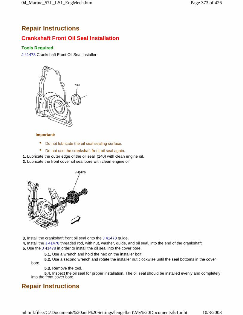
Repair Instructions
Crankshaft Front Oil Seal Installation
Tools Required
J 41478 Crankshaft Front Oil Seal Installer
Important:
• Do not lubricate the oil seal sealing surface.
• Do not use the crankshaft front oil seal again.
1. Lubricate the outer edge of the oil seal (140) with clean engine oil. 2. Lubricate the front cover oil seal bore with clean engine oil.
3. Install the crankshaft front oil seal onto the J 41478 guide. 4. Install the J 41478 threaded rod, with nut, washer, guide, and oil seal, into the end of the crankshaft. 5. Use the J 41478 in order to install the oil seal into the cover bore.
5.1. Use a wrench and hold the hex on the installer bolt. 5.2. Use a second wrench and rotate the installer nut clockwise until the seal bottoms in the coverbore. 5.3. Remove the tool. 5.4. Inspect the oil seal for proper installation. The oil seal should be installed evenly and completelyinto the front cover bore.
Repair Instructions
Page 373 of 42604_Marine_57L_LS1_EngMech.htm
10/3/2003mhtml:file://C:\Documents%20and%20Settings\lengelbert\My%20Documents\ls1.mht
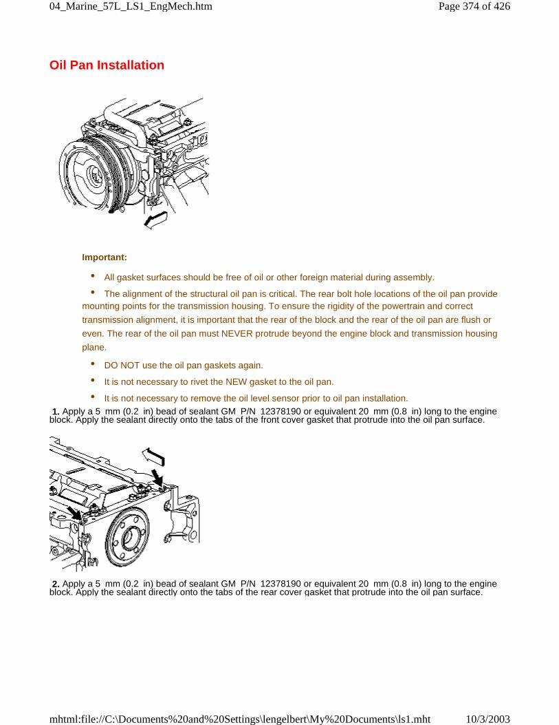
Oil Pan Installation
Important:
• All gasket surfaces should be free of oil or other foreign material during assembly.
• The alignment of the structural oil pan is critical. The rear bolt hole locations of the oil pan providemounting points for the transmission housing. To ensure the rigidity of the powertrain and correct
transmission alignment, it is important that the rear of the block and the rear of the oil pan are flush or
even. The rear of the oil pan must NEVER protrude beyond the engine block and transmission housing
plane.
• DO NOT use the oil pan gaskets again.
• It is not necessary to rivet the NEW gasket to the oil pan.
• It is not necessary to remove the oil level sensor prior to oil pan installation.
1. Apply a 5 mm (0.2 in) bead of sealant GM P/N 12378190 or equivalent 20 mm (0.8 in) long to the engineblock. Apply the sealant directly onto the tabs of the front cover gasket that protrude into the oil pan surface.
2. Apply a 5 mm (0.2 in) bead of sealant GM P/N 12378190 or equivalent 20 mm (0.8 in) long to the engineblock. Apply the sealant directly onto the tabs of the rear cover gasket that protrude into the oil pan surface.
Page 374 of 42604_Marine_57L_LS1_EngMech.htm
10/3/2003mhtml:file://C:\Documents%20and%20Settings\lengelbert\My%20Documents\ls1.mht
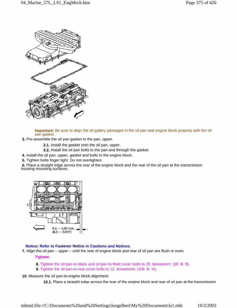
Important: Be sure to align the oil gallery passages in the oil pan and engine block properly with the oilpan gasket.
3. Pre-assemble the oil pan gasket to the pan, upper.
3.1. Install the gasket onto the oil pan, upper. 3.2. Install the oil pan bolts to the pan and through the gasket.
4. Install the oil pan, upper, gasket and bolts to the engine block. 5. Tighten bolts finger tight. Do not overtighten. 6. Place a straight edge across the rear of the engine block and the rear of the oil pan at the transmissionhousing mounting surfaces.
Notice: Refer to Fastener Notice in Cautions and Notices. 7. Align the oil pan – upper – until the rear of engine block and rear of oil pan are flush or even.
Tighten:
8. Tighten the oil pan-to-block and oil pan-to-front cover bolts to 25 &newtonm; (18 lb ft). 9. Tighten the oil pan-to-rear cover bolts to 12 &newtonm; (106 lb in).
10. Measure the oil pan-to-engine block alignment.
10.1. Place a straight edge across the rear of the engine block and rear of oil pan at the transmission
Page 375 of 42604_Marine_57L_LS1_EngMech.htm
10/3/2003mhtml:file://C:\Documents%20and%20Settings\lengelbert\My%20Documents\ls1.mht
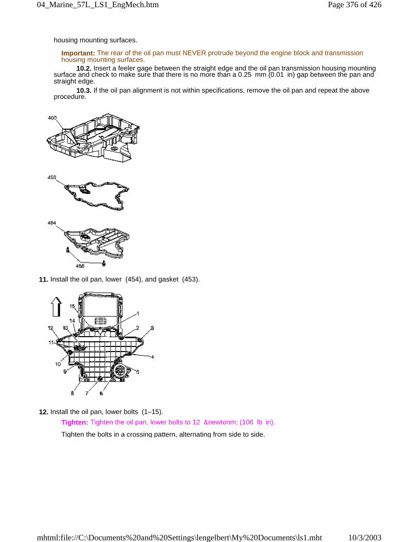
housing mounting surfaces.
Important: The rear of the oil pan must NEVER protrude beyond the engine block and transmissionhousing mounting surfaces.
10.2. Insert a feeler gage between the straight edge and the oil pan transmission housing mountingsurface and check to make sure that there is no more than a 0.25 mm (0.01 in) gap between the pan andstraight edge. 10.3. If the oil pan alignment is not within specifications, remove the oil pan and repeat the aboveprocedure.
11. Install the oil pan, lower (454), and gasket (453).
12. Install the oil pan, lower bolts (1–15).
Tighten: Tighten the oil pan, lower bolts to 12 &newtonm; (106 lb in).
Tighten the bolts in a crossing pattern, alternating from side to side.
Page 376 of 42604_Marine_57L_LS1_EngMech.htm
10/3/2003mhtml:file://C:\Documents%20and%20Settings\lengelbert\My%20Documents\ls1.mht
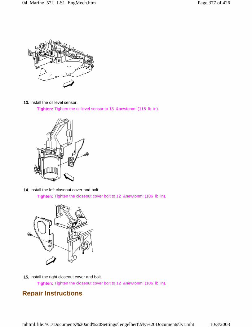
13. Install the oil level sensor.
Tighten: Tighten the oil level sensor to 13 &newtonm; (115 lb in).
14. Install the left closeout cover and bolt.
Tighten: Tighten the closeout cover bolt to 12 &newtonm; (106 lb in).
15. Install the right closeout cover and bolt.
Tighten: Tighten the closeout cover bolt to 12 &newtonm; (106 lb in).
Repair Instructions
Page 377 of 42604_Marine_57L_LS1_EngMech.htm
10/3/2003mhtml:file://C:\Documents%20and%20Settings\lengelbert\My%20Documents\ls1.mht
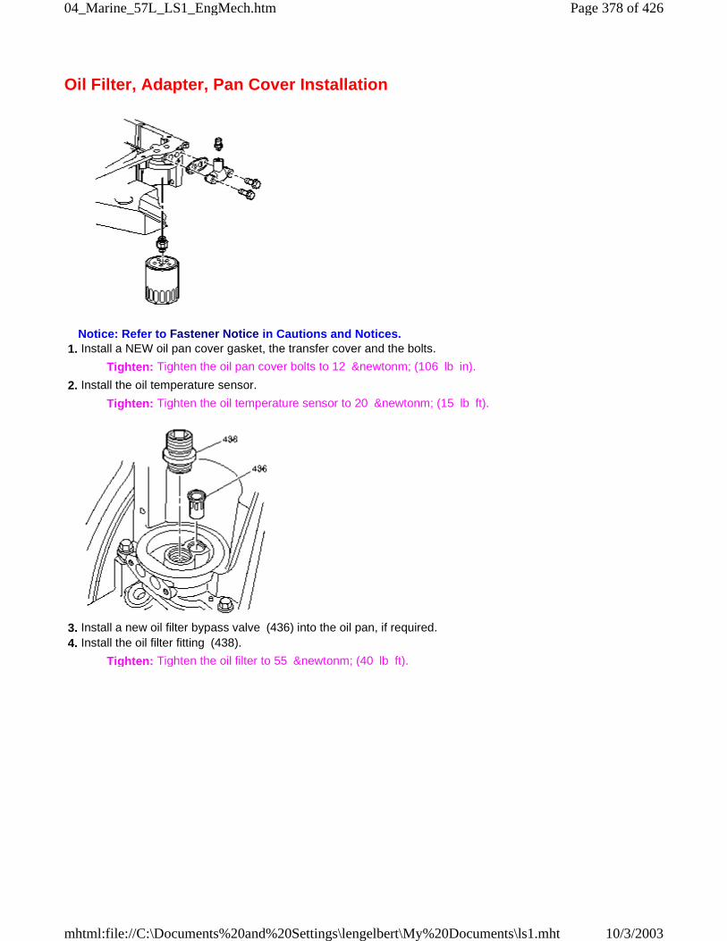
Oil Filter, Adapter, Pan Cover Installation
Notice: Refer to Fastener Notice in Cautions and Notices. 1. Install a NEW oil pan cover gasket, the transfer cover and the bolts.
Tighten: Tighten the oil pan cover bolts to 12 &newtonm; (106 lb in).
2. Install the oil temperature sensor.
Tighten: Tighten the oil temperature sensor to 20 &newtonm; (15 lb ft).
3. Install a new oil filter bypass valve (436) into the oil pan, if required. 4. Install the oil filter fitting (438).
Tighten: Tighten the oil filter to 55 &newtonm; (40 lb ft).
Page 378 of 42604_Marine_57L_LS1_EngMech.htm
10/3/2003mhtml:file://C:\Documents%20and%20Settings\lengelbert\My%20Documents\ls1.mht
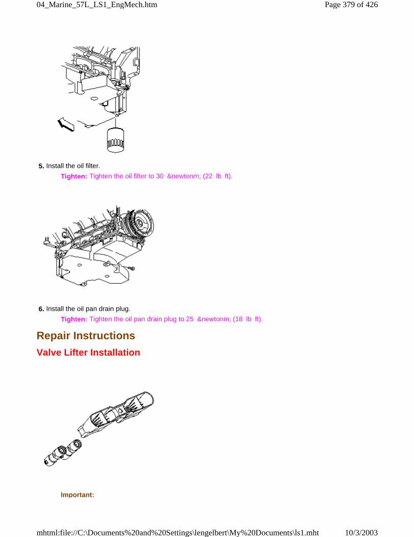
5. Install the oil filter.
Tighten: Tighten the oil filter to 30 &newtonm; (22 lb ft).
6. Install the oil pan drain plug.
Tighten: Tighten the oil pan drain plug to 25 &newtonm; (18 lb ft).
Repair Instructions
Valve Lifter Installation
Important:
Page 379 of 42604_Marine_57L_LS1_EngMech.htm
10/3/2003mhtml:file://C:\Documents%20and%20Settings\lengelbert\My%20Documents\ls1.mht
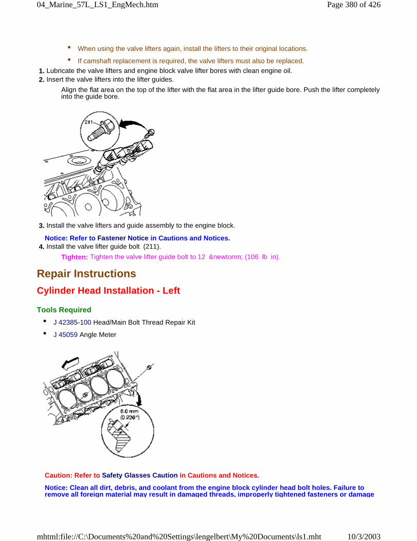
• When using the valve lifters again, install the lifters to their original locations.
• If camshaft replacement is required, the valve lifters must also be replaced.
1. Lubricate the valve lifters and engine block valve lifter bores with clean engine oil. 2. Insert the valve lifters into the lifter guides.
Align the flat area on the top of the lifter with the flat area in the lifter guide bore. Push the lifter completelyinto the guide bore.
3. Install the valve lifters and guide assembly to the engine block.
Notice: Refer to Fastener Notice in Cautions and Notices. 4. Install the valve lifter guide bolt (211).
Tighten: Tighten the valve lifter guide bolt to 12 &newtonm; (106 lb in).
Repair Instructions
Cylinder Head Installation - Left
Tools Required
• J 42385-100 Head/Main Bolt Thread Repair Kit
• J 45059 Angle Meter
Caution: Refer to Safety Glasses Caution in Cautions and Notices.
Notice: Clean all dirt, debris, and coolant from the engine block cylinder head bolt holes. Failure toremove all foreign material may result in damaged threads, improperly tightened fasteners or damage
Page 380 of 42604_Marine_57L_LS1_EngMech.htm
10/3/2003mhtml:file://C:\Documents%20and%20Settings\lengelbert\My%20Documents\ls1.mht
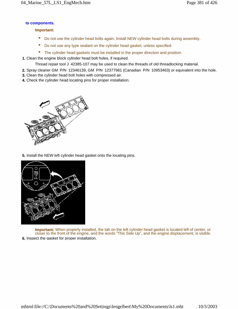
to components.
Important:
• Do not use the cylinder head bolts again. Install NEW cylinder head bolts during assembly.
• Do not use any type sealant on the cylinder head gasket, unless specified.
• The cylinder head gaskets must be installed in the proper direction and position.
1. Clean the engine block cylinder head bolt holes, if required.
Thread repair tool J 42385-107 may be used to clean the threads of old threadlocking material.
2. Spray cleaner GM P/N 12346139, GM P/N 12377981 (Canadian P/N 10953463) or equivalent into the hole. 3. Clean the cylinder head bolt holes with compressed air. 4. Check the cylinder head locating pins for proper installation.
5. Install the NEW left cylinder head gasket onto the locating pins.
Important: When properly installed, the tab on the left cylinder head gasket is located left of center, orcloser to the front of the engine, and the words “This Side Up”, and the engine displacement, is visible.
6. Inspect the gasket for proper installation.
Page 381 of 42604_Marine_57L_LS1_EngMech.htm
10/3/2003mhtml:file://C:\Documents%20and%20Settings\lengelbert\My%20Documents\ls1.mht
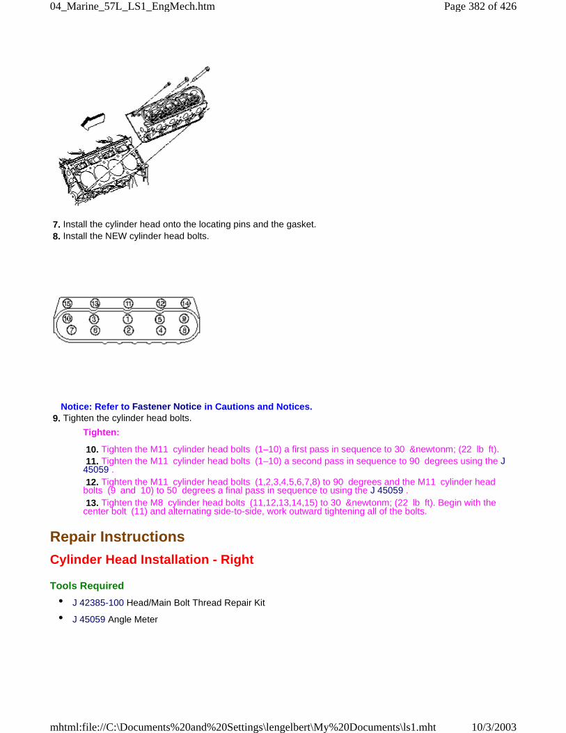
7. Install the cylinder head onto the locating pins and the gasket. 8. Install the NEW cylinder head bolts.
Notice: Refer to Fastener Notice in Cautions and Notices. 9. Tighten the cylinder head bolts.
Tighten:
10. Tighten the M11 cylinder head bolts (1–10) a first pass in sequence to 30 &newtonm; (22 lb ft). 11. Tighten the M11 cylinder head bolts (1–10) a second pass in sequence to 90 degrees using the J45059 . 12. Tighten the M11 cylinder head bolts (1,2,3,4,5,6,7,8) to 90 degrees and the M11 cylinder headbolts (9 and 10) to 50 degrees a final pass in sequence to using the J 45059 . 13. Tighten the M8 cylinder head bolts (11,12,13,14,15) to 30 &newtonm; (22 lb ft). Begin with thecenter bolt (11) and alternating side-to-side, work outward tightening all of the bolts.
Repair Instructions
Cylinder Head Installation - Right
Tools Required
• J 42385-100 Head/Main Bolt Thread Repair Kit
• J 45059 Angle Meter
Page 382 of 42604_Marine_57L_LS1_EngMech.htm
10/3/2003mhtml:file://C:\Documents%20and%20Settings\lengelbert\My%20Documents\ls1.mht
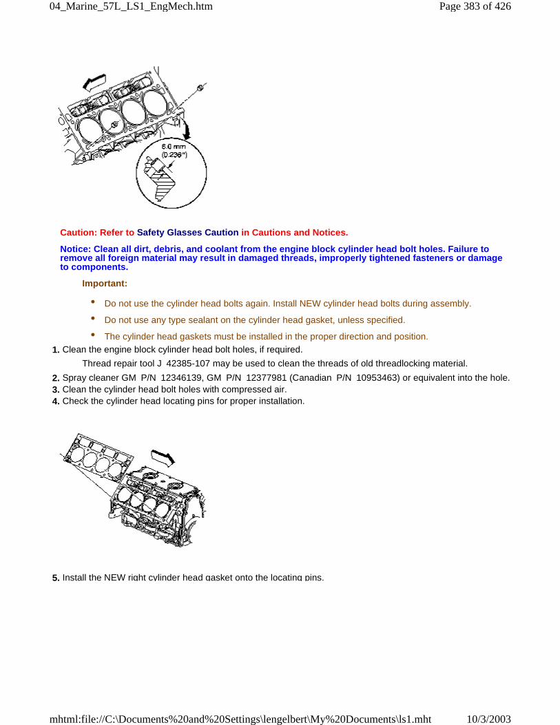
Caution: Refer to Safety Glasses Caution in Cautions and Notices.
Notice: Clean all dirt, debris, and coolant from the engine block cylinder head bolt holes. Failure toremove all foreign material may result in damaged threads, improperly tightened fasteners or damageto components.
Important:
• Do not use the cylinder head bolts again. Install NEW cylinder head bolts during assembly.
• Do not use any type sealant on the cylinder head gasket, unless specified.
• The cylinder head gaskets must be installed in the proper direction and position.
1. Clean the engine block cylinder head bolt holes, if required.
Thread repair tool J 42385-107 may be used to clean the threads of old threadlocking material.
2. Spray cleaner GM P/N 12346139, GM P/N 12377981 (Canadian P/N 10953463) or equivalent into the hole. 3. Clean the cylinder head bolt holes with compressed air. 4. Check the cylinder head locating pins for proper installation.
5. Install the NEW right cylinder head gasket onto the locating pins.
Page 383 of 42604_Marine_57L_LS1_EngMech.htm
10/3/2003mhtml:file://C:\Documents%20and%20Settings\lengelbert\My%20Documents\ls1.mht
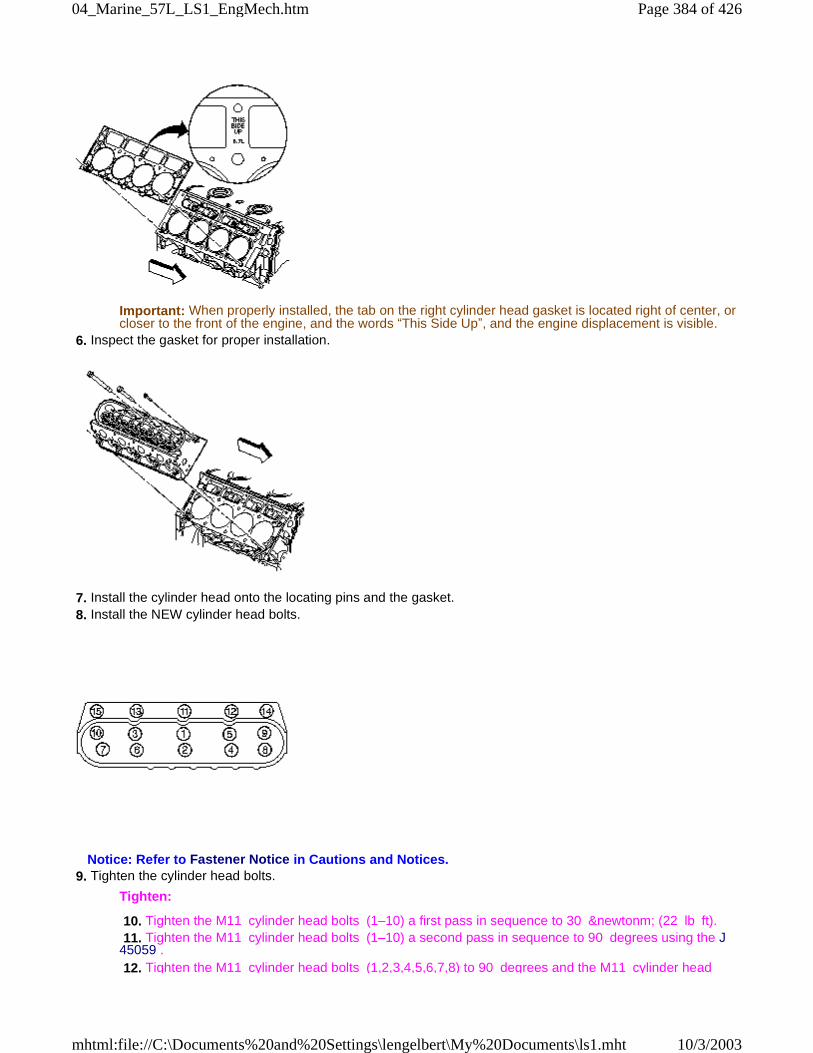
Important: When properly installed, the tab on the right cylinder head gasket is located right of center, orcloser to the front of the engine, and the words “This Side Up”, and the engine displacement is visible.
6. Inspect the gasket for proper installation.
7. Install the cylinder head onto the locating pins and the gasket. 8. Install the NEW cylinder head bolts.
Notice: Refer to Fastener Notice in Cautions and Notices. 9. Tighten the cylinder head bolts.
Tighten:
10. Tighten the M11 cylinder head bolts (1–10) a first pass in sequence to 30 &newtonm; (22 lb ft). 11. Tighten the M11 cylinder head bolts (1–10) a second pass in sequence to 90 degrees using the J45059 . 12. Tighten the M11 cylinder head bolts (1,2,3,4,5,6,7,8) to 90 degrees and the M11 cylinder head
Page 384 of 42604_Marine_57L_LS1_EngMech.htm
10/3/2003mhtml:file://C:\Documents%20and%20Settings\lengelbert\My%20Documents\ls1.mht
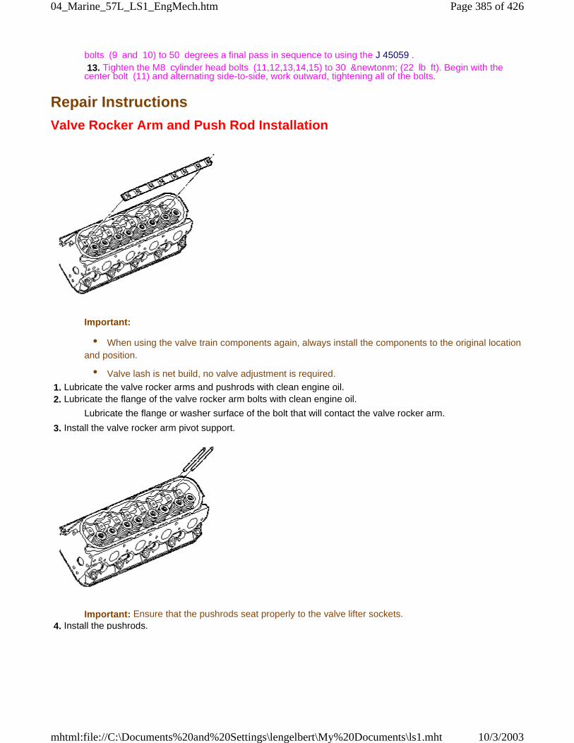
bolts (9 and 10) to 50 degrees a final pass in sequence to using the J 45059 . 13. Tighten the M8 cylinder head bolts (11,12,13,14,15) to 30 &newtonm; (22 lb ft). Begin with thecenter bolt (11) and alternating side-to-side, work outward, tightening all of the bolts.
Repair Instructions
Valve Rocker Arm and Push Rod Installation
Important:
• When using the valve train components again, always install the components to the original locationand position.
• Valve lash is net build, no valve adjustment is required.
1. Lubricate the valve rocker arms and pushrods with clean engine oil. 2. Lubricate the flange of the valve rocker arm bolts with clean engine oil.
Lubricate the flange or washer surface of the bolt that will contact the valve rocker arm.
3. Install the valve rocker arm pivot support.
Important: Ensure that the pushrods seat properly to the valve lifter sockets. 4. Install the pushrods.
Page 385 of 42604_Marine_57L_LS1_EngMech.htm
10/3/2003mhtml:file://C:\Documents%20and%20Settings\lengelbert\My%20Documents\ls1.mht
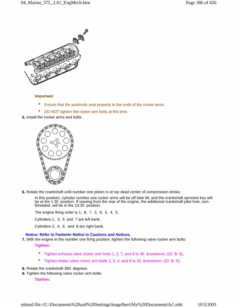
Important:
• Ensure that the pushrods seat properly to the ends of the rocker arms.
• DO NOT tighten the rocker arm bolts at this time.
5. Install the rocker arms and bolts.
6. Rotate the crankshaft until number one piston is at top dead center of compression stroke.
In this position, cylinder number one rocker arms will be off lobe lift, and the crankshaft sprocket key willbe at the 1:30 position. If viewing from the rear of the engine, the additional crankshaft pilot hole, non-threaded, will be in the 10:30 position.
The engine firing order is 1, 8, 7, 2, 6, 5, 4, 3.
Cylinders 1, 3, 5 and 7 are left bank.
Cylinders 2, 4, 6, and 8 are right bank.
Notice: Refer to Fastener Notice in Cautions and Notices. 7. With the engine in the number one firing position, tighten the following valve rocker arm bolts:
Tighten:
• Tighten exhaust valve rocker arm bolts 1, 2, 7, and 8 to 30 &newtonm; (22 lb ft).
• Tighten intake valve rocker arm bolts 1, 3, 4, and 5 to 30 &newtonm; (22 lb ft).
8. Rotate the crankshaft 360 degrees. 9. Tighten the following valve rocker arm bolts:
Tighten:
Page 386 of 42604_Marine_57L_LS1_EngMech.htm
10/3/2003mhtml:file://C:\Documents%20and%20Settings\lengelbert\My%20Documents\ls1.mht
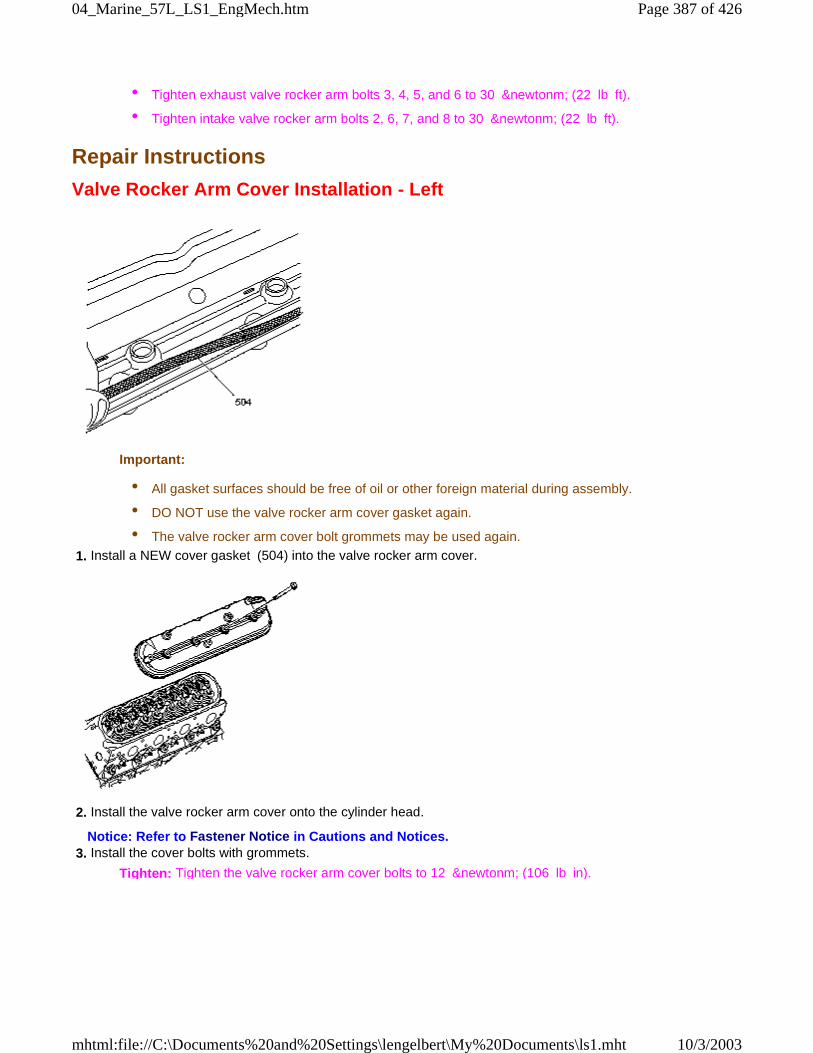
• Tighten exhaust valve rocker arm bolts 3, 4, 5, and 6 to 30 &newtonm; (22 lb ft).
• Tighten intake valve rocker arm bolts 2, 6, 7, and 8 to 30 &newtonm; (22 lb ft).
Repair Instructions
Valve Rocker Arm Cover Installation - Left
Important:
• All gasket surfaces should be free of oil or other foreign material during assembly.
• DO NOT use the valve rocker arm cover gasket again.
• The valve rocker arm cover bolt grommets may be used again.
1. Install a NEW cover gasket (504) into the valve rocker arm cover.
2. Install the valve rocker arm cover onto the cylinder head.
Notice: Refer to Fastener Notice in Cautions and Notices. 3. Install the cover bolts with grommets.
Tighten: Tighten the valve rocker arm cover bolts to 12 &newtonm; (106 lb in).
Page 387 of 42604_Marine_57L_LS1_EngMech.htm
10/3/2003mhtml:file://C:\Documents%20and%20Settings\lengelbert\My%20Documents\ls1.mht
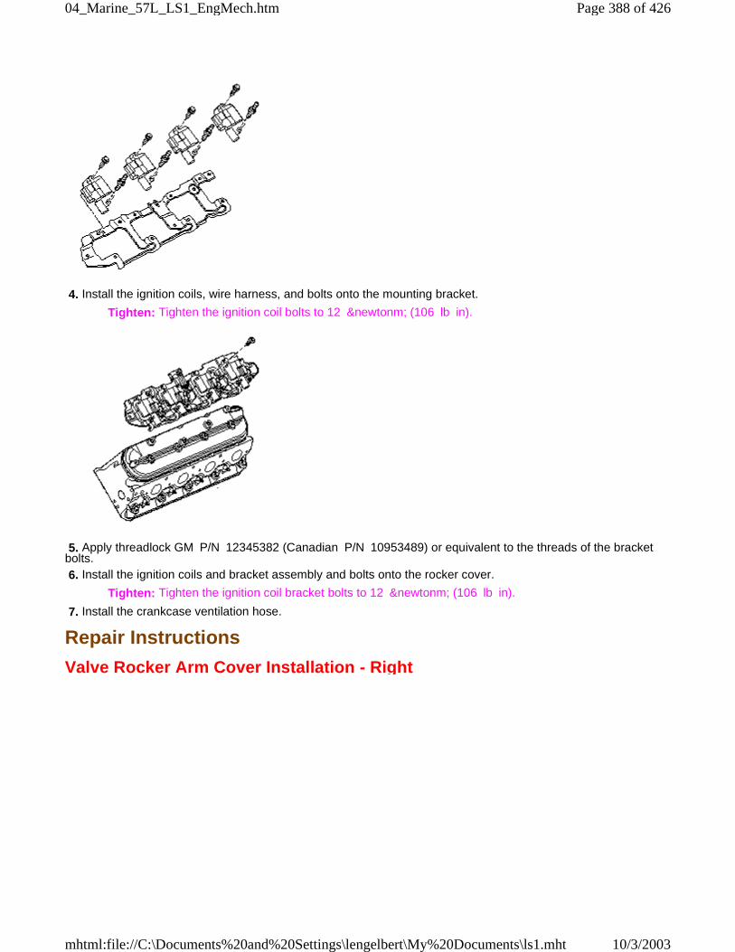
4. Install the ignition coils, wire harness, and bolts onto the mounting bracket.
Tighten: Tighten the ignition coil bolts to 12 &newtonm; (106 lb in).
5. Apply threadlock GM P/N 12345382 (Canadian P/N 10953489) or equivalent to the threads of the bracketbolts. 6. Install the ignition coils and bracket assembly and bolts onto the rocker cover.
Tighten: Tighten the ignition coil bracket bolts to 12 &newtonm; (106 lb in).
7. Install the crankcase ventilation hose.
Repair Instructions
Valve Rocker Arm Cover Installation - Right
Page 388 of 42604_Marine_57L_LS1_EngMech.htm
10/3/2003mhtml:file://C:\Documents%20and%20Settings\lengelbert\My%20Documents\ls1.mht
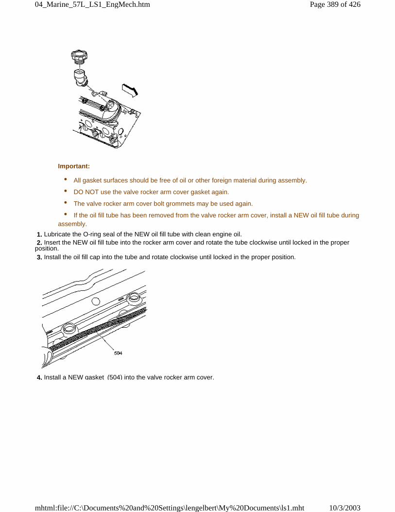
Important:
• All gasket surfaces should be free of oil or other foreign material during assembly.
• DO NOT use the valve rocker arm cover gasket again.
• The valve rocker arm cover bolt grommets may be used again.
• If the oil fill tube has been removed from the valve rocker arm cover, install a NEW oil fill tube duringassembly.
1. Lubricate the O-ring seal of the NEW oil fill tube with clean engine oil. 2. Insert the NEW oil fill tube into the rocker arm cover and rotate the tube clockwise until locked in the properposition. 3. Install the oil fill cap into the tube and rotate clockwise until locked in the proper position.
4. Install a NEW gasket (504) into the valve rocker arm cover.
Page 389 of 42604_Marine_57L_LS1_EngMech.htm
10/3/2003mhtml:file://C:\Documents%20and%20Settings\lengelbert\My%20Documents\ls1.mht
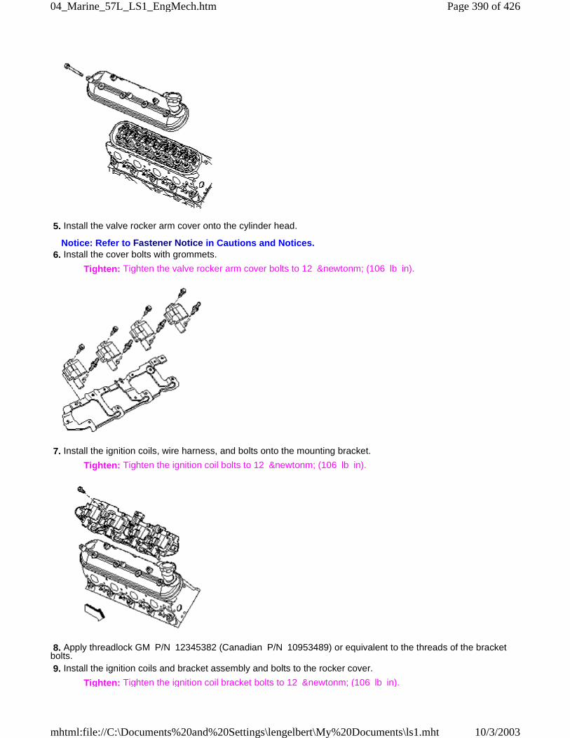
5. Install the valve rocker arm cover onto the cylinder head.
Notice: Refer to Fastener Notice in Cautions and Notices. 6. Install the cover bolts with grommets.
Tighten: Tighten the valve rocker arm cover bolts to 12 &newtonm; (106 lb in).
7. Install the ignition coils, wire harness, and bolts onto the mounting bracket.
Tighten: Tighten the ignition coil bolts to 12 &newtonm; (106 lb in).
8. Apply threadlock GM P/N 12345382 (Canadian P/N 10953489) or equivalent to the threads of the bracketbolts. 9. Install the ignition coils and bracket assembly and bolts to the rocker cover.
Tighten: Tighten the ignition coil bracket bolts to 12 &newtonm; (106 lb in).
Page 390 of 42604_Marine_57L_LS1_EngMech.htm
10/3/2003mhtml:file://C:\Documents%20and%20Settings\lengelbert\My%20Documents\ls1.mht
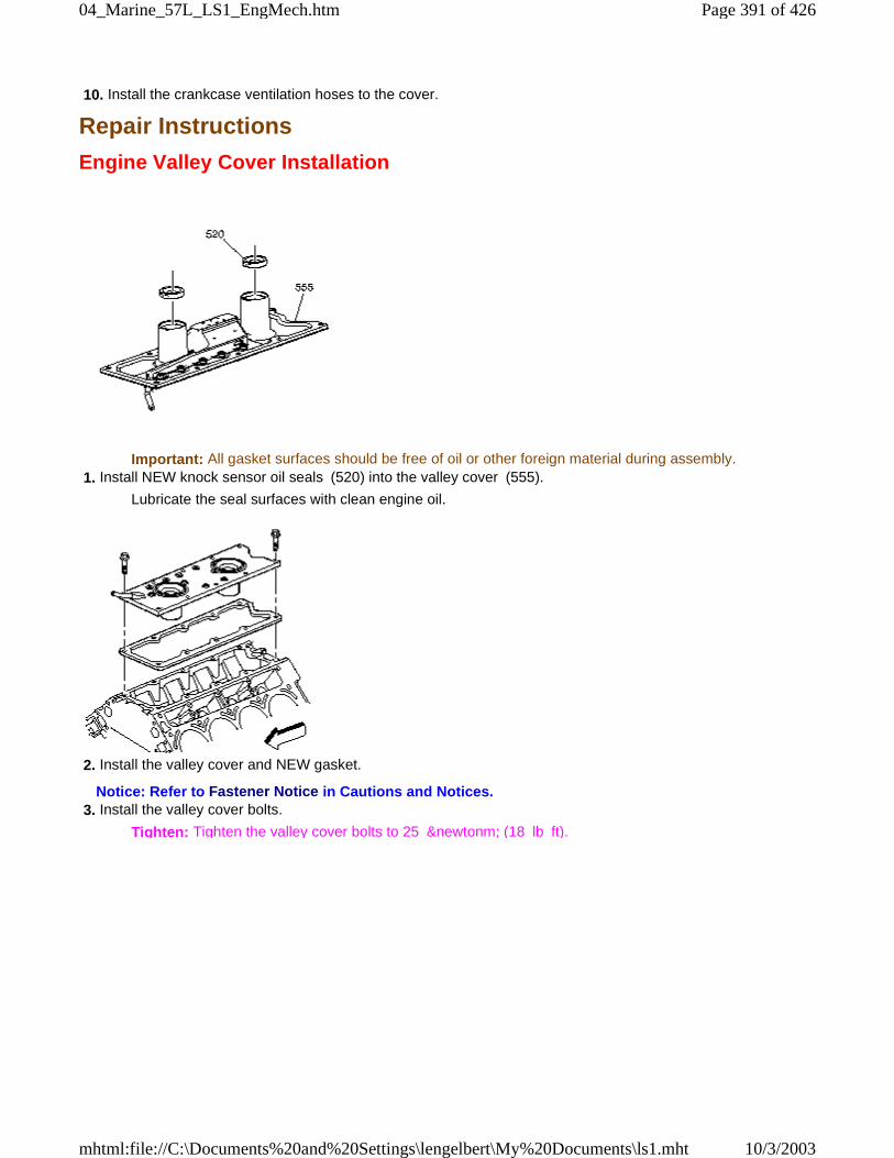
10. Install the crankcase ventilation hoses to the cover.
Repair Instructions
Engine Valley Cover Installation
Important: All gasket surfaces should be free of oil or other foreign material during assembly. 1. Install NEW knock sensor oil seals (520) into the valley cover (555).
Lubricate the seal surfaces with clean engine oil.
2. Install the valley cover and NEW gasket.
Notice: Refer to Fastener Notice in Cautions and Notices. 3. Install the valley cover bolts.
Tighten: Tighten the valley cover bolts to 25 &newtonm; (18 lb ft).
Page 391 of 42604_Marine_57L_LS1_EngMech.htm
10/3/2003mhtml:file://C:\Documents%20and%20Settings\lengelbert\My%20Documents\ls1.mht
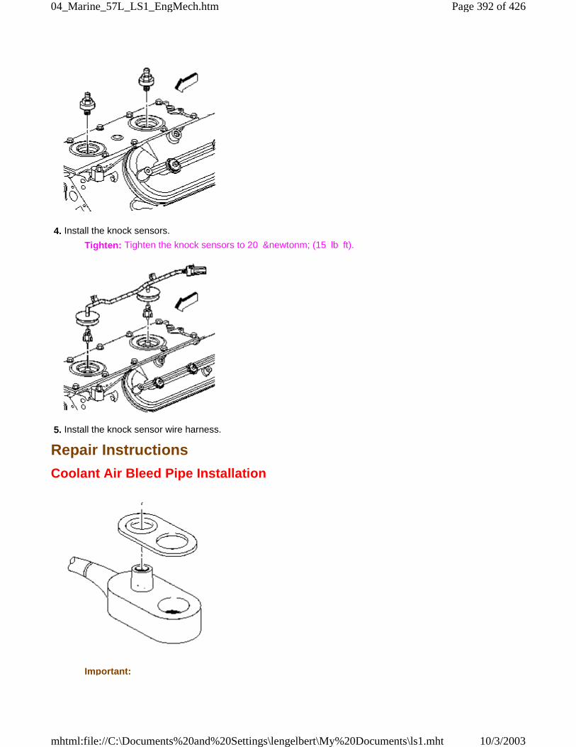
4. Install the knock sensors.
Tighten: Tighten the knock sensors to 20 &newtonm; (15 lb ft).
5. Install the knock sensor wire harness.
Repair Instructions
Coolant Air Bleed Pipe Installation
Important:
Page 392 of 42604_Marine_57L_LS1_EngMech.htm
10/3/2003mhtml:file://C:\Documents%20and%20Settings\lengelbert\My%20Documents\ls1.mht
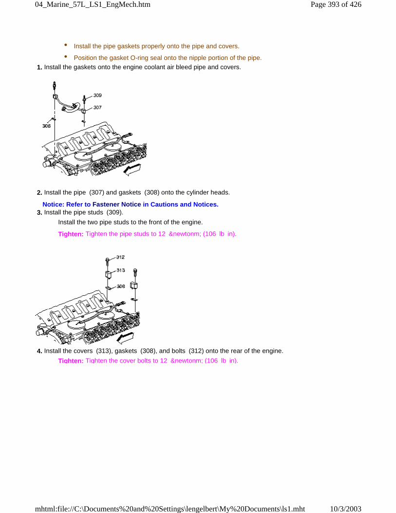
• Install the pipe gaskets properly onto the pipe and covers.
• Position the gasket O-ring seal onto the nipple portion of the pipe.
1. Install the gaskets onto the engine coolant air bleed pipe and covers.
2. Install the pipe (307) and gaskets (308) onto the cylinder heads.
Notice: Refer to Fastener Notice in Cautions and Notices. 3. Install the pipe studs (309).
Install the two pipe studs to the front of the engine.
Tighten: Tighten the pipe studs to 12 &newtonm; (106 lb in).
4. Install the covers (313), gaskets (308), and bolts (312) onto the rear of the engine.
Tighten: Tighten the cover bolts to 12 &newtonm; (106 lb in).
Page 393 of 42604_Marine_57L_LS1_EngMech.htm
10/3/2003mhtml:file://C:\Documents%20and%20Settings\lengelbert\My%20Documents\ls1.mht
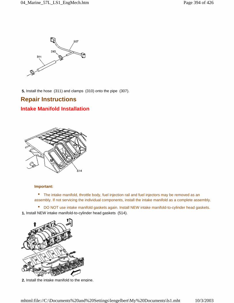
5. Install the hose (311) and clamps (310) onto the pipe (307).
Repair Instructions
Intake Manifold Installation
Important:
• The intake manifold, throttle body, fuel injection rail and fuel injectors may be removed as anassembly. If not servicing the individual components, install the intake manifold as a complete assembly.
• DO NOT use intake manifold gaskets again. Install NEW intake manifold-to-cylinder head gaskets.
1. Install NEW intake manifold-to-cylinder head gaskets (514).
2. Install the intake manifold to the engine.
Page 394 of 42604_Marine_57L_LS1_EngMech.htm
10/3/2003mhtml:file://C:\Documents%20and%20Settings\lengelbert\My%20Documents\ls1.mht
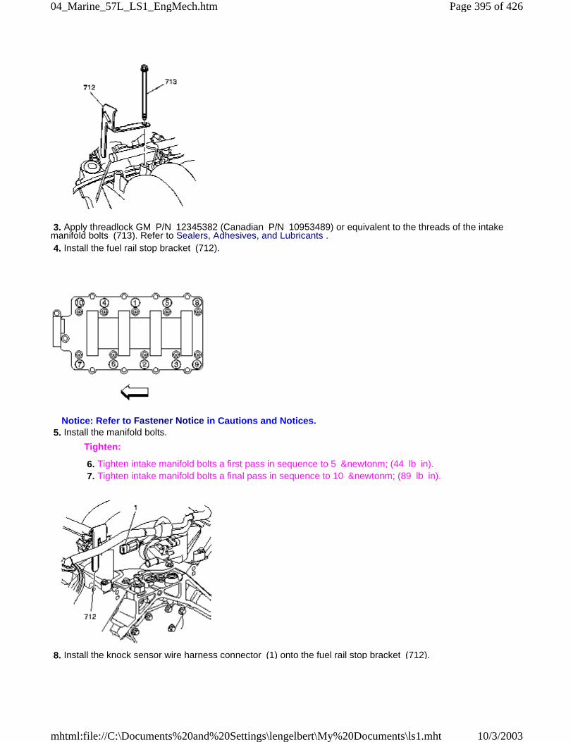
3. Apply threadlock GM P/N 12345382 (Canadian P/N 10953489) or equivalent to the threads of the intakemanifold bolts (713). Refer to Sealers, Adhesives, and Lubricants . 4. Install the fuel rail stop bracket (712).
Notice: Refer to Fastener Notice in Cautions and Notices. 5. Install the manifold bolts.
Tighten:
6. Tighten intake manifold bolts a first pass in sequence to 5 &newtonm; (44 lb in). 7. Tighten intake manifold bolts a final pass in sequence to 10 &newtonm; (89 lb in).
8. Install the knock sensor wire harness connector (1) onto the fuel rail stop bracket (712).
Page 395 of 42604_Marine_57L_LS1_EngMech.htm
10/3/2003mhtml:file://C:\Documents%20and%20Settings\lengelbert\My%20Documents\ls1.mht
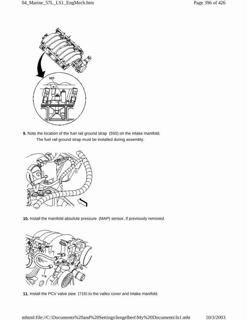
9. Note the location of the fuel rail ground strap (550) on the intake manifold.
The fuel rail ground strap must be installed during assembly.
10. Install the manifold absolute pressure (MAP) sensor, if previously removed.
11. Install the PCV valve pipe (716) to the valley cover and intake manifold.
Page 396 of 42604_Marine_57L_LS1_EngMech.htm
10/3/2003mhtml:file://C:\Documents%20and%20Settings\lengelbert\My%20Documents\ls1.mht
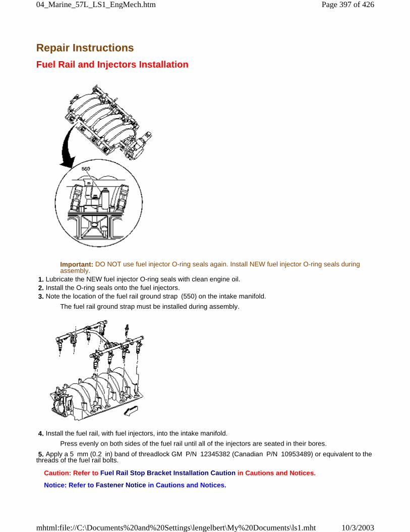
Repair Instructions
Fuel Rail and Injectors Installation
Important: DO NOT use fuel injector O-ring seals again. Install NEW fuel injector O-ring seals duringassembly.
1. Lubricate the NEW fuel injector O-ring seals with clean engine oil. 2. Install the O-ring seals onto the fuel injectors. 3. Note the location of the fuel rail ground strap (550) on the intake manifold.
The fuel rail ground strap must be installed during assembly.
4. Install the fuel rail, with fuel injectors, into the intake manifold.
Press evenly on both sides of the fuel rail until all of the injectors are seated in their bores.
5. Apply a 5 mm (0.2 in) band of threadlock GM P/N 12345382 (Canadian P/N 10953489) or equivalent to thethreads of the fuel rail bolts.
Caution: Refer to Fuel Rail Stop Bracket Installation Caution in Cautions and Notices.
Notice: Refer to Fastener Notice in Cautions and Notices.
Page 397 of 42604_Marine_57L_LS1_EngMech.htm
10/3/2003mhtml:file://C:\Documents%20and%20Settings\lengelbert\My%20Documents\ls1.mht
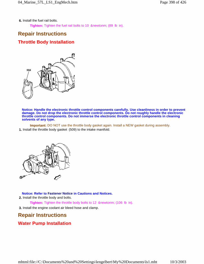
6. Install the fuel rail bolts.
Tighten: Tighten the fuel rail bolts to 10 &newtonm; (89 lb in).
Repair Instructions
Throttle Body Installation
Notice: Handle the electronic throttle control components carefully. Use cleanliness in order to preventdamage. Do not drop the electronic throttle control components. Do not roughly handle the electronicthrottle control components. Do not immerse the electronic throttle control components in cleaningsolvents of any type.
Important: DO NOT use the throttle body gasket again. Install a NEW gasket during assembly. 1. Install the throttle body gasket (509) to the intake manifold.
Notice: Refer to Fastener Notice in Cautions and Notices. 2. Install the throttle body and bolts.
Tighten: Tighten the throttle body bolts to 12 &newtonm; (106 lb in).
3. Install the engine coolant air bleed hose and clamp.
Repair Instructions
Water Pump Installation
Page 398 of 42604_Marine_57L_LS1_EngMech.htm
10/3/2003mhtml:file://C:\Documents%20and%20Settings\lengelbert\My%20Documents\ls1.mht
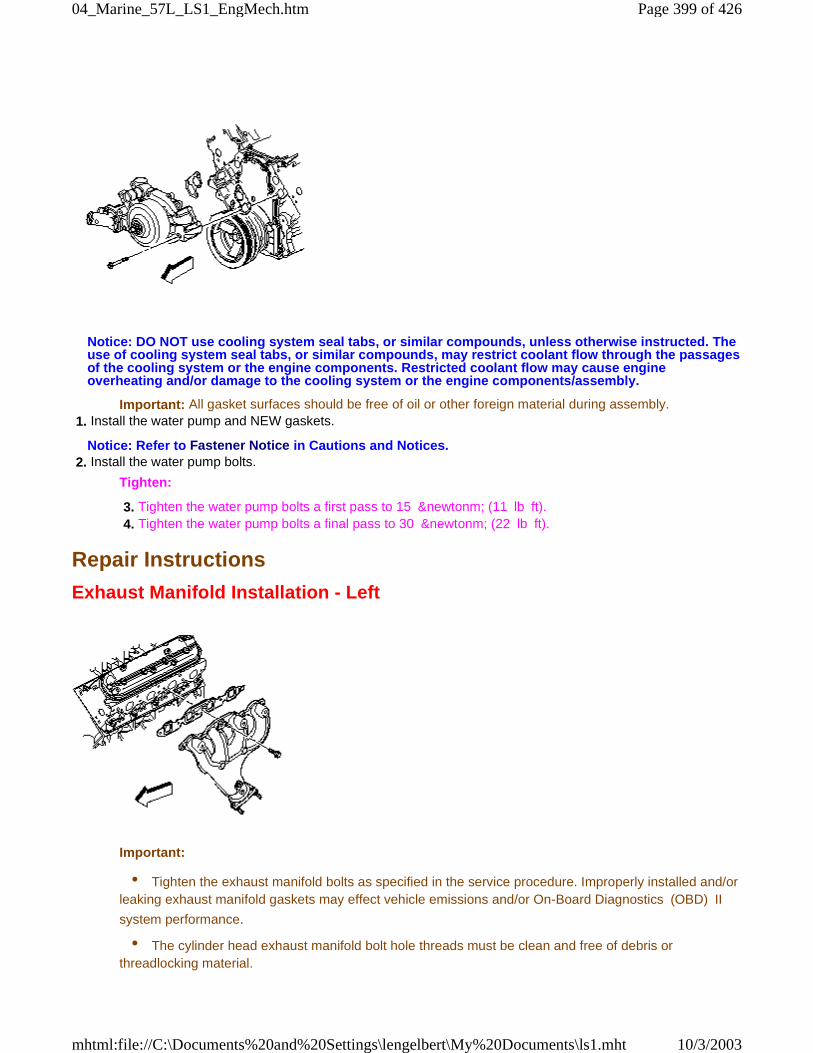
Notice: DO NOT use cooling system seal tabs, or similar compounds, unless otherwise instructed. Theuse of cooling system seal tabs, or similar compounds, may restrict coolant flow through the passagesof the cooling system or the engine components. Restricted coolant flow may cause engineoverheating and/or damage to the cooling system or the engine components/assembly.
Important: All gasket surfaces should be free of oil or other foreign material during assembly. 1. Install the water pump and NEW gaskets.
Notice: Refer to Fastener Notice in Cautions and Notices. 2. Install the water pump bolts.
Tighten:
3. Tighten the water pump bolts a first pass to 15 &newtonm; (11 lb ft). 4. Tighten the water pump bolts a final pass to 30 &newtonm; (22 lb ft).
Repair Instructions
Exhaust Manifold Installation - Left
Important:
• Tighten the exhaust manifold bolts as specified in the service procedure. Improperly installed and/orleaking exhaust manifold gaskets may effect vehicle emissions and/or On-Board Diagnostics (OBD) II
system performance.
• The cylinder head exhaust manifold bolt hole threads must be clean and free of debris orthreadlocking material.
Page 399 of 42604_Marine_57L_LS1_EngMech.htm
10/3/2003mhtml:file://C:\Documents%20and%20Settings\lengelbert\My%20Documents\ls1.mht
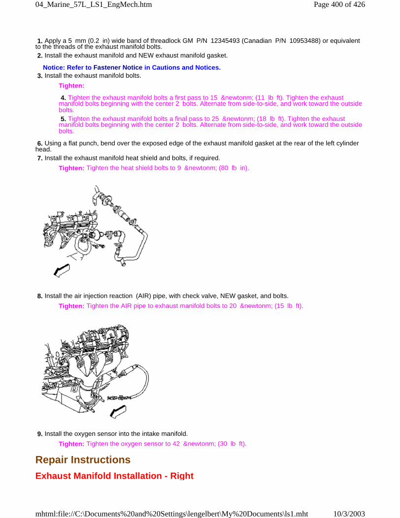
1. Apply a 5 mm (0.2 in) wide band of threadlock GM P/N 12345493 (Canadian P/N 10953488) or equivalentto the threads of the exhaust manifold bolts. 2. Install the exhaust manifold and NEW exhaust manifold gasket.
Notice: Refer to Fastener Notice in Cautions and Notices. 3. Install the exhaust manifold bolts.
Tighten:
4. Tighten the exhaust manifold bolts a first pass to 15 &newtonm; (11 lb ft). Tighten the exhaustmanifold bolts beginning with the center 2 bolts. Alternate from side-to-side, and work toward the outsidebolts. 5. Tighten the exhaust manifold bolts a final pass to 25 &newtonm; (18 lb ft). Tighten the exhaustmanifold bolts beginning with the center 2 bolts. Alternate from side-to-side, and work toward the outsidebolts.
6. Using a flat punch, bend over the exposed edge of the exhaust manifold gasket at the rear of the left cylinderhead. 7. Install the exhaust manifold heat shield and bolts, if required.
Tighten: Tighten the heat shield bolts to 9 &newtonm; (80 lb in).
8. Install the air injection reaction (AIR) pipe, with check valve, NEW gasket, and bolts.
Tighten: Tighten the AIR pipe to exhaust manifold bolts to 20 &newtonm; (15 lb ft).
9. Install the oxygen sensor into the intake manifold.
Tighten: Tighten the oxygen sensor to 42 &newtonm; (30 lb ft).
Repair Instructions
Exhaust Manifold Installation - Right
Page 400 of 42604_Marine_57L_LS1_EngMech.htm
10/3/2003mhtml:file://C:\Documents%20and%20Settings\lengelbert\My%20Documents\ls1.mht
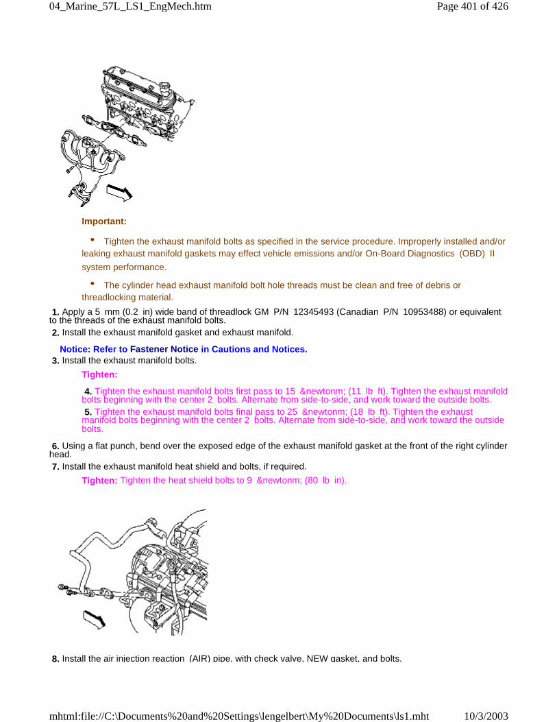
Important:
• Tighten the exhaust manifold bolts as specified in the service procedure. Improperly installed and/orleaking exhaust manifold gaskets may effect vehicle emissions and/or On-Board Diagnostics (OBD) II
system performance.
• The cylinder head exhaust manifold bolt hole threads must be clean and free of debris orthreadlocking material.
1. Apply a 5 mm (0.2 in) wide band of threadlock GM P/N 12345493 (Canadian P/N 10953488) or equivalentto the threads of the exhaust manifold bolts. 2. Install the exhaust manifold gasket and exhaust manifold.
Notice: Refer to Fastener Notice in Cautions and Notices. 3. Install the exhaust manifold bolts.
Tighten:
4. Tighten the exhaust manifold bolts first pass to 15 &newtonm; (11 lb ft). Tighten the exhaust manifoldbolts beginning with the center 2 bolts. Alternate from side-to-side, and work toward the outside bolts. 5. Tighten the exhaust manifold bolts final pass to 25 &newtonm; (18 lb ft). Tighten the exhaustmanifold bolts beginning with the center 2 bolts. Alternate from side-to-side, and work toward the outsidebolts.
6. Using a flat punch, bend over the exposed edge of the exhaust manifold gasket at the front of the right cylinderhead. 7. Install the exhaust manifold heat shield and bolts, if required.
Tighten: Tighten the heat shield bolts to 9 &newtonm; (80 lb in).
8. Install the air injection reaction (AIR) pipe, with check valve, NEW gasket, and bolts.
Page 401 of 42604_Marine_57L_LS1_EngMech.htm
10/3/2003mhtml:file://C:\Documents%20and%20Settings\lengelbert\My%20Documents\ls1.mht
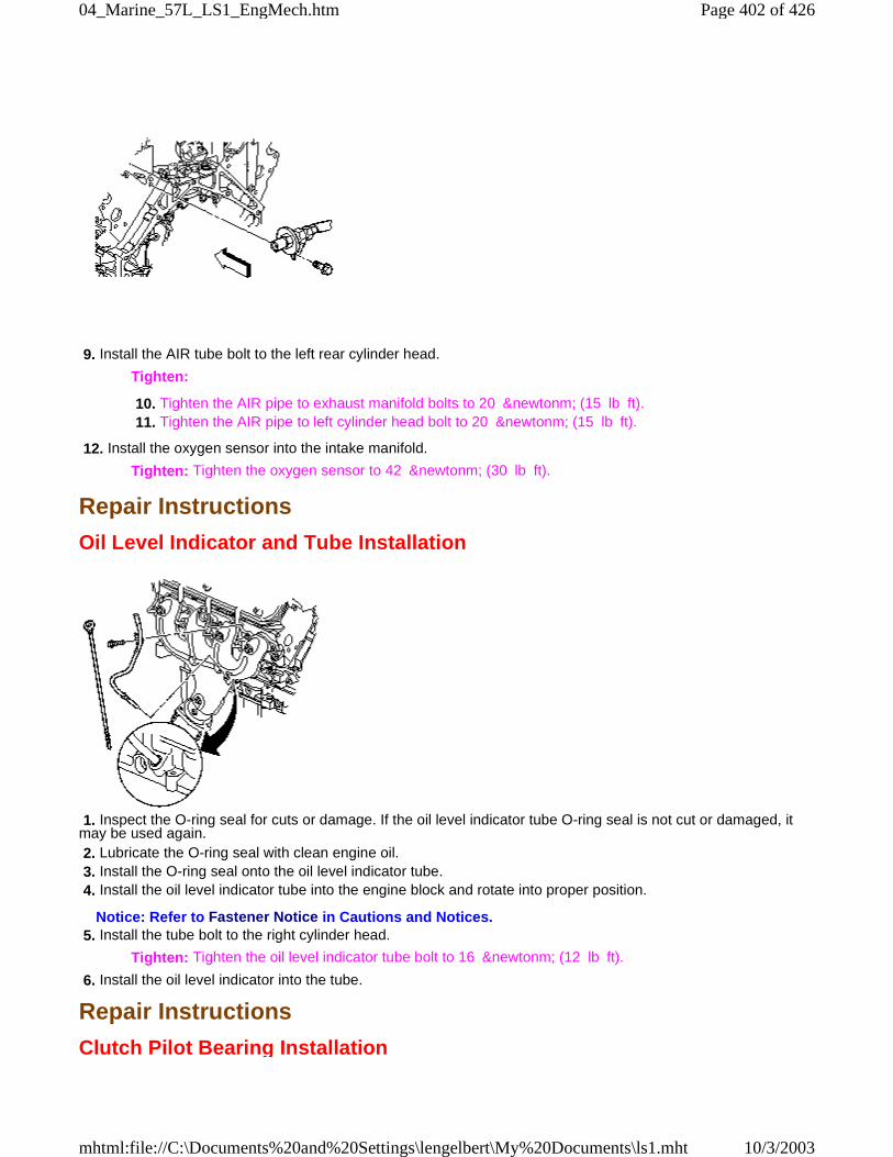
9. Install the AIR tube bolt to the left rear cylinder head.
Tighten:
10. Tighten the AIR pipe to exhaust manifold bolts to 20 &newtonm; (15 lb ft). 11. Tighten the AIR pipe to left cylinder head bolt to 20 &newtonm; (15 lb ft).
12. Install the oxygen sensor into the intake manifold.
Tighten: Tighten the oxygen sensor to 42 &newtonm; (30 lb ft).
Repair Instructions
Oil Level Indicator and Tube Installation
1. Inspect the O-ring seal for cuts or damage. If the oil level indicator tube O-ring seal is not cut or damaged, itmay be used again. 2. Lubricate the O-ring seal with clean engine oil. 3. Install the O-ring seal onto the oil level indicator tube. 4. Install the oil level indicator tube into the engine block and rotate into proper position.
Notice: Refer to Fastener Notice in Cautions and Notices. 5. Install the tube bolt to the right cylinder head.
Tighten: Tighten the oil level indicator tube bolt to 16 &newtonm; (12 lb ft).
6. Install the oil level indicator into the tube.
Repair Instructions
Clutch Pilot Bearing Installation
Page 402 of 42604_Marine_57L_LS1_EngMech.htm
10/3/2003mhtml:file://C:\Documents%20and%20Settings\lengelbert\My%20Documents\ls1.mht
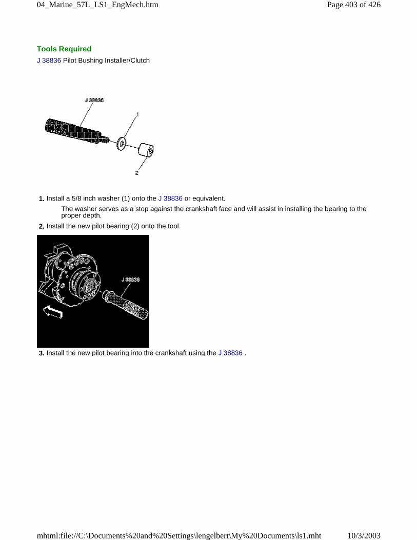
Tools Required
J 38836 Pilot Bushing Installer/Clutch
1. Install a 5/8 inch washer (1) onto the J 38836 or equivalent.
The washer serves as a stop against the crankshaft face and will assist in installing the bearing to theproper depth.
2. Install the new pilot bearing (2) onto the tool.
3. Install the new pilot bearing into the crankshaft using the J 38836 .
Page 403 of 42604_Marine_57L_LS1_EngMech.htm
10/3/2003mhtml:file://C:\Documents%20and%20Settings\lengelbert\My%20Documents\ls1.mht

4. Inspect the clutch pilot bearing for proper installation.
A properly installed clutch pilot bearing will be installed until flush to the rear face of the crankshaft.
Repair Instructions
Engine Flywheel Installation
Important:
• For manual transmission applications, note the position and direction of the engine flywheel beforeremoval. The flywheel does not use a locating pin for alignment. Mark or scribe the end of the crankshaft
and the flywheel before component removal. The existing manual transmission engine flywheel must be
installed to the original position and direction. The engine flywheel will not initially seat against the
crankshaft flange, but will be pulled onto the crankshaft by the engine flywheel bolts. This procedure
requires a three stage tightening process.
• DO NOT remove the propshaft hub or flexplate from the automatic transmission engine flywheel.
Page 404 of 42604_Marine_57L_LS1_EngMech.htm
10/3/2003mhtml:file://C:\Documents%20and%20Settings\lengelbert\My%20Documents\ls1.mht
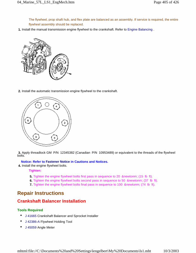
The flywheel, prop shaft hub, and flex plate are balanced as an assembly. If service is required, the entire
flywheel assembly should be replaced.
1. Install the manual transmission engine flywheel to the crankshaft. Refer to Engine Balancing .
2. Install the automatic transmission engine flywheel to the crankshaft.
3. Apply threadlock GM P/N 12345382 (Canadian P/N 10953489) or equivalent to the threads of the flywheelbolts.
Notice: Refer to Fastener Notice in Cautions and Notices. 4. Install the engine flywheel bolts.
Tighten:
5. Tighten the engine flywheel bolts first pass in sequence to 20 &newtonm; (15 lb ft). 6. Tighten the engine flywheel bolts second pass in sequence to 50 &newtonm; (37 lb ft). 7. Tighten the engine flywheel bolts final pass in sequence to 100 &newtonm; (74 lb ft).
Repair Instructions
Crankshaft Balancer Installation
Tools Required
• J 41665 Crankshaft Balancer and Sprocket Installer
• J 42386-A Flywheel Holding Tool
• J 45059 Angle Meter
Page 405 of 42604_Marine_57L_LS1_EngMech.htm
10/3/2003mhtml:file://C:\Documents%20and%20Settings\lengelbert\My%20Documents\ls1.mht
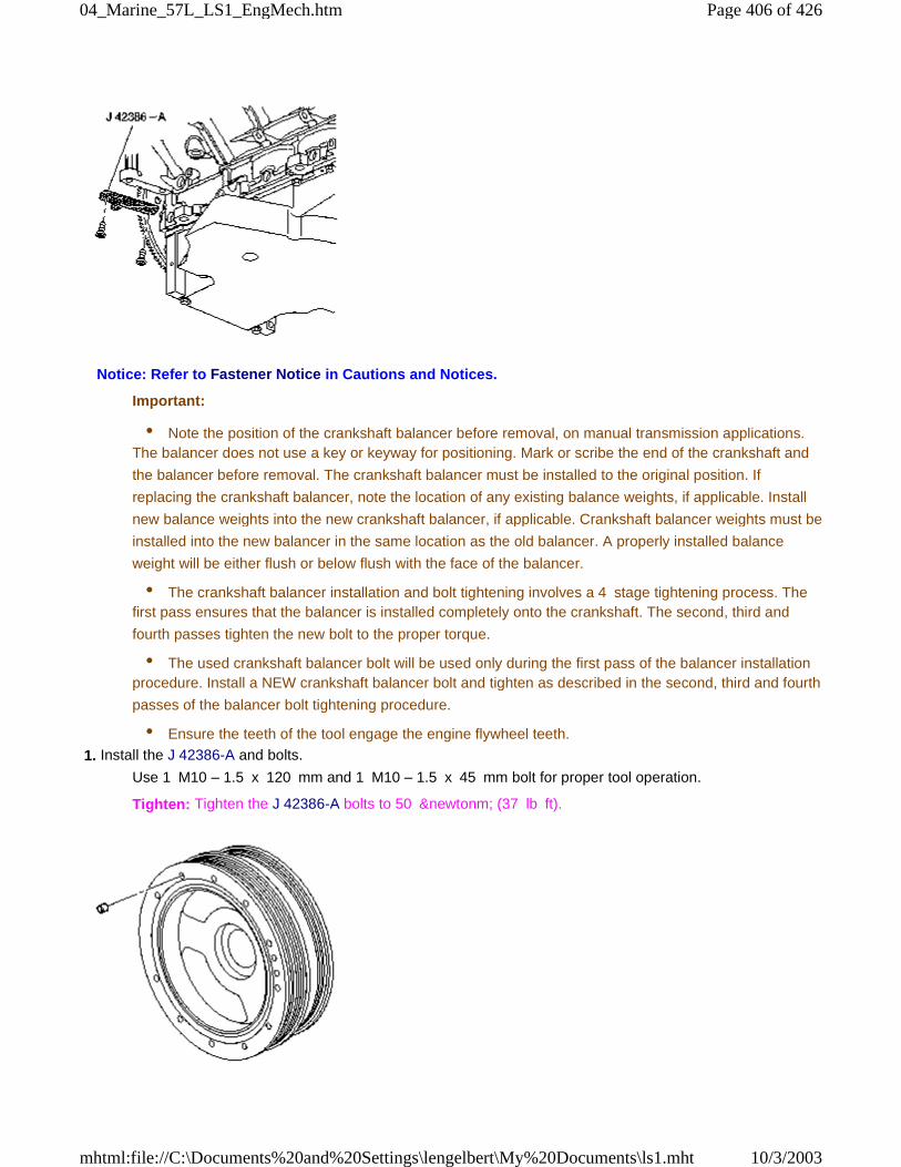
Notice: Refer to Fastener Notice in Cautions and Notices.
Important:
• Note the position of the crankshaft balancer before removal, on manual transmission applications.The balancer does not use a key or keyway for positioning. Mark or scribe the end of the crankshaft and
the balancer before removal. The crankshaft balancer must be installed to the original position. If
replacing the crankshaft balancer, note the location of any existing balance weights, if applicable. Install
new balance weights into the new crankshaft balancer, if applicable. Crankshaft balancer weights must be
installed into the new balancer in the same location as the old balancer. A properly installed balance
weight will be either flush or below flush with the face of the balancer.
• The crankshaft balancer installation and bolt tightening involves a 4 stage tightening process. Thefirst pass ensures that the balancer is installed completely onto the crankshaft. The second, third and
fourth passes tighten the new bolt to the proper torque.
• The used crankshaft balancer bolt will be used only during the first pass of the balancer installationprocedure. Install a NEW crankshaft balancer bolt and tighten as described in the second, third and fourth
passes of the balancer bolt tightening procedure.
• Ensure the teeth of the tool engage the engine flywheel teeth.
1. Install the J 42386-A and bolts.
Use 1 M10 – 1.5 x 120 mm and 1 M10 – 1.5 x 45 mm bolt for proper tool operation.
Tighten: Tighten the J 42386-A bolts to 50 &newtonm; (37 lb ft).
Page 406 of 42604_Marine_57L_LS1_EngMech.htm
10/3/2003mhtml:file://C:\Documents%20and%20Settings\lengelbert\My%20Documents\ls1.mht
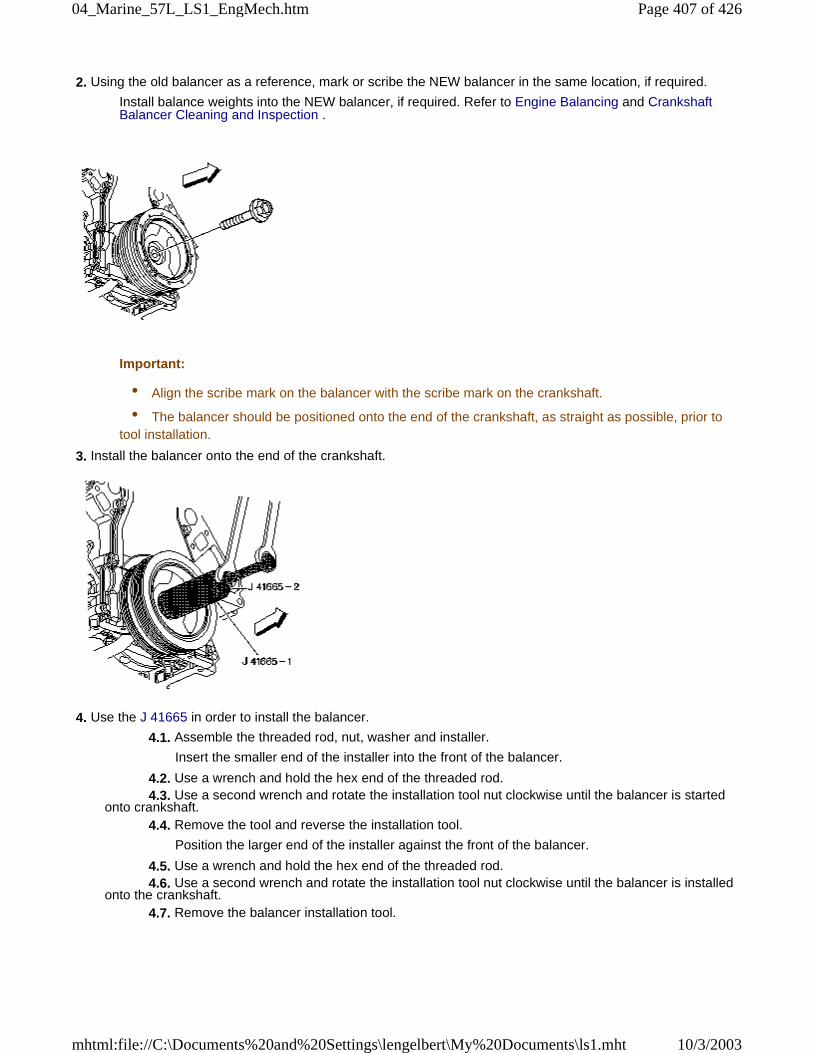
2. Using the old balancer as a reference, mark or scribe the NEW balancer in the same location, if required.
Install balance weights into the NEW balancer, if required. Refer to Engine Balancing and CrankshaftBalancer Cleaning and Inspection .
Important:
• Align the scribe mark on the balancer with the scribe mark on the crankshaft.
• The balancer should be positioned onto the end of the crankshaft, as straight as possible, prior totool installation.
3. Install the balancer onto the end of the crankshaft.
4. Use the J 41665 in order to install the balancer.
4.1. Assemble the threaded rod, nut, washer and installer.
Insert the smaller end of the installer into the front of the balancer.
4.2. Use a wrench and hold the hex end of the threaded rod. 4.3. Use a second wrench and rotate the installation tool nut clockwise until the balancer is startedonto crankshaft. 4.4. Remove the tool and reverse the installation tool.
Position the larger end of the installer against the front of the balancer.
4.5. Use a wrench and hold the hex end of the threaded rod. 4.6. Use a second wrench and rotate the installation tool nut clockwise until the balancer is installedonto the crankshaft. 4.7. Remove the balancer installation tool.
Page 407 of 42604_Marine_57L_LS1_EngMech.htm
10/3/2003mhtml:file://C:\Documents%20and%20Settings\lengelbert\My%20Documents\ls1.mht
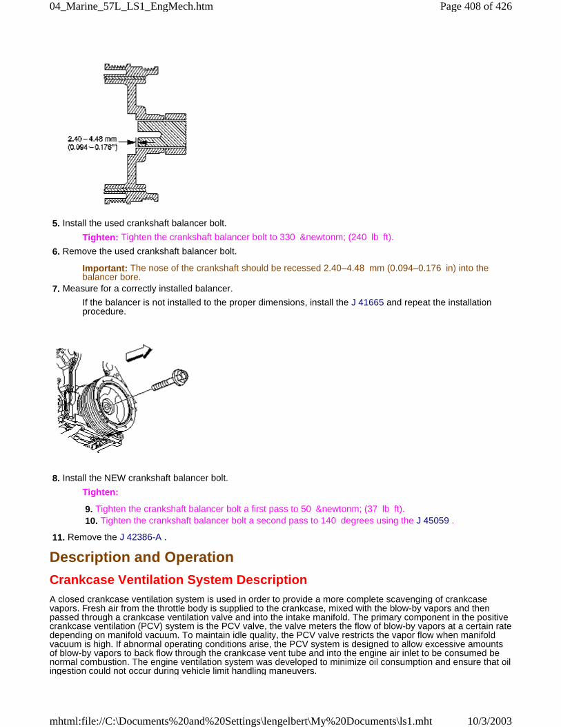
5. Install the used crankshaft balancer bolt.
Tighten: Tighten the crankshaft balancer bolt to 330 &newtonm; (240 lb ft).
6. Remove the used crankshaft balancer bolt.
Important: The nose of the crankshaft should be recessed 2.40–4.48 mm (0.094–0.176 in) into thebalancer bore.
7. Measure for a correctly installed balancer.
If the balancer is not installed to the proper dimensions, install the J 41665 and repeat the installationprocedure.
8. Install the NEW crankshaft balancer bolt.
Tighten:
9. Tighten the crankshaft balancer bolt a first pass to 50 &newtonm; (37 lb ft). 10. Tighten the crankshaft balancer bolt a second pass to 140 degrees using the J 45059 .
11. Remove the J 42386-A .
Description and Operation
Crankcase Ventilation System DescriptionA closed crankcase ventilation system is used in order to provide a more complete scavenging of crankcasevapors. Fresh air from the throttle body is supplied to the crankcase, mixed with the blow-by vapors and thenpassed through a crankcase ventilation valve and into the intake manifold. The primary component in the positivecrankcase ventilation (PCV) system is the PCV valve, the valve meters the flow of blow-by vapors at a certain ratedepending on manifold vacuum. To maintain idle quality, the PCV valve restricts the vapor flow when manifoldvacuum is high. If abnormal operating conditions arise, the PCV system is designed to allow excessive amountsof blow-by vapors to back flow through the crankcase vent tube and into the engine air inlet to be consumed benormal combustion. The engine ventilation system was developed to minimize oil consumption and ensure that oilingestion could not occur during vehicle limit handling maneuvers.
Page 408 of 42604_Marine_57L_LS1_EngMech.htm
10/3/2003mhtml:file://C:\Documents%20and%20Settings\lengelbert\My%20Documents\ls1.mht
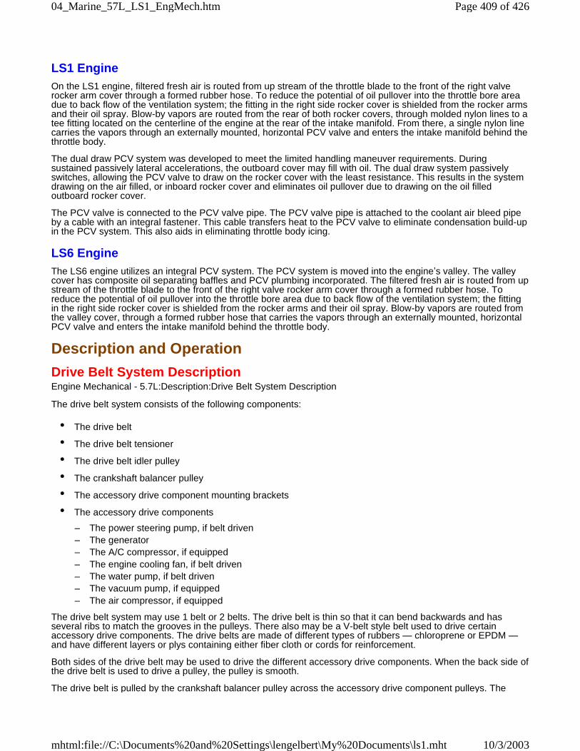
LS1 EngineOn the LS1 engine, filtered fresh air is routed from up stream of the throttle blade to the front of the right valverocker arm cover through a formed rubber hose. To reduce the potential of oil pullover into the throttle bore areadue to back flow of the ventilation system; the fitting in the right side rocker cover is shielded from the rocker armsand their oil spray. Blow-by vapors are routed from the rear of both rocker covers, through molded nylon lines to atee fitting located on the centerline of the engine at the rear of the intake manifold. From there, a single nylon linecarries the vapors through an externally mounted, horizontal PCV valve and enters the intake manifold behind thethrottle body.
The dual draw PCV system was developed to meet the limited handling maneuver requirements. Duringsustained passively lateral accelerations, the outboard cover may fill with oil. The dual draw system passivelyswitches, allowing the PCV valve to draw on the rocker cover with the least resistance. This results in the systemdrawing on the air filled, or inboard rocker cover and eliminates oil pullover due to drawing on the oil filledoutboard rocker cover.
The PCV valve is connected to the PCV valve pipe. The PCV valve pipe is attached to the coolant air bleed pipeby a cable with an integral fastener. This cable transfers heat to the PCV valve to eliminate condensation build-upin the PCV system. This also aids in eliminating throttle body icing.
LS6 EngineThe LS6 engine utilizes an integral PCV system. The PCV system is moved into the engine’s valley. The valleycover has composite oil separating baffles and PCV plumbing incorporated. The filtered fresh air is routed from upstream of the throttle blade to the front of the right valve rocker arm cover through a formed rubber hose. Toreduce the potential of oil pullover into the throttle bore area due to back flow of the ventilation system; the fittingin the right side rocker cover is shielded from the rocker arms and their oil spray. Blow-by vapors are routed fromthe valley cover, through a formed rubber hose that carries the vapors through an externally mounted, horizontalPCV valve and enters the intake manifold behind the throttle body.
Description and Operation
Drive Belt System DescriptionEngine Mechanical - 5.7L:Description:Drive Belt System Description
The drive belt system consists of the following components:
• The drive belt
• The drive belt tensioner
• The drive belt idler pulley
• The crankshaft balancer pulley
• The accessory drive component mounting brackets
• The accessory drive components
– The power steering pump, if belt driven– The generator– The A/C compressor, if equipped– The engine cooling fan, if belt driven– The water pump, if belt driven– The vacuum pump, if equipped– The air compressor, if equipped
The drive belt system may use 1 belt or 2 belts. The drive belt is thin so that it can bend backwards and hasseveral ribs to match the grooves in the pulleys. There also may be a V-belt style belt used to drive certainaccessory drive components. The drive belts are made of different types of rubbers — chloroprene or EPDM —and have different layers or plys containing either fiber cloth or cords for reinforcement.
Both sides of the drive belt may be used to drive the different accessory drive components. When the back side ofthe drive belt is used to drive a pulley, the pulley is smooth.
The drive belt is pulled by the crankshaft balancer pulley across the accessory drive component pulleys. The
Page 409 of 42604_Marine_57L_LS1_EngMech.htm
10/3/2003mhtml:file://C:\Documents%20and%20Settings\lengelbert\My%20Documents\ls1.mht
spring loaded drive belt tensioner keeps constant tension on the drive belt to prevent the drive belt from slipping.The drive belt tensioner arm will move when loads are applied to the drive belt by the accessory drivecomponents and the crankshaft.
The drive belt system may have an idler pulley, which is used to add wrap to the adjacent pulleys. Some systemsuse an idler pulley in place of an accessory drive component when the vehicle is not equipped with the accessory.
Description and Operation
Engine Component Description
LS1/LS6 Engine
The 5.7 Liter V8 engine is identified as RPO LS1 (VIN G) and RPO LS6 (VIN S).
Camshaft and Drive SystemA billet steel 1-piece camshaft is supported by 5 bearings pressed into the engine block. The camshaft has amachined camshaft sensor reluctor ring incorporated between the fourth and fifth bearing journals. The camshafttiming sprocket is mounted to the front of the camshaft and is driven by the crankshaft sprocket through thecamshaft timing chain. The crankshaft sprocket is splined and drives the oil pump driven gear. A retaining platemounted to the front of the engine block maintains camshaft location.
CrankshaftThe crankshaft is cast nodular iron. The crankshaft is supported by 5 crankshaft bearings. The bearings areretained by crankshaft bearing caps which are machined with the engine block for the proper alignment andclearance. The crankshaft journals are undercut and rolled. The center main journal is the thrust journal. Acrankshaft position reluctor ring is mounted at the rear of the crankshaft. The reluctor ring is not serviceableseparately.
Cylinder Heads
Page 410 of 42604_Marine_57L_LS1_EngMech.htm
10/3/2003mhtml:file://C:\Documents%20and%20Settings\lengelbert\My%20Documents\ls1.mht
The cylinder head assemblies are cast aluminum and have pressed in place powdered metal valve guides andvalve seats. Passages for the vapor ventilation system are at the front of each cylinder head. There are noexhaust gas passages within the cylinder head. Valve rocker arm covers are retained to the cylinder head by4 center mounted rocker arm cover bolts.
Engine BlockThe engine block is a cam-in-block deep skirt 90 degree V configuration with 5 crankshaft bearing caps. Theengine block is aluminum with cast in place iron cylinder bore liners. The 5 crankshaft bearing caps each have4 vertical M10 and 2 horizontal M8 mounting bolts. The camshaft is supported by 5 camshaft bearings pressedinto the block.
Exhaust ManifoldsThe exhaust manifolds are a 1-piece cast iron design. The exhaust manifolds direct exhaust gasses from thecombustion chambers to the exhaust system. Each manifold has a single inlet for the air injection reaction (AIR)system and an externally mounted heat shield retained by bolts.
Intake ManifoldThe IAFM or integrated air fuel module is a one piece composite design that incorporates metal threaded insertsfor mounting the fuel rail and throttle body. The intake manifold is sealed to the cylinder heads by eight separatenonreusable silicone sealing gaskets which press into the grooves of the intake housing. The drive by wire throttlebody assembly bolts to the front of the intake manifold. The throttle body is sealed to the intake manifold by a onepiece push in place silicone gasket. The fuel rail assembly with eight separate fuel injectors is retained to theintake by four bolts. The injectors are seated in their individual manifold bores with O-ring seals to provide sealing.A fuel rail stop bracket is retained at the rear of the left fuel rail by the intake manifold mounting bolts. A snap fitmanifold absolute pressure (MAP) sensor housing is mounted at the rear of the manifold and sealed by an O-ringseal. The MAP sensor is installed and retained to the MAP sensor housing. There are no coolant passages withinthe intake manifold.
Oil PanThe structural 2-piece oil pan assembly has cast aluminum upper and lower halves. Incorporated into the upperoil pan design is the oil filter mounting boss, oil level sensor mounting bore, and a non-removable oil pan baffle.The oil pan cover, oil temperature sensor, and oil level sensor mount to the sides of the upper oil pan.Incorporated into the lower oil pan design is the drain plug opening and internal oil control ribbing. A nylon carrierwith a silicone bead type gasket provides sealing between the upper and lower halves of the oil pan assembly.The alignment of the structural oil pan assembly to the rear of the engine block and transmission housing iscritical.
Piston and Connecting Rod AssembliesThe pistons are cast aluminum. The pistons use two compression rings and one oil control ring assembly. Thepiston is a low friction, lightweight design with a flat top and barrel shaped skirt. All 2004 applications have pistonswith graphite coated skirts. The piston pins are chromium steel. They have a floating fit in the piston and areretained by a press fit in the connecting rod. The connecting rods are powdered metal. The connecting rods arefractured at the connecting rod journal and then machined for the proper clearance. The piston, pin, andconnecting rod are to be serviced as an assembly.
Valve Rocker Arm Cover AssembliesThe valve rocker arm covers are cast aluminum and use a pre-molded silicone gasket for sealing. Mounted toeach rocker cover is an ignition coil and bracket assembly. Incorporated into the right cover is the oil fill tube, thepositive crankcase ventilation (PCV) system passage, and the engine fresh air passage.
Valve TrainMotion is transmitted from the camshaft through the hydraulic roller valve lifters and tubular pushrods to the rollertype rocker arms. The valve lifter guides position and retain the valve lifters. The valve rocker arms for each bankof cylinders are mounted on pedestals or pivot supports. Each rocker arm is retained on the pivot support andcylinder head by a bolt. Valve lash is net build. For the LS6 application, both the intake and exhaust valves are ofa hollow stem design. The exhaust valve stem is sodium filled for improved cooling.
Description and Operation
Page 411 of 42604_Marine_57L_LS1_EngMech.htm
10/3/2003mhtml:file://C:\Documents%20and%20Settings\lengelbert\My%20Documents\ls1.mht
New Product InformationThe purpose of New Product Information is to highlight or indicate important product changes from the previousmodel year.
Changes may include one or more of the following items:
• Torque values and/or fastener tightening strategies
• Changed engine specifications
• New sealants and/or adhesives
• Disassembly and assembly procedure revisions
• Engine mechanical diagnostic procedure revisions
• New special tools required
• A component comparison from the previous year
Torque Values and/or Fastener Tightening Strategies
• All fasteners and threaded holes on the LS1/LS6 engines utilize metric threads.
• Cylinder head, connecting rod, crankshaft balancer, and main bearing cap bolts now apply a torque angletightening strategy.
• Certain fasteners should not be used again. Bolts, studs, or other fasteners that must be replaced will becalled out in the specific service procedure.
New Sealants and/or AdhesivesCanadian SPO part numbers have been added. Refer to Sealers, Adhesives, and Lubricants .
Disassembly and Assembly Procedure Revisions
• The piston, pin, and connecting rod are to be serviced as an assembly.
• Newer design pistons have a graphite coated piston skirt. The coated skirt outside diameter (OD) may beslightly larger than the cylinder bore inside diameter (ID) and the piston assembly may have a slight interference
fit to the cylinder bore during initial installation.
Engine Mechanical Diagnostic Procedure RevisionsAll diagnosis on a vehicle should follow a logical process. Strategy based diagnostics is a uniform approach forrepairing all systems. The diagnostic flow may always be used in order to resolve a system condition. Thediagnostic flow is the place to start when repairs are necessary. For a detailed explanation, refer to DiagnosticStarting Point - Engine Mechanical .
New Special Tools RequiredAngle Meter J 45059 has been developed to provide technicians with a convenient method to tighten bolts thatrequire the torque angle tightening strategy.
A Component Comparison from the Previous Year
• A timing chain guide has been added to the valve train system. The nylon chain guide is retained to the frontof the engine block by two bolts.
• The positive crankcase ventilation (PCV) system is now incorporated into the engine valley cover for bothLS1 and LS6 applications.
Page 412 of 42604_Marine_57L_LS1_EngMech.htm
10/3/2003mhtml:file://C:\Documents%20and%20Settings\lengelbert\My%20Documents\ls1.mht
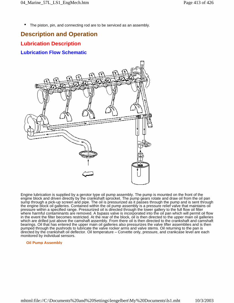
• The piston, pin, and connecting rod are to be serviced as an assembly.
Description and Operation
Lubrication Description
Lubrication Flow Schematic
Engine lubrication is supplied by a gerotor type oil pump assembly. The pump is mounted on the front of theengine block and driven directly by the crankshaft sprocket. The pump gears rotate and draw oil from the oil pansump through a pick-up screen and pipe. The oil is pressurized as it passes through the pump and is sent throughthe engine block oil galleries. Contained within the oil pump assembly is a pressure relief valve that maintains oilpressure within a specified range. Pressurized oil is directed through the lower gallery to the full flow oil filterwhere harmful contaminants are removed. A bypass valve is incorporated into the oil pan which will permit oil flowin the event the filter becomes restricted. At the rear of the block, oil is then directed to the upper main oil gallerieswhich are drilled just above the camshaft assembly. From there oil is then directed to the crankshaft and camshaftbearings. Oil that has entered the upper main oil galleries also pressurizes the valve lifter assemblies and is thenpumped through the pushrods to lubricate the valve rocker arms and valve stems. Oil returning to the pan isdirected by the crankshaft oil deflector. Oil temperature – Corvette only, pressure, and crankcase level are eachmonitored by individual sensors.
Oil Pump Assembly
Page 413 of 42604_Marine_57L_LS1_EngMech.htm
10/3/2003mhtml:file://C:\Documents%20and%20Settings\lengelbert\My%20Documents\ls1.mht
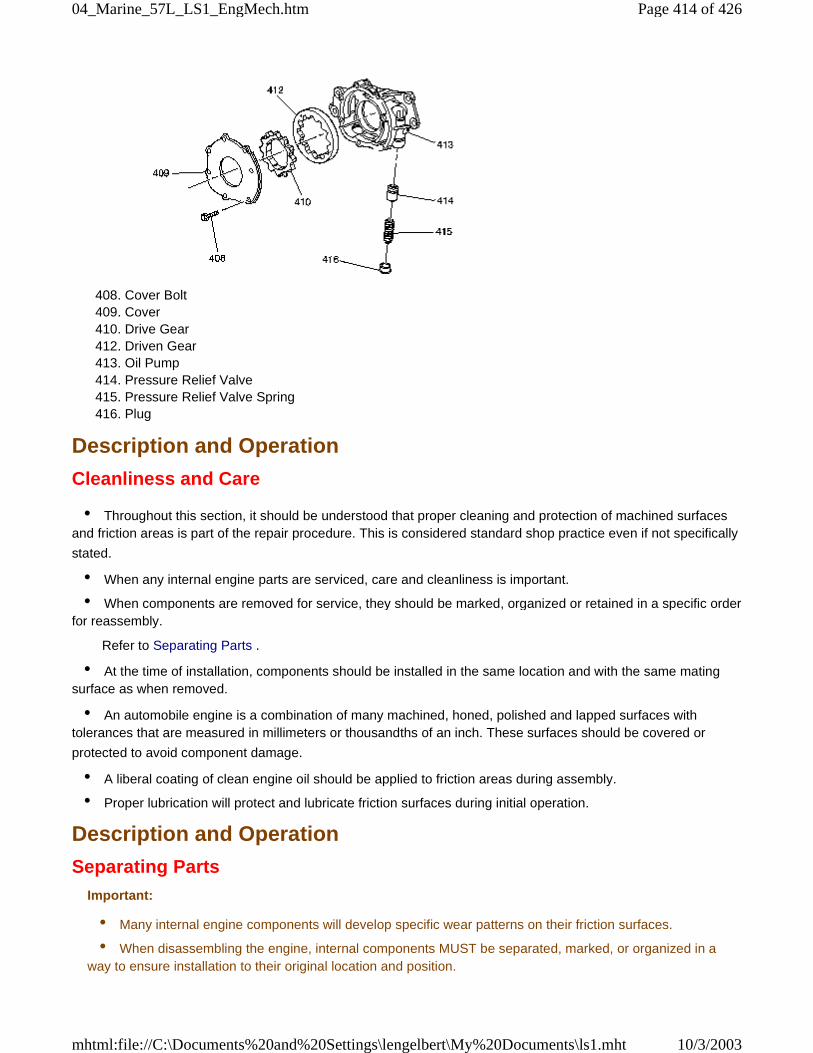
408. Cover Bolt 409. Cover 410. Drive Gear 412. Driven Gear 413. Oil Pump 414. Pressure Relief Valve 415. Pressure Relief Valve Spring 416. Plug
Description and Operation
Cleanliness and Care
• Throughout this section, it should be understood that proper cleaning and protection of machined surfacesand friction areas is part of the repair procedure. This is considered standard shop practice even if not specifically
stated.
• When any internal engine parts are serviced, care and cleanliness is important.
• When components are removed for service, they should be marked, organized or retained in a specific orderfor reassembly.
Refer to Separating Parts .
• At the time of installation, components should be installed in the same location and with the same matingsurface as when removed.
• An automobile engine is a combination of many machined, honed, polished and lapped surfaces withtolerances that are measured in millimeters or thousandths of an inch. These surfaces should be covered or
protected to avoid component damage.
• A liberal coating of clean engine oil should be applied to friction areas during assembly.
• Proper lubrication will protect and lubricate friction surfaces during initial operation.
Description and Operation
Separating PartsImportant:
• Many internal engine components will develop specific wear patterns on their friction surfaces.
• When disassembling the engine, internal components MUST be separated, marked, or organized in away to ensure installation to their original location and position.
Page 414 of 42604_Marine_57L_LS1_EngMech.htm
10/3/2003mhtml:file://C:\Documents%20and%20Settings\lengelbert\My%20Documents\ls1.mht
Separate, mark, or organize the following components:
• Piston and the piston pin
• Piston to the specific cylinder bore
• Piston rings to the piston
• Connecting rod to the crankshaft journal
• Connecting rod to the bearing cap
A paint stick or etching/engraving type tool are recommended. Stamping the connecting rod or cap near thebearing bore may affect component geometry.
• Crankshaft main and connecting rod bearings
• Camshaft and valve lifters
• Valve lifters, lifter guides, pushrods and rocker arm assemblies
• Valve to the valve guide
• Valve spring and shim to the cylinder head location
• Engine block main bearing cap location and direction
• Oil pump drive and driven gears
Description and Operation
Replacing Engine Gaskets
Tools Required
J 28410 Gasket Remover
Gasket Use and Applying Sealants
• Do not use any gasket again unless specified.
• Gaskets that can be used again are identified in the service procedure.
• Do not apply sealant to any gasket or sealing surface unless called out in the service information.
Separating Components
• Use a rubber mallet to separate components.
• Bump the part sideways to loosen the components.
• Bumping should be done at bends or reinforced areas to prevent distortion of parts.
Cleaning Gasket Surfaces
• Remove all gasket and sealing material from the part using the J 28410 or equivalent.
• Care must be used to avoid gouging or scraping the sealing surfaces.
• Do not use any other method or technique to remove sealant or gasket material from a part.
• Do not use abrasive pads, sand paper, or power tools to clean the gasket surfaces.
– These methods of cleaning can cause damage to the component sealing surfaces.– Abrasive pads also produce a fine grit that the oil filter cannot remove from the oil.– This grit is abrasive and has been known to cause internal engine damage.
Page 415 of 42604_Marine_57L_LS1_EngMech.htm
10/3/2003mhtml:file://C:\Documents%20and%20Settings\lengelbert\My%20Documents\ls1.mht
Assembling Components
Notice: Refer to Sealant Notice in Cautions and Notices.
• When assembling components, use only the sealant specified or equivalent in the service procedure.
• Sealing surfaces should be clean and free of debris or oil.
• Specific components such as crankshaft oil seals or valve stem oil seals may require lubrication duringassembly.
• Components requiring lubrication will be identified in the service procedure.
• When applying sealant to a component, apply the amount specified in the service procedure.
• Do not allow the sealant to enter into any blind threaded holes, as it may prevent the bolt from clampingproperly or cause component damage when tightened.
• Tighten bolts to specifications. Do not overtighten.
Description and Operation
Use of RTV and Anaerobic Sealer
Pipe Joint CompoundImportant: 3 types of sealer are commonly used in engines. These are room temperature vulcanizing (RTV)sealer, anaerobic gasket eliminator sealer, and pipe joint compound. The correct sealer and amount must beused in the proper location to prevent oil leaks. DO NOT interchange the 3 types of sealers. Use only thespecific sealer or the equivalent as recommended in the service procedure.
• Pipe joint compound is a pliable sealer that does not completely harden. This type sealer is used where2 non-rigid parts, such as the oil pan and the engine block, are assembled together.
• Do not use pipe joint compound in areas where extreme temperatures are expected. These areas includeexhaust manifold, head gasket, or other surfaces where gasket eliminator is specified.
• Follow all safety recommendations and directions that are on the container.
To remove the sealant or the gasket material, refer to Replacing Engine Gaskets .
Notice: Refer to Sealant Notice in Cautions and Notices.
• Apply the pipe joint compound to a clean surface. Use a bead size or quantity as specified in the procedure.Run the bead to the inside of any bolt holes.
• Apply a continuous bead of pipe joint compound to one sealing surface. Sealing surfaces to be resealedmust be clean and dry.
• Tighten the bolts to specifications. Do not overtighten.
RTV Sealer
• RTV sealant hardens when exposed to air. This type sealer is used where 2 non-rigid parts, such as theintake manifold and the engine block, are assembled together.
• Do not use RTV sealant in areas where extreme temperatures are expected. These areas include exhaustmanifold, head gasket, or other surfaces where a gasket eliminator is specified.
• Follow all safety recommendations and directions that are on the container.
To remove the sealant or the gasket material, refer to Replacing Engine Gaskets .
Notice: Refer to Sealant Notice in Cautions and Notices.
Page 416 of 42604_Marine_57L_LS1_EngMech.htm
10/3/2003mhtml:file://C:\Documents%20and%20Settings\lengelbert\My%20Documents\ls1.mht
• Apply RTV to a clean surface. Use a bead size as specified in the procedure. Run the bead to the inside ofany bolt holes.
• Assemble components while RTV is still wet, within 3 minutes. Do not wait for RTV to skin over.
• Tighten bolts to specifications. Do not overtighten.
Anaerobic Sealer
• Anaerobic gasket eliminator hardens in the absence of air. This type sealer is used where 2 rigid parts,such as castings, are assembled together. When 2 rigid parts are disassembled and no sealer or gasket is
readily noticeable, the parts were probably assembled using a gasket eliminator.
• Follow all safety recommendations and directions that are on the container.
To remove the sealant or the gasket material, refer to Replacing Engine Gaskets .
• Apply a continuous bead of gasket eliminator to one flange. Surfaces to be resealed must be clean and dry.
• Spread the sealer evenly with your finger to get a uniform coating on the sealing surface.
Notice: Refer to Sealant Notice in Cautions and Notices.
Important: Anaerobic sealed joints that are partially torqued and allowed to cure more than five minutesmay result in incorrect shimming and sealing of the joint.
• Tighten bolts to specifications. Do not overtighten.
• After properly tightening the fasteners, remove the excess sealer from the outside of the joint.
Description and Operation
Tools and EquipmentEngine Mechanical - 5.7L:Description:Tools and Equipment
Special tools are listed and illustrated throughout this section with a complete listing at the end of the section.These tools, or their equivalents, are specially designed to quickly and safely accomplish the operations for whichthey are intended. The use of these special tools will also minimize possible damage to engine components.Some precision measuring tools are required for inspection of certain critical components. Torque wrenches anda torque angle meter are necessary for the proper tightening of various fasteners.
To properly service the engine assembly, the following items should be readily available:
• Approved eye protection and safety gloves
• A clean, well lit, work area
• A suitable parts cleaning tank
• A compressed air supply
• Trays or storage containers to keep parts and fasteners organized
• An adequate set of hand tools
• Approved engine repair stand
• An approved engine lifting device that will adequately support the weight of the components
Special Tools and Equipment
Special ToolsEngine Mechanical - 5.7L:Tools:Special Tools
Illustration Tool Number/Description
Page 417 of 42604_Marine_57L_LS1_EngMech.htm
10/3/2003mhtml:file://C:\Documents%20and%20Settings\lengelbert\My%20Documents\ls1.mht
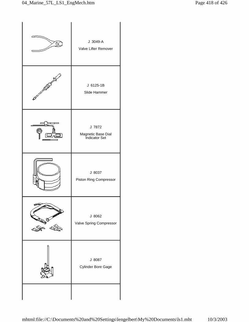
J 3049-A
Valve Lifter Remover
J 6125-1B
Slide Hammer
J 7872
Magnetic Base DialIndicator Set
J 8037
Piston Ring Compressor
J 8062
Valve Spring Compressor
J 8087
Cylinder Bore Gage
Page 418 of 42604_Marine_57L_LS1_EngMech.htm
10/3/2003mhtml:file://C:\Documents%20and%20Settings\lengelbert\My%20Documents\ls1.mht
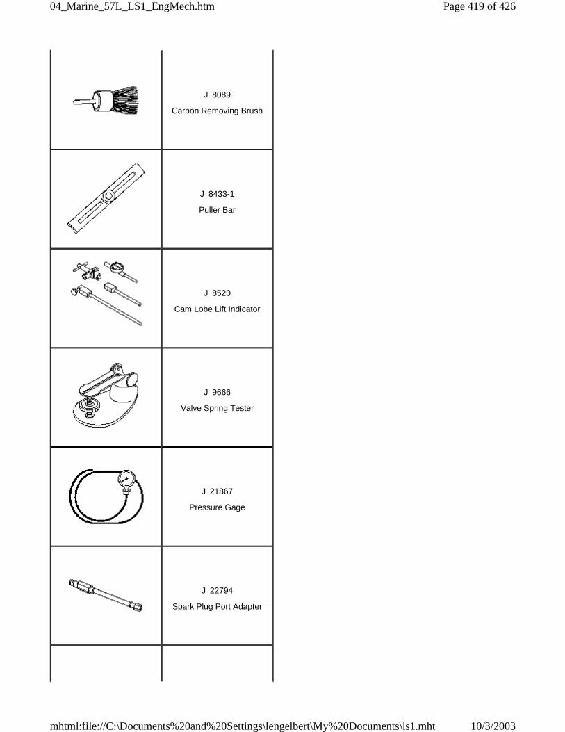
J 8089
Carbon Removing Brush
J 8433-1
Puller Bar
J 8520
Cam Lobe Lift Indicator
J 9666
Valve Spring Tester
J 21867
Pressure Gage
J 22794
Spark Plug Port Adapter
Page 419 of 42604_Marine_57L_LS1_EngMech.htm
10/3/2003mhtml:file://C:\Documents%20and%20Settings\lengelbert\My%20Documents\ls1.mht
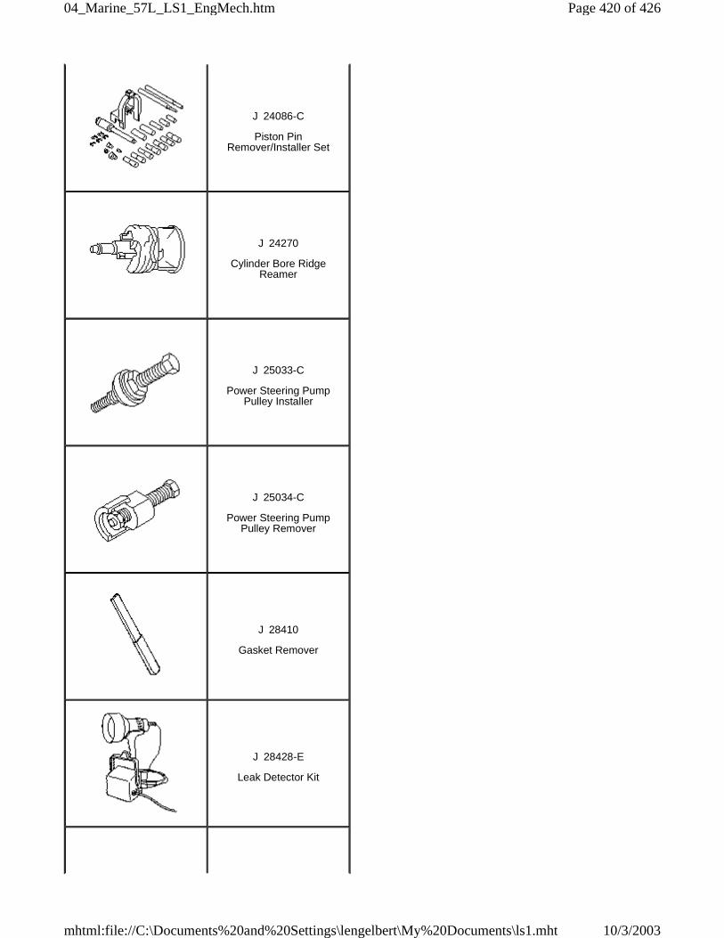
J 24086-C
Piston PinRemover/Installer Set
J 24270
Cylinder Bore RidgeReamer
J 25033-C
Power Steering PumpPulley Installer
J 25034-C
Power Steering PumpPulley Remover
J 28410
Gasket Remover
J 28428-E
Leak Detector Kit
Page 420 of 42604_Marine_57L_LS1_EngMech.htm
10/3/2003mhtml:file://C:\Documents%20and%20Settings\lengelbert\My%20Documents\ls1.mht
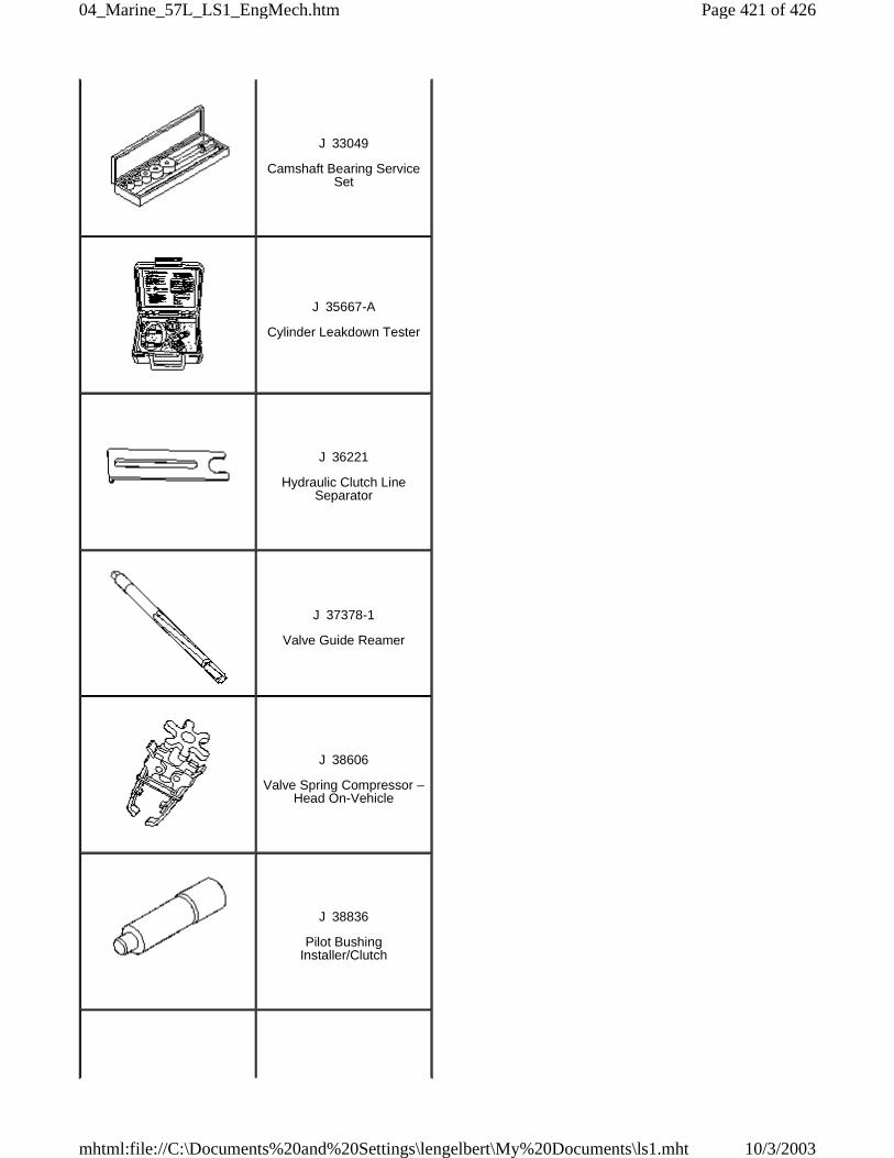
J 33049
Camshaft Bearing ServiceSet
J 35667-A
Cylinder Leakdown Tester
J 36221
Hydraulic Clutch LineSeparator
J 37378-1
Valve Guide Reamer
J 38606
Valve Spring Compressor –Head On-Vehicle
J 38836
Pilot BushingInstaller/Clutch
Page 421 of 42604_Marine_57L_LS1_EngMech.htm
10/3/2003mhtml:file://C:\Documents%20and%20Settings\lengelbert\My%20Documents\ls1.mht
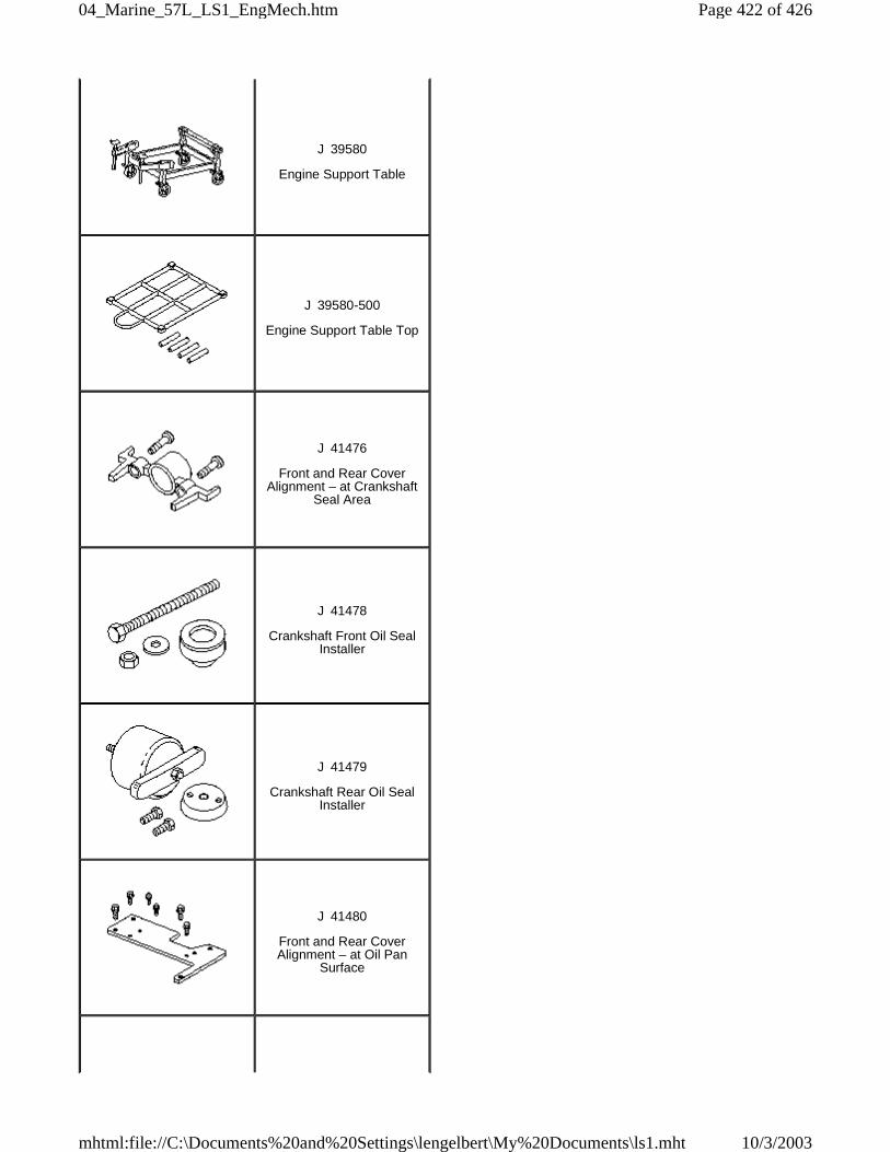
J 39580
Engine Support Table
J 39580-500
Engine Support Table Top
J 41476
Front and Rear CoverAlignment – at Crankshaft
Seal Area
J 41478
Crankshaft Front Oil SealInstaller
J 41479
Crankshaft Rear Oil SealInstaller
J 41480
Front and Rear CoverAlignment – at Oil Pan
Surface
Page 422 of 42604_Marine_57L_LS1_EngMech.htm
10/3/2003mhtml:file://C:\Documents%20and%20Settings\lengelbert\My%20Documents\ls1.mht
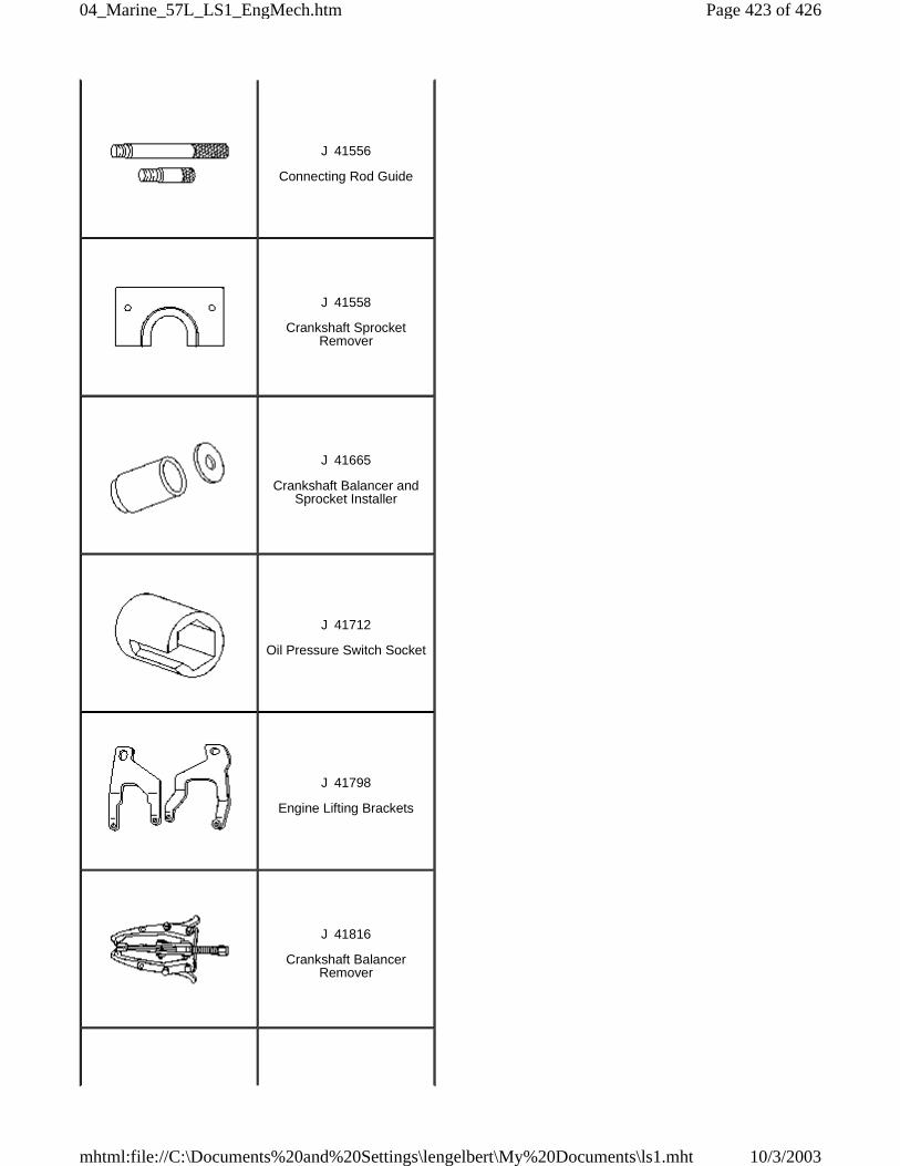
J 41556
Connecting Rod Guide
J 41558
Crankshaft SprocketRemover
J 41665
Crankshaft Balancer andSprocket Installer
J 41712
Oil Pressure Switch Socket
J 41798
Engine Lifting Brackets
J 41816
Crankshaft BalancerRemover
Page 423 of 42604_Marine_57L_LS1_EngMech.htm
10/3/2003mhtml:file://C:\Documents%20and%20Settings\lengelbert\My%20Documents\ls1.mht
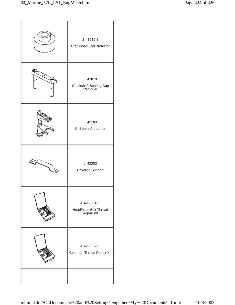
J 41816-2
Crankshaft End Protector
J 41818
Crankshaft Bearing CapRemover
J 42188
Ball Joint Separator
J 42203
Driveline Support
J 42385-100
Head/Main Bolt ThreadRepair Kit
J 42385-200
Common Thread Repair Kit
Page 424 of 42604_Marine_57L_LS1_EngMech.htm
10/3/2003mhtml:file://C:\Documents%20and%20Settings\lengelbert\My%20Documents\ls1.mht

J 42385-300
Fixtures and Hardware Kit
J 42386-A
Flywheel Holding Tool
J 42907
Oil Pressure Testing Tool
J 43276
Clutch Pilot BearingRemover
J 43690
Rod Bearing Checking Tool
J 43690-100
Rod Bearing Checking Tool– Adapter Kit
Page 425 of 42604_Marine_57L_LS1_EngMech.htm
10/3/2003mhtml:file://C:\Documents%20and%20Settings\lengelbert\My%20Documents\ls1.mht
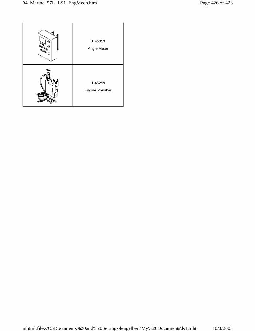
J 45059
Angle Meter
J 45299
Engine Preluber
Page 426 of 42604_Marine_57L_LS1_EngMech.htm
10/3/2003mhtml:file://C:\Documents%20and%20Settings\lengelbert\My%20Documents\ls1.mht