i marine diesel engine - catalina 380
TRANSCRIPT

I MARINE DIESEL ENGINE
MODELS: 3JH3(8)E, 3JH3(C)E*, 4JH3(8)E, 4JH3(C)E
*The 3JH3(C)E is an EPA Certified Engine. It meets the low emission standards set by the EPA.
OPERATION MANUAL
California Proposition 65 Warning
Diesel engine exhaust and some of its constituents are recognized by
the State of California to cause cancer, birth defects, and other
reproductive harm.
•

Contents
CONTENTS
INTRODUCTION .............................................. 3
FOR YOUR SAFETY ................................... 4
1.1 Warning symbols ................................ 4
1.2 Safety Precautions .............................. 4 1.3 Warning Labels ................................... 7
2 PRODUCT EXPLANATION ......................... 8
2.1 Use, Driving System etc ...................... 8
2.2 Engine Specifications ......................... 9
2.3 Names of Parts .................................. 13
2.4 Major Servicing Parts ......................... 15
2.5 Control Equipment ............................ 16
2.5.1 Control Panel. .......................... 16
2.5.2 Single Lever Remote
Control Handle ........................ 18
2.5.3 Stopping Equipment ............... 18
3 OPERATION .............................................. 19
3.1 Fuel Oil, Lube Oil & Cooling Water ..... 19
3.1.1 Fuel Oil .................................... 19
3.1.2 Lube Oil ................................... 20
3.1.3 Cooling Water .......................... 20
3.2 Before Initial Operation ...................... 21
3.2.1 Supply Fuel Oil ........................ 21
3.2.2 Supply Engine Lube Oil .......... .21
3.2.3 Supply Clutch Lube Oil ........... 22
3.2.4 Supply Cooling Water ............. 22
3.2.5 Cranking (Idling) ...................... 23
3.2.6 Check and Resupply Lube
Oil and Cooling Water ............. 24
3.3 Operating your Engine ...................... 25
3.3.1 Inspection Before Starting ...... 25
3.3.2 How to Start the Engine .......... 26
2
3.3.3 Operation ................................ 28
3.3.4 Cautions during Operation ...... 29
3.3.5 Stopping the Engine ............... 29
3.4 Long term Storage ............................ 30
4 MAINTENANCE & INSPECTION ............... 32
4.1 General Inspection Rules .................. 32
4.2 List of Periodic Inspection Items ....... 33
4.3 Periodic Inspection Items ................. 35
4.3.1 Inspection on Initial 50 Hrs. of
Operation (or after 1 month) .... 35
4.3.2 Inspection Every 50 Hours
(or monthly) ............................. 35
4.3.3 Inspection Every 150 Hrs ........ 37
4.3.4 Inspection Every 300 Hrs ........ 37
4.3.5 Inspection Every 600 Hrs ........ 38
4.4 EPA Requirements ........................... 40
4.4.1 EPA Certification Plate ............ 40
4.4.2 Conditions to Insure
Compliance with Emission
Standards ............................... 40
4.4.3 Inspection and Maintenance .... 41
5 TROUBLE AND TROUBLESHOOTING ..... 42
6 PIPING DIAGRAMS .................................. .45
7 WIRING DIAGRAMS ................................. .46
APPENDIX A (Piping diagrams) ..................... A-1
(See the back of this Manual)
APPENDIX B (Wiring diagrams) .................... B-1
(See the back of this Manual)

Introduction
Thank you for purchasing a YANMAR Marine Diesel Engine.
This Operation Manual describes the operation, maintenance and inspection of the 3JH3(8)E, 3JH3(C)E, 4JH3(8)E, 4JH3(C)E Yanmar Marine Diesel Engines.
Read this Operation Manual carefully before operating the engine to ensure that it is used correctly and that it stays in the best possible condition.
Keep this Operation Manual in a convenient place for easy access.
If this Operation Manual is lost or damaged, order a new one from your dealer or distributor.
Make sure this manual is transfered to subsequent owners. It should be considered as a permanent part of the engine and remain so. E Constant efforts are made to improve the quality and performance.of Yanmar products, so some details included in this Operation Manual may differ slightly from your engine. If you have any questions about this, please contact your Yanmar dealer or distributor.
The marine gear described in this manual is Yanmar Model KM Series.
Models 3JH3(B)E, 3JH3(C)E, 4JH3(B)E, 4JH3(C)E Operation Manual (Marine Engine)
Code. No. 499613 - 02780
The essentials of the sail drive are described in this manual. For further details on its use, refer to the sail drive manual.
3

1. For your safety
1.1 WARNING SYMBOLS
Most operation, maintenance and inspection problems arise due to users' failure to comply with the rules and precautions for safe operation described in this operation manual. Often, users do not understand or recognize the signs of approaching problems. Improper handling can cause burns and other injuries and can result in death.
Be sure to read this operation manual carefully before operating the engine and observe all of the instructions and precautions described in this manual.
Below follow the warning signs used in this manual. Pay special attention to parts containing these words and signs.
A DANGER DANGER indicates an imminently hazardous situation which, if not avoided, WILL result in death or serious injury.
A WARNING WARNING indicates a potentially hazardous situation which, if not avoided, COULD result in death or serious injury.
A CAUTION CAUTION indicates a potentially hazardous situation which, if not avoided, may result in minor or moderate injury. This sign is also be used to alert against unsafe practices.
NOTICE The descriptions captioned by are particularly important cautions for handling. If you ignore them, the performance of your machine may deteriorate leading to problems.
1.2 SAFETY PRECAUTIONS
(Observe these instructions for your own safety!)
Precautions for Operation
4
Filler Cap of Fresh Water Tank Never open the cap of the fresh water tank while the engine is still hot. Steam and hot water will spurt out and burn you seriously. Wait until the temperature of the fresh water tank has dropped, wrap a cloth around the filler cap and loosen the cap slowly. After inspection, refasten the cap firmly.

1. For your safety
Battery Never smoke or permit sparks near the battery, because it may emit explosive hydrogen gas. Place the battery in a well-ventilated place.
Fuel Use only diesel oil. Never use other fuels, including gasoline, kerosene, etc., because they could cause a fire. The wrong fuel could also cause the fuel injection pump and injector to fail due to lack of proper lubrication. Be sure to check that you have selected the correct diesel fuel before filling the fuel tank.
Fire Prevention Be sure to stop the engine and confirm that there are no open flames in the vicinity before supplying fuel. If you do spill fuel, wipe such spillage carefully and dispose of the wiping materials properly. Wash your hands thorougly with soap and water. Never place oil or other flammable material in the engine room. Install a fire extinguisher near the engine room, and familiarize yourself ~ with its use. IiIiI Exhaust Gas Exhaust gas contains poisonous carbon monoxide and should not be inhaled. Be sure to install ventilation ports or ventilators in the engine room and ensure good ventilation during engine operation.
Moving Parts Do not touch or let your clothing get caught in the moving parts of the engine, such as the front drive shaft, V-belt or propeller shaft, during engine operation. You will be injured. Never operate the engine without the covers on the moving parts.
Burns The whole engine is hot during operation and immediately after stopping. The exhaust manifold, exhaust pipe and high pressure fuel pipe are very hot. Never touch these parts with your body or clothing.
5

1. For your safety
Pi'!f.! ... I·U'
~ fl'·Wlij#;-
6
Alcohol Never operate the engine while you are under the influence of alcohol. Never operate the engine when you are ill or feeling unwell.
SAFETY PRECAUTIONS FOR INSPECTION
Battery Fluid Battery fluid is dilute sulfuric acid. It can blind you if it gets in your eyes, or burn your skin. Keep the fluid away from your body. If you touch it, wash it off immediately with a large quantity or fresh water and call your doctor for treatment.
Fire by Electric Short-Circuits Always turn off the battery switch before inspecting the electrical system. Failure to do so could cause short-circuiting and fires.
Stop the engine before servicing Stop the engine before you service it. Turn the battery switch off. If you must inspect while the engine is in operation, never touch moving parts. Keep your body and clothing well clear of all moving parts.
Scalds If extracting oil from the engine while it is still hot, don't let the oil splash on you. Wait until the temperature has dropped before extracting cooling water from the engine. Don't let it splash on you.
Forbidden Modifications Never release the limiting devices such as the engine speed limit, fuel injection limit, etc. Modification will impair the safety and performance of the product and shorten product life. Also note that any troubles arising from modification are not covered by our warranty.
Precautions for Treating Waste Never dispose of waste oil or other fluid in a field, sewer, river, or the sea. Treat waste matters safely observing regulations or laws. Ask a waste recovery company to collect it.

1. For your safety
SAFETY PRECAUTIONS FOR INSPECTION
1.3 WARNING LABELS
To insure safe operation, warning device labels have been attached. Their location is shown below and they should always be visible. Please replace if damaged or lost.
CD
3JH3(8)(C)E CD
4JH3(8)(C)E
Warning Device Labels, Parts Numbers
No.
eD
®
Part Code No.
128296-07260
120324-07350
CD • & AWARNING
A. I! Iii ttil>hJlt: •
• Rolatlng parI •. -Can Cau •• injury.
T282915-07350
@ .~ •• DANGER
~ •• ;a1l!1~J:~1',7'l1l11
.. t.I:~\t:"'Fl!~\. e.;aIJl~~ WI,.,~I1C~T~laft'H'o
e Naver ramov. th. cap while th. engine il 11111 hoi. eHol wal.r ma, spurt out end burn you. 1211296-07150
7

2. Product explanation
2.1 USE, DRIVING SYSTEM, ETC.
The engine is equipped with a marine gear or a sail drive unit. The marine gear output shaft connects with the propellor shaft.
In order to obtain full performance from your engine, it is imperative that you check the size and structure of the hull and use a propeller of the appropriate size.
The engine must be installed correctly with safe cooling water and exhaust piping and electrical wiring. The PTO work should be easy to use for onboard equipment.
To handle the drive equipment, driven systems (including the propeller) and other onboard equipment, be sure to observe the instructions and cautions given in the operation manuals supplied by the shipyard and equipment manufacturers.
The laws of some countries may require hull and engine inspections, depending on the use, size and cruising area of the boat.
The installation, fitting and surveying of this engine all require specialized knowledge and engineering skills. Consult Yanmar's local subsidiary in your region or your distributor or dealer.
A WARNING
Never modify this product or release the limit devices (which limit engine speed, fuel injection quantity, etc.). Modification will impair the safety and performance of the product and functions and shorten the product life. Please note that any troubles arising from modification of the product will not be covered by our warranty.
DETAIL OF NAME PLATE
The name plate shown below is attached to the engine. Check the engine's model, output, rpm and serial number on the name plate.
MODEL __________________ __
CONT. RATING __ --=:k:.:..W=--__ ~r;.::;p.;.;.;m MAX.OUT PUT __ ......;.;k;.;.W~ ___ r~p_m
8
The name plate shown below is described in the marine gear. Check the marine gear's model, gear ratio, oil used, oil quantity and serial number.
0 MODEL KM 0 GEAR RATIO OIL SAE 2oIJoHD OIL QTY. LTR. NO.
1f6l1lZIIIC' 0 OSAKA JAPAN 0

2. Product explanation
2.2 Engine Specifications 2.2.1
Engine Model
Type
Combustion system
Number of cylinders
Bore x stroke
Displacement
Output/crankshaft
Continuous speed
rating output Brake mean effective pressure
Piston speed
Output/crankshaft
One hour speed
rating output Brake mean effective pressure
Piston speed
Compression ratio
Fuel injection timing (b.T.D.C.)
Fuel injection pressure
Main power take off
Front power take off
Direction of Crankshaft rotation Propeller shaft (Ahead)
Cooling system
Lubrication system
Type Starting
Starting motor system AC generator
Model
Type
Reduction Forward ratio Reverse
Marine Gear Forward or Sail Drive Propeller
speed Reverse
Lubricating oil capacity
Weight
Overall length
Dimensions Overall width
Overall height
Lubricating oil Total capacity Effective
Engine weight without marine gear / sail drive
mm
e kW/rpm (hp/rpm)
kg/cm'
m/sec.
kW/rpm (hp/rpm)
kg/cm'
m/sec.
kg/cm'
rpm
rpm
standard unite
long-reach unite
kg
mm
mm
mm
e e
kg
(Note) 1. Rating condition: ISO 3046-1. 2.1 hp=0.7355 kW.
3JH3E 3JH3BE
Vertical 4-cycle water cooled diesel engine
Direct injection
3
84x90
1.496
26.5/3650 (36/3650)
5.93
10.95
29.4/3800 (40/3800)
6.33
11.4
18.6
14±1
220±5
At Flywheel side
At Crankshaft V-pulley side
Counter-clockwise viewed from stern
Clockwise viewed from stem
Fresh water cooling with heat exchanger
Complete enclosed forced lubrication
Electric
DC 12V, 1.2 kW
12V, 55A (12V, 80A optional)
KM3P KM3A
Mechanical cone clutch with single stage for both ahead and astern
2.36 2.61 3.20 2.33 2.64
3.16 3.16 3.16 3.04 3.04
1547 1399 1141 1564 1384
1155 1156 1156 1199 1199
0.35 0.45
-
13
755.6 752.8
520.6 520.6
624.9 624.9
5.0 (at rake angle 8') 5.5 (at rake angle 0')
1.1 (at rake angle 8') 1.2 (at rake angle 0')
173
9

2. Product explanation
2.2 Engine Specifications 2.2.2
Engine Model
Type
Combustion system
Number of cylinders
Bore x stroke
Displacement
Output/crankshaft
Continuous speed
rating output Brake mean effective pressure
Piston speed
Output/crankshaft
One hour speed
rating output Brake mean effective pressu re
Piston speed
Compression ratio
Fuel injection timing (b.T.D.C.)
Fuel injection pressure
Main power take off
Front power take off
Direction of Crankshaft rotation Propeller shaft (Ahead)
Cooling system
Lubrication system
Type Starting
Starting motor system AC generator
Model
Type
Reduction Forward ratio Reverse
Marine Gear Forward or Sail Drive Propeller
speed Reverse
Lubricating oil capacity
Weight
Overall length
Dimensions Overall width
Overall height
Lubricating oil Total capacity Effective
Engine weight without marine gear / sail drive
mm
e kW/rpm (hp/rpm)
kg/cm'
m/sec.
kW/rpm (hp/rpm)
kg/cm'
m/sec.
kg/cm'
rpm
rpm
standard unite
long-reach unite
kg
mm
mm
mm
e e kg
(Note) 1. Rating condition: ISO 3046-1. 2. 1 hp=O. 7355 kW.
10
3JH3CE Vertical4-cycle water cooled diesel engine
Direct injection
3
84x90
1.496
26.5/3650 (36/3650)
5.93
10.95
29.4/3800 (40/3800)
6.33
11.4
18.6
14±1
220±5
At Flywheel side
At Crankshaft V-pulley side
Counter-clockwise viewed from stern
Clockwise viewed from stern
Fresh water cooling with heat exchanger
Complete enclosed forced lubrication
Electric
DC 12V, 1.2 kW
12V, 55A (12V, 80Aoptional)
SD31 SD40
Sail drive unit- Dog type clutch, spiral bevel gear type
2.31 2.32
2.31 2.32
1580 1632
1580 1632
2.2 1.8
2.5 -
33 39
545.8 545.8
520.6 520.6
624.9 624.9
5.5 (at rake angle 0°)
1.2 (at rake angle 0°)
173

2. Product explanation
2.2 Engine Specifications 2.2.3
Engine Model
Type
Combustion system
Number of cylinders
Bore x stroke
Displacement
Output/crankshaft
Continuous speed
rating output Brake mean effective pressure
Piston speed
Output/crankshaft
One hour speed
rating output Brake mean effective pressure
Piston speed
Compression ratio
Fuel injection timing (b.T.D.C.)
Fuel injection pressure
Main power take off
Front power take off
Direction of Crankshaft rotation Propeller shaft (Ahead)
Cooling system
Lubrication system
Type Starting
Starting motor system AC generator
Model
Type
Reduction Forward ratio Reverse
Marine Gear Forward or Sail Drive Propeller
speed Reverse
Lubricating oil capacity
Weight
Overall length
Dimensions Overall width
Overall height
Lubricating oil Total capacity Effective
Engine weight without marine gear / sail drive
mm
e kW/rpm (hp/rpm)
kg/cm'
m/sec.
kW/rpm (hp/rpm)
kg/cm'
m/sec.
°
kg/cm'
rpm
rpm
standard unite
long-reach unite
kg
mm
mm
mm
e e
kg
4JH3E 4JH3BE 4JH3WE Vertical4-cycle water cooled diesel engine
Direct injection
4
84x90
1.995
36.8/3650 (50/3650)
6.18
10.95
41.2/3800 (56/3800)
6.65
11.4
17.7
12±1
220±5
At Flywheel side
At Crankshaft V-pulley side
Counter-clockwise viewed from stern
Clockwise viewed from stern
Fresh water COOling with heat exchanger
Complete enclosed forced lubrication
Electric
DC 12V, 1.2 kW
12V, 55A (12V, 80A optional)
KM3P KM3A I KBW20-1
Mechanical cone clutch with single stage for both ahead and astern
2.36 2.61 2.33 2.64 2.17 2.62 3.28
3.16 3.16 3.04 3.04 3.06 3.06 3.06
1547 1399 1564 1384 1685 1394 1114
1156 1156 1199 1199 1195 1195 1195
0.35 0.45 1.2
-
13 26
849.6 885.8 922.8
563.1 563.1 576.6
619.9 619.9 619.9
5.3* 5.8 (at rake angle 0°)
1.2* 1.4 (at rake angle 0°)
210 236
(Note) 1. Rating condition: ISO 3046-1. 2.1 hp=0.7355 kW. * At rake angle 8°
11

2. Product explanation
2.2 Engine Specifications 2.2.4
Engine Model
Type
Combustion system
Number of cylinders
Bore x stroke
Displacement
Output/crankshaft
Continuous speed
rating output Brake mean effective pressure
Piston speed
Output/crankshaft
One hour speed
rating output Brake mean effective pressure
Piston speed
Compression ratio
Fuel injection timing (b.T.D.C.)
Fuel injection pressure
Main power take off
Front power take off
Direction of Crankshaft rotation Propeller shaft (Ahead)
Cooling system
Lubrication system
Type Starting
Starting motor system AC generator
Model
Type
Reduction Forward ratio Reverse
Marine Gear Forward or Sail Drive Propeller
speed Reverse
Lubricating oil capacity
Weight
Overall length
Dimensions Overall width
Overall height
Lubricating oil Total capacity Effective
Engine weight without marine gear / sail drive
mm
e kW/rpm (hp/rpm)
kg/cm'
m/sec.
kW/rpm (hp/rpm)
kg/cm'
m/sec.
°
kg/cm'
rpm
rpm
standard unite
long-reach unite
kg
mm
mm
mm
C
C
kg
(Note) 1. Rating condition: ISO 3046-1. 2. 1hp=0.7355 kW.
12
1.47
1.47
2485
2483
4JH3B4E 4JH3CE 4JH3CE1 Vertical4-cycle water cooled diesel engine
Direct injection
4
84x90
1.995
36.8/3650 34.6/3650 36.8/3650 (50/3650) (47.3/3650) (50/3650)
6.18 5.81 6.18
10.95
41.2/3800 38.2/3800 41.2/3800 (56/3800) (52/3800) (56/3800)
6.65 6.17 6.65
11.4
17.7
12±1
220±5
At Flywheel side
At Crankshaft V-pulley side
Counter-clockwise viewed from stern
Clockwise viewed from stern
Fresh water cooling with heat exchanger
Complete enclosed forced lubrication
Electric
DC 12V, 1.2 kW
12V, 55A(12V, 80Aoptional)
KM4A1 SD31 SD40
Sail drive unit- Dog type clutch, spiral bevel gear type
2.14 2.63 3.30 2.31 2.32
2.14 2.63 3.30 2.31 2.32
1708 1389 1107 1580 1632
1706 1388 1106 1580 1632
1.3 2.2 1.8
- 2.5 -
27.5 33 39
905.8 639.8 639.8
580.6 563.1 563.1
619.9 623.6 623.6
5.8 (at rake angle 0°)
1.4 (at rake angle 0°)
238 210

2. Product explanation
2.3 Names of Parts
Operation Side 3JH3(B)(C)E
Marine gear
Shift lever
Intake manifold Dipstick
Fuel filter
Fuel oil pump
Oil filler cap
Fuel feed pump
Lube oil filter
Note: This illustration shows Yanmar marine gear (Model: KM3A) after it has been attached.
Non Operation Side 3JH3(B)(C)E
Fresh water pump V-belt Fresh water tank
Alternator
Exhaust manifold
Starter motor
Seawater pump
13

2. Product explanation
Operation Side 4JH3(8)(C)E
Marine gear
Shift lever
Oil Filter Cap (Marine gear)
Intake manifold
Fuel filter
Fuel oil pump
Oil filler cap
Fuel feed pump
Lube oil filter
Note: This illustration shows Yanmar marine gear (Model: KM3A) after it has been attached.
Non Operation Side 4JH3(8)(C)E
Fresh water pump
14
V-belt Fresh water tank
Alternator
Exhaust manifold
Starter motor
Seawater pump

2. Product explanation
2.4 Major Servicing Parts
Name of part Function
Fuel filter Removes dust and water from fuel. Drain the filter periodically. The internal element (filter) should be changed periodically.
Fuel feed pump Feed fuel to the fuel injection pump. Moving the priming
Priming lever lever up and down feeds the fuel. When there is no fuel, the priming lever is used to bleed air from the fuel system.
Filler port (engine) Filler port for engine lube oil.
Filler port (marine gear) Filler port for marine gear lube oil.
Lube oil filter Filters fine metal fragments and carbon from the lube oil.
Filtered lube oil is distributed to the engine's moving parts.
Cooling System Seawater passes through the heat exchanger cooling the fresh water, which in turn cools the engine.
Fresh water cooling
Fresh water pump There are two cooling systems: fresh water and seawater.
The fresh water pump is run by the alternator and the V-belt.
Fresh water cooling The fresh water in the fresh water cooler is fed to the engine by the fresh water pump. The cooling fresh water returns to the engine after it is cooled with seawater in the fresh water cooler.
Filler cap The filler cap on the cooling water tank covers the water supply port. The cap has a pressure regulating valve. When the cooling water temp. rises, the pressure rises inside the fresh water cooler.
Subtank The pressure regulating valve releases vapor and hot water overflow to the subtank.
Rubber hose The hose connects the filler cap and subtank. Vapor and hot water discharged to the subtank return there to the cooling water. When the engine stops and cooling water cools, the pressure in the cooling water tank also drops very low. The filler cap valve then opens to send water back from the subtank. This minimizes cooling water consumption.
Fresh water pump The centrifugal water pump circulates fresh cooling water inside the engine. The pump and alternator are driven by the V-belt.
Intake air silencer This is the air intake silencer. The silencer guards against dirt in the air and reduces the noise of air intake.
Nameplate Name plates are provided on the engine and the marine gear and have the model, serial number and other data.
Starter Starter motor for the engine. Powered by the battery.
Alternator Rotates by belt drive, generates electricity and charges the battery.
15

2. Product explanation
2.5 Control Equipment
The equipment in the control room, making remote control possible, consists of: the instrument panel, which is connected by wire harness; the remote control handle, which is hooked up by remote control cable to each of the engine control levers, and the stopping equipment.
2.5.1 Control Panel
Electric Operation There are two control panel options. The controls and alarm lamps included are shown below.
8-2-type
CD Water Proof (sail drive) @ High temp. cooling water @ Low lube oil pressure @ Charge ® Key switch/start
16
® Buzzer (J) Stop button ® Tachometre ® Illumination switch
®
@l Cooling water temperature
® C-type
@ Lube oil pressure @ Hour metre ® Fuse @ Buzzer-off

2. Product explanation
(1) Controls and Equipment
Controls and Equipment Mechanism
Key Switch
o~ Rotary switch with 2 positions. In the OFF position, the switch key can be inserted or removed. In OFF, all electric current is cut off.
~M~ In ON (1 position to the right), the engine is tumed on. In ON, electric current to the controls and equipment is turned on. In the START position the engine will start.
./' . The engine cannot be stopped with the key switch .
/ Alarm Lamps Lamps come on when there is a problem. See Section 2 for the types of lamps and
the way they work.
Alarm Buzzer Buzzer goes off when there is a problem.
Illumination Switch This switch turns on the control panel lamps.
Tachometre The engine's rotation speed is indicated by the needle.
Hour Metre The number of hours of operation is indicated, and can be used as a guide for periodic (optional) maintenance checks. The hour meter is at the bottom of the tachometre.
(2) Alarm Equipment (lamps and buzzer) Mechanism When the sensor detects a problem during operation, the lamps come on and the buzzer goes off.
Alarm monitors are located on the control panel. Under normal conditions, the monitors are off. When there is a problem, the monitors light up.
(3) Alarm Devices Check that the pilot lamps on the instrument panel are as shown below when the starter key is turned on:
Low L.O. pressure alarm lamp Lit Pilot
Charge lamp Lit lamps
Cooling water temp. alarm lamp Off
NOTE: All these signals will continue until the engine starts up or the key is turned off.
17

2. Product explanation
2.5.2 Single Lever Remote Control Handle (Morse Type) - Optional.
This remote control system uses a single handle to operate marinegear-clutch(neutral, forward, reverse) and to control the engine speed.
NEUTRAL: Power to the propeller shaft is cut off and the engine idles. FWD (FORWARD) REV (REVERSE)
~~·.,i-.i::
'-~ti~~//
<D FWD (forward) o REv (reverse) @ NEUTRAL (boat is stopped) @ Clutch is disengaged ® Pull out handle
The handle controls the course of the boat (ahead or astern) and, at the same time, acts as an accelerator increasing the engine speed as it is pushed further in the FWD or REV direction. If the handle is pulled out, engine speed can be controlled without engaging the clutch (clutch remains in the NEUTRAL, no load position).
18
NOTICE Yanmar recommends the use of a single-lever type for the remote control lever. If only the two-lever type is available in the market, operate the engine at 1000 rpm or lower before engaging and disengaging the marine gear-clutch.
2.5.3 Stopping Equipment
Manual Operation
Engine stopping by engine stop cable
Engine stop cable
The engine is stopped by pulling out the engine stop knob, which catches the fuel injection pump stop lever thus cutting off fuel injection.
Electric Operation
Stop button on the instrument panel
~
I-'
¢ "\,
[ .....-J
'" Engine stopping by stop button
Push the stop button on the instrument panel.
A CAUTION
If the engine is stopped suddenly at a high temperature, the temperature of various parts will increase and engine trouble may occur.

3. Operation
3.1 Fuel Oil, Lube Oil, and Cooling Water
3.1.1 Fuel Oil
NOTICE When other than the specified fuel oil is used, the engine will not perform to full capacity and parts may be damaged.
(1) Selection of Fuel Oil Use diesel fuels for best engine performance. Cetane fuel number should be 45 or greater.
(2) Handling of Fuel Oil 1) Water and dust in the fuel cause engine
failure. When fuel is stored, be sure that the inside of the storage container is clean, and that the fuel is stored away from dirt or rain water.
2) Keep the fuel container stationery for several hours to allow any dirt or water to settle to the bottom. Use a pump to extract the clear, filtered fuel from the top of the container for use.
Use the clear filtered fuel from the upper middle section of the container only, leaving any contaminated fuel at the bottom.
(3) Fuel Tank (optional) Be sure to attach a drain cock to the fuel tank to enable dirt and water to settle at the bottom of the tank to be drained off. The fuel outlet should be positioned 20-30mm above the bottom of the tank so that only clean fuel is used.
-+---CD
@
CD Sediment @G) Drain cock @)Toengine
(4) Fuel System Install the fuel pipe from the fuel tank to the fuel pump in accordance with the diagram. The oil/water separator (optional) is placed at the centre section of the line.
CD
CD Fuel filter @ Fuel feed pump
(priming lever) ® OillWater separator @) Approx. 20-30 mm ® Within 500 mm
Fuel system
®
=-- !-::::::
® Drain cock (j) Fuel cock ® Fuel return ® To fuel injection pump @)Fueltank
19

3. Operation
3.1.2 Lube Oil
NOTICE Using other than the specified lube oil will lead to seizure of parts, abnormal wear, and shorten engine life.
(1) Selection of Engine Lube Oil Use the following lube oil: • API Classification ............................. CD
(2) Selection of Oil for Marine Gear • API Classification ............................. CD
(3) Selection of Oil for Sail Drive Unit SAE Viscosity ................... 90 or 80W90
(4) Handling the Lube Oil 1) When handling and storing lube oil, be
careful not to allow dust and water to enter the lube oil. Clean around the filter port before refilling.
2) Do not mix lube oils of different types or brands. Mixing may cause the chemical characteristics of the lube oil to change and lubricating performance to drop, reducing the engine's life. Before supplying lube oil to the engine and marine gear for the first time, extract all the lube oil already in the tank. Use new lube oil.
3) Lube oil supplied to the engine will undergo natural degeneration with time even when the engine is not used. Lube oil should be replaced at the specified intervals, regardless of whether the engine is being used or not.
20
Air temperature
Single grade Multi grade
"C "F
L11:: $: -~.
~10'
i -15' _ -10'
-25' -30' -35' -31' -41i" -40
-55'llJy67'
If you operate your equipment at temperatures below the limits shown, consult your dealer for special lubricants and starting aids,
3.1.3 Cooling Water
It is important to check the cooling water daily. Be sure to use clean soft water (tap water) for cooling fresh water.
NOTICE Be sure to add antirust or antifreeze to cooling fresh water. In cold seasons, the antifreeze is especially important. Without antirust, cooling performance will drop due to scale and rust in the cooling water system. Without antifreeze, cooling water will freeze and expand, breaking various parts. For your reference, antifreeze mixed with antirust is now available in the market.
3. Operation
Handling of Cooling Water 1. Choose antirust which will not have any
adverse effects on the materials (cast iron, aluminum, copper, etc.) of the engine's fresh water cooling system.
2. Use the proper mixing ratio of antirust to fresh water strictly as instructed by the antirust maker.
3. Replace the cooling water periodically, according to the maintenance schedule given in this operation manual.
4. Remove the scale from the cooling water system periodically, according to the instructions in this operation manual.
5. Use the proper mixing ratio of antifreeze to fresh water strictly, as instructed by the antifreeze maker. If too much antifreeze is used, the cooling performance of the cooling water will drop and the engine may become overheated.
6. Do not mix different brands of antirust or antifreeze. Chemical reactions may make the antifreeze or antirust useless and engine trouble could result.
NOTICE Excessive use of antifreeze also lowers the cooling efficiency of the engine. Be sure to use the mixing ratios specified by the antifreeze maker for your temperature range.
3.2 Before Initial Operation
Perform the following before using the engine for the first time:
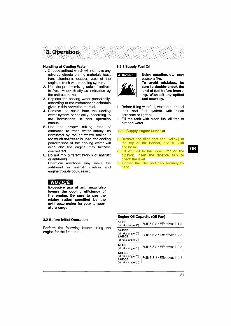
3.2.1 Supply Fuel Oil
Using gasoline, etc. may cause a fire. To avoid mistakes, be sure to double-check the kind of fuel before inserting. Wipe off any spilled fuel carefully.
1. Before filling with fuel, wash out the fuel tank and fuel system with clean kerosene or light oil.
2. Fill the tank with clean fuel oil free of dirt and water.
3.2.2 Supply Engine Lube Oil
1. Remove the filler port cap (yellow) at the top of the bonnet, and fill with engine oil.
2. Fill with oil to the upper limit on the dipstick. Insert the dipstick fully to check the level.
3. Tighten the filler port cap securely by hand.
Engine Oil Capacity (Oil Pan)
3JH3E Full: 5.0 f / Effective: 1.1 f (at rake angle 8°)
3JH3BE (at rake angle 0°) Full: 5.5 f / Effective: 1.2 f 3JH3CE (at rake angle 0°)
4JH3E Full: 5.3 f / Effective: 1.2 f (at rake angle 8°)
4JH3BE (at rake angle 0°) Full: 5.8 f / Effective: 1.4 e 4JH3CE (at rake angle 0°)
21

3. Operation
NOTICE
Do not overfill. Overfilling will cause oil to be sprayed out from breather and lead to engine problems.
CD Filler port @Bonnet
@ Dipstick ® Lower limit @ Upper limit
3.2.3 Supply Clutch Lube Oil
1. Remove the filler port cap at the top of the bonnet, and fill with marine gearclutch- lube oil.
2. Fill with oil to the upper limit on the dipstick. Insert the dipstick fully to check the level.
3. Tighten the filler port cap securely by hand.
Marine gear oil capacity
KM3P KM3A
22
Full 0.35 e / Effective 0.05 e Full 0.45 e / Effective 0.05 e
CD Oil filler port cap @Dipstick @ Upper limit/Lower limit
3.2.4 Supply Cooling Water
Supply cooling water according to the following procedures. Be sure to add antirust or antifreeze to the cooling water.
1. Be sure to close the 3 water drain cocks.
Fresh Seawater Model water line line
3JH3(B)E 3 1 4JH3(B)E 3 1
Note: The water drain cocks are opened before shipping from the plant.
2. Remove the filler cap of the fresh water cooler by turning the cap counterclockwise 1/3 of a turn.
CD Filler cap @Dents
@ Fresh water cooler @Notches

3. Operation
3. Pour cooling water slowly into the fresh water tank so that air bubbles do not develop. Supply until the water overflows from the filler port.
If the filler cap is loose, hot steam and water will spout out which may cause burns.
4. After supplying cooling water, replace filler cap and tighten it firmly. Failure to do so will cause water leakage. To replace the cap, align the detents on the bottom of the cap with the notches on the filler port and turn clockwise % of a turn.
5. Remove the subtank cap and fill with water to the lower limit. Replace cap. Subtank capacity: 0.8 e
6. Check the rubber hose connecting the subtank to the fresh water cooler. Be sure the hose is securely connected
3.2.5 Cranking
When the engine has not been used for a long period of time, lube oil will not be distributed to all of the operating parts. Using the engine in this condition will lead to seizure. After a long period of disuse, distribute lube oil to each part by cranking. Perform in accordance with the following procedures before beginning operation.
1. Open Kingston cock. 2. Open fuel tank cock. 3. Put remote control lever in NEUTRAL.
@
0)~ ... ,<d@
® and there is no looseness or damage. CD Forward @Neutral ® Reverse
When the hose is not watertight, an excessive amount of cooling water will be used.
CD To fresh water cooler @ Lower limit
@ Upper limit @:leap
®
CD Fresh water tank @ For fresh water
(3JH3E series only)
® For seawater @:l Starter motor ® Alternator
23

3. Operation
CD Fresh water pump @Altemator
CD Stop solenoid @ For fresh water
(4JH3E series only)
24
@ For fresh water ® Fresh water tank
@ Flywheel housing
4. Turn on battery switch and insert key into key switch. Turn the key to the ON position.
5. Manual stop device Pull the stop knob continuously while cranking. Electric stop device Push the stop button on the instrument panel continuously while cranking.
6. When the key switch is turned, the engine will begin cranking. Continue cranking for about 5 seconds, and check for abnormal noise during that time. (If you remove your hand from the stop knob or stop button while cranking, the engine will start.)
3.2.6 Check and Resupply Lube Oil and Cooling Water
When engine oil, clutch oil, or cooling water is supplied for the first time or when they must be replaced, conduct a trial operation of the engine for about 5 minutes and check the quantity of lube oil and cooling water. The trial engine operation will send the lube oil and cooling water to the parts, so the lube oil and cooling water levels will drop. Check and resupply as necessary. 1. Supplying engine lube oil (See 3.2.2) 2. Supplying marine gear lube oil
(See 3.2.3) 3. Supplying cooling water (See 3.2.4)

3. Operation
3.3 Operating your engine
A WARNING
To prevent exhaust gas poisoning, ensure good ventilation during operation. Install ventilation windows, ports or ventilators in the engine room. Never touch or allow your clothes to touch the moving parts of the engine during operation. If the front drive shaft, V-belt, propeller shaft, etc. catches your body or clothes, serious injury may result. Check that no tools, cloth, etc. are left on or around the engine.
A CAUTION
The engine is very hot during operation and immediately after stopping, especially the exhaust manifold and the exhaust pipe. Avoid burns! Never touch or allow your clothes to touch any part of the engine.
3.3.1 Inspection Before Starting
Before starting the engine, make it a daily rule to conduct the following inspections:
(1) Visual Checks Check for the following: 1. Lube oil leakage from the engine 2. Fuel oil leakage from the fuel system 3. Water leakage from the cooling water
system 4. Damage to parts 5. Loosening or loss of bolts
If any problem is found, do not operate the engine before completing repairs.
(2) Checking and Resupplying Fuel Oil Check the fuel level inside the fuel tank and supply with the recommended fuel, if necessary. (See 3.2.1)
(3) Checking and Resupplying Engine Lube Oil
1. Check the engine oil level with the oil dipstick.
2. If the oil level is low, supply with the recommended lube oil using the filler port. Supply oil up to the top mark on the oil dipstick. (See 3.2.2)
(4) Checking and Resupplying Clutch Lube Oil
1. Check the clutch oil level with the oil dipstick.
2. If the oil level is low, supply with the recommended lube oil using the filler port. Supply oil up to the top mark on the oil dipstick. (See 3.2.3)
(5) Checking and Resupplying Fresh Water (For Fresh Water Cooling System)
Check the fresh water level before operation while the engine is cold. Checking the water level while the engine is hot is dangerous, and the cooling water ~ reading will be misleading due to thermal IiiI expansion. Check and supply cooling water routinely at the subtank only. Do not remove the filler cap of the fresh water tank during usual operation.
A DANGER
Do not open the filler cap during operation or immediately after stopping the engine. Hot steam and water will spout out. To remove the cap, wait until the engine has cooled down, wrap the cap with a cloth and loosen the cap slowly. After checking, replace the cap and tighten firmly.
1. Check that the cooling fresh water level is above the lower limit on the side of the subtank.
2. If the water level is close to the lower limit, remove the subtank cap and supply fresh water.
3. When the water in the subtank runs out, remove the filler cap of the fresh water cooler and supply water until it overflows from the filler port. (See 3.2.4)
25

3. Operation
NOTICE If the cooling fresh water runs out too often, or only the cooling fresh water in the fresh water tank drops without any change in the water level of the subtank, there may be some leakage of water or air. In such cases, consult your Yanmar dealer or distributor without delay.
Note: The water rises in the subtank during engine operation.
26
This is not abnormal. After stopping the engine, the cooling water cools down and the extra water in the subtank returns to the fresh water tank.
(6) Checking the Remote Control Handle Be sure to check that the remote control handle lever moves smoothly before use. If it is hard to operate, lubricate the joints of the remote control cable and also the lever bearings. If the lever comes out or there is play in the lever, adjust the remote control cable. (See 4.3.4 (3))
(7) Checking the Alarm Devices Electric Operation
When operating the key switch, check that the alarm devices work normally. (See 2.5.1 (3))
(8) Preparing Fuel, Lube Oil, and Cooling Fresh Water in Reserve
Prepare sufficient fuel for the day's operation. Always store lube oil and cooling fresh water in reserve (for at least one refill) onboard, to be ready for emergencies.
3.3.2 How to Start the Engine
(1) Start the engine according to the following procedures:
Electric Operation 1. Open the Kingston cock. 2. Open the fuel tank cock. 3. Set the remote control lever in
NEUTRAL.
NOTICE Safety equipment (optional) makes it impossible to start the engine in any other position than NEUTRAL.

3. Operation
4. Turn on the battery switch. 5. Insert the key into the key switch and
turn the key to ON. If the alarm buzzer sounds and alarm lamps come on, the alarm devices are normal.
Note: The cooling water temp. warning lamp does not come on. (See 2.5.1.(3))
6. Turn the key switch to start the engine. Release the key switch when the engine has started. The alarm buzzer should stop and the alarm lamps go out.
CD OFF position CD @ON poo';oo t~ ®STARTPOSltIO~" O~ ~ ST~ @
./' '
/ (2) Restarting After Starting Failure Before turning the key switch again, be sure to confirm that the engine has stopped completely. If the engine is restarted while the engine still has not stopped, the pinion gear of the starter motor will be damaged.
Turn the key for a maximum of 15 seconds in the start position. If the engine does not start the first time, wait for about 15 seconds before trying again. After the engine has started, do not turn the key off. (It should remain ON.) Alarm devices will not work when the key is OFF.
(3) Air Venting of the Fuel System After Starting Failure
If the engine only idles and won't start after several attempts, there may be air in the fuel system. If air is in the fuel system, fuel cannot reach the fuel injection pump. Vent the air in the system according to the following procedures.
Fuel System Air Venting Procedures
1. Check the fuel level in the fuel tank. Replenish if insufficient.
2. Loosen the air vent bolt at the top of the oil/water separator by turning it 2 or 3 times. When fuel which does not contain air bubbles comes out of the bolt hole, tighten the air vent bolt.
3. Loosen the air vent bolts of the fuel filter and the fuel injection pump by turning them 2 or 3 times .
4. Feed fuel with the fuel feed pump by moving the lever on the left side of the feed pump up and down.
5. Allow the fuel containing air bubbles to flow out from the air vent bolt holes. When the fuel coming out no longer contains bubbles, tighten the air vent bolts. This completes the air venting of the fuel system. Try starting the engine again.
6. In subsequent engine operation after the start-up, the automatic air-venting device works to purge the air in the fuel system. No manual air-venting is required for normal engine operation.
27

3. Operation
(4) After the Engine has Started After the engine has started, check the following items at a low engine speed:
1. Check that the gauges and alarm devices on the instrument panel are normal.
2. Check for water or oil leakage from the engine.
3. Check that exhaust colour, engine vibrations and sound are normal.
4. When there are no problems, keep the engine at low speed with the boat still stopped to send lube oil to all parts of the engine.
5. Check that sufficient cooling water is discharged from the seawater outlet pipe. Operation with too small seawater discharge will burn the impeller of the seawater pump. If seawater discharge is too small, stop the engine immediately. Identify the cause and repair.
28
• Is the Kingston cock open? • Is the inlet of the Kingston cock on
the hull bottom clogged? • Is the seawater suction hose broken,
or does the hose suck in air due to a loose joint?
NOTICE The engine will seize if it is operated when cooling seawater discharge is too small or if load is applied without any warming up operation.
3.3.3 Operation
(1) Engine Acceleration and Deceleration
Use the governor handle to control acceleration and deceleration. Move the handle slowly.
(2) FORWARD-NEUTRAL (boat stopped) - REVERSE Clutch
Use the clutch handle to change from FORWARD to NEUTRAL (boat stopped) to REVERSE.
NOTICE Shifting the clutch while operating at high speed or not pushing the handle fully into position (half clutch) will result in damage to clutch parts and abnormal wear.
1. Before using the clutch, be sure to move the governor handle to a low speed position (less than 1000 rpm). Move the governor handle to a high speed position after completing clutch operation.
2. When changing between FORWARD and REVERSE, bring the clutch to NEUTRAL and pause before slowly shifting to the desired position. Do not shift abruptly from FORWARD to REVERSE or vice versa.
3. Move the clutch handle accurately and fully into the FORWARD, NEUTRAL, and REVERSE positions.

3. Operation
3.3.4 Cautions During Operation
Always be on the lookout for problems during engine operation. Pay particular attention to the following:
(1) Is sufficient water being discharged from the seawater outlet pipe?
If the discharge is small, stop the engine immediately, identify the cause and repair.
(2) Is the exhaust colour normal? The continuous emission of black exhaust indicates engine overloading. This shortens the engine's life and should be avoided.
(3) Are there abnormal vibrations or noise?
Depending on the hull structure, engine and hull resonance may suddenly become great at a certain engine speed range, causing heavy vibrations. Avoid operation in this speed range. If you hear any abnormal sounds, stop the engine and inspect.
(4) Alarm buzzer sounds during operation.
If the alarm buzzer sounds during operation, lower the engine speed immediately, check the warning lamps, and stop the engine for repairs.
(5) Is there water, oil, or gas leakage, or are there any loose bolts?
Check the engine room periodically for any problems.
(6) Is there sufficient fuel oil in the fuel oil tank?
Replenish fuel oil in advance to avoid running out of fuel during operation.
(7) When operating the engine at low speed for long periods of time, race the engine once every 2 hours.
Note: Racing the Engine With the clutch in NEUTRAL, accelerate from the low speed position to the high speed position and repeat this process about 5 times. This is done to clean out carbon from the cylinders and the fuel injection valve. Neglecting to race the engine will result in poor exhaust colour and reduce engine performance.
NOTICE Electric Operation Never turn off the battery switch or spark the battery cable during operation. Damage to parts in the electric system will result.
3.3.5 Stopping the Engine
Stop the engine in accordance with the following procedures:
1. Put the remote control handle in NEUTRAL.
2. Be sure to race the engine before stopping it. (See 3.3.4 (7))
3. Cool down the engine at low speed (approximately 1000 rpm) for about 5 minutes.
NOTICE Stopping the engine suddenly while operating at high speed will cause the engine temperature to rise quickly, causing deterioration of the oil and sticking of parts.
29

3. Operation
Engine stopping by engine stop cable
Engine stop cable
Manual stop device 4. Continue to pull out the engine stop
knob (stop lever) until the engine is completely stopped. If you release the knob before the engine has completely stopped, it may restart.
Electric stop device Push the stop button on the instrument panel.
Stop button on the instrument panel
r-:
~
¢ ~
[
'" ~
Engine stopping by stop button
5. Close the fuel tank cock. 6. Close the Kingston cock.
30
NOTICE Neglecting to close the Kingston cock will allow water to leak into the boat and may cause it to sink. Be sure to close the cock.
3.4 Long Term Storage
(1) In cold temperatures or before long term storage, be sure to drain the water from the seawater cooling system.
.A CAUTION
Drain water from the cooling system after the engine has cooled down. Be careful to avoid burns.
NOTICE If water is left inside, it may freeze and damage parts of the cooling system (fresh water cooler, seawater pump, etc.) when ambient temperature is below aoc.
CD Alternator @Draincock
@ Fresh water tank ® Seawater pump
1. Loosen the drain cocks attached on the pipe, and drain off the water inside.
2. Loosen the 4 bolts fixing the side cover of the seawater pump, remove the cover and drain the water from inside. Retighten the bolts when finished.
3. Close the drain cocks.

3. Operation
(2) If antifreeze has not been added to the cooling fresh water, be sure to drain off the water from the fresh water cooling system daily after use.
Fresh Water Cooling
NOTICE If the water is not removed, it may freeze and damage parts of the cooling water system (fresh water cooler, cylinder block, cylinder head, etc.) when ambient temperature is below O°C.
1. Open the water drain cocks (3 positions as illustrated) and drain the cooling water from inside.
2. With a screw driver, loosen the drain plug attached to the lube oil filter mount.
3. Close the drain cocks and the drain plug after draining the water.
CD For fresh water (3JH3E series only)
@ For fresh water ® For seawater
CD Drain plug (4JH3E series only)
@Drain plug (3JH3E series only)
CD For fresh water
(3) Carry out the next periodic inspection before placing the engine in storage. Clean the outside of the engine wiping off any dust or oil.
(4) To prevent condensation inside the fuel tank, either drain off the fuel or fill the tank.
(5) Grease the exposed area and joints of the remote control cable and the bearings of the remote control handle.
(6) Cover the intake silencer, exhaust pipe, etc. with vinyl sheets and seal them to prevent moisture from entering.
(7) Drain bilge in the hull bottom completely. Water may leak into the boat when it is moored, and whenever possible it should be landed.
(8) Waterproof the engine room to prevent rain and seawater from entering.
(9) During long term storage, charge the battery once a month to compensate for the battery's self-discharge.
31

4. Maintenance & Inspection
4.1 General Inspection Rules
Conduct Periodic Inspection for Your Safety. The functions of engine components will degenerate and engine performance will drop according to the use of the engine. If countermeasures are not taken, you may encounter unexpected troubles while cruising at sea. Consumption of fuel or lube oil may become excessive and exhaust gas and engine noise may increase. These all shorten the life of the engine. Daily and periodic inspection and servicing increase your safety at sea.
Inspect Before Starting. Make it a daily rule to inspect before starting. (See 3.3.1)
Periodic Inspections at Fixed Intervals. Periodic inspections must be made after every 50, 150, 300 and 600 hours of use. Conduct periodic inspections according to the procedures described in this Operation Manual.
Use Genuine Parts. Be sure to use genuine parts for consumable and replacement parts. Use of other parts will reduce engine performance and shorten the life of the engine.
NOTICE
Consult Your YANMAR Dealer or Distributor. Specialized technicians are ready to assist you with periodic inspections and maintenance. Consult your YANMAR dealer or distributor in accordance with the service agreement.
Servicing Tools Prepare servicing tools onboard to be ready for inspecting and serviCing the engine and other equipment.
Tightening Torque of Bolts & Nuts Over-tightening of bolts and nuts causes them to come off or their threads to be damaged. Insufficient tightening causes oil leakage from the installation face or troubles due to the loosening of bolts. Bolts and nuts must be tightened to the appropriate tightening torque. Important parts must be tightened with a torque wrench to the correct tightening torque and in the right order. Consult with your dealer or distributor if the servicing requires the removal of such parts.
The standard tightening torque for standard bolts & nuts is listed below.
Apply the following tightening torque to bolts having "7" on the head. (JIS strength classification: 7n Tighten bolts with no "7" mark to 60% tightening torque. If the parts to be tightened are made from light alloy aluminum, tighten the bolts to 80% tightening torque.
Bolt dia. x pitch mm M6x1.0 M8x1.25 M10x1.5 M12x1.75 M14x1.5 M16x1.5
Tightening torque Nm 11 ± 01 26± 03 50± 05 90 ± 10 140 ± 15 230 ± 20
32

4. Maintenance & Inspection
4.2 List of Periodic Inspection Items Daily and periodic inspections are important to keep the engine in its best condition. The following is a summary of inspection and servicing items by inspection interval. Periodic inspection intervals should vary depending on the uses, loads, fuels and lube oils used and handling conditions, and are hard to establish definitively. The following should be treated as a general standard only. Section 4.3 gives a detailed explanation of which parts must be inspected and the procedure for doing so for each interval.
NOTICE Schedule your own periodic inspection plan according to the operational conditions of your engine and inspect every item. Neglect of periodic inspection may lead to engine troubles and shorten the life of the engine. Inspection and servicing at 600 hours and thereafter require special knowledge and techniques. Consult your Yanmar dealer or distributor.
33

4. Maintenance & Inspection
0: Check @: Replace .: Consult local dealer
System Item Before After 50 Every Every Every starting hrs or one 150 hrs 300 hrs 600 hrs
month (1 year)
Check the fuel level, and refill 0
Drain the fuel tank o (first) 0
Fuel system' Drain the fuel filter 0
Replace the fuel filter @
Check the injection timing • Check the injection spray condition •
Crankcase 0 Check the lube oil level
Marine gear 0
Lubricating Crankcase @(first) @
system Replace the lube oil
Marine gear @(first) @
Check the oil pressure warning lamp function 0
Replace the lube oil filter @(first) @
0 Seawater outlet During
operation
Check cooling water level 0
Cooling system Adjust the tension of cooling water pump o (first) 0
driving belt
Check the impeller of the cooling water 0
pump (seawater pump)
Replace the fresh water cooling Every year
Clean the element of the air intake silencer 0
Clean the exhaust/water mixing elbow 0
Air intake and Clean the breather pipe 0
exhaust system 0 Check the exhaust gas condition During
operation
Check the charge lamp function 0
Check the electrolyte level in the battery 0 Electrical system
Adjust the tension of the alternator driving belt o (first) 0
Check the wiring connectors 0
0 Check for leakage of water and oil (After
Cylinder head, starting)
etc. Retighten all major nuts and bolts • Adjust intake/exhaust valve clearance o (first) •
Remote control Check the remote control operation o (first) • system, etc. Adjust the propeller shaft alignment o (first) •
*For EPA Requirements, see also 4.4
34

4. Maintenance & Inspection
4.3 Periodic Inspection Items
4.3.1 Inspection on Initial 50 Hrs. of Operation (or after 1 Month)
(1) Replacing the Engine Lube Oil and Lube Filter (1 st time)
During initial operation of the engine, the oil is quickly contaminated due to the initial wear of internal parts. The lube oil must therefore be replaced early. Replace the lube oil filter at the same time. It is easiest and most effective to drain the engine lube oil after operation while the engine is still warm.
1. Remove the lube oil dipstick. Attach the oil drain pump and drain off oil.
2. Remove the lube oil filter with the filter detach/attach tool. (Turn to the left.)
3. Clean the filter installation face and attach the new filter, tightening by hand.
4. Turn an additional 3/4 of a turn with the attachment tool. (Turn to the right. Tightening torque: 20 - 24 Nm)
5. Fill with new lube oil. (See 3.2.2) 6. Perform a trial run and check for oil
leakage. 7. Approximately 10 minutes after stop
ping the engine, remove the oil dipstick and check the oil level. Add oil if the level is too low.
A CAUTION
Beware of oil splashes if extracting the lube oil while it is hot.
(2) Replacing the Clutch Lube Oil and Cleaning the Clutch Filter (1 st time)
During initial operation, the oil is quickly contaminated due to the initial wear of internal parts. The lube oil must therefore be replaced early. 1. Remove the cap from the filler port and
attach the oil drain pump. Drain off oil. 2. Fill with new lube oil. (See 3.2.3) 3. Perform a trial run and check for oil
leakage.
(3) Draining the (optional) Fuel Tank Open the drain cock and drain off any water or dirt collected on the bottom. Put a pan under the drain to catch the fuel. Once the water and dirt has been drained off and the fuel coming out is clear, close the drain cock.
4.3.2 Inspection Every 50 Hours (or Monthly)
(1) Draining the Fuel Filter 1. Close the fuel oil cock. 2. Remove the fuel filter cover and drain
off any water and dirt collected inside. 3. After reassembly, be sure to vent air
from the fuel system. (See 3.3.2(3))
35

4. Maintenance & Inspection
(2) Inspection and Adjustment of Intakel Exhaust Valve Head Clearance (1 st time)
Settling of a new engine and individual engine use will cause changes in the intake/exhaust valve and rocker arm clearance, and adjustment is necessary. This adjustment requires specialized knowledge and techniques. Consult your Yanmar dealer or distributor.
(3) Adjusting the Remote Control Cable The various control levers on the engine side are connected to the remote control lever by the remote control cable. The cable will become stretched and the attachments loose after long hours of use causing deviation. It is dangerous to control operation under these conditions, and the remote control cable must be checked and adjusted periodically.
A) Adjusting the Governor Remote Control Cable
Check to see that the control lever on the engine side moves to the high speed bolt position and low speed bolt position when the remote control lever is moved to H (high speed) and L (low speed) respectively. When there is deviation, loosen the bracket for the remote control cable on the engine side and adjust. Adjust the high speed bolt position first and then adjust the low speed idling.
36
CD Marine gear @ Cable ® Adjustment
B) Adjusting the Clutch Remote Control Cable
Check to see that the control lever moves to the correct position when the remote control handle is put in NEUTRAL, FORWARD, REVERSE. Use the NEUTRAL position as the standard for adjustment. When there is deviation, loosen the bracket for the remote control cable on the clutch side and adjust.
CD Cable @ Fuel oil pump ® Adjustment
(4) Electric Operation
A WARNING
Before inspecting the electrical system, be sure either to turn off the battery switch or to disconnect the (-) terminal

4. Maintenance & Inspection
of the earth cable. Otherwise, a shortcircuit could cause a fire. Ensure good ventilation when charging the battery. The use of open flames is strictly prohibited. Hydrogen gas may also catch fire. Battery fluid is diluted sulfuric acid. It can blind you or burn your eyes or skin. Wear goggles and gloves when handling battery fluid. Should the fluid be deposited on your skin, wash with a large quantity of fresh water and seek treatment from a doctor.
1} If operation continues with insufficient battery fluid, the battery will be destroyed. Check the fluid level periodically. If the level is lower than specified, resupply battery fluid (available in the market) up to the upper limit of the battery. (Battery fluid tends to evaporate in high temperatures, especially in summer. In such cases, inspect the battery earlier than specified.)
2} If the engine speed will not rise and the engine cannot be started, measure the specific gravity with a pycnometre (available in the market). The specific gravity of the fluid when fully charged is over 1.27(at 20°C). Fluid with a specific gravity of below 1.24 needs charging. If the specific gravity cannot be raised by charging, the battery must be replaced.
NOTICE The capacities of the standard alternator and the recommended battery assume only the power necessary for regular operation. If the power is also used for inboard lighting or other purposes, the generating and charging capacities may be insufficient. In such cases, consult your Yanmar dealer or distributor.
4.3.3 Inspection Every 150 hours.
Replace the engine oil and the clutch lube oil. After the second oil change, the engine oil should be replaced after every 150 hours.
4.3.4 Inspection Every 300 Hrs.
(1) Replacing the Fuel Filter When there is dirt in the fuel, the filter becomes clogged, and the fuel will not flow easily. Check and replace the inside element.
1. Close the fuel cock. 2. Remove the filter case by loosening the
retainer ring (turn to the left) with the filter wrench.
3. Pull the element out from the bottom, and replace with a new one.
4. Clean the inside of the case thoroughly, put on the O-ring, and close with the retainer ring. (Turn to the right. Tightening torque: 12 Nm)
5. Air will enter into the fuel system when the filter is disassembled, and should be vented. (See 3.3.2(3))
(2) Adjusting the Tension of the Cooling Water Pump Driving Belt.
When there is not enough tension in the Vbelt, it will slip and the cooling water pump will fail to supply cooling water. Engine over-heating and seizure will result.
37

4. Maintenance & Inspection
When there is too much tension in the Vbelt, the belt will become damaged more quickly and the bearing of the cooling water pump may be damaged.
1. Check the tension of the V-belt by pressing down on the middle of the belt with your finger. With proper flexion, the V-belt should sink 8-10 mm.
2. Loosen the set bolt and move the cooling water pump to adjust V-belt tension.
3. Be careful not to get any oil on the Vbelt. Oil on the belt causes slipping and stretching. Replace the belt if it is marred.
(3) Adjusting the Tension of the Alter-nator Driving Belt.
When there is not enough tension in the Vbelt, the alternator will not turn and power will not be generated. When there is too much tension in the Vbelt, the belt will become damaged more quickly, and the alternator bearing may be damaged.
1. Check the tension of the V-belt by pressing down on the middle of the belt with your finger. With proper flexion, the V-belt should sink 8-1 Omm.
2. Loosen the set bolt and move the alternator to adjust V-belt tension.
38
3. Be careful not to get any oil on the Vbelt. Oil on the belt causes slipping and stretching. Replace the belt if it is marred.
(4) Replacing the Engine Oil and Lube Oil Filter
(See 4.3.1(1))
(5) Cleaning the Intake Silencer Disassemble the intake silencer and clean the inside thoroughly. Remove the cover by taking off the clamp. Clean the element with a neutral detergent. Reassemble after it is completely dry.
4.3.5 Inspection Every 600 Hrs.
(1) Replacing Fresh Water Cooling Cooling performance drops when cooling water is contaminated with rust and scale. Even if antifreeze or antirust is added, the cooling water must be replaced periodically because the properties of the agent will degenerate. To extract the cooling water, open the cooling water cocks (three places) as shown in 3.4(2). (Refer to 3.2.4 for resupplying cooling water.)
(2) Inspecting Inner Parts of the Sea-water Pump
Depending on the use, the inside parts of the seawater pump deteriorate and discharge performance drops. At the specified interval or when the volume of seawater discharged is reduced, inspect the seawater pump in accordance with the following procedures:
1. Loosen the side cover set bolts and remove the side cover.
2. Illuminate the inside of the seawater pump with a flashlight and inspect.
3. If any of the following problems is found, disassembly and maintenance are necessary:

4. Maintenance & Inspection
a) Impeller blades are cracked or nicked. Edges or surfaces of the blades are marred or scratched.
Note: The impeller must be replaced periodically (every 1000 hrs.).
b) Wear plate is damaged.
4. If no damage is found when inspecting the inside of the pump, reassemble the side cover. Fit the O-ring to the groove of the joint face before replacing the side cover. If a large amount of water leaks continuously from the water drain pipe beneath the seawater pump during operation, disassembly and maintenance (replacement of the oil seal) are necessary. When disassembly and maintenance of the seawater pump are necessary, consult your Yanmar dealer or distributor.
The seawater pump turns in the counterclockwise direction, but the impeller must be installed by turning in the clockwise direction. If the impeller has been removed for any reason and must be reassembled, be very careful not to make a mistake and turn it in the wrong direction. Additionally, if the engine is being turned manually, be careful to turn it in the correct direction. Incorrect turning will twist the impeller and damage it.
(3) Inspection and Adjustment of Intakel Exhaust Valve Clearance.
When operating for long periods of time, the clearance between the intake/exhaust valve and the rocker arm will change and affect operation performance. Adjustment is necessary. Adjustment requires specialized knowledge and techniques. Consult your Yanmar dealer or distributor.
(4) Inspecting and Adjusting the Fuel Injection Spray Condition.
Adjustment is necessary to obtain the optimal fuel injection to ensure the best possible engine performance. This inspection requires specialized knowledge and techniques. Consult your Yanmar dealer or distributor.
(5) Adjusting the Remote Control Cable (See 4.3.2(3))
(6) Inspecting and Adjusting the Fuel Injection Timing
Fuel injection timing must be adjusted to ensure optimal engine performance. This maintenance requires specialized knowledge. Consult your Yanmar dealer or distributor.
39

4. Maintenance & Inspection
4.4 EPA Requirements* *(Applicable for the model 3JH3(C)E only)
4.4.1 EPA Certification Plate
This engine has the following EPA Certification Plate attached:
• EPA Certification Plate
• Attachment Position for Certification EPA certification plate
Plate (attached to the top of the bonnet)
4.4.2 Conditions to Insure Compliance with Emission Standards
This product is an EPA approved engine. The following are the conditions that must be met in order to insure that the emission during operation meets the EPA standards. Be sure to follow these.
• The surrounding conditions should be as follows: a) Ambient temperature: -20 - 40°C b) Relative humidity: 80% or lower c) Permissable value for intake negative
pressure: 0.5kPa (50mmAq) or lower d) Permissable value for exhaust back
pressure: 7.8kPa (800mmAq) or lower
• The fuel and lube oil used should be as follows: a) Fuel: The diesel gas oil ISO 8217
40
DMA, BS 2869 A 1 or A2 (Cetane No. 45 minimally.) b) Lube oil: Type API, class CD
• Do not remove the seals limiting the amount of fuel injected and the speed.
• Be sure to carry out inspections. Follow the basic guidelines outlined in 4.3 (Periodic Inspection Items) of this manual and keep a record of the results. Pay particular attention to these important points: replacing the lube oil, lube oil filter, the fuel filter and cleaning the intake silencer element.
Note: Inspections are divided into two sections in accordance with whom is in charge of carrying out the inspection: (the User) and (the Maker).

4. Maintenance & Inspection
• Warranty period for emission parts If the schedule of periodic maintenance outlined in 4.4.3 (Inspection and Maintenance) is followed, the warranty period is
determined by the age of the engine or the number of hours of operation as indicated below:
Name of parts Warranty period (19~kW<37)
Fuel injection pump assembly 3000 hrs. of operation or 5 years,
Fuel injection valve assembly whichever comes first
4.4.3 Inspection and Maintenance
Inspection and maintenance for EPA related parts are shown in the chart below. (Inspection and maintenance not noted below are the same, see 4.2 and 4.3)
Item Content Interval term
Check fuel valve nozzle (clean) 1000
Fuel Check & adjustment of fuel injection pressure 1000 oil & atomizing condition
Check fuel pump (adjust) 2000
Note: The inspection and maintenance shown above are to be performed at your Yanmar dealer or distributor
41

5. Trouble and Troubleshooting
Trouble Alarm Buzzer and Alarm
Lamps On During
Operation
Eng.Lube Oil Press.
Warning Lamp goes on
*Water proof warning lamp
goes on
CW.Temp.(Fresh Water)
waming lamp goes on
Faulty Warning Devices
Warning lamps do not go
on
One of the warning lamps
does not go out
Charge lamp does not go
out during operation
Probable Cause Measure Reference
NOTICE Shift to low speed operation immediately, and check which lamp has come on. Stop
the engine for inspection. If no abnormality is identified and there is no problem with
operation, return to port at your lowest speed and request repairs.
Engine Lube Oil insufficient;
Fuel filter clogged.
Breakage of seal mount on the sail
drive.
Insufficient water in fresh water cooler.
Insufficient seawater causing temp. to
rise.
Contamination inside cooling system.
NOTICE
Check Lube Oil level.
Replenish or replace.
Check and change the rubber
mount.
3.2.2
4.3.1(1)
Check cooling water and replenish. 3.2.4
Check seawater system.
Ask for repairs.
Do not operate the engine if alarm devices are not repaired.
Serious accidents may result if difficulties are not spotted due to faulty alarm lamps.
When switch is turned ON:
Alarm buzzer does not sound. Circuit broken or buzzer defective. Ask for repairs.
Eng. Lube Oil Press.
Seawater.
No current available.
Circuit broken or lamp burnt out.
Sensor switches faulty.
V-belt is loose or broken.
Battery defective.
Alternator power generator failure.
Ask for repairs.
Ask for repairs.
Replace V-belt; adjust tension.
Check fluid level, specific gravity;
replace.
Ask for repairs.
4.3.4(3)
4.3.2(4)
*Note: Other warning lamps do not go on when the switch is turned on. They only go on when there is an abnormality.
42

5. Trouble and Troubleshooting
Trouble Probable Cause Measure Reference
Starting Failures
Starter turns, but engine No fuel. Replenish fuel; vent air.
does not start Fuel filter is clogged. Replace element.
Improper fuel. Replace with recommended fuel.
Faulty fuel injection. Ask for repairs.
Compression leakage from Ask for repairs.
intake/exhaust valve.
Starter does not turn or Faulty clutch position. Shift to NEUTRAL and start.
turns slowly Insufficient battery charge. Check fluid lever; recharge; replace.
(Engine can be turned Cable terminal contact failure. Remove rust from terminal; retighten.
manually) Faulty safety switch device. Ask for repairs.
Faulty starter switch. Ask for repairs.
Power lacking due to other use. Ask for repairs.
Consult your dealer.
Engine cannot be turned Internal parts seized; broken. Ask for repairs.
manually
Abnormal Exhaust Colour Load increased. Inspect propeller.
Black smoke Contaminated intake silencer. Clean element.
Improper fuel. Replace with recommended fuel.
Faulty spraying of fuel injection valve. Ask for repairs.
Incorrect intake/exhaust valve head Ask for repairs.
clearance.
White smoke Improper fuel. Ask for repairs.
Faulty spraying of fuel injection valve. Ask for repairs.
Fuel injection timing off. Ask for repairs.
Lube oil burns; excessive consumption. Ask for repairs.
Consulting Your Yanmar Dealer or Distributor
Refer difficult problems and repairs to your Yanmar dealer or distributor. At the time of trouble, check and report the following:
1. Engine model and number: 2. Boat name, material of hull, size (tons): 3. Use, type of fishing done, no. of hours run: 4. Total no. of operation hours (refer to hour metre), age of boat: 5. Condition before trouble (engine rpm, type of operation, load condition, etc.): 6. Details of trouble:
3.3.2(3)
4.3.4(1)
3.3.2(1)
4.3.2(4)
4.3.4(6)
3.1.1
3.1.1
(exhaust colour; sound of engine; does engine start; can engine be turned manually; type of fuel used; brand and viscosity of lube oil; etc.)
7. Past problems and repairs:
43

5. Trouble and Troubleshooting
WARRANTY SERVICE
Owner Satisfaction Your satisfaction and goodwill are important to us and to your dealer. Normally any problems concerning the product will be handled by our dealer's service department. If you have a warranty problem that has not been handled to your satisfaction, we suggest you take the following action:
• Discuss your problem with a member of the dealership management. Complaints can often quickly be resolved at this level. If the problem has already been reviewed with the Service Manager, contact the owner of the dealership or the General Manager.
m·
44
If your problem still has not been resolved to your satisfaction, contact your local Yanmar Subsidiary Company. (See the back of this manual for addresses)
We will need the following information in order to assist you:
• Your name, address and telephone number
• Product model and serial number • Purchase date • Dealer's name and address • Nature of the problem
After reviewing all the facts involved, you will be advised of what action can be undertaken. Please remember that your problem will most likely be resolved at the dealership, using the dealer's facilities, equipment and personnel. It is therefore very important that your initial contact be with the dealer.

6. Piping diagram (See appendix A at the back of this book)
NOTATION
RH Rubber hose
SGP STS Steel pipe
C1201T Copper pipe
-t\t- Screw joint (Union)
-II- Flange joint
+- Eye joint
-<- Insertion joint
~ --- Drill hole
---- C.0<?ling fresh water pIping
---- Cooling seawater piping
--- Lubricating oil piping
-- Fuel oil piping
1 Overflow 2 Fuel oil inlet 3 Fuel feed pump 4 Fuel injection pump 5 Lub. oil filter (cartridge type) 6 Fuel high pressure pipe 7 Fuel injection nozzle 8 Oil pressure switch 9 Lub. oil cooler
10 Mixing elbow 11 Fresh water cooler 12 Lub. oil inlet filter 13 Main bearing 14 Seawater inlet 15 Cooling water pump (seawater) 16 Hot water connection outlet 17 Thermostat 18 Cooling water pump (fresh
water) 19 Hot water connection inlet 20 Fresh water temperature switch 21 Lub. oil pump 22 Pressure control valve 23 Fuel oil filter (cartridge type) 24 From cilinder head 25 To cam shaft
NOTES: Dimension of steel pipe: outer dia.x thickness Dimension of rubber pipe: inner dia. x thickness
Note: This piping diagram is for the 4JH3E model. The piping diagram for the 3JH3E model is the same except that this model has 3 cylinders. Model 3JH3E, however, does not have a lube oil cooler.
45

7. Wiring diagrams (See appendix B at the back of this book)
Colour coding for wiring diagrams
R Red
B Black
W White
Y Yellow
L Blue
G Green
0 Orange
Lg Light green
Lb Light blue
Br Brown
P Pink
Gr Grey
Pu Purple
46
For B/C-type panel 1 Starter switch 2 Stop switch 3 Switch (lamp chklillum.) 4 Relay 5 Relay (optional) 6 Engine stop solenoid (optional) 7 Procured by customer 8 (Cross sectional area) 9 Battery switch
10 Battery 11 Air heater 12 Starter relay' 13 Starter 14 Cooling water temperature
switch 15 Engine oil pressure switch 16 Alternator 17 Earth bolt 18 (Sail drive) 19 Tachometre sensor 20 (Cooling water temperature
sender) 21 Engine oil pressure sender 22 Wire harness for 2 panel
(optional) 23 Wire harness (optional)
24 Option 25 Instrument panel 26 Buzzer 27 Tachometre 28 Water proof 29 Oil pressure 30 Cooling Fresh Water temp. 31 Charge 32 Switch (lamp chklillum.) 33 Starter switch 34 Stop switch 35 Instrument panel
(No.2 station)(optional) 36 Tachometre 37 Buzzer 38 Water proof 39 Oil pressure 40 Cooling Fresh Water temp. 41 Charge 42 Buzzer switch 43 FUSE (3A) 44 Eng. oil pressure metre 45 Cooling water temp. metre 46 Hour metre 47 Illumination switch 48 Cooling water temp. 49 Eng. oil pressure
• Note: When using extension wireharnesses of more than 6m, the starter relay connection is as shown here.

President, Yanmar Marine Int’l
Declaration of Conformity for Recreational Craft Propulsion Engine with the Exhaust emission requirements of Directive 94/25/EC as amended by 2003/44/EC
(To be completed by manufacturer of inboard engines without integral exhaust)
Nameofenginemanufacturer:_Y~a=m==n=a~r~C~o~,,~L==td~, ________________________________________________________ _
Street:.....:l:....-..::;.3=.2 __________________________ Town: Chayamachi, Kitaku, Osaka-City
Post Code: 530-8311 Country:....::.J..:;:.ap"-'a=n=--______________ _
NameofA~~~~R~r~ffibtiw:~Y....::.a=~=m=r~M~a=n='n=e~I=n=~=m=a=ti~o=n=~~B~,V~, ______________________________________ _
Street: Blugplein 11 Town: Almere-de Vaart
Post Code:.....::l:..::3..:;;3.:2-=B::::...;S"'---_______________ Country: The Netherlands
Name of Notified Body for exhaust emission assessment: Societe Nationale de Certification et d'Homologation
Street: 11, route de Luxembourg Town:....;;S::....:a=n=d;;..;.w.;..;e;;..;:i=le=r ________________________________ _
Post Code:....::L:::..-....::::5.:2..::;.3..::::.0 _________ Country: Luxembourg ID Number:_O.::....4..;..;:9;..;::;9 _______ _
,, "
Module used for exhaust emission assessment: 0 B+C ~ B+D 0 B+E 0 B+F 0 G 0 H
or engine type-approved according to: 0 stage II of Directive 97/68/EC 0 Directive 88177/EC OtherCommunHyDkectivesapplied:_8~9~/~3~36~/=E~E~C~ ___________________ ~
DESCRIPTION OF ENGINE(s) AND ESSENTIAL REQUIERMENTS
Engine Type: o z or sterndrive without integral
exhaust [8] Inboard engine
Essential requirements
Annex I.B - Exhaust Emissions
engine identification
exhaust emission requirements
durability
owner's manual
!Annex I.e - Noise Emissions
Fuel Type:
[8] Di esel
o Petrol
Standards Used
EN ISO 8178-1:1996
Combustion cycle:
o 2 stroke
[8] 4 stroke
Other co
normative ~.~ ~ (/).r:;;:::
document used u 2
X
see craft manufacturer's Declaration of Conformity
ENGINE(S) COVERED BY THIS DECLARATION Engine model(s) 01' EC Type certificate engine family name(s): number (exhaust)
SNCH*94/25*2003/44* RCD-IGMIOXI 0009*00 RCD-2YMI5XI 0004*00 RC D-3YM30XI 0005*00 RC D-4JH4XI 0014*00 RC D-4JH3TXI 0011 *01 RC D-4LHAXI 0015*00 RC D-6LPADXI 0012*00 RCD-6LPASXI 0007*00 RC D-6CXMXI 0006*00 RCD-6LY2XI 0008*00 RC D-6LY3XI 0010*00 RC D-4JH3TX2 0016*00 RC D-4JH4TX2 0017*00
I declare on behalf of the engine manufacturer that the engine( s) will meet the exhaust emission requirements of Directive 94/25/EC as amended by Directive 2003/44/EC when installed in a recreational craft, in accordance with the engine manufacturer ' s supplied instructions and that this (these) engine(s) must not be put into service until the recreational craft into which it is (they are) to be installed has been declared in conformity with the relevant provisions of the above mentioned Directive,
Name: G-. J . 9-:J L'-i ..... +-- oA Signature and title: -b~~f-----rr'----:;;J"£------------------(identi fication of the person empowered to sign on (or an equivalent marking) behalf of the engine manufacturer or his authorised representative)
Date: (yr/month/day) 2005 I 10 I 21

President, Yanmar Marine Int’l
Declaration of Conformity for Recreational Craft Propulsion Engine with the Exhaust and Noise emission requirements of Directive 94/25/EC as amended by 2003/44/EC (To be completed by manufacturer of outboard or inboard engines with integral exhaust)
Street:-..:l::.--=3=2 ___________________ Town: Chayamati, Kitaku, Osaka-City
Post Code: 530-8311 Country:~J_=.ap£;:..:a=n::....._ ______________ _
Na~eofAuthor~edRepresentative(~applicabk):~Y~a=~~a=r~~~ar=in=e~In=t=e=~=a=h=·o=n=a~I=B~.V~. ____________ _
Street: Brugplein 11 Town: Almere-de Vaart
Post Code:.....!1;..:::3.:;;.3.=.2....::;B::.;:S:::.....-______________ Country: The Netherlands
Na~e of Notified Body for exhaust e~ission assess~ent: Societe National de Certification et d'Homologation
Street: 11, route de Luxembourg Town:....:S:o.;:a=n=d::;..;w.;....;e::...::i;;;:.;le=r ________________ _
Post Code:....::L:::...-....:::5..:2:.::.3..;::.0 ________ Country: Luxembourg ID Nu~ber:_0-=-4..:....:;9....;;;.9 _______ _
Na~e of Notified Body for noise e~ission assess~ent: Nederlands Keurings Instituut voor Pleziervaartuigen
Street: Nipkowweg 9 Town:....:J~o~u=re~ __________________________________ ___
Post Code:--'=8=5..;::.0-"'-0....:...A=B::.....-______ Country: The Netherlands ID Nu~ber:_0-=-6:::....:1=-=3'--______ _
Module used for exhaust emission assess~ent: B+C D B+D ~ B+E D B+F D G D H D or engine type-approved according to: D stage II of Directive 97/68/EC D Directive 88177/EC
Module used for noise e~ission assess~ent: Aa ~ G D H D ~ther Co~~unity Directives applied: _8-=-9~/~3~3~6/~E=E-=-C~ ____________________ ___
DESCRIPTI~N ~F ENGINE(s) AND ESSENTIAL REQUIERMENTS
Engine Type: o Outboard
Fuel Type: C8:l Diesel
Co~busion cycle: o 2 stroke
C8:l z or sterndrive with integral exhaust o Petrol C8:l 4 stroke
~
Essential requil'ements Standards Used Other normative u Q) .- Q) Q) t::: -
document used V)..t:::t;: u ~
Annex I.B - Exhaust Emissions
engine identification (LB . I ) 0 exhaust emission requirements EN ISO 8178-1 : 1996 C8:l
durability 0 owner's manual 0
Annex I.C - Noise Emissions
Noise emission levels (I.e. I) EN ISO 14509 C8:l
owner's manual (1. e.2) 0
ENGINE(S) COVERED BY THIS DECLARATION Engine model(s) or EC Type certificate engine family name(s): number (exhaust)
SNCH*94/25*2003/44* RCD-4LHAXI 0015*00
4LHA-HTZP RCD-6LY2Xl 0008*00
4LHA-DTZP 4LHA-STZP
RCD-6LPADXI 0012*00 6LPA-DTZP
RCD-6LPASXI 0007*00 6LPA-STZP
I declare on behalf of the engine manufacturer that the engine( s) mentioned above complie( s) with all applicable essential requirements in the way specified and is in conformity with the type for which above mentioned EC type examination certificate(s) has been issued. ~
Name: G . '\ Cf--t c ......... ·b 04 Signature and title. ----+-----------::;"iI"""------------------(identification '&ftlie person empowered to sign on (or an equivalent marking behalf of the engine manufacturer or his authorised representative)
Date: (yr/month/day) 2005 I 10 I 20